630 series Technical Manual - ABB
1268
Relion ® Protection and Control 630 series Technical Manual
-
Upload
khangminh22 -
Category
Documents
-
view
0 -
download
0
Transcript of 630 series Technical Manual - ABB

Relion® Protection and Control
630 seriesTechnical Manual


Document ID: 1MRS756508Issued: 2011-03-07
Revision: BProduct version: 1.1
© Copyright 2011 ABB. All rights reserved

CopyrightThis document and parts thereof must not be reproduced or copied without writtenpermission from ABB, and the contents thereof must not be imparted to a thirdparty, nor used for any unauthorized purpose.
The software or hardware described in this document is furnished under a licenseand may be used, copied, or disclosed only in accordance with the terms of suchlicense.
TrademarksABB and Relion are registered trademarks of ABB Group. All other brand orproduct names mentioned in this document may be trademarks or registeredtrademarks of their respective holders.
WarrantyPlease inquire about the terms of warranty from your nearest ABB representative.
ABB Oy
Distribution Automation
P.O. Box 699
FI-65101 Vaasa, Finland
Telephone: +358 10 2211
Facsimile: +358 10 22 41094
http://www.abb.com/substationautomation

DisclaimerThe data, examples and diagrams in this manual are included solely for the conceptor product description and are not to be deemed as a statement of guaranteedproperties. All persons responsible for applying the equipment addressed in thismanual must satisfy themselves that each intended application is suitable andacceptable, including that any applicable safety or other operational requirementsare complied with. In particular, any risks in applications where a system failure and/or product failure would create a risk for harm to property or persons (including butnot limited to personal injuries or death) shall be the sole responsibility of theperson or entity applying the equipment, and those so responsible are herebyrequested to ensure that all measures are taken to exclude or mitigate such risks.
This document has been carefully checked by ABB but deviations cannot becompletely ruled out. In case any errors are detected, the reader is kindly requestedto notify the manufacturer. Other than under explicit contractual commitments, inno event shall ABB be responsible or liable for any loss or damage resulting fromthe use of this manual or the application of the equipment.

ConformityThis product complies with the directive of the Council of the EuropeanCommunities on the approximation of the laws of the Member States relating toelectromagnetic compatibility (EMC Directive 2004/108/EC) and concerningelectrical equipment for use within specified voltage limits (Low-voltage directive2006/95/EC). This conformity is the result of tests conducted by ABB inaccordance with the product standards EN 50263 and EN 60255-26 for the EMCdirective, and with the product standards EN 60255-1 and EN 60255-27 for the lowvoltage directive. The IED is designed in accordance with the internationalstandards of the IEC 60255 series.
Table of contents
Section 1 Introduction.....................................................................39This manual......................................................................................39Intended audience............................................................................39Product documentation.....................................................................40
Product documentation set..........................................................40Document revision history...........................................................41Related documentation................................................................42
Symbols and conventions.................................................................42Safety indication symbols............................................................42Manual conventions.....................................................................42Functions, codes and symbols....................................................43
Section 2 630 series overview........................................................47Overview...........................................................................................47
Product series version history.....................................................47PCM600 and IED connectivity package version..........................47
Local HMI.........................................................................................48Display.........................................................................................48LEDs............................................................................................51Keypad........................................................................................51
Web HMI...........................................................................................51Authorization.....................................................................................53Communication.................................................................................53
Section 3 Basic functions...............................................................55General parameters..........................................................................55Binary input.......................................................................................58
Binary input debounce filter.........................................................58Oscillation filter............................................................................58
User authentication...........................................................................59Functionality................................................................................59Operation principle......................................................................59
Authorization handling in the IED...........................................60Authority status ATHSTAT..........................................................61
Identification...........................................................................61Functionality...........................................................................61Function block........................................................................61Signals....................................................................................61Settings..................................................................................61Operation principle.................................................................61
Table of contents
630 series 1Technical Manual
Local Human-Machine-Interface LHMI.............................................62Local HMI screen behaviour........................................................62
Identification...........................................................................62Settings..................................................................................62
Local HMI signals........................................................................62Identification...........................................................................62Function block........................................................................63Signals....................................................................................63
Basic part for LED indication module..........................................63Identification...........................................................................63Function block........................................................................64Signals....................................................................................64Settings..................................................................................65
Display part for HMI function keys control module......................65Identification...........................................................................65Function block........................................................................65Signals....................................................................................66Settings..................................................................................66
Operation principle......................................................................66LED........................................................................................66Function keys.........................................................................75
IED identifiers TERMINALID............................................................76Identification................................................................................76Functionality................................................................................77Settings........................................................................................77Application...................................................................................77
Customer specific settings.....................................................77Product information .........................................................................78
Functionality................................................................................78Settings........................................................................................78Application...................................................................................78
Factory defined settings.........................................................78Primary system values PRIMVAL.....................................................79
Identification................................................................................79Functionality................................................................................79Settings........................................................................................79Functionality................................................................................79
Global phase base values BASEPH.................................................79Identification................................................................................79Functionality................................................................................79The principles for voltage settings given in pu.............................80
Global residual base values BASERES...........................................81Identification................................................................................81
Table of contents
2 630 seriesTechnical Manual
Functionality................................................................................81Angle reference AISVBAS................................................................82
Identification................................................................................82Functionality ...............................................................................82Settings........................................................................................82
Parameter setting group handling....................................................83Functionality................................................................................83Setting group handling SETGRPS..............................................83
Identification...........................................................................83Settings..................................................................................83
Parameter setting groups ACTVGRP..........................................83Identification...........................................................................83Function block........................................................................83Signals....................................................................................84Settings..................................................................................84
Application...................................................................................84Operation principle......................................................................85
Signal matrix for analog inputs SMAI...............................................86Functionality................................................................................86Signal matrix for analog inputs SMAI_20_1/SMAI_80_1.............86
Identification...........................................................................86Function block........................................................................86Signals....................................................................................87Settings..................................................................................88
Signal matrix for analog inputs SMAI_20_2/SMAI_80_2.............91Identification...........................................................................91Function block........................................................................91Signals....................................................................................92Settings..................................................................................93
Functionality................................................................................95Operation principle .....................................................................95
Measured value expander block MVEXP.........................................98Identification................................................................................98Functionality................................................................................98Function block.............................................................................99Signals.........................................................................................99Settings........................................................................................99Application...................................................................................99Operation principle....................................................................100
Fixed signals FXDSIGN..................................................................100Identification..............................................................................100Functionality..............................................................................100Function block...........................................................................101
Table of contents
630 series 3Technical Manual

Signals.......................................................................................101Settings......................................................................................101Functionality..............................................................................101Operation principle....................................................................101
Pulse counter PCGGIO..................................................................102Identification..............................................................................102Functionality..............................................................................102Function block...........................................................................102Signals.......................................................................................103Settings......................................................................................103Monitored data...........................................................................104Application.................................................................................104Operation principle....................................................................104Technical data...........................................................................106
Event counter CNTGGIO................................................................106Identification..............................................................................106Function block...........................................................................106Functionality..............................................................................106Operation principle....................................................................106
Reporting..............................................................................107Application.................................................................................107Technical data...........................................................................107
Logic rotating switch for function selection and LHMIpresentation SLGGIO.....................................................................107
Identification..............................................................................107Functionality..............................................................................107Function block...........................................................................108Signals.......................................................................................108Settings......................................................................................109Monitored data...........................................................................110Operation principle....................................................................110
Selector mini switch VSGGIO.........................................................111Identification..............................................................................111Functionality..............................................................................111Function block...........................................................................111Signals.......................................................................................111Settings......................................................................................112Application.................................................................................112Operation principle....................................................................113
IEC 61850 generic communication I/O functions DPGGIO............114Identification..............................................................................114Functionality..............................................................................114Function block...........................................................................114
Table of contents
4 630 seriesTechnical Manual
Signals.......................................................................................114Settings......................................................................................115Operation principle....................................................................115
Single point generic control 8 signals SPC8GGIO.........................115Identification..............................................................................115Functionality..............................................................................115Function block...........................................................................115Signals.......................................................................................116Settings......................................................................................116Operation principle....................................................................117
Test mode functionality TESTMODE..............................................117Identification..............................................................................117Functionality..............................................................................117Function block...........................................................................118Signals.......................................................................................118Settings......................................................................................118Application.................................................................................118Operation principle....................................................................119
Disturbance report..........................................................................120Functionality..............................................................................120Disturbance report DRRDRE.....................................................121
Identification.........................................................................121Function block......................................................................121Signals..................................................................................121Settings................................................................................121Monitored data.....................................................................122
Analog input signals A1RADR and A2RADR............................122Identification.........................................................................122Function block......................................................................123Signals..................................................................................123Settings................................................................................123
Analog input signals A3RADR and A4RADR............................124Identification.........................................................................124Function block......................................................................125Signals..................................................................................125Settings................................................................................125
Binary input signals BxRBDR....................................................126Identification.........................................................................126Function block......................................................................127Signals..................................................................................127Settings................................................................................127
Application.................................................................................128Operation principle....................................................................129
Table of contents
630 series 5Technical Manual
Disturbance information.......................................................131Indications ...........................................................................131Event recorder .....................................................................131Event list ..............................................................................131Trip value recorder ..............................................................131Disturbance recorder ...........................................................132Time tagging.........................................................................132Recording times...................................................................132Analog signals......................................................................133Binary signals.......................................................................135Trigger signals......................................................................135Post Retrigger......................................................................136
Technical data...........................................................................137Indications......................................................................................137
Functionality..............................................................................137Function block...........................................................................138Signals.......................................................................................138
Input signals.........................................................................138Operation principle....................................................................138Technical data...........................................................................139
Event recorder ...............................................................................139Functionality..............................................................................139Function block...........................................................................139Signals.......................................................................................139
Input signals.........................................................................139Operation principle....................................................................139Technical data...........................................................................140
Event list.........................................................................................140Functionality..............................................................................140Function block...........................................................................140Signals.......................................................................................141
Input signals.........................................................................141Operation principle....................................................................141Technical data...........................................................................141
Trip value recorder.........................................................................141Functionality..............................................................................141Function block...........................................................................142Signals.......................................................................................142
Input signals.........................................................................142Operation principle....................................................................142Technical data...........................................................................143
Disturbance recorder......................................................................143Function block...........................................................................143
Table of contents
6 630 seriesTechnical Manual

Signals.......................................................................................143Input and output signals.......................................................143
Setting parameters....................................................................143Operation principle....................................................................144
Memory and storage............................................................144Technical data...........................................................................145
Non-volatile memory.......................................................................146Self supervision with internal event list ..........................................146
Functionality..............................................................................146Internal error signals INTERRSIG.............................................146
Identification.........................................................................146Function block......................................................................146Signals..................................................................................147Settings................................................................................147
Internal event list SELFSUPEVLST...........................................147Identification.........................................................................147Settings................................................................................147
Application.................................................................................147Operation principle....................................................................148
Internal signals.....................................................................150Run-time model....................................................................152
Technical data...........................................................................153Time synchronization......................................................................154
Functionality..............................................................................154Time synchronization TIMESYNCHGEN...................................154
Identification.........................................................................154Settings................................................................................154
Time synchronization via SNTP................................................154Identification.........................................................................154Settings................................................................................155
Time system, summer time begin DSTBEGIN..........................155Identification.........................................................................155Settings................................................................................155
Time system, summer time ends DSTEND...............................156Identification.........................................................................156Settings................................................................................156
Time zone from UTC TIMEZONE..............................................156Identification.........................................................................156Settings................................................................................157
Time synchronization via IRIG-B...............................................157Identification.........................................................................157Settings................................................................................157
Operation principle....................................................................158
Table of contents
630 series 7Technical Manual
General concepts.................................................................158Real-time clock (RTC) operation..........................................159Synchronization alternatives................................................160
Technical data...........................................................................161Denial of service.............................................................................161
Functionality..............................................................................161Denial of service, frame rate control for front portDOSFRNT.................................................................................162
Identification.........................................................................162Function block......................................................................162Signals..................................................................................162Settings................................................................................162Monitored data.....................................................................162
Denial of service, frame rate control for LAN1 portDOSLAN1..................................................................................163
Identification.........................................................................163Function block......................................................................163Signals..................................................................................163Settings................................................................................163Monitored data.....................................................................164
Operation principle....................................................................164IEC 61850-8-1 communication protocol ........................................164
Identification..............................................................................164Functionality..............................................................................165Settings......................................................................................165Application.................................................................................165
Horizontal communication via GOOSE................................167Technical data...........................................................................169
Horizontal communication via GOOSE for interlocking..................169Identification..............................................................................169Function block...........................................................................170Signals.......................................................................................170Settings......................................................................................172
Goose binary receive GOOSEBINRCV..........................................172Identification..............................................................................172Function block...........................................................................173Signals.......................................................................................173Settings......................................................................................174
GOOSE function block to receive a double point valueGOOSEDPRCV..............................................................................175
Identification..............................................................................175Functionality..............................................................................175Function block...........................................................................175Signals.......................................................................................175
Table of contents
8 630 seriesTechnical Manual

Settings......................................................................................176Operation principle ...................................................................176
GOOSE function block to receive an integer valueGOOSEINTRCV.............................................................................176
Identification..............................................................................176Functionality..............................................................................176Function block...........................................................................177Signals.......................................................................................177Settings......................................................................................177Operation principle ...................................................................177
GOOSE function block to receive a measurand valueGOOSEMVRCV.............................................................................178
Identification..............................................................................178Functionality..............................................................................178Function block...........................................................................178Signals.......................................................................................178Settings......................................................................................179Operation principle ...................................................................179
GOOSE function block to receive a single point valueGOOSESPRCV..............................................................................179
Identification..............................................................................179Functionality..............................................................................180Function block...........................................................................180Signals.......................................................................................180Settings......................................................................................180Operation principle ...................................................................180
IEC 61850 generic communication I/O functions SPGGIO............181Identification..............................................................................181Functionality..............................................................................181Function block...........................................................................181Signals.......................................................................................181Settings......................................................................................182Application.................................................................................182Operation principle....................................................................182
IEC 61850 generic communication I/O functions MVGGIO............182Identification..............................................................................182Functionality..............................................................................182Function block...........................................................................182Signals.......................................................................................183Settings......................................................................................183Monitored data...........................................................................184Functionality..............................................................................184Operation principle....................................................................184
IEC 60870-5-103 communication protocol.....................................184
Table of contents
630 series 9Technical Manual

Settings......................................................................................185Function commands for IEC 60870-5-103 I103CMD.....................185
Functionality..............................................................................185Function block...........................................................................185Signals.......................................................................................186Settings......................................................................................186
IED commands for IEC 60870-5-103 I103IEDCMD.......................186Functionality..............................................................................186Function block...........................................................................186Signals.......................................................................................186Settings......................................................................................187
Function commands user defined for IEC 60870-5-103I103USRCMD.................................................................................187
Functionality..............................................................................187Function block...........................................................................187Signals.......................................................................................187Settings......................................................................................188
Function commands generic for IEC 60870-5-103I103GENCMD.................................................................................188
Functionality..............................................................................188Function block...........................................................................189Signals.......................................................................................189Settings......................................................................................189
IED commands with position and select for IEC 60870-5-103I103POSCMD.................................................................................189
Functionality..............................................................................189Function block...........................................................................190Signals.......................................................................................190Settings......................................................................................190
Measurands for IEC 60870-5-103 I103MEAS................................190Functionality..............................................................................190Function block...........................................................................191Signals.......................................................................................191Settings......................................................................................192
Measurands user defined signals for IEC 60870-5-103I103MEASUSR...............................................................................192
Functionality..............................................................................192Function block...........................................................................192Signals.......................................................................................193Settings......................................................................................193
Function status auto-recloser for IEC 60870-5-103 I103AR...........194Functionality..............................................................................194Function block...........................................................................194Signals.......................................................................................194
Table of contents
10 630 seriesTechnical Manual
Settings......................................................................................194Function status earth-fault for IEC 60870-5-103 I103EF................195
Functionality..............................................................................195Function block...........................................................................195Signals.......................................................................................195Settings......................................................................................195
Function status fault protection for IEC 60870-5-103I103FLTPROT................................................................................195
Functionality..............................................................................195Function block...........................................................................196Signals.......................................................................................196Settings......................................................................................197
IED status for IEC 60870-5-103 I103IED.......................................198Functionality..............................................................................198Function block...........................................................................198Signals.......................................................................................198Settings......................................................................................198
Supervison status for IEC 60870-5-103 I103SUPERV...................199Functionality..............................................................................199Function block...........................................................................199Signals.......................................................................................199Settings......................................................................................199
Status for user defined signals for IEC 60870-5-103I103USRDEF..................................................................................200
Functionality..............................................................................200Function block...........................................................................200Signals.......................................................................................201Settings......................................................................................201
Automation bits AUTOBITS............................................................201Identification..............................................................................201Functionality..............................................................................202Function block...........................................................................202Signals.......................................................................................202Settings......................................................................................203Application.................................................................................204Operation principle....................................................................204
Configurable logic blocks................................................................204Standard configurable logic blocks............................................204
Functionality.........................................................................204OR function block.................................................................205Inverter function block INVERTER.......................................206PULSETIMER function block ..............................................207Controllable gate function block GATE................................208Exclusive OR function block XOR........................................209
Table of contents
630 series 11Technical Manual

Loop delay function block LOOPDELAY..............................210Timer function block TIMERSET..........................................210AND function block ..............................................................212Set-reset memory function block SRMEMORY....................213Reset-set with memory function block RSMEMORY...........214
Configurable logic Q/T...............................................................215Functionality.........................................................................215ORQT function block ...........................................................215INVERTERQT function block ..............................................216Pulse timer function block PULSTIMERQT..........................217XORQT function block..........................................................218Settable timer function block TIMERSETQT........................219ANDQT function block .........................................................221Set-reset function block SRMEMORYQT.............................222Reset-set function block RSMEMORYQT ...........................223INVALIDQT function block...................................................224
Application.................................................................................226Technical data...........................................................................226
Boolean 16 to integer conversion B16I...........................................227Identification..............................................................................227Functionality..............................................................................227Function block...........................................................................227Signals.......................................................................................228Settings......................................................................................228Monitored data...........................................................................228Operation principle....................................................................229
Integer to boolean 16 conversion IB16A........................................229Identification..............................................................................229Functionality..............................................................................229Function block...........................................................................229Signals.......................................................................................229Settings......................................................................................230Operation principle....................................................................230
Additional arithmetic and logic functions........................................230Additional arithmetic and logic functions...................................230ADDI function block...................................................................231
Functionality.........................................................................231Function block......................................................................231Signals..................................................................................231
ADDR function block.................................................................231Functionality.........................................................................231Function block......................................................................232Signals..................................................................................232
Table of contents
12 630 seriesTechnical Manual
DIVI function block.....................................................................232Functionality.........................................................................232Function block......................................................................233Signals..................................................................................233
DIVR function block...................................................................233Functionality.........................................................................233Function block......................................................................234Signals..................................................................................234
MULI function block...................................................................234Functionality.........................................................................234Function block......................................................................234Signals..................................................................................235
MULR function block.................................................................235Functionality.........................................................................235Function block......................................................................235Signals..................................................................................235
SUBI function block...................................................................236Functionality.........................................................................236Function block......................................................................236Signals..................................................................................236
SUBR function block..................................................................236Functionality.........................................................................236Function block......................................................................237Signals..................................................................................237
ITOR function block...................................................................237Functionality.........................................................................237Function block......................................................................237Signals..................................................................................237
RTOI function block...................................................................238Functionality.........................................................................238Function block......................................................................238Signals..................................................................................238
MINMAXR function block ..........................................................238Functionality.........................................................................238Function block......................................................................239Signals..................................................................................239
SWITCHI function block............................................................239Functionality.........................................................................239Function block......................................................................240Signals..................................................................................240
SWITCHR function block...........................................................240Functionality.........................................................................240Function block......................................................................241
Table of contents
630 series 13Technical Manual
Signals..................................................................................241
Section 4 Protection functions......................................................243Three-phase current protection......................................................243
Three-phase non-directional overcurrent protectionPHxPTOC..................................................................................243
Identification.........................................................................243Function block......................................................................243Functionality.........................................................................243Operation principle...............................................................244Base values..........................................................................246Measurement modes............................................................247Timer characteristics............................................................247Application............................................................................248Signals..................................................................................254Settings................................................................................256Measured values..................................................................259Monitored data.....................................................................260Technical data......................................................................262
Three-phase directional overcurrent protectionDPHxPDOC...............................................................................262
Identification.........................................................................262Function block......................................................................263Functionality.........................................................................263Operation principle ..............................................................263Base values..........................................................................268Measuring modes.................................................................269Directional overcurrent characteristics ................................269Application............................................................................277Signals..................................................................................279Settings................................................................................281Measured values..................................................................284Monitored data.....................................................................286Technical data......................................................................288
Three-phase thermal overload protection for overhead linesand cables T1PTTR...................................................................289
Identification.........................................................................289Function block......................................................................289Functionality.........................................................................289Operation principle...............................................................290Base values..........................................................................293Application............................................................................293Signals..................................................................................294Settings................................................................................294
Table of contents
14 630 seriesTechnical Manual

Measured values..................................................................295Monitored data.....................................................................296Technical data......................................................................296
Three-phase thermal overload protection, two timeconstants T2PTTR.....................................................................296
Identification.........................................................................296Function block......................................................................297Functionality.........................................................................297Operation principle...............................................................297Base values..........................................................................301Application............................................................................301Signals..................................................................................303Settings................................................................................304Measured values..................................................................305Monitored data.....................................................................305Technical data......................................................................306
Motor stall protection JAMPTOC...............................................306Identification.........................................................................306Function block......................................................................306Functionality.........................................................................306Operation principle...............................................................307Base values..........................................................................308Application............................................................................308Signals..................................................................................309Settings................................................................................309Measured values..................................................................309Monitored data.....................................................................310Technical data......................................................................310
Loss of load protection LOFLPTUC...........................................310Identification.........................................................................310Function block......................................................................310Functionality.........................................................................310Operation principle...............................................................311Base values..........................................................................312Application............................................................................312Signals..................................................................................313Settings................................................................................313Measured values..................................................................313Monitored data.....................................................................314Technical data......................................................................314
Motor thermal overload protection MPTTR...............................314Identification.........................................................................314Function block......................................................................314
Table of contents
630 series 15Technical Manual

Functionality.........................................................................315Operation principle...............................................................315Base values..........................................................................322Application............................................................................323Signals..................................................................................328Settings................................................................................329Measured values..................................................................330Monitored data.....................................................................330Technical data......................................................................331
Motor startup supervision STTPMSU........................................331Identification.........................................................................331Function block......................................................................331Functionality.........................................................................331Operation principle...............................................................332Base values..........................................................................338Application............................................................................339Signals..................................................................................342Settings................................................................................342Measured values..................................................................343Monitored data.....................................................................344Technical data......................................................................344
Earth-fault protection......................................................................345Non-directional earth-fault protection EFxPTOC.......................345
Identification.........................................................................345Function block......................................................................345Functionality.........................................................................345Operation principle...............................................................345Base values..........................................................................347Measurement modes............................................................348Timer characteristics............................................................348Application............................................................................350Signals..................................................................................351Settings................................................................................353Measured values..................................................................356Monitored data.....................................................................357Technical data......................................................................357
Directional earth-fault protection DEFxPDEF............................358Identification.........................................................................358Function block......................................................................358Functionality.........................................................................359Operation principle...............................................................359Directional earth-fault principles...........................................363Base values..........................................................................369
Table of contents
16 630 seriesTechnical Manual
Timer characteristics............................................................369Measurement modes............................................................371Directional earth-fault characteristics...................................371Application............................................................................381Signals..................................................................................383Settings................................................................................384Measured values..................................................................388Monitored data.....................................................................389Technical data......................................................................390
Transient/intermittent earth-fault protection INTRPTEF............391Identification.........................................................................391Function block......................................................................391Functionality.........................................................................391Operation principle...............................................................391Base values..........................................................................393Application............................................................................394Signals..................................................................................395Settings................................................................................396Measured values..................................................................396Monitored data.....................................................................397Technical data......................................................................397
Admittance-based earth-fault protection EFPADM....................397Identification.........................................................................397Function block......................................................................398Functionality.........................................................................398Operation principle...............................................................399Neutral admittance characteristics.......................................411Base values..........................................................................417Recorded data......................................................................418Application............................................................................419Signals..................................................................................422Settings................................................................................423Measured values..................................................................424Monitored data.....................................................................425Technical data......................................................................427
Rotor earth-fault protection MREFPTOC...................................428Identification.........................................................................428Function block......................................................................428Functionality.........................................................................428Operation principle...............................................................428Base values..........................................................................430Application............................................................................430Signals..................................................................................433
Table of contents
630 series 17Technical Manual
Settings................................................................................433Measured values..................................................................434Monitored data.....................................................................434Technical data......................................................................434
Wattmetric earth-fault protection WPWDE................................434Identification.........................................................................434Function block......................................................................435Functionality.........................................................................435Operation principle...............................................................435Timer characteristics............................................................440Measuring modes.................................................................442Application............................................................................442Signals..................................................................................445Settings................................................................................445Measured values..................................................................446Monitored data.....................................................................446Technical data......................................................................447
Differential protection......................................................................447Transformer differential protection for two windingtransformers TR2PTDF.............................................................447
Identification.........................................................................447Function block......................................................................448Functionality.........................................................................448Operation principle...............................................................448Application............................................................................462CT connections and transformation ratio correction.............476Base values..........................................................................478Signals..................................................................................479Settings................................................................................480Measured values..................................................................481Monitored data.....................................................................482Technical data......................................................................484
Low impedance restricted earth-fault protectionLREFPNDF................................................................................484
Identification.........................................................................484Function block......................................................................484Functionality.........................................................................484Operation principle...............................................................485Base values..........................................................................488Application............................................................................488Signals..................................................................................492Settings................................................................................492Measured values..................................................................493Monitored data.....................................................................493
Table of contents
18 630 seriesTechnical Manual

Technical data......................................................................494High impedance restricted earth-fault protectionHREFPDIF.................................................................................494
Identification.........................................................................494Function block......................................................................494Functionality.........................................................................494Operation principle...............................................................495Base values..........................................................................495Application............................................................................496The measuring configuration................................................497Recommendations for current transformers ........................498Signals..................................................................................500Settings................................................................................501Measured values..................................................................501Monitored data.....................................................................501Technical data......................................................................502
Stabilized differential protection for motors MPDIF...................502Identification.........................................................................502Function block......................................................................502Functionality.........................................................................502Operation principle...............................................................503Base values..........................................................................508Application............................................................................509Signals..................................................................................515Settings................................................................................516Measured values..................................................................517Monitored data.....................................................................517Technical data......................................................................518
High-impedance or flux-balance based differentialprotection for machines MHZPDIF............................................518
Identification.........................................................................518Function block......................................................................519Functionality.........................................................................519Operation principle...............................................................519Base values..........................................................................520Application............................................................................520Recommendations for current transformers.........................523Example calculations for high-impedance differentialprotection..............................................................................528Signals..................................................................................531Settings................................................................................531Measured values..................................................................532Monitored data.....................................................................532Technical data......................................................................533
Table of contents
630 series 19Technical Manual

Unbalance protection......................................................................533Negative sequence current protection NSPTOC.......................533
Identification.........................................................................533Function block......................................................................533Functionality.........................................................................533Operation principle...............................................................534Base values..........................................................................536Application............................................................................536Signals..................................................................................536Settings................................................................................537Measured values..................................................................538Monitored data.....................................................................538Technical data......................................................................539
Phase discontinuity protection PDNSPTOC..............................539Identification.........................................................................539Function block......................................................................539Functionality.........................................................................539Operation principle...............................................................540Base values..........................................................................541Application............................................................................541Signals..................................................................................542Settings................................................................................543Measured values..................................................................543Monitored data.....................................................................544Technical data......................................................................544
Phase reversal protection PREVPTOC.....................................544Identification.........................................................................544Function block......................................................................544Functionality.........................................................................545Operation principle...............................................................545Base values..........................................................................546Application............................................................................546Signals..................................................................................546Settings................................................................................547Measured values..................................................................547Monitored data.....................................................................548Technical data......................................................................548
Negative sequence time overcurrent protection MNSPTOC.....548Identification.........................................................................548Function block......................................................................549Functionality.........................................................................549Operation principle...............................................................549Base values..........................................................................550
Table of contents
20 630 seriesTechnical Manual

Timer characteristics............................................................551Application............................................................................553Signals..................................................................................553Settings................................................................................554Measured values..................................................................555Monitored data.....................................................................555Technical data......................................................................555
Voltage protection...........................................................................556Three-phase overvoltage protection PHPTOV..........................556
Identification.........................................................................556Function block......................................................................556Functionality.........................................................................556Operation principle...............................................................556Base values..........................................................................561Application............................................................................561Signals..................................................................................562Settings................................................................................562Measured values..................................................................564Monitored data.....................................................................564Technical data......................................................................565
Three-phase undervoltage protection PHPTUV........................565Identification.........................................................................565Function block......................................................................565Functionality.........................................................................565Operation principle...............................................................566Base values..........................................................................570Application............................................................................570Signals..................................................................................571Settings................................................................................571Measured values..................................................................573Monitored data.....................................................................573Technical data......................................................................574
Residual overvoltage protection ROVPTOV..............................574Identification.........................................................................574Function block......................................................................574Functionality.........................................................................574Operation principle...............................................................575Base values..........................................................................576Application............................................................................576Signals..................................................................................577Settings................................................................................577Measured values..................................................................578Monitored data.....................................................................578
Table of contents
630 series 21Technical Manual
Technical data......................................................................578Positive sequence overvoltage protection PSPTOV.................579
Identification.........................................................................579Function block......................................................................579Functionality.........................................................................579Operation principle...............................................................579Base values..........................................................................580Application............................................................................581Signals..................................................................................581Settings................................................................................582Measured values..................................................................582Monitored data.....................................................................583
Negative sequence overvoltage protection NSPTOV................583Identification.........................................................................583Function block......................................................................584Functionality.........................................................................584Operation principle...............................................................584Base values..........................................................................585Application............................................................................585Signals..................................................................................586Settings................................................................................586Measured values..................................................................587Monitored data.....................................................................587Technical data......................................................................588
Positive sequence undervoltage protection PSPTUV...............588Identification.........................................................................588Function block......................................................................588Functionality.........................................................................588Operation principle...............................................................589Base values..........................................................................590Application............................................................................590Signals..................................................................................591Settings................................................................................592Measured values..................................................................592Monitored data.....................................................................593Technical data......................................................................593
Overexitation protection OEPVPH.............................................593Identification.........................................................................593Function block......................................................................594Functionality.........................................................................594Operation principle...............................................................594Base values..........................................................................597Timer characteristics............................................................598
Table of contents
22 630 seriesTechnical Manual
Application............................................................................602Signals..................................................................................607Settings................................................................................607Measured values..................................................................608Monitored data.....................................................................608Technical data......................................................................609
Frequency protection......................................................................609Overfrequency protection DAPTOF...........................................609
Identification.........................................................................609Function block......................................................................610Functionality.........................................................................610Operation principle...............................................................610Application............................................................................611Signals..................................................................................612Settings................................................................................612Measured values..................................................................613Monitored data.....................................................................613Technical data......................................................................613
Underfrequency protection DAPTUF.........................................614Identification.........................................................................614Function block......................................................................614Functionality.........................................................................614Operation principle...............................................................614Application............................................................................616Signals..................................................................................617Settings................................................................................618Measured values..................................................................618Monitored data.....................................................................618Technical data......................................................................619
Frequency gradient protection DAPFRC...................................619Identification.........................................................................619Function block......................................................................619Functionality.........................................................................619Operation principle...............................................................620Application............................................................................621Signals..................................................................................622Settings................................................................................622Measured values..................................................................622Monitored data.....................................................................623Technical data......................................................................623
Load shedding LSHDPFRQ......................................................623Identification.........................................................................623Function block......................................................................624
Table of contents
630 series 23Technical Manual
Functionality.........................................................................624Operation principle...............................................................625Application............................................................................630Signals..................................................................................633Settings................................................................................634Measured values..................................................................635Monitored data.....................................................................635Technical data......................................................................636
Impedance protection.....................................................................636Distance protection DSTPDIS...................................................636
Identification.........................................................................636Function block......................................................................637Functionality.........................................................................637Operation principle...............................................................639Base values..........................................................................681Recorded data......................................................................681Application............................................................................684Signals..................................................................................686Settings................................................................................688Measured values..................................................................696Monitored data.....................................................................698Technical data......................................................................715
Three-phase underexitation protection UEXPDIS.....................716Identification.........................................................................716Function block......................................................................716Functionality.........................................................................716Operation principle...............................................................716Base values..........................................................................719Application............................................................................720Signals..................................................................................723Settings................................................................................724Measured values..................................................................725Monitored data.....................................................................725Technical data......................................................................726
Three-phase underimpedance protection UZPDIS...................727Identification.........................................................................727Function block......................................................................727Functionality.........................................................................727Operation principle...............................................................727Base values..........................................................................730Application............................................................................730Signals..................................................................................735Settings................................................................................735
Table of contents
24 630 seriesTechnical Manual

Measured values..................................................................736Monitored data.....................................................................737Technical data......................................................................737
Power protection.............................................................................737Directional overpower protection DOPPDPR............................737
Identification.........................................................................737Function block......................................................................738Functionality.........................................................................738Operation principle...............................................................738Base values..........................................................................741Application............................................................................742Signals..................................................................................744Settings................................................................................745Measured values..................................................................745Monitored data.....................................................................746Technical data......................................................................747
Multipurpose analog protection MAPGAPC...................................747Identification..............................................................................747Function block...........................................................................747Functionality..............................................................................747Operation principle....................................................................748Application.................................................................................749Signals.......................................................................................749Settings......................................................................................750Measured values.......................................................................750Monitored data...........................................................................750Technical data...........................................................................751
Section 5 Protection related functions..........................................753Three-phase inrush detector INRPHAR.........................................753
Identification..............................................................................753Function block...........................................................................753Functionality..............................................................................753Operation principle....................................................................753Base values...............................................................................755Application.................................................................................755Signals.......................................................................................756Settings......................................................................................757Measured values.......................................................................757Monitored data...........................................................................758Technical data...........................................................................758
Circuit breaker failure protection CCBRBRF..................................758Identification..............................................................................758Function block...........................................................................758
Table of contents
630 series 25Technical Manual

Functionality..............................................................................759Operation principle ...................................................................759Base values...............................................................................764Application.................................................................................764Signals.......................................................................................765Settings......................................................................................766Measured values.......................................................................766Monitored data...........................................................................767Technical data...........................................................................767
Tripping logic TRPPTRC................................................................767Identification..............................................................................767Function block...........................................................................767Functionality..............................................................................768Principle of operation.................................................................768Application.................................................................................769Signals.......................................................................................770Settings......................................................................................771Measured values.......................................................................771Monitored data...........................................................................771
Fault locator SCEFRFLO................................................................771Identification..............................................................................771Function block...........................................................................772Functionality..............................................................................772Operation principle....................................................................772
Fault type selection..............................................................773Fault distance calculation.....................................................774Steady-state asymmetry and load compensation................780Triggering the SCEFRFLO ..................................................780Result validity indicator for earth faults ................................783ALARM output......................................................................784Impedance settings..............................................................784
Base values...............................................................................793Recorded data...........................................................................793Application.................................................................................794Configuration.............................................................................794Signals.......................................................................................795Settings......................................................................................796Measured values.......................................................................797Monitored data...........................................................................798Technical data...........................................................................805
Switch onto fault CVRSOF.............................................................805Identification..............................................................................805Function block...........................................................................805
Table of contents
26 630 seriesTechnical Manual

Functionality..............................................................................805Operation principle....................................................................806Base values...............................................................................808Application.................................................................................809Signals.......................................................................................810Settings......................................................................................810Measured values.......................................................................811Monitored data...........................................................................811Technical data...........................................................................812
Current reversal logic CRWPSCH..................................................812Identification..............................................................................812Function block...........................................................................812Functionality..............................................................................812Operation principle....................................................................813Base values...............................................................................815Application.................................................................................815Signals.......................................................................................818Settings......................................................................................819Measured values.......................................................................819Monitored data...........................................................................820Technical data...........................................................................820
Scheme communication logic DSOCPSCH...................................820Identification..............................................................................820Function block...........................................................................821Functionality..............................................................................821Operation principle....................................................................821Application.................................................................................827Signals.......................................................................................833Settings......................................................................................834Measured values.......................................................................834Monitored data...........................................................................835Technical data...........................................................................835
Local acceleration logic DSTPLAL.................................................835Identification..............................................................................835Function block...........................................................................835Functionality..............................................................................836Operation principle....................................................................836Base values...............................................................................839Application.................................................................................839Signals.......................................................................................841Settings......................................................................................841Measured values.......................................................................842Monitored data...........................................................................842
Table of contents
630 series 27Technical Manual

Technical data...........................................................................843Communication logic for residual overcurrent RESCPSCH...........843
Identification..............................................................................843Function block...........................................................................843Functionality..............................................................................843Operation principle....................................................................844Application.................................................................................850Signals.......................................................................................856Settings......................................................................................856Measured values.......................................................................857Monitored data...........................................................................857Technical data...........................................................................858
Current reversal and WEI logic for residual overcurrentRCRWPSCH..................................................................................858
Identification..............................................................................858Function block...........................................................................858Functionality..............................................................................858Operation principle....................................................................859Base values...............................................................................861Application.................................................................................861Signals.......................................................................................863Settings......................................................................................864Measured values.......................................................................864Monitored data...........................................................................865Technical data...........................................................................865
Emergency start function ESMGAPC.............................................865Identification..............................................................................865Function block...........................................................................865Functionality..............................................................................866Operation principle....................................................................866Application.................................................................................867Signals.......................................................................................867Settings......................................................................................867Measured values.......................................................................868Monitored data...........................................................................868Technical data...........................................................................868
Section 6 Supervision functions...................................................869Trip circuit supervision TCSSCBR..................................................869
Identification..............................................................................869Function block...........................................................................869Functionality..............................................................................869Operation principle....................................................................869Application.................................................................................870
Table of contents
28 630 seriesTechnical Manual
Signals.......................................................................................874Settings......................................................................................874Measured values.......................................................................875Monitored data...........................................................................875Technical data...........................................................................875
Current circuit supervision CCRDIF...............................................875Identification..............................................................................875Function block...........................................................................875Functionality..............................................................................876Operation principle....................................................................876Base values...............................................................................878Application.................................................................................878Signals.......................................................................................882Settings......................................................................................882Measured values.......................................................................883Monitored data...........................................................................883Technical data...........................................................................883
Fuse failure supervision SEQRFUF...............................................883Identification..............................................................................883Function block...........................................................................884Functionality..............................................................................884Operation principle....................................................................884Base values...............................................................................888Application.................................................................................888Signals.......................................................................................889Settings......................................................................................890Monitored data...........................................................................891Technical data...........................................................................891
Station battery supervision SPVNZBAT.........................................891Identification..............................................................................891Function block...........................................................................892Functionality..............................................................................892Operation principle ...................................................................892Application.................................................................................894Signals.......................................................................................894Settings......................................................................................895Measured values.......................................................................895Monitored data...........................................................................895Technical data...........................................................................896
Tap position TPOSSLTC................................................................896Identification..............................................................................896Function block...........................................................................896Functionality..............................................................................896
Table of contents
630 series 29Technical Manual
Operation principle....................................................................896Application.................................................................................899Signals.......................................................................................900Settings......................................................................................901Measured values.......................................................................901Monitored data...........................................................................901Technical data...........................................................................901
Section 7 Condition monitoring functions.....................................903Circuit breaker condition monitoring SSCBR..................................903
Identification..............................................................................903Function block...........................................................................903Functionality..............................................................................903Operation principle....................................................................903
Circuit breaker status...........................................................904Circuit breaker operation monitoring....................................905Breaker contact travel time...................................................906Operation counter.................................................................907Accumulation of Iyt................................................................908Remaining life of the circuit breaker.....................................909Circuit breaker spring-charged indication.............................911Gas pressure supervision.....................................................911
Application.................................................................................912Signals.......................................................................................915Settings......................................................................................916Measured values.......................................................................917Monitored data...........................................................................918Technical data...........................................................................919
Section 8 Measurement functions................................................921Basic measurements......................................................................921
Functions...................................................................................921Measurement functionality.........................................................922Measurement function applications...........................................930Three-phase current CMMXU...................................................931
Identification.........................................................................931Function block......................................................................932Signals..................................................................................932Settings................................................................................933Monitored data.....................................................................934Technical data......................................................................935
Three-phase voltage VPHMMXU and VPPMMXU....................935Identification.........................................................................935Identification.........................................................................935
Table of contents
30 630 seriesTechnical Manual

Function block......................................................................936Function block......................................................................936Signals..................................................................................936Settings................................................................................938Monitored data.....................................................................940Technical data......................................................................942Technical data......................................................................942
Residual current RESCMMXU..................................................942Identification.........................................................................942Function block......................................................................942Signals..................................................................................942Settings................................................................................943Monitored data.....................................................................944Technical data......................................................................944
Residual voltage RESVMMXU..................................................944Identification.........................................................................944Function block......................................................................944Signals..................................................................................945Settings................................................................................945Monitored data.....................................................................946Technical data......................................................................947
Sequence current CSMSQI.......................................................947Identification.........................................................................947Function block......................................................................947Signals..................................................................................947Settings................................................................................948Monitored data.....................................................................949Technical data......................................................................949
Sequence voltage VSMSQI.......................................................949Identification.........................................................................949Function block......................................................................950Signals..................................................................................950Settings................................................................................950Monitored data.....................................................................951Technical data......................................................................952
Three-phase power PWRMMXU...............................................952Identification.........................................................................952Function block......................................................................952Base values..........................................................................953Signals..................................................................................953Settings................................................................................954Monitored data.....................................................................956Technical data......................................................................957
Table of contents
630 series 31Technical Manual
Energy monitoring EPDMMTR.......................................................957Identification..............................................................................957Function block...........................................................................958Functionality..............................................................................958Operation principle....................................................................958Application.................................................................................961Signals.......................................................................................962Settings......................................................................................962Measured values.......................................................................964Monitored data...........................................................................964Technical data...........................................................................966
Section 9 Power quality measurement functions.........................967Voltage unbalance VSQVUB..........................................................967
Identification..............................................................................967Function block...........................................................................967Functionality..............................................................................967Operation principle....................................................................968Base values...............................................................................969Application.................................................................................970Signals.......................................................................................971Settings......................................................................................971Measured values.......................................................................972Monitored data...........................................................................972
Current harmonics CMHAI.............................................................973Identification..............................................................................973Function block...........................................................................973Functionality..............................................................................973Operation principle....................................................................974
Harmonics calculator............................................................974Base values...............................................................................976Application.................................................................................976Signals.......................................................................................977Settings......................................................................................978Measured values.......................................................................979Monitored Data..........................................................................980
Voltage harmonics VPPMHAI and VPHMHAI................................985Identification..............................................................................985Function block...........................................................................985Functionality..............................................................................986Operation principle....................................................................986
Harmonics calculator............................................................987Base values...............................................................................988Application.................................................................................988
Table of contents
32 630 seriesTechnical Manual
Signals.......................................................................................989Settings......................................................................................990Measured values.......................................................................993Monitored Data..........................................................................993
Voltage variation PHQVVR...........................................................1004Identification............................................................................1004Function block.........................................................................1004Functionality............................................................................1005Operation principle..................................................................1005
Variation detection..............................................................1006Duration measurement.......................................................1007Variation validation.............................................................1008
Recorded data.........................................................................1010Base values.............................................................................1011Application...............................................................................1012Signals.....................................................................................1013Settings....................................................................................1014Measured values.....................................................................1015Monitored data.........................................................................1015Technical data.........................................................................1019
Section 10 Control functions........................................................1021Apparatus control.........................................................................1021
Introduction..............................................................................1021Application...............................................................................1021Interaction between modules...................................................1023Operation principle..................................................................1025Local/remote switch LOCREM................................................1026
Identification.......................................................................1026Function block....................................................................1026Functionality.......................................................................1026Operation principle.............................................................1027Application..........................................................................1027Signals................................................................................1027Settings..............................................................................1027Measured values................................................................1028
Bay control QCCBAY..............................................................1028Identification.......................................................................1028Function block....................................................................1028Functionality.......................................................................1028Operation principle.............................................................1028Application..........................................................................1029Signals................................................................................1030Measured values................................................................1030
Table of contents
630 series 33Technical Manual

Monitored data...................................................................1030Switch control GNRLCSWI......................................................1030
Identification.......................................................................1030Function block....................................................................1031Functionality.......................................................................1031Operation principle.............................................................1031Application..........................................................................1035Signals................................................................................1036Settings..............................................................................1037Measured values................................................................1037Monitored data...................................................................1038
Circuit breaker DAXCBR.........................................................1038Identification.......................................................................1038Function block....................................................................1039Functionality.......................................................................1039Operation principle.............................................................1039Application..........................................................................1043Signals................................................................................1044Settings..............................................................................1045Measured values................................................................1045Monitored data...................................................................1046
Circuit switch DAXSWI............................................................1046Identification.......................................................................1046Function block....................................................................1047Functionality.......................................................................1047Operation principle.............................................................1047Application..........................................................................1051Signals................................................................................1052Settings..............................................................................1053Measured values................................................................1053Monitored data...................................................................1054
Reservation..................................................................................1054General principles of reservation.............................................1054
Interlocking...................................................................................1057General principles of interlocking............................................1057Application...............................................................................1059Logical node for interlocking SCILO........................................1060
Identification.......................................................................1060Function block....................................................................1060Functionality.......................................................................1060Operation principle.............................................................1060Application..........................................................................1061Signals................................................................................1061
Table of contents
34 630 seriesTechnical Manual

Position evaluation POS_EVAL...............................................1061Identification.......................................................................1061Functionality.......................................................................1062Function block....................................................................1062Logic diagram.....................................................................1062Signals................................................................................1062Settings..............................................................................1063
Synchrocheck SYNCRSYN..........................................................1063Identification............................................................................1063Function block.........................................................................1063Functionality............................................................................1064Operation principle..................................................................1064Base values.............................................................................1074Application...............................................................................1074Application Examples..............................................................1081Signals.....................................................................................1083Settings....................................................................................1085Measured values.....................................................................1087Monitored data.........................................................................1088Technical data.........................................................................1090
Auto-recloser DARREC................................................................1090Identification............................................................................1090Function block.........................................................................1091Functionality............................................................................1091
Protection signal definition.................................................1091Zone coordination...............................................................1092Master and slave scheme..................................................1092Thermal overload blocking.................................................1093
Operation principle..................................................................1093Signal collection and delay logic........................................1094Shot initiation......................................................................1098Shot pointer controller........................................................1102Reclose controller...............................................................1103Sequence controller...........................................................1104Protection coordination controller.......................................1105Circuit breaker controller....................................................1107
Application...............................................................................1108Shot initiation......................................................................1109Sequence...........................................................................1111Configuration examples......................................................1112Delayed initiation lines........................................................1115Shot initiation from protection start signal..........................1117Fast trip in Switch on to fault..............................................1117
Table of contents
630 series 35Technical Manual
Counters..................................................................................1118Signals.....................................................................................1118Settings....................................................................................1119Measured values.....................................................................1122Monitored data.........................................................................1123Technical data.........................................................................1124
Voltage regulator OLATCC...........................................................1125Identification............................................................................1125Function block.........................................................................1125Functionality............................................................................1125Operation principle..................................................................1126Voltage and current measurements........................................1127Tap changer position inputs....................................................1127Operation mode selection........................................................1128Manual voltage regulation.......................................................1129Automatic voltage regulation of single transformer.................1130Automatic voltage regulation of parallel transformers.............1134
Master/Follower principle M/F............................................1135Negative Reactance Principle NRP....................................1137Minimizing Circulating Current principle MCC....................1139
Timer characteristics...............................................................1141Pulse control............................................................................1143Blocking scheme.....................................................................1144Alarm indication.......................................................................1148Base values.............................................................................1149Application...............................................................................1149Signals.....................................................................................1159Settings....................................................................................1160Measured values.....................................................................1162Monitored data.........................................................................1163Technical data.........................................................................1165
Section 11 General function block features.................................1167Definite time characteristics..........................................................1167
Definite time operation.............................................................1167Current based inverse definite minimum time (IDMT)characteristics...............................................................................1170
IDMT curves for overcurrent protection...................................1170Standard inverse-time characteristics................................1172User-programmable inverse-time characteristics...............1187RI and RD-type inverse-time characteristics......................1187
Reset in inverse-time modes...................................................1191Inverse-timer freezing..............................................................1200
Voltage based inverse definite minimum time characteristics......1201
Table of contents
36 630 seriesTechnical Manual

IDMT curves for overvoltage protection...................................1201Standard inverse-time characteristics for overvoltageprotection............................................................................1203User programmable inverse-time characteristics forovervoltage protection........................................................1207IDMT curve saturation of overvoltage protection................1208
IDMT curves for undervoltage protection................................1208Standard inverse-time characteristics for undervoltageprotection............................................................................1209User-programmable inverse-time characteristics forundervoltage protection......................................................1211IDMT curve saturation of undervoltage protection.............1212
Measurement modes....................................................................1212
Section 12 Requirements for measurement transformers............1215Current transformers....................................................................1215
Current transformer requirements for non-directionalovercurrent protection..............................................................1215
Current transformer accuracy class and accuracy limitfactor..................................................................................1215Non-directional overcurrent protection...............................1216Example for non-directional overcurrent protection............1217
Section 13 IED physical connections...........................................1219Protective earth connections........................................................1219Inputs............................................................................................1221
Measuring inputs.....................................................................1221Auxiliary supply voltage input..................................................1222Binary inputs............................................................................1223RTD inputs...............................................................................1227
Outputs.........................................................................................1228Outputs for tripping and controlling..........................................1228Outputs for signalling...............................................................1231mA outputs..............................................................................1234IRF...........................................................................................1235
Communication connections........................................................1235Ethernet RJ-45 front connection..............................................1236Ethernet connection for station communication.......................1236Optical serial rear connection..................................................1236Communication interfaces and protocols................................1237Recommended third-party industrial Ethernet switches..........1237
Terminal diagrams........................................................................1238
Section 14 Technical data............................................................1243
Table of contents
630 series 37Technical Manual

Section 15 IED and functionality tests..........................................1249
Section 16 Applicable standards and regulations........................1253
Section 17 Glossary.....................................................................1255
Table of contents
38 630 seriesTechnical Manual
Section 1 Introduction
1.1 This manual
The technical manual contains application and functionality descriptions and listsfunction blocks, logic diagrams, input and output signals, setting parameters andtechnical data sorted per function. The manual can be used as a technical referenceduring the engineering phase, installation and commissioning phase, and duringnormal service.
1.2 Intended audience
This manual addresses system engineers and installation and commissioningpersonnel, who use technical data during engineering, installation andcommissioning, and in normal service.
The system engineer must have a thorough knowledge of protection systems,protection equipment, protection functions and the configured functional logic inthe IEDs. The installation and commissioning personnel must have a basicknowledge in handling electronic equipment.
1MRS756508 B Section 1Introduction
630 series 39Technical Manual
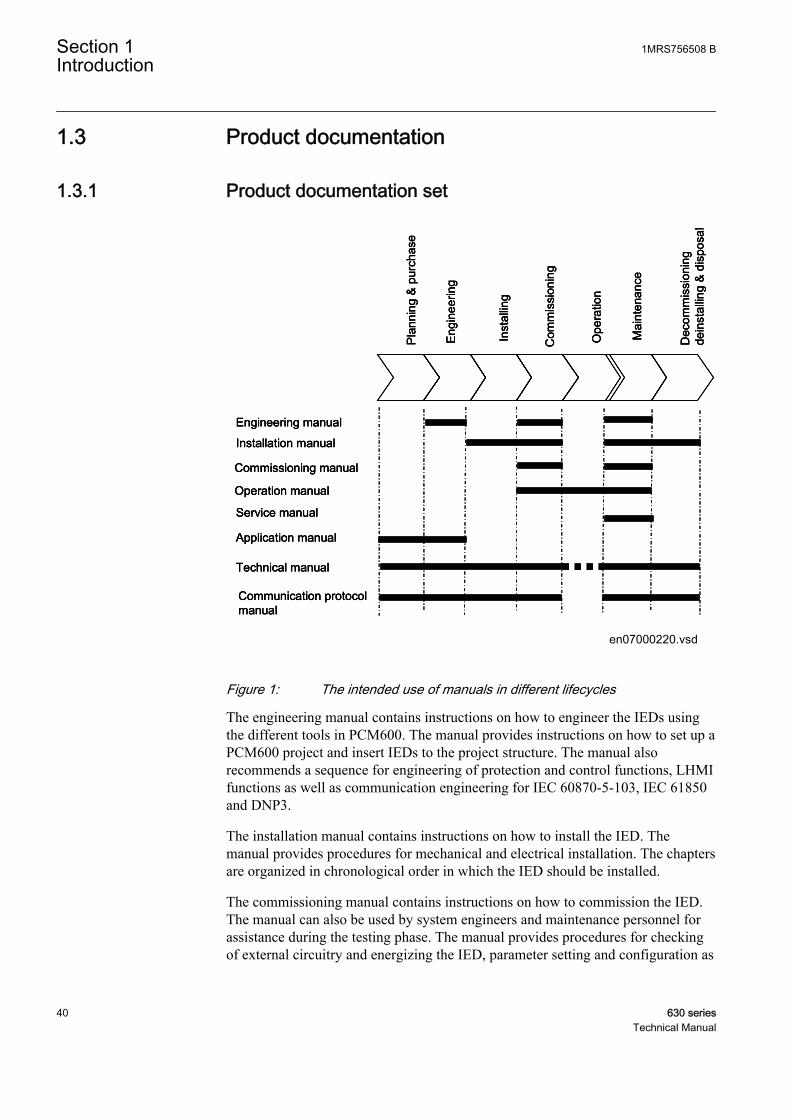
1.3 Product documentation
1.3.1 Product documentation set
Pla
nnin
g &
pur
chas
e
Eng
inee
ring
Inst
allin
g
Com
mis
sion
ing
Ope
ratio
n
Mai
nten
ance
Dec
omm
issi
onin
gde
inst
allin
g&
dis
posa
l
Application manual
Operation manual
Installation manual
Service manual
Engineering manual
Commissioning manual
Communication protocolmanual
Technical manual
Pla
nnin
g &
pur
chas
e
Eng
inee
ring
Inst
allin
g
Com
mis
sion
ing
Ope
ratio
n
Mai
nten
ance
Dec
omm
issi
onin
gde
inst
allin
g&
dis
posa
l
Pla
nnin
g &
pur
chas
e
Eng
inee
ring
Inst
allin
g
Com
mis
sion
ing
Ope
ratio
n
Mai
nten
ance
Dec
omm
issi
onin
gde
inst
allin
g&
dis
posa
l
Application manualApplication manual
Operation manualOperation manual
Installation manualInstallation manual
Service manualService manual
Engineering manualEngineering manual
Commissioning manualCommissioning manual
Communication protocolmanualCommunication protocolmanual
Technical manualTechnical manual
en07000220.vsd
IEC07000220 V1 EN
Figure 1: The intended use of manuals in different lifecycles
The engineering manual contains instructions on how to engineer the IEDs usingthe different tools in PCM600. The manual provides instructions on how to set up aPCM600 project and insert IEDs to the project structure. The manual alsorecommends a sequence for engineering of protection and control functions, LHMIfunctions as well as communication engineering for IEC 60870-5-103, IEC 61850and DNP3.
The installation manual contains instructions on how to install the IED. Themanual provides procedures for mechanical and electrical installation. The chaptersare organized in chronological order in which the IED should be installed.
The commissioning manual contains instructions on how to commission the IED.The manual can also be used by system engineers and maintenance personnel forassistance during the testing phase. The manual provides procedures for checkingof external circuitry and energizing the IED, parameter setting and configuration as
Section 1 1MRS756508 BIntroduction
40 630 seriesTechnical Manual

well as verifying settings by secondary injection. The manual describes the processof testing an IED in a substation which is not in service. The chapters are organizedin chronological order in which the IED should be commissioned.
The operation manual contains instructions on how to operate the IED once it hasbeen commissioned. The manual provides instructions for monitoring, controllingand setting the IED. The manual also describes how to identify disturbances andhow to view calculated and measured power grid data to determine the cause of afault.
The service manual contains instructions on how to service and maintain the IED.The manual also provides procedures for de-energizing, de-commissioning anddisposal of the IED.
The application manual contains descriptions of preconfigurations. The manual canbe used as a reference for configuring control, protection, measurement, recordingand LED functions. The manual can also be used when creating configurationsaccording to specific application requirements.
The technical manual contains application and functionality descriptions and listsfunction blocks, logic diagrams, input and output signals, setting parameters andtechnical data sorted per function. The manual can be used as a technical referenceduring the engineering phase, installation and commissioning phase, and duringnormal service.
The communication protocol manual describes a communication protocolsupported by the IED. The manual concentrates on vendor-specific implementations.
The point list manual describes the outlook and properties of the data pointsspecific to the IED. The manual should be used in conjunction with thecorresponding communication protocol manual.
The service manual is not available yet.
1.3.2 Document revision historyDocument revision/date Product series version HistoryA/2009-09-15 1.0 First release
B/2011-03-07 1.1 Content updated to correspond to theproduct series version
Download the latest documents from the ABB web site http://www.abb.com/substationautomation.
1MRS756508 B Section 1Introduction
630 series 41Technical Manual
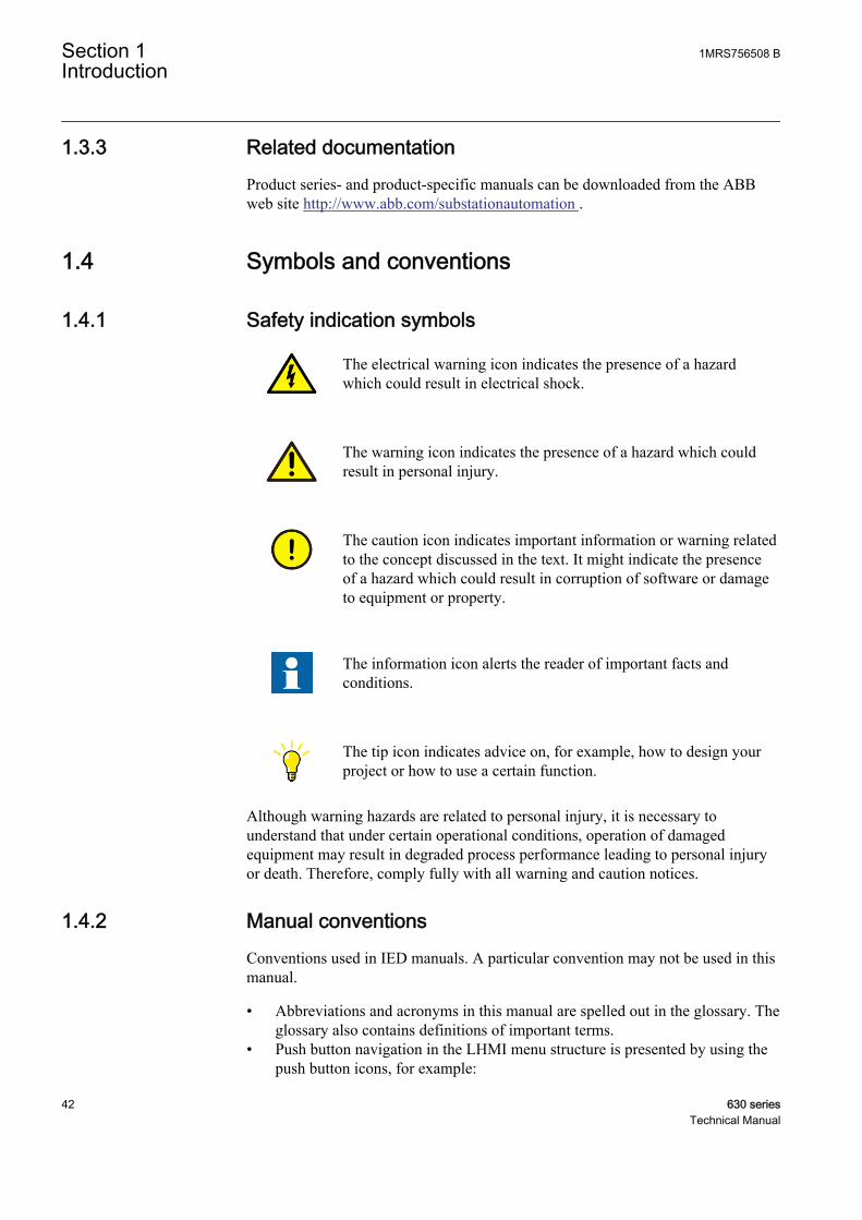
1.3.3 Related documentationProduct series- and product-specific manuals can be downloaded from the ABBweb site http://www.abb.com/substationautomation .
1.4 Symbols and conventions
1.4.1 Safety indication symbols
The electrical warning icon indicates the presence of a hazardwhich could result in electrical shock.
The warning icon indicates the presence of a hazard which couldresult in personal injury.
The caution icon indicates important information or warning relatedto the concept discussed in the text. It might indicate the presenceof a hazard which could result in corruption of software or damageto equipment or property.
The information icon alerts the reader of important facts andconditions.
The tip icon indicates advice on, for example, how to design yourproject or how to use a certain function.
Although warning hazards are related to personal injury, it is necessary tounderstand that under certain operational conditions, operation of damagedequipment may result in degraded process performance leading to personal injuryor death. Therefore, comply fully with all warning and caution notices.
1.4.2 Manual conventionsConventions used in IED manuals. A particular convention may not be used in thismanual.
• Abbreviations and acronyms in this manual are spelled out in the glossary. Theglossary also contains definitions of important terms.
• Push button navigation in the LHMI menu structure is presented by using thepush button icons, for example:
Section 1 1MRS756508 BIntroduction
42 630 seriesTechnical Manual
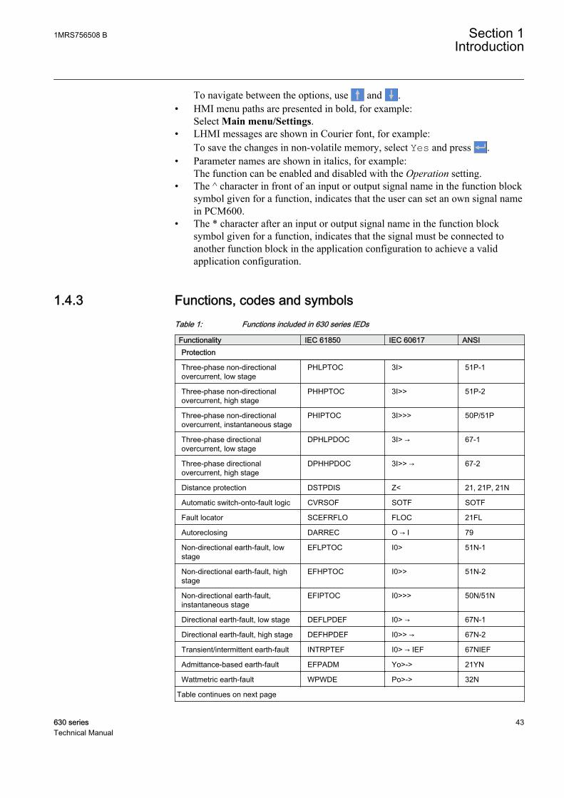
To navigate between the options, use and .• HMI menu paths are presented in bold, for example:
Select Main menu/Settings.• LHMI messages are shown in Courier font, for example:
To save the changes in non-volatile memory, select Yes and press .• Parameter names are shown in italics, for example:
The function can be enabled and disabled with the Operation setting.• The ^ character in front of an input or output signal name in the function block
symbol given for a function, indicates that the user can set an own signal namein PCM600.
• The * character after an input or output signal name in the function blocksymbol given for a function, indicates that the signal must be connected toanother function block in the application configuration to achieve a validapplication configuration.
1.4.3 Functions, codes and symbolsTable 1: Functions included in 630 series IEDs
Functionality IEC 61850 IEC 60617 ANSIProtection
Three-phase non-directionalovercurrent, low stage
PHLPTOC 3I> 51P-1
Three-phase non-directionalovercurrent, high stage
PHHPTOC 3I>> 51P-2
Three-phase non-directionalovercurrent, instantaneous stage
PHIPTOC 3I>>> 50P/51P
Three-phase directionalovercurrent, low stage
DPHLPDOC 3I> → 67-1
Three-phase directionalovercurrent, high stage
DPHHPDOC 3I>> → 67-2
Distance protection DSTPDIS Z< 21, 21P, 21N
Automatic switch-onto-fault logic CVRSOF SOTF SOTF
Fault locator SCEFRFLO FLOC 21FL
Autoreclosing DARREC O → I 79
Non-directional earth-fault, lowstage
EFLPTOC I0> 51N-1
Non-directional earth-fault, highstage
EFHPTOC I0>> 51N-2
Non-directional earth-fault,instantaneous stage
EFIPTOC I0>>> 50N/51N
Directional earth-fault, low stage DEFLPDEF I0> → 67N-1
Directional earth-fault, high stage DEFHPDEF I0>> → 67N-2
Transient/intermittent earth-fault INTRPTEF I0> → IEF 67NIEF
Admittance-based earth-fault EFPADM Yo>-> 21YN
Wattmetric earth-fault WPWDE Po>-> 32N
Table continues on next page
1MRS756508 B Section 1Introduction
630 series 43Technical Manual

Functionality IEC 61850 IEC 60617 ANSIStabilised restricted earth-fault LREFPNDF dI0Lo> 87NL
High-impedance-based restrictedearth-fault
HREFPDIF dI0Hi> 87NH
Rotor earth-fault MREFPTOC Io>R 64R
Phase discontinuity PDNSPTOC I2/I1> 46PD
Negative-sequence overcurrent NSPTOC I2> 46
Negative-sequence overcurrentprotection for motors
MNSPTOC I2>M 46M
Phase reversal PREVPTOC I2>> 46R
Three-phase thermal overloadprotection for feeder
T1PTTR 3Ith>F 49F
Three-phase thermal overloadprotection for transformers
T2PTTR 3Ith>T 49T
Three-phase thermal overloadprotection for motors
MPTTR 3Ith>M 49M
Motor startup supervision STTPMSU Is2t n< 48,66,14,51LR
Motor load jam protection JAMPTOC Ist> 51LR
Emergency start ESMGAPC ESTART ESTART
Loss of load supervision LOFLPTUC 3I< 37
Three-phase current inrushdetection
INRPHAR 3I2f> 68
Transformer differential protectionfor two-winding transformers
TR2PTDF 3dI>T 87T
High-impedance or flux-balance-based differential protection formachines
MHZPDIF 3dIHi>G/M 87GH/87MH
Stabilized differential protectionfor motors
MPDIF 3dI>M 87M
Three-phase overvoltage PHPTOV 3U> 59
Three-phase undervoltage PHPTUV 3U< 27
Positive-sequence overvoltage PSPTOV U1> 47O+
Positive-sequence undervoltage PSPTUV U1< 47U+
Negative-sequence overvoltage NSPTOV U2> 47O-
Residual overvoltage ROVPTOV U0> 59G
Frequency gradient DAPFRC df/dt> 81R
Overfrequency DAPTOF f> 81O
Underfrequency DAPTUF f< 81U
Load shedding LSHDPFRQ UFLS/R 81LSH
Overexcitation OEPVPH U/f> 24
Three-phase underexcitation UEXPDIS X< 40
Directional overpower DOPPDPR P> 32O
Three-phase underimpedance UZPDIS Z< GT 21GT
Circuit-breaker failure CCBRBRF 3I>/I0>BF 51BF/51NBF
Table continues on next page
Section 1 1MRS756508 BIntroduction
44 630 seriesTechnical Manual
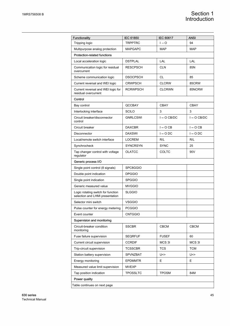
Functionality IEC 61850 IEC 60617 ANSITripping logic TRPPTRC I → O 94
Multipurpose analog protection MAPGAPC MAP MAP
Protection-related functions
Local acceleration logic DSTPLAL LAL LAL
Communication logic for residualovercurrent
RESCPSCH CLN 85N
Scheme communication logic DSOCPSCH CL 85
Current reversal and WEI logic CRWPSCH CLCRW 85CRW
Current reversal and WEI logic forresidual overcurrent
RCRWPSCH CLCRWN 85NCRW
Control
Bay control QCCBAY CBAY CBAY
Interlocking interface SCILO 3 3
Circuit breaker/disconnectorcontrol
GNRLCSWI I ↔ O CB/DC I ↔ O CB/DC
Circuit breaker DAXCBR I ↔ O CB I ↔ O CB
Disconnector DAXSWI I ↔ O DC I ↔ O DC
Local/remote switch interface LOCREM R/L R/L
Synchrocheck SYNCRSYN SYNC 25
Tap changer control with voltageregulator
OLATCC COLTC 90V
Generic process I/O
Single point control (8 signals) SPC8GGIO
Double point indication DPGGIO
Single point indication SPGGIO
Generic measured value MVGGIO
Logic rotating switch for functionselection and LHMI presentation
SLGGIO
Selector mini switch VSGGIO
Pulse counter for energy metering PCGGIO
Event counter CNTGGIO
Supervision and monitoring
Circuit-breaker conditionmonitoring
SSCBR CBCM CBCM
Fuse failure supervision SEQRFUF FUSEF 60
Current circuit supervision CCRDIF MCS 3I MCS 3I
Trip-circuit supervision TCSSCBR TCS TCM
Station battery supervision SPVNZBAT U<> U<>
Energy monitoring EPDMMTR E E
Measured value limit supervision MVEXP
Tap position indication TPOSSLTC TPOSM 84M
Power quality
Table continues on next page
1MRS756508 B Section 1Introduction
630 series 45Technical Manual

Functionality IEC 61850 IEC 60617 ANSIVoltage variation PHQVVR PQMU PQMV
Voltage unbalance VSQVUB PQMUBU PQMUBV
Current harmonics CMHAI PQM3I PQM3I
Voltage harmonics phase-to-phase VPPMHAI PQM3Upp PQM3Vpp
Voltage harmonics phase-to-earth VPHMHAI PQM3Upe PQM3Vpg
Measurement
Three-phase current CMMXU 3I 3I
Three-phase voltage (phase-to-earth)
VPHMMXU 3Upe 3Upe
Three-phase voltage (phase-to-phase)
VPPMMXU 3Upp 3Upp
Residual current RESCMMXU I0 I0
Residual voltage RESVMMXU U0 Vn
Power monitoring with P, Q, S,power factor, frequency
PWRMMXU PQf PQf
Sequence current CSMSQI I1, I2 I1, I2
Sequence voltage VSMSQI U1, U2 V1, V2
Disturbance recorder function
Analog channels 1-10 (samples) A1RADR ACH1 ACH1
Analog channels 11-20 (samples) A2RADR ACH2 ACH2
Analog channels 21-30 (calc. val.) A3RADR ACH3 ACH3
Analog channels 31-40 (calc. val.) A4RADR ACH4 ACH4
Binary channels 1-16 B1RBDR BCH1 BCH1
Binary channels 17-32 B2RBDR BCH2 BCH2
Binary channels 33-48 B3RBDR BCH3 BCH3
Binary channels 49-64 B4RBDR BCH4 BCH4
Station communication (GOOSE)
Binary receive GOOSEBINRCV
Double point receive GOOSEDPRCV
Interlock receive GOOSEINTLKRCV
Integer receive GOOSEINTRCV
Measured value receive GOOSEMVRCV
Single point receive GOOSESPRCV
Section 1 1MRS756508 BIntroduction
46 630 seriesTechnical Manual

Section 2 630 series overview
2.1 Overview
630 series consists of IEDs for protection, control, measurement and supervision ofutility and industrial distribution substations, medium and large asynchronousmotors in industrial power systems, and transformers in utility and industry powerdistribution networks.
630 series is a part of ABB’s Relion® product family. The 630 protection andcontrol product series is characterized by functional scalability and flexibleconfigurability. It also features necessary control functions for bay control indifferent applications.
The supported communication protocols including IEC 61850 offer seamlessconnectivity to various station automation and SCADA systems.
2.1.1 Product series version historyProduct series version Product series history1.0 First release
1.1 • Support for IEC 60870-5-103 communication protocol• Analog GOOSE• RTD module• New analog input modules• Additional arithmetic and logic function support• Admittance-based earth-fault protection• Wattmetric earth-fault protection• Power quality functions• Stabilized three-phase differential protection for motors and generators• High-impedance/flux-balance-based differential protection for motors
and generators• Synchronized motor protections• Voltage control of transformers (single and parallel)• Three-phase under-impedance protection• Overexcitation protection
2.1.2 PCM600 and IED connectivity package version• Protection and Control IED Manager PCM600 Ver. 2.3 or later• ABB REF630 Connectivity Package Ver. 1.1 or later• ABB REM630 Connectivity Package Ver. 1.1 or later• ABB RET630 Connectivity Package Ver. 1.1 or later
1MRS756508 B Section 2630 series overview
630 series 47Technical Manual

Download connectivity packages from the ABB web site http://www.abb.com/substationautomation
2.2 Local HMI
A071260 V3 EN
Figure 2: 19" LHMI
The LHMI of the IED contains the following elements:
• Display• Buttons• LED indicators• Communication port
The LHMI is used for setting, monitoring and controlling .
2.2.1 DisplayThe LHMI includes a graphical monochrome display with a resolution of 320 x240 pixels. The character size can vary. The amount of characters and rows fittingthe view depends on the character size and the view that is shown.
Section 2 1MRS756508 B630 series overview
48 630 seriesTechnical Manual
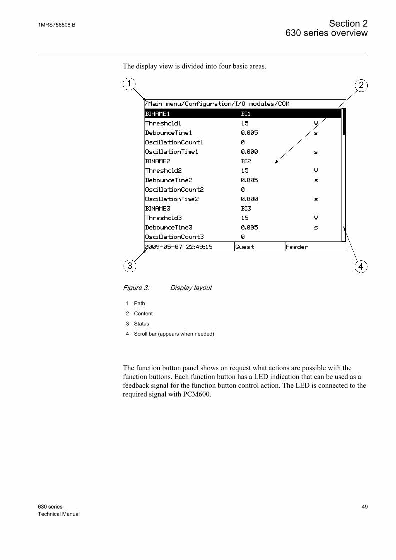
The display view is divided into four basic areas.
A071258 V2 EN
Figure 3: Display layout
1 Path
2 Content
3 Status
4 Scroll bar (appears when needed)
The function button panel shows on request what actions are possible with thefunction buttons. Each function button has a LED indication that can be used as afeedback signal for the function button control action. The LED is connected to therequired signal with PCM600.
1MRS756508 B Section 2630 series overview
630 series 49Technical Manual

GUID-6828CE38-2B88-4BB5-8F29-27D2AC27CC18 V1 EN
Figure 4: Function button panel
The alarm LED panel shows on request the alarm text labels for the alarm LEDs.
GUID-3CBCBC36-EFCE-43A0-9D62-8D88AD6B6287 V1 EN
Figure 5: Alarm LED panel
The function button and alarm LED panels are not visible at the same time. Eachpanel is shown by pressing one of the function buttons or the Multipage button.Pressing the ESC button clears the panel from the display. Both the panels havedynamic width that depends on the label string length that the panel contains.
Section 2 1MRS756508 B630 series overview
50 630 seriesTechnical Manual
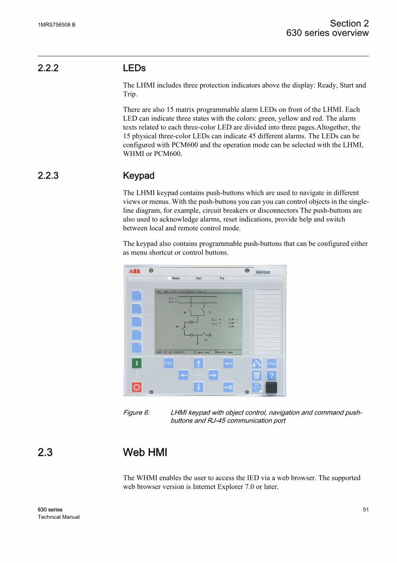
2.2.2 LEDsThe LHMI includes three protection indicators above the display: Ready, Start andTrip.
There are also 15 matrix programmable alarm LEDs on front of the LHMI. EachLED can indicate three states with the colors: green, yellow and red. The alarmtexts related to each three-color LED are divided into three pages.Altogether, the15 physical three-color LEDs can indicate 45 different alarms. The LEDs can beconfigured with PCM600 and the operation mode can be selected with the LHMI,WHMI or PCM600.
2.2.3 KeypadThe LHMI keypad contains push-buttons which are used to navigate in differentviews or menus. With the push-buttons you can you can control objects in the single-line diagram, for example, circuit breakers or disconnectors The push-buttons arealso used to acknowledge alarms, reset indications, provide help and switchbetween local and remote control mode.
The keypad also contains programmable push-buttons that can be configured eitheras menu shortcut or control buttons.
GUID-FE571EAC-D3AF-4E26-8C01-197F21AA96CA V1 EN
Figure 6: LHMI keypad with object control, navigation and command push-buttons and RJ-45 communication port
2.3 Web HMI
The WHMI enables the user to access the IED via a web browser. The supportedweb browser version is Internet Explorer 7.0 or later.
1MRS756508 B Section 2630 series overview
630 series 51Technical Manual

WHMI is disabled by default. To enable the WHMI, select Mainmenu/Configuration/HMI/Web HMI/Operation via the LHMI.
WHMI offers several functions.
• Alarm indications and event lists• System supervision• Parameter settings• Measurement display• Disturbance records• Phasor diagram
The menu tree structure on the WHMI is almost identical to the one on the LHMI.
A071242 V3 EN
Figure 7: Example view of the WHMI
The WHMI can be accessed locally and remotely.
• Locally by connecting the user's computer to the IED via the frontcommunication port.
• Remotely over LAN/WAN.
Section 2 1MRS756508 B630 series overview
52 630 seriesTechnical Manual

2.4 Authorization
The user categories are predefined for the LHMI and WHMI, each with differentrights.
The IED users can be created, deleted and edited only with PCM600. One user canbelong to one or several user categories.
At delivery, the user has full access until users are created withPCM600. Logging on is not required for the LHMI.
Table 2: Predefined user categories
User category User rightsSystemOperator Control from LHMI, no bypass
ProtectionEngineer All settings
DesignEngineer Application configuration
UserAdministrator User and password administration
All changes in user management settings will cause an IED reboot.
2.5 Communication
The IED supports communication protocols IEC 61850-8-1, IEC 60870-5-103 andDNP3 over TCP/IP.
All operational information and controls are available through these protocols.However, some communication functionality, for example, horizontalcommunication (GOOSE) between the IEDs, is only enabled by the IEC 61850-8-1communication protocol.
Disturbance files are accessed using the IEC 61850 or IEC 60870-5-103 protocols.Disturbance files are also available to any Ethernet based application in thestandard COMTRADE format. The IED can send binary signals to other IEDs (socalled horizontal communication) using the IEC 61850-8-1 GOOSE (GenericObject Oriented Substation Event) profile. Binary GOOSE messaging can, forexample, be employed for protection and interlocking-based protection schemes.The IED meets the GOOSE performance requirements for tripping applications indistribution substations, as defined by the IEC 61850 standard. Further, the IEDsupports the sending and receiving of analog values using GOOSE messaging.Analog GOOSE messaging enables fast transfer of analog measurement values
1MRS756508 B Section 2630 series overview
630 series 53Technical Manual

over the station bus, thus facilitating for example sharing of RTD input values,such as surrounding temperature values, to other IED applications. The IEDinteroperates with other IEC 61850 compliant IEDs, tools and systems andsimultaneously reports events to five different clients on the IEC 61850 station bus.For a system using DNP3 over TCP/IP, events can be sent to four different masters.For systems using IEC 60870-5-103 IED can be connected to one master in astation bus with star-topology.
All communication connectors, except for the front port connector, are placed onintegrated communication modules. The IED is connected to Ethernet-basedcommunication systems via the RJ-45 connector (10/100BASE-TX) or the fibre-optic multimode LC connector (100BASE-FX).
IEC 60870-5-103 is available from optical serial port where it is possible to useserial glass fibre (ST connector) or serial plastic fibre (snap-in connector).
The IED supports SNTP, DNP3 and IRIG-B time synchronization methods with atime-stamping resolution of 1 ms.
The IED supports the following time synchronization methods with a timestampingresolution of 1 ms:
Ethernet communication based:
• SNTP (simple network time protocol)• DNP3
With special time synchronization wiring:
• IRIG-B
IEC 60870-5-103 serial communication has a time-stamping resolution of 10 ms.
Section 2 1MRS756508 B630 series overview
54 630 seriesTechnical Manual

Section 3 Basic functions
3.1 General parameters
Table 3: Battery voltage setting available for each BIO and COM board.
Name Values (Range) Unit Step Default DescriptionBatteryVoltage 24 - 250 V 1 110 Station battery voltage
Table 4: Binary input settings available for all binary inputs in BIO and COM boards.
Name Values (Range) Unit Step Default DescriptionThreshold1 6 - 900 %UB 1 65 Threshold in percentage of station
battery voltage for input 1
DebounceTime1 0.000 - 0.100 s 0.001 0.005 Debounce time for input 1
OscillationCount1 0 - 255 - 1 0 Oscillation count for input 1
OscillationTime1 0.000 - 600.000 s 0.001 0.000 Oscillation time for input 1
Binary input settings are the same for each channel. The channelnumbers are shown after the parameter name in LHMI and PCM600.
Table 5: RTD01_4AO output channel settings (basic)
Name Values (Range) Unit Step Default DescriptionMinMaxRange1 0..20 mA
4..20 mAUser Defined
- - 4..20 mA Min Max range of transducer value foranalog output 1
MinPrimValue1 -1000000000.000 -1000000000.000
- 0.001 4.000 Minimum primary value for analog output1
MaxPrimValue1 -1000000000.000 -1000000000.000
- 0.001 20.000 Maximum primary value for analogoutput 1
RTD output channel settings are the same for each channel. Thechannel numbers are shown after the parameter name in LHMI andPCM600.
1MRS756508 B Section 3Basic functions
630 series 55Technical Manual
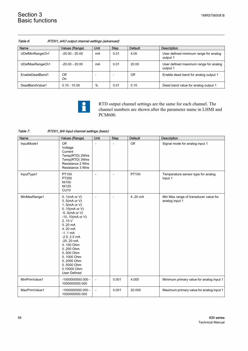
Table 6: RTD01_4AO output channel settings (advanced)
Name Values (Range) Unit Step Default DescriptionUDefMinRangeCh1 -20.00 - 20.00 mA 0.01 4.00 User defined minimum range for analog
output 1
UDefMaxRangeCh1 -20.00 - 20.00 mA 0.01 20.00 User defined maximum range for analogoutput 1
EnableDeadBand1 OffOn
- - Off Enable dead band for analog output 1
DeadBandValue1 0.10 - 10.00 % 0.01 0.10 Dead band value for analog output 1
RTD output channel settings are the same for each channel. Thechannel numbers are shown after the parameter name in LHMI andPCM600.
Table 7: RTD01_8AI input channel settings (basic)
Name Values (Range) Unit Step Default DescriptionInputMode1 Off
VoltageCurrentTemp(RTD) 2WireTemp(RTD) 3WireResistance 2 WireResistance 3 Wire
- - Off Signal mode for analog input 1
InputType1 PT100PT250NI100NI120CU10
- - PT100 Temperature sensor type for analoginput 1
MinMaxRange1 0..1(mA or V)0..5(mA or V)1..5(mA or V)0..10(mA or V)-5..5(mA or V)-10..10(mA or V)2..10 V0..20 mA4..20 mA-1..1 mA-2.5..2.5 mA-20..20 mA0..100 Ohm0..200 Ohm0..500 Ohm0..1000 Ohm0..2000 Ohm0..5000 Ohm0.10000 OhmUser Defined
- - 4..20 mA Min Max range of transducer value foranalog input 1
MinPrimValue1 -1000000000.000 -1000000000.000
- 0.001 4.000 Minimum primary value for analog input 1
MaxPrimValue1 -1000000000.000 -1000000000.000
- 0.001 20.000 Maximum primary value for analog input 1
Section 3 1MRS756508 BBasic functions
56 630 seriesTechnical Manual
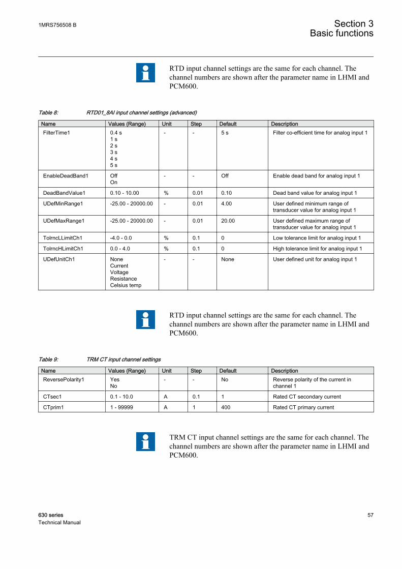
RTD input channel settings are the same for each channel. Thechannel numbers are shown after the parameter name in LHMI andPCM600.
Table 8: RTD01_8AI input channel settings (advanced)
Name Values (Range) Unit Step Default DescriptionFilterTime1 0.4 s
1 s2 s3 s4 s5 s
- - 5 s Filter co-efficient time for analog input 1
EnableDeadBand1 OffOn
- - Off Enable dead band for analog input 1
DeadBandValue1 0.10 - 10.00 % 0.01 0.10 Dead band value for analog input 1
UDefMinRange1 -25.00 - 20000.00 - 0.01 4.00 User defined minimum range oftransducer value for analog input 1
UDefMaxRange1 -25.00 - 20000.00 - 0.01 20.00 User defined maximum range oftransducer value for analog input 1
TolrncLLimitCh1 -4.0 - 0.0 % 0.1 0 Low tolerance limit for analog input 1
TolrncHLimitCh1 0.0 - 4.0 % 0.1 0 High tolerance limit for analog input 1
UDefUnitCh1 NoneCurrentVoltageResistanceCelsius temp
- - None User defined unit for analog input 1
RTD input channel settings are the same for each channel. Thechannel numbers are shown after the parameter name in LHMI andPCM600.
Table 9: TRM CT input channel settings
Name Values (Range) Unit Step Default DescriptionReversePolarity1 Yes
No- - No Reverse polarity of the current in
channel 1
CTsec1 0.1 - 10.0 A 0.1 1 Rated CT secondary current
CTprim1 1 - 99999 A 1 400 Rated CT primary current
TRM CT input channel settings are the same for each channel. Thechannel numbers are shown after the parameter name in LHMI andPCM600.
1MRS756508 B Section 3Basic functions
630 series 57Technical Manual

Table 10: TRM VT input channel settings
Name Values (Range) Unit Step Default DescriptionVTsec6 0.001 - 999.999 V 0.001 110 Rated VT secondary voltage
VTprim6 0.001 - 9999.999 kV 0.001 20 Rated VT primary voltage
TRM VT input channel settings are the same for each channel. Thechannel numbers are shown after the parameter name in LHMI andPCM600.
3.2 Binary input
3.2.1 Binary input debounce filterThe debounce filter eliminates debounces and short disturbances on a binary input.
A time counter is used for filtering. The time counter is increased once in amillisecond when a binary input is high, or decreased when a binary input is low. Anew debounced binary input signal is forwarded when the time counter reaches theset DebounceTimevalue and the debounced input value is low or when the timecounter reaches 0 and the debounced input value is high.
The binary input ON-event gets the time stamp of the first rising edge, after whichthe counter does not reach 0 again. The same happens when the signal goes downto 0 again.
Each binary input has a filter time parameter DebounceTime#, where # is thenumber of the binary input of the module in question (for example DebounceTime1).
The lowest debounce filter time used is 5 ms, even though it ispossible to set lower values for the parameter.
3.2.2 Oscillation filterBinary input lines can be very long in substations and there are electromagneticfields from, for example, nearby breakers. Floating input lines can result in binaryinputs' activity. These events are unwanted traffic in the system. An oscillationfilter is used to reduce the load from the system when a binary input starts oscillating.
Each debounced input signal change increments an oscillation counter. Every timethe oscillation time counter reaches the set OscillationTime, the oscillation counteris checked and both the counters are reset. If the counter value is above the setOscillationCount value the signal is declared as oscillating. If the value is below
Section 3 1MRS756508 BBasic functions
58 630 seriesTechnical Manual
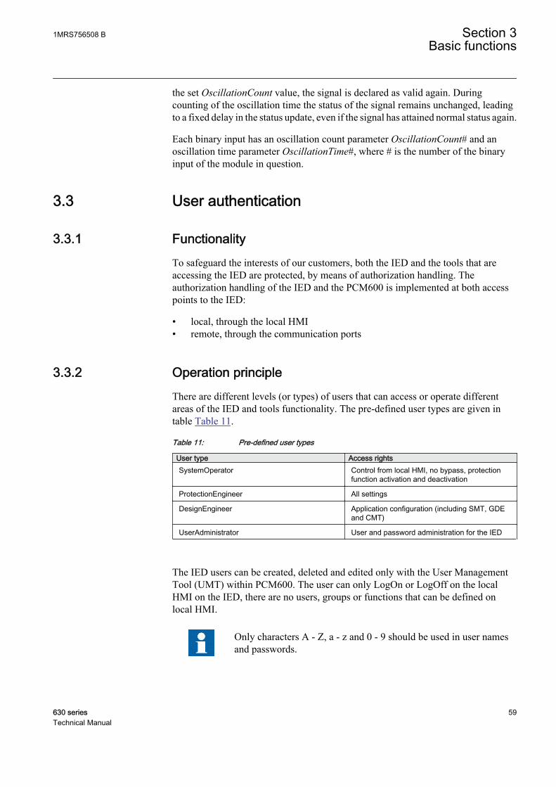
the set OscillationCount value, the signal is declared as valid again. Duringcounting of the oscillation time the status of the signal remains unchanged, leadingto a fixed delay in the status update, even if the signal has attained normal status again.
Each binary input has an oscillation count parameter OscillationCount# and anoscillation time parameter OscillationTime#, where # is the number of the binaryinput of the module in question.
3.3 User authentication
3.3.1 FunctionalityTo safeguard the interests of our customers, both the IED and the tools that areaccessing the IED are protected, by means of authorization handling. Theauthorization handling of the IED and the PCM600 is implemented at both accesspoints to the IED:
• local, through the local HMI• remote, through the communication ports
3.3.2 Operation principleThere are different levels (or types) of users that can access or operate differentareas of the IED and tools functionality. The pre-defined user types are given intable Table 11.
Table 11: Pre-defined user types
User type Access rightsSystemOperator Control from local HMI, no bypass, protection
function activation and deactivation
ProtectionEngineer All settings
DesignEngineer Application configuration (including SMT, GDEand CMT)
UserAdministrator User and password administration for the IED
The IED users can be created, deleted and edited only with the User ManagementTool (UMT) within PCM600. The user can only LogOn or LogOff on the localHMI on the IED, there are no users, groups or functions that can be defined onlocal HMI.
Only characters A - Z, a - z and 0 - 9 should be used in user namesand passwords.
1MRS756508 B Section 3Basic functions
630 series 59Technical Manual

At least one user must be included in the UserAdministrator groupto be able to write users, created in PCM600, to IED.
3.3.2.1 Authorization handling in the IED
At delivery the default user is the SuperUser. No Log on is required to operate theIED until a user has been created with the User Management Tool.
Once a user is created and written to the IED, that user can perform a Log on, usingthe password assigned in the tool. Then the default user will be Guest.
If there is no user created, an attempt to log on will display a message box: “Nouser defined!”
If one user leaves the IED without logging off, then after the timeout (set in Mainmenu/Configuration/HMI/LHMI/Display Timeout) elapses, the IED will returnto Guest state, when only reading is possible. By factory default, the displaytimeout is set to 60 minutes.
If one or more users are created with the User Management Tool and written to theIED, then, when a user attempts a Log on by pressing the key or when the userattempts to perform an operation that is password protected, the Log on windowopens.
The cursor is focused on the User identity field, so upon pressing the key, onecan change the user name, by browsing the list of users, with the “up” and “down”arrows. After choosing the right user name, the user must press the key again.
When it comes to password, upon pressing the key, the following characterswill show up: “✳✳✳✳✳✳✳✳”. The user must scroll for every letter in thepassword. After all the letters are introduced (passwords are case sensitive) chooseOK and press the key again.
At successful Log on, the local HMI shows the new user name in the status bar atthe bottom of the display. If the Log on is OK, when required to change forexample a password protected setting, the local HMI returns to the actual settingfolder. If the Log on has failed, an "Error Access Denied" message opens. If a userenters an incorrect password three times, that user will be blocked for ten minutesbefore a new attempt to log in can be performed. The user will be blocked fromlogging in, both from the local HMI and PCM600 and WebHMI. However, otherusers are to log in during this period.
Section 3 1MRS756508 BBasic functions
60 630 seriesTechnical Manual
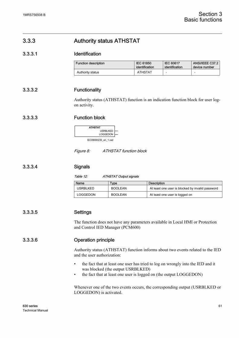
3.3.3 Authority status ATHSTAT
3.3.3.1 Identification
Function description IEC 61850identification
IEC 60617identification
ANSI/IEEE C37.2device number
Authority status ATHSTAT - -
3.3.3.2 Functionality
Authority status (ATHSTAT) function is an indication function block for user log-on activity.
3.3.3.3 Function block
ATHSTATUSRBLKED
LOGGEDON
IEC09000235_en_1.vsdIEC09000235 V1 EN
Figure 8: ATHSTAT function block
3.3.3.4 Signals
Table 12: ATHSTAT Output signals
Name Type DescriptionUSRBLKED BOOLEAN At least one user is blocked by invalid password
LOGGEDON BOOLEAN At least one user is logged on
3.3.3.5 Settings
The function does not have any parameters available in Local HMI or Protectionand Control IED Manager (PCM600)
3.3.3.6 Operation principle
Authority status (ATHSTAT) function informs about two events related to the IEDand the user authorization:
• the fact that at least one user has tried to log on wrongly into the IED and itwas blocked (the output USRBLKED)
• the fact that at least one user is logged on (the output LOGGEDON)
Whenever one of the two events occurs, the corresponding output (USRBLKED orLOGGEDON) is activated.
1MRS756508 B Section 3Basic functions
630 series 61Technical Manual

3.4 Local Human-Machine-Interface LHMI
3.4.1 Local HMI screen behaviour
3.4.1.1 Identification
Function description IEC 61850identification
IEC 60617identification
ANSI/IEEE C37.2device number
Local HMI screen behaviour SCREEN - -
3.4.1.2 Settings
Table 13: SCREEN Non group settings (basic)
Name Values (Range) Unit Step Default DescriptionDisplayTimeout 10 - 120 Min 10 60 Local HMI display
timeout
ContrastLevel -100 - 100 % 10 0 Contrast level fordisplay
DefaultScreen Main menuControlEventsMeasurementsDisturbance recordsMonitoring
- - Main menu Default screen
EvListSrtOrder Latest on topOldest on top
- - Latest on top Sort order of eventlist
AutoIndicationDRP OffOn
- - Off Automatic indicationof disturbance report
SubstIndSLD NoYes
- - No Substitute indicationon single linediagram
InterlockIndSLD NoYes
- - No Interlock indicationon single linediagram
BypassCommands NoYes
- - No Enable bypass ofcommands
3.4.2 Local HMI signals
3.4.2.1 Identification
Function description IEC 61850identification
IEC 60617identification
ANSI/IEEE C37.2device number
Local HMI signals LHMICTRL - -
Section 3 1MRS756508 BBasic functions
62 630 seriesTechnical Manual
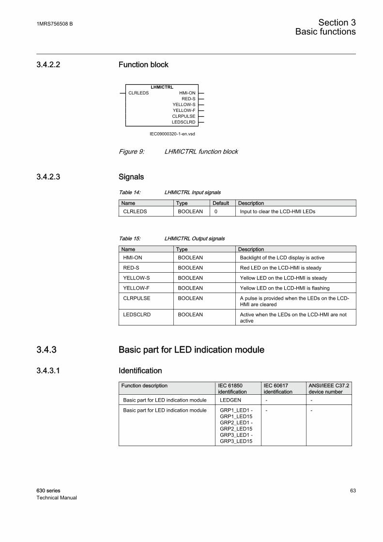
3.4.2.2 Function block
LHMICTRLCLRLEDS HMI-ON
RED-SYELLOW-SYELLOW-FCLRPULSELEDSCLRD
IEC09000320-1-en.vsdIEC09000320 V1 EN
Figure 9: LHMICTRL function block
3.4.2.3 Signals
Table 14: LHMICTRL Input signals
Name Type Default DescriptionCLRLEDS BOOLEAN 0 Input to clear the LCD-HMI LEDs
Table 15: LHMICTRL Output signals
Name Type DescriptionHMI-ON BOOLEAN Backlight of the LCD display is active
RED-S BOOLEAN Red LED on the LCD-HMI is steady
YELLOW-S BOOLEAN Yellow LED on the LCD-HMI is steady
YELLOW-F BOOLEAN Yellow LED on the LCD-HMI is flashing
CLRPULSE BOOLEAN A pulse is provided when the LEDs on the LCD-HMI are cleared
LEDSCLRD BOOLEAN Active when the LEDs on the LCD-HMI are notactive
3.4.3 Basic part for LED indication module
3.4.3.1 Identification
Function description IEC 61850identification
IEC 60617identification
ANSI/IEEE C37.2device number
Basic part for LED indication module LEDGEN - -
Basic part for LED indication module GRP1_LED1 -GRP1_LED15GRP2_LED1 -GRP2_LED15GRP3_LED1 -GRP3_LED15
- -
1MRS756508 B Section 3Basic functions
630 series 63Technical Manual
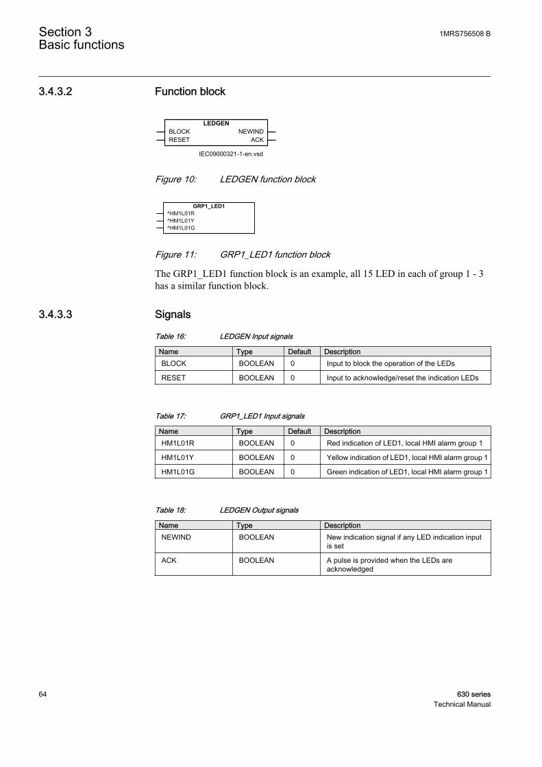
3.4.3.2 Function block
LEDGENBLOCKRESET
NEWINDACK
IEC09000321-1-en.vsdIEC09000321 V1 EN
Figure 10: LEDGEN function block
GRP1_LED1^HM1L01R^HM1L01Y^HM1L01G
IEC09000322 V1 EN
Figure 11: GRP1_LED1 function block
The GRP1_LED1 function block is an example, all 15 LED in each of group 1 - 3has a similar function block.
3.4.3.3 Signals
Table 16: LEDGEN Input signals
Name Type Default DescriptionBLOCK BOOLEAN 0 Input to block the operation of the LEDs
RESET BOOLEAN 0 Input to acknowledge/reset the indication LEDs
Table 17: GRP1_LED1 Input signals
Name Type Default DescriptionHM1L01R BOOLEAN 0 Red indication of LED1, local HMI alarm group 1
HM1L01Y BOOLEAN 0 Yellow indication of LED1, local HMI alarm group 1
HM1L01G BOOLEAN 0 Green indication of LED1, local HMI alarm group 1
Table 18: LEDGEN Output signals
Name Type DescriptionNEWIND BOOLEAN New indication signal if any LED indication input
is set
ACK BOOLEAN A pulse is provided when the LEDs areacknowledged
Section 3 1MRS756508 BBasic functions
64 630 seriesTechnical Manual

3.4.3.4 Settings
Table 19: LEDGEN Non group settings (basic)
Name Values (Range) Unit Step Default DescriptionOperation Off
On- - Off Operation Off/On
tRestart 0.0 - 100.0 s 0.1 0.0 Defines the disturbance length
tMax 0.0 - 100.0 s 0.1 0.0 Maximum time for the definition of adisturbance
Table 20: GRP1_LED1 Non group settings (basic)
Name Values (Range) Unit Step Default DescriptionSequenceType Follow-S
Follow-FLatchedAck-F-SLatchedAck-S-FLatchedColl-SLatchedReset-S
- - Follow-S Sequence type for LED 1, local HMIalarm group 1
LabelOff 0 - 18 - 1 G1L01_OFF Label string shown when LED 1, alarmgroup 1 is off
LabelRed 0 - 18 - 1 G1L01_RED Label string shown when LED 1, alarmgroup 1 is red
LabelYellow 0 - 18 - 1 G1L01_YELLOW Label string shown when LED 1, alarmgroup 1 is yellow
LabelGreen 0 - 18 - 1 G1L01_GREEN Label string shown when LED 1, alarmgroup 1 is green
3.4.4 Display part for HMI function keys control module
3.4.4.1 Identification
Function description IEC 61850identification
IEC 60617identification
ANSI/IEEE C37.2device number
LCD part for HMI Function KeysControl module
FNKEYMD1 -FNKEYMD5
- -
3.4.4.2 Function block
FNKEYMD1^LEDCTL1 ^FKEYOUT1
IEC09000327 V1 EN
Figure 12: FNKEYMD1 function block
Only the function block for the first button is shown above. There is a similar blockfor every function button.
1MRS756508 B Section 3Basic functions
630 series 65Technical Manual
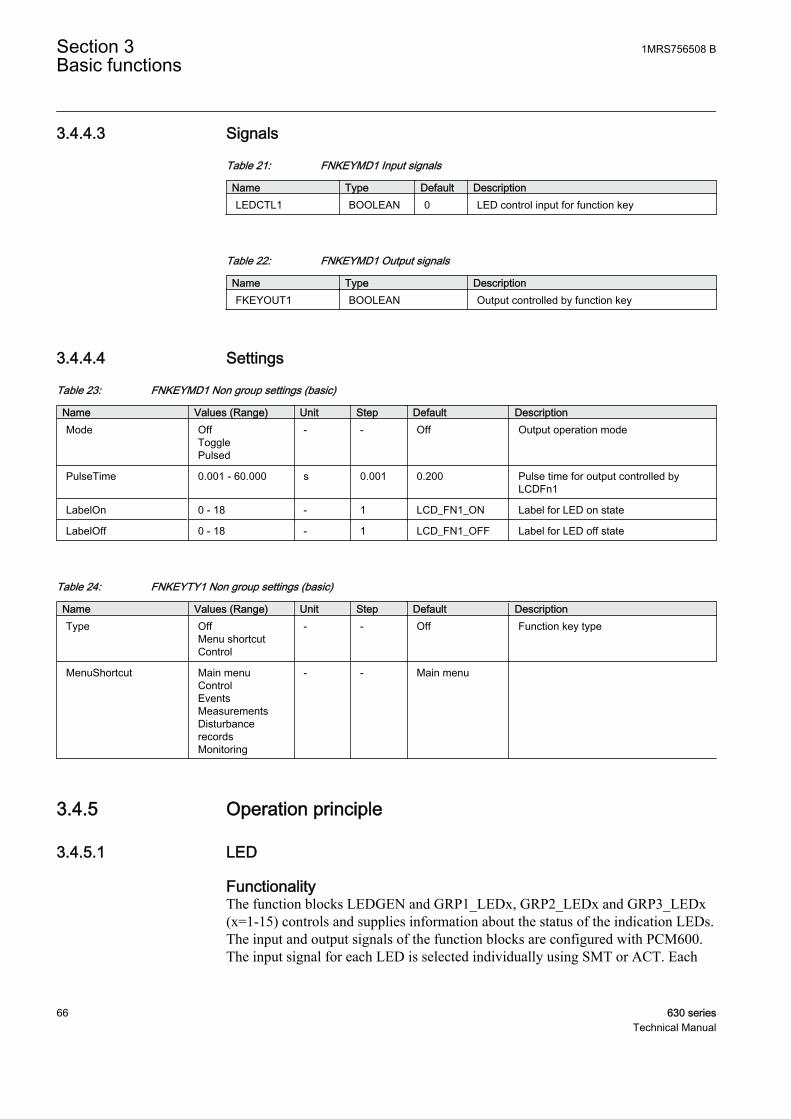
3.4.4.3 Signals
Table 21: FNKEYMD1 Input signals
Name Type Default DescriptionLEDCTL1 BOOLEAN 0 LED control input for function key
Table 22: FNKEYMD1 Output signals
Name Type DescriptionFKEYOUT1 BOOLEAN Output controlled by function key
3.4.4.4 Settings
Table 23: FNKEYMD1 Non group settings (basic)
Name Values (Range) Unit Step Default DescriptionMode Off
TogglePulsed
- - Off Output operation mode
PulseTime 0.001 - 60.000 s 0.001 0.200 Pulse time for output controlled byLCDFn1
LabelOn 0 - 18 - 1 LCD_FN1_ON Label for LED on state
LabelOff 0 - 18 - 1 LCD_FN1_OFF Label for LED off state
Table 24: FNKEYTY1 Non group settings (basic)
Name Values (Range) Unit Step Default DescriptionType Off
Menu shortcutControl
- - Off Function key type
MenuShortcut Main menuControlEventsMeasurementsDisturbancerecordsMonitoring
- - Main menu
3.4.5 Operation principle
3.4.5.1 LED
FunctionalityThe function blocks LEDGEN and GRP1_LEDx, GRP2_LEDx and GRP3_LEDx(x=1-15) controls and supplies information about the status of the indication LEDs.The input and output signals of the function blocks are configured with PCM600.The input signal for each LED is selected individually using SMT or ACT. Each
Section 3 1MRS756508 BBasic functions
66 630 seriesTechnical Manual
LED is controlled by a GRP1_LEDx function block, that controls the color and theoperating mode.
Each indication LED on local HMI can be set individually to operate in sixdifferent sequences; two as follow type and four as latch type. Two of the latchingsequence types are intended to be used as a protection indication system, either incollecting or restarting mode, with reset functionality. The other two are intendedto be used as signalling system in collecting mode with acknowledgmentfunctionality.
Status LEDsThere are three status LEDs above the display in the front of the IED, green,yellow and red.
The green LED has a fixed function, while the yellow and red LEDs are userconfigured. The yellow LED can be used to indicate that a disturbance report iscreated (steady) or that the IED is in test mode (flashing). The red LED can be usedto indicate a trip command.
Indication LEDs
Operating modesCollecting mode
• LEDs, which are used in collecting mode of operation, are accumulatedcontinuously until the unit is acknowledged manually. This mode is suitablewhen the LEDs are used as a simplified alarm system.
Re-starting mode
• In the re-starting mode of operation each new start resets all previous activeLEDs and activates only those, which appear during one disturbance. OnlyLEDs defined for re- starting mode with the latched sequence type 6(LatchedReset-S) will initiate a reset and a restart at a new disturbance. Adisturbance is defined to end a settable time after the reset of the activatedinput signals or when the maximum time limit has elapsed.
Acknowledgment/reset
• From local HMI• The active indications can be acknowledged/reset manually. Manual
acknowledgment and manual reset have the same meaning and is acommon signal for all the operating sequences and LEDs. The functionis positive edge triggered, not level triggered. The acknowledgment/resetis performed via the button and menus on the LHMI.
• From function input
1MRS756508 B Section 3Basic functions
630 series 67Technical Manual

• The active indications can also be acknowledged/reset from an input,ACK_RST, to the function. This input can for example be configured toa binary input operated from an external push button. The function ispositive edge triggered, not level triggered. This means that even if thebutton is continuously pressed, the acknowledgment/reset only affectsindications active at the moment when the button is first pressed.
• Automatic reset• The automatic reset can only be performed for indications defined for re-
starting mode with the latched sequence type 6 (LatchedReset-S). Whenthe automatic reset of the LEDs has been performed, still persistingindications will be indicated with a steady light.
Operating sequenceThe sequences can be of type Follow or Latched. For the Follow type the LEDfollow the input signal completely. For the Latched type each LED latches to thecorrespond¬ing input signal until it is reset.
The figures below show the function of available sequences selectable for eachLED separately. For sequence 1 and 2 (Follow type), the acknowledgment/resetfunction is not applicable. Sequence 3 and 4 (Latched type with acknowledgement)are only work¬ing in collecting mode. Sequence 5 is working according to Latchedtype and collecting mode while sequence 6 is working according to Latched typeand re-starting mode. The letters S and F in the sequence names have the meaningS = Steady and F = Flash.
At the activation of the input signal, the indication obtains corresponding colorcorresponding to the activated input and operates according to the selectedsequence diagrams below.
In the sequence diagrams the LEDs have the following characteristics:
= No indication = Steady light = Flash
G= Green Y= Yellow R= RedIEC09000311.vsd
IEC09000311 V1 EN
Figure 13: Symbols used in the sequence diagrams
Sequence 1 (Follow-S)This sequence follows all the time, with a steady light, the corresponding inputsignals. It does not react on acknowledgment or reset. Every LED is independent ofthe other LEDs in its operation.
Section 3 1MRS756508 BBasic functions
68 630 seriesTechnical Manual
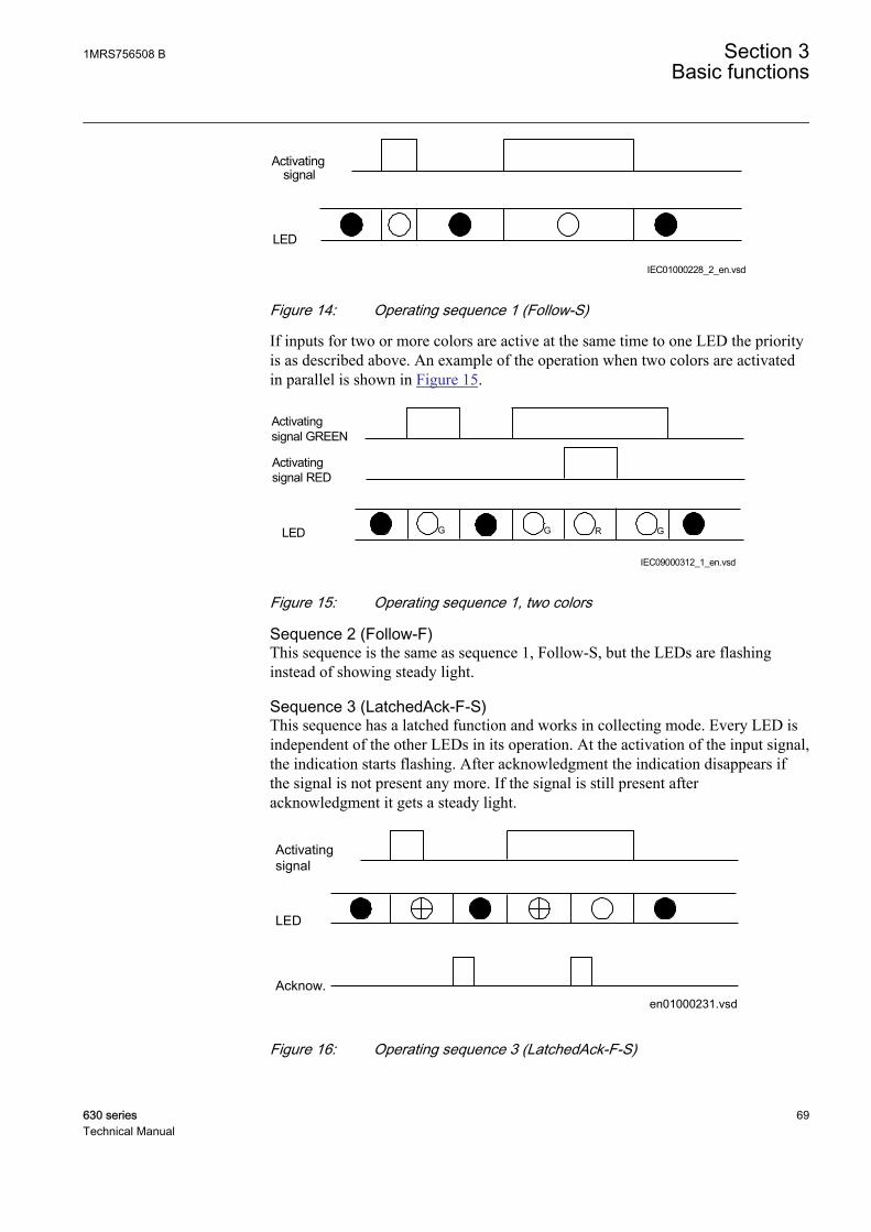
Activatingsignal
LED
IEC01000228_2_en.vsdIEC01000228 V2 EN
Figure 14: Operating sequence 1 (Follow-S)
If inputs for two or more colors are active at the same time to one LED the priorityis as described above. An example of the operation when two colors are activatedin parallel is shown in Figure 15.
Activatingsignal GREEN
LED
IEC09000312_1_en.vsd
G R GG
Activatingsignal RED
IEC09000312 V1 EN
Figure 15: Operating sequence 1, two colors
Sequence 2 (Follow-F)This sequence is the same as sequence 1, Follow-S, but the LEDs are flashinginstead of showing steady light.
Sequence 3 (LatchedAck-F-S)This sequence has a latched function and works in collecting mode. Every LED isindependent of the other LEDs in its operation. At the activation of the input signal,the indication starts flashing. After acknowledgment the indication disappears ifthe signal is not present any more. If the signal is still present afteracknowledgment it gets a steady light.
Activatingsignal
LED
Acknow.en01000231.vsd
IEC01000231 V1 EN
Figure 16: Operating sequence 3 (LatchedAck-F-S)
1MRS756508 B Section 3Basic functions
630 series 69Technical Manual

When an acknowledgment is performed, all indications that appear before theindication with higher priority has been reset, will be acknowledged, independentof if the low priority indication appeared before or after acknowledgment. InFigure 17 it is shown the sequence when a signal of lower priority becomesactivated after acknowledgment has been performed on a higher priority signal.The low priority signal will be shown as acknowledged when the high prioritysignal resets.
Activatingsignal RED
LED
AcknowIEC09000313_1_en.vsd
Activatingsignal GREEN
R R G
IEC09000313 V1 EN
Figure 17: Operating sequence 3, 2 colors involved
If all three signals are activated the order of priority is still maintained.Acknowledgment of indications with higher priority will acknowledge also lowpriority indications, which are not visible according to Figure 18.
Activatingsignal RED
LED
Acknow.IEC09000314-1-en.vsd
Activatingsignal YELLOW
G Y R R Y
Activatingsignal GREEN
IEC09000314 V1 EN
Figure 18: Operating sequence 3, three colors involved, alternative 1
If an indication with higher priority appears after acknowledgment of a lowerpriority indication the high priority indication will be shown as not acknowledgedaccording to Figure 19.
Section 3 1MRS756508 BBasic functions
70 630 seriesTechnical Manual
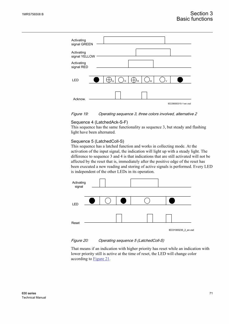
Activatingsignal RED
LED
Acknow.IEC09000315-1-en.vsd
Activatingsignal YELLOW
G G R R Y
Activatingsignal GREEN
IEC09000315 V1 EN
Figure 19: Operating sequence 3, three colors involved, alternative 2
Sequence 4 (LatchedAck-S-F)This sequence has the same functionality as sequence 3, but steady and flashinglight have been alternated.
Sequence 5 (LatchedColl-S)This sequence has a latched function and works in collecting mode. At theactivation of the input signal, the indication will light up with a steady light. Thedifference to sequence 3 and 4 is that indications that are still activated will not beaffected by the reset that is, immediately after the positive edge of the reset hasbeen executed a new reading and storing of active signals is performed. Every LEDis independent of the other LEDs in its operation.
IEC01000235_2_en.vsd
Activating signal
LED
Reset
IEC01000235 V2 EN
Figure 20: Operating sequence 5 (LatchedColl-S)
That means if an indication with higher priority has reset while an indication withlower priority still is active at the time of reset, the LED will change coloraccording to Figure 21.
1MRS756508 B Section 3Basic functions
630 series 71Technical Manual

Activatingsignal RED
LED
Reset
IEC09000316_1_en.vsd
Activatingsignal GREEN
R G
IEC09000316 V1 EN
Figure 21: Operating sequence 5, two colors
Sequence 6 (LatchedReset-S)In this mode all activated LEDs, which are set to sequence 6 (LatchedReset-S), areautomatically reset at a new disturbance when activating any input signal for otherLEDs set to sequence 6 (LatchedReset-S). Also in this case indications that are stillactivated will not be affected by manual reset, that is, immediately after thepositive edge of that the manual reset has been executed a new reading and storingof active signals is performed. LEDs set for sequence 6 are completely independentin its operation of LEDs set for other sequences.
Timing diagram for sequence 6Figure 22 shows the timing diagram for two indications within one disturbance.
Section 3 1MRS756508 BBasic functions
72 630 seriesTechnical Manual
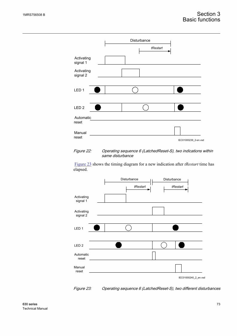
IEC01000239_2-en.vsd
Activatingsignal 2
LED 2
Manualreset
Activatingsignal 1
Automaticreset
LED 1
Disturbance
tRestart
IEC01000239 V2 EN
Figure 22: Operating sequence 6 (LatchedReset-S), two indications withinsame disturbance
Figure 23 shows the timing diagram for a new indication after tRestart time haselapsed.
IEC01000240_2_en.vsd
Activating signal 2
LED 2
Manual reset
Activating signal 1
Automatic reset
LED 1
Disturbance
tRestart
Disturbance
tRestart
IEC01000240 V2 EN
Figure 23: Operating sequence 6 (LatchedReset-S), two different disturbances
1MRS756508 B Section 3Basic functions
630 series 73Technical Manual
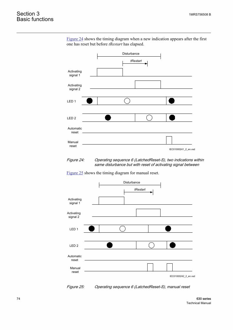
Figure 24 shows the timing diagram when a new indication appears after the firstone has reset but before tRestart has elapsed.
IEC01000241_2_en.vsd
Activating signal 2
LED 2
Manual reset
Activating signal 1
Automatic reset
LED 1
Disturbance
tRestart
IEC01000241 V2 EN
Figure 24: Operating sequence 6 (LatchedReset-S), two indications withinsame disturbance but with reset of activating signal between
Figure 25 shows the timing diagram for manual reset.
IEC01000242_2_en.vsd
Activating signal 2
LED 2
Manual reset
Activating signal 1
Automatic reset
LED 1
Disturbance
tRestart
IEC01000242 V2 EN
Figure 25: Operating sequence 6 (LatchedReset-S), manual reset
Section 3 1MRS756508 BBasic functions
74 630 seriesTechnical Manual

3.4.5.2 Function keys
FunctionalityLocal Human-Machine-Interface (LHMI) has five function buttons, directly to theleft of the display, that can be configured either as menu shortcut or controlbuttons. Each button has an indication LED that can be configured in theapplication configuration.
When used as a menu shortcut, a function button provides a fast way to navigatebetween default nodes in the menu tree. When used as a control, the button cancontrol a binary signal.
Operation principleEach output on the FNKEYMD1 - FNKEYMD5 function blocks can be controlledfrom the LHMI function keys. By pressing a function button on the LHMI, theoutput status of the actual function block will change. These binary outputs can inturn be used to control other function blocks, for example, switch control blocks,binary I/O outputs etc.
FNKEYMD1 - FNKEYMD5 function block also has a number of settings andparameters that control the behavior of the function block. These settings andparameters are normally set using the PST.
Operating sequenceThe operation mode is set individually for each output, either OFF, TOGGLE orPULSED.
Mode 0 (OFF)
This mode always gives the output the value 0 (FALSE). Changes on the IOattribute are ignored.
Input value
Output value
IEC09000330-1-en.vsdIEC09000330 V1 EN
Figure 26: Sequence diagram for Mode 0
Mode 1 (TOGGLE)
In this mode the output toggles each time the function block detects that the inputhas been written. Note that the input attribute is reset each time the function blockexecutes. The function block execution is marked with a dotted line below.
1MRS756508 B Section 3Basic functions
630 series 75Technical Manual
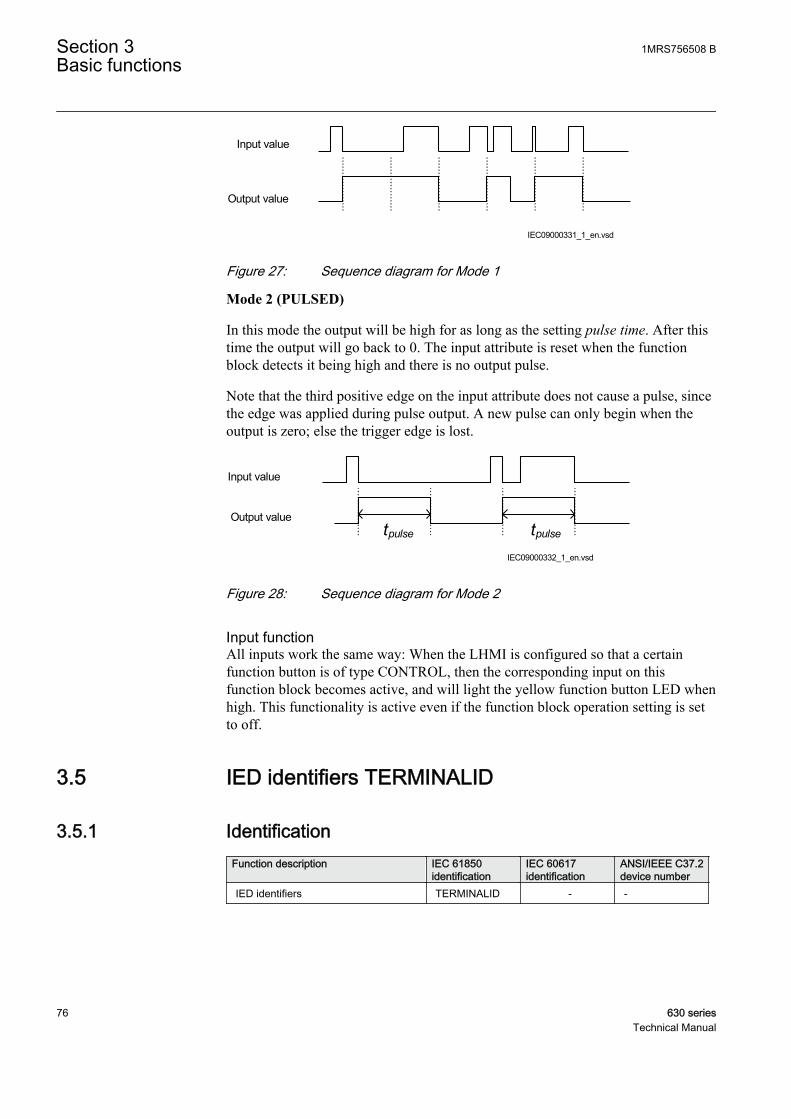
Input value
Output value
IEC09000331_1_en.vsdIEC09000331 V1 EN
Figure 27: Sequence diagram for Mode 1
Mode 2 (PULSED)
In this mode the output will be high for as long as the setting pulse time. After thistime the output will go back to 0. The input attribute is reset when the functionblock detects it being high and there is no output pulse.
Note that the third positive edge on the input attribute does not cause a pulse, sincethe edge was applied during pulse output. A new pulse can only begin when theoutput is zero; else the trigger edge is lost.
Input value
tpulse tpulseOutput value
IEC09000332_1_en.vsdIEC09000332 V1 EN
Figure 28: Sequence diagram for Mode 2
Input functionAll inputs work the same way: When the LHMI is configured so that a certainfunction button is of type CONTROL, then the corresponding input on thisfunction block becomes active, and will light the yellow function button LED whenhigh. This functionality is active even if the function block operation setting is setto off.
3.5 IED identifiers TERMINALID
3.5.1 IdentificationFunction description IEC 61850
identificationIEC 60617identification
ANSI/IEEE C37.2device number
IED identifiers TERMINALID - -
Section 3 1MRS756508 BBasic functions
76 630 seriesTechnical Manual
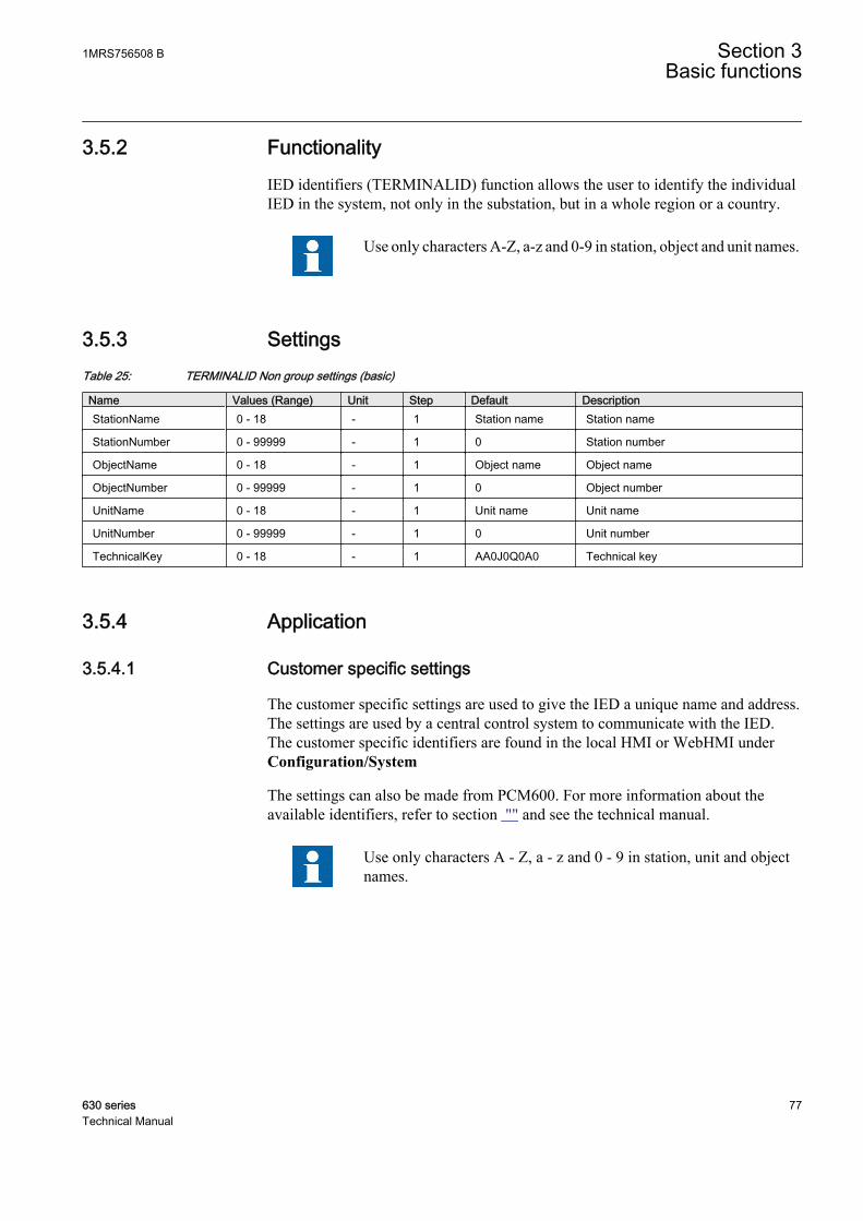
3.5.2 FunctionalityIED identifiers (TERMINALID) function allows the user to identify the individualIED in the system, not only in the substation, but in a whole region or a country.
Use only characters A-Z, a-z and 0-9 in station, object and unit names.
3.5.3 SettingsTable 25: TERMINALID Non group settings (basic)
Name Values (Range) Unit Step Default DescriptionStationName 0 - 18 - 1 Station name Station name
StationNumber 0 - 99999 - 1 0 Station number
ObjectName 0 - 18 - 1 Object name Object name
ObjectNumber 0 - 99999 - 1 0 Object number
UnitName 0 - 18 - 1 Unit name Unit name
UnitNumber 0 - 99999 - 1 0 Unit number
TechnicalKey 0 - 18 - 1 AA0J0Q0A0 Technical key
3.5.4 Application
3.5.4.1 Customer specific settings
The customer specific settings are used to give the IED a unique name and address.The settings are used by a central control system to communicate with the IED.The customer specific identifiers are found in the local HMI or WebHMI underConfiguration/System
The settings can also be made from PCM600. For more information about theavailable identifiers, refer to section "" and see the technical manual.
Use only characters A - Z, a - z and 0 - 9 in station, unit and objectnames.
1MRS756508 B Section 3Basic functions
630 series 77Technical Manual
3.6 Product information
3.6.1 FunctionalityThe Product identifiers function identifies the IED. The function has seven pre-set,settings that are unchangeable but nevertheless very important:
• IEDProdType• ProductDef• ProductVer• SerialNo• OrderingNo• ProductionDate
The settings are visible on the local HMI or WebHMI, under Information/Productidentifiers
They are very helpful in case of support process (such as repair or maintenance).
3.6.2 SettingsThe function does not have any parameters available in the local HMI, WebHMI orPCM600.
3.6.3 Application
3.6.3.1 Factory defined settings
The factory defined settings are very useful for identifying a specific version andvery helpful in the case of maintenance, repair, interchanging IEDs betweendifferent Substation Automation Systems and upgrading. The factory made settingscan not be changed by the customer. They can only be viewed. The settings arefound in the local HMI or WebHMI under Information/Product identifiers
The following identifiers are available:
• IEDProdType• Describes the type of the IED (like REF, REM or RET. Example: REF630
• ProductDef• Describes the release number, from the production. Example: 1.1.0.A1
• ProductVer• Describes the product version. Example: 1.1.0
• SerialNo• OrderingNo• ProductionDate
Section 3 1MRS756508 BBasic functions
78 630 seriesTechnical Manual

3.7 Primary system values PRIMVAL
3.7.1 IdentificationFunction description IEC 61850
identificationIEC 60617identification
ANSI/IEEE C37.2device number
Primary system values PRIMVAL - -
3.7.2 FunctionalityThe rated system frequency and phasor rotation are set under Main menu/Configuration/ System in the local HMI and PCM600 parameter setting tree.
3.7.3 SettingsTable 26: PRIMVAL Non group settings (basic)
Name Values (Range) Unit Step Default DescriptionFrequency 50.0 - 60.0 Hz 10.0 50.0 Rated system frequency
PhaseRotation Normal=L1L2L3Inverse=L3L2L1
- - Normal=L1L2L3 System phase rotation
3.7.4 FunctionalityThe rated system frequency and phasor rotation are set under Main menu/Configuration/ System in the local HMI and PCM600 parameter setting tree.
3.8 Global phase base values BASEPH
3.8.1 IdentificationFunction description IEC 61850
identificationIEC 60617identification
ANSI/IEEE C37.2device number
Global base values BASEPH - -
3.8.2 FunctionalityAlmost all the current, voltage and power setting values are given in per unit (p.u.)values. The p.u. values are relational values to certain base values (given in A, kV,kVA). The base values are separate setting parameters for an IED. The base valuesare set independently of the used measurement device primary ratings. This allowsfor the settings to be given in relation to the nominal current and voltage values of
1MRS756508 B Section 3Basic functions
630 series 79Technical Manual

the protected object, for example, if the measurement devices are oversized andtheir primary ratings are higher than the nominal values of the protected object.
The phase-to-earth or phase-to-phase base values are defined in BASEPH. Theglobal settings related to BASEPH are located under the "Configuration/Analoginputs/Base values/Phase Grp 1…3" menu in LHMI and under the "Configuration/Analog inputs/Base values/BASEPH :1…3" menu in the parameter setting tool.
The BASEPH (Phase Grp) is called phase-to-earth or phase-to-phase base valuegroup.
There are three groups (instances) of BASEPH (Phase Grp). As a default, all theapplicable functions in the IED are set to use the same group of the base values.However, in each applicable function there is a selection (Base value Sel phaseadvanced settings) where one of the three possible groups can be selectedindividually for the function in question.
For example, all PHxPTOC functions use the first group Base value Sel phase ="Phase Grp 1" as a default but two other groups "Phase Grp 2" are "Phase Grp 3"are possible to select.
Table 27: BASEPH Non group settings (basic)
Name Values (Range) Unit Step Default DescriptionVoltage base Val PP 0.01 - 440.00 kV 0.01 20.00 Voltage base value, phase-to-phase
Current base Val Ph 1 - 6000 A 1 400 Current base value, phase
S base value 3Ph 0.05 - 1800000.00 kVA 0.05 13856.00 Three-phase power base value
3.8.3 The principles for voltage settings given in puThe voltage base value in BASEPH is the phase-to-phase voltage. This means thatin voltage settings that are related to phase-to-phase voltage 1.0 p.u. means 20.00kV (assuming the default value for the Voltage base Val PP setting). An exampleof this kind of setting is DSTPDIS PP V Ph Sel GFC (the default value 0.8 pucorresponds to 0.8 x 20kV = 16kV ).
For the voltage settings that are related to the phase-to-earth voltage the functionscontain internal scaling factor (0.5774). Therefore for the voltage settings related tothe phase-to-earth voltage 1.0 results in a nominal phase-to-earth voltage of 11.55kV, assuming the default value 20.00 kV for the Voltage base Val PP setting. Anexample of this kind of setting is PSPTOV Start value (the default value 1.1 pucorresponds to 1.1 x 0.5774 x 20kV ≈12.7kV ).
.
There are few functions for which the internal scaling is not done.In these functions it can be selected whether phase-to-phasevoltages or phase-to-earth voltages are used, for example, theVoltage selection setting in PHPTOV. This also means that thevoltage settings in these functions can be either related to phase-to-
Section 3 1MRS756508 BBasic functions
80 630 seriesTechnical Manual

phase voltage or to the phase-to-earth voltage depending on theselection. In functions, for example, PHPTOV, PHPTUV andSYNCRSYN, 1.0 p.u. means 20.00 kV, assuming the default valuefor the Voltage base Val PP setting regardless of the voltages usedin the functions. So, if the Voltage selection setting in PHPTOV isset to “phase-to-earth” ("1"), a value of 0.64 p.u. for Start valueresults in 12.8 kV (≈1.1 x 11.55 kV)
3.9 Global residual base values BASERES
3.9.1 IdentificationFunction description IEC 61850
identificationIEC 60617identification
ANSI/IEEE C37.2device number
Global base values BASERES - -
3.9.2 FunctionalityAlmost all the current, voltage and power setting values are given in per unit (p.u.)values. The p.u. values are relational values to certain base values (given in A, kV,kVA). The base values are separate setting parameters for an IED. The base valuesare set independently of the used measurement device primary ratings. This allowsfor the settings to be given in relation to the nominal current and voltage values ofthe protected object, for example, if the measurement devices are oversized andtheir primary ratings are higher than the nominal values of the protected object.
The residual base values are defined in BASERES. The global settings related toBASERES are located under the "Configuration/Analog inputs/Base values/Residual Grp 1…3" menu in LHMI and under the "Configuration/Analog inputs/Base values/BASERES :1…3" menu in PST.
The BASERES (Residual Grp) is called residual base value group.
There are three groups (instances) of BASERES (Residual Grp). As a default, allthe applicable functions in the IED are set to use the same group of the base values.However, in each applicable function there is a selection (Base value Sel Resadvanced settings) where one of the three possible groups can be selectedindividually for the function in question.
For example, all EFxPTOC functions use the first group Base value Sel Res ="Residual Grp 1"e) as default and two other groups "Residual Grp 2" or "ResidualGrp 3" are possible to select.
1MRS756508 B Section 3Basic functions
630 series 81Technical Manual
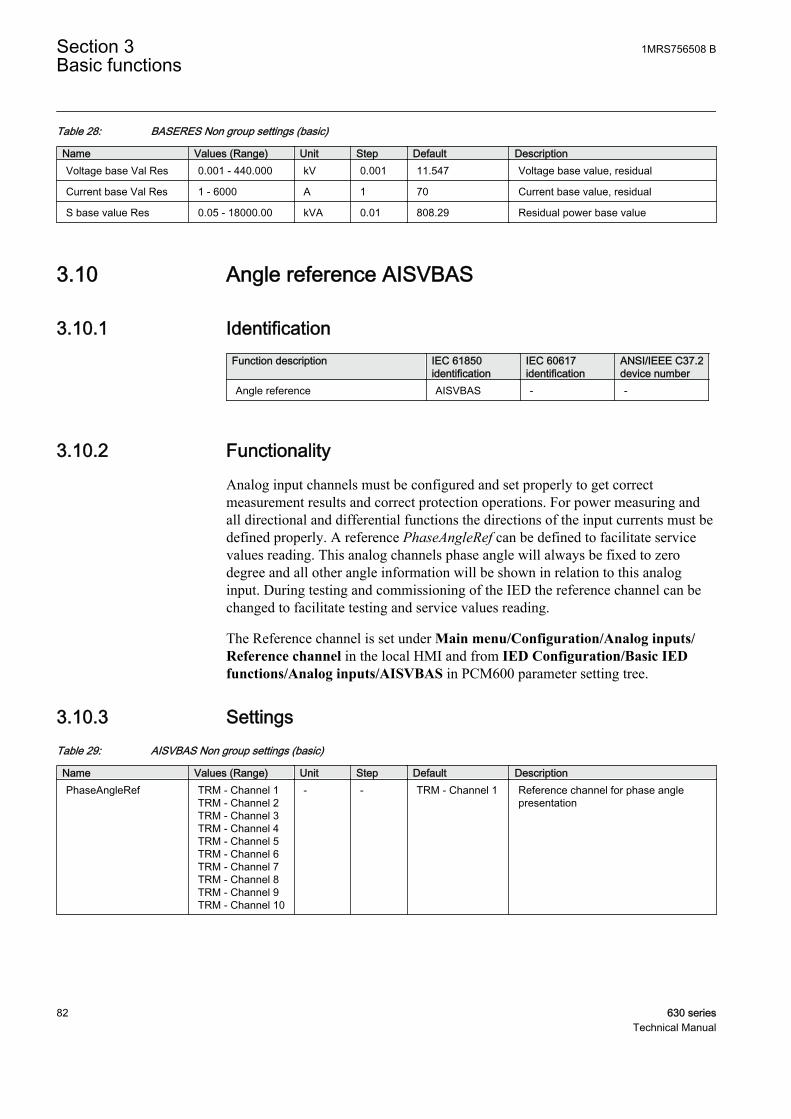
Table 28: BASERES Non group settings (basic)
Name Values (Range) Unit Step Default DescriptionVoltage base Val Res 0.001 - 440.000 kV 0.001 11.547 Voltage base value, residual
Current base Val Res 1 - 6000 A 1 70 Current base value, residual
S base value Res 0.05 - 18000.00 kVA 0.01 808.29 Residual power base value
3.10 Angle reference AISVBAS
3.10.1 IdentificationFunction description IEC 61850
identificationIEC 60617identification
ANSI/IEEE C37.2device number
Angle reference AISVBAS - -
3.10.2 FunctionalityAnalog input channels must be configured and set properly to get correctmeasurement results and correct protection operations. For power measuring andall directional and differential functions the directions of the input currents must bedefined properly. A reference PhaseAngleRef can be defined to facilitate servicevalues reading. This analog channels phase angle will always be fixed to zerodegree and all other angle information will be shown in relation to this analoginput. During testing and commissioning of the IED the reference channel can bechanged to facilitate testing and service values reading.
The Reference channel is set under Main menu/Configuration/Analog inputs/Reference channel in the local HMI and from IED Configuration/Basic IEDfunctions/Analog inputs/AISVBAS in PCM600 parameter setting tree.
3.10.3 SettingsTable 29: AISVBAS Non group settings (basic)
Name Values (Range) Unit Step Default DescriptionPhaseAngleRef TRM - Channel 1
TRM - Channel 2TRM - Channel 3TRM - Channel 4TRM - Channel 5TRM - Channel 6TRM - Channel 7TRM - Channel 8TRM - Channel 9TRM - Channel 10
- - TRM - Channel 1 Reference channel for phase anglepresentation
Section 3 1MRS756508 BBasic functions
82 630 seriesTechnical Manual
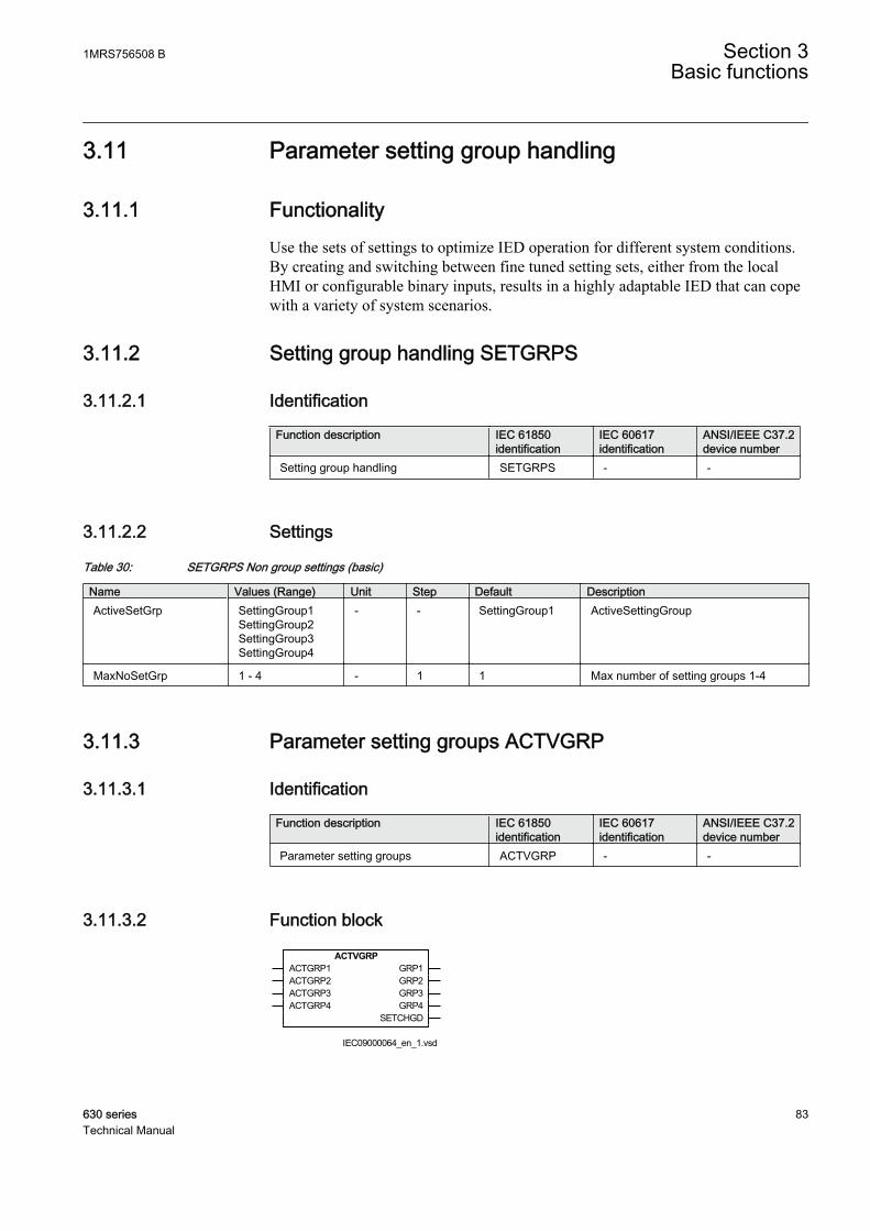
3.11 Parameter setting group handling
3.11.1 FunctionalityUse the sets of settings to optimize IED operation for different system conditions.By creating and switching between fine tuned setting sets, either from the localHMI or configurable binary inputs, results in a highly adaptable IED that can copewith a variety of system scenarios.
3.11.2 Setting group handling SETGRPS
3.11.2.1 Identification
Function description IEC 61850identification
IEC 60617identification
ANSI/IEEE C37.2device number
Setting group handling SETGRPS - -
3.11.2.2 Settings
Table 30: SETGRPS Non group settings (basic)
Name Values (Range) Unit Step Default DescriptionActiveSetGrp SettingGroup1
SettingGroup2SettingGroup3SettingGroup4
- - SettingGroup1 ActiveSettingGroup
MaxNoSetGrp 1 - 4 - 1 1 Max number of setting groups 1-4
3.11.3 Parameter setting groups ACTVGRP
3.11.3.1 Identification
Function description IEC 61850identification
IEC 60617identification
ANSI/IEEE C37.2device number
Parameter setting groups ACTVGRP - -
3.11.3.2 Function block
ACTVGRPACTGRP1ACTGRP2ACTGRP3ACTGRP4
GRP1GRP2GRP3GRP4
SETCHGD
IEC09000064_en_1.vsdIEC09000064 V1 EN
1MRS756508 B Section 3Basic functions
630 series 83Technical Manual
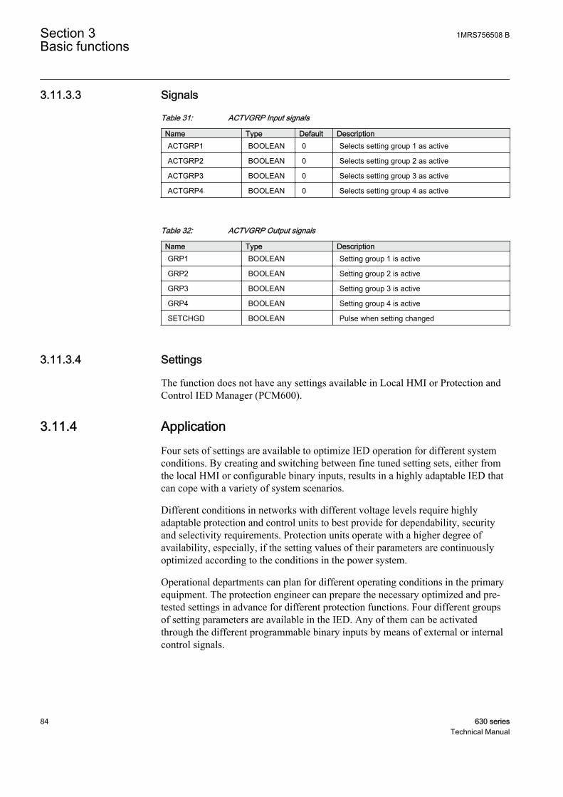
3.11.3.3 Signals
Table 31: ACTVGRP Input signals
Name Type Default DescriptionACTGRP1 BOOLEAN 0 Selects setting group 1 as active
ACTGRP2 BOOLEAN 0 Selects setting group 2 as active
ACTGRP3 BOOLEAN 0 Selects setting group 3 as active
ACTGRP4 BOOLEAN 0 Selects setting group 4 as active
Table 32: ACTVGRP Output signals
Name Type DescriptionGRP1 BOOLEAN Setting group 1 is active
GRP2 BOOLEAN Setting group 2 is active
GRP3 BOOLEAN Setting group 3 is active
GRP4 BOOLEAN Setting group 4 is active
SETCHGD BOOLEAN Pulse when setting changed
3.11.3.4 Settings
The function does not have any settings available in Local HMI or Protection andControl IED Manager (PCM600).
3.11.4 ApplicationFour sets of settings are available to optimize IED operation for different systemconditions. By creating and switching between fine tuned setting sets, either fromthe local HMI or configurable binary inputs, results in a highly adaptable IED thatcan cope with a variety of system scenarios.
Different conditions in networks with different voltage levels require highlyadaptable protection and control units to best provide for dependability, securityand selectivity requirements. Protection units operate with a higher degree ofavailability, especially, if the setting values of their parameters are continuouslyoptimized according to the conditions in the power system.
Operational departments can plan for different operating conditions in the primaryequipment. The protection engineer can prepare the necessary optimized and pre-tested settings in advance for different protection functions. Four different groupsof setting parameters are available in the IED. Any of them can be activatedthrough the different programmable binary inputs by means of external or internalcontrol signals.
Section 3 1MRS756508 BBasic functions
84 630 seriesTechnical Manual

3.11.5 Operation principleParameter setting groups (ACTVGRP) function has four functional inputs, eachcorresponding to one of the setting groups stored in the IED. Activation of any ofthese inputs changes the active setting group. Five functional output signals areavailable for configuration purposes, so that up to date information on the activesetting group is always available.
A setting group is selected by using the local HMI, from a front connected personalcomputer, remotely from the station control or station monitoring system or byactivating the corresponding input to the ACTVGRP function block.
Each input of the function block can be configured to connect to any of the binaryinputs in the IED. To do this PCM600 must be used.
The external control signals are used for activating a suitable setting group whenadaptive functionality is necessary. Input signals that should activate setting groupsmust be either permanent or a pulse exceeding 400 ms.
More than one input may be activated at the same time. In such cases the lowerorder setting group has priority. This means that if for example both group four andgroup two are set to activate, group two will be the one activated.
Every time the active group is changed, the output signal SETCHGD is sending apulse.
The parameter MaxNoSetGrp defines the maximum number of setting groups inuse to switch between.
IOx-Bly1
IOx-Bly2
IOx-Bly3
IOx-Bly4
Æ
Æ
Æ
Æ
ACTIVATE GROUP 4ACTIVATE GROUP 3ACTIVATE GROUP 2
ACTIVATE GROUP 1
ACTGRP1
ACTGRP2
ACTGRP3
ACTGRP4
GRP1
GRP2
GRP3
GRP4
ACTVGRP
SETCHGD
IEC09000063_en_1.vsdIEC09000063 V1 EN
Figure 29: Connection of the function to external circuits
1MRS756508 B Section 3Basic functions
630 series 85Technical Manual
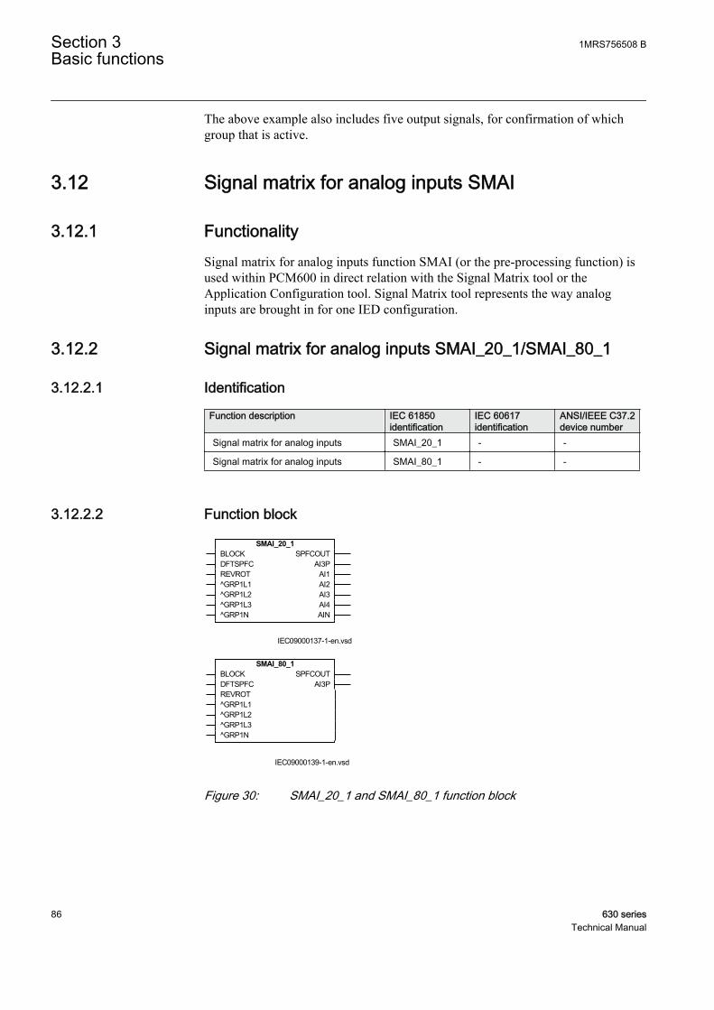
The above example also includes five output signals, for confirmation of whichgroup that is active.
3.12 Signal matrix for analog inputs SMAI
3.12.1 FunctionalitySignal matrix for analog inputs function SMAI (or the pre-processing function) isused within PCM600 in direct relation with the Signal Matrix tool or theApplication Configuration tool. Signal Matrix tool represents the way analoginputs are brought in for one IED configuration.
3.12.2 Signal matrix for analog inputs SMAI_20_1/SMAI_80_1
3.12.2.1 Identification
Function description IEC 61850identification
IEC 60617identification
ANSI/IEEE C37.2device number
Signal matrix for analog inputs SMAI_20_1 - -
Signal matrix for analog inputs SMAI_80_1 - -
3.12.2.2 Function block
SMAI_20_1BLOCKDFTSPFCREVROT^GRP1L1^GRP1L2^GRP1L3^GRP1N
SPFCOUTAI3P
AI1AI2AI3AI4AIN
IEC09000137-1-en.vsdIEC09000137 V1 EN
SMAI_80_1BLOCKDFTSPFCREVROT^GRP1L1^GRP1L2^GRP1L3^GRP1N
SPFCOUTAI3P
IEC09000139-1-en.vsdIEC09000139 V1 EN
Figure 30: SMAI_20_1 and SMAI_80_1 function block
Section 3 1MRS756508 BBasic functions
86 630 seriesTechnical Manual
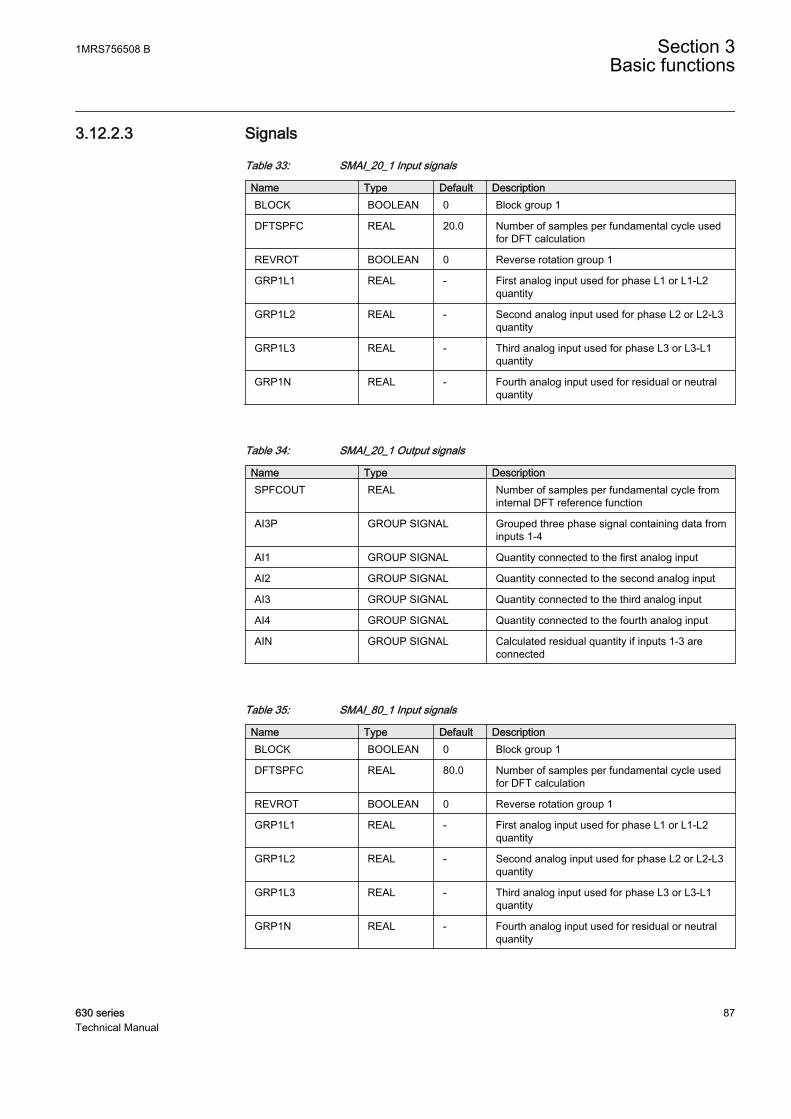
3.12.2.3 Signals
Table 33: SMAI_20_1 Input signals
Name Type Default DescriptionBLOCK BOOLEAN 0 Block group 1
DFTSPFC REAL 20.0 Number of samples per fundamental cycle usedfor DFT calculation
REVROT BOOLEAN 0 Reverse rotation group 1
GRP1L1 REAL - First analog input used for phase L1 or L1-L2quantity
GRP1L2 REAL - Second analog input used for phase L2 or L2-L3quantity
GRP1L3 REAL - Third analog input used for phase L3 or L3-L1quantity
GRP1N REAL - Fourth analog input used for residual or neutralquantity
Table 34: SMAI_20_1 Output signals
Name Type DescriptionSPFCOUT REAL Number of samples per fundamental cycle from
internal DFT reference function
AI3P GROUP SIGNAL Grouped three phase signal containing data frominputs 1-4
AI1 GROUP SIGNAL Quantity connected to the first analog input
AI2 GROUP SIGNAL Quantity connected to the second analog input
AI3 GROUP SIGNAL Quantity connected to the third analog input
AI4 GROUP SIGNAL Quantity connected to the fourth analog input
AIN GROUP SIGNAL Calculated residual quantity if inputs 1-3 areconnected
Table 35: SMAI_80_1 Input signals
Name Type Default DescriptionBLOCK BOOLEAN 0 Block group 1
DFTSPFC REAL 80.0 Number of samples per fundamental cycle usedfor DFT calculation
REVROT BOOLEAN 0 Reverse rotation group 1
GRP1L1 REAL - First analog input used for phase L1 or L1-L2quantity
GRP1L2 REAL - Second analog input used for phase L2 or L2-L3quantity
GRP1L3 REAL - Third analog input used for phase L3 or L3-L1quantity
GRP1N REAL - Fourth analog input used for residual or neutralquantity
1MRS756508 B Section 3Basic functions
630 series 87Technical Manual
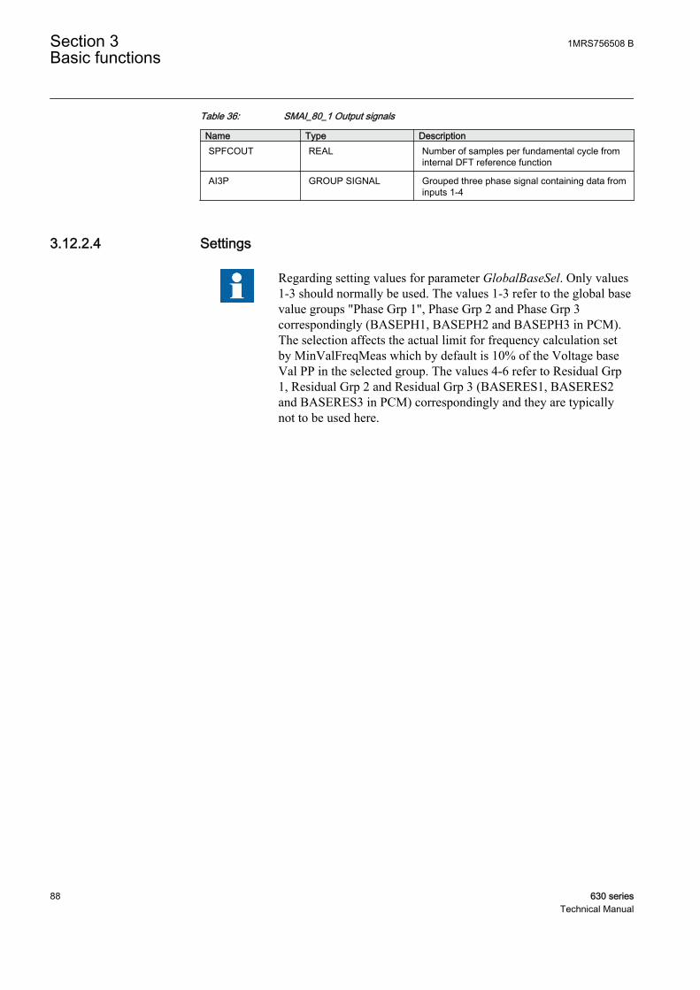
Table 36: SMAI_80_1 Output signals
Name Type DescriptionSPFCOUT REAL Number of samples per fundamental cycle from
internal DFT reference function
AI3P GROUP SIGNAL Grouped three phase signal containing data frominputs 1-4
3.12.2.4 Settings
Regarding setting values for parameter GlobalBaseSel. Only values1-3 should normally be used. The values 1-3 refer to the global basevalue groups "Phase Grp 1", Phase Grp 2 and Phase Grp 3correspondingly (BASEPH1, BASEPH2 and BASEPH3 in PCM).The selection affects the actual limit for frequency calculation setby MinValFreqMeas which by default is 10% of the Voltage baseVal PP in the selected group. The values 4-6 refer to Residual Grp1, Residual Grp 2 and Residual Grp 3 (BASERES1, BASERES2and BASERES3 in PCM) correspondingly and they are typicallynot to be used here.
Section 3 1MRS756508 BBasic functions
88 630 seriesTechnical Manual

Table 37: SMAI_20_1 Non group settings (basic)
Name Values (Range) Unit Step Default DescriptionGlobalBaseSel1)
1 - 6 - 1 1 Selection of one of the Global BaseValue groups
DFTRefExtOut InternalDFTRefDFTRefGrp1DFTRefGrp2DFTRefGrp3DFTRefGrp4DFTRefGrp5DFTRefGrp6DFTRefGrp7DFTRefGrp8DFTRefGrp9DFTRefGrp10DFTRefGrp11DFTRefGrp12External DFT ref
- - InternalDFTRef DFT reference for external output
DFTReference InternalDFTRefDFTRefGrp1DFTRefGrp2DFTRefGrp3DFTRefGrp4DFTRefGrp5DFTRefGrp6DFTRefGrp7DFTRefGrp8DFTRefGrp9DFTRefGrp10DFTRefGrp11DFTRefGrp12External DFT ref
- - InternalDFTRef DFT reference
ConnectionType Ph-NPh-Ph
- - Ph-N Input connection type
AnalogInputType VoltageCurrent
- - Voltage Analog input signal type
1) Only values 1–3 should normally be used. The values 1–3 refer to the global base value groups Phase Grp 1, Phase Grp 2 and PhaseGrp 3 correspondingly (BASEPH1, BASEPH2 and BASEPH3 in PCM). The selection affects the actual limit for frequency calculation setby MinValFreqMeas which by default is 10 percent of the Voltage base Val PP in the selected group. Values 4–6 refer to Residual Grp1, Residual Grp 2 and Residual Grp 3 (BASERES1, BASERES2 and BASERES3 in PCM) correspondingly and they are typically notused here.
Table 38: SMAI_20_1 Non group settings (advanced)
Name Values (Range) Unit Step Default DescriptionNegation Off
NegateNNegate3PhNegate3Ph+N
- - Off Negation
MinValFreqMeas 5 - 200 % 1 10 Limit for frequency calculation in % ofUBase
Even if the AnalogInputType setting of a SMAI block is set toCurrent, the MinValFreqMeas setting is still visible. This meansthat the minimum level for current amplitude is based on Voltagebase Val PP. For example, if Voltage base Val PP is 20000, the
1MRS756508 B Section 3Basic functions
630 series 89Technical Manual
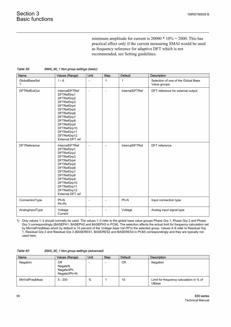
minimum amplitude for current is 20000 * 10% = 2000. This haspractical affect only if the current measuring SMAI would be usedas frequency reference for adaptive DFT which is notrecommended, see Setting guidelines.
Table 39: SMAI_80_1 Non group settings (basic)
Name Values (Range) Unit Step Default DescriptionGlobalBaseSel1)
1 - 6 - 1 1 Selection of one of the Global BaseValue groups
DFTRefExtOut InternalDFTRefDFTRefGrp1DFTRefGrp2DFTRefGrp3DFTRefGrp4DFTRefGrp5DFTRefGrp6DFTRefGrp7DFTRefGrp8DFTRefGrp9DFTRefGrp10DFTRefGrp11DFTRefGrp12External DFT ref
- - InternalDFTRef DFT reference for external output
DFTReference InternalDFTRefDFTRefGrp1DFTRefGrp2DFTRefGrp3DFTRefGrp4DFTRefGrp5DFTRefGrp6DFTRefGrp7DFTRefGrp8DFTRefGrp9DFTRefGrp10DFTRefGrp11DFTRefGrp12External DFT ref
- - InternalDFTRef DFT reference
ConnectionType Ph-NPh-Ph
- - Ph-N Input connection type
AnalogInputType VoltageCurrent
- - Voltage Analog input signal type
1) Only values 1–3 should normally be used. The values 1–3 refer to the global base value groups Phase Grp 1, Phase Grp 2 and PhaseGrp 3 correspondingly (BASEPH1, BASEPH2 and BASEPH3 in PCM). The selection affects the actual limit for frequency calculation setby MinValFreqMeas which by default is 10 percent of the Voltage base Val PP in the selected group. Values 4–6 refer to Residual Grp1, Residual Grp 2 and Residual Grp 3 (BASERES1, BASERES2 and BASERES3 in PCM) correspondingly and they are typically notused here.
Table 40: SMAI_80_1 Non group settings (advanced)
Name Values (Range) Unit Step Default DescriptionNegation Off
NegateNNegate3PhNegate3Ph+N
- - Off Negation
MinValFreqMeas 5 - 200 % 1 10 Limit for frequency calculation in % ofUBase
Section 3 1MRS756508 BBasic functions
90 630 seriesTechnical Manual
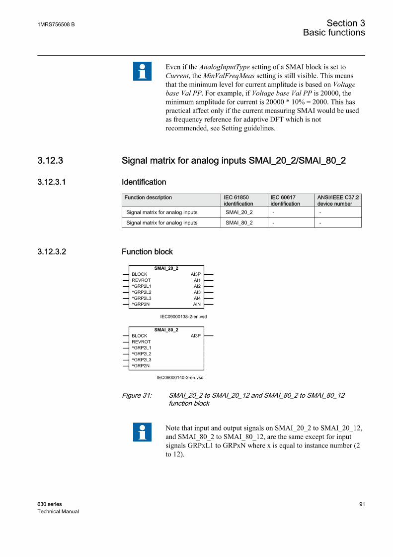
Even if the AnalogInputType setting of a SMAI block is set toCurrent, the MinValFreqMeas setting is still visible. This meansthat the minimum level for current amplitude is based on Voltagebase Val PP. For example, if Voltage base Val PP is 20000, theminimum amplitude for current is 20000 * 10% = 2000. This haspractical affect only if the current measuring SMAI would be usedas frequency reference for adaptive DFT which is notrecommended, see Setting guidelines.
3.12.3 Signal matrix for analog inputs SMAI_20_2/SMAI_80_2
3.12.3.1 Identification
Function description IEC 61850identification
IEC 60617identification
ANSI/IEEE C37.2device number
Signal matrix for analog inputs SMAI_20_2 - -
Signal matrix for analog inputs SMAI_80_2 - -
3.12.3.2 Function block
SMAI_20_2BLOCKREVROT^GRP2L1^GRP2L2^GRP2L3^GRP2N
AI3PAI1AI2AI3AI4AIN
IEC09000138-2-en.vsdIEC09000138 V2 EN
SMAI_80_2BLOCKREVROT^GRP2L1^GRP2L2^GRP2L3^GRP2N
AI3P
IEC09000140-2-en.vsdIEC09000140 V2 EN
Figure 31: SMAI_20_2 to SMAI_20_12 and SMAI_80_2 to SMAI_80_12function block
Note that input and output signals on SMAI_20_2 to SMAI_20_12,and SMAI_80_2 to SMAI_80_12, are the same except for inputsignals GRPxL1 to GRPxN where x is equal to instance number (2to 12).
1MRS756508 B Section 3Basic functions
630 series 91Technical Manual
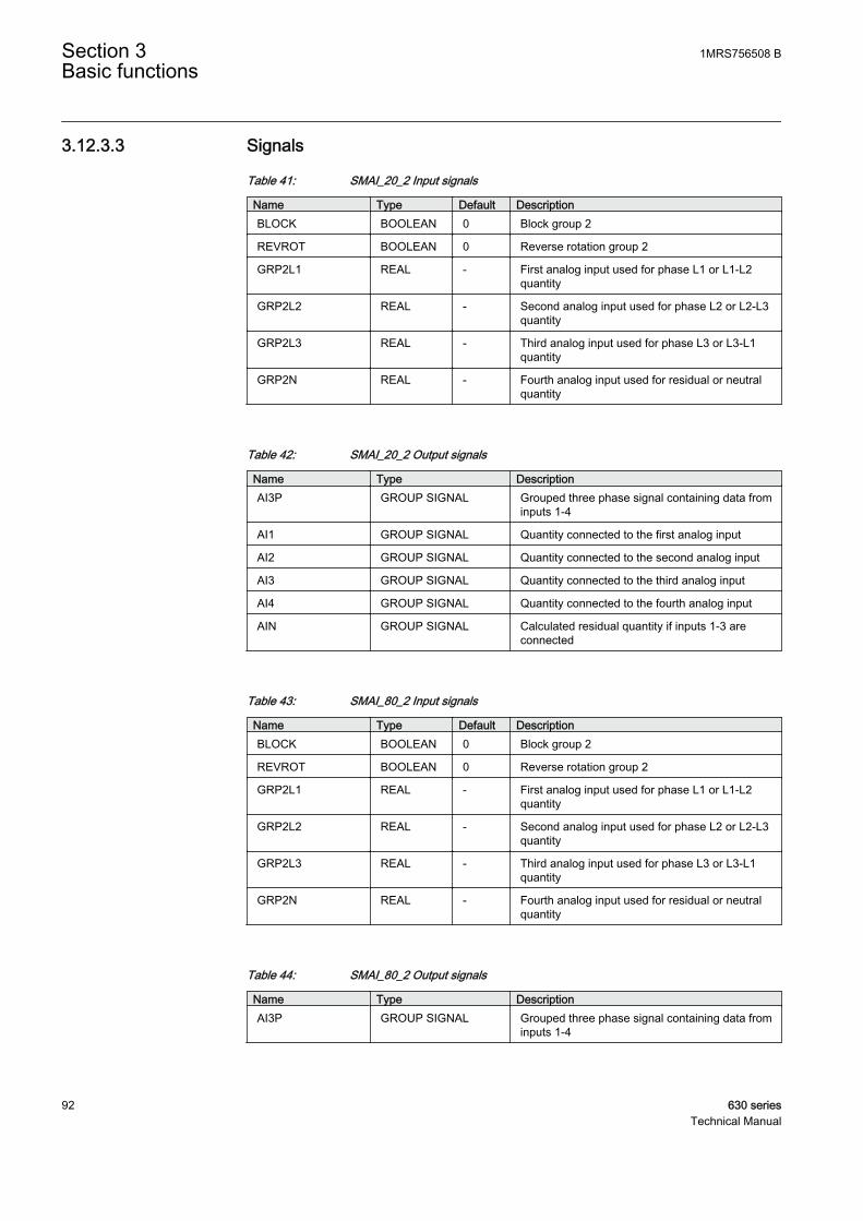
3.12.3.3 Signals
Table 41: SMAI_20_2 Input signals
Name Type Default DescriptionBLOCK BOOLEAN 0 Block group 2
REVROT BOOLEAN 0 Reverse rotation group 2
GRP2L1 REAL - First analog input used for phase L1 or L1-L2quantity
GRP2L2 REAL - Second analog input used for phase L2 or L2-L3quantity
GRP2L3 REAL - Third analog input used for phase L3 or L3-L1quantity
GRP2N REAL - Fourth analog input used for residual or neutralquantity
Table 42: SMAI_20_2 Output signals
Name Type DescriptionAI3P GROUP SIGNAL Grouped three phase signal containing data from
inputs 1-4
AI1 GROUP SIGNAL Quantity connected to the first analog input
AI2 GROUP SIGNAL Quantity connected to the second analog input
AI3 GROUP SIGNAL Quantity connected to the third analog input
AI4 GROUP SIGNAL Quantity connected to the fourth analog input
AIN GROUP SIGNAL Calculated residual quantity if inputs 1-3 areconnected
Table 43: SMAI_80_2 Input signals
Name Type Default DescriptionBLOCK BOOLEAN 0 Block group 2
REVROT BOOLEAN 0 Reverse rotation group 2
GRP2L1 REAL - First analog input used for phase L1 or L1-L2quantity
GRP2L2 REAL - Second analog input used for phase L2 or L2-L3quantity
GRP2L3 REAL - Third analog input used for phase L3 or L3-L1quantity
GRP2N REAL - Fourth analog input used for residual or neutralquantity
Table 44: SMAI_80_2 Output signals
Name Type DescriptionAI3P GROUP SIGNAL Grouped three phase signal containing data from
inputs 1-4
Section 3 1MRS756508 BBasic functions
92 630 seriesTechnical Manual

3.12.3.4 Settings
Regarding setting values for parameter GlobalBaseSel. Only values1-3 should normally be used. The values 1-3 refer to the global basevalue groups "Phase Grp 1", Phase Grp 2 and Phase Grp 3correspondingly (BASEPH1, BASEPH2 and BASEPH3 in PCM).The selection affects the actual limit for frequency calculation setby MinValFreqMeas which by default is 10% of the Voltage baseVal PP in the selected group. The values 4-6 refer to Residual Grp1, Residual Grp 2 and Residual Grp 3 (BASERES1, BASERES2and BASERES3 in PCM) correspondingly and they are typicallynot to be used here.
Table 45: SMAI_20_2 Non group settings (basic)
Name Values (Range) Unit Step Default DescriptionGlobalBaseSel1)
1 - 6 - 1 1 Selection of one of the Global BaseValue groups
DFTReference InternalDFTRefDFTRefGrp1DFTRefGrp2DFTRefGrp3DFTRefGrp4DFTRefGrp5DFTRefGrp6DFTRefGrp7DFTRefGrp8DFTRefGrp9DFTRefGrp10DFTRefGrp11DFTRefGrp12External DFT ref
- - InternalDFTRef DFT reference
ConnectionType Ph-NPh-Ph
- - Ph-N Input connection type
AnalogInputType VoltageCurrent
- - Voltage Analog input signal type
1) Only values 1–3 should normally be used. The values 1–3 refer to the global base value groups Phase Grp 1, Phase Grp 2 and PhaseGrp 3 correspondingly (BASEPH1, BASEPH2 and BASEPH3 in PCM). The selection affects the actual limit for frequency calculation setby MinValFreqMeas which by default is 10 percent of the Voltage base Val PP in the selected group. Values 4–6 refer to Residual Grp1, Residual Grp 2 and Residual Grp 3 (BASERES1, BASERES2 and BASERES3 in PCM) correspondingly and they are typically notused here.
Table 46: SMAI_20_2 Non group settings (advanced)
Name Values (Range) Unit Step Default DescriptionNegation Off
NegateNNegate3PhNegate3Ph+N
- - Off Negation
MinValFreqMeas 5 - 200 % 1 10 Limit for frequency calculation in % ofUBase
1MRS756508 B Section 3Basic functions
630 series 93Technical Manual
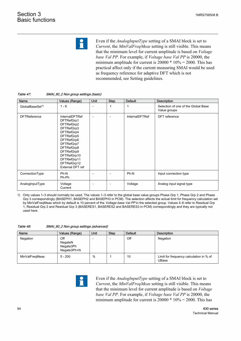
Even if the AnalogInputType setting of a SMAI block is set toCurrent, the MinValFreqMeas setting is still visible. This meansthat the minimum level for current amplitude is based on Voltagebase Val PP. For example, if Voltage base Val PP is 20000, theminimum amplitude for current is 20000 * 10% = 2000. This haspractical affect only if the current measuring SMAI would be usedas frequency reference for adaptive DFT which is notrecommended, see Setting guidelines.
Table 47: SMAI_80_2 Non group settings (basic)
Name Values (Range) Unit Step Default DescriptionGlobalBaseSel1) 1 - 6 - 1 1 Selection of one of the Global Base
Value groups
DFTReference InternalDFTRefDFTRefGrp1DFTRefGrp2DFTRefGrp3DFTRefGrp4DFTRefGrp5DFTRefGrp6DFTRefGrp7DFTRefGrp8DFTRefGrp9DFTRefGrp10DFTRefGrp11DFTRefGrp12External DFT ref
- - InternalDFTRef DFT reference
ConnectionType Ph-NPh-Ph
- - Ph-N Input connection type
AnalogInputType VoltageCurrent
- - Voltage Analog input signal type
1) Only values 1–3 should normally be used. The values 1–3 refer to the global base value groups Phase Grp 1, Phase Grp 2 and PhaseGrp 3 correspondingly (BASEPH1, BASEPH2 and BASEPH3 in PCM). The selection affects the actual limit for frequency calculation setby MinValFreqMeas which by default is 10 percent of the Voltage base Val PP in the selected group. Values 4–6 refer to Residual Grp1, Residual Grp 2 and Residual Grp 3 (BASERES1, BASERES2 and BASERES3 in PCM) correspondingly and they are typically notused here.
Table 48: SMAI_80_2 Non group settings (advanced)
Name Values (Range) Unit Step Default DescriptionNegation Off
NegateNNegate3PhNegate3Ph+N
- - Off Negation
MinValFreqMeas 5 - 200 % 1 10 Limit for frequency calculation in % ofUBase
Even if the AnalogInputType setting of a SMAI block is set toCurrent, the MinValFreqMeas setting is still visible. This meansthat the minimum level for current amplitude is based on Voltagebase Val PP. For example, if Voltage base Val PP is 20000, theminimum amplitude for current is 20000 * 10% = 2000. This has
Section 3 1MRS756508 BBasic functions
94 630 seriesTechnical Manual

practical affect only if the current measuring SMAI would be usedas frequency reference for adaptive DFT which is notrecommended, see Setting guidelines.
3.12.4 FunctionalitySignal matrix for analog inputs function SMAI (or the pre-processing function) isused within PCM600 in direct relation with the Signal Matrix tool or theApplication Configuration tool. Signal Matrix tool represents the way analoginputs are brought in for one IED configuration.
3.12.5 Operation principleEvery Signal matrix for analog inputs function (SMAI) can receive four analogsignals (three phases and one neutral value), either voltage or current, see Figure 30and Figure 31. SMAI outputs give information about every aspect of the 3phanalog signals acquired (phase angle, RMS value, frequency and frequencyderivates etc. – 244 values in total). The BLOCK input will reset all outputs to 0.
The output signals AI1 to AI4 in SMAI_20_x function block are direct outputs ofthe, in SMT or ACT, connected input group signals to GRPxL1, GRPxL2,GRPxL3 and GRPxN, x=1-12. GRPxN is always the neutral current. If GRPxN isnot connected, the AI4 output is all zero. The AIN output is the calculated residualsum of inputs GRPxL1, GRPxL2 and GRPxL3 and is equal to output AI4 if allinputs, including GRPxN, are connected. In a similar way the output signal AI3P infunction block SMAI_80_x is a group signal containing data from inputs GRPxL1,GRPxL2, GRPxL3 and GRPxN. Note that function block will always calculate theresidual sum of current/voltage if the input is not connected in SMT or ACT.Applications with a few exceptions shall always be connected to AI3P.
The input signal REVROT is used to reverse the phase order.
Value group 1 to 3 for setting GlobalBaseSel refers to phase andphase-to-phase global base value function instances. Value group 4to 6 refer to residual global base value function instances and arenot intended for most applications.
More detailed explanation of some of the settings and example of using frequencyadaptive DFT.
DFTRefExtOut: Parameter valid for function block SMAI_20_1:1, SMAI_20_1:2and SMAI_80_1 only. Reference block for external output (SPFCOUT functionoutput).
DFTReference: Reference DFT for the block.
1MRS756508 B Section 3Basic functions
630 series 95Technical Manual
These DFT reference block settings decide DFT reference for DFT calculations(InternalDFTRef will use fixed DFT reference based on set system frequency.DFTRefGrpn will use DFT reference from the selected group block, when owngroup selected adaptive DFT reference will be used based on calculated signalfrequency from own group.ExternalDFTRef will use reference based on inputDFTSPFC.
MinValFreqMeas: The minimum value of the voltage for which the frequency iscalculated, expressed as percent of Voltage base Val PP (of the selected BASEPHgroup).
Settings DFTRefExtOut and DFTReference shall be set to defaultvalue InternalDFTRef if no VT inputs are available. If, however, itis necessary to use frequency adaptive DFT (DFTReference set toother than default, refering current measuring SMAI) when novoltages are available, one must note that the MinValFreqMeassetting is still set in reference to Voltage base Val PP (of theselected BASEPH group). This means that the minimum level forcurrent amplitude is based on Voltage base Val PP. For example, ifVoltage base Val PP is 20000, the resulting minimum amplitude forcurrent is 20000 * 10% = 2000.
Example of adaptive frequency tracking
Section 3 1MRS756508 BBasic functions
96 630 seriesTechnical Manual
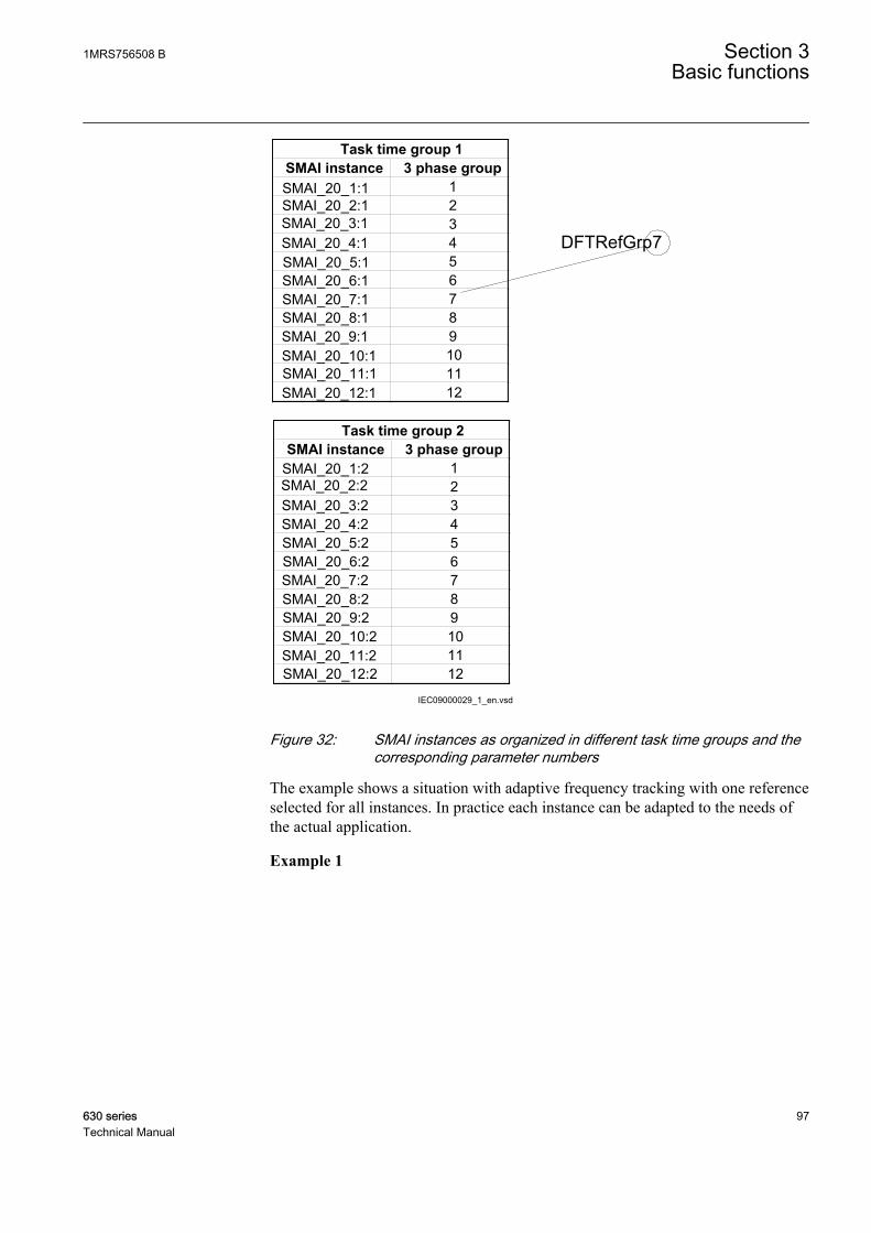
IEC09000029_1_en.vsd
SMAI instance 3 phase groupSMAI_20_1:1 1SMAI_20_2:1 2SMAI_20_3:1 3SMAI_20_4:1 4SMAI_20_5:1 5SMAI_20_6:1 6SMAI_20_7:1 7SMAI_20_8:1 8SMAI_20_9:1 9SMAI_20_10:1 10SMAI_20_11:1 11SMAI_20_12:1 12
Task time group 1
SMAI instance 3 phase groupSMAI_20_1:2 1SMAI_20_2:2 2SMAI_20_3:2 3SMAI_20_4:2 4SMAI_20_5:2 5SMAI_20_6:2 6SMAI_20_7:2 7SMAI_20_8:2 8SMAI_20_9:2 9SMAI_20_10:2 10SMAI_20_11:2 11SMAI_20_12:2 12
Task time group 2
DFTRefGrp7
IEC09000029 V1 EN
Figure 32: SMAI instances as organized in different task time groups and thecorresponding parameter numbers
The example shows a situation with adaptive frequency tracking with one referenceselected for all instances. In practice each instance can be adapted to the needs ofthe actual application.
Example 1
1MRS756508 B Section 3Basic functions
630 series 97Technical Manual
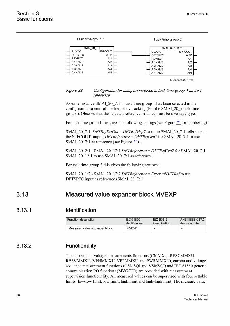
SMAI_20_7:1BLOCKDFTSPFCREVROTAI1NAMEAI2NAMEAI3NAMEAI4NAME
SPFCOUTAI3P
AI1AI2AI3AI4AIN
SMAI_20_1-12:2BLOCKDFTSPFCREVROTAI1NAMEAI2NAMEAI3NAMEAI4NAME
SPFCOUTAI3P
AI1AI2AI3AI4AIN
IEC09000028-1.vsd
Task time group 1 Task time group 2
IEC09000028 V1 EN
Figure 33: Configuration for using an instance in task time group 1 as DFTreference
Assume instance SMAI_20_7:1 in task time group 1 has been selected in theconfiguration to control the frequency tracking (For the SMAI_20_x task timegroups). Observe that the selected reference instance must be a voltage type.
For task time group 1 this gives the following settings (see Figure "" for numbering):
SMAI_20_7:1: DFTRefExtOut = DFTRefGrp7 to route SMAI_20_7:1 reference tothe SPFCOUT output, DFTReference = DFTRefGrp7 for SMAI_20_7:1 to useSMAI_20_7:1 as reference (see Figure ""). .
SMAI_20_2:1 - SMAI_20_12:1 DFTReference = DFTRefGrp7 for SMAI_20_2:1 -SMAI_20_12:1 to use SMAI_20_7:1 as reference.
For task time group 2 this gives the following settings:
SMAI_20_1:2 - SMAI_20_12:2 DFTReference = ExternalDFTRef to useDFTSPFC input as reference (SMAI_20_7:1)
3.13 Measured value expander block MVEXP
3.13.1 IdentificationFunction description IEC 61850
identificationIEC 60617identification
ANSI/IEEE C37.2device number
Measured value expander block MVEXP - -
3.13.2 FunctionalityThe current and voltage measurements functions (CMMXU, RESCMMXU,RESVMMXU, VPHMMXU, VPPMMXU and PWRMMXU), current and voltagesequence measurement functions (CSMSQI and VSMSQI) and IEC 61850 genericcommunication I/O functions (MVGGIO) are provided with measurementsupervision functionality. All measured values can be supervised with four settablelimits: low-low limit, low limit, high limit and high-high limit. The measure value
Section 3 1MRS756508 BBasic functions
98 630 seriesTechnical Manual

expander block has been introduced to enable translating the integer output signalfrom the measuring functions to 5 binary signals: below low-low limit, below lowlimit, normal, above high-high limit or above high limit. The output signals can beused as conditions in the configurable logic or for alarming purpose.
3.13.3 Function blockMVEXP
RANGE* HIGHHIGHHIGH
NORMALLOW
LOWLOW
IEC09000215-1-en.vsdIEC09000215 V1 EN
Figure 34: MVEXP function block
3.13.4 Signals
Table 49: MVEXP Input signals
Name Type Default DescriptionRANGE INTEGER 0 Measured value range
Table 50: MVEXP Output signals
Name Type DescriptionHIGHHIGH BOOLEAN Measured value is above high-high limit
HIGH BOOLEAN Measured value is between high and high-high limit
NORMAL BOOLEAN Measured value is between high and low limit
LOW BOOLEAN Measured value is between low and low-low limit
LOWLOW BOOLEAN Measured value is below low-low limit
3.13.5 SettingsThe function does not have any parameters available in Local HMI or Protectionand Control IED Manager (PCM600).
3.13.6 ApplicationThe current and voltage measurements functions (CMMXU, RESCMMXU,RESVMMXU, VPHMMXU, VPPMMXU), power measurement function(PWRMMXU), current and voltage sequence measurement functions (CSMSQIand VSMSQI) and IEC 61850 generic communication I/O functions (MVGGIO)are provided with measurement supervision functionality. All measured values can
1MRS756508 B Section 3Basic functions
630 series 99Technical Manual
be supervised with four settable limits, that is low-low limit, low limit, high limitand high-high limit. The measure value expander block (MVEXP) has beenintroduced to be able to translate the integer output signal from the measuringfunctions to 5 binary signals, that is below low-low limit, below low limit, normal,above high-high limit or above high limit. The output signals can be used asconditions in the configurable logic.
3.13.7 Operation principleThe input signal must be connected to a range output of a measuring function block(CMMXU, RESCMMXU, RESVMMXU, VPHMMXU, VPPMMXU,PWRMMXU, CSMSQI, VSMSQI or MVGGIO). The function block converts theinput integer value to five binary output signals according to table 51.
Table 51: Input integer value converted to binary output signals
Measured supervisedvalue is:
below low-lowlimit
between low‐low and lowlimit
between lowand high limit
between high-high and highlimit
above high-high limit
Output:LOWLOW High
LOW High
NORMAL High
HIGH High
HIGHHIGH High
3.14 Fixed signals FXDSIGN
3.14.1 IdentificationFunction description IEC 61850
identificationIEC 60617identification
ANSI/IEEE C37.2device number
Fixed signals FXDSIGN - -
3.14.2 FunctionalityThe Fixed signals function (FXDSIGN) generates a number of pre-set (fixed)signals that can be used in the configuration of an IED, either for forcing theunused inputs in other function blocks to a certain level/value, or for creatingcertain logic.
Section 3 1MRS756508 BBasic functions
100 630 seriesTechnical Manual

3.14.3 Function blockFXDSIGN
OFFON
INTZEROINTONE
INTALONEREALZERO
STRNULLZEROSMPL
GRP_OFF
IEC09000037.vsdIEC09000037 V1 EN
Figure 35: FXDSIGN function block
3.14.4 SignalsTable 52: FXDSIGN Output signals
Name Type DescriptionOFF BOOLEAN Boolean signal fixed off
ON BOOLEAN Boolean signal fixed on
INTZERO INTEGER Integer signal fixed zero
INTONE INTEGER Integer signal fixed one
INTALONE INTEGER Integer signal fixed all ones
REALZERO REAL Real signal fixed zero
STRNULL STRING String signal with no characters
ZEROSMPL GROUP SIGNAL Channel id for zero sample
GRP_OFF GROUP SIGNAL Group signal fixed off
3.14.5 SettingsThe function does not have any settings available in Local HMI or Protection andControl IED Manager (PCM600).
3.14.6 FunctionalityThe Fixed signals function (FXDSIGN) generates a number of pre-set (fixed)signals that can be used in the configuration of an IED, either for forcing theunused inputs in other function blocks to a certain level/value, or for creatingcertain logic.
3.14.7 Operation principleThere are nine outputs from FXDSIGN function block:
1MRS756508 B Section 3Basic functions
630 series 101Technical Manual
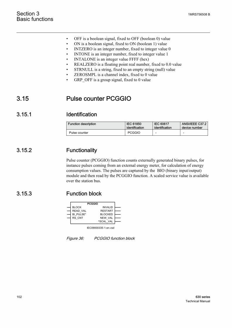
• OFF is a boolean signal, fixed to OFF (boolean 0) value• ON is a boolean signal, fixed to ON (boolean 1) value• INTZERO is an integer number, fixed to integer value 0• INTONE is an integer number, fixed to integer value 1• INTALONE is an integer value FFFF (hex)• REALZERO is a floating point real number, fixed to 0.0 value• STRNULL is a string, fixed to an empty string (null) value• ZEROSMPL is a channel index, fixed to 0 value• GRP_OFF is a group signal, fixed to 0 value
3.15 Pulse counter PCGGIO
3.15.1 IdentificationFunction description IEC 61850
identificationIEC 60617identification
ANSI/IEEE C37.2device number
Pulse counter PCGGIO - -
3.15.2 FunctionalityPulse counter (PCGGIO) function counts externally generated binary pulses, forinstance pulses coming from an external energy meter, for calculation of energyconsumption values. The pulses are captured by the BIO (binary input/output)module and then read by the PCGGIO function. A scaled service value is availableover the station bus.
3.15.3 Function block
IEC09000335-1-en.vsd
PCGGIOBLOCKREAD_VALBI_PULSE*RS_CNT
INVALIDRESTARTBLOCKEDNEW_VAL
^SCAL_VAL
IEC09000335 V1 EN
Figure 36: PCGGIO function block
Section 3 1MRS756508 BBasic functions
102 630 seriesTechnical Manual
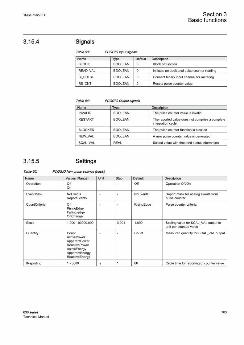
3.15.4 SignalsTable 53: PCGGIO Input signals
Name Type Default DescriptionBLOCK BOOLEAN 0 Block of function
READ_VAL BOOLEAN 0 Initiates an additional pulse counter reading
BI_PULSE BOOLEAN 0 Connect binary input channel for metering
RS_CNT BOOLEAN 0 Resets pulse counter value
Table 54: PCGGIO Output signals
Name Type DescriptionINVALID BOOLEAN The pulse counter value is invalid
RESTART BOOLEAN The reported value does not comprise a completeintegration cycle
BLOCKED BOOLEAN The pulse counter function is blocked
NEW_VAL BOOLEAN A new pulse counter value is generated
SCAL_VAL REAL Scaled value with time and status information
3.15.5 SettingsTable 55: PCGGIO Non group settings (basic)
Name Values (Range) Unit Step Default DescriptionOperation Off
On- - Off Operation Off/On
EventMask NoEventsReportEvents
- - NoEvents Report mask for analog events frompulse counter
CountCriteria OffRisingEdgeFalling edgeOnChange
- - RisingEdge Pulse counter criteria
Scale 1.000 - 90000.000 - 0.001 1.000 Scaling value for SCAL_VAL output tounit per counted value
Quantity CountActivePowerApparentPowerReactivePowerActiveEnergyApparentEnergyReactiveEnergy
- - Count Measured quantity for SCAL_VAL output
tReporting 1 - 3600 s 1 60 Cycle time for reporting of counter value
1MRS756508 B Section 3Basic functions
630 series 103Technical Manual
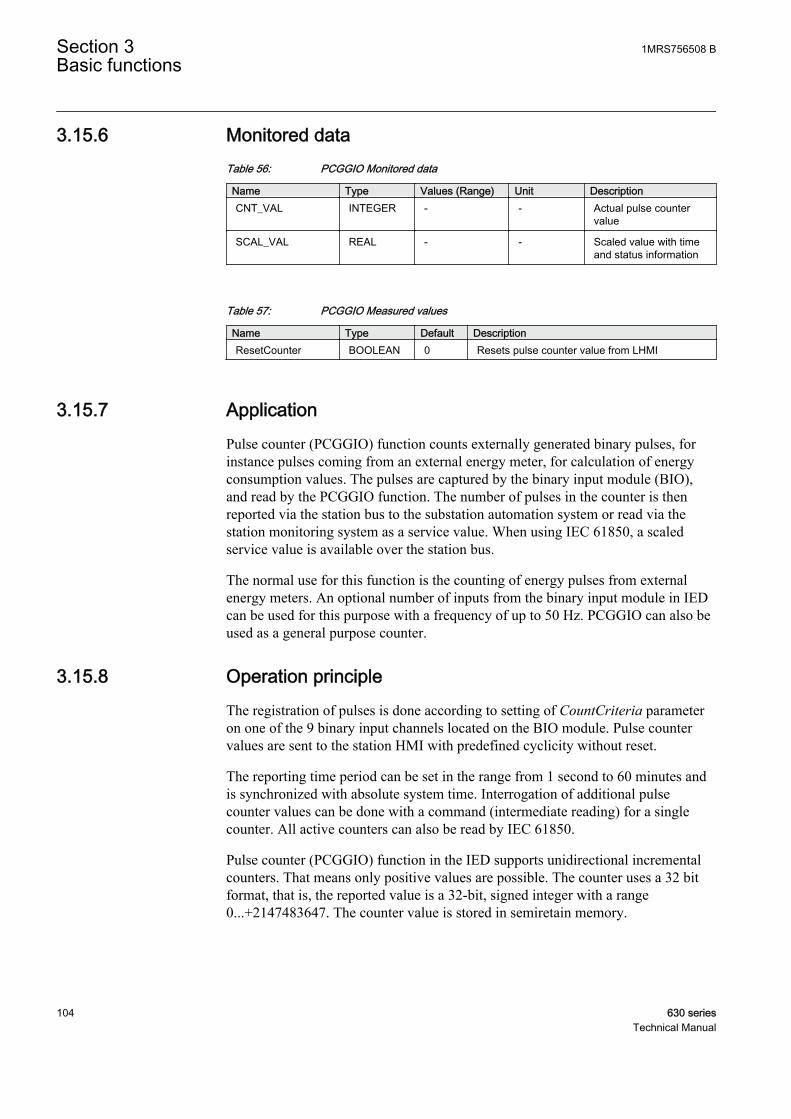
3.15.6 Monitored dataTable 56: PCGGIO Monitored data
Name Type Values (Range) Unit DescriptionCNT_VAL INTEGER - - Actual pulse counter
value
SCAL_VAL REAL - - Scaled value with timeand status information
Table 57: PCGGIO Measured values
Name Type Default DescriptionResetCounter BOOLEAN 0 Resets pulse counter value from LHMI
3.15.7 ApplicationPulse counter (PCGGIO) function counts externally generated binary pulses, forinstance pulses coming from an external energy meter, for calculation of energyconsumption values. The pulses are captured by the binary input module (BIO),and read by the PCGGIO function. The number of pulses in the counter is thenreported via the station bus to the substation automation system or read via thestation monitoring system as a service value. When using IEC 61850, a scaledservice value is available over the station bus.
The normal use for this function is the counting of energy pulses from externalenergy meters. An optional number of inputs from the binary input module in IEDcan be used for this purpose with a frequency of up to 50 Hz. PCGGIO can also beused as a general purpose counter.
3.15.8 Operation principleThe registration of pulses is done according to setting of CountCriteria parameteron one of the 9 binary input channels located on the BIO module. Pulse countervalues are sent to the station HMI with predefined cyclicity without reset.
The reporting time period can be set in the range from 1 second to 60 minutes andis synchronized with absolute system time. Interrogation of additional pulsecounter values can be done with a command (intermediate reading) for a singlecounter. All active counters can also be read by IEC 61850.
Pulse counter (PCGGIO) function in the IED supports unidirectional incrementalcounters. That means only positive values are possible. The counter uses a 32 bitformat, that is, the reported value is a 32-bit, signed integer with a range0...+2147483647. The counter value is stored in semiretain memory.
Section 3 1MRS756508 BBasic functions
104 630 seriesTechnical Manual
The reported value to station HMI over the station bus contains Identity, ScaledValue (pulse count x scale), Time, and Pulse Counter Quality. The Pulse CounterQuality consists of:
• Invalid (board hardware error or configuration error)• Wrapped around• Blocked• Adjusted
The transmission of the counter value can be done as a service value, that is, thevalue frozen in the last integration cycle is read by the station HMI from thedatabase. PCGGIO updates the value in the database when an integration cycle isfinished and activates the NEW_VAL signal in the function block. This signal canbe time tagged, and transmitted to the station HMI. This time corresponds to thetime when the value was frozen by the function.
The BLOCK and READ_VAL inputs can be connected to blocks, which areintended to be controlled either from the station HMI or/and the local HMI. Aslong as the BLOCK signal is set, the pulse counter is blocked. The signalconnected to READ_VAL performs readings according to the setting of parameterCountCriteria. The signal must be a pulse with a length >1 second.
The BI_PULSE input is connected to the used input of the function block for thebinary input output module (BIO).
The RS_CNT input is used for resetting the counter.
Each PCGGIO function block has four binary output signals that can be used forfor event recording: INVALID, RESTART, BLOCKED and NEW_VAL. Thesesignals and the SCAL_VAL signal are accessable over IEC 61850.
The INVALID signal is a steady signal and is set if the binary input module, wherethe pulse counter input is located, fails or has wrong configuration.
The RESTART signal is a steady signal and is set when the reported value does notcomprise a complete integration cycle. That is, in the first message after IED start-up, in the first message after deblocking, and after the counter has wrapped aroundduring last integration cycle.
The BLOCKED signal is a steady signal and is set when the counter is blocked.There are two reasons why the counter is blocked:
• The BLOCK input is set, or• The binary input module, where the counter input is situated, is inoperative.
The NEW_VAL signal is a pulse signal. The signal is set if the counter value wasupdated since last report.
The SCAL_VAL signal consists of scaled value (according to parameter Scale),time and status information.
1MRS756508 B Section 3Basic functions
630 series 105Technical Manual

3.15.9 Technical dataTable 58: PCGGIO technical data
Function Setting range AccuracyCycle time for report ofcounter value
(1–3600) s -
3.16 Event counter CNTGGIO
3.16.1 IdentificationFunction description IEC 61850
identificationIEC 60617identification
ANSI/IEEE C37.2device number
Event counter CNTGGIO - -
3.16.2 Function block
GUID-70FE6C09-DC4B-4B1B-B9B4-63C7115F752D V1 EN
Figure 37: Function block
3.16.3 FunctionalityThe event counter function CNTGGIO consists of six counters which are used forstoring the number of times each counter has been activated. It is also providedwith a common blocking function for all six counters to be used, for example, attesting. Each counter can be set to "On" or "Off" separately with a parameter setting.
3.16.4 Operation principleThe event counter function has six inputs for increasing the counter values for eachof the six counters respectively. The content of the counters is increased by onestep for each positive edge of the input respectively. The maximum count-up speedis 10 pulses per second. The maximum counter value is 10000. The counter stops at10000 and no restart takes places, even if the count exceeds 10000.
A mechanism for limiting the number of writings per time period is included in theproduct to avoid the risk of the flash memory becoming worn out due to too manywritings. As a result, it can take a long time, up to one hour, before a new value is
Section 3 1MRS756508 BBasic functions
106 630 seriesTechnical Manual

stored in the flash memory. If a new CNTGGIO value is not stored before auxiliarypower interruption, it is lost. The CNTGGIO-stored values in the flash memoryare, however, not lost at an auxiliary power interruption.
The function block also has an input BLOCK. The activation of the BLOCK inputblocks all six counters. The inputs can be used for blocking the counters at testing,for example.
All inputs are configured via PCM 600.
3.16.4.1 Reporting
The content of the counters can be read in the local HMI.
Reset of counters can be performed in the local HMI and with a binary input.
Reading of the content and resetting of the counters can also be performedremotely with PCM600 or MicroSCADA, for example.
3.16.5 Application
3.16.6 Technical dataTable 59: CNTGGIO Technical data
Function Range or value AccuracyCounter value 0-10000 -
Maximum count up speed 10 pulses/second -
3.17 Logic rotating switch for function selection andLHMI presentation SLGGIO
3.17.1 IdentificationFunction description IEC 61850
identificationIEC 60617identification
ANSI/IEEE C37.2device number
Logic rotating switch for functionselection and LHMI presentation
SLGGIO - -
3.17.2 FunctionalityThe logic rotating switch for function selection and LHMI presentation function(SLGGIO) (or the selector switch function block) is used to get a selector switchfunctionality similar to the one provided by a hardware selector switch. Hardwareselector switches are used extensively by utilities, in order to have different
1MRS756508 B Section 3Basic functions
630 series 107Technical Manual
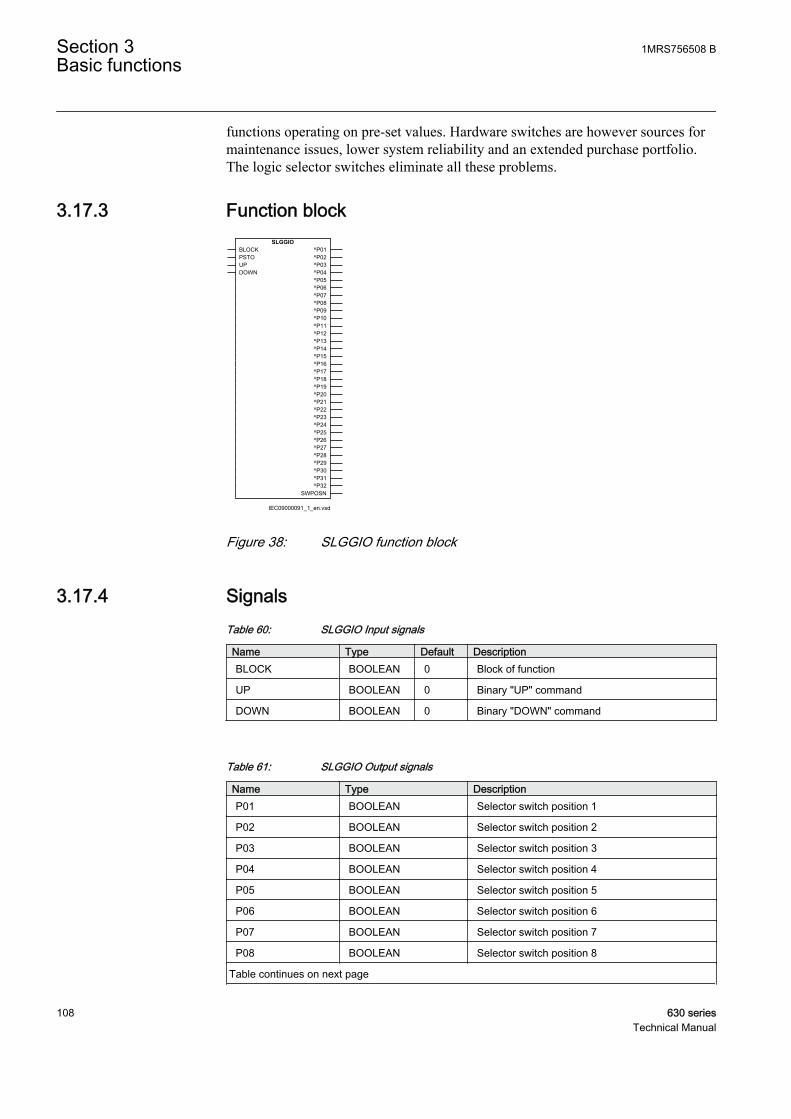
functions operating on pre-set values. Hardware switches are however sources formaintenance issues, lower system reliability and an extended purchase portfolio.The logic selector switches eliminate all these problems.
3.17.3 Function block
IEC09000091_1_en.vsd
SLGGIOBLOCKPSTOUPDOWN
^P01^P02^P03^P04^P05^P06^P07^P08^P09^P10^P11^P12^P13^P14^P15^P16^P17^P18^P19^P20^P21^P22^P23^P24^P25^P26^P27^P28^P29^P30^P31^P32
SWPOSN
IEC09000091 V1 EN
Figure 38: SLGGIO function block
3.17.4 SignalsTable 60: SLGGIO Input signals
Name Type Default DescriptionBLOCK BOOLEAN 0 Block of function
UP BOOLEAN 0 Binary "UP" command
DOWN BOOLEAN 0 Binary "DOWN" command
Table 61: SLGGIO Output signals
Name Type DescriptionP01 BOOLEAN Selector switch position 1
P02 BOOLEAN Selector switch position 2
P03 BOOLEAN Selector switch position 3
P04 BOOLEAN Selector switch position 4
P05 BOOLEAN Selector switch position 5
P06 BOOLEAN Selector switch position 6
P07 BOOLEAN Selector switch position 7
P08 BOOLEAN Selector switch position 8
Table continues on next page
Section 3 1MRS756508 BBasic functions
108 630 seriesTechnical Manual
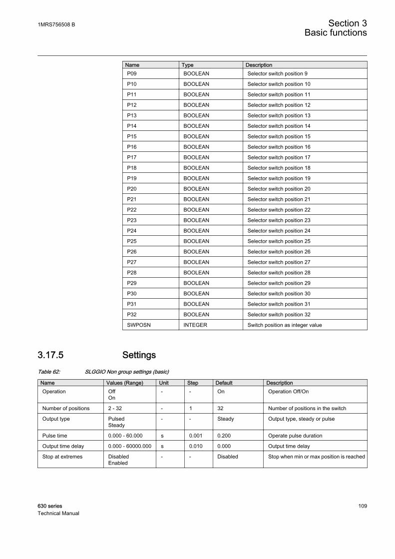
Name Type DescriptionP09 BOOLEAN Selector switch position 9
P10 BOOLEAN Selector switch position 10
P11 BOOLEAN Selector switch position 11
P12 BOOLEAN Selector switch position 12
P13 BOOLEAN Selector switch position 13
P14 BOOLEAN Selector switch position 14
P15 BOOLEAN Selector switch position 15
P16 BOOLEAN Selector switch position 16
P17 BOOLEAN Selector switch position 17
P18 BOOLEAN Selector switch position 18
P19 BOOLEAN Selector switch position 19
P20 BOOLEAN Selector switch position 20
P21 BOOLEAN Selector switch position 21
P22 BOOLEAN Selector switch position 22
P23 BOOLEAN Selector switch position 23
P24 BOOLEAN Selector switch position 24
P25 BOOLEAN Selector switch position 25
P26 BOOLEAN Selector switch position 26
P27 BOOLEAN Selector switch position 27
P28 BOOLEAN Selector switch position 28
P29 BOOLEAN Selector switch position 29
P30 BOOLEAN Selector switch position 30
P31 BOOLEAN Selector switch position 31
P32 BOOLEAN Selector switch position 32
SWPOSN INTEGER Switch position as integer value
3.17.5 SettingsTable 62: SLGGIO Non group settings (basic)
Name Values (Range) Unit Step Default DescriptionOperation Off
On- - On Operation Off/On
Number of positions 2 - 32 - 1 32 Number of positions in the switch
Output type PulsedSteady
- - Steady Output type, steady or pulse
Pulse time 0.000 - 60.000 s 0.001 0.200 Operate pulse duration
Output time delay 0.000 - 60000.000 s 0.010 0.000 Output time delay
Stop at extremes DisabledEnabled
- - Disabled Stop when min or max position is reached
1MRS756508 B Section 3Basic functions
630 series 109Technical Manual
3.17.6 Monitored dataTable 63: SLGGIO Monitored data
Name Type Values (Range) Unit DescriptionSWPOSN INTEGER - - Switch position as
integer value
3.17.7 Operation principleThe logic rotating switch for function selection and LHMI presentation (SLGGIO)function has two operating inputs – UP and DOWN. When a signal is received onthe UP input, the block will activate the output next to the present activated output,in ascending order (if the present activated output is 3 – for example and oneoperates the UP input, then the output 4 will be activated). When a signal isreceived on the DOWN input, the block will activate the output next to the presentactivated output, in descending order (if the present activated output is 3 – forexample and one operates the DOWN input, then the output 2 will be activated).Depending on the output settings the output signals can be steady or pulsed. In caseof steady signals, in case of UP or DOWN operation, the previously active outputwill be deactivated. Also, depending on the settings one can have a time delaybetween the UP or DOWN activation signal positive front and the output activation.
Besides the inputs visible in the application configuration in the ApplicationConfiguration tool, there are other possibilities that will allow an user to set thedesired position directly (without activating the intermediate positions), eitherlocally or remotely, using a “select before execute” dialog. One can block thefunction operation, by activating the BLOCK input. In this case, the presentposition will be kept and further operation will be blocked. The operator place(local or remote) is specified through the PSTO input. If any operation is allowedthe signal INTONE from the Fixed signal function block can be connected.SLGGIO function block has also an integer value output, that generates the actualposition number. The positions and the block names are fully settable by the user.These names will appear in the menu, so the user can see the position namesinstead of a number.
SLGGIO function can be connected to Dynamic Text (32 Inputs),Select Button (32 Inputs) and Indication Button (32 Inputs) displaysymbols.
Section 3 1MRS756508 BBasic functions
110 630 seriesTechnical Manual
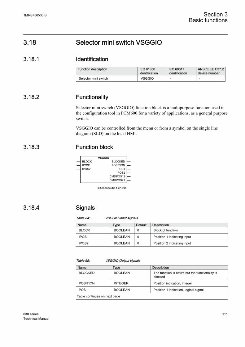
3.18 Selector mini switch VSGGIO
3.18.1 IdentificationFunction description IEC 61850
identificationIEC 60617identification
ANSI/IEEE C37.2device number
Selector mini switch VSGGIO - -
3.18.2 FunctionalitySelector mini switch (VSGGIO) function block is a multipurpose function used inthe configuration tool in PCM600 for a variety of applications, as a general purposeswitch.
VSGGIO can be controlled from the menu or from a symbol on the single linediagram (SLD) on the local HMI.
3.18.3 Function blockVSGGIO
BLOCKIPOS1IPOS2
BLOCKEDPOSITION
POS1POS2
CMDPOS12CMDPOS21
IEC09000340-1-en.vsdIEC09000340 V1 EN
3.18.4 SignalsTable 64: VSGGIO Input signals
Name Type Default DescriptionBLOCK BOOLEAN 0 Block of function
IPOS1 BOOLEAN 0 Position 1 indicating input
IPOS2 BOOLEAN 0 Position 2 indicating input
Table 65: VSGGIO Output signals
Name Type DescriptionBLOCKED BOOLEAN The function is active but the functionality is
blocked
POSITION INTEGER Position indication, integer
POS1 BOOLEAN Position 1 indication, logical signal
Table continues on next page
1MRS756508 B Section 3Basic functions
630 series 111Technical Manual
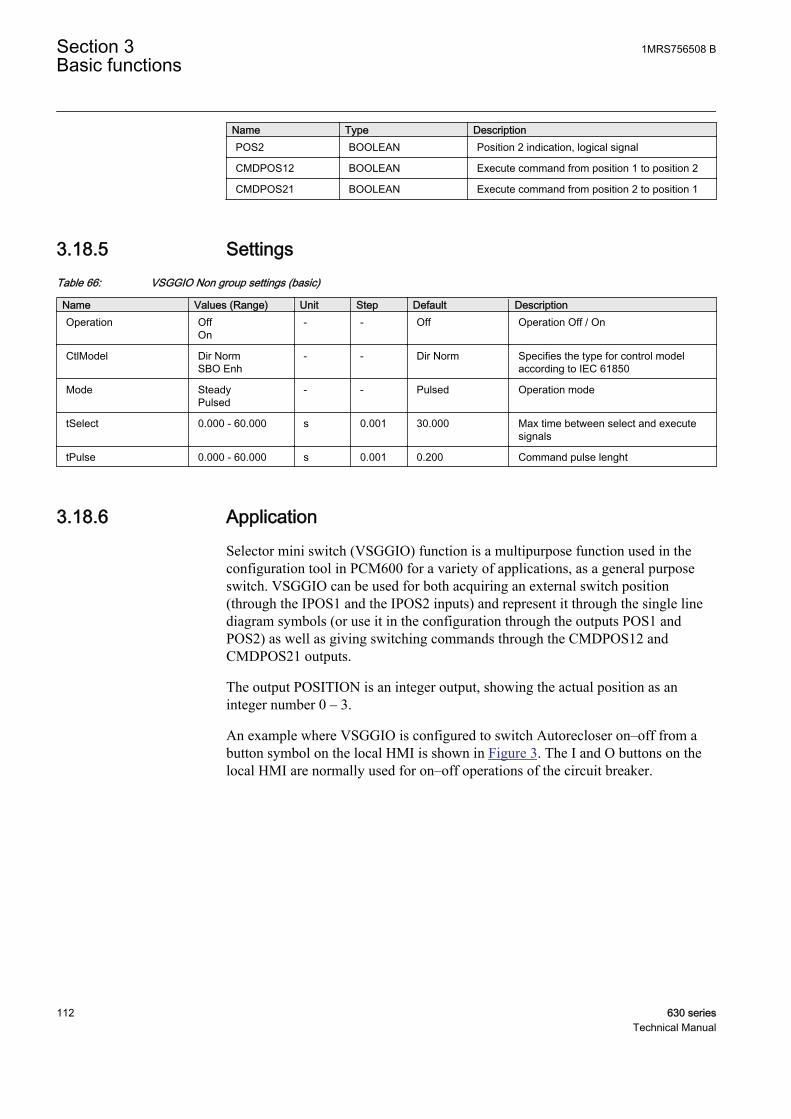
Name Type DescriptionPOS2 BOOLEAN Position 2 indication, logical signal
CMDPOS12 BOOLEAN Execute command from position 1 to position 2
CMDPOS21 BOOLEAN Execute command from position 2 to position 1
3.18.5 SettingsTable 66: VSGGIO Non group settings (basic)
Name Values (Range) Unit Step Default DescriptionOperation Off
On- - Off Operation Off / On
CtlModel Dir NormSBO Enh
- - Dir Norm Specifies the type for control modelaccording to IEC 61850
Mode SteadyPulsed
- - Pulsed Operation mode
tSelect 0.000 - 60.000 s 0.001 30.000 Max time between select and executesignals
tPulse 0.000 - 60.000 s 0.001 0.200 Command pulse lenght
3.18.6 ApplicationSelector mini switch (VSGGIO) function is a multipurpose function used in theconfiguration tool in PCM600 for a variety of applications, as a general purposeswitch. VSGGIO can be used for both acquiring an external switch position(through the IPOS1 and the IPOS2 inputs) and represent it through the single linediagram symbols (or use it in the configuration through the outputs POS1 andPOS2) as well as giving switching commands through the CMDPOS12 andCMDPOS21 outputs.
The output POSITION is an integer output, showing the actual position as aninteger number 0 – 3.
An example where VSGGIO is configured to switch Autorecloser on–off from abutton symbol on the local HMI is shown in Figure 3. The I and O buttons on thelocal HMI are normally used for on–off operations of the circuit breaker.
Section 3 1MRS756508 BBasic functions
112 630 seriesTechnical Manual
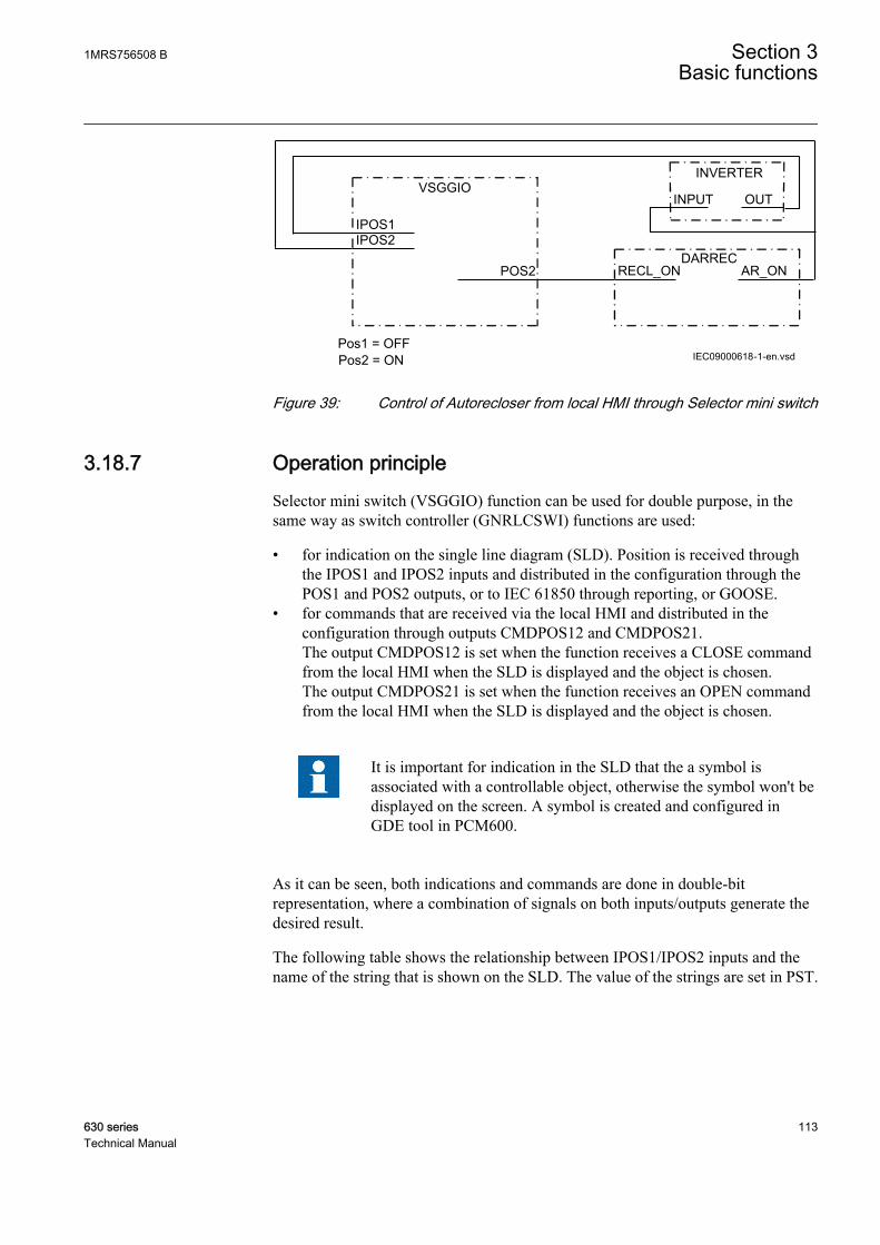
IEC09000618-1-en.vsd
POS2
IPOS1IPOS2
Pos1 = OFF
VSGGIO
DARRECRECL_ON AR_ON
INVERTER
INPUT OUT
Pos2 = ONIEC09000618 V1 EN
Figure 39: Control of Autorecloser from local HMI through Selector mini switch
3.18.7 Operation principleSelector mini switch (VSGGIO) function can be used for double purpose, in thesame way as switch controller (GNRLCSWI) functions are used:
• for indication on the single line diagram (SLD). Position is received throughthe IPOS1 and IPOS2 inputs and distributed in the configuration through thePOS1 and POS2 outputs, or to IEC 61850 through reporting, or GOOSE.
• for commands that are received via the local HMI and distributed in theconfiguration through outputs CMDPOS12 and CMDPOS21.The output CMDPOS12 is set when the function receives a CLOSE commandfrom the local HMI when the SLD is displayed and the object is chosen.The output CMDPOS21 is set when the function receives an OPEN commandfrom the local HMI when the SLD is displayed and the object is chosen.
It is important for indication in the SLD that the a symbol isassociated with a controllable object, otherwise the symbol won't bedisplayed on the screen. A symbol is created and configured inGDE tool in PCM600.
As it can be seen, both indications and commands are done in double-bitrepresentation, where a combination of signals on both inputs/outputs generate thedesired result.
The following table shows the relationship between IPOS1/IPOS2 inputs and thename of the string that is shown on the SLD. The value of the strings are set in PST.
1MRS756508 B Section 3Basic functions
630 series 113Technical Manual
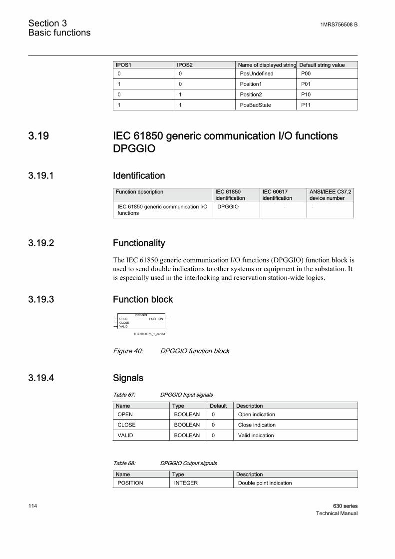
IPOS1 IPOS2 Name of displayed string Default string value0 0 PosUndefined P00
1 0 Position1 P01
0 1 Position2 P10
1 1 PosBadState P11
3.19 IEC 61850 generic communication I/O functionsDPGGIO
3.19.1 IdentificationFunction description IEC 61850
identificationIEC 60617identification
ANSI/IEEE C37.2device number
IEC 61850 generic communication I/Ofunctions
DPGGIO - -
3.19.2 FunctionalityThe IEC 61850 generic communication I/O functions (DPGGIO) function block isused to send double indications to other systems or equipment in the substation. Itis especially used in the interlocking and reservation station-wide logics.
3.19.3 Function blockDPGGIO
OPENCLOSEVALID
POSITION
IEC09000075_1_en.vsd
IEC09000075 V1 EN
Figure 40: DPGGIO function block
3.19.4 SignalsTable 67: DPGGIO Input signals
Name Type Default DescriptionOPEN BOOLEAN 0 Open indication
CLOSE BOOLEAN 0 Close indication
VALID BOOLEAN 0 Valid indication
Table 68: DPGGIO Output signals
Name Type DescriptionPOSITION INTEGER Double point indication
Section 3 1MRS756508 BBasic functions
114 630 seriesTechnical Manual
3.19.5 SettingsThe function does not have any parameters available in Local HMI or Protectionand Control IED Manager (PCM600).
3.19.6 Operation principleUpon receiving the input signals, the IEC 61850 generic communication I/Ofunctions (DPGGIO) function block will send the signals over IEC 61850-8-1 tothe equipment or system that requests these signals. To be able to get the signals,PCM600 must be used to define which function block in which equipment orsystem should receive this information.
3.20 Single point generic control 8 signals SPC8GGIO
3.20.1 IdentificationFunction description IEC 61850
identificationIEC 60617identification
ANSI/IEEE C37.2device number
Single point generic control 8 signals SPC8GGIO - -
3.20.2 FunctionalityThe Single point generic control 8 signals (SPC8GGIO) function block is acollection of 8 single point commands, designed to bring in commands fromREMOTE (SCADA) to those parts of the logic configuration that do not needextensive command receiving functionality (for example, GNRLCSWI). In thisway, simple commands can be sent directly to the IED outputs, withoutconfirmation. Confirmation (status) of the result of the commands is supposed tobe achieved by other means, such as binary inputs and SPGGIO function blocks.The commands can be pulsed or steady.
3.20.3 Function block
GUID-132B75E8-C3F0-465F-9762-18716DF9FB32 V1 EN
Figure 41: SPC8GGIO function block
1MRS756508 B Section 3Basic functions
630 series 115Technical Manual
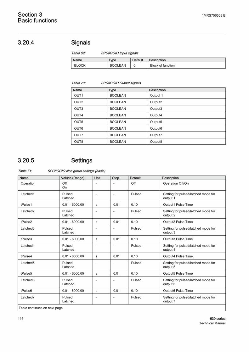
3.20.4 SignalsTable 69: SPC8GGIO Input signals
Name Type Default DescriptionBLOCK BOOLEAN 0 Block of function
Table 70: SPC8GGIO Output signals
Name Type DescriptionOUT1 BOOLEAN Output 1
OUT2 BOOLEAN Output2
OUT3 BOOLEAN Output3
OUT4 BOOLEAN Output4
OUT5 BOOLEAN Output5
OUT6 BOOLEAN Output6
OUT7 BOOLEAN Output7
OUT8 BOOLEAN Output8
3.20.5 SettingsTable 71: SPC8GGIO Non group settings (basic)
Name Values (Range) Unit Step Default DescriptionOperation Off
On- - Off Operation Off/On
Latched1 PulsedLatched
- - Pulsed Setting for pulsed/latched mode foroutput 1
tPulse1 0.01 - 6000.00 s 0.01 0.10 Output1 Pulse Time
Latched2 PulsedLatched
- - Pulsed Setting for pulsed/latched mode foroutput 2
tPulse2 0.01 - 6000.00 s 0.01 0.10 Output2 Pulse Time
Latched3 PulsedLatched
- - Pulsed Setting for pulsed/latched mode foroutput 3
tPulse3 0.01 - 6000.00 s 0.01 0.10 Output3 Pulse Time
Latched4 PulsedLatched
- - Pulsed Setting for pulsed/latched mode foroutput 4
tPulse4 0.01 - 6000.00 s 0.01 0.10 Output4 Pulse Time
Latched5 PulsedLatched
- - Pulsed Setting for pulsed/latched mode foroutput 5
tPulse5 0.01 - 6000.00 s 0.01 0.10 Output5 Pulse Time
Latched6 PulsedLatched
- - Pulsed Setting for pulsed/latched mode foroutput 6
tPulse6 0.01 - 6000.00 s 0.01 0.10 Output6 Pulse Time
Latched7 PulsedLatched
- - Pulsed Setting for pulsed/latched mode foroutput 7
Table continues on next page
Section 3 1MRS756508 BBasic functions
116 630 seriesTechnical Manual
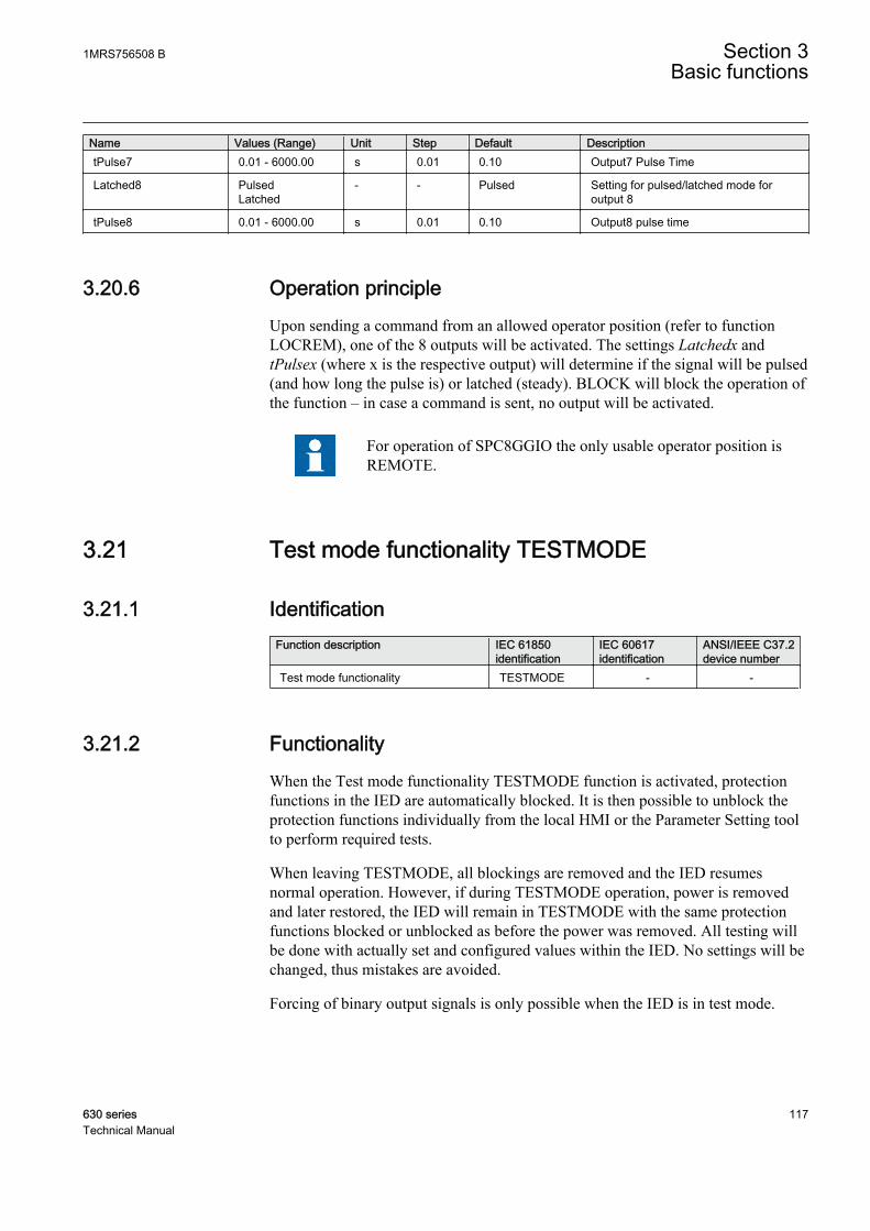
Name Values (Range) Unit Step Default DescriptiontPulse7 0.01 - 6000.00 s 0.01 0.10 Output7 Pulse Time
Latched8 PulsedLatched
- - Pulsed Setting for pulsed/latched mode foroutput 8
tPulse8 0.01 - 6000.00 s 0.01 0.10 Output8 pulse time
3.20.6 Operation principleUpon sending a command from an allowed operator position (refer to functionLOCREM), one of the 8 outputs will be activated. The settings Latchedx andtPulsex (where x is the respective output) will determine if the signal will be pulsed(and how long the pulse is) or latched (steady). BLOCK will block the operation ofthe function – in case a command is sent, no output will be activated.
For operation of SPC8GGIO the only usable operator position isREMOTE.
3.21 Test mode functionality TESTMODE
3.21.1 IdentificationFunction description IEC 61850
identificationIEC 60617identification
ANSI/IEEE C37.2device number
Test mode functionality TESTMODE - -
3.21.2 FunctionalityWhen the Test mode functionality TESTMODE function is activated, protectionfunctions in the IED are automatically blocked. It is then possible to unblock theprotection functions individually from the local HMI or the Parameter Setting toolto perform required tests.
When leaving TESTMODE, all blockings are removed and the IED resumesnormal operation. However, if during TESTMODE operation, power is removedand later restored, the IED will remain in TESTMODE with the same protectionfunctions blocked or unblocked as before the power was removed. All testing willbe done with actually set and configured values within the IED. No settings will bechanged, thus mistakes are avoided.
Forcing of binary output signals is only possible when the IED is in test mode.
1MRS756508 B Section 3Basic functions
630 series 117Technical Manual
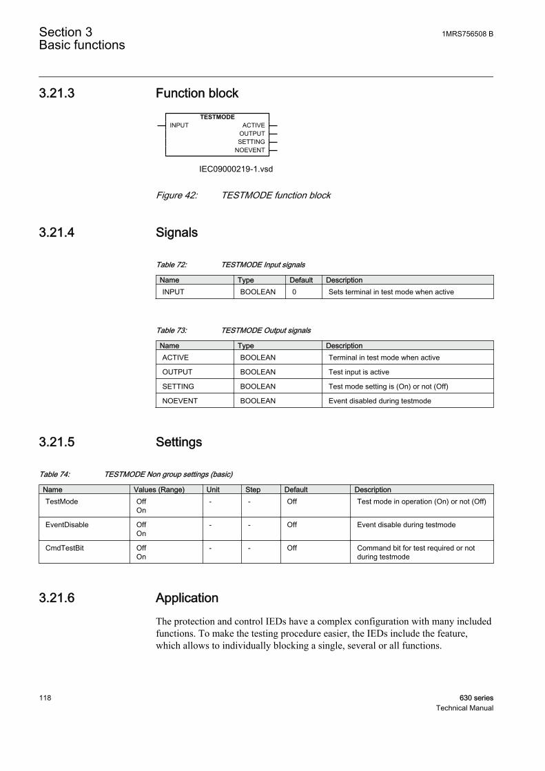
3.21.3 Function blockTESTMODE
INPUT ACTIVEOUTPUTSETTING
NOEVENT
IEC09000219-1.vsdIEC09000219 V1 EN
Figure 42: TESTMODE function block
3.21.4 Signals
Table 72: TESTMODE Input signals
Name Type Default DescriptionINPUT BOOLEAN 0 Sets terminal in test mode when active
Table 73: TESTMODE Output signals
Name Type DescriptionACTIVE BOOLEAN Terminal in test mode when active
OUTPUT BOOLEAN Test input is active
SETTING BOOLEAN Test mode setting is (On) or not (Off)
NOEVENT BOOLEAN Event disabled during testmode
3.21.5 Settings
Table 74: TESTMODE Non group settings (basic)
Name Values (Range) Unit Step Default DescriptionTestMode Off
On- - Off Test mode in operation (On) or not (Off)
EventDisable OffOn
- - Off Event disable during testmode
CmdTestBit OffOn
- - Off Command bit for test required or notduring testmode
3.21.6 ApplicationThe protection and control IEDs have a complex configuration with many includedfunctions. To make the testing procedure easier, the IEDs include the feature,which allows to individually blocking a single, several or all functions.
Section 3 1MRS756508 BBasic functions
118 630 seriesTechnical Manual

This means that it is possible to see when a function is activated or trips. It alsoenables the user to follow the operation of several related functions to checkcorrect functionality and to check parts of the configuration, and so on.
3.21.7 Operation principlePut the IED into test mode to test functions in the IED. Set the IED in test mode by
• configuration, activating the input signal of the function block TESTMODE.• setting TestMode to On in the local HMI, under Main menu/Test/IED test
mode.
While the IED is in test mode, the ACTIVE output of the function blockTESTMODE is activated. The other outputs of the function block TESTMODEshows the generator of the “Test mode: On” state — input from configuration(OUTPUT output is activated) or setting from local HMI (SETTING output isactivated).
While the IED is in test mode, the yellow START LED will flash and all functionsare blocked. Any function can be unblocked individually regarding functionalityand event signalling.
Forcing of binary output signals is only possible when the IED is in test mode.
Most of the functions in the IED can individually be blocked by means of settingsfrom the local HMI. To enable these blockings the IED must be set in test mode(output ACTIVE is activated). When leaving the test mode, that is entering normalmode, these blockings are disabled and everything is set to normal operation. Alltesting will be done with actually set and configured values within the IED. Nosettings will be changed, thus no mistakes are possible.
The blocked functions will still be blocked next time entering the test mode, if theblockings were not reset.
The blocking of a function concerns all output signals from the actual function, sono outputs will be activated.
When a binary input is used to set the IED in test mode and aparameter, that requires restart of the application, is changed, theIED will re-enter test mode and all functions will be blocked, alsofunctions that were unblocked before the change. During the re-entering to test mode, all functions will be temporarily unblockedfor a short time, which might lead to unwanted operations. This isonly valid if the IED is put in TEST mode by a binary input, not bylocal HMI.
The TESTMODE function block might be used to automatically block functionswhen a test handle is inserted in a test switch. A contact in the test switch (RTXP24
1MRS756508 B Section 3Basic functions
630 series 119Technical Manual

contact 29-30) can supply a binary input which in turn is configured to theTESTMODE function block.
Each of the protection functions includes the blocking from the TESTMODEfunction block.
The functions can also be blocked from sending events over IEC 61850 station busto prevent filling station and SCADA databases with test events, for exampleduring a maintenance test.
3.22 Disturbance report
3.22.1 FunctionalityComplete and reliable information about disturbances in the primary and/or in thesecondary system together with continuous event-logging is accomplished by thedisturbance report functionality.
Disturbance report DRRDRE, always included in the IED, acquires sampled dataof all selected analog input and binary signals connected to the function block thatis, maximum 40 analog and 64 binary signals.
The Disturbance report functionality is a common name for several functions:
• Event list• Indications• Event recorder• Trip value recorder• Disturbance recorder
The Disturbance report function is characterized by great flexibility regardingconfiguration, starting conditions, recording times, and large storage capacity.
A disturbance is defined as an activation of an input to the AxRADR or BxRBDRfunction blocks, which are set to trigger the disturbance recorder. All signals fromstart of pre-fault time to the end of post-fault time will be included in the recording.
Every disturbance report recording is saved in the IED in the standard Comtradeformat. The same applies to all events, which are continuously saved in a ring-buffer. The local HMI is used to get information about the recordings. Thedisturbance report files may be uploaded to PCM600 for further analysis using thedisturbance handling tool.
Section 3 1MRS756508 BBasic functions
120 630 seriesTechnical Manual
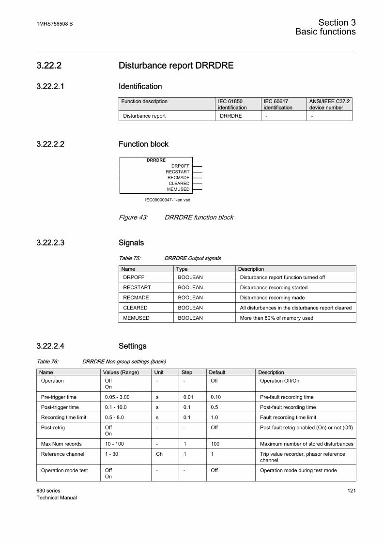
3.22.2 Disturbance report DRRDRE
3.22.2.1 Identification
Function description IEC 61850identification
IEC 60617identification
ANSI/IEEE C37.2device number
Disturbance report DRRDRE - -
3.22.2.2 Function block
DRRDREDRPOFF
RECSTARTRECMADECLEARED
MEMUSED
IEC09000347-1-en.vsdIEC09000347 V1 EN
Figure 43: DRRDRE function block
3.22.2.3 Signals
Table 75: DRRDRE Output signals
Name Type DescriptionDRPOFF BOOLEAN Disturbance report function turned off
RECSTART BOOLEAN Disturbance recording started
RECMADE BOOLEAN Disturbance recording made
CLEARED BOOLEAN All disturbances in the disturbance report cleared
MEMUSED BOOLEAN More than 80% of memory used
3.22.2.4 Settings
Table 76: DRRDRE Non group settings (basic)
Name Values (Range) Unit Step Default DescriptionOperation Off
On- - Off Operation Off/On
Pre-trigger time 0.05 - 3.00 s 0.01 0.10 Pre-fault recording time
Post-trigger time 0.1 - 10.0 s 0.1 0.5 Post-fault recording time
Recording time limit 0.5 - 8.0 s 0.1 1.0 Fault recording time limit
Post-retrig OffOn
- - Off Post-fault retrig enabled (On) or not (Off)
Max Num records 10 - 100 - 1 100 Maximum number of stored disturbances
Reference channel 1 - 30 Ch 1 1 Trip value recorder, phasor referencechannel
Operation mode test OffOn
- - Off Operation mode during test mode
1MRS756508 B Section 3Basic functions
630 series 121Technical Manual
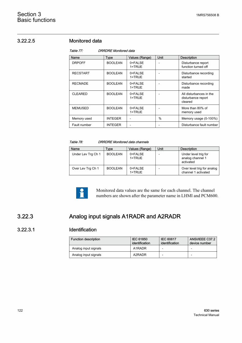
3.22.2.5 Monitored data
Table 77: DRRDRE Monitored data
Name Type Values (Range) Unit DescriptionDRPOFF BOOLEAN 0=FALSE
1=TRUE- Disturbance report
function turned off
RECSTART BOOLEAN 0=FALSE1=TRUE
- Disturbance recordingstarted
RECMADE BOOLEAN 0=FALSE1=TRUE
- Disturbance recordingmade
CLEARED BOOLEAN 0=FALSE1=TRUE
- All disturbances in thedisturbance reportcleared
MEMUSED BOOLEAN 0=FALSE1=TRUE
- More than 80% ofmemory used
Memory used INTEGER - % Memory usage (0-100%)
Fault number INTEGER - - Disturbance fault number
Table 78: DRRDRE Monitored data channels
Name Type Values (Range) Unit DescriptionUnder Lev Trg Ch 1 BOOLEAN 0=FALSE
1=TRUE- Under level trig for
analog channel 1activated
Over Lev Trg Ch 1 BOOLEAN 0=FALSE1=TRUE
- Over level trig for analogchannel 1 activated
Monitored data values are the same for each channel. The channelnumbers are shown after the parameter name in LHMI and PCM600.
3.22.3 Analog input signals A1RADR and A2RADR
3.22.3.1 Identification
Function description IEC 61850identification
IEC 60617identification
ANSI/IEEE C37.2device number
Analog input signals A1RADR - -
Analog input signals A2RADR - -
Section 3 1MRS756508 BBasic functions
122 630 seriesTechnical Manual
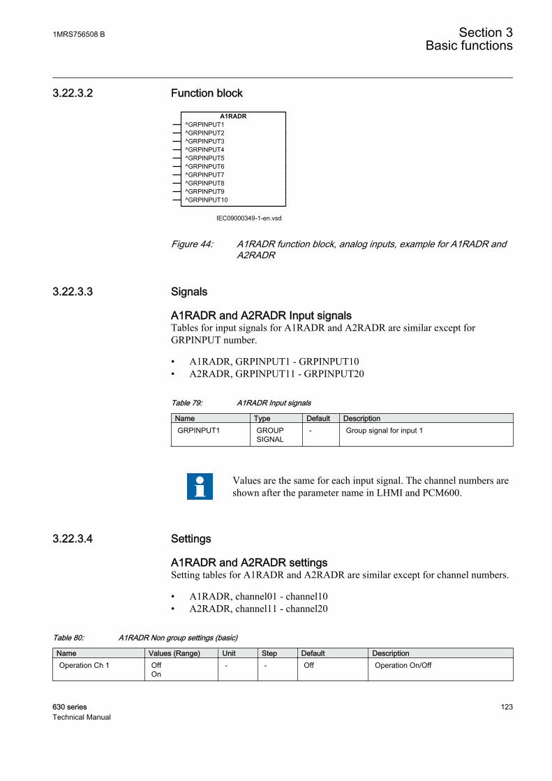
3.22.3.2 Function block
A1RADR^GRPINPUT1^GRPINPUT2^GRPINPUT3^GRPINPUT4^GRPINPUT5^GRPINPUT6^GRPINPUT7^GRPINPUT8^GRPINPUT9^GRPINPUT10
IEC09000349-1-en.vsdIEC09000349 V1 EN
Figure 44: A1RADR function block, analog inputs, example for A1RADR andA2RADR
3.22.3.3 Signals
A1RADR and A2RADR Input signalsTables for input signals for A1RADR and A2RADR are similar except forGRPINPUT number.
• A1RADR, GRPINPUT1 - GRPINPUT10• A2RADR, GRPINPUT11 - GRPINPUT20
Table 79: A1RADR Input signals
Name Type Default DescriptionGRPINPUT1 GROUP
SIGNAL- Group signal for input 1
Values are the same for each input signal. The channel numbers areshown after the parameter name in LHMI and PCM600.
3.22.3.4 Settings
A1RADR and A2RADR settingsSetting tables for A1RADR and A2RADR are similar except for channel numbers.
• A1RADR, channel01 - channel10• A2RADR, channel11 - channel20
Table 80: A1RADR Non group settings (basic)
Name Values (Range) Unit Step Default DescriptionOperation Ch 1 Off
On- - Off Operation On/Off
1MRS756508 B Section 3Basic functions
630 series 123Technical Manual

Table 81: A1RADR Non group settings (advanced)
Name Values (Range) Unit Step Default DescriptionNominal value Ch 1 0.0 - 999999.9 - 0.1 0.0 Nominal value for
analog channel 1
Under trigger Ch 1 OffOn
- - Off Use under leveltrigger for analogchannel 1 (on) ornot (off)
Under Trg Lev Ch 1 0 - 200 % 1 50 Under trigger levelfor analog channel 1in % of signal
Over trigger Ch 1 OffOn
- - Off Use over leveltrigger for analogchannel 1 (on) ornot (off)
Over Trg Lev Ch 1 0 - 5000 % 1 200 Over trigger level foranalog channel 1 in% of signal
IEC60870-5-103
Function type Ch 1 0 - 255 - 1 0 Function type foranalog channel 1(IEC60870-5-103)
Information Num Ch1
0 - 255 - 1 0 Information numberfor analog channel 1(IEC60870-5-103)
Settings are the same for each channel. The channel numbers areshown after the parameter name in LHMI and PCM600.
3.22.4 Analog input signals A3RADR and A4RADR
3.22.4.1 Identification
Function description IEC 61850identification
IEC 60617identification
ANSI/IEEE C37.2device number
Analog input signals A3RADR - -
Analog input signals A4RADR - -
In release 1.0 A3RADR was reserved for external analog signals.From release 1.1 A3RADR is reserved for internally calculatedanalog signals.
Section 3 1MRS756508 BBasic functions
124 630 seriesTechnical Manual
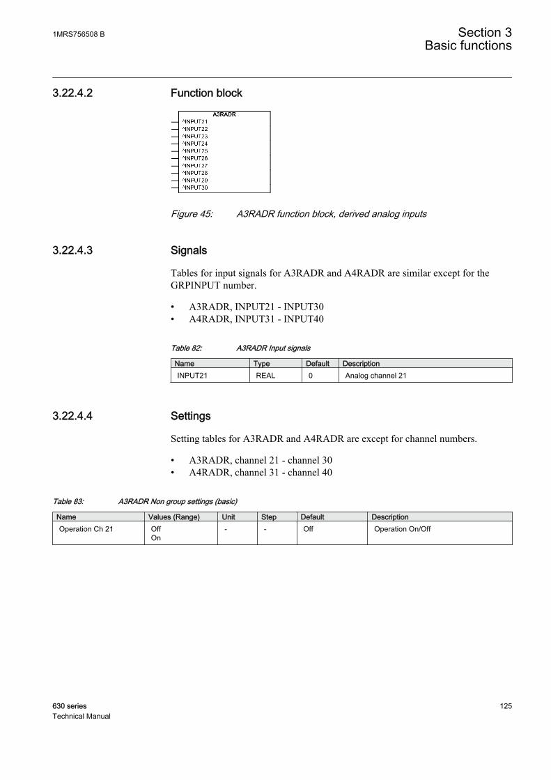
3.22.4.2 Function block
GUID-88FD658F-1A11-4704-B152-F9E0C16C873B V1 EN
Figure 45: A3RADR function block, derived analog inputs
3.22.4.3 Signals
Tables for input signals for A3RADR and A4RADR are similar except for theGRPINPUT number.
• A3RADR, INPUT21 - INPUT30• A4RADR, INPUT31 - INPUT40
Table 82: A3RADR Input signals
Name Type Default DescriptionINPUT21 REAL 0 Analog channel 21
3.22.4.4 Settings
Setting tables for A3RADR and A4RADR are except for channel numbers.
• A3RADR, channel 21 - channel 30• A4RADR, channel 31 - channel 40
Table 83: A3RADR Non group settings (basic)
Name Values (Range) Unit Step Default DescriptionOperation Ch 21 Off
On- - Off Operation On/Off
1MRS756508 B Section 3Basic functions
630 series 125Technical Manual

Table 84: A3RADR Non group settings (advanced)
Name Values (Range) Unit Step Default DescriptionNominal value Ch 21 0.0 - 999999.9 - 0.1 0.0 Nominal value for
analog channel 21
Under trigger Ch 21 OffOn
- - Off Use under leveltrigger for analogchannel 21 (on) ornot (off)
Under Trg Lev Ch 21 0 - 200 % 1 50 Under trigger levelfor analog channel21 in % of signal
Over trigger Ch 21 OffOn
- - Off Use over leveltrigger for analogchannel 21 (on) ornot (off)
Over Trg Lev Ch 21 0 - 5000 % 1 200 Over trigger level foranalog channel 21in % of signal
IEC60870-5-103
Function type Ch 21 0 - 255 - 1 0 Function type foranalog channel 21(IEC60870-5-103)
Information Num Ch21
0 - 255 - 1 0 Information numberfor analog channel21(IEC60870-5-103)
3.22.5 Binary input signals BxRBDR
3.22.5.1 Identification
Function description IEC 61850identification
IEC 60617identification
ANSI/IEEE C37.2device number
Binary input signals B1RBDR - -
Binary input signals B2RBDR - -
Binary input signals B3RBDR - -
Binary input signals B4RBDR - -
Section 3 1MRS756508 BBasic functions
126 630 seriesTechnical Manual
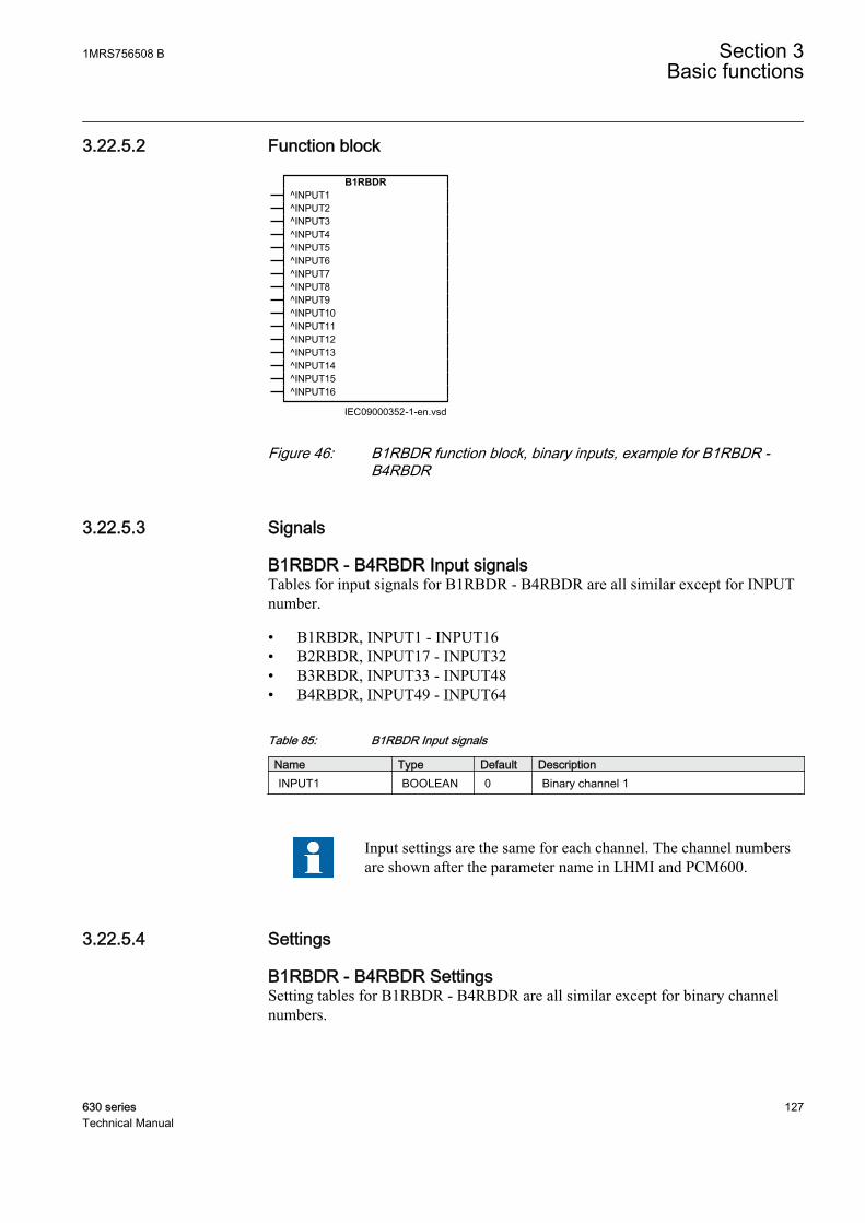
3.22.5.2 Function block
B1RBDR^INPUT1^INPUT2^INPUT3^INPUT4^INPUT5^INPUT6^INPUT7^INPUT8^INPUT9^INPUT10^INPUT11^INPUT12^INPUT13^INPUT14^INPUT15^INPUT16
IEC09000352-1-en.vsdIEC09000352 V1 EN
Figure 46: B1RBDR function block, binary inputs, example for B1RBDR -B4RBDR
3.22.5.3 Signals
B1RBDR - B4RBDR Input signalsTables for input signals for B1RBDR - B4RBDR are all similar except for INPUTnumber.
• B1RBDR, INPUT1 - INPUT16• B2RBDR, INPUT17 - INPUT32• B3RBDR, INPUT33 - INPUT48• B4RBDR, INPUT49 - INPUT64
Table 85: B1RBDR Input signals
Name Type Default DescriptionINPUT1 BOOLEAN 0 Binary channel 1
Input settings are the same for each channel. The channel numbersare shown after the parameter name in LHMI and PCM600.
3.22.5.4 Settings
B1RBDR - B4RBDR SettingsSetting tables for B1RBDR - B4RBDR are all similar except for binary channelnumbers.
1MRS756508 B Section 3Basic functions
630 series 127Technical Manual

• B1RBDR, channel1 - channel16• B2RBDR, channel17 - channel32• B3RBDR, channel33 - channel48• B4RBDR, channel49 - channel64
Table 86: B1RBDR Non group settings (basic)
Name Values (Range) Unit Step Default DescriptionTrigger operation 1 Off
On- - Off Trigger operation On/Off
Set LED 1 OffStartTripStart and Trip
- - Off Set LED on HMI for binary channel 1
Table 87: B1RBDR Non group settings (advanced)
Name Values (Range) Unit Step Default DescriptionTrigger level 1 Trig on 0
Trig on 1- - Trig on 1 Trigger on positive
(1) or negative (0)slope for binaryinput 1
Show indication 1 HideShow
- - Hide Indication mask forbinary channel 1
IEC60870-5-103
Function type Ch 1 0 - 255 - 1 0 Function type forbinary channel 1(IEC60870-5-103)
Information Num Ch1
0 - 255 - 1 0 Information numberfor binary channel 1(IEC60870-5-103)
Settings are the same for each channel. The channel numbers areshown after the parameter name in LHMI and PCM600.
3.22.6 ApplicationTo get fast, complete and reliable information about disturbances in the primary and/or in the secondary system it is very important to gather information on faultcurrents, voltages and events. It is also important having a continuous event-logging to be able to monitor in an overview perspective. These tasks areaccomplished by the disturbance report function DRRDRE and facilitate a betterunderstanding of the power system behavior and related primary and secondaryequipment during and after a disturbance. An analysis of the recorded dataprovides valuable information that can be used to explain a disturbance, basis forchange of IED setting plan, improve existing equipment, and so on. Thisinformation can also be used in a longer perspective when planning for and
Section 3 1MRS756508 BBasic functions
128 630 seriesTechnical Manual
designing new installations, that is, a disturbance recording could be a part ofFunctional Analysis (FA).
Disturbance report DRRDRE, always included in the IED, acquires sampled dataof all selected analog and binary signals connected to the function blocks.
• Maximum 20 external analog signals• 20 internal derived analog signals• 64 binary signals
Disturbance report function is a common name for several functions that is,Indications, Event recorder, Event list, Trip value recorder, Disturbance recorder.
Disturbance report function is characterized by great flexibility as far asconfiguration, starting conditions, recording times, and large storage capacity areconcerned. Thus, disturbance report is not dependent on the operation of protectivefunctions, and it can record disturbances that were not discovered by protectivefunctions for one reason or another. Disturbance report can be used as an advancedstand-alone disturbance recorder.
Every disturbance report recording is saved in the IED. The same applies to allevents, which are continuously saved in a ring-buffer. Local HMI can be used toget information about the recordings, and the disturbance report files may beuploaded in the PCM600 using the Disturbance handling tool, for report reading orfurther analysis (using WaveWin, that can be found on the PCM600 installationCD). The user can also upload disturbance report files using MMS (over 61850)clients.
If the IED is connected to a station bus (IEC 61850-8-1), the disturbance recorder(record made and fault number) and the fault locator information are available asGOOSE or Report Control data.
3.22.7 Operation principleDisturbance report DRRDRE is a common name for several functions to supply theoperator, analysis engineer, and so on, with sufficient information about events inthe system.
The functions included in the disturbance report are:
• Event list• Indications• Event recorder• Trip value recorder• Disturbance recorder
Figure 47 shows the relations between Disturbance Report, included functions andfunction blocks. Event list , Event recorder and Indications uses information fromthe binary input function blocks (BxRBDR). Trip value recorder uses analog
1MRS756508 B Section 3Basic functions
630 series 129Technical Manual

information from the analog input function blocks (AxRADR). Disturbancerecorder DRRDRE acquires information from both AxRADR and BxRBDR.
Trip Value Rec
Event List
Event Recorder
Indications
DisturbanceRecorder
A1-4RADR
B1-4RBDR
Disturbance Report
Binary signals
Analog signalsA4RADR
B4RBDR
RDRE
IEC09000136_en_1.vsdIEC09000136 V1 EN
Figure 47: Disturbance report functions and related function blocks
The whole disturbance report can contain information for a number of recordings,each with the data coming from all the parts mentioned above. The event listfunction is working continuously, independent of disturbance triggering, recordingtime, and so on. All information in the disturbance report is stored in non-volatileflash memories. This implies that no information is lost in case of loss of auxiliarypower. Each report will get an identification number in the interval from 0-999.
en05000161.vsd
Disturbance report
Record no. N Record no. N+1 Record no. N+100
General dist.information Indications Trip
valuesEvent
recordingsDisturbance
recording Event list
IEC05000161 V1 EN
Figure 48: Disturbance report structure
Up to 100 disturbance reports can be stored. If a new disturbance is to be recordedwhen the memory is full, the oldest disturbance report is overwritten by the new
Section 3 1MRS756508 BBasic functions
130 630 seriesTechnical Manual
one. The total recording capacity for the disturbance recorder is depending ofsampling frequency, number of analog and binary channels and recording time. Ina 50 Hz system it is possible to record 100 where the maximum recording time is3.4 seconds. The memory limit does not affect the rest of the disturbance report(Event list, Event recorder, Indications and Trip value recorder).
The maximum number of recordings depend on each recordingstotal recording time. Long recording time will reduce the number ofrecordings to less than 100.
The IED flash disk should NOT be used to store any user files. Thismight cause disturbance recordings to be deleted due to lack of diskspace.
3.22.7.1 Disturbance information
Date and time of the disturbance, the indications, events, fault location and the tripvalues are available on the LHMI. To acquire a complete disturbance report, use aPC and either the PCM600 Disturbance handling tool or MMS (over 61850) client.The PC can be connected to IED front port, or remotely via a station bus.
3.22.7.2 Indications
Indications is a list of signals that were activated during the total recording time ofthe disturbance (not time-tagged), see Indication section for detailed information.
3.22.7.3 Event recorder
The event recorder may contain a list of up to 150 time-tagged events, which haveoccurred during the disturbance. The information is available via the local HMI orPCM600, see Event recorder section for detailed information.
3.22.7.4 Event list
The event list may contain a list of totally 1000 time-tagged events. The listinformation is continuously updated when selected binary signals change state. Theoldest data is overwritten. The logged signals may be presented via local HMI,WebHMI or PCM600, see Event list section for detailed information.
3.22.7.5 Trip value recorder
The recorded trip values include phasors of selected analog signals before the faultand during the fault, see Trip value recorder section for detailed information.
1MRS756508 B Section 3Basic functions
630 series 131Technical Manual

3.22.7.6 Disturbance recorder
Disturbance recorder records analog and binary signal data before, during and afterthe fault, see Disturbance recorder section for detailed information.
3.22.7.7 Time tagging
The IED has a built-in real-time calendar and clock. This function is used for alltime tagging within the disturbance report
3.22.7.8 Recording times
Disturbance report DRRDRE records information about a disturbance during asettable time frame. The recording times are valid for the whole disturbance report.Disturbance recorder, event recorder and indication function register disturbancedata and events during tRecording, the total recording time.
The total recording time, tRecording, of a recorded disturbance is:
tRecording = Pre-trigger time + tFault + Post-trigger time or Pre-trigger time + Recording time limit,depending on which criterion stops the current disturbance recording
Section 3 1MRS756508 BBasic functions
132 630 seriesTechnical Manual

Pre-trigger time
Recording time limit
Post-trigger time
IEC09000708-1-en.vsd
1 2 3
Trig point
IEC09000708 V1 EN
Figure 49: The recording times definition
Pre-trigger time,1
Pre--trigger recording time. The time before the fault including the operate time ofthe trigger. Use the setting Pre-trigger time to set this time.
tFault, 2 Fault time of the recording. The fault time cannot be set. It continues as long asany valid trigger condition, binary or analog, persists (unless limited by Recordingtime limit the limit time).
Post-triggertime, 3
Post fault recording time. The time the disturbance recording continues after allactivated triggers are reset. Use the setting Post-trigger time to set this time.
Recording timelimit
Limit time. The maximum allowed recording time after the disturbance recordingwas triggered. The limit time is used to eliminate the consequences of a trigger thatdoes not reset within a reasonable time interval. It limits the maximum recordingtime of a recording and prevents subsequent overwriting of already storeddisturbances. Use the setting Recording time limit to set this time.
3.22.7.9 Analog signals
Up to 40 analog signals can be selected for recording by the disturbance recorderand triggering of the Disturbance report function. Out of these 40, 20 are reservedfor external analog signals from analog input modules via preprocessing functionblocks (SMAI). The last 20 channels may be connected to internally calculatedanalog signals available as function block output signals (phase differentialcurrents, bias currents and so on).
1MRS756508 B Section 3Basic functions
630 series 133Technical Manual
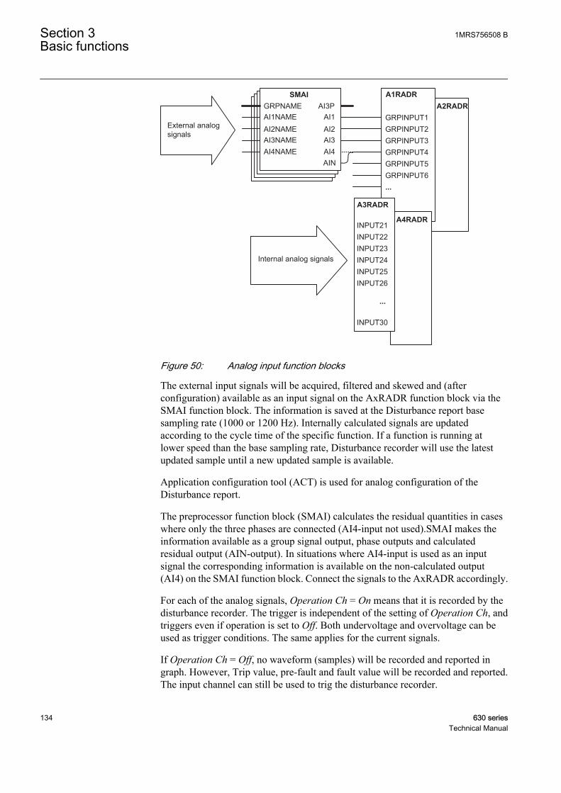
A4RADR
A2RADRA1RADRSMAI
AI1AI2AI3AI4
AI3PAI1NAMEAI2NAMEAI3NAME
GRPNAME
AI4NAME
GRPINPUT1GRPINPUT2GRPINPUT3GRPINPUT4GRPINPUT5GRPINPUT6...
A3RADR
INPUT21INPUT22INPUT23INPUT24INPUT25INPUT26
...
INPUT30
Internal analog signals
External analogsignals
AIN
GUID-ECD1F42C-23E5-4B0A-953A-CC6D9FDA1C27 V1 EN
Figure 50: Analog input function blocks
The external input signals will be acquired, filtered and skewed and (afterconfiguration) available as an input signal on the AxRADR function block via theSMAI function block. The information is saved at the Disturbance report basesampling rate (1000 or 1200 Hz). Internally calculated signals are updatedaccording to the cycle time of the specific function. If a function is running atlower speed than the base sampling rate, Disturbance recorder will use the latestupdated sample until a new updated sample is available.
Application configuration tool (ACT) is used for analog configuration of theDisturbance report.
The preprocessor function block (SMAI) calculates the residual quantities in caseswhere only the three phases are connected (AI4-input not used).SMAI makes theinformation available as a group signal output, phase outputs and calculatedresidual output (AIN-output). In situations where AI4-input is used as an inputsignal the corresponding information is available on the non-calculated output(AI4) on the SMAI function block. Connect the signals to the AxRADR accordingly.
For each of the analog signals, Operation Ch = On means that it is recorded by thedisturbance recorder. The trigger is independent of the setting of Operation Ch, andtriggers even if operation is set to Off. Both undervoltage and overvoltage can beused as trigger conditions. The same applies for the current signals.
If Operation Ch = Off, no waveform (samples) will be recorded and reported ingraph. However, Trip value, pre-fault and fault value will be recorded and reported.The input channel can still be used to trig the disturbance recorder.
Section 3 1MRS756508 BBasic functions
134 630 seriesTechnical Manual
If Operation Ch = On, waveform (samples) will also be recorded and reported ingraph.
The analog signals are presented only in the disturbance recording, but they affectthe entire disturbance report when being used as triggers.
3.22.7.10 Binary signals
Up to 64 binary signals can be selected to be handled by disturbance report. Thesignals can be selected from internal logical and binary input signals. A binarysignal is selected to be recorded when:
• the corresponding function block is included in the configuration• the signal is connected to the input of the function block
Each of the 64 signals can be selected as a trigger of the disturbance report(Operation Ch = Off). A binary signal can be selected to activate the yellow(START) and red (TRIP) LED on the local HMI (Set LED = Off/Start/Trip/Startand Trip).
The selected signals are presented in the event recorder, event list and thedisturbance recording. But they affect the whole disturbance report when they areused as triggers. The indications are also selected from these 64 signals with localHMI Show indication=Show/Hide.
3.22.7.11 Trigger signals
The trigger conditions affect the entire disturbance report, except the event list,which runs continuously. As soon as at least one trigger condition is fulfilled, acomplete disturbance report is recorded. On the other hand, if no trigger conditionis fulfilled, there is no disturbance report, no indications, and so on. This impliesthe importance of choosing the right signals as trigger conditions.
A trigger can be of type:
• Manual trigger• Binary-signal trigger• Analog-signal trigger (over/under function)
Manual triggerA disturbance report can be manually triggered from the local HMI, WebHMI,PCM600 or via station bus (IEC 61850). When the trigger is activated, the manualtrigger signal is generated. This feature is especially useful for testing.
Manual triggering of the disturbance recorder from the WebHMImakes a recording with length of 1 second.
1MRS756508 B Section 3Basic functions
630 series 135Technical Manual
Binary-signal triggerAny binary signal state (logic one or a logic zero) can be selected to generate atrigger (Trigger level = Trig on 0/Trig on 1). When a binary signal is selected togenerate a trigger from a logic zero, the selected signal will not be listed in theindications list of the disturbance report.
Analog-signal triggerAll analog signals are available for trigger purposes, no matter if they are recordedin the disturbance recorder or not. The settings are Over trigger Ch, Under triggerCh, Over Trg Lev Ch and Under Trg Lev Ch.
The check of the trigger condition is based on peak-to-peak values. When this isfound, the absolute average value of these two peak values is calculated. If theaverage value is above the threshold level for an overvoltage or overcurrent trigger,this trigger is indicated with a greater than (>) sign with the user-defined name.
If the average value is below the set threshold level for an undervoltage orundercurrent trigger, this trigger is indicated with a less than (<) sign with its name.The procedure is separately performed for each channel.
This method of checking the analog start conditions gives a function which isinsensitive to DC offset in the signal. The operate time for this start is typically inthe range of one cycle, 20 ms for a 50 Hz network.
All under/over trig signal information is available on the local HMI and PCM600.
3.22.7.12 Post Retrigger
Disturbance report function does not respond to any new trig condition, during arecording. Under certain circumstances the fault condition may reoccur during thepost-fault recording, for instance by automatic reclosing to a still faulty power line.
In order to capture the new disturbance it is possible to allow retriggering (Post-retrig = On) during the post-fault time. In this case a new, complete recording willstart and, during a period, run in parallel with the initial recording.
When the retrig parameter is disabled (Post-retrig = Off), a new recording will notstart until the post-fault (Post-trigger time or Recording time limit) period isterminated. If a new trig occurs during the post-fault period and lasts longer thanthe proceeding recording a new complete recording will be fetched.
Disturbance report function can handle maximum 3 simultaneous disturbancerecordings.
Section 3 1MRS756508 BBasic functions
136 630 seriesTechnical Manual

3.22.8 Technical dataTable 88: DRRDRE technical data
Function Range or value AccuracyPre-fault time (0.05–3.00) s -
Post-fault time (0.1–10.0) s -
Limit time (0.5–8.0) s -
Maximum number of recordings 100, first in - first out -
Time tagging resolution 1 ms See time synchronizationtechnical data
Maximum number of analog inputs 20 + 10 (external + internallyderived)
-
Maximum number of binary inputs 64 -
Maximum number of phasors in theTrip Value recorder per recording
30 -
Maximum number of indications in adisturbance report
64 -
Maximum number of events in theEvent recording per recording
150 -
Maximum number of events in theEvent list
1000, first in - first out -
Maximum total recording time (3.4 srecording time and maximum numberof channels, typical value)
340 seconds (100 recordings)at 50 Hz, 280 seconds (80recordings) at 60 Hz
-
Sampling rate 1 kHz at 50 Hz1.2 kHz at 60 Hz
-
Recording bandwidth (5-300) Hz -
3.23 Indications
3.23.1 FunctionalityTo get fast, condensed and reliable information about disturbances in the primaryand/or in the secondary system it is important to know, for example binary signalsthat have changed status during a disturbance. This information is used in the shortperspective to get information via the local HMI in a straightforward way.
There are three LEDs on the local HMI (green, yellow and red), which will displaystatus information about the IED and the Disturbance report function (trigged).
The Indication list function shows all selected binary input signals connected to theDisturbance report function that have changed status during a disturbance.
1MRS756508 B Section 3Basic functions
630 series 137Technical Manual

3.23.2 Function blockThe Indications function has no function block of it’s own. .
3.23.3 Signals
3.23.3.1 Input signals
The Indications function may log the same binary input signals as the Disturbancereport function.
3.23.4 Operation principleThe LED indications display this information:
Green LED:
Steady light In Service
Flashing light Internal fail
Dark No power supply
Yellow LED:
Function controlled by SetLEDn setting in Disturbance report function.
Red LED:
Function controlled by SetLEDn setting in Disturbance report function.
Indication list:
The possible indicated signals are the same as the ones chosen for the disturbancereport function and disturbance recorder.
The indication function tracks 0 to 1 changes of binary signals during the recordingperiod of the collection window. This means that constant logic zero, constant logicone or state changes from logic one to logic zero will not be visible in the list ofindications. Signals are not time tagged. In order to be recorded in the list ofindications the:
• Signal must be connected to binary input BxRBDR function block• DRRDRE parameter Operation must be set On• DRRDRE must be trigged (binary or analog)• Input signal must change state from logical 0 to 1 during the recording time.
Indications are selected with the indication mask (IndicationMask) whenconfiguring the binary inputs.
Section 3 1MRS756508 BBasic functions
138 630 seriesTechnical Manual
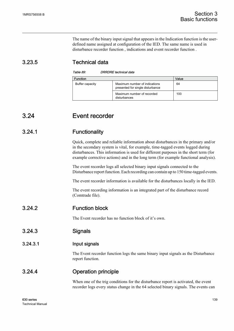
The name of the binary input signal that appears in the Indication function is the user-defined name assigned at configuration of the IED. The same name is used indisturbance recorder function , indications and event recorder function .
3.23.5 Technical dataTable 89: DRRDRE technical data
Function ValueBuffer capacity Maximum number of indications
presented for single disturbance64
Maximum number of recordeddisturbances
100
3.24 Event recorder
3.24.1 FunctionalityQuick, complete and reliable information about disturbances in the primary and/orin the secondary system is vital, for example, time-tagged events logged duringdisturbances. This information is used for different purposes in the short term (forexample corrective actions) and in the long term (for example functional analysis).
The event recorder logs all selected binary input signals connected to theDisturbance report function. Each recording can contain up to 150 time-tagged events.
The event recorder information is available for the disturbances locally in the IED.
The event recording information is an integrated part of the disturbance record(Comtrade file).
3.24.2 Function blockThe Event recorder has no function block of it’s own.
3.24.3 Signals
3.24.3.1 Input signals
The Event recorder function logs the same binary input signals as the Disturbancereport function.
3.24.4 Operation principleWhen one of the trig conditions for the disturbance report is activated, the eventrecorder logs every status change in the 64 selected binary signals. The events can
1MRS756508 B Section 3Basic functions
630 series 139Technical Manual

be generated by both internal logical signals and binary input channels. Theinternal signals are time-tagged in the main processor module, while the binaryinput channels are time-tagged directly in each I/O module. The events arecollected during the total recording time (pre-, post-fault and limit time), and arestored in the disturbance report flash memory at the end of each recording.
In case of overlapping recordings, due to PostRetrig = On and a new trig signalappears during post-fault time, events will be saved in both recording files.
The name of the binary input signal that appears in the event recording is the user-defined name assigned when configuring the IED. The same name is used in thedisturbance recorder function , indications and event recorder function .
The event record is stored as a part of the disturbance report information andmanaged via the local HMI or PCM600.
Events can not be read from the IED if more than one user isaccessing the IED simultaneously.
3.24.5 Technical dataTable 90: DRRDRE technical data
Function ValueBuffer capacity Maximum number of events in disturbance
report150
Maximum number of disturbance reports 100
Resolution 1 ms
Accuracy Depending on timesynchronizing
3.25 Event list
3.25.1 FunctionalityContinuous event-logging is useful for monitoring the system from an overviewperspective and is a complement to specific disturbance recorder functions.
The event list logs all binary input signals connected to the Disturbance reportfunction. The list may contain up to 1000 time-tagged events stored in a ring-buffer.
3.25.2 Function blockThe Event list has no function block of it’s own.
Section 3 1MRS756508 BBasic functions
140 630 seriesTechnical Manual
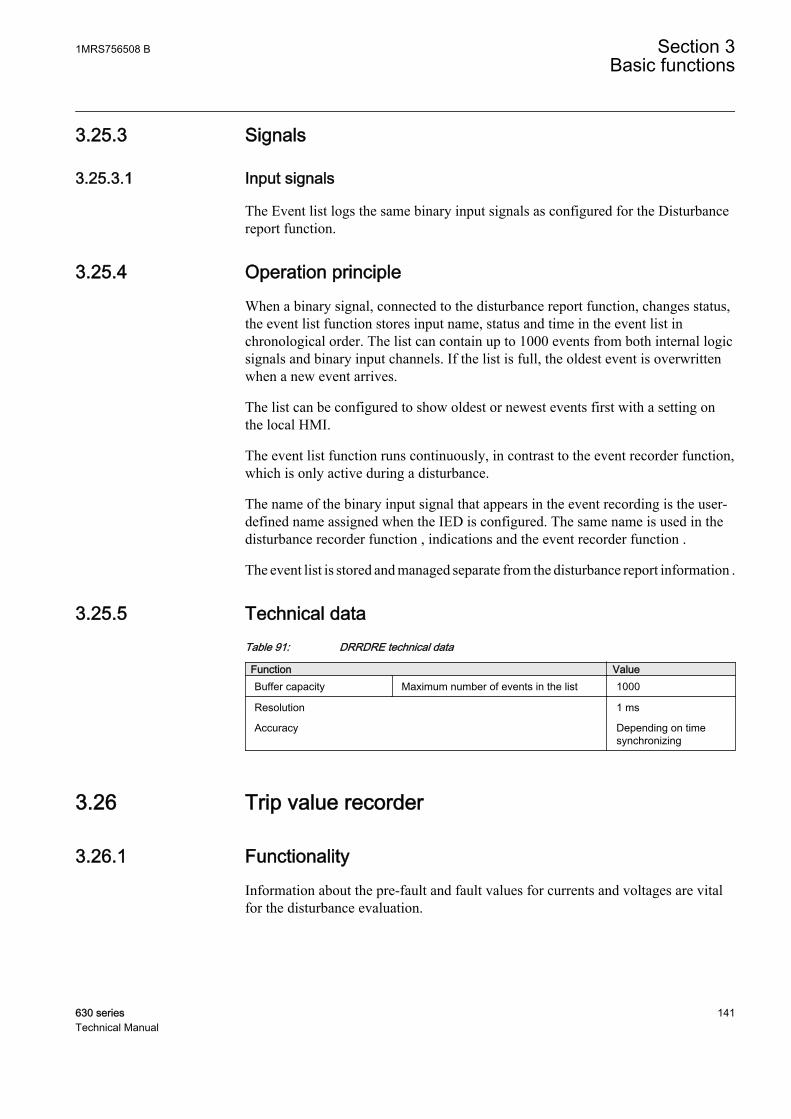
3.25.3 Signals
3.25.3.1 Input signals
The Event list logs the same binary input signals as configured for the Disturbancereport function.
3.25.4 Operation principleWhen a binary signal, connected to the disturbance report function, changes status,the event list function stores input name, status and time in the event list inchronological order. The list can contain up to 1000 events from both internal logicsignals and binary input channels. If the list is full, the oldest event is overwrittenwhen a new event arrives.
The list can be configured to show oldest or newest events first with a setting onthe local HMI.
The event list function runs continuously, in contrast to the event recorder function,which is only active during a disturbance.
The name of the binary input signal that appears in the event recording is the user-defined name assigned when the IED is configured. The same name is used in thedisturbance recorder function , indications and the event recorder function .
The event list is stored and managed separate from the disturbance report information .
3.25.5 Technical dataTable 91: DRRDRE technical data
Function ValueBuffer capacity Maximum number of events in the list 1000
Resolution 1 ms
Accuracy Depending on timesynchronizing
3.26 Trip value recorder
3.26.1 FunctionalityInformation about the pre-fault and fault values for currents and voltages are vitalfor the disturbance evaluation.
1MRS756508 B Section 3Basic functions
630 series 141Technical Manual

The Trip value recorder calculates the values of all selected analog input signalsconnected to the Disturbance report function. The result is magnitude and phaseangle before and during the fault for each analog input signal.
The trip value recorder information is available for the disturbances locally in theIED.
The trip value recorder information is an integrated part of the disturbance record(Comtrade file).
3.26.2 Function blockThe Trip value recorder has no function block of it’s own.
3.26.3 Signals
3.26.3.1 Input signals
The trip value recorder function uses analog input signals connected to A1RADRor A2RADR (not A3RADR and A4RADR).
3.26.4 Operation principleTrip value recorder calculates and presents both fault and pre-fault amplitudes aswell as the phase angles of all the selected analog input signals. The parameterZeroAngleRef points out which input signal is used as the angle reference.
When the disturbance report function is triggered the sample for the faultinterception is searched for, by checking the non-periodic changes in the analoginput signals. The channel search order is consecutive, starting with the analoginput with the lowest number.
When a starting point is found, the Fourier estimation of the pre-fault values of thecomplex values of the analog signals starts 1.5 cycle before the fault sample. Theestimation uses samples during one period. The post-fault values are calculatedusing the Recursive Least Squares (RLS) method. The calculation starts a fewsamples after the fault sample and uses samples during 1/2 - 2 cycles depending onthe shape of the signals.
If no starting point is found in the recording, the disturbance report trig sample isused as the start sample for the Fourier estimation. The estimation uses samplesduring one cycle before the trig sample. In this case the calculated values are usedboth as pre-fault and fault values.
The name of the analog input signal that appears in the Trip value recorder functionis the user-defined name assigned when the IED is configured. The same name isused in the Disturbance recorder function .
Section 3 1MRS756508 BBasic functions
142 630 seriesTechnical Manual

The trip value record is stored as a part of the disturbance report information(LMBRFLO) and managed in via the local HMI or PCM600.
3.26.5 Technical dataTable 92: DRRDRE technical data
Function ValueBuffer capacity
Maximum number of analog inputs 20
Maximum number of disturbance reports 100
3.27 Disturbance recorder
The Disturbance recorder function supplies fast, complete and reliable informationabout disturbances in the power system. It facilitates understanding systembehavior and related primary and secondary equipment during and after adisturbance. Recorded information is used for different purposes in the shortperspective (for example corrective actions) and long perspective (for examplefunctional analysis).
The Disturbance recorder acquires sampled data from selected analog- and binarysignals connected to the Disturbance report function (maximum 40 analog and 64binary signals). The binary signals available are the same as for the event recorderfunction.
The function is characterized by great flexibility and is not dependent on theoperation of protection functions. It can record disturbances not detected byprotection functions.
The disturbance recorder information for the last 100 disturbances are saved in theIED and the local HMI is used to view the list of recordings.
3.27.1 Function blockThe Disturbance recorder has no function block of it’s own.
3.27.2 Signals
3.27.2.1 Input and output signals
See Disturbance report for input and output signals.
3.27.3 Setting parametersSee Disturbance report for settings.
1MRS756508 B Section 3Basic functions
630 series 143Technical Manual

3.27.4 Operation principleDisturbance recording is based on the acquisition of binary and analog signals. Thebinary signals can be either true binary input signals or internal logical signalsgenerated by the functions in the IED. The analog signals to be recorded are inputchannels from the Transformer Input Module (TRM) through the Signal MatrixAnalog Input (SMAI) and some internally derived analog signals.
Disturbance recorder collects analog values and binary signals continuously, in acyclic buffer. The pre-fault buffer operates according to the FIFO principle; olddata will continuously be overwritten as new data arrives when the buffer is full.The size of this buffer is determined by the set pre-fault recording time.
Upon detection of a fault condition (triggering), the disturbance is time tagged andthe data storage continues in a post-fault buffer. The storage process continues aslong as the fault condition prevails - plus a certain additional time. This is calledthe post-fault time and it can be set in the disturbance report.
The above mentioned two parts form a disturbance recording. The whole memory,intended for disturbance recordings, acts as a cyclic buffer and when it is full, theoldest recording is overwritten. The last 100 recordings are stored in the IED.
The time tagging refers to the activation of the trigger that starts the disturbancerecording. A recording can be trigged by, manual start, binary input and/or fromanalog inputs (over-/underlevel trig).
A user-defined name for each of the signals can be set. These names are commonfor all functions within the disturbance report functionality.
3.27.4.1 Memory and storage
The maximum number of recordings depend on each recordingstotal recording time. Long recording time will reduce the number ofrecordings to less than 100.
When a recording is completed, a post recording processing occurs.
This post-recording processing comprises:
• Saving the data for analog channels with corresponding data for binary signals• Add relevant data to be used by the Disturbance handling tool (part of PCM 600)• Compression of the data, which is performed without losing any data accuracy• Storing the compressed data in a non-volatile memory (flash memory)
The recorded disturbance is now ready for retrieval and evaluation.
The recording files comply with the Comtrade standard IEC 60255-24 and aredivided into three files; a header file (HDR), a configuration file (CFG) and a datafile (DAT).
Section 3 1MRS756508 BBasic functions
144 630 seriesTechnical Manual

The header file (optional in the standard) contains basic information about thedisturbance, that is, information from the Disturbance report sub-functions . TheDisturbance handling tool use this information and present the recording in a user-friendly way.
General:
• Station name, object name and unit name• Date and time for the trig of the disturbance• Record number• Sampling rate• Time synchronization source• Recording times• Activated trig signal• Active setting group
Analog:
• Signal names for selected analog channels• Information e.g. trig on analog inputs• Primary and secondary instrument transformer rating• Over- or Undertrig: level and operation• Over- or Undertrig status at time of trig• CT direction
Binary:
• Signal names• Status of binary input signals
The configuration file is a mandatory file containing information needed tointerpret the data file. For example sampling rate, number of channels, systemfrequency, channel info etc.
The data file, which also is mandatory, containing values for each input channel foreach sample in the record (scaled value). The data file also contains a sequencenumber and time stamp for each set of samples.
3.27.5 Technical dataTable 93: DRRDRE technical data
Function ValueBuffer capacity Maximum number of analog inputs 40
Maximum number of binary inputs 64
Maximum number of disturbance reports 100
Maximum total recording time (3.4 s recording time and maximum numberof channels, typical value)
340 seconds (100recordings) at 50 Hz280 seconds (80recordings) at 60 Hz
1MRS756508 B Section 3Basic functions
630 series 145Technical Manual

3.28 Non-volatile memory
In addition to the setting values, the IED can store some data in the non-volatilememory.
• Configuration• Trip lock-out• Events• Disturbance records• CB conditioning monitoring values• Thermal loading• Number of auto-reclosure shots and starts/trips of the protection stages (only
REF630)• Function key & alarm LED states• Protection function recorded data
3.29 Self supervision with internal event list
3.29.1 FunctionalitySelf supervision with internal event list (INTERRSIG and SELFSUPEVLST)function listens and reacts to internal system events, generated by the different built-in self-supervision elements. The internal events are saved in an internal event list.
3.29.2 Internal error signals INTERRSIG
3.29.2.1 Identification
Function description IEC 61850identification
IEC 60617identification
ANSI/IEEE C37.2device number
Internal error signal INTERRSIG - -
3.29.2.2 Function block
INTERRSIGFAIL
WARNINGTSYNCERR
RTCERR
IEC09000334-1-en.vsdIEC09000334 V1 EN
Figure 51: INTERRSIG function block
Section 3 1MRS756508 BBasic functions
146 630 seriesTechnical Manual

3.29.2.3 Signals
Table 94: INTERRSIG Output signals
Name Type DescriptionFAIL BOOLEAN Internal fail
WARNING BOOLEAN Internal warning
TSYNCERR BOOLEAN Time synchronization error
RTCERR BOOLEAN Real time clock error
3.29.2.4 Settings
The function does not have any settings available in Local HMI or Protection andControl IED Manager (PCM600).
3.29.3 Internal event list SELFSUPEVLST
3.29.3.1 Identification
Function description IEC 61850identification
IEC 60617identification
ANSI/IEEE C37.2device number
Internal event list SELFSUPEVLST - -
3.29.3.2 Settings
The function does not have any settings available in Local HMI or Protection andControl IED Manager (PCM600).
3.29.4 ApplicationThe protection and control IEDs have many included functions. Self supervisionwith internal event list (SELFSUPEVLST) and internal error signals(INTERRSIG) function provide supervision of the IED. The fault signals make iteasier to analyze and locate a fault.
Both hardware and software supervision is included and it is also possible toindicate possible faults through a hardware contact on the power supply module and/or through the software communication.
Internal events are generated by the built-in supervisory functions. The supervisoryfunctions supervise the status of the various modules in the IED and, in case offailure, a corresponding event is generated. Similarly, when the failure is corrected,a corresponding event is generated.
Apart from the built-in supervision of the various modules, events are alsogenerated when the status changes for the:
1MRS756508 B Section 3Basic functions
630 series 147Technical Manual

• built-in real time clock (in operation/out of order).• external time synchronization (in operation/out of order).
Events are also generated:
• whenever any setting in the IED is changed.
The internal events are time tagged with a resolution of 1 ms and stored in a list.The list can store up to 40 events. The list is based on the FIFO principle, that is,when it is full, the oldest event is overwritten. The list can be cleared via the localHMI .
The list of internal events provides valuable information, which can be used duringcommissioning and fault tracing.
The list of internal events can be found in the local HMI, WebHMI or PCM600.
The list can be cleared via the local HMI or WebHMI. Menu path:Clear/Clearinternal event list
3.29.5 Operation principleThe self-supervision operates continuously and includes:
• Normal micro-processor watchdog function.• Checking of digitized measuring signals.• Other alarms, for example hardware and time synchronization.
The SELFSUPEVLST function status can be monitored from the local HMI, fromthe Event Viewer in PCM600 or from a SMS/SCS system.
Under the Diagnostics menu in the local HMI the present information from the self-supervision function can be reviewed. The information can be found underMonitoring/Internal Events or Monitoring/IED Status. The information fromthe self-supervision function is also available in the Event Viewer in PCM600.
A self-supervision summary can be obtained by means of the potential free alarmcontact (INTERNAL FAIL) located on the power supply module. This output relayis activated (no fault) and deactivated (fault) by the Internal Fail signal, see Figure52. Also the software watchdog timeout and the undervoltage detection of the PSMwill deactivate the relay.
Section 3 1MRS756508 BBasic functions
148 630 seriesTechnical Manual

IEC09000390-1-en.vsd
Power supply fault
WatchdogTX overflowMaster resp.Supply fault
ReBoot I/O
Internal Fail (CPU)
Power supplymodule
I/O nodes
CEM
AND
Fault
Fault
Fault
INTERNALFAIL
I/O nodes = BIOxxxx = Inverted signal
IEC09000390 V1 EN
Figure 52: Hardware self-supervision, potential-free contact
1MRS756508 B Section 3Basic functions
630 series 149Technical Manual

Time Synch Error
Internal Warning
GENTS SYNC ERROR
GENTS SYNC OK
SR
GENTS RTC ERROR SR
>1 Internal Fail
LIODEV STOPPED SR
Real Time Clock Error
e.g. BIO1- ERROR
Settings changedSETTINGS CHANGED
RTE FATAL ERROR
WDOG STARVED SW Watchdog Error
GENTS RTC OK
GENTS TIME RESET>1
LIODEV STARTED
>1LIODEV FAIL
>1
Runtime Exec Error
>1
RTE APP FAILED SR
RTE ALL APPS OK
>1
Setting groups changedSETTINGS CHANGED
CHANGE LOCK ON SR Change lock
CHANGE LOCK OFF
Runtime App Error
FTF FATAL ERROR File System Error
SR
IEC 61850 READY
DNP 3 STARTUP ERROR S
RDNP 3 READY
IEC 61850 Error
IOM2- ERROR
DNP 3 Error
IEC 61850 NOT READY
IEC09000381-1-en.vsdIEC09000381 V1 EN
Figure 53: Self supervision, function block internal signals
Some signals are available from the INTERRSIG function block. The signals fromINTERRSIG function block are sent as events to the station level of the controlsystem. The signals from the INTERRSIG function block can also be connected tobinary outputs for signalization via output relays or they can be used as conditionsfor other functions if required/desired.
Individual error signals from I/O modules can be obtained from respective modulein the Signal Matrix tool. Error signals from time synchronization can be obtainedfrom the time synchronization block INTERSIG.
3.29.5.1 Internal signals
SELFSUPEVLST function provides several status signals, that tells about thecondition of the IED. As they provide information about the internal status of the
Section 3 1MRS756508 BBasic functions
150 630 seriesTechnical Manual

IED, they are also called internal signals. The internal signals can be divided intotwo groups.
• Standard signals are always presented in the IED, see Table 95.• Hardware dependent internal signals are collected depending on the hardware
configuration, see Table 96.
Explanations of internal signals are listed in Table 97.
Table 95: SELFSUPEVLST standard internal signals
Name of signal DescriptionInternal Fail Internal fail status
Internal Warning Internal warning status
Real Time Clock Error Real time clock status
Time Synch Error Time synchronization status
Runtime App Error Runtime application error status
Runtime Exec Error Runtime execution error status
IEC61850 Error IEC 61850 error status
SW Watchdog Error SW watchdog error status
Settings Changed Settings changed
Setting Group Changed Setting groups changed
Change Lock Change lock status
File System Error Fault tolerant file system status
DNP3 Error DNP3 error status
Table 96: Self-supervision's hardware dependent internal signals
Card Name of signal DescriptionPSM PSM-Error Power supply module error status
TRM TRM-Error Transformator module error status
COM COM-Error Communication module error status
BIO BIO-Error Binary input/output module error status
AIM AIM-Error Analog input module error status
RTD RTD-Error Resistance temperature detector / mA-outputmodule error status
1MRS756508 B Section 3Basic functions
630 series 151Technical Manual

Table 97: Explanations of internal signals
Name of signal Reasons for activationInternal Fail This signal will be active if one or more of the following
internal signals are active; Real Time Clock Error, RuntimeApp Error, Runtime Exec Error, SW Watchdog Error, FileSystem Error
Internal Warning This signal will be active if one or more of the followinginternal signals are active; IEC 61850 Error, DNP3 Error
Real Time Clock Error This signal will be active if there is a hardware error withthe real time clock.
Time Synch Error This signal will be active when the source of the timesynchronization is lost, or when the time system has tomake a time reset.
Runtime Exec Error This signal will be active if the Runtime Engine failed to dosome actions with the application threads. The actions canbe loading of settings or parameters for components,changing of setting groups, loading or unloading ofapplication threads.
IEC61850 Error This signal will be active if the IEC 61850 stack did notsucceed in some actions like reading IEC 61850configuration, startup, for example.
SW Watchdog Error This signal will be activated when the IED has been undertoo heavy load for at least 5 minutes. The operatingsystems background task is used for the measurements.
Runtime App Error This signal will be active if one or more of the applicationthreads are not in the state that Runtime Engine expects.The states can be CREATED, INITIALIZED, RUNNING, forexample.
Settings Changed This signal will generate an internal event to the internalevent list if any settings are changed.
Setting Groups Changed This signal will generate an internal event to the InternalEvent List if any setting groups are changed.
Change Lock This signal will generate an internal Event to the InternalEvent List if the Change Lock status is changed
File System Error This signal will be active if both the working file and thebackup file are corrupted and cannot be recovered.
DNP3 Error This signal will be active when DNP3 detects anyconfiguration error during startup.
3.29.5.2 Run-time model
The analog signals to the A/D converter is internally distributed into two differentconverters, one with low amplification and one with high amplification, see Figure54.
Section 3 1MRS756508 BBasic functions
152 630 seriesTechnical Manual

u1
x2
x1
u1
x2
x1
Adx ControllerAdx_High
Adx_LowADx
en05000296-2-en.vsdIEC05000296 V2 EN
Figure 54: Simplified drawing of A/D converter for the IED.
The technique to split the analog input signal into two A/D converters withdifferent amplification makes it possible to supervise the incoming signals undernormal conditions where the signals from the two converters should be identical.An alarm is given if the signals are out of the boundaries. Another benefit is that itimproves the dynamic performance of the A/D conversion.
The self-supervision of the A/D conversion is controlled by the ADx_Controllerfunction. One of the tasks for the controller is to perform a validation of the inputsignals. This is done in a validation filter which has mainly two objects: First is thevalidation part that checks that the A/D conversion seems to work as expected.Secondly, the filter chooses which of the two signals that shall be sent to the CPU,that is the signal that has the most suitable level, the ADx_LO or the 16 timeshigherADx_HI.
When the signal is within measurable limits on both channels, a direct comparisonof the two channels can be performed. If the validation fails, the CPU will beinformed and an alarm will be given.
The ADx_Controller also supervise other parts of the A/D converter.
3.29.6 Technical dataTable 98: Self supervision with internal event list
Data ValueRecording manner Continuous, event controlled
List size
1MRS756508 B Section 3Basic functions
630 series 153Technical Manual
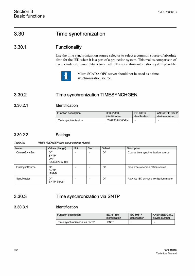
3.30 Time synchronization
3.30.1 FunctionalityUse the time synchronization source selector to select a common source of absolutetime for the IED when it is a part of a protection system. This makes comparison ofevents and disturbance data between all IEDs in a station automation system possible.
Micro SCADA OPC server should not be used as a timesynchronization source.
3.30.2 Time synchronization TIMESYNCHGEN
3.30.2.1 Identification
Function description IEC 61850identification
IEC 60617identification
ANSI/IEEE C37.2device number
Time synchronization TIMESYNCHGEN - -
3.30.2.2 Settings
Table 99: TIMESYNCHGEN Non group settings (basic)
Name Values (Range) Unit Step Default DescriptionCoarseSyncSrc Off
SNTPDNPIEC60870-5-103
- - Off Coarse time synchronization source
FineSyncSource OffSNTPIRIG-B
- - Off Fine time synchronization source
SyncMaster OffSNTP-Server
- - Off Activate IED as synchronization master
3.30.3 Time synchronization via SNTP
3.30.3.1 Identification
Function description IEC 61850identification
IEC 60617identification
ANSI/IEEE C37.2device number
Time synchronization via SNTP SNTP - -
Section 3 1MRS756508 BBasic functions
154 630 seriesTechnical Manual
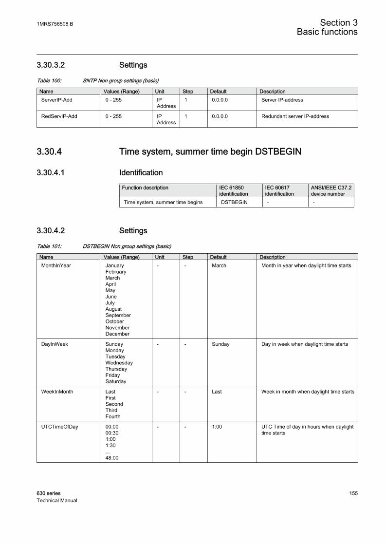
3.30.3.2 Settings
Table 100: SNTP Non group settings (basic)
Name Values (Range) Unit Step Default DescriptionServerIP-Add 0 - 255 IP
Address1 0.0.0.0 Server IP-address
RedServIP-Add 0 - 255 IPAddress
1 0.0.0.0 Redundant server IP-address
3.30.4 Time system, summer time begin DSTBEGIN
3.30.4.1 Identification
Function description IEC 61850identification
IEC 60617identification
ANSI/IEEE C37.2device number
Time system, summer time begins DSTBEGIN - -
3.30.4.2 Settings
Table 101: DSTBEGIN Non group settings (basic)
Name Values (Range) Unit Step Default DescriptionMonthInYear January
FebruaryMarchAprilMayJuneJulyAugustSeptemberOctoberNovemberDecember
- - March Month in year when daylight time starts
DayInWeek SundayMondayTuesdayWednesdayThursdayFridaySaturday
- - Sunday Day in week when daylight time starts
WeekInMonth LastFirstSecondThirdFourth
- - Last Week in month when daylight time starts
UTCTimeOfDay 00:0000:301:001:30...48:00
- - 1:00 UTC Time of day in hours when daylighttime starts
1MRS756508 B Section 3Basic functions
630 series 155Technical Manual

3.30.5 Time system, summer time ends DSTEND
3.30.5.1 Identification
Function description IEC 61850identification
IEC 60617identification
ANSI/IEEE C37.2device number
Time system, summer time ends DSTEND - -
3.30.5.2 Settings
Table 102: DSTEND Non group settings (basic)
Name Values (Range) Unit Step Default DescriptionMonthInYear January
FebruaryMarchAprilMayJuneJulyAugustSeptemberOctoberNovemberDecember
- - October Month in year when daylight time ends
DayInWeek SundayMondayTuesdayWednesdayThursdayFridaySaturday
- - Sunday Day in week when daylight time ends
WeekInMonth LastFirstSecondThirdFourth
- - Last Week in month when daylight time ends
UTCTimeOfDay 00:0000:301:001:30...48:00
- - 1:00 UTC Time of day in hours when daylighttime ends
3.30.6 Time zone from UTC TIMEZONE
3.30.6.1 Identification
Function description IEC 61850identification
IEC 60617identification
ANSI/IEEE C37.2device number
Time zone from UTC TIMEZONE - -
Section 3 1MRS756508 BBasic functions
156 630 seriesTechnical Manual

3.30.6.2 Settings
Table 103: TIMEZONE Non group settings (basic)
Name Values (Range) Unit Step Default DescriptionNoHalfHourUTC -24 - 24 - 1 0 Number of half-hours from UTC
3.30.7 Time synchronization via IRIG-B
3.30.7.1 Identification
Function description IEC 61850identification
IEC 60617identification
ANSI/IEEE C37.2device number
Time synchronization via IRIG-B IRIG-B - -
3.30.7.2 Settings
Table 104: IRIG-B Non group settings (basic)
Name Values (Range) Unit Step Default DescriptionTimeDomain LocalTime
UTC- - LocalTime Time domain
Encoding IRIG-B13441344TZ
- - IRIG-B Type of encoding
TimeZoneAs1344 MinusTZPlusTZ
- - PlusTZ Time zone as in 1344 standard
Use time synchronization to achieve a common time base for the IEDs in aprotection and control system. This makes comparison of events and disturbancedata between all IEDs in the system possible.
Time-tagging of internal events and disturbances are an excellent help whenevaluating faults. Without time synchronization, only the events within the IED canbe compared to one another. With time synchronization, events and disturbanceswithin the entire station, and even between line ends, can be compared at evaluation.
In the IED, the internal time can be synchronized from a number of sources:
• SNTP• IRIG-B• DNP• IEC60870-5-103
Micro SCADA OPC server should not be used as a timesynchronization source.
1MRS756508 B Section 3Basic functions
630 series 157Technical Manual
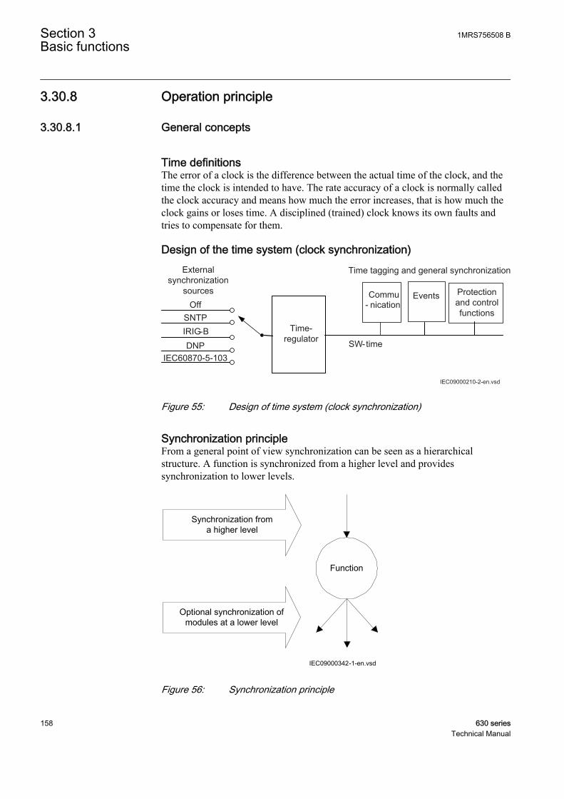
3.30.8 Operation principle
3.30.8.1 General concepts
Time definitionsThe error of a clock is the difference between the actual time of the clock, and thetime the clock is intended to have. The rate accuracy of a clock is normally calledthe clock accuracy and means how much the error increases, that is how much theclock gains or loses time. A disciplined (trained) clock knows its own faults andtries to compensate for them.
Design of the time system (clock synchronization)
SW-time
Protectionand control functions
Time tagging and general synchronization
Commu- nication
Events
IEC09000210-2-en.vsd
Externalsynchronization
sourcesOff
SNTP
DNPIRIG-B Time-
regulator
IEC60870-5-103
IEC09000210 V2 EN
Figure 55: Design of time system (clock synchronization)
Synchronization principleFrom a general point of view synchronization can be seen as a hierarchicalstructure. A function is synchronized from a higher level and providessynchronization to lower levels.
Function
Synchronization froma higher level
Optional synchronization of modules at a lower level
IEC09000342-1-en.vsdIEC09000342 V1 EN
Figure 56: Synchronization principle
Section 3 1MRS756508 BBasic functions
158 630 seriesTechnical Manual

A function is said to be synchronized when it periodically receives synchronizationmessages from a higher level. As the level decreases, the accuracy of thesynchronization decreases as well. A function can have several potential sources ofsynchronization, with different maximum errors, which give the function thepossibility to choose the source with the best quality, and to adjust its internal clockafter this source. The maximum error of a clock can be defined as:
• The maximum error of the last used synchronization message• The time since the last used synchronization message• The rate accuracy of the internal clock in the function.
3.30.8.2 Real-time clock (RTC) operation
The IED has a built-in real-time clock (RTC) with a resolution of one second. Theclock has a built-in calendar that handles leap years through 2038.
Real-time clock at power offDuring power off, the system time in the IED is kept by a capacitor-backed real-time clock that will provide 35 ppm accuracy for 5 days. This means that if thepower is off, the time in the IED may drift with 3 seconds per day, during 5 days,and after this time the time will be lost completely.
Real-time clock at startup
Time synchronization startup procedureThe first message that contains the full time (as for instance SNTP and IRIG-B)gives an accurate time to the IED. The IED is brought into a safe state and the timeis set to the correct value. After the initial setting of the clock, one of three thingshappens with each of the coming synchronization messages, configured as “fine”:
• If the synchronization message, which is similar to the other messages, fromits origin has an offset compared to the internal time in the IED, the message isused directly for synchronization, that is, for adjusting the internal clock toobtain zero offset at the next coming time message.
• If the synchronization message has an offset that is large compared to the othermessages, a spike-filter in the IED removes this time-message.
• If the synchronization message has an offset that is large, and the followingmessage also has a large offset, the spike filter does not act and the offset inthe synchronization message is compared to a threshold that defaults to 500milliseconds. If the offset is more than the threshold, the IED is brought into asafe state and the clock is set to the correct time. If the offset is lower than thethreshold, the clock is adjusted with 10 000 ppm until the offset is removed.With an adjustment of 10 000 ppm, it takes 50 seconds to remove an offset of500 milliseconds.
Synchronization messages configured as coarse are only used for initial setting ofthe time. After this has been done, the messages are checked against the internaltime and only an offset of more than 10 seconds resets the time.
1MRS756508 B Section 3Basic functions
630 series 159Technical Manual
Rate accuracyIn the IED, the rate accuracy at cold start is 100 ppm but if the IED is synchronizedfor a while, the rate accuracy is approximately 1 ppm if the surroundingtemperature is constant. Normally, it takes 20 minutes to reach full accuracy.
Time-out on synchronization sourcesAll synchronization interfaces has a time-out and a configured interface mustreceive time-messages regularly in order not to give an error signal (TSYNCERR).Normally, the time-out is set so that one message can be lost without getting aTSYNCERR, but if more than one message is lost, a TSYNCERR is given.
3.30.8.3 Synchronization alternatives
Two main alternatives of external time synchronization are available. Thesynchronization message is applied either via any of the communication ports ofthe IED as a telegram message including date and time or via IRIG-B.
Synchronization via SNTPSNTP provides a ping-pong method of synchronization. A message is sent from anIED to an SNTP server, and the SNTP server returns the message after filling in areception time and a transmission time. SNTP operates via the normal Ethernetnetwork that connects IEDs together in an IEC 61850 network. For SNTP tooperate properly, there must be an SNTP-server present, preferably in the samestation. The SNTP synchronization provides an accuracy that gives 1 ms accuracyfor binary inputs. The IED itself can be set as an SNTP-time server.
SNTP server requirementsThe SNTP server to be used is connected to the local network, that is not more than4-5 switches or routers away from the IED. The SNTP server is dedicated for itstask, or at least equipped with a real-time operating system, that is not a PC withSNTP server software. The SNTP server should be stable, that is, eithersynchronized from a stable source like GPS, or local without synchronization.Using a local SNTP server without synchronization as primary or secondary serverin a redundant configuration is not recommended.
Synchronization via IRIG-BThe DNP3 communication can be the source for the course time synchronization,while the fine time synchronization needs a source with higher accuracy. See thecommunication protocol manual for a detailed description of the DNP3 protocol.
IRIG-B is a protocol used only for time synchronization. A clock can provide localtime of the year in this format. The “B” in IRIG-B states that 100 bits per secondare transmitted, and the message is sent every second. After IRIG-B there numbersstating if and how the signal is modulated and the information transmitted.
To receive IRIG-B there are one dedicated connector for the IRIG-B port. IRIG-B00x messages can be supplied via the galvanic interface, where x (in 00x) means anumber in the range of 1-7.
Section 3 1MRS756508 BBasic functions
160 630 seriesTechnical Manual

If the x in 00x is 4, 5, 6 or 7, the time message from IRIG-B contains informationof the year. If x is 0, 1, 2 or 3, the information contains only the time within theyear, and year information has to come from the tool or local HMI.
The IRIG-B input also takes care of IEEE1344 messages that are sent by IRIG-Bclocks, as IRIG-B previously did not have any year information. IEEE1344 iscompatible with IRIG-B and contains year information and information of the time-zone.
It is recommended to use IEEE 1344 for supplying time information to the IRIG-Bmodule. In this case, send also the local time in the messages.
Synchronization via DNPThe DNP3 communication can be the source for the course time synchronization,while the fine time synchronization needs a source with higher accuracy. See thecommunication protocol manual for a detailed description of the DNP3 protocol.
Synchronization via IEC60870-5-103The IEC60870-5-103 communication can be the source for the course timesynchronization, while the fine time synchronization needs a source with higheraccuracy. See the communication protocol manual for a detailed description of theIEC60870-5-103 protocol.
3.30.9 Technical dataTable 105: Time synchronization, time tagging
Function ValueTime tagging resolution, events and sampled measurement values 1 ms
Time tagging error with synchronization once/min (minute pulsesynchronization), events and sampled measurement values
± 1.0 ms typically
Time tagging error with SNTP synchronization, sampledmeasurement values
± 1.0 ms typically
3.31 Denial of service
3.31.1 FunctionalityThe Denial of service functions (DOSLAN1 and DOSFRNT) are designed to limitoverload on the IED produced by heavy Ethernet network traffic. Thecommunication facilities must not be allowed to compromise the primaryfunctionality of the device. All inbound network traffic will be quota controlled sothat too heavy network loads can be controlled. Heavy network load might forinstance be the result of malfunctioning equipment connected to the network.
1MRS756508 B Section 3Basic functions
630 series 161Technical Manual
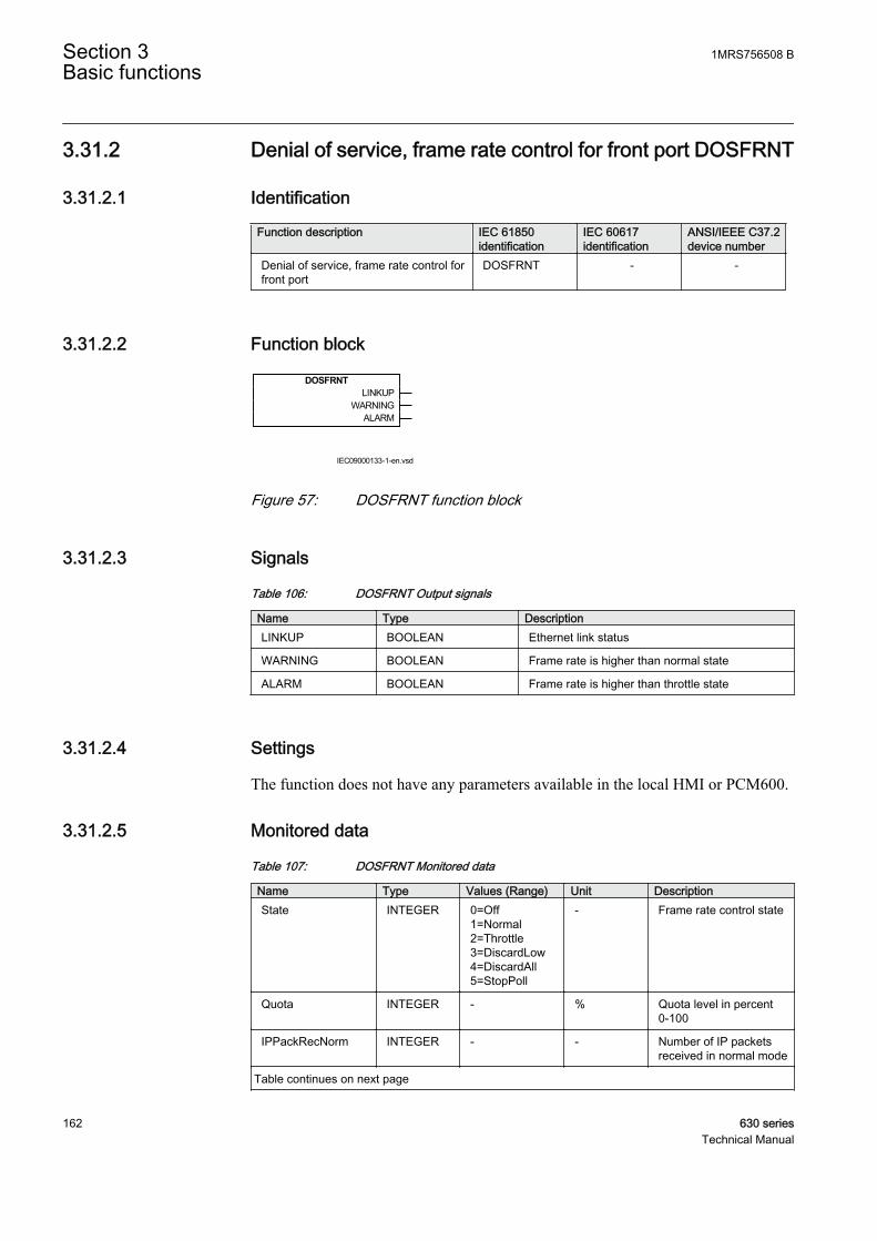
3.31.2 Denial of service, frame rate control for front port DOSFRNT
3.31.2.1 Identification
Function description IEC 61850identification
IEC 60617identification
ANSI/IEEE C37.2device number
Denial of service, frame rate control forfront port
DOSFRNT - -
3.31.2.2 Function block
DOSFRNTLINKUP
WARNINGALARM
IEC09000133-1-en.vsd
IEC09000133 V1 EN
Figure 57: DOSFRNT function block
3.31.2.3 Signals
Table 106: DOSFRNT Output signals
Name Type DescriptionLINKUP BOOLEAN Ethernet link status
WARNING BOOLEAN Frame rate is higher than normal state
ALARM BOOLEAN Frame rate is higher than throttle state
3.31.2.4 Settings
The function does not have any parameters available in the local HMI or PCM600.
3.31.2.5 Monitored data
Table 107: DOSFRNT Monitored data
Name Type Values (Range) Unit DescriptionState INTEGER 0=Off
1=Normal2=Throttle3=DiscardLow4=DiscardAll5=StopPoll
- Frame rate control state
Quota INTEGER - % Quota level in percent0-100
IPPackRecNorm INTEGER - - Number of IP packetsreceived in normal mode
Table continues on next page
Section 3 1MRS756508 BBasic functions
162 630 seriesTechnical Manual
Name Type Values (Range) Unit DescriptionIPPackRecPoll INTEGER - - Number of IP packets
received in polled mode
IPPackDisc INTEGER - - Number of IP packetsdiscarded
NonIPPackRecNorm INTEGER - - Number of non IPpackets received innormal mode
NonIPPackRecPoll INTEGER - - Number of non IPpackets received inpolled mode
NonIPPackDisc INTEGER - - Number of non IPpackets discarded
3.31.3 Denial of service, frame rate control for LAN1 port DOSLAN1
3.31.3.1 Identification
Function description IEC 61850identification
IEC 60617identification
ANSI/IEEE C37.2device number
Denial of service, frame rate control forLAN1 port
DOSLAN1 - -
3.31.3.2 Function block
DOSLAN1LINKUP
WARNINGALARM
IEC09000134-1-en.vsdIEC09000134 V1 EN
Figure 58: DOSLAN1 function block
3.31.3.3 Signals
Table 108: DOSLAN1 Output signals
Name Type DescriptionLINKUP BOOLEAN Ethernet link status
WARNING BOOLEAN Frame rate is higher than normal state
ALARM BOOLEAN Frame rate is higher than throttle state
3.31.3.4 Settings
The function does not have any parameters available in the local HMI or PCM600.
1MRS756508 B Section 3Basic functions
630 series 163Technical Manual
3.31.3.5 Monitored data
Table 109: DOSLAN1 Monitored data
Name Type Values (Range) Unit DescriptionState INTEGER 0=Off
1=Normal2=Throttle3=DiscardLow4=DiscardAll5=StopPoll
- Frame rate control state
Quota INTEGER - % Quota level in percent0-100
IPPackRecNorm INTEGER - - Number of IP packetsreceived in normal mode
IPPackRecPoll INTEGER - - Number of IP packetsreceived in polled mode
IPPackDisc INTEGER - - Number of IP packetsdiscarded
NonIPPackRecNorm INTEGER - - Number of non IPpackets received innormal mode
NonIPPackRecPoll INTEGER - - Number of non IPpackets received inpolled mode
NonIPPackDisc INTEGER - - Number of non IPpackets discarded
3.31.4 Operation principleThe Denial of service functions (DOSLAN1 and DOSFRNT) measures the IEDload from communication and, if necessary, limit it for not jeopardizing the IEDscontrol and protection functionality due to high CPU load. The function has thefollowing outputs:
• LINKUP indicates the Ethernet link status• WARNING indicates that communication (frame rate) is higher than normal• ALARM indicates that the IED limits communication
3.32 IEC 61850-8-1 communication protocol
3.32.1 IdentificationFunction description IEC 61850
identificationIEC 60617identification
ANSI/IEEE C37.2device number
IEC 61850-8-1 communication protocol IEC 61850-8-1 - -
Section 3 1MRS756508 BBasic functions
164 630 seriesTechnical Manual
3.32.2 FunctionalityIEC 61850-8-1 protocol allows intelligent electrical devices (IEDs) from differentvendors to exchange information and simplifies system engineering. Peer-to-peercommunication according to GOOSE is part of the standard. Disturbance filesuploading is provided.
The event system has a rate limiter to reduce CPU load. Each channel has a quotaof 10 events/second. If the quota is exceeded the event channel is blocked until theevent changes is below the quota.
3.32.3 SettingsTable 110: IEC61850-8-1 Non group settings (basic)
Name Values (Range) Unit Step Default DescriptionOperation Off
On- - On Operation Off/On
3.32.4 ApplicationIEC 61850-8-1 communication protocol allows vertical communication to HSIclients and allows horizontal communication between two or more intelligentelectronic devices (IEDs) from one or several vendors to exchange information andto use it in the performance of their functions and for correct co-operation.
GOOSE (Generic Object Oriented Substation Event), which is a part of IEC 61850–8–1 standard, allows the IEDs to communicate state and control informationamongst themselves, using a publish-subscribe mechanism. That is, upon detectingan event, the IED(s) use a multi-cast transmission to notify those devices that haveregistered to receive the data. An IED can, by publishing a GOOSE message,report it's status. It can also request a control action to be directed at any device inthe network.
Figure 59 shows the topology of an IEC 61850–8–1 configuration. IEC 61850–8–1specifies only the interface to the substation LAN. The LAN itself is left to thesystem integrator.
1MRS756508 B Section 3Basic functions
630 series 165Technical Manual

KIOSK 2 KIOSK 3
Station HSIBase System
EngineeringWorkstation
SMSGateway
Printer
CC
IEC09000135_en.vsd
KIOSK 1
IED 1
IED 2
IED 3
IED 1
IED 2
IED 3
IED 1
IED 2
IED 3
IEC09000135 V1 EN
Figure 59: Example of a communication system with IEC 61850
Figure 60 shows the GOOSE peer-to-peer communication.
Control Protection Control ProtectionControl and protection
GOOSE
en05000734.vsd
Station HSIMicroSCADA
Gateway
IEDA
IEDA
IEDA
IEDA
IEDA
IEC05000734 V1 EN
Figure 60: Example of a broadcasted GOOSE message
Section 3 1MRS756508 BBasic functions
166 630 seriesTechnical Manual
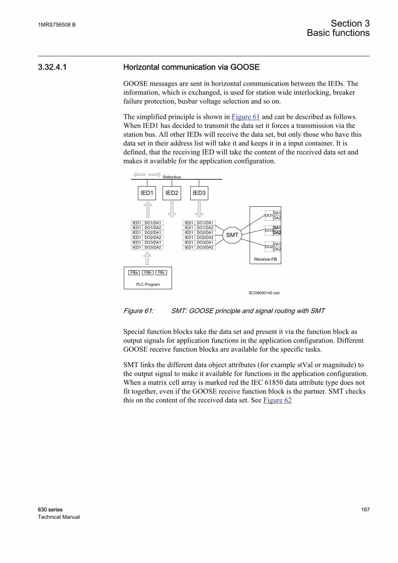
3.32.4.1 Horizontal communication via GOOSE
GOOSE messages are sent in horizontal communication between the IEDs. Theinformation, which is exchanged, is used for station wide interlocking, breakerfailure protection, busbar voltage selection and so on.
The simplified principle is shown in Figure 61 and can be described as follows.When IED1 has decided to transmit the data set it forces a transmission via thestation bus. All other IEDs will receive the data set, but only those who have thisdata set in their address list will take it and keeps it in a input container. It isdefined, that the receiving IED will take the content of the received data set andmakes it available for the application configuration.
IEC08000145.vsd
IED1 IED3IED2
DO1/DA1DO1/DA2DO2/DA1DO2/DA2DO3/DA1DO3/DA2
IED1IED1IED1IED1IED1IED1
SMT
Receive-FB
DA1DA2DO1
DA1DA2DA1DA2DO3
DA1DA2DO2
Stationbus
DO1/DA1DO1/DA2DO2/DA1DO2/DA2DO3/DA1DO3/DA2
IED1IED1IED1IED1IED1IED1
PLC Program
FBa FBb FBc
IEC08000145 V1 EN
Figure 61: SMT: GOOSE principle and signal routing with SMT
Special function blocks take the data set and present it via the function block asoutput signals for application functions in the application configuration. DifferentGOOSE receive function blocks are available for the specific tasks.
SMT links the different data object attributes (for example stVal or magnitude) tothe output signal to make it available for functions in the application configuration.When a matrix cell array is marked red the IEC 61850 data attribute type does notfit together, even if the GOOSE receive function block is the partner. SMT checksthis on the content of the received data set. See Figure 62
1MRS756508 B Section 3Basic functions
630 series 167Technical Manual

IEC08000174.vsdIEC08000174 V1 EN
Figure 62: SMT: GOOSE marshalling with SMT
GOOSE receive function blocks extract process information, received by the dataset, into single attribute information that can be used within the applicationconfiguration. Crosses in the SMT matrix connect received values to the respectivefunction block signal in SMT, see Figure 63
The corresponding quality attribute is automatically connected bySMT. This quality attribute is available in ACT, through the outputsof the available GOOSE function blocks.
Section 3 1MRS756508 BBasic functions
168 630 seriesTechnical Manual
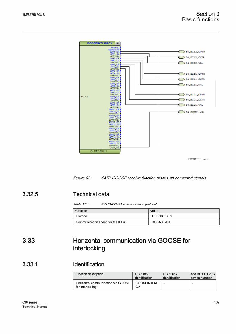
IEC08000171_1_en.vsd
IEC08000171 V1 EN
Figure 63: SMT: GOOSE receive function block with converted signals
3.32.5 Technical dataTable 111: IEC 61850-8-1 communication protocol
Function ValueProtocol IEC 61850-8-1
Communication speed for the IEDs 100BASE-FX
3.33 Horizontal communication via GOOSE forinterlocking
3.33.1 IdentificationFunction description IEC 61850
identificationIEC 60617identification
ANSI/IEEE C37.2device number
Horizontal communication via GOOSEfor interlocking
GOOSEINTLKRCV
- -
1MRS756508 B Section 3Basic functions
630 series 169Technical Manual

3.33.2 Function blockGOOSEINTLKRCV
BLOCK ^RESREQ^RESGRANT
^APP1_OP^APP1_CLAPP1VAL
^APP2_OP^APP2_CLAPP2VAL
^APP3_OP^APP3_CLAPP3VAL
^APP4_OP^APP4_CLAPP4VAL
^APP5_OP^APP5_CLAPP5VAL
^APP6_OP^APP6_CLAPP6VAL
^APP7_OP^APP7_CLAPP7VAL
^APP8_OP^APP8_CLAPP8VAL
^APP9_OP^APP9_CLAPP9VAL
^APP10_OP^APP10_CLAPP10VAL
^APP11_OP^APP11_CLAPP11VAL
^APP12_OP^APP12_CLAPP12VAL
^APP13_OP^APP13_CLAPP13VAL
^APP14_OP^APP14_CLAPP14VAL
^APP15_OP^APP15_CLAPP15VALCOM_VAL
IEC09000099_1_en.vsdIEC09000099 V1 EN
Figure 64: GOOSEINTLKRCV function block
3.33.3 SignalsTable 112: GOOSEINTLKRCV Input signals
Name Type Default DescriptionBLOCK BOOLEAN 0 Block of output signals
Section 3 1MRS756508 BBasic functions
170 630 seriesTechnical Manual
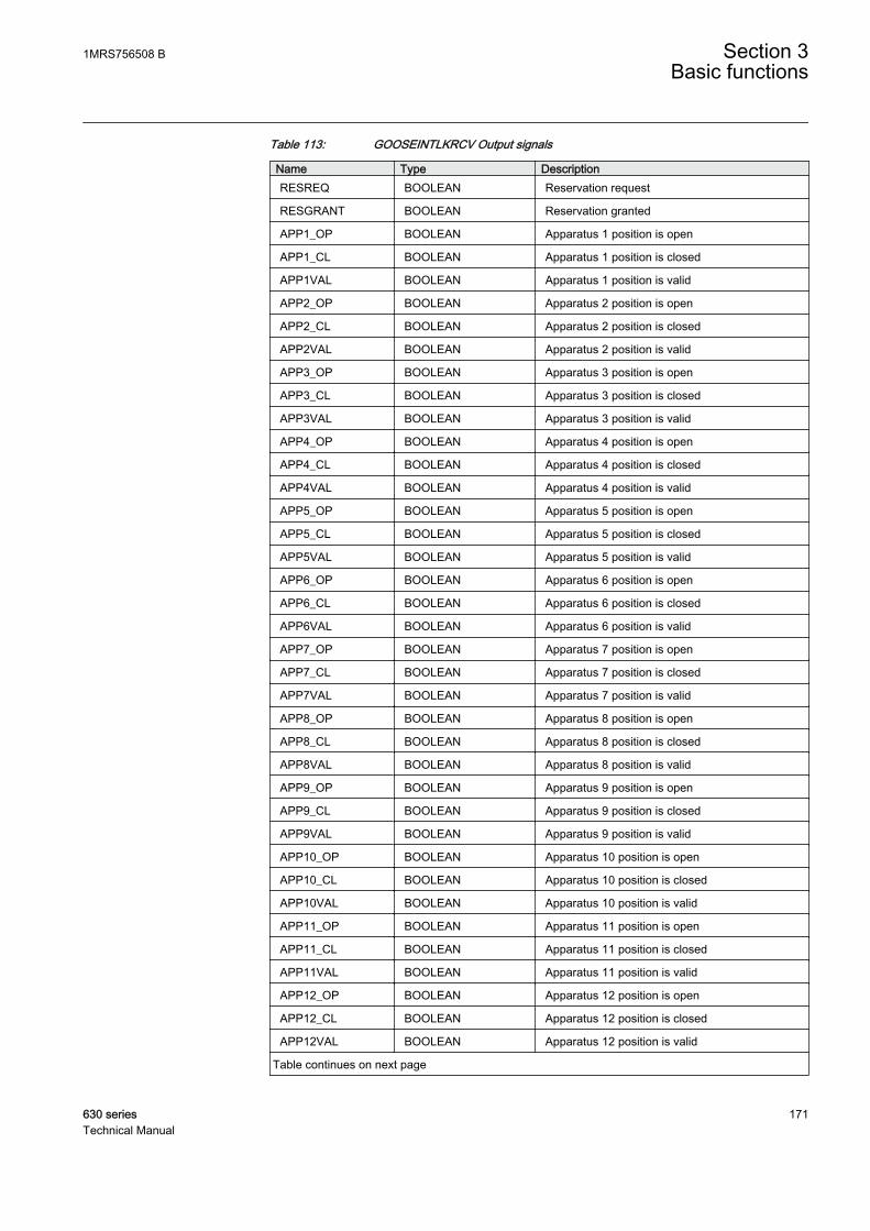
Table 113: GOOSEINTLKRCV Output signals
Name Type DescriptionRESREQ BOOLEAN Reservation request
RESGRANT BOOLEAN Reservation granted
APP1_OP BOOLEAN Apparatus 1 position is open
APP1_CL BOOLEAN Apparatus 1 position is closed
APP1VAL BOOLEAN Apparatus 1 position is valid
APP2_OP BOOLEAN Apparatus 2 position is open
APP2_CL BOOLEAN Apparatus 2 position is closed
APP2VAL BOOLEAN Apparatus 2 position is valid
APP3_OP BOOLEAN Apparatus 3 position is open
APP3_CL BOOLEAN Apparatus 3 position is closed
APP3VAL BOOLEAN Apparatus 3 position is valid
APP4_OP BOOLEAN Apparatus 4 position is open
APP4_CL BOOLEAN Apparatus 4 position is closed
APP4VAL BOOLEAN Apparatus 4 position is valid
APP5_OP BOOLEAN Apparatus 5 position is open
APP5_CL BOOLEAN Apparatus 5 position is closed
APP5VAL BOOLEAN Apparatus 5 position is valid
APP6_OP BOOLEAN Apparatus 6 position is open
APP6_CL BOOLEAN Apparatus 6 position is closed
APP6VAL BOOLEAN Apparatus 6 position is valid
APP7_OP BOOLEAN Apparatus 7 position is open
APP7_CL BOOLEAN Apparatus 7 position is closed
APP7VAL BOOLEAN Apparatus 7 position is valid
APP8_OP BOOLEAN Apparatus 8 position is open
APP8_CL BOOLEAN Apparatus 8 position is closed
APP8VAL BOOLEAN Apparatus 8 position is valid
APP9_OP BOOLEAN Apparatus 9 position is open
APP9_CL BOOLEAN Apparatus 9 position is closed
APP9VAL BOOLEAN Apparatus 9 position is valid
APP10_OP BOOLEAN Apparatus 10 position is open
APP10_CL BOOLEAN Apparatus 10 position is closed
APP10VAL BOOLEAN Apparatus 10 position is valid
APP11_OP BOOLEAN Apparatus 11 position is open
APP11_CL BOOLEAN Apparatus 11 position is closed
APP11VAL BOOLEAN Apparatus 11 position is valid
APP12_OP BOOLEAN Apparatus 12 position is open
APP12_CL BOOLEAN Apparatus 12 position is closed
APP12VAL BOOLEAN Apparatus 12 position is valid
Table continues on next page
1MRS756508 B Section 3Basic functions
630 series 171Technical Manual

Name Type DescriptionAPP13_OP BOOLEAN Apparatus 13 position is open
APP13_CL BOOLEAN Apparatus 13 position is closed
APP13VAL BOOLEAN Apparatus 13 position is valid
APP14_OP BOOLEAN Apparatus 14 position is open
APP14_CL BOOLEAN Apparatus 14 position is closed
APP14VAL BOOLEAN Apparatus 14 position is valid
APP15_OP BOOLEAN Apparatus 15 position is open
APP15_CL BOOLEAN Apparatus 15 position is closed
APP15VAL BOOLEAN Apparatus 15 position is valid
COM_VAL BOOLEAN Receive communication status is valid
3.33.4 SettingsTable 114: GOOSEINTLKRCV Non group settings (basic)
Name Values (Range) Unit Step Default DescriptionOperation Off
On- - Off Operation Off/On
3.34 Goose binary receive GOOSEBINRCV
3.34.1 IdentificationFunction description IEC 61850
identificationIEC 60617identification
ANSI/IEEE C37.2device number
Goose binary receive GOOSEBINRCV - -
Section 3 1MRS756508 BBasic functions
172 630 seriesTechnical Manual
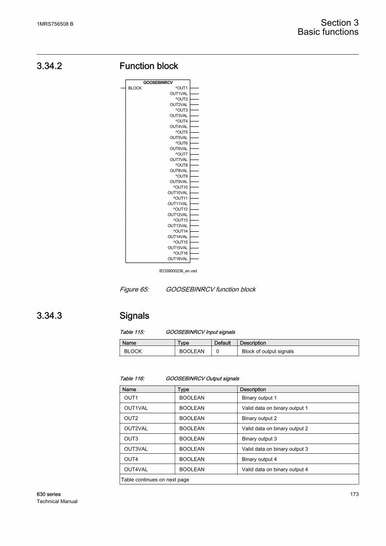
3.34.2 Function blockGOOSEBINRCV
BLOCK ^OUT1OUT1VAL
^OUT2OUT2VAL
^OUT3OUT3VAL
^OUT4OUT4VAL
^OUT5OUT5VAL
^OUT6OUT6VAL
^OUT7OUT7VAL
^OUT8OUT8VAL
^OUT9OUT9VAL
^OUT10OUT10VAL
^OUT11OUT11VAL
^OUT12OUT12VAL
^OUT13OUT13VAL
^OUT14OUT14VAL
^OUT15OUT15VAL
^OUT16OUT16VAL
IEC09000236_en.vsdIEC09000236 V1 EN
Figure 65: GOOSEBINRCV function block
3.34.3 SignalsTable 115: GOOSEBINRCV Input signals
Name Type Default DescriptionBLOCK BOOLEAN 0 Block of output signals
Table 116: GOOSEBINRCV Output signals
Name Type DescriptionOUT1 BOOLEAN Binary output 1
OUT1VAL BOOLEAN Valid data on binary output 1
OUT2 BOOLEAN Binary output 2
OUT2VAL BOOLEAN Valid data on binary output 2
OUT3 BOOLEAN Binary output 3
OUT3VAL BOOLEAN Valid data on binary output 3
OUT4 BOOLEAN Binary output 4
OUT4VAL BOOLEAN Valid data on binary output 4
Table continues on next page
1MRS756508 B Section 3Basic functions
630 series 173Technical Manual
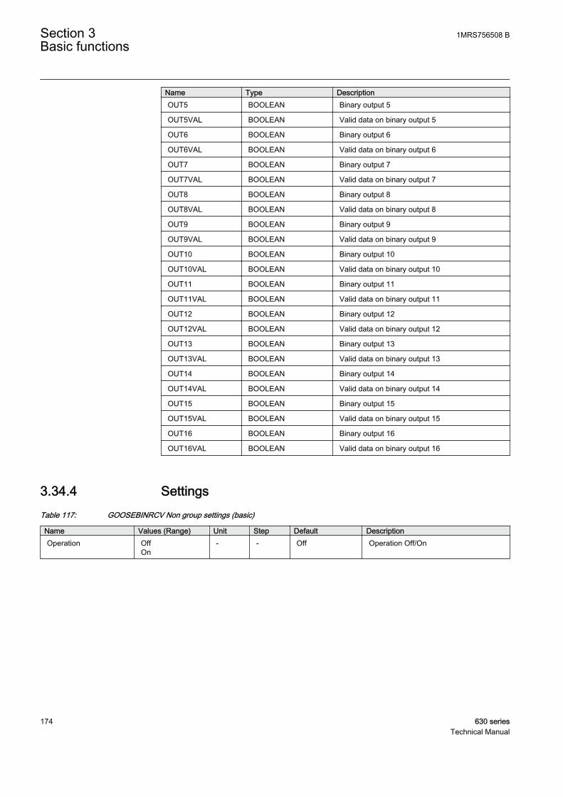
Name Type DescriptionOUT5 BOOLEAN Binary output 5
OUT5VAL BOOLEAN Valid data on binary output 5
OUT6 BOOLEAN Binary output 6
OUT6VAL BOOLEAN Valid data on binary output 6
OUT7 BOOLEAN Binary output 7
OUT7VAL BOOLEAN Valid data on binary output 7
OUT8 BOOLEAN Binary output 8
OUT8VAL BOOLEAN Valid data on binary output 8
OUT9 BOOLEAN Binary output 9
OUT9VAL BOOLEAN Valid data on binary output 9
OUT10 BOOLEAN Binary output 10
OUT10VAL BOOLEAN Valid data on binary output 10
OUT11 BOOLEAN Binary output 11
OUT11VAL BOOLEAN Valid data on binary output 11
OUT12 BOOLEAN Binary output 12
OUT12VAL BOOLEAN Valid data on binary output 12
OUT13 BOOLEAN Binary output 13
OUT13VAL BOOLEAN Valid data on binary output 13
OUT14 BOOLEAN Binary output 14
OUT14VAL BOOLEAN Valid data on binary output 14
OUT15 BOOLEAN Binary output 15
OUT15VAL BOOLEAN Valid data on binary output 15
OUT16 BOOLEAN Binary output 16
OUT16VAL BOOLEAN Valid data on binary output 16
3.34.4 SettingsTable 117: GOOSEBINRCV Non group settings (basic)
Name Values (Range) Unit Step Default DescriptionOperation Off
On- - Off Operation Off/On
Section 3 1MRS756508 BBasic functions
174 630 seriesTechnical Manual
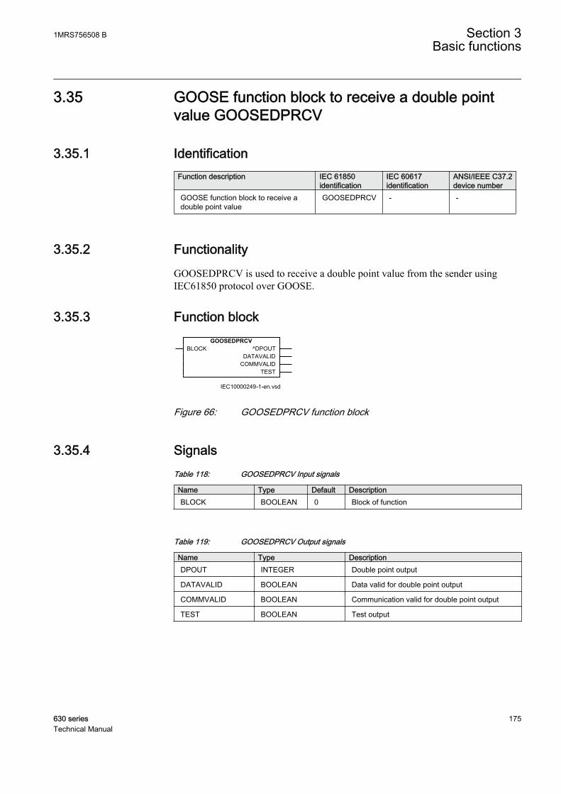
3.35 GOOSE function block to receive a double pointvalue GOOSEDPRCV
3.35.1 IdentificationFunction description IEC 61850
identificationIEC 60617identification
ANSI/IEEE C37.2device number
GOOSE function block to receive adouble point value
GOOSEDPRCV - -
3.35.2 FunctionalityGOOSEDPRCV is used to receive a double point value from the sender usingIEC61850 protocol over GOOSE.
3.35.3 Function block
IEC10000249-1-en.vsd
GOOSEDPRCVBLOCK ^DPOUT
DATAVALIDCOMMVALID
TEST
IEC10000249 V1 EN
Figure 66: GOOSEDPRCV function block
3.35.4 SignalsTable 118: GOOSEDPRCV Input signals
Name Type Default DescriptionBLOCK BOOLEAN 0 Block of function
Table 119: GOOSEDPRCV Output signals
Name Type DescriptionDPOUT INTEGER Double point output
DATAVALID BOOLEAN Data valid for double point output
COMMVALID BOOLEAN Communication valid for double point output
TEST BOOLEAN Test output
1MRS756508 B Section 3Basic functions
630 series 175Technical Manual
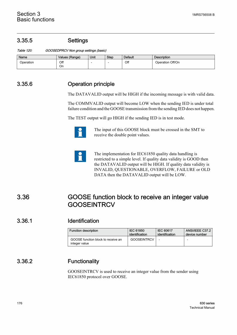
3.35.5 SettingsTable 120: GOOSEDPRCV Non group settings (basic)
Name Values (Range) Unit Step Default DescriptionOperation Off
On- - Off Operation Off/On
3.35.6 Operation principleThe DATAVALID output will be HIGH if the incoming message is with valid data.
The COMMVALID output will become LOW when the sending IED is under totalfailure condition and the GOOSE transmission from the sending IED does not happen.
The TEST output will go HIGH if the sending IED is in test mode.
The input of this GOOSE block must be crossed in the SMT toreceive the double point values.
The implementation for IEC61850 quality data handling isrestricted to a simple level. If quality data validity is GOOD thenthe DATAVALID output will be HIGH. If quality data validity isINVALID, QUESTIONABLE, OVERFLOW, FAILURE or OLDDATA then the DATAVALID output will be LOW.
3.36 GOOSE function block to receive an integer valueGOOSEINTRCV
3.36.1 IdentificationFunction description IEC 61850
identificationIEC 60617identification
ANSI/IEEE C37.2device number
GOOSE function block to receive aninteger value
GOOSEINTRCV - -
3.36.2 FunctionalityGOOSEINTRCV is used to receive an integer value from the sender usingIEC61850 protocol over GOOSE.
Section 3 1MRS756508 BBasic functions
176 630 seriesTechnical Manual
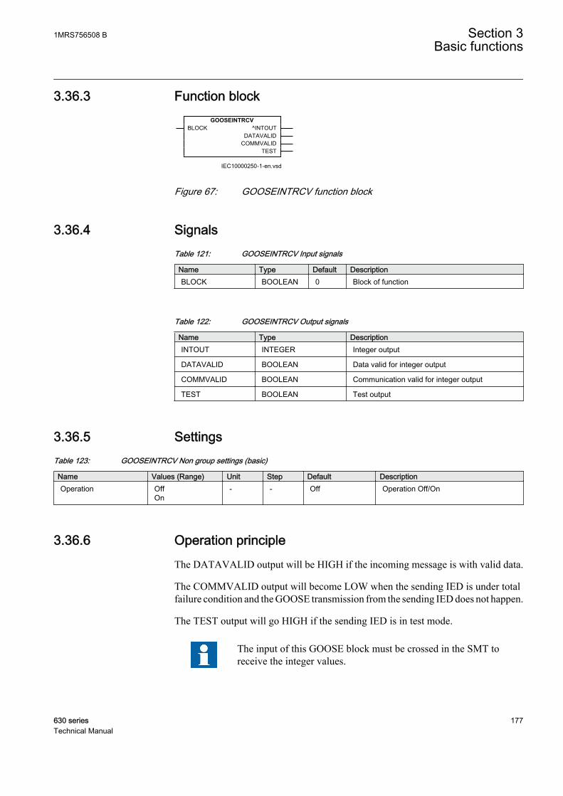
3.36.3 Function block
IEC10000250-1-en.vsd
GOOSEINTRCVBLOCK ^INTOUT
DATAVALIDCOMMVALID
TEST
IEC10000250 V1 EN
Figure 67: GOOSEINTRCV function block
3.36.4 SignalsTable 121: GOOSEINTRCV Input signals
Name Type Default DescriptionBLOCK BOOLEAN 0 Block of function
Table 122: GOOSEINTRCV Output signals
Name Type DescriptionINTOUT INTEGER Integer output
DATAVALID BOOLEAN Data valid for integer output
COMMVALID BOOLEAN Communication valid for integer output
TEST BOOLEAN Test output
3.36.5 SettingsTable 123: GOOSEINTRCV Non group settings (basic)
Name Values (Range) Unit Step Default DescriptionOperation Off
On- - Off Operation Off/On
3.36.6 Operation principleThe DATAVALID output will be HIGH if the incoming message is with valid data.
The COMMVALID output will become LOW when the sending IED is under totalfailure condition and the GOOSE transmission from the sending IED does not happen.
The TEST output will go HIGH if the sending IED is in test mode.
The input of this GOOSE block must be crossed in the SMT toreceive the integer values.
1MRS756508 B Section 3Basic functions
630 series 177Technical Manual
The implementation for IEC61850 quality data handling isrestricted to a simple level. If quality data validity is GOOD thenthe DATAVALID output will be HIGH. If quality data validity isINVALID, QUESTIONABLE, OVERFLOW, FAILURE or OLDDATA then the DATAVALID output will be LOW.
3.37 GOOSE function block to receive a measurandvalue GOOSEMVRCV
3.37.1 IdentificationFunction description IEC 61850
identificationIEC 60617identification
ANSI/IEEE C37.2device number
GOOSE function block to receive ameasurand value
GOOSEMVRCV - -
3.37.2 FunctionalityGOOSEMVRCV is used to receive measured value from the sender usingIEC61850 protocol over GOOSE.
3.37.3 Function block
IEC10000251-1-en.vsd
GOOSEMVRCVBLOCK ^MVOUT
DATAVALIDCOMMVALID
TEST
IEC10000251 V1 EN
Figure 68: GOOSEMVRCV function block
3.37.4 SignalsTable 124: GOOSEMVRCV Input signals
Name Type Default DescriptionBLOCK BOOLEAN 0 Block of function
Section 3 1MRS756508 BBasic functions
178 630 seriesTechnical Manual

Table 125: GOOSEMVRCV Output signals
Name Type DescriptionMVOUT REAL Measurand value output
DATAVALID BOOLEAN Data valid for measurand value output
COMMVALID BOOLEAN Communication valid for measurand value output
TEST BOOLEAN Test output
3.37.5 SettingsTable 126: GOOSEMVRCV Non group settings (basic)
Name Values (Range) Unit Step Default DescriptionOperation Off
On- - Off Operation Off/On
3.37.6 Operation principleThe DATAVALID output will be HIGH if the incoming message is with valid data.
The COMMVALID output will become LOW when the sending IED is under totalfailure condition and the GOOSE transmission from the sending IED does not happen.
The TEST output will go HIGH if the sending IED is in test mode.
The input of this GOOSE block must be crossed in the SMT toreceive the float values.
The implementation for IEC61850 quality data handling isrestricted to a simple level. If quality data validity is GOOD thenthe DATAVALID output will be HIGH. If quality data validity isINVALID, QUESTIONABLE, OVERFLOW, FAILURE or OLDDATA then the DATAVALID output will be LOW.
3.38 GOOSE function block to receive a single pointvalue GOOSESPRCV
3.38.1 IdentificationFunction description IEC 61850
identificationIEC 60617identification
ANSI/IEEE C37.2device number
GOOSE function block to receive asingle point value
GOOSESPRCV - -
1MRS756508 B Section 3Basic functions
630 series 179Technical Manual

3.38.2 FunctionalityGOOSESPRCV is used to receive a single point value from the sender usingIEC61850 protocol over GOOSE.
3.38.3 Function blockGOOSESPRCV
BLOCK ^SPOUTDATAVALID
COMMVALIDTEST
IEC10000248-1-en.vsdIEC10000248 V1 EN
Figure 69: GOOSESPRCV function block
3.38.4 SignalsTable 127: GOOSESPRCV Input signals
Name Type Default DescriptionBLOCK BOOLEAN 0 Block of function
Table 128: GOOSESPRCV Output signals
Name Type DescriptionSPOUT BOOLEAN Single point output
DATAVALID BOOLEAN Data valid for single point output
COMMVALID BOOLEAN Communication valid for single point output
TEST BOOLEAN Test output
3.38.5 SettingsTable 129: GOOSESPRCV Non group settings (basic)
Name Values (Range) Unit Step Default DescriptionOperation Off
On- - Off Operation Off/On
3.38.6 Operation principleThe DATAVALID output will be HIGH if the incoming message is with valid data.
The COMMVALID output will become LOW when the sending IED is under totalfailure condition and the GOOSE transmission from the sending IED does not happen.
The TEST output will go HIGH if the sending IED is in test mode.
Section 3 1MRS756508 BBasic functions
180 630 seriesTechnical Manual
The input of this GOOSE block must be crossed in the SMT toreceive the binary single point values.
The implementation for IEC61850 quality data handling isrestricted to a simple level. If quality data validity is GOOD thenthe DATAVALID output will be HIGH. If quality data validity isINVALID, QUESTIONABLE, OVERFLOW, FAILURE or OLDDATA then the DATAVALID output will be LOW.
3.39 IEC 61850 generic communication I/O functionsSPGGIO
3.39.1 IdentificationFunction description IEC 61850
identificationIEC 60617identification
ANSI/IEEE C37.2device number
IEC 61850 generic communication I/Ofunctions
SPGGIO - -
3.39.2 FunctionalityIEC61850 generic communication I/O functions (SPGGIO) is used to send onesingle logical signal to other systems or equipment in the substation.
3.39.3 Function blockSPGGIO
BLOCK^IN
IEC09000237_en_1.vsdIEC09000237 V1 EN
Figure 70: SPGGIO function block
3.39.4 SignalsTable 130: SPGGIO Input signals
Name Type Default DescriptionBLOCK BOOLEAN 0 Block of function
IN BOOLEAN 0 Input status
1MRS756508 B Section 3Basic functions
630 series 181Technical Manual
3.39.5 SettingsThe function does not have any parameters available in Local HMI or Protectionand Control IED Manager (PCM600).
3.39.6 ApplicationIEC 61850 generic communication I/O functions (SPGGIO) function is used tosend one single logical output to other systems or equipment in the substation. Ithas one visible input, that should be connected in ACT tool.
3.39.7 Operation principleUpon receiving a signal at its input, IEC61850 generic communication I/Ofunctions (SPGGIO) function sends the signal over IEC 61850-8-1 to theequipment or system that requests this signal. To get the signal, PCM600 must beused to define which function block in which equipment or system should receivethis information.
3.40 IEC 61850 generic communication I/O functionsMVGGIO
3.40.1 IdentificationFunction description IEC 61850
identificationIEC 60617identification
ANSI/IEEE C37.2device number
IEC 61850 generic communication I/Ofunctions
MVGGIO - -
3.40.2 FunctionalityIEC61850 generic communication I/O functions (MVGGIO) function is used tosend the instantaneous value of an analog output to other systems or equipment inthe substation. It can also be used inside the same IED, to attach a RANGE aspectto an analog value and to permit measurement supervision on that value.
3.40.3 Function blockMVGGIO
BLOCKIN
VALUERANGE
IEC09000239_en.vsd
Section 3 1MRS756508 BBasic functions
182 630 seriesTechnical Manual
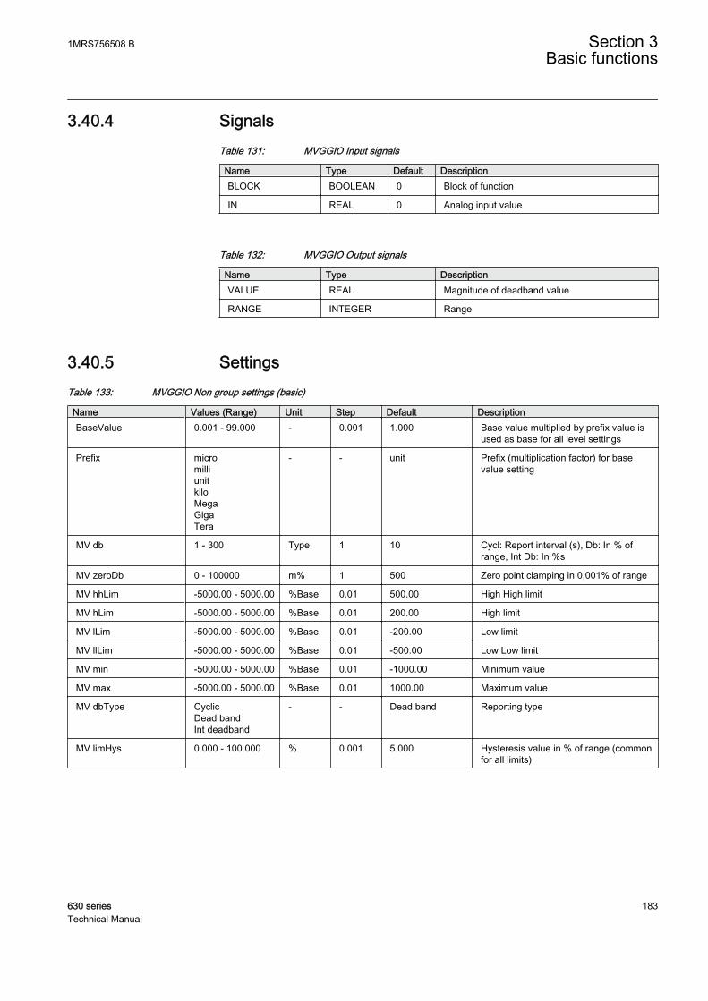
3.40.4 SignalsTable 131: MVGGIO Input signals
Name Type Default DescriptionBLOCK BOOLEAN 0 Block of function
IN REAL 0 Analog input value
Table 132: MVGGIO Output signals
Name Type DescriptionVALUE REAL Magnitude of deadband value
RANGE INTEGER Range
3.40.5 SettingsTable 133: MVGGIO Non group settings (basic)
Name Values (Range) Unit Step Default DescriptionBaseValue 0.001 - 99.000 - 0.001 1.000 Base value multiplied by prefix value is
used as base for all level settings
Prefix micromilliunitkiloMegaGigaTera
- - unit Prefix (multiplication factor) for basevalue setting
MV db 1 - 300 Type 1 10 Cycl: Report interval (s), Db: In % ofrange, Int Db: In %s
MV zeroDb 0 - 100000 m% 1 500 Zero point clamping in 0,001% of range
MV hhLim -5000.00 - 5000.00 %Base 0.01 500.00 High High limit
MV hLim -5000.00 - 5000.00 %Base 0.01 200.00 High limit
MV lLim -5000.00 - 5000.00 %Base 0.01 -200.00 Low limit
MV llLim -5000.00 - 5000.00 %Base 0.01 -500.00 Low Low limit
MV min -5000.00 - 5000.00 %Base 0.01 -1000.00 Minimum value
MV max -5000.00 - 5000.00 %Base 0.01 1000.00 Maximum value
MV dbType CyclicDead bandInt deadband
- - Dead band Reporting type
MV limHys 0.000 - 100.000 % 0.001 5.000 Hysteresis value in % of range (commonfor all limits)
1MRS756508 B Section 3Basic functions
630 series 183Technical Manual

3.40.6 Monitored dataTable 134: MVGGIO Monitored data
Name Type Values (Range) Unit DescriptionVALUE REAL - - Magnitude of deadband
value
RANGE INTEGER 0=Normal1=High2=Low3=High-High4=Low-Low
- Range
3.40.7 FunctionalityIEC61850 generic communication I/O functions (MVGGIO) function is used tosend the instantaneous value of an analog output to other systems or equipment inthe substation. It can also be used inside the same IED, to attach a RANGE aspectto an analog value and to permit measurement supervision on that value.
3.40.8 Operation principleUpon receiving an analog signal at its input, IEC61850 generic communication I/Ofunctions (MVGGIO) will give the instantaneous value of the signal and the range,as output values. In the same time, it will send over IEC 61850-8-1 the value, toother IEC 61850 clients in the substation.
3.41 IEC 60870-5-103 communication protocol
IEC 60870-5-103 is an unbalanced (master-slave) protocol for coded-bit serialcommunication exchanging information with a control system, and with a datatransfer rate up to 38400 bit/s. In IEC terminology, a primary station is a masterand a secondary station is a slave. The communication is based on a point-to-pointprinciple. The master must have software that can interpret IEC 60870-5-103communication messages.
Function blocks available for the IEC 60870–5–103 protocol are described in Basicfunctions section.The Communication protocol manual for IEC 60870-5-103includes the 630 series vendor specific IEC 60870-5-103 implementation.
Section 3 1MRS756508 BBasic functions
184 630 seriesTechnical Manual
3.41.1 SettingsTable 135: IEC60870-5-103 Non group settings (basic)
Name Values (Range) Unit Step Default DescriptionOperation Off
On- - Off Operation
SlaveAddress 1 - 31 - 1 1 Slave address
BaudRate 9600 Bd19200 Bd
- - 9600 Bd Baudrate on serial line
RevPolarity OffOn
- - On Invert polarity
CycMeasRepTime 1.0 - 1800.0 s 0.1 5.0 Cyclic reporting time of measurments
MasterTimeDomain UTCLocalLocal with DST
- - UTC Master time domain
TimeSyncMode IEDTimeLinMastTimeIEDTimeSkew
- - IEDTime Time synchronization mode
EvalTimeAccuracy 5ms10ms20ms40msOff
- - 5ms Evaluate time accuracy for invalid time
EventRepMode SeqOfEventHiPriSpont
- - SeqOfEvent Event reporting mode
3.42 Function commands for IEC 60870-5-103 I103CMD
3.42.1 FunctionalityI103CMD is a command function block in control direction with pre-definedoutput signals.
3.42.2 Function block
IEC10000282-1-en.vsd
I103CMDBLOCK 16-AR
17-DIFF18-PROT
IEC10000282 V1 EN
Figure 71: I103CMD function block
1MRS756508 B Section 3Basic functions
630 series 185Technical Manual
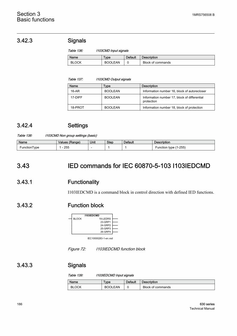
3.42.3 SignalsTable 136: I103CMD Input signals
Name Type Default DescriptionBLOCK BOOLEAN 0 Block of commands
Table 137: I103CMD Output signals
Name Type Description16-AR BOOLEAN Information number 16, block of autorecloser
17-DIFF BOOLEAN Information number 17, block of differentialprotection
18-PROT BOOLEAN Information number 18, block of protection
3.42.4 SettingsTable 138: I103CMD Non group settings (basic)
Name Values (Range) Unit Step Default DescriptionFunctionType 1 - 255 - 1 1 Function type (1-255)
3.43 IED commands for IEC 60870-5-103 I103IEDCMD
3.43.1 FunctionalityI103IEDCMD is a command block in control direction with defined IED functions.
3.43.2 Function block
IEC10000283-1-en.vsd
I103IEDCMDBLOCK 19-LEDRS
23-GRP124-GRP225-GRP326-GRP4
IEC10000283 V1 EN
Figure 72: I103IEDCMD function block
3.43.3 SignalsTable 139: I103IEDCMD Input signals
Name Type Default DescriptionBLOCK BOOLEAN 0 Block of commands
Section 3 1MRS756508 BBasic functions
186 630 seriesTechnical Manual

Table 140: I103IEDCMD Output signals
Name Type Description19-LEDRS BOOLEAN Information number 19, reset LEDs
23-GRP1 BOOLEAN Information number 23, activate setting group 1
24-GRP2 BOOLEAN Information number 24, activate setting group 2
25-GRP3 BOOLEAN Information number 25, activate setting group 3
26-GRP4 BOOLEAN Information number 26, activate setting group 4
3.43.4 SettingsTable 141: I103IEDCMD Non group settings (basic)
Name Values (Range) Unit Step Default DescriptionFunctionType 1 - 255 - 1 255 Function type (1-255)
3.44 Function commands user defined for IEC60870-5-103 I103USRCMD
3.44.1 FunctionalityI103USRCMD is a command block in control direction with user defined outputsignals. These function blocks include the FunctionType parameter for each blockin the private range, and the Information number parameter for each output signal.
3.44.2 Function block
IEC10000284-1-en.vsd
I103USRCMDBLOCK ^OUTPUT1
^OUTPUT2^OUTPUT3^OUTPUT4^OUTPUT5^OUTPUT6^OUTPUT7^OUTPUT8
IEC10000284 V1 EN
Figure 73: I103USRCMD function block
3.44.3 SignalsTable 142: I103USRCMD Input signals
Name Type Default DescriptionBLOCK BOOLEAN 0 Block of commands
1MRS756508 B Section 3Basic functions
630 series 187Technical Manual
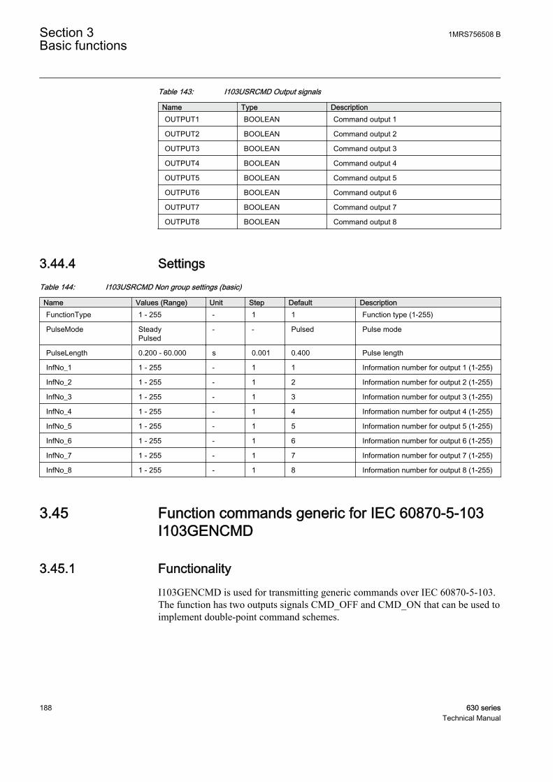
Table 143: I103USRCMD Output signals
Name Type DescriptionOUTPUT1 BOOLEAN Command output 1
OUTPUT2 BOOLEAN Command output 2
OUTPUT3 BOOLEAN Command output 3
OUTPUT4 BOOLEAN Command output 4
OUTPUT5 BOOLEAN Command output 5
OUTPUT6 BOOLEAN Command output 6
OUTPUT7 BOOLEAN Command output 7
OUTPUT8 BOOLEAN Command output 8
3.44.4 SettingsTable 144: I103USRCMD Non group settings (basic)
Name Values (Range) Unit Step Default DescriptionFunctionType 1 - 255 - 1 1 Function type (1-255)
PulseMode SteadyPulsed
- - Pulsed Pulse mode
PulseLength 0.200 - 60.000 s 0.001 0.400 Pulse length
InfNo_1 1 - 255 - 1 1 Information number for output 1 (1-255)
InfNo_2 1 - 255 - 1 2 Information number for output 2 (1-255)
InfNo_3 1 - 255 - 1 3 Information number for output 3 (1-255)
InfNo_4 1 - 255 - 1 4 Information number for output 4 (1-255)
InfNo_5 1 - 255 - 1 5 Information number for output 5 (1-255)
InfNo_6 1 - 255 - 1 6 Information number for output 6 (1-255)
InfNo_7 1 - 255 - 1 7 Information number for output 7 (1-255)
InfNo_8 1 - 255 - 1 8 Information number for output 8 (1-255)
3.45 Function commands generic for IEC 60870-5-103I103GENCMD
3.45.1 FunctionalityI103GENCMD is used for transmitting generic commands over IEC 60870-5-103.The function has two outputs signals CMD_OFF and CMD_ON that can be used toimplement double-point command schemes.
Section 3 1MRS756508 BBasic functions
188 630 seriesTechnical Manual
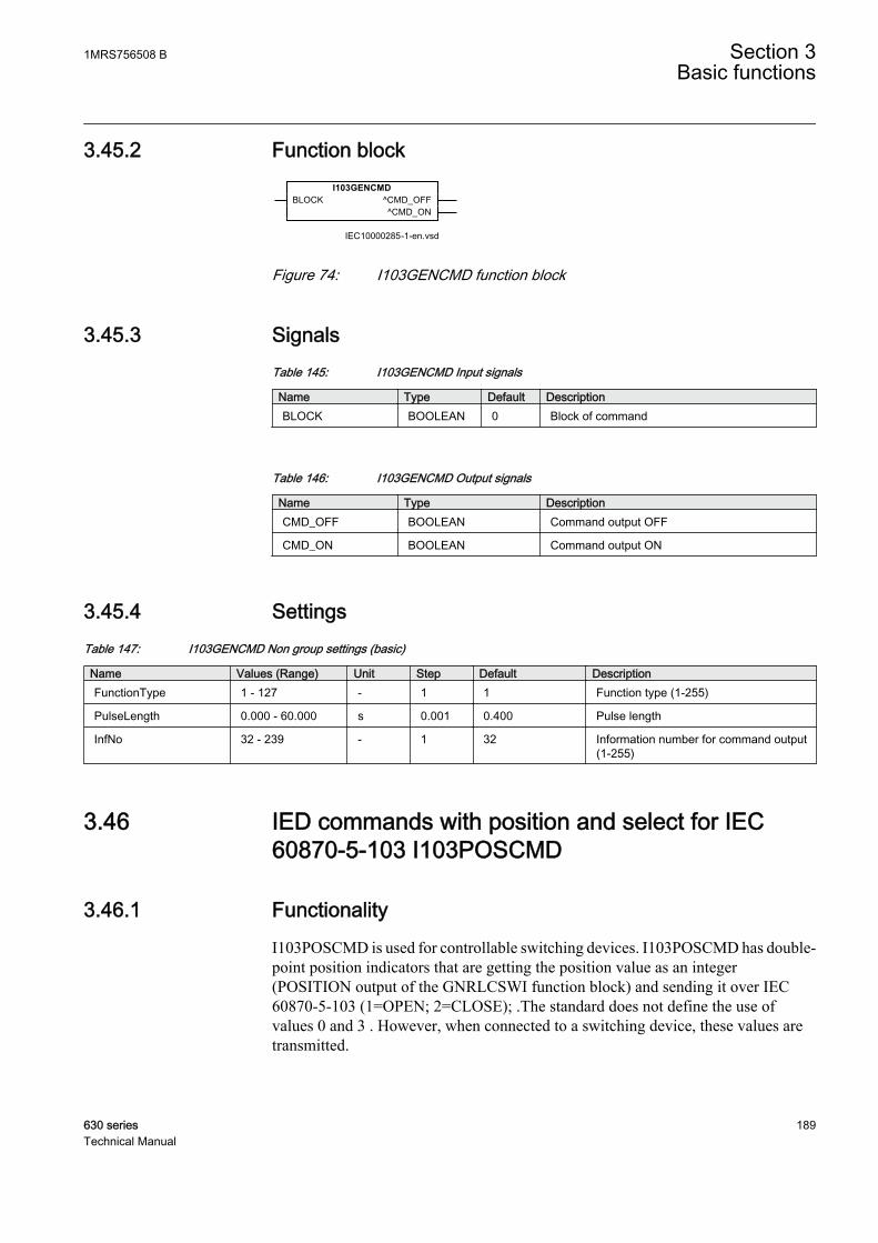
3.45.2 Function block
IEC10000285-1-en.vsd
I103GENCMDBLOCK ^CMD_OFF
^CMD_ON
IEC10000285 V1 EN
Figure 74: I103GENCMD function block
3.45.3 SignalsTable 145: I103GENCMD Input signals
Name Type Default DescriptionBLOCK BOOLEAN 0 Block of command
Table 146: I103GENCMD Output signals
Name Type DescriptionCMD_OFF BOOLEAN Command output OFF
CMD_ON BOOLEAN Command output ON
3.45.4 SettingsTable 147: I103GENCMD Non group settings (basic)
Name Values (Range) Unit Step Default DescriptionFunctionType 1 - 127 - 1 1 Function type (1-255)
PulseLength 0.000 - 60.000 s 0.001 0.400 Pulse length
InfNo 32 - 239 - 1 32 Information number for command output(1-255)
3.46 IED commands with position and select for IEC60870-5-103 I103POSCMD
3.46.1 FunctionalityI103POSCMD is used for controllable switching devices. I103POSCMD has double-point position indicators that are getting the position value as an integer(POSITION output of the GNRLCSWI function block) and sending it over IEC60870-5-103 (1=OPEN; 2=CLOSE); .The standard does not define the use ofvalues 0 and 3 . However, when connected to a switching device, these values aretransmitted.
1MRS756508 B Section 3Basic functions
630 series 189Technical Manual

The BLOCK input will block only the signals in monitoring direction (the positioninformation), not the commands via IEC 60870-5-103. The SELECT input is usedto indicate that the monitored apparatus has been selected (in a select-before-operate type of control)
3.46.2 Function block
IEC10000286-1-en.vsd
I103POSCMDBLOCKPOSITIONSELECT
IEC10000286 V1 EN
Figure 75: I103POSCMD function block
3.46.3 SignalsTable 148: I103POSCMD Input signals
Name Type Default DescriptionBLOCK BOOLEAN 0 Block of indications
POSITION INTEGER 0 Position indication of controllable object
SELECT BOOLEAN 0 Select indication of controllable object
3.46.4 SettingsTable 149: I103POSCMD Non group settings (basic)
Name Values (Range) Unit Step Default DescriptionFunctionType 1 - 255 - 1 1 Function type (1-255)
InfNo 160 - 196 - 4 160 Information number for positionindication and command output(160-196.)
3.47 Measurands for IEC 60870-5-103 I103MEAS
3.47.1 Functionality103MEAS is a function block that reports all valid measuring types depending onconnected signals.
The measured values come from the corresponding MMXU function block and aredepending on the function block settings. The event reporting interval is set by theCycMeasRepTime parameter of the IEC 60870-5-103 communication settings.
Section 3 1MRS756508 BBasic functions
190 630 seriesTechnical Manual

Input signals of the IEC 60870-5-103 I103MEAS block should be connected to thecorresponding outputs of the MMXU application functions. Depending on theconnected input signals, the IEC 60870-5-103 protocol automatically selects theproper ASDU Meas 3 or Meas 9 to be used as Class 2 data.
3.47.2 Function block
IEC10000287-1-en.vsd
I103MEASBLOCKIL1IL2IL3INUL1UL2UL3UL1L2UNPQF
IEC10000287 V1 EN
Figure 76: I103MEAS function block
3.47.3 SignalsTable 150: I103MEAS Input signals
Name Type Default DescriptionBLOCK BOOLEAN 0 Block of service value reporting
IL1 REAL 0.0 Service value for current phase L1
IL2 REAL 0.0 Service value for current phase L2
IL3 REAL 0.0 Service value for current phase L3
IN REAL 0.0 Service value for residual current IN
UL1 REAL 0.0 Service value for voltage phase L1
UL2 REAL 0.0 Service value for voltage phase L2
UL3 REAL 0.0 Service value for voltage phase L3
UL1L2 REAL 0.0 Service value for voltage phase-phase L1-L2
UN REAL 0.0 Service value for residual voltage UN
P REAL 0.0 Service value for active power
Q REAL 0.0 Service value for reactive power
F REAL 0.0 Service value for system frequency
1MRS756508 B Section 3Basic functions
630 series 191Technical Manual
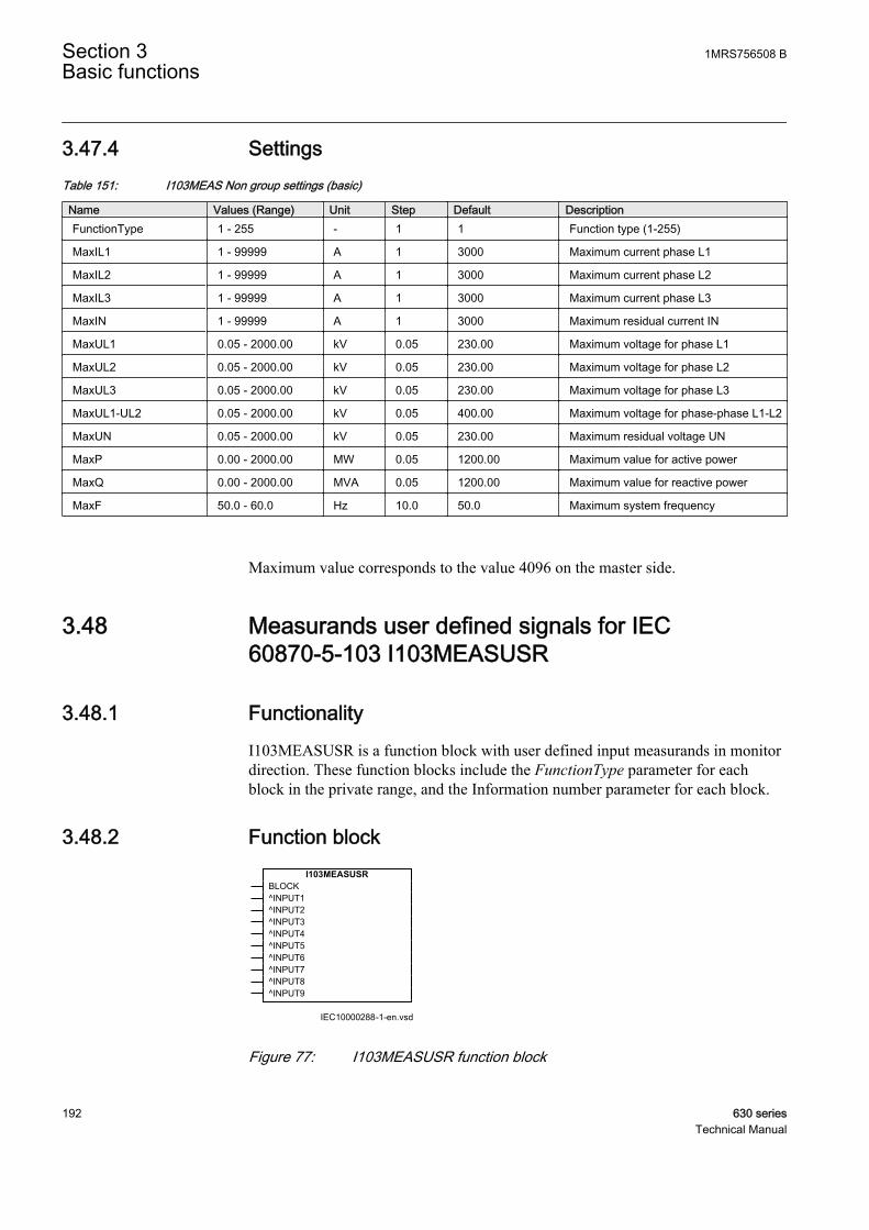
3.47.4 SettingsTable 151: I103MEAS Non group settings (basic)
Name Values (Range) Unit Step Default DescriptionFunctionType 1 - 255 - 1 1 Function type (1-255)
MaxIL1 1 - 99999 A 1 3000 Maximum current phase L1
MaxIL2 1 - 99999 A 1 3000 Maximum current phase L2
MaxIL3 1 - 99999 A 1 3000 Maximum current phase L3
MaxIN 1 - 99999 A 1 3000 Maximum residual current IN
MaxUL1 0.05 - 2000.00 kV 0.05 230.00 Maximum voltage for phase L1
MaxUL2 0.05 - 2000.00 kV 0.05 230.00 Maximum voltage for phase L2
MaxUL3 0.05 - 2000.00 kV 0.05 230.00 Maximum voltage for phase L3
MaxUL1-UL2 0.05 - 2000.00 kV 0.05 400.00 Maximum voltage for phase-phase L1-L2
MaxUN 0.05 - 2000.00 kV 0.05 230.00 Maximum residual voltage UN
MaxP 0.00 - 2000.00 MW 0.05 1200.00 Maximum value for active power
MaxQ 0.00 - 2000.00 MVA 0.05 1200.00 Maximum value for reactive power
MaxF 50.0 - 60.0 Hz 10.0 50.0 Maximum system frequency
Maximum value corresponds to the value 4096 on the master side.
3.48 Measurands user defined signals for IEC60870-5-103 I103MEASUSR
3.48.1 FunctionalityI103MEASUSR is a function block with user defined input measurands in monitordirection. These function blocks include the FunctionType parameter for eachblock in the private range, and the Information number parameter for each block.
3.48.2 Function block
IEC10000288-1-en.vsd
I103MEASUSRBLOCK^INPUT1^INPUT2^INPUT3^INPUT4^INPUT5^INPUT6^INPUT7^INPUT8^INPUT9
IEC10000288 V1 EN
Figure 77: I103MEASUSR function block
Section 3 1MRS756508 BBasic functions
192 630 seriesTechnical Manual

3.48.3 SignalsTable 152: I103MEASUSR Input signals
Name Type Default DescriptionBLOCK BOOLEAN 0 Block of service value reporting
INPUT1 REAL 0.0 Service value for measurement on input 1
INPUT2 REAL 0.0 Service value for measurement on input 2
INPUT3 REAL 0.0 Service value for measurement on input 3
INPUT4 REAL 0.0 Service value for measurement on input 4
INPUT5 REAL 0.0 Service value for measurement on input 5
INPUT6 REAL 0.0 Service value for measurement on input 6
INPUT7 REAL 0.0 Service value for measurement on input 7
INPUT8 REAL 0.0 Service value for measurement on input 8
INPUT9 REAL 0.0 Service value for measurement on input 9
3.48.4 SettingsTable 153: I103MEASUSR Non group settings (basic)
Name Values (Range) Unit Step Default DescriptionFunctionType 1 - 255 - 1 25 Function type (1-255)
InfNo 1 - 255 - 1 1 Information number for measurands(1-255)
MaxMeasur1 0.05 -10000000000.00
- 0.05 1000.00 Maximum value for measurement oninput 1
MaxMeasur2 0.05 -10000000000.00
- 0.05 1000.00 Maximum value for measurement oninput 2
MaxMeasur3 0.05 -10000000000.00
- 0.05 1000.00 Maximum value for measurement oninput 3
MaxMeasur4 0.05 -10000000000.00
- 0.05 1000.00 Maximum value for measurement oninput 4
MaxMeasur5 0.05 -10000000000.00
- 0.05 1000.00 Maximum value for measurement oninput 5
MaxMeasur6 0.05 -10000000000.00
- 0.05 1000.00 Maximum value for measurement oninput 6
MaxMeasur7 0.05 -10000000000.00
- 0.05 1000.00 Maximum value for measurement oninput 7
MaxMeasur8 0.05 -10000000000.00
- 0.05 1000.00 Maximum value for measurement oninput 8
MaxMeasur9 0.05 -10000000000.00
- 0.05 1000.00 Maximum value for measurement oninput 9
1MRS756508 B Section 3Basic functions
630 series 193Technical Manual
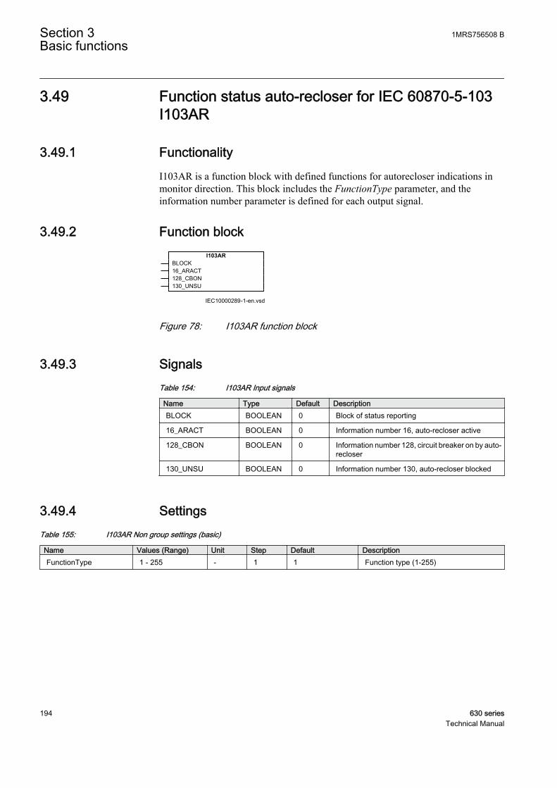
3.49 Function status auto-recloser for IEC 60870-5-103I103AR
3.49.1 FunctionalityI103AR is a function block with defined functions for autorecloser indications inmonitor direction. This block includes the FunctionType parameter, and theinformation number parameter is defined for each output signal.
3.49.2 Function block
IEC10000289-1-en.vsd
I103ARBLOCK16_ARACT128_CBON130_UNSU
IEC10000289 V1 EN
Figure 78: I103AR function block
3.49.3 SignalsTable 154: I103AR Input signals
Name Type Default DescriptionBLOCK BOOLEAN 0 Block of status reporting
16_ARACT BOOLEAN 0 Information number 16, auto-recloser active
128_CBON BOOLEAN 0 Information number 128, circuit breaker on by auto-recloser
130_UNSU BOOLEAN 0 Information number 130, auto-recloser blocked
3.49.4 SettingsTable 155: I103AR Non group settings (basic)
Name Values (Range) Unit Step Default DescriptionFunctionType 1 - 255 - 1 1 Function type (1-255)
Section 3 1MRS756508 BBasic functions
194 630 seriesTechnical Manual
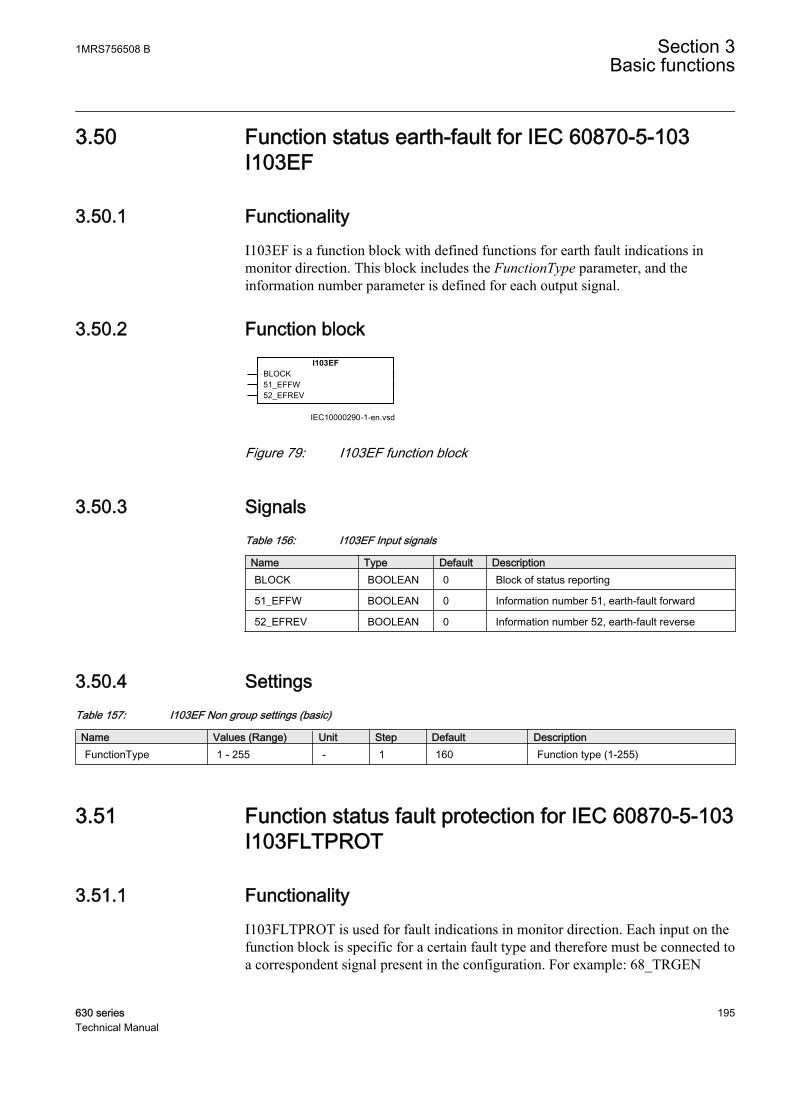
3.50 Function status earth-fault for IEC 60870-5-103I103EF
3.50.1 FunctionalityI103EF is a function block with defined functions for earth fault indications inmonitor direction. This block includes the FunctionType parameter, and theinformation number parameter is defined for each output signal.
3.50.2 Function block
IEC10000290-1-en.vsd
I103EFBLOCK51_EFFW52_EFREV
IEC10000290 V1 EN
Figure 79: I103EF function block
3.50.3 SignalsTable 156: I103EF Input signals
Name Type Default DescriptionBLOCK BOOLEAN 0 Block of status reporting
51_EFFW BOOLEAN 0 Information number 51, earth-fault forward
52_EFREV BOOLEAN 0 Information number 52, earth-fault reverse
3.50.4 SettingsTable 157: I103EF Non group settings (basic)
Name Values (Range) Unit Step Default DescriptionFunctionType 1 - 255 - 1 160 Function type (1-255)
3.51 Function status fault protection for IEC 60870-5-103I103FLTPROT
3.51.1 FunctionalityI103FLTPROT is used for fault indications in monitor direction. Each input on thefunction block is specific for a certain fault type and therefore must be connected toa correspondent signal present in the configuration. For example: 68_TRGEN
1MRS756508 B Section 3Basic functions
630 series 195Technical Manual

represents the General Trip of the device, and therefore must be connected to thegeneral trip signal SMPPTRC_TRIP or equivalent.
The delay observed in the protocol is the time difference in between the signal thatis triggering the Disturbance Recorder and the respective configured signal to theIEC 60870-5-103 I103FLTPROT.
3.51.2 Function block
IEC10000291-1-en.vsd
I103FLTPROTBLOCK64_STL165_STL266_STL367_STIN68_TRGEN69_TRL170_TRL271_TRL372_TRBKUP73_SCL74_FW75_REV76_TRANS77_RECEV78_ZONE179_ZONE280_ZONE381_ZONE482_ZONE584_STGEN85_BFP86_MTRL187_MTRL288_MTRL389_MTRN90_IOC91_IOC92_IEF93_IEFARINPROGFLTLOC
IEC10000291 V1 EN
Figure 80: I103FLTPROT function block
3.51.3 SignalsTable 158: I103FLTPROT Input signals
Name Type Default DescriptionBLOCK BOOLEAN 0 Block of status reporting.
64_STL1 BOOLEAN 0 Information number 64, start phase L1
65_STL2 BOOLEAN 0 Information number 65, start phase L2
66_STL3 BOOLEAN 0 Information number 66, start phase L3
67_STIN BOOLEAN 0 Information number 67, start residual current IN
68_TRGEN BOOLEAN 0 Information number 68, trip general
69_TRL1 BOOLEAN 0 Information number 69, trip phase L1
Table continues on next page
Section 3 1MRS756508 BBasic functions
196 630 seriesTechnical Manual

Name Type Default Description70_TRL2 BOOLEAN 0 Information number 70, trip phase L2
71_TRL3 BOOLEAN 0 Information number 71, trip phase L3
72_TRBKUP BOOLEAN 0 Information number 72, back up trip I>>
73_SCL REAL 0 Information number 73, fault location in ohm
74_FW BOOLEAN 0 Information number 74, forward/line
75_REV BOOLEAN 0 Information number 75, reverse/busbar
76_TRANS BOOLEAN 0 Information number 76, signal transmitted
77_RECEV BOOLEAN 0 Information number 77, signal received
78_ZONE1 BOOLEAN 0 Information number 78, zone 1
79_ZONE2 BOOLEAN 0 Information number 79, zone 2
80_ZONE3 BOOLEAN 0 Information number 80, zone 3
81_ZONE4 BOOLEAN 0 Information number 81, zone 4
82_ZONE5 BOOLEAN 0 Information number 82, zone 5
84_STGEN BOOLEAN 0 Information number 84, start general
85_BFP BOOLEAN 0 Information number 85, breaker failure
86_MTRL1 BOOLEAN 0 Information number 86, trip measuring systemphase L1
87_MTRL2 BOOLEAN 0 Information number 87, trip measuring systemphase L2
88_MTRL3 BOOLEAN 0 Information number 88, trip measuring systemphase L3
89_MTRN BOOLEAN 0 Information number 89, trip measuring systemneutral N
90_IOC BOOLEAN 0 Information number 90, over current trip, stage low
91_IOC BOOLEAN 0 Information number 91, over current trip, stage high
92_IEF BOOLEAN 0 Information number 92, earth-fault trip, stage low
93_IEF BOOLEAN 0 Information number 93, earth-fault trip, stage high
ARINPROG BOOLEAN 0 Autorecloser in progress (SMBRREC- INPROGR)
FLTLOC BOOLEAN 0 Faultlocator faultlocation valid (LMBRFLO-CALCMADE)
3.51.4 SettingsTable 159: I103FLTPROT Non group settings (basic)
Name Values (Range) Unit Step Default DescriptionFunctionType 1 - 255 - 1 128 Function type (1-255)
1MRS756508 B Section 3Basic functions
630 series 197Technical Manual
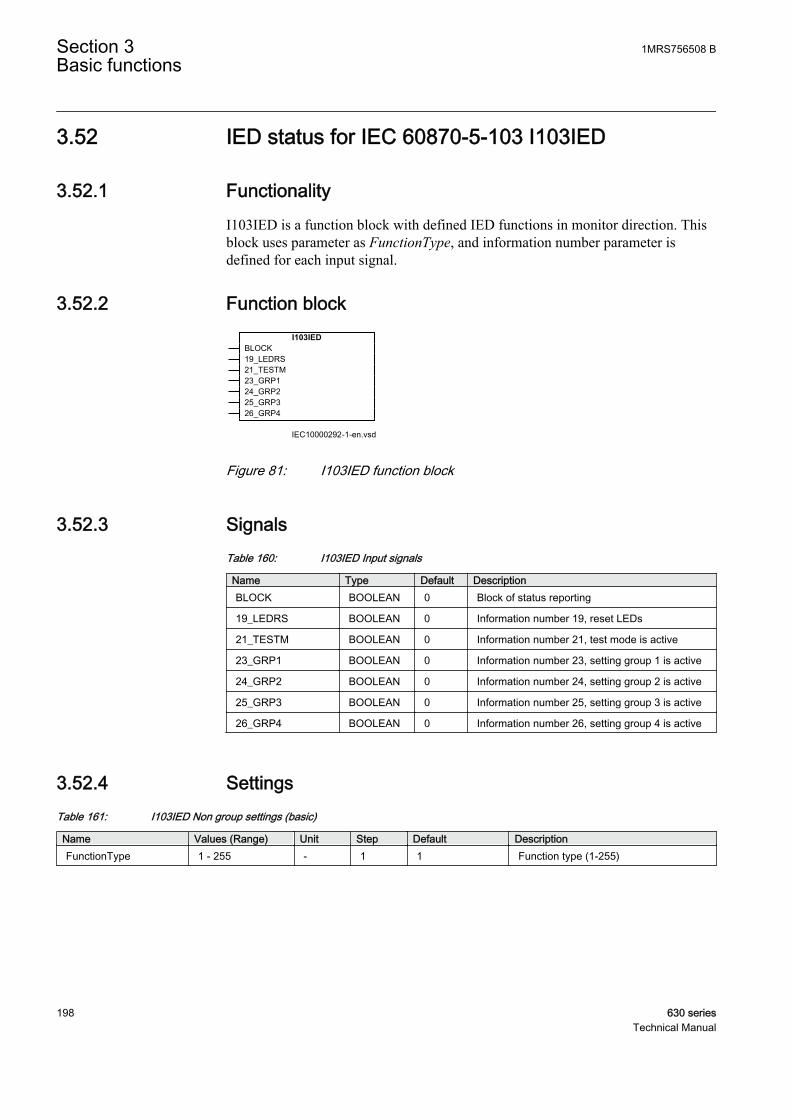
3.52 IED status for IEC 60870-5-103 I103IED
3.52.1 FunctionalityI103IED is a function block with defined IED functions in monitor direction. Thisblock uses parameter as FunctionType, and information number parameter isdefined for each input signal.
3.52.2 Function block
IEC10000292-1-en.vsd
I103IEDBLOCK19_LEDRS21_TESTM23_GRP124_GRP225_GRP326_GRP4
IEC10000292 V1 EN
Figure 81: I103IED function block
3.52.3 SignalsTable 160: I103IED Input signals
Name Type Default DescriptionBLOCK BOOLEAN 0 Block of status reporting
19_LEDRS BOOLEAN 0 Information number 19, reset LEDs
21_TESTM BOOLEAN 0 Information number 21, test mode is active
23_GRP1 BOOLEAN 0 Information number 23, setting group 1 is active
24_GRP2 BOOLEAN 0 Information number 24, setting group 2 is active
25_GRP3 BOOLEAN 0 Information number 25, setting group 3 is active
26_GRP4 BOOLEAN 0 Information number 26, setting group 4 is active
3.52.4 SettingsTable 161: I103IED Non group settings (basic)
Name Values (Range) Unit Step Default DescriptionFunctionType 1 - 255 - 1 1 Function type (1-255)
Section 3 1MRS756508 BBasic functions
198 630 seriesTechnical Manual
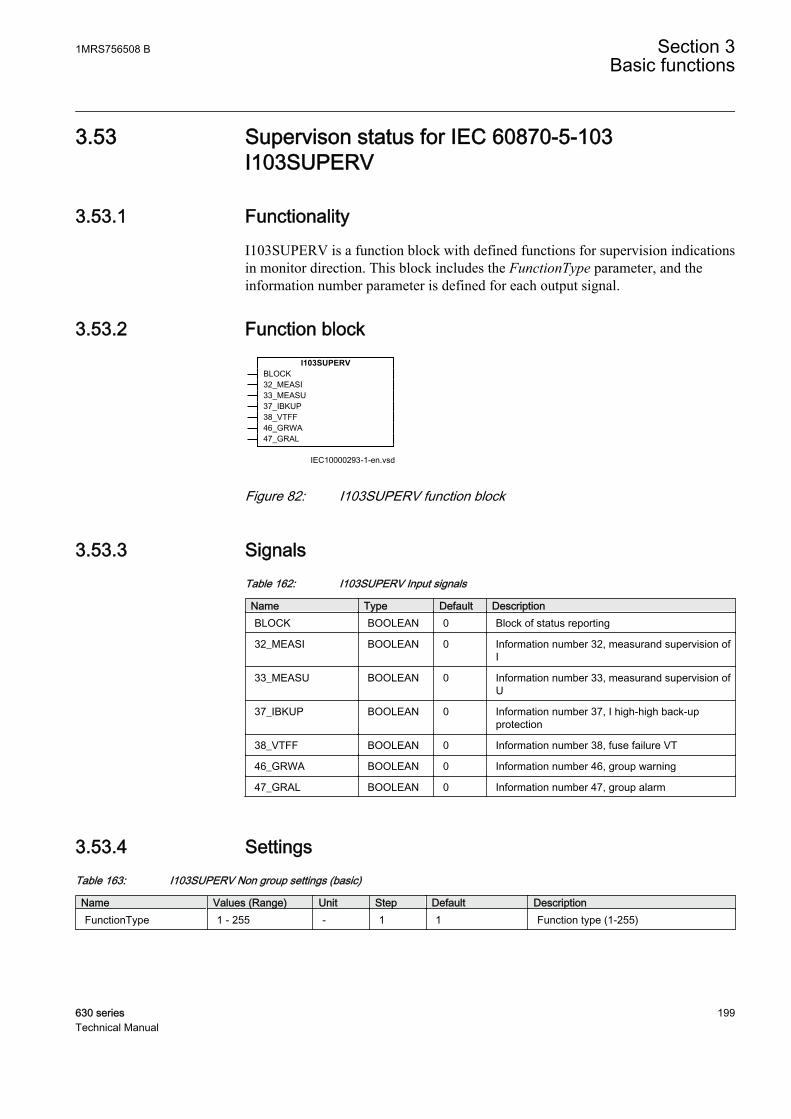
3.53 Supervison status for IEC 60870-5-103I103SUPERV
3.53.1 FunctionalityI103SUPERV is a function block with defined functions for supervision indicationsin monitor direction. This block includes the FunctionType parameter, and theinformation number parameter is defined for each output signal.
3.53.2 Function block
IEC10000293-1-en.vsd
I103SUPERVBLOCK32_MEASI33_MEASU37_IBKUP38_VTFF46_GRWA47_GRAL
IEC10000293 V1 EN
Figure 82: I103SUPERV function block
3.53.3 SignalsTable 162: I103SUPERV Input signals
Name Type Default DescriptionBLOCK BOOLEAN 0 Block of status reporting
32_MEASI BOOLEAN 0 Information number 32, measurand supervision ofI
33_MEASU BOOLEAN 0 Information number 33, measurand supervision ofU
37_IBKUP BOOLEAN 0 Information number 37, I high-high back-upprotection
38_VTFF BOOLEAN 0 Information number 38, fuse failure VT
46_GRWA BOOLEAN 0 Information number 46, group warning
47_GRAL BOOLEAN 0 Information number 47, group alarm
3.53.4 SettingsTable 163: I103SUPERV Non group settings (basic)
Name Values (Range) Unit Step Default DescriptionFunctionType 1 - 255 - 1 1 Function type (1-255)
1MRS756508 B Section 3Basic functions
630 series 199Technical Manual

3.54 Status for user defined signals for IEC 60870-5-103I103USRDEF
3.54.1 FunctionalityI103USRDEF is a function blocks with user defined input signals in monitordirection. These function blocks include the FunctionType parameter for eachblock in the private range, and the information number parameter for each inputsignal.
I103USRDEF can be used, for example in mapping the INF numbers not supporteddirectly by specific function blocks, like: INF17, INF18, INF20 or INF35. Afterconnecting the appropriate signals to the I103USRDEF inputs, the user must alsoset the InfNo_x values in the settings.
GUID-391D4145-B7E6-4174-B3F7-753ADDA4D06F V1 EN
Figure 83: IEC 60870-5-103I103USRDEF:1
3.54.2 Function block
IEC10000294-1-en.vsd
I103USRDEFBLOCK^INPUT1^INPUT2^INPUT3^INPUT4^INPUT5^INPUT6^INPUT7^INPUT8
IEC10000294 V1 EN
Figure 84: I103USRDEF function block
Section 3 1MRS756508 BBasic functions
200 630 seriesTechnical Manual
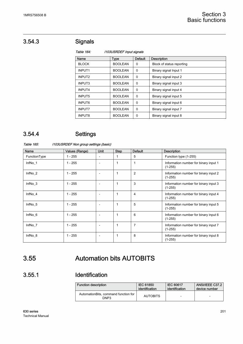
3.54.3 SignalsTable 164: I103USRDEF Input signals
Name Type Default DescriptionBLOCK BOOLEAN 0 Block of status reporting
INPUT1 BOOLEAN 0 Binary signal Input 1
INPUT2 BOOLEAN 0 Binary signal input 2
INPUT3 BOOLEAN 0 Binary signal input 3
INPUT4 BOOLEAN 0 Binary signal input 4
INPUT5 BOOLEAN 0 Binary signal input 5
INPUT6 BOOLEAN 0 Binary signal input 6
INPUT7 BOOLEAN 0 Binary signal input 7
INPUT8 BOOLEAN 0 Binary signal input 8
3.54.4 SettingsTable 165: I103USRDEF Non group settings (basic)
Name Values (Range) Unit Step Default DescriptionFunctionType 1 - 255 - 1 5 Function type (1-255)
InfNo_1 1 - 255 - 1 1 Information number for binary input 1(1-255)
InfNo_2 1 - 255 - 1 2 Information number for binary input 2(1-255)
InfNo_3 1 - 255 - 1 3 Information number for binary input 3(1-255)
InfNo_4 1 - 255 - 1 4 Information number for binary input 4(1-255)
InfNo_5 1 - 255 - 1 5 Information number for binary input 5(1-255)
InfNo_6 1 - 255 - 1 6 Information number for binary input 6(1-255)
InfNo_7 1 - 255 - 1 7 Information number for binary input 7(1-255)
InfNo_8 1 - 255 - 1 8 Information number for binary input 8(1-255)
3.55 Automation bits AUTOBITS
3.55.1 IdentificationFunction description IEC 61850
identificationIEC 60617identification
ANSI/IEEE C37.2device number
AutomationBits, command function forDNP3 AUTOBITS - -
1MRS756508 B Section 3Basic functions
630 series 201Technical Manual
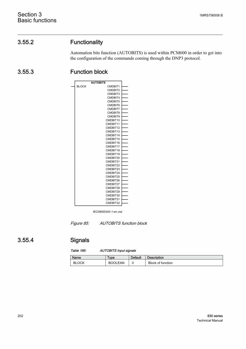
3.55.2 FunctionalityAutomation bits function (AUTOBITS) is used within PCM600 in order to get intothe configuration of the commands coming through the DNP3 protocol.
3.55.3 Function blockAUTOBITS
BLOCK CMDBIT1CMDBIT2CMDBIT3CMDBIT4CMDBIT5CMDBIT6CMDBIT7CMDBIT8CMDBIT9
CMDBIT10CMDBIT11CMDBIT12CMDBIT13CMDBIT14CMDBIT15CMDBIT16CMDBIT17CMDBIT18CMDBIT19CMDBIT20CMDBIT21CMDBIT22CMDBIT23CMDBIT24CMDBIT25CMDBIT26CMDBIT27CMDBIT28CMDBIT29CMDBIT30CMDBIT31CMDBIT32
IEC09000345-1-en.vsdIEC09000345 V1 EN
Figure 85: AUTOBITS function block
3.55.4 SignalsTable 166: AUTOBITS Input signals
Name Type Default DescriptionBLOCK BOOLEAN 0 Block of function
Section 3 1MRS756508 BBasic functions
202 630 seriesTechnical Manual

Table 167: AUTOBITS Output signals
Name Type DescriptionCMDBIT1 BOOLEAN Command out bit 1
CMDBIT2 BOOLEAN Command out bit 2
CMDBIT3 BOOLEAN Command out bit 3
CMDBIT4 BOOLEAN Command out bit 4
CMDBIT5 BOOLEAN Command out bit 5
CMDBIT6 BOOLEAN Command out bit 6
CMDBIT7 BOOLEAN Command out bit 7
CMDBIT8 BOOLEAN Command out bit 8
CMDBIT9 BOOLEAN Command out bit 9
CMDBIT10 BOOLEAN Command out bit 10
CMDBIT11 BOOLEAN Command out bit 11
CMDBIT12 BOOLEAN Command out bit 12
CMDBIT13 BOOLEAN Command out bit 13
CMDBIT14 BOOLEAN Command out bit 14
CMDBIT15 BOOLEAN Command out bit 15
CMDBIT16 BOOLEAN Command out bit 16
CMDBIT17 BOOLEAN Command out bit 17
CMDBIT18 BOOLEAN Command out bit 18
CMDBIT19 BOOLEAN Command out bit 19
CMDBIT20 BOOLEAN Command out bit 20
CMDBIT21 BOOLEAN Command out bit 21
CMDBIT22 BOOLEAN Command out bit 22
CMDBIT23 BOOLEAN Command out bit 23
CMDBIT24 BOOLEAN Command out bit 24
CMDBIT25 BOOLEAN Command out bit 25
CMDBIT26 BOOLEAN Command out bit 26
CMDBIT27 BOOLEAN Command out bit 27
CMDBIT28 BOOLEAN Command out bit 28
CMDBIT29 BOOLEAN Command out bit 29
CMDBIT30 BOOLEAN Command out bit 30
CMDBIT31 BOOLEAN Command out bit 31
CMDBIT32 BOOLEAN Command out bit 32
3.55.5 SettingsTable 168: AUTOBITS Non group settings (basic)
Name Values (Range) Unit Step Default DescriptionOperation Off
On- - Off Operation Off / On
1MRS756508 B Section 3Basic functions
630 series 203Technical Manual
3.55.6 ApplicationThe AUTOBITS function block (or the automation bits function block) is usedwithin PCM600 in order to get into the configuration the commands comingthrough the DNP3 protocol.
See the communication protocol manual for a detailed description of the DNP3protocol
3.55.7 Operation principleAutomation bits function (AUTOBITS) has 32 individual outputs which each canbe mapped as a Binary Output point in DNP3. The output is operated by a "Object12" in DNP3. This object contains parameters for control-code, count, on-time andoff-time. To operate an AUTOBITS output point, send a control-code of latch-On,latch-Off, pulse-On, pulse-Off, Trip or Close. The remaining parameters will beregarded were appropriate. ex: pulse-On, on-time=100, off-time=300, count=5would give 5 positive 100 ms pulses, 300 ms apart.
There is a BLOCK input signal, which will disable the operation of the function, inthe same way the setting Operation: On/Off does. That means that, upon activationof the BLOCK input, all 32 CMDBITxx outputs will be set to 0. The BLOCK actslike an overriding, the function still receives data from the DNP3 master. Upondeactivation of BLOCK, all the 32 CMDBITxx outputs will be set by the DNP3master again, momentarily.
For description of the DNP3 protocol implementation, refer to DNP3communication protocol manual.
3.56 Configurable logic blocks
3.56.1 Standard configurable logic blocks
3.56.1.1 Functionality
A number of logic blocks and timers are available for user to adapt theconfiguration to the specific application needs.
• OR function block.
• INVERTER function blocks that inverts the input signal.
• PULSETIMER function block can be used, for example, for pulse extensionsor limiting of operation of outputs.
Section 3 1MRS756508 BBasic functions
204 630 seriesTechnical Manual
• GATE function block is used for controlling if a signal should be able to passfrom the input to the output or not depending on a setting.
• XOR function block.
• LOOPDELAY function block used to delay the output signal one executioncycle.
• TIMERSET function has pick-up and drop-out delayed outputs related to theinput signal. The timer has a settable time delay.
• AND function block.
• SRMEMORY function block is a flip-flop that can set or reset an output fromtwo inputs respectively. Each block has two outputs where one is inverted. Thememory setting controls if the block after a power interruption should return tothe state before the interruption, or be reset. Set input has priority.
• RSMEMORY function block is a flip-flop that can reset or set an output fromtwo inputs respectively. Each block has two outputs where one is inverted. Thememory setting controls if the block after a power interruption should return tothe state before the interruption, or be reset. Reset input has priority.
3.56.1.2 OR function block
IdentificationFunction description IEC 61850
identificationIEC 60617identification
ANSI/IEEE C37.2device number
OR Function block OR - -
FunctionalityThe OR function is used to form general combinatory expressions with booleanvariables. The OR function block has six inputs and two outputs. One of theoutputs is inverted.
1MRS756508 B Section 3Basic functions
630 series 205Technical Manual
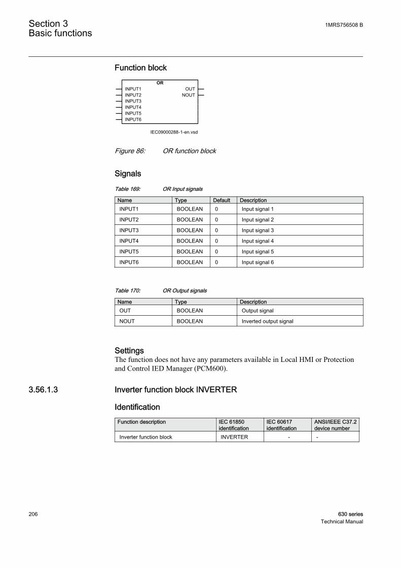
Function blockOR
INPUT1INPUT2INPUT3INPUT4INPUT5INPUT6
OUTNOUT
IEC09000288-1-en.vsdIEC09000288 V1 EN
Figure 86: OR function block
Signals
Table 169: OR Input signals
Name Type Default DescriptionINPUT1 BOOLEAN 0 Input signal 1
INPUT2 BOOLEAN 0 Input signal 2
INPUT3 BOOLEAN 0 Input signal 3
INPUT4 BOOLEAN 0 Input signal 4
INPUT5 BOOLEAN 0 Input signal 5
INPUT6 BOOLEAN 0 Input signal 6
Table 170: OR Output signals
Name Type DescriptionOUT BOOLEAN Output signal
NOUT BOOLEAN Inverted output signal
SettingsThe function does not have any parameters available in Local HMI or Protectionand Control IED Manager (PCM600).
3.56.1.3 Inverter function block INVERTER
IdentificationFunction description IEC 61850
identificationIEC 60617identification
ANSI/IEEE C37.2device number
Inverter function block INVERTER - -
Section 3 1MRS756508 BBasic functions
206 630 seriesTechnical Manual

Function blockINVERTER
INPUT OUT
IEC09000287-1-en.vsdIEC09000287 V1 EN
Figure 87: INVERTER function block
Signals
Table 171: INVERTER Input signals
Name Type Default DescriptionINPUT BOOLEAN 0 Input signal
Table 172: INVERTER Output signals
Name Type DescriptionOUT BOOLEAN Output signal
SettingsThe function does not have any parameters available in Local HMI or Protectionand Control IED Manager (PCM600).
3.56.1.4 PULSETIMER function block
IdentificationFunction description IEC 61850
identificationIEC 60617identification
ANSI/IEEE C37.2device number
PULSETIMER function block PULSETIMER - -
FunctionalityThe pulse function can be used, for example for pulse extensions or limiting ofoperation of outputs. The PULSETIMER has a settable length.
Function blockPULSETIMER
INPUT OUT
IEC09000291-1-en.vsdIEC09000291 V1 EN
Figure 88: PULSETIMER function block
1MRS756508 B Section 3Basic functions
630 series 207Technical Manual

Signals
Table 173: PULSETIMER Input signals
Name Type Default DescriptionINPUT BOOLEAN 0 Input signal
Table 174: PULSETIMER Output signals
Name Type DescriptionOUT BOOLEAN Output signal
Settings
Table 175: PULSETIMER Non group settings (basic)
Name Values (Range) Unit Step Default Descriptiont 0.000 - 90000.000 s 0.001 0.010 Pulse time length
3.56.1.5 Controllable gate function block GATE
IdentificationFunction description IEC 61850
identificationIEC 60617identification
ANSI/IEEE C37.2device number
Controllable gate function block GATE - -
FunctionalityThe GATE function block is used for controlling if a signal should pass from theinput to the output or not, depending on setting.
Function blockGATE
INPUT OUT
IEC09000295-1-en.vsdIEC09000295 V1 EN
Figure 89: GATE function block
Signals
Table 176: GATE Input signals
Name Type Default DescriptionINPUT BOOLEAN 0 Input signal
Section 3 1MRS756508 BBasic functions
208 630 seriesTechnical Manual
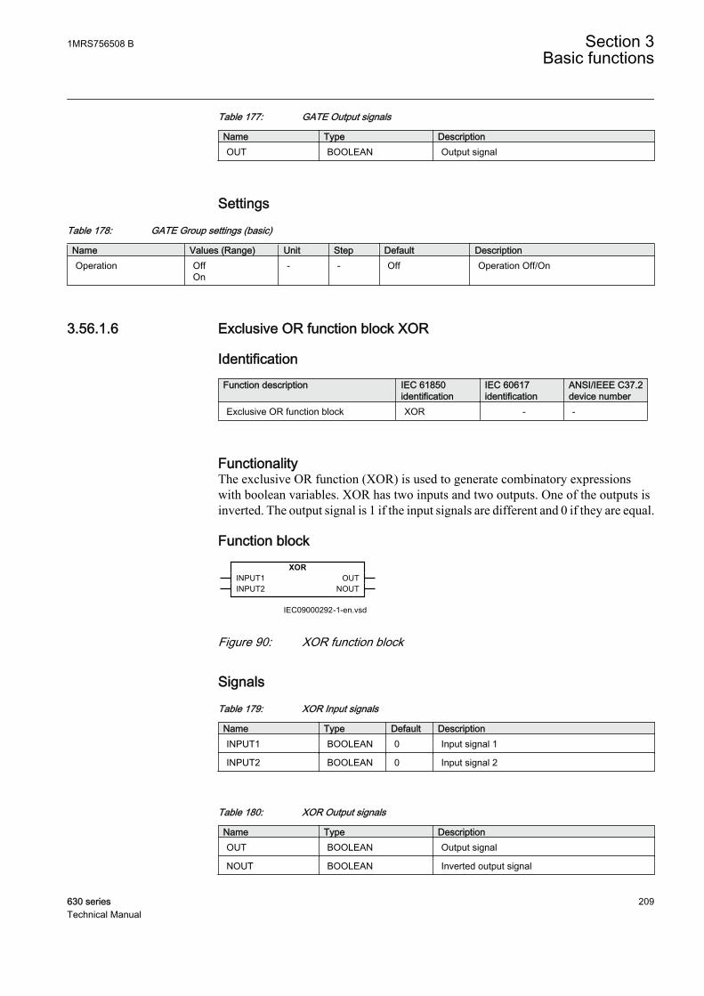
Table 177: GATE Output signals
Name Type DescriptionOUT BOOLEAN Output signal
Settings
Table 178: GATE Group settings (basic)
Name Values (Range) Unit Step Default DescriptionOperation Off
On- - Off Operation Off/On
3.56.1.6 Exclusive OR function block XOR
IdentificationFunction description IEC 61850
identificationIEC 60617identification
ANSI/IEEE C37.2device number
Exclusive OR function block XOR - -
FunctionalityThe exclusive OR function (XOR) is used to generate combinatory expressionswith boolean variables. XOR has two inputs and two outputs. One of the outputs isinverted. The output signal is 1 if the input signals are different and 0 if they are equal.
Function blockXOR
INPUT1INPUT2
OUTNOUT
IEC09000292-1-en.vsdIEC09000292 V1 EN
Figure 90: XOR function block
Signals
Table 179: XOR Input signals
Name Type Default DescriptionINPUT1 BOOLEAN 0 Input signal 1
INPUT2 BOOLEAN 0 Input signal 2
Table 180: XOR Output signals
Name Type DescriptionOUT BOOLEAN Output signal
NOUT BOOLEAN Inverted output signal
1MRS756508 B Section 3Basic functions
630 series 209Technical Manual
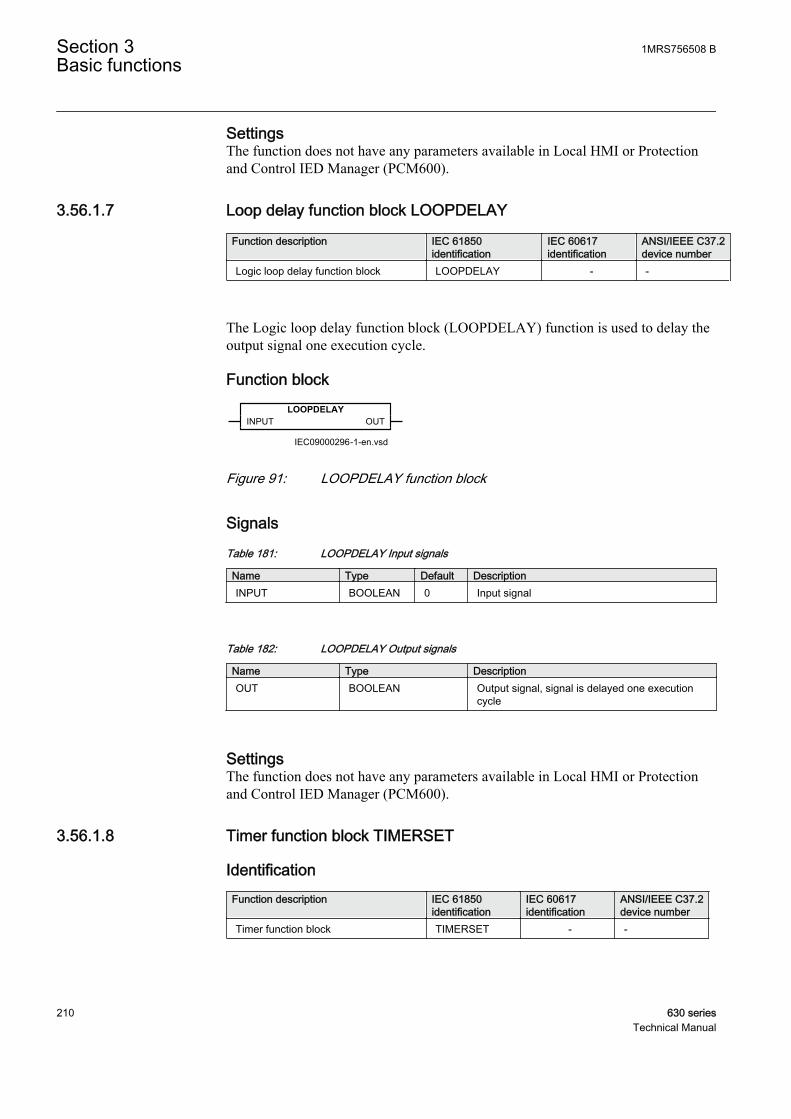
SettingsThe function does not have any parameters available in Local HMI or Protectionand Control IED Manager (PCM600).
3.56.1.7 Loop delay function block LOOPDELAY
Function description IEC 61850identification
IEC 60617identification
ANSI/IEEE C37.2device number
Logic loop delay function block LOOPDELAY - -
The Logic loop delay function block (LOOPDELAY) function is used to delay theoutput signal one execution cycle.
Function blockLOOPDELAY
INPUT OUT
IEC09000296-1-en.vsdIEC09000296 V1 EN
Figure 91: LOOPDELAY function block
Signals
Table 181: LOOPDELAY Input signals
Name Type Default DescriptionINPUT BOOLEAN 0 Input signal
Table 182: LOOPDELAY Output signals
Name Type DescriptionOUT BOOLEAN Output signal, signal is delayed one execution
cycle
SettingsThe function does not have any parameters available in Local HMI or Protectionand Control IED Manager (PCM600).
3.56.1.8 Timer function block TIMERSET
IdentificationFunction description IEC 61850
identificationIEC 60617identification
ANSI/IEEE C37.2device number
Timer function block TIMERSET - -
Section 3 1MRS756508 BBasic functions
210 630 seriesTechnical Manual
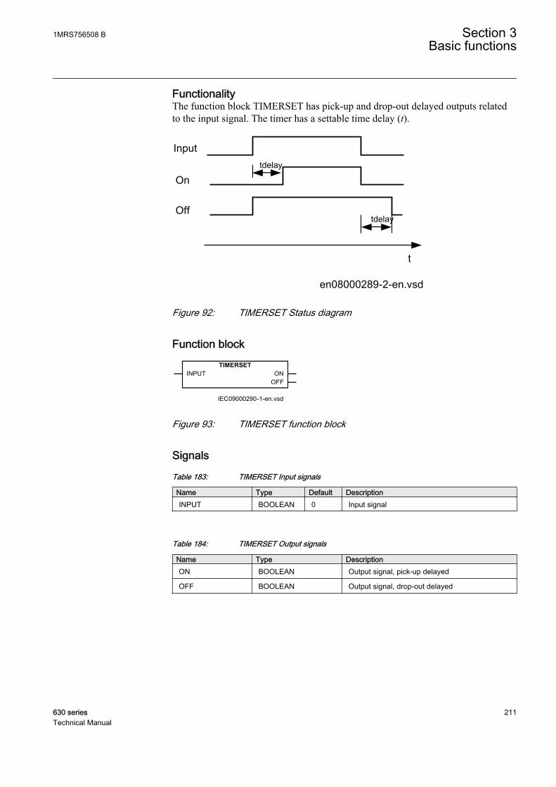
FunctionalityThe function block TIMERSET has pick-up and drop-out delayed outputs relatedto the input signal. The timer has a settable time delay (t).
On
Off
t
tdelay
tdelay
en08000289-2-en.vsd
Input
IEC08000289 V1 EN
Figure 92: TIMERSET Status diagram
Function blockTIMERSET
INPUT ONOFF
IEC09000290-1-en.vsdIEC09000290 V1 EN
Figure 93: TIMERSET function block
Signals
Table 183: TIMERSET Input signals
Name Type Default DescriptionINPUT BOOLEAN 0 Input signal
Table 184: TIMERSET Output signals
Name Type DescriptionON BOOLEAN Output signal, pick-up delayed
OFF BOOLEAN Output signal, drop-out delayed
1MRS756508 B Section 3Basic functions
630 series 211Technical Manual
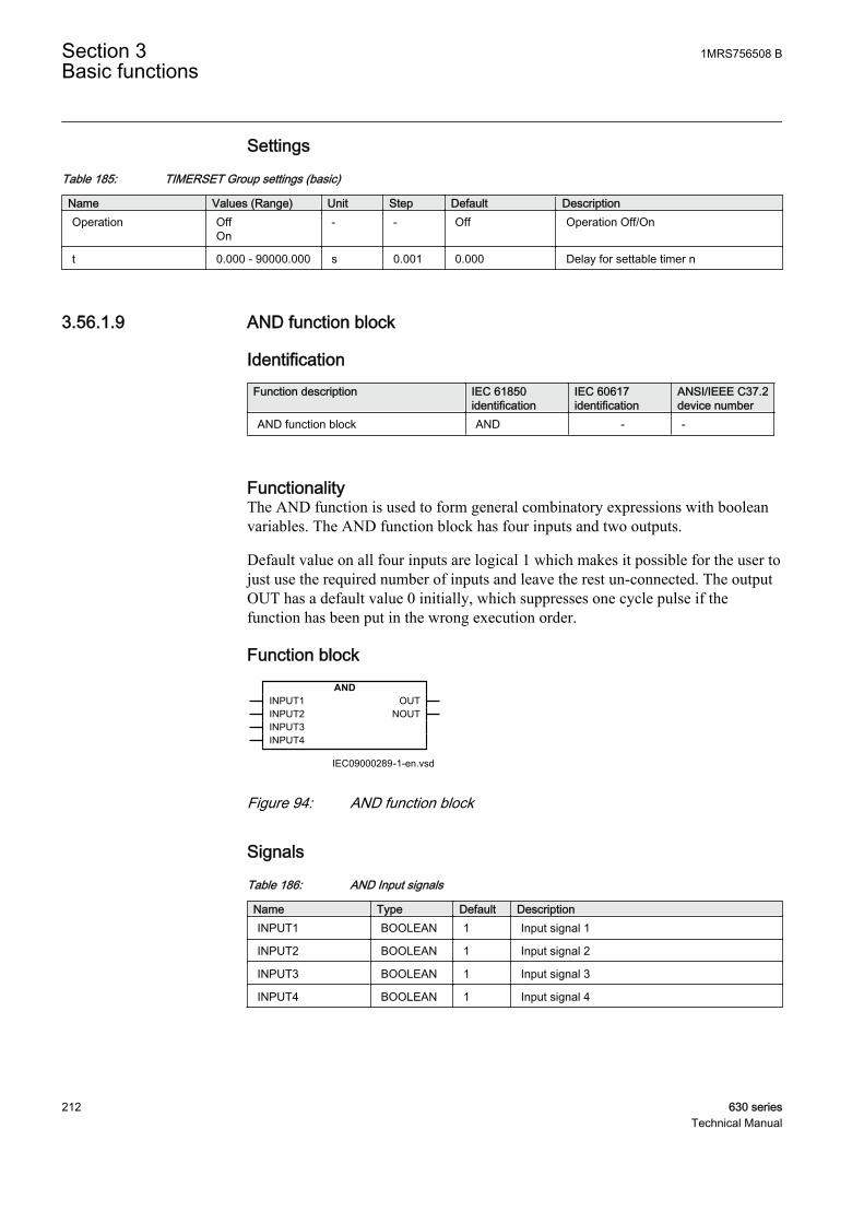
Settings
Table 185: TIMERSET Group settings (basic)
Name Values (Range) Unit Step Default DescriptionOperation Off
On- - Off Operation Off/On
t 0.000 - 90000.000 s 0.001 0.000 Delay for settable timer n
3.56.1.9 AND function block
IdentificationFunction description IEC 61850
identificationIEC 60617identification
ANSI/IEEE C37.2device number
AND function block AND - -
FunctionalityThe AND function is used to form general combinatory expressions with booleanvariables. The AND function block has four inputs and two outputs.
Default value on all four inputs are logical 1 which makes it possible for the user tojust use the required number of inputs and leave the rest un-connected. The outputOUT has a default value 0 initially, which suppresses one cycle pulse if thefunction has been put in the wrong execution order.
Function blockAND
INPUT1INPUT2INPUT3INPUT4
OUTNOUT
IEC09000289-1-en.vsdIEC09000289 V1 EN
Figure 94: AND function block
Signals
Table 186: AND Input signals
Name Type Default DescriptionINPUT1 BOOLEAN 1 Input signal 1
INPUT2 BOOLEAN 1 Input signal 2
INPUT3 BOOLEAN 1 Input signal 3
INPUT4 BOOLEAN 1 Input signal 4
Section 3 1MRS756508 BBasic functions
212 630 seriesTechnical Manual

Table 187: AND Output signals
Name Type DescriptionOUT BOOLEAN Output signal
NOUT BOOLEAN Inverted output signal
SettingsThe function does not have any parameters available in Local HMI or Protectionand Control IED Manager (PCM600).
3.56.1.10 Set-reset memory function block SRMEMORY
IdentificationFunction description IEC 61850
identificationIEC 60617identification
ANSI/IEEE C37.2device number
Set-reset memory function block SRMEMORY - -
FunctionalityThe Set-Reset function SRMEMORY is a flip-flop with memory that can set orreset an output from two inputs respectively. Each SRMEMORY function blockhas two outputs, where one is inverted. The memory setting controls if the flip-flopafter a power interruption will return the state it had before or if it will be reset. Fora Set-Reset flip-flop, SET input has higher priority over RESET input.
Table 188: Truth table for the Set-Reset (SRMEMORY) function block
SET RESET OUT NOUT1 0 1 0
0 1 0 1
1 1 1 0
0 0 0 1
Function blockSRMEMORY
SETRESET
OUTNOUT
IEC09000293-1-en.vsdIEC09000293 V1 EN
Figure 95: SRMEMORY function block
1MRS756508 B Section 3Basic functions
630 series 213Technical Manual
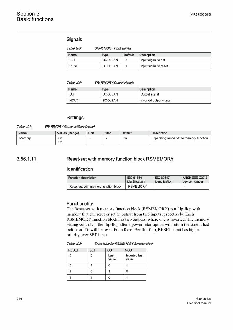
Signals
Table 189: SRMEMORY Input signals
Name Type Default DescriptionSET BOOLEAN 0 Input signal to set
RESET BOOLEAN 0 Input signal to reset
Table 190: SRMEMORY Output signals
Name Type DescriptionOUT BOOLEAN Output signal
NOUT BOOLEAN Inverted output signal
Settings
Table 191: SRMEMORY Group settings (basic)
Name Values (Range) Unit Step Default DescriptionMemory Off
On- - On Operating mode of the memory function
3.56.1.11 Reset-set with memory function block RSMEMORY
IdentificationFunction description IEC 61850
identificationIEC 60617identification
ANSI/IEEE C37.2device number
Reset-set with memory function block RSMEMORY - -
FunctionalityThe Reset-set with memory function block (RSMEMORY) is a flip-flop withmemory that can reset or set an output from two inputs respectively. EachRSMEMORY function block has two outputs, where one is inverted. The memorysetting controls if the flip-flop after a power interruption will return the state it hadbefore or if it will be reset. For a Reset-Set flip-flop, RESET input has higherpriority over SET input.
Table 192: Truth table for RSMEMORY function block
RESET SET OUT NOUT0 0 Last
valueInverted lastvalue
0 1 0 1
1 0 1 0
1 1 0 1
Section 3 1MRS756508 BBasic functions
214 630 seriesTechnical Manual

Function blockRSMEMORY
SETRESET
OUTNOUT
IEC09000294-1-en.vsdIEC09000294 V1 EN
Figure 96: RSMEMORY function block
Signals
Table 193: RSMEMORY Input signals
Name Type Default DescriptionSET BOOLEAN 0 Input signal to set
RESET BOOLEAN 0 Input signal to reset
Table 194: RSMEMORY Output signals
Name Type DescriptionOUT BOOLEAN Output signal
NOUT BOOLEAN Inverted output signal
Settings
Table 195: RSMEMORY Group settings (basic)
Name Values (Range) Unit Step Default DescriptionMemory Off
On- - On Operating mode of the memory function
3.56.2 Configurable logic Q/T
3.56.2.1 Functionality
A number of logic blocks and timers with the capability to propagate timestampand quality of the input signals are available. The function blocks assist the user toadapt the IEDs configuration to the specific application needs.
3.56.2.2 ORQT function block
IdentificationFunction description IEC 61850
identificationIEC 60617identification
ANSI/IEEE C37.2device number
ORQT function block ORQT - -
1MRS756508 B Section 3Basic functions
630 series 215Technical Manual

FunctionalityORQT function block (ORQT) is used to form general combinatory expressionswith boolean variables. ORQT function block has six inputs and two outputs. Oneof the outputs is inverted.
Function blockORQT
INPUT1INPUT2INPUT3INPUT4INPUT5INPUT6
OUTNOUT
IEC09000298-1-en.vsdIEC09000298 V1 EN
Figure 97: ORQT function block
Signals
Table 196: ORQT Input signals
Name Type Default DescriptionINPUT1 BOOLEAN 0 Input signal 1
INPUT2 BOOLEAN 0 Input signal 2
INPUT3 BOOLEAN 0 Input signal 3
INPUT4 BOOLEAN 0 Input signal 4
INPUT5 BOOLEAN 0 Input signal 5
INPUT6 BOOLEAN 0 Input signal 6
Table 197: ORQT Output signals
Name Type DescriptionOUT BOOLEAN Output signal
NOUT BOOLEAN Inverted output signal
SettingsThe function does not have any parameters available in Local HMI or Protectionand Control IED Manager (PCM600).
3.56.2.3 INVERTERQT function block
IdentificationFunction description IEC 61850
identificationIEC 60617identification
ANSI/IEEE C37.2device number
INVERTERQT function block INVERTERQT - -
Section 3 1MRS756508 BBasic functions
216 630 seriesTechnical Manual

Function blockINVERTERQT
INPUT OUT
IEC09000299-1-en.vsdIEC09000299 V1 EN
Figure 98: INVERTERQT function block
Signals
Table 198: INVERTERQT Input signals
Name Type Default DescriptionINPUT BOOLEAN 0 Input signal
Table 199: INVERTERQT Output signals
Name Type DescriptionOUT BOOLEAN Output signal
SettingsThe function does not have any parameters available in Local HMI or Protectionand Control IED Manager (PCM600).
3.56.2.4 Pulse timer function block PULSTIMERQT
IdentificationFunction description IEC 61850
identificationIEC 60617identification
ANSI/IEEE C37.2device number
Pulse timer function block PULSTIMERQT - -
FunctionalityPulse timer function block (PULSETIMERQT) can be used, for example, for pulseextensions or limiting of operation of outputs. The pulse timer has a settable lengthand will also propagate quality and time.
When the input goes to 1 the output will be 1 for the time set by the time delayparameter t. Then return to 0.
When the output changes value, the timestamp of the output signal is updated.
The supported “quality” state bits are propagated from the input each execution tothe output. A change of these bits will not lead to an updated timestamp on the output.
1MRS756508 B Section 3Basic functions
630 series 217Technical Manual
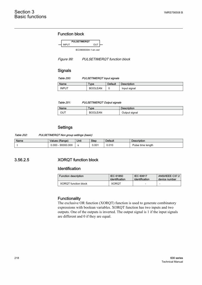
Function blockPULSETIMERQT
INPUT OUT
IEC09000304-1-en.vsdIEC09000304 V1 EN
Figure 99: PULSETIMERQT function block
Signals
Table 200: PULSETIMERQT Input signals
Name Type Default DescriptionINPUT BOOLEAN 0 Input signal
Table 201: PULSETIMERQT Output signals
Name Type DescriptionOUT BOOLEAN Output signal
Settings
Table 202: PULSETIMERQT Non group settings (basic)
Name Values (Range) Unit Step Default Descriptiont 0.000 - 90000.000 s 0.001 0.010 Pulse time length
3.56.2.5 XORQT function block
IdentificationFunction description IEC 61850
identificationIEC 60617identification
ANSI/IEEE C37.2device number
XORQT function block XORQT - -
FunctionalityThe exclusive OR function (XORQT) function is used to generate combinatoryexpressions with boolean variables. XORQT function has two inputs and twooutputs. One of the outputs is inverted. The output signal is 1 if the input signalsare different and 0 if they are equal.
Section 3 1MRS756508 BBasic functions
218 630 seriesTechnical Manual
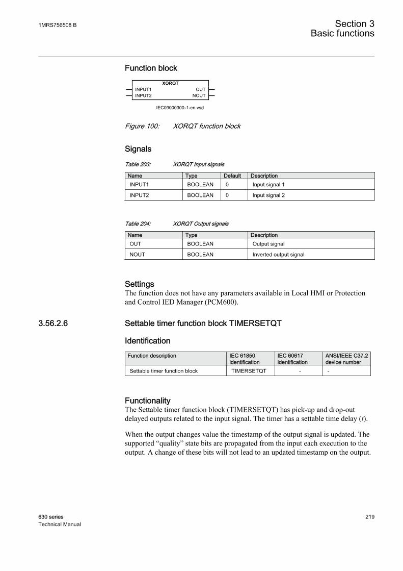
Function blockXORQT
INPUT1INPUT2
OUTNOUT
IEC09000300-1-en.vsdIEC09000300 V1 EN
Figure 100: XORQT function block
Signals
Table 203: XORQT Input signals
Name Type Default DescriptionINPUT1 BOOLEAN 0 Input signal 1
INPUT2 BOOLEAN 0 Input signal 2
Table 204: XORQT Output signals
Name Type DescriptionOUT BOOLEAN Output signal
NOUT BOOLEAN Inverted output signal
SettingsThe function does not have any parameters available in Local HMI or Protectionand Control IED Manager (PCM600).
3.56.2.6 Settable timer function block TIMERSETQT
IdentificationFunction description IEC 61850
identificationIEC 60617identification
ANSI/IEEE C37.2device number
Settable timer function block TIMERSETQT - -
FunctionalityThe Settable timer function block (TIMERSETQT) has pick-up and drop-outdelayed outputs related to the input signal. The timer has a settable time delay (t).
When the output changes value the timestamp of the output signal is updated. Thesupported “quality” state bits are propagated from the input each execution to theoutput. A change of these bits will not lead to an updated timestamp on the output.
1MRS756508 B Section 3Basic functions
630 series 219Technical Manual

On
Off
t
tdelay
tdelay
en08000289-2-en.vsd
Input
IEC08000289 V1 EN
Figure 101: TIMERSETQT function
Function blockTIMERSETQT
INPUT ONOFF
IEC09000303-1-en.vsdIEC09000303 V1 EN
Figure 102: TIMERSETQT function block
Signals
Table 205: TIMERSETQT Input signals
Name Type Default DescriptionINPUT BOOLEAN 0 Input signal
Table 206: TIMERSETQT Output signals
Name Type DescriptionON BOOLEAN Output signal, pick-up delayed
OFF BOOLEAN Output signal, drop-out delayed
Settings
Table 207: TIMERSETQT Group settings (basic)
Name Values (Range) Unit Step Default DescriptionOperation Off
On- - Off Operation Off/On
t 0.000 - 90000.000 s 0.001 0.000 Delay for settable timer n
Section 3 1MRS756508 BBasic functions
220 630 seriesTechnical Manual
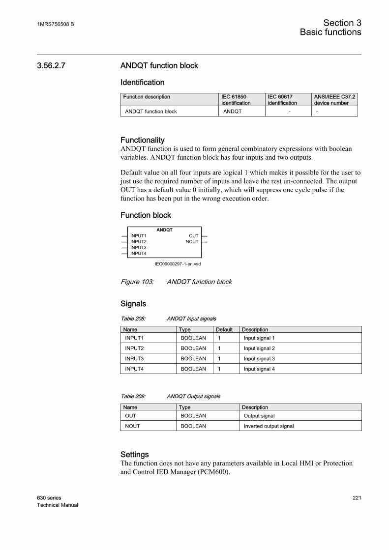
3.56.2.7 ANDQT function block
IdentificationFunction description IEC 61850
identificationIEC 60617identification
ANSI/IEEE C37.2device number
ANDQT function block ANDQT - -
FunctionalityANDQT function is used to form general combinatory expressions with booleanvariables. ANDQT function block has four inputs and two outputs.
Default value on all four inputs are logical 1 which makes it possible for the user tojust use the required number of inputs and leave the rest un-connected. The outputOUT has a default value 0 initially, which will suppress one cycle pulse if thefunction has been put in the wrong execution order.
Function blockANDQT
INPUT1INPUT2INPUT3INPUT4
OUTNOUT
IEC09000297-1-en.vsdIEC09000297 V1 EN
Figure 103: ANDQT function block
Signals
Table 208: ANDQT Input signals
Name Type Default DescriptionINPUT1 BOOLEAN 1 Input signal 1
INPUT2 BOOLEAN 1 Input signal 2
INPUT3 BOOLEAN 1 Input signal 3
INPUT4 BOOLEAN 1 Input signal 4
Table 209: ANDQT Output signals
Name Type DescriptionOUT BOOLEAN Output signal
NOUT BOOLEAN Inverted output signal
SettingsThe function does not have any parameters available in Local HMI or Protectionand Control IED Manager (PCM600).
1MRS756508 B Section 3Basic functions
630 series 221Technical Manual
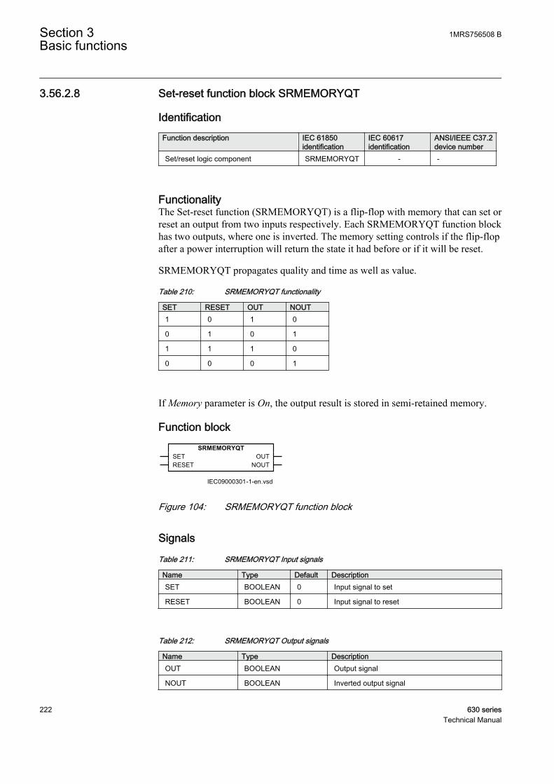
3.56.2.8 Set-reset function block SRMEMORYQT
IdentificationFunction description IEC 61850
identificationIEC 60617identification
ANSI/IEEE C37.2device number
Set/reset logic component SRMEMORYQT - -
FunctionalityThe Set-reset function (SRMEMORYQT) is a flip-flop with memory that can set orreset an output from two inputs respectively. Each SRMEMORYQT function blockhas two outputs, where one is inverted. The memory setting controls if the flip-flopafter a power interruption will return the state it had before or if it will be reset.
SRMEMORYQT propagates quality and time as well as value.
Table 210: SRMEMORYQT functionality
SET RESET OUT NOUT1 0 1 0
0 1 0 1
1 1 1 0
0 0 0 1
If Memory parameter is On, the output result is stored in semi-retained memory.
Function blockSRMEMORYQT
SETRESET
OUTNOUT
IEC09000301-1-en.vsdIEC09000301 V1 EN
Figure 104: SRMEMORYQT function block
Signals
Table 211: SRMEMORYQT Input signals
Name Type Default DescriptionSET BOOLEAN 0 Input signal to set
RESET BOOLEAN 0 Input signal to reset
Table 212: SRMEMORYQT Output signals
Name Type DescriptionOUT BOOLEAN Output signal
NOUT BOOLEAN Inverted output signal
Section 3 1MRS756508 BBasic functions
222 630 seriesTechnical Manual
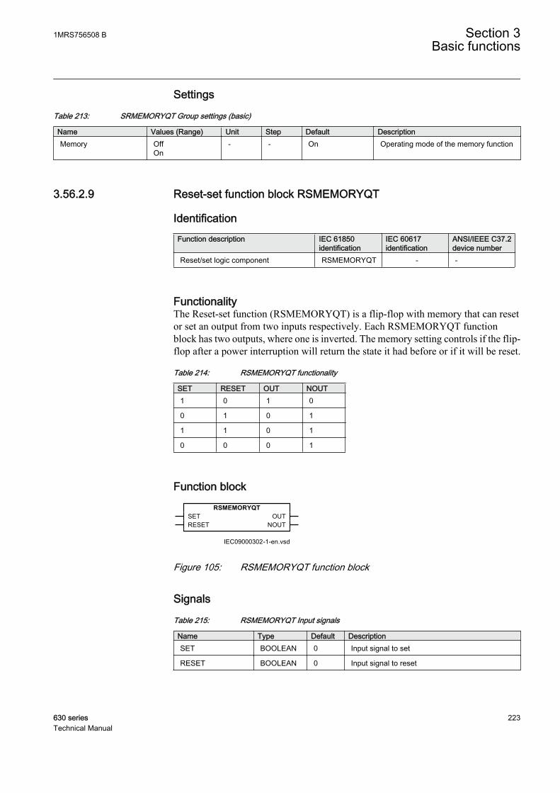
Settings
Table 213: SRMEMORYQT Group settings (basic)
Name Values (Range) Unit Step Default DescriptionMemory Off
On- - On Operating mode of the memory function
3.56.2.9 Reset-set function block RSMEMORYQT
IdentificationFunction description IEC 61850
identificationIEC 60617identification
ANSI/IEEE C37.2device number
Reset/set logic component RSMEMORYQT - -
FunctionalityThe Reset-set function (RSMEMORYQT) is a flip-flop with memory that can resetor set an output from two inputs respectively. Each RSMEMORYQT functionblock has two outputs, where one is inverted. The memory setting controls if the flip-flop after a power interruption will return the state it had before or if it will be reset.
Table 214: RSMEMORYQT functionality
SET RESET OUT NOUT1 0 1 0
0 1 0 1
1 1 0 1
0 0 0 1
Function blockRSMEMORYQT
SETRESET
OUTNOUT
IEC09000302-1-en.vsdIEC09000302 V1 EN
Figure 105: RSMEMORYQT function block
Signals
Table 215: RSMEMORYQT Input signals
Name Type Default DescriptionSET BOOLEAN 0 Input signal to set
RESET BOOLEAN 0 Input signal to reset
1MRS756508 B Section 3Basic functions
630 series 223Technical Manual
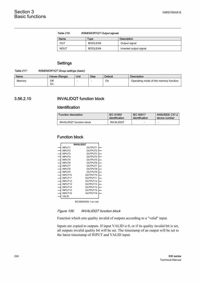
Table 216: RSMEMORYQT Output signals
Name Type DescriptionOUT BOOLEAN Output signal
NOUT BOOLEAN Inverted output signal
Settings
Table 217: RSMEMORYQT Group settings (basic)
Name Values (Range) Unit Step Default DescriptionMemory Off
On- - On Operating mode of the memory function
3.56.2.10 INVALIDQT function block
IdentificationFunction description IEC 61850
identificationIEC 60617identification
ANSI/IEEE C37.2device number
INVALIDQT function block INVALIDQT - -
Function blockINVALIDQT
INPUT1INPUT2INPUT3INPUT4INPUT5INPUT6INPUT7INPUT8INPUT9INPUT10INPUT11INPUT12INPUT13INPUT14INPUT15INPUT16VALID
OUTPUT1OUTPUT2OUTPUT3OUTPUT4OUTPUT5OUTPUT6OUTPUT7OUTPUT8OUTPUT9
OUTPUT10OUTPUT11OUTPUT12OUTPUT13OUTPUT14OUTPUT15OUTPUT16
IEC09000305-1-en.vsdIEC09000305 V1 EN
Figure 106: INVALIDQT function block
Function which sets quality invalid of outputs according to a "valid" input.
Inputs are copied to outputs. If input VALID is 0, or if its quality invalid bit is set,all outputs invalid quality bit will be set. The timestamp of an output will be set tothe latest timestamp of INPUT and VALID input.
Section 3 1MRS756508 BBasic functions
224 630 seriesTechnical Manual

Signals
Table 218: INVALIDQT Input signals
Name Type Default DescriptionINPUT1 BOOLEAN 0 Indication input 1
INPUT2 BOOLEAN 0 Indication input 2
INPUT3 BOOLEAN 0 Indication input 3
INPUT4 BOOLEAN 0 Indication input 4
INPUT5 BOOLEAN 0 Indication input 5
INPUT6 BOOLEAN 0 Indication input 6
INPUT7 BOOLEAN 0 Indication input 7
INPUT8 BOOLEAN 0 Indication input 8
INPUT9 BOOLEAN 0 Indication input 9
INPUT10 BOOLEAN 0 Indication input 10
INPUT11 BOOLEAN 0 Indication input 11
INPUT12 BOOLEAN 0 Indication input 12
INPUT13 BOOLEAN 0 Indication input 13
INPUT14 BOOLEAN 0 Indication input 14
INPUT15 BOOLEAN 0 Indication input 15
INPUT16 BOOLEAN 0 Indication input 16
VALID BOOLEAN 1 Inputs are valid or not
Table 219: INVALIDQT Output signals
Name Type DescriptionOUTPUT1 BOOLEAN Indication output 1
OUTPUT2 BOOLEAN Indication output 2
OUTPUT3 BOOLEAN Indication output 3
OUTPUT4 BOOLEAN Indication output 4
OUTPUT5 BOOLEAN Indication output 5
OUTPUT6 BOOLEAN Indication output 6
OUTPUT7 BOOLEAN Indication output 7
OUTPUT8 BOOLEAN Indication output 8
OUTPUT9 BOOLEAN Indication output 9
OUTPUT10 BOOLEAN Indication output 10
OUTPUT11 BOOLEAN Indication output 11
OUTPUT12 BOOLEAN Indication output 12
OUTPUT13 BOOLEAN Indication output 13
OUTPUT14 BOOLEAN Indication output 14
OUTPUT15 BOOLEAN Indication output 15
OUTPUT16 BOOLEAN Indication output 16
1MRS756508 B Section 3Basic functions
630 series 225Technical Manual
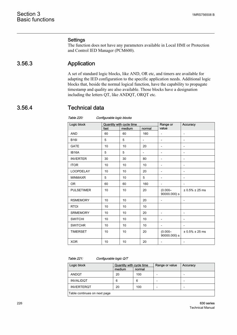
SettingsThe function does not have any parameters available in Local HMI or Protectionand Control IED Manager (PCM600).
3.56.3 ApplicationA set of standard logic blocks, like AND, OR etc, and timers are available foradapting the IED configuration to the specific application needs. Additional logicblocks that, beside the normal logical function, have the capability to propagatetimestamp and quality are also available. Those blocks have a designationincluding the letters QT, like ANDQT, ORQT etc.
3.56.4 Technical dataTable 220: Configurable logic blocks
Logic block Quantity with cycle time Range orvalue
Accuracyfast medium normal
AND 60 60 160 - -
B16I 5 5 - - -
GATE 10 10 20 - -
IB16A 5 5 - - -
INVERTER 30 30 80 - -
ITOR 10 10 10 - -
LOOPDELAY 10 10 20 - -
MINMAXR 5 10 5 - -
OR 60 60 160 - -
PULSETIMER 10 10 20 (0.000–90000.000) s
± 0.5% ± 25 ms
RSMEMORY 10 10 20 - -
RTOI 10 10 10
SRMEMORY 10 10 20 - -
SWITCHI 10 10 10 - -
SWITCHR 10 10 10 - -
TIMERSET 10 10 20 (0.000–90000.000) s
± 0.5% ± 25 ms
XOR 10 10 20 - -
Table 221: Configurable logic Q/T
Logic block Quantity with cycle time Range or value Accuracymedium normal
ANDQT 20 100 - -
INVALIDQT 6 6 - -
INVERTERQT 20 100 - -
Table continues on next page
Section 3 1MRS756508 BBasic functions
226 630 seriesTechnical Manual

Logic block Quantity with cycle time Range or value Accuracymedium normal
ORQT 20 100 - -
PULSETIMERQT 10 30 (0.000-90000.000) s
± 0.5% ± 25 ms
RSMEMORYQT 10 30 - -
SRMEMORYQT 10 30 - -
TIMERSETQT 10 30 (0.000-90000.000) s
± 0.5% ± 25 ms
XORQT 10 30 - -
3.57 Boolean 16 to integer conversion B16I
3.57.1 IdentificationFunction description IEC 61850
identificationIEC 60617identification
ANSI/IEEE C37.2device number
Boolean 16 to integer conversion B16I - -
3.57.2 FunctionalityBoolean 16 to integer conversion function (B16I) is used to transform a set of 16binary (logical) signals into an integer.
3.57.3 Function blockB16I
BLOCKIN1IN2IN3IN4IN5IN6IN7IN8IN9IN10IN11IN12IN13IN14IN15IN16
OUT
IEC09000035-1-en.vsd
IEC09000035 V1 EN
Figure 107: B16I function block
1MRS756508 B Section 3Basic functions
630 series 227Technical Manual

3.57.4 SignalsTable 222: B16I Input signals
Name Type Default DescriptionBLOCK BOOLEAN 0 Block of function
IN1 BOOLEAN 0 Input 1
IN2 BOOLEAN 0 Input 2
IN3 BOOLEAN 0 Input 3
IN4 BOOLEAN 0 Input 4
IN5 BOOLEAN 0 Input 5
IN6 BOOLEAN 0 Input 6
IN7 BOOLEAN 0 Input 7
IN8 BOOLEAN 0 Input 8
IN9 BOOLEAN 0 Input 9
IN10 BOOLEAN 0 Input 10
IN11 BOOLEAN 0 Input 11
IN12 BOOLEAN 0 Input 12
IN13 BOOLEAN 0 Input 13
IN14 BOOLEAN 0 Input 14
IN15 BOOLEAN 0 Input 15
IN16 BOOLEAN 0 Input 16
Table 223: B16I Output signals
Name Type DescriptionOUT INTEGER Output value
3.57.5 SettingsThe function does not have any parameters available in local HMI or Protectionand Control IED Manager (PCM600)
3.57.6 Monitored dataTable 224: B16I Monitored data
Name Type Values (Range) Unit DescriptionOUT INTEGER - - Output value
Section 3 1MRS756508 BBasic functions
228 630 seriesTechnical Manual

3.57.7 Operation principleBoolean 16 to integer conversion function (B16I) is used to transform a set of 16binary (logical) signals into an integer. The BLOCK input will freeze the output atthe last value.
3.58 Integer to boolean 16 conversion IB16A
3.58.1 IdentificationFunction description IEC 61850
identificationIEC 60617identification
ANSI/IEEE C37.2device number
Integer to boolean 16 conversion IB16A - -
3.58.2 FunctionalityInteger to boolean 16 conversion function (IB16A) is used to transform an integerinto a set of 16 binary (logical) signals.
3.58.3 Function blockIB16A
BLOCKINP
OUT1OUT2OUT3OUT4OUT5OUT6OUT7OUT8OUT9
OUT10OUT11OUT12OUT13OUT14OUT15OUT16
IEC09000036-1-en.vsd
IEC09000036 V1 EN
Figure 108: IB16A function block
3.58.4 SignalsTable 225: IB16A Input signals
Name Type Default DescriptionBLOCK BOOLEAN 0 Block of function
INP INTEGER 0 Integer Input
1MRS756508 B Section 3Basic functions
630 series 229Technical Manual

Table 226: IB16A Output signals
Name Type DescriptionOUT1 BOOLEAN Output 1
OUT2 BOOLEAN Output 2
OUT3 BOOLEAN Output 3
OUT4 BOOLEAN Output 4
OUT5 BOOLEAN Output 5
OUT6 BOOLEAN Output 6
OUT7 BOOLEAN Output 7
OUT8 BOOLEAN Output 8
OUT9 BOOLEAN Output 9
OUT10 BOOLEAN Output 10
OUT11 BOOLEAN Output 11
OUT12 BOOLEAN Output 12
OUT13 BOOLEAN Output 13
OUT14 BOOLEAN Output 14
OUT15 BOOLEAN Output 15
OUT16 BOOLEAN Output 16
3.58.5 SettingsThe function does not have any parameters available in local HMI or Protectionand Control IED Manager (PCM600)
3.58.6 Operation principleInteger to boolean 16 conversion function (IB16A) is used to transform an integerinto a set of 16 binary (logical) signals. IB16A function is designed for receivingthe integer input locally. The BLOCK input will freeze the logical outputs at thelast value.
3.59 Additional arithmetic and logic functions
3.59.1 Additional arithmetic and logic functionsThe additional arithmetic or logic functions are used in the ACT level as aconnection between function blocks.
The available arithmetic functions are integer addition, integer division, integermultiplication, integer subtraction, real addition, real division, real multiplication,real subtraction, integer to real conversion, real to integer conversion and ten inputreal minimum or maximum functionalities.
Section 3 1MRS756508 BBasic functions
230 630 seriesTechnical Manual
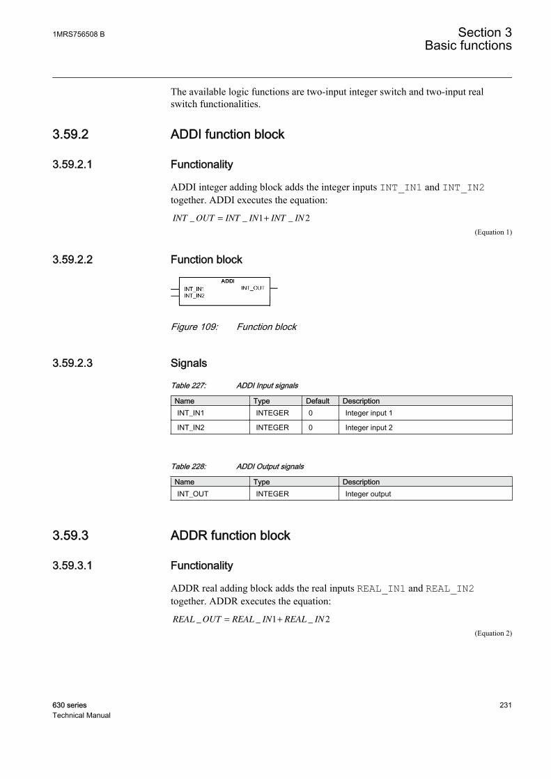
The available logic functions are two-input integer switch and two-input realswitch functionalities.
3.59.2 ADDI function block
3.59.2.1 Functionality
ADDI integer adding block adds the integer inputs INT_IN1 and INT_IN2together. ADDI executes the equation:
INT OUT INT IN INT IN_ _ _= +1 2
GUID-2572C1EA-50AF-4C6D-B2EF-99F3BD78DCCF V1 EN (Equation 1)
3.59.2.2 Function block
GUID-C7C029E0-7214-4A90-BE19-806DF678D510 V1 EN
Figure 109: Function block
3.59.2.3 Signals
Table 227: ADDI Input signals
Name Type Default DescriptionINT_IN1 INTEGER 0 Integer input 1
INT_IN2 INTEGER 0 Integer input 2
Table 228: ADDI Output signals
Name Type DescriptionINT_OUT INTEGER Integer output
3.59.3 ADDR function block
3.59.3.1 Functionality
ADDR real adding block adds the real inputs REAL_IN1 and REAL_IN2together. ADDR executes the equation:
REAL OUT REAL IN REAL IN_ _ _= +1 2
GUID-6E181221-5580-4964-8D65-A4319CF5E804 V1 EN (Equation 2)
1MRS756508 B Section 3Basic functions
630 series 231Technical Manual

3.59.3.2 Function block
GUID-7D1CAD31-BE10-49C1-BB23-87E53304EB01 V1 EN
Figure 110: Function block
3.59.3.3 Signals
Table 229: ADDR Input signals
Name Type Default DescriptionREAL_IN1 REAL 0.0 Real input 1
REAL_IN2 REAL 0.0 Real input 2
Table 230: ADDR Output signals
Name Type DescriptionREAL_OUT REAL Real output
3.59.4 DIVI function block
3.59.4.1 Functionality
DIVI integer division block divides the INT_IN1 input by INT_IN2. The outputof the division, the module of division INT_OUT_MOD and the validity of integerdivision in case of division by zero INT_VALID.
DIVI executes two equations
INT OUTINT IN
INT IN_
_
_=
1
2
GUID-7834309B-7558-4D99-9D0C-68FEC275B5A3 V1 EN (Equation 3)
INT OUT MOD MODINT IN
INT IN_ _
_
_=
1
2
GUID-39E9D90A-2266-4FF1-AF18-3BB2BF892A23 V1 EN (Equation 4)
Table 231: INT_VALID behavior
Input INT_IN2 Output INT_VALIDZero FALSE
Lower or higher than zero TRUE
Section 3 1MRS756508 BBasic functions
232 630 seriesTechnical Manual

3.59.4.2 Function block
GUID-B761969D-C7F8-4D25-B6AE-FEBA6F9A112C V1 EN
Figure 111: Function block
3.59.4.3 Signals
Table 232: DIVI Input signals
Name Type Default DescriptionINT_IN1 INTEGER 0 Integer input 1
INT_IN2 INTEGER 0 Integer input 2
Table 233: DIVI Output signals
Name Type DescriptionINT_OUT INTEGER Integer output
INT_VALID BOOLEAN Integer output validity
INT_OUT_MOD INTEGER Integer output division modulo
3.59.5 DIVR function block
3.59.5.1 Functionality
DIVR real division block divides the REAL_IN1 input by REAL_IN2. Theoutputs are the division and the division validity in case of division by zeroREAL_VALID.
DIVR executes an equation
REAL OUTREAL IN
REAL IN_
_
_=
1
2
GUID-14B9E785-FDB8-410A-BB65-3ABE49A09DA5 V1 EN (Equation 5)
Table 234: REAL_VALID behavior
Input REAL_IN2 Output REAL_VALIDZero FALSE
Lower or higher than zero TRUE
1MRS756508 B Section 3Basic functions
630 series 233Technical Manual
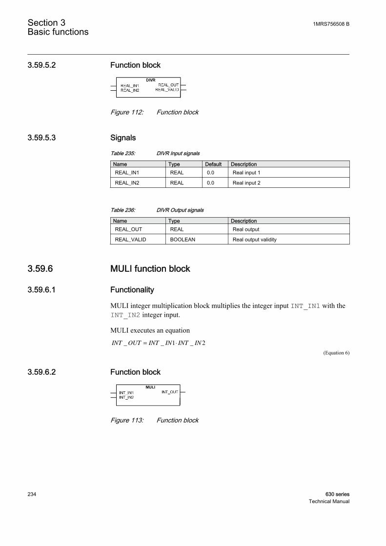
3.59.5.2 Function block
GUID-6B1B85CC-3125-4429-88D9-11EBA237F658 V1 EN
Figure 112: Function block
3.59.5.3 Signals
Table 235: DIVR Input signals
Name Type Default DescriptionREAL_IN1 REAL 0.0 Real input 1
REAL_IN2 REAL 0.0 Real input 2
Table 236: DIVR Output signals
Name Type DescriptionREAL_OUT REAL Real output
REAL_VALID BOOLEAN Real output validity
3.59.6 MULI function block
3.59.6.1 Functionality
MULI integer multiplication block multiplies the integer input INT_IN1 with theINT_IN2 integer input.
MULI executes an equation
INT OUT INT IN INT IN_ _ _= ⋅1 2
GUID-87381AFB-2C81-4904-B026-7F7235346A3F V1 EN (Equation 6)
3.59.6.2 Function block
GUID-D0EA1F48-3533-45D9-8BFF-7A256919D23A V1 EN
Figure 113: Function block
Section 3 1MRS756508 BBasic functions
234 630 seriesTechnical Manual

3.59.6.3 Signals
Table 237: MULI Input signals
Name Type Default DescriptionINT_IN1 INTEGER 0 Integer input 1
INT_IN2 INTEGER 0 Integer input 2
Table 238: MULI Output signals
Name Type DescriptionINT_OUT INTEGER Integer output
3.59.7 MULR function block
3.59.7.1 Functionality
MULR real multiplication block multiplies the real input REAL_IN1 with the realinput REAL_IN2.
MULR executes the equation:
REAL OUT REAL IN REAL IN_ _ _= ⋅1 2
GUID-2351068B-A88E-40B6-A66C-C519A593321D V1 EN (Equation 7)
3.59.7.2 Function block
GUID-4FA9C990-EB79-4DAA-BCD5-B970683162E7 V1 EN
Figure 114: Function block
3.59.7.3 Signals
Table 239: MULR Input signals
Name Type Default DescriptionREAL_IN1 REAL 0.0 Real input 1
REAL_IN2 REAL 0.0 Real input 2
Table 240: MULR Output signals
Name Type DescriptionREAL_OUT REAL Real output
1MRS756508 B Section 3Basic functions
630 series 235Technical Manual
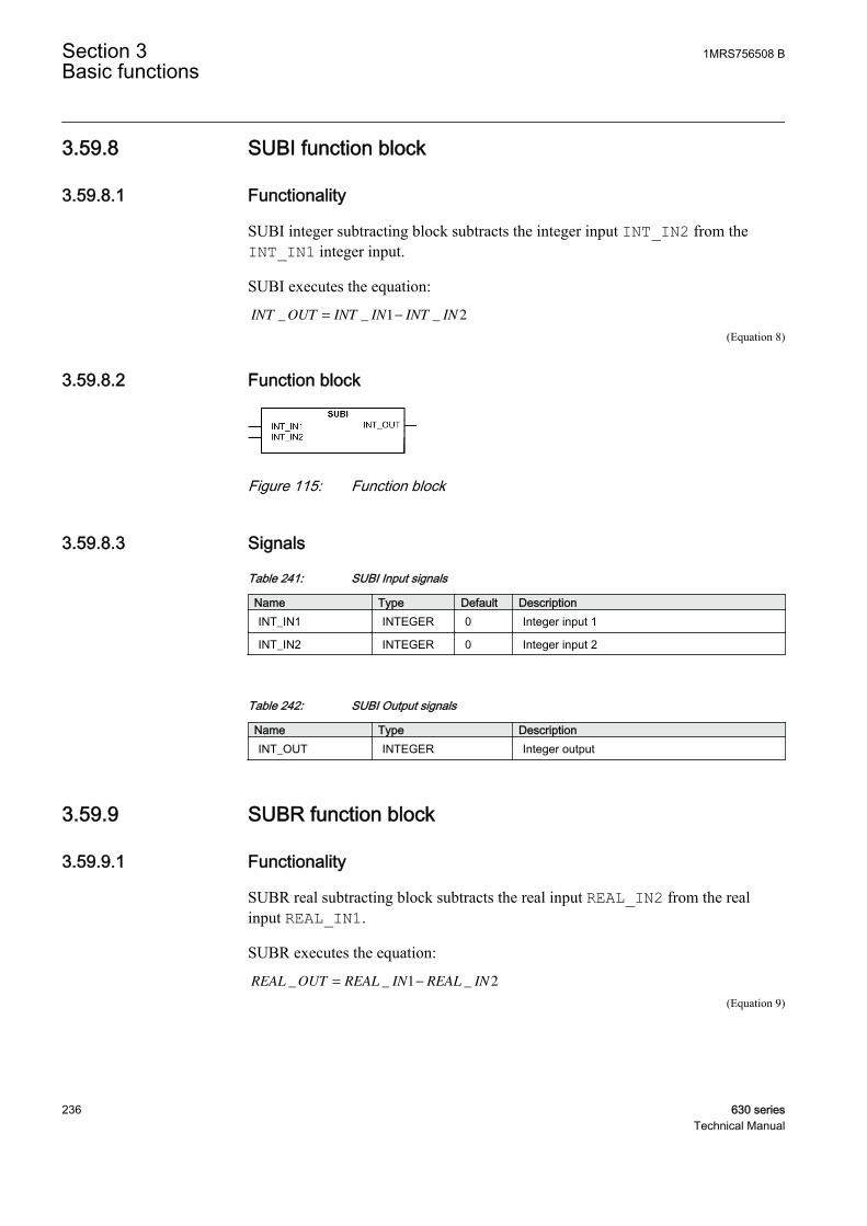
3.59.8 SUBI function block
3.59.8.1 Functionality
SUBI integer subtracting block subtracts the integer input INT_IN2 from theINT_IN1 integer input.
SUBI executes the equation:
INT OUT INT IN INT IN_ _ _= −1 2
GUID-1289EF1B-D197-46B3-8F54-5FE151ECC5E3 V1 EN (Equation 8)
3.59.8.2 Function block
GUID-6B9207E6-88BA-43C0-9017-E8BD5C25FE2B V1 EN
Figure 115: Function block
3.59.8.3 Signals
Table 241: SUBI Input signals
Name Type Default DescriptionINT_IN1 INTEGER 0 Integer input 1
INT_IN2 INTEGER 0 Integer input 2
Table 242: SUBI Output signals
Name Type DescriptionINT_OUT INTEGER Integer output
3.59.9 SUBR function block
3.59.9.1 Functionality
SUBR real subtracting block subtracts the real input REAL_IN2 from the realinput REAL_IN1.
SUBR executes the equation:
REAL OUT REAL IN REAL IN_ _ _= −1 2
GUID-2BD26A2C-31AA-4660-ABC3-5675589E9E54 V1 EN (Equation 9)
Section 3 1MRS756508 BBasic functions
236 630 seriesTechnical Manual
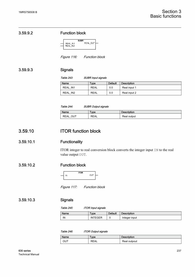
3.59.9.2 Function block
GUID-1594E7C3-491A-4F11-8250-7EBF5E67E476 V1 EN
Figure 116: Function block
3.59.9.3 Signals
Table 243: SUBR Input signals
Name Type Default DescriptionREAL_IN1 REAL 0.0 Real input 1
REAL_IN2 REAL 0.0 Real input 2
Table 244: SUBR Output signals
Name Type DescriptionREAL_OUT REAL Real output
3.59.10 ITOR function block
3.59.10.1 Functionality
ITOR integer to real conversion block converts the integer input IN to the realvalue output OUT.
3.59.10.2 Function block
GUID-E281071A-813C-4060-B076-4C79C412DEC4 V1 EN
Figure 117: Function block
3.59.10.3 Signals
Table 245: ITOR Input signals
Name Type Default DescriptionIN INTEGER 0 Integer input
Table 246: ITOR Output signals
Name Type DescriptionOUT REAL Real outpout
1MRS756508 B Section 3Basic functions
630 series 237Technical Manual

3.59.11 RTOI function block
3.59.11.1 Functionality
RTOI real to integer conversion block converts the real input IN to the integervalue output OUT with the validity information OUT_VAL as the real value canexceed the integer size.
Table 247: RTOI OUT_VAL logic
Value of OUT_VAL DescriptionTRUE Integer conversion valid
FALSE Absolute real input size exceeds the maximuminteger size
3.59.11.2 Function block
GUID-4BBB4336-8318-4330-B65D-C49411F71BAB V1 EN
Figure 118: Function block
3.59.11.3 Signals
Table 248: RTOI Input signals
Name Type Default DescriptionINT REAL 0.0 Real input
Table 249: RTOI Output signals
Name Type DescriptionOUT INTEGER Integer output
OUT_VAL BOOLEAN Output conversion validity
3.59.12 MINMAXR function block
3.59.12.1 Functionality
MINMAXR minimum and maximum value selector from the real input signalsfinds the minimum and maximum value from the ten inputs and gives thequantities of these to the outputs MIN and MAX as well as the channel number thathas the absolute minimum and maximum values MIN_IN_CH and MAX_IN_CH.When using less than ten inputs, the last connected input should be connected to allthe rest open inputs for correct operation.
Section 3 1MRS756508 BBasic functions
238 630 seriesTechnical Manual
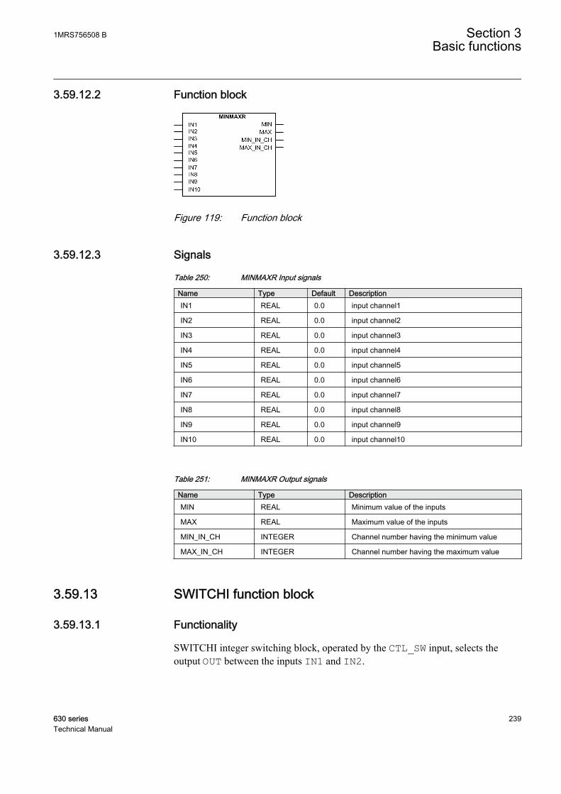
3.59.12.2 Function block
GUID-C32ADA8A-F602-4C1C-BBCB-A7D491B94301 V1 EN
Figure 119: Function block
3.59.12.3 Signals
Table 250: MINMAXR Input signals
Name Type Default DescriptionIN1 REAL 0.0 input channel1
IN2 REAL 0.0 input channel2
IN3 REAL 0.0 input channel3
IN4 REAL 0.0 input channel4
IN5 REAL 0.0 input channel5
IN6 REAL 0.0 input channel6
IN7 REAL 0.0 input channel7
IN8 REAL 0.0 input channel8
IN9 REAL 0.0 input channel9
IN10 REAL 0.0 input channel10
Table 251: MINMAXR Output signals
Name Type DescriptionMIN REAL Minimum value of the inputs
MAX REAL Maximum value of the inputs
MIN_IN_CH INTEGER Channel number having the minimum value
MAX_IN_CH INTEGER Channel number having the maximum value
3.59.13 SWITCHI function block
3.59.13.1 Functionality
SWITCHI integer switching block, operated by the CTL_SW input, selects theoutput OUT between the inputs IN1 and IN2.
1MRS756508 B Section 3Basic functions
630 series 239Technical Manual

Table 252: SWITCHI output logic
CTL_SW OUTFALSE IN2
TRUE IN1
3.59.13.2 Function block
GUID-657E28F9-4646-4574-AEC2-50B022C17B93 V1 EN
Figure 120: Function block
3.59.13.3 Signals
Table 253: SWITCHI Input signals
Name Type Default DescriptionCTL_SW BOOLEAN 1 Control Switch
IN1 INTEGER 0 Integer input 1
IN2 INTEGER 0 Integer input 2
Table 254: SWITCHI Output signals
Name Type DescriptionOUT INTEGER Integer switch output
3.59.14 SWITCHR function block
3.59.14.1 Functionality
SWITCHR real switching block, operated by the CTL_SW input, selects the outputvalue OUT between the IN1 and IN2 inputs.
CTL_SW OUTFALSE IN2
TRUE IN1
Section 3 1MRS756508 BBasic functions
240 630 seriesTechnical Manual
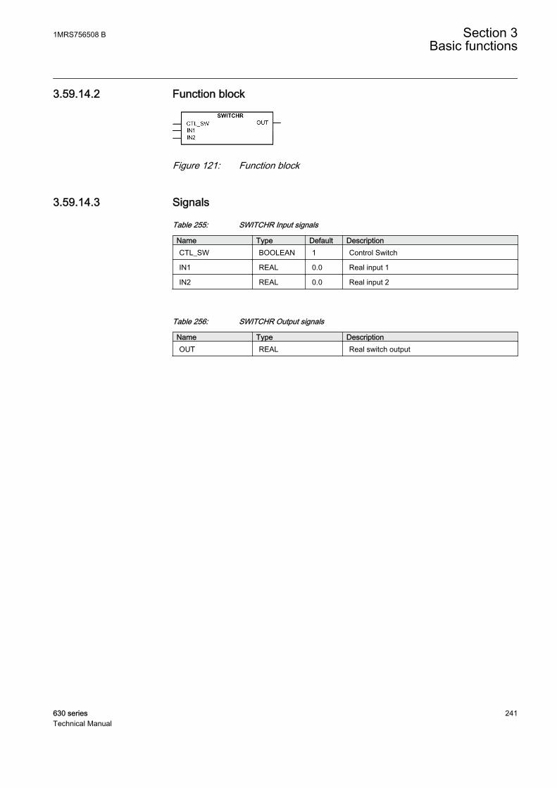
3.59.14.2 Function block
GUID-63F5ED57-E6C4-40A2-821A-4814E1554663 V1 EN
Figure 121: Function block
3.59.14.3 Signals
Table 255: SWITCHR Input signals
Name Type Default DescriptionCTL_SW BOOLEAN 1 Control Switch
IN1 REAL 0.0 Real input 1
IN2 REAL 0.0 Real input 2
Table 256: SWITCHR Output signals
Name Type DescriptionOUT REAL Real switch output
1MRS756508 B Section 3Basic functions
630 series 241Technical Manual

242

Section 4 Protection functions
4.1 Three-phase current protection
4.1.1 Three-phase non-directional overcurrent protectionPHxPTOC
4.1.1.1 Identification
Function description IEC 61850identification
IEC 60617identification
ANSI/IEEE C37.2device number
Three-phase non-directionalovercurrent protection - Low stage
PHLPTOC 3I> 51P-1
Three-phase non-directionalovercurrent protection - High stage
PHHPTOC 3I>> 51P-2
Three-phase non-directionalovercurrent protection - Instantaneousstage
PHIPTOC 3I>>> 50P/51P
4.1.1.2 Function block
A070990 V1 EN
Figure 122: Function block
4.1.1.3 Functionality
The three-phase overcurrent protection PHxPTOC is used as one-phase, two-phaseor three-phase non-directional overcurrent and short-circuit protection for feeders.
The function starts when the current exceeds the set limit. The operate timecharacteristics for low stage PHLPTOC and high stage PHHPTOC can be selectedto be either definite time (DT) or inverse definite minimum time (IDMT).Theinstantaneous stage PHIPTOC always operates with the DT characteristic.
1MRS756508 B Section 4Protection functions
630 series 243Technical Manual

In the DT mode, the function operates after a predefined operate time and resetswhen the fault current disappears. The IDMT mode provides current-dependenttimer characteristics.
The function contains a blocking functionality. It is possible to block functionoutputs, timers or the function itself, if desired.
4.1.1.4 Operation principle
The function can be enabled and disabled with the Operation setting. Thecorresponding parameter values are "On" and "Off".
The operation of three-phase non-directional overcurrent protection can bedescribed by using a module diagram. All the modules in the diagram are explainedin the next sections.
A070996 V1 EN
Figure 123: Functional module diagram. Group signal I3P is used for feedingthe necessary analog signals to the function.
Level detectorThe measured phase currents are compared phasewise to the set Start value. If themeasured value exceeds the set Start value, the level detector reports the exceedingof the value to the phase selection logic. If the ENA_MULT input is active, the Startvalue setting is multiplied by the Start value Mult setting.
Do not set the multiplier setting Start value Mult higher thannecessary. If the value is too high, the function may not operate atall during an inrush followed by a fault, no matter how severe thefault is.
The start value multiplication is normally done when the inrush detection function(INRPHAR) is connected to the ENA_MULT input.
Section 4 1MRS756508 BProtection functions
244 630 seriesTechnical Manual

A070554 V1 EN
Figure 124: Start value behavior with ENA_MULT input activated
Phase selection logicIf the fault criteria are fulfilled in the level detector, the phase selection logicdetects the phase or phases in which the measured current exceeds the setting. Ifthe phase information matches the Num of start phases setting, the phase selectionlogic activates the timer module.
TimerOnce activated, the timer activates the START output. The ST_A, ST_B and ST_Coutputs are used to indicate which phases are started. Depending on the value ofthe Operating curve type setting, the time characteristics are according to DT orIDMT. When the operation timer has reached the value of Operate delay time inthe DT mode or the maximum value defined by the inverse time curve, theOPERATE output is activated. The OPR_A, OPR_B and OPR_C outputs are used toindicate which phases are operated.
When the user-programmable IDMT curve is selected, the operation timecharacteristics are defined by the parameters Curve parameter A, Curve parameterB, Curve parameter C, Curve parameter D and Curve parameter E.
If a drop-off situation happens, that is, a fault suddenly disappears before theoperate delay is exceeded, the timer reset state is activated. The functionality of thetimer in the reset state depends on the combination of the Operating curve type,Type of reset curve and Reset delay time settings. When the DT characteristic isselected, the reset timer runs until the set Reset delay time value is exceeded. When
1MRS756508 B Section 4Protection functions
630 series 245Technical Manual
the IDMT curves are selected, the Type of reset curve setting can be set to"Immediate", "Def time reset" or "Inverse reset". The reset curve type "Immediate"causes an immediate reset. With the reset curve type "Def time reset", the resettime depends on the Reset delay time setting. With the reset curve type "Inversereset", the reset time depends on the current during the drop-off situation. TheSTART output is deactivated when the reset timer has elapsed.
The "Inverse reset" selection is only supported with ANSI or userprogrammable types of the IDMT operating curves. If anotheroperating curve type is selected, an immediate reset occurs duringthe drop-off situation.
The setting Time multiplier is used for scaling the IDMT operate and reset times.
The setting parameter Minimum operate time defines the minimum desired operatetime for IDMT. The setting is applicable only when the IDMT curves are used.
The Minimum operate time setting should be used with great carebecause the operation time is according to the IDMT curve, butalways at least the value of the Minimum operate time setting. Formore information, see the General function block features sectionin this manual.
The timer calculates the start duration value START_DUR, which indicates thepercentage ratio of the start situation and the set operating time. The value isavailable in the monitored data view.
The binary input BLOCK can be used to block the function. The activation of theBLOCK input deactivates all outputs and resets internal timers. The binary inputBLK_ST can be used to block the start signals. The binary input BLK_OPR can beused to block the operation signals. The operation timer counting can be frozen tothe prevailing value by activating the FR_TIMER input.
4.1.1.5 Base values
In this function block, some of the settings are set in per unit (pu). These pu valuesare relational to certain base values, for example the values given in A, kV andkVA. The IED supports alternative base value groups for the phase current or voltage-related settings, for example "Phase Grp 1", "Phase Grp 2" and "Phase Grp 3".One of the groups to be used with the Base value Sel phase setting must be selected.
For more information, see the Basic functions section in this manual.
Section 4 1MRS756508 BProtection functions
246 630 seriesTechnical Manual
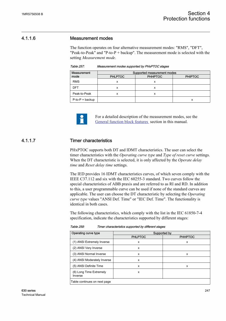
4.1.1.6 Measurement modes
The function operates on four alternative measurement modes: "RMS", "DFT","Peak-to-Peak" and "P-to-P + backup". The measurement mode is selected with thesetting Measurement mode.
Table 257: Measurement modes supported by PHxPTOC stages
Measurementmode
Supported measurement modesPHLPTOC PHHPTOC PHIPTOC
RMS x x
DFT x x
Peak-to-Peak x x
P-to-P + backup x
For a detailed description of the measurement modes, see theGeneral function block features section in this manual.
4.1.1.7 Timer characteristics
PHxPTOC supports both DT and IDMT characteristics. The user can select thetimer characteristics with the Operating curve type and Type of reset curve settings.When the DT characteristic is selected, it is only affected by the Operate delaytime and Reset delay time settings.
The IED provides 16 IDMT characteristics curves, of which seven comply with theIEEE C37.112 and six with the IEC 60255-3 standard. Two curves follow thespecial characteristics of ABB praxis and are referred to as RI and RD. In additionto this, a user programmable curve can be used if none of the standard curves areapplicable. The user can choose the DT characteristic by selecting the Operatingcurve type values "ANSI Def. Time" or "IEC Def. Time". The functionality isidentical in both cases.
The following characteristics, which comply with the list in the IEC 61850-7-4specification, indicate the characteristics supported by different stages:
Table 258: Timer characteristics supported by different stages
Operating curve type Supported byPHLPTOC PHHPTOC
(1) ANSI Extremely Inverse x x
(2) ANSI Very Inverse x
(3) ANSI Normal Inverse x x
(4) ANSI Moderately Inverse x
(5) ANSI Definite Time x x
(6) Long Time ExtremelyInverse
x
Table continues on next page
1MRS756508 B Section 4Protection functions
630 series 247Technical Manual

Operating curve type Supported byPHLPTOC PHHPTOC
(7) Long Time Very Inverse x
(8) Long Time Inverse x
(9) IEC Normal Inverse x x
(10) IEC Very Inverse x x
(11) IEC Inverse x
(12) IEC Extremely Inverse x x
(13) IEC Short Time Inverse x
(14) IEC Long Time Inverse x
(15) IEC Definite Time x x
(17) User programmable x x
(18) RI type x
(19) RD type x
PHIPTOC supports only definite time characteristic.
For a detailed description of timers, see the General function blockfeatures section in this manual.
Table 259: Reset time characteristics supported by different stages
Reset curve type Supported by PHLPTOC PHHPTOC Note
(1) Immediate x x Available for alloperate time curves
(2) Def time reset x x Available for alloperate time curves
(3) Inverse reset x x Available only for ANSIand userprogrammable curves
The Type of reset curve setting does not apply to PHIPTOC orwhen the DT operation is selected. The reset is purely defined bythe Reset delay time setting.
4.1.1.8 Application
PHxPTOC is used in several applications in the power system. The applicationsinclude but are not limited to:
Section 4 1MRS756508 BProtection functions
248 630 seriesTechnical Manual
• Selective overcurrent and short-circuit protection of feeders in distribution andsubtransmission systems
• Backup overcurrent and short-circuit protection of power transformers andgenerators
• Overcurrent and short-circuit protection of various devices connected to thepower system, for example shunt capacitor banks, shunt reactors and motors
• General backup protection
PHxPTOC is used for single-phase, two-phase and three-phase non-directionalovercurrent and short-circuit protection. Typically, overcurrent protection is usedfor clearing two and three-phase short circuits. Therefore, the user can choose howmany phases, at minimum, must have currents above the start level for the functionto operate. When the number of start-phase settings is set to "1 out of 3", theoperation of PHxPTOC is enabled with the presence of high current in one-phase.
When the setting is "2 out of 3" or "3 out of 3", single-phase faultsare not detected. The setting "3 out of 3" requires the fault to bepresent in all three phases.
Many applications require several steps using different current start levels and timedelays. PHxPTOC consists of three protection stages:
• Low PHLPTOC• High PHHPTOC• Instantaneous PHIPTOC.
PHLPTOC is used for overcurrent protection. The function contains several typesof time-delay characteristics. PHHPTOC and PHIPTOC are used for fast clearanceof very high overcurrent situations.
Transformer and busbar overcurrent protection with reverse blockingprincipleBy implementing a full set of overcurrent protection stages and blocking channelsbetween the protection stages of the incoming feeders, bus-tie and outgoingfeeders, it is possible to speed up the operation of overcurrent protection in thebusbar and transformer LV-side faults without impairing the selectivity. Also, thesecurity degree of busbar protection is increased, because there is now a dedicated,selective and fast busbar protection functionality which is based on the blockableovercurrent protection principle. The additional time selective stages on thetransformer HV and LV-sides provide increased security degree of backupprotection for the transformer, busbar and also for the outgoing feeders.
Depending on the overcurrent stage in question, the selectivity of the scheme inFigure 125 is based on the operating current, operating time or blockings betweensuccessive overcurrent stages. With blocking channels, the operating time of theprotection can be drastically shortened if compared to the simple time selectiveprotection. In addition to the busbar protection, this blocking principle is applicable
1MRS756508 B Section 4Protection functions
630 series 249Technical Manual
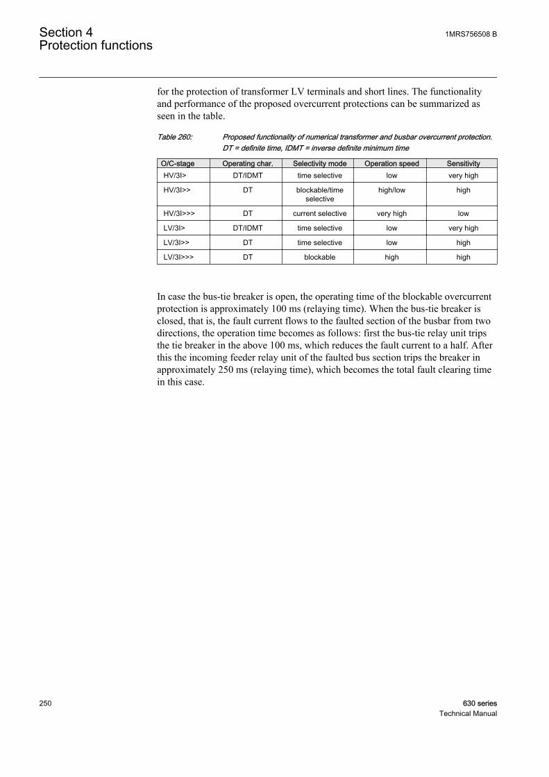
for the protection of transformer LV terminals and short lines. The functionalityand performance of the proposed overcurrent protections can be summarized asseen in the table.
Table 260: Proposed functionality of numerical transformer and busbar overcurrent protection.DT = definite time, IDMT = inverse definite minimum time
O/C-stage Operating char. Selectivity mode Operation speed SensitivityHV/3I> DT/IDMT time selective low very high
HV/3I>> DT blockable/timeselective
high/low high
HV/3I>>> DT current selective very high low
LV/3I> DT/IDMT time selective low very high
LV/3I>> DT time selective low high
LV/3I>>> DT blockable high high
In case the bus-tie breaker is open, the operating time of the blockable overcurrentprotection is approximately 100 ms (relaying time). When the bus-tie breaker isclosed, that is, the fault current flows to the faulted section of the busbar from twodirections, the operation time becomes as follows: first the bus-tie relay unit tripsthe tie breaker in the above 100 ms, which reduces the fault current to a half. Afterthis the incoming feeder relay unit of the faulted bus section trips the breaker inapproximately 250 ms (relaying time), which becomes the total fault clearing timein this case.
Section 4 1MRS756508 BProtection functions
250 630 seriesTechnical Manual
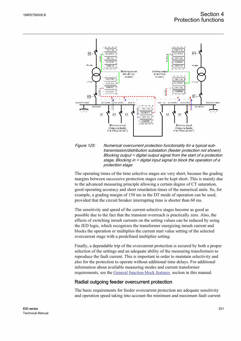
A070980 V2 EN
Figure 125: Numerical overcurrent protection functionality for a typical sub-transmission/distribution substation (feeder protection not shown).Blocking output = digital output signal from the start of a protectionstage, Blocking in = digital input signal to block the operation of aprotection stage
The operating times of the time selective stages are very short, because the gradingmargins between successive protection stages can be kept short. This is mainly dueto the advanced measuring principle allowing a certain degree of CT saturation,good operating accuracy and short retardation times of the numerical units. So, forexample, a grading margin of 150 ms in the DT mode of operation can be used,provided that the circuit breaker interrupting time is shorter than 60 ms.
The sensitivity and speed of the current-selective stages become as good aspossible due to the fact that the transient overreach is practically zero. Also, theeffects of switching inrush currents on the setting values can be reduced by usingthe IED logic, which recognizes the transformer energizing inrush current andblocks the operation or multiplies the current start value setting of the selectedovercurrent stage with a predefined multiplier setting.
Finally, a dependable trip of the overcurrent protection is secured by both a properselection of the settings and an adequate ability of the measuring transformers toreproduce the fault current. This is important in order to maintain selectivity andalso for the protection to operate without additional time delays. For additionalinformation about available measuring modes and current transformerrequirements, see the General function block features section in this manual.
Radial outgoing feeder overcurrent protectionThe basic requirements for feeder overcurrent protection are adequate sensitivityand operation speed taking into account the minimum and maximum fault current
1MRS756508 B Section 4Protection functions
630 series 251Technical Manual

levels along the protected line, selectivity requirements, inrush currents and thethermal and mechanical withstand of the lines to be protected.
In many cases the above requirements can be best fulfilled by using multiple-stageovercurrent units. Figure 126 shows an example of this. A brief coordination studyhas been carried out between the incoming and outgoing feeders.
The protection scheme is implemented with three-stage numerical overcurrentprotection, where the low-set stage PHLPTOC operates in IDMT-mode and thetwo higher stages PHHPTOC and PHIPTOC in DT-mode. Also the thermalwithstand of the line types along the feeder and maximum expected inrush currentsof the feeders are shown. Faults occurring near the station where the fault currentlevels are the highest are cleared rapidly by the instantaneous stage in order tominimize the effects of severe short circuit faults. The influence of the inrushcurrent is taken into consideration by connecting the inrush current detector to thestart value multiplying input of the instantaneous stage. By this way the start valueis multiplied with a predefined setting during the inrush situation and nuisancetripping can be avoided.
Section 4 1MRS756508 BProtection functions
252 630 seriesTechnical Manual

A070982 V1 EN
Figure 126: Functionality of numerical multiple-stage overcurrent protection
The coordination plan is an effective tool to study the operation of time selectiveoperation characteristics. All the points mentioned earlier, required to define theovercurrent protection parameters, can be expressed simultaneously in acoordination plan. In Figure 127, the coordination plan shows an example ofoperation characteristics in the LV-side incoming feeder and radial outgoing feeder.
1MRS756508 B Section 4Protection functions
630 series 253Technical Manual
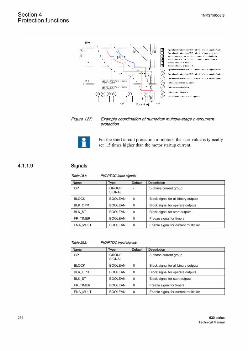
A070984 V2 EN
Figure 127: Example coordination of numerical multiple-stage overcurrentprotection
For the short circuit protection of motors, the start value is typicallyset 1.5 times higher than the motor startup current.
4.1.1.9 Signals
Table 261: PHLPTOC Input signals
Name Type Default DescriptionI3P GROUP
SIGNAL- 3-phase current group
BLOCK BOOLEAN 0 Block signal for all binary outputs
BLK_OPR BOOLEAN 0 Block signal for operate outputs
BLK_ST BOOLEAN 0 Block signal for start outputs
FR_TIMER BOOLEAN 0 Freeze signal for timers
ENA_MULT BOOLEAN 0 Enable signal for current multiplier
Table 262: PHHPTOC Input signals
Name Type Default DescriptionI3P GROUP
SIGNAL- 3-phase current group
BLOCK BOOLEAN 0 Block signal for all binary outputs
BLK_OPR BOOLEAN 0 Block signal for operate outputs
BLK_ST BOOLEAN 0 Block signal for start outputs
FR_TIMER BOOLEAN 0 Freeze signal for timers
ENA_MULT BOOLEAN 0 Enable signal for current multiplier
Section 4 1MRS756508 BProtection functions
254 630 seriesTechnical Manual
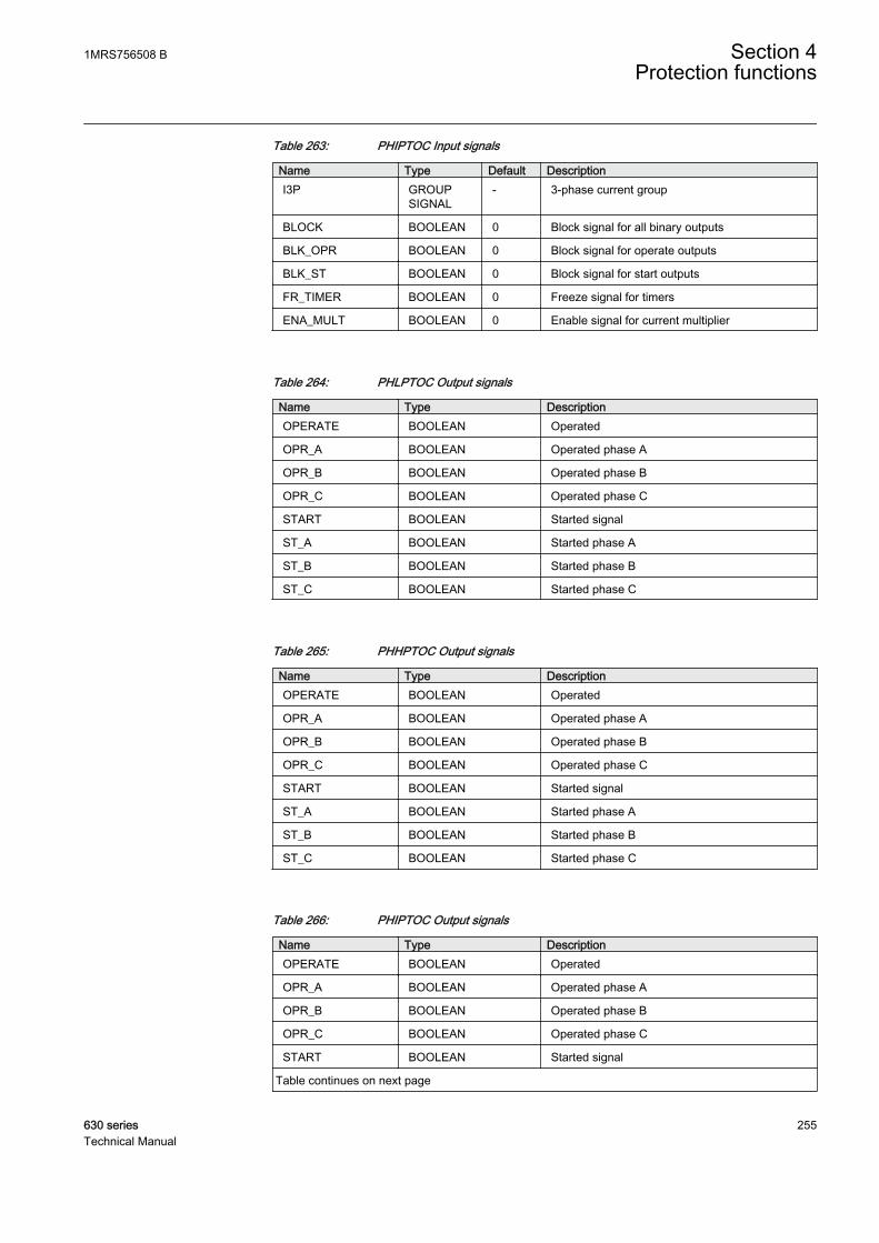
Table 263: PHIPTOC Input signals
Name Type Default DescriptionI3P GROUP
SIGNAL- 3-phase current group
BLOCK BOOLEAN 0 Block signal for all binary outputs
BLK_OPR BOOLEAN 0 Block signal for operate outputs
BLK_ST BOOLEAN 0 Block signal for start outputs
FR_TIMER BOOLEAN 0 Freeze signal for timers
ENA_MULT BOOLEAN 0 Enable signal for current multiplier
Table 264: PHLPTOC Output signals
Name Type DescriptionOPERATE BOOLEAN Operated
OPR_A BOOLEAN Operated phase A
OPR_B BOOLEAN Operated phase B
OPR_C BOOLEAN Operated phase C
START BOOLEAN Started signal
ST_A BOOLEAN Started phase A
ST_B BOOLEAN Started phase B
ST_C BOOLEAN Started phase C
Table 265: PHHPTOC Output signals
Name Type DescriptionOPERATE BOOLEAN Operated
OPR_A BOOLEAN Operated phase A
OPR_B BOOLEAN Operated phase B
OPR_C BOOLEAN Operated phase C
START BOOLEAN Started signal
ST_A BOOLEAN Started phase A
ST_B BOOLEAN Started phase B
ST_C BOOLEAN Started phase C
Table 266: PHIPTOC Output signals
Name Type DescriptionOPERATE BOOLEAN Operated
OPR_A BOOLEAN Operated phase A
OPR_B BOOLEAN Operated phase B
OPR_C BOOLEAN Operated phase C
START BOOLEAN Started signal
Table continues on next page
1MRS756508 B Section 4Protection functions
630 series 255Technical Manual
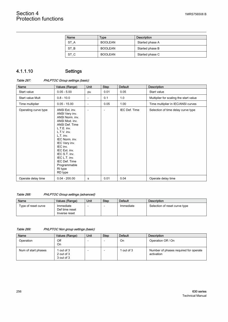
Name Type DescriptionST_A BOOLEAN Started phase A
ST_B BOOLEAN Started phase B
ST_C BOOLEAN Started phase C
4.1.1.10 Settings
Table 267: PHLPTOC Group settings (basic)
Name Values (Range) Unit Step Default DescriptionStart value 0.05 - 5.00 pu 0.01 0.05 Start value
Start value Mult 0.8 - 10.0 - 0.1 1.0 Multiplier for scaling the start value
Time multiplier 0.05 - 15.00 - 0.05 1.00 Time multiplier in IEC/ANSI curves
Operating curve type ANSI Ext. inv.ANSI Very inv.ANSI Norm. inv.ANSI Mod. inv.ANSI Def. TimeL.T.E. inv.L.T.V. inv.L.T. inv.IEC Norm. inv.IEC Very inv.IEC inv.IEC Ext. inv.IEC S.T. inv.IEC L.T. inv.IEC Def. TimeProgrammableRI typeRD type
- - IEC Def. Time Selection of time delay curve type
Operate delay time 0.04 - 200.00 s 0.01 0.04 Operate delay time
Table 268: PHLPTOC Group settings (advanced)
Name Values (Range) Unit Step Default DescriptionType of reset curve Immediate
Def time resetInverse reset
- - Immediate Selection of reset curve type
Table 269: PHLPTOC Non group settings (basic)
Name Values (Range) Unit Step Default DescriptionOperation Off
On- - On Operation Off / On
Num of start phases 1 out of 32 out of 33 out of 3
- - 1 out of 3 Number of phases required for operateactivation
Section 4 1MRS756508 BProtection functions
256 630 seriesTechnical Manual
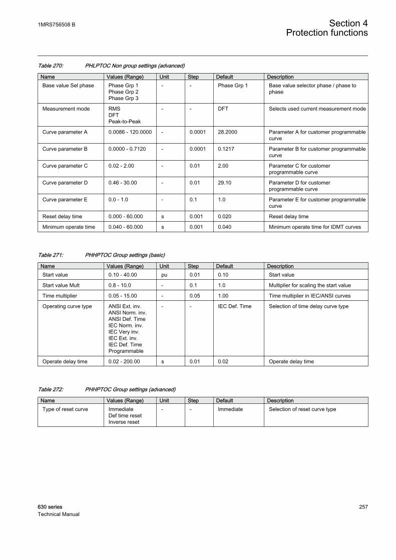
Table 270: PHLPTOC Non group settings (advanced)
Name Values (Range) Unit Step Default DescriptionBase value Sel phase Phase Grp 1
Phase Grp 2Phase Grp 3
- - Phase Grp 1 Base value selector phase / phase tophase
Measurement mode RMSDFTPeak-to-Peak
- - DFT Selects used current measurement mode
Curve parameter A 0.0086 - 120.0000 - 0.0001 28.2000 Parameter A for customer programmablecurve
Curve parameter B 0.0000 - 0.7120 - 0.0001 0.1217 Parameter B for customer programmablecurve
Curve parameter C 0.02 - 2.00 - 0.01 2.00 Parameter C for customerprogrammable curve
Curve parameter D 0.46 - 30.00 - 0.01 29.10 Parameter D for customerprogrammable curve
Curve parameter E 0.0 - 1.0 - 0.1 1.0 Parameter E for customer programmablecurve
Reset delay time 0.000 - 60.000 s 0.001 0.020 Reset delay time
Minimum operate time 0.040 - 60.000 s 0.001 0.040 Minimum operate time for IDMT curves
Table 271: PHHPTOC Group settings (basic)
Name Values (Range) Unit Step Default DescriptionStart value 0.10 - 40.00 pu 0.01 0.10 Start value
Start value Mult 0.8 - 10.0 - 0.1 1.0 Multiplier for scaling the start value
Time multiplier 0.05 - 15.00 - 0.05 1.00 Time multiplier in IEC/ANSI curves
Operating curve type ANSI Ext. inv.ANSI Norm. inv.ANSI Def. TimeIEC Norm. inv.IEC Very inv.IEC Ext. inv.IEC Def. TimeProgrammable
- - IEC Def. Time Selection of time delay curve type
Operate delay time 0.02 - 200.00 s 0.01 0.02 Operate delay time
Table 272: PHHPTOC Group settings (advanced)
Name Values (Range) Unit Step Default DescriptionType of reset curve Immediate
Def time resetInverse reset
- - Immediate Selection of reset curve type
1MRS756508 B Section 4Protection functions
630 series 257Technical Manual

Table 273: PHHPTOC Non group settings (basic)
Name Values (Range) Unit Step Default DescriptionOperation Off
On- - On Operation Off / On
Num of start phases 1 out of 32 out of 33 out of 3
- - 1 out of 3 Number of phases required for operateactivation
Table 274: PHHPTOC Non group settings (advanced)
Name Values (Range) Unit Step Default DescriptionBase value Sel phase Phase Grp 1
Phase Grp 2Phase Grp 3
- - Phase Grp 1 Base value selector phase / phase tophase
Measurement mode RMSDFTPeak-to-Peak
- - DFT Selects used current measurement mode
Curve parameter A 0.0086 - 120.0000 - 0.0001 28.2000 Parameter A for customer programmablecurve
Curve parameter B 0.0000 - 0.7120 - 0.0001 0.1217 Parameter B for customer programmablecurve
Curve parameter C 0.02 - 2.00 - 0.01 2.00 Parameter C for customerprogrammable curve
Curve parameter D 0.46 - 30.00 - 0.01 29.10 Parameter D for customerprogrammable curve
Curve parameter E 0.0 - 1.0 - 0.1 1.0 Parameter E for customer programmablecurve
Reset delay time 0.000 - 60.000 s 0.001 0.020 Reset delay time
Minimum operate time 0.020 - 60.000 s 0.001 0.020 Minimum operate time for IDMT curves
Table 275: PHIPTOC Group settings (basic)
Name Values (Range) Unit Step Default DescriptionStart value 0.10 - 40.00 pu 0.01 0.10 Start value
Start value Mult 0.8 - 10.0 - 0.1 1.0 Multiplier for scaling the start value
Operate delay time 0.02 - 200.00 s 0.01 0.02 Operate delay time
Table 276: PHIPTOC Non group settings (basic)
Name Values (Range) Unit Step Default DescriptionOperation Off
On- - On Operation Off / On
Num of start phases 1 out of 32 out of 33 out of 3
- - 1 out of 3 Number of phases required for operateactivation
Section 4 1MRS756508 BProtection functions
258 630 seriesTechnical Manual
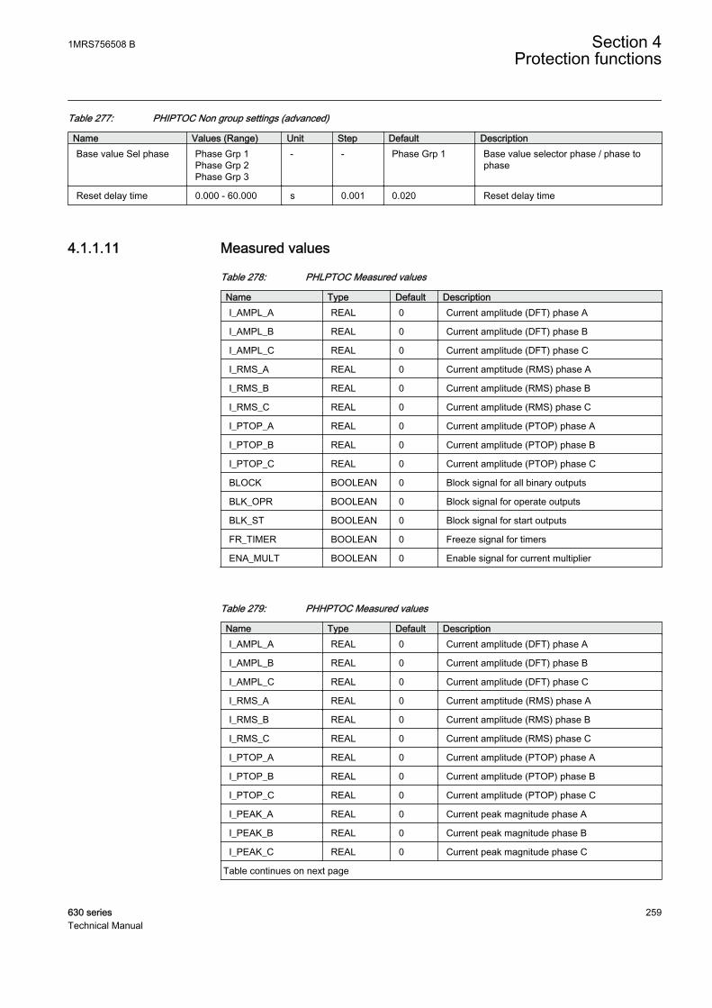
Table 277: PHIPTOC Non group settings (advanced)
Name Values (Range) Unit Step Default DescriptionBase value Sel phase Phase Grp 1
Phase Grp 2Phase Grp 3
- - Phase Grp 1 Base value selector phase / phase tophase
Reset delay time 0.000 - 60.000 s 0.001 0.020 Reset delay time
4.1.1.11 Measured values
Table 278: PHLPTOC Measured values
Name Type Default DescriptionI_AMPL_A REAL 0 Current amplitude (DFT) phase A
I_AMPL_B REAL 0 Current amplitude (DFT) phase B
I_AMPL_C REAL 0 Current amplitude (DFT) phase C
I_RMS_A REAL 0 Current amptitude (RMS) phase A
I_RMS_B REAL 0 Current amplitude (RMS) phase B
I_RMS_C REAL 0 Current amplitude (RMS) phase C
I_PTOP_A REAL 0 Current amplitude (PTOP) phase A
I_PTOP_B REAL 0 Current amplitude (PTOP) phase B
I_PTOP_C REAL 0 Current amplitude (PTOP) phase C
BLOCK BOOLEAN 0 Block signal for all binary outputs
BLK_OPR BOOLEAN 0 Block signal for operate outputs
BLK_ST BOOLEAN 0 Block signal for start outputs
FR_TIMER BOOLEAN 0 Freeze signal for timers
ENA_MULT BOOLEAN 0 Enable signal for current multiplier
Table 279: PHHPTOC Measured values
Name Type Default DescriptionI_AMPL_A REAL 0 Current amplitude (DFT) phase A
I_AMPL_B REAL 0 Current amplitude (DFT) phase B
I_AMPL_C REAL 0 Current amplitude (DFT) phase C
I_RMS_A REAL 0 Current amptitude (RMS) phase A
I_RMS_B REAL 0 Current amplitude (RMS) phase B
I_RMS_C REAL 0 Current amplitude (RMS) phase C
I_PTOP_A REAL 0 Current amplitude (PTOP) phase A
I_PTOP_B REAL 0 Current amplitude (PTOP) phase B
I_PTOP_C REAL 0 Current amplitude (PTOP) phase C
I_PEAK_A REAL 0 Current peak magnitude phase A
I_PEAK_B REAL 0 Current peak magnitude phase B
I_PEAK_C REAL 0 Current peak magnitude phase C
Table continues on next page
1MRS756508 B Section 4Protection functions
630 series 259Technical Manual
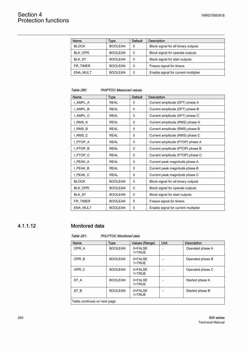
Name Type Default DescriptionBLOCK BOOLEAN 0 Block signal for all binary outputs
BLK_OPR BOOLEAN 0 Block signal for operate outputs
BLK_ST BOOLEAN 0 Block signal for start outputs
FR_TIMER BOOLEAN 0 Freeze signal for timers
ENA_MULT BOOLEAN 0 Enable signal for current multiplier
Table 280: PHIPTOC Measured values
Name Type Default DescriptionI_AMPL_A REAL 0 Current amplitude (DFT) phase A
I_AMPL_B REAL 0 Current amplitude (DFT) phase B
I_AMPL_C REAL 0 Current amplitude (DFT) phase C
I_RMS_A REAL 0 Current amptitude (RMS) phase A
I_RMS_B REAL 0 Current amplitude (RMS) phase B
I_RMS_C REAL 0 Current amplitude (RMS) phase C
I_PTOP_A REAL 0 Current amplitude (PTOP) phase A
I_PTOP_B REAL 0 Current amplitude (PTOP) phase B
I_PTOP_C REAL 0 Current amplitude (PTOP) phase C
I_PEAK_A REAL 0 Current peak magnitude phase A
I_PEAK_B REAL 0 Current peak magnitude phase B
I_PEAK_C REAL 0 Current peak magnitude phase C
BLOCK BOOLEAN 0 Block signal for all binary outputs
BLK_OPR BOOLEAN 0 Block signal for operate outputs
BLK_ST BOOLEAN 0 Block signal for start outputs
FR_TIMER BOOLEAN 0 Freeze signal for timers
ENA_MULT BOOLEAN 0 Enable signal for current multiplier
4.1.1.12 Monitored data
Table 281: PHLPTOC Monitored data
Name Type Values (Range) Unit DescriptionOPR_A BOOLEAN 0=FALSE
1=TRUE- Operated phase A
OPR_B BOOLEAN 0=FALSE1=TRUE
- Operated phase B
OPR_C BOOLEAN 0=FALSE1=TRUE
- Operated phase C
ST_A BOOLEAN 0=FALSE1=TRUE
- Started phase A
ST_B BOOLEAN 0=FALSE1=TRUE
- Started phase B
Table continues on next page
Section 4 1MRS756508 BProtection functions
260 630 seriesTechnical Manual
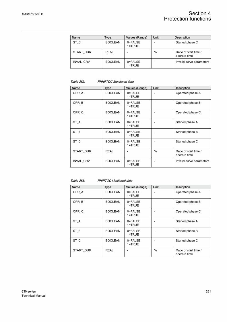
Name Type Values (Range) Unit DescriptionST_C BOOLEAN 0=FALSE
1=TRUE- Started phase C
START_DUR REAL - % Ratio of start time /operate time
INVAL_CRV BOOLEAN 0=FALSE1=TRUE
- Invalid curve parameters
Table 282: PHHPTOC Monitored data
Name Type Values (Range) Unit DescriptionOPR_A BOOLEAN 0=FALSE
1=TRUE- Operated phase A
OPR_B BOOLEAN 0=FALSE1=TRUE
- Operated phase B
OPR_C BOOLEAN 0=FALSE1=TRUE
- Operated phase C
ST_A BOOLEAN 0=FALSE1=TRUE
- Started phase A
ST_B BOOLEAN 0=FALSE1=TRUE
- Started phase B
ST_C BOOLEAN 0=FALSE1=TRUE
- Started phase C
START_DUR REAL - % Ratio of start time /operate time
INVAL_CRV BOOLEAN 0=FALSE1=TRUE
- Invalid curve parameters
Table 283: PHIPTOC Monitored data
Name Type Values (Range) Unit DescriptionOPR_A BOOLEAN 0=FALSE
1=TRUE- Operated phase A
OPR_B BOOLEAN 0=FALSE1=TRUE
- Operated phase B
OPR_C BOOLEAN 0=FALSE1=TRUE
- Operated phase C
ST_A BOOLEAN 0=FALSE1=TRUE
- Started phase A
ST_B BOOLEAN 0=FALSE1=TRUE
- Started phase B
ST_C BOOLEAN 0=FALSE1=TRUE
- Started phase C
START_DUR REAL - % Ratio of start time /operate time
1MRS756508 B Section 4Protection functions
630 series 261Technical Manual
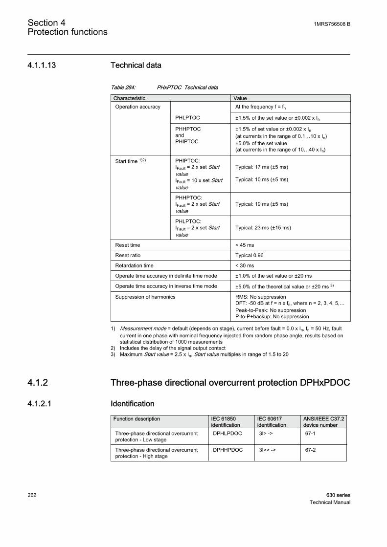
4.1.1.13 Technical data
Table 284: PHxPTOC Technical data
Characteristic ValueOperation accuracy At the frequency f = fn
PHLPTOC ±1.5% of the set value or ±0.002 x In
PHHPTOCandPHIPTOC
±1.5% of set value or ±0.002 x In(at currents in the range of 0.1…10 x In)±5.0% of the set value(at currents in the range of 10…40 x In)
Start time 1)2) PHIPTOC:IFault = 2 x set StartvalueIFault = 10 x set Startvalue
Typical: 17 ms (±5 ms) Typical: 10 ms (±5 ms)
PHHPTOC:IFault = 2 x set Startvalue
Typical: 19 ms (±5 ms)
PHLPTOC:IFault = 2 x set Startvalue
Typical: 23 ms (±15 ms)
Reset time < 45 ms
Reset ratio Typical 0.96
Retardation time < 30 ms
Operate time accuracy in definite time mode ±1.0% of the set value or ±20 ms
Operate time accuracy in inverse time mode ±5.0% of the theoretical value or ±20 ms 3)
Suppression of harmonics RMS: No suppressionDFT: -50 dB at f = n x fn, where n = 2, 3, 4, 5,…Peak-to-Peak: No suppressionP-to-P+backup: No suppression
1) Measurement mode = default (depends on stage), current before fault = 0.0 x In, fn = 50 Hz, faultcurrent in one phase with nominal frequency injected from random phase angle, results based onstatistical distribution of 1000 measurements
2) Includes the delay of the signal output contact3) Maximum Start value = 2.5 x In, Start value multiples in range of 1.5 to 20
4.1.2 Three-phase directional overcurrent protection DPHxPDOC
4.1.2.1 Identification
Function description IEC 61850identification
IEC 60617identification
ANSI/IEEE C37.2device number
Three-phase directional overcurrentprotection - Low stage
DPHLPDOC 3I> -> 67-1
Three-phase directional overcurrentprotection - High stage
DPHHPDOC 3I>> -> 67-2
Section 4 1MRS756508 BProtection functions
262 630 seriesTechnical Manual
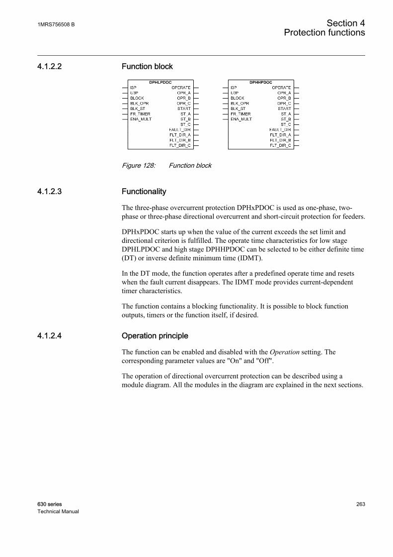
4.1.2.2 Function block
GUID-F1375979-D1D3-426B-A327-70BD5869B7EB V1 EN
Figure 128: Function block
4.1.2.3 Functionality
The three-phase overcurrent protection DPHxPDOC is used as one-phase, two-phase or three-phase directional overcurrent and short-circuit protection for feeders.
DPHxPDOC starts up when the value of the current exceeds the set limit anddirectional criterion is fulfilled. The operate time characteristics for low stageDPHLPDOC and high stage DPHHPDOC can be selected to be either definite time(DT) or inverse definite minimum time (IDMT).
In the DT mode, the function operates after a predefined operate time and resetswhen the fault current disappears. The IDMT mode provides current-dependenttimer characteristics.
The function contains a blocking functionality. It is possible to block functionoutputs, timers or the function itself, if desired.
4.1.2.4 Operation principle
The function can be enabled and disabled with the Operation setting. Thecorresponding parameter values are "On" and "Off".
The operation of directional overcurrent protection can be described using amodule diagram. All the modules in the diagram are explained in the next sections.
1MRS756508 B Section 4Protection functions
630 series 263Technical Manual

GUID-021E1EE5-3286-4E88-9F94-521609D77F1D V2 EN
Figure 129: Functional module diagram
Directional calculationThe directional calculation compares the current phasors to the polarizing phasor.A suitable polarization quantity can be selected from the different polarizationquantities, which are the positive sequence voltage, negative sequence voltage, self-polarizing (faulted) voltage and cross-polarizing voltages (healthy voltages). Thepolarizing method is defined with the Pol quantity setting.
Table 285: Polarizing quantities
Polarizing quantity DescriptionPos. seq. volt Positive sequence voltage
Neg. seq. volt Negative sequence voltage
Self pol Self polarization
Cross pol Cross polarization
The directional operation can be selected with the Directional mode setting. Theuser can select either "Non-directional", "Forward" or "Reverse" operation. Bysetting the value of Allow Non Dir to "Allowed", the non-directional operation isallowed when the directional information is invalid.
The Characteristic angle setting is used to turn the directional characteristic. Thevalue of Characteristic angle should be chosen in such a way that all the faults inthe operating direction are seen in the operating zone and all the faults in the
Section 4 1MRS756508 BProtection functions
264 630 seriesTechnical Manual
opposite direction are seen in the non-operating zone. The value of Characteristicangle depends on the network configuration.
Reliable operation requires both the operating and polarizing quantities to exceedcertain minimum amplitude levels. The minimum amplitude level for the operatingquantity (current) is set with the Min operate current setting. The minimumamplitude level for the polarizing quantity (voltage) is set with the Min operatevoltage setting. If the amplitude level of the operating quantity or polarizingquantity is below the set level, the direction information of the corresponding phaseis set to "Unknown".
The polarizing quantity validity can remain valid even if the amplitude of thepolarizing quantity falls below the value of the Min operate voltage setting. In thiscase, the directional information is provided by a special memory function for atime defined with the Voltage Mem time setting.
DPHxPDOC is provided with a memory function to secure a reliable and correctdirectional IED operation in case of a close short circuit or an earth faultcharacterized by an extremely low voltage. At sudden loss of the polarizationquantity, the angle difference is calculated on the basis of a fictive voltage. Thefictive voltage is calculated using the polarizing quantity measured before the faultoccurred. The memory function enables the function to operate up to a maximumof three seconds after a total loss of voltage. This time can be set with the VoltageMem time setting.
The value for the Min operate voltage setting should be carefullyselected since the accuracy in low signal levels is strongly affectedby the measuring device accuracy.
When the voltage of one or more phases falls below Min operate voltage at a closefault, the corresponding phase-related fictive voltage is used to determine the phaseangle. The measured voltage is applied again as soon as the voltage rises aboveMin operate voltage. The fictive voltage is also discarded if the measured voltagestays below Min operate voltage for longer than Voltage Mem time or if the faultcurrent disappears while the fictive voltage is in use. When the voltage is belowMin operate voltage and hysteresis and the fictive voltage is unusable, the faultdirection cannot be determined. The fictive voltage can be unusable for three reasons:
• The fictive voltage is discarded after Voltage Mem time• The phase angle cannot be reliably measured before the fault situation.• When the used Pol quantity setting is "Neg. seq. volt.", the measured negative-
sequence voltage before the fault is often too low for the fictive voltage function.
1MRS756508 B Section 4Protection functions
630 series 265Technical Manual
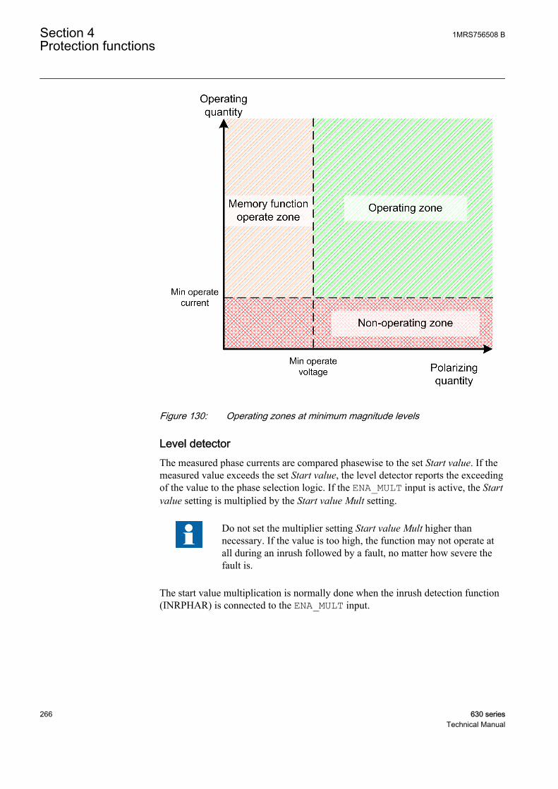
GUID-718D61B4-DAD0-4F43-8108-86F7B44E7E2D V1 EN
Figure 130: Operating zones at minimum magnitude levels
Level detectorThe measured phase currents are compared phasewise to the set Start value. If themeasured value exceeds the set Start value, the level detector reports the exceedingof the value to the phase selection logic. If the ENA_MULT input is active, the Startvalue setting is multiplied by the Start value Mult setting.
Do not set the multiplier setting Start value Mult higher thannecessary. If the value is too high, the function may not operate atall during an inrush followed by a fault, no matter how severe thefault is.
The start value multiplication is normally done when the inrush detection function(INRPHAR) is connected to the ENA_MULT input.
Section 4 1MRS756508 BProtection functions
266 630 seriesTechnical Manual

A070554 V1 EN
Figure 131: Start value behavior with ENA_MULT input activated
Phase selection logicIf the fault criteria are fulfilled in the level detector and the directional calculation,the phase selection logic detects the phase or phases in which the measured currentexceeds the setting. If the phase information matches the Num of start phasessetting, the phase selection logic activates the timer module.
The phase selection logic provides also information about phase specific faultdirections. The FLT_DIR_A output indicates the direction of the fault in phase A.Similarly, the FLT_DIR_B output indicates the direction of the fault in phase B.The direction of the fault in phase C is indicated by the FLT_DIR_C output. Thegeneral fault direction information is provided by the FAULT_DIR output.
TimerOnce activated, the timer activates the START output. The ST_A, ST_B and ST_Coutputs are used to indicate which phases are started. When the operation timer hasreached the value set by Operate delay time in the DT mode or the maximum valuedefined by the inverse time curve, the OPERATE output is activated. The OPR_A,OPR_B and OPR_C outputs are used to indicate which phases are operated.
DPHxPDOC can be blocked from BLOCK, the binary input. Activation of BLOCKinput deactivates all outputs and resets internal timers. The start signals from thefunction can be blocked from BLK_ST, the binary input. The operate signals fromthe function can be blocked from BLK_OPR, the binary input. The operation timer
1MRS756508 B Section 4Protection functions
630 series 267Technical Manual
counting can be frozen to the prevailing value by activating the FR_TIMER inputsignal.
When the user-programmable IDMT curve is selected, the operation timecharacteristics are defined by the parameters Curve parameter A, Curve parameterB, Curve parameter C, Curve parameter D and Curve parameter E.
If a drop-off situation happens, that is, a fault suddenly disappears before theoperate delay is exceeded, the timer reset state is activated. The functionality of thetimer in the reset state depends on the combination of the Operating curve type,Type of reset curve and Reset delay time settings. When the DT characteristic isselected, the reset timer runs until the set Reset delay time value is exceeded. Whenthe IDMT curves are selected, the Type of reset curve setting can be set to"Immediate", "Def time reset" or "Inverse reset". The reset curve type "Immediate"causes an immediate reset. With the reset curve type "Def time reset", the resettime depends on the Reset delay time setting. With the reset curve type "Inversereset", the reset time depends on the current during the drop-off situation. TheSTART output is deactivated when the reset timer has elapsed.
The "Inverse reset" selection is only supported with ANSI or userprogrammable types of the IDMT operating curves. If anotheroperating curve type is selected, an immediate reset occurs duringthe drop-off situation.
The setting Time multiplier is used for scaling the IDMT operate and reset times.
The setting parameter Minimum operate time defines the minimum desired operatetime for IDMT. The setting is applicable only when the IDMT curves are used.
The Minimum operate time setting should be used with great carebecause the operation time is according to the IDMT curve, butalways at least the value of the Minimum operate time setting. Formore information, see the General function block features sectionin this manual.
The timer calculates the start duration value START_DUR, which indicates thepercentage ratio of the start situation and the set operating time. The value isavailable in the monitored data view.
The angle values available at the input monitor data view are inradians.
4.1.2.5 Base values
In this function block, some of the settings are set in per unit (pu). These pu valuesare relational to certain base values, for example the values given in A, kV and
Section 4 1MRS756508 BProtection functions
268 630 seriesTechnical Manual
kVA. The IED supports alternative base value groups for the phase current or voltage-related settings, for example "Phase Grp 1", "Phase Grp 2" and "Phase Grp 3".One of the groups to be used with the Base value Sel phase setting must be selected.
For more information, see the Basic functions section in this manual.
4.1.2.6 Measuring modes
The function operates on three alternative measurement modes: “RMS”, “DFT”and “Peak-to-Peak” . The measurement mode is selected with the Measurementmode setting.
Table 286: Measurement modes supported by DPHxPDOC stages
Measurement mode Supported measurement modesDPHLPDOC DPHHPDOC
RMS x x
DFT x x
Peak-to-Peak x x
4.1.2.7 Directional overcurrent characteristics
The forward and reverse sectors are defined separately. The forward operation areais limited with the Min forward angle and Max forward angle settings. The reverseoperation area is limited with the Min reverse angle and Max reverse angle settings.
The sector limits are always given as positive degree values.
In the forward operation area, the Max forward angle setting gives thecounterclockwise sector and the Min forward angle setting gives the correspondingclockwise sector, measured from the Characteristic angle setting.
In the backward operation area, the Max reverse angle setting gives thecounterclockwise sector and the Min reverse angle setting gives the correspondingclockwise sector, a measurement from the Characteristic angle setting that hasbeen rotated 180 degrees.
Relay characteristic angle (RCA) is set positive if the operating current lags thepolarizing quantity and negative if the operating current leads the polarizing quantity.
1MRS756508 B Section 4Protection functions
630 series 269Technical Manual

GUID-CD0B7D5A-1F1A-47E6-AF2A-F6F898645640 V2 EN
Figure 132: Configurable operating sectors
Table 287: Momentary per phase direction value for monitored data view
Criterion for per phase direction information The value for DIR_A/_B/_CThe ANGLE_X is not in any of the definedsectors, or the direction cannot be defined duetoo low amplitude
0 = unknown
The ANGLE_X is in the forward sector 1 = forward
The ANGLE_X is in the reverse sector 2 = backward
(The ANGLE_X is in both forward and reversesectors, that is, when the sectors are overlapping)
3 = both
Table 288: Momentary phase combined direction value for monitored data view
Criterion for phase combined direction information The value for DIRECTIONThe direction information (DIR_X) for all phasesis unknown
0 = unknown
The direction information (DIR_X) for at least onephase is forward, none being in reverse
1 = forward
The direction information (DIR_X) for at least onephase is reverse, none being in forward
2 = backward
The direction information (DIR_X) for somephase is forward and for some phase is reverse
3 = both
Section 4 1MRS756508 BProtection functions
270 630 seriesTechnical Manual

FAULT_DIR gives the detected direction of the fault during fault situations, that is,when the START output is active.
Self-polarizing as polarizing methodTable 289: Equations for calculating angle difference for self-polarizing method
Faultedphases
Used faultcurrent
Usedpolarizingvoltage
Angle difference
A IA UA ANGLE A U IA A RCA_ ( ) - ( ) - = ϕ ϕ ϕ
GUID-60308BBA-07F8-4FB4-A9E8-3850325E368C V2 EN
B IB UB ANGLE B U IB B RCA_ ( ) - ( ) - = ϕ ϕ ϕ
GUID-9AF57A77-F9C6-46B7-B056-AC7542EBF449 V2 EN
C IC UC ANGLE C U IC C RCA_ ( ) - ( ) - = ϕ ϕ ϕ
GUID-51FEBD95-672C-440F-A678-DD01ABB2D018 V2 EN
A - B IA - IB UAB ANGLE A U I IAB A B RCA_ ( ) - ( - ) - = ϕ ϕ ϕ
GUID-7DA1116D-86C0-4D7F-AA19-DCF32C530C4C V2 EN
B - C IB - IC UBC ANGLE B U I IBC B C RCA_ ( ) - ( - ) - = ϕ ϕ ϕ
GUID-3E9788CA-D2FC-4FC4-8F9E-1466F3775826 V2 EN
C - A IC - IA UCA ANGLE C U I ICA C A RCA_ ( ) - ( - ) - = ϕ ϕ ϕ
GUID-EFD80F78-4B26-46B6-A5A6-CCA6B7E20C6E V2 EN
In an example case of the phasors in a single-phase earth fault where the faultedphase is phase A, the angle difference between the polarizing quantity UA andoperating quantity IA is marked as φ. In the self-polarization method, there is noneed to rotate the polarizing quantity.
GUID-C648173C-D8BB-4F37-8634-5D4DC7D366FF V1 EN
Figure 133: Single-phase earth fault, phase A
1MRS756508 B Section 4Protection functions
630 series 271Technical Manual

In an example case of a two-phase short-circuit failure where the fault is betweenphases B and C, the angle difference is measured between the polarizing quantityUBC and operating quantity IB - IC in the self-polarizing method.
GUID-65CFEC0E-0367-44FB-A116-057DD29FEB79 V1 EN
Figure 134: Two-phase short circuit, short circuit is between phases B and C
Cross-polarizing as polarizing quantityTable 290: Equations for calculating angle difference for cross-polarizing method
Faultedphases
Usedfaultcurrent
Usedpolarizingvoltage
Angle difference
A IA UBCANGLE A U I
BC A RCA
o_ ( ) - ( ) - = +ϕ ϕ ϕ 90
GUID-4F0D1491-3679-4B1F-99F7-3704BC15EF9D V3 EN
B IB UCAANGLE B U I
CA B RCA
o_ ( ) - ( ) - = +ϕ ϕ ϕ 90
GUID-F5252292-E132-41A7-9F6D-C2A3958EE6AD V3 EN
C IC UABANGLE C U I
AB C RCA
o_ ( ) - ( ) - = +ϕ ϕ ϕ 90
GUID-84D97257-BAEC-4264-9D93-EC2DF853EAE1 V3 EN
A - B IA - IB UBC -UCA
ANGLE A U U I IBC CA A B RCA
o_ ( - ) - ( - ) - = +ϕ ϕ ϕ 90
GUID-AFB15C3F-B9BB-47A2-80E9-796AA1165409 V2 EN
B - C IB - IC UCA -UAB
ANGLE B U U I ICA AB B C RCA
o_ ( - ) - ( - ) - = +ϕ ϕ ϕ 90
GUID-C698D9CA-9139-40F2-9097-007B6B14D053 V2 EN
C - A IC - IA UAB -UBC
ANGLE C U U I IAB BC C A RCA
o_ ( - ) - ( - ) - = +ϕ ϕ ϕ 90
GUID-838ECE7D-8B1C-466F-8166-E8FE16D28AAD V2 EN
The angle difference between the polarizing quantity UBC and operating quantityIA is marked as φ in an example of the phasors in a single-phase earth fault where
Section 4 1MRS756508 BProtection functions
272 630 seriesTechnical Manual
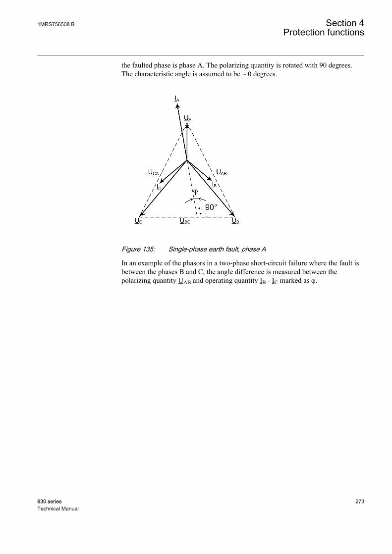
the faulted phase is phase A. The polarizing quantity is rotated with 90 degrees.The characteristic angle is assumed to be ~ 0 degrees.
GUID-6C7D1317-89C4-44BE-A1EB-69BC75863474 V1 EN
Figure 135: Single-phase earth fault, phase A
In an example of the phasors in a two-phase short-circuit failure where the fault isbetween the phases B and C, the angle difference is measured between thepolarizing quantity UAB and operating quantity IB - IC marked as φ.
1MRS756508 B Section 4Protection functions
630 series 273Technical Manual

GUID-C2EC2EF1-8A84-4A32-818C-6D7620EA9969 V1 EN
Figure 136: Two-phase short circuit, short circuit is between phases B and C
The equations are valid when network rotating direction is counter-clockwise, that is, ABC. If the network rotating direction isreversed, 180 degrees is added to the calculated angle difference.This is done automatically with a system parameter Phase rotation.
Negative sequence voltage as polarizing quantityWhen the negative voltage is used as the polarizing quantity, the angle differencebetween the operating and polarizing quantity is calculated with the same formulafor all fault types:
ANGLE X U I RCA_ ( ) ( )= − − −ϕ ϕ ϕ2 2
GUID-470263DD-C1D7-4E59-B011-24D8D35BD52A V3 EN (Equation 10)
Section 4 1MRS756508 BProtection functions
274 630 seriesTechnical Manual
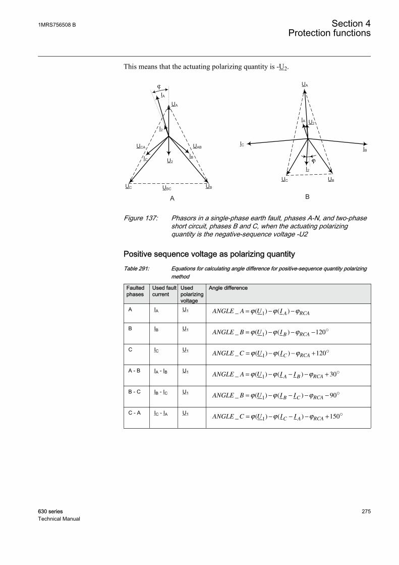
This means that the actuating polarizing quantity is -U2.
UA
UBUC UBC
UABUCA
IA
IBIC U2
I2
UA
UBUC
IA
IBIC
U2
I2
A BGUID-027DD4B9-5844-4C46-BA9C-54784F2300D3 V2 EN
Figure 137: Phasors in a single-phase earth fault, phases A-N, and two-phaseshort circuit, phases B and C, when the actuating polarizingquantity is the negative-sequence voltage -U2
Positive sequence voltage as polarizing quantityTable 291: Equations for calculating angle difference for positive-sequence quantity polarizing
method
Faultedphases
Used faultcurrent
Usedpolarizingvoltage
Angle difference
A IA U1 ANGLE A U IA RCA_ ( ) ( )= − −ϕ ϕ ϕ1
GUID-4C933201-2290-4AA3-97A3-670A40CC4114 V4 EN
B IB U1ANGLE B U I
B RCA_ ( ) ( )= − − −ϕ ϕ ϕ1 120o
GUID-648D061C-6F5F-4372-B120-0F02B42E9809 V4 EN
C IC U1ANGLE C U I
C RCA_ ( ) ( )= − − +ϕ ϕ ϕ1 120o
GUID-355EF014-D8D0-467E-A952-1D1602244C9F V4 EN
A - B IA - IB U1ANGLE A U I I
A B RCA_ ( ) ( )= − − − +ϕ ϕ ϕ1 30o
GUID-B07C3B0A-358E-480F-A059-CC5F3E6839B1 V3 EN
B - C IB - IC U1ANGLE B U I I
B C RCA_ ( ) ( )= − − − −ϕ ϕ ϕ1 90o
GUID-4597F122-99A6-46F6-A38C-81232C985BC9 V3 EN
C - A IC - IA U1ANGLE C U I I
C A RCA_ ( ) ( )= − − − +ϕ ϕ ϕ1 150o
GUID-9892503C-2233-4BC5-8C54-BCF005E20A08 V3 EN
1MRS756508 B Section 4Protection functions
630 series 275Technical Manual
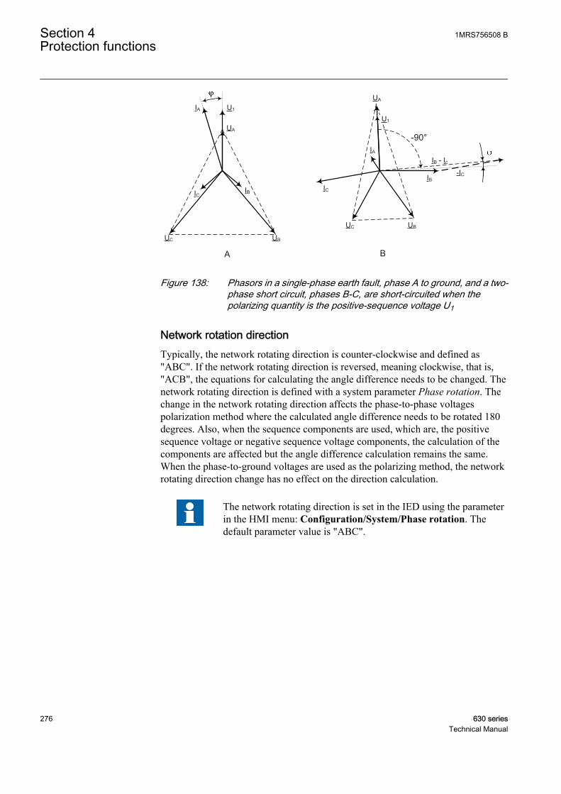
UA
UBUC
IA
IBIC
UA
UBUC
IA
IBIC
A B
-IC
IB - Ic
-90°
U1
U1
GUID-1937EA60-4285-44A7-8A7D-52D7B66FC5A6 V3 EN
Figure 138: Phasors in a single-phase earth fault, phase A to ground, and a two-phase short circuit, phases B-C, are short-circuited when thepolarizing quantity is the positive-sequence voltage U1
Network rotation directionTypically, the network rotating direction is counter-clockwise and defined as"ABC". If the network rotating direction is reversed, meaning clockwise, that is,"ACB", the equations for calculating the angle difference needs to be changed. Thenetwork rotating direction is defined with a system parameter Phase rotation. Thechange in the network rotating direction affects the phase-to-phase voltagespolarization method where the calculated angle difference needs to be rotated 180degrees. Also, when the sequence components are used, which are, the positivesequence voltage or negative sequence voltage components, the calculation of thecomponents are affected but the angle difference calculation remains the same.When the phase-to-ground voltages are used as the polarizing method, the networkrotating direction change has no effect on the direction calculation.
The network rotating direction is set in the IED using the parameterin the HMI menu: Configuration/System/Phase rotation. Thedefault parameter value is "ABC".
Section 4 1MRS756508 BProtection functions
276 630 seriesTechnical Manual
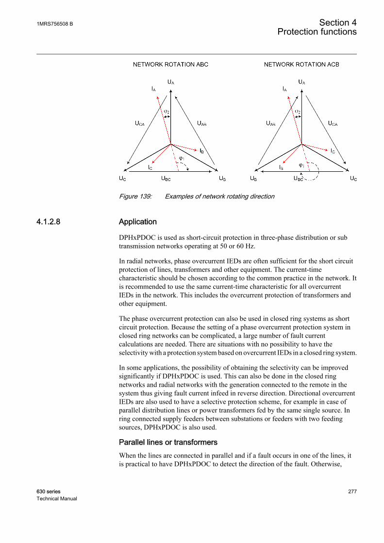
GUID-BF32C1D4-ECB5-4E96-A27A-05C637D32C86 V1 EN
Figure 139: Examples of network rotating direction
4.1.2.8 Application
DPHxPDOC is used as short-circuit protection in three-phase distribution or subtransmission networks operating at 50 or 60 Hz.
In radial networks, phase overcurrent IEDs are often sufficient for the short circuitprotection of lines, transformers and other equipment. The current-timecharacteristic should be chosen according to the common practice in the network. Itis recommended to use the same current-time characteristic for all overcurrentIEDs in the network. This includes the overcurrent protection of transformers andother equipment.
The phase overcurrent protection can also be used in closed ring systems as shortcircuit protection. Because the setting of a phase overcurrent protection system inclosed ring networks can be complicated, a large number of fault currentcalculations are needed. There are situations with no possibility to have theselectivity with a protection system based on overcurrent IEDs in a closed ring system.
In some applications, the possibility of obtaining the selectivity can be improvedsignificantly if DPHxPDOC is used. This can also be done in the closed ringnetworks and radial networks with the generation connected to the remote in thesystem thus giving fault current infeed in reverse direction. Directional overcurrentIEDs are also used to have a selective protection scheme, for example in case ofparallel distribution lines or power transformers fed by the same single source. Inring connected supply feeders between substations or feeders with two feedingsources, DPHxPDOC is also used.
Parallel lines or transformersWhen the lines are connected in parallel and if a fault occurs in one of the lines, itis practical to have DPHxPDOC to detect the direction of the fault. Otherwise,
1MRS756508 B Section 4Protection functions
630 series 277Technical Manual
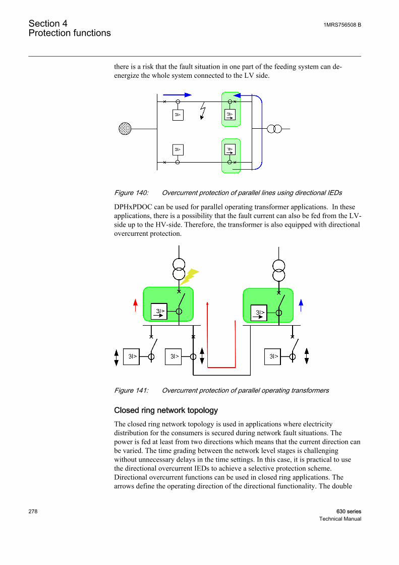
there is a risk that the fault situation in one part of the feeding system can de-energize the whole system connected to the LV side.
GUID-1A2BD0AD-B217-46F4-A6B4-6FC6E6256EB3 V2 EN
Figure 140: Overcurrent protection of parallel lines using directional IEDs
DPHxPDOC can be used for parallel operating transformer applications. In theseapplications, there is a possibility that the fault current can also be fed from the LV-side up to the HV-side. Therefore, the transformer is also equipped with directionalovercurrent protection.
GUID-74662396-1BAD-4AC2-ADB6-F4A8B3341860 V2 EN
Figure 141: Overcurrent protection of parallel operating transformers
Closed ring network topologyThe closed ring network topology is used in applications where electricitydistribution for the consumers is secured during network fault situations. Thepower is fed at least from two directions which means that the current direction canbe varied. The time grading between the network level stages is challengingwithout unnecessary delays in the time settings. In this case, it is practical to usethe directional overcurrent IEDs to achieve a selective protection scheme.Directional overcurrent functions can be used in closed ring applications. Thearrows define the operating direction of the directional functionality. The double
Section 4 1MRS756508 BProtection functions
278 630 seriesTechnical Manual

arrows define the non-directional functionality where faults can be detected in bothdirections.
GUID-276A9D62-BD74-4335-8F20-EC1731B58889 V1 EN
Figure 142: Closed ring network topology where feeding lines are protectedwith directional overcurrent IEDs
4.1.2.9 Signals
Table 292: DPHLPDOC Input signals
Name Type Default DescriptionI3P GROUP
SIGNAL- 3-phase current group
U3P GROUPSIGNAL
- 3-phase voltage group
BLOCK BOOLEAN 0 Block signal for all binary outputs
BLK_OPR BOOLEAN 0 Block signal for operate outputs
BLK_ST BOOLEAN 0 Block signal for start outputs
FR_TIMER BOOLEAN 0 Freeze signal for timers
ENA_MULT BOOLEAN 0 Enable signal for current multiplier
1MRS756508 B Section 4Protection functions
630 series 279Technical Manual

Table 293: DPHHPDOC Input signals
Name Type Default DescriptionI3P GROUP
SIGNAL- 3-phase current group
U3P GROUPSIGNAL
- 3-phase voltage group
BLOCK BOOLEAN 0 Block signal for all binary outputs
BLK_OPR BOOLEAN 0 Block signal for operate outputs
BLK_ST BOOLEAN 0 Block signal for start outputs
FR_TIMER BOOLEAN 0 Freeze signal for timers
ENA_MULT BOOLEAN 0 Enable signal for current multiplier
Table 294: DPHLPDOC Output signals
Name Type DescriptionOPERATE BOOLEAN Operated
OPR_A BOOLEAN Operated phase A
OPR_B BOOLEAN Operated phase B
OPR_C BOOLEAN Operated phase C
START BOOLEAN Started signal
ST_A BOOLEAN Started phase A
ST_B BOOLEAN Started phase B
ST_C BOOLEAN Started phase C
FAULT_DIR INTEGER Detected fault direction, general
FLT_DIR_A INTEGER Detected fault direction, phase A
FLT_DIR_B INTEGER Detected fault direction, phase B
FLT_DIR_C INTEGER Detected fault direction, phase C
Table 295: DPHHPDOC Output signals
Name Type DescriptionOPERATE BOOLEAN Operated
OPR_A BOOLEAN Operated phase A
OPR_B BOOLEAN Operated phase B
OPR_C BOOLEAN Operated phase C
START BOOLEAN Started signal
ST_A BOOLEAN Started phase A
ST_B BOOLEAN Started phase B
ST_C BOOLEAN Started phase C
FAULT_DIR INTEGER Detected fault direction, general
FLT_DIR_A INTEGER Detected fault direction, phase A
FLT_DIR_B INTEGER Detected fault direction, phase B
FLT_DIR_C INTEGER Detected fault direction, phase C
Section 4 1MRS756508 BProtection functions
280 630 seriesTechnical Manual

4.1.2.10 Settings
Table 296: DPHLPDOC Group settings (basic)
Name Values (Range) Unit Step Default DescriptionDirectional mode Non-directional
ForwardReverse
- - Forward Directional mode
Start value 0.05 - 5.00 pu 0.01 0.05 Start value
Characteristic angle -179 - 180 Deg 1 0 Characteristic angle
Start value Mult 0.8 - 10.0 - 0.1 1.0 Multiplier for scaling the start value
Time multiplier 0.05 - 15.00 - 0.05 1.00 Time multiplier in IEC/ANSI curves
Operating curve type ANSI Ext. inv.ANSI Very inv.ANSI Norm. inv.ANSI Mod. inv.ANSI Def. TimeL.T.E. inv.L.T.V. inv.L.T. inv.IEC Norm. inv.IEC Very inv.IEC inv.IEC Ext. inv.IEC S.T. inv.IEC L.T. inv.IEC Def. TimeProgrammableRI typeRD type
- - IEC Def. Time Selection of time delay curve type
Operate delay time 0.04 - 200.00 s 0.01 0.04 Operate delay time
Table 297: DPHLPDOC Group settings (advanced)
Name Values (Range) Unit Step Default DescriptionPol quantity Pos. seq. volt.
Self polNeg. seq. volt.Cross Pol
- - Cross Pol Reference quantity used to determinefault direction
Max forward angle 45 - 135 Deg 5 90 Maximum phase angle in forwarddirection
Min forward angle 45 - 135 Deg 5 90 Minimum phase angle in forward direction
Max reverse angle 45 - 135 Deg 5 90 Maximum phase angle in reversedirection
Min reverse angle 45 - 135 Deg 5 90 Minimum phase angle in reverse direction
Type of reset curve ImmediateDef time resetInverse reset
- - Immediate Selection of reset curve type
1MRS756508 B Section 4Protection functions
630 series 281Technical Manual

Table 298: DPHLPDOC Non group settings (basic)
Name Values (Range) Unit Step Default DescriptionOperation Off
On- - On Operation Off / On
Num of start phases 1 out of 32 out of 33 out of 3
- - 1 out of 3 Number of phases required for operateactivation
Table 299: DPHLPDOC Non group settings (advanced)
Name Values (Range) Unit Step Default DescriptionBase value Sel phase Phase Grp 1
Phase Grp 2Phase Grp 3
- - Phase Grp 1 Base value selector phase / phase tophase
Measurement mode RMSDFTPeak-to-Peak
- - DFT Selects used current measurement mode
Min operate current 0.01 - 1.00 pu 0.01 0.01 Minimum operating current to allowdirectional criteria
Min operate voltage 0.01 - 1.00 pu 0.01 0.01 Minimum operating voltage to allowdirectional criteria
Curve parameter A 0.0086 - 120.0000 - 0.0001 28.2000 Parameter A for customer programmablecurve
Curve parameter B 0.0000 - 0.7120 - 0.0001 0.1217 Parameter B for customer programmablecurve
Curve parameter C 0.02 - 2.00 - 0.01 2.00 Parameter C for customerprogrammable curve
Curve parameter D 0.46 - 30.00 - 0.01 29.10 Parameter D for customerprogrammable curve
Curve parameter E 0.0 - 1.0 - 0.1 1.0 Parameter E for customer programmablecurve
Reset delay time 0.000 - 60.000 s 0.001 0.020 Reset delay time
Minimum operate time 0.040 - 60.000 s 0.001 0.040 Minimum operate time for IDMT curves
Voltage Mem time 0 - 3000 ms 1 40 Voltage memory time
Allow Non Dir Not allowedAllowed
- - Not allowed Allows prot activation as non-dir when dirinfo is invalid
Table 300: DPHHPDOC Group settings (basic)
Name Values (Range) Unit Step Default DescriptionDirectional mode Non-directional
ForwardReverse
- - Forward Directional mode
Start value 0.10 - 40.00 pu 0.01 0.10 Start value
Characteristic angle -179 - 180 Deg 1 0 Characteristic angle
Start value Mult 0.8 - 10.0 - 0.1 1.0 Multiplier for scaling the start value
Table continues on next page
Section 4 1MRS756508 BProtection functions
282 630 seriesTechnical Manual
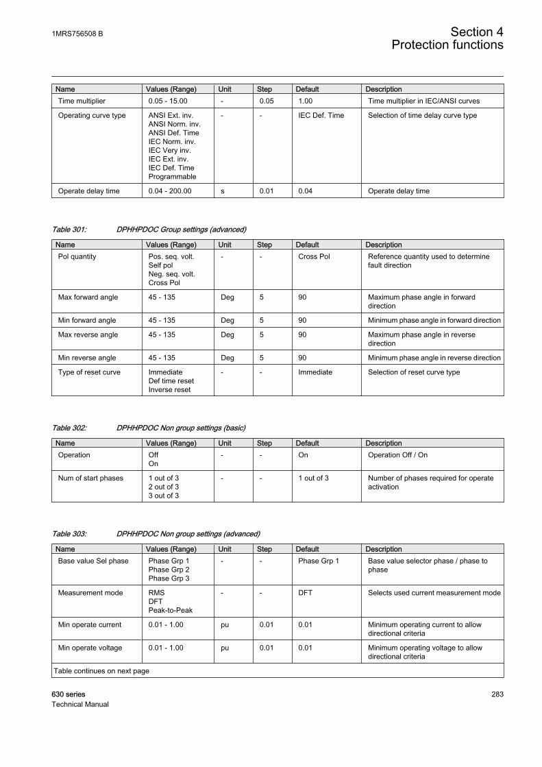
Name Values (Range) Unit Step Default DescriptionTime multiplier 0.05 - 15.00 - 0.05 1.00 Time multiplier in IEC/ANSI curves
Operating curve type ANSI Ext. inv.ANSI Norm. inv.ANSI Def. TimeIEC Norm. inv.IEC Very inv.IEC Ext. inv.IEC Def. TimeProgrammable
- - IEC Def. Time Selection of time delay curve type
Operate delay time 0.04 - 200.00 s 0.01 0.04 Operate delay time
Table 301: DPHHPDOC Group settings (advanced)
Name Values (Range) Unit Step Default DescriptionPol quantity Pos. seq. volt.
Self polNeg. seq. volt.Cross Pol
- - Cross Pol Reference quantity used to determinefault direction
Max forward angle 45 - 135 Deg 5 90 Maximum phase angle in forwarddirection
Min forward angle 45 - 135 Deg 5 90 Minimum phase angle in forward direction
Max reverse angle 45 - 135 Deg 5 90 Maximum phase angle in reversedirection
Min reverse angle 45 - 135 Deg 5 90 Minimum phase angle in reverse direction
Type of reset curve ImmediateDef time resetInverse reset
- - Immediate Selection of reset curve type
Table 302: DPHHPDOC Non group settings (basic)
Name Values (Range) Unit Step Default DescriptionOperation Off
On- - On Operation Off / On
Num of start phases 1 out of 32 out of 33 out of 3
- - 1 out of 3 Number of phases required for operateactivation
Table 303: DPHHPDOC Non group settings (advanced)
Name Values (Range) Unit Step Default DescriptionBase value Sel phase Phase Grp 1
Phase Grp 2Phase Grp 3
- - Phase Grp 1 Base value selector phase / phase tophase
Measurement mode RMSDFTPeak-to-Peak
- - DFT Selects used current measurement mode
Min operate current 0.01 - 1.00 pu 0.01 0.01 Minimum operating current to allowdirectional criteria
Min operate voltage 0.01 - 1.00 pu 0.01 0.01 Minimum operating voltage to allowdirectional criteria
Table continues on next page
1MRS756508 B Section 4Protection functions
630 series 283Technical Manual

Name Values (Range) Unit Step Default DescriptionCurve parameter A 0.0086 - 120.0000 - 0.0001 28.2000 Parameter A for customer programmable
curve
Curve parameter B 0.0000 - 0.7120 - 0.0001 0.1217 Parameter B for customer programmablecurve
Curve parameter C 0.02 - 2.00 - 0.01 2.00 Parameter C for customerprogrammable curve
Curve parameter D 0.46 - 30.00 - 0.01 29.10 Parameter D for customerprogrammable curve
Curve parameter E 0.0 - 1.0 - 0.1 1.0 Parameter E for customer programmablecurve
Reset delay time 0.000 - 60.000 s 0.001 0.020 Reset delay time
Minimum operate time 0.040 - 60.000 s 0.001 0.040 Minimum operate time for IDMT curves
Voltage Mem time 0 - 3000 ms 1 40 Voltage memory time
Allow Non Dir Not allowedAllowed
- - Not allowed Allows prot activation as non-dir when dirinfo is invalid
4.1.2.11 Measured values
Table 304: DPHLPDOC Measured values
Name Type Default DescriptionI_AMPL_A REAL 0 Current amplitude (DFT) phase A
I_AMPL_B REAL 0 Current amplitude (DFT) phase B
I_AMPL_C REAL 0 Current amplitude (DFT) phase C
I_ANGL_A REAL 0 Current phase angle phase A
I_ANGL_B REAL 0 Current phase angle phase B
I_ANGL_C REAL 0 Current phase angle phase C
I_RMS_A REAL 0 Current amptitude (RMS) phase A
I_RMS_B REAL 0 Current amplitude (RMS) phase B
I_RMS_C REAL 0 Current amplitude (RMS) phase C
I_PTOP_A REAL 0 Current amplitude (PTOP) phase A
I_PTOP_B REAL 0 Current amplitude (PTOP) phase B
I_PTOP_C REAL 0 Current amplitude (PTOP) phase C
I2_AMPL REAL 0 Negative phase sequence current amplitude
I2_ANGL REAL 0 Negative phase sequence current angle
U_AMPL_A REAL 0 Polarizing phase-to-ground voltage amplitude
U_AMPL_B REAL 0 Polarizing phase-to-ground voltage amplitude
U_AMPL_C REAL 0 Polarizing phase-to-ground voltage amplitude
U_ANGL_A REAL 0 Polarizing phase-to-ground voltage phase angle
U_ANGL_B REAL 0 Polarizing phase-toground voltage phase angle
U_ANGL_C REAL 0 Polarizing phase-toground voltage phase angle
U_AMPL_AB REAL 0 Polarizing phase-to-phase voltage amplitude
U_AMPL_BC REAL 0 Polarizing phase-to-phase voltage amplitude
Table continues on next page
Section 4 1MRS756508 BProtection functions
284 630 seriesTechnical Manual
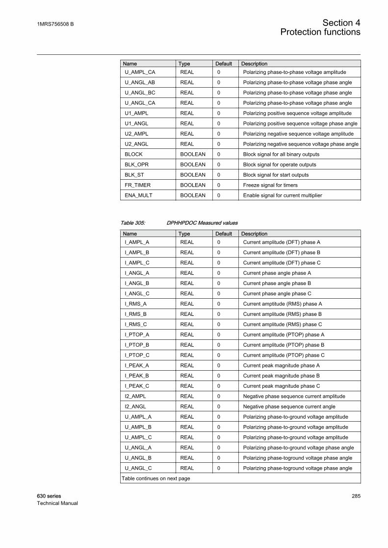
Name Type Default DescriptionU_AMPL_CA REAL 0 Polarizing phase-to-phase voltage amplitude
U_ANGL_AB REAL 0 Polarizing phase-to-phase voltage phase angle
U_ANGL_BC REAL 0 Polarizing phase-to-phase voltage phase angle
U_ANGL_CA REAL 0 Polarizing phase-to-phase voltage phase angle
U1_AMPL REAL 0 Polarizing positive sequence voltage amplitude
U1_ANGL REAL 0 Polarizing positive sequence voltage phase angle
U2_AMPL REAL 0 Polarizing negative sequence voltage amplitude
U2_ANGL REAL 0 Polarizing negative sequence voltage phase angle
BLOCK BOOLEAN 0 Block signal for all binary outputs
BLK_OPR BOOLEAN 0 Block signal for operate outputs
BLK_ST BOOLEAN 0 Block signal for start outputs
FR_TIMER BOOLEAN 0 Freeze signal for timers
ENA_MULT BOOLEAN 0 Enable signal for current multiplier
Table 305: DPHHPDOC Measured values
Name Type Default DescriptionI_AMPL_A REAL 0 Current amplitude (DFT) phase A
I_AMPL_B REAL 0 Current amplitude (DFT) phase B
I_AMPL_C REAL 0 Current amplitude (DFT) phase C
I_ANGL_A REAL 0 Current phase angle phase A
I_ANGL_B REAL 0 Current phase angle phase B
I_ANGL_C REAL 0 Current phase angle phase C
I_RMS_A REAL 0 Current amptitude (RMS) phase A
I_RMS_B REAL 0 Current amplitude (RMS) phase B
I_RMS_C REAL 0 Current amplitude (RMS) phase C
I_PTOP_A REAL 0 Current amplitude (PTOP) phase A
I_PTOP_B REAL 0 Current amplitude (PTOP) phase B
I_PTOP_C REAL 0 Current amplitude (PTOP) phase C
I_PEAK_A REAL 0 Current peak magnitude phase A
I_PEAK_B REAL 0 Current peak magnitude phase B
I_PEAK_C REAL 0 Current peak magnitude phase C
I2_AMPL REAL 0 Negative phase sequence current amplitude
I2_ANGL REAL 0 Negative phase sequence current angle
U_AMPL_A REAL 0 Polarizing phase-to-ground voltage amplitude
U_AMPL_B REAL 0 Polarizing phase-to-ground voltage amplitude
U_AMPL_C REAL 0 Polarizing phase-to-ground voltage amplitude
U_ANGL_A REAL 0 Polarizing phase-to-ground voltage phase angle
U_ANGL_B REAL 0 Polarizing phase-toground voltage phase angle
U_ANGL_C REAL 0 Polarizing phase-toground voltage phase angle
Table continues on next page
1MRS756508 B Section 4Protection functions
630 series 285Technical Manual
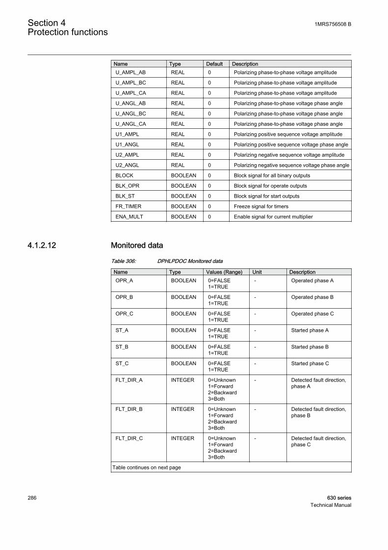
Name Type Default DescriptionU_AMPL_AB REAL 0 Polarizing phase-to-phase voltage amplitude
U_AMPL_BC REAL 0 Polarizing phase-to-phase voltage amplitude
U_AMPL_CA REAL 0 Polarizing phase-to-phase voltage amplitude
U_ANGL_AB REAL 0 Polarizing phase-to-phase voltage phase angle
U_ANGL_BC REAL 0 Polarizing phase-to-phase voltage phase angle
U_ANGL_CA REAL 0 Polarizing phase-to-phase voltage phase angle
U1_AMPL REAL 0 Polarizing positive sequence voltage amplitude
U1_ANGL REAL 0 Polarizing positive sequence voltage phase angle
U2_AMPL REAL 0 Polarizing negative sequence voltage amplitude
U2_ANGL REAL 0 Polarizing negative sequence voltage phase angle
BLOCK BOOLEAN 0 Block signal for all binary outputs
BLK_OPR BOOLEAN 0 Block signal for operate outputs
BLK_ST BOOLEAN 0 Block signal for start outputs
FR_TIMER BOOLEAN 0 Freeze signal for timers
ENA_MULT BOOLEAN 0 Enable signal for current multiplier
4.1.2.12 Monitored data
Table 306: DPHLPDOC Monitored data
Name Type Values (Range) Unit DescriptionOPR_A BOOLEAN 0=FALSE
1=TRUE- Operated phase A
OPR_B BOOLEAN 0=FALSE1=TRUE
- Operated phase B
OPR_C BOOLEAN 0=FALSE1=TRUE
- Operated phase C
ST_A BOOLEAN 0=FALSE1=TRUE
- Started phase A
ST_B BOOLEAN 0=FALSE1=TRUE
- Started phase B
ST_C BOOLEAN 0=FALSE1=TRUE
- Started phase C
FLT_DIR_A INTEGER 0=Unknown1=Forward2=Backward3=Both
- Detected fault direction,phase A
FLT_DIR_B INTEGER 0=Unknown1=Forward2=Backward3=Both
- Detected fault direction,phase B
FLT_DIR_C INTEGER 0=Unknown1=Forward2=Backward3=Both
- Detected fault direction,phase C
Table continues on next page
Section 4 1MRS756508 BProtection functions
286 630 seriesTechnical Manual
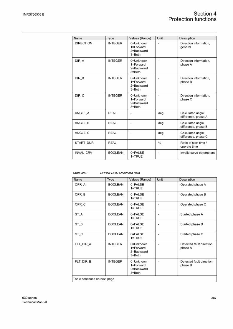
Name Type Values (Range) Unit DescriptionDIRECTION INTEGER 0=Unknown
1=Forward2=Backward3=Both
- Direction information,general
DIR_A INTEGER 0=Unknown1=Forward2=Backward3=Both
- Direction information,phase A
DIR_B INTEGER 0=Unknown1=Forward2=Backward3=Both
- Direction information,phase B
DIR_C INTEGER 0=Unknown1=Forward2=Backward3=Both
- Direction information,phase C
ANGLE_A REAL - deg Calculated angledifference, phase A
ANGLE_B REAL - deg Calculated angledifference, phase B
ANGLE_C REAL - deg Calculated angledifference, phase C
START_DUR REAL - % Ratio of start time /operate time
INVAL_CRV BOOLEAN 0=FALSE1=TRUE
- Invalid curve parameters
Table 307: DPHHPDOC Monitored data
Name Type Values (Range) Unit DescriptionOPR_A BOOLEAN 0=FALSE
1=TRUE- Operated phase A
OPR_B BOOLEAN 0=FALSE1=TRUE
- Operated phase B
OPR_C BOOLEAN 0=FALSE1=TRUE
- Operated phase C
ST_A BOOLEAN 0=FALSE1=TRUE
- Started phase A
ST_B BOOLEAN 0=FALSE1=TRUE
- Started phase B
ST_C BOOLEAN 0=FALSE1=TRUE
- Started phase C
FLT_DIR_A INTEGER 0=Unknown1=Forward2=Backward3=Both
- Detected fault direction,phase A
FLT_DIR_B INTEGER 0=Unknown1=Forward2=Backward3=Both
- Detected fault direction,phase B
Table continues on next page
1MRS756508 B Section 4Protection functions
630 series 287Technical Manual
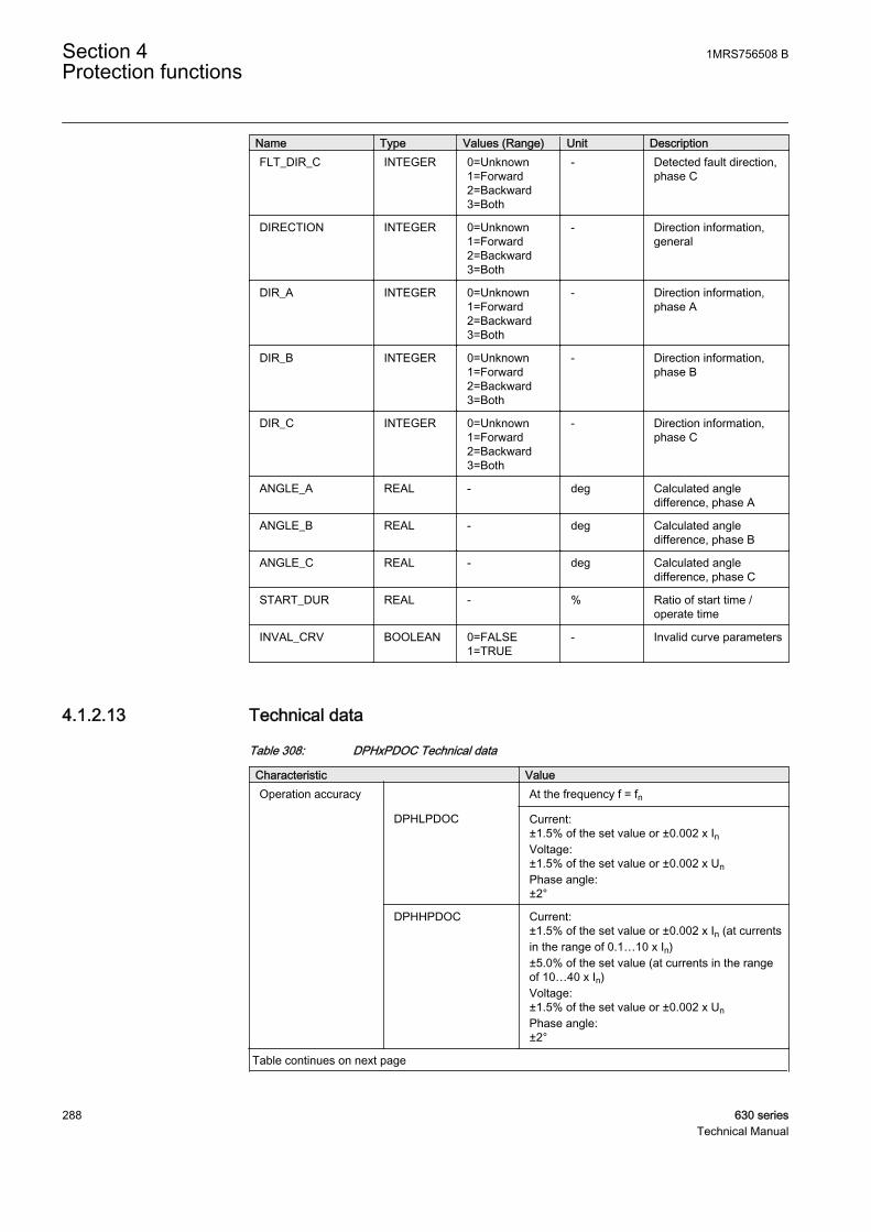
Name Type Values (Range) Unit DescriptionFLT_DIR_C INTEGER 0=Unknown
1=Forward2=Backward3=Both
- Detected fault direction,phase C
DIRECTION INTEGER 0=Unknown1=Forward2=Backward3=Both
- Direction information,general
DIR_A INTEGER 0=Unknown1=Forward2=Backward3=Both
- Direction information,phase A
DIR_B INTEGER 0=Unknown1=Forward2=Backward3=Both
- Direction information,phase B
DIR_C INTEGER 0=Unknown1=Forward2=Backward3=Both
- Direction information,phase C
ANGLE_A REAL - deg Calculated angledifference, phase A
ANGLE_B REAL - deg Calculated angledifference, phase B
ANGLE_C REAL - deg Calculated angledifference, phase C
START_DUR REAL - % Ratio of start time /operate time
INVAL_CRV BOOLEAN 0=FALSE1=TRUE
- Invalid curve parameters
4.1.2.13 Technical data
Table 308: DPHxPDOC Technical data
Characteristic ValueOperation accuracy At the frequency f = fn
DPHLPDOC Current:±1.5% of the set value or ±0.002 x InVoltage:±1.5% of the set value or ±0.002 x UnPhase angle:±2°
DPHHPDOC Current:±1.5% of the set value or ±0.002 x In (at currentsin the range of 0.1…10 x In)±5.0% of the set value (at currents in the rangeof 10…40 x In)Voltage:±1.5% of the set value or ±0.002 x UnPhase angle:±2°
Table continues on next page
Section 4 1MRS756508 BProtection functions
288 630 seriesTechnical Manual

Characteristic ValueStart time1)2) IFault = 2.0 x set Start
valueTypical: 24 ms (±15 ms)
Reset time < 40 ms
Reset ratio Typical 0.96
Retardation time < 35 ms
Operate time accuracy in definite time mode ±1.0% of the set value or ±20 ms
Operate time accuracy in inverse time mode ±5.0% of the theoretical value or ±20 ms3)
Suppression of harmonics RMS: No suppressionDFT: -50 dB at f = n x fn, where n = 2, 3, 4, 5,…Peak-to-Peak: No suppressionP-to-P+backup: No suppression
1) Measurement mode = default (depends of stage), current before fault = 0.0 x In, fn = 50 Hz, faultcurrent in one phase with nominal frequency injected from random phase angle, results based onstatistical distribution of 1000 measurements
2) Includes the delay of the signal output contact3) Maximum Start value = 2.5 x In, Start value multiples in range of 1.5 to 20
4.1.3 Three-phase thermal overload protection for overhead linesand cables T1PTTR
4.1.3.1 Identification
Function description IEC 61850identification
IEC 60617identification
ANSI/IEEE C37.2device number
Three-phase thermal overloadprotection for overhead lines and cables
T1PTTR 3lth> 49F
4.1.3.2 Function block
A070658 V3 EN
Figure 143: Function block
4.1.3.3 Functionality
The increased utilization of power systems closer to the thermal limits hasgenerated a need for a thermal overload function also for power lines.
1MRS756508 B Section 4Protection functions
630 series 289Technical Manual
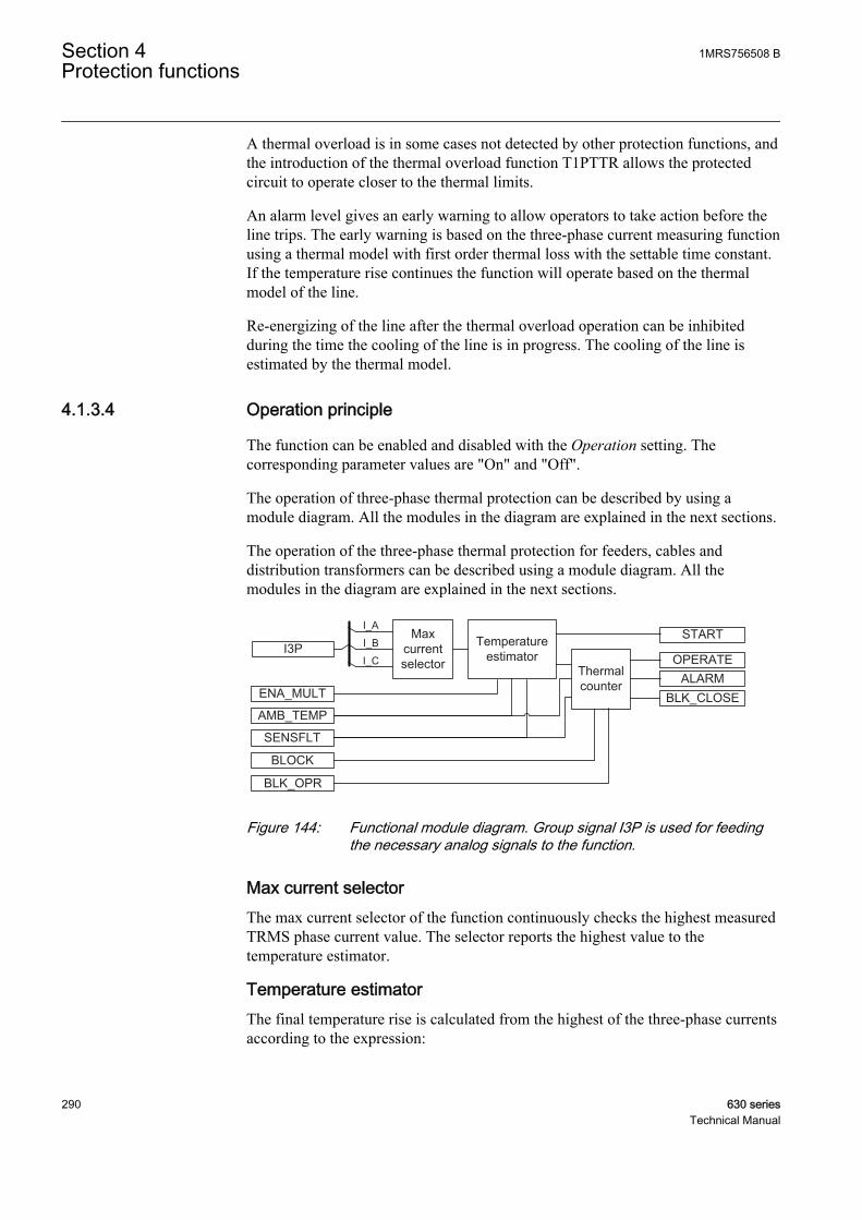
A thermal overload is in some cases not detected by other protection functions, andthe introduction of the thermal overload function T1PTTR allows the protectedcircuit to operate closer to the thermal limits.
An alarm level gives an early warning to allow operators to take action before theline trips. The early warning is based on the three-phase current measuring functionusing a thermal model with first order thermal loss with the settable time constant.If the temperature rise continues the function will operate based on the thermalmodel of the line.
Re-energizing of the line after the thermal overload operation can be inhibitedduring the time the cooling of the line is in progress. The cooling of the line isestimated by the thermal model.
4.1.3.4 Operation principle
The function can be enabled and disabled with the Operation setting. Thecorresponding parameter values are "On" and "Off".
The operation of three-phase thermal protection can be described by using amodule diagram. All the modules in the diagram are explained in the next sections.
The operation of the three-phase thermal protection for feeders, cables anddistribution transformers can be described using a module diagram. All themodules in the diagram are explained in the next sections.
Temperature estimator
Thermal counterENA_MULT
ALARMBLK_CLOSE
OPERATE
BLOCK
STARTMax current selector
AMB_TEMP
BLK_OPR
I3P
I_A
I_B
I_C
SENSFLT
A080008 V2 EN
Figure 144: Functional module diagram. Group signal I3P is used for feedingthe necessary analog signals to the function.
Max current selectorThe max current selector of the function continuously checks the highest measuredTRMS phase current value. The selector reports the highest value to thetemperature estimator.
Temperature estimatorThe final temperature rise is calculated from the highest of the three-phase currentsaccording to the expression:
Section 4 1MRS756508 BProtection functions
290 630 seriesTechnical Manual
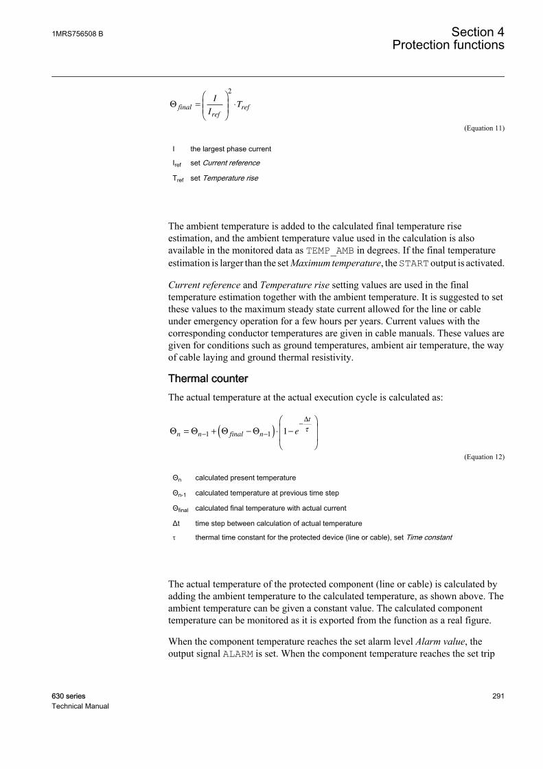
Θ final
ref
ref
I
IT=
⋅
2
A070780 V2 EN (Equation 11)
I the largest phase current
Iref set Current reference
Tref set Temperature rise
The ambient temperature is added to the calculated final temperature riseestimation, and the ambient temperature value used in the calculation is alsoavailable in the monitored data as TEMP_AMB in degrees. If the final temperatureestimation is larger than the set Maximum temperature, the START output is activated.
Current reference and Temperature rise setting values are used in the finaltemperature estimation together with the ambient temperature. It is suggested to setthese values to the maximum steady state current allowed for the line or cableunder emergency operation for a few hours per years. Current values with thecorresponding conductor temperatures are given in cable manuals. These values aregiven for conditions such as ground temperatures, ambient air temperature, the wayof cable laying and ground thermal resistivity.
Thermal counterThe actual temperature at the actual execution cycle is calculated as:
Θ Θ Θ Θ
∆
n n final n
t
e= + −( ) ⋅ −
− −
−
1 1 1 τ
A070781 V2 EN (Equation 12)
Θn calculated present temperature
Θn-1 calculated temperature at previous time step
Θfinal calculated final temperature with actual current
Δt time step between calculation of actual temperature
t thermal time constant for the protected device (line or cable), set Time constant
The actual temperature of the protected component (line or cable) is calculated byadding the ambient temperature to the calculated temperature, as shown above. Theambient temperature can be given a constant value. The calculated componenttemperature can be monitored as it is exported from the function as a real figure.
When the component temperature reaches the set alarm level Alarm value, theoutput signal ALARM is set. When the component temperature reaches the set trip
1MRS756508 B Section 4Protection functions
630 series 291Technical Manual
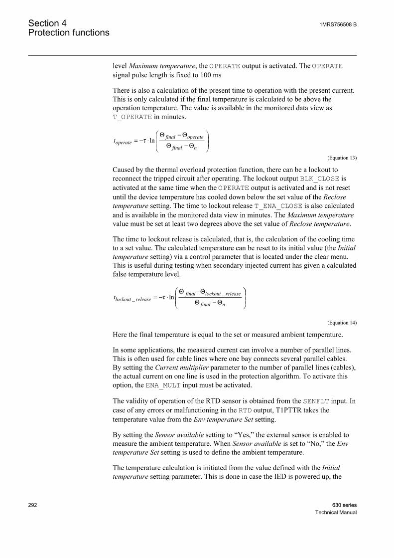
level Maximum temperature, the OPERATE output is activated. The OPERATEsignal pulse length is fixed to 100 ms
There is also a calculation of the present time to operation with the present current.This is only calculated if the final temperature is calculated to be above theoperation temperature. The value is available in the monitored data view asT_OPERATE in minutes.
toperate
final operate
final n
= − ⋅
−
−
τ lnΘ Θ
Θ Θ
A070782 V2 EN (Equation 13)
Caused by the thermal overload protection function, there can be a lockout toreconnect the tripped circuit after operating. The lockout output BLK_CLOSE isactivated at the same time when the OPERATE output is activated and is not resetuntil the device temperature has cooled down below the set value of the Reclosetemperature setting. The time to lockout release T_ENA_CLOSE is also calculatedand is available in the monitored data view in minutes. The Maximum temperaturevalue must be set at least two degrees above the set value of Reclose temperature.
The time to lockout release is calculated, that is, the calculation of the cooling timeto a set value. The calculated temperature can be reset to its initial value (the Initialtemperature setting) via a control parameter that is located under the clear menu.This is useful during testing when secondary injected current has given a calculatedfalse temperature level.
tlockout release
final lockout release
final n
_
_ln= − ⋅
−
−
τΘ Θ
Θ Θ
A070783 V3 EN (Equation 14)
Here the final temperature is equal to the set or measured ambient temperature.
In some applications, the measured current can involve a number of parallel lines.This is often used for cable lines where one bay connects several parallel cables.By setting the Current multiplier parameter to the number of parallel lines (cables),the actual current on one line is used in the protection algorithm. To activate thisoption, the ENA_MULT input must be activated.
The validity of operation of the RTD sensor is obtained from the SENFLT input. Incase of any errors or malfunctioning in the RTD output, T1PTTR takes thetemperature value from the Env temperature Set setting.
By setting the Sensor available setting to “Yes,” the external sensor is enabled tomeasure the ambient temperature. When Sensor available is set to “No,” the Envtemperature Set setting is used to define the ambient temperature.
The temperature calculation is initiated from the value defined with the Initialtemperature setting parameter. This is done in case the IED is powered up, the
Section 4 1MRS756508 BProtection functions
292 630 seriesTechnical Manual
function is turned "Off" and back "On" or reset through the Clear menu. Thetemperature is also stored in the nonvolatile memory and restored in case the IEDis restarted.
The thermal time constant of the protected circuit is given in minutes with the Timeconstant setting. Please see cable manufacturers manuals for further details.
The binary input BLOCK can be used to block the function. The activation of theBLOCK input deactivates all outputs and resets internal timers. The binary inputBLK_OPR can be used to block the operate signals.
4.1.3.5 Base values
In this function block, some of the settings are set in per unit (pu). These pu valuesare relational to certain base values, for example the values given in A, kV andkVA. The IED supports alternative base value groups for the phase current or voltage-related settings, for example "Phase Grp 1", "Phase Grp 2" and "Phase Grp 3".One of the groups to be used with the Base value Sel phase setting must be selected.
For more information, see the Basic functions section in this manual.
4.1.3.6 Application
The lines and cables in the power system are constructed for a certain maximumload current level. If the current exceeds this level, the losses will be higher thanexpected. As a consequence, the temperature of the conductors will increase. If thetemperature of the lines and cables reaches too high values, it can cause a risk ofdamages by, for example, the following ways:
• The sag of overhead lines can reach an unacceptable value.• If the temperature of conductors, for example aluminium conductors, becomes
too high, the material will be destroyed.• In cables the insulation can be damaged as a consequence of overtemperature,
and therefore phase-to-phase or phase-to-earth faults can occur.
In stressed situations in the power system, the lines and cables may be required tobe overloaded for a limited time. This should be done without any risk for the above-mentioned risks.
The thermal overload protection provides information that makes temporaryoverloading of cables and lines possible. The thermal overload protection estimatesthe conductor temperature continuously. This estimation is made by using athermal model of the line/cable that is based on the current measurement.
If the temperature of the protected object reaches a set warning level, a signal isgiven to the operator. This enables actions in the power system to be done before
1MRS756508 B Section 4Protection functions
630 series 293Technical Manual
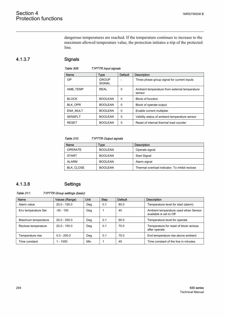
dangerous temperatures are reached. If the temperature continues to increase to themaximum allowed temperature value, the protection initiates a trip of the protectedline.
4.1.3.7 Signals
Table 309: T1PTTR Input signals
Name Type Default DescriptionI3P GROUP
SIGNAL- Three phase group signal for current inputs
AMB_TEMP REAL 0 Ambient temperature from external temperaturesensor
BLOCK BOOLEAN 0 Block of function
BLK_OPR BOOLEAN 0 Block of operate output
ENA_MULT BOOLEAN 0 Enable current multiplier
SENSFLT BOOLEAN 0 Validity status of ambient temperature sensor
RESET BOOLEAN 0 Reset of internal thermal load counter
Table 310: T1PTTR Output signals
Name Type DescriptionOPERATE BOOLEAN Operate signal
START BOOLEAN Start Signal
ALARM BOOLEAN Alarm signal
BLK_CLOSE BOOLEAN Thermal overload indicator. To inhibit reclose
4.1.3.8 Settings
Table 311: T1PTTR Group settings (basic)
Name Values (Range) Unit Step Default DescriptionAlarm value 20.0 - 150.0 Deg 0.1 80.0 Temperature level for start (alarm)
Env temperature Set -50 - 100 Deg 1 40 Ambient temperature used when Sensoravailable is set to Off
Maximum temperature 20.0 - 200.0 Deg 0.1 90.0 Temperature level for operate
Reclose temperature 20.0 - 150.0 Deg 0.1 70.0 Temperature for reset of block recloseafter operate
Temperature rise 0.0 - 200.0 Deg 0.1 75.0 End temperature rise above ambient
Time constant 1 - 1000 Min 1 45 Time constant of the line in minutes.
Section 4 1MRS756508 BProtection functions
294 630 seriesTechnical Manual
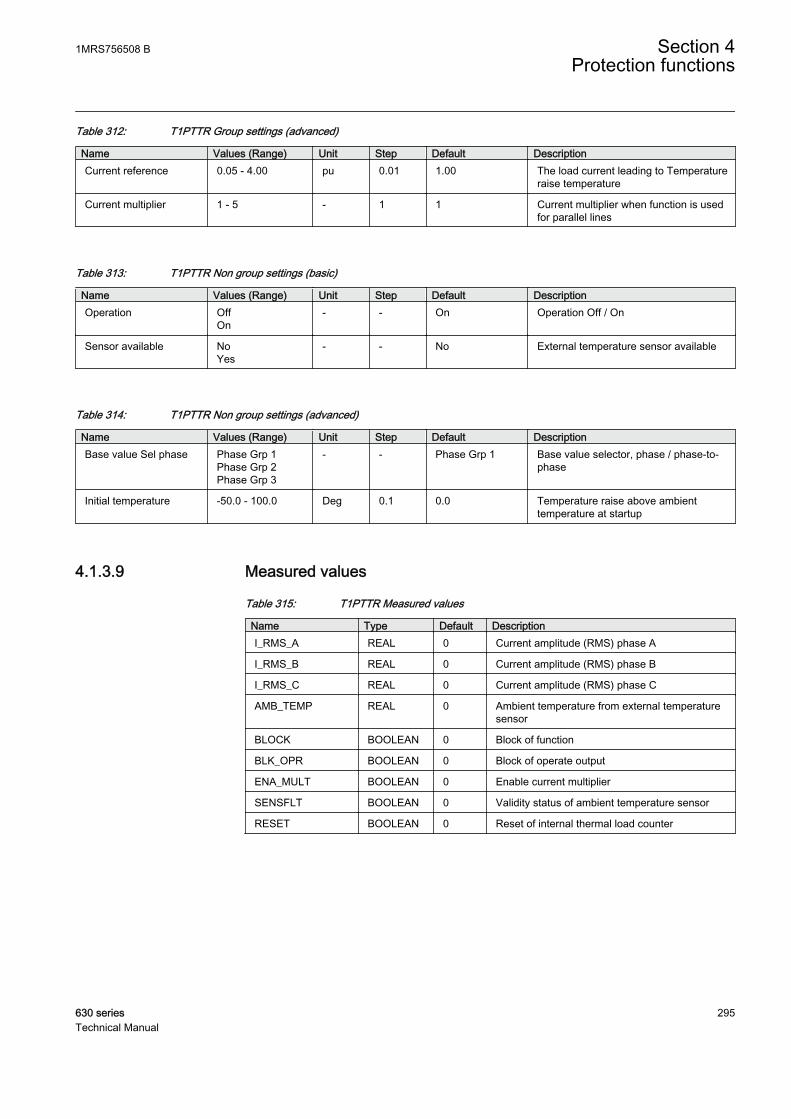
Table 312: T1PTTR Group settings (advanced)
Name Values (Range) Unit Step Default DescriptionCurrent reference 0.05 - 4.00 pu 0.01 1.00 The load current leading to Temperature
raise temperature
Current multiplier 1 - 5 - 1 1 Current multiplier when function is usedfor parallel lines
Table 313: T1PTTR Non group settings (basic)
Name Values (Range) Unit Step Default DescriptionOperation Off
On- - On Operation Off / On
Sensor available NoYes
- - No External temperature sensor available
Table 314: T1PTTR Non group settings (advanced)
Name Values (Range) Unit Step Default DescriptionBase value Sel phase Phase Grp 1
Phase Grp 2Phase Grp 3
- - Phase Grp 1 Base value selector, phase / phase-to-phase
Initial temperature -50.0 - 100.0 Deg 0.1 0.0 Temperature raise above ambienttemperature at startup
4.1.3.9 Measured values
Table 315: T1PTTR Measured values
Name Type Default DescriptionI_RMS_A REAL 0 Current amplitude (RMS) phase A
I_RMS_B REAL 0 Current amplitude (RMS) phase B
I_RMS_C REAL 0 Current amplitude (RMS) phase C
AMB_TEMP REAL 0 Ambient temperature from external temperaturesensor
BLOCK BOOLEAN 0 Block of function
BLK_OPR BOOLEAN 0 Block of operate output
ENA_MULT BOOLEAN 0 Enable current multiplier
SENSFLT BOOLEAN 0 Validity status of ambient temperature sensor
RESET BOOLEAN 0 Reset of internal thermal load counter
1MRS756508 B Section 4Protection functions
630 series 295Technical Manual
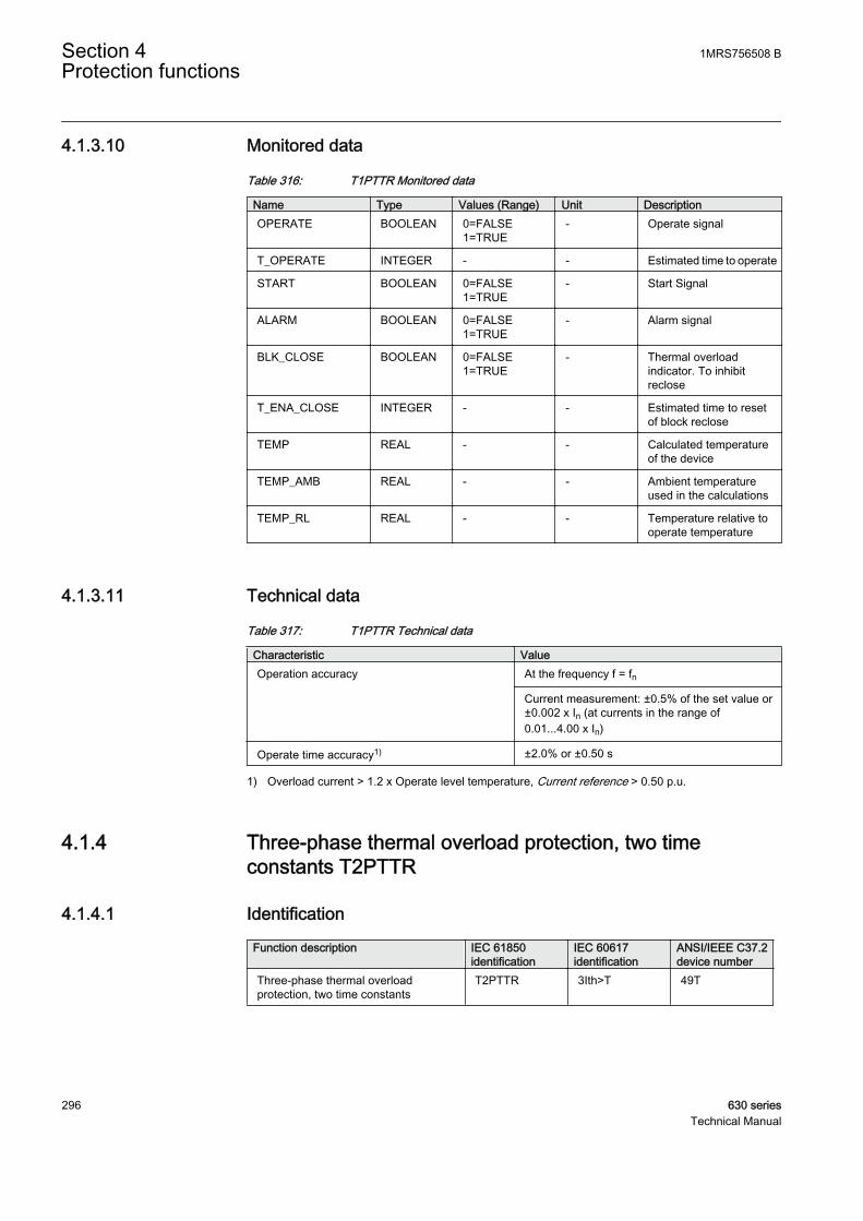
4.1.3.10 Monitored data
Table 316: T1PTTR Monitored data
Name Type Values (Range) Unit DescriptionOPERATE BOOLEAN 0=FALSE
1=TRUE- Operate signal
T_OPERATE INTEGER - - Estimated time to operate
START BOOLEAN 0=FALSE1=TRUE
- Start Signal
ALARM BOOLEAN 0=FALSE1=TRUE
- Alarm signal
BLK_CLOSE BOOLEAN 0=FALSE1=TRUE
- Thermal overloadindicator. To inhibitreclose
T_ENA_CLOSE INTEGER - - Estimated time to resetof block reclose
TEMP REAL - - Calculated temperatureof the device
TEMP_AMB REAL - - Ambient temperatureused in the calculations
TEMP_RL REAL - - Temperature relative tooperate temperature
4.1.3.11 Technical data
Table 317: T1PTTR Technical data
Characteristic ValueOperation accuracy At the frequency f = fn
Current measurement: ±0.5% of the set value or±0.002 x In (at currents in the range of0.01...4.00 x In)
Operate time accuracy1) ±2.0% or ±0.50 s
1) Overload current > 1.2 x Operate level temperature, Current reference > 0.50 p.u.
4.1.4 Three-phase thermal overload protection, two timeconstants T2PTTR
4.1.4.1 Identification
Function description IEC 61850identification
IEC 60617identification
ANSI/IEEE C37.2device number
Three-phase thermal overloadprotection, two time constants
T2PTTR 3Ith>T 49T
Section 4 1MRS756508 BProtection functions
296 630 seriesTechnical Manual

4.1.4.2 Function block
GUID-3BBE6F98-B838-4323-A7AF-05DC53B68F4A V1 EN
Figure 145: Function block
4.1.4.3 Functionality
The three-phase thermal overload, two time constant protection function T2PTTRprotects the transformer mainly from short-time overloads. The transformer isprotected from long-time overloads with the oil temperature detector included in itsequipment.
The alarm signal gives an early warning to allow the operators to take action beforethe transformer trips. The early warning is based on the three-phase currentmeasuring function using a thermal model with two settable time constants. If thetemperature rise continues, T2PTTR operates based on the thermal model of thetransformer.
After a thermal overload operation, the re-energizing of the transformer is inhibitedduring the transformer cooling time. The transformer cooling is estimated with athermal model.
4.1.4.4 Operation principle
The function can be enabled and disabled with the Operation setting. Thecorresponding parameter values are "On" and "Off".
The operation of three-phase thermal overload, two time constant protection can bedescribed using a module diagram. All the modules in the diagram are explained inthe next sections.
GUID-AFAF9BF2-9F2B-4626-BF07-7D41BF61801F V1 EN
Figure 146: Functional module diagram. I_A, I_B and I_C represent phasecurrents.
1MRS756508 B Section 4Protection functions
630 series 297Technical Manual

Max current selectorThe max current selector of the function continuously checks the highest measuredTRMS phase current value. The selector reports the highest value to the thermalcounter.
Temperature estimatorThe final temperature rise is calculated from the highest of the three-phase currentsaccording to the expression:
Θ final
ref
ref
I
IT=
⋅
2
GUID-06DE6459-E94A-4FC7-8357-CA58988CEE97 V2 EN (Equation 15)
I highest measured phase current
Iref the set value of the Current reference setting
Tref the set value of the Temperature rise setting (temperature rise (°C) with the steady-state currentIref
The ambient temperature is added to the calculated final temperature riseestimation, and the ambient temperature value used in the calculation is alsoavailable in the monitored data as TEMP_AMB in degrees. If the total value oftemperature is higher than the set operating temperature level, the START output isactivated.
The Current reference setting is a steady-state current that gives the steady-stateend temperature value Temperature rise. It gives a setting value corresponding tothe rated power of the transformer.
The Temperature rise setting is used when the value of the reference temperaturerise corresponds to the Current reference value. The temperature values with thecorresponding transformer load currents are usually given by transformermanufacturers.
Thermal counterT2PTTR applies the thermal model of two time constants for temperaturemeasurement. The temperature rise in degrees Celsius (°C) is calculated from thehighest of the three-phase currents according to the expression:
Section 4 1MRS756508 BProtection functions
298 630 seriesTechnical Manual

∆Θ
∆
=
⋅ −
+ −( ) ⋅
−
pI
IT e p
ref
ref
t
* *
2
11 1τII
IT e
ref
ref
t
⋅
⋅ −
−
2
21
∆
τ
GUID-27A879A9-AF94-4BC3-BAA1-501189F6DE0C V2 EN (Equation 16)
ΔΘ calculated temperature rise (°C) in transformer
I measured phase current with the highest TRMS value
Iref the set value of the Current reference setting (rated current of the protected object)
Tref the set value of the Temperature rise setting (temperature rise setting (°C) with the steady-statecurrent Iref)
p the set value of the p-factor setting (weighting factor for the short time constant)
Δt time step between the calculation of the actual temperature
t1 the set value of the Short time constant setting (the short heating / cooling time constant)
t2 the set value of the Long time constant setting (the long heating / cooling time constant)
The warming and cooling following the two time-constant thermal curve is acharacteristic of transformers. The thermal time constants of the protectedtransformer are given in seconds with the Short time constant and Long timeconstant settings. The Short time constant setting describes the warming of thetransformer with respect to windings. The Long time constant setting describes thewarming of the transformer with respect to the oil. Using the two time-constantmodel, the IED is able to follow both fast and slow changes in the temperature ofthe protected object.
The p-factor setting is the weighting factor between Short time constant τ1 andLong time constant τ2. The higher the value of the p-factor setting, the larger is theshare of the steep part of the heating curve. When p=1, only Short-time constant isused. When p = 0, only Long time constant is used.
1MRS756508 B Section 4Protection functions
630 series 299Technical Manual
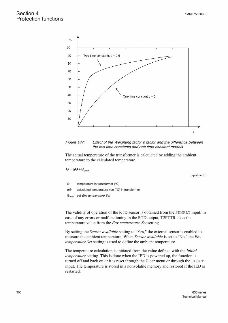
GUID-E040FFF4-7FE3-4736-8E5F-D96DB1F1B16B V1 EN
Figure 147: Effect of the Weighting factor p factor and the difference betweenthe two time constants and one time constant models
The actual temperature of the transformer is calculated by adding the ambienttemperature to the calculated temperature.
Θ Θ Θ= ∆ +amb
GUID-77E49346-66D2-4CAB-A764-E81D6F382E74 V2 EN (Equation 17)
Θ temperature in transformer (°C)
ΔΘ calculated temperature rise (°C) in transformer
Θamb set Env temperature Set
The validity of operation of the RTD sensor is obtained from the SENFLT input. Incase of any errors or malfunctioning in the RTD output, T2PTTR takes thetemperature value from the Env temperature Set setting.
By setting the Sensor available setting to "Yes," the external sensor is enabled tomeasure the ambient temperature. When Sensor available is set to "No," the Envtemperature Set setting is used to define the ambient temperature.
The temperature calculation is initiated from the value defined with the Initialtemperature setting. This is done when the IED is powered up, the function isturned off and back on or it is reset through the Clear menu or through the RESETinput. The temperature is stored in a nonvolatile memory and restored if the IED isrestarted.
Section 4 1MRS756508 BProtection functions
300 630 seriesTechnical Manual

The Max temperature setting defines the maximum temperature of the transformerin degrees Celsius (°C). The value of the Max temperature setting is usually givenby transformer manufacturers. The actual alarm, operating and lockouttemperatures for T2PTTR are given as a percentage value of the Max temperaturesetting.
When the transformer temperature reaches the alarm level defined with the Alarmtemperature setting, the ALARM output signal is set. When the transformertemperature reaches the trip level value defined with the Operate temperaturesetting, the OPERATE output is activated. The OPERATE output is deactivatedwhen the value of the measured current falls below 10 percent of the CurrentReference value or the calculated temperature value falls below Operatetemperature.
There is also a calculation of the present time to operation with the present current.T_OPERATE is only calculated if the final temperature is calculated to be abovethe operation temperature. The value is available in the monitored data view.
After operating, there can be a lockout to reconnect the tripped circuit due to thethermal overload protection function. The BLK_CLOSE lockout output is activatedwhen the device temperature is above the Reclose temperature lockout releasetemperature setting value. The time to lockout release T_ENA_CLOSE is alsocalculated. The value is available in the monitored data view.
4.1.4.5 Base values
In this function block, some of the settings are set in per unit (pu). These pu valuesare relational to certain base values, for example the values given in A, kV andkVA. The IED supports alternative base value groups for the phase current or voltage-related settings, for example "Phase Grp 1", "Phase Grp 2" and "Phase Grp 3".One of the groups to be used with the Base value Sel phase setting must be selected.
For more information, see the Basic functions section in this manual.
4.1.4.6 Application
The transformers in a power system are constructed for a certain maximum loadcurrent level. If the current exceeds this level, the losses are higher than expected.This results in a rise in transformer temperature. If the temperature rise is too high,the equipment is damaged:
• Insulation within the transformer ages faster, which in turn increases the riskof internal phase-to-phase or phase-to-earth faults.
• Possible hotspots forming within the transformer degrade the quality of thetransformer oil.
1MRS756508 B Section 4Protection functions
630 series 301Technical Manual
During stressed situations in power systems, it is required to overload thetransformers for a limited time without any risks. The thermal overload protectionprovides information and makes temporary overloading of transformers possible.
The permissible load level of a power transformer is highly dependent on thetransformer cooling system. The two main principles are:
• ONAN: The air is naturally circulated to the coolers without fans, and the oil isnaturally circulated without pumps.
• OFAF: The coolers have fans to force air for cooling, and pumps to force thecirculation of the transformer oil.
The protection has several parameter sets located in the setting groups, for exampleone for a non-forced cooling and one for a forced cooling situation. Both thepermissive steady-state loading level as well as the thermal time constant areinfluenced by the transformer cooling system. The active setting group can bechanged by a parameter, or through a binary input if the binary input is enabled forit. This feature can be used for transformers where forced cooling is taken out ofoperation or extra cooling is switched on. The parameters can also be changedwhen a fan or pump fails to operate.
The thermal overload protection continuously estimates the internal heat content,that is, the temperature of the transformer. This estimation is made by using athermal model of the transformer which is based on the current measurement.
If the heat content of the protected transformer reaches the set alarm level, a signalis given to the operator. This enables the action that needs to be taken in the powersystems before the temperature reaches a high value. If the temperature continuesto rise to the trip value, the protection initiates the trip of the protected transformer.
After the trip, the transformer needs to cool down to a temperature level where thetransformer can be taken into service again. T2PTTR continues to estimate the heatcontent of the transformer during this cooling period using a set cooling timeconstant. The energizing of the transformer is blocked until the heat content isreduced to the set level.
The thermal curve of two time constants is typical for a transformer. The thermaltime constants of the protected transformer are given in seconds with the Short timeconstant and Long time constant settings. If the manufacturer does not state anyother value, the Long time constant can be set to 4920 s (82 minutes) for adistribution transformer and 7260 s (121 minutes) for a supply transformer. Thecorresponding Short time constants are 306 s (5.1 minutes) and 456 s (7.6 minutes).
If the manufacturer of the power transformer has stated only one, that is, singletime constant, it can be converted to two time constants. The single time constant isalso used by itself if the p-factor setting is set to zero and the time constant value isset to the value of the Long time constant setting. The thermal image correspondsto the one time constant model in that case.
Section 4 1MRS756508 BProtection functions
302 630 seriesTechnical Manual
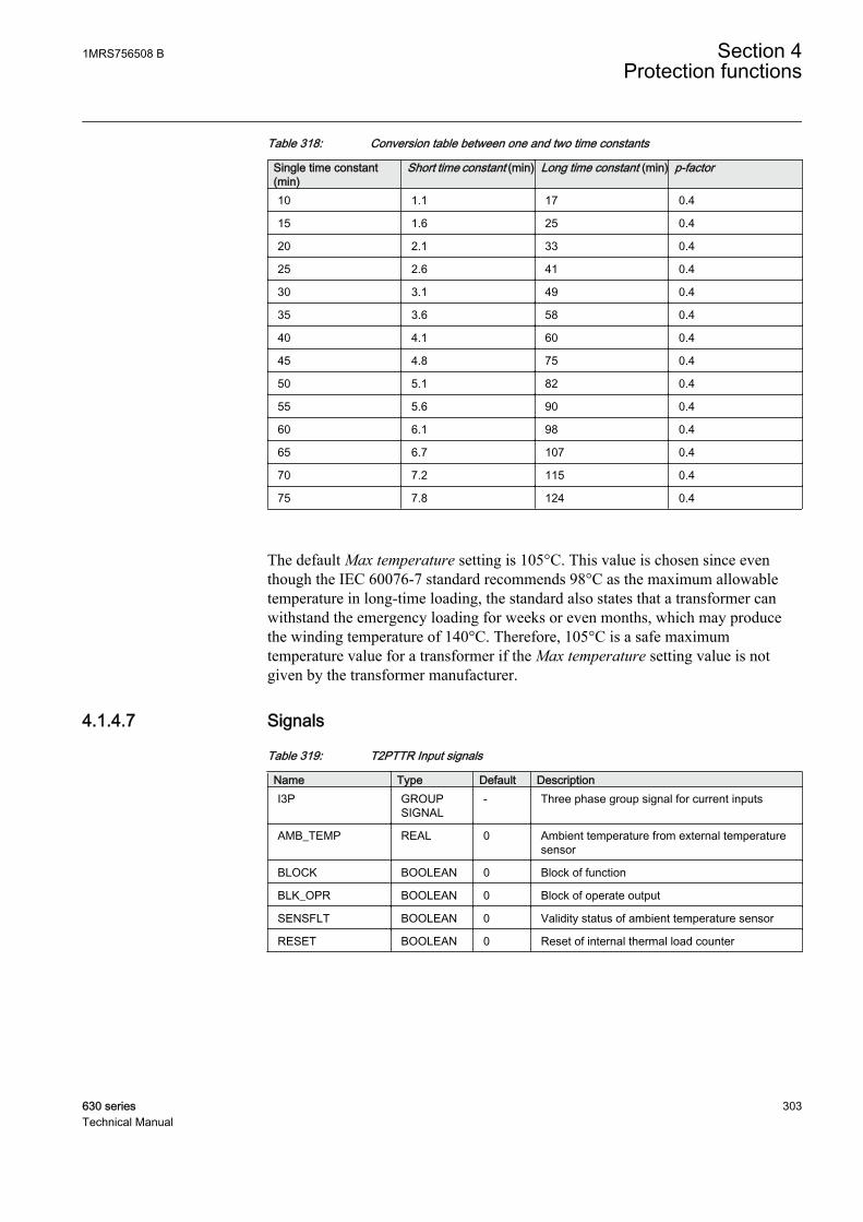
Table 318: Conversion table between one and two time constants
Single time constant(min)
Short time constant (min) Long time constant (min) p-factor
10 1.1 17 0.4
15 1.6 25 0.4
20 2.1 33 0.4
25 2.6 41 0.4
30 3.1 49 0.4
35 3.6 58 0.4
40 4.1 60 0.4
45 4.8 75 0.4
50 5.1 82 0.4
55 5.6 90 0.4
60 6.1 98 0.4
65 6.7 107 0.4
70 7.2 115 0.4
75 7.8 124 0.4
The default Max temperature setting is 105°C. This value is chosen since eventhough the IEC 60076-7 standard recommends 98°C as the maximum allowabletemperature in long-time loading, the standard also states that a transformer canwithstand the emergency loading for weeks or even months, which may producethe winding temperature of 140°C. Therefore, 105°C is a safe maximumtemperature value for a transformer if the Max temperature setting value is notgiven by the transformer manufacturer.
4.1.4.7 Signals
Table 319: T2PTTR Input signals
Name Type Default DescriptionI3P GROUP
SIGNAL- Three phase group signal for current inputs
AMB_TEMP REAL 0 Ambient temperature from external temperaturesensor
BLOCK BOOLEAN 0 Block of function
BLK_OPR BOOLEAN 0 Block of operate output
SENSFLT BOOLEAN 0 Validity status of ambient temperature sensor
RESET BOOLEAN 0 Reset of internal thermal load counter
1MRS756508 B Section 4Protection functions
630 series 303Technical Manual
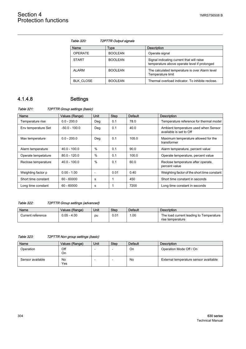
Table 320: T2PTTR Output signals
Name Type DescriptionOPERATE BOOLEAN Operate signal
START BOOLEAN Signal indicating current that will raisetemperature above operate level if prolonged
ALARM BOOLEAN The calculated temperature is over Alarm levelTemperature limit
BLK_CLOSE BOOLEAN Thermal overload indicator. To inhibite reclose.
4.1.4.8 Settings
Table 321: T2PTTR Group settings (basic)
Name Values (Range) Unit Step Default DescriptionTemperature rise 0.0 - 200.0 Deg 0.1 78.0 Temperature reference for thermal model
Env temperature Set -50.0 - 100.0 Deg 0.1 40.0 Ambient temperature used when Sensoravailable is set to Off
Max temperature 0.0 - 200.0 Deg 0.1 105.0 Maximum temperature allowed for thetransformer
Alarm temperature 40.0 - 100.0 % 0.1 90.0 Alarm temperature, percent value
Operate tempetature 80.0 - 120.0 % 0.1 100.0 Operate temperature, percent value
Reclose temperature 40.0 - 100.0 % 0.1 60.0 Reclose temperature after operate,percent value
Weighting factor p 0.00 - 1.00 - 0.01 0.40 Weighting factor of the short time constant
Short time constant 60 - 60000 s 1 450 Short time constant in seconds
Long time constant 60 - 60000 s 1 7200 Long time constant in seconds
Table 322: T2PTTR Group settings (advanced)
Name Values (Range) Unit Step Default DescriptionCurrent reference 0.05 - 4.00 pu 0.01 1.00 The load current leading to Temperature
rise temperature
Table 323: T2PTTR Non group settings (basic)
Name Values (Range) Unit Step Default DescriptionOperation Off
On- - On Operation Mode Off / On
Sensor available NoYes
- - No External temperature sensor availiable
Section 4 1MRS756508 BProtection functions
304 630 seriesTechnical Manual
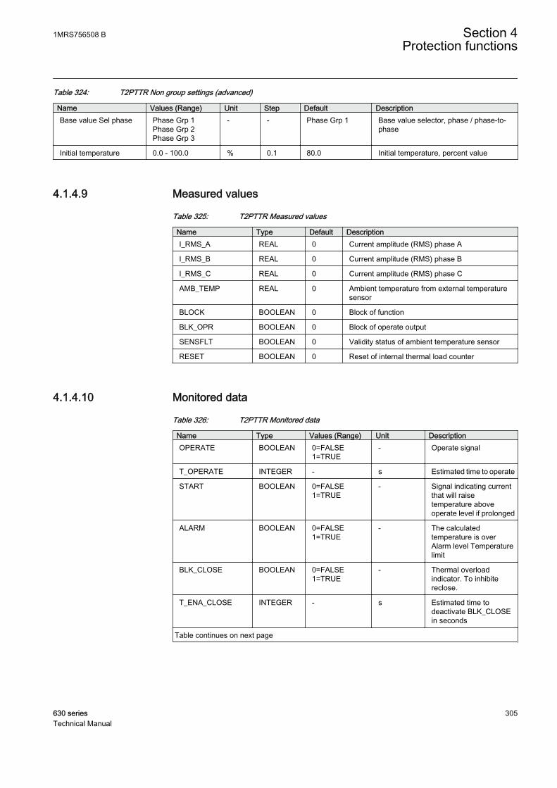
Table 324: T2PTTR Non group settings (advanced)
Name Values (Range) Unit Step Default DescriptionBase value Sel phase Phase Grp 1
Phase Grp 2Phase Grp 3
- - Phase Grp 1 Base value selector, phase / phase-to-phase
Initial temperature 0.0 - 100.0 % 0.1 80.0 Initial temperature, percent value
4.1.4.9 Measured values
Table 325: T2PTTR Measured values
Name Type Default DescriptionI_RMS_A REAL 0 Current amplitude (RMS) phase A
I_RMS_B REAL 0 Current amplitude (RMS) phase B
I_RMS_C REAL 0 Current amplitude (RMS) phase C
AMB_TEMP REAL 0 Ambient temperature from external temperaturesensor
BLOCK BOOLEAN 0 Block of function
BLK_OPR BOOLEAN 0 Block of operate output
SENSFLT BOOLEAN 0 Validity status of ambient temperature sensor
RESET BOOLEAN 0 Reset of internal thermal load counter
4.1.4.10 Monitored data
Table 326: T2PTTR Monitored data
Name Type Values (Range) Unit DescriptionOPERATE BOOLEAN 0=FALSE
1=TRUE- Operate signal
T_OPERATE INTEGER - s Estimated time to operate
START BOOLEAN 0=FALSE1=TRUE
- Signal indicating currentthat will raisetemperature aboveoperate level if prolonged
ALARM BOOLEAN 0=FALSE1=TRUE
- The calculatedtemperature is overAlarm level Temperaturelimit
BLK_CLOSE BOOLEAN 0=FALSE1=TRUE
- Thermal overloadindicator. To inhibitereclose.
T_ENA_CLOSE INTEGER - s Estimated time todeactivate BLK_CLOSEin seconds
Table continues on next page
1MRS756508 B Section 4Protection functions
630 series 305Technical Manual
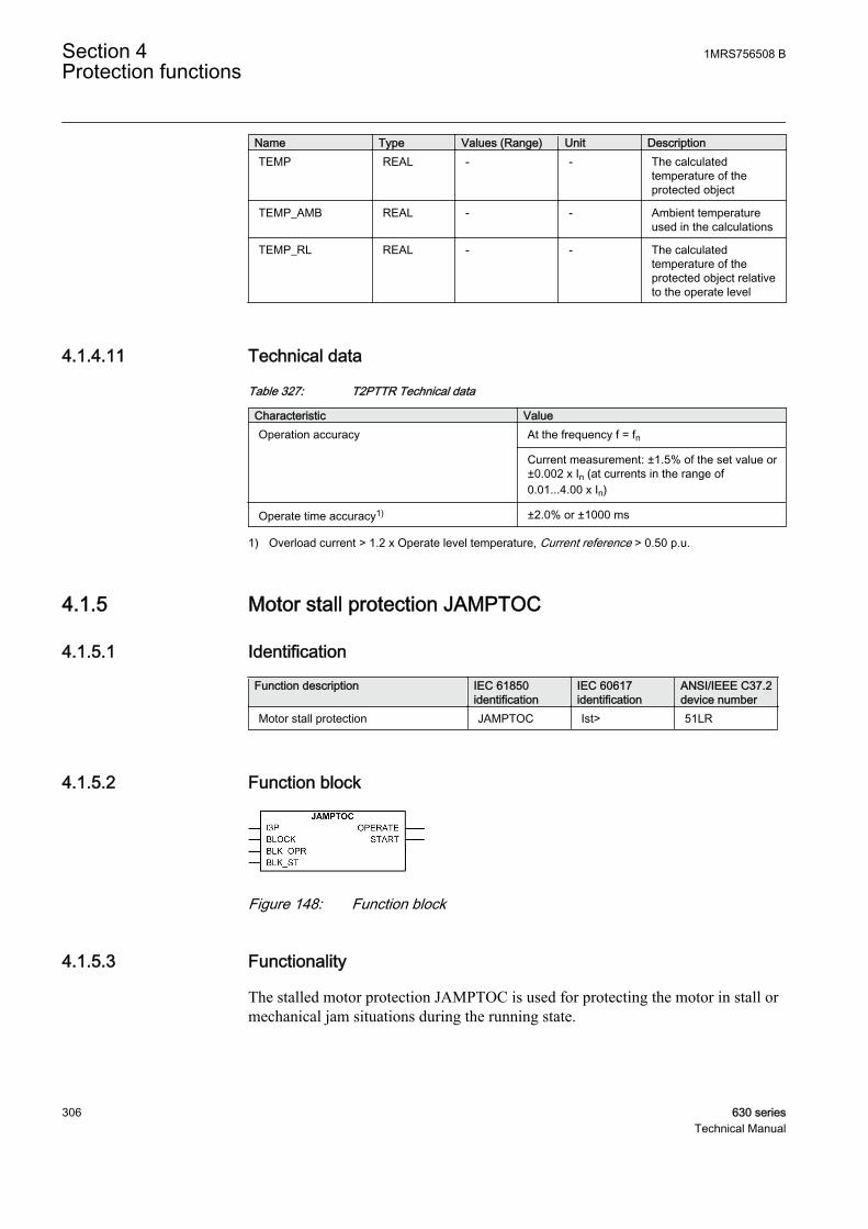
Name Type Values (Range) Unit DescriptionTEMP REAL - - The calculated
temperature of theprotected object
TEMP_AMB REAL - - Ambient temperatureused in the calculations
TEMP_RL REAL - - The calculatedtemperature of theprotected object relativeto the operate level
4.1.4.11 Technical data
Table 327: T2PTTR Technical data
Characteristic ValueOperation accuracy At the frequency f = fn
Current measurement: ±1.5% of the set value or±0.002 x In (at currents in the range of0.01...4.00 x In)
Operate time accuracy1) ±2.0% or ±1000 ms
1) Overload current > 1.2 x Operate level temperature, Current reference > 0.50 p.u.
4.1.5 Motor stall protection JAMPTOC
4.1.5.1 Identification
Function description IEC 61850identification
IEC 60617identification
ANSI/IEEE C37.2device number
Motor stall protection JAMPTOC Ist> 51LR
4.1.5.2 Function block
GUID-41BFFE63-0330-4C85-B43E-E63A80CC2859 V1 EN
Figure 148: Function block
4.1.5.3 Functionality
The stalled motor protection JAMPTOC is used for protecting the motor in stall ormechanical jam situations during the running state.
Section 4 1MRS756508 BProtection functions
306 630 seriesTechnical Manual
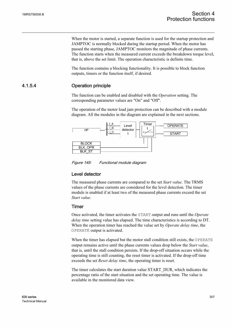
When the motor is started, a separate function is used for the startup protection andJAMPTOC is normally blocked during the startup period. When the motor haspassed the starting phase, JAMPTOC monitors the magnitude of phase currents.The function starts when the measured current exceeds the breakdown torque level,that is, above the set limit. The operation characteristic is definite time.
The function contains a blocking functionality. It is possible to block functionoutputs, timers or the function itself, if desired.
4.1.5.4 Operation principle
The function can be enabled and disabled with the Operation setting. Thecorresponding parameter values are "On" and "Off".
The operation of the motor load jam protection can be described with a modulediagram. All the modules in the diagram are explained in the next sections.
GUID-2CA97EA5-09E4-40FE-8F99-ED9251BC50C0 V1 EN
Figure 149: Functional module diagram
Level detectorThe measured phase currents are compared to the set Start value. The TRMSvalues of the phase currents are considered for the level detection. The timermodule is enabled if at least two of the measured phase currents exceed the setStart value.
TimerOnce activated, the timer activates the START output and runs until the Operatedelay time setting value has elapsed. The time characteristics is according to DT.When the operation timer has reached the value set by Operate delay time, theOPERATE output is activated.
When the timer has elapsed but the motor stall condition still exists, the OPERATEoutput remains active until the phase currents values drop below the Start value,that is, until the stall condition persists. If the drop-off situation occurs while theoperating time is still counting, the reset timer is activated. If the drop-off timeexceeds the set Reset delay time, the operating timer is reset.
The timer calculates the start duration value START_DUR, which indicates thepercentage ratio of the start situation and the set operating time. The value isavailable in the monitored data view.
1MRS756508 B Section 4Protection functions
630 series 307Technical Manual
The blocking functionality contains three binary inputs. The BLOCK input blocksthe operation of the whole function, and the timers are reset. The BLOCK input canbe used to block the protection during a motor start.
The activation of the BLK_ST and BLK_OPR inputs blocks the starting andoperating outputs respectively.
4.1.5.5 Base values
In this function block, some of the settings are set in per unit (pu). These pu valuesare relational to certain base values, for example the values given in A, kV andkVA. The IED supports alternative base value groups for the phase current or voltage-related settings, for example "Phase Grp 1", "Phase Grp 2" and "Phase Grp 3".One of the groups to be used with the Base value Sel phase setting must be selected.
For more information, see the Basic functions section in this manual.
4.1.5.6 Application
The motor protection during stall is primarily needed to protect the motor fromexcessive temperature rise, as the motor draws large currents during the stall phase.This condition causes a temperature rise in the stator windings. Due to reducedspeed, the temperature also rises in the rotor. The rotor temperature rise is morecritical when the motor stops.
The physical and dielectric insulations of the system deteriorate with age and thedeterioration is accelerated by the temperature increase. Insulation life is related tothe time interval during which the insulation is maintained at a given temperature.
An induction motor stalls when the load torque value exceeds the breakdowntorque value, causing the speed to decrease to zero or to some stable operatingpoint well below the rated speed. This occurs, for example, when the applied shaftload is suddenly increased and is greater than the producing motor torque due tothe bearing failures. This condition develops a motor current almost equal to thevalue of the locked-rotor current.
JAMPTOC is designed to protect the motor in stall or mechanical jam situationsduring the running state. To provide a good and reliable protection for motors in astall situation, the temperature effects on the motor have to be kept within theallowed limits.
Section 4 1MRS756508 BProtection functions
308 630 seriesTechnical Manual
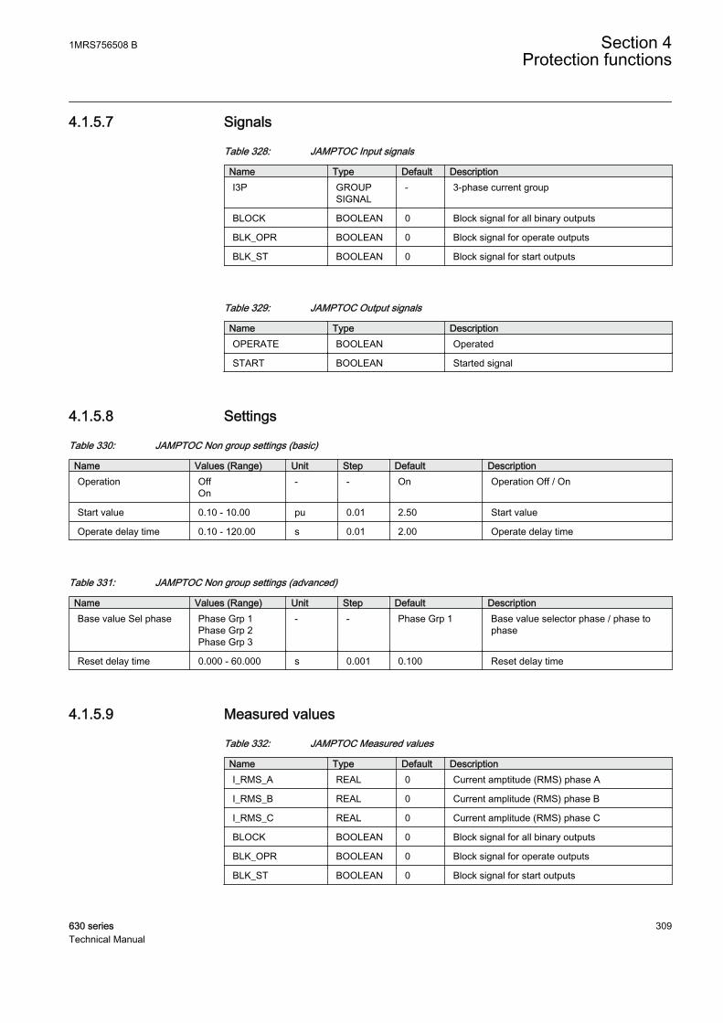
4.1.5.7 Signals
Table 328: JAMPTOC Input signals
Name Type Default DescriptionI3P GROUP
SIGNAL- 3-phase current group
BLOCK BOOLEAN 0 Block signal for all binary outputs
BLK_OPR BOOLEAN 0 Block signal for operate outputs
BLK_ST BOOLEAN 0 Block signal for start outputs
Table 329: JAMPTOC Output signals
Name Type DescriptionOPERATE BOOLEAN Operated
START BOOLEAN Started signal
4.1.5.8 Settings
Table 330: JAMPTOC Non group settings (basic)
Name Values (Range) Unit Step Default DescriptionOperation Off
On- - On Operation Off / On
Start value 0.10 - 10.00 pu 0.01 2.50 Start value
Operate delay time 0.10 - 120.00 s 0.01 2.00 Operate delay time
Table 331: JAMPTOC Non group settings (advanced)
Name Values (Range) Unit Step Default DescriptionBase value Sel phase Phase Grp 1
Phase Grp 2Phase Grp 3
- - Phase Grp 1 Base value selector phase / phase tophase
Reset delay time 0.000 - 60.000 s 0.001 0.100 Reset delay time
4.1.5.9 Measured values
Table 332: JAMPTOC Measured values
Name Type Default DescriptionI_RMS_A REAL 0 Current amptitude (RMS) phase A
I_RMS_B REAL 0 Current amplitude (RMS) phase B
I_RMS_C REAL 0 Current amplitude (RMS) phase C
BLOCK BOOLEAN 0 Block signal for all binary outputs
BLK_OPR BOOLEAN 0 Block signal for operate outputs
BLK_ST BOOLEAN 0 Block signal for start outputs
1MRS756508 B Section 4Protection functions
630 series 309Technical Manual
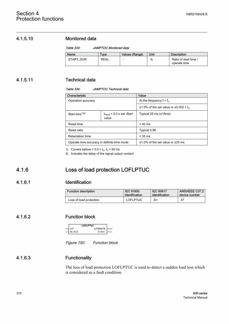
4.1.5.10 Monitored data
Table 333: JAMPTOC Monitored data
Name Type Values (Range) Unit DescriptionSTART_DUR REAL - % Ratio of start time /
operate time
4.1.5.11 Technical data
Table 334: JAMPTOC Technical data
Characteristic ValueOperation accuracy At the frequency f = fn
±1.5% of the set value or ±0.002 × In
Start time1)2) IFault = 2.0 x set Startvalue
Typical 25 ms (±15ms)
Reset time < 40 ms
Reset ratio Typical 0.96
Retardation time < 35 ms
Operate time accuracy in definite time mode ±1.0% of the set value or ±20 ms
1) Current before = 0.0 × In, fn = 50 Hz2) Includes the delay of the signal output contact
4.1.6 Loss of load protection LOFLPTUC
4.1.6.1 Identification
Function description IEC 61850identification
IEC 60617identification
ANSI/IEEE C37.2device number
Loss of load protection LOFLPTUC 3I< 37
4.1.6.2 Function block
GUID-1FDE7A5A-269B-4956-966C-F6FFC8A8C047 V1 EN
Figure 150: Function block
4.1.6.3 Functionality
The loss of load protection LOFLPTUC is used to detect a sudden load loss whichis considered as a fault condition.
Section 4 1MRS756508 BProtection functions
310 630 seriesTechnical Manual

LOFLPTUC starts when the current is less than the set limit. It operates with thedefinite time (DT) characteristics, which means that the function operates after apredefined operate time and resets when the fault current disappears.
The function contains a blocking functionality. It is possible to block functionoutputs, the definite timer or the function itself, if desired.
4.1.6.4 Operation principle
The function can be enabled and disabled with the Operation setting. Thecorresponding parameter values are "On" and "Off".
The operation of loss of load protection can be described by using a modulediagram. All the modules in the diagram are explained in the next sections.
The operation of the loss of load supervision can be described using a modulediagram. All the modules in the diagram are explained in the next sections.
GUID-7D506CAB-76F4-48BB-85BA-FAEFBED33926 V1 EN
Figure 151: Functional module diagram. Group signal I3P is used for feedingthe necessary analog signals to the function.
Level detector 1This module compares the phase currents (RMS value) to the set Start value highsetting. If all the phase current values are less than the set Start value high value,the loss of load condition is detected and an enable signal is sent to the timer. Thissignal is disabled after one or several phase currents have exceeded the set Startvalue high value of the element.
Level detector 2This is a low-current detection module, which monitors the de-energized conditionof the motor. It compares the phase currents (RMS value) to the set Start value lowsetting. If any of the phase current values is less than the set Start value low, asignal is sent to block the operation of the timer.
TimerOnce activated, the timer activates the START output. The time characteristic isaccording to DT. When the operation timer has reached the value set by Operatedelay time, the OPERATE output is activated. If the fault disappears before the
1MRS756508 B Section 4Protection functions
630 series 311Technical Manual

module operates, the reset timer is activated. If the reset timer reaches the value setby Reset delay time, the operate timer resets and the START output is deactivated.
The timer calculates the start duration value START_DUR, which indicates thepercentage ratio of the start situation and the set operating time. The value isavailable in the monitored data view.
The BLOCK signal blocks the operation of the function and resets the timer.
4.1.6.5 Base values
In this function block, some of the settings are set in per unit (pu). These pu valuesare relational to certain base values, for example the values given in A, kV andkVA. The IED supports alternative base value groups for the phase current or voltage-related settings, for example "Phase Grp 1", "Phase Grp 2" and "Phase Grp 3".One of the groups to be used with the Base value Sel phase setting must be selected.
For more information, see the Basic functions section in this manual.
4.1.6.6 Application
When a motor runs with a load connected, it draws a current equal to a valuebetween the no-load value and the rated current of the motor. The minimum loadcurrent can be determined by studying the characteristics of the connected load.When the current drawn by the motor is less than the minimum load current drawn,it can be inferred that the motor is either disconnected from the load or thecoupling mechanism is faulty. If the motor is allowed to run in this condition, itmay aggravate the fault in the coupling mechanism or harm the personnel handlingthe machine. Therefore, the motor has to be disconnected from the power supply assoon as the above condition is detected.
LOFLPTUC detects the condition by monitoring the current values and helpsdisconnect the motor from the power supply instantaneously or after a delayaccording to the requirement.
When the motor is at standstill, the current will be zero and it is not recommendedto activate the trip during this time. The minimum current drawn by the motorwhen it is connected to the power supply is the no load current, that is, the higherstart value current. If the current drawn is below the lower start value current, themotor is disconnected from the power supply. LOFLPTUC detects this conditionand interprets that the motor is de-energized and disables the function to preventunnecessary trip events.
Section 4 1MRS756508 BProtection functions
312 630 seriesTechnical Manual
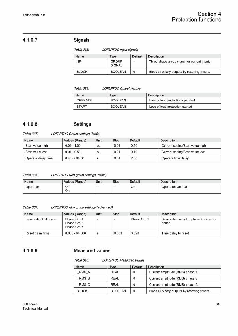
4.1.6.7 Signals
Table 335: LOFLPTUC Input signals
Name Type Default DescriptionI3P GROUP
SIGNAL- Three phase group signal for current inputs
BLOCK BOOLEAN 0 Block all binary outputs by resetting timers.
Table 336: LOFLPTUC Output signals
Name Type DescriptionOPERATE BOOLEAN Loss of load protection operated
START BOOLEAN Loss of load protection started
4.1.6.8 Settings
Table 337: LOFLPTUC Group settings (basic)
Name Values (Range) Unit Step Default DescriptionStart value high 0.01 - 1.00 pu 0.01 0.50 Current setting/Start value high
Start value low 0.01 - 0.50 pu 0.01 0.10 Current setting/Start value low
Operate delay time 0.40 - 600.00 s 0.01 2.00 Operate time delay
Table 338: LOFLPTUC Non group settings (basic)
Name Values (Range) Unit Step Default DescriptionOperation Off
On- - On Operation On / Off
Table 339: LOFLPTUC Non group settings (advanced)
Name Values (Range) Unit Step Default DescriptionBase value Sel phase Phase Grp 1
Phase Grp 2Phase Grp 3
- - Phase Grp 1 Base value selector, phase / phase-to-phase
Reset delay time 0.000 - 60.000 s 0.001 0.020 Time delay to reset
4.1.6.9 Measured values
Table 340: LOFLPTUC Measured values
Name Type Default DescriptionI_RMS_A REAL 0 Current amptitude (RMS) phase A
I_RMS_B REAL 0 Current amptitude (RMS) phase B
I_RMS_C REAL 0 Current amptitude (RMS) phase C
BLOCK BOOLEAN 0 Block all binary outputs by resetting timers.
1MRS756508 B Section 4Protection functions
630 series 313Technical Manual
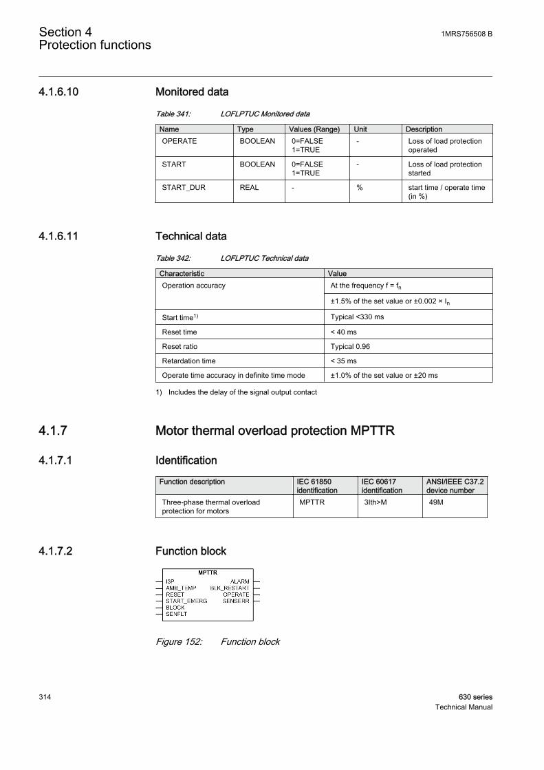
4.1.6.10 Monitored data
Table 341: LOFLPTUC Monitored data
Name Type Values (Range) Unit DescriptionOPERATE BOOLEAN 0=FALSE
1=TRUE- Loss of load protection
operated
START BOOLEAN 0=FALSE1=TRUE
- Loss of load protectionstarted
START_DUR REAL - % start time / operate time(in %)
4.1.6.11 Technical data
Table 342: LOFLPTUC Technical data
Characteristic ValueOperation accuracy At the frequency f = fn
±1.5% of the set value or ±0.002 × In
Start time1) Typical <330 ms
Reset time < 40 ms
Reset ratio Typical 0.96
Retardation time < 35 ms
Operate time accuracy in definite time mode ±1.0% of the set value or ±20 ms
1) Includes the delay of the signal output contact
4.1.7 Motor thermal overload protection MPTTR
4.1.7.1 Identification
Function description IEC 61850identification
IEC 60617identification
ANSI/IEEE C37.2device number
Three-phase thermal overloadprotection for motors
MPTTR 3Ith>M 49M
4.1.7.2 Function block
GUID-ACB38A3C-9AEE-46B0-ACD0-EB7919C527A5 V1 EN
Figure 152: Function block
Section 4 1MRS756508 BProtection functions
314 630 seriesTechnical Manual

4.1.7.3 Functionality
The motor thermal overload protection function MPTTR protects the electricmotors from overheating. MPTTR models the thermal behavior of motor on thebasis of the measured load current and disconnects the motor when the thermalcontent reaches 100 percent. The thermal overload conditions are the most oftenencountered abnormal conditions in industrial motor applications. The thermaloverload conditions are typically the result of an abnormal rise in the motorrunning current, which produces an increase in the thermal dissipation of the motorand temperature or reduces cooling. MPTTR prevents an electric motor fromdrawing excessive current and overheating, which causes the premature insulationfailures of the windings and, in worst cases, burning out of the motors.
4.1.7.4 Operation principle
The function can be enabled and disabled with the Operation setting. Thecorresponding parameter values are "On" and "Off".
The operation of the motor thermal overload protection function can be describedusing a module diagram. All the modules in the diagram are explained in the nextsections.
GUID-BFBC82F2-3365-41A0-A362-9D1F6E1EED39 V2 EN
Figure 153: Functional module diagram
Max current selectorThe maximum current selector of the function continuously checks the highestmeasured TRMS phase current value. The selector reports the highest value to thetemperature estimator.
Internal FLC calculatorFull load current (FLC) of the motor is defined by the manufacturer at an ambienttemperature of 40°C. Special considerations are required with an application wherethe ambient temperature of a motor exceeds or remains below 40°C. A motoroperating at a higher temperature, even if at or below rated load, can subject themotor windings to excessive temperature similar to that resulting from overloadoperation at normal ambient temperature. The motor rating has to be appropriately
1MRS756508 B Section 4Protection functions
630 series 315Technical Manual

reduced for operation in such high ambient temperatures. Similarly, when theambient temperature is considerably lower than the nominal 40°C, the motor canbe slightly overloaded. For calculating thermal level it is better that the FLC valuesare scaled for different temperatures. The scaled currents are known as internalFLC. An internal FLC is calculated based on the ambient temperature shown in thetable. The Env temperature mode setting defines whether the thermal levelcalculations are based on FLC or internal FLC.
When the value of the Env temperature mode setting is set to the "FLC Only"mode, no internal FLC is calculated. Instead, the FLC given in the data sheet of themanufacturer is used. When the value of the Env temperature mode setting is set tothe "Set Amb Temp" mode, the internal FLC is calculated based on the ambienttemperature taken as an input through the Env temperature Set setting. When theEnv temperature mode setting is on the "Use RTD" mode, the internal FLC iscalculated from temperature data available through resistance temperature detectors(RTDs) using the AMB_TEMP input.
Table 343: Modification of internal FLC
Ambient Temperature Tamb Internal FLC
<20°C FLC x 1.09
20 to <40°C FLC x (1.18 - Tamb x 0.09/20)
40°C FLC
>40 to 65°C FLC x (1 –[(Tamb -40)/100])
>65°C FLC x 0.75
The validity of operation of the RTD sensor is obtained from the SENFLT input. Incase of any errors or malfunctioning in the RTD output, the SENSERR outputbecomes activated and the function takes the value of temperature available fromthe Env temperature Set setting for calculating the internal FLC. The ambienttemperature is used for calculating thermal level and it is available in the monitoreddata view on the LHMI from the TEMP_AMB output in degrees. The activation ofthe BLOCK input does not affect the TEMP_AMB output.
Thermal level calculatorThe heating of the motor is determined by the square value of the load current.However, in case of unbalanced phase currents, the negative-sequence current alsocauses additional heating. This is taken into account by means of the Negative Seqfactor setting.
The thermal load is calculated based on different situations or operations and it alsodepends on the phase current level. The equations used for the heating calculationsare:
Section 4 1MRS756508 BProtection functions
316 630 seriesTechnical Manual

θτ
B
r r
tI
k IK
I
k Ie p=
×
+ ×
×
× −( )×−
2
22
2
1/
%
GUID-526B455A-67DD-46E7-813D-A64EC619F6D7 V2 EN (Equation 18)
θτ
A
r r
tI
k IK
I
k Ie=
×
+ ×
×
× −( )×−
2
22
2
1 100/
%
GUID-9C893D3E-7CAF-4EA6-B92D-C914288D7CFC V2 EN (Equation 19)
I TRMS value of the measured max of phase currents
Ir set rated current, FLC or internal FLC
I2 measured negative sequence current
k set value of Overload factor
K2 set value of Negative Seq factor
p set value of Weighting factor
t time constant
The equation θB is used when the values of all the phase currents are below theoverload limit, that is, k x Ir. The equation θA is used when the value of any one ofthe phase currents exceeds the overload limit.
During overload condition, the thermal level calculator calculates the value of θB inbackground, and when the overload ends the thermal level is brought linearly fromθA to θB with a speed of 1.66 percent per second. For the motor at standstill, that is,when the current is below the value of 0.12 x Ir, the cooling is expressed as:
θ θ τ= ×
−
02 e
t
GUID-2C640EA9-DF69-42A9-A6A8-3CD20AEC76BD V2 EN (Equation 20)
θ02 initial thermal level when cooling begins
1MRS756508 B Section 4Protection functions
630 series 317Technical Manual

GUID-A19F9DF2-2F04-401F-AE7A-6CE55F88EB1D V2 EN
Figure 154: Thermal behavior
The required overload factor and negative sequence current heating effect factorare set by the values of the Overload factor and Negative Seq factor settings.
In order to accurately calculate the motor thermal condition, different timeconstants are used in the above equations. These time constants are employedbased on different motor running conditions, for example starting, normal or stop,and are set through the Time constant start, Time constant normal and Timeconstant stop settings. Only one time constant is valid at a time.
Table 344: Time constant and the respective phase current values
Time constant (tau) in use Phase currentTime constant start Any current whose value is over 2.5 x Ir
Time constant normal Any current whose value is over 0.12 x Ir and allcurrents are below 2.5 x Ir
Time constant stop All the currents whose values are below 0.12 x Ir
The Weighting factor p setting determines the ratio of the thermal increase of thetwo curves θA and θB.
The thermal level at the power-up of the IED is defined by the Initial thermal Valsetting.
The activation of the RESET binary input resets the value of the calculated thermallevel to the Initial thermal Val setting.
The calculated thermal level, the THERM_LEVEL output, is available in themonitored data view on the LHMI or through tools via communications. Theactivation of the BLOCK input does not affect the calculated thermal level.
The thermal level at the beginning of the startup condition of a motor and at theend of the startup condition is available in the monitored data view at theTHERMLEV_ST and THERMLEV_END outputs respectively. The activation of theBLOCK input does not have any effect on these outputs.
Section 4 1MRS756508 BProtection functions
318 630 seriesTechnical Manual

Alarm and tripping logicThe module generates alarm, restart inhibit and tripping signals.
When the thermal level exceeds the set value of the Alarm thermal value setting,the ALARM output is activated. Sometimes a condition arises when it becomesnecessary to inhibit the restarting of a motor, for example in case of some extremestarting condition like long starting time. If the thermal content exceeds the setvalue of the Restart thermal val setting, the BLK_RESTART output is activated.The time for the next possible motor startup is available in the monitored data viewfrom the T_ENARESTART output. The T_ENARESTART output estimates the timefor the BLK_RESTART deactivation considering as if the motor is stopped. Whenthe thermal content reaches 100 percent, the OPERATE output is activated. TheOPERATE output is deactivated when the value of the measured current falls below12 percent of the rated current or the thermal content drops below 100 percent.
On the rising edge of the emergency start signal START_EMERG, the thermal levelis set to a value below the thermal restart inhibit level. This allows at least onemotor startup, even though the thermal level has exceeded the restart inhibit level.
When the thermal content reaches 100 percent, the OPERATE output is activated.
The activation of the BLOCK input blocks the ALARM, BLK_RESTART andOPERATE outputs.
1MRS756508 B Section 4Protection functions
630 series 319Technical Manual
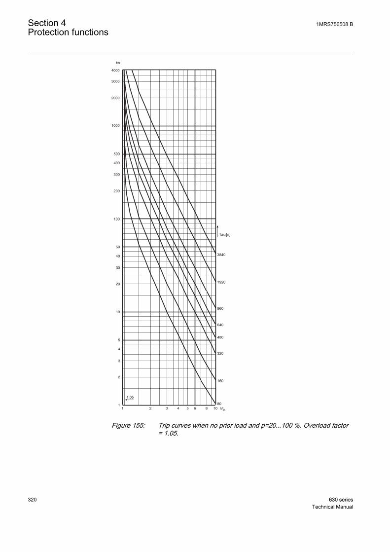
Tau
3840
1920
960
640
480
320
160
80
[s]
GUID-F3D1E6D3-86E9-4C0A-BD43-350003A07292 V1 EN
Figure 155: Trip curves when no prior load and p=20...100 %. Overload factor= 1.05.
Section 4 1MRS756508 BProtection functions
320 630 seriesTechnical Manual

Tau
3840
1920
96080 160 320 480 640
[s]
GUID-44A67C51-E35D-4335-BDBD-5CD0D3F41EF1 V1 EN
Figure 156: Trip curves at prior load 1 x FLC and p=100 %, Overload factor =1.05.
1MRS756508 B Section 4Protection functions
630 series 321Technical Manual
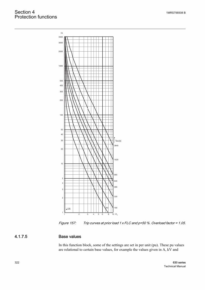
Tau
3840
1920
960
640
480
320
16080
[s]
GUID-5CB18A7C-54FC-4836-9049-0CE926F35ADF V1 EN
Figure 157: Trip curves at prior load 1 x FLC and p=50 %. Overload factor = 1.05.
4.1.7.5 Base values
In this function block, some of the settings are set in per unit (pu). These pu valuesare relational to certain base values, for example the values given in A, kV and
Section 4 1MRS756508 BProtection functions
322 630 seriesTechnical Manual

kVA. The IED supports alternative base value groups for the phase current or voltage-related settings, for example "Phase Grp 1", "Phase Grp 2" and "Phase Grp 3".One of the groups to be used with the Base value Sel phase setting must be selected.
For more information, see the Basic functions section in this manual.
4.1.7.6 Application
MPTTR is intended to limit the motor thermal level to predetermined values duringthe abnormal motor operating conditions. This prevents a premature motorinsulation failure.
The abnormal conditions result in overheating and include overload, stalling,failure to start, high ambient temperature, restricted motor ventilation, reducedspeed operation, frequent starting or jogging, high or low line voltage or frequency,mechanical failure of the driven load, improper installation and unbalanced linevoltage or single phasing. The protection of insulation failure by theimplementation of current sensing cannot detect some of these conditions, such asrestricted ventilation. Similarly, the protection by sensing temperature alone can beinadequate in cases like frequent starting or jogging. The thermal overloadprotection addresses these deficiencies to a larger extent by deploying a motorthermal model based on load current.
The thermal load is calculated using the true RMS phase value and negativesequence value of the current. The heating up of the motor is determined by thesquare value of the load current. However, while calculating the thermal level, therated current should be re-rated or de-rated depending on the value of the ambienttemperature. Apart from current, the rate at which motor heats up or cools isgoverned by the time constant of the motor. There are two thermal curves: onewhich characterizes short-time and long-time overloads used for tripping andanother which is used for the thermal condition of the motor.
The calculation of thermal load is based on different situations or operations andalso depends on the value of phase current level. The equations used for the heatingup calculations are:
θτ
B
r r
tI
k IK
I
k Ie p=
×
+ ×
×
× −( )×−
2
22
2
1/
%
GUID-526B455A-67DD-46E7-813D-A64EC619F6D7 V2 EN (Equation 21)
θτ
A
r r
tI
k IK
I
k Ie=
×
+ ×
×
× −( )×−
2
22
2
1 100/
%
GUID-9C893D3E-7CAF-4EA6-B92D-C914288D7CFC V2 EN (Equation 22)
1MRS756508 B Section 4Protection functions
630 series 323Technical Manual
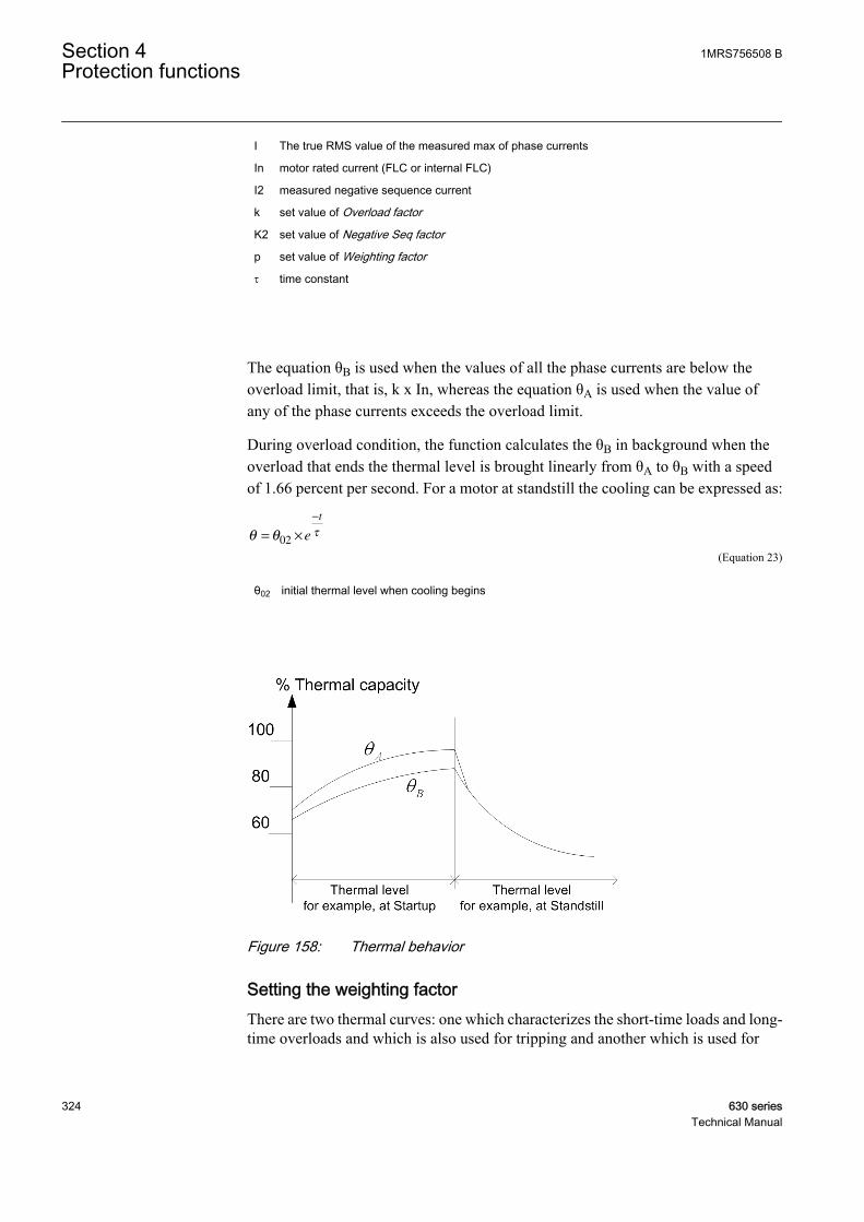
I The true RMS value of the measured max of phase currents
In motor rated current (FLC or internal FLC)
I2 measured negative sequence current
k set value of Overload factor
K2 set value of Negative Seq factor
p set value of Weighting factor
t time constant
The equation θB is used when the values of all the phase currents are below theoverload limit, that is, k x In, whereas the equation θA is used when the value ofany of the phase currents exceeds the overload limit.
During overload condition, the function calculates the θB in background when theoverload that ends the thermal level is brought linearly from θA to θB with a speedof 1.66 percent per second. For a motor at standstill the cooling can be expressed as:
θ θ τ= ×
−
02 e
t
GUID-2C640EA9-DF69-42A9-A6A8-3CD20AEC76BD V2 EN (Equation 23)
θ02 initial thermal level when cooling begins
GUID-A19F9DF2-2F04-401F-AE7A-6CE55F88EB1D V2 EN
Figure 158: Thermal behavior
Setting the weighting factorThere are two thermal curves: one which characterizes the short-time loads and long-time overloads and which is also used for tripping and another which is used for
Section 4 1MRS756508 BProtection functions
324 630 seriesTechnical Manual

monitoring the thermal condition of the motor. The value of the Weighting factor psetting determines the ratio of the thermal increase of the two curves.
When the Weighting factor p setting is 100 percent, a pure single time constantthermal unit is produced which is used for application with the cables. As presentedin Figure 159, the hot curve with the value of Weighting factor p being 100 percentonly allows an operate time which is about 10 percent of that with no prior load.For example, when the set time constant is 640 seconds, the operate time with theprior load 1 x FLC (full Load Current) and overload factor 1.05 is only 2 seconds,even if the motor could withstand at least 5 to 6 seconds. To allow the use of thefull capacity of the motor, a lower value of Weighting factor p should be used.
Normally, an approximate value of half of the thermal capacity is used when themotor is running at full load. Thus by setting Weighting factor p to 50 percent, theIED notifies a 45 to 50 percent thermal capacity use at full load.
For direct-on-line started motors with hot spot tendencies, the value of Weightingfactor p is typically set to 50 percent, which will properly distinguish between short-time thermal stress and long-time thermal history. After a short period of thermalstress, for example a motor startup, the thermal level starts to decrease quitesharply, simulating the leveling out of the hot spots. Consequently, the probabilityof successive allowed startups increases.
When protecting the objects without hot spot tendencies, for example motorsstarted with soft starters, and cables, the value of Weighting factor p is set to 100percent. With the value of Weighting factor p set to 100 percent, the thermal leveldecreases slowly after a heavy load condition. This makes the protection suitablefor applications where no hot spots are expected. Only in special cases where thethermal overload protection is required to follow the characteristics of the object tobe protected more closely and the thermal capacity of the object is very wellknown, a value between 50 and 100 percent is required.
For motor applications where, for example, two hot starts are allowed instead ofthree cold starts, the value of the setting Weighting factor p being 40 percent hasproven to be useful. Setting the value of Weighting factor p significantly below 50percent should be handled carefully as there is a possibility to overload theprotected object as a thermal unit might allow too many hot starts or the thermalhistory of the motor has not been taken into account sufficiently.
1MRS756508 B Section 4Protection functions
630 series 325Technical Manual

t/s
1000
100
500
200
50
10
20
5
1
2
3
4
30
40
300
400
2000
3000
4000
1 2 3 4 5 106 8 I/Iq
1.05
p[%]
20
50
75
100
x
Cold
curve
GUID-B6F9E655-4FFC-4B06-841A-68DADE785BF2 V1 EN
Figure 159: The influence of Weighting factor p at prior load 1xFLC,timeconstant = 640 sec, and Overload factor = 1.05
Section 4 1MRS756508 BProtection functions
326 630 seriesTechnical Manual
Setting the overload factorThe value of Overload factor defines the highest permissible continuous load. Therecommended value is 1.05.
Setting the negative sequence factorDuring the unbalance condition, the symmetry of the stator currents is disturbedand a counter-rotating negative sequence component current is set up. An increasedstator current causes additional heating in the stator and the negative sequencecomponent current excessive heating in the rotor. Also mechanical problems likerotor vibration can occur.
The most common cause of unbalance for three-phase motors is the loss of phaseresulting in an open fuse, connector or conductor. Often mechanical problems canbe more severe than the heating effects and therefore a separate unbalanceprotection is used.
Unbalances in other connected loads in the same busbar can also affect the motor.A voltage unbalance typically produces 5 to 7 times higher current unbalance.Because the thermal overload protection is based on the highest TRMS value of thephase current, the additional heating in stator winding is automatically taken intoaccount. For more accurate thermal modeling, the Negative Seq factor setting isused for taking account of the rotor heating effect.
Negative Seq factorR
R
R
R
=2
1
GUID-EA5AD510-A3CA-47FB-91F0-75D7272B654E V1 EN (Equation 24)
RR2 rotor negative sequence resistance
RR1 rotor positive sequence resistance
A conservative estimate for the setting can be calculated:
Negative Seq factor
ILR
=175
2
GUID-13CE37C5-295F-41D4-8159-400FA377C84C V1 EN
ILR locked rotor current (multiple of set Rated current). The same as the startup current at thebeginning of the motor startup.
For example, if the rated current of a motor is 230 A, startup current is 5.7 x Ir,
Negative Seq factor = =175
5 75 4
2.
.
GUID-DF682702-E6B1-4814-8B2E-31C28F3A03DF V1 EN
1MRS756508 B Section 4Protection functions
630 series 327Technical Manual
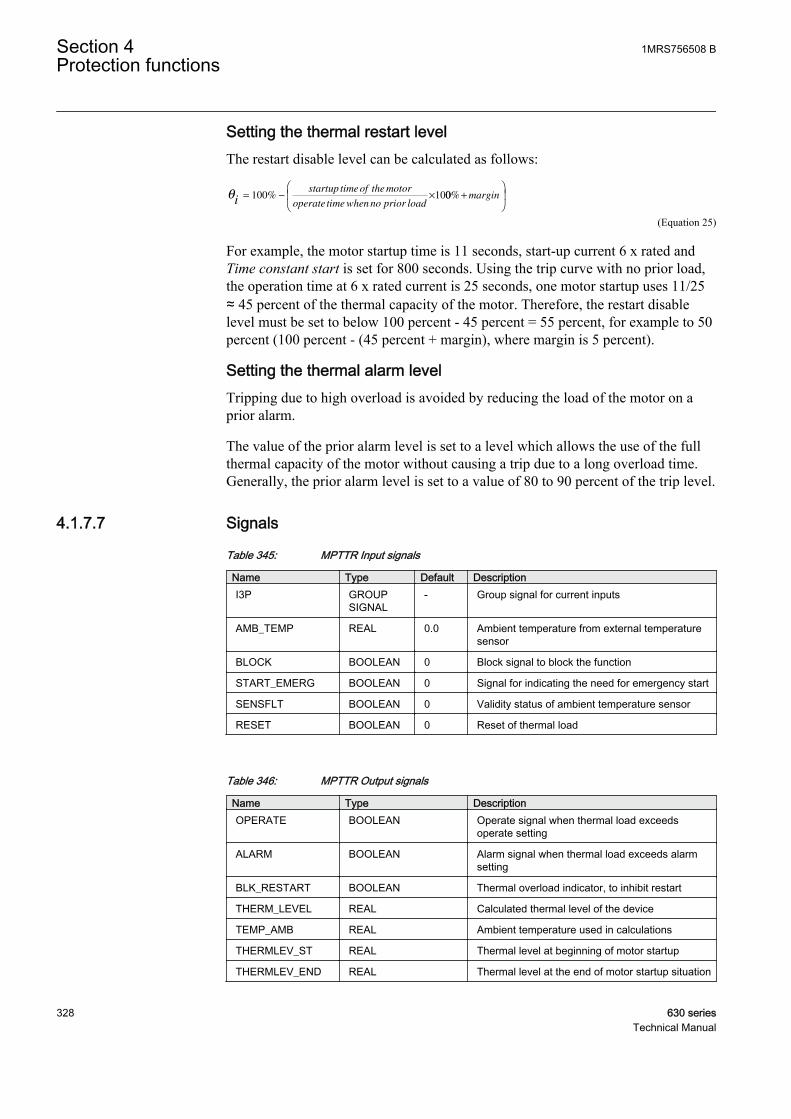
Setting the thermal restart levelThe restart disable level can be calculated as follows:
θi
startup timeof the motor
operate time when no prior load= − ×100 10% 00% +
margin
GUID-5B3B714D-8C58-4C5D-910D-A23852BC8B15 V1 EN (Equation 25)
For example, the motor startup time is 11 seconds, start-up current 6 x rated andTime constant start is set for 800 seconds. Using the trip curve with no prior load,the operation time at 6 x rated current is 25 seconds, one motor startup uses 11/25≈ 45 percent of the thermal capacity of the motor. Therefore, the restart disablelevel must be set to below 100 percent - 45 percent = 55 percent, for example to 50percent (100 percent - (45 percent + margin), where margin is 5 percent).
Setting the thermal alarm levelTripping due to high overload is avoided by reducing the load of the motor on aprior alarm.
The value of the prior alarm level is set to a level which allows the use of the fullthermal capacity of the motor without causing a trip due to a long overload time.Generally, the prior alarm level is set to a value of 80 to 90 percent of the trip level.
4.1.7.7 Signals
Table 345: MPTTR Input signals
Name Type Default DescriptionI3P GROUP
SIGNAL- Group signal for current inputs
AMB_TEMP REAL 0.0 Ambient temperature from external temperaturesensor
BLOCK BOOLEAN 0 Block signal to block the function
START_EMERG BOOLEAN 0 Signal for indicating the need for emergency start
SENSFLT BOOLEAN 0 Validity status of ambient temperature sensor
RESET BOOLEAN 0 Reset of thermal load
Table 346: MPTTR Output signals
Name Type DescriptionOPERATE BOOLEAN Operate signal when thermal load exceeds
operate setting
ALARM BOOLEAN Alarm signal when thermal load exceeds alarmsetting
BLK_RESTART BOOLEAN Thermal overload indicator, to inhibit restart
THERM_LEVEL REAL Calculated thermal level of the device
TEMP_AMB REAL Ambient temperature used in calculations
THERMLEV_ST REAL Thermal level at beginning of motor startup
THERMLEV_END REAL Thermal level at the end of motor startup situation
Section 4 1MRS756508 BProtection functions
328 630 seriesTechnical Manual

4.1.7.8 Settings
Table 347: MPTTR Group settings (basic)
Name Values (Range) Unit Step Default DescriptionEnv temperature mode FLC Only
Use RTDSet Amb Temp
- - FLC Only Mode of measuring ambient temperature
Env temperature Set -20.0 - 70.0 Deg 0.1 40.0 Setting for ambient environmenttemperature
Alarm thermal value 50.0 - 100.0 % 0.1 95.0 Thermal level above which functiongives an alarm
Restart thermal Val 20.0 - 80.0 % 0.1 40.0 Thermal level above which functioninhibits motor restarting
Overload factor 1.00 - 1.20 - 0.01 1.05 Overload factor (k)
Weighting factor p 20.0 - 100.0 - 0.1 50.0 Weighting factor (p)
Time constant normal 80 - 4000 s 1 320 Motor time constant during the normaloperation of motor
Time constant start 80 - 4000 s 1 320 Motor time constant during the start ofmotor
Time constant stop 80 - 8000 s 1 500 Motor time constant during the standstillcondition of motor
Table 348: MPTTR Group settings (advanced)
Name Values (Range) Unit Step Default DescriptionNegative Seq factor 0.0 - 10.0 - 0.1 0.0 Heating effect factor for negative
sequence current
Table 349: MPTTR Non group settings (basic)
Name Values (Range) Unit Step Default DescriptionOperation Off
On- - On Operation Off/On
Table 350: MPTTR Non group settings (advanced)
Name Values (Range) Unit Step Default DescriptionBase value Sel phase Phase Grp 1
Phase Grp 2Phase Grp 3
- - Phase Grp 1 Base value selector, phase / phase-to-phase
Initial thermal Val 0.0 - 100.0 % 0.1 74.0 Thermal level at power up
1MRS756508 B Section 4Protection functions
630 series 329Technical Manual
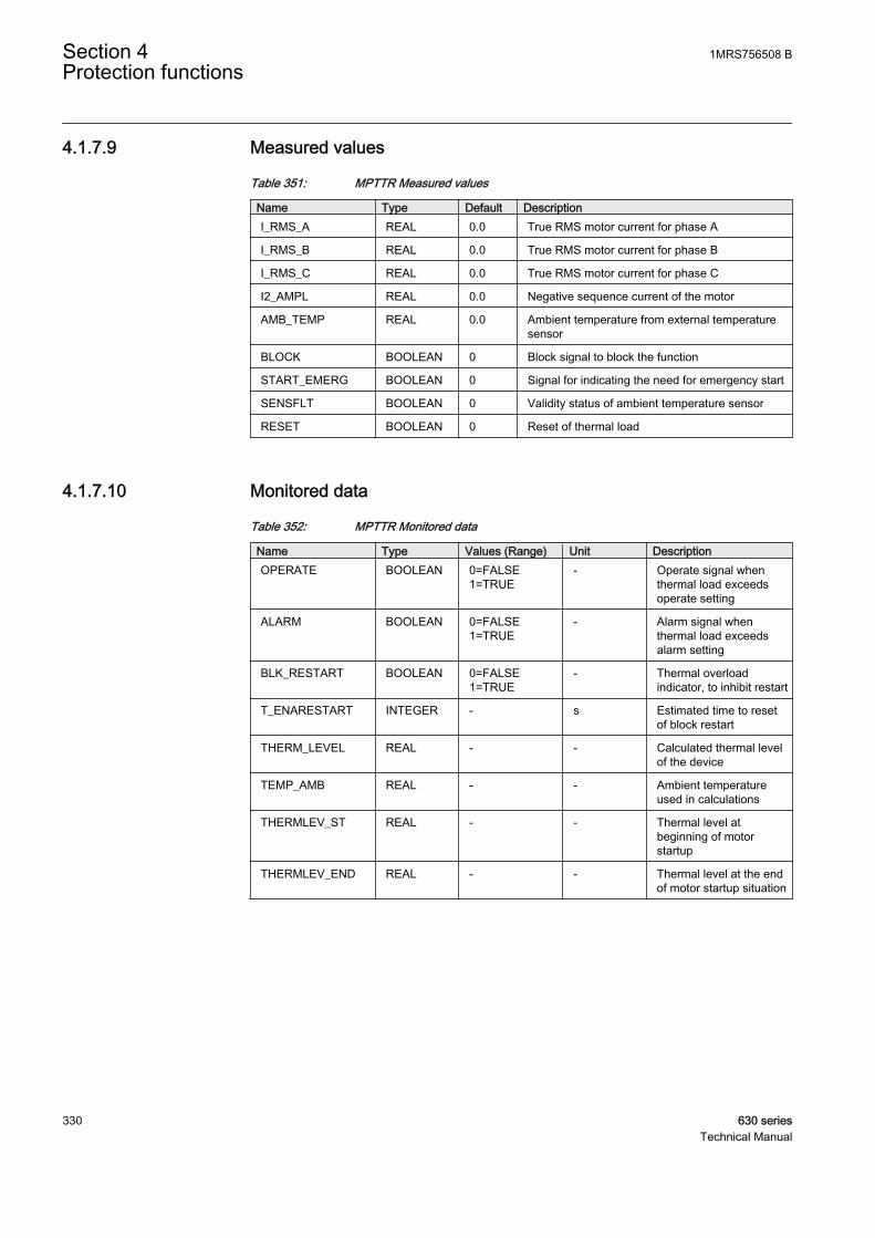
4.1.7.9 Measured values
Table 351: MPTTR Measured values
Name Type Default DescriptionI_RMS_A REAL 0.0 True RMS motor current for phase A
I_RMS_B REAL 0.0 True RMS motor current for phase B
I_RMS_C REAL 0.0 True RMS motor current for phase C
I2_AMPL REAL 0.0 Negative sequence current of the motor
AMB_TEMP REAL 0.0 Ambient temperature from external temperaturesensor
BLOCK BOOLEAN 0 Block signal to block the function
START_EMERG BOOLEAN 0 Signal for indicating the need for emergency start
SENSFLT BOOLEAN 0 Validity status of ambient temperature sensor
RESET BOOLEAN 0 Reset of thermal load
4.1.7.10 Monitored data
Table 352: MPTTR Monitored data
Name Type Values (Range) Unit DescriptionOPERATE BOOLEAN 0=FALSE
1=TRUE- Operate signal when
thermal load exceedsoperate setting
ALARM BOOLEAN 0=FALSE1=TRUE
- Alarm signal whenthermal load exceedsalarm setting
BLK_RESTART BOOLEAN 0=FALSE1=TRUE
- Thermal overloadindicator, to inhibit restart
T_ENARESTART INTEGER - s Estimated time to resetof block restart
THERM_LEVEL REAL - - Calculated thermal levelof the device
TEMP_AMB REAL - - Ambient temperatureused in calculations
THERMLEV_ST REAL - - Thermal level atbeginning of motorstartup
THERMLEV_END REAL - - Thermal level at the endof motor startup situation
Section 4 1MRS756508 BProtection functions
330 630 seriesTechnical Manual
4.1.7.11 Technical data
Table 353: MPTTR Technical data
Characteristic ValueOperation accuracy At the frequency f = fn
Current measurement:±1.5% of the set value or ±0.002 × In(at currents in the range of 0.01...4.00 × In)
Operate time accuracy1) ±2.0% or ±0.050 s
1) Overload current > 1.2 × Operate level temperature
4.1.8 Motor startup supervision STTPMSU
4.1.8.1 Identification
Function description IEC 61850identification
IEC 60617identification
ANSI/IEEE C37.2device number
Motor startup supervision STTPMSU Is2tn< 49,66,48,51LR
4.1.8.2 Function block
GUID-3C371BA6-923D-4B7C-A328-5A4B1B350D27 V1 EN
Figure 160: Function block
4.1.8.3 Functionality
The motor startup supervision function STTPMSU is designed for protectionagainst excessive starting time and locked rotor conditions of the motor duringstarting. For a good and reliable operation of the motor, the thermal stress duringthe motor starting is maintained within the allowed limits.
The starting of the motor is supervised by monitoring the TRMS magnitude of allthe phase currents or by monitoring the status of the circuit breaker connected tothe motor.
During the startup period of the motor, STTPMSU calculates the integral of the I²tvalue. If the calculated value exceeds the set value, the operate signal is activated.
1MRS756508 B Section 4Protection functions
630 series 331Technical Manual

STTPMSU has the provision to check the locked rotor condition of the motor usingthe speed switch, which means checking if the rotor is able to rotate or not. Thisfeature operates after a predefined operating time.
STTPMSU also protects the motor from an excessive number of startups. Uponexceeding the specified number of startups within certain duration, STTPMSUblocks further starts. The restart of the motor is also inhibited after each start andcontinues to be inhibited for a set duration. When the lock of start of motor isenabled, STTPMSU gives the time remaining until the restart of the motor.
STTPMSU contains a blocking functionality. It is possible to block functionoutputs, timer or the function itself, if desired.
4.1.8.4 Operation principle
The function can be enabled and disabled with the Operation setting. Thecorresponding parameter values are "On" and "Off".
The operation of the motor startup supervision function can be described using amodule diagram. All the modules in the diagram are explained in the next sections.
GUID-06FE0DD3-07D9-4C3F-B8C3-39782E7EAD18 V1 EN
Figure 161: Functional module diagram. Group signal I3P is used for feedingthe necessary analog signals to the function.
Startup supervisorThis module detects the starting of the motor. The starting and stalling motorconditions are detected in four different modes of operation. This is done throughthe Operation mode setting.
When the Operation mode setting is operated in the “IIt” mode, the functioncalculates the value of the thermal stress of the motor during the startup condition.In this mode, the startup condition is detected by monitoring the TRMS currents.
Section 4 1MRS756508 BProtection functions
332 630 seriesTechnical Manual

The Operation mode setting in the “IIt, CB” mode enables the function to calculatethe value of the thermal stress when a startup is monitored in addition to theCB_CLOSED input.
In the “IIt & stall” mode, the function calculates the thermal stress of the motorduring the startup condition. In this mode, the startup condition is detected bymonitoring the TRMS currents. In the “IIt & stall” mode, the function also checksfor motor stalling by monitoring the speed switch.
In the “IIt & stall, CB” mode, the function calculates the thermal stresses of themotor during the startup condition. The startup condition is monitored in additionto the circuit breaker status. In the “IIt & stall, CB” mode, the function also checksfor motor stalling by monitoring the speed switch.
When the trueRMS value of current is used for startup supervision in the “IIt” and“IIt & stall” modes, the module initially recognizes the de-energized condition ofthe motor when the values of all three phase currents are less than 0.1 pu for 100ms. If the value of any of the phase currents rises after the de-energized conditionfrom 0.1 pu to a value equal or greater than Start detection A within 50 ms afterenergization, the MOT_START output signal is activated indicating that the motorstartup is in progress. The MOT_START output remains active until the values ofall three phase currents drop below 0.9 x Start detection A and remain below thatlevel for a time period of Str over delay time, that is, until the startup situation is over.
GUID-4475BDFB-57AE-4BFD-9EE7-AE7672F7206E V2 EN
Figure 162: Functionality of startup supervision in "IIt and IIt&stall" mode
In case of the “IIt, CB” or “IIt & stall, CB” modes, the function initially recognizesthe de-energized condition of the motor when the value of all three phase currentsis below the value of the 0.1 pu setting for 100 ms. The beginning of the motorstartup is recognized when CB is closed, that is, when the CB_CLOSED input isactivated and at least one phase current value exceeds the 0.1 pu setting.
1MRS756508 B Section 4Protection functions
630 series 333Technical Manual

But in normal practice, these two events do not take place at the same instant, thatis, the CB main contact is closed first, in which case the phase current value risesabove 0.1 pu and after some delay the CB auxiliary contact gives the informationof the CB_CLOSED input. In some cases, the CB_CLOSED input can be active butthe value of current may not be greater than the value of the Motor standstill Asetting. To allow both possibilities, a time slot of 200 milliseconds is provided forcurrent and the CB_CLOSED input. If both events occur during this time, the motorstartup is recognized.
The motor startup ends either within the value of the Str over delay time settingfrom the beginning of the startup or the opening of CB, that is, when theCB_CLOSED input is de-activated during the Str over delay time. The operation ofthe MOT_START output signal in this operation mode is as shown in the figure.
This CB mode can be used in soft-started or slip ring motors for protection againsta large starting current, that is, a problem in starting and so on.
Section 4 1MRS756508 BProtection functions
334 630 seriesTechnical Manual

GUID-DDAD7B3F-28BE-4573-BE79-FBB488A22ECA V1 EN
GUID-1470A4DB-310F-46BC-B775-843EAB8BA836 V1 EN
Figure 163: Functionality of startup supervision in "IIt, CB" mode and "IIt andstall, CB" mode
The Str over delay time setting has different purposes in different modes of operation:
1MRS756508 B Section 4Protection functions
630 series 335Technical Manual

• In the “IIt” or “IIt & stall” modes, the aim of this setting is to check for thecompletion of the motor startup period. The purpose of this time delay settingis to allow for short interruptions in the current without changing the state ofthe MOT_START output. In this mode of operation, the value of the setting isin the range of around 100 milliseconds.
• In the “IIt, CB” or “IIt & stall, CB” modes, the purpose of this setting is tocheck for the life of the protection scheme after the CB_CLOSED input hasbeen activated. Based on the values of the phase currents, the completion ofthe startup period cannot be judged. So in this mode of operation, the value ofthe time delay setting can even be as high as within the range of seconds, forexample around 30 seconds.
The BLOCK input signal is used to block the operation of the MOT_START output.The activation of the BLOCK input signal deactivates the MOT_START output.
Thermal stress calculatorBecause of the high current surges during the startup period, a thermal stress isimposed on the rotor. With less air circulation in the ventilation of the rotor beforeit reaches its full speed, the situation becomes even worse. Consequently, a longstartup causes a rapid heating of the rotor.
This module calculates the thermal stress developed in the motor during startup.The heat developed during the starting can be calculated with the formula,
W R i t dts s
t
= ( )∫2
0
GUID-7A92209F-7451-415B-8C3D-276A6ED4A44B V1 EN (Equation 26)
Rs combined rotor and stator resistance
is starting current of the motor
t starting time of the motor
This equation is normally represented as the integral of I²t. It is a commonly usedmethod in protective relays to protect the motor from thermal stress during starting.The advantage of this method over the traditional definite time overcurrentprotection is that when the motor is started with a reduced voltage as in the star-delta starting method, the starting current is lower. This allows more starting timefor the motor since the module is monitoring the integral of I²t.
The module calculates the accumulated heat continuously and compares it to thelimiting value obtained from the product of the square of the values of the Motorstart-up A and Motor start-up time settings. When the calculated value of thethermal stress exceeds this limit, the OPR_IIT output is activated.
Section 4 1MRS756508 BProtection functions
336 630 seriesTechnical Manual

The module also measures the time START_TIME required by the motor to attainthe rated speed and the relative thermal stress IIT_RL. The values are available inthe monitored data view.
The BLOCK input is used to reset the operation of thermal stress calculator. Theactivation of the BLK_OPR input signal blocks the operation of the OPR_IIT output.
Stall protectionThis module is activated only when the selected Operation mode setting value is“IIt & stall” or “IIt & stall, CB”.
The startup current is specific to each motor and depends on the startup methodused, like direct on-line, autotransformer and rotor resistance insertion, and so on.The startup time is dependent of the load connected to the motor.
Based on the motor characteristics supplied by the manufacturer, this module isrequired if the stalling time is shorter than or too close to the starting time. In suchcases, a speed switch must be used to indicate whether a motor is acceleratingduring startup or not.
At motor standstill, the STALL_IND input is active. It indicates that the rotor isnot rotating. When the motor is started, at certain revolution the deactivation of theSTALL_IND by the speed switch that indicates the rotor is rotating. If the input isnot deactivated within Lock rotor time, the OPR_STALL output is activated.
The module calculates the duration of the motor in stalling condition, theSTALL_RL output indicating the percent ratio of the start situation and the setvalue of Lock rotor time. The value is available in the monitored data view.
The BLK_OPR input signal is used to block the operation of the OPR_STALLoutput. The activation of the BLOCK input resets the operate timer.
Cumulative startup protectionThis module protects the motor from an excessive number of startups.
Whenever the motor is started, the latest value of START_TIME is added to theexisting value of T_ST_CNT and the updated cumulative startup time is availableat T_ST_CNT. If the value of T_ST_CNT is greater than the value of Cumulativetime Lim, the LOCK_START output, that is, the lockout condition for the restart ofmotor, is enabled. The LOCK_START output remains high until the T_ST_CNTvalue reduces to a value less than the value of Cumulative time Lim. The start timecounter reduces at the rate of the value of Counter Red rate.
The LOCK_START output becomes activated at the start of MOT_START. Theoutput remains active for a period of Restart inhibit time.
1MRS756508 B Section 4Protection functions
630 series 337Technical Manual
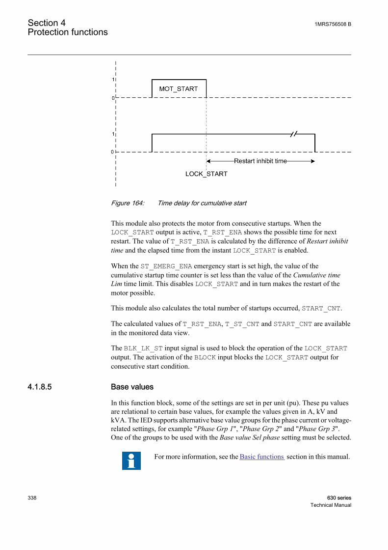
GUID-200BC4CB-8B33-4616-B014-AFCC99ED9224 V2 EN
Figure 164: Time delay for cumulative start
This module also protects the motor from consecutive startups. When theLOCK_START output is active, T_RST_ENA shows the possible time for nextrestart. The value of T_RST_ENA is calculated by the difference of Restart inhibittime and the elapsed time from the instant LOCK_START is enabled.
When the ST_EMERG_ENA emergency start is set high, the value of thecumulative startup time counter is set less than the value of the Cumulative timeLim time limit. This disables LOCK_START and in turn makes the restart of themotor possible.
This module also calculates the total number of startups occurred, START_CNT.
The calculated values of T_RST_ENA, T_ST_CNT and START_CNT are availablein the monitored data view.
The BLK_LK_ST input signal is used to block the operation of the LOCK_STARToutput. The activation of the BLOCK input blocks the LOCK_START output forconsecutive start condition.
4.1.8.5 Base values
In this function block, some of the settings are set in per unit (pu). These pu valuesare relational to certain base values, for example the values given in A, kV andkVA. The IED supports alternative base value groups for the phase current or voltage-related settings, for example "Phase Grp 1", "Phase Grp 2" and "Phase Grp 3".One of the groups to be used with the Base value Sel phase setting must be selected.
For more information, see the Basic functions section in this manual.
Section 4 1MRS756508 BProtection functions
338 630 seriesTechnical Manual
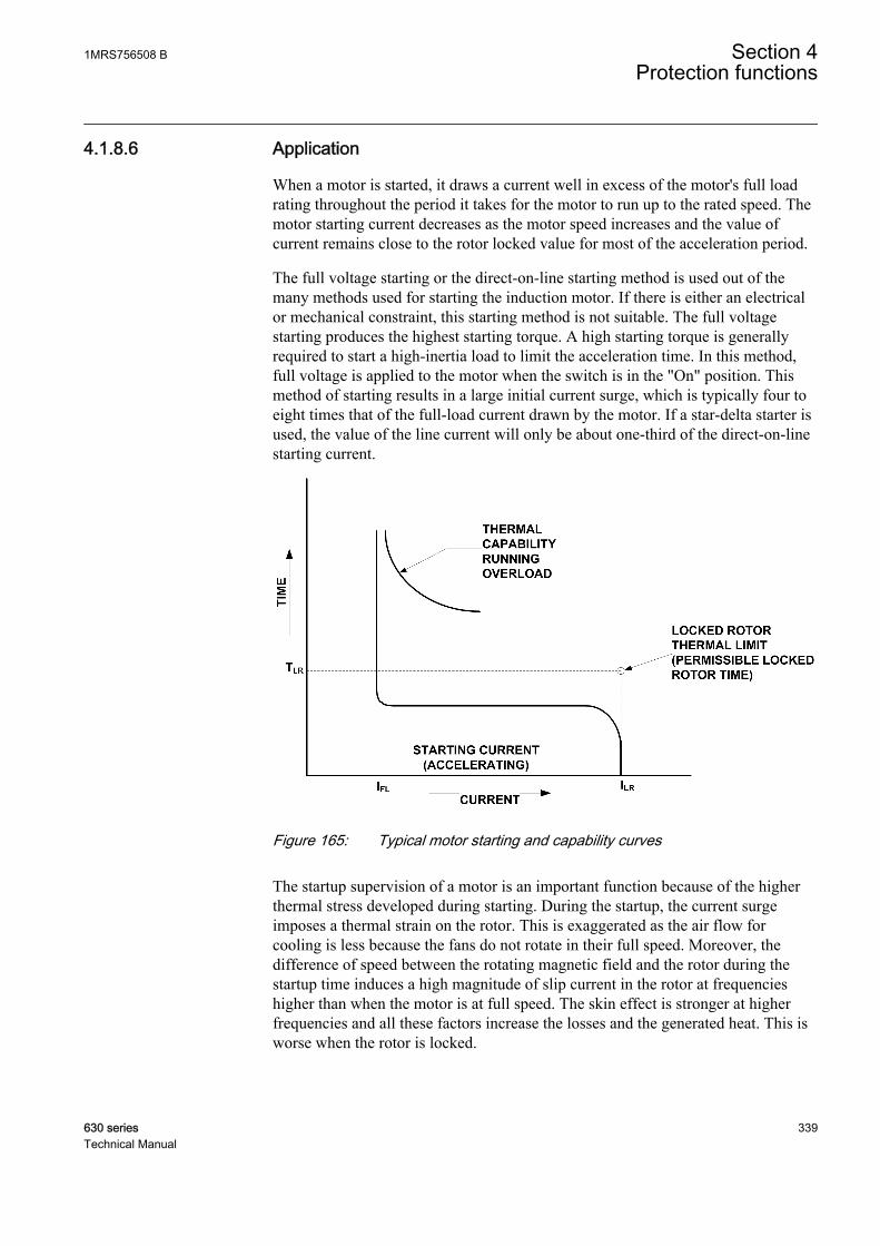
4.1.8.6 Application
When a motor is started, it draws a current well in excess of the motor's full loadrating throughout the period it takes for the motor to run up to the rated speed. Themotor starting current decreases as the motor speed increases and the value ofcurrent remains close to the rotor locked value for most of the acceleration period.
The full voltage starting or the direct-on-line starting method is used out of themany methods used for starting the induction motor. If there is either an electricalor mechanical constraint, this starting method is not suitable. The full voltagestarting produces the highest starting torque. A high starting torque is generallyrequired to start a high-inertia load to limit the acceleration time. In this method,full voltage is applied to the motor when the switch is in the "On" position. Thismethod of starting results in a large initial current surge, which is typically four toeight times that of the full-load current drawn by the motor. If a star-delta starter isused, the value of the line current will only be about one-third of the direct-on-linestarting current.
GUID-F4C17D13-48CA-480A-BBE5-DFD7D6316DB8 V1 EN
Figure 165: Typical motor starting and capability curves
The startup supervision of a motor is an important function because of the higherthermal stress developed during starting. During the startup, the current surgeimposes a thermal strain on the rotor. This is exaggerated as the air flow forcooling is less because the fans do not rotate in their full speed. Moreover, thedifference of speed between the rotating magnetic field and the rotor during thestartup time induces a high magnitude of slip current in the rotor at frequencieshigher than when the motor is at full speed. The skin effect is stronger at higherfrequencies and all these factors increase the losses and the generated heat. This isworse when the rotor is locked.
1MRS756508 B Section 4Protection functions
630 series 339Technical Manual
The starting current for slip-ring motors is less than the full load current andtherefore it is advisable to use the circuit breaker in the closed position to indicatethe starting for such type of motors.
The starting times vary depending on motor design and load-torque characteristics.The time taken may vary from less than two seconds to more than 60 seconds. Thestarting time is determined for each application.
When the permissible stall time is less than the starting time of the motor, thestalling protection is used and the value of the time delay setting should be setslightly less than the permissible stall time. The speed switch on the motor shaftmust be used for detecting whether the motor begins to accelerate or not. However,if the safe stall time is longer than the startup time of the motor, the speed switch isnot required.
The failure of a motor to accelerate or to reach its full nominal speed in anacceptable time when the stator is energized is caused by several types of abnormalconditions, including a mechanical failure of the motor or load bearings, lowsupply voltage, open circuit in one phase of a three-phase voltage supply or toohigh starting voltage. All these abnormal conditions result in overheating.
Repeated starts increase the temperature to a high value in the stator or rotorwindings, or both, unless enough time is allowed for the heat to dissipate. Toensure a safe operation it is necessary to provide a fixed-time interval betweenstarts or limit the number of starts within a period of time. This is why the motormanufacturers have restrictions on how many starts are allowed in a defined timeinterval. This function does not allow starting of the motor if the number of startsexceeds the set level in the register that calculates them. This insures that thethermal effects on the motor for consecutive starts stay within permissible levels.
For example, the motor manufacturer may state that three starts at the maximumare allowed within 4 hours and the startup situation time is 60 seconds. Byinitiating three successive starts we reach the situation as illustrated. As a result,the value of the register adds up to a total of 180 seconds. Right after the third starthas been initiated, the output lock of start of motor is activated and the fourth startwill not be allowed, provided the time limit has been set to 121 seconds.
Furthermore, a maximum of three starts in 4 hours means that the value of theregister should reach the set start time counter limit within 4 hours to allow a newstart. Accordingly, the start time counter reduction should be 60 seconds in 4 hoursand should thus be set to 60 s / 4 h = 15 s / h.
Section 4 1MRS756508 BProtection functions
340 630 seriesTechnical Manual
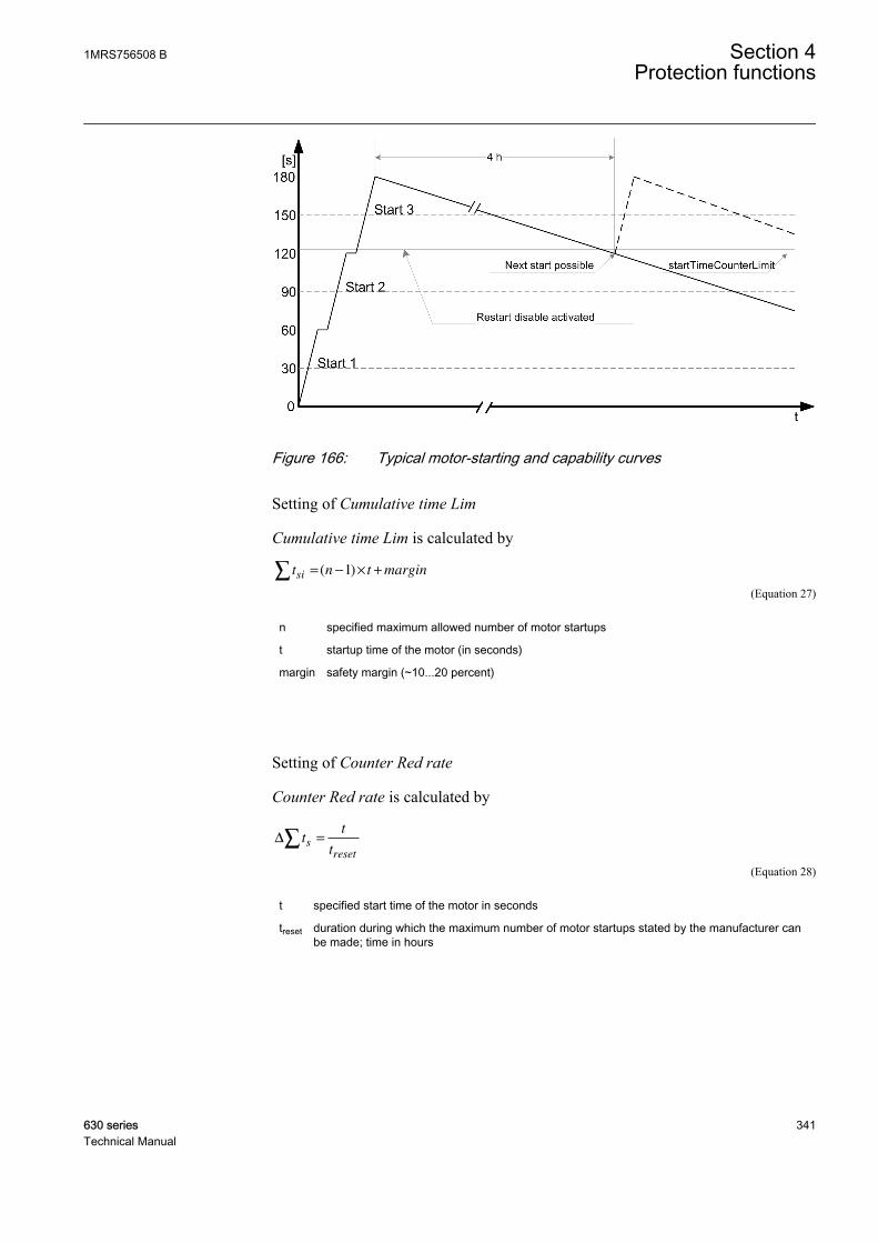
GUID-6E9B7247-9009-4302-A79B-B326009ECC7A V1 EN
Figure 166: Typical motor-starting and capability curves
Setting of Cumulative time Lim
Cumulative time Lim is calculated by
t n t marginsi∑ = − × +( )1
GUID-0214B677-48D0-4DD4-BD1E-67BA9FD3C345 V1 EN (Equation 27)
n specified maximum allowed number of motor startups
t startup time of the motor (in seconds)
margin safety margin (~10...20 percent)
Setting of Counter Red rate
Counter Red rate is calculated by
∆ tt
ts
reset
∑ =
GUID-E7C44256-0F67-4D70-9B54-1C5042A151AF V1 EN (Equation 28)
t specified start time of the motor in seconds
treset duration during which the maximum number of motor startups stated by the manufacturer canbe made; time in hours
1MRS756508 B Section 4Protection functions
630 series 341Technical Manual

4.1.8.7 Signals
Table 354: STTPMSU Input signals
Name Type Default DescriptionI3P GROUP
SIGNAL- Group connection for three phase current signals
BLOCK BOOLEAN 0 Block of function
BLK_OPR BOOLEAN 0 Blocks all operate signals
BLK_LK_ST BOOLEAN 0 Blocks lock out condition for restart of motor
CB_CLOSED BOOLEAN 0 Input signal showing the status of motor circuitbreaker
STALL_IND BOOLEAN 0 Input signal for showing the motor is not stalling
ST_EMERG_ENA BOOLEAN 0 Enable emergency start to disable lock of start ofmotor
Table 355: STTPMSU Output signals
Name Type DescriptionOPR_IIT BOOLEAN Operate/trip signal for thermal stress.
OPR_STALL BOOLEAN Operate/trip signal for stalling protection.
MOT_START BOOLEAN Signal to show that motor startup is in progress
LOCK_START BOOLEAN Lock out condition for restart of motor.
4.1.8.8 Settings
Table 356: STTPMSU Group settings (basic)
Name Values (Range) Unit Step Default DescriptionMotor start-up A 1.0 - 10.0 pu 0.1 2.0 Motor starting current
Motor start-up time 0.3 - 80.0 s 0.1 5.0 Motor starting time
Lock rotor time 2.0 - 120.0 s 1.0 10.0 Permitted stalling time
Table 357: STTPMSU Group settings (advanced)
Name Values (Range) Unit Step Default DescriptionStart detection A 0.1 - 10.0 pu 0.1 1.5 Current value for detecting starting of
motor.
Section 4 1MRS756508 BProtection functions
342 630 seriesTechnical Manual
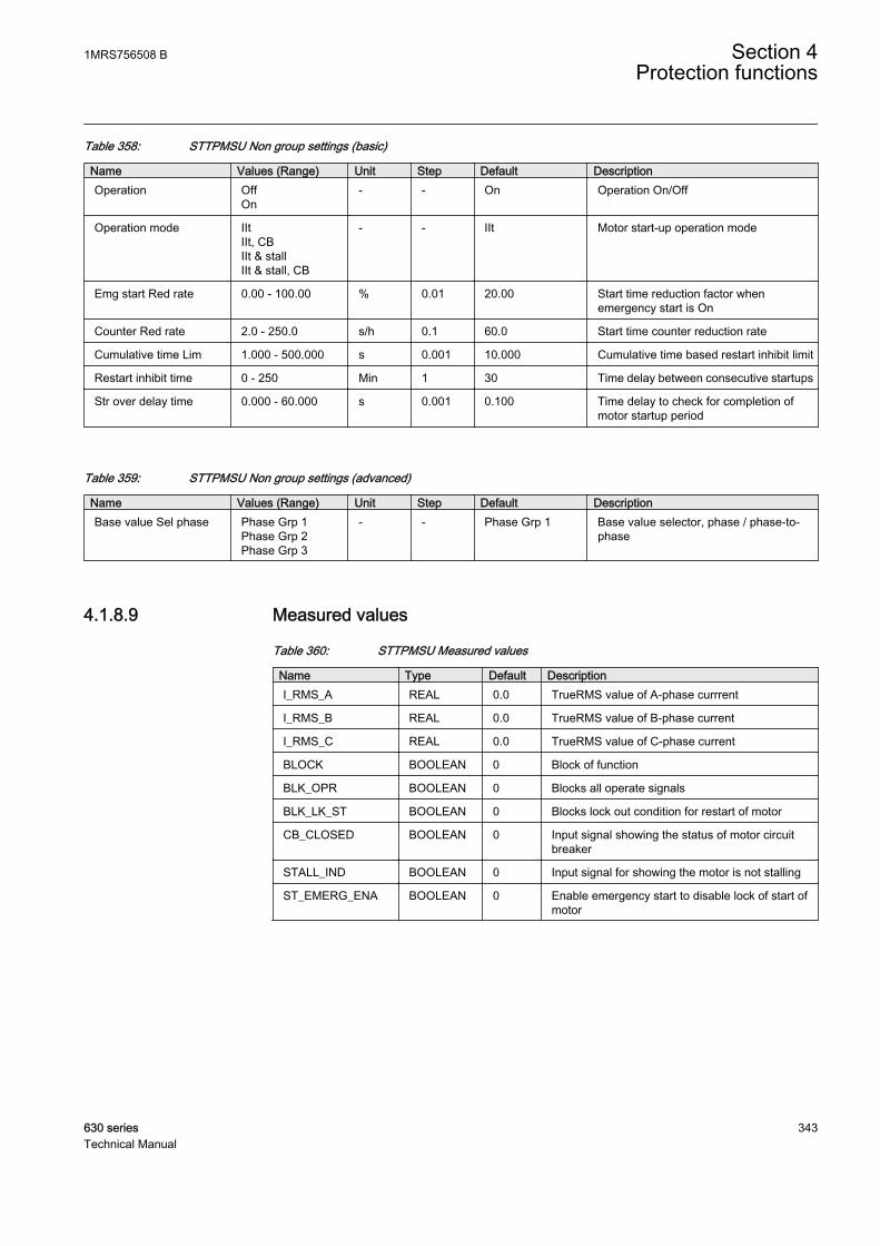
Table 358: STTPMSU Non group settings (basic)
Name Values (Range) Unit Step Default DescriptionOperation Off
On- - On Operation On/Off
Operation mode IItIIt, CBIIt & stallIIt & stall, CB
- - IIt Motor start-up operation mode
Emg start Red rate 0.00 - 100.00 % 0.01 20.00 Start time reduction factor whenemergency start is On
Counter Red rate 2.0 - 250.0 s/h 0.1 60.0 Start time counter reduction rate
Cumulative time Lim 1.000 - 500.000 s 0.001 10.000 Cumulative time based restart inhibit limit
Restart inhibit time 0 - 250 Min 1 30 Time delay between consecutive startups
Str over delay time 0.000 - 60.000 s 0.001 0.100 Time delay to check for completion ofmotor startup period
Table 359: STTPMSU Non group settings (advanced)
Name Values (Range) Unit Step Default DescriptionBase value Sel phase Phase Grp 1
Phase Grp 2Phase Grp 3
- - Phase Grp 1 Base value selector, phase / phase-to-phase
4.1.8.9 Measured values
Table 360: STTPMSU Measured values
Name Type Default DescriptionI_RMS_A REAL 0.0 TrueRMS value of A-phase currrent
I_RMS_B REAL 0.0 TrueRMS value of B-phase current
I_RMS_C REAL 0.0 TrueRMS value of C-phase current
BLOCK BOOLEAN 0 Block of function
BLK_OPR BOOLEAN 0 Blocks all operate signals
BLK_LK_ST BOOLEAN 0 Blocks lock out condition for restart of motor
CB_CLOSED BOOLEAN 0 Input signal showing the status of motor circuitbreaker
STALL_IND BOOLEAN 0 Input signal for showing the motor is not stalling
ST_EMERG_ENA BOOLEAN 0 Enable emergency start to disable lock of start ofmotor
1MRS756508 B Section 4Protection functions
630 series 343Technical Manual

4.1.8.10 Monitored data
Table 361: STTPMSU Monitored data
Name Type Values (Range) Unit DescriptionOPR_IIT BOOLEAN 0=FALSE
1=TRUE- Operate/trip signal for
thermal stress.
OPR_STALL BOOLEAN 0=FALSE1=TRUE
- Operate/trip signal forstalling protection.
MOT_START BOOLEAN 0=FALSE1=TRUE
- Signal to show thatmotor startup is inprogress
LOCK_START BOOLEAN 0=FALSE1=TRUE
- Lock out condition forrestart of motor.
START_CNT INTEGER - - Number of motor start-ups occurred
START_TIME REAL - s Measured motor lateststartup time in sec
T_ST_CNT REAL - s Cumulated start-up timein sec
T_RST_ENA INTEGER - - Time left for restart whenlockstart is enabled inminutes
IIT_RL REAL - % Thermal stress relativeto set maximum thermalstress
STALL_RL REAL - % Start time relative to theoperate time for stallcondition
4.1.8.11 Technical data
Table 362: STTPMSU Technical data
Characteristic ValueOperation accuracy At the frequency f = fn
±1.5% of the set value or ±0.002 × In
Start time1)2) IFault = 1.1 × set Startdetection A
Typical 25 ms (± 15ms)
Operate time accuracy ±1.0% of the set value or ±20 ms
Reset ratio Typical 0.90
1) Current before = 0.0 x In, fn = 50 Hz, overcurrent in one phase2) Includes the delay of the signal output contact
Section 4 1MRS756508 BProtection functions
344 630 seriesTechnical Manual
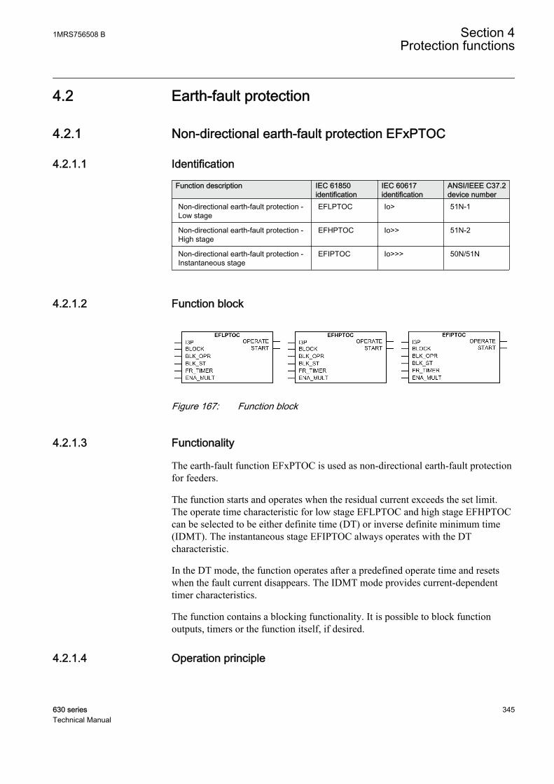
4.2 Earth-fault protection
4.2.1 Non-directional earth-fault protection EFxPTOC
4.2.1.1 Identification
Function description IEC 61850identification
IEC 60617identification
ANSI/IEEE C37.2device number
Non-directional earth-fault protection -Low stage
EFLPTOC Io> 51N-1
Non-directional earth-fault protection -High stage
EFHPTOC Io>> 51N-2
Non-directional earth-fault protection -Instantaneous stage
EFIPTOC Io>>> 50N/51N
4.2.1.2 Function block
A070988 V1 EN
Figure 167: Function block
4.2.1.3 Functionality
The earth-fault function EFxPTOC is used as non-directional earth-fault protectionfor feeders.
The function starts and operates when the residual current exceeds the set limit.The operate time characteristic for low stage EFLPTOC and high stage EFHPTOCcan be selected to be either definite time (DT) or inverse definite minimum time(IDMT). The instantaneous stage EFIPTOC always operates with the DTcharacteristic.
In the DT mode, the function operates after a predefined operate time and resetswhen the fault current disappears. The IDMT mode provides current-dependenttimer characteristics.
The function contains a blocking functionality. It is possible to block functionoutputs, timers or the function itself, if desired.
4.2.1.4 Operation principle
1MRS756508 B Section 4Protection functions
630 series 345Technical Manual
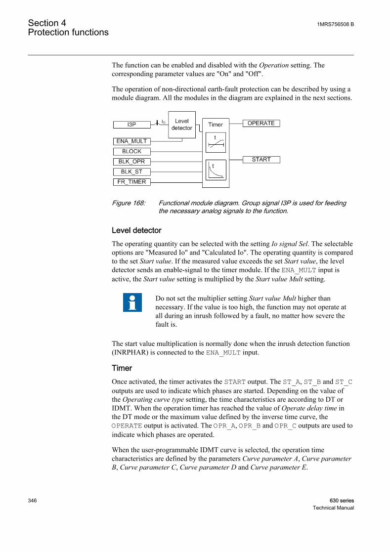
The function can be enabled and disabled with the Operation setting. Thecorresponding parameter values are "On" and "Off".
The operation of non-directional earth-fault protection can be described by using amodule diagram. All the modules in the diagram are explained in the next sections.
A070994 V1 EN
Figure 168: Functional module diagram. Group signal I3P is used for feedingthe necessary analog signals to the function.
Level detectorThe operating quantity can be selected with the setting Io signal Sel. The selectableoptions are "Measured Io" and "Calculated Io". The operating quantity is comparedto the set Start value. If the measured value exceeds the set Start value, the leveldetector sends an enable-signal to the timer module. If the ENA_MULT input isactive, the Start value setting is multiplied by the Start value Mult setting.
Do not set the multiplier setting Start value Mult higher thannecessary. If the value is too high, the function may not operate atall during an inrush followed by a fault, no matter how severe thefault is.
The start value multiplication is normally done when the inrush detection function(INRPHAR) is connected to the ENA_MULT input.
TimerOnce activated, the timer activates the START output. The ST_A, ST_B and ST_Coutputs are used to indicate which phases are started. Depending on the value ofthe Operating curve type setting, the time characteristics are according to DT orIDMT. When the operation timer has reached the value of Operate delay time inthe DT mode or the maximum value defined by the inverse time curve, theOPERATE output is activated. The OPR_A, OPR_B and OPR_C outputs are used toindicate which phases are operated.
When the user-programmable IDMT curve is selected, the operation timecharacteristics are defined by the parameters Curve parameter A, Curve parameterB, Curve parameter C, Curve parameter D and Curve parameter E.
Section 4 1MRS756508 BProtection functions
346 630 seriesTechnical Manual

If a drop-off situation happens, that is, a fault suddenly disappears before theoperate delay is exceeded, the timer reset state is activated. The functionality of thetimer in the reset state depends on the combination of the Operating curve type,Type of reset curve and Reset delay time settings. When the DT characteristic isselected, the reset timer runs until the set Reset delay time value is exceeded. Whenthe IDMT curves are selected, the Type of reset curve setting can be set to"Immediate", "Def time reset" or "Inverse reset". The reset curve type "Immediate"causes an immediate reset. With the reset curve type "Def time reset", the resettime depends on the Reset delay time setting. With the reset curve type "Inversereset", the reset time depends on the current during the drop-off situation. TheSTART output is deactivated when the reset timer has elapsed.
The "Inverse reset" selection is only supported with ANSI or userprogrammable types of the IDMT operating curves. If anotheroperating curve type is selected, an immediate reset occurs duringthe drop-off situation.
The setting Time multiplier is used for scaling the IDMT operate and reset times.
The setting parameter Minimum operate time defines the minimum desired operatetime for IDMT. The setting is applicable only when the IDMT curves are used.
The Minimum operate time setting should be used with great carebecause the operation time is according to the IDMT curve, butalways at least the value of the Minimum operate time setting. Formore information, see the General function block features sectionin this manual.
The timer calculates the start duration value START_DUR, which indicates thepercentage ratio of the start situation and the set operating time. The value isavailable in the monitored data view.
The binary input BLOCK can be used to block the function. The activation of theBLOCK input deactivates all outputs and resets internal timers. The binary inputBLK_ST can be used to block the start signals. The binary input BLK_OPR can beused to block the operation signals. The operation timer counting can be frozen tothe prevailing value by activating the FR_TIMER input.
4.2.1.5 Base values
In this function block, some of the settings are set in per unit (pu). These pu valuesare relational to certain base values, for example the values given in A, kV andkVA. The IED supports alternative base value groups for the phase current or voltage-related settings, for example "Phase Grp 1", "Phase Grp 2" and "Phase Grp 3".One of the groups to be used with the Base value Sel phase setting must be selected.
1MRS756508 B Section 4Protection functions
630 series 347Technical Manual
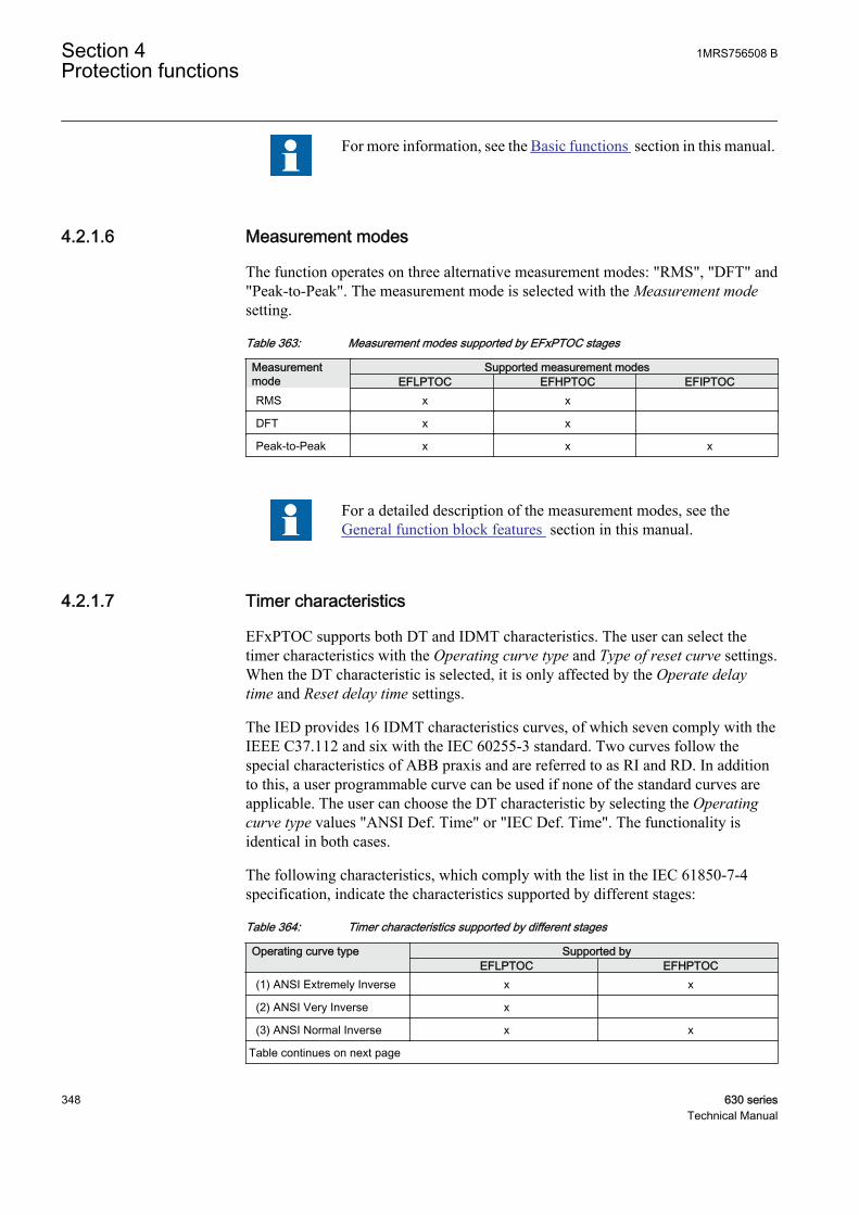
For more information, see the Basic functions section in this manual.
4.2.1.6 Measurement modes
The function operates on three alternative measurement modes: "RMS", "DFT" and"Peak-to-Peak". The measurement mode is selected with the Measurement modesetting.
Table 363: Measurement modes supported by EFxPTOC stages
Measurementmode
Supported measurement modesEFLPTOC EFHPTOC EFIPTOC
RMS x x
DFT x x
Peak-to-Peak x x x
For a detailed description of the measurement modes, see theGeneral function block features section in this manual.
4.2.1.7 Timer characteristics
EFxPTOC supports both DT and IDMT characteristics. The user can select thetimer characteristics with the Operating curve type and Type of reset curve settings.When the DT characteristic is selected, it is only affected by the Operate delaytime and Reset delay time settings.
The IED provides 16 IDMT characteristics curves, of which seven comply with theIEEE C37.112 and six with the IEC 60255-3 standard. Two curves follow thespecial characteristics of ABB praxis and are referred to as RI and RD. In additionto this, a user programmable curve can be used if none of the standard curves areapplicable. The user can choose the DT characteristic by selecting the Operatingcurve type values "ANSI Def. Time" or "IEC Def. Time". The functionality isidentical in both cases.
The following characteristics, which comply with the list in the IEC 61850-7-4specification, indicate the characteristics supported by different stages:
Table 364: Timer characteristics supported by different stages
Operating curve type Supported byEFLPTOC EFHPTOC
(1) ANSI Extremely Inverse x x
(2) ANSI Very Inverse x
(3) ANSI Normal Inverse x x
Table continues on next page
Section 4 1MRS756508 BProtection functions
348 630 seriesTechnical Manual

Operating curve type Supported byEFLPTOC EFHPTOC
(4) ANSI Moderately Inverse x
(5) ANSI Definite Time x x
(6) Long Time ExtremelyInverse
x
(7) Long Time Very Inverse x
(8) Long Time Inverse x
(9) IEC Normal Inverse x x
(10) IEC Very Inverse x x
(11) IEC Inverse x
(12) IEC Extremely Inverse x x
(13) IEC Short Time Inverse x
(14) IEC Long Time Inverse x
(15) IEC Definite Time x x
(17) User programmablecurve
x x
(18) RI type x
(19) RD type x
EFIPTOC supports only definite time characteristics.
For a detailed description of timers, see the General function blockfeatures section in this manual.
Table 365: Reset time characteristics supported by different stages
Reset curve type Supported by EFLPTOC EFHPTOC Note
(1) Immediate x x Available for alloperate time curves
(2) Def time reset x x Available for alloperate time curves
(3) Inverse reset x x Available only for ANSIand user
programmable curves
The Type of reset curve setting does not apply to EFIPTOC or whenthe DT operation is selected. The reset is purely defined by theReset delay time setting.
1MRS756508 B Section 4Protection functions
630 series 349Technical Manual

4.2.1.8 Application
EFxPTOC is designed for protection and clearance of earth faults in distributionand sub-transmission networks where the neutral point is isolated or earthed via aresonance coil or through low resistance. It also applies to solidly earthed networksand earth-fault protection of different equipment connected to the power systems,such as shunt capacitor bank or shunt reactors and for backup earth-fault protectionof power transformers.
Many applications require several steps using different current start levels and timedelays. EFxPTOC consists of three different protection stages:
• Low (EFLPTOC)• High (EFHPTOC)• Instantaneous (EFIPTOC).
EFLPTOC contains several types of time-delay characteristics. EFHPTOC andEFIPTOC are used for fast clearance of serious earth faults.
Note the following when using the earth-fault function for the protection oftransformers. When a power transformer is energized, an inrush current flowsthrough the earthed star-point of all the transformers connected to the bus. This cancause the earth-fault function to operate. The operation can be avoided by usingblocking from inrush detection or by setting longer operation time.
GUID-9239F574-77CD-4797-97DC-17AA437C74E5 V1 EN
Figure 169: Path of inrush currents through earthed star-points of transformers
Section 4 1MRS756508 BProtection functions
350 630 seriesTechnical Manual
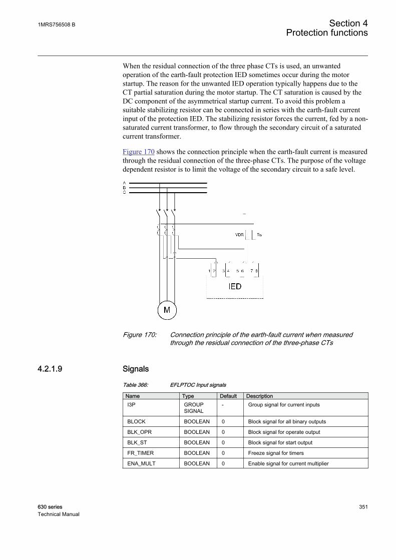
When the residual connection of the three phase CTs is used, an unwantedoperation of the earth-fault protection IED sometimes occur during the motorstartup. The reason for the unwanted IED operation typically happens due to theCT partial saturation during the motor startup. The CT saturation is caused by theDC component of the asymmetrical startup current. To avoid this problem asuitable stabilizing resistor can be connected in series with the earth-fault currentinput of the protection IED. The stabilizing resistor forces the current, fed by a non-saturated current transformer, to flow through the secondary circuit of a saturatedcurrent transformer.
Figure 170 shows the connection principle when the earth-fault current is measuredthrough the residual connection of the three-phase CTs. The purpose of the voltagedependent resistor is to limit the voltage of the secondary circuit to a safe level.
GUID-A75844B1-E021-44F8-97EA-986DCBBF5A6A V1 EN
Figure 170: Connection principle of the earth-fault current when measuredthrough the residual connection of the three-phase CTs
4.2.1.9 Signals
Table 366: EFLPTOC Input signals
Name Type Default DescriptionI3P GROUP
SIGNAL- Group signal for current inputs
BLOCK BOOLEAN 0 Block signal for all binary outputs
BLK_OPR BOOLEAN 0 Block signal for operate output
BLK_ST BOOLEAN 0 Block signal for start output
FR_TIMER BOOLEAN 0 Freeze signal for timers
ENA_MULT BOOLEAN 0 Enable signal for current multiplier
1MRS756508 B Section 4Protection functions
630 series 351Technical Manual
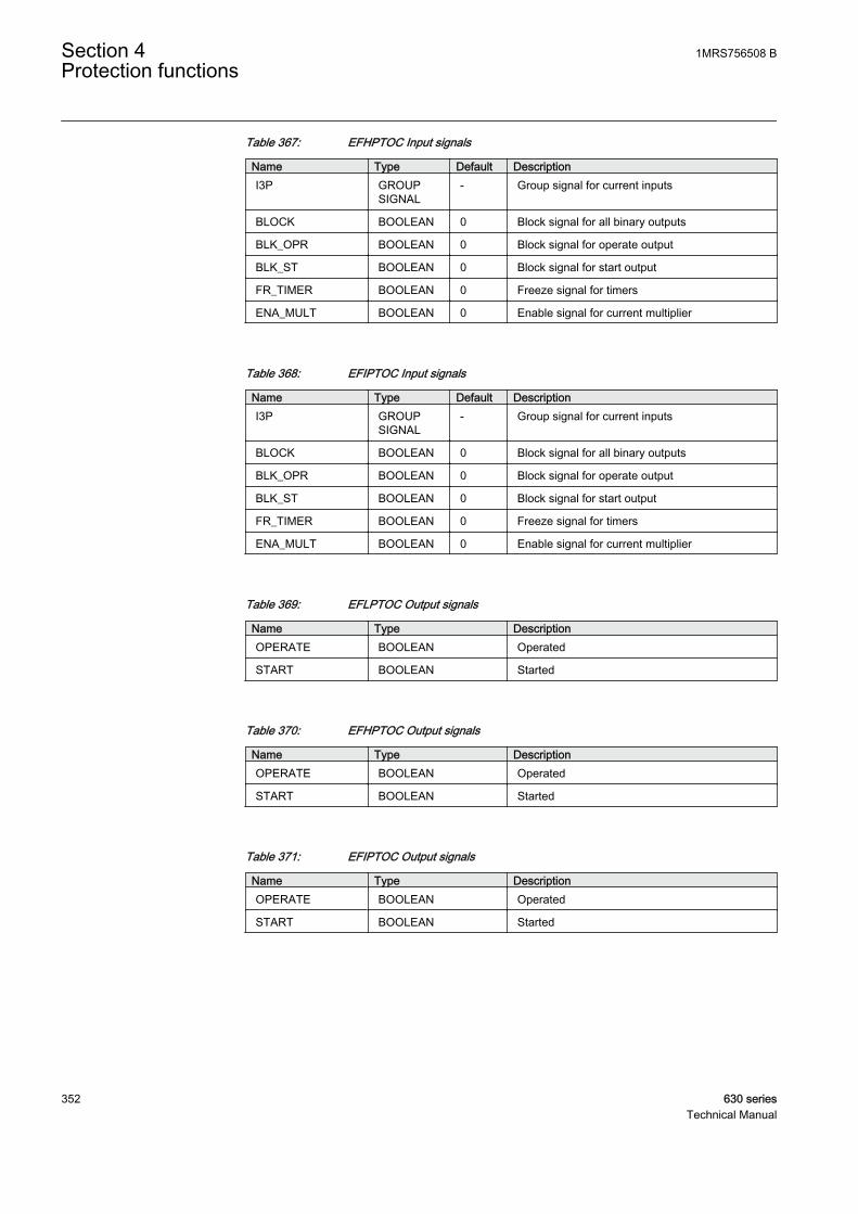
Table 367: EFHPTOC Input signals
Name Type Default DescriptionI3P GROUP
SIGNAL- Group signal for current inputs
BLOCK BOOLEAN 0 Block signal for all binary outputs
BLK_OPR BOOLEAN 0 Block signal for operate output
BLK_ST BOOLEAN 0 Block signal for start output
FR_TIMER BOOLEAN 0 Freeze signal for timers
ENA_MULT BOOLEAN 0 Enable signal for current multiplier
Table 368: EFIPTOC Input signals
Name Type Default DescriptionI3P GROUP
SIGNAL- Group signal for current inputs
BLOCK BOOLEAN 0 Block signal for all binary outputs
BLK_OPR BOOLEAN 0 Block signal for operate output
BLK_ST BOOLEAN 0 Block signal for start output
FR_TIMER BOOLEAN 0 Freeze signal for timers
ENA_MULT BOOLEAN 0 Enable signal for current multiplier
Table 369: EFLPTOC Output signals
Name Type DescriptionOPERATE BOOLEAN Operated
START BOOLEAN Started
Table 370: EFHPTOC Output signals
Name Type DescriptionOPERATE BOOLEAN Operated
START BOOLEAN Started
Table 371: EFIPTOC Output signals
Name Type DescriptionOPERATE BOOLEAN Operated
START BOOLEAN Started
Section 4 1MRS756508 BProtection functions
352 630 seriesTechnical Manual
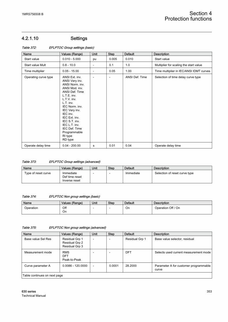
4.2.1.10 Settings
Table 372: EFLPTOC Group settings (basic)
Name Values (Range) Unit Step Default DescriptionStart value 0.010 - 5.000 pu 0.005 0.010 Start value
Start value Mult 0.8 - 10.0 - 0.1 1.0 Multiplier for scaling the start value
Time multiplier 0.05 - 15.00 - 0.05 1.00 Time multiplier in IEC/ANSI IDMT curves
Operating curve type ANSI Ext. inv.ANSI Very inv.ANSI Norm. inv.ANSI Mod. inv.ANSI Def. TimeL.T.E. inv.L.T.V. inv.L.T. inv.IEC Norm. inv.IEC Very inv.IEC inv.IEC Ext. inv.IEC S.T. inv.IEC L.T. inv.IEC Def. TimeProgrammableRI typeRD type
- - ANSI Def. Time Selection of time delay curve type
Operate delay time 0.04 - 200.00 s 0.01 0.04 Operate delay time
Table 373: EFLPTOC Group settings (advanced)
Name Values (Range) Unit Step Default DescriptionType of reset curve Immediate
Def time resetInverse reset
- - Immediate Selection of reset curve type
Table 374: EFLPTOC Non group settings (basic)
Name Values (Range) Unit Step Default DescriptionOperation Off
On- - On Operation Off / On
Table 375: EFLPTOC Non group settings (advanced)
Name Values (Range) Unit Step Default DescriptionBase value Sel Res Residual Grp 1
Residual Grp 2Residual Grp 3
- - Residual Grp 1 Base value selector, residual
Measurement mode RMSDFTPeak-to-Peak
- - DFT Selects used current measurement mode
Curve parameter A 0.0086 - 120.0000 - 0.0001 28.2000 Parameter A for customer programmablecurve
Table continues on next page
1MRS756508 B Section 4Protection functions
630 series 353Technical Manual

Name Values (Range) Unit Step Default DescriptionCurve parameter B 0.0000 - 0.7120 - 0.0001 0.1217 Parameter B for customer programmable
curve
Curve parameter C 0.02 - 2.00 - 0.01 2.00 Parameter C for customerprogrammable curve
Curve parameter D 0.46 - 30.00 - 0.01 29.10 Parameter D for customerprogrammable curve
Curve parameter E 0.0 - 1.0 - 0.1 1.0 Parameter E for customer programmablecurve
Reset delay time 0.000 - 60.000 s 0.001 0.020 Reset delay time
Minimum operate time 0.040 - 60.000 s 0.001 0.040 Minimum operate time for IDMT curves
Table 376: EFHPTOC Group settings (basic)
Name Values (Range) Unit Step Default DescriptionStart value 0.10 - 40.00 pu 0.01 0.10 Start value
Start value Mult 0.8 - 10.0 - 0.1 1.0 Multiplier for scaling the start value
Time multiplier 0.05 - 15.00 - 0.05 1.00 Time multiplier in IEC/ANSI IDMT curves
Operating curve type ANSI Ext. inv.ANSI Norm. inv.ANSI Def. TimeIEC Norm. inv.IEC Very inv.IEC Ext. inv.IEC Def. TimeProgrammable
- - IEC Def. Time Selection of time delay curve type
Operate delay time 0.02 - 200.00 s 0.01 0.02 Operate delay time
Table 377: EFHPTOC Group settings (advanced)
Name Values (Range) Unit Step Default DescriptionType of reset curve Immediate
Def time resetInverse reset
- - Immediate Selection of reset curve type
Table 378: EFHPTOC Non group settings (basic)
Name Values (Range) Unit Step Default DescriptionOperation Off
On- - On Operation Off / On
Section 4 1MRS756508 BProtection functions
354 630 seriesTechnical Manual

Table 379: EFHPTOC Non group settings (advanced)
Name Values (Range) Unit Step Default DescriptionBase value Sel Res Residual Grp 1
Residual Grp 2Residual Grp 3
- - Residual Grp 1 Base value selector, residual
Measurement mode RMSDFTPeak-to-Peak
- - DFT Selects used current measurement mode
Curve parameter A 0.0086 - 120.0000 - 0.0001 28.2000 Parameter A for customer programmablecurve
Curve parameter B 0.0000 - 0.7120 - 0.0001 0.1217 Parameter B for customer programmablecurve
Curve parameter C 0.02 - 2.00 - 0.01 2.00 Parameter C for customerprogrammable curve
Curve parameter D 0.46 - 30.00 - 0.01 29.10 Parameter D for customerprogrammable curve
Curve parameter E 0.0 - 1.0 - 0.1 1.0 Parameter E for customer programmablecurve
Reset delay time 0.000 - 60.000 s 0.001 0.020 Reset delay time
Minimum operate time 0.020 - 60.000 s 0.001 0.020 Minimum operate time for IDMT curves
Table 380: EFIPTOC Group settings (basic)
Name Values (Range) Unit Step Default DescriptionStart value 0.10 - 40.00 pu 0.01 0.10 Start value
Start value Mult 0.8 - 10.0 - 0.1 1.0 Multiplier for scaling the start value
Operate delay time 0.02 - 200.00 s 0.01 0.02 Operate delay time
Table 381: EFIPTOC Non group settings (basic)
Name Values (Range) Unit Step Default DescriptionOperation Off
On- - On Operation Off / On
Table 382: EFIPTOC Non group settings (advanced)
Name Values (Range) Unit Step Default DescriptionBase value Sel Res Residual Grp 1
Residual Grp 2Residual Grp 3
- - Residual Grp 1 Base value selector, residual
Reset delay time 0.000 - 60.000 s 0.001 0.020 Reset delay time
1MRS756508 B Section 4Protection functions
630 series 355Technical Manual
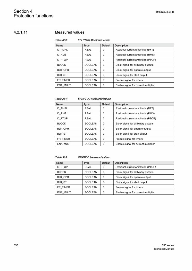
4.2.1.11 Measured values
Table 383: EFLPTOC Measured values
Name Type Default DescriptionI0_AMPL REAL 0 Residual current amplitude (DFT)
I0_RMS REAL 0 Residual current amplitude (RMS)
I0_PTOP REAL 0 Residual current amplitude (PTOP)
BLOCK BOOLEAN 0 Block signal for all binary outputs
BLK_OPR BOOLEAN 0 Block signal for operate output
BLK_ST BOOLEAN 0 Block signal for start output
FR_TIMER BOOLEAN 0 Freeze signal for timers
ENA_MULT BOOLEAN 0 Enable signal for current multiplier
Table 384: EFHPTOC Measured values
Name Type Default DescriptionI0_AMPL REAL 0 Residual current amplitude (DFT)
I0_RMS REAL 0 Residual current amplitude (RMS)
I0_PTOP REAL 0 Residual current amplitude (PTOP)
BLOCK BOOLEAN 0 Block signal for all binary outputs
BLK_OPR BOOLEAN 0 Block signal for operate output
BLK_ST BOOLEAN 0 Block signal for start output
FR_TIMER BOOLEAN 0 Freeze signal for timers
ENA_MULT BOOLEAN 0 Enable signal for current multiplier
Table 385: EFIPTOC Measured values
Name Type Default DescriptionI0_PTOP REAL 0 Residual current amplitude (PTOP)
BLOCK BOOLEAN 0 Block signal for all binary outputs
BLK_OPR BOOLEAN 0 Block signal for operate output
BLK_ST BOOLEAN 0 Block signal for start output
FR_TIMER BOOLEAN 0 Freeze signal for timers
ENA_MULT BOOLEAN 0 Enable signal for current multiplier
Section 4 1MRS756508 BProtection functions
356 630 seriesTechnical Manual

4.2.1.12 Monitored data
Table 386: EFLPTOC Monitored data
Name Type Values (Range) Unit DescriptionOPERATE BOOLEAN 0=FALSE
1=TRUE- Operated
START BOOLEAN 0=FALSE1=TRUE
- Started
START_DUR REAL - % Ratio of start time /operate time
INVAL_CRV BOOLEAN 0=FALSE1=TRUE
- Invalid curve parameters
Table 387: EFHPTOC Monitored data
Name Type Values (Range) Unit DescriptionOPERATE BOOLEAN 0=FALSE
1=TRUE- Operated
START BOOLEAN 0=FALSE1=TRUE
- Started
START_DUR REAL - % Ratio of start time /operate time
INVAL_CRV BOOLEAN 0=FALSE1=TRUE
- Invalid curve parameters
Table 388: EFIPTOC Monitored data
Name Type Values (Range) Unit DescriptionOPERATE BOOLEAN 0=FALSE
1=TRUE- Operated
START BOOLEAN 0=FALSE1=TRUE
- Started
START_DUR REAL - % Ratio of start time /operate time
4.2.1.13 Technical data
Table 389: EFxPTOC Technical data
Characteristic ValueOperation accuracy At the frequency f = fn
EFLPTOC ±1.5% of the set value or ±0.001 x In
EFHPTOCandEFIPTOC
±1.5% of set value or ±0.002 x In(at currents in the range of 0.1…10 x In)±5.0% of the set value(at currents in the range of 10…40 x In)
Table continues on next page
1MRS756508 B Section 4Protection functions
630 series 357Technical Manual

Characteristic ValueStart time 1)2) EFIPTOC:
IFault = 2 x set Startvalue
Typical 12 ms (±5 ms)
EFHPTOC:IFault = 2 x set Startvalue
Typical 19 ms (±5 ms)
EFLPTOC:IFault = 2 x set Startvalue
Typical 23 ms (±15 ms)
Reset time < 45 ms
Reset ratio Typical 0.96
Retardation time < 30 ms
Operate time accuracy in definite time mode ±1.0% of the set value or ±20 ms
Operate time accuracy in inverse time mode ±5.0% of the theoretical value or ±20 ms 3)
Suppression of harmonics RMS: No suppressionDFT: -50 dB at f = n x fn, where n = 2, 3, 4, 5,…Peak-to-Peak: No suppression
1) Operate curve type = IEC definite time, Measurement mode = default (depends on stage), currentbefore fault = 0.0 x In, fn = 50 Hz, earth-fault current with nominal frequency injected from randomphase angle, results based on statistical distribution of 1000 measurements
2) Includes the delay of the signal output contact3) Maximum Start value = 2.5 x In, Start value multiples in range of 1.5 to 20
4.2.2 Directional earth-fault protection DEFxPDEF
4.2.2.1 Identification
Function description IEC 61850identification
IEC 60617identification
ANSI/IEEE C37.2device number
Directional earth-fault protection - Lowstage
DEFLPDEF Io>-> 67N-1
Directional earth-fault protection - Highstage
DEFHPDEF Io>>-> 67N-2
4.2.2.2 Function block
A070992 V1 EN
Figure 171: Function block
Section 4 1MRS756508 BProtection functions
358 630 seriesTechnical Manual
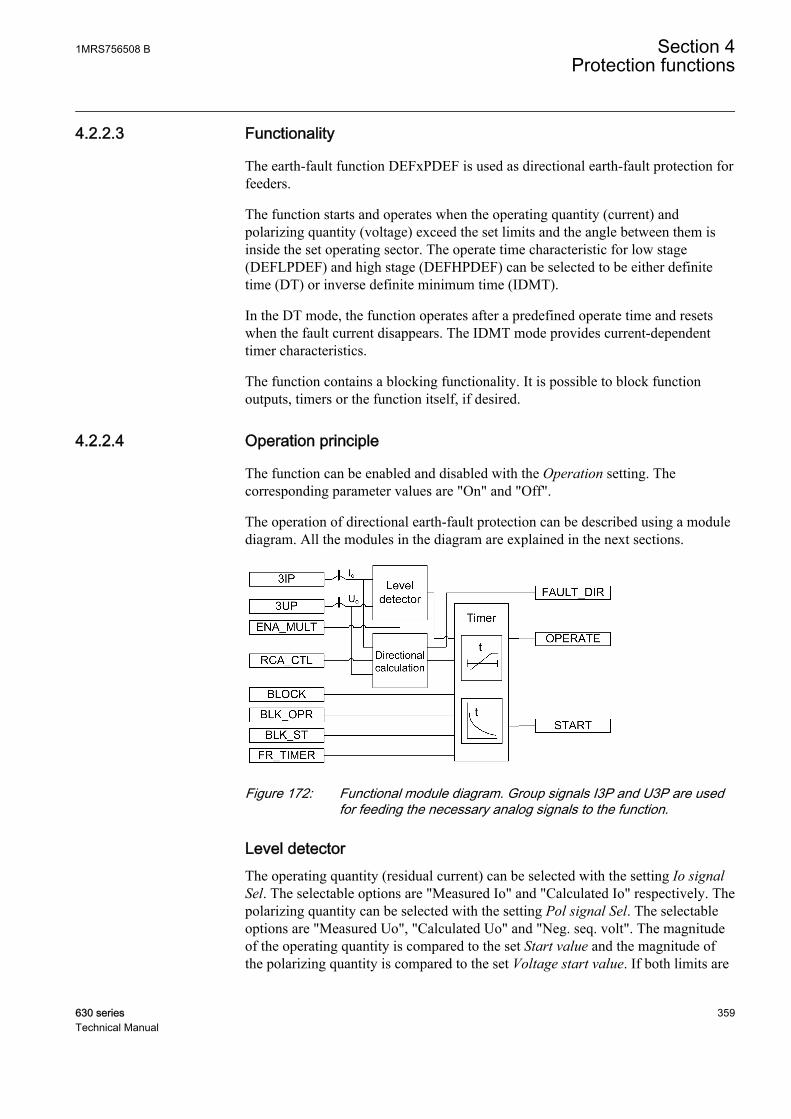
4.2.2.3 Functionality
The earth-fault function DEFxPDEF is used as directional earth-fault protection forfeeders.
The function starts and operates when the operating quantity (current) andpolarizing quantity (voltage) exceed the set limits and the angle between them isinside the set operating sector. The operate time characteristic for low stage(DEFLPDEF) and high stage (DEFHPDEF) can be selected to be either definitetime (DT) or inverse definite minimum time (IDMT).
In the DT mode, the function operates after a predefined operate time and resetswhen the fault current disappears. The IDMT mode provides current-dependenttimer characteristics.
The function contains a blocking functionality. It is possible to block functionoutputs, timers or the function itself, if desired.
4.2.2.4 Operation principle
The function can be enabled and disabled with the Operation setting. Thecorresponding parameter values are "On" and "Off".
The operation of directional earth-fault protection can be described using a modulediagram. All the modules in the diagram are explained in the next sections.
A071000 V1 EN
Figure 172: Functional module diagram. Group signals I3P and U3P are usedfor feeding the necessary analog signals to the function.
Level detectorThe operating quantity (residual current) can be selected with the setting Io signalSel. The selectable options are "Measured Io" and "Calculated Io" respectively. Thepolarizing quantity can be selected with the setting Pol signal Sel. The selectableoptions are "Measured Uo", "Calculated Uo" and "Neg. seq. volt". The magnitudeof the operating quantity is compared to the set Start value and the magnitude ofthe polarizing quantity is compared to the set Voltage start value. If both limits are
1MRS756508 B Section 4Protection functions
630 series 359Technical Manual
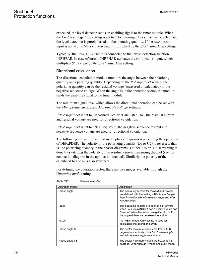
exceeded, the level detector sends an enabling signal to the timer module. Whenthe Enable voltage limit setting is set to "No", Voltage start value has no effect andthe level detection is purely based on the operating quantity. If the ENA_MULTinput is active, the Start value setting is multiplied by the Start value Mult setting.
Typically, the ENA_MULT input is connected to the inrush detection functionINRHPAR. In case of inrush, INRPHAR activates the ENA_MULT input, whichmultiplies Start value by the Start value Mult setting.
Directional calculationThe directional calculation module monitors the angle between the polarizingquantity and operating quantity. Depending on the Pol signal Sel setting, thepolarizing quantity can be the residual voltage (measured or calculated) or thenegative sequence voltage. When the angle is in the operation sector, the modulesends the enabling signal to the timer module.
The minimum signal level which allows the directional operation can be set withthe Min operate current and Min operate voltage settings.
If Pol signal Sel is set to "Measured Uo" or "Calculated Uo", the residual currentand residual voltage are used for directional calculation.
If Pol signal Sel is set to "Neg. seq. volt", the negative sequence current andnegative sequence voltage are used for directional calculation.
The following convention is used in the phasor diagrams representing the operationof DEFxPDEF: The polarity of the polarizing quantity (Uo or U2) is reversed, thatis, the polarizing quantity in the phasor diagrams is either -Uo or -U2. Reversing isdone by switching the polarity of the residual current measuring channel (see theconnection diagram in the application manual). Similarly the polarity of thecalculated Io and I2 is also switched.
For defining the operation sector, there are five modes available through theOperation mode setting.
Table 390: Operation modes
Operation mode DescriptionPhase angle The operating sectors for forward and reverse
are defined with the settings Min forward angle,Max forward angle, Min reverse angle and Maxreverse angle.
IoSin The operating sectors are defined as "forward"when |Io| x sin (ANGLE) has a positive value and"reverse" when the value is negative. ANGLE isthe angle difference between -Uo and Io.
IoCos As "IoSin" mode. Only cosine is used forcalculating the operation current.
Phase angle 80 The sector maximum values are frozen to 80degrees respectively. Only Min forward angleand Min reverse angle are settable.
Phase angle 88 The sector maximum values are frozen to 88degrees. Otherwise as "Phase angle 80" mode.
Section 4 1MRS756508 BProtection functions
360 630 seriesTechnical Manual
Polarizing quantity selection "Neg. seq. volt." is available only inthe "Phase angle" operation mode.
The directionality of the operation can be selected with the Directional modesetting. The user can select either "Non-directional", "Forward" or "Reverse"operation. The operation criterion is selected with the Operation mode setting. Bysetting Allow Non Dir to "True", non-directional operation is allowed when thedirectionality information is invalid, that is, when the magnitude of the polarizingquantity is less than the value of the Min operate voltage setting.
If the Enable voltage limit setting is set to "True", the magnitude ofthe polarizing quantity is checked even if Directional mode is set to"Non-directional" or Allow Non Dir to "True".
The Characteristic angle setting is used in the "Phase angle" mode to adjust theoperation according to the method of neutral point earthing so that in an isolatednetwork the Characteristic angle (φRCA) = -90° and in a compensated networkφRCA = 0°. In addition, the characteristic angle can be changed via the controlsignal RCA_CTL. RCA_CTL affects the Characteristic angle setting.
The Correction angle setting can be used to improve selectivity when there areinaccuracies due to measurement transformers. The setting decreases the operationsector. The correction can only be used with the "IoCos" or "IoSin" modes.
The polarity of the polarizing quantity can be reversed by setting the Pol reversalto "True", which turns the polarizing quantity by 180 degrees.
For definitions of different directional earth-fault characteristics,see the Directional earth-fault characteristics section in this manual.
The directional calculation module calculates several values which are presented inthe monitored data.
1MRS756508 B Section 4Protection functions
630 series 361Technical Manual

Table 391: Monitored data values
Monitored data values DescriptionFAULT_DIR The detected direction of fault during fault
situations, that is, when START output is active.
DIRECTION The momentary operating direction indicationoutput.
ANGLE Also called operating angle, shows the angledifference between the polarizing quantity (Uo,U2) and operating quantity (Io, I2).
ANGLE_RCA The angle difference between the operatingangle and Characteristic angle, that is,ANGLE_RCA = ANGLE – Characteristic angle.
I_OPER The current that is used for fault detection. If theOperation mode setting is "Phase angle", "Phaseangle 80" or "Phase angle 88", I_OPER is themeasured or calculated residual current. If theOperation mode setting is "IoSin", I_OPER iscalculated as follows I_OPER = Io x sin(ANGLE).If the Operation mode setting is "IoCos", I_OPERis calculated as follows I_OPER = Io xcos(ANGLE).
Monitored data values are accessible on the LHMI or through tools viacommunications.
TimerOnce activated, the timer activates the START output. The ST_A, ST_B and ST_Coutputs are used to indicate which phases are started. Depending on the value ofthe Operating curve type setting, the time characteristics are according to DT orIDMT. When the operation timer has reached the value of Operate delay time inthe DT mode or the maximum value defined by the inverse time curve, theOPERATE output is activated. The OPR_A, OPR_B and OPR_C outputs are used toindicate which phases are operated.
When the user-programmable IDMT curve is selected, the operation timecharacteristics are defined by the parameters Curve parameter A, Curve parameterB, Curve parameter C, Curve parameter D and Curve parameter E.
If a drop-off situation happens, that is, a fault suddenly disappears before theoperate delay is exceeded, the timer reset state is activated. The functionality of thetimer in the reset state depends on the combination of the Operating curve type,Type of reset curve and Reset delay time settings. When the DT characteristic isselected, the reset timer runs until the set Reset delay time value is exceeded. Whenthe IDMT curves are selected, the Type of reset curve setting can be set to"Immediate", "Def time reset" or "Inverse reset". The reset curve type "Immediate"causes an immediate reset. With the reset curve type "Def time reset", the resettime depends on the Reset delay time setting. With the reset curve type "Inversereset", the reset time depends on the current during the drop-off situation. TheSTART output is deactivated when the reset timer has elapsed.
Section 4 1MRS756508 BProtection functions
362 630 seriesTechnical Manual
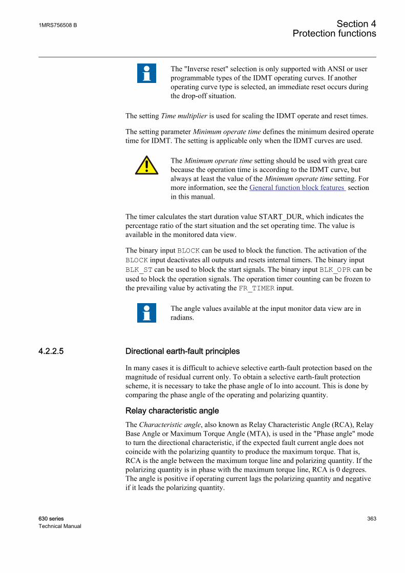
The "Inverse reset" selection is only supported with ANSI or userprogrammable types of the IDMT operating curves. If anotheroperating curve type is selected, an immediate reset occurs duringthe drop-off situation.
The setting Time multiplier is used for scaling the IDMT operate and reset times.
The setting parameter Minimum operate time defines the minimum desired operatetime for IDMT. The setting is applicable only when the IDMT curves are used.
The Minimum operate time setting should be used with great carebecause the operation time is according to the IDMT curve, butalways at least the value of the Minimum operate time setting. Formore information, see the General function block features sectionin this manual.
The timer calculates the start duration value START_DUR, which indicates thepercentage ratio of the start situation and the set operating time. The value isavailable in the monitored data view.
The binary input BLOCK can be used to block the function. The activation of theBLOCK input deactivates all outputs and resets internal timers. The binary inputBLK_ST can be used to block the start signals. The binary input BLK_OPR can beused to block the operation signals. The operation timer counting can be frozen tothe prevailing value by activating the FR_TIMER input.
The angle values available at the input monitor data view are inradians.
4.2.2.5 Directional earth-fault principles
In many cases it is difficult to achieve selective earth-fault protection based on themagnitude of residual current only. To obtain a selective earth-fault protectionscheme, it is necessary to take the phase angle of Io into account. This is done bycomparing the phase angle of the operating and polarizing quantity.
Relay characteristic angleThe Characteristic angle, also known as Relay Characteristic Angle (RCA), RelayBase Angle or Maximum Torque Angle (MTA), is used in the "Phase angle" modeto turn the directional characteristic, if the expected fault current angle does notcoincide with the polarizing quantity to produce the maximum torque. That is,RCA is the angle between the maximum torque line and polarizing quantity. If thepolarizing quantity is in phase with the maximum torque line, RCA is 0 degrees.The angle is positive if operating current lags the polarizing quantity and negativeif it leads the polarizing quantity.
1MRS756508 B Section 4Protection functions
630 series 363Technical Manual

Example 1.
The "Phase angle" mode is selected, compensated network (φRCA = 0 deg)
=> Characteristic angle = 0 deg
GUID-829C6CEB-19F0-4730-AC98-C5528C35A297 V2 EN
Figure 173: Definition of the relay characteristic angle, RCA=0 degrees in acompensated network
Example 2.
The "Phase angle" mode is selected, solidly earthed network (φRCA = +60 deg)
=> Characteristic angle = +60 deg
Section 4 1MRS756508 BProtection functions
364 630 seriesTechnical Manual
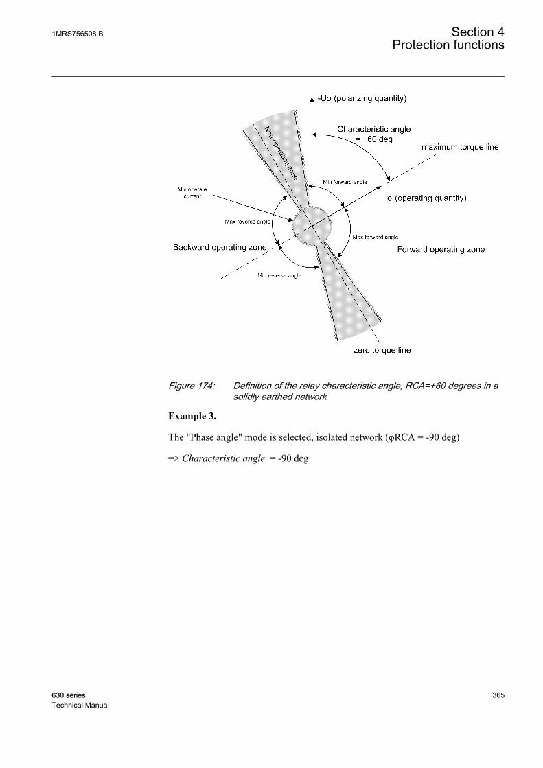
GUID-D72D678C-9C87-4830-BB85-FE00F5EA39C2 V2 EN
Figure 174: Definition of the relay characteristic angle, RCA=+60 degrees in asolidly earthed network
Example 3.
The "Phase angle" mode is selected, isolated network (φRCA = -90 deg)
=> Characteristic angle = -90 deg
1MRS756508 B Section 4Protection functions
630 series 365Technical Manual
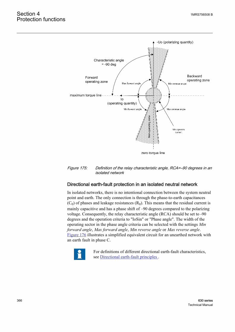
GUID-67BE307E-576A-44A9-B615-2A3B184A410D V2 EN
Figure 175: Definition of the relay characteristic angle, RCA=–90 degrees in anisolated network
Directional earth-fault protection in an isolated neutral networkIn isolated networks, there is no intentional connection between the system neutralpoint and earth. The only connection is through the phase-to-earth capacitances(C0) of phases and leakage resistances (R0). This means that the residual current ismainly capacitive and has a phase shift of –90 degrees compared to the polarizingvoltage. Consequently, the relay characteristic angle (RCA) should be set to -90degrees and the operation criteria to "IoSin" or "Phase angle". The width of theoperating sector in the phase angle criteria can be selected with the settings Minforward angle, Max forward angle, Min reverse angle or Max reverse angle.Figure 176 illustrates a simplified equivalent circuit for an unearthed network withan earth fault in phase C.
For definitions of different directional earth-fault characteristics,see Directional earth-fault principles .
Section 4 1MRS756508 BProtection functions
366 630 seriesTechnical Manual
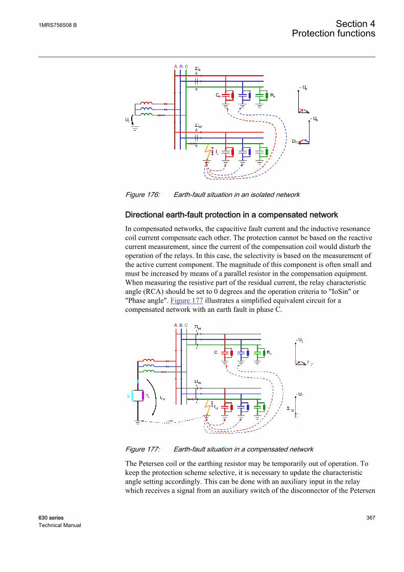
A070441 V1 EN
Figure 176: Earth-fault situation in an isolated network
Directional earth-fault protection in a compensated networkIn compensated networks, the capacitive fault current and the inductive resonancecoil current compensate each other. The protection cannot be based on the reactivecurrent measurement, since the current of the compensation coil would disturb theoperation of the relays. In this case, the selectivity is based on the measurement ofthe active current component. The magnitude of this component is often small andmust be increased by means of a parallel resistor in the compensation equipment.When measuring the resistive part of the residual current, the relay characteristicangle (RCA) should be set to 0 degrees and the operation criteria to "IoSin" or"Phase angle". Figure 177 illustrates a simplified equivalent circuit for acompensated network with an earth fault in phase C.
A070444 V2 EN
Figure 177: Earth-fault situation in a compensated network
The Petersen coil or the earthing resistor may be temporarily out of operation. Tokeep the protection scheme selective, it is necessary to update the characteristicangle setting accordingly. This can be done with an auxiliary input in the relaywhich receives a signal from an auxiliary switch of the disconnector of the Petersen
1MRS756508 B Section 4Protection functions
630 series 367Technical Manual

coil in compensated networks. As a result the characteristic angle is setautomatically to suit the earthing method used. The RCA_CTL input can be used tochange the operation criteria as described in Table 392 and Table 393:
Table 392: Relay characteristic angle control in Iosin(φ) and Iocos(φ) operation criteria
Operation mode setting: RCA_CTL = FALSE RCA_CTL = TRUEIosin Actual operation mode: Iosin Actual operation mode: Iocos
Iocos Actual operation mode: Iocos Actual operation mode: Iosin
Table 393: Characteristic angle control in phase angle operation mode
Characteristicangle setting
RCA_CTL = FALSE RCA_CTL = TRUE
-90° φRCA = -90° φRCA = 0°
0° φRCA = 0° φRCA = -90°
Use of the extended phase angle characteristicThe traditional method of adapting the directional earth-fault protection function tothe prevailing neutral earthing conditions is done with the Characteristic anglesetting. In an unearthed network, Characteristic angle is set to -90 degrees and in acompensated network Characteristic angle is set to 0 degrees. In case the earthingmethod of the network is temporarily changed from compensated to unearthed dueto the disconnection of the arc suppression coil, the Characteristic angle settingshould be modified correspondingly. This can be done using the setting groups orthe RCA_CTL input. Alternatively, the operating sector of the directional earth-fault protection function can be extended to cover the operating sectors of bothneutral earthing principles. Such characteristic is valid for both unearthed andcompensated network and does not require any modification in case the neutralearthing changes temporarily from the unearthed to compensated network or viceversa.
The extended phase angle characteristic is created by entering a value of over 90degrees for the Min forward angle setting; a typical value is 170 degrees (Minreverse angle in case Directional mode is set to "Reverse"). The Max forwardangle setting should be set to cover the possible measurement inaccuracies ofcurrent and voltage transformers; a typical value is 80 degrees (Max reverse anglein case Directional mode is set to "Reverse").
Section 4 1MRS756508 BProtection functions
368 630 seriesTechnical Manual

A070443 V3 EN
Figure 178: Extended operation area in directional earth-fault protection
4.2.2.6 Base values
In this function block, some of the settings are set in per unit (pu). These pu valuesare relational to certain base values, for example the values given in A, kV andkVA. The IED supports alternative base value groups for the phase current or voltage-related settings, for example "Phase Grp 1", "Phase Grp 2" and "Phase Grp 3".One of the groups to be used with the Base value Sel phase setting must be selected.
For more information, see the Basic functions section in this manual.
4.2.2.7 Timer characteristics
DEFxPDEF supports both DT and IDMT characteristics. The user can select thetimer characteristics with the Operating curve type setting.
The IED provides 16 IDMT characteristics curves, of which seven comply with theIEEE C37.112 and six with the IEC 60255-3 standard. Two curves follow the
1MRS756508 B Section 4Protection functions
630 series 369Technical Manual
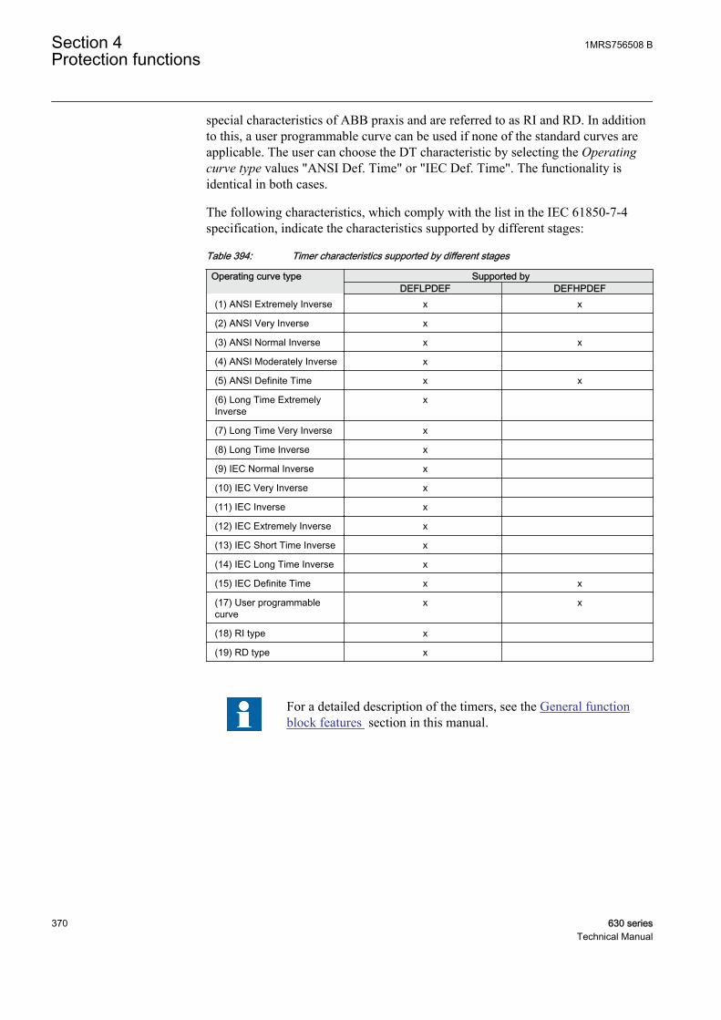
special characteristics of ABB praxis and are referred to as RI and RD. In additionto this, a user programmable curve can be used if none of the standard curves areapplicable. The user can choose the DT characteristic by selecting the Operatingcurve type values "ANSI Def. Time" or "IEC Def. Time". The functionality isidentical in both cases.
The following characteristics, which comply with the list in the IEC 61850-7-4specification, indicate the characteristics supported by different stages:
Table 394: Timer characteristics supported by different stages
Operating curve type Supported byDEFLPDEF DEFHPDEF
(1) ANSI Extremely Inverse x x
(2) ANSI Very Inverse x
(3) ANSI Normal Inverse x x
(4) ANSI Moderately Inverse x
(5) ANSI Definite Time x x
(6) Long Time ExtremelyInverse
x
(7) Long Time Very Inverse x
(8) Long Time Inverse x
(9) IEC Normal Inverse x
(10) IEC Very Inverse x
(11) IEC Inverse x
(12) IEC Extremely Inverse x
(13) IEC Short Time Inverse x
(14) IEC Long Time Inverse x
(15) IEC Definite Time x x
(17) User programmablecurve
x x
(18) RI type x
(19) RD type x
For a detailed description of the timers, see the General functionblock features section in this manual.
Section 4 1MRS756508 BProtection functions
370 630 seriesTechnical Manual
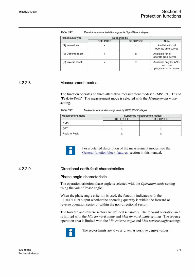
Table 395: Reset time characteristics supported by different stages
Reset curve type Supported by DEFLPDEF DEFHPDEF Note
(1) Immediate x x Available for alloperate time curves
(2) Def time reset x x Available for alloperate time curves
(3) Inverse reset x x Available only for ANSIand user
programmable curves
4.2.2.8 Measurement modes
The function operates on three alternative measurement modes: "RMS", "DFT" and"Peak-to-Peak". The measurement mode is selected with the Measurement modesetting.
Table 396: Measurement modes supported by DEFxPDEF stages
Measurement mode Supported measurement modesDEFLPDEF DEFHPDEF
RMS x x
DFT x x
Peak-to-Peak x x
For a detailed description of the measurement modes, see theGeneral function block features section in this manual.
4.2.2.9 Directional earth-fault characteristics
Phase angle characteristicThe operation criterion phase angle is selected with the Operation mode settingusing the value "Phase angle".
When the phase angle criterion is used, the function indicates with theDIRECTION output whether the operating quantity is within the forward orreverse operation sector or within the non-directional sector.
The forward and reverse sectors are defined separately. The forward operation areais limited with the Min forward angle and Max forward angle settings. The reverseoperation area is limited with the Min reverse angle and Max reverse angle settings.
The sector limits are always given as positive degree values.
1MRS756508 B Section 4Protection functions
630 series 371Technical Manual

In the forward operation area, the Max forward angle setting gives the clockwisesector and the Min forward angle setting correspondingly the counterclockwisesector, measured from the Characteristic angle setting.
In the reverse operation area, the Max reverse angle setting gives the clockwisesector and the Min reverse angle setting correspondingly the counterclockwisesector, measured from the complement of the Characteristic angle setting (180degrees phase shift) .
The relay characteristic angle (RCA) is set to positive if the operating current lagsthe polarizing quantity. It is set to negative if it leads the polarizing quantity.
GUID-92004AD5-05AA-4306-9574-9ED8D51524B4 V2 EN
Figure 179: Configurable operating sectors in phase angle characteristic
Section 4 1MRS756508 BProtection functions
372 630 seriesTechnical Manual

Table 397: Momentary operating direction
Fault direction The value for DIRECTIONAngle between the polarizing and operatingquantity is not in any of the defined sectors.
0 = unknown
Angle between the polarizing and operatingquantity is in the forward sector.
1= forward
Angle between the polarizing and operatingquantity is in the reverse sector.
2 = backward
Angle between the polarizing and operatingquantity is in both the forward and the reversesectors, that is, the sectors are overlapping.
3 = both
If the Allow Non Dir setting is "False", the directional operation (forward, reverse)is not allowed when the measured polarizing or operating quantities are invalid,that is, their magnitude is below the set minimum values. The minimum values canbe defined with the settings Min operate current and Min operate voltage. In caseof low magnitudes, the FAULT_DIR and DIRECTION outputs are set to 0 =unknown, except when the Allow non dir setting is "True". In that case, thefunction is allowed to operate in the directional mode as non-directional, since thedirectional information is invalid.
Iosin(φ) and Iocos(φ) criteriaA more modern approach to directional protection is the active or reactive currentmeasurement. The operating characteristic of the directional operation depends onthe earthing principle of the network. The Iosin(φ) criterion is used in an isolatednetwork, measuring the reactive component of the fault current caused by the earthcapacitance. The Iocos(φ) criterion is used in a compensated network, measuringthe active component of the fault current.
The operation criteria Iosin(φ) and Iocos(φ) are selected with the Operation modesetting using the values "IoSin" or "IoCos" respectively.
The angle correction setting can be used to improve selectivity. The settingdecreases the operation sector. The correction can only be used with the Iosin(φ) orIocos(φ) criterion. The RCA_CTL input is used to change the Io characteristic:
Table 398: Relay characteristic angle control in the IoSin and IoCos operation criteria
Operation mode: RCA_CTL = "False" RCA_CTL = "True"IoSin Actual operation criterion:
Iosin(φ)Actual operation criterion:Iocos(φ)
IoCos Actual operation criterion:Iocos(φ)
Actual operation criterion:Iosin(φ)
When the Iosin(φ) or Iocos(φ) criterion is used, the component indicates a forward-or reverse-type fault through the FAULT_DIR and DIRECTION outputs, in which1 equals a forward fault and 2 equals a reverse fault. Directional operation is notallowed (the Allow non dir setting is "False") when the measured polarizing or
1MRS756508 B Section 4Protection functions
630 series 373Technical Manual
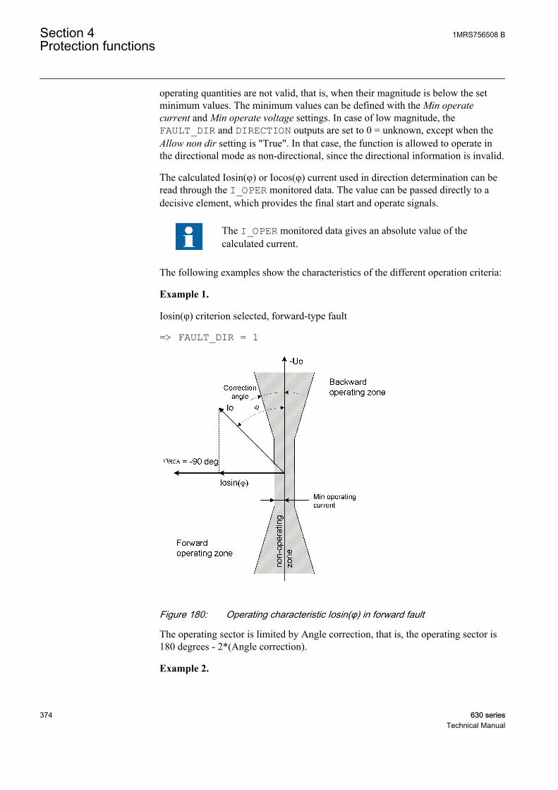
operating quantities are not valid, that is, when their magnitude is below the setminimum values. The minimum values can be defined with the Min operatecurrent and Min operate voltage settings. In case of low magnitude, theFAULT_DIR and DIRECTION outputs are set to 0 = unknown, except when theAllow non dir setting is "True". In that case, the function is allowed to operate inthe directional mode as non-directional, since the directional information is invalid.
The calculated Iosin(φ) or Iocos(φ) current used in direction determination can beread through the I_OPER monitored data. The value can be passed directly to adecisive element, which provides the final start and operate signals.
The I_OPER monitored data gives an absolute value of thecalculated current.
The following examples show the characteristics of the different operation criteria:
Example 1.
Iosin(φ) criterion selected, forward-type fault
=> FAULT_DIR = 1
GUID-560EFC3C-34BF-4852-BF8C-E3A2A7750275 V2 EN
Figure 180: Operating characteristic Iosin(φ) in forward fault
The operating sector is limited by Angle correction, that is, the operating sector is180 degrees - 2*(Angle correction).
Example 2.
Section 4 1MRS756508 BProtection functions
374 630 seriesTechnical Manual

Iosin(φ) criterion selected, reverse-type fault
=> FAULT_DIR = 2
GUID-10A890BE-8C81-45B2-9299-77DD764171E1 V2 EN
Figure 181: Operating characteristic Iosin(φ) in reverse fault
Example 3.
Iocos(φ) criterion selected, forward-type fault
=> FAULT_DIR = 1
1MRS756508 B Section 4Protection functions
630 series 375Technical Manual
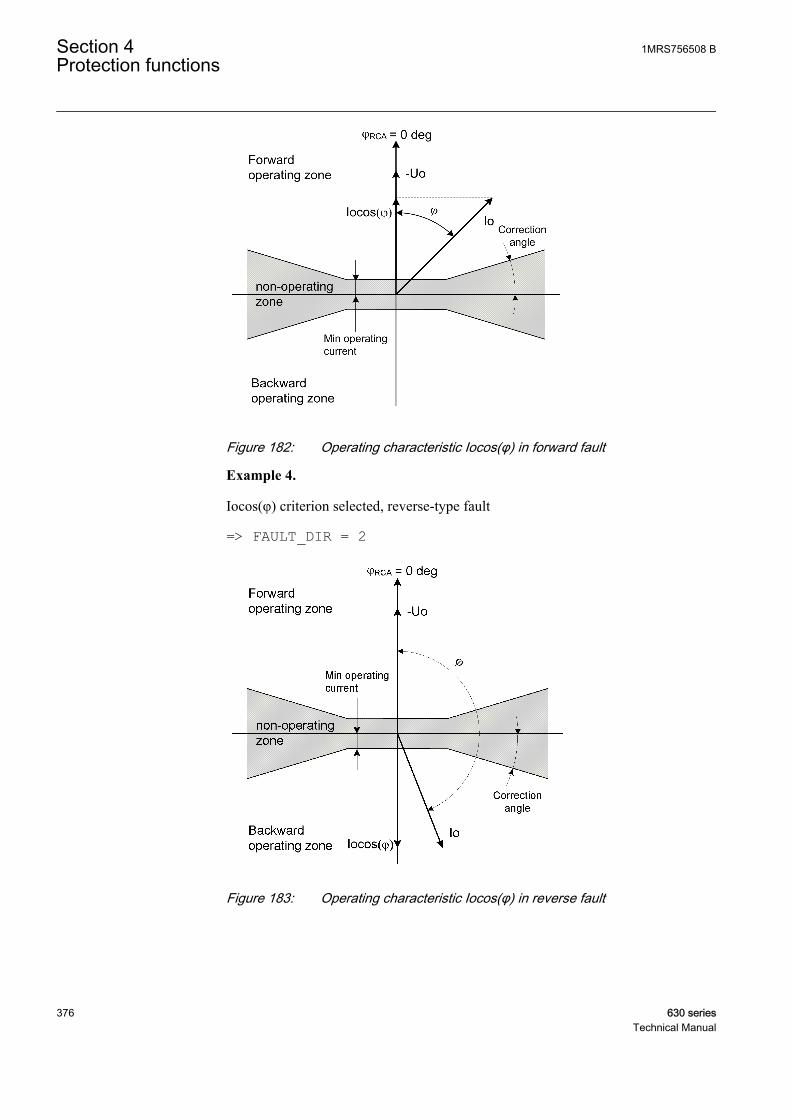
GUID-11E40C1F-6245-4532-9199-2E2F1D9B45E4 V2 EN
Figure 182: Operating characteristic Iocos(φ) in forward fault
Example 4.
Iocos(φ) criterion selected, reverse-type fault
=> FAULT_DIR = 2
GUID-54ACB854-F11D-4AF2-8BDB-69E5F6C13EF1 V2 EN
Figure 183: Operating characteristic Iocos(φ) in reverse fault
Section 4 1MRS756508 BProtection functions
376 630 seriesTechnical Manual
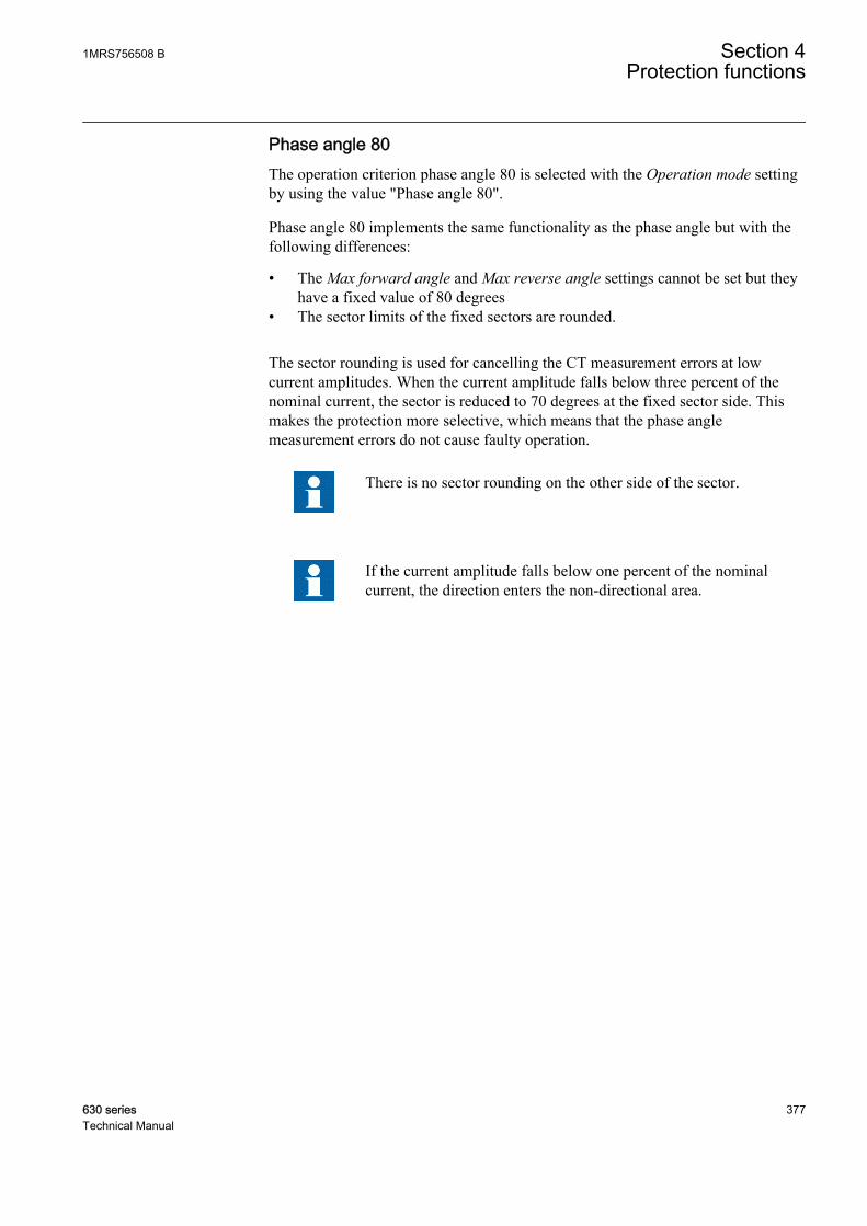
Phase angle 80The operation criterion phase angle 80 is selected with the Operation mode settingby using the value "Phase angle 80".
Phase angle 80 implements the same functionality as the phase angle but with thefollowing differences:
• The Max forward angle and Max reverse angle settings cannot be set but theyhave a fixed value of 80 degrees
• The sector limits of the fixed sectors are rounded.
The sector rounding is used for cancelling the CT measurement errors at lowcurrent amplitudes. When the current amplitude falls below three percent of thenominal current, the sector is reduced to 70 degrees at the fixed sector side. Thismakes the protection more selective, which means that the phase anglemeasurement errors do not cause faulty operation.
There is no sector rounding on the other side of the sector.
If the current amplitude falls below one percent of the nominalcurrent, the direction enters the non-directional area.
1MRS756508 B Section 4Protection functions
630 series 377Technical Manual
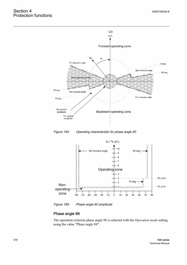
GUID-EFC9438D-9169-4733-9BE9-6B343F37001A V2 EN
Figure 184: Operating characteristic for phase angle 80
2
3
4
6
7
8
9
10
Io / % of In
0 90453015 7560-90 -45 -30 -15-75 -60
Min forward angle
1
80 deg
70 deg
Operating zone
Non-operating
zone
3% of In
1% of In
GUID-49D23ADF-4DA0-4F7A-8020-757F32928E60 V2 EN
Figure 185: Phase angle 80 amplitude
Phase angle 88The operation criterion phase angle 88 is selected with the Operation mode settingusing the value "Phase angle 88".
Section 4 1MRS756508 BProtection functions
378 630 seriesTechnical Manual
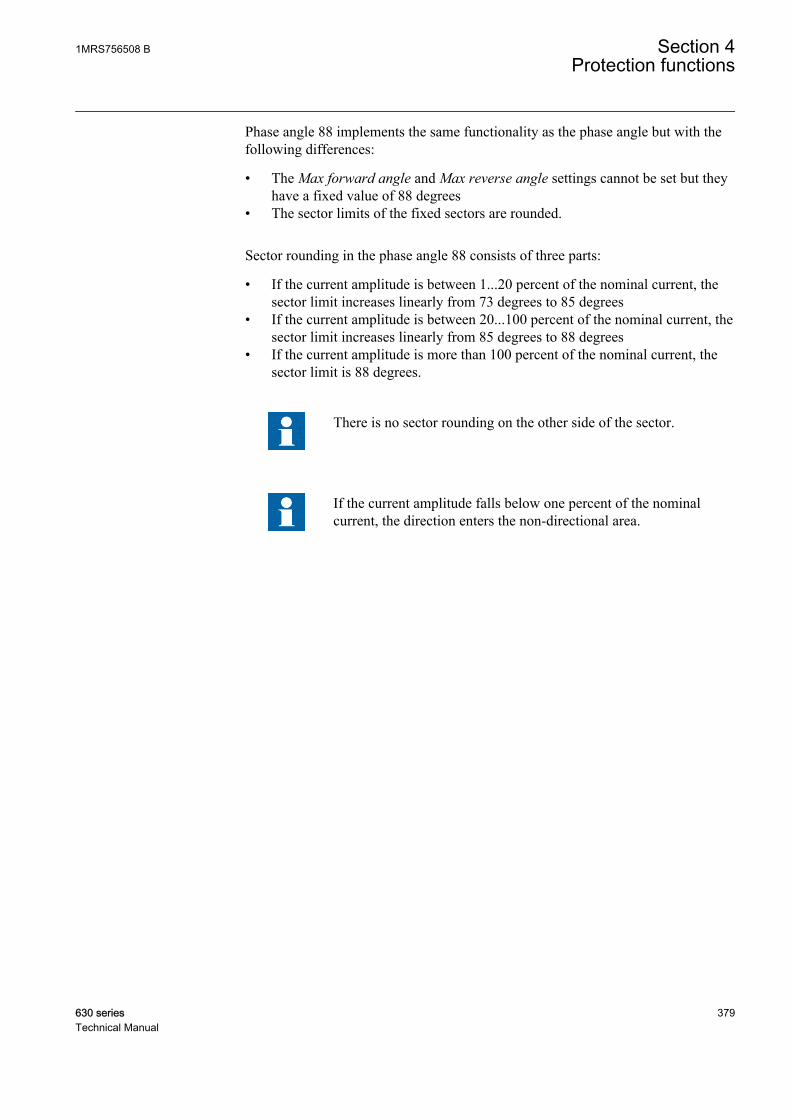
Phase angle 88 implements the same functionality as the phase angle but with thefollowing differences:
• The Max forward angle and Max reverse angle settings cannot be set but theyhave a fixed value of 88 degrees
• The sector limits of the fixed sectors are rounded.
Sector rounding in the phase angle 88 consists of three parts:
• If the current amplitude is between 1...20 percent of the nominal current, thesector limit increases linearly from 73 degrees to 85 degrees
• If the current amplitude is between 20...100 percent of the nominal current, thesector limit increases linearly from 85 degrees to 88 degrees
• If the current amplitude is more than 100 percent of the nominal current, thesector limit is 88 degrees.
There is no sector rounding on the other side of the sector.
If the current amplitude falls below one percent of the nominalcurrent, the direction enters the non-directional area.
1MRS756508 B Section 4Protection functions
630 series 379Technical Manual
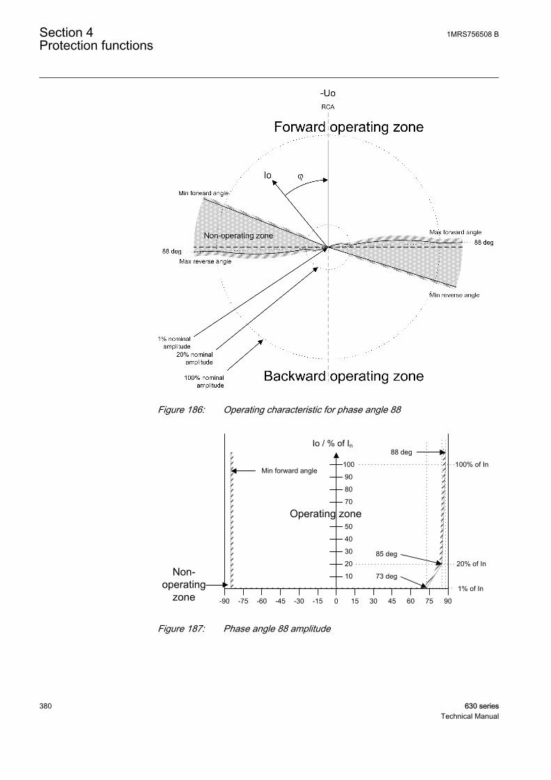
GUID-0F0560B7-943E-4CED-A4B8-A561BAE08956 V2 EN
Figure 186: Operating characteristic for phase angle 88
20
30
40
50
70
80
90
100
Io / % of In
0 90453015 7560-90 -45 -30 -15-75 -60
Min forward angle
10
88 deg
85 deg
73 deg
100% of In
20% of In
1% of In
GUID-F9F1619D-E1B5-4650-A5CB-B62A7F6B0A90 V2 EN
Figure 187: Phase angle 88 amplitude
Section 4 1MRS756508 BProtection functions
380 630 seriesTechnical Manual
4.2.2.10 Application
The directional earth-fault protection (DEFxPDEF) is designed for protection andclearance of earth faults and for earth-fault protection of different equipmentconnected to the power systems, such as shunt capacitor banks or shunt reactors,and for backup earth-fault protection of power transformers.
Many applications require several steps using different current start levels and timedelays. DEFxPDEF consists of two different stages:
• low (DEFLPDEF)• high (DEFHPDEF)
DEFLPDEF contains several types of time delay characteristics. DEFHPDEF isused for fast clearance of serious earth faults.
The protection can be based on the phase angle criterion with extended operatingsector. It can also be based on measuring either the reactive part Iosin(φ) or theactive part Iocos(φ) of the residual current. In isolated networks or in networkswith high impedance earthing, the phase-to-earth fault current is significantlysmaller than the short-circuit currents. In addition, the magnitude of the faultcurrent is almost independent of the fault location in the network.
The function uses the residual current components Iocos(φ) or Iosin(φ) accordingto the earthing method, where φ is the angle between the residual current and thereference residual voltage (-Uo). In compensated networks, the phase anglecriterion with extended operating sector can also be used. When the relaycharacteristic angle RCA is 0 degrees, the negative quadrant of the operation sectorcan be extended with the Min forward angle setting. The operation sector can beset between 0 and -180 degrees, so that the total operation sector is from +90 to-180 degrees. In other words, the sector can be up to 270 degrees wide. This allowsthe protection settings to stay the same when the resonance coil is disconnectedfrom between the neutral point and earth.
System neutral earthing is meant to protect personnel and equipment and to reduceinterference for example in telecommunication systems. The neutral earthing setschallenges for protection systems, especially for earth-fault protection.
In isolated networks, there is no intentional connection between the system neutralpoint and earth. The only connection is through the line-to-earth capacitances (C0)of phases and leakage resistances (R0). This means that the residual current ismainly capacitive and has –90 degrees phase shift compared to the residual voltage(-Uo). The characteristic angle is -90 degrees.
In resonance-earthed networks, the capacitive fault current and the inductiveresonance coil current compensate each other. The protection cannot be based onthe reactive current measurement, since the current of the compensation coil woulddisturb the operation of the relays. In this case, the selectivity is based on themeasurement of the active current component. This means that the residual current
1MRS756508 B Section 4Protection functions
630 series 381Technical Manual
is mainly resistive and has zero phase shift compared to the residual voltage (-Uo)and the characteristic angle is 0 degrees. Often the magnitude of this component issmall, and must be increased by means of a parallel resistor in the compensationequipment.
In networks where the neutral point is earthed through low resistance, thecharacteristic angle is also 0 degrees (for phase angle). Alternatively, Iocos(φ)operation can be used.
In solidly earthed networks, the Characteristic angle is typically set to +60 degreesfor the phase angle. Alternatively, Iosin(φ) operation can be used with a reversalpolarizing quantity. The polarizing quantity can be rotated 180 degrees by settingthe Pol reversal parameter to "True" or by switching the polarity of the residualvoltage measurement wires. Although the Iosin(φ) operation can be used in solidlyearthed networks, the phase angle is recommended.
Connection of measuring transformers in directional earth faultapplicationsThe residual current Io can be measured with a core balance current transformer orthe residual connection of the phase current signals. If the neutral of the network iseither isolated or earthed with high impedance, a core balance current transformeris recommended to be used in earth-fault protection. To ensure sufficient accuracyof residual current measurements and consequently the selectivity of the scheme,the core balance current transformers should have a transformation ratio of at least70:1. Lower transformation ratios such as 50:1 or 50:5 are not recommended.
Attention should be paid to make sure the measuring transformers are connectedcorrectly so that DEFxPDEF is able to detect the fault current direction withoutfailure. As directional earth fault uses residual current and residual voltage (-Uo),the poles of the measuring transformers must match each other and also the faultcurrent direction. Also the earthing of the cable sheath must be taken into noticewhen using core balance current transformers. The following figure describes howmeasuring transformers can be connected to the IED.
Section 4 1MRS756508 BProtection functions
382 630 seriesTechnical Manual
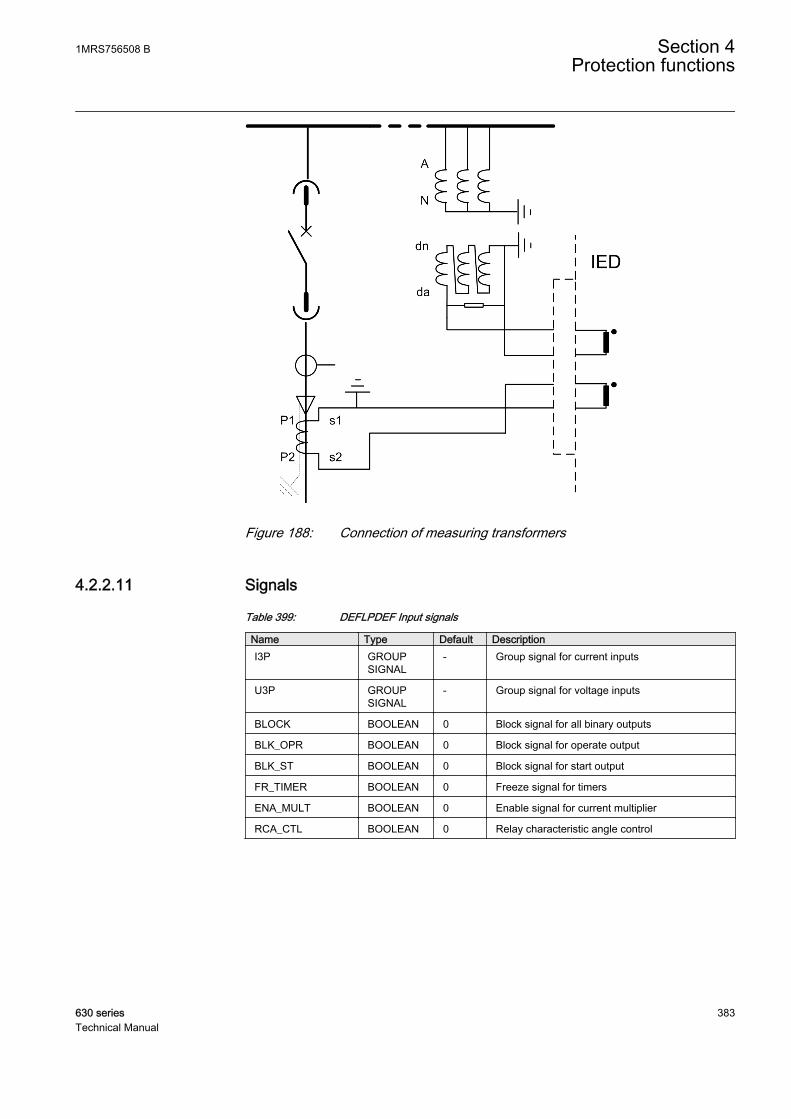
A070697 V2 EN
Figure 188: Connection of measuring transformers
4.2.2.11 Signals
Table 399: DEFLPDEF Input signals
Name Type Default DescriptionI3P GROUP
SIGNAL- Group signal for current inputs
U3P GROUPSIGNAL
- Group signal for voltage inputs
BLOCK BOOLEAN 0 Block signal for all binary outputs
BLK_OPR BOOLEAN 0 Block signal for operate output
BLK_ST BOOLEAN 0 Block signal for start output
FR_TIMER BOOLEAN 0 Freeze signal for timers
ENA_MULT BOOLEAN 0 Enable signal for current multiplier
RCA_CTL BOOLEAN 0 Relay characteristic angle control
1MRS756508 B Section 4Protection functions
630 series 383Technical Manual
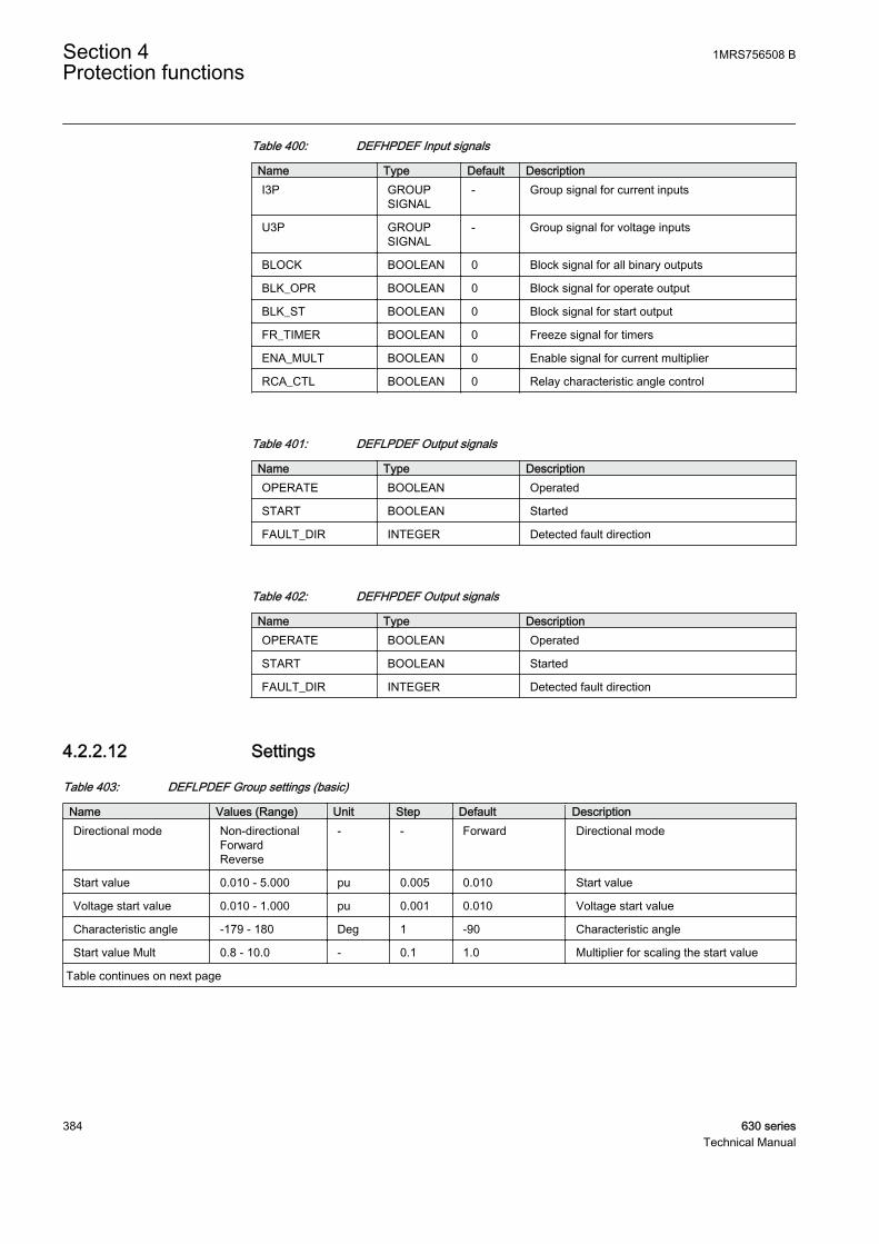
Table 400: DEFHPDEF Input signals
Name Type Default DescriptionI3P GROUP
SIGNAL- Group signal for current inputs
U3P GROUPSIGNAL
- Group signal for voltage inputs
BLOCK BOOLEAN 0 Block signal for all binary outputs
BLK_OPR BOOLEAN 0 Block signal for operate output
BLK_ST BOOLEAN 0 Block signal for start output
FR_TIMER BOOLEAN 0 Freeze signal for timers
ENA_MULT BOOLEAN 0 Enable signal for current multiplier
RCA_CTL BOOLEAN 0 Relay characteristic angle control
Table 401: DEFLPDEF Output signals
Name Type DescriptionOPERATE BOOLEAN Operated
START BOOLEAN Started
FAULT_DIR INTEGER Detected fault direction
Table 402: DEFHPDEF Output signals
Name Type DescriptionOPERATE BOOLEAN Operated
START BOOLEAN Started
FAULT_DIR INTEGER Detected fault direction
4.2.2.12 Settings
Table 403: DEFLPDEF Group settings (basic)
Name Values (Range) Unit Step Default DescriptionDirectional mode Non-directional
ForwardReverse
- - Forward Directional mode
Start value 0.010 - 5.000 pu 0.005 0.010 Start value
Voltage start value 0.010 - 1.000 pu 0.001 0.010 Voltage start value
Characteristic angle -179 - 180 Deg 1 -90 Characteristic angle
Start value Mult 0.8 - 10.0 - 0.1 1.0 Multiplier for scaling the start value
Table continues on next page
Section 4 1MRS756508 BProtection functions
384 630 seriesTechnical Manual
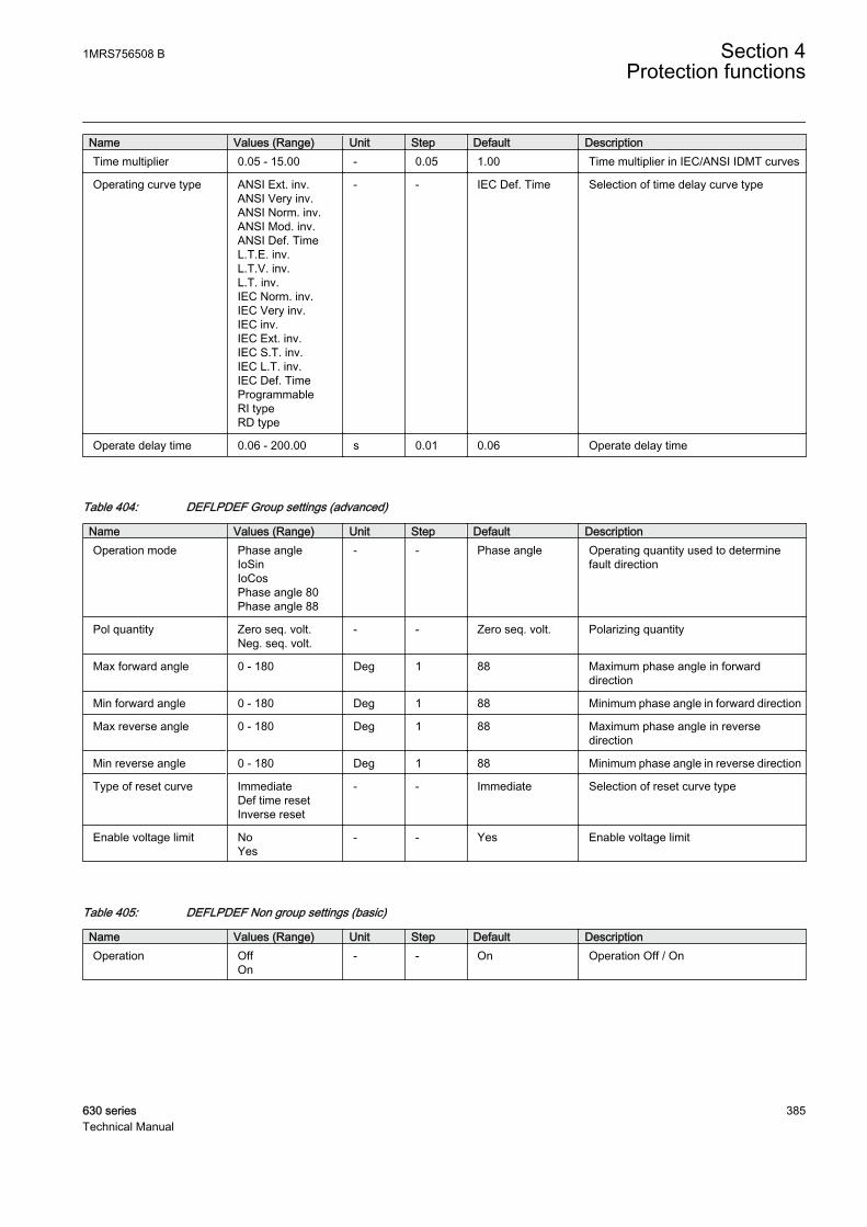
Name Values (Range) Unit Step Default DescriptionTime multiplier 0.05 - 15.00 - 0.05 1.00 Time multiplier in IEC/ANSI IDMT curves
Operating curve type ANSI Ext. inv.ANSI Very inv.ANSI Norm. inv.ANSI Mod. inv.ANSI Def. TimeL.T.E. inv.L.T.V. inv.L.T. inv.IEC Norm. inv.IEC Very inv.IEC inv.IEC Ext. inv.IEC S.T. inv.IEC L.T. inv.IEC Def. TimeProgrammableRI typeRD type
- - IEC Def. Time Selection of time delay curve type
Operate delay time 0.06 - 200.00 s 0.01 0.06 Operate delay time
Table 404: DEFLPDEF Group settings (advanced)
Name Values (Range) Unit Step Default DescriptionOperation mode Phase angle
IoSinIoCosPhase angle 80Phase angle 88
- - Phase angle Operating quantity used to determinefault direction
Pol quantity Zero seq. volt.Neg. seq. volt.
- - Zero seq. volt. Polarizing quantity
Max forward angle 0 - 180 Deg 1 88 Maximum phase angle in forwarddirection
Min forward angle 0 - 180 Deg 1 88 Minimum phase angle in forward direction
Max reverse angle 0 - 180 Deg 1 88 Maximum phase angle in reversedirection
Min reverse angle 0 - 180 Deg 1 88 Minimum phase angle in reverse direction
Type of reset curve ImmediateDef time resetInverse reset
- - Immediate Selection of reset curve type
Enable voltage limit NoYes
- - Yes Enable voltage limit
Table 405: DEFLPDEF Non group settings (basic)
Name Values (Range) Unit Step Default DescriptionOperation Off
On- - On Operation Off / On
1MRS756508 B Section 4Protection functions
630 series 385Technical Manual
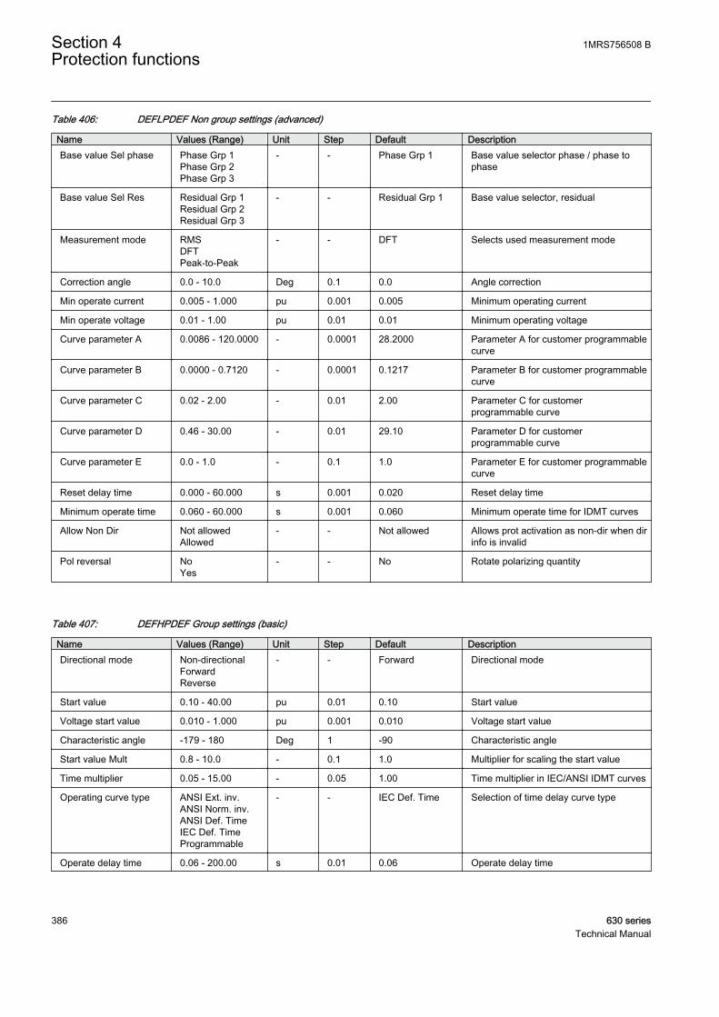
Table 406: DEFLPDEF Non group settings (advanced)
Name Values (Range) Unit Step Default DescriptionBase value Sel phase Phase Grp 1
Phase Grp 2Phase Grp 3
- - Phase Grp 1 Base value selector phase / phase tophase
Base value Sel Res Residual Grp 1Residual Grp 2Residual Grp 3
- - Residual Grp 1 Base value selector, residual
Measurement mode RMSDFTPeak-to-Peak
- - DFT Selects used measurement mode
Correction angle 0.0 - 10.0 Deg 0.1 0.0 Angle correction
Min operate current 0.005 - 1.000 pu 0.001 0.005 Minimum operating current
Min operate voltage 0.01 - 1.00 pu 0.01 0.01 Minimum operating voltage
Curve parameter A 0.0086 - 120.0000 - 0.0001 28.2000 Parameter A for customer programmablecurve
Curve parameter B 0.0000 - 0.7120 - 0.0001 0.1217 Parameter B for customer programmablecurve
Curve parameter C 0.02 - 2.00 - 0.01 2.00 Parameter C for customerprogrammable curve
Curve parameter D 0.46 - 30.00 - 0.01 29.10 Parameter D for customerprogrammable curve
Curve parameter E 0.0 - 1.0 - 0.1 1.0 Parameter E for customer programmablecurve
Reset delay time 0.000 - 60.000 s 0.001 0.020 Reset delay time
Minimum operate time 0.060 - 60.000 s 0.001 0.060 Minimum operate time for IDMT curves
Allow Non Dir Not allowedAllowed
- - Not allowed Allows prot activation as non-dir when dirinfo is invalid
Pol reversal NoYes
- - No Rotate polarizing quantity
Table 407: DEFHPDEF Group settings (basic)
Name Values (Range) Unit Step Default DescriptionDirectional mode Non-directional
ForwardReverse
- - Forward Directional mode
Start value 0.10 - 40.00 pu 0.01 0.10 Start value
Voltage start value 0.010 - 1.000 pu 0.001 0.010 Voltage start value
Characteristic angle -179 - 180 Deg 1 -90 Characteristic angle
Start value Mult 0.8 - 10.0 - 0.1 1.0 Multiplier for scaling the start value
Time multiplier 0.05 - 15.00 - 0.05 1.00 Time multiplier in IEC/ANSI IDMT curves
Operating curve type ANSI Ext. inv.ANSI Norm. inv.ANSI Def. TimeIEC Def. TimeProgrammable
- - IEC Def. Time Selection of time delay curve type
Operate delay time 0.06 - 200.00 s 0.01 0.06 Operate delay time
Section 4 1MRS756508 BProtection functions
386 630 seriesTechnical Manual
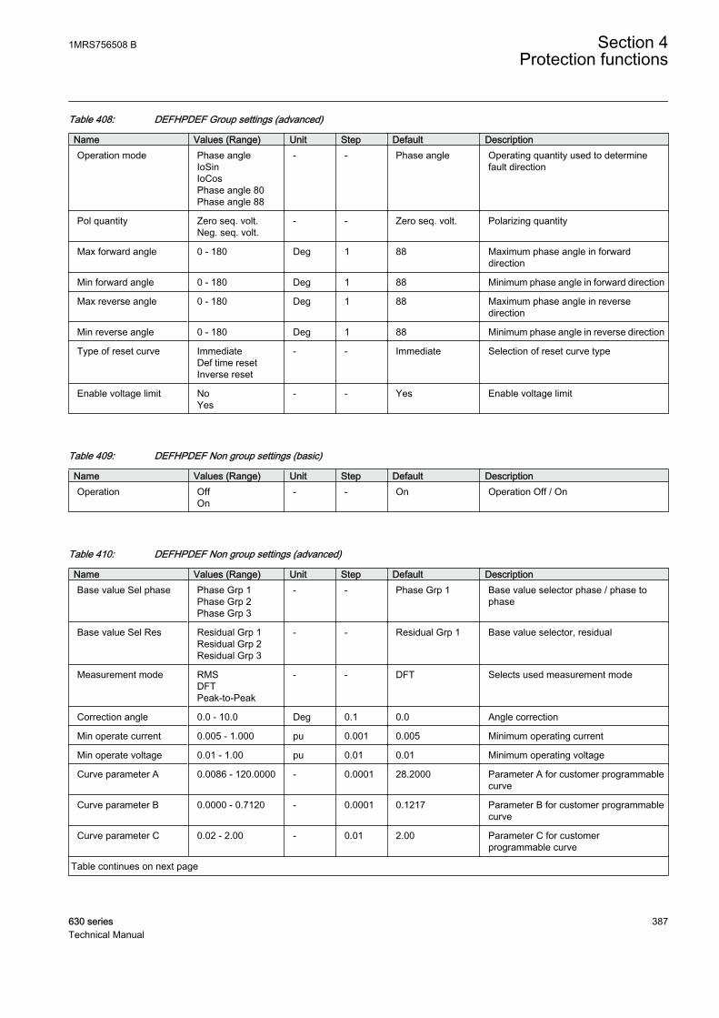
Table 408: DEFHPDEF Group settings (advanced)
Name Values (Range) Unit Step Default DescriptionOperation mode Phase angle
IoSinIoCosPhase angle 80Phase angle 88
- - Phase angle Operating quantity used to determinefault direction
Pol quantity Zero seq. volt.Neg. seq. volt.
- - Zero seq. volt. Polarizing quantity
Max forward angle 0 - 180 Deg 1 88 Maximum phase angle in forwarddirection
Min forward angle 0 - 180 Deg 1 88 Minimum phase angle in forward direction
Max reverse angle 0 - 180 Deg 1 88 Maximum phase angle in reversedirection
Min reverse angle 0 - 180 Deg 1 88 Minimum phase angle in reverse direction
Type of reset curve ImmediateDef time resetInverse reset
- - Immediate Selection of reset curve type
Enable voltage limit NoYes
- - Yes Enable voltage limit
Table 409: DEFHPDEF Non group settings (basic)
Name Values (Range) Unit Step Default DescriptionOperation Off
On- - On Operation Off / On
Table 410: DEFHPDEF Non group settings (advanced)
Name Values (Range) Unit Step Default DescriptionBase value Sel phase Phase Grp 1
Phase Grp 2Phase Grp 3
- - Phase Grp 1 Base value selector phase / phase tophase
Base value Sel Res Residual Grp 1Residual Grp 2Residual Grp 3
- - Residual Grp 1 Base value selector, residual
Measurement mode RMSDFTPeak-to-Peak
- - DFT Selects used measurement mode
Correction angle 0.0 - 10.0 Deg 0.1 0.0 Angle correction
Min operate current 0.005 - 1.000 pu 0.001 0.005 Minimum operating current
Min operate voltage 0.01 - 1.00 pu 0.01 0.01 Minimum operating voltage
Curve parameter A 0.0086 - 120.0000 - 0.0001 28.2000 Parameter A for customer programmablecurve
Curve parameter B 0.0000 - 0.7120 - 0.0001 0.1217 Parameter B for customer programmablecurve
Curve parameter C 0.02 - 2.00 - 0.01 2.00 Parameter C for customerprogrammable curve
Table continues on next page
1MRS756508 B Section 4Protection functions
630 series 387Technical Manual

Name Values (Range) Unit Step Default DescriptionCurve parameter D 0.46 - 30.00 - 0.01 29.10 Parameter D for customer
programmable curve
Curve parameter E 0.0 - 1.0 - 0.1 1.0 Parameter E for customer programmablecurve
Reset delay time 0.000 - 60.000 s 0.001 0.020 Reset delay time
Minimum operate time 0.060 - 60.000 s 0.001 0.060 Minimum operate time for IDMT curves
Allow Non Dir Not allowedAllowed
- - Not allowed Allows prot activation as non-dir when dirinfo is invalid
Pol reversal NoYes
- - No Rotate polarizing quantity
4.2.2.13 Measured values
Table 411: DEFLPDEF Measured values
Name Type Default DescriptionI_AMPL_RES REAL 0 Residual current amplitude (DFT)
I_ANGL_RES REAL 0 Residual current phase angle
I_RMS_RES REAL 0 Residual current amplitude (RMS)
I_PTOP_RES REAL 0 Residual current amplitude (PTOP)
I2_AMPL REAL 0 Negative sequence current amplitude (DFT)
I2_ANGL REAL 0 Negative sequence current phase angle
U_AMPL_RES REAL 0 Residual voltage amplitude (DFT)
U_ANGL_RES REAL 0 Residual voltage phase angle
U2_AMPL REAL 0 Negative sequence voltage amplitude (DFT)
U2_ANGL REAL 0 Negative sequence voltage phase angle
BLOCK BOOLEAN 0 Block signal for all binary outputs
BLK_OPR BOOLEAN 0 Block signal for operate output
BLK_ST BOOLEAN 0 Block signal for start output
FR_TIMER BOOLEAN 0 Freeze signal for timers
ENA_MULT BOOLEAN 0 Enable signal for current multiplier
RCA_CTL BOOLEAN 0 Relay characteristic angle control
Table 412: DEFHPDEF Measured values
Name Type Default DescriptionI_AMPL_RES REAL 0 Residual current amplitude (DFT)
I_ANGL_RES REAL 0 Residual current phase angle
I_RMS_RES REAL 0 Residual current amplitude (RMS)
I_PTOP_RES REAL 0 Residual current amplitude (PTOP)
I2_AMPL REAL 0 Negative sequence current amplitude (DFT)
I2_ANGL REAL 0 Negative sequence current phase angle
Table continues on next page
Section 4 1MRS756508 BProtection functions
388 630 seriesTechnical Manual

Name Type Default DescriptionU_AMPL_RES REAL 0 Residual voltage amplitude (DFT)
U_ANGL_RES REAL 0 Residual voltage phase angle
U2_AMPL REAL 0 Negative sequence voltage amplitude (DFT)
U2_ANGL REAL 0 Negative sequence voltage phase angle
BLOCK BOOLEAN 0 Block signal for all binary outputs
BLK_OPR BOOLEAN 0 Block signal for operate output
BLK_ST BOOLEAN 0 Block signal for start output
FR_TIMER BOOLEAN 0 Freeze signal for timers
ENA_MULT BOOLEAN 0 Enable signal for current multiplier
RCA_CTL BOOLEAN 0 Relay characteristic angle control
4.2.2.14 Monitored data
Table 413: DEFLPDEF Monitored data
Name Type Values (Range) Unit DescriptionOPERATE BOOLEAN 0=FALSE
1=TRUE- Operated
START BOOLEAN 0=FALSE1=TRUE
- Started
FAULT_DIR INTEGER 0=Unknown1=Forward2=Backward3=Both
- Detected fault direction
DIRECTION INTEGER 0=Unknown1=Forward2=Backward3=Both
- Direction information
ANGLE_RCA REAL - deg Angle between operatingangle and characteristicangle
ANGLE REAL - deg Angle betweenpolarizing and operatingquantity
I_OPER REAL - A Calculated operatingcurrent
START_DUR REAL - % Ratio of start time /operate time
INVAL_CRV BOOLEAN 0=FALSE1=TRUE
- Invalid curve parameters
1MRS756508 B Section 4Protection functions
630 series 389Technical Manual
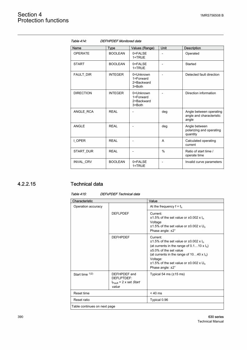
Table 414: DEFHPDEF Monitored data
Name Type Values (Range) Unit DescriptionOPERATE BOOLEAN 0=FALSE
1=TRUE- Operated
START BOOLEAN 0=FALSE1=TRUE
- Started
FAULT_DIR INTEGER 0=Unknown1=Forward2=Backward3=Both
- Detected fault direction
DIRECTION INTEGER 0=Unknown1=Forward2=Backward3=Both
- Direction information
ANGLE_RCA REAL - deg Angle between operatingangle and characteristicangle
ANGLE REAL - deg Angle betweenpolarizing and operatingquantity
I_OPER REAL - A Calculated operatingcurrent
START_DUR REAL - % Ratio of start time /operate time
INVAL_CRV BOOLEAN 0=FALSE1=TRUE
- Invalid curve parameters
4.2.2.15 Technical data
Table 415: DEFxPDEF Technical data
Characteristic ValueOperation accuracy At the frequency f = fn
DEFLPDEF Current:±1.5% of the set value or ±0.002 x InVoltage±1.5% of the set value or ±0.002 x UnPhase angle: ±2°
DEFHPDEF Current:±1.5% of the set value or ±0.002 x In(at currents in the range of 0.1…10 x In)±5.0% of the set value(at currents in the range of 10…40 x In)Voltage:±1.5% of the set value or ±0.002 x UnPhase angle: ±2°
Start time 1)2) DEFHPDEF andDEFLPTDEF:IFault = 2 x set Startvalue
Typical 54 ms (±15 ms)
Reset time < 40 ms
Reset ratio Typical 0.96
Table continues on next page
Section 4 1MRS756508 BProtection functions
390 630 seriesTechnical Manual

Characteristic ValueRetardation time < 30 ms
Operate time accuracy in definite time mode ±1.0% of the set value or ±20 ms
Operate time accuracy in inverse time mode ±5.0% of the theoretical value or ±20 ms 3)
Suppression of harmonics RMS: No suppressionDFT: -50 dB at f = n x fn, where n = 2, 3, 4, 5,…Peak-to-Peak: No suppression
1) Measurement mode = default (depends on stage), current before fault = 0.0 x In, fn = 50 Hz, earth-fault current with nominal frequency injected from random phase angle, results based on statisticaldistribution of 1000 measurements
2) Includes the delay of the signal output contact3) Maximum Start value = 2.5 x In, Start value multiples in range of 1.5 to 20
4.2.3 Transient/intermittent earth-fault protection INTRPTEF
4.2.3.1 Identification
Function description IEC 61850identification
IEC 60617identification
ANSI/IEEE C37.2device number
Transient/intermittent earth-faultprotection
INTRPTEF Io> ->IEF 67NIEF
4.2.3.2 Function block
A070664 V2 EN
Figure 189: Function block
4.2.3.3 Functionality
The transient/intermittent measuring earth-fault protection INTRPTEF is a sample-based function designed for the protection and clearance of permanent andintermittent earth faults in distribution and sub-transmission networks. Faultdetection is done from the residual current and residual voltage signals bymonitoring the transients with predefined criteria.
The operate time characteristics are according to definite time (DT).
The function contains a blocking functionality. It is possible to block functionoutputs, timers or the function itself, if desired.
4.2.3.4 Operation principle
1MRS756508 B Section 4Protection functions
630 series 391Technical Manual

The function can be enabled and disabled with the Operation setting. Thecorresponding parameter values are "On" and "Off".
The operation of transient/intermittent earth-fault protection can be described byusing a module diagram. All the modules in the diagram are explained in the nextsections.
GUID-7A54CD1C-5E46-447B-B308-B23B45147FF3 V2 EN
Figure 190: Functional module diagram. Group signal I3P is used for feedingthe necessary analog signals to the function.
Level detectorThe level detector module is used only when selected Operation mode is"Transient EF". The module compares the measured residual voltage to the setVoltage start value. If the measured value exceeds the set Voltage start value, themodule reports the exceeding of the value to the fault indication logic.
Transient detectorThe transient detector module is used for detecting transients in the residual currentand residual voltage signals. There are predefined criteria for Io and Uo signals fordetecting transients and their direction. The found transients that fulfil the criteriaare reported to the fault indication logic separately for Io and Uo.
Fault indication logicDepending on the set Operation mode, INTRPTEF has two independent modes fordetecting earth faults. The "Transient EF" mode is intended to detect all kinds ofearth faults. The "Intermittent EF" mode is dedicated for detecting intermittentearth faults in cable networks.
Traditional earth fault protection should always be used in parallelwith the INTRPTEF function.
The fault indication logic module checks that the detected transients match thedirectional criteria set by the Directional mode setting. When the setting value
Section 4 1MRS756508 BProtection functions
392 630 seriesTechnical Manual
"Forward" is used, meaning that the fault is in the fed cable from the IED point ofview, the matching can be done only if the direction of the transients in Io and Uoare both positive or negative. When the setting value "Reverse" is used, meaningthat respectively the fault is in the background network, the matching is done onlyif the direction of the transients is not equal (one positive and one negative). If thedirection has no importance, the value "Non-directional" can be selected.
The detected fault direction (FAULT_DIR) is available as output or in themonitored data view.
In the "Transient EF" mode, when the start transient of the fault is detected and theUo level exceeds the set Voltage start value, timer 1 is activated. Timer 1 is keptactivated until the Uo level exceeds the set value or in case of a drop-off, the drop-off duration is shorter than the set Reset delay time.
Timer 1The time characteristic is according to DT. When the timer has reached the valueset by Operate delay time and in the "Intermittent EF" mode at least one transientis detected during the drop-off cycle, the OPERATE output of the function isactivated. In the "Transient EF" mode, the OPERATE output is activated afteroperate time if the residual voltage exceeds the set Voltage start value. Theactivation of the BLOCK input resets the timer and the START and OPERATEoutputs are deactivated.
The timer calculates the start duration value START_DUR, which indicates thepercentage ratio of the start situation and the set operation time. The value isavailable in the monitored data view.
Timer 2If the function is used in the directional mode and an opposite direction transient isdetected, the BLK_EF output is activated for the fixed delay time of 25 ms. If theSTART output is activated when the BLK_EF output is active, the BLK_EF outputis deactivated. The BLK_EF output is activated only in the "Intermittent EF" mode.
The binary input BLOCK can be used to block the function. The activation of theBLOCK input deactivates all outputs and resets internal timers. The binary inputBLK_ST can be used to block the start signals. The binary input BLK_OPR can beused to block the operation signals. The operation timer counting can be frozen tothe prevailing value by activating the FR_TIMER input.
4.2.3.5 Base values
In this function block, some of the settings are set in per unit (pu). These pu valuesare relational to certain base values, for example the values given in A, kV andkVA. The IED supports alternative base value groups for the phase current or voltage-related settings, for example "Phase Grp 1", "Phase Grp 2" and "Phase Grp 3".One of the groups to be used with the Base value Sel phase setting must be selected.
1MRS756508 B Section 4Protection functions
630 series 393Technical Manual
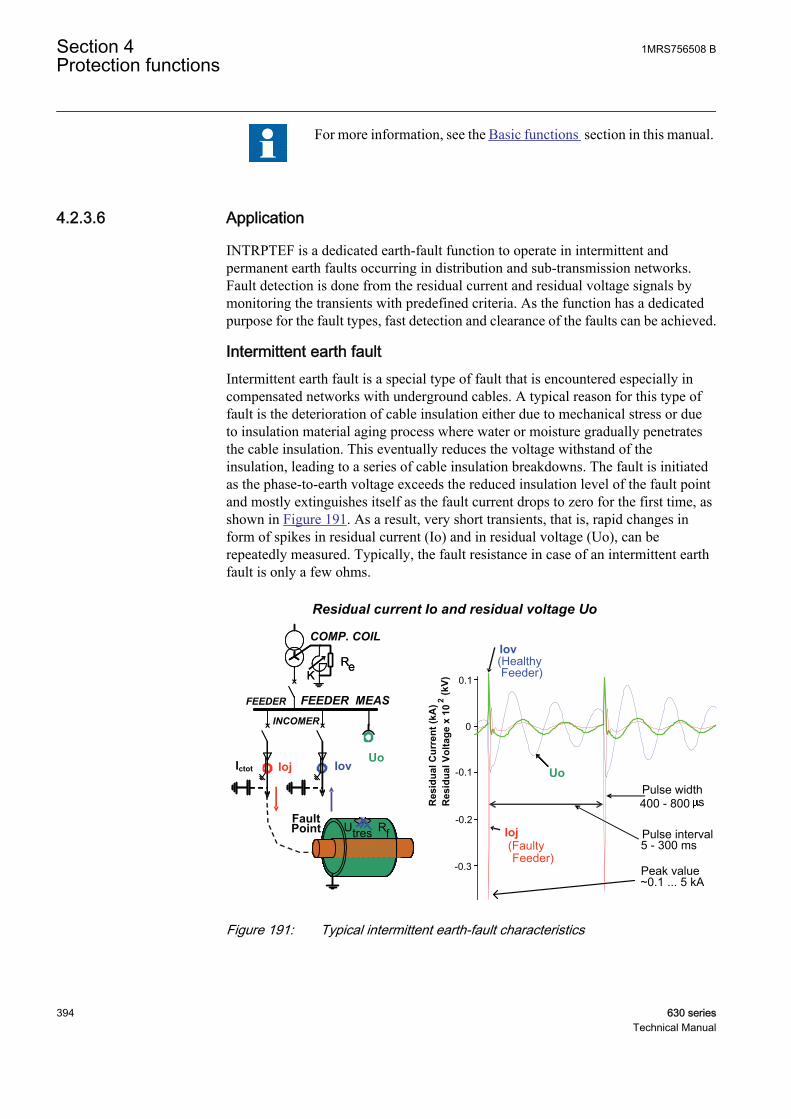
For more information, see the Basic functions section in this manual.
4.2.3.6 Application
INTRPTEF is a dedicated earth-fault function to operate in intermittent andpermanent earth faults occurring in distribution and sub-transmission networks.Fault detection is done from the residual current and residual voltage signals bymonitoring the transients with predefined criteria. As the function has a dedicatedpurpose for the fault types, fast detection and clearance of the faults can be achieved.
Intermittent earth faultIntermittent earth fault is a special type of fault that is encountered especially incompensated networks with underground cables. A typical reason for this type offault is the deterioration of cable insulation either due to mechanical stress or dueto insulation material aging process where water or moisture gradually penetratesthe cable insulation. This eventually reduces the voltage withstand of theinsulation, leading to a series of cable insulation breakdowns. The fault is initiatedas the phase-to-earth voltage exceeds the reduced insulation level of the fault pointand mostly extinguishes itself as the fault current drops to zero for the first time, asshown in Figure 191. As a result, very short transients, that is, rapid changes inform of spikes in residual current (Io) and in residual voltage (Uo), can berepeatedly measured. Typically, the fault resistance in case of an intermittent earthfault is only a few ohms.
Residual current Io and residual voltage Uo
FEEDER FEEDER MEAS
Iov
FaultPoint
KRe
-0.3
-0.2
-0.1
Res
idua
l Cur
rent
(kA
)R
esid
ual V
olta
ge x
10
2(k
V)
INCOMER
COMP. COIL
IojUo
KRe
0
0.1
Ioj(FaultyFeeder)
Iov(HealthyFeeder)
UoPulse width400 - 800 s
Pulse interval5 - 300 ms
Peak value~0.1 ... 5 kA
UtresUtres
Ictot
Rf
GUID-415078AD-21B3-4103-9622-712BB88F274A V2 EN
Figure 191: Typical intermittent earth-fault characteristics
Section 4 1MRS756508 BProtection functions
394 630 seriesTechnical Manual

Earth-fault transientsIn general, earth faults generate transients in currents and voltages. There areseveral factors that affect the magnitude and frequency of these transients, such asthe fault moment on the voltage wave, fault location, fault resistance and theparameters of the feeders and the supplying transformers. In the fault initiation, thevoltage of the faulty phase decreases and the corresponding capacitance isdischarged to earth (-> discharge transients). At the same time, the voltages of thehealthy phases increase and the related capacitances are charged (-> charge transient).
If the fault is permanent (non-transient) in nature, only the initial fault transient incurrent and voltage can be measured, whereas the intermittent fault createsrepetitive transients.
GUID-CC4ADDEA-EE11-4011-B184-F873473EBA9F V1 EN
Figure 192: Example of earth-fault transients, including discharge and chargetransient components, when a permanent fault occurs in a 20 kVnetwork in phase C
4.2.3.7 Signals
Table 416: INTRPTEF Input signals
Name Type Default DescriptionI3P GROUP
SIGNAL- Group signal for current inputs
U3P GROUPSIGNAL
- Group signal for voltage inputs
BLOCK BOOLEAN 0 Block of function
BLK_OPR BOOLEAN 0 Block of trip signal
BLK_ST BOOLEAN 0 Block of start signal
FR_TIMER BOOLEAN 0 Freeze operation timer
1MRS756508 B Section 4Protection functions
630 series 395Technical Manual

Table 417: INTRPTEF Output signals
Name Type DescriptionOPERATE BOOLEAN Operate signal
START BOOLEAN Start signal
FAULT_DIR INTEGER Detected fault direction
BLK_EF BOOLEAN Block signal for EF to indicate opposite directionpeaks
4.2.3.8 Settings
Table 418: INTRPTEF Group settings (basic)
Name Values (Range) Unit Step Default DescriptionDirectional mode Non-directional
ForwardReverse
- - Forward Directional mode (Non-directional,Forward,Reverse)
Voltage start value 0.005 - 0.500 pu 0.001 0.005 Voltage start value for transient EF
Operate delay time 0.04 - 1200.00 s 0.01 0.50 Operate delay time
Table 419: INTRPTEF Non group settings (basic)
Name Values (Range) Unit Step Default DescriptionOperation Off
On- - On Operation Off / On
Operation mode Intermittent EFTransient EF
- - Intermittent EF Operation criteria
Table 420: INTRPTEF Non group settings (advanced)
Name Values (Range) Unit Step Default DescriptionBase value Sel Res Residual Grp 1
Residual Grp 2Residual Grp 3
- - Residual Grp 1 Base value selector, residual
Peak counter limit 2 - 20 - 1 2 Min requirement for peak counter beforestart in IEF mode
Reset delay time 0.000 - 60.000 s 0.001 0.500 Reset delay time
Block EF reset time 0.025 - 1.000 s 0.001 0.025 Reset time of the BLK_EF output
4.2.3.9 Measured values
Table 421: INTRPTEF Measured values
Name Type Default DescriptionI0_AMPL REAL 0 Residual current amplitude
U0_AMPL REAL 0 Residual voltage amplitude
BLOCK BOOLEAN 0 Block of function
Table continues on next page
Section 4 1MRS756508 BProtection functions
396 630 seriesTechnical Manual
Name Type Default DescriptionBLK_OPR BOOLEAN 0 Block of trip signal
BLK_ST BOOLEAN 0 Block of start signal
FR_TIMER BOOLEAN 0 Freeze operation timer
4.2.3.10 Monitored data
Table 422: INTRPTEF Monitored data
Name Type Values (Range) Unit DescriptionOPERATE BOOLEAN 0=FALSE
1=TRUE- Operate signal
START BOOLEAN 0=FALSE1=TRUE
- Start signal
FAULT_DIR INTEGER 0=Unknown1=Forward2=Backward
- Detected fault direction
BLK_EF BOOLEAN 0=FALSE1=TRUE
- Block signal for EF toindicate oppositedirection peaks
I0_PEAK_IND BOOLEAN 0=FALSE1=TRUE
- Indicates residualcurrent peak
START_DUR REAL - % Ratio of start time /operate time
4.2.3.11 Technical data
Table 423: INTRPTEF Technical data
Characteristic ValueOperation accuracy (Uo criteria with transientprotection)
At the frequency f = fn
±1.5% of the set value or ±0.002 × Uo
Operate time accuracy ±1.0% of the set value or ±20 ms
Suppression of harmonics DFT: -50 dB at f = n × fn, where n = 2, 3, 4, 5
4.2.4 Admittance-based earth-fault protection EFPADM
4.2.4.1 Identification
Functional description IEC 61850identification
IEC 60617identification
ANSI/IEEE C37.2device number
Admittance-based earth-fault protection EFPADM Yo>-> 21YN
1MRS756508 B Section 4Protection functions
630 series 397Technical Manual
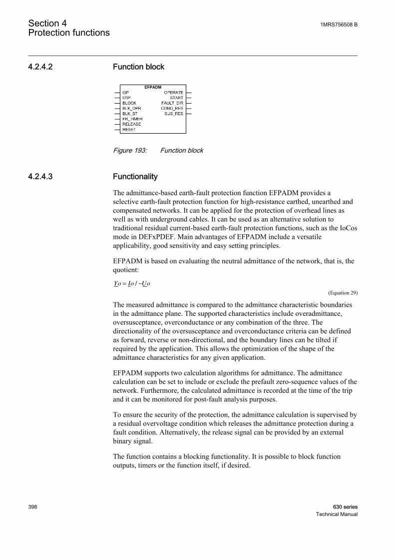
4.2.4.2 Function block
GUID-D0EF6621-9FAB-4950-9F06-A617BC8AED6C V2 EN
Figure 193: Function block
4.2.4.3 Functionality
The admittance-based earth-fault protection function EFPADM provides aselective earth-fault protection function for high-resistance earthed, unearthed andcompensated networks. It can be applied for the protection of overhead lines aswell as with underground cables. It can be used as an alternative solution totraditional residual current-based earth-fault protection functions, such as the IoCosmode in DEFxPDEF. Main advantages of EFPADM include a versatileapplicability, good sensitivity and easy setting principles.
EFPADM is based on evaluating the neutral admittance of the network, that is, thequotient:
Yo Io Uo= −/
GUID-F8BBC6A4-47BB-4FCB-A2E0-87FD46073AAF V1 EN (Equation 29)
The measured admittance is compared to the admittance characteristic boundariesin the admittance plane. The supported characteristics include overadmittance,oversusceptance, overconductance or any combination of the three. Thedirectionality of the oversusceptance and overconductance criteria can be definedas forward, reverse or non-directional, and the boundary lines can be tilted ifrequired by the application. This allows the optimization of the shape of theadmittance characteristics for any given application.
EFPADM supports two calculation algorithms for admittance. The admittancecalculation can be set to include or exclude the prefault zero-sequence values of thenetwork. Furthermore, the calculated admittance is recorded at the time of the tripand it can be monitored for post-fault analysis purposes.
To ensure the security of the protection, the admittance calculation is supervised bya residual overvoltage condition which releases the admittance protection during afault condition. Alternatively, the release signal can be provided by an externalbinary signal.
The function contains a blocking functionality. It is possible to block functionoutputs, timers or the function itself, if desired.
Section 4 1MRS756508 BProtection functions
398 630 seriesTechnical Manual
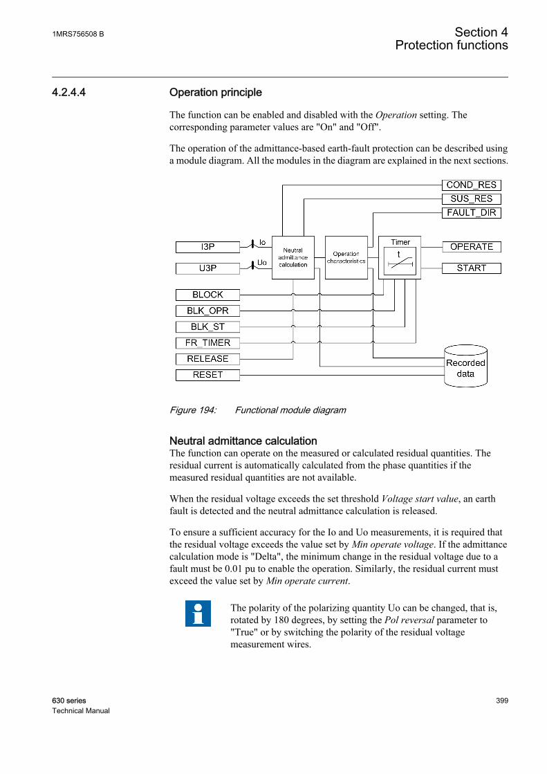
4.2.4.4 Operation principle
The function can be enabled and disabled with the Operation setting. Thecorresponding parameter values are "On" and "Off".
The operation of the admittance-based earth-fault protection can be described usinga module diagram. All the modules in the diagram are explained in the next sections.
GUID-25147744-FFCB-46DA-AAA9-421C7C437D8F V2 EN
Figure 194: Functional module diagram
Neutral admittance calculationThe function can operate on the measured or calculated residual quantities. Theresidual current is automatically calculated from the phase quantities if themeasured residual quantities are not available.
When the residual voltage exceeds the set threshold Voltage start value, an earthfault is detected and the neutral admittance calculation is released.
To ensure a sufficient accuracy for the Io and Uo measurements, it is required thatthe residual voltage exceeds the value set by Min operate voltage. If the admittancecalculation mode is "Delta", the minimum change in the residual voltage due to afault must be 0.01 pu to enable the operation. Similarly, the residual current mustexceed the value set by Min operate current.
The polarity of the polarizing quantity Uo can be changed, that is,rotated by 180 degrees, by setting the Pol reversal parameter to"True" or by switching the polarity of the residual voltagemeasurement wires.
1MRS756508 B Section 4Protection functions
630 series 399Technical Manual
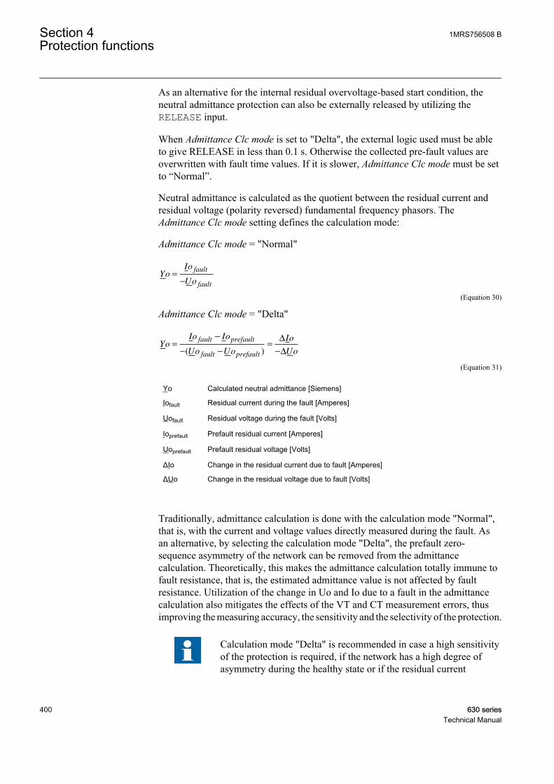
As an alternative for the internal residual overvoltage-based start condition, theneutral admittance protection can also be externally released by utilizing theRELEASE input.
When Admittance Clc mode is set to "Delta", the external logic used must be ableto give RELEASE in less than 0.1 s. Otherwise the collected pre-fault values areoverwritten with fault time values. If it is slower, Admittance Clc mode must be setto “Normal”.
Neutral admittance is calculated as the quotient between the residual current andresidual voltage (polarity reversed) fundamental frequency phasors. TheAdmittance Clc mode setting defines the calculation mode:
Admittance Clc mode = "Normal"
YoIo
Uo
fault
fault
=
−
GUID-B1E03EA1-E958-43F3-8A28-2D268138DE36 V1 EN (Equation 30)
Admittance Clc mode = "Delta"
YoIo Io
Uo Uo
Io
Uo
fault prefault
fault prefault
=
−
− −
=
−( )
∆
∆
GUID-B0611FF1-46FD-4E81-A11D-4721F0AF7BF8 V1 EN (Equation 31)
Yo Calculated neutral admittance [Siemens]
Iofault Residual current during the fault [Amperes]
Uofault Residual voltage during the fault [Volts]
Ioprefault Prefault residual current [Amperes]
Uoprefault Prefault residual voltage [Volts]
ΔIo Change in the residual current due to fault [Amperes]
ΔUo Change in the residual voltage due to fault [Volts]
Traditionally, admittance calculation is done with the calculation mode "Normal",that is, with the current and voltage values directly measured during the fault. Asan alternative, by selecting the calculation mode "Delta", the prefault zero-sequence asymmetry of the network can be removed from the admittancecalculation. Theoretically, this makes the admittance calculation totally immune tofault resistance, that is, the estimated admittance value is not affected by faultresistance. Utilization of the change in Uo and Io due to a fault in the admittancecalculation also mitigates the effects of the VT and CT measurement errors, thusimproving the measuring accuracy, the sensitivity and the selectivity of the protection.
Calculation mode "Delta" is recommended in case a high sensitivityof the protection is required, if the network has a high degree ofasymmetry during the healthy state or if the residual current
Section 4 1MRS756508 BProtection functions
400 630 seriesTechnical Manual
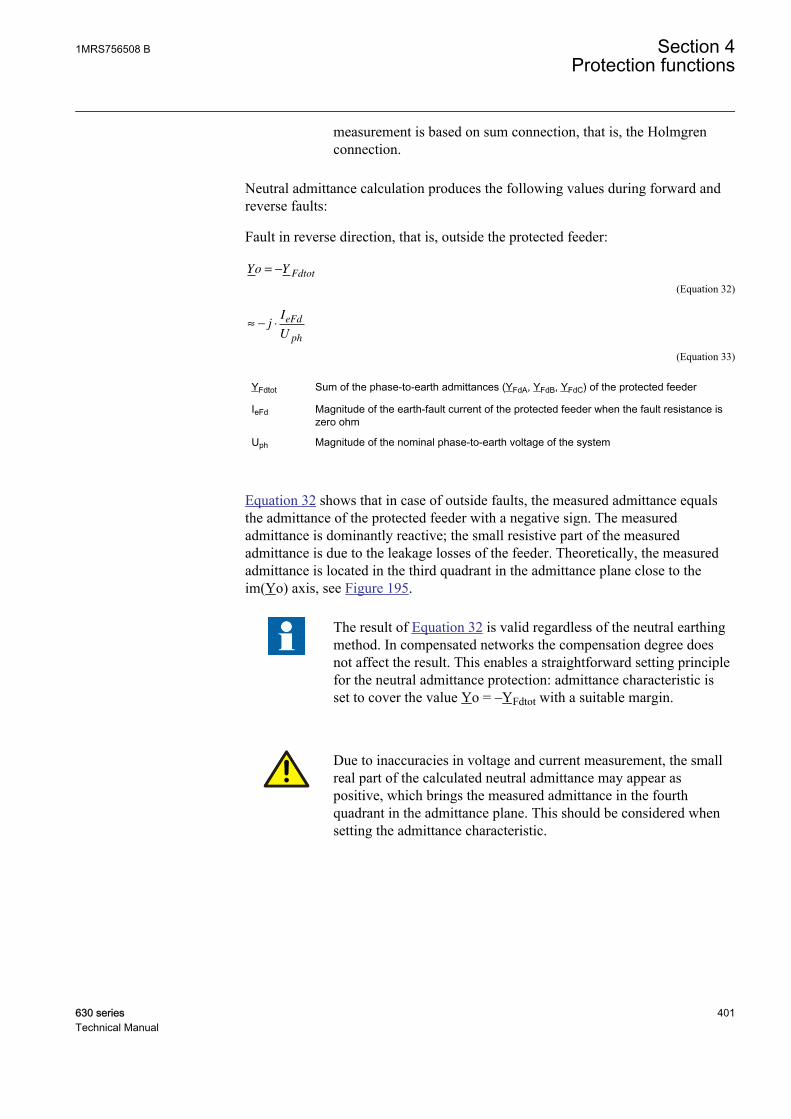
measurement is based on sum connection, that is, the Holmgrenconnection.
Neutral admittance calculation produces the following values during forward andreverse faults:
Fault in reverse direction, that is, outside the protected feeder:
Yo YFdtot
= −
GUID-B6E3F720-1F9F-4C11-A5DC-722838E8CCDA V1 EN (Equation 32)
≈ − ⋅jI
U
eFd
ph
GUID-19AA418B-9A0A-4CEE-8772-0CD3F595E63F V1 EN (Equation 33)
YFdtot Sum of the phase-to-earth admittances (YFdA, YFdB, YFdC) of the protected feeder
IeFd Magnitude of the earth-fault current of the protected feeder when the fault resistance iszero ohm
Uph Magnitude of the nominal phase-to-earth voltage of the system
Equation 32 shows that in case of outside faults, the measured admittance equalsthe admittance of the protected feeder with a negative sign. The measuredadmittance is dominantly reactive; the small resistive part of the measuredadmittance is due to the leakage losses of the feeder. Theoretically, the measuredadmittance is located in the third quadrant in the admittance plane close to theim(Yo) axis, see Figure 195.
The result of Equation 32 is valid regardless of the neutral earthingmethod. In compensated networks the compensation degree doesnot affect the result. This enables a straightforward setting principlefor the neutral admittance protection: admittance characteristic isset to cover the value Yo = –YFdtot with a suitable margin.
Due to inaccuracies in voltage and current measurement, the smallreal part of the calculated neutral admittance may appear aspositive, which brings the measured admittance in the fourthquadrant in the admittance plane. This should be considered whensetting the admittance characteristic.
1MRS756508 B Section 4Protection functions
630 series 401Technical Manual
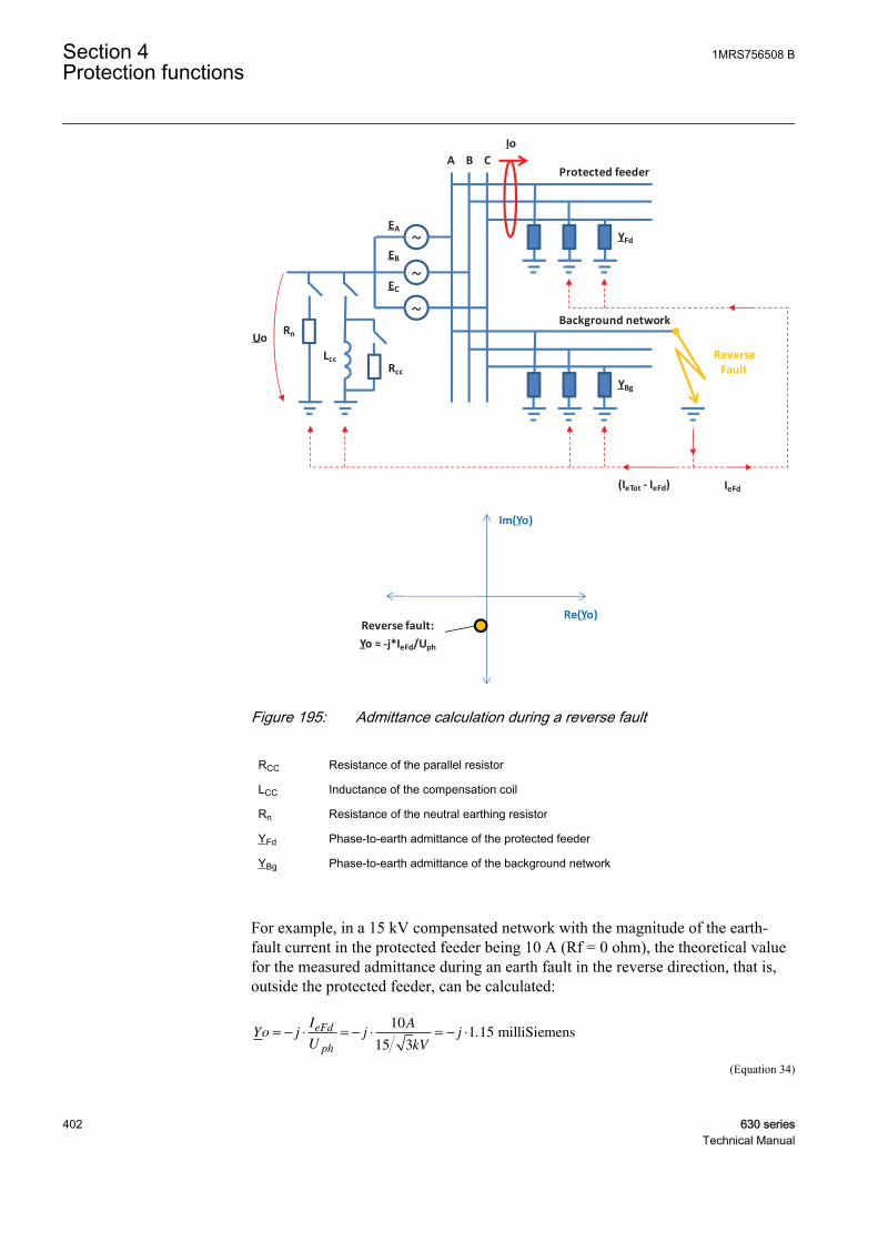
~
~
~
A B C
Uo
EA
EB
EC
Io
Reverse Fault
YFd
LccRcc
YBg
IeFd(IeTot - IeFd)
Rn
Protected feeder
Background network
Im(Yo)
Re(Yo)Reverse fault:
Yo ≈ -j*IeFd/Uph
GUID-B852BF65-9C03-49F2-8FA9-E958EB37FF13 V1 EN
Figure 195: Admittance calculation during a reverse fault
RCC Resistance of the parallel resistor
LCC Inductance of the compensation coil
Rn Resistance of the neutral earthing resistor
YFd Phase-to-earth admittance of the protected feeder
YBg Phase-to-earth admittance of the background network
For example, in a 15 kV compensated network with the magnitude of the earth-fault current in the protected feeder being 10 A (Rf = 0 ohm), the theoretical valuefor the measured admittance during an earth fault in the reverse direction, that is,outside the protected feeder, can be calculated:
Yo jI
Uj
A
kV
jeFd
ph
≈ − ⋅ = − ⋅ = − ⋅10
15 31 15. milliSiemens
GUID-E2A45F20-9821-436E-94F1-F0BFCB78A1E3 V1 EN (Equation 34)
Section 4 1MRS756508 BProtection functions
402 630 seriesTechnical Manual

The result is valid regardless of the neutral earthing method.
In this case, the resistive part of the measured admittance is due to leakage lossesof the protected feeder. As they are typically very small, the resistive part is closeto zero. Due to inaccuracies in the voltage and current measurement, the small realpart of the apparent neutral admittance may appear positive. This should beconsidered in the setting of the admittance characteristic.
Fault in the forward direction, that is, inside the protected feeder:
Unearthed network:
Yo YBgtot
=
GUID-5F1D2145-3C0F-4F8F-9E17-5B88C1822566 V1 EN (Equation 35)
≈ ⋅−
jI I
U
eTot eFd
ph
GUID-0B7C9BA9-B41B-4825-9C1B-F8F36640B693 V1 EN (Equation 36)
Compensated network:
Yo Y YBgtot CC
= +
GUID-F3810944-D0E1-4C9A-A99B-8409F4D3CF05 V1 EN (Equation 37)
≈
+ ⋅ ⋅ −( ) −( )I j I K I
U
Rcc eTot eFd
ph
1
GUID-208EA80C-62B6-46E0-8A5B-DC425F0FE122 V1 EN (Equation 38)
High-resistance earthed network:
Yo Y YBgtot Rn
= +
GUID-F91DA4E4-F439-4BFA-AA0D-5839B1574946 V1 EN (Equation 39)
≈
+ ⋅ −( )I j I I
U
Rn eTot eFd
ph
GUID-CAA0C492-20CF-406C-80AC-8301375AB454 V1 EN (Equation 40)
YBgtot Sum of the phase-to-earth admittances (YBgA, YBgB, YBgC) of the background network
YCC Admittance of the earthing arrangement (compensation coil and parallel resistor)
IRcc Rated current of the parallel resistor
IeFd Magnitude of the earth-fault current of the protected feeder when the fault resistance is zero ohm
IeTot Magnitude of the uncompensated earth-fault current of the network when Rf is zero ohm
K Compensation degree, K = 1 full resonance, K<1 undercompensated, K>1 overcompensated
IRn Rated current of the neutral earthing resistor
Equation 35 shows that in case of a fault inside the protected feeder in unearthednetworks, the measured admittance equals the admittance of the background
1MRS756508 B Section 4Protection functions
630 series 403Technical Manual
network. The admittance is dominantly reactive; the small resistive part of themeasured admittance is due to the leakage losses of the background network.Theoretically, the measured admittance is located in the first quadrant in theadmittance plane, close to the im(Yo) axis, see Figure 196.
Equation 37 shows that in case of a fault inside the protected feeder incompensated networks, the measured admittance equals the admittance of thebackground network and the coil including the parallel resistor. Basically, thecompensation degree determines the imaginary part of the measured admittanceand the resistive part is due to the parallel resistor of the coil and the leakage lossesof the background network and the losses of the coil. Theoretically, the measuredadmittance is located in the first or fourth quadrant in the admittance plane,depending on the compensation degree, see Figure 196.
Before the parallel resistor is connected, the resistive part of themeasured admittance is due to the leakage losses of the backgroundnetwork and the losses of the coil. As they are typically small, theresistive part may not be sufficiently large to secure thediscrimination of the fault and its direction based on the measuredconductance. This and the rating and the operation logic of theparallel resistor should be considered when setting the admittancecharacteristic in compensated networks.
Equation 39 shows that in case of a fault inside the protected feeder in high-resistance earthed systems, the measured admittance equals the admittance of thebackground network and the neutral earthing resistor. Basically, the imaginary partof the measured admittance is due to the phase-to-earth capacitances of thebackground network, and the resistive part is due to the neutral earthing resistorand the leakage losses of the background network. Theoretically, the measuredadmittance is located in the first quadrant in the admittance plane, see Figure 196.
Section 4 1MRS756508 BProtection functions
404 630 seriesTechnical Manual

Im(Yo)
Re(Yo)
Forward fault, unearthed network:
Yo ≈ j*(IeTot-IeFd)/Uph
Forward fault, compensated network:
Yo ≈ (Ircc + j*(IeTot*(1-K) - IeFd))/Uph
Under-comp. (K<1)
Resonance (K=1)
Over-comp. (K>1)
Reverse fault:
Yo ≈ -j*IeFd/Uph
Forward fault, high resistance earthed network:
Yo ≈ (IRn+j*(IeTot-IeFd))/Uph
~
~
~
A B C
EA
EB
EC
Io
Forward Fault
LccRcc
IeFdIeTot
(IeTot - IeFd)
Uo Rn
Protected feeder
Background network
YFd
YBg
GUID-5DB19698-38F9-433E-954F-4EBDBA5B63BD V1 EN
Figure 196: Admittance calculation during a forward fault
When the network is fully compensated in compensated networks,theoretically during a forward fault the imaginary part of themeasured admittance equals the susceptance of the protected feederwith a negative sign. The discrimination between a forward andreverse fault must therefore be based on the real part of themeasured admittance, that is, conductance. Thus, the best
1MRS756508 B Section 4Protection functions
630 series 405Technical Manual
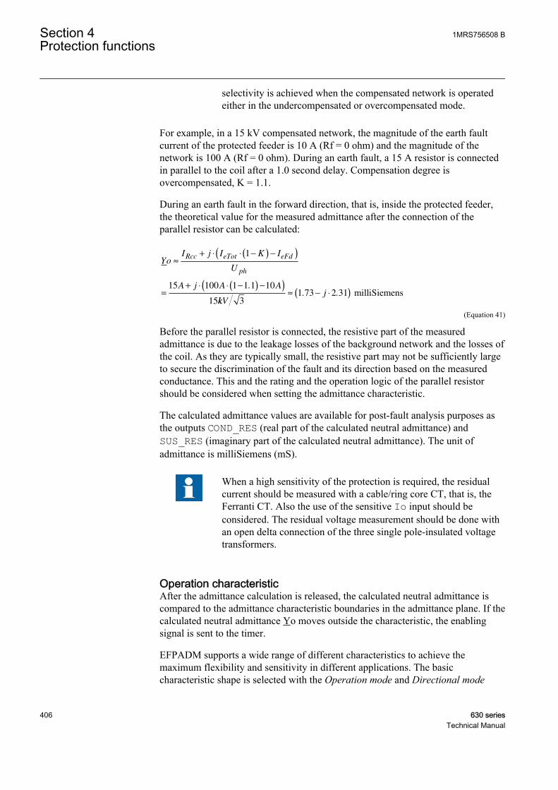
selectivity is achieved when the compensated network is operatedeither in the undercompensated or overcompensated mode.
For example, in a 15 kV compensated network, the magnitude of the earth faultcurrent of the protected feeder is 10 A (Rf = 0 ohm) and the magnitude of thenetwork is 100 A (Rf = 0 ohm). During an earth fault, a 15 A resistor is connectedin parallel to the coil after a 1.0 second delay. Compensation degree isovercompensated, K = 1.1.
During an earth fault in the forward direction, that is, inside the protected feeder,the theoretical value for the measured admittance after the connection of theparallel resistor can be calculated:
YoI j I K I
U
A j A A
Rcc eTot eFd
ph
≈
+ ⋅ ⋅ −( ) −( )
=
+ ⋅ ⋅ −( ) −( )
1
15 100 1 1 1 10
15
.
kkVj
31 73 2 31≈ − ⋅( ). . milliSiemens
GUID-8763BA04-22DC-4B93-B52D-1E8FD44A68B9 V1 EN (Equation 41)
Before the parallel resistor is connected, the resistive part of the measuredadmittance is due to the leakage losses of the background network and the losses ofthe coil. As they are typically small, the resistive part may not be sufficiently largeto secure the discrimination of the fault and its direction based on the measuredconductance. This and the rating and the operation logic of the parallel resistorshould be considered when setting the admittance characteristic.
The calculated admittance values are available for post-fault analysis purposes asthe outputs COND_RES (real part of the calculated neutral admittance) andSUS_RES (imaginary part of the calculated neutral admittance). The unit ofadmittance is milliSiemens (mS).
When a high sensitivity of the protection is required, the residualcurrent should be measured with a cable/ring core CT, that is, theFerranti CT. Also the use of the sensitive Io input should beconsidered. The residual voltage measurement should be done withan open delta connection of the three single pole-insulated voltagetransformers.
Operation characteristicAfter the admittance calculation is released, the calculated neutral admittance iscompared to the admittance characteristic boundaries in the admittance plane. If thecalculated neutral admittance Yo moves outside the characteristic, the enablingsignal is sent to the timer.
EFPADM supports a wide range of different characteristics to achieve themaximum flexibility and sensitivity in different applications. The basiccharacteristic shape is selected with the Operation mode and Directional mode
Section 4 1MRS756508 BProtection functions
406 630 seriesTechnical Manual
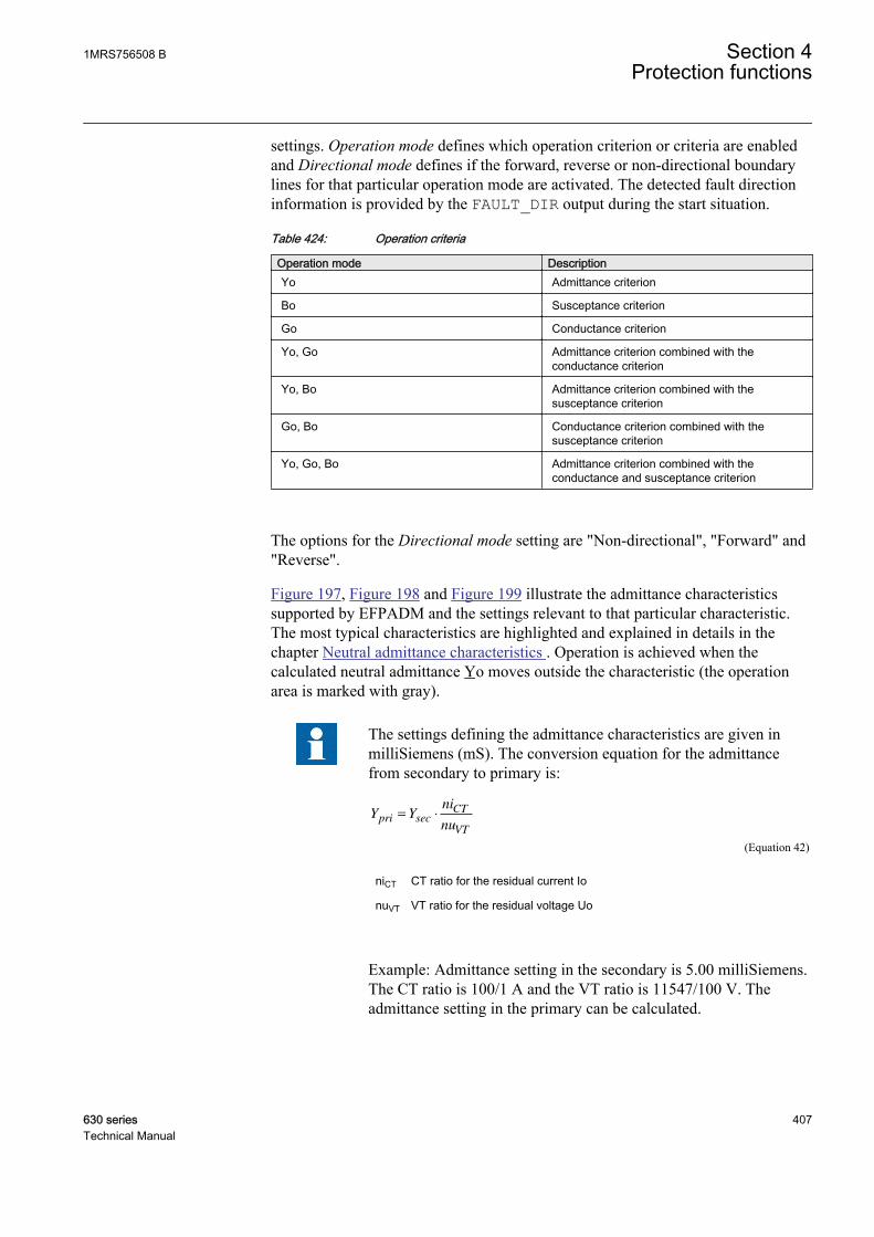
settings. Operation mode defines which operation criterion or criteria are enabledand Directional mode defines if the forward, reverse or non-directional boundarylines for that particular operation mode are activated. The detected fault directioninformation is provided by the FAULT_DIR output during the start situation.
Table 424: Operation criteria
Operation mode DescriptionYo Admittance criterion
Bo Susceptance criterion
Go Conductance criterion
Yo, Go Admittance criterion combined with theconductance criterion
Yo, Bo Admittance criterion combined with thesusceptance criterion
Go, Bo Conductance criterion combined with thesusceptance criterion
Yo, Go, Bo Admittance criterion combined with theconductance and susceptance criterion
The options for the Directional mode setting are "Non-directional", "Forward" and"Reverse".
Figure 197, Figure 198 and Figure 199 illustrate the admittance characteristicssupported by EFPADM and the settings relevant to that particular characteristic.The most typical characteristics are highlighted and explained in details in thechapter Neutral admittance characteristics . Operation is achieved when thecalculated neutral admittance Yo moves outside the characteristic (the operationarea is marked with gray).
The settings defining the admittance characteristics are given inmilliSiemens (mS). The conversion equation for the admittancefrom secondary to primary is:
Y Yni
nupri
CT
VT
= ⋅sec
GUID-2F4EAEF7-0D92-477F-8D4C-00C7BEDE04CB V1 EN (Equation 42)
niCT CT ratio for the residual current Io
nuVT VT ratio for the residual voltage Uo
Example: Admittance setting in the secondary is 5.00 milliSiemens.The CT ratio is 100/1 A and the VT ratio is 11547/100 V. Theadmittance setting in the primary can be calculated.
1MRS756508 B Section 4Protection functions
630 series 407Technical Manual
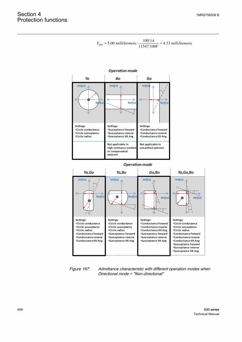
Y milliSiemensA
VmilliSiemenspri = ⋅ =5 00
100 1
11547 1004 33. .
GUID-9CFD2291-9894-4D04-9499-DF38F1F64D59 V1 EN
Operation mode
Yo Bo Go
Im(Yo)
Settings:•Circle conductance•Circle susceptance•Circle radius
Im(Yo)
Settings:•Susceptance forward•Susceptance reverse•Susceptance tilt Ang
Re(Yo)
Settings:•Conductance forward•Conductance reverse•Conductance tilt Ang
Re(Yo)
Im(Yo)
Re(Yo)
Not applicable in high resistance earthed or compensated systems!
Not applicable in unearthed systems!
Operation mode
Yo,Go Yo,Bo Go,Bo Yo,Go,Bo
Settings:•Circle conductance•Circle susceptance•Circle radius•Conductance forward•Conductance reverse•Conductance tilt Ang
Im(Yo) Im(Yo)
Settings:•Circle conductance•Circle susceptance•Circle radius•Susceptance forward•Susceptance reverse•Susceptance tilt Ang
Re(Yo)
Im(Yo)
Settings:•Conductance forward•Conductance reverse•Conductance tilt Ang•Susceptance forward•Susceptance reverse•Susceptance tilt Ang
Re(Yo)
Im(Yo)
Settings:•Circle conductance•Circle susceptance•Circle radius•Conductance forward•Conductance reverse•Conductance tilt Ang•Susceptance forward•Susceptance reverse•Susceptance tilt Ang
Re(Yo) Re(Yo)
GUID-FD8DAB15-CA27-40B0-9A43-FCF0881DB21E V1 EN
Figure 197: Admittance characteristic with different operation modes whenDirectional mode = "Non-directional"
Section 4 1MRS756508 BProtection functions
408 630 seriesTechnical Manual

Operation mode
Yo Bo Go
Settings:•Circle conductance•Circle susceptance•Circle radius
Settings:•Susceptance forward•Susceptance tilt Ang
Settings:•Conductance forward•Conductance tilt Ang
Im(Yo)
Re(Yo) Re(Yo)
Im(Yo)Im(Yo)
Re(Yo)
Not applicable in high resistance earthed or compensated systems!
Not applicable in unearthed systems!
Operation mode
Yo,Go Yo,Bo Go,Bo Yo,Go,Bo
Settings:•Circle conductance•Circle susceptance•Circle radius•Conductance forward•Conductance tilt Ang
Settings:•Circle conductance•Circle susceptance•Circle radius•Susceptance forward•Susceptance tilt Ang
Settings:•Conductance forward•Conductance tilt Ang•Susceptance forward•Susceptance tilt Ang
Settings:•Circle conductance•Circle susceptance•Circle radius•Conductance forward•Conductance tilt Ang•Susceptance forward•Susceptance tilt Ang
Im(Yo) Im(Yo)
Re(Yo)
Im(Yo)
Re(Yo)
Im(Yo)
Re(Yo) Re(Yo)
GUID-7EDB14B9-64B4-449C-9290-70A4CC2D588F V1 EN
Figure 198: Admittance characteristic with different operation modes whenDirectional mode = "Forward"
1MRS756508 B Section 4Protection functions
630 series 409Technical Manual
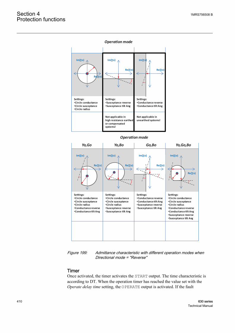
Operation mode
Settings:•Circle conductance•Circle susceptance•Circle radius
Settings:•Susceptance reverse•Susceptance tilt Ang
Settings:•Conductance reverse•Conductance tilt Ang
Im(Yo)
Re(Yo) Re(Yo)
Im(Yo)Im(Yo)
Re(Yo)
Not applicable in high resistance earthed or compensated systems!
Not applicable in unearthed systems!
Operation mode
Yo,Go Yo,Bo Go,Bo Yo,Go,Bo
Settings:•Circle conductance•Circle susceptance•Circle radius•Conductance reverse•Conductance tilt Ang
Settings:•Circle conductance•Circle susceptance•Circle radius•Susceptance reverse•Susceptance tilt Ang
Settings:•Conductance reverse•Conductance tilt Ang•Susceptance reverse•Susceptance tilt Ang
Settings:•Circle conductance•Circle susceptance•Circle radius•Conductance reverse•Conductance tilt Ang•Susceptance reverse•Susceptance tilt Ang
Im(Yo) Im(Yo)
Re(Yo)
Im(Yo)
Re(Yo)
Im(Yo)
Re(Yo)
Re(Yo)
GUID-C847609F-E261-4265-A1D9-3C449F8672A1 V1 EN
Figure 199: Admittance characteristic with different operation modes whenDirectional mode = "Reverse"
TimerOnce activated, the timer activates the START output. The time characteristic isaccording to DT. When the operation timer has reached the value set with theOperate delay time setting, the OPERATE output is activated. If the fault
Section 4 1MRS756508 BProtection functions
410 630 seriesTechnical Manual
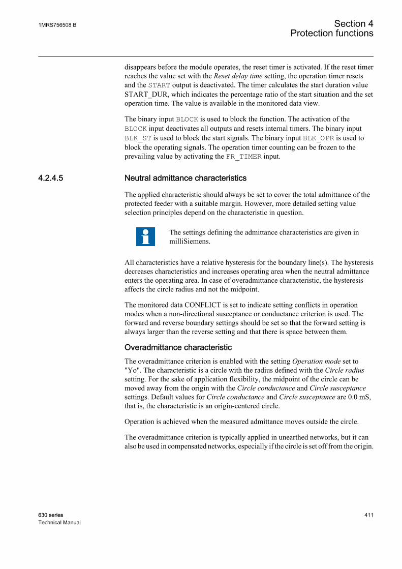
disappears before the module operates, the reset timer is activated. If the reset timerreaches the value set with the Reset delay time setting, the operation timer resetsand the START output is deactivated. The timer calculates the start duration valueSTART_DUR, which indicates the percentage ratio of the start situation and the setoperation time. The value is available in the monitored data view.
The binary input BLOCK is used to block the function. The activation of theBLOCK input deactivates all outputs and resets internal timers. The binary inputBLK_ST is used to block the start signals. The binary input BLK_OPR is used toblock the operating signals. The operation timer counting can be frozen to theprevailing value by activating the FR_TIMER input.
4.2.4.5 Neutral admittance characteristics
The applied characteristic should always be set to cover the total admittance of theprotected feeder with a suitable margin. However, more detailed setting valueselection principles depend on the characteristic in question.
The settings defining the admittance characteristics are given inmilliSiemens.
All characteristics have a relative hysteresis for the boundary line(s). The hysteresisdecreases characteristics and increases operating area when the neutral admittanceenters the operating area. In case of overadmittance characteristic, the hysteresisaffects the circle radius and not the midpoint.
The monitored data CONFLICT is set to indicate setting conflicts in operationmodes when a non-directional susceptance or conductance criterion is used. Theforward and reverse boundary settings should be set so that the forward setting isalways larger than the reverse setting and that there is space between them.
Overadmittance characteristicThe overadmittance criterion is enabled with the setting Operation mode set to"Yo". The characteristic is a circle with the radius defined with the Circle radiussetting. For the sake of application flexibility, the midpoint of the circle can bemoved away from the origin with the Circle conductance and Circle susceptancesettings. Default values for Circle conductance and Circle susceptance are 0.0 mS,that is, the characteristic is an origin-centered circle.
Operation is achieved when the measured admittance moves outside the circle.
The overadmittance criterion is typically applied in unearthed networks, but it canalso be used in compensated networks, especially if the circle is set off from the origin.
1MRS756508 B Section 4Protection functions
630 series 411Technical Manual
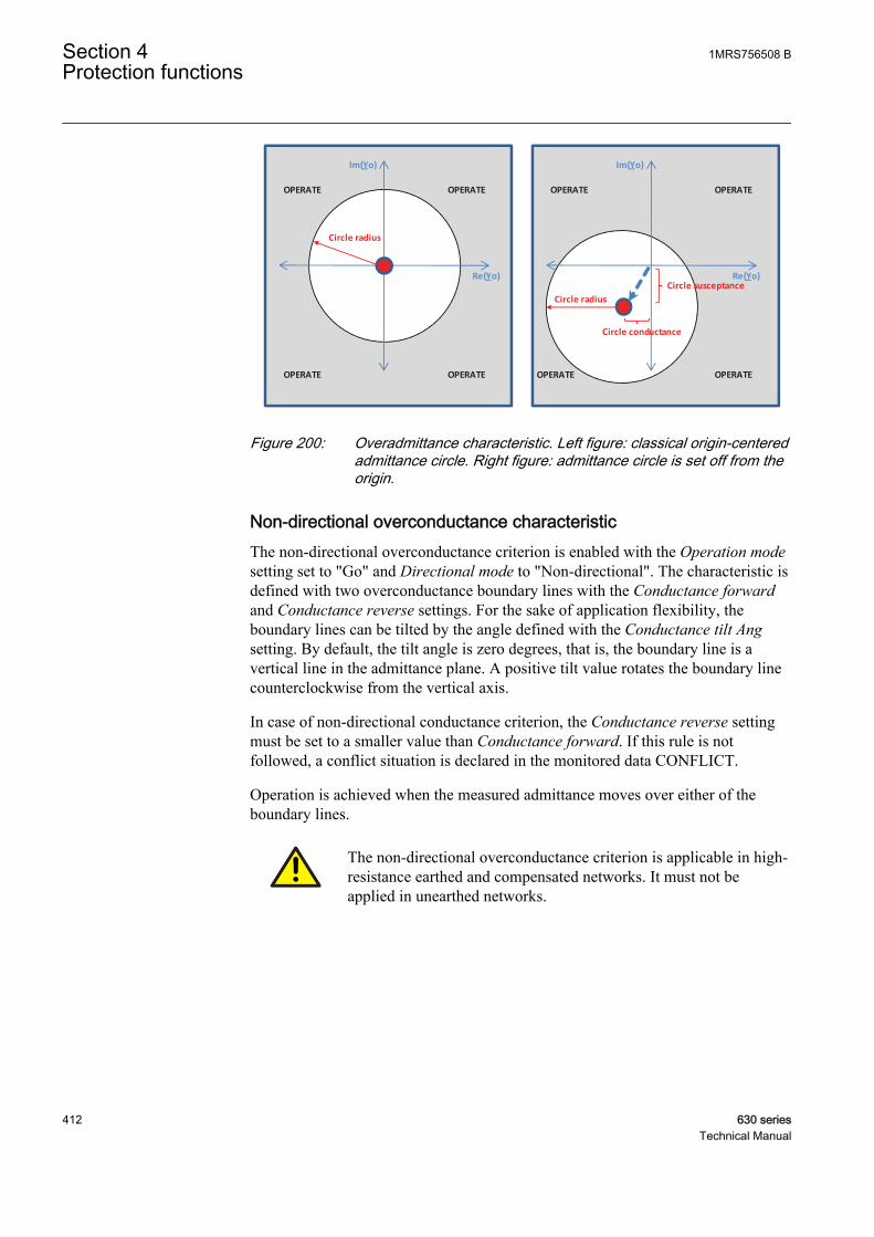
Im(Yo)
Re(Yo)
Circle radius
OPERATEOPERATE
OPERATE OPERATE
Im(Yo)
Re(Yo)
Circle radius
OPERATEOPERATE
OPERATE OPERATE
Circle conductance
Circle susceptance
GUID-AD789221-4073-4587-8E82-CD9BBD672AE0 V1 EN
Figure 200: Overadmittance characteristic. Left figure: classical origin-centeredadmittance circle. Right figure: admittance circle is set off from theorigin.
Non-directional overconductance characteristicThe non-directional overconductance criterion is enabled with the Operation modesetting set to "Go" and Directional mode to "Non-directional". The characteristic isdefined with two overconductance boundary lines with the Conductance forwardand Conductance reverse settings. For the sake of application flexibility, theboundary lines can be tilted by the angle defined with the Conductance tilt Angsetting. By default, the tilt angle is zero degrees, that is, the boundary line is avertical line in the admittance plane. A positive tilt value rotates the boundary linecounterclockwise from the vertical axis.
In case of non-directional conductance criterion, the Conductance reverse settingmust be set to a smaller value than Conductance forward. If this rule is notfollowed, a conflict situation is declared in the monitored data CONFLICT.
Operation is achieved when the measured admittance moves over either of theboundary lines.
The non-directional overconductance criterion is applicable in high-resistance earthed and compensated networks. It must not beapplied in unearthed networks.
Section 4 1MRS756508 BProtection functions
412 630 seriesTechnical Manual
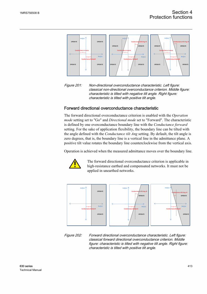
Re(Yo)
Im(Yo)
Conductance forward
Conductance reverse
Conductance tilt Ang <0
Re(Yo)
Im(Yo)
Conductance tilt Ang >0
Re(Yo)
Im(Yo)
OPERATEOPERATE
OPERATE OPERATE
OPERATEOPERATE
OPERATE OPERATE
OPERATEOPERATE
OPERATE OPERATE
Conductance forward
Conductance reverse
Conductance forward
Conductance reverse
GUID-F5487D41-6B8E-4A7A-ABD3-EBF7254ADC4C V1 EN
Figure 201: Non-directional overconductance characteristic. Left figure:classical non-directional overconductance criterion. Middle figure:characteristic is tilted with negative tilt angle. Right figure:characteristic is tilted with positive tilt angle.
Forward directional overconductance characteristicThe forward directional overconductance criterion is enabled with the Operationmode setting set to "Go" and Directional mode set to "Forward". The characteristicis defined by one overconductance boundary line with the Conductance forwardsetting. For the sake of application flexibility, the boundary line can be tilted withthe angle defined with the Conductance tilt Ang setting. By default, the tilt angle iszero degrees, that is, the boundary line is a vertical line in the admittance plane. Apositive tilt value rotates the boundary line counterclockwise from the vertical axis.
Operation is achieved when the measured admittance moves over the boundary line.
The forward directional overconductance criterion is applicable inhigh-resistance earthed and compensated networks. It must not beapplied in unearthed networks.
Re(Yo)
Im(Yo)
Conductance forward
Conductance tilt Ang <0
Re(Yo)
Im(Yo)
Conductance tilt Ang >0
Re(Yo)
Im(Yo)
OPERATE
OPERATE
OPERATE
OPERATE
OPERATE
OPERATE
Conductance forward Conductance forward
GUID-43F312AA-874A-4CE7-ABFE-D76BA70B7A5D V1 EN
Figure 202: Forward directional overconductance characteristic. Left figure:classical forward directional overconductance criterion. Middlefigure: characteristic is tilted with negative tilt angle. Right figure:characteristic is tilted with positive tilt angle.
1MRS756508 B Section 4Protection functions
630 series 413Technical Manual

Forward directional oversusceptance characteristicThe forward directional oversusceptance criterion is enabled with the Operationmode setting set to "Bo" and Directional mode to "Forward". The characteristic isdefined by one oversusceptance boundary line with the Susceptance forwardsetting. For the sake of application flexibility, the boundary line can be tilted by theangle defined with the Susceptance tilt Ang setting. By default, the tilt angle is zerodegrees, that is, the boundary line is a horizontal line in the admittance plane. Apositive tilt value rotates the boundary line counterclockwise from the horizontal axis
Operation is achieved when the measured admittance moves over the boundary line.
The forward directional oversusceptance criterion is applicable inunearthed networks. It must not be applied in compensated networks.
Re(Yo) Re(Yo)Re(Yo)
Im(Yo)
Susceptance forward
Re(Yo)
Im(Yo)
Re(Yo)
Im(Yo)
OPERATEOPERATEOPERATEOPERATE OPERATEOPERATE
Susceptance forward Susceptance forward
Susceptance tilt Ang >0
Susceptance tilt Ang <0
GUID-43B0F2F9-38CE-4F94-8381-0F20A0668AB1 V1 EN
Figure 203: Forward directional oversusceptance characteristic. Left figure:classical forward directional oversusceptance criterion. Middlefigure: characteristic is tilted with negative tilt angle. Right figure:characteristic is tilted with positive tilt angle.
Combined overadmittance and overconductance characteristicThe combined overadmittance and overconductance criterion is enabled with theOperation mode setting set to "Yo, Go" and Directional mode to "Non-directional".The characteristic is a combination of a circle with the radius defined with theCircle radius setting and two overconductance boundary lines with the settingsConductance forward and Conductance reverse. For the sake of applicationflexibility, the midpoint of the circle can be moved from the origin with the Circleconductance and Circle susceptance settings. Also the boundary lines can be tiltedby the angle defined with the Conductance tilt Ang setting. By default, the Circleconductance and Circle susceptance are 0.0 mS and Conductance tilt Ang equalszero degrees, that is, the characteristic is a combination of an origin-centered circlewith two vertical overconductance boundary lines. A positive tilt value for theConductance tilt Ang setting rotates boundary lines counterclockwise from thevertical axis.
In case of the non-directional conductance criterion, the Conductance reversesetting must be set to a smaller value than Conductance forward. If this rule is not
Section 4 1MRS756508 BProtection functions
414 630 seriesTechnical Manual

followed, a conflict situation is declared in the monitored data CONFLICT.If thisrule is not followed, a conflict situation is declared in the monitored data CONFLICT.
Operation is achieved when the measured admittance moves outside thecharacteristic.
The combined overadmittance and overconductance criterion is applicable inunearthed, high-resistance earthed and compensated networks or in systems wherethe system earthing may temporarily change during normal operation fromcompensated network to unearthed system.
Compared to the overadmittance criterion, the combined characteristic improvessensitivity in high-resistance earthed and compensated networks. Compared to thenon-directional overconductance criterion, the combined characteristic enables theprotection to be applied also in unearthed systems.
Re(Yo)
Im(Yo) Im(Yo)
OPERATEOPERATE
Re(Yo)Circle radius
Circle radiusCircle conductance
Circle susceptance
Conductance forward
Conductance reverse
OPERATEOPERATE
Conductance forward
Conductance reverse
OPERATEOPERATE
OPERATEOPERATE
Conductance tilt Ang
GUID-7AE09721-1428-4392-9142-A6D39FD4C287 V1 EN
Figure 204: Combined overadmittance and overconductance characteristic.Left figure: classical origin-centered admittance circle combinedwith two overconductance boundary lines. Right figure: admittancecircle is set off from the origin.
Combined overconductance and oversusceptance characteristicThe combined overconductance and oversusceptance criterion is enabled with theOperation mode setting set to "Go, Bo".
By setting Directional mode to "Forward", the characteristic is a combination oftwo boundary lines with the settings Conductance forward and Susceptanceforward. See Figure 205.
By setting Directional mode to "Non-directional", the characteristic is acombination of four boundary lines with the settings Conductance forward,Conductance reverse, Susceptance forward and Susceptance reverse. See Figure206.
1MRS756508 B Section 4Protection functions
630 series 415Technical Manual

For the sake of application flexibility, the boundary lines can be tilted by the angledefined with the Conductance tilt Ang and Susceptance tilt Ang settings. Bydefault, the tilt angles are zero degrees, that is, the boundary lines are straight linesin the admittance plane. A positive Conductance tilt Ang value rotates theoverconductance boundary line counterclockwise from the vertical axis. A positiveSusceptance tilt Ang value rotates the oversusceptance boundary linecounterclockwise from the horizontal axis.
In case of the non-directional conductance and susceptance criteria, theConductance reverse setting must be set to a smaller value than Conductanceforward and the Susceptance reverse setting must be set to a smaller value thanSusceptance forward. If this rule is not followed, a conflict situation is declared inthe monitored data CONFLICT.
Operation is achieved when the measured admittance moves outside thecharacteristic.
The combined overconductance and oversusceptance criterion is applicable in high-resistance earthed, unearthed and compensated networks or in the systems wherethe system earthing may temporarily change during normal operation fromcompensated to unearthed system.
Re(Yo)
Im(Yo)
Susceptance forward
OPERATEOPERATE
Conductance forward
Conductance tilt Ang >0
OPERATE
Re(Yo)
Im(Yo)
Susceptance forward
OPERATE
OPERATE
Conductance forward
OPERATE
Susceptance tilt Ang <0
GUID-1A21391B-A053-432B-8A44-7D2BF714C52D V1 EN
Figure 205: Combined forward directional overconductance and forwarddirectional oversusceptance characteristic. Left figure: theConductance tilt Ang and Susceptance tilt Ang settings equal zerodegrees. Right figure: the setting Conductance tilt Ang > 0 degreesand the setting Susceptance tilt Ang < 0 degrees.
Section 4 1MRS756508 BProtection functions
416 630 seriesTechnical Manual
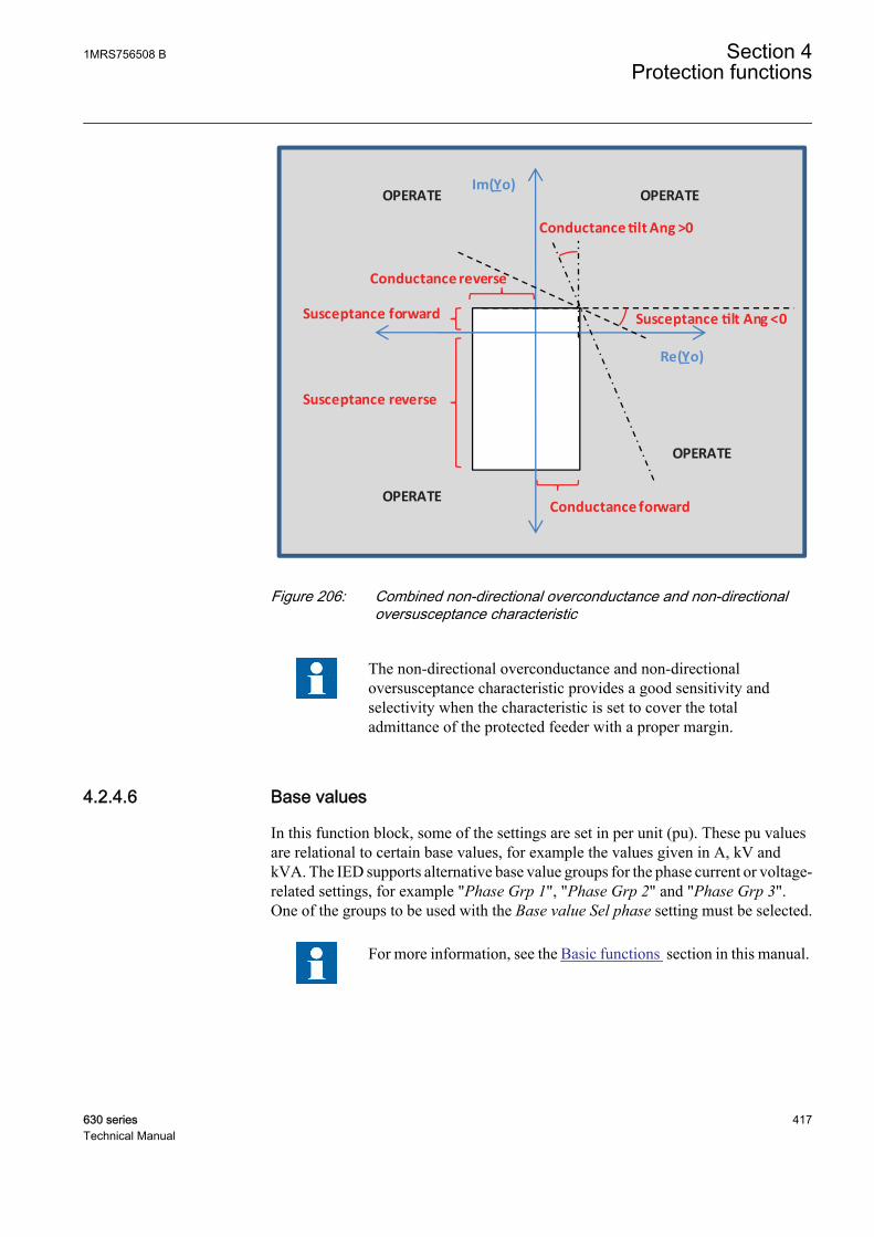
Re(Yo)
Im(Yo)
Susceptance forward
OPERATEOPERATE
Conductance forward
OPERATE
Susceptance reverse
OPERATE
Conductance tilt Ang >0
Susceptance tilt Ang <0
Conductance reverse
GUID-0A34B498-4FDB-44B3-A539-BAE8F10ABDF0 V1 EN
Figure 206: Combined non-directional overconductance and non-directionaloversusceptance characteristic
The non-directional overconductance and non-directionaloversusceptance characteristic provides a good sensitivity andselectivity when the characteristic is set to cover the totaladmittance of the protected feeder with a proper margin.
4.2.4.6 Base values
In this function block, some of the settings are set in per unit (pu). These pu valuesare relational to certain base values, for example the values given in A, kV andkVA. The IED supports alternative base value groups for the phase current or voltage-related settings, for example "Phase Grp 1", "Phase Grp 2" and "Phase Grp 3".One of the groups to be used with the Base value Sel phase setting must be selected.
For more information, see the Basic functions section in this manual.
1MRS756508 B Section 4Protection functions
630 series 417Technical Manual

4.2.4.7 Recorded data
The required information for a later fault analysis is recorded when the recordingfunction of EFPADM is triggered. The triggering occurs at the moment of a trip ora falling edge of the start signal.
Table 425: EFPADM recorded data
Parameter name Descriptionn Recording time Recording date and time
n FAULT_DIR Detected fault direction
n COND_RES (Go) Real part of neutral admittance
n SUS_RES (Bo) Imaginary part of neutral admittance
n I_AMPL_RES Pre Flt Magnitude of prefault residual current
n I_ANGL_RES Pre Flt Angle of prefault residual current
n U_AMPL_RES Pre Flt Magnitude of prefault residual voltage
n U_ANGL_RES Pre Flt Angle of prefault residual voltage
n I_AMPL_RES fault Magnitude of fault state residual current
n I_ANGL_RES fault Angle of fault state residual current
n U_AMPL_RES fault Magnitude of fault state residual voltage
n U_ANGL_RES fault Angle of fault state residual voltage
n START_DUR Ratio of started time / operation time
The triggering moment of the recorded data is stored in the n Recording timeparameter. The n COND_RES (Go) and n SUS_RES (Bo) parameters are the realand imaginary components of the neutral admittance calculation used in theoperation characteristics functionality. The direction of the fault determined by theoperation characteristics is indicated with the n FAULT_DIR parameter("Unknown", "Forward", "Backward" or "Both").
The prefault residual current and voltage values can be read from the nI_AMPL_RES Pre Flt, n I_ANGL_RES Pre Flt, n U_AMPL_RES Pre Flt and nU_ANGL_RES Pre Flt parameters. The corresponding fault state current andvoltage values can be found in the parameters n I_AMPL_RES fault, nI_ANGL_RES fault, n U_AMPL_RES fault and n U_ANGL_RES fault. The startduration value is stored in the n START_DUR parameter.
When Admittance Clc mode is set to "Normal", the prefault values are not collected.
There are a total of three sets of recorded data which are saved in the data banks 1,2 and 3. The data bank 1 holds the most recent recorded data and the older data aremoved to the following banks (1->2 and 2->3) when triggering occurs. When allthree banks have data and a new triggering occurs, the latest data are placed intobank 1 and the data in bank 3 become overwritten by the data from bank 2.
The activation of the RESET binary input resets all recorded data banks.
Section 4 1MRS756508 BProtection functions
418 630 seriesTechnical Manual
4.2.4.8 Application
Neutral admittance protection provides a selective earth-fault protection functionfor high-resistance earthed, unearthed and compensated networks. It can be appliedfor the protection of overhead lines as well as with underground cables. It can beused as an alternative solution to traditional residual current-based earth-faultprotection functions, for example the IoCos mode in DEFxPDEF. Main advantagesof EFPADM include versatile applicability, good sensitivity and easy settingprinciples.
As a start condition for the neutral admittance protection, the residual overvoltagecondition is used. When the residual voltage exceeds the set threshold Voltage startvalue, an earth fault is detected and the neutral admittance calculation is released.In order to guarantee a high security of protection, that is, avoid false starts, theVoltage start value setting must be set above the highest possible value of Uoduring normal operation with a proper margin. It should consider all possibleoperation conditions and configuration changes in the network. In unearthedsystems, the healthy-state Uo is typically less than 1%xUph (Uph = nominal phase-to-earth voltage). In compensated networks, the healthy-state Uo may reach valueseven up to 30%xUph if the network includes large parts of overheadlines without aphase transposition. Generally, the highest Uo is achieved when the compensationcoil is tuned to the full resonance and when the parallel resistor of the coil is notconnected.
The residual overvoltage-based start condition for the admittance protectionenables a multistage protection principle. For example, one instance of EFPADMcould be used for alarming to detect faults with a high fault resistance using arelatively low value for the Voltage start value setting. Another instance ofEFPADM could then be set to trip with a lower sensitivity by selecting a highervalue of the Voltage start value setting than in the alarming instance (stage).
To apply the neutral admittance protection, at least the following network data arerequired:
• System earthing method• Maximum value for Uo during the healthy state• Maximum earth-fault current of the protected feeder when the fault resistance
Rf is zero ohm• Maximum uncompensated earth-fault current of the system (Rf = 0 ohm)• Rated current of the parallel resistor of the coil (active current forcing scheme)
in the case of a compensated neutral network• Rated current of the neutral earthing resistor in the case of a high-resistance
earthed system• Knowledge of the magnitude of Uo as a function of the fault resistance to
verify the sensitivity of the protection in terms of fault resistance
Figure 207 shows the influence of fault resistance on the residual voltagemagnitude in unearthed and compensated networks. Such information should be
1MRS756508 B Section 4Protection functions
630 series 419Technical Manual
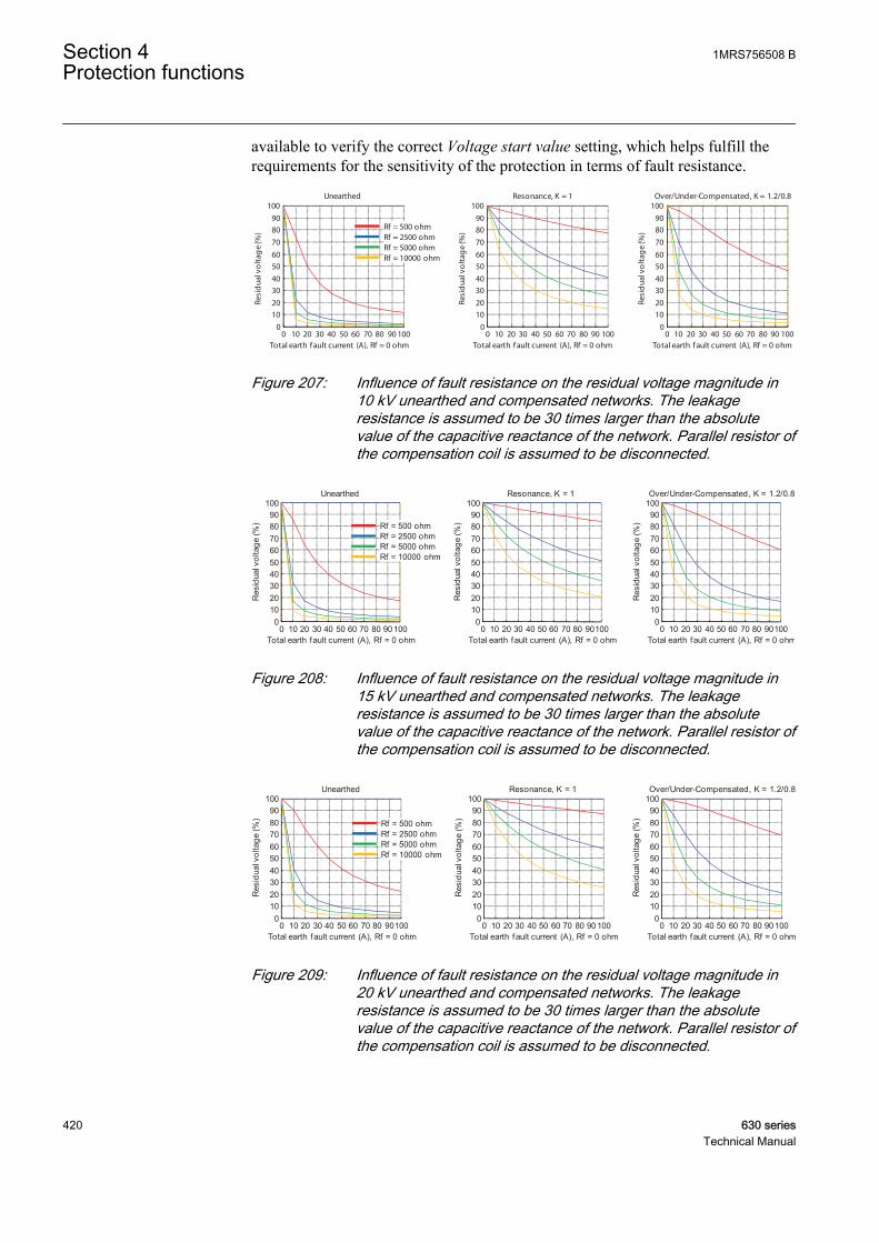
available to verify the correct Voltage start value setting, which helps fulfill therequirements for the sensitivity of the protection in terms of fault resistance.
0 10 20 30 40 50 60 70 80 90 1000
102030405060708090
100
Total earth f ault current (A), Rf = 0 ohm
Resi
dua
l vo
ltag
e (%
)
Resonance, K = 1
0 10 20 30 40 50 60 70 80 90 1000
102030405060708090
100
Total earth f ault current (A), Rf = 0 ohm
Resi
dua
l vo
ltag
e (%
)
Over/Under-Compensated, K = 1.2/0.8
0 10 20 30 40 50 60 70 80 90 1000
102030405060708090
100
Total earth fault current (A), Rf = 0 ohm
Resi
dua
l vo
ltag
e (%
)
Unearthed
Rf = 500 ohmRf = 2500 ohmRf = 5000 ohmRf = 10000 ohm
GUID-2F3654EF-9700-4FB7-B73C-85F7ED5D8EEF V1 EN
Figure 207: Influence of fault resistance on the residual voltage magnitude in10 kV unearthed and compensated networks. The leakageresistance is assumed to be 30 times larger than the absolutevalue of the capacitive reactance of the network. Parallel resistor ofthe compensation coil is assumed to be disconnected.
0 10 20 30 40 50 60 70 80 901000
102030405060708090
100
Total earth fault current (A), Rf = 0 ohm
Res
idua
l vol
tage
(%)
Resonance, K = 1
0 10 20 30 40 50 60 70 80 901000
102030405060708090
100
Total earth fault current (A), Rf = 0 ohmR
esid
ual v
olta
ge (%
)
Over/Under-Compensated, K = 1.2/0.8
0 10 20 30 40 50 60 70 80 901000
102030405060708090
100
Total earth fault current (A), Rf = 0 ohm
Res
idua
l vol
tage
(%)
Unearthed
Rf = 500 ohmRf = 2500 ohmRf = 5000 ohmRf = 10000 ohm
GUID-3880FB01-5C89-4E19-A529-805208382BB1 V1 EN
Figure 208: Influence of fault resistance on the residual voltage magnitude in15 kV unearthed and compensated networks. The leakageresistance is assumed to be 30 times larger than the absolutevalue of the capacitive reactance of the network. Parallel resistor ofthe compensation coil is assumed to be disconnected.
0 10 20 30 40 50 60 70 80 901000
102030405060708090
100
Total earth fault current (A), Rf = 0 ohm
Res
idua
l vol
tage
(%)
Resonance, K = 1
0 10 20 30 40 50 60 70 80 901000
102030405060708090
100
Total earth fault current (A), Rf = 0 ohm
Res
idua
l vol
tage
(%)
Over/Under-Compensated, K = 1.2/0.8
0 10 20 30 40 50 60 70 80 901000
102030405060708090
100
Total earth fault current (A), Rf = 0 ohm
Res
idua
l vol
tage
(%)
Unearthed
Rf = 500 ohmRf = 2500 ohmRf = 5000 ohmRf = 10000 ohm
GUID-6321328D-6C17-4155-A2DF-7E1C47A44D53 V1 EN
Figure 209: Influence of fault resistance on the residual voltage magnitude in20 kV unearthed and compensated networks. The leakageresistance is assumed to be 30 times larger than the absolutevalue of the capacitive reactance of the network. Parallel resistor ofthe compensation coil is assumed to be disconnected.
Section 4 1MRS756508 BProtection functions
420 630 seriesTechnical Manual
ExampleIn a 15 kV, 50 Hz compensated network, the maximum value for Uo during thehealthy state is 10%xUph. Maximum earth-fault current of the system is 100 A.The maximum earth fault current of the protected feeder is 10 A (Rf = 0 ohm). Theapplied active current forcing scheme uses a 15 A resistor, which is connected inparallel to the coil during the fault after a 1.0 second delay.
Solution: As a start condition for the neutral admittance protection, the internalresidual overvoltage condition of EFPADM is used. The Voltage start value settingmust be set above the maximum healthy-state Uo of 10%xUph with a suitable margin.
Voltage start value = 0.15 pu
According to Figure 208, this selection ensures at least a sensitivity correspondingto a 2000 ohm fault resistance when the compensation degree varies between 80%and 120%. The greatest sensitivity is achieved when the compensation degree isclose to full resonance.
An earth-fault current of 10 A can be converted into admittance.
YA
kV
jFdtot
= ≈ ⋅10
15 31 15. milliSiemens
GUID-3631BAB9-7D65-4591-A3D6-834687D0E03C V1 EN
A parallel resistor current of 15 A can be converted into admittance.
GA
kVcc = ≈
15
15 31 73. milliSiemens
GUID-4B7A18DE-68CB-42B2-BF02-115F0ECC03D9 V1 EN
According to Equation 32, during an outside fault EFPADM measures thefollowing admittance:
Yo Y jFdtot
= − ≈ − ⋅1 15. milliSiemens
GUID-AD02E209-1740-4930-8E28-AB85637CEF0D V1 EN
According to Equation 37, during an inside fault EFPADM measures theadmittance after the connection of the parallel resistor:
Yo Y Y j BBgtot CC
= + ≈ + ⋅( )1 73. milliSiemens
GUID-28AF4976-1872-48A1-ACC7-7CC3B51CD9D8 V1 EN
Where the imaginary part of the admittance, B, depends on the tuning of the coil(compensation degree).
The admittance characteristic is selected to be the combined overconductance andoversusceptance characteristic with four boundary lines:
Operation mode = "Go, Bo"
Directional mode = "Non-directional"
1MRS756508 B Section 4Protection functions
630 series 421Technical Manual

The admittance characteristic is set to cover the total admittance of the protectedfeeder with a proper margin, see Figure 210.
Conductance forward = 1.73 mS · 0.2 ≈ 0.35 mS
Conductance reverse = -1.0 mS (valid range apprx. 0.5 · 1.15 - 1.2 · 1.73 = -0.6...-2.1)
Susceptance forward = 0.1 mS
Susceptance reverse = -1.15 mS · 1.2 ≈ -1.4 mS
-5 -4 -3 -2 -1 0 1 2 3 4 5-5
-4
-3
-2
-1
0
1
2
3
4
5Go (mS)
Bo (mS)
Backward fault:
Yo ≈ -j*1.15mS Forward fault,
Yo ≈ 1.73+j*Bo mS
-5 -4 -3 -2 -1 0 1 2 3 4 5-5
-4
-3
-2
-1
0
1
2
3
4
5Go (mS)
Bo (mS)
0.35 mS-1.0 mS
-1.4 mS
0.1 mS
OPERATE OPERATE
OPERATE OPERATE
GUID-AE9BB46E-B927-43F6-881A-A96D3410268D V1 EN
Figure 210: Admittances of the example
4.2.4.9 Signals
Table 426: EFPADM Input signals
Name Type Default DescriptionI3P GROUP
SIGNAL- Three phase group signal for current inputs
U3P GROUPSIGNAL
- Three phase group signal for voltage inputs
BLOCK BOOLEAN 0 Block all outputs (includes timer reset)
BLK_OPR BOOLEAN 0 Block operate output
BLK_ST BOOLEAN 0 Block start output
FR_TIMER BOOLEAN 0 Freeze timer
RELEASE BOOLEAN 0 External trigger signal to release neutraladmittance protection
RESET BOOLEAN 0 External reset signal to reset recorded data
Section 4 1MRS756508 BProtection functions
422 630 seriesTechnical Manual
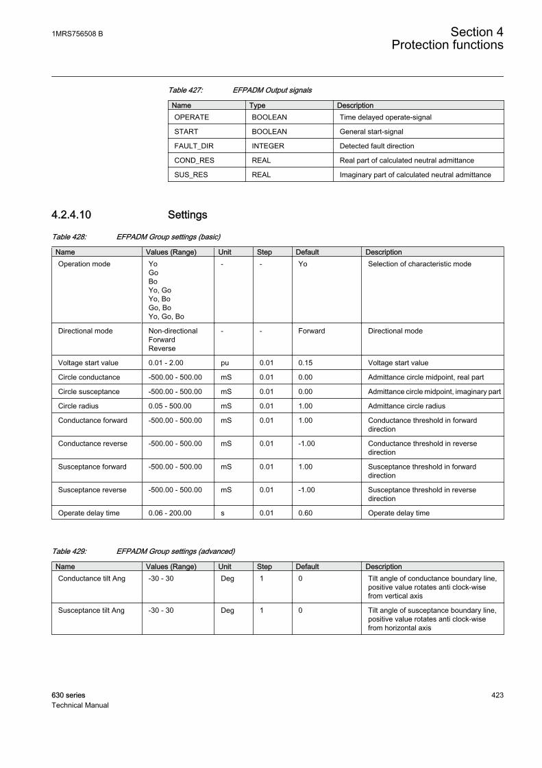
Table 427: EFPADM Output signals
Name Type DescriptionOPERATE BOOLEAN Time delayed operate-signal
START BOOLEAN General start-signal
FAULT_DIR INTEGER Detected fault direction
COND_RES REAL Real part of calculated neutral admittance
SUS_RES REAL Imaginary part of calculated neutral admittance
4.2.4.10 Settings
Table 428: EFPADM Group settings (basic)
Name Values (Range) Unit Step Default DescriptionOperation mode Yo
GoBoYo, GoYo, BoGo, BoYo, Go, Bo
- - Yo Selection of characteristic mode
Directional mode Non-directionalForwardReverse
- - Forward Directional mode
Voltage start value 0.01 - 2.00 pu 0.01 0.15 Voltage start value
Circle conductance -500.00 - 500.00 mS 0.01 0.00 Admittance circle midpoint, real part
Circle susceptance -500.00 - 500.00 mS 0.01 0.00 Admittance circle midpoint, imaginary part
Circle radius 0.05 - 500.00 mS 0.01 1.00 Admittance circle radius
Conductance forward -500.00 - 500.00 mS 0.01 1.00 Conductance threshold in forwarddirection
Conductance reverse -500.00 - 500.00 mS 0.01 -1.00 Conductance threshold in reversedirection
Susceptance forward -500.00 - 500.00 mS 0.01 1.00 Susceptance threshold in forwarddirection
Susceptance reverse -500.00 - 500.00 mS 0.01 -1.00 Susceptance threshold in reversedirection
Operate delay time 0.06 - 200.00 s 0.01 0.60 Operate delay time
Table 429: EFPADM Group settings (advanced)
Name Values (Range) Unit Step Default DescriptionConductance tilt Ang -30 - 30 Deg 1 0 Tilt angle of conductance boundary line,
positive value rotates anti clock-wisefrom vertical axis
Susceptance tilt Ang -30 - 30 Deg 1 0 Tilt angle of susceptance boundary line,positive value rotates anti clock-wisefrom horizontal axis
1MRS756508 B Section 4Protection functions
630 series 423Technical Manual
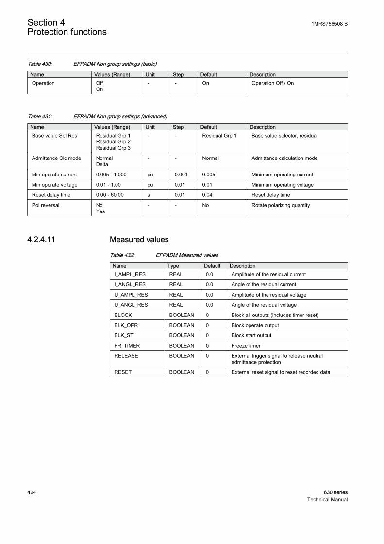
Table 430: EFPADM Non group settings (basic)
Name Values (Range) Unit Step Default DescriptionOperation Off
On- - On Operation Off / On
Table 431: EFPADM Non group settings (advanced)
Name Values (Range) Unit Step Default DescriptionBase value Sel Res Residual Grp 1
Residual Grp 2Residual Grp 3
- - Residual Grp 1 Base value selector, residual
Admittance Clc mode NormalDelta
- - Normal Admittance calculation mode
Min operate current 0.005 - 1.000 pu 0.001 0.005 Minimum operating current
Min operate voltage 0.01 - 1.00 pu 0.01 0.01 Minimum operating voltage
Reset delay time 0.00 - 60.00 s 0.01 0.04 Reset delay time
Pol reversal NoYes
- - No Rotate polarizing quantity
4.2.4.11 Measured values
Table 432: EFPADM Measured values
Name Type Default DescriptionI_AMPL_RES REAL 0.0 Amplitude of the residual current
I_ANGL_RES REAL 0.0 Angle of the residual current
U_AMPL_RES REAL 0.0 Amplitude of the residual voltage
U_ANGL_RES REAL 0.0 Angle of the residual voltage
BLOCK BOOLEAN 0 Block all outputs (includes timer reset)
BLK_OPR BOOLEAN 0 Block operate output
BLK_ST BOOLEAN 0 Block start output
FR_TIMER BOOLEAN 0 Freeze timer
RELEASE BOOLEAN 0 External trigger signal to release neutraladmittance protection
RESET BOOLEAN 0 External reset signal to reset recorded data
Section 4 1MRS756508 BProtection functions
424 630 seriesTechnical Manual
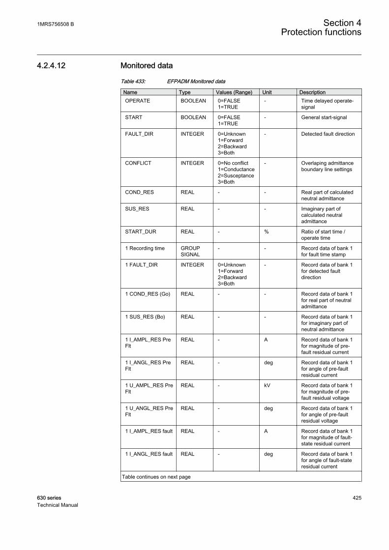
4.2.4.12 Monitored data
Table 433: EFPADM Monitored data
Name Type Values (Range) Unit DescriptionOPERATE BOOLEAN 0=FALSE
1=TRUE- Time delayed operate-
signal
START BOOLEAN 0=FALSE1=TRUE
- General start-signal
FAULT_DIR INTEGER 0=Unknown1=Forward2=Backward3=Both
- Detected fault direction
CONFLICT INTEGER 0=No conflict1=Conductance2=Susceptance3=Both
- Overlaping admittanceboundary line settings
COND_RES REAL - - Real part of calculatedneutral admittance
SUS_RES REAL - - Imaginary part ofcalculated neutraladmittance
START_DUR REAL - % Ratio of start time /operate time
1 Recording time GROUPSIGNAL
- - Record data of bank 1for fault time stamp
1 FAULT_DIR INTEGER 0=Unknown1=Forward2=Backward3=Both
- Record data of bank 1for detected faultdirection
1 COND_RES (Go) REAL - - Record data of bank 1for real part of neutraladmittance
1 SUS_RES (Bo) REAL - - Record data of bank 1for imaginary part ofneutral admittance
1 I_AMPL_RES PreFlt
REAL - A Record data of bank 1for magnitude of pre-fault residual current
1 I_ANGL_RES PreFlt
REAL - deg Record data of bank 1for angle of pre-faultresidual current
1 U_AMPL_RES PreFlt
REAL - kV Record data of bank 1for magnitude of pre-fault residual voltage
1 U_ANGL_RES PreFlt
REAL - deg Record data of bank 1for angle of pre-faultresidual voltage
1 I_AMPL_RES fault REAL - A Record data of bank 1for magnitude of fault-state residual current
1 I_ANGL_RES fault REAL - deg Record data of bank 1for angle of fault-stateresidual current
Table continues on next page
1MRS756508 B Section 4Protection functions
630 series 425Technical Manual
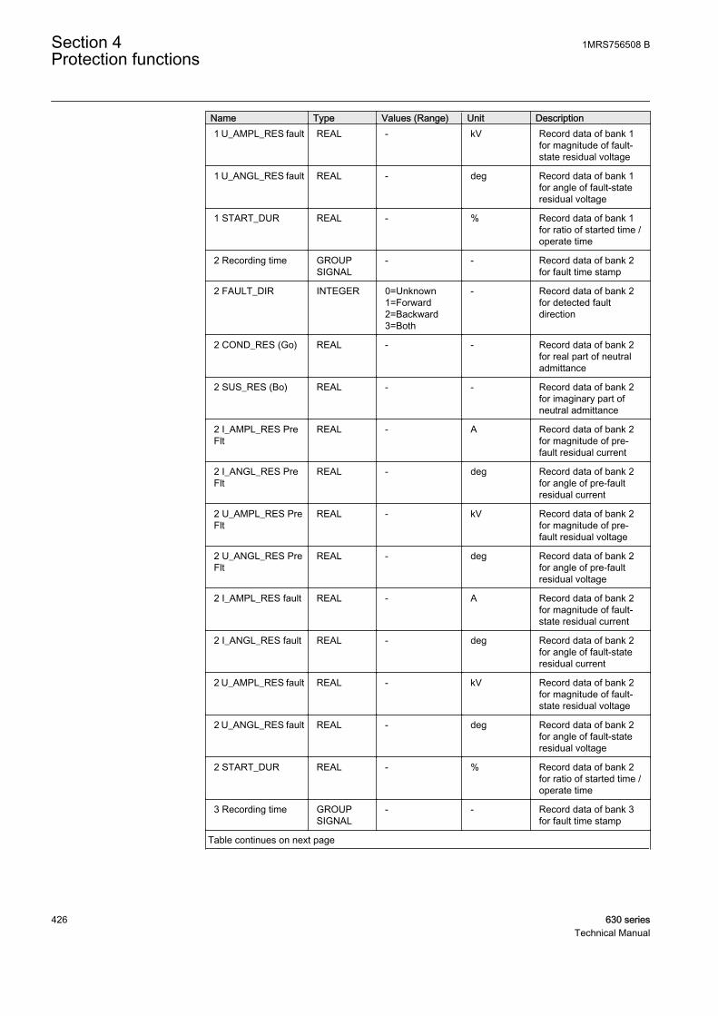
Name Type Values (Range) Unit Description1 U_AMPL_RES fault REAL - kV Record data of bank 1
for magnitude of fault-state residual voltage
1 U_ANGL_RES fault REAL - deg Record data of bank 1for angle of fault-stateresidual voltage
1 START_DUR REAL - % Record data of bank 1for ratio of started time /operate time
2 Recording time GROUPSIGNAL
- - Record data of bank 2for fault time stamp
2 FAULT_DIR INTEGER 0=Unknown1=Forward2=Backward3=Both
- Record data of bank 2for detected faultdirection
2 COND_RES (Go) REAL - - Record data of bank 2for real part of neutraladmittance
2 SUS_RES (Bo) REAL - - Record data of bank 2for imaginary part ofneutral admittance
2 I_AMPL_RES PreFlt
REAL - A Record data of bank 2for magnitude of pre-fault residual current
2 I_ANGL_RES PreFlt
REAL - deg Record data of bank 2for angle of pre-faultresidual current
2 U_AMPL_RES PreFlt
REAL - kV Record data of bank 2for magnitude of pre-fault residual voltage
2 U_ANGL_RES PreFlt
REAL - deg Record data of bank 2for angle of pre-faultresidual voltage
2 I_AMPL_RES fault REAL - A Record data of bank 2for magnitude of fault-state residual current
2 I_ANGL_RES fault REAL - deg Record data of bank 2for angle of fault-stateresidual current
2 U_AMPL_RES fault REAL - kV Record data of bank 2for magnitude of fault-state residual voltage
2 U_ANGL_RES fault REAL - deg Record data of bank 2for angle of fault-stateresidual voltage
2 START_DUR REAL - % Record data of bank 2for ratio of started time /operate time
3 Recording time GROUPSIGNAL
- - Record data of bank 3for fault time stamp
Table continues on next page
Section 4 1MRS756508 BProtection functions
426 630 seriesTechnical Manual
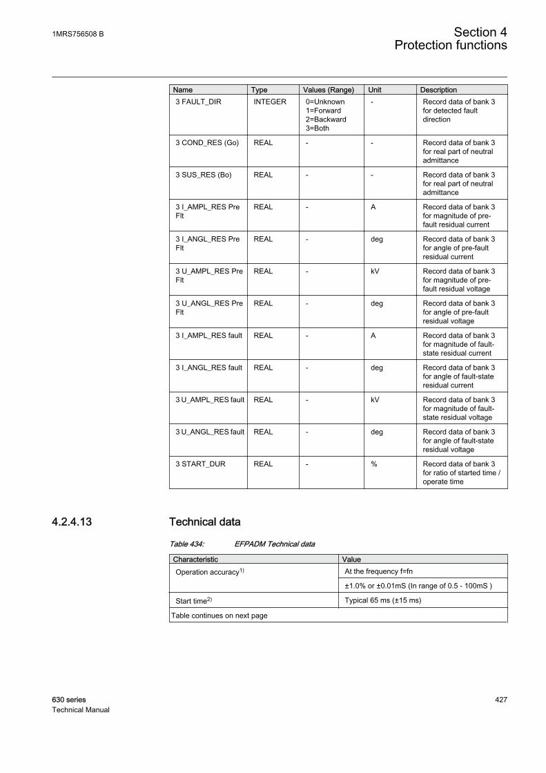
Name Type Values (Range) Unit Description3 FAULT_DIR INTEGER 0=Unknown
1=Forward2=Backward3=Both
- Record data of bank 3for detected faultdirection
3 COND_RES (Go) REAL - - Record data of bank 3for real part of neutraladmittance
3 SUS_RES (Bo) REAL - - Record data of bank 3for real part of neutraladmittance
3 I_AMPL_RES PreFlt
REAL - A Record data of bank 3for magnitude of pre-fault residual current
3 I_ANGL_RES PreFlt
REAL - deg Record data of bank 3for angle of pre-faultresidual current
3 U_AMPL_RES PreFlt
REAL - kV Record data of bank 3for magnitude of pre-fault residual voltage
3 U_ANGL_RES PreFlt
REAL - deg Record data of bank 3for angle of pre-faultresidual voltage
3 I_AMPL_RES fault REAL - A Record data of bank 3for magnitude of fault-state residual current
3 I_ANGL_RES fault REAL - deg Record data of bank 3for angle of fault-stateresidual current
3 U_AMPL_RES fault REAL - kV Record data of bank 3for magnitude of fault-state residual voltage
3 U_ANGL_RES fault REAL - deg Record data of bank 3for angle of fault-stateresidual voltage
3 START_DUR REAL - % Record data of bank 3for ratio of started time /operate time
4.2.4.13 Technical data
Table 434: EFPADM Technical data
Characteristic ValueOperation accuracy1) At the frequency f=fn
±1.0% or ±0.01mS (In range of 0.5 - 100mS )
Start time2) Typical 65 ms (±15 ms)
Table continues on next page
1MRS756508 B Section 4Protection functions
630 series 427Technical Manual

Characteristic ValueReset time < 50 ms
Operate time accuracy in definite time mode ±1.0% of the set value of ±20 ms
Suppression of harmonics -50dB at f = n x fn, where n = 2, 3, 4, 5,…
1) Io varied during the test. Uo = 1.0 x Un = phase to earth voltage during earth-fault in compensatedor un-earthed network..
2) Includes the delay of the signal output contact. Results based on statistical distribution of 1000measurements
4.2.5 Rotor earth-fault protection MREFPTOC
4.2.5.1 Identification
Function description IEC 61850 IEC 60617 ANSI/IEEEidentification
Rotor earth-fault protection MREFPTOC Io>R 64R
4.2.5.2 Function block
GUID-54E746C0-FC28-40A4-B4B8-19D24C6E85FB V1 EN
Figure 211: Function block
4.2.5.3 Functionality
The rotor earth-fault protection function MREFPTOC is used to detect an earthfault in the rotor circuit of synchronous machines. MREFPTOC is used with theinjection device REK510, which requires a secured 58, 100 or 230 V AC 50/60 Hzinput source and injects a 100 V AC voltage via its coupling capacitors to the rotorcircuit towards earth.
MREFPTOC consists of independent alarm and operating stages. The operatingtime characteristic is according to definite time (DT) for both stages.
MREFPTOC contains a blocking functionality. Blocking deactivates all outputsand resets timers.
4.2.5.4 Operation principle
The function can be enabled and disabled with the Operation setting. Thecorresponding parameter values are "On" and "Off".
Section 4 1MRS756508 BProtection functions
428 630 seriesTechnical Manual

The operation of the rotor earth-fault protection function can be described using amodule diagram. All the modules in the diagram are explained in the next sections.
Level detector 1I3P
BLOCK
OPERATEIo
ALARM
Timer 1
Timer 2Level
detector 2
START
GUID-DF6DB7C8-5AD5-4A6C-93AD-30B9C980EAF4 V1 EN
Figure 212: Functional module diagram
Level detector 1The measured rotor earth-fault current (DFT value) is compared to the Operatestart value setting. If the measured value exceeds that of the Operate start valuesetting, level detector 1 sends a signal to start the timer 1 module.
Level detector 2The measured rotor earth-fault current (DFT value) is compared to the set Alarmstart value. If the measured value exceeds that of the Alarm start value setting,level detector 2 sends a signal to start the timer 2 module.
For MREFPTOC, the earth-fault current is the current that flowsdue to the voltage injected by the injection device in the rotorcircuit when an earth fault arises.
A considerable amount of harmonics, mainly 3rd and 6th, can occurin the excitation current under normal no-fault conditions,especially with the thyristor excitation and rotating diode rectifiersystems. MREFPTOC uses DFT value calculation to filter DC andharmonic components which could otherwise give out false alarmsor trips.
Timer 1Once activated, the timer activates the START output. The timer characteristic isaccording to DT. When the operation timer has reached the value set by Operatedelay time in the DT mode, the OPERATE output is activated. If a drop-offsituation occurs, that is, a fault suddenly disappears before the operating delay isexceeded, the timer reset state is activated. The reset time depends on the Resetdelay time setting.
1MRS756508 B Section 4Protection functions
630 series 429Technical Manual
The binary input BLOCK can be used to block the function. The activation of theBLOCK input deactivates all outputs and resets the internal timers.
Timer 2Once activated, the timer activates the alarm timer. The timer characteristic isaccording to DT. When the alarm timer has reached the value set by Alarm delaytime in the DT mode, the ALARM output is activated. If a drop-off situation occurs,that is, a fault suddenly disappears before the alarm delay is exceeded, the timerreset state is activated. The reset time depends on the Alm Reset delay time setting.
The binary input BLOCK can be used to block the function. The activation of theBLOCK input deactivates all outputs and resets the internal timers.
4.2.5.5 Base values
In MREFPTOC, some of the settings are set in per unit (pu). These pu values arerelational to certain base values, for example, the values given in A, kV and kVA.The IED supports alternative base value groups for the phase current-related orvoltage-related settings. For example, "Residual Grp 1", "Residual Grp 2" and"Residual Grp 3" are supported for the residual current-related or voltage-relatedsettings. One of the groups must be selected to be used with the Base value Sel Ressettings.
A proper base value must be set for MREFPTOC as the valuedepends on the nominal current of the IED-measuring input.
4.2.5.6 Application
The rotor circuit of synchronous machines is normally isolated from the earth. Therotor circuit can be exposed to an abnormal mechanical or thermal stress due to, forexample, vibrations, overcurrent and choked cooling medium flow. This can resultin the breakdown of the insulation between the field winding and the rotor iron atthe point exposed to excessive stress. If the isolation resistance is decreasedsignificantly, this can be seen as an earth fault. For generators with slip rings, therotor insulation resistance is sometimes reduced due to the accumulated carbondust layer produced by the carbon brushes. As the circuit has a high impedance toearth, a single earth fault does not lead to any immediate damage because the faultcurrent is small due to a low voltage. There is, however, a risk that a second earthfault appears, creating a rotor winding interturn fault and causing severe magneticimbalance and heavy rotor vibrations that soon lead to a severe damage.
Therefore, it is essential that any occurrence of an insulation failure is detected andthat the machine is disconnected as soon as possible. Normally, the device istripped after a short time delay.
Section 4 1MRS756508 BProtection functions
430 630 seriesTechnical Manual
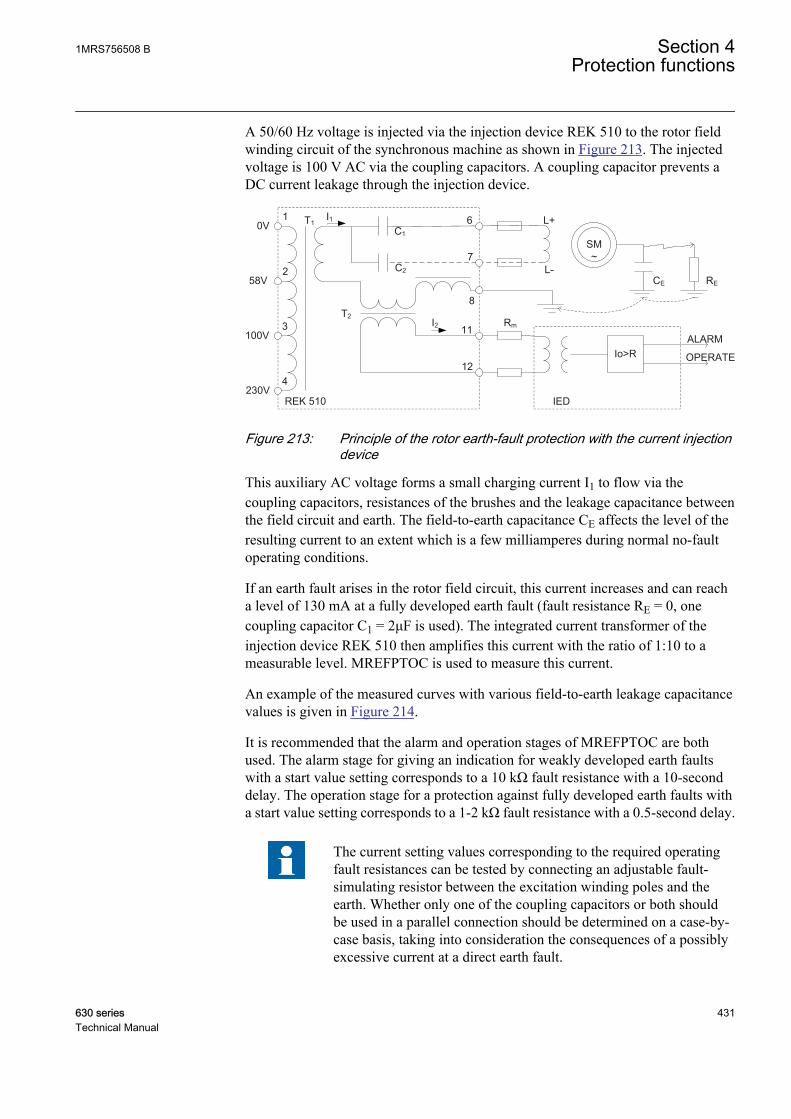
A 50/60 Hz voltage is injected via the injection device REK 510 to the rotor fieldwinding circuit of the synchronous machine as shown in Figure 213. The injectedvoltage is 100 V AC via the coupling capacitors. A coupling capacitor prevents aDC current leakage through the injection device.
SM~
Io>R
IED
L+
L-CE RE
0V
58V
100V
230VREK 510
C1
C2
T2
T11
2
3
4
6
7
8
11
12
Rm
I1
I2ALARM
OPERATE
GUID-959646C8-FC8C-4691-B262-613D87B81A2C V1 EN
Figure 213: Principle of the rotor earth-fault protection with the current injectiondevice
This auxiliary AC voltage forms a small charging current I1 to flow via thecoupling capacitors, resistances of the brushes and the leakage capacitance betweenthe field circuit and earth. The field-to-earth capacitance CE affects the level of theresulting current to an extent which is a few milliamperes during normal no-faultoperating conditions.
If an earth fault arises in the rotor field circuit, this current increases and can reacha level of 130 mA at a fully developed earth fault (fault resistance RE = 0, onecoupling capacitor C1 = 2μF is used). The integrated current transformer of theinjection device REK 510 then amplifies this current with the ratio of 1:10 to ameasurable level. MREFPTOC is used to measure this current.
An example of the measured curves with various field-to-earth leakage capacitancevalues is given in Figure 214.
It is recommended that the alarm and operation stages of MREFPTOC are bothused. The alarm stage for giving an indication for weakly developed earth faultswith a start value setting corresponds to a 10 kΩ fault resistance with a 10-seconddelay. The operation stage for a protection against fully developed earth faults witha start value setting corresponds to a 1-2 kΩ fault resistance with a 0.5-second delay.
The current setting values corresponding to the required operatingfault resistances can be tested by connecting an adjustable fault-simulating resistor between the excitation winding poles and theearth. Whether only one of the coupling capacitors or both shouldbe used in a parallel connection should be determined on a case-by-case basis, taking into consideration the consequences of a possiblyexcessive current at a direct earth fault.
1MRS756508 B Section 4Protection functions
630 series 431Technical Manual
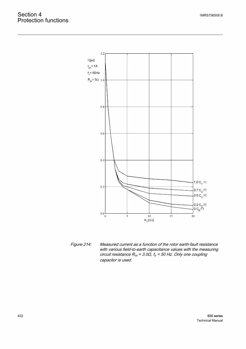
GUID-92E515E2-DC29-4D68-A80E-FF85C009C76C V1 EN
Figure 214: Measured current as a function of the rotor earth-fault resistancewith various field-to-earth capacitance values with the measuringcircuit resistance Rm = 3.0Ω, fn = 50 Hz. Only one couplingcapacitor is used.
Section 4 1MRS756508 BProtection functions
432 630 seriesTechnical Manual

4.2.5.7 Signals
Table 435: MREFPTOC Input signals
Name Type Default DescriptionI3P GROUP
SIGNAL- Group signal for current inputs
BLOCK BOOLEAN 0 Block signal for all binary outputs
Table 436: MREFPTOC Output signals
Name Type DescriptionOPERATE BOOLEAN Operated
START BOOLEAN Started
ALARM BOOLEAN Alarm signal
4.2.5.8 Settings
Table 437: MREFPTOC Group settings (basic)
Name Values (Range) Unit Step Default DescriptionAlarm start value 0.010 - 2.000 pu 0.001 0.010 Alarm start value for rotor earth fault
current
Operate start value 0.010 - 2.000 pu 0.001 0.010 Operate start value for rotor earth faultcurrent
Alarm delay time 0.04 - 200.00 s 0.01 10.00 Alarm delay time
Operate delay time 0.04 - 200.00 s 0.01 0.50 Operate delay time
Table 438: MREFPTOC Non group settings (basic)
Name Values (Range) Unit Step Default DescriptionOperation Off
On- - On Operation Off / On
Table 439: MREFPTOC Non group settings (advanced)
Name Values (Range) Unit Step Default DescriptionBase value Sel Res Residual Grp 1
Residual Grp 2Residual Grp 3
- - Residual Grp 2 Base value selector, residual
Alm reset delay time 0.00 - 60.00 s 0.01 0.02 Alarm reset delay time
Reset delay time 0.00 - 60.00 s 0.01 0.02 Reset delay time
1MRS756508 B Section 4Protection functions
630 series 433Technical Manual
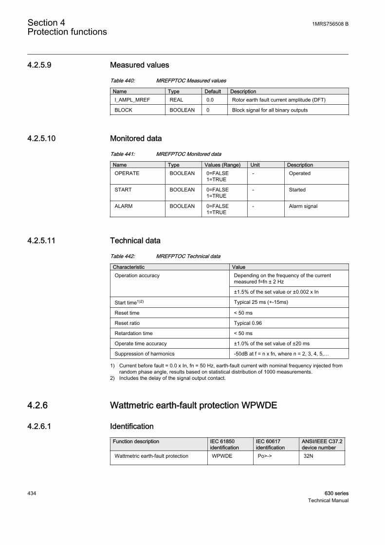
4.2.5.9 Measured values
Table 440: MREFPTOC Measured values
Name Type Default DescriptionI_AMPL_MREF REAL 0.0 Rotor earth fault current amplitude (DFT)
BLOCK BOOLEAN 0 Block signal for all binary outputs
4.2.5.10 Monitored data
Table 441: MREFPTOC Monitored data
Name Type Values (Range) Unit DescriptionOPERATE BOOLEAN 0=FALSE
1=TRUE- Operated
START BOOLEAN 0=FALSE1=TRUE
- Started
ALARM BOOLEAN 0=FALSE1=TRUE
- Alarm signal
4.2.5.11 Technical data
Table 442: MREFPTOC Technical data
Characteristic ValueOperation accuracy Depending on the frequency of the current
measured f=fn ± 2 Hz
±1.5% of the set value or ±0.002 x In
Start time1)2) Typical 25 ms (+-15ms)
Reset time < 50 ms
Reset ratio Typical 0.96
Retardation time < 50 ms
Operate time accuracy ±1.0% of the set value of ±20 ms
Suppression of harmonics -50dB at f = n x fn, where n = 2, 3, 4, 5,…
1) Current before fault = 0.0 x In, fn = 50 Hz, earth-fault current with nominal frequency injected fromrandom phase angle, results based on statistical distribution of 1000 measurements.
2) Includes the delay of the signal output contact.
4.2.6 Wattmetric earth-fault protection WPWDE
4.2.6.1 Identification
Function description IEC 61850identification
IEC 60617identification
ANSI/IEEE C37.2device number
Wattmetric earth-fault protection WPWDE Po>-> 32N
Section 4 1MRS756508 BProtection functions
434 630 seriesTechnical Manual
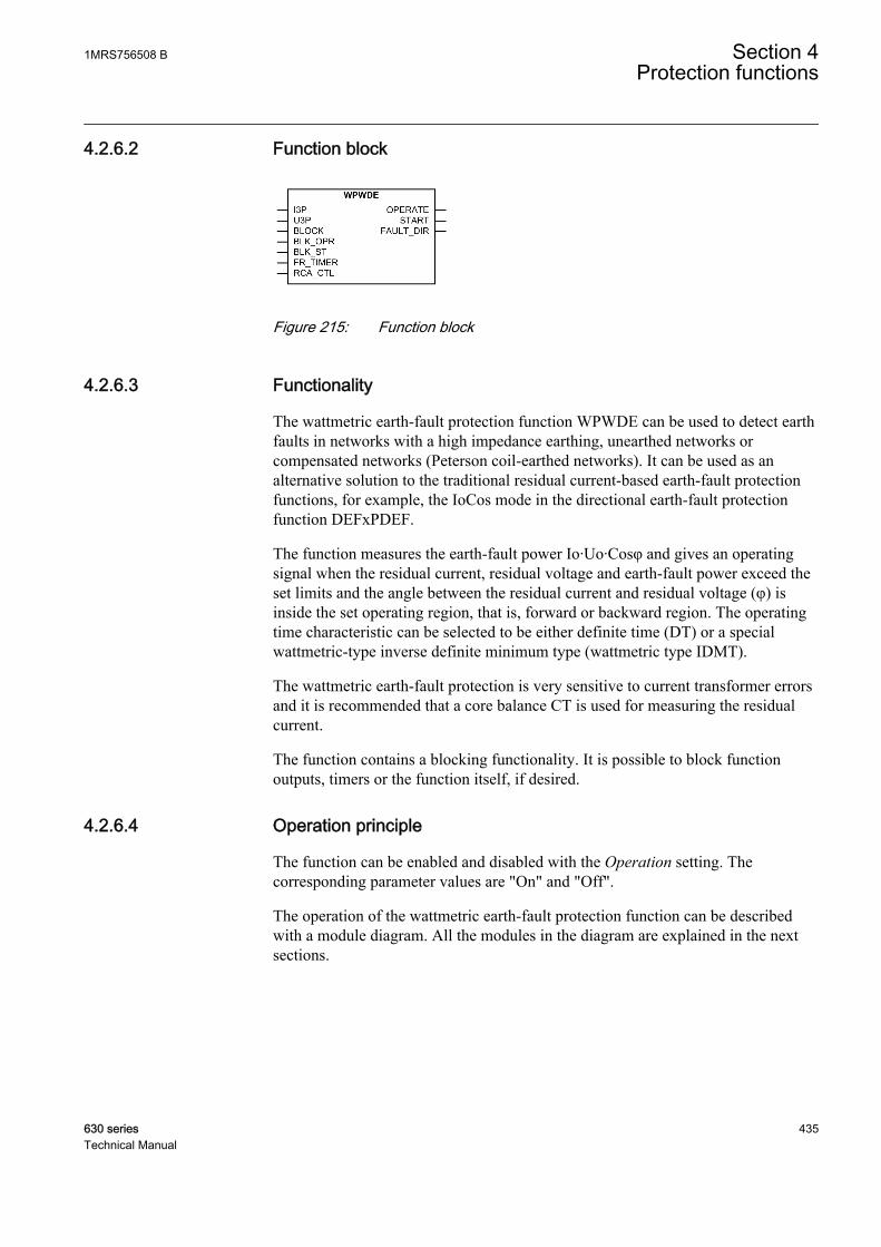
4.2.6.2 Function block
GUID-99E2503A-C202-4367-8FBE-C6027A21DB78 V1 EN
Figure 215: Function block
4.2.6.3 Functionality
The wattmetric earth-fault protection function WPWDE can be used to detect earthfaults in networks with a high impedance earthing, unearthed networks orcompensated networks (Peterson coil-earthed networks). It can be used as analternative solution to the traditional residual current-based earth-fault protectionfunctions, for example, the IoCos mode in the directional earth-fault protectionfunction DEFxPDEF.
The function measures the earth-fault power Io·Uo·Cosφ and gives an operatingsignal when the residual current, residual voltage and earth-fault power exceed theset limits and the angle between the residual current and residual voltage (φ) isinside the set operating region, that is, forward or backward region. The operatingtime characteristic can be selected to be either definite time (DT) or a specialwattmetric-type inverse definite minimum type (wattmetric type IDMT).
The wattmetric earth-fault protection is very sensitive to current transformer errorsand it is recommended that a core balance CT is used for measuring the residualcurrent.
The function contains a blocking functionality. It is possible to block functionoutputs, timers or the function itself, if desired.
4.2.6.4 Operation principle
The function can be enabled and disabled with the Operation setting. Thecorresponding parameter values are "On" and "Off".
The operation of the wattmetric earth-fault protection function can be describedwith a module diagram. All the modules in the diagram are explained in the nextsections.
1MRS756508 B Section 4Protection functions
630 series 435Technical Manual

Directionalcalculation
Level detector
I3P
Residualpower
calculation
U3P
BLK_OPRBLK_ST
BLOCK
FAULT_DIR
OPERATE
FR_TIMER
I0
U0
START
RCA_CTL
t
Timer
t
GUID-134FC6D3-50C1-4667-A438-F3BB41E8A8D4 V1 EN
Figure 216: Functional module diagram
Directional calculationThe directional calculation module monitors the angle between the operatingquantity (residual current) and polarizing quantity (residual voltage). When theangle after considering the Characteristic angle setting is in the operation section,the module sends an enable signal to the level detector. The directional operation isselected with the Directional mode setting. Either the "Forward" or "Reverse"operation mode can be selected. The direction of fault is calculated based on thephase angle difference between the operating quantity and polarizing quantity, thevalue (ANGLE) is available through the monitored data view.
The polarizing quantity for a directional earth fault is shifted by180˚ and hence it is represented as –Uo in the phasor diagrams.
If the angle difference lies between -90˚ to 0˚ or 0˚ to +90˚, a forward directionfault is considered. If the phase angle difference lies within -90˚ to -180˚ or +90˚ to+180˚, a reverse direction fault is detected. Thus, the normal width of a sector is 180˚.
Section 4 1MRS756508 BProtection functions
436 630 seriesTechnical Manual

GUID-2A90B4D8-02B0-495C-A86E-559A09AE70DC V1 EN
Figure 217: Definition of the relay characteristic angle
The phase angle difference is calculated based on the Characteristic angle setting(also known as Relay Characteristic Angle (RCA) or Relay Base Angle (RBA) orMaximum Torque Angle (MTA)). The Characteristic angle setting is done basedon the method of earthing employed in the network. For example, in case of anunearthed network, the Characteristic angle setting is set to -90˚, in case of acompensated network, the Characteristic angle setting is set to 0˚. In general,Characteristic angle is selected so that is close to the expected fault angle value,which results maximum sensitivity. Characteristic angle can be set anywherebetween -179˚ to +180˚. Thus the effective phase angle (Φ) for calculating theresidual power considering the characteristic angle is
φ = ∠ − − ∠ −( )( )Uo Io Characteristic angle
GUID-D538B6BE-5A4E-4D96-850E-A8555FC57C4A V1 EN (Equation 43)
In addition, the characteristic angle can be changed via the control signalRCA_CTL. The RCA_CTL input is used in the compensated networks where thecompensation coil sometimes is temporarily disconnected. When the coil isdisconnected, the compensated network becomes isolated and the Characteristicangle setting must be changed. This can be done automatically with the RCA_CTLinput, which results in the addition of -90˚ in the Characteristic angle setting.
The value (ANGLE_RCA) is available in the monitored data view.
1MRS756508 B Section 4Protection functions
630 series 437Technical Manual
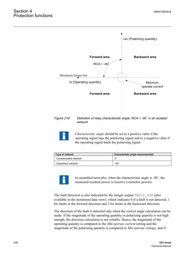
-Uo (Polarizing quantity)
Forward area
Io (Operating quantity)
RCA = -90˚
Maximum torque line
Backward area
Minimumoperate current
Forward area Backward area
GUID-001A8AA8-0C40-4580-A502-048A296EF6F2 V1 EN
Figure 218: Definition of relay characteristic angle, RCA = -90˚ in an isolatednetwork
Characteristic angle should be set to a positive value if theoperating signal lags the polarizing signal and to a negative value ifthe operating signal leads the polarizing signal.
Type of network Characteristic angle recommendedCompensated network 0˚
Unearthed network -90˚
In unearthed networks, when the characteristic angle is -90˚, themeasured residual power is reactive (varmetric power).
The fault direction is also indicated by the integer output FAULT_DIR (alsoavailable in the monitored data view), which indicates 0 if a fault is not detected, 1for faults in the forward direction and 2 for faults in the backward direction.
The direction of the fault is detected only when the correct angle calculation can bemade. If the magnitude of the operating quantity or polarizing quantity is not highenough, the direction calculation is not reliable. Hence, the magnitude of theoperating quantity is compared to the Min operate current setting and themagnitude of the polarizing quantity is compared to Min operate voltage, and if
Section 4 1MRS756508 BProtection functions
438 630 seriesTechnical Manual
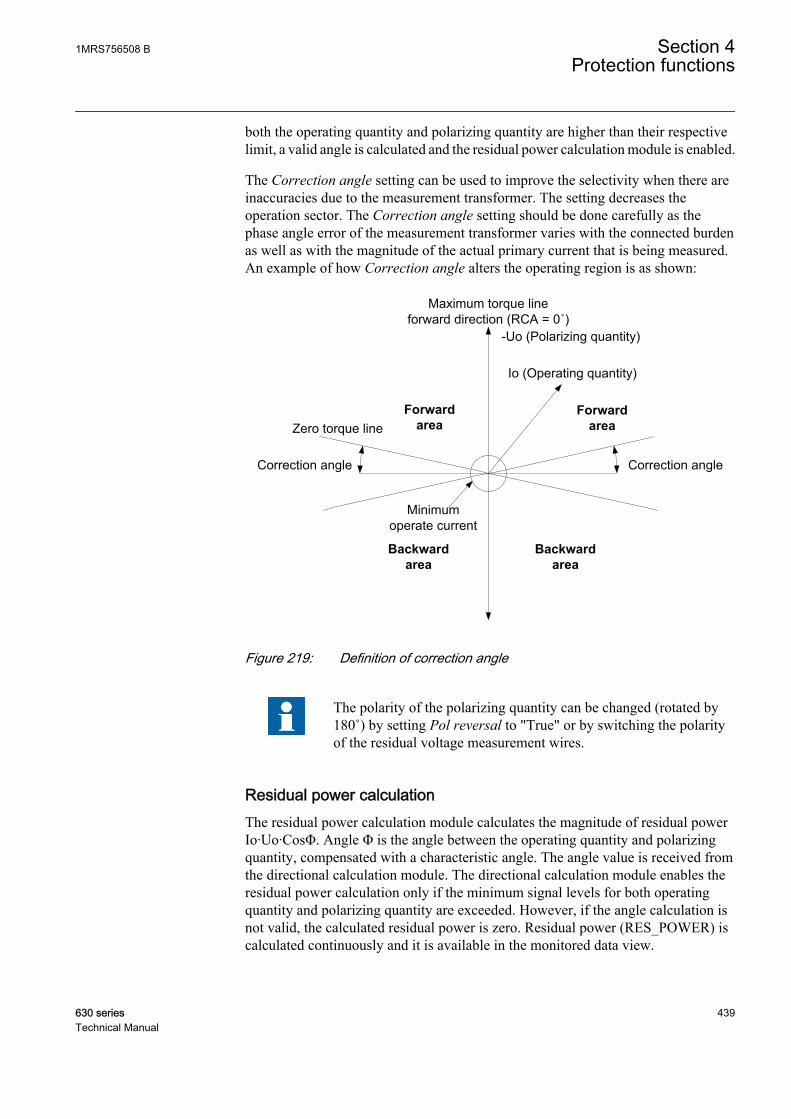
both the operating quantity and polarizing quantity are higher than their respectivelimit, a valid angle is calculated and the residual power calculation module is enabled.
The Correction angle setting can be used to improve the selectivity when there areinaccuracies due to the measurement transformer. The setting decreases theoperation sector. The Correction angle setting should be done carefully as thephase angle error of the measurement transformer varies with the connected burdenas well as with the magnitude of the actual primary current that is being measured.An example of how Correction angle alters the operating region is as shown:
-Uo (Polarizing quantity)
Backwardarea
Forwardarea
Io (Operating quantity)
Zero torque line
Minimumoperate current
Maximum torque line forward direction (RCA = 0˚)
Correction angleCorrection angle
Forwardarea
Backwardarea
GUID-300A4B7E-173B-4C04-9C9A-6AC1B6FCAF9B V1 EN
Figure 219: Definition of correction angle
The polarity of the polarizing quantity can be changed (rotated by180˚) by setting Pol reversal to "True" or by switching the polarityof the residual voltage measurement wires.
Residual power calculationThe residual power calculation module calculates the magnitude of residual powerIo·Uo·CosΦ. Angle Φ is the angle between the operating quantity and polarizingquantity, compensated with a characteristic angle. The angle value is received fromthe directional calculation module. The directional calculation module enables theresidual power calculation only if the minimum signal levels for both operatingquantity and polarizing quantity are exceeded. However, if the angle calculation isnot valid, the calculated residual power is zero. Residual power (RES_POWER) iscalculated continuously and it is available in the monitored data view.
1MRS756508 B Section 4Protection functions
630 series 439Technical Manual
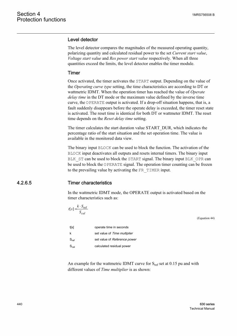
Level detectorThe level detector compares the magnitudes of the measured operating quantity,polarizing quantity and calculated residual power to the set Current start value,Voltage start value and Res power start value respectively. When all threequantities exceed the limits, the level detector enables the timer module.
TimerOnce activated, the timer activates the START output. Depending on the value ofthe Operating curve type setting, the time characteristics are according to DT orwattmetric IDMT. When the operation timer has reached the value of Operatedelay time in the DT mode or the maximum value defined by the inverse timecurve, the OPERATE output is activated. If a drop-off situation happens, that is, afault suddenly disappears before the operate delay is exceeded, the timer reset stateis activated. The reset time is identical for both DT or wattmeter IDMT. The resettime depends on the Reset delay time setting.
The timer calculates the start duration value START_DUR, which indicates thepercentage ratio of the start situation and the set operation time. The value isavailable in the monitored data view.
The binary input BLOCK can be used to block the function. The activation of theBLOCK input deactivates all outputs and resets internal timers. The binary inputBLK_ST can be used to block the START signal. The binary input BLK_OPR canbe used to block the OPERATE signal. The operation timer counting can be frozento the prevailing value by activating the FR_TIMER input.
4.2.6.5 Timer characteristics
In the wattmetric IDMT mode, the OPERATE output is activated based on thetimer characteristics such as:
t sk S
Scal
[ ] =
⋅ ref
GUID-FEA556F2-175E-4BDD-BD0F-52E9F5499CA8 V1 EN (Equation 44)
t[s] operate time in seconds
k set value of Time multiplier
Sref set value of Reference power
Scal calculated residual power
An example for the wattmetric IDMT curve for Sref set at 0.15 pu and withdifferent values of Time multiplier is as shown:
Section 4 1MRS756508 BProtection functions
440 630 seriesTechnical Manual

GUID-83FAE3CA-CF48-4841-BCAB-65F2967E04FC V1 EN
Figure 220: Operate time curves for wattmetric IDMT for Sref set at 0.15 pu
1MRS756508 B Section 4Protection functions
630 series 441Technical Manual
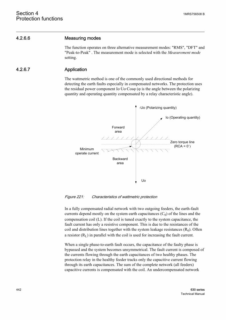
4.2.6.6 Measuring modes
The function operates on three alternative measurement modes: "RMS", "DFT" and"Peak-to-Peak" . The measurement mode is selected with the Measurement modesetting.
4.2.6.7 Application
The wattmetric method is one of the commonly used directional methods fordetecting the earth faults especially in compensated networks. The protection usesthe residual power component Io·Uo·Cosφ (φ is the angle between the polarizingquantity and operating quantity compensated by a relay characteristic angle).
-Uo (Polarizing quantity)
Uo
Backward area
Forwardarea
Io (Operating quantity)
Zero torque line(RCA = 0˚)
Minimumoperate current
GUID-1766F465-7164-4FC2-9245-CFCBB08E3633 V1 EN
Figure 221: Characteristics of wattmetric protection
In a fully compensated radial network with two outgoing feeders, the earth-faultcurrents depend mostly on the system earth capacitances (C0) of the lines and thecompensation coil (L). If the coil is tuned exactly to the system capacitance, thefault current has only a resistive component. This is due to the resistances of thecoil and distribution lines together with the system leakage resistances (R0). Oftena resistor (RL) in parallel with the coil is used for increasing the fault current.
When a single phase-to-earth fault occurs, the capacitance of the faulty phase isbypassed and the system becomes unsymmetrical. The fault current is composed ofthe currents flowing through the earth capacitances of two healthy phases. Theprotection relay in the healthy feeder tracks only the capacitive current flowingthrough its earth capacitances. The sum of the complete network (all feeders)capacitive currents is compensated with the coil. An undercompensated network
Section 4 1MRS756508 BProtection functions
442 630 seriesTechnical Manual

where the coil current IL = ICtot - ICfd (ICtot is the total earth-fault current of thenetwork and ICfd is the earth-fault current of the healthy feeder) is as shown:
A B C
U0
C0
ΣI01
ΣI02
- U0
ΣI02
R0
L RL
- U0
ΣI01
IL
ICfd
Ictot = Ief
GUID-908FF1EF-2E56-4717-8EA2-895805681E60 V1 EN
Figure 222: Typical radial compensated network employed with wattmetricprotection
The wattmetric function is activated when the residual active power componentexceeds the set limit. However, to ensure a selective operation it is also requiredthat the residual current and residual voltage also exceed the set limit.
The sensitivity of the wattmetric method is determined by the magnitude of theresidual voltage, which in turn is determined by the fault resistance and maximumhealthy-state residual voltage. The threshold value of the residual voltage must beset above the maximum healthy-state residual voltage value with a proper margin.When the fault resistance values are high, there is a reduction in the residualvoltage, which reduces the active residual power.
It is highly recommended that core balance CTs are used for measuring Io whenusing the wattmetric method. With some core balance CTs, when a lowtransformation ratio is used, the CT can suffer accuracy problems and even adistorted secondary current waveform. Therefore, to ensure a sufficient accuracy ofthe residual current measurement and consequently a better selectivity of thescheme, the core balance current transformer should preferably have atransformation ratio of at least 70:1. Lower transformation ratios such as 50:1 or50:5 are not recommended, unless the phase displacement errors and CT amplitudeare checked first.
It is not recommended to use the directional wattmetric protection in case of a ringor meshed system as the wattmetric requires a radial power flow to operate.
1MRS756508 B Section 4Protection functions
630 series 443Technical Manual
The relay characteristic angle needs to be set based on the system earthing. In anunearthed network, that is, the network is only coupled to earth via thecapacitances between the phase conductors and earth. The characteristic angle ischosen as -90º in such a network.
In compensated networks, the capacitive fault current and inductive resonance coilcurrent compensates each other, meaning that the fault current is mainly resistiveand has zero phase shift compared to the residual voltage. In such networks, thecharacteristic angle is chosen as 0º. Often the magnitude of active component issmall and must be increased by means of a parallel resistor in a compensation coil.In networks where the neutral point is earthed though a low resistance, thecharacteristic angle is always 0º.
As the amplitude of the residual current is independent of the fault location, theselectivity of the earth-fault protection is achieved by time coordination.
Use of wattmetric protection gives a possibility to use the dedicated inversedefinite minimum time characteristics. This is applicable in large high-impedanceearthed networks with a large capacitive earth-fault current.
In network employing a low-impedance earthed system, a medium-size neutralpoint resistor is used. Such a resistor gives a resistive earth-fault current componentof about 200 - 400 A for an excessive earth fault. In such a system the directionalresidual power protection gives better possibilities for selectivity enabled by theinverse time power characteristics.
Along with the wattmetric protection it is recommended that the normal non-directional residual current function and non-directional residual voltage functionare also used (can be with definite or inverse time delay). The non-directionalresidual current function compares the residual current without checking any phaseangles and gives a quick protection under cross-country faults. The start valuesetting for this non-directional current function should be higher than the setting forall single-phase earth faults with a short IDMT time delay. This is an alternative tothe distance protection with the phase preference logic. The zero-sequence currentfor cross-country faults flowing through the feeder is high compared to the zero-sequence current of the single-phase earth fault. Under this condition the corebalance CT tends to be saturated as it is not designed for a large zero-sequencecurrent resulting in an inaccurate measurement. Hence, the non-directional residualcurrent function should use the calculated residual current derived from the sum ofthe three-phase currents. Non-directional residual voltage function with a longtimer setting acts as a backup protection.
Due to the residual connection of the three-phase CTs and the open deltaconnection of the three-phase VTs, the third harmonic currents and voltages ofeach phase add up and pollute the residual current and voltage measurements. Toenable a sensitive setting, the DFT measuring mode is used.
Section 4 1MRS756508 BProtection functions
444 630 seriesTechnical Manual

4.2.6.8 Signals
Table 443: WPWDE Input signals
Name Type Default DescriptionI3P GROUP
SIGNAL- Three phase group signal for current inputs
U3P GROUPSIGNAL
- Three phase group signal for voltage inputs
BLOCK BOOLEAN 0 Block signal for all binary outputs
BLK_OPR BOOLEAN 0 Block signal for operate output
BLK_ST BOOLEAN 0 Block signal for start output
FR_TIMER BOOLEAN 0 Freeze signal for timers
RCA_CTL BOOLEAN 0 Relay characteristic angle control
Table 444: WPWDE Output signals
Name Type DescriptionOPERATE BOOLEAN Operated
START BOOLEAN Started
FAULT_DIR INTEGER Detected fault direction
4.2.6.9 Settings
Table 445: WPWDE Group settings (basic)
Name Values (Range) Unit Step Default DescriptionDirectional mode Forward
Reverse- - Forward Directional mode
Current start value 0.01 - 5.00 pu 0.01 0.01 Start value for residual current
Voltage start value 0.010 - 1.000 pu 0.001 0.010 Start value for residual voltage
Power start value 0.003 - 1.000 pu 0.001 0.003 Start value for residual active power
Reference power 0.050 - 1.000 pu 0.001 0.150 Reference value of residual power forWattmetric IDMT curves
Characteristic angle -179 - 180 Deg 1 -90 Characteristic angle
Time multiplier 0.05 - 2.00 - 0.01 1.00 Time multiplier for Wattmetric IDMTcurves
Operating curve type ANSI Def. TimeIEC Def. TimeWattMetric IDMT
- - IEC Def. Time Selection of time delay curve type
Operate delay time 0.06 - 200.00 s 0.01 0.06 Operate delay time for definite time
Table 446: WPWDE Non group settings (basic)
Name Values (Range) Unit Step Default DescriptionOperation Off
On- - On Operation Off / On
1MRS756508 B Section 4Protection functions
630 series 445Technical Manual

Table 447: WPWDE Non group settings (advanced)
Name Values (Range) Unit Step Default DescriptionBase value Sel Res Residual Grp 1
Residual Grp 2Residual Grp 3
- - Residual Grp 1 Base value selector, residual
Measurement mode RMSDFTPeak-to-Peak
- - DFT Selects used current measurement mode
Correction angle 0.0 - 10.0 Deg 0.1 2.0 Angle correction
Min operate current 0.010 - 5.000 pu 0.001 0.010 Minimum operate residual current fordeciding fault direction
Min operate voltage 0.01 - 1.00 pu 0.01 0.01 Minimum operate residual voltage fordeciding fault direction
Reset delay time 0.000 - 60.000 s 0.001 0.020 Reset delay time
Pol reversal NoYes
- - No Rotate polarizing quantity
4.2.6.10 Measured values
Table 448: WPWDE Measured values
Name Type Default DescriptionI_RMS_RES REAL 0.0 Residual current amplitude (RMS)
I_AMPL_RES REAL 0.0 Residual current amplitude (DFT)
I_ANGL_RES REAL 0.0 Residual current phase angle
I_PTOP_RES REAL 0.0 Residual current amplitude (PTOP)
U_AMPL_RES REAL 0.0 Residual voltage amplitude (DFT)
U_ANGL_RES REAL 0.0 Residual voltage phase angle
BLOCK BOOLEAN 0 Block signal for all binary outputs
BLK_OPR BOOLEAN 0 Block signal for operate output
BLK_ST BOOLEAN 0 Block signal for start output
FR_TIMER BOOLEAN 0 Freeze signal for timers
RCA_CTL BOOLEAN 0 Relay characteristic angle control
4.2.6.11 Monitored data
Table 449: WPWDE Monitored data
Name Type Values (Range) Unit DescriptionOPERATE BOOLEAN 0=FALSE
1=TRUE- Operated
START BOOLEAN 0=FALSE1=TRUE
- Started
FAULT_DIR INTEGER 0=Unknown1=Forward2=Backward
- Detected fault direction
Table continues on next page
Section 4 1MRS756508 BProtection functions
446 630 seriesTechnical Manual
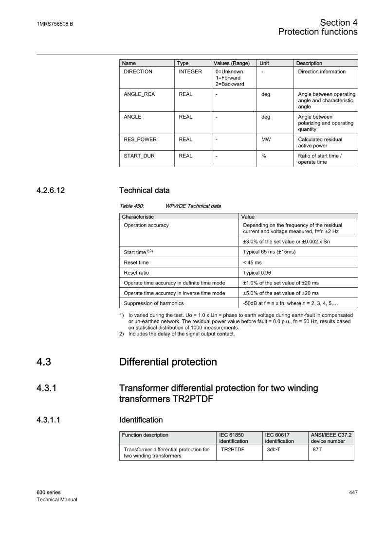
Name Type Values (Range) Unit DescriptionDIRECTION INTEGER 0=Unknown
1=Forward2=Backward
- Direction information
ANGLE_RCA REAL - deg Angle between operatingangle and characteristicangle
ANGLE REAL - deg Angle betweenpolarizing and operatingquantity
RES_POWER REAL - MW Calculated residualactive power
START_DUR REAL - % Ratio of start time /operate time
4.2.6.12 Technical data
Table 450: WPWDE Technical data
Characteristic ValueOperation accuracy Depending on the frequency of the residual
current and voltage measured, f=fn ±2 Hz
±3.0% of the set value or ±0.002 x Sn
Start time1)2) Typical 65 ms (±15ms)
Reset time < 45 ms
Reset ratio Typical 0.96
Operate time accuracy in definite time mode ±1.0% of the set value of ±20 ms
Operate time accuracy in inverse time mode ±5.0% of the set value of ±20 ms
Suppression of harmonics -50dB at f = n x fn, where n = 2, 3, 4, 5,…
1) Io varied during the test. Uo = 1.0 x Un = phase to earth voltage during earth-fault in compensatedor un-earthed network. The residual power value before fault = 0.0 p.u., fn = 50 Hz, results basedon statistical distribution of 1000 measurements.
2) Includes the delay of the signal output contact.
4.3 Differential protection
4.3.1 Transformer differential protection for two windingtransformers TR2PTDF
4.3.1.1 Identification
Function description IEC 61850identification
IEC 60617identification
ANSI/IEEE C37.2device number
Transformer differential protection fortwo winding transformers
TR2PTDF 3dI>T 87T
1MRS756508 B Section 4Protection functions
630 series 447Technical Manual
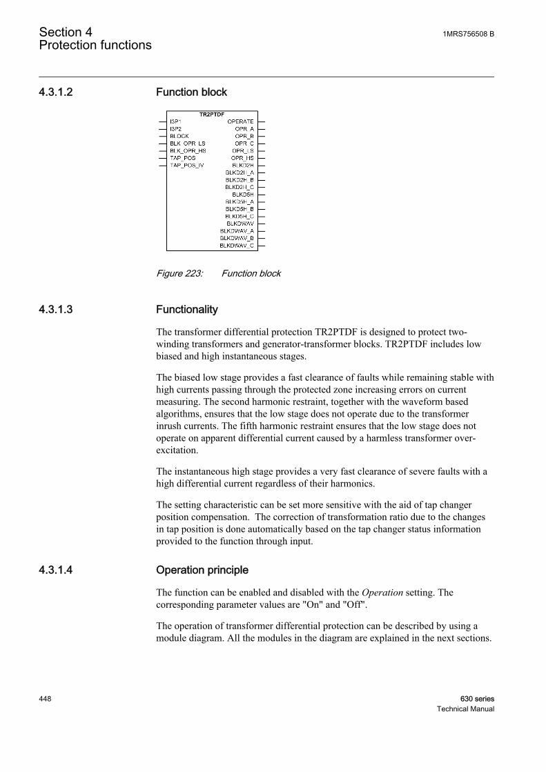
4.3.1.2 Function block
GUID-D47B83D3-6980-42E8-A283-8DAE8D5A3A26 V1 EN
Figure 223: Function block
4.3.1.3 Functionality
The transformer differential protection TR2PTDF is designed to protect two-winding transformers and generator-transformer blocks. TR2PTDF includes lowbiased and high instantaneous stages.
The biased low stage provides a fast clearance of faults while remaining stable withhigh currents passing through the protected zone increasing errors on currentmeasuring. The second harmonic restraint, together with the waveform basedalgorithms, ensures that the low stage does not operate due to the transformerinrush currents. The fifth harmonic restraint ensures that the low stage does notoperate on apparent differential current caused by a harmless transformer over-excitation.
The instantaneous high stage provides a very fast clearance of severe faults with ahigh differential current regardless of their harmonics.
The setting characteristic can be set more sensitive with the aid of tap changerposition compensation. The correction of transformation ratio due to the changesin tap position is done automatically based on the tap changer status informationprovided to the function through input.
4.3.1.4 Operation principle
The function can be enabled and disabled with the Operation setting. Thecorresponding parameter values are "On" and "Off".
The operation of transformer differential protection can be described by using amodule diagram. All the modules in the diagram are explained in the next sections.
Section 4 1MRS756508 BProtection functions
448 630 seriesTechnical Manual

GUID-4107A323-08ED-4FDF-9C8D-DA0AC8AE3E84 V1 EN
Figure 224: Functional module diagram. Group signals I3P1 and I3P2 are usedfor feeding the necessary analog signals to the function. I_x1 andI_x2 represent the phase currents of winding 1 and winding 2.
Differential calculationTR2PTDF operates phase-wise on a difference of incoming and outgoing currents.The positive direction of the currents is towards the protected object.
Winding 1(usually HV)
Winding 2(usually LV)
1WI 2WI
GUID-DABAB343-214F-4A86-ADC8-BFD8E64B25A7 V3 EN
Figure 225: Positive direction of the currents
I I Id W W= +1 2
GUID-0B35503B-CA7D-4598-A1E4-59C9AA66012D V2 EN (Equation 45)
1MRS756508 B Section 4Protection functions
630 series 449Technical Manual

In a normal situation, no fault occurs in the area protected by TR2PTDF. Then thecurrents IW1 and IW 2 are equal and the differential current Id is zero. In practice,however, the differential current deviates from zero in normal situations. In thepower transformer protection, the differential current is caused by CT inaccuracies,variations in tap changer position (if not compensated), transformer no-load currentand instantaneous transformer inrush currents. An increase in the load currentcauses the differential current, caused by the CT inaccuracies and the tap changerposition, to grow at the same percentage rate.
In a biased differential IED in normal operation or during external faults, the higherthe load current is the higher is the differential current required for tripping. Whenan internal fault occurs, the currents on both sides of the protected object areflowing into it. This causes the biasing current to be considerably smaller, whichmakes the operation more sensitive during internal faults.
I
I I
b
W W
=
−1 2
2
GUID-1403DDDA-D840-4746-A925-F426AC7A8608 V2 EN (Equation 46)
If the biasing current is small compared to the differential current or if the phaseangle between the winding 1 and winding 2 phase currents is close to zero (in anormal situation, the phase difference is 180 degrees), a fault has most certainlyoccurred in the area protected by the differential IED. Then the operation value setfor the instantaneous stage is automatically halved and the internal blocking signalsof the biased stage are inhibited.
The values displayed on the monitored data view for windingscurrent, bias current and differential current are per unit.
Transformer vector group matchingThe phase difference of the winding 1 and winding 2 currents that is caused by thevector group of the power transformer is numerically compensated. The matchingof the phase difference is based on the phase shifting and the numerical deltaconnection inside the IED. The Winding 2 type parameter determines theconnections of the phase windings on the low voltage side(”Y”, ”YN”, ”D”, ”Z”, ”ZN”). Similarly, the Winding 1 type parameter determinesthe connection on winding 1 (”Y”, ”YN”, ”D”, ”Z”, ”ZN”).
The vector group matching can be implemented either on both, winding 1 andwinding 2, or only on winding 1 or winding 2, at intervals of 30° with the Clocknumber setting.
When the vector group matching is Yy0 and the CT connection type is according to"Type 1", the phase angle of the phase currents connected to the IED does notchange. When the vector group matching is Yy6, the phase currents are turned180° in the IED.
Section 4 1MRS756508 BProtection functions
450 630 seriesTechnical Manual
Example 1Vector group matching of a Ynd11-connected power transformer on winding 1, CTconnection type according to type 1. The Winding 1 type setting is ”YN”, Winding2 type is ”D” and Clock number is “Clk Num 11”. This is compensated internallyby giving winding 1 internal compensation value +30° and winding 2 internalcompensation value 0°:
II I
II I
II I
L mHV
L L
L mHV
L L
L mHV
L L
1
1 2
2
2 3
3
3 1
3
3
3
=
−
=
−
=
−
GUID-633921A4-D973-4BD2-BFDF-E9FF73C3B9E3 V1 EN (Equation 47)
Example 2But if vector group is Yd11 and CT connection type is according to type 1, thecompensation is a little different. The Winding 1 type setting is ”Y”, Winding 2type is “D” and Clock number is “Clk Num 11”. This is compensated internally bygiving winding 1 internal compensation value 0° and winding 2 internalcompensation value -30°;
II I
II I
II I
L mLVL L
L mLVL L
L mLVL L
11 3
22 1
33 2
3
3
3
=−
=−
=−
GUID-41089920-D9BF-4574-96FB-0B1F48019391 V1 EN (Equation 48)
The "Y" side currents stay untouched, while the "d" side currents are compensatedto match the currents actually flowing in the windings.
In this example there is no neutral current on either side of the transformer(assuming there are no earthing transformers installed). In the previous example,however, the matching is done differently to have the winding 1 neutral currentcompensated at the same time.
Zero-sequence component eliminationIf Clock number is "Clk Num 2", "Clk Num 4", "Clk Num 8" or "Clk Num 10", thevector group matching is always done on both, winding 1 and winding 2. Thecombination results in the correct compensation. In this case the zero-sequencecomponent is always removed from both sides automatically. The Zro Aelimination parameter cannot change this.
If Clock number is "Clk Num 1", "Clk Num 5", "Clk Num 7" or "Clk Num 11", thevector group matching is done on one side only. A possible zero-sequence
1MRS756508 B Section 4Protection functions
630 series 451Technical Manual
component of the phase currents at earth faults occurring outside the protectionarea is eliminated in the numerically implemented delta connection before thedifferential current and the biasing current are calculated. This is why the vectorgroup matching is almost always made on the star connected side of the "Ynd" and"Dyn" connected transformers.
If Clock number is "Clk Num 0" or "Clk Num 6", the zero-sequence component ofthe phase currents is not eliminated automatically on either side. Therefore, the zero-sequence component on the star connected side that is earthed at its star point hasto be eliminated by using the Zro A elimination parameter.
The same parameter has to be used to eliminate the zero-sequence component ifthere is, for example, an earthing transformer on the delta-connected side of the"Ynd" power transformer in the area to be protected. In this case, the vector groupmatching is normally made on the side of the star connection. On the side of thedelta connection, the elimination of the zero-sequence component has to beseparately selected.
By using the Zro A elimination parameter, the zero-sequence component of thephase currents is calculated and reduced for each phase current:
I I x I I I
I I x I I I
I I
L m L L L L
L m L L L L
L m L
1 1 1 2 3
2 2 1 2 3
3 3
1
3
1
3
= − + +( )
= − + +( )
= −− + +( )1
31 2 3x I I IL L L
GUID-398EDAFF-4A32-4C39-AD75-1F6D19B8FF48 V1 EN (Equation 49)
In many cases with the earthed neutral of a "wye" winding, it ispossible to make the compensation so that a zero-sequencecomponent of the phase currents is automatically eliminated. Forexample, in a case of a "Ynd" transformer, the compensation ismade on the winding 1 side to automatically eliminate the zero-sequence component of the phase currents on that side (and the "d"side does not have them). In those cases, explicit elimination is notneeded.
Compensation of tap changer positionThe position of the tap changer used for voltage control can be compensated andthe position information is provided for the protection function through the tapposition indication function TPOSSLTC1.
Typically, the tap changer is located within the high voltage winding, that is,winding 1, of the power transformer. The Tapped winding parameter specifieswhether the tap changer is connected to the high voltage side winding or the lowvoltage side winding. This parameter is also used to enable and disable the
Section 4 1MRS756508 BProtection functions
452 630 seriesTechnical Manual

automatic adaptation to the tap changer position. The possible values are "Not inuse", "Winding 1", "Winding 2".
The Tap nominal parameter tells the number of the tap, which results in thenominal voltage (and current). When the current tap position deviates from thisvalue, the input current values on the side where the tap changer resides are scaledto match the currents on the other side.
A correct scaling is determined by the number of steps and the direction of thedeviation from the nominal tap and the percentage change in voltage resulting froma deviation of one tap step. The percentage value is set using the Step of tap parameter.
The operating range of the tap changer is defined by the Min winding tap and Maxwinding tap parameters. The Min winding tap parameter tells the tap positionnumber resulting in the minimum effective number of winding turns on the side ofthe transformer where the tap changer is connected. Correspondingly, the Maxwinding tap parameter tells the tap position number resulting in the maximumeffective number of winding turns.
The Min winding tap and Max winding tap parameters help the tap positioncompensation algorithm know in which direction the compensation is being made.This ensures also that if the current tap position information is corrupted for somereason, the automatic tap changer position adaptation does not try to adapt to anyunrealistic position values.
GUID-317C68F8-A517-458A-A5D0-32FCE6C5F547 V1 EN
Figure 226: Simplified presentation of the high voltage and medium voltagewindings with demonstration of the Max winding tap, Min windingtap and Tap nominal parameters
The position value in the TAP_POS input is valid if the value of the TAP_POS_IVinput is “FALSE.” When the value of the TAP_POS_IV input is “TRUE,” theposition information in TAP_POS is not used but the last value beforeTAP_POS_IV changed to “TRUE” is used instead. In addition, the minimumsensitivity of the biased stage, set by the Low operate value setting, isautomatically desensitized with the total range of the tap position correction. Thenew acting low operate value is
Desensitized Low operate value = Lowoperatevalue ABS MaxWi+ ( nnding tap Min winding tap Step of tap− ×)
GUID-2E5AD399-D8DD-4F64-A194-7540D55DB8ED V3 EN (Equation 50)
1MRS756508 B Section 4Protection functions
630 series 453Technical Manual

Second harmonic blockingThe transformer magnetizing inrush currents occur when energizing thetransformer after a period of de-energization. The inrush current can be many timesthe rated current and the halving time can be up to several seconds. To thedifferential protection, the inrush current represents a differential current, whichwould cause the differential protection to operate almost always when thetransformer is connected to the network. Typically, the inrush current contains alarge amount of second harmonics.
Blocking the operation of the TR2PTDF biased low stage at a magnetizing inrushcurrent is based on the ratio of the amplitudes of the second harmonic digitallyfiltered from the differential current and the fundamental frequency (Id2f /Id1f).
The blocking also prevents unwanted operation at the recovery and sympatheticmagnetizing inrushes. At the recovery inrush, the magnetizing current of thetransformer to be protected increases momentarily when the voltage returns tonormal after the clearance of a fault outside the protected area. The sympatheticinrush is caused by the energization of another transformer running in parallel withthe protected transformer already connected to the network.
The ratio of the second harmonic to a fundamental component can varyconsiderably between the phases. Especially when the delta compensation is donefor a Ynd1 connected transformer and the two phases of the inrush currents areotherwise equal but opposite in phase angle, the subtraction of the phases in a deltacompensation results in a very small second harmonic component.
Some measures have to be taken in order to avoid the false tripping of a phasehaving too low a ratio of the second harmonic to the fundamental component. Oneway could be to always block all the phases when the second harmonic blockingconditions are fulfilled in at least one phase. The other way is to calculate theweighted ratios of the second harmonic to the fundamental component for eachphase using the original ratios of the phases. The latter option is used here. Thesecond harmonic ratios I_2H_RAT_x are given in monitored data.
The ratio to be used for second harmonic blocking is, therefore, calculated as aweighted average on the basis of the ratios calculated from the differential currentsof the three phases. The ratio of the concerned phase is of most weight compared tothe ratios of the other two phases. In this IED, if the weighting factors are four, oneand one, four is the factor of the phase concerned. The operation of the biased stageon the concerned phase is blocked if the weighted ratio of that phase is above theset blocking limit Start value 2.H and if blocking is enabled through the Restraintmode parameter.
Using separate blocking for the individual phases and weighted averages calculatedfor the separate phases provides a blocking scheme that is stable at the connectioninrush currents.
Section 4 1MRS756508 BProtection functions
454 630 seriesTechnical Manual

If the peak value of the differential current is very high, that is Ir> 12 xIn, the limitfor the second harmonic blocking is desensitized (in the phase in question) byincreasing it proportionally to the peak value of the differential current.
The connection of the power transformer against a fault inside the protected areadoes not delay the operation of the tripping, because in such a situation theblocking based on the second harmonic of the differential current is prevented by aseparate algorithm based on a different waveform and a different rate of change ofthe normal inrush current and the inrush current containing the fault current. Thealgorithm does not eliminate the blocking at inrush currents, unless there is a faultin the protected area.
The feature can also be enabled and disabled with the Harmonic deblock 2.Hparameter.
Fifth harmonic blockingThe inhibition of TR2PTDF operation in the situations of overexcitation is basedon the ratio of the fifth harmonic and the fundamental component of the differentialcurrent (Id5f/Id1f). The ratio is calculated separately for each phase withoutweighting the factors. If the ratio exceeds the setting value of Start value 5.H and ifblocking is enabled through the Restraint mode parameter, the operation of thebiased stage of TR2PTDF in the concerned phase is blocked.
At dangerous levels of overvoltage, which can cause damage to the transformer,the blocking can be automatically eliminated. If the ratio of the fifth harmonic andthe fundamental component of the differential current exceeds the Stop value 5.Hparameter, the blocking removal is enabled. The enabling and disabling ofdeblocking feature is also done through the Harmonic deblock 5.H parameter.
GUID-A97464D1-3085-4F27-B829-11EEC47CA654 V1 EN
Figure 227: The limits and operation of the fifth harmonic blocking when bothblocking and deblocking features are enabled using the Harmonicdeblock 5.H control parameter.
The fifth harmonic blocking has a hysteresis to avoid rapid fluctuation between"TRUE" and "FALSE". The blocking also has a counter, which counts the required
1MRS756508 B Section 4Protection functions
630 series 455Technical Manual

consecutive fulfillments of the condition. When the condition is not fulfilled, thecounter is decreased (if >0).
Also the fifth harmonic deblocking has a hysteresis and a counter which counts therequired consecutive fulfillments of the condition. When the condition is notfulfilled, the counter is decreased (if >0).
Waveform blockingThe biased low stage can always be blocked with waveform blocking. The stagecan not be disabled with the Restraint mode parameter. This algorithm has twoparts. The first part is intended for external faults while the second is intended forinrush situations. The algorithm has criteria for a low current period during inrushwhere also the differential current (not derivative) is checked.
Biased low stageThe current differential protection needs to be biased because the possibleappearance of a differential current can be due to something else than an actualfault in the transformer (or generator).
In the case of transformer protection, a false differential current can be caused by:
• CT errors• Varying tap changer positions (if not automatically compensated)• Transformer no-load current• Transformer inrush currents• Transformer overexcitation in overvoltage• Underfrequency situations• CT saturation at high currents passing through the transformer.
The differential current caused by CT errors or tap changer positions increases atthe same percent ratio as the load current.
In the protection of generators, the false differential current can be caused by:
• CT errors• CT saturation at high currents passing through the generator.
Section 4 1MRS756508 BProtection functions
456 630 seriesTechnical Manual
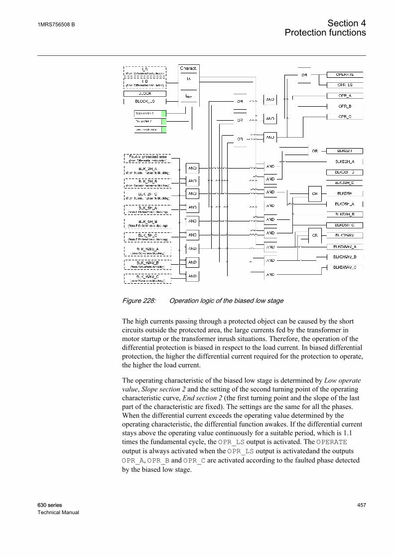
GUID-C76B2341-0DA7-4E35-A17C-1A7C70CE002C V1 EN
Figure 228: Operation logic of the biased low stage
The high currents passing through a protected object can be caused by the shortcircuits outside the protected area, the large currents fed by the transformer inmotor startup or the transformer inrush situations. Therefore, the operation of thedifferential protection is biased in respect to the load current. In biased differentialprotection, the higher the differential current required for the protection to operate,the higher the load current.
The operating characteristic of the biased low stage is determined by Low operatevalue, Slope section 2 and the setting of the second turning point of the operatingcharacteristic curve, End section 2 (the first turning point and the slope of the lastpart of the characteristic are fixed). The settings are the same for all the phases.When the differential current exceeds the operating value determined by theoperating characteristic, the differential function awakes. If the differential currentstays above the operating value continuously for a suitable period, which is 1.1times the fundamental cycle, the OPR_LS output is activated. The OPERATEoutput is always activated when the OPR_LS output is activatedand the outputsOPR_A, OPR_B and OPR_C are activated according to the faulted phase detectedby the biased low stage.
1MRS756508 B Section 4Protection functions
630 series 457Technical Manual

The stage can be blocked internally by the second or fifth harmonic restraint, or byspecial algorithms detecting inrush and current transformer saturation at externalfaults. When the operation of the biased low stage is blocked by the secondharmonic blocking functionality, the outputs BLKD2H_A, BLKD2H_B, BLKD2H_Cand the combined output BLKD2H are activated according to the phase information.
When operation of the biased low stage is blocked by the fifth harmonic blockingfunctionality, the outputs BLKD5H_A, BLKD5H_B, BLKD5H_C and the combinedoutput BLKD5H are activated according to the phase information. Correspondingly,when the operation of the biased low stage is blocked by the waveform blockingfunctionality, the outputs BLKDWAV_A, BLKDWAV_B, BLKDWAV_C and thecombined output BLKDWAV are activated according to the phase information.
When required, the operate outputs of the biased low stage can be blocked by theBLK_OPR_LS or BLOCK external control signals.
Ib2
Id1
Id2
Ib3
Id3
100
200
300
100 200 300 400 500
End section 2End section 1
Low operate value
Section 1 Section 2 Section 3
Ib [%In]
Id [%In]
GUID-8F4DB4E4-64B4-4035-9A31-C3B68EE7BEF2 V1 EN
Figure 229: Operation characteristic for biased operation of TR2PTDF
Lowoperate value Id In= ×1 100/ %
GUID-8C70C699-8216-4E56-997D-B0B15FACB932 V2 EN (Equation 51)
Slope section Id Ib2 2 2 100= ×/ %
GUID-D1C2CAED-3D58-4405-A79D-17B203A8D3A9 V3 EN (Equation 52)
The second turning point End section 2 can be set in the range of 100 percent to500 percent.
The slope of the differential function's operating characteristic curve varies in thedifferent sections of the range.
Section 4 1MRS756508 BProtection functions
458 630 seriesTechnical Manual
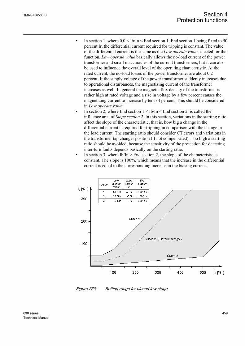
• In section 1, where 0.0 < Ib/In < End section 1, End section 1 being fixed to 50percent Ir, the differential current required for tripping is constant. The valueof the differential current is the same as the Low operate value selected for thefunction. Low operate value basically allows the no-load current of the powertransformer and small inaccuracies of the current transformers, but it can alsobe used to influence the overall level of the operating characteristic. At therated current, the no-load losses of the power transformer are about 0.2percent. If the supply voltage of the power transformer suddenly increases dueto operational disturbances, the magnetizing current of the transformerincreases as well. In general the magnetic flux density of the transformer israther high at rated voltage and a rise in voltage by a few percent causes themagnetizing current to increase by tens of percent. This should be consideredin Low operate value
• In section 2, where End section 1 < Ib/In < End section 2, is called theinfluence area of Slope section 2. In this section, variations in the starting ratioaffect the slope of the characteristic, that is, how big a change in thedifferential current is required for tripping in comparison with the change inthe load current. The starting ratio should consider CT errors and variations inthe transformer tap changer position (if not compensated). Too high a startingratio should be avoided, because the sensitivity of the protection for detectinginter-turn faults depends basically on the starting ratio.
• In section 3, where Ib/In > End section 2, the slope of the characteristic isconstant. The slope is 100%, which means that the increase in the differentialcurrent is equal to the corresponding increase in the biasing current.
GUID-739E1789-778D-44BF-BD4A-6BD684BF041D V2 EN
Figure 230: Setting range for biased low stage
1MRS756508 B Section 4Protection functions
630 series 459Technical Manual

If the biasing current is small compared to the differential current of the phaseangle between the winding 1 and winding 2 phase currents is close to zero (in anormal situation, the phase difference is 180 degrees), a fault has most likelyoccurred in the area protected by TR2PTDF. Then the internal blocking signals ofthe biased stage are inhibited.
Instantaneous high stageThe instantaneous high stage operation can be enabled and disabled with theEnable high set setting. The corresponding parameter values are "TRUE" and"FALSE."
The operation of the instantaneous high stage is not biased. The instantaneous stageoperates and the output OPR_HS is activated when the amplitude of thefundamental frequency component of the differential current exceeds the set Highoperate value or when the instantaneous value of the differential current exceeds2.5 times the value of High operate value. The factor 2.5 (=1.8 x √2) is due to themaximum asymmetric short circuit current.
If the biasing current is small compared to the differential current or the phaseangle between the winding 1 and winding 2 phase currents is close to zero (in anormal situation, the phase difference is 180 degrees), a fault has occurred in thearea protected by TR2PTDF. Then the operation value set for the instantaneousstage is automatically halved and the internal blocking signals of the biased stageare inhibited.
GUID-8B8EC6FC-DF75-4674-808B-7B4C68E9F3E8 V1 EN
Figure 231: Operating characteristics of the protection. (LS) stands for thebiased low stage and (HS) for the instantaneous high stage
The OPERATE output is activated always when the OPR_HS output activates andoutputs OPR_A, OPR_B and OPR_C are activated according to the faulted phasedetected by the instantaneous high stage.
Section 4 1MRS756508 BProtection functions
460 630 seriesTechnical Manual
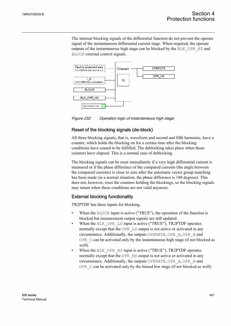
The internal blocking signals of the differential function do not prevent the operatesignal of the instantaneous differential current stage. When required, the operateoutputs of the instantaneous high stage can be blocked by the BLK_OPR_HS andBLOCK external control signals.
GUID-6BB9E91D-6C5D-404C-8380-A3D8F3398F8C V2 EN
Figure 232: Operation logic of instantaneous high stage
Reset of the blocking signals (de-block)All three blocking signals, that is, waveform and second and fifth harmonic, have acounter, which holds the blocking on for a certain time after the blockingconditions have ceased to be fulfilled. The deblocking takes place when thosecounters have elapsed. This is a normal case of deblocking.
The blocking signals can be reset immediately if a very high differential current ismeasured or if the phase difference of the compared currents (the angle betweenthe compared currents) is close to zero after the automatic vector group matchinghas been made (in a normal situation, the phase difference is 180 degrees). Thisdoes not, however, reset the counters holding the blockings, so the blocking signalsmay return when these conditions are not valid anymore.
External blocking functionalityTR2PTDF has three inputs for blocking.
• When the BLOCK input is active ("TRUE"), the operation of the function isblocked but measurement output signals are still updated.
• When the BLK_OPR_LS input is active ("TRUE"), TR2PTDF operatesnormally except that the OPR_LS output is not active or activated in anycircumstance. Additionally, the outputs OPERATE, OPR_A, OPR_B andOPR_C can be activated only by the instantaneous high stage (if not blocked aswell).
• When the BLK_OPR_HS input is active ("TRUE"), TR2PTDF operatesnormally except that the OPR_HS output is not active or activated in anycircumstance. Additionally, the outputs OPERATE, OPR_A, OPR_B andOPR_C can be activated only by the biased low stage (if not blocked as well).
1MRS756508 B Section 4Protection functions
630 series 461Technical Manual
4.3.1.5 Application
TR2PTDF is a unit protection function serving as the main protection fortransformers in case of winding failure. The protective zone of a differentialprotection includes the transformer, the bus-work or the cables between the currenttransformer and the power transformer. When bushing current transformers areused for the differential IED, the protective zone does not include the bus work orcables between the circuit breaker and the power transformer.
In some substations, there is a current differential protection for the busbar. Thebusbar protection includes bus work or cables between the circuit breaker and thepower transformer. Internal electrical faults are very serious and cause immediatedamage. Short circuits and earth faults in windings and terminals are normallydetected by the differential protection. If enough turns are short-circuited, theinterturn faults, which are flashovers between the conductors within the samephysical winding, are also detected. The interturn faults are the most difficulttransformer-winding faults to detect with electrical protections. A small interturnfault including a few turns results in an undetectable amount of current until thefault develops into an earth fault. Therefore, it is important that the differentialprotection has a high level of sensitivity and that it is possible to use a sensitivesetting without causing unwanted operations for external faults.
It is important that the faulty transformer is disconnected as fast as possible. AsTR2PTDF is a unit protection function, it can be designed for fast tripping, thusproviding a selective disconnection of the faulty transformer. TR2PTDF shouldnever operate to faults outside the protective zone.
TR2PTDF compares the current flowing into the transformer to the current leavingthe transformer. A correct analysis of fault conditions by TR2PTDF must considerthe changes to voltages, currents and phase angles. The traditional transformerdifferential protection functions required auxiliary transformers for the correctionof the phase shift and turns ratio. The numerical microprocessor based differentialalgorithm implemented in TR2PTDF compensates for both the turns ratio and thephase shift internally in the software.
The differential current should theoretically be zero during normal load or externalfaults if the turns ratio and the phase shift are correctly compensated. However,there are several different phenomena other than internal faults that causeunwanted and false differential currents. The main reasons for unwanteddifferential currents are:
• Mismatch due to varying tap changer positions• Different characteristics, loads and operating conditions of the current
transformers• Zero sequence currents that only flow on one side of the power transformer• Normal magnetizing currents• Magnetizing inrush currents• Overexcitation magnetizing currents.
Section 4 1MRS756508 BProtection functions
462 630 seriesTechnical Manual
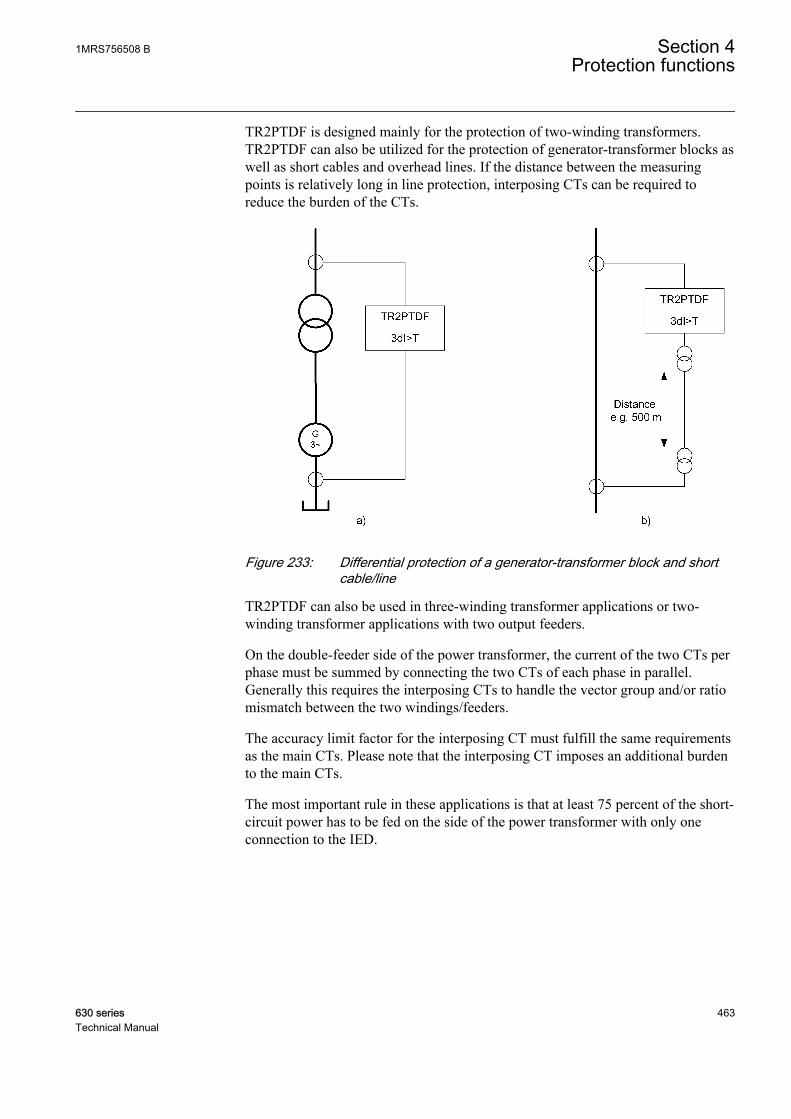
TR2PTDF is designed mainly for the protection of two-winding transformers.TR2PTDF can also be utilized for the protection of generator-transformer blocks aswell as short cables and overhead lines. If the distance between the measuringpoints is relatively long in line protection, interposing CTs can be required toreduce the burden of the CTs.
GUID-B326703C-3645-4256-96AD-DA87FC9E9C67 V1 EN
Figure 233: Differential protection of a generator-transformer block and shortcable/line
TR2PTDF can also be used in three-winding transformer applications or two-winding transformer applications with two output feeders.
On the double-feeder side of the power transformer, the current of the two CTs perphase must be summed by connecting the two CTs of each phase in parallel.Generally this requires the interposing CTs to handle the vector group and/or ratiomismatch between the two windings/feeders.
The accuracy limit factor for the interposing CT must fulfill the same requirementsas the main CTs. Please note that the interposing CT imposes an additional burdento the main CTs.
The most important rule in these applications is that at least 75 percent of the short-circuit power has to be fed on the side of the power transformer with only oneconnection to the IED.
1MRS756508 B Section 4Protection functions
630 series 463Technical Manual
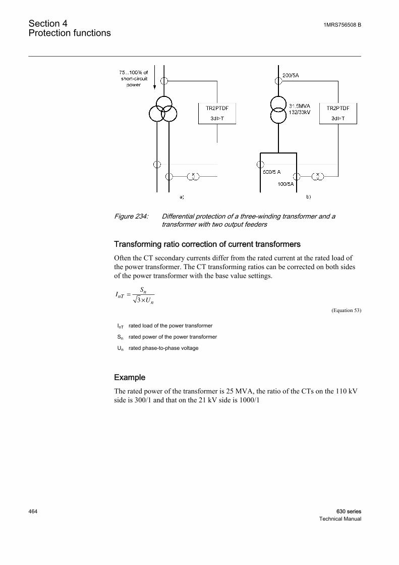
GUID-799588E3-C63F-4687-98C5-FF48284676DF V1 EN
Figure 234: Differential protection of a three-winding transformer and atransformer with two output feeders
Transforming ratio correction of current transformersOften the CT secondary currents differ from the rated current at the rated load ofthe power transformer. The CT transforming ratios can be corrected on both sidesof the power transformer with the base value settings.
IS
UnT
n
n
=
×3
GUID-B5467DB8-17EB-4D09-A741-1F5BB23466AA V1 EN (Equation 53)
InT rated load of the power transformer
Sn rated power of the power transformer
Un rated phase-to-phase voltage
ExampleThe rated power of the transformer is 25 MVA, the ratio of the CTs on the 110 kVside is 300/1 and that on the 21 kV side is 1000/1
Section 4 1MRS756508 BProtection functions
464 630 seriesTechnical Manual
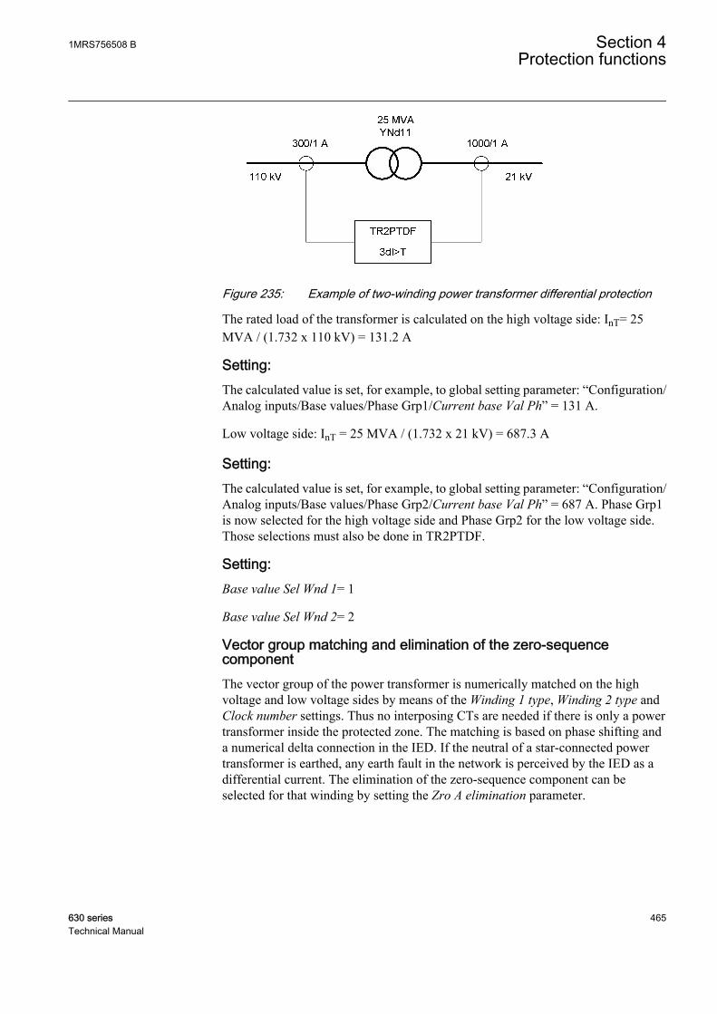
GUID-854DC103-BBAB-4A62-AB87-6429B06C5500 V2 EN
Figure 235: Example of two-winding power transformer differential protection
The rated load of the transformer is calculated on the high voltage side: InT= 25MVA / (1.732 x 110 kV) = 131.2 A
Setting:The calculated value is set, for example, to global setting parameter: “Configuration/Analog inputs/Base values/Phase Grp1/Current base Val Ph” = 131 A.
Low voltage side: InT = 25 MVA / (1.732 x 21 kV) = 687.3 A
Setting:The calculated value is set, for example, to global setting parameter: “Configuration/Analog inputs/Base values/Phase Grp2/Current base Val Ph” = 687 A. Phase Grp1is now selected for the high voltage side and Phase Grp2 for the low voltage side.Those selections must also be done in TR2PTDF.
Setting:Base value Sel Wnd 1= 1
Base value Sel Wnd 2= 2
Vector group matching and elimination of the zero-sequencecomponentThe vector group of the power transformer is numerically matched on the highvoltage and low voltage sides by means of the Winding 1 type, Winding 2 type andClock number settings. Thus no interposing CTs are needed if there is only a powertransformer inside the protected zone. The matching is based on phase shifting anda numerical delta connection in the IED. If the neutral of a star-connected powertransformer is earthed, any earth fault in the network is perceived by the IED as adifferential current. The elimination of the zero-sequence component can beselected for that winding by setting the Zro A elimination parameter.
1MRS756508 B Section 4Protection functions
630 series 465Technical Manual
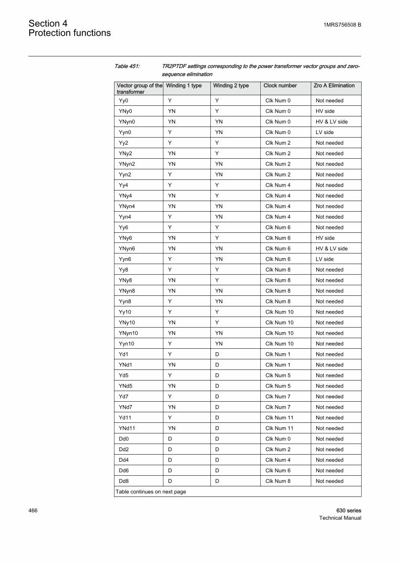
Table 451: TR2PTDF settings corresponding to the power transformer vector groups and zero-sequence elimination
Vector group of thetransformer
Winding 1 type Winding 2 type Clock number Zro A Elimination
Yy0 Y Y Clk Num 0 Not needed
YNy0 YN Y Clk Num 0 HV side
YNyn0 YN YN Clk Num 0 HV & LV side
Yyn0 Y YN Clk Num 0 LV side
Yy2 Y Y Clk Num 2 Not needed
YNy2 YN Y Clk Num 2 Not needed
YNyn2 YN YN Clk Num 2 Not needed
Yyn2 Y YN Clk Num 2 Not needed
Yy4 Y Y Clk Num 4 Not needed
YNy4 YN Y Clk Num 4 Not needed
YNyn4 YN YN Clk Num 4 Not needed
Yyn4 Y YN Clk Num 4 Not needed
Yy6 Y Y Clk Num 6 Not needed
YNy6 YN Y Clk Num 6 HV side
YNyn6 YN YN Clk Num 6 HV & LV side
Yyn6 Y YN Clk Num 6 LV side
Yy8 Y Y Clk Num 8 Not needed
YNy8 YN Y Clk Num 8 Not needed
YNyn8 YN YN Clk Num 8 Not needed
Yyn8 Y YN Clk Num 8 Not needed
Yy10 Y Y Clk Num 10 Not needed
YNy10 YN Y Clk Num 10 Not needed
YNyn10 YN YN Clk Num 10 Not needed
Yyn10 Y YN Clk Num 10 Not needed
Yd1 Y D Clk Num 1 Not needed
YNd1 YN D Clk Num 1 Not needed
Yd5 Y D Clk Num 5 Not needed
YNd5 YN D Clk Num 5 Not needed
Yd7 Y D Clk Num 7 Not needed
YNd7 YN D Clk Num 7 Not needed
Yd11 Y D Clk Num 11 Not needed
YNd11 YN D Clk Num 11 Not needed
Dd0 D D Clk Num 0 Not needed
Dd2 D D Clk Num 2 Not needed
Dd4 D D Clk Num 4 Not needed
Dd6 D D Clk Num 6 Not needed
Dd8 D D Clk Num 8 Not needed
Table continues on next page
Section 4 1MRS756508 BProtection functions
466 630 seriesTechnical Manual

Vector group of thetransformer
Winding 1 type Winding 2 type Clock number Zro A Elimination
Dd10 D D Clk Num 10 Not needed
Dy1 D Y Clk Num 1 Not needed
Dyn1 D YN Clk Num 1 Not needed
Dy5 D Y Clk Num 5 Not needed
Dyn5 D YN Clk Num 5 Not needed
Dy7 D Y Clk Num 7 Not needed
Dyn7 D YN Clk Num 7 Not needed
Dy11 D Y Clk Num 11 Not needed
Dyn11 D YN Clk Num 11 Not needed
Yz1 Y Z Clk Num 1 Not needed
YNz1 YN Z Clk Num 1 Not needed
YNzn1 YN ZN Clk Num 1 LV side
Yzn1 Y ZN Clk Num 1 Not needed
Yz5 Y Z Clk Num 5 Not needed
YNz5 YN Z Clk Num 5 Not needed
YNzn5 YN ZN Clk Num 5 LV side
Yzn5 Y ZN Clk Num 5 Not needed
Yz7 Y Z Clk Num 7 Not needed
YNz7 YN Z Clk Num 7 Not needed
YNzn7 YN ZN Clk Num 7 LV side
Yzn7 Y ZN Clk Num 7 Not needed
Yz11 Y Z Clk Num 11 Not needed
YNz11 YN Z Clk Num 11 Not needed
YNzn11 YN ZN Clk Num 11 LV side
Yzn11 Y ZN Clk Num 11 Not needed
Zy1 Z Y Clk Num 1 Not needed
Zyn1 Z YN Clk Num 1 Not needed
ZNyn1 ZN YN Clk Num 1 HV side
ZNy1 ZN Y Clk Num 1 Not needed
Zy5 Z Y Clk Num 5 Not needed
Zyn5 Z YN Clk Num 5 Not needed
ZNyn5 ZN YN Clk Num 5 HV side
ZNy5 ZN Y Clk Num 5 Not needed
Zy7 Z Y Clk Num 7 Not needed
Zyn7 Z YN Clk Num 7 Not needed
ZNyn7 ZN YN Clk Num 7 HV side
ZNy7 ZN Y Clk Num 7 Not needed
Zy11 Z Y Clk Num 11 Not needed
Zyn11 Z YN Clk Num 11 Not needed
Table continues on next page
1MRS756508 B Section 4Protection functions
630 series 467Technical Manual

Vector group of thetransformer
Winding 1 type Winding 2 type Clock number Zro A Elimination
ZNyn11 ZN YN Clk Num 11 HV side
ZNy11 ZN Y Clk Num 11 Not needed
Dz0 D Z Clk Num 0 Not needed
Dzn0 D ZN Clk Num 0 LV side
Dz2 D Z Clk Num 2 Not needed
Dzn2 D ZN Clk Num 2 Not needed
Dz4 D Z Clk Num 4 Not needed
Dzn4 D ZN Clk Num 4 Not needed
Dz6 D Z Clk Num 6 Not needed
Dzn6 D ZN Clk Num 6 LV side
Dz8 D Z Clk Num 8 Not needed
Dzn8 D ZN Clk Num 8 Not needed
Dz10 D Z Clk Num 10 Not needed
Dzn10 D ZN Clk Num 10 Not needed
Zd0 Z D Clk Num 0 Not needed
ZNd0 ZN D Clk Num 0 HV side
Zd2 Z D Clk Num 2 Not needed
ZNd2 ZN D Clk Num 2 Not needed
Zd4 Z D Clk Num 4 Not needed
ZNd4 ZN D Clk Num 4 Not needed
Zd6 Z D Clk Num 6 Not needed
ZNd6 ZN D Clk Num 6 HV side
Zd8 Z D Clk Num 8 Not needed
ZNd8 ZN D Clk Num 8 Not needed
Zd10 Z D Clk Num 10 Not needed
ZNd10 ZN D Clk Num 10 Not needed
Zz0 Z Z Clk Num 0 Not needed
ZNz0 ZN Z Clk Num 0 HV side
ZNzn0 ZN ZN Clk Num 0 HV & LV side
Zzn0 Z ZN Clk Num 0 LV side
Zz2 Z Z Clk Num 2 Not needed
ZNz2 ZN Z Clk Num 2 Not needed
ZNzn2 ZN ZN Clk Num 2 Not needed
Zzn2 Z ZN Clk Num 2 Not needed
Zz4 Z Z Clk Num 4 Not needed
ZNz4 ZN Z Clk Num 4 Not needed
ZNzn4 ZN ZN Clk Num 4 Not needed
Zzn4 Z ZN Clk Num 4 Not needed
Zz6 Z Z Clk Num 6 Not needed
Table continues on next page
Section 4 1MRS756508 BProtection functions
468 630 seriesTechnical Manual
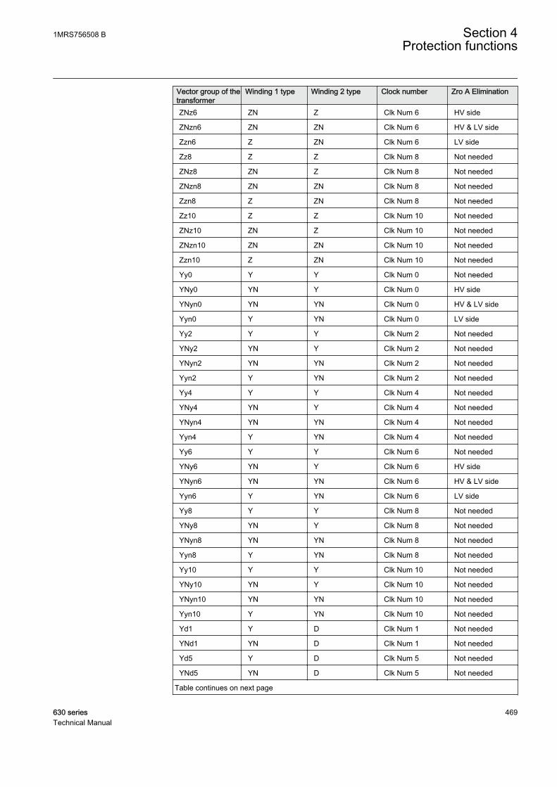
Vector group of thetransformer
Winding 1 type Winding 2 type Clock number Zro A Elimination
ZNz6 ZN Z Clk Num 6 HV side
ZNzn6 ZN ZN Clk Num 6 HV & LV side
Zzn6 Z ZN Clk Num 6 LV side
Zz8 Z Z Clk Num 8 Not needed
ZNz8 ZN Z Clk Num 8 Not needed
ZNzn8 ZN ZN Clk Num 8 Not needed
Zzn8 Z ZN Clk Num 8 Not needed
Zz10 Z Z Clk Num 10 Not needed
ZNz10 ZN Z Clk Num 10 Not needed
ZNzn10 ZN ZN Clk Num 10 Not needed
Zzn10 Z ZN Clk Num 10 Not needed
Yy0 Y Y Clk Num 0 Not needed
YNy0 YN Y Clk Num 0 HV side
YNyn0 YN YN Clk Num 0 HV & LV side
Yyn0 Y YN Clk Num 0 LV side
Yy2 Y Y Clk Num 2 Not needed
YNy2 YN Y Clk Num 2 Not needed
YNyn2 YN YN Clk Num 2 Not needed
Yyn2 Y YN Clk Num 2 Not needed
Yy4 Y Y Clk Num 4 Not needed
YNy4 YN Y Clk Num 4 Not needed
YNyn4 YN YN Clk Num 4 Not needed
Yyn4 Y YN Clk Num 4 Not needed
Yy6 Y Y Clk Num 6 Not needed
YNy6 YN Y Clk Num 6 HV side
YNyn6 YN YN Clk Num 6 HV & LV side
Yyn6 Y YN Clk Num 6 LV side
Yy8 Y Y Clk Num 8 Not needed
YNy8 YN Y Clk Num 8 Not needed
YNyn8 YN YN Clk Num 8 Not needed
Yyn8 Y YN Clk Num 8 Not needed
Yy10 Y Y Clk Num 10 Not needed
YNy10 YN Y Clk Num 10 Not needed
YNyn10 YN YN Clk Num 10 Not needed
Yyn10 Y YN Clk Num 10 Not needed
Yd1 Y D Clk Num 1 Not needed
YNd1 YN D Clk Num 1 Not needed
Yd5 Y D Clk Num 5 Not needed
YNd5 YN D Clk Num 5 Not needed
Table continues on next page
1MRS756508 B Section 4Protection functions
630 series 469Technical Manual
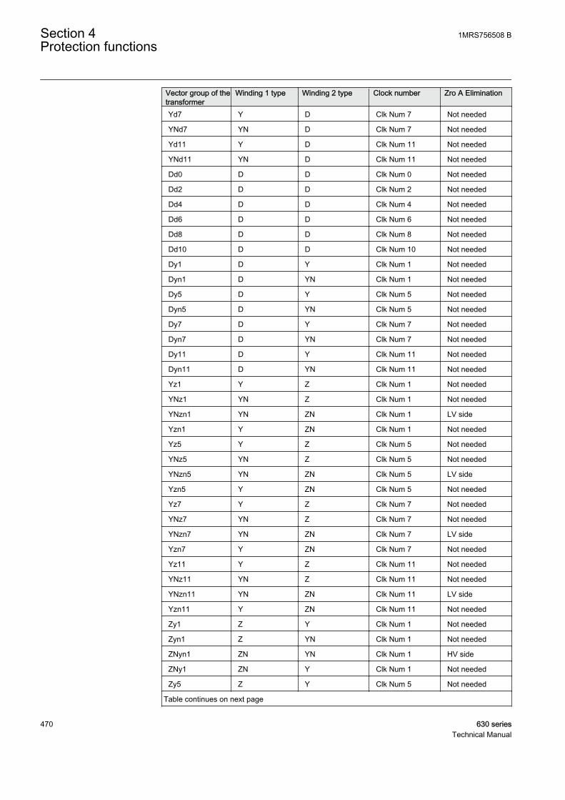
Vector group of thetransformer
Winding 1 type Winding 2 type Clock number Zro A Elimination
Yd7 Y D Clk Num 7 Not needed
YNd7 YN D Clk Num 7 Not needed
Yd11 Y D Clk Num 11 Not needed
YNd11 YN D Clk Num 11 Not needed
Dd0 D D Clk Num 0 Not needed
Dd2 D D Clk Num 2 Not needed
Dd4 D D Clk Num 4 Not needed
Dd6 D D Clk Num 6 Not needed
Dd8 D D Clk Num 8 Not needed
Dd10 D D Clk Num 10 Not needed
Dy1 D Y Clk Num 1 Not needed
Dyn1 D YN Clk Num 1 Not needed
Dy5 D Y Clk Num 5 Not needed
Dyn5 D YN Clk Num 5 Not needed
Dy7 D Y Clk Num 7 Not needed
Dyn7 D YN Clk Num 7 Not needed
Dy11 D Y Clk Num 11 Not needed
Dyn11 D YN Clk Num 11 Not needed
Yz1 Y Z Clk Num 1 Not needed
YNz1 YN Z Clk Num 1 Not needed
YNzn1 YN ZN Clk Num 1 LV side
Yzn1 Y ZN Clk Num 1 Not needed
Yz5 Y Z Clk Num 5 Not needed
YNz5 YN Z Clk Num 5 Not needed
YNzn5 YN ZN Clk Num 5 LV side
Yzn5 Y ZN Clk Num 5 Not needed
Yz7 Y Z Clk Num 7 Not needed
YNz7 YN Z Clk Num 7 Not needed
YNzn7 YN ZN Clk Num 7 LV side
Yzn7 Y ZN Clk Num 7 Not needed
Yz11 Y Z Clk Num 11 Not needed
YNz11 YN Z Clk Num 11 Not needed
YNzn11 YN ZN Clk Num 11 LV side
Yzn11 Y ZN Clk Num 11 Not needed
Zy1 Z Y Clk Num 1 Not needed
Zyn1 Z YN Clk Num 1 Not needed
ZNyn1 ZN YN Clk Num 1 HV side
ZNy1 ZN Y Clk Num 1 Not needed
Zy5 Z Y Clk Num 5 Not needed
Table continues on next page
Section 4 1MRS756508 BProtection functions
470 630 seriesTechnical Manual
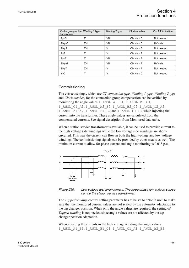
Vector group of thetransformer
Winding 1 type Winding 2 type Clock number Zro A Elimination
Zyn5 Z YN Clk Num 5 Not needed
ZNyn5 ZN YN Clk Num 5 HV side
ZNy5 ZN Y Clk Num 5 Not needed
Zy7 Z Y Clk Num 7 Not needed
Zyn7 Z YN Clk Num 7 Not needed
ZNyn7 ZN YN Clk Num 7 HV side
ZNy7 ZN Y Clk Num 7 Not needed
Yy0 Y Y Clk Num 0 Not needed
CommissioningThe correct settings, which are CT connection type, Winding 1 type, Winding 2 typeand Clock number, for the connection group compensation can be verified bymonitoring the angle values I_ANGL_A1_B1, I_ANGL_B1_C1,I_ANGL_C1_A1, I_ANGL_A2_B2, I_ANGL_B2_C2, I_ANGL_C2_A2,I_ANGL_A1_A2, I_ANGL_B1_B2 and I_ANGL_C1_C2 while injecting thecurrent into the transformer. These angle values are calculated from thecompensated currents. See signal description from Monitored data table.
When a station service transformer is available, it can be used to provide current tothe high voltage side windings while the low voltage side windings are short-circuited. This way the current can flow in both the high voltage and low voltagewindings. The commissioning signals can be provided by other means as well. Theminimum current to allow for phase current and angle monitoring is 0.015 p.u..
GUID-5ACBF127-85A3-4E5E-A130-9F7206A2DB4C V1 EN
Figure 236: Low voltage test arrangement. The three-phase low voltage sourcecan be the station service transformer.
The Tapped winding control setting parameter has to be set to “Not in use” to makesure that the monitored current values are not scaled by the automatic adaptation tothe tap changer position. When only the angle values are required, the setting ofTapped winding is not needed since angle values are not affected by the tapchanger position adaptation.
When injecting the currents in the high voltage winding, the angle valuesI_ANGL_A1_B1, I_ANGL_B1_C1, I_ANGL_C1_A1, I_ANGL_A2_B2,
1MRS756508 B Section 4Protection functions
630 series 471Technical Manual

I_ANGL_B2_C2 and I_ANGL_C2_A2 have to show +120 deg. Otherwise thephase order can be wrong or the polarity of a current transformer differs from thepolarities of the other current transformers on the same side.
If the angle values I_ANGL_A1_B1, I_ANGL_B1_C1 and I_ANGL_C1_A1show -120 deg, the phase order is wrong on the high voltage side. If the anglevalues I_ANGL_A2_B2, I_ANGL_B2_C2 and I_ANGL_C2_A2 show -120 deg,the phase order is wrong on the low voltage side. If the angle valuesI_ANGL_A1_B1, I_ANGL_B1_C1 and I_ANGL_C1_A1 do not show the samevalue of +120, the polarity of one current transformer can be wrong. For instance,if the polarity of the current transformer measuring IL2 is wrong,I_ANGL_A1_B1 shows -60 deg, I_ANGL_B1_C1 shows -60 deg andI_ANGL_C1_A1 shows +120 deg.
When the phase order and the angle values are correct, the angle valuesI_ANGL_A1_A2, I_ANGL_B1_B2 and I_ANGL_C1_C2 usually show ±180deg. There can be several reasons if the angle values are not ±180 deg. If the valuesare 0 deg, the value given for CT connection type is probably wrong. If the anglevalues are something else, the value for Clock number can be wrong. Anotherreason is that the combination of Winding 1 type and Winding 2 type does notmatch Clock number. This means that the resulting connection group is not supported.
ExampleIf Winding 1 type is set to "Y", Winding 2 type is set to “Y” and Clock number isset to "Clk num 1", the resulting connection group "Yy1" is not a supportedcombination. Similarly if Winding 1 type is set to "Y", Winding 2 type is set to "D"and Clock number is set to "Clk num 0", the resulting connection group "Yd0" isnot a supported combination. All the non-supported combinations of Winding 1type, Winding 2 type and Clock number settings result in the default connectiongroup compensation that is "Yy0".
Recommendations for current transformersThe more important the object to be protected, the more attention has to be paid tothe current transformers. It is not normally possible to dimension the currenttransformer so that they repeat the currents with high DC components withoutsaturating when the residual flux of the current transformer is high. TR2PTDFoperates reliably even though the current transformers are partially saturated.
The accuracy class recommended for current transformers to be used withTR2PTDF is 5P, in which the limit of the current error at the rated primary currentis 1 percent and the limit of the phase displacement is 60 minutes. The limit of thecomposite error at the rated accuracy limit primary current is 5 percent.
The approximate value of the accuracy limit factor Fa corresponding to the actualcurrent transformer burden can be calculated on the basis of the rated accuracylimit factor Fn at the rated burden, the rated burden Sn, the internal burden Sinandthe actual burden Sa of the current transformer.
Section 4 1MRS756508 BProtection functions
472 630 seriesTechnical Manual
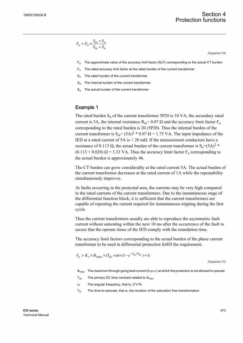
F FS S
S Sa n
in n
in a
= ×
+
+
GUID-26DEE538-9E1A-49A2-9C97-F69BD44591C9 V2 EN (Equation 54)
Fa The approximate value of the accuracy limit factor (ALF) corresponding to the actual CT burden
Fn The rated accuracy limit factor at the rated burden of the current transformer
Sn The rated burden of the current transformer
Sin The internal burden of the current transformer
Sa The actual burden of the current transformer
Example 1The rated burden Sn of the current transformer 5P20 is 10 VA, the secondary ratedcurrent is 5A, the internal resistance Rin= 0.07 Ω and the accuracy limit factor Fncorresponding to the rated burden is 20 (5P20). Thus the internal burden of thecurrent transformer is Sin= (5A)2 * 0.07 Ω = 1.75 VA. The input impedance of theIED at a rated current of 5A is < 20 mΩ. If the measurement conductors have aresistance of 0.113 Ω, the actual burden of the current transformer is Sa=(5A)2 *(0.113 + 0.020) Ω = 3.33 VA. Thus the accuracy limit factor Fa corresponding tothe actual burden is approximately 46.
The CT burden can grow considerably at the rated current 5A. The actual burden ofthe current transformer decreases at the rated current of 1A while the repeatabilitysimultaneously improves.
At faults occurring in the protected area, the currents may be very high comparedto the rated currents of the current transformers. Due to the instantaneous stage ofthe differential function block, it is sufficient that the current transformers arecapable of repeating the current required for instantaneous tripping during the firstcycle.
Thus the current transformers usually are able to reproduce the asymmetric faultcurrent without saturating within the next 10 ms after the occurrence of the fault tosecure that the operate times of the IED comply with the retardation time.
The accuracy limit factors corresponding to the actual burden of the phase currenttransformer to be used in differential protection fulfill the requirement.
F K Ik T ea r dc
T Tm dc> × × × × − +−
max/
( ( ) )ω 1 1
GUID-DA861DAD-C40E-4A82-8973-BBAFD15279C0 V1 EN (Equation 55)
Ikmax The maximum through-going fault current (in p.u.) at which the protection is not allowed to operate
Tdc The primary DC time constant related to Ikmax
ω The angular frequency, that is, 2*π*fn
Tm The time-to-saturate, that is, the duration of the saturation free transformation
1MRS756508 B Section 4Protection functions
630 series 473Technical Manual
Kr The remanence factor 1/(1-r), where r is the maximum remanence flux in p.u. from saturation flux
The accuracy limit factors corresponding to the actual burden of the phase currenttransformer is used in differential protection.
The parameter r is the maximum remanence flux density in the CT core in p.u.from saturation flux density. The value of the parameter r depends on the magneticmaterial used and on the construction of the CT. For instance, if the value of r =0.4, the remanence flux density can be 40 percent of the saturation flux density.The manufacturer of the CT has to be contacted when an accurate value for theparameter r is needed. The value r = 0.4 is recommended to be used when anaccurate value is not available.
The required minimum time-to-saturate Tm in TR2PTDF is half fundamental cycleperiod (10 ms when fn = 50Hz).
Two typical cases are considered for the determination of the sufficient accuracylimit factor (Fa):
1. A fault occurring at the substation bus:The protection must be stable at a fault arising during a normal operatingsituation. Re-energizing the transformer against a bus fault leads to very highfault currents and thermal stress and therefore re-energizing is not preferred inthis case. Thus, the remanence can be neglected.The maximum through-going fault current Ikmax is typically 10 p.u. for asubstation main transformer. At a short circuit fault close to the supplytransformer, the DC time constant (Tdc) of the fault current is almost the sameas that of the transformer, the typical value being 100 ms.
Ikmax 10 p.u.
Tdc 100 ms
ω 100π Hz
Tm 10 ms
Kr 1
When the values are substituted in Equation 55, the result is:
Fa > × × × × − + ≈−
K Ik T er dc
T Tm dcmax
/( ( ) )ω 1 1 40
GUID-7F1019C5-C819-440B-871B-5CFD1AF88956 V1 EN
2. Re-energizing against a fault occurring further down in the network:The protection must be stable also during re-energization against a fault on theline. In this case, the existence of remanence is very probable. It is assumed tobe 40 percent here.
Section 4 1MRS756508 BProtection functions
474 630 seriesTechnical Manual
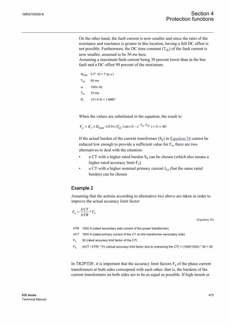
On the other hand, the fault current is now smaller and since the ratio of theresistance and reactance is greater in this location, having a full DC offset isnot possible. Furthermore, the DC time constant (Tdc) of the fault current isnow smaller, assumed to be 50 ms here.Assuming a maximum fault current being 30 percent lower than in the busfault and a DC offset 90 percent of the maximum.
Ikmax 0.7* 10 = 7 (p.u.)
Tdc 50 ms
ω 100π Hz
Tm 10 ms
Kr 1/(1-0.4) = 1.6667
When the values are substituted in the equation, the result is:
Fa > × × × × × − + ≈−
K Ik T er dc
T Tm dcmax
/. ( ( ) )0 9 1 1 40ω
GUID-9B859B2D-AC40-4278-8A99-3475442D7C67 V1 EN
If the actual burden of the current transformer (Sa) in Equation 54 cannot bereduced low enough to provide a sufficient value for Fa, there are twoalternatives to deal with the situation:• a CT with a higher rated burden Sn can be chosen (which also means a
higher rated accuracy limit Fn)• a CT with a higher nominal primary current I1n (but the same rated
burden) can be chosen
Example 2Assuming that the actions according to alternative two above are taken in order toimprove the actual accuracy limit factor:
FIrCT
IrTRFa n= *
GUID-31A3C436-4E17-40AE-A4EA-D2BD6B72034E V1 EN (Equation 56)
IrTR 1000 A (rated secondary side current of the power transformer)
IrCT 1500 A (rated primary current of the CT on the transformer secondary side)
Fn 30 (rated accuracy limit factor of the CT)
Fa (IrCT / IrTR) * Fn (actual accuracy limit factor due to oversizing the CT) = (1500/1000) * 30 = 45
In TR2PTDF, it is important that the accuracy limit factors Fa of the phase currenttransformers at both sides correspond with each other, that is, the burdens of thecurrent transformers on both sides are to be as equal as possible. If high inrush or
1MRS756508 B Section 4Protection functions
630 series 475Technical Manual

start currents with high DC components pass through the protected object when itis connected to the network, special attention is required for the performance andthe burdens of the current transformers and for the settings of the function block.
4.3.1.6 CT connections and transformation ratio correction
The connections of the primary current transformers are designated as "Type 1"and "Type 2".
• If the positive directions of the winding 1 and winding 2 IED currents areopposite, the CT connection type setting parameter is "Type 1". Theconnection examples of "Type 1" are as shown in Figure 237 and Figure 238.
• If the positive directions of the winding 1 and winding 2 IED currents equate,the CT connection type setting parameter is "Type 2". The connectionexamples of "Type 2" are as shown in Figure 239 and Figure 240.
• The default value of the CT connection type setting is "Type 1".
L1 L2 L3
123456789
10
X101
1/5AN
1/5AN
1/5AN
IL1
IL2
IL3
IL1B
P1
P2
P1
P2
S1
S2
S1S2
AIM
1/5AN
1/5AN
1/5AN
IL2B
IL3B
X102AIM
12345678910
GUID-0C7035F9-87D2-4A32-BAFB-5BB32FC8A806 V1 EN
Figure 237: Connection example of current transformers of Type 1
Section 4 1MRS756508 BProtection functions
476 630 seriesTechnical Manual
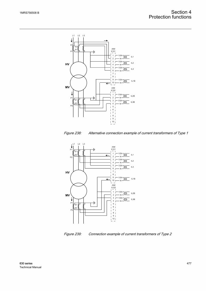
L1 L2 L3
P2
P1
P2
P1
S1
S1
S2
S2
123456789
10
X101
1/5AN
1/5AN
1/5AN
IL1
IL2
IL3
IL1B
AIM
1/5AN
1/5AN
1/5AN
IL2B
IL3B
X102AIM
123456789
10
GUID-514655CA-688C-4591-BCDE-EF7185BC3225 V1 EN
Figure 238: Alternative connection example of current transformers of Type 1
L1 L2 L3
P1
P2
P1
P2
S1
S2
S1
S2
12345678910
X101
1/5AN
1/5AN
1/5AN
IL1
IL2
IL3
1/5AN
1/5AN
IL1B
IL2B
IL3B
X102AIM
AIM
1/5AN
123456789
10
GUID-AB97BE14-E066-487D-9FB9-F7519A8DC877 V1 EN
Figure 239: Connection example of current transformers of Type 2
1MRS756508 B Section 4Protection functions
630 series 477Technical Manual
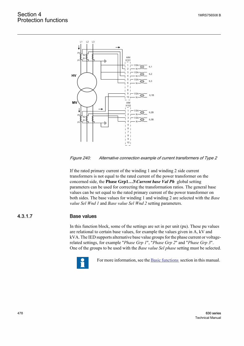
L1 L2 L3
P1
P2
P1
P2
S1S2
S1S2
123456789
10
X101
1/5AN
1/5AN
1/5AN
IL1
IL2
IL3
1/5AN
1/5AN
IL1B
IL2B
IL3B
X102AIM
AIM
1/5AN
12345678910
GUID-A8E1D0D2-2DD9-458F-BDE3-0695BEDB22B6 V1 EN
Figure 240: Alternative connection example of current transformers of Type 2
If the rated primary current of the winding 1 and winding 2 side currenttransformers is not equal to the rated current of the power transformer on theconcerned side, the Phase Grp1…3\Current base Val Ph global settingparameters can be used for correcting the transformation ratios. The general basevalues can be set equal to the rated primary current of the power transformer onboth sides. The base values for winding 1 and winding 2 are selected with the Basevalue Sel Wnd 1 and Base value Sel Wnd 2 setting parameters.
4.3.1.7 Base values
In this function block, some of the settings are set in per unit (pu). These pu valuesare relational to certain base values, for example the values given in A, kV andkVA. The IED supports alternative base value groups for the phase current or voltage-related settings, for example "Phase Grp 1", "Phase Grp 2" and "Phase Grp 3".One of the groups to be used with the Base value Sel phase setting must be selected.
For more information, see the Basic functions section in this manual.
Section 4 1MRS756508 BProtection functions
478 630 seriesTechnical Manual
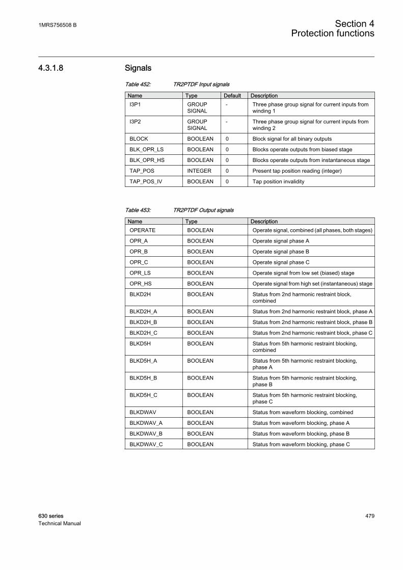
4.3.1.8 Signals
Table 452: TR2PTDF Input signals
Name Type Default DescriptionI3P1 GROUP
SIGNAL- Three phase group signal for current inputs from
winding 1
I3P2 GROUPSIGNAL
- Three phase group signal for current inputs fromwinding 2
BLOCK BOOLEAN 0 Block signal for all binary outputs
BLK_OPR_LS BOOLEAN 0 Blocks operate outputs from biased stage
BLK_OPR_HS BOOLEAN 0 Blocks operate outputs from instantaneous stage
TAP_POS INTEGER 0 Present tap position reading (integer)
TAP_POS_IV BOOLEAN 0 Tap position invalidity
Table 453: TR2PTDF Output signals
Name Type DescriptionOPERATE BOOLEAN Operate signal, combined (all phases, both stages)
OPR_A BOOLEAN Operate signal phase A
OPR_B BOOLEAN Operate signal phase B
OPR_C BOOLEAN Operate signal phase C
OPR_LS BOOLEAN Operate signal from low set (biased) stage
OPR_HS BOOLEAN Operate signal from high set (instantaneous) stage
BLKD2H BOOLEAN Status from 2nd harmonic restraint block,combined
BLKD2H_A BOOLEAN Status from 2nd harmonic restraint block, phase A
BLKD2H_B BOOLEAN Status from 2nd harmonic restraint block, phase B
BLKD2H_C BOOLEAN Status from 2nd harmonic restraint block, phase C
BLKD5H BOOLEAN Status from 5th harmonic restraint blocking,combined
BLKD5H_A BOOLEAN Status from 5th harmonic restraint blocking,phase A
BLKD5H_B BOOLEAN Status from 5th harmonic restraint blocking,phase B
BLKD5H_C BOOLEAN Status from 5th harmonic restraint blocking,phase C
BLKDWAV BOOLEAN Status from waveform blocking, combined
BLKDWAV_A BOOLEAN Status from waveform blocking, phase A
BLKDWAV_B BOOLEAN Status from waveform blocking, phase B
BLKDWAV_C BOOLEAN Status from waveform blocking, phase C
1MRS756508 B Section 4Protection functions
630 series 479Technical Manual

4.3.1.9 Settings
Table 454: TR2PTDF Group settings (basic)
Name Values (Range) Unit Step Default DescriptionRestraint mode 2.h & 5.h & wav
Waveform2.h & waveform5.h & waveform
- - 2.h & 5.h & wav Selects what harmonic blocking methodsare in use
High operate value 500 - 3000 % 10 1000 Instantaneous stage setting
Low operate value 5 - 50 % 1 20 Basic setting for stabilized operation
Slope section 2 10 - 50 % 1 30 Slope of the second line of the operatingcharacteristics
End section 2 100 - 500 % 1 150 Turn-point between sections 2 and 3 ofthe characteristics
Start value 2.H 7 - 20 % 1 15 2. harmonic blocking ratio
Start value 5.H 10 - 50 % 1 35 5. harmonic blocking ratio
Table 455: TR2PTDF Group settings (advanced)
Name Values (Range) Unit Step Default DescriptionStop value 5.H 10 - 50 % 1 35 5. harmonic deblocking ratio
Enable high set NoYes
- - Yes Enable instantaneous (high set) stage
Harmonic deblock 2.H Not allowedAllowed
- - Allowed 2. harmonic deblocking in case of switchon to fault
Harmonic deblock 5.H Not allowedAllowed
- - Not allowed 5. harmonic deblocking in case of severeovervoltage
Table 456: TR2PTDF Non group settings (basic)
Name Values (Range) Unit Step Default DescriptionOperation Off
On- - On Operation Off / On
Clock number Clk Num 0Clk Num 1Clk Num 2Clk Num 4Clk Num 5Clk Num 6Clk Num 7Clk Num 8Clk Num 10Clk Num 11
- - Clk Num 0 Phase shift between winding1 andwinding 2 (clock number)
Winding 1 type YYNDZZN
- - Y Connection of the winding 1
Table continues on next page
Section 4 1MRS756508 BProtection functions
480 630 seriesTechnical Manual
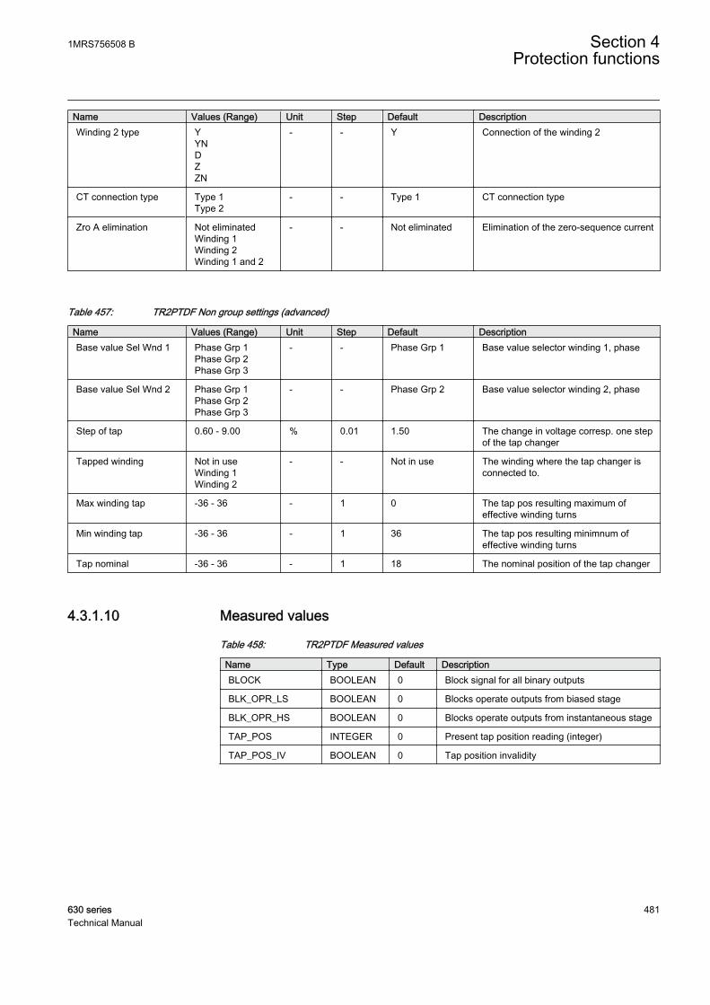
Name Values (Range) Unit Step Default DescriptionWinding 2 type Y
YNDZZN
- - Y Connection of the winding 2
CT connection type Type 1Type 2
- - Type 1 CT connection type
Zro A elimination Not eliminatedWinding 1Winding 2Winding 1 and 2
- - Not eliminated Elimination of the zero-sequence current
Table 457: TR2PTDF Non group settings (advanced)
Name Values (Range) Unit Step Default DescriptionBase value Sel Wnd 1 Phase Grp 1
Phase Grp 2Phase Grp 3
- - Phase Grp 1 Base value selector winding 1, phase
Base value Sel Wnd 2 Phase Grp 1Phase Grp 2Phase Grp 3
- - Phase Grp 2 Base value selector winding 2, phase
Step of tap 0.60 - 9.00 % 0.01 1.50 The change in voltage corresp. one stepof the tap changer
Tapped winding Not in useWinding 1Winding 2
- - Not in use The winding where the tap changer isconnected to.
Max winding tap -36 - 36 - 1 0 The tap pos resulting maximum ofeffective winding turns
Min winding tap -36 - 36 - 1 36 The tap pos resulting minimnum ofeffective winding turns
Tap nominal -36 - 36 - 1 18 The nominal position of the tap changer
4.3.1.10 Measured values
Table 458: TR2PTDF Measured values
Name Type Default DescriptionBLOCK BOOLEAN 0 Block signal for all binary outputs
BLK_OPR_LS BOOLEAN 0 Blocks operate outputs from biased stage
BLK_OPR_HS BOOLEAN 0 Blocks operate outputs from instantaneous stage
TAP_POS INTEGER 0 Present tap position reading (integer)
TAP_POS_IV BOOLEAN 0 Tap position invalidity
1MRS756508 B Section 4Protection functions
630 series 481Technical Manual

4.3.1.11 Monitored data
Table 459: TR2PTDF Monitored data
Name Type Values (Range) Unit DescriptionOPR_A BOOLEAN 0=FALSE
1=TRUE- Operate signal phase A
OPR_B BOOLEAN 0=FALSE1=TRUE
- Operate signal phase B
OPR_C BOOLEAN 0=FALSE1=TRUE
- Operate signal phase C
OPR_LS BOOLEAN 0=FALSE1=TRUE
- Operate signal from lowset (biased) stage
OPR_HS BOOLEAN 0=FALSE1=TRUE
- Operate signal from highset (instantaneous) stage
BLKD2H_A BOOLEAN 0=FALSE1=TRUE
- Status from 2ndharmonic restraint block,phase A
BLKD2H_B BOOLEAN 0=FALSE1=TRUE
- Status from 2ndharmonic restraint block,phase B
BLKD2H_C BOOLEAN 0=FALSE1=TRUE
- Status from 2ndharmonic restraint block,phase C
BLKD5H_A BOOLEAN 0=FALSE1=TRUE
- Status from 5thharmonic restraintblocking, phase A
BLKD5H_B BOOLEAN 0=FALSE1=TRUE
- Status from 5thharmonic restraintblocking, phase B
BLKD5H_C BOOLEAN 0=FALSE1=TRUE
- Status from 5thharmonic restraintblocking, phase C
BLKDWAV_A BOOLEAN 0=FALSE1=TRUE
- Status from waveformblocking, phase A
BLKDWAV_B BOOLEAN 0=FALSE1=TRUE
- Status from waveformblocking, phase B
BLKDWAV_C BOOLEAN 0=FALSE1=TRUE
- Status from waveformblocking, phase C
I_AMPL_A1 REAL - - Compensated currentamplitude phase A,winding 1
I_AMPL_B1 REAL - - Compensated currentamplitude phase B,winding 1
I_AMPL_C1 REAL - - Compensated currentamplitude phase C,winding 1
I_AMPL_A2 REAL - - Compensated currentamplitude phase A,winding 2
Table continues on next page
Section 4 1MRS756508 BProtection functions
482 630 seriesTechnical Manual

Name Type Values (Range) Unit DescriptionI_AMPL_B2 REAL - - Compensated current
amplitude phase B,winding 2
I_AMPL_C2 REAL - - Compensated currentamplitude phase C,winding 2
ID_A REAL - - Differential currentphase A
ID_B REAL - - Differential currentphase B
ID_C REAL - - Differential currentphase C
IB_A REAL - - Bias current phase A
IB_B REAL - - Biasing current phase B
IB_C REAL - - Biasing current phase C
I_ANGL_A1_B1 REAL - deg Current phase anglephase A – phase B,winding 1
I_ANGL_B1_C1 REAL - deg Current phase anglephase B – phase C,winding 1
I_ANGL_C1_A1 REAL - deg Current phase anglephase C – phase A,winding 1
I_ANGL_A2_B2 REAL - deg Current phase anglephase A – phase B,winding 2
I_ANGL_B2_C2 REAL - deg Current phase anglephase B – phase C,winding 2
I_ANGL_C2_A2 REAL - deg Current phase anglephase C – phase A,winding 2
I_ANGL_A1_A2 REAL - deg Current phase angle diffbetween winding 1 and2, phase A
I_ANGL_B1_B2 REAL - deg Current phase angle diffbetween winding 1 and2, phase B
I_ANGL_C1_C2 REAL - deg Current phase angle diffbetween winding 1 and2, phase C
I_2H_RAT_A REAL - - Differential currentsecond harmonic ratio,phase A
I_2H_RAT_B REAL - - Differential currentsecond harmonic ratio,phase B
I_2H_RAT_C REAL - - Differential currentsecond harmonic ratio,phase C
1MRS756508 B Section 4Protection functions
630 series 483Technical Manual
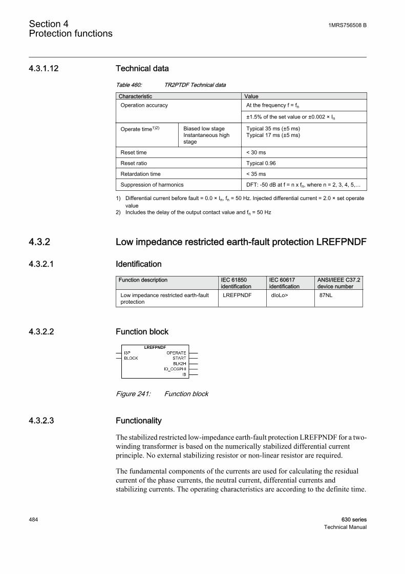
4.3.1.12 Technical data
Table 460: TR2PTDF Technical data
Characteristic ValueOperation accuracy At the frequency f = fn
±1.5% of the set value or ±0.002 × In
Operate time1)2) Biased low stageInstantaneous highstage
Typical 35 ms (±5 ms)Typical 17 ms (±5 ms)
Reset time < 30 ms
Reset ratio Typical 0.96
Retardation time < 35 ms
Suppression of harmonics DFT: -50 dB at f = n x fn, where n = 2, 3, 4, 5,…
1) Differential current before fault = 0.0 × In, fn = 50 Hz. Injected differential current = 2.0 × set operatevalue
2) Includes the delay of the output contact value and fn = 50 Hz
4.3.2 Low impedance restricted earth-fault protection LREFPNDF
4.3.2.1 Identification
Function description IEC 61850identification
IEC 60617identification
ANSI/IEEE C37.2device number
Low impedance restricted earth-faultprotection
LREFPNDF dIoLo> 87NL
4.3.2.2 Function block
GUID-8BE869D7-E9E4-47C9-B777-DE7A055FCA8B V1 EN
Figure 241: Function block
4.3.2.3 Functionality
The stabilized restricted low-impedance earth-fault protection LREFPNDF for a two-winding transformer is based on the numerically stabilized differential currentprinciple. No external stabilizing resistor or non-linear resistor are required.
The fundamental components of the currents are used for calculating the residualcurrent of the phase currents, the neutral current, differential currents andstabilizing currents. The operating characteristics are according to the definite time.
Section 4 1MRS756508 BProtection functions
484 630 seriesTechnical Manual
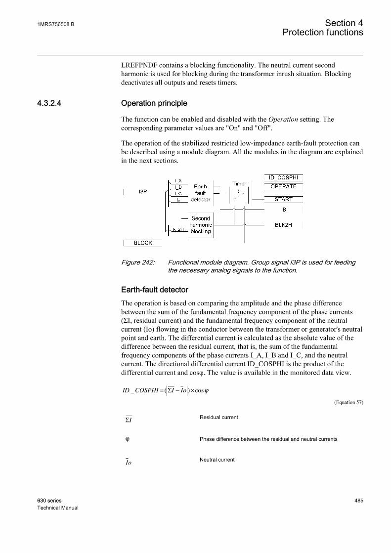
LREFPNDF contains a blocking functionality. The neutral current secondharmonic is used for blocking during the transformer inrush situation. Blockingdeactivates all outputs and resets timers.
4.3.2.4 Operation principle
The function can be enabled and disabled with the Operation setting. Thecorresponding parameter values are "On" and "Off".
The operation of the stabilized restricted low-impedance earth-fault protection canbe described using a module diagram. All the modules in the diagram are explainedin the next sections.
GUID-6E8DDE24-71AE-450E-9ED2-22DF9895CBAD V1 EN
Figure 242: Functional module diagram. Group signal I3P is used for feedingthe necessary analog signals to the function.
Earth-fault detectorThe operation is based on comparing the amplitude and the phase differencebetween the sum of the fundamental frequency component of the phase currents(ΣI, residual current) and the fundamental frequency component of the neutralcurrent (Io) flowing in the conductor between the transformer or generator's neutralpoint and earth. The differential current is calculated as the absolute value of thedifference between the residual current, that is, the sum of the fundamentalfrequency components of the phase currents I_A, I_B and I_C, and the neutralcurrent. The directional differential current ID_COSPHI is the product of thedifferential current and cosφ. The value is available in the monitored data view.
ID COSPHI I Io_ ( ) cos= − ×Σ ϕ
GUID-46782962-D465-47D2-8ECE-3FF0B87B324F V3 EN (Equation 57)
ΣIGUID-87E4DEDD-9288-41D9-B608-714CF3CC7A04 V1 EN
Residual current
ϕ
GUID-C4F98C50-7279-4DAA-8C77-5C761572F4B4 V1 EN
Phase difference between the residual and neutral currents
Io
GUID-2D713C98-4F81-4DF4-8193-C47120A65489 V1 EN
Neutral current
1MRS756508 B Section 4Protection functions
630 series 485Technical Manual

An earth fault occurring in the protected area, that is, between the phase CTs andthe neutral connection CT, causes a differential current. The directions, that is, thephase difference of the residual current and the neutral current, are considered inthe operation criteria to maintain selectivity. A correct value for CT connectiontype is determined by the connection polarities of the current transformer.
The current transformer ratio mismatch between the phase currenttransformer and neutral current transformer (residual current in theanalog input settings) is taken into account by the function with theproperly set analog input setting values.
During an earth fault in the protected area, the currents ΣI and Io are directedtowards the protected area. The factor cosφ is 1 when the phase difference of theresidual current and the neutral current is 180 degrees, that is, when the currents arein opposite direction at the earth faults within the protected area. Similarly,ID_COSPHI is specified to be 0 when the phase difference between the residualcurrent and the neutral current is less than 90 degrees in situations where there isno earth fault in the protected area. Thus tripping is possible only when the phasedifference between the residual current and the neutral current is above 90 degrees.
The stabilizing current IB used by the stabilizing current principle is calculated asan average of the phase currents in the windings to be protected. The value isavailable in the monitored data view.
IB
I A I B I C
=
+ +_ _ _
3
GUID-E162EE11-DEDF-49BA-B60F-E22ECF1ACAE8 V2 EN (Equation 58)
The Operate value setting is used for defining the characteristics of the function.The differential current value required for tripping is constant at the stabilizingcurrent values 0.0 < IB/In < 1.0, where In is the nominal current and refers to thenominal of the phase current inputs in this function. When the stabilizing current ishigher than 1.0, the slope of the operation characteristic (ID/IB) is constant at 50percent.
Section 4 1MRS756508 BProtection functions
486 630 seriesTechnical Manual
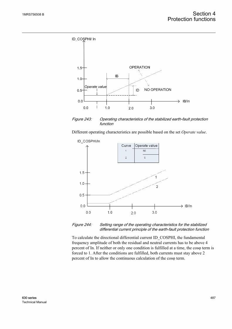
GUID-9D592151-7598-479B-9285-7FB7C09F0FAB V1 EN
Figure 243: Operating characteristics of the stabilized earth-fault protectionfunction
Different operating characteristics are possible based on the set Operate value.
GUID-552423CA-6FE9-4F69-8341-FFE0FF1943D4 V1 EN
Figure 244: Setting range of the operating characteristics for the stabilizeddifferential current principle of the earth-fault protection function
To calculate the directional differential current ID_COSPHI, the fundamentalfrequency amplitude of both the residual and neutral currents has to be above 4percent of In. If neither or only one condition is fulfilled at a time, the cosφ term isforced to 1. After the conditions are fulfilled, both currents must stay above 2percent of In to allow the continuous calculation of the cosφ term.
1MRS756508 B Section 4Protection functions
630 series 487Technical Manual

Second harmonic blockingThis module compares the ratio of the current second harmonic (I0_2H) and I0 tothe set value Start value 2.H. If the ratio (I0_2H / I0) value exceeds the set value,the BLK2H output is activated.
The blocking also prevents unwanted operation at the recovery and sympatheticmagnetizing inrushes. At the recovery inrush, the magnetizing current of thetransformer to be protected increases momentarily when the voltage returns tonormal after the clearance of a fault outside the protected area. The sympatheticinrush is caused by the energization of a transformer running in parallel with theprotected transformer connected to the network.
The second harmonic blocking is disabled when Restraint mode is set to "None"and enabled when set to "Harmonic2".
TimerOnce activated, the timer activates the START output. The time characteristic isaccording to DT. When the operation timer has reached the value set by Minimumoperate time, the OPERATE output is activated. If the fault disappears before themodule operates, the reset timer is activated. If the reset timer reaches the value setby Reset delay time, the reset timer resets and the START output is deactivated.
The timer calculates the start duration value START_DUR, which indicates thepercentage ratio of the start situation and the set operation time. The value isavailable in the monitored data view.
The activation of the BLOCK signal resets the timer and deactivates the START andOPERATE outputs. The activation of the output of the second harmonic blockingsignal BLK2H deactivates the OPERATE output.
4.3.2.5 Base values
In this function block, some of the settings are set in per unit (pu). These pu valuesare relational to certain base values, for example the values given in A, kV andkVA. The IED supports alternative base value groups for the phase current or voltage-related settings, for example "Phase Grp 1", "Phase Grp 2" and "Phase Grp 3".One of the groups to be used with the Base value Sel phase setting must be selected.
For more information, see the Basic functions section in this manual.
4.3.2.6 Application
An earth-fault protection using an overcurrent element does not adequately protectthe transformer winding in general and the star-connected winding in particular.
Section 4 1MRS756508 BProtection functions
488 630 seriesTechnical Manual
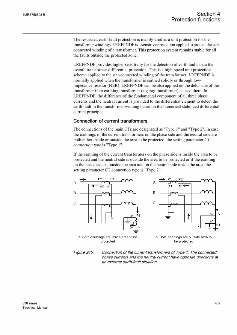
The restricted earth-fault protection is mainly used as a unit protection for thetransformer windings. LREFPNDF is a sensitive protection applied to protect the star-connected winding of a transformer. This protection system remains stable for allthe faults outside the protected zone.
LREFPNDF provides higher sensitivity for the detection of earth faults than theoverall transformer differential protection. This is a high-speed unit protectionscheme applied to the star-connected winding of the transformer. LREFPNDF isnormally applied when the transformer is earthed solidly or through low-impedance resistor (NER). LREFPNDF can be also applied on the delta side of thetransformer if an earthing transformer (zig-zag transformer) is used there. InLREFPNDF, the difference of the fundamental component of all three phasecurrents and the neutral current is provided to the differential element to detect theearth fault in the transformer winding based on the numerical stabilized differentialcurrent principle.
Connection of current transformersThe connections of the main CTs are designated as "Type 1" and "Type 2". In casethe earthings of the current transformers on the phase side and the neutral side areboth either inside or outside the area to be protected, the setting parameter CTconnection type is "Type 1".
If the earthing of the current transformers on the phase side is inside the area to beprotected and the neutral side is outside the area to be protected or if the earthingon the phase side is outside the area and on the neutral side inside the area, thesetting parameter CT connection type is "Type 2".
GUID-63BD73B4-7B60-4354-9690-E96C0A8076C7 V1 EN
Figure 245: Connection of the current transformers of Type 1. The connectedphase currents and the neutral current have opposite directions atan external earth-fault situation.
1MRS756508 B Section 4Protection functions
630 series 489Technical Manual

GUID-124047A0-9B33-4D2F-9519-75D98C0A4534 V1 EN
Figure 246: Connection of the current transformers of Type 2. The phasecurrents and the neutral current have equal directions at anexternal earth-fault situation.
Internal and external faultsLREFPNDF does not respond to any faults outside the protected zone. An externalfault is detected by checking the phase angle difference of the neutral current andthe sum of the phase currents. When the difference is less than 90 degrees, theoperation is internally restrained or blocked. Hence the protection is not sensitiveto an external fault.
A
B
I a = 0
Ib = 0Ib = 0
I c = 0I
Io
zone of protection
C
a
b
c
IN
Izs1
Izs1
Izs1
Io
IN Reference is Neutral Current
Restrain for external fault
Operate for internal fault
For external fault
Uzs
GUID-FAC5E4AD-A4A7-4D39-9EAC-C380EA33CB78 V2 EN
Figure 247: Current flow in all the CTs for an external fault
Section 4 1MRS756508 BProtection functions
490 630 seriesTechnical Manual
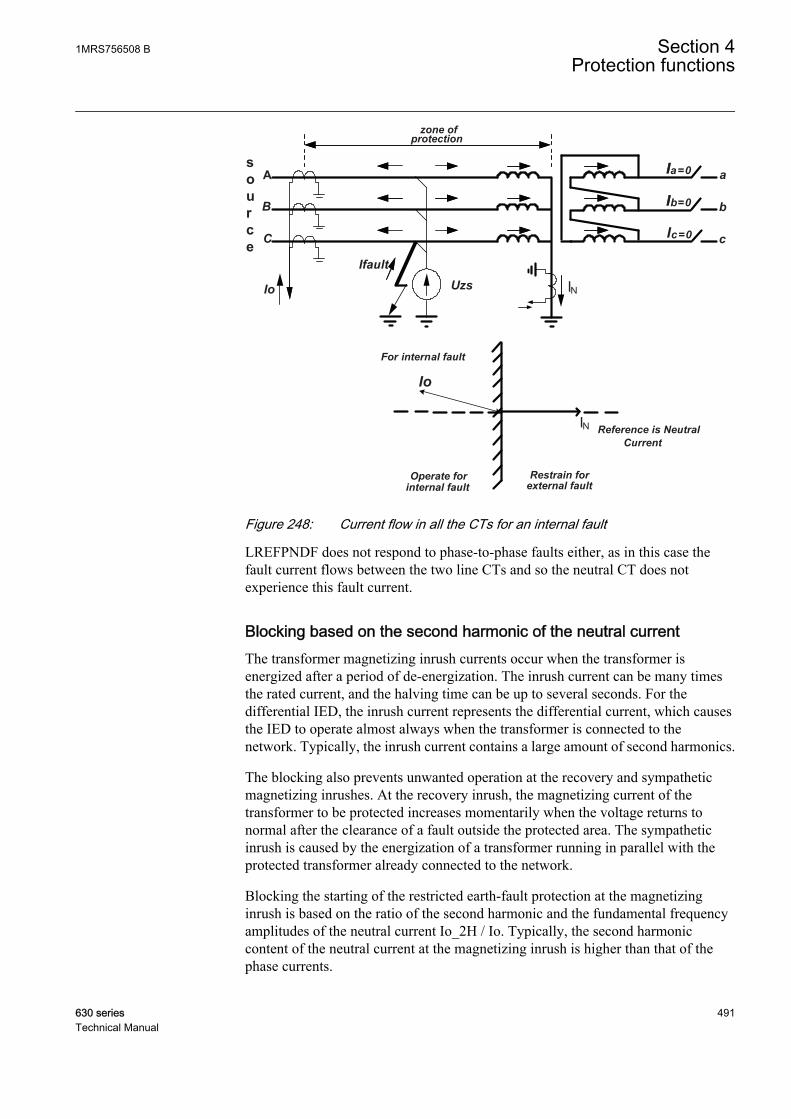
A
B
C
a
b
c
Ia = 0I
Ib = 0I
c = 0I
UzsIo
zone of protection
Ifault
IN
Io
IN Reference is Neutral Current
Restrain for external fault
Operate for internal fault
For internal fault
source
GUID-D5D712D4-2291-4C49-93DE-363F9F10801C V2 EN
Figure 248: Current flow in all the CTs for an internal fault
LREFPNDF does not respond to phase-to-phase faults either, as in this case thefault current flows between the two line CTs and so the neutral CT does notexperience this fault current.
Blocking based on the second harmonic of the neutral currentThe transformer magnetizing inrush currents occur when the transformer isenergized after a period of de-energization. The inrush current can be many timesthe rated current, and the halving time can be up to several seconds. For thedifferential IED, the inrush current represents the differential current, which causesthe IED to operate almost always when the transformer is connected to thenetwork. Typically, the inrush current contains a large amount of second harmonics.
The blocking also prevents unwanted operation at the recovery and sympatheticmagnetizing inrushes. At the recovery inrush, the magnetizing current of thetransformer to be protected increases momentarily when the voltage returns tonormal after the clearance of a fault outside the protected area. The sympatheticinrush is caused by the energization of a transformer running in parallel with theprotected transformer already connected to the network.
Blocking the starting of the restricted earth-fault protection at the magnetizinginrush is based on the ratio of the second harmonic and the fundamental frequencyamplitudes of the neutral current Io_2H / Io. Typically, the second harmoniccontent of the neutral current at the magnetizing inrush is higher than that of thephase currents.
1MRS756508 B Section 4Protection functions
630 series 491Technical Manual
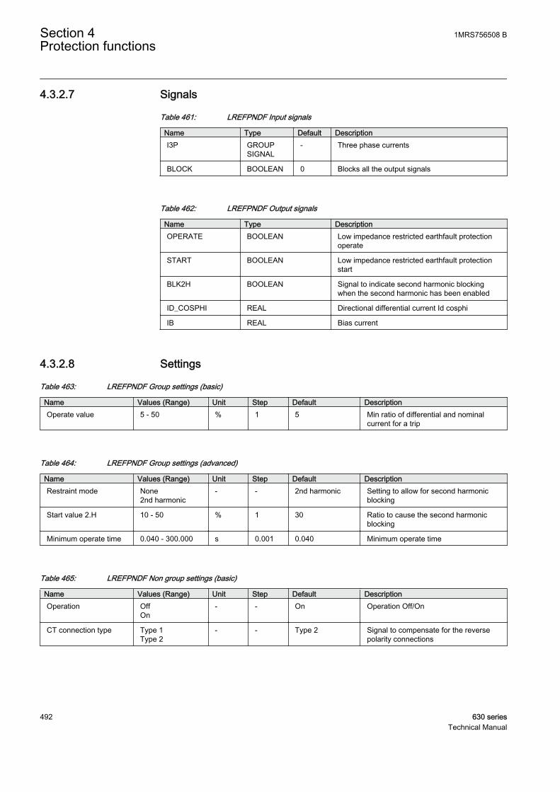
4.3.2.7 Signals
Table 461: LREFPNDF Input signals
Name Type Default DescriptionI3P GROUP
SIGNAL- Three phase currents
BLOCK BOOLEAN 0 Blocks all the output signals
Table 462: LREFPNDF Output signals
Name Type DescriptionOPERATE BOOLEAN Low impedance restricted earthfault protection
operate
START BOOLEAN Low impedance restricted earthfault protectionstart
BLK2H BOOLEAN Signal to indicate second harmonic blockingwhen the second harmonic has been enabled
ID_COSPHI REAL Directional differential current Id cosphi
IB REAL Bias current
4.3.2.8 Settings
Table 463: LREFPNDF Group settings (basic)
Name Values (Range) Unit Step Default DescriptionOperate value 5 - 50 % 1 5 Min ratio of differential and nominal
current for a trip
Table 464: LREFPNDF Group settings (advanced)
Name Values (Range) Unit Step Default DescriptionRestraint mode None
2nd harmonic- - 2nd harmonic Setting to allow for second harmonic
blocking
Start value 2.H 10 - 50 % 1 30 Ratio to cause the second harmonicblocking
Minimum operate time 0.040 - 300.000 s 0.001 0.040 Minimum operate time
Table 465: LREFPNDF Non group settings (basic)
Name Values (Range) Unit Step Default DescriptionOperation Off
On- - On Operation Off/On
CT connection type Type 1Type 2
- - Type 2 Signal to compensate for the reversepolarity connections
Section 4 1MRS756508 BProtection functions
492 630 seriesTechnical Manual

Table 466: LREFPNDF Non group settings (advanced)
Name Values (Range) Unit Step Default DescriptionBase value Sel phase Phase Grp 1
Phase Grp 2Phase Grp 3
- - Phase Grp 1 Base value selector, phase / phase-to-phase
Reset delay time 0.000 - 60.000 s 0.001 0.020 Reset delay time
4.3.2.9 Measured values
Table 467: LREFPNDF Measured values
Name Type Default DescriptionI_AMPL_A REAL 0.0 current amplitude (DFT) phase 1
I_AMPL_B REAL 0.0 current amplitude (DFT) phase 2
I_AMPL_C REAL 0.0 current amplitude (DFT) phase 3
I0_AMPL REAL 0.0 Current amplitude (DFT) Neutral
I0_ANG REAL 0.0 Angle of the current in neutral
I0_2H_AMPL REAL 0.0 Amplitude of second harmonic component ofneutral current
BLOCK BOOLEAN 0 Blocks all the output signals
4.3.2.10 Monitored data
Table 468: LREFPNDF Monitored data
Name Type Values (Range) Unit DescriptionOPERATE BOOLEAN 0=FALSE
1=TRUE- Low impedance
restricted earthfaultprotection operate
START BOOLEAN 0=FALSE1=TRUE
- Low impedancerestricted earthfaultprotection start
BLK2H BOOLEAN 0=FALSE1=TRUE
- Signal to indicate secondharmonic blocking whenthe second harmonichas been enabled
ID_COSPHI REAL - A Directional differentialcurrent Id cosphi
IB REAL - A Bias current
START_DUR REAL - % Start duration inpercentage of the totaloperating time
1MRS756508 B Section 4Protection functions
630 series 493Technical Manual
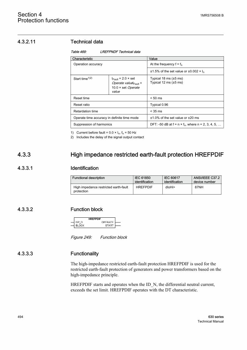
4.3.2.11 Technical data
Table 469: LREFPNDF Technical data
Characteristic ValueOperation accuracy At the frequency f = fn
±1.5% of the set value or ±0.002 × In
Start time1)2) IFault = 2.0 × setOperate valueIFault =10.0 × set Operatevalue
Typical 18 ms (±5 ms)Typical 12 ms (±5 ms)
Reset time < 50 ms
Reset ratio Typical 0.96
Retardation time < 35 ms
Operate time accuracy in definite time mode ±1.0% of the set value or ±20 ms
Suppression of harmonics DFT: -50 dB at f = n × fn, where n = 2, 3, 4, 5, …
1) Current before fault = 0.0 × In, fn = 50 Hz2) Includes the delay of the signal output contact
4.3.3 High impedance restricted earth-fault protection HREFPDIF
4.3.3.1 Identification
Functional description IEC 61850identification
IEC 60617identification
ANSI/IEEE C37.2device number
High impedance restricted earth-faultprotection
HREFPDIF dIoHi> 87NH
4.3.3.2 Function block
GUID-6099228D-39F5-40D3-B3F9-F3425395ABF6 V1 EN
Figure 249: Function block
4.3.3.3 Functionality
The high-impedance restricted earth-fault protection HREFPDIF is used for therestricted earth-fault protection of generators and power transformers based on thehigh-impedance principle.
HREFPDIF starts and operates when the ID_N, the differential neutral current,exceeds the set limit. HREFPDIF operates with the DT characteristic.
Section 4 1MRS756508 BProtection functions
494 630 seriesTechnical Manual
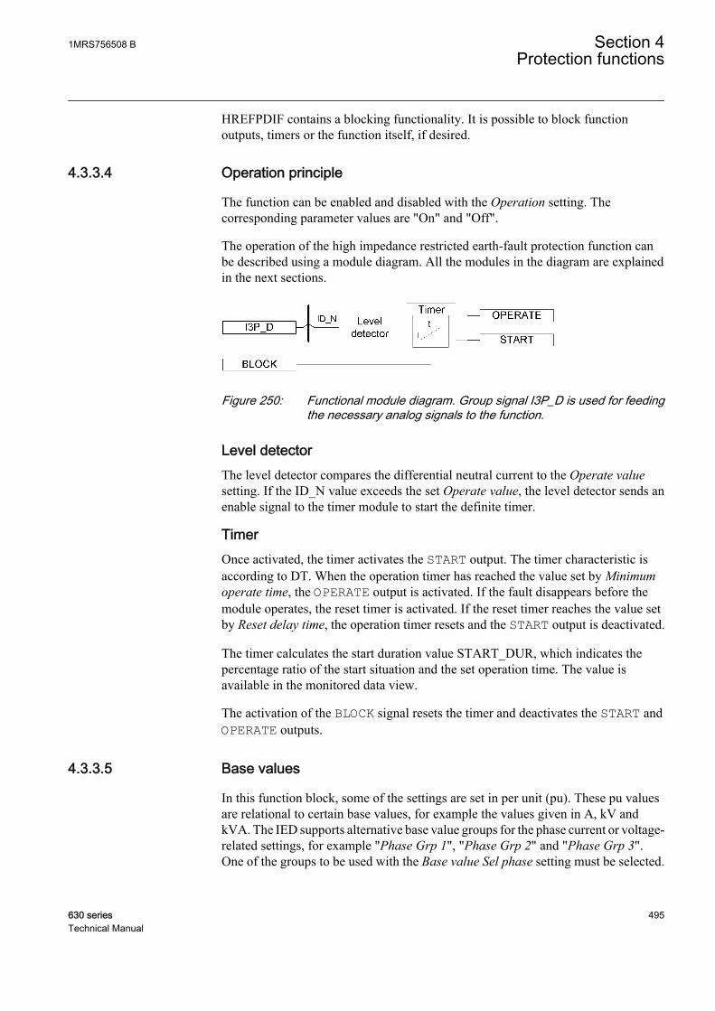
HREFPDIF contains a blocking functionality. It is possible to block functionoutputs, timers or the function itself, if desired.
4.3.3.4 Operation principle
The function can be enabled and disabled with the Operation setting. Thecorresponding parameter values are "On" and "Off".
The operation of the high impedance restricted earth-fault protection function canbe described using a module diagram. All the modules in the diagram are explainedin the next sections.
GUID-424EBB88-7E8C-401D-9656-B160A8F94526 V1 EN
Figure 250: Functional module diagram. Group signal I3P_D is used for feedingthe necessary analog signals to the function.
Level detectorThe level detector compares the differential neutral current to the Operate valuesetting. If the ID_N value exceeds the set Operate value, the level detector sends anenable signal to the timer module to start the definite timer.
TimerOnce activated, the timer activates the START output. The timer characteristic isaccording to DT. When the operation timer has reached the value set by Minimumoperate time, the OPERATE output is activated. If the fault disappears before themodule operates, the reset timer is activated. If the reset timer reaches the value setby Reset delay time, the operation timer resets and the START output is deactivated.
The timer calculates the start duration value START_DUR, which indicates thepercentage ratio of the start situation and the set operation time. The value isavailable in the monitored data view.
The activation of the BLOCK signal resets the timer and deactivates the START andOPERATE outputs.
4.3.3.5 Base values
In this function block, some of the settings are set in per unit (pu). These pu valuesare relational to certain base values, for example the values given in A, kV andkVA. The IED supports alternative base value groups for the phase current or voltage-related settings, for example "Phase Grp 1", "Phase Grp 2" and "Phase Grp 3".One of the groups to be used with the Base value Sel phase setting must be selected.
1MRS756508 B Section 4Protection functions
630 series 495Technical Manual
For more information, see the Basic functions section in this manual.
4.3.3.6 Application
In solidly earthed systems, the restricted earth-fault protection is always deployedas a complement to the normal transformer differential protection. The advantageof the restricted earth-fault protection is its high sensitivity. Sensitivities of close to1.0 percent can be achieved, whereas normal differential IEDs have their minimumsensitivity in the range of 5 to 10 percent. The level for HREFPDIF is dependent ofthe current transformers' magnetizing currents. The restricted earth-fault protectionis also very fast due to the simple measuring principle as it is a unit type of protection.
The differences in measuring principle limit the biased differential IED'spossibility to detect the earth faults. Such faults are then only detected by therestricted earth-fault function.
The restricted earth-fault IED is connected across each directly or to low ohmicearthed transformer winding. If the same CTs are connected to other IEDs, separatecores are to be used.
Section 4 1MRS756508 BProtection functions
496 630 seriesTechnical Manual
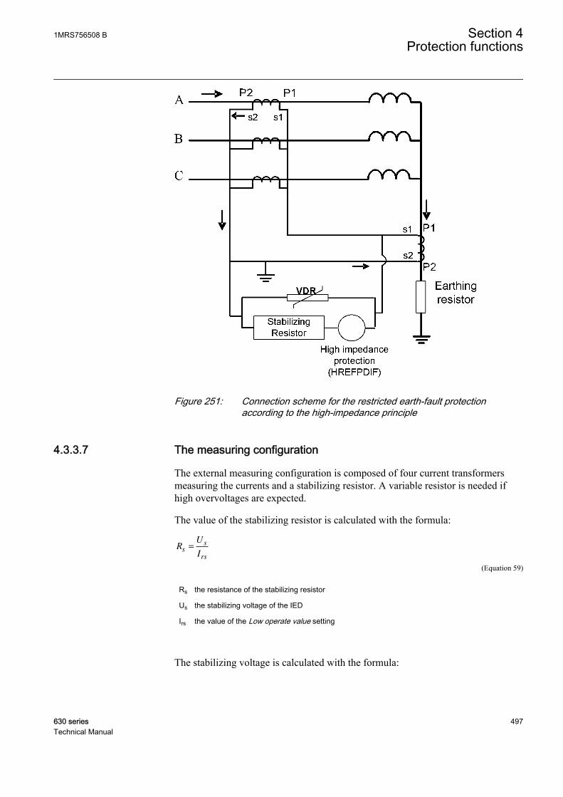
GUID-367BDBC9-D2E8-48D3-B98F-623F7CD70D99 V2 EN
Figure 251: Connection scheme for the restricted earth-fault protectionaccording to the high-impedance principle
4.3.3.7 The measuring configuration
The external measuring configuration is composed of four current transformersmeasuring the currents and a stabilizing resistor. A variable resistor is needed ifhigh overvoltages are expected.
The value of the stabilizing resistor is calculated with the formula:
RU
Is
s
rs
=
GUID-00FCABE9-93E2-4BDD-83C6-EB1BE7FFE986 V1 EN (Equation 59)
Rs the resistance of the stabilizing resistor
Us the stabilizing voltage of the IED
Irs the value of the Low operate value setting
The stabilizing voltage is calculated with the formula:
1MRS756508 B Section 4Protection functions
630 series 497Technical Manual
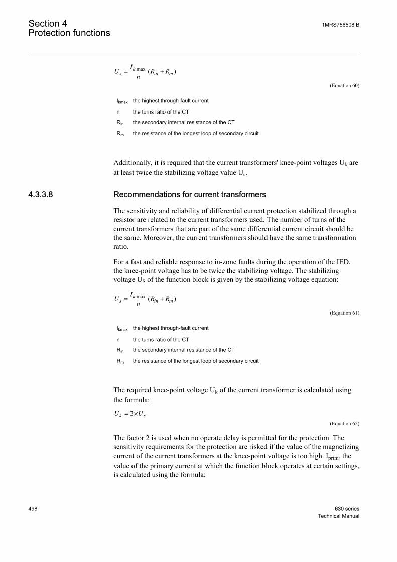
UI
nR Rs
kin m= +
max( )
GUID-6A4C58E7-3D26-40C9-A070-0D99BA209B1A V1 EN (Equation 60)
Ikmax the highest through-fault current
n the turns ratio of the CT
Rin the secondary internal resistance of the CT
Rm the resistance of the longest loop of secondary circuit
Additionally, it is required that the current transformers' knee-point voltages Uk areat least twice the stabilizing voltage value Us.
4.3.3.8 Recommendations for current transformers
The sensitivity and reliability of differential current protection stabilized through aresistor are related to the current transformers used. The number of turns of thecurrent transformers that are part of the same differential current circuit should bethe same. Moreover, the current transformers should have the same transformationratio.
For a fast and reliable response to in-zone faults during the operation of the IED,the knee-point voltage has to be twice the stabilizing voltage. The stabilizingvoltage US of the function block is given by the stabilizing voltage equation:
UI
nR Rs
kin m= +
max( )
GUID-6A4C58E7-3D26-40C9-A070-0D99BA209B1A V1 EN (Equation 61)
Ikmax the highest through-fault current
n the turns ratio of the CT
Rin the secondary internal resistance of the CT
Rm the resistance of the longest loop of secondary circuit
The required knee-point voltage Uk of the current transformer is calculated usingthe formula:
U Uk s= ×2
GUID-4F7F301A-1573-4736-B740-622605DB0FFB V1 EN (Equation 62)
The factor 2 is used when no operate delay is permitted for the protection. Thesensitivity requirements for the protection are risked if the value of the magnetizingcurrent of the current transformers at the knee-point voltage is too high. Iprim, thevalue of the primary current at which the function block operates at certain settings,is calculated using the formula:
Section 4 1MRS756508 BProtection functions
498 630 seriesTechnical Manual
I n I I m Iprim rs u m= × + + ×( )
GUID-2A742729-7244-4B1C-A4DF-404BDD3A68D9 V1 EN (Equation 63)
Iprim the primary current at which the function block operates
n the transformation ratio of the current transformer
Irs the current value representing the function block setting
Iu the current flowing through the protection varistor
m the number of current transformers included in the protection
Im the magnetizing current of one current transformer
The Ie value given in many catalogues is the excitation current at the knee-pointvoltage. Im = 0.5 x Ie gives a realistic value for Iprim.
The selection of current transformers can be divided into procedures:
1. The nominal current In of the protected winding has to be known. The value ofIn also affects how high Ikmax is. Normally, the Ikmax values are:
• for small transformers Ikmax = 16 x In• for big transformers Ikmax = 12 x In• for generators Ikmax = 6 x In
2. The nominal primary current I1n of the CT has to be higher than the nominalcurrent of the protected winding. The choice of the CT also specifies Rin.
3. The required Uk is calculated using Equation 62. If the Uk of the CT is nothigh enough, another CT has to be chosen. The value of the Uk is given by themanufacturer in the case of class X current transformer or it can be estimatedusing Equation 64.
4. The sensitivity Iprim is calculated using Equation 63. If the achieved sensitivityis sufficient, the present CT is chosen. If a better sensitivity is needed, a CTwith a bigger core is chosen.
If other than class X current transformers are used, an estimate for Uk is calculated:
U F I R Rk a n in m= × × × +0 8 2. ( )
GUID-AFA68232-5288-4220-845E-40347B691E29 V1 EN (Equation 64)
Fa the actual accuracy limit factor
I2n the rated secondary current of the current transformer
Rin the secondary internal resistance of the CT
Rm the resistance of the longest loop of the secondary circuit
If the rated accuracy limit factor Fn is used here instead of Fa, Rm is replaced withthe rated burden of the current transformer.
1MRS756508 B Section 4Protection functions
630 series 499Technical Manual
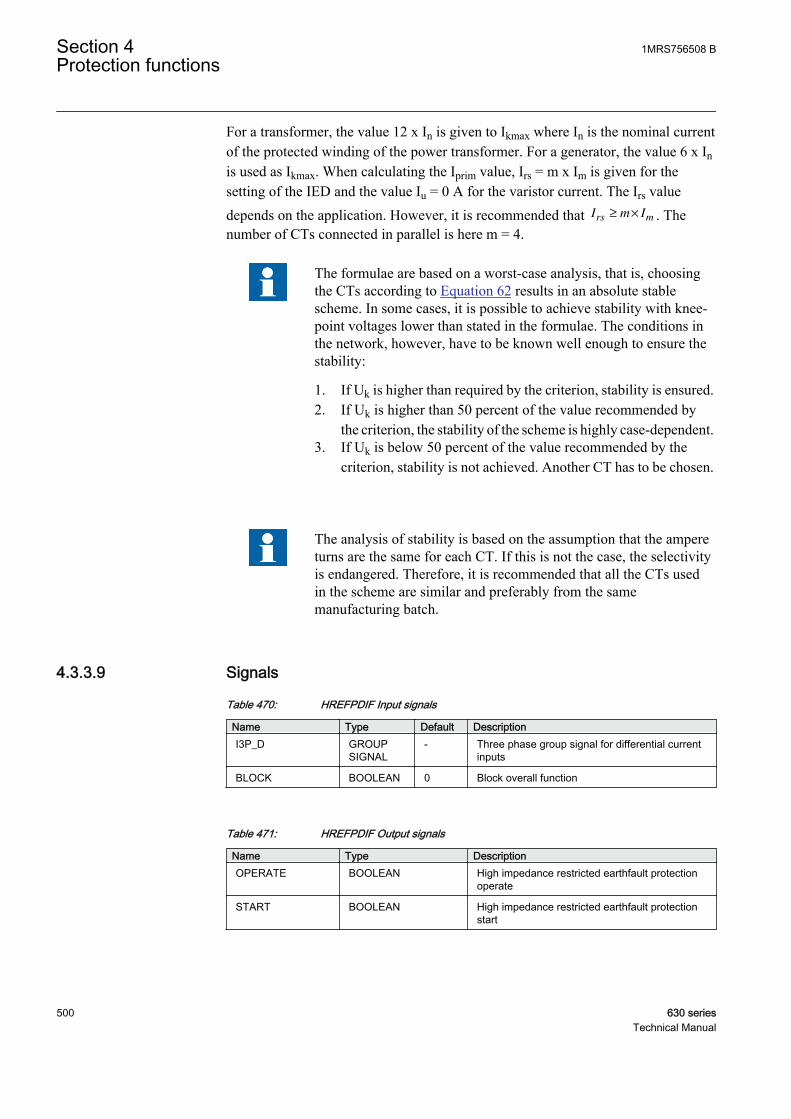
For a transformer, the value 12 x In is given to Ikmax where In is the nominal currentof the protected winding of the power transformer. For a generator, the value 6 x Inis used as Ikmax. When calculating the Iprim value, Irs = m x Im is given for thesetting of the IED and the value Iu = 0 A for the varistor current. The Irs valuedepends on the application. However, it is recommended that I m Irs m≥ × . Thenumber of CTs connected in parallel is here m = 4.
The formulae are based on a worst-case analysis, that is, choosingthe CTs according to Equation 62 results in an absolute stablescheme. In some cases, it is possible to achieve stability with knee-point voltages lower than stated in the formulae. The conditions inthe network, however, have to be known well enough to ensure thestability:
1. If Uk is higher than required by the criterion, stability is ensured.2. If Uk is higher than 50 percent of the value recommended by
the criterion, the stability of the scheme is highly case-dependent.3. If Uk is below 50 percent of the value recommended by the
criterion, stability is not achieved. Another CT has to be chosen.
The analysis of stability is based on the assumption that the ampereturns are the same for each CT. If this is not the case, the selectivityis endangered. Therefore, it is recommended that all the CTs usedin the scheme are similar and preferably from the samemanufacturing batch.
4.3.3.9 Signals
Table 470: HREFPDIF Input signals
Name Type Default DescriptionI3P_D GROUP
SIGNAL- Three phase group signal for differential current
inputs
BLOCK BOOLEAN 0 Block overall function
Table 471: HREFPDIF Output signals
Name Type DescriptionOPERATE BOOLEAN High impedance restricted earthfault protection
operate
START BOOLEAN High impedance restricted earthfault protectionstart
Section 4 1MRS756508 BProtection functions
500 630 seriesTechnical Manual
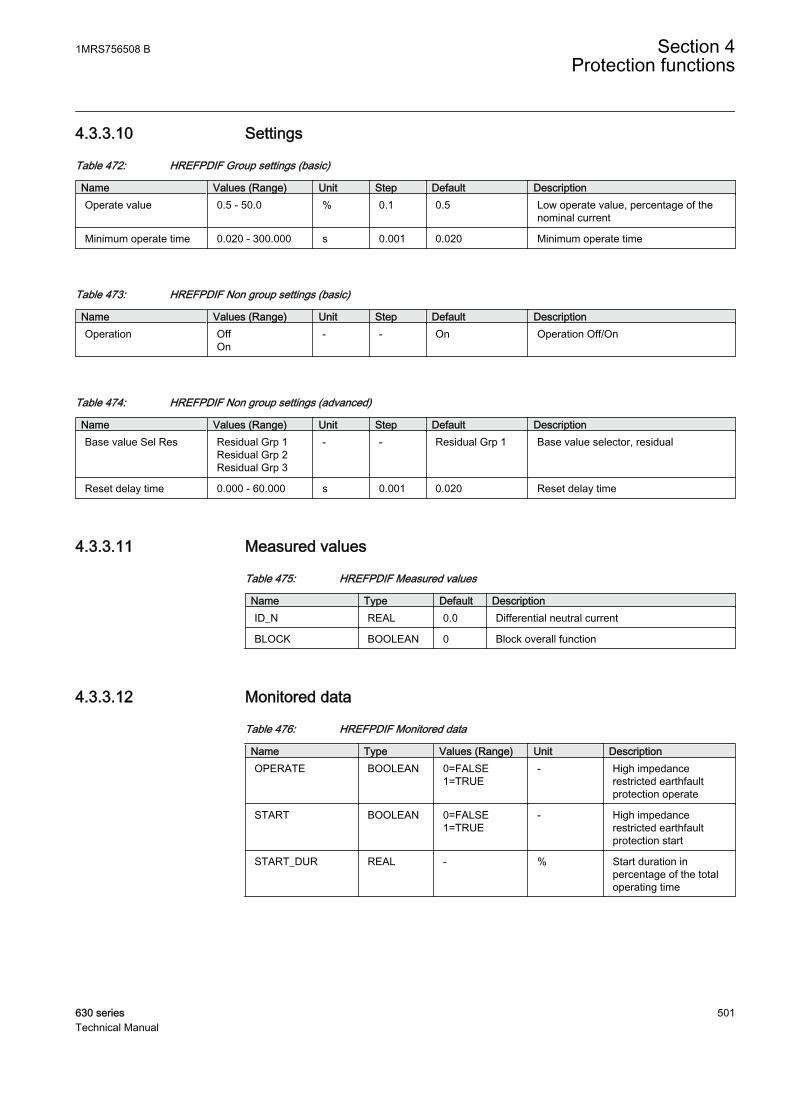
4.3.3.10 Settings
Table 472: HREFPDIF Group settings (basic)
Name Values (Range) Unit Step Default DescriptionOperate value 0.5 - 50.0 % 0.1 0.5 Low operate value, percentage of the
nominal current
Minimum operate time 0.020 - 300.000 s 0.001 0.020 Minimum operate time
Table 473: HREFPDIF Non group settings (basic)
Name Values (Range) Unit Step Default DescriptionOperation Off
On- - On Operation Off/On
Table 474: HREFPDIF Non group settings (advanced)
Name Values (Range) Unit Step Default DescriptionBase value Sel Res Residual Grp 1
Residual Grp 2Residual Grp 3
- - Residual Grp 1 Base value selector, residual
Reset delay time 0.000 - 60.000 s 0.001 0.020 Reset delay time
4.3.3.11 Measured values
Table 475: HREFPDIF Measured values
Name Type Default DescriptionID_N REAL 0.0 Differential neutral current
BLOCK BOOLEAN 0 Block overall function
4.3.3.12 Monitored data
Table 476: HREFPDIF Monitored data
Name Type Values (Range) Unit DescriptionOPERATE BOOLEAN 0=FALSE
1=TRUE- High impedance
restricted earthfaultprotection operate
START BOOLEAN 0=FALSE1=TRUE
- High impedancerestricted earthfaultprotection start
START_DUR REAL - % Start duration inpercentage of the totaloperating time
1MRS756508 B Section 4Protection functions
630 series 501Technical Manual
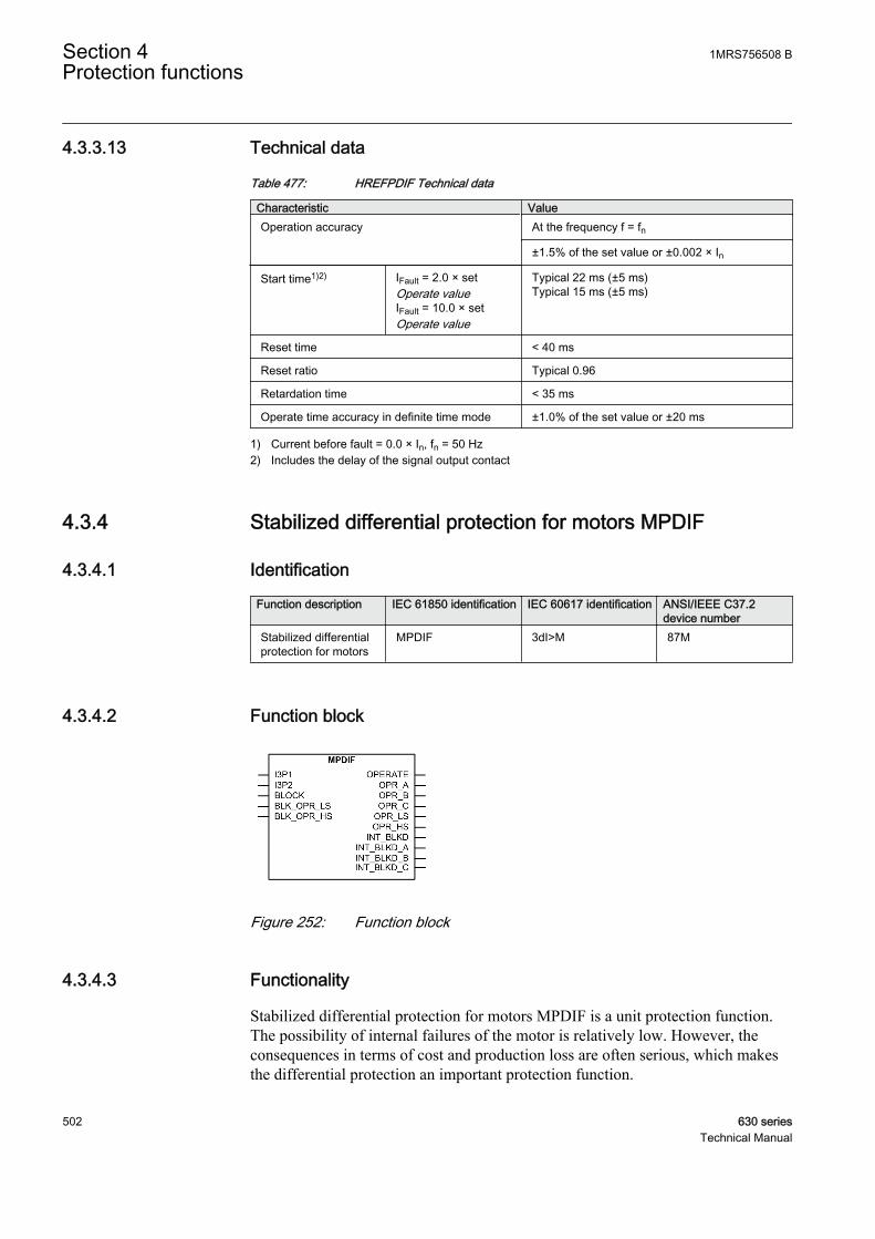
4.3.3.13 Technical data
Table 477: HREFPDIF Technical data
Characteristic ValueOperation accuracy At the frequency f = fn
±1.5% of the set value or ±0.002 × In
Start time1)2) IFault = 2.0 × setOperate valueIFault = 10.0 × setOperate value
Typical 22 ms (±5 ms)Typical 15 ms (±5 ms)
Reset time < 40 ms
Reset ratio Typical 0.96
Retardation time < 35 ms
Operate time accuracy in definite time mode ±1.0% of the set value or ±20 ms
1) Current before fault = 0.0 × In, fn = 50 Hz2) Includes the delay of the signal output contact
4.3.4 Stabilized differential protection for motors MPDIF
4.3.4.1 Identification
Function description IEC 61850 identification IEC 60617 identification ANSI/IEEE C37.2device number
Stabilized differentialprotection for motors
MPDIF 3dI>M 87M
4.3.4.2 Function block
GUID-D1B0188F-177E-4331-B9AA-501AC7DD7535 V1 EN
Figure 252: Function block
4.3.4.3 Functionality
Stabilized differential protection for motors MPDIF is a unit protection function.The possibility of internal failures of the motor is relatively low. However, theconsequences in terms of cost and production loss are often serious, which makesthe differential protection an important protection function.
Section 4 1MRS756508 BProtection functions
502 630 seriesTechnical Manual
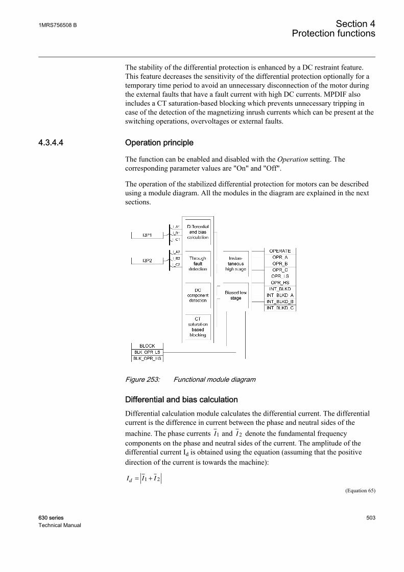
The stability of the differential protection is enhanced by a DC restraint feature.This feature decreases the sensitivity of the differential protection optionally for atemporary time period to avoid an unnecessary disconnection of the motor duringthe external faults that have a fault current with high DC currents. MPDIF alsoincludes a CT saturation-based blocking which prevents unnecessary tripping incase of the detection of the magnetizing inrush currents which can be present at theswitching operations, overvoltages or external faults.
4.3.4.4 Operation principle
The function can be enabled and disabled with the Operation setting. Thecorresponding parameter values are "On" and "Off".
The operation of the stabilized differential protection for motors can be describedusing a module diagram. All the modules in the diagram are explained in the nextsections.
GUID-DC78623F-2BC7-45ED-889A-EC0352F3114B V1 EN
Figure 253: Functional module diagram
Differential and bias calculationDifferential calculation module calculates the differential current. The differentialcurrent is the difference in current between the phase and neutral sides of themachine. The phase currents I1 and I 2 denote the fundamental frequencycomponents on the phase and neutral sides of the current. The amplitude of thedifferential current Id is obtained using the equation (assuming that the positivedirection of the current is towards the machine):
I I Id = +1 2
GUID-9BC6A743-CA43-407E-8340-7463F15C8128 V1 EN (Equation 65)
1MRS756508 B Section 4Protection functions
630 series 503Technical Manual
During normal conditions, there is no fault in the area protected by the functionblock, so the currents I1 and I 2 are equal and the differential current Id = 0.However, in practice some differential current exists due to inaccuracies in thecurrent transformer on the phase and neutral sides, but it is very small duringnormal conditions.
The module calculates the differential current for all three phases.
The low-stage differential protection is stabilized with a bias current. The biascurrent is also known as the stabilizing current. Stabilization means that thedifferential current required for tripping increases according to the bias current andthe operation characteristics. When an internal fault occurs, the currents on bothsides of the protected object are flowing into it. This causes the biasing current tobe considerably smaller, which makes the operation more sensitive during internalfaults.
The traditional way for calculating the stabilized current is:
II I
b =−1 2
2
GUID-34FA472E-E419-4A0E-94A3-238D7A3CE5ED V1 EN (Equation 66)
The module calculates the bias current for all three phases.
Through-fault detectionThrough-fault (TF) detection module is for detecting whether the fault is external,that is, going through, or internal. This information is essential for ensuring thecorrect operation of the protection in case of the CT saturation:
• In a through-fault situation, CTs can saturate because of a high fault currentmagnitude. Such AC saturation does not happen immediately when the faultbegins. Thus, the TF module sees the fault as external because the bias currentis high but the differential current remains low. If the AC saturation thenoccurs, a CT saturation-based blocking is allowed to work to prevent tripping.
• Normally, the phase angle between the machine neutral and line side CTs is180 degrees. If an internal fault occurs during a through fault, an angle lessthan 50 degrees clearly indicates an internal fault and the TF module overrules,that is, deblocks the presence of any blocking due to CT saturation.
CT saturation-based blockingHigher currents during the motor startup or abnormally high magnetizing currentsat an overvoltage (transformer-fed motor) or an external fault may saturate thecurrent transformers. The uneven saturation of the star and line side CTs (forexample, due to burden differences) may lead to a differential current which cancause a differential protection to operate. This module blocks the operation ofMPDIF biased low stage internally in case of the CT saturation. Once the blockingis activated, it is held for a certain time after the blocking conditions have ceased tobe fulfilled.
Section 4 1MRS756508 BProtection functions
504 630 seriesTechnical Manual
DC component detectionOn detection of a DC component, the function temporarily desensitizes thedifferential protection. The functioning of this module depends on the DC restrainEnable setting. The DC components are continuously extracted from the threeinstantaneous differential currents. The highest DC component of all three is takenas a kind of DC restraint in a sense that the highest effective, temporary sensitivityof the protection is temporarily decreased as a function of this highest DC offset.The calculated DC restraint current is not allowed to decay (from its highest evermeasured value) faster than with a time constant of one second. The value of thetemporarily effective sensitivity limit is limited upwards to the rated current of themachine or 3.3 times that of Low operate value, whichever is smaller. Thetemporary extra limit decays exponentially from its maximum value with a timeconstant of one second.
This feature should be used in case of networks where very long time constants areexpected. The temporary sensitivity limit is higher to the set operatingcharacteristics. In other words, the temporary limit has superposed the unchangedoperating characteristics and temporarily determines the highest sensitivity of theprotection. The temporary sensitivity is less than the sensitivity in section 1 of theoperating characteristic and is supposed to prevent an unwanted trip during theexternal faults with lower currents.
Biased low stageThe current differential protection needs to be biased because of the possibleappearance of a differential current which can be due to something else than anactual fault in the motor. In case of motor protection, a false differential current canbe caused by:
• CT errors• CT saturation at high currents passing through the motor
The differential current caused by CT errors increases at the same percent ratio asthe load current.
The high currents passing through the protected object can be caused by thethrough fault. Therefore, the operation of the differential protection is biased withrespect to the load current. In the biased differential protection, the higher thedifferential current required for the protection of operation, the higher the loadcurrent.
Based on the conditions checked from the through-fault module, the DC(component) detection module and the CT saturation-based blocking modules, thebiased low-stage module decides whether the differential current is due to theinternal faults or some false reason. In case of detection of the TF, DC or CTsaturation, the internal differential blocking signal is generated, which in turnblocks the operate signal. In case of internal faults, the operation of the differentialprotection is affected by the bias current .
1MRS756508 B Section 4Protection functions
630 series 505Technical Manual

The Low operate value setting for the stabilized stage of the function block isdetermined with the equation:
Lowoperate valueI
I
d
n
= ⋅1
100%
GUID-22A3726A-4B8C-418F-B8C3-D6A5AACD165F V1 EN (Equation 67)
The Slope section 2 is determined correspondingly:
Slope sectionI
I
d
b
2 1002
2
= ⋅ %
GUID-6707BA3B-6446-4B54-B09B-7D8D1F0DDF32 V1 EN (Equation 68)
The end of the first section End section 1 can be set at a desired point within therange of 0 to 100 percent (or % In). Accordingly, the end of the second section Endsection 2 can be set within the range of 100 percent to 300 percent (or % In).
The slope of the operating characteristic for the function block varies in differentparts of the range.
In section 1, where 0.0 < Ib/In < End section 1, the differential current required fortripping is constant. The value of the differential current is the same as the Lowoperate value setting selected for the function block. The Low operate value settingallows for small inaccuracies of the current transformers but it can also be used toinfluence the overall level of the operating characteristic.
In section 2, where End section 1 < Ib/In < End section 2, is called the influencearea of the setting Slope section 2. In this section, variations in End section 2 affectthe slope of the characteristic, that is, how big the change in the differential currentrequired for tripping is in comparison to the change in the load current. The Endsection 2 setting allows for the CT errors.
In section 3, where Ib/In > End section 2, the slope of the characteristic is constant.The slope is 100 percent, which means that an increase in the differential current isequal to the corresponding increase in the stabilizing current.
The required differential current for tripping at a certain stabilizing current levelcan be calculated using the formulae:
For a stabilizing current lower than End section 1
I I Set Lowoperatevaluedoperate n[% ] =
GUID-4FAC8F94-FBB0-47DB-A952-F995889969C6 V1 EN (Equation 69)
For a stabilizing current higher than End section 1 but lower than End section 2
I I Lowoperate value I I End section Slopedoperate n b n[% ] ( [% ] )= + − ⋅1 ssection 2
GUID-EB0A327A-4079-45A5-87E6-AA30A8D2220C V1 EN (Equation 70)
For higher stabilizing current values exceeding End section 2
Section 4 1MRS756508 BProtection functions
506 630 seriesTechnical Manual
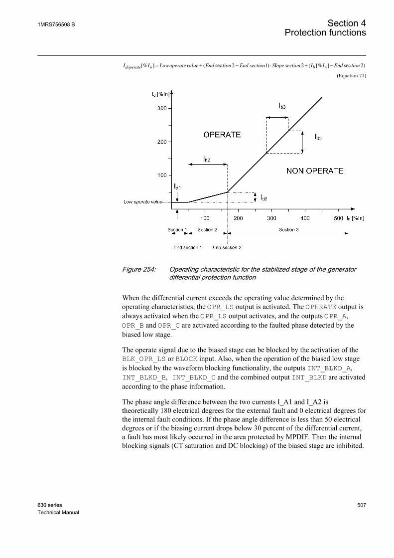
I I Lowoperate value End tion End section Sdoperate n[% ] ( sec )= + − ⋅2 1 llope section I I End tionb n2 2+ −( [% ] sec )
GUID-E9DA330C-84A8-40C2-BCFB-1F7E517395D8 V2 EN (Equation 71)
GUID-295E8CB1-B4A0-4207-A1B2-F542C5D1DF94 V1 EN
Figure 254: Operating characteristic for the stabilized stage of the generatordifferential protection function
When the differential current exceeds the operating value determined by theoperating characteristics, the OPR_LS output is activated. The OPERATE output isalways activated when the OPR_LS output activates, and the outputs OPR_A,OPR_B and OPR_C are activated according to the faulted phase detected by thebiased low stage.
The operate signal due to the biased stage can be blocked by the activation of theBLK_OPR_LS or BLOCK input. Also, when the operation of the biased low stageis blocked by the waveform blocking functionality, the outputs INT_BLKD_A,INT_BLKD_B, INT_BLKD_C and the combined output INT_BLKD are activatedaccording to the phase information.
The phase angle difference between the two currents I_A1 and I_A2 istheoretically 180 electrical degrees for the external fault and 0 electrical degrees forthe internal fault conditions. If the phase angle difference is less than 50 electricaldegrees or if the biasing current drops below 30 percent of the differential current,a fault has most likely occurred in the area protected by MPDIF. Then the internalblocking signals (CT saturation and DC blocking) of the biased stage are inhibited.
1MRS756508 B Section 4Protection functions
630 series 507Technical Manual
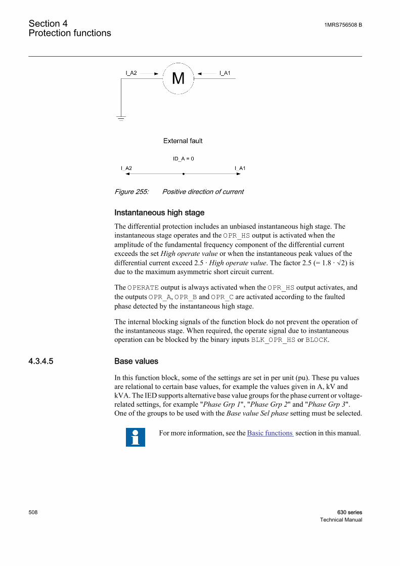
GUID-D401D103-BD7C-4096-986F-578925ADB1CC V1 EN
Figure 255: Positive direction of current
Instantaneous high stageThe differential protection includes an unbiased instantaneous high stage. Theinstantaneous stage operates and the OPR_HS output is activated when theamplitude of the fundamental frequency component of the differential currentexceeds the set High operate value or when the instantaneous peak values of thedifferential current exceed 2.5 · High operate value. The factor 2.5 (= 1.8 · √2) isdue to the maximum asymmetric short circuit current.
The OPERATE output is always activated when the OPR_HS output activates, andthe outputs OPR_A, OPR_B and OPR_C are activated according to the faultedphase detected by the instantaneous high stage.
The internal blocking signals of the function block do not prevent the operation ofthe instantaneous stage. When required, the operate signal due to instantaneousoperation can be blocked by the binary inputs BLK_OPR_HS or BLOCK.
4.3.4.5 Base values
In this function block, some of the settings are set in per unit (pu). These pu valuesare relational to certain base values, for example the values given in A, kV andkVA. The IED supports alternative base value groups for the phase current or voltage-related settings, for example "Phase Grp 1", "Phase Grp 2" and "Phase Grp 3".One of the groups to be used with the Base value Sel phase setting must be selected.
For more information, see the Basic functions section in this manual.
Section 4 1MRS756508 BProtection functions
508 630 seriesTechnical Manual

4.3.4.6 Application
The differential protection works on the principle of calculating the differentialcurrent at two ends of the winding, that is, the current entering the winding iscompared to the current exiting the winding. In case of any internal fault, thecurrents entering and exiting the winding are different, which results in adifferential current, which is then used as a base for generating the operatingsignal. Due to this principle, the differential protection does not trip during externalfaults. However, it should be noted that interturn faults in the same phase areusually not detected unless they developed into some other kind of fault.
The short circuit between the phases of the stator windings normally causes largefault currents. The short circuit creates a risk of damages to the insulation,windings and stator core. The large short circuit currents cause large current forceswhich can damage other components in the machine. The short circuit can alsoinitiate explosion and fire. When a short circuit occurs in a machine, there is adamage that has to be repaired. The severity and the repair time depend on thedegree of damage, which is highly dependent on the fault time. The fast faultclearance of this fault type is of greatest importance to limit the damages and theeconomic loss.
To limit the damages in connection to the stator winding short circuits, the faultclearance time must be as short as possible (instantaneous). The fault currentcontributions from both the external power system (via the machine or the blockcircuit breaker) and from the machine itself must be disconnected as fast as possible.
The DC restraint feature should be used in case of an application with a long DCtime constant in the fault currents are present. This fault current may be of a lessermagnitude (less than rated current) but is unpleasant and tends to saturate the CTand operate the differential protection for external faults. This feature is effective atmoderate through-currents and ineffective at higher through-currents.
Although the short circuit fault current is normally very large, that is, significantlylarger than the rated current of the machine, it is possible that a short circuit canoccur between phases close to the neutral point of the machine, causing a relativelysmall fault current. The fault current fed from the synchronous machine can also belimited due to a low excitation of the synchronous generator. This is normally thecase at the run-up of the synchronous machine, before synchronization to thenetwork. Therefore, it is desired that the detection of the machine phase-to-phaseshort circuits shall be relatively sensitive, thus detecting the small fault currents.
It is also important that the machine short circuit protection does not trip forexternal faults when a large fault current is fed from the machine. To combine fastfault clearance, sensitivity and selectivity, the machine current differentialprotection is normally the best alternative for the phase-to-phase short circuits.
The risk of an unwanted differential protection operation caused by the currenttransformer saturation is a universal differential protection problem. If a bigsynchronous machine is tripped in connection to an external short circuit, it givesan increased risk of a power system collapse. Besides, there is a production loss for
1MRS756508 B Section 4Protection functions
630 series 509Technical Manual
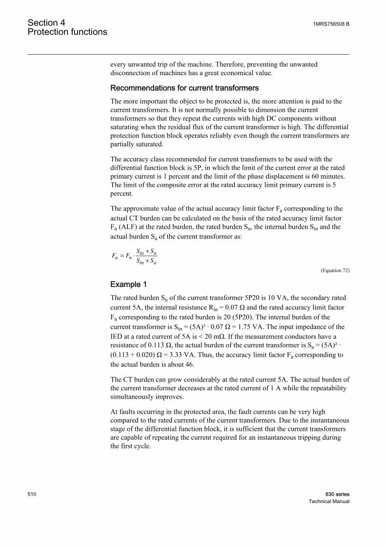
every unwanted trip of the machine. Therefore, preventing the unwanteddisconnection of machines has a great economical value.
Recommendations for current transformersThe more important the object to be protected is, the more attention is paid to thecurrent transformers. It is not normally possible to dimension the currenttransformers so that they repeat the currents with high DC components withoutsaturating when the residual flux of the current transformer is high. The differentialprotection function block operates reliably even though the current transformers arepartially saturated.
The accuracy class recommended for current transformers to be used with thedifferential function block is 5P, in which the limit of the current error at the ratedprimary current is 1 percent and the limit of the phase displacement is 60 minutes.The limit of the composite error at the rated accuracy limit primary current is 5percent.
The approximate value of the actual accuracy limit factor Fa corresponding to theactual CT burden can be calculated on the basis of the rated accuracy limit factorFn (ALF) at the rated burden, the rated burden Sn, the internal burden Sin and theactual burden Sa of the current transformer as:
F FS S
S Sa n
in n
in a
= ⋅
+
+
GUID-8EFD1AED-A804-45DD-963F-D453A6B3D782 V1 EN (Equation 72)
Example 1The rated burden Sn of the current transformer 5P20 is 10 VA, the secondary ratedcurrent 5A, the internal resistance Rin = 0.07 Ω and the rated accuracy limit factorFn corresponding to the rated burden is 20 (5P20). The internal burden of thecurrent transformer is Sin = (5A)² · 0.07 Ω = 1.75 VA. The input impedance of theIED at a rated current of 5A is < 20 mΩ. If the measurement conductors have aresistance of 0.113 Ω, the actual burden of the current transformer is Sa = (5A)² ·(0.113 + 0.020) Ω = 3.33 VA. Thus, the accuracy limit factor Fa corresponding tothe actual burden is about 46.
The CT burden can grow considerably at the rated current 5A. The actual burden ofthe current transformer decreases at the rated current of 1 A while the repeatabilitysimultaneously improves.
At faults occurring in the protected area, the fault currents can be very highcompared to the rated currents of the current transformers. Due to the instantaneousstage of the differential function block, it is sufficient that the current transformersare capable of repeating the current required for an instantaneous tripping duringthe first cycle.
Section 4 1MRS756508 BProtection functions
510 630 seriesTechnical Manual
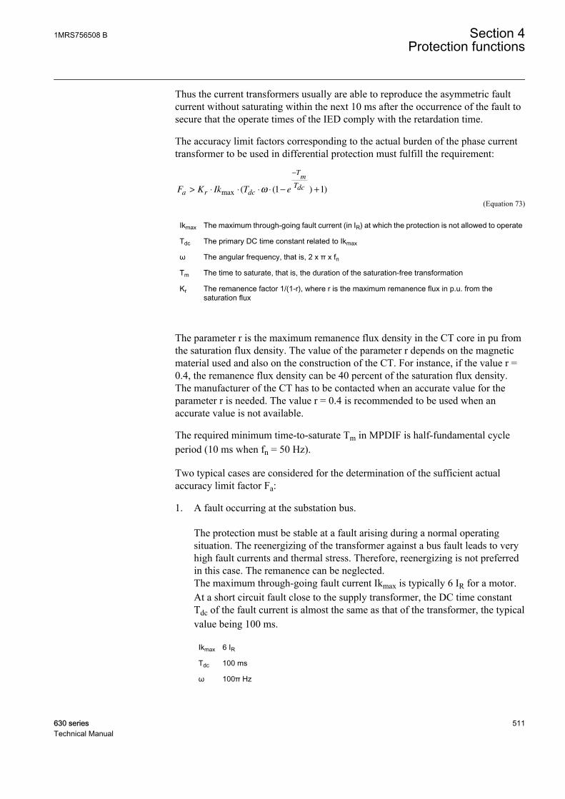
Thus the current transformers usually are able to reproduce the asymmetric faultcurrent without saturating within the next 10 ms after the occurrence of the fault tosecure that the operate times of the IED comply with the retardation time.
The accuracy limit factors corresponding to the actual burden of the phase currenttransformer to be used in differential protection must fulfill the requirement:
F K Ik T ea r dc
Tm
Tdc> ⋅ ⋅ ⋅ ⋅ − +
−
max ( ( ) )ω 1 1
GUID-21C442C8-79F8-411A-829A-1980BC5D1A2E V1 EN (Equation 73)
Ikmax The maximum through-going fault current (in IR) at which the protection is not allowed to operate
Tdc The primary DC time constant related to Ikmax
ω The angular frequency, that is, 2 x π x fn
Tm The time to saturate, that is, the duration of the saturation-free transformation
Kr The remanence factor 1/(1-r), where r is the maximum remanence flux in p.u. from thesaturation flux
The parameter r is the maximum remanence flux density in the CT core in pu fromthe saturation flux density. The value of the parameter r depends on the magneticmaterial used and also on the construction of the CT. For instance, if the value r =0.4, the remanence flux density can be 40 percent of the saturation flux density.The manufacturer of the CT has to be contacted when an accurate value for theparameter r is needed. The value r = 0.4 is recommended to be used when anaccurate value is not available.
The required minimum time-to-saturate Tm in MPDIF is half-fundamental cycleperiod (10 ms when fn = 50 Hz).
Two typical cases are considered for the determination of the sufficient actualaccuracy limit factor Fa:
1. A fault occurring at the substation bus. The protection must be stable at a fault arising during a normal operatingsituation. The reenergizing of the transformer against a bus fault leads to veryhigh fault currents and thermal stress. Therefore, reenergizing is not preferredin this case. The remanence can be neglected.The maximum through-going fault current Ikmax is typically 6 IR for a motor.At a short circuit fault close to the supply transformer, the DC time constantTdc of the fault current is almost the same as that of the transformer, the typicalvalue being 100 ms.
Ikmax 6 IR
Tdc 100 ms
ω 100π Hz
1MRS756508 B Section 4Protection functions
630 series 511Technical Manual

Tm 10 ms
Kr 1
Equation 73 with these values gives the result:
F K Ik T ea r dc
Tm
Tdc> ⋅ ⋅ ⋅ ⋅ − + ≈
−
max ( ( ) )ω 1 1 24
GUID-C510CA46-3857-40D3-B40A-3C237BCE6E79 V1 EN
2. Reenergizing against a fault occurring further down in the network. The protection must be stable also during reenergization against a fault on theline. In this case, the existence of remanence is very probable. It is assumed tobe 40 percent here.On the other hand the fault current is now smaller and since the ratio of theresistance and reactance is greater in this location, having a full DC offset isnot possible. Furthermore, the DC time constant (Tdc) of the fault current isnow smaller, assumed to be 50 ms here.Assuming the maximum fault current is 30 percent lower than in the bus faultand a DC offset 90 percent of the maximum.
Ikmax 0.7 · 6 = 4.2 (IR)
Tdc 50 ms
ω 100π Hz
Tm 10 ms
Kr 1/(1-0.4) = 1.6667
Equation 73 with these values gives the result:
F K Ik T ea r dc
Tm
Tdc> ⋅ ⋅ ⋅ ⋅ ⋅ − + ≈
−
max . ( ( ) )0 9 1 1 24ω
GUID-46A4591B-876D-4E32-A9AB-29F6C1657644 V1 EN
If the actual burden of the current transformer Sa in the accuracy limit factorequation cannot be reduced low enough to provide a sufficient value for Fa, thereare two alternatives to deal with the situation.
1. A current transformer with a higher rated burden Sn can be chosen (which alsomeans a higher rated accurate limit Fn).
2. A current transformer with a higher nominal primary current I1n (but the samerated burden) can be chosen.
Alternative 2 is more cost-effective and therefore often better, although thesensitivity of the scheme is slightly reduced.
Section 4 1MRS756508 BProtection functions
512 630 seriesTechnical Manual
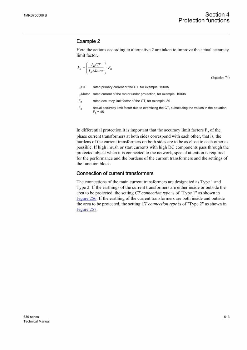
Example 2Here the actions according to alternative 2 are taken to improve the actual accuracylimit factor.
FI CT
I MotorFa
R
R
n=
⋅
GUID-560620F9-50B1-4DA4-AF3F-2B24212080D9 V1 EN (Equation 74)
IRCT rated primary current of the CT, for example, 1500A
IRMotor rated current of the motor under protection, for example, 1000A
Fn rated accuracy limit factor of the CT, for example, 30
Fa actual accuracy limit factor due to oversizing the CT, substituting the values in the equation,Fa = 45
In differential protection it is important that the accuracy limit factors Fa of thephase current transformers at both sides correspond with each other, that is, theburdens of the current transformers on both sides are to be as close to each other aspossible. If high inrush or start currents with high DC components pass through theprotected object when it is connected to the network, special attention is requiredfor the performance and the burdens of the current transformers and the settings ofthe function block.
Connection of current transformersThe connections of the main current transformers are designated as Type 1 andType 2. If the earthings of the current transformers are either inside or outside thearea to be protected, the setting CT connection type is of "Type 1" as shown inFigure 256. If the earthing of the current transformers are both inside and outsidethe area to be protected, the setting CT connection type is of "Type 2" as shown inFigure 257.
1MRS756508 B Section 4Protection functions
630 series 513Technical Manual

GUID-A6716146-6ECD-46A2-B2AC-4408DDDB7BF6 V1 EN
Figure 256: Connection of current transformer of Type 1
GUID-20C85C2F-B738-4E5A-ACE1-7B30EC9799E2 V1 EN
Figure 257: Connection of current transformer of Type 2
Saturation of current transformersThere are basically two types of saturation phenomena that have to be detected: theAC saturation and the DC saturation. The AC saturation is caused by a high faultcurrent where the CT magnetic flux exceeds its maximum value. As a result, thesecondary current is distorted as shown in Figure 258. A DC component in the
Section 4 1MRS756508 BProtection functions
514 630 seriesTechnical Manual
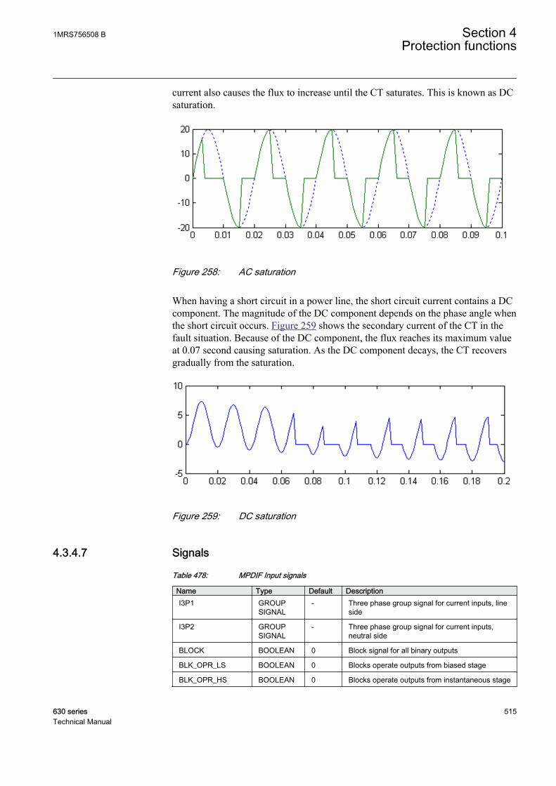
current also causes the flux to increase until the CT saturates. This is known as DCsaturation.
GUID-0A569D8E-6A69-43F1-848B-6AA364E130B7 V1 EN
Figure 258: AC saturation
When having a short circuit in a power line, the short circuit current contains a DCcomponent. The magnitude of the DC component depends on the phase angle whenthe short circuit occurs. Figure 259 shows the secondary current of the CT in thefault situation. Because of the DC component, the flux reaches its maximum valueat 0.07 second causing saturation. As the DC component decays, the CT recoversgradually from the saturation.
GUID-505C1447-5FA4-43B7-8AD7-9E2449CC10C3 V1 EN
Figure 259: DC saturation
4.3.4.7 Signals
Table 478: MPDIF Input signals
Name Type Default DescriptionI3P1 GROUP
SIGNAL- Three phase group signal for current inputs, line
side
I3P2 GROUPSIGNAL
- Three phase group signal for current inputs,neutral side
BLOCK BOOLEAN 0 Block signal for all binary outputs
BLK_OPR_LS BOOLEAN 0 Blocks operate outputs from biased stage
BLK_OPR_HS BOOLEAN 0 Blocks operate outputs from instantaneous stage
1MRS756508 B Section 4Protection functions
630 series 515Technical Manual

Table 479: MPDIF Output signals
Name Type DescriptionOPERATE BOOLEAN Operate signal, combined (all phases, both stages)
OPR_A BOOLEAN Operate signal, Phase A
OPR_B BOOLEAN Operate signal, Phase B
OPR_C BOOLEAN Operate signal, Phase C
OPR_LS BOOLEAN Operate signal from low set (biased) stage
OPR_HS BOOLEAN Operate signal from high set (instantaneous) stage
INT_BLKD BOOLEAN Protection internally blocked, combined
INT_BLKD_A BOOLEAN Protection internally blocked, Phase A
INT_BLKD_B BOOLEAN Protection internally blocked, Phase B
INT_BLKD_C BOOLEAN Protection internally blocked, Phase C
4.3.4.8 Settings
Table 480: MPDIF Group settings (basic)
Name Values (Range) Unit Step Default DescriptionHigh operate value 100 - 1000 % 1 500 Instantaneous stage setting
Low operate value 5 - 30 % 1 5 Basic setting for stabilized operation
Slope section 2 10.0 - 50.0 % 0.1 20.0 Slope of the second line of the operationcharacteristics
End section 1 0 - 100 % 1 50 Turn-point between sections 1 and 2 ofthe characteristics
End section 2 100 - 300 % 1 150 Turn-point between sections 2 and 3 ofthe characteristics
Table 481: MPDIF Group settings (advanced)
Name Values (Range) Unit Step Default DescriptionDC restrain enable No
Yes- - No Setting for enabling DC restrain feature
Table 482: MPDIF Non group settings (basic)
Name Values (Range) Unit Step Default DescriptionOperation Off
On- - On Operation Off / On
CT connection type Type 1Type 2
- - Type 1 CT connection type
Table 483: MPDIF Non group settings (advanced)
Name Values (Range) Unit Step Default DescriptionBase value Sel phase Phase Grp 1
Phase Grp 2Phase Grp 3
- - Phase Grp 1 Base value selector phase / phase tophase
Section 4 1MRS756508 BProtection functions
516 630 seriesTechnical Manual

4.3.4.9 Measured values
Table 484: MPDIF Measured values
Name Type Default DescriptionBLOCK BOOLEAN 0 Block signal for all binary outputs
BLK_OPR_LS BOOLEAN 0 Blocks operate outputs from biased stage
BLK_OPR_HS BOOLEAN 0 Blocks operate outputs from instantaneous stage
4.3.4.10 Monitored data
Table 485: MPDIF Monitored data
Name Type Values (Range) Unit DescriptionOPR_A BOOLEAN 0=FALSE
1=TRUE- Operate signal, Phase A
OPR_B BOOLEAN 0=FALSE1=TRUE
- Operate signal, Phase B
OPR_C BOOLEAN 0=FALSE1=TRUE
- Operate signal, Phase C
OPR_LS BOOLEAN 0=FALSE1=TRUE
- Operate signal from lowset (biased) stage
OPR_HS BOOLEAN 0=FALSE1=TRUE
- Operate signal from highset (instantaneous) stage
INT_BLKD_A BOOLEAN 0=FALSE1=TRUE
- Protection internallyblocked, Phase A
INT_BLKD_B BOOLEAN 0=FALSE1=TRUE
- Protection internallyblocked, Phase B
INT_BLKD_C BOOLEAN 0=FALSE1=TRUE
- Protection internallyblocked, Phase C
ID_A REAL - A Differential current,Phase A
ID_B REAL - A Differential current,Phase B
ID_C REAL - A Differential current,Phase C
IB_A REAL - A Bias current, phase A
IB_B REAL - A Bias current, phase B
IB_C REAL - A Bias current, phase C
I_ANGL_A1_B1 REAL - deg Current phase anglePhase A – Phase B, lineside
I_ANGL_B1_C1 REAL - deg Current phase anglePhase B – Phase C, lineside
I_ANGL_C1_A1 REAL - deg Current phase anglePhase C – Phase A, lineside
Table continues on next page
1MRS756508 B Section 4Protection functions
630 series 517Technical Manual
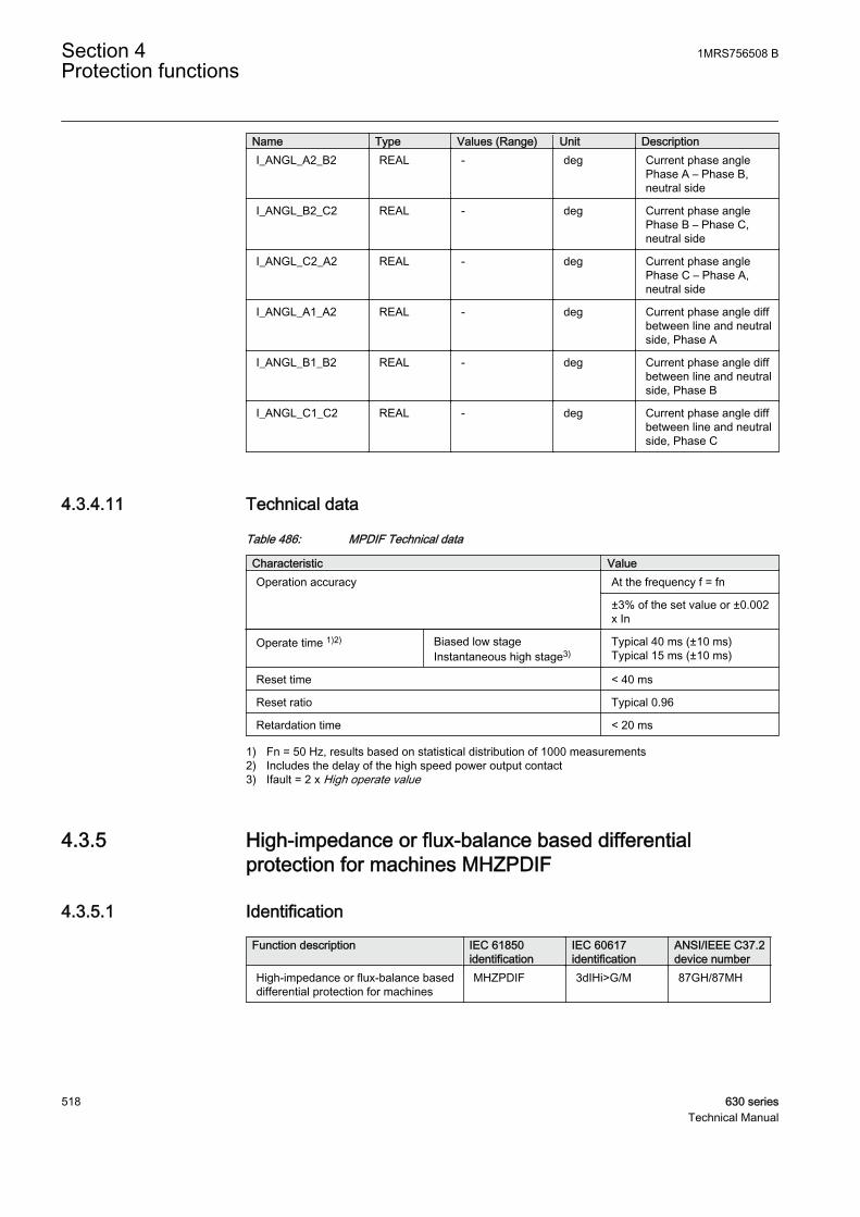
Name Type Values (Range) Unit DescriptionI_ANGL_A2_B2 REAL - deg Current phase angle
Phase A – Phase B,neutral side
I_ANGL_B2_C2 REAL - deg Current phase anglePhase B – Phase C,neutral side
I_ANGL_C2_A2 REAL - deg Current phase anglePhase C – Phase A,neutral side
I_ANGL_A1_A2 REAL - deg Current phase angle diffbetween line and neutralside, Phase A
I_ANGL_B1_B2 REAL - deg Current phase angle diffbetween line and neutralside, Phase B
I_ANGL_C1_C2 REAL - deg Current phase angle diffbetween line and neutralside, Phase C
4.3.4.11 Technical data
Table 486: MPDIF Technical data
Characteristic ValueOperation accuracy At the frequency f = fn
±3% of the set value or ±0.002x In
Operate time 1)2) Biased low stageInstantaneous high stage3)
Typical 40 ms (±10 ms)Typical 15 ms (±10 ms)
Reset time < 40 ms
Reset ratio Typical 0.96
Retardation time < 20 ms
1) Fn = 50 Hz, results based on statistical distribution of 1000 measurements2) Includes the delay of the high speed power output contact3) Ifault = 2 x High operate value
4.3.5 High-impedance or flux-balance based differentialprotection for machines MHZPDIF
4.3.5.1 Identification
Function description IEC 61850identification
IEC 60617identification
ANSI/IEEE C37.2device number
High-impedance or flux-balance baseddifferential protection for machines
MHZPDIF 3dIHi>G/M 87GH/87MH
Section 4 1MRS756508 BProtection functions
518 630 seriesTechnical Manual
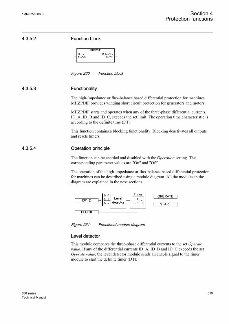
4.3.5.2 Function block
GUID-24CCEC75-1ADE-4D2D-86D6-35E22B7278FF V1 EN
Figure 260: Function block
4.3.5.3 Functionality
The high-impedance or flux-balance based differential protection for machinesMHZPDIF provides winding short circuit protection for generators and motors.
MHZPDIF starts and operates when any of the three-phase differential currents,ID_A, ID_B and ID_C, exceeds the set limit. The operation time characteristic isaccording to the definite time (DT).
This function contains a blocking functionality. Blocking deactivates all outputsand resets timers.
4.3.5.4 Operation principle
The function can be enabled and disabled with the Operation setting. Thecorresponding parameter values are "On" and "Off".
The operation of the high-impedance or flux-balance based differential protectionfor machines can be described using a module diagram. All the modules in thediagram are explained in the next sections.
GUID-8FB25404-B7E4-41C1-9BE2-461AA2F8C335 V1 EN
Figure 261: Functional module diagram
Level detectorThis module compares the three-phase differential currents to the set Operatevalue. If any of the differential currents ID_A, ID_B and ID_C exceeds the setOperate value, the level detector module sends an enable signal to the timermodule to start the definite timer (DT).
1MRS756508 B Section 4Protection functions
630 series 519Technical Manual

TimerOnce activated, the timer activates the START output. The timer characteristic isaccording to DT. When the operation timer has reached the value set by Minimumoperate time, the OPERATE output is activated. If the fault disappears before themodule operates, the reset timer is activated. If the reset timer reaches the value setby Reset delay time, the operation timer resets and the START output is deactivated.
The timer calculates the start duration value START_DUR, which indicates thepercentage ratio of the start situation and the set operation time. The value isavailable in the monitored data view.
The activation of the BLOCK signal resets the timer and deactivates the START andOPERATE outputs.
It is recommended to use the adaptive DFT preprocessing block toprovide the analog input to this function.
4.3.5.5 Base values
In this function block, some of the settings are set in per unit (pu). These pu valuesare relational to certain base values, for example the values given in A, kV andkVA. The IED supports alternative base value groups for the phase current or voltage-related settings, for example "Phase Grp 1", "Phase Grp 2" and "Phase Grp 3".Similarly, "Residual Grp 1", "Residual Grp 2" and "Residual Grp 3" are supportedfor the residual current or voltage-related settings. One of the groups must beselected to be used with the Base value Sel phase or Base value Sel Res settings.
For more information, see the Basic functions section in this manual.
4.3.5.6 Application
The high-impedance or flux-balance based differential protection for machinesprovides the winding short circuit and earth-fault protection for generators andmotors. The high-impedance or flux-balance principle has been used through manyyears for differential protection due to the capability to manage through-faults witha heavy current transformer (CT) saturation.
High-impedance principleThe high-impedance principle is stable for all types of faults outside the protectionzone. The stabilization is obtained by a stabilizing resistor in the differential circuit.This method requires all the CTs to have a similar magnetizing characteristic, sameratio and a relatively high knee point voltage. The CTs in each phase are connected
Section 4 1MRS756508 BProtection functions
520 630 seriesTechnical Manual
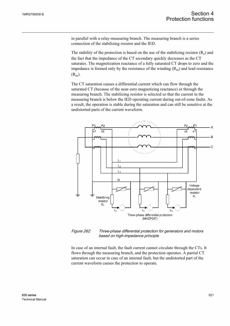
in parallel with a relay-measuring branch. The measuring branch is a seriesconnection of the stabilizing resistor and the IED.
The stability of the protection is based on the use of the stabilizing resistor (Rs) andthe fact that the impedance of the CT secondary quickly decreases as the CTsaturates. The magnetization reactance of a fully saturated CT drops to zero and theimpedance is formed only by the resistance of the winding (Rin) and lead resistance(Rm).
The CT saturation causes a differential current which can flow through thesaturated CT (because of the near-zero magnetizing reactance) or through themeasuring branch. The stabilizing resistor is selected so that the current in themeasuring branch is below the IED operating current during out-of-zone faults. Asa result, the operation is stable during the saturation and can still be sensitive at theundistorted parts of the current waveform.
GUID-C9F29BF5-BFE3-4EB8-B7AA-025B4D72CE98 V1 EN
Figure 262: Three-phase differential protection for generators and motorsbased on high-impedance principle
In case of an internal fault, the fault current cannot circulate through the CTs. Itflows through the measuring branch, and the protection operates. A partial CTsaturation can occur in case of an internal fault, but the undistorted part of thecurrent waveform causes the protection to operate.
1MRS756508 B Section 4Protection functions
630 series 521Technical Manual
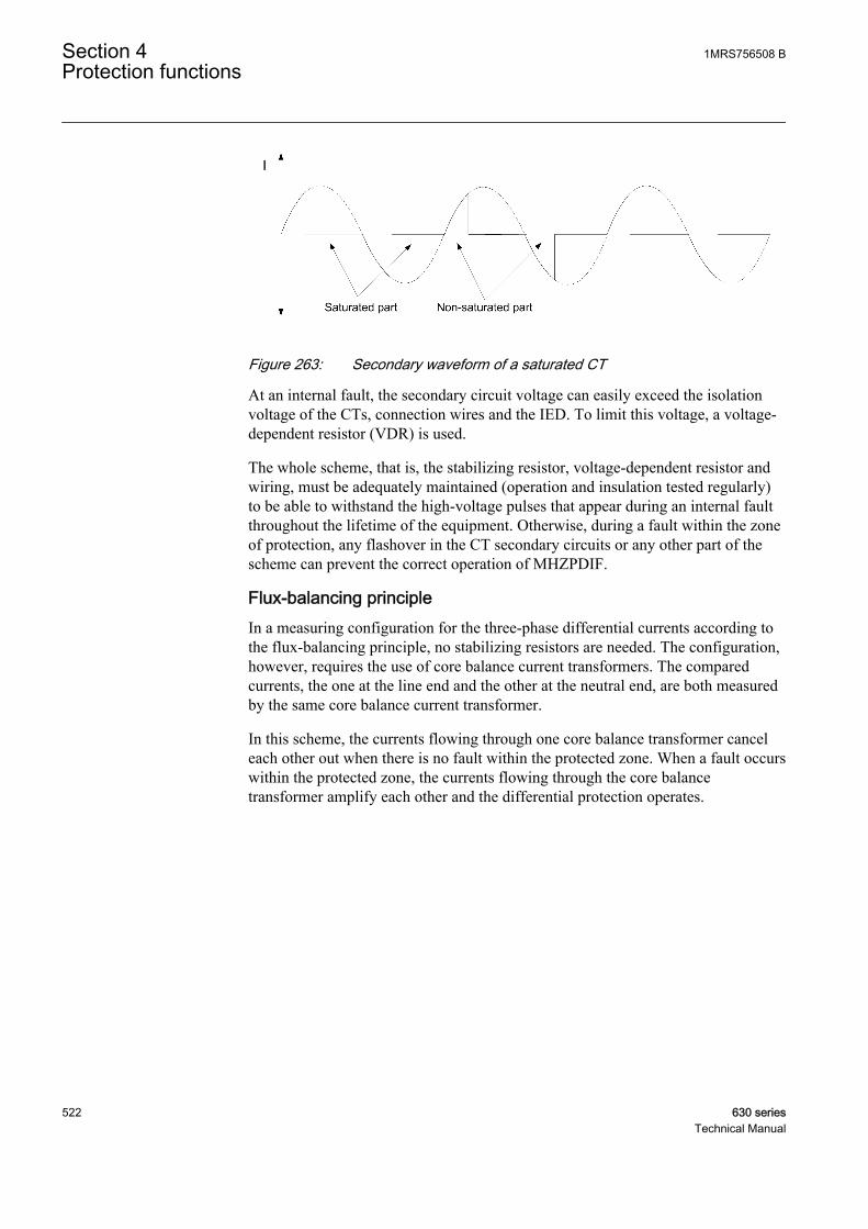
GUID-AB182BA0-40A2-435F-85ED-9629D5F49955 V1 EN
Figure 263: Secondary waveform of a saturated CT
At an internal fault, the secondary circuit voltage can easily exceed the isolationvoltage of the CTs, connection wires and the IED. To limit this voltage, a voltage-dependent resistor (VDR) is used.
The whole scheme, that is, the stabilizing resistor, voltage-dependent resistor andwiring, must be adequately maintained (operation and insulation tested regularly)to be able to withstand the high-voltage pulses that appear during an internal faultthroughout the lifetime of the equipment. Otherwise, during a fault within the zoneof protection, any flashover in the CT secondary circuits or any other part of thescheme can prevent the correct operation of MHZPDIF.
Flux-balancing principleIn a measuring configuration for the three-phase differential currents according tothe flux-balancing principle, no stabilizing resistors are needed. The configuration,however, requires the use of core balance current transformers. The comparedcurrents, the one at the line end and the other at the neutral end, are both measuredby the same core balance current transformer.
In this scheme, the currents flowing through one core balance transformer canceleach other out when there is no fault within the protected zone. When a fault occurswithin the protected zone, the currents flowing through the core balancetransformer amplify each other and the differential protection operates.
Section 4 1MRS756508 BProtection functions
522 630 seriesTechnical Manual

GUID-A4DDB734-AC8E-4124-9B70-5A501ED80EC6 V1 EN
Figure 264: Three-phase differential protection for generators and motorsbased on flux-balancing principle
The advantage of this scheme is that the CT rated primary current can be selectedsmaller than the rated current of the machine.
If six current transformers are used, the flux-balancing principle(that is, summing two CTs in each phase) cannot be used. Instead,the high-impedance principle or stabilized three-phase differentialprotection must be used.
4.3.5.7 Recommendations for current transformers
High-impedance principleThe sensitivity and reliability of the protection depend on the characteristics of thecurrent transformers. The CTs must have an identical transformation ratio. It isrecommended that all current transformers have an equal burden and characteristicsand that they are of the same type, preferably from the same manufacturing batch,that is, an identical construction used. If the CT characteristics and the burdenvalues are not equal, the calculation for each branch in the scheme should be doneseparately and the worst-case result is used. In the case where the CT windingresistance and the burden of the branches are not equal, the maximum burden equalto 3.2 Ω should be used for calculating the stabilized voltage.
1MRS756508 B Section 4Protection functions
630 series 523Technical Manual
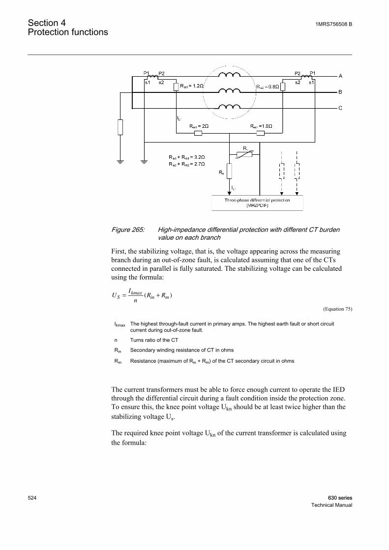
GUID-575B946F-B88E-40B1-9307-950BFE94B3B0 V1 EN
Figure 265: High-impedance differential protection with different CT burdenvalue on each branch
First, the stabilizing voltage, that is, the voltage appearing across the measuringbranch during an out-of-zone fault, is calculated assuming that one of the CTsconnected in parallel is fully saturated. The stabilizing voltage can be calculatedusing the formula:
UI
nR RS
kmaxin m= +( )
GUID-42B37DB8-C02D-4FE2-942E-64B2F07E79AB V1 EN (Equation 75)
Ikmax The highest through-fault current in primary amps. The highest earth fault or short circuitcurrent during out-of-zone fault.
n Turns ratio of the CT
Rin Secondary winding resistance of CT in ohms
Rm Resistance (maximum of Rin + Rm) of the CT secondary circuit in ohms
The current transformers must be able to force enough current to operate the IEDthrough the differential circuit during a fault condition inside the protection zone.To ensure this, the knee point voltage Ukn should be at least twice higher than thestabilizing voltage Us.
The required knee point voltage Ukn of the current transformer is calculated usingthe formula:
Section 4 1MRS756508 BProtection functions
524 630 seriesTechnical Manual
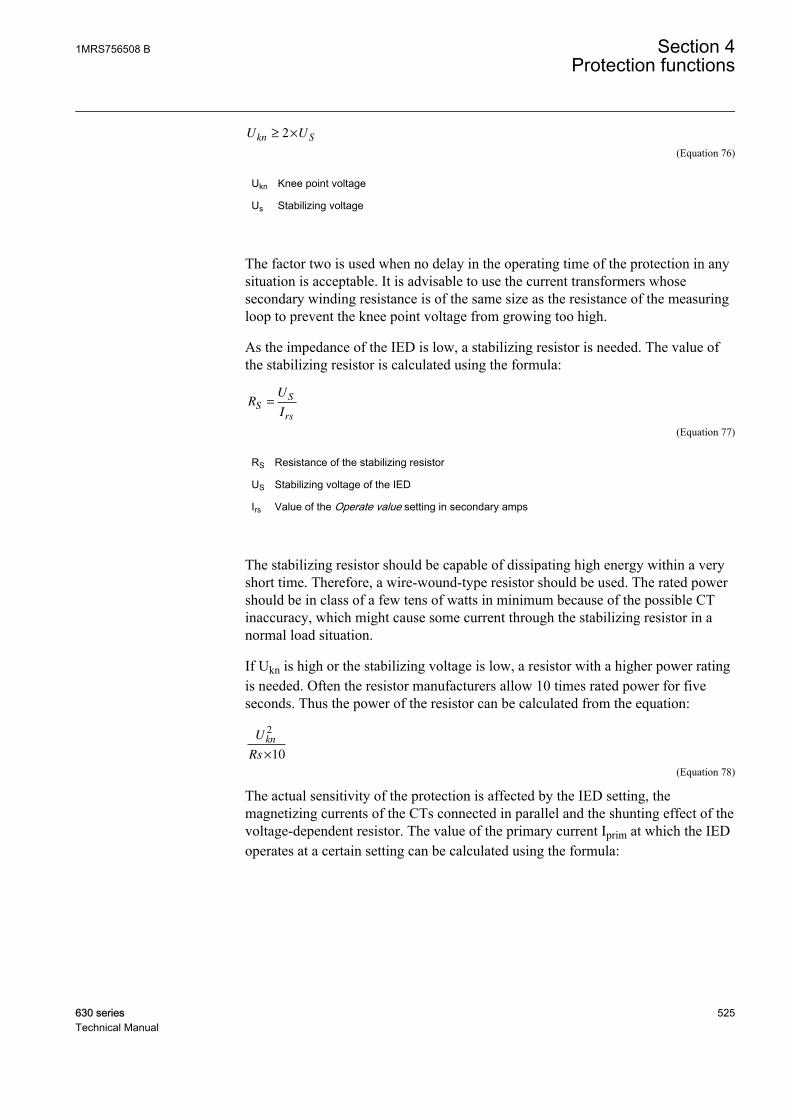
U Ukn S≥ ×2
GUID-D4379003-3492-4C28-8285-3FF3EB0942A9 V1 EN (Equation 76)
Ukn Knee point voltage
Us Stabilizing voltage
The factor two is used when no delay in the operating time of the protection in anysituation is acceptable. It is advisable to use the current transformers whosesecondary winding resistance is of the same size as the resistance of the measuringloop to prevent the knee point voltage from growing too high.
As the impedance of the IED is low, a stabilizing resistor is needed. The value ofthe stabilizing resistor is calculated using the formula:
RU
IS
S
rs
=
GUID-F56F36B1-C353-4B94-B99D-1C930B842920 V1 EN (Equation 77)
RS Resistance of the stabilizing resistor
US Stabilizing voltage of the IED
Irs Value of the Operate value setting in secondary amps
The stabilizing resistor should be capable of dissipating high energy within a veryshort time. Therefore, a wire-wound-type resistor should be used. The rated powershould be in class of a few tens of watts in minimum because of the possible CTinaccuracy, which might cause some current through the stabilizing resistor in anormal load situation.
If Ukn is high or the stabilizing voltage is low, a resistor with a higher power ratingis needed. Often the resistor manufacturers allow 10 times rated power for fiveseconds. Thus the power of the resistor can be calculated from the equation:
U
Rs
kn
2
10×
GUID-2A68A3E9-C55F-4478-995E-7888F1A37002 V1 EN (Equation 78)
The actual sensitivity of the protection is affected by the IED setting, themagnetizing currents of the CTs connected in parallel and the shunting effect of thevoltage-dependent resistor. The value of the primary current Iprim at which the IEDoperates at a certain setting can be calculated using the formula:
1MRS756508 B Section 4Protection functions
630 series 525Technical Manual
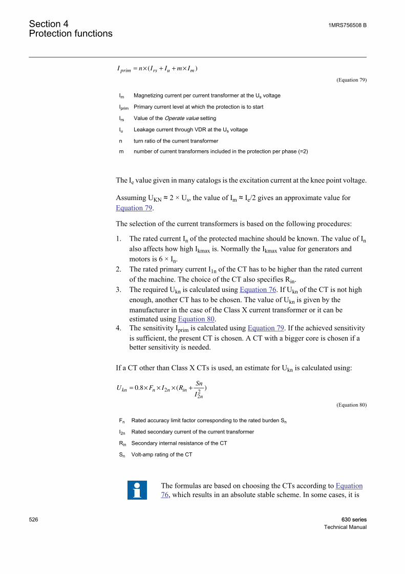
I n I I m Iprim rs u m= × + + ×( )
GUID-64075260-CB30-4CD4-A88F-BC4530F21968 V1 EN (Equation 79)
Im Magnetizing current per current transformer at the Us voltage
Iprim Primary current level at which the protection is to start
Irs Value of the Operate value setting
Iu Leakage current through VDR at the Us voltage
n turn ratio of the current transformer
m number of current transformers included in the protection per phase (=2)
The Ie value given in many catalogs is the excitation current at the knee point voltage.
Assuming UKN ≈ 2 × Us, the value of Im ≈ Ie/2 gives an approximate value forEquation 79.
The selection of the current transformers is based on the following procedures:
1. The rated current In of the protected machine should be known. The value of Inalso affects how high Ikmax is. Normally the Ikmax value for generators andmotors is 6 × In.
2. The rated primary current I1n of the CT has to be higher than the rated currentof the machine. The choice of the CT also specifies Rin.
3. The required Ukn is calculated using Equation 76. If Ukn of the CT is not highenough, another CT has to be chosen. The value of Ukn is given by themanufacturer in the case of the Class X current transformer or it can beestimated using Equation 80.
4. The sensitivity Iprim is calculated using Equation 79. If the achieved sensitivityis sufficient, the present CT is chosen. A CT with a bigger core is chosen if abetter sensitivity is needed.
If a CT other than Class X CTs is used, an estimate for Ukn is calculated using:
U F I RSn
Ikn n n in
n
= × × × +0 8 2
22
. ( )
GUID-7D424942-08A0-49E6-8905-4BAD2092AE73 V1 EN (Equation 80)
Fn Rated accuracy limit factor corresponding to the rated burden Sn
I2n Rated secondary current of the current transformer
Rin Secondary internal resistance of the CT
Sn Volt-amp rating of the CT
The formulas are based on choosing the CTs according to Equation76, which results in an absolute stable scheme. In some cases, it is
Section 4 1MRS756508 BProtection functions
526 630 seriesTechnical Manual
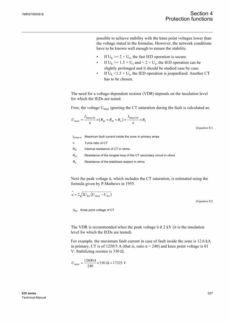
possible to achieve stability with the knee point voltages lower thanthe voltage stated in the formulas. However, the network conditionshave to be known well enough to ensure the stability.
• If Uk >= 2 × Us, the fast IED operation is secure.• If Uk >= 1.5 × Us and < 2 × Us, the IED operation can be
slightly prolonged and it should be studied case by case.• If Uk <1.5 × Us, the IED operation is jeopardized. Another CT
has to be chosen.
The need for a voltage-dependent resistor (VDR) depends on the insulation levelfor which the IEDs are tested.
First, the voltage Umax ignoring the CT saturation during the fault is calculated as:
UI
nR R R
I
nRmax
kmax in
in m s
kmax in
s= × + +( ) ≈ ×
GUID-774FDBB5-408A-4EAB-8E1A-600D0A68BD07 V1 EN (Equation 81)
Ikmax in Maximum fault current inside the zone in primary amps
n Turns ratio of CT
Rin Internal resistance of CT in ohms
Rm Resistance of the longest loop of the CT secondary circuit in ohms
Rs Resistance of the stabilized resistor in ohms
Next the peak voltage û, which includes the CT saturation, is estimated using theformula given by P.Mathews in 1955.
u U U Ukn max kn
∧
= −( )2 2
GUID-A51971B7-BA7A-4C5D-AC86-FFC1B674FE18 V1 EN (Equation 82)
Ukn Knee point voltage of CT
The VDR is recommended when the peak voltage û ≥ 2 kV (it is the insulationlevel for which the IEDs are tested).
For example, the maximum fault current in case of fault inside the zone is 12.6 kAin primary, CT is of 1250/5 A (that is, ratio n = 240) and knee point voltage is 81V. Stabilizing resistor is 330 Ω.
UA
Vmax = × =12600
240330 17325 Ω
GUID-D5C1796B-342C-4A77-B454-59B68C3B8558 V1 EN
1MRS756508 B Section 4Protection functions
630 series 527Technical Manual
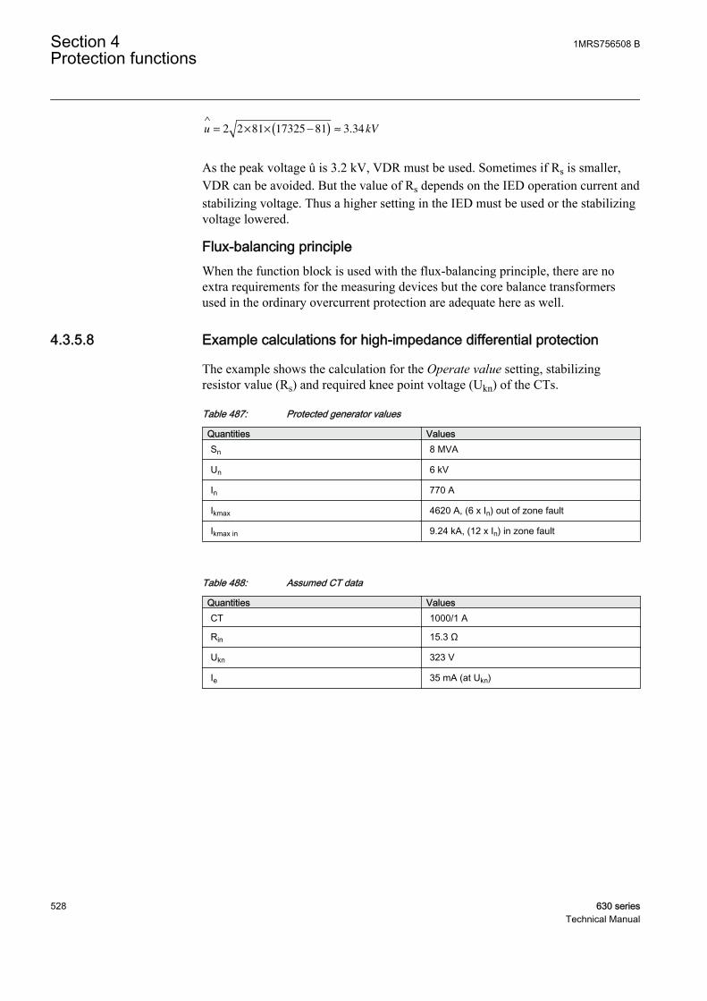
u kV
∧
= × × −( ) ≈2 2 81 17325 81 3 34.
GUID-FBEA5B92-671B-4EF7-9FE0-CFAA612DB59B V1 EN
As the peak voltage û is 3.2 kV, VDR must be used. Sometimes if Rs is smaller,VDR can be avoided. But the value of Rs depends on the IED operation current andstabilizing voltage. Thus a higher setting in the IED must be used or the stabilizingvoltage lowered.
Flux-balancing principleWhen the function block is used with the flux-balancing principle, there are noextra requirements for the measuring devices but the core balance transformersused in the ordinary overcurrent protection are adequate here as well.
4.3.5.8 Example calculations for high-impedance differential protection
The example shows the calculation for the Operate value setting, stabilizingresistor value (Rs) and required knee point voltage (Ukn) of the CTs.
Table 487: Protected generator values
Quantities ValuesSn 8 MVA
Un 6 kV
In 770 A
Ikmax 4620 A, (6 x In) out of zone fault
Ikmax in 9.24 kA, (12 x In) in zone fault
Table 488: Assumed CT data
Quantities ValuesCT 1000/1 A
Rin 15.3 Ω
Ukn 323 V
Ie 35 mA (at Ukn)
Section 4 1MRS756508 BProtection functions
528 630 seriesTechnical Manual
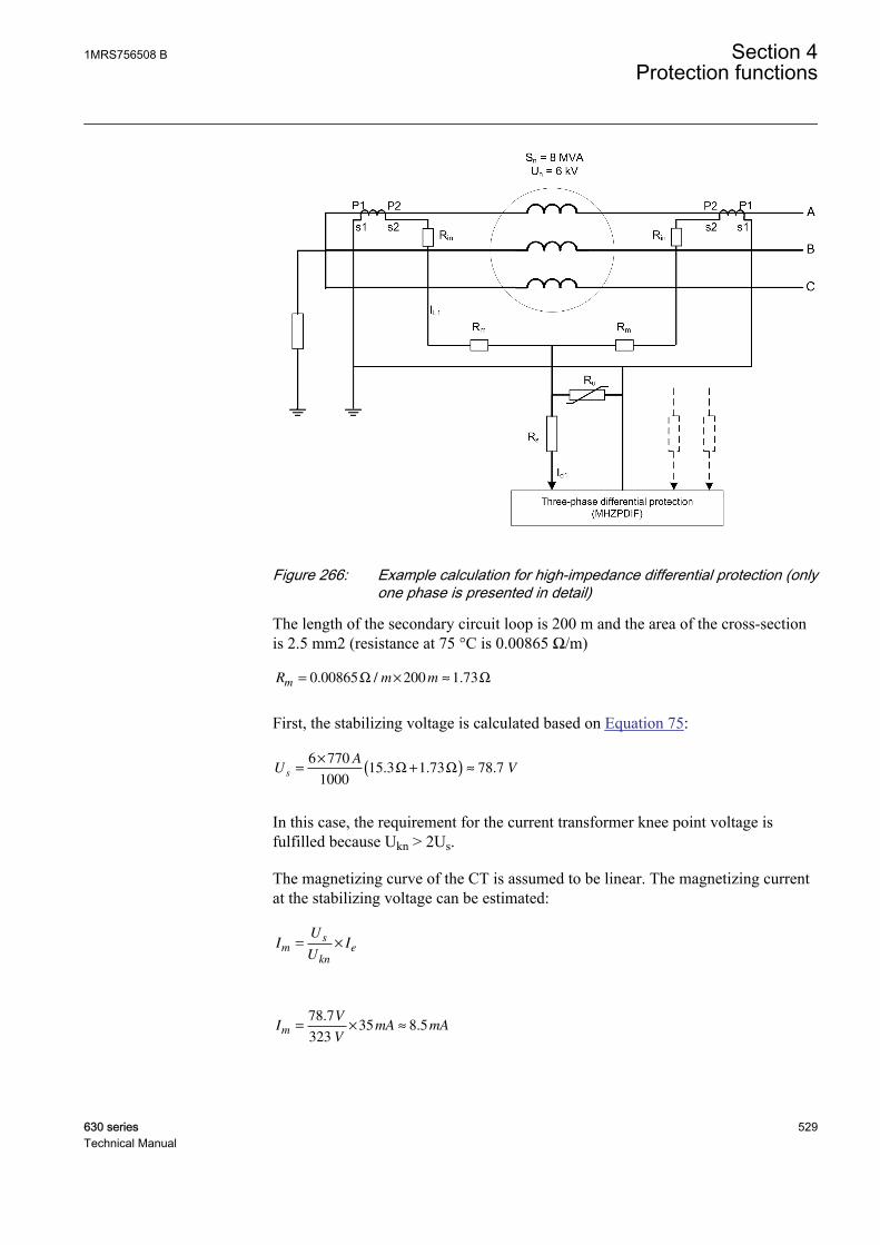
GUID-19DB39B0-4D6F-4EE3-8F19-B797A22F8316 V1 EN
Figure 266: Example calculation for high-impedance differential protection (onlyone phase is presented in detail)
The length of the secondary circuit loop is 200 m and the area of the cross-sectionis 2.5 mm2 (resistance at 75 °C is 0.00865 Ω/m)
R m mm = × ≈0 00865 200 1 73. / .Ω Ω
GUID-0C91267F-3989-4FA6-940F-4D77721B50A0 V1 EN
First, the stabilizing voltage is calculated based on Equation 75:
UA
Vs
=×
+( ) ≈6 770
100015 3 1 73 78 7. . .Ω Ω
GUID-745EC85F-77A1-4BA5-9DF6-C713C028AE87 V1 EN
In this case, the requirement for the current transformer knee point voltage isfulfilled because Ukn > 2Us.
The magnetizing curve of the CT is assumed to be linear. The magnetizing currentat the stabilizing voltage can be estimated:
IU
UIm
s
kn
e= ×
GUID-89021103-B75B-4469-8F94-6BFCF22E4B2C V1 EN
IV
VmA mAm = × ≈
78 7
32335 8 5
..
GUID-491DEB8A-FFFD-452E-9E1C-51F71CD2122A V1 EN
1MRS756508 B Section 4Protection functions
630 series 529Technical Manual
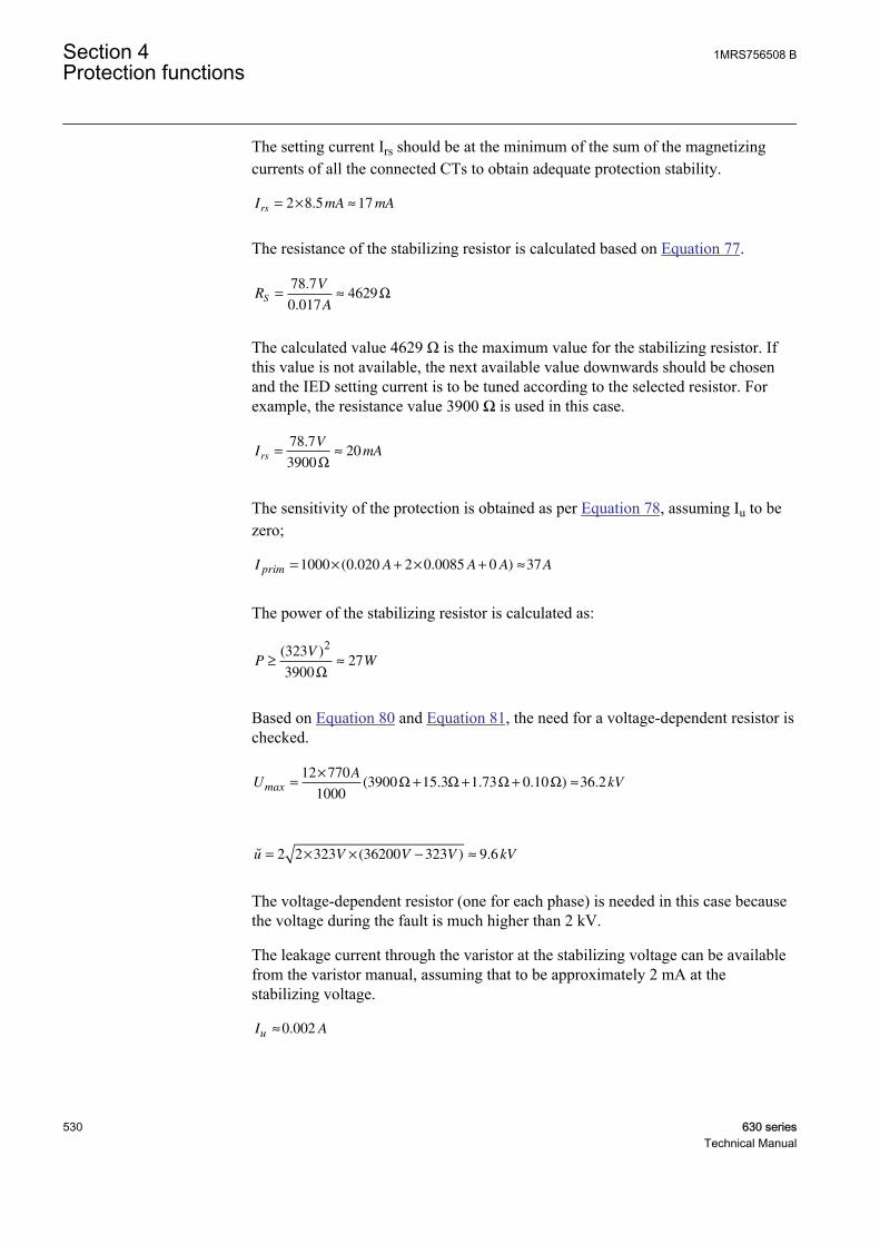
The setting current Irs should be at the minimum of the sum of the magnetizingcurrents of all the connected CTs to obtain adequate protection stability.
I mA mArs
= × ≈2 8 5 17.
GUID-36EDA686-1C70-4ED6-9101-B789DF25D41A V1 EN
The resistance of the stabilizing resistor is calculated based on Equation 77.
RV
AS
= ≈78 7
0 0174629
.
.Ω
GUID-FE3950D9-8DCD-4826-B00A-5260FF86E105 V1 EN
The calculated value 4629 Ω is the maximum value for the stabilizing resistor. Ifthis value is not available, the next available value downwards should be chosenand the IED setting current is to be tuned according to the selected resistor. Forexample, the resistance value 3900 Ω is used in this case.
IV
mArs
= ≈78 7
390020
.
Ω
GUID-748E772E-1AF6-44B4-A83A-5F013186AC4B V1 EN
The sensitivity of the protection is obtained as per Equation 78, assuming Iu to bezero;
I A A A Aprim = × + × + ≈1000 0 020 2 0 0085 0 37( . . )
GUID-91ECE858-3738-47A7-B026-294F1422542A V1 EN
The power of the stabilizing resistor is calculated as:
PV
W≥ ≈( )323
390027
2
Ω
GUID-45E53EAB-5A26-4F30-BDF9-FC68F48C301F V1 EN
Based on Equation 80 and Equation 81, the need for a voltage-dependent resistor ischecked.
UA
kVmax =×
+ + + ≈12 770
10003900 15 3 1 73 0 10 36 2( . . . ) .Ω Ω Ω Ω
GUID-816E7C20-DDD5-4FAA-85AF-A70A59BE5ADF V1 EN
˘ ( ) .u V V V kV= × × − ≈2 2 323 36200 323 9 6
GUID-A76CF2FC-4F8B-4E74-9AE0-BBCB4F7F7446 V1 EN
The voltage-dependent resistor (one for each phase) is needed in this case becausethe voltage during the fault is much higher than 2 kV.
The leakage current through the varistor at the stabilizing voltage can be availablefrom the varistor manual, assuming that to be approximately 2 mA at thestabilizing voltage.
I Au ≈0 002.
GUID-60950B16-2C98-4137-A2B7-962BAC5921D6 V1 EN
Section 4 1MRS756508 BProtection functions
530 630 seriesTechnical Manual

The sensitivity of the protection can be recalculated taking into account the leakagecurrent through the varistor as per Equation 78.
I A A A Aprim = × + × + ≈1000 0 020 2 0 0085 0 002 39( . . . )
GUID-5B1557F6-D7F3-4422-B74D-8728BDD5BAE1 V1 EN
4.3.5.9 Signals
Table 489: MHZPDIF Input signals
Name Type Default DescriptionI3P_D GROUP
SIGNAL- Three phase group signal for differential current
inputs
BLOCK BOOLEAN 0 Block signal for all binary outputs
Table 490: MHZPDIF Output signals
Name Type DescriptionOPERATE BOOLEAN Operated
OPR_A BOOLEAN Operated phase A
OPR_B BOOLEAN Operated phase B
OPR_C BOOLEAN Operated phase C
START BOOLEAN Started
ST_A BOOLEAN Started phase A
ST_B BOOLEAN Started phase B
ST_C BOOLEAN Started phase C
4.3.5.10 Settings
Table 491: MHZPDIF Group settings (basic)
Name Values (Range) Unit Step Default DescriptionOperate value 0.5 - 50.0 % 0.1 0.5 Operate value, percentage of the
nominal current
Minimum operate time 0.02 - 300.00 s 0.01 0.02 Minimum operate time
Table 492: MHZPDIF Non group settings (basic)
Name Values (Range) Unit Step Default DescriptionOperation Off
On- - On Operation Off / On
1MRS756508 B Section 4Protection functions
630 series 531Technical Manual
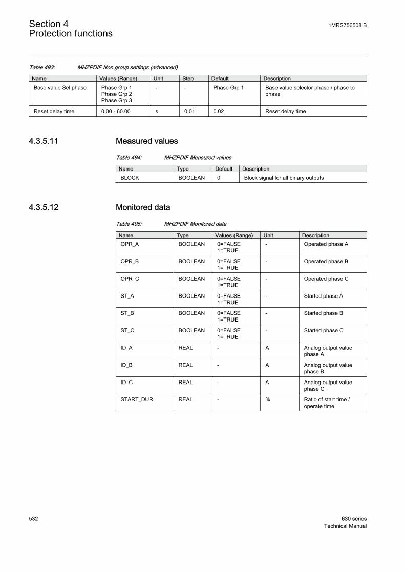
Table 493: MHZPDIF Non group settings (advanced)
Name Values (Range) Unit Step Default DescriptionBase value Sel phase Phase Grp 1
Phase Grp 2Phase Grp 3
- - Phase Grp 1 Base value selector phase / phase tophase
Reset delay time 0.00 - 60.00 s 0.01 0.02 Reset delay time
4.3.5.11 Measured values
Table 494: MHZPDIF Measured values
Name Type Default DescriptionBLOCK BOOLEAN 0 Block signal for all binary outputs
4.3.5.12 Monitored data
Table 495: MHZPDIF Monitored data
Name Type Values (Range) Unit DescriptionOPR_A BOOLEAN 0=FALSE
1=TRUE- Operated phase A
OPR_B BOOLEAN 0=FALSE1=TRUE
- Operated phase B
OPR_C BOOLEAN 0=FALSE1=TRUE
- Operated phase C
ST_A BOOLEAN 0=FALSE1=TRUE
- Started phase A
ST_B BOOLEAN 0=FALSE1=TRUE
- Started phase B
ST_C BOOLEAN 0=FALSE1=TRUE
- Started phase C
ID_A REAL - A Analog output valuephase A
ID_B REAL - A Analog output valuephase B
ID_C REAL - A Analog output valuephase C
START_DUR REAL - % Ratio of start time /operate time
Section 4 1MRS756508 BProtection functions
532 630 seriesTechnical Manual
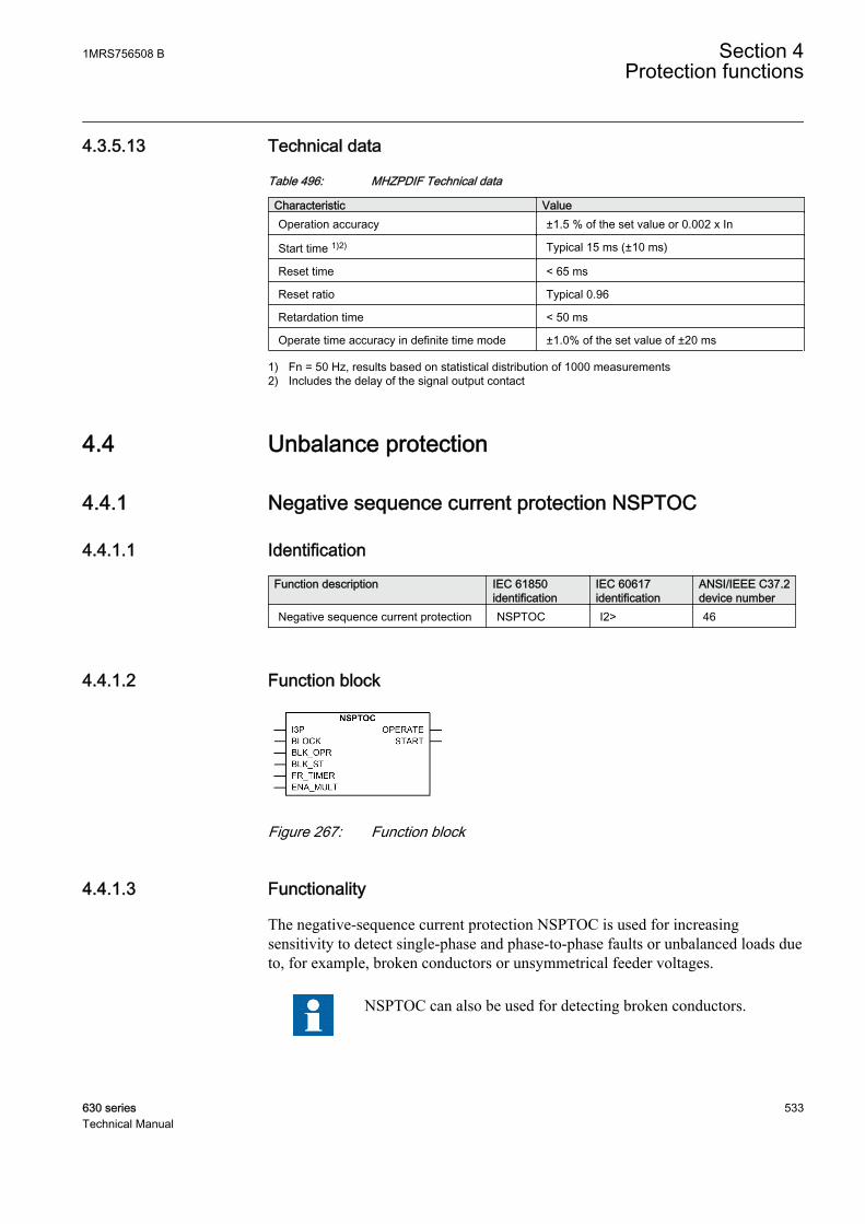
4.3.5.13 Technical data
Table 496: MHZPDIF Technical data
Characteristic ValueOperation accuracy ±1.5 % of the set value or 0.002 x In
Start time 1)2) Typical 15 ms (±10 ms)
Reset time < 65 ms
Reset ratio Typical 0.96
Retardation time < 50 ms
Operate time accuracy in definite time mode ±1.0% of the set value of ±20 ms
1) Fn = 50 Hz, results based on statistical distribution of 1000 measurements2) Includes the delay of the signal output contact
4.4 Unbalance protection
4.4.1 Negative sequence current protection NSPTOC
4.4.1.1 Identification
Function description IEC 61850identification
IEC 60617identification
ANSI/IEEE C37.2device number
Negative sequence current protection NSPTOC I2> 46
4.4.1.2 Function block
GUID-97DA5E96-A45D-4CEA-B1E7-B6BB62E0C4F1 V1 EN
Figure 267: Function block
4.4.1.3 Functionality
The negative-sequence current protection NSPTOC is used for increasingsensitivity to detect single-phase and phase-to-phase faults or unbalanced loads dueto, for example, broken conductors or unsymmetrical feeder voltages.
NSPTOC can also be used for detecting broken conductors.
1MRS756508 B Section 4Protection functions
630 series 533Technical Manual
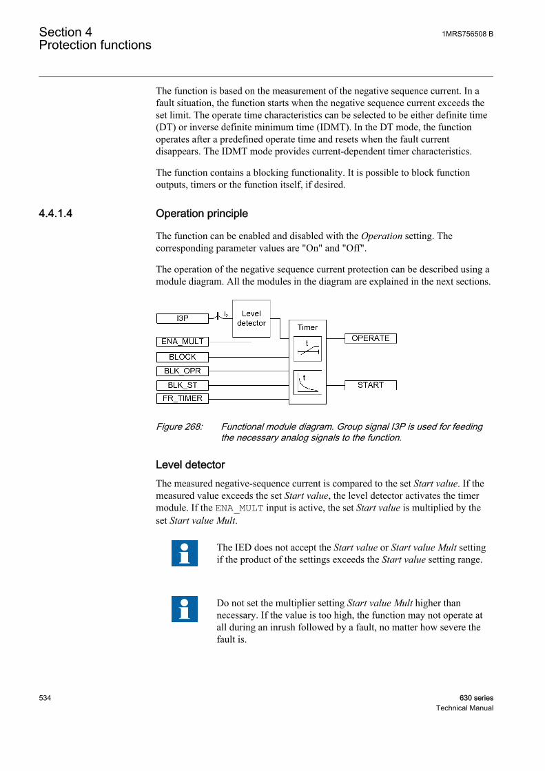
The function is based on the measurement of the negative sequence current. In afault situation, the function starts when the negative sequence current exceeds theset limit. The operate time characteristics can be selected to be either definite time(DT) or inverse definite minimum time (IDMT). In the DT mode, the functionoperates after a predefined operate time and resets when the fault currentdisappears. The IDMT mode provides current-dependent timer characteristics.
The function contains a blocking functionality. It is possible to block functionoutputs, timers or the function itself, if desired.
4.4.1.4 Operation principle
The function can be enabled and disabled with the Operation setting. Thecorresponding parameter values are "On" and "Off".
The operation of the negative sequence current protection can be described using amodule diagram. All the modules in the diagram are explained in the next sections.
GUID-27733093-7ECF-48D3-BCB5-88FF47FC40E3 V1 EN
Figure 268: Functional module diagram. Group signal I3P is used for feedingthe necessary analog signals to the function.
Level detectorThe measured negative-sequence current is compared to the set Start value. If themeasured value exceeds the set Start value, the level detector activates the timermodule. If the ENA_MULT input is active, the set Start value is multiplied by theset Start value Mult.
The IED does not accept the Start value or Start value Mult settingif the product of the settings exceeds the Start value setting range.
Do not set the multiplier setting Start value Mult higher thannecessary. If the value is too high, the function may not operate atall during an inrush followed by a fault, no matter how severe thefault is.
Section 4 1MRS756508 BProtection functions
534 630 seriesTechnical Manual
TimerOnce activated, the timer activates the START output. The ST_A, ST_B and ST_Coutputs are used to indicate which phases are started. Depending on the value ofthe Operating curve type setting, the time characteristics are according to DT orIDMT. When the operation timer has reached the value of Operate delay time inthe DT mode or the maximum value defined by the inverse time curve, theOPERATE output is activated. The OPR_A, OPR_B and OPR_C outputs are used toindicate which phases are operated.
When the user-programmable IDMT curve is selected, the operation timecharacteristics are defined by the parameters Curve parameter A, Curve parameterB, Curve parameter C, Curve parameter D and Curve parameter E.
If a drop-off situation happens, that is, a fault suddenly disappears before theoperate delay is exceeded, the timer reset state is activated. The functionality of thetimer in the reset state depends on the combination of the Operating curve type,Type of reset curve and Reset delay time settings. When the DT characteristic isselected, the reset timer runs until the set Reset delay time value is exceeded. Whenthe IDMT curves are selected, the Type of reset curve setting can be set to"Immediate", "Def time reset" or "Inverse reset". The reset curve type "Immediate"causes an immediate reset. With the reset curve type "Def time reset", the resettime depends on the Reset delay time setting. With the reset curve type "Inversereset", the reset time depends on the current during the drop-off situation. TheSTART output is deactivated when the reset timer has elapsed.
The "Inverse reset" selection is only supported with ANSI or userprogrammable types of the IDMT operating curves. If anotheroperating curve type is selected, an immediate reset occurs duringthe drop-off situation.
The setting Time multiplier is used for scaling the IDMT operate and reset times.
The setting parameter Minimum operate time defines the minimum desired operatetime for IDMT. The setting is applicable only when the IDMT curves are used.
The Minimum operate time setting should be used with great carebecause the operation time is according to the IDMT curve, butalways at least the value of the Minimum operate time setting. Formore information, see the General function block features sectionin this manual.
The timer calculates the start duration value START_DUR, which indicates thepercentage ratio of the start situation and the set operating time. The value isavailable in the monitored data view.
The binary input BLOCK can be used to block the function. The activation of theBLOCK input deactivates all outputs and resets internal timers. The binary inputBLK_ST can be used to block the start signals. The binary input BLK_OPR can be
1MRS756508 B Section 4Protection functions
630 series 535Technical Manual
used to block the operation signals. The operation timer counting can be frozen tothe prevailing value by activating the FR_TIMER input.
4.4.1.5 Base values
In this function block, some of the settings are set in per unit (pu). These pu valuesare relational to certain base values, for example the values given in A, kV andkVA. The IED supports alternative base value groups for the phase current or voltage-related settings, for example "Phase Grp 1", "Phase Grp 2" and "Phase Grp 3".One of the groups to be used with the Base value Sel phase setting must be selected.
For more information, see the Basic functions section in this manual.
4.4.1.6 Application
Since the negative sequence current quantities are not present during normal,balanced load conditions, the negative sequence overcurrent protection elementscan be set for faster and more sensitive operation than the normal phase-overcurrent protection for fault conditions occurring between two phases. Thenegative sequence overcurrent protection also provides a back-up protectionfunctionality for the feeder earth-fault protection in solid and low resistanceearthed networks.
The negative sequence overcurrent protection provides the back-up earth-faultprotection on the high voltage side of a delta-wye connected power transformer forearth faults taking place on the wye-connected low voltage side. If an earth faultoccurs on the wye-connected side of the power transformer, negative sequencecurrent quantities appear on the delta-connected side of the power transformer.
Multiple time curves and time multiplier settings are also available for coordinatingwith other devices in the system.
4.4.1.7 Signals
Table 497: NSPTOC Input signals
Name Type Default DescriptionI3P GROUP
SIGNAL- Three phase group signal for current inputs
BLOCK BOOLEAN 0 Blocks all binary outputs by resetting timers
BLK_OPR BOOLEAN 0 Blocks operate outputs.
BLK_ST BOOLEAN 0 Blocks start outputs.
FR_TIMER BOOLEAN 0 Freeze internal operate timer counts.
ENA_MULT BOOLEAN 0 Enables current multiplier.
Section 4 1MRS756508 BProtection functions
536 630 seriesTechnical Manual
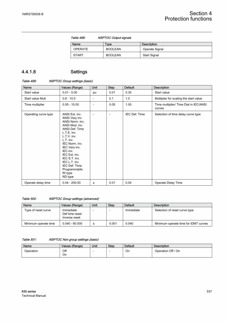
Table 498: NSPTOC Output signals
Name Type DescriptionOPERATE BOOLEAN Operate Signal
START BOOLEAN Start Signal
4.4.1.8 Settings
Table 499: NSPTOC Group settings (basic)
Name Values (Range) Unit Step Default DescriptionStart value 0.01 - 5.00 pu 0.01 0.30 Start value
Start value Mult 0.8 - 10.0 - 0.1 1.0 Multiplier for scaling the start value
Time multiplier 0.05 - 15.00 - 0.05 1.00 Time multiplier/ Time Dial in IEC/ANSIcurves
Operating curve type ANSI Ext. inv.ANSI Very inv.ANSI Norm. inv.ANSI Mod. inv.ANSI Def. TimeL.T.E. inv.L.T.V. inv.L.T. inv.IEC Norm. inv.IEC Very inv.IEC inv.IEC Ext. inv.IEC S.T. inv.IEC L.T. inv.IEC Def. TimeProgrammableRI typeRD type
- - IEC Def. Time Selection of time delay curve type
Operate delay time 0.04 - 200.00 s 0.01 0.04 Operate Delay Time
Table 500: NSPTOC Group settings (advanced)
Name Values (Range) Unit Step Default DescriptionType of reset curve Immediate
Def time resetInverse reset
- - Immediate Selection of reset curve type
Minimum operate time 0.040 - 60.000 s 0.001 0.040 Minimum operate time for IDMT curves
Table 501: NSPTOC Non group settings (basic)
Name Values (Range) Unit Step Default DescriptionOperation Off
On- - On Operation Off / On
1MRS756508 B Section 4Protection functions
630 series 537Technical Manual

Table 502: NSPTOC Non group settings (advanced)
Name Values (Range) Unit Step Default DescriptionBase value Sel phase Phase Grp 1
Phase Grp 2Phase Grp 3
- - Phase Grp 1 Base value selector, phase / phase-to-phase
Curve parameter A 0.0086 - 120.0000 - 0.0001 28.2000 Parameter A for customer programmablecurve
Curve parameter B 0.0000 - 0.7120 - 0.0001 0.1217 Parameter B for customer programmablecurve
Curve parameter C 0.02 - 2.00 - 0.01 2.00 Parameter C for customerprogrammable curve
Curve parameter D 0.46 - 30.00 - 0.01 29.10 Parameter D for customerprogrammable curve
Curve parameter E 0.0 - 1.0 - 0.1 1.0 Parameter E for customer programmablecurve
Reset delay time 0.000 - 60.000 s 0.001 0.020 Reset delay time
4.4.1.9 Measured values
Table 503: NSPTOC Measured values
Name Type Default DescriptionI2_AMPL REAL 0 Negative sequence current
BLOCK BOOLEAN 0 Blocks all binary outputs by resetting timers
BLK_OPR BOOLEAN 0 Blocks operate outputs.
BLK_ST BOOLEAN 0 Blocks start outputs.
FR_TIMER BOOLEAN 0 Freeze internal operate timer counts.
ENA_MULT BOOLEAN 0 Enables current multiplier.
4.4.1.10 Monitored data
Table 504: NSPTOC Monitored data
Name Type Values (Range) Unit DescriptionOPERATE BOOLEAN 0=FALSE
1=TRUE- Operate Signal
START BOOLEAN 0=FALSE1=TRUE
- Start Signal
START_DUR REAL - % Start Duration
INVAL_CRV BOOLEAN 0=FALSE1=TRUE
- Invalid curve parameters
Section 4 1MRS756508 BProtection functions
538 630 seriesTechnical Manual

4.4.1.11 Technical data
Table 505: NSPTOC Technical data
Characteristic ValueOperation accuracy At the frequency f = fn
±1.5% of the set value or ±0.002 × In
Start time 1)2) IFault = 2 × set StartvalueIFault = 10 × set Startvalue
Typical 23 ms (±15 ms)Typical 16 ms (±15 ms)
Reset time < 40 ms
Reset ratio Typical 0.96
Retardation time < 35 ms
Operate time accuracy in definite time mode ±1.0% of the set value or ±20 ms
Operate time accuracy in inverse time mode ±5.0% of the theoretical value or ±20 ms 3)
Suppression of harmonics DFT: -50 dB at f = n × fn, where n = 2, 3, 4, 5,…
1) Operate curve type = IEC definite time, negative sequence current before fault = 0.0, fn = 50 Hz2) Includes the delay of the signal output contact3) Maximum Start value = 2.5 × In, Start value multiples in range of 1.5 to 20
4.4.2 Phase discontinuity protection PDNSPTOC
4.4.2.1 Identification
Function description IEC 61850identification
IEC 60617identification
ANSI/IEEE C37.2device number
Phase discontinuity protection PDNSPTOC I2/I1> 46PD
4.4.2.2 Function block
A070685 V1 EN
Figure 269: Function block
4.4.2.3 Functionality
The phase discontinuity protection PDNSPTOC is used for detecting unbalancesituations caused by broken conductors.
1MRS756508 B Section 4Protection functions
630 series 539Technical Manual
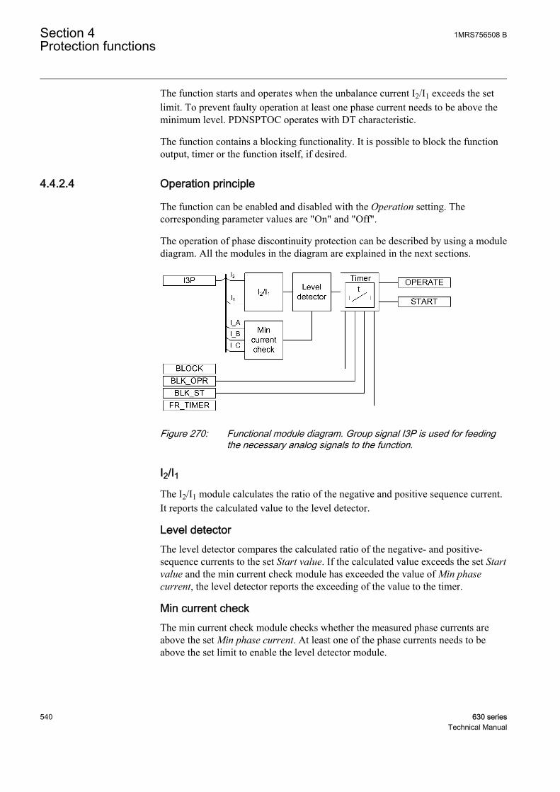
The function starts and operates when the unbalance current I2/I1 exceeds the setlimit. To prevent faulty operation at least one phase current needs to be above theminimum level. PDNSPTOC operates with DT characteristic.
The function contains a blocking functionality. It is possible to block the functionoutput, timer or the function itself, if desired.
4.4.2.4 Operation principle
The function can be enabled and disabled with the Operation setting. Thecorresponding parameter values are "On" and "Off".
The operation of phase discontinuity protection can be described by using a modulediagram. All the modules in the diagram are explained in the next sections.
GUID-A492307B-54B7-4CAF-A7E7-E660FC4769DA V1 EN
Figure 270: Functional module diagram. Group signal I3P is used for feedingthe necessary analog signals to the function.
I2/I1The I2/I1 module calculates the ratio of the negative and positive sequence current.It reports the calculated value to the level detector.
Level detectorThe level detector compares the calculated ratio of the negative- and positive-sequence currents to the set Start value. If the calculated value exceeds the set Startvalue and the min current check module has exceeded the value of Min phasecurrent, the level detector reports the exceeding of the value to the timer.
Min current checkThe min current check module checks whether the measured phase currents areabove the set Min phase current. At least one of the phase currents needs to beabove the set limit to enable the level detector module.
Section 4 1MRS756508 BProtection functions
540 630 seriesTechnical Manual
TimerOnce activated, the timer activates the START output. The time characteristic isaccording to DT. When the operation timer has reached the value set by Operatedelay time, the OPERATE output is activated. If the fault disappears before themodule operates, the reset timer is activated. If the reset timer reaches the value setby Reset delay time, the operate timer resets and the START output is deactivated.
The timer calculates the start duration value START_DUR, which indicates thepercentage ratio of the start situation and the set operation time. The value isavailable in the monitored data view.
The binary input BLOCK can be used to block the function. The activation of theBLOCK input deactivates all outputs and resets internal timers. The binary inputBLK_ST can be used to block the start signals. The binary input BLK_OPR can beused to block the operation signals. The operation timer counting can be frozen tothe prevailing value by activating the FR_TIMER input.
4.4.2.5 Base values
In this function block, some of the settings are set in per unit (pu). These pu valuesare relational to certain base values, for example the values given in A, kV andkVA. The IED supports alternative base value groups for the phase current or voltage-related settings, for example "Phase Grp 1", "Phase Grp 2" and "Phase Grp 3".One of the groups to be used with the Base value Sel phase setting must be selected.
For more information, see the Basic functions section in this manual.
4.4.2.6 Application
In three-phase distribution and subtransmission network applications the phasediscontinuity in one phase can cause increase of zero sequence voltage and shortovervoltage peaks and also oscillation in the corresponding phase.
PDNSPTOC is a three-phase protection with DT characteristic, designed fordetecting broken conductors in distribution and subtransmission networks. Thefunction is applicable for both overhead lines and underground cables.
The operation of PDNSPTOC is based on the ratio of positive and negativesequence currents. This gives better sensitivity and stability compared to plainnegative sequence current protection since the calculated ratio of positive andnegative sequence currents is relatively constant during load variations.
The unbalance of the network is detected by monitoring the negative and positivesequence current ratio, where the negative sequence current value is I2 and I1 is thepositive sequence current value. The unbalance is calculated:
1MRS756508 B Section 4Protection functions
630 series 541Technical Manual
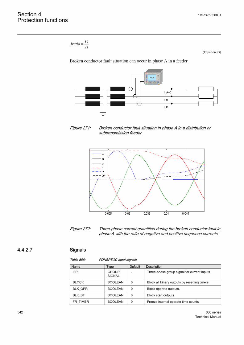
IratioI
I=
2
1
A070702 V2 EN (Equation 83)
Broken conductor fault situation can occur in phase A in a feeder.
IECA070699 V2 EN
Figure 271: Broken conductor fault situation in phase A in a distribution orsubtransmission feeder
IECA070698 V1 EN
Figure 272: Three-phase current quantities during the broken conductor fault inphase A with the ratio of negative and positive sequence currents
4.4.2.7 Signals
Table 506: PDNSPTOC Input signals
Name Type Default DescriptionI3P GROUP
SIGNAL- Three-phase group signal for current inputs
BLOCK BOOLEAN 0 Block all binary outputs by resetting timers.
BLK_OPR BOOLEAN 0 Block operate outputs.
BLK_ST BOOLEAN 0 Block start outputs
FR_TIMER BOOLEAN 0 Freeze internal operate time counts
Section 4 1MRS756508 BProtection functions
542 630 seriesTechnical Manual
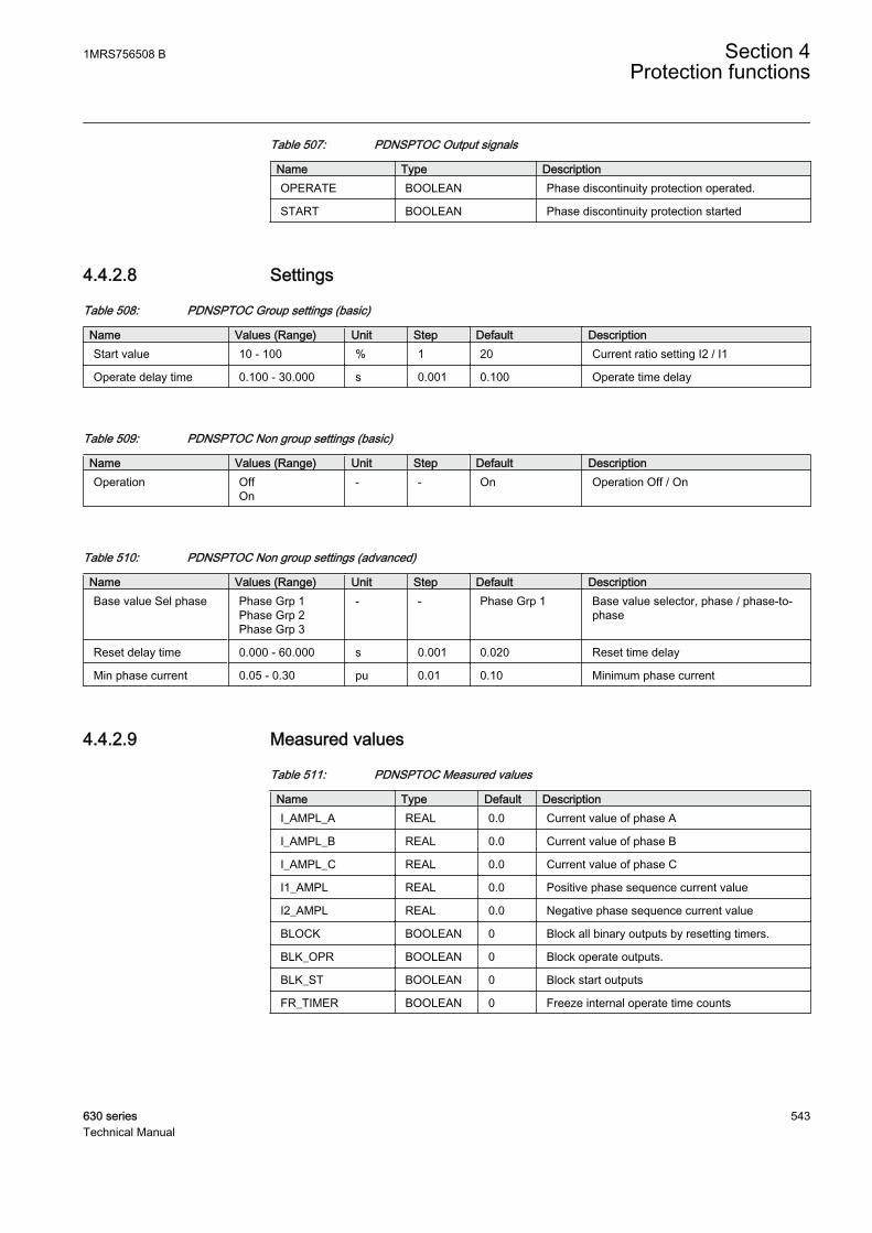
Table 507: PDNSPTOC Output signals
Name Type DescriptionOPERATE BOOLEAN Phase discontinuity protection operated.
START BOOLEAN Phase discontinuity protection started
4.4.2.8 Settings
Table 508: PDNSPTOC Group settings (basic)
Name Values (Range) Unit Step Default DescriptionStart value 10 - 100 % 1 20 Current ratio setting I2 / I1
Operate delay time 0.100 - 30.000 s 0.001 0.100 Operate time delay
Table 509: PDNSPTOC Non group settings (basic)
Name Values (Range) Unit Step Default DescriptionOperation Off
On- - On Operation Off / On
Table 510: PDNSPTOC Non group settings (advanced)
Name Values (Range) Unit Step Default DescriptionBase value Sel phase Phase Grp 1
Phase Grp 2Phase Grp 3
- - Phase Grp 1 Base value selector, phase / phase-to-phase
Reset delay time 0.000 - 60.000 s 0.001 0.020 Reset time delay
Min phase current 0.05 - 0.30 pu 0.01 0.10 Minimum phase current
4.4.2.9 Measured values
Table 511: PDNSPTOC Measured values
Name Type Default DescriptionI_AMPL_A REAL 0.0 Current value of phase A
I_AMPL_B REAL 0.0 Current value of phase B
I_AMPL_C REAL 0.0 Current value of phase C
I1_AMPL REAL 0.0 Positive phase sequence current value
I2_AMPL REAL 0.0 Negative phase sequence current value
BLOCK BOOLEAN 0 Block all binary outputs by resetting timers.
BLK_OPR BOOLEAN 0 Block operate outputs.
BLK_ST BOOLEAN 0 Block start outputs
FR_TIMER BOOLEAN 0 Freeze internal operate time counts
1MRS756508 B Section 4Protection functions
630 series 543Technical Manual
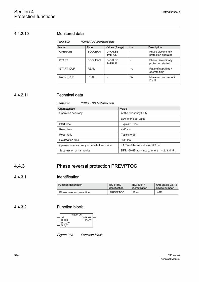
4.4.2.10 Monitored data
Table 512: PDNSPTOC Monitored data
Name Type Values (Range) Unit DescriptionOPERATE BOOLEAN 0=FALSE
1=TRUE- Phase discontinuity
protection operated.
START BOOLEAN 0=FALSE1=TRUE
- Phase discontinuityprotection started
START_DUR REAL - % Ratio of start time /operate time
RATIO_I2_I1 REAL - % Measured current ratioI2 / I1
4.4.2.11 Technical data
Table 513: PDNSPTOC Technical data
Characteristic ValueOperation accuracy At the frequency f = fn
±2% of the set value
Start time Typical 15 ms
Reset time < 40 ms
Reset ratio Typical 0.96
Retardation time < 35 ms
Operate time accuracy in definite time mode ±1.0% of the set value or ±20 ms
Suppression of harmonics DFT: -50 dB at f = n x fn, where n = 2, 3, 4, 5,…
4.4.3 Phase reversal protection PREVPTOC
4.4.3.1 Identification
Function description IEC 61850identification
IEC 60617identification
ANSI/IEEE C37.2device number
Phase reversal protection PREVPTOC I2>> 46R
4.4.3.2 Function block
GUID-7580B052-365E-40D4-B3E3-6F4C1993CF67 V2 EN
Figure 273: Function block
Section 4 1MRS756508 BProtection functions
544 630 seriesTechnical Manual
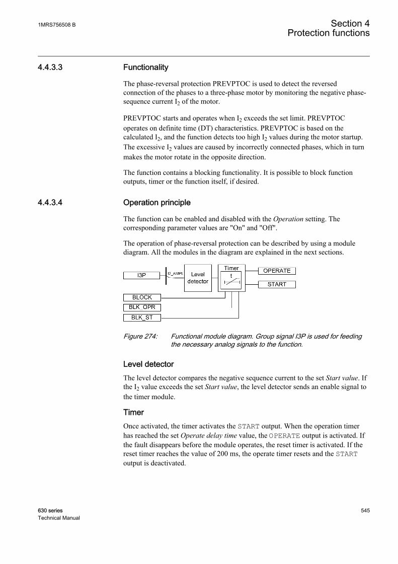
4.4.3.3 Functionality
The phase-reversal protection PREVPTOC is used to detect the reversedconnection of the phases to a three-phase motor by monitoring the negative phase-sequence current I2 of the motor.
PREVPTOC starts and operates when I2 exceeds the set limit. PREVPTOCoperates on definite time (DT) characteristics. PREVPTOC is based on thecalculated I2, and the function detects too high I2 values during the motor startup.The excessive I2 values are caused by incorrectly connected phases, which in turnmakes the motor rotate in the opposite direction.
The function contains a blocking functionality. It is possible to block functionoutputs, timer or the function itself, if desired.
4.4.3.4 Operation principle
The function can be enabled and disabled with the Operation setting. Thecorresponding parameter values are "On" and "Off".
The operation of phase-reversal protection can be described by using a modulediagram. All the modules in the diagram are explained in the next sections.
GUID-9262A00B-39E7-4690-AE02-5927BF7DFA00 V1 EN
Figure 274: Functional module diagram. Group signal I3P is used for feedingthe necessary analog signals to the function.
Level detectorThe level detector compares the negative sequence current to the set Start value. Ifthe I2 value exceeds the set Start value, the level detector sends an enable signal tothe timer module.
TimerOnce activated, the timer activates the START output. When the operation timerhas reached the set Operate delay time value, the OPERATE output is activated. Ifthe fault disappears before the module operates, the reset timer is activated. If thereset timer reaches the value of 200 ms, the operate timer resets and the STARToutput is deactivated.
1MRS756508 B Section 4Protection functions
630 series 545Technical Manual

The timer calculates the start duration value START_DUR, which indicates thepercentage ratio of the start situation and the set operation time. The value isavailable in the monitored data view.
The activation of the BLOCK signal resets the timer and deactivates the START andOPERATE outputs. It is possible to block individual START and OPERATE outputsby the activation of the BLK_ST and BLK_OPR inputs respectively.
4.4.3.5 Base values
In this function block, some of the settings are set in per unit (pu). These pu valuesare relational to certain base values, for example the values given in A, kV andkVA. The IED supports alternative base value groups for the phase current or voltage-related settings, for example "Phase Grp 1", "Phase Grp 2" and "Phase Grp 3".One of the groups to be used with the Base value Sel phase setting must be selected.
For more information, see the Basic functions section in this manual.
4.4.3.6 Application
The rotation of a motor in the reverse direction is not a desirable operatingcondition. When the motor drives fans and pumps, for example, and the rotationdirection is reversed due to a wrong phase sequence, the driven process can bedisturbed and the flow of the cooling air of the motor can become reversed too.With a motor designed only for a particular rotation direction, the reversed rotationdirection can lead to an inefficient cooling of the motor due to the fan design.
In a motor, the value of the negative sequence component of the phase currents isvery negligible when compared to the positive-sequence component of the currentduring a healthy operating condition of the motor. But when the motor is startedwith the phase connections in the reverse order, the magnitude of I2 is very high.So whenever the value of I2 exceeds the start value, the function detects the reverserotation direction and provides an operate signal that disconnects the motor fromthe supply.
4.4.3.7 Signals
Table 514: PREVPTOC Input signals
Name Type Default DescriptionI3P GROUP
SIGNAL- Three phase group signal for current inputs
BLOCK BOOLEAN 0 Block overall function
BLK_OPR BOOLEAN 0 Block operate output
BLK_ST BOOLEAN 0 Block start output
Section 4 1MRS756508 BProtection functions
546 630 seriesTechnical Manual

Table 515: PREVPTOC Output signals
Name Type DescriptionOPERATE BOOLEAN Operated signal
START BOOLEAN Started signal
4.4.3.8 Settings
Table 516: PREVPTOC Group settings (basic)
Name Values (Range) Unit Step Default DescriptionStart value 0.05 - 1.00 pu 0.01 0.75 Start value
Operate delay time 0.100 - 30.000 s 0.001 0.100 Operate delay time
Table 517: PREVPTOC Non group settings (basic)
Name Values (Range) Unit Step Default DescriptionOperation Off
On- - On Operation Off/On
Table 518: PREVPTOC Non group settings (advanced)
Name Values (Range) Unit Step Default DescriptionBase value Sel phase Phase Grp 1
Phase Grp 2Phase Grp 3
- - Phase Grp 1 Base value selector, phase / phase-to-phase
4.4.3.9 Measured values
Table 519: PREVPTOC Measured values
Name Type Default DescriptionI2_AMPL REAL 0.0 Negative phase sequence current value
BLOCK BOOLEAN 0 Block overall function
BLK_OPR BOOLEAN 0 Block operate output
BLK_ST BOOLEAN 0 Block start output
1MRS756508 B Section 4Protection functions
630 series 547Technical Manual
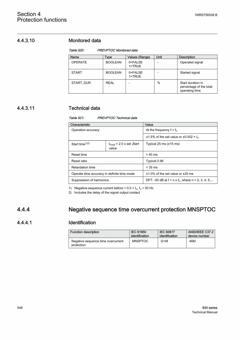
4.4.3.10 Monitored data
Table 520: PREVPTOC Monitored data
Name Type Values (Range) Unit DescriptionOPERATE BOOLEAN 0=FALSE
1=TRUE- Operated signal
START BOOLEAN 0=FALSE1=TRUE
- Started signal
START_DUR REAL - % Start duration inpercentage of the totaloperating time
4.4.3.11 Technical data
Table 521: PREVPTOC Technical data
Characteristic ValueOperation accuracy At the frequency f = fn
±1.5% of the set value or ±0.002 × In
Start time1)2) IFault = 2.0 x set Startvalue
Typical 25 ms (±15 ms)
Reset time < 40 ms
Reset ratio Typical 0.96
Retardation time < 35 ms
Operate time accuracy in definite time mode ±1.0% of the set value or ±20 ms
Suppression of harmonics DFT: -50 dB at f = n x fn, where n = 2, 3, 4, 5,…
1) Negative-sequence current before = 0.0 × In, fn = 50 Hz2) Includes the delay of the signal output contact
4.4.4 Negative sequence time overcurrent protection MNSPTOC
4.4.4.1 Identification
Function description IEC 61850identification
IEC 60617identification
ANSI/IEEE C37.2device number
Negative sequence time overcurrentprotection
MNSPTOC I2>M 46M
Section 4 1MRS756508 BProtection functions
548 630 seriesTechnical Manual

4.4.4.2 Function block
GUID-FF704D53-EE79-4285-B87F-413FBE54659F V1 EN
Figure 275: Function block
4.4.4.3 Functionality
The unbalance protection based on the negative-sequence current functionMNSPTOC protects electric motors from phase unbalance. A small voltageunbalance can produce a large negative sequence current flow in the motor. Forexample, a 5 percent voltage unbalance produces a stator negative sequence currentof 30 percent of the full load current, which can severely heat the motor.MNSPTOC detects the large negative sequence current and disconnects the motor.
4.4.4.4 Operation principle
The function can be enabled and disabled with the Operation setting. Thecorresponding parameter values are "On" and "Off".
The operation of unbalance protection based on negative sequence current can bedescribed by using a module diagram. All the modules in the diagram are explainedin the next sections.
GUID-F2FE853C-A48C-4395-B9F1-4F30AF5FD103 V1 EN
Figure 276: Functional module diagram
Level detectorThe calculated negative-sequence current is compared to the Start value setting. Ifthe measured value exceeds the Start value setting, the function activates the timermodule.
TimerOnce activated, the timer activates the START output. Depending on the value ofthe set Operating curve type, the time characteristics are according to DT or IDMT.When the operation timer has reached the value set by Operate delay time in the
1MRS756508 B Section 4Protection functions
630 series 549Technical Manual

DT mode or the maximum value defined by the inverse time curve, the OPERATEoutput is activated.
In a drop-off situation, that is, when the value of the negative-sequence currentdrops below the Start value setting, the reset timer is activated and the STARToutput resets after the time delay of Reset delay time for the DT characteristics. ForIDMT, the reset time depends on the curve type selected.
For the IDMT curves, it is possible to define minimum and maximum operatetimes with the Minimum operate time and Maximum operate time settings. TheMachine time Mult setting parameter corresponds to the machine constant, equal tothe I2
2t constant of the machine, as stated by the machine manufacturer.
The activation of the OPERATE output activates the BLK_RESTART output. Thedeactivation of the OPERATE output activates the cooling timer. The timer is set tothe value entered in the Cooling time setting. The BLK_RESTART output is keptactive until the cooling timer is exceeded. If the negative-sequence currentincreases above the set value during this period, the OPERATE output is activatedimmediately.
The operation timer counting can be frozen to the prevailing value by activating theFR_TIMER input.
The T_ENARESTART output indicates the duration for which the BLK_RESTARToutput remains active, that is, it indicates the remaining time of the cooling timer.The value is available in the monitored data view.
The timer calculates the start duration value START_DUR, which indicates thepercentage ratio of the start situation and the set operation time. The value isavailable in the monitored data view.
The BLOCK binary input can be used for blocking the function. Activating theBLOCK input deactivates all the binary outputs and resets the internal timers. It ispossible to block individual START and OPERATE outputs with the activation ofthe BLK_ST and BLK_OPR inputs.
4.4.4.5 Base values
In this function block, some of the settings are set in per unit (pu). These pu valuesare relational to certain base values, for example the values given in A, kV andkVA. The IED supports alternative base value groups for the phase current or voltage-related settings, for example "Phase Grp 1", "Phase Grp 2" and "Phase Grp 3".One of the groups to be used with the Base value Sel phase setting must be selected.
For more information, see the Basic functions section in this manual.
Section 4 1MRS756508 BProtection functions
550 630 seriesTechnical Manual
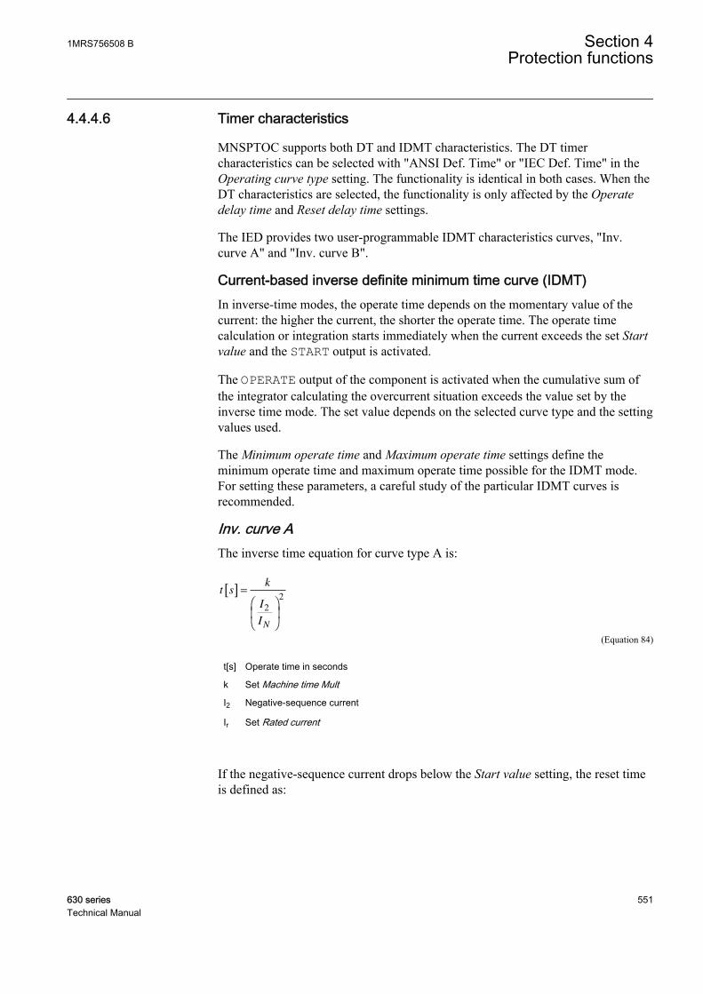
4.4.4.6 Timer characteristics
MNSPTOC supports both DT and IDMT characteristics. The DT timercharacteristics can be selected with "ANSI Def. Time" or "IEC Def. Time" in theOperating curve type setting. The functionality is identical in both cases. When theDT characteristics are selected, the functionality is only affected by the Operatedelay time and Reset delay time settings.
The IED provides two user-programmable IDMT characteristics curves, "Inv.curve A" and "Inv. curve B".
Current-based inverse definite minimum time curve (IDMT)In inverse-time modes, the operate time depends on the momentary value of thecurrent: the higher the current, the shorter the operate time. The operate timecalculation or integration starts immediately when the current exceeds the set Startvalue and the START output is activated.
The OPERATE output of the component is activated when the cumulative sum ofthe integrator calculating the overcurrent situation exceeds the value set by theinverse time mode. The set value depends on the selected curve type and the settingvalues used.
The Minimum operate time and Maximum operate time settings define theminimum operate time and maximum operate time possible for the IDMT mode.For setting these parameters, a careful study of the particular IDMT curves isrecommended.
Inv. curve AThe inverse time equation for curve type A is:
t sk
I
IN
[ ] =
2
2
GUID-C17AF789-778A-40D4-B001-C0D57A1822FB V1 EN (Equation 84)
t[s] Operate time in seconds
k Set Machine time Mult
I2 Negative-sequence current
Ir Set Rated current
If the negative-sequence current drops below the Start value setting, the reset timeis defined as:
1MRS756508 B Section 4Protection functions
630 series 551Technical Manual
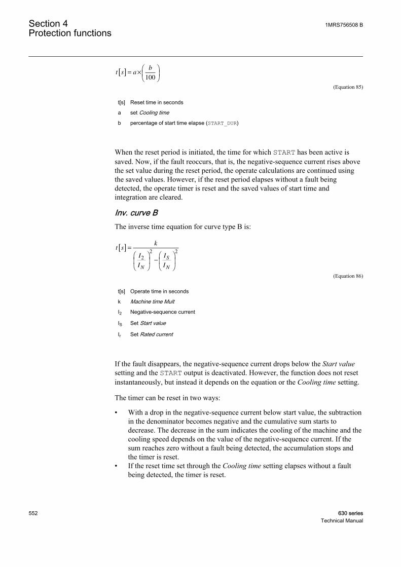
t s ab
[ ] = ×
100
GUID-8BE4B6AC-FB61-4D30-B77B-3E599D5BAE81 V1 EN (Equation 85)
t[s] Reset time in seconds
a set Cooling time
b percentage of start time elapse (START_DUR)
When the reset period is initiated, the time for which START has been active issaved. Now, if the fault reoccurs, that is, the negative-sequence current rises abovethe set value during the reset period, the operate calculations are continued usingthe saved values. However, if the reset period elapses without a fault beingdetected, the operate timer is reset and the saved values of start time andintegration are cleared.
Inv. curve BThe inverse time equation for curve type B is:
t sk
I
I
I
IN
S
N
[ ] =
−
2
2 2
GUID-572198A3-2386-4A6B-A67B-F1E81CDDA90C V2 EN (Equation 86)
t[s] Operate time in seconds
k Machine time Mult
I2 Negative-sequence current
IS Set Start value
Ir Set Rated current
If the fault disappears, the negative-sequence current drops below the Start valuesetting and the START output is deactivated. However, the function does not resetinstantaneously, but instead it depends on the equation or the Cooling time setting.
The timer can be reset in two ways:
• With a drop in the negative-sequence current below start value, the subtractionin the denominator becomes negative and the cumulative sum starts todecrease. The decrease in the sum indicates the cooling of the machine and thecooling speed depends on the value of the negative-sequence current. If thesum reaches zero without a fault being detected, the accumulation stops andthe timer is reset.
• If the reset time set through the Cooling time setting elapses without a faultbeing detected, the timer is reset.
Section 4 1MRS756508 BProtection functions
552 630 seriesTechnical Manual
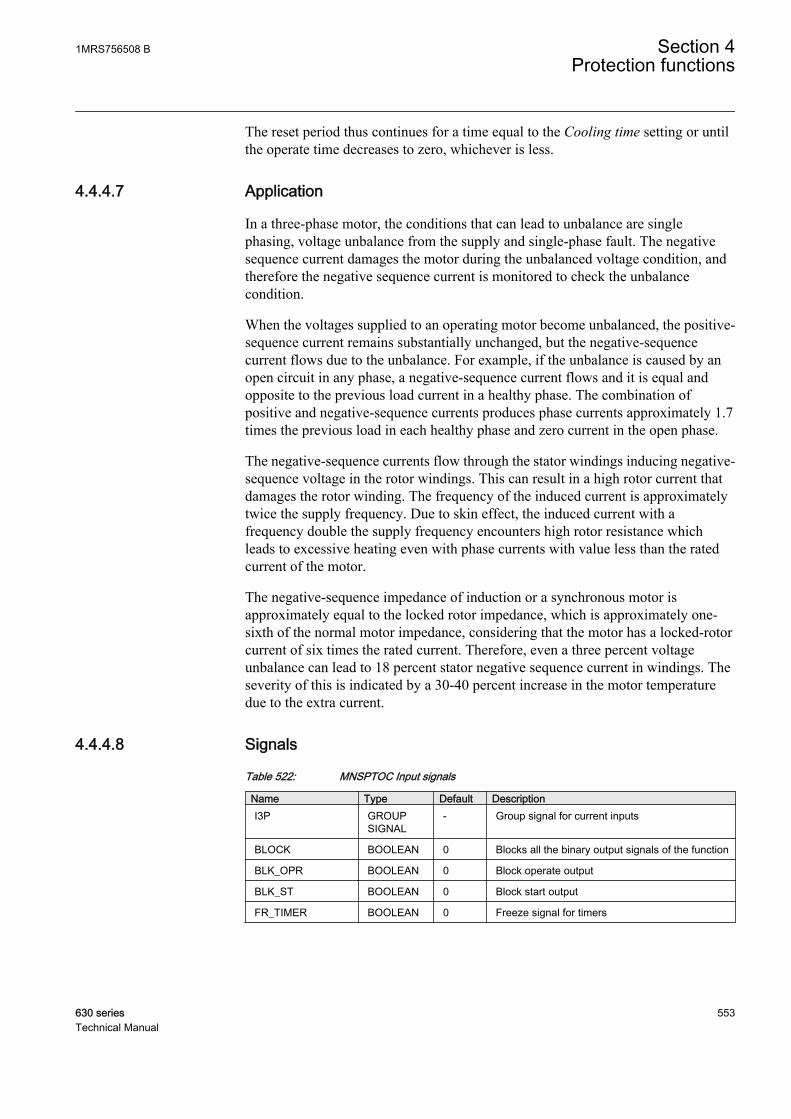
The reset period thus continues for a time equal to the Cooling time setting or untilthe operate time decreases to zero, whichever is less.
4.4.4.7 Application
In a three-phase motor, the conditions that can lead to unbalance are singlephasing, voltage unbalance from the supply and single-phase fault. The negativesequence current damages the motor during the unbalanced voltage condition, andtherefore the negative sequence current is monitored to check the unbalancecondition.
When the voltages supplied to an operating motor become unbalanced, the positive-sequence current remains substantially unchanged, but the negative-sequencecurrent flows due to the unbalance. For example, if the unbalance is caused by anopen circuit in any phase, a negative-sequence current flows and it is equal andopposite to the previous load current in a healthy phase. The combination ofpositive and negative-sequence currents produces phase currents approximately 1.7times the previous load in each healthy phase and zero current in the open phase.
The negative-sequence currents flow through the stator windings inducing negative-sequence voltage in the rotor windings. This can result in a high rotor current thatdamages the rotor winding. The frequency of the induced current is approximatelytwice the supply frequency. Due to skin effect, the induced current with afrequency double the supply frequency encounters high rotor resistance whichleads to excessive heating even with phase currents with value less than the ratedcurrent of the motor.
The negative-sequence impedance of induction or a synchronous motor isapproximately equal to the locked rotor impedance, which is approximately one-sixth of the normal motor impedance, considering that the motor has a locked-rotorcurrent of six times the rated current. Therefore, even a three percent voltageunbalance can lead to 18 percent stator negative sequence current in windings. Theseverity of this is indicated by a 30-40 percent increase in the motor temperaturedue to the extra current.
4.4.4.8 Signals
Table 522: MNSPTOC Input signals
Name Type Default DescriptionI3P GROUP
SIGNAL- Group signal for current inputs
BLOCK BOOLEAN 0 Blocks all the binary output signals of the function
BLK_OPR BOOLEAN 0 Block operate output
BLK_ST BOOLEAN 0 Block start output
FR_TIMER BOOLEAN 0 Freeze signal for timers
1MRS756508 B Section 4Protection functions
630 series 553Technical Manual

Table 523: MNSPTOC Output signals
Name Type DescriptionOPERATE BOOLEAN Operated
START BOOLEAN Started
BLK_RESTART BOOLEAN Signal for blocking reconnection of an overheatedmachine
4.4.4.9 Settings
Table 524: MNSPTOC Group settings (basic)
Name Values (Range) Unit Step Default DescriptionStart value 0.01 - 0.50 pu 0.01 0.20 Start value of negative-sequence current
Operating curve type ANSI Def. TimeIEC Def. TimeInv. Curve AInv. Curve B
- - IEC Def. Time Selection of time delay curve type
Machine time Mult 5.0 - 100.0 - 0.1 5.0 Machine time multiplier
Operate delay time 0.10 - 120.00 s 0.01 1.00 Operate time in definite-time mode
Maximum operate time 500 - 7200 s 1 1000 Max operate time regardless of theinverse characteristic
Minimum operate time 0.10 - 120.00 s 0.01 0.10 Definite minimum operate time
Cooling time 5 - 7200 s 1 50 Time required to cool the machine
Table 525: MNSPTOC Non group settings (basic)
Name Values (Range) Unit Step Default DescriptionOperation Off
On- - On Operation Off / On
Table 526: MNSPTOC Non group settings (advanced)
Name Values (Range) Unit Step Default DescriptionBase value Sel phase Phase Grp 1
Phase Grp 2Phase Grp 3
- - Phase Grp 1 Base value selector, phase / phase-to-phase
Reset delay time 0.00 - 60.00 s 0.01 0.02 Resetting time of the operate timecounter in DT mode
Section 4 1MRS756508 BProtection functions
554 630 seriesTechnical Manual

4.4.4.10 Measured values
Table 527: MNSPTOC Measured values
Name Type Default DescriptionI2_AMPL REAL 0.0 Negative phase sequence current value
BLOCK BOOLEAN 0 Blocks all the binary output signals of the function
BLK_OPR BOOLEAN 0 Block operate output
BLK_ST BOOLEAN 0 Block start output
FR_TIMER BOOLEAN 0 Freeze signal for timers
4.4.4.11 Monitored data
Table 528: MNSPTOC Monitored data
Name Type Values (Range) Unit DescriptionOPERATE BOOLEAN 0=FALSE
1=TRUE- Operated
START BOOLEAN 0=FALSE1=TRUE
- Started
BLK_RESTART BOOLEAN 0=FALSE1=TRUE
- Signal for blockingreconnection of anoverheated machine
T_ENARESTART INTEGER - s Estimated time to resetof block restart
START_DUR REAL - % Ratio of start time /operate time
4.4.4.12 Technical data
Table 529: MNSPTOC Technical data
Characteristic ValueOperation accuracy At the frequency f = fn
±1.5% of the set value or ±0.002 × In
Start time1)2) IFault = 5.0 x set Startvalue
Typical 43 ms (±15 ms)
Reset time < 70 ms
Reset ratio Typical 0.96
Retardation time < 35 ms
Operate time accuracy in definite time mode ±1.0% of the set value or ±35 ms
Operate time accuracy in inverse time mode ±5.0% of the theoretical value or ±30 ms 3)
Suppression of harmonics DFT: -50 dB at f = n x fn, where n = 2, 3, 4, 5,…
1) Negative-sequence current before = 0.0 × In, fn = 50 Hz2) Includes the delay of the signal output contact3) Start value multiples in range of 1.10 to 5.00
1MRS756508 B Section 4Protection functions
630 series 555Technical Manual

4.5 Voltage protection
4.5.1 Three-phase overvoltage protection PHPTOV
4.5.1.1 Identification
Function description IEC 61850identification
IEC 60617identification
ANSI/IEEE C37.2device number
Three-phase overvoltage protection PHPTOV 3U> 59
4.5.1.2 Function block
A070749 V1 EN
Figure 277: Function block
4.5.1.3 Functionality
The three-phase overvoltage protection PHPTOV is applied on power systemelements, such as generators, transformers, motors and power lines, to protect thesystem from excessive voltages that could damage the insulation and causeinsulation breakdown. The three-phase overvoltage function includes a settablevalue for the detection of overvoltage either in a single phase, two phases or threephases.
Correspondingly, the function gives an operate signal in the respective phases.
PHPTOV includes both definite time (DT) and inverse definite minimum time(IDMT) characteristics for the delay of the trip.
The function contains a blocking functionality. It is possible to block functionoutputs, timer or the function itself, if desired.
4.5.1.4 Operation principle
The function can be enabled and disabled with the Operation setting. Thecorresponding parameter values are "On" and "Off".
The operation of the three-phase overvoltage protection can be described using amodule diagram. All the modules in the diagram are explained in the next sections.
Section 4 1MRS756508 BProtection functions
556 630 seriesTechnical Manual
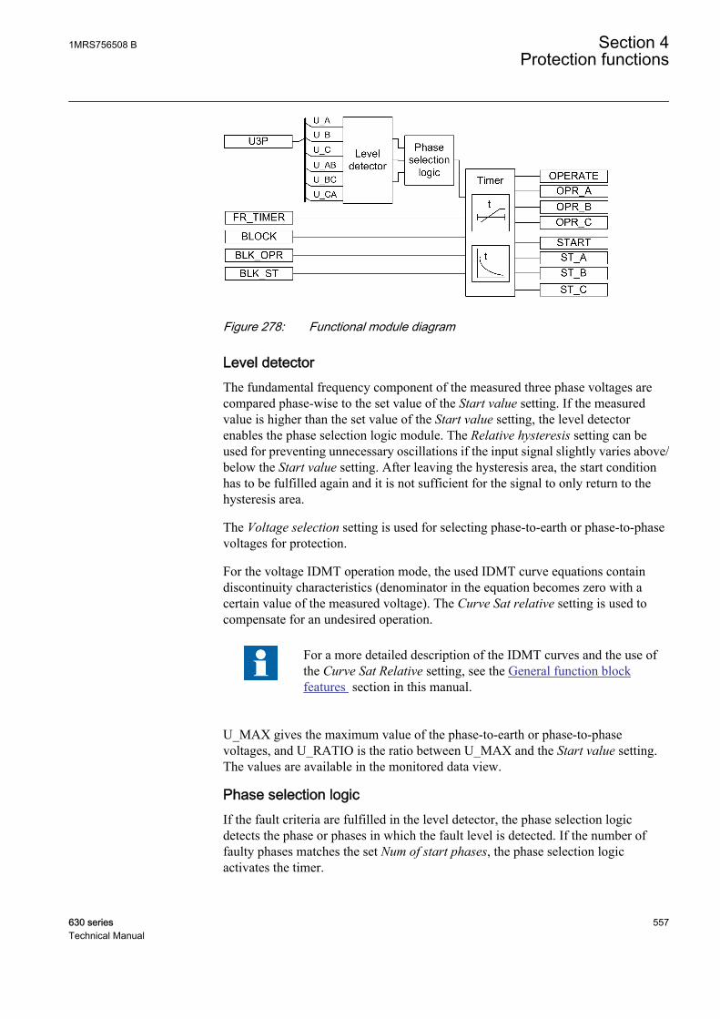
GUID-F524F580-1383-4EC3-B338-AAB702025E97 V1 EN
Figure 278: Functional module diagram
Level detectorThe fundamental frequency component of the measured three phase voltages arecompared phase-wise to the set value of the Start value setting. If the measuredvalue is higher than the set value of the Start value setting, the level detectorenables the phase selection logic module. The Relative hysteresis setting can beused for preventing unnecessary oscillations if the input signal slightly varies above/below the Start value setting. After leaving the hysteresis area, the start conditionhas to be fulfilled again and it is not sufficient for the signal to only return to thehysteresis area.
The Voltage selection setting is used for selecting phase-to-earth or phase-to-phasevoltages for protection.
For the voltage IDMT operation mode, the used IDMT curve equations containdiscontinuity characteristics (denominator in the equation becomes zero with acertain value of the measured voltage). The Curve Sat relative setting is used tocompensate for an undesired operation.
For a more detailed description of the IDMT curves and the use ofthe Curve Sat Relative setting, see the General function blockfeatures section in this manual.
U_MAX gives the maximum value of the phase-to-earth or phase-to-phasevoltages, and U_RATIO is the ratio between U_MAX and the Start value setting.The values are available in the monitored data view.
Phase selection logicIf the fault criteria are fulfilled in the level detector, the phase selection logicdetects the phase or phases in which the fault level is detected. If the number offaulty phases matches the set Num of start phases, the phase selection logicactivates the timer.
1MRS756508 B Section 4Protection functions
630 series 557Technical Manual
TimerOnce activated, the timer activates the START output and the corresponding outputof the respective phases (ST A, ST B, ST C). Depending on the value of the setOperating curve type, the time characteristics are selected according to DT orIDMT. PHPTOV supports the following IDMT operating curve types:
• (5) ANSI Def. Time• (15) IEC Def. Time• (17) Inv. Curve A• (18) Inv. Curve B• (19) Inv. Curve C• (20) Programmable.
For a detailed description of the voltage IDMT curves, see theGeneral function block features section in this manual.
When the operation timer has reached the value set by Operate delay time in theDT mode or the maximum value set by the IDMT operate time curve, theOPERATE output is activated. The corresponding output for the respective phases(OPR A, OPR B, OPR C) is also activated.
When the user programmable IDMT operate time curve is selected, the operatetime characteristics are defined by the parameters Curve parameter A, Curveparameter B, Curve parameter C, Curve parameter D and Curve parameter E.
If a drop-off situation occurs, that is, a fault suddenly disappears before theoperation delay is exceeded, the reset state is activated. The behavior in the drop-off situation depends on the selected operation time characteristics. If the DTcharacteristics are selected, the reset timer runs until the set Reset delay time valueis exceeded. If the drop-off situation exceeds the set Reset delay time, the timer isreset and the START output is deactivated.
When the IDMT operation time curve is selected, the functionality of the timer inthe drop-off state depends on the combination of the Type of reset curve, Type oftime reset and Reset delay time settings.
Section 4 1MRS756508 BProtection functions
558 630 seriesTechnical Manual
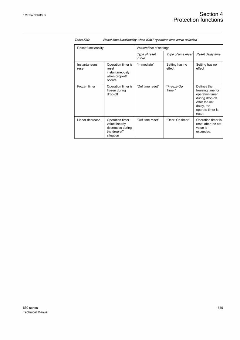
Table 530: Reset time functionality when IDMT operation time curve selected
Reset functionality Value/effect of settings
Type of resetcurve
Type of time reset Reset delay time
Instantaneousreset
Operation timer isresetinstantaneouslywhen drop-offoccurs
“Immediate” Setting has noeffect
Setting has noeffect
Frozen timer Operation timer isfrozen duringdrop-off
“Def time reset” “Freeze OpTimer”
Defines thefreezing time foroperation timerduring drop-off.After the setdelay, theoperate timer isreset.
Linear decrease Operation timervalue linearlydecreases duringthe drop-offsituation
“Def time reset” “Decr. Op timer” Operation timer isreset after the setvalue isexceeded.
1MRS756508 B Section 4Protection functions
630 series 559Technical Manual

Example
GUID-504A5E09-8D82-4B57-9B3A-2BAE7F84FC0D V2 EN
Figure 279: Behavior of different IDMT reset modes.
The Time multiplier setting is used for scaling the IDMT operating times.
The Minimum operate time setting defines the minimum operate time for IDMT.The setting is only applicable when the IDMT curves are used.
The Minimum operate time setting should be used with carebecause the operation time is according to the IDMT curve butalways at least the value of the Minimum operate time setting. Formore information, see the General function block features sectionin this manual.
Section 4 1MRS756508 BProtection functions
560 630 seriesTechnical Manual
The timer calculates the start duration value START_DUR, which indicates thepercentage ratio of the start situation and the set operation time. The value isavailable in the monitored data view.
The binary input BLOCK can be used to block the function. The activation of theBLOCK input deactivates all outputs and resets the internal timers. The binary inputBLK_ST can be used to block the start signals. The binary input BLK_OPR can beused to block the operating signals. The operation timer counting can be frozen tothe prevailing value by activating the FR_TIMER input.
Note that the FR_TIMER input has no effect during definite timelinearly decreasing reset.
4.5.1.5 Base values
In this function block, some of the settings are set in per unit (pu). These pu valuesare relational to certain base values, for example the values given in A, kV andkVA. The IED supports alternative base value groups for the phase current or voltage-related settings, for example "Phase Grp 1", "Phase Grp 2" and "Phase Grp 3".One of the groups to be used with the Base value Sel phase setting must be selected.
For more information, see the Basic functions section in this manual.
4.5.1.6 Application
Overvoltage in a network occurs either due to the transient surges on the networkor due to prolonged power frequency overvoltages. Surge arresters are used toprotect the network against the transient overvoltages, but the IED protectionfunction is used to protect against power frequency overvoltages.
The power frequency overvoltage may occur in the network due to contingenciessuch as:
• Defective operation of the automatic voltage regulator when the generator is inisolated operation.
• Operation under manual control with the voltage regulator out of service. Asudden variation of load, in particular the reactive power component, gives riseto a substantial change in voltage because of the large voltage regulationinherent in a typical alternator.
• Sudden loss of load due to the tripping of outgoing feeders, leaving thegenerator isolated or feeding a very small load, can cause a sudden rise in theterminal voltage due to the trapped field flux and overspeed.
1MRS756508 B Section 4Protection functions
630 series 561Technical Manual
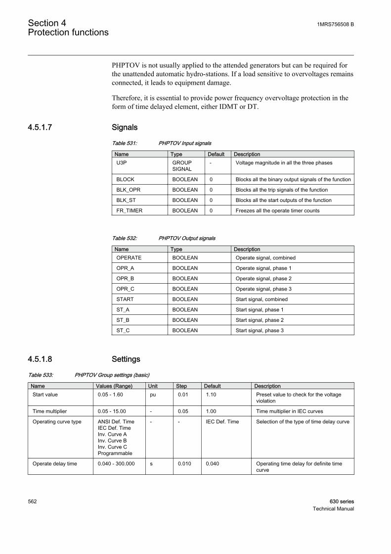
PHPTOV is not usually applied to the attended generators but can be required forthe unattended automatic hydro-stations. If a load sensitive to overvoltages remainsconnected, it leads to equipment damage.
Therefore, it is essential to provide power frequency overvoltage protection in theform of time delayed element, either IDMT or DT.
4.5.1.7 Signals
Table 531: PHPTOV Input signals
Name Type Default DescriptionU3P GROUP
SIGNAL- Voltage magnitude in all the three phases
BLOCK BOOLEAN 0 Blocks all the binary output signals of the function
BLK_OPR BOOLEAN 0 Blocks all the trip signals of the function
BLK_ST BOOLEAN 0 Blocks all the start outputs of the function
FR_TIMER BOOLEAN 0 Freezes all the operate timer counts
Table 532: PHPTOV Output signals
Name Type DescriptionOPERATE BOOLEAN Operate signal, combined
OPR_A BOOLEAN Operate signal, phase 1
OPR_B BOOLEAN Operate signal, phase 2
OPR_C BOOLEAN Operate signal, phase 3
START BOOLEAN Start signal, combined
ST_A BOOLEAN Start signal, phase 1
ST_B BOOLEAN Start signal, phase 2
ST_C BOOLEAN Start signal, phase 3
4.5.1.8 Settings
Table 533: PHPTOV Group settings (basic)
Name Values (Range) Unit Step Default DescriptionStart value 0.05 - 1.60 pu 0.01 1.10 Preset value to check for the voltage
violation
Time multiplier 0.05 - 15.00 - 0.05 1.00 Time multiplier in IEC curves
Operating curve type ANSI Def. TimeIEC Def. TimeInv. Curve AInv. Curve BInv. Curve CProgrammable
- - IEC Def. Time Selection of the type of time delay curve
Operate delay time 0.040 - 300.000 s 0.010 0.040 Operating time delay for definite timecurve
Section 4 1MRS756508 BProtection functions
562 630 seriesTechnical Manual
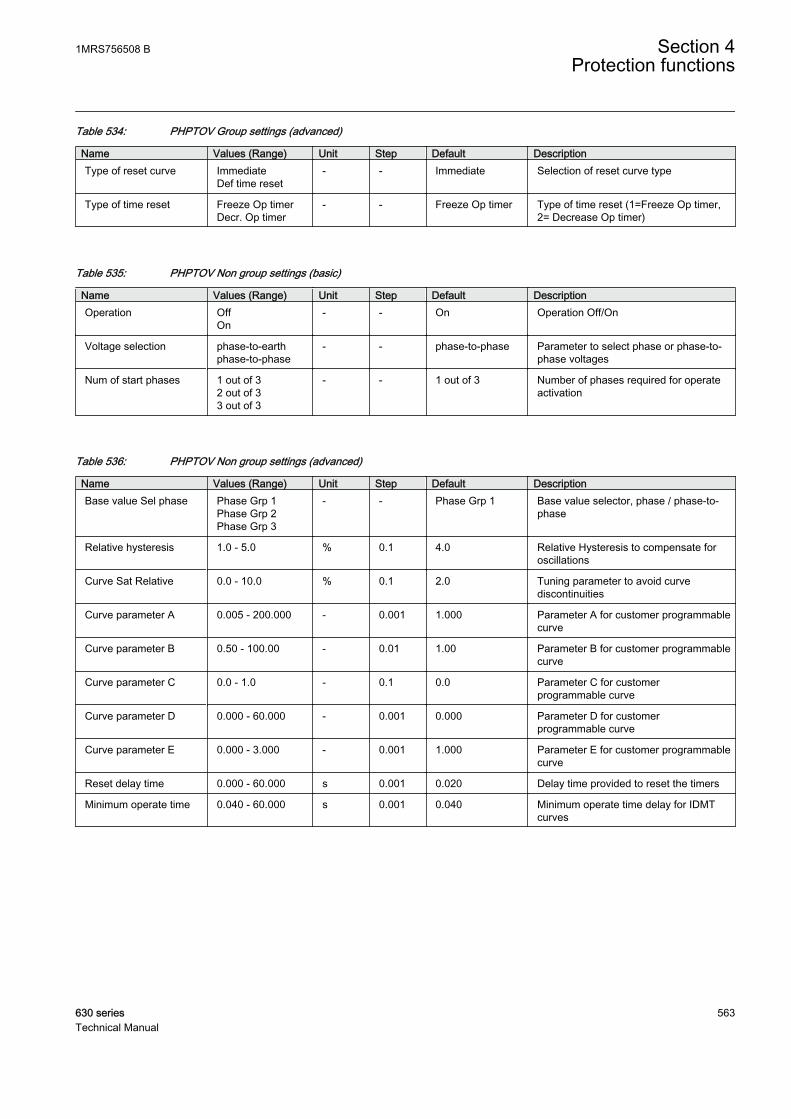
Table 534: PHPTOV Group settings (advanced)
Name Values (Range) Unit Step Default DescriptionType of reset curve Immediate
Def time reset- - Immediate Selection of reset curve type
Type of time reset Freeze Op timerDecr. Op timer
- - Freeze Op timer Type of time reset (1=Freeze Op timer,2= Decrease Op timer)
Table 535: PHPTOV Non group settings (basic)
Name Values (Range) Unit Step Default DescriptionOperation Off
On- - On Operation Off/On
Voltage selection phase-to-earthphase-to-phase
- - phase-to-phase Parameter to select phase or phase-to-phase voltages
Num of start phases 1 out of 32 out of 33 out of 3
- - 1 out of 3 Number of phases required for operateactivation
Table 536: PHPTOV Non group settings (advanced)
Name Values (Range) Unit Step Default DescriptionBase value Sel phase Phase Grp 1
Phase Grp 2Phase Grp 3
- - Phase Grp 1 Base value selector, phase / phase-to-phase
Relative hysteresis 1.0 - 5.0 % 0.1 4.0 Relative Hysteresis to compensate foroscillations
Curve Sat Relative 0.0 - 10.0 % 0.1 2.0 Tuning parameter to avoid curvediscontinuities
Curve parameter A 0.005 - 200.000 - 0.001 1.000 Parameter A for customer programmablecurve
Curve parameter B 0.50 - 100.00 - 0.01 1.00 Parameter B for customer programmablecurve
Curve parameter C 0.0 - 1.0 - 0.1 0.0 Parameter C for customerprogrammable curve
Curve parameter D 0.000 - 60.000 - 0.001 0.000 Parameter D for customerprogrammable curve
Curve parameter E 0.000 - 3.000 - 0.001 1.000 Parameter E for customer programmablecurve
Reset delay time 0.000 - 60.000 s 0.001 0.020 Delay time provided to reset the timers
Minimum operate time 0.040 - 60.000 s 0.001 0.040 Minimum operate time delay for IDMTcurves
1MRS756508 B Section 4Protection functions
630 series 563Technical Manual
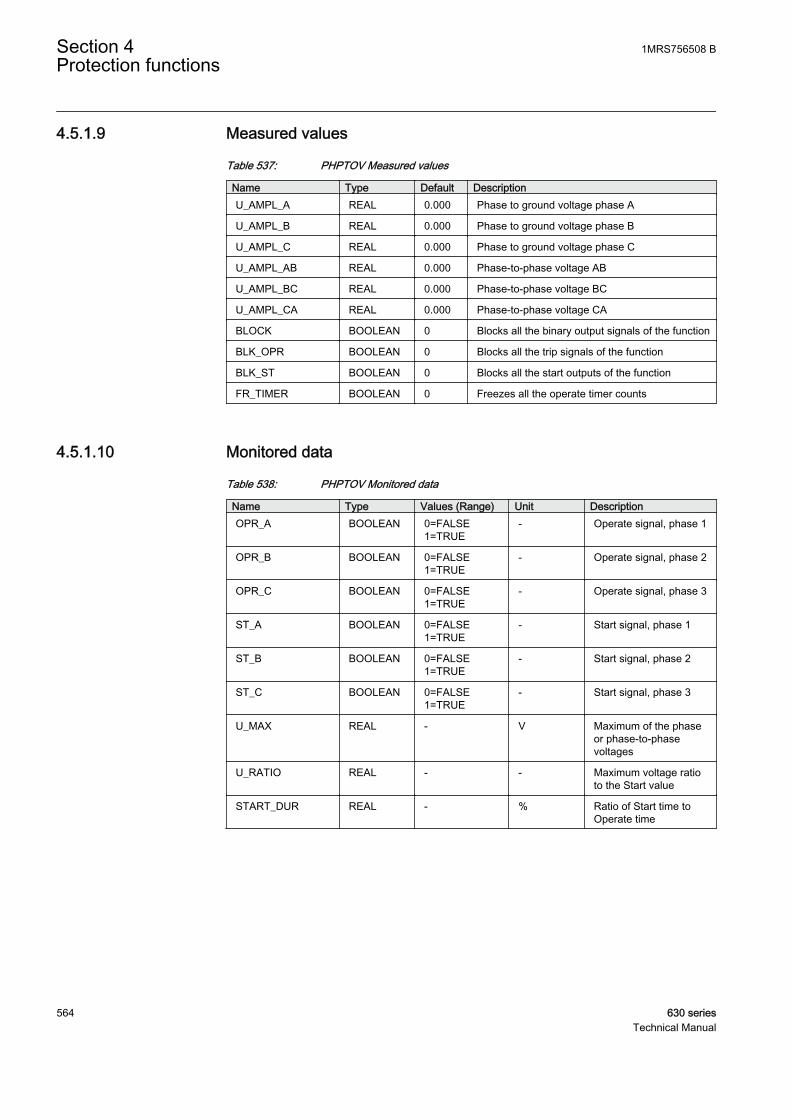
4.5.1.9 Measured values
Table 537: PHPTOV Measured values
Name Type Default DescriptionU_AMPL_A REAL 0.000 Phase to ground voltage phase A
U_AMPL_B REAL 0.000 Phase to ground voltage phase B
U_AMPL_C REAL 0.000 Phase to ground voltage phase C
U_AMPL_AB REAL 0.000 Phase-to-phase voltage AB
U_AMPL_BC REAL 0.000 Phase-to-phase voltage BC
U_AMPL_CA REAL 0.000 Phase-to-phase voltage CA
BLOCK BOOLEAN 0 Blocks all the binary output signals of the function
BLK_OPR BOOLEAN 0 Blocks all the trip signals of the function
BLK_ST BOOLEAN 0 Blocks all the start outputs of the function
FR_TIMER BOOLEAN 0 Freezes all the operate timer counts
4.5.1.10 Monitored data
Table 538: PHPTOV Monitored data
Name Type Values (Range) Unit DescriptionOPR_A BOOLEAN 0=FALSE
1=TRUE- Operate signal, phase 1
OPR_B BOOLEAN 0=FALSE1=TRUE
- Operate signal, phase 2
OPR_C BOOLEAN 0=FALSE1=TRUE
- Operate signal, phase 3
ST_A BOOLEAN 0=FALSE1=TRUE
- Start signal, phase 1
ST_B BOOLEAN 0=FALSE1=TRUE
- Start signal, phase 2
ST_C BOOLEAN 0=FALSE1=TRUE
- Start signal, phase 3
U_MAX REAL - V Maximum of the phaseor phase-to-phasevoltages
U_RATIO REAL - - Maximum voltage ratioto the Start value
START_DUR REAL - % Ratio of Start time toOperate time
Section 4 1MRS756508 BProtection functions
564 630 seriesTechnical Manual

4.5.1.11 Technical data
Table 539: PHPTOV Technical data
Characteristic ValueOperation accuracy At the frequency f = fn
±1.5% of the set value or ±0.002 × Un
Start time1)2) UFault = 2.0 x set Startvalue
Typical 17 ms (±15 ms)
Reset time < 40 ms
Reset ratio Depends of the set Relative hysteresis
Retardation time < 35 ms
Operate time accuracy in definite time mode ±1.0% of the set value or ±20 ms
Operate time accuracy in inverse time mode ±5.0% of the theoretical value or ±20 ms3)
Suppression of harmonics DFT: -50 dB at f = n × fn, where n = 2, 3, 4, 5,…
1) Start value = 1.0 × Un, Voltage before fault = 0.9 × Un, fn = 50 Hz, overvoltage in one phase-to-phase with nominal frequency injected from random phase angle
2) Includes the delay of the signal output contact3) Maximum Start value = 1.20 × Un, Start value multiples in range of 1.10 to 2.00
4.5.2 Three-phase undervoltage protection PHPTUV
4.5.2.1 Identification
Function description IEC 61850identification
IEC 60617identification
ANSI/IEEE C37.2device number
Three-phase undervoltage protection PHPTUV 3U< 27
4.5.2.2 Function block
GUID-2773C568-EF69-4371-9DEF-FB495E868B60 V2 EN
Figure 280: Function block
4.5.2.3 Functionality
The three-phase undervoltage protection PHPTUV is used to disconnect from thenetwork devices, for example electric motors, which are damaged when subjectedto service under low voltage conditions. PHPTUV includes a settable value for the
1MRS756508 B Section 4Protection functions
630 series 565Technical Manual
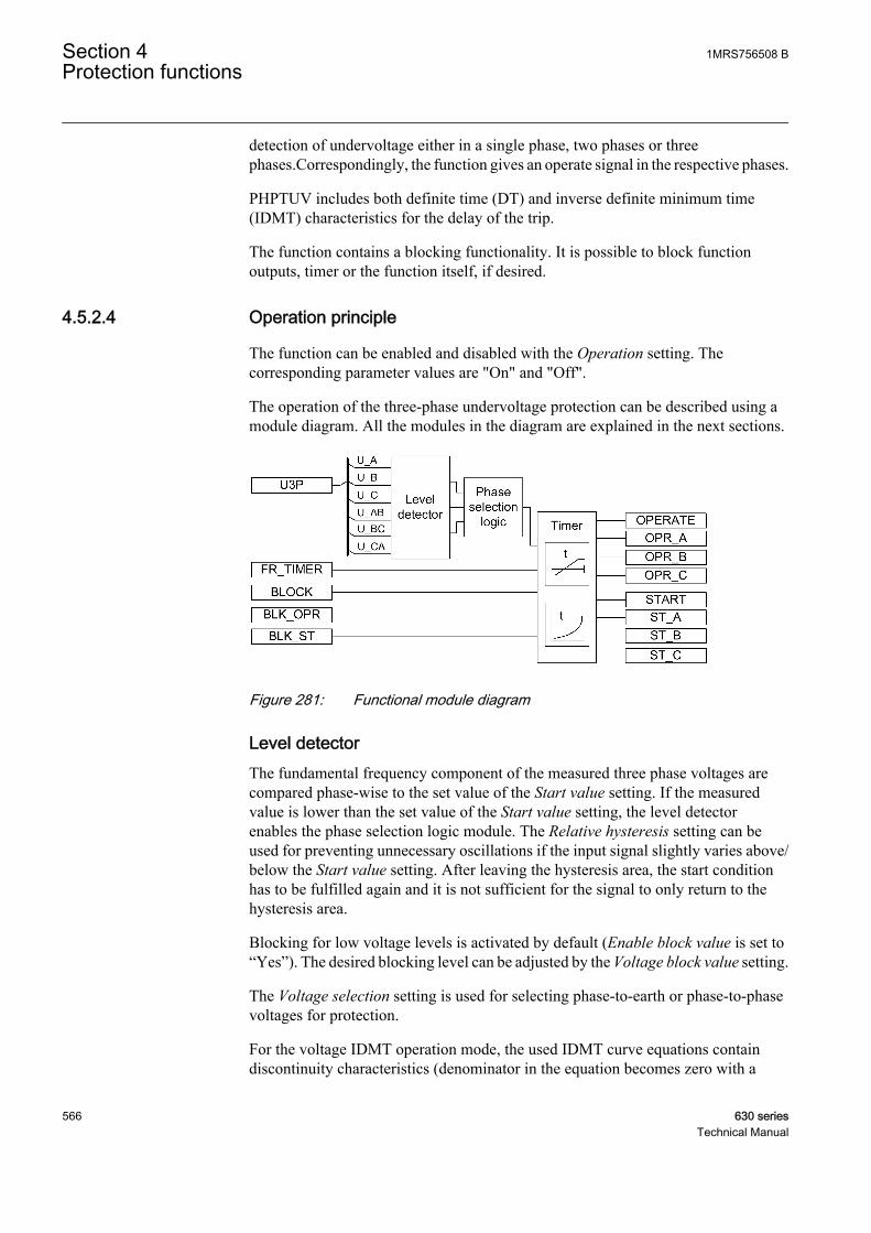
detection of undervoltage either in a single phase, two phases or threephases.Correspondingly, the function gives an operate signal in the respective phases.
PHPTUV includes both definite time (DT) and inverse definite minimum time(IDMT) characteristics for the delay of the trip.
The function contains a blocking functionality. It is possible to block functionoutputs, timer or the function itself, if desired.
4.5.2.4 Operation principle
The function can be enabled and disabled with the Operation setting. Thecorresponding parameter values are "On" and "Off".
The operation of the three-phase undervoltage protection can be described using amodule diagram. All the modules in the diagram are explained in the next sections.
GUID-324DEF92-B761-4D39-A77B-D72BED33208D V1 EN
Figure 281: Functional module diagram
Level detectorThe fundamental frequency component of the measured three phase voltages arecompared phase-wise to the set value of the Start value setting. If the measuredvalue is lower than the set value of the Start value setting, the level detectorenables the phase selection logic module. The Relative hysteresis setting can beused for preventing unnecessary oscillations if the input signal slightly varies above/below the Start value setting. After leaving the hysteresis area, the start conditionhas to be fulfilled again and it is not sufficient for the signal to only return to thehysteresis area.
Blocking for low voltage levels is activated by default (Enable block value is set to“Yes”). The desired blocking level can be adjusted by the Voltage block value setting.
The Voltage selection setting is used for selecting phase-to-earth or phase-to-phasevoltages for protection.
For the voltage IDMT operation mode, the used IDMT curve equations containdiscontinuity characteristics (denominator in the equation becomes zero with a
Section 4 1MRS756508 BProtection functions
566 630 seriesTechnical Manual

certain value of the measured voltage). The Curve Sat relative setting is used tocompensate for an undesired operation.
For a more detailed description of the IDMT curves and the use ofthe Curve Sat Relative setting, see the General function blockfeatures section in this manual.
U_MIN gives the maximum value of the phase-to-earth or phase-to-phase voltages,and U_RATIO is the ratio between U_MIN and the Start value setting. The valuesare available in the monitored data view.
Phase selection logicIf the fault criteria are fulfilled in the level detector, the phase selection logicdetects the phase or phases in which the fault level is detected. If the number offaulty phases matches the set Num of start phases, the phase selection logicactivates the timer.
TimerOnce activated, the timer activates the START output and the corresponding outputof the respective phases (ST A, ST B, ST C). Depending on the value of the setOperating curve type, the time characteristics are selected according to DT orIDMT. PHPTUV supports the following IDMT operating curve types:
• (5) ANSI Def. Time• (15) IEC Def. Time• (21) Inv. Curve A• (22) Inv. Curve B• (23) Programmable
For a detailed description of the voltage IDMT curves, see theGeneral function block features section in this manual.
When the operation timer has reached the value set by Operate delay time in theDT mode or the maximum value set by the IDMT operate time curve, theOPERATE output is activated. The corresponding output for the respective phases(OPR A, OPR B, OPR C) is also activated.
When the user programmable IDMT operate time curve is selected, the operatetime characteristics are defined by the parameters Curve parameter A, Curveparameter B, Curve parameter C, Curve parameter D and Curve parameter E.
If a drop-off situation occurs, that is, a fault suddenly disappears before theoperation delay is exceeded, the reset state is activated. The behavior in the drop-off situation depends on the selected operation time characteristics. If the DTcharacteristics are selected, the reset timer runs until the set Reset delay time value
1MRS756508 B Section 4Protection functions
630 series 567Technical Manual
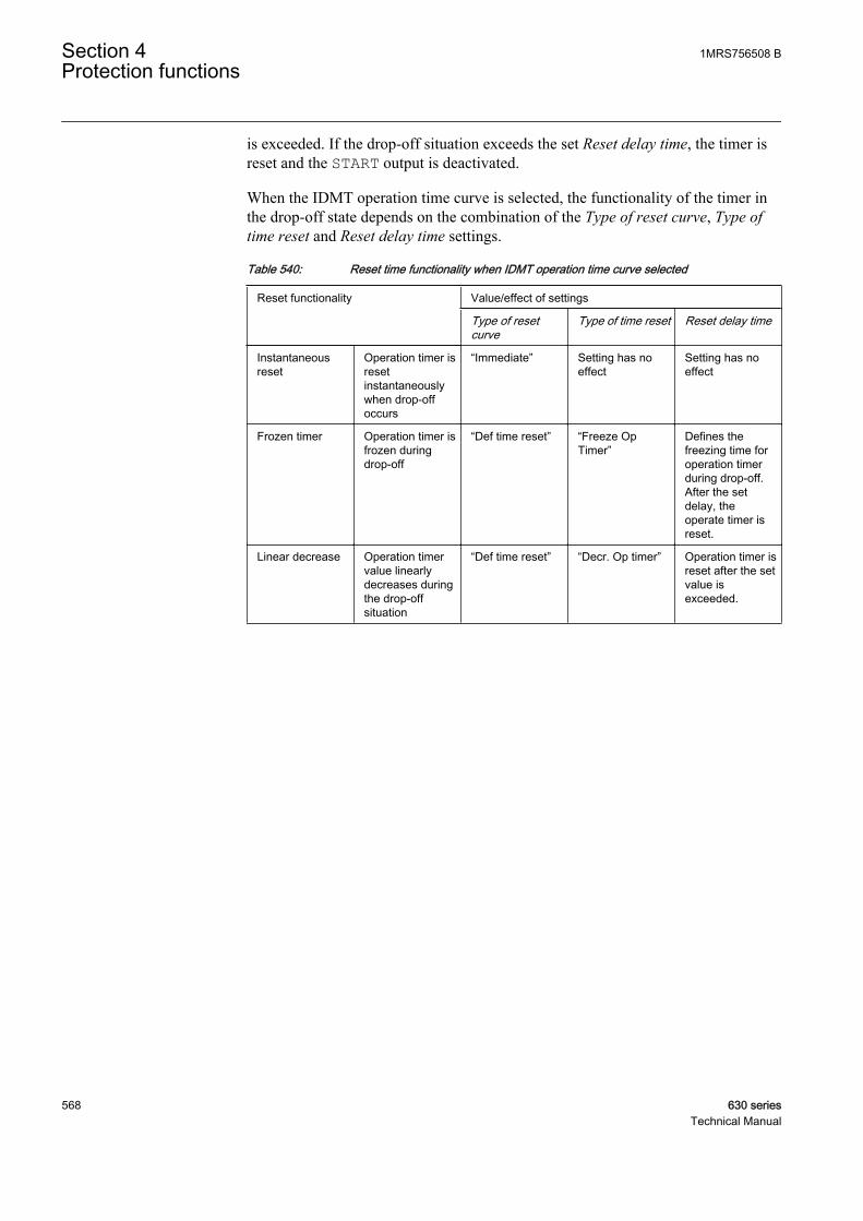
is exceeded. If the drop-off situation exceeds the set Reset delay time, the timer isreset and the START output is deactivated.
When the IDMT operation time curve is selected, the functionality of the timer inthe drop-off state depends on the combination of the Type of reset curve, Type oftime reset and Reset delay time settings.
Table 540: Reset time functionality when IDMT operation time curve selected
Reset functionality Value/effect of settings
Type of resetcurve
Type of time reset Reset delay time
Instantaneousreset
Operation timer isresetinstantaneouslywhen drop-offoccurs
“Immediate” Setting has noeffect
Setting has noeffect
Frozen timer Operation timer isfrozen duringdrop-off
“Def time reset” “Freeze OpTimer”
Defines thefreezing time foroperation timerduring drop-off.After the setdelay, theoperate timer isreset.
Linear decrease Operation timervalue linearlydecreases duringthe drop-offsituation
“Def time reset” “Decr. Op timer” Operation timer isreset after the setvalue isexceeded.
Section 4 1MRS756508 BProtection functions
568 630 seriesTechnical Manual

Example
GUID-111E2F60-2BFC-4D9B-B6C3-473F7689C142 V2 EN
Figure 282: Behavior of different IDMT reset modes
The Time multiplier setting is used for scaling the IDMT operating times.
The Minimum operate time setting defines the minimum operate time for IDMT.The setting is only applicable when the IDMT curves are used.
The Minimum operate time setting should be used with carebecause the operation time is according to the IDMT curve butalways at least the value of the Minimum operate time setting. Formore information, see the General function block features sectionin this manual.
The timer calculates the start duration value START_DUR, which indicates thepercentage ratio of the start situation and the set operation time. The value isavailable in the monitored data view.
1MRS756508 B Section 4Protection functions
630 series 569Technical Manual

The binary input BLOCK can be used to block the function. The activation of theBLOCK input deactivates all outputs and resets the internal timers. The binary inputBLK_ST can be used to block the start signals. The binary input BLK_OPR can beused to block the operating signals. The operation timer counting can be frozen tothe prevailing value by activating the FR_TIMER input.
Note that the FR_TIMER input has no effect during definite timelinearly decreasing reset.
4.5.2.5 Base values
In this function block, some of the settings are set in per unit (pu). These pu valuesare relational to certain base values, for example the values given in A, kV andkVA. The IED supports alternative base value groups for the phase current or voltage-related settings, for example "Phase Grp 1", "Phase Grp 2" and "Phase Grp 3".One of the groups to be used with the Base value Sel phase setting must be selected.
For more information, see the Basic functions section in this manual.
4.5.2.6 Application
PHPTUV is applied to power system elements, such as generators, transformers,motors and power lines, to detect low voltage conditions. Low voltage conditionsare caused by abnormal operation or a fault in the power system. PHPTUV can beused in combination with overcurrent protections. Other applications are thedetection of a no-voltage condition, for example before the energization of a highvoltage line, or an automatic breaker trip in case of a blackout. PHPTUV is alsoused to initiate voltage correction measures, such as insertion of shunt capacitorbanks, to compensate for a reactive load and thereby to increase the voltage.
PHPTUV can be used to disconnect from the network devices, such as electricmotors, which are damaged when subjected to service under low voltageconditions. PHPTUV deals with low voltage conditions at power system frequency.Low voltage conditions can be caused by:
1. Malfunctioning of a voltage regulator or wrong settings under manual control(symmetrical voltage decrease).
2. Overload (symmetrical voltage decrease).3. Short circuits, often as phase-to-earth faults (unsymmetrical voltage decrease).
PHPTUV prevents sensitive equipment from running under conditions that couldcause overheating and thus shorten their life time expectancy. In many cases,PHPTUV is a useful function in circuits for local or remote automation processesin the power system.
Section 4 1MRS756508 BProtection functions
570 630 seriesTechnical Manual
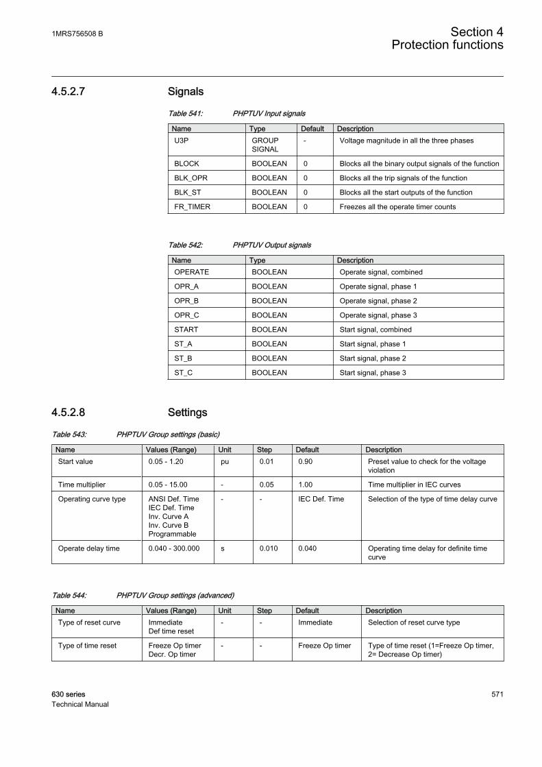
4.5.2.7 Signals
Table 541: PHPTUV Input signals
Name Type Default DescriptionU3P GROUP
SIGNAL- Voltage magnitude in all the three phases
BLOCK BOOLEAN 0 Blocks all the binary output signals of the function
BLK_OPR BOOLEAN 0 Blocks all the trip signals of the function
BLK_ST BOOLEAN 0 Blocks all the start outputs of the function
FR_TIMER BOOLEAN 0 Freezes all the operate timer counts
Table 542: PHPTUV Output signals
Name Type DescriptionOPERATE BOOLEAN Operate signal, combined
OPR_A BOOLEAN Operate signal, phase 1
OPR_B BOOLEAN Operate signal, phase 2
OPR_C BOOLEAN Operate signal, phase 3
START BOOLEAN Start signal, combined
ST_A BOOLEAN Start signal, phase 1
ST_B BOOLEAN Start signal, phase 2
ST_C BOOLEAN Start signal, phase 3
4.5.2.8 Settings
Table 543: PHPTUV Group settings (basic)
Name Values (Range) Unit Step Default DescriptionStart value 0.05 - 1.20 pu 0.01 0.90 Preset value to check for the voltage
violation
Time multiplier 0.05 - 15.00 - 0.05 1.00 Time multiplier in IEC curves
Operating curve type ANSI Def. TimeIEC Def. TimeInv. Curve AInv. Curve BProgrammable
- - IEC Def. Time Selection of the type of time delay curve
Operate delay time 0.040 - 300.000 s 0.010 0.040 Operating time delay for definite timecurve
Table 544: PHPTUV Group settings (advanced)
Name Values (Range) Unit Step Default DescriptionType of reset curve Immediate
Def time reset- - Immediate Selection of reset curve type
Type of time reset Freeze Op timerDecr. Op timer
- - Freeze Op timer Type of time reset (1=Freeze Op timer,2= Decrease Op timer)
1MRS756508 B Section 4Protection functions
630 series 571Technical Manual
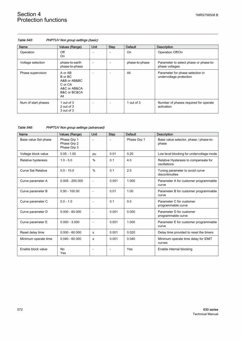
Table 545: PHPTUV Non group settings (basic)
Name Values (Range) Unit Step Default DescriptionOperation Off
On- - On Operation Off/On
Voltage selection phase-to-earthphase-to-phase
- - phase-to-phase Parameter to select phase or phase-to-phase voltages
Phase supervision A or ABB or BCA&B or AB&BCC or CAA&C or AB&CAB&C or BC&CAAll
- - All Parameter for phase selection inundervoltage protection
Num of start phases 1 out of 32 out of 33 out of 3
- - 1 out of 3 Number of phases required for operateactivation
Table 546: PHPTUV Non group settings (advanced)
Name Values (Range) Unit Step Default DescriptionBase value Sel phase Phase Grp 1
Phase Grp 2Phase Grp 3
- - Phase Grp 1 Base value selector, phase / phase-to-phase
Voltage block value 0.05 - 1.00 pu 0.01 0.20 Low level blocking for undervoltage mode
Relative hysteresis 1.0 - 5.0 % 0.1 4.0 Relative Hysteresis to compensate foroscillations
Curve Sat Relative 0.0 - 10.0 % 0.1 2.0 Tuning parameter to avoid curvediscontinuities
Curve parameter A 0.005 - 200.000 - 0.001 1.000 Parameter A for customer programmablecurve
Curve parameter B 0.50 - 100.00 - 0.01 1.00 Parameter B for customer programmablecurve
Curve parameter C 0.0 - 1.0 - 0.1 0.0 Parameter C for customerprogrammable curve
Curve parameter D 0.000 - 60.000 - 0.001 0.000 Parameter D for customerprogrammable curve
Curve parameter E 0.000 - 3.000 - 0.001 1.000 Parameter E for customer programmablecurve
Reset delay time 0.000 - 60.000 s 0.001 0.020 Delay time provided to reset the timers
Minimum operate time 0.040 - 60.000 s 0.001 0.040 Minimum operate time delay for IDMTcurves
Enable block value NoYes
- - Yes Enable internal blocking
Section 4 1MRS756508 BProtection functions
572 630 seriesTechnical Manual

4.5.2.9 Measured values
Table 547: PHPTUV Measured values
Name Type Default DescriptionU_AMPL_A REAL 0.000 Phase to ground voltage phase A
U_AMPL_B REAL 0.000 Phase to ground voltage phase B
U_AMPL_C REAL 0.000 Phase to ground voltage phase C
U_AMPL_AB REAL 0.000 Phase-to-phase voltage AB
U_AMPL_BC REAL 0.000 Phase-to-phase voltage BC
U_AMPL_CA REAL 0.000 Phase-to-phase voltage CA
BLOCK BOOLEAN 0 Blocks all the binary output signals of the function
BLK_OPR BOOLEAN 0 Blocks all the trip signals of the function
BLK_ST BOOLEAN 0 Blocks all the start outputs of the function
FR_TIMER BOOLEAN 0 Freezes all the operate timer counts
4.5.2.10 Monitored data
Table 548: PHPTUV Monitored data
Name Type Values (Range) Unit DescriptionOPR_A BOOLEAN 0=FALSE
1=TRUE- Operate signal, phase 1
OPR_B BOOLEAN 0=FALSE1=TRUE
- Operate signal, phase 2
OPR_C BOOLEAN 0=FALSE1=TRUE
- Operate signal, phase 3
ST_A BOOLEAN 0=FALSE1=TRUE
- Start signal, phase 1
ST_B BOOLEAN 0=FALSE1=TRUE
- Start signal, phase 2
ST_C BOOLEAN 0=FALSE1=TRUE
- Start signal, phase 3
U_MIN REAL - V Minimum of the phase orphase-to-phase voltages
U_RATIO REAL - - Minimum voltage ratio tothe Start value
START_DUR REAL - % Ratio of Start time toOperate time
1MRS756508 B Section 4Protection functions
630 series 573Technical Manual
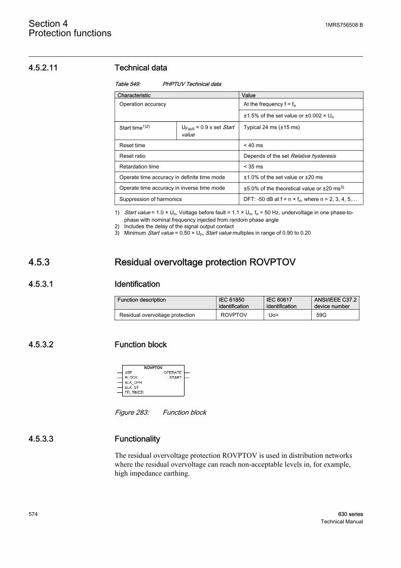
4.5.2.11 Technical data
Table 549: PHPTUV Technical data
Characteristic ValueOperation accuracy At the frequency f = fn
±1.5% of the set value or ±0.002 × Un
Start time1)2) UFault = 0.9 x set Startvalue
Typical 24 ms (±15 ms)
Reset time < 40 ms
Reset ratio Depends of the set Relative hysteresis
Retardation time < 35 ms
Operate time accuracy in definite time mode ±1.0% of the set value or ±20 ms
Operate time accuracy in inverse time mode ±5.0% of the theoretical value or ±20 ms3)
Suppression of harmonics DFT: -50 dB at f = n × fn, where n = 2, 3, 4, 5,…
1) Start value = 1.0 × Un, Voltage before fault = 1.1 × Un, fn = 50 Hz, undervoltage in one phase-to-phase with nominal frequency injected from random phase angle
2) Includes the delay of the signal output contact3) Minimum Start value = 0.50 × Un, Start value multiples in range of 0.90 to 0.20
4.5.3 Residual overvoltage protection ROVPTOV
4.5.3.1 Identification
Function description IEC 61850identification
IEC 60617identification
ANSI/IEEE C37.2device number
Residual overvoltage protection ROVPTOV Uo> 59G
4.5.3.2 Function block
A070767 V2 EN
Figure 283: Function block
4.5.3.3 Functionality
The residual overvoltage protection ROVPTOV is used in distribution networkswhere the residual overvoltage can reach non-acceptable levels in, for example,high impedance earthing.
Section 4 1MRS756508 BProtection functions
574 630 seriesTechnical Manual
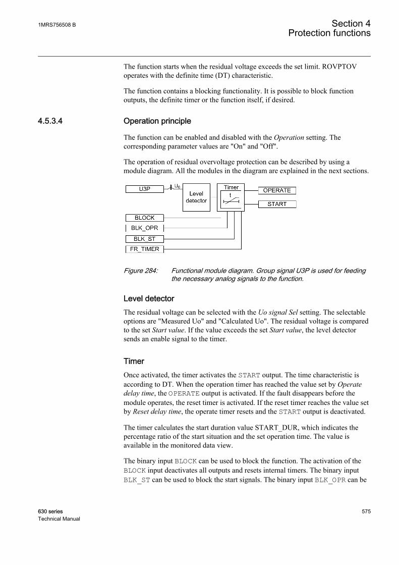
The function starts when the residual voltage exceeds the set limit. ROVPTOVoperates with the definite time (DT) characteristic.
The function contains a blocking functionality. It is possible to block functionoutputs, the definite timer or the function itself, if desired.
4.5.3.4 Operation principle
The function can be enabled and disabled with the Operation setting. Thecorresponding parameter values are "On" and "Off".
The operation of residual overvoltage protection can be described by using amodule diagram. All the modules in the diagram are explained in the next sections.
A070998 V1 EN
Figure 284: Functional module diagram. Group signal U3P is used for feedingthe necessary analog signals to the function.
Level detectorThe residual voltage can be selected with the Uo signal Sel setting. The selectableoptions are "Measured Uo" and "Calculated Uo". The residual voltage is comparedto the set Start value. If the value exceeds the set Start value, the level detectorsends an enable signal to the timer.
TimerOnce activated, the timer activates the START output. The time characteristic isaccording to DT. When the operation timer has reached the value set by Operatedelay time, the OPERATE output is activated. If the fault disappears before themodule operates, the reset timer is activated. If the reset timer reaches the value setby Reset delay time, the operate timer resets and the START output is deactivated.
The timer calculates the start duration value START_DUR, which indicates thepercentage ratio of the start situation and the set operation time. The value isavailable in the monitored data view.
The binary input BLOCK can be used to block the function. The activation of theBLOCK input deactivates all outputs and resets internal timers. The binary inputBLK_ST can be used to block the start signals. The binary input BLK_OPR can be
1MRS756508 B Section 4Protection functions
630 series 575Technical Manual
used to block the operation signals. The operation timer counting can be frozen tothe prevailing value by activating the FR_TIMER input.
4.5.3.5 Base values
In this function block, some of the settings are set in per unit (pu). These pu valuesare relational to certain base values, for example the values given in A, kV andkVA. The IED supports alternative base value groups for the phase current or voltage-related settings, for example "Phase Grp 1", "Phase Grp 2" and "Phase Grp 3".One of the groups to be used with the Base value Sel phase setting must be selected.
For more information, see the Basic functions section in this manual.
4.5.3.6 Application
ROVPTOV is designed to be used for earth-fault protection in isolated neutral,resistance earthed or reactance earthed systems. In compensated networks, startingof the function can be used to control the switching device of the neutral resistor.The function can also be used for the back-up protection of feeders for busbarprotection when a more dedicated busbar protection would not be justified.
In compensated and isolated neutral systems, the system neutral voltage, that is, theresidual voltage, increases in case of any fault connected to earth. Depending onthe type of the fault and the fault resistance, the residual voltage reaches differentvalues. The highest residual voltage, equal to the phase-to-earth voltage, isachieved for a single-phase earth fault. The residual voltage increasesapproximately the same amount in the whole system and does not provide anyguidance in finding the faulty component. Therefore, this function is often used asa backup protection or as a release signal for the feeder earth-fault protection.
The protection can also be used for the earth-fault protection of generators andmotors and for the unbalance protection of capacitor banks.
The residual voltage can be calculated internally based on the measurement of thethree-phase voltage. This voltage can also be measured by a single-phase voltagetransformer, located between a transformer star point and earth, or by using an open-delta connection of three single-phase voltage transformers.
Section 4 1MRS756508 BProtection functions
576 630 seriesTechnical Manual
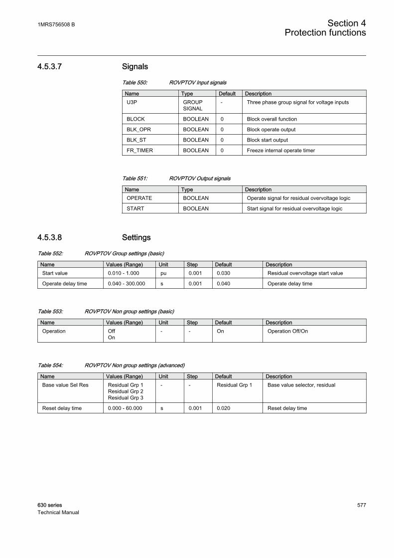
4.5.3.7 Signals
Table 550: ROVPTOV Input signals
Name Type Default DescriptionU3P GROUP
SIGNAL- Three phase group signal for voltage inputs
BLOCK BOOLEAN 0 Block overall function
BLK_OPR BOOLEAN 0 Block operate output
BLK_ST BOOLEAN 0 Block start output
FR_TIMER BOOLEAN 0 Freeze internal operate timer
Table 551: ROVPTOV Output signals
Name Type DescriptionOPERATE BOOLEAN Operate signal for residual overvoltage logic
START BOOLEAN Start signal for residual overvoltage logic
4.5.3.8 Settings
Table 552: ROVPTOV Group settings (basic)
Name Values (Range) Unit Step Default DescriptionStart value 0.010 - 1.000 pu 0.001 0.030 Residual overvoltage start value
Operate delay time 0.040 - 300.000 s 0.001 0.040 Operate delay time
Table 553: ROVPTOV Non group settings (basic)
Name Values (Range) Unit Step Default DescriptionOperation Off
On- - On Operation Off/On
Table 554: ROVPTOV Non group settings (advanced)
Name Values (Range) Unit Step Default DescriptionBase value Sel Res Residual Grp 1
Residual Grp 2Residual Grp 3
- - Residual Grp 1 Base value selector, residual
Reset delay time 0.000 - 60.000 s 0.001 0.020 Reset delay time
1MRS756508 B Section 4Protection functions
630 series 577Technical Manual

4.5.3.9 Measured values
Table 555: ROVPTOV Measured values
Name Type Default DescriptionU0_AMPL REAL 0.0 Residual voltage amplitude
BLOCK BOOLEAN 0 Block overall function
BLK_OPR BOOLEAN 0 Block operate output
BLK_ST BOOLEAN 0 Block start output
FR_TIMER BOOLEAN 0 Freeze internal operate timer
4.5.3.10 Monitored data
Table 556: ROVPTOV Monitored data
Name Type Values (Range) Unit DescriptionOPERATE BOOLEAN 0=FALSE
1=TRUE- Operate signal for
residual overvoltage logic
START BOOLEAN 0=FALSE1=TRUE
- Start signal for residualovervoltage logic
START_DUR REAL - % Start duration inpercentage of the totaloperating time
4.5.3.11 Technical data
Table 557: ROVPTOV Technical data
Characteristic ValueOperation accuracy At the frequency f = fn
±1.5% of the set value or ±0.002 × Un
Start time1)2) UFault = 1.1 x set Startvalue
Typical 27 ms (± 15 ms)
Reset time < 40 ms
Reset ratio Typical 0.96
Retardation time < 35 ms
Operate time accuracy in definite time mode ±1.0% of the set value or ±20 ms
Suppression of harmonics DFT: -50 dB at f = n × fn, where n = 2, 3, 4, 5,…
1) Residual voltage before fault = 0.0 × Un, fn = 50 Hz, residual voltage with nominal frequency injectedfrom random phase angle
2) Includes the delay of the signal output contact
Section 4 1MRS756508 BProtection functions
578 630 seriesTechnical Manual

4.5.4 Positive sequence overvoltage protection PSPTOV
4.5.4.1 Identification
Function description IEC 61850identification
IEC 60617identification
ANSI/IEEE C37.2device number
Positive-sequence overvoltageprotection
PSPTOV U1> 47–0
4.5.4.2 Function block
GUID-D4416734-B75E-4C4D-B4C3-DC6AFDC07E9B V1 EN
Figure 285: Function block
4.5.4.3 Functionality
The positive sequence overvoltage protection PSPTOV is used as an alternative tothe ordinary three-phase overvoltage protection. PSPTOV is used for supervisionand for detection of abnormal conditions, which, in combination with the otherprotection functions, increase the security of the complete protection system.
The function starts when the positive sequence voltage exceeds the set limit.PSPTOV operates on definite time (DT) characteristics.
The function contains a blocking functionality. It is possible to block functionoutputs, the definite timer or the function itself, if desired.
4.5.4.4 Operation principle
The function can be enabled and disabled with the Operation setting. Thecorresponding parameter values are "On" and "Off".
The operation of the positive-sequence overvoltage protection can be describedusing a module diagram. All the modules in the diagram are explained in the nextsections.
1MRS756508 B Section 4Protection functions
630 series 579Technical Manual
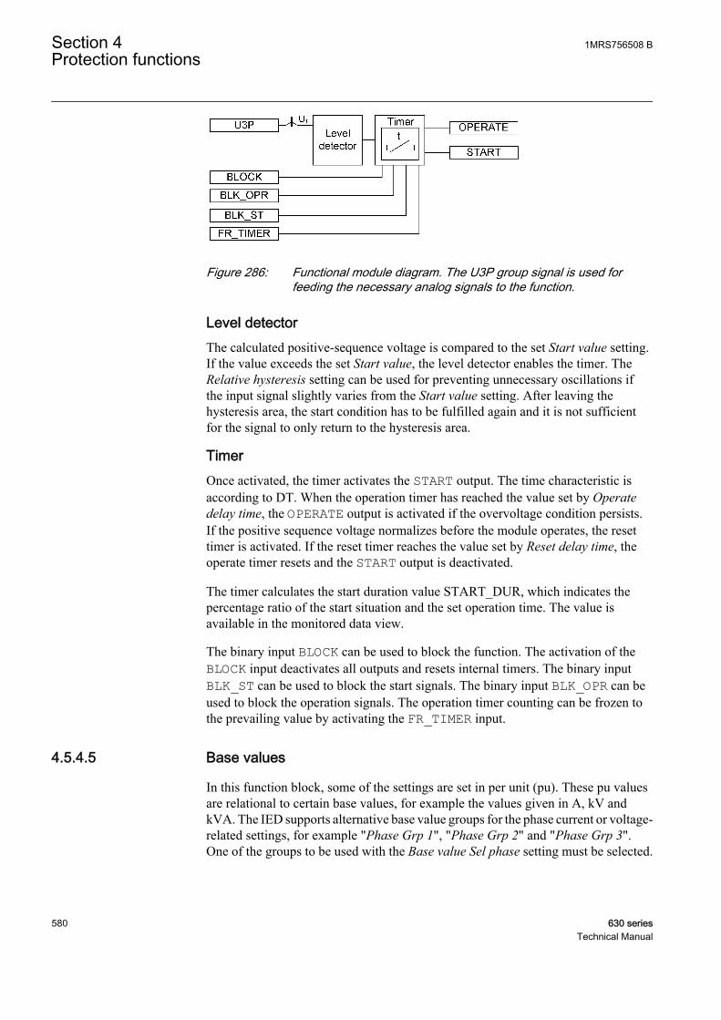
GUID-27B218E8-42F4-40D3-A69D-C6960B49A9BD V1 EN
Figure 286: Functional module diagram. The U3P group signal is used forfeeding the necessary analog signals to the function.
Level detectorThe calculated positive-sequence voltage is compared to the set Start value setting.If the value exceeds the set Start value, the level detector enables the timer. TheRelative hysteresis setting can be used for preventing unnecessary oscillations ifthe input signal slightly varies from the Start value setting. After leaving thehysteresis area, the start condition has to be fulfilled again and it is not sufficientfor the signal to only return to the hysteresis area.
TimerOnce activated, the timer activates the START output. The time characteristic isaccording to DT. When the operation timer has reached the value set by Operatedelay time, the OPERATE output is activated if the overvoltage condition persists.If the positive sequence voltage normalizes before the module operates, the resettimer is activated. If the reset timer reaches the value set by Reset delay time, theoperate timer resets and the START output is deactivated.
The timer calculates the start duration value START_DUR, which indicates thepercentage ratio of the start situation and the set operation time. The value isavailable in the monitored data view.
The binary input BLOCK can be used to block the function. The activation of theBLOCK input deactivates all outputs and resets internal timers. The binary inputBLK_ST can be used to block the start signals. The binary input BLK_OPR can beused to block the operation signals. The operation timer counting can be frozen tothe prevailing value by activating the FR_TIMER input.
4.5.4.5 Base values
In this function block, some of the settings are set in per unit (pu). These pu valuesare relational to certain base values, for example the values given in A, kV andkVA. The IED supports alternative base value groups for the phase current or voltage-related settings, for example "Phase Grp 1", "Phase Grp 2" and "Phase Grp 3".One of the groups to be used with the Base value Sel phase setting must be selected.
Section 4 1MRS756508 BProtection functions
580 630 seriesTechnical Manual

For more information, see the Basic functions section in this manual.
4.5.4.6 Application
A sudden power loss, tap-changer regulating failures and open line ends on longlines are abnormal conditions which cause overvoltages in a power system.PSPTOV is applied to power system elements, such as generators, transformers,motors and power lines, to detect overvoltage conditions.
PSPTOV can be used in combination with low-current signals or a directionalreactive overpower function to identify the distribution line with an open remoteend. PSPTOV can also be used to initiate voltage correction measures like insertionof shunt reactors or switching out capacitor banks to control the voltage.
Overvoltage faced by the power transformer can lead to an overexcitation problem.The overexcitation occurs normally when the ratio of the voltage-to-frequencyincreases much above the design value resulting into transformer operation under anonlinear region. Such an overvoltage situation can be faced by a transformerduring a sudden loss of load due to underfrequency load shedding. Theoverexcitation results into increase in exciting current eventually resulting intoheating of core and can damage the transformer. The positive sequence overvoltageprotection along with the underfrequency protection can be used for the protectionof the transformer during overexcitation.
Some common reasons leading to positive sequence overvoltages are:
• Broken conductor falling to a crossing overhead line, transformer flashoverfault from high voltage winding to low voltage winding
• Malfunctioning of a voltage regulator or wrong settings under manual control(symmetrical voltage increase)
• Low load compared to the reactive power generation (symmetrical voltageincrease)
PSPTOV prevents sensitive equipment from running overvoltage conditionscausing the equipment to overheat or stress on insulation material.
4.5.4.7 Signals
Table 558: PSPTOV Input signals
Name Type Default DescriptionU3P GROUP
SIGNAL- Three phase group signal for voltage inputs
BLOCK BOOLEAN 0 Block overall function
BLK_OPR BOOLEAN 0 Block operate output
BLK_ST BOOLEAN 0 Block start output
FR_TIMER BOOLEAN 0 Freeze internal operate timer
1MRS756508 B Section 4Protection functions
630 series 581Technical Manual
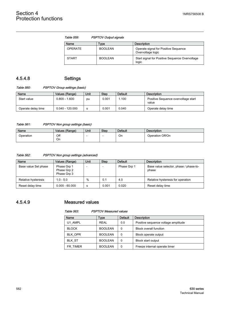
Table 559: PSPTOV Output signals
Name Type DescriptionOPERATE BOOLEAN Operate signal for Positive Sequence
Overvoltage logic
START BOOLEAN Start signal for Positive Sequence Overvoltagelogic
4.5.4.8 Settings
Table 560: PSPTOV Group settings (basic)
Name Values (Range) Unit Step Default DescriptionStart value 0.800 - 1.600 pu 0.001 1.100 Positive Sequence overvoltage start
value
Operate delay time 0.040 - 120.000 s 0.001 0.040 Operate delay time
Table 561: PSPTOV Non group settings (basic)
Name Values (Range) Unit Step Default DescriptionOperation Off
On- - On Operation Off/On
Table 562: PSPTOV Non group settings (advanced)
Name Values (Range) Unit Step Default DescriptionBase value Sel phase Phase Grp 1
Phase Grp 2Phase Grp 3
- - Phase Grp 1 Base value selector, phase / phase-to-phase
Relative hysteresis 1.0 - 5.0 % 0.1 4.0 Relative hysteresis for operation
Reset delay time 0.000 - 60.000 s 0.001 0.020 Reset delay time
4.5.4.9 Measured values
Table 563: PSPTOV Measured values
Name Type Default DescriptionU1_AMPL REAL 0.0 Positive sequence voltage amplitude
BLOCK BOOLEAN 0 Block overall function
BLK_OPR BOOLEAN 0 Block operate output
BLK_ST BOOLEAN 0 Block start output
FR_TIMER BOOLEAN 0 Freeze internal operate timer
Section 4 1MRS756508 BProtection functions
582 630 seriesTechnical Manual

4.5.4.10 Monitored data
Table 564: PSPTOV Monitored data
Name Type Values (Range) Unit DescriptionOPERATE BOOLEAN 0=FALSE
1=TRUE- Operate signal for
Positive SequenceOvervoltage logic
START BOOLEAN 0=FALSE1=TRUE
- Start signal for PositiveSequence Overvoltagelogic
START_DUR REAL - % Start duration inpercentage of the totaloperating time
Table 565: PSPTOV Technical data
Characteristic ValueOperation accuracy At the frequency f = fn
±1.5% of the set value or ±0.002 x Un
Start time1)2) UFault = 1.1 x set StartvalueUFault = 2.0 x set Startvalue
Typical: 29 ms (±15 ms) Typical: 24 ms (±15 ms)
Reset time < 40 ms
Reset ratio Typical 0.96
Retardation time < 35 ms
Operate time accuracy in definite time mode ±1.0% of the set value or ±20 ms
Suppression of harmonics DFT: -50 dB at f = n x fn, where n = 2, 3, 4, 5,…
1) Residual voltage before fault = 0.0 x Un, fn = 50 Hz, residual voltage with nominal frequency injectedfrom random phase angle
2) Includes the delay of the signal output contact
4.5.5 Negative sequence overvoltage protection NSPTOV
4.5.5.1 Identification
Function description IEC 61850identification
IEC 60617identification
ANSI/IEEE C37.2device number
Negative sequence overvoltageprotection
NSPTOV U2> 60Q
1MRS756508 B Section 4Protection functions
630 series 583Technical Manual

4.5.5.2 Function block
GUID-93CA0B64-09E7-4DCD-82A2-3680066F9C0E V1 EN
Figure 287: Function block
4.5.5.3 Functionality
The negative-sequence overvoltage protection NSPTOV is used to detect negativesequence overvoltage conditions. NSPTOV is used for the protection of machines.
The function starts when the negative sequence voltage exceeds the set limit.NSPTOV operates with the definite time (DT) characteristics.
The function contains a blocking functionality. It is possible to block functionoutputs, the definite timer or the function itself, if desired.
4.5.5.4 Operation principle
The function can be enabled and disabled with the Operation setting. Thecorresponding parameter values are "On" and "Off".
The operation of the negative-sequence overvoltage protection can be describedusing a module diagram. All the modules in the diagram are explained in the nextsections.
GUID-5EAC4B47-E042-4BA5-ADC9-2408D2615123 V1 EN
Figure 288: Functional module diagram. The U3P group signal is used forfeeding the necessary analog signals to the function.
Level detectorThe calculated negative-sequence voltage is compared to the set Start value setting.If the value exceeds the set Start value, the level detector enables the timer.
Section 4 1MRS756508 BProtection functions
584 630 seriesTechnical Manual
TimerOnce activated, the timer activates the START output. The time characteristic isaccording to DT. When the operation timer has reached the value set by Operatedelay time, the OPERATE output is activated if the overvoltage condition persists.If the negative-sequence voltage normalizes before the module operates, the resettimer is activated. If the reset timer reaches the value set by Reset delay time, theoperate timer resets and the START output is deactivated.
The timer calculates the start duration value START_DUR, which indicates thepercentage ratio of the start situation and the set operation time. The value isavailable in the monitored data view.
The binary input BLOCK can be used to block the function. The activation of theBLOCK input deactivates all outputs and resets internal timers. The binary inputBLK_ST can be used to block the start signals. The binary input BLK_OPR can beused to block the operation signals. The operation timer counting can be frozen tothe prevailing value by activating the FR_TIMER input.
4.5.5.5 Base values
In this function block, some of the settings are set in per unit (pu). These pu valuesare relational to certain base values, for example the values given in A, kV andkVA. The IED supports alternative base value groups for the phase current or voltage-related settings, for example "Phase Grp 1", "Phase Grp 2" and "Phase Grp 3".One of the groups to be used with the Base value Sel phase setting must be selected.
For more information, see the Basic functions section in this manual.
4.5.5.6 Application
A continuous or temporary voltage unbalance can appear in the network for variousreasons. The voltage unbalance mainly occurs due to broken conductors orasymmetrical loads and is characterized by the appearance of a negative-sequencecomponent of the voltage. In rotating machines, the voltage unbalance results in acurrent unbalance, which heats the rotors of the machines. The rotating machines,therefore, do not tolerate a continuous negative-sequence voltage higher thantypically 1-2 percent x Un.
The negative-sequence component current I2, drawn by an asynchronous or asynchronous machine, is linearly proportional to the negative-sequence componentvoltage U2. When U2 is P% of Un, I2 is typically about 5 x P% x In.
The negative-sequence overcurrent NSPTOC blocks are used to accomplish aselective protection against the voltage and current unbalance for each machine
1MRS756508 B Section 4Protection functions
630 series 585Technical Manual
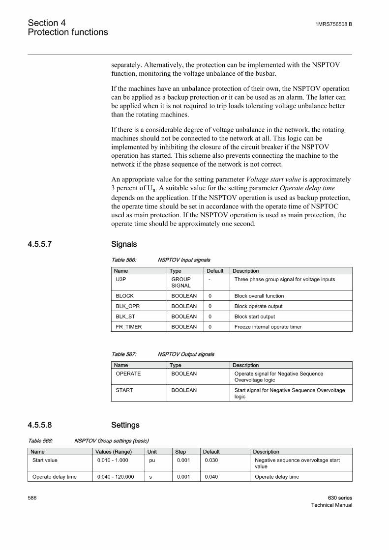
separately. Alternatively, the protection can be implemented with the NSPTOVfunction, monitoring the voltage unbalance of the busbar.
If the machines have an unbalance protection of their own, the NSPTOV operationcan be applied as a backup protection or it can be used as an alarm. The latter canbe applied when it is not required to trip loads tolerating voltage unbalance betterthan the rotating machines.
If there is a considerable degree of voltage unbalance in the network, the rotatingmachines should not be connected to the network at all. This logic can beimplemented by inhibiting the closure of the circuit breaker if the NSPTOVoperation has started. This scheme also prevents connecting the machine to thenetwork if the phase sequence of the network is not correct.
An appropriate value for the setting parameter Voltage start value is approximately3 percent of Un. A suitable value for the setting parameter Operate delay timedepends on the application. If the NSPTOV operation is used as backup protection,the operate time should be set in accordance with the operate time of NSPTOCused as main protection. If the NSPTOV operation is used as main protection, theoperate time should be approximately one second.
4.5.5.7 Signals
Table 566: NSPTOV Input signals
Name Type Default DescriptionU3P GROUP
SIGNAL- Three phase group signal for voltage inputs
BLOCK BOOLEAN 0 Block overall function
BLK_OPR BOOLEAN 0 Block operate output
BLK_ST BOOLEAN 0 Block start output
FR_TIMER BOOLEAN 0 Freeze internal operate timer
Table 567: NSPTOV Output signals
Name Type DescriptionOPERATE BOOLEAN Operate signal for Negative Sequence
Overvoltage logic
START BOOLEAN Start signal for Negative Sequence Overvoltagelogic
4.5.5.8 Settings
Table 568: NSPTOV Group settings (basic)
Name Values (Range) Unit Step Default DescriptionStart value 0.010 - 1.000 pu 0.001 0.030 Negative sequence overvoltage start
value
Operate delay time 0.040 - 120.000 s 0.001 0.040 Operate delay time
Section 4 1MRS756508 BProtection functions
586 630 seriesTechnical Manual

Table 569: NSPTOV Non group settings (basic)
Name Values (Range) Unit Step Default DescriptionOperation Off
On- - On Operation Off/On
Table 570: NSPTOV Non group settings (advanced)
Name Values (Range) Unit Step Default DescriptionBase value Sel phase Phase Grp 1
Phase Grp 2Phase Grp 3
- - Phase Grp 1 Base value selector, phase / phase-to-phase
Reset delay time 0.000 - 60.000 s 0.001 0.020 Reset delay time
4.5.5.9 Measured values
Table 571: NSPTOV Measured values
Name Type Default DescriptionU2_AMPL REAL 0.0 Negative sequence voltage amplitude
BLOCK BOOLEAN 0 Block overall function
BLK_OPR BOOLEAN 0 Block operate output
BLK_ST BOOLEAN 0 Block start output
FR_TIMER BOOLEAN 0 Freeze internal operate timer
4.5.5.10 Monitored data
Table 572: NSPTOV Monitored data
Name Type Values (Range) Unit DescriptionOPERATE BOOLEAN 0=FALSE
1=TRUE- Operate signal for
Negative SequenceOvervoltage logic
START BOOLEAN 0=FALSE1=TRUE
- Start signal for NegativeSequence Overvoltagelogic
START_DUR REAL - % Start duration inpercentage of the totaloperating time
1MRS756508 B Section 4Protection functions
630 series 587Technical Manual

4.5.5.11 Technical data
Table 573: NSPTOV Technical data
Characteristic ValueOperation accuracy At the frequency f = fn
±1.5% of the set value or ±0.002 × Un
Start time1)2) UFault = 1.1 x set StartvalueUFault = 2.0 x set Startvalue
Typical 29 ms (± 15ms)Typical 24 ms (± 15ms)
Reset time < 40 ms
Reset ratio Typical 0.96
Retardation time < 35 ms
Operate time accuracy in definite time mode ±1.0% of the set value or ±20 ms
Suppression of harmonics DFT: -50 dB at f = n × fn, where n = 2, 3, 4, 5,…
1) Residual voltage before fault = 0.0 × Un, fn = 50 Hz, residual overvoltage with nominal frequencyinjected from random phase angle
2) Includes the delay of the signal output contact
4.5.6 Positive sequence undervoltage protection PSPTUV
4.5.6.1 Identification
Function description IEC 61850identification
IEC 60617identification
ANSI/IEEE C37.2device number
Positive sequence undervoltageprotection
PSPTUV U1< 47-U
4.5.6.2 Function block
GUID-E756BC9C-F607-4860-B515-508567DC7764 V1 EN
Figure 289: Function block
4.5.6.3 Functionality
The positive-sequence undervoltage protection PSPTUV is used to detect positive-sequence undervoltage conditions. PSPTUV is used for the protection of smallpower generation plants. The function helps in isolating an embedded plant from afault line when the fault current fed by the plant is too low to start an overcurrentfunction but high enough to maintain the arc. Fast isolation of all the fault current
Section 4 1MRS756508 BProtection functions
588 630 seriesTechnical Manual
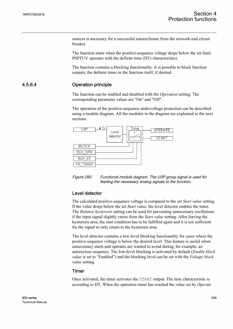
sources is necessary for a successful autoreclosure from the network-end circuitbreaker.
The function starts when the positive-sequence voltage drops below the set limit.PSPTUV operates with the definite time (DT) characteristics.
The function contains a blocking functionality. It is possible to block functionoutputs, the definite timer or the function itself, if desired.
4.5.6.4 Operation principle
The function can be enabled and disabled with the Operation setting. Thecorresponding parameter values are "On" and "Off".
The operation of the positive-sequence undervoltage protection can be describedusing a module diagram. All the modules in the diagram are explained in the nextsections.
GUID-CE4BEAC7-518C-43B7-9586-6957189EF018 V1 EN
Figure 290: Functional module diagram. The U3P group signal is used forfeeding the necessary analog signals to the function.
Level detectorThe calculated positive-sequence voltage is compared to the set Start value setting.If the value drops below the set Start value, the level detector enables the timer.The Relative hysteresis setting can be used for preventing unnecessary oscillationsif the input signal slightly varies from the Start value setting. After leaving thehysteresis area, the start condition has to be fulfilled again and it is not sufficientfor the signal to only return to the hysteresis area.
The level detector contains a low-level blocking functionality for cases where thepositive-sequence voltage is below the desired level. This feature is useful whenunnecessary starts and operates are wanted to avoid during, for example, anautoreclose sequence. The low-level blocking is activated by default (Enable blockvalue is set to “Enabled”) and the blocking level can be set with the Voltage blockvalue setting.
TimerOnce activated, the timer activates the START output. The time characteristic isaccording to DT. When the operation timer has reached the value set by Operate
1MRS756508 B Section 4Protection functions
630 series 589Technical Manual
delay time, the OPERATE output is activated if the undervoltage condition persists.If the positive-sequence voltage normalizes before the module operates, the resettimer is activated. If the reset timer reaches the value set by Reset delay time, theoperate timer resets and the START output is deactivated.
The timer calculates the start duration value START_DUR, which indicates thepercentage ratio of the start situation and the set operation time. The value isavailable in the monitored data view.
The binary input BLOCK can be used to block the function. The activation of theBLOCK input deactivates all outputs and resets internal timers. The binary inputBLK_ST can be used to block the start signals. The binary input BLK_OPR can beused to block the operation signals. The operation timer counting can be frozen tothe prevailing value by activating the FR_TIMER input.
4.5.6.5 Base values
In this function block, some of the settings are set in per unit (pu). These pu valuesare relational to certain base values, for example the values given in A, kV andkVA. The IED supports alternative base value groups for the phase current or voltage-related settings, for example "Phase Grp 1", "Phase Grp 2" and "Phase Grp 3".One of the groups to be used with the Base value Sel phase setting must be selected.
For more information, see the Basic functions section in this manual.
4.5.6.6 Application
PSPTUV can be applied for protecting a power station used for embeddedgeneration when network faults like short circuits or phase-to-earth faults in atransmission or a distribution line cause a potentially dangerous situations for thepower station. A network fault can be dangerous for the power station for variousreasons. The operation of the protection can cause an islanding condition, alsocalled a loss-of-mains condition, in which a part of the network, that is, an islandfed by the power station, is isolated from the rest of the network. There is then arisk of an autoreclosure taking place when the voltages of different parts of thenetwork do not synchronize, which is a straining incident for the power station.Another risk is that the generator can lose synchronism during the network fault. Asufficiently fast trip of the utility circuit breaker of the power station can avoidthese risks.
The lower the three-phase symmetrical voltage of the network is, the higher is theprobability that the generator loses the synchronism. The positive-sequence voltageis also available during asymmetrical faults. It is a more appropriate criterion fordetecting the risk of loss of synchronism than, for example, the lowest phase-to-phase voltage.
Section 4 1MRS756508 BProtection functions
590 630 seriesTechnical Manual

Analyzing the loss of synchronism of a generator is rather complicated and requiresa model of the generator with its prime mover and controllers. The generator canbe able to operate synchronously even if the voltage drops by a few tens of percentfor some hundreds of milliseconds. The setting of PSPTUV is thus determined bythe need to protect the power station from the risks of the islanding conditionssince that requires a higher setting value.
The loss of synchronism of a generator means that the generator is unable tooperate as a generator with the network frequency but enters into an unstablecondition in which it operates by turns as a generator and a motor. Such a conditionstresses the generator thermally and mechanically. This kind of loss ofsynchronism should not be mixed with the one between an island and the utilitynetwork. In the islanding situation, the condition of the generator itself is normalbut the phase angle and the frequency of the phase-to-phase voltage can bedifferent from the corresponding voltage in the rest of the network. The island canhave a frequency of its own relatively fast when fed by a small power station with alow inertia.
PSPTUV complements other loss-of-grid protection principles based on thefrequency and voltage operation.
Motor stalling and failure to start can lead to a continuous undervoltage. The positive-sequence undervoltage is used as a backup protection against the motor stallcondition.
4.5.6.7 Signals
Table 574: PSPTUV Input signals
Name Type Default DescriptionU3P GROUP
SIGNAL- Three phase group signal for voltage inputs
BLOCK BOOLEAN 0 Block overall function
BLK_OPR BOOLEAN 0 Block operate output
BLK_ST BOOLEAN 0 Block start output
FR_TIMER BOOLEAN 0 Freeze internal operate timer
Table 575: PSPTUV Output signals
Name Type DescriptionOPERATE BOOLEAN Operate signal for Positive Sequence
Undervoltage protection
START BOOLEAN Start signal for Positive Sequence Undervoltagelogic
1MRS756508 B Section 4Protection functions
630 series 591Technical Manual

4.5.6.8 Settings
Table 576: PSPTUV Group settings (basic)
Name Values (Range) Unit Step Default DescriptionStart value 0.010 - 1.200 pu 0.001 0.900 Positive sequence undervoltage start
value
Operate delay time 0.040 - 120.000 s 0.001 0.040 Operate delay time
Table 577: PSPTUV Group settings (advanced)
Name Values (Range) Unit Step Default DescriptionVoltage block value 0.01 - 1.00 pu 0.01 0.20 Internal blocking level
Enable block value DisabledEnabled
- - Enabled Enable Internal Blocking
Table 578: PSPTUV Non group settings (basic)
Name Values (Range) Unit Step Default DescriptionOperation Off
On- - On Operation Off/On
Table 579: PSPTUV Non group settings (advanced)
Name Values (Range) Unit Step Default DescriptionBase value Sel phase Phase Grp 1
Phase Grp 2Phase Grp 3
- - Phase Grp 1 Base value selector, phase / phase-to-phase
Relative hysteresis 1.0 - 5.0 % 0.1 4.0 Relative hysteresis for operation
Reset delay time 0.000 - 60.000 s 0.001 0.020 Reset delay time
4.5.6.9 Measured values
Table 580: PSPTUV Measured values
Name Type Default DescriptionU1_AMPL REAL 0.0 Positive sequence voltage amplitude
BLOCK BOOLEAN 0 Block overall function
BLK_OPR BOOLEAN 0 Block operate output
BLK_ST BOOLEAN 0 Block start output
FR_TIMER BOOLEAN 0 Freeze internal operate timer
Section 4 1MRS756508 BProtection functions
592 630 seriesTechnical Manual

4.5.6.10 Monitored data
Table 581: PSPTUV Monitored data
Name Type Values (Range) Unit DescriptionOPERATE BOOLEAN 0=FALSE
1=TRUE- Operate signal for
Positive SequenceUndervoltage protection
START BOOLEAN 0=FALSE1=TRUE
- Start signal for PositiveSequence Undervoltagelogic
START_DUR REAL - % Start duration inpercentage of the totaloperating time
4.5.6.11 Technical data
Table 582: PSPTUV Technical data
Characteristic ValueOperation accuracy At the frequency f = fn
±1.5% of the set value or ±0.002 × Un
Start time1)2) UFault = 0.9 x set Startvalue
Typical 28 ms (±15 ms)
Reset time < 40 ms
Reset ratio Typical 0.96
Retardation time < 35 ms
Operate time accuracy in definite time mode ±1.0% of the set value or ±20 ms
Suppression of harmonics DFT: -50 dB at f = n × fn, where n = 2, 3, 4, 5,…
1) Residual voltage before fault = 1.1 × Un, fn = 50 Hz, residual voltage with nominal frequency injectedfrom random phase angle
2) Includes the delay of the signal output contact
4.5.7 Overexitation protection OEPVPH
4.5.7.1 Identification
Function description IEC 61850identification
IEC 60617identification
ANSI/IEEE C37.2device number
Overexcitation protection OEPVPH U/f> 24
1MRS756508 B Section 4Protection functions
630 series 593Technical Manual
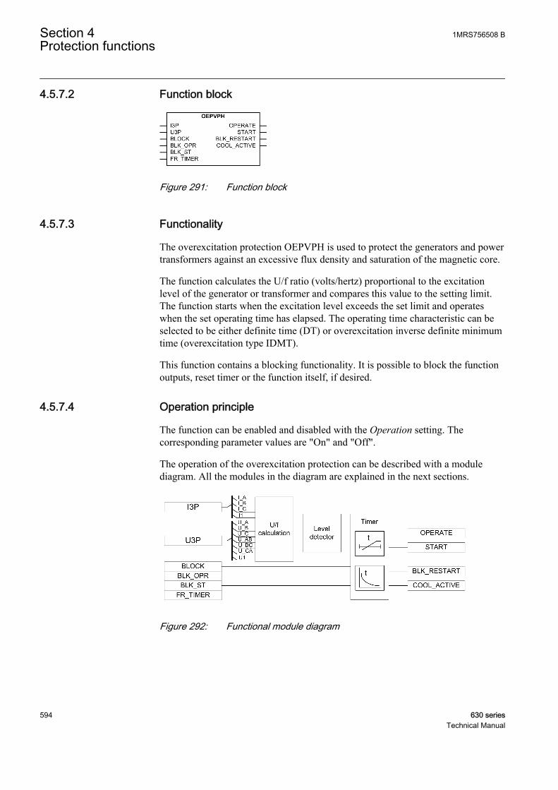
4.5.7.2 Function block
GUID-2573B480-1482-4E9B-BEB9-0FEE8BB0C145 V1 EN
Figure 291: Function block
4.5.7.3 Functionality
The overexcitation protection OEPVPH is used to protect the generators and powertransformers against an excessive flux density and saturation of the magnetic core.
The function calculates the U/f ratio (volts/hertz) proportional to the excitationlevel of the generator or transformer and compares this value to the setting limit.The function starts when the excitation level exceeds the set limit and operateswhen the set operating time has elapsed. The operating time characteristic can beselected to be either definite time (DT) or overexcitation inverse definite minimumtime (overexcitation type IDMT).
This function contains a blocking functionality. It is possible to block the functionoutputs, reset timer or the function itself, if desired.
4.5.7.4 Operation principle
The function can be enabled and disabled with the Operation setting. Thecorresponding parameter values are "On" and "Off".
The operation of the overexcitation protection can be described with a modulediagram. All the modules in the diagram are explained in the next sections.
GUID-19FF0393-D642-488F-BB49-DF89594902DF V1 EN
Figure 292: Functional module diagram
Section 4 1MRS756508 BProtection functions
594 630 seriesTechnical Manual

U/f calculationThis module calculates the "U/f ratio", that is, the excitation level from the internalinduced voltage (E) and frequency. The actual measured voltage (Um) deviatesfrom the internal induced voltage (emf) E, a value the equipment has to withstand.This voltage compensation is based on the load current (IL) and the leakagereactance (Xleak) of the equipment. The leakage reactance of the transformer orgenerator is set through the Leakage React setting in percentage of the Z base.
The internal induced voltage (E) is calculated from the measured voltage. Thesettings Voltage selection and Phase supervision determine which voltages andcurrents are to be used. If the Voltage selection setting is set to "phase-to-earth" or"phase-to-phase", the Phase supervision setting is needed for determining whichphases or phase-to-phase voltages ("A or AB", "B or BC" and "C or CA") andcurrents are to be used for the calculation of the induced voltage.
Table 583: Voltages and currents used for induced voltage E calculation
Voltage selection setting Phase supervision setting Calculation of internal induced voltage (emf) Ephase-to-earth A or AB
E U I j XA A leak= ⋅ + ⋅ ⋅( )3 ( )
GUID-1287475D-62CA-4683-8E56-C49878E707CE V1 EN
phase-to-earth B or BCE U I j XB B leak= ⋅ + ⋅ ⋅( )3 ( )
GUID-E78900F1-CF36-46B9-8358-40769F4C59E2 V1 EN
phase-to-earth C or CAE U I j XC C leak= ⋅ + ⋅ ⋅( )3 ( )
GUID-DA1EB85C-01C5-48D3-8862-87B248CAD3C2 V1 EN
phase-to-phase A or ABE U I I j XAB A B leak= + − ⋅ ⋅( )( ) ( )
GUID-D3885BFD-D9F3-4E6E-9214-209EA9FA419E V1 EN
phase-to-phase B or BCE U I I j XBC B C leak= + − ⋅ ⋅( )( ) ( )
GUID-751A9D22-A5C7-4991-AA26-CDD1435910EF V1 EN
phase-to-phase C or CAE U I I j XCA C A leak= + − ⋅ ⋅( )( ) ( )
GUID-B9AA1AEC-B25A-4C62-A84F-3A7025B2D230 V1 EN
Pos sequence N/AE U I j X leak= ⋅ + ⋅ ⋅( )3 1 1 ( )
GUID-AADD53F4-E176-4753-9EFF-564EBBF7A3C3 V1 EN
The voltages, currents and leakage reactance Xleak are given in volts, amps and ohms.
If all three phase or phase-to-phase voltages and phase currents arefed to the IED, the positive-sequence alternative is recommended.
If the leakage reactance of the protected equipment is unknown orif the measured voltage Um is to be used in the excitation level
1MRS756508 B Section 4Protection functions
630 series 595Technical Manual

calculation, the leakage reactance setting is set to zero. Thecalculated induced voltage E is then equal to the measured voltage.
The calculated "U/f ratio" is scaled to a value based on the nominal Un/fn ratio.However, the highest allowed continuous voltage (in % Un) can be defined bysetting the parameter Volt Max continuous to change the basis of the voltage. Themeasured voltage is compared to the new base value to obtain the excitation level.
The excitation level (M) can be calculated:
M
E
f
U
f
Volt Max continuous
m
n
n
=
×
100
GUID-6C4FE80D-7940-4130-9BF7-E44ED087EE41 V1 EN (Equation 87)
M the excitation level ("U/f ratio" or "Volts/Hertz") in pu
E the internal induced voltage (emf)
fm the measured frequency
Un the nominal phase-to-phase voltage
fn the nominal frequency
If the input frequency fm is less than 20 percent of the nominal frequency fn, thecalculation of the excitation level is disabled and forced to zero value, that is, thefunction is blocked internally during low-frequency condition.
The calculated excitation level ("U/f ratio" or "Volts/Hertz") VOLTPERHZ isavailable in the monitored data view.
Level detectorThe level detector compares the calculated excitation level to the Start valuesetting. If the excitation level exceeds the set limit, the module sends an enablingsignal to start the timer.
TimerOnce activated, the timer activates the START output. Depending on the value ofthe set Operating curve type, the time characteristics are according to DT or IDMT.When the operation timer has reached the value set by Operate delay time in theDT mode or the value defined by the inverse time curve, the OPERATE output isactivated.
In a drop-off situation, that is, when the excitation level drops below Start valuebefore the function operates, the reset timer is activated and the START outputresets after the time delay of Reset delay time for the DT characteristics. For theIDMT curves, the reset operation is as described in the Timer characteristics chapter.
Section 4 1MRS756508 BProtection functions
596 630 seriesTechnical Manual

For the IDMT curves, it is possible to define the maximum and minimum operatingtimes via the Minimum operate time and Maximum operate time settings. TheMaximum operate time setting is used to prevent the infinite start situations at lowdegrees of overexcitation. The Time multiplier setting is used for scaling the IDMToperate times.
The activation of the OPERATE output activates the BLK_RESTART andCOOL_ACTIVE outputs.
For the DT characteristics, the deactivation of the OPERATE output activates thecooling timer. The timer is set to the value entered in the Cooling time setting. TheBLK_RESTART and COOL_ACTIVE outputs are kept active until the coolingtimer is reset. If the excitation increases above the set value during this period, theOPERATE output is activated immediately. For IDMT, the deactivation ofBLK_RESTART and COOL_ACTIVE depends on the curve type selected.
The operation timer counting can be frozen to the prevailing value by activating theFR_TIMER input.
The T_ENARESTART output indicates the duration for which the BLK_RESTARToutput remains active. The value is available in the monitored data view.
The timer calculates the start duration value START_DUR, which indicates thepercentage ratio of the start situation and the set operating time. The value isavailable in the monitored data view.
The BLOCK binary input can be used for blocking the function. Activating theBLOCK input deactivates all the binary outputs and resets the internal timers. Thebinary input BLK_ST is used to block the start signals. The binary input BLK_OPRis used to block the operating signals.
Blocking logicThere are three operation modes in the blocking functionality. The operation modesare controlled by the BLOCK input and the global setting "Configuration/System/Blocking mode" which selects the blocking mode. The BLOCK input can becontrolled by a binary input, a horizontal communication input or an internal signalof the IED program. The influence of the BLOCK signal activation is preselectedwith the global setting Blocking mode.
The Blocking mode setting has three blocking methods. In the "Freeze timers"mode, the operation timer is frozen to the prevailing value. In the "Block all"mode, the whole function is blocked and the timers are reset. In the "BlockOPERATE output" mode, the function operates normally but the OPERATE outputis not activated.
4.5.7.5 Base values
In this function block, some of the settings are set in per unit (pu). These pu valuesare relational to certain base values, for example the values given in A, kV and
1MRS756508 B Section 4Protection functions
630 series 597Technical Manual
kVA. The IED supports alternative base value groups for the phase current or voltage-related settings, for example "Phase Grp 1", "Phase Grp 2" and "Phase Grp 3".One of the groups to be used with the Base value Sel phase setting must be selected.
For more information, see the Basic functions section in this manual.
4.5.7.6 Timer characteristics
OEPVPH supports both DT and IDMT characteristics. The DT timercharacteristics can be selected as "ANSI Def. Time" or "IEC Def. Time" in theOperating curve type setting. The functionality is identical in both cases. When theDT characteristics are selected, the functionality is only affected by the Operatedelay time and Reset delay time settings.
OEPVPH also supports four overexcitation IDMT characteristic curves: "OvExtIDMT Crv1", "OvExt IDMT Crv2", "OvExt IDMT Crv3" and "OvExt IDMT Crv4".
Overexcitation inverse definite minimum time curve (IDMT)In the inverse time modes, the operate time depends on the momentary value of theexcitation: the higher the excitation level, the shorter the operate time. The operatetime calculation or integration starts immediately when the excitation level exceedsthe set Start value and the START output is activated.
The OPERATE output is activated when the cumulative sum of the integratorcalculating the overexcitation situation exceeds the value set by the inverse timemode. The set value depends on the selected curve type and the setting values used.
The Minimum operate time and Maximum operate time settings define theminimum operate time and maximum operate time possible for the IDMT mode.For setting these parameters, a careful study of the particular IDMT curves isrecommended.
The operation time of the function block can vary much betweendifferent operating curve types even if other setting parameters forthe curves were not changed.
Once activated, the timer activates the START output for the IDMT curves. If theexcitation level drops below the Start value setting before the function operates, thereset timer is activated and the START output resets immediately. If STARTreoccurs during the reset time, the operation calculation is made based on theeffects of the period when START was previously active. This is intended to allowan operating condition to occur in less time to account for the heating effects fromthe previous active start period.
Section 4 1MRS756508 BProtection functions
598 630 seriesTechnical Manual

For the IDMT curves, when START is deactivated, the integral value calculatedduring START is continuously decremented by a constant that causes its value tobecome zero when the reset time elapses during the reset period. If a fault reoccurs,the integration continues from the current integral value and the start time isadjusted, as shown in Figure 293. The start time becomes the value at the timewhen the fault dropped off minus the amount of reset time that occurred. If thereset period elapses without a fault being detected, the saved values of the starttime and integration are cleared.
START Drop-off START Reset
reset time
Operate level
Inverse time counter
time
50%
100%
START resets
25%
GUID-C6AAFC57-08D7-4AF9-99D6-6153D9A7D0DC V1 EN
Figure 293: An example of a delayed reset in the inverse time characteristics.When the start becomes active during the reset period, the operatetime counter continues from the level corresponding to the drop-off(reset time = 0.50 · Cooling time).
Overexcitation IDMT curves 1, 2 and 3The base equation for the IDMT curves "OvExt IDMT Crv1", "OvExt IDMTCrv2" and "OvExt IDMT Crv3" is:
t s e
ak b M
c( ) = ⋅
+ −
60
100
GUID-5D74EA35-03AD-44D1-9EE0-0B1999C55BF1 V1 EN (Equation 88)
t(s) the operate time in seconds
M excitation level (U/f ratio or volts/hertz) in pu
k the Time multiplier setting
1MRS756508 B Section 4Protection functions
630 series 599Technical Manual
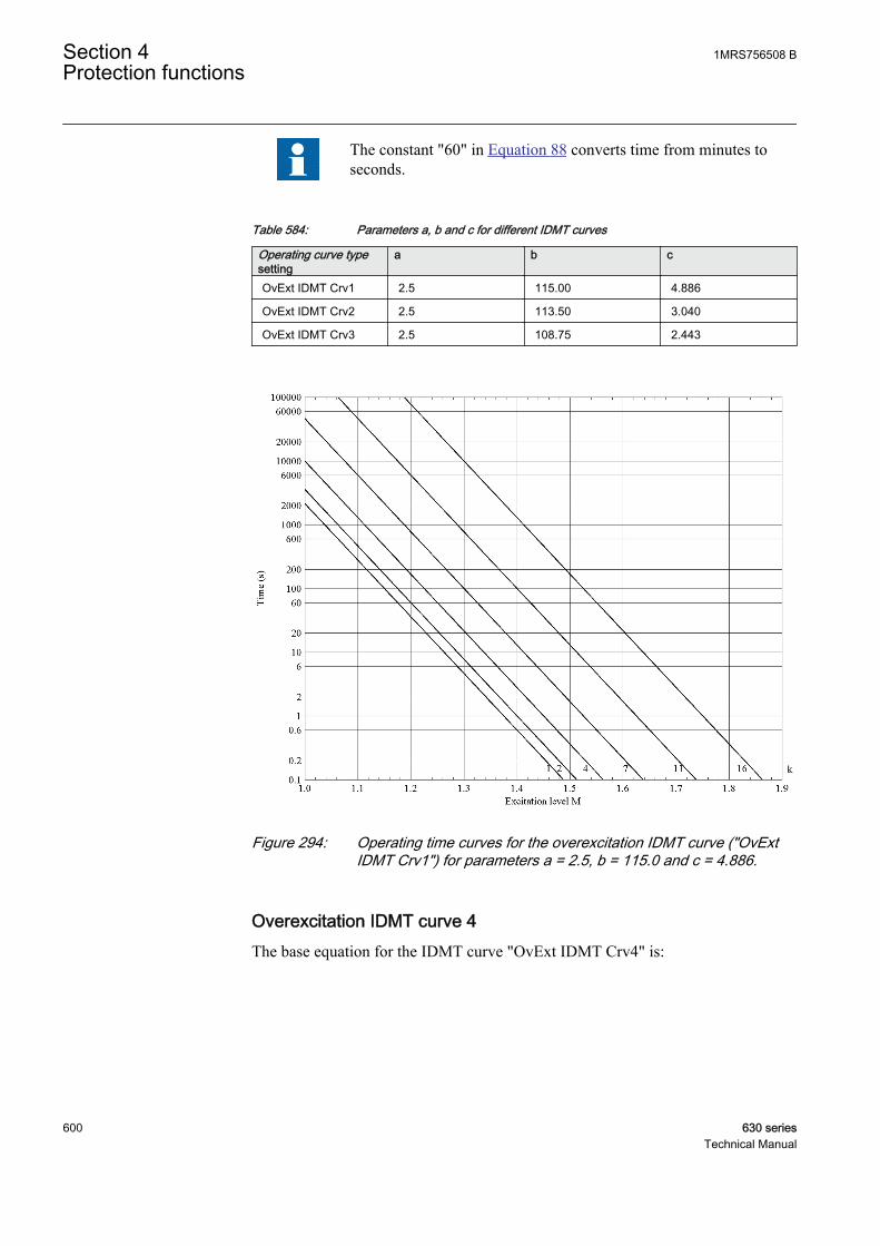
The constant "60" in Equation 88 converts time from minutes toseconds.
Table 584: Parameters a, b and c for different IDMT curves
Operating curve typesetting
a b c
OvExt IDMT Crv1 2.5 115.00 4.886
OvExt IDMT Crv2 2.5 113.50 3.040
OvExt IDMT Crv3 2.5 108.75 2.443
GUID-BD1205DC-1794-4F64-A950-6199C54DB7B1 V1 EN
Figure 294: Operating time curves for the overexcitation IDMT curve ("OvExtIDMT Crv1") for parameters a = 2.5, b = 115.0 and c = 4.886.
Overexcitation IDMT curve 4The base equation for the IDMT curve "OvExt IDMT Crv4" is:
Section 4 1MRS756508 BProtection functions
600 630 seriesTechnical Manual
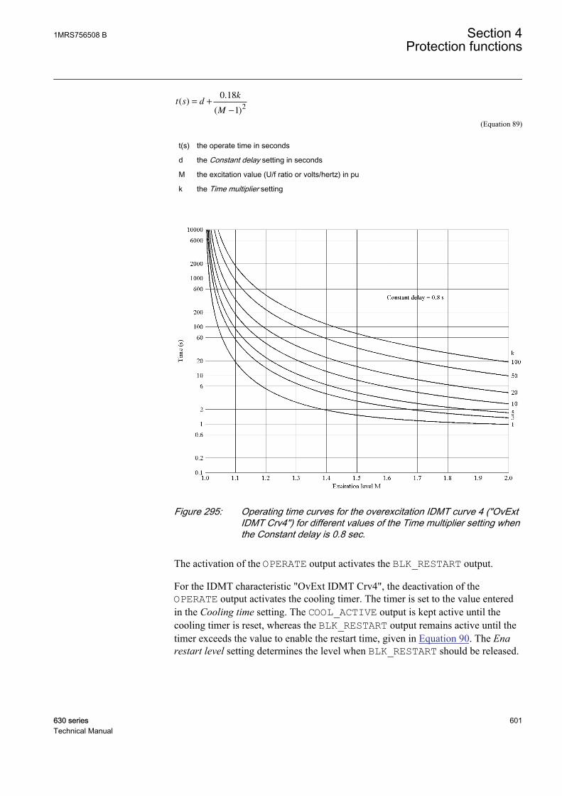
t s dk
M
( ).
( )= +
−
0 18
12
GUID-154EC60E-DF7E-4013-8846-C357174869F4 V1 EN (Equation 89)
t(s) the operate time in seconds
d the Constant delay setting in seconds
M the excitation value (U/f ratio or volts/hertz) in pu
k the Time multiplier setting
GUID-6FC7624E-7E13-4645-8943-0FDFBAA1D184 V1 EN
Figure 295: Operating time curves for the overexcitation IDMT curve 4 ("OvExtIDMT Crv4") for different values of the Time multiplier setting whenthe Constant delay is 0.8 sec.
The activation of the OPERATE output activates the BLK_RESTART output.
For the IDMT characteristic "OvExt IDMT Crv4", the deactivation of theOPERATE output activates the cooling timer. The timer is set to the value enteredin the Cooling time setting. The COOL_ACTIVE output is kept active until thecooling timer is reset, whereas the BLK_RESTART output remains active until thetimer exceeds the value to enable the restart time, given in Equation 90. The Enarestart level setting determines the level when BLK_RESTART should be released.
1MRS756508 B Section 4Protection functions
630 series 601Technical Manual
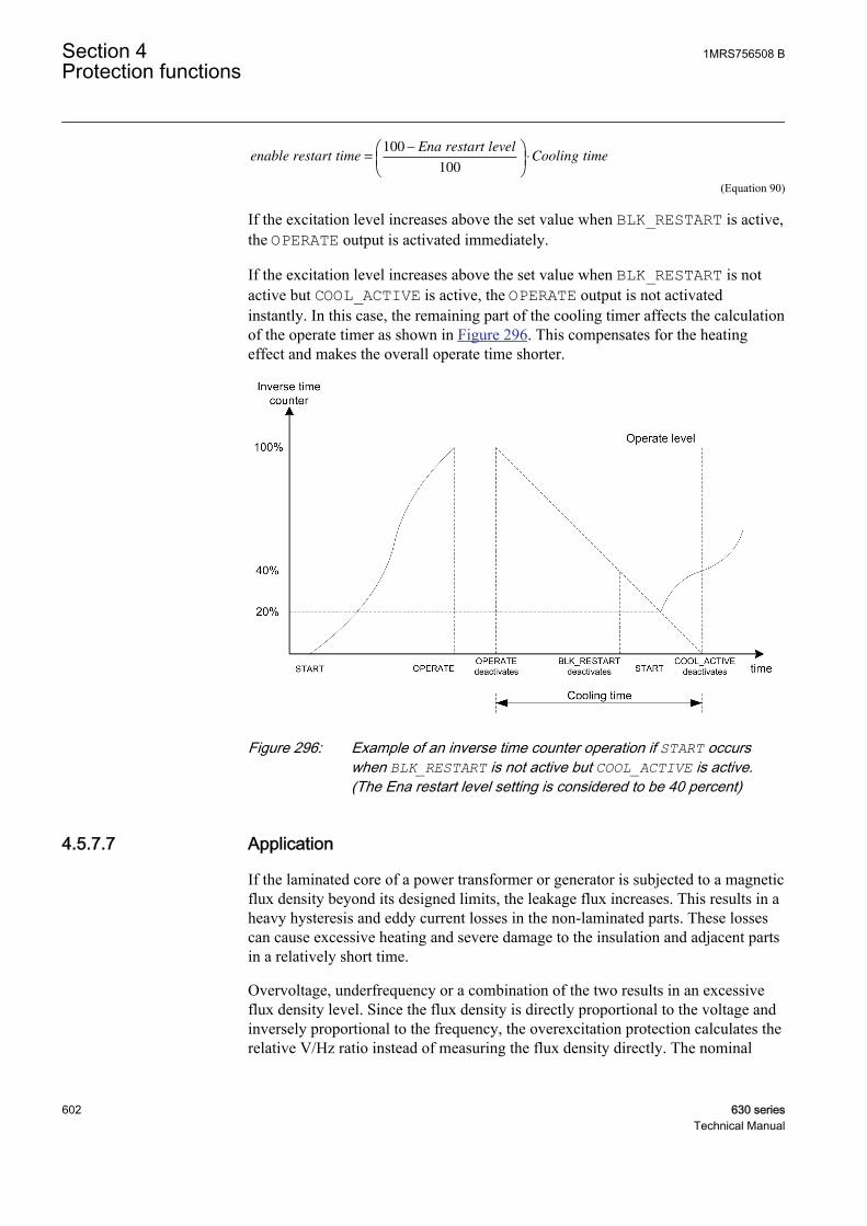
enable restart timeEna restart level
Cooling time=−
⋅100
100
GUID-76116B3C-28C5-4865-A164-A2376B881915 V1 EN (Equation 90)
If the excitation level increases above the set value when BLK_RESTART is active,the OPERATE output is activated immediately.
If the excitation level increases above the set value when BLK_RESTART is notactive but COOL_ACTIVE is active, the OPERATE output is not activatedinstantly. In this case, the remaining part of the cooling timer affects the calculationof the operate timer as shown in Figure 296. This compensates for the heatingeffect and makes the overall operate time shorter.
GUID-6D98255F-CD77-44BB-A8F4-8E34D0956F21 V1 EN
Figure 296: Example of an inverse time counter operation if START occurswhen BLK_RESTART is not active but COOL_ACTIVE is active.(The Ena restart level setting is considered to be 40 percent)
4.5.7.7 Application
If the laminated core of a power transformer or generator is subjected to a magneticflux density beyond its designed limits, the leakage flux increases. This results in aheavy hysteresis and eddy current losses in the non-laminated parts. These lossescan cause excessive heating and severe damage to the insulation and adjacent partsin a relatively short time.
Overvoltage, underfrequency or a combination of the two results in an excessiveflux density level. Since the flux density is directly proportional to the voltage andinversely proportional to the frequency, the overexcitation protection calculates therelative V/Hz ratio instead of measuring the flux density directly. The nominal
Section 4 1MRS756508 BProtection functions
602 630 seriesTechnical Manual

level (nominal voltage at nominal frequency) is usually considered as the 100-percent level, which can be exceeded slightly based on the design.
The greatest risk for overexcitation exists in a thermal power station when thegenerator-transformer unit is disconnected from the rest of the network or in thenetwork islands where high voltages or low frequencies can occur.
Overexcitation can occur during the startup and shutdown of the generator if thefield current is not properly adjusted. The loss-of-load or load shedding can alsoresult in overexcitation if the voltage control and frequency governor do notfunction properly. The low frequency in a system isolated from the main networkcan result in overexcitation if the voltage-regulating system maintains a normalvoltage.
Overexcitation protection for the transformer is generally provided by the generatoroverexcitation protection, which uses the VTs connected to the generator terminals.The curves that define the generator and transformer V/Hz limits must becoordinated properly to protect both equipments.
If the generator can be operated with a leading power factor, the high-side voltageof the transformer can have a higher pu V/Hz than the generator V/Hz. This needsto be considered in a proper overexcitation protection of the transformer. Also,measurement for the voltage must not be taken from any winding where OLTC islocated.
It is assumed that overexcitation is a symmetrical phenomenon caused by eventssuch as loss-of-load. It should be noted that a high phase-to-earth voltage does notmean overexcitation. For example, in an unearthed power system, a single-phase-to-earth fault means high voltages on the two healthy phases but no overexcitation onany winding. The phase-to-phase voltages remain essentially unchanged. Thevoltage to be considered for the overexcitation is the voltage between the two endsof each winding.
Example calculations for overexcitation protection
Example 1Nominal values of the machine
Nominal phase-to-phase voltage (Un) 11000 V
Nominal phase current (In) 7455 A
Nominal frequency (fn) 50 Hz
Leakage reactance (Xleak) 20% or 0.2 pu
Measured voltage and load currents of the machine
Phase A-to-phase B voltage (UAB) 11500∠0° V
1MRS756508 B Section 4Protection functions
630 series 603Technical Manual
Phase A current (IA) 5600∠-63.57° A
Phase B current (IB) 5600∠176.42° A
Measured frequency (fm) 49.98 Hz
The setting Volt Max continuous 100%
The setting Voltage selection phase-to-phase
The setting Phase supervision A or AB
The pu leakage reactance XleakPU is converted to ohms.
X XU
Ileak leakPU
n
n
Ω= ×
×( )
= ×
×( )
=
30 2 11000
7455 3. 00 170378. Ohms
GUID-93EB75F7-CAA1-4127-95A8-E58A8FC291F5 V1 EN (Equation 91)
The internal induced voltage E of the machine is calculated.
E U I I jXAB A B leak= + − ×( ) ( )
GUID-EFEFD1C2-206B-4CC1-A58F-75C05E0897F9 V1 EN (Equation 92)
E = 11500∠0°+ (5600∠-63.57°- 5600∠176.42°) x (0.170378∠90°) = 12490 V
The excitation level M of the machine is calculated.
Excitationlevel M =
×
=
1249049 98
1100050
1 001 1359
.
..
GUID-75BDACA1-7D77-4E84-A574-AEF9A8AD1A08 V1 EN
Example 2The situation and the data are according to example 1. In this case, themanufacturer of the machine allows the continuous operation at 105 percent of thenominal voltage at the rated load and this value to be used as the base foroverexcitation.
Usually, the U/f characteristics are specified so that the ratio is 1.00at the nominal voltage and nominal frequency. Therefore, the value100 percent for the setting Volt Max continuous is recommended.
If the Volt Max continuous setting is 105 percent, the excitation level M of themachine is calculated with the equation.
Excitationlevel M =
×
=
1249049 98
1100050
1 051 0818
.
..
GUID-9373AED6-4A78-487C-979B-31E8D77D5668 V1 EN
Section 4 1MRS756508 BProtection functions
604 630 seriesTechnical Manual
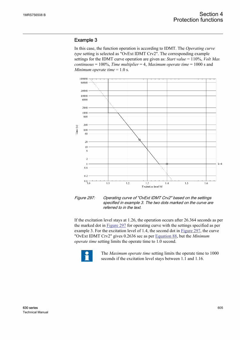
Example 3In this case, the function operation is according to IDMT. The Operating curvetype setting is selected as "OvExt IDMT Crv2". The corresponding examplesettings for the IDMT curve operation are given as: Start value = 110%, Volt Maxcontinuous = 100%, Time multiplier = 4, Maximum operate time = 1000 s andMinimum operate time = 1.0 s.
GUID-433F1AF8-DA0B-4FEA-A281-1872487F3B97 V1 EN
Figure 297: Operating curve of "OvExt IDMT Crv2" based on the settingsspecified in example 3. The two dots marked on the curve arereferred to in the text.
If the excitation level stays at 1.26, the operation occurs after 26.364 seconds as perthe marked dot in Figure 297 for operating curve with the settings specified as perexample 3. For the excitation level of 1.4, the second dot in Figure 297, the curve"OvExt IDMT Crv2" gives 0.2636 sec as per Equation 88, but the Minimumoperate time setting limits the operate time to 1.0 second.
The Maximum operate time setting limits the operate time to 1000seconds if the excitation level stays between 1.1 and 1.16.
1MRS756508 B Section 4Protection functions
630 series 605Technical Manual

In general, however, the excitation level seldom remains constant.Therefore, the exact operate times in any inverse time mode aredifficult to predict.
Example 4In this case, the function operation is according to IDMT. The Operating curvetype setting is selected as "OvExt IDMT Crv4". The corresponding examplesettings for the IDMT curve operation are given as: Start value = 110%, Volt Maxcontinuous = 100%, Time multiplier = 5, Maximum operate time = 3600 s andConstant delay = 0.8 s.
GUID-78B05F4B-3434-4DD5-89F6-17F099444C04 V1 EN
Figure 298: Operating curve of “OvExt IDMT Crv4” based on the specifiedsettings. The two dots marked on the curve are referred to in the text.
If the excitation level stays at 1.25, the operation occurs after 15.20 s. At theexcitation level of 1.42, the time to operation would be 5.90 s as per the two dots inFigure 298. In this case, the setting Maximum operate time = 3600 s does not limitthe maximum operate time because the operate time at Start value = 110% (1.1 pu)is approximately 75 seconds.
Section 4 1MRS756508 BProtection functions
606 630 seriesTechnical Manual
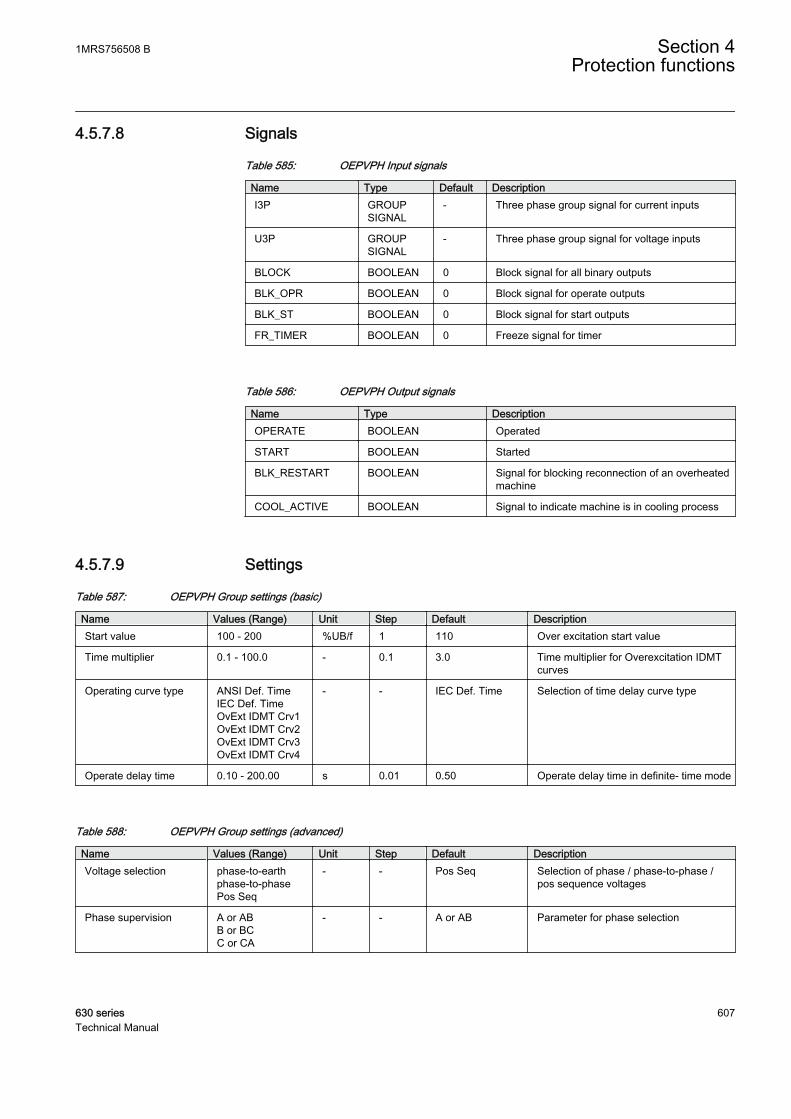
4.5.7.8 Signals
Table 585: OEPVPH Input signals
Name Type Default DescriptionI3P GROUP
SIGNAL- Three phase group signal for current inputs
U3P GROUPSIGNAL
- Three phase group signal for voltage inputs
BLOCK BOOLEAN 0 Block signal for all binary outputs
BLK_OPR BOOLEAN 0 Block signal for operate outputs
BLK_ST BOOLEAN 0 Block signal for start outputs
FR_TIMER BOOLEAN 0 Freeze signal for timer
Table 586: OEPVPH Output signals
Name Type DescriptionOPERATE BOOLEAN Operated
START BOOLEAN Started
BLK_RESTART BOOLEAN Signal for blocking reconnection of an overheatedmachine
COOL_ACTIVE BOOLEAN Signal to indicate machine is in cooling process
4.5.7.9 Settings
Table 587: OEPVPH Group settings (basic)
Name Values (Range) Unit Step Default DescriptionStart value 100 - 200 %UB/f 1 110 Over excitation start value
Time multiplier 0.1 - 100.0 - 0.1 3.0 Time multiplier for Overexcitation IDMTcurves
Operating curve type ANSI Def. TimeIEC Def. TimeOvExt IDMT Crv1OvExt IDMT Crv2OvExt IDMT Crv3OvExt IDMT Crv4
- - IEC Def. Time Selection of time delay curve type
Operate delay time 0.10 - 200.00 s 0.01 0.50 Operate delay time in definite- time mode
Table 588: OEPVPH Group settings (advanced)
Name Values (Range) Unit Step Default DescriptionVoltage selection phase-to-earth
phase-to-phasePos Seq
- - Pos Seq Selection of phase / phase-to-phase /pos sequence voltages
Phase supervision A or ABB or BCC or CA
- - A or AB Parameter for phase selection
1MRS756508 B Section 4Protection functions
630 series 607Technical Manual
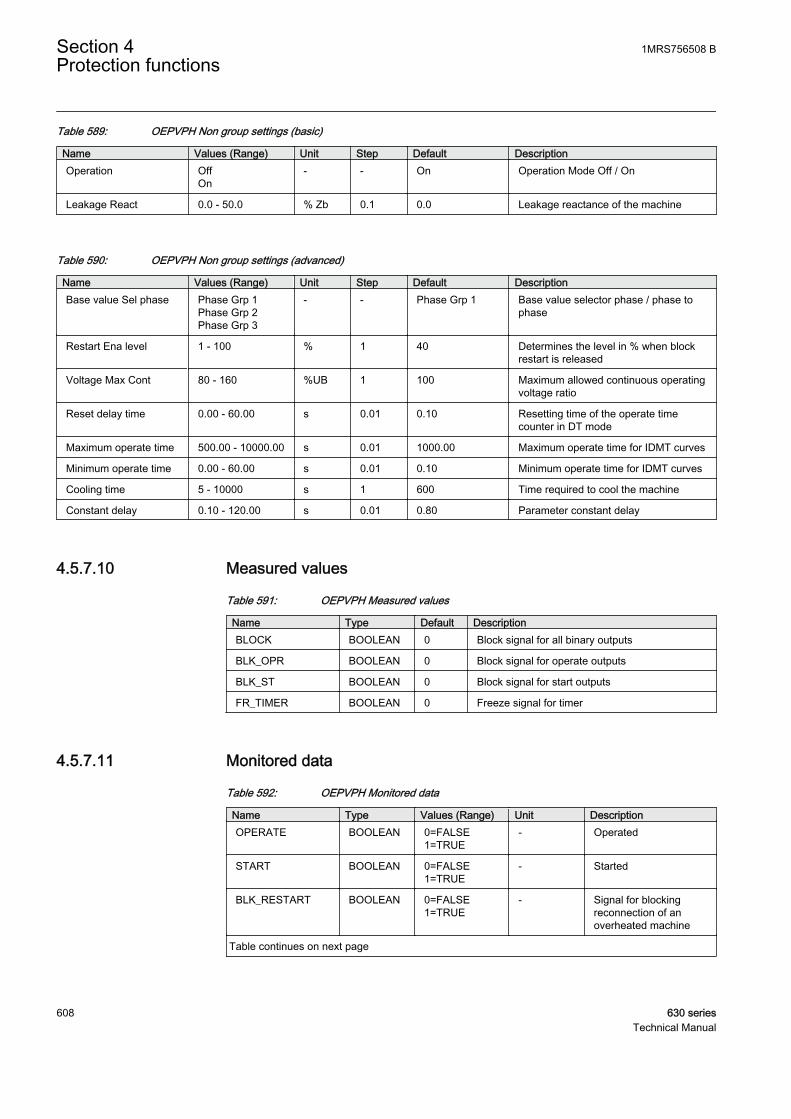
Table 589: OEPVPH Non group settings (basic)
Name Values (Range) Unit Step Default DescriptionOperation Off
On- - On Operation Mode Off / On
Leakage React 0.0 - 50.0 % Zb 0.1 0.0 Leakage reactance of the machine
Table 590: OEPVPH Non group settings (advanced)
Name Values (Range) Unit Step Default DescriptionBase value Sel phase Phase Grp 1
Phase Grp 2Phase Grp 3
- - Phase Grp 1 Base value selector phase / phase tophase
Restart Ena level 1 - 100 % 1 40 Determines the level in % when blockrestart is released
Voltage Max Cont 80 - 160 %UB 1 100 Maximum allowed continuous operatingvoltage ratio
Reset delay time 0.00 - 60.00 s 0.01 0.10 Resetting time of the operate timecounter in DT mode
Maximum operate time 500.00 - 10000.00 s 0.01 1000.00 Maximum operate time for IDMT curves
Minimum operate time 0.00 - 60.00 s 0.01 0.10 Minimum operate time for IDMT curves
Cooling time 5 - 10000 s 1 600 Time required to cool the machine
Constant delay 0.10 - 120.00 s 0.01 0.80 Parameter constant delay
4.5.7.10 Measured values
Table 591: OEPVPH Measured values
Name Type Default DescriptionBLOCK BOOLEAN 0 Block signal for all binary outputs
BLK_OPR BOOLEAN 0 Block signal for operate outputs
BLK_ST BOOLEAN 0 Block signal for start outputs
FR_TIMER BOOLEAN 0 Freeze signal for timer
4.5.7.11 Monitored data
Table 592: OEPVPH Monitored data
Name Type Values (Range) Unit DescriptionOPERATE BOOLEAN 0=FALSE
1=TRUE- Operated
START BOOLEAN 0=FALSE1=TRUE
- Started
BLK_RESTART BOOLEAN 0=FALSE1=TRUE
- Signal for blockingreconnection of anoverheated machine
Table continues on next page
Section 4 1MRS756508 BProtection functions
608 630 seriesTechnical Manual
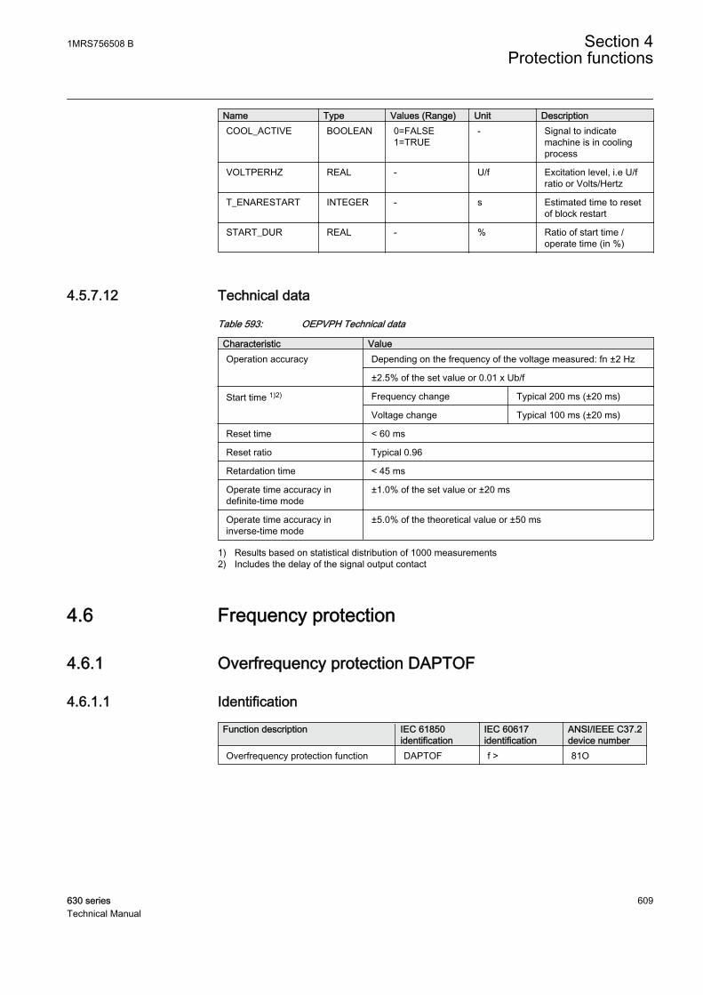
Name Type Values (Range) Unit DescriptionCOOL_ACTIVE BOOLEAN 0=FALSE
1=TRUE- Signal to indicate
machine is in coolingprocess
VOLTPERHZ REAL - U/f Excitation level, i.e U/fratio or Volts/Hertz
T_ENARESTART INTEGER - s Estimated time to resetof block restart
START_DUR REAL - % Ratio of start time /operate time (in %)
4.5.7.12 Technical data
Table 593: OEPVPH Technical data
Characteristic ValueOperation accuracy Depending on the frequency of the voltage measured: fn ±2 Hz
±2.5% of the set value or 0.01 x Ub/f
Start time 1)2) Frequency change Typical 200 ms (±20 ms)
Voltage change Typical 100 ms (±20 ms)
Reset time < 60 ms
Reset ratio Typical 0.96
Retardation time < 45 ms
Operate time accuracy indefinite-time mode
±1.0% of the set value or ±20 ms
Operate time accuracy ininverse-time mode
±5.0% of the theoretical value or ±50 ms
1) Results based on statistical distribution of 1000 measurements2) Includes the delay of the signal output contact
4.6 Frequency protection
4.6.1 Overfrequency protection DAPTOF
4.6.1.1 Identification
Function description IEC 61850identification
IEC 60617identification
ANSI/IEEE C37.2device number
Overfrequency protection function DAPTOF f > 81O
1MRS756508 B Section 4Protection functions
630 series 609Technical Manual

4.6.1.2 Function block
GUID-BCCA2C67-2D5D-429B-9740-73B16EBBA6AF V1 EN
Figure 299: Function block
4.6.1.3 Functionality
The overfrequency protection function DAPTOF can be used to protect networkcomponents from possible damage caused by overfrequency conditions. DAPTOFcan also be used as a sub-nominal frequency stage initiating load restoring.
The frequency must exceed the set start frequency value before the function canstart and operate. DAPTOF operates with definite time (DT) characteristics. Toavoid unwanted operation due to an uncertain frequency measurement at a lowvoltage magnitude, a voltage-controlled blocking of the function is available, thatis, if the voltage is lower than the set minimum voltage, the function is blocked.The frequency measurement is based on the voltage available only for preprocessorfunction SMAI internally. This voltage is dependent on all connected phase-to-earth or phase-to-phase voltages. If only one phase-to-earth or phase-to-phasevoltage is connected then, that is used.
The function contains a blocking functionality. Blocking deactivates all outputsand resets timers.
4.6.1.4 Operation principle
The function can be enabled and disabled with the Operation setting. Thecorresponding parameter values are "On" and "Off".
The operation of the overfrequency protection can be described by using a modulediagram. All the modules in the diagram are explained in the next sections.
GUID-A7DC35DA-4628-45B5-A67A-669C447E950E V1 EN
Figure 300: Functional module diagram
Section 4 1MRS756508 BProtection functions
610 630 seriesTechnical Manual

Overfrequency detectorThe fundamental frequency is compared to the Start value setting. If the frequencyexceeds the set Start value, the enable signal is sent to the timer.
Low amplitude blockingThe voltage is compared to the value of the MinValFreqMeas setting. If the voltagemagnitude is below the set value, the LOWAMPL_BLKD output is activated, whichalso resets the timer.
MinValFreqMeas is the setting related to the preprocessor functionSMAI. The setting level is compared to the physically connectedvoltages. For example, if phase-to-phase voltages are physicallyconnected (phase-to-earth voltages virtual), the 10% setting resultsin ten percent of the normal phase-to-phase voltage. If phase-to-earth voltages are connected (phase-to-phase voltages virtual), the10% setting results in 17 percent of the normal phase-to-earthvoltage. This is assuming the base voltage is set to be the normal/nominal phase-to-phase voltage.
The activation of the BLOCK input deactivates the LOWAMPL_BLKD output.
TimerOnce activated, the timer activates the START output. The time characteristic isaccording to DT. When the operation timer has reached the value set by Operatedelay time, the OPERATE output is activated. If the frequency becomes normalbefore the module operates, the reset timer is activated. If the reset timer reachesthe value set by Reset delay time, the operate timer resets and the START output isdeactivated.
The timer calculates the start duration value START_DUR, which indicates thepercentage ratio of the start situation and the set operation time. The value isavailable in the monitored data view.
For a detailed description of the definite timer, see the Generalfunction block features section in this manual.
The activation of the BLOCK input resets the timer and deactivates the OPERATEand START outputs.
4.6.1.5 Application
DAPTOF is applicable in all situations where high levels of the fundamentalfrequency of power system voltage must be reliably detected. A high fundamentalfrequency in a power system indicates that there is an unbalance betweenproduction and consumption. In this case, the available generation is too large
1MRS756508 B Section 4Protection functions
630 series 611Technical Manual
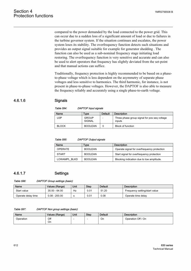
compared to the power demanded by the load connected to the power grid. Thiscan occur due to a sudden loss of a significant amount of load or due to failures inthe turbine governor system. If the situation continues and escalates, the powersystem loses its stability. The overfrequency function detects such situations andprovides an output signal suitable for example for generator shedding . Thefunction can also be used as a sub-nominal frequency stage initiating loadrestoring. The overfrequency function is very sensitive and accurate and can alsobe used to alert operators that frequency has slightly deviated from the set-pointand that manual actions can suffice.
Traditionally, frequency protection is highly recommended to be based on a phase-to-phase voltage which is less dependent on the asymmetry of separate phasevoltages and less sensitive to harmonics. The third harmonic, for instance, is notpresent in phase-to-phase voltages. However, the DAPTOF is also able to measurethe frequency reliably and accurately using a single phase-to-earth voltage.
4.6.1.6 Signals
Table 594: DAPTOF Input signals
Name Type Default DescriptionU3P GROUP
SIGNAL- Three phase group signal for pos seq voltage
inputs
BLOCK BOOLEAN 0 Block of function
Table 595: DAPTOF Output signals
Name Type DescriptionOPERATE BOOLEAN Operate signal for overfrequency protection
START BOOLEAN Start signal for overfrequency protection
LOWAMPL_BLKD BOOLEAN Blocking indication due to low amplitude.
4.6.1.7 Settings
Table 596: DAPTOF Group settings (basic)
Name Values (Range) Unit Step Default DescriptionStart value 35.00 - 64.00 Hz 0.01 51.20 Frequency setting/start value
Operate delay time 0.08 - 200.00 s 0.01 0.08 Operate time delay
Table 597: DAPTOF Non group settings (basic)
Name Values (Range) Unit Step Default DescriptionOperation Off
On- - On Operation Off / On
Section 4 1MRS756508 BProtection functions
612 630 seriesTechnical Manual

Table 598: DAPTOF Non group settings (advanced)
Name Values (Range) Unit Step Default DescriptionReset delay time 0.00 - 60.00 s 0.01 0.02 Time delay for reset
4.6.1.8 Measured values
Table 599: DAPTOF Measured values
Name Type Default DescriptionBLOCK BOOLEAN 0 Block of function
4.6.1.9 Monitored data
Table 600: DAPTOF Monitored data
Name Type Values (Range) Unit DescriptionOPERATE BOOLEAN 0=FALSE
1=TRUE- Operate signal for
overfrequency protection
START BOOLEAN 0=FALSE1=TRUE
- Start signal foroverfrequency protection
LOWAMPL_BLKD BOOLEAN 0=FALSE1=TRUE
- Blocking indication dueto low amplitude.
FREQ REAL - Hz Measured frequency
START_DUR REAL - % Start duration inpercents of the totaloperation time.
4.6.1.10 Technical data
Table 601: DAPTOF Technical data
Characteristic ValueOperation accuracy At the frequency f = 35 to 66 Hz
± 0.003 Hz
Start time1)2) fFault = 1.01 × set Startvalue
Typical < 190 ms
Reset time < 190 ms
Operate time accuracy in definite time mode ±1.0% of the set value or ±30 ms
Suppression of harmonics DFT: -50 dB at f = n × fn, where n = 2, 3, 4, 5,…
1) Frequency before fault = 0.99 × fn, fn = 50 Hz2) Includes the delay of the signal output contact
1MRS756508 B Section 4Protection functions
630 series 613Technical Manual
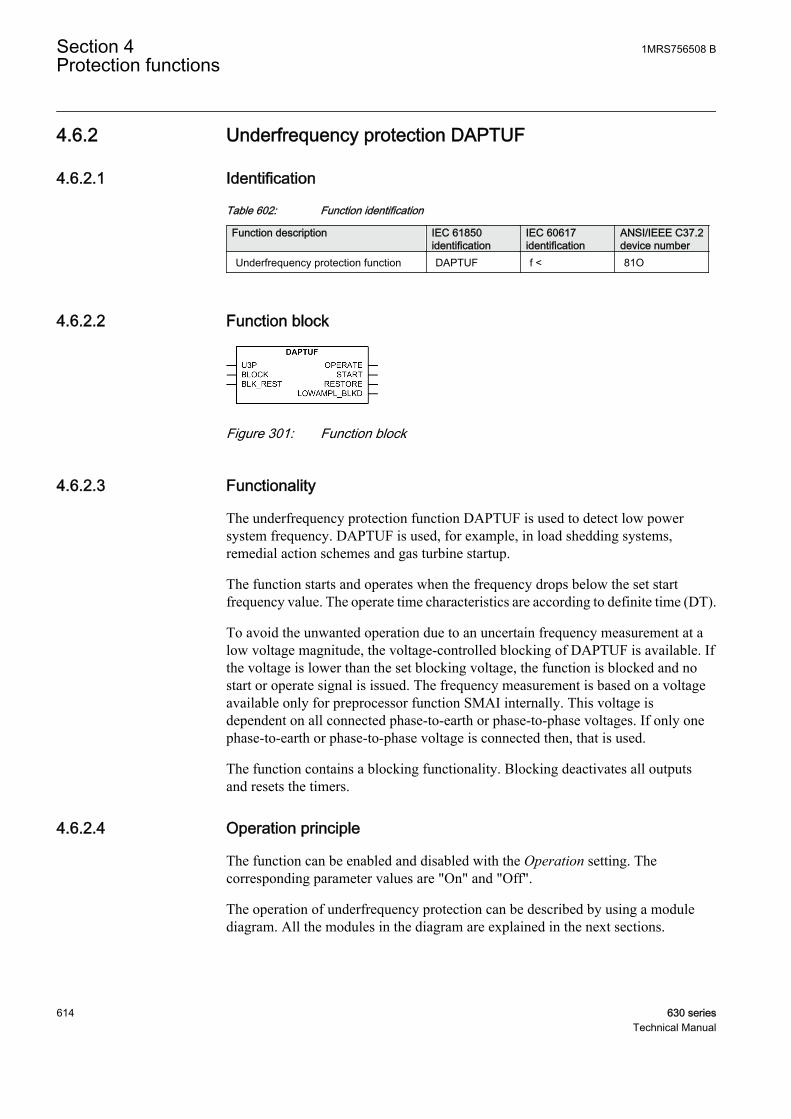
4.6.2 Underfrequency protection DAPTUF
4.6.2.1 Identification
Table 602: Function identification
Function description IEC 61850identification
IEC 60617identification
ANSI/IEEE C37.2device number
Underfrequency protection function DAPTUF f < 81O
4.6.2.2 Function block
GUID-8B24B83B-5226-43CA-B4BC-4E8D926DA380 V1 EN
Figure 301: Function block
4.6.2.3 Functionality
The underfrequency protection function DAPTUF is used to detect low powersystem frequency. DAPTUF is used, for example, in load shedding systems,remedial action schemes and gas turbine startup.
The function starts and operates when the frequency drops below the set startfrequency value. The operate time characteristics are according to definite time (DT).
To avoid the unwanted operation due to an uncertain frequency measurement at alow voltage magnitude, the voltage-controlled blocking of DAPTUF is available. Ifthe voltage is lower than the set blocking voltage, the function is blocked and nostart or operate signal is issued. The frequency measurement is based on a voltageavailable only for preprocessor function SMAI internally. This voltage isdependent on all connected phase-to-earth or phase-to-phase voltages. If only onephase-to-earth or phase-to-phase voltage is connected then, that is used.
The function contains a blocking functionality. Blocking deactivates all outputsand resets the timers.
4.6.2.4 Operation principle
The function can be enabled and disabled with the Operation setting. Thecorresponding parameter values are "On" and "Off".
The operation of underfrequency protection can be described by using a modulediagram. All the modules in the diagram are explained in the next sections.
Section 4 1MRS756508 BProtection functions
614 630 seriesTechnical Manual
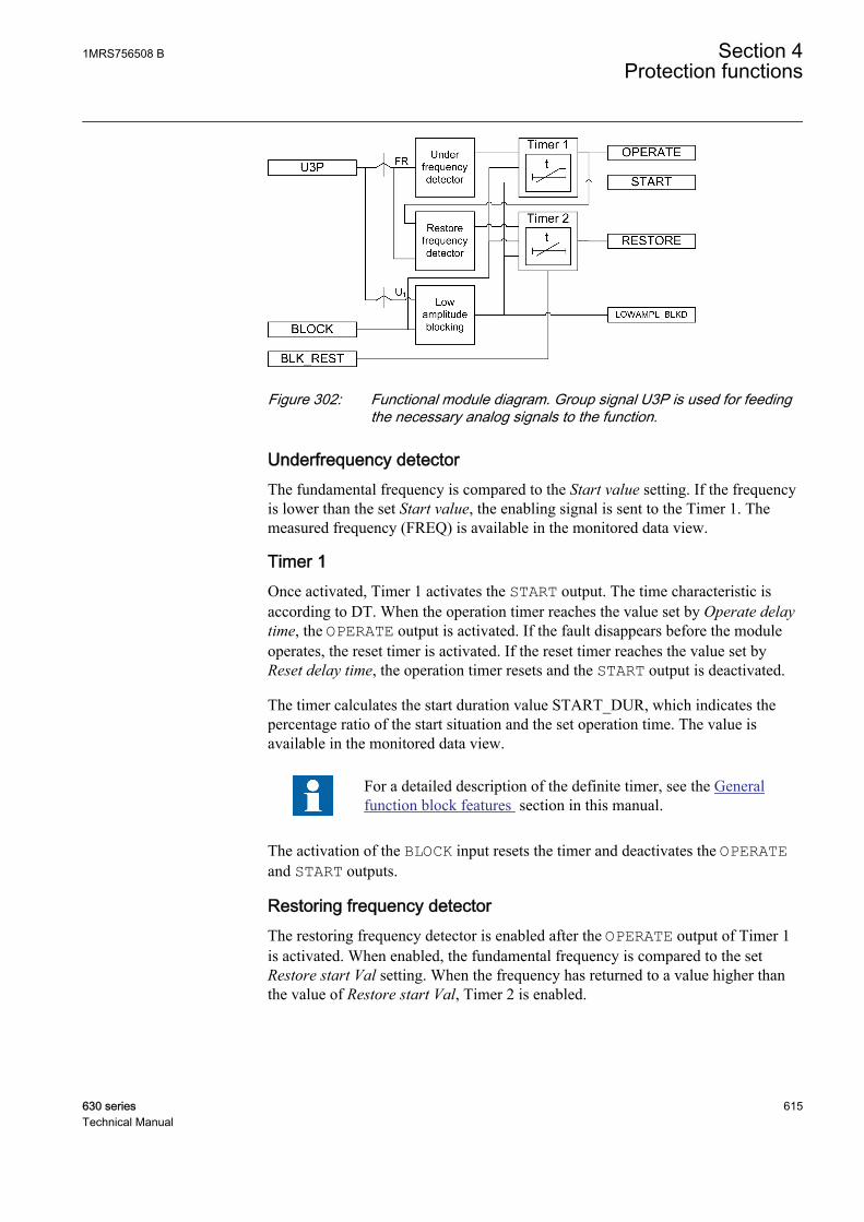
GUID-5B1963AF-7E93-4EF6-AD2D-61E3BCBCFE8F V1 EN
Figure 302: Functional module diagram. Group signal U3P is used for feedingthe necessary analog signals to the function.
Underfrequency detectorThe fundamental frequency is compared to the Start value setting. If the frequencyis lower than the set Start value, the enabling signal is sent to the Timer 1. Themeasured frequency (FREQ) is available in the monitored data view.
Timer 1Once activated, Timer 1 activates the START output. The time characteristic isaccording to DT. When the operation timer reaches the value set by Operate delaytime, the OPERATE output is activated. If the fault disappears before the moduleoperates, the reset timer is activated. If the reset timer reaches the value set byReset delay time, the operation timer resets and the START output is deactivated.
The timer calculates the start duration value START_DUR, which indicates thepercentage ratio of the start situation and the set operation time. The value isavailable in the monitored data view.
For a detailed description of the definite timer, see the Generalfunction block features section in this manual.
The activation of the BLOCK input resets the timer and deactivates the OPERATEand START outputs.
Restoring frequency detectorThe restoring frequency detector is enabled after the OPERATE output of Timer 1is activated. When enabled, the fundamental frequency is compared to the setRestore start Val setting. When the frequency has returned to a value higher thanthe value of Restore start Val, Timer 2 is enabled.
1MRS756508 B Section 4Protection functions
630 series 615Technical Manual
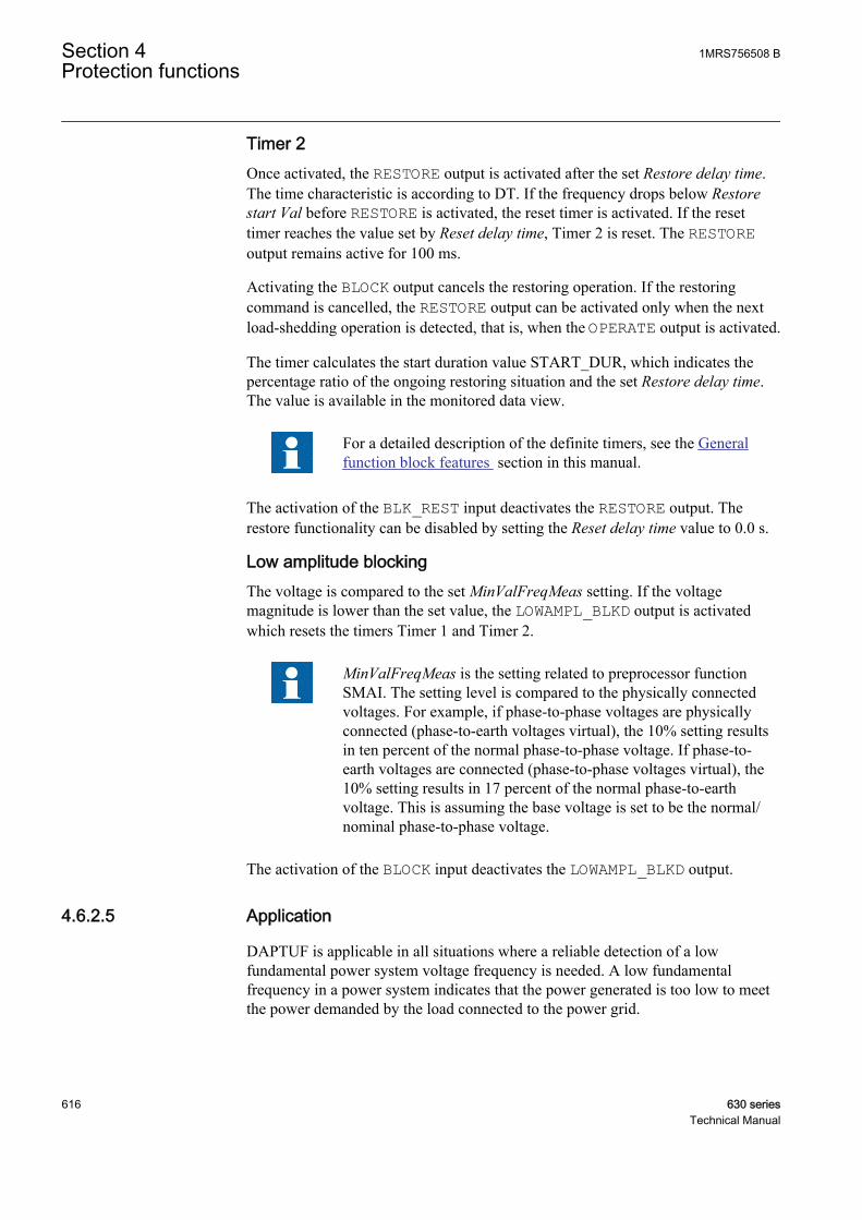
Timer 2Once activated, the RESTORE output is activated after the set Restore delay time.The time characteristic is according to DT. If the frequency drops below Restorestart Val before RESTORE is activated, the reset timer is activated. If the resettimer reaches the value set by Reset delay time, Timer 2 is reset. The RESTOREoutput remains active for 100 ms.
Activating the BLOCK output cancels the restoring operation. If the restoringcommand is cancelled, the RESTORE output can be activated only when the nextload-shedding operation is detected, that is, when the OPERATE output is activated.
The timer calculates the start duration value START_DUR, which indicates thepercentage ratio of the ongoing restoring situation and the set Restore delay time.The value is available in the monitored data view.
For a detailed description of the definite timers, see the Generalfunction block features section in this manual.
The activation of the BLK_REST input deactivates the RESTORE output. Therestore functionality can be disabled by setting the Reset delay time value to 0.0 s.
Low amplitude blockingThe voltage is compared to the set MinValFreqMeas setting. If the voltagemagnitude is lower than the set value, the LOWAMPL_BLKD output is activatedwhich resets the timers Timer 1 and Timer 2.
MinValFreqMeas is the setting related to preprocessor functionSMAI. The setting level is compared to the physically connectedvoltages. For example, if phase-to-phase voltages are physicallyconnected (phase-to-earth voltages virtual), the 10% setting resultsin ten percent of the normal phase-to-phase voltage. If phase-to-earth voltages are connected (phase-to-phase voltages virtual), the10% setting results in 17 percent of the normal phase-to-earthvoltage. This is assuming the base voltage is set to be the normal/nominal phase-to-phase voltage.
The activation of the BLOCK input deactivates the LOWAMPL_BLKD output.
4.6.2.5 Application
DAPTUF is applicable in all situations where a reliable detection of a lowfundamental power system voltage frequency is needed. A low fundamentalfrequency in a power system indicates that the power generated is too low to meetthe power demanded by the load connected to the power grid.
Section 4 1MRS756508 BProtection functions
616 630 seriesTechnical Manual

An underfrequency can occur as a result of an overload of the generators operatingin an isolated system. It can also occur as a result of a serious fault in the powersystem due to the deficit of generation when compared to the load. This can happendue to a fault in the grid system on transmission lines that link two parts of thesystem. As a result, the system splits in two with one part having the excess loadand the other part the corresponding deficit. The frequency dips rapidly in thelatter, resulting in load shedding either by the load shedding relays or by theoperator action. DAPTUF detects such situations and provides an output signalsuitable for load shedding, generator boosting, set point change in sub-transmissionDC systems, gas turbine startup and so on
In some cases, to reduce the power system voltage and the voltage dependent partof the load, shunt reactors are automatically switched on at low frequencies. TheDAPTUF function is very sensitive and accurate and can also be used to alert theoperators that the frequency deviates slightly from the set-point and that manualactions can be sufficient enough to ensure the stability of the system. Theunderfrequency signal is also used for over-excitation detection. This is especiallyimportant for generator step-up transformers during a rollout sequence when thetransformers can be connected to the generator but disconnected from the grid. Ifthe generator is still energized, the system experiences over-excitation due to thelow frequency.
When the system recovers from the disturbance after the action of theunderfrequency protection, the operating frequency recovers to nominal frequency.The load that was shed during the disturbance can be restored.
4.6.2.6 Signals
Table 603: DAPTUF Input signals
Name Type Default DescriptionU3P GROUP
SIGNAL- Three phase group signal for pos seq voltage
inputs
BLOCK BOOLEAN 0 Block of function
BLK_REST BOOLEAN 0 Blocking restore output.
Table 604: DAPTUF Output signals
Name Type DescriptionOPERATE BOOLEAN Operate signal for underfrequency protection
START BOOLEAN Start signal for underfrequency protection
RESTORE BOOLEAN Restore signal for load restoring purposes.
LOWAMPL_BLKD BOOLEAN Blocking indication due to low amplitude.
1MRS756508 B Section 4Protection functions
630 series 617Technical Manual

4.6.2.7 Settings
Table 605: DAPTUF Group settings (basic)
Name Values (Range) Unit Step Default DescriptionStart value 35.00 - 64.00 Hz 0.01 48.80 Frequency setting/start value.
Operate delay time 0.08 - 200.00 s 0.01 0.08 Operate time delay
Table 606: DAPTUF Group settings (advanced)
Name Values (Range) Unit Step Default DescriptionRestore start Val 35.00 - 64.00 Hz 0.01 49.90 Restore frequency setting value
Restore delay time 0.00 - 60.00 s 0.01 0.00 Restore time delay
Table 607: DAPTUF Non group settings (basic)
Name Values (Range) Unit Step Default DescriptionOperation Off
On- - On Operation Off / On
Table 608: DAPTUF Non group settings (advanced)
Name Values (Range) Unit Step Default DescriptionReset delay time 0.00 - 60.00 s 0.01 0.02 Time delay for reset
4.6.2.8 Measured values
Table 609: DAPTUF Measured values
Name Type Default DescriptionBLOCK BOOLEAN 0 Block of function
BLK_REST BOOLEAN 0 Blocking restore output.
4.6.2.9 Monitored data
Table 610: DAPTUF Monitored data
Name Type Values (Range) Unit DescriptionOPERATE BOOLEAN 0=FALSE
1=TRUE- Operate signal for
underfrequencyprotection
START BOOLEAN 0=FALSE1=TRUE
- Start signal forunderfrequencyprotection
RESTORE BOOLEAN 0=FALSE1=TRUE
- Restore signal for loadrestoring purposes.
Table continues on next page
Section 4 1MRS756508 BProtection functions
618 630 seriesTechnical Manual
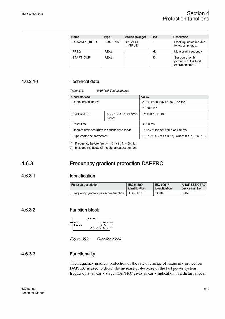
Name Type Values (Range) Unit DescriptionLOWAMPL_BLKD BOOLEAN 0=FALSE
1=TRUE- Blocking indication due
to low amplitude.
FREQ REAL - Hz Measured frequency
START_DUR REAL - % Start duration inpercents of the totaloperation time.
4.6.2.10 Technical data
Table 611: DAPTUF Technical data
Characteristic ValueOperation accuracy At the frequency f = 35 to 66 Hz
± 0.003 Hz
Start time1)2) fFault = 0.99 × set Startvalue
Typical < 190 ms
Reset time < 190 ms
Operate time accuracy in definite time mode ±1.0% of the set value or ±30 ms
Suppression of harmonics DFT: -50 dB at f = n × fn, where n = 2, 3, 4, 5,…
1) Frequency before fault = 1.01 × fn, fn = 50 Hz2) Includes the delay of the signal output contact
4.6.3 Frequency gradient protection DAPFRC
4.6.3.1 Identification
Function description IEC 61850identification
IEC 60617identification
ANSI/IEEE C37.2device number
Frequency gradient protection function DAPFRC df/dt> 81R
4.6.3.2 Function block
GUID-ADC9C642-C93E-46FB-AF8D-B52B6DABBE6E V2 EN
Figure 303: Function block
4.6.3.3 Functionality
The frequency gradient protection or the rate of change of frequency protectionDAPFRC is used to detect the increase or decrease of the fast power systemfrequency at an early stage. DAPFRC gives an early indication of a disturbance in
1MRS756508 B Section 4Protection functions
630 series 619Technical Manual

the system. The function can be used for generation shedding, load shedding andremedial action schemes.
The rate of change of the fundamental frequency is calculated and compared to theset frequency gradient value before the function can start and operate. DAPFRCoperates with the definite time (DT) characteristics. The function can discriminatebetween a positive or negative change in frequency.
A voltage-controlled blocking feature is available to avoid unwanted operation dueto uncertain frequency measurement at a low-voltage magnitude, that is, if thevoltage is lower than the set blocking voltage, the function is blocked. Thefrequency measurement is based on a voltage available only for the preprocessorfunction SMAI internally. This voltage is dependent on all connected phase-to-earth or phase-to-phase voltages. If only one phase-to-earth or phase-to-phasevoltage is connected, that is used.
The function contains a blocking functionality. Blocking deactivates all outputsand resets timers.
4.6.3.4 Operation principle
The function can be enabled and disabled with the Operation setting. Thecorresponding parameter values are "On" and "Off".
The operation of frequency gradient protection can be described by using a modulediagram. All the modules in the diagram are explained in the next sections.
GUID-31BC1CD5-76B7-4130-8E4B-97A44EF28A75 V2 EN
Figure 304: Functional module diagram. Group signal U3P is used for feedingthe necessary analog signals to the function.
Frequency rate of change detectorThe rate of change of the frequency of the positive sequence voltage is calculatedfrom phase-to-phase or phase-to-earth voltages and compared to the set Start value.If the measured frequency rate of change is higher than the set Start value, thetimer module is enabled.
The sign of the set Start value controls DAPFRC to react on a positive change oron a negative change in frequency. A positive setting of Start value sets thefrequency rate of change detector to react on increases of the frequency. Similarly,a negative setting of Start value results in a decrease of frequency.
Section 4 1MRS756508 BProtection functions
620 630 seriesTechnical Manual

Low amplitude blockingThe voltage is compared to the set MinValFreqMeas value. If the voltagemagnitude is detected to be below the set value, the LOWAMPL_BLKD output isactivated, which resets the timer.
MinValFreqMeas is the setting related to Preprocessor functionSMAI. The setting level is compared to the physically connectedvoltages. For example, if phase-to-phase voltages are physicallyconnected (phase-to-earth voltages virtual), the 10% setting resultsin ten percent of the normal phase-to-phase voltage. If phase-to-earth voltages are connected (phase-to-phase voltages virtual), the10% setting results in 17 percent of the normal phase-to-earthvoltage. This is assuming the base voltage is set to be the normal/nominal phase-to-phase voltage.
TimerOnce activated, the timer activates the START output. The time characteristic isaccording to DT. When the operation timer reaches the value set by Operate delaytime, the OPERATE output is activated. If the frequency rate of change conditiondisappears before the module operates, the reset timer is activated. If the reset timerreaches the value set by Reset delay time, the operation timer resets and the STARToutput is deactivated.
The timer calculates the start duration value START_DUR, which indicates thepercentage ratio of the start situation and the set operation time. The value isavailable in the monitored data view.
The activation of the BLOCK input resets the timer and deactivates the START andOPERATE outputs.
4.6.3.5 Application
DAPFRC is applicable in all the situations where the change of the fundamentalpower system voltage frequency should be detected reliably. DAPFRC can be usedfor both increasing and decreasing of the frequencies. This function provides anoutput signal suitable for load shedding, generator shedding, generator boostingand gas turbine startup. The frequency gradient is often used in combination with alow frequency signal, especially in smaller power systems where the loss of a fairlylarge generator requires quick remedial actions to secure the power system'sintegrity. In such situations, load shedding actions are required at a rather highfrequency level, but in combination with a large negative frequency gradient, theunderfrequency protection can be used at a high setting.
1MRS756508 B Section 4Protection functions
630 series 621Technical Manual
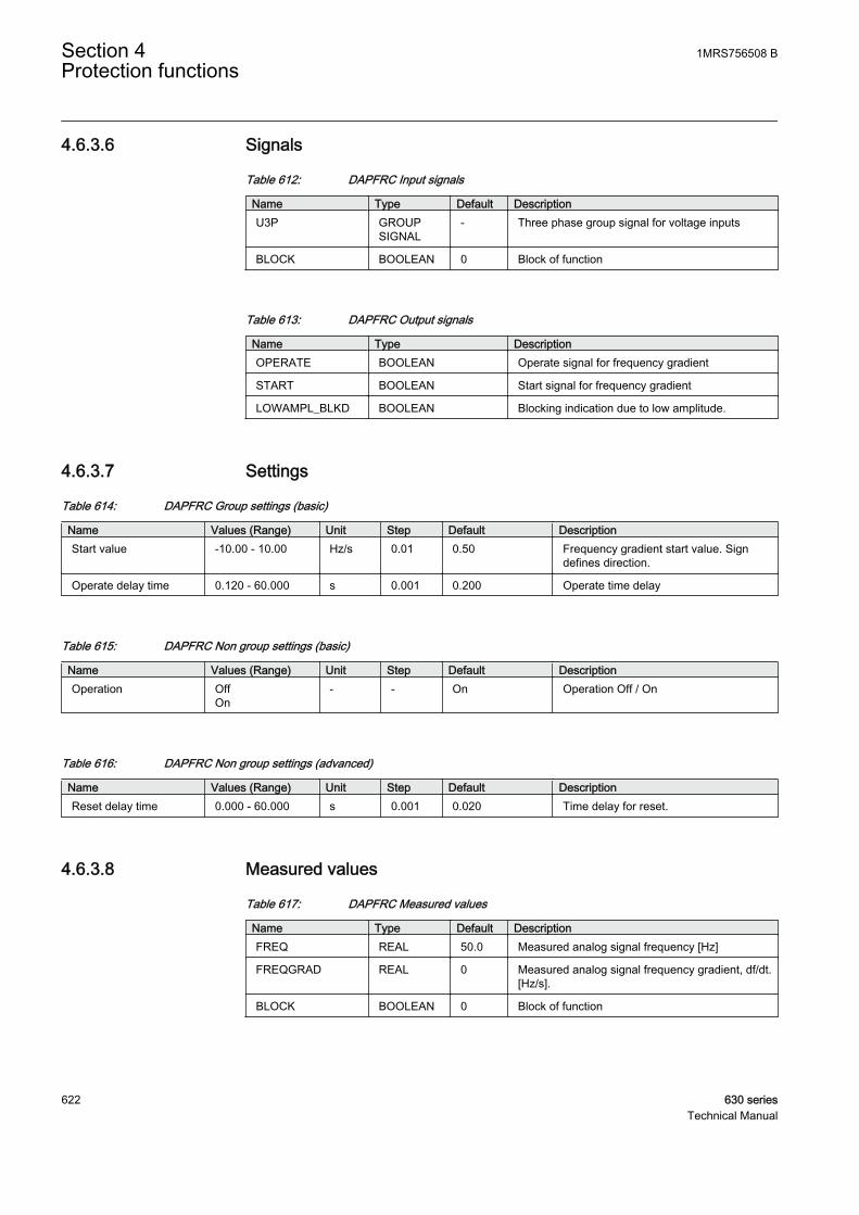
4.6.3.6 Signals
Table 612: DAPFRC Input signals
Name Type Default DescriptionU3P GROUP
SIGNAL- Three phase group signal for voltage inputs
BLOCK BOOLEAN 0 Block of function
Table 613: DAPFRC Output signals
Name Type DescriptionOPERATE BOOLEAN Operate signal for frequency gradient
START BOOLEAN Start signal for frequency gradient
LOWAMPL_BLKD BOOLEAN Blocking indication due to low amplitude.
4.6.3.7 Settings
Table 614: DAPFRC Group settings (basic)
Name Values (Range) Unit Step Default DescriptionStart value -10.00 - 10.00 Hz/s 0.01 0.50 Frequency gradient start value. Sign
defines direction.
Operate delay time 0.120 - 60.000 s 0.001 0.200 Operate time delay
Table 615: DAPFRC Non group settings (basic)
Name Values (Range) Unit Step Default DescriptionOperation Off
On- - On Operation Off / On
Table 616: DAPFRC Non group settings (advanced)
Name Values (Range) Unit Step Default DescriptionReset delay time 0.000 - 60.000 s 0.001 0.020 Time delay for reset.
4.6.3.8 Measured values
Table 617: DAPFRC Measured values
Name Type Default DescriptionFREQ REAL 50.0 Measured analog signal frequency [Hz]
FREQGRAD REAL 0 Measured analog signal frequency gradient, df/dt.[Hz/s].
BLOCK BOOLEAN 0 Block of function
Section 4 1MRS756508 BProtection functions
622 630 seriesTechnical Manual
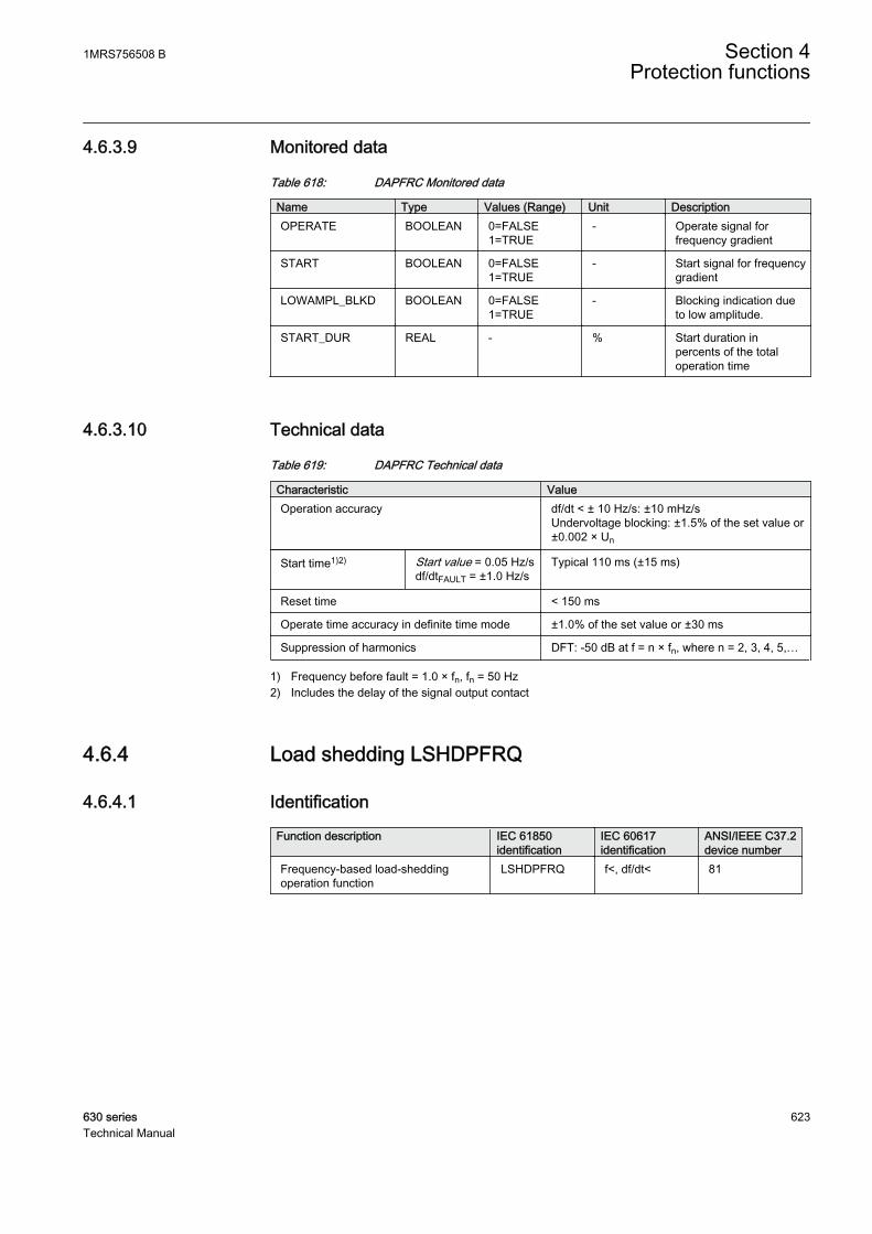
4.6.3.9 Monitored data
Table 618: DAPFRC Monitored data
Name Type Values (Range) Unit DescriptionOPERATE BOOLEAN 0=FALSE
1=TRUE- Operate signal for
frequency gradient
START BOOLEAN 0=FALSE1=TRUE
- Start signal for frequencygradient
LOWAMPL_BLKD BOOLEAN 0=FALSE1=TRUE
- Blocking indication dueto low amplitude.
START_DUR REAL - % Start duration inpercents of the totaloperation time
4.6.3.10 Technical data
Table 619: DAPFRC Technical data
Characteristic ValueOperation accuracy df/dt < ± 10 Hz/s: ±10 mHz/s
Undervoltage blocking: ±1.5% of the set value or±0.002 × Un
Start time1)2) Start value = 0.05 Hz/sdf/dtFAULT = ±1.0 Hz/s
Typical 110 ms (±15 ms)
Reset time < 150 ms
Operate time accuracy in definite time mode ±1.0% of the set value or ±30 ms
Suppression of harmonics DFT: -50 dB at f = n × fn, where n = 2, 3, 4, 5,…
1) Frequency before fault = 1.0 × fn, fn = 50 Hz2) Includes the delay of the signal output contact
4.6.4 Load shedding LSHDPFRQ
4.6.4.1 Identification
Function description IEC 61850identification
IEC 60617identification
ANSI/IEEE C37.2device number
Frequency-based load-sheddingoperation function
LSHDPFRQ f<, df/dt< 81
1MRS756508 B Section 4Protection functions
630 series 623Technical Manual
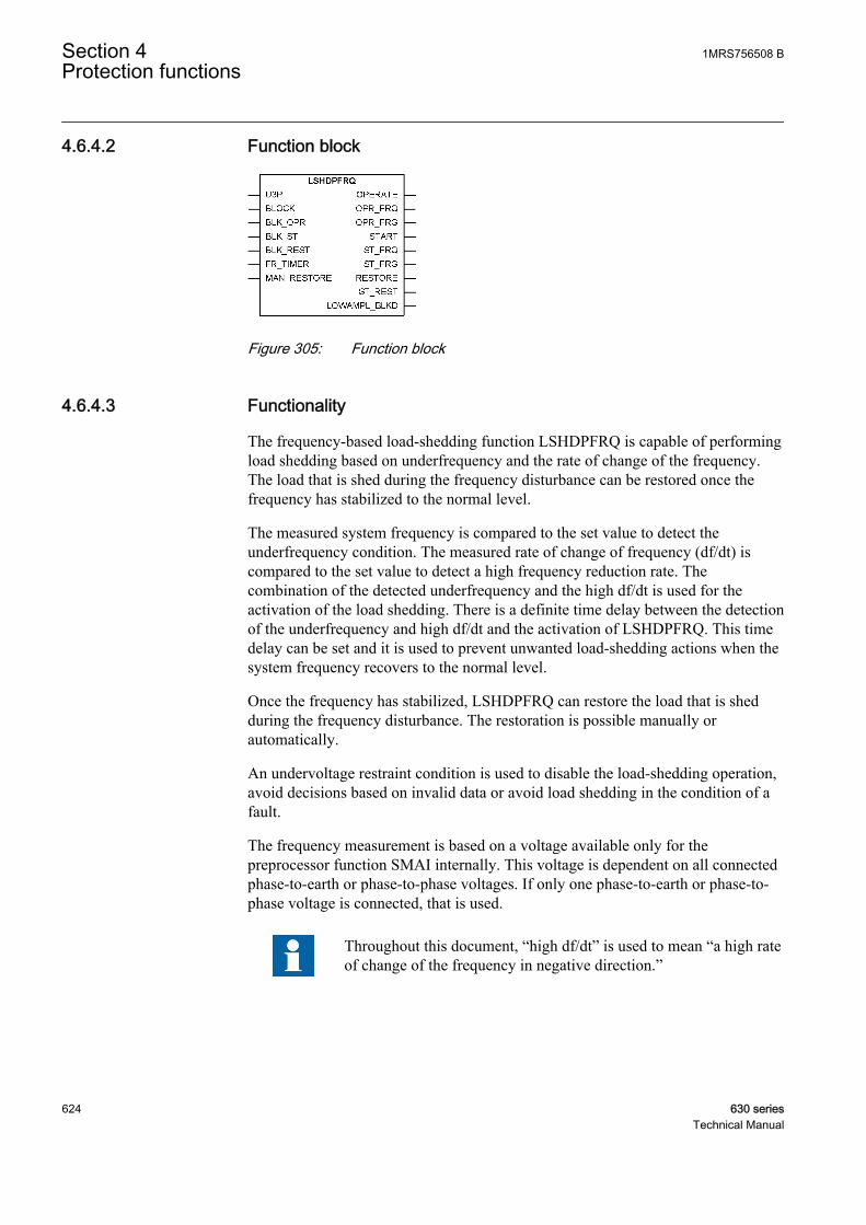
4.6.4.2 Function block
GUID-EF9080CF-8CC2-4140-AF5E-E95F9059B9DF V1 EN
Figure 305: Function block
4.6.4.3 Functionality
The frequency-based load-shedding function LSHDPFRQ is capable of performingload shedding based on underfrequency and the rate of change of the frequency.The load that is shed during the frequency disturbance can be restored once thefrequency has stabilized to the normal level.
The measured system frequency is compared to the set value to detect theunderfrequency condition. The measured rate of change of frequency (df/dt) iscompared to the set value to detect a high frequency reduction rate. Thecombination of the detected underfrequency and the high df/dt is used for theactivation of the load shedding. There is a definite time delay between the detectionof the underfrequency and high df/dt and the activation of LSHDPFRQ. This timedelay can be set and it is used to prevent unwanted load-shedding actions when thesystem frequency recovers to the normal level.
Once the frequency has stabilized, LSHDPFRQ can restore the load that is shedduring the frequency disturbance. The restoration is possible manually orautomatically.
An undervoltage restraint condition is used to disable the load-shedding operation,avoid decisions based on invalid data or avoid load shedding in the condition of afault.
The frequency measurement is based on a voltage available only for thepreprocessor function SMAI internally. This voltage is dependent on all connectedphase-to-earth or phase-to-phase voltages. If only one phase-to-earth or phase-to-phase voltage is connected, that is used.
Throughout this document, “high df/dt” is used to mean “a high rateof change of the frequency in negative direction.”
Section 4 1MRS756508 BProtection functions
624 630 seriesTechnical Manual
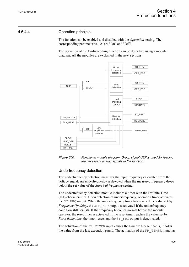
4.6.4.4 Operation principle
The function can be enabled and disabled with the Operation setting. Thecorresponding parameter values are "On" and "Off".
The operation of the load-shedding function can be described using a modulediagram. All the modules are explained in the next sections.
Load shedding control
ST_FRQ
OPR_FRQ
Restore detection
Under frequency detection
df/dt detection
ST_FRG
OPR_FRG
ST_REST
START
U3P
FR_TIMERBLK_ST
BLOCK
BLK_REST
Low amplitude blocking
LOWAMPL_BLKD
OPERATE
RESTOREMAN_RESTORE
BLK_OPR
U1
FR
GRAD
GUID-D6091070-DFC8-4806-96DE-B2B760BCBFFA V3 EN
Figure 306: Functional module diagram. Group signal U3P is used for feedingthe necessary analog signals to the function.
Underfrequency detectionThe underfrequency detection measures the input frequency calculated from thevoltage signal. An underfrequency is detected when the measured frequency dropsbelow the set value of the Start Val frequency setting.
The underfrequency detection module includes a timer with the Definite Time(DT) characteristics. Upon detection of underfrequency, operation timer activatesthe ST_FRQ output. When the underfrequency timer has reached the value set byFrequency Op delay, the OPR_FRQ output is activated if the underfrequencycondition still persists. If the frequency becomes normal before the moduleoperates, the reset timer is activated. If the reset timer reaches the value set byReset delay time, the timer resets and the ST_FRQ output is deactivated.
The activation of the FR_TIMER input causes the timer to freeze, that is, it holdsthe value from the last execution round. The activation of the FR_TIMER input has
1MRS756508 B Section 4Protection functions
630 series 625Technical Manual

no effect on the operation of the ST_FRQ output. However, the activation of theOPR_FRQ output is delayed by the time for which the FR_TIMER input remainshigh.
The timer is reset by the activation of the BLOCK input. It is possible to block theindividual start and operate outputs ST_FRQ and OPR_FRQ by the activation ofthe BLK_ST and BLK_OPR inputs respectively.
df/dt detectionThe df/dt detection measures the input frequency calculated from the voltage signaland calculates its gradient. A high df/dt condition is detected by comparing thegradient to the Start value df/dt setting. The Start value df/dt setting is set in termsof positive values. The df/dt detection is activated when the frequency gradientdecreases at a faster rate than the set value of Start value df/dt.
The df/dt detection module includes a timer with the DT characteristics. Upondetection of df/dt, operation timer activates the ST_FRG output. When the timerhas reached the value set by Df/dt operate delay, the OPR_FRG output is activatedif the df/dt condition still persists. If df/dt becomes normal before the moduleoperates, the reset timer is activated. If the reset timer reaches the value of theReset delay time setting, the timer resets and the ST_FRG output is deactivated.
Load-shedding controlThe way of load shedding, that is, whether to operate based on underfrequency orhigh df/dt or both, is defined with the Load shed mode user setting. The validoperation modes for the Load shed mode settings are "Freq<", "Freq< AND df/dt"and "Freq< OR df/dt".
Once the selected operation mode conditions are satisfied, the START andOPERATE output signals are activated.
When the START output is active, the percentage of the elapsed delay time can bemonitored through START_DUR which is available as monitored data.
Section 4 1MRS756508 BProtection functions
626 630 seriesTechnical Manual
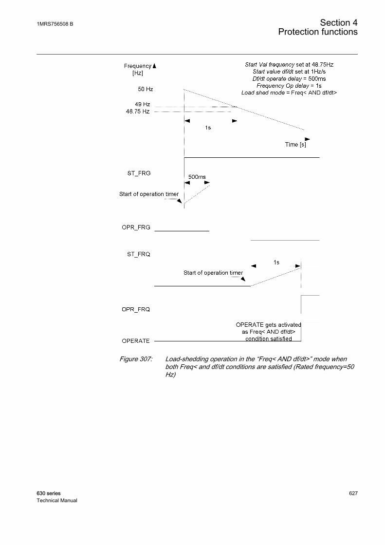
GUID-EA561B7D-2C93-4FE8-B188-D2EA281DA934 V1 EN
Figure 307: Load-shedding operation in the “Freq< AND df/dt>” mode whenboth Freq< and df/dt conditions are satisfied (Rated frequency=50Hz)
1MRS756508 B Section 4Protection functions
630 series 627Technical Manual

GUID-5C98E80A-534D-488B-855B-D5D9F1E4FE40 V1 EN
Figure 308: Load-shedding operation in the “Freq< AND df/dt>” mode whenonly the df/dt condition is satisfied (Rated frequency=50 Hz)
Restore detectionIf after the activation of the OPERATE input the frequency recovers to a levelabove the Restore start Val setting, the RESTORE signal output is activated. TheRESTORE output remains active for a 100 ms. The Restore mode setting is used toselect the restoring mode to be "Disabled", "Auto" or "Manual".
Section 4 1MRS756508 BProtection functions
628 630 seriesTechnical Manual
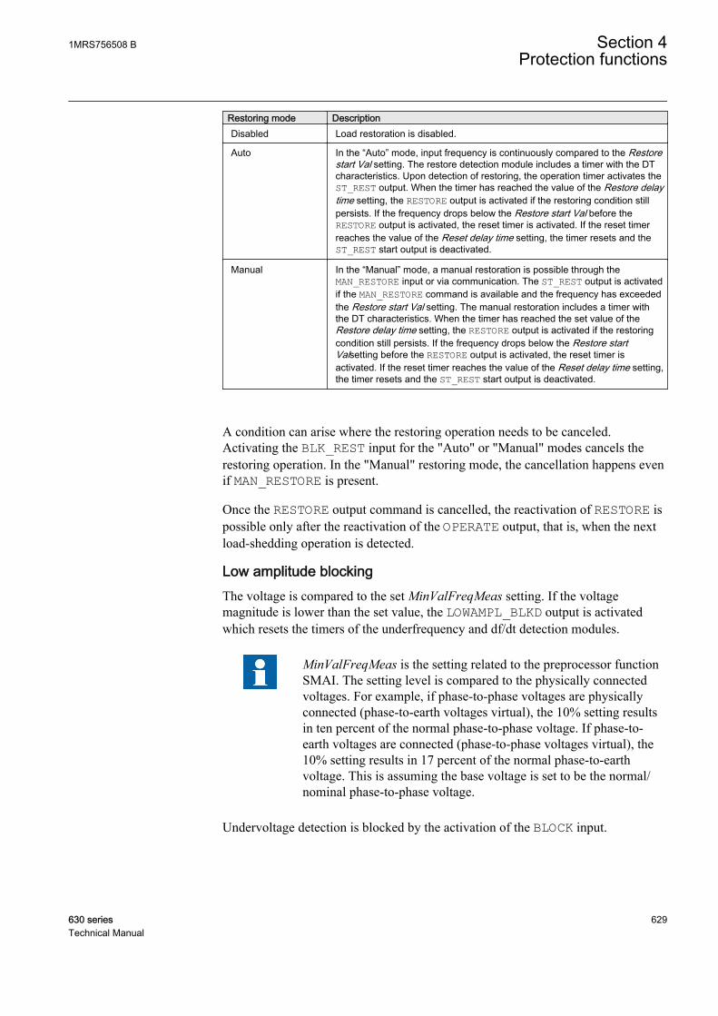
Restoring mode DescriptionDisabled Load restoration is disabled.
Auto In the “Auto” mode, input frequency is continuously compared to the Restorestart Val setting. The restore detection module includes a timer with the DTcharacteristics. Upon detection of restoring, the operation timer activates theST_REST output. When the timer has reached the value of the Restore delaytime setting, the RESTORE output is activated if the restoring condition stillpersists. If the frequency drops below the Restore start Val before theRESTORE output is activated, the reset timer is activated. If the reset timerreaches the value of the Reset delay time setting, the timer resets and theST_REST start output is deactivated.
Manual In the “Manual” mode, a manual restoration is possible through theMAN_RESTORE input or via communication. The ST_REST output is activatedif the MAN_RESTORE command is available and the frequency has exceededthe Restore start Val setting. The manual restoration includes a timer withthe DT characteristics. When the timer has reached the set value of theRestore delay time setting, the RESTORE output is activated if the restoringcondition still persists. If the frequency drops below the Restore startValsetting before the RESTORE output is activated, the reset timer isactivated. If the reset timer reaches the value of the Reset delay time setting,the timer resets and the ST_REST start output is deactivated.
A condition can arise where the restoring operation needs to be canceled.Activating the BLK_REST input for the "Auto" or "Manual" modes cancels therestoring operation. In the "Manual" restoring mode, the cancellation happens evenif MAN_RESTORE is present.
Once the RESTORE output command is cancelled, the reactivation of RESTORE ispossible only after the reactivation of the OPERATE output, that is, when the nextload-shedding operation is detected.
Low amplitude blockingThe voltage is compared to the set MinValFreqMeas setting. If the voltagemagnitude is lower than the set value, the LOWAMPL_BLKD output is activatedwhich resets the timers of the underfrequency and df/dt detection modules.
MinValFreqMeas is the setting related to the preprocessor functionSMAI. The setting level is compared to the physically connectedvoltages. For example, if phase-to-phase voltages are physicallyconnected (phase-to-earth voltages virtual), the 10% setting resultsin ten percent of the normal phase-to-phase voltage. If phase-to-earth voltages are connected (phase-to-phase voltages virtual), the10% setting results in 17 percent of the normal phase-to-earthvoltage. This is assuming the base voltage is set to be the normal/nominal phase-to-phase voltage.
Undervoltage detection is blocked by the activation of the BLOCK input.
1MRS756508 B Section 4Protection functions
630 series 629Technical Manual

Blocking logicThere are three operation modes in the blocking functionality. The operation modesare controlled by the BLOCK input and the Configuration/System/Blocking modeglobal setting that selects the blocking mode. The BLOCK input can be controlledwith a binary input, a horizontal communication input or an internal signal of theIED program. The influence of the BLOCK input signal activation is preselectedwith the Blocking mode global setting.
The Blocking mode setting has three blocking methods. In the "Freeze timers"mode, the operate timer is frozen to the prevailing value. In the "Block all" mode,the whole function is blocked and the timers are reset. In the "Block OPERATEoutput" mode, the function operates normally but the OPERATE, OPR_FRQ andOPR_FRG outputs are not activated.
4.6.4.5 Application
An AC power system operates at a defined rated frequency. The nominal frequencyin most systems in the world is 50 Hz or 60 Hz. The nominal frequency is such thatthe operating frequency value remains approximately at the nominal frequencyvalue by a small margin. The safe margin of operation is usually less than ±0.5 Hz.The system frequency stability is one of the main concerns in the transmission anddistribution network operation and control. To protect the frequency-sensitiveelectrical equipment in the network, departure from the allowed band for safeoperation should be inhibited.
Any increase in the connected load requires an increase in the real powergeneration to maintain the system frequency. Frequency variations form wheneverthere are system conditions that result in an unbalance between the generation andload. The rate of change of the frequency represents the magnitude of thedifference between the load and generation. A reduction in frequency and anegative rate of change of the frequency are observed when the load is greater thanthe generation, and an increase in the frequency along with a positive rate ofchange of the frequency are observed if the generation is greater than the load. Therate of change of the frequency is used for a faster decision of load shedding. In anunderfrequency situation, the load shedding trips out the unimportant loads tostabilize the network. Thus, loads are normally prioritized so that the less importantloads are shed before the important loads.
During the operation of some of the protective schemes or other systememergencies, the power system is divided into small islands. There is always a load- generation imbalance in such islands that leads to a deviation in the operatingfrequency from the nominal frequency. This off-nominal frequency operation isharmful to power system components like turbines and motors. Therefore, suchsituation must be prevented from continuing. The frequency-based load-sheddingscheme should be applied to restore the operation of the system to normalfrequency. This is achieved by quickly creating the load - generation balance bydisconnecting the load.
Section 4 1MRS756508 BProtection functions
630 630 seriesTechnical Manual
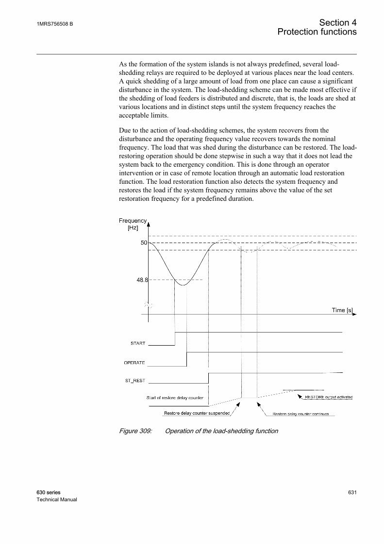
As the formation of the system islands is not always predefined, several load-shedding relays are required to be deployed at various places near the load centers.A quick shedding of a large amount of load from one place can cause a significantdisturbance in the system. The load-shedding scheme can be made most effective ifthe shedding of load feeders is distributed and discrete, that is, the loads are shed atvarious locations and in distinct steps until the system frequency reaches theacceptable limits.
Due to the action of load-shedding schemes, the system recovers from thedisturbance and the operating frequency value recovers towards the nominalfrequency. The load that was shed during the disturbance can be restored. The load-restoring operation should be done stepwise in such a way that it does not lead thesystem back to the emergency condition. This is done through an operatorintervention or in case of remote location through an automatic load restorationfunction. The load restoration function also detects the system frequency andrestores the load if the system frequency remains above the value of the setrestoration frequency for a predefined duration.
GUID-8FFC488C-BD1F-467C-8540-47606B22AED1 V1 EN
Figure 309: Operation of the load-shedding function
1MRS756508 B Section 4Protection functions
630 series 631Technical Manual

Power system protection by load sheddingThe decision on the amount of load that is required to be shed is taken through themeasurement of frequency and the rate of change of frequency (df/dt). At a singlelocation, many steps of load shedding can be defined based on different criteria ofthe frequency and df/dt. Typically, the load shedding is performed in six or foursteps with each shedding increasing the portion of load from five to twenty-fivepercent of full load within a few seconds. After every shedding, the systemfrequency is read back and further shedding actions are taken only if necessary. Inorder to take the effect of any transient, a sufficient time delay should be set.
The value of the setting has to be well below the lowest occurring normalfrequency and well above the lowest acceptable frequency of the system. Thesetting level, the number of steps and the distance between two steps (in time or infrequency) depend on the characteristics of the power system under consideration.The size of the largest loss of generation compared to the size of the power systemis a critical parameter. In large systems, the load shedding can be set at a highfrequency level and the time delay is normally not critical. In small systems, thefrequency start level has to be set at a low value and the time delay must be short.
If a moderate system operates at 50 Hz, an underfrequency should be set fordifferent steps from 49.2 Hz to 47.5 Hz in steps of 0.3 – 0.4 Hz. The operating timefor the underfrequency can be set from a few seconds to a few fractions of a secondstepwise from a higher frequency value to a lower frequency value.
Table 620: Setting for a five-step underfrequency operation
Load-shedding steps Start value Freq setting Frequency Op delay setting1 0.984 · Fn (49.2 Hz) 45000 ms
2 0.978 · Fn (49.2 Hz) 30000 ms
3 0.968 · Fn (49.2 Hz) 15000 ms
4 0.958 · Fn (49.2 Hz) 5000ms
5 0.950 · Fn (49.2 Hz) 500 ms
The rate of change of frequency function is not instantaneous since the functionneeds time to supply a stable value. It is recommended to have a time delay longenough to take care of the signal noise.
Small industrial systems can experience the rate of change of frequency as large as5 Hz/s due to a single event. Even large power systems can form small islands witha large imbalance between the load and generation when severe faults orcombinations of faults are cleared. Up to 3 Hz/s has been experienced when a smallisland becomes isolated from a large system. For normal severe disturbances inlarge power systems, the rate of change of the frequency is much less, often just afraction of 1.0 Hz/s.
Similarly, the setting for df/dt can be from 0.1 Hz/s to 1.2 Hz/s in steps of 0.1 Hz/sto 0.3 Hz/s for large distributed power networks, with the operating time varying
Section 4 1MRS756508 BProtection functions
632 630 seriesTechnical Manual
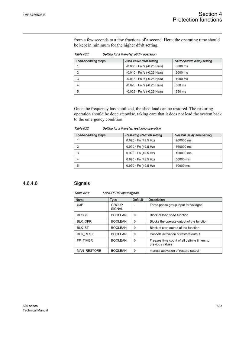
from a few seconds to a few fractions of a second. Here, the operating time shouldbe kept in minimum for the higher df/dt setting.
Table 621: Setting for a five-step df/dt< operation
Load-shedding steps Start value df/dt setting Df/dt operate delay setting1 -0.005 · Fn /s (-0.25 Hz/s) 8000 ms
2 -0.010 · Fn /s (-0.25 Hz/s) 2000 ms
3 -0.015 · Fn /s (-0.25 Hz/s) 1000 ms
4 -0.020 · Fn /s (-0.25 Hz/s) 500 ms
5 -0.025 · Fn /s (-0.25 Hz/s) 250 ms
Once the frequency has stabilized, the shed load can be restored. The restoringoperation should be done stepwise, taking care that it does not lead the system backto the emergency condition.
Table 622: Setting for a five-step restoring operation
Load-shedding steps Restoring start Val setting Restore delay time setting1 0.990 · Fn (49.5 Hz) 200000 ms
2 0.990 · Fn (49.5 Hz) 160000 ms
3 0.990 · Fn (49.5 Hz) 100000 ms
4 0.990 · Fn (49.5 Hz) 50000 ms
5 0.990 · Fn (49.5 Hz) 10000 ms
4.6.4.6 Signals
Table 623: LSHDPFRQ Input signals
Name Type Default DescriptionU3P GROUP
SIGNAL- Three phase group input for voltages
BLOCK BOOLEAN 0 Block of load shed function
BLK_OPR BOOLEAN 0 Blocks the operate output of the function
BLK_ST BOOLEAN 0 Block of start output of the function
BLK_REST BOOLEAN 0 Cancels activation of restore output
FR_TIMER BOOLEAN 0 Freezes time count of all definite timers toprevious values
MAN_RESTORE BOOLEAN 0 manual activation of restore output
1MRS756508 B Section 4Protection functions
630 series 633Technical Manual

Table 624: LSHDPFRQ Output signals
Name Type DescriptionOPERATE BOOLEAN Operation of load shedding
OPR_FRQ BOOLEAN Operate signal for under frequency
OPR_FRG BOOLEAN Operate signal for high df/dt
START BOOLEAN General start. Under frequency or high df/dtdetected
ST_FRQ BOOLEAN Pick-Up signal for under frequency detection
ST_FRG BOOLEAN Pick-Up signal for high df/dt detection
RESTORE BOOLEAN Restore signal for load restoring purposes
ST_REST BOOLEAN Restore frequency attained and restore timerstarted
LOWAMPL_BLKD BOOLEAN Signal indicating internal blocking due to lowamplitude
4.6.4.7 Settings
Table 625: LSHDPFRQ Group settings (basic)
Name Values (Range) Unit Step Default DescriptionLoad shed mode Freq<
freq< AND dfdt>Freq< OR dfdt>
- - Freq< Set the operation mode for loadshedding function
Restore mode DisabledAutoManual
- - Disabled Mode of operation of restore functionality
Start Val frequency 35.00 - 60.00 Hz 0.01 48.80 Frequency setting/start value
Start value df/dt 0.10 - 10.00 Hz/s 0.01 0.50 Setting of frequency gradient for df/dtdetection
Restore start Val 45.00 - 60.00 Hz 0.01 49.90 Restore frequency setting value
Frequency Op delay 0.08 - 200.00 s 0.01 0.08 Time Delay to operate for underfrequency stage
Df/dt operate delay 0.12 - 60.00 s 0.01 0.20 Time Delay to operate for df/dt stage
Restore delay time 0.17 - 60.00 s 0.01 0.30 Time Delay to restore
Table 626: LSHDPFRQ Non group settings (basic)
Name Values (Range) Unit Step Default DescriptionOperation Off
On- - On Operation off/On
Table 627: LSHDPFRQ Non group settings (advanced)
Name Values (Range) Unit Step Default DescriptionReset delay time 0.00 - 60.00 s 0.01 0.05 Time Delay after which the definite
timers will reset
Section 4 1MRS756508 BProtection functions
634 630 seriesTechnical Manual

4.6.4.8 Measured values
Table 628: LSHDPFRQ Measured values
Name Type Default DescriptionBLOCK BOOLEAN 0 Block of load shed function
BLK_OPR BOOLEAN 0 Blocks the operate output of the function
BLK_ST BOOLEAN 0 Block of start output of the function
BLK_REST BOOLEAN 0 Cancels activation of restore output
FR_TIMER BOOLEAN 0 Freezes time count of all definite timers toprevious values
MAN_RESTORE BOOLEAN 0 manual activation of restore output
4.6.4.9 Monitored data
Table 629: LSHDPFRQ Monitored data
Name Type Values (Range) Unit DescriptionOPERATE BOOLEAN 0=FALSE
1=TRUE- Operation of load
shedding
OPR_FRQ BOOLEAN 0=FALSE1=TRUE
- Operate signal for underfrequency
OPR_FRG BOOLEAN 0=FALSE1=TRUE
- Operate signal for high df/dt
START BOOLEAN 0=FALSE1=TRUE
- General start. Underfrequency or high df/dtdetected
ST_FRQ BOOLEAN 0=FALSE1=TRUE
- Pick-Up signal for underfrequency detection
ST_FRG BOOLEAN 0=FALSE1=TRUE
- Pick-Up signal for high df/dt detection
RESTORE BOOLEAN 0=FALSE1=TRUE
- Restore signal for loadrestoring purposes
ST_REST BOOLEAN 0=FALSE1=TRUE
- Restore frequencyattained and restoretimer started
LOWAMPL_BLKD BOOLEAN 0=FALSE1=TRUE
- Signal indicating internalblocking due to lowamplitude
START_DUR REAL - % Start duration inpercents of the totaloperation time
1MRS756508 B Section 4Protection functions
630 series 635Technical Manual

4.6.4.10 Technical data
Table 630: LSHDPFRQ Technical data
Characteristic ValueOperation accuracy At the frequency f = 35 to 66 Hz
± 0.003 Hz
Start time1)2) Load shed mode Typical 175 ms (±15ms)Typical 250 ms (±15ms)
Freq<: fFault = 0.80 ×set Start valuefreq< AND dfdt>: df/dt= 0.3 Hz/s
Reset time < 190 ms
Operate time accuracy in definite time mode ±1.0% of the set value or ±30 ms
Suppression of harmonics DFT: -50 dB at f = n × fn, where n = 2, 3, 4, 5,…
1) Frequency before fault = 1.2 × fn, fn = 50 Hz2) Includes the delay of the signal output contact
4.7 Impedance protection
4.7.1 Distance protection DSTPDIS
4.7.1.1 Identification
Function description IEC 61850identification
IEC 60617identification
ANSI/IEEE C37.2device number
Three-phase distance protectionfunction
DSTPDIS Z< 21, 21P, 21N
Section 4 1MRS756508 BProtection functions
636 630 seriesTechnical Manual
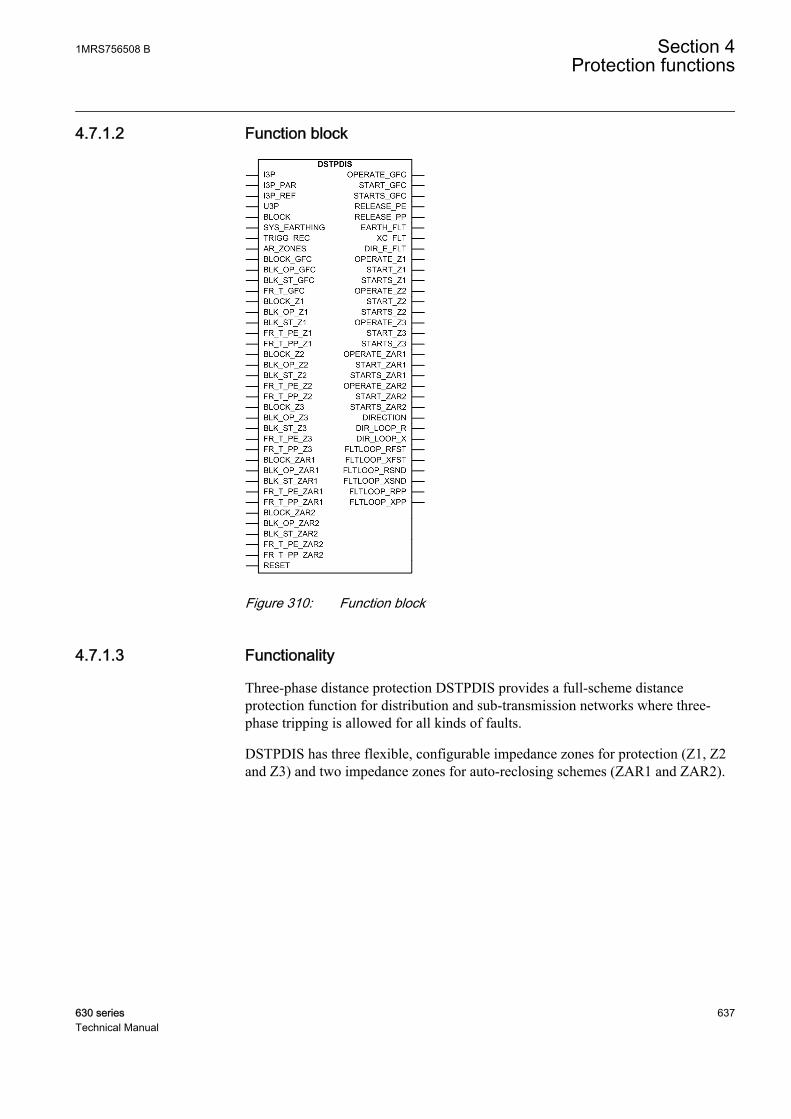
4.7.1.2 Function block
GUID-6231ECEF-A728-430D-A88C-F26653CA4E1E V1 EN
Figure 310: Function block
4.7.1.3 Functionality
Three-phase distance protection DSTPDIS provides a full-scheme distanceprotection function for distribution and sub-transmission networks where three-phase tripping is allowed for all kinds of faults.
DSTPDIS has three flexible, configurable impedance zones for protection (Z1, Z2and Z3) and two impedance zones for auto-reclosing schemes (ZAR1 and ZAR2).
1MRS756508 B Section 4Protection functions
630 series 637Technical Manual
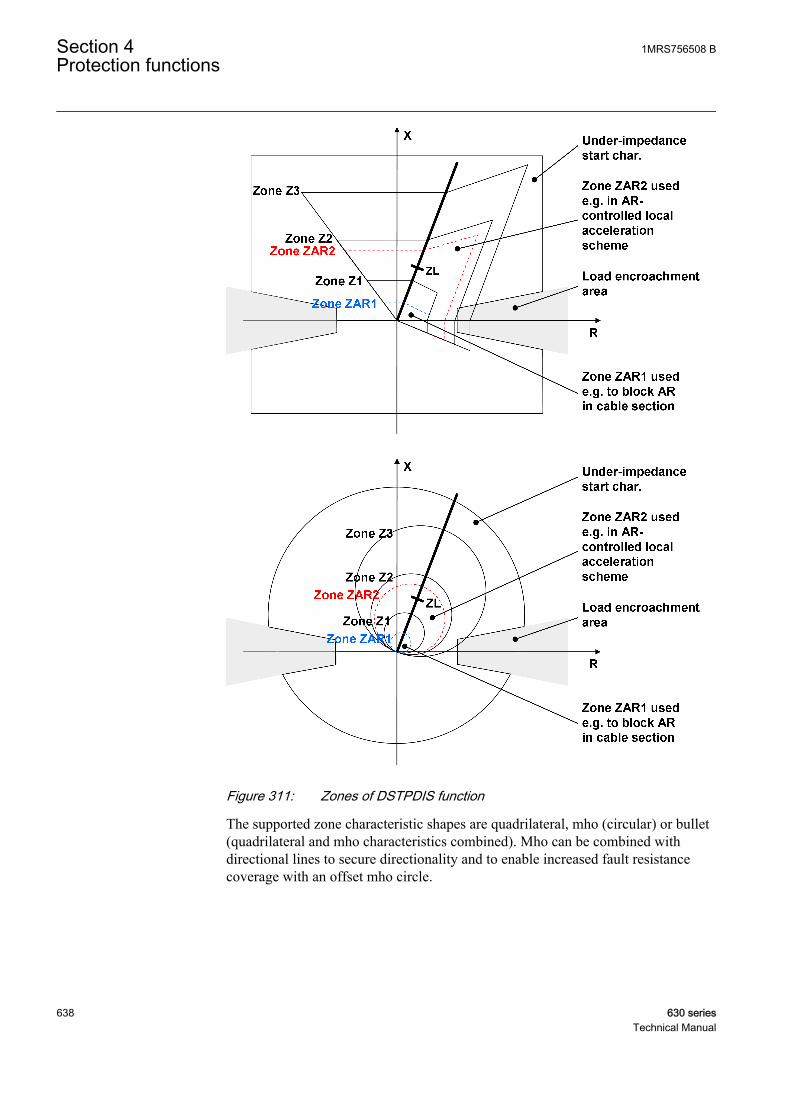
GUID-F07C2455-01C2-429B-BB8F-07483C4A9AA0 V1 EN
Figure 311: Zones of DSTPDIS function
The supported zone characteristic shapes are quadrilateral, mho (circular) or bullet(quadrilateral and mho characteristics combined). Mho can be combined withdirectional lines to secure directionality and to enable increased fault resistancecoverage with an offset mho circle.
Section 4 1MRS756508 BProtection functions
638 630 seriesTechnical Manual
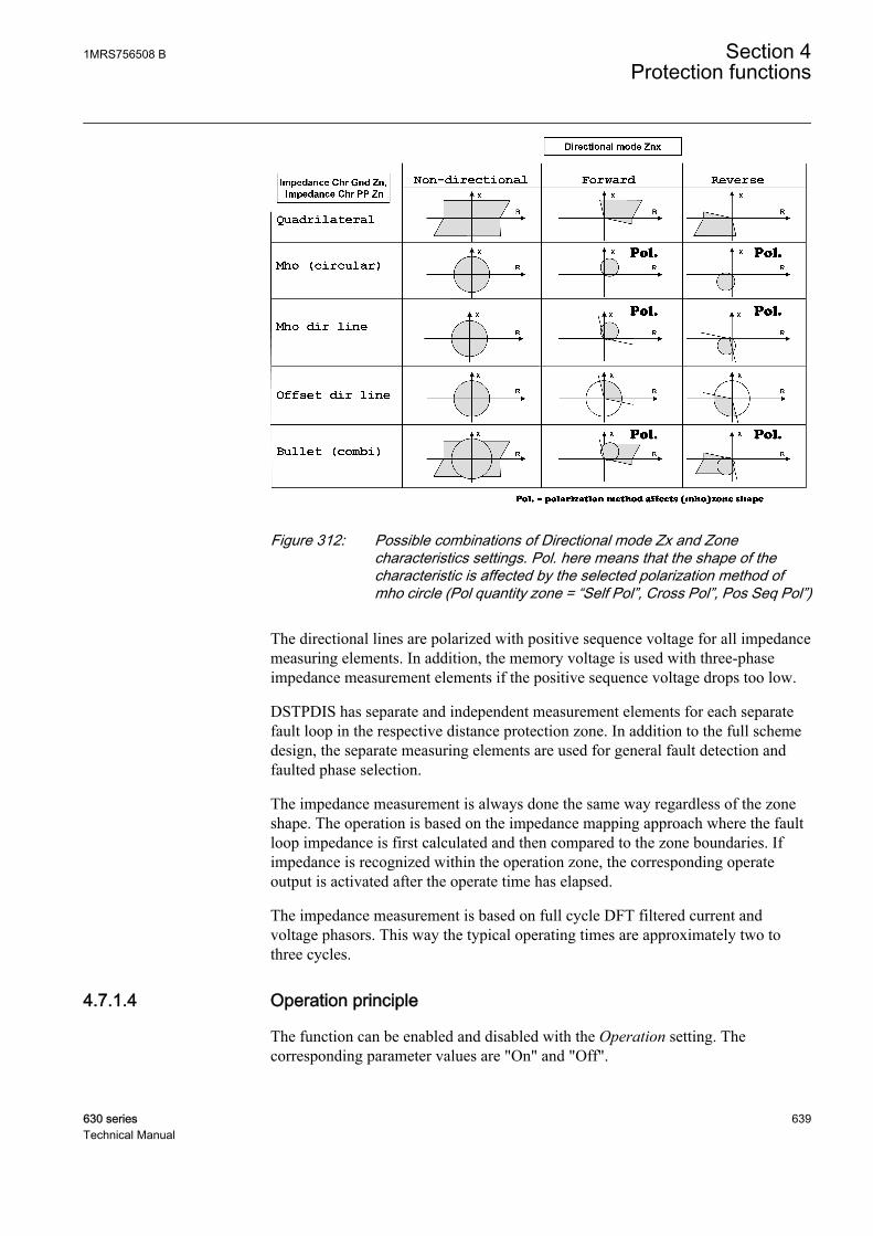
GUID-C075CCAC-AC5E-4793-B0DB-BCE9ACF7A7FC V1 EN
Figure 312: Possible combinations of Directional mode Zx and Zonecharacteristics settings. Pol. here means that the shape of thecharacteristic is affected by the selected polarization method ofmho circle (Pol quantity zone = “Self Pol”, Cross Pol”, Pos Seq Pol”)
The directional lines are polarized with positive sequence voltage for all impedancemeasuring elements. In addition, the memory voltage is used with three-phaseimpedance measurement elements if the positive sequence voltage drops too low.
DSTPDIS has separate and independent measurement elements for each separatefault loop in the respective distance protection zone. In addition to the full schemedesign, the separate measuring elements are used for general fault detection andfaulted phase selection.
The impedance measurement is always done the same way regardless of the zoneshape. The operation is based on the impedance mapping approach where the faultloop impedance is first calculated and then compared to the zone boundaries. Ifimpedance is recognized within the operation zone, the corresponding operateoutput is activated after the operate time has elapsed.
The impedance measurement is based on full cycle DFT filtered current andvoltage phasors. This way the typical operating times are approximately two tothree cycles.
4.7.1.4 Operation principle
The function can be enabled and disabled with the Operation setting. Thecorresponding parameter values are "On" and "Off".
1MRS756508 B Section 4Protection functions
630 series 639Technical Manual

The function consists of sub-functions which are described in the next sections.
GUID-EEDE16EA-76C4-45DD-B99D-0763E18EBD98 V1 EN
Figure 313: Main functionality of DSTPDIS
All outputs and the operation of all sub-functions can be blocked with the BLOCKbinary input signal. In addition, it resets the timers.
Earth-fault detection functionThe recognition of an earth fault is an important part in identifying the correct faulttype. This information is used in faulted loop (phase) selection to release thecorrect impedance-measuring elements. The earth-fault recognition is alwaysrequired to release the phase-to-earth impedance-measuring elements.
The earth-fault detection is indicated with the EARTH_FLT output. The earth-faultdetection criterion can be defined with the EF detection Mod GFC setting. Thefundamental criterion is based on the residual current. The residual voltage andreference neutral current, measured from the transformer neutral point, can be usedfor the earth-fault detection criteria.
Table 631: Selection of earth-fault detection criteria
Setting Enumerator nameEF detection Mod GFC • Io
• Io OR Uo• Io AND Uo• Io AND Ioref
If the residual current Io is derived from the phase currents either by the summationconnection of CTs, that is, the Holmgreen connection, or by internally summingthe phase currents, there is a risk of a false earth-fault detection due to apparentresidual current from the current transformer errors. This risk can be eliminatedusing a stabilized residual current measurement. The stabilization is enabled by
Section 4 1MRS756508 BProtection functions
640 630 seriesTechnical Manual

setting the EF Det neutral A GFC setting to "Virtual". The stabilization increasesthe residual current Gnd Op current GFC threshold setting when the maximumphase current exceeds the base current. The increase is defined with the Stab slope1 GFC setting. The apparent residual current may exist during short circuits and ininrush current situations if the CTs saturate partially. The earth-fault detectionfunction takes the CT saturation into account with additional stabilization settingsGnd Op current 2 GFC, A Ph Stab value GFC and Stab slope 2 GFC.
Setting EF Det neutral A GFC to "Measured" disables the stabilization of theresidual current measurement and should be used only when the residual current ismeasured with a cable current transformer. The residual current threshold settingfor earth-fault detection is Gnd Op current GFC. If residual current is measuredfrom a transformer neural point, Gnd Op A Ref GFC is used. This is valid when thesetting EF detection mod GFC is "Io AND Ioref".
GUID-79F7EA98-29B1-4D43-AABA-E42939ECFB71 V1 EN
Figure 314: Stabilized residual current measurement for earth-fault detection
The residual voltage can also be used as a complementary criterion for earth-faultdetection. This is valid when the setting EF detection Mod GFC is "Io OR Uo" orEF detection Mod GFC is "Io AND Uo". The threshold setting for the residualvoltage is Gnd Str voltage GFC.
Directional function for earth faultsIn low-impedance earthed networks, when the System grounding GFC setting is setto "Low impedance", the earth-fault detection function can be optionallysupervised by a directional function which can be enabled with the Dir Mode EFGFC setting. If Dir mode EF GFC is set to "Forward" or "Reverse", the earth-faultdetection function becomes directional. In this case, in addition to satisfying theoperation criteria, the detection of an earth-fault requires that the calculated
1MRS756508 B Section 4Protection functions
630 series 641Technical Manual
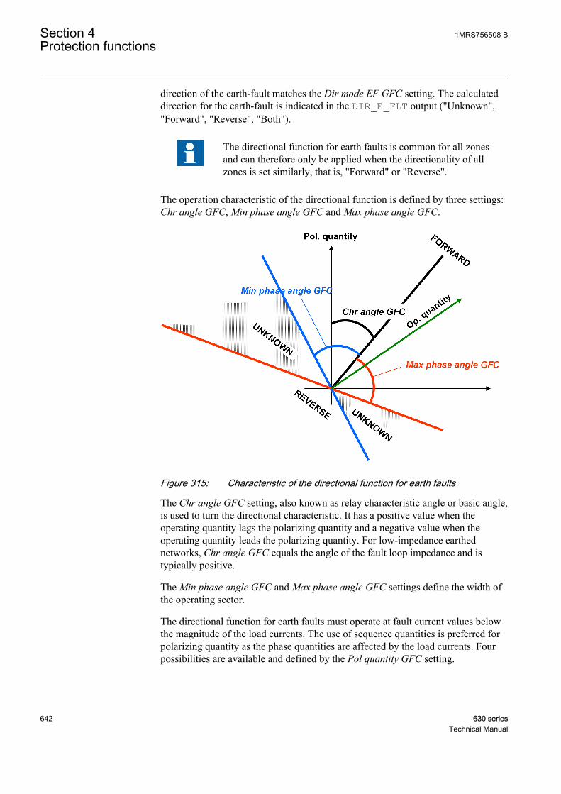
direction of the earth-fault matches the Dir mode EF GFC setting. The calculateddirection for the earth-fault is indicated in the DIR_E_FLT output ("Unknown","Forward", "Reverse", "Both").
The directional function for earth faults is common for all zonesand can therefore only be applied when the directionality of allzones is set similarly, that is, "Forward" or "Reverse".
The operation characteristic of the directional function is defined by three settings:Chr angle GFC, Min phase angle GFC and Max phase angle GFC.
GUID-42B80900-4546-4802-9977-2D58C7D53103 V1 EN
Figure 315: Characteristic of the directional function for earth faults
The Chr angle GFC setting, also known as relay characteristic angle or basic angle,is used to turn the directional characteristic. It has a positive value when theoperating quantity lags the polarizing quantity and a negative value when theoperating quantity leads the polarizing quantity. For low-impedance earthednetworks, Chr angle GFC equals the angle of the fault loop impedance and istypically positive.
The Min phase angle GFC and Max phase angle GFC settings define the width ofthe operating sector.
The directional function for earth faults must operate at fault current values belowthe magnitude of the load currents. The use of sequence quantities is preferred forpolarizing quantity as the phase quantities are affected by the load currents. Fourpossibilities are available and defined by the Pol quantity GFC setting.
Section 4 1MRS756508 BProtection functions
642 630 seriesTechnical Manual
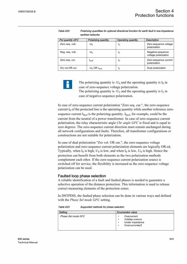
Table 632: Polarizing quantities for optional directional function for earth fault in low-impedanceearthed networks
Pol quantity GFC Polarizing quantity Operating quantity DescriptionZero seq. volt. -U0 I0 Zero-sequence voltage
polarization
Neg. seq. volt. -U2 I2 Negative-sequencevoltage polarization
Zero seq. cur. Ioref I0 Zero-sequence currentpolarization
Zro vol.OR cur. -U0 OR Ioref I0 Dual polarization
The polarizing quantity is -U0 and the operating quantity is I0 incase of zero-sequence voltage polarization.The polarizing quantity is -U2 and the operating quantity is I2 incase of negative-sequence polarization.
In case of zero-sequence current polarization "Zero seq. cur.", the zero-sequencecurrent I0 of the protected line is the operating quantity while another reference zero-sequence current I0ref is the polarizing quantity. I0ref, for example, could be thecurrent from the neutral of a power transformer. In case of zero-sequence currentpolarization, the relay characteristic angle Chr angle GFC is fixed and is equal tozero degrees. The zero-sequence current direction must remain unchanged duringall network configurations and faults. Therefore, all transformer configurations orconstructions are not suitable for polarization.
In case of dual polarization "Zro vol. OR cur.", the zero-sequence voltagepolarization and zero-sequence current polarization elements are logically OR:ed.Typically, when I0 is high, U0 is low, and when I0 is low, U0 is high. Hence theprotection can benefit from both elements as the two polarization methodscomplement each other. If the zero-sequence current polarization source isswitched off for service, the flexibility is increased as the zero-sequence voltagepolarization can be used.
Faulted loop phase selectionA reliable identification of a fault and faulted phases is needed to guarantee aselective operation of the distance protection. This information is used to releasecorrect measuring elements of the protection zones.
In DSTPDIS, the faulted phase selection can be done in various ways and definedwith the Phase Sel mode GFC setting.
Table 633: Supported methods for phase selection
Setting Enumerator valuePhase Sel mode GFC • Overcurrent
• Voltdep overcur• Under impedance• Overcur/underZ
1MRS756508 B Section 4Protection functions
630 series 643Technical Manual
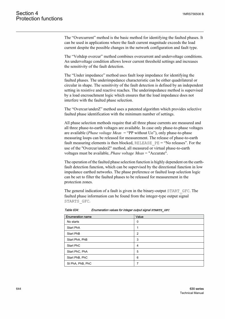
The “Overcurrent” method is the basic method for identifying the faulted phases. Itcan be used in applications where the fault current magnitude exceeds the loadcurrent despite the possible changes in the network configuration and fault type.
The “Voltdep overcur” method combines overcurrent and undervoltage conditions.An undervoltage condition allows lower current threshold settings and increasesthe sensitivity of the fault detection.
The “Under impedance” method uses fault loop impedance for identifying thefaulted phases. The underimpedance characteristic can be either quadrilateral orcircular in shape. The sensitivity of the fault detection is defined by an independentsetting in resistive and reactive reaches. The underimpedance method is supervisedby a load encroachment logic which ensures that the load impedance does notinterfere with the faulted phase selection.
The “Overcur/underZ” method uses a patented algorithm which provides selectivefaulted phase identification with the minimum number of settings.
All phase selection methods require that all three phase currents are measured andall three phase-to-earth voltages are available. In case only phase-to-phase voltagesare available (Phase voltage Meas = “PP without Uo”), only phase-to-phasemeasuring loops can be released for measurement. The release of phase-to-earthfault measuring elements is then blocked, RELEASE_PE = “No releases”. For theuse of the "Overcur/underZ" method, all measured or virtual phase-to-earthvoltages must be available, Phase voltage Meas = "Accurate".
The operation of the faulted phase selection function is highly dependent on the earth-fault detection function, which can be supervised by the directional function in lowimpedance earthed networks. The phase preference or faulted loop selection logiccan be set to filter the faulted phases to be released for measurement in theprotection zones.
The general indication of a fault is given in the binary-output START_GFC. Thefaulted phase information can be found from the integer-type output signalSTARTS_GFC.
Table 634: Enumeration values for integer output signal STARTS_GFC
Enumeration name ValueNo starts 0
Start PhA 1
Start PhB 2
Start PhA, PhB 3
Start PhC 4
Start PhC, PhA 5
Start PhB, PhC 6
St PhA, PhB, PhC 7
Section 4 1MRS756508 BProtection functions
644 630 seriesTechnical Manual
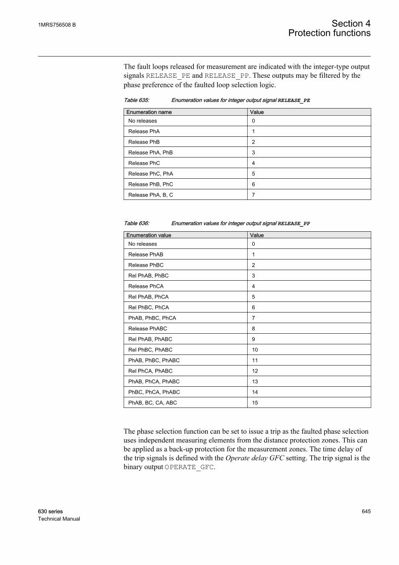
The fault loops released for measurement are indicated with the integer-type outputsignals RELEASE_PE and RELEASE_PP. These outputs may be filtered by thephase preference of the faulted loop selection logic.
Table 635: Enumeration values for integer output signal RELEASE_PE
Enumeration name ValueNo releases 0
Release PhA 1
Release PhB 2
Release PhA, PhB 3
Release PhC 4
Release PhC, PhA 5
Release PhB, PhC 6
Release PhA, B, C 7
Table 636: Enumeration values for integer output signal RELEASE_PP
Enumeration value ValueNo releases 0
Release PhAB 1
Release PhBC 2
Rel PhAB, PhBC 3
Release PhCA 4
Rel PhAB, PhCA 5
Rel PhBC, PhCA 6
PhAB, PhBC, PhCA 7
Release PhABC 8
Rel PhAB, PhABC 9
Rel PhBC, PhABC 10
PhAB, PhBC, PhABC 11
Rel PhCA, PhABC 12
PhAB, PhCA, PhABC 13
PhBC, PhCA, PhABC 14
PhAB, BC, CA, ABC 15
The phase selection function can be set to issue a trip as the faulted phase selectionuses independent measuring elements from the distance protection zones. This canbe applied as a back-up protection for the measurement zones. The time delay ofthe trip signals is defined with the Operate delay GFC setting. The trip signal is thebinary output OPERATE_GFC.
1MRS756508 B Section 4Protection functions
630 series 645Technical Manual
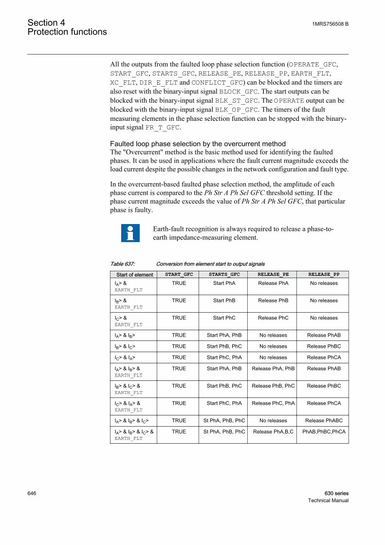
All the outputs from the faulted loop phase selection function (OPERATE_GFC,START_GFC, STARTS_GFC, RELEASE_PE, RELEASE_PP, EARTH_FLT,XC_FLT, DIR_E_FLT and CONFLICT_GFC) can be blocked and the timers arealso reset with the binary-input signal BLOCK_GFC. The start outputs can beblocked with the binary-input signal BLK_ST_GFC. The OPERATE output can beblocked with the binary-input signal BLK_OP_GFC. The timers of the faultmeasuring elements in the phase selection function can be stopped with the binary-input signal FR_T_GFC.
Faulted loop phase selection by the overcurrent methodThe "Overcurrent" method is the basic method used for identifying the faultedphases. It can be used in applications where the fault current magnitude exceeds theload current despite the possible changes in the network configuration and fault type.
In the overcurrent-based faulted phase selection method, the amplitude of eachphase current is compared to the Ph Str A Ph Sel GFC threshold setting. If thephase current magnitude exceeds the value of Ph Str A Ph Sel GFC, that particularphase is faulty.
Earth-fault recognition is always required to release a phase-to-earth impedance-measuring element.
Table 637: Conversion from element start to output signals
Start of element START_GFC STARTS_GFC RELEASE_PE RELEASE_PPIA> &EARTH_FLT
TRUE Start PhA Release PhA No releases
IB> &EARTH_FLT
TRUE Start PhB Release PhB No releases
IC> &EARTH_FLT
TRUE Start PhC Release PhC No releases
IA> & IB> TRUE Start PhA, PhB No releases Release PhAB
IB> & IC> TRUE Start PhB, PhC No releases Release PhBC
IC> & IA> TRUE Start PhC, PhA No releases Release PhCA
IA> & IB> &EARTH_FLT
TRUE Start PhA, PhB Release PhA, PhB Release PhAB
IB> & IC> &EARTH_FLT
TRUE Start PhB, PhC Release PhB, PhC Release PhBC
IC> & IA> &EARTH_FLT
TRUE Start PhC, PhA Release PhC, PhA Release PhCA
IA> & IB> & IC> TRUE St PhA, PhB, PhC No releases Release PhABC
IA> & IB> & IC> &EARTH_FLT
TRUE St PhA, PhB, PhC Release PhA,B,C PhAB,PhBC,PhCA
Section 4 1MRS756508 BProtection functions
646 630 seriesTechnical Manual

In case of a high-impedance earthed network, a phase preference logic can beadded to complement the phase selection in case of a cross-country fault. This canaffect the RELEASE_PE signals.
In case of a low-impedance earthed network, a faulted loop selection logic can beadded to complement the phase selection in case of a two-phase-to-earth fault. Thiscan affect the RELEASE_PE and RELEASE_PP signals.
Faulted phase selection, the voltdep overcur methodThe "Voltdep overcur" method combines the overcurrent and undervoltageconditions. The phase current amplitude is compared to the Ph Str A Ph Sel GFCthreshold setting but a lower current Ph Lo A Ph Sel GFC threshold is valid duringan undervoltage condition. This increases the sensitivity of the fault detection. Theamplitude of phase-to-earth and phase-to-phase voltages is compared to the Ph VPh Sel GFC and PP V Ph Sel GFC settings. In case of a three-phase fault, the phase-to-phase voltages are monitored and compared to the PP V Ph Sel GFC setting.
Earth-fault recognition is required to release a phase-to-earthimpedance measuring element.
GUID-0E69CC47-562A-422A-992D-9117001E840E V1 EN
Figure 316: Overcurrent/undervoltage characteristics
1MRS756508 B Section 4Protection functions
630 series 647Technical Manual
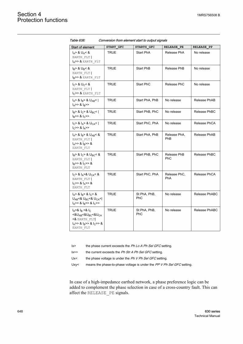
Table 638: Conversion from element start to output signals
Start of element START_GFC STARTS_GFC RELEASE_PE RELEASE_PPIA> & UA< &EARTH_FLT |IA>> & EARTH_FLT
TRUE Start PhA Release PhA No release
IB> & UB< &EARTH_FLT |IB>> & EARTH_FLT
TRUE Start PhB Release PhB No release
IC> & UC< &EARTH_FLT |IC>> & EARTH_FLT
TRUE Start PhC Release PhC No release
IA> & IB> & UAB< |IA>> & IB>>
TRUE Start PhA, PhB No release Release PhAB
IB> & IC> & UBC< |IB>> & IC>>
TRUE Start PhB, PhC No release Release PhBC
IC> & IA> & UCA< |IC>> & IA>>
TRUE Start PhC, PhA No release Release PhCA
IA> & IB> & UAB< &EARTH_FLT |IA>> & IB>> &EARTH_FLT
TRUE Start PhA, PhB Release PhA,PhB
Release PhAB
IB> & IC> & UBC< &EARTH_FLT |IB>> & IC>> &EARTH_FLT
TRUE Start PhB, PhC Release PhBPhC
Release PhBC
IC> & IA>& UCA< &EARTH_FLT |IC>> & IA>> &EARTH_FLT
TRUE Start PhC, PhA Release PhC,PhA
Release PhCA
IA> & IB> & IC> &UAB<& UBC<& UCA<|IA>> & IB>> & IC>>
TRUE St PhA, PhB,PhC
No release Release PhABC
IA>& IB >& IC<&UAB<&UBC<&UCA<& EARTH_FLT|IA>> & IB>> & IC>> &EARTH_FLT
TRUE St PhA, PhB,PhC
No release Release PhABC
Ix> the phase current exceeds the Ph Lo A Ph Sel GFC setting.
Ix>> the current exceeds the Ph Str A Ph Sel GFC setting.
Ux< the phase voltage is under the Ph V Ph Sel GFC setting.
Uxy< means the phase-to-phase voltage is under the PP V Ph Sel GFC setting.
In case of a high-impedance earthed network, a phase preference logic can beadded to complement the phase selection in case of a cross-country fault. This canaffect the RELEASE_PE signals.
Section 4 1MRS756508 BProtection functions
648 630 seriesTechnical Manual

In case of a low-impedance earthed network, a faulted loop selection logic can beadded to complement the phase selection in case of a two-phase-to-earth fault. Thiscan affect the RELEASE_PE and RELEASE_PP signals.
Faulted phase selection, the underimpedance methodThe "Under impedance" method uses fault loop impedance for identifying thefaulted phases. The advantage of the underimpedance criterion is that thesensitivity of the fault detection is independent of the source impedance. Theunderimpedance function has six impedance measuring elements. The phase-to-earth measuring elements are calculated:
ZU
IA
A
A
=
GUID-34FC67B7-F0E9-4083-9E27-76B6CAD3CC82 V1 EN (Equation 93)
ZU
IB
B
B
=
GUID-F4A6E6E6-83BD-48E6-9135-7BACD7C6BE59 V1 EN (Equation 94)
ZU
IC
C
C
=
GUID-E82B402A-6878-4C95-85B0-5A0E65F71C95 V1 EN (Equation 95)
The phase-to-phase measuring elements are based on the formulae:
ZU
IAB
AB
AB
=
GUID-2172DAEE-B80F-455F-B2ED-67C84F55D211 V1 EN (Equation 96)
ZU
IBC
BC
BC
=
GUID-061DEFA3-D7B6-41BF-859F-DB964323403B V1 EN (Equation 97)
ZU
ICA
CA
CA
=
GUID-FC87CF5F-04B1-4481-A407-83275287EE0B V1 EN (Equation 98)
The faulted phase identification is done by comparing the measured impedance tothe operating characteristics in the impedance domain. If a measured fault loopimpedance is inside the characteristics, the corresponding phase(s) is identified asfaulty.
The earth return path impedance is included in the calculated faultloop impedance of the phase-to-earth measuring element.
The shape of the characteristic is selected with the Z Chr Mod Ph Sel GFC setting.Two shapes are available and they have flexible configuration:
1MRS756508 B Section 4Protection functions
630 series 649Technical Manual
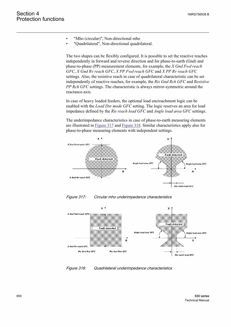
• "Mho (circular)", Non-directional mho• "Quadrilateral", Non-directional quadrilateral.
The two shapes can be flexibly configured. It is possible to set the reactive reachesindependently in forward and reverse direction and for phase-to-earth (Gnd) andphase-to-phase (PP) measurement elements, for example, the X Gnd Fwd reachGFC, X Gnd Rv reach GFC, X PP Fwd reach GFC and X PP Rv reach GFCsettings. Also, the resistive reach in case of quadrilateral characteristic can be setindependently of reactive reaches, for example, the Ris Gnd Rch GFC and ResistivePP Rch GFC settings. The characteristic is always mirror-symmetric around thereactance-axis.
In case of heavy loaded feeders, the optional load encroachment logic can beenabled with the Load Dsr mode GFC setting. The logic reserves an area for loadimpedance defined by the Ris reach load GFC and Angle load area GFC settings.
The underimpedance characteristics in case of phase-to-earth measuring elementsare illustrated in Figure 317 and Figure 318. Similar characteristics apply also forphase-to-phase measuring elements with independent settings.
GUID-E4A115A0-CBEF-42BF-9C3E-F65F6F42144F V1 EN
Figure 317: Circular mho underimpedance characteristics
GUID-2FF39588-DE16-45C9-84F5-38B8BB11CDA9 V1 EN
Figure 318: Quadrilateral underimpedance characteristics
Section 4 1MRS756508 BProtection functions
650 630 seriesTechnical Manual
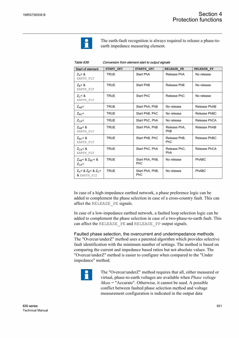
The earth-fault recognition is always required to release a phase-to-earth impedance measuring element.
Table 639: Conversion from element start to output signals
Start of element START_GFC STARTS_GFC RELEASE_PE RELEASE_PPZA< &EARTH_FLT
TRUE Start PhA Release PhA No release
ZB< &EARTH_FLT
TRUE Start PhB Release PhB No release
ZC< &EARTH_FLT
TRUE Start PhC Release PhC No release
ZAB< TRUE Start PhA, PhB No release Release PhAB
ZBC< TRUE Start PhB, PhC No release Release PhBC
ZCA< TRUE Start PhC, PhA No release Release PhCA
ZAB< &EARTH_FLT
TRUE Start PhA, PhB Release PhA,PhB
Release PhAB
ZBC< &EARTH_FLT
TRUE Start PhB, PhC Release PhB,PhC
Release PhBC
ZCA< &EARTH_FLT
TRUE Start PhC, PhA Release PhC,PhA
Release PhCA
ZAB< & ZBC< &ZCA<
TRUE Start PhA, PhB,PhC
No release PhABC
ZA< & ZB< & ZC<& EARTH_FLT
TRUE Start PhA, PhB,PhC
No release PhABC
In case of a high-impedance earthed network, a phase preference logic can beadded to complement the phase selection in case of a cross-country fault. This canaffect the RELEASE_PE signals.
In case of a low-impedance earthed network, a faulted loop selection logic can beadded to complement the phase selection in case of a two-phase-to-earth fault. Thiscan affect the RELEASE_PE and RELEASE_PP output signals.
Faulted phase selection, the overcurrent and underimpedance methodsThe "Overcur/underZ" method uses a patented algorithm which provides selectivefault identification with the minimum number of settings. The method is based oncomparing the current and impedance based ratios but not absolute values. The"Overcur/underZ" method is easier to configure when compared to the "Underimpedance" method.
The "Overcur/underZ" method requires that all, either measured orvirtual, phase-to-earth voltages are available when Phase voltageMeas = "Accurate". Otherwise, it cannot be used. A possibleconflict between faulted phase selection method and voltagemeasurement configuration is indicated in the output data
1MRS756508 B Section 4Protection functions
630 series 651Technical Manual
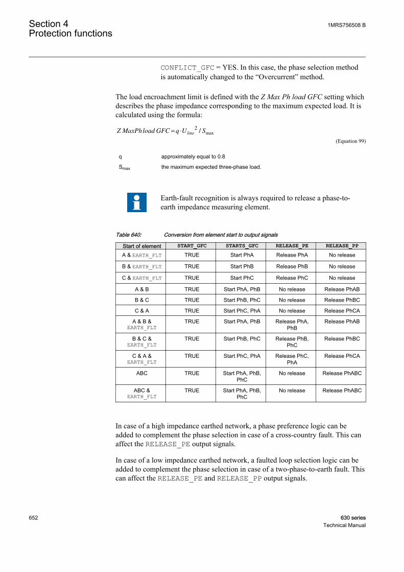
CONFLICT_GFC = YES. In this case, the phase selection methodis automatically changed to the “Overcurrent” method.
The load encroachment limit is defined with the Z Max Ph load GFC setting whichdescribes the phase impedance corresponding to the maximum expected load. It iscalculated using the formula:
Z MaxPhload GFC q U Sline
= ⋅2
/ max
GUID-451E878F-D422-4222-A539-7F32A56853DA V1 EN (Equation 99)
q approximately equal to 0.8
Smax the maximum expected three-phase load.
Earth-fault recognition is always required to release a phase-to-earth impedance measuring element.
Table 640: Conversion from element start to output signals
Start of element START_GFC STARTS_GFC RELEASE_PE RELEASE_PPA & EARTH_FLT TRUE Start PhA Release PhA No release
B & EARTH_FLT TRUE Start PhB Release PhB No release
C & EARTH_FLT TRUE Start PhC Release PhC No release
A & B TRUE Start PhA, PhB No release Release PhAB
B & C TRUE Start PhB, PhC No release Release PhBC
C & A TRUE Start PhC, PhA No release Release PhCA
A & B &EARTH_FLT
TRUE Start PhA, PhB Release PhA,PhB
Release PhAB
B & C &EARTH_FLT
TRUE Start PhB, PhC Release PhB,PhC
Release PhBC
C & A &EARTH_FLT
TRUE Start PhC, PhA Release PhC,PhA
Release PhCA
ABC TRUE Start PhA, PhB,PhC
No release Release PhABC
ABC &EARTH_FLT
TRUE Start PhA, PhB,PhC
No release Release PhABC
In case of a high impedance earthed network, a phase preference logic can beadded to complement the phase selection in case of a cross-country fault. This canaffect the RELEASE_PE output signals.
In case of a low impedance earthed network, a faulted loop selection logic can beadded to complement the phase selection in case of a two-phase-to-earth fault. Thiscan affect the RELEASE_PE and RELEASE_PP output signals.
Section 4 1MRS756508 BProtection functions
652 630 seriesTechnical Manual

Cross-country fault detection function for high impedance earthednetworksIn isolated and high impedance earthed networks, the overvoltages produced by asingle-phase earth fault may lead to a cross-country fault, where twosimultaneously single-phase earth faults are present in the system but in differentlocations and phases. The cross-country fault is hazardous because the magnitudeof the fault current through earth can be as high as in the case of a two-phase short-circuit fault. The protection must therefore remove the cross-country fault quicklywithout sacrificing the selectivity. This can be done with the help of a phasepreference logic which is activated by the cross-country fault detection function.The phase preference logic transforms the fault back to an ordinary single-phaseearth fault by tripping selectively one of the faulted feeders.
Only the cross-country detecting function becomes active if the network is eitherisolated or high impedance earthed (System grounding GFC = "High impedance").
The fault detection is based on monitoring two quantities:
• Residual current• Phase-to-phase voltages.
A cross-country fault is detected if:
• An earth fault is detected, EARTH_FLT = TRUE.AND
• The calculated residual current exceeds the value of the Gnd Op A XC GFCsetting. This setting value should exceed the highest expected single-phase earth-fault current. The residual current is calculated from phase currents and alsomonitored because the cable current transformer saturates easily due to thehigh fault current.AND
• The residual overcurrent condition must be valid at least for the durationdefined by the Cross-country Dl GFC setting. This shows that the detection isnot misled by the high magnitude initial transients of a single-phase earth fault.OR
• Any phase-to-phase voltage drops below the value of the PP voltage XCFGFC setting. The undervoltage condition is based on the fact that during a single-phase earth fault, the phase-to-phase voltages are unaffected in isolated andhigh impedance earthed networks. The fulfilment of this criterion avoids theneed for any delays in combination with the residual overcurrent condition.
The detection of a cross-country fault is indicated by the XC_FLT output signal.
1MRS756508 B Section 4Protection functions
630 series 653Technical Manual

GUID-0085EBAA-5AED-4E57-B3BD-156656CE15D7 V1 EN
Figure 319: Cross-country fault detection logic for high impedance earthednetworks
Phase preference logic for high impedance earthed networksThe phase preference logic for high impedance earthed networks is a supplement tothe faulted phase identification function. It provides a selective filtering of phase-to-earth measurement elements in case of a cross-country fault or double earth-fault inisolated and high impedance earthed networks.
The logic releases, the preferred phase-to-earth loop for measurement when a cross-country fault with two faulted phase-to-earth loops are detected. The phasepreference scheme must be set in the same way for the entire system so that alldistance relays measure the same preferred phase-to-earth loop. As a result, the cross-country fault is changed back into and ordinary single-phase earth-fault by trippingselectively one of the faulted feeders.
The phase preference logic influences only the selection of the phase-earth loopsand has no effect on the selection of the phase-to-phase loops. The influence isseen in the RELEASE_PE output. The logic does not affect the RELEASE_PP orSTART/STARTS outputs.
The phase preference logic is applicable only in isolated and high impedanceearthed networks with System grounding GFC = "High impedance".
All schemes except "No-filter" require a cross-country fault detection XC_FLT =TRUE; otherwise all the phase-to-earth measuring elements are blocked,RELEASE_PE = No release. This guarantees that tripping at single-phase earthfault in high impedance earthed network is blocked.
If a cross-country fault is detected, XC_FLT = TRUE and only a single fault loopcan be identified as faulty by the faulted phase selection function, then that loop is
Section 4 1MRS756508 BProtection functions
654 630 seriesTechnical Manual

directly selected for measurement. In such case, simultaneous tripping of bothfaulted feeders during a cross-country is expected.
Example: consider a cross-country fault where phases A and B become faultedsimultaneously. All relays, R1, R2, R3 and R4, are equipped with an "Acyc C-A-B" phase preference scheme.
GUID-FAEE560E-977D-4BFE-B863-FA853399EEC2 V1 EN
Figure 320: Cross-country fault (or double earth-fault) in high impedanceearthed system
The expected operations of the relays are:
• R1: The cross-country fault cannot be detected as the residual current does notflow through the R1 relay. The phase-to-phase loop AB is measured in theforward direction but the estimated impedance represents an averageimpedance between two fault locations and therefore is not seen in the Z1 zone.
• R2: The cross-country fault is detected as large residual current flowingthrough the R2 relay. Phase A earth fault is seen in forward direction andphase B earth fault in reverse direction. Based on "Acyc C-A-B" phasepreference scheme, phase A is selected for measurement. The R2 relayoperates without delay and opens the CB2 circuit breaker.
• R3: The cross-country fault is detected when a large residual current flowsthrough the R3 relay. The phase A earth fault is seen in reverse direction andphase B earth fault in forward direction. Based on the "Acyc C-A-B" phasepreference scheme, phase A is selected for measurement. As fault directiondoes not coincide with zone direction, the R3 relay does not operate.
• R4: Same as the R1 relay.
As a result of the circuit-breaker CB2 operation, the cross-country fault istransformed back to an ordinary single-phase earth fault.
The tables summarize the available phase preference logic schemes and theiroperation in different fault scenarios. The logic is selected with the Ph Prf mode HiZ GFC setting. In case the logic is not required, then the "No-filter" option shouldbe selected.
"No-filter" option does not block the single-phase earth-faults, andtherefore this option should be used with caution.
1MRS756508 B Section 4Protection functions
630 series 655Technical Manual
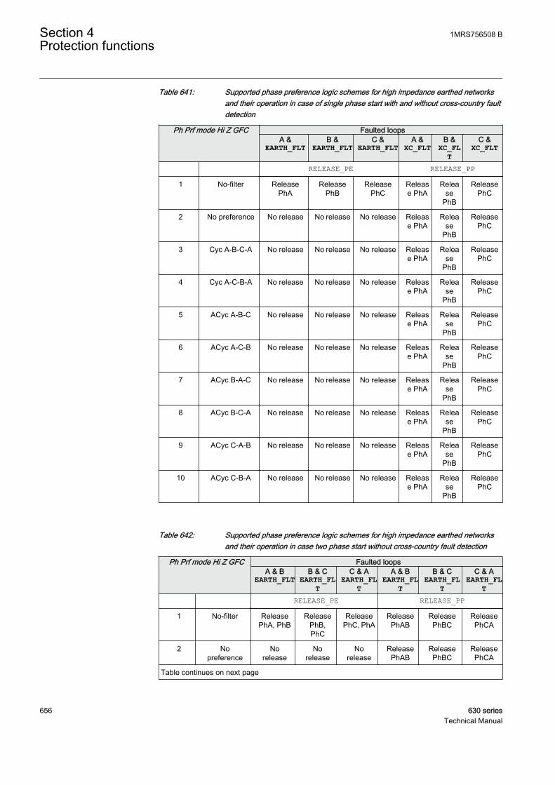
Table 641: Supported phase preference logic schemes for high impedance earthed networksand their operation in case of single phase start with and without cross-country faultdetection
Ph Prf mode Hi Z GFC Faulted loopsA &
EARTH_FLTB &
EARTH_FLTC &
EARTH_FLTA &
XC_FLTB &
XC_FLT
C &XC_FLT
RELEASE_PE RELEASE_PP
1 No-filter ReleasePhA
ReleasePhB
ReleasePhC
Release PhA
Release
PhB
ReleasePhC
2 No preference No release No release No release Release PhA
Release
PhB
ReleasePhC
3 Cyc A-B-C-A No release No release No release Release PhA
Release
PhB
ReleasePhC
4 Cyc A-C-B-A No release No release No release Release PhA
Release
PhB
ReleasePhC
5 ACyc A-B-C No release No release No release Release PhA
Release
PhB
ReleasePhC
6 ACyc A-C-B No release No release No release Release PhA
Release
PhB
ReleasePhC
7 ACyc B-A-C No release No release No release Release PhA
Release
PhB
ReleasePhC
8 ACyc B-C-A No release No release No release Release PhA
Release
PhB
ReleasePhC
9 ACyc C-A-B No release No release No release Release PhA
Release
PhB
ReleasePhC
10 ACyc C-B-A No release No release No release Release PhA
Release
PhB
ReleasePhC
Table 642: Supported phase preference logic schemes for high impedance earthed networksand their operation in case two phase start without cross-country fault detection
Ph Prf mode Hi Z GFC Faulted loopsA & B
EARTH_FLTB & C
EARTH_FLT
C & AEARTH_FL
T
A & BEARTH_FL
T
B & CEARTH_FL
T
C & AEARTH_FL
T RELEASE_PE RELEASE_PP
1 No-filter ReleasePhA, PhB
ReleasePhB,PhC
ReleasePhC, PhA
ReleasePhAB
ReleasePhBC
ReleasePhCA
2 Nopreference
Norelease
Norelease
Norelease
ReleasePhAB
ReleasePhBC
ReleasePhCA
Table continues on next page
Section 4 1MRS756508 BProtection functions
656 630 seriesTechnical Manual

Ph Prf mode Hi Z GFC Faulted loopsA & B
EARTH_FLTB & C
EARTH_FLT
C & AEARTH_FL
T
A & BEARTH_FL
T
B & CEARTH_FL
T
C & AEARTH_FL
T3 Cyc A-B-C-A No
releaseNo
releaseNo
releaseReleasePhAB
ReleasePhBC
ReleasePhCA
4 Cyc A-C-B-A Norelease
Norelease
Norelease
ReleasePhAB
ReleasePhBC
ReleasePhCA
5 ACyc A-B-C Norelease
Norelease
Norelease
ReleasePhAB
ReleasePhBC
ReleasePhCA
6 ACyc A-C-B Norelease
Norelease
Norelease
ReleasePhAB
ReleasePhBC
ReleasePhCA
7 ACyc B-A-C Norelease
Norelease
Norelease
ReleasePhAB
ReleasePhBC
ReleasePhCA
8 ACyc B-C-A Norelease
Norelease
Norelease
ReleasePhAB
ReleasePhBC
ReleasePhCA
9 ACyc C-A-B Norelease
Norelease
Norelease
ReleasePhAB
ReleasePhBC
ReleasePhCA
10 ACyc C-B-A Norelease
Norelease
Norelease
ReleasePhAB
ReleasePhBC
ReleasePhCA
Table 643: Supported phase preference logic schemes for high impedance earthed networksand their operation in case two phase starts with cross-country fault detection
Ph Pref logic Hi Imp Faulted loopsA & BXC_FLT
B & CXC_FLT
C & AXC_FLT
A & BXC_FLT
B & CXC_FLT
C & AXC_FLT
RELEASE_PE RELEASE_PP
1 No-filter ReleasePhA, PhB
ReleasePhB,PhC
ReleasePhC, PhA
ReleasePhAB
ReleasePhBC
ReleasePhCA
2 Nopreference
ReleasePhA, PhB
ReleasePhB,PhC
ReleasePhC, PhA
ReleasePhAB
ReleasePhBC
ReleasePhCA
3 Cyc A-B-C-A ReleasePhA
ReleasePhB
ReleasePhC
ReleasePhAB
ReleasePhBC
ReleasePhCA
4 Cyc A-C-B-A ReleasePhB
ReleasePhC
ReleasePhA
ReleasePhAB
ReleasePhBC
ReleasePhCA
5 ACyc A-B-C ReleasePhA
ReleasePhB
ReleasePhA
ReleasePhAB
ReleasePhBC
ReleasePhCA
6 ACyc A-C-B ReleasePhA
ReleasePhC
ReleasePhA
ReleasePhAB
ReleasePhBC
ReleasePhCA
7 ACyc B-A-C ReleasePhB
ReleasePhB
ReleasePhA
ReleasePhAB
ReleasePhBC
ReleasePhCA
8 ACyc B-C-A ReleasePhB
ReleasePhB
ReleasePhC
ReleasePhAB
ReleasePhBC
ReleasePhCA
9 ACyc C-A-B ReleasePhA
ReleasePhC
ReleasePhC
ReleasePhAB
ReleasePhBC
ReleasePhCA
10 ACyc C-B-A ReleasePhB
ReleasePhC
ReleasePhC
ReleasePhAB
ReleasePhBC
ReleasePhCA
1MRS756508 B Section 4Protection functions
630 series 657Technical Manual
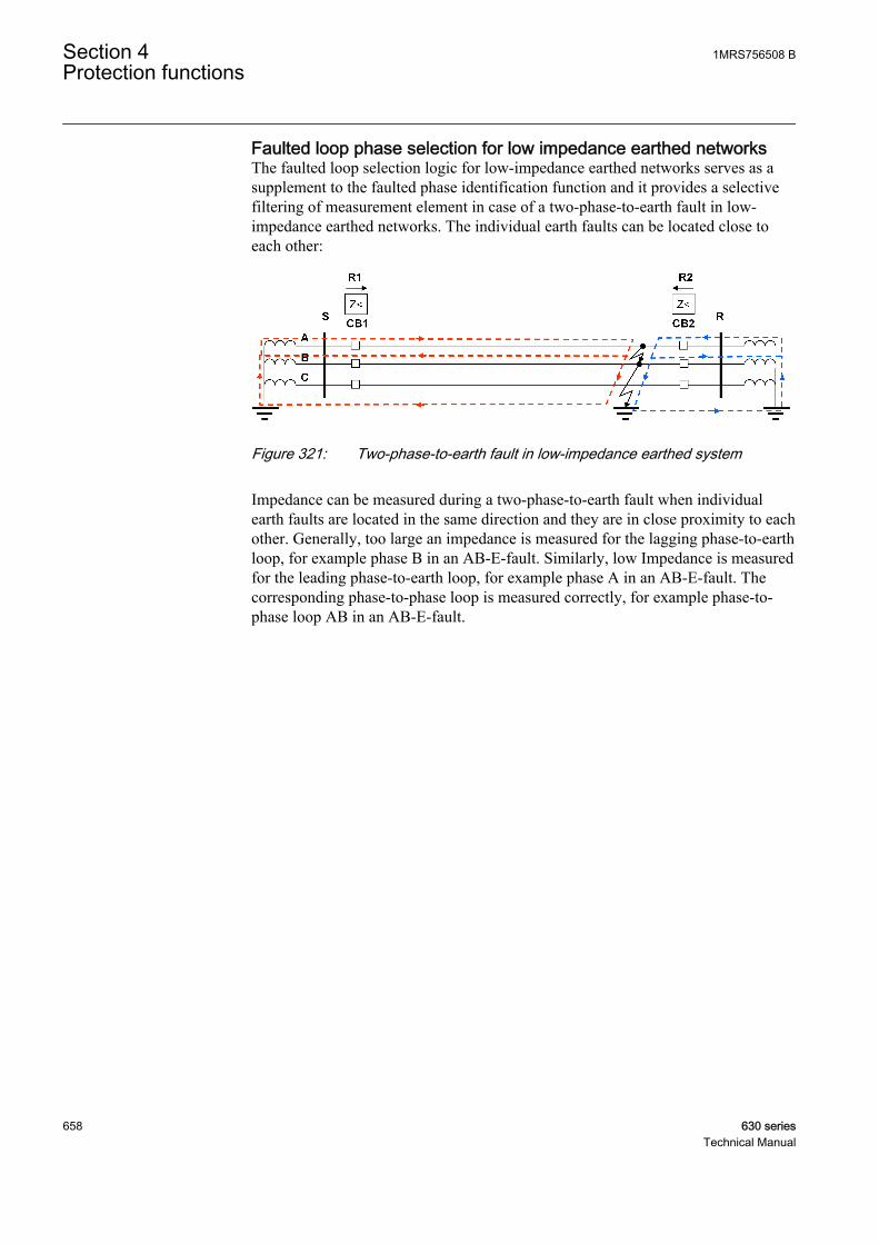
Faulted loop phase selection for low impedance earthed networksThe faulted loop selection logic for low-impedance earthed networks serves as asupplement to the faulted phase identification function and it provides a selectivefiltering of measurement element in case of a two-phase-to-earth fault in low-impedance earthed networks. The individual earth faults can be located close toeach other:
GUID-5E4A334F-E562-4F4F-9165-0B426D8B6573 V1 EN
Figure 321: Two-phase-to-earth fault in low-impedance earthed system
Impedance can be measured during a two-phase-to-earth fault when individualearth faults are located in the same direction and they are in close proximity to eachother. Generally, too large an impedance is measured for the lagging phase-to-earthloop, for example phase B in an AB-E-fault. Similarly, low Impedance is measuredfor the leading phase-to-earth loop, for example phase A in an AB-E-fault. Thecorresponding phase-to-phase loop is measured correctly, for example phase-to-phase loop AB in an AB-E-fault.
Section 4 1MRS756508 BProtection functions
658 630 seriesTechnical Manual
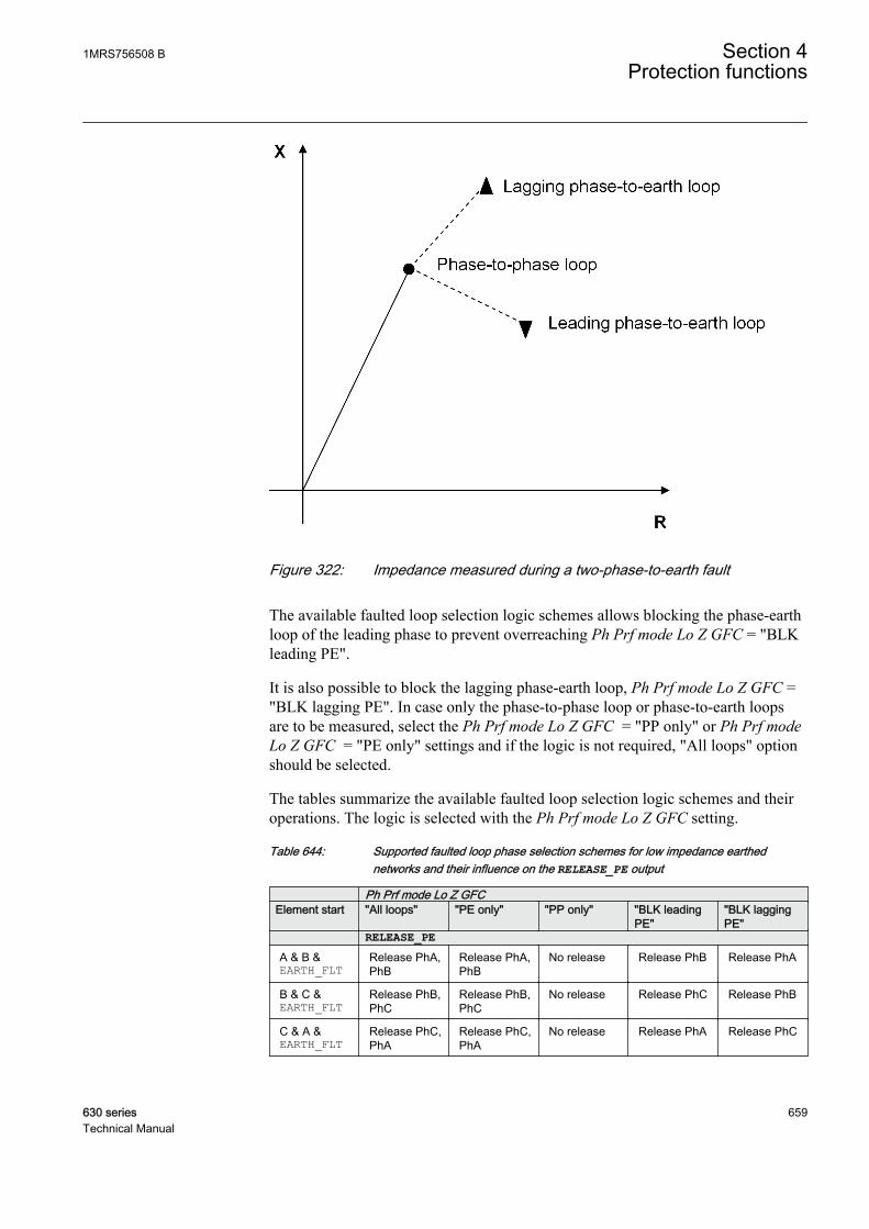
GUID-3DC6652A-5E20-4EEA-AE5B-E956980D23F1 V1 EN
Figure 322: Impedance measured during a two-phase-to-earth fault
The available faulted loop selection logic schemes allows blocking the phase-earthloop of the leading phase to prevent overreaching Ph Prf mode Lo Z GFC = "BLKleading PE".
It is also possible to block the lagging phase-earth loop, Ph Prf mode Lo Z GFC ="BLK lagging PE". In case only the phase-to-phase loop or phase-to-earth loopsare to be measured, select the Ph Prf mode Lo Z GFC = "PP only" or Ph Prf modeLo Z GFC = "PE only" settings and if the logic is not required, "All loops" optionshould be selected.
The tables summarize the available faulted loop selection logic schemes and theiroperations. The logic is selected with the Ph Prf mode Lo Z GFC setting.
Table 644: Supported faulted loop phase selection schemes for low impedance earthednetworks and their influence on the RELEASE_PE output
Ph Prf mode Lo Z GFCElement start "All loops" "PE only" "PP only" "BLK leading
PE""BLK laggingPE"
RELEASE_PEA & B &EARTH_FLT
Release PhA,PhB
Release PhA,PhB
No release Release PhB Release PhA
B & C &EARTH_FLT
Release PhB,PhC
Release PhB,PhC
No release Release PhC Release PhB
C & A &EARTH_FLT
Release PhC,PhA
Release PhC,PhA
No release Release PhA Release PhC
1MRS756508 B Section 4Protection functions
630 series 659Technical Manual
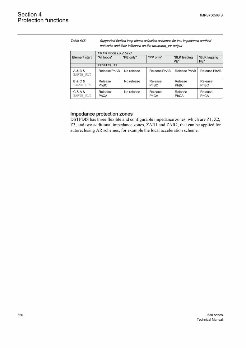
Table 645: Supported faulted loop phase selection schemes for low impedance earthednetworks and their influence on the RELEASE_PP output
Ph Prf mode Lo Z GFCElement start "All loops" "PE only" "PP only" "BLK leading
PE""BLK laggingPE"
RELEASE_PPA & B &EARTH_FLT
Release PhAB No release Release PhAB Release PhAB Release PhAB
B & C &EARTH_FLT
ReleasePhBC
No release ReleasePhBC
ReleasePhBC
ReleasePhBC
C & A &EARTH_FLT
ReleasePhCA
No release ReleasePhCA
ReleasePhCA
ReleasePhCA
Impedance protection zonesDSTPDIS has three flexible and configurable impedance zones, which are Z1, Z2,Z3, and two additional impedance zones, ZAR1 and ZAR2, that can be applied forautoreclosing AR schemes, for example the local acceleration scheme.
Section 4 1MRS756508 BProtection functions
660 630 seriesTechnical Manual
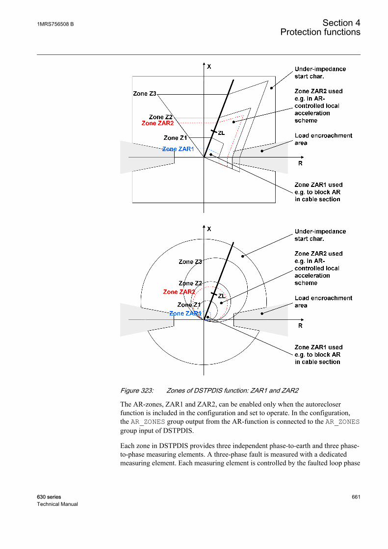
GUID-F07C2455-01C2-429B-BB8F-07483C4A9AA0 V1 EN
Figure 323: Zones of DSTPDIS function: ZAR1 and ZAR2
The AR-zones, ZAR1 and ZAR2, can be enabled only when the autorecloserfunction is included in the configuration and set to operate. In the configuration,the AR_ZONES group output from the AR-function is connected to the AR_ZONESgroup input of DSTPDIS.
Each zone in DSTPDIS provides three independent phase-to-earth and three phase-to-phase measuring elements. A three-phase fault is measured with a dedicatedmeasuring element. Each measuring element is controlled by the faulted loop phase
1MRS756508 B Section 4Protection functions
630 series 661Technical Manual

selection function. Based on the recognized fault type, the release-signals are givenfor the corresponding measuring elements.
The general indication of fault for each zone is given in the START_Zx (x = 1...3,AR1, AR2) binary output. The faulted phase information can be found from theSTARTS_Zx (x = 1...3, AR1, AR2) integer type output signal.
Table 646: Enumeration values for integer output signal STARTS_Zx (x = 1...3, AR1, AR2 )
Enumeration name ValueNo starts 0
Start PhA 1
Start PhB 2
Start PhA, PhB 3
Start PhC 4
Start PhC, PhA 5
Start PhB, PhC 6
Start PhA, PhB, PhC 7
The operate signal from each zone is the OPERATE_Zx (x = 1...3,AR1, AR2) binary output signal.
The output from each zones can be blocked and the timers are also reset with theBLOCK_Zx (x = 1...3 AR1, AR2) binary input signal. The start outputs can beblocked with the BLK_ST_Zx (x = 1...3, AR1, AR2) binary input signal and theoperate output can be blocked with the BLK_OP_Zx (x = 1...3, AR1, AR2) binaryinput signal. The timers of phase-to-earth and phase-to-phase fault measuringelements can be stopped with the FR_T_PE_Zx (x = 1...3, AR1, AR2) andFR_T_PP_Zx (x = 1...3, AR1, AR2) binary input signals.
The CONFLICT_Zx (x = 1...3, AR1, AR2) output data is an assisting integer typeoutput which supervises the validity of a tilt angle of quadrilateral characteristics sothat the characteristics always produces a closed boundary. It can have the values:No conflict, PhE angle tilt, PhPh angle tilt and PhE,PhPh tilt. If the actual value forAngle tilt Zx (x = 1...3, AR1, AR2) is not valid, the value of Angle tilt Zx is forcedto zero.
Impedance measurementThe impedance measurement is based on a full cycle DFT-filtered current andvoltage phasors providing the operating time for approximately two to three cycles.
DSTPDIS provides three independent phase-to-earth, phase-to-phase measuringelements per zone and the three-phase fault is measured with a dedicatedmeasurement element.
The impedance measurement is done similarly regardless of the zone shape. Theoperation is based on impedance mapping approach where the fault loop
Section 4 1MRS756508 BProtection functions
662 630 seriesTechnical Manual

impedance is first calculated and then compared with the zone boundaries. Ifimpedance is recognized inside the operation zone, the corresponding operateoutput is activated after the operate time has elapsed.
Phase-to-earth impedance measuring elementsThe phase-to-earth impedance measuring elements provide the basic earth-faultprotection in direct or low impedance earthed networks. The earth-fault protectionis enabled with the Op Mod Gnd loops Znx (x = 1...3, AR1, AR2) = "Enabled"setting. The enabling requires that all the three phase-to-earth voltages aremeasured. Otherwise, the release of the earth-fault measuring elements isautomatically blocked.
The reach of phase-to-earth measuring elements is based on loop impedance
Z Z RF R R R j X X X RFN1 1 0 1 1 0 13 3+ + = + − + ⋅ + − +( ( ) / ) ( ( ) / )
GUID-F9E9588C-0C04-48DC-A7CE-3DC9EB38276A V1 EN (Equation 100)
GUID-FC3E00A3-D2E5-44C8-98CA-C3B3CB7F0BD5 V1 EN
Figure 324: The fault loop impedance model for phase-to-earth impedancemeasuring elements
R1 Positive sequence resistance from measuring point to fault location
X1 Positive sequence reactance from measuring point to fault location
RN Earth return path resistance = (R0 - R1)/3 from measuring point to fault loaction
XN Earth return path reactance = (X0 - X1)/3 from measuring point to fault location
R0 Zero sequence resistance from measuring point to fault location
X0 Zero sequence reactance from measuring point to fault location
RF Physical fault resistance between phase and earth (includes arc and earthing resistances)
Considering the load in case of a single line to earth fault, conventional distanceprotection might overreach at the exporting end and underreach at the importingend. DSTPDIS has a load compensation functionality which increases the security
1MRS756508 B Section 4Protection functions
630 series 663Technical Manual
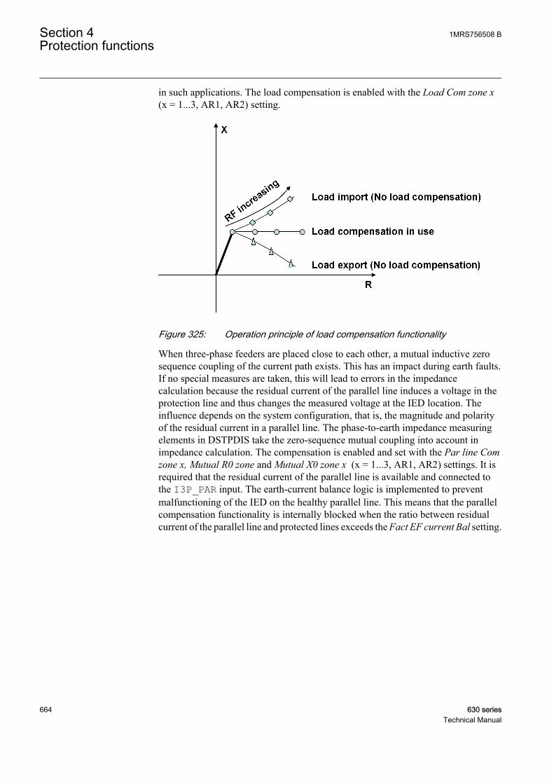
in such applications. The load compensation is enabled with the Load Com zone x(x = 1...3, AR1, AR2) setting.
GUID-7B58F330-E0FF-479F-B433-25EE831555BF V1 EN
Figure 325: Operation principle of load compensation functionality
When three-phase feeders are placed close to each other, a mutual inductive zerosequence coupling of the current path exists. This has an impact during earth faults.If no special measures are taken, this will lead to errors in the impedancecalculation because the residual current of the parallel line induces a voltage in theprotection line and thus changes the measured voltage at the IED location. Theinfluence depends on the system configuration, that is, the magnitude and polarityof the residual current in a parallel line. The phase-to-earth impedance measuringelements in DSTPDIS take the zero-sequence mutual coupling into account inimpedance calculation. The compensation is enabled and set with the Par line Comzone x, Mutual R0 zone and Mutual X0 zone x (x = 1...3, AR1, AR2) settings. It isrequired that the residual current of the parallel line is available and connected tothe I3P_PAR input. The earth-current balance logic is implemented to preventmalfunctioning of the IED on the healthy parallel line. This means that the parallelcompensation functionality is internally blocked when the ratio between residualcurrent of the parallel line and protected lines exceeds the Fact EF current Bal setting.
Section 4 1MRS756508 BProtection functions
664 630 seriesTechnical Manual

GUID-510EFF41-3C62-4024-BACC-8884B7743A9C V1 EN
Figure 326: Operation principle of parallel line compensation functionality
The time delay of operation is defined with the Gnd operate Dl Znx (x = 1...3,AR1, AR2) setting. The timer can be disabled with the Gnd Op Dl mode Znx ="Disable" setting. This blocks the OPERATE_Zx (x = 1...3, AR1, AR2) output ofthe phase-to-earth measuring elements.
Phase-to-phase impedance measuring elementsThe phase-to-phase distance protection is suitable as a basic protection functionagainst two-phase short circuit faults in all kinds of networks, regardless of thetreatment of the neutral point. The short circuit fault protection is enabled with theOp Mod PP loops Znx (x = 1...3, AR1, AR2) = "Enabled" setting.
The reach of the phase-to-phase measuring elements is based on the loop impedance
ZR
R j XR
F F
1 2 21 1+ + += ⋅
GUID-F26B67C9-E462-4857-B73B-48AC5EE46AE5 V1 EN (Equation 101)
1MRS756508 B Section 4Protection functions
630 series 665Technical Manual

GUID-0DA458BD-E68F-4685-9B2C-FBC72FBD7270 V1 EN
Figure 327: The fault loop impedance model for phase-to-phase impedancemeasuring elements
R1 Positive-sequence resistance from measuring point to fault location
X1 Positive-sequence reactance from measuring point to fault location
RF Physical fault resistance between phases, for example, arc resistance
The phase-to-phase impedance measuring elements measure onlyhalf of the physical fault resistance between phases. This must betaken into account when the resistive reach of the phase-to-phaseelements is set (that is, setting the value of 5 ohm corresponds5+5=10 ohm of physical arc resistance between phases).
The resistive reach setting is common for phase-to-phase and three-phaseimpedance measuring elements.
The time delay of operation is defined with the PP operate delay Znx (x = 1...3,AR1, AR2) setting. The timer can be disabled with the PP Op delay Mod Znx ="Disabled" setting. This blocks the OPERATE_Zx (x = 1...3, AR1, AR2) output ofthe phase-to-phase measuring elements.
Three-phase impedance measuring elementDSTPDIS has a dedicated measuring element for three-phase short-circuit fault foreach zone. The three-phase measuring element utilizes the positive sequencequantities for a fault loop impedance estimation which increases the accuracy byreducing the influence of line parameter asymmetry. This is advantageousespecially in case of non-transposed, asymmetrical lines. The three-phaseimpedance measuring element is enabled together with the phase-to-phaseimpedance elements by the OP Mod PP loops Znx (x = 1...3, AR1, AR2) ="Enabled" setting.
Section 4 1MRS756508 BProtection functions
666 630 seriesTechnical Manual

The reach of three-phase measuring element is based on the loop impedance:
Three-phase measuring element reach = Z + R = R + j 1 F 1 XX + R1 F
GUID-86A2A6CF-4650-4335-B1F2-7A16E29C12F9 V1 EN (Equation 102)
GUID-0A98A6B5-BEE5-48DA-B053-7D7331F74BB3 V1 EN
Figure 328: The fault loop impedance model for three-phase impedancemeasuring element
R1 Positive sequence resistance from measuring point to fault location
X1 Positive sequence reactance from measuring point to fault location
RF Physical fault resistance per phase, for example, arc resistance
The three-phase impedance measuring element measures thephysical fault resistance per phase. The resistive reach setting iscommon for three-phase and phase-to-phase impedance measuringelements.
The time delay of operation is defined with the PP operate delay Znx (x = 1...3,AR1, AR2) setting. The timer can be disabled with the PP Op delay Mod znx ="Disabled" setting. This will block the OPERATE_Zx (x = 1...3, AR1, AR2) outputof the three-phase measuring elements.
Entering the line reachThe line reach is entered in primary ohms. The impedance format is selected withthe Impedance mode Zn = "Rectangular" for the vectors R, X and "Polar" for themagnitude and angle.
Impedance mode Zn = RectangularIn case of phase-to-phase or three-phase impedance measuring elements, the linereach is defined with:
1MRS756508 B Section 4Protection functions
630 series 667Technical Manual
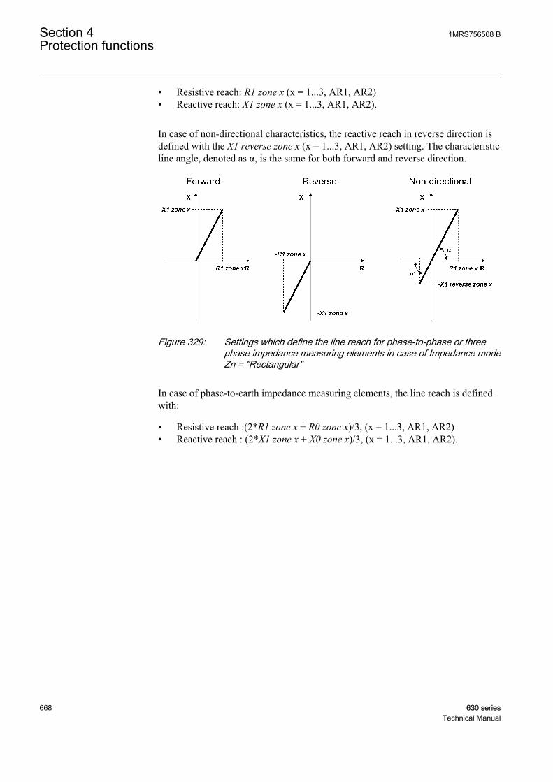
• Resistive reach: R1 zone x (x = 1...3, AR1, AR2)• Reactive reach: X1 zone x (x = 1...3, AR1, AR2).
In case of non-directional characteristics, the reactive reach in reverse direction isdefined with the X1 reverse zone x (x = 1...3, AR1, AR2) setting. The characteristicline angle, denoted as α, is the same for both forward and reverse direction.
GUID-4C1DE86E-2076-460B-A627-9538BCA22237 V1 EN
Figure 329: Settings which define the line reach for phase-to-phase or threephase impedance measuring elements in case of Impedance modeZn = "Rectangular"
In case of phase-to-earth impedance measuring elements, the line reach is definedwith:
• Resistive reach :(2*R1 zone x + R0 zone x)/3, (x = 1...3, AR1, AR2)• Reactive reach : (2*X1 zone x + X0 zone x)/3, (x = 1...3, AR1, AR2).
Section 4 1MRS756508 BProtection functions
668 630 seriesTechnical Manual

GUID-2570E424-A4D9-4E79-8D48-4940D07D9975 V1 EN
Figure 330: Settings which define line reach for phase-to-earth impedancemeasuring elements in case of Impedance mode Zn ="Rectangular" and forward or reverse directionality
In case of non-directional characteristics, the reactive reach in reverse direction isdefined with the X1 reverse zone x (x = 1...3, AR1, AR2) setting. The total reactivereach in reverse direction includes a part which is common to both forward andreverse direction. This part is automatically calculated based on the values of R1zone x, R0 zone 0, X1 zone x and X0 zone x settings. The characteristic line angle,denoted as α, is the same for forward and reverse direction.
1MRS756508 B Section 4Protection functions
630 series 669Technical Manual

GUID-C1268DE7-169A-4BCD-9896-05E65B5A4919 V1 EN
Figure 331: Settings which define the line reach for phase-to-earth impedancemeasuring elements in case of Impedance mode Zn ="Rectangular" and non-directional directionality
Impedance mode Zn = PolarIn case of phase-to-phase or three-phase impedance measuring elements, the linereach is defined with:
• Z1 zone x (x = 1...3, AR1, AR2)• Z1 angle zone x (x = 1...3 AR1, AR2)
In case of non-directional characteristics, the reactive reach magnitude in reversedirection is defined with the Z1 reverse zone x (x = 1...3, AR1, AR2) setting. Thecharacteristic line angle, Z1 angle zone x, is the same for forward and reversedirection.
Section 4 1MRS756508 BProtection functions
670 630 seriesTechnical Manual
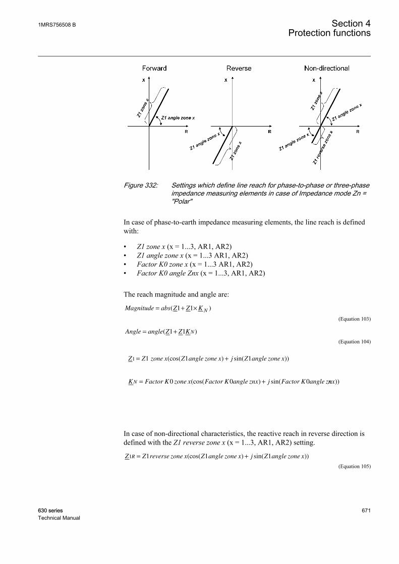
GUID-E0E4261B-794C-4C2B-8B24-CA95B086B619 V1 EN
Figure 332: Settings which define line reach for phase-to-phase or three-phaseimpedance measuring elements in case of Impedance mode Zn ="Polar"
In case of phase-to-earth impedance measuring elements, the line reach is definedwith:
• Z1 zone x (x = 1...3, AR1, AR2)• Z1 angle zone x (x = 1...3 AR1, AR2)• Factor K0 zone x (x = 1...3 AR1, AR2)• Factor K0 angle Znx (x = 1...3, AR1, AR2)
The reach magnitude and angle are:
Magnitude abs Z Z KN
= + ×( )1 1
GUID-E4CF913D-749C-4077-B57E-8DE8D7015AB3 V1 EN (Equation 103)
Angle angle Z Z KN= +( )1 1
GUID-FFD16052-88A1-4059-BC2C-D0B5DD1BDFCA V1 EN (Equation 104)
Z Z zone x Z angle zone x j Z angle zone x1 1 1 1= +(cos( ) sin( ))
GUID-BD71218F-BDC4-4664-9596-620C039E785D V1 EN
K Factor K zone x Factor K angle znx j Factor K angle zN = +0 0 0(cos( ) sin( nnx))
GUID-1E27246E-79FD-4ADA-A5F1-A724E45FE89D V1 EN
In case of non-directional characteristics, the reactive reach in reverse direction isdefined with the Z1 reverse zone x (x = 1...3, AR1, AR2) setting.
Z Z reverse zone x Z angle zone x j Z angle zone xR1 1 1 1= +(cos( ) sin( ))
GUID-9779A9CD-9A0A-4218-85E6-C2F09473EF88 V1 EN (Equation 105)
1MRS756508 B Section 4Protection functions
630 series 671Technical Manual
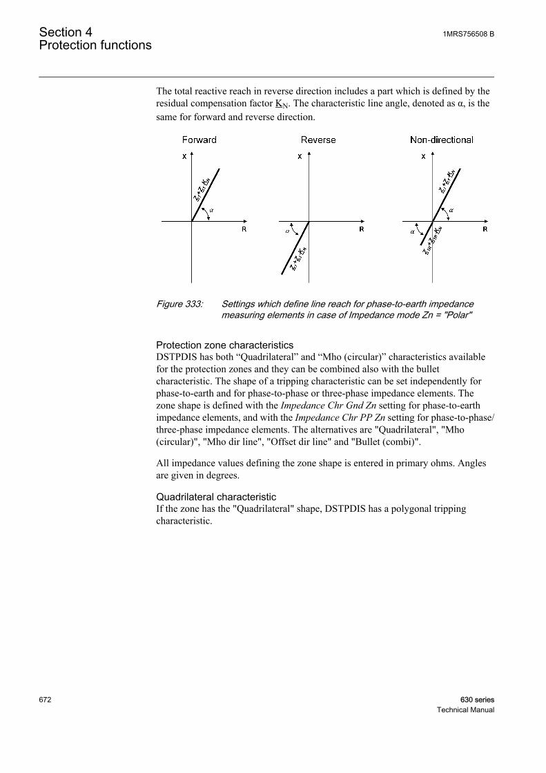
The total reactive reach in reverse direction includes a part which is defined by theresidual compensation factor KN. The characteristic line angle, denoted as α, is thesame for forward and reverse direction.
GUID-4F0CDEF1-F5CF-47CF-84C8-E645A1DFCF24 V1 EN
Figure 333: Settings which define line reach for phase-to-earth impedancemeasuring elements in case of Impedance mode Zn = "Polar"
Protection zone characteristicsDSTPDIS has both “Quadrilateral” and “Mho (circular)” characteristics availablefor the protection zones and they can be combined also with the bulletcharacteristic. The shape of a tripping characteristic can be set independently forphase-to-earth and for phase-to-phase or three-phase impedance elements. Thezone shape is defined with the Impedance Chr Gnd Zn setting for phase-to-earthimpedance elements, and with the Impedance Chr PP Zn setting for phase-to-phase/three-phase impedance elements. The alternatives are "Quadrilateral", "Mho(circular)", "Mho dir line", "Offset dir line" and "Bullet (combi)".
All impedance values defining the zone shape is entered in primary ohms. Anglesare given in degrees.
Quadrilateral characteristicIf the zone has the "Quadrilateral" shape, DSTPDIS has a polygonal trippingcharacteristic.
Section 4 1MRS756508 BProtection functions
672 630 seriesTechnical Manual
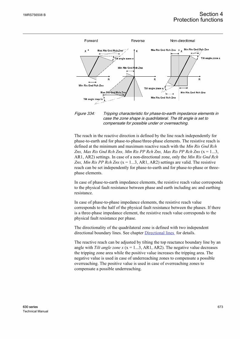
GUID-E8BBCC67-C630-4686-A01A-4331C833DAC7 V1 EN
Figure 334: Tripping characteristic for phase-to-earth impedance elements incase the zone shape is quadrilateral. The tilt angle is set tocompensate for possible under or overreaching.
The reach in the reactive direction is defined by the line reach independently forphase-to-earth and for phase-to-phase/three-phase elements. The resistive reach isdefined at the minimum and maximum reactive reach with the Min Ris Gnd RchZnx, Max Ris Gnd Rch Znx, Min Ris PP Rch Znx, Max Ris PP Rch Znx (x = 1...3,AR1, AR2) settings. In case of a non-directional zone, only the Min Ris Gnd RchZnx, Min Ris PP Rch Znx (x = 1...3, AR1, AR2) settings are valid. The resistivereach can be set independently for phase-to-earth and for phase-to-phase or three-phase elements.
In case of phase-to-earth impedance elements, the resistive reach value correspondsto the physical fault resistance between phase and earth including arc and earthingresistance.
In case of phase-to-phase impedance elements, the resistive reach valuecorresponds to the half of the physical fault resistance between the phases. If thereis a three-phase impedance element, the resistive reach value corresponds to thephysical fault resistance per phase.
The directionality of the quadrilateral zone is defined with two independentdirectional boundary lines. See chapter Directional lines for details.
The reactive reach can be adjusted by tilting the top reactance boundary line by anangle with Tilt angle zone x (x = 1...3, AR1, AR2). The negative value decreasesthe tripping zone area while the positive value increases the tripping area. Thenegative value is used in case of underreaching zones to compensate a possibleoverreaching. The positive value is used in case of overreaching zones tocompensate a possible underreaching.
1MRS756508 B Section 4Protection functions
630 series 673Technical Manual
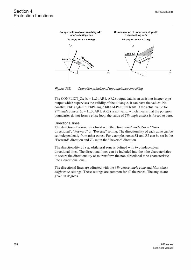
GUID-A0AF25AD-F990-4056-88F5-34723BA1C1FE V1 EN
Figure 335: Operation principle of top reactance line tilting
The CONFLICT_Zx (x = 1...3, AR1, AR2) output data is an assisting integer-typeoutput which supervises the validity of the tilt angle. It can have the values: Noconflict, PhE angle tilt, PhPh angle tilt and PhE, PhPh tilt. If the actual value forTilt angle zone x (x = 1...3, AR1, AR2) is not valid, which means that the polygonboundaries do not form a close loop, the value of Tilt angle zone x is forced to zero.
Directional linesThe direction of a zone is defined with the Directional mode Znx = "Non-directional", "Forward" or "Reverse" setting. The directionality of each zone can beset independently from other zones. For example, zones Z1 and Z2 can be set in the"Forward" direction and Z3 set in the "Reverse" direction.
The directionality of a quadrilateral zone is defined with two independentdirectional lines. The directional lines can be included into the mho characteristicsto secure the directionality or to transform the non-directional mho characteristicinto a directional one.
The directional lines are adjusted with the Min phase angle zone and Max phaseangle zone settings. These settings are common for all the zones. The angles aregiven in degrees.
Section 4 1MRS756508 BProtection functions
674 630 seriesTechnical Manual

GUID-17446A91-C260-4683-BE0A-B778541C1F32 V1 EN
Figure 336: Settings that adjust directional lines in case of quadrilateralcharacteristics
If there is no fault present, the calculated direction of the fault or load current isindicated in the DIRECTION = "Unknown", "Forward", "Reverse" or "Both"output. The direction is based on the measurement of the three-phase impedanceelement.
Voltage memoryThe directional lines are polarized with a positive sequence voltage for allimpedance measuring elements. The memory voltage is used with three-phaseimpedance measurement elements if the positive sequence voltage is too low. Thisassures the correct directional measurement in case of close-in three-phase faults,where the voltages on all three phases are close to zero. The memory voltage iscalculated using the positive-sequence voltage measured before the fault occurred.The memory function enables the function to operate up to a maximum of threeseconds after a total loss of voltage. This time can be set with the Voltage Memtime setting.
Mho circular characteristicWhen the zone characteristic is "Mho (circular)", the distance protection has acircular tripping characteristic. The zone reach is defined independently by the linereach for phase-to-earth and phase-to-phase/three-phase elements. The resistivereach of the tripping characteristic depends on the selected polarization methoddefined with the Pol quantity zone setting (Pol quantity zone = "Self Pol", "CrossPol", "Pos seq Pol"). The non-directional mho characteristics is an exception beingindependent from the selected polarization method. It is always explicitly definedby the reach settings and thus fixed in the impedance plane.
Table 647: Polarization methods and corresponding polarization voltages
Fault loop "Self Pol" "Cross Pol" "Pos seq Pol"
ZA UL1 j·UL23/√3 U1
ZB UL2 j·UL31/√3 U1·1∠-120°
Table continues on next page
1MRS756508 B Section 4Protection functions
630 series 675Technical Manual

ZC UL3 j·UL12/√3 U1·1∠120°
ZAB UL12 j·(UL23-UL31)/√3 U1·√3·1∠30°
ZBC UL23 j·(UL31-UL12)/√3 U1·√3·1∠-90°
ZCA UL31 j·(UL12-UL23)/√3 U1·√3·1∠150°
ZABC U11)
1) Regardless of the selected polarization method, the three-phase fault measuring element alwaysuses a positive sequence voltage for polarization. Memory voltage is included in the polarizationvoltage to secure directionality in case the positive sequence voltage becomes too small.
In case of self-polarization "Self pol", the polarization voltage is the faultedvoltage. The tripping characteristic is fixed in the impedance plane and defined bythe line reach.
GUID-C0CA4179-2858-4111-BD75-4517279DDFC1 V1 EN
Figure 337: Tripping characteristic in case the zone characteristic is "Mho(circular)" and Pol quantity zone is "Self pol"
In case of cross-polarization "Cross Pol", the polarization voltages is in theoryquadrature to the fault loop voltage. The phase angle of the polarization voltage isrotated 90 degrees to match the original fault loop voltage. The cross-polarizationexpands the tripping characteristic according to the prevailing system conditions.In case of short-circuit faults, the circle expands as a function of the sourceimpedance magnitude Z1source. In case of an earth fault, the circle expands as afunction of the source impedance Z1source, Z0source and earthing impedancemagnitude ZE as (2*Z1source + Z0source)/3 +ZE.
Section 4 1MRS756508 BProtection functions
676 630 seriesTechnical Manual
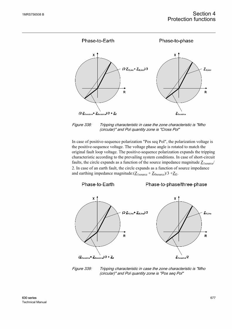
GUID-C8A7570F-11B4-4BDB-A833-CEAFAC96EB72 V2 EN
Figure 338: Tripping characteristic in case the zone characteristic is "Mho(circular)" and Pol quantity zone is "Cross Pol"
In case of positive-sequence polarization "Pos seq Pol", the polarization voltage isthe positive-sequence voltage. The voltage phase angle is rotated to match theoriginal fault loop voltage. The positive-sequence polarization expands the trippingcharacteristic according to the prevailing system conditions. In case of short-circuitfaults, the circle expands as a function of the source impedance magnitude Z1source/2. In case of an earth fault, the circle expands as a function of source impedanceand earthing impedance magnitude:(Z1source + Z0source)/3 +ZE.
GUID-16B49D5C-2C1B-4C16-AF67-DDB75983B16F V1 EN
Figure 339: Tripping characteristic in case the zone characteristic is "Mho(circular)" and Pol quantity zone is "Pos seq Pol"
1MRS756508 B Section 4Protection functions
630 series 677Technical Manual
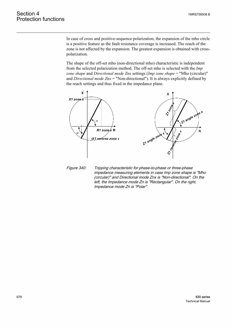
In case of cross and positive-sequence polarization, the expansion of the mho circleis a positive feature as the fault resistance coverage is increased. The reach of thezone is not affected by the expansion. The greatest expansion is obtained with cross-polarization.
The shape of the off-set mho (non-directional mho) characteristic is independentfrom the selected polarization method. The off-set mho is selected with the Impzone shape and Directional mode Znx settings (Imp zone shape = "Mho (circular)"and Directional mode Znx = "Non-directional"). It is always explicitly defined bythe reach settings and thus fixed in the impedance plane.
GUID-2A5B8628-6823-4C7A-BDE4-748DD4A88E37 V1 EN
Figure 340: Tripping characteristic for phase-to-phase or three-phaseimpedance measuring elements in case Imp zone shape is "Mho(circular)" and Directional mode Znx is "Non-directional". On theleft, the Impedance mode Zn is "Rectangular". On the right,Impedance mode Zn is "Polar".
Section 4 1MRS756508 BProtection functions
678 630 seriesTechnical Manual
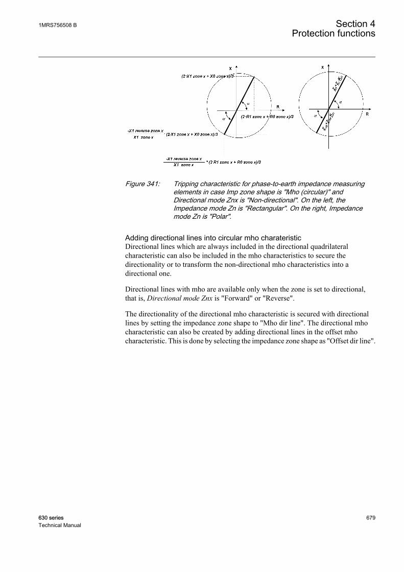
GUID-11313BFE-988D-411E-8767-E5A6E09C3889 V1 EN
Figure 341: Tripping characteristic for phase-to-earth impedance measuringelements in case Imp zone shape is "Mho (circular)" andDirectional mode Znx is "Non-directional". On the left, theImpedance mode Zn is "Rectangular". On the right, Impedancemode Zn is "Polar".
Adding directional lines into circular mho charateristicDirectional lines which are always included in the directional quadrilateralcharacteristic can also be included in the mho characteristics to secure thedirectionality or to transform the non-directional mho characteristics into adirectional one.
Directional lines with mho are available only when the zone is set to directional,that is, Directional mode Znx is "Forward" or "Reverse".
The directionality of the directional mho characteristic is secured with directionallines by setting the impedance zone shape to "Mho dir line". The directional mhocharacteristic can also be created by adding directional lines in the offset mhocharacteristic. This is done by selecting the impedance zone shape as "Offset dir line".
1MRS756508 B Section 4Protection functions
630 series 679Technical Manual

GUID-C075CCAC-AC5E-4793-B0DB-BCE9ACF7A7FC V1 EN
Figure 342: Possible combinations of the Directional mode Zx and zonecharacteristics settings. Pol. in the figure means that the shape ofthe characteristic is affected by the selected polarization method ofthe mho circle, Pol quantity zone = "Self Pol", "Cross Pol" and "PosSeq Pol"
Bullet combi characteristicIn case the impedance zone shape equals to "Bullet (combi)", the distanceprotection has a tripping characteristic which is a combination of the quadrilateraland mho. All settings relevant to the quadrilateral and mho are applicable. Theshape of the "Bullet (combi)" characteristic is affected by the selected polarizationmethod of the mho circle (Pol quantity zone = "Self Pol", "Cross Pol", "Pos seq Pol").
The directionality of the "Bullet (combi)" characteristic is defined by thedirectional lines when Directional mode Zx is "Forward" or "Reverse".
Section 4 1MRS756508 BProtection functions
680 630 seriesTechnical Manual
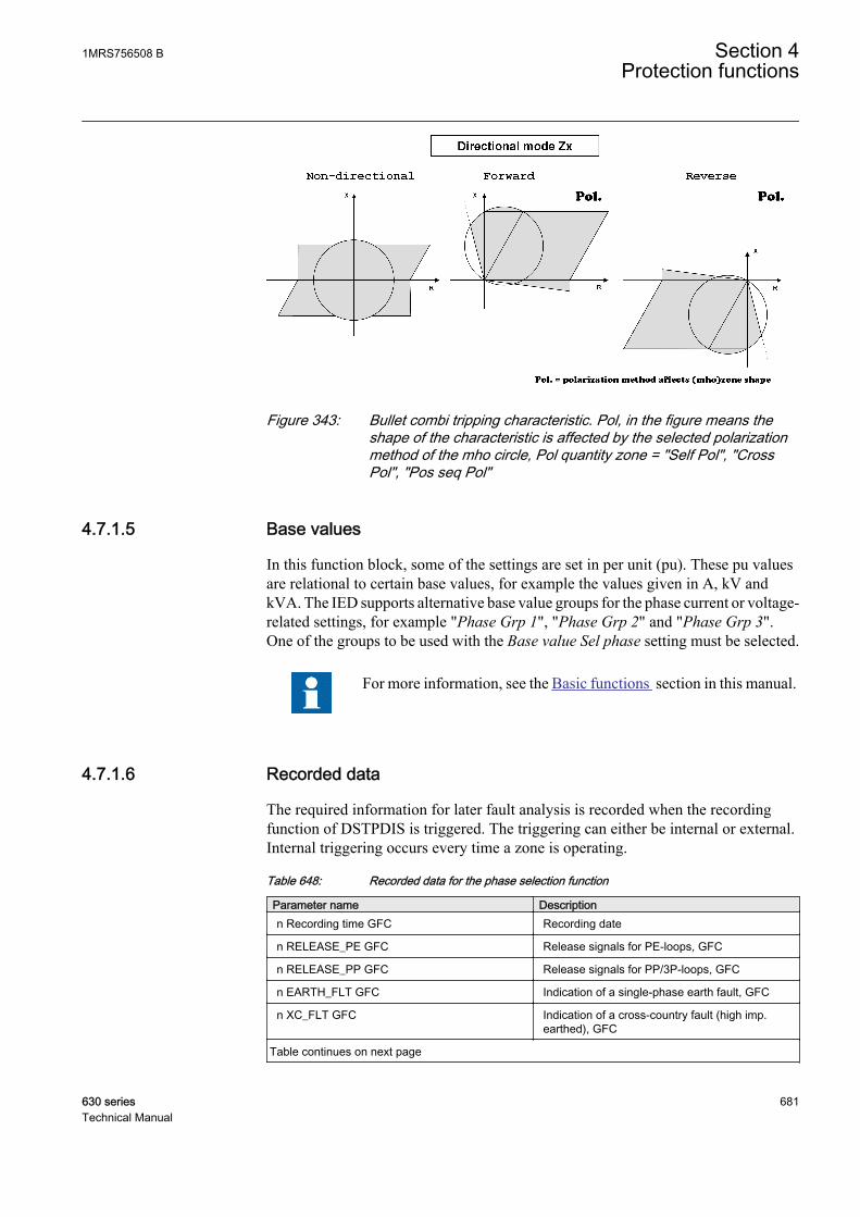
GUID-D6A4B225-F76D-40C7-8D9D-364787F35E8A V1 EN
Figure 343: Bullet combi tripping characteristic. Pol, in the figure means theshape of the characteristic is affected by the selected polarizationmethod of the mho circle, Pol quantity zone = "Self Pol", "CrossPol", "Pos seq Pol"
4.7.1.5 Base values
In this function block, some of the settings are set in per unit (pu). These pu valuesare relational to certain base values, for example the values given in A, kV andkVA. The IED supports alternative base value groups for the phase current or voltage-related settings, for example "Phase Grp 1", "Phase Grp 2" and "Phase Grp 3".One of the groups to be used with the Base value Sel phase setting must be selected.
For more information, see the Basic functions section in this manual.
4.7.1.6 Recorded data
The required information for later fault analysis is recorded when the recordingfunction of DSTPDIS is triggered. The triggering can either be internal or external.Internal triggering occurs every time a zone is operating.
Table 648: Recorded data for the phase selection function
Parameter name Descriptionn Recording time GFC Recording date
n RELEASE_PE GFC Release signals for PE-loops, GFC
n RELEASE_PP GFC Release signals for PP/3P-loops, GFC
n EARTH_FLT GFC Indication of a single-phase earth fault, GFC
n XC_FLT GFC Indication of a cross-country fault (high imp.earthed), GFC
Table continues on next page
1MRS756508 B Section 4Protection functions
630 series 681Technical Manual

Parameter name Descriptionn DIR_E_FLT GFC Earth-fault direction (low imp. earthed), GFC
n DIRECTION Direction of fault or load
n Zones OPERATE Operate signals of all zones
The direction of the fault is indicated with the parameter n DIRECTION("Unknown", "Forward", "Reverse" or "Both"). In case of a no-fault condition, thedirection of the load current seen by a three-phase fault measuring element isindicated.
The parameter n Zones OPERATE can have the values (0...31):
:
Table 649: Enumeration values and names for the parameter n Zones OPERATE
Enumerator value Enumerator name0 No Zn operates
1 Zn1
2 Zn2
3 Zn1,2
4 Zn3
5 Zn1,3
6 Zn2,3
7 Zn1,2,3
8 AR1
9 Zn1,AR1
10 Zn2,AR1
11 Zn1,2,AR1
12 Zn3,AR1
13 Zn1,3,AR1
14 Zn2,3,AR1
15 Zn1,2,3,AR1
16 AR2
17 Zn1,AR2
18 Zn2,AR2
19 Zn1,2,AR2
20 Zn3,AR2
21 Zn1,3,AR2
22 Zn2,3,AR2
23 Zn1,2,3,AR2
24 AR1,AR2
25 Zn1,AR1,AR2
Table continues on next page
Section 4 1MRS756508 BProtection functions
682 630 seriesTechnical Manual
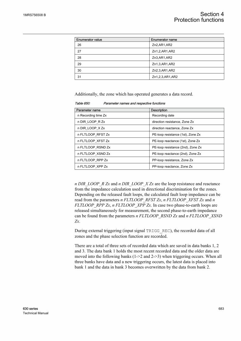
Enumerator value Enumerator name26 Zn2,AR1,AR2
27 Zn1,2,AR1,AR2
28 Zn3,AR1,AR2
29 Zn1,3,AR1,AR2
30 Zn2,3,AR1,AR2
31 Zn1,2,3,AR1,AR2
Additionally, the zone which has operated generates a data record.
Table 650: Parameter names and respective functions
Parameter name Descriptionn Recording time Zx Recording date
n DIR_LOOP_R Zx direction resistance, Zone Zx
n DIR_LOOP_X Zx direction reactance, Zone Zx
n FLTLOOP_RFST Zx PE-loop resistance (1st), Zone Zx
n FLTLOOP_XFST Zx PE-loop reactance (1st), Zone Zx
n FLTLOOP_RSND Zx PE-loop resistance (2nd), Zone Zx
n FLTLOOP_XSND Zx PE-loop reactance (2nd), Zone Zx
n FLTLOOP_RPP Zx PP-loop resistance, Zone Zx
n FLTLOOP_XPP Zx PP-loop reactance, Zone Zx
n DIR_LOOP_R Zx and n DIR_LOOP_X Zx are the loop resistance and reactancefrom the impedance calculation used in directional discrimination for the zones.Depending on the released fault loops, the calculated fault loop impedance can beread from the parameters n FLTLOOP_RFST Zx, n FLTLOOP_XFST Zx and nFLTLOOP_RPP Zx, n FLTLOOP_XPP Zx. In case two phase-to-earth loops arereleased simultaneously for measurement, the second phase-to-earth impedancecan be found from the parameters n FLTLOOP_RSND Zx and n FLTLOOP_XSNDZx.
During external triggering (input signal TRIGG_REC), the recorded data of allzones and the phase selection function are recorded.
There are a total of three sets of recorded data which are saved in data banks 1, 2and 3. The data bank 1 holds the most recent recorded data and the older data aremoved into the following banks (1->2 and 2->3) when triggering occurs. When allthree banks have data and a new triggering occurs, the latest data is placed intobank 1 and the data in bank 3 becomes overwritten by the data from bank 2.
1MRS756508 B Section 4Protection functions
630 series 683Technical Manual

4.7.1.7 Application
DSTPDIS provides a fast and reliable protection for overhead lines and powercables. DSTPDIS is applied in distribution and sub-transmission networks wherethree-phase tripping is allowed for all kinds of faults.
GUID-8CCC2537-4568-4097-A173-87398731E593 V1 EN
Figure 344: Application scope of DSTPDIS
Typically these networks are operated in ring or meshed type of configurations. Itis also characteristic for these networks that the switching state is changedfrequently due to daily operation and load flow considerations. The networks alsoinclude varying capacities of distributed generation. This makes it impossible toapply simple overcurrent based schemes. In these kind of networks, DSTPDIS isused to provide a fast and selective protection for overhead lines and power cables.It can also be applied for radial feeders to increase the sensitivity of the protection,especially if the short circuit power of the source is low or it is changing due tonetwork operation.
From selectivity point of view, it is advantageous that in the protection chain allfunctions in different positions operate according to the same measuring principle.Therefore, DSTPDIS can also be applied for the backup protection of maintransformers and buses. This way the selectivity with the distance protection of theoutgoing lines is easier to achieve.
Section 4 1MRS756508 BProtection functions
684 630 seriesTechnical Manual
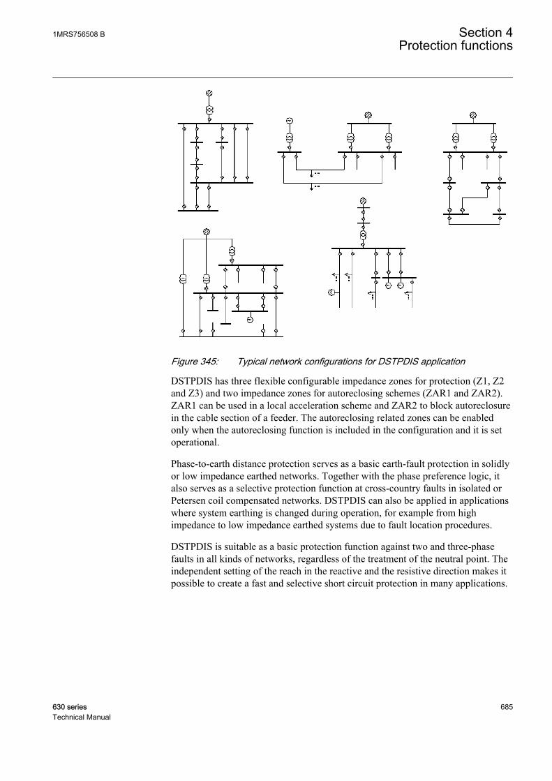
GUID-B45F50FA-E707-4C55-BFD1-96E3B01A102B V1 EN
Figure 345: Typical network configurations for DSTPDIS application
DSTPDIS has three flexible configurable impedance zones for protection (Z1, Z2and Z3) and two impedance zones for autoreclosing schemes (ZAR1 and ZAR2).ZAR1 can be used in a local acceleration scheme and ZAR2 to block autoreclosurein the cable section of a feeder. The autoreclosing related zones can be enabledonly when the autoreclosing function is included in the configuration and it is setoperational.
Phase-to-earth distance protection serves as a basic earth-fault protection in solidlyor low impedance earthed networks. Together with the phase preference logic, italso serves as a selective protection function at cross-country faults in isolated orPetersen coil compensated networks. DSTPDIS can also be applied in applicationswhere system earthing is changed during operation, for example from highimpedance to low impedance earthed systems due to fault location procedures.
DSTPDIS is suitable as a basic protection function against two and three-phasefaults in all kinds of networks, regardless of the treatment of the neutral point. Theindependent setting of the reach in the reactive and the resistive direction makes itpossible to create a fast and selective short circuit protection in many applications.
1MRS756508 B Section 4Protection functions
630 series 685Technical Manual
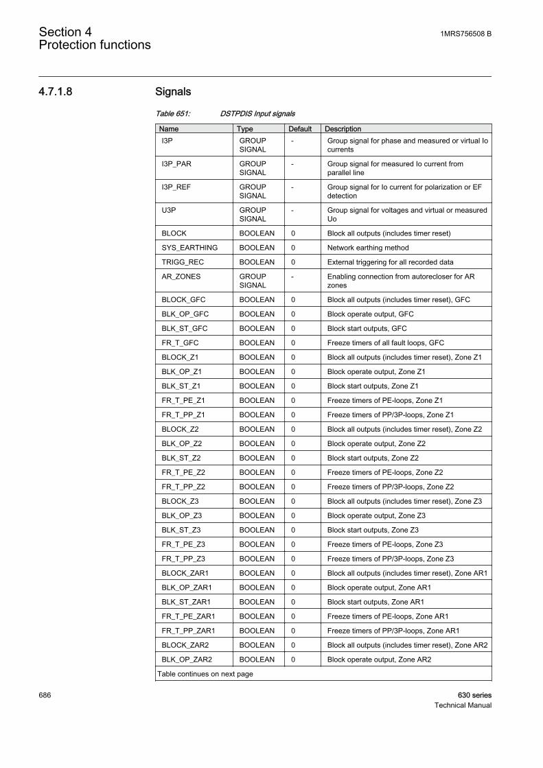
4.7.1.8 Signals
Table 651: DSTPDIS Input signals
Name Type Default DescriptionI3P GROUP
SIGNAL- Group signal for phase and measured or virtual Io
currents
I3P_PAR GROUPSIGNAL
- Group signal for measured Io current fromparallel line
I3P_REF GROUPSIGNAL
- Group signal for Io current for polarization or EFdetection
U3P GROUPSIGNAL
- Group signal for voltages and virtual or measuredUo
BLOCK BOOLEAN 0 Block all outputs (includes timer reset)
SYS_EARTHING BOOLEAN 0 Network earthing method
TRIGG_REC BOOLEAN 0 External triggering for all recorded data
AR_ZONES GROUPSIGNAL
- Enabling connection from autorecloser for ARzones
BLOCK_GFC BOOLEAN 0 Block all outputs (includes timer reset), GFC
BLK_OP_GFC BOOLEAN 0 Block operate output, GFC
BLK_ST_GFC BOOLEAN 0 Block start outputs, GFC
FR_T_GFC BOOLEAN 0 Freeze timers of all fault loops, GFC
BLOCK_Z1 BOOLEAN 0 Block all outputs (includes timer reset), Zone Z1
BLK_OP_Z1 BOOLEAN 0 Block operate output, Zone Z1
BLK_ST_Z1 BOOLEAN 0 Block start outputs, Zone Z1
FR_T_PE_Z1 BOOLEAN 0 Freeze timers of PE-loops, Zone Z1
FR_T_PP_Z1 BOOLEAN 0 Freeze timers of PP/3P-loops, Zone Z1
BLOCK_Z2 BOOLEAN 0 Block all outputs (includes timer reset), Zone Z2
BLK_OP_Z2 BOOLEAN 0 Block operate output, Zone Z2
BLK_ST_Z2 BOOLEAN 0 Block start outputs, Zone Z2
FR_T_PE_Z2 BOOLEAN 0 Freeze timers of PE-loops, Zone Z2
FR_T_PP_Z2 BOOLEAN 0 Freeze timers of PP/3P-loops, Zone Z2
BLOCK_Z3 BOOLEAN 0 Block all outputs (includes timer reset), Zone Z3
BLK_OP_Z3 BOOLEAN 0 Block operate output, Zone Z3
BLK_ST_Z3 BOOLEAN 0 Block start outputs, Zone Z3
FR_T_PE_Z3 BOOLEAN 0 Freeze timers of PE-loops, Zone Z3
FR_T_PP_Z3 BOOLEAN 0 Freeze timers of PP/3P-loops, Zone Z3
BLOCK_ZAR1 BOOLEAN 0 Block all outputs (includes timer reset), Zone AR1
BLK_OP_ZAR1 BOOLEAN 0 Block operate output, Zone AR1
BLK_ST_ZAR1 BOOLEAN 0 Block start outputs, Zone AR1
FR_T_PE_ZAR1 BOOLEAN 0 Freeze timers of PE-loops, Zone AR1
FR_T_PP_ZAR1 BOOLEAN 0 Freeze timers of PP/3P-loops, Zone AR1
BLOCK_ZAR2 BOOLEAN 0 Block all outputs (includes timer reset), Zone AR2
BLK_OP_ZAR2 BOOLEAN 0 Block operate output, Zone AR2
Table continues on next page
Section 4 1MRS756508 BProtection functions
686 630 seriesTechnical Manual
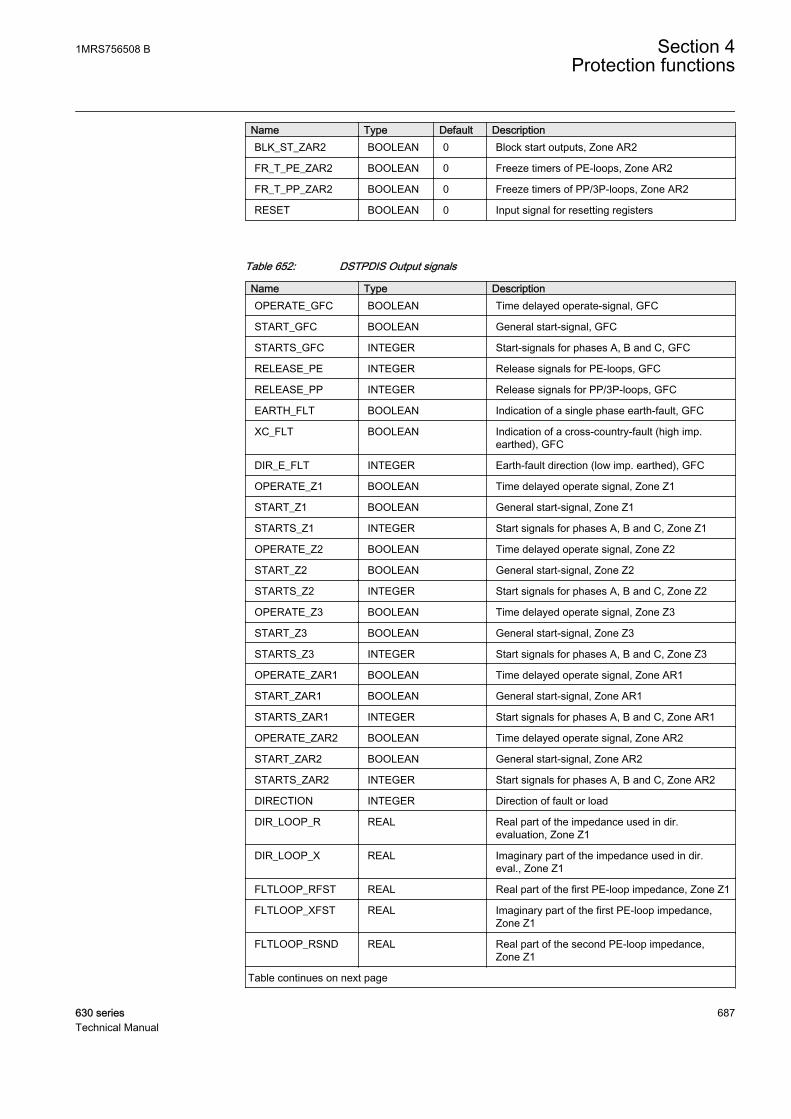
Name Type Default DescriptionBLK_ST_ZAR2 BOOLEAN 0 Block start outputs, Zone AR2
FR_T_PE_ZAR2 BOOLEAN 0 Freeze timers of PE-loops, Zone AR2
FR_T_PP_ZAR2 BOOLEAN 0 Freeze timers of PP/3P-loops, Zone AR2
RESET BOOLEAN 0 Input signal for resetting registers
Table 652: DSTPDIS Output signals
Name Type DescriptionOPERATE_GFC BOOLEAN Time delayed operate-signal, GFC
START_GFC BOOLEAN General start-signal, GFC
STARTS_GFC INTEGER Start-signals for phases A, B and C, GFC
RELEASE_PE INTEGER Release signals for PE-loops, GFC
RELEASE_PP INTEGER Release signals for PP/3P-loops, GFC
EARTH_FLT BOOLEAN Indication of a single phase earth-fault, GFC
XC_FLT BOOLEAN Indication of a cross-country-fault (high imp.earthed), GFC
DIR_E_FLT INTEGER Earth-fault direction (low imp. earthed), GFC
OPERATE_Z1 BOOLEAN Time delayed operate signal, Zone Z1
START_Z1 BOOLEAN General start-signal, Zone Z1
STARTS_Z1 INTEGER Start signals for phases A, B and C, Zone Z1
OPERATE_Z2 BOOLEAN Time delayed operate signal, Zone Z2
START_Z2 BOOLEAN General start-signal, Zone Z2
STARTS_Z2 INTEGER Start signals for phases A, B and C, Zone Z2
OPERATE_Z3 BOOLEAN Time delayed operate signal, Zone Z3
START_Z3 BOOLEAN General start-signal, Zone Z3
STARTS_Z3 INTEGER Start signals for phases A, B and C, Zone Z3
OPERATE_ZAR1 BOOLEAN Time delayed operate signal, Zone AR1
START_ZAR1 BOOLEAN General start-signal, Zone AR1
STARTS_ZAR1 INTEGER Start signals for phases A, B and C, Zone AR1
OPERATE_ZAR2 BOOLEAN Time delayed operate signal, Zone AR2
START_ZAR2 BOOLEAN General start-signal, Zone AR2
STARTS_ZAR2 INTEGER Start signals for phases A, B and C, Zone AR2
DIRECTION INTEGER Direction of fault or load
DIR_LOOP_R REAL Real part of the impedance used in dir.evaluation, Zone Z1
DIR_LOOP_X REAL Imaginary part of the impedance used in dir.eval., Zone Z1
FLTLOOP_RFST REAL Real part of the first PE-loop impedance, Zone Z1
FLTLOOP_XFST REAL Imaginary part of the first PE-loop impedance,Zone Z1
FLTLOOP_RSND REAL Real part of the second PE-loop impedance,Zone Z1
Table continues on next page
1MRS756508 B Section 4Protection functions
630 series 687Technical Manual
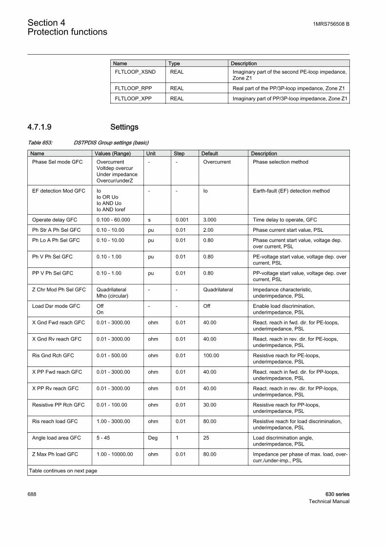
Name Type DescriptionFLTLOOP_XSND REAL Imaginary part of the second PE-loop impedance,
Zone Z1
FLTLOOP_RPP REAL Real part of the PP/3P-loop impedance, Zone Z1
FLTLOOP_XPP REAL Imaginary part of PP/3P-loop impedance, Zone Z1
4.7.1.9 Settings
Table 653: DSTPDIS Group settings (basic)
Name Values (Range) Unit Step Default DescriptionPhase Sel mode GFC Overcurrent
Voltdep overcurUnder impedanceOvercur/underZ
- - Overcurrent Phase selection method
EF detection Mod GFC IoIo OR UoIo AND UoIo AND Ioref
- - Io Earth-fault (EF) detection method
Operate delay GFC 0.100 - 60.000 s 0.001 3.000 Time delay to operate, GFC
Ph Str A Ph Sel GFC 0.10 - 10.00 pu 0.01 2.00 Phase current start value, PSL
Ph Lo A Ph Sel GFC 0.10 - 10.00 pu 0.01 0.80 Phase current start value, voltage dep.over current, PSL
Ph V Ph Sel GFC 0.10 - 1.00 pu 0.01 0.80 PE-voltage start value, voltage dep. overcurrent, PSL
PP V Ph Sel GFC 0.10 - 1.00 pu 0.01 0.80 PP-voltage start value, voltage dep. overcurrent, PSL
Z Chr Mod Ph Sel GFC QuadrilateralMho (circular)
- - Quadrilateral Impedance characteristic,underimpedance, PSL
Load Dsr mode GFC OffOn
- - Off Enable load discrimination,underimpedance, PSL
X Gnd Fwd reach GFC 0.01 - 3000.00 ohm 0.01 40.00 React. reach in fwd. dir. for PE-loops,underimpedance, PSL
X Gnd Rv reach GFC 0.01 - 3000.00 ohm 0.01 40.00 React. reach in rev. dir. for PE-loops,underimpedance, PSL
Ris Gnd Rch GFC 0.01 - 500.00 ohm 0.01 100.00 Resistive reach for PE-loops,underimpedance, PSL
X PP Fwd reach GFC 0.01 - 3000.00 ohm 0.01 40.00 React. reach in fwd. dir. for PP-loops,underimpedance, PSL
X PP Rv reach GFC 0.01 - 3000.00 ohm 0.01 40.00 React. reach in rev. dir. for PP-loops,underimpedance, PSL
Resistive PP Rch GFC 0.01 - 100.00 ohm 0.01 30.00 Resistive reach for PP-loops,underimpedance, PSL
Ris reach load GFC 1.00 - 3000.00 ohm 0.01 80.00 Resistive reach for load discrimination,underimpedance, PSL
Angle load area GFC 5 - 45 Deg 1 25 Load discrimination angle,underimpedance, PSL
Z Max Ph load GFC 1.00 - 10000.00 ohm 0.01 80.00 Impedance per phase of max. load, over-curr./under-imp., PSL
Table continues on next page
Section 4 1MRS756508 BProtection functions
688 630 seriesTechnical Manual
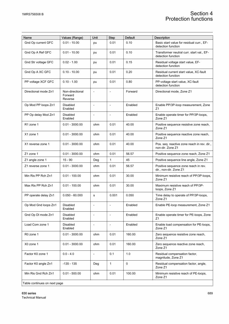
Name Values (Range) Unit Step Default DescriptionGnd Op current GFC 0.01 - 10.00 pu 0.01 0.10 Basic start value for residual curr., EF-
detection function
Gnd Op A Ref GFC 0.01 - 10.00 pu 0.01 0.10 Transformer neutral curr. start val., EF-detection function
Gnd Str voltage GFC 0.02 - 1.00 pu 0.01 0.15 Residual voltage start value, EF-detection function
Gnd Op A XC GFC 0.10 - 10.00 pu 0.01 0.20 Residual current start value, XC-faultdetection function
PP voltage XCF GFC 0.10 - 1.00 pu 0.01 0.80 PP-voltage start value, XC-faultdetection function
Directional mode Zn1 Non-directionalForwardReverse
- - Forward Directional mode, Zone Z1
Op Mod PP loops Zn1 DisabledEnabled
- - Enabled Enable PP/3P-loop measurement, ZoneZ1
PP Op delay Mod Zn1 DisabledEnabled
- - Enabled Enable operate timer for PP/3P-loops,Zone Z1
R1 zone 1 0.01 - 3000.00 ohm 0.01 40.00 Positive sequence resistive zone reach,Zone Z1
X1 zone 1 0.01 - 3000.00 ohm 0.01 40.00 Positive sequence reactive zone reach,Zone Z1
X1 reverse zone 1 0.01 - 3000.00 ohm 0.01 40.00 Pos. seq. reactive zone reach in rev. dir.,non-dir. Zone Z1
Z1 zone 1 0.01 - 3000.00 ohm 0.01 56.57 Positive sequence zone reach, Zone Z1
Z1 angle zone 1 15 - 90 Deg 1 45 Positive sequence line angle, Zone Z1
Z1 reverse zone 1 0.01 - 3000.00 ohm 0.01 56.57 Positive sequence zone reach in rev.dir., non-dir. Zone Z1
Min Ris PP Rch Zn1 0.01 - 100.00 ohm 0.01 30.00 Minimum resistive reach of PP/3P-loops,Zone Z1
Max Ris PP Rch Zn1 0.01 - 100.00 ohm 0.01 30.00 Maximum resistive reach of PP/3P-loops, Zone Z1
PP operate delay Zn1 0.050 - 60.000 s 0.001 0.050 Time delay to operate of PP/3P-loops,Zone Z1
Op Mod Gnd loops Zn1 DisabledEnabled
- - Enabled Enable PE-loop measurement, Zone Z1
Gnd Op Dl mode Zn1 DisabledEnabled
- - Enabled Enable operate timer for PE-loops, ZoneZ1
Load Com zone 1 DisabledEnabled
- - Enabled Enable load compensation for PE-loops,Zone Z1
R0 zone 1 0.01 - 3000.00 ohm 0.01 160.00 Zero sequence resistive zone reach,Zone Z1
X0 zone 1 0.01 - 3000.00 ohm 0.01 160.00 Zero sequence reactive zone reach,Zone Z1
Factor K0 zone 1 0.0 - 4.0 - 0.1 1.0 Residual compensation factor,magnitude, Zone Z1
Factor K0 angle Zn1 -135 - 135 Deg 1 0 Residual compensation factor, angle,Zone Z1
Min Ris Gnd Rch Zn1 0.01 - 500.00 ohm 0.01 100.00 Minimum resistive reach of PE-loops,Zone Z1
Table continues on next page
1MRS756508 B Section 4Protection functions
630 series 689Technical Manual
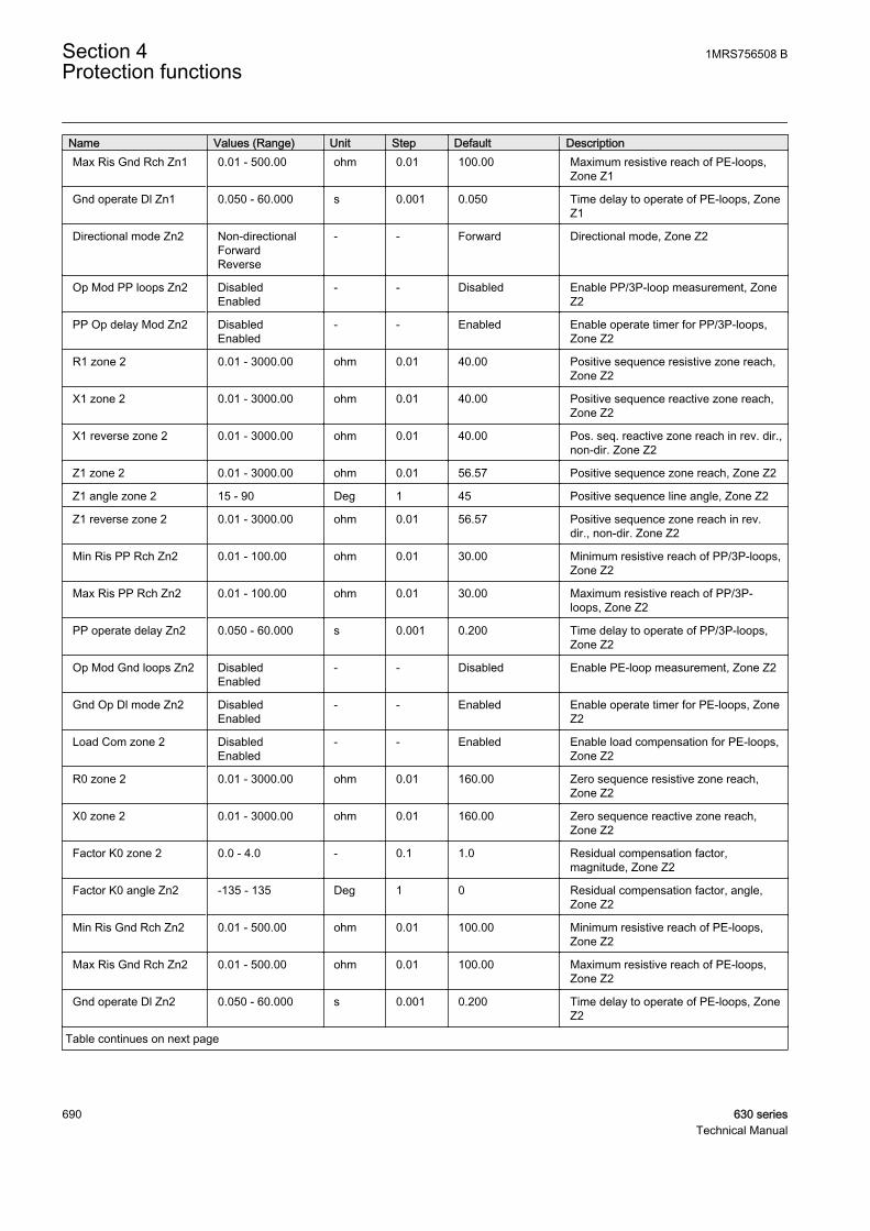
Name Values (Range) Unit Step Default DescriptionMax Ris Gnd Rch Zn1 0.01 - 500.00 ohm 0.01 100.00 Maximum resistive reach of PE-loops,
Zone Z1
Gnd operate Dl Zn1 0.050 - 60.000 s 0.001 0.050 Time delay to operate of PE-loops, ZoneZ1
Directional mode Zn2 Non-directionalForwardReverse
- - Forward Directional mode, Zone Z2
Op Mod PP loops Zn2 DisabledEnabled
- - Disabled Enable PP/3P-loop measurement, ZoneZ2
PP Op delay Mod Zn2 DisabledEnabled
- - Enabled Enable operate timer for PP/3P-loops,Zone Z2
R1 zone 2 0.01 - 3000.00 ohm 0.01 40.00 Positive sequence resistive zone reach,Zone Z2
X1 zone 2 0.01 - 3000.00 ohm 0.01 40.00 Positive sequence reactive zone reach,Zone Z2
X1 reverse zone 2 0.01 - 3000.00 ohm 0.01 40.00 Pos. seq. reactive zone reach in rev. dir.,non-dir. Zone Z2
Z1 zone 2 0.01 - 3000.00 ohm 0.01 56.57 Positive sequence zone reach, Zone Z2
Z1 angle zone 2 15 - 90 Deg 1 45 Positive sequence line angle, Zone Z2
Z1 reverse zone 2 0.01 - 3000.00 ohm 0.01 56.57 Positive sequence zone reach in rev.dir., non-dir. Zone Z2
Min Ris PP Rch Zn2 0.01 - 100.00 ohm 0.01 30.00 Minimum resistive reach of PP/3P-loops,Zone Z2
Max Ris PP Rch Zn2 0.01 - 100.00 ohm 0.01 30.00 Maximum resistive reach of PP/3P-loops, Zone Z2
PP operate delay Zn2 0.050 - 60.000 s 0.001 0.200 Time delay to operate of PP/3P-loops,Zone Z2
Op Mod Gnd loops Zn2 DisabledEnabled
- - Disabled Enable PE-loop measurement, Zone Z2
Gnd Op Dl mode Zn2 DisabledEnabled
- - Enabled Enable operate timer for PE-loops, ZoneZ2
Load Com zone 2 DisabledEnabled
- - Enabled Enable load compensation for PE-loops,Zone Z2
R0 zone 2 0.01 - 3000.00 ohm 0.01 160.00 Zero sequence resistive zone reach,Zone Z2
X0 zone 2 0.01 - 3000.00 ohm 0.01 160.00 Zero sequence reactive zone reach,Zone Z2
Factor K0 zone 2 0.0 - 4.0 - 0.1 1.0 Residual compensation factor,magnitude, Zone Z2
Factor K0 angle Zn2 -135 - 135 Deg 1 0 Residual compensation factor, angle,Zone Z2
Min Ris Gnd Rch Zn2 0.01 - 500.00 ohm 0.01 100.00 Minimum resistive reach of PE-loops,Zone Z2
Max Ris Gnd Rch Zn2 0.01 - 500.00 ohm 0.01 100.00 Maximum resistive reach of PE-loops,Zone Z2
Gnd operate Dl Zn2 0.050 - 60.000 s 0.001 0.200 Time delay to operate of PE-loops, ZoneZ2
Table continues on next page
Section 4 1MRS756508 BProtection functions
690 630 seriesTechnical Manual

Name Values (Range) Unit Step Default DescriptionDirectional mode Zn3 Non-directional
ForwardReverse
- - Forward Directional mode, Zone Z3
Op Mod PP loops Zn3 DisabledEnabled
- - Disabled Enable PP/3P-loop measurement, ZoneZ3
PP Op delay Mod Zn3 DisabledEnabled
- - Enabled Enable operate timer for PP/3P-loops,Zone Z3
R1 zone 3 0.01 - 3000.00 ohm 0.01 40.00 Positive sequence resistive zone reach,Zone Z3
X1 zone 3 0.01 - 3000.00 ohm 0.01 40.00 Positive sequence reactive zone reach,Zone Z3
X1 reverse zone 3 0.01 - 3000.00 ohm 0.01 40.00 Pos. seq. reactive zone reach in rev. dir.,non-dir. Zone Z3
Z1 zone 3 0.01 - 3000.00 ohm 0.01 56.57 Positive sequence zone reach, Zone Z3
Z1 angle zone 3 15 - 90 Deg 1 45 Positive sequence line angle, Zone Z3
Z1 reverse zone 3 0.01 - 3000.00 ohm 0.01 56.57 Positive sequence zone reach in rev.dir., non-dir. Zone Z3
Min Ris PP Rch Zn3 0.01 - 100.00 ohm 0.01 30.00 Minimum resistive reach of PP/3P-loops,Zone Z3
Max Ris PP Rch Zn3 0.01 - 100.00 ohm 0.01 30.00 Maximum resistive reach of PP/3P-loops, Zone Z3
PP operate delay Zn3 0.050 - 60.000 s 0.001 0.400 Time delay to operate of PP/3P-loops,Zone Z3
Op Mod Gnd loops Zn3 DisabledEnabled
- - Disabled Enable PE-loop measurement, Zone Z3
Gnd Op Dl mode Zn3 DisabledEnabled
- - Enabled Enable operate timer for PE-loops, ZoneZ3
Load Com zone 3 DisabledEnabled
- - Enabled Enable load compensation for PE-loops,Zone Z3
R0 zone 3 0.01 - 3000.00 ohm 0.01 160.00 Zero sequence resistive zone reach,Zone Z3
X0 zone 3 0.01 - 3000.00 ohm 0.01 160.00 Zero sequence reactive zone reach,Zone Z3
Factor K0 zone 3 0.0 - 4.0 - 0.1 1.0 Residual compensation factor,magnitude, Zone Z3
Factor K0 angle Zn3 -135 - 135 Deg 1 0 Residual compensation factor, angle,Zone Z3
Min Ris Gnd Rch Zn3 0.01 - 500.00 ohm 0.01 100.00 Minimum resistive reach of PE-loops,Zone Z3
Max Ris Gnd Rch Zn3 0.01 - 500.00 ohm 0.01 100.00 Maximum resistive reach of PE-loops,Zone Z3
Gnd operate Dl Zn3 0.050 - 60.000 s 0.001 0.400 Time delay to operate of PE-loops, ZoneZ3
Directional mode AR1 Non-directionalForwardReverse
- - Forward Directional mode, Zone AR1
Op Mod PP loops AR1 DisabledEnabled
- - Disabled Enable PP/3P-loop measurement, ZoneAR1
Table continues on next page
1MRS756508 B Section 4Protection functions
630 series 691Technical Manual

Name Values (Range) Unit Step Default DescriptionPP Op delay Mod AR1 Disabled
Enabled- - Enabled Enable operate timer for PP/3P-loops,
Zone AR1
R1 AR1 0.01 - 3000.00 ohm 0.01 40.00 Positive sequence resistive zone reach,Zone AR1
X1 AR1 0.01 - 3000.00 ohm 0.01 40.00 Positive sequence reactive zone reach,Zone AR1
X1 reverse AR1 0.01 - 3000.00 ohm 0.01 40.00 Pos. seq. reactive zone reach in rev. dir,non-dir. Zone AR1
Z1 AR1 0.01 - 3000.00 ohm 0.01 56.57 Positive sequence zone reach, Zone AR1
Z1 angle AR1 15 - 90 Deg 1 45 Positive sequence line angle, Zone AR1
Z1 reverse AR1 0.01 - 3000.00 ohm 0.01 56.57 Positive sequence zone reach in rev.dir., non-dir. Zone AR1
Min Ris PP Rch AR1 0.01 - 100.00 ohm 0.01 30.00 Minimum resistive reach of PP/3P-loops,Zone AR1
Max Ris PP Rch AR1 0.01 - 100.00 ohm 0.01 30.00 Maximum resistive reach of PP/3P-loops, Zone AR1
PP operate delay AR1 0.050 - 60.000 s 0.001 0.050 Time delay to operate of PP/3P-loops,Zone AR1
Op Mod Gnd loops AR1 DisabledEnabled
- - Disabled Enable PE-loop measurement, Zone AR1
Gnd Op Dl mode AR1 DisabledEnabled
- - Enabled Enable operate timer for PE-loops, ZoneAR1
Load Com AR1 DisabledEnabled
- - Enabled Enable load compensation for PE-loops,Zone AR1
R0 AR1 0.01 - 3000.00 ohm 0.01 160.00 Zero sequence resistive zone reach,Zone AR1
X0 AR1 0.01 - 3000.00 ohm 0.01 160.00 Zero sequence reactive zone reach,Zone AR1
Factor K0 AR1 0.0 - 4.0 - 0.1 1.0 Residual compensation factor,magnitude, Zone AR1
Factor K0 angle AR1 -135 - 135 Deg 1 0 Residual compensation factor, angle,Zone AR1
Min Ris Gnd Rch AR1 0.01 - 500.00 ohm 0.01 100.00 Minimum resistive reach of PE-loops,Zone AR1
Max Ris Gnd Rch AR1 0.01 - 500.00 ohm 0.01 100.00 Maximum resistive reach of PE-loops,Zone AR1
Gnd operate Dl AR1 0.050 - 60.000 s 0.001 0.050 Time delay to operate of PE-loops, ZoneAR1
Directional mode AR2 Non-directionalForwardReverse
- - Forward Directional mode, Zone AR2
Op Mod PP loops AR2 DisabledEnabled
- - Disabled Enable PP/3P-loop measurement, ZoneAR2
PP Op delay Mod AR2 DisabledEnabled
- - Enabled Enable operate timer for PP/3P-loops,Zone AR2
R1 AR2 0.01 - 3000.00 ohm 0.01 40.00 Positive sequence resistive zone reach,Zone AR2
X1 AR2 0.01 - 3000.00 ohm 0.01 40.00 Positive sequence reactive zone reach,Zone AR2
Table continues on next page
Section 4 1MRS756508 BProtection functions
692 630 seriesTechnical Manual
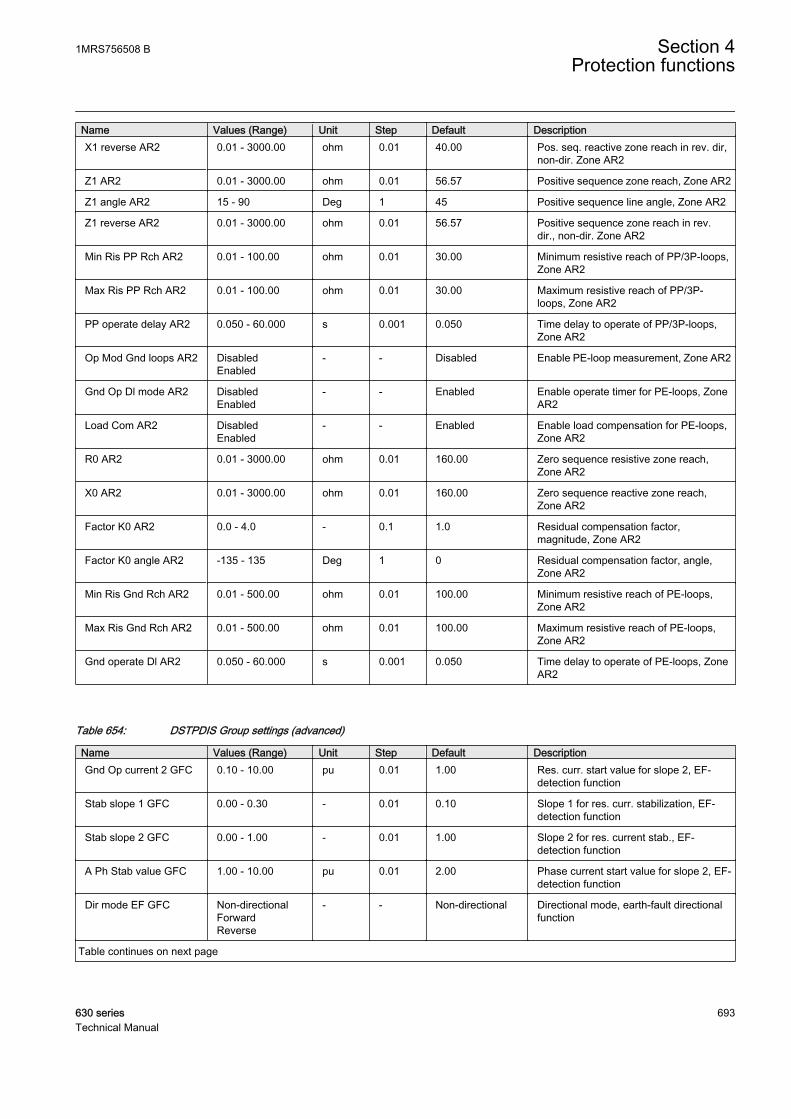
Name Values (Range) Unit Step Default DescriptionX1 reverse AR2 0.01 - 3000.00 ohm 0.01 40.00 Pos. seq. reactive zone reach in rev. dir,
non-dir. Zone AR2
Z1 AR2 0.01 - 3000.00 ohm 0.01 56.57 Positive sequence zone reach, Zone AR2
Z1 angle AR2 15 - 90 Deg 1 45 Positive sequence line angle, Zone AR2
Z1 reverse AR2 0.01 - 3000.00 ohm 0.01 56.57 Positive sequence zone reach in rev.dir., non-dir. Zone AR2
Min Ris PP Rch AR2 0.01 - 100.00 ohm 0.01 30.00 Minimum resistive reach of PP/3P-loops,Zone AR2
Max Ris PP Rch AR2 0.01 - 100.00 ohm 0.01 30.00 Maximum resistive reach of PP/3P-loops, Zone AR2
PP operate delay AR2 0.050 - 60.000 s 0.001 0.050 Time delay to operate of PP/3P-loops,Zone AR2
Op Mod Gnd loops AR2 DisabledEnabled
- - Disabled Enable PE-loop measurement, Zone AR2
Gnd Op Dl mode AR2 DisabledEnabled
- - Enabled Enable operate timer for PE-loops, ZoneAR2
Load Com AR2 DisabledEnabled
- - Enabled Enable load compensation for PE-loops,Zone AR2
R0 AR2 0.01 - 3000.00 ohm 0.01 160.00 Zero sequence resistive zone reach,Zone AR2
X0 AR2 0.01 - 3000.00 ohm 0.01 160.00 Zero sequence reactive zone reach,Zone AR2
Factor K0 AR2 0.0 - 4.0 - 0.1 1.0 Residual compensation factor,magnitude, Zone AR2
Factor K0 angle AR2 -135 - 135 Deg 1 0 Residual compensation factor, angle,Zone AR2
Min Ris Gnd Rch AR2 0.01 - 500.00 ohm 0.01 100.00 Minimum resistive reach of PE-loops,Zone AR2
Max Ris Gnd Rch AR2 0.01 - 500.00 ohm 0.01 100.00 Maximum resistive reach of PE-loops,Zone AR2
Gnd operate Dl AR2 0.050 - 60.000 s 0.001 0.050 Time delay to operate of PE-loops, ZoneAR2
Table 654: DSTPDIS Group settings (advanced)
Name Values (Range) Unit Step Default DescriptionGnd Op current 2 GFC 0.10 - 10.00 pu 0.01 1.00 Res. curr. start value for slope 2, EF-
detection function
Stab slope 1 GFC 0.00 - 0.30 - 0.01 0.10 Slope 1 for res. curr. stabilization, EF-detection function
Stab slope 2 GFC 0.00 - 1.00 - 0.01 1.00 Slope 2 for res. current stab., EF-detection function
A Ph Stab value GFC 1.00 - 10.00 pu 0.01 2.00 Phase current start value for slope 2, EF-detection function
Dir mode EF GFC Non-directionalForwardReverse
- - Non-directional Directional mode, earth-fault directionalfunction
Table continues on next page
1MRS756508 B Section 4Protection functions
630 series 693Technical Manual
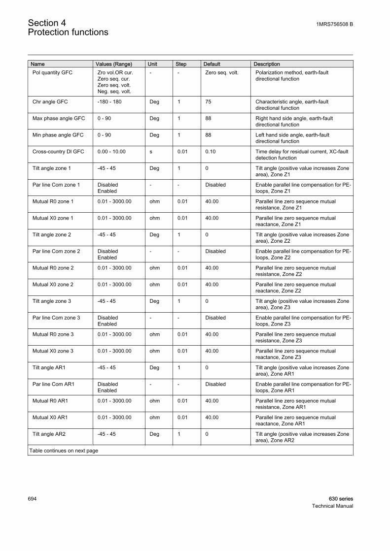
Name Values (Range) Unit Step Default DescriptionPol quantity GFC Zro vol.OR cur.
Zero seq. cur.Zero seq. volt.Neg. seq. volt.
- - Zero seq. volt. Polarization method, earth-faultdirectional function
Chr angle GFC -180 - 180 Deg 1 75 Characteristic angle, earth-faultdirectional function
Max phase angle GFC 0 - 90 Deg 1 88 Right hand side angle, earth-faultdirectional function
Min phase angle GFC 0 - 90 Deg 1 88 Left hand side angle, earth-faultdirectional function
Cross-country Dl GFC 0.00 - 10.00 s 0.01 0.10 Time delay for residual current, XC-faultdetection function
Tilt angle zone 1 -45 - 45 Deg 1 0 Tilt angle (positive value increases Zonearea), Zone Z1
Par line Com zone 1 DisabledEnabled
- - Disabled Enable parallel line compensation for PE-loops, Zone Z1
Mutual R0 zone 1 0.01 - 3000.00 ohm 0.01 40.00 Parallel line zero sequence mutualresistance, Zone Z1
Mutual X0 zone 1 0.01 - 3000.00 ohm 0.01 40.00 Parallel line zero sequence mutualreactance, Zone Z1
Tilt angle zone 2 -45 - 45 Deg 1 0 Tilt angle (positive value increases Zonearea), Zone Z2
Par line Com zone 2 DisabledEnabled
- - Disabled Enable parallel line compensation for PE-loops, Zone Z2
Mutual R0 zone 2 0.01 - 3000.00 ohm 0.01 40.00 Parallel line zero sequence mutualresistance, Zone Z2
Mutual X0 zone 2 0.01 - 3000.00 ohm 0.01 40.00 Parallel line zero sequence mutualreactance, Zone Z2
Tilt angle zone 3 -45 - 45 Deg 1 0 Tilt angle (positive value increases Zonearea), Zone Z3
Par line Com zone 3 DisabledEnabled
- - Disabled Enable parallel line compensation for PE-loops, Zone Z3
Mutual R0 zone 3 0.01 - 3000.00 ohm 0.01 40.00 Parallel line zero sequence mutualresistance, Zone Z3
Mutual X0 zone 3 0.01 - 3000.00 ohm 0.01 40.00 Parallel line zero sequence mutualreactance, Zone Z3
Tilt angle AR1 -45 - 45 Deg 1 0 Tilt angle (positive value increases Zonearea), Zone AR1
Par line Com AR1 DisabledEnabled
- - Disabled Enable parallel line compensation for PE-loops, Zone AR1
Mutual R0 AR1 0.01 - 3000.00 ohm 0.01 40.00 Parallel line zero sequence mutualresistance, Zone AR1
Mutual X0 AR1 0.01 - 3000.00 ohm 0.01 40.00 Parallel line zero sequence mutualreactance, Zone AR1
Tilt angle AR2 -45 - 45 Deg 1 0 Tilt angle (positive value increases Zonearea), Zone AR2
Table continues on next page
Section 4 1MRS756508 BProtection functions
694 630 seriesTechnical Manual

Name Values (Range) Unit Step Default DescriptionPar line Com AR2 Disabled
Enabled- - Disabled Enable parallel line compensation for PE-
loops, Zone AR2
Mutual R0 AR2 0.01 - 3000.00 ohm 0.01 40.00 Parallel line zero sequence mutualresistance, Zone AR2
Mutual X0 AR2 0.01 - 3000.00 ohm 0.01 40.00 Parallel line zero sequence mutualreactance, Zone AR2
Table 655: DSTPDIS Non group settings (basic)
Name Values (Range) Unit Step Default DescriptionOperation Off
On- - On Operation Off / On
Phase voltage Meas AccuratePP without Uo
- - Accurate Phase voltage measurement principle
System grounding GFC High impedanceLow impedanceFrom input
- - Low impedance Network neutral earthing method
Ph Prf mode Hi Z GFC No filterNo preferenceCyc A-B-C-ACyc A-C-B-AAcyc A-B-CAcyc A-C-BAcyc B-A-CAcyc B-C-AAcyc C-A-BAcyc C-B-A
- - No filter Phase preference mode for highimpedance earthed network
Ph Prf mode Lo Z GFC All loopsPE onlyPP onlyBLK leading PEBLK lagging PE
- - All loops Loop selection mode for low impedanceearthed network
Impedance mode Zn RectangularPolar
- - Rectangular Impedance format, Zones
Impedance Chr Gnd Zn QuadrilateralMho (circular)Mho dir lineOffset dir lineBullet (combi)
- - Quadrilateral Impedance characteristic for PE-loops,Zones
Impedance Chr PP Zn QuadrilateralMho (circular)Mho dir lineOffset dir lineBullet (combi)
- - Quadrilateral Impedance characteristic for PP/3P-loops, Zones
Max phase angle zone 0 - 45 Deg 1 15 Angle from R-axis to right hand sidedirectional line
Min phase angle zone 90 - 135 Deg 1 115 Angle from R-axis to left hand sidedirectional line
Pol quantity zone Pos. seq. volt.Self polCross Pol
- - Pos. seq. volt. Mho polarization method for zones
1MRS756508 B Section 4Protection functions
630 series 695Technical Manual

Table 656: DSTPDIS Non group settings (advanced)
Name Values (Range) Unit Step Default DescriptionBase value Sel phase Phase Grp 1
Phase Grp 2Phase Grp 3
- - Phase Grp 1 Base value selector, phase
Base value Sel Res Residual Grp 1Residual Grp 2Residual Grp 3
- - Residual Grp 1 Base value selector, residual
Base Val Sel Res Ref Residual Grp 1Residual Grp 2Residual Grp 3
- - Residual Grp 2 Base value selector for referenceresidual current
EF Det neutral A GFC MeasuredVirtual
- - Measured Residual current meas. principle, EF-detection function
Fact EF current Bal 1.000 - 2.000 - 0.001 1.200 Residual current ratio for parallel linecompensation
Voltage Mem time 100 - 3000 ms 5 400 Voltage memory time
4.7.1.10 Measured values
Table 657: DSTPDIS Measured values
Name Type Default DescriptionI_AMPL_A REAL 0 Amplitude of the phase A current
I_AMPL_B REAL 0 Amplitude of the phase B current
I_AMPL_C REAL 0 Amplitude of the phase C current
I0_AMPL REAL 0 Amplitude of the residual current
I0_ANGL REAL 0 Angle of the residual current
I0_AMPL_VIR REAL 0 Amplitude of residual current, virtual
I0_AMPL_REF REAL 0 Amplitude of transformer neutral current
I0_ANGL_REF REAL 0 Angle of the transformer neutral current
I1_AMPL REAL 0 Amplitude of the positive-sequence current
I2_AMPL REAL 0 Amplitude of the negative-sequence current
I2_ANGL REAL 0 Angle of the negative-sequence current
U_AMPL_A REAL 0 Amplitude of the phase A voltage
U_AMPL_B REAL 0 Amplitude of the phase B voltage
U_AMPL_C REAL 0 Amplitude of the phase C voltage
U_AMPL_AB REAL 0 Amplitude of the phase-to-phase AB voltage
U_AMPL_BC REAL 0 Amplitude of the phase-to-phase BC voltage
U_AMPL_CA REAL 0 Amplitude of the phase-to-phase CA voltage
U0_AMPL REAL 0 Amplitude of the residual voltage
U0_ANGL REAL 0 Angle of the residual voltage
U1_AMPL REAL 0 Amplitude of the positive-sequence voltage
U1_ANGL REAL 0 Angle of the positive-sequence voltage
U2_AMPL REAL 0 Amplitude of the negative-sequence voltage
Table continues on next page
Section 4 1MRS756508 BProtection functions
696 630 seriesTechnical Manual
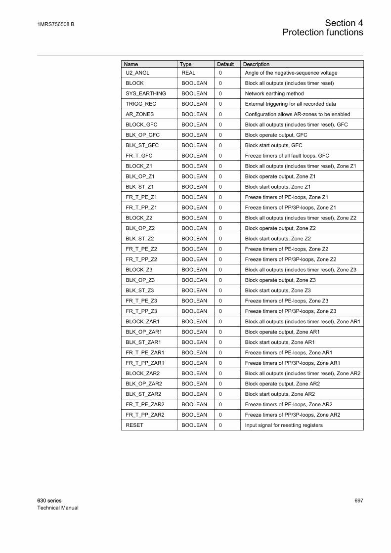
Name Type Default DescriptionU2_ANGL REAL 0 Angle of the negative-sequence voltage
BLOCK BOOLEAN 0 Block all outputs (includes timer reset)
SYS_EARTHING BOOLEAN 0 Network earthing method
TRIGG_REC BOOLEAN 0 External triggering for all recorded data
AR_ZONES BOOLEAN 0 Configuration allows AR-zones to be enabled
BLOCK_GFC BOOLEAN 0 Block all outputs (includes timer reset), GFC
BLK_OP_GFC BOOLEAN 0 Block operate output, GFC
BLK_ST_GFC BOOLEAN 0 Block start outputs, GFC
FR_T_GFC BOOLEAN 0 Freeze timers of all fault loops, GFC
BLOCK_Z1 BOOLEAN 0 Block all outputs (includes timer reset), Zone Z1
BLK_OP_Z1 BOOLEAN 0 Block operate output, Zone Z1
BLK_ST_Z1 BOOLEAN 0 Block start outputs, Zone Z1
FR_T_PE_Z1 BOOLEAN 0 Freeze timers of PE-loops, Zone Z1
FR_T_PP_Z1 BOOLEAN 0 Freeze timers of PP/3P-loops, Zone Z1
BLOCK_Z2 BOOLEAN 0 Block all outputs (includes timer reset), Zone Z2
BLK_OP_Z2 BOOLEAN 0 Block operate output, Zone Z2
BLK_ST_Z2 BOOLEAN 0 Block start outputs, Zone Z2
FR_T_PE_Z2 BOOLEAN 0 Freeze timers of PE-loops, Zone Z2
FR_T_PP_Z2 BOOLEAN 0 Freeze timers of PP/3P-loops, Zone Z2
BLOCK_Z3 BOOLEAN 0 Block all outputs (includes timer reset), Zone Z3
BLK_OP_Z3 BOOLEAN 0 Block operate output, Zone Z3
BLK_ST_Z3 BOOLEAN 0 Block start outputs, Zone Z3
FR_T_PE_Z3 BOOLEAN 0 Freeze timers of PE-loops, Zone Z3
FR_T_PP_Z3 BOOLEAN 0 Freeze timers of PP/3P-loops, Zone Z3
BLOCK_ZAR1 BOOLEAN 0 Block all outputs (includes timer reset), Zone AR1
BLK_OP_ZAR1 BOOLEAN 0 Block operate output, Zone AR1
BLK_ST_ZAR1 BOOLEAN 0 Block start outputs, Zone AR1
FR_T_PE_ZAR1 BOOLEAN 0 Freeze timers of PE-loops, Zone AR1
FR_T_PP_ZAR1 BOOLEAN 0 Freeze timers of PP/3P-loops, Zone AR1
BLOCK_ZAR2 BOOLEAN 0 Block all outputs (includes timer reset), Zone AR2
BLK_OP_ZAR2 BOOLEAN 0 Block operate output, Zone AR2
BLK_ST_ZAR2 BOOLEAN 0 Block start outputs, Zone AR2
FR_T_PE_ZAR2 BOOLEAN 0 Freeze timers of PE-loops, Zone AR2
FR_T_PP_ZAR2 BOOLEAN 0 Freeze timers of PP/3P-loops, Zone AR2
RESET BOOLEAN 0 Input signal for resetting registers
1MRS756508 B Section 4Protection functions
630 series 697Technical Manual
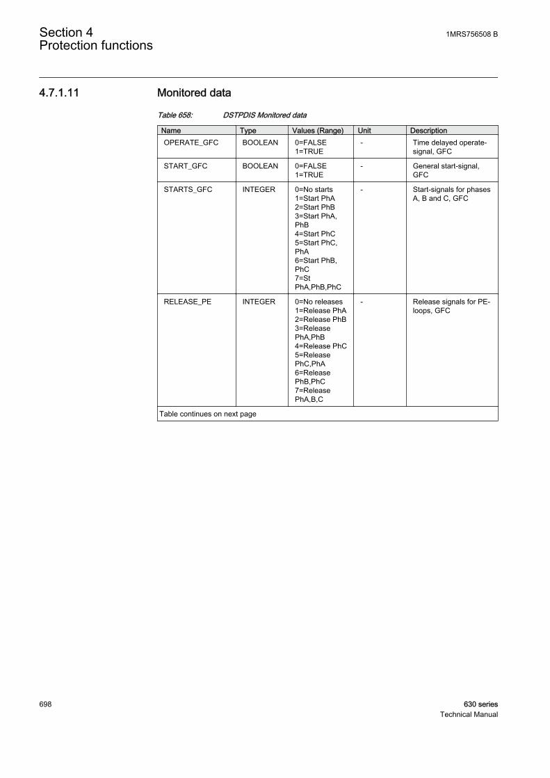
4.7.1.11 Monitored data
Table 658: DSTPDIS Monitored data
Name Type Values (Range) Unit DescriptionOPERATE_GFC BOOLEAN 0=FALSE
1=TRUE- Time delayed operate-
signal, GFC
START_GFC BOOLEAN 0=FALSE1=TRUE
- General start-signal,GFC
STARTS_GFC INTEGER 0=No starts1=Start PhA2=Start PhB3=Start PhA,PhB4=Start PhC5=Start PhC,PhA6=Start PhB,PhC7=StPhA,PhB,PhC
- Start-signals for phasesA, B and C, GFC
RELEASE_PE INTEGER 0=No releases1=Release PhA2=Release PhB3=ReleasePhA,PhB4=Release PhC5=ReleasePhC,PhA6=ReleasePhB,PhC7=ReleasePhA,B,C
- Release signals for PE-loops, GFC
Table continues on next page
Section 4 1MRS756508 BProtection functions
698 630 seriesTechnical Manual

Name Type Values (Range) Unit DescriptionRELEASE_PP INTEGER 0=No releases
1=Release PhAB2=ReleasePhBC3=RelPhAB,PhBC4=ReleasePhCA5=RelPhAB,PhCA6=RelPhBC,PhCA7=PhAB,PhBC,PhCA8=ReleasePhABC9=RelPhAB,PhABC10=RelPhBC,PhABC11=PhAB,PhBC,PhABC12=RelPhCA,PhABC13=PhAB,PhCA,PhABC14=PhBC,PhCA,PhABC15=PhAB,BC,CA,ABC
- Release signals for PP/3P-loops, GFC
EARTH_FLT BOOLEAN 0=No1=Yes
- Indication of a singlephase earth-fault, GFC
XC_FLT BOOLEAN 0=No1=Yes
- Indication of a cross-country-fault (high imp.earthed), GFC
DIR_E_FLT INTEGER 0=Unknown1=Forward2=Reverse3=Both
- Earth-fault direction (lowimp. earthed), GFC
CONFLICT_GFC BOOLEAN 0=No1=Yes
- Conflict with PSL-function and voltagemeasuring principle
OPERATE_Z1 BOOLEAN 0=FALSE1=TRUE
- Time delayed operatesignal, Zone Z1
START_Z1 BOOLEAN 0=FALSE1=TRUE
- General start-signal,Zone Z1
STARTS_Z1 INTEGER 0=No starts1=Start PhA2=Start PhB3=Start PhA,PhB4=Start PhC5=Start PhC,PhA6=Start PhB,PhC7=StPhA,PhB,PhC
- Start signals for phasesA, B and C, Zone Z1
Table continues on next page
1MRS756508 B Section 4Protection functions
630 series 699Technical Manual

Name Type Values (Range) Unit DescriptionCONFLICT_Z1 INTEGER 0=No conflict
1=PhE angle tilt2=PhPh angle tilt3=PhE,PhPh tilt
- Tilt angle validity check,Zone Z1
OPERATE_Z2 BOOLEAN 0=FALSE1=TRUE
- Time delayed operatesignal, Zone Z2
START_Z2 BOOLEAN 0=FALSE1=TRUE
- General start-signal,Zone Z2
STARTS_Z2 INTEGER 0=No starts1=Start PhA2=Start PhB3=Start PhA,PhB4=Start PhC5=Start PhC,PhA6=Start PhB,PhC7=StPhA,PhB,PhC
- Start signals for phasesA, B and C, Zone Z2
CONFLICT_Z2 INTEGER 0=No conflict1=PhE angle tilt2=PhPh angle tilt3=PhE,PhPh tilt
- Tilt angle validity check,Zone Z2
OPERATE_Z3 BOOLEAN 0=FALSE1=TRUE
- Time delayed operatesignal, Zone Z3
START_Z3 BOOLEAN 0=FALSE1=TRUE
- General start-signal,Zone Z3
STARTS_Z3 INTEGER 0=No starts1=Start PhA2=Start PhB3=Start PhA,PhB4=Start PhC5=Start PhC,PhA6=Start PhB,PhC7=StPhA,PhB,PhC
- Start signals for phasesA, B and C, Zone Z3
CONFLICT_Z3 INTEGER 0=No conflict1=PhE angle tilt2=PhPh angle tilt3=PhE,PhPh tilt
- Tilt angle validity check,Zone Z3
OPERATE_ZAR1 BOOLEAN 0=FALSE1=TRUE
- Time delayed operatesignal, Zone AR1
START_ZAR1 BOOLEAN 0=FALSE1=TRUE
- General start-signal,Zone AR1
Table continues on next page
Section 4 1MRS756508 BProtection functions
700 630 seriesTechnical Manual
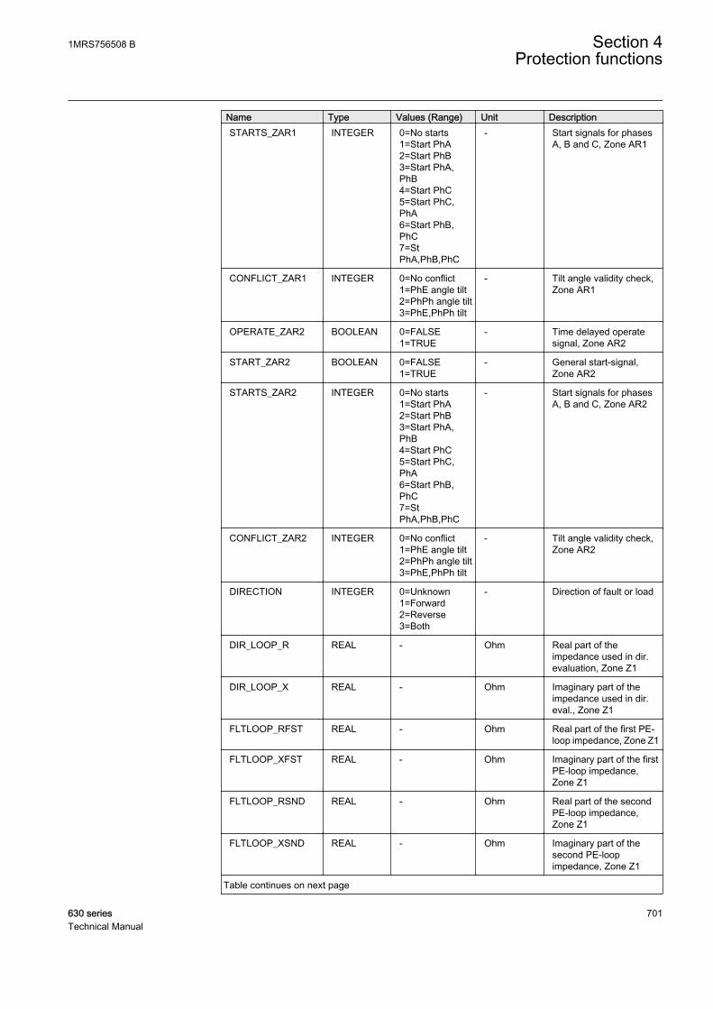
Name Type Values (Range) Unit DescriptionSTARTS_ZAR1 INTEGER 0=No starts
1=Start PhA2=Start PhB3=Start PhA,PhB4=Start PhC5=Start PhC,PhA6=Start PhB,PhC7=StPhA,PhB,PhC
- Start signals for phasesA, B and C, Zone AR1
CONFLICT_ZAR1 INTEGER 0=No conflict1=PhE angle tilt2=PhPh angle tilt3=PhE,PhPh tilt
- Tilt angle validity check,Zone AR1
OPERATE_ZAR2 BOOLEAN 0=FALSE1=TRUE
- Time delayed operatesignal, Zone AR2
START_ZAR2 BOOLEAN 0=FALSE1=TRUE
- General start-signal,Zone AR2
STARTS_ZAR2 INTEGER 0=No starts1=Start PhA2=Start PhB3=Start PhA,PhB4=Start PhC5=Start PhC,PhA6=Start PhB,PhC7=StPhA,PhB,PhC
- Start signals for phasesA, B and C, Zone AR2
CONFLICT_ZAR2 INTEGER 0=No conflict1=PhE angle tilt2=PhPh angle tilt3=PhE,PhPh tilt
- Tilt angle validity check,Zone AR2
DIRECTION INTEGER 0=Unknown1=Forward2=Reverse3=Both
- Direction of fault or load
DIR_LOOP_R REAL - Ohm Real part of theimpedance used in dir.evaluation, Zone Z1
DIR_LOOP_X REAL - Ohm Imaginary part of theimpedance used in dir.eval., Zone Z1
FLTLOOP_RFST REAL - Ohm Real part of the first PE-loop impedance, Zone Z1
FLTLOOP_XFST REAL - Ohm Imaginary part of the firstPE-loop impedance,Zone Z1
FLTLOOP_RSND REAL - Ohm Real part of the secondPE-loop impedance,Zone Z1
FLTLOOP_XSND REAL - Ohm Imaginary part of thesecond PE-loopimpedance, Zone Z1
Table continues on next page
1MRS756508 B Section 4Protection functions
630 series 701Technical Manual
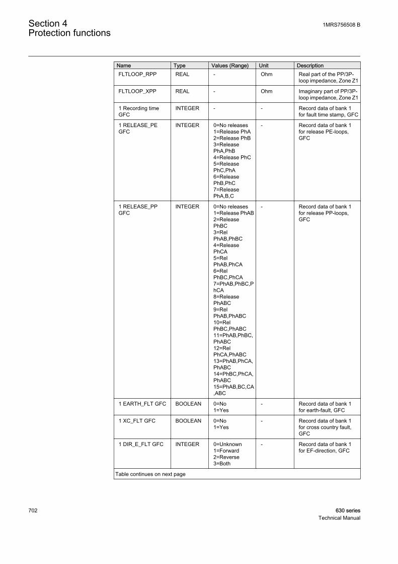
Name Type Values (Range) Unit DescriptionFLTLOOP_RPP REAL - Ohm Real part of the PP/3P-
loop impedance, Zone Z1
FLTLOOP_XPP REAL - Ohm Imaginary part of PP/3P-loop impedance, Zone Z1
1 Recording timeGFC
INTEGER - - Record data of bank 1for fault time stamp, GFC
1 RELEASE_PEGFC
INTEGER 0=No releases1=Release PhA2=Release PhB3=ReleasePhA,PhB4=Release PhC5=ReleasePhC,PhA6=ReleasePhB,PhC7=ReleasePhA,B,C
- Record data of bank 1for release PE-loops,GFC
1 RELEASE_PPGFC
INTEGER 0=No releases1=Release PhAB2=ReleasePhBC3=RelPhAB,PhBC4=ReleasePhCA5=RelPhAB,PhCA6=RelPhBC,PhCA7=PhAB,PhBC,PhCA8=ReleasePhABC9=RelPhAB,PhABC10=RelPhBC,PhABC11=PhAB,PhBC,PhABC12=RelPhCA,PhABC13=PhAB,PhCA,PhABC14=PhBC,PhCA,PhABC15=PhAB,BC,CA,ABC
- Record data of bank 1for release PP-loops,GFC
1 EARTH_FLT GFC BOOLEAN 0=No1=Yes
- Record data of bank 1for earth-fault, GFC
1 XC_FLT GFC BOOLEAN 0=No1=Yes
- Record data of bank 1for cross country fault,GFC
1 DIR_E_FLT GFC INTEGER 0=Unknown1=Forward2=Reverse3=Both
- Record data of bank 1for EF-direction, GFC
Table continues on next page
Section 4 1MRS756508 BProtection functions
702 630 seriesTechnical Manual

Name Type Values (Range) Unit Description1 DIRECTION INTEGER 0=Unknown
1=Forward2=Reverse3=Both
- Record data of bank 1for direction
1 Zones OPERATE INTEGER 0=No Znoperates1=Zn12=Zn23=Zn1,24=Zn35=Zn1,36=Zn2,37=Zn1,2,38=AR19=Zn1,AR110=Zn2,AR111=Zn1,2,AR112=Zn3,AR113=Zn1,3,AR114=Zn2,3,AR115=Zn1,2,3,AR116=AR217=Zn1,AR218=Zn2,AR219=Zn1,2,AR220=Zn3,AR221=Zn1,3,AR222=Zn2,3,AR223=Zn1,2,3,AR224=AR1,AR225=Zn1,AR1,AR226=Zn2,AR1,AR227=Zn1,2,AR1,AR228=Zn3,AR1,AR229=Zn1,3,AR1,AR230=Zn2,3,AR1,AR231=Zn1,2,3,AR1,AR2
- Record data of bank 1for operate signals of allzones
2 Recording timeGFC
INTEGER - - Record data of bank 2for fault time stamp, GFC
2 RELEASE_PEGFC
INTEGER 0=No releases1=Release PhA2=Release PhB3=ReleasePhA,PhB4=Release PhC5=ReleasePhC,PhA6=ReleasePhB,PhC7=ReleasePhA,B,C
- Record data of bank 2for release PE-loops,GFC
Table continues on next page
1MRS756508 B Section 4Protection functions
630 series 703Technical Manual

Name Type Values (Range) Unit Description2 RELEASE_PPGFC
INTEGER 0=No releases1=Release PhAB2=ReleasePhBC3=RelPhAB,PhBC4=ReleasePhCA5=RelPhAB,PhCA6=RelPhBC,PhCA7=PhAB,PhBC,PhCA8=ReleasePhABC9=RelPhAB,PhABC10=RelPhBC,PhABC11=PhAB,PhBC,PhABC12=RelPhCA,PhABC13=PhAB,PhCA,PhABC14=PhBC,PhCA,PhABC15=PhAB,BC,CA,ABC
- Record data of bank 2for release PP-loops,GFC
2 EARTH_FLT GFC BOOLEAN 0=No1=Yes
- Record data of bank 2for earth-fault, GFC
2 XC_FLT GFC BOOLEAN 0=No1=Yes
- Record data of bank 2for cross country fault,GFC
2 DIR_E_FLT GFC INTEGER 0=Unknown1=Forward2=Reverse3=Both
- Record data of bank 2for EF-direction, GFC
2 DIRECTION INTEGER 0=Unknown1=Forward2=Reverse3=Both
- Record data of bank 2for direction
Table continues on next page
Section 4 1MRS756508 BProtection functions
704 630 seriesTechnical Manual
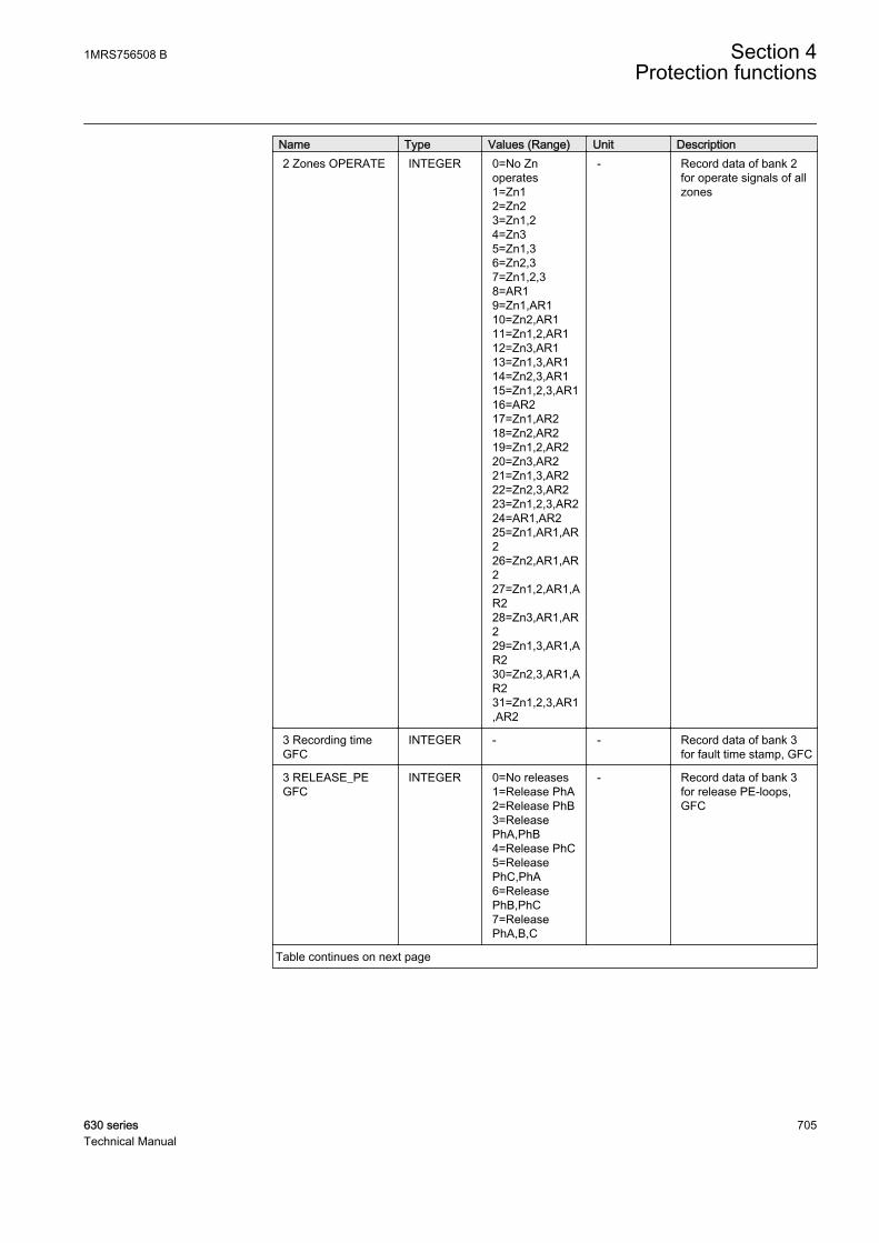
Name Type Values (Range) Unit Description2 Zones OPERATE INTEGER 0=No Zn
operates1=Zn12=Zn23=Zn1,24=Zn35=Zn1,36=Zn2,37=Zn1,2,38=AR19=Zn1,AR110=Zn2,AR111=Zn1,2,AR112=Zn3,AR113=Zn1,3,AR114=Zn2,3,AR115=Zn1,2,3,AR116=AR217=Zn1,AR218=Zn2,AR219=Zn1,2,AR220=Zn3,AR221=Zn1,3,AR222=Zn2,3,AR223=Zn1,2,3,AR224=AR1,AR225=Zn1,AR1,AR226=Zn2,AR1,AR227=Zn1,2,AR1,AR228=Zn3,AR1,AR229=Zn1,3,AR1,AR230=Zn2,3,AR1,AR231=Zn1,2,3,AR1,AR2
- Record data of bank 2for operate signals of allzones
3 Recording timeGFC
INTEGER - - Record data of bank 3for fault time stamp, GFC
3 RELEASE_PEGFC
INTEGER 0=No releases1=Release PhA2=Release PhB3=ReleasePhA,PhB4=Release PhC5=ReleasePhC,PhA6=ReleasePhB,PhC7=ReleasePhA,B,C
- Record data of bank 3for release PE-loops,GFC
Table continues on next page
1MRS756508 B Section 4Protection functions
630 series 705Technical Manual
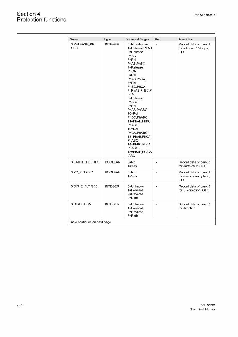
Name Type Values (Range) Unit Description3 RELEASE_PPGFC
INTEGER 0=No releases1=Release PhAB2=ReleasePhBC3=RelPhAB,PhBC4=ReleasePhCA5=RelPhAB,PhCA6=RelPhBC,PhCA7=PhAB,PhBC,PhCA8=ReleasePhABC9=RelPhAB,PhABC10=RelPhBC,PhABC11=PhAB,PhBC,PhABC12=RelPhCA,PhABC13=PhAB,PhCA,PhABC14=PhBC,PhCA,PhABC15=PhAB,BC,CA,ABC
- Record data of bank 3for release PP-loops,GFC
3 EARTH_FLT GFC BOOLEAN 0=No1=Yes
- Record data of bank 3for earth-fault, GFC
3 XC_FLT GFC BOOLEAN 0=No1=Yes
- Record data of bank 3for cross country fault,GFC
3 DIR_E_FLT GFC INTEGER 0=Unknown1=Forward2=Reverse3=Both
- Record data of bank 3for EF-direction, GFC
3 DIRECTION INTEGER 0=Unknown1=Forward2=Reverse3=Both
- Record data of bank 3for direction
Table continues on next page
Section 4 1MRS756508 BProtection functions
706 630 seriesTechnical Manual
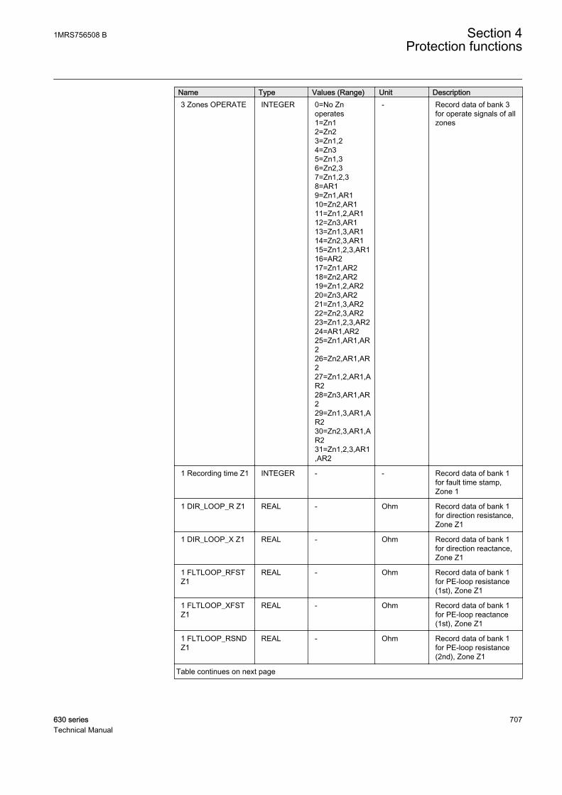
Name Type Values (Range) Unit Description3 Zones OPERATE INTEGER 0=No Zn
operates1=Zn12=Zn23=Zn1,24=Zn35=Zn1,36=Zn2,37=Zn1,2,38=AR19=Zn1,AR110=Zn2,AR111=Zn1,2,AR112=Zn3,AR113=Zn1,3,AR114=Zn2,3,AR115=Zn1,2,3,AR116=AR217=Zn1,AR218=Zn2,AR219=Zn1,2,AR220=Zn3,AR221=Zn1,3,AR222=Zn2,3,AR223=Zn1,2,3,AR224=AR1,AR225=Zn1,AR1,AR226=Zn2,AR1,AR227=Zn1,2,AR1,AR228=Zn3,AR1,AR229=Zn1,3,AR1,AR230=Zn2,3,AR1,AR231=Zn1,2,3,AR1,AR2
- Record data of bank 3for operate signals of allzones
1 Recording time Z1 INTEGER - - Record data of bank 1for fault time stamp,Zone 1
1 DIR_LOOP_R Z1 REAL - Ohm Record data of bank 1for direction resistance,Zone Z1
1 DIR_LOOP_X Z1 REAL - Ohm Record data of bank 1for direction reactance,Zone Z1
1 FLTLOOP_RFSTZ1
REAL - Ohm Record data of bank 1for PE-loop resistance(1st), Zone Z1
1 FLTLOOP_XFSTZ1
REAL - Ohm Record data of bank 1for PE-loop reactance(1st), Zone Z1
1 FLTLOOP_RSNDZ1
REAL - Ohm Record data of bank 1for PE-loop resistance(2nd), Zone Z1
Table continues on next page
1MRS756508 B Section 4Protection functions
630 series 707Technical Manual
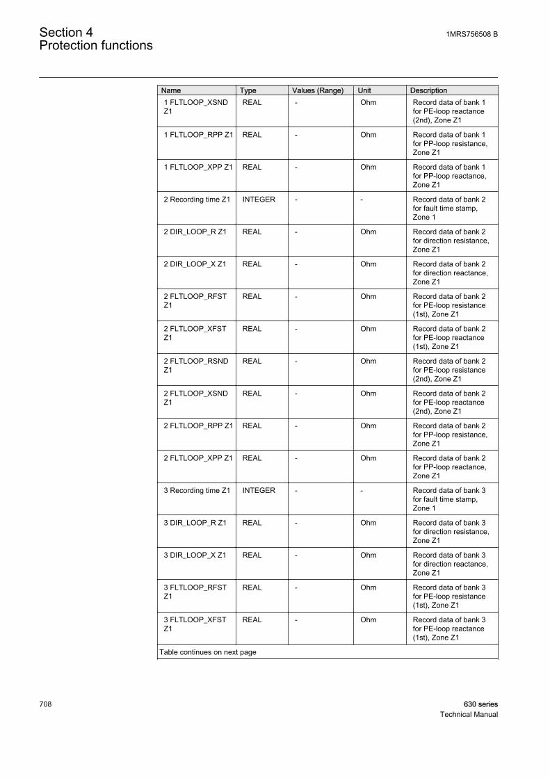
Name Type Values (Range) Unit Description1 FLTLOOP_XSNDZ1
REAL - Ohm Record data of bank 1for PE-loop reactance(2nd), Zone Z1
1 FLTLOOP_RPP Z1 REAL - Ohm Record data of bank 1for PP-loop resistance,Zone Z1
1 FLTLOOP_XPP Z1 REAL - Ohm Record data of bank 1for PP-loop reactance,Zone Z1
2 Recording time Z1 INTEGER - - Record data of bank 2for fault time stamp,Zone 1
2 DIR_LOOP_R Z1 REAL - Ohm Record data of bank 2for direction resistance,Zone Z1
2 DIR_LOOP_X Z1 REAL - Ohm Record data of bank 2for direction reactance,Zone Z1
2 FLTLOOP_RFSTZ1
REAL - Ohm Record data of bank 2for PE-loop resistance(1st), Zone Z1
2 FLTLOOP_XFSTZ1
REAL - Ohm Record data of bank 2for PE-loop reactance(1st), Zone Z1
2 FLTLOOP_RSNDZ1
REAL - Ohm Record data of bank 2for PE-loop resistance(2nd), Zone Z1
2 FLTLOOP_XSNDZ1
REAL - Ohm Record data of bank 2for PE-loop reactance(2nd), Zone Z1
2 FLTLOOP_RPP Z1 REAL - Ohm Record data of bank 2for PP-loop resistance,Zone Z1
2 FLTLOOP_XPP Z1 REAL - Ohm Record data of bank 2for PP-loop reactance,Zone Z1
3 Recording time Z1 INTEGER - - Record data of bank 3for fault time stamp,Zone 1
3 DIR_LOOP_R Z1 REAL - Ohm Record data of bank 3for direction resistance,Zone Z1
3 DIR_LOOP_X Z1 REAL - Ohm Record data of bank 3for direction reactance,Zone Z1
3 FLTLOOP_RFSTZ1
REAL - Ohm Record data of bank 3for PE-loop resistance(1st), Zone Z1
3 FLTLOOP_XFSTZ1
REAL - Ohm Record data of bank 3for PE-loop reactance(1st), Zone Z1
Table continues on next page
Section 4 1MRS756508 BProtection functions
708 630 seriesTechnical Manual

Name Type Values (Range) Unit Description3 FLTLOOP_RSNDZ1
REAL - Ohm Record data of bank 3for PE-loop resistance(2nd), Zone Z1
3 FLTLOOP_XSNDZ1
REAL - Ohm Record data of bank 3for PE-loop reactance(2nd), Zone Z1
3 FLTLOOP_RPP Z1 REAL - Ohm Record data of bank 3for PP-loop resistance,Zone Z1
3 FLTLOOP_XPP Z1 REAL - Ohm Record data of bank 3for PP-loop reactance,Zone Z1
1 Recording time Z2 INTEGER - - Record data of bank 1for fault time stamp,Zone 2
1 DIR_LOOP_R Z2 REAL - Ohm Record data of bank 1for direction resistance,Zone Z2
1 DIR_LOOP_X Z2 REAL - Ohm Record data of bank 1for direction reactance,Zone Z2
1 FLTLOOP_RFSTZ2
REAL - Ohm Record data of bank 1for PE-loop resistance(1st), Zone Z2
1 FLTLOOP_XFSTZ2
REAL - Ohm Record data of bank 1for PE-loop reactance(1st), Zone Z2
1 FLTLOOP_RSNDZ2
REAL - Ohm Record data of bank 1for PE-loop resistance(2nd), Zone Z2
1 FLTLOOP_XSNDZ2
REAL - Ohm Record data of bank 1for PE-loop reactance(2nd), Zone Z2
1 FLTLOOP_RPP Z2 REAL - Ohm Record data of bank 1for PP-loop resistance,Zone Z2
1 FLTLOOP_XPP Z2 REAL - Ohm Record data of bank 1for PP-loop reactance,Zone Z2
2 Recording time Z2 INTEGER - - Record data of bank 2for fault time stamp,Zone 2
2 DIR_LOOP_R Z2 REAL - Ohm Record data of bank 2for direction resistance,Zone Z2
2 DIR_LOOP_X Z2 REAL - Ohm Record data of bank 2for direction reactance,Zone Z2
2 FLTLOOP_RFSTZ2
REAL - Ohm Record data of bank 2for PE-loop resistance(1st), Zone Z2
Table continues on next page
1MRS756508 B Section 4Protection functions
630 series 709Technical Manual
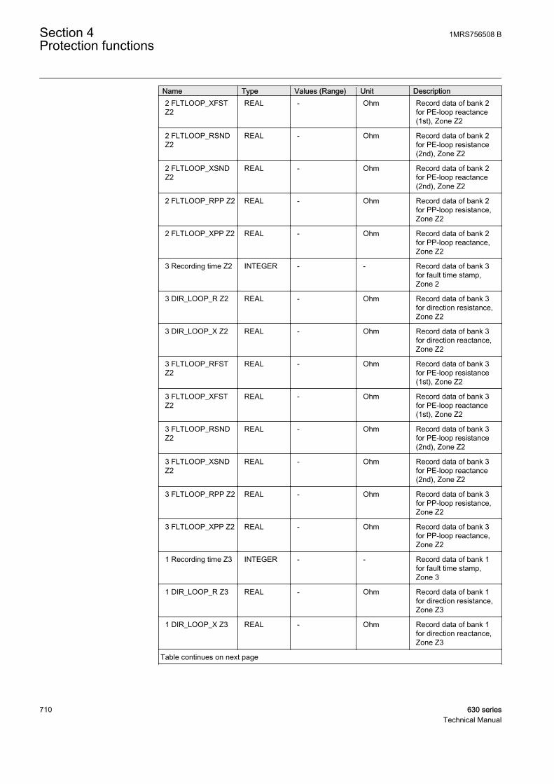
Name Type Values (Range) Unit Description2 FLTLOOP_XFSTZ2
REAL - Ohm Record data of bank 2for PE-loop reactance(1st), Zone Z2
2 FLTLOOP_RSNDZ2
REAL - Ohm Record data of bank 2for PE-loop resistance(2nd), Zone Z2
2 FLTLOOP_XSNDZ2
REAL - Ohm Record data of bank 2for PE-loop reactance(2nd), Zone Z2
2 FLTLOOP_RPP Z2 REAL - Ohm Record data of bank 2for PP-loop resistance,Zone Z2
2 FLTLOOP_XPP Z2 REAL - Ohm Record data of bank 2for PP-loop reactance,Zone Z2
3 Recording time Z2 INTEGER - - Record data of bank 3for fault time stamp,Zone 2
3 DIR_LOOP_R Z2 REAL - Ohm Record data of bank 3for direction resistance,Zone Z2
3 DIR_LOOP_X Z2 REAL - Ohm Record data of bank 3for direction reactance,Zone Z2
3 FLTLOOP_RFSTZ2
REAL - Ohm Record data of bank 3for PE-loop resistance(1st), Zone Z2
3 FLTLOOP_XFSTZ2
REAL - Ohm Record data of bank 3for PE-loop reactance(1st), Zone Z2
3 FLTLOOP_RSNDZ2
REAL - Ohm Record data of bank 3for PE-loop resistance(2nd), Zone Z2
3 FLTLOOP_XSNDZ2
REAL - Ohm Record data of bank 3for PE-loop reactance(2nd), Zone Z2
3 FLTLOOP_RPP Z2 REAL - Ohm Record data of bank 3for PP-loop resistance,Zone Z2
3 FLTLOOP_XPP Z2 REAL - Ohm Record data of bank 3for PP-loop reactance,Zone Z2
1 Recording time Z3 INTEGER - - Record data of bank 1for fault time stamp,Zone 3
1 DIR_LOOP_R Z3 REAL - Ohm Record data of bank 1for direction resistance,Zone Z3
1 DIR_LOOP_X Z3 REAL - Ohm Record data of bank 1for direction reactance,Zone Z3
Table continues on next page
Section 4 1MRS756508 BProtection functions
710 630 seriesTechnical Manual
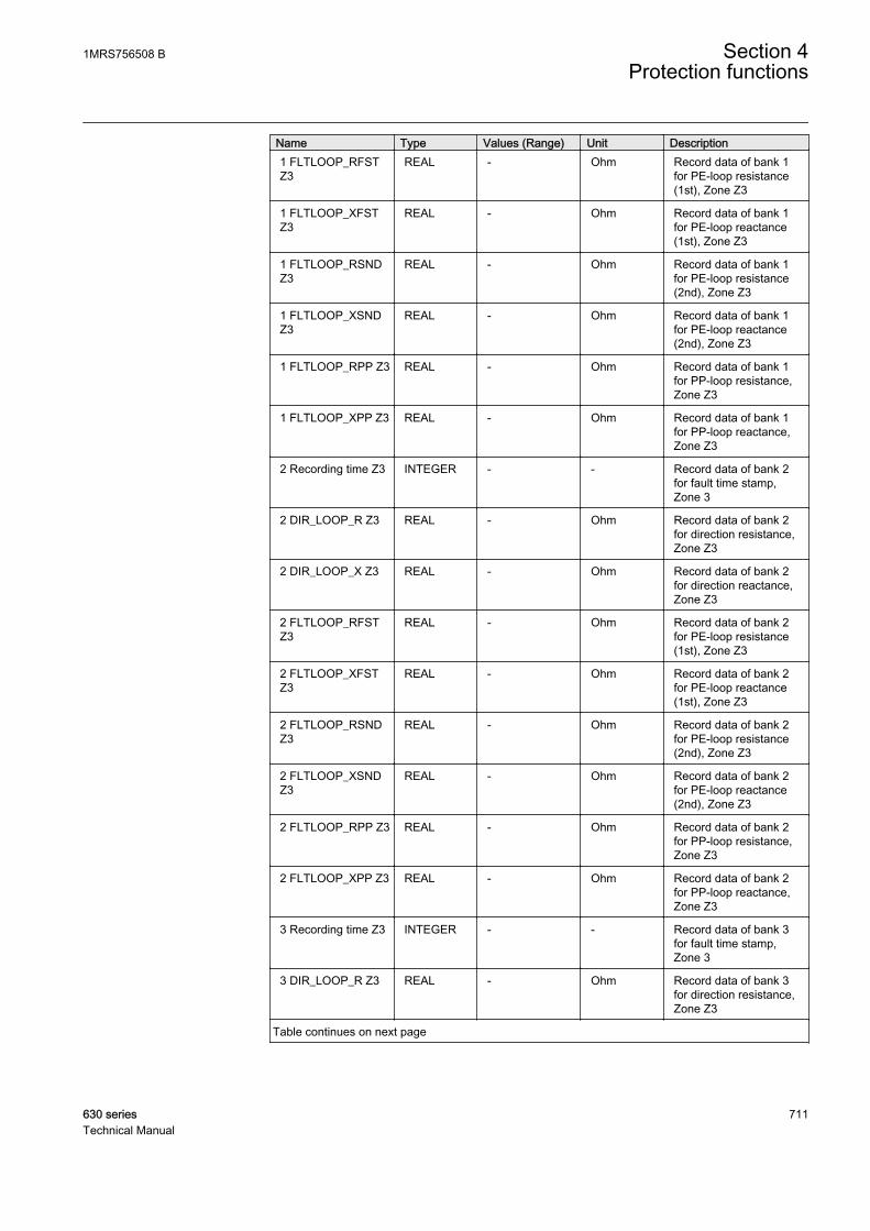
Name Type Values (Range) Unit Description1 FLTLOOP_RFSTZ3
REAL - Ohm Record data of bank 1for PE-loop resistance(1st), Zone Z3
1 FLTLOOP_XFSTZ3
REAL - Ohm Record data of bank 1for PE-loop reactance(1st), Zone Z3
1 FLTLOOP_RSNDZ3
REAL - Ohm Record data of bank 1for PE-loop resistance(2nd), Zone Z3
1 FLTLOOP_XSNDZ3
REAL - Ohm Record data of bank 1for PE-loop reactance(2nd), Zone Z3
1 FLTLOOP_RPP Z3 REAL - Ohm Record data of bank 1for PP-loop resistance,Zone Z3
1 FLTLOOP_XPP Z3 REAL - Ohm Record data of bank 1for PP-loop reactance,Zone Z3
2 Recording time Z3 INTEGER - - Record data of bank 2for fault time stamp,Zone 3
2 DIR_LOOP_R Z3 REAL - Ohm Record data of bank 2for direction resistance,Zone Z3
2 DIR_LOOP_X Z3 REAL - Ohm Record data of bank 2for direction reactance,Zone Z3
2 FLTLOOP_RFSTZ3
REAL - Ohm Record data of bank 2for PE-loop resistance(1st), Zone Z3
2 FLTLOOP_XFSTZ3
REAL - Ohm Record data of bank 2for PE-loop reactance(1st), Zone Z3
2 FLTLOOP_RSNDZ3
REAL - Ohm Record data of bank 2for PE-loop resistance(2nd), Zone Z3
2 FLTLOOP_XSNDZ3
REAL - Ohm Record data of bank 2for PE-loop reactance(2nd), Zone Z3
2 FLTLOOP_RPP Z3 REAL - Ohm Record data of bank 2for PP-loop resistance,Zone Z3
2 FLTLOOP_XPP Z3 REAL - Ohm Record data of bank 2for PP-loop reactance,Zone Z3
3 Recording time Z3 INTEGER - - Record data of bank 3for fault time stamp,Zone 3
3 DIR_LOOP_R Z3 REAL - Ohm Record data of bank 3for direction resistance,Zone Z3
Table continues on next page
1MRS756508 B Section 4Protection functions
630 series 711Technical Manual
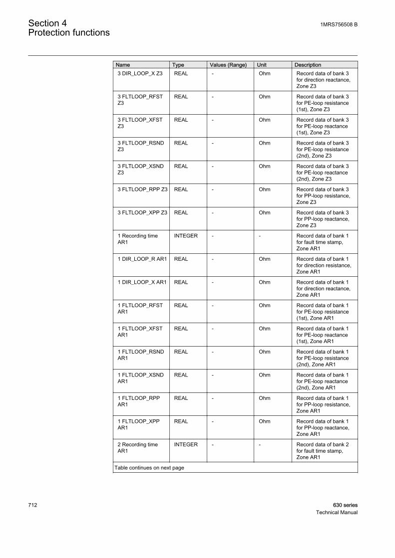
Name Type Values (Range) Unit Description3 DIR_LOOP_X Z3 REAL - Ohm Record data of bank 3
for direction reactance,Zone Z3
3 FLTLOOP_RFSTZ3
REAL - Ohm Record data of bank 3for PE-loop resistance(1st), Zone Z3
3 FLTLOOP_XFSTZ3
REAL - Ohm Record data of bank 3for PE-loop reactance(1st), Zone Z3
3 FLTLOOP_RSNDZ3
REAL - Ohm Record data of bank 3for PE-loop resistance(2nd), Zone Z3
3 FLTLOOP_XSNDZ3
REAL - Ohm Record data of bank 3for PE-loop reactance(2nd), Zone Z3
3 FLTLOOP_RPP Z3 REAL - Ohm Record data of bank 3for PP-loop resistance,Zone Z3
3 FLTLOOP_XPP Z3 REAL - Ohm Record data of bank 3for PP-loop reactance,Zone Z3
1 Recording timeAR1
INTEGER - - Record data of bank 1for fault time stamp,Zone AR1
1 DIR_LOOP_R AR1 REAL - Ohm Record data of bank 1for direction resistance,Zone AR1
1 DIR_LOOP_X AR1 REAL - Ohm Record data of bank 1for direction reactance,Zone AR1
1 FLTLOOP_RFSTAR1
REAL - Ohm Record data of bank 1for PE-loop resistance(1st), Zone AR1
1 FLTLOOP_XFSTAR1
REAL - Ohm Record data of bank 1for PE-loop reactance(1st), Zone AR1
1 FLTLOOP_RSNDAR1
REAL - Ohm Record data of bank 1for PE-loop resistance(2nd), Zone AR1
1 FLTLOOP_XSNDAR1
REAL - Ohm Record data of bank 1for PE-loop reactance(2nd), Zone AR1
1 FLTLOOP_RPPAR1
REAL - Ohm Record data of bank 1for PP-loop resistance,Zone AR1
1 FLTLOOP_XPPAR1
REAL - Ohm Record data of bank 1for PP-loop reactance,Zone AR1
2 Recording timeAR1
INTEGER - - Record data of bank 2for fault time stamp,Zone AR1
Table continues on next page
Section 4 1MRS756508 BProtection functions
712 630 seriesTechnical Manual

Name Type Values (Range) Unit Description2 DIR_LOOP_R AR1 REAL - Ohm Record data of bank 2
for direction resistance,Zone AR1
2 DIR_LOOP_X AR1 REAL - Ohm Record data of bank 2for direction reactance,Zone AR1
2 FLTLOOP_RFSTAR1
REAL - Ohm Record data of bank 2for PE-loop resistance(1st), Zone AR1
2 FLTLOOP_XFSTAR1
REAL - Ohm Record data of bank 2for PE-loop reactance(1st), Zone AR1
2 FLTLOOP_RSNDAR1
REAL - Ohm Record data of bank 2for PE-loop resistance(2nd), Zone AR1
2 FLTLOOP_XSNDAR1
REAL - Ohm Record data of bank 2for PE-loop reactance(2nd), Zone AR1
2 FLTLOOP_RPPAR1
REAL - Ohm Record data of bank 2for PP-loop resistance,Zone AR1
2 FLTLOOP_XPPAR1
REAL - Ohm Record data of bank 2for PP-loop reactance,Zone AR1
3 Recording timeAR1
INTEGER - - Record data of bank 3for fault time stamp,Zone AR1
3 DIR_LOOP_R AR1 REAL - Ohm Record data of bank 3for direction resistance,Zone AR1
3 DIR_LOOP_X AR1 REAL - Ohm Record data of bank 3for direction reactance,Zone AR1
3 FLTLOOP_RFSTAR1
REAL - Ohm Record data of bank 3for PE-loop resistance(1st), Zone AR1
3 FLTLOOP_XFSTAR1
REAL - Ohm Record data of bank 3for PE-loop reactance(1st), Zone AR1
3 FLTLOOP_RSNDAR1
REAL - Ohm Record data of bank 3for PE-loop resistance(2nd), Zone AR1
3 FLTLOOP_XSNDAR1
REAL - Ohm Record data of bank 3for PE-loop reactance(2nd), Zone AR1
3 FLTLOOP_RPPAR1
REAL - Ohm Record data of bank 3for PP-loop resistance,Zone AR1
3 FLTLOOP_XPPAR1
REAL - Ohm Record data of bank 3for PP-loop reactance,Zone AR1
Table continues on next page
1MRS756508 B Section 4Protection functions
630 series 713Technical Manual

Name Type Values (Range) Unit Description1 Recording timeAR2
INTEGER - - Record data of bank 1for fault time stamp,Zone AR2
1 DIR_LOOP_R AR2 REAL - Ohm Record data of bank 1for direction resistance,Zone AR2
1 DIR_LOOP_X AR2 REAL - Ohm Record data of bank 1for direction reactance,Zone AR2
1 FLTLOOP_RFSTAR2
REAL - Ohm Record data of bank 1for PE-loop resistance(1st), Zone AR2
1 FLTLOOP_XFSTAR2
REAL - Ohm Record data of bank 1for PE-loop reactance(1st), Zone AR2
1 FLTLOOP_RSNDAR2
REAL - Ohm Record data of bank 1for PE-loop resistance(2nd), Zone AR2
1 FLTLOOP_XSNDAR2
REAL - Ohm Record data of bank 1for PE-loop reactance(2nd), Zone AR2
1 FLTLOOP_RPPAR2
REAL - Ohm Record data of bank 1for PP-loop resistance,Zone AR2
1 FLTLOOP_XPPAR2
REAL - Ohm Record data of bank 1for PP-loop reactance,Zone AR2
2 Recording timeAR2
INTEGER - - Record data of bank 2for fault time stamp,Zone AR2
2 DIR_LOOP_R AR2 REAL - Ohm Record data of bank 2for direction resistance,Zone AR2
2 DIR_LOOP_X AR2 REAL - Ohm Record data of bank 2for direction reactance,Zone AR2
2 FLTLOOP_RFSTAR2
REAL - Ohm Record data of bank 2for PE-loop resistance(1st), Zone AR2
2 FLTLOOP_XFSTAR2
REAL - Ohm Record data of bank 1for PE-loop reactance(1st), Zone AR2
2 FLTLOOP_RSNDAR2
REAL - Ohm Record data of bank 2for PE-loop resistance(2nd), Zone AR2
2 FLTLOOP_XSNDAR2
REAL - Ohm Record data of bank 2for PE-loop reactance(2nd), Zone AR2
2 FLTLOOP_RPPAR2
REAL - Ohm Record data of bank 2for PP-loop resistance,Zone AR2
Table continues on next page
Section 4 1MRS756508 BProtection functions
714 630 seriesTechnical Manual
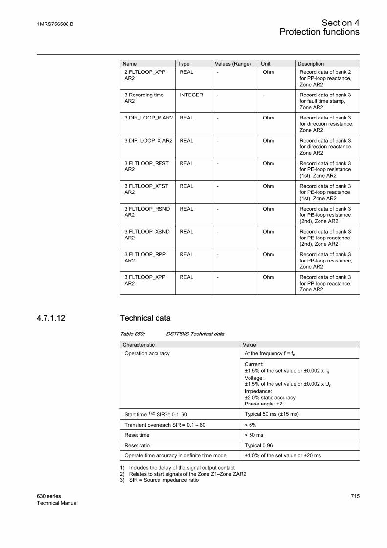
Name Type Values (Range) Unit Description2 FLTLOOP_XPPAR2
REAL - Ohm Record data of bank 2for PP-loop reactance,Zone AR2
3 Recording timeAR2
INTEGER - - Record data of bank 3for fault time stamp,Zone AR2
3 DIR_LOOP_R AR2 REAL - Ohm Record data of bank 3for direction resistance,Zone AR2
3 DIR_LOOP_X AR2 REAL - Ohm Record data of bank 3for direction reactance,Zone AR2
3 FLTLOOP_RFSTAR2
REAL - Ohm Record data of bank 3for PE-loop resistance(1st), Zone AR2
3 FLTLOOP_XFSTAR2
REAL - Ohm Record data of bank 3for PE-loop reactance(1st), Zone AR2
3 FLTLOOP_RSNDAR2
REAL - Ohm Record data of bank 3for PE-loop resistance(2nd), Zone AR2
3 FLTLOOP_XSNDAR2
REAL - Ohm Record data of bank 3for PE-loop reactance(2nd), Zone AR2
3 FLTLOOP_RPPAR2
REAL - Ohm Record data of bank 3for PP-loop resistance,Zone AR2
3 FLTLOOP_XPPAR2
REAL - Ohm Record data of bank 3for PP-loop reactance,Zone AR2
4.7.1.12 Technical data
Table 659: DSTPDIS Technical data
Characteristic ValueOperation accuracy At the frequency f = fn
Current:±1.5% of the set value or ±0.002 x InVoltage:±1.5% of the set value or ±0.002 x UnImpedance:±2.0% static accuracyPhase angle: ±2°
Start time 1)2) SIR3): 0.1–60 Typical 50 ms (±15 ms)
Transient overreach SIR = 0.1 – 60 < 6%
Reset time < 50 ms
Reset ratio Typical 0.96
Operate time accuracy in definite time mode ±1.0% of the set value or ±20 ms
1) Includes the delay of the signal output contact2) Relates to start signals of the Zone Z1–Zone ZAR23) SIR = Source impedance ratio
1MRS756508 B Section 4Protection functions
630 series 715Technical Manual

4.7.2 Three-phase underexitation protection UEXPDIS
4.7.2.1 Identification
Function description IEC 61850identification
IEC 60617identification
ANSI/IEEE C37.2device number
Three-phase underexcitation protection UEXPDIS X< 40
4.7.2.2 Function block
GUID-D82B59E6-78DE-494F-890A-3848616388DE V1 EN
Figure 346: Function block
4.7.2.3 Functionality
The three-phase underexcitation protection UEXPDIS is used to protect thesynchronous machine against the underexcitation or loss of excitation condition.
The protection is based on the offset-mho circular characteristics on the impedanceplane. The function calculates the apparent impedance from the machine terminalvoltages and currents. If the impedance vector enters the offset-mho circle, thefunction gives the operating signal after a set definite time. The operating timecharacteristics are according to definite time (DT).
This function contains a blocking functionality. It is possible to block the functionoutputs, timer or the function itself, if desired.
4.7.2.4 Operation principle
The function can be enabled and disabled with the Operation setting. Thecorresponding parameter values are "On" and "Off".
The operation of the three-phase underexcitation protection function can bedescribed using a module diagram. All the modules in the diagram are explained inthe next sections.
Section 4 1MRS756508 BProtection functions
716 630 seriesTechnical Manual

U3P
I3P
Impedance calculation
U_AU_BU_C
I_AI_BI_C
BLK_OPR
External loss
detectionEXT_LOS_DET
OPERATE
START
I1
U1
Impedance reach check
tTimer
BLOCK
BLK_ST
U_ABU_BCU_CA
FR_TIMER
GUID-00F32CB4-F05B-4A43-AC64-31A4FBEA5312 V1 EN
Figure 347: Functional module diagram
Impedance calculationThis module calculates the apparent impedance based on the selected voltages andcurrents. The Measurement mode and Phase Sel for Z Clc settings determine whichvoltages and currents are to be used. If the Measurement mode is set to "1Phase-earth" or "1Phase-phase", the Phase Sel for Z Clc setting is needed for determiningwhich phase or phase-phase voltages ("A or AB", "B or BC" and "C or CA") andcurrents should be used for calculating the impedance.
Table 660: Voltages and currents used in impedance calculation
Measurement mode Phase Sel for Z Clc Voltages and currents1Phase-earth A or AB U_A, I_A
1Phase-earth B or BC U_B, I_B
1Phase-earth C or CA U_C, I_C
1Phase-phase A or AB U_AB, I_A, I_B
1Phase-phase B or BC U_BC, I_B, I_C
1Phase-phase C or CA U_CA, I_C, I_A
3Phase-earth N/A U_A, U_B, U_C, I_A, I_B, I_C
3Phase-phase N/A U_AB, U_BC, U_CA, I_A, I_B, I_C
Pos seqn N/A { U_A,U_B,U_C } or { U_AB,U_BC,U_CA }and I_A, I_B, I_C
If all three phase voltages and phase currents are fed to the IED, thepositive-sequence alternative is recommended.
If the polarity of the voltage signals is opposite to the normal polarity, thecorrection can be done by setting Voltage reversal to "Yes", which rotates theimpedance vector by 180 degrees.
1MRS756508 B Section 4Protection functions
630 series 717Technical Manual
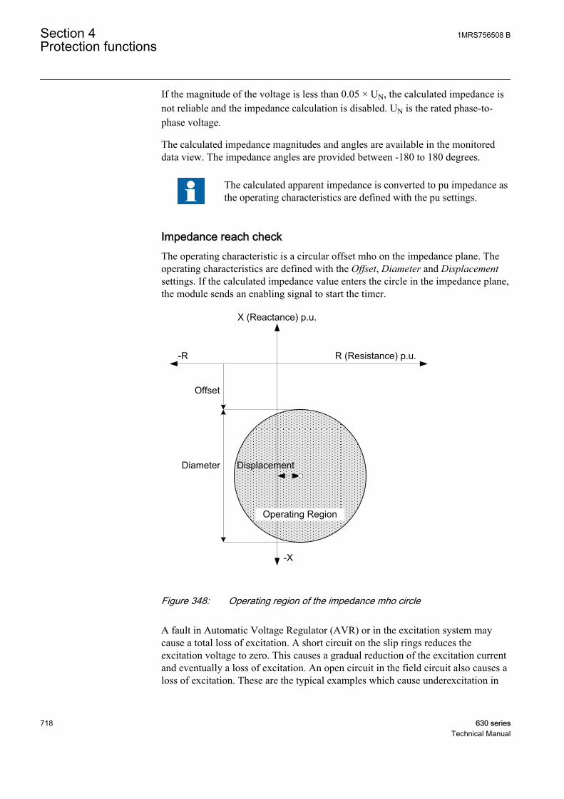
If the magnitude of the voltage is less than 0.05 × UN, the calculated impedance isnot reliable and the impedance calculation is disabled. UN is the rated phase-to-phase voltage.
The calculated impedance magnitudes and angles are available in the monitoreddata view. The impedance angles are provided between -180 to 180 degrees.
The calculated apparent impedance is converted to pu impedance asthe operating characteristics are defined with the pu settings.
Impedance reach checkThe operating characteristic is a circular offset mho on the impedance plane. Theoperating characteristics are defined with the Offset, Diameter and Displacementsettings. If the calculated impedance value enters the circle in the impedance plane,the module sends an enabling signal to start the timer.
GUID-78CC6BF8-EC11-47E8-962B-FA3FDFAB62AC V1 EN
Figure 348: Operating region of the impedance mho circle
A fault in Automatic Voltage Regulator (AVR) or in the excitation system maycause a total loss of excitation. A short circuit on the slip rings reduces theexcitation voltage to zero. This causes a gradual reduction of the excitation currentand eventually a loss of excitation. An open circuit in the field circuit also causes aloss of excitation. These are the typical examples which cause underexcitation in
Section 4 1MRS756508 BProtection functions
718 630 seriesTechnical Manual

synchronous machines. This module detects the underexcitation condition for theabove cases when the calculated impedance enters the operating characteristics.
External loss detectionThis module checks the status information of the excitation system. The module isactivated when the External Los Det Ena setting is set to "Enable". The total loss ofexcitation current or a failure in the excitation system is indicated by connectingthe external binary signal to the EXT_LOS_DET input. The timer is enabledimmediately when the EXT_LOS_DET input is activated.
TimerOnce activated, the timer activates the START output. The time characteristic isaccording to DT. When the duration of the underexcitation exceeds the set definiteOperate delay time, the OPERATE output is activated. If the impedance locusmoves out of the offset-mho operating characteristics before the module operates,the reset timer is activated. If the reset timer reaches the value set by Reset delaytime, the operating timer resets and the START output is deactivated.
The timer calculates the start duration value START_DUR, which indicates thepercentage ratio of the start situation and the set operating time (DT). The value isavailable in the monitored data view.
The activation of the BLOCK input deactivates all the binary outputs and resets theinternal timers. The BLK_ST binary input can be used to block the START signal.The BLK_OPR binary input can be used to block the OPERATE signal. Theoperation timer counting can be frozen on the prevailing value by activating theFR_TIMER input.
The angle values available at the input monitor data view are inradians.
4.7.2.5 Base values
In this function block, some of the settings are set in per unit (pu). These pu valuesare relational to certain base values, for example the values given in A, kV andkVA. The IED supports alternative base value groups for the phase current or voltage-related settings, for example "Phase Grp 1", "Phase Grp 2" and "Phase Grp 3".One of the groups to be used with the Base value Sel phase setting must be selected.
For more information, see the Basic functions section in this manual.
1MRS756508 B Section 4Protection functions
630 series 719Technical Manual
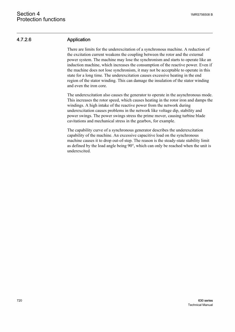
4.7.2.6 Application
There are limits for the underexcitation of a synchronous machine. A reduction ofthe excitation current weakens the coupling between the rotor and the externalpower system. The machine may lose the synchronism and starts to operate like aninduction machine, which increases the consumption of the reactive power. Even ifthe machine does not lose synchronism, it may not be acceptable to operate in thisstate for a long time. The underexcitation causes excessive heating in the endregion of the stator winding. This can damage the insulation of the stator windingand even the iron core.
The underexcitation also causes the generator to operate in the asynchronous mode.This increases the rotor speed, which causes heating in the rotor iron and damps thewindings. A high intake of the reactive power from the network duringunderexcitation causes problems in the network like voltage dip, stability andpower swings. The power swings stress the prime mover, causing turbine bladecavitations and mechanical stress in the gearbox, for example.
The capability curve of a synchronous generator describes the underexcitationcapability of the machine. An excessive capacitive load on the synchronousmachine causes it to drop out-of-step. The reason is the steady-state stability limitas defined by the load angle being 90°, which can only be reached when the unit isunderexcited.
Section 4 1MRS756508 BProtection functions
720 630 seriesTechnical Manual
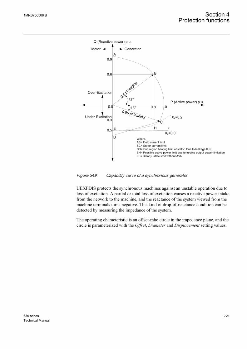
Q (Reactive power) p.u.
P (Active power) p.u.
0.95 pf leading
0.8 pf
lagg
ing
A
B
C
D
FE
0.0 0.8
0.6
0.5
0.3
1.0
0.9
GeneratorMotor
Over-Excitation
Under-Excitation
H
Xe=0.2
Xs=0.0
37o
18o
Where,AB= Field current limitBC= Stator current limitCD= End region heating limit of stator. Due to leakage fluxBH= Possible active power limit due to turbine output power limitationEF= Steady -state limit without AVR
GUID-875108FD-722B-4A19-81A6-49942A645756 V1 EN
Figure 349: Capability curve of a synchronous generator
UEXPDIS protects the synchronous machines against an unstable operation due toloss of excitation. A partial or total loss of excitation causes a reactive power intakefrom the network to the machine, and the reactance of the system viewed from themachine terminals turns negative. This kind of drop-of-reactance condition can bedetected by measuring the impedance of the system.
The operating characteristic is an offset-mho circle in the impedance plane, and thecircle is parameterized with the Offset, Diameter and Displacement setting values.
1MRS756508 B Section 4Protection functions
630 series 721Technical Manual
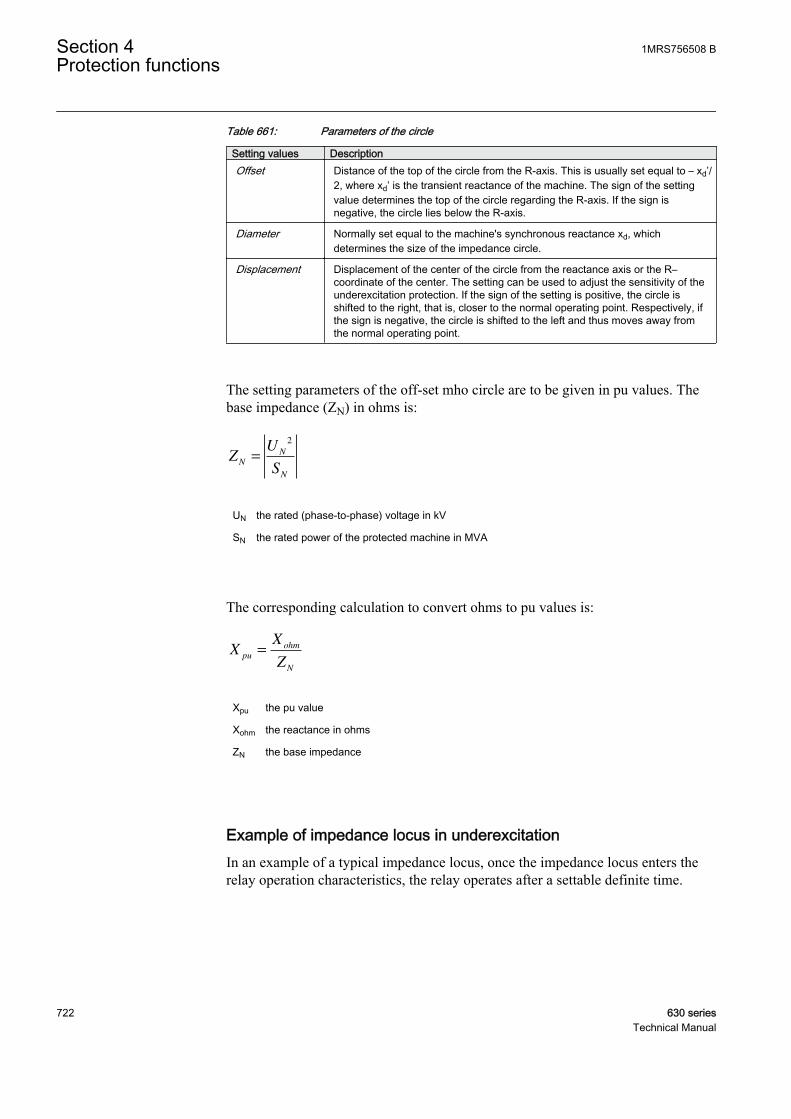
Table 661: Parameters of the circle
Setting values DescriptionOffset Distance of the top of the circle from the R-axis. This is usually set equal to – xd’/
2, where xd’ is the transient reactance of the machine. The sign of the settingvalue determines the top of the circle regarding the R-axis. If the sign isnegative, the circle lies below the R-axis.
Diameter Normally set equal to the machine's synchronous reactance xd, whichdetermines the size of the impedance circle.
Displacement Displacement of the center of the circle from the reactance axis or the R–coordinate of the center. The setting can be used to adjust the sensitivity of theunderexcitation protection. If the sign of the setting is positive, the circle isshifted to the right, that is, closer to the normal operating point. Respectively, ifthe sign is negative, the circle is shifted to the left and thus moves away fromthe normal operating point.
The setting parameters of the off-set mho circle are to be given in pu values. Thebase impedance (ZN) in ohms is:
ZU
SN
N
N
=
2
GUID-FDF8D989-6F91-4AE9-8A3C-31769808FF71 V1 EN
UN the rated (phase-to-phase) voltage in kV
SN the rated power of the protected machine in MVA
The corresponding calculation to convert ohms to pu values is:
XX
Zpu
ohm
N
=
GUID-8F02750E-98A4-4AD9-82C6-0632CCE84F01 V1 EN
Xpu the pu value
Xohm the reactance in ohms
ZN the base impedance
Example of impedance locus in underexcitationIn an example of a typical impedance locus, once the impedance locus enters therelay operation characteristics, the relay operates after a settable definite time.
Section 4 1MRS756508 BProtection functions
722 630 seriesTechnical Manual
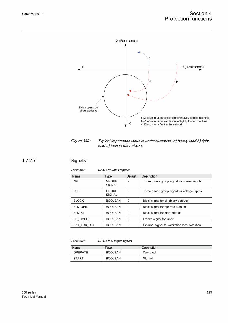
a) Z locus in under excitation for heavily loaded machineb) Z locus in under excitation for lightly loaded machinec) Z locus for a fault in the network
X (Reactance)
R (Resistance)
-X
Relay operation characteristics
-R
a b
c
GUID-BA88ECBB-5F42-4B24-B4BC-B922E2CB6769 V1 EN
Figure 350: Typical impedance locus in underexcitation: a) heavy load b) lightload c) fault in the network
4.7.2.7 Signals
Table 662: UEXPDIS Input signals
Name Type Default DescriptionI3P GROUP
SIGNAL- Three phase group signal for current inputs
U3P GROUPSIGNAL
- Three phase group signal for voltage inputs
BLOCK BOOLEAN 0 Block signal for all binary outputs
BLK_OPR BOOLEAN 0 Block signal for operate outputs
BLK_ST BOOLEAN 0 Block signal for start outputs
FR_TIMER BOOLEAN 0 Freeze signal for timer
EXT_LOS_DET BOOLEAN 0 External signal for excitation loss detection
Table 663: UEXPDIS Output signals
Name Type DescriptionOPERATE BOOLEAN Operated
START BOOLEAN Started
1MRS756508 B Section 4Protection functions
630 series 723Technical Manual
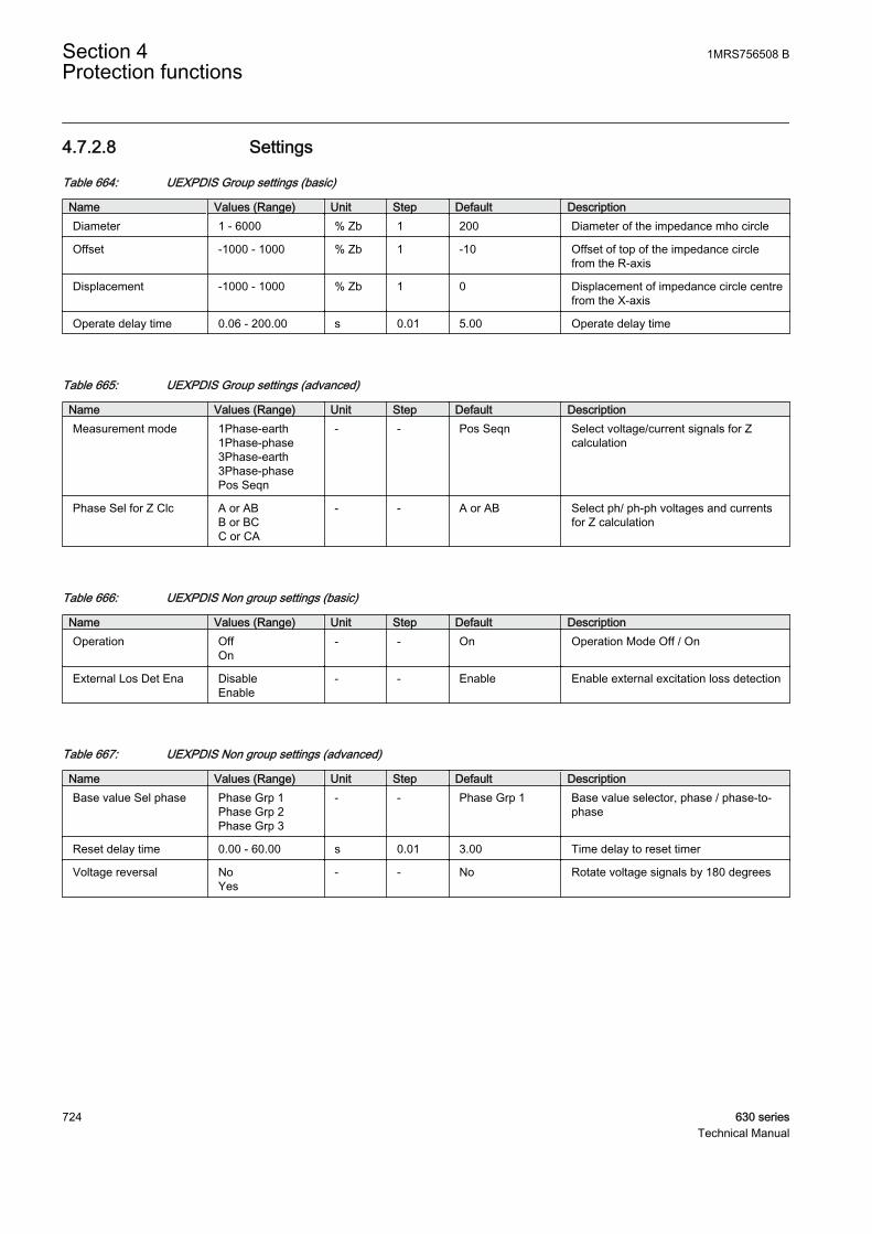
4.7.2.8 Settings
Table 664: UEXPDIS Group settings (basic)
Name Values (Range) Unit Step Default DescriptionDiameter 1 - 6000 % Zb 1 200 Diameter of the impedance mho circle
Offset -1000 - 1000 % Zb 1 -10 Offset of top of the impedance circlefrom the R-axis
Displacement -1000 - 1000 % Zb 1 0 Displacement of impedance circle centrefrom the X-axis
Operate delay time 0.06 - 200.00 s 0.01 5.00 Operate delay time
Table 665: UEXPDIS Group settings (advanced)
Name Values (Range) Unit Step Default DescriptionMeasurement mode 1Phase-earth
1Phase-phase3Phase-earth3Phase-phasePos Seqn
- - Pos Seqn Select voltage/current signals for Zcalculation
Phase Sel for Z Clc A or ABB or BCC or CA
- - A or AB Select ph/ ph-ph voltages and currentsfor Z calculation
Table 666: UEXPDIS Non group settings (basic)
Name Values (Range) Unit Step Default DescriptionOperation Off
On- - On Operation Mode Off / On
External Los Det Ena DisableEnable
- - Enable Enable external excitation loss detection
Table 667: UEXPDIS Non group settings (advanced)
Name Values (Range) Unit Step Default DescriptionBase value Sel phase Phase Grp 1
Phase Grp 2Phase Grp 3
- - Phase Grp 1 Base value selector, phase / phase-to-phase
Reset delay time 0.00 - 60.00 s 0.01 3.00 Time delay to reset timer
Voltage reversal NoYes
- - No Rotate voltage signals by 180 degrees
Section 4 1MRS756508 BProtection functions
724 630 seriesTechnical Manual

4.7.2.9 Measured values
Table 668: UEXPDIS Measured values
Name Type Default DescriptionI_AMPL_A REAL 0.0 Current amplitude (DFT) phase A
I_AMPL_B REAL 0.0 Current amplitude (DFT) phase B
I_AMPL_C REAL 0.0 Current amplitude (DFT) phase C
I_ANGL_A REAL 0.0 Current phase angle phase A
I_ANGL_B REAL 0.0 Current phase angle phase B
I_ANGL_C REAL 0.0 Current phase angle phase C
I1_AMPL REAL 0.0 Positive sequence current amplitude
I1_ANGL REAL 0.0 Positive sequence current angle
U_AMPL_A REAL 0.0 Phase A-to-ground voltage amplitude
U_AMPL_B REAL 0.0 Phase B-to-ground voltage amplitude
U_AMPL_C REAL 0.0 Phase C-to-ground voltage amplitude
U_ANGL_A REAL 0.0 Phase A-to-ground voltage phase angle
U_ANGL_B REAL 0.0 Phase B-to-ground voltage phase angle
U_ANGL_C REAL 0.0 Phase C-to-ground voltage phase angle
U_AMPL_AB REAL 0.0 Phase-to-phase A-B voltage amplitude
U_AMPL_BC REAL 0.0 Phase-to-phase B-C voltage amplitude
U_AMPL_CA REAL 0.0 Phase-to-phase C-A voltage amplitude
U_ANGL_AB REAL 0.0 Phase-to-phase A-B voltage phase angle
U_ANGL_BC REAL 0.0 Phase-to-phase B-C voltage phase angle
U_ANGL_CA REAL 0.0 Phase-to-phase C-A voltage phase angle
U1_AMPL REAL 0.0 Positive sequence voltage amplitude
U1_ANGL REAL 0.0 Positive sequence voltage phase angle
BLOCK BOOLEAN 0 Block signal for all binary outputs
BLK_OPR BOOLEAN 0 Block signal for operate outputs
BLK_ST BOOLEAN 0 Block signal for start outputs
FR_TIMER BOOLEAN 0 Freeze signal for timer
EXT_LOS_DET BOOLEAN 0 External signal for excitation loss detection
4.7.2.10 Monitored data
Table 669: UEXPDIS Monitored data
Name Type Values (Range) Unit DescriptionOPERATE BOOLEAN 0=FALSE
1=TRUE- Operated
START BOOLEAN 0=FALSE1=TRUE
- Started
Z_AMPL_A REAL - pu Impedance amplitudephase A
Table continues on next page
1MRS756508 B Section 4Protection functions
630 series 725Technical Manual
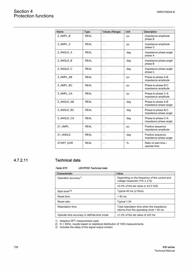
Name Type Values (Range) Unit DescriptionZ_AMPL_B REAL - pu Impedance amplitude
phase B
Z_AMPL_C REAL - pu Impedance amplitudephase C
Z_ANGLE_A REAL - deg Impedance phase anglephase A
Z_ANGLE_B REAL - deg Impedance phase anglephase B
Z_ANGLE_C REAL - deg Impedance phase anglephase C
Z_AMPL_AB REAL - pu Phase-to-phase A-Bimpedance amplitude
Z_AMPL_BC REAL - pu Phase-to-phase B-Cimpedance amplitude
Z_AMPL_CA REAL - pu Phase-to-phase C-Aimpedance amplitude
Z_ANGLE_AB REAL - deg Phase-to-phase A-Bimpedance phase angle
Z_ANGLE_BC REAL - deg Phase-to-phase B-Cimpedance phase angle
Z_ANGLE_CA REAL - deg Phase-to-phase C-Aimpedance phase angle
Z1_AMPL REAL - pu Positive sequenceimpedance amplitude
Z1_ANGLE REAL - deg Positive sequenceimpedance phase angle
START_DUR REAL - % Ratio of start time /operate time
4.7.2.11 Technical data
Table 670: UEXPDIS Technical data
Characteristic ValueOperation accuracy1) Depending on the frequency of the current and
voltage measured, f=fn ± 2 Hz
±3.0% of the set value or ±0.2 %Zb
Start time2)3) Typical 45 ms (±15ms)
Reset time < 50 ms
Reset ratio Typical 1.04
Retardation time Total retardation time when the impedancereturns from the operating circle < 40 ms
Operate time accuracy in definite-time mode ±1.0% of the set value of ±20 ms
1) Adaptive DFT measurement used.2) fn = 50Hz, results based on statistical distribution of 1000 measurements.3) Includes the delay of the signal output contact.
Section 4 1MRS756508 BProtection functions
726 630 seriesTechnical Manual
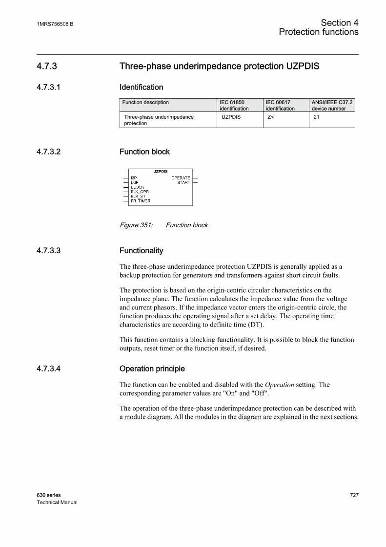
4.7.3 Three-phase underimpedance protection UZPDIS
4.7.3.1 Identification
Function description IEC 61850identification
IEC 60617identification
ANSI/IEEE C37.2device number
Three-phase underimpedanceprotection
UZPDIS Z< 21
4.7.3.2 Function block
GUID-856BE5AC-7DD6-46CA-860F-61E3853908E7 V1 EN
Figure 351: Function block
4.7.3.3 Functionality
The three-phase underimpedance protection UZPDIS is generally applied as abackup protection for generators and transformers against short circuit faults.
The protection is based on the origin-centric circular characteristics on theimpedance plane. The function calculates the impedance value from the voltageand current phasors. If the impedance vector enters the origin-centric circle, thefunction produces the operating signal after a set delay. The operating timecharacteristics are according to definite time (DT).
This function contains a blocking functionality. It is possible to block the functionoutputs, reset timer or the function itself, if desired.
4.7.3.4 Operation principle
The function can be enabled and disabled with the Operation setting. Thecorresponding parameter values are "On" and "Off".
The operation of the three-phase underimpedance protection can be described witha module diagram. All the modules in the diagram are explained in the next sections.
1MRS756508 B Section 4Protection functions
630 series 727Technical Manual
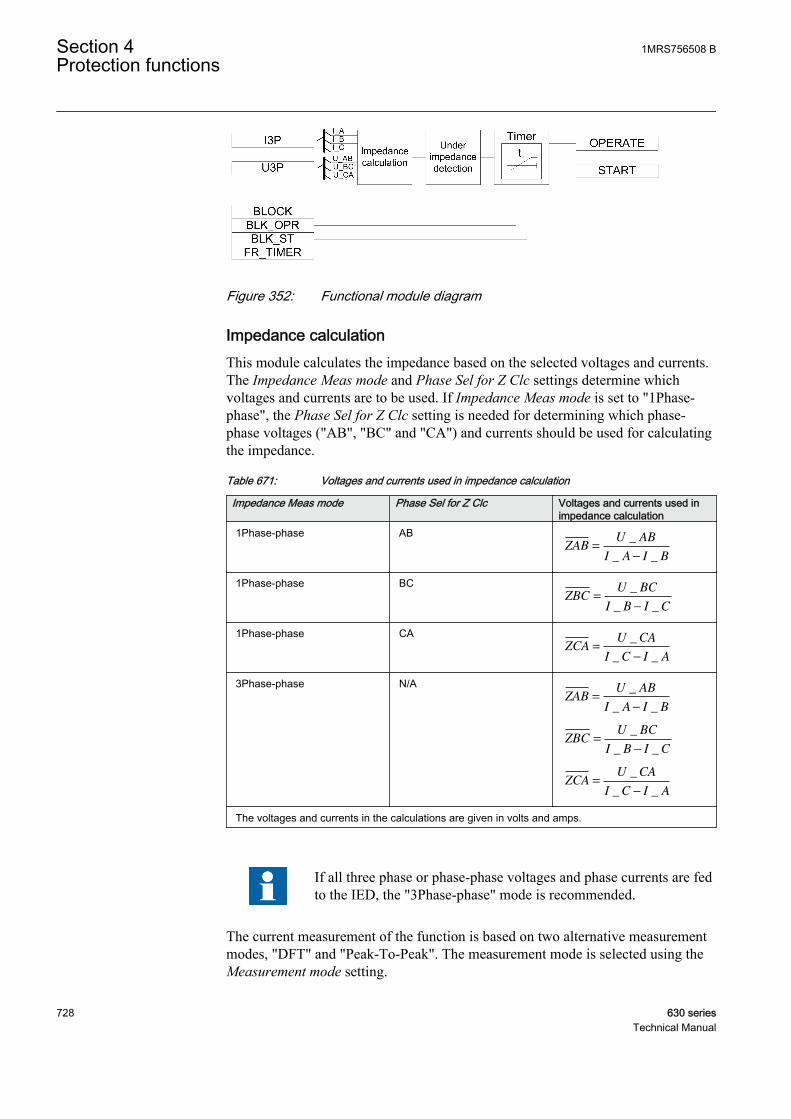
GUID-97E6023F-064C-4535-A537-75763A7EA8C6 V1 EN
Figure 352: Functional module diagram
Impedance calculationThis module calculates the impedance based on the selected voltages and currents.The Impedance Meas mode and Phase Sel for Z Clc settings determine whichvoltages and currents are to be used. If Impedance Meas mode is set to "1Phase-phase", the Phase Sel for Z Clc setting is needed for determining which phase-phase voltages ("AB", "BC" and "CA") and currents should be used for calculatingthe impedance.
Table 671: Voltages and currents used in impedance calculation
Impedance Meas mode Phase Sel for Z Clc Voltages and currents used inimpedance calculation
1Phase-phase ABZAB
U AB
I A I B=
−
_
_ _
1Phase-phase BCZBC
U BC
I B I C=
−
_
_ _
1Phase-phase CAZCA
U CA
I C I A=
−
_
_ _
3Phase-phase N/AZAB
U AB
I A I B=
−
_
_ _
ZBCU BC
I B I C=
−
_
_ _
ZCAU CA
I C I A=
−
_
_ _
The voltages and currents in the calculations are given in volts and amps.
If all three phase or phase-phase voltages and phase currents are fedto the IED, the "3Phase-phase" mode is recommended.
The current measurement of the function is based on two alternative measurementmodes, "DFT" and "Peak-To-Peak". The measurement mode is selected using theMeasurement mode setting.
Section 4 1MRS756508 BProtection functions
728 630 seriesTechnical Manual
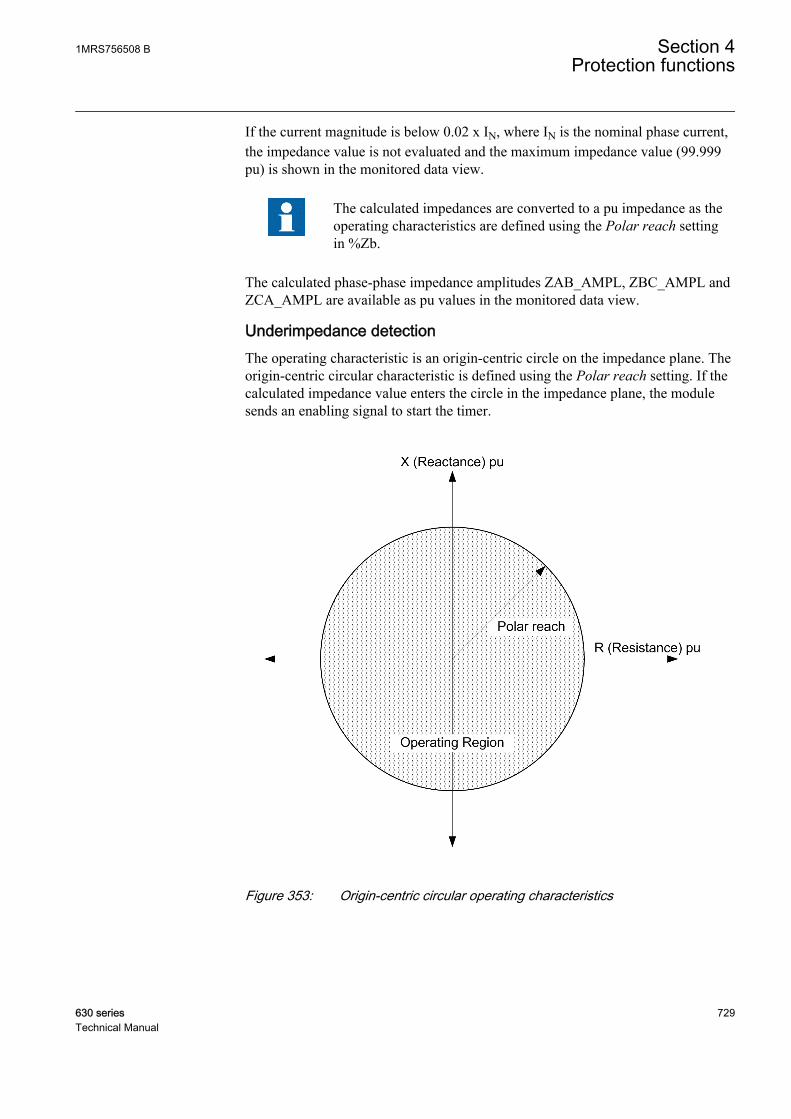
If the current magnitude is below 0.02 x IN, where IN is the nominal phase current,the impedance value is not evaluated and the maximum impedance value (99.999pu) is shown in the monitored data view.
The calculated impedances are converted to a pu impedance as theoperating characteristics are defined using the Polar reach settingin %Zb.
The calculated phase-phase impedance amplitudes ZAB_AMPL, ZBC_AMPL andZCA_AMPL are available as pu values in the monitored data view.
Underimpedance detectionThe operating characteristic is an origin-centric circle on the impedance plane. Theorigin-centric circular characteristic is defined using the Polar reach setting. If thecalculated impedance value enters the circle in the impedance plane, the modulesends an enabling signal to start the timer.
GUID-28F500A3-B738-4BEF-8451-45D67E1762BF V1 EN
Figure 353: Origin-centric circular operating characteristics
1MRS756508 B Section 4Protection functions
630 series 729Technical Manual

More than one impedance value is available when Impedance Measmode is set to "3Phase-phase", and the function considers thelowest impedance value for starting and operating.
TimerOnce activated, the timer activates START output. The time characteristic isaccording to DT. When the duration of the underimpedance condition exceeds theset definite Operate delay time, the OPERATE output is activated. If the impedancelocus moves out of circular operating characteristics before the module operates,the reset timer is activated. If the reset timer reaches the value set by Reset delaytime, the operating timer resets and the START output is deactivated.
The timer calculates the start duration value START_DUR, which indicates thepercentage ratio of the start situation and the set operating time (DT). The value isavailable in the monitored data view.
The activation of the BLOCK input deactivates all binary outputs and resets internaltimers. The BLK_ST binary input can be used to block the START signal. TheBLK_OPR binary input can be used to block the OPERATE signal. The operationtimer counting can be frozen on the prevailing value by activating the FR_TIMERinput.
4.7.3.5 Base values
In this function block, some of the settings are set in per unit (pu). These pu valuesare relational to certain base values, for example the values given in A, kV andkVA. The IED supports alternative base value groups for the phase current or voltage-related settings, for example "Phase Grp 1", "Phase Grp 2" and "Phase Grp 3".One of the groups to be used with the Base value Sel phase setting must be selected.
For more information, see the Basic functions section in this manual.
4.7.3.6 Application
The three-phase underimpedance protection is used as a backup protection againstshort circuit faults at the generator terminals or on the high-voltage side of a step-up transformer. This function can be used either instead of the definite time voltage-dependent overcurrent protection or to obtain a limited protection zone and theoptimum operating time instead of the non-directional overcurrent protection.
Comparison between overcurrent and underimpedance protectionWhen a fault occurs at zero seconds in the phase current in a three-phase shortcircuit with an ordinary overcurrent IED having the current setting as 1.2 x In, the
Section 4 1MRS756508 BProtection functions
730 630 seriesTechnical Manual

time setting should be less than 0.2 seconds because the short circuit current decaysbelow the set value and the IED drops off with a higher value of time. The currentsetting can also be reduced to 1.1 x In, although this provides no substantial rise inthe time setting. In some situations, either of the above current settings isappropriate, but if longer tripping times are required to maintain the timeselectivity, the underimpedance protection is needed.
GUID-A0F9BC84-C51C-4F93-9A32-DF303D3A9898 V1 EN
Figure 354: Short circuit current waveform, fault occurs at time 0 seconds(Current setting limit is multiplied by the square root of 2).
The phase voltage in a three-phase short circuit when a fault occurs at zero secondsis shown in Figure 355. The voltage drop caused by a three-phase fault providesmore time for determining the fault by means of an underimpedance protection.
1MRS756508 B Section 4Protection functions
630 series 731Technical Manual
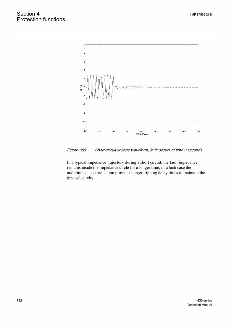
GUID-4F3DC9C2-A983-4408-854F-050F940CA1A7 V1 EN
Figure 355: Short-circuit voltage waveform, fault occurs at time 0 seconds
In a typical impedance trajectory during a short circuit, the fault impedanceremains inside the impedance circle for a longer time, in which case theunderimpedance protection provides longer tripping delay times to maintain thetime selectivity.
Section 4 1MRS756508 BProtection functions
732 630 seriesTechnical Manual

GUID-818E1FD1-0FB7-49A3-84CB-D5999F68CBB3 V1 EN
Figure 356: Typical impedance trajectory during a short circuit.
Underimpedance protection for transformersThe underimpedance function is used as a short circuit protection instead of theovercurrent protection. It is also used as a backup to the differential protection oftransformers.
The voltage and current phasors are measured with the VTs and CTs connected onthe HV side of the transformer.
The phase and current shifts due to transformer D/Y connectionsand other factors complicate the settings for the faults in thesecondary winding (as seen from the IED), and detailedcalculations are necessary for a good coverage.
The Polar reach setting is set to a value equal to 150 percent of the transformershort circuit impedance. The setting also provides a backup protection for thebusbar and feeder faults on the HV side.
1MRS756508 B Section 4Protection functions
630 series 733Technical Manual
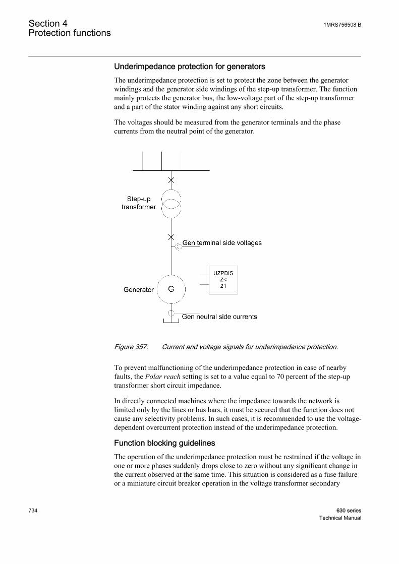
Underimpedance protection for generatorsThe underimpedance protection is set to protect the zone between the generatorwindings and the generator side windings of the step-up transformer. The functionmainly protects the generator bus, the low-voltage part of the step-up transformerand a part of the stator winding against any short circuits.
The voltages should be measured from the generator terminals and the phasecurrents from the neutral point of the generator.
GUID-744031AE-0995-4337-80F2-114360E46F7A V1 EN
Figure 357: Current and voltage signals for underimpedance protection.
To prevent malfunctioning of the underimpedance protection in case of nearbyfaults, the Polar reach setting is set to a value equal to 70 percent of the step-uptransformer short circuit impedance.
In directly connected machines where the impedance towards the network islimited only by the lines or bus bars, it must be secured that the function does notcause any selectivity problems. In such cases, it is recommended to use the voltage-dependent overcurrent protection instead of the underimpedance protection.
Function blocking guidelinesThe operation of the underimpedance protection must be restrained if the voltage inone or more phases suddenly drops close to zero without any significant change inthe current observed at the same time. This situation is considered as a fuse failureor a miniature circuit breaker operation in the voltage transformer secondary
Section 4 1MRS756508 BProtection functions
734 630 seriesTechnical Manual
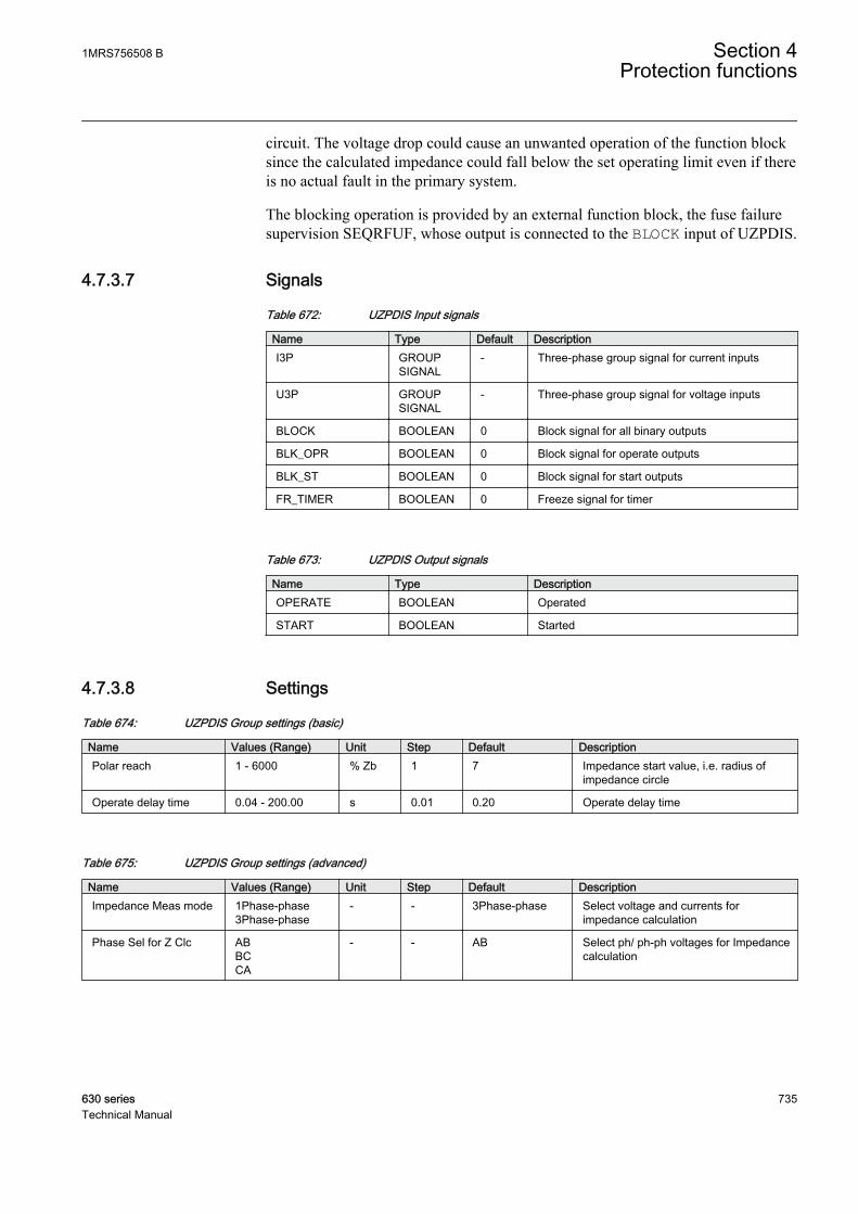
circuit. The voltage drop could cause an unwanted operation of the function blocksince the calculated impedance could fall below the set operating limit even if thereis no actual fault in the primary system.
The blocking operation is provided by an external function block, the fuse failuresupervision SEQRFUF, whose output is connected to the BLOCK input of UZPDIS.
4.7.3.7 Signals
Table 672: UZPDIS Input signals
Name Type Default DescriptionI3P GROUP
SIGNAL- Three-phase group signal for current inputs
U3P GROUPSIGNAL
- Three-phase group signal for voltage inputs
BLOCK BOOLEAN 0 Block signal for all binary outputs
BLK_OPR BOOLEAN 0 Block signal for operate outputs
BLK_ST BOOLEAN 0 Block signal for start outputs
FR_TIMER BOOLEAN 0 Freeze signal for timer
Table 673: UZPDIS Output signals
Name Type DescriptionOPERATE BOOLEAN Operated
START BOOLEAN Started
4.7.3.8 Settings
Table 674: UZPDIS Group settings (basic)
Name Values (Range) Unit Step Default DescriptionPolar reach 1 - 6000 % Zb 1 7 Impedance start value, i.e. radius of
impedance circle
Operate delay time 0.04 - 200.00 s 0.01 0.20 Operate delay time
Table 675: UZPDIS Group settings (advanced)
Name Values (Range) Unit Step Default DescriptionImpedance Meas mode 1Phase-phase
3Phase-phase- - 3Phase-phase Select voltage and currents for
impedance calculation
Phase Sel for Z Clc ABBCCA
- - AB Select ph/ ph-ph voltages for Impedancecalculation
1MRS756508 B Section 4Protection functions
630 series 735Technical Manual

Table 676: UZPDIS Non group settings (basic)
Name Values (Range) Unit Step Default DescriptionOperation Off
On- - On Operation Mode Off / On
Table 677: UZPDIS Non group settings (advanced)
Name Values (Range) Unit Step Default DescriptionBase value Sel phase Phase Grp 1
Phase Grp 2Phase Grp 3
- - Phase Grp 1 Base value selector, phase / phase-to-phase
Measurement mode DFTPeak-to-Peak
- - DFT Selected measurement mode for phasecurrents
Reset delay time 0.00 - 60.00 s 0.01 0.02 Reset delay time
4.7.3.9 Measured values
Table 678: UZPDIS Measured values
Name Type Default DescriptionI_AMPL_A REAL 0.0 Current amplitude (DFT) phase A
I_AMPL_B REAL 0.0 Current amplitude (DFT) phase B
I_AMPL_C REAL 0.0 Current amplitude (DFT) phase C
I_PTOP_A REAL 0.0 Current amplitude (PTOP) phase A
I_PTOP_B REAL 0.0 Current amplitude (PTOP) phase B
I_PTOP_C REAL 0.0 Current amplitude (PTOP) phase C
I_ANGL_A REAL 0.0 Current phase angle phase A
I_ANGL_B REAL 0.0 Current phase angle phase B
I_ANGL_C REAL 0.0 Current phase angle phase C
U_AMPL_AB REAL 0.0 Phase-to-phase A-B voltage amplitude
U_AMPL_BC REAL 0.0 Phase-to-phase B-C voltage amplitude
U_AMPL_CA REAL 0.0 Phase-to-phase C-A voltage amplitude
BLOCK BOOLEAN 0 Block signal for all binary outputs
BLK_OPR BOOLEAN 0 Block signal for operate outputs
BLK_ST BOOLEAN 0 Block signal for start outputs
FR_TIMER BOOLEAN 0 Freeze signal for timer
Section 4 1MRS756508 BProtection functions
736 630 seriesTechnical Manual
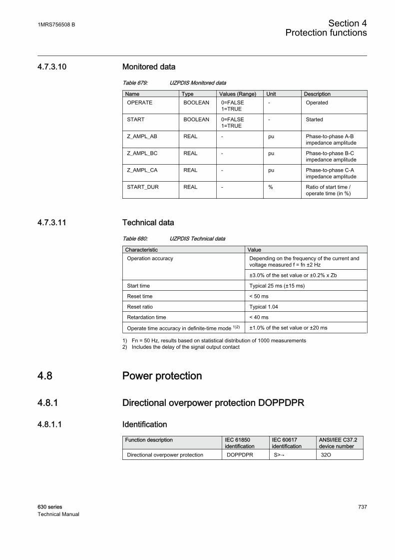
4.7.3.10 Monitored data
Table 679: UZPDIS Monitored data
Name Type Values (Range) Unit DescriptionOPERATE BOOLEAN 0=FALSE
1=TRUE- Operated
START BOOLEAN 0=FALSE1=TRUE
- Started
Z_AMPL_AB REAL - pu Phase-to-phase A-Bimpedance amplitude
Z_AMPL_BC REAL - pu Phase-to-phase B-Cimpedance amplitude
Z_AMPL_CA REAL - pu Phase-to-phase C-Aimpedance amplitude
START_DUR REAL - % Ratio of start time /operate time (in %)
4.7.3.11 Technical data
Table 680: UZPDIS Technical data
Characteristic ValueOperation accuracy Depending on the frequency of the current and
voltage measured f = fn ±2 Hz
±3.0% of the set value or ±0.2% x Zb
Start time Typical 25 ms (±15 ms)
Reset time < 50 ms
Reset ratio Typical 1.04
Retardation time < 40 ms
Operate time accuracy in definite-time mode 1)2) ±1.0% of the set value or ±20 ms
1) Fn = 50 Hz, results based on statistical distribution of 1000 measurements2) Includes the delay of the signal output contact
4.8 Power protection
4.8.1 Directional overpower protection DOPPDPR
4.8.1.1 Identification
Function description IEC 61850identification
IEC 60617identification
ANSI/IEE C37.2device number
Directional overpower protection DOPPDPR S>→ 32O
1MRS756508 B Section 4Protection functions
630 series 737Technical Manual

4.8.1.2 Function block
GUID-E4756531-3C76-4D90-B0DC-DCC21770ABB2 V1 EN
Figure 358: Function block
4.8.1.3 Functionality
The directional overpower protection DOPPDPR can be used for generatorprotection against delivering an excessive power beyond the generator's capacity tothe grid, against the generator running like a motor, against the motor running likea generator and protecting a motor which consumes more reactive power due toloss of field. DOPPDPR can also be used in feeder protection for indicatingoverload on the distribution system to indicate that a customer is supplying powerinto the grid and for protecting the transformer from delivering an excessive load.
DOPPDPR starts and operates when the measured power exceeds the set limit andin a specified direction. The operate time characteristics are according to definitetime (DT).
This function contains a blocking functionality. It is possible to block the functionoutputs, timer or the function itself, if desired.
4.8.1.4 Operation principle
The function can be enabled and disabled with the Operation setting. Thecorresponding parameter values are "On" and "Off".
The operation of the directional overpower protection function can be describedusing a module diagram. All the modules in the diagram are explained in the nextsections.
Section 4 1MRS756508 BProtection functions
738 630 seriesTechnical Manual
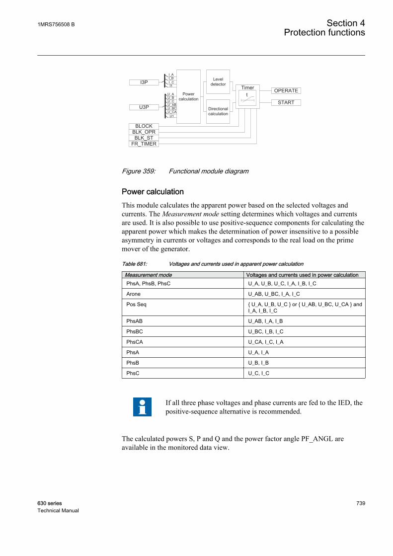
BLOCK
BLK_STFR_TIMER
OPERATE
STARTDirectional calculation
U3P
I3P
Power calculation
U_AU_BU_C
I_AI_BI_CI1
U1
U_ABU_BCU_CA
Level detector
tTimer
BLK_OPR
GUID-0D501C16-0882-4420-BC15-E4D57AD2AE18 V1 EN
Figure 359: Functional module diagram
Power calculationThis module calculates the apparent power based on the selected voltages andcurrents. The Measurement mode setting determines which voltages and currentsare used. It is also possible to use positive-sequence components for calculating theapparent power which makes the determination of power insensitive to a possibleasymmetry in currents or voltages and corresponds to the real load on the primemover of the generator.
Table 681: Voltages and currents used in apparent power calculation
Measurement mode Voltages and currents used in power calculationPhsA, PhsB, PhsC U_A, U_B, U_C, I_A, I_B, I_C
Arone U_AB, U_BC, I_A, I_C
Pos Seq { U_A, U_B, U_C } or { U_AB, U_BC, U_CA } andI_A, I_B, I_C
PhsAB U_AB, I_A, I_B
PhsBC U_BC, I_B, I_C
PhsCA U_CA, I_C, I_A
PhsA U_A, I_A
PhsB U_B, I_B
PhsC U_C, I_C
If all three phase voltages and phase currents are fed to the IED, thepositive-sequence alternative is recommended.
The calculated powers S, P and Q and the power factor angle PF_ANGL areavailable in the monitored data view.
1MRS756508 B Section 4Protection functions
630 series 739Technical Manual

Level detectorThe level detector compares the magnitude of the measured apparent power to theset Start value. If the measured value exceeds the set Start value, the level detectorsends an enabling signal to the timer module.
Directional calculationThe directional calculation module monitors the direction of the apparent power.When the apparent power flow is in the operating area, the module sends theenabling signal to the timer module. The directional operation can be selected withthe combination of the settings Directional mode and Power angle. The selectableoptions for the Directional mode setting are "Forward" and "Reverse". The Powerangle setting can be used to set the power direction between the reactive and activepower.
A typical error is, for example, that the VT or CT poles are wronglyconnected. This is seen as a power flow opposite to that of theintended direction. The Pol Reversal setting can be used to correctthe situation. By setting the value to "Yes", the measured apparentpower is turned 180 degrees.
GUID-7C8F2C37-311E-455F-A68B-18DE1208E118 V1 EN
Figure 360: Operating characteristics with the Start Value setting, the Powerangle setting being 0 and Directional mode "Forward"
Section 4 1MRS756508 BProtection functions
740 630 seriesTechnical Manual
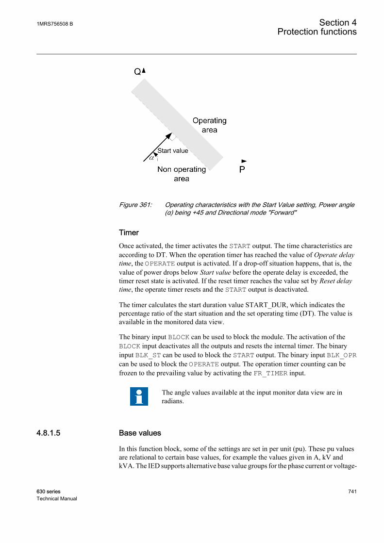
GUID-E85507DB-E41A-4C1E-9EED-89B5BB0DA2F6 V1 EN
Figure 361: Operating characteristics with the Start Value setting, Power angle(α) being +45 and Directional mode "Forward"
TimerOnce activated, the timer activates the START output. The time characteristics areaccording to DT. When the operation timer has reached the value of Operate delaytime, the OPERATE output is activated. If a drop-off situation happens, that is, thevalue of power drops below Start value before the operate delay is exceeded, thetimer reset state is activated. If the reset timer reaches the value set by Reset delaytime, the operate timer resets and the START output is deactivated.
The timer calculates the start duration value START_DUR, which indicates thepercentage ratio of the start situation and the set operating time (DT). The value isavailable in the monitored data view.
The binary input BLOCK can be used to block the module. The activation of theBLOCK input deactivates all the outputs and resets the internal timer. The binaryinput BLK_ST can be used to block the START output. The binary input BLK_OPRcan be used to block the OPERATE output. The operation timer counting can befrozen to the prevailing value by activating the FR_TIMER input.
The angle values available at the input monitor data view are inradians.
4.8.1.5 Base values
In this function block, some of the settings are set in per unit (pu). These pu valuesare relational to certain base values, for example the values given in A, kV andkVA. The IED supports alternative base value groups for the phase current or voltage-
1MRS756508 B Section 4Protection functions
630 series 741Technical Manual
related settings, for example "Phase Grp 1", "Phase Grp 2" and "Phase Grp 3".One of the groups to be used with the Base value Sel phase setting must be selected.
For more information, see the Basic functions section in this manual.
4.8.1.6 Application
DOPPDPR is used to provide protection against an excessive power flow in the setoperating direction. Main application is the protection of generators and turbines. Itcan also be used in feeder protection applications, for example, the ring network.
DOPPDPR in the forward direction can be used to protect the generators or motorsfrom delivering or consuming excess power. For example, the generator overpowerprotection can be used to shed a noncritical feeder load or to start parallelgenerators. A synchronous motor may start consuming more reactive power in caseof loss of excitation, in which case the forward overpower protection is used todetect such condition.
The directional overpower function has many applications when used as a reversepower protection. A generator in a power plant converts mechanical energy toelectrical energy. Sometimes the mechanical power from a prime mover maydecrease to a limit that it does not cover the internal losses. The synchronousgenerator becomes a synchronous motor and starts importing power from thesystem. The effect of a generator acting as a motor implies no risk to the machinebut can cause damage to the prime mover. The extent of the damage depends onthe type of the prime mover.
Steam turbines become overheated easily if the steam flow drops too low or if thesteam ceases to flow through the turbine. The break of a main steam pipe, damageto one or more blades in the steam turbine or an inadvertent closing of the mainstop valves are typical causes for the low steam flow. The steam turbines of turbogenerators can be protected during a low steam flow with the overpower protectionoperating in reverse direction. Hydroturbines tolerate reverse power much betterthan steam turbines do. There is a risk that the turbine runner moves axially andtouches stationary parts. They are not always strong enough to withstand theassociated stresses.
A hydroturbine that rotates in water with the closed wicket gates draws about 10percent of the rated power from the rest of the power system if the intake isblocked due to ice, snow, branches or leaves. A complete blockage of the intakemay cause cavitations. If there is only air in the hydroturbine, the power demanddrops to about 3 percent. The risk of damages to the hydroturbines can justify thereverse operation of the overpower protection in unattended plants.
Section 4 1MRS756508 BProtection functions
742 630 seriesTechnical Manual

Whenever a low value of the reverse power setting is required, anunderpower protection should also be used in conjunction withDOPPDPR. The limit depends on the CT and VT accuracy.
Diesel engines should have overpower protection in reverse direction. Thegenerator takes about 15 percent or more of its rated power from the system. A stiffengine may require 25 percent of the rated power to motor it. A well run enginemay need no more than 5 percent. It is necessary to obtain information from theengine manufacturer and to measure the reverse power during commissioning.
Reverse overpower can also act as an alternative for an under excitation protectionin case of small generators. If the field excitation is reduced, the generator maystart importing the reactive power, making the generator run as an asynchronousgenerator. A synchronous generator is not designed to work asynchronously andmay become damaged due to heating in the damper windings or heating in the rotordue to slip frequency current.
When operated in reverse power direction, it can be used as an alarm if the powerflowing from the industry is feeding the grid, which may not be desired as per therules and regulations of the utility owning the grid.
GUID-8F443990-50DE-4771-97C3-0B545BDC2D45 V1 EN
Figure 362: Forward active overpower characteristics and forward reactiveoverpower characteristics
1MRS756508 B Section 4Protection functions
630 series 743Technical Manual
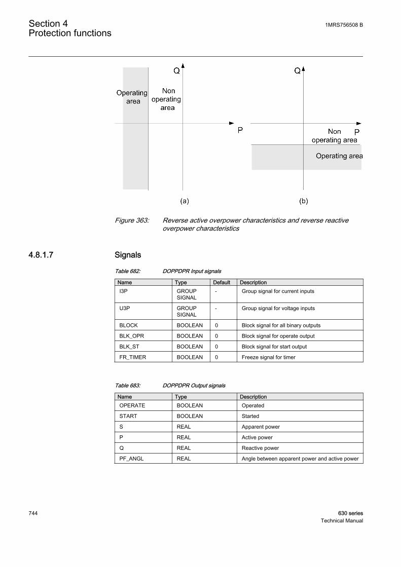
GUID-0C752136-2105-42F0-8B84-9FF31214A84B V1 EN
Figure 363: Reverse active overpower characteristics and reverse reactiveoverpower characteristics
4.8.1.7 Signals
Table 682: DOPPDPR Input signals
Name Type Default DescriptionI3P GROUP
SIGNAL- Group signal for current inputs
U3P GROUPSIGNAL
- Group signal for voltage inputs
BLOCK BOOLEAN 0 Block signal for all binary outputs
BLK_OPR BOOLEAN 0 Block signal for operate output
BLK_ST BOOLEAN 0 Block signal for start output
FR_TIMER BOOLEAN 0 Freeze signal for timer
Table 683: DOPPDPR Output signals
Name Type DescriptionOPERATE BOOLEAN Operated
START BOOLEAN Started
S REAL Apparent power
P REAL Active power
Q REAL Reactive power
PF_ANGL REAL Angle between apparent power and active power
Section 4 1MRS756508 BProtection functions
744 630 seriesTechnical Manual

4.8.1.8 Settings
Table 684: DOPPDPR Group settings (basic)
Name Values (Range) Unit Step Default DescriptionDirectional mode Forward
Reverse- - Forward Directional mode
Start value 0.01 - 2.00 pu 0.01 1.00 Start value
Power angle -90.00 - 90.00 Deg 0.01 0.00 Adjustable angle for power
Operate delay time 0.04 - 300.00 s 0.01 0.04 Operate delay time
Table 685: DOPPDPR Non group settings (basic)
Name Values (Range) Unit Step Default DescriptionOperation Off
On- - On Operation Mode Off / On
Table 686: DOPPDPR Non group settings (advanced)
Name Values (Range) Unit Step Default DescriptionBase value Sel phase Phase Grp 1
Phase Grp 2Phase Grp 3
- - Phase Grp 1 Base value selector phase / phase tophase
Measurement mode PhsA, PhsB, PhsCAronePos SeqPhsABPhsBCPhsCAPhsAPhsBPhsC
- - Pos Seq Selection of power calculation method
Reset delay time 0.00 - 60.00 s 0.01 0.02 Reset delay time
Pol reversal NoYes
- - No Reversing the definition of the positivepower direction
4.8.1.9 Measured values
Table 687: DOPPDPR Measured values
Name Type Default DescriptionI_AMPL_A REAL 0.0 Current amplitude (DFT) phase A
I_AMPL_B REAL 0.0 Current amplitude (DFT) phase B
I_AMPL_C REAL 0.0 Current amplitude (DFT) phase C
I_ANGL_A REAL 0.0 Current phase angle phase A
I_ANGL_B REAL 0.0 Current phase angle phase B
I_ANGL_C REAL 0.0 Current phase angle phase C
I1_AMPL REAL 0.0 Positive sequence current amplitude
Table continues on next page
1MRS756508 B Section 4Protection functions
630 series 745Technical Manual
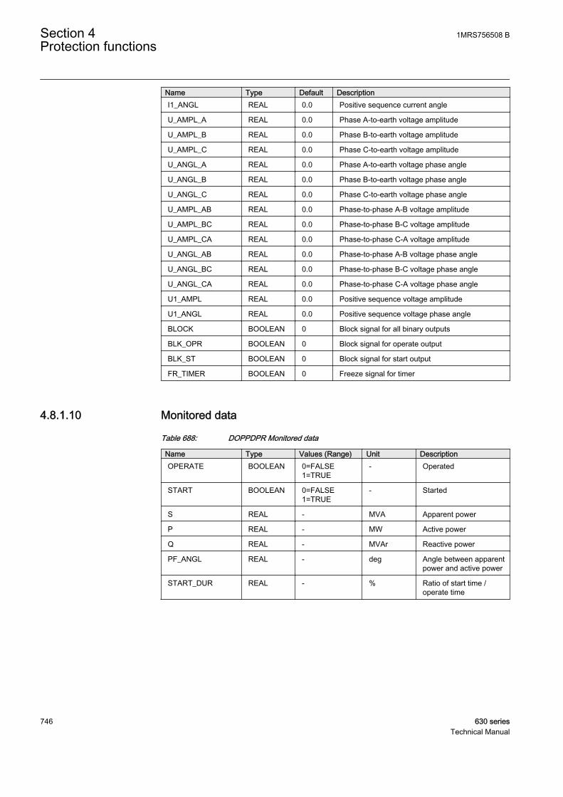
Name Type Default DescriptionI1_ANGL REAL 0.0 Positive sequence current angle
U_AMPL_A REAL 0.0 Phase A-to-earth voltage amplitude
U_AMPL_B REAL 0.0 Phase B-to-earth voltage amplitude
U_AMPL_C REAL 0.0 Phase C-to-earth voltage amplitude
U_ANGL_A REAL 0.0 Phase A-to-earth voltage phase angle
U_ANGL_B REAL 0.0 Phase B-to-earth voltage phase angle
U_ANGL_C REAL 0.0 Phase C-to-earth voltage phase angle
U_AMPL_AB REAL 0.0 Phase-to-phase A-B voltage amplitude
U_AMPL_BC REAL 0.0 Phase-to-phase B-C voltage amplitude
U_AMPL_CA REAL 0.0 Phase-to-phase C-A voltage amplitude
U_ANGL_AB REAL 0.0 Phase-to-phase A-B voltage phase angle
U_ANGL_BC REAL 0.0 Phase-to-phase B-C voltage phase angle
U_ANGL_CA REAL 0.0 Phase-to-phase C-A voltage phase angle
U1_AMPL REAL 0.0 Positive sequence voltage amplitude
U1_ANGL REAL 0.0 Positive sequence voltage phase angle
BLOCK BOOLEAN 0 Block signal for all binary outputs
BLK_OPR BOOLEAN 0 Block signal for operate output
BLK_ST BOOLEAN 0 Block signal for start output
FR_TIMER BOOLEAN 0 Freeze signal for timer
4.8.1.10 Monitored data
Table 688: DOPPDPR Monitored data
Name Type Values (Range) Unit DescriptionOPERATE BOOLEAN 0=FALSE
1=TRUE- Operated
START BOOLEAN 0=FALSE1=TRUE
- Started
S REAL - MVA Apparent power
P REAL - MW Active power
Q REAL - MVAr Reactive power
PF_ANGL REAL - deg Angle between apparentpower and active power
START_DUR REAL - % Ratio of start time /operate time
Section 4 1MRS756508 BProtection functions
746 630 seriesTechnical Manual

4.8.1.11 Technical data
Table 689: DOPPDPR Technical data
Characteristic ValueOperation accuracy Depending on the frequency of the current and
voltage measured f=fn ±2 Hz
±3% of the set value or ±0.002 x Sn
Start time1)2) Typical 20 ms (±15ms)
Reset time < 40 ms
Reset ratio Typical 0.94
Retardation time < 45 ms
Operate time accuracy ±1.0% of the set value of ±20 ms
1) U = Un, Fn = 50Hz, results based on statistical distribution of 1000 measurements.2) Includes the delay of the signal output contact.
4.9 Multipurpose analog protection MAPGAPC
4.9.1 IdentificationFunction description IEC 61850
identificationIEC 60617identification
ANSI/IEEE C37.2device number
Multipurpose analog protection MAPGAPC MAP MAP
4.9.2 Function block
GUID-75500106-5F41-4834-9D02-40282D4C7221 V1 EN
Figure 364: Function block
4.9.3 FunctionalityThe multipurpose analog protection function MAPGAPC is used as a generalprotection with many possible application areas as it has flexible measuring andsetting facilities. The function can be used as an underprotection or overprotectionwith a settable absolute hysteresis limit. The function operates with the definitetime (DT) characteristics.
The function contains a blocking functionality. It is possible to block functionoutputs, the definite timer or the function itself, if desired.
1MRS756508 B Section 4Protection functions
630 series 747Technical Manual
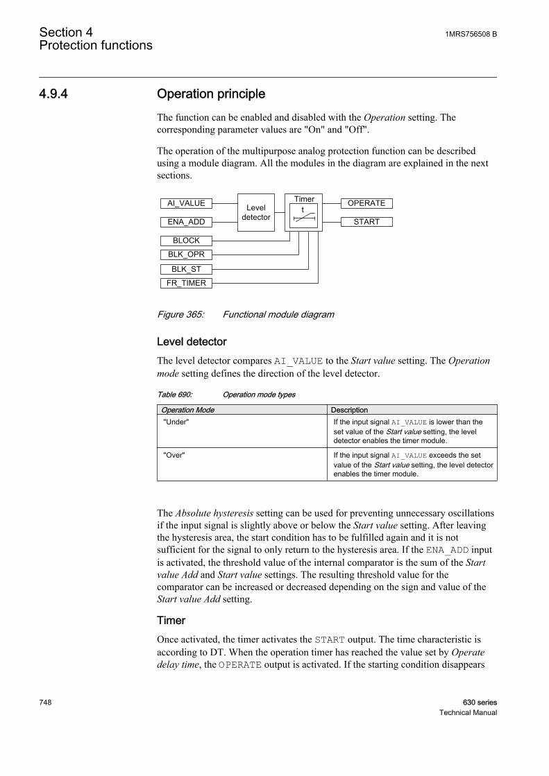
4.9.4 Operation principleThe function can be enabled and disabled with the Operation setting. Thecorresponding parameter values are "On" and "Off".
The operation of the multipurpose analog protection function can be describedusing a module diagram. All the modules in the diagram are explained in the nextsections.
GUID-FA6A9C14-37BF-4D65-B0CD-A89F359C4EEE V1 EN
Figure 365: Functional module diagram
Level detectorThe level detector compares AI_VALUE to the Start value setting. The Operationmode setting defines the direction of the level detector.
Table 690: Operation mode types
Operation Mode Description"Under" If the input signal AI_VALUE is lower than the
set value of the Start value setting, the leveldetector enables the timer module.
"Over" If the input signal AI_VALUE exceeds the setvalue of the Start value setting, the level detectorenables the timer module.
The Absolute hysteresis setting can be used for preventing unnecessary oscillationsif the input signal is slightly above or below the Start value setting. After leavingthe hysteresis area, the start condition has to be fulfilled again and it is notsufficient for the signal to only return to the hysteresis area. If the ENA_ADD inputis activated, the threshold value of the internal comparator is the sum of the Startvalue Add and Start value settings. The resulting threshold value for thecomparator can be increased or decreased depending on the sign and value of theStart value Add setting.
TimerOnce activated, the timer activates the START output. The time characteristic isaccording to DT. When the operation timer has reached the value set by Operatedelay time, the OPERATE output is activated. If the starting condition disappears
Section 4 1MRS756508 BProtection functions
748 630 seriesTechnical Manual
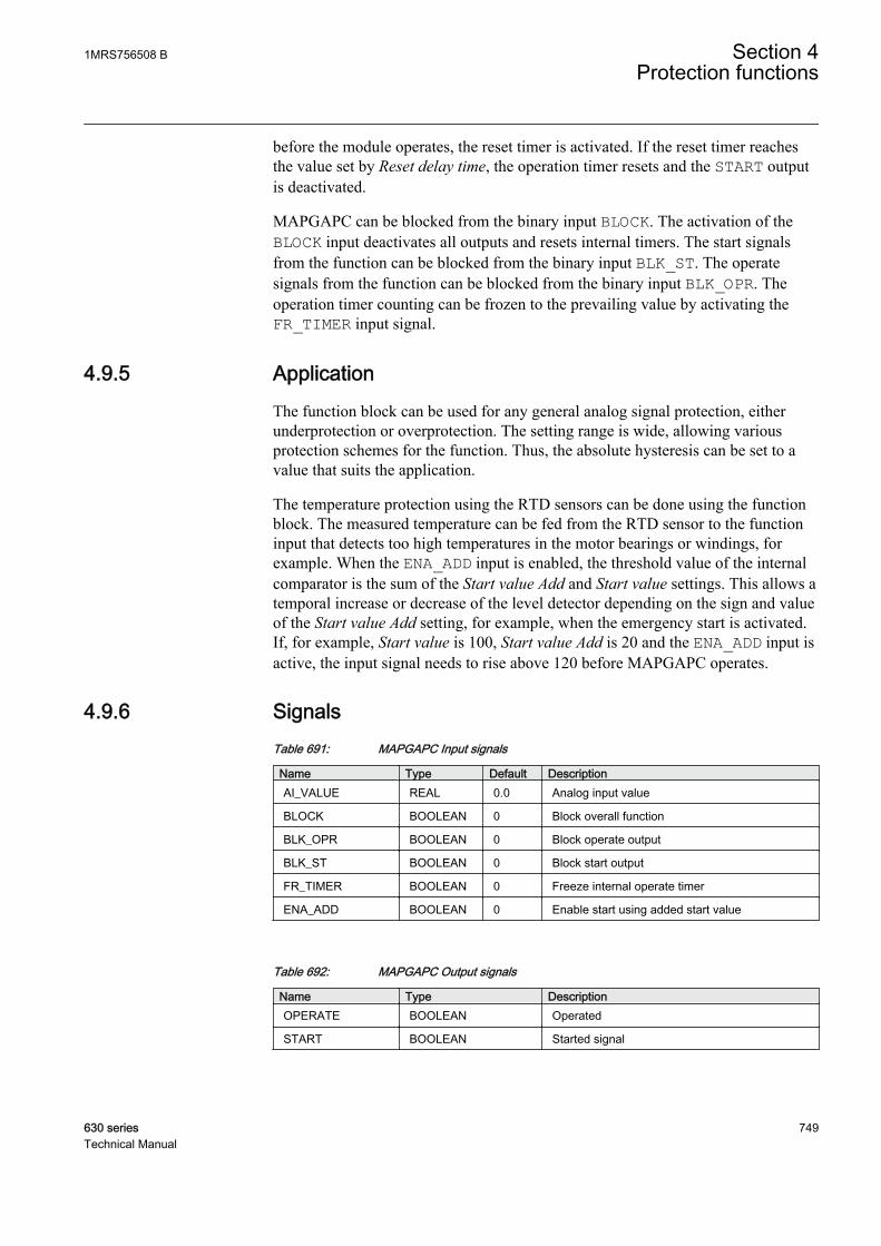
before the module operates, the reset timer is activated. If the reset timer reachesthe value set by Reset delay time, the operation timer resets and the START outputis deactivated.
MAPGAPC can be blocked from the binary input BLOCK. The activation of theBLOCK input deactivates all outputs and resets internal timers. The start signalsfrom the function can be blocked from the binary input BLK_ST. The operatesignals from the function can be blocked from the binary input BLK_OPR. Theoperation timer counting can be frozen to the prevailing value by activating theFR_TIMER input signal.
4.9.5 ApplicationThe function block can be used for any general analog signal protection, eitherunderprotection or overprotection. The setting range is wide, allowing variousprotection schemes for the function. Thus, the absolute hysteresis can be set to avalue that suits the application.
The temperature protection using the RTD sensors can be done using the functionblock. The measured temperature can be fed from the RTD sensor to the functioninput that detects too high temperatures in the motor bearings or windings, forexample. When the ENA_ADD input is enabled, the threshold value of the internalcomparator is the sum of the Start value Add and Start value settings. This allows atemporal increase or decrease of the level detector depending on the sign and valueof the Start value Add setting, for example, when the emergency start is activated.If, for example, Start value is 100, Start value Add is 20 and the ENA_ADD input isactive, the input signal needs to rise above 120 before MAPGAPC operates.
4.9.6 SignalsTable 691: MAPGAPC Input signals
Name Type Default DescriptionAI_VALUE REAL 0.0 Analog input value
BLOCK BOOLEAN 0 Block overall function
BLK_OPR BOOLEAN 0 Block operate output
BLK_ST BOOLEAN 0 Block start output
FR_TIMER BOOLEAN 0 Freeze internal operate timer
ENA_ADD BOOLEAN 0 Enable start using added start value
Table 692: MAPGAPC Output signals
Name Type DescriptionOPERATE BOOLEAN Operated
START BOOLEAN Started signal
1MRS756508 B Section 4Protection functions
630 series 749Technical Manual

4.9.7 SettingsTable 693: MAPGAPC Group settings (basic)
Name Values (Range) Unit Step Default DescriptionStart value -10000.0 - 10000.0 - 0.1 0.0 Start value
Start value Add -100.0 - 100.0 - 0.1 0.0 Added value to start value
Operate delay time 0.03 - 200.00 s 0.01 0.03 Operate delay time
Table 694: MAPGAPC Non group settings (basic)
Name Values (Range) Unit Step Default DescriptionOperation Off
On- - On Operation Off/On
Operation mode UnderOver
- - Over Operation mode (1=Over;2=Under)
Table 695: MAPGAPC Non group settings (advanced)
Name Values (Range) Unit Step Default DescriptionAbsolute hysteresis 0.01 - 100.00 - 0.01 0.10 Absolute hysteresis for operation
Reset delay time 0.00 - 60.00 s 0.01 0.00 Reset delay time
4.9.8 Measured valuesTable 696: MAPGAPC Measured values
Name Type Default DescriptionAI_VALUE REAL 0.0 Analog input value
BLOCK BOOLEAN 0 Block overall function
BLK_OPR BOOLEAN 0 Block operate output
BLK_ST BOOLEAN 0 Block start output
FR_TIMER BOOLEAN 0 Freeze internal operate timer
ENA_ADD BOOLEAN 0 Enable start using added start value
4.9.9 Monitored dataTable 697: MAPGAPC Monitored data
Name Type Values (Range) Unit DescriptionOPERATE BOOLEAN 0=FALSE
1=TRUE- Operated
START BOOLEAN 0=FALSE1=TRUE
- Started signal
START_DUR REAL - % Start duration inpercentage of the totaloperating time
Section 4 1MRS756508 BProtection functions
750 630 seriesTechnical Manual

4.9.10 Technical dataTable 698: MAPGAPC Technical data
Characteristic ValueOperate time accuracy ±1.0% of the set value or ±20 ms
1MRS756508 B Section 4Protection functions
630 series 751Technical Manual

752

Section 5 Protection related functions
5.1 Three-phase inrush detector INRPHAR
5.1.1 IdentificationFunction description IEC 61850
identificationIEC 60617identification
ANSI/IEEE C37.2device number
Three-phase inrush detector INRPHAR 3I2f> 68
5.1.2 Function block
GUID-819A17B1-03BB-4163-84A5-695728676B1F V1 EN
Figure 366: Function block
5.1.3 FunctionalityThe transformer inrush detection INRPHAR is used to coordinate transformerinrush situations in distribution networks.
Transformer inrush detection is based on the following principle: the output signalBLK2H is activated once the numerically derived ratio of second harmonic currentI_2H and the fundamental frequency current I_1H exceeds the set value.
The operate time characteristic for the function is of definite time (DT) type.
The function contains a blocking functionality. Blocking deactivates all outputsand resets timers.
5.1.4 Operation principleThe function can be enabled and disabled with the Operation setting. Thecorresponding parameter values are "On" and "Off".
The operation of an inrush current detection function can be described using amodule diagram. All the modules in the diagram are explained in the next sections.
1MRS756508 B Section 5Protection related functions
630 series 753Technical Manual
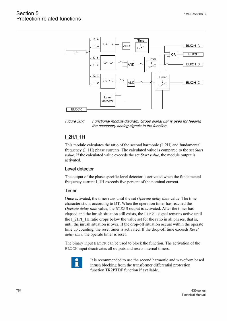
GUID-3F8B897F-79BF-4F06-A343-DB1174AA4E72 V1 EN
Figure 367: Functional module diagram. Group signal I3P is used for feedingthe necessary analog signals to the function.
I_2H/I_1HThis module calculates the ratio of the second harmonic (I_2H) and fundamentalfrequency (I_1H) phase currents. The calculated value is compared to the set Startvalue. If the calculated value exceeds the set Start value, the module output isactivated.
Level detectorThe output of the phase specific level detector is activated when the fundamentalfrequency current I_1H exceeds five percent of the nominal current.
TimerOnce activated, the timer runs until the set Operate delay time value. The timecharacteristic is according to DT. When the operation timer has reached theOperate delay time value, the BLK2H output is activated. After the timer haselapsed and the inrush situation still exists, the BLK2H signal remains active untilthe I_2H/I_1H ratio drops below the value set for the ratio in all phases, that is,until the inrush situation is over. If the drop-off situation occurs within the operatetime up counting, the reset timer is activated. If the drop-off time exceeds Resetdelay time, the operate timer is reset.
The binary input BLOCK can be used to block the function. The activation of theBLOCK input deactivates all outputs and resets internal timers.
It is recommended to use the second harmonic and waveform basedinrush blocking from the transformer differential protectionfunction TR2PTDF function if available.
Section 5 1MRS756508 BProtection related functions
754 630 seriesTechnical Manual

5.1.5 Base valuesIn this function block, some of the settings are set in per unit (pu). These pu valuesare relational to certain base values, for example the values given in A, kV andkVA. The IED supports alternative base value groups for the phase current or voltage-related settings, for example "Phase Grp 1", "Phase Grp 2" and "Phase Grp 3".One of the groups to be used with the Base value Sel phase setting must be selected.
For more information, see the Basic functions section in this manual.
5.1.6 ApplicationTransformer protections require high stability to avoid tripping during magnetizinginrush conditions. A typical example of an inrush detector application is doublingthe start value of an overcurrent protection during inrush detection.
The inrush detection function can be used to selectively block overcurrent and earth-fault function stages when the ratio of second harmonic component over thefundamental component exceeds the set value.
Other applications of this function include the detection of inrush in linesconnected to a transformer.
1MRS756508 B Section 5Protection related functions
630 series 755Technical Manual
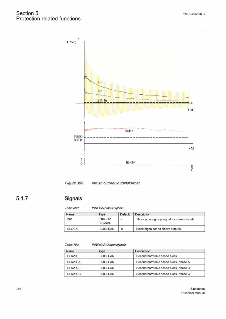
A070695 V2 EN
Figure 368: Inrush current in transformer
5.1.7 SignalsTable 699: INRPHAR Input signals
Name Type Default DescriptionI3P GROUP
SIGNAL- Three phase group signal for current inputs
BLOCK BOOLEAN 0 Block signal for all binary outputs
Table 700: INRPHAR Output signals
Name Type DescriptionBLK2H BOOLEAN Second harmonic based block
BLK2H_A BOOLEAN Second harmonic based block, phase A
BLK2H_B BOOLEAN Second harmonic based block, phase B
BLK2H_C BOOLEAN Second harmonic based block, phase C
Section 5 1MRS756508 BProtection related functions
756 630 seriesTechnical Manual

5.1.8 SettingsTable 701: INRPHAR Group settings (basic)
Name Values (Range) Unit Step Default DescriptionStart value 5 - 100 % 1 20 Ratio of the 2. to the 1. harmonic leading
to restraint
Operate delay time 0.020 - 60.000 s 0.001 0.020 Operate delay time
Table 702: INRPHAR Non group settings (basic)
Name Values (Range) Unit Step Default DescriptionOperation Off
On- - On Operation Off / On
Table 703: INRPHAR Non group settings (advanced)
Name Values (Range) Unit Step Default DescriptionBase value Sel phase Phase Grp 1
Phase Grp 2Phase Grp 3
- - Phase Grp 1 Base value selector, phase / phase-to-phase
Reset delay time 0.000 - 60.000 s 0.001 0.020 Reset delay time
5.1.9 Measured valuesTable 704: INRPHAR Measured values
Name Type Default DescriptionI_1H_A REAL 0 Current fundamental frequency component,
phase A
I_1H_B REAL 0 Current fundamental frequency component,phase B
I_1H_C REAL 0 Current fundamental frequency component,phase C
I_2H_A REAL 0 Current second harmonic component, phase A
I_2H_B REAL 0 Current second harmonic component, phase B
I_2H_C REAL 0 Current second harmonic component, phase C
BLOCK BOOLEAN 0 Block signal for all binary outputs
1MRS756508 B Section 5Protection related functions
630 series 757Technical Manual
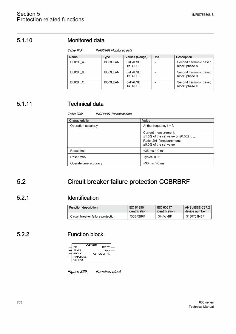
5.1.10 Monitored dataTable 705: INRPHAR Monitored data
Name Type Values (Range) Unit DescriptionBLK2H_A BOOLEAN 0=FALSE
1=TRUE- Second harmonic based
block, phase A
BLK2H_B BOOLEAN 0=FALSE1=TRUE
- Second harmonic basedblock, phase B
BLK2H_C BOOLEAN 0=FALSE1=TRUE
- Second harmonic basedblock, phase C
5.1.11 Technical dataTable 706: INRPHAR Technical data
Characteristic ValueOperation accuracy At the frequency f = fn
Current measurement:±1.5% of the set value or ±0.002 x InRatio I2f/I1f measurement:±5.0% of the set value
Reset time +35 ms / -0 ms
Reset ratio Typical 0.96
Operate time accuracy +30 ms / -0 ms
5.2 Circuit breaker failure protection CCBRBRF
5.2.1 IdentificationFunction description IEC 61850
identificationIEC 60617identification
ANSI/IEEE C37.2device number
Circuit breaker failure protection CCBRBRF 3I>/Io>BF 51BF/51NBF
5.2.2 Function block
A071002 V1 EN
Figure 369: Function block
Section 5 1MRS756508 BProtection related functions
758 630 seriesTechnical Manual
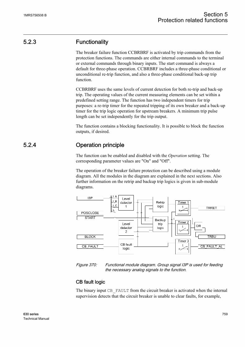
5.2.3 FunctionalityThe breaker failure function CCBRBRF is activated by trip commands from theprotection functions. The commands are either internal commands to the terminalor external commands through binary inputs. The start command is always adefault for three-phase operation. CCBRBRF includes a three-phase conditional orunconditional re-trip function, and also a three-phase conditional back-up tripfunction.
CCBRBRF uses the same levels of current detection for both re-trip and back-uptrip. The operating values of the current measuring elements can be set within apredefined setting range. The function has two independent timers for trippurposes: a re-trip timer for the repeated tripping of its own breaker and a back-uptimer for the trip logic operation for upstream breakers. A minimum trip pulselength can be set independently for the trip output.
The function contains a blocking functionality. It is possible to block the functionoutputs, if desired.
5.2.4 Operation principleThe function can be enabled and disabled with the Operation setting. Thecorresponding parameter values are "On" and "Off".
The operation of the breaker failure protection can be described using a modulediagram. All the modules in the diagram are explained in the next sections. Alsofurther information on the retrip and backup trip logics is given in sub-modulediagrams.
A071004 V1 EN
Figure 370: Functional module diagram. Group signal I3P is used for feedingthe necessary analog signals to the function.
CB fault logicThe binary input CB_FAULT from the circuit breaker is activated when the internalsupervision detects that the circuit breaker is unable to clear faults, for example,
1MRS756508 B Section 5Protection related functions
630 series 759Technical Manual

when SF6 gas pressure is low in the circuit breaker. If the fault duration exceedsthe set CB fault delay time, the output CB_FAULT_AL becomes active so thatactions can be done to repair the circuit breaker. A typical setting is 5.0 seconds.
Level detector 1The measured phase currents are compared phasewise to the set Current value. Ifthe measured value exceeds the set Current value, the level detector reports theexceeding of the value to the retrip and backup trip logics. The parameter should beset low enough so that the breaker failure situations with a small fault current or ahigh load current can be detected. The setting can be chosen in accordance with themost sensitive protection function to start the breaker failure protection.
Level detector 2The measured residual current is compared to the set Current value Res. If themeasured value exceeds the set Current value Res, the level detector reports theexceeding of the value to the backup trip logic. In high impedance earthed systems,the residual current at phase to earth faults are normally much smaller than theshort circuit currents. To detect a breaker failure at single-phase earth faults inthese systems, it is necessary to measure the residual current separately. Ineffectively earthed systems, also the setting of the earth-fault current protection canbe chosen at a relatively low current level. The CB failure trip mode is set "1 out of4". The current setting should be chosen in accordance with the setting of thesensitive earth-fault protection.
Retrip logicThe operation of the retrip logic can be described by using a module diagram:
A070689 V2 EN
Figure 371: Retrip logic internal design
The retrip function operates with or without a current check selected with the CBfail retrip mode setting. In "Current check" mode, the retrip is only performed if
Section 5 1MRS756508 BProtection related functions
760 630 seriesTechnical Manual

the current through the circuit breaker exceeds the Current value level. In "Withoutcheck" mode, the retrip is done without checking the phase currents.
The CB failure mode setting is used to select the mode the breaker fault is detectedwith. In "Current" mode, the detection is based on the current level exceeding. In"Breaker status" mode, the detection is based on the closed position of the circuitbreaker after a trip signal is issued, that is, after a long duration of the trip signal. In"Both" mode, the detection is based either on the exceeding of Current value levelor on the long duration of the trip signal. When external information of a circuitbreaker fault is connected to the active CB_FAULT input, the retrip function is notallowed to operate. The blocking is used to disable the whole function.
Backup trip logicThe operation of the backup trip logic can be described by using a module diagram:
POSCLOSE
START
CB failure mode ”Current”
CB failure mode ”Breaker status”
CB failure mode ”Both”
ANDCB failure trip mode”1 out of 3"
CB failure trip mode ”1 out of 4"
AND
AND
AND
CB failure trip mode ”2 out of 4"
AND
OR
OR
AND
AND
ANDOR
OR
AND
I >(from Level detector 1)
Backup trip timer start
Backup trip
Io >(from Level detector 2)
CB_FAULT
AND
A070690 V3 EN
Figure 372: Backup trip logic internal design
The current detection characteristics can be selected with the CB failure trip modesetting in three following options:
• "1 out of 3" in which detecting opening failure (high current) in one phaseonly is sufficient
• "1 out of 4" in which detecting opening failure (high current) or high residualcurrent in one phase only is sufficient
• "2 out of 4" in which at least two high currents (phase current and residualcurrent) are required for breaker failure detection.
1MRS756508 B Section 5Protection related functions
630 series 761Technical Manual

In most applications, "1 out of 3" is sufficient. In the "Breaker status" mode, thebackup trip is done when the status inputs indicate that the circuit breaker is inclosed state.
The setting CB failure mode is used to select the mode the breaker fault is detectedwith. In "Current" mode, the detection is based on the current level exceeding. In"Breaker status" mode, the detection is based on the closed position of the circuitbreaker after a trip signal is issued, that is, after a long duration of the trip signal. In"Both" mode, the detection is based either on the exceeding of the Current valueRes level, depending on the current detection mode, or on the long duration of thetrip signal. When external information on a circuit breaker fault is connected to theactive CB_FAULT input, the backup trip function is issued to the upstream breakerwithout delay. The blocking is used for disabling the whole function.
Timer 1Once activated, the timer runs until the set Retrip time value has elapsed. The timecharacteristic is according to DT. When the operation timer has reached themaximum time value, the TRRET output is activated.
When setting the value of the Retrip time setting, the time delays should beconsidered into calculation:
• the circuit breaker operating time (tcbopen), which is the time betweenactivating the trip command for the circuit breaker trip coil and CB reachingthe open position
• the reset time (tBFP_reset) of current detection in current based operation modeis the time between the moment when the circuit breaker is opened and themoment when the measured current is detected to be under the set level of thelevel detector limits
• the additional safety margin (tmargin) is to avoid unintentional operation ofcircuit breaker failure protection, retripping or backup tripping, when the CB isopened successfully.
The minimum time delay for the retrip can be estimated as:
Retriptime t t tcbopen BFP reset margin≥ + +_
GUID-D9A545B5-AF05-4238-8315-26B36D471B78 V2 EN (Equation 106)
Timer 2Once activated, the timer runs until the set CB failure delay value is elapsed. Thetime characteristic is according to DT. When the operation timer has reached theset maximum time value CB failure delay, the TRBU output is activated. The valueof this setting is made as low as possible at the same time as any unwantedoperation is avoided. A typical setting is 90 - 150 ms which is also dependent onthe retrip timer.
The minimum time delay for the backup trip can be estimated as:
Section 5 1MRS756508 BProtection related functions
762 630 seriesTechnical Manual
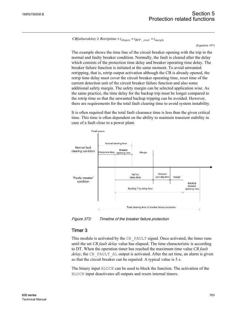
CBfailuredelay Retriptime t t tcbopen BFP reset margin≥ + + +_
A070693 V3 EN (Equation 107)
The example shows the time line of the circuit breaker opening with the trip in thenormal and faulty breaker condition. Normally, the fault is cleared after the delaywhich consists of the protection time delay and breaker operating time delay. Thebreaker failure function is initiated at the same moment. To avoid unwantedretripping, that is, retrip output activation although the CB is already opened, theretrip time delay must cover the circuit breaker operating time, reset time of thecurrent detection unit of the circuit breaker failure function and also someadditional safety margin. The safety margin can be selected application wise. Asthe same practice, the time delay for the backup trip must be longer compared tothe retrip time so that the unwanted backup tripping can be avoided. However,there are requirements for the total fault clearing time to avoid system instability.
It is often required that the total fault clearance time is less than the given criticaltime. This time is often dependent on the ability to maintain transient stability incase of a fault close to a power plant.
A070692 V1 EN
Figure 373: Timeline of the breaker failure protection
Timer 3This module is activated by the CB_FAULT signal. Once activated, the timer runsuntil the set CB fault delay value has elapsed. The time characteristic is accordingto DT. When the operation timer has reached the maximum time value CB faultdelay, the CB_FAULT_AL output is activated. After the set time, an alarm is givenso that the circuit breaker can be repaired. A typical value is 5 s.
The binary input BLOCK can be used to block the function. The activation of theBLOCK input deactivates all outputs and resets internal timers.
1MRS756508 B Section 5Protection related functions
630 series 763Technical Manual
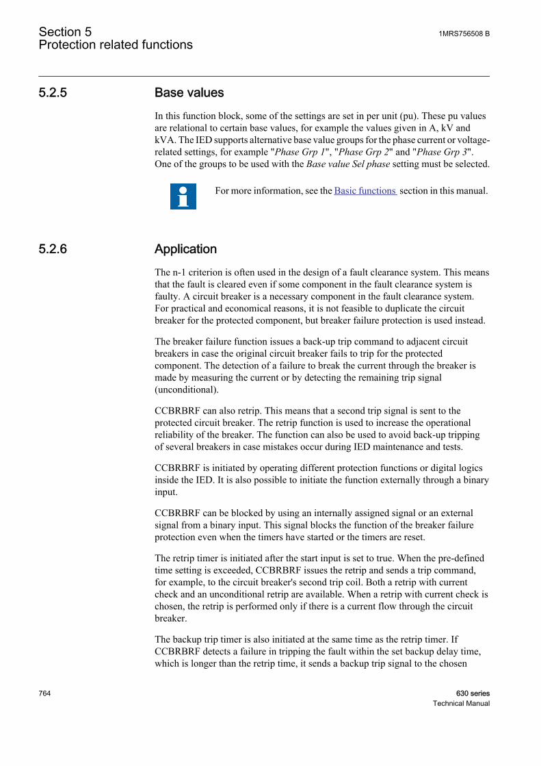
5.2.5 Base valuesIn this function block, some of the settings are set in per unit (pu). These pu valuesare relational to certain base values, for example the values given in A, kV andkVA. The IED supports alternative base value groups for the phase current or voltage-related settings, for example "Phase Grp 1", "Phase Grp 2" and "Phase Grp 3".One of the groups to be used with the Base value Sel phase setting must be selected.
For more information, see the Basic functions section in this manual.
5.2.6 ApplicationThe n-1 criterion is often used in the design of a fault clearance system. This meansthat the fault is cleared even if some component in the fault clearance system isfaulty. A circuit breaker is a necessary component in the fault clearance system.For practical and economical reasons, it is not feasible to duplicate the circuitbreaker for the protected component, but breaker failure protection is used instead.
The breaker failure function issues a back-up trip command to adjacent circuitbreakers in case the original circuit breaker fails to trip for the protectedcomponent. The detection of a failure to break the current through the breaker ismade by measuring the current or by detecting the remaining trip signal(unconditional).
CCBRBRF can also retrip. This means that a second trip signal is sent to theprotected circuit breaker. The retrip function is used to increase the operationalreliability of the breaker. The function can also be used to avoid back-up trippingof several breakers in case mistakes occur during IED maintenance and tests.
CCBRBRF is initiated by operating different protection functions or digital logicsinside the IED. It is also possible to initiate the function externally through a binaryinput.
CCBRBRF can be blocked by using an internally assigned signal or an externalsignal from a binary input. This signal blocks the function of the breaker failureprotection even when the timers have started or the timers are reset.
The retrip timer is initiated after the start input is set to true. When the pre-definedtime setting is exceeded, CCBRBRF issues the retrip and sends a trip command,for example, to the circuit breaker's second trip coil. Both a retrip with currentcheck and an unconditional retrip are available. When a retrip with current check ischosen, the retrip is performed only if there is a current flow through the circuitbreaker.
The backup trip timer is also initiated at the same time as the retrip timer. IfCCBRBRF detects a failure in tripping the fault within the set backup delay time,which is longer than the retrip time, it sends a backup trip signal to the chosen
Section 5 1MRS756508 BProtection related functions
764 630 seriesTechnical Manual
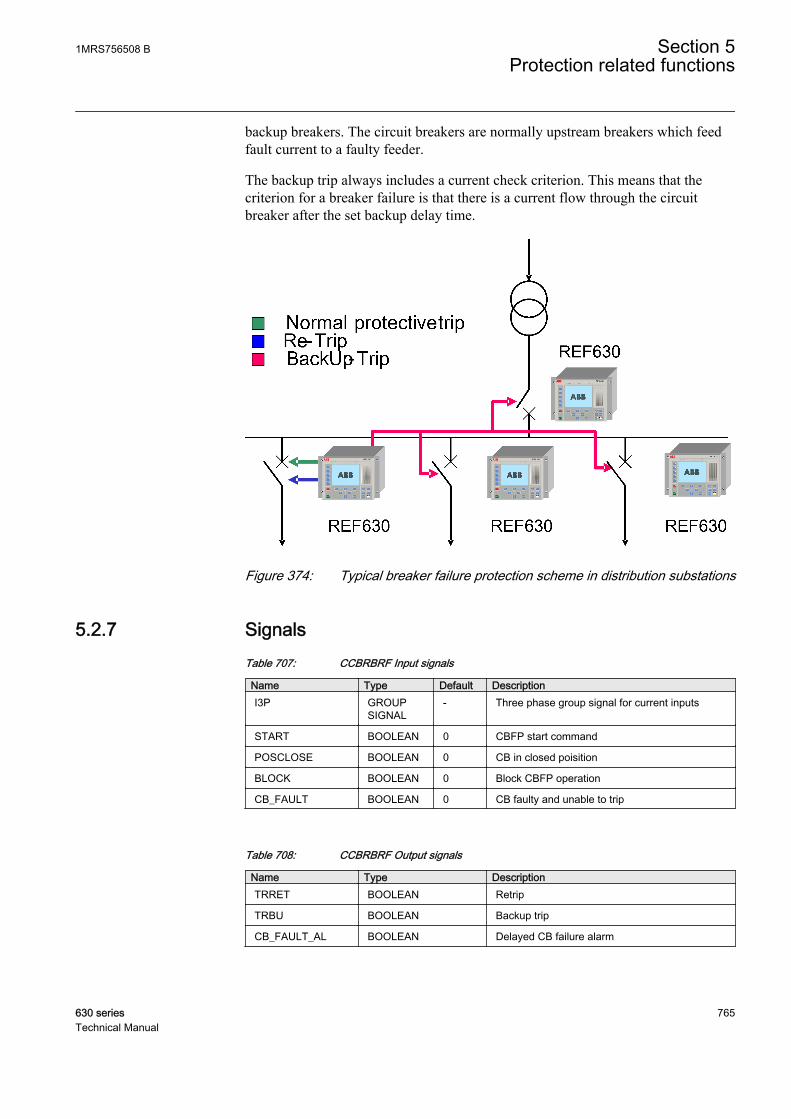
backup breakers. The circuit breakers are normally upstream breakers which feedfault current to a faulty feeder.
The backup trip always includes a current check criterion. This means that thecriterion for a breaker failure is that there is a current flow through the circuitbreaker after the set backup delay time.
GUID-DA28AB63-2327-41B2-976E-99D36F516172 V1 EN
Figure 374: Typical breaker failure protection scheme in distribution substations
5.2.7 SignalsTable 707: CCBRBRF Input signals
Name Type Default DescriptionI3P GROUP
SIGNAL- Three phase group signal for current inputs
START BOOLEAN 0 CBFP start command
POSCLOSE BOOLEAN 0 CB in closed poisition
BLOCK BOOLEAN 0 Block CBFP operation
CB_FAULT BOOLEAN 0 CB faulty and unable to trip
Table 708: CCBRBRF Output signals
Name Type DescriptionTRRET BOOLEAN Retrip
TRBU BOOLEAN Backup trip
CB_FAULT_AL BOOLEAN Delayed CB failure alarm
1MRS756508 B Section 5Protection related functions
630 series 765Technical Manual
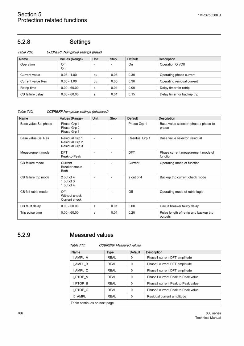
5.2.8 SettingsTable 709: CCBRBRF Non group settings (basic)
Name Values (Range) Unit Step Default DescriptionOperation Off
On- - On Operation On/Off
Current value 0.05 - 1.00 pu 0.05 0.30 Operating phase current
Current value Res 0.05 - 1.00 pu 0.05 0.30 Operating residual current
Retrip time 0.00 - 60.00 s 0.01 0.00 Delay timer for retrip
CB failure delay 0.00 - 60.00 s 0.01 0.15 Delay timer for backup trip
Table 710: CCBRBRF Non group settings (advanced)
Name Values (Range) Unit Step Default DescriptionBase value Sel phase Phase Grp 1
Phase Grp 2Phase Grp 3
- - Phase Grp 1 Base value selector, phase / phase-to-phase
Base value Sel Res Residual Grp 1Residual Grp 2Residual Grp 3
- - Residual Grp 1 Base value selector, residual
Measurement mode DFTPeak-to-Peak
- - DFT Phase current measurement mode offunction
CB failure mode CurrentBreaker statusBoth
- - Current Operating mode of function
CB failure trip mode 2 out of 41 out of 31 out of 4
- - 2 out of 4 Backup trip current check mode
CB fail retrip mode OffWithout checkCurrent check
- - Off Operating mode of retrip logic
CB fault delay 0.00 - 60.00 s 0.01 5.00 Circuit breaker faulty delay
Trip pulse time 0.00 - 60.00 s 0.01 0.20 Pulse length of retrip and backup tripoutputs
5.2.9 Measured valuesTable 711: CCBRBRF Measured values
Name Type Default DescriptionI_AMPL_A REAL 0 Phase1 current DFT amplitude
I_AMPL_B REAL 0 Phase2 current DFT amplitude
I_AMPL_C REAL 0 Phase3 current DFT amplitude
I_PTOP_A REAL 0 Phase1 current Peak to Peak value
I_PTOP_B REAL 0 Phase2 current Peak to Peak value
I_PTOP_C REAL 0 Phase3 current Peak to Peak value
I0_AMPL REAL 0 Residual current amplitude
Table continues on next page
Section 5 1MRS756508 BProtection related functions
766 630 seriesTechnical Manual
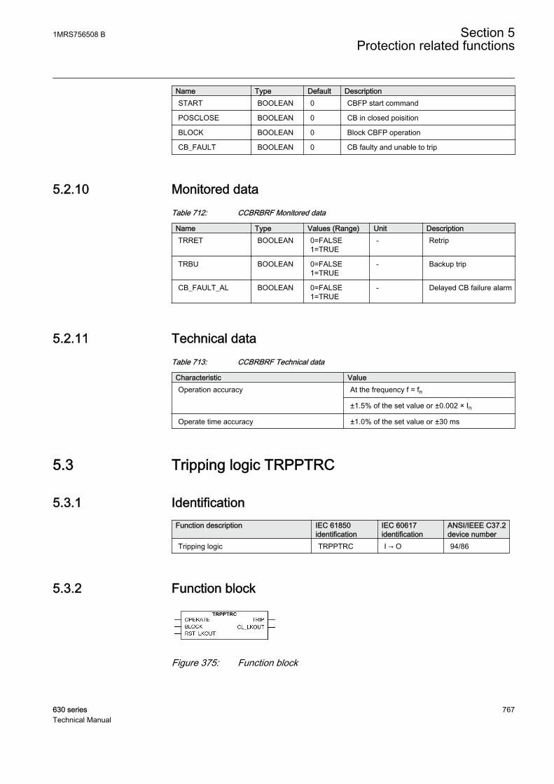
Name Type Default DescriptionSTART BOOLEAN 0 CBFP start command
POSCLOSE BOOLEAN 0 CB in closed poisition
BLOCK BOOLEAN 0 Block CBFP operation
CB_FAULT BOOLEAN 0 CB faulty and unable to trip
5.2.10 Monitored dataTable 712: CCBRBRF Monitored data
Name Type Values (Range) Unit DescriptionTRRET BOOLEAN 0=FALSE
1=TRUE- Retrip
TRBU BOOLEAN 0=FALSE1=TRUE
- Backup trip
CB_FAULT_AL BOOLEAN 0=FALSE1=TRUE
- Delayed CB failure alarm
5.2.11 Technical dataTable 713: CCBRBRF Technical data
Characteristic ValueOperation accuracy At the frequency f = fn
±1.5% of the set value or ±0.002 × In
Operate time accuracy ±1.0% of the set value or ±30 ms
5.3 Tripping logic TRPPTRC
5.3.1 IdentificationFunction description IEC 61850
identificationIEC 60617identification
ANSI/IEEE C37.2device number
Tripping logic TRPPTRC I → O 94/86
5.3.2 Function block
A071286 V1 EN
Figure 375: Function block
1MRS756508 B Section 5Protection related functions
630 series 767Technical Manual
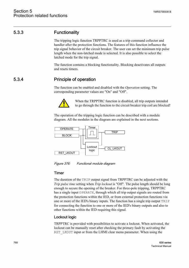
5.3.3 FunctionalityThe tripping logic function TRPPTRC is used as a trip command collector andhandler after the protection functions. The features of this function influence thetrip signal behavior of the circuit breaker. The user can set the minimum trip pulselength when the non-latched mode is selected. It is also possible to select thelatched mode for the trip signal.
The function contains a blocking functionality. Blocking deactivates all outputsand resets timers.
5.3.4 Principle of operationThe function can be enabled and disabled with the Operation setting. Thecorresponding parameter values are "On" and "Off".
When the TRPPTRC function is disabled, all trip outputs intendedto go through the function to the circuit breaker trip coil are blocked!
The operation of the tripping logic function can be described with a modulediagram. All the modules in the diagram are explained in the next sections.
A070882 V4 EN
Figure 376: Functional module diagram
TimerThe duration of the TRIP output signal from TRPPTRC can be adjusted with theTrip pulse time setting when Trip lockout is "Off". The pulse length should be longenough to secure the opening of the breaker. For three-pole tripping, TRPPTRChas a single input OPERATE, through which all trip output signals are routed fromthe protection functions within the IED, or from external protection functions viaone or more of the IED's binary inputs. The function has a single trip output TRIPfor connecting the function to one or more of the IED's binary outputs and also toother functions within the IED requiring this signal.
Lockout logicTRPPTRC is provided with possibilities to activate a lockout. When activated, thelockout can be manually reset after checking the primary fault by activating theRST_LKOUT input or from the LHMI clear menu parameter. When using the
Section 5 1MRS756508 BProtection related functions
768 630 seriesTechnical Manual
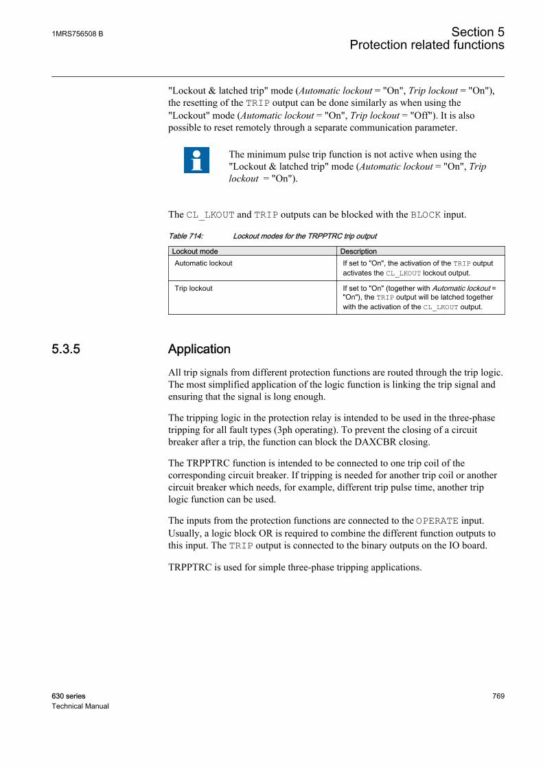
"Lockout & latched trip" mode (Automatic lockout = "On", Trip lockout = "On"),the resetting of the TRIP output can be done similarly as when using the"Lockout" mode (Automatic lockout = "On", Trip lockout = "Off"). It is alsopossible to reset remotely through a separate communication parameter.
The minimum pulse trip function is not active when using the"Lockout & latched trip" mode (Automatic lockout = "On", Triplockout = "On").
The CL_LKOUT and TRIP outputs can be blocked with the BLOCK input.
Table 714: Lockout modes for the TRPPTRC trip output
Lockout mode DescriptionAutomatic lockout If set to "On", the activation of the TRIP output
activates the CL_LKOUT lockout output.
Trip lockout If set to "On" (together with Automatic lockout ="On"), the TRIP output will be latched togetherwith the activation of the CL_LKOUT output.
5.3.5 ApplicationAll trip signals from different protection functions are routed through the trip logic.The most simplified application of the logic function is linking the trip signal andensuring that the signal is long enough.
The tripping logic in the protection relay is intended to be used in the three-phasetripping for all fault types (3ph operating). To prevent the closing of a circuitbreaker after a trip, the function can block the DAXCBR closing.
The TRPPTRC function is intended to be connected to one trip coil of thecorresponding circuit breaker. If tripping is needed for another trip coil or anothercircuit breaker which needs, for example, different trip pulse time, another triplogic function can be used.
The inputs from the protection functions are connected to the OPERATE input.Usually, a logic block OR is required to combine the different function outputs tothis input. The TRIP output is connected to the binary outputs on the IO board.
TRPPTRC is used for simple three-phase tripping applications.
1MRS756508 B Section 5Protection related functions
630 series 769Technical Manual
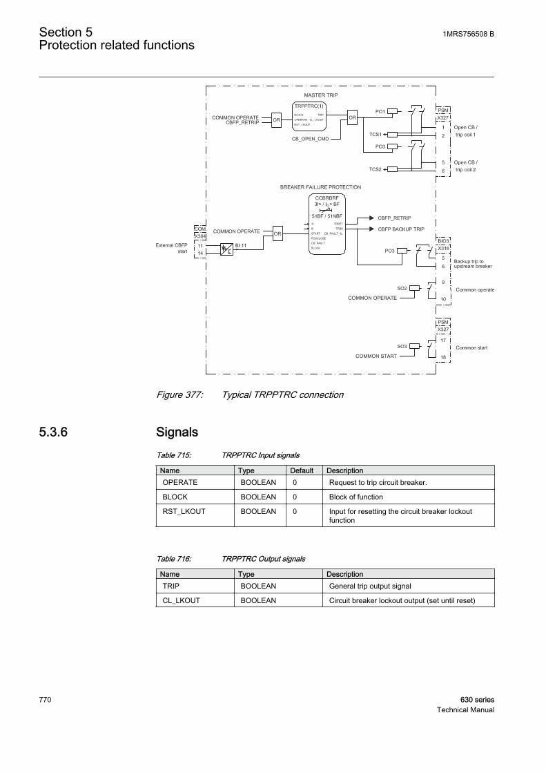
GUID-4C1ED151-A703-4CBC-A4A1-558027B10625 V1 EN
Figure 377: Typical TRPPTRC connection
5.3.6 SignalsTable 715: TRPPTRC Input signals
Name Type Default DescriptionOPERATE BOOLEAN 0 Request to trip circuit breaker.
BLOCK BOOLEAN 0 Block of function
RST_LKOUT BOOLEAN 0 Input for resetting the circuit breaker lockoutfunction
Table 716: TRPPTRC Output signals
Name Type DescriptionTRIP BOOLEAN General trip output signal
CL_LKOUT BOOLEAN Circuit breaker lockout output (set until reset)
Section 5 1MRS756508 BProtection related functions
770 630 seriesTechnical Manual
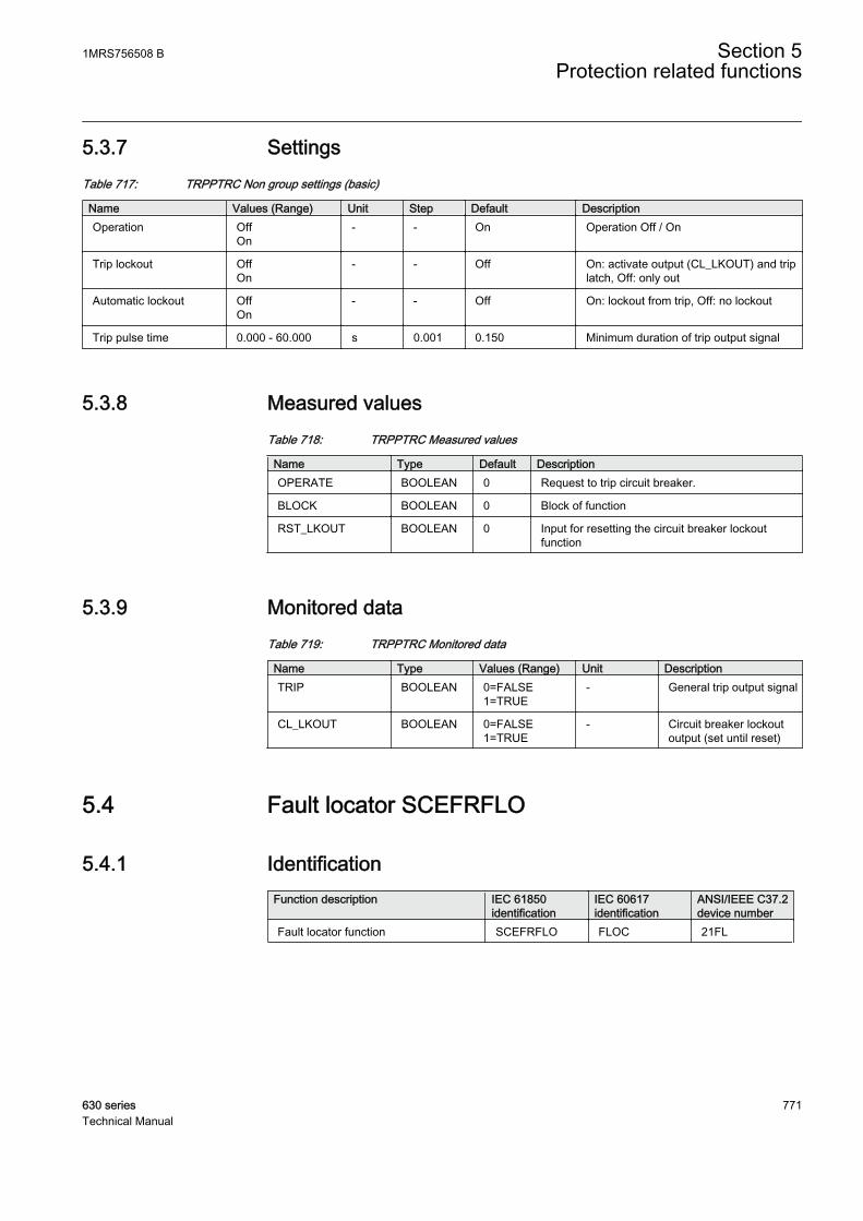
5.3.7 SettingsTable 717: TRPPTRC Non group settings (basic)
Name Values (Range) Unit Step Default DescriptionOperation Off
On- - On Operation Off / On
Trip lockout OffOn
- - Off On: activate output (CL_LKOUT) and triplatch, Off: only out
Automatic lockout OffOn
- - Off On: lockout from trip, Off: no lockout
Trip pulse time 0.000 - 60.000 s 0.001 0.150 Minimum duration of trip output signal
5.3.8 Measured valuesTable 718: TRPPTRC Measured values
Name Type Default DescriptionOPERATE BOOLEAN 0 Request to trip circuit breaker.
BLOCK BOOLEAN 0 Block of function
RST_LKOUT BOOLEAN 0 Input for resetting the circuit breaker lockoutfunction
5.3.9 Monitored dataTable 719: TRPPTRC Monitored data
Name Type Values (Range) Unit DescriptionTRIP BOOLEAN 0=FALSE
1=TRUE- General trip output signal
CL_LKOUT BOOLEAN 0=FALSE1=TRUE
- Circuit breaker lockoutoutput (set until reset)
5.4 Fault locator SCEFRFLO
5.4.1 IdentificationFunction description IEC 61850
identificationIEC 60617identification
ANSI/IEEE C37.2device number
Fault locator function SCEFRFLO FLOC 21FL
1MRS756508 B Section 5Protection related functions
630 series 771Technical Manual
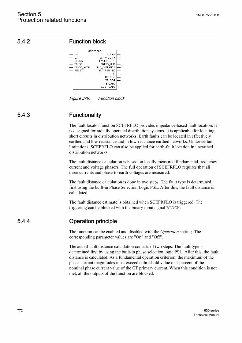
5.4.2 Function block
GUID-961EEAE7-D10F-406E-9BC5-28DC1DE177B7 V2 EN
Figure 378: Function block
5.4.3 FunctionalityThe fault locator function SCEFRFLO provides impedance-based fault location. Itis designed for radially operated distribution systems. It is applicable for locatingshort circuits in distribution networks. Earth faults can be located in effectivelyearthed and low resistance and in low-reactance earthed networks. Under certainlimitations, SCEFRFLO can also be applied for earth-fault location in uneartheddistribution networks.
The fault distance calculation is based on locally measured fundamental frequencycurrent and voltage phasors. The full operation of SCEFRFLO requires that allthree currents and phase-to-earth voltages are measured.
The fault distance calculation is done in two steps. The fault type is determinedfirst using the built-in Phase Selection Logic PSL. After this, the fault distance iscalculated.
The fault distance estimate is obtained when SCEFRFLO is triggered. Thetriggering can be blocked with the binary input signal BLOCK.
5.4.4 Operation principleThe function can be enabled and disabled with the Operation setting. Thecorresponding parameter values are "On" and "Off".
The actual fault distance calculation consists of two steps. The fault type isdetermined first by using the built-in phase selection logic PSL. After this, the faultdistance is calculated. As a fundamental operation criterion, the maximum of thephase current magnitudes must exceed a threshold value of 1 percent of thenominal phase current value of the CT primary current. When this condition is notmet, all the outputs of the function are blocked.
Section 5 1MRS756508 BProtection related functions
772 630 seriesTechnical Manual

5.4.4.1 Fault type selection
The identification of the faulty phases is compulsory for the correct operation ofthe fault locator function. This is because only one of the impedance measuringelements, that is, the fault loops, provides the correct result for a specific fault type.A three-phase fault is an exception and it could, in theory, be calculated with anyof the fault loops.
Fault type Description Output FAULT_LOOPA-E Phase A-to-earth fault 1
B-E Phase B-to-earth fault 2
C-E Phase C-to-earth fault 3
A-B Phase A-to-B short circuit fault 12
B-C Phase B-to-C short circuit fault 23
C-A Phase C-to-A short circuit fault 31
A-B-C-(E) Three-phase short circuit 123
The fault loop used in the fault distance calculation is indicated in theFAULT_LOOP output as integer numbers 1, 2, 3, 12, 23, 31 or 123.
In case of phase-to-phase-to-earth faults A-B-E, B-C-E or C-A-E, the selected faultloop depends on the location of the individual earth faults. When the faults arelocated at the same feeder, the corresponding phase-to-phase loop 12, 23 or 31 isused for calculation. When the faults are located at different feeders, the phase-to-earth loop 1, 2 or 3, corresponding to the faulty phase at the protected feeder, isused for calculation.
Identification of the faulty phase is provided by the built-in PSL based oncombined impedance and current criteria. PSL is virtually setting-free and has onlyone parameter, Z Max phase load, for discriminating a large symmetrical load froma three-phase fault. The Z Max phase load parameter can be calculated using theequation:
Z Max phaseloadU
S=
0 8
2
.
max
GUID-9801C2DA-D1BD-4EA4-ABDD-1126B6CEA0AE V1 EN (Equation 108)
U nominal phase-to-phase voltage
Smax maximum three-phase load
For example, if U = 20 kV and Smax = 1 MVA, Z Max phase load = 320 ohm.
1MRS756508 B Section 5Protection related functions
630 series 773Technical Manual
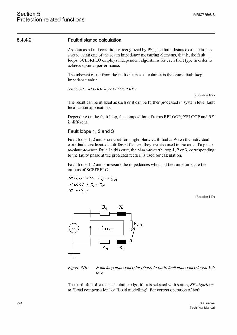
5.4.4.2 Fault distance calculation
As soon as a fault condition is recognized by PSL, the fault distance calculation isstarted using one of the seven impedance measuring elements, that is, the faultloops. SCEFRFLO employs independent algorithms for each fault type in order toachieve optimal performance.
The inherent result from the fault distance calculation is the ohmic fault loopimpedance value:
ZFLOOP RFLOOP j XFLOOP RF= + × +
GUID-062F4362-3C18-4B5B-A136-24127E839F6D V1 EN (Equation 109)
The result can be utilized as such or it can be further processed in system level faultlocalization applications.
Depending on the fault loop, the composition of terms RFLOOP, XFLOOP and RFis different.
Fault loops 1, 2 and 3Fault loops 1, 2 and 3 are used for single-phase earth faults. When the individualearth faults are located at different feeders, they are also used in the case of a phase-to-phase-to-earth fault. In this case, the phase-to-earth loop 1, 2 or 3, correspondingto the faulty phase at the protected feeder, is used for calculation.
Fault loops 1, 2 and 3 measure the impedances which, at the same time, are theoutputs of SCEFRFLO:
GUID-63FFBE53-B17B-4914-94BB-65236C1EFBEA V1 EN (Equation 110)
GUID-846A9380-8705-478D-9929-8BD61930BC66 V1 EN
Figure 379: Fault loop impedance for phase-to-earth fault impedance loops 1, 2or 3
The earth-fault distance calculation algorithm is selected with setting EF algorithmto "Load compensation" or "Load modelling". For correct operation of both
Section 5 1MRS756508 BProtection related functions
774 630 seriesTechnical Manual

algorithms there should not be any zero-sequence current sources, for example,earthing transformers, in front of the IED location.
"Load compensation" utilizes symmetrical components to compensate the effect ofa load on the measured voltages and currents. It should be selected in case of radialfeeders with low impedance/effectively earthed systems, where the fault current isfed from one side only and there are no in-feeds along the protected line.
"Load modelling" takes into account the effect of the load in measured currents andvoltages by load modelling. The "Load modelling" algorithm can be applied incase of radial feeders with low impedance/effectively earthed systems, where thefault current is fed from one side only.
The "Load modelling" algorithm requires the Equivalent load Dis setting, that is,an equivalent load distance, as an additional parameter. The maximum value of thevoltage drop, denoted Udrop(real), appears at the end of the line. The Equivalentload Dis parameter is the distance at which a single load tap corresponding to thetotal load of the feeder would result in a voltage drop equal to Udrop(real). Thedashed curve shows the voltage drop profile in this case.
GUID-3576462C-9920-4590-889A-5A8E8DD1B64B V1 EN
Figure 380: Description of the equivalent load distance
The value of Equivalent load Dis can be calculated based on the load flow andvoltage drop calculations using equation:
1MRS756508 B Section 5Protection related functions
630 series 775Technical Manual

Equivalent load Dis = Udrop(real) / Udrop(s=1),
Udrop(real) the actual maximum voltage drop of the feeder
Udrop(s=1) the fictional voltage drop if the entire load is tapped at the end of the feeder
Alternatively, the Equivalent load Dis parameter can be determined by conductinga single-phase earth-fault test (Rfault = 0 ohm) at that point of the feeder where themaximum actual voltage drop takes place. This point is typically located at the endof the main line. The calculated value of Equivalent load Dis can be obtained fromthe S_CALC output.
In case of evenly distributed load, Equivalent load Dis ~ 0.5. When the load istapped at the end of the line, Equivalent load Dis = 1.0. If nothing else is known, agood initial guess for Equivalent load Dis is 0.5.
In addition, when "Load modelling" algorithm is used, the user can select with theEF algorithm current setting whether the I0 or I2-current based algorithm is used.The difference between I0 and I2 is that I2 does not require the settings Phcapacitive React and Ph leakage Ris. In case of I0, these settings are required inorder to compensate for the influence of line charging capacitances. This typicallyimproves the accuracy of a fault location estimate when fault resistance is involvedin the fault.
Under certain restrictions the "Load modelling" algorithm can also be applied intounearthed networks. Based on simulation and field tests, when Rfault = 0 ohm, thedefined earth-fault current magnitude should exceed the pre-fault load currentIef(Rfault=0) / ILoad≥1. This ratio is recorded and can be read from theIFLT_PER_ILD output. The low ratio affects also the validity estimate ofcalculated fault distance, which can be read from the EF_VALIDITY output.Sufficient fault current magnitude can be achieved, for example, with properswitching operations in the background network, which increases the fault current.After the switching operation, a re-energizing of the faulted line is done and a newestimate obtained. The fault resistance decreases the fault location accuracy and itshould not be too large, maximum a few hundreds of ohms.
Fault loops 12, 23 and 31Fault loops 12, 23 and 31 are used for the phase-to-phase short circuit faults andalso for the phase-to-phase-to-earth faults if the individual earth-faults are locatedin the same feeder.
Fault loops 12, 23 and 31 measure the impedances, which at the same time are theoutputs of SCEFRFLO.
Section 5 1MRS756508 BProtection related functions
776 630 seriesTechnical Manual

RFLOOP R R
XFLOOP X
RF R
fault
fault
= +
=
=
1
1
2
2
/
/
GUID-457251F5-6518-497E-A015-4933EDD541AE V1 EN (Equation 111)
GUID-3FA48705-A1CD-4CB8-87C9-2FE5CC192040 V1 EN
Figure 381: Fault loop impedance for phase-to-phase fault impedance loops12, 23 and 31
For the fault loops 12, 23, 31, the estimated fault resistance is halfthe total fault resistance between the phases.
The fault distance calculation algorithm for the phase-to-phase fault impedanceloops (12, 23 or 31) is defined by using setting Load Com PP loops ="Disabled"/"Enabled" setting and setting Simple mode PP loops ="Disabled"/"Enabled".
The load compensation can be enabled or disabled with the Load Com PP loops =FALSE/TRUE setting. The load compensation should be disabled only if the ratiobetween the fault current and load current is large or when the value of the faultdistance estimate for the short circuit fault is required for each shot of an auto-reclosing cycle.
The fault distance calculation is the most accurate when the calculation is madewith the fault loop model. This model requires positive sequence impedances asinitial data. If the data is not accessible, the calculation can be made with a simplefault loop model that does not need any impedance data. The simple fault loopmodel is enabled, with the value Simple mode PP loops = TRUE. When the simplemodel is enabled, the conversion of electrical fault distance into a physical distanceis not done in the IED and the FLT_DISTANCE output is not valid. The estimatedimpedances are still calculated and shown normally in their respective outputs.
Fault loop 123Fault loop 123 is used only for the three-phase short circuit fault and it measuresthe impedances that are the outputs of SCEFRFLO:
1MRS756508 B Section 5Protection related functions
630 series 777Technical Manual

RFLOOP R R
XFLOOP X
RF R
fault
fault
= +
=
=
1
1
GUID-E37FE8BB-6284-451F-B59E-B94D9BCB4C67 V1 EN (Equation 112)
GUID-F56A8418-F124-4833-BF83-430D234FDF6E V1 EN
Figure 382: Fault loop impedance for a three-phase fault impedance loop 123
The three-phase fault distance is calculated with a special measuring element usingpositive sequence quantities. This is advantageous especially in case of non-transposed (asymmetric) lines, as the line parameter has less influence. If the line isnon-transposed, all the phase-to-phase loops have different fault loop reactance.The use of positive sequence quantities results in the average value of phase-to-phase loop reactance. This is the most representative estimate in case of three-phase faults.
The fault distance calculation algorithm for the three-phase fault impedance loop isdefined by using the setting Load Com PP loops = "Disabled"/"Enabled" andsetting Simple mode PP loops = "Disabled"/"Enabled" setting.
The load compensation can be enabled or disabled with the Load Com PP loops =FALSE/TRUE setting. The load compensation should be disabled only if the ratiobetween the fault current and load current is large or when the value of the faultdistance estimate for the short circuit fault is required for each shot of an auto-reclosing cycle.
The fault distance calculation is the most accurate when the calculation is madewith the fault loop model. This model requires positive sequence impedances asinitial data. If the data is not accessible, then the calculation can be made with asimple fault loop model that does not need any impedance data. The simple faultloop model is enabled, with the value Simple mode PP loops = TRUE. When thesimple model is enabled, the conversion of electrical fault distance into a physicaldistance is not done in the IED and the FLT_DISTANCE output is not valid. Theestimated impedances are still calculated and shown normally in their respectiveoutputs.
Section 5 1MRS756508 BProtection related functions
778 630 seriesTechnical Manual
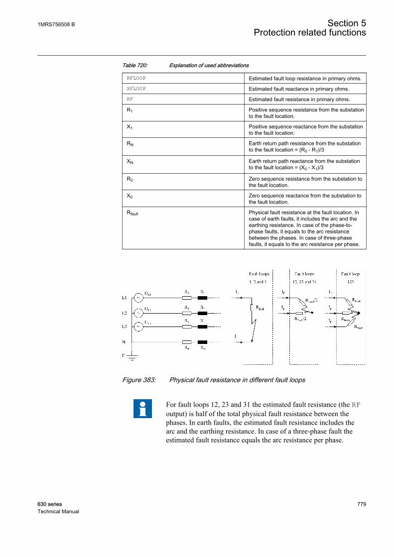
Table 720: Explanation of used abbreviations
RFLOOP Estimated fault loop resistance in primary ohms.
XFLOOP Estimated fault reactance in primary ohms.
RF Estimated fault resistance in primary ohms.
R1 Positive sequence resistance from the substationto the fault location.
X1 Positive sequence reactance from the substationto the fault location.
RN Earth return path resistance from the substationto the fault location = (R0 - R1)/3
XN Earth return path reactance from the substationto the fault location = (X0 - X1)/3
R0 Zero sequence resistance from the substation tothe fault location.
X0 Zero sequence reactance from the substation tothe fault location.
Rfault Physical fault resistance at the fault location. Incase of earth faults, it includes the arc and theearthing resistance. In case of the phase-to-phase faults, it equals to the arc resistancebetween the phases. In case of three-phasefaults, it equals to the arc resistance per phase.
GUID-6E182370-3330-47B0-B208-2091D8843AE8 V1 EN
Figure 383: Physical fault resistance in different fault loops
For fault loops 12, 23 and 31 the estimated fault resistance (the RFoutput) is half of the total physical fault resistance between thephases. In earth faults, the estimated fault resistance includes thearc and the earthing resistance. In case of a three-phase fault theestimated fault resistance equals the arc resistance per phase.
1MRS756508 B Section 5Protection related functions
630 series 779Technical Manual
5.4.4.3 Steady-state asymmetry and load compensation
In reality, power systems are never totally symmetrical. The asymmetry producessteady-state quantities in the form of zero and negative sequence voltages andcurrents. If not compensated, these are the error sources for the fault distancecalculation, especially in the case of earth faults. In SCEFRFLO, all the faultdistance calculation algorithms utilize the delta (Δ) quantities which eliminate thesteady-state asymmetry. The delta quantities are also used for load compensationfor short circuit faults (fault loops 12, 23, 31 and 123).
The delta quantities describe the change in the measured quantities due to the fault:
Δx = xfault - xpre-fault.
The Pre fault time setting is used for generating the delta quantities. The pre-faultvalues are captured at least Pre fault time earlier than the actual fault moment occurs.
Load current is one of the main error sources for the fault distance calculation. Theeffect of the load current increases with high fault resistance values. SCEFRFLOemploys independent load compensation methods for each type of fault in order toachieve optimal performance. For the earth faults (fault loops 1, 2, and 3), the loadcompensation is done numerically within the fault distance algorithm. For the shortcircuit faults (fault loops 12, 23, 31 and 123), the delta quantities are used for theload compensation.
5.4.4.4 Triggering the SCEFRFLO
The fault distance estimate is obtained when SCEFRFLO is triggered. Thetriggering can be blocked with the BLOCK binary input signal.
SCEFRFLO requires a minimum of two cycles of measuring time after the faultoccurrence. This provides time for filtering the fault distance estimate. Thebehavior of the fault distance estimate of SCEFRFLO varies as a function of time:
• Immediately after the fault occurrence, the estimate is affected by initialtransient in voltages and currents
• After one cycle, when the fault has occurred, the fault distance starts toconverge towards the final value.
• After two cycles, when the fault has occurred, the fault distance estimate isready and SCEFRFLO can be triggered. The more there is measuring time, thebetter the fault distance estimate is.
Section 5 1MRS756508 BProtection related functions
780 630 seriesTechnical Manual

GUID-FA598223-CCF0-40C2-B206-54A231633153 V1 EN
Figure 384: The behavior of the fault distance estimate in time
The actual trigger time is saved in the registers (recorded data). The trigger methodis defined with the control parameter Calculation Trg mode with the values"External", "Internal" and "Continuous".
ExternalIn case of external triggering, an external trigger signal should be connected to theTRIGG input. The trigger signal is typically a trip signal from a protectivefunction. The TRIGG_OUT output signal can be monitored to see if the distanceestimate is updated. The Pre fault time setting should be set at a default value of100 ms using the external triggering. This guarantees that the load compensationuses valid data from the load conditions.
InternalIn case of internal triggering, the TRIGG input is not used for triggering. Instead,the trigger signal is created by PSL. The challenge is to time the triggering momentso that there is sufficient measuring time without the feeder breaker being operated.This is done by timing the actual triggering moment based on the Pre fault time setting.
To prove that the internal triggering has time to operate before the feeder breaker isopened, the Pre fault time setting must be set to a valuer smaller than or equal to
1MRS756508 B Section 5Protection related functions
630 series 781Technical Manual
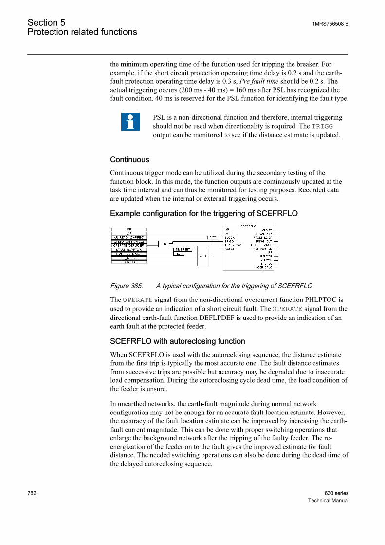
the minimum operating time of the function used for tripping the breaker. Forexample, if the short circuit protection operating time delay is 0.2 s and the earth-fault protection operating time delay is 0.3 s, Pre fault time should be 0.2 s. Theactual triggering occurs (200 ms - 40 ms) = 160 ms after PSL has recognized thefault condition. 40 ms is reserved for the PSL function for identifying the fault type.
PSL is a non-directional function and therefore, internal triggeringshould not be used when directionality is required. The TRIGGoutput can be monitored to see if the distance estimate is updated.
ContinuousContinuous trigger mode can be utilized during the secondary testing of thefunction block. In this mode, the function outputs are continuously updated at thetask time interval and can thus be monitored for testing purposes. Recorded dataare updated when the internal or external triggering occurs.
Example configuration for the triggering of SCEFRFLO
GUID-1ABD2908-F4F6-4E77-A736-D58D08DBEB18 V1 EN
Figure 385: A typical configuration for the triggering of SCEFRFLO
The OPERATE signal from the non-directional overcurrent function PHLPTOC isused to provide an indication of a short circuit fault. The OPERATE signal from thedirectional earth-fault function DEFLPDEF is used to provide an indication of anearth fault at the protected feeder.
SCEFRFLO with autoreclosing functionWhen SCEFRFLO is used with the autoreclosing sequence, the distance estimatefrom the first trip is typically the most accurate one. The fault distance estimatesfrom successive trips are possible but accuracy may be degraded due to inaccurateload compensation. During the autoreclosing cycle dead time, the load condition ofthe feeder is unsure.
In unearthed networks, the earth-fault magnitude during normal networkconfiguration may not be enough for an accurate fault location estimate. However,the accuracy of the fault location estimate can be improved by increasing the earth-fault current magnitude. This can be done with proper switching operations thatenlarge the background network after the tripping of the faulty feeder. The re-energization of the feeder on to the fault gives the improved estimate for faultdistance. The needed switching operations can also be done during the dead time ofthe delayed autoreclosing sequence.
Section 5 1MRS756508 BProtection related functions
782 630 seriesTechnical Manual
Triggering of SCEFRFLO may also be inhibited during the autoreclosingsequence. This is achieved by connecting the signal AR_READY from theautoreclosing function that indicates that the autoreclosing sequence is in progressto the BLOCK input of SCEFRFLO. Blocking of SCEFRFLO triggering issuggested during the autoreclosing sequence when the load compensation or steady-state asymmetry elimination is based on the delta quantities. This applies to theshort circuit faults (fault loops 12, 23, 31 and the 123) when the setting is LoadCom PP loops = TRUE or to earth faults with the value EF algorithm = Loadcompensation.
5.4.4.5 Result validity indicator for earth faults
Fault localization is a challenging task. There are many factors that can deterioratethe accuracy of the calculated fault distance estimate. The most important factors are:
• Fault resistance. The smaller the fault resistance, the more accurate the resultis likely to be. The accuracy of the fault distance estimation deteriorates if theresistive part of the fault loop impedance becomes much larger than thereactive part due to the large fault resistance. The fault resistance is typicallyquite low during short circuits. However, it can be the most dominant errorsource in earth faults.
• Asymmetry. The asymmetry of the line parameters and the loading affects thefault distance estimation accuracy. If the asymmetry has a very high value, theaccuracy of the fault distance estimation deteriorates.
• Saturation. The saturation of current or voltage transformers increases certainharmonics, especially the second, the fifth and the seventh. Saturationdeteriorates the fault distance estimate.
• In unearthed networks, the ratio between the earth-fault current (Rfault = 0ohms) and load current magnitude is critical. The higher the ratio, the betterthe fault distance estimate.
Furthermore, the distribution networks have specific features which furthercomplicate and challenge fault localization algorithms. These include, for example,non-homogeneity of lines, presence of laterals and load taps.
The validity of the estimated earth fault distance is judged and reported togetherwith the fault distance estimate. The EF_VALIDITY output has various values:
1MRS756508 B Section 5Protection related functions
630 series 783Technical Manual

Table 721: The EF_VALIDITY output values
N/A Indicator is not applicable (fault type is a shortcircuit).
High Result is not affected by error sources.
Moderate Result is slightly affected by error sources. Theadditional error in the fault distance estimate canbe tens of percents.
Poor Fault distance algorithm is greatly affected byerror sources and cannot function properly. Inthis case, the result is only trend setting. Theresult can only indicate, for example, whether thefault is in the beginning or in the end of thefeeder section.
5.4.4.6 ALARM output
The SCEFRFLO function contains an alarm output for the calculated fault distance.If the value of the calculated fault distance FLT_DISTANCE is between the Lowalarm Dis limit setting and High alarm Dis limit, the ALARM output is set to TRUE.
The ALARM output can be utilized, for example, in regions with waterways or otherplaces where knowledge of certain fault locations is of high importance.
GUID-888F1A74-78DC-4303-BEAD-86C052FBC5A9 V1 EN
Figure 386: An example of the ALARM output usage
5.4.4.7 Impedance settings
The fault distance calculation in SCEFRFLO is based on the fault impedance loopmodeling. The fault loop is parameterized with the impedance settings, for exampleR1 line section A, X1 line section A, R0 line section A, and X0 line section A. The
Section 5 1MRS756508 BProtection related functions
784 630 seriesTechnical Manual
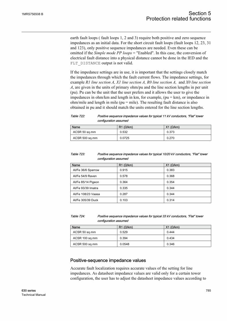
earth fault loops ( fault loops 1, 2 and 3) require both positive and zero sequenceimpedances as an initial data. For the short circuit fault loops (fault loops 12, 23, 31and 123), only positive sequence impedances are needed. Even these can beomitted if the Simple mode PP loops = "Enabled". In this case, the conversion ofelectrical fault distance into a physical distance cannot be done in the IED and theFLT_DISTANCE output is not valid.
If the impedance settings are in use, it is important that the settings closely matchthe impedances through which the fault current flows. The impedance settings, forexample R1 line section A, X1 line section A, R0 line section A, and X0 line sectionA, are given in the units of primary ohm/pu and the line section lengths in per unit(pu). Pu can be the unit that the user prefers and it allows the user to give theimpedances in ohm/km and length in km, for example, (pu = km), or impedance inohm/mile and length in mile (pu = mile). The resulting fault distance is alsoobtained in pu and it should match the units entered for the line section lengths.
Table 722: Positive sequence impedance values for typical 11 kV conductors, “Flat” towerconfiguration assumed
Name R1 (Ω/km) X1 (Ω/km)ACSR 50 sq.mm 0.532 0.373
ACSR 500 sq.mm 0.0725 0.270
Table 723: Positive sequence impedance values for typical 10/20 kV conductors, “Flat” towerconfiguration assumed
Name R1 (Ω/km) X1 (Ω/km)Al/Fe 36/6 Sparrow 0.915 0.383
Al/Fe 54/9 Raven 0.578 0.368
Al/Fe 85/14 Pigeon 0.364 0.354
Al/Fe 93/39 Imatra 0.335 0.344
Al/Fe 108/23 Vaasa 0.287 0.344
Al/Fe 305/39 Duck 0.103 0.314
Table 724: Positive sequence impedance values for typical 33 kV conductors, “Flat” towerconfiguration assumed
Name R1 (Ω/km) X1 (Ω/km)ACSR 50 sq.mm 0.529 0.444
ACSR 100 sq.mm 0.394 0.434
ACSR 500 sq.mm 0.0548 0.346
Positive-sequence impedance valuesAccurate fault localization requires accurate values of the setting for lineimpedances. As datasheet impedance values are valid only for a certain towerconfiguration, the user has to adjust the datasheet impedance values according to
1MRS756508 B Section 5Protection related functions
630 series 785Technical Manual
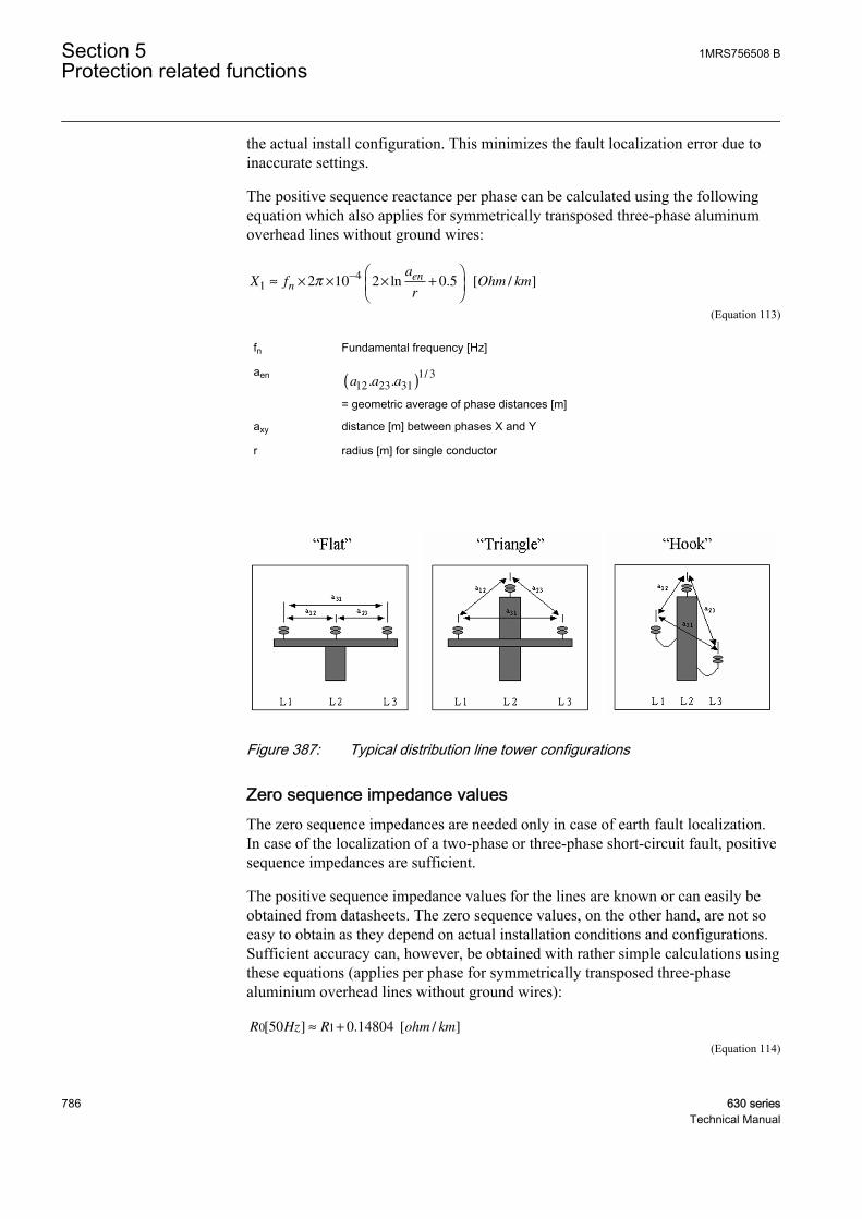
the actual install configuration. This minimizes the fault localization error due toinaccurate settings.
The positive sequence reactance per phase can be calculated using the followingequation which also applies for symmetrically transposed three-phase aluminumoverhead lines without ground wires:
X fa
rOhm kmn
en1
42 10 2 0 5≈ × × × +
−π ln . [ / ]
GUID-B3D2EC98-E22D-447A-8269-DD770726B0E9 V1 EN (Equation 113)
fn Fundamental frequency [Hz]
aena a a12 23 31
1 3. .
/( )
= geometric average of phase distances [m]
axy distance [m] between phases X and Y
r radius [m] for single conductor
GUID-86571C2A-BC00-4A84-9A56-F3B9AC538BCE V1 EN
Figure 387: Typical distribution line tower configurations
Zero sequence impedance valuesThe zero sequence impedances are needed only in case of earth fault localization.In case of the localization of a two-phase or three-phase short-circuit fault, positivesequence impedances are sufficient.
The positive sequence impedance values for the lines are known or can easily beobtained from datasheets. The zero sequence values, on the other hand, are not soeasy to obtain as they depend on actual installation conditions and configurations.Sufficient accuracy can, however, be obtained with rather simple calculations usingthese equations (applies per phase for symmetrically transposed three-phasealuminium overhead lines without ground wires):
R Hz R ohm km0 150 0 14804[ ] . [ / ]≈ +
GUID-9788EC26-6E2D-4DD4-89D9-565D4D7481D4 V1 EN (Equation 114)
Section 5 1MRS756508 BProtection related functions
786 630 seriesTechnical Manual
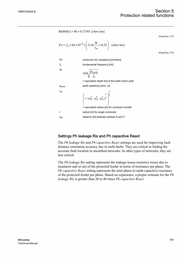
R Hz R ohm km0 60 1 0 17765[ ] . [ / ]≈ +
GUID-6AA28C80-E150-4B1B-8AF8-EAA328B626FF V1 EN (Equation 115)
X fW
rohm kmn
en
04
4 10 3 0 25= × × × × +
−
π ln . [ / ]
GUID-B1FFED85-92F0-42C6-AEDE-B980047E2A55 V1 EN (Equation 116)
R1 conductor AC resistance [ohm/km]
fn fundamental frequency [Hz]
W658
ρearth
nf
= equivalent depth [m] of the earth return path
ρearth earth resistivity [ohm, m]
ren
r a a a⋅ ⋅ ⋅
( )12 23 312 2 2
1
3
1
3
= equivalent radius [m] for conductor bundle
r radius [m] for single conductor
axy distance [m] between phases X and Y
Settings Ph leakage Ris and Ph capacitive ReactThe Ph leakage Ris and Ph capacitive React settings are used for improving faultdistance estimation accuracy due to earth faults. They are critical in finding theaccurate fault location in unearthed networks. In other types of networks, they areless critical.
The Ph leakage Ris setting represents the leakage losses (resistive losses due toinsulators and so on) of the protected feeder in terms of resistance per phase. ThePh capacitive React setting represents the total phase-to-earth capacitive reactanceof the protected feeder per phase. Based on experience, a proper estimate for the Phleakage Ris is greater than 20 to 40 times Ph capacitive React.
1MRS756508 B Section 5Protection related functions
630 series 787Technical Manual
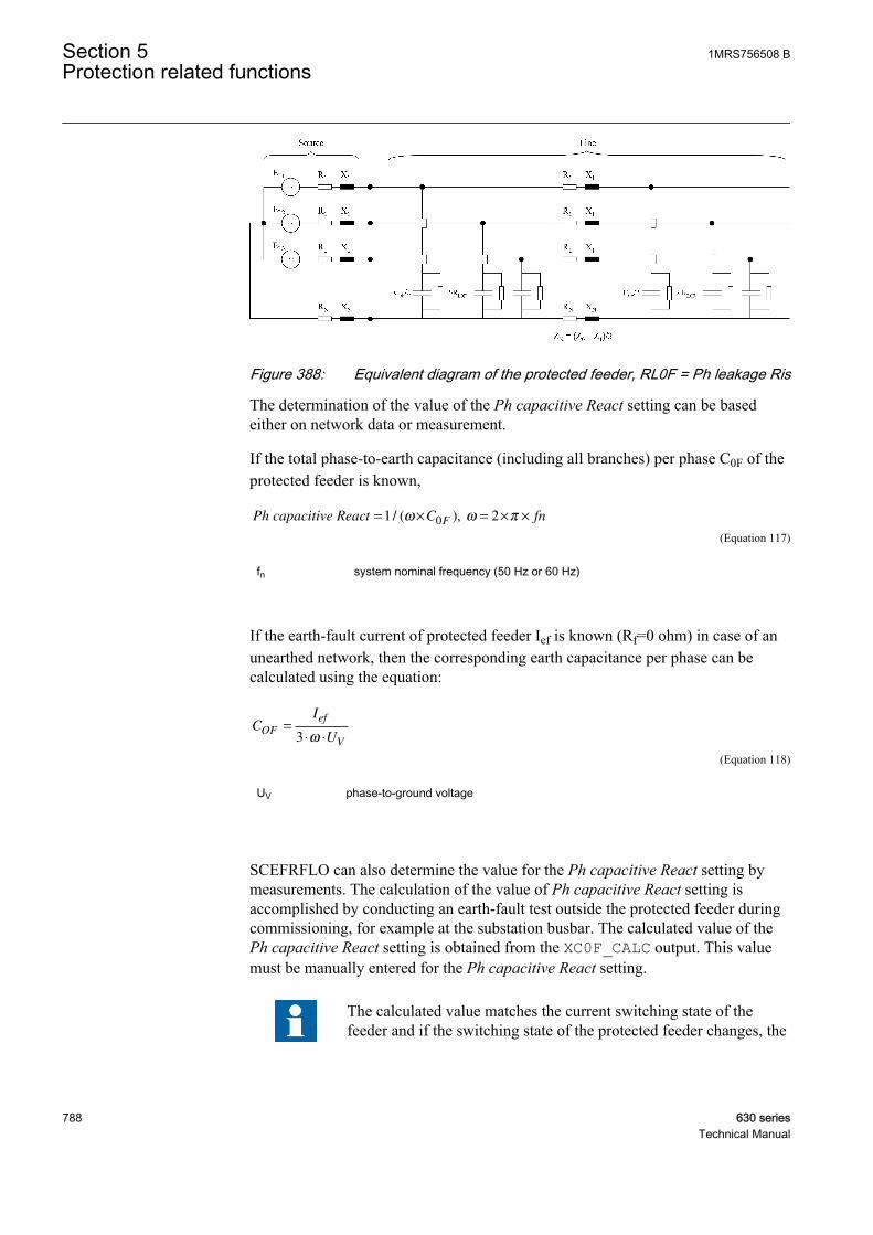
GUID-F1F1C5F8-B0FD-4EC8-903D-0A6BBF3E0B46 V1 EN
Figure 388: Equivalent diagram of the protected feeder, RL0F = Ph leakage Ris
The determination of the value of the Ph capacitive React setting can be basedeither on network data or measurement.
If the total phase-to-earth capacitance (including all branches) per phase C0F of theprotected feeder is known,
Ph capacitive React = × = × ×1 20/ ( ),ω ω πC fnF
GUID-95F80FC2-BF63-45AE-A6C0-98265F599CF9 V1 EN (Equation 117)
fn system nominal frequency (50 Hz or 60 Hz)
If the earth-fault current of protected feeder Ief is known (Rf=0 ohm) in case of anunearthed network, then the corresponding earth capacitance per phase can becalculated using the equation:
CI
UOF
ef
V
=
⋅ ⋅3 ω
GUID-7897F6EB-6E9E-436A-AC97-359F44E17D81 V1 EN (Equation 118)
UV phase-to-ground voltage
SCEFRFLO can also determine the value for the Ph capacitive React setting bymeasurements. The calculation of the value of Ph capacitive React setting isaccomplished by conducting an earth-fault test outside the protected feeder duringcommissioning, for example at the substation busbar. The calculated value of thePh capacitive React setting is obtained from the XC0F_CALC output. This valuemust be manually entered for the Ph capacitive React setting.
The calculated value matches the current switching state of thefeeder and if the switching state of the protected feeder changes, the
Section 5 1MRS756508 BProtection related functions
788 630 seriesTechnical Manual

value is no longer valid. In this case, the setting should be updated,for example by repeating the test.
The calculation procedure of the Ph capacitive React setting is triggered by thebinary signal connected to the TRIGG_XC0F input. The trigger signal shouldindicate that an earth-fault is detected outside the protected feeder.
Figure 389 shows a typical configuration of the Ph capacitive React settingcalculation triggering.
The logic is based on:
• If the earth-fault is detected by overvoltage function (START of ROVPTOV)and fault is not seen by forward looking earth-fault protection functions(START of DEFLPDEF), then after a set delay (TIMERSET) outputXC0F_CALC is updated.
• The Delay (TIMERSET) must be set longer than the start delay of directionalearth-fault function (DEFLPEF) inside terminal , but shorter than theminimum operate time of directional earth-fault functions in the substation.For example, if the start delay is 100 ms and the shortest operate time 300 ms,then a value of 200 ms can be used.
• Additionally, circuit breaker and disconnector status is used to verify thatentire feeder is measured.
GUID-E8D104FD-6E19-466A-A7A5-0C178DAD980B V1 EN
Figure 389: Typical configuration for XC0F calculation triggering
Modelling a non-homogenous lineA typical distribution feeder is built with several different types of overhead linesand cables. This means that the feeder is electrically non-homogenous. Theimpedance diagram is non-linear.
1MRS756508 B Section 5Protection related functions
630 series 789Technical Manual

GUID-33901C2C-7D94-41A1-AD60-7960A45A1BD2 V1 EN
Figure 390: Non-homogeneity of a feeder in an impedance diagram
If the impedance of an individual line section varies, an accurate conversion of thefault loop reactance into a physical fault distance, for example into kilometres, isnot possible with only one impedance setting. Therefore, SCEFRFLO allows themodeling of the line impedance variation in IED with three line sections and withindependent impedance settings. This improves the accuracy of the physical faultdistance conversion done in the IED, especially in cases where the line impedancenon-homogeneity is severe. The number of line sections used in the conversionprocedure from ohmic fault distance into physical fault distance are defined byusing the Num of line sections setting.
If Num of line sections = 0, the conversion of the electrical fault distance into aphysical distance is not done in the IED and the FLT_DISTANCE output is notvalid. Estimated impedances are still calculated and are shown on their respectiveoutputs. In order to guarantee accurate impedance estimation, the user should giveas good values as possible for the longitudinal impedance settings R1 line sectionA, X1 line section A, R0 line section A, X0 line section A and the Line Len section Aparameter corresponding to the total line length. Other longitudinal impedancesettings are disabled (sections B and C).
If Num of line sections = 1, the longitudinal impedance settings R1 line section A,X1 line section A, R0 line section A, X0 line section A and the Line Len section Aparameter are enabled for the conversion of the electrical fault distance into aphysical distance. This option should be used only in the case of a homogeneousline, for example, when the protected feeder consists of only one conductor type.Also this option should be used if the user is only interested in calculated fault loopreactance XFLOOP and final fault location is done in higher system level utilizing,for example DMS-system.
If Num of line sections = 2, the longitudinal impedance settings R1 line section A,X1 line section A, R0 line section A, X0 line section A, R1 line section B, X1 linesection B, R0 line section B, X0 line section B and the parameters Line Len sectionA, Line Len section B are enabled for the conversion of the electrical fault distanceinto a physical distance. This option should be used in the case of a non-homogenous line, for example, when the protected feeder consists of two types ofconductors.
Section 5 1MRS756508 BProtection related functions
790 630 seriesTechnical Manual
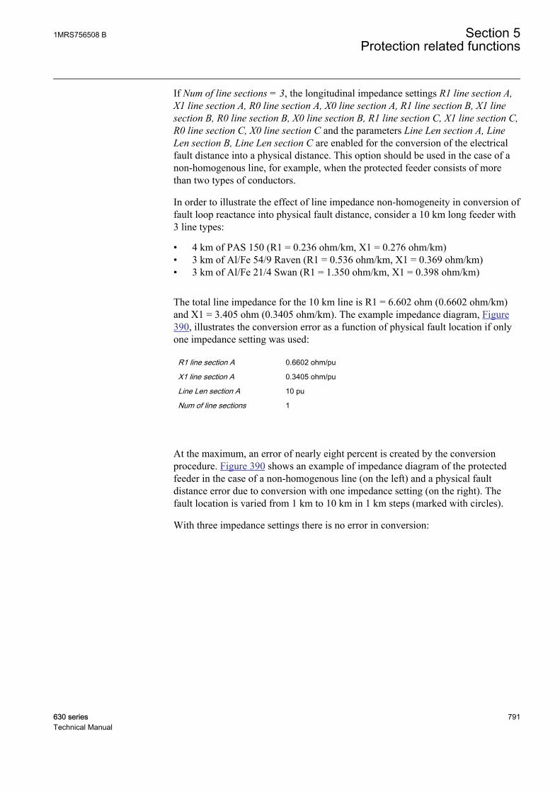
If Num of line sections = 3, the longitudinal impedance settings R1 line section A,X1 line section A, R0 line section A, X0 line section A, R1 line section B, X1 linesection B, R0 line section B, X0 line section B, R1 line section C, X1 line section C,R0 line section C, X0 line section C and the parameters Line Len section A, LineLen section B, Line Len section C are enabled for the conversion of the electricalfault distance into a physical distance. This option should be used in the case of anon-homogenous line, for example, when the protected feeder consists of morethan two types of conductors.
In order to illustrate the effect of line impedance non-homogeneity in conversion offault loop reactance into physical fault distance, consider a 10 km long feeder with3 line types:
• 4 km of PAS 150 (R1 = 0.236 ohm/km, X1 = 0.276 ohm/km)• 3 km of Al/Fe 54/9 Raven (R1 = 0.536 ohm/km, X1 = 0.369 ohm/km)• 3 km of Al/Fe 21/4 Swan (R1 = 1.350 ohm/km, X1 = 0.398 ohm/km)
The total line impedance for the 10 km line is R1 = 6.602 ohm (0.6602 ohm/km)and X1 = 3.405 ohm (0.3405 ohm/km). The example impedance diagram, Figure390, illustrates the conversion error as a function of physical fault location if onlyone impedance setting was used:
R1 line section A 0.6602 ohm/pu
X1 line section A 0.3405 ohm/pu
Line Len section A 10 pu
Num of line sections 1
At the maximum, an error of nearly eight percent is created by the conversionprocedure. Figure 390 shows an example of impedance diagram of the protectedfeeder in the case of a non-homogenous line (on the left) and a physical faultdistance error due to conversion with one impedance setting (on the right). Thefault location is varied from 1 km to 10 km in 1 km steps (marked with circles).
With three impedance settings there is no error in conversion:
1MRS756508 B Section 5Protection related functions
630 series 791Technical Manual
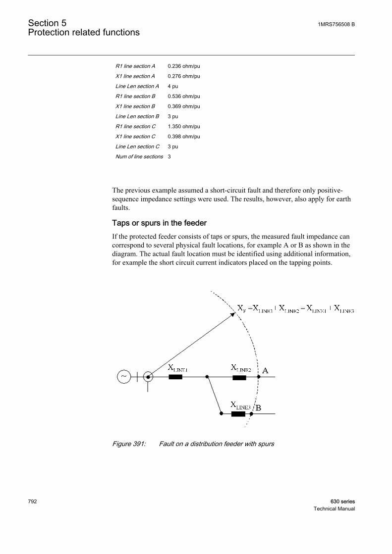
R1 line section A 0.236 ohm/pu
X1 line section A 0.276 ohm/pu
Line Len section A 4 pu
R1 line section B 0.536 ohm/pu
X1 line section B 0.369 ohm/pu
Line Len section B 3 pu
R1 line section C 1.350 ohm/pu
X1 line section C 0.398 ohm/pu
Line Len section C 3 pu
Num of line sections 3
The previous example assumed a short-circuit fault and therefore only positive-sequence impedance settings were used. The results, however, also apply for earthfaults.
Taps or spurs in the feederIf the protected feeder consists of taps or spurs, the measured fault impedance cancorrespond to several physical fault locations, for example A or B as shown in thediagram. The actual fault location must be identified using additional information,for example the short circuit current indicators placed on the tapping points.
GUID-36C77B78-CCEB-49A8-BF61-1CE2DC95EEDD V1 EN
Figure 391: Fault on a distribution feeder with spurs
Section 5 1MRS756508 BProtection related functions
792 630 seriesTechnical Manual
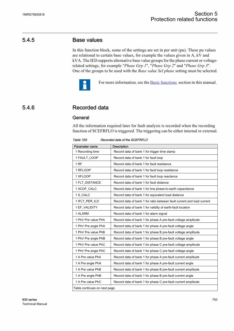
5.4.5 Base valuesIn this function block, some of the settings are set in per unit (pu). These pu valuesare relational to certain base values, for example the values given in A, kV andkVA. The IED supports alternative base value groups for the phase current or voltage-related settings, for example "Phase Grp 1", "Phase Grp 2" and "Phase Grp 3".One of the groups to be used with the Base value Sel phase setting must be selected.
For more information, see the Basic functions section in this manual.
5.4.6 Recorded data
GeneralAll the information required later for fault analysis is recorded when the recordingfunction of SCEFRFLO is triggered. The triggering can be either internal or external.
Table 725: Recorded data of the SCEFRFLO
Parameter name Description1 Recording time Record data of bank 1 for trigger time stamp
1 FAULT_LOOP Record data of bank 1 for fault loop
1 RF Record data of bank 1 for fault resistance
1 RFLOOP Record data of bank 1 for fault loop resistance
1 XFLOOP Record data of bank 1 for fault loop reactance
1 FLT_DISTANCE Record data of bank 1 for fault distance
1 XCOF_CALC Record data of bank 1 for line phase-to-earth capacitance
1 S_CALC Record data of bank 1 for equivalent load distance
1 IFLT_PER_ILD Record data of bank 1 for ratio between fault current and load current
1 EF_VALIDITY Record data of bank 1 for validity of earth-fault location
1 ALARM Record data of bank 1 for alarm signal
1 PhV Pre value PhA Record data of bank 1 for phase A pre-fault voltage amplitude
1 PhV Pre angle PhA Record data of bank 1 for phase A pre-fault voltage angle
1 PhV Pre value PhB Record data of bank 1 for phase B pre-fault voltage amplitude
1 PhV Pre angle PhB Record data of bank 1 for phase B pre-fault voltage angle
1 PhV Pre value PhC Record data of bank 1 for phase C pre-fault voltage amplitude
1 PhV Pre angle PhC Record data of bank 1 for phase C pre-fault voltage angle
1 A Pre value PhA Record data of bank 1 for phase A pre-fault current amplitude
1 A Pre angle PhA Record data of bank 1 for phase A pre-fault current angle
1 A Pre value PhB Record data of bank 1 for phase B pre-fault current amplitude
1 A Pre angle PhB Record data of bank 1 for phase B pre-fault current angle
1 A Pre value PhC Record data of bank 1 for phase C pre-fault current amplitude
Table continues on next page
1MRS756508 B Section 5Protection related functions
630 series 793Technical Manual

Parameter name Description1 A Pre angle PhC Record data of bank 1 for phase C pre-fault current angle
1 PhV Flt value PhA Record data of bank 1 for phase A voltage amplitude during fault
1 PhV Flt angle PhA Record data of bank 1 for phase A voltage angle during fault
1 PhV Flt value PhB Record data of bank 1 for phase B voltage amplitude during fault
1 PhV Flt angle PhB Record data of bank 1 for phase B voltage angle during fault
1 PhV Flt value PhC Record data of bank 1 for phase C voltage amplitude during fault
1 PhV Flt angle PhC Record data of bank 1 for phase C voltage angle during fault
1 A Flt value PhA Record data of bank 1 for phase A current amplitude during fault
1 A Flt angle PhA Record data of bank 1 for phase A current angle during fault
1 A Flt value PhB Record data of bank 1 for phase B current amplitude during fault
1 A Flt angle PhB Record data of bank 1 for phase B current angle during fault
1 A Flt value PhC Record data of bank 1 for phase C current amplitude during fault
1 A Flt angle PhC Record data of bank 1 for phase C current angle during fault
The registers can be reset with the RESET binary input signal.
When a new triggering occurs, the data is overwritten.
5.4.7 ApplicationThe main objective of line protection and monitoring terminals is fast, selectiveand reliable operation for faults on a protected line section. Besides this,information on the distance to fault is very important for those involved inoperation and maintenance. Reliable information on the fault location greatlydecreases the downtime of the protected lines and increases the total availability ofa power system.
SCEFRFLO can be applied as a device level solution or as a part of a system levelsolution. In the device level applications, the physical fault distance(FLT_DISTANCE) is calculated in the IED based on settings. A more accurateresult can be expected if the fault loop impedance (XFLOOP, RFLOOP) estimatedby SCEFRFLO is utilized in the system level fault location applications.
SCEFRFLO provides the distance to the fault together with the information aboutthe measuring loop that has been used in the calculation. Also, an estimate for thefault resistance at the fault point is calculated. In addition, both pre-fault and faultquantities of voltages and currents are available for a post-fault analysis in therecorded data. The validity of the estimated earth-fault distance is judged andreported together with the fault distance estimate.
5.4.8 ConfigurationSCEFRFLO requires three phase currents for operation. The phase currents can bemeasured with conventional current transformers or Rogowski coils.
Section 5 1MRS756508 BProtection related functions
794 630 seriesTechnical Manual

The full operation of SCEFRFLO requires that all three phase-to-earth voltages aremeasured. The voltages can be measured with conventional voltage transformers orvoltage dividers connected between the phase and earth. Other alternative is tomeasure phase-to-phase voltages and residual voltage (Uo). Both these alternativesare covered by setting the configuration parameter Phase voltage Meas to"Accurate". When the Phase voltage Meas setting is set to "PhToPh without Uo"and only phase-to-phase voltages are available, only short-circuit measuring loops(fault loops 12, 23, 31, 123) can be measured accurately. In this case, the earth-fault loops (fault loops 1, 2, 3) cannot provide correct fault distance estimates andthe triggering of the function is automatically disabled.
5.4.9 SignalsTable 726: SCEFRFLO Input signals
Name Type Default DescriptionI3P GROUP
SIGNAL- Three phase group signal for current inputs
U3P GROUPSIGNAL
- Three phase group signal for voltage inputs
BLOCK BOOLEAN 0 Signal for blocking the triggering
TRIGG BOOLEAN 0 Triggering signal for outputs of the function
TRIGG_XC0F BOOLEAN 0 Triggering signal for XC0F calculation
RESET BOOLEAN 0 Input signal for resetting registers
Table 727: SCEFRFLO Output signals
Name Type DescriptionALARM BOOLEAN Alarm signal indicating that fault is located
between set limits
EF_VALIDITY INTEGER Validity of earth fault location
FAULT_LOOP INTEGER Fault impedance loop used for distancemeasurement
TRIGG_OUT BOOLEAN Signal indicating function triggering
FLT_DISTANCE REAL Fault distance in units selected by the user (pu)
IFLT_PER_ILD REAL Ratio between fault current and load current incase of an earth fault
RF REAL Fault resistance in primary ohms
RFLOOP REAL Fault loop resistance in primary ohms
XFLOOP REAL Fault loop reactance in primary ohms
S_CALC REAL Estimated equivalent load distance
XC0F_CALC REAL Estimated phase-to-earth capacitive reactance ofthe feeder
1MRS756508 B Section 5Protection related functions
630 series 795Technical Manual

5.4.10 SettingsTable 728: SCEFRFLO Group settings (basic)
Name Values (Range) Unit Step Default DescriptionZ Max phase load 1.00 - 10000.00 ohm 0.01 80.00 Impedance per phase of max. load, over-
curr./under-imp., PSL
Ph leakage Ris 1 - 1000000 ohm 1 210000 Line PhE leakage resistance in primaryohms
Ph capacitive React 1 - 1000000 ohm 1 7000 Line PhE capacitive reactance in primaryohms
R1 line section A 0.001 - 1000.000 ohm/pu 0.001 1.000 Positive-sequence line resistance, linesection A
X1 line section A 0.001 - 1000.000 ohm/pu 0.001 1.000 Positive-sequence line reactance, linesection A
R0 line section A 0.001 - 1000.000 ohm/pu 0.001 4.000 Zero-sequence line resistance, linesection A
X0 line section A 0.001 - 1000.000 ohm/pu 0.001 4.000 Zero-sequence line reactance, linesection A
Line Len section A 0.001 - 1000.000 pu 0.001 1.000 Line length, section A
Table 729: SCEFRFLO Group settings (advanced)
Name Values (Range) Unit Step Default DescriptionEquivalent load Dis 0.01 - 1.00 - 0.01 0.50 Equivalent load distance when EF
algorithm = load modelling
Num of line sections 0 - 3 - 1 1 Number of line sections
R1 line section B 0.001 - 1000.000 ohm/pu 0.001 1.000 Positive-sequence line resistance, linesection B
X1 line section B 0.001 - 1000.000 ohm/pu 0.001 1.000 Positive-sequence line reactance, linesection B
R0 line section B 0.001 - 1000.000 ohm/pu 0.001 4.000 Zero-sequence line resistance, linesection B
X0 line section B 0.001 - 1000.000 ohm/pu 0.001 4.000 Zero-sequence line reactance, linesection B
Line Len section B 0.001 - 1000.000 pu 0.001 1.000 Line length, section B
R1 line section C 0.001 - 1000.000 ohm/pu 0.001 1.000 Positive-sequence line resistance, linesection C
X1 line section C 0.001 - 1000.000 ohm/pu 0.001 1.000 Positive-sequence line reactance, linesection C
R0 line section C 0.001 - 1000.000 ohm/pu 0.001 4.000 Zero-sequence line resistance, linesection C
X0 line section C 0.001 - 1000.000 ohm/pu 0.001 4.000 Zero-sequence line reactance, linesection C
Line Len section C 0.001 - 1000.000 pu 0.001 1.000 Line length, section C
Section 5 1MRS756508 BProtection related functions
796 630 seriesTechnical Manual

Table 730: SCEFRFLO Non group settings (basic)
Name Values (Range) Unit Step Default DescriptionOperation Off
On- - On Operation mode Off / On
Phase voltage Meas AccuratePP without Uo
- - Accurate Phase voltage measurement principle
Calculation Trg mode ExternalInternalContinuous
- - External Trigger mode for distance calculation
Pre fault time 0.100 - 300.000 s 0.001 0.100 Time delay for healthy values of I and Ubefore fault [s]
Table 731: SCEFRFLO Non group settings (advanced)
Name Values (Range) Unit Step Default DescriptionBase value Sel phase Phase Grp 1
Phase Grp 2Phase Grp 3
- - Phase Grp 1 Base value selector, phase / phase-to-phase
High alarm Dis limit 0.001 - 1.000 pu 0.001 1.000 High alarm limit for calculated distance
Low alarm Dis limit 0.001 - 1.000 pu 0.001 1.000 Low alarm limit for calculated distance
EF algorithm Load compLoad modelling
- - Load comp PE-loop calculation algorithm
EF algorithm current I0 basedI2 based
- - I0 based Earth-fault current model
Load Com PP loops DisabledEnabled
- - Enabled Enable load compensation for PP/3P-loops
Simple mode PP loops DisabledEnabled
- - Disabled Enable calc. without impedance settingsfor PP/3P-loops
5.4.11 Measured valuesTable 732: SCEFRFLO Measured values
Name Type Default DescriptionI_AMPL_A REAL 0 Amplitude of the phase A current
I_AMPL_B REAL 0 Amplitude of the phase B current
I_AMPL_C REAL 0 Amplitude of the phase C current
U_AMPL_A REAL 0 Amplitude of the phase A voltage
U_AMPL_B REAL 0 Amplitude of the phase B voltage
U_AMPL_C REAL 0 Amplitude of the phase C voltage
BLOCK BOOLEAN 0 Signal for blocking the triggering
TRIGG BOOLEAN 0 Triggering signal for outputs of the function
TRIGG_XC0F BOOLEAN 0 Triggering signal for XC0F calculation
RESET BOOLEAN 0 Input signal for resetting registers
1MRS756508 B Section 5Protection related functions
630 series 797Technical Manual
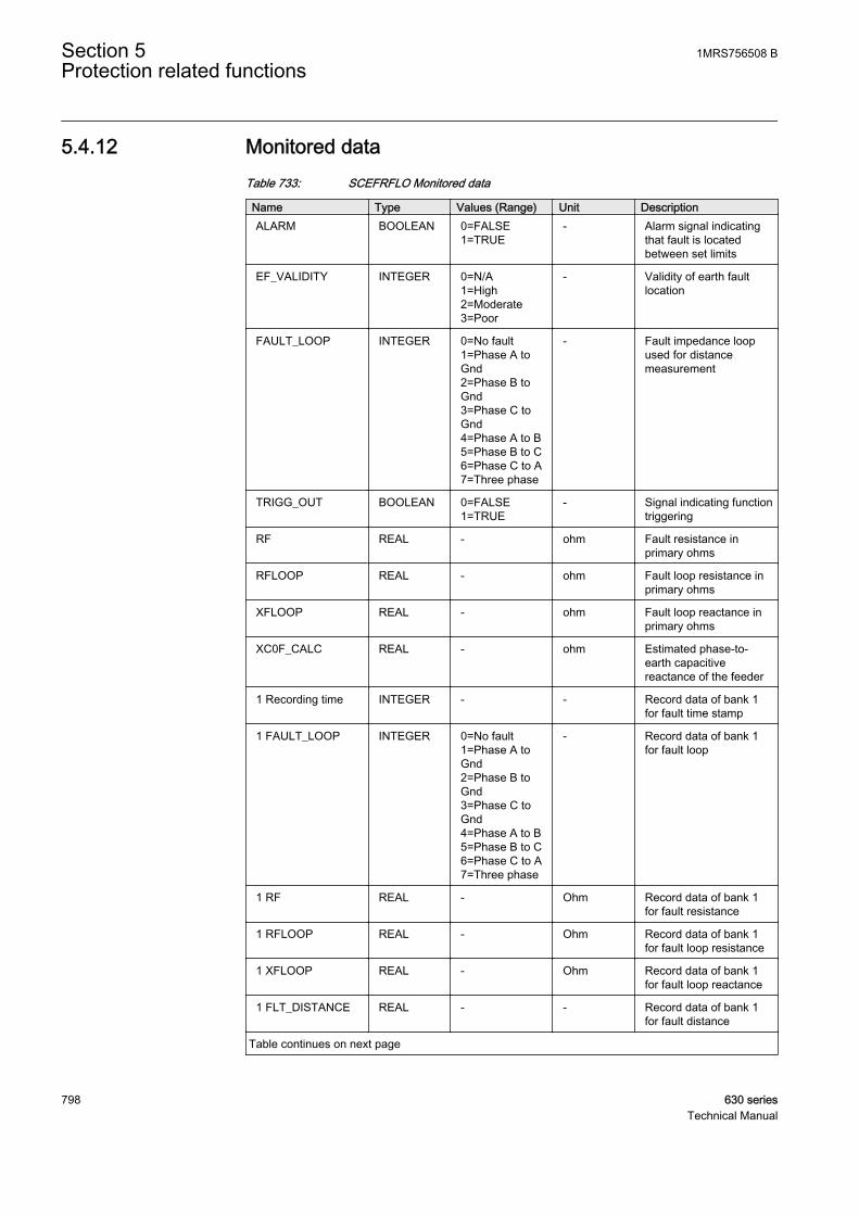
5.4.12 Monitored dataTable 733: SCEFRFLO Monitored data
Name Type Values (Range) Unit DescriptionALARM BOOLEAN 0=FALSE
1=TRUE- Alarm signal indicating
that fault is locatedbetween set limits
EF_VALIDITY INTEGER 0=N/A1=High2=Moderate3=Poor
- Validity of earth faultlocation
FAULT_LOOP INTEGER 0=No fault1=Phase A toGnd2=Phase B toGnd3=Phase C toGnd4=Phase A to B5=Phase B to C6=Phase C to A7=Three phase
- Fault impedance loopused for distancemeasurement
TRIGG_OUT BOOLEAN 0=FALSE1=TRUE
- Signal indicating functiontriggering
RF REAL - ohm Fault resistance inprimary ohms
RFLOOP REAL - ohm Fault loop resistance inprimary ohms
XFLOOP REAL - ohm Fault loop reactance inprimary ohms
XC0F_CALC REAL - ohm Estimated phase-to-earth capacitivereactance of the feeder
1 Recording time INTEGER - - Record data of bank 1for fault time stamp
1 FAULT_LOOP INTEGER 0=No fault1=Phase A toGnd2=Phase B toGnd3=Phase C toGnd4=Phase A to B5=Phase B to C6=Phase C to A7=Three phase
- Record data of bank 1for fault loop
1 RF REAL - Ohm Record data of bank 1for fault resistance
1 RFLOOP REAL - Ohm Record data of bank 1for fault loop resistance
1 XFLOOP REAL - Ohm Record data of bank 1for fault loop reactance
1 FLT_DISTANCE REAL - - Record data of bank 1for fault distance
Table continues on next page
Section 5 1MRS756508 BProtection related functions
798 630 seriesTechnical Manual
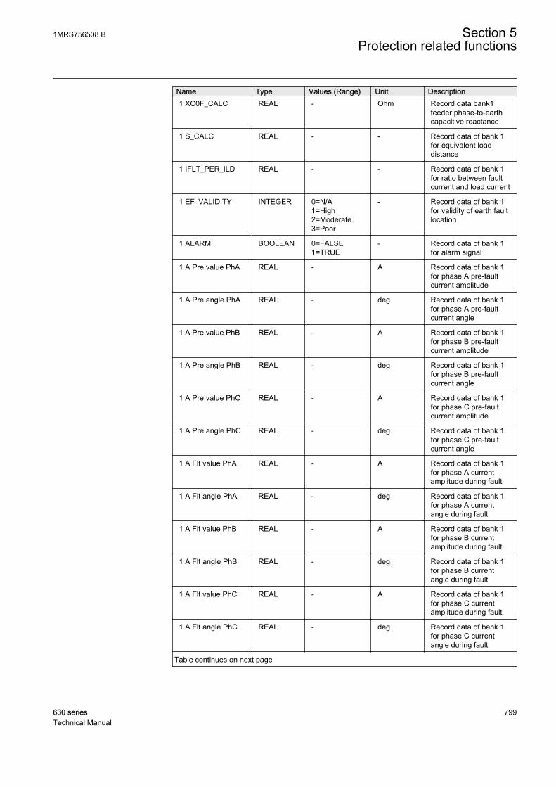
Name Type Values (Range) Unit Description1 XC0F_CALC REAL - Ohm Record data bank1
feeder phase-to-earthcapacitive reactance
1 S_CALC REAL - - Record data of bank 1for equivalent loaddistance
1 IFLT_PER_ILD REAL - - Record data of bank 1for ratio between faultcurrent and load current
1 EF_VALIDITY INTEGER 0=N/A1=High2=Moderate3=Poor
- Record data of bank 1for validity of earth faultlocation
1 ALARM BOOLEAN 0=FALSE1=TRUE
- Record data of bank 1for alarm signal
1 A Pre value PhA REAL - A Record data of bank 1for phase A pre-faultcurrent amplitude
1 A Pre angle PhA REAL - deg Record data of bank 1for phase A pre-faultcurrent angle
1 A Pre value PhB REAL - A Record data of bank 1for phase B pre-faultcurrent amplitude
1 A Pre angle PhB REAL - deg Record data of bank 1for phase B pre-faultcurrent angle
1 A Pre value PhC REAL - A Record data of bank 1for phase C pre-faultcurrent amplitude
1 A Pre angle PhC REAL - deg Record data of bank 1for phase C pre-faultcurrent angle
1 A Flt value PhA REAL - A Record data of bank 1for phase A currentamplitude during fault
1 A Flt angle PhA REAL - deg Record data of bank 1for phase A currentangle during fault
1 A Flt value PhB REAL - A Record data of bank 1for phase B currentamplitude during fault
1 A Flt angle PhB REAL - deg Record data of bank 1for phase B currentangle during fault
1 A Flt value PhC REAL - A Record data of bank 1for phase C currentamplitude during fault
1 A Flt angle PhC REAL - deg Record data of bank 1for phase C currentangle during fault
Table continues on next page
1MRS756508 B Section 5Protection related functions
630 series 799Technical Manual
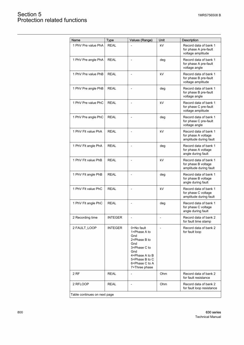
Name Type Values (Range) Unit Description1 PhV Pre value PhA REAL - kV Record data of bank 1
for phase A pre-faultvoltage amplitude
1 PhV Pre angle PhA REAL - deg Record data of bank 1for phase A pre-faultvoltage angle
1 PhV Pre value PhB REAL - kV Record data of bank 1for phase B pre-faultvoltage amplitude
1 PhV Pre angle PhB REAL - deg Record data of bank 1for phase B pre-faultvoltage angle
1 PhV Pre value PhC REAL - kV Record data of bank 1for phase C pre-faultvoltage amplitude
1 PhV Pre angle PhC REAL - deg Record data of bank 1for phase C pre-faultvoltage angle
1 PhV Flt value PhA REAL - kV Record data of bank 1for phase A voltageamplitude during fault
1 PhV Flt angle PhA REAL - deg Record data of bank 1for phase A voltageangle during fault
1 PhV Flt value PhB REAL - kV Record data of bank 1for phase B voltageamplitude during fault
1 PhV Flt angle PhB REAL - deg Record data of bank 1for phase B voltageangle during fault
1 PhV Flt value PhC REAL - kV Record data of bank 1for phase C voltageamplitude during fault
1 PhV Flt angle PhC REAL - deg Record data of bank 1for phase C voltageangle during fault
2 Recording time INTEGER - - Record data of bank 2for fault time stamp
2 FAULT_LOOP INTEGER 0=No fault1=Phase A toGnd2=Phase B toGnd3=Phase C toGnd4=Phase A to B5=Phase B to C6=Phase C to A7=Three phase
- Record data of bank 2for fault loop
2 RF REAL - Ohm Record data of bank 2for fault resistance
2 RFLOOP REAL - Ohm Record data of bank 2for fault loop resistance
Table continues on next page
Section 5 1MRS756508 BProtection related functions
800 630 seriesTechnical Manual

Name Type Values (Range) Unit Description2 XFLOOP REAL - Ohm Record data of bank 2
for fault loop reactance
2 FLT_DISTANCE REAL - - Record data of bank 2for fault distance
2 XC0F_CALC REAL - Ohm Record data bank2feeder phase-to-earthcapacitive reactance
2 S_CALC REAL - - Record data of bank 2for equivalent loaddistance
2 IFLT_PER_ILD REAL - - Record data of bank 2for ratio between faultcurrent and load current
2 EF_VALIDITY INTEGER 0=N/A1=High2=Moderate3=Poor
- Record data of bank 2for validity of earth faultlocation
2 ALARM BOOLEAN 0=FALSE1=TRUE
- Record data of bank 2for alarm signal
2 A Pre value PhA REAL - A Record data of bank 2for phase A pre-faultcurrent amplitude
2 A Pre angle PhA REAL - deg Record data of bank 2for phase A pre-faultcurrent angle
2 A Pre value PhB REAL - A Record data of bank 2for phase B pre-faultcurrent amplitude
2 A Pre angle PhB REAL - deg Record data of bank 2for phase B pre-faultcurrent angle
2 A Pre value PhC REAL - A Record data of bank 2for phase C pre-faultcurrent amplitude
2 A Pre angle PhC REAL - deg Record data of bank 2for phase C pre-faultcurrent angle
2 A Flt value PhA REAL - A Record data of bank 2for phase A currentamplitude during fault
2 A Flt angle PhA REAL - deg Record data of bank 2for phase A currentangle during fault
2 A Flt value PhB REAL - A Record data of bank 2for phase B currentamplitude during fault
2 A Flt angle PhB REAL - deg Record data of bank 2for phase B currentangle during fault
2 A Flt value PhC REAL - A Record data of bank 2for phase C currentamplitude during fault
Table continues on next page
1MRS756508 B Section 5Protection related functions
630 series 801Technical Manual
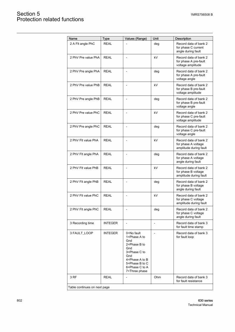
Name Type Values (Range) Unit Description2 A Flt angle PhC REAL - deg Record data of bank 2
for phase C currentangle during fault
2 PhV Pre value PhA REAL - kV Record data of bank 2for phase A pre-faultvoltage amplitude
2 PhV Pre angle PhA REAL - deg Record data of bank 2for phase A pre-faultvoltage angle
2 PhV Pre value PhB REAL - kV Record data of bank 2for phase B pre-faultvoltage amplitude
2 PhV Pre angle PhB REAL - deg Record data of bank 2for phase B pre-faultvoltage angle
2 PhV Pre value PhC REAL - kV Record data of bank 2for phase C pre-faultvoltage amplitude
2 PhV Pre angle PhC REAL - deg Record data of bank 2for phase C pre-faultvoltage angle
2 PhV Flt value PhA REAL - kV Record data of bank 2for phase A voltageamplitude during fault
2 PhV Flt angle PhA REAL - deg Record data of bank 2for phase A voltageangle during fault
2 PhV Flt value PhB REAL - kV Record data of bank 2for phase B voltageamplitude during fault
2 PhV Flt angle PhB REAL - deg Record data of bank 2for phase B voltageangle during fault
2 PhV Flt value PhC REAL - kV Record data of bank 2for phase C voltageamplitude during fault
2 PhV Flt angle PhC REAL - deg Record data of bank 2for phase C voltageangle during fault
3 Recording time INTEGER - - Record data of bank 3for fault time stamp
3 FAULT_LOOP INTEGER 0=No fault1=Phase A toGnd2=Phase B toGnd3=Phase C toGnd4=Phase A to B5=Phase B to C6=Phase C to A7=Three phase
- Record data of bank 3for fault loop
3 RF REAL - Ohm Record data of bank 3for fault resistance
Table continues on next page
Section 5 1MRS756508 BProtection related functions
802 630 seriesTechnical Manual

Name Type Values (Range) Unit Description3 RFLOOP REAL - Ohm Record data of bank 3
for fault loop resistance
3 XFLOOP REAL - Ohm Record data of bank 3for fault loop reactance
3 FLT_DISTANCE REAL - - Record data of bank 3for fault distance
3 XC0F_CALC REAL - Ohm Record data bank3feeder phase-to-earthcapacitive reactance
3 S_CALC REAL - - Record data of bank 3for equivalent loaddistance
3 IFLT_PER_ILD REAL - - Record data of bank 3for ratio between faultcurrent and load current
3 EF_VALIDITY INTEGER 0=N/A1=High2=Moderate3=Poor
- Record data of bank 3for validity of earth faultlocation
3 ALARM BOOLEAN 0=FALSE1=TRUE
- Record data of bank 3for alarm signal
3 A Pre value PhA REAL - A Record data of bank 3for phase A pre-faultcurrent amplitude
3 A Pre angle PhA REAL - deg Record data of bank 3for phase A pre-faultcurrent angle
3 A Pre value PhB REAL - A Record data of bank 3for phase B pre-faultcurrent amplitude
3 A Pre angle PhB REAL - deg Record data of bank 3for phase B pre-faultcurrent angle
3 A Pre value PhC REAL - A Record data of bank 3for phase C pre-faultcurrent amplitude
3 A Pre angle PhC REAL - deg Record data of bank 3for phase C pre-faultcurrent angle
3 A Flt value PhA REAL - A Record data of bank 3for phase A currentamplitude during fault
3 A Flt angle PhA REAL - deg Record data of bank 3for phase A currentangle during fault
3 A Flt value PhB REAL - A Record data of bank 3for phase B currentamplitude during fault
3 A Flt angle PhB REAL - deg Record data of bank 3for phase B currentangle during fault
Table continues on next page
1MRS756508 B Section 5Protection related functions
630 series 803Technical Manual
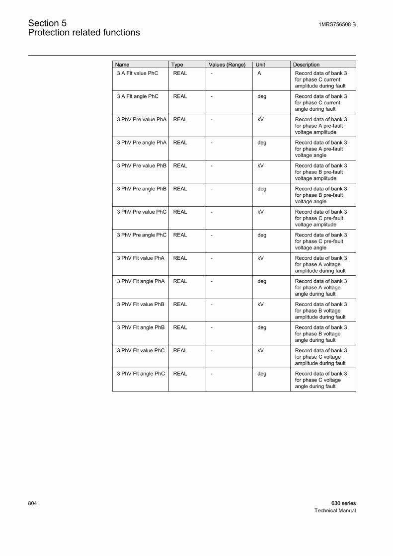
Name Type Values (Range) Unit Description3 A Flt value PhC REAL - A Record data of bank 3
for phase C currentamplitude during fault
3 A Flt angle PhC REAL - deg Record data of bank 3for phase C currentangle during fault
3 PhV Pre value PhA REAL - kV Record data of bank 3for phase A pre-faultvoltage amplitude
3 PhV Pre angle PhA REAL - deg Record data of bank 3for phase A pre-faultvoltage angle
3 PhV Pre value PhB REAL - kV Record data of bank 3for phase B pre-faultvoltage amplitude
3 PhV Pre angle PhB REAL - deg Record data of bank 3for phase B pre-faultvoltage angle
3 PhV Pre value PhC REAL - kV Record data of bank 3for phase C pre-faultvoltage amplitude
3 PhV Pre angle PhC REAL - deg Record data of bank 3for phase C pre-faultvoltage angle
3 PhV Flt value PhA REAL - kV Record data of bank 3for phase A voltageamplitude during fault
3 PhV Flt angle PhA REAL - deg Record data of bank 3for phase A voltageangle during fault
3 PhV Flt value PhB REAL - kV Record data of bank 3for phase B voltageamplitude during fault
3 PhV Flt angle PhB REAL - deg Record data of bank 3for phase B voltageangle during fault
3 PhV Flt value PhC REAL - kV Record data of bank 3for phase C voltageamplitude during fault
3 PhV Flt angle PhC REAL - deg Record data of bank 3for phase C voltageangle during fault
Section 5 1MRS756508 BProtection related functions
804 630 seriesTechnical Manual
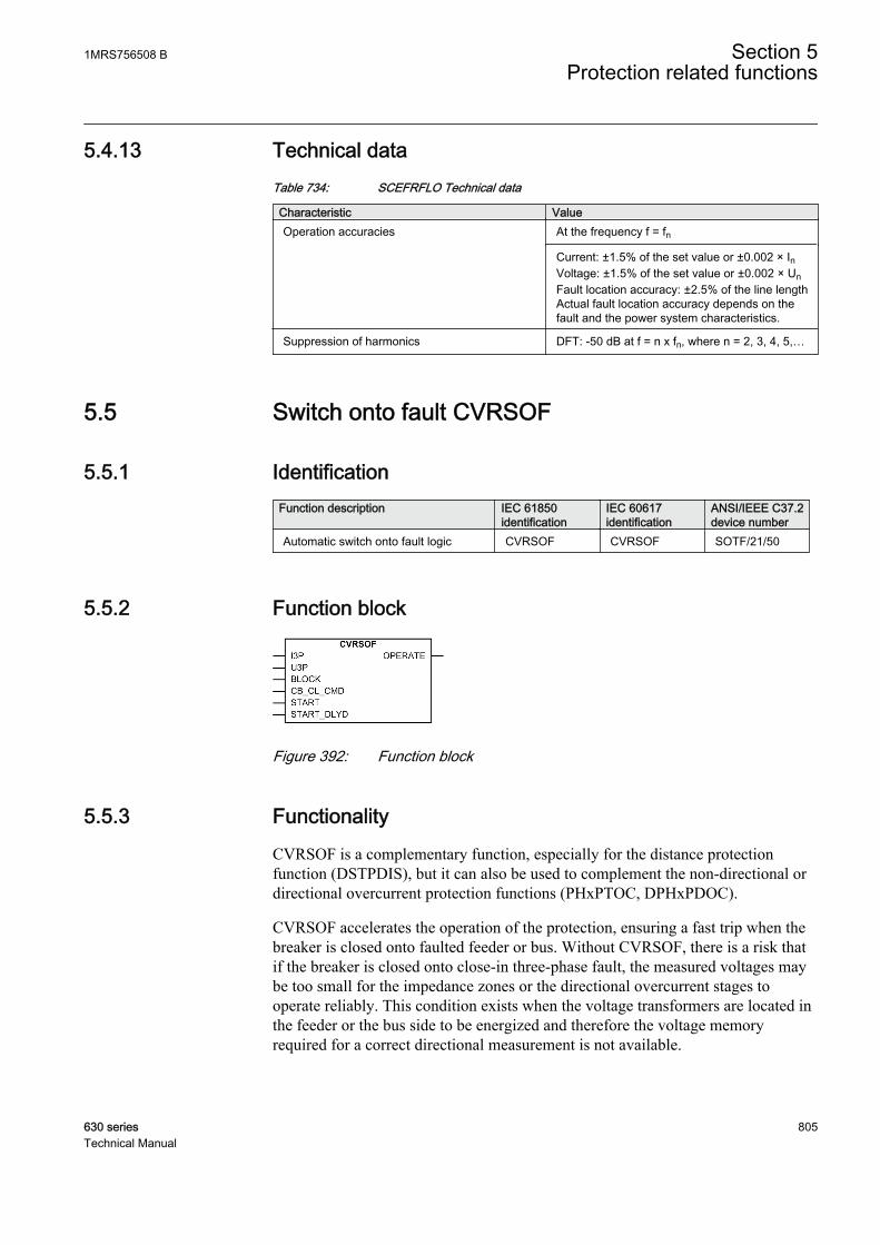
5.4.13 Technical dataTable 734: SCEFRFLO Technical data
Characteristic ValueOperation accuracies At the frequency f = fn
Current: ±1.5% of the set value or ±0.002 × InVoltage: ±1.5% of the set value or ±0.002 × UnFault location accuracy: ±2.5% of the line lengthActual fault location accuracy depends on thefault and the power system characteristics.
Suppression of harmonics DFT: -50 dB at f = n x fn, where n = 2, 3, 4, 5,…
5.5 Switch onto fault CVRSOF
5.5.1 IdentificationFunction description IEC 61850
identificationIEC 60617identification
ANSI/IEEE C37.2device number
Automatic switch onto fault logic CVRSOF CVRSOF SOTF/21/50
5.5.2 Function block
GUID-B2628196-CAD7-4628-80C7-89131D312B90 V1 EN
Figure 392: Function block
5.5.3 FunctionalityCVRSOF is a complementary function, especially for the distance protectionfunction (DSTPDIS), but it can also be used to complement the non-directional ordirectional overcurrent protection functions (PHxPTOC, DPHxPDOC).
CVRSOF accelerates the operation of the protection, ensuring a fast trip when thebreaker is closed onto faulted feeder or bus. Without CVRSOF, there is a risk thatif the breaker is closed onto close-in three-phase fault, the measured voltages maybe too small for the impedance zones or the directional overcurrent stages tooperate reliably. This condition exists when the voltage transformers are located inthe feeder or the bus side to be energized and therefore the voltage memoryrequired for a correct directional measurement is not available.
1MRS756508 B Section 5Protection related functions
630 series 805Technical Manual

5.5.4 Operation principleThe function can be enabled and disabled with the Operation setting. Thecorresponding parameter values are "On" and "Off".
The operation of automatic switch-onto-fault logic can be described by using amodule diagram. All the modules in the diagram are explained in the next sections.
GUID-4538CEF9-F0F1-4C3D-82F1-22FEF52D93DD V1 EN
Figure 393: Functional module diagram
TriggerThis module is used for detecting a possible fault immediately after circuit breakerclosing. The use of external protection function (typically the start-signal from a non-directional distance zone or overcurrent stage) is required for fault indication. TheSTART and START_DLYD inputs are available for the purpose.
• The START input has no delay. Thus, a switch-onto-fault situation isimmediately signalled to SOTF control.
• START_DLYD is used when an additional delay is required to start the signal.The switch-onto-fault situation is signalled to the SOTF control after the setOperate delay time.
Dead-line detection
The dead-line detection should be used only when the voltagetransformers are located on the line side of the circuit breaker.
Section 5 1MRS756508 BProtection related functions
806 630 seriesTechnical Manual

The Automatic SOTF Ini setting is used to configure the internal dead-linedetection function.
Table 735: Options for dead-line detection
Value of Automatic SOTF Ini Description“DLD disabled” The dead-line detection function is disabled. This
operation mode must be applied when voltagetransformers are located on the bus side of thecircuit breaker.
“Voltage” The dead-line detection function is enabled andbased solely on the undervoltage condition. Adead-line condition is declared, if all the phasevoltages are below the Voltage dead Lin Valsetting. The dead line is detected if the dead-linecondition is declared and simultaneously no faultis detected by the START and START_DLYDinputs . The dead-line condition is signalled tothe SOTF control after the delay defined with theDead line time setting.
“Current” The dead-line detection function is enabled andbased solely on the undercurrent condition. Adead-line condition is declared, if all the phasecurrents are below the Current dead Lin Valsetting. The dead line is detected if the dead-linecondition is declared and simultaneously no faultis detected by the START and START_DLYDinputs. The dead-line condition is signalled to theSOTF control after delay defined with the Deadline time setting.
“Current & Voltage” The dead-line detection function is enabled andbased on undercurrent and undervoltagecondition. A dead line condition is declared, if allthe phase currents are below the Current deadLin Val setting and simultaneously all phasevoltages are below the Voltage dead Lin Valsetting. The dead line is detected if the dead-linecondition is declared and simultaneously no faultis detected by the START and START_DLYDinputs. The dead-line condition is signalled to theSOTF control after delay defined with the Deadline time setting.
SOTF detectionThe purpose of this module is to detect the switch onto fault situation based on thecurrent and voltage measurements. If the voltage, in any of the phases, is below theVoltage dead Lin Val setting and simultaneously the current in the same phaseexceeds the Current dead Lin Val setting, the SOTF situation is signalled to SOTFcontrol module after the set Cur voltage Det time.
SOTF controlThe SOTF control module needs to be activated before the operation is possible inthe switch-onto-fault situation. There are two ways to activate the SOTF controlmodule.
1MRS756508 B Section 5Protection related functions
630 series 807Technical Manual

• By CB_CL_CMD (circuit breaker closing command) or• By the dead-line condition received from the dead-line detection module
The dead-line detection should be used only when the voltagetransformers are located on the line side of the circuit breaker.
When the CB_CL_CMD input is activated or the dead-line condition is detected, theSOTF control module becomes active. The reset timer is started whenCB_CL_CMD is inactivated or the dead-line condition disappears. Thus the modulebecomes inactive after the set SOTF reset time is exceeded.
When the SOTF control module is active, the Operation mode setting defines theoperation criteria for the detection of a switch-onto-fault condition. The detectioncan be based on the external start signals from the distance or overcurrentfunctions, or on the measured internal voltage and current levels or on both.
Table 736: Options for SOTF detection
Value of Operation mode Description“Start” The OPERATE output is activated immediately
after a signal from the trigger module. Thisindicates that the breaker is closed onto fault.
“Current & Vlotage” The OPERATE output is activated immediatelyafter a signal from the SOTF detection module.This indicates that the breaker is closed onto fault.This operation mode can be used, for example, ifthe non-directional distance zone is not available.
“Both” The OPERATE output is activated immediatelyafter a signal from the trigger or SOTF detectionmodules. This indicates that the breaker isclosed onto fault.
The OPERATE output can be blocked by activating the BLOCK input.
5.5.5 Base valuesIn this function block, some of the settings are set in per unit (pu). These pu valuesare relational to certain base values, for example the values given in A, kV andkVA. The IED supports alternative base value groups for the phase current or voltage-related settings, for example "Phase Grp 1", "Phase Grp 2" and "Phase Grp 3".One of the groups to be used with the Base value Sel phase setting must be selected.
For more information, see the Basic functions section in this manual.
Section 5 1MRS756508 BProtection related functions
808 630 seriesTechnical Manual

5.5.6 ApplicationThe operation of CVRSOF is generally based on the non-directional distance zoneor the non-directional overcurrent stage. When the feeder-side voltage transformersare used for providing the polarization quantity for the distance or directionalovercurrent protection, the use of non-directional impedance or current basedprotection for starting CVRSOF secures a fast switch-onto-fault tripping in the close-in three-phase short circuits. The non-directional protection provides a fast faultclearance when the protection is used for energizing a bus from the feeder with ashort-circuit fault in it. Other protection functions, like time delayed zero sequenceovercurrent functions, can be connected to CVRSOF to increase the dependabilityof the scheme. The other main advantage of using CVRSOF is that it typicallyaccelerates the tripping in case of energizing a feeder onto a fault. WithoutCVRSOF, this tripping is normally performed by the normal time-gradedprotection or alternatively by the time-delayed local backup protection, for whichoperate times are considerably longer than with CVRSOF tripping.
An internal dead-line detection check is provided to activate the function when thevoltage transformers are located on the feeder side. An initiation by the dead-linedetection is highly recommended for the busbar configurations where more thanone circuit breaker at one feeder end can energize the protected feeder or the feedercan also be energized from the other end.
Setting guidelinesInput START: If a distance zone is used for starting the switch-onto-fault function,the zone has to be set to cover the entire protected feeder with a safety margin ofminimum 20 percent. If the non-directional zone is not available, the internalCurrent & Voltage criterion or the start signal from the GFC function can be usedinstead. If a non-directional overcurrent is used for starting, the current setting mustnot be higher than what is required for the non-delayed and dependable tripping fora close-in three-phase fault during minimum source conditions. If the short-circuitcurrent along the feeder is considerably higher than the maximum load currents, itis possible that the whole feeder length is covered by CVRSOF tripping. If it isrequired to delay the tripping, for example, due to high inrush currents, the startingsignal can be connected to the START_DLYD input instead.
The Current dead Lin Val setting parameter is set to 20 percent of the base currentby default. The parameter must be set with a sufficient margin of 15 to 20 percentunder the minimum expected load current. The setting must still exceed themaximum charging current of a feeder.
The Voltage dead Lin Val setting parameter is set to 70 percent of the base voltageby default. This is a suitable setting in most cases, but it is recommended to checkthe suitability in the actual application.
The Cur voltage Det time setting parameter is set to 0.02 seconds by default. The issuitable in most applications. This delay can be coordinated, for example, with thedead time settings of the AR shots to prevent the release of CVRSOF by the dead-line detection function when the high speed auto-reclosing is in progress.
1MRS756508 B Section 5Protection related functions
630 series 809Technical Manual

The Dead line time setting parameter is set to 0.2 seconds by default. This issuitable in most applications. The delay must not be set too short to avoidunwanted activations during the transients in the system.
The SOTF reset time setting parameter is set to 1 second by default. This is suitablefor most applications.
5.5.7 SignalsTable 737: CVRSOF Input signals
Name Type Default DescriptionI3P GROUP
SIGNAL- Three phase group signal for current inputs
U3P GROUPSIGNAL
- Three phase group signal for voltage inputs
BLOCK BOOLEAN 0 Block of function
CB_CL_CMD BOOLEAN 0 External enabling of SOTF by CB close command
START BOOLEAN 0 Start from function to be accelerated by SOTF
START_DLYD BOOLEAN 0 Start from function to be accelerated with delayby SOTF
Table 738: CVRSOF Output signals
Name Type DescriptionOPERATE BOOLEAN Operate
5.5.8 SettingsTable 739: CVRSOF Non group settings (basic)
Name Values (Range) Unit Step Default DescriptionOperation Off
On- - On Operation Off / On
Table 740: CVRSOF Non group settings (advanced)
Name Values (Range) Unit Step Default DescriptionBase value Sel phase Phase Grp 1
Phase Grp 2Phase Grp 3
- - Phase Grp 1 Base value selector, phase / phase-to-phase
Operation mode StartCurrent&VoltageBoth
- - Both Mode of operation of SOTF Function
Automatic SOTF Ini DLD disabledVoltageCurrentCurrent & Voltage
- - DLD disabled Automatic switchonto fault initialization
Table continues on next page
Section 5 1MRS756508 BProtection related functions
810 630 seriesTechnical Manual
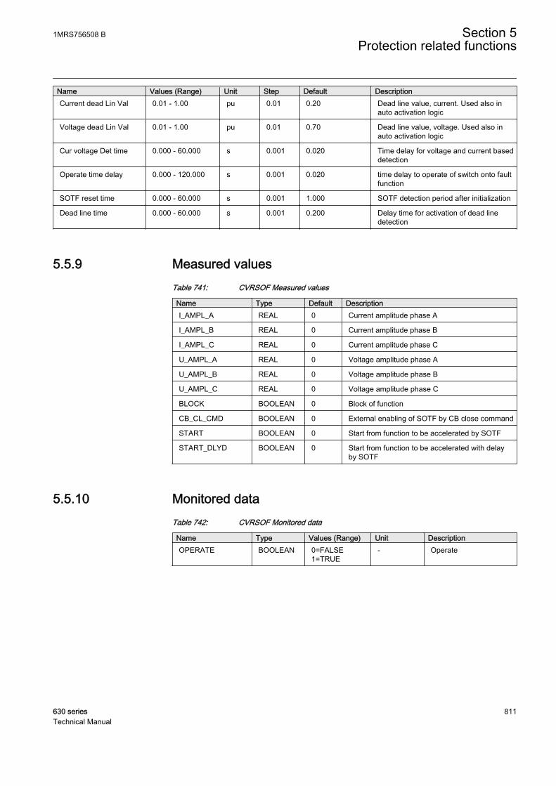
Name Values (Range) Unit Step Default DescriptionCurrent dead Lin Val 0.01 - 1.00 pu 0.01 0.20 Dead line value, current. Used also in
auto activation logic
Voltage dead Lin Val 0.01 - 1.00 pu 0.01 0.70 Dead line value, voltage. Used also inauto activation logic
Cur voltage Det time 0.000 - 60.000 s 0.001 0.020 Time delay for voltage and current baseddetection
Operate time delay 0.000 - 120.000 s 0.001 0.020 time delay to operate of switch onto faultfunction
SOTF reset time 0.000 - 60.000 s 0.001 1.000 SOTF detection period after initialization
Dead line time 0.000 - 60.000 s 0.001 0.200 Delay time for activation of dead linedetection
5.5.9 Measured valuesTable 741: CVRSOF Measured values
Name Type Default DescriptionI_AMPL_A REAL 0 Current amplitude phase A
I_AMPL_B REAL 0 Current amplitude phase B
I_AMPL_C REAL 0 Current amplitude phase C
U_AMPL_A REAL 0 Voltage amplitude phase A
U_AMPL_B REAL 0 Voltage amplitude phase B
U_AMPL_C REAL 0 Voltage amplitude phase C
BLOCK BOOLEAN 0 Block of function
CB_CL_CMD BOOLEAN 0 External enabling of SOTF by CB close command
START BOOLEAN 0 Start from function to be accelerated by SOTF
START_DLYD BOOLEAN 0 Start from function to be accelerated with delayby SOTF
5.5.10 Monitored dataTable 742: CVRSOF Monitored data
Name Type Values (Range) Unit DescriptionOPERATE BOOLEAN 0=FALSE
1=TRUE- Operate
1MRS756508 B Section 5Protection related functions
630 series 811Technical Manual
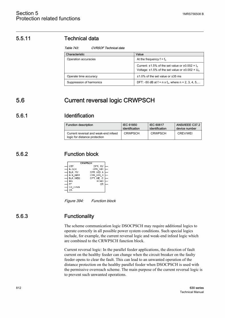
5.5.11 Technical dataTable 743: CVRSOF Technical data
Characteristic ValueOperation accuracies At the frequency f = fn
Current: ±1.5% of the set value or ±0.002 × InVoltage: ±1.5% of the set value or ±0.002 × Un
Operate time accuracy ±1.0% of the set value or ±35 ms
Suppression of harmonics DFT: -50 dB at f = n x fn, where n = 2, 3, 4, 5,…
5.6 Current reversal logic CRWPSCH
5.6.1 IdentificationFunction description IEC 61850
identificationIEC 60617identification
ANSI/IEEE C37.2device number
Current reversal and weak-end infeedlogic for distance protection
CRWPSCH CRWPSCH CREV/WEI
5.6.2 Function block
GUID-8482C3BF-061D-40F3-9E31-1361C45E41A1 V2 EN
Figure 394: Function block
5.6.3 FunctionalityThe scheme communication logic DSOCPSCH may require additional logics tooperate correctly in all possible power system conditions. Such special logicsinclude, for example, the current reversal logic and weak-end infeed logic whichare combined to the CRWPSCH function block.
Current reversal logic: In the parallel feeder applications, the direction of faultcurrent on the healthy feeder can change when the circuit breaker on the faultyfeeder opens to clear the fault. This can lead to an unwanted operation of thedistance protection on the healthy parallel feeder when DSOCPSCH is used withthe permissive overreach scheme. The main purpose of the current reversal logic isto prevent such unwanted operations.
Section 5 1MRS756508 BProtection related functions
812 630 seriesTechnical Manual

The weak-end infeed (WEI) logic: Basically, the permissive communicationschemes can operate only when the protection in the remote terminal can detect thefault. This detection requires a sufficient minimum fault current. If such current isnot available due to a too weak remote end source, the weak-end infeed logic canbe used to overcome the situation and trip the remote end breaker.
5.6.4 Operation principleThe function can be enabled and disabled with the Operation setting. Thecorresponding parameter values are "On" and "Off".
The operation of current reversal and weak-end infeed logic can be described byusing a module diagram. All the modules in the diagram are explained in the nextsections.
GUID-646B1E3C-B2C3-4614-AC7F-1E10E22ED8F8 V1 EN
Figure 395: Functional module diagram
Current reversal logicThe current reversal logic is enabled by changing the value of the Reversal modesetting to “On”.
The current reversal logic uses the start signal of the reverse looking zone (Z3)connected to the IRV input, which is used to recognize the fault being in thereverse direction, that is, in the parallel feeder. When the reverse zone is activated,after a start delay (the Reversal time setting), the logic is ready to issue anOPR_IRV output signal. The OPR_IRV signal is connected to the BLK_CS inputof the scheme communication logic function DSOCPSCH in order to block thesending of the carrier send signal (CS) and the activation of the OPERATE outputof the communication logic. The OPR_IRV signal has a drop-off delay definedwith the Reversal reset time setting.
An internal 10 ms drop-off timer is provided which secures thecurrent reversal logic to be activated for the short duration inputsignals, even if the Reversal reset time setting is set to zero.
1MRS756508 B Section 5Protection related functions
630 series 813Technical Manual

The BLK_IRV input is used to block the activation of the OPR_IRV output. TheBLK_IRV input is typically connected to the forward looking zone start signalswithin the terminal. General blocking is achieved by activating the BLOCK input.
Weak-end infeed logicThe weak-end infeed logic is used in cases where the fault current infeed is too lowdue to, for example, high source impedance or fault current distribution betweensources to activate the distance protection function. When activated, the CR signalis logically combined with the local criteria to initiate the tripping of the weak endbreaker. The received signal is also echoed back to accelerate the tripping in theopposite end with the stronger source.
GUID-8B36621F-9C58-4474-81CD-7A3F7B4A242E V1 EN
Figure 396: Functional module diagram of weak-end infeed logic
The WEI logic is enabled using the Wei mode setting.
• If Wei mode= “Off”, the WEI logic is disabled.• If Wei mode= “Echo”, the WEI logic is enabled without the trip function.• If Wei mode= “Echo & Trip”, the WEI logic is enabled with the trip function.
Level detectorThe phase-to-earth voltages are monitored and the virtual phase-to-earth voltagesare calculated inside the function. The undervoltage criteria are applied to the phase-to-phase voltages with the PPV level for Wei setting and for the phase-to-earthvoltages with the Phv level for Wei. The level detector sends an enable signal forrespective phase to the weak end trip logic when one or more voltages are belowthe corresponding settings. The level detector does blocks enable signal if all threephase voltages are above the set value more than 100 ms. This is to avoid sendingan unnecessary operate signal, if the breaker is already open.
Echo logicThe WEI logic returns the received carrier signal with the ECHO output when itreceives a CR signal under the condition that no fault has been detected by theforward and reverse looking zones and the duration of CR is longer than thecoordination time delay (setting Wei Crd time). The received carrier receive signalis also given as the CR output.
Section 5 1MRS756508 BProtection related functions
814 630 seriesTechnical Manual
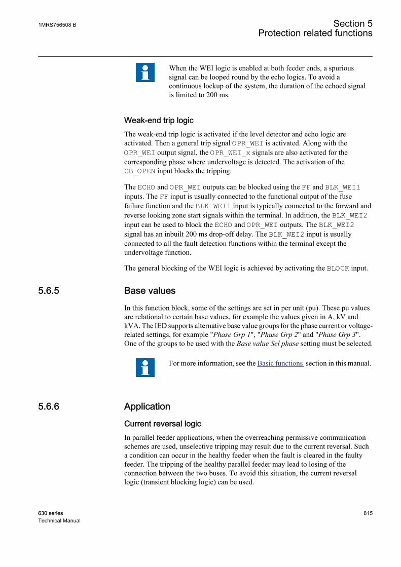
When the WEI logic is enabled at both feeder ends, a spurioussignal can be looped round by the echo logics. To avoid acontinuous lockup of the system, the duration of the echoed signalis limited to 200 ms.
Weak-end trip logicThe weak-end trip logic is activated if the level detector and echo logic areactivated. Then a general trip signal OPR_WEI is activated. Along with theOPR_WEI output signal, the OPR_WEI_x signals are also activated for thecorresponding phase where undervoltage is detected. The activation of theCB_OPEN input blocks the tripping.
The ECHO and OPR_WEI outputs can be blocked using the FF and BLK_WEI1inputs. The FF input is usually connected to the functional output of the fusefailure function and the BLK_WEI1 input is typically connected to the forward andreverse looking zone start signals within the terminal. In addition, the BLK_WEI2input can be used to block the ECHO and OPR_WEI outputs. The BLK_WEI2signal has an inbuilt 200 ms drop-off delay. The BLK_WEI2 input is usuallyconnected to all the fault detection functions within the terminal except theundervoltage function.
The general blocking of the WEI logic is achieved by activating the BLOCK input.
5.6.5 Base valuesIn this function block, some of the settings are set in per unit (pu). These pu valuesare relational to certain base values, for example the values given in A, kV andkVA. The IED supports alternative base value groups for the phase current or voltage-related settings, for example "Phase Grp 1", "Phase Grp 2" and "Phase Grp 3".One of the groups to be used with the Base value Sel phase setting must be selected.
For more information, see the Basic functions section in this manual.
5.6.6 Application
Current reversal logicIn parallel feeder applications, when the overreaching permissive communicationschemes are used, unselective tripping may result due to the current reversal. Sucha condition can occur in the healthy feeder when the fault is cleared in the faultyfeeder. The tripping of the healthy parallel feeder may lead to losing of theconnection between the two buses. To avoid this situation, the current reversallogic (transient blocking logic) can be used.
1MRS756508 B Section 5Protection related functions
630 series 815Technical Manual
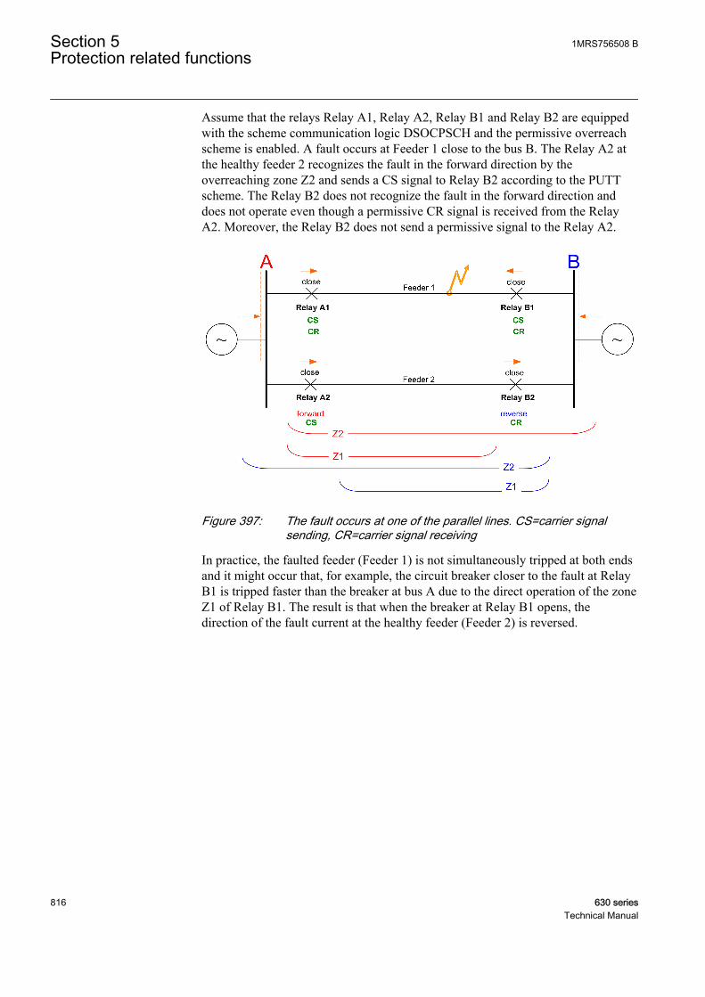
Assume that the relays Relay A1, Relay A2, Relay B1 and Relay B2 are equippedwith the scheme communication logic DSOCPSCH and the permissive overreachscheme is enabled. A fault occurs at Feeder 1 close to the bus B. The Relay A2 atthe healthy feeder 2 recognizes the fault in the forward direction by theoverreaching zone Z2 and sends a CS signal to Relay B2 according to the PUTTscheme. The Relay B2 does not recognize the fault in the forward direction anddoes not operate even though a permissive CR signal is received from the RelayA2. Moreover, the Relay B2 does not send a permissive signal to the Relay A2.
GUID-CB87B7FF-C2D1-4E9B-A5B6-C5A414E945AE V1 EN
Figure 397: The fault occurs at one of the parallel lines. CS=carrier signalsending, CR=carrier signal receiving
In practice, the faulted feeder (Feeder 1) is not simultaneously tripped at both endsand it might occur that, for example, the circuit breaker closer to the fault at RelayB1 is tripped faster than the breaker at bus A due to the direct operation of the zoneZ1 of Relay B1. The result is that when the breaker at Relay B1 opens, thedirection of the fault current at the healthy feeder (Feeder 2) is reversed.
Section 5 1MRS756508 BProtection related functions
816 630 seriesTechnical Manual
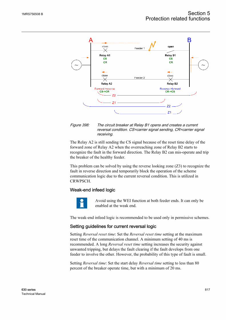
GUID-2DFEBD2E-66C2-4CE6-9B6A-DDE77894427A V1 EN
Figure 398: The circuit breaker at Relay B1 opens and creates a currentreversal condition. CS=carrier signal sending, CR=carrier signalreceiving.
The Relay A2 is still sending the CS signal because of the reset time delay of theforward zone of Relay A2 when the overreaching zone of Relay B2 starts torecognize the fault in the forward direction. The Relay B2 can mis-operate and tripthe breaker of the healthy feeder.
This problem can be solved by using the reverse looking zone (Z3) to recognize thefault in reverse direction and temporarily block the operation of the schemecommunication logic due to the current reversal condition. This is utilized inCRWPSCH.
Weak-end infeed logic
Avoid using the WEI function at both feeder ends. It can only beenabled at the weak end.
The weak-end infeed logic is recommended to be used only in permissive schemes.
Setting guidelines for current reversal logicSetting Reversal reset time: Set the Reversal reset time setting at the maximumreset time of the communication channel. A minimum setting of 40 ms isrecommended. A long Reversal reset time setting increases the security againstunwanted tripping, but delays the fault clearing if the fault develops from onefeeder to involve the other. However, the probability of this type of fault is small.
Setting Reversal time: Set the start delay Reversal time setting to less than 80percent of the breaker operate time, but with a minimum of 20 ms.
1MRS756508 B Section 5Protection related functions
630 series 817Technical Manual
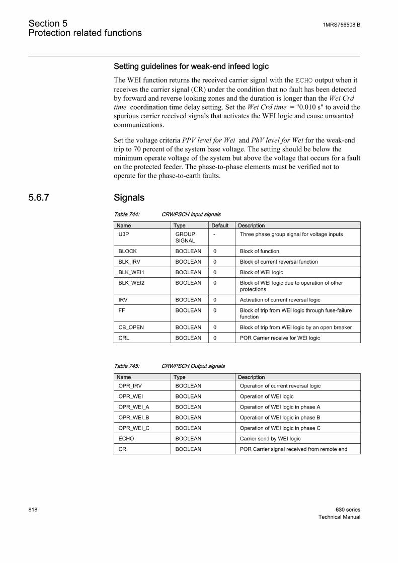
Setting guidelines for weak-end infeed logicThe WEI function returns the received carrier signal with the ECHO output when itreceives the carrier signal (CR) under the condition that no fault has been detectedby forward and reverse looking zones and the duration is longer than the Wei Crdtime coordination time delay setting. Set the Wei Crd time = "0.010 s" to avoid thespurious carrier received signals that activates the WEI logic and cause unwantedcommunications.
Set the voltage criteria PPV level for Wei and PhV level for Wei for the weak-endtrip to 70 percent of the system base voltage. The setting should be below theminimum operate voltage of the system but above the voltage that occurs for a faulton the protected feeder. The phase-to-phase elements must be verified not tooperate for the phase-to-earth faults.
5.6.7 SignalsTable 744: CRWPSCH Input signals
Name Type Default DescriptionU3P GROUP
SIGNAL- Three phase group signal for voltage inputs
BLOCK BOOLEAN 0 Block of function
BLK_IRV BOOLEAN 0 Block of current reversal function
BLK_WEI1 BOOLEAN 0 Block of WEI logic
BLK_WEI2 BOOLEAN 0 Block of WEI logic due to operation of otherprotections
IRV BOOLEAN 0 Activation of current reversal logic
FF BOOLEAN 0 Block of trip from WEI logic through fuse-failurefunction
CB_OPEN BOOLEAN 0 Block of trip from WEI logic by an open breaker
CRL BOOLEAN 0 POR Carrier receive for WEI logic
Table 745: CRWPSCH Output signals
Name Type DescriptionOPR_IRV BOOLEAN Operation of current reversal logic
OPR_WEI BOOLEAN Operation of WEI logic
OPR_WEI_A BOOLEAN Operation of WEI logic in phase A
OPR_WEI_B BOOLEAN Operation of WEI logic in phase B
OPR_WEI_C BOOLEAN Operation of WEI logic in phase C
ECHO BOOLEAN Carrier send by WEI logic
CR BOOLEAN POR Carrier signal received from remote end
Section 5 1MRS756508 BProtection related functions
818 630 seriesTechnical Manual

5.6.8 SettingsTable 746: CRWPSCH Non group settings (basic)
Name Values (Range) Unit Step Default DescriptionOperation Off
On- - On Operation Off / On
Reversal mode OffOn
- - Off Operating mode of Current ReversalLogic
Wei mode OffEchoEcho & Trip
- - Off Operating mode of WEI logic
PhV level for Wei 0.10 - 0.90 pu 0.01 0.70 Phase to Neutral voltage for detection offault condition
PPV level for Wei 0.10 - 0.90 pu 0.01 0.70 Phase to Phase voltage for detection offault condition
Reversal time 0.000 - 60.000 s 0.001 0.020 Pickup time for current reversal logic
Reversal reset time 0.000 - 60.000 s 0.001 0.060 Time Delay to prevent Carrier send andlocal trip
Wei Crd time 0.000 - 60.000 s 0.001 0.010 Coordination time for the WEI logic
Table 747: CRWPSCH Non group settings (advanced)
Name Values (Range) Unit Step Default DescriptionBase value Sel phase Phase Grp 1
Phase Grp 2Phase Grp 3
- - Phase Grp 1 Base value selector, phase / phase-to-phase
5.6.9 Measured valuesTable 748: CRWPSCH Measured values
Name Type Default DescriptionU_AMPL_A REAL 100 Phase to ground voltage phase A
U_AMPL_B REAL 100 Phase to ground voltage phase B
U_AMPL_C REAL 100 Phase to ground voltage phase C
BLOCK BOOLEAN 0 Block of function
BLK_IRV BOOLEAN 0 Block of current reversal function
BLK_WEI1 BOOLEAN 0 Block of WEI logic
BLK_WEI2 BOOLEAN 0 Block of WEI logic due to operation of otherprotections
IRV BOOLEAN 0 Activation of current reversal logic
FF BOOLEAN 0 Block of trip from WEI logic through fuse-failurefunction
CB_OPEN BOOLEAN 0 Block of trip from WEI logic by an open breaker
CRL BOOLEAN 0 POR Carrier receive for WEI logic
1MRS756508 B Section 5Protection related functions
630 series 819Technical Manual
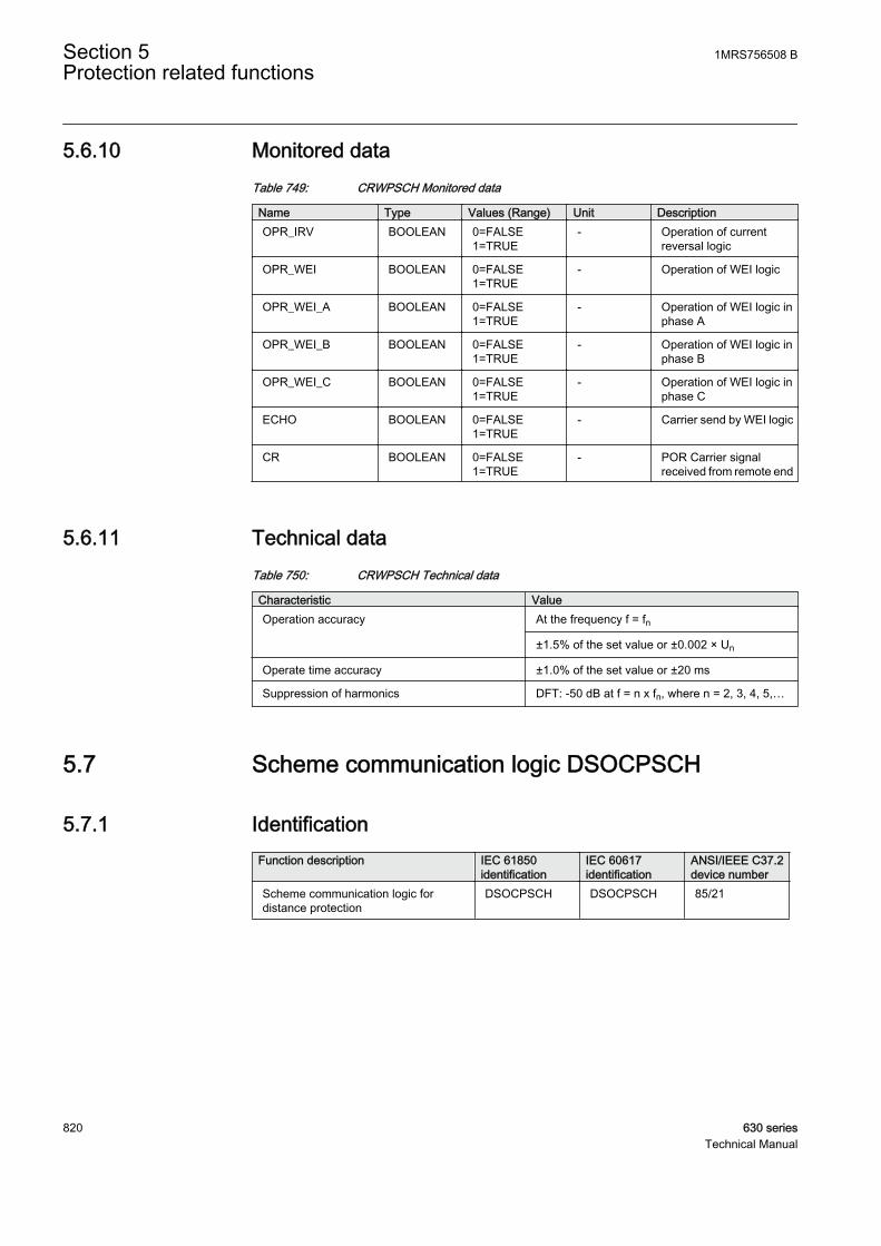
5.6.10 Monitored dataTable 749: CRWPSCH Monitored data
Name Type Values (Range) Unit DescriptionOPR_IRV BOOLEAN 0=FALSE
1=TRUE- Operation of current
reversal logic
OPR_WEI BOOLEAN 0=FALSE1=TRUE
- Operation of WEI logic
OPR_WEI_A BOOLEAN 0=FALSE1=TRUE
- Operation of WEI logic inphase A
OPR_WEI_B BOOLEAN 0=FALSE1=TRUE
- Operation of WEI logic inphase B
OPR_WEI_C BOOLEAN 0=FALSE1=TRUE
- Operation of WEI logic inphase C
ECHO BOOLEAN 0=FALSE1=TRUE
- Carrier send by WEI logic
CR BOOLEAN 0=FALSE1=TRUE
- POR Carrier signalreceived from remote end
5.6.11 Technical dataTable 750: CRWPSCH Technical data
Characteristic ValueOperation accuracy At the frequency f = fn
±1.5% of the set value or ±0.002 × Un
Operate time accuracy ±1.0% of the set value or ±20 ms
Suppression of harmonics DFT: -50 dB at f = n x fn, where n = 2, 3, 4, 5,…
5.7 Scheme communication logic DSOCPSCH
5.7.1 IdentificationFunction description IEC 61850
identificationIEC 60617identification
ANSI/IEEE C37.2device number
Scheme communication logic fordistance protection
DSOCPSCH DSOCPSCH 85/21
Section 5 1MRS756508 BProtection related functions
820 630 seriesTechnical Manual
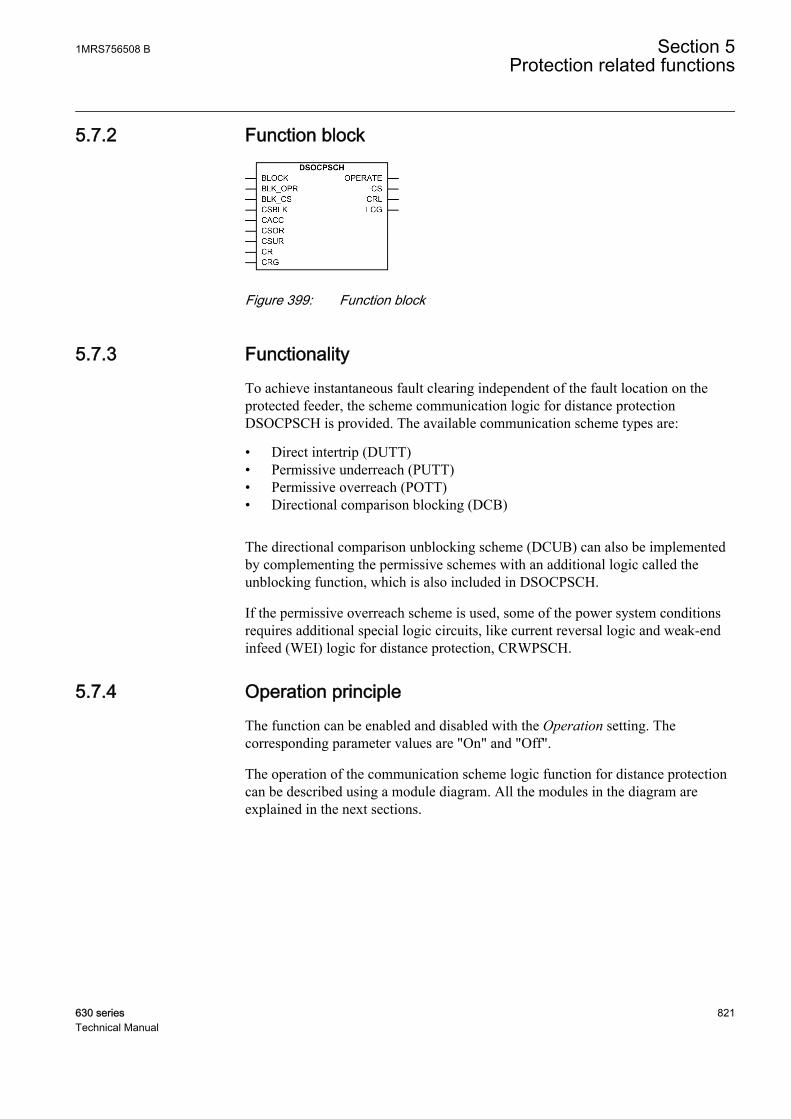
5.7.2 Function block
GUID-ACBB51BD-3020-435C-9D85-006FEC90C795 V1 EN
Figure 399: Function block
5.7.3 FunctionalityTo achieve instantaneous fault clearing independent of the fault location on theprotected feeder, the scheme communication logic for distance protectionDSOCPSCH is provided. The available communication scheme types are:
• Direct intertrip (DUTT)• Permissive underreach (PUTT)• Permissive overreach (POTT)• Directional comparison blocking (DCB)
The directional comparison unblocking scheme (DCUB) can also be implementedby complementing the permissive schemes with an additional logic called theunblocking function, which is also included in DSOCPSCH.
If the permissive overreach scheme is used, some of the power system conditionsrequires additional special logic circuits, like current reversal logic and weak-endinfeed (WEI) logic for distance protection, CRWPSCH.
5.7.4 Operation principleThe function can be enabled and disabled with the Operation setting. Thecorresponding parameter values are "On" and "Off".
The operation of the communication scheme logic function for distance protectioncan be described using a module diagram. All the modules in the diagram areexplained in the next sections.
1MRS756508 B Section 5Protection related functions
630 series 821Technical Manual
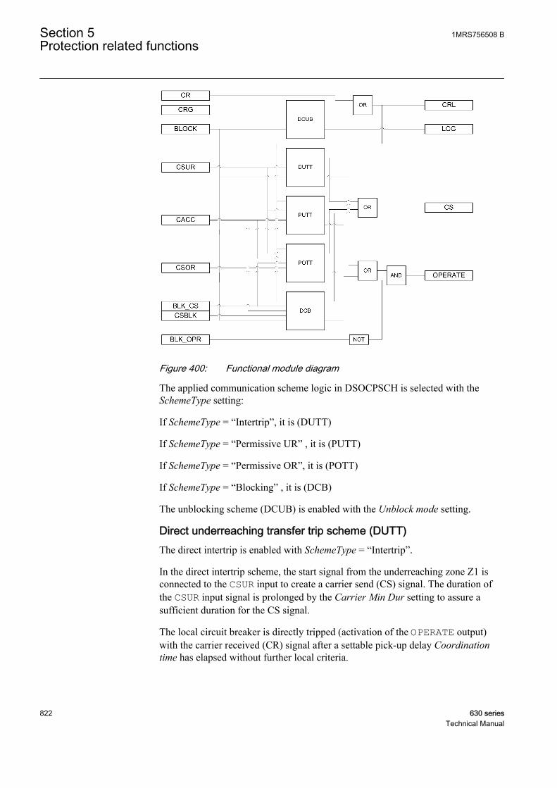
GUID-F7DC90D5-9A80-4369-ADBE-556D227AF6ED V1 EN
Figure 400: Functional module diagram
The applied communication scheme logic in DSOCPSCH is selected with theSchemeType setting:
If SchemeType = “Intertrip”, it is (DUTT)
If SchemeType = “Permissive UR” , it is (PUTT)
If SchemeType = “Permissive OR”, it is (POTT)
If SchemeType = “Blocking” , it is (DCB)
The unblocking scheme (DCUB) is enabled with the Unblock mode setting.
Direct underreaching transfer trip scheme (DUTT)The direct intertrip is enabled with SchemeType = “Intertrip”.
In the direct intertrip scheme, the start signal from the underreaching zone Z1 isconnected to the CSUR input to create a carrier send (CS) signal. The duration ofthe CSUR input signal is prolonged by the Carrier Min Dur setting to assure asufficient duration for the CS signal.
The local circuit breaker is directly tripped (activation of the OPERATE output)with the carrier received (CR) signal after a settable pick-up delay Coordinationtime has elapsed without further local criteria.
Section 5 1MRS756508 BProtection related functions
822 630 seriesTechnical Manual
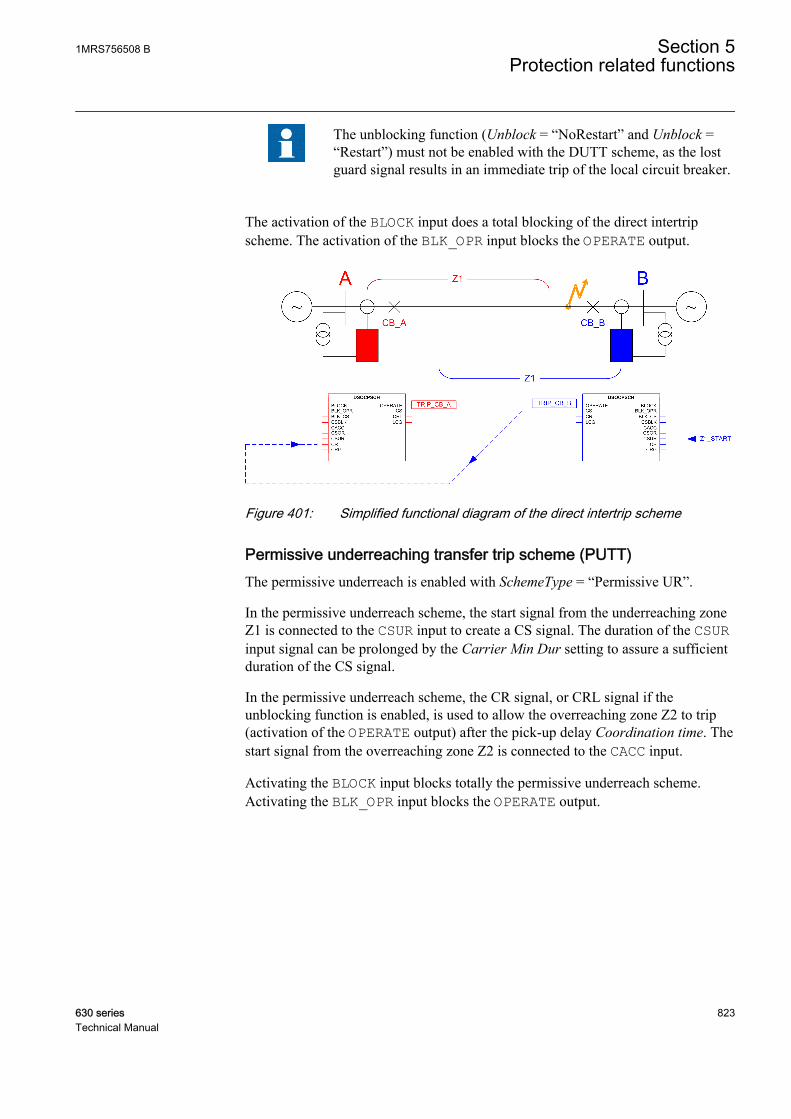
The unblocking function (Unblock = “NoRestart” and Unblock =“Restart”) must not be enabled with the DUTT scheme, as the lostguard signal results in an immediate trip of the local circuit breaker.
The activation of the BLOCK input does a total blocking of the direct intertripscheme. The activation of the BLK_OPR input blocks the OPERATE output.
GUID-E5832505-6E03-4A5E-909E-2E587BE67B8E V1 EN
Figure 401: Simplified functional diagram of the direct intertrip scheme
Permissive underreaching transfer trip scheme (PUTT)The permissive underreach is enabled with SchemeType = “Permissive UR”.
In the permissive underreach scheme, the start signal from the underreaching zoneZ1 is connected to the CSUR input to create a CS signal. The duration of the CSURinput signal can be prolonged by the Carrier Min Dur setting to assure a sufficientduration of the CS signal.
In the permissive underreach scheme, the CR signal, or CRL signal if theunblocking function is enabled, is used to allow the overreaching zone Z2 to trip(activation of the OPERATE output) after the pick-up delay Coordination time. Thestart signal from the overreaching zone Z2 is connected to the CACC input.
Activating the BLOCK input blocks totally the permissive underreach scheme.Activating the BLK_OPR input blocks the OPERATE output.
1MRS756508 B Section 5Protection related functions
630 series 823Technical Manual

GUID-5FEFC0F6-0EC3-4256-8BC5-6A72DDE4E07A V1 EN
Figure 402: Simplified functional diagram of permissive underreach scheme
POTT (Permissive overrreaching transfer trip scheme)The permissive overreach is enabled with SchemeType = “Permissive OR”.
In the permissive overreach scheme, the start signal from the overreaching zone Z2is connected to the CSOR input to create a CS signal. The CS signal can also beissued simultaneously from the underreaching zone Z1. In this case, the start signalfrom the underreaching zone Z1 is connected to the CSUR input. The duration ofthe CSUR input signal is prolonged by the Carrier Min Dur setting, to assure asufficient duration of the CS signal. The carrier send from CSOR overreaching zonecan be blocked with the BLK_CS input.
In case of the parallel feeders, and when the external currentreversal logic (CRWPSCH) is enabled, the CS signal is notprolonged and the value of Carrier Min Dur is set to zero in tosecure correct operation.
In the permissive overreach scheme, the received signal CR or CRL, if unblockingfunction is enabled used to allow the overreaching zone Z2 to trip (activation of theOPERATE output) after the settable pick-up delay Coordination time. The startsignal from the overreaching zone is connected to the CACC input.
Activating the BLOCK input blocks totally the permissive overreach scheme.Activating the BLK_OPR input blocks the OPERATE output.
Section 5 1MRS756508 BProtection related functions
824 630 seriesTechnical Manual

GUID-4923C51C-075A-4E73-BA47-3321511AFF6D V1 EN
Figure 403: Simplified functional diagram of permissive overreach scheme
Directional comparison blocking scheme (DCB)The directional comparison blocking scheme is enabled with SchemeType =“Blocking”.
In the blocking scheme, the start signal from the reverse looking zone Z3 isconnected to the CSBLK input in to create a CS signal. The starting of the reverselooking zone indicates that the fault is located outside the protected feeder. Theduration of the CSBLK input signal can be prolonged with the Carrier Min Dursetting to assure a sufficient duration of the CS signal. The CS signal from theCSBLK reverse zone can be blocked with the BLK_CS input.
The principal operation of the blocking scheme is that the overreaching zone Z2 isallowed to trip (activation of the OPERATE output) after the settable Coordinationtime has elapsed, and if no blocking signal is received from the remote terminal. Toprevent a false trip in case of an external fault, the block signal (CR) must bereceived before the Coordination time has elapsed. The start signal from theoverreaching zone Z2 is connected to the CACC input.
The Coordination time setting in the blocking scheme depends, forexample, on communication system delay and on the terminalresponse times in transmitting the CS signal to the other feeder end.The Coordination time setting must not be zero.
Activating the BLOCK input blocks totally the permissive overreach scheme.Activating the BLK_OPR input blocks the OPERATE output.
1MRS756508 B Section 5Protection related functions
630 series 825Technical Manual

GUID-BB454B55-19FA-4AB3-B3D2-43D8698A65D1 V1 EN
Figure 404: Simplified functional diagram of the blocking scheme, internal fault.The CS signal is not sent as the fault is not seen by the reverse-looking zones (Z3).
GUID-631F4D44-A77C-4C20-9671-863FF9D258DC V1 EN
Figure 405: Simplified functional diagram of the blocking scheme, externalfault. The IED at bus B sees the fault in the reverse direction andsends a blocking signal (CS) to the IED at bus A. There is no CBoperation at either end.
The unblocking function used with the blocking function provides a possibility tosupervise the communication channel. In this case, the CRL output signal is used asa local blocking signal.
Section 5 1MRS756508 BProtection related functions
826 630 seriesTechnical Manual
The operation mode Unblock = “Restart” is not recommended asthe blocking is activated only for 150 ms after the guard signaldisappears. This results in an unwanted operation of the protection.
DCUB (Directional Comparison Unblocking)The unblocking function is a complementary logic, which can be used togetherwith the permissive communication schemes. In the unblocking scheme, thedependability of the permissive schemes is improved by using the loss of guardsignal from the communication equipment to create locally a CRL output signal.This enables the permissive scheme to operate even if the communication channelis interrupted or lost.
The unblocking function uses a carrier guard signal (CRG), which must always bepresent. The absence of the CRG signal for a time longer than the value of the Lossof carrier time setting is used to generate a logical CRL signal. This enables thepermissive scheme to operate despite the loss of the communication channel. Acommunication failure shorter than the value of the Loss of carrier time setting isalways ignored.
The unblocking function is configured with the Unblock setting :
• Unblock = “Off”: The unblocking function is disabled.• Unblock = “NoRestart”: If the CRG signal disappears for a longer time than
defined in the Loss of carrier time setting. The logical CRL signal is generated.The CRL output signal is kept up until the CRG signal is present again. Thecommunication failure is not signaled by the LCG output.
• Unblock = “Restart”: If the CRG signal disappears for a longer time thandefined in the Loss of carrier time setting, theCRL output signal is generated.The CRL output signal is kept up for 150 ms, after which a communicationfailure is signaled by the LCG output. The LCG output is reset 200 ms after theCRG signal is present again. The purpose of this mode is to ensure trippingduring a fixed delay of 150 ms after the loss of communication due to possibleconsequences of an internal fault. After this time, the accelerated tripping isallowed only if the actual CR signal is received again.
With operation modes Unblock = “NoRestart” and Unblock = “Restart” the createdCRL output signal is internally ORed with the CR input to allow the permissivescheme to operate even when the communication channel has been interrupted orlost. The CRL and LCG output signals are also available as outputs for monitoringpurposes. Activating the BLOCK input blocks the CRL and LCG outputs.
5.7.5 ApplicationTo achieve fast fault clearing for the fault on the part of the protected feeder notcovered by the instantaneous zone, Z1, the stepped distance protection function canbe supported with DSOCPSCH.
1MRS756508 B Section 5Protection related functions
630 series 827Technical Manual
Applying DSOCPSCH requires a communication channel capable of transmittingan "On" or "Off" signal in each direction. To enable fast tripping, the mostimportant requirement for communication channel is the communication speed.
The performance of DSOCPSCH is directly related to the communication channelspeed, and to the security against false or lost signals. Therefore, dedicatedcommunication channels are recommended. With short distances up to a fewkilometers, a typical communication media is a simple pilot wire based onauxiliary power. With distances up to 150 km, the fibre-optic cables utilizing thedigital data transmission can be used. To avoid false signals causing unwantedoperation, the security of the communication channel should be emphasized. It isalso important to pay attention to the dependability of the communication channelto ensure that the signals are reliably transmitted during the power system faults.
Communication schemes supported by DSOCPSCH:
• Direct underreaching transfer trip, DUTT• Permissive underreaching transfer trip, PUTT• Permissive overreaching transfer trip, POTT• Directional comparison blocking scheme, DCB• Directional comparison unblocking scheme, DCUB
Depending on whether the communication channel is used for sending a block or atrip signal, the communication schemes can be divided into blocking schemes andpermissive schemes.
In permissive schemes, the trip signals of the distance zones are interchangedbetween the terminals to receive a permission to trip during an internal fault. Thetripping of the local terminal depends on both the starting of its own forward-looking zone, and on the received signal from the opposite terminal. In theunderreaching scheme, no signals are sent during an external fault. During anexternal fault, a trip signal is also sent to the opposite terminal ff the fault is seen inthe forward direction and the overreaching scheme is used. However, in case ofexternal faults, tripping is always blocked because either no signal is received asthe opposite terminal sees a reverse fault, or because the signal is received but thefault is seen in the reverse direction. In either case, the blocking is not dependenton the received signal so that a lost communication channel would not result infalse operation.
In the blocking scheme, a blocking signal is sent to the opposite terminal if thefault is locally seen in the reverse direction, that is, during an external fault. Thus,the blocking is dependent on the received signal, and there is typically a need todelay the tripping of the terminal receiving the blocking signal. This delay depends,for example, on the response times of the communication channel and terminals.During an internal fault, there is no signal transmission between the terminals.Thereby the tripping does not depend on the received signal from the oppositeterminal.
In conclusion, when compared to the blocking schemes, the permissive schemesare inherently faster and have better security** against false tripping, since tripping
Section 5 1MRS756508 BProtection related functions
828 630 seriesTechnical Manual
in an external fault is not possible in case of a channel interruption. In a blockingscheme, a lost communication channel simultaneously with an external fault maylead to a false operation of the protection if the communication channel is not beingsupervised. On the other hand, as the fast trip of the permissive scheme depends onthe received signal, its dependability*** is lower than that of the blocking scheme.[1] [2]
The unblocking scheme is also available to enhance the dependability of thepermissive scheme. If the communication channel is interrupted, andsimultaneously a fault occurs in the forward direction within that time, tripping isstill possible either during a fixed time interval counting from the beginning of theinterruption, or for as long as the communication channel is lost. This is achievedby connecting the supervision output of the implemented communicationfunctionality to the dedicated carrier guard signal input of DSOCPSCH. In general,the unblocking scheme provides better security than the blocking scheme becausetripping in external faults is only possible if the fault occurs within the fixed timeinterval from the beginning of the channel interruption..
The direct transfer trip scheme uses the underreaching zone to trip the local breakerand to transfer the trip signal to a remote terminal. The remote terminal operatesimmediately based on the received transfer trip signal, without any additionalconditions. This scheme is very simple, but the security is low as a spurious signalresults in false operation of the protection.
Direct intertripIn some applications, there is a need to trip the remote-end breaker immediatelybased on fault detection by the local measurements. This applies, for example,when the transformers or reactors are connected to the system without circuitbreakers, or for remote tripping after the operation of the local breaker failureprotection (CBFP).
In the direct intertrip scheme (DUTT), the carrier send signal (CS) is initiated by anunderreaching zone, or by the tripping signal from an external IED, such astransformer or reactor protection. At the remote end, the received signals initiates abreaker trip immediately without any further local protection criteria. To limit therisk for unwanted trip due to spurious sending of signals, the trip can be delayed bythe Coordination time setting, which should be set to 10...30 ms, depending on thetype of the communication channel. The general requirement for implementing thecommunication channel operating in direct inter tripping applications is that itshould be very secure and dependable.
Setting guidelines for the intertrip scheme, DUTT:
Scheme type = "Intertrip"
Coordination time = "0.050" s (10 ms + maximal transmission time)
[1] ** security = The ability to block operation in case of an external fault[2] *** dependability = The ability to operate in case of an internal fault
1MRS756508 B Section 5Protection related functions
630 series 829Technical Manual

Carrier Min Dur = "0.1" s
Permissive underreach schemeIn permissive underreach scheme, the permission to trip is obtained locally fromthe underreaching zone and sent to the remote end. The received signal iscombined again with the local fault indication from the overreaching zone resultingto trip command after a settable pick-up delay Coordination time.
In the permissive underreach scheme, the IED of either feeder end sends apermissive signal to trip the other end. The communication channel needs to beable to receive and transmit at the same time. In permissive schemes, a generalrequirement for the communication channel is that it must be fast and secure, butalso dependable. Inadequate security causes the unwanted tripping for the externalfaults. Inadequate speed or dependability causes delayed tripping for internal faults.
In the permissive underreach scheme, the CS signal is issued based on theunderreaching zone, Z1.
The underreach scheme is not applicable on short feeder lengths due to thedifficulties in the impedance measurement to distinguish between the internal andexternal faults in such cases.
The underreaching zones (Z1) at local and remote end must overlap to prevent agap between the protection zones, where the faults would not be detected. If theunderreaching zone does not meet the required sensitivity, for example, the faultinfeed from a remote end, the blocking or permissive overreach scheme is considered.
To achieve an instantaneous trip, the carrier received signal (CR) must be receivedwhen the overreaching zone, Z2, is still starting . In some cases, due to a fault incurrent distribution, the overreaching zone can operate only after the fault has beencleared by the remote terminal. In this case, there is certain risk that in case theremote terminal is tripped directly by, for example, the zone Z1, the CS signalissued by the zone resets before the overreaching zone of the local end terminal hasoperated. To assure a sufficient duration of the CR signal, the CS signal can beprolonged by the time Carrier Min Dur. The recommended value of the CarrierMin Dur setting is "0.1" s.
The received communication signal is combined with the output from the localoverreaching zone. Therefore, there is less concern for false signal causing anincorrect trip, and therefore the timer Coordination time is set to "0". Acommunication channel failure does not affect the selectivity, but delays thetripping at the other end for certain fault locations.
Setting guidelines for the permissive underreach scheme, PUTT:
Scheme type = "Permissive UR"
Coordination time = "0" s
Carrier Min Dur = "0.1" s
Section 5 1MRS756508 BProtection related functions
830 630 seriesTechnical Manual
Permissive overreach schemeIn permissive overreach scheme, the permission to trip is obtained locally from anoverreaching zone and sent to the remote end. The received signal is thencombined with the local fault indication from the overreaching zone, resulting intrip command after a settable pick-up delay Coordination time.
In the permissive overreach scheme, the IED at either end of the feeder sends apermissive signal to trip the other end. Therefore the communication channel mustbe able to receive and transmit at the same time. A general requirement for thecommunication on permissive schemes is that it should be fast and secure.
In the permissive overreach scheme, the CS signal is issued based on theoverreaching zone, Z2.
The permissive overreach scheme can be used for all feeder types and lengths.
In the permissive overreach scheme, the communication channel plays an essentialrole in obtaining a fast tripping at both ends. Typically, a lost communicationchannel does not cause false tripping. However, it delays the operation of theprotection for the faults anywhere on the feeder.
The communication channel for a permissive overreach scheme must be fast andsecure, but also dependable. Inadequate security can cause unwanted tripping forexternal faults. Inadequate speed or dependability can cause delayed tripping forinternal faults.
In the permissive overreaching scheme, the CS signal can be issued in parallel bothfrom the overreaching and underreaching zones. The CS signal from theoverreaching zone must not be prolonged, while the CS signal from theunderreaching zone must typically be prolonged. In parallel feeder applications, thescheme typically needs to be complemented by the current reversal logic. Toensure the correct operation in this case, the CS signal shall not be prolonged(Carrier Min Dur = "0" s). There is no need to delay the tripping while receivingthe carrier signal, so set the timer Coordination time to "0".
Setting guidelines for the permissive overreaching transfer trip scheme, POTT:
Scheme type = "Permissive OR"
Coordination time = "0" s
Carrier Min Dur = "0.1" s
Carrier Min Dur = "0" s (in case of parallel lines and current reversal logic)
Directional comparison blocking schemeIn the blocking scheme, the reverse-looking zone, Z3, is used for sending a blocksignal to the remote end to block the overreaching zone.
1MRS756508 B Section 5Protection related functions
630 series 831Technical Manual
The blocking scheme is very dependable because it operates on faults anywhere onthe protected feeder, even if the communication channel is out of service.Conversely, it is less secure than a permissive scheme because it trips for externalfaults within the reach of the overreaching local zone, in case the communicationchannel is out of service and no block signal is received.
Inadequate speed or low dependability of the communication channel can causespurious tripping for external faults.
To secure that the blocking signal has time to arrive before the local overreachingzone trips, the trip is delayed by the Coordination time setting. The Coordinationtime setting must be set longer than the maximal transmission time of the channeladded by the start and response times of the IEDs sending and receiving the CSsignal. A security margin of at least 10 ms should be considered. The time delayCarrier Min Dur for prolonging the CS signal is set to "0".
Setting guidelines for the blocking scheme, DCB:
Scheme type = "Blocking"
Coordination time = "0.1" s (10 ms + maximal transmission time)
Carrier Min Dur = "0" s
Directional comparison unblocking schemeMetallic communication paths unfavourably affected by fault-generated noise or byother electrical phenomena, such as lightning, are not suitable for conventionalpermissive schemes that rely on the signal transmitted during a fault in theprotected feeder. Principally, the communication media must be properly shieldedor otherwise designed to provide an adequate performance during such conditions.
In general, to overcome the lower dependability of permissive schemes, theunblocking scheme can be used. The function is used at older, less reliablecommunication, where the signal has to be sent through the primary fault. Theunblocking function uses a carrier guard signal (CRG) which must always bepresent, even when no CR signal is received. Due to the absence of the CRG signalduring the security time, the Loss of carrier time setting is used as a CR signal.This also enables a permissive scheme to operate when the communication channelis temporarily lost during an internal fault.
Setting guidelines for the unblocking scheme, DCUB:
The unblocking function is configured with the Unblock setting:
• Unblock = “Off”: The unblocking function is disabled• Unblock = “NoRestart”: If the CRG signal disappears for a longer time period
defined in the Loss of carrier time setting, a logical carrier received signal(CRL) is generated. The CRL signal is kept up until the CRG signal is present.
Section 5 1MRS756508 BProtection related functions
832 630 seriesTechnical Manual
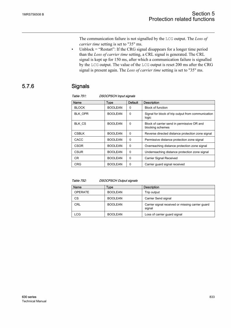
The communication failure is not signalled by the LCG output. The Loss ofcarrier time setting is set to "35" ms.
• Unblock = “Restart”: If the CRG signal disappears for a longer time periodthan the Loss of carrier time setting, a CRL signal is generated. The CRLsignal is kept up for 150 ms, after which a communication failure is signalledby the LCG output. The value of the LCG output is reset 200 ms after the CRGsignal is present again. The Loss of carrier time setting is set to "35" ms.
5.7.6 SignalsTable 751: DSOCPSCH Input signals
Name Type Default DescriptionBLOCK BOOLEAN 0 Block of function
BLK_OPR BOOLEAN 0 Signal for block of trip output from communicationlogic
BLK_CS BOOLEAN 0 Block of carrier send in permissive OR andblocking schemes
CSBLK BOOLEAN 0 Reverse directed distance protection zone signal
CACC BOOLEAN 0 Permissive distance protection zone signal
CSOR BOOLEAN 0 Overreaching distance protection zone signal
CSUR BOOLEAN 0 Underreaching distance protection zone signal
CR BOOLEAN 0 Carrier Signal Received
CRG BOOLEAN 0 Carrier guard signal received
Table 752: DSOCPSCH Output signals
Name Type DescriptionOPERATE BOOLEAN Trip output
CS BOOLEAN Carrier Send signal
CRL BOOLEAN Carrier signal received or missing carrier guardsignal
LCG BOOLEAN Loss of carrier guard signal
1MRS756508 B Section 5Protection related functions
630 series 833Technical Manual

5.7.7 SettingsTable 753: DSOCPSCH Non group settings (basic)
Name Values (Range) Unit Step Default DescriptionOperation Off
On- - On Operation Off / On
Scheme type OffIntertripPermissive URPermissive ORBlocking
- - Permissive UR Scheme type
Coordination time 0.000 - 60.000 s 0.001 0.035 Communication scheme coordinationtime
Carrier Min Dur 0.000 - 60.000 s 0.001 0.100 Minimum duration of a carrier send signal
Table 754: DSOCPSCH Non group settings (advanced)
Name Values (Range) Unit Step Default DescriptionLoss of carrier time 0.000 - 60.000 s 0.001 0.035 Security timer for loss of carrier guard
detection
Unblock mode OffNoRestartRestart
- - Off Operation mode of unblocking logic
5.7.8 Measured valuesTable 755: DSOCPSCH Measured values
Name Type Default DescriptionBLOCK BOOLEAN 0 Block of function
BLK_OPR BOOLEAN 0 Signal for block of trip output from communicationlogic
BLK_CS BOOLEAN 0 Block of carrier send in permissive OR andblocking schemes
CSBLK BOOLEAN 0 Reverse directed distance protection zone signal
CACC BOOLEAN 0 Permissive distance protection zone signal
CSOR BOOLEAN 0 Overreaching distance protection zone signal
CSUR BOOLEAN 0 Underreaching distance protection zone signal
CR BOOLEAN 0 Carrier Signal Received
CRG BOOLEAN 0 Carrier guard signal received
Section 5 1MRS756508 BProtection related functions
834 630 seriesTechnical Manual

5.7.9 Monitored dataTable 756: DSOCPSCH Monitored data
Name Type Values (Range) Unit DescriptionOPERATE BOOLEAN 0=FALSE
1=TRUE- Trip output
CS BOOLEAN 0=FALSE1=TRUE
- Carrier Send signal
CRL BOOLEAN 0=FALSE1=TRUE
- Carrier signal receivedor missing carrier guardsignal
LCG BOOLEAN 0=FALSE1=TRUE
- Loss of carrier guardsignal
5.7.10 Technical dataTable 757: DSOCPSCH Technical data
Characteristic ValueOperate time accuracy ±1.0% of the set value or ±20 ms
5.8 Local acceleration logic DSTPLAL
5.8.1 IdentificationFunction description IEC 61850
identificationIEC 60617identification
ANSI/IEEE C37.2device number
Local acceleration logic function DSTPLAL DSTPLAL LAL/21
5.8.2 Function block
GUID-975CAB39-678F-488F-A8F0-A8357005F805 V1 EN
Figure 406: Function block
1MRS756508 B Section 5Protection related functions
630 series 835Technical Manual
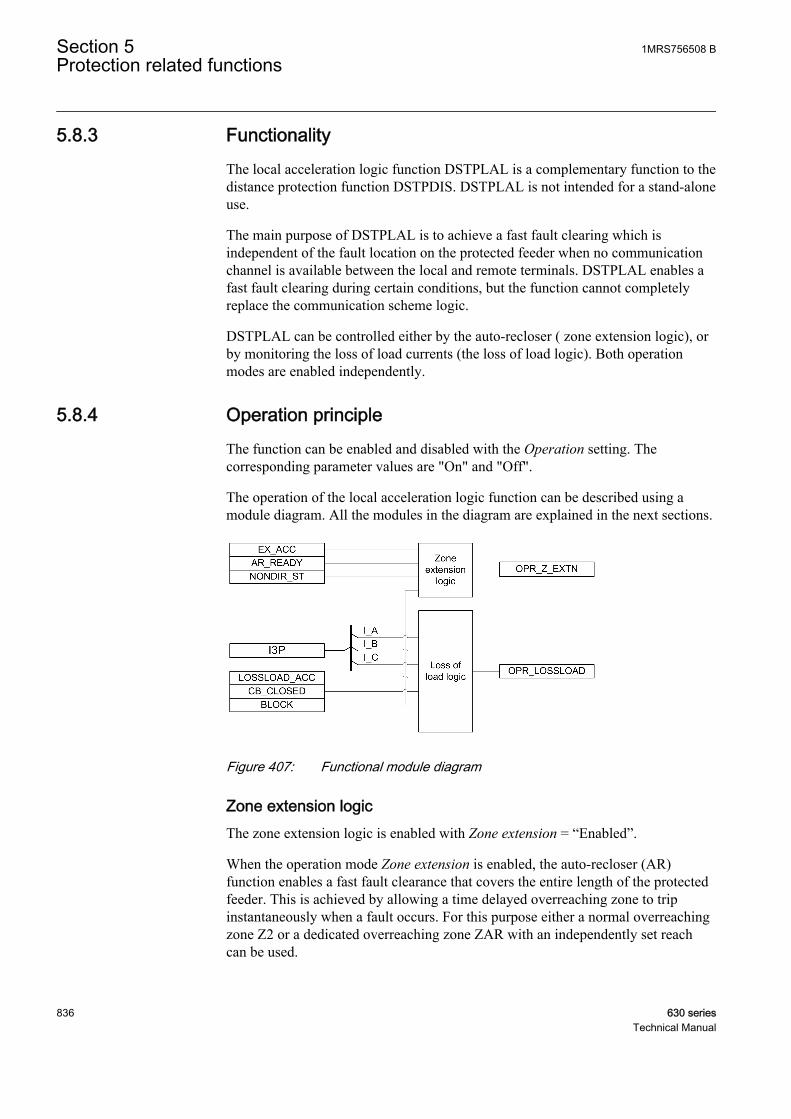
5.8.3 FunctionalityThe local acceleration logic function DSTPLAL is a complementary function to thedistance protection function DSTPDIS. DSTPLAL is not intended for a stand-aloneuse.
The main purpose of DSTPLAL is to achieve a fast fault clearing which isindependent of the fault location on the protected feeder when no communicationchannel is available between the local and remote terminals. DSTPLAL enables afast fault clearing during certain conditions, but the function cannot completelyreplace the communication scheme logic.
DSTPLAL can be controlled either by the auto-recloser ( zone extension logic), orby monitoring the loss of load currents (the loss of load logic). Both operationmodes are enabled independently.
5.8.4 Operation principleThe function can be enabled and disabled with the Operation setting. Thecorresponding parameter values are "On" and "Off".
The operation of the local acceleration logic function can be described using amodule diagram. All the modules in the diagram are explained in the next sections.
GUID-8244C3AE-7CD7-4C3A-9104-0144F332E8BF V1 EN
Figure 407: Functional module diagram
Zone extension logicThe zone extension logic is enabled with Zone extension = “Enabled”.
When the operation mode Zone extension is enabled, the auto-recloser (AR)function enables a fast fault clearance that covers the entire length of the protectedfeeder. This is achieved by allowing a time delayed overreaching zone to tripinstantaneously when a fault occurs. For this purpose either a normal overreachingzone Z2 or a dedicated overreaching zone ZAR with an independently set reachcan be used.
Section 5 1MRS756508 BProtection related functions
836 630 seriesTechnical Manual
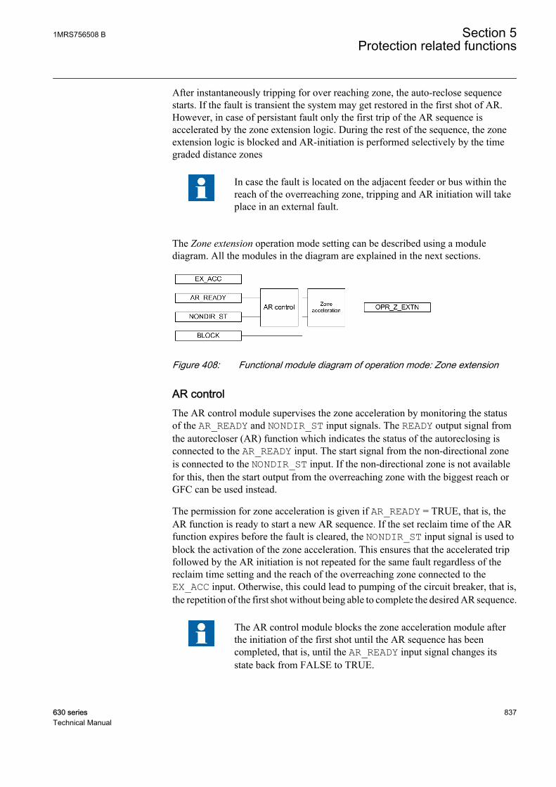
After instantaneously tripping for over reaching zone, the auto-reclose sequencestarts. If the fault is transient the system may get restored in the first shot of AR.However, in case of persistant fault only the first trip of the AR sequence isaccelerated by the zone extension logic. During the rest of the sequence, the zoneextension logic is blocked and AR-initiation is performed selectively by the timegraded distance zones
In case the fault is located on the adjacent feeder or bus within thereach of the overreaching zone, tripping and AR initiation will takeplace in an external fault.
The Zone extension operation mode setting can be described using a modulediagram. All the modules in the diagram are explained in the next sections.
GUID-F201BE49-3B21-43AD-AA03-C5EE4D0C355E V1 EN
Figure 408: Functional module diagram of operation mode: Zone extension
AR controlThe AR control module supervises the zone acceleration by monitoring the statusof the AR_READY and NONDIR_ST input signals. The READY output signal fromthe autorecloser (AR) function which indicates the status of the autoreclosing isconnected to the AR_READY input. The start signal from the non-directional zoneis connected to the NONDIR_ST input. If the non-directional zone is not availablefor this, then the start output from the overreaching zone with the biggest reach orGFC can be used instead.
The permission for zone acceleration is given if AR_READY = TRUE, that is, theAR function is ready to start a new AR sequence. If the set reclaim time of the ARfunction expires before the fault is cleared, the NONDIR_ST input signal is used toblock the activation of the zone acceleration. This ensures that the accelerated tripfollowed by the AR initiation is not repeated for the same fault regardless of thereclaim time setting and the reach of the overreaching zone connected to theEX_ACC input. Otherwise, this could lead to pumping of the circuit breaker, that is,the repetition of the first shot without being able to complete the desired AR sequence.
The AR control module blocks the zone acceleration module afterthe initiation of the first shot until the AR sequence has beencompleted, that is, until the AR_READY input signal changes itsstate back from FALSE to TRUE.
1MRS756508 B Section 5Protection related functions
630 series 837Technical Manual

Zone accelerationThe start signal from the overreaching zone whose operation is to be accelerated isconnected to the EX_ACC input. When the EX_ACC input is activated andsimultaneously the AR control module gives a permission for acceleration, theoperate signal from the zone extension logic is obtained from the OPR_Z_EXTNoutput, which is used to trip the circuit breaker and initiate the autoreclosing (theAR shot).
The activation of the BLOCK input blocks the OPR_Z_EXTN output.
Loss of load logicThe loss of load logic is enabled with Loss of load Op = “Enabled.”
When the Loss of load Op operation mode is enabled, a time-delayed overreachingzone is allowed to trip instantaneously if the loss of load current condition is detected.
The loss of load function does not operate in case of a three-phasefault as all the phases are faulty. Therefore, none of the currentvalues drops below the Minimum current setting, meaning that theloss of load current condition cannot be detected.
The Loss of load Op setting mode can be described using a module diagram. Allthe modules in the diagram are explained in the next sections.
GUID-3E5D26BC-7873-40C3-A160-DB9FF9ADC983 V1 EN
Figure 409: Functional module diagram of operation mode: Loss of load Op
InitializationThe initialization module gives an enabling signal to the trip logic module whenthe values of all three phase currents are above the set value of Load current valuefor more than the time set with Load release on time. The enabling signal has a drop-off delay defined with the Load release off Tm setting.
Section 5 1MRS756508 BProtection related functions
838 630 seriesTechnical Manual
Loss of load current detectionThe loss of load current detection module gives an enabling signal to the trip logicmodule if any of the phase current values drops below the Minimum currentsetting due to a remote end breaker opening and simultaneously the value of atleast one phase current exceeds the value of the Load current value setting due to afault. Such a condition has to be valid for longer than the Minimum current timesetting.
Trip logicThe operate signal is obtained from the OPR_LOSSLOAD output if bothinitialization and loss of load current detection modules are activated andsimultaneously a fault is seen by the overreaching zone connected to theLOSSLOAD_ACC input.
The activation of the BLOCK input blocks the OPR_LOSSLOAD output.Temporarily blocking is achieved using the circuit breaker close command pulseconnected to the CB_CLOSED input. It is used to prevent an unwanted operationdue to initial transients after the breaker is closed, for example, in case of inrushcurrents.
5.8.5 Base valuesIn this function block, some of the settings are set in per unit (pu). These pu valuesare relational to certain base values, for example the values given in A, kV andkVA. The IED supports alternative base value groups for the phase current or voltage-related settings, for example "Phase Grp 1", "Phase Grp 2" and "Phase Grp 3".One of the groups to be used with the Base value Sel phase setting must be selected.
For more information, see the Basic functions section in this manual.
5.8.6 ApplicationDSTPLAL is used in those applications when the conventional communicationscheme logic cannot be applied (when no communication channel is available), butthe user still requires a fast clearance for the faults on the entire feeder.
DSTPLAL enables a fast fault clearing during certain conditions. DSTPLAL isunable to replace the communication scheme logic completely due to a possiblelack of selectivity during the first trip and AR initiation and also as the loss of loadlogic cannot operate for three-phase faults. DSTPLAL is controlled either by the auto-recloser (zone extension logic), or by monitoring the loss of load current (loss ofload logic).
1MRS756508 B Section 5Protection related functions
630 series 839Technical Manual

Zone extension logicThe Zone extension setting can be applied in cases when the auto-recloser functionis in operation. When Zone extension is enabled, the auto-recloser (AR) function isused to enable the fast fault clearance independent of the fault location on theprotected feeder. This is achieved by allowing a time delayed overreaching zone totrip instantly when a fault occurs. Also, in cases where there are tapped loads onthe protected feeder, it is required to set a dedicated zone to initiate one or twoshots as fast as possible before the protection devices of these taps clear. If the faultis still present after these shots, further tripping is delayed more in accordance withthe other zones so that the operation becomes slower than the protection of the loadtaps, enabling it to clear. The final tripping that ends the sequence is alwaysperformed selectively according to a proper time grading of the zones.
If the fault is located on the adjacent feeder or bus within the reachof the overreaching zone, the tripping and the AR initiation takesplace during an external fault.
Loss of load logicThe loss of load acceleration gives the overreaching zone a permission to operateinstantly after the detection of a loss of load current condition.
The loss of load logic is unable to operate for three-phase faults.
Setting guidelines
The Load current value setting must be set below the minimum three-phase loadcurrent during the healthy state. A security factor of 0.5 is used:
Load current value = 0.5*Iminload
Iminload the minimum load current during normal operation conditions.
The loss of load function is released after Load release on time is elapsed at thesame time as the load current in all three phases has been above the Load currentvalue setting. If the current values drop below the Load current value setting, therelease condition stays activated until the drop-out delay time has expired (theLoad release off Tm setting). The value of Load release off Tm is by default setto ”0.3 s". The Load release on time setting is used to increase the security of theloss of load function, for example in the case of transient inrush currents during theenergizing of a power transformer. When there is no need for delaying the release,the Load release on time is set to zero in applications.
Section 5 1MRS756508 BProtection related functions
840 630 seriesTechnical Manual
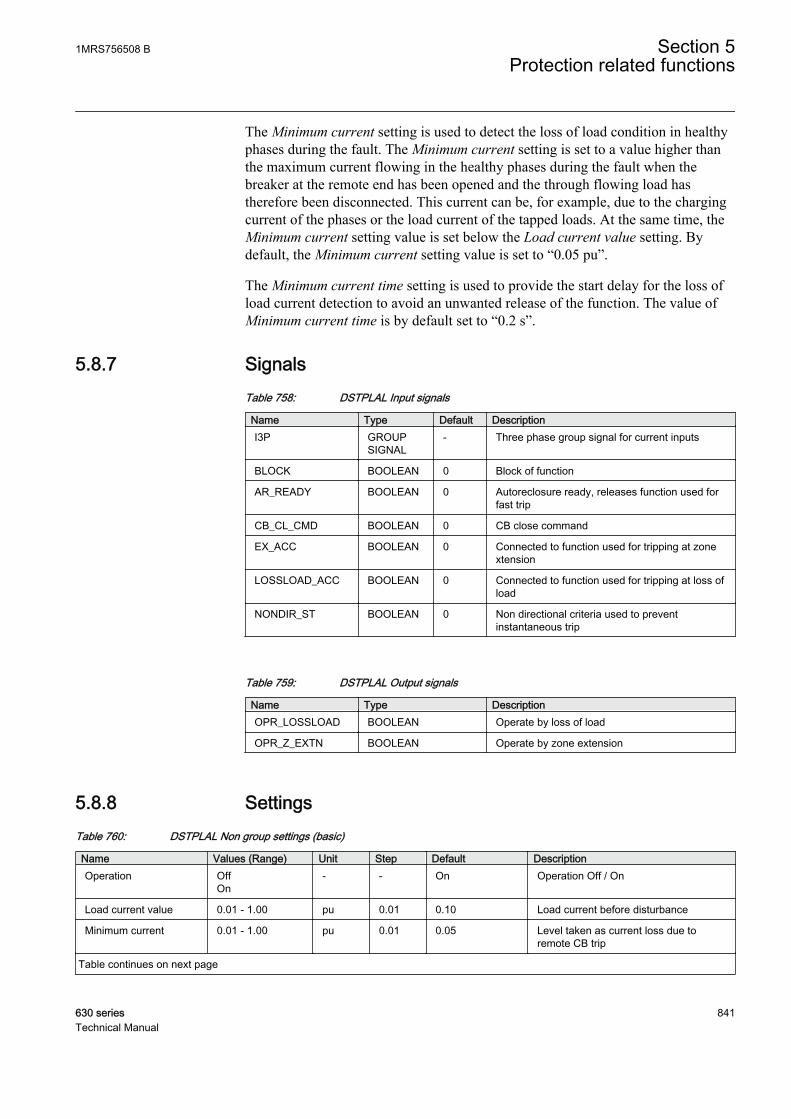
The Minimum current setting is used to detect the loss of load condition in healthyphases during the fault. The Minimum current setting is set to a value higher thanthe maximum current flowing in the healthy phases during the fault when thebreaker at the remote end has been opened and the through flowing load hastherefore been disconnected. This current can be, for example, due to the chargingcurrent of the phases or the load current of the tapped loads. At the same time, theMinimum current setting value is set below the Load current value setting. Bydefault, the Minimum current setting value is set to “0.05 pu”.
The Minimum current time setting is used to provide the start delay for the loss ofload current detection to avoid an unwanted release of the function. The value ofMinimum current time is by default set to “0.2 s”.
5.8.7 SignalsTable 758: DSTPLAL Input signals
Name Type Default DescriptionI3P GROUP
SIGNAL- Three phase group signal for current inputs
BLOCK BOOLEAN 0 Block of function
AR_READY BOOLEAN 0 Autoreclosure ready, releases function used forfast trip
CB_CL_CMD BOOLEAN 0 CB close command
EX_ACC BOOLEAN 0 Connected to function used for tripping at zonextension
LOSSLOAD_ACC BOOLEAN 0 Connected to function used for tripping at loss ofload
NONDIR_ST BOOLEAN 0 Non directional criteria used to preventinstantaneous trip
Table 759: DSTPLAL Output signals
Name Type DescriptionOPR_LOSSLOAD BOOLEAN Operate by loss of load
OPR_Z_EXTN BOOLEAN Operate by zone extension
5.8.8 SettingsTable 760: DSTPLAL Non group settings (basic)
Name Values (Range) Unit Step Default DescriptionOperation Off
On- - On Operation Off / On
Load current value 0.01 - 1.00 pu 0.01 0.10 Load current before disturbance
Minimum current 0.01 - 1.00 pu 0.01 0.05 Level taken as current loss due toremote CB trip
Table continues on next page
1MRS756508 B Section 5Protection related functions
630 series 841Technical Manual
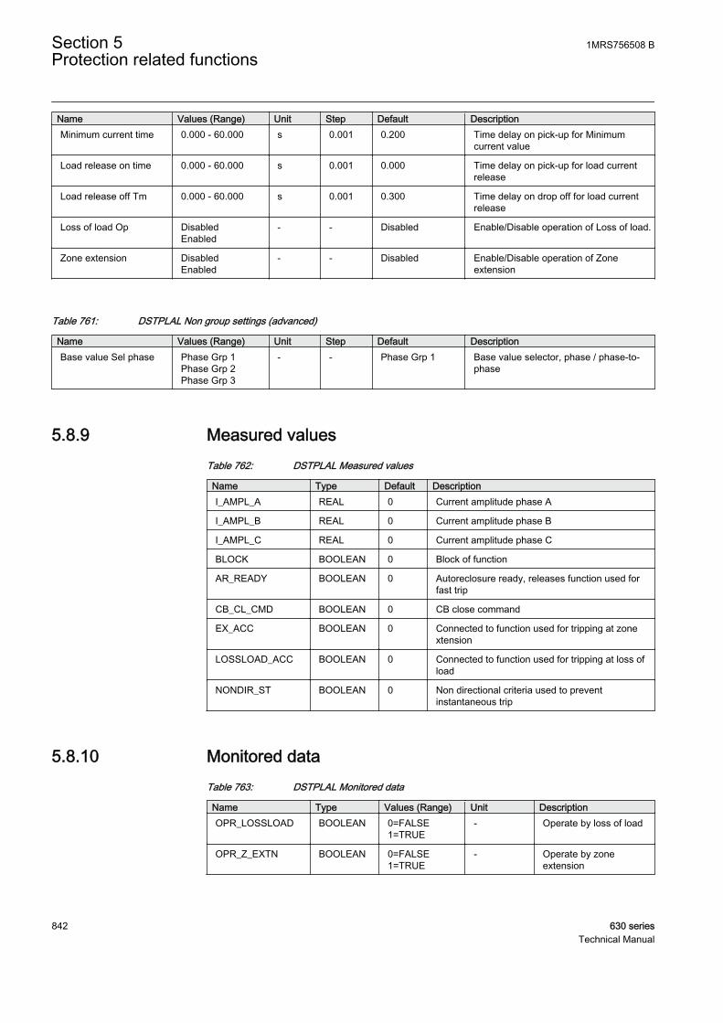
Name Values (Range) Unit Step Default DescriptionMinimum current time 0.000 - 60.000 s 0.001 0.200 Time delay on pick-up for Minimum
current value
Load release on time 0.000 - 60.000 s 0.001 0.000 Time delay on pick-up for load currentrelease
Load release off Tm 0.000 - 60.000 s 0.001 0.300 Time delay on drop off for load currentrelease
Loss of load Op DisabledEnabled
- - Disabled Enable/Disable operation of Loss of load.
Zone extension DisabledEnabled
- - Disabled Enable/Disable operation of Zoneextension
Table 761: DSTPLAL Non group settings (advanced)
Name Values (Range) Unit Step Default DescriptionBase value Sel phase Phase Grp 1
Phase Grp 2Phase Grp 3
- - Phase Grp 1 Base value selector, phase / phase-to-phase
5.8.9 Measured valuesTable 762: DSTPLAL Measured values
Name Type Default DescriptionI_AMPL_A REAL 0 Current amplitude phase A
I_AMPL_B REAL 0 Current amplitude phase B
I_AMPL_C REAL 0 Current amplitude phase C
BLOCK BOOLEAN 0 Block of function
AR_READY BOOLEAN 0 Autoreclosure ready, releases function used forfast trip
CB_CL_CMD BOOLEAN 0 CB close command
EX_ACC BOOLEAN 0 Connected to function used for tripping at zonextension
LOSSLOAD_ACC BOOLEAN 0 Connected to function used for tripping at loss ofload
NONDIR_ST BOOLEAN 0 Non directional criteria used to preventinstantaneous trip
5.8.10 Monitored dataTable 763: DSTPLAL Monitored data
Name Type Values (Range) Unit DescriptionOPR_LOSSLOAD BOOLEAN 0=FALSE
1=TRUE- Operate by loss of load
OPR_Z_EXTN BOOLEAN 0=FALSE1=TRUE
- Operate by zoneextension
Section 5 1MRS756508 BProtection related functions
842 630 seriesTechnical Manual

5.8.11 Technical dataTable 764: DSTPLAL Technical data
Characteristic ValueOperation accuracy At the frequency f = fn
±1.5% of the set value or ±0.002 × In
Operate time accuracy ±1.0% of the set value or ±20 ms
Suppression of harmonics DFT: -50 dB at f = n x fn, where n = 2, 3, 4, 5,…
5.9 Communication logic for residual overcurrentRESCPSCH
5.9.1 IdentificationFunction description IEC 61850
identificationIEC 60617identification
ANSI/IEEE C37.2device number
Scheme communication logic forresidual overcurrent protection
RESCPSCH RESCPSCH 85N
5.9.2 Function block
GUID-87A087BE-1208-4202-97B1-A388B10AEA6E V1 EN
Figure 410: Function block
5.9.3 FunctionalityThe scheme communication logic for residual overcurrent protection RESCPSCHis provided to achieve an instantaneous fault clearing independent of the faultlocation on the protected feeder. The available communication scheme types are:
• Direct intertrip (DUTT)• Permissive underreach (PUTT)• Permissive overreach (POTT• Directional comparison blocking (DCB)
1MRS756508 B Section 5Protection related functions
630 series 843Technical Manual

The directional comparison unblocking scheme (DCUB) can also be provided bycomplementing the permissive schemes with an additional logic called theunblocking function, which is also included in RESCPSCH.
If the permissive overreaching scheme is used, some of the power systemconditions requires additional special logic circuits, like current reversal logic andweak-end infeed (WEI) logic for distance protection, RCRWPSCH.
5.9.4 Operation principleThe function can be enabled and disabled with the Operation setting. Thecorresponding parameter values are "On" and "Off".
The operation of the scheme communication logic function for residual overcurrentprotection can be described using a module diagram. All the modules in thediagram are explained in the next sections.
GUID-C8EE9156-EF07-41EB-903F-06DA8269C5AA V1 EN
Figure 411: Functional module diagram
If SchemeType = “Intertrip”, it is (DUTT)
If SchemeType = “Permissive UR” , it is (PUTT)
If SchemeType = “Permissive OR”, it is (POTT)
If SchemeType = “Blocking” , it is (DCB)
The unblocking scheme (DCUB) is enabled with the Unblock mode setting.
Section 5 1MRS756508 BProtection related functions
844 630 seriesTechnical Manual

The applied communication scheme logic in RESCPSCH is selected with theSchemeType setting:
Direct underreaching transfer trip scheme (DUTT)The direct intertrip is enabled with SchemeType = “Intertrip”.
In the direct intertrip scheme, the start signal from the underreaching(instantaneous) residual overcurrent function DEFHPDEF, is connected to theCSUR input to create a carrier send (CS) signal. The duration of the CSUR inputsignal can be prolonged by the Carrier Min Dur setting to assure a sufficientduration for the CS signal.
The local circuit breaker is directly tripped (activation of the OPERATE output)with the carrier received (CR) signal after a settable pick-up delay Coordinationtime has elapsed without further local criteria.
The unblocking function (Unblock = “NoRestart” and Unblock =“Restart”) must not be enabled with the DUTT scheme, as the lostguard signal results in an immediate trip of the local circuit breaker.
The activation of the BLOCK input does a total blocking of the direct intertripscheme. The activation of the BLK_OPR input blocks the OPERATE output.
GUID-47FB8923-BB0D-4856-9CB7-3C6FF359F09D V1 EN
Figure 412: Simplified functional diagram of the direct intertrip scheme
Permissive underreaching transfer trip scheme (PUTT)The permissive underreach is enabled with SchemeType = “Permissive UR”.
In the permissive underreach scheme, the start signal from the underreaching(instantaneous) residual overcurrent function DEFHPDEF, is connected to theCSUR input to create a CS signal. The duration of the CSUR input signal can beprolonged by the Carrier Min Dur setting to assure a sufficient duration of the CSsignal.
1MRS756508 B Section 5Protection related functions
630 series 845Technical Manual

In the permissive underreach scheme, the CR signal or CRL signal if unblockingfunction is enabled, is used to allow the overreaching residual overcurrent functionDEFLPDEF, to trip (activation of the OPERATE output) after the pick-up delayCoordination time. The start signal from the overreaching function is connected tothe CACC input. A general start signal in forward direction can also be connected tothe CACC input.
The CS signal is also generated if the CR signal is received and the local carrieracceleration signal CACC is active.
Activating the BLOCK input blocks totally the permissive underreach scheme.Activating the BLK_OPR input blocks the OPERATE output.
GUID-8BFAECCF-472E-45B9-9E1B-DCFAD672A563 V1 EN
Figure 413: Simplified functional diagram of permissive underreach scheme
POTT (Permissive overrreaching transfer trip scheme)The permissive overreach is enabled with SchemeType = “Permissive OR”.
In the permissive overreach scheme, the start signal from the overreaching residualovercurrent function DEFLPDEF, is connected to the CSOR input to create a CSsignal. The CS signal can also be issued simultaneously from the underreachingresidual overcurrent function DEFHPDEF. In this case, the start signal from theunderreaching function is connected to the CSUR input. The duration of the CSURinput signal can be prolonged by the Carrier Min Dur setting, to assure a sufficientduration of the CS signal. The carrier send from CSOR can be blocked with theBLK_CS input.
In case of parallel feeders, and when the external current reversallogic (RCRWPSCH) is enabled, the CS signal is not prolonged andthe value of Carrier Min Dur is set to zero to secure correct operation.
Section 5 1MRS756508 BProtection related functions
846 630 seriesTechnical Manual
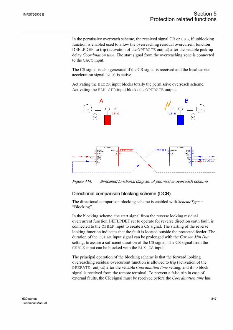
In the permissive overreach scheme, the received signal CR or CRL, if unblockingfunction is enabled used to allow the overreaching residual overcurrent functionDEFLPDEF, to trip (activation of the OPERATE output) after the settable pick-updelay Coordination time. The start signal from the overreaching zone is connectedto the CACC input.
The CS signal is also generated if the CR signal is received and the local carrieracceleration signal CACC is active.
Activating the BLOCK input blocks totally the permissive overreach scheme.Activating the BLK_OPR input blocks the OPERATE output.
GUID-33562061-82CD-4345-95D2-66A8AE677B94 V1 EN
Figure 414: Simplified functional diagram of permissive overreach scheme
Directional comparison blocking scheme (DCB)The directional comparison blocking scheme is enabled with SchemeType =“Blocking”.
In the blocking scheme, the start signal from the reverse looking residualovercurrent function DEFLPDEF set to operate for reverse direction earth fault, isconnected to the CSBLK input to create a CS signal. The starting of the reverselooking function indicates that the fault is located outside the protected feeder. Theduration of the CSBLK input signal can be prolonged with the Carrier Min Dursetting, to assure a sufficient duration of the CS signal. The CS signal from theCSBLK input can be blocked with the BLK_CS input.
The principal operation of the blocking scheme is that the forward lookingoverreaching residual overcurrent function is allowed to trip (activation of theOPERATE output) after the settable Coordination time setting, and if no blocksignal is received from the remote terminal. To prevent a false trip in case ofexternal faults, the CR signal must be received before the Coordination time has
1MRS756508 B Section 5Protection related functions
630 series 847Technical Manual
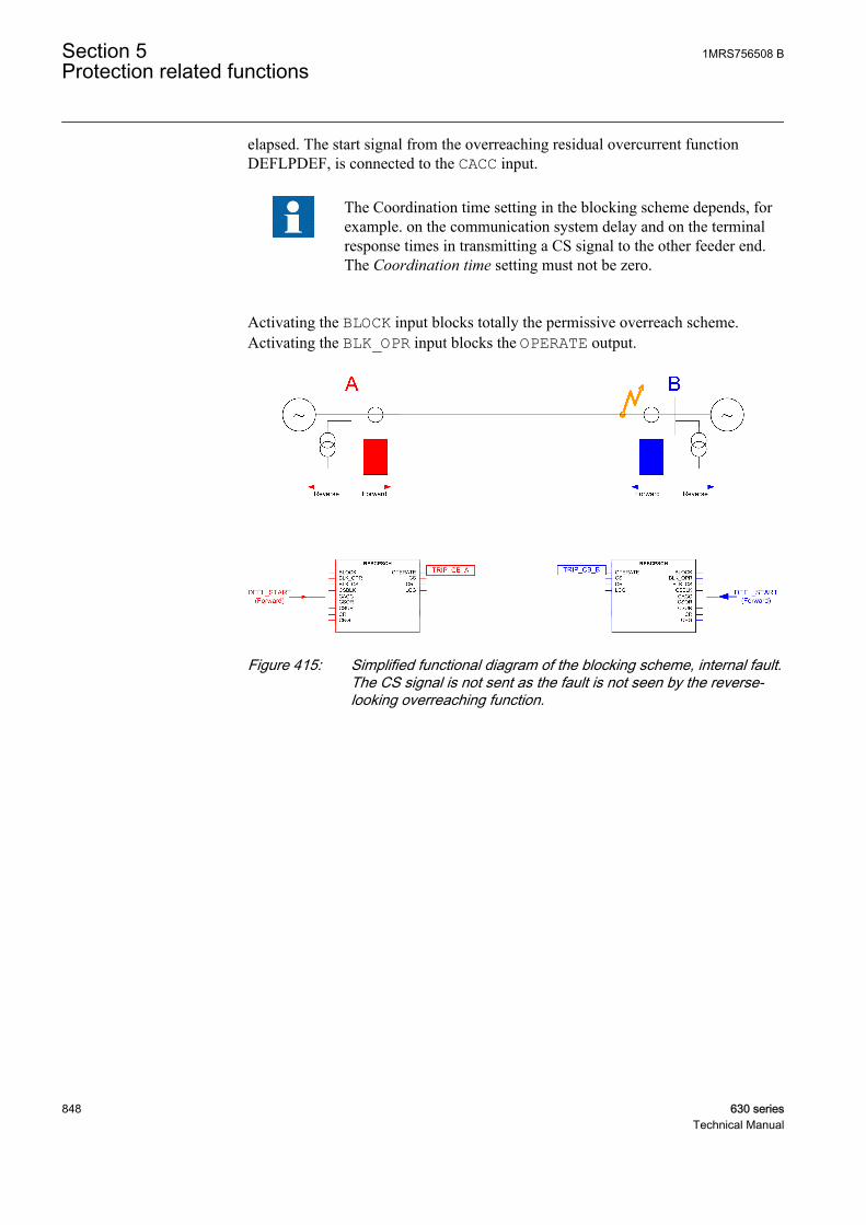
elapsed. The start signal from the overreaching residual overcurrent functionDEFLPDEF, is connected to the CACC input.
The Coordination time setting in the blocking scheme depends, forexample. on the communication system delay and on the terminalresponse times in transmitting a CS signal to the other feeder end.The Coordination time setting must not be zero.
Activating the BLOCK input blocks totally the permissive overreach scheme.Activating the BLK_OPR input blocks the OPERATE output.
GUID-0EECD5F8-A08B-4D14-91FE-987F5009B2A3 V1 EN
Figure 415: Simplified functional diagram of the blocking scheme, internal fault.The CS signal is not sent as the fault is not seen by the reverse-looking overreaching function.
Section 5 1MRS756508 BProtection related functions
848 630 seriesTechnical Manual

GUID-E2A25FAC-19BD-427C-AD02-0E5805F818EF V1 EN
Figure 416: Simplified functional diagram of the blocking scheme, externalfault. The IED at bus B sees the fault in the reverse direction andsends a blocking signal (CS) to the IED at bus A. There is no CBoperation at either end.
The unblocking function used with the blocking function provides a possibility tosupervise the communication channel. In this case, the CRL output signal is used asa local blocking signal.
The operation mode Unblock = “Restart” is not recommended asthe blocking is activated only for 150 ms after the guard signaldisappears. This results in an unwanted operation of the protection.
DCUB (Directional Comparison Unblocking)The unblocking function is a complementary logic, which can be used togetherwith the permissive communication schemes. In the unblocking scheme, thedependability of the permissive schemes is improved by using the loss of guardsignal from the communication equipment to create locally a CRL output signal.This enables the permissive scheme to operate even if the communication channelis interrupted or lost.
The unblocking function uses a carrier guard signal (CRG), which must always bepresent. The absence of the CRG signal for a time longer than the value of the Lossof carrier time setting is used to generate a logical CRL signal. This enables thepermissive scheme to operate despite the loss of the communication channel. Acommunication failure shorter than the value of the Loss of carrier time setting isalways ignored.
The unblocking function is configured with the Unblock setting :
1MRS756508 B Section 5Protection related functions
630 series 849Technical Manual

• Unblock = “Off”: The unblocking function is disabled.• Unblock = “NoRestart”: If the CRG signal disappears for a longer time than
defined in the Loss of carrier time setting. The logical CRL signal is generated.The CRL output signal is kept up until the CRG signal is present again. Thecommunication failure is not signaled by the LCG output.
• Unblock = “Restart”: If the CRG signal disappears for a longer time thandefined in the Loss of carrier time setting, theCRL output signal is generated.The CRL output signal is kept up for 150 ms, after which a communicationfailure is signaled by the LCG output. The LCG output is reset 200 ms after theCRG signal is present again. The purpose of this mode is to ensure trippingduring a fixed delay of 150 ms after the loss of communication due to possibleconsequences of an internal fault. After this time, the accelerated tripping isallowed only if the actual CR signal is received again.
With operation modes Unblock = “NoRestart” and Unblock = “Restart” the createdCRL output signal is internally ORed with the CR input to allow the permissivescheme to operate even when the communication channel has been interrupted orlost. The values of CRL and LCG output signals are also available through themonitored data view. Activating the BLOCK input blocks the CRL and LCG outputs.
5.9.5 ApplicationTo achieve a fast fault clearing for a fault on the part of the protected feeder notcovered by the instantaneous step of residual overcurrent protection, the directionalresidual overcurrent protection can be supported with RESCPSCH.
Applying RESCPSCH requires a communication channel capable of transmittingan "On" or "Off" signal in each direction. To enable fast tripping, the mostimportant requirement for communication is the communication speed.
The performance of RESCPSCH function is directly related to the communicationchannel speed, and to the security against false or lost signals. Therefore, dedicatedcommunication channels are recommended. A typical communication media is asimple pilot wire based on auxiliary power with short distances up to fewkilometers, and fiber-optic cables utilizing digital data transmission up to distancesof 150 km. To avoid false signals that could cause unwanted operation, the securityof the communication channel should be emphasized. It is also important to payattention to the dependability of the communication channel to ensure that thesignals are reliably transmitted during power system faults.
The communication schemes supported by RESCPSCH are:
• Direct underreaching transfer trip, DUTT• Permissive underreaching transfer trip, PUTT• Permissive overreaching transfer trip, POTT• Directional comparison blocking scheme, DCB• Directional comparison unblocking scheme, DCUB
Section 5 1MRS756508 BProtection related functions
850 630 seriesTechnical Manual

Depending on whether the communication channel is used for sending a block or atrip signal, the communication schemes can be divided into blocking schemes andpermissive schemes.
In permissive schemes, the trip signals of the directional residual overcurrentprotection are interchanged between the terminals to receive a permission to tripduring an internal fault. The tripping of the local terminal depends on both thestarting of its own forward looking function and on the received signal from theopposite terminal. In the underreaching scheme, no signals are sent during anexternal fault. However, during an external fault, a trip signal is also send to theopposite terminal, if the fault is seen in the forward direction and the overreachingscheme is used. However, in case of external faults, the tripping is always blockedeither due to that no signal is received as the opposite terminal sees a reverse fault,or that the signal is received but locally the fault is seen in the reverse direction. Ineither case, the blocking is eventually not dependent on the received signal so thata lost communication channel would not result in false operation.
In the blocking scheme, a blocking signal is sent to the opposite terminal if thefault is locally seen in the reverse direction, that is, during an external fault. Thus,the blocking is dependent on the received signal, and there is typically a need todelay the tripping of the terminal receiving the blocking signal. This delay depends,for example, on the response times of the communication channel and terminals.During an internal fault, there is no signal transmission between the terminals, sothe tripping does not depend on the received signal from the opposite terminal.
In conclusion, permissive schemes are inherently faster and have better security**against false tripping than a blocking scheme, since tripping in an external fault isnot possible in case of a channel interruption. In a blocking scheme, a lostcommunication channel simultaneously with an external fault may lead to a falseoperation of the protection if the communication channel is not being supervised.On the other hand, as the fast trip of the permissive scheme depends on a receivedsignal, its dependability*** is lower than that of the blocking scheme. [3] [4]
The unblocking scheme is also available to enhance the dependability of thepermissive scheme. If the communication channel is interrupted, andsimultaneously a fault occurs in the forward direction within that time, tripping isstill possible either during a fixed time interval from the beginning of theinterruption, or as long as the communication channel is lost. This is achieved byconnecting the supervision output of the implemented communication functionalityto the dedicated carrier guard signal input of RESCPSCH. In general, theunblocking scheme also provides better security than the blocking scheme becausetripping in external faults is only possible if the fault occurs within the above time.
The direct transfer trip scheme uses the underreaching function to trip the localbreaker and to transfer the trip signal to the remote terminal. The remote terminaloperates immediately based on the received transfer trip signal, without any
[3] ** security = The ability to block operation in case of an external fault[4] *** dependability = The ability to operate in case of an internal fault
1MRS756508 B Section 5Protection related functions
630 series 851Technical Manual

additional conditions. This scheme is very simple, but its security is low, as aspurious signal results in false operation of the protection.
Direct intertripIn some applications, there is a need to trip the remote end breaker immediatelybased on fault detection by the local measurements. This applies, for example,when the transformers or reactors are connected to the system without circuit-breakers, or for remote tripping following the operation of the local breaker failureprotection (CBFP).
In the direct intertrip scheme (DUTT), the carrier send signal (CS) is initiated bythe underreaching, or from the tripping signal of an external IED, such astransformer or reactor protection. At the remote end, the received signals initiatesthe breaker trip immediately without any further local protection criteria. To limitthe risk for unwanted trip due to spurious sending of signals, the trip can bedelayed by the Coordination time setting, which should be set to 10-30 ms,depending on the type of the communication channel. The general requirement forimplementing the communication channel operating in direct intertrippingapplications is that it should be very secure and dependable.
Setting guidelines for intertrip scheme, DUTT:
Scheme type = "Intertrip"
Coordination time = "0.050" s (10 ms + maximal transmission time)
Carrier Min Dur = "0.1" s
Permissive underreach schemeIn the permissive underreach scheme, a permission to trip is obtained locally fromthe underreaching function and sent to the remote end. The received signal is thencombined again with the local fault indication from the overreaching functionresulting to trip command after a settable pick-up delay Coordination time.
In the permissive underreach scheme, the IED of either feeder end sends apermissive signal to trip the other end. The communication channel needs to beable to receive and transmit at the same time. In permissive schemes, a generalrequirement for the communication channel is that it must be fast and secure, butalso the dependable. Inadequate security causes unwanted tripping for externalfaults. Inadequate speed or dependability causes delayed tripping for internal faults.
In the permissive underreach scheme, the CS signal is issued based on theunderreaching residual overcurrent protection function.
The permissive scheme is not applicable on short feeder lengths due to thedifficulties in the impedance measurement to distinguish between the internal andexternal faults in such cases.
It is possible that the residual overcurrent function starts only at one end due to thesystem conditions like weak zero sequence source at one end, or high fault
Section 5 1MRS756508 BProtection related functions
852 630 seriesTechnical Manual
resistance. It is still possible to achieve fast tripping from both ends by connectinga general forward start signal to CACC. So, even if the local overreaching residualovercurrent function has not picked up, the local OPERATE output would still beactivated. The function also generates a CS signal by combining the carrierreceived (CR) signal from a remote end and also the local activation of CACC,giving the permission to a remote function to trip instantaneously.
The CR signal must be received when the overreaching residual overcurrentprotection is still started to achieve an instantaneous trip. In some cases, due to thefault current distribution, the overreaching protection can operate only after thefault has been cleared by the remote terminal. In this case, there is a certain riskthat if the remote terminal is tripped directly by the instantaneous underreachingfunction, the CS signal issued by it resets before the overreaching function of thelocal end terminal is operated. To assure a sufficient duration of the CR signal, theCS signal , can be prolonged by time Carrier Min Dur. The recommended value ofthe Carrier Min Dur setting is "0.1" s.
The received communication signal is combined with the output from the localoverreaching function. Therefore, there is less concern for false signal causing anincorrect trip. Therefore, the timer Coordination time can be set to "0". Acommunication channel failure does not affect the selectivity, but delays thetripping at the other end for certain fault locations.
Setting guidelines for the permissive underreach scheme, PUTT:
Scheme type = "Permissive UR"
Coordination time = "0" s
Carrier Min Dur = "0.1" s
Permissive overreach schemeIn the permissive overreach scheme, permission to trip is obtained locally from anoverreaching function and sent to the remote end. The received signal is thencombined with the local fault indication from the overreaching function, resultingin trip command after a settable pick-up delay Coordination time.
In the permissive overreach scheme, the IED at either end of the feeder sends apermissive signal to trip the other end. Therefore the communication channel mustbe able to receive and transmit at the same time. A general requirement for thecommunication on permissive schemes is that it should be fast and secure.
In the permissive overreach scheme, the CS signal is issued based on the start ofthe overreaching residual overcurrent function.
It is possible that the residual overcurrent function start at one end due to systemconditions like weak zero sequence source at one end, or high fault resistance. It isstill possible to get fast tripping from both ends by connecting a general forwardstart signal to CACC. So, even if the local overreaching residual overcurrentfunction has not picked up, the local OPERATE would still be activated. The
1MRS756508 B Section 5Protection related functions
630 series 853Technical Manual

function also generates a CS signal by combining the CR signal from a remote endand local activation of CACC, giving permission to the remote function to tripinstantaneously.
The permissive overreach scheme can be used for all feeder types and lengths.
In the permissive overreach scheme, the communication channel plays an essentialrole in obtaining a fast tripping at both ends. Typically, a lost communicationchannel does not cause false tripping. However, it delays the operation of theprotection for the faults anywhere on the feeder.
The communication channel for a permissive overreach scheme must be fast andsecure, but also dependable. Inadequate security can cause unwanted tripping forexternal faults. Inadequate speed or dependability can cause delayed tripping forinternal faults.
In the permissive overreaching scheme, the CS signal can be issued in parallel bothfrom the overreaching and underreaching functions. The CS signal from theoverreaching function must not be prolonged, while the CS signal from theunderreaching function must typically be prolonged. In parallel feeder applications,the scheme typically needs to be complemented by the current reversal logic. Toensure a correct operation in this case, the CS signal shall not be prolonged(Carrier Min Dur = "0" s). There is no need to delay the tripping when receivingthe carrier signal, so set the time Coordination time to "0".
Setting guidelines for the permissive overreaching transfer trip scheme, POTT:
Scheme type = "Permissive OR"
Coordination time = "0" s
Carrier Min Dur = "0.1" s
Carrier Min Dur = "0" s (in case of parallel lines and current reversal logic)
Directional comparison blocking schemeIn the blocking scheme, the reverse-looking residual overcurrent function, is usedfor sending a block signal to the remote end to block the overreaching forwardlooking residual overcurrent function.
The blocking scheme is very dependable because it operates for faults anywhere onthe protected feeder, even if the communication channel is out of service.Conversely, it is less secure than a permissive scheme because it trips for externalfaults within the reach of the overreaching local function, if the communicationchannel is out of service and no block signal is received.
Inadequate speed or low dependability of the communication channel can causespurious tripping for external faults.
To secure that the blocking signal has time to arrive before the local overreachingfunction trips, the trip is delayed by the Coordination time setting. The
Section 5 1MRS756508 BProtection related functions
854 630 seriesTechnical Manual
Coordination time setting must be set longer than the maximal transmission time ofthe channel added by the start and response times of the IEDs sending andreceiving the CS signal. A security margin of at least 10 ms should be considered.The time delay Carrier Min Dur for prolonging the CS signal is set to "0".
Setting guidelines for the blocking scheme:
Scheme type = "Blocking"
Coordination time = "0.1" s (10 ms + maximal transmission time)
Carrier Min Dur = "0" s
Directional comparison unblocking schemeMetallic communication paths adversely affected by fault-generated noise or byother electrical phenomena, such as lightning, are not suitable for conventionalpermissive schemes that rely on signal transmitted during a fault in the protectedfeeder. Principally, the communication media must be properly shielded orotherwise designed to provide an adequate performance during such conditions.
In general, to overcome the lower dependability of permissive schemes, theunblocking scheme can be used. The function is used at older, less reliablecommunication, where the signal has to be sent through the primary fault. Theunblocking function uses a carrier guard signal (CRG) which must always bepresent, even when no CR signal is received. Due to the absence of the CRG signalduring the security time, the Loss of carrier time setting is used as a CR signal.This also enables a permissive scheme to operate when the communication channelis temporarily lost during an internal fault.
Setting guidelines for the unblocking scheme:
The unblocking function is configured with the Unblock setting:
• Unblock = “Off”: The unblocking function is disabled• Unblock = “NoRestart”: If the CRG signal disappears for a longer time period
defined in the Loss of carrier time setting, a logical carrier received signal(CRL) is generated. The CRL signal is kept up until the CRG signal is present.The communication failure is not signalled by the LCG output. The Loss ofcarrier time setting is set to "35" ms.
• Unblock = “Restart”: If the CRG signal disappears for a longer time periodthan the Loss of carrier time setting, a CRL signal is generated. The CRLsignal is kept up for 150 ms, after which a communication failure is signalledby the LCG output. The value of the LCG output is reset 200 ms after the CRGsignal is present again. The Loss of carrier time setting is set to "35" ms.
1MRS756508 B Section 5Protection related functions
630 series 855Technical Manual

5.9.6 SignalsTable 765: RESCPSCH Input signals
Name Type Default DescriptionBLOCK BOOLEAN 0 Block of function
BLK_OPR BOOLEAN 0 Signal for blocking trip due to communication logic
BLK_CS BOOLEAN 0 Signal for blocking CS in Overreach and Blockingschemes
CSBLK BOOLEAN 0 Reverse residual overcurrent signal for CarrierSend
CACC BOOLEAN 0 Signal to be used for tripping by CommunicationScheme
CSOR BOOLEAN 0 Overreaching residual overcurrent signal forCarrier Send
CSUR BOOLEAN 0 Underreaching residual overcurrent signal forCarrier Send
CR BOOLEAN 0 Carrier Receive for Communication Scheme Logic
CRG BOOLEAN 0 Carrier guard signal received
Table 766: RESCPSCH Output signals
Name Type DescriptionOPERATE BOOLEAN Trip by Communication Scheme Logic
CS BOOLEAN Carrier Send by Communication Scheme Logic
CRL BOOLEAN Carrier Receive from Communication SchemeLogic
LCG BOOLEAN loss of carrier guard signal
5.9.7 SettingsTable 767: RESCPSCH Non group settings (basic)
Name Values (Range) Unit Step Default DescriptionOperation Off
On- - On Operation Off / On
Scheme type OffIntertripPermissive URPermissive ORBlocking
- - Permissive UR Scheme type, Mode of Operation
Coordination time 0.000 - 60.000 s 0.001 0.035 Communication scheme coordinationtime
Carrier Min Dur 0.000 - 60.000 s 0.001 0.100 Minimum duration of a carrier send signal
Section 5 1MRS756508 BProtection related functions
856 630 seriesTechnical Manual
Table 768: RESCPSCH Non group settings (advanced)
Name Values (Range) Unit Step Default DescriptionLoss of carrier time 0.000 - 60.000 s 0.001 0.035 Security timer for loss of carrier guard
detection
Unblock mode OffNoRestartRestart
- - Off Operation mode of unblocking logic
5.9.8 Measured valuesTable 769: RESCPSCH Measured values
Name Type Default DescriptionBLOCK BOOLEAN 0 Block of function
BLK_OPR BOOLEAN 0 Signal for blocking trip due to communication logic
BLK_CS BOOLEAN 0 Signal for blocking CS in Overreach and Blockingschemes
CSBLK BOOLEAN 0 Reverse residual overcurrent signal for CarrierSend
CACC BOOLEAN 0 Signal to be used for tripping by CommunicationScheme
CSOR BOOLEAN 0 Overreaching residual overcurrent signal forCarrier Send
CSUR BOOLEAN 0 Underreaching residual overcurrent signal forCarrier Send
CR BOOLEAN 0 Carrier Receive for Communication Scheme Logic
CRG BOOLEAN 0 Carrier guard signal received
5.9.9 Monitored dataTable 770: RESCPSCH Monitored data
Name Type Values (Range) Unit DescriptionOPERATE BOOLEAN 0=FALSE
1=TRUE- Trip by Communication
Scheme Logic
CS BOOLEAN 0=FALSE1=TRUE
- Carrier Send byCommunication SchemeLogic
CRL BOOLEAN 0=FALSE1=TRUE
- Carrier Receive fromCommunication SchemeLogic
LCG BOOLEAN 0=FALSE1=TRUE
- loss of carrier guardsignal
1MRS756508 B Section 5Protection related functions
630 series 857Technical Manual

5.9.10 Technical dataTable 771: RESCPSCH Technical data
Characteristic ValueOperate time accuracy ±1.0% of the set value or ±20 ms
5.10 Current reversal and WEI logic for residualovercurrent RCRWPSCH
5.10.1 IdentificationFunction description IEC 61850
identificationIEC 60617identification
ANSI/IEEE C37.2device number
Current reversal and weak-end infeedlogics for residual overcurrent protection
RCRWPSCH RCRWPSCH RCREV/WEI
5.10.2 Function block
GUID-866360F3-65D7-40DE-97D3-6A70057BC59A V2 EN
Figure 417: Function block
5.10.3 FunctionalityThe scheme communication logic for residual overcurrent protection RESCPSCHmay require additional logics to operate correctly in all possible power systemconditions. Such special logics include, for example, the current reversal and weak-end infeed logics which are combined to the RCRWPSCH function block.
Current reversal logic: In the parallel feeder applications, the direction of faultcurrent on the healthy feeder can change when the circuit breaker on the faultyfeeder opens to clear the fault. This can lead to an unwanted operation of theresidual overcurrent protection on the healthy parallel feeder when RESCPSCHwith the permissive overreach scheme is used. The main purpose of the currentreversal logic is to prevent such unwanted operations.
The weak-end infeed (WEI) logic: Basically, the permissive communicationschemes can operate only when the protection in the remote terminal can detect the
Section 5 1MRS756508 BProtection related functions
858 630 seriesTechnical Manual

fault. This detection requires a sufficient minimum fault current. If such current isnot available due to too weak a remote end source, the WEI logic can be used toovercome the situation and trip the remote end breaker.
5.10.4 Operation principleThe function can be enabled and disabled with the Operation setting. Thecorresponding parameter values are "On" and "Off".
The operation of current reversal and weak-end infeed logics for residualovercurrent protection can be described by using a module diagram. All themodules in the diagram are explained in the next sections.
GUID-469E8E54-ED7E-4299-9CE6-5B76FEC08C6C V1 EN
Figure 418: Functional module diagram
Current reversal logicThe current reversal logic is enabled by changing the value of the Reversal modesetting to “On”.
The current reversal logic uses the start signal of the reverse directional residualovercurrent function connected to the IRV input, which is used to recognize thefault being in the reverse direction, that is, in the parallel feeder. When the reversedirectional residual overcurrent function is activated, after a start delay (settingReversal time) the logic is ready to issue an OPR_IRV output signal. TheOPR_IRV signal is connected to the BLK_CS input of the scheme communicationlogic function to block the sending of the carrier send signal (CS) and theactivation of the OPERATE output of the communication logic. The OPR_IRVsignal has a drop-off delay defined with the Reversal reset time setting.
An internal 10 ms drop-off timer is provided which secures thecurrent reversal logic to be activated for short duration inputsignals, even if the Reversal reset time setting is set to zero.
The BLK_IRV input is used to block the activation of the OPR_IRV output. TheBLK_IRV input is typically connected to the forward looking residual overcurrent
1MRS756508 B Section 5Protection related functions
630 series 859Technical Manual
function start signals within the terminal. General blocking is achieved byactivating the BLOCK input.
Weak-end infeed (WEI) logicThe WEI logic is used in cases where the fault current infeed is too low due to, forexample, high source impedance or fault current distribution between sources toactivate the residual overcurrent protection function. When activated, the carrierreceive (CR) signal is logically combined with the local criteria to initiate thetripping of the weak end breaker. The received signal is also echoed back toaccelerate the tripping at the opposite end with the stronger source.
GUID-418AE3A0-3B07-4B1C-8B26-B69C608D2A9A V2 EN
Figure 419: Functional module diagram of the weak-end infeed logic
The WEI logic is enabled using the Wei mode setting.
• If Wei mode= “Off,” the WEI logic is disabled.• If Wei mode= “Echo,” the WEI logic is enabled without the trip function.• If Wei mode= “Echo & Trip,” the WEI logic is enabled with the trip function.
Level detectorThe level detector sends an enabling signal to the weak-end trip logic when theresidual voltage is above the Residual voltage Val setting.
Echo logicThe WEI logic returns the received carrier signal with the ECHO output when itreceives a carrier receive signal (CR) under the conditions that no fault has beendetected by the forward and reverse directional residual overcurrent functions andthat the duration of CR is longer than the coordination time delay (the setting WeiCrd time). The received carrier receive signal is also given as the CR output.
When the WEI logic is enabled at both feeder ends, a spurioussignal can be looped round by the echo logics. To avoid acontinuous lockup of the system, the duration of the echoed signalis limited to 200 ms.
The ECHO and CR outputs can be blocked by activating the BLOCK input. The FF,BLK_WEI1 and BLK_WEI2 inputs can be used to block the ECHO output. The FF
Section 5 1MRS756508 BProtection related functions
860 630 seriesTechnical Manual

input is usually connected to the functional output of the fuse failure function, andthe BLK_WEI1 input is typically connected to the start signals of the forward andreverse directional residual overcurrent functions within the terminal. TheBLK_WEI2 signal has an inbuilt 200 ms drop-off delay. The BLK_WEI2 input isusually connected to all the fault detection functions within the terminal except theresidual overvoltage function.
Weak-end trip logicThe weak-end trip logic is activated if the level detector and echo logic areactivated. Then a general trip signal OPR_WEI is activated. The tripping is blockedif the CB_OPEN input is activated.
The OPR_WEI output can be blocked by activating the BLOCK input.
5.10.5 Base valuesIn this function block, some of the settings are set in per unit (pu). These pu valuesare relational to certain base values, for example the values given in A, kV andkVA. The IED supports alternative base value groups for the phase current or voltage-related settings, for example "Phase Grp 1", "Phase Grp 2" and "Phase Grp 3".One of the groups to be used with the Base value Sel phase setting must be selected.
For more information, see the Basic functions section in this manual.
5.10.6 Application
Current reversal logicWhen the overreaching permissive communication schemes are used in parallelfeeder applications, the current reversal can result in unselective tripping. Such acondition can occur in the healthy feeder when the fault is cleared in the faultyfeeder. The tripping of the healthy parallel feeder can lead to the losing of theconnection between the two buses. To avoid this situation, the current reversallogic (transient blocking logic) can be used.
In the current reversal condition, the relays Relay A1, Relay A2, Relay B1 andRelay B2 can be equipped with the scheme communication logic RESCPSCH andthe permissive overreach scheme can be enabled.
A fault occurs at Feeder 1 close to the bus B. Relay A2 at the healthy feeder 2recognizes the fault in the forward direction and sends a CS signal to Relay B2according to the PUTT scheme. Relay B2 does not recognize the fault in theforward direction and hence does not send a permissive signal to Relay A2.
1MRS756508 B Section 5Protection related functions
630 series 861Technical Manual
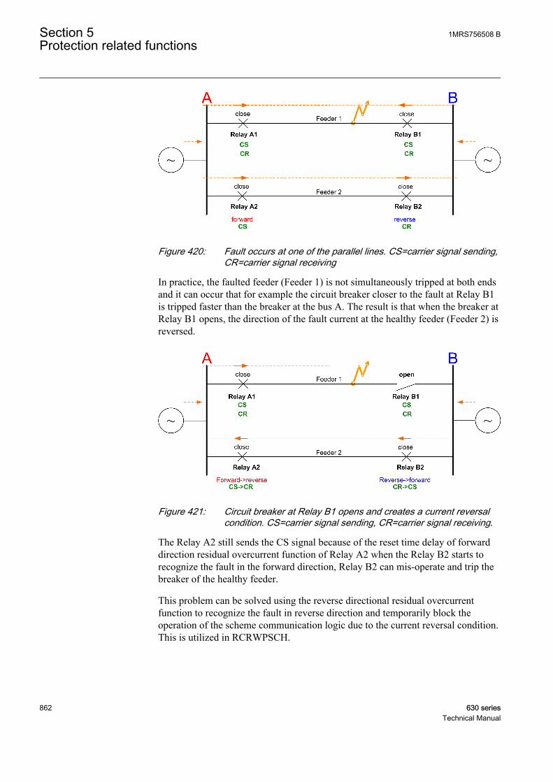
GUID-BB20534F-6AD9-4FE4-B668-F2D3C1BFD277 V1 EN
Figure 420: Fault occurs at one of the parallel lines. CS=carrier signal sending,CR=carrier signal receiving
In practice, the faulted feeder (Feeder 1) is not simultaneously tripped at both endsand it can occur that for example the circuit breaker closer to the fault at Relay B1is tripped faster than the breaker at the bus A. The result is that when the breaker atRelay B1 opens, the direction of the fault current at the healthy feeder (Feeder 2) isreversed.
GUID-3A4476C3-324C-48B0-840B-543E00B08499 V1 EN
Figure 421: Circuit breaker at Relay B1 opens and creates a current reversalcondition. CS=carrier signal sending, CR=carrier signal receiving.
The Relay A2 still sends the CS signal because of the reset time delay of forwarddirection residual overcurrent function of Relay A2 when the Relay B2 starts torecognize the fault in the forward direction, Relay B2 can mis-operate and trip thebreaker of the healthy feeder.
This problem can be solved using the reverse directional residual overcurrentfunction to recognize the fault in reverse direction and temporarily block theoperation of the scheme communication logic due to the current reversal condition.This is utilized in RCRWPSCH.
Section 5 1MRS756508 BProtection related functions
862 630 seriesTechnical Manual
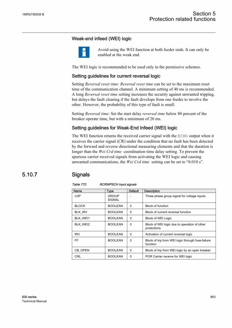
Weak-end infeed (WEI) logic
Avoid using the WEI function at both feeder ends. It can only beenabled at the weak end.
The WEI logic is recommended to be used only in the permissive schemes.
Setting guidelines for current reversal logicSetting Reversal reset time: Reversal reset time can be set to the maximum resettime of the communication channel. A minimum setting of 40 ms is recommended.A long Reversal reset time setting increases the security against unwanted tripping,but delays the fault clearing if the fault develops from one feeder to involve theother. However, the probability of this type of fault is small.
Setting Reversal time: Set the start delay reversal time below 80 percent of thebreaker operate time, but with a minimum of 20 ms.
Setting guidelines for Weak-End Infeed (WEI) logicThe WEI function returns the received carrier signal with the ECHO output when itreceives the carrier signal (CR) under the condition that no fault has been detectedby the forward and reverse directional measuring elements and that the duration islonger than the Wei Crd time coordination time delay setting. To prevent thespurious carrier received signals from activating the WEI logic and causingunwanted communications, the Wei Crd time setting can be set to “0.010 s”.
5.10.7 SignalsTable 772: RCRWPSCH Input signals
Name Type Default DescriptionU3P GROUP
SIGNAL- Three phase group signal for voltage inputs
BLOCK BOOLEAN 0 Block of function
BLK_IRV BOOLEAN 0 Block of current reversal function
BLK_WEI1 BOOLEAN 0 Block of WEI Logic
BLK_WEI2 BOOLEAN 0 Block of WEI logic due to operation of otherprotections
IRV BOOLEAN 0 Activation of current reversal logic
FF BOOLEAN 0 Block of trip from WEI logic through fuse-failurefunction
CB_OPEN BOOLEAN 0 Block of trip from WEI logic by an open breaker
CRL BOOLEAN 0 POR Carrier receive for WEI logic
1MRS756508 B Section 5Protection related functions
630 series 863Technical Manual
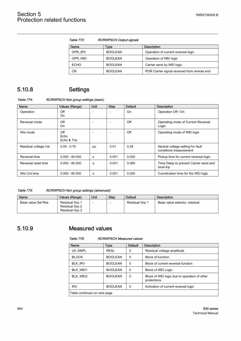
Table 773: RCRWPSCH Output signals
Name Type DescriptionOPR_IRV BOOLEAN Operation of current reversal logic
OPR_WEI BOOLEAN Operation of WEI logic
ECHO BOOLEAN Carrier send by WEI logic
CR BOOLEAN POR Carrier signal received from remote end
5.10.8 SettingsTable 774: RCRWPSCH Non group settings (basic)
Name Values (Range) Unit Step Default DescriptionOperation Off
On- - On Operation Off / On
Reversal mode OffOn
- - Off Operating mode of Current ReversalLogic
Wei mode OffEchoEcho & Trip
- - Off Operating mode of WEI logic
Residual voltage Val 0.05 - 0.70 pu 0.01 0.25 Neutral voltage setting for faultconditions measurement
Reversal time 0.000 - 60.000 s 0.001 0.020 Pickup time for current reversal logic
Reversal reset time 0.000 - 60.000 s 0.001 0.060 Time Delay to prevent Carrier send andlocal trip
Wei Crd time 0.000 - 60.000 s 0.001 0.000 Coordination time for the WEI logic
Table 775: RCRWPSCH Non group settings (advanced)
Name Values (Range) Unit Step Default DescriptionBase value Sel Res Residual Grp 1
Residual Grp 2Residual Grp 3
- - Residual Grp 1 Base value selector, residual
5.10.9 Measured valuesTable 776: RCRWPSCH Measured values
Name Type Default DescriptionU0_AMPL REAL 0 Residual voltage amplitude
BLOCK BOOLEAN 0 Block of function
BLK_IRV BOOLEAN 0 Block of current reversal function
BLK_WEI1 BOOLEAN 0 Block of WEI Logic
BLK_WEI2 BOOLEAN 0 Block of WEI logic due to operation of otherprotections
IRV BOOLEAN 0 Activation of current reversal logic
Table continues on next page
Section 5 1MRS756508 BProtection related functions
864 630 seriesTechnical Manual
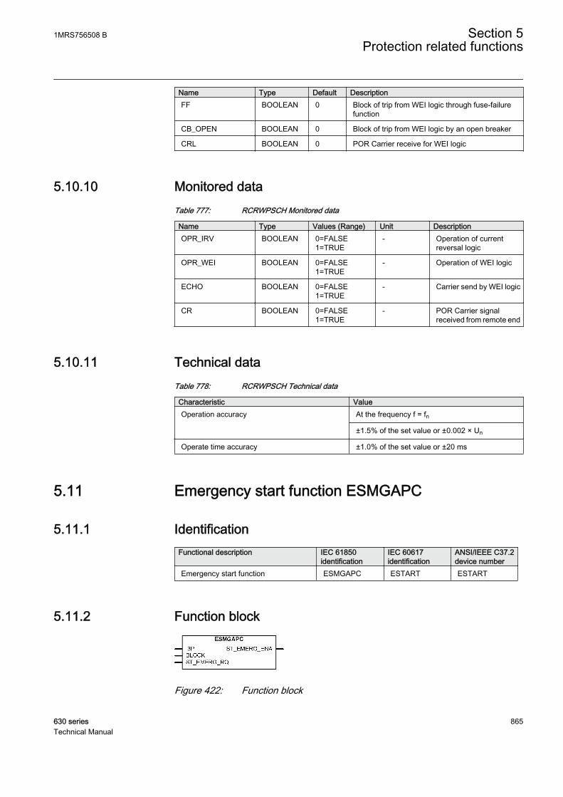
Name Type Default DescriptionFF BOOLEAN 0 Block of trip from WEI logic through fuse-failure
function
CB_OPEN BOOLEAN 0 Block of trip from WEI logic by an open breaker
CRL BOOLEAN 0 POR Carrier receive for WEI logic
5.10.10 Monitored dataTable 777: RCRWPSCH Monitored data
Name Type Values (Range) Unit DescriptionOPR_IRV BOOLEAN 0=FALSE
1=TRUE- Operation of current
reversal logic
OPR_WEI BOOLEAN 0=FALSE1=TRUE
- Operation of WEI logic
ECHO BOOLEAN 0=FALSE1=TRUE
- Carrier send by WEI logic
CR BOOLEAN 0=FALSE1=TRUE
- POR Carrier signalreceived from remote end
5.10.11 Technical dataTable 778: RCRWPSCH Technical data
Characteristic ValueOperation accuracy At the frequency f = fn
±1.5% of the set value or ±0.002 × Un
Operate time accuracy ±1.0% of the set value or ±20 ms
5.11 Emergency start function ESMGAPC
5.11.1 IdentificationFunctional description IEC 61850
identificationIEC 60617identification
ANSI/IEEE C37.2device number
Emergency start function ESMGAPC ESTART ESTART
5.11.2 Function block
GUID-3DFAC950-3ECE-49B5-8D3D-B33DFE3B847B V1 EN
Figure 422: Function block
1MRS756508 B Section 5Protection related functions
630 series 865Technical Manual
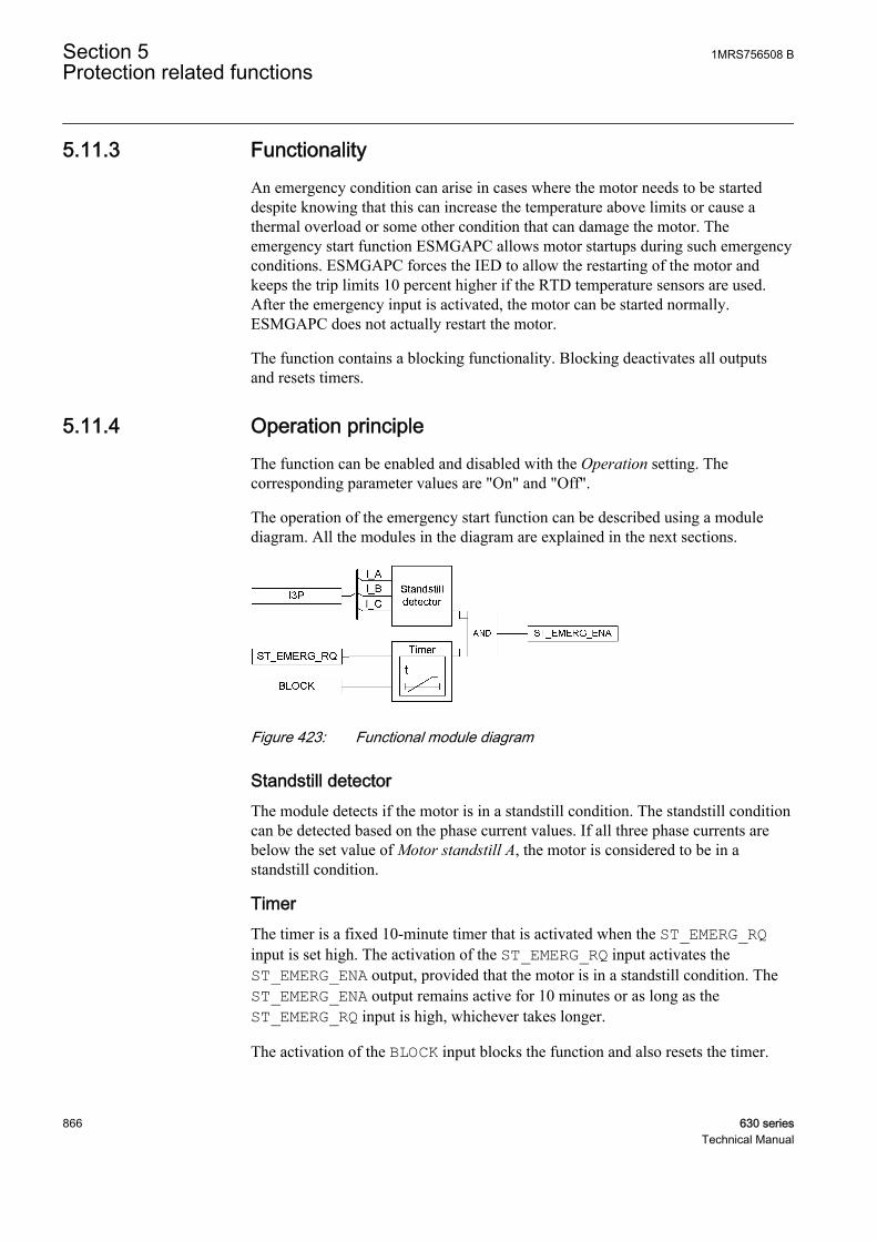
5.11.3 FunctionalityAn emergency condition can arise in cases where the motor needs to be starteddespite knowing that this can increase the temperature above limits or cause athermal overload or some other condition that can damage the motor. Theemergency start function ESMGAPC allows motor startups during such emergencyconditions. ESMGAPC forces the IED to allow the restarting of the motor andkeeps the trip limits 10 percent higher if the RTD temperature sensors are used.After the emergency input is activated, the motor can be started normally.ESMGAPC does not actually restart the motor.
The function contains a blocking functionality. Blocking deactivates all outputsand resets timers.
5.11.4 Operation principleThe function can be enabled and disabled with the Operation setting. Thecorresponding parameter values are "On" and "Off".
The operation of the emergency start function can be described using a modulediagram. All the modules in the diagram are explained in the next sections.
GUID-3B7AF933-9E24-48E7-98C1-0E4FBD9C7BA8 V1 EN
Figure 423: Functional module diagram
Standstill detectorThe module detects if the motor is in a standstill condition. The standstill conditioncan be detected based on the phase current values. If all three phase currents arebelow the set value of Motor standstill A, the motor is considered to be in astandstill condition.
TimerThe timer is a fixed 10-minute timer that is activated when the ST_EMERG_RQinput is set high. The activation of the ST_EMERG_RQ input activates theST_EMERG_ENA output, provided that the motor is in a standstill condition. TheST_EMERG_ENA output remains active for 10 minutes or as long as theST_EMERG_RQ input is high, whichever takes longer.
The activation of the BLOCK input blocks the function and also resets the timer.
Section 5 1MRS756508 BProtection related functions
866 630 seriesTechnical Manual
The function also provides the ST_EMERG_ENA output change date and time,T_ST_EMERG. The information is available in the monitored data view.
5.11.5 ApplicationIf the motor needs to be started in an emergency condition at the risk of damagingthe motor, all the external restart inhibits are ignored, allowing the motor to berestarted. Furthermore, if the calculated thermal level is higher than the restartinhibit level at an emergency start condition, the calculated thermal level is setslightly below the restart inhibit level. Also, if the register value of the cumulativestartup time counter exceeds the restart inhibit level, the value is set slightly belowthe restart disable value to allow at least one motor startup. If RTDs are used, theset trip values are increased by 10 percent.
The activation of the ST_EMERG_RQ digital input allows to perform emergencystart. The IED is forced to a state which allows the restart of motor, and theoperator can now restart the motor. If RTDs are used, the operator should makesure that the RTD temperatures are low enough to restore the RTD trip level backto normal before the emergency start is deactivated. A new emergency start cannotbe made until the 10 minute time-out has passed or until the emergency start isreleased, whichever takes longer.
The last change of the emergency start output signal is recorded.
5.11.6 SignalsTable 779: ESMGAPC Input signals
Name Type Default DescriptionI3P GROUP
SIGNAL- Group signal for current inputs
BLOCK BOOLEAN 0 Block signal to block the function.
ST_EMERG_RQ BOOLEAN 0 Input emergency start signal from the operator.
Table 780: ESMGAPC Output signals
Name Type DescriptionST_EMERG_ENA BOOLEAN Emergency start signal
5.11.7 SettingsTable 781: ESMGAPC Non group settings (basic)
Name Values (Range) Unit Step Default DescriptionOperation Off
On- - On Operation Off/On
1MRS756508 B Section 5Protection related functions
630 series 867Technical Manual
Table 782: ESMGAPC Non group settings (advanced)
Name Values (Range) Unit Step Default DescriptionBase value Sel phase Phase Grp 1
Phase Grp 2Phase Grp 3
- - Phase Grp 1 Base value selector phase / phase tophase
Motor standstill A 0.05 - 0.20 pu 0.01 0.12 Current limit to check for motor standstillcondition
5.11.8 Measured valuesTable 783: ESMGAPC Measured values
Name Type Default DescriptionI_RMS_A REAL 0.0 TrueRMS motor current for phase A.
I_RMS_B REAL 0.0 TrueRMS motor current for phase B.
I_RMS_C REAL 0.0 TrueRMS motor current for phase C.
BLOCK BOOLEAN 0 Block signal to block the function.
ST_EMERG_RQ BOOLEAN 0 Input emergency start signal from the operator.
5.11.9 Monitored dataTable 784: ESMGAPC Monitored data
Name Type Values (Range) Unit DescriptionST_EMERG_ENA BOOLEAN 0=FALSE
1=TRUE- Emergency start signal
T_ST_EMERG INTEGER - - Time when emergencystart output signal waslast activated /deactivated
5.11.10 Technical dataTable 785: ESMGAPC Technical data
Characteristic ValueOperation accuracy At the frequency f = fn
±1.5% of the set value or ±0.002 × Un
Section 5 1MRS756508 BProtection related functions
868 630 seriesTechnical Manual
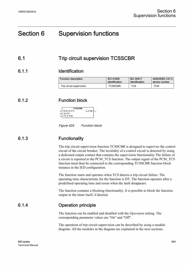
Section 6 Supervision functions
6.1 Trip circuit supervision TCSSCBR
6.1.1 IdentificationFunction description IEC 61850
identificationIEC 60617identification
ANSI/IEEE C37.2device number
Trip circuit supervision TCSSCBR TCS TCM
6.1.2 Function block
A071006 V2 EN
Figure 424: Function block
6.1.3 FunctionalityThe trip circuit supervision function TCSSCBR is designed to supervise the controlcircuit of the circuit breaker. The invalidity of a control circuit is detected by usinga dedicated output contact that contains the supervision functionality.The failure ofa circuit is reported to the PCM_TCS function. The output signal of the PCM_TCSfunction must then be connected to the corresponding TCSSCBR function blockinstance in the IED configuration.
The function starts and operates when TCS detects a trip circuit failure. Theoperating time characteristic for the function is DT. The function operates after apredefined operating time and resets when the fault disappears.
The function contains a blocking functionality. It is possible to block the functionoutput or the timer itself, if desired.
6.1.4 Operation principleThe function can be enabled and disabled with the Operation setting. Thecorresponding parameter values are "On" and "Off".
The operation of trip circuit supervision can be described by using a modulediagram. All the modules in the diagram are explained in the next sections.
1MRS756508 B Section 6Supervision functions
630 series 869Technical Manual
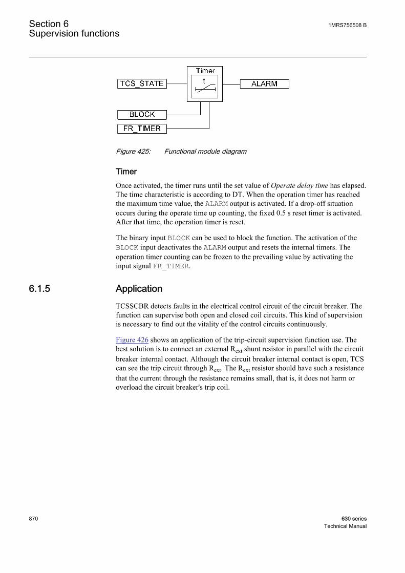
A080006 V2 EN
Figure 425: Functional module diagram
TimerOnce activated, the timer runs until the set value of Operate delay time has elapsed.The time characteristic is according to DT. When the operation timer has reachedthe maximum time value, the ALARM output is activated. If a drop-off situationoccurs during the operate time up counting, the fixed 0.5 s reset timer is activated.After that time, the operation timer is reset.
The binary input BLOCK can be used to block the function. The activation of theBLOCK input deactivates the ALARM output and resets the internal timers. Theoperation timer counting can be frozen to the prevailing value by activating theinput signal FR_TIMER.
6.1.5 ApplicationTCSSCBR detects faults in the electrical control circuit of the circuit breaker. Thefunction can supervise both open and closed coil circuits. This kind of supervisionis necessary to find out the vitality of the control circuits continuously.
Figure 426 shows an application of the trip-circuit supervision function use. Thebest solution is to connect an external Rext shunt resistor in parallel with the circuitbreaker internal contact. Although the circuit breaker internal contact is open, TCScan see the trip circuit through Rext. The Rext resistor should have such a resistancethat the current through the resistance remains small, that is, it does not harm oroverload the circuit breaker's trip coil.
Section 6 1MRS756508 BSupervision functions
870 630 seriesTechnical Manual
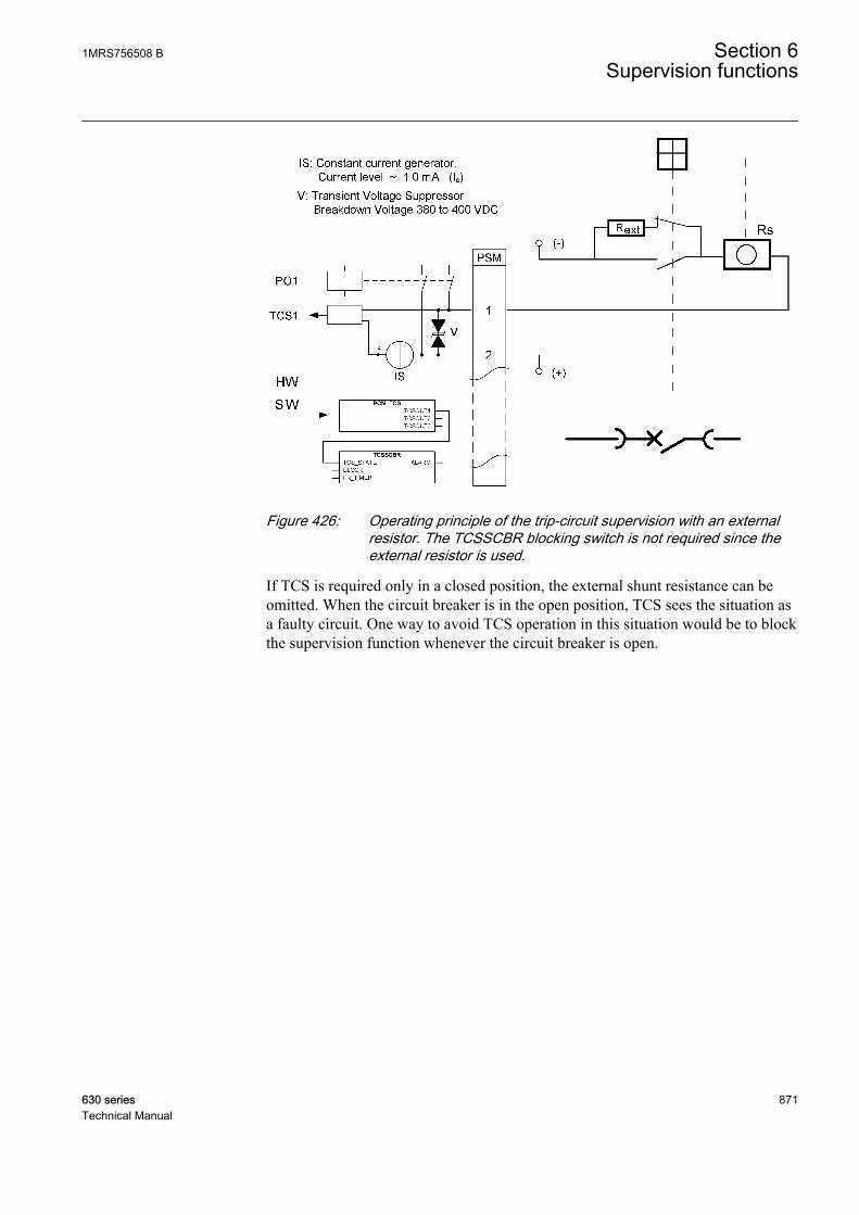
GUID-A916D887-EC5A-4286-B1AE-823540EC722C V1 EN
Figure 426: Operating principle of the trip-circuit supervision with an externalresistor. The TCSSCBR blocking switch is not required since theexternal resistor is used.
If TCS is required only in a closed position, the external shunt resistance can beomitted. When the circuit breaker is in the open position, TCS sees the situation asa faulty circuit. One way to avoid TCS operation in this situation would be to blockthe supervision function whenever the circuit breaker is open.
1MRS756508 B Section 6Supervision functions
630 series 871Technical Manual

GUID-4B905B99-D653-4B2D-96C1-666511CA3711 V1 EN
Figure 427: Operating principle of the trip-circuit supervision without anexternal resistor. The circuit breaker open indication is set to blockTCSSCBR when the circuit breaker is open.
Trip circuit supervision and other trip contactsIt is typical that the trip circuit contains more than one trip contact in parallel, forexample in transformer feeders where the trip of a Buchholz relay is connected inparallel with the feeder terminal and other relays involved.
GUID-7264738C-F9D7-48F0-B6FC-F85FD10D5B84 V1 EN
Figure 428: Constant test current flow in parallel trip contacts and trip-circuitsupervision
Section 6 1MRS756508 BSupervision functions
872 630 seriesTechnical Manual
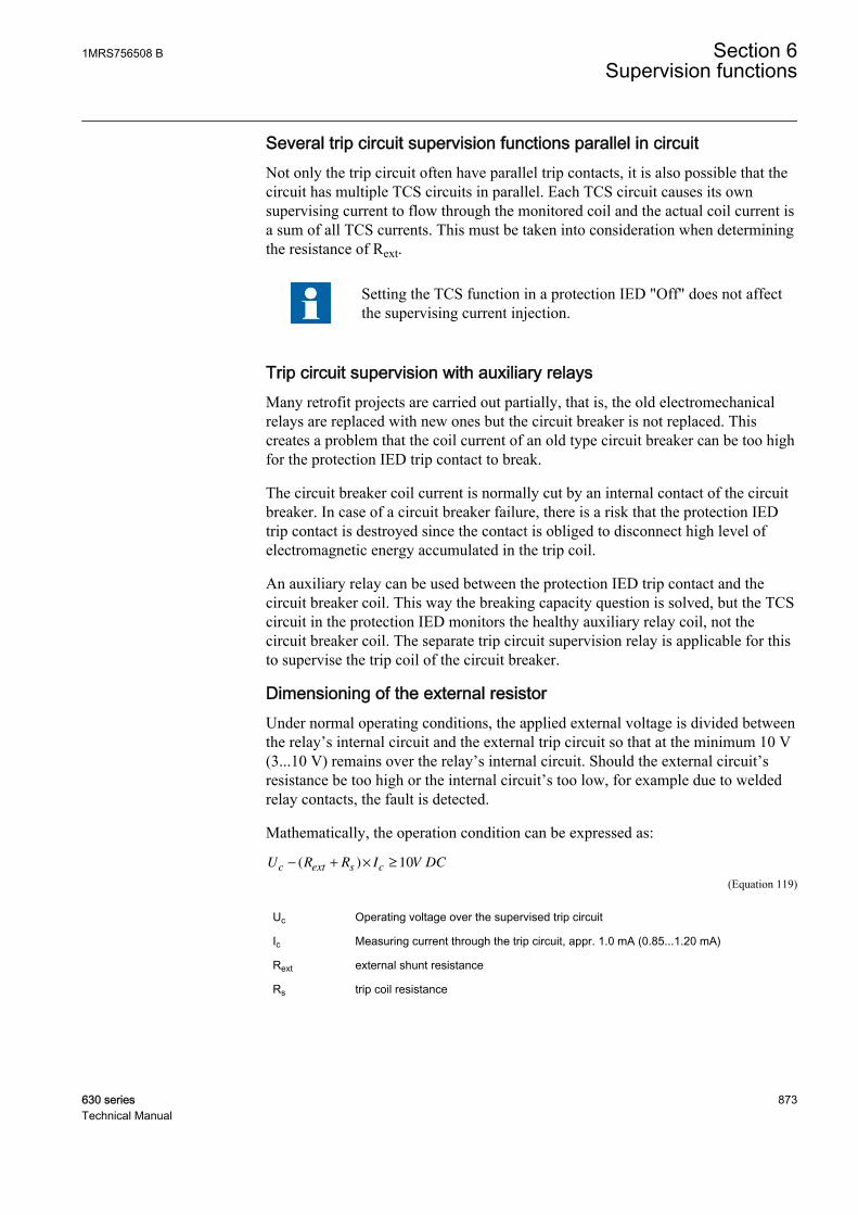
Several trip circuit supervision functions parallel in circuitNot only the trip circuit often have parallel trip contacts, it is also possible that thecircuit has multiple TCS circuits in parallel. Each TCS circuit causes its ownsupervising current to flow through the monitored coil and the actual coil current isa sum of all TCS currents. This must be taken into consideration when determiningthe resistance of Rext.
Setting the TCS function in a protection IED "Off" does not affectthe supervising current injection.
Trip circuit supervision with auxiliary relaysMany retrofit projects are carried out partially, that is, the old electromechanicalrelays are replaced with new ones but the circuit breaker is not replaced. Thiscreates a problem that the coil current of an old type circuit breaker can be too highfor the protection IED trip contact to break.
The circuit breaker coil current is normally cut by an internal contact of the circuitbreaker. In case of a circuit breaker failure, there is a risk that the protection IEDtrip contact is destroyed since the contact is obliged to disconnect high level ofelectromagnetic energy accumulated in the trip coil.
An auxiliary relay can be used between the protection IED trip contact and thecircuit breaker coil. This way the breaking capacity question is solved, but the TCScircuit in the protection IED monitors the healthy auxiliary relay coil, not thecircuit breaker coil. The separate trip circuit supervision relay is applicable for thisto supervise the trip coil of the circuit breaker.
Dimensioning of the external resistorUnder normal operating conditions, the applied external voltage is divided betweenthe relay’s internal circuit and the external trip circuit so that at the minimum 10 V(3...10 V) remains over the relay’s internal circuit. Should the external circuit’sresistance be too high or the internal circuit’s too low, for example due to weldedrelay contacts, the fault is detected.
Mathematically, the operation condition can be expressed as:
U R R I V DCc ext s c− + × ≥( ) 10
GUID-34BDFCA2-E72E-4602-9F0D-281CDDF0A93A V1 EN (Equation 119)
Uc Operating voltage over the supervised trip circuit
Ic Measuring current through the trip circuit, appr. 1.0 mA (0.85...1.20 mA)
Rext external shunt resistance
Rs trip coil resistance
1MRS756508 B Section 6Supervision functions
630 series 873Technical Manual
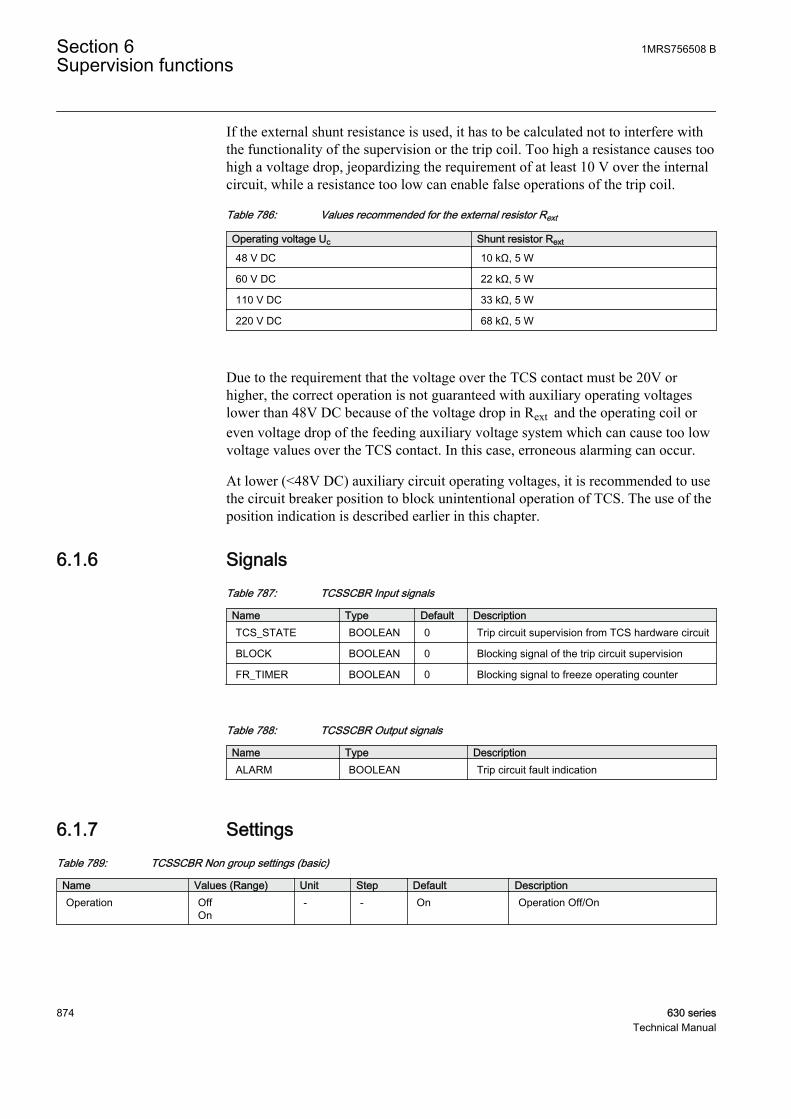
If the external shunt resistance is used, it has to be calculated not to interfere withthe functionality of the supervision or the trip coil. Too high a resistance causes toohigh a voltage drop, jeopardizing the requirement of at least 10 V over the internalcircuit, while a resistance too low can enable false operations of the trip coil.
Table 786: Values recommended for the external resistor Rext
Operating voltage Uc Shunt resistor Rext
48 V DC 10 kΩ, 5 W
60 V DC 22 kΩ, 5 W
110 V DC 33 kΩ, 5 W
220 V DC 68 kΩ, 5 W
Due to the requirement that the voltage over the TCS contact must be 20V orhigher, the correct operation is not guaranteed with auxiliary operating voltageslower than 48V DC because of the voltage drop in Rext and the operating coil oreven voltage drop of the feeding auxiliary voltage system which can cause too lowvoltage values over the TCS contact. In this case, erroneous alarming can occur.
At lower (<48V DC) auxiliary circuit operating voltages, it is recommended to usethe circuit breaker position to block unintentional operation of TCS. The use of theposition indication is described earlier in this chapter.
6.1.6 SignalsTable 787: TCSSCBR Input signals
Name Type Default DescriptionTCS_STATE BOOLEAN 0 Trip circuit supervision from TCS hardware circuit
BLOCK BOOLEAN 0 Blocking signal of the trip circuit supervision
FR_TIMER BOOLEAN 0 Blocking signal to freeze operating counter
Table 788: TCSSCBR Output signals
Name Type DescriptionALARM BOOLEAN Trip circuit fault indication
6.1.7 SettingsTable 789: TCSSCBR Non group settings (basic)
Name Values (Range) Unit Step Default DescriptionOperation Off
On- - On Operation Off/On
Section 6 1MRS756508 BSupervision functions
874 630 seriesTechnical Manual
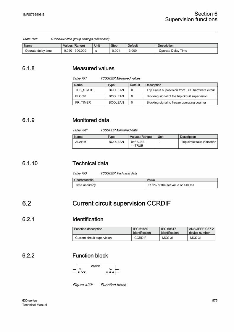
Table 790: TCSSCBR Non group settings (advanced)
Name Values (Range) Unit Step Default DescriptionOperate delay time 0.020 - 300.000 s 0.001 3.000 Operate Delay Time
6.1.8 Measured valuesTable 791: TCSSCBR Measured values
Name Type Default DescriptionTCS_STATE BOOLEAN 0 Trip circuit supervision from TCS hardware circuit
BLOCK BOOLEAN 0 Blocking signal of the trip circuit supervision
FR_TIMER BOOLEAN 0 Blocking signal to freeze operating counter
6.1.9 Monitored dataTable 792: TCSSCBR Monitored data
Name Type Values (Range) Unit DescriptionALARM BOOLEAN 0=FALSE
1=TRUE- Trip circuit fault indication
6.1.10 Technical dataTable 793: TCSSCBR Technical data
Characteristic ValueTime accuracy ±1.0% of the set value or ±40 ms
6.2 Current circuit supervision CCRDIF
6.2.1 IdentificationFunction description IEC 61850
identificationIEC 60617identification
ANSI/IEEE C37.2device number
Current circuit supervision CCRDIF MCS 3I MCS 3I
6.2.2 Function block
GUID-DB608E0F-5793-4D82-8744-B13C20BC0A63 V1 EN
Figure 429: Function block
1MRS756508 B Section 6Supervision functions
630 series 875Technical Manual
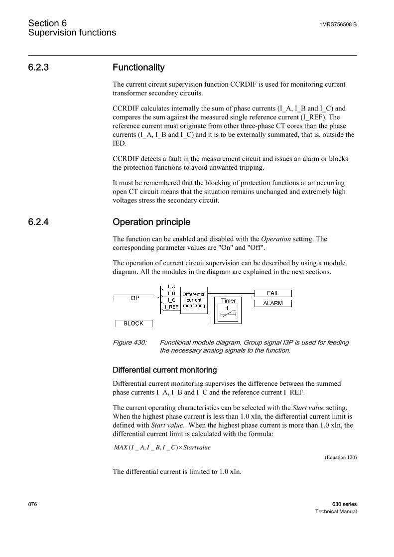
6.2.3 FunctionalityThe current circuit supervision function CCRDIF is used for monitoring currenttransformer secondary circuits.
CCRDIF calculates internally the sum of phase currents (I_A, I_B and I_C) andcompares the sum against the measured single reference current (I_REF). Thereference current must originate from other three-phase CT cores than the phasecurrents (I_A, I_B and I_C) and it is to be externally summated, that is, outside theIED.
CCRDIF detects a fault in the measurement circuit and issues an alarm or blocksthe protection functions to avoid unwanted tripping.
It must be remembered that the blocking of protection functions at an occurringopen CT circuit means that the situation remains unchanged and extremely highvoltages stress the secondary circuit.
6.2.4 Operation principleThe function can be enabled and disabled with the Operation setting. Thecorresponding parameter values are "On" and "Off".
The operation of current circuit supervision can be described by using a modulediagram. All the modules in the diagram are explained in the next sections.
GUID-03189A4C-F326-4CD4-9467-E60A773B00DC V1 EN
Figure 430: Functional module diagram. Group signal I3P is used for feedingthe necessary analog signals to the function.
Differential current monitoringDifferential current monitoring supervises the difference between the summedphase currents I_A, I_B and I_C and the reference current I_REF.
The current operating characteristics can be selected with the Start value setting.When the highest phase current is less than 1.0 xIn, the differential current limit isdefined with Start value. When the highest phase current is more than 1.0 xIn, thedifferential current limit is calculated with the formula:
MAX I A I B I C Startvalue( _ , _ , _ )×
GUID-A0C500CA-4A1A-44AA-AC14-4540676DD8CB V2 EN (Equation 120)
The differential current is limited to 1.0 xIn.
Section 6 1MRS756508 BSupervision functions
876 630 seriesTechnical Manual

GUID-DC279F84-19B8-4FCB-A79A-2461C047F1B2 V1 EN
Figure 431: CCRDIF operating characteristics
When the differential current I_DIFF is in the operating region, the FAIL output isactivated.
The function is internally blocked if any phase current is higher than the set Maxoperate current. When the internal blocking activates, the FAIL output isdeactivated immediately. The internal blocking is used for avoiding false operationduring a fault situation when the current transformers are saturated due to highfault currents.
The value of the differential current is available in the monitored data view on theLHMI or through other communication tools. The value is calculated with theformula:
I DIFF I A I B I C I REF_ _ _ _ _= + + −
GUID-9CC931FA-0637-4FF8-85D4-6F461BD996A9 V2 EN (Equation 121)
The Start value setting is given in units of xIn of the phase current transformer. Thepossible difference in the phase and reference current transformer ratios isinternally compensated by scaling I_REF with the value derived from the Primarycurrent setting values. These setting parameters can be found in the Basic functionssection.
The activation of the BLOCK input deactivates the FAIL output immediately.
1MRS756508 B Section 6Supervision functions
630 series 877Technical Manual

TimerThe timer is activated with the FAIL signal. The ALARM output is activated after afixed 200 ms delay. FAIL needs to be active during the delay.
When the internal blocking is activated, the FAIL output is deactivatedimmediately. The ALARM output is deactivated after a fixed 3 s delay, and theFAIL is deactivated.
The deactivation happens only when the highest phase current ismore than 5 percent of the nominal current (0.05 xIn).
When the line is de-energized, the deactivation of the ALARM output is prevented.
The activation of the BLOCK input deactivates the ALARM output.
6.2.5 Base valuesIn this function block, some of the settings are set in per unit (pu). These pu valuesare relational to certain base values, for example the values given in A, kV andkVA. The IED supports alternative base value groups for the phase current or voltage-related settings, for example "Phase Grp 1", "Phase Grp 2" and "Phase Grp 3".One of the groups to be used with the Base value Sel phase setting must be selected.
For more information, see the Basic functions section in this manual.
6.2.6 ApplicationOpen or short-circuited current transformer cores can cause unwanted operation inmany protection functions such as differential, earth-fault current and negativesequence current functions. When currents from two independent three-phase setsof CTs or CT cores measuring the same primary currents are available, reliablecurrent circuit supervision can be arranged by comparing the currents from the twosets. When an error in any CT circuit is detected, the protection functionsconcerned can be blocked and an alarm given.
In case of high currents, the unequal transient saturation of CT cores with adifferent remanence or saturation factor may result in differences in the secondarycurrents from the two CT cores. Unwanted blocking of protection functions duringthe transient stage must then be avoided.
The supervision function must be sensitive and have a short operate time in orderto prevent unwanted tripping from fast-acting, sensitive numerical protections incase of faulty CT secondary circuits.
Section 6 1MRS756508 BSupervision functions
878 630 seriesTechnical Manual
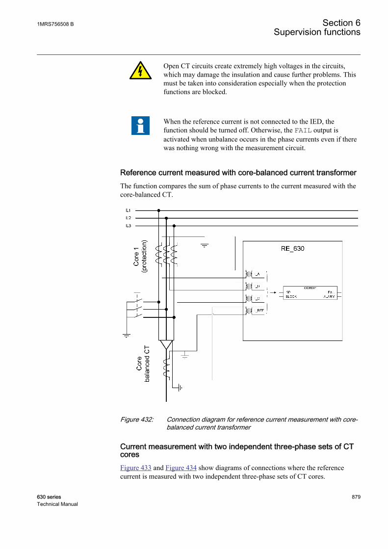
Open CT circuits create extremely high voltages in the circuits,which may damage the insulation and cause further problems. Thismust be taken into consideration especially when the protectionfunctions are blocked.
When the reference current is not connected to the IED, thefunction should be turned off. Otherwise, the FAIL output isactivated when unbalance occurs in the phase currents even if therewas nothing wrong with the measurement circuit.
Reference current measured with core-balanced current transformerThe function compares the sum of phase currents to the current measured with thecore-balanced CT.
GUID-EA681A69-B377-4553-AE17-E6E877D821CB V1 EN
Figure 432: Connection diagram for reference current measurement with core-balanced current transformer
Current measurement with two independent three-phase sets of CTcoresFigure 433 and Figure 434 show diagrams of connections where the referencecurrent is measured with two independent three-phase sets of CT cores.
1MRS756508 B Section 6Supervision functions
630 series 879Technical Manual
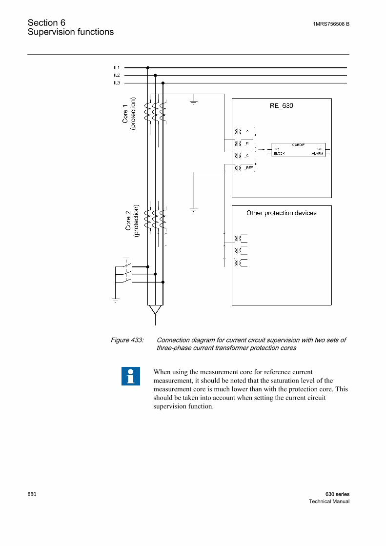
GUID-FA4A5A77-7670-4D05-BCF2-30276444B891 V1 EN
Figure 433: Connection diagram for current circuit supervision with two sets ofthree-phase current transformer protection cores
When using the measurement core for reference currentmeasurement, it should be noted that the saturation level of themeasurement core is much lower than with the protection core. Thisshould be taken into account when setting the current circuitsupervision function.
Section 6 1MRS756508 BSupervision functions
880 630 seriesTechnical Manual
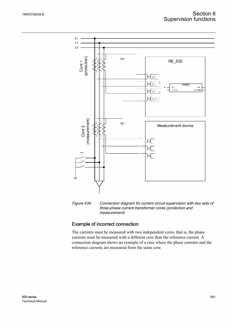
GUID-DA69204E-AA14-4907-9295-D66C0DCD03F4 V1 EN
Figure 434: Connection diagram for current circuit supervision with two sets ofthree-phase current transformer cores (protection andmeasurement)
Example of incorrect connectionThe currents must be measured with two independent cores, that is, the phasecurrents must be measured with a different core than the reference current. Aconnection diagram shows an example of a case where the phase currents and thereference currents are measured from the same core.
1MRS756508 B Section 6Supervision functions
630 series 881Technical Manual

GUID-215E4836-FC10-4AEB-9C54-8E7D6734B941 V1 EN
Figure 435: Example of incorrect reference current connection
6.2.7 SignalsTable 794: CCRDIF Input signals
Name Type Default DescriptionI3P GROUP
SIGNAL- Three phase group signal for current inputs
BLOCK BOOLEAN 0 Block of function
Table 795: CCRDIF Output signals
Name Type DescriptionFAIL BOOLEAN Detection of current circuit failure
ALARM BOOLEAN Alarm for current circuit failure
6.2.8 SettingsTable 796: CCRDIF Non group settings (basic)
Name Values (Range) Unit Step Default DescriptionOperation Off
On- - On Operation Off / On
Start value 0.05 - 2.00 pu 0.01 0.20 Minimum operate current differential level
Section 6 1MRS756508 BSupervision functions
882 630 seriesTechnical Manual
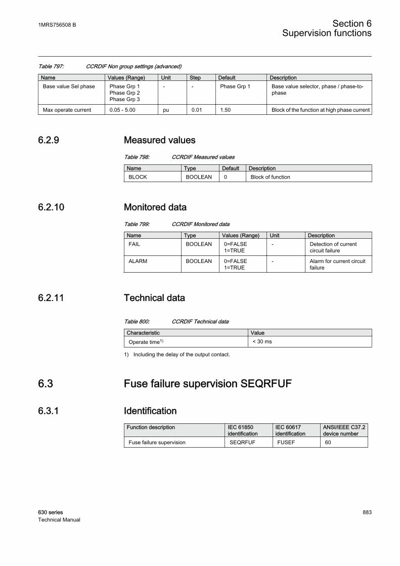
Table 797: CCRDIF Non group settings (advanced)
Name Values (Range) Unit Step Default DescriptionBase value Sel phase Phase Grp 1
Phase Grp 2Phase Grp 3
- - Phase Grp 1 Base value selector, phase / phase-to-phase
Max operate current 0.05 - 5.00 pu 0.01 1.50 Block of the function at high phase current
6.2.9 Measured valuesTable 798: CCRDIF Measured values
Name Type Default DescriptionBLOCK BOOLEAN 0 Block of function
6.2.10 Monitored dataTable 799: CCRDIF Monitored data
Name Type Values (Range) Unit DescriptionFAIL BOOLEAN 0=FALSE
1=TRUE- Detection of current
circuit failure
ALARM BOOLEAN 0=FALSE1=TRUE
- Alarm for current circuitfailure
6.2.11 Technical data
Table 800: CCRDIF Technical data
Characteristic ValueOperate time1) < 30 ms
1) Including the delay of the output contact.
6.3 Fuse failure supervision SEQRFUF
6.3.1 IdentificationFunction description IEC 61850
identificationIEC 60617identification
ANSI/IEEE C37.2device number
Fuse failure supervision SEQRFUF FUSEF 60
1MRS756508 B Section 6Supervision functions
630 series 883Technical Manual
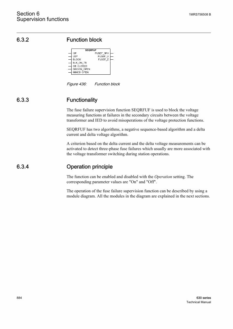
6.3.2 Function block
GUID-684B4209-8418-41F0-928D-64FE3ACF9321 V1 EN
Figure 436: Function block
6.3.3 FunctionalityThe fuse failure supervision function SEQRFUF is used to block the voltagemeasuring functions at failures in the secondary circuits between the voltagetransformer and IED to avoid misoperations of the voltage protection functions.
SEQRFUF has two algorithms, a negative sequence-based algorithm and a deltacurrent and delta voltage algorithm.
A criterion based on the delta current and the delta voltage measurements can beactivated to detect three-phase fuse failures which usually are more associated withthe voltage transformer switching during station operations.
6.3.4 Operation principleThe function can be enabled and disabled with the Operation setting. Thecorresponding parameter values are "On" and "Off".
The operation of the fuse failure supervision function can be described by using amodule diagram. All the modules in the diagram are explained in the next sections.
Section 6 1MRS756508 BSupervision functions
884 630 seriesTechnical Manual

GUID-94AAAC84-143B-494C-8207-F9B0401CE7EC V2 EN
Figure 437: Functional module diagram
Negative phase-sequence criterionA fuse failure based on negative sequence criterion is detected if the measurednegative sequence voltage exceeds the set Neg Seq voltage Lev value and themeasured negative sequence current is below the set Neg Seq current Lev value.The detected fuse failure is reported to the decision logic module.
Voltage checkThe phase voltage magnitude is checked when deciding whether the fuse failure isa three, two or a single-phase fault.
The module makes a phase-specific comparison between each voltage input andthe Seal in voltage setting. In case the input voltage is lower than the setting, thecorresponding phase is reported to the decision logic module.
Dead-line detectionThe dead-line detection function is activated from the dead-line condition when thevoltage and current in at least one phase are below the respective set values ofVoltage dead Lin Val and Current dead Lin Val. This prevents the blocking of theimpedance protection by fuse-failure detection during the dead-line condition. This
1MRS756508 B Section 6Supervision functions
630 series 885Technical Manual

also occurs during single pole auto-reclosing. The 200 ms drop-off timer prolongsthe dead-line condition after the line energization in order to prevent the blockingof the impedance protection for unequal pole closing.
Current and voltage delta criterionThe delta function can be activated by setting the Change rate enable parameter to"Yes". Once the function is activated, it operates in parallel with the negativesequence based algorithm. The current and voltage are continuously measured inall three phases to calculate:
• Change of voltage dU/dt• Change of current dI/dt
The calculated delta quantities are compared to the respective set values of theCurrent change rate and Voltage change rate settings.
The delta current and delta voltage algorithms detect a fuse failure if there is asufficient negative change in the voltage amplitude without a sufficient change inthe current amplitude in each phase separately. This is performed when the circuitbreaker is closed. Information about the circuit breaker position is connected to theCB_CLOSED input.
There are two conditions for activating the current and voltage delta function:
• The magnitude of ∆U exceeds the corresponding value of the Min Op voltagedelta setting and the magnitude of ∆I is below the value of the Min Op currentdelta setting in any phase at the same time due to the closure of the circuitbreaker, that is, CB_CLOSED = TRUE.
• The magnitude of ∆U exceeds the value of the Min Op voltage delta settingand the magnitude of ∆I is below the Min Op current delta setting in any phaseat the same time since the magnitude of the phase current in the same phaseexceeds the Current level setting.
The first condition requires the delta criterion to be fulfilled in any phase at thesame time as the circuit breaker is closed. Opening the circuit breaker at one endand energizing the line from the other end onto a fault could lead to an improperoperation of SEQRFUF with an open breaker. If this is considered to be animportant disadvantage, the CB_CLOSED input is to be connected to FALSE.
The second condition requires the delta criterion to be fulfilled in one phasetogether with high current for the same phase. The measured phase current is usedto reduce the risk of a false fuse-failure detection. If the current on the protectedline is low, a voltage drop in the system (not caused by the fuse failure) is notfollowed by a current change and a false fuse failure can occur. To prevent this, theminimum phase current criterion is checked.
The fuse-failure detection is active until the voltages return above the Min Opvoltage delta setting. If a voltage in a phase is below the Min Op voltage delta
Section 6 1MRS756508 BSupervision functions
886 630 seriesTechnical Manual
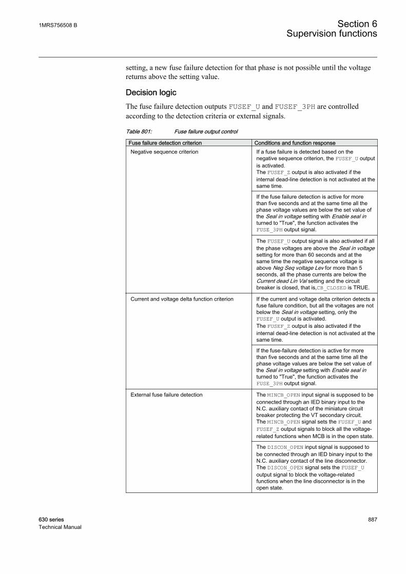
setting, a new fuse failure detection for that phase is not possible until the voltagereturns above the setting value.
Decision logicThe fuse failure detection outputs FUSEF_U and FUSEF_3PH are controlledaccording to the detection criteria or external signals.
Table 801: Fuse failure output control
Fuse failure detection criterion Conditions and function responseNegative sequence criterion If a fuse failure is detected based on the
negative sequence criterion, the FUSEF_U outputis activated.The FUSEF_Z output is also activated if theinternal dead-line detection is not activated at thesame time.
If the fuse failure detection is active for morethan five seconds and at the same time all thephase voltage values are below the set value ofthe Seal in voltage setting with Enable seal inturned to "True", the function activates theFUSE_3PH output signal.
The FUSEF_U output signal is also activated if allthe phase voltages are above the Seal in voltagesetting for more than 60 seconds and at thesame time the negative sequence voltage isabove Neg Seq voltage Lev for more than 5seconds, all the phase currents are below theCurrent dead Lin Val setting and the circuitbreaker is closed, that is,CB_CLOSED is TRUE.
Current and voltage delta function criterion If the current and voltage delta criterion detects afuse failure condition, but all the voltages are notbelow the Seal in voltage setting, only theFUSEF_U output is activated.The FUSEF_Z output is also activated if theinternal dead-line detection is not activated at thesame time.
If the fuse-failure detection is active for morethan five seconds and at the same time all thephase voltage values are below the set value ofthe Seal in voltage setting with Enable seal inturned to "True", the function activates theFUSE_3PH output signal.
External fuse failure detection The MINCB_OPEN input signal is supposed to beconnected through an IED binary input to theN.C. auxiliary contact of the miniature circuitbreaker protecting the VT secondary circuit.The MINCB_OPEN signal sets the FUSEF_U andFUSEF_Z output signals to block all the voltage-related functions when MCB is in the open state.
The DISCON_OPEN input signal is supposed tobe connected through an IED binary input to theN.C. auxiliary contact of the line disconnector.The DISCON_OPEN signal sets the FUSEF_Uoutput signal to block the voltage-relatedfunctions when the line disconnector is in theopen state.
1MRS756508 B Section 6Supervision functions
630 series 887Technical Manual
It is recommended to always set Enable seal in to "True". Thissecures that the blocked protection functions remain blocked untilnormal voltage conditions are restored if the fuse failure has beenactive for 5 seconds, that is, the fuse failure outputs are deactivatedwhen the normal voltage conditions are restored.
The activation of the BLOCK input deactivates the FUSEF_U, FUSEF_3PH andFUSEF_Z outputs. The BLK_ON_TR input is intended to be connected to the tripoutput of any of the protection functions in the IED. When activated for more than20 ms, the operation of the fuse failure is blocked for a fixed time of 100 ms. Theaim is to increase the security against unwanted operations during the opening ofthe breaker. These unwanted operations could cause an unbalance condition forwhich the fuse failure could operate.
6.3.5 Base valuesIn this function block, some of the settings are set in per unit (pu). These pu valuesare relational to certain base values, for example the values given in A, kV andkVA. The IED supports alternative base value groups for the phase current or voltage-related settings, for example "Phase Grp 1", "Phase Grp 2" and "Phase Grp 3".One of the groups to be used with the Base value Sel phase setting must be selected.
For more information, see the Basic functions section in this manual.
6.3.6 ApplicationSome protection functions operate on the basis of the measured voltage value in theIED point. These functions can fail if there is a fault in the measuring circuitsbetween the voltage transformers and the IED.
A fault in the voltage measuring circuit is referred to as a fuse failure. This term ismisleading since a blown fuse is just one of the many possible reasons for a brokencircuit. Since incorrectly measured voltage can result in a faulty operation of someof the protection functions, it is important to detect the fuse failures. A fast fusefailure detection is one of the means to block voltage-based functions before theyoperate.
Section 6 1MRS756508 BSupervision functions
888 630 seriesTechnical Manual
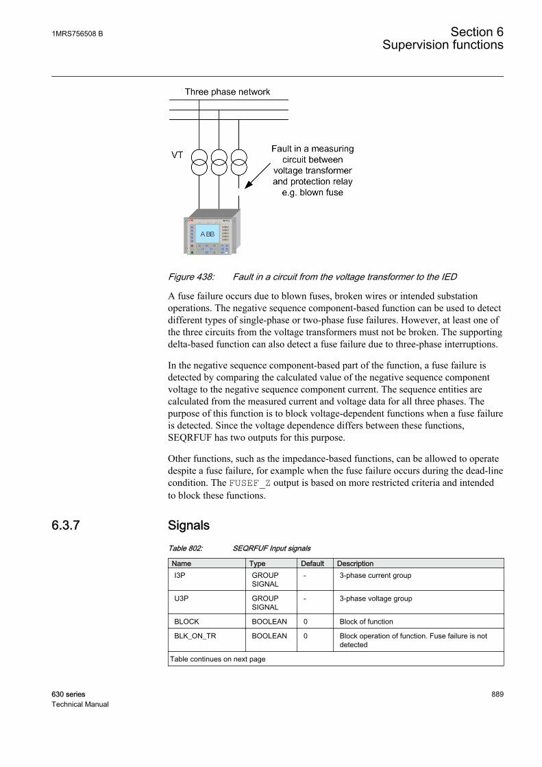
GUID-E086FC34-27C8-4722-8A8D-A573BA7AC878 V1 EN
Figure 438: Fault in a circuit from the voltage transformer to the IED
A fuse failure occurs due to blown fuses, broken wires or intended substationoperations. The negative sequence component-based function can be used to detectdifferent types of single-phase or two-phase fuse failures. However, at least one ofthe three circuits from the voltage transformers must not be broken. The supportingdelta-based function can also detect a fuse failure due to three-phase interruptions.
In the negative sequence component-based part of the function, a fuse failure isdetected by comparing the calculated value of the negative sequence componentvoltage to the negative sequence component current. The sequence entities arecalculated from the measured current and voltage data for all three phases. Thepurpose of this function is to block voltage-dependent functions when a fuse failureis detected. Since the voltage dependence differs between these functions,SEQRFUF has two outputs for this purpose.
Other functions, such as the impedance-based functions, can be allowed to operatedespite a fuse failure, for example when the fuse failure occurs during the dead-linecondition. The FUSEF_Z output is based on more restricted criteria and intendedto block these functions.
6.3.7 SignalsTable 802: SEQRFUF Input signals
Name Type Default DescriptionI3P GROUP
SIGNAL- 3-phase current group
U3P GROUPSIGNAL
- 3-phase voltage group
BLOCK BOOLEAN 0 Block of function
BLK_ON_TR BOOLEAN 0 Block operation of function. Fuse failure is notdetected
Table continues on next page
1MRS756508 B Section 6Supervision functions
630 series 889Technical Manual
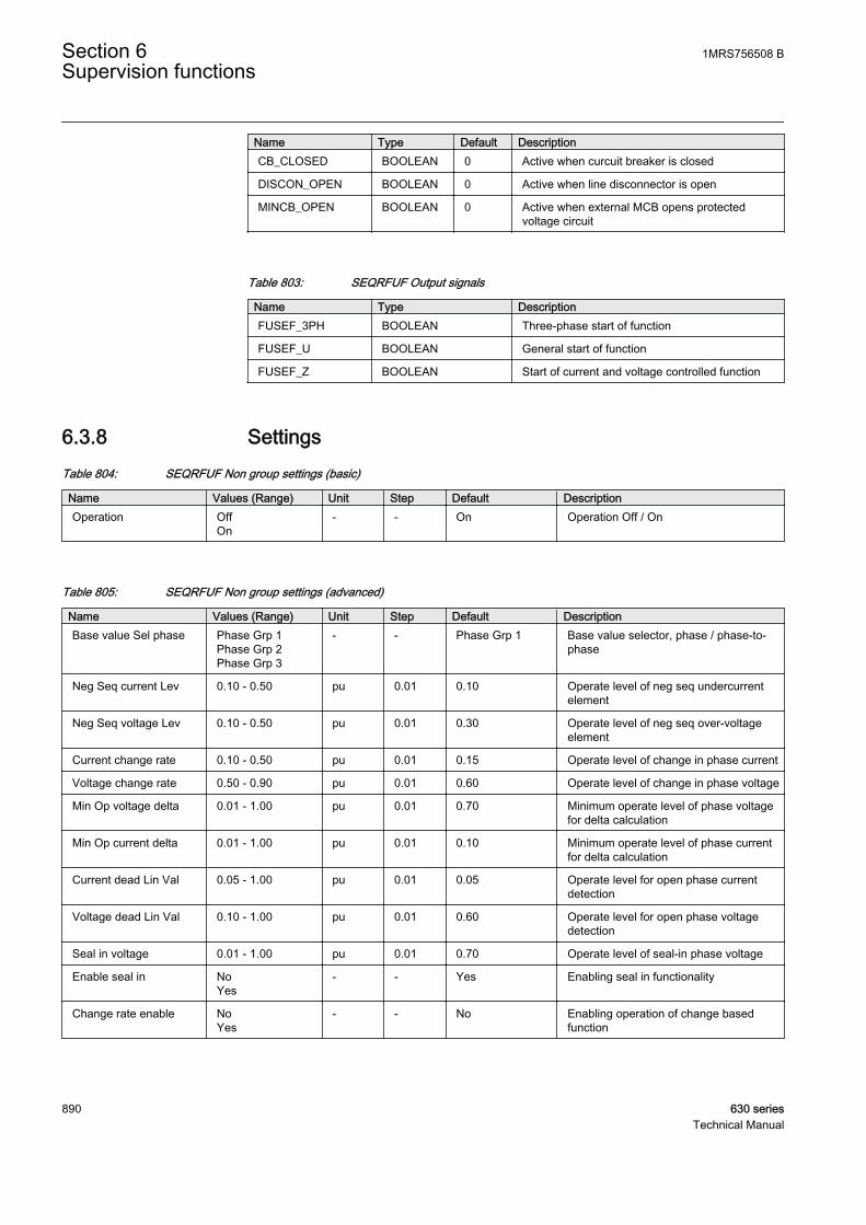
Name Type Default DescriptionCB_CLOSED BOOLEAN 0 Active when curcuit breaker is closed
DISCON_OPEN BOOLEAN 0 Active when line disconnector is open
MINCB_OPEN BOOLEAN 0 Active when external MCB opens protectedvoltage circuit
Table 803: SEQRFUF Output signals
Name Type DescriptionFUSEF_3PH BOOLEAN Three-phase start of function
FUSEF_U BOOLEAN General start of function
FUSEF_Z BOOLEAN Start of current and voltage controlled function
6.3.8 SettingsTable 804: SEQRFUF Non group settings (basic)
Name Values (Range) Unit Step Default DescriptionOperation Off
On- - On Operation Off / On
Table 805: SEQRFUF Non group settings (advanced)
Name Values (Range) Unit Step Default DescriptionBase value Sel phase Phase Grp 1
Phase Grp 2Phase Grp 3
- - Phase Grp 1 Base value selector, phase / phase-to-phase
Neg Seq current Lev 0.10 - 0.50 pu 0.01 0.10 Operate level of neg seq undercurrentelement
Neg Seq voltage Lev 0.10 - 0.50 pu 0.01 0.30 Operate level of neg seq over-voltageelement
Current change rate 0.10 - 0.50 pu 0.01 0.15 Operate level of change in phase current
Voltage change rate 0.50 - 0.90 pu 0.01 0.60 Operate level of change in phase voltage
Min Op voltage delta 0.01 - 1.00 pu 0.01 0.70 Minimum operate level of phase voltagefor delta calculation
Min Op current delta 0.01 - 1.00 pu 0.01 0.10 Minimum operate level of phase currentfor delta calculation
Current dead Lin Val 0.05 - 1.00 pu 0.01 0.05 Operate level for open phase currentdetection
Voltage dead Lin Val 0.10 - 1.00 pu 0.01 0.60 Operate level for open phase voltagedetection
Seal in voltage 0.01 - 1.00 pu 0.01 0.70 Operate level of seal-in phase voltage
Enable seal in NoYes
- - Yes Enabling seal in functionality
Change rate enable NoYes
- - No Enabling operation of change basedfunction
Section 6 1MRS756508 BSupervision functions
890 630 seriesTechnical Manual
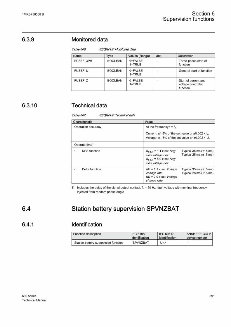
6.3.9 Monitored dataTable 806: SEQRFUF Monitored data
Name Type Values (Range) Unit DescriptionFUSEF_3PH BOOLEAN 0=FALSE
1=TRUE- Three-phase start of
function
FUSEF_U BOOLEAN 0=FALSE1=TRUE
- General start of function
FUSEF_Z BOOLEAN 0=FALSE1=TRUE
- Start of current andvoltage controlledfunction
6.3.10 Technical dataTable 807: SEQRFUF Technical data
Characteristic ValueOperation accuracy At the frequency f = fn
Current: ±1.5% of the set value or ±0.002 × InVoltage: ±1.5% of the set value or ±0.002 × Un
Operate time1)
• NPS function UFault = 1.1 x set NegSeq voltage LevUFault = 5.0 x set NegSeq voltage Lev
Typical 35 ms (±15 ms)Typical 25 ms (±15 ms)
• Delta function ΔU = 1.1 x set Voltagechange rateΔU = 2.0 x set Voltagechange rate
Typical 35 ms (±15 ms)Typical 28 ms (±15 ms)
1) Includes the delay of the signal output contact, fn = 50 Hz, fault voltage with nominal frequencyinjected from random phase angle
6.4 Station battery supervision SPVNZBAT
6.4.1 IdentificationFunction description IEC 61850
identificationIEC 60617identification
ANSI/IEEE C37.2device number
Station battery supervision function SPVNZBAT U<> -
1MRS756508 B Section 6Supervision functions
630 series 891Technical Manual

6.4.2 Function block
GUID-CB57D54A-0413-4A02-AF8C-C745B2CB8621 V1 EN
Figure 439: Function block
6.4.3 FunctionalityThe station battery supervision function SPVNZBAT is used for monitoring batteryterminal voltage.
SPVNZBAT activates the start and alarm outputs when the battery terminal voltageexceeds the set upper limit or drops below the set lower limit. A time delay for theovervoltage and undervoltage alarms can be set according to definite timecharacteristics.
In the definite time (DT) mode, SPVNZBAT operates after a predefined operatetime and resets when the battery undervoltage or overvoltage condition disappears.
The function contains a blocking functionality. It is possible to block functionoutputs, timers or the function itself, if desired.
6.4.4 Operation principleThe function can be enabled and disabled with the Operation setting. Thecorresponding parameter values are "On" and "Off".
The function execution requires that at least one of the functionoutputs is connected in configuration.
The operation of the station battery supervision function can be described by usinga module diagram. All the modules in the diagram are explained in the next sections.
GUID-800F5217-5187-4686-8C71-EDB4288A849E V1 EN
Figure 440: Functional module diagram
Section 6 1MRS756508 BSupervision functions
892 630 seriesTechnical Manual

The battery rated voltage is set with the Battery voltage Rtg setting. The value ofthe Low battery value and High battery value settings are given in relative per unitto the Battery voltage Rtg setting.
The battery voltage to be connected to the input U_BATT_IN is available asanalog Input BATTAMPL from power source (PSM) hardware module.
Level detector 1The level detector compares the battery voltage U_BATT_IN to the set value of theLow battery value setting. If the value of U_BATT_IN input drops below the valueof the Low battery value setting, the level detector sends an enabling signal to thetimer 1 module.
The measured voltage between the battery terminals U_BATT is available inmonitored data view.
Level detector 2The level detector compares the battery voltage U_BATT_IN to the set value of theHigh battery value setting. If the value of U_BATT_IN exceeds the set value of theHigh battery value setting, the level detector sends an enabling signal to the timer 2module.
Timer 1Once activated, the timer activates the ST_ULOW output for undervoltagecondition. When the operate timer has reached the value set by the Alarm delaytime setting, the AL_ULOW output is activated. If the voltage returns to normalvalue before the module operates, the reset timer is activated. If the reset timerreaches the value set by Reset delay time, the operate timer resets and theST_ULOW output is deactivated.
The activation of the BLOCK input resets the timer and deactivates the ST_ULOWand AL_ULOW outputs. The activation of BLK_ST and BLK_AL blocks theindividual start and alarm outputs respectively.
Timer 2Once activated, the timer activates ST_UHIGH for overvoltage condition. Whenthe operate timer has reached the value set by the Alarm delay time setting, theAL_UHIGH output is activated. If the voltage returns to normal value before themodule operates, the reset timer is activated. If the reset timer reaches the value setby Reset delay time, the operate timer resets and the ST_UHIGH output is deactivated.
The activation of the BLOCK input signal resets the timer and deactivates theST_UHIGH and AL_UHIGH outputs. The activation of BLK_ST and BLK_ALblocks the individual alarm and operate outputs respectively.
1MRS756508 B Section 6Supervision functions
630 series 893Technical Manual
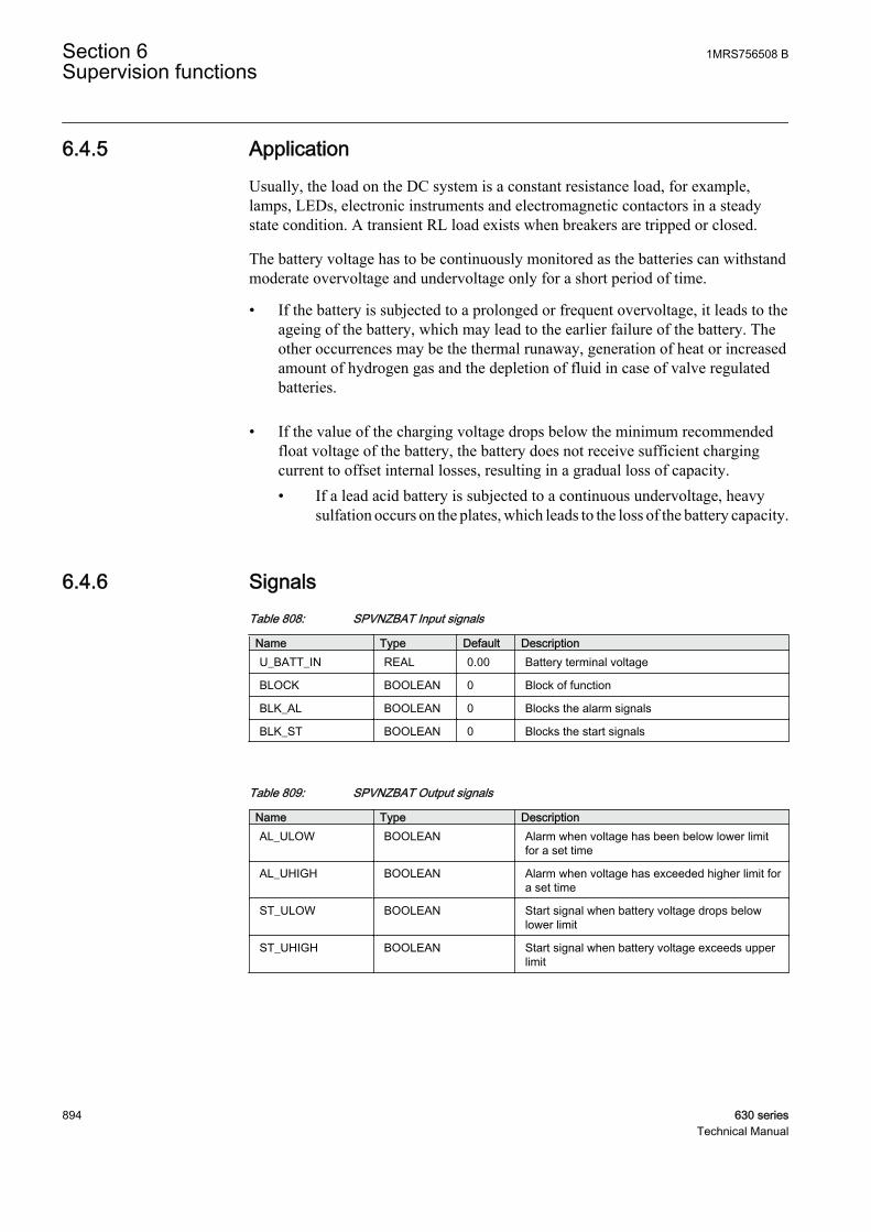
6.4.5 ApplicationUsually, the load on the DC system is a constant resistance load, for example,lamps, LEDs, electronic instruments and electromagnetic contactors in a steadystate condition. A transient RL load exists when breakers are tripped or closed.
The battery voltage has to be continuously monitored as the batteries can withstandmoderate overvoltage and undervoltage only for a short period of time.
• If the battery is subjected to a prolonged or frequent overvoltage, it leads to theageing of the battery, which may lead to the earlier failure of the battery. Theother occurrences may be the thermal runaway, generation of heat or increasedamount of hydrogen gas and the depletion of fluid in case of valve regulatedbatteries.
• If the value of the charging voltage drops below the minimum recommendedfloat voltage of the battery, the battery does not receive sufficient chargingcurrent to offset internal losses, resulting in a gradual loss of capacity.• If a lead acid battery is subjected to a continuous undervoltage, heavy
sulfation occurs on the plates, which leads to the loss of the battery capacity.
6.4.6 SignalsTable 808: SPVNZBAT Input signals
Name Type Default DescriptionU_BATT_IN REAL 0.00 Battery terminal voltage
BLOCK BOOLEAN 0 Block of function
BLK_AL BOOLEAN 0 Blocks the alarm signals
BLK_ST BOOLEAN 0 Blocks the start signals
Table 809: SPVNZBAT Output signals
Name Type DescriptionAL_ULOW BOOLEAN Alarm when voltage has been below lower limit
for a set time
AL_UHIGH BOOLEAN Alarm when voltage has exceeded higher limit fora set time
ST_ULOW BOOLEAN Start signal when battery voltage drops belowlower limit
ST_UHIGH BOOLEAN Start signal when battery voltage exceeds upperlimit
Section 6 1MRS756508 BSupervision functions
894 630 seriesTechnical Manual

6.4.7 SettingsTable 810: SPVNZBAT Non group settings (basic)
Name Values (Range) Unit Step Default DescriptionOperation Off
On- - On Operation Off/On
Battery voltage Rtg 20.00 - 250.00 V 1.00 110.00 Battery rated voltage
Low battery value 0.60 - 1.40 pu 0.01 0.70 Lower limit for the battery terminal voltage
High battery value 0.60 - 1.40 pu 0.01 1.20 Upper limit for the battery terminal voltage
Alarm delay time 0.100 - 60.000 s 0.001 0.200 Delay time for alarm
Table 811: SPVNZBAT Non group settings (advanced)
Name Values (Range) Unit Step Default DescriptionReset delay time 0.000 - 60.000 s 0.001 0.000 Reset time provided to reset the timers
6.4.8 Measured valuesTable 812: SPVNZBAT Measured values
Name Type Default DescriptionU_BATT_IN REAL 0.00 Battery terminal voltage
BLOCK BOOLEAN 0 Block of function
BLK_AL BOOLEAN 0 Blocks the alarm signals
BLK_ST BOOLEAN 0 Blocks the start signals
6.4.9 Monitored dataTable 813: SPVNZBAT Monitored data
Name Type Values (Range) Unit DescriptionU_BATT REAL - kV Service value of the
battery terminal voltage
AL_ULOW BOOLEAN 0=FALSE1=TRUE
- Alarm when voltage hasbeen below lower limitfor a set time
AL_UHIGH BOOLEAN 0=FALSE1=TRUE
- Alarm when voltage hasexceeded higher limit fora set time
ST_ULOW BOOLEAN 0=FALSE1=TRUE
- Start signal when batteryvoltage drops belowlower limit
ST_UHIGH BOOLEAN 0=FALSE1=TRUE
- Start signal when batteryvoltage exceeds upperlimit
1MRS756508 B Section 6Supervision functions
630 series 895Technical Manual
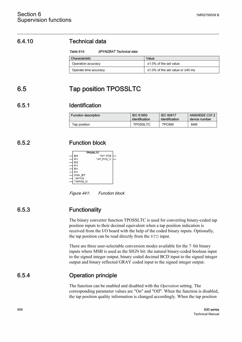
6.4.10 Technical dataTable 814: SPVNZBAT Technical data
Characteristic ValueOperation accuracy ±1.0% of the set value
Operate time accuracy ±1.0% of the set value or ±40 ms
6.5 Tap position TPOSSLTC
6.5.1 IdentificationFunction description IEC 61850
identificationIEC 60617identification
ANSI/IEEE C37.2device number
Tap position TPOSSLTC TPOSM 84M
6.5.2 Function block
GUID-C04491F3-1BA9-4ECB-BA1C-1A29006172DA V1 EN
Figure 441: Function block
6.5.3 FunctionalityThe binary converter function TPOSSLTC is used for converting binary-coded tapposition inputs to their decimal equivalent when a tap position indication isreceived from the I/O board with the help of the coded binary inputs. Optionally,the tap position can be read directly from the RTD input.
There are three user-selectable conversion modes available for the 7–bit binaryinputs where MSB is used as the SIGN bit: the natural binary-coded boolean inputto the signed integer output, binary coded decimal BCD input to the signed integeroutput and binary reflected GRAY coded input to the signed integer output.
6.5.4 Operation principleThe function can be enabled and disabled with the Operation setting. Thecorresponding parameter values are "On" and "Off". When the function is disabled,the tap position quality information is changed accordingly. When the tap position
Section 6 1MRS756508 BSupervision functions
896 630 seriesTechnical Manual

information is not available, it is recommended to disable this function with theOperation setting.
The operation of tap position indication function can be described by using amodule diagram. All the modules in the diagram are explained in the next sections.
GUID-3A6C1CB7-9E2F-449F-9CFD-528DCB418834 V1 EN
Figure 442: Functional module diagram
Tap position decoderThe function has four alternative user selectable operation modes: “BIN,” “BCD,”“GRAY” and “Input TAPPOS”. The operation mode is selected with the Operationmode parameter. Each operation mode can be used to convert the maximum of a 6–bit coded input to an 8–bit signed short integer output. For less than the 6–bit input(usually 19 positions with 5 bits when the BCD coding is used), the rest of the bitscan be set to FALSE (0).
The operation mode “BIN” is selected when the natural binary coding is used forshowing the position of the transformer tap changer. The basic principle of thenatural binary coding is to calculate the sum of the bits set to TRUE (1). LSB hasthe factor 1. Each following bit has the previous factor multiplied by 2. This is alsocalled dual coding.
The operation mode “BCD” is selected when the binary-coded decimal coding isused for showing the position of the transformer tap changer. The basic principle ofthe binary coded decimal coding is to calculate the sum of the bits set to TRUE (1).The four bits nibble (BI3...BI0) have a typical factor to the natural binary coding.The sum of the values should not be more than 9. If the nibble sum is greater than9, the tap position validity output TAP_POS_IV is set to FALSE (0).
The operation mode “GRAY” is selected when the binary-reflected Gray coding isused for showing the position of the transformer tap changer. The basic principle ofthe Gray coding is that only one actual bit changes value with consecutivenumbers. This function is based on the common binary-reflected Gray code, whichis used with some tap changers. Changing the bit closest to the right side bit gives anew pattern.
1MRS756508 B Section 6Supervision functions
630 series 897Technical Manual

An additional separate input, SIGN_BIT, can be used for negative values. If thevalues are positive, the input should be set to FALSE (0). If SIGN_BIT is set toTRUE (1) making the number negative, the remaining bits are identical to those ofthe coded positive number.
The tap position validity output TAP_POS_IV is set to TRUE (1) in all validcases. The output is set to FALSE (0) in invalid combinations in the binary inputs.For example, when the “BCD” mode is selected and the input binary combinationis “0001101”, TAP_POS_IV is set to FALSE (0) and the TAP_POS output is inthis case “9”. For negative values, when SIGN_BIT is set to TRUE (1) and theinput binary combination is “1011011”, TAP_POS_IV is set to FALSE (0) and theTAP_POS output is in this case “-19”.
When Operation mode is set to “Input TAPPOS” (4), the RTD card output REALvalue is used for showing the position of the transformer tap changer. Theinvalidity information from the RTD card is connected through the TAPPOS_IVinput. The TAP_POS and TAP_POS_IV outputs are then set according to theinputs from RTD. The tap position value is also converted from REAL to INTaccording to rounding rules.
Table 815: Truth table of the decoding modes
Inputs TAP_POS outputsSIGN_BIT
BI5 BI4 BI3 BI2 BI1 BI0 BIN BCD GRAY
... ... ... ... ... ... ...
1 0 0 0 0 1 1 —3 —3 —3
1 0 0 0 0 1 0 —2 —2 —2
1 0 0 0 0 0 1 —1 —1 —1
0 0 0 0 0 0 0 0 0 0
0 0 0 0 0 0 1 1 1 1
0 0 0 0 0 1 0 2 2 3
0 0 0 0 0 1 1 3 3 2
0 0 0 0 1 0 0 4 4 7
0 0 0 0 1 0 1 5 5 6
0 0 0 0 1 1 0 6 6 4
0 0 0 0 1 1 1 7 7 5
0 0 0 1 0 0 0 8 8 15
0 0 0 1 0 0 1 9 9 14
0 0 0 1 0 1 0 10 9 12
0 0 0 1 0 1 1 11 9 13
0 0 0 1 1 0 0 12 9 8
0 0 0 1 1 0 1 13 9 9
0 0 0 1 1 1 0 14 9 11
Table continues on next page
Section 6 1MRS756508 BSupervision functions
898 630 seriesTechnical Manual

Inputs TAP_POS outputs0 0 0 1 1 1 1 15 9 10
0 0 1 0 0 0 0 16 10 31
0 0 1 0 0 0 1 17 11 30
0 0 1 0 0 1 0 18 12 28
0 0 1 0 0 1 1 19 13 29
0 0 1 0 1 0 0 20 14 24
0 0 1 0 1 0 1 21 15 25
0 0 1 0 1 1 0 22 16 27
0 0 1 0 1 1 1 23 17 26
0 0 1 1 0 0 0 24 18 16
0 0 1 1 0 0 1 25 19 17
0 0 1 1 0 1 0 26 19 19
0 0 1 1 0 1 1 27 19 18
0 0 1 1 1 0 0 28 19 23
0 0 1 1 1 0 1 29 19 22
0 0 1 1 1 1 0 30 19 20
0 0 1 1 1 1 1 31 19 21
0 1 0 0 0 0 0 32 20 63
0 1 0 0 0 0 1 33 21 62
0 1 0 0 0 1 0 34 22 60
0 1 0 0 0 1 1 35 23 61
0 1 0 0 1 0 0 36 24 56
... ... ... ... ... ... ...
6.5.5 ApplicationTPOSSLTC provides tap position information for other functions as a signedinteger value that can be fed to the tap position input.
The position information of the tap changer can be coded in various methods formany applications, for example, the differential protection algorithms. In thisfunction, the binary inputs in the transformer terminal connector are used as inputsto the function. The coding method can be chosen by setting the mode parameter.The available coding methods are BCD, Gray and Natural binary coding. Since thenumber of binary inputs is limited to seven, the coding functions are limited toseven bits including the sign bit and thus the six bits are used in the codingfunctions. The position limits for the tap positions at BCD, Gray and Naturalbinary coding are ±39, ±63 and ±63 respectively.
In this example, the transformer tap changer position indication is wired as a mAsignal from the corresponding measuring transducer. The position indication isconnected to input 1 (AI_VAL1) of the X130 (RTD) card. The tap changer
1MRS756508 B Section 6Supervision functions
630 series 899Technical Manual
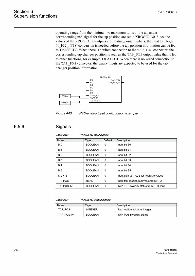
operating range from the minimum to maximum turns of the tap and acorresponding mA signal for the tap position are set in XRGGIO130. Since thevalues of the XRGGIO130 outputs are floating point numbers, the float to integer(T_F32_INT8) conversion is needed before the tap position information can be fedto TPOSSLTC. When there is a wired connection to the TAP_POS connector, thecorresponding tap changer position is seen as the TAP_POS output value that is fedto other functions, for example, OLATCC1. When there is no wired connection tothe TAP_POS connector, the binary inputs are expected to be used for the tapchanger position information.
TPOSSLTCBI0BI1BI2BI3BI4BI5SIGN_BITTAPPOSTAPPOS_IV
TAP_POSTAP_POS_IV
RTD AI
RTD ERR
GUID-0E0ED6D1-15F8-43C9-A086-744AE5820166 V1 EN
Figure 443: RTD/analog input configuration example
6.5.6 SignalsTable 816: TPOSSLTC Input signals
Name Type Default DescriptionBI0 BOOLEAN 0 Input bit B0
BI1 BOOLEAN 0 Input bit B1
BI2 BOOLEAN 0 Input bit B2
BI3 BOOLEAN 0 Input bit B3
BI4 BOOLEAN 0 Input bit B4
BI5 BOOLEAN 0 Input bit B5
SIGN_BIT BOOLEAN 0 Input sign as TRUE for negative values
TAPPOS REAL 0 Input tap position real value from RTD
TAPPOS_IV BOOLEAN 0 TAPPOS invalidity status from RTD card
Table 817: TPOSSLTC Output signals
Name Type DescriptionTAP_POS INTEGER Tap position value as integer
TAP_POS_IV BOOLEAN TAP_POS invalidity status
Section 6 1MRS756508 BSupervision functions
900 630 seriesTechnical Manual
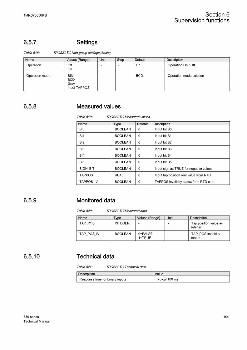
6.5.7 SettingsTable 818: TPOSSLTC Non group settings (basic)
Name Values (Range) Unit Step Default DescriptionOperation Off
On- - On Operation On / Off
Operation mode BINBCDGrayInput TAPPOS
- - BCD Operation mode seletion
6.5.8 Measured valuesTable 819: TPOSSLTC Measured values
Name Type Default DescriptionBI0 BOOLEAN 0 Input bit B0
BI1 BOOLEAN 0 Input bit B1
BI2 BOOLEAN 0 Input bit B2
BI3 BOOLEAN 0 Input bit B3
BI4 BOOLEAN 0 Input bit B4
BI5 BOOLEAN 0 Input bit B5
SIGN_BIT BOOLEAN 0 Input sign as TRUE for negative values
TAPPOS REAL 0 Input tap position real value from RTD
TAPPOS_IV BOOLEAN 0 TAPPOS invalidity status from RTD card
6.5.9 Monitored dataTable 820: TPOSSLTC Monitored data
Name Type Values (Range) Unit DescriptionTAP_POS INTEGER - - Tap position value as
integer
TAP_POS_IV BOOLEAN 0=FALSE1=TRUE
- TAP_POS invaliditystatus
6.5.10 Technical dataTable 821: TPOSSLTC Technical data
Descrpition ValueResponse time for binary inputs Typical 100 ms
1MRS756508 B Section 6Supervision functions
630 series 901Technical Manual

902
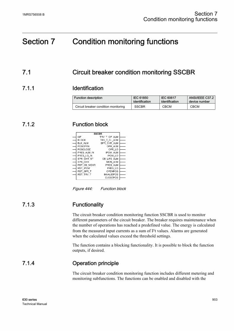
Section 7 Condition monitoring functions
7.1 Circuit breaker condition monitoring SSCBR
7.1.1 IdentificationFunction description IEC 61850
identificationIEC 60617identification
ANSI/IEEE C37.2device number
Circuit breaker condition monitoring SSCBR CBCM CBCM
7.1.2 Function block
GUID-4175F53E-AC71-43E8-B348-CFEB451BE987 V2 EN
Figure 444: Function block
7.1.3 FunctionalityThe circuit breaker condition monitoring function SSCBR is used to monitordifferent parameters of the circuit breaker. The breaker requires maintenance whenthe number of operations has reached a predefined value. The energy is calculatedfrom the measured input currents as a sum of Iyt values. Alarms are generatedwhen the calculated values exceed the threshold settings.
The function contains a blocking functionality. It is possible to block the functionoutputs, if desired.
7.1.4 Operation principleThe circuit breaker condition monitoring function includes different metering andmonitoring subfunctions. The functions can be enabled and disabled with the
1MRS756508 B Section 7Condition monitoring functions
630 series 903Technical Manual
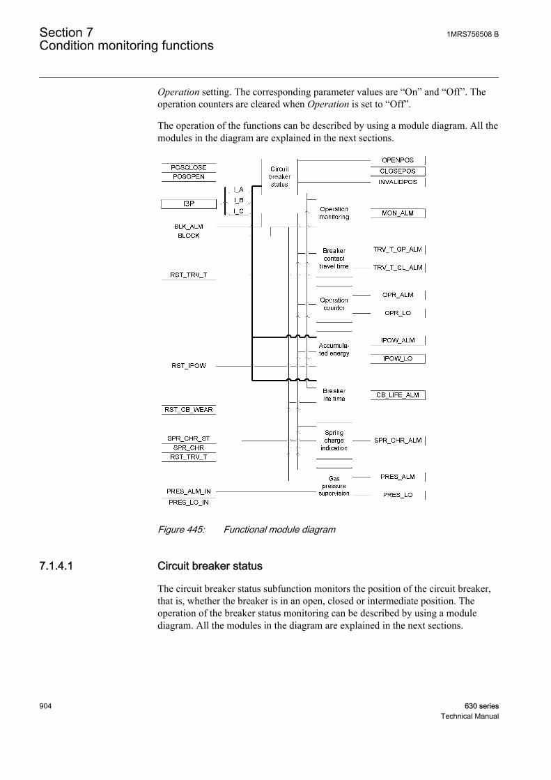
Operation setting. The corresponding parameter values are “On” and “Off”. Theoperation counters are cleared when Operation is set to “Off”.
The operation of the functions can be described by using a module diagram. All themodules in the diagram are explained in the next sections.
GUID-B22C9526-9992-4170-BC33-049FC24E5CF8 V2 EN
Figure 445: Functional module diagram
7.1.4.1 Circuit breaker status
The circuit breaker status subfunction monitors the position of the circuit breaker,that is, whether the breaker is in an open, closed or intermediate position. Theoperation of the breaker status monitoring can be described by using a modulediagram. All the modules in the diagram are explained in the next sections.
Section 7 1MRS756508 BCondition monitoring functions
904 630 seriesTechnical Manual

GUID-6DCC968F-7E0B-49CB-B054-4FD7C99277CA V1 EN
Figure 446: Functional module diagram for monitoring circuit breaker status
Phase current checkThis module compares the three phase currents with the setting Acc stop current. Ifthe current in a phase exceeds the set level, information about phase is reported tothe contact position indicator module.
Contact position indicatorThe circuit breaker status is open if the auxiliary input contact POSCLOSE is low,the POSOPEN input is high and the current is zero. The circuit breaker is closedwhen the POSOPEN input is low and the POSCLOSE input is high. The breaker isin the intermediate position if both the auxiliary contacts have the same value, thatis, both are in the logical level "0", or if the auxiliary input contact POSCLOSE islow and the POSOPEN input is high, but the current is not zero.
The status of the breaker is indicated with the binary outputs OPENPOS,INTERMPOS and CLOSEPOS for open, intermediate and closed positionrespectively.
7.1.4.2 Circuit breaker operation monitoring
The purpose of the circuit breaker operation monitoring subfunction is to indicate ifthe circuit breaker has not been operated for a long time.
The operation of the circuit breaker operation monitoring can be described with amodule diagram. All the modules in the diagram are explained in the next sections.
GUID-FEDC58F4-B835-41BA-BD4C-459F63E6DE79 V1 EN
Figure 447: Functional module diagram for calculating inactive days and alarmfor circuit breaker operation monitoring
1MRS756508 B Section 7Condition monitoring functions
630 series 905Technical Manual

Inactivity timerThe module calculates the number of days the circuit breaker has remainedinactive, that is, has stayed in the same open or closed state. The calculation is doneby monitoring the states of the POSOPEN and POSCLOSE auxiliary contacts.
The inactive days INA_DAYS is available in the monitored data view. It is alsopossible to set the initial inactive days with the Ini inactive days parameter.
Alarm limit checkWhen the inactive days exceed the limit value defined with the Inactive Alm dayssetting, the MON_ALM alarm is initiated. The time in hours at which this alarm isactivated can be set with the Inactive Alm hours parameter as coordinates of UTC.The alarm signal MON_ALM can be blocked by activating the binary input BLOCK.
7.1.4.3 Breaker contact travel time
The breaker contact travel time module calculates the breaker contact travel timefor the closing and opening operation. The operation of the breaker contact traveltime measurement can be described with a module diagram. All the modules in thediagram are explained in the next sections.
GUID-61AAA5AC-675A-4EEE-8003-040D3951AB4C V2 EN
Figure 448: Functional module diagram for breaker contact travel time
Traveling time calculatorThe contact travel time of the breaker is calculated from the time between auxiliarycontacts' state change. The open travel time is measured between the opening ofthe POSCLOSE auxiliary contact and the closing of the POSOPEN auxiliarycontact. Travel time is also measured between the opening of the POSOPENauxiliary contact and the closing of the POSCLOSE auxiliary contact.
Section 7 1MRS756508 BCondition monitoring functions
906 630 seriesTechnical Manual
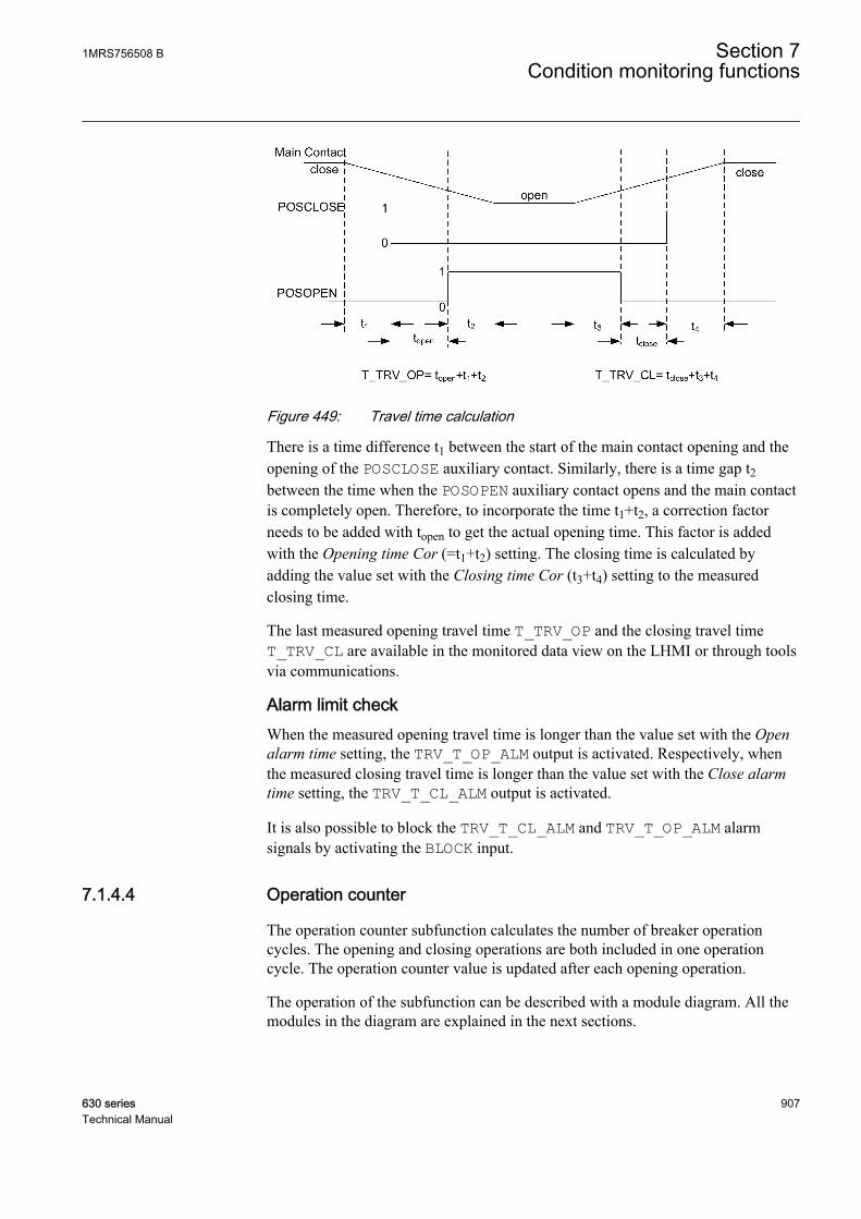
A071107 V1 EN
Figure 449: Travel time calculation
There is a time difference t1 between the start of the main contact opening and theopening of the POSCLOSE auxiliary contact. Similarly, there is a time gap t2between the time when the POSOPEN auxiliary contact opens and the main contactis completely open. Therefore, to incorporate the time t1+t2, a correction factorneeds to be added with topen to get the actual opening time. This factor is addedwith the Opening time Cor (=t1+t2) setting. The closing time is calculated byadding the value set with the Closing time Cor (t3+t4) setting to the measuredclosing time.
The last measured opening travel time T_TRV_OP and the closing travel timeT_TRV_CL are available in the monitored data view on the LHMI or through toolsvia communications.
Alarm limit checkWhen the measured opening travel time is longer than the value set with the Openalarm time setting, the TRV_T_OP_ALM output is activated. Respectively, whenthe measured closing travel time is longer than the value set with the Close alarmtime setting, the TRV_T_CL_ALM output is activated.
It is also possible to block the TRV_T_CL_ALM and TRV_T_OP_ALM alarmsignals by activating the BLOCK input.
7.1.4.4 Operation counter
The operation counter subfunction calculates the number of breaker operationcycles. The opening and closing operations are both included in one operationcycle. The operation counter value is updated after each opening operation.
The operation of the subfunction can be described with a module diagram. All themodules in the diagram are explained in the next sections.
1MRS756508 B Section 7Condition monitoring functions
630 series 907Technical Manual

GUID-681DC9AA-8A18-4695-B7C5-E093B697BB39 V1 EN
Figure 450: Functional module diagram for counting circuit breaker operations
Operation counterThe operation counter counts the number of operations based on the state change ofthe binary auxiliary contacts inputs POSCLOSE and POSOPEN.
The number of operations NO_OPR is available in the monitored data view on theLHMI or through tools via communications. The old circuit breaker operationcounter value can be taken into use by writing the value to the Counter initial Valparameter and by setting the parameter CB wear values in the clear menu fromWHMI or LHMI.
Alarm limit checkThe OPR_ALM operation alarm is generated when the number of operationsexceeds the value set with the Alarm Op number threshold setting. However, if thenumber of operations increases further and exceeds the limit value set with theLockout Op number setting, the OPR_LO output is activated.
The binary outputs OPR_LO and OPR_ALM are deactivated when the BLOCK inputis activated.
7.1.4.5 Accumulation of Iyt
Accumulation of the Iyt module calculates the accumulated energy.
The operation of the module can be described with a module diagram. All themodules in the diagram are explained in the next sections.
GUID-A3FC3D01-1E8B-409A-8214-34BF59362F5C V1 EN
Figure 451: Functional module diagram for calculating accumulative energyand alarm
Section 7 1MRS756508 BCondition monitoring functions
908 630 seriesTechnical Manual
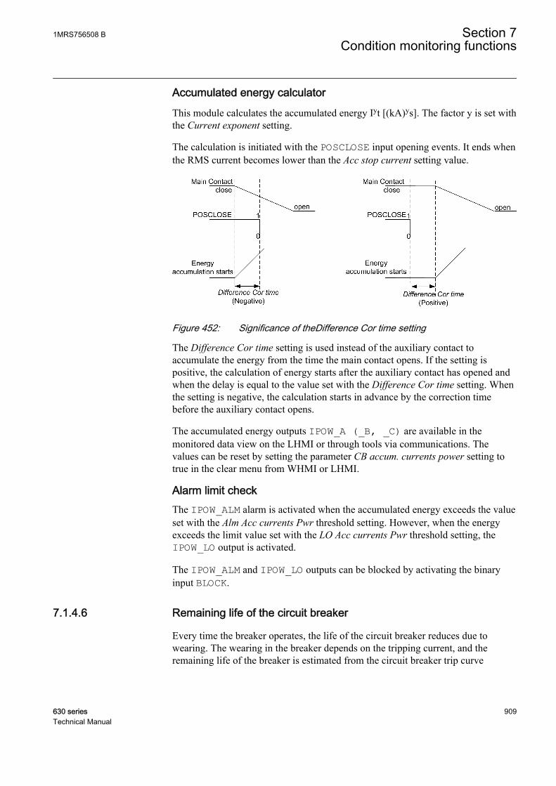
Accumulated energy calculator
This module calculates the accumulated energy Iyt [(kA)ys]. The factor y is set withthe Current exponent setting.
The calculation is initiated with the POSCLOSE input opening events. It ends whenthe RMS current becomes lower than the Acc stop current setting value.
A071110 V1 EN
Figure 452: Significance of theDifference Cor time setting
The Difference Cor time setting is used instead of the auxiliary contact toaccumulate the energy from the time the main contact opens. If the setting ispositive, the calculation of energy starts after the auxiliary contact has opened andwhen the delay is equal to the value set with the Difference Cor time setting. Whenthe setting is negative, the calculation starts in advance by the correction timebefore the auxiliary contact opens.
The accumulated energy outputs IPOW_A (_B, _C) are available in themonitored data view on the LHMI or through tools via communications. Thevalues can be reset by setting the parameter CB accum. currents power setting totrue in the clear menu from WHMI or LHMI.
Alarm limit checkThe IPOW_ALM alarm is activated when the accumulated energy exceeds the valueset with the Alm Acc currents Pwr threshold setting. However, when the energyexceeds the limit value set with the LO Acc currents Pwr threshold setting, theIPOW_LO output is activated.
The IPOW_ALM and IPOW_LO outputs can be blocked by activating the binaryinput BLOCK.
7.1.4.6 Remaining life of the circuit breaker
Every time the breaker operates, the life of the circuit breaker reduces due towearing. The wearing in the breaker depends on the tripping current, and theremaining life of the breaker is estimated from the circuit breaker trip curve
1MRS756508 B Section 7Condition monitoring functions
630 series 909Technical Manual
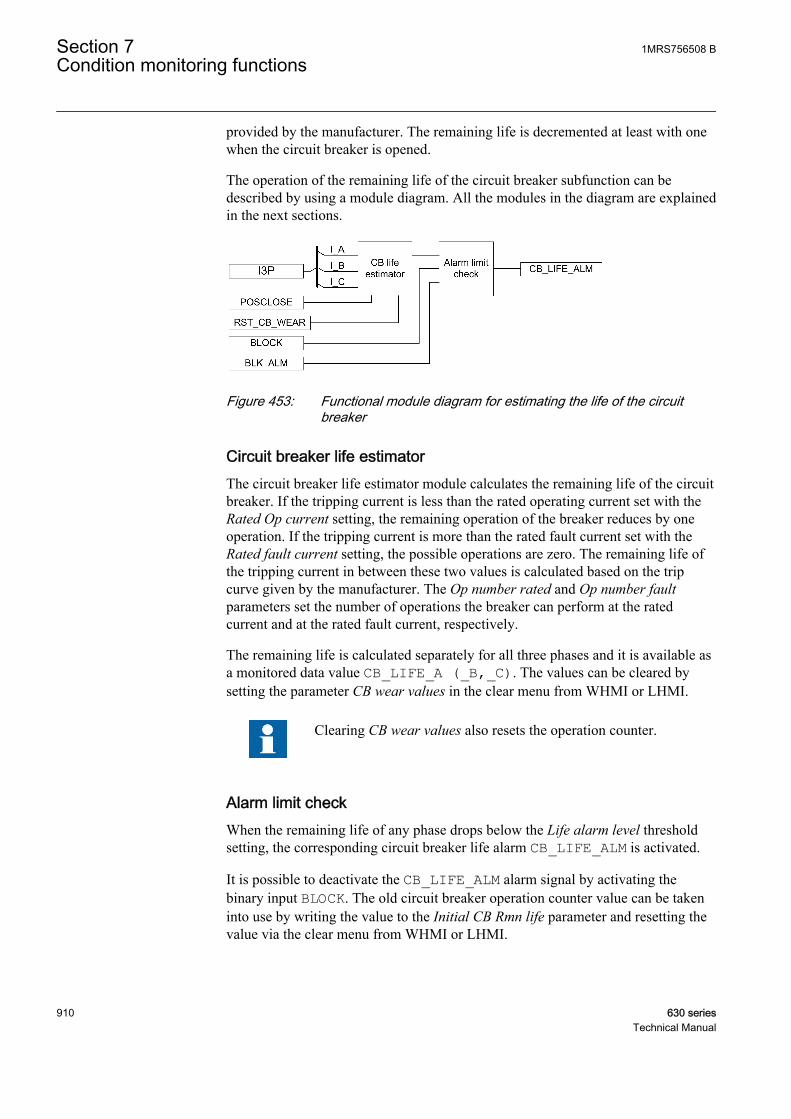
provided by the manufacturer. The remaining life is decremented at least with onewhen the circuit breaker is opened.
The operation of the remaining life of the circuit breaker subfunction can bedescribed by using a module diagram. All the modules in the diagram are explainedin the next sections.
GUID-1F5E13A4-5E35-4743-9E9A-47596433F421 V1 EN
Figure 453: Functional module diagram for estimating the life of the circuitbreaker
Circuit breaker life estimatorThe circuit breaker life estimator module calculates the remaining life of the circuitbreaker. If the tripping current is less than the rated operating current set with theRated Op current setting, the remaining operation of the breaker reduces by oneoperation. If the tripping current is more than the rated fault current set with theRated fault current setting, the possible operations are zero. The remaining life ofthe tripping current in between these two values is calculated based on the tripcurve given by the manufacturer. The Op number rated and Op number faultparameters set the number of operations the breaker can perform at the ratedcurrent and at the rated fault current, respectively.
The remaining life is calculated separately for all three phases and it is available asa monitored data value CB_LIFE_A (_B,_C). The values can be cleared bysetting the parameter CB wear values in the clear menu from WHMI or LHMI.
Clearing CB wear values also resets the operation counter.
Alarm limit checkWhen the remaining life of any phase drops below the Life alarm level thresholdsetting, the corresponding circuit breaker life alarm CB_LIFE_ALM is activated.
It is possible to deactivate the CB_LIFE_ALM alarm signal by activating thebinary input BLOCK. The old circuit breaker operation counter value can be takeninto use by writing the value to the Initial CB Rmn life parameter and resetting thevalue via the clear menu from WHMI or LHMI.
Section 7 1MRS756508 BCondition monitoring functions
910 630 seriesTechnical Manual
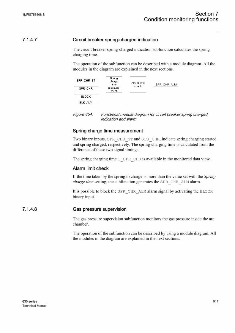
7.1.4.7 Circuit breaker spring-charged indication
The circuit breaker spring-charged indication subfunction calculates the springcharging time.
The operation of the subfunction can be described with a module diagram. All themodules in the diagram are explained in the next sections.
GUID-167AB9F8-CE8F-499B-8CC6-423E809AA311 V1 EN
Figure 454: Functional module diagram for circuit breaker spring chargedindication and alarm
Spring charge time measurementTwo binary inputs, SPR_CHR_ST and SPR_CHR, indicate spring charging startedand spring charged, respectively. The spring-charging time is calculated from thedifference of these two signal timings.
The spring charging time T_SPR_CHR is available in the monitored data view .
Alarm limit checkIf the time taken by the spring to charge is more than the value set with the Springcharge time setting, the subfunction generates the SPR_CHR_ALM alarm.
It is possible to block the SPR_CHR_ALM alarm signal by activating the BLOCKbinary input.
7.1.4.8 Gas pressure supervision
The gas pressure supervision subfunction monitors the gas pressure inside the arcchamber.
The operation of the subfunction can be described by using a module diagram. Allthe modules in the diagram are explained in the next sections.
1MRS756508 B Section 7Condition monitoring functions
630 series 911Technical Manual
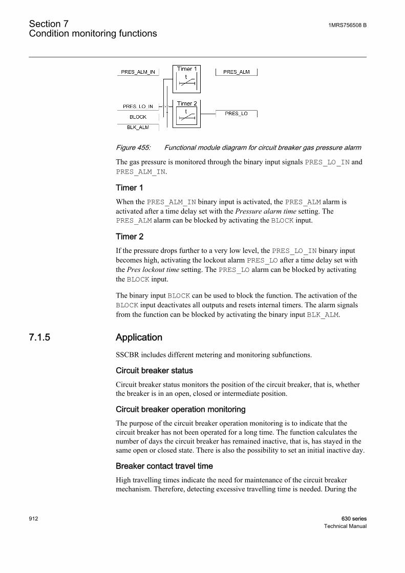
GUID-7C15B086-B40A-47B6-93BA-0044405311B1 V1 EN
Figure 455: Functional module diagram for circuit breaker gas pressure alarm
The gas pressure is monitored through the binary input signals PRES_LO_IN andPRES_ALM_IN.
Timer 1When the PRES_ALM_IN binary input is activated, the PRES_ALM alarm isactivated after a time delay set with the Pressure alarm time setting. ThePRES_ALM alarm can be blocked by activating the BLOCK input.
Timer 2If the pressure drops further to a very low level, the PRES_LO_IN binary inputbecomes high, activating the lockout alarm PRES_LO after a time delay set withthe Pres lockout time setting. The PRES_LO alarm can be blocked by activatingthe BLOCK input.
The binary input BLOCK can be used to block the function. The activation of theBLOCK input deactivates all outputs and resets internal timers. The alarm signalsfrom the function can be blocked by activating the binary input BLK_ALM.
7.1.5 ApplicationSSCBR includes different metering and monitoring subfunctions.
Circuit breaker statusCircuit breaker status monitors the position of the circuit breaker, that is, whetherthe breaker is in an open, closed or intermediate position.
Circuit breaker operation monitoringThe purpose of the circuit breaker operation monitoring is to indicate that thecircuit breaker has not been operated for a long time. The function calculates thenumber of days the circuit breaker has remained inactive, that is, has stayed in thesame open or closed state. There is also the possibility to set an initial inactive day.
Breaker contact travel timeHigh travelling times indicate the need for maintenance of the circuit breakermechanism. Therefore, detecting excessive travelling time is needed. During the
Section 7 1MRS756508 BCondition monitoring functions
912 630 seriesTechnical Manual
opening cycle operation, the main contact starts opening. The auxiliary contact Aopens, the auxiliary contact B closes, and the main contact reaches its openingposition. During the closing cycle, the first main contact starts closing. Theauxiliary contact B opens, the auxiliary contact A closes, and the main contactreaches its close position. The travel times are calculated based on the statechanges of the auxiliary contacts and the adding correction factor to consider thetime difference of the main contact's and the auxiliary contact's position change.
Operation counterRoutine maintenance of the breaker, such as lubricating breaker mechanism, isgenerally based on a number of operations. A suitable threshold setting, to raise analarm when the number of operation cycle exceeds the set limit, helps preventivemaintenance. This can also be used to indicate the requirement for oil sampling fordielectric testing in case of an oil circuit breaker.
The change of state can be detected from the binary input of the auxiliary contact.There is a possibility to set an initial value for the counter which can be used toinitialize this functionality after a period of operation or in case of refurbishedprimary equipment.
Accumulation of Iyt
Accumulation of Iyt calculates the accumulated energy ΣIyt where the factor y isknown as the current exponent. The factor y depends on the type of the circuitbreaker. For oil circuit breakers the factor y is normally 2. In case of a high-voltagesystem, the factor y can be 1.4...1.5.
Remaining life of the breakerEvery time the breaker operates, the life of the circuit breaker reduces due towearing. The wearing in the breaker depends on the tripping current, and theremaining life of the breaker is estimated from the circuit breaker trip curveprovided by the manufacturer.
Example for estimating the remaining life of a circuit breaker
1MRS756508 B Section 7Condition monitoring functions
630 series 913Technical Manual

A071114 V2 EN
Figure 456: Trip Curves for a typical 12 kV, 630 A, 16 kA vacuum interrupter
Nr the number of closing-opening operations allowed for the circuit breaker
Ia the current at the time of tripping of the circuit breaker
Calculation of Directional Coef
The directional coefficient is calculated according to the formula:
Directional Coef
B
A
I
I
f
r
=
= −
log
log
.2 2609
A070794 V2 EN (Equation 122)
Ir Rated operating current = 630 A
If Rated fault current = 16 kA
A Op number rated = 30000
B Op number fault = 20
Section 7 1MRS756508 BCondition monitoring functions
914 630 seriesTechnical Manual

Calculation for estimating the remaining life
The equation shows that there are 30,000 possible operations at the rated operatingcurrent of 630 A and 20 operations at the rated fault current 16 kA. Therefore, ifthe tripping current is 10 kA, one operation at 10 kA is equivalent to30,000/500=60 operations at the rated current. It is also assumed that prior to thistripping, the remaining life of the circuit breaker is 15,000 operations. Therefore,after one operation of 10 kA, the remaining life of the circuit breaker is15,000-60=14,940 at the rated operating current.
Spring charged indicationFor normal operation of the circuit breaker, the circuit breaker spring should becharged within a specified time. Therefore, detecting long spring charging timeindicates that it is time for the circuit breaker maintenance. The last value of thespring charging time can be used as a service value.
Gas pressure supervisionThe gas pressure supervision monitors the gas pressure inside the arc chamber.When the pressure becomes too low compared to the required value, the circuitbreaker operations are locked. A binary input is available based on the pressurelevels in the function, and alarms are generated based on these inputs.
7.1.6 SignalsTable 822: SSCBR Input signals
Name Type Default DescriptionI3P GROUP
SIGNAL- Three phase group signal for current inputs
BLOCK BOOLEAN 0 Block all the alarm and lockout indication
BLK_ALM BOOLEAN 0 Block all the alarms
POSOPEN BOOLEAN 0 Signal for open position of apparatus from I/O
POSCLOSE BOOLEAN 0 Signal for close position of apparatus from I/O
PRES_ALM_IN BOOLEAN 0 Binary pressure alarm input
PRES_LO_IN BOOLEAN 0 Binary pressure input for lockout indication
SPR_CHR_ST BOOLEAN 0 CB spring charging started input
SPR_CHR BOOLEAN 0 CB spring charged input
RST_CB_WEAR BOOLEAN 0 Reset input for CB remaining life and operationcounter
RST_IPOW BOOLEAN 0 Reset accumulated currents power
RST_SPR_T BOOLEAN 0 Reset input for the charging time of the CB spring
RST_TRV_T BOOLEAN 0 Reset input for CB closing and opening travel times
1MRS756508 B Section 7Condition monitoring functions
630 series 915Technical Manual

Table 823: SSCBR Output signals
Name Type DescriptionTRV_T_OP_ALM BOOLEAN CB open travel time exceeded set value
TRV_T_CL_ALM BOOLEAN CB close travel time exceeded set value
SPR_CHR_ALM BOOLEAN Spring charging time has crossed the set value
OPR_ALM BOOLEAN Number of CB operations exceeds alarm limit
OPR_LO BOOLEAN Number of CB operations exceeds lockout limit
IPOW_ALM BOOLEAN Accumulated currents power (Iyt),exceeded alarmlimit
IPOW_LO BOOLEAN Accumulated currents power (Iyt),exceededlockout limit
CB_LIFE_ALM BOOLEAN Remaining life of CB reduced to Life alarm level
MON_ALM BOOLEAN CB 'not operated for long time' alarm
PRES_ALM BOOLEAN Pressure below alarm level
PRES_LO BOOLEAN Pressure below lockout level
OPENPOS BOOLEAN CB is in open position
INVALIDPOS BOOLEAN CB is in invalid position (not positively open orclosed)
CLOSEPOS BOOLEAN CB is in closed position
7.1.7 SettingsTable 824: SSCBR Non group settings (basic)
Name Values (Range) Unit Step Default DescriptionOperation Off
On- - On Operation Off / On
Acc stop current 5.00 - 500.00 A 0.01 10.00 RMS current setting below which energyacm stops
Current exponent 0.00 - 2.00 - 0.01 2.00 Current exponent setting for energycalculation
Rated fault current 500.00 - 75000.00 A 0.01 5000.00 Rated fault current of the breaker
Rated Op current 100.00 - 5000.00 A 0.01 1000.00 Rated operating current of the breaker
Alm Acc currents Pwr 0.00 - 20000.00 - 0.01 2500.00 Setting of alarm level for accumulatedcurrents power
LO Acc currents Pwr 0.00 - 20000.00 - 0.01 2500.00 Lockout limit setting for accumulatedcurrents power
Op number rated 1 - 99999 - 1 10000 Number of operations possible at ratedcurrent
Op number fault 1 - 10000 - 1 1000 Number of operations possible at ratedfault current
Alarm Op number 0 - 9999 - 1 200 Alarm limit for number of operations
Lockout Op number 0 - 9999 - 1 300 Lockout limit for number of operations
Open alarm time 0 - 200 ms 1 40 Alarm level setting for open travel time
Close alarm time 0 - 200 ms 1 40 Alarm level setting for close travel time
Table continues on next page
Section 7 1MRS756508 BCondition monitoring functions
916 630 seriesTechnical Manual

Name Values (Range) Unit Step Default DescriptionSpring charge time 0.00 - 60.00 s 0.01 1.00 Setting of alarm for spring charging time
Inactive Alm days 0 - 9999 Day 1 2000 Alarm limit value of the inactive dayscounter
Initial CB Rmn life 0 - 9999 - 1 5000 Initial value for the CB remaining lifeestimates
Table 825: SSCBR Non group settings (advanced)
Name Values (Range) Unit Step Default DescriptionDirectional Coef -3.00 - -0.50 - 0.01 -1.50 Directional coefficient for CB life
calculation
Life alarm level 0 - 99999 - 1 5000 Alarm level for CB remaining life
Opening time Cor 0 - 100 ms 1 10 Correction factor for open travel time
Closing time Cor 0 - 100 ms 1 10 Correction factor for close travel time
Difference Cor time -10 - 10 ms 1 5 Correction factor for time difference inauxiliary and main contacts open time
Pressure alarm time 0.00 - 60.00 s 0.01 0.10 Time delay for gas pressure alarm
Pres lockout time 0.00 - 60.00 s 0.01 0.10 Time delay for gas pressure lockout
Inactive Alm hours 0 - 23 Hour 1 0 Alarm time of the inactive days counterin hours
Counter initial Val 0 - 9999 - 1 0 Operation numbers counter initializationvalue
Ini inactive days 0 - 9999 Day 1 0 Initial value of the inactive days counter
Ini Acc currents Pwr 0.00 - 9999.99 - 0.01 0.00 Initial value for accumulation energy (Iyt)
7.1.8 Measured valuesTable 826: SSCBR Measured values
Name Type Default DescriptionI_RMS_A REAL 0 RMS Current input phase A
I_RMS_B REAL 0 RMS Current input phase B
I_RMS_C REAL 0 RMS Current input phase C
BLOCK BOOLEAN 0 Block all the alarm and lockout indication
BLK_ALM BOOLEAN 0 Block all the alarms
POSOPEN BOOLEAN 0 Signal for open position of apparatus from I/O
POSCLOSE BOOLEAN 0 Signal for close position of apparatus from I/O
PRES_ALM_IN BOOLEAN 0 Binary pressure alarm input
PRES_LO_IN BOOLEAN 0 Binary pressure input for lockout indication
SPR_CHR_ST BOOLEAN 0 CB spring charging started input
SPR_CHR BOOLEAN 0 CB spring charged input
RST_CB_WEAR BOOLEAN 0 Reset input for CB remaining life and operationcounter
Table continues on next page
1MRS756508 B Section 7Condition monitoring functions
630 series 917Technical Manual
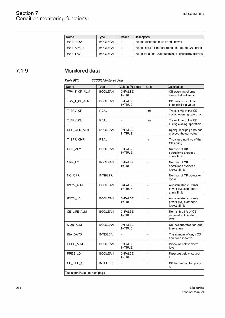
Name Type Default DescriptionRST_IPOW BOOLEAN 0 Reset accumulated currents power
RST_SPR_T BOOLEAN 0 Reset input for the charging time of the CB spring
RST_TRV_T BOOLEAN 0 Reset input for CB closing and opening travel times
7.1.9 Monitored dataTable 827: SSCBR Monitored data
Name Type Values (Range) Unit DescriptionTRV_T_OP_ALM BOOLEAN 0=FALSE
1=TRUE- CB open travel time
exceeded set value
TRV_T_CL_ALM BOOLEAN 0=FALSE1=TRUE
- CB close travel timeexceeded set value
T_TRV_OP REAL - ms Travel time of the CBduring opening operation
T_TRV_CL REAL - ms Travel time of the CBduring closing operation
SPR_CHR_ALM BOOLEAN 0=FALSE1=TRUE
- Spring charging time hascrossed the set value
T_SPR_CHR REAL - s The charging time of theCB spring
OPR_ALM BOOLEAN 0=FALSE1=TRUE
- Number of CBoperations exceedsalarm limit
OPR_LO BOOLEAN 0=FALSE1=TRUE
- Number of CBoperations exceedslockout limit
NO_OPR INTEGER - - Number of CB operationcycle
IPOW_ALM BOOLEAN 0=FALSE1=TRUE
- Accumulated currentspower (Iyt),exceededalarm limit
IPOW_LO BOOLEAN 0=FALSE1=TRUE
- Accumulated currentspower (Iyt),exceededlockout limit
CB_LIFE_ALM BOOLEAN 0=FALSE1=TRUE
- Remaining life of CBreduced to Life alarmlevel
MON_ALM BOOLEAN 0=FALSE1=TRUE
- CB 'not operated for longtime' alarm
INA_DAYS INTEGER - - The number of days CBhas been inactive
PRES_ALM BOOLEAN 0=FALSE1=TRUE
- Pressure below alarmlevel
PRES_LO BOOLEAN 0=FALSE1=TRUE
- Pressure below lockoutlevel
CB_LIFE_A INTEGER - - CB Remaining life phaseA
Table continues on next page
Section 7 1MRS756508 BCondition monitoring functions
918 630 seriesTechnical Manual
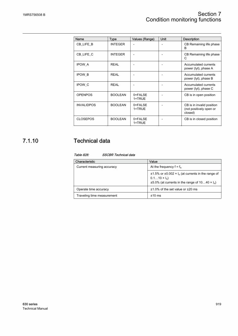
Name Type Values (Range) Unit DescriptionCB_LIFE_B INTEGER - - CB Remaining life phase
B
CB_LIFE_C INTEGER - - CB Remaining life phaseC
IPOW_A REAL - - Accumulated currentspower (Iyt), phase A
IPOW_B REAL - - Accumulated currentspower (Iyt), phase B
IPOW_C REAL - - Accumulated currentspower (Iyt), phase C
OPENPOS BOOLEAN 0=FALSE1=TRUE
- CB is in open position
INVALIDPOS BOOLEAN 0=FALSE1=TRUE
- CB is in invalid position(not positively open orclosed)
CLOSEPOS BOOLEAN 0=FALSE1=TRUE
- CB is in closed position
7.1.10 Technical data
Table 828: SSCBR Technical data
Characteristic ValueCurrent measuring accuracy At the frequency f = fn
±1.5% or ±0.002 × In (at currents in the range of0.1…10 × In)±5.0% (at currents in the range of 10…40 × In)
Operate time accuracy ±1.0% of the set value or ±20 ms
Traveling time measurement ±10 ms
1MRS756508 B Section 7Condition monitoring functions
630 series 919Technical Manual

920

Section 8 Measurement functions
8.1 Basic measurements
8.1.1 FunctionsThe three-phase current measurement function CMMXU is used for monitoringand metering the phase currents of the power system.
The three-phase voltage measurement functions VPHMMXU and VPPMMXU areused for monitoring and metering the phase and line voltage of the power system.
The residual current measurement function RESCMMXU is used for monitoringand metering the residual current of the power system.
The residual voltage measurement function RESVMMXU is used for monitoringand metering the residual voltage of the power system.
The sequence current measurement CSMSQI is used for monitoring and meteringthe phase sequence currents.
The sequence voltage measurement VSMSQI is used for monitoring and meteringthe phase sequence voltages.
The three phase power measurement PWRMMXU is used for monitoring andmetering the active power, reactive power, apparent power, power factor and thefrequency. PWRMMXU calculates these quantities by using the fundamentalfrequency phasors, for example, the DFT values of the measured current andvoltage signals.
The information of the measured quantity is available in the monitored data viewon the LHMI or through tools via communication.
RESVMMXU has two outputs for the residual voltages. Onecorresponds to the true RMS value and the other is the fundamentalcomponent amplitude. The service value U0_RMS_DB providesthe true RMS value. However, if a fundamental component with anangle is required, U0_MAG_DB and U0_ANGL_INST should bemonitored.
1MRS756508 B Section 8Measurement functions
630 series 921Technical Manual
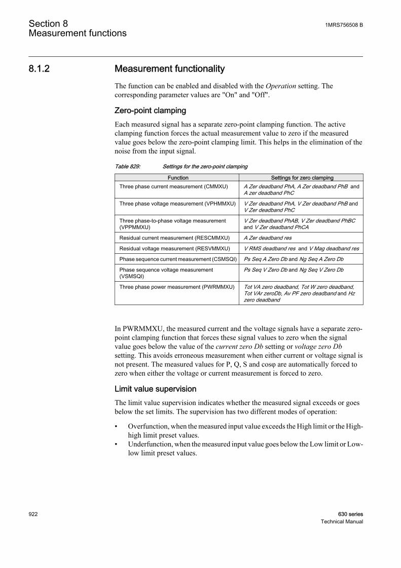
8.1.2 Measurement functionalityThe function can be enabled and disabled with the Operation setting. Thecorresponding parameter values are "On" and "Off".
Zero-point clampingEach measured signal has a separate zero-point clamping function. The activeclamping function forces the actual measurement value to zero if the measuredvalue goes below the zero-point clamping limit. This helps in the elimination of thenoise from the input signal.
Table 829: Settings for the zero-point clamping
Function Settings for zero clampingThree phase current measurement (CMMXU) A Zer deadband PhA, A Zer deadband PhB and
A zer deadband PhC
Three phase voltage measurement (VPHMMXU) V Zer deadband PhA, V Zer deadband PhB andV Zer deadband PhC
Three phase-to-phase voltage measurement(VPPMMXU)
V Zer deadband PhAB, V Zer deadband PhBCand V Zer deadband PhCA
Residual current measurement (RESCMMXU) A Zer deadband res
Residual voltage measurement (RESVMMXU) V RMS deadband res and V Mag deadband res
Phase sequence current measurement (CSMSQI) Ps Seq A Zero Db and Ng Seq A Zero Db
Phase sequence voltage measurement(VSMSQI)
Ps Seq V Zero Db and Ng Seq V Zero Db
Three phase power measurement (PWRMMXU) Tot VA zero deadband, Tot W zero deadband,Tot VAr zeroDb, Av PF zero deadband and Hzzero deadband
In PWRMMXU, the measured current and the voltage signals have a separate zero-point clamping function that forces these signal values to zero when the signalvalue goes below the value of the current zero Db setting or voltage zero Dbsetting. This avoids erroneous measurement when either current or voltage signal isnot present. The measured values for P, Q, S and cosφ are automatically forced tozero when either the voltage or current measurement is forced to zero.
Limit value supervisionThe limit value supervision indicates whether the measured signal exceeds or goesbelow the set limits. The supervision has two different modes of operation:
• Overfunction, when the measured input value exceeds the High limit or the High-high limit preset values.
• Underfunction, when the measured input value goes below the Low limit or Low-low limit preset values.
Section 8 1MRS756508 BMeasurement functions
922 630 seriesTechnical Manual
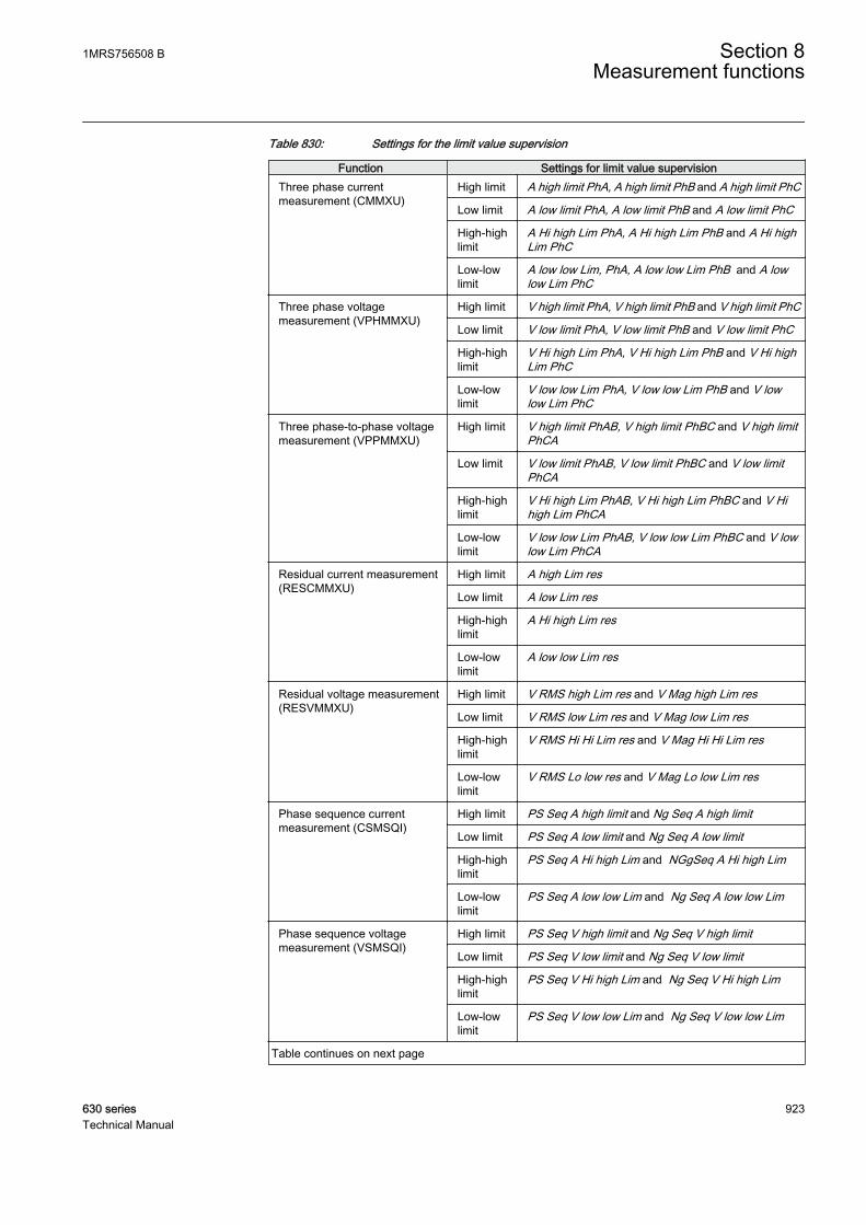
Table 830: Settings for the limit value supervision
Function Settings for limit value supervisionThree phase currentmeasurement (CMMXU)
High limit A high limit PhA, A high limit PhB and A high limit PhC
Low limit A low limit PhA, A low limit PhB and A low limit PhC
High-highlimit
A Hi high Lim PhA, A Hi high Lim PhB and A Hi highLim PhC
Low-lowlimit
A low low Lim, PhA, A low low Lim PhB and A lowlow Lim PhC
Three phase voltagemeasurement (VPHMMXU)
High limit V high limit PhA, V high limit PhB and V high limit PhC
Low limit V low limit PhA, V low limit PhB and V low limit PhC
High-highlimit
V Hi high Lim PhA, V Hi high Lim PhB and V Hi highLim PhC
Low-lowlimit
V low low Lim PhA, V low low Lim PhB and V lowlow Lim PhC
Three phase-to-phase voltagemeasurement (VPPMMXU)
High limit V high limit PhAB, V high limit PhBC and V high limitPhCA
Low limit V low limit PhAB, V low limit PhBC and V low limitPhCA
High-highlimit
V Hi high Lim PhAB, V Hi high Lim PhBC and V Hihigh Lim PhCA
Low-lowlimit
V low low Lim PhAB, V low low Lim PhBC and V lowlow Lim PhCA
Residual current measurement(RESCMMXU)
High limit A high Lim res
Low limit A low Lim res
High-highlimit
A Hi high Lim res
Low-lowlimit
A low low Lim res
Residual voltage measurement(RESVMMXU)
High limit V RMS high Lim res and V Mag high Lim res
Low limit V RMS low Lim res and V Mag low Lim res
High-highlimit
V RMS Hi Hi Lim res and V Mag Hi Hi Lim res
Low-lowlimit
V RMS Lo low res and V Mag Lo low Lim res
Phase sequence currentmeasurement (CSMSQI)
High limit PS Seq A high limit and Ng Seq A high limit
Low limit PS Seq A low limit and Ng Seq A low limit
High-highlimit
PS Seq A Hi high Lim and NGgSeq A Hi high Lim
Low-lowlimit
PS Seq A low low Lim and Ng Seq A low low Lim
Phase sequence voltagemeasurement (VSMSQI)
High limit PS Seq V high limit and Ng Seq V high limit
Low limit PS Seq V low limit and Ng Seq V low limit
High-highlimit
PS Seq V Hi high Lim and Ng Seq V Hi high Lim
Low-lowlimit
PS Seq V low low Lim and Ng Seq V low low Lim
Table continues on next page
1MRS756508 B Section 8Measurement functions
630 series 923Technical Manual
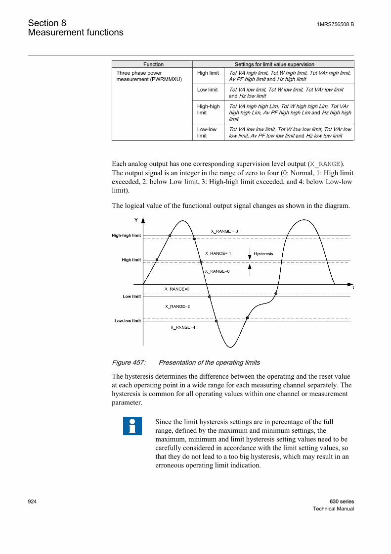
Function Settings for limit value supervisionThree phase powermeasurement (PWRMMXU)
High limit Tot VA high limit, Tot W high limit, Tot VAr high limit,Av PF high limit and Hz high limit
Low limit Tot VA low limit, Tot W low limit, Tot VAr low limitand Hz low limit
High-highlimit
Tot VA high high Lim, Tot W high high Lim, Tot VArhigh high Lim, Av PF high high Lim and Hz high highlimit
Low-lowlimit
Tot VA low low limit, Tot W low low limit, Tot VAr lowlow limit, Av PF low low limit and Hz low low limit
Each analog output has one corresponding supervision level output (X_RANGE).The output signal is an integer in the range of zero to four (0: Normal, 1: High limitexceeded, 2: below Low limit, 3: High-high limit exceeded, and 4: below Low-lowlimit).
The logical value of the functional output signal changes as shown in the diagram.
GUID-267D40DC-C3F6-4709-8068-D3AB8CB56DE1 V1 EN
Figure 457: Presentation of the operating limits
The hysteresis determines the difference between the operating and the reset valueat each operating point in a wide range for each measuring channel separately. Thehysteresis is common for all operating values within one channel or measurementparameter.
Since the limit hysteresis settings are in percentage of the fullrange, defined by the maximum and minimum settings, themaximum, minimum and limit hysteresis setting values need to becarefully considered in accordance with the limit setting values, sothat they do not lead to a too big hysteresis, which may result in anerroneous operating limit indication.
Section 8 1MRS756508 BMeasurement functions
924 630 seriesTechnical Manual
Table 831: Settings for hysteresis-deciding operating limits
Function Settings for hysteresis-deciding operating limitsThree phase current measurement (CMMXU) A limit Hys PhA, A limit Hys PhB and A limit Hys
PhC
Three phase voltage measurement (VPHMMXU) V limit Hys PhA, V limit Hys PhB and V limit HysPhC
Three phase-to-phase voltage measurement(VPPMMXU)
V limit Hys PhAB, V limit Hys PhBC and V limitHys PhCA
Residual current measurement (RESCMMXU) A limit Hys res
Residual voltage measurement (RESVMMXU) V RMS limit Hys res and V Mag limit Hys
Phase sequence current measurement (CSMSQI) Ps Seq A limit Hys and Ng Seq A limit Hys
Phase sequence voltage measurement(VSMSQI)
Ps Seq V limit Hys and Ng Seq V limit Hys
Three phase power measurement (PWRMMXU) Tot VA limit Hys, Tot W limit Hys, Tot VAr limitHys , Av PF limit Hys and Hz limit hysteresis
Actual value of the measured quantityThe actual value of the measured quantity is available locally and remotely. Themeasurement is continuous for each of the separately measured quantity. Thereporting of the newer value depends on the selected reporting mode available.There are three basic reporting modes available:
• Cyclic reporting (Cyclic)• Amplitude deadband reporting (Deadband)• Integral deadband reporting (Int deadband)
Table 832: Settings for the reporting mode
Functions Settings for the reporting modeThree phase current measurement (CMMXU) A Db type PhA, A Db type PhB and A Db type PhC
Three phase voltage measurement (VPHMMXU) V Db type PhA, V Db type PhB and V Db type PhC
Three phase-to-phase voltage measurement(VPPMMXU)
V Db type PhAB, V Db type PhBC and V Db typePhCA
Residual current measurement (RESCMMXU) A Db type res
Residual voltage measurement (RESVMMXU) V RMS Db type res and V Mag Db type res
Phase sequence current measurement (CSMSQI) Ps Seq A db type and Ng Seq A db type
Phase sequence voltage measurement(VSMSQI)
Ps Seq V db type and Ng Seq V db type
Three phase power measurement (PWRMMXU) Tot VA deadband type, Tot W deadband type,Tot VAr Db type, Av PF deadband type and Hzdeadband type
Cyclic reportingIn cyclic reporting, the function gives a new value when the deadband time haselapsed.
1MRS756508 B Section 8Measurement functions
630 series 925Technical Manual

GUID-E6A704D7-25B0-41A0-B5A7-581628FA3A9C V1 EN
Figure 458: Cyclic reporting
Amplitude deadband reportingIn the amplitude deadband reporting mode, a new value is reported when themeasured quantity changes more than the defined set limits (±ΔY).
GUID-598314B7-9BC1-48EB-A8D2-1666FA39908F V1 EN
Figure 459: An example of amplitude deadband supervision reporting
This type of reporting limits the information flow to a minimum necessity.
Section 8 1MRS756508 BMeasurement functions
926 630 seriesTechnical Manual
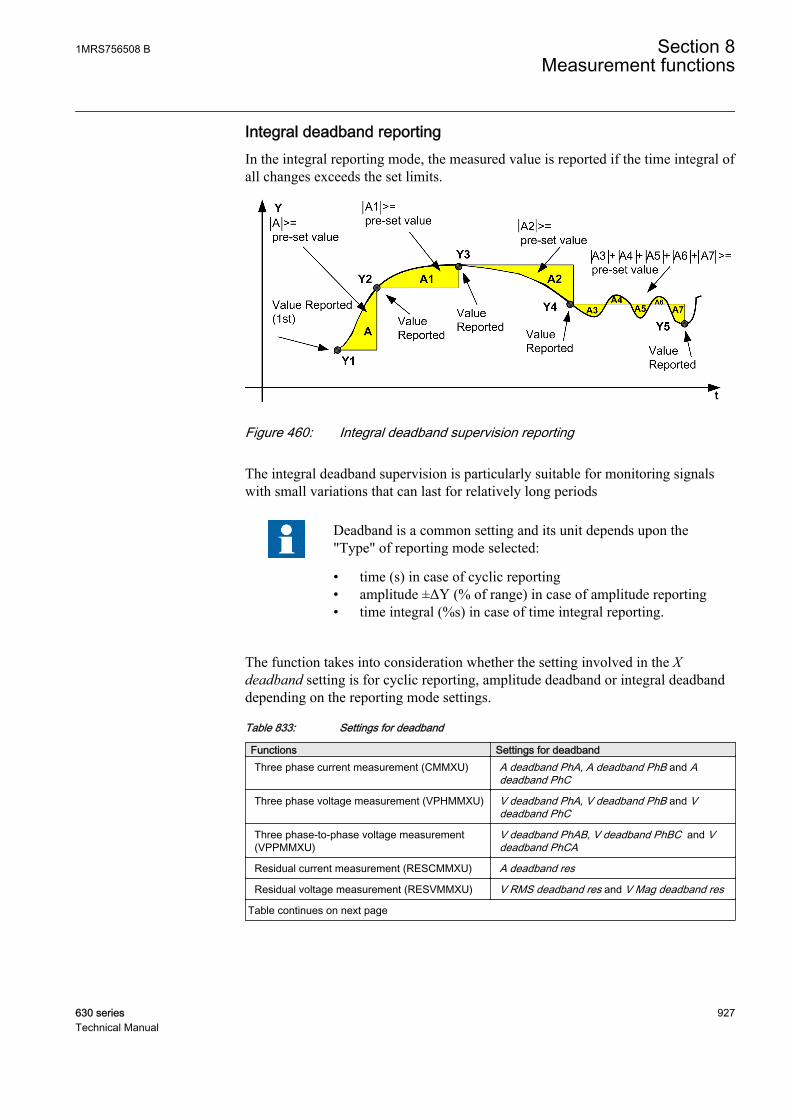
Integral deadband reportingIn the integral reporting mode, the measured value is reported if the time integral ofall changes exceeds the set limits.
GUID-81E681F8-0E9F-435A-B8F6-A7157C8884CA V1 EN
Figure 460: Integral deadband supervision reporting
The integral deadband supervision is particularly suitable for monitoring signalswith small variations that can last for relatively long periods
Deadband is a common setting and its unit depends upon the"Type" of reporting mode selected:
• time (s) in case of cyclic reporting• amplitude ±ΔY (% of range) in case of amplitude reporting• time integral (%s) in case of time integral reporting.
The function takes into consideration whether the setting involved in the Xdeadband setting is for cyclic reporting, amplitude deadband or integral deadbanddepending on the reporting mode settings.
Table 833: Settings for deadband
Functions Settings for deadbandThree phase current measurement (CMMXU) A deadband PhA, A deadband PhB and A
deadband PhC
Three phase voltage measurement (VPHMMXU) V deadband PhA, V deadband PhB and Vdeadband PhC
Three phase-to-phase voltage measurement(VPPMMXU)
V deadband PhAB, V deadband PhBC and Vdeadband PhCA
Residual current measurement (RESCMMXU) A deadband res
Residual voltage measurement (RESVMMXU) V RMS deadband res and V Mag deadband res
Table continues on next page
1MRS756508 B Section 8Measurement functions
630 series 927Technical Manual
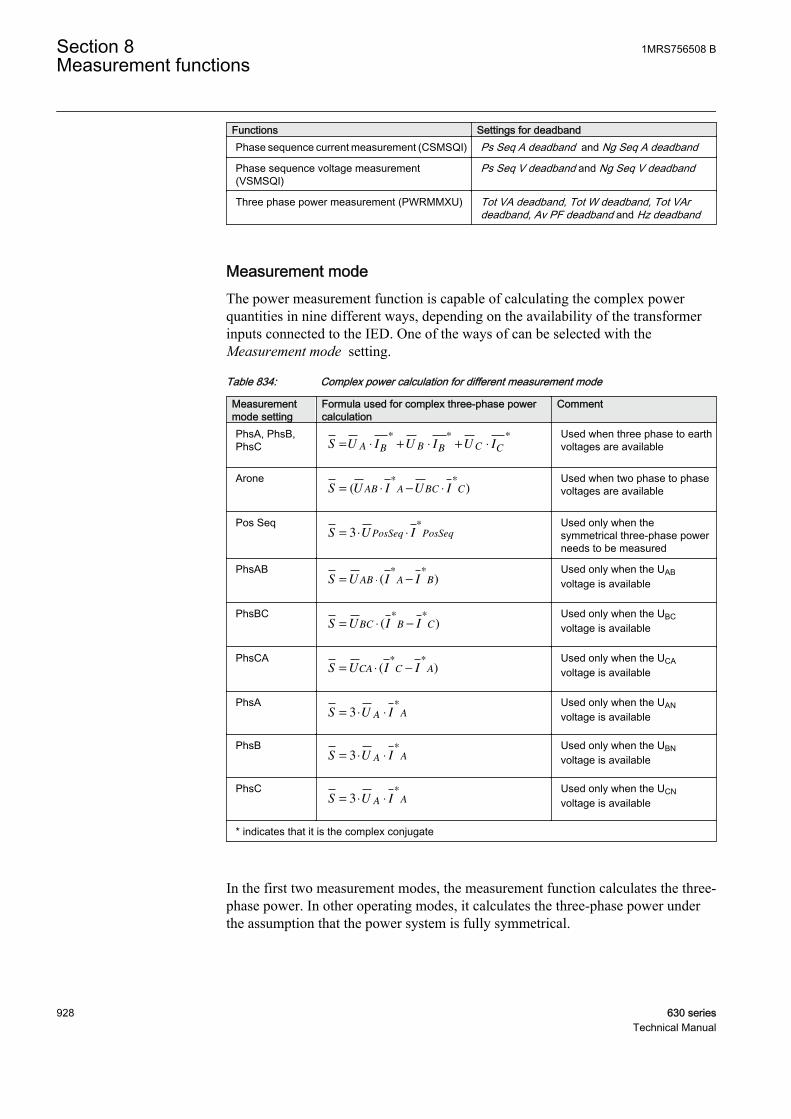
Functions Settings for deadbandPhase sequence current measurement (CSMSQI) Ps Seq A deadband and Ng Seq A deadband
Phase sequence voltage measurement(VSMSQI)
Ps Seq V deadband and Ng Seq V deadband
Three phase power measurement (PWRMMXU) Tot VA deadband, Tot W deadband, Tot VArdeadband, Av PF deadband and Hz deadband
Measurement modeThe power measurement function is capable of calculating the complex powerquantities in nine different ways, depending on the availability of the transformerinputs connected to the IED. One of the ways of can be selected with theMeasurement mode setting.
Table 834: Complex power calculation for different measurement mode
Measurementmode setting
Formula used for complex three-phase powercalculation
Comment
PhsA, PhsB,PhsC S U I U I U IA B B B C C= ⋅ + ⋅ + ⋅
* * *
GUID-0A2FE804-8D3D-4D25-83E9-894274DF90B2 V1 EN
Used when three phase to earthvoltages are available
AroneS U I U IAB A BC C= ⋅ − ⋅( )
* *
GUID-5C27ADCB-1520-4180-91B5-A45DADE896EA V1 EN
Used when two phase to phasevoltages are available
Pos SeqS U IPosSeq PosSeq= ⋅ ⋅3
*
GUID-55CBB5E1-B9B0-47E7-9D5B-8DF2DFA00A79 V1 EN
Used only when thesymmetrical three-phase powerneeds to be measured
PhsABS U I IAB A B= −⋅ ( )
* *
GUID-E298FEB8-DCD7-4FC9-A6F6-E921DD77689B V1 EN
Used only when the UABvoltage is available
PhsBCS U I IBC B C= ⋅ −( )
* *
GUID-B172BBA4-E1F6-4331-B276-4EC4BD8B559D V1 EN
Used only when the UBCvoltage is available
PhsCAS U I ICA C A= ⋅ −( )
* *
GUID-14EC8FA5-A755-45DC-885A-1CA6F4790F58 V1 EN
Used only when the UCAvoltage is available
PhsAS U IA A= ⋅ ⋅3
*
GUID-7474201D-ABEA-42D6-BC5F-1B5EF29D86B7 V1 EN
Used only when the UANvoltage is available
PhsBS U IA A= ⋅ ⋅3
*
GUID-A39129C9-51AE-44EF-BC55-B02BA33B0382 V1 EN
Used only when the UBNvoltage is available
PhsCS U IA A= ⋅ ⋅3
*
GUID-03690BA1-15FE-4A11-9EC2-1C4F1362BADE V1 EN
Used only when the UCNvoltage is available
* indicates that it is the complex conjugate
In the first two measurement modes, the measurement function calculates the three-phase power. In other operating modes, it calculates the three-phase power underthe assumption that the power system is fully symmetrical.
Section 8 1MRS756508 BMeasurement functions
928 630 seriesTechnical Manual
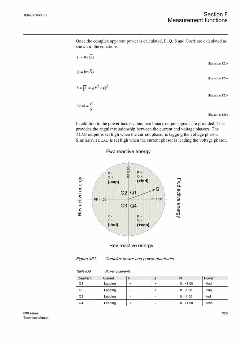
Once the complex apparent power is calculated, P, Q, S and Cosϕ are calculated asshown in the equations.
P S= Re( )
GUID-AF8C9EDD-0236-4F73-AC5A-D0E2CB8F06A9 V1 EN (Equation 123)
Q S= Im( )
GUID-5075A8BE-E0B0-4062-AECE-7CFB5D4C15F4 V1 EN (Equation 124)
S S P Q= = +2 2
GUID-B16BCE0F-650C-4BFE-9800-A26D6B0BBFE6 V1 EN (Equation 125)
CosP
Sφ =
GUID-B9101319-21B9-4BF4-A06F-DB84262B9AA3 V1 EN (Equation 126)
In addition to the power factor value, two binary output signals are provided. Thisprovides the angular relationship between the current and voltage phasors. TheILAG output is set high when the current phasor is lagging the voltage phasor.Similarly, ILEAD is set high when the current phasor is leading the voltage phasor.
P +Q +
PF 1.00PF -1.00
PF
0.00
P +Q -
P -Q +
P -Q -
GUID-668C013C-6D2D-4824-A738-1803C803C2E7 V1 EN
Figure 461: Complex power and power quadrants
Table 835: Power quadrants
Quadrant Current P Q PF PowerQ1 Lagging + + 0...+1.00 +ind
Q2 Lagging – + 0...-1.00 -cap
Q3 Leading – – 0...-1.00 -ind
Q4 Leading + - 0...+1.00 +cap
1MRS756508 B Section 8Measurement functions
630 series 929Technical Manual
Low-pass filteringTo minimize the influence of the noise signal on the measurement, the recursive low-pass filtering of the P, Q, S and Cosφ measured values can be introduced. Thismakes the measurement response slower to the step changes in the measuredquantity. The filtering is performed in accordance with the recursive formula:
X k X k Xold calculated= ⋅ + − ⋅( )1
GUID-C89ED51D-38F5-4D41-BD03-9621D5FBE6DF V2 EN (Equation 127)
X new measured value that needs to be represented as an output for example, P, Q,S or Cosφ.
Xold measured value of the previous execution cycle.
Xcalculated new calculated value in the present execution cycle.
k set relation constant, which influence the filter properties.
The default value for the relation constant k is zero. The new calculated value isgiven out without any filtering with this value k. When the value k is set above0.00, the filtering is enabled and the appropriate value k is determined separatelyfor all applications.
8.1.3 Measurement function applicationsThe measurement functions are used for power system measurement, supervisionand reporting to LHMI, a monitoring tool within PCM600 or to the station level,for example, via IEC 61850. The continuous monitoring of the measured values,for example active power, reactive power, currents, voltages, frequency and powerfactors, is vital for the efficient production, transmission and distribution ofelectrical energy. It provides a fast and easy overview of the present status of thepower system to the system operator. Additionally, it can be used during the testingand the commissioning of protection and control functions to verify the properoperation and connection of instrument transformers, that is the CTs and VTs. Theproper operation of the IED analog measurement chain can be verified during thenormal service by a periodic comparison of the measured value from IED to theother independent meters.
When the zero signal is measured, the noise in the input signal can still producesmall measurement values. The zero point clamping function can be used to ignorethe noise in the input signal and hence, to prevent the noise getting displayed in theuser display. Zero clamping is done for the measured analog signals and angle values.
The limit supervision indicates whether the measured signal has exceeded or gonebelow the set limits by activating the alarm or warning outputs of the function.These outputs can be used to configure the reporting function (events). Thesupervision function has four different limits:
Section 8 1MRS756508 BMeasurement functions
930 630 seriesTechnical Manual
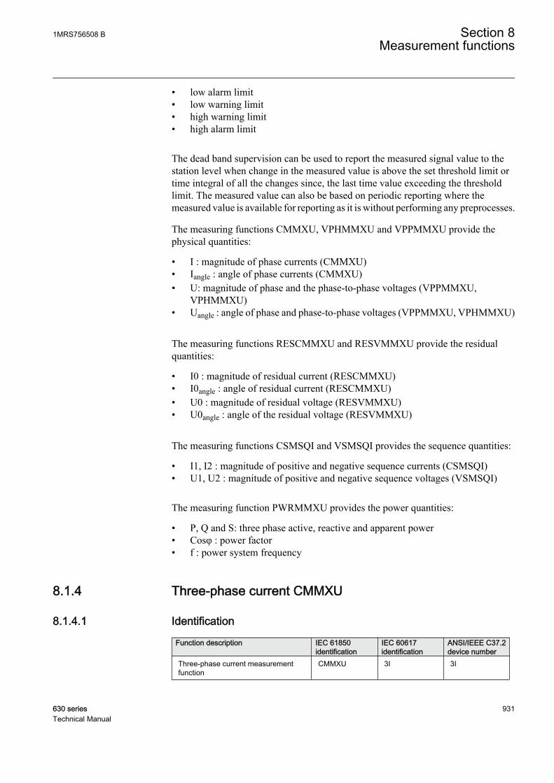
• low alarm limit• low warning limit• high warning limit• high alarm limit
The dead band supervision can be used to report the measured signal value to thestation level when change in the measured value is above the set threshold limit ortime integral of all the changes since, the last time value exceeding the thresholdlimit. The measured value can also be based on periodic reporting where themeasured value is available for reporting as it is without performing any preprocesses.
The measuring functions CMMXU, VPHMMXU and VPPMMXU provide thephysical quantities:
• I : magnitude of phase currents (CMMXU)• Iangle : angle of phase currents (CMMXU)• U: magnitude of phase and the phase-to-phase voltages (VPPMMXU,
VPHMMXU)• Uangle : angle of phase and phase-to-phase voltages (VPPMMXU, VPHMMXU)
The measuring functions RESCMMXU and RESVMMXU provide the residualquantities:
• I0 : magnitude of residual current (RESCMMXU)• I0angle : angle of residual current (RESCMMXU)• U0 : magnitude of residual voltage (RESVMMXU)• U0angle : angle of the residual voltage (RESVMMXU)
The measuring functions CSMSQI and VSMSQI provides the sequence quantities:
• I1, I2 : magnitude of positive and negative sequence currents (CSMSQI)• U1, U2 : magnitude of positive and negative sequence voltages (VSMSQI)
The measuring function PWRMMXU provides the power quantities:
• P, Q and S: three phase active, reactive and apparent power• Cosφ : power factor• f : power system frequency
8.1.4 Three-phase current CMMXU
8.1.4.1 Identification
Function description IEC 61850identification
IEC 60617identification
ANSI/IEEE C37.2device number
Three-phase current measurementfunction
CMMXU 3I 3I
1MRS756508 B Section 8Measurement functions
630 series 931Technical Manual
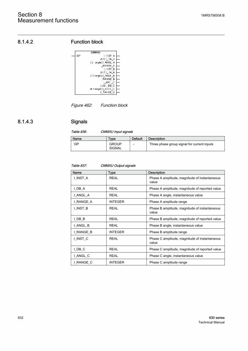
8.1.4.2 Function block
GUID-59A05E73-834D-4DF8-818B-F9EAF0392ADB V1 EN
Figure 462: Function block
8.1.4.3 Signals
Table 836: CMMXU Input signals
Name Type Default DescriptionI3P GROUP
SIGNAL- Three phase group signal for current inputs
Table 837: CMMXU Output signals
Name Type DescriptionI_INST_A REAL Phase A amplitude, magnitude of instantaneous
value
I_DB_A REAL Phase A amplitude, magnitude of reported value
I_ANGL_A REAL Phase A angle, instantaneous value
I_RANGE_A INTEGER Phase A amplitude range
I_INST_B REAL Phase B amplitude, magnitude of instantaneousvalue
I_DB_B REAL Phase B amplitude, magnitude of reported value
I_ANGL_B REAL Phase B angle, instantaneous value
I_RANGE_B INTEGER Phase B amplitude range
I_INST_C REAL Phase C amplitude, magnitude of instantaneousvalue
I_DB_C REAL Phase C amplitude, magnitude of reported value
I_ANGL_C REAL Phase C angle, instantaneous value
I_RANGE_C INTEGER Phase C amplitude range
Section 8 1MRS756508 BMeasurement functions
932 630 seriesTechnical Manual

8.1.4.4 Settings
Table 838: CMMXU Non group settings (basic)
Name Values (Range) Unit Step Default DescriptionOperation Off
On- - On Operation On / Off
A deadband PhA 1 - 300 Type 1 10 Cycl: Report interval (s), Db: In % ofrange, Int Db: In %s
A Hi high Lim PhA 0.0 - 100000.0 A 0.1 500.0 High High limit (physical value)
A high limit PhA 0.0 - 100000.0 A 0.1 400.0 High limit (physical value)
A low limit PhA 0.0 - 100000.0 A 0.1 0.0 Low limit (physical value)
A low low Lim PhA 0.0 - 100000.0 A 0.1 0.0 Low Low limit (physical value)
A minimum PhA 0.0 - 100000.0 A 0.1 0.0 Minimum value
A maximum PhA 0.0 - 100000.0 A 0.1 500.0 Maximum value
A Db type PhA CyclicDead bandInt deadband
- - Cyclic Reporting type
A deadband PhB 1 - 300 Type 1 10 Cycl: Report interval (s), Db: In % ofrange, Int Db: In %s
A Hi high Lim PhB 0.0 - 100000.0 A 0.1 500.0 High High limit (physical value)
A high limit PhB 0.0 - 100000.0 A 0.1 400.0 High limit (physical value)
A low limit PhB 0.0 - 100000.0 A 0.1 0.0 Low limit (physical value)
A low low Lim PhB 0.0 - 100000.0 A 0.1 0.0 Low Low limit (physical value)
A minimum PhB 0.0 - 100000.0 A 0.1 0.0 Minimum value
A maximum PhB 0.0 - 100000.0 A 0.1 500.0 Maximum value
A Db type PhB CyclicDead bandInt deadband
- - Cyclic Reporting type
A deadband PhC 1 - 300 Type 1 10 Cycl: Report interval (s), Db: In % ofrange, Int Db: In %s
A Hi high Lim PhC 0.0 - 100000.0 A 0.1 500.0 High High limit (physical value)
A high limit PhC 0.0 - 100000.0 A 0.1 400.0 High limit (physical value)
A low limit PhC 0.0 - 100000.0 A 0.1 0.0 Low limit (physical value)
A low low Lim PhC 0.0 - 100000.0 A 0.1 0.0 Low Low limit (physical value)
A minimum PhC 0.0 - 100000.0 A 0.1 0.0 Minimum value
A maximum PhC 0.0 - 100000.0 A 0.1 500.0 Maximum value
A Db type PhC CyclicDead bandInt deadband
- - Cyclic Reporting type
1MRS756508 B Section 8Measurement functions
630 series 933Technical Manual
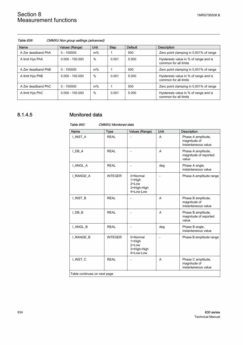
Table 839: CMMXU Non group settings (advanced)
Name Values (Range) Unit Step Default DescriptionA Zer deadband PhA 0 - 100000 m% 1 500 Zero point clamping in 0,001% of range
A limit Hys PhA 0.000 - 100.000 % 0.001 5.000 Hysteresis value in % of range and iscommon for all limits
A Zer deadband PhB 0 - 100000 m% 1 500 Zero point clamping in 0,001% of range
A limit Hys PhB 0.000 - 100.000 % 0.001 5.000 Hysteresis value in % of range and iscommon for all limits
A Zer deadband PhC 0 - 100000 m% 1 500 Zero point clamping in 0,001% of range
A limit Hys PhC 0.000 - 100.000 % 0.001 5.000 Hysteresis value in % of range and iscommon for all limits
8.1.4.5 Monitored data
Table 840: CMMXU Monitored data
Name Type Values (Range) Unit DescriptionI_INST_A REAL - A Phase A amplitude,
magnitude ofinstantaneous value
I_DB_A REAL - A Phase A amplitude,magnitude of reportedvalue
I_ANGL_A REAL - deg Phase A angle,instantaneous value
I_RANGE_A INTEGER 0=Normal1=High2=Low3=High-High4=Low-Low
- Phase A amplitude range
I_INST_B REAL - A Phase B amplitude,magnitude ofinstantaneous value
I_DB_B REAL - A Phase B amplitude,magnitude of reportedvalue
I_ANGL_B REAL - deg Phase B angle,instantaneous value
I_RANGE_B INTEGER 0=Normal1=High2=Low3=High-High4=Low-Low
- Phase B amplitude range
I_INST_C REAL - A Phase C amplitude,magnitude ofinstantaneous value
Table continues on next page
Section 8 1MRS756508 BMeasurement functions
934 630 seriesTechnical Manual
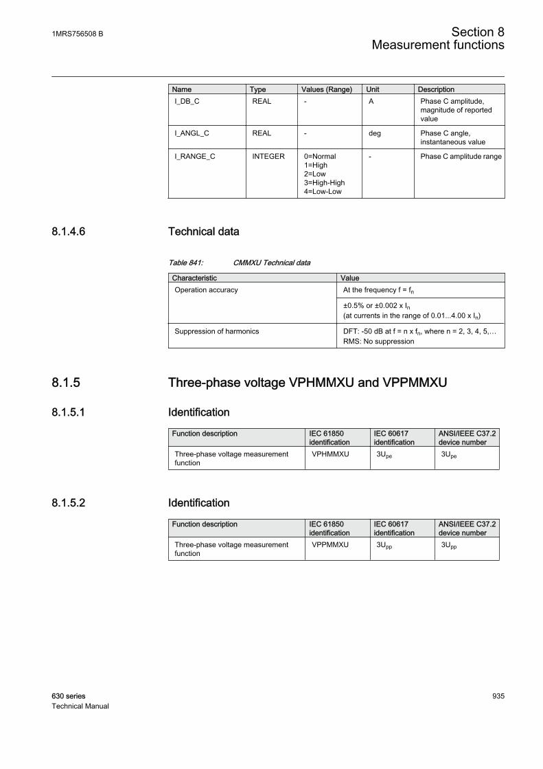
Name Type Values (Range) Unit DescriptionI_DB_C REAL - A Phase C amplitude,
magnitude of reportedvalue
I_ANGL_C REAL - deg Phase C angle,instantaneous value
I_RANGE_C INTEGER 0=Normal1=High2=Low3=High-High4=Low-Low
- Phase C amplitude range
8.1.4.6 Technical data
Table 841: CMMXU Technical data
Characteristic ValueOperation accuracy At the frequency f = fn
±0.5% or ±0.002 x In(at currents in the range of 0.01...4.00 x In)
Suppression of harmonics DFT: -50 dB at f = n x fn, where n = 2, 3, 4, 5,…RMS: No suppression
8.1.5 Three-phase voltage VPHMMXU and VPPMMXU
8.1.5.1 Identification
Function description IEC 61850identification
IEC 60617identification
ANSI/IEEE C37.2device number
Three-phase voltage measurementfunction
VPHMMXU 3Upe 3Upe
8.1.5.2 Identification
Function description IEC 61850identification
IEC 60617identification
ANSI/IEEE C37.2device number
Three-phase voltage measurementfunction
VPPMMXU 3Upp 3Upp
1MRS756508 B Section 8Measurement functions
630 series 935Technical Manual
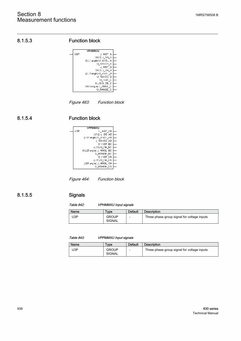
8.1.5.3 Function block
GUID-A0EE79C7-38CC-4F68-B458-22F54F7BCA43 V1 EN
Figure 463: Function block
8.1.5.4 Function block
GUID-B18BB9BB-3585-48FB-A575-5FB217CB9957 V1 EN
Figure 464: Function block
8.1.5.5 Signals
Table 842: VPHMMXU Input signals
Name Type Default DescriptionU3P GROUP
SIGNAL- Three phase group signal for voltage inputs
Table 843: VPPMMXU Input signals
Name Type Default DescriptionU3P GROUP
SIGNAL- Three phase group signal for voltage inputs
Section 8 1MRS756508 BMeasurement functions
936 630 seriesTechnical Manual
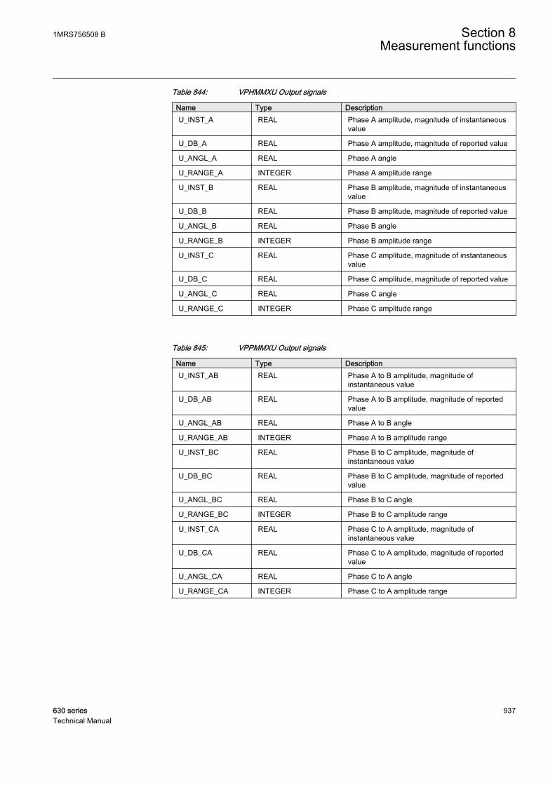
Table 844: VPHMMXU Output signals
Name Type DescriptionU_INST_A REAL Phase A amplitude, magnitude of instantaneous
value
U_DB_A REAL Phase A amplitude, magnitude of reported value
U_ANGL_A REAL Phase A angle
U_RANGE_A INTEGER Phase A amplitude range
U_INST_B REAL Phase B amplitude, magnitude of instantaneousvalue
U_DB_B REAL Phase B amplitude, magnitude of reported value
U_ANGL_B REAL Phase B angle
U_RANGE_B INTEGER Phase B amplitude range
U_INST_C REAL Phase C amplitude, magnitude of instantaneousvalue
U_DB_C REAL Phase C amplitude, magnitude of reported value
U_ANGL_C REAL Phase C angle
U_RANGE_C INTEGER Phase C amplitude range
Table 845: VPPMMXU Output signals
Name Type DescriptionU_INST_AB REAL Phase A to B amplitude, magnitude of
instantaneous value
U_DB_AB REAL Phase A to B amplitude, magnitude of reportedvalue
U_ANGL_AB REAL Phase A to B angle
U_RANGE_AB INTEGER Phase A to B amplitude range
U_INST_BC REAL Phase B to C amplitude, magnitude ofinstantaneous value
U_DB_BC REAL Phase B to C amplitude, magnitude of reportedvalue
U_ANGL_BC REAL Phase B to C angle
U_RANGE_BC INTEGER Phase B to C amplitude range
U_INST_CA REAL Phase C to A amplitude, magnitude ofinstantaneous value
U_DB_CA REAL Phase C to A amplitude, magnitude of reportedvalue
U_ANGL_CA REAL Phase C to A angle
U_RANGE_CA INTEGER Phase C to A amplitude range
1MRS756508 B Section 8Measurement functions
630 series 937Technical Manual

8.1.5.6 Settings
Table 846: VPHMMXU Non group settings (basic)
Name Values (Range) Unit Step Default DescriptionOperation Off
On- - On Operation On / Off
V deadband PhA 1 - 300 Type 1 10 Cycl: Report interval (s), Db: In % ofrange, Int Db: In %s
V Hi high Lim PhA 0 - 1000000 V 1 12990 High High limit (physical value)
V high limit PhA 0 - 1000000 V 1 12125 High limit (physical value)
V low limit PhA 0 - 1000000 V 1 0 Low limit (physical value)
V low low Lim PhA 0 - 1000000 V 1 0 Low Low limit (physical value)
V minimum PhA 0 - 1000000 V 1 0 Minimum value
V maximum PhA 0 - 1000000 V 1 15000 Maximum value
V Db type PhA CyclicDead bandInt deadband
- - Cyclic Reporting type
V deadband PhB 1 - 300 Type 1 10 Cycl: Report interval (s), Db: In % ofrange, Int Db: In %s
V Hi high Lim PhB 0 - 1000000 V 1 12990 High High limit (physical value)
V high limit PhB 0 - 1000000 V 1 12125 High limit (physical value)
V low limit PhB 0 - 1000000 V 1 0 Low limit (physical value)
V low low Lim PhB 0 - 1000000 V 1 0 Low Low limit (physical value)
V minimum PhB 0 - 1000000 V 1 0 Minimum value
V maximum PhB 0 - 1000000 V 1 15000 Maximum value
V Db type PhB CyclicDead bandInt deadband
- - Cyclic Reporting type
V deadband PhC 1 - 300 Type 1 10 Cycl: Report interval (s), Db: In % ofrange, Int Db: In %s
V Hi high Lim PhC 0 - 1000000 V 1 12990 High High limit (physical value)
V high limit PhC 0 - 1000000 V 1 12125 High limit (physical value)
V low limit PhC 0 - 1000000 V 1 0 Low limit (physical value)
V low low Lim PhC 0 - 1000000 V 1 0 Low Low limit (physical value)
V minimum PhC 0 - 1000000 V 1 0 Minimum value
V maximum PhC 0 - 1000000 V 1 15000 Maximum value
V Db type PhC CyclicDead bandInt deadband
- - Cyclic Reporting type
Section 8 1MRS756508 BMeasurement functions
938 630 seriesTechnical Manual
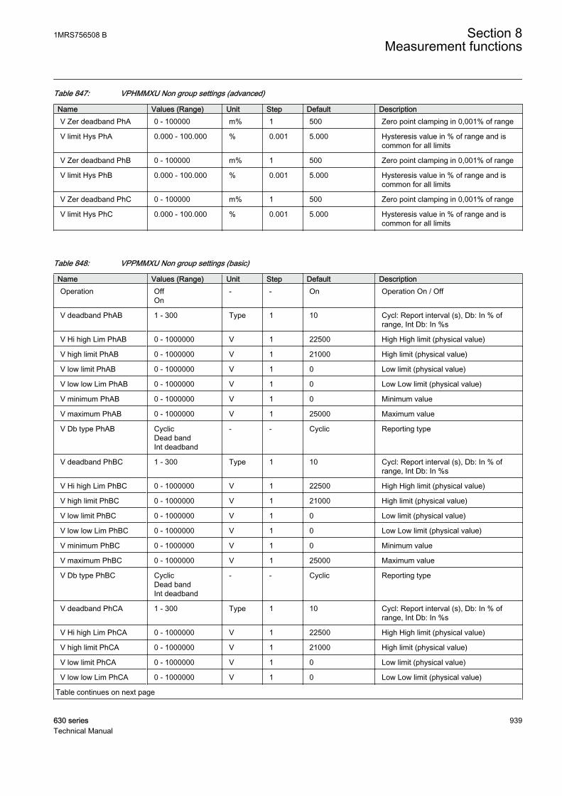
Table 847: VPHMMXU Non group settings (advanced)
Name Values (Range) Unit Step Default DescriptionV Zer deadband PhA 0 - 100000 m% 1 500 Zero point clamping in 0,001% of range
V limit Hys PhA 0.000 - 100.000 % 0.001 5.000 Hysteresis value in % of range and iscommon for all limits
V Zer deadband PhB 0 - 100000 m% 1 500 Zero point clamping in 0,001% of range
V limit Hys PhB 0.000 - 100.000 % 0.001 5.000 Hysteresis value in % of range and iscommon for all limits
V Zer deadband PhC 0 - 100000 m% 1 500 Zero point clamping in 0,001% of range
V limit Hys PhC 0.000 - 100.000 % 0.001 5.000 Hysteresis value in % of range and iscommon for all limits
Table 848: VPPMMXU Non group settings (basic)
Name Values (Range) Unit Step Default DescriptionOperation Off
On- - On Operation On / Off
V deadband PhAB 1 - 300 Type 1 10 Cycl: Report interval (s), Db: In % ofrange, Int Db: In %s
V Hi high Lim PhAB 0 - 1000000 V 1 22500 High High limit (physical value)
V high limit PhAB 0 - 1000000 V 1 21000 High limit (physical value)
V low limit PhAB 0 - 1000000 V 1 0 Low limit (physical value)
V low low Lim PhAB 0 - 1000000 V 1 0 Low Low limit (physical value)
V minimum PhAB 0 - 1000000 V 1 0 Minimum value
V maximum PhAB 0 - 1000000 V 1 25000 Maximum value
V Db type PhAB CyclicDead bandInt deadband
- - Cyclic Reporting type
V deadband PhBC 1 - 300 Type 1 10 Cycl: Report interval (s), Db: In % ofrange, Int Db: In %s
V Hi high Lim PhBC 0 - 1000000 V 1 22500 High High limit (physical value)
V high limit PhBC 0 - 1000000 V 1 21000 High limit (physical value)
V low limit PhBC 0 - 1000000 V 1 0 Low limit (physical value)
V low low Lim PhBC 0 - 1000000 V 1 0 Low Low limit (physical value)
V minimum PhBC 0 - 1000000 V 1 0 Minimum value
V maximum PhBC 0 - 1000000 V 1 25000 Maximum value
V Db type PhBC CyclicDead bandInt deadband
- - Cyclic Reporting type
V deadband PhCA 1 - 300 Type 1 10 Cycl: Report interval (s), Db: In % ofrange, Int Db: In %s
V Hi high Lim PhCA 0 - 1000000 V 1 22500 High High limit (physical value)
V high limit PhCA 0 - 1000000 V 1 21000 High limit (physical value)
V low limit PhCA 0 - 1000000 V 1 0 Low limit (physical value)
V low low Lim PhCA 0 - 1000000 V 1 0 Low Low limit (physical value)
Table continues on next page
1MRS756508 B Section 8Measurement functions
630 series 939Technical Manual
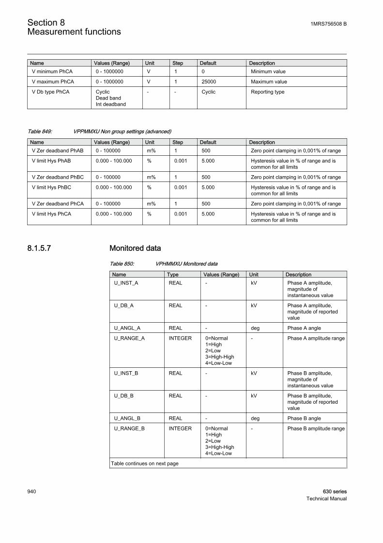
Name Values (Range) Unit Step Default DescriptionV minimum PhCA 0 - 1000000 V 1 0 Minimum value
V maximum PhCA 0 - 1000000 V 1 25000 Maximum value
V Db type PhCA CyclicDead bandInt deadband
- - Cyclic Reporting type
Table 849: VPPMMXU Non group settings (advanced)
Name Values (Range) Unit Step Default DescriptionV Zer deadband PhAB 0 - 100000 m% 1 500 Zero point clamping in 0,001% of range
V limit Hys PhAB 0.000 - 100.000 % 0.001 5.000 Hysteresis value in % of range and iscommon for all limits
V Zer deadband PhBC 0 - 100000 m% 1 500 Zero point clamping in 0,001% of range
V limit Hys PhBC 0.000 - 100.000 % 0.001 5.000 Hysteresis value in % of range and iscommon for all limits
V Zer deadband PhCA 0 - 100000 m% 1 500 Zero point clamping in 0,001% of range
V limit Hys PhCA 0.000 - 100.000 % 0.001 5.000 Hysteresis value in % of range and iscommon for all limits
8.1.5.7 Monitored data
Table 850: VPHMMXU Monitored data
Name Type Values (Range) Unit DescriptionU_INST_A REAL - kV Phase A amplitude,
magnitude ofinstantaneous value
U_DB_A REAL - kV Phase A amplitude,magnitude of reportedvalue
U_ANGL_A REAL - deg Phase A angle
U_RANGE_A INTEGER 0=Normal1=High2=Low3=High-High4=Low-Low
- Phase A amplitude range
U_INST_B REAL - kV Phase B amplitude,magnitude ofinstantaneous value
U_DB_B REAL - kV Phase B amplitude,magnitude of reportedvalue
U_ANGL_B REAL - deg Phase B angle
U_RANGE_B INTEGER 0=Normal1=High2=Low3=High-High4=Low-Low
- Phase B amplitude range
Table continues on next page
Section 8 1MRS756508 BMeasurement functions
940 630 seriesTechnical Manual
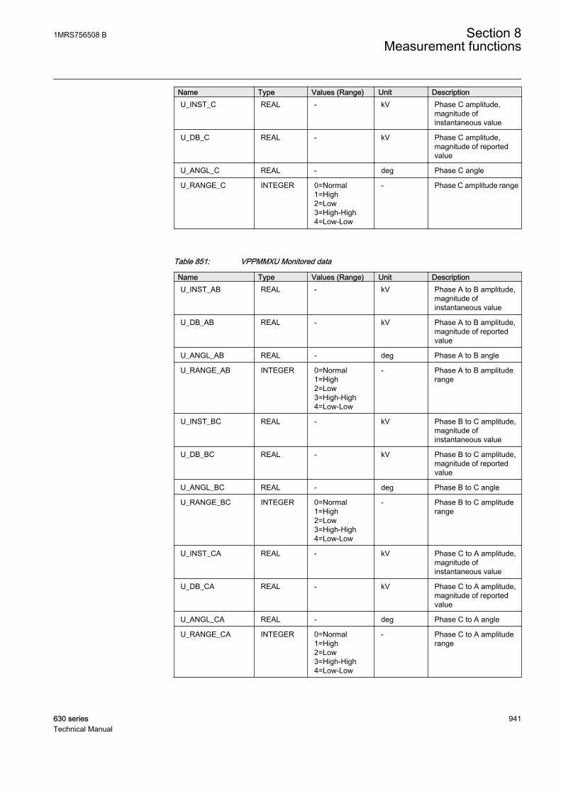
Name Type Values (Range) Unit DescriptionU_INST_C REAL - kV Phase C amplitude,
magnitude ofinstantaneous value
U_DB_C REAL - kV Phase C amplitude,magnitude of reportedvalue
U_ANGL_C REAL - deg Phase C angle
U_RANGE_C INTEGER 0=Normal1=High2=Low3=High-High4=Low-Low
- Phase C amplitude range
Table 851: VPPMMXU Monitored data
Name Type Values (Range) Unit DescriptionU_INST_AB REAL - kV Phase A to B amplitude,
magnitude ofinstantaneous value
U_DB_AB REAL - kV Phase A to B amplitude,magnitude of reportedvalue
U_ANGL_AB REAL - deg Phase A to B angle
U_RANGE_AB INTEGER 0=Normal1=High2=Low3=High-High4=Low-Low
- Phase A to B amplituderange
U_INST_BC REAL - kV Phase B to C amplitude,magnitude ofinstantaneous value
U_DB_BC REAL - kV Phase B to C amplitude,magnitude of reportedvalue
U_ANGL_BC REAL - deg Phase B to C angle
U_RANGE_BC INTEGER 0=Normal1=High2=Low3=High-High4=Low-Low
- Phase B to C amplituderange
U_INST_CA REAL - kV Phase C to A amplitude,magnitude ofinstantaneous value
U_DB_CA REAL - kV Phase C to A amplitude,magnitude of reportedvalue
U_ANGL_CA REAL - deg Phase C to A angle
U_RANGE_CA INTEGER 0=Normal1=High2=Low3=High-High4=Low-Low
- Phase C to A amplituderange
1MRS756508 B Section 8Measurement functions
630 series 941Technical Manual

8.1.5.8 Technical data
Table 852: VPHMMXU Technical data
Characteristic ValueOperation accuracy At the frequency f = fn
±0.5% or ±0.002 x Un(at voltages in the range of 0.01...1.15 × Un)
Suppression of harmonics DFT: -50dB at f = n × fn, where n = 2, 3, 4, 5,…RMS: No suppression
8.1.5.9 Technical data
Table 853: VPPMMXU Technical data
Characteristic ValueOperation accuracy At the frequency f = fn
±0.5% or ±0.002 x Un(at voltages in the range of 0.01...1.15 × Un)
Suppression of harmonics DFT: -50dB at f = n × fn, where n = 2, 3, 4, 5,…RMS: No suppression
8.1.6 Residual current RESCMMXU
8.1.6.1 Identification
Function description IEC 61850identification
IEC 60617identification
ANSI/IEEE C37.2device number
Residual current RESCMMXU Io Io
8.1.6.2 Function block
GUID-246247B0-E97B-458E-B5EA-78B922B8CF5E V1 EN
Figure 465: Function block
8.1.6.3 Signals
Table 854: RESCMMXU Input signals
Name Type Default DescriptionI3P GROUP
SIGNAL- Three phase group signal for current inputs
Section 8 1MRS756508 BMeasurement functions
942 630 seriesTechnical Manual

Table 855: RESCMMXU Output signals
Name Type DescriptionI0_INST REAL Residual current RMS, magnitude of
instantaneous value
I0_DB REAL Residual current RMS, magnitude of reportedvalue
I0_ANGL REAL Residual current angle
I0_RANGE INTEGER Residual current RMS range
8.1.6.4 Settings
Table 856: RESCMMXU Non group settings (basic)
Name Values (Range) Unit Step Default DescriptionOperation Off
On- - On Operation On / Off
A deadband res 1 - 300 Type 1 10 Cycl: Report interval (s), Db: In % ofrange, Int Db: In %s
A Hi high Lim res 0.0 - 100000.0 A 0.1 15.0 High High limit (physical value)
A high limit res 0.0 - 100000.0 A 0.1 5.0 High limit (physical value)
A low limit res 0.0 - 100000.0 A 0.1 0.0 Low limit (physical value)
A low low Lim res 0.0 - 100000.0 A 0.1 0.0 Low Low limit (physical value)
A minimum res 0.0 - 100000.0 A 0.1 0.0 Minimum value
A maximum res 0.0 - 100000.0 A 0.1 70.0 Maximum value
A Db type res CyclicDead bandInt deadband
- - Cyclic Reporting type
Table 857: RESCMMXU Non group settings (advanced)
Name Values (Range) Unit Step Default DescriptionA Zer deadband res 0 - 100000 m% 1 500 Zero point clamping in 0,001% of range
A limit Hys res 0.000 - 100.000 % 0.001 5.000 Hysteresis value in % of range and iscommon for all limits
1MRS756508 B Section 8Measurement functions
630 series 943Technical Manual
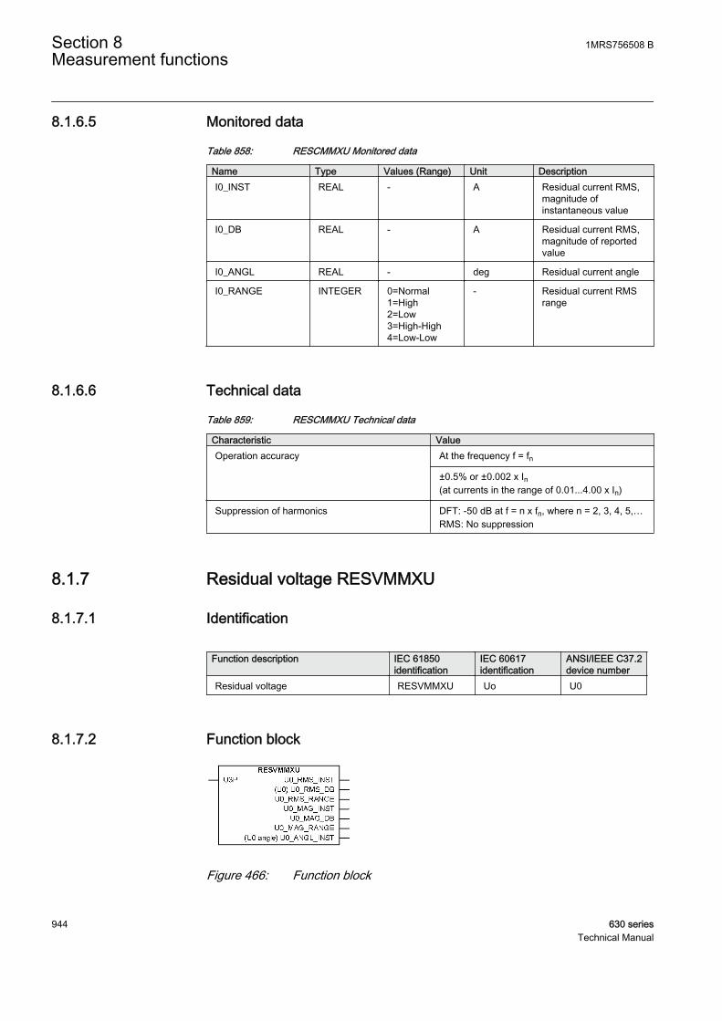
8.1.6.5 Monitored data
Table 858: RESCMMXU Monitored data
Name Type Values (Range) Unit DescriptionI0_INST REAL - A Residual current RMS,
magnitude ofinstantaneous value
I0_DB REAL - A Residual current RMS,magnitude of reportedvalue
I0_ANGL REAL - deg Residual current angle
I0_RANGE INTEGER 0=Normal1=High2=Low3=High-High4=Low-Low
- Residual current RMSrange
8.1.6.6 Technical data
Table 859: RESCMMXU Technical data
Characteristic ValueOperation accuracy At the frequency f = fn
±0.5% or ±0.002 x In(at currents in the range of 0.01...4.00 x In)
Suppression of harmonics DFT: -50 dB at f = n x fn, where n = 2, 3, 4, 5,…RMS: No suppression
8.1.7 Residual voltage RESVMMXU
8.1.7.1 Identification
Function description IEC 61850identification
IEC 60617identification
ANSI/IEEE C37.2device number
Residual voltage RESVMMXU Uo U0
8.1.7.2 Function block
GUID-DAE9974F-2215-4E98-B902-E7A92A81DDEF V1 EN
Figure 466: Function block
Section 8 1MRS756508 BMeasurement functions
944 630 seriesTechnical Manual

8.1.7.3 Signals
Table 860: RESVMMXU Input signals
Name Type Default DescriptionU3P GROUP
SIGNAL- Three phase group signal for voltage inputs
Table 861: RESVMMXU Output signals
Name Type DescriptionU0_RMS_INST REAL U0 RMS, magnitude of instantaneous value
U0_RMS_DB REAL U0 RMS, magnitude of reported value
U0_RMS_RANGE INTEGER U0 RMS range
U0_MAG_INST REAL U0 Amplitude, magnitude of instantaneous value
U0_MAG_DB REAL U0 Amplitude, magnitude of reported value
U0_MAG_RANGE INTEGER U0 Amplitude range
U0_ANGL_INST REAL U0 angle, instantaneous value
8.1.7.4 Settings
Table 862: RESVMMXU Non group settings (basic)
Name Values (Range) Unit Step Default DescriptionOperation Off
On- - On Operation On / Off
V RMS deadband res 1 - 300 Type 1 10 Cycl: Report interval (s), Db: In % ofrange, Int Db: In %s
V RMS Hi Hi Lim res 0 - 1000000 V 1 1154 High High limit (physical value)
V RMS high Lim res 0 - 1000000 V 1 577 High limit (physical value)
V RMS low limit res 0 - 1000000 V 1 0 Low limit (physical value)
V RMS Lo low Lim res 0 - 1000000 V 1 0 Low Low limit (physical value)
V RMS minimum res 0 - 1000000 V 1 0 Minimum value
V RMS maximum res 0 - 1000000 V 1 15000 Maximum value
V RMS Db type res CyclicDead bandInt deadband
- - Cyclic Reporting type
V Mag deadband res 1 - 300 Type 1 10 Cycl: Report interval (s), Db: In % ofrange, Int Db: In %s
V Mag Hi Hi Lim res 0 - 1000000 V 1 1154 High High limit (physical value)
V Mag high Lim res 0 - 1000000 V 1 577 High limit (physical value)
V Mag low limit res 0 - 1000000 V 1 0 Low limit (physical value)
V Mag Lo low Lim res 0 - 1000000 V 1 0 Low Low limit (physical value)
Table continues on next page
1MRS756508 B Section 8Measurement functions
630 series 945Technical Manual
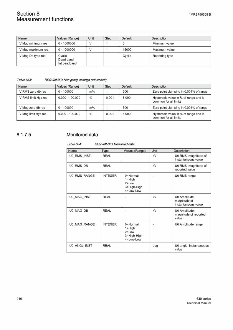
Name Values (Range) Unit Step Default DescriptionV Mag minimum res 0 - 1000000 V 1 0 Minimum value
V Mag maximum res 0 - 1000000 V 1 15000 Maximum value
V Mag Db type res CyclicDead bandInt deadband
- - Cyclic Reporting type
Table 863: RESVMMXU Non group settings (advanced)
Name Values (Range) Unit Step Default DescriptionV RMS zero db res 0 - 100000 m% 1 500 Zero point clamping in 0,001% of range
V RMS limit Hys res 0.000 - 100.000 % 0.001 5.000 Hysteresis value in % of range and iscommon for all limits
V Mag zero db res 0 - 100000 m% 1 500 Zero point clamping in 0,001% of range
V Mag limit Hys res 0.000 - 100.000 % 0.001 5.000 Hysteresis value in % of range and iscommon for all limits
8.1.7.5 Monitored data
Table 864: RESVMMXU Monitored data
Name Type Values (Range) Unit DescriptionU0_RMS_INST REAL - kV U0 RMS, magnitude of
instantaneous value
U0_RMS_DB REAL - kV U0 RMS, magnitude ofreported value
U0_RMS_RANGE INTEGER 0=Normal1=High2=Low3=High-High4=Low-Low
- U0 RMS range
U0_MAG_INST REAL - kV U0 Amplitude,magnitude ofinstantaneous value
U0_MAG_DB REAL - kV U0 Amplitude,magnitude of reportedvalue
U0_MAG_RANGE INTEGER 0=Normal1=High2=Low3=High-High4=Low-Low
- U0 Amplitude range
U0_ANGL_INST REAL - deg U0 angle, instantaneousvalue
Section 8 1MRS756508 BMeasurement functions
946 630 seriesTechnical Manual
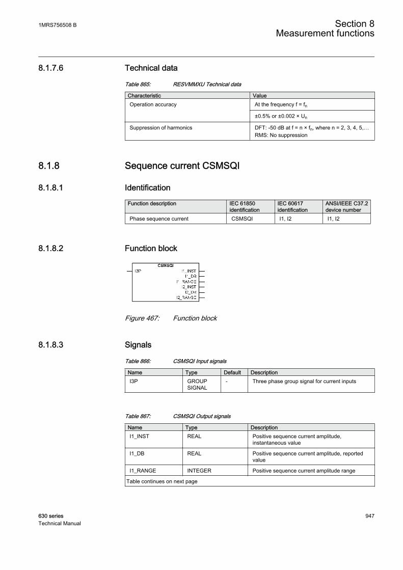
8.1.7.6 Technical data
Table 865: RESVMMXU Technical data
Characteristic ValueOperation accuracy At the frequency f = fn
±0.5% or ±0.002 × Un
Suppression of harmonics DFT: -50 dB at f = n × fn, where n = 2, 3, 4, 5,…RMS: No suppression
8.1.8 Sequence current CSMSQI
8.1.8.1 Identification
Function description IEC 61850identification
IEC 60617identification
ANSI/IEEE C37.2device number
Phase sequence current CSMSQI I1, I2 I1, I2
8.1.8.2 Function block
GUID-4FE7181C-001E-4AFF-878D-BA49CB28494D V1 EN
Figure 467: Function block
8.1.8.3 Signals
Table 866: CSMSQI Input signals
Name Type Default DescriptionI3P GROUP
SIGNAL- Three phase group signal for current inputs
Table 867: CSMSQI Output signals
Name Type DescriptionI1_INST REAL Positive sequence current amplitude,
instantaneous value
I1_DB REAL Positive sequence current amplitude, reportedvalue
I1_RANGE INTEGER Positive sequence current amplitude range
Table continues on next page
1MRS756508 B Section 8Measurement functions
630 series 947Technical Manual
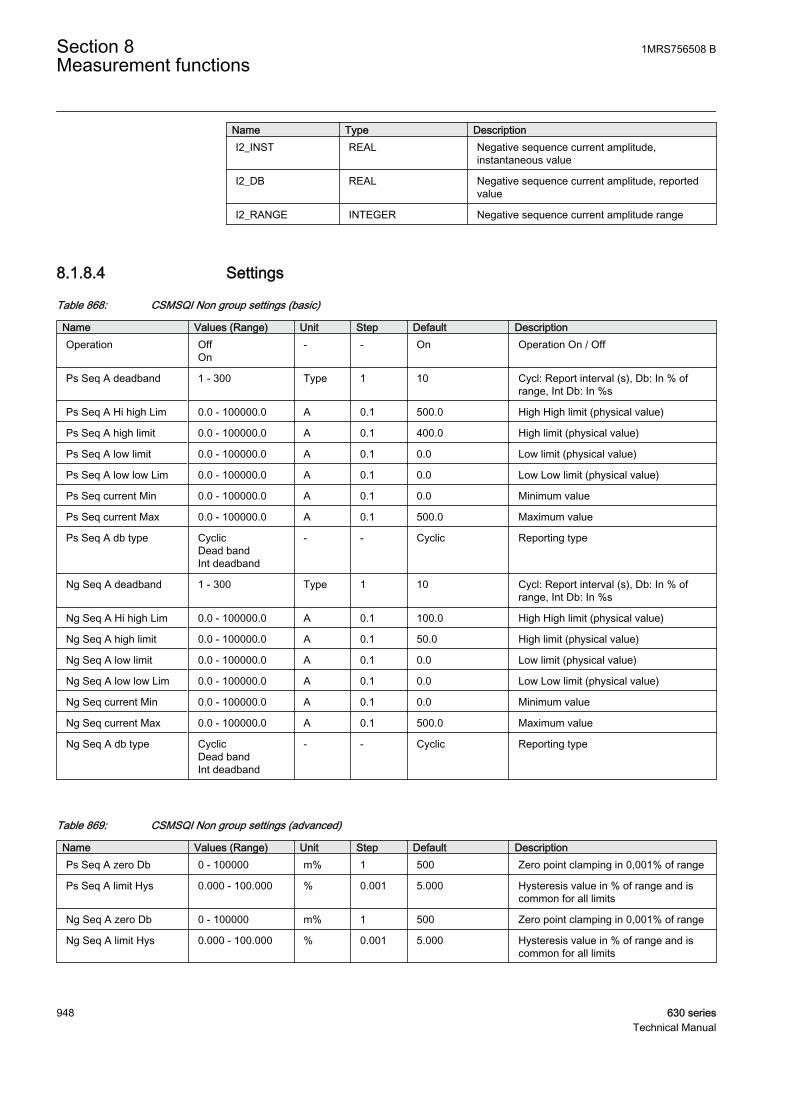
Name Type DescriptionI2_INST REAL Negative sequence current amplitude,
instantaneous value
I2_DB REAL Negative sequence current amplitude, reportedvalue
I2_RANGE INTEGER Negative sequence current amplitude range
8.1.8.4 Settings
Table 868: CSMSQI Non group settings (basic)
Name Values (Range) Unit Step Default DescriptionOperation Off
On- - On Operation On / Off
Ps Seq A deadband 1 - 300 Type 1 10 Cycl: Report interval (s), Db: In % ofrange, Int Db: In %s
Ps Seq A Hi high Lim 0.0 - 100000.0 A 0.1 500.0 High High limit (physical value)
Ps Seq A high limit 0.0 - 100000.0 A 0.1 400.0 High limit (physical value)
Ps Seq A low limit 0.0 - 100000.0 A 0.1 0.0 Low limit (physical value)
Ps Seq A low low Lim 0.0 - 100000.0 A 0.1 0.0 Low Low limit (physical value)
Ps Seq current Min 0.0 - 100000.0 A 0.1 0.0 Minimum value
Ps Seq current Max 0.0 - 100000.0 A 0.1 500.0 Maximum value
Ps Seq A db type CyclicDead bandInt deadband
- - Cyclic Reporting type
Ng Seq A deadband 1 - 300 Type 1 10 Cycl: Report interval (s), Db: In % ofrange, Int Db: In %s
Ng Seq A Hi high Lim 0.0 - 100000.0 A 0.1 100.0 High High limit (physical value)
Ng Seq A high limit 0.0 - 100000.0 A 0.1 50.0 High limit (physical value)
Ng Seq A low limit 0.0 - 100000.0 A 0.1 0.0 Low limit (physical value)
Ng Seq A low low Lim 0.0 - 100000.0 A 0.1 0.0 Low Low limit (physical value)
Ng Seq current Min 0.0 - 100000.0 A 0.1 0.0 Minimum value
Ng Seq current Max 0.0 - 100000.0 A 0.1 500.0 Maximum value
Ng Seq A db type CyclicDead bandInt deadband
- - Cyclic Reporting type
Table 869: CSMSQI Non group settings (advanced)
Name Values (Range) Unit Step Default DescriptionPs Seq A zero Db 0 - 100000 m% 1 500 Zero point clamping in 0,001% of range
Ps Seq A limit Hys 0.000 - 100.000 % 0.001 5.000 Hysteresis value in % of range and iscommon for all limits
Ng Seq A zero Db 0 - 100000 m% 1 500 Zero point clamping in 0,001% of range
Ng Seq A limit Hys 0.000 - 100.000 % 0.001 5.000 Hysteresis value in % of range and iscommon for all limits
Section 8 1MRS756508 BMeasurement functions
948 630 seriesTechnical Manual
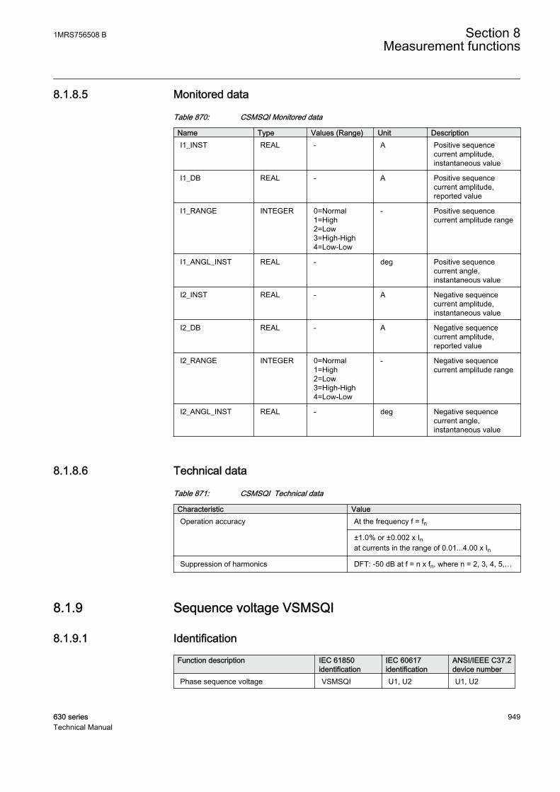
8.1.8.5 Monitored data
Table 870: CSMSQI Monitored data
Name Type Values (Range) Unit DescriptionI1_INST REAL - A Positive sequence
current amplitude,instantaneous value
I1_DB REAL - A Positive sequencecurrent amplitude,reported value
I1_RANGE INTEGER 0=Normal1=High2=Low3=High-High4=Low-Low
- Positive sequencecurrent amplitude range
I1_ANGL_INST REAL - deg Positive sequencecurrent angle,instantaneous value
I2_INST REAL - A Negative sequencecurrent amplitude,instantaneous value
I2_DB REAL - A Negative sequencecurrent amplitude,reported value
I2_RANGE INTEGER 0=Normal1=High2=Low3=High-High4=Low-Low
- Negative sequencecurrent amplitude range
I2_ANGL_INST REAL - deg Negative sequencecurrent angle,instantaneous value
8.1.8.6 Technical data
Table 871: CSMSQI Technical data
Characteristic ValueOperation accuracy At the frequency f = fn
±1.0% or ±0.002 x Inat currents in the range of 0.01...4.00 x In
Suppression of harmonics DFT: -50 dB at f = n x fn, where n = 2, 3, 4, 5,…
8.1.9 Sequence voltage VSMSQI
8.1.9.1 Identification
Function description IEC 61850identification
IEC 60617identification
ANSI/IEEE C37.2device number
Phase sequence voltage VSMSQI U1, U2 U1, U2
1MRS756508 B Section 8Measurement functions
630 series 949Technical Manual
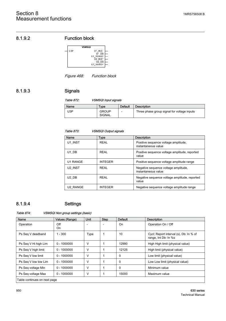
8.1.9.2 Function block
GUID-5357C0A7-F155-4087-9E8C-794EF09478E0 V1 EN
Figure 468: Function block
8.1.9.3 Signals
Table 872: VSMSQI Input signals
Name Type Default DescriptionU3P GROUP
SIGNAL- Three phase group signal for voltage inputs
Table 873: VSMSQI Output signals
Name Type DescriptionU1_INST REAL Positive sequence voltage amplitude,
instantaneous value
U1_DB REAL Positive sequence voltage amplitude, reportedvalue
U1 RANGE INTEGER Positive sequence voltage amplitude range
U2_INST REAL Negative sequence voltage amplitude,instantaneous value
U2_DB REAL Negative sequence voltage amplitude, reportedvalue
U2_RANGE INTEGER Negative sequence voltage amplitude range
8.1.9.4 Settings
Table 874: VSMSQI Non group settings (basic)
Name Values (Range) Unit Step Default DescriptionOperation Off
On- - On Operation On / Off
Ps Seq V deadband 1 - 300 Type 1 10 Cycl: Report interval (s), Db: In % ofrange, Int Db: In %s
Ps Seq V Hi high Lim 0 - 1000000 V 1 12990 High High limit (physical value)
Ps Seq V high limit 0 - 1000000 V 1 12125 High limit (physical value)
Ps Seq V low limit 0 - 1000000 V 1 0 Low limit (physical value)
Ps Seq V low low Lim 0 - 1000000 V 1 0 Low Low limit (physical value)
Ps Seq voltage Min 0 - 1000000 V 1 0 Minimum value
Ps Seq voltage Max 0 - 1000000 V 1 15000 Maximum value
Table continues on next page
Section 8 1MRS756508 BMeasurement functions
950 630 seriesTechnical Manual

Name Values (Range) Unit Step Default DescriptionPs Seq V db type Cyclic
Dead bandInt deadband
- - Cyclic Reporting type
Ng Seq V deadband 1 - 300 Type 1 10 Cycl: Report interval (s), Db: In % ofrange, Int Db: In %s
Ng Seq V Hi high Lim 0 - 1000000 V 1 1154 High High limit (physical value)
Ng Seq V High limit 0 - 1000000 V 1 577 High limit (physical value)
Ng Seq V low limit 0 - 1000000 V 1 0 Low limit (physical value)
Ng Seq V low low Lim 0 - 1000000 V 1 0 Low Low limit (physical value)
Ng Seq voltage Min 0 - 1000000 V 1 0 Minimum value
Ng Seq voltage Max 0 - 1000000 V 1 15000 Maximum value
Ng Seq V db type CyclicDead bandInt deadband
- - Cyclic Reporting type
Table 875: VSMSQI Non group settings (advanced)
Name Values (Range) Unit Step Default DescriptionPs Seq V zero Db 0 - 100000 m% 1 500 Zero point clamping in 0,001% of range
Ps Seq V limit Hys 0.000 - 100.000 % 0.001 5.000 Hysteresis value in % of range and iscommon for all limits
Ng Seq V zero Db 0 - 100000 m% 1 500 Zero point clamping in 0,001% of range
Ng Seq V limit Hys 0.000 - 100.000 % 0.001 5.000 Hysteresis value in % of range and iscommon for all limits
8.1.9.5 Monitored data
Table 876: VSMSQI Monitored data
Name Type Values (Range) Unit DescriptionU1_INST REAL - kV Positive sequence
voltage amplitude,instantaneous value
U1_DB REAL - kV Positive sequencevoltage amplitude,reported value
U1 RANGE INTEGER 0=Normal1=High2=Low3=High-High4=Low-Low
- Positive sequencevoltage amplitude range
U1_ANGL_INST REAL - deg Positive sequencevoltage angle,instantaneous value
U2_INST REAL - kV Negative sequencevoltage amplitude,instantaneous value
Table continues on next page
1MRS756508 B Section 8Measurement functions
630 series 951Technical Manual
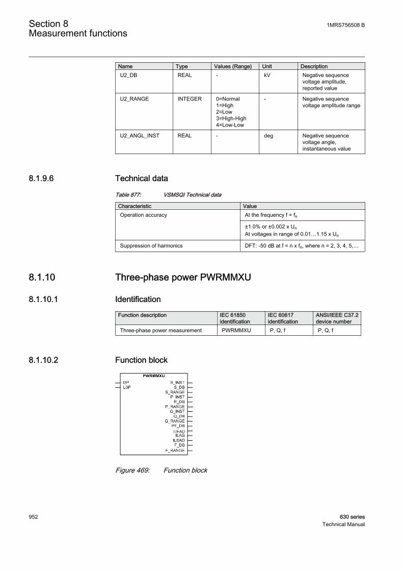
Name Type Values (Range) Unit DescriptionU2_DB REAL - kV Negative sequence
voltage amplitude,reported value
U2_RANGE INTEGER 0=Normal1=High2=Low3=High-High4=Low-Low
- Negative sequencevoltage amplitude range
U2_ANGL_INST REAL - deg Negative sequencevoltage angle,instantaneous value
8.1.9.6 Technical data
Table 877: VSMSQI Technical data
Characteristic ValueOperation accuracy At the frequency f = fn
±1.0% or ±0.002 x UnAt voltages in range of 0.01…1.15 x Un
Suppression of harmonics DFT: -50 dB at f = n x fn, where n = 2, 3, 4, 5,…
8.1.10 Three-phase power PWRMMXU
8.1.10.1 Identification
Function description IEC 61850identification
IEC 60617identification
ANSI/IEEE C37.2device number
Three-phase power measurement PWRMMXU P, Q, f P, Q, f
8.1.10.2 Function block
GUID-BBC4E3AF-25FA-4427-A440-524B47D394C0 V1 EN
Figure 469: Function block
Section 8 1MRS756508 BMeasurement functions
952 630 seriesTechnical Manual
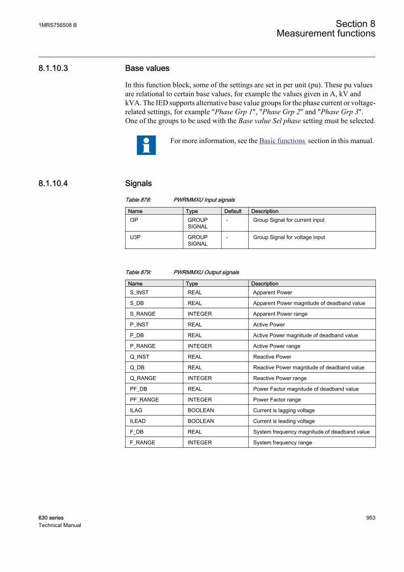
8.1.10.3 Base values
In this function block, some of the settings are set in per unit (pu). These pu valuesare relational to certain base values, for example the values given in A, kV andkVA. The IED supports alternative base value groups for the phase current or voltage-related settings, for example "Phase Grp 1", "Phase Grp 2" and "Phase Grp 3".One of the groups to be used with the Base value Sel phase setting must be selected.
For more information, see the Basic functions section in this manual.
8.1.10.4 Signals
Table 878: PWRMMXU Input signals
Name Type Default DescriptionI3P GROUP
SIGNAL- Group Signal for current input
U3P GROUPSIGNAL
- Group Signal for voltage input
Table 879: PWRMMXU Output signals
Name Type DescriptionS_INST REAL Apparent Power
S_DB REAL Apparent Power magnitude of deadband value
S_RANGE INTEGER Apparent Power range
P_INST REAL Active Power
P_DB REAL Active Power magnitude of deadband value
P_RANGE INTEGER Active Power range
Q_INST REAL Reactive Power
Q_DB REAL Reactive Power magnitude of deadband value
Q_RANGE INTEGER Reactive Power range
PF_DB REAL Power Factor magnitude of deadband value
PF_RANGE INTEGER Power Factor range
ILAG BOOLEAN Current is lagging voltage
ILEAD BOOLEAN Current is leading voltage
F_DB REAL System frequency magnitude of deadband value
F_RANGE INTEGER System frequency range
1MRS756508 B Section 8Measurement functions
630 series 953Technical Manual
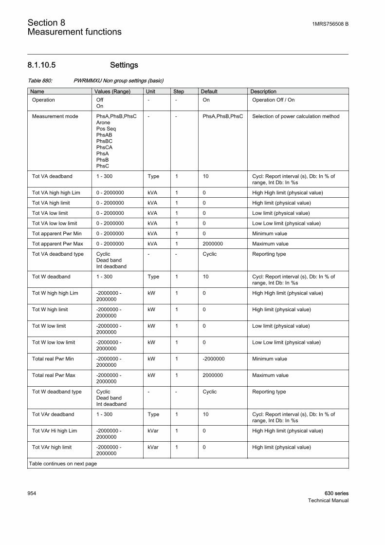
8.1.10.5 Settings
Table 880: PWRMMXU Non group settings (basic)
Name Values (Range) Unit Step Default DescriptionOperation Off
On- - On Operation Off / On
Measurement mode PhsA,PhsB,PhsCAronePos SeqPhsABPhsBCPhsCAPhsAPhsBPhsC
- - PhsA,PhsB,PhsC Selection of power calculation method
Tot VA deadband 1 - 300 Type 1 10 Cycl: Report interval (s), Db: In % ofrange, Int Db: In %s
Tot VA high high Lim 0 - 2000000 kVA 1 0 High High limit (physical value)
Tot VA high limit 0 - 2000000 kVA 1 0 High limit (physical value)
Tot VA low limit 0 - 2000000 kVA 1 0 Low limit (physical value)
Tot VA low low limit 0 - 2000000 kVA 1 0 Low Low limit (physical value)
Tot apparent Pwr Min 0 - 2000000 kVA 1 0 Minimum value
Tot apparent Pwr Max 0 - 2000000 kVA 1 2000000 Maximum value
Tot VA deadband type CyclicDead bandInt deadband
- - Cyclic Reporting type
Tot W deadband 1 - 300 Type 1 10 Cycl: Report interval (s), Db: In % ofrange, Int Db: In %s
Tot W high high Lim -2000000 -2000000
kW 1 0 High High limit (physical value)
Tot W high limit -2000000 -2000000
kW 1 0 High limit (physical value)
Tot W low limit -2000000 -2000000
kW 1 0 Low limit (physical value)
Tot W low low limit -2000000 -2000000
kW 1 0 Low Low limit (physical value)
Total real Pwr Min -2000000 -2000000
kW 1 -2000000 Minimum value
Total real Pwr Max -2000000 -2000000
kW 1 2000000 Maximum value
Tot W deadband type CyclicDead bandInt deadband
- - Cyclic Reporting type
Tot VAr deadband 1 - 300 Type 1 10 Cycl: Report interval (s), Db: In % ofrange, Int Db: In %s
Tot VAr Hi high Lim -2000000 -2000000
kVar 1 0 High High limit (physical value)
Tot VAr high limit -2000000 -2000000
kVar 1 0 High limit (physical value)
Table continues on next page
Section 8 1MRS756508 BMeasurement functions
954 630 seriesTechnical Manual
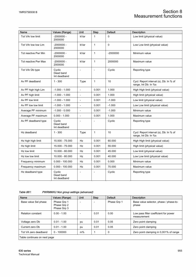
Name Values (Range) Unit Step Default DescriptionTot VAr low limit -2000000 -
2000000kVar 1 0 Low limit (physical value)
Tot VAr low low Lim -2000000 -2000000
kVar 1 0 Low Low limit (physical value)
Tot reactive Pwr Min -2000000 -2000000
kVar 1 -2000000 Minimum value
Tot reactive Pwr Max -2000000 -2000000
kVar 1 2000000 Maximum value
Tot VAr Db type CyclicDead bandInt deadband
- - Cyclic Reporting type
Av PF deadband 1 - 300 Type 1 10 Cycl: Report interval (s), Db: In % ofrange, Int Db: In %s
Av PF high high Lim -1.000 - 1.000 - 0.001 1.000 High High limit (physical value)
Av PF high limit -1.000 - 1.000 - 0.001 1.000 High limit (physical value)
Av PF low limit -1.000 - 1.000 - 0.001 -1.000 Low limit (physical value)
Av PF low low limit -1.000 - 1.000 - 0.001 -1.000 Low Low limit (physical value)
Average PF minimum -1.000 - 0.000 - 0.001 -1.000 Minimum value
Average PF maximum 0.000 - 1.000 - 0.001 1.000 Maximum value
Av PF deadband type CyclicDead bandInt deadband
- - Cyclic Reporting type
Hz deadband 1 - 300 Type 1 10 Cycl: Report interval (s), Db: In % ofrange, Int Db: In %s
Hz high high limit 15.000 - 75.000 Hz 0.001 60.000 High High limit (physical value)
Hz high limit 15.000 - 75.000 Hz 0.001 55.000 High limit (physical value)
Hz low limit 10.000 - 60.000 Hz 0.001 45.000 Low limit (physical value)
Hz low low limit 10.000 - 60.000 Hz 0.001 40.000 Low Low limit (physical value)
Frequency minimum 0.000 - 100.000 Hz 0.001 0.000 Minimum value
Frequency maximum 0.000 - 100.000 Hz 0.001 70.000 Maximum value
Hz deadband type CyclicDead bandInt deadband
- - Cyclic Reporting type
Table 881: PWRMMXU Non group settings (advanced)
Name Values (Range) Unit Step Default DescriptionBase value Sel phase Phase Grp 1
Phase Grp 2Phase Grp 3
- - Phase Grp 1 Base value selector, phase / phase-to-phase
Relation constant 0.00 - 1.00 - 0.01 0.00 Low pass filter coefficient for powermeasurement
Voltage zero Db 0.01 - 1.00 pu 0.01 0.05 Zero point clamping
Current zero Db 0.01 - 1.00 pu 0.01 0.05 Zero point clamping
Tot VA zero deadband 0 - 100000 m% 1 0 Zero point clamping in 0,001% of range
Table continues on next page
1MRS756508 B Section 8Measurement functions
630 series 955Technical Manual
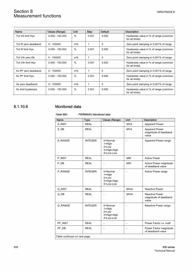
Name Values (Range) Unit Step Default DescriptionTot VA limit Hys 0.000 - 100.000 % 0.001 5.000 Hysteresis value in % of range (common
for all limits)
Tot W zero deadband 0 - 100000 m% 1 0 Zero point clamping in 0,001% of range
Tot W limit Hys 0.000 - 100.000 % 0.001 5.000 Hysteresis value in % of range (commonfor all limits)
Tot VAr zero Db 0 - 100000 m% 1 0 Zero point clamping in 0,001% of range
Tot VAr limit Hys 0.000 - 100.000 % 0.001 5.000 Hysteresis value in % of range (commonfor all limits)
Av PF zero deadband 0 - 100000 m% 1 0 Zero point clamping in 0,001% of range
Av PF limit Hys 0.000 - 100.000 % 0.001 5.000 Hysteresis value in % of range (commonfor all limits)
Hz zero deadband 0 - 100000 m% 1 0 Zero point clamping in 0,001% of range
Hz limit hysteresis 0.000 - 100.000 % 0.001 5.000 Hysteresis value in % of range (commonfor all limits)
8.1.10.6 Monitored data
Table 882: PWRMMXU Monitored data
Name Type Values (Range) Unit DescriptionS_INST REAL - MVA Apparent Power
S_DB REAL - MVA Apparent Powermagnitude of deadbandvalue
S_RANGE INTEGER 0=Normal1=High2=Low3=High-High4=Low-Low
- Apparent Power range
P_INST REAL - MW Active Power
P_DB REAL - MW Active Power magnitudeof deadband value
P_RANGE INTEGER 0=Normal1=High2=Low3=High-High4=Low-Low
- Active Power range
Q_INST REAL - MVAr Reactive Power
Q_DB REAL - MVAr Reactive Powermagnitude of deadbandvalue
Q_RANGE INTEGER 0=Normal1=High2=Low3=High-High4=Low-Low
- Reactive Power range
PF_INST REAL - - Power Factor i.e. cosfi
PF_DB REAL - - Power Factor magnitudeof deadband value
Table continues on next page
Section 8 1MRS756508 BMeasurement functions
956 630 seriesTechnical Manual

Name Type Values (Range) Unit DescriptionPF_RANGE INTEGER 0=Normal
1=High2=Low3=High-High4=Low-Low
- Power Factor range
ILAG BOOLEAN 0=FALSE1=TRUE
- Current is lagging voltage
ILEAD BOOLEAN 0=FALSE1=TRUE
- Current is leading voltage
F_INST REAL - Hz System frequency
F_DB REAL - Hz System frequencymagnitude of deadbandvalue
F_RANGE INTEGER 0=Normal1=High2=Low3=High-High4=Low-Low
- System frequency range
8.1.10.7 Technical data
Table 883: PWRMMXU Technical data
Characteristic ValueOperation accuracy At all three currents in range 0.10…1.20 x Inn
At all three voltages in range 0.50…1.15 x UnAt the frequency f = fnActive power and energy in range |PF| > 0.71Reactive power and energy in range |PF| < 0.71
±1.5% for power (S, P and Q)±0.015 for power factor
Suppression of harmonics DFT: -50dB at f = n x fn, where n = 2, 3, 4, 5,…
8.2 Energy monitoring EPDMMTR
8.2.1 IdentificationFunction description IEC 61850
identificationIEC 60617identification
ANSI/IEEE C37.2device number
Energy monitoring (including powerdemand)
EPDMMTR E E
1MRS756508 B Section 8Measurement functions
630 series 957Technical Manual

8.2.2 Function block
GUID-5C85EAEA-48EB-4B3F-8D0C-8C1CA3BA7256 V1 EN
Figure 470: Function block
8.2.3 FunctionalityThe energy monitoring function EPDMMTR is used to calculate the active andreactive energy from the respective power inputs P and Q. The function alsoprovides alarm outputs when the energy exceeds the set limit.
In addition, the function provides the service value of maximum power demandduring the set interval time and the pulse outputs for the measured energy.
8.2.4 Operation principleThe function can be enabled and disabled with the Operation setting. Thecorresponding parameter values are "On" and "Off".
The operation of the energy-monitoring function can be described using a modulediagram. All the modules in the diagram are explained in the next sections.
GUID-7BA2DEA2-A5E6-41A0-9E36-3DEEEADC7B9B V1 EN
Figure 471: Functional module diagram
Section 8 1MRS756508 BMeasurement functions
958 630 seriesTechnical Manual

Zero-point clampingZero point clamping is used to ignore the possible noise in the input signals. Themeasured values below the zero point-clamping limits are forced to zero. W zerodeadband and VAr zero deadband are the settings used to set the limit. Enable zerodeadband can be set to “Yes” or “No” to enable or disable the function.
This module takes care of the directionality of the energy measured based on theset reference direction. The Active energy Dir and Reactive energy Dir settings canbe used to set the reference directions for forward and reverse, active and reactiveenergy flows respectively. All the positive values, dependent on the set referencedirection, are calculated and displayed in the forward outputs and the negativevalues in the reverse outputs. However, both forward and reverse output values aredisplayed as absolute values, that is, positive values. The active power, from supplyto load, is shown in forward direction when Active energy Dir is set to “Forward”.The active power is shown in reverse direction when Active energy Dir is set to“Reverse”. The same applies to reactive energy calculation.
Energy calculationThis module calculates the linear average of the active and reactive energies over aset time interval Demand period, based on the measured powers. The interval canbe set to “1”, “5”, “10”, “15”, “30”, “60” or “180” minutes. A new energy value isobtained once a minute, indicating the actual energy over the energy time intervalpreceding the update time. The energy values, based on sliding average and thefinal output value, are updated at the end of the time interval. For example, theenergy value based on the setting interval of “180” minutes is displayed in theoutput for the first time after 180 minutes and the value is calculated from theinterval t0 – t180. The next value is displayed at the moment t180+1 and it is based onaverage between t0+1 – t180+1.
In the outputs, the energy values are calculated based on the set Demand period.
Energy = Average power calculated over the demand period × Demand period.
The accumulation of the energy values is based on the same principles as demandenergy calculation. The accumulated values are always calculated from the one-minute values by summing, independent of the set Demand period. Theaccumulation feature can be enabled by setting Enable accumulation to “Yes” andit can be disabled by setting Enable accumulation to “No”. The binary inputSTACM, can also be used for starting the accumulation. RSTACM is used to resetthe accumulation. The accumulated energy calculations can start from predefinedoffset values using the Forward Wh Initial and Reverse Wh Initial settings for theaccumulated active energy values and Forward VArh initial and Reverse VArhinitial settings for the accumulated reactive-energy values.
EAFACM and EARACM are the analog value outputs of the accumulated active-energy values in forward and reverse directions respectively. ERFACM andERRACM are the analog value outputs of the accumulated reactive-energy values inforward and reverse directions respectively. These accumulated values are
1MRS756508 B Section 8Measurement functions
630 series 959Technical Manual
available in the monitored data view, so there is a possibility of saturation for theseoutputs. To handle this, the Energy Acc Lim setting is used. Whenever theaccumulated energy crosses Energy Acc Lim, there is an increment on the energycounter value and the accumulated energy value becomes zero. EAFCNT andEARCNT are the counter values for accumulated active energy. ERFCNT andERVCNT are the counter values for accumulated reactive energy. The RSTACMinput is also used to reset the counter output values.
ACMST is the binary output indicating the start of the accumulation.
The pulse outputs, EAFPULSE, EARPULSE, ERFPULSE and ERRPULSE, areactivated based on the calculated values of forward and reverse, active and reactiveaccumulated energy. The number of pulses depends on the energy quantity perpulse determined by the Forward Wh Acc Pls, Reverse Wh Acc Pls, Forward VArhAcc Pls and Reverse VArh Acc Pls settings. For instance, if the active accumulatedforward-energy value is 1 MWh and Forward Wh Acc Pls is 100 KWh, 10 pulsesof EAFPULSE is generated. The pulse-on-and-off time duration can be set usingthe Pulse on time and Pulse off time settings.
During the demand period, the BCR (binary counter reading) representations of thecalculated energy are available as pulse counter outputs. The integer binary counteroutputs EAFDMD_BCR and EARDMD_BCR represent the active energy in theforward and reverse directions respectively. The energy quantity per count isdefined by the Forward Wh Itrv Pls and Reverse Wh Itrv Pls settings. For instance,if the active-forward-demand energy for the set interval is 100 kWh and ForwardWh Itrv Pls is 10 kWh, the EAFDMD_BCR value is equal to 10. Similarly, theinteger binary counter outputs ERFDMD_BCR and ERRDMD_BCR represent thereactive energy in the forward and reverse directions respectively. The energyquantity per count is defined by the Forward VArh Itrv Pls and Reverse VArh ItrvPls settings.
The BCR representations of the accumulated energy are available as pulse counteroutputs. The integer binary counter outputs EAFACM_BCR and EARACM_BCRrepresent the accumulated active energy in the forward and reverse directionsrespectively. The energy quantity per count is defined by the Forward Wh Acc Plsand Reverse Wh Acc Pls settings. For instance, if the accumulated forward-energyvalue is 500 kWh and Forward Wh Acc Pls is 10 kWh, the EAFACM_BCR value isequal to 50. Similarly, the integer binary counter outputs ERFACM_BCR andERRACM_BCR represent the accumulated reactive energy in the forward andreverse directions respectively. The energy quantity per count is defined by theDemand Varh Pls Qty and Supply Varh Pls Qty settings.
Limit supervisionThe limit supervision module supervises the energy values for each demand periodfor the limits defined by Energy active limit and Energy reactive limit. When theactive energy values for the demand period exceeds Energy active limit, the binaryalarm outputs EAFALM and EARALM are activated. When the reactive energy
Section 8 1MRS756508 BMeasurement functions
960 630 seriesTechnical Manual

values for the demand period exceeds Energy reactive limit, the binary alarmoutputs ERFALM and ERRALM are activated.
Maximum power demand calculatorThe power demand is obtained by dividing the average energy in the interval withthe set Demand period. The active power demand outputs PAFDMD and PARDMDin forward and reverse directions and the reactive power demand outputs PRFDMDand PRRDMD are available in the monitored data view.
The maximum demand value is initially zero. After the first Demand period, thecalculated power demand is stored as the maximum power demand. Subsequently,whenever the calculated power demand exceeds the maximum power demandcalculated earlier, the new values of maximum power demand are updated. Themaximum power demand is reset with the RSTDMD binary input. The maximumdemand values MAXPAFDMD, MAXPARDMD, MAXPRFDMD and MAXPRRDMD areavailable in the monitored data view.
8.2.5 ApplicationEPDMMTR measures and monitors the energy values from the connected powersignals. The functionality includes zero point clamping, energy calculation,accumulation of the energy values and maximum power demand. The referencedirections for positive and negative active and reactive energy flows can be set.
The function has a zero point clamping detection to ignore noise in the inputsignals. The zero point clamping detection function forces the input signal valuesunder zero-value detection level to zero. The clamping limit can be set and thefunctionality can be enabled or disabled with the Enable zero deadband setting.
EPDMMTR calculates the linear average of the measured power signal over settime interval. The time interval can be set and it varies between one minute andthree hours.
The alarm output signals indicate if the periodic accumulated energy value exceedsthe limit set by the user during that energy interval. The maximum power demandfor the set interval is calculated.
The accumulated values are calculated by summing the one-minute energy values.The calculation of the accumulated values are independent of the energycalculations based on the time interval which can be set. The accumulated valuesare displayed as power unit hours in the outputs. The accumulation can be startedor reset with binary inputs. The accumulated energy is also available as pulsecounter outputs.
1MRS756508 B Section 8Measurement functions
630 series 961Technical Manual
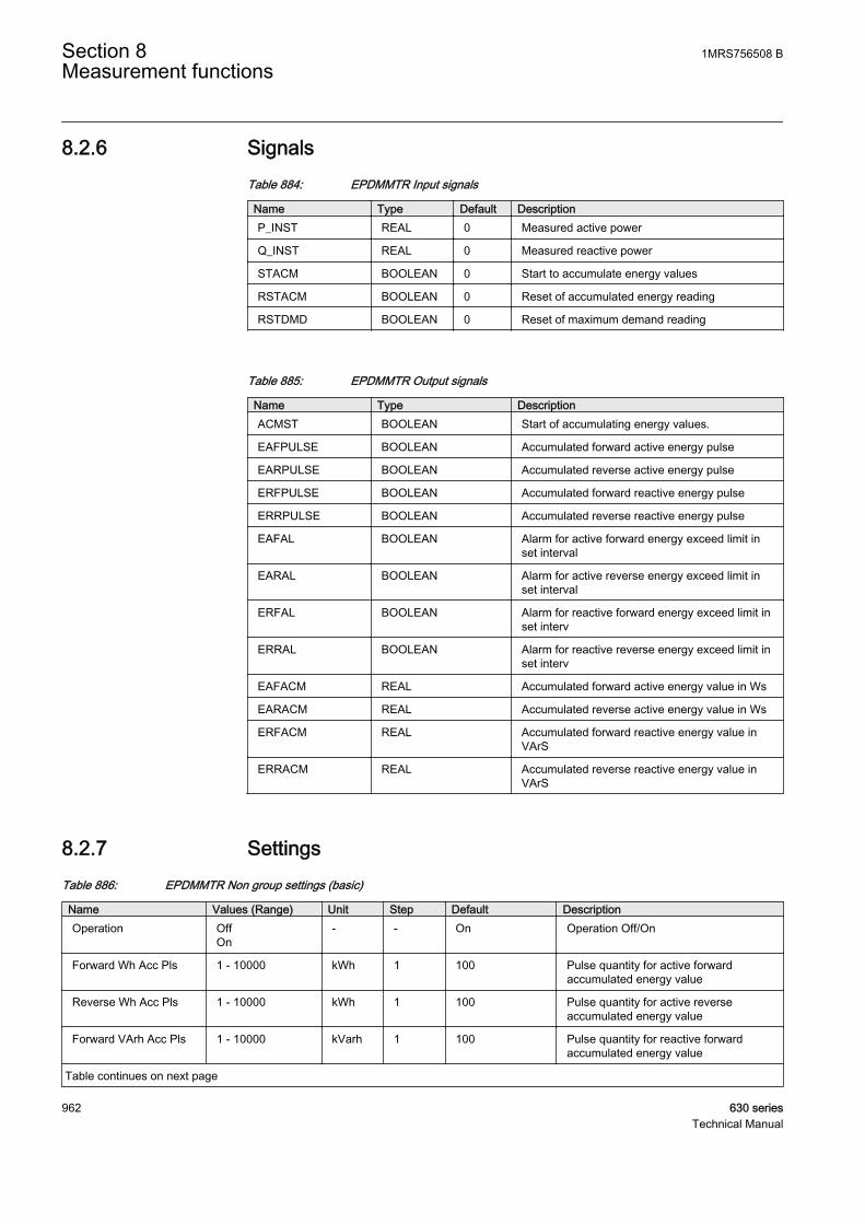
8.2.6 SignalsTable 884: EPDMMTR Input signals
Name Type Default DescriptionP_INST REAL 0 Measured active power
Q_INST REAL 0 Measured reactive power
STACM BOOLEAN 0 Start to accumulate energy values
RSTACM BOOLEAN 0 Reset of accumulated energy reading
RSTDMD BOOLEAN 0 Reset of maximum demand reading
Table 885: EPDMMTR Output signals
Name Type DescriptionACMST BOOLEAN Start of accumulating energy values.
EAFPULSE BOOLEAN Accumulated forward active energy pulse
EARPULSE BOOLEAN Accumulated reverse active energy pulse
ERFPULSE BOOLEAN Accumulated forward reactive energy pulse
ERRPULSE BOOLEAN Accumulated reverse reactive energy pulse
EAFAL BOOLEAN Alarm for active forward energy exceed limit inset interval
EARAL BOOLEAN Alarm for active reverse energy exceed limit inset interval
ERFAL BOOLEAN Alarm for reactive forward energy exceed limit inset interv
ERRAL BOOLEAN Alarm for reactive reverse energy exceed limit inset interv
EAFACM REAL Accumulated forward active energy value in Ws
EARACM REAL Accumulated reverse active energy value in Ws
ERFACM REAL Accumulated forward reactive energy value inVArS
ERRACM REAL Accumulated reverse reactive energy value inVArS
8.2.7 SettingsTable 886: EPDMMTR Non group settings (basic)
Name Values (Range) Unit Step Default DescriptionOperation Off
On- - On Operation Off/On
Forward Wh Acc Pls 1 - 10000 kWh 1 100 Pulse quantity for active forwardaccumulated energy value
Reverse Wh Acc Pls 1 - 10000 kWh 1 100 Pulse quantity for active reverseaccumulated energy value
Forward VArh Acc Pls 1 - 10000 kVarh 1 100 Pulse quantity for reactive forwardaccumulated energy value
Table continues on next page
Section 8 1MRS756508 BMeasurement functions
962 630 seriesTechnical Manual

Name Values (Range) Unit Step Default DescriptionReverse VArh Acc Pls 1 - 10000 kVarh 1 100 Pulse quantity for reactive reverse
accumulated energy value
Forward Wh Itrv Pls 1 - 10000 kWh 1 100 Pulse quantity for active forward energyof set interval
Reverse Wh Itrv Pls 1 - 10000 kWh 1 100 Pulse quantity for active reverse energyof set interval
Forward VArh ItrvPls 1 - 10000 kVarh 1 100 Pulse quantity for reactive forwardenergy of set interval
Reverse VArh ItrvPls 1 - 10000 kVarh 1 100 Pulse quantity for reactive reverseenergy of set interval
Demand period 1 Minute5 Minutes10 Minutes15 Minutes30 Minutes60 Minutes180 Minutes
- - 1 Minute Time interval for energy calculation
Pulse on time 0.000 - 60.000 s 0.001 1.000 Energy accumulated pulse ON time insecs
Pulse off time 0.000 - 60.000 s 0.001 0.500 Energy accumulated pulse OFF time insecs
Enable accumulation NoYes
- - No Activate the accumulation of energyvalues
Table 887: EPDMMTR Non group settings (advanced)
Name Values (Range) Unit Step Default DescriptionActive energy Dir Forward
Reverse- - Forward Direction of active energy flow Forward/
Reverse
Reactive energy Dir ForwardReverse
- - Forward Direction of reactive energy flow Forward/Reverse
Energy active limit 1 - 10000000 kWh 1 1000000 Active energy limit
Energy reactive lim 1 - 10000000 kVarh 1 1000 Reactive energy limit
W zero deadband 0.001 - 10000.000 kW 0.001 10.000 Zero point clamping level at active Power
VAr zero deadband 0.001 - 10000.000 kVar 0.001 10.000 Zero point clamping level at reactivePower
Forward Wh initial 0 - 10000000 kWh 1 0 Preset Initial value for forward activeenergy
Reverse Wh initial 0 - 10000000 kWh 1 0 Preset Initial value for reverse activeenergy
Forward VArh initial 0 - 10000000 kVarh 1 0 Preset Initial value for forward reactiveenergy
Reverse VArh initial 0 - 10000000 kVarh 1 0 Preset Initial value for reverse reactiveenergy
Enable zero deadband NoYes
- - Yes Enable of zero point clamping detectionfunction
1MRS756508 B Section 8Measurement functions
630 series 963Technical Manual
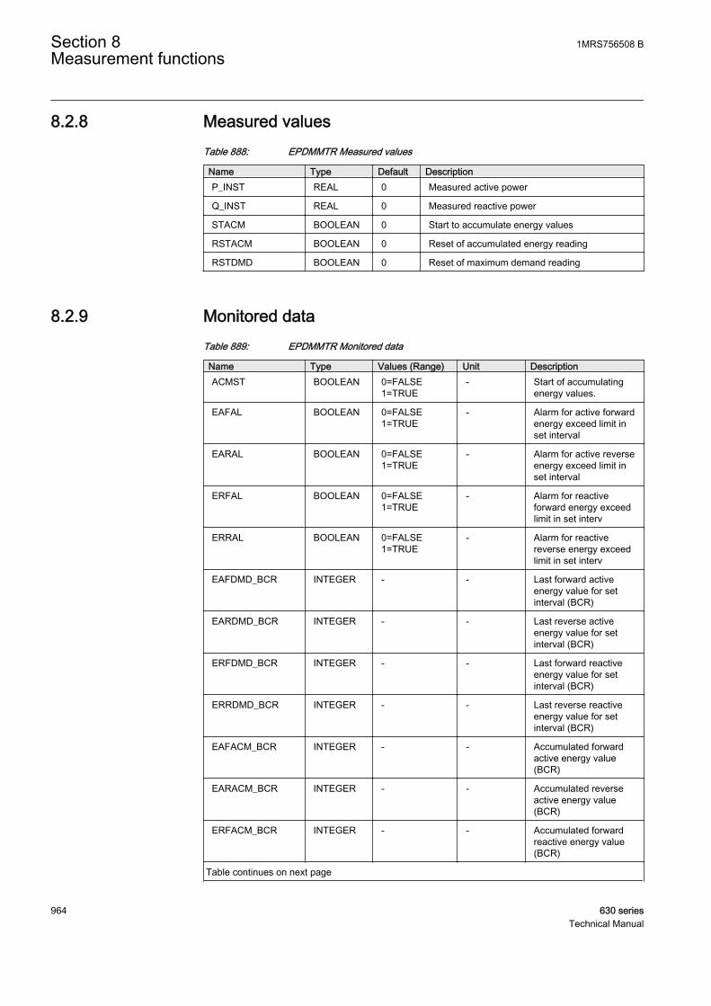
8.2.8 Measured valuesTable 888: EPDMMTR Measured values
Name Type Default DescriptionP_INST REAL 0 Measured active power
Q_INST REAL 0 Measured reactive power
STACM BOOLEAN 0 Start to accumulate energy values
RSTACM BOOLEAN 0 Reset of accumulated energy reading
RSTDMD BOOLEAN 0 Reset of maximum demand reading
8.2.9 Monitored dataTable 889: EPDMMTR Monitored data
Name Type Values (Range) Unit DescriptionACMST BOOLEAN 0=FALSE
1=TRUE- Start of accumulating
energy values.
EAFAL BOOLEAN 0=FALSE1=TRUE
- Alarm for active forwardenergy exceed limit inset interval
EARAL BOOLEAN 0=FALSE1=TRUE
- Alarm for active reverseenergy exceed limit inset interval
ERFAL BOOLEAN 0=FALSE1=TRUE
- Alarm for reactiveforward energy exceedlimit in set interv
ERRAL BOOLEAN 0=FALSE1=TRUE
- Alarm for reactivereverse energy exceedlimit in set interv
EAFDMD_BCR INTEGER - - Last forward activeenergy value for setinterval (BCR)
EARDMD_BCR INTEGER - - Last reverse activeenergy value for setinterval (BCR)
ERFDMD_BCR INTEGER - - Last forward reactiveenergy value for setinterval (BCR)
ERRDMD_BCR INTEGER - - Last reverse reactiveenergy value for setinterval (BCR)
EAFACM_BCR INTEGER - - Accumulated forwardactive energy value(BCR)
EARACM_BCR INTEGER - - Accumulated reverseactive energy value(BCR)
ERFACM_BCR INTEGER - - Accumulated forwardreactive energy value(BCR)
Table continues on next page
Section 8 1MRS756508 BMeasurement functions
964 630 seriesTechnical Manual
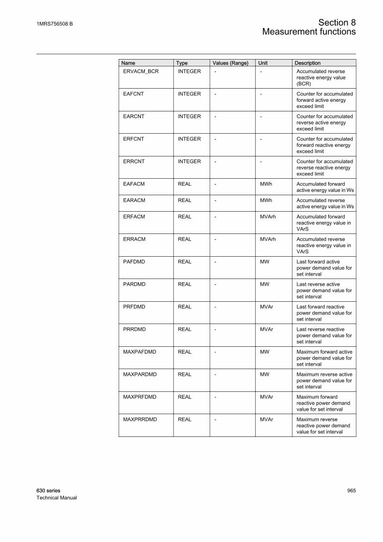
Name Type Values (Range) Unit DescriptionERVACM_BCR INTEGER - - Accumulated reverse
reactive energy value(BCR)
EAFCNT INTEGER - - Counter for accumulatedforward active energyexceed limit
EARCNT INTEGER - - Counter for accumulatedreverse active energyexceed limit
ERFCNT INTEGER - - Counter for accumulatedforward reactive energyexceed limit
ERRCNT INTEGER - - Counter for accumulatedreverse reactive energyexceed limit
EAFACM REAL - MWh Accumulated forwardactive energy value in Ws
EARACM REAL - MWh Accumulated reverseactive energy value in Ws
ERFACM REAL - MVArh Accumulated forwardreactive energy value inVArS
ERRACM REAL - MVArh Accumulated reversereactive energy value inVArS
PAFDMD REAL - MW Last forward activepower demand value forset interval
PARDMD REAL - MW Last reverse activepower demand value forset interval
PRFDMD REAL - MVAr Last forward reactivepower demand value forset interval
PRRDMD REAL - MVAr Last reverse reactivepower demand value forset interval
MAXPAFDMD REAL - MW Maximum forward activepower demand value forset interval
MAXPARDMD REAL - MW Maximum reverse activepower demand value forset interval
MAXPRFDMD REAL - MVAr Maximum forwardreactive power demandvalue for set interval
MAXPRRDMD REAL - MVAr Maximum reversereactive power demandvalue for set interval
1MRS756508 B Section 8Measurement functions
630 series 965Technical Manual

8.2.10 Technical dataTable 890: EPDMMTR Technical data
Characteristic ValueOperation accuracy At all three currents in range 0.10…1.20 x Inn
At all three voltages in range 0.50…1.15 x UnAt the frequency f = fnActive power and energy in range |PF| > 0.71Reactive power and energy in range |PF| < 0.71
±1.5% for energy
Suppression of harmonics DFT: -50dB at f = n x fn, where n = 2, 3, 4, 5,…
Section 8 1MRS756508 BMeasurement functions
966 630 seriesTechnical Manual
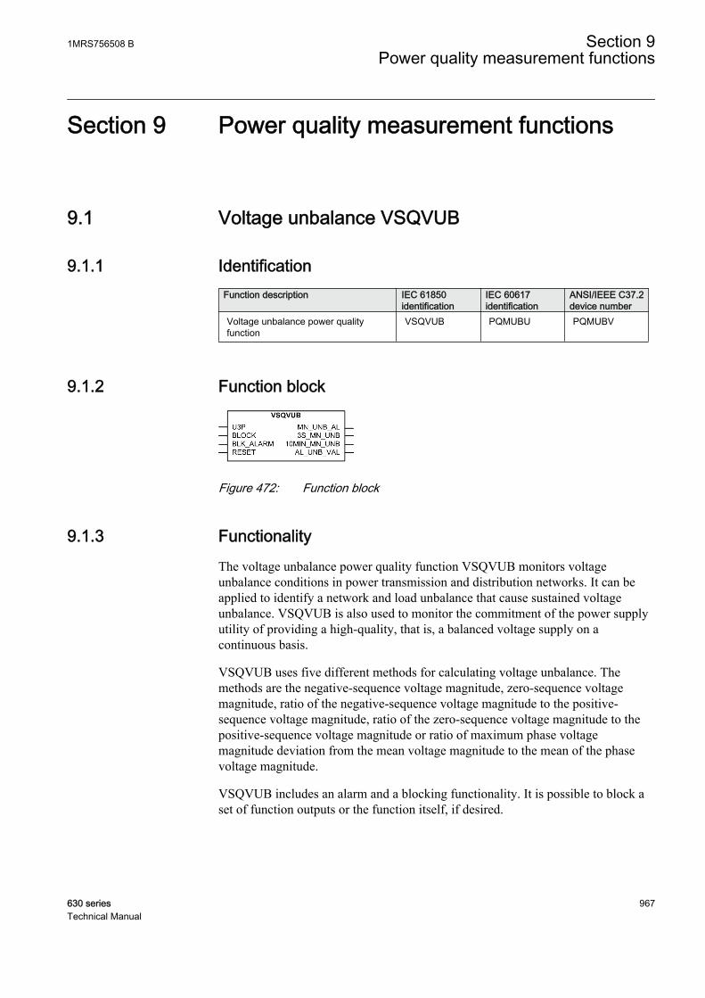
Section 9 Power quality measurement functions
9.1 Voltage unbalance VSQVUB
9.1.1 IdentificationFunction description IEC 61850
identificationIEC 60617identification
ANSI/IEEE C37.2device number
Voltage unbalance power qualityfunction
VSQVUB PQMUBU PQMUBV
9.1.2 Function block
GUID-AB05A93B-1338-4052-9FA1-A482471A2315 V1 EN
Figure 472: Function block
9.1.3 FunctionalityThe voltage unbalance power quality function VSQVUB monitors voltageunbalance conditions in power transmission and distribution networks. It can beapplied to identify a network and load unbalance that cause sustained voltageunbalance. VSQVUB is also used to monitor the commitment of the power supplyutility of providing a high-quality, that is, a balanced voltage supply on acontinuous basis.
VSQVUB uses five different methods for calculating voltage unbalance. Themethods are the negative-sequence voltage magnitude, zero-sequence voltagemagnitude, ratio of the negative-sequence voltage magnitude to the positive-sequence voltage magnitude, ratio of the zero-sequence voltage magnitude to thepositive-sequence voltage magnitude or ratio of maximum phase voltagemagnitude deviation from the mean voltage magnitude to the mean of the phasevoltage magnitude.
VSQVUB includes an alarm and a blocking functionality. It is possible to block aset of function outputs or the function itself, if desired.
1MRS756508 B Section 9Power quality measurement functions
630 series 967Technical Manual
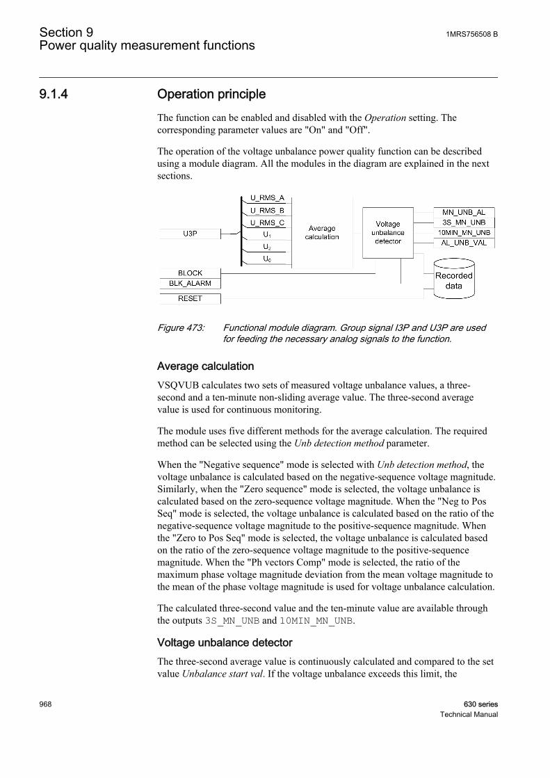
9.1.4 Operation principleThe function can be enabled and disabled with the Operation setting. Thecorresponding parameter values are "On" and "Off".
The operation of the voltage unbalance power quality function can be describedusing a module diagram. All the modules in the diagram are explained in the nextsections.
GUID-C87394EF-DE57-49C2-B8A4-1DD26A86D2F6 V2 EN
Figure 473: Functional module diagram. Group signal I3P and U3P are usedfor feeding the necessary analog signals to the function.
Average calculationVSQVUB calculates two sets of measured voltage unbalance values, a three-second and a ten-minute non-sliding average value. The three-second averagevalue is used for continuous monitoring.
The module uses five different methods for the average calculation. The requiredmethod can be selected using the Unb detection method parameter.
When the "Negative sequence" mode is selected with Unb detection method, thevoltage unbalance is calculated based on the negative-sequence voltage magnitude.Similarly, when the "Zero sequence" mode is selected, the voltage unbalance iscalculated based on the zero-sequence voltage magnitude. When the "Neg to PosSeq" mode is selected, the voltage unbalance is calculated based on the ratio of thenegative-sequence voltage magnitude to the positive-sequence magnitude. Whenthe "Zero to Pos Seq" mode is selected, the voltage unbalance is calculated basedon the ratio of the zero-sequence voltage magnitude to the positive-sequencemagnitude. When the "Ph vectors Comp" mode is selected, the ratio of themaximum phase voltage magnitude deviation from the mean voltage magnitude tothe mean of the phase voltage magnitude is used for voltage unbalance calculation.
The calculated three-second value and the ten-minute value are available throughthe outputs 3S_MN_UNB and 10MIN_MN_UNB.
Voltage unbalance detectorThe three-second average value is continuously calculated and compared to the setvalue Unbalance start val. If the voltage unbalance exceeds this limit, the
Section 9 1MRS756508 BPower quality measurement functions
968 630 seriesTechnical Manual

MN_UNB_AL output is activated. A maximum value calculation based on thevalues of the three-second sliding average is started when MN_UNB_AL is active.The highest unbalance value AL_UNB_VAL and the time of occurrenceAL_UNB_DATE are available in the monitored data view.
The BLK_ALARM input is used to block the alarm output MN_UNB_VAL. In thiscase, the other outputs are updated normally. However, the activation of theBLOCK input blocks the alarm output MN_UNB_VAL and also the internalrecorders. All the other outputs are updated normally.
Recorded dataThe information required for a later fault analysis is stored when the recorded datamodule is triggered. This happens when a voltage unbalance is detected by thevoltage unbalance detector module.
Three sets of recorded data are available in total. The sets are saved in data banks1-3. The data bank 1 holds the most recent recorded data. Older data are moved tothe subsequent banks (1→2 and 2→3) when a voltage unbalance is detected. Whenall three banks have data and a new unbalance is detected, the most recent data setis placed into bank 1 and the data in bank 3 are overwritten by the data from bank 2.
The recorded data can be reset with the RESET binary input signal or by navigatingto the HMI reset (Main menu / Clear / Clear recorded data / VSQVUBx).
When a voltage unbalance is detected in the system, the function responds with theMN_UNB_AL alarm signal. During the alarm situation, the function stores themaximum magnitude and the time of occurrence. The recorded data are storedwhen MN_UNB_AL is deactivated.
Parameter name Descriptionn Recording time Time of recording data
n AL_UNB_VAL Maximum 3 sec voltage unbalance
9.1.5 Base valuesIn this function block, some of the settings are set in per unit (pu). These pu valuesare relational to certain base values, for example the values given in A, kV andkVA. The IED supports alternative base value groups for the phase current or voltage-related settings, for example "Phase Grp 1", "Phase Grp 2" and "Phase Grp 3".One of the groups to be used with the Base value Sel phase setting must be selected.
For more information, see the Basic functions section in this manual.
1MRS756508 B Section 9Power quality measurement functions
630 series 969Technical Manual
9.1.6 Application
Ideally, in a three-phase or multiphase power system, the frequency and voltagemagnitude of all the phases are equal and the phase displacement between any twoconsecutive phases is also equal. This is called a balanced source. Apart from thebalanced source, usually the power system network and loads are also balanced,implying that the network impedance and load impedance in each phase are equal.In some cases, the condition of a balance network and load are not met completely,which leads to a current and voltage unbalance in the system. Providingunbalanced supply voltage to some of the loads causes a detrimental effect on theiroperation. For example, a small magnitude of a negative-sequence voltage appliedto an induction motor results in a significant heating of the motor.
A balanced supply, balanced network and balanced load lead to a better powerquality. When one of these conditions is disturbed, the power quality isdeteriorated. VSQVUB monitors such voltage unbalance conditions in powertransmission and distribution networks. VSQVUB calculates two sets of measuredvalues, a three-second and a ten-minute non-sliding average value. The three-second average value is used for continuous monitoring while the ten-minuteaverage value is used for percentile calculation for a longer period of time. It canbe applied to identify the network and load unbalance that may cause sustainedvoltage unbalance. A single-phase or phase-to-phase fault in the network or loadside can create voltage unbalance but, as faults are usually isolated in a short periodof time, the voltage unbalance is not a sustained one. Therefore, the voltageunbalance may not be covered by VSQVUB.
The function uses five different methods for calculating voltage unbalance. Themethods are:
• Negative-sequence voltage magnitude• Zero-sequence voltage magnitude• Ratio of negative-sequence to positive-sequence voltage magnitude• Ratio of zero-sequence to positive-sequence voltage magnitude• Ratio of maximum phase voltage magnitude deviation from the mean voltage
magnitude to the mean of phase voltage magnitude.
Usually, the ratio of the negative-sequence voltage magnitude to the positive-sequence voltage magnitude is selected for monitoring the voltage unbalance.However, other methods may also be used if required.
Section 9 1MRS756508 BPower quality measurement functions
970 630 seriesTechnical Manual
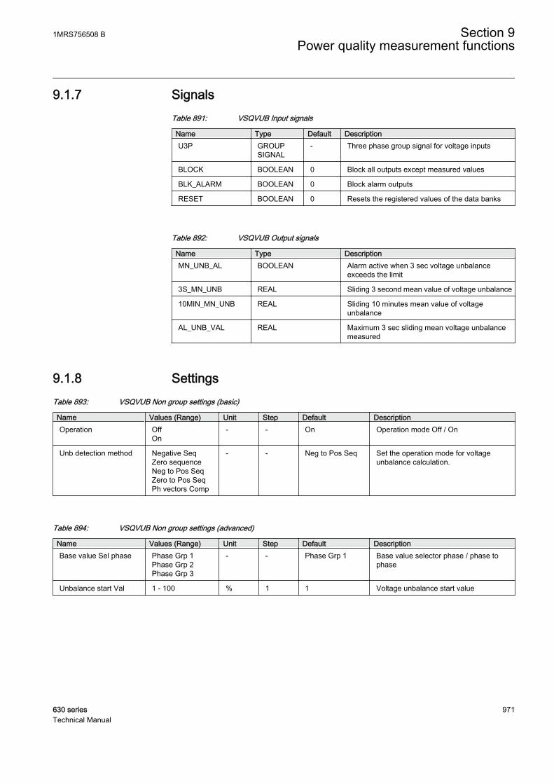
9.1.7 SignalsTable 891: VSQVUB Input signals
Name Type Default DescriptionU3P GROUP
SIGNAL- Three phase group signal for voltage inputs
BLOCK BOOLEAN 0 Block all outputs except measured values
BLK_ALARM BOOLEAN 0 Block alarm outputs
RESET BOOLEAN 0 Resets the registered values of the data banks
Table 892: VSQVUB Output signals
Name Type DescriptionMN_UNB_AL BOOLEAN Alarm active when 3 sec voltage unbalance
exceeds the limit
3S_MN_UNB REAL Sliding 3 second mean value of voltage unbalance
10MIN_MN_UNB REAL Sliding 10 minutes mean value of voltageunbalance
AL_UNB_VAL REAL Maximum 3 sec sliding mean voltage unbalancemeasured
9.1.8 SettingsTable 893: VSQVUB Non group settings (basic)
Name Values (Range) Unit Step Default DescriptionOperation Off
On- - On Operation mode Off / On
Unb detection method Negative SeqZero sequenceNeg to Pos SeqZero to Pos SeqPh vectors Comp
- - Neg to Pos Seq Set the operation mode for voltageunbalance calculation.
Table 894: VSQVUB Non group settings (advanced)
Name Values (Range) Unit Step Default DescriptionBase value Sel phase Phase Grp 1
Phase Grp 2Phase Grp 3
- - Phase Grp 1 Base value selector phase / phase tophase
Unbalance start Val 1 - 100 % 1 1 Voltage unbalance start value
1MRS756508 B Section 9Power quality measurement functions
630 series 971Technical Manual
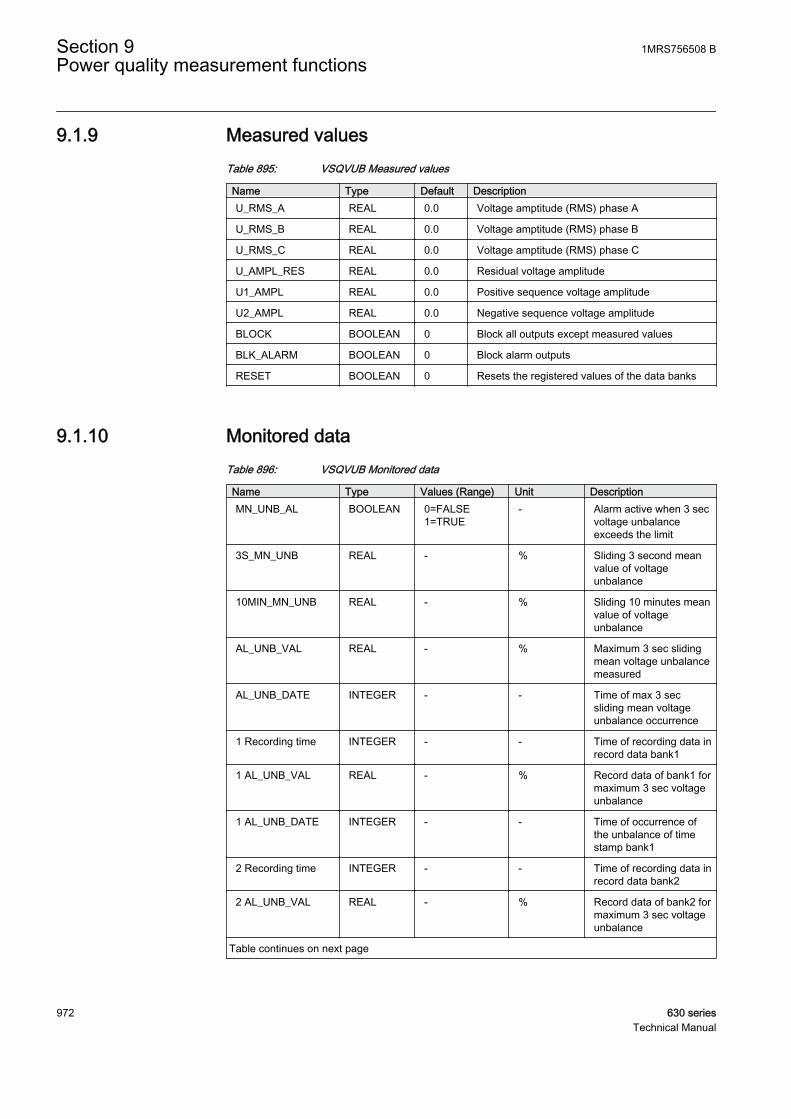
9.1.9 Measured valuesTable 895: VSQVUB Measured values
Name Type Default DescriptionU_RMS_A REAL 0.0 Voltage amptitude (RMS) phase A
U_RMS_B REAL 0.0 Voltage amptitude (RMS) phase B
U_RMS_C REAL 0.0 Voltage amptitude (RMS) phase C
U_AMPL_RES REAL 0.0 Residual voltage amplitude
U1_AMPL REAL 0.0 Positive sequence voltage amplitude
U2_AMPL REAL 0.0 Negative sequence voltage amplitude
BLOCK BOOLEAN 0 Block all outputs except measured values
BLK_ALARM BOOLEAN 0 Block alarm outputs
RESET BOOLEAN 0 Resets the registered values of the data banks
9.1.10 Monitored dataTable 896: VSQVUB Monitored data
Name Type Values (Range) Unit DescriptionMN_UNB_AL BOOLEAN 0=FALSE
1=TRUE- Alarm active when 3 sec
voltage unbalanceexceeds the limit
3S_MN_UNB REAL - % Sliding 3 second meanvalue of voltageunbalance
10MIN_MN_UNB REAL - % Sliding 10 minutes meanvalue of voltageunbalance
AL_UNB_VAL REAL - % Maximum 3 sec slidingmean voltage unbalancemeasured
AL_UNB_DATE INTEGER - - Time of max 3 secsliding mean voltageunbalance occurrence
1 Recording time INTEGER - - Time of recording data inrecord data bank1
1 AL_UNB_VAL REAL - % Record data of bank1 formaximum 3 sec voltageunbalance
1 AL_UNB_DATE INTEGER - - Time of occurrence ofthe unbalance of timestamp bank1
2 Recording time INTEGER - - Time of recording data inrecord data bank2
2 AL_UNB_VAL REAL - % Record data of bank2 formaximum 3 sec voltageunbalance
Table continues on next page
Section 9 1MRS756508 BPower quality measurement functions
972 630 seriesTechnical Manual

Name Type Values (Range) Unit Description2 AL_UNB_DATE INTEGER - - Time of occurrence of
the unbalance of timestamp bank2
3 Recording time INTEGER - - Time of recording data inrecord data bank3
3 AL_UNB_VAL REAL - % Record data of bank3 formaximum 3 sec voltageunbalance
3 AL_UNB_DATE INTEGER - - Time of occurrence ofthe unbalance of timestamp bank3
Table 897: Technical data
Parameter Accuracy/valueRetardation time
Transient overreach
Reset ratio
9.2 Current harmonics CMHAI
9.2.1 IdentificationFunction description IEC 61850 identification IEC 60617 identification ANSI/IEEE C37.2
device numberCurrent harmonicsmeasurement
CMHAI PQ 3Unf, PQ 3Inf PQ 3Unf, PQ 3Inf
9.2.2 Function block
GUID-35372773-72BC-407C-8B20-FDC04752D07C V1 EN
Figure 474: Function block
9.2.3 FunctionalityThe current harmonics monitoring function CMHAI is a sample-based functiondesigned for monitoring the waveform distortion in distribution and transmissionnetworks.
1MRS756508 B Section 9Power quality measurement functions
630 series 973Technical Manual
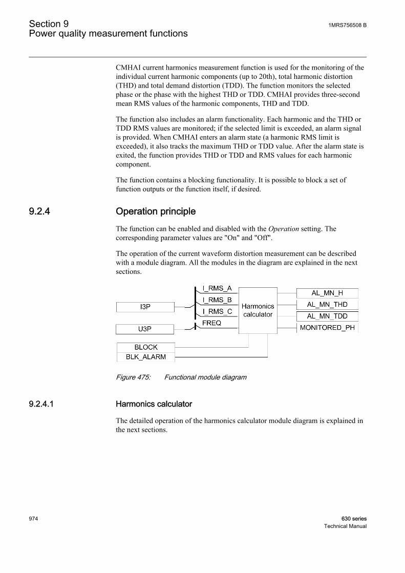
CMHAI current harmonics measurement function is used for the monitoring of theindividual current harmonic components (up to 20th), total harmonic distortion(THD) and total demand distortion (TDD). The function monitors the selectedphase or the phase with the highest THD or TDD. CMHAI provides three-secondmean RMS values of the harmonic components, THD and TDD.
The function also includes an alarm functionality. Each harmonic and the THD orTDD RMS values are monitored; if the selected limit is exceeded, an alarm signalis provided. When CMHAI enters an alarm state (a harmonic RMS limit isexceeded), it also tracks the maximum THD or TDD value. After the alarm state isexited, the function provides THD or TDD and RMS values for each harmoniccomponent.
The function contains a blocking functionality. It is possible to block a set offunction outputs or the function itself, if desired.
9.2.4 Operation principleThe function can be enabled and disabled with the Operation setting. Thecorresponding parameter values are "On" and "Off".
The operation of the current waveform distortion measurement can be describedwith a module diagram. All the modules in the diagram are explained in the nextsections.
GUID-C1CD8BBA-EDE3-467D-A4EA-A4DE7CB44923 V1 EN
Figure 475: Functional module diagram
9.2.4.1 Harmonics calculator
The detailed operation of the harmonics calculator module diagram is explained inthe next sections.
Section 9 1MRS756508 BPower quality measurement functions
974 630 seriesTechnical Manual
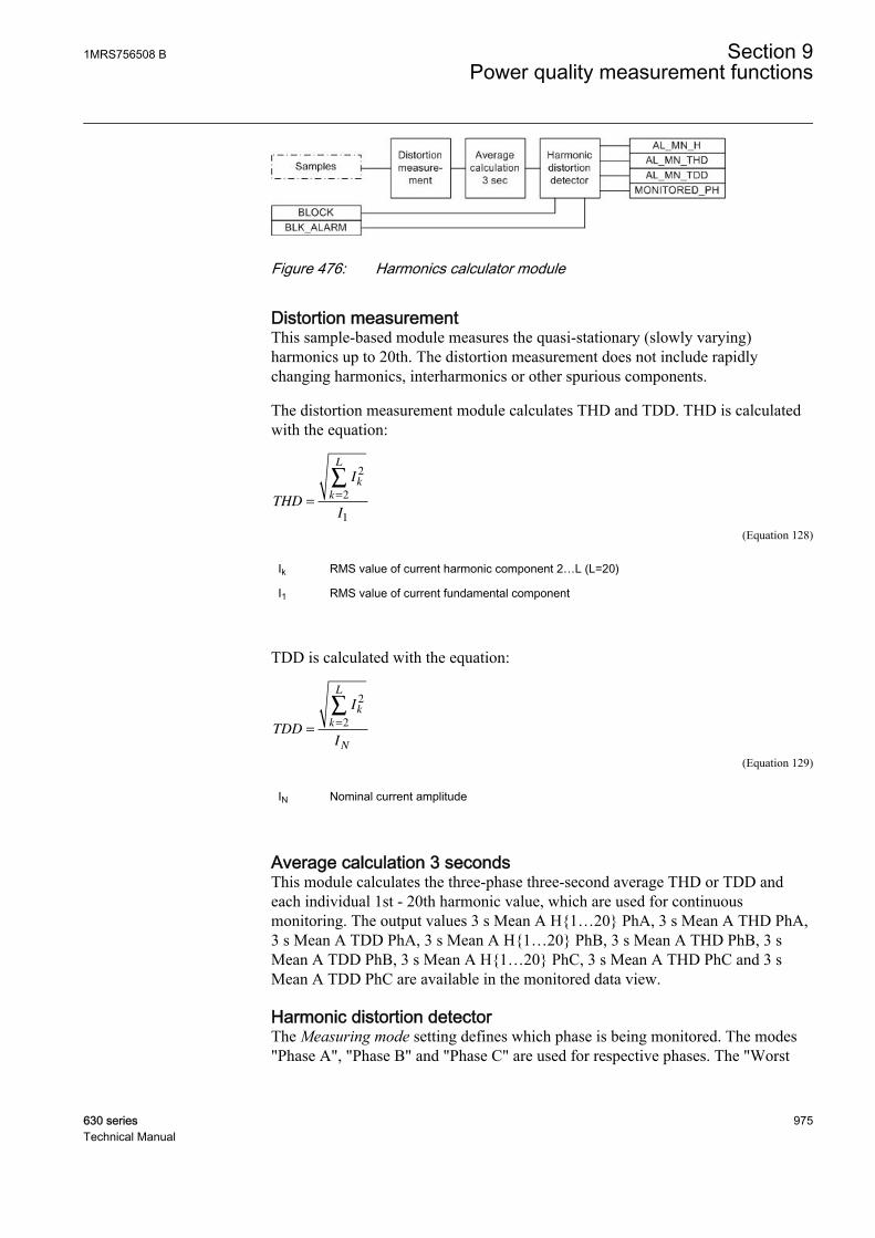
GUID-B48ADE03-E956-46D9-9364-A8D41EB9FB32 V1 EN
Figure 476: Harmonics calculator module
Distortion measurementThis sample-based module measures the quasi-stationary (slowly varying)harmonics up to 20th. The distortion measurement does not include rapidlychanging harmonics, interharmonics or other spurious components.
The distortion measurement module calculates THD and TDD. THD is calculatedwith the equation:
THD
I
I
k
k
L
==
∑2
2
1
GUID-DC202724-9091-4B76-B0E9-8F2BA0757252 V1 EN (Equation 128)
Ik RMS value of current harmonic component 2…L (L=20)
I1 RMS value of current fundamental component
TDD is calculated with the equation:
TDD
I
I
k
k
L
N
==
∑2
2
GUID-F9B80BE9-F994-4BE0-8D07-833B3A6A524A V1 EN (Equation 129)
IN Nominal current amplitude
Average calculation 3 secondsThis module calculates the three-phase three-second average THD or TDD andeach individual 1st - 20th harmonic value, which are used for continuousmonitoring. The output values 3 s Mean A H{1…20} PhA, 3 s Mean A THD PhA,3 s Mean A TDD PhA, 3 s Mean A H{1…20} PhB, 3 s Mean A THD PhB, 3 sMean A TDD PhB, 3 s Mean A H{1…20} PhC, 3 s Mean A THD PhC and 3 sMean A TDD PhC are available in the monitored data view.
Harmonic distortion detectorThe Measuring mode setting defines which phase is being monitored. The modes"Phase A", "Phase B" and "Phase C" are used for respective phases. The "Worst
1MRS756508 B Section 9Power quality measurement functions
630 series 975Technical Manual
case" monitoring mode is used for the phase with the highest measured THD orTDD value. This means that the actual monitored phase can change continuously.The MONITORED_PH output indicates the actual phase.
The three-second average THD or TDD and each individual 2nd - 20th harmonicvalue are continuously calculated and compared to the set value {2nd - 20th} Hlimit Val, THD limit value and TDD limit value. If the value exceeds the limit, theAL_MN_H, AL_MN_THD and AL_MN_TDD outputs are activated.
Tracking of maximum values based on the three-second averages is started when atleast one of the outputs AL_MN_H, AL_MN_THD or AL_MN_TDD is active. TheMAXH{1…20}, MAXTHD and MAXTDD outputs indicate the maximum harmonicvalues occurred during the previous alarm state.
The outputs are available in the monitored data view.
The BLK_ALARM input is used to block all the alarm outputs (AL_MN_H,AL_MN_THD and AL_MN_TDD). In this case, all the other outputs are updatednormally. Activation of the BLOCK input blocks all the alarm outputs as well as theoutputs indicating the maximum value.
9.2.5 Base valuesIn this function block, some of the settings are set in per unit (pu). These pu valuesare relational to certain base values, for example the values given in A, kV andkVA. The IED supports alternative base value groups for the phase current or voltage-related settings, for example "Phase Grp 1", "Phase Grp 2" and "Phase Grp 3".One of the groups to be used with the Base value Sel phase setting must be selected.
For more information, see the Basic functions section in this manual.
9.2.6 ApplicationThe power quality in standards is defined through the characteristics of the supplyvoltage. Transients, short- and long-duration voltage variations, unbalance andwaveform distortion are the key characteristics describing the power quality. Thepower quality is, however, a customer-driven issue. It can be said that any powerproblem concerning the voltage or current that results in the failure or misoperationof the customer equipment is a power quality problem.
Harmonic distortion in a power system is caused by nonlinear devices. Electronicpower converter loads constitute the most important class of nonlinear loads in apower system. Switch-mode power supplies in a number of single-phase electronicequipment (personal computers, printers, copiers etc.) have very high third-harmonic content in the current. The three-phase electronic power converters (dc/
Section 9 1MRS756508 BPower quality measurement functions
976 630 seriesTechnical Manual
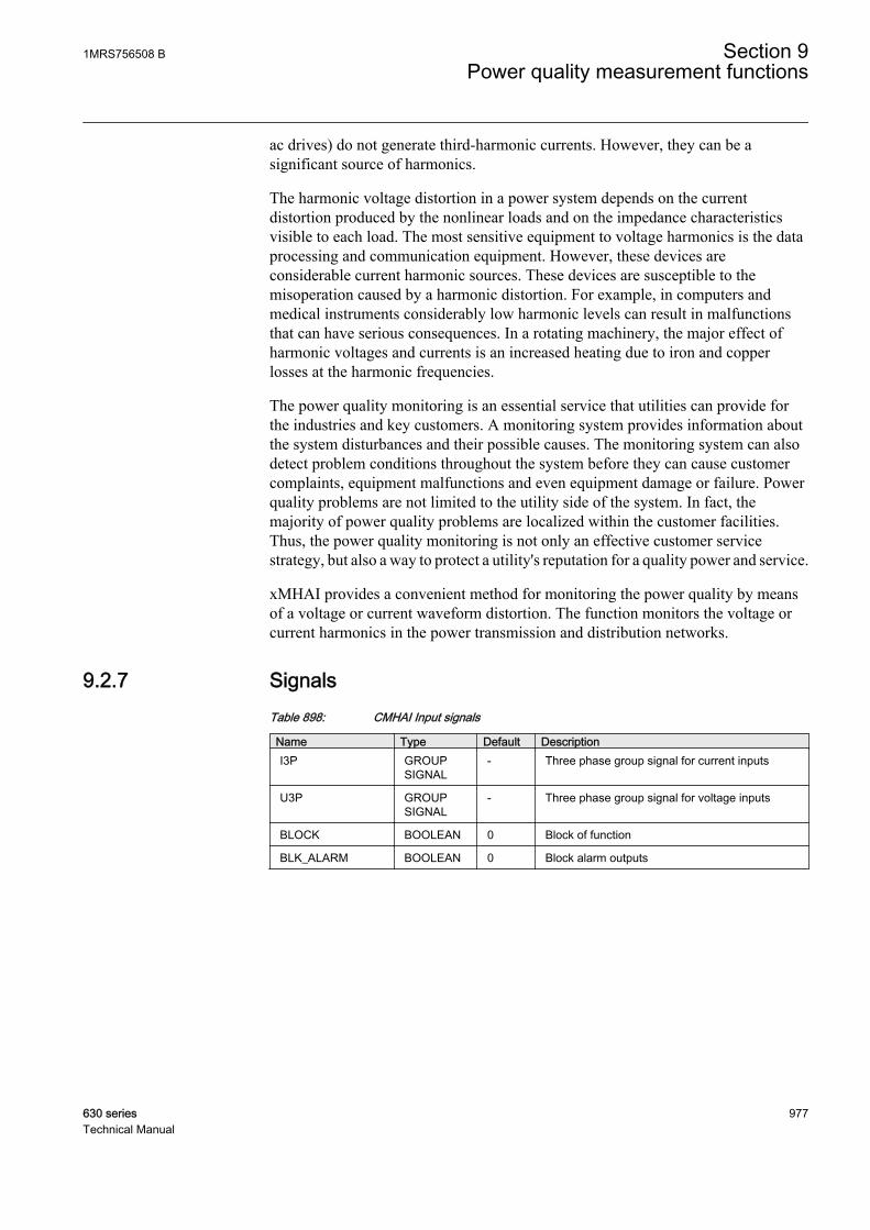
ac drives) do not generate third-harmonic currents. However, they can be asignificant source of harmonics.
The harmonic voltage distortion in a power system depends on the currentdistortion produced by the nonlinear loads and on the impedance characteristicsvisible to each load. The most sensitive equipment to voltage harmonics is the dataprocessing and communication equipment. However, these devices areconsiderable current harmonic sources. These devices are susceptible to themisoperation caused by a harmonic distortion. For example, in computers andmedical instruments considerably low harmonic levels can result in malfunctionsthat can have serious consequences. In a rotating machinery, the major effect ofharmonic voltages and currents is an increased heating due to iron and copperlosses at the harmonic frequencies.
The power quality monitoring is an essential service that utilities can provide forthe industries and key customers. A monitoring system provides information aboutthe system disturbances and their possible causes. The monitoring system can alsodetect problem conditions throughout the system before they can cause customercomplaints, equipment malfunctions and even equipment damage or failure. Powerquality problems are not limited to the utility side of the system. In fact, themajority of power quality problems are localized within the customer facilities.Thus, the power quality monitoring is not only an effective customer servicestrategy, but also a way to protect a utility's reputation for a quality power and service.
xMHAI provides a convenient method for monitoring the power quality by meansof a voltage or current waveform distortion. The function monitors the voltage orcurrent harmonics in the power transmission and distribution networks.
9.2.7 SignalsTable 898: CMHAI Input signals
Name Type Default DescriptionI3P GROUP
SIGNAL- Three phase group signal for current inputs
U3P GROUPSIGNAL
- Three phase group signal for voltage inputs
BLOCK BOOLEAN 0 Block of function
BLK_ALARM BOOLEAN 0 Block alarm outputs
1MRS756508 B Section 9Power quality measurement functions
630 series 977Technical Manual
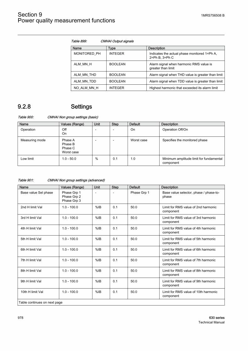
Table 899: CMHAI Output signals
Name Type DescriptionMONITORED_PH INTEGER Indicates the actual phase monitored 1=Ph A,
2=Ph B, 3=Ph C
ALM_MN_H BOOLEAN Alarm signal when harmonic RMS value isgreater than limit
ALM_MN_THD BOOLEAN Alarm signal when THD value is greater than limit
ALM_MN_TDD BOOLEAN Alarm signal when TDD value is greater than limit
NO_ALM_MN_H INTEGER Highest harmonic that exceeded its alarm limit
9.2.8 SettingsTable 900: CMHAI Non group settings (basic)
Name Values (Range) Unit Step Default DescriptionOperation Off
On- - On Operation Off/On
Measuring mode Phase APhase BPhase CWorst case
- - Worst case Specifies the monitored phase
Low limit 1.0 - 50.0 % 0.1 1.0 Minimum amplitude limit for fundamentalcomponent
Table 901: CMHAI Non group settings (advanced)
Name Values (Range) Unit Step Default DescriptionBase value Sel phase Phase Grp 1
Phase Grp 2Phase Grp 3
- - Phase Grp 1 Base value selector, phase / phase-to-phase
2nd H limit Val 1.0 - 100.0 %IB 0.1 50.0 Limit for RMS value of 2nd harmoniccomponent
3rd H limit Val 1.0 - 100.0 %IB 0.1 50.0 Limit for RMS value of 3rd harmoniccomponent
4th H limit Val 1.0 - 100.0 %IB 0.1 50.0 Limit for RMS value of 4th harmoniccomponent
5th H limit Val 1.0 - 100.0 %IB 0.1 50.0 Limit for RMS value of 5th harmoniccomponent
6th H limit Val 1.0 - 100.0 %IB 0.1 50.0 Limit for RMS value of 6th harmoniccomponent
7th H limit Val 1.0 - 100.0 %IB 0.1 50.0 Limit for RMS value of 7th harmoniccomponent
8th H limit Val 1.0 - 100.0 %IB 0.1 50.0 Limit for RMS value of 8th harmoniccomponent
9th H limit Val 1.0 - 100.0 %IB 0.1 50.0 Limit for RMS value of 9th harmoniccomponent
10th H limit Val 1.0 - 100.0 %IB 0.1 50.0 Limit for RMS value of 10th harmoniccomponent
Table continues on next page
Section 9 1MRS756508 BPower quality measurement functions
978 630 seriesTechnical Manual
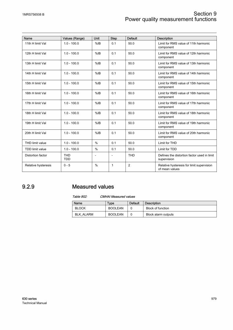
Name Values (Range) Unit Step Default Description11th H limit Val 1.0 - 100.0 %IB 0.1 50.0 Limit for RMS value of 11th harmonic
component
12th H limit Val 1.0 - 100.0 %IB 0.1 50.0 Limit for RMS value of 12th harmoniccomponent
13th H limit Val 1.0 - 100.0 %IB 0.1 50.0 Limit for RMS value of 13th harmoniccomponent
14th H limit Val 1.0 - 100.0 %IB 0.1 50.0 Limit for RMS value of 14th harmoniccomponent
15th H limit Val 1.0 - 100.0 %IB 0.1 50.0 Limit for RMS value of 15th harmoniccomponent
16th H limit Val 1.0 - 100.0 %IB 0.1 50.0 Limit for RMS value of 16th harmoniccomponent
17th H limit Val 1.0 - 100.0 %IB 0.1 50.0 Limit for RMS value of 17th harmoniccomponent
18th H limit Val 1.0 - 100.0 %IB 0.1 50.0 Limit for RMS value of 18th harmoniccomponent
19th H limit Val 1.0 - 100.0 %IB 0.1 50.0 Limit for RMS value of 19th harmoniccomponent
20th H limit Val 1.0 - 100.0 %IB 0.1 50.0 Limit for RMS value of 20th harmoniccomponent
THD limit value 1.0 - 100.0 % 0.1 50.0 Limit for THD
TDD limit value 1.0 - 100.0 % 0.1 50.0 Limit for TDD
Distortion factor THDTDD
- - THD Defines the distortion factor used in limitsupervision
Relative hysteresis 0 - 5 % 1 2 Relative hysteresis for limit supervisionof mean values
9.2.9 Measured valuesTable 902: CMHAI Measured values
Name Type Default DescriptionBLOCK BOOLEAN 0 Block of function
BLK_ALARM BOOLEAN 0 Block alarm outputs
1MRS756508 B Section 9Power quality measurement functions
630 series 979Technical Manual
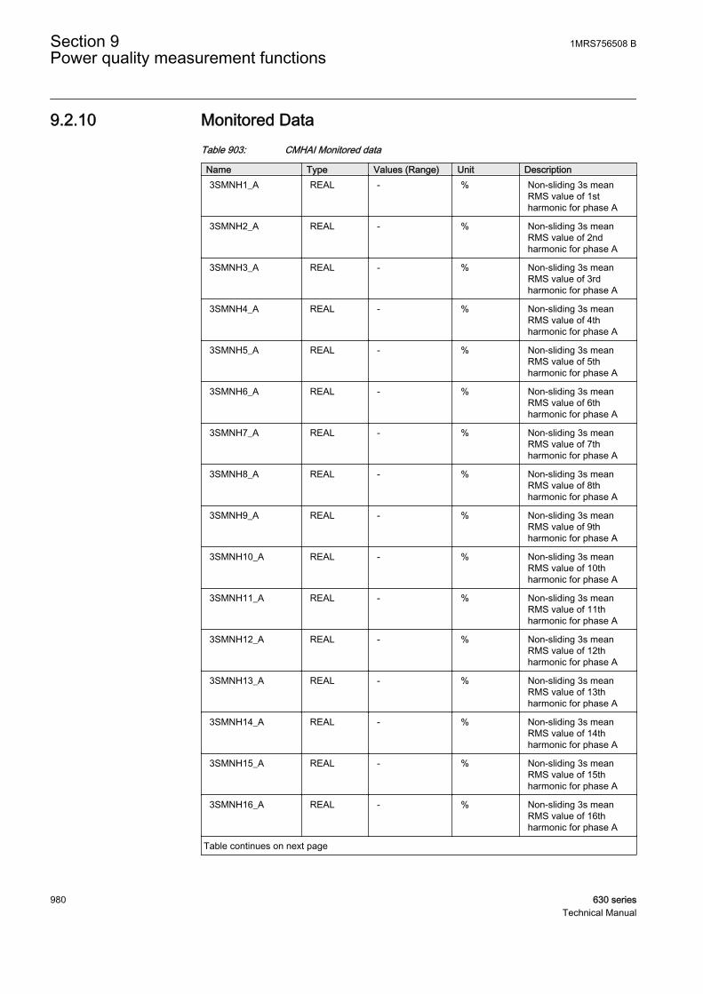
9.2.10 Monitored DataTable 903: CMHAI Monitored data
Name Type Values (Range) Unit Description3SMNH1_A REAL - % Non-sliding 3s mean
RMS value of 1stharmonic for phase A
3SMNH2_A REAL - % Non-sliding 3s meanRMS value of 2ndharmonic for phase A
3SMNH3_A REAL - % Non-sliding 3s meanRMS value of 3rdharmonic for phase A
3SMNH4_A REAL - % Non-sliding 3s meanRMS value of 4thharmonic for phase A
3SMNH5_A REAL - % Non-sliding 3s meanRMS value of 5thharmonic for phase A
3SMNH6_A REAL - % Non-sliding 3s meanRMS value of 6thharmonic for phase A
3SMNH7_A REAL - % Non-sliding 3s meanRMS value of 7thharmonic for phase A
3SMNH8_A REAL - % Non-sliding 3s meanRMS value of 8thharmonic for phase A
3SMNH9_A REAL - % Non-sliding 3s meanRMS value of 9thharmonic for phase A
3SMNH10_A REAL - % Non-sliding 3s meanRMS value of 10thharmonic for phase A
3SMNH11_A REAL - % Non-sliding 3s meanRMS value of 11thharmonic for phase A
3SMNH12_A REAL - % Non-sliding 3s meanRMS value of 12thharmonic for phase A
3SMNH13_A REAL - % Non-sliding 3s meanRMS value of 13thharmonic for phase A
3SMNH14_A REAL - % Non-sliding 3s meanRMS value of 14thharmonic for phase A
3SMNH15_A REAL - % Non-sliding 3s meanRMS value of 15thharmonic for phase A
3SMNH16_A REAL - % Non-sliding 3s meanRMS value of 16thharmonic for phase A
Table continues on next page
Section 9 1MRS756508 BPower quality measurement functions
980 630 seriesTechnical Manual
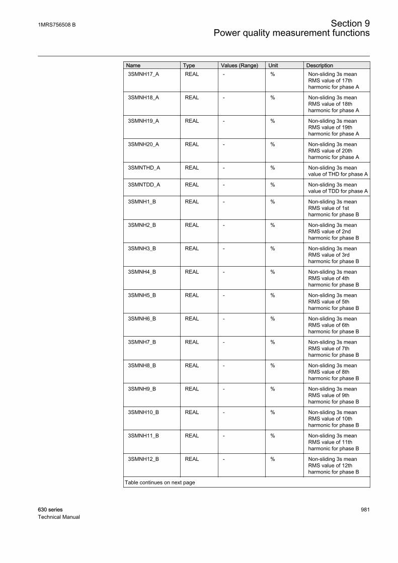
Name Type Values (Range) Unit Description3SMNH17_A REAL - % Non-sliding 3s mean
RMS value of 17thharmonic for phase A
3SMNH18_A REAL - % Non-sliding 3s meanRMS value of 18thharmonic for phase A
3SMNH19_A REAL - % Non-sliding 3s meanRMS value of 19thharmonic for phase A
3SMNH20_A REAL - % Non-sliding 3s meanRMS value of 20thharmonic for phase A
3SMNTHD_A REAL - % Non-sliding 3s meanvalue of THD for phase A
3SMNTDD_A REAL - % Non-sliding 3s meanvalue of TDD for phase A
3SMNH1_B REAL - % Non-sliding 3s meanRMS value of 1stharmonic for phase B
3SMNH2_B REAL - % Non-sliding 3s meanRMS value of 2ndharmonic for phase B
3SMNH3_B REAL - % Non-sliding 3s meanRMS value of 3rdharmonic for phase B
3SMNH4_B REAL - % Non-sliding 3s meanRMS value of 4thharmonic for phase B
3SMNH5_B REAL - % Non-sliding 3s meanRMS value of 5thharmonic for phase B
3SMNH6_B REAL - % Non-sliding 3s meanRMS value of 6thharmonic for phase B
3SMNH7_B REAL - % Non-sliding 3s meanRMS value of 7thharmonic for phase B
3SMNH8_B REAL - % Non-sliding 3s meanRMS value of 8thharmonic for phase B
3SMNH9_B REAL - % Non-sliding 3s meanRMS value of 9thharmonic for phase B
3SMNH10_B REAL - % Non-sliding 3s meanRMS value of 10thharmonic for phase B
3SMNH11_B REAL - % Non-sliding 3s meanRMS value of 11thharmonic for phase B
3SMNH12_B REAL - % Non-sliding 3s meanRMS value of 12thharmonic for phase B
Table continues on next page
1MRS756508 B Section 9Power quality measurement functions
630 series 981Technical Manual

Name Type Values (Range) Unit Description3SMNH13_B REAL - % Non-sliding 3s mean
RMS value of 13thharmonic for phase B
3SMNH14_B REAL - % Non-sliding 3s meanRMS value of 14thharmonic for phase B
3SMNH15_B REAL - % Non-sliding 3s meanRMS value of 15thharmonic for phase B
3SMNH16_B REAL - % Non-sliding 3s meanRMS value of 16thharmonic for phase B
3SMNH17_B REAL - % Non-sliding 3s meanRMS value of 17thharmonic for phase B
3SMNH18_B REAL - % Non-sliding 3s meanRMS value of 18thharmonic for phase B
3SMNH19_B REAL - % Non-sliding 3s meanRMS value of 19thharmonic for phase B
3SMNH20_B REAL - % Non-sliding 3s meanRMS value of 20thharmonic for phase B
3SMNTHD_B REAL - % Non-sliding 3s meanvalue of THD for phase B
3SMNTDD_B REAL - % Non-sliding 3s meanvalue of TDD for phase B
3SMNH1_C REAL - % Non-sliding 3s meanRMS value of 1stharmonic for phase C
3SMNH2_C REAL - % Non-sliding 3s meanRMS value of 2ndharmonic for phase C
3SMNH3_C REAL - % Non-sliding 3s meanRMS value of 3rdharmonic for phase C
3SMNH4_C REAL - % Non-sliding 3s meanRMS value of 4thharmonic for phase C
3SMNH5_C REAL - % Non-sliding 3s meanRMS value of 5thharmonic for phase C
3SMNH6_C REAL - % Non-sliding 3s meanRMS value of 6thharmonic for phase C
3SMNH7_C REAL - % Non-sliding 3s meanRMS value of 7thharmonic for phase C
3SMNH8_C REAL - % Non-sliding 3s meanRMS value of 8thharmonic for phase C
Table continues on next page
Section 9 1MRS756508 BPower quality measurement functions
982 630 seriesTechnical Manual
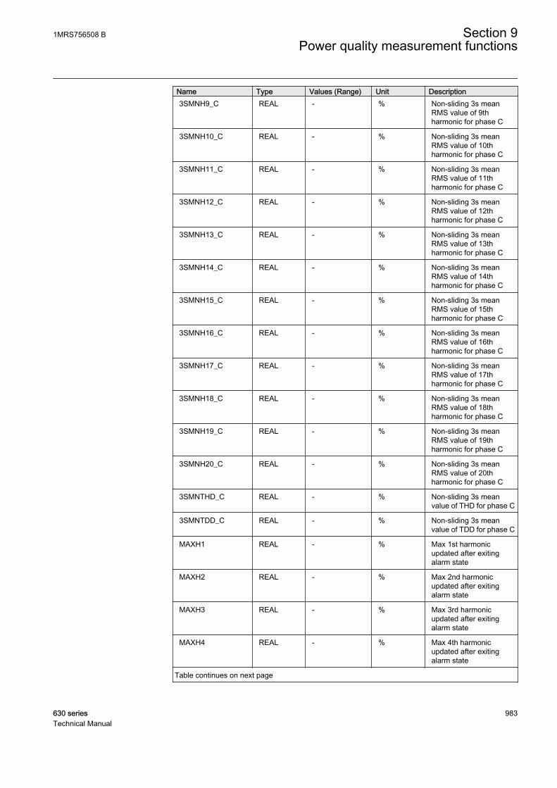
Name Type Values (Range) Unit Description3SMNH9_C REAL - % Non-sliding 3s mean
RMS value of 9thharmonic for phase C
3SMNH10_C REAL - % Non-sliding 3s meanRMS value of 10thharmonic for phase C
3SMNH11_C REAL - % Non-sliding 3s meanRMS value of 11thharmonic for phase C
3SMNH12_C REAL - % Non-sliding 3s meanRMS value of 12thharmonic for phase C
3SMNH13_C REAL - % Non-sliding 3s meanRMS value of 13thharmonic for phase C
3SMNH14_C REAL - % Non-sliding 3s meanRMS value of 14thharmonic for phase C
3SMNH15_C REAL - % Non-sliding 3s meanRMS value of 15thharmonic for phase C
3SMNH16_C REAL - % Non-sliding 3s meanRMS value of 16thharmonic for phase C
3SMNH17_C REAL - % Non-sliding 3s meanRMS value of 17thharmonic for phase C
3SMNH18_C REAL - % Non-sliding 3s meanRMS value of 18thharmonic for phase C
3SMNH19_C REAL - % Non-sliding 3s meanRMS value of 19thharmonic for phase C
3SMNH20_C REAL - % Non-sliding 3s meanRMS value of 20thharmonic for phase C
3SMNTHD_C REAL - % Non-sliding 3s meanvalue of THD for phase C
3SMNTDD_C REAL - % Non-sliding 3s meanvalue of TDD for phase C
MAXH1 REAL - % Max 1st harmonicupdated after exitingalarm state
MAXH2 REAL - % Max 2nd harmonicupdated after exitingalarm state
MAXH3 REAL - % Max 3rd harmonicupdated after exitingalarm state
MAXH4 REAL - % Max 4th harmonicupdated after exitingalarm state
Table continues on next page
1MRS756508 B Section 9Power quality measurement functions
630 series 983Technical Manual
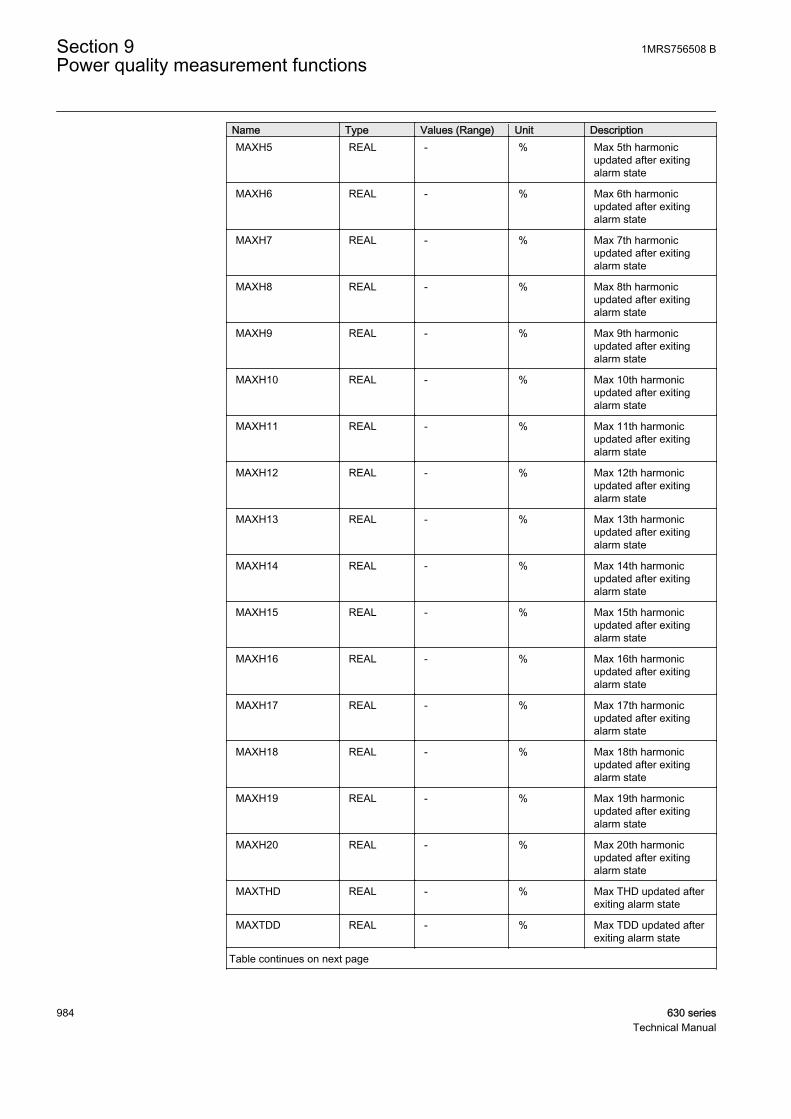
Name Type Values (Range) Unit DescriptionMAXH5 REAL - % Max 5th harmonic
updated after exitingalarm state
MAXH6 REAL - % Max 6th harmonicupdated after exitingalarm state
MAXH7 REAL - % Max 7th harmonicupdated after exitingalarm state
MAXH8 REAL - % Max 8th harmonicupdated after exitingalarm state
MAXH9 REAL - % Max 9th harmonicupdated after exitingalarm state
MAXH10 REAL - % Max 10th harmonicupdated after exitingalarm state
MAXH11 REAL - % Max 11th harmonicupdated after exitingalarm state
MAXH12 REAL - % Max 12th harmonicupdated after exitingalarm state
MAXH13 REAL - % Max 13th harmonicupdated after exitingalarm state
MAXH14 REAL - % Max 14th harmonicupdated after exitingalarm state
MAXH15 REAL - % Max 15th harmonicupdated after exitingalarm state
MAXH16 REAL - % Max 16th harmonicupdated after exitingalarm state
MAXH17 REAL - % Max 17th harmonicupdated after exitingalarm state
MAXH18 REAL - % Max 18th harmonicupdated after exitingalarm state
MAXH19 REAL - % Max 19th harmonicupdated after exitingalarm state
MAXH20 REAL - % Max 20th harmonicupdated after exitingalarm state
MAXTHD REAL - % Max THD updated afterexiting alarm state
MAXTDD REAL - % Max TDD updated afterexiting alarm state
Table continues on next page
Section 9 1MRS756508 BPower quality measurement functions
984 630 seriesTechnical Manual
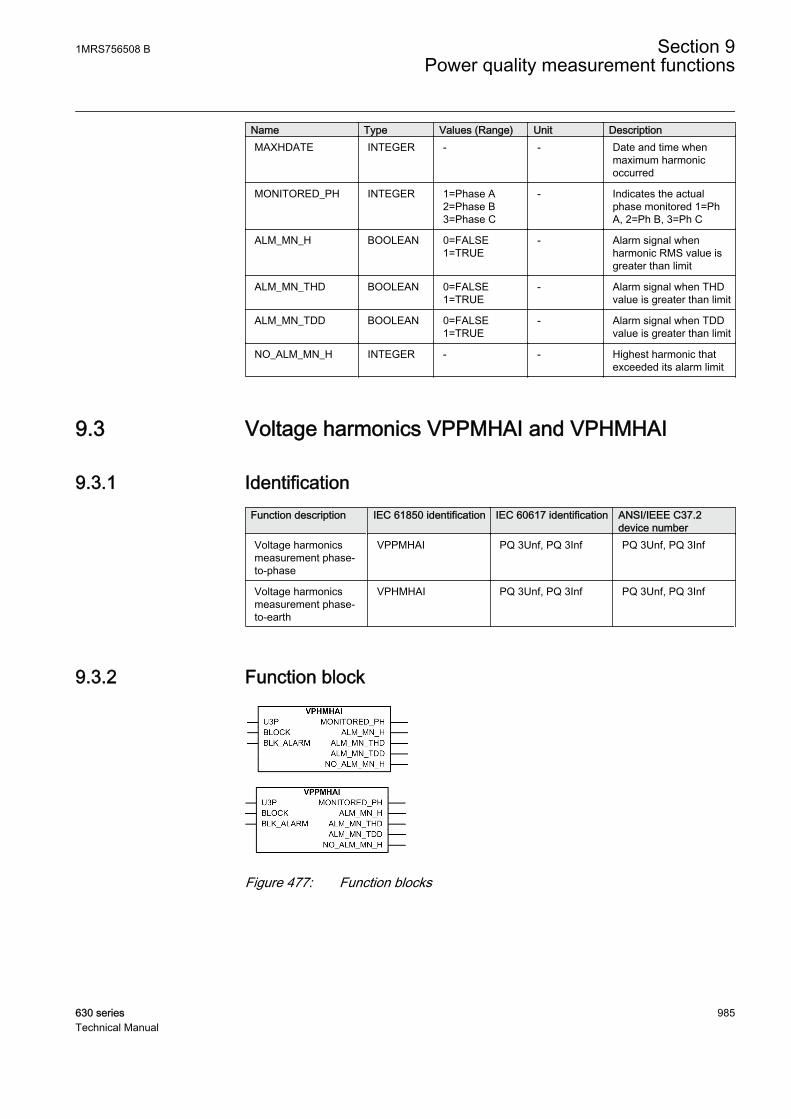
Name Type Values (Range) Unit DescriptionMAXHDATE INTEGER - - Date and time when
maximum harmonicoccurred
MONITORED_PH INTEGER 1=Phase A2=Phase B3=Phase C
- Indicates the actualphase monitored 1=PhA, 2=Ph B, 3=Ph C
ALM_MN_H BOOLEAN 0=FALSE1=TRUE
- Alarm signal whenharmonic RMS value isgreater than limit
ALM_MN_THD BOOLEAN 0=FALSE1=TRUE
- Alarm signal when THDvalue is greater than limit
ALM_MN_TDD BOOLEAN 0=FALSE1=TRUE
- Alarm signal when TDDvalue is greater than limit
NO_ALM_MN_H INTEGER - - Highest harmonic thatexceeded its alarm limit
9.3 Voltage harmonics VPPMHAI and VPHMHAI
9.3.1 IdentificationFunction description IEC 61850 identification IEC 60617 identification ANSI/IEEE C37.2
device numberVoltage harmonicsmeasurement phase-to-phase
VPPMHAI PQ 3Unf, PQ 3Inf PQ 3Unf, PQ 3Inf
Voltage harmonicsmeasurement phase-to-earth
VPHMHAI PQ 3Unf, PQ 3Inf PQ 3Unf, PQ 3Inf
9.3.2 Function block
GUID-F66695D0-3028-47B7-A547-8A17F86F4CDE V1 EN
GUID-68E614C4-F4EC-4527-844C-7869A17A03CE V1 EN
Figure 477: Function blocks
1MRS756508 B Section 9Power quality measurement functions
630 series 985Technical Manual
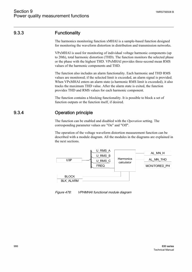
9.3.3 FunctionalityThe harmonics monitoring function xMHAI is a sample-based function designedfor monitoring the waveform distortion in distribution and transmission networks.
VPxMHAI is used for monitoring of individual voltage harmonic components (upto 20th), total harmonic distortion (THD). The function monitors the selected phaseor the phase with the highest THD. VPxMHAI provides three-second mean RMSvalues of the harmonic components and THD.
The function also includes an alarm functionality. Each harmonic and THD RMSvalues are monitored; if the selected limit is exceeded, an alarm signal is provided.When VPxMHAI enters an alarm state (a harmonic RMS limit is exceeded), it alsotracks the maximum THD value. After the alarm state is exited, the functionprovides THD and RMS values for each harmonic component.
The function contains a blocking functionality. It is possible to block a set offunction outputs or the function itself, if desired.
9.3.4 Operation principleThe function can be enabled and disabled with the Operation setting. Thecorresponding parameter values are "On" and "Off".
The operation of the voltage waveform distortion measurement function can bedescribed with a module diagram. All the modules in the diagrams are explained inthe next sections.
GUID-8DF02E0C-A5CA-4246-A215-43AA15CBAC94 V1 EN
Figure 478: VPHMHAI functional module diagram
Section 9 1MRS756508 BPower quality measurement functions
986 630 seriesTechnical Manual

GUID-4BF39EB6-063D-4CAF-950F-57D8B10374DB V1 EN
Figure 479: VPPMHAI functional module diagram
9.3.4.1 Harmonics calculator
The detailed operation of the harmonics calculator module diagram is explained inthe next sections.
GUID-B48ADE03-E956-46D9-9364-A8D41EB9FB32 V1 EN
Figure 480: Harmonics calculator module
Distortion measurementThis sample-based module measures the quasi-stationary (slowly varying)harmonics up to 20th. The distortion measurement does not include rapidlychanging harmonics, interharmonics or other spurious components.
VPxMHAI module calculates THD. THD is calculated with the equation:
THD
U
U
k
k
L
==
∑2
2
1
GUID-A4AF0573-3879-4629-932A-20A6316FA919 V1 EN (Equation 130)
Uk RMS value of voltage harmonic component 2…L (L = 20)
U1 RMS value of voltage fundamental component
Average calculation 3 secondsThis module calculates the three-phase three-second average THD and eachindividual 1st - 20th harmonic value which are used for continuous monitoring.VPHMHAI output values 3s Mean PhV H{1…20} PhA, 3s Mean PhV THD PhA,3s Mean PhV H{1…20} PhB, 3s Mean PhV THD PhB, 3s Mean PhV H{1…20}PhC, 3s Mean PhV THD PhC are available in the monitored data view. Also the
1MRS756508 B Section 9Power quality measurement functions
630 series 987Technical Manual

VPPMHAI output values 3s Mean PPV H{1…20} PhAB, 3s Mean PPV THDPhAB, 3s Mean PPV H{1…20} PhBC, 3s Mean PPV THD PhBC, 3s Mean PPVH{1…20} PhCA, 3s Mean PPV THD PhCA are available in the monitored data view.
Harmonic distortion detectorThe Measuring mode setting defines which phase is being monitored. The modes"Phase AB", Phase BC and Phase CA are used for respective phases. The "Worstcase" monitoring mode is used for the phase with the highest measured THD value.This means that the actual phase monitored can change continuously. TheMONITORED_PH output indicates the actual phase.
The three-second average THD and each individual 2nd - 20th harmonic value iscontinuously calculated and compared to the set value {2nd - 20th} H voltagevalue, THD voltage value. If the value exceeds limit, the AL_MN_H, AL_MN_THDand AL_MN_TDD outputs are activated respectively.
The tracking of maximum values based on the three second averages is startedwhen at least one of the outputs AL_MN_H and AL_MN_THD is active. TheMAXPHVH {1...20}, MAXPPVH {1...20} and MAXTHD outputs indicate themaximum harmonic values occurred during the previous alarm state.
These outputs are available in the monitored data view.
The BLK_ALARM input is used to block all the alarm outputs (AL_MN_H andAL_MN_THD). In this case, all the other outputs are updated normally. Activationof the BLOCK input blocks all the alarm outputs and the output indicating themaximum values.
9.3.5 Base valuesIn this function block, some of the settings are set in per unit (pu). These pu valuesare relational to certain base values, for example the values given in A, kV andkVA. The IED supports alternative base value groups for the phase current or voltage-related settings, for example "Phase Grp 1", "Phase Grp 2" and "Phase Grp 3".One of the groups to be used with the Base value Sel phase setting must be selected.
For more information, see the Basic functions section in this manual.
9.3.6 ApplicationThe power quality in standards is defined through the characteristics of the supplyvoltage. Transients, short and long duration voltage variations, unbalance andwaveform distortion are the key characteristics describing power quality. Thepower quality is however a customer-driven issue. It can be said that any power
Section 9 1MRS756508 BPower quality measurement functions
988 630 seriesTechnical Manual

problem concerning the voltage or current that results in the failure or misoperationof the customer equipment is a power quality problem.
Harmonic distortion in a power system is caused by nonlinear devices. Electronicpower converter loads constitute the most important class of the nonlinear loads ina power system. A number of single-phase electronic equipments (personalcomputers, printers, copiers and so on) in the switch mode power supplies, have ahigh third-harmonic content in the current. The three-phase electronic powerconverters (dc/ac drives) do not generate the third-harmonic currents. However,they can be a significant source of harmonics.
The harmonic voltage distortion in a power system depends on the currentdistortion produced by the nonlinear loads and on the impedance characteristicsvisible to each load. The most sensitive equipment to voltage harmonics is the dataprocessing and communication equipment, However, these devices areconsiderable current harmonic sources. These devices are susceptible to themisoperation caused by a harmonic distortion. For example, in computers andmedical instruments considerably low harmonic levels can result in malfunctionsthat can have serious consequences. In a rotating machinery, the major effect ofharmonic voltages and currents is an increased heating due to iron and copperlosses at the harmonic frequencies.
The power quality monitoring is an essential service utility that can be provided forthe industries and key customers. Monitoring system provides the informationabout the system disturbances and their possible causes. The monitoring systemcan also detect problem conditions throughout the system before they can causecustomer complaints, equipment malfunctions, and even equipment damage orfailure. Power quality problems are not limited to the utility side of the system. Infact, the majority of power quality problems are localized within the customerfacilities. Thus, the power quality monitoring is not only an effective customerservice strategy, but also a way to protect the quality of the utility reputation for aquality power and service.
xMHAI provides a convenient method for monitoring the power quality by meansof a voltage or current waveform distortion. The function monitors the voltage orcurrent harmonics in the power transmission and distribution networks. xMHAIproduces a statistical data about the harmonic distortion which is comparable to thestandard definitions of a good quality power. In addition, the function provides ashort term, three seconds average and maximum values for the THD and individualharmonics.
9.3.7 SignalsTable 904: VPHMHAI Input signals
Name Type Default DescriptionU3P GROUP
SIGNAL- Three phase group signal for voltage inputs
BLOCK BOOLEAN 0 Block of function
BLK_ALARM BOOLEAN 0 Block alarm outputs
1MRS756508 B Section 9Power quality measurement functions
630 series 989Technical Manual
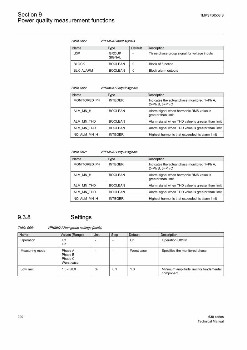
Table 905: VPPMHAI Input signals
Name Type Default DescriptionU3P GROUP
SIGNAL- Three phase group signal for voltage inputs
BLOCK BOOLEAN 0 Block of function
BLK_ALARM BOOLEAN 0 Block alarm outputs
Table 906: VPHMHAI Output signals
Name Type DescriptionMONITORED_PH INTEGER Indicates the actual phase monitored 1=Ph A,
2=Ph B, 3=Ph C
ALM_MN_H BOOLEAN Alarm signal when harmonic RMS value isgreater than limit
ALM_MN_THD BOOLEAN Alarm signal when THD value is greater than limit
ALM_MN_TDD BOOLEAN Alarm signal when TDD value is greater than limit
NO_ALM_MN_H INTEGER Highest harmonic that exceeded its alarm limit
Table 907: VPPMHAI Output signals
Name Type DescriptionMONITORED_PH INTEGER Indicates the actual phase monitored 1=Ph A,
2=Ph B, 3=Ph C
ALM_MN_H BOOLEAN Alarm signal when harmonic RMS value isgreater than limit
ALM_MN_THD BOOLEAN Alarm signal when THD value is greater than limit
ALM_MN_TDD BOOLEAN Alarm signal when TDD value is greater than limit
NO_ALM_MN_H INTEGER Highest harmonic that exceeded its alarm limit
9.3.8 SettingsTable 908: VPHMHAI Non group settings (basic)
Name Values (Range) Unit Step Default DescriptionOperation Off
On- - On Operation Off/On
Measuring mode Phase APhase BPhase CWorst case
- - Worst case Specifies the monitored phase
Low limit 1.0 - 50.0 % 0.1 1.0 Minimum amplitude limit for fundamentalcomponent
Section 9 1MRS756508 BPower quality measurement functions
990 630 seriesTechnical Manual

Table 909: VPHMHAI Non group settings (advanced)
Name Values (Range) Unit Step Default DescriptionBase value Sel phase Phase Grp 1
Phase Grp 2Phase Grp 3
- - Phase Grp 1 Base value selector, phase / phase-to-phase
2nd H limit Val 1.0 - 100.0 %IB 0.1 50.0 Limit for RMS value of 2nd harmoniccomponent
3rd H limit Val 1.0 - 100.0 %IB 0.1 50.0 Limit for RMS value of 3rd harmoniccomponent
4th H limit Val 1.0 - 100.0 %IB 0.1 50.0 Limit for RMS value of 4th harmoniccomponent
5th H limit Val 1.0 - 100.0 %IB 0.1 50.0 Limit for RMS value of 5th harmoniccomponent
6th H limit Val 1.0 - 100.0 %IB 0.1 50.0 Limit for RMS value of 6th harmoniccomponent
7th H limit Val 1.0 - 100.0 %IB 0.1 50.0 Limit for RMS value of 7th harmoniccomponent
8th H limit Val 1.0 - 100.0 %IB 0.1 50.0 Limit for RMS value of 8th harmoniccomponent
9th H limit Val 1.0 - 100.0 %IB 0.1 50.0 Limit for RMS value of 9th harmoniccomponent
10th H limit Val 1.0 - 100.0 %IB 0.1 50.0 Limit for RMS value of 10th harmoniccomponent
11th H limit Val 1.0 - 100.0 %IB 0.1 50.0 Limit for RMS value of 11th harmoniccomponent
12th H limit Val 1.0 - 100.0 %IB 0.1 50.0 Limit for RMS value of 12th harmoniccomponent
13th H limit Val 1.0 - 100.0 %IB 0.1 50.0 Limit for RMS value of 13th harmoniccomponent
14th H limit Val 1.0 - 100.0 %IB 0.1 50.0 Limit for RMS value of 14th harmoniccomponent
15th H limit Val 1.0 - 100.0 %IB 0.1 50.0 Limit for RMS value of 15th harmoniccomponent
16th H limit Val 1.0 - 100.0 %IB 0.1 50.0 Limit for RMS value of 16th harmoniccomponent
17th H limit Val 1.0 - 100.0 %IB 0.1 50.0 Limit for RMS value of 17th harmoniccomponent
18th H limit Val 1.0 - 100.0 %IB 0.1 50.0 Limit for RMS value of 18th harmoniccomponent
19th H limit Val 1.0 - 100.0 %IB 0.1 50.0 Limit for RMS value of 19th harmoniccomponent
20th H limit Val 1.0 - 100.0 %IB 0.1 50.0 Limit for RMS value of 20th harmoniccomponent
THD limit value 1.0 - 100.0 % 0.1 50.0 Limit for THD
TDD limit value 1.0 - 100.0 % 0.1 50.0 Limit for TDD
Distortion factor THDTDD
- - THD Defines the distortion factor used in limitsupervision
Relative hysteresis 0 - 5 % 1 2 Relative hysteresis for limit supervisionof mean values
1MRS756508 B Section 9Power quality measurement functions
630 series 991Technical Manual

Table 910: VPPMHAI Non group settings (basic)
Name Values (Range) Unit Step Default DescriptionOperation Off
On- - On Operation Off/On
Measuring mode Phase ABPhase BCPhase CAWorst case
- - Worst case Specifies the monitored phase
Low limit 1.0 - 50.0 % 0.1 1.0 Minimum amplitude limit for fundamentalcomponent
Table 911: VPPMHAI Non group settings (advanced)
Name Values (Range) Unit Step Default DescriptionBase value Sel phase Phase Grp 1
Phase Grp 2Phase Grp 3
- - Phase Grp 1 Base value selector, phase / phase-to-phase
2nd H limit Val 1.0 - 100.0 %IB 0.1 50.0 Limit for RMS value of 2nd harmoniccomponent
3rd H limit Val 1.0 - 100.0 %IB 0.1 50.0 Limit for RMS value of 3rd harmoniccomponent
4th H limit Val 1.0 - 100.0 %IB 0.1 50.0 Limit for RMS value of 4th harmoniccomponent
5th H limit Val 1.0 - 100.0 %IB 0.1 50.0 Limit for RMS value of 5th harmoniccomponent
6th H limit Val 1.0 - 100.0 %IB 0.1 50.0 Limit for RMS value of 6th harmoniccomponent
7th H limit Val 1.0 - 100.0 %IB 0.1 50.0 Limit for RMS value of 7th harmoniccomponent
8th H limit Val 1.0 - 100.0 %IB 0.1 50.0 Limit for RMS value of 8th harmoniccomponent
9th H limit Val 1.0 - 100.0 %IB 0.1 50.0 Limit for RMS value of 9th harmoniccomponent
10th H limit Val 1.0 - 100.0 %IB 0.1 50.0 Limit for RMS value of 10th harmoniccomponent
11th H limit Val 1.0 - 100.0 %IB 0.1 50.0 Limit for RMS value of 11th harmoniccomponent
12th H limit Val 1.0 - 100.0 %IB 0.1 50.0 Limit for RMS value of 12th harmoniccomponent
13th H limit Val 1.0 - 100.0 %IB 0.1 50.0 Limit for RMS value of 13th harmoniccomponent
14th H limit Val 1.0 - 100.0 %IB 0.1 50.0 Limit for RMS value of 14th harmoniccomponent
15th H limit Val 1.0 - 100.0 %IB 0.1 50.0 Limit for RMS value of 15th harmoniccomponent
16th H limit Val 1.0 - 100.0 %IB 0.1 50.0 Limit for RMS value of 16th harmoniccomponent
17th H limit Val 1.0 - 100.0 %IB 0.1 50.0 Limit for RMS value of 17th harmoniccomponent
Table continues on next page
Section 9 1MRS756508 BPower quality measurement functions
992 630 seriesTechnical Manual

Name Values (Range) Unit Step Default Description18th H limit Val 1.0 - 100.0 %IB 0.1 50.0 Limit for RMS value of 18th harmonic
component
19th H limit Val 1.0 - 100.0 %IB 0.1 50.0 Limit for RMS value of 19th harmoniccomponent
20th H limit Val 1.0 - 100.0 %IB 0.1 50.0 Limit for RMS value of 20th harmoniccomponent
THD limit value 1.0 - 100.0 % 0.1 50.0 Limit for THD
TDD limit value 1.0 - 100.0 % 0.1 50.0 Limit for TDD
Distortion factor THDTDD
- - THD Defines the distortion factor used in limitsupervision
Relative hysteresis 0 - 5 % 1 2 Relative hysteresis for limit supervisionof mean values
9.3.9 Measured valuesTable 912: VPHMHAI Measured values
Name Type Default DescriptionBLOCK BOOLEAN 0 Block of function
BLK_ALARM BOOLEAN 0 Block alarm outputs
Table 913: VPPMHAI Measured values
Name Type Default DescriptionBLOCK BOOLEAN 0 Block of function
BLK_ALARM BOOLEAN 0 Block alarm outputs
9.3.10 Monitored DataTable 914: VPHMHAI Monitored data
Name Type Values (Range) Unit Description3SMNH1_A REAL - % Non-sliding 3s mean
RMS value of 1stharmonic for phase A
3SMNH2_A REAL - % Non-sliding 3s meanRMS value of 2ndharmonic for phase A
3SMNH3_A REAL - % Non-sliding 3s meanRMS value of 3rdharmonic for phase A
3SMNH4_A REAL - % Non-sliding 3s meanRMS value of 4thharmonic for phase A
3SMNH5_A REAL - % Non-sliding 3s meanRMS value of 5thharmonic for phase A
Table continues on next page
1MRS756508 B Section 9Power quality measurement functions
630 series 993Technical Manual
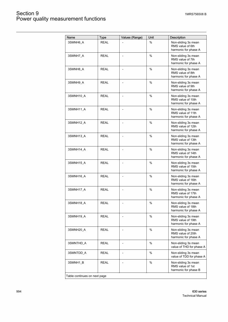
Name Type Values (Range) Unit Description3SMNH6_A REAL - % Non-sliding 3s mean
RMS value of 6thharmonic for phase A
3SMNH7_A REAL - % Non-sliding 3s meanRMS value of 7thharmonic for phase A
3SMNH8_A REAL - % Non-sliding 3s meanRMS value of 8thharmonic for phase A
3SMNH9_A REAL - % Non-sliding 3s meanRMS value of 9thharmonic for phase A
3SMNH10_A REAL - % Non-sliding 3s meanRMS value of 10thharmonic for phase A
3SMNH11_A REAL - % Non-sliding 3s meanRMS value of 11thharmonic for phase A
3SMNH12_A REAL - % Non-sliding 3s meanRMS value of 12thharmonic for phase A
3SMNH13_A REAL - % Non-sliding 3s meanRMS value of 13thharmonic for phase A
3SMNH14_A REAL - % Non-sliding 3s meanRMS value of 14thharmonic for phase A
3SMNH15_A REAL - % Non-sliding 3s meanRMS value of 15thharmonic for phase A
3SMNH16_A REAL - % Non-sliding 3s meanRMS value of 16thharmonic for phase A
3SMNH17_A REAL - % Non-sliding 3s meanRMS value of 17thharmonic for phase A
3SMNH18_A REAL - % Non-sliding 3s meanRMS value of 18thharmonic for phase A
3SMNH19_A REAL - % Non-sliding 3s meanRMS value of 19thharmonic for phase A
3SMNH20_A REAL - % Non-sliding 3s meanRMS value of 20thharmonic for phase A
3SMNTHD_A REAL - % Non-sliding 3s meanvalue of THD for phase A
3SMNTDD_A REAL - % Non-sliding 3s meanvalue of TDD for phase A
3SMNH1_B REAL - % Non-sliding 3s meanRMS value of 1stharmonic for phase B
Table continues on next page
Section 9 1MRS756508 BPower quality measurement functions
994 630 seriesTechnical Manual

Name Type Values (Range) Unit Description3SMNH2_B REAL - % Non-sliding 3s mean
RMS value of 2ndharmonic for phase B
3SMNH3_B REAL - % Non-sliding 3s meanRMS value of 3rdharmonic for phase B
3SMNH4_B REAL - % Non-sliding 3s meanRMS value of 4thharmonic for phase B
3SMNH5_B REAL - % Non-sliding 3s meanRMS value of 5thharmonic for phase B
3SMNH6_B REAL - % Non-sliding 3s meanRMS value of 6thharmonic for phase B
3SMNH7_B REAL - % Non-sliding 3s meanRMS value of 7thharmonic for phase B
3SMNH8_B REAL - % Non-sliding 3s meanRMS value of 8thharmonic for phase B
3SMNH9_B REAL - % Non-sliding 3s meanRMS value of 9thharmonic for phase B
3SMNH10_B REAL - % Non-sliding 3s meanRMS value of 10thharmonic for phase B
3SMNH11_B REAL - % Non-sliding 3s meanRMS value of 11thharmonic for phase B
3SMNH12_B REAL - % Non-sliding 3s meanRMS value of 12thharmonic for phase B
3SMNH13_B REAL - % Non-sliding 3s meanRMS value of 13thharmonic for phase B
3SMNH14_B REAL - % Non-sliding 3s meanRMS value of 14thharmonic for phase B
3SMNH15_B REAL - % Non-sliding 3s meanRMS value of 15thharmonic for phase B
3SMNH16_B REAL - % Non-sliding 3s meanRMS value of 16thharmonic for phase B
3SMNH17_B REAL - % Non-sliding 3s meanRMS value of 17thharmonic for phase B
3SMNH18_B REAL - % Non-sliding 3s meanRMS value of 18thharmonic for phase B
Table continues on next page
1MRS756508 B Section 9Power quality measurement functions
630 series 995Technical Manual
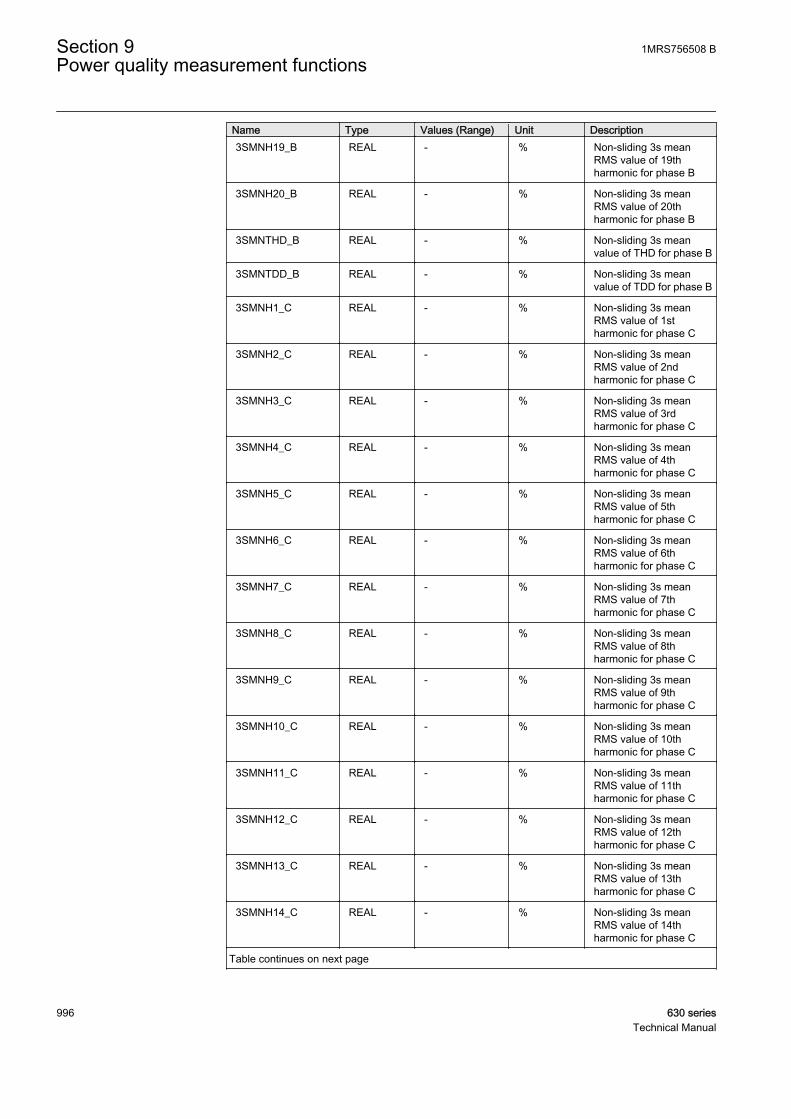
Name Type Values (Range) Unit Description3SMNH19_B REAL - % Non-sliding 3s mean
RMS value of 19thharmonic for phase B
3SMNH20_B REAL - % Non-sliding 3s meanRMS value of 20thharmonic for phase B
3SMNTHD_B REAL - % Non-sliding 3s meanvalue of THD for phase B
3SMNTDD_B REAL - % Non-sliding 3s meanvalue of TDD for phase B
3SMNH1_C REAL - % Non-sliding 3s meanRMS value of 1stharmonic for phase C
3SMNH2_C REAL - % Non-sliding 3s meanRMS value of 2ndharmonic for phase C
3SMNH3_C REAL - % Non-sliding 3s meanRMS value of 3rdharmonic for phase C
3SMNH4_C REAL - % Non-sliding 3s meanRMS value of 4thharmonic for phase C
3SMNH5_C REAL - % Non-sliding 3s meanRMS value of 5thharmonic for phase C
3SMNH6_C REAL - % Non-sliding 3s meanRMS value of 6thharmonic for phase C
3SMNH7_C REAL - % Non-sliding 3s meanRMS value of 7thharmonic for phase C
3SMNH8_C REAL - % Non-sliding 3s meanRMS value of 8thharmonic for phase C
3SMNH9_C REAL - % Non-sliding 3s meanRMS value of 9thharmonic for phase C
3SMNH10_C REAL - % Non-sliding 3s meanRMS value of 10thharmonic for phase C
3SMNH11_C REAL - % Non-sliding 3s meanRMS value of 11thharmonic for phase C
3SMNH12_C REAL - % Non-sliding 3s meanRMS value of 12thharmonic for phase C
3SMNH13_C REAL - % Non-sliding 3s meanRMS value of 13thharmonic for phase C
3SMNH14_C REAL - % Non-sliding 3s meanRMS value of 14thharmonic for phase C
Table continues on next page
Section 9 1MRS756508 BPower quality measurement functions
996 630 seriesTechnical Manual

Name Type Values (Range) Unit Description3SMNH15_C REAL - % Non-sliding 3s mean
RMS value of 15thharmonic for phase C
3SMNH16_C REAL - % Non-sliding 3s meanRMS value of 16thharmonic for phase C
3SMNH17_C REAL - % Non-sliding 3s meanRMS value of 17thharmonic for phase C
3SMNH18_C REAL - % Non-sliding 3s meanRMS value of 18thharmonic for phase C
3SMNH19_C REAL - % Non-sliding 3s meanRMS value of 19thharmonic for phase C
3SMNH20_C REAL - % Non-sliding 3s meanRMS value of 20thharmonic for phase C
3SMNTHD_C REAL - % Non-sliding 3s meanvalue of THD for phase C
3SMNTDD_C REAL - % Non-sliding 3s meanvalue of TDD for phase C
MAXH1 REAL - % Max 1st harmonicupdated after exitingalarm state
MAXH2 REAL - % Max 2nd harmonicupdated after exitingalarm state
MAXH3 REAL - % Max 3rd harmonicupdated after exitingalarm state
MAXH4 REAL - % Max 4th harmonicupdated after exitingalarm state
MAXH5 REAL - % Max 5th harmonicupdated after exitingalarm state
MAXH6 REAL - % Max 6th harmonicupdated after exitingalarm state
MAXH7 REAL - % Max 7th harmonicupdated after exitingalarm state
MAXH8 REAL - % Max 8th harmonicupdated after exitingalarm state
MAXH9 REAL - % Max 9th harmonicupdated after exitingalarm state
MAXH10 REAL - % Max 10th harmonicupdated after exitingalarm state
Table continues on next page
1MRS756508 B Section 9Power quality measurement functions
630 series 997Technical Manual
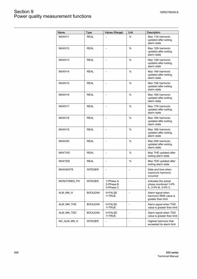
Name Type Values (Range) Unit DescriptionMAXH11 REAL - % Max 11th harmonic
updated after exitingalarm state
MAXH12 REAL - % Max 12th harmonicupdated after exitingalarm state
MAXH13 REAL - % Max 13th harmonicupdated after exitingalarm state
MAXH14 REAL - % Max 14th harmonicupdated after exitingalarm state
MAXH15 REAL - % Max 15th harmonicupdated after exitingalarm state
MAXH16 REAL - % Max 16th harmonicupdated after exitingalarm state
MAXH17 REAL - % Max 17th harmonicupdated after exitingalarm state
MAXH18 REAL - % Max 18th harmonicupdated after exitingalarm state
MAXH19 REAL - % Max 19th harmonicupdated after exitingalarm state
MAXH20 REAL - % Max 20th harmonicupdated after exitingalarm state
MAXTHD REAL - % Max THD updated afterexiting alarm state
MAXTDD REAL - % Max TDD updated afterexiting alarm state
MAXHDATE INTEGER - - Date and time whenmaximum harmonicoccurred
MONITORED_PH INTEGER 1=Phase A2=Phase B3=Phase C
- Indicates the actualphase monitored 1=PhA, 2=Ph B, 3=Ph C
ALM_MN_H BOOLEAN 0=FALSE1=TRUE
- Alarm signal whenharmonic RMS value isgreater than limit
ALM_MN_THD BOOLEAN 0=FALSE1=TRUE
- Alarm signal when THDvalue is greater than limit
ALM_MN_TDD BOOLEAN 0=FALSE1=TRUE
- Alarm signal when TDDvalue is greater than limit
NO_ALM_MN_H INTEGER - - Highest harmonic thatexceeded its alarm limit
Section 9 1MRS756508 BPower quality measurement functions
998 630 seriesTechnical Manual

Table 915: VPPMHAI Monitored data
Name Type Values (Range) Unit Description3SMNH1_AB REAL - % Non-sliding 3s mean
RMS value of 1stharmonic for phase AB
3SMNH2_AB REAL - % Non-sliding 3s meanRMS value of 2ndharmonic for phase AB
3SMNH3_AB REAL - % Non-sliding 3s meanRMS value of 3rdharmonic for phase AB
3SMNH4_AB REAL - % Non-sliding 3s meanRMS value of 4thharmonic for phase AB
3SMNH5_AB REAL - % Non-sliding 3s meanRMS value of 5thharmonic for phase AB
3SMNH6_AB REAL - % Non-sliding 3s meanRMS value of 6thharmonic for phase AB
3SMNH7_AB REAL - % Non-sliding 3s meanRMS value of 7thharmonic for phase AB
3SMNH8_AB REAL - % Non-sliding 3s meanRMS value of 8thharmonic for phase AB
3SMNH9_AB REAL - % Non-sliding 3s meanRMS value of 9thharmonic for phase AB
3SMNH10_AB REAL - % Non-sliding 3s meanRMS value of 10thharmonic for phase AB
3SMNH11_AB REAL - % Non-sliding 3s meanRMS value of 11thharmonic for phase AB
3SMNH12_AB REAL - % Non-sliding 3s meanRMS value of 12thharmonic for phase AB
3SMNH13_AB REAL - % Non-sliding 3s meanRMS value of 13thharmonic for phase AB
3SMNH14_AB REAL - % Non-sliding 3s meanRMS value of 14thharmonic for phase AB
3SMNH15_AB REAL - % Non-sliding 3s meanRMS value of 15thharmonic for phase AB
3SMNH16_AB REAL - % Non-sliding 3s meanRMS value of 16thharmonic for phase AB
3SMNH17_AB REAL - % Non-sliding 3s meanRMS value of 17thharmonic for phase AB
Table continues on next page
1MRS756508 B Section 9Power quality measurement functions
630 series 999Technical Manual
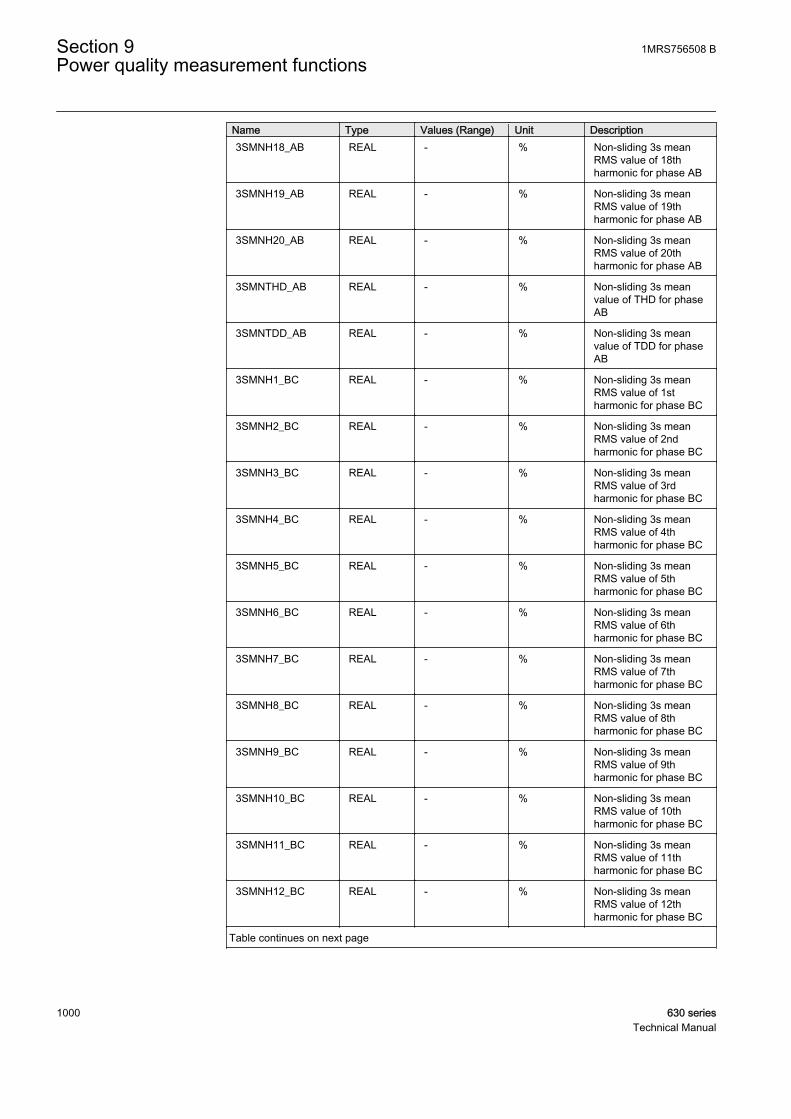
Name Type Values (Range) Unit Description3SMNH18_AB REAL - % Non-sliding 3s mean
RMS value of 18thharmonic for phase AB
3SMNH19_AB REAL - % Non-sliding 3s meanRMS value of 19thharmonic for phase AB
3SMNH20_AB REAL - % Non-sliding 3s meanRMS value of 20thharmonic for phase AB
3SMNTHD_AB REAL - % Non-sliding 3s meanvalue of THD for phaseAB
3SMNTDD_AB REAL - % Non-sliding 3s meanvalue of TDD for phaseAB
3SMNH1_BC REAL - % Non-sliding 3s meanRMS value of 1stharmonic for phase BC
3SMNH2_BC REAL - % Non-sliding 3s meanRMS value of 2ndharmonic for phase BC
3SMNH3_BC REAL - % Non-sliding 3s meanRMS value of 3rdharmonic for phase BC
3SMNH4_BC REAL - % Non-sliding 3s meanRMS value of 4thharmonic for phase BC
3SMNH5_BC REAL - % Non-sliding 3s meanRMS value of 5thharmonic for phase BC
3SMNH6_BC REAL - % Non-sliding 3s meanRMS value of 6thharmonic for phase BC
3SMNH7_BC REAL - % Non-sliding 3s meanRMS value of 7thharmonic for phase BC
3SMNH8_BC REAL - % Non-sliding 3s meanRMS value of 8thharmonic for phase BC
3SMNH9_BC REAL - % Non-sliding 3s meanRMS value of 9thharmonic for phase BC
3SMNH10_BC REAL - % Non-sliding 3s meanRMS value of 10thharmonic for phase BC
3SMNH11_BC REAL - % Non-sliding 3s meanRMS value of 11thharmonic for phase BC
3SMNH12_BC REAL - % Non-sliding 3s meanRMS value of 12thharmonic for phase BC
Table continues on next page
Section 9 1MRS756508 BPower quality measurement functions
1000 630 seriesTechnical Manual
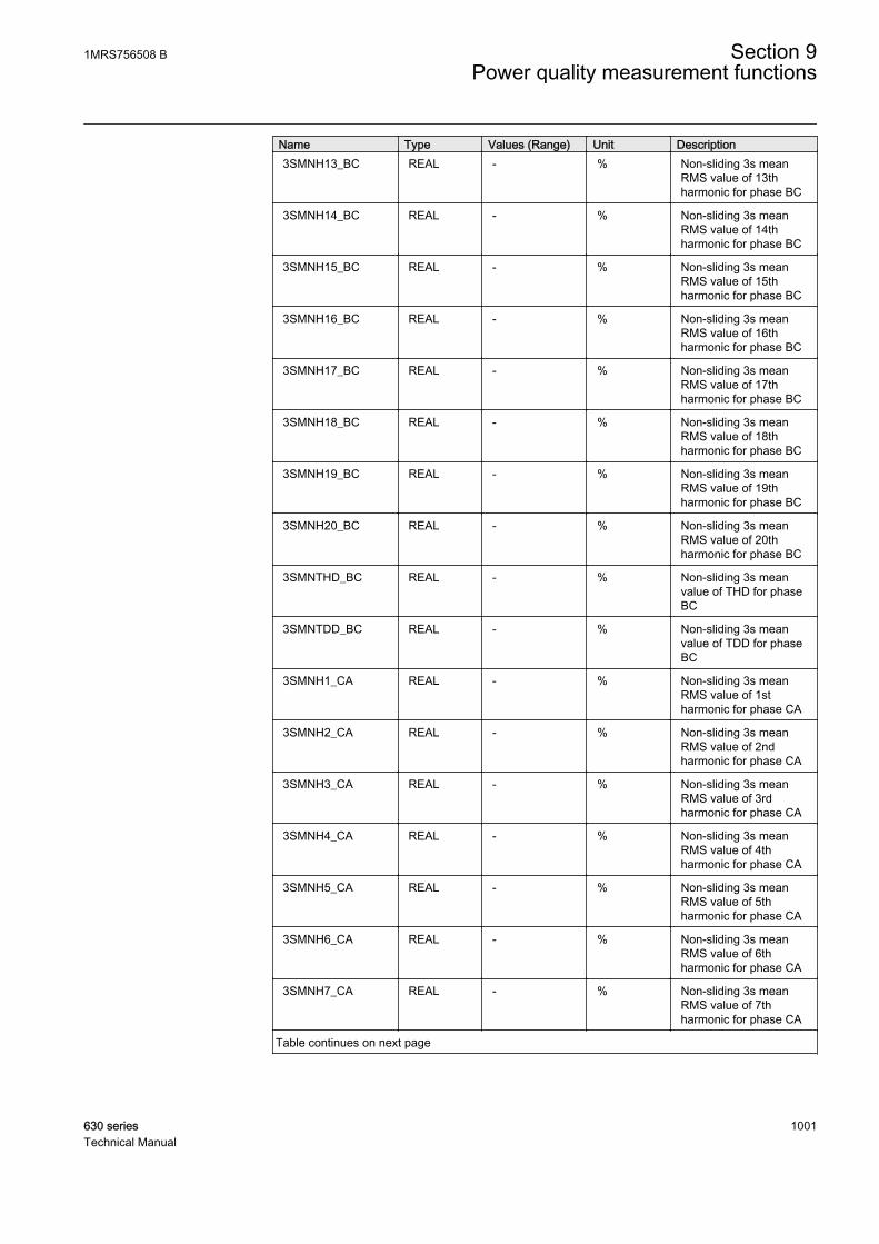
Name Type Values (Range) Unit Description3SMNH13_BC REAL - % Non-sliding 3s mean
RMS value of 13thharmonic for phase BC
3SMNH14_BC REAL - % Non-sliding 3s meanRMS value of 14thharmonic for phase BC
3SMNH15_BC REAL - % Non-sliding 3s meanRMS value of 15thharmonic for phase BC
3SMNH16_BC REAL - % Non-sliding 3s meanRMS value of 16thharmonic for phase BC
3SMNH17_BC REAL - % Non-sliding 3s meanRMS value of 17thharmonic for phase BC
3SMNH18_BC REAL - % Non-sliding 3s meanRMS value of 18thharmonic for phase BC
3SMNH19_BC REAL - % Non-sliding 3s meanRMS value of 19thharmonic for phase BC
3SMNH20_BC REAL - % Non-sliding 3s meanRMS value of 20thharmonic for phase BC
3SMNTHD_BC REAL - % Non-sliding 3s meanvalue of THD for phaseBC
3SMNTDD_BC REAL - % Non-sliding 3s meanvalue of TDD for phaseBC
3SMNH1_CA REAL - % Non-sliding 3s meanRMS value of 1stharmonic for phase CA
3SMNH2_CA REAL - % Non-sliding 3s meanRMS value of 2ndharmonic for phase CA
3SMNH3_CA REAL - % Non-sliding 3s meanRMS value of 3rdharmonic for phase CA
3SMNH4_CA REAL - % Non-sliding 3s meanRMS value of 4thharmonic for phase CA
3SMNH5_CA REAL - % Non-sliding 3s meanRMS value of 5thharmonic for phase CA
3SMNH6_CA REAL - % Non-sliding 3s meanRMS value of 6thharmonic for phase CA
3SMNH7_CA REAL - % Non-sliding 3s meanRMS value of 7thharmonic for phase CA
Table continues on next page
1MRS756508 B Section 9Power quality measurement functions
630 series 1001Technical Manual
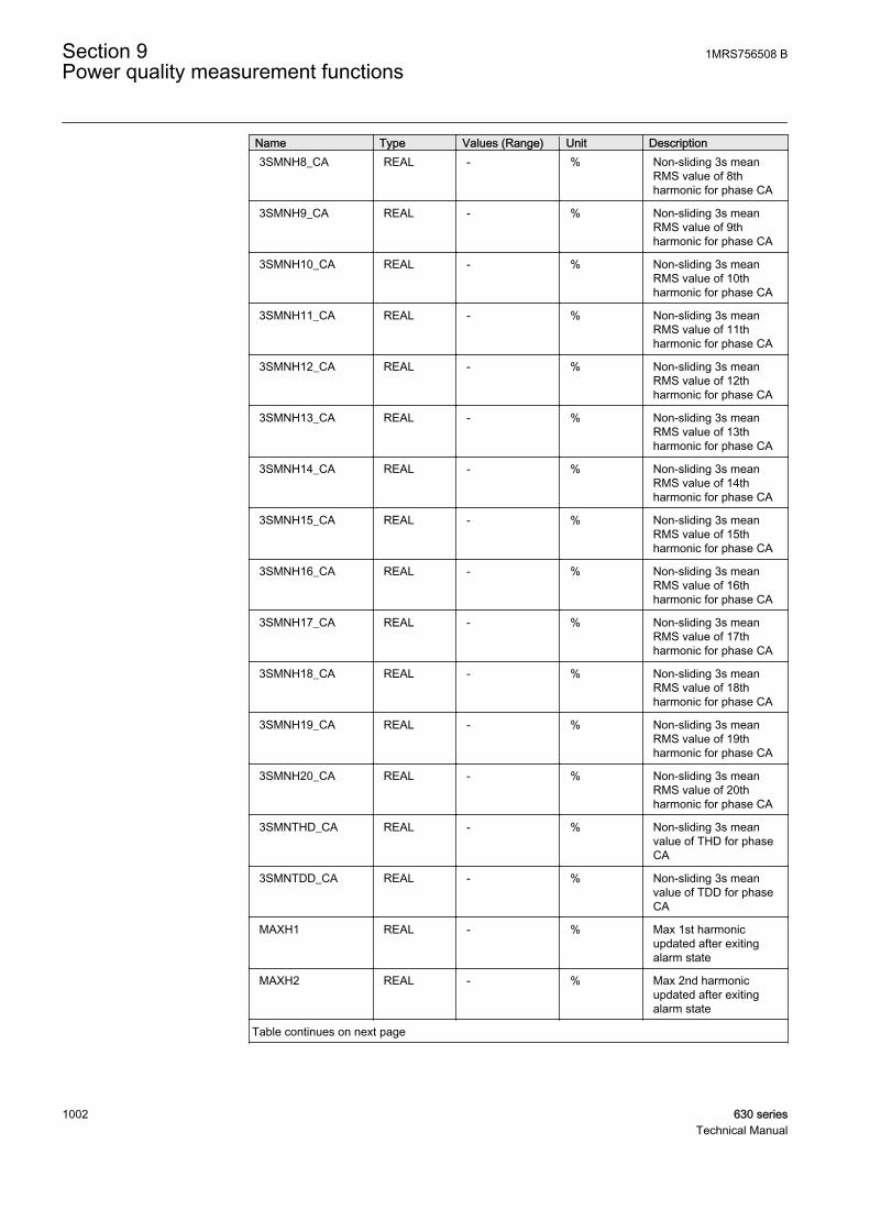
Name Type Values (Range) Unit Description3SMNH8_CA REAL - % Non-sliding 3s mean
RMS value of 8thharmonic for phase CA
3SMNH9_CA REAL - % Non-sliding 3s meanRMS value of 9thharmonic for phase CA
3SMNH10_CA REAL - % Non-sliding 3s meanRMS value of 10thharmonic for phase CA
3SMNH11_CA REAL - % Non-sliding 3s meanRMS value of 11thharmonic for phase CA
3SMNH12_CA REAL - % Non-sliding 3s meanRMS value of 12thharmonic for phase CA
3SMNH13_CA REAL - % Non-sliding 3s meanRMS value of 13thharmonic for phase CA
3SMNH14_CA REAL - % Non-sliding 3s meanRMS value of 14thharmonic for phase CA
3SMNH15_CA REAL - % Non-sliding 3s meanRMS value of 15thharmonic for phase CA
3SMNH16_CA REAL - % Non-sliding 3s meanRMS value of 16thharmonic for phase CA
3SMNH17_CA REAL - % Non-sliding 3s meanRMS value of 17thharmonic for phase CA
3SMNH18_CA REAL - % Non-sliding 3s meanRMS value of 18thharmonic for phase CA
3SMNH19_CA REAL - % Non-sliding 3s meanRMS value of 19thharmonic for phase CA
3SMNH20_CA REAL - % Non-sliding 3s meanRMS value of 20thharmonic for phase CA
3SMNTHD_CA REAL - % Non-sliding 3s meanvalue of THD for phaseCA
3SMNTDD_CA REAL - % Non-sliding 3s meanvalue of TDD for phaseCA
MAXH1 REAL - % Max 1st harmonicupdated after exitingalarm state
MAXH2 REAL - % Max 2nd harmonicupdated after exitingalarm state
Table continues on next page
Section 9 1MRS756508 BPower quality measurement functions
1002 630 seriesTechnical Manual
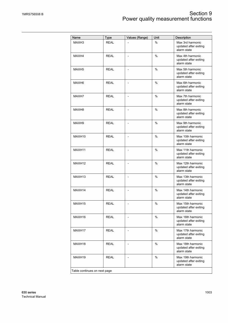
Name Type Values (Range) Unit DescriptionMAXH3 REAL - % Max 3rd harmonic
updated after exitingalarm state
MAXH4 REAL - % Max 4th harmonicupdated after exitingalarm state
MAXH5 REAL - % Max 5th harmonicupdated after exitingalarm state
MAXH6 REAL - % Max 6th harmonicupdated after exitingalarm state
MAXH7 REAL - % Max 7th harmonicupdated after exitingalarm state
MAXH8 REAL - % Max 8th harmonicupdated after exitingalarm state
MAXH9 REAL - % Max 9th harmonicupdated after exitingalarm state
MAXH10 REAL - % Max 10th harmonicupdated after exitingalarm state
MAXH11 REAL - % Max 11th harmonicupdated after exitingalarm state
MAXH12 REAL - % Max 12th harmonicupdated after exitingalarm state
MAXH13 REAL - % Max 13th harmonicupdated after exitingalarm state
MAXH14 REAL - % Max 14th harmonicupdated after exitingalarm state
MAXH15 REAL - % Max 15th harmonicupdated after exitingalarm state
MAXH16 REAL - % Max 16th harmonicupdated after exitingalarm state
MAXH17 REAL - % Max 17th harmonicupdated after exitingalarm state
MAXH18 REAL - % Max 18th harmonicupdated after exitingalarm state
MAXH19 REAL - % Max 19th harmonicupdated after exitingalarm state
Table continues on next page
1MRS756508 B Section 9Power quality measurement functions
630 series 1003Technical Manual
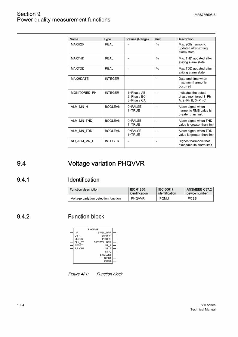
Name Type Values (Range) Unit DescriptionMAXH20 REAL - % Max 20th harmonic
updated after exitingalarm state
MAXTHD REAL - % Max THD updated afterexiting alarm state
MAXTDD REAL - % Max TDD updated afterexiting alarm state
MAXHDATE INTEGER - - Date and time whenmaximum harmonicoccurred
MONITORED_PH INTEGER 1=Phase AB2=Phase BC3=Phase CA
- Indicates the actualphase monitored 1=PhA, 2=Ph B, 3=Ph C
ALM_MN_H BOOLEAN 0=FALSE1=TRUE
- Alarm signal whenharmonic RMS value isgreater than limit
ALM_MN_THD BOOLEAN 0=FALSE1=TRUE
- Alarm signal when THDvalue is greater than limit
ALM_MN_TDD BOOLEAN 0=FALSE1=TRUE
- Alarm signal when TDDvalue is greater than limit
NO_ALM_MN_H INTEGER - - Highest harmonic thatexceeded its alarm limit
9.4 Voltage variation PHQVVR
9.4.1 IdentificationFunction description IEC 61850
identificationIEC 60617identification
ANSI/IEEE C37.2device number
Voltage variation detection function PHQVVR PQMU PQSS
9.4.2 Function block
GUID-E951A8E5-29D8-46B5-A051-7510C61144DA V1 EN
Figure 481: Function block
Section 9 1MRS756508 BPower quality measurement functions
1004 630 seriesTechnical Manual

9.4.3 FunctionalityThe voltage variation measurement function PHQVVR is used for measuring theshort-duration voltage variations in distribution networks.
Power quality in the voltage waveform is evaluated by measuring voltage swells,dips and interruptions. PHQVVR includes single-phase and three-phase voltagevariation modes.
Typically, short-duration voltage variations are defined to last more than half of thenominal frequency period and less than one minute. The maximum magnitude (inthe case of a voltage swell) or depth (in the case of a voltage dip or interruption)and the duration of the variation can be obtained by measuring the RMS value ofthe voltage for each phase. International standard 61000-4-30 defines the functionto be implemented using the RMS value of the voltage.
PHQVVR contains a blocking functionality. It is possible to block a set of functionoutputs or the function itself, if desired.
9.4.4 Operation principleThe function can be enabled and disabled with the Operation setting. Thecorresponding parameter values are "On" and "Off".
When the setting is set to "Off", the counter outputs are stored in the nonvolatilememory and SWELLCNT, DIPCNT and INTCNT are reset.
The operation of the voltage variation detection function can be described with amodule diagram. All the modules in the diagram are explained in the next sections.
1MRS756508 B Section 9Power quality measurement functions
630 series 1005Technical Manual

GUID-25C749E6-E307-46CF-8244-87F8E81BB6F0 V1 EN
Figure 482: Functional module diagram. Group signal I3P and U3P are usedfor feeding the necessary analog signals to the function.
9.4.4.1 Variation detection
Variation detection compares the measured voltage to the limit settings. The inputparameter Voltage selection is used to select whether phase-to-earth or phase-to-phase voltages are used for power quality monitoring. When there is a permanentundervoltage or overvoltage, the Reference voltage setting can be set to this voltagelevel to avoid the undesired voltage dip or swell indications. This is accomplishedby converting the variation limits with the Reference voltage setting in the variationdetection module. In other words, when there is a voltage different from thenominal voltage, the Reference voltage setting is set to that voltage.
The voltage detection module monitors continuously the voltage waveform fordetecting voltage swells, dips and interruptions. When the measured RMS valuedrops below Voltage dip set and simultaneously stays above the value of VoltageInt set, the DIPST output is activated. If the voltage drops below the value ofVoltage Int set, the INTST output is activated. When the measured RMS valuerises above the value of Voltage swell set, the SWELLST output is activated.
The detection principle for voltage interruption is a special case.The INTST output is activated when the voltage levels of allmonitored phases (defined with the Phase supervision setting) dropbelow the Voltage Int setting.
Section 9 1MRS756508 BPower quality measurement functions
1006 630 seriesTechnical Manual

U_A
U_C U_B
DIPSTINTST
SWELLST
Voltage Int set
Voltage dip set
Voltage swell set
FALSETRUE FALSETRUE
FALSETRUE
GUID-A9CD43FF-E859-4E3D-8095-8A71CBCACBCC V1 EN
Figure 483: Detection of three-phase voltage interruption
Variation detection measures the voltage variation magnitude on each phaseseparately. This per-phase measurement enables the detection of, for example, single-phase earth faults. The ST_A_AB, ST_B_BC and ST_C_CA outputs are used toindicate on which phase voltage variation is detected. The Phase supervisionparameter defines which voltage phase or phases are monitored. If a voltage phaseis selected to be monitored, the function assumes it to be connected to a voltagemeasurement channel. In other words, if an unconnected phase is monitored, thefunction falsely detects voltage interruption on that particular phase.
The maximum magnitude and depth are defined as a percentage value calculatedfrom the difference between the referenced and the measured voltage. For example,a 70 percent depth means that the minimum magnitude of a voltage dip variation is70 percent of the reference voltage amplitude).
The BLK_ST input is used to block all the start outputs (ST_A_AB, ST_B_BC,ST_C_CA, SWELLST, DIPST and INTST). In this case, all other outputs(registers, operate outputs and counters) are updated normally. The activation ofthe BLOCK input blocks all the outputs, including the start outputs.
9.4.4.2 Duration measurement
The duration of each voltage phase corresponds to the period during which themeasured RMS values remain above or below the corresponding limit.
The duration measurement module measures the voltage variation duration of eachvoltage channel separately and also the total variation duration. This means that thevoltage variation may start on one phase and terminate on another phase. The totalvariation duration is as shown in Figure 484. The measured value of the totalvariation duration is used in the variation validation module for variation validation.
1MRS756508 B Section 9Power quality measurement functions
630 series 1007Technical Manual
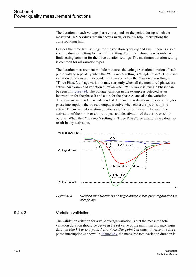
The duration of each voltage phase corresponds to the period during which themeasured TRMS values remain above (swell) or below (dip, interruption) thecorresponding limit.
Besides the three limit settings for the variation types dip and swell, there is also aspecific duration setting for each limit setting. For interruption, there is only onelimit setting common for the three duration settings. The maximum duration settingis common for all variation types.
The duration measurement module measures the voltage variation duration of eachphase voltage separately when the Phase mode setting is "Single Phase". The phasevariation durations are independent. However, when the Phase mode setting is"Three Phase", voltage variation may start only when all the monitored phases areactive. An example of variation duration when Phase mode is "Single Phase" canbe seen in Figure 484. The voltage variation in the example is detected as aninterruption for the phase B and a dip for the phase A, and also the variationdurations are interpreted as independent U_B and U_A durations. In case of single-phase interruption, the DIPST output is active when either ST_A or ST_B isactive. The measured variation durations are the times measured between theactivation of the ST_A or ST_B outputs and deactivation of the ST_A or ST_Boutputs. When the Phase mode setting is "Three Phase", the example case does notresult in any activation.
GUID-22014C0F-9FE2-4528-80BA-AEE2CD9813B8 V1 EN
Figure 484: Duration measurements of single-phase interruption regarded as avoltage dip
9.4.4.3 Variation validation
The validation criterion for a valid voltage variation is that the measured totalvariation duration should be between the set value of the minimum and maximumduration (the V Var Dur point 1 and V Var Dur point 2 settings). In case of a three-phase interruption as shown in Figure 483, the measured total variation duration is
Section 9 1MRS756508 BPower quality measurement functions
1008 630 seriesTechnical Manual
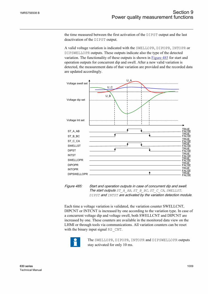
the time measured between the first activation of the DIPST output and the lastdeactivation of the DIPST output.
A valid voltage variation is indicated with the SWELLOPR, DIPOPR, INTOPR orDIPSWELLOPR outputs. These outputs indicate also the type of the detectedvariation. The functionality of these outputs is shown in Figure 485 for start andoperation outputs for concurrent dip and swell. After a new valid variation isdetected, the measurement data of that variation are provided and the recorded dataare updated accordingly.
U_A
U_C
U_B
ST_B_BCST_C_CA
ST_A_AB
DIPSTINTST
SWELLST
SWELLOPR
INTOPRDIPSWELLOPR
DIPOPR
Voltage Int set
Voltage dip set
Voltage swell set
FALSETRUE FALSETRUE
FALSETRUE
FALSETRUE FALSETRUE
FALSETRUE
FALSETRUE FALSETRUE
FALSETRUE
FALSETRUE
GUID-C415DC17-E9D5-4995-99B6-A020B678EC09 V1 EN
Figure 485: Start and operation outputs in case of concurrent dip and swell.The start outputs ST_A_AB, ST_B_BC, ST_C_CA, SWELLST.DIPST and INTST are activated by the variation detection module.
Each time a voltage variation is validated, the variation counter SWELLCNT,DIPCNT or INTCNT is increased by one according to the variation type. In case ofa concurrent voltage dip and voltage swell, both SWELLCNT and DIPCNT areincreased by one. These counters are available in the monitored data view on theLHMI or through tools via communications. All variation counters can be resetwith the binary input signal RS_CNT.
The SWELLOPR, DIPOPR, INTOPR and DIPSWELLOPR outputsstay activated for only 10 ms.
1MRS756508 B Section 9Power quality measurement functions
630 series 1009Technical Manual
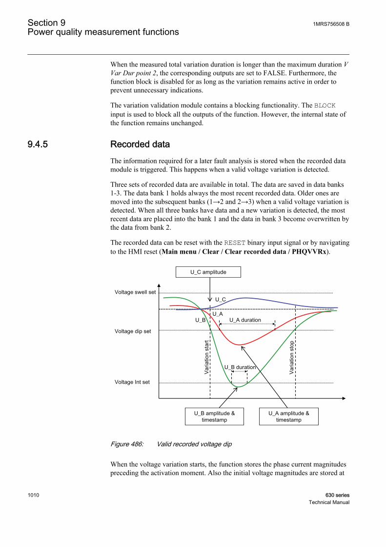
When the measured total variation duration is longer than the maximum duration VVar Dur point 2, the corresponding outputs are set to FALSE. Furthermore, thefunction block is disabled for as long as the variation remains active in order toprevent unnecessary indications.
The variation validation module contains a blocking functionality. The BLOCKinput is used to block all the outputs of the function. However, the internal state ofthe function remains unchanged.
9.4.5 Recorded dataThe information required for a later fault analysis is stored when the recorded datamodule is triggered. This happens when a valid voltage variation is detected.
Three sets of recorded data are available in total. The data are saved in data banks1-3. The data bank 1 holds always the most recent recorded data. Older ones aremoved into the subsequent banks (1→2 and 2→3) when a valid voltage variation isdetected. When all three banks have data and a new variation is detected, the mostrecent data are placed into the bank 1 and the data in bank 3 become overwritten bythe data from bank 2.
The recorded data can be reset with the RESET binary input signal or by navigatingto the HMI reset (Main menu / Clear / Clear recorded data / PHQVVRx).
U_A
U_C
U_B U_A duration
U_B duration
U_B amplitude & timestamp
U_A amplitude & timestamp
U_C amplitude
Voltage Int set
Voltage dip set
Voltage swell set
Varia
tion
star
t
Varia
tion
stop
GUID-C8AD5D24-038C-4274-97A0-7E2982241E57 V1 EN
Figure 486: Valid recorded voltage dip
When the voltage variation starts, the function stores the phase current magnitudespreceding the activation moment. Also the initial voltage magnitudes are stored at
Section 9 1MRS756508 BPower quality measurement functions
1010 630 seriesTechnical Manual
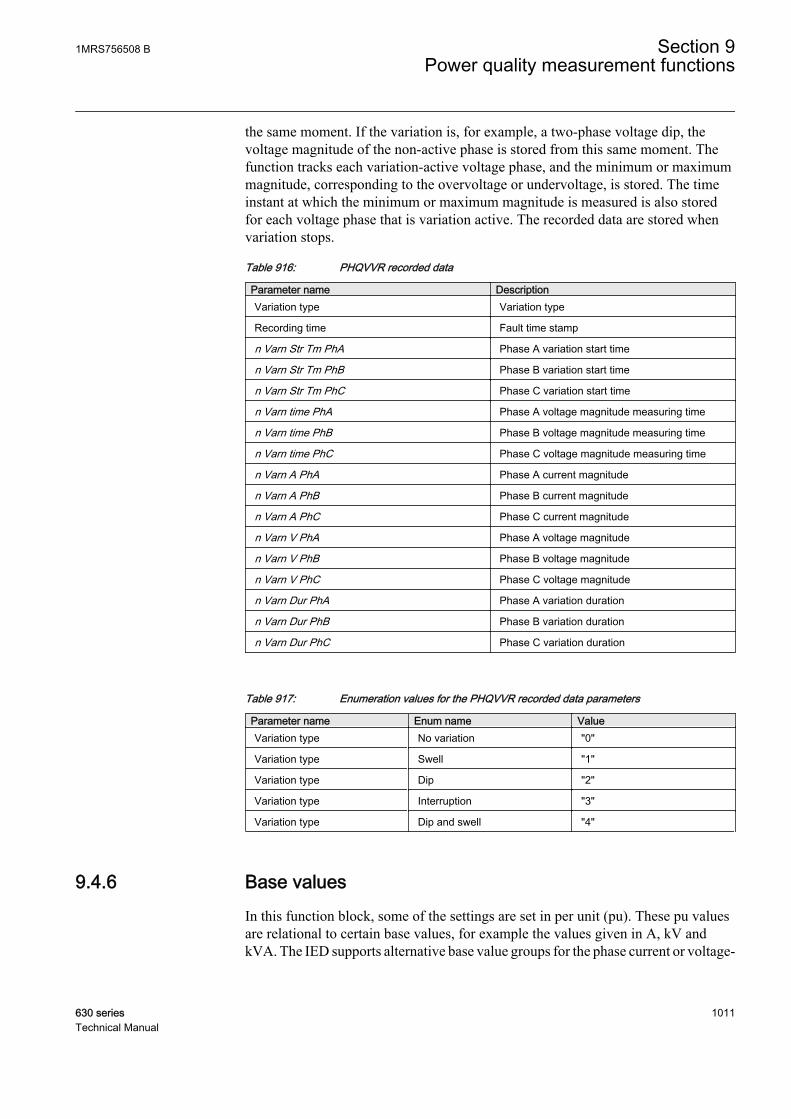
the same moment. If the variation is, for example, a two-phase voltage dip, thevoltage magnitude of the non-active phase is stored from this same moment. Thefunction tracks each variation-active voltage phase, and the minimum or maximummagnitude, corresponding to the overvoltage or undervoltage, is stored. The timeinstant at which the minimum or maximum magnitude is measured is also storedfor each voltage phase that is variation active. The recorded data are stored whenvariation stops.
Table 916: PHQVVR recorded data
Parameter name DescriptionVariation type Variation type
Recording time Fault time stamp
n Varn Str Tm PhA Phase A variation start time
n Varn Str Tm PhB Phase B variation start time
n Varn Str Tm PhC Phase C variation start time
n Varn time PhA Phase A voltage magnitude measuring time
n Varn time PhB Phase B voltage magnitude measuring time
n Varn time PhC Phase C voltage magnitude measuring time
n Varn A PhA Phase A current magnitude
n Varn A PhB Phase B current magnitude
n Varn A PhC Phase C current magnitude
n Varn V PhA Phase A voltage magnitude
n Varn V PhB Phase B voltage magnitude
n Varn V PhC Phase C voltage magnitude
n Varn Dur PhA Phase A variation duration
n Varn Dur PhB Phase B variation duration
n Varn Dur PhC Phase C variation duration
Table 917: Enumeration values for the PHQVVR recorded data parameters
Parameter name Enum name ValueVariation type No variation "0"
Variation type Swell "1"
Variation type Dip "2"
Variation type Interruption "3"
Variation type Dip and swell "4"
9.4.6 Base valuesIn this function block, some of the settings are set in per unit (pu). These pu valuesare relational to certain base values, for example the values given in A, kV andkVA. The IED supports alternative base value groups for the phase current or voltage-
1MRS756508 B Section 9Power quality measurement functions
630 series 1011Technical Manual
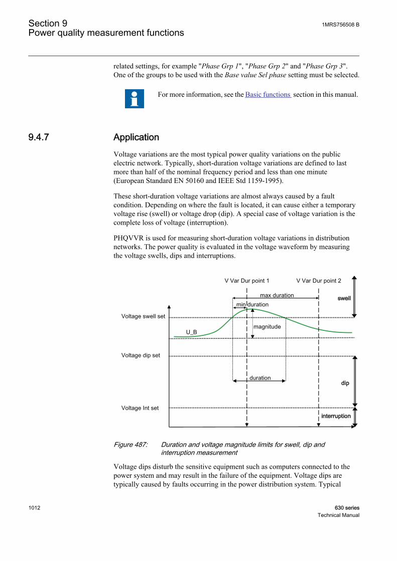
related settings, for example "Phase Grp 1", "Phase Grp 2" and "Phase Grp 3".One of the groups to be used with the Base value Sel phase setting must be selected.
For more information, see the Basic functions section in this manual.
9.4.7 ApplicationVoltage variations are the most typical power quality variations on the publicelectric network. Typically, short-duration voltage variations are defined to lastmore than half of the nominal frequency period and less than one minute(European Standard EN 50160 and IEEE Std 1159-1995).
These short-duration voltage variations are almost always caused by a faultcondition. Depending on where the fault is located, it can cause either a temporaryvoltage rise (swell) or voltage drop (dip). A special case of voltage variation is thecomplete loss of voltage (interruption).
PHQVVR is used for measuring short-duration voltage variations in distributionnetworks. The power quality is evaluated in the voltage waveform by measuringthe voltage swells, dips and interruptions.
U_B
interruption
dip
swell
duration
max duration
magnitude
Voltage Int set
Voltage dip set
Voltage swell set
V Var Dur point 1 V Var Dur point 2
min duration
GUID-EF7957CE-E6EF-483E-A879-ABD003AC1AF9 V1 EN
Figure 487: Duration and voltage magnitude limits for swell, dip andinterruption measurement
Voltage dips disturb the sensitive equipment such as computers connected to thepower system and may result in the failure of the equipment. Voltage dips aretypically caused by faults occurring in the power distribution system. Typical
Section 9 1MRS756508 BPower quality measurement functions
1012 630 seriesTechnical Manual
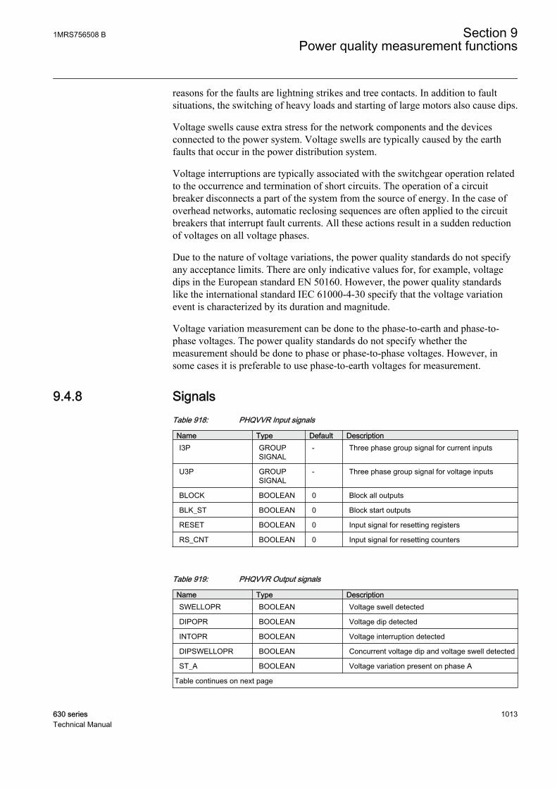
reasons for the faults are lightning strikes and tree contacts. In addition to faultsituations, the switching of heavy loads and starting of large motors also cause dips.
Voltage swells cause extra stress for the network components and the devicesconnected to the power system. Voltage swells are typically caused by the earthfaults that occur in the power distribution system.
Voltage interruptions are typically associated with the switchgear operation relatedto the occurrence and termination of short circuits. The operation of a circuitbreaker disconnects a part of the system from the source of energy. In the case ofoverhead networks, automatic reclosing sequences are often applied to the circuitbreakers that interrupt fault currents. All these actions result in a sudden reductionof voltages on all voltage phases.
Due to the nature of voltage variations, the power quality standards do not specifyany acceptance limits. There are only indicative values for, for example, voltagedips in the European standard EN 50160. However, the power quality standardslike the international standard IEC 61000-4-30 specify that the voltage variationevent is characterized by its duration and magnitude.
Voltage variation measurement can be done to the phase-to-earth and phase-to-phase voltages. The power quality standards do not specify whether themeasurement should be done to phase or phase-to-phase voltages. However, insome cases it is preferable to use phase-to-earth voltages for measurement.
9.4.8 SignalsTable 918: PHQVVR Input signals
Name Type Default DescriptionI3P GROUP
SIGNAL- Three phase group signal for current inputs
U3P GROUPSIGNAL
- Three phase group signal for voltage inputs
BLOCK BOOLEAN 0 Block all outputs
BLK_ST BOOLEAN 0 Block start outputs
RESET BOOLEAN 0 Input signal for resetting registers
RS_CNT BOOLEAN 0 Input signal for resetting counters
Table 919: PHQVVR Output signals
Name Type DescriptionSWELLOPR BOOLEAN Voltage swell detected
DIPOPR BOOLEAN Voltage dip detected
INTOPR BOOLEAN Voltage interruption detected
DIPSWELLOPR BOOLEAN Concurrent voltage dip and voltage swell detected
ST_A BOOLEAN Voltage variation present on phase A
Table continues on next page
1MRS756508 B Section 9Power quality measurement functions
630 series 1013Technical Manual
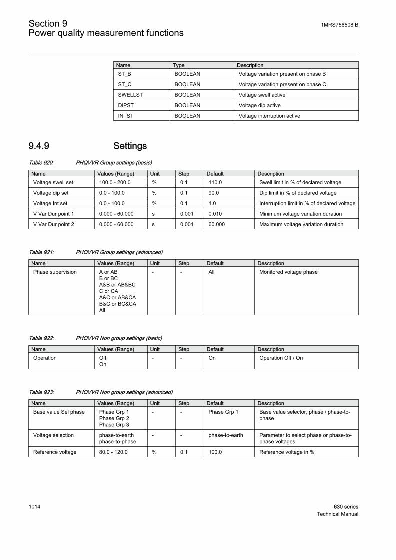
Name Type DescriptionST_B BOOLEAN Voltage variation present on phase B
ST_C BOOLEAN Voltage variation present on phase C
SWELLST BOOLEAN Voltage swell active
DIPST BOOLEAN Voltage dip active
INTST BOOLEAN Voltage interruption active
9.4.9 SettingsTable 920: PHQVVR Group settings (basic)
Name Values (Range) Unit Step Default DescriptionVoltage swell set 100.0 - 200.0 % 0.1 110.0 Swell limit in % of declared voltage
Voltage dip set 0.0 - 100.0 % 0.1 90.0 Dip limit in % of declared voltage
Voltage Int set 0.0 - 100.0 % 0.1 1.0 Interruption limit in % of declared voltage
V Var Dur point 1 0.000 - 60.000 s 0.001 0.010 Minimum voltage variation duration
V Var Dur point 2 0.000 - 60.000 s 0.001 60.000 Maximum voltage variation duration
Table 921: PHQVVR Group settings (advanced)
Name Values (Range) Unit Step Default DescriptionPhase supervision A or AB
B or BCA&B or AB&BCC or CAA&C or AB&CAB&C or BC&CAAll
- - All Monitored voltage phase
Table 922: PHQVVR Non group settings (basic)
Name Values (Range) Unit Step Default DescriptionOperation Off
On- - On Operation Off / On
Table 923: PHQVVR Non group settings (advanced)
Name Values (Range) Unit Step Default DescriptionBase value Sel phase Phase Grp 1
Phase Grp 2Phase Grp 3
- - Phase Grp 1 Base value selector, phase / phase-to-phase
Voltage selection phase-to-earthphase-to-phase
- - phase-to-earth Parameter to select phase or phase-to-phase voltages
Reference voltage 80.0 - 120.0 % 0.1 100.0 Reference voltage in %
Section 9 1MRS756508 BPower quality measurement functions
1014 630 seriesTechnical Manual
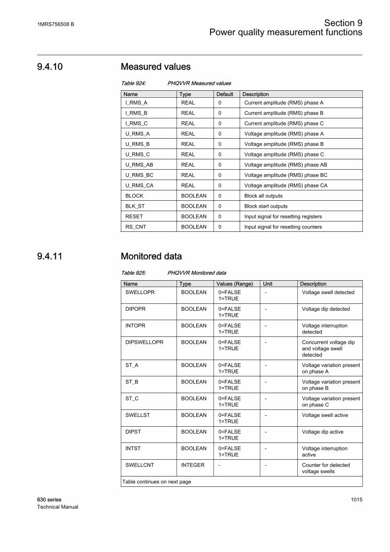
9.4.10 Measured valuesTable 924: PHQVVR Measured values
Name Type Default DescriptionI_RMS_A REAL 0 Current amplitude (RMS) phase A
I_RMS_B REAL 0 Current amplitude (RMS) phase B
I_RMS_C REAL 0 Current amplitude (RMS) phase C
U_RMS_A REAL 0 Voltage amplitude (RMS) phase A
U_RMS_B REAL 0 Voltage amplitude (RMS) phase B
U_RMS_C REAL 0 Voltage amplitude (RMS) phase C
U_RMS_AB REAL 0 Voltage amplitude (RMS) phase AB
U_RMS_BC REAL 0 Voltage amplitude (RMS) phase BC
U_RMS_CA REAL 0 Voltage amplitude (RMS) phase CA
BLOCK BOOLEAN 0 Block all outputs
BLK_ST BOOLEAN 0 Block start outputs
RESET BOOLEAN 0 Input signal for resetting registers
RS_CNT BOOLEAN 0 Input signal for resetting counters
9.4.11 Monitored dataTable 925: PHQVVR Monitored data
Name Type Values (Range) Unit DescriptionSWELLOPR BOOLEAN 0=FALSE
1=TRUE- Voltage swell detected
DIPOPR BOOLEAN 0=FALSE1=TRUE
- Voltage dip detected
INTOPR BOOLEAN 0=FALSE1=TRUE
- Voltage interruptiondetected
DIPSWELLOPR BOOLEAN 0=FALSE1=TRUE
- Concurrent voltage dipand voltage swelldetected
ST_A BOOLEAN 0=FALSE1=TRUE
- Voltage variation presenton phase A
ST_B BOOLEAN 0=FALSE1=TRUE
- Voltage variation presenton phase B
ST_C BOOLEAN 0=FALSE1=TRUE
- Voltage variation presenton phase C
SWELLST BOOLEAN 0=FALSE1=TRUE
- Voltage swell active
DIPST BOOLEAN 0=FALSE1=TRUE
- Voltage dip active
INTST BOOLEAN 0=FALSE1=TRUE
- Voltage interruptionactive
SWELLCNT INTEGER - - Counter for detectedvoltage swells
Table continues on next page
1MRS756508 B Section 9Power quality measurement functions
630 series 1015Technical Manual

Name Type Values (Range) Unit DescriptionDIPCNT INTEGER - - Counter for detected
voltage dips
INTCNT INTEGER - - Counter for detectedvoltage interruptions
1 Variation type INTEGER 0=No variation1=Swell2=Dip3=Interruption4=Dip and swell
- Record data of bank 1for variation type
1 Recording time INTEGER - - Record data of bank 1for fault time stamp
1 Varn Str Tm PhA INTEGER - - Record data of bank 1for phase A variationstart time
1 Varn Str Tm PhB INTEGER - - Record data of bank 1for phase B variationstart time
1 Varn Str Tm PhC INTEGER - - Record data of bank 1for phase C variationstart time
1 Varn time PhA INTEGER - - Record data of bank 1for phase A voltagemagnitude meas time
1 Varn time PhB INTEGER - - Record data of bank 1for phase B voltagemagnitude meas time
1 Varn time PhC INTEGER - - Record data of bank 1for phase C voltagemagnitude meas time
1 Varn A PhA REAL - % Record data of bank 1for phase A currentmagnitude
1 Varn A PhB REAL - % Record data of bank 1for phase B currentmagnitude
1 Varn A PhC REAL - % Record data of bank 1for phase C currentmagnitude
1 Varn V PhA REAL - % Record data of bank 1for phase A voltagemagnitude
1 Varn V PhB REAL - % Record data of bank 1for phase B voltagemagnitude
1 Varn V PhC REAL - % Record data of bank 1for phase C voltagemagnitude
1 Varn Dur PhA REAL - ms Record data of bank 1for phase A variationduration
1 Varn Dur PhB REAL - ms Record data of bank 1for phase B variationduration
Table continues on next page
Section 9 1MRS756508 BPower quality measurement functions
1016 630 seriesTechnical Manual
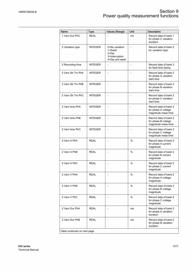
Name Type Values (Range) Unit Description1 Varn Dur PhC REAL - ms Record data of bank 1
for phase C variationduration
2 Variation type INTEGER 0=No variation1=Swell2=Dip3=Interruption4=Dip and swell
- Record data of bank 2for variation type
2 Recording time INTEGER - - Record data of bank 2for fault time stamp
2 Varn Str Tm PhA INTEGER - - Record data of bank 2for phase A variationstart time
2 Varn Str Tm PhB INTEGER - - Record data of bank 2for phase B variationstart time
2 Varn Str Tm PhC INTEGER - - Record data of bank 2for phase C variationstart time
2 Varn time PhA INTEGER - - Record data of bank 2for phase A voltagemagnitude meas time
2 Varn time PhB INTEGER - - Record data of bank 2for phase B voltagemagnitude meas time
2 Varn time PhC INTEGER - - Record data of bank 2for phase C voltagemagnitude meas time
2 Varn A PhA REAL - % Record data of bank 2for phase A currentmagnitude
2 Varn A PhB REAL - % Record data of bank 2for phase B currentmagnitude
2 Varn A PhC REAL - % Record data of bank 2for phase C currentmagnitude
2 Varn V PhA REAL - % Record data of bank 2for phase A voltagemagnitude
2 Varn V PhB REAL - % Record data of bank 2for phase B voltagemagnitude
2 Varn V PhC REAL - % Record data of bank 2for phase C voltagemagnitude
2 Varn Dur PhA REAL - ms Record data of bank 2for phase A variationduration
2 Varn Dur PhB REAL - ms Record data of bank 2for phase B variationduration
Table continues on next page
1MRS756508 B Section 9Power quality measurement functions
630 series 1017Technical Manual

Name Type Values (Range) Unit Description2 Varn Dur PhC REAL - ms Record data of bank 2
for phase C variationduration
3 Variation type INTEGER 0=No variation1=Swell2=Dip3=Interruption4=Dip and swell
- Record data of bank 3for variation type
3 Recording time INTEGER - - Record data of bank 3for fault time stamp
3 Varn Str Tm PhA INTEGER - - Record data of bank 3for phase A variationstart time
3 Varn Str Tm PhB INTEGER - - Record data of bank 3for phase B variationstart time
3 Varn Str Tm PhC INTEGER - - Record data of bank 3for phase C variationstart time
3 Varn time PhA INTEGER - - Record data of bank 3for phase A voltagemagnitude meas time
3 Varn time PhB INTEGER - - Record data of bank 3for phase B voltagemagnitude meas time
3 Varn time PhC INTEGER - - Record data of bank 3for phase C voltagemagnitude meas time
3 Varn A PhA REAL - % Record data of bank 3for phase A currentmagnitude
3 Varn A PhB REAL - % Record data of bank 3for phase B currentmagnitude
3 Varn A PhC REAL - % Record data of bank 3for phase C currentmagnitude
3 Varn V PhA REAL - % Record data of bank 3for phase A voltagemagnitude
3 Varn V PhB REAL - % Record data of bank 3for phase B voltagemagnitude
3 Varn V PhC REAL - % Record data of bank 3for phase C voltagemagnitude
Table continues on next page
Section 9 1MRS756508 BPower quality measurement functions
1018 630 seriesTechnical Manual
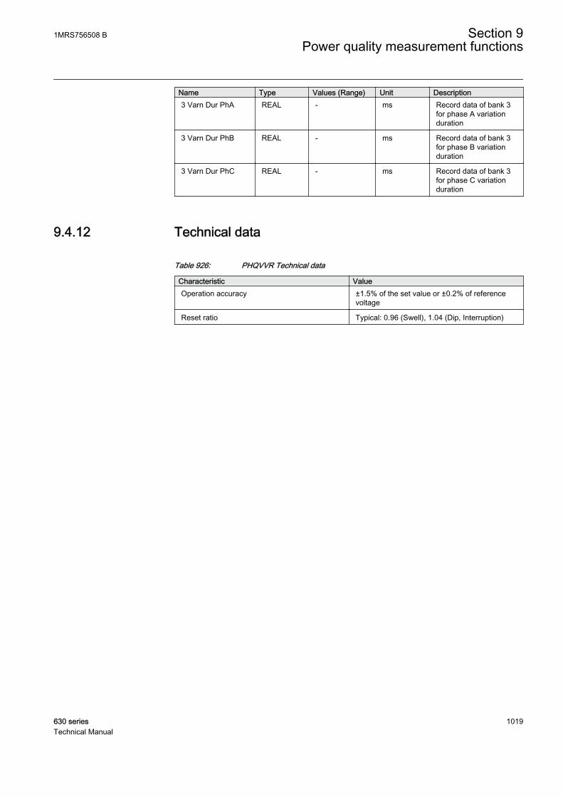
Name Type Values (Range) Unit Description3 Varn Dur PhA REAL - ms Record data of bank 3
for phase A variationduration
3 Varn Dur PhB REAL - ms Record data of bank 3for phase B variationduration
3 Varn Dur PhC REAL - ms Record data of bank 3for phase C variationduration
9.4.12 Technical data
Table 926: PHQVVR Technical data
Characteristic ValueOperation accuracy ±1.5% of the set value or ±0.2% of reference
voltage
Reset ratio Typical: 0.96 (Swell), 1.04 (Dip, Interruption)
1MRS756508 B Section 9Power quality measurement functions
630 series 1019Technical Manual

1020

Section 10 Control functions
10.1 Apparatus control
10.1.1 IntroductionThe apparatus control is a combination of functions which continuously superviseand control the circuit breakers, disconnectors and earthing switches within a bay.The permission to operate an apparatus is given after the evaluation of otherfunctions' conditions such as interlocking, synchrocheck, operator place selectionand the external or internal blockings.
10.1.2 ApplicationThe apparatus control is a combination of functions which continuously superviseand control the circuit breakers, disconnectors and earthing switches within a bay.The permission to operate an apparatus is given after the evaluation of otherfunctions' conditions, such as interlocking, synchrocheck, operator place selectionand external or internal blockings.
The commands to an apparatus can be initiated from the Control Center (CC), thestation HMI or the local HMI on the IED front.
GUID-7A0B6A4F-08C3-4619-ABF8-866F8FC23F85 V1 EN
Figure 488: Apparatus control function
1MRS756508 B Section 10Control functions
630 series 1021Technical Manual

The features in the apparatus control function are:
• Operation of primary apparatuses• Select-Execute principle to give a high reliability• Selection and reservation function to prevent simultaneous operation• Selection and supervision of operator place• Command supervision• Block/deblock of operation• Block/deblock of the updating of position indications• Substitution of position indications• Overriding of interlocking functions• Overriding of synchrocheck• Operation counter
The apparatus control is realized with a number of function blocks designated:
• LocalRemote switch function (LOCREM)• Bay control function (QCCBAY)• Switch controller function (GNRLCSWI)• Circuit breaker function (DAXCBR)• Circuit switch function (DAXSWI)
The last three functions are logical nodes according to IEC 61850. The signal flowbetween these function blocks is as shown in Figure 489. The applicationdescription for these functions can be found below. SCILO is the logical node forinterlocking.
The control operation can be performed from the LHMI. If the administrator hasdefined users with the User Manager Tool (UTM), the local/remote switch is underauthority control. If not, the default, that is, the factory user, is the SuperUser, whocan perform control operations from the LHMI without LogOn. The defaultposition of the local/remote switch is on remote.
Section 10 1MRS756508 BControl functions
1022 630 seriesTechnical Manual
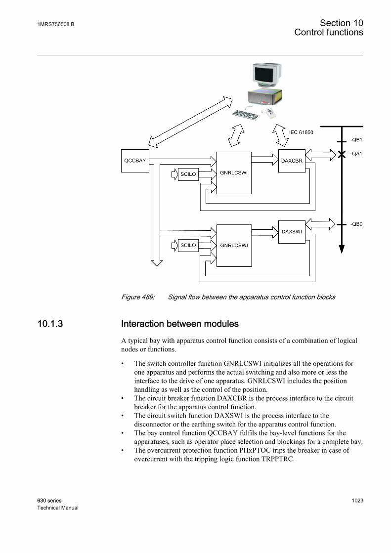
GUID-65876561-511D-4620-BA05-05ED673E2F72 V1 EN
Figure 489: Signal flow between the apparatus control function blocks
10.1.3 Interaction between modulesA typical bay with apparatus control function consists of a combination of logicalnodes or functions.
• The switch controller function GNRLCSWI initializes all the operations forone apparatus and performs the actual switching and also more or less theinterface to the drive of one apparatus. GNRLCSWI includes the positionhandling as well as the control of the position.
• The circuit breaker function DAXCBR is the process interface to the circuitbreaker for the apparatus control function.
• The circuit switch function DAXSWI is the process interface to thedisconnector or the earthing switch for the apparatus control function.
• The bay control function QCCBAY fulfils the bay-level functions for theapparatuses, such as operator place selection and blockings for a complete bay.
• The overcurrent protection function PHxPTOC trips the breaker in case ofovercurrent with the tripping logic function TRPPTRC.
1MRS756508 B Section 10Control functions
630 series 1023Technical Manual

• The autoreclosing function DARREC consists of the facilities to automaticallyclose a tripped breaker with respect to a number of configurable conditions.
• The logical node SCILO provides the information to GNRLCSWI if SCILO ispermitted to operate due to the switchyard topology. The interlockingconditions are evaluated with a separate logic and connected to SCILO.
• The synchronism-check function SYNCRSYN calculates the voltage phasordifference from both sides of an open breaker and compares it to predefinedswitching conditions (synchrocheck). Also the case that one side is dead(energizing-check) is included.
Section 10 1MRS756508 BControl functions
1024 630 seriesTechnical Manual
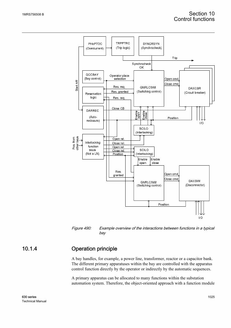
GUID-3EA2929A-B765-4F6B-A056-1CD01CEE832D V1 EN
Figure 490: Example overview of the interactions between functions in a typicalbay
10.1.4 Operation principleA bay handles, for example, a power line, transformer, reactor or a capacitor bank.The different primary apparatuses within the bay are controlled with the apparatuscontrol function directly by the operator or indirectly by the automatic sequences.
A primary apparatus can be allocated to many functions within the substationautomation system. Therefore, the object-oriented approach with a function module
1MRS756508 B Section 10Control functions
630 series 1025Technical Manual
that handles the interaction and status of each process object ensures consistency inthe process information used by higher-level control functions.
The primary apparatuses such as breakers, disconnectors and earthing switch arecontrolled and supervised by the switch controller function GNRLCSWI. Thenumber and type of signals connected to a breaker, disconnector and earthingswitch are almost the same. The function module used to handle all three types ofapparatuses is also same.
The module is connected to the physical process in the switchyard through aninterface module with a number of digital inputs and outputs. The circuit breakerfunction DAXCBR acts as an interface module for circuit breaker, and the earthingswitch function DAXSWI acts as an interface module for disconnectors andearthing switch. There are four types of function blocks available to cover most ofthe control and supervision within the bay. These function blocks areinterconnected to form a control function reflecting the switchyard configuration.The total number of these functions to be used depends on the number ofapparatuses to be controlled.
The function block LocalRemote used to handle the local/remote switch alsobelongs to the control function.
10.1.5 Local/remote switch LOCREM
10.1.5.1 Identification
Function description IEC 61850identification
IEC 60617identification
ANSI/IEEE C37.2device number
Local/Remote switch control function LOCREM R/L R/L
10.1.5.2 Function block
GUID-F8DC8400-B050-4387-B273-326EFC4BFDDA V1 EN
Figure 491: Function block
10.1.5.3 Functionality
The signals from an external local/remote switch are applied with the local remoteswitch function LOCREM to the bay control function QCCBAY. The value of theControl mode setting is set to select if the switch signals are coming from the localHMI or from an external local/remote switch connected with the binary inputs.
Section 10 1MRS756508 BControl functions
1026 630 seriesTechnical Manual
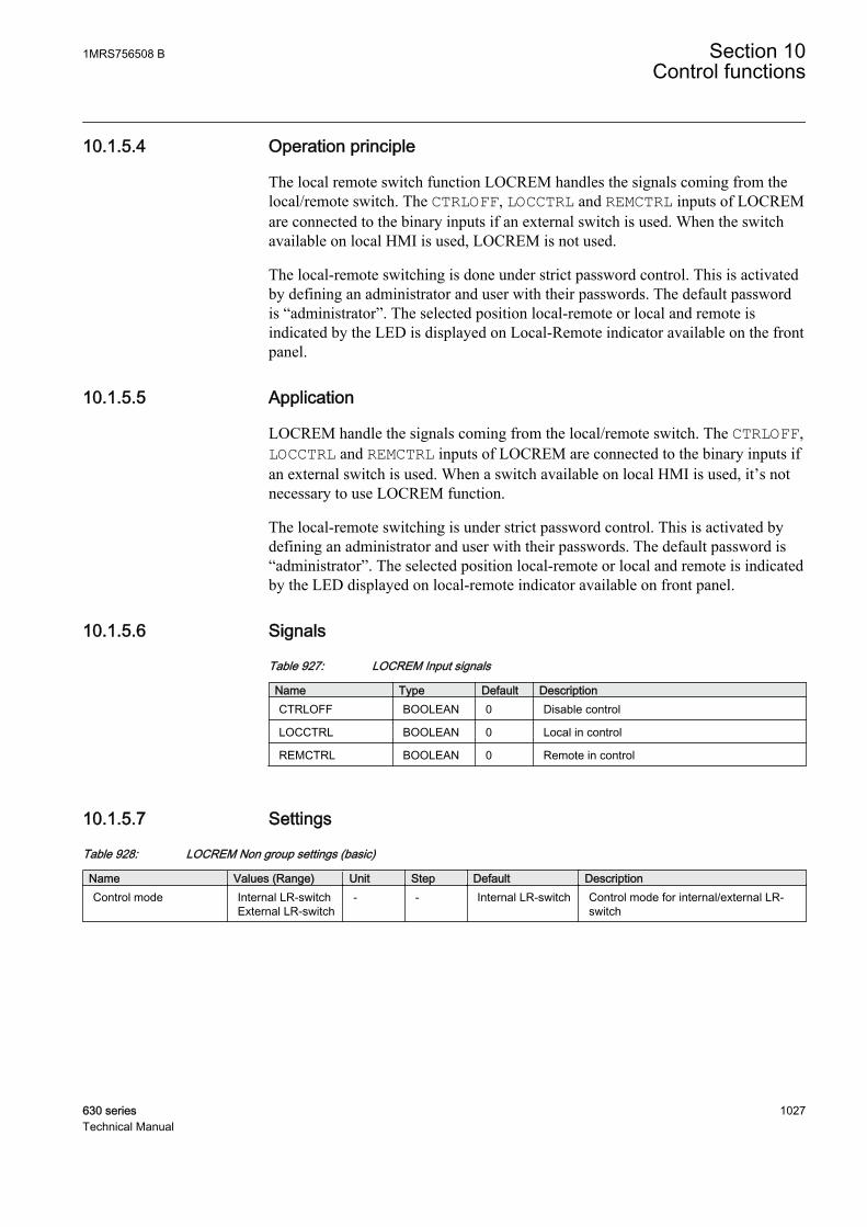
10.1.5.4 Operation principle
The local remote switch function LOCREM handles the signals coming from thelocal/remote switch. The CTRLOFF, LOCCTRL and REMCTRL inputs of LOCREMare connected to the binary inputs if an external switch is used. When the switchavailable on local HMI is used, LOCREM is not used.
The local-remote switching is done under strict password control. This is activatedby defining an administrator and user with their passwords. The default passwordis “administrator”. The selected position local-remote or local and remote isindicated by the LED is displayed on Local-Remote indicator available on the frontpanel.
10.1.5.5 Application
LOCREM handle the signals coming from the local/remote switch. The CTRLOFF,LOCCTRL and REMCTRL inputs of LOCREM are connected to the binary inputs ifan external switch is used. When a switch available on local HMI is used, it’s notnecessary to use LOCREM function.
The local-remote switching is under strict password control. This is activated bydefining an administrator and user with their passwords. The default password is“administrator”. The selected position local-remote or local and remote is indicatedby the LED displayed on local-remote indicator available on front panel.
10.1.5.6 Signals
Table 927: LOCREM Input signals
Name Type Default DescriptionCTRLOFF BOOLEAN 0 Disable control
LOCCTRL BOOLEAN 0 Local in control
REMCTRL BOOLEAN 0 Remote in control
10.1.5.7 Settings
Table 928: LOCREM Non group settings (basic)
Name Values (Range) Unit Step Default DescriptionControl mode Internal LR-switch
External LR-switch- - Internal LR-switch Control mode for internal/external LR-
switch
1MRS756508 B Section 10Control functions
630 series 1027Technical Manual
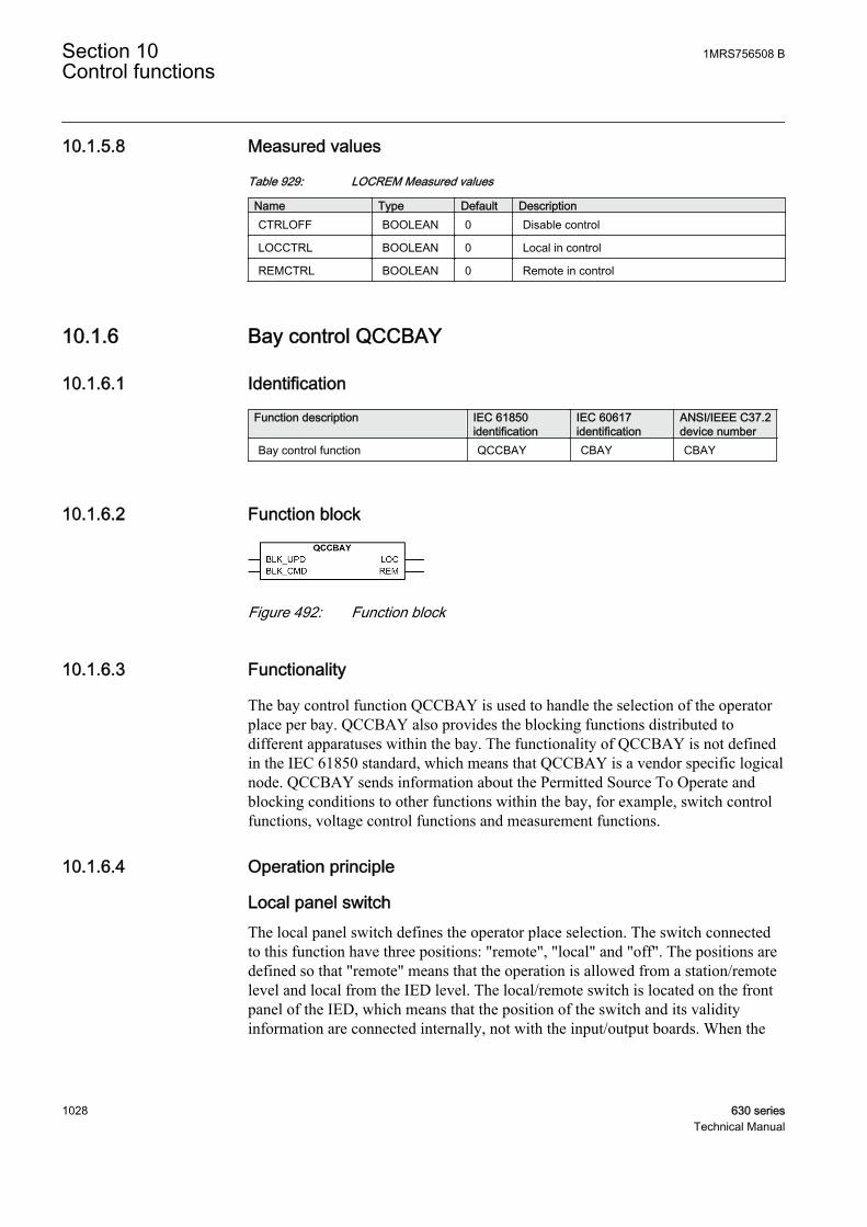
10.1.5.8 Measured values
Table 929: LOCREM Measured values
Name Type Default DescriptionCTRLOFF BOOLEAN 0 Disable control
LOCCTRL BOOLEAN 0 Local in control
REMCTRL BOOLEAN 0 Remote in control
10.1.6 Bay control QCCBAY
10.1.6.1 Identification
Function description IEC 61850identification
IEC 60617identification
ANSI/IEEE C37.2device number
Bay control function QCCBAY CBAY CBAY
10.1.6.2 Function block
GUID-95381B17-6BB5-4E0F-A61A-90E7BB2F94AD V1 EN
Figure 492: Function block
10.1.6.3 Functionality
The bay control function QCCBAY is used to handle the selection of the operatorplace per bay. QCCBAY also provides the blocking functions distributed todifferent apparatuses within the bay. The functionality of QCCBAY is not definedin the IEC 61850 standard, which means that QCCBAY is a vendor specific logicalnode. QCCBAY sends information about the Permitted Source To Operate andblocking conditions to other functions within the bay, for example, switch controlfunctions, voltage control functions and measurement functions.
10.1.6.4 Operation principle
Local panel switchThe local panel switch defines the operator place selection. The switch connectedto this function have three positions: "remote", "local" and "off". The positions aredefined so that "remote" means that the operation is allowed from a station/remotelevel and local from the IED level. The local/remote switch is located on the frontpanel of the IED, which means that the position of the switch and its validityinformation are connected internally, not with the input/output boards. When the
Section 10 1MRS756508 BControl functions
1028 630 seriesTechnical Manual
switch is mounted separately on the IED, the signals are connected to the functionwith the input/output boards.
When the local panel switch is in the "Off" position, all commands from the remoteand local level are ignored.
To adapt the signals from an external local/remote switch, the local remote switchfunction LOCREM is needed.
Permitted Source To Operate PSTOThe actual state of the operator place is presented with the value of the LR_POSoutput signal. The LR_POS output value is evaluated from the local/remote switchposition. When the external panel switch is in the "Off" position, the LR_POSoutput value is set to 0. In this case, it is not possible to control anything. Thepermitted source to operate information is internally delivered to the functions thatdepend on it (GNRLCSWI and LSHDPFRQ).
BlockingsThe blockings state the position indications and commands that are intend toprovide the possibility for the user to make common blockings for the functionsconfigured within a complete bay.
The blocking facilities provided by the bay control function are:
• Blocking of position indications: The activation of the BLK_UPD input blocksall the inputs related to apparatus positions for all configured functions withinthe bay.
• Blocking of commands: The activation of the BLK_CMD input blocks all thecommands for all configured functions within the bay.
10.1.6.5 Application
QCCBAY is used to handle the selection of the operator place per bay. QCCBAYgives permission to operate from two types of locations either from remote, forexample, control center or station HMI or from local, for example, the local HMIon the IED. The Local/Remote switch position can also be set to Off, which meansno operator place selected, resulting into a no operation from local or remote.
The bay control function QCCBAY also provides blocking functions that can bedistributed to different apparatuses within the bay. There are two different blockingalternatives:
• Blocking of update of positions• Blocking of commands
1MRS756508 B Section 10Control functions
630 series 1029Technical Manual
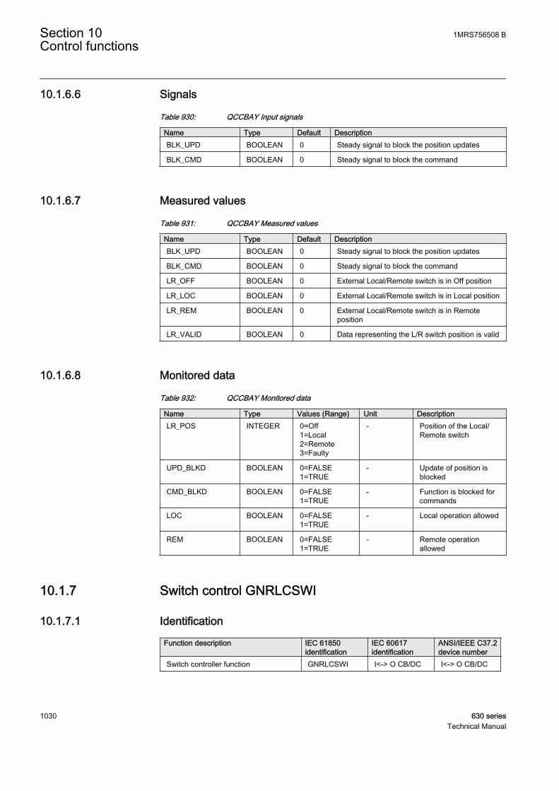
10.1.6.6 Signals
Table 930: QCCBAY Input signals
Name Type Default DescriptionBLK_UPD BOOLEAN 0 Steady signal to block the position updates
BLK_CMD BOOLEAN 0 Steady signal to block the command
10.1.6.7 Measured values
Table 931: QCCBAY Measured values
Name Type Default DescriptionBLK_UPD BOOLEAN 0 Steady signal to block the position updates
BLK_CMD BOOLEAN 0 Steady signal to block the command
LR_OFF BOOLEAN 0 External Local/Remote switch is in Off position
LR_LOC BOOLEAN 0 External Local/Remote switch is in Local position
LR_REM BOOLEAN 0 External Local/Remote switch is in Remoteposition
LR_VALID BOOLEAN 0 Data representing the L/R switch position is valid
10.1.6.8 Monitored data
Table 932: QCCBAY Monitored data
Name Type Values (Range) Unit DescriptionLR_POS INTEGER 0=Off
1=Local2=Remote3=Faulty
- Position of the Local/Remote switch
UPD_BLKD BOOLEAN 0=FALSE1=TRUE
- Update of position isblocked
CMD_BLKD BOOLEAN 0=FALSE1=TRUE
- Function is blocked forcommands
LOC BOOLEAN 0=FALSE1=TRUE
- Local operation allowed
REM BOOLEAN 0=FALSE1=TRUE
- Remote operationallowed
10.1.7 Switch control GNRLCSWI
10.1.7.1 Identification
Function description IEC 61850identification
IEC 60617identification
ANSI/IEEE C37.2device number
Switch controller function GNRLCSWI I<-> O CB/DC I<-> O CB/DC
Section 10 1MRS756508 BControl functions
1030 630 seriesTechnical Manual
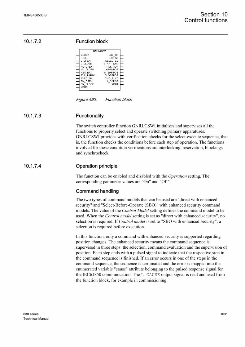
10.1.7.2 Function block
A070361 V1 EN
Figure 493: Function block
10.1.7.3 Functionality
The switch controller function GNRLCSWI initializes and supervises all thefunctions to properly select and operate switching primary apparatuses.GNRLCSWI provides with verification checks for the select-execute sequence, thatis, the function checks the conditions before each step of operation. The functionsinvolved for these condition verifications are interlocking, reservation, blockingsand synchrocheck.
10.1.7.4 Operation principle
The function can be enabled and disabled with the Operation setting. Thecorresponding parameter values are "On" and "Off".
Command handlingThe two types of command models that can be used are "direct with enhancedsecurity" and "Select-Before-Operate (SBO)" with enhanced security commandmodels. The value of the Control Model setting defines the command model to beused. When the Control model setting is set as "direct with enhanced security", noselection is required. If Control model is set to "SBO with enhanced security", aselection is required before execution.
In this function, only a command with enhanced security is supported regardingposition changes. The enhanced security means the command sequence issupervised in three steps: the selection, command evaluation and the supervision ofposition. Each step ends with a pulsed signal to indicate that the respective step inthe command sequence is finished. If an error occurs in one of the steps in thecommand sequence, the sequence is terminated and the error is mapped into theenumerated variable "cause" attribute belonging to the pulsed response signal forthe IEC61850 communication. The L_CAUSE output signal is read and used fromthe function block, for example in commissioning.
1MRS756508 B Section 10Control functions
630 series 1031Technical Manual
There is no relation between the command direction and the actualposition. For example, if the switch is in closed position, it ispossible to execute a closing command.
The evaluation of the position is done before an executing command. If the valueof Pos dependent setting is set to "Not perm 00/11" and the apparatus position is inthe intermediate or bad state, no executing command is sent. If the parameter is"Always permit", the execution command is sent regardless of the position value.
Blocking principlesThe blocking principles are:
• Blocking only commands is possible in several ways:• With the bay control function QCCBAY: The command blocking can be
issued either with the BLK_UPD input or through the IEC61850 DO(Data Object) BlkCmd input in QCCBAY.
• With the IEC61850 DO BlkCmd in GNRLCSWI.• TheBLOCK input signal is used to block the function from DO (Data Object)
Behavior (IEC61850). If DO Beh is set to "blocked", the function is active butno outputs or reports are generated. The control commands are rejected and thefunctional and configuration data is visible. The DO Beh can be set to"blocked" with DO Mod of the LN GNRLCSWI or with DO Mod of LLN0 ofthe logical device (LD) where GNRLCSWI resides.
The different block conditions only affect the operation of thisfunction, no blocking signals are forwarded to the other functions.The blocking outputs are stored in a nonvolatile memory.
Interaction with synchrocheck and synchronizing functionsGNRLCSWI works in conjunction with the synchrocheck and synchronizingfunction SYNCRSYN. It is assumed that the synchrocheck function operatescontinuously and activates the SYNC_OK when all synchronizing conditions aresatisfied to the switch controller GNRLCSWI. The result from the synchrocheckfunction is evaluated during the closing execution. If the synchrocheck isoverridden, the evaluation of the synchrocheck state is omitted. When there is apositive confirmation from the synchrocheck function, the switch controller sendsthe closing signal EXE_CL to the switch function DAXCBR.
When there is no positive confirmation from the synchrocheck function, the switchcontroller sends a start signal START_SYN to the synchronizing function. Thefunction sends a closing command to the switch function when the synchronizingconditions are fulfilled. If no synchronizing function is included, the timer for thesupervision of the synchronizing-in-progress signal is set to 0, which means thesynchronizing function is in the "Off" state. The switch controller sets the attribute"blocked-by-synchrocheck" in the cause signal.
Section 10 1MRS756508 BControl functions
1032 630 seriesTechnical Manual

SynchroCheck
OR
GNRLCSWI DAXCBR
CLOSE
SYNC_OK
EXE_CL
Synchronizing function
.
SYN_INPRO
START_SYN
SYNOK
SYNCRSYN
GUID-2FC9447F-9921-4939-A5B5-AA24931BA5EC V2 EN
Figure 494: Interaction between GNRLCSWI, synchrocheck, synchronizingfunction and DAXCBR
Time diagramsGNRLCSWI uses timers to evaluate different time supervision conditions.
The timer setting Select command time supervises the time between the select andthe execute command signals, that is, the time operator has for performing thecommand execution after selecting the object of operation.
GUID-07559B18-C6BD-4255-8E79-0D7B1DFE3417 V1 EN
Figure 495: Select command time
The timer setting Cmd response time supervises the time between the executecommand and command termination.
1MRS756508 B Section 10Control functions
630 series 1033Technical Manual

GUID-28B00CFF-037F-4A97-B96B-0FDCEB2D5701 V1 EN
Figure 496: Cmd response time
The value of the Synchrocheck time setting defines the maximum allowed timebetween the execute command and the value of the SYNC_OK input to becometrue. The SYNC_OK input is available from synchrocheck function. If theSYNC_OK input is TRUE at the time of receipt of execute command signal, thevalue of the timer setting Synchrocheck time does not start. If SYNC_OK fails toactivate within the value of the Synchrocheck timesetting, the START_SY output isactivated, which in turn starts the synchronizing module of SYNCRSYN. When allthe synchronizing conditions are fulfilled, SYNCRSYN provides a closingcommand. The SYN_INPRO input indicates that the checks for synchronizingconditions are in process. The SYN_INPRO input for GNRLCSWI is connecteddirectly from the SYN_INPRO output of SYNCRSYN function. If SYN_INPROfails to activate within Synchronizing time after the receipt of START_SY, theL_CAUSE output is set to 11 indicating “blocked-by-synchrocheck”.
GUID-E7111BFA-56A8-4413-B91E-421E08547074 V1 EN
Figure 497: Synchrocheck time and Synchronizing time
Opening and Closing CommandThe output command for opening or closing EXE_OP and EXE_CL can beactivated in various ways. The activation of L_SEL and then L_OPEN results inthe EXE_OP output being set to high. Similarly, the activation of L_SEL and thenL_CLOSE results in EXE_CL to activate. Also, the EXE_OP and EXE_CL outputscan be activated by the activation of the automatic opening and closing commandAU_OPEN and AU_CLOSE respectively. In case of an interlocking logic being
Section 10 1MRS756508 BControl functions
1034 630 seriesTechnical Manual
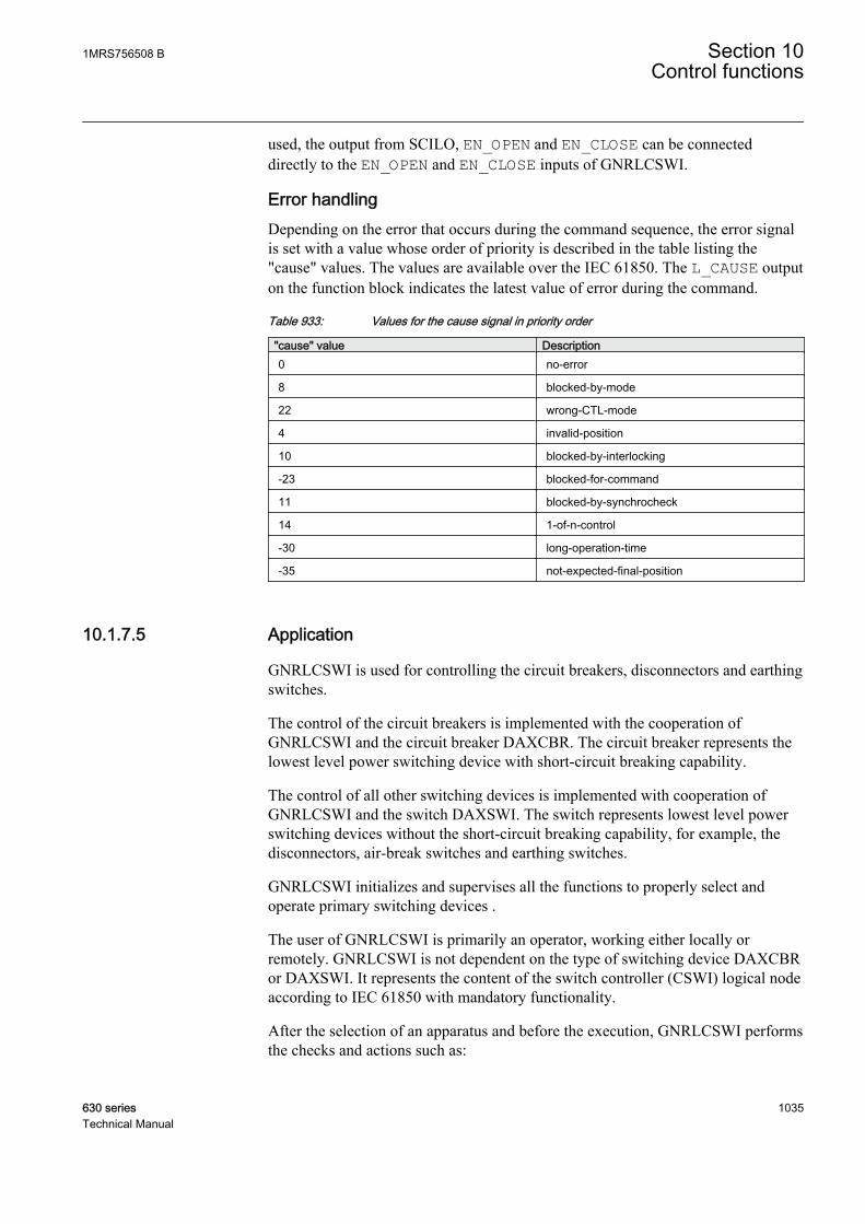
used, the output from SCILO, EN_OPEN and EN_CLOSE can be connecteddirectly to the EN_OPEN and EN_CLOSE inputs of GNRLCSWI.
Error handlingDepending on the error that occurs during the command sequence, the error signalis set with a value whose order of priority is described in the table listing the"cause" values. The values are available over the IEC 61850. The L_CAUSE outputon the function block indicates the latest value of error during the command.
Table 933: Values for the cause signal in priority order
"cause" value Description0 no-error
8 blocked-by-mode
22 wrong-CTL-mode
4 invalid-position
10 blocked-by-interlocking
-23 blocked-for-command
11 blocked-by-synchrocheck
14 1-of-n-control
-30 long-operation-time
-35 not-expected-final-position
10.1.7.5 Application
GNRLCSWI is used for controlling the circuit breakers, disconnectors and earthingswitches.
The control of the circuit breakers is implemented with the cooperation ofGNRLCSWI and the circuit breaker DAXCBR. The circuit breaker represents thelowest level power switching device with short-circuit breaking capability.
The control of all other switching devices is implemented with cooperation ofGNRLCSWI and the switch DAXSWI. The switch represents lowest level powerswitching devices without the short-circuit breaking capability, for example, thedisconnectors, air-break switches and earthing switches.
GNRLCSWI initializes and supervises all the functions to properly select andoperate primary switching devices .
The user of GNRLCSWI is primarily an operator, working either locally orremotely. GNRLCSWI is not dependent on the type of switching device DAXCBRor DAXSWI. It represents the content of the switch controller (CSWI) logical nodeaccording to IEC 61850 with mandatory functionality.
After the selection of an apparatus and before the execution, GNRLCSWI performsthe checks and actions such as:
1MRS756508 B Section 10Control functions
630 series 1035Technical Manual
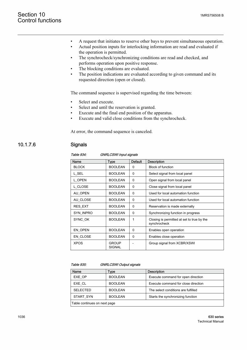
• A request that initiates to reserve other bays to prevent simultaneous operation.• Actual position inputs for interlocking information are read and evaluated if
the operation is permitted.• The synchrocheck/synchronizing conditions are read and checked, and
performs operation upon positive response.• The blocking conditions are evaluated.• The position indications are evaluated according to given command and its
requested direction (open or closed).
The command sequence is supervised regarding the time between:
• Select and execute.• Select and until the reservation is granted.• Execute and the final end position of the apparatus.• Execute and valid close conditions from the synchrocheck.
At error, the command sequence is canceled.
10.1.7.6 Signals
Table 934: GNRLCSWI Input signals
Name Type Default DescriptionBLOCK BOOLEAN 0 Block of function
L_SEL BOOLEAN 0 Select signal from local panel
L_OPEN BOOLEAN 0 Open signal from local panel
L_CLOSE BOOLEAN 0 Close signal from local panel
AU_OPEN BOOLEAN 0 Used for local automation function
AU_CLOSE BOOLEAN 0 Used for local automation function
RES_EXT BOOLEAN 0 Reservation is made externally
SYN_INPRO BOOLEAN 0 Synchronizing function in progress
SYNC_OK BOOLEAN 1 Closing is permitted at set to true by thesynchrocheck
EN_OPEN BOOLEAN 0 Enables open operation
EN_CLOSE BOOLEAN 0 Enables close operation
XPOS GROUPSIGNAL
- Group signal from XCBR/XSWI
Table 935: GNRLCSWI Output signals
Name Type DescriptionEXE_OP BOOLEAN Execute command for open direction
EXE_CL BOOLEAN Execute command for close direction
SELECTED BOOLEAN The select conditions are fulfilled
START_SYN BOOLEAN Starts the synchronizing function
Table continues on next page
Section 10 1MRS756508 BControl functions
1036 630 seriesTechnical Manual
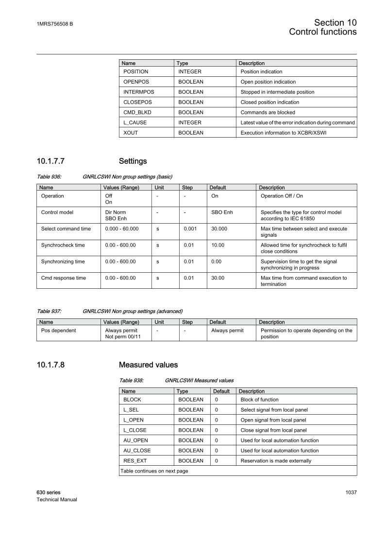
Name Type DescriptionPOSITION INTEGER Position indication
OPENPOS BOOLEAN Open position indication
INTERMPOS BOOLEAN Stopped in intermediate position
CLOSEPOS BOOLEAN Closed position indication
CMD_BLKD BOOLEAN Commands are blocked
L_CAUSE INTEGER Latest value of the error indication during command
XOUT BOOLEAN Execution information to XCBR/XSWI
10.1.7.7 Settings
Table 936: GNRLCSWI Non group settings (basic)
Name Values (Range) Unit Step Default DescriptionOperation Off
On- - On Operation Off / On
Control model Dir NormSBO Enh
- - SBO Enh Specifies the type for control modelaccording to IEC 61850
Select command time 0.000 - 60.000 s 0.001 30.000 Max time between select and executesignals
Synchrocheck time 0.00 - 600.00 s 0.01 10.00 Allowed time for synchrocheck to fulfilclose conditions
Synchronizing time 0.00 - 600.00 s 0.01 0.00 Supervision time to get the signalsynchronizing in progress
Cmd response time 0.00 - 600.00 s 0.01 30.00 Max time from command execution totermination
Table 937: GNRLCSWI Non group settings (advanced)
Name Values (Range) Unit Step Default DescriptionPos dependent Always permit
Not perm 00/11- - Always permit Permission to operate depending on the
position
10.1.7.8 Measured values
Table 938: GNRLCSWI Measured values
Name Type Default DescriptionBLOCK BOOLEAN 0 Block of function
L_SEL BOOLEAN 0 Select signal from local panel
L_OPEN BOOLEAN 0 Open signal from local panel
L_CLOSE BOOLEAN 0 Close signal from local panel
AU_OPEN BOOLEAN 0 Used for local automation function
AU_CLOSE BOOLEAN 0 Used for local automation function
RES_EXT BOOLEAN 0 Reservation is made externally
Table continues on next page
1MRS756508 B Section 10Control functions
630 series 1037Technical Manual

Name Type Default DescriptionSYN_INPRO BOOLEAN 0 Synchronizing function in progress
SYNC_OK BOOLEAN 1 Closing is permitted at set to true by thesynchrocheck
EN_OPEN BOOLEAN 0 Enables open operation
EN_CLOSE BOOLEAN 0 Enables close operation
10.1.7.9 Monitored data
Table 939: GNRLCSWI Monitored data
Name Type Values (Range) Unit DescriptionEXE_OP BOOLEAN 0=FALSE
1=TRUE- Execute command for
open direction
EXE_CL BOOLEAN 0=FALSE1=TRUE
- Execute command forclose direction
SELECTED BOOLEAN 0=FALSE1=TRUE
- The select conditions arefulfilled
START_SYN BOOLEAN 0=FALSE1=TRUE
- Starts the synchronizingfunction
OPENPOS BOOLEAN 0=FALSE1=TRUE
- Open position indication
INTERMPOS BOOLEAN 0=FALSE1=TRUE
- Stopped in intermediateposition
CLOSEPOS BOOLEAN 0=FALSE1=TRUE
- Closed positionindication
CMD_BLKD BOOLEAN 0=FALSE1=TRUE
- Commands are blocked
10.1.8 Circuit breaker DAXCBR
10.1.8.1 Identification
Function description IEC 61850identification
IEC 60617identification
ANSI/IEEE C37.2device number
Circuit breaker controller function DAXCBR I<-> O CB I<->O CB
Section 10 1MRS756508 BControl functions
1038 630 seriesTechnical Manual
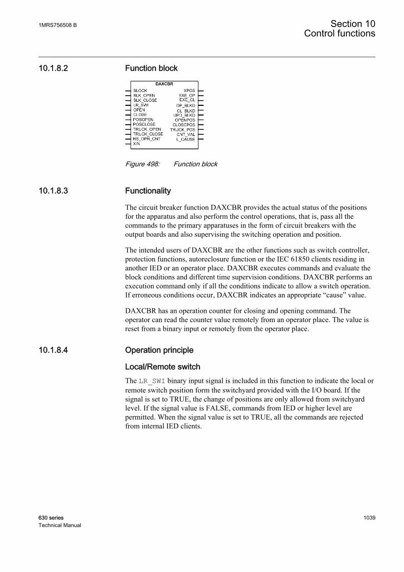
10.1.8.2 Function block
A070364 V1 EN
Figure 498: Function block
10.1.8.3 Functionality
The circuit breaker function DAXCBR provides the actual status of the positionsfor the apparatus and also perform the control operations, that is, pass all thecommands to the primary apparatuses in the form of circuit breakers with theoutput boards and also supervising the switching operation and position.
The intended users of DAXCBR are the other functions such as switch controller,protection functions, autoreclosure function or the IEC 61850 clients residing inanother IED or an operator place. DAXCBR executes commands and evaluate theblock conditions and different time supervision conditions. DAXCBR performs anexecution command only if all the conditions indicate to allow a switch operation.If erroneous conditions occur, DAXCBR indicates an appropriate “cause” value.
DAXCBR has an operation counter for closing and opening command. Theoperator can read the counter value remotely from an operator place. The value isreset from a binary input or remotely from the operator place.
10.1.8.4 Operation principle
Local/Remote switchThe LR_SWI binary input signal is included in this function to indicate the local orremote switch position form the switchyard provided with the I/O board. If thesignal is set to TRUE, the change of positions are only allowed from switchyardlevel. If the signal value is FALSE, commands from IED or higher level arepermitted. When the signal value is set to TRUE, all the commands are rejectedfrom internal IED clients.
1MRS756508 B Section 10Control functions
630 series 1039Technical Manual
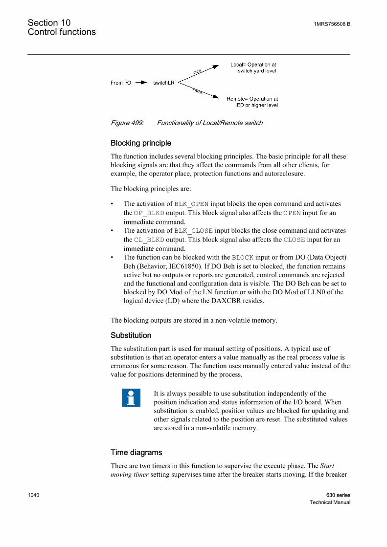
GUID-7A2969FB-067C-4B48-B6D0-4EFF979C9913 V1 EN
Figure 499: Functionality of Local/Remote switch
Blocking principleThe function includes several blocking principles. The basic principle for all theseblocking signals are that they affect the commands from all other clients, forexample, the operator place, protection functions and autoreclosure.
The blocking principles are:
• The activation of BLK_OPEN input blocks the open command and activatesthe OP_BLKD output. This block signal also affects the OPEN input for animmediate command.
• The activation of BLK_CLOSE input blocks the close command and activatesthe CL_BLKD output. This block signal also affects the CLOSE input for animmediate command.
• The function can be blocked with the BLOCK input or from DO (Data Object)Beh (Behavior, IEC61850). If DO Beh is set to blocked, the function remainsactive but no outputs or reports are generated, control commands are rejectedand the functional and configuration data is visible. The DO Beh can be set toblocked by DO Mod of the LN function or with the DO Mod of LLN0 of thelogical device (LD) where the DAXCBR resides.
The blocking outputs are stored in a non-volatile memory.
SubstitutionThe substitution part is used for manual setting of positions. A typical use ofsubstitution is that an operator enters a value manually as the real process value iserroneous for some reason. The function uses manually entered value instead of thevalue for positions determined by the process.
It is always possible to use substitution independently of theposition indication and status information of the I/O board. Whensubstitution is enabled, position values are blocked for updating andother signals related to the position are reset. The substituted valuesare stored in a non-volatile memory.
Time diagramsThere are two timers in this function to supervise the execute phase. The Startmoving timer setting supervises time after the breaker starts moving. If the breaker
Section 10 1MRS756508 BControl functions
1040 630 seriesTechnical Manual

fails to open before Start moving time is lapsed, the L_CAUSE output is set to‘-31'indicating “switch not start moving”. The intermediate timer measures thetime spent in intermediate position. If the breaker remains in intermediate positionfor a time greater than the value of the Intermediate time setting, the L_CAUSEoutput is set to ‘-32’ indicating “persisting intermediate state”.
A070365 V2 EN
Figure 500: The start moving timer and intermediate timer during the executephase
The output pulses for open and close command can have different pulse lengths.The Open pulse time and Close pulse time timer settings are for the length of theexecute output pulses to be sent to the primary equipment. The pulses can also beset to be adaptive with the configuration parameter Adaptive pulse. The adaptiveparameter affects both execute output pulses.
A070367 V2 EN
Figure 501: Execute output pulse
If the pulse is set to be adaptive, it is not possible for the pulse to exceed Openpulse time or Close pulse time.
The execute output pulses are reset when:
1MRS756508 B Section 10Control functions
630 series 1041Technical Manual

• A new expected final position is reached and the configuration settingparameter Adaptive pulse is set to true.
• The open pulse time or close pulse time have elapsed.• An error occurs due to the switch not starting to move, that is, if the value of
Start moving time setting has elapsed.
If the start position indicates bad state (OPENPOS=1 andCLOSEPOS =1) when a command is executed, the execute outputpulse resets only when Open pulse timer or Close pulse timer haveelapsed.
One exception from the first item above occurs when the primary device is in openposition and an open command is executed or if the primary device is in closeposition and a close command is executed. In these cases, with the additionalcondition that the configuration parameter Adaptive pulse is true, the executeoutput pulse is always activated and resets when Start moving time has elapsed. Ifthe configuration parameter Adaptive pulse is set to false, the execution outputremains active until the pulse duration timer has elapsed.
An example of when a primary device is open and an open command is executedcan be shown.
A070366 V2 EN
Figure 502: An example of open command with open position indication
Position IndicatorsThe binary input signal indicating the open and close position of the disconnectoror earth switch are connected to the POSOPEN and POSCLOSE inputs respectively.Based on these inputs, the OPENPOS and CLOSEPOS binary outputs get activatedif the disconnector or earth switch is in open or close position respectively.
Section 10 1MRS756508 BControl functions
1042 630 seriesTechnical Manual
Command inputs and counterThe pulse signal for the immediate opening and closing command of breaker isgiven to the function with the OPEN and CLOSE inputs respectively. The activationof OPEN and CLOSE inputs activates the EXE_OP and EXE_CL outputs of thefunction, whose pulse length is defined by the Open pulse time and Close pulsetime setting respectively. The OPEN and CLOSE inputs of the function is connectedfrom the switch controller function GNRLCSWI outputs EXE_OP and EXE_CLrespectively.
The number of circuit breaker operations are available with the CNT_VAL output.The activation of the RS_OPR_CNT input resets the counter. The number ofoperations are stored in nonvolatile memory.
Error handlingDepending on the error that occurs during the command sequence, the error signalis set with a value. The table describes vendor specific cause values in addition tothese specified in IEC 61850-8-1 standard. The cause values are listed in order ofpriority. The L_CAUSE output on the function block indicates the latest value oferror during the command.
Table 940: Values for cause signal in priority order
Cause value Description
0 no-error
8 blocked-by-mode
2 blocked-by-switching-hierarchy
-24 blocked-for-open-command
-25 blocked-for-close-command
9 blocked-by-process
12 command-already-in-execution
-31 switch-not-start-moving
-32 persistent-intermediate-state
-33 switch-returned-to-initial-position
-34 switch-in-bad-state
-35 not-expected-final-position
When used for non-controllable earth switch, DAXSWI providesonly status information.
10.1.8.5 Application
DAXCBR is a component used to close and interrupt an AC power circuit anyconditions.
1MRS756508 B Section 10Control functions
630 series 1043Technical Manual

DAXCBR represents a lowest level power switching device with short-circuitbreaking capability.
The purpose of this component is to provide the actual status of positions and toperform control operations, that is, to pass all the commands to the primary devicewith the output I/O-board and to supervise the switching operation and position.This component is the lowest or the closest software component to the physicaldevice. It is used by other functions that need to operate the physical device in'direct' manner, that is not invoking other functions before operating.
This also means that the properties and knowledge that affect the operationdepending on the physical device, are part of this function.
The component has the following functions:
• Local or remote switch intended for a switchyard• Block or deblock for open and close command respectively• Update block or deblock of position indication• Substitution of a position indication• Supervision timer for the primary device to start moving on a command• Supervision of allowed time for intermediate position• Definition of pulse duration for open and close command respectively
10.1.8.6 Signals
Table 941: DAXCBR Input signals
Name Type Default DescriptionBLOCK BOOLEAN 0 Block of function
BLK_OPEN BOOLEAN 0 Signal to block the open command
BLK_CLOSE BOOLEAN 0 Signal to block the close command
LR_SWI BOOLEAN 0 Local/Remote switch indication from switchyard
OPEN BOOLEAN 0 Pulsed signal used to immediately open the switch
CLOSE BOOLEAN 0 Pulsed signal used to immediately close the switch
POSOPEN BOOLEAN 0 Signal for open position of apparatus from I/O
POSCLOSE BOOLEAN 0 Signal for close position of apparatus from I/O
TRUCK_OPEN BOOLEAN 0 Signal for open position of truck from I/O
TRUCK_CLOSE BOOLEAN 0 Signal for close position of truck from I/O
RS_OPR_CNT BOOLEAN 0 Resets the operation counter
XIN BOOLEAN 0 Execution information from CSWI
Section 10 1MRS756508 BControl functions
1044 630 seriesTechnical Manual
Table 942: DAXCBR Output signals
Name Type DescriptionXPOS GROUP SIGNAL Group connection to CSWI
EXE_OP BOOLEAN Executes the command for open direction
EXE_CL BOOLEAN Executes the command for close direction
OP_BLKD BOOLEAN Indication that the function is blocked for opencommands
CL_BLKD BOOLEAN Indication that the function is blocked for closecommands
UPD_BLKD BOOLEAN The update of position indication is blocked
OPENPOS BOOLEAN Apparatus open position
CLOSEPOS BOOLEAN Apparatus closed position
TRUCK_POS INTEGER Truck position indication
CNT_VAL INTEGER The value of the operation counter
L_CAUSE INTEGER Latest value of the error indication during command
10.1.8.7 Settings
Table 943: DAXCBR Non group settings (basic)
Name Values (Range) Unit Step Default DescriptionOperation Off
On- - On Operation Off / On
Start moving time 0.000 - 60.000 s 0.001 0.100 Supervision time for the apparatus tomove after a command
Intermediate time 0.000 - 60.000 s 0.001 0.150 Allowed time for intermediate position
Table 944: DAXCBR Non group settings (advanced)
Name Values (Range) Unit Step Default DescriptionOpen pulse time 0.000 - 60.000 s 0.001 0.200 Output pulse length for open command
Close pulse time 0.000 - 60.000 s 0.001 0.200 Output pulse length for close command
Adaptive pulse Not adaptiveAdaptive
- - Not adaptive The output resets when a new correctend position is reached
Suppress mid Pos OffOn
- - On If 'On' mid-pos is suppressed andIntermediate time is used
10.1.8.8 Measured values
Table 945: DAXCBR Measured values
Name Type Default DescriptionBLOCK BOOLEAN 0 Block of function
BLK_OPEN BOOLEAN 0 Signal to block the open command
BLK_CLOSE BOOLEAN 0 Signal to block the close command
Table continues on next page
1MRS756508 B Section 10Control functions
630 series 1045Technical Manual
Name Type Default DescriptionLR_SWI BOOLEAN 0 Local/Remote switch indication from switchyard
OPEN BOOLEAN 0 Pulsed signal used to immediately open the switch
CLOSE BOOLEAN 0 Pulsed signal used to immediately close the switch
POSOPEN BOOLEAN 0 Signal for open position of apparatus from I/O
POSCLOSE BOOLEAN 0 Signal for close position of apparatus from I/O
TRUCK_OPEN BOOLEAN 0 Signal for open position of truck from I/O
TRUCK_CLOSE BOOLEAN 0 Signal for close position of truck from I/O
RS_OPR_CNT BOOLEAN 0 Resets the operation counter
10.1.8.9 Monitored data
Table 946: DAXCBR Monitored data
Name Type Values (Range) Unit DescriptionEXE_OP BOOLEAN 0=FALSE
1=TRUE- Executes the command
for open direction
EXE_CL BOOLEAN 0=FALSE1=TRUE
- Executes the commandfor close direction
SUBSTED BOOLEAN 0=FALSE1=TRUE
- Indication that theposition is substituted
OP_BLKD BOOLEAN 0=FALSE1=TRUE
- Indication that thefunction is blocked foropen commands
CL_BLKD BOOLEAN 0=FALSE1=TRUE
- Indication that thefunction is blocked forclose commands
UPD_BLKD BOOLEAN 0=FALSE1=TRUE
- The update of positionindication is blocked
POSITION INTEGER - - Apparatus positionindication
OPENPOS BOOLEAN 0=FALSE1=TRUE
- Apparatus open position
CLOSEPOS BOOLEAN 0=FALSE1=TRUE
- Apparatus closedposition
BLOCKED BOOLEAN 0=FALSE1=TRUE
- The function is active butthe functionality isblocked
10.1.9 Circuit switch DAXSWI
10.1.9.1 Identification
Function description IEC 61850identification
IEC 60617identification
ANSI/IEEE C37.2device number
Circuit switch controller function DAXSWI I<-> O DC I<->O DC
Section 10 1MRS756508 BControl functions
1046 630 seriesTechnical Manual
10.1.9.2 Function block
A070363 V1 EN
Figure 503: Function block
10.1.9.3 Functionality
The circuit switch function DAXSWI provides the actual status of positions for theapparatus and to perform the control operations, that is, passing all the commandsto the primary apparatuses in the form of disconnector / earthswitch with the outputboards and also supervise the switching operation and position.
The intended users of DAXSWI are other functions like switch controller,protection functions, autoreclosure function or IEC 61850 clients residing inanother IED or at an operator place. DAXSWI executes commands, evaluatesblock conditions and different time supervision conditions. DAXSWI performs anexecution command only if all conditions indicate a switch operation to beallowed. If erroneous conditions occur, DAXSWI indicates an appropriate “cause”value.
DAXSWI has an operation counter for closing and opening command. Theoperator can read the counter value remotely from an operator place. The value isreset from a binary input or remotely from the operator place.
10.1.9.4 Operation principle
Local/Remote switchThe LR_SWI binary input signal is included in this function to indicate the local orremote switch position form the switchyard provided with the I/O board. If thesignal is set to TRUE, the change of positions are only allowed from switchyardlevel. If the signal value is FALSE, commands from IED or higher level arepermitted. When the signal value is set to TRUE, all the commands are rejectedfrom internal IED clients.
1MRS756508 B Section 10Control functions
630 series 1047Technical Manual

GUID-7A2969FB-067C-4B48-B6D0-4EFF979C9913 V1 EN
Figure 504: Functionality of Local/Remote switch
Blocking principleThe function includes several blocking principles. The basic principle for all theseblocking signals are that they affect the commands from all other clients, forexample, the operator place, protection functions and autoreclosure.
The blocking principles are:
• The activation of BLK_OPEN input blocks the open command and activatesthe OP_BLKD output. This block signal also affects the OPEN input for animmediate command.
• The activation of BLK_CLOSE input blocks the close command and activatesthe CL_BLKD output. This block signal also affects the CLOSE input for animmediate command.
• The function can be blocked with the BLOCK input or from DO (Data Object)Beh (Behavior, IEC61850). If DO Beh is set to blocked, the function remainsactive but no outputs or reports are generated, control commands are rejectedand the functional and configuration data is visible. The DO Beh can be set toblocked by DO Mod of the LN function or with the DO Mod of LLN0 of thelogical device (LD) where the DAXCBR resides.
The blocking outputs are stored in a non-volatile memory.
SubstitutionThe substitution part is used for manual setting of positions. A typical use ofsubstitution is that an operator enters a value manually as the real process value iserroneous for some reason. The function uses manually entered value instead of thevalue for positions determined by the process.
It is always possible to use substitution independently of theposition indication and status information of the I/O board. Whensubstitution is enabled, position values are blocked for updating andother signals related to the position are reset. The substituted valuesare stored in a non-volatile memory.
Time diagramsThere are two timers in this function to supervise the execute phase. The Startmoving timer setting supervises time after the breaker starts moving. If the breaker
Section 10 1MRS756508 BControl functions
1048 630 seriesTechnical Manual

fails to open before Start moving time is lapsed, the L_CAUSE output is set to‘-31'indicating “switch not start moving”. The intermediate timer measures thetime spent in intermediate position. If the breaker remains in intermediate positionfor a time greater than the value of the Intermediate time setting, the L_CAUSEoutput is set to ‘-32’ indicating “persisting intermediate state”.
A070365 V2 EN
Figure 505: The start moving timer and intermediate timer during the executephase
The output pulses for open and close command can have different pulse lengths.The Open pulse time and Close pulse time timer settings are for the length of theexecute output pulses to be sent to the primary equipment. The pulses can also beset to be adaptive with the configuration parameter Adaptive pulse. The adaptiveparameter affects both execute output pulses.
A070367 V2 EN
Figure 506: Execute output pulse
If the pulse is set to be adaptive, it is not possible for the pulse to exceed Openpulse time or Close pulse time.
The execute output pulses are reset when:
1MRS756508 B Section 10Control functions
630 series 1049Technical Manual
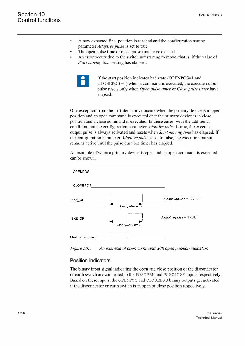
• A new expected final position is reached and the configuration settingparameter Adaptive pulse is set to true.
• The open pulse time or close pulse time have elapsed.• An error occurs due to the switch not starting to move, that is, if the value of
Start moving time setting has elapsed.
If the start position indicates bad state (OPENPOS=1 andCLOSEPOS =1) when a command is executed, the execute outputpulse resets only when Open pulse timer or Close pulse timer haveelapsed.
One exception from the first item above occurs when the primary device is in openposition and an open command is executed or if the primary device is in closeposition and a close command is executed. In these cases, with the additionalcondition that the configuration parameter Adaptive pulse is true, the executeoutput pulse is always activated and resets when Start moving time has elapsed. Ifthe configuration parameter Adaptive pulse is set to false, the execution outputremains active until the pulse duration timer has elapsed.
An example of when a primary device is open and an open command is executedcan be shown.
A070366 V2 EN
Figure 507: An example of open command with open position indication
Position IndicatorsThe binary input signal indicating the open and close position of the disconnectoror earth switch are connected to the POSOPEN and POSCLOSE inputs respectively.Based on these inputs, the OPENPOS and CLOSEPOS binary outputs get activatedif the disconnector or earth switch is in open or close position respectively.
Section 10 1MRS756508 BControl functions
1050 630 seriesTechnical Manual
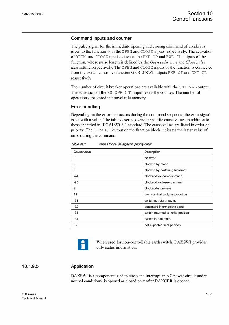
Command inputs and counterThe pulse signal for the immediate opening and closing command of breaker isgiven to the function with the OPEN and CLOSE inputs respectively. The activationof OPEN and CLOSE inputs activates the EXE_OP and EXE_CL outputs of thefunction, whose pulse length is defined by the Open pulse time and Close pulsetime setting respectively. The OPEN and CLOSE inputs of the function is connectedfrom the switch controller function GNRLCSWI outputs EXE_OP and EXE_CLrespectively.
The number of circuit breaker operations are available with the CNT_VAL output.The activation of the RS_OPR_CNT input resets the counter. The number ofoperations are stored in nonvolatile memory.
Error handlingDepending on the error that occurs during the command sequence, the error signalis set with a value. The table describes vendor specific cause values in addition tothese specified in IEC 61850-8-1 standard. The cause values are listed in order ofpriority. The L_CAUSE output on the function block indicates the latest value oferror during the command.
Table 947: Values for cause signal in priority order
Cause value Description
0 no-error
8 blocked-by-mode
2 blocked-by-switching-hierarchy
-24 blocked-for-open-command
-25 blocked-for-close-command
9 blocked-by-process
12 command-already-in-execution
-31 switch-not-start-moving
-32 persistent-intermediate-state
-33 switch-returned-to-initial-position
-34 switch-in-bad-state
-35 not-expected-final-position
When used for non-controllable earth switch, DAXSWI providesonly status information.
10.1.9.5 Application
DAXSWI is a component used to close and interrupt an AC power circuit undernormal conditions, is opened or closed only after DAXCBR is opened.
1MRS756508 B Section 10Control functions
630 series 1051Technical Manual

DAXSWI represents lowest level power switching devices without short-circuitbreaking capability, for example disconnectors, air-break switches and earthswitches.
The purpose of this component is to provide the actual status of positions and toperform control operations, that is to pass all the commands to the primary devicevia output I/O-board and to supervise the switching operation and position. Thiscomponent is the lowest or the closest software component to the physical device.It is used by other functions that need to operate the physical device in "direct"manner, that is, not invoking other functions before operating.
This also means that the properties and knowledge that affect the operationdepending on the physical device are part of this function.
The component has the following functions:
• Local or remote switch intended for a switchyard• Block or deblock for open and close command respectively• Update block or deblock of position indication• Substitution of a position indication• Supervision timer for the primary device to start moving on a command• Supervision of allowed time for intermediate position• Definition of pulse duration for open and close command respectively
10.1.9.6 Signals
Table 948: DAXSWI Input signals
Name Type Default DescriptionBLOCK BOOLEAN 0 Block of function
BLK_OPEN BOOLEAN 0 Signal to block the open command
BLK_CLOSE BOOLEAN 0 Signal to block the close command
LR_SWI BOOLEAN 0 Local/Remote switch indication from switchyard
OPEN BOOLEAN 0 Pulsed signal used to immediately open the switch
CLOSE BOOLEAN 0 Pulsed signal used to immediately close the switch
POSOPEN BOOLEAN 0 Signal for open position of apparatus from I/O
POSCLOSE BOOLEAN 0 Signal for close position of apparatus from I/O
RS_OPR_CNT BOOLEAN 0 Resets the operation counter
XIN BOOLEAN 0 Execution information from CSWI
Table 949: DAXSWI Output signals
Name Type DescriptionXPOS GROUP SIGNAL Group connection to CSWI
EXE_OP BOOLEAN Executes the command for open direction
EXE_CL BOOLEAN Executes the command for close direction
Table continues on next page
Section 10 1MRS756508 BControl functions
1052 630 seriesTechnical Manual
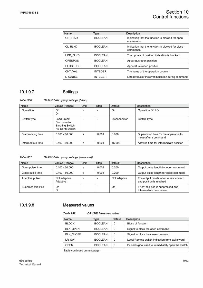
Name Type DescriptionOP_BLKD BOOLEAN Indication that the function is blocked for open
commands
CL_BLKD BOOLEAN Indication that the function is blocked for closecommands
UPD_BLKD BOOLEAN The update of position indication is blocked
OPENPOS BOOLEAN Apparatus open position
CLOSEPOS BOOLEAN Apparatus closed position
CNT_VAL INTEGER The value of the operation counter
L_CAUSE INTEGER Latest value of the error indication during command
10.1.9.7 Settings
Table 950: DAXSWI Non group settings (basic)
Name Values (Range) Unit Step Default DescriptionOperation Off
On- - On Operation Off / On
Switch type Load BreakDisconnectorEarthing SwitchHS Earth Switch
- - Disconnector Switch Type
Start moving time 0.100 - 60.000 s 0.001 3.000 Supervision time for the apparatus tomove after a command
Intermediate time 0.100 - 60.000 s 0.001 15.000 Allowed time for intermediate position
Table 951: DAXSWI Non group settings (advanced)
Name Values (Range) Unit Step Default DescriptionOpen pulse time 0.100 - 60.000 s 0.001 0.200 Output pulse length for open command
Close pulse time 0.100 - 60.000 s 0.001 0.200 Output pulse length for close command
Adaptive pulse Not adaptiveAdaptive
- - Not adaptive The output resets when a new correctend position is reached
Suppress mid Pos OffOn
- - On If 'On' mid-pos is suppressed andIntermediate time is used
10.1.9.8 Measured values
Table 952: DAXSWI Measured values
Name Type Default DescriptionBLOCK BOOLEAN 0 Block of function
BLK_OPEN BOOLEAN 0 Signal to block the open command
BLK_CLOSE BOOLEAN 0 Signal to block the close command
LR_SWI BOOLEAN 0 Local/Remote switch indication from switchyard
OPEN BOOLEAN 0 Pulsed signal used to immediately open the switch
Table continues on next page
1MRS756508 B Section 10Control functions
630 series 1053Technical Manual
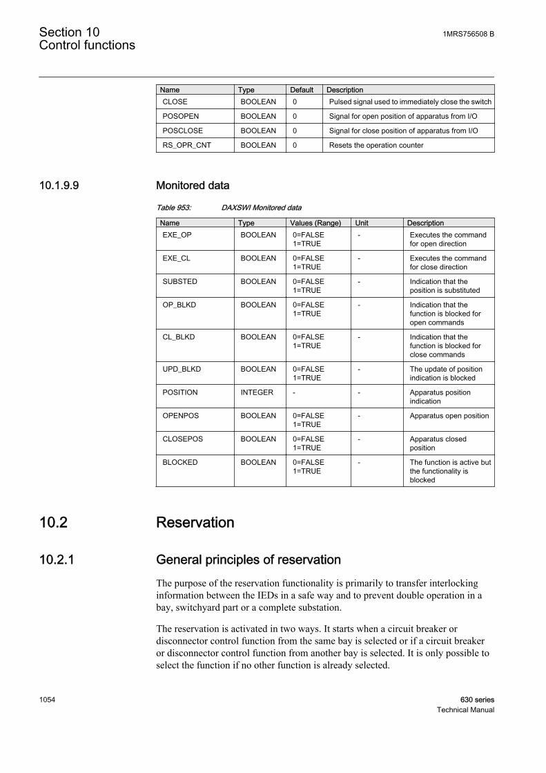
Name Type Default DescriptionCLOSE BOOLEAN 0 Pulsed signal used to immediately close the switch
POSOPEN BOOLEAN 0 Signal for open position of apparatus from I/O
POSCLOSE BOOLEAN 0 Signal for close position of apparatus from I/O
RS_OPR_CNT BOOLEAN 0 Resets the operation counter
10.1.9.9 Monitored data
Table 953: DAXSWI Monitored data
Name Type Values (Range) Unit DescriptionEXE_OP BOOLEAN 0=FALSE
1=TRUE- Executes the command
for open direction
EXE_CL BOOLEAN 0=FALSE1=TRUE
- Executes the commandfor close direction
SUBSTED BOOLEAN 0=FALSE1=TRUE
- Indication that theposition is substituted
OP_BLKD BOOLEAN 0=FALSE1=TRUE
- Indication that thefunction is blocked foropen commands
CL_BLKD BOOLEAN 0=FALSE1=TRUE
- Indication that thefunction is blocked forclose commands
UPD_BLKD BOOLEAN 0=FALSE1=TRUE
- The update of positionindication is blocked
POSITION INTEGER - - Apparatus positionindication
OPENPOS BOOLEAN 0=FALSE1=TRUE
- Apparatus open position
CLOSEPOS BOOLEAN 0=FALSE1=TRUE
- Apparatus closedposition
BLOCKED BOOLEAN 0=FALSE1=TRUE
- The function is active butthe functionality isblocked
10.2 Reservation
10.2.1 General principles of reservationThe purpose of the reservation functionality is primarily to transfer interlockinginformation between the IEDs in a safe way and to prevent double operation in abay, switchyard part or a complete substation.
The reservation is activated in two ways. It starts when a circuit breaker ordisconnector control function from the same bay is selected or if a circuit breakeror disconnector control function from another bay is selected. It is only possible toselect the function if no other function is already selected.
Section 10 1MRS756508 BControl functions
1054 630 seriesTechnical Manual
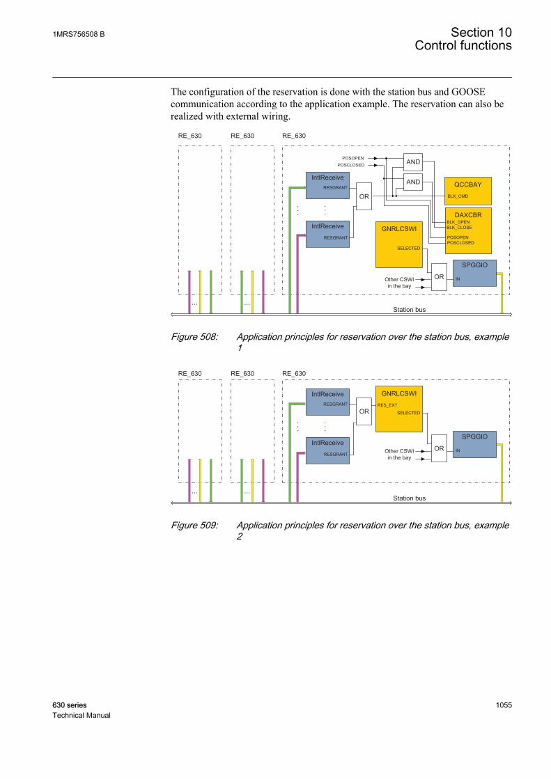
The configuration of the reservation is done with the station bus and GOOSEcommunication according to the application example. The reservation can also berealized with external wiring.
OROther CSWIin the bay
GNRLCSWI
SELECTED
RE_630RE_630 RE_630
IntlReceiveRESGRANT
IntlReceive
RESGRANT
SPGGIO
IN
•••
•••
• • •• • •
Station bus
OR
DAXCBRBLK_OPENBLK_CLOSE
AND
AND QCCBAY
BLK_CMD
POSOPENPOSCLOSED
POSOPENPOSCLOSED
GUID-1A9D1831-7794-4CDE-9CFE-C88B51A21765 V1 EN
Figure 508: Application principles for reservation over the station bus, example1
OROther CSWIin the bay
GNRLCSWI
RES_EXT
SELECTED
RE_630RE_630 RE_630
IntlReceiveRESGRANT
IntlReceive
RESGRANT
SPGGIO
IN
•••
•••
• • •• • •
Station bus
OR
GUID-173810BD-D9FB-42D8-99DF-50AB7359B67C V2 EN
Figure 509: Application principles for reservation over the station bus, example2
1MRS756508 B Section 10Control functions
630 series 1055Technical Manual

BOBI
RE_630RE_630
BI BO
+
OROther CSWIin the bay
GNRLCSWI
SELECTED
DAXCBRBLK_OPENBLK_CLOSE
AND
AND QCCBAY
BLK_CMD
POSOPENPOSCLOSED
POSOPENPOSCLOSED
GUID-92879C67-B957-4FCE-B3AC-E99F392481B5 V1 EN
Figure 510: Application principles for reservation with external wiring, example 1
GUID-4EEF2FCB-CD11-4923-812F-02F866DE9CD8 V1 EN
Figure 511: Application principles for reservation with external wiring, example 2
Section 10 1MRS756508 BControl functions
1056 630 seriesTechnical Manual

10.3 Interlocking
10.3.1 General principles of interlockingThe interlocking function consists of the software modules located in each controlIED. The function is distributed and does not depend on any central function. Thecommunication between modules in different bays is performed with the station bus.
The reservation functionality is used to ensure that Medium Voltage (MV)apparatuses that affect the interlock are blocked during the time gap, which arisesbetween position updates. This is done with the communication system, reservingall MV apparatuses that influence the interlocking condition of an intendedoperation. The reservation is maintained until the operation is performed.
After the selection and reservation of an apparatus, the function has complete dataon the status of all apparatuses in the switchyard that are affected by the selection.The other operators cannot interfere with the reserved apparatus or the status ofswitching devices that affect the function.
The interlocking logic is implemented case by case using configurable logic withthe graphical configuration tool PCM600.
The open or closed positions of the MV apparatuses are inputs to software modulesdistributed in the control IEDs. Each module contains an interlocking logic for abay. The specific interlocking conditions and connections between standardinterlocking modules are performed with an engineering tool. The bay-levelinterlocking signals can include the information such as:
• Positions of MV apparatuses (sometimes per phase)• Valid positions (if evaluated in the control module)• External release (to add special conditions for release)• Line voltage (to block operation of line earthing switch)• Output signals to release the MV apparatus
The example of an interlocking module is connected to the surrounding functionswithin a bay is as shown in the figure.
1MRS756508 B Section 10Control functions
630 series 1057Technical Manual
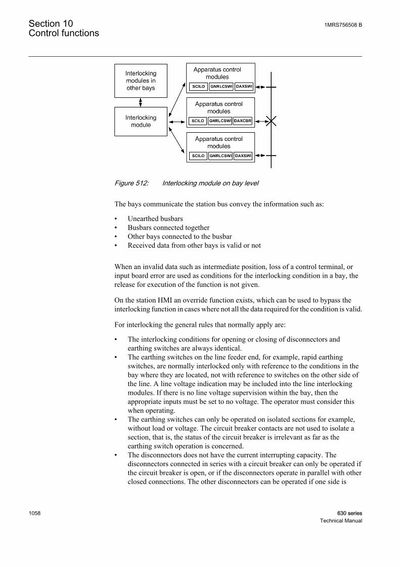
GUID-0F308468-CEC5-4B4D-98DD-ADF58D913885 V1 EN
Figure 512: Interlocking module on bay level
The bays communicate the station bus convey the information such as:
• Unearthed busbars• Busbars connected together• Other bays connected to the busbar• Received data from other bays is valid or not
When an invalid data such as intermediate position, loss of a control terminal, orinput board error are used as conditions for the interlocking condition in a bay, therelease for execution of the function is not given.
On the station HMI an override function exists, which can be used to bypass theinterlocking function in cases where not all the data required for the condition is valid.
For interlocking the general rules that normally apply are:
• The interlocking conditions for opening or closing of disconnectors andearthing switches are always identical.
• The earthing switches on the line feeder end, for example, rapid earthingswitches, are normally interlocked only with reference to the conditions in thebay where they are located, not with reference to switches on the other side ofthe line. A line voltage indication may be included into the line interlockingmodules. If there is no line voltage supervision within the bay, then theappropriate inputs must be set to no voltage. The operator must consider thiswhen operating.
• The earthing switches can only be operated on isolated sections for example,without load or voltage. The circuit breaker contacts are not used to isolate asection, that is, the status of the circuit breaker is irrelevant as far as theearthing switch operation is concerned.
• The disconnectors does not have the current interrupting capacity. Thedisconnectors connected in series with a circuit breaker can only be operated ifthe circuit breaker is open, or if the disconnectors operate in parallel with otherclosed connections. The other disconnectors can be operated if one side is
Section 10 1MRS756508 BControl functions
1058 630 seriesTechnical Manual
completely isolated or if the disconnectors operate in parallel with the otherclosed connections or if they are earthed on both sides.
10.3.2 ApplicationThe main purpose of switchgear interlocking is:
• To avoid the dangerous or damaging operation of switchgear.• To enforce the restrictions on the operation of the substation for other reasons,
for example, load configuration. The examples of the latter are to limit thenumber of parallel transformers to a maximum of two or to ensure thatenergizing is always from one side, for example, the high voltage side of atransformer.
This document deals with only few of the interlocking restrictions caused byswitching devices other than the one to be controlled. The switch interlock becauseof device alarms, is not included in this document.
The disconnectors and earthing switches have a limited switching capacity. Thedisconnectors therefore only operate:
• With basically zero current: The circuit is open on one side and has a smallextension. The capacitive current is small, for example, less than 5A andpower transformers with inrush current are not allowed.
• To connect or disconnect a parallel circuit carrying load current: The switchingvoltage across the open contacts is thus virtually zero due to the parallelcircuit, that is, less than 1 percent of rated voltage. The paralleling of powertransformers is not allowed.
The earthing switches are allowed to connect and disconnect earthing of isolatedpoints. Due to the capacitive or inductive coupling there may be some voltage, forexample, less than 40 percent of rated voltage before earthing and some current, forexample, less than 100 A after earthing of the line.
The circuit breakers are usually not interlocked. The closing is interlocked againstrunning the disconnectors in the same bay and the bus-coupler opening isinterlocked during the busbar transfer.
The positions of all switching devices in a bay and from some other bays determinethe conditions for operational interlocking. The conditions from other stations areusually not available. Therefore, a line earthing switch is usually not fullyinterlocked. The operator must be convinced that the line is not energized from theother side before closing the earthing switch. As an option, a voltage indication canbe used for interlocking. Care must be taken to avoid a dangerous enable conditionat the loss of a VT secondary voltage, for example, a blown fuse.
The switch positions used by the operational interlocking logic are obtained fromthe auxiliary contacts or position sensors. For each end position, that is, open or
1MRS756508 B Section 10Control functions
630 series 1059Technical Manual

closed, a true indication is needed – thus forming a double indication. Theapparatus control function continuously checks its consistency. If neither conditionis high, that is, 1 or TRUE, the switch is in an intermediate position, for example,moving. This dynamic state continues for some time, which in the case ofdisconnectors is may be up to 10 seconds. If both the indications stay low for alonger period, the position indication is interpreted as unknown. If both indicationsstay high, something is wrong, and the state is again treated as unknown. In bothcases an alarm is sent to the operator. The indications from position sensors is self-checked and system faults are indicated by the fault signal. In the interlockinglogic, the signals are used to avoid dangerous enable or release conditions. Whenthe switching state of a switching device cannot be determined operation is notpermitted.
10.3.3 Logical node for interlocking SCILO
10.3.3.1 Identification
Function description IEC 61850identification
IEC 60617identification
ANSI/IEEE C37.2device number
Switch interlocking function SCILO CILO 3
10.3.3.2 Function block
GUID-9AC26991-7CA2-4A02-9A84-08C50D6F4716 V1 EN
Figure 513: Function block
10.3.3.3 Functionality
The interlock switching function SCILO is used to enable a switching operation ifthe interlocking conditions permit. SCILO does not provide any interlockingfunctionality by itself . The interlocking conditions are generated by means ofconfigurable logic or in separate function blocks containing the interlocking logic.
10.3.3.4 Operation principle
The switching interlock function SCILO has a logic to enable the open and closecommands respectively if the interlocking conditions are fulfilled. If the switch hasa defined end position, for example, open, then the appropriate enable signalEN_OPENis false. The enable signals EN_OPEN and EN_CLOSE are true at thesame time only in the intermediate and bad position state and if they are enabled bythe interlocking function. The position inputs come from the logical nodes circuitbreaker/switch function (DAXCBR / DAXSWI) and the enable signals from the
Section 10 1MRS756508 BControl functions
1060 630 seriesTechnical Manual
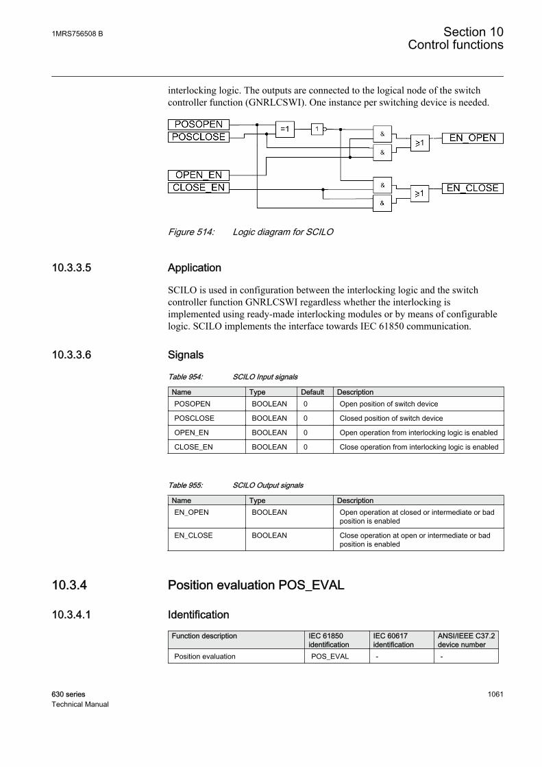
interlocking logic. The outputs are connected to the logical node of the switchcontroller function (GNRLCSWI). One instance per switching device is needed.
GUID-6A6B153C-7EF9-4A18-9903-75C0B33F2E2C V1 EN
Figure 514: Logic diagram for SCILO
10.3.3.5 Application
SCILO is used in configuration between the interlocking logic and the switchcontroller function GNRLCSWI regardless whether the interlocking isimplemented using ready-made interlocking modules or by means of configurablelogic. SCILO implements the interface towards IEC 61850 communication.
10.3.3.6 Signals
Table 954: SCILO Input signals
Name Type Default DescriptionPOSOPEN BOOLEAN 0 Open position of switch device
POSCLOSE BOOLEAN 0 Closed position of switch device
OPEN_EN BOOLEAN 0 Open operation from interlocking logic is enabled
CLOSE_EN BOOLEAN 0 Close operation from interlocking logic is enabled
Table 955: SCILO Output signals
Name Type DescriptionEN_OPEN BOOLEAN Open operation at closed or intermediate or bad
position is enabled
EN_CLOSE BOOLEAN Close operation at open or intermediate or badposition is enabled
10.3.4 Position evaluation POS_EVAL
10.3.4.1 Identification
Function description IEC 61850identification
IEC 60617identification
ANSI/IEEE C37.2device number
Position evaluation POS_EVAL - -
1MRS756508 B Section 10Control functions
630 series 1061Technical Manual

10.3.4.2 Functionality
Position evaluation (POS_EVAL) function converts the input position data signalPOSITION, consisting of value, time and signal status, to binary signalsOPENPOS or CLOSEPOS.
The output signals are used by other functions in the interlocking scheme.
10.3.4.3 Function blockPOS_EVAL
POSITION OPENPOSCLOSEPOS
IEC09000079_1_en.vsd
IEC09000079 V1 EN
Figure 515: POS_EVAL function block
10.3.4.4 Logic diagram
POS_EVALPOSITION OPENPOS
CLOSEPOS
IEC08000469-1-en.vsd
Position including quality Open/close position of switch device
IEC08000469-1-EN V1 EN
Only the value, open/close, and status is used in this function. Time information isnot used.
Input position (Value) Signal quality Output OPENPOS Output CLOSEPOS0 (Breakerintermediate)
Good 0 0
1 (Breaker open) Good 1 0
2 (Breaker closed) Good 0 1
3 (Breaker faulty) Good 0 0
Any Invalid 0 0
Any Oscillatory 0 0
10.3.4.5 Signals
Table 956: POS_EVAL Input signals
Name Type Default DescriptionPOSITION INTEGER 0 Position status including quality
Section 10 1MRS756508 BControl functions
1062 630 seriesTechnical Manual
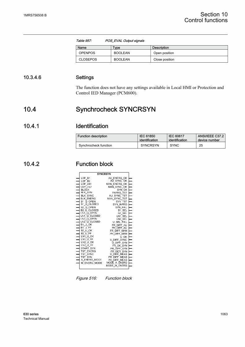
Table 957: POS_EVAL Output signals
Name Type DescriptionOPENPOS BOOLEAN Open position
CLOSEPOS BOOLEAN Close position
10.3.4.6 Settings
The function does not have any settings available in Local HMI or Protection andControl IED Manager (PCM600).
10.4 Synchrocheck SYNCRSYN
10.4.1 IdentificationFunction description IEC 61850
identificationIEC 60617identification
ANSI/IEEE C37.2device number
Synchrocheck function SYNCRSYN SYNC 25
10.4.2 Function block
GUID-E7B0BB19-06BC-427B-8868-B95CE65FBD44 V1 EN
Figure 516: Function block
1MRS756508 B Section 10Control functions
630 series 1063Technical Manual
10.4.3 FunctionalityThe synchrocheck function SYNCRSYN checks the condition across the circuitbreaker from separate power system parts and gives the output signal for closingthe circuit breaker. SYNCRSYN includes the functionality of synchronizing,synchrocheck and energizing check.
For the systems which are running asynchronously, a synchronizing function isprovided. The main purpose of the synchronizing function is to provide acontrolled closing of circuit breakers when two asynchronous systems are going tobe connected. It is used for the slip frequencies that are higher than those forsynchrocheck and lower than the maximum possible set level for the synchronizingfunction.
The synchrocheck function checks that the voltages on both sides of the circuitbreaker are synchronized. It is used to perform a controlled re-connection of twosystems which are divided after islanding and it is also used to perform a controlledre-connection of the system after reclosing.
The energizing check function checks that at least one side is dead to ensure thatclosing can be done safely.
SYNCRSYN includes a built-in voltage selection scheme for the double bus singlecircuit breaker arrangement. It is possible to have a manual closing and automaticreclosing using SYNCRSYN with different settings.
10.4.4 Operation principleThe function can be enabled and disabled with the Operation setting. Thecorresponding parameter values are "On" and "Off".
The operation of the function can be described using a module diagram. All themodules in the diagram are explained in the next sections.
Section 10 1MRS756508 BControl functions
1064 630 seriesTechnical Manual

GUID-7ACCE172-0B7D-4DD0-B389-5403A098F20E V1 EN
Figure 517: Functional module diagram
Fuse failure supervisionExternal fuse-failure signals or signals from a tripped fuse switch or an MCB areconnected to the binary inputs that are then configured to the inputs ofSYNCRSYN. Alternatively, the internal signals from the fuse failure supervisionfunction can also be used when available.
There are two alternative connections possible for the inputs related to the fusefailure supervision. The inputs with the label U_OK must be used if the availablefuse failure information indicates that the voltage circuit is healthy. The inputs with
1MRS756508 B Section 10Control functions
630 series 1065Technical Manual

the label U_FF must be used if the available fuse failure information indicates thatthe voltage circuit is faulty.
The B1(2)_U_OK and B1(2)_U_FF inputs are to be connected for indicatingthe fuse failure information related to the busbar voltage. The LN1(2)_U_OK andLN1(2)_U_FF inputs are to be connected for indicating the fuse failureinformation related to the line voltage.
In the event of a fuse failure, the energizing check module is blocked. Thiseventually blocks the synchrocheck and synchronizing functions.
Voltage selectionThe voltage selection module includes the selection of appropriate line and busvoltages depending on the type of system configuration. The module includes afuse supervision feature which supervises the voltage transformer fuses for theselected voltage transformer. The module forms the basic part of SYNCRSYN anddetermines the parameters which are fed to the synchronizing, synchrocheck andenergizing check modules.
The CB configuration busbar configuration setting is used to define the type ofvoltage selection for different configurations.
Table 958: Description for CB configuration setting
CB configuration setting Description"No voltage sel" No voltage selection
"Double bus" Single circuit breaker with double bus
"1 1/2 bus 1 CB" 1 1/2 circuit breaker arrangement with thebreaker connected to busbar 1
"1 1/2 bus 1 CB" 1 1/2 circuit breaker arrangement with thebreaker connected to busbar 2
"Tie CB" 1 1/2 circuit breaker arrangement with thebreaker connected to lines 1 and 2
If the CB configuration setting is set to "No Voltage Sel", the used default voltagesare ULine1 and UBus1. This is also the case when the external voltage selection isprovided. The fuse failure supervision for the used inputs must also be connected.
The voltage selection made by voltage selection modules and fuse conditions arethe inputs for the synchronizing, synchrocheck and energizing check modules. Forthe disconnector positions, it is advisable to use (NO) a and (NC) b type contacts tosupply the disconnector with open and closed positions, but it is of course alsopossible to use an inverter for one of the positions.
The Phase selection bus configuration parameter setting is used for the selection ofthe measuring phase of the voltage for busbars. The voltage can be a single-phase(phase-to-neutral) or two-phase (phase-to-phase) voltage.
Section 10 1MRS756508 BControl functions
1066 630 seriesTechnical Manual

The Phase selection line configuration parameter setting is used for selection ofmeasuring phase of the voltage for lines. The voltages can be a single-phase (phase-to-neutral) or two-phase (phase-to-phase) voltage.
Voltage selection for a single circuit breaker with double busbarsThe auxiliary contacts of the disconnectors are connected to the B1_Q_OPEN andB1_Q_CLOSED inputs for bus 1 and B2_Q_OPEN and B2_Q_CLOSED for bus 2to select between the bus 1 and bus 2 voltages. If the disconnector connected to bus2 is closed and the disconnector connected to bus 1 is opened, the bus 2 voltage isused. All other combinations use bus 1 voltage. The B1_SEL and B2_SEL outputsrespectively indicate the selected bus voltage for synchronizing.
A check is carried out for the fuse failure signals for the bus 1, bus 2 and linevoltage transformers. The B1_U_OK input or B1_U_FF and B2_U_OK orB2_U_FF supervises the fuse for the bus 1 and bus 2 voltage transformersrespectively. LN1_U_OK or LN1_U_FF supervises the fuse for the line voltagetransformer. The inputs fail (FF) or healthy (OK) can alternatively be useddepending on the available signal. If a fuse failure is detected in either of theselected bus or line voltage source, the output signal U_SEL_FAIL is set. Theactivation of the BLOCK input signal blocks the module and U_SEL_FAIL.
GUID-9C87EB8F-8AB6-463C-A3C5-43A408C6919B V1 EN
Figure 518: Logic diagram for the voltage selection function of a single circuitbreaker with double busbars
Energizing checkThe main purpose of the energizing check module is to facilitate the controlled re-connection of the disconnected lines and buses to the energized lines and buses.The energizing function in the module is defined as a situation where a deadsection of the network is connected to an energized one. The module can beoperated either in auto or manual mode.
1MRS756508 B Section 10Control functions
630 series 1067Technical Manual
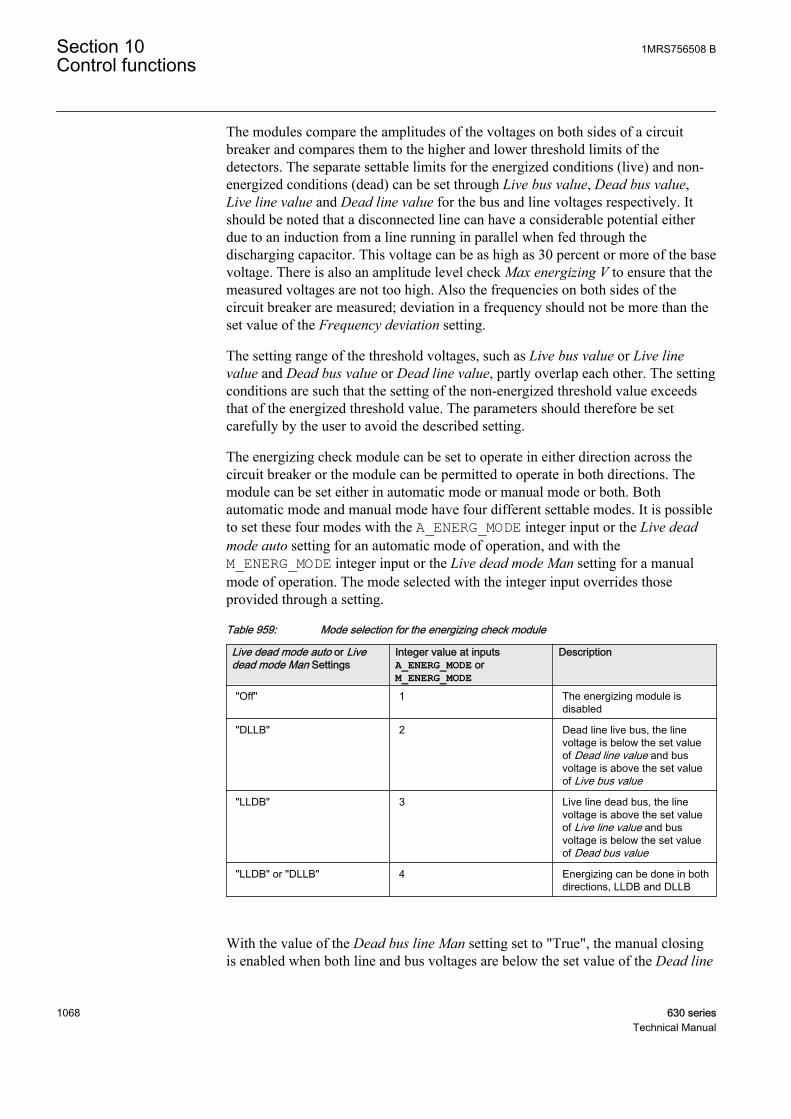
The modules compare the amplitudes of the voltages on both sides of a circuitbreaker and compares them to the higher and lower threshold limits of thedetectors. The separate settable limits for the energized conditions (live) and non-energized conditions (dead) can be set through Live bus value, Dead bus value,Live line value and Dead line value for the bus and line voltages respectively. Itshould be noted that a disconnected line can have a considerable potential eitherdue to an induction from a line running in parallel when fed through thedischarging capacitor. This voltage can be as high as 30 percent or more of the basevoltage. There is also an amplitude level check Max energizing V to ensure that themeasured voltages are not too high. Also the frequencies on both sides of thecircuit breaker are measured; deviation in a frequency should not be more than theset value of the Frequency deviation setting.
The setting range of the threshold voltages, such as Live bus value or Live linevalue and Dead bus value or Dead line value, partly overlap each other. The settingconditions are such that the setting of the non-energized threshold value exceedsthat of the energized threshold value. The parameters should therefore be setcarefully by the user to avoid the described setting.
The energizing check module can be set to operate in either direction across thecircuit breaker or the module can be permitted to operate in both directions. Themodule can be set either in automatic mode or manual mode or both. Bothautomatic mode and manual mode have four different settable modes. It is possibleto set these four modes with the A_ENERG_MODE integer input or the Live deadmode auto setting for an automatic mode of operation, and with theM_ENERG_MODE integer input or the Live dead mode Man setting for a manualmode of operation. The mode selected with the integer input overrides thoseprovided through a setting.
Table 959: Mode selection for the energizing check module
Live dead mode auto or Livedead mode Man Settings
Integer value at inputsA_ENERG_MODE orM_ENERG_MODE
Description
"Off" 1 The energizing module isdisabled
"DLLB" 2 Dead line live bus, the linevoltage is below the set valueof Dead line value and busvoltage is above the set valueof Live bus value
"LLDB" 3 Live line dead bus, the linevoltage is above the set valueof Live line value and busvoltage is below the set valueof Dead bus value
"LLDB" or "DLLB" 4 Energizing can be done in bothdirections, LLDB and DLLB
With the value of the Dead bus line Man setting set to "True", the manual closingis enabled when both line and bus voltages are below the set value of the Dead line
Section 10 1MRS756508 BControl functions
1068 630 seriesTechnical Manual
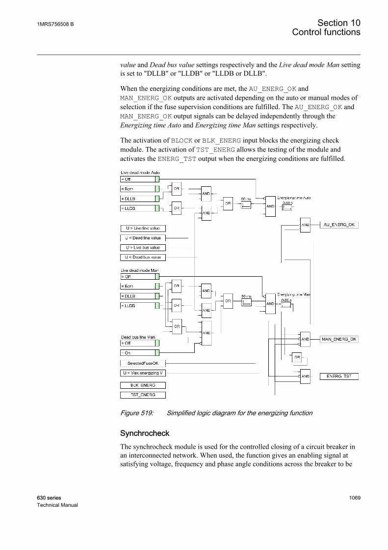
value and Dead bus value settings respectively and the Live dead mode Man settingis set to "DLLB" or "LLDB" or "LLDB or DLLB".
When the energizing conditions are met, the AU_ENERG_OK andMAN_ENERG_OK outputs are activated depending on the auto or manual modes ofselection if the fuse supervision conditions are fulfilled. The AU_ENERG_OK andMAN_ENERG_OK output signals can be delayed independently through theEnergizing time Auto and Energizing time Man settings respectively.
The activation of BLOCK or BLK_ENERG input blocks the energizing checkmodule. The activation of TST_ENERG allows the testing of the module andactivates the ENERG_TST output when the energizing conditions are fulfilled.
GUID-D7635D35-2C5D-4EDD-847E-FA2B3EE34FE1 V1 EN
Figure 519: Simplified logic diagram for the energizing function
SynchrocheckThe synchrocheck module is used for the controlled closing of a circuit breaker inan interconnected network. When used, the function gives an enabling signal atsatisfying voltage, frequency and phase angle conditions across the breaker to be
1MRS756508 B Section 10Control functions
630 series 1069Technical Manual
closed. The function can be used as a condition to be fulfilled before the breaker isclosed manually or with the autorecloser function or with both methods.
The synchrocheck module measures the amplitude, frequency and phase angle ofthe voltages on both sides of a circuit breaker and compares them to the thresholdvalue of the limit detectors. The differences in voltage, frequency and phase anglevalues between the two sides of the circuit breaker are measured and available forevaluation before the synchronizing is done. If the available bus voltage is phase-to-phase and the line voltage is phase-to-neutral (or the opposite), a compensation isrequired. This is done with the Voltage ratio setting (defined as the ratio of busvoltage to line voltage), which scales up the line voltage to a level equal to the busvoltage. A typical example of the setting is to compensate for the voltagedifference caused by connecting the bus voltage as phase-to-phase and the linevoltage as phase-to-neutral, in which case the value of the Voltage ratio settingneeds to be set to "1.73". A compensation for a phase shift caused by a linetransformer between the two measurement points of the bus voltage and linevoltage can be made with the Phase shift setting.
When the Synchrocheck mode setting is "ON", the measuring starts. If the value ofthe Synchrocheck mode setting is "OFF", it disables the synchrocheck function anddeactivates the AU_SYNC_OK, MAN_SYNC_OK, AU_SYNC_TST andMAN_SYNC_TST outputs.
The synchrocheck module starts synchronizing check if the voltage at both sides ofthe breaker is above 80 percent of the base value. When the values of the voltageson both the sides are above 80% of the base value, the measured values arecompared to the set value for acceptable frequency, phase angle and voltagedifference which are set using Dif frequency Auto or Dif phase angle Auto for theauto mode or with the Dif frequency Man or Dif phase angle Man settings for themanual mode and difference voltage settings. If a compensation factor is set due tothe use of different voltages on the bus and line, the factor is deducted from the linevoltage before the comparison is made for the phase angle values. The phase anglesetting must be chosen to allow closing under the maximum load condition.
The frequency on both sides of the circuit breaker is also measured. Thefrequencies must not deviate from the rated frequency more than ±5 Hz. Thefrequency difference between the bus frequency and the line frequency is measuredand must not exceed the set value of the Frequency deviation setting.
The MAN_SYNC_OK and AUTO_SYNC_OK outputs are activated when the actualmeasured conditions match the set conditions for the manual and autosynchronizing modes respectively. It is possible to delay independently theMAN_SYNC_OK and AUTO_SYNC_OK output signals with the Syn Chk delay Manand Syn Chk delay Auto timer settings respectively to ensure that the synchrocheckconditions remain constant and that the situation is not caused by a temporaryinterference. If the conditions do not persist for the specified time, the delay timeris reset and the procedure is restarted until the conditions are fulfilled again. Thecircuit breaker closing is thus not permitted until the synchrocheck situation hasremained constant throughout the set delay setting time.
Section 10 1MRS756508 BControl functions
1070 630 seriesTechnical Manual

The MAN_SYNC_TST and AU_SYNC_TST outputs are activated when the actualmeasured conditions match the set conditions for the manual and autosynchronizing modes respectively if the TST_SYNC input is active.
A number of outputs are available as information about a synchronizing conditionbeing checked. The U_OK output indicates that the voltage amplitude at the lineand bus sides is above 80 percent of the base value. The activation of theU_DIFF_SYNC output indicates that the voltage difference between the two sidesof the circuit breaker is out of limit, and when the FR_DIFF_AU, FR_DIFF_MANoutputs are activated, it indicates that the frequency difference is out of limit for theauto and manual operations respectively. The PH_DIFF_AU and PH_DIFF_MANoutputs are related outputs to indicate the phase angle difference is out of limit forthe auto and manual operation.
The activation of the BLOCK or BLK_SYNC inputs blocks the synchrocheck module.
GUID-F4F75F11-876C-499E-87D9-B8A3F0F342EB V1 EN
Figure 520: Simplified logic diagram for the synchrocheck function
SynchronizingThe synchronizing module measures the conditions across the circuit breaker. Themodule also determines the angle change occurring during the closing delay of thecircuit breaker from the value of the measured slip frequency. The output is onlygiven when all the measured conditions are simultaneously within their set limits.The issue of the output signal is timed to give closure at the optimal time including
1MRS756508 B Section 10Control functions
630 series 1071Technical Manual

the time for the circuit breaker and the closing circuit. The main purpose of theenergizing check module is to facilitate the controlled re-connection ofdisconnected signals.
The synchronizing module measures the amplitude, frequency and phase angle ofthe voltages on both sides of the circuit breaker and compares them to the thresholdlimit detectors. The voltage, frequency and phase angle difference values betweenthe two sides of the circuit breaker are measured and available for evaluationbefore the synchronizing. If the available bus voltage is phase-to-phase and the linevoltage is phase-to-neutral (or the opposite), a compensation is required. This isdone with the Voltage ratio setting (defined as the ratio of bus voltage to linevoltage), which scales up the line voltage to a level equal to the bus voltage. Atypical example of the setting is to compensate for the voltage difference caused byconnecting the bus voltage as phase-phase and the line voltage as phase-neutral, inwhich case the Voltage ratio setting needs to be set to 1.73. A compensation for thephase shift caused by a line transformer between the two measurement points forthe bus voltage and line voltage can be made with the Phase shift setting. When theSynchronizing mode setting is "ON", the measuring starts. If the value ofSynchronizing mode is "OFF", the synchronizing module is disabled.
The module starts the synchronizing check if the voltage on both sides of thebreaker is above 80 percent of the base value which is supervising that the voltageson both sides are live; also indicated by a high value of the U_OK_SYN output.When the voltages on both sides are above 80 percent of the base value, the modulemeasures and starts comparing various synchronizing parameters.
The voltage difference between the line and bus voltages is measured andcompared to an allowable limit defined by the Dif voltage Syn setting. Thedifference is set depending on the network configuration and the expected voltagesin the two networks running asynchronously. The U_DIFF_SYN output isactivated when the voltage difference is out of limit for synchronizing.
The frequency is measured on both the line and the bus side. The frequencies mustnot deviate from the rated frequency by more than the set value of the Frequencydeviation setting and the rate of change of frequency should not be more than theMax Dif Hz rate Syn setting. It is also required that the difference in frequencies onboth sides of the breaker must be between the Maximum Dif Hz Syn and MinimumDif Hz Syn settings. If the rate of frequency change for the bus and line frequenciesis above the value of the Max Dif Hz rate Syn setting, the FR_DER_SYN output isactivated.
The Maximum Dif Hz Syn setting provides the maximum slip frequency at whichsynchronizing is accepted. The 1/Maximum Dif Hz Syn setting shows the time forthe vector to turn 360˚, (one turn on the synchronoscope) and it is also known asthe beat time. A typical value lies between 200-250 mHz which gives a beat timeof 4-5 seconds. Higher values should be avoided as the two networks are normallyregulated to normal frequency independently, so the frequency difference is small.The setting Minimum Dif Hz Syn is the minimum frequency difference where the
Section 10 1MRS756508 BControl functions
1072 630 seriesTechnical Manual
systems are defined to be asynchronous. At a frequency difference lower than thisvalue, the systems are considered to be in parallel. A typical value is 10 mHz.
The activation of the FR_OK_SYN and FR_DIFF_SYN outputs indicates thefrequency difference between bus and line is in band or out of band (within thelimit of Minimum Dif Hz Syn – Maximum Dif Hz Syn) for synchronizing respectively.
The value of Minimum Dif Hz Syn is set to the same value as Diffrequency Man or Dif frequency Auto of the synchrocheck module,depending on whether the functions are used for manual operation,autoreclosing or both.
The measured frequencies between the settings for the maximum and minimumfrequency initiate the evaluation of the angle change to allow operation to be sentat the right moment, including the set value of Closing time of the circuit breakertime. There is an internal phase angle released to block any incorrect closingpulses. At operation, the SYN_OK output is activated with a pulse defined by theClose pulse time setting and the function reset. The function also resets if thesynchronizing conditions are not fulfilled within the set value of the Wait Syn timeperiod. This then prevents the functions from being maintained in operation bymistake for a long time waiting for the conditions to be fulfilled.
The Closing time setting of the circuit breaker is set to match the closing time forthe circuit breaker and should also include the possible auxiliary relays in theclosing circuit. It is important to check that no slow logic components are used inthe configuration of the IED as there can be big variations in closing time due tothose components.
The Minimum Syn time setting time is set to limit the minimum time at which thesynchronizing closing attempt is given. The setting gives the SYN_OK output if afulfilled condition occurs within this time when the synchronizing function is started.
The start of synchronizing is initiated by the START_SYN input. The SYN_INPROoutput indicates that the synchronizing process is in progress. If any failure of thesynchronizing output occurs, the SYN_FAIL output is activated.
The Wait Syn time setting is set to reset the operation of the synchronizing functionif the synchronizing conditions are not fulfilled within this time. The setting mustbe set considering the value of the Minimum Dif Hz Syn setting which decides themaximum time required to reach phase equality. At a setting of 10 ms the beat timeis 100 seconds and the setting thus needs to be at least Minimum Syn time plus 100seconds. If the network frequencies are expected to be outside the limits from thestart, a margin needs to be added.
The activation of TST_SYN allows the testing of the module and activates theSYN_TST output when the synchronizing conditions are fulfilled. The activation ofthe BLOCK or BLK_SYN input blocks the synchronizing module.
1MRS756508 B Section 10Control functions
630 series 1073Technical Manual
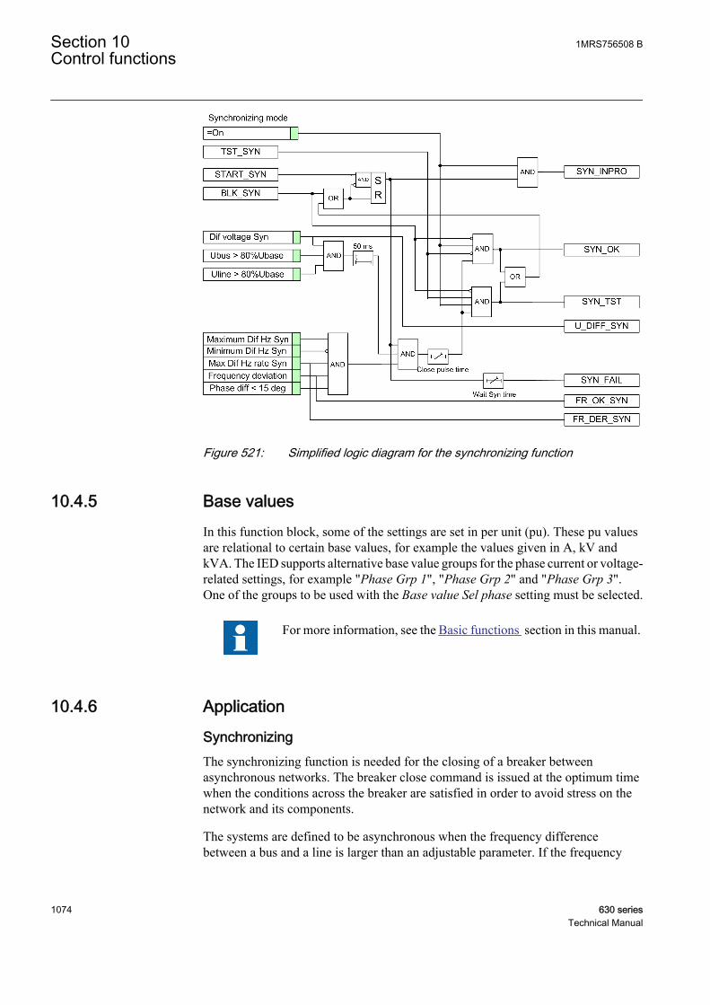
GUID-6FFA3DFD-DD0B-45B7-8E30-8D5BE2DB0274 V1 EN
Figure 521: Simplified logic diagram for the synchronizing function
10.4.5 Base valuesIn this function block, some of the settings are set in per unit (pu). These pu valuesare relational to certain base values, for example the values given in A, kV andkVA. The IED supports alternative base value groups for the phase current or voltage-related settings, for example "Phase Grp 1", "Phase Grp 2" and "Phase Grp 3".One of the groups to be used with the Base value Sel phase setting must be selected.
For more information, see the Basic functions section in this manual.
10.4.6 Application
SynchronizingThe synchronizing function is needed for the closing of a breaker betweenasynchronous networks. The breaker close command is issued at the optimum timewhen the conditions across the breaker are satisfied in order to avoid stress on thenetwork and its components.
The systems are defined to be asynchronous when the frequency differencebetween a bus and a line is larger than an adjustable parameter. If the frequency
Section 10 1MRS756508 BControl functions
1074 630 seriesTechnical Manual
difference is less than the threshold value, the systems operate as if they wereconnected in parallel and synchrocheck function was used.
At power plants, the synchronizing function is needed to permit the manual orautomatic closing of the circuit breaker.
The synchronizing function measures the difference between the line and busvoltages. It operates and enables a closing command to the circuit breaker when thecalculated closing angle is equal to the measured phase angle and certainconditions are simultaneously fulfilled.
The conditions are:
• The line and bus voltages are over 80 percent of the base value.• The difference in the voltage between the line and bus sides is smaller than the
set value of Dif voltage Syn.• The frequency deviation at the line and bus sides should not exceed the set
value of the Frequency deviation limit.• The difference in the frequency between the line and bus sides is less than the
set value of Maximum Dif Hz Syn and larger than the set value of Minimum DifHz Syn.
• The rate of change of the frequencies of both the bus and line voltages shouldbe below the set value of Max Dif Hz rate Syn.
If the difference in the frequency between the line and bus sides isless than the value of Minimum Dif Hz Syn, the synchrocheckmodule is used.
The synchronizing function compensates for the measured slip frequency as well asthe circuit breaker closing delay. The measured frequencies between the settingsfor the maximum and minimum frequencies initiate the evaluation of the anglechange to allow operation to be sent at the right moment including the set closingtime of the CB time. There is an internal phase angle release to block any incorrectclosing pulses.
At operation, the SYN_OK output activates with a pulse of defined duration and thefunction resets after the pulse ends. The function also resets if the synchronizingconditions are not fulfilled within the set wait period. This prevents the situationthat the function is by mistake maintained in operation a long time for conditions tobe fulfilled.
The reference voltage can be phase-to-neutral or phase-to-phase voltages.
1MRS756508 B Section 10Control functions
630 series 1075Technical Manual
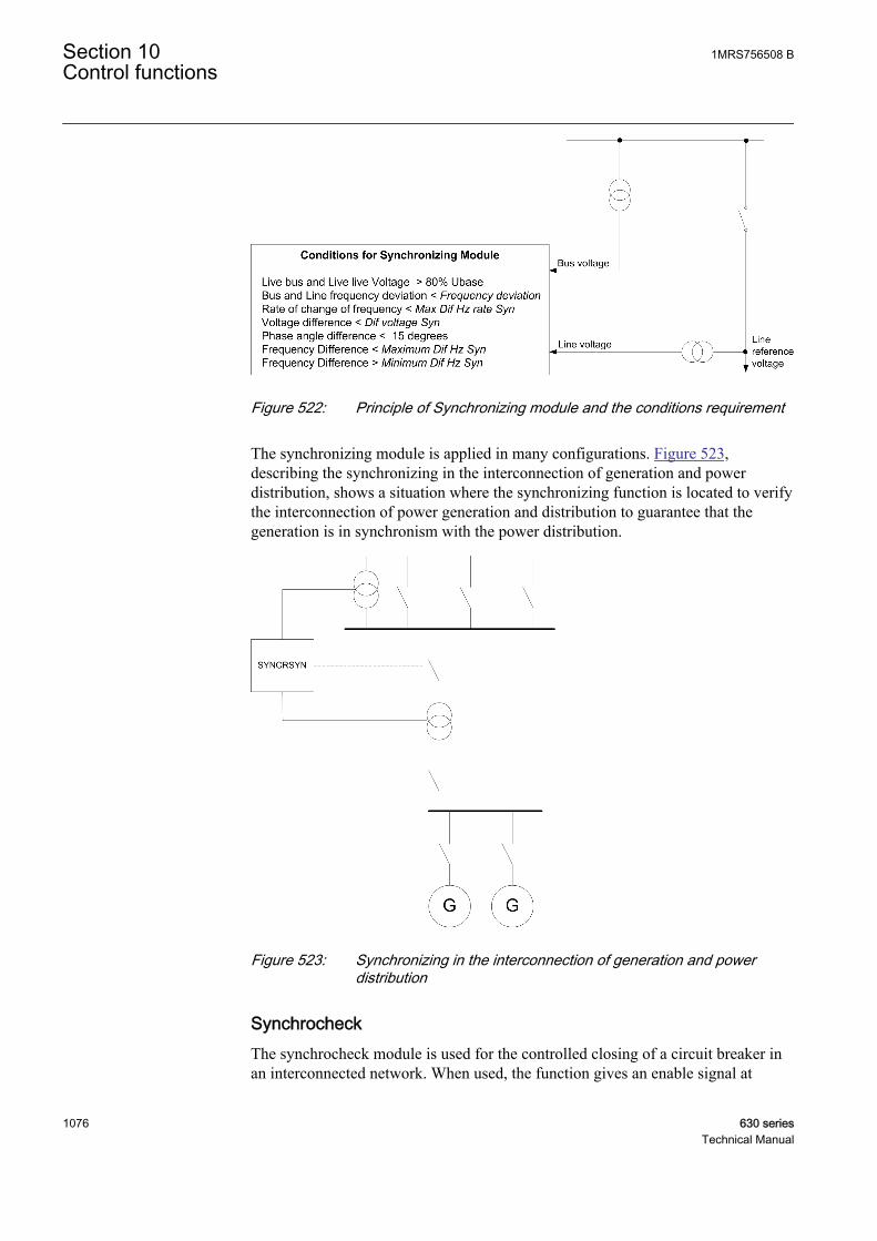
GUID-AA63F2FB-8FEA-4802-B018-6818AE8F43E8 V1 EN
Figure 522: Principle of Synchronizing module and the conditions requirement
The synchronizing module is applied in many configurations. Figure 523,describing the synchronizing in the interconnection of generation and powerdistribution, shows a situation where the synchronizing function is located to verifythe interconnection of power generation and distribution to guarantee that thegeneration is in synchronism with the power distribution.
GUID-4ED3F321-1C43-4515-842B-F310109AC2E5 V1 EN
Figure 523: Synchronizing in the interconnection of generation and powerdistribution
SynchrocheckThe synchrocheck module is used for the controlled closing of a circuit breaker inan interconnected network. When used, the function gives an enable signal at
Section 10 1MRS756508 BControl functions
1076 630 seriesTechnical Manual
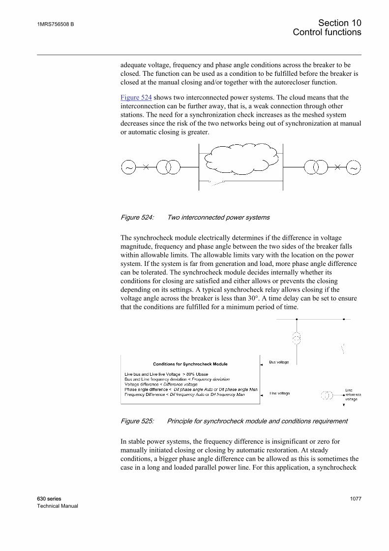
adequate voltage, frequency and phase angle conditions across the breaker to beclosed. The function can be used as a condition to be fulfilled before the breaker isclosed at the manual closing and/or together with the autorecloser function.
Figure 524 shows two interconnected power systems. The cloud means that theinterconnection can be further away, that is, a weak connection through otherstations. The need for a synchronization check increases as the meshed systemdecreases since the risk of the two networks being out of synchronization at manualor automatic closing is greater.
GUID-CCCE2418-8E2C-4063-88F0-17F7175CECF2 V1 EN
Figure 524: Two interconnected power systems
The synchrocheck module electrically determines if the difference in voltagemagnitude, frequency and phase angle between the two sides of the breaker fallswithin allowable limits. The allowable limits vary with the location on the powersystem. If the system is far from generation and load, more phase angle differencecan be tolerated. The synchrocheck module decides internally whether itsconditions for closing are satisfied and either allows or prevents the closingdepending on its settings. A typical synchrocheck relay allows closing if thevoltage angle across the breaker is less than 30°. A time delay can be set to ensurethat the conditions are fulfilled for a minimum period of time.
GUID-4A77374D-D292-4712-81A2-FAA95B4E649B V1 EN
Figure 525: Principle for synchrocheck module and conditions requirement
In stable power systems, the frequency difference is insignificant or zero formanually initiated closing or closing by automatic restoration. At steadyconditions, a bigger phase angle difference can be allowed as this is sometimes thecase in a long and loaded parallel power line. For this application, a synchrocheck
1MRS756508 B Section 10Control functions
630 series 1077Technical Manual

with a long operate time and high sensitivity regarding the frequency difference (3mHz) and a relatively big phase angle difference setting is accepted.
Another situation is where the operation of the power network is disturbed and a high-speed autoreclosing after the fault clearance takes place. This can cause a powerswing in the network and the phase angle difference begins to oscillate. Generally,the frequency difference is the time derivative of the phase angle difference andtypically oscillates between positive and negative values. When the circuit breakerneeds to be closed by the autoreclosing after the fault clearance, some frequencydifference is tolerated, and to a greater extent than in a steady condition asmentioned in the above case. But if a greater phase angle difference is allowed atthe same time, there is some risk that autoreclosing takes place when the phaseangle difference is big and increasing. In this case it should be safer to close whenthe phase angle difference is smaller.
To fulfill the requirements, the synchrocheck module is provided with duplicatesettings:
• Manual mode for steady conditions• Auto mode for operation under disturbed conditions
The synchrocheck module can be utilized for various types of networkconfigurations or topologies. The typical examples where the synchrocheck can beutilized are:
Figure 526, depicting synchrocheck in sectionalizer, shows an example of thedouble busbar system in which the feeding can be from at least two differentsources and voltages can therefore be opposite to each other.
GUID-EE488025-7707-4A52-98DC-18EE50C1585D V1 EN
Figure 526: Synchrocheck in sectionalizer
Figure 527 shows the synchrocheck for a doubly fed power line. The closing of thecircuit breaker requires that both sides are in synchronism. The energization checkis required for the breaker closing first during autoreclosing, and the synchronismcheck is needed for all the breakers closing afterwards to complete the autorecloseoperation.
Section 10 1MRS756508 BControl functions
1078 630 seriesTechnical Manual

GUID-7E069163-5979-41E0-9567-42BB25F6BAEF V1 EN
Figure 527: Synchrocheck for doubly fed power line
Many power utilities require the three-phase autoreclosing to be combined withsynchrocheck and energizing check. It is checked that if the line is dead, thiscondition is sufficient to allow autoreclosing to be executed at one end. At theopposite end of the line, usually synchrocheck is applied. The autoreclosing waitsfor the line to be energized from the first line end and the synchrocheck conditionsare fulfilled. The autoreclosing is completed.
Energizing checkThe main purpose of the energizing check module is to facilitate the controlled re-connection of disconnected lines and buses to energized lines and buses. Theenergizing function of the module is applied in a situation where a dead section ofthe network is to be connected to an energized section. The module can be operatedin auto or manual mode.
The energizing check function measures the bus and line voltages and comparesthem to both high and low threshold values. The output is given when themeasured conditions match the set conditions. Figure 528 shows a power systemsnetwork in which the bus side network is live and the line side which is dead needsto be energized by closing the circuit breaker A. For this kind of system, theenergizing module checks for various conditions and provides the energizing OKsignal if the selected mode for energizing is Dead Line Live Bus "DLLB" or DeadLine Live Bus or Live Line Dead Bus "DLLB or LLDB".
GUID-44907AA5-B9A5-4089-9116-4884B9E90C1B V1 EN
Figure 528: Principle for the energizing check function
1MRS756508 B Section 10Control functions
630 series 1079Technical Manual

The energizing check module can operate in the Dead Line Live Bus (DLLB)direction, Live Line Dead Bus (LLDB) direction or both directions over the circuitbreaker. The energizing from different directions can be different for the automaticreclosing and manual closing of the circuit breaker. For the manual closing it isalso possible to allow closing when both sides of the breaker are dead.
The equipment is considered energized if the voltage is above a set value, forexample 80 percent of the base voltage, and non-energized if it is below a setvalue, for example 30 percent of the base voltage. A disconnected line has aconsiderable potential because of the factors, such as induction from a line runningin parallel or feeding with the extinguishing capacitors in the circuit breakers.Normally for breakers in radial distribution network the level is well below 30 percent.
When the energizing conditions are satisfied according to the settings, the situationhas to remain constant for a certain period of time before the close signal ispermitted. The purpose of the delayed operate time is to ensure that the dead sideremains de-energized and that the condition is not due to temporary interference.
Fuse failure supervisionThe fuse failure supervision module continuously supervises the external fusefailure of the voltage transformer of the busbar. It also supervises the line voltages.The external fuse-failure signals or signals from a tripped fuse switch/MCB areconnected to binary inputs that are then configured to the inputs of SYNCRSYN.Alternatively, the internal signals from the fuse failure supervision function canalso be used when available.
In the event of a fuse failure, the energizing check module is blocked, whicheventually blocks the synchrocheck and synchronizing modules.
Voltage selectionThe voltage selection function is used for the connection of appropriate voltages tothe energizing check, synchrocheck and synchronizing modules. For example,when an IED is used in a double bus arrangement, the voltage to be selecteddepends on the status of the breakers and disconnectors. By checking the status ofthe auxiliary contacts of the disconnectors, the right voltages for the synchrocheckand energizing check functions are selected. The available voltage selection type isfor single circuit breaker with the double busbar arrangement. A single circuitbreaker with a single busbar does not need any voltage selection functions, nordoes a single circuit breaker with double busbars using external voltage selectionneed any internal voltage selections.
The voltages from busbars and lines must be physically connected to the voltageinputs in the IED and connected, using the control software, to SYNCRSYNavailable in the IED.
Synchronizing, synchrocheck and energizing check are based on three-phasevoltage measurements, but usually the single-phase quantities are satisfactory.Preferably a phase-to-phase voltage is used, but sometimes there is just a single phase-
Section 10 1MRS756508 BControl functions
1080 630 seriesTechnical Manual
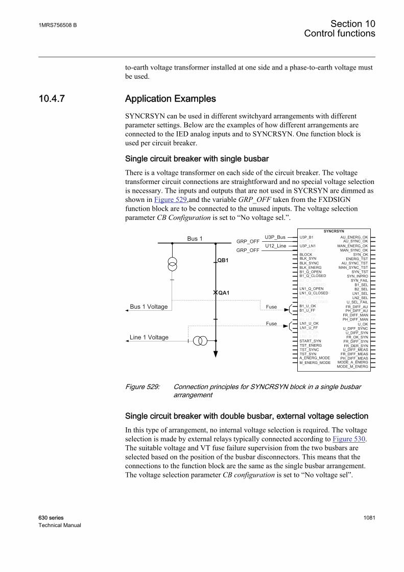
to-earth voltage transformer installed at one side and a phase-to-earth voltage mustbe used.
10.4.7 Application ExamplesSYNCRSYN can be used in different switchyard arrangements with differentparameter settings. Below are the examples of how different arrangements areconnected to the IED analog inputs and to SYNCRSYN. One function block isused per circuit breaker.
Single circuit breaker with single busbarThere is a voltage transformer on each side of the circuit breaker. The voltagetransformer circuit connections are straightforward and no special voltage selectionis necessary. The inputs and outputs that are not used in SYCRSYN are dimmed asshown in Figure 529,and the variable GRP_OFF taken from the FXDSIGNfunction block are to be connected to the unused inputs. The voltage selectionparameter CB Configuration is set to “No voltage sel.”.
Line 1 Voltage
Bus 1 Voltage
Bus 1
QB1
QA1
Fuse
Fuse
B1_SEL
U3P_B1SYNCRSYN
U3P_B2U3P_LN1U3P_LN2
B2_SELLN1_SELLN2_SEL
BLOCKBLK_SYNBLK_SYNCBLK_ENERG
LN1_Q_OPENLN1_Q_CLOSEDLN2_Q_OPENLN2_Q_CLOSED U_SEL_FAIL
AU_ENERG_OK
MAN_ENERG_OK
ENERG_TST
MODE_A_ENERGMODE_M_ENERG
AU_SYNC_OK
B1_U_FFB1_U_OK
B2_U_OKB2_U_FFLN1_U_OKLN1_U_FFLN2_U_OKLN2_U_FF
TST_ENERGTST_SYNC
START_SYN
TST_SYN
MAN_SYNC_OK
AU_SYNC_TSTMAN_SYNC_TST
FR_DIFF_AU
FR_DIFF_MANPH_DIFF_AU
PH_DIFF_MANU_OK
U_DIFF_SYNC
U_DIFF_MEASFR_DIFF_MEASPH_DIFF_MEAS
U_DIFF_SYNFR_OK_SYN
FR_DIFF_SYNFR_DER_SYN
SYN_OK
SYN_INPROSYN_FAIL
SYN_TSTB1_Q_OPENB1_Q_CLOSEDB2_Q_OPENB2_Q_CLOSED
A_ENERG_MODEM_ENERG_MODE
U12_LineGRP_OFF
U3P_BusGRP_OFF
GUID-A502866F-B01F-4B0D-881E-FA7DCCDB8988 V2 EN
Figure 529: Connection principles for SYNCRSYN block in a single busbararrangement
Single circuit breaker with double busbar, external voltage selectionIn this type of arrangement, no internal voltage selection is required. The voltageselection is made by external relays typically connected according to Figure 530.The suitable voltage and VT fuse failure supervision from the two busbars areselected based on the position of the busbar disconnectors. This means that theconnections to the function block are the same as the single busbar arrangement.The voltage selection parameter CB configuration is set to “No voltage sel”.
1MRS756508 B Section 10Control functions
630 series 1081Technical Manual
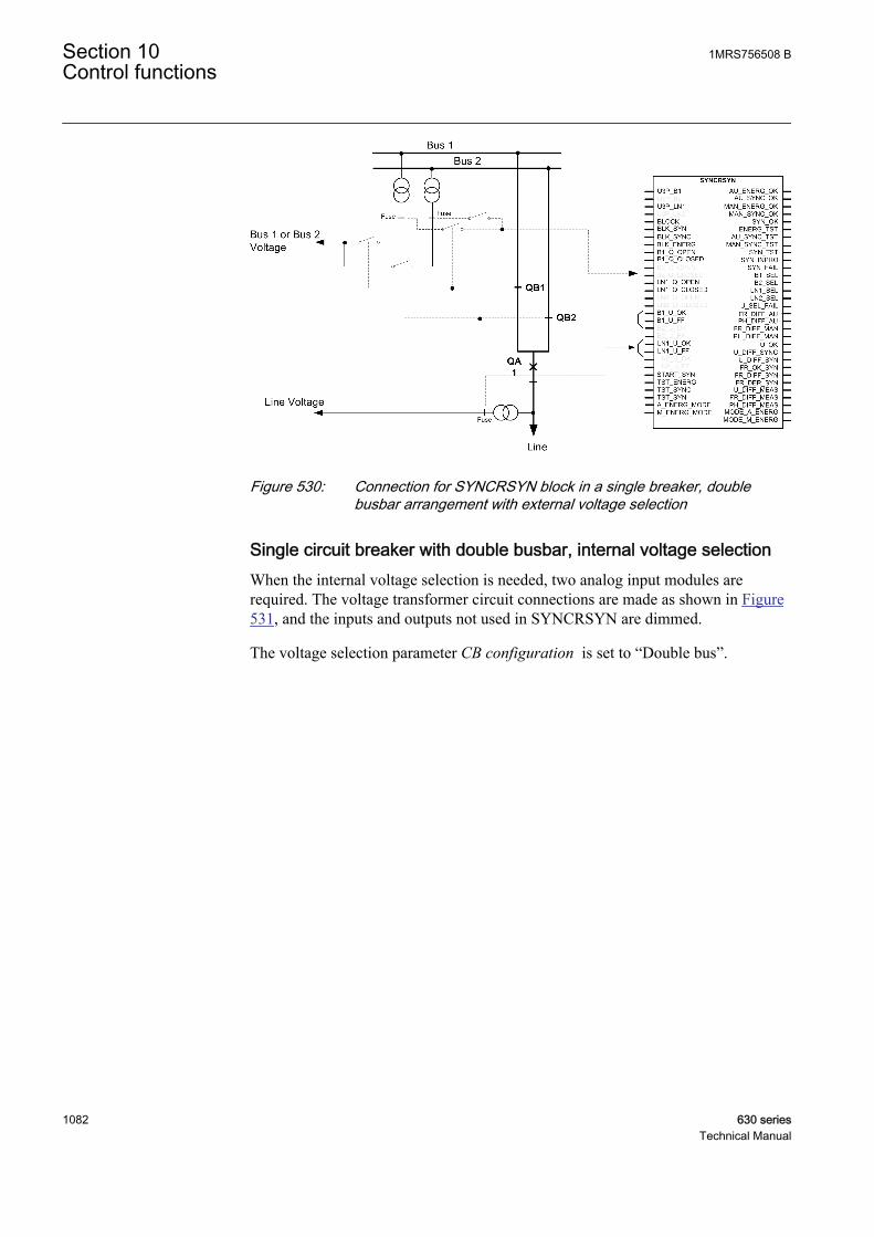
GUID-21F37E93-1661-43BC-8480-7E7738608039 V1 EN
Figure 530: Connection for SYNCRSYN block in a single breaker, doublebusbar arrangement with external voltage selection
Single circuit breaker with double busbar, internal voltage selectionWhen the internal voltage selection is needed, two analog input modules arerequired. The voltage transformer circuit connections are made as shown in Figure531, and the inputs and outputs not used in SYNCRSYN are dimmed.
The voltage selection parameter CB configuration is set to “Double bus”.
Section 10 1MRS756508 BControl functions
1082 630 seriesTechnical Manual

GUID-217A58A6-87D8-4FC4-AA9D-5A3D08DBE45F V1 EN
Figure 531: Connection for SYNCRSYN block in a single breaker, doublebusbar arrangement with internal voltage selection
10.4.8 SignalsTable 960: SYNCRSYN Input signals
Name Type Default DescriptionU3P_B1 GROUP
SIGNAL- Three phase group signal for voltage inputs,
busbar 1
U3P_B2 GROUPSIGNAL
- Three phase group signal for voltage inputs,busbar 2
U3P_LN1 GROUPSIGNAL
- Three phase group signal for voltage inputs, line 1
U3P_LN2 GROUPSIGNAL
- Three phase group signal for voltage inputs, line 2
BLOCK BOOLEAN 0 General block
BLK_SYN BOOLEAN 0 Block synchronizing
BLK_SYNC BOOLEAN 0 Block synchro check
BLK_ENERG BOOLEAN 0 Block energizing check
B1_Q_OPEN BOOLEAN 0 Open status for CB or disconnector connected tobus1
B1_Q_CLOSED BOOLEAN 0 Close status for CB or disconnector connected tobus1
B2_Q_OPEN BOOLEAN 0 Open status for CB or disconnector connected tobus2
Table continues on next page
1MRS756508 B Section 10Control functions
630 series 1083Technical Manual
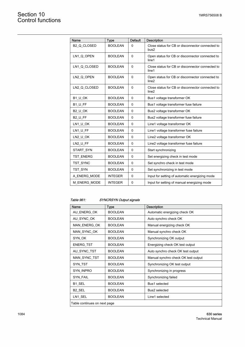
Name Type Default DescriptionB2_Q_CLOSED BOOLEAN 0 Close status for CB or disconnector connected to
bus2
LN1_Q_OPEN BOOLEAN 0 Open status for CB or disconnector connected toline1
LN1_Q_CLOSED BOOLEAN 0 Close status for CB or disconnector connected toline1
LN2_Q_OPEN BOOLEAN 0 Open status for CB or disconnector connected toline2
LN2_Q_CLOSED BOOLEAN 0 Close status for CB or disconnector connected toline2
B1_U_OK BOOLEAN 0 Bus1 voltage transformer OK
B1_U_FF BOOLEAN 0 Bus1 voltage transformer fuse failure
B2_U_OK BOOLEAN 0 Bus2 voltage transformer OK
B2_U_FF BOOLEAN 0 Bus2 voltage transformer fuse failure
LN1_U_OK BOOLEAN 0 Line1 voltage transformer OK
LN1_U_FF BOOLEAN 0 Line1 voltage transformer fuse failure
LN2_U_OK BOOLEAN 0 Line2 voltage transformer OK
LN2_U_FF BOOLEAN 0 Line2 voltage transformer fuse failure
START_SYN BOOLEAN 0 Start synchronizing
TST_ENERG BOOLEAN 0 Set energizing check in test mode
TST_SYNC BOOLEAN 0 Set synchro check in test mode
TST_SYN BOOLEAN 0 Set synchronizing in test mode
A_ENERG_MODE INTEGER 0 Input for setting of automatic energizing mode
M_ENERG_MODE INTEGER 0 Input for setting of manual energizing mode
Table 961: SYNCRSYN Output signals
Name Type DescriptionAU_ENERG_OK BOOLEAN Automatic energizing check OK
AU_SYNC_OK BOOLEAN Auto synchro check OK
MAN_ENERG_OK BOOLEAN Manual energizing check OK
MAN_SYNC_OK BOOLEAN Manual synchro check OK
SYN_OK BOOLEAN Synchronizing OK output
ENERG_TST BOOLEAN Energizing check OK test output
AU_SYNC_TST BOOLEAN Auto synchro check OK test output
MAN_SYNC_TST BOOLEAN Manual synchro check OK test output
SYN_TST BOOLEAN Synchronizing OK test output
SYN_INPRO BOOLEAN Synchronizing in progress
SYN_FAIL BOOLEAN Synchronizing failed
B1_SEL BOOLEAN Bus1 selected
B2_SEL BOOLEAN Bus2 selected
LN1_SEL BOOLEAN Line1 selected
Table continues on next page
Section 10 1MRS756508 BControl functions
1084 630 seriesTechnical Manual

Name Type DescriptionLN2_SEL BOOLEAN Line2 selected
U_SEL_FAIL BOOLEAN Selected voltage transformer fuse failed
FR_DIFF_AU BOOLEAN Frequency difference out of limit for Auto operation
PH_DIFF_AU BOOLEAN Phase angle difference out of limit for Autooperation
FR_DIFF_MAN BOOLEAN Frequency difference out of limit for Manualoperation
PH_DIFF_MAN BOOLEAN Phase angle difference out of limit for ManualOperation
U_OK BOOLEAN Voltage amplitudes above set limits
U_DIFF_SYNC BOOLEAN Voltage difference out of limit
U_DIFF_SYN BOOLEAN Voltage difference out of limit for synchronizing
FR_OK_SYN BOOLEAN Frequency difference in band for synchronizing
FR_DIFF_SYN BOOLEAN Frequency difference out of limit for synchronizing
FR_DER_SYN BOOLEAN Frequency derivative out of limit for synchronizing
U_DIFF_MEAS REAL Calculated difference in voltage
FR_DIFF_MEAS REAL Calculated difference in frequency
PH_DIFF_MEAS REAL Calculated difference of phase angle
MODE_A_ENERG INTEGER Selected mode for automatic energizing
MODE_M_ENERG INTEGER Selected mode for manual energizing
10.4.9 SettingsTable 962: SYNCRSYN Group settings (basic)
Name Values (Range) Unit Step Default DescriptionDead bus value 0.05 - 0.50 pu 0.01 0.40 Voltage low limit bus for energizing check
Dead line value 0.05 - 0.50 pu 0.01 0.40 Voltage low limit line for energizing check
Live bus value 0.40 - 1.20 pu 0.01 0.80 Voltage high limit bus for energizing check
Live line value 0.40 - 1.20 pu 0.01 0.80 Voltage high limit line for energizing check
Frequency deviation 1 - 5 Hz 1 5 Max allowed Frequency deviation fromrated frequency
Difference voltage 0.02 - 0.50 pu 0.01 0.15 Voltage difference limit
Max energizing V 0.80 - 1.40 pu 0.01 1.15 Maximum voltage for energizing
Phase shift -180 - 180 Deg 5 0 Phase shift
Voltage ratio 0.20 - 5.00 - 0.01 1.00 Voltage ratio
Live dead mode Auto OffLLDBDLLBLLDB or DLLB
- - LLDB Automatic energizing check mode
Dif phase angle Auto 5 - 90 Deg 1 25 Phase angle difference limit betweenbus and line Auto
Dif frequency Auto 0.003 - 1.000 Hz 0.001 0.010 Frequency difference limit between busand line Auto
Table continues on next page
1MRS756508 B Section 10Control functions
630 series 1085Technical Manual
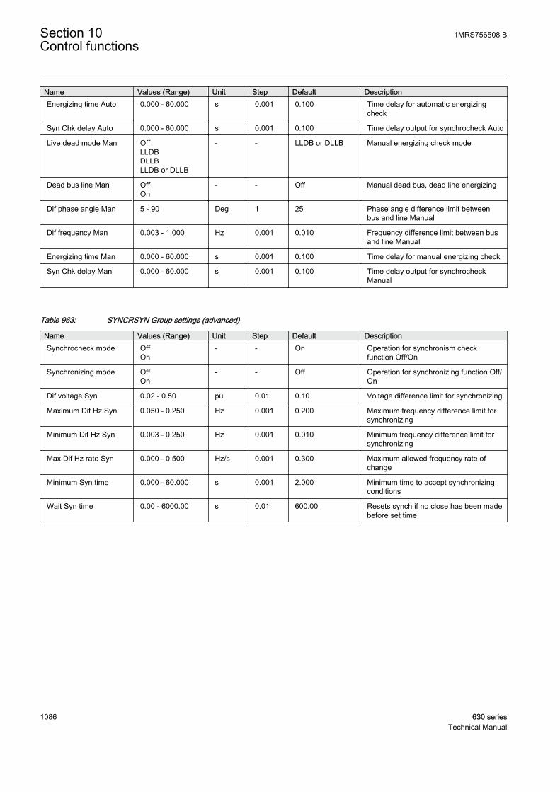
Name Values (Range) Unit Step Default DescriptionEnergizing time Auto 0.000 - 60.000 s 0.001 0.100 Time delay for automatic energizing
check
Syn Chk delay Auto 0.000 - 60.000 s 0.001 0.100 Time delay output for synchrocheck Auto
Live dead mode Man OffLLDBDLLBLLDB or DLLB
- - LLDB or DLLB Manual energizing check mode
Dead bus line Man OffOn
- - Off Manual dead bus, dead line energizing
Dif phase angle Man 5 - 90 Deg 1 25 Phase angle difference limit betweenbus and line Manual
Dif frequency Man 0.003 - 1.000 Hz 0.001 0.010 Frequency difference limit between busand line Manual
Energizing time Man 0.000 - 60.000 s 0.001 0.100 Time delay for manual energizing check
Syn Chk delay Man 0.000 - 60.000 s 0.001 0.100 Time delay output for synchrocheckManual
Table 963: SYNCRSYN Group settings (advanced)
Name Values (Range) Unit Step Default DescriptionSynchrocheck mode Off
On- - On Operation for synchronism check
function Off/On
Synchronizing mode OffOn
- - Off Operation for synchronizing function Off/On
Dif voltage Syn 0.02 - 0.50 pu 0.01 0.10 Voltage difference limit for synchronizing
Maximum Dif Hz Syn 0.050 - 0.250 Hz 0.001 0.200 Maximum frequency difference limit forsynchronizing
Minimum Dif Hz Syn 0.003 - 0.250 Hz 0.001 0.010 Minimum frequency difference limit forsynchronizing
Max Dif Hz rate Syn 0.000 - 0.500 Hz/s 0.001 0.300 Maximum allowed frequency rate ofchange
Minimum Syn time 0.000 - 60.000 s 0.001 2.000 Minimum time to accept synchronizingconditions
Wait Syn time 0.00 - 6000.00 s 0.01 600.00 Resets synch if no close has been madebefore set time
Section 10 1MRS756508 BControl functions
1086 630 seriesTechnical Manual

Table 964: SYNCRSYN Non group settings (basic)
Name Values (Range) Unit Step Default DescriptionOperation Off
On- - On Operation Off / On
CB configuration No voltage sel.Double bus1 1/2 bus 1 CB1 1/2 bus 2 CBTie CB
- - No voltage sel. Select CB configuration
Phase selection bus phase1phase2phase3phase1-phase2phase2-phase3phase3-phase1
- - phase1-phase2 Select phase for buses
Phase selection line phase1phase2phase3phase1-phase2phase2-phase3phase3-phase1
- - phase1-phase2 Select phase for lines
Closing time of CB 0.000 - 60.000 s 0.001 0.080 Closing time of the breaker
Table 965: SYNCRSYN Non group settings (advanced)
Name Values (Range) Unit Step Default DescriptionBase value Sel phase Phase Grp 1
Phase Grp 2Phase Grp 3
- - Phase Grp 1 Base value selector, phase / phase-to-phase
Close pulse time 0.050 - 60.000 s 0.001 0.200 Breaker closing pulse duration
10.4.10 Measured valuesTable 966: SYNCRSYN Measured values
Name Type Default DescriptionBLOCK BOOLEAN 0 General block
BLK_SYN BOOLEAN 0 Block synchronizing
BLK_SYNC BOOLEAN 0 Block synchro check
BLK_ENERG BOOLEAN 0 Block energizing check
B1_Q_OPEN BOOLEAN 0 Open status for CB or disconnector connected tobus1
B1_Q_CLOSED BOOLEAN 0 Close status for CB or disconnector connected tobus1
B2_Q_OPEN BOOLEAN 0 Open status for CB or disconnector connected tobus2
B2_Q_CLOSED BOOLEAN 0 Close status for CB or disconnector connected tobus2
LN1_Q_OPEN BOOLEAN 0 Open status for CB or disconnector connected toline1
Table continues on next page
1MRS756508 B Section 10Control functions
630 series 1087Technical Manual
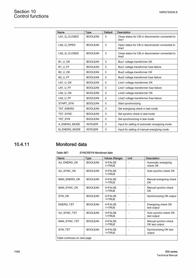
Name Type Default DescriptionLN1_Q_CLOSED BOOLEAN 0 Close status for CB or disconnector connected to
line1
LN2_Q_OPEN BOOLEAN 0 Open status for CB or disconnector connected toline2
LN2_Q_CLOSED BOOLEAN 0 Close status for CB or disconnector connected toline2
B1_U_OK BOOLEAN 0 Bus1 voltage transformer OK
B1_U_FF BOOLEAN 0 Bus1 voltage transformer fuse failure
B2_U_OK BOOLEAN 0 Bus2 voltage transformer OK
B2_U_FF BOOLEAN 0 Bus2 voltage transformer fuse failure
LN1_U_OK BOOLEAN 0 Line1 voltage transformer OK
LN1_U_FF BOOLEAN 0 Line1 voltage transformer fuse failure
LN2_U_OK BOOLEAN 0 Line2 voltage transformer OK
LN2_U_FF BOOLEAN 0 Line2 voltage transformer fuse failure
START_SYN BOOLEAN 0 Start synchronizing
TST_ENERG BOOLEAN 0 Set energizing check in test mode
TST_SYNC BOOLEAN 0 Set synchro check in test mode
TST_SYN BOOLEAN 0 Set synchronizing in test mode
A_ENERG_MODE INTEGER 0 Input for setting of automatic energizing mode
M_ENERG_MODE INTEGER 0 Input for setting of manual energizing mode
10.4.11 Monitored dataTable 967: SYNCRSYN Monitored data
Name Type Values (Range) Unit DescriptionAU_ENERG_OK BOOLEAN 0=FALSE
1=TRUE- Automatic energizing
check OK
AU_SYNC_OK BOOLEAN 0=FALSE1=TRUE
- Auto synchro check OK
MAN_ENERG_OK BOOLEAN 0=FALSE1=TRUE
- Manual energizing checkOK
MAN_SYNC_OK BOOLEAN 0=FALSE1=TRUE
- Manual synchro checkOK
SYN_OK BOOLEAN 0=FALSE1=TRUE
- Synchronizing OK output
ENERG_TST BOOLEAN 0=FALSE1=TRUE
- Energizing check OKtest output
AU_SYNC_TST BOOLEAN 0=FALSE1=TRUE
- Auto synchro check OKtest output
MAN_SYNC_TST BOOLEAN 0=FALSE1=TRUE
- Manual synchro checkOK test output
SYN_TST BOOLEAN 0=FALSE1=TRUE
- Synchronizing OK testoutput
Table continues on next page
Section 10 1MRS756508 BControl functions
1088 630 seriesTechnical Manual
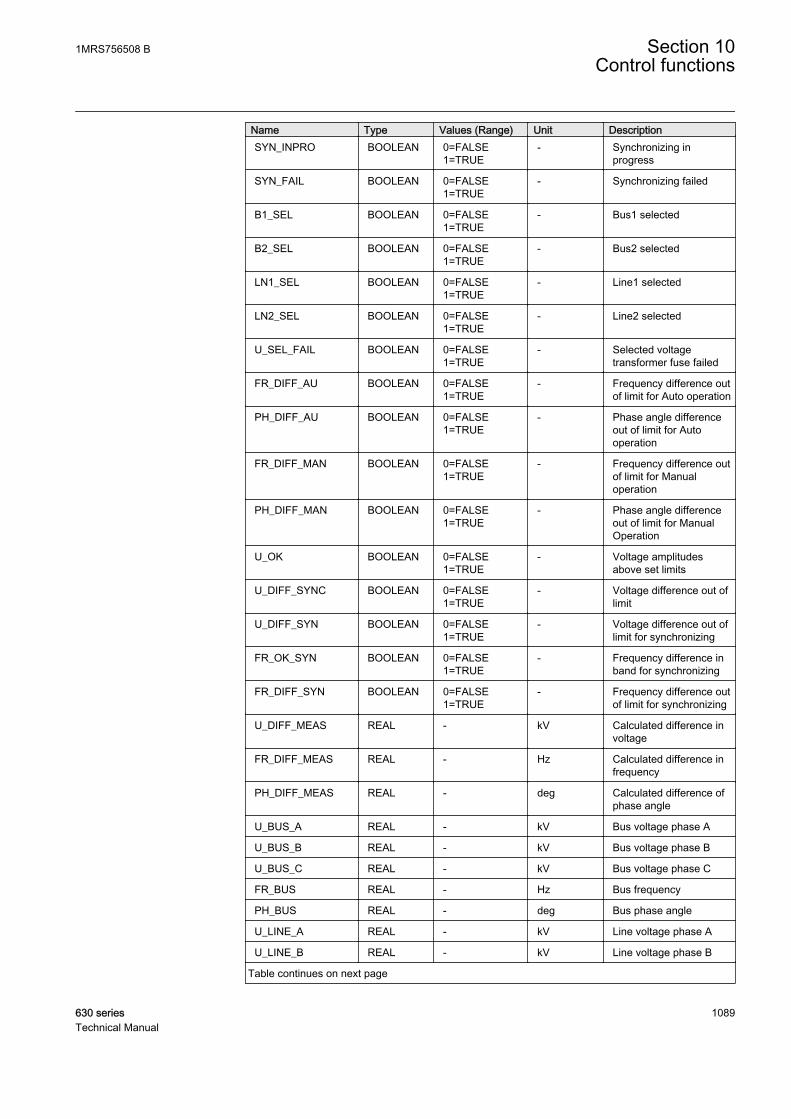
Name Type Values (Range) Unit DescriptionSYN_INPRO BOOLEAN 0=FALSE
1=TRUE- Synchronizing in
progress
SYN_FAIL BOOLEAN 0=FALSE1=TRUE
- Synchronizing failed
B1_SEL BOOLEAN 0=FALSE1=TRUE
- Bus1 selected
B2_SEL BOOLEAN 0=FALSE1=TRUE
- Bus2 selected
LN1_SEL BOOLEAN 0=FALSE1=TRUE
- Line1 selected
LN2_SEL BOOLEAN 0=FALSE1=TRUE
- Line2 selected
U_SEL_FAIL BOOLEAN 0=FALSE1=TRUE
- Selected voltagetransformer fuse failed
FR_DIFF_AU BOOLEAN 0=FALSE1=TRUE
- Frequency difference outof limit for Auto operation
PH_DIFF_AU BOOLEAN 0=FALSE1=TRUE
- Phase angle differenceout of limit for Autooperation
FR_DIFF_MAN BOOLEAN 0=FALSE1=TRUE
- Frequency difference outof limit for Manualoperation
PH_DIFF_MAN BOOLEAN 0=FALSE1=TRUE
- Phase angle differenceout of limit for ManualOperation
U_OK BOOLEAN 0=FALSE1=TRUE
- Voltage amplitudesabove set limits
U_DIFF_SYNC BOOLEAN 0=FALSE1=TRUE
- Voltage difference out oflimit
U_DIFF_SYN BOOLEAN 0=FALSE1=TRUE
- Voltage difference out oflimit for synchronizing
FR_OK_SYN BOOLEAN 0=FALSE1=TRUE
- Frequency difference inband for synchronizing
FR_DIFF_SYN BOOLEAN 0=FALSE1=TRUE
- Frequency difference outof limit for synchronizing
U_DIFF_MEAS REAL - kV Calculated difference involtage
FR_DIFF_MEAS REAL - Hz Calculated difference infrequency
PH_DIFF_MEAS REAL - deg Calculated difference ofphase angle
U_BUS_A REAL - kV Bus voltage phase A
U_BUS_B REAL - kV Bus voltage phase B
U_BUS_C REAL - kV Bus voltage phase C
FR_BUS REAL - Hz Bus frequency
PH_BUS REAL - deg Bus phase angle
U_LINE_A REAL - kV Line voltage phase A
U_LINE_B REAL - kV Line voltage phase B
Table continues on next page
1MRS756508 B Section 10Control functions
630 series 1089Technical Manual

Name Type Values (Range) Unit DescriptionU_LINE_C REAL - kV Line voltage phase C
FR_LINE REAL - Hz Line frequency
PH_LINE REAL - deg Line phase angle
MODE_A_ENERG INTEGER 0=Off1=DLLB2=LLDB3=LLDB or DLLB
- Selected mode forautomatic energizing
MODE_M_ENERG INTEGER 0=Off1=DLLB2=LLDB3=LLDB or DLLB
- Selected mode formanual energizing
10.4.12 Technical data
Table 968: SYNCRSYN Technical data
Characteristic ValueOperation accuracy At the frequency f = fn
Voltage: ±1.0% or ±0.002 x UnFrequency: ±10 mHzPhase angle ±2°
Reset time < 50 ms
Reset ratio Typical 0.96
Operate time accuracy ±1.0% of the set value or ±20 ms
10.5 Auto-recloser DARREC
10.5.1 IdentificationFunction description IEC 61850 logical
node nameIEC 60617identification
ANSI/IEEE C37.2device number
Auto-recloser DARREC O-->I 79
Section 10 1MRS756508 BControl functions
1090 630 seriesTechnical Manual

10.5.2 Function block
GUID-EFE5F459-43FB-46E3-9E63-E1A7B6C0EFA6 V2 EN
Figure 532: Function block
10.5.3 FunctionalityAbout 80 to 85 percent of faults in the MV overhead lines are transient andautomatically cleared with a momentary de-energization of the line. The rest of thefaults, 15 to 20 percent, can be cleared by longer interruptions. The de-energizationof the fault location for a selected time period is implemented through automaticreclosing, during which most of the faults can be cleared.
In case of a permanent fault, the automatic reclosing is followed by final tripping.A permanent fault must be located and cleared before the fault location can be re-energized.
The auto-reclose function AR can be used with any circuit breaker suitable for auto-reclosing. The function provides five programmable auto-reclose shots which canperform one to five successive auto-reclosings of desired type and duration, forinstance one high-speed and one delayed auto-reclosing.
When the reclosing is initiated with starting of the protection function, the auto-reclose function can execute the final trip of the circuit breaker in a short operatetime, provided that the fault still persists when the last selected reclosing has beencarried out.
10.5.3.1 Protection signal definition
The Control line setting defines which of the initiation signals are protection startand trip signals and which are not. With this setting, the user can distinguish theblocking signals from the protection signals. The Control line setting is a bit mask,that is, the lowest bit controls the INIT_1 line and the highest bit the INIT_6line. Some example combinations of the Control line setting are as follows:
1MRS756508 B Section 10Control functions
630 series 1091Technical Manual

Table 969: Control line setting definition
Control linesetting
INIT_1 INIT_2DEL_INIT_2
INIT_3DEL_INIT_3
INIT_4DEL_INIT_4
INIT_5 INIT_6
0 other other other other other other
1 prot other other other other other
2 other prot other other other other
3 prot prot other other other other
4 other other prot other other other
5 prot other prot other other other
...63 prot prot prot prot prot prot
prot = protection signal
other = non-protection signal
When the corresponding bit or bits in both the Control line setting and the INIT_Xline are TRUE:
• The CLOSE_CB output is blocked until the protection is reset• If the INIT_X line defined as the protection signal is activated during the
discrimination time, the AR function goes to lockout• If the INIT_X line defined as the protection signal stays active longer than the
time set by the Max trip time setting, the AR function goes to lockout (long trip)• The UNSUC_RECL output is activated after a pre-defined two minutes
(alarming earth-fault).
10.5.3.2 Zone coordination
Zone coordination is used in the zone sequence between local protection units anddownstream devices. At the falling edge of the INC_SHOTP line, the value of theshot pointer is increased by one, unless a shot is in progress or the shot pointeralready has the maximum value.
The falling edge of the INC_SHOTP line is not accepted if any of the shots are inprogress.
10.5.3.3 Master and slave scheme
With the cooperation between the AR units in the same IED or between IEDs,sequential reclosings of two breakers at a line end in a 1½-breaker, double breakeror ring-bus arrangement can be achieved. One unit is defined as a master and itexecutes the reclosing first. If the reclosing is successful and no trip takes place, thesecond unit, that is the slave, is released to complete the reclose shot. Withpersistent faults, the breaker reclosing is limited to the first breaker.
Section 10 1MRS756508 BControl functions
1092 630 seriesTechnical Manual

A070877 V1 EN
Figure 533: Master and slave scheme
If the AR unit is defined as a master by setting its Terminal priority to High (master)”:
• The unit activates the CMD_WAIT output to the low priority slave unitwhenever a shot is in progress, a reclosing is unsuccessful or theBLK_RCLM_T input is active
• The CMD_WAIT output is reset one second after the reclose command is givenor if the sequence is unsuccessful when the reclaim time elapses.
If the AR unit is defined as a slave by setting its terminal priority to low:
• The unit waits until the master releases the BLK_RECL_T input (theCMD_WAIT output in the master). Only after this signal has been deactivated,the reclose time for the slave unit can be started.
• The slave unit is set to a lockout state if the BLK_RECL_T input is notreleased within the time defined by the Max wait time setting , which followsthe initiation of an auto-reclose shot.
If the terminal priority of the AR unit is set to "none", the AR unit skips all theseactions.
10.5.3.4 Thermal overload blocking
An alarm or start signal from the thermal overload protection (T1PTTR) can berouted to the input BLK_THERM to block and hold the reclose sequence. TheBLK_THERM signal does not affect the starting of the sequence. When the reclosetime has elapsed and the BLK_THERM input is active, the shot is not ready until theBLK_THERM input deactivates. Should the BLK_THERM input remain activelonger than the time set by the setting Max block time, the AR function goes to lockout.
If the BLK_THERM input is activated when the auto wait timer is running, the autowait timer is reset and the timer restarted when the BLK_THERM input deactivates.
10.5.4 Operation principleThe function can be enabled and disabled with the Operation setting. Thecorresponding parameter values are "On" and "Off".
The reclosing operation can be enabled and disabled with the Reclosing operationsetting. This setting does not disable the function, only the reclosing functionality.The setting has three parameter values: “On”, “External Ctl” and ”Off”. The setting
1MRS756508 B Section 10Control functions
630 series 1093Technical Manual
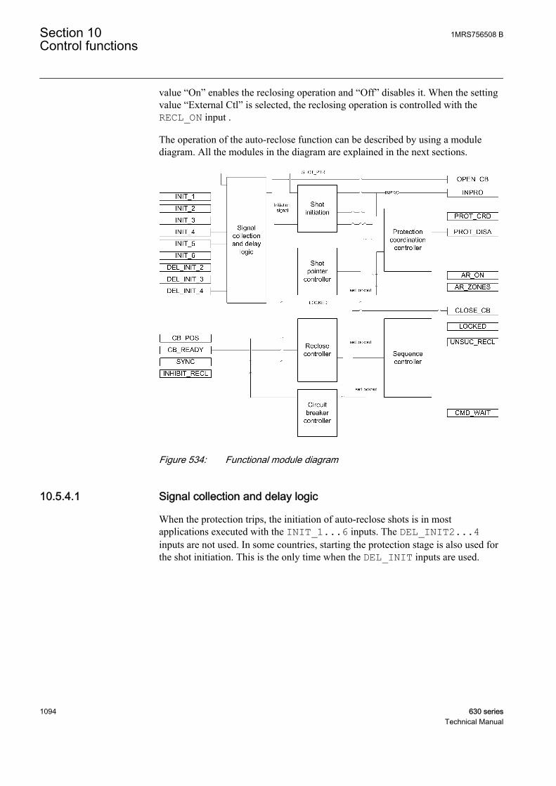
value “On” enables the reclosing operation and “Off” disables it. When the settingvalue “External Ctl” is selected, the reclosing operation is controlled with theRECL_ON input .
The operation of the auto-reclose function can be described by using a modulediagram. All the modules in the diagram are explained in the next sections.
GUID-D23F3727-4ECC-413F-86B7-84371D022881 V1 EN
Figure 534: Functional module diagram
10.5.4.1 Signal collection and delay logic
When the protection trips, the initiation of auto-reclose shots is in mostapplications executed with the INIT_1...6 inputs. The DEL_INIT2...4inputs are not used. In some countries, starting the protection stage is also used forthe shot initiation. This is the only time when the DEL_INIT inputs are used.
Section 10 1MRS756508 BControl functions
1094 630 seriesTechnical Manual

A070865 V2 EN
Figure 535: Schematic diagram of delayed initiation input signals
In total, the AR function contains six separate initiation lines used for the initiationor blocking of the auto-reclose shots. These lines are divided into two types ofchannels. In three of these channels, the signal to the AR function can be delayed,whereas the other three channels do not have any delaying capability.
Each channel that is capable of delaying a start signal has four time delays. Thetime delay is selected based on the shot pointer in the AR function. For the firstreclose attempt, the first time delay is selected; for the second attempt, the secondtime delay and so on. For the fourth and fifth attempts, the time delays are the same.
Time delay settings for the DEL_INIT_2 signal are as follows:
• Str 2 delay shot 1• Str 2 delay shot 2• Str 2 delay shot 3• Str 2 delay shot 4
Time delay settings for the DEL_INIT_3 signal are as follows:
1MRS756508 B Section 10Control functions
630 series 1095Technical Manual
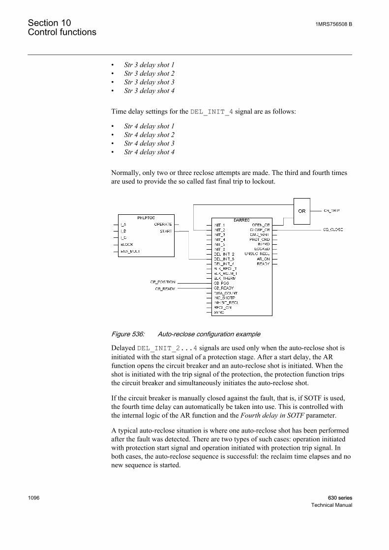
• Str 3 delay shot 1• Str 3 delay shot 2• Str 3 delay shot 3• Str 3 delay shot 4
Time delay settings for the DEL_INIT_4 signal are as follows:
• Str 4 delay shot 1• Str 4 delay shot 2• Str 4 delay shot 3• Str 4 delay shot 4
Normally, only two or three reclose attempts are made. The third and fourth timesare used to provide the so called fast final trip to lockout.
A070866 V2 EN
Figure 536: Auto-reclose configuration example
Delayed DEL_INIT_2...4 signals are used only when the auto-reclose shot isinitiated with the start signal of a protection stage. After a start delay, the ARfunction opens the circuit breaker and an auto-reclose shot is initiated. When theshot is initiated with the trip signal of the protection, the protection function tripsthe circuit breaker and simultaneously initiates the auto-reclose shot.
If the circuit breaker is manually closed against the fault, that is, if SOTF is used,the fourth time delay can automatically be taken into use. This is controlled withthe internal logic of the AR function and the Fourth delay in SOTF parameter.
A typical auto-reclose situation is where one auto-reclose shot has been performedafter the fault was detected. There are two types of such cases: operation initiatedwith protection start signal and operation initiated with protection trip signal. Inboth cases, the auto-reclose sequence is successful: the reclaim time elapses and nonew sequence is started.
Section 10 1MRS756508 BControl functions
1096 630 seriesTechnical Manual
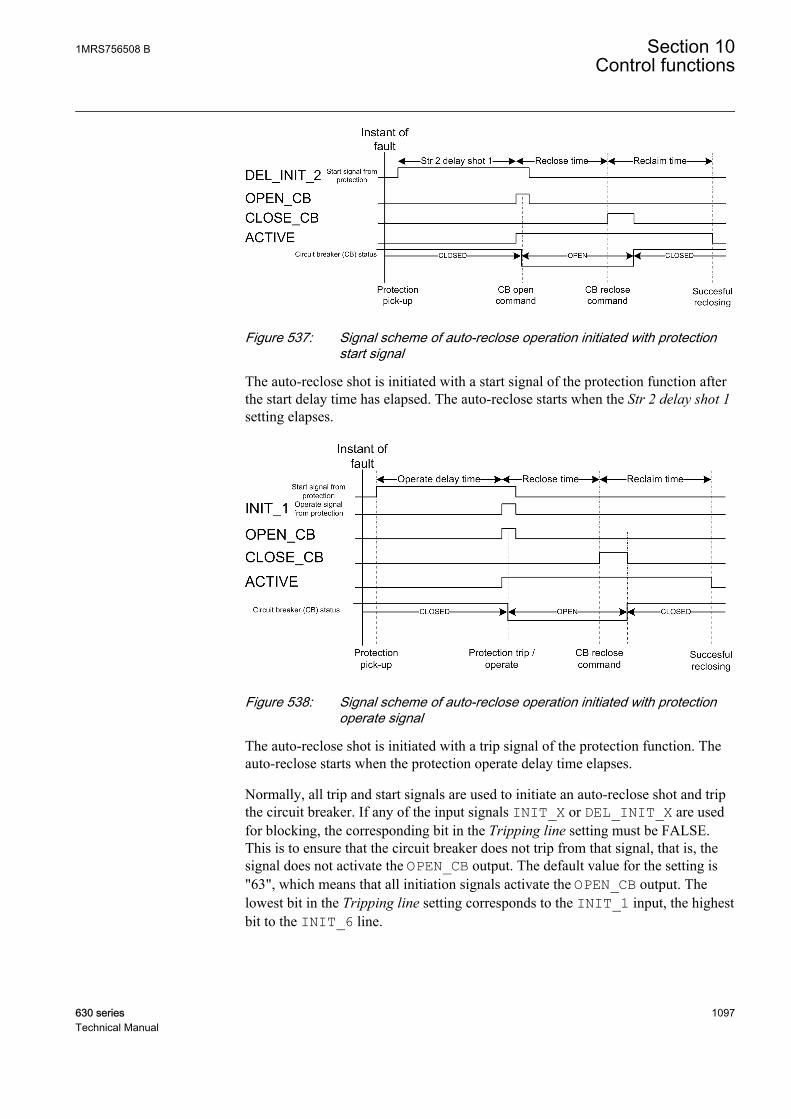
A070867 V1 EN
Figure 537: Signal scheme of auto-reclose operation initiated with protectionstart signal
The auto-reclose shot is initiated with a start signal of the protection function afterthe start delay time has elapsed. The auto-reclose starts when the Str 2 delay shot 1setting elapses.
A070868 V1 EN
Figure 538: Signal scheme of auto-reclose operation initiated with protectionoperate signal
The auto-reclose shot is initiated with a trip signal of the protection function. Theauto-reclose starts when the protection operate delay time elapses.
Normally, all trip and start signals are used to initiate an auto-reclose shot and tripthe circuit breaker. If any of the input signals INIT_X or DEL_INIT_X are usedfor blocking, the corresponding bit in the Tripping line setting must be FALSE.This is to ensure that the circuit breaker does not trip from that signal, that is, thesignal does not activate the OPEN_CB output. The default value for the setting is"63", which means that all initiation signals activate the OPEN_CB output. Thelowest bit in the Tripping line setting corresponds to the INIT_1 input, the highestbit to the INIT_6 line.
1MRS756508 B Section 10Control functions
630 series 1097Technical Manual
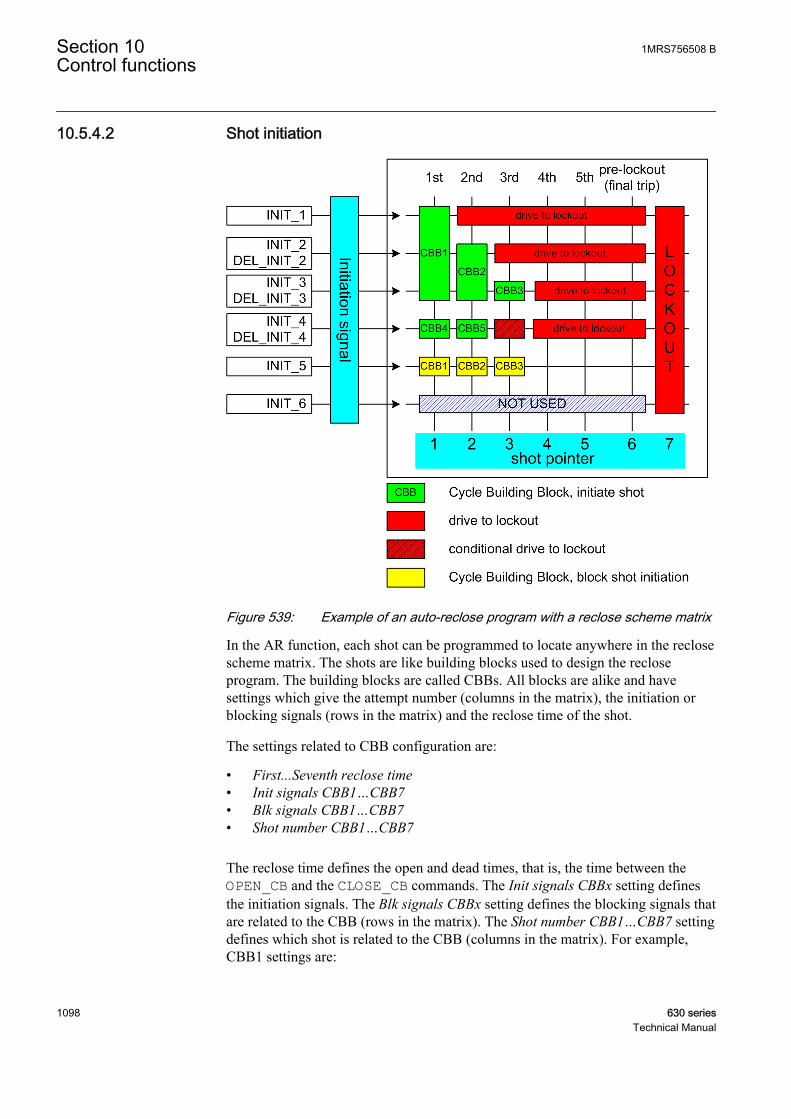
10.5.4.2 Shot initiation
A070869 V1 EN
Figure 539: Example of an auto-reclose program with a reclose scheme matrix
In the AR function, each shot can be programmed to locate anywhere in the reclosescheme matrix. The shots are like building blocks used to design the recloseprogram. The building blocks are called CBBs. All blocks are alike and havesettings which give the attempt number (columns in the matrix), the initiation orblocking signals (rows in the matrix) and the reclose time of the shot.
The settings related to CBB configuration are:
• First...Seventh reclose time• Init signals CBB1…CBB7• Blk signals CBB1…CBB7• Shot number CBB1…CBB7
The reclose time defines the open and dead times, that is, the time between theOPEN_CB and the CLOSE_CB commands. The Init signals CBBx setting definesthe initiation signals. The Blk signals CBBx setting defines the blocking signals thatare related to the CBB (rows in the matrix). The Shot number CBB1…CBB7 settingdefines which shot is related to the CBB (columns in the matrix). For example,CBB1 settings are:
Section 10 1MRS756508 BControl functions
1098 630 seriesTechnical Manual

• First reclose time = 1.0s• Init signals CBB1 = 7 (three lowest bits: 111000 = 7)• Blk signals CBB1 = 16 (the fifth bit: 000010 = 16)• Shot number CBB1 = 1
CBB2 settings are:
• Second reclose time = 10s• Init signals CBB2 = 6 (the second and third bits: 011000 = 6)• Blk signals CBB2 = 16 (the fifth bit: 000010 = 16)• Shot number CBB2 = 2
CBB3 settings are:
• Third reclose time = 30s• Init signals CBB3 = 4 (the third bit: 001000 = 4)• Blk signals CBB3 = 16 (the fifth bit: 000010 = 16)• Shot number CBB3 = 3
CBB4 settings are:
• Fourth reclose time = 0.5s• Init signals CBB4 = 8 (the fourth bit: 000100 = 8)• Blk signals CBB4 = 0 (no blocking signals related to this CBB)• Shot number CBB4 = 1
If a shot is initiated from the INIT_1 line, only one shot is allowed beforelockout. If a shot is initiated from the INIT_3 line, three shots are allowed beforelockout.
A sequence initiation from the INIT_4 line leads to a lockout after two shots. In asituation where the initiation is made from both the INIT_3 and INIT_4 lines, athird shot is allowed, that is, CBB3 is allowed to start. This is called conditionallockout. If the initiation is made from the INIT_2 and INIT_3 lines, animmediate lockout occurs.
The INIT_5 line is used for blocking purposes. If the INIT_5 line is activeduring a sequence start, the reclose attempt is blocked and the AR function goes tolockout.
If more than one CBBs are started with the shot pointer, the CBBwith the smallest individual number is always selected. Forexample, if the INIT_2 and INIT_4 lines are active for thesecond shot, that is, the shot pointer is 2, CBB2 is started instead ofCBB5.
1MRS756508 B Section 10Control functions
630 series 1099Technical Manual

Even if the initiation signals are not received from the protection functions, the ARfunction can be set to continue from the second to the fifth reclose shot. The ARfunction can, for example, be requested to automatically continue with thesequence when the circuit breaker fails to close when requested. In such a case, theAR function issues a CLOSE_CB command. When the wait close time elapses, thatis, the closing of the circuit breaker fails, the next shot is automatically started.Another example is the embedded generation on the power line, which can makethe synchronism check fail and prevent the reclosing. If the auto-reclose sequenceis continued to the second shot, a successful synchronous reclosing is more likelythan with the first shot, since the second shot lasts longer than the first one.
A070870 V1 EN
Figure 540: Logic diagram of auto-initiation sequence detection
Automatic initiation can be selected with the Auto initiation Cnd setting to be thefollowing:
Section 10 1MRS756508 BControl functions
1100 630 seriesTechnical Manual
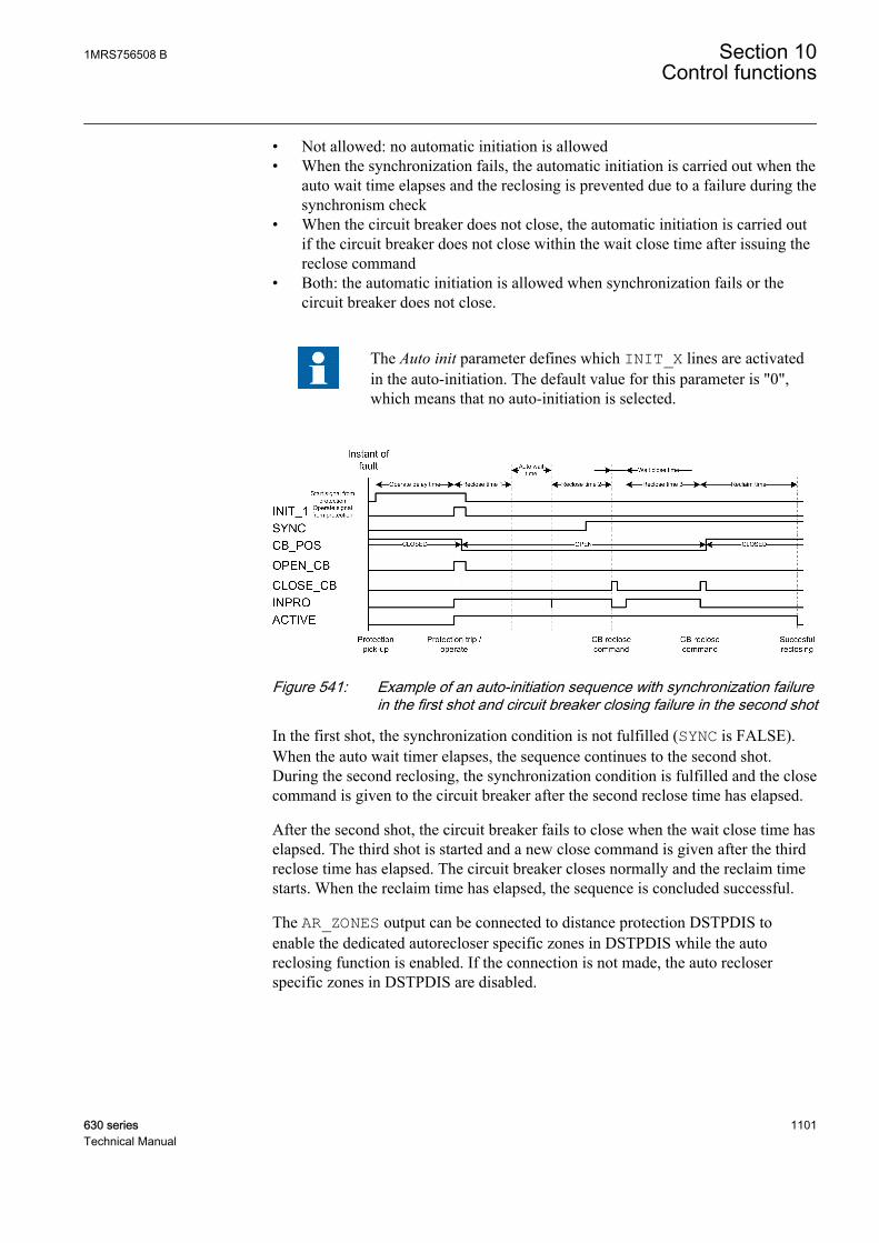
• Not allowed: no automatic initiation is allowed• When the synchronization fails, the automatic initiation is carried out when the
auto wait time elapses and the reclosing is prevented due to a failure during thesynchronism check
• When the circuit breaker does not close, the automatic initiation is carried outif the circuit breaker does not close within the wait close time after issuing thereclose command
• Both: the automatic initiation is allowed when synchronization fails or thecircuit breaker does not close.
The Auto init parameter defines which INIT_X lines are activatedin the auto-initiation. The default value for this parameter is "0",which means that no auto-initiation is selected.
A070871 V1 EN
Figure 541: Example of an auto-initiation sequence with synchronization failurein the first shot and circuit breaker closing failure in the second shot
In the first shot, the synchronization condition is not fulfilled (SYNC is FALSE).When the auto wait timer elapses, the sequence continues to the second shot.During the second reclosing, the synchronization condition is fulfilled and the closecommand is given to the circuit breaker after the second reclose time has elapsed.
After the second shot, the circuit breaker fails to close when the wait close time haselapsed. The third shot is started and a new close command is given after the thirdreclose time has elapsed. The circuit breaker closes normally and the reclaim timestarts. When the reclaim time has elapsed, the sequence is concluded successful.
The AR_ZONES output can be connected to distance protection DSTPDIS toenable the dedicated autorecloser specific zones in DSTPDIS while the autoreclosing function is enabled. If the connection is not made, the auto recloserspecific zones in DSTPDIS are disabled.
1MRS756508 B Section 10Control functions
630 series 1101Technical Manual
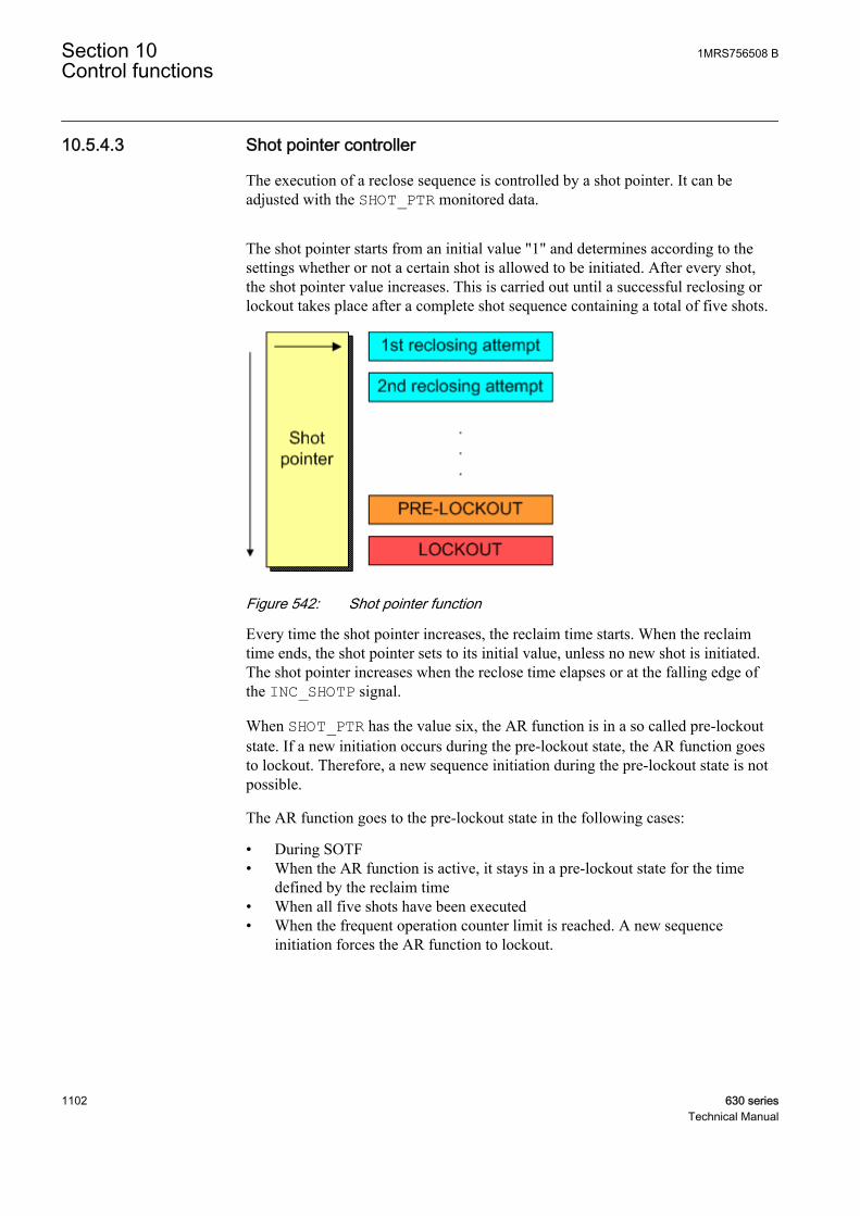
10.5.4.3 Shot pointer controller
The execution of a reclose sequence is controlled by a shot pointer. It can beadjusted with the SHOT_PTR monitored data.
The shot pointer starts from an initial value "1" and determines according to thesettings whether or not a certain shot is allowed to be initiated. After every shot,the shot pointer value increases. This is carried out until a successful reclosing orlockout takes place after a complete shot sequence containing a total of five shots.
A070872 V1 EN
Figure 542: Shot pointer function
Every time the shot pointer increases, the reclaim time starts. When the reclaimtime ends, the shot pointer sets to its initial value, unless no new shot is initiated.The shot pointer increases when the reclose time elapses or at the falling edge ofthe INC_SHOTP signal.
When SHOT_PTR has the value six, the AR function is in a so called pre-lockoutstate. If a new initiation occurs during the pre-lockout state, the AR function goesto lockout. Therefore, a new sequence initiation during the pre-lockout state is notpossible.
The AR function goes to the pre-lockout state in the following cases:
• During SOTF• When the AR function is active, it stays in a pre-lockout state for the time
defined by the reclaim time• When all five shots have been executed• When the frequent operation counter limit is reached. A new sequence
initiation forces the AR function to lockout.
Section 10 1MRS756508 BControl functions
1102 630 seriesTechnical Manual
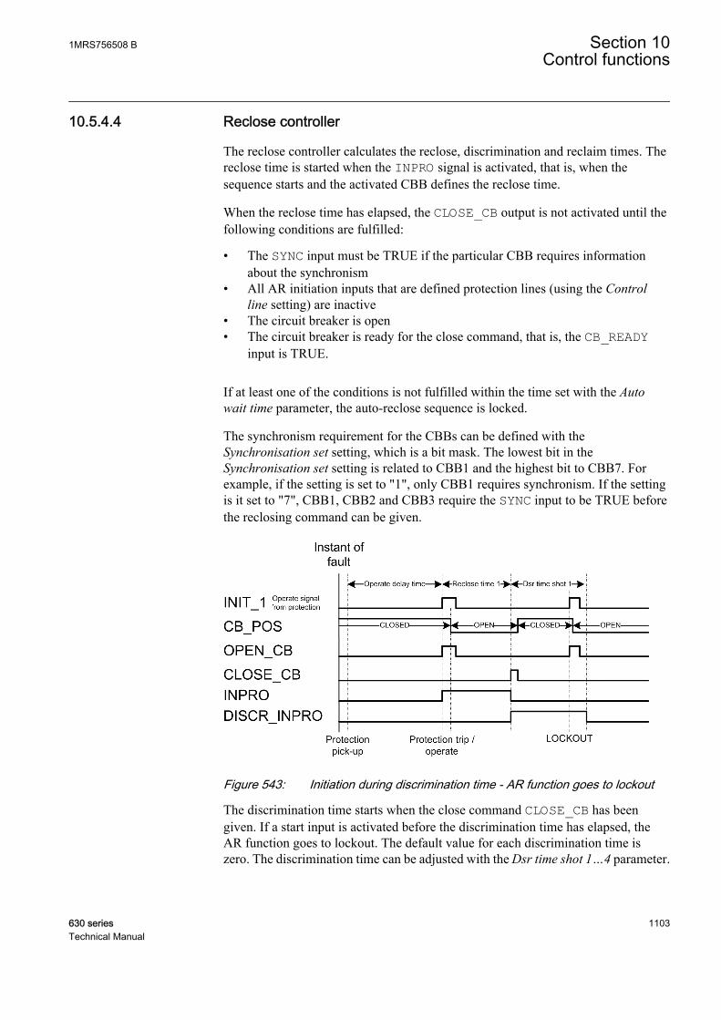
10.5.4.4 Reclose controller
The reclose controller calculates the reclose, discrimination and reclaim times. Thereclose time is started when the INPRO signal is activated, that is, when thesequence starts and the activated CBB defines the reclose time.
When the reclose time has elapsed, the CLOSE_CB output is not activated until thefollowing conditions are fulfilled:
• The SYNC input must be TRUE if the particular CBB requires informationabout the synchronism
• All AR initiation inputs that are defined protection lines (using the Controlline setting) are inactive
• The circuit breaker is open• The circuit breaker is ready for the close command, that is, the CB_READY
input is TRUE.
If at least one of the conditions is not fulfilled within the time set with the Autowait time parameter, the auto-reclose sequence is locked.
The synchronism requirement for the CBBs can be defined with theSynchronisation set setting, which is a bit mask. The lowest bit in theSynchronisation set setting is related to CBB1 and the highest bit to CBB7. Forexample, if the setting is set to "1", only CBB1 requires synchronism. If the settingis it set to "7", CBB1, CBB2 and CBB3 require the SYNC input to be TRUE beforethe reclosing command can be given.
A070873 V1 EN
Figure 543: Initiation during discrimination time - AR function goes to lockout
The discrimination time starts when the close command CLOSE_CB has beengiven. If a start input is activated before the discrimination time has elapsed, theAR function goes to lockout. The default value for each discrimination time iszero. The discrimination time can be adjusted with the Dsr time shot 1…4 parameter.
1MRS756508 B Section 10Control functions
630 series 1103Technical Manual

A070874 V1 EN
Figure 544: Initiation after elapsed discrimination time - new shot begins
10.5.4.5 Sequence controller
When the LOCKED output is active, the AR function is in lockout. This means thatnew sequences cannot be initialized, because AR is insensitive to initiationcommands. It can be released from the lockout state in the following ways:
• The function is reset through communication with the RsRec parameter• The lockout is automatically reset after the reclaim time, if the Auto lockout
reset setting is in use.
If the Auto lockout reset setting is not in use, the lockout can bereleased only with the RsRec parameter.
The AR function can go to lockout for many reasons:
• The INHIBIT_RECL input is active• All shots have been executed and a new initiation is made (final trip)• The time set with the Auto wait time parameter expires and the automatic
sequence initiation is not allowed because of a synchronization failure• The time set with the Wait close time parameter expires, that is, the circuit
breaker does not close or the automatic sequence initiation is not allowed dueto a closing failure of the circuit breaker
• A new shot is initiated during the discrimination time• The time set with the Max wait time parameter expires, that is, the master unit
does not release the slave unit
Section 10 1MRS756508 BControl functions
1104 630 seriesTechnical Manual
• The frequent operation counter limit is reached and new sequence is initiated.The lockout is released when the recovery timer elapses
• The protection trip signal has been active longer than the time set with the Maxwait time parameter since the shot initiation
• The circuit breaker is closed manually during an auto-reclose sequence and themanual close mode is FALSE.
10.5.4.6 Protection coordination controller
The PROT_CRD output is used for controlling the protection functions. In severalapplications, such as fuse-saving applications involving down-stream fuses,tripping and initiation of shot 1 should be fast (instantaneous or short-timedelayed). The tripping and initiation of shots 2, 3 and definite tripping time shouldbe delayed.
In this example, two overcurrent elements PHLPTOC and PHIPTOC are used.PHIPTOC is given an instantaneous characteristic and PHLPTOC is given a timedelay.
The PROT_CRD output is activated, if the SHOT_PTR value is the same or higherthan the value defined with the Protection crd limit setting and all initializationsignals have been reset. The PROT_CRD output is reset under the followingconditions:
• If the cut-out time elapses• If the reclaim time elapses and the AR function is ready for a new sequence• If the AR function is in lockout or disabled, that is, if the value of the
Protection crd mode setting is "AR inoperative" or "AR inop, CB man".
The PROT_CRD output can also be controlled with the Protection crd modesetting. The setting has the following modes:
• "no condition": the PROT_CRD output is controlled only with the Protectioncrd limit setting
• "AR inoperative": the PROT_CRD output is active, if the AR function isdisabled or in the lockout state, or if the INHIBIT_RECL input is active
• "CB close manual": the PROT_CRD output is active for the reclaim time if thecircuit breaker has been manually closed, that is, the AR function has notissued a close command
• "AR inop, CB man": both the modes "AR inoperative" and "CB close manual"are effective
• "always": the PROT_CRD output is constantly active
1MRS756508 B Section 10Control functions
630 series 1105Technical Manual

Shot 1(CBB1)
0.3s
Shot 2(CBB2)15.0s
INIT_1 (I>>)
INIT_2 (I>)
INIT_3 (Io>)
Lockout
Lockout
Lockout
A070875 V3 EN
Figure 545: Configuration example of using the PROT_CRD output for protectionblocking
If the Protection crd limit setting has the value "1", the instantaneous three-phaseovercurrent protection function PHIPTOC is disabled or blocked after the first shot.
The protection functions can also be controlled with the PROT_DISA output. ThePROT_DISA output signal is a bit mask that is controlled with the Disable shot 1…5 settings. The Disable shot 1 setting defines the bits that are active at the first shot,the Disable shot 2 setting defines the bits that are active at the second shot and soon. The PROT_DISA signal is updated when the SHOT_PTR value is updated. Inthis way, the user can, for example, control the protection functions to initiate acomplex auto-reclose sequence to be executed in a desired order. However, thisoutput is not needed in most auto-reclose applications due to a simple protectionscheme.
The protection functions can also be controlled with the PROT_DISA output. ThePROT_DISA output signal is a bit mask that is controlled with the Disable shot 1…5 settings. The Disable shot 1 setting defines the bits that are active at the first shot,the Disable shot 2 setting defines the bits that are active at the second shot and soon. The PROT_DISA signal is updated when the SHOT_PTR value is updated. Inthis way, the user can, for example, control the protection functions to initiate acomplex autoreclose sequence to be executed in a desired order. However, thisoutput is not needed in most autoreclose applications due to a simple protectionscheme.
The PROT_DISA output follows the Disable shot 5 setting in the pre-lockout andlockout states and in SOTF.
The PROT_DISA signal is reset when the cutout time elapses. The signal is reset tothe value defined with the Disable pro signal parameter.
A070876 V1 EN
Figure 546: Signal scheme of PROT_DISA signal behavior
Section 10 1MRS756508 BControl functions
1106 630 seriesTechnical Manual

The Disable shot x settings have the following values in the sequence:
Table 970: Disable shot x values
Setting ValueDisable shot 1 "0"
Disable shot 2 "2"
Disable shot 3 "0"
Disable shot 4 "4"
Disable shot 5 "6"
Since the PROT_DISA output is a bit mask integer, the bits must beextracted from it with the integer-to-bit conversion INT_TO_BIT inthe configuration.
10.5.4.7 Circuit breaker controller
Circuit breaker controller contains two features: SOTF and frequent-operationcounter. SOTF protects the AR function in permanent faults.
The circuit breaker position information is controlled with the CB closed Pos statussetting. The setting value "TRUE” means that when the circuit breaker is closed,the CB_POS input is TRUE. When the setting value is “FALSE”, the CB_POSinput is FALSE, provided that the circuit breaker is closed. The reclose commandpulse time can be controlled with the Close pulse time setting: the CLOSE_CBoutput is active for the time set with the Close pulse time setting. The CLOSE_CBoutput is deactivated also when the circuit breaker is detected to be closed, that is,when the CB_POS input changes from open state to closed state. The Wait closetime setting defines the time after the CLOSE_CB command activation, duringwhich the circuit breaker should be closed. If the closing of circuit breaker does nothappen during this time, the auto-reclose function is driven to lockout or, ifallowed, an auto-initiation is activated.
The main motivation for auto-reclosing to begin with is the assumption that thefault is temporary by nature, and that a momentary de-energizing of the power lineand an automatic reclosing restores the power supply. However, when the powerline is manually energized and an immediate protection trip is detected, it is verylikely that the fault is of a permanent type. A permanent fault is, for example,energizing a power line into a forgotten earthing after a maintenance work alongthe power line. In such cases, SOTF is activated, but only for the reclaim time afterenergizing the power line and only when the circuit breaker is closed manually andnot by the AR function.
SOTF disables any initiation of an auto-reclose shot. The energizing of the powerline is detected from the CB_POS information.
1MRS756508 B Section 10Control functions
630 series 1107Technical Manual

SOTF is activated when the AR function is enabled or when the AR function isstarted and the SOTF should remain active for the reclaim time.
When SOTF is detected, the output SOTF is active.
If the Manual close mode setting is set to FALSE and the circuitbreaker has been manually closed during an auto-reclose shot, theAR unit goes to an immediate lockout.
If the Manual close mode setting is set to TRUE and the circuitbreaker has been manually closed during an auto-reclose shot (theINPRO is active), the shot is considered as completed.
When SOTF starts, reclaim time is restarted, provided that it isrunning.
The frequent-operation counter is intended for blocking the auto-reclose function incases where the fault causes repetitive auto-reclose sequences during a short periodof time. For instance, if a tree causes a short circuit and, as a result, there are auto-reclose shots within a few minutes interval during a stormy night. These types offaults can easily damage the circuit breaker if the AR function is not locked by afrequent-operation counter.
The frequent-operation counter has three settings:
• Frq Op counter limit• Frq Op counter time• Frq Op recovery time
The Frq Op counter limit setting defines the number of reclose attempts that areallowed during the time defined with the Frq Op counter time setting. If the setvalue is reached within a pre-defined period defined with the Frq Op counter timesetting, the AR function goes to lockout when a new shot begins, provided that thecounter is still above the set limit. The lockout is released after the recovery timehas elapsed. The recovery time can be defined with the Frq Op recovery time setting .
If the circuit breaker is manually closed during the recovery time, the reclaim timeis activated after the recovery timer has elapsed.
10.5.5 ApplicationModern electric power systems can deliver energy to users very reliably. However,different kind of faults can occur. Protection relays play an important role indetecting failures or abnormalities in the system. They detect faults and give
Section 10 1MRS756508 BControl functions
1108 630 seriesTechnical Manual
commands for corresponding circuit breakers to isolate the defective elementbefore excessive damage or a possible power system collapse occurs. A fastisolation also limits the disturbances caused for the healthy parts of the power system.
The faults can be transient, semi-transient or permanent. Permanent fault, forexample in power cables, means that there is a physical damage in the faultlocation that must first be located and repaired before the network voltage can berestored.
In overhead lines, the insulating material between phase conductors is air. Themajority of the faults are flash-over arcing faults caused by lightning, for example.Only a short interruption is needed for extinguishing the arc. These faults aretransient by nature.
A semi-transient fault can be caused for example by a bird or a tree branch fallingon the overhead line. The fault disappears on its own if the fault current burns thebranch or the wind blows it away.
Transient and semi-transient faults can be cleared by momentarily de-energizingthe power line. Using the auto-reclose function minimizes interruptions in thepower system service and brings the power back on-line quickly and effortlessly.
The basic idea of the auto-reclose function is simple. In overhead lines, where thepossibility of self-clearing faults is high, the auto-reclose function tries to restorethe power by reclosing the breaker. This is a method to get the power system backinto normal operation by removing the transient or semi-transient faults. Severaltrials, that is, auto-reclose shots are allowed. If none of the trials is successful andthe fault persists, definite final tripping follows.
The auto-reclose function can be used with every circuit breaker that has the abilityfor a reclosing sequence. In DARREC auto-reclose function the implementingmethod of auto-reclose sequences is patented by ABB
Table 971: Important definitions related to auto-reclosing
auto-reclose shot an operation where after a preset time the breaker is closed from the breakertripping caused by protection
auto-reclosesequence
a predefined method to do reclose attempts (shots) to restore the power system
SOTF If the protection detects a fault immediately after an open circuit breaker hasbeen closed, it indicates that the fault was already there. It can be, for example,a forgotten earthing after maintenance work. Such closing of the circuit breakeris known as switch on to fault. Autoreclosing in such conditions is prohibited.
final trip Occurs in case of a permanent fault, when the circuit breaker is opened for thelast time after all programmed auto-reclose operations. Since no auto-reclosingfollows, the circuit breaker remains open. This is called final trip or definite trip.
10.5.5.1 Shot initiation
In some applications, the START signal is used for initiating or blockingautoreclose shots, in other applications the OPERATE command is needed. In its
1MRS756508 B Section 10Control functions
630 series 1109Technical Manual
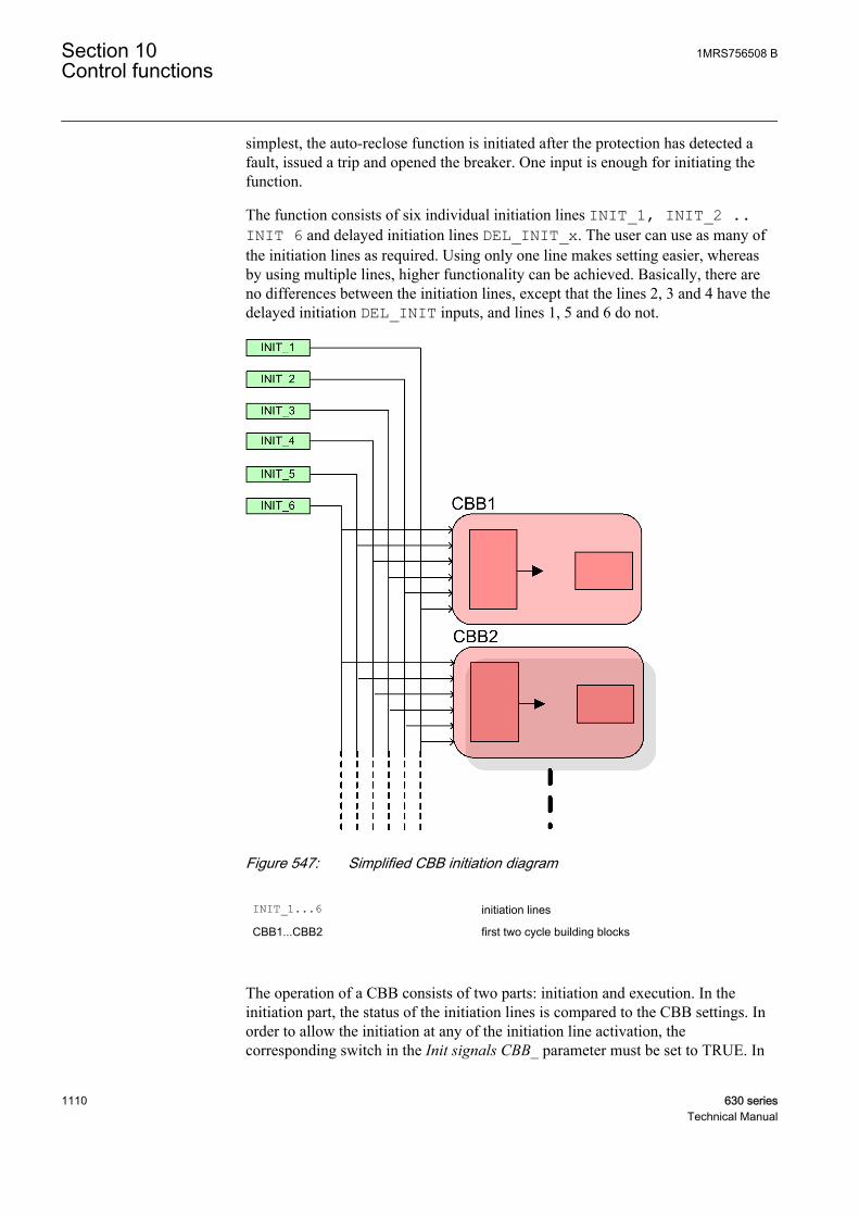
simplest, the auto-reclose function is initiated after the protection has detected afault, issued a trip and opened the breaker. One input is enough for initiating thefunction.
The function consists of six individual initiation lines INIT_1, INIT_2 ..INIT 6 and delayed initiation lines DEL_INIT_x. The user can use as many ofthe initiation lines as required. Using only one line makes setting easier, whereasby using multiple lines, higher functionality can be achieved. Basically, there areno differences between the initiation lines, except that the lines 2, 3 and 4 have thedelayed initiation DEL_INIT inputs, and lines 1, 5 and 6 do not.
A070884 V1 EN
Figure 547: Simplified CBB initiation diagram
INIT_1...6 initiation lines
CBB1...CBB2 first two cycle building blocks
The operation of a CBB consists of two parts: initiation and execution. In theinitiation part, the status of the initiation lines is compared to the CBB settings. Inorder to allow the initiation at any of the initiation line activation, thecorresponding switch in the Init signals CBB_ parameter must be set to TRUE. In
Section 10 1MRS756508 BControl functions
1110 630 seriesTechnical Manual
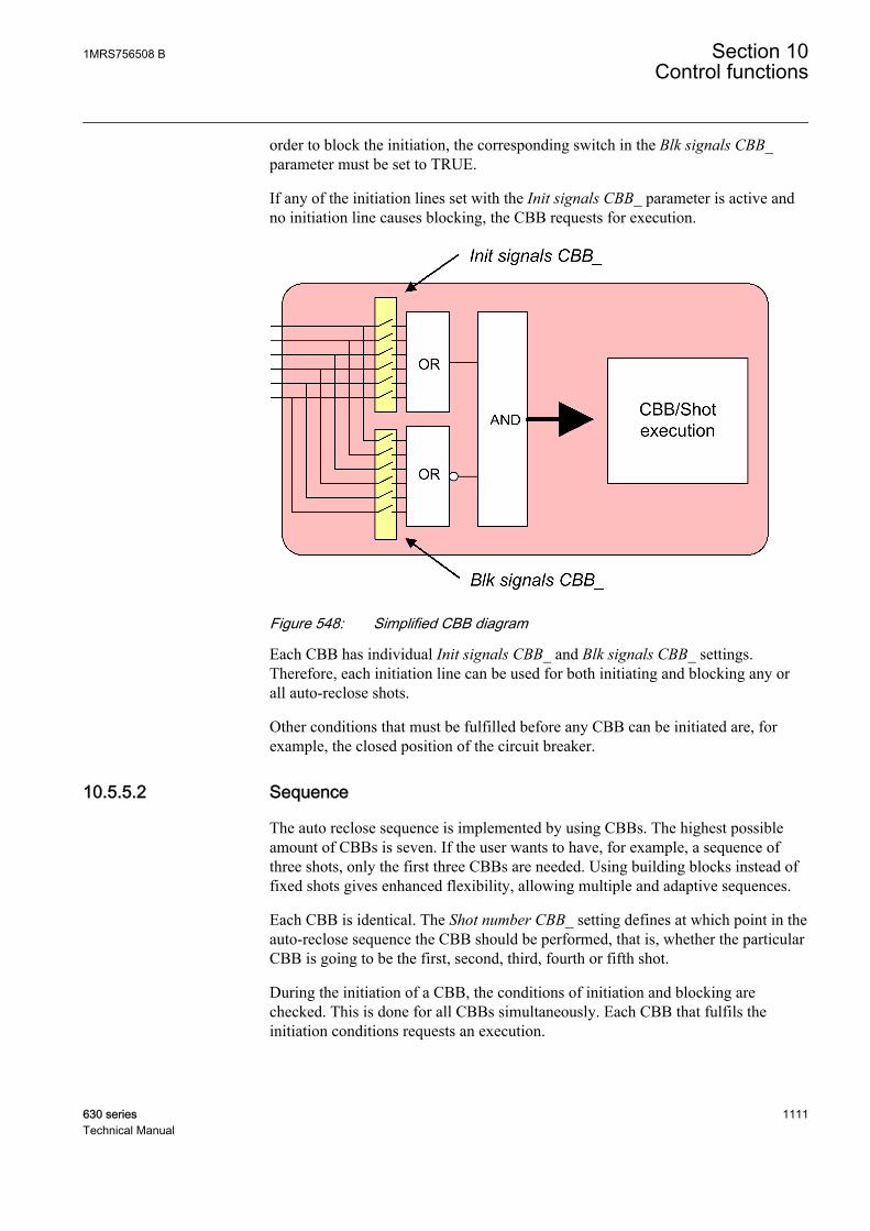
order to block the initiation, the corresponding switch in the Blk signals CBB_parameter must be set to TRUE.
If any of the initiation lines set with the Init signals CBB_ parameter is active andno initiation line causes blocking, the CBB requests for execution.
A070885 V1 EN
Figure 548: Simplified CBB diagram
Each CBB has individual Init signals CBB_ and Blk signals CBB_ settings.Therefore, each initiation line can be used for both initiating and blocking any orall auto-reclose shots.
Other conditions that must be fulfilled before any CBB can be initiated are, forexample, the closed position of the circuit breaker.
10.5.5.2 Sequence
The auto reclose sequence is implemented by using CBBs. The highest possibleamount of CBBs is seven. If the user wants to have, for example, a sequence ofthree shots, only the first three CBBs are needed. Using building blocks instead offixed shots gives enhanced flexibility, allowing multiple and adaptive sequences.
Each CBB is identical. The Shot number CBB_ setting defines at which point in theauto-reclose sequence the CBB should be performed, that is, whether the particularCBB is going to be the first, second, third, fourth or fifth shot.
During the initiation of a CBB, the conditions of initiation and blocking arechecked. This is done for all CBBs simultaneously. Each CBB that fulfils theinitiation conditions requests an execution.
1MRS756508 B Section 10Control functions
630 series 1111Technical Manual

The function also keeps track of shots already performed, that is, at which point theauto-reclose sequence is from shot 1 to lockout. For example, if shots 1 and 2 havealready been performed, only shots 3 to 5 are allowed.
Additionally, the Enable shot jump setting gives two possibilities:
• Only such CBBs that are set for the next shot in the sequence can be acceptedfor execution. For example, if the next shot in the sequence should be shot 2, arequest from CBB set for shot 3 is rejected.
• Any CBB that is set for the next shot or any of the following shots can beaccepted for execution. For example, if the next shot in the sequence should beshot 2, also CBBs that are set for shots 3, 4 and 5 are accepted. In other words,shot 2 can be ignored.
In case there are multiple CBBs allowed for execution, the CBB with the smallestnumber is chosen. For example, if CBB2 and CBB4 request an execution, CBB2 isallowed to execute the shot.
The auto-reclose function can perform up to five auto-reclose shots or cycles.
10.5.5.3 Configuration examples
OR CB_TRIP
Circuit breaker position information from binary inputConditions to verify if circuit breaker is ready to be reclosed
CB_CLOSE
PHLPTOC
I_A
I_B START
OPERATE
I_C
BLOCK
ENA_MULT
PHHPTOC
I_A
I_B START
OPERATE
I_C
BLOCK
ENA_MULT
EFLPTOC
Io
BLOCK START
OPERATE
ENA_MULT
DARRECOPEN_CB
CLOSE_CBCMD_WAITPROT_CRD
INPROLOCKED
UNSUC_RECL
DEL_INIT_4DEL_INIT_3DEL_INIT_2INIT_6INIT_5INIT_4INIT_3INIT_2INIT_1
SYNC
INC_SHOTP
CB_READYCB_POS
RECL_ONINHIBIT_RECL
BLK_RCLM_TBLK_RECL_T
BLK_THERM
DISA_COUNT
AR_ON
A070886 V3 EN
Figure 549: Example connection between protection and autoreclose functionsin IED configuration
It is possible to create several sequences for a configuration.
Section 10 1MRS756508 BControl functions
1112 630 seriesTechnical Manual

Autoreclose sequences for overcurrent and non-directional earth-fault protectionapplications where high speed and delayed autoreclosings are needed can be asfollows:
Example 1.The sequence is implemented by two shots which have the same reclosing time forall protection functions, namely I>>, I> and Io>. The initiation of the shots is doneby activating the operating signals of the protection functions.
A070887 V1 EN
Figure 550: Autoreclose sequence with two shots
tHSAR Time delay of high-speed autoreclosing, here: First reclose time
tDAR Time delay of delayed autoreclosing, here: Second reclose time
tProtection Operating time for the protection stage to clear the fault
tCB_O Operating time for opening the circuit breaker
tCB_C Operating time for closing the circuit breaker
In this case, the sequence needs two CBBs. The reclosing times for shot 1 and shot2 are different, but each protection function initiates the same sequence. The CBBsequence is as follows:
Shot 1(CBB1)
0.3s
Shot 2(CBB2)15.0s
INIT_1 (I>>)
INIT_2 (I>)
INIT_3 (Io>)
Lockout
Lockout
Lockout
A071270 V2 EN
Figure 551: Two shots with three initiation lines
1MRS756508 B Section 10Control functions
630 series 1113Technical Manual

Table 972: Settings for configuration example 1
Setting name Setting valueShot number CBB1 1
Init signals CBB1 7 (lines 1,2 and 3 = 1+2+4 = 7)
First reclose time 0.3s (an example)
Shot number CBB2 2
Init signals CBB2 7 (lines 1,2 and 3 = 1+2+4 = 7)
Second reclose time 15.0s (an example)
Example 2There are two separate sequences implemented with three shots. Shot 1 isimplemented by CBB1 and it is initiated with the high stage of the overcurrentprotection (I>>). Shot 1 is set as a high-speed autoreclosing with a short timedelay. Shot 2 is implemented with CBB2 and meant to be the first shot of theautoreclose sequence initiated by the low stage of the overcurrent protection (I>)and the low stage of the non-directional earth-fault protection (Io>). It has the samereclosing time in both situations. It is set as a high-speed autoreclosing forcorresponding faults. The third shot, which is the second shot in the autoreclosesequence initiated by I> or Io>, is set as a delayed autoreclosing and executed afteran unsuccessful high-speed autoreclosing of a corresponding sequence.
A071272 V1 EN
Figure 552: Autoreclose sequence with two shots with different shot settingsaccording to initiation signal
Section 10 1MRS756508 BControl functions
1114 630 seriesTechnical Manual
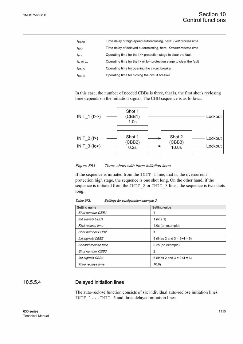
tHSAR Time delay of high-speed autoreclosing, here: First reclose time
tDAR Time delay of delayed autoreclosing, here: Second reclose time
tl>> Operating time for the I>> protection stage to clear the fault
tl> or lo> Operating time for the I> or Io> protection stage to clear the fault
tCB_O Operating time for opening the circuit breaker
tCB_C Operating time for closing the circuit breaker
In this case, the number of needed CBBs is three, that is, the first shot's reclosingtime depends on the initiation signal. The CBB sequence is as follows:
INIT_1 (I>>)
INIT_2 (I>)
INIT_3 (Io>)
Shot 1(CBB1)
1.0s
Shot 1(CBB2)
0.2s
Shot 2(CBB3)10.0s
Lockout
Lockout
Lockout
A071274 V2 EN
Figure 553: Three shots with three initiation lines
If the sequence is initiated from the INIT_1 line, that is, the overcurrentprotection high stage, the sequence is one shot long. On the other hand, if thesequence is initiated from the INIT_2 or INIT_3 lines, the sequence is two shotslong.
Table 973: Settings for configuration example 2
Setting name Setting valueShot number CBB1 1
Init signals CBB1 1 (line 1)
First reclose time 1.0s (an example)
Shot number CBB2 1
Init signals CBB2 6 (lines 2 and 3 = 2+4 = 6)
Second reclose time 0.2s (an example)
Shot number CBB3 2
Init signals CBB3 6 (lines 2 and 3 = 2+4 = 6)
Third reclose time 10.0s
10.5.5.4 Delayed initiation lines
The auto-reclose function consists of six individual auto-reclose initiation linesINIT_1...INIT 6 and three delayed initiation lines:
1MRS756508 B Section 10Control functions
630 series 1115Technical Manual

• DEL_INIT_2• DEL_INIT_3• DEL_INIT_4
DEL_INIT_2 and INIT_2 are connected together with an OR-gate, as are inputs3 and 4. Inputs 1, 5 and 6 do not have any delayed input. From the auto-reclosingpoint of view, it does not matter whether INIT_x or DEL_INIT_x line is usedfor shot initiation or blocking.
The auto-reclose function can also open the circuit breaker from any of theinitiation lines. It is selected with the Tripping line setting. As a default, allinitiation lines activate the OPEN_CB output.
A070276 V1 EN
Figure 554: Simplified logic diagram of initiation lines
Each delayed initiation line has four different time settings:
Table 974: Settings for delayed initiation lines
Setting name Description and purposeStr x delay shot 1 Time delay for the DEL_INIT_x line, where x is
the number of the line 2, 3 or 4. Used for shot 1.
Str x delay shot 2 Time delay for the DEL_INIT_x line, used forshot 2.
Str x delay shot 3 Time delay for the DEL_INIT_x line, used forshot 3.
Str x delay shot 4 Time delay for the DEL_INIT_x line, used forshots 4 and 5. Optionally, can also be used withSOTF.
Section 10 1MRS756508 BControl functions
1116 630 seriesTechnical Manual
10.5.5.5 Shot initiation from protection start signal
In it simplest, all auto-reclose shots are initiated by protection trips. As a result, alltrip times in the sequence are the same. This is why using protection trips may notbe the optimal solution. Using protection start signals instead of protection trips forinitiating shots shortens the trip times.
Example 1When a two-shot-sequence is used, the start information from the protectionfunction is routed to the DEL_INIT 2 input and the operate information to theINIT_2 input. The following conditions have to apply:
• protection operate time = 0.5s• Str 2 delay shot 1 = 0.05s• Str 2 delay shot 2 = 60s• Str 2 delay shot 3 = 60s
Operation in a permanent fault:
1. Protection starts and activates the DEL_INIT 2 input.2. After 0.05 seconds, the first autoreclose shot is initiated. The function opens
the circuit breaker: the OPEN_CB output activates. The total trip time is theprotection start delay + 0.05 seconds + the time it takes to open the circuit breaker.
3. After the first shot, the circuit breaker is reclosed and the protection starts again.4. Because the delay of the second shot is 60 seconds, the protection is faster and
trips after the set operation time, activating the INIT 2 input. The secondshot is initiated.
5. After the second shot, the circuit breaker is reclosed and the protection startsagain.
6. Because the delay of the second shot is 60 seconds, the protection is faster andtrips after the set operation time. No further shots are programmed after thefinal trip. The function is in lockout and the sequence is considered unsuccessful.
Example 2The delays can be used also for fast final trip. The conditions are the same as inExample 1, with the exception of Str 2 delay shot 3 = 0.10 seconds.
The operation in a permanent fault is the same as in Example 1, except that afterthe second shot when the protection starts again, Str 2 delay shot 3 elapses beforethe protection operate time and the final trip follows. The total trip time is theprotection start delay + 0.10 seconds + the time it takes to open the circuit breaker.
10.5.5.6 Fast trip in Switch on to fault
The Str _ delay shot 4 parameter delays can also be used to achieve a fast andaccelerated trip with SOTF. This is done by setting the Fourth delay in SOTF
1MRS756508 B Section 10Control functions
630 series 1117Technical Manual

parameter to "1" and connecting the protection start information to thecorresponding DEL_INIT_ input.
When the function detects a closing of the circuit breaker, that is, any other closingexcept the reclosing done by the function itself, it always prohibits shot initiationfor the time set with the Reclaim time parameter. Furthermore, if the Fourth delayin SOTF parameter is "1", the Str _ delay shot 4 parameter delays are also activated.
Example 1The protection operation time is 0.5 seconds, the Fourth delay in SOTF parameteris set to "1" and the Str 2 delay shot 4 parameter is 0.05 seconds. The protectionstart signal is connected to the DEL_INIT_2 input.
If the protection starts after the circuit breaker closes, the fast trip follows after theset 0.05 seconds. The total trip time is the protection start delay + 0.05 seconds +the time it takes to open the circuit breaker.
10.5.6 CountersThe AR function contains six counters. Their values are stored in a semi-retainmemory. The counters are increased at the rising edge of the reclose command.The counters count the following situations:
• COUNTER: counts every reclose command activation• CNT_SHOT1: counts reclose commands that are executed from shot 1• CNT_SHOT2: counts reclose commands that are executed from shot 2• CNT_SHOT3: counts reclose commands that are executed from shot 3• CNT_SHOT4: counts reclose commands that are executed from shot 4• CNT_SHOT5: counts reclose commands that are executed from shot 5
The counters are disabled through communication with the DsaCnt parameter.When the counters are disabled, the values are not updated.
The counters are reset through communication with the RsCnt parameter.
10.5.7 SignalsTable 975: DARREC Input signals
Name Type Default DescriptionINIT_1 BOOLEAN 0 AR initialization / blocking signal 1
INIT_2 BOOLEAN 0 AR initialization / blocking signal 2
INIT_3 BOOLEAN 0 AR initialization / blocking signal 3
INIT_4 BOOLEAN 0 AR initialization / blocking signal 4
INIT_5 BOOLEAN 0 AR initialization / blocking signal 5
INIT_6 BOOLEAN 0 AR initialization / blocking signal 6
DEL_INIT_2 BOOLEAN 0 Delayed AR initialization / blocking signal 2
Table continues on next page
Section 10 1MRS756508 BControl functions
1118 630 seriesTechnical Manual
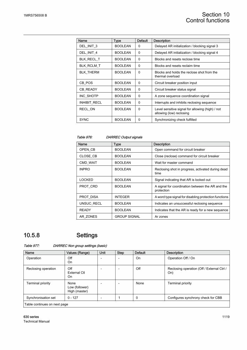
Name Type Default DescriptionDEL_INIT_3 BOOLEAN 0 Delayed AR initialization / blocking signal 3
DEL_INIT_4 BOOLEAN 0 Delayed AR initialization / blocking signal 4
BLK_RECL_T BOOLEAN 0 Blocks and resets reclose time
BLK_RCLM_T BOOLEAN 0 Blocks and resets reclaim time
BLK_THERM BOOLEAN 0 Blocks and holds the reclose shot from thethermal overload
CB_POS BOOLEAN 0 Circuit breaker position input
CB_READY BOOLEAN 0 Circuit breaker status signal
INC_SHOTP BOOLEAN 0 A zone sequence coordination signal
INHIBIT_RECL BOOLEAN 0 Interrupts and inhibits reclosing sequence
RECL_ON BOOLEAN 0 Level sensitive signal for allowing (high) / notallowing (low) reclosing
SYNC BOOLEAN 0 Synchronizing check fulfilled
Table 976: DARREC Output signals
Name Type DescriptionOPEN_CB BOOLEAN Open command for circuit breaker
CLOSE_CB BOOLEAN Close (reclose) command for circuit breaker
CMD_WAIT BOOLEAN Wait for master command
INPRO BOOLEAN Reclosing shot in progress, activated during deadtime
LOCKED BOOLEAN Signal indicating that AR is locked out
PROT_CRD BOOLEAN A signal for coordination between the AR and theprotection
PROT_DISA INTEGER A word type signal for disabling protection functions
UNSUC_RECL BOOLEAN Indicates an unsuccessful reclosing sequence
READY BOOLEAN Indicates that the AR is ready for a new sequence
AR_ZONES GROUP SIGNAL Ar zones
10.5.8 SettingsTable 977: DARREC Non group settings (basic)
Name Values (Range) Unit Step Default DescriptionOperation Off
On- - On Operation Off / On
Reclosing operation OffExternal CtlOn
- - Off Reclosing operation (Off / External Ctrl /On)
Terminal priority NoneLow (follower)High (master)
- - None Terminal priority
Synchronisation set 0 - 127 - 1 0 Configures synchrony check for CBB
Table continues on next page
1MRS756508 B Section 10Control functions
630 series 1119Technical Manual
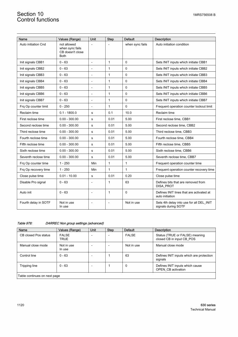
Name Values (Range) Unit Step Default DescriptionAuto initiation Cnd not allowed
when sync failsCB doesn't closeBoth
- - when sync fails Auto initiation condition
Init signals CBB1 0 - 63 - 1 0 Sets INIT inputs which initiate CBB1
Init signals CBB2 0 - 63 - 1 0 Sets INIT inputs which initiate CBB2
Init signals CBB3 0 - 63 - 1 0 Sets INIT inputs which initiate CBB3
Init signals CBB4 0 - 63 - 1 0 Sets INIT inputs which initiate CBB4
Init signals CBB5 0 - 63 - 1 0 Sets INIT inputs which initiate CBB5
Init signals CBB6 0 - 63 - 1 0 Sets INIT inputs which initiate CBB6
Init signals CBB7 0 - 63 - 1 0 Sets INIT inputs which initiate CBB7
Frq Op counter limit 0 - 250 - 1 0 Frequent operation counter lockout limit
Reclaim time 0.1 - 1800.0 s 0.1 10.0 Reclaim time
First reclose time 0.00 - 300.00 s 0.01 5.00 First reclose time, CBB1
Second reclose time 0.00 - 300.00 s 0.01 5.00 Second reclose time, CBB2
Third reclose time 0.00 - 300.00 s 0.01 5.00 Third reclose time, CBB3
Fourth reclose time 0.00 - 300.00 s 0.01 5.00 Fourth reclose time, CBB4
Fifth reclose time 0.00 - 300.00 s 0.01 5.00 Fifth reclose time, CBB5
Sixth reclose time 0.00 - 300.00 s 0.01 5.00 Sixth reclose time, CBB6
Seventh reclose time 0.00 - 300.00 s 0.01 5.00 Seventh reclose time, CBB7
Frq Op counter time 1 - 250 Min 1 1 Frequent operation counter time
Frq Op recovery time 1 - 250 Min 1 1 Frequent operation counter recovery time
Close pulse time 0.01 - 10.00 s 0.01 0.20 Close pulse time
Disable Pro signal 0 - 63 - 1 63 Defines bits that are removed fromDISA_PROT
Auto init 0 - 63 - 1 0 Defines INIT lines that are activated atauto initiation
Fourth delay in SOTF Not in useIn use
- - Not in use Sets 4th delay into use for all DEL_INITsignals during SOTF
Table 978: DARREC Non group settings (advanced)
Name Values (Range) Unit Step Default DescriptionCB closed Pos status FALSE
TRUE- - FALSE Status (TRUE or FALSE) meaning
closed CB in input CB_POS
Manual close mode Not in useIn use
- - Not in use Manual close mode
Control line 0 - 63 - 1 63 Defines INIT inputs which are protectionsignals
Tripping line 0 - 63 - 1 0 Defines INIT inputs which causeOPEN_CB activation
Table continues on next page
Section 10 1MRS756508 BControl functions
1120 630 seriesTechnical Manual

Name Values (Range) Unit Step Default DescriptionProtection Crd mode no condition
AR inoperativeCB close manualAR inop, CB manalways
- - AR inop, CB man Protection coordination mode
Shot number CBB1 0 - 5 - 1 0 Sets shot number CBB1
Shot number CBB2 0 - 5 - 1 0 Sets shot number CBB2
Shot number CBB3 0 - 5 - 1 0 Sets shot number CBB3
Shot number CBB4 0 - 5 - 1 0 Sets shot number CBB4
Shot number CBB5 0 - 5 - 1 0 Sets shot number CBB5
Shot number CBB6 0 - 5 - 1 0 Sets shot number CBB6
Shot number CBB7 0 - 5 - 1 0 Sets shot number CBB7
Blk signals CBB1 0 - 63 - 1 0 Sets INIT inputs which block CBB1
Blk signals CBB2 0 - 63 - 1 0 Sets INIT inputs which block CBB2
Blk signals CBB3 0 - 63 - 1 0 Sets INIT inputs which block CBB3
Blk signals CBB4 0 - 63 - 1 0 Sets INIT inputs which block CBB4
Blk signals CBB5 0 - 63 - 1 0 Sets INIT inputs which block CBB5
Blk signals CBB6 0 - 63 - 1 0 Sets INIT inputs which block CBB6
Blk signals CBB7 0 - 63 - 1 0 Sets INIT inputs which block CBB7
Disable shot 1 0 - 63 - 1 0 Configures bits in PROT_DISA output forfirst reclose
Disable shot 2 0 - 63 - 1 0 Configures bits in PROT_DISA output forsecondreclose
Disable shot 3 0 - 63 - 1 0 Configures bits in PROT_DISA output forthird reclose
Disable shot 4 0 - 63 - 1 0 Configures bits in PROT_DISA output forfourth reclose
Disable shot 5 0 - 63 - 1 0 Configures bits in PROT_DISA output forfifth reclose
Protection Crd limit 1 - 5 - 1 1 Protection coordination shot limit
Dsr time shot 1 0.00 - 10.00 s 0.01 0.00 Discrimination time for first reclosing
Dsr time shot 2 0.00 - 10.00 s 0.01 0.00 Discrimination time for second reclosing
Dsr time shot 3 0.00 - 10.00 s 0.01 0.00 Discrimination time for third reclosing
Dsr time shot 4 0.00 - 10.00 s 0.01 0.00 Discrimination time for fourth reclosing
Max Thm block time 0.1 - 1800.0 s 0.1 10.0 Maximum wait time for thermal blockinsignal deactivation
Cut-out time 0.0 - 1800.0 s 0.1 10.0 Cut-out time for protection coordination
Auto wait time 0.00 - 60.00 s 0.01 2.00 Maximum wait time for reclosingcondition fulfilling
Wait close time 0.05 - 10.00 s 0.05 0.25 Allowed CB closing time after reclosecommand
Max wait time 0.1 - 1800.0 s 0.1 10.0 Maximum wait time for BLK_DEAD_Trelease (from master)
Max trip time 0.1 - 10.0 s 0.1 10.0 Maximum wait time for protection signaldeactivation
Table continues on next page
1MRS756508 B Section 10Control functions
630 series 1121Technical Manual

Name Values (Range) Unit Step Default DescriptionStr 2 delay shot 1 0.00 - 300.00 s 0.01 0.00 Time delay for DEL_INIT_2, first reclosing
Str 2 delay shot 2 0.00 - 300.00 s 0.01 0.00 Time delay for DEL_INIT_2, secondreclosing
Str 2 delay shot 3 0.00 - 300.00 s 0.01 0.00 Time delay for DEL_INIT_2, thirdreclosing
Str 2 delay shot 4 0.00 - 300.00 s 0.01 0.00 Time delay for DEL_INIT_2, fourthreclosing
Str 3 delay shot 1 0.00 - 300.00 s 0.01 0.00 Time delay for DEL_INIT_3, first reclosing
Str 3 delay shot 2 0.00 - 300.00 s 0.01 0.00 Time delay for DEL_INIT_3, secondreclosing
Str 3 delay shot 3 0.00 - 300.00 s 0.01 0.00 Time delay for DEL_INIT_3, thirdreclosing
Str 3 delay shot 4 0.00 - 300.00 s 0.01 0.00 Time delay for DEL_INIT_3, fourthreclosing
Str 4 delay shot 1 0.00 - 300.00 s 0.01 0.00 Time delay for DEL_INIT_4, first reclosing
Str 4 delay shot 2 0.00 - 300.00 s 0.01 0.00 Time delay for DEL_INIT_4, secondreclosing
Str 4 delay shot 3 0.00 - 300.00 s 0.01 0.00 Time delay for DEL_INIT_4, thirdreclosing
Str 4 delay shot 4 0.00 - 300.00 s 0.01 0.00 Time delay for DEL_INIT_4, fourthreclosing
Auto lockout reset Not in useIn use
- - In use Automatic lockout reset in use
Enable shot jump 0 - 1 - 1 1 Enable shot jumpping
10.5.9 Measured valuesTable 979: DARREC Measured values
Name Type Default DescriptionINIT_1 BOOLEAN 0 AR initialization / blocking signal 1
INIT_2 BOOLEAN 0 AR initialization / blocking signal 2
INIT_3 BOOLEAN 0 AR initialization / blocking signal 3
INIT_4 BOOLEAN 0 AR initialization / blocking signal 4
INIT_5 BOOLEAN 0 AR initialization / blocking signal 5
INIT_6 BOOLEAN 0 AR initialization / blocking signal 6
DEL_INIT_2 BOOLEAN 0 Delayed AR initialization / blocking signal 2
DEL_INIT_3 BOOLEAN 0 Delayed AR initialization / blocking signal 3
DEL_INIT_4 BOOLEAN 0 Delayed AR initialization / blocking signal 4
BLK_RECL_T BOOLEAN 0 Blocks and resets reclose time
BLK_RCLM_T BOOLEAN 0 Blocks and resets reclaim time
BLK_THERM BOOLEAN 0 Blocks and holds the reclose shot from thethermal overload
CB_POS BOOLEAN 0 Circuit breaker position input
Table continues on next page
Section 10 1MRS756508 BControl functions
1122 630 seriesTechnical Manual
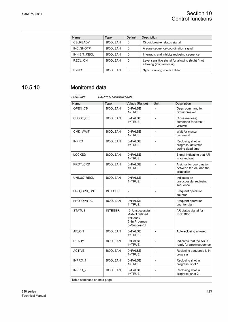
Name Type Default DescriptionCB_READY BOOLEAN 0 Circuit breaker status signal
INC_SHOTP BOOLEAN 0 A zone sequence coordination signal
INHIBIT_RECL BOOLEAN 0 Interrupts and inhibits reclosing sequence
RECL_ON BOOLEAN 0 Level sensitive signal for allowing (high) / notallowing (low) reclosing
SYNC BOOLEAN 0 Synchronizing check fulfilled
10.5.10 Monitored dataTable 980: DARREC Monitored data
Name Type Values (Range) Unit DescriptionOPEN_CB BOOLEAN 0=FALSE
1=TRUE- Open command for
circuit breaker
CLOSE_CB BOOLEAN 0=FALSE1=TRUE
- Close (reclose)command for circuitbreaker
CMD_WAIT BOOLEAN 0=FALSE1=TRUE
- Wait for mastercommand
INPRO BOOLEAN 0=FALSE1=TRUE
- Reclosing shot inprogress, activatedduring dead time
LOCKED BOOLEAN 0=FALSE1=TRUE
- Signal indicating that ARis locked out
PROT_CRD BOOLEAN 0=FALSE1=TRUE
- A signal for coordinationbetween the AR and theprotection
UNSUC_RECL BOOLEAN 0=FALSE1=TRUE
- Indicates anunsuccessful reclosingsequence
FRQ_OPR_CNT INTEGER - - Frequent operationcounter
FRQ_OPR_AL BOOLEAN 0=FALSE1=TRUE
- Frequent operationcounter alarm
STATUS INTEGER -2=Unsuccessful-1=Not defined1=Ready2=In Progress3=Successful
- AR status signal forIEC61850
AR_ON BOOLEAN 0=FALSE1=TRUE
- Autoreclosing allowed
READY BOOLEAN 0=FALSE1=TRUE
- Indicates that the AR isready for a new sequence
ACTIVE BOOLEAN 0=FALSE1=TRUE
- Reclosing sequence is inprogress
INPRO_1 BOOLEAN 0=FALSE1=TRUE
- Reclosing shot inprogress, shot 1
INPRO_2 BOOLEAN 0=FALSE1=TRUE
- Reclosing shot inprogress, shot 2
Table continues on next page
1MRS756508 B Section 10Control functions
630 series 1123Technical Manual
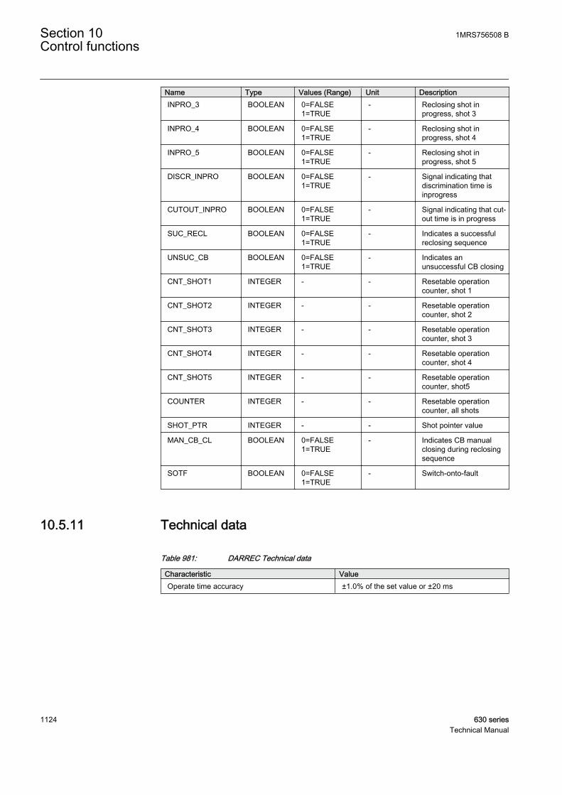
Name Type Values (Range) Unit DescriptionINPRO_3 BOOLEAN 0=FALSE
1=TRUE- Reclosing shot in
progress, shot 3
INPRO_4 BOOLEAN 0=FALSE1=TRUE
- Reclosing shot inprogress, shot 4
INPRO_5 BOOLEAN 0=FALSE1=TRUE
- Reclosing shot inprogress, shot 5
DISCR_INPRO BOOLEAN 0=FALSE1=TRUE
- Signal indicating thatdiscrimination time isinprogress
CUTOUT_INPRO BOOLEAN 0=FALSE1=TRUE
- Signal indicating that cut-out time is in progress
SUC_RECL BOOLEAN 0=FALSE1=TRUE
- Indicates a successfulreclosing sequence
UNSUC_CB BOOLEAN 0=FALSE1=TRUE
- Indicates anunsuccessful CB closing
CNT_SHOT1 INTEGER - - Resetable operationcounter, shot 1
CNT_SHOT2 INTEGER - - Resetable operationcounter, shot 2
CNT_SHOT3 INTEGER - - Resetable operationcounter, shot 3
CNT_SHOT4 INTEGER - - Resetable operationcounter, shot 4
CNT_SHOT5 INTEGER - - Resetable operationcounter, shot5
COUNTER INTEGER - - Resetable operationcounter, all shots
SHOT_PTR INTEGER - - Shot pointer value
MAN_CB_CL BOOLEAN 0=FALSE1=TRUE
- Indicates CB manualclosing during reclosingsequence
SOTF BOOLEAN 0=FALSE1=TRUE
- Switch-onto-fault
10.5.11 Technical data
Table 981: DARREC Technical data
Characteristic ValueOperate time accuracy ±1.0% of the set value or ±20 ms
Section 10 1MRS756508 BControl functions
1124 630 seriesTechnical Manual
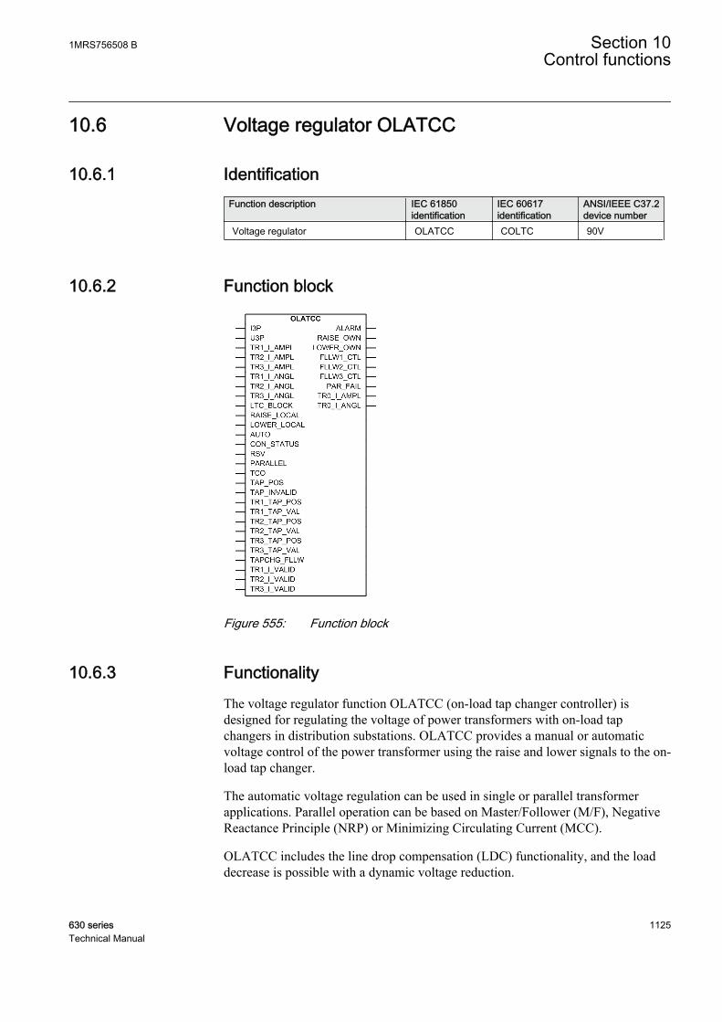
10.6 Voltage regulator OLATCC
10.6.1 IdentificationFunction description IEC 61850
identificationIEC 60617identification
ANSI/IEEE C37.2device number
Voltage regulator OLATCC COLTC 90V
10.6.2 Function block
GUID-D38AAD14-5EB0-435B-9F1C-7CD6507D780E V1 EN
Figure 555: Function block
10.6.3 FunctionalityThe voltage regulator function OLATCC (on-load tap changer controller) isdesigned for regulating the voltage of power transformers with on-load tapchangers in distribution substations. OLATCC provides a manual or automaticvoltage control of the power transformer using the raise and lower signals to the on-load tap changer.
The automatic voltage regulation can be used in single or parallel transformerapplications. Parallel operation can be based on Master/Follower (M/F), NegativeReactance Principle (NRP) or Minimizing Circulating Current (MCC).
OLATCC includes the line drop compensation (LDC) functionality, and the loaddecrease is possible with a dynamic voltage reduction.
1MRS756508 B Section 10Control functions
630 series 1125Technical Manual

Either definite time characteristic (DT) or inverse time characteristic (IDMT) isselectable for delays between the raise and lower operations.
The function contains a blocking functionality. It is possible to block the voltagecontrol operations with an external signal or with the supervision functionality ofthe function, if desired.
10.6.4 Operation principleThe function can be enabled and disabled with the Operation setting. Thecorresponding parameter values are "On" and "Off".
The operation of the voltage regulator function can be described using a modulediagram. All the modules in the diagram are explained in the next sections.
TCO
RSV
TAPCHG_FLLW
TAP_POS
LTC_BLOCK Blockingscheme
ALARM
Autoparallel(NRP) t
Timer
t
TR0_I_AMPLTR0_I_ANGL
Alarmindication
Autoparallel
(Follower)
Auto single
Automatic voltage
regulation
FLLW1_CTLFLLW2_CTLFLLW3_CTLPAR_FAIL
RSV
Autoparallel(Master)
I3P
I_A
I_B
I_C
U3P U_AB
Auto parallel(MCC)
TR2_TAP_VALTR3_TAP_POSTR3_TAP_VAL
TR1_TAP_POSTR1_TAP_VALTR2_TAP_POS
Pulsecontrol
RAISE_OWNLOWER_OWN
TR2_I_ANGLTR3_I_AMPLTR3_I_ANGL
TR1_I_AMPLTR1_I_ANGLTR2_I_AMPL
TR1_I_VALIDTR2_I_VALIDTR3_I_VALID
PARALLEL
AUTO
Operation mode
selection
RAISE_LOCALLOWER_LOCALCON_STATUS
Manual voltage
regulation
GUID-C498AFAA-794C-4A3E-8CBF-0D1929B09D8C V1 EN
Figure 556: Functional module diagram. Group signals I3P and U3P are usedfor feeding the necessary analog signals to the function.
Section 10 1MRS756508 BControl functions
1126 630 seriesTechnical Manual
10.6.5 Voltage and current measurementsThe measured voltage must be a phase-to-phase voltage from the regulated side.Typically, it is the phase-to-phase voltage U_AB from the secondary side of thepower transformer. If the phase voltages are measured, the voltage U_AB iscalculated internally in the IED.
Currents from the secondary side of the power transformer (I_A – I_C) haveseveral uses.
• The highest phase current value is used for overcurrent blocking. Primarycurrents are not yet available for this use.
• The currents from the secondary side of the power transformer are used forline drop compensation (average of the connected inputs).
• The currents from the secondary side of the power transformer are used forcalculating the circulating current in the Negative Reactance Principle (NRP)and Minimizing Circulating Current (MCC) operation modes.
Both voltage U_AB and the phase currents from the secondary side (I_x, where xis A, B or C) are always measured using the value of the filtered fundamentalfrequency component (DFT). Hence, the harmonics are always suppressed.Moreover, the measured voltage value is continuously average-filtered with the eight-value-long sliding window where the resulting filtering delay is not compensated.The phase compensated voltage U_A is always used in calculations, although it isnot connected. Um is the averaged value used for control and its magnitude can beread from the monitored data U_MEAS.
Similarly, the magnitude of the phase current of the own transformer, I_x and thephase angle difference between the internally phase-compensated voltage U_A andphase current I_x are also average-filtered by the same length-fixed window. Thephase angle value can be read from the monitored data ANGL_UA_IA. Thesecurrents and phase angle differences are used solely on circulating currentcalculations.
The angle difference is used in Equation 133, Equation 134 andEquation 136.
There are minimum limits for the voltage and current magnitudes, resulting in themagnitude and phase angle difference values diverging from zero. The voltagemagnitude must exceed three percent of Un and the current I_A must exceed twopercent of In.
10.6.6 Tap changer position inputsThe position value of the tap changer can be brought to OLATCC as a resistancevalue, a mA signal or as a binary-coded signal. For more information on how the
1MRS756508 B Section 10Control functions
630 series 1127Technical Manual

resistance value, the mA signal or a binary-coded interface are implemented, seeTPOSSLTC in the technical manual of the IED.
The indicated tap changer position of the own transformer is internally connectedto the TAP_POS input, and the tap changer positions of the parallel transformersare fed to the other TRx_TAP_POS inputs. This also defines the connectionidentity so that follower 1 is connected to TR1_TAP_POS, follower 2 is connectedto TR2_TAP_POS and follower 3 is connected to TR3_TAP_POS. The owntransformer position can be read from the monitored data TAP_POS. The followertap changer positions can also be read from the input data TRx_TAP_POS, wherex is a value between 1 and 3.
The tap changer position value is given in parentheses. For example, (0) indicatesthat there is no tap changer position connected or the tap changer position valuequality is bad. Typically, if no tap changer position is connected, all theTPOSSLTC binary inputs are FALSE by default and the value shown is (0). Avalue other than zero indicates bad quality. Also, if the state of the inputTAP_INVALID is TRUE (1), the bad quality for input TAP_POS is indicated.Correspondingly, if the inputs TR1_TAP_VAL, TR2_TAP_VAL or TR3_I_VALare FALSE (0), the quality is bad in inputs TR1_TAP_POS, TR2_TAP_POS andTR3_TAP_POS. A bad-quality tap changer position is dealt by OLATCC like anunconnected tap position information.
10.6.7 Operation mode selectionOLATCC has the Operation mode and Auto parallel mode settings for selecting thedesired operation mode. The Operation mode setting can have any of the followingvalues: "Manual", "Auto single," "Auto parallel" and "Input control". The “Not inuse” mode can be set by using the Operation setting. If the Operation mode settingis set to "Input control", the acting operation mode is determined by the inputsPARALLEL and AUTO as shown in the table for acting operation mode. ThePARALLEL input defines if the transformer (voltage regulator) is in the parallel orsingle mode. The AUTO input defines the operation status in the single mode.
Table 982: Acting operation mode determined by the operation mode inputs
PARALLEL AUTO Operation Mode0 0 Manual
0 1 Auto single
1 0 or 1 Auto parallel
Furthermore, if Operation mode has been set to "Auto parallel", the second settingparameter Auto parallel mode defines the parallel mode and the alternatives are"Master", "Follower", "MCC" or "NRP".
The acting operation mode can be read from the monitored data OPR_MODE_STS.
Section 10 1MRS756508 BControl functions
1128 630 seriesTechnical Manual
Command ExclusionAn acting operation mode change using two inputs (PARALLEL and AUTO) andsetting group change (either with the input or via menu) is needed when the actingoperation mode must be changed automatically, that is, there is a logic whichdrives these two inputs and setting group change based on the status informationfrom the circuit breakers.
The common Local/Remote (L/R) exclusion concerns the manual raise and lowercommands of OLATCC, that is, it internally provides the exclusion mechanism toprevent the remote commands (from SCADA) when the IED is in local mode andvice versa.
10.6.8 Manual voltage regulationThe manual raise and lower commands can be given either via the configurationinputs LOWER_LOCAL and RAISE_LOCAL, via the HMI of the IED or via remotecommands. The acting operation mode of OLATCC must be set to "Manual" andthe Local/Remote control LR state monitored data of the IED has to be "Local" toexecute the control commands manually from HMI or via configuration inputs.Although OLATCC is set to "Manual" but the LR state is set to "OFF" or"Remote", no manual control commands can be given.
For remote commands, the acting operation mode of the OLATCC function mustalso be set to "Manual" and the LR state monitored data has to be "Remote".
Voltage control vs. tap changer moving directionOLATCC has the control settings Lower block tap and Raise block tap. The Lowerblock tap and Raise block tap settings should give the tap changer position thatresults in the lowest and highest controlled voltage value (usually at the LV side ofthe transformer). The setting of both Raise block tap value > Lower block tap valueand Lower block tap value > Raise block tap value is allowed.
When the value of Raise block tap exceeds the Lower block tap value, the raisecontrol activates the RAISE_OWN output. This results in raising the tap changerposition, and the measured voltage rises. Furthermore, the RAISE_OWN outputvalue is TRUE. If the own tap changer position is connected (that is, the own tapchanger's quality is good), the tap changer alarm is activated if the tap changer doesnot move upwards in the Cmd error delay time setting after the pulse activation,resulting that ALARM_REAS in the monitored data contains a command errorvalue. The Cmd error delay time setting default value is 20 seconds.
The lowering control works in a similar way, as shown in Figure 557. In the outputdata the LOWER_OWN output value is TRUE. An alarm is generated if the tapchanger does not move downwards in Cmd error delay time after the pulseactivation (assuming that the own tap changer position is connected).
In the second case, the parameters are set so that the value of Lower block tapexceeds the value of Raise block tap. The raising control activates the
1MRS756508 B Section 10Control functions
630 series 1129Technical Manual
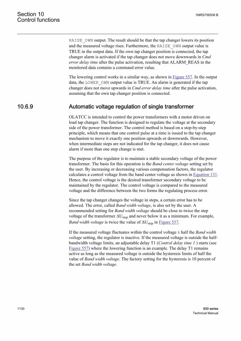
RAISE_OWN output. The result should be that the tap changer lowers its positionand the measured voltage rises. Furthermore, the RAISE_OWN output value isTRUE in the output data. If the own tap changer position is connected, the tapchanger alarm is activated if the tap changer does not move downwards in Cmderror delay time after the pulse activation, resulting that ALARM_REAS in themonitored data contains a command error value.
The lowering control works in a similar way, as shown in Figure 557. In the outputdata, the LOWER_OWN output value is TRUE. An alarm is generated if the tapchanger does not move upwards in Cmd error delay time after the pulse activation,assuming that the own tap changer position is connected.
10.6.9 Automatic voltage regulation of single transformerOLATCC is intended to control the power transformers with a motor driven onload tap changer. The function is designed to regulate the voltage at the secondaryside of the power transformer. The control method is based on a step-by-stepprinciple, which means that one control pulse at a time is issued to the tap changermechanism to move it exactly one position upwards or downwards. However,when intermediate steps are not indicated for the tap changer, it does not causealarm if more than one step change is met.
The purpose of the regulator is to maintain a stable secondary voltage of the powertransformer. The basis for this operation is the Band center voltage setting set bythe user. By increasing or decreasing various compensation factors, the regulatorcalculates a control voltage from the band center voltage as shown in Equation 131.Hence, the control voltage is the desired transformer secondary voltage to bemaintained by the regulator. The control voltage is compared to the measuredvoltage and the difference between the two forms the regulating process error.
Since the tap changer changes the voltage in steps, a certain error has to beallowed. The error, called Band width voltage, is also set by the user. Arecommended setting for Band width voltage should be close to twice the stepvoltage of the transformer ΔUstep and never below it as a minimum. For example,Band width voltage is twice the value of ΔUstep in Figure 557.
If the measured voltage fluctuates within the control voltage ± half the Band widthvoltage setting, the regulator is inactive. If the measured voltage is outside the half-bandwidth voltage limits, an adjustable delay T1 (Control delay time 1 ) starts (seeFigure 557) where the lowering function is an example. The delay T1 remainsactive as long as the measured voltage is outside the hysteresis limits of half thevalue of Band width voltage. The factory setting for the hysteresis is 10 percent ofthe set Band width voltage.
Section 10 1MRS756508 BControl functions
1130 630 seriesTechnical Manual
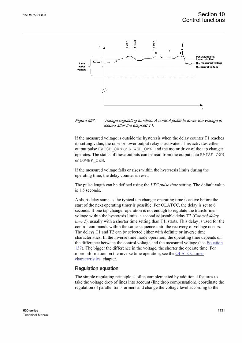
GUID-65BA0EC4-8E96-41E1-B273-3519DF5C25E1 V1 EN
Figure 557: Voltage regulating function. A control pulse to lower the voltage isissued after the elapsed T1.
If the measured voltage is outside the hysteresis when the delay counter T1 reachesits setting value, the raise or lower output relay is activated. This activates eitheroutput pulse RAISE_OWN or LOWER_OWN, and the motor drive of the tap changeroperates. The status of these outputs can be read from the output data RAISE_OWNor LOWER_OWN.
If the measured voltage falls or rises within the hysteresis limits during theoperating time, the delay counter is reset.
The pulse length can be defined using the LTC pulse time setting. The default valueis 1.5 seconds.
A short delay same as the typical tap changer operating time is active before thestart of the next operating timer is possible. For OLATCC, the delay is set to 6seconds. If one tap changer operation is not enough to regulate the transformervoltage within the hysteresis limits, a second adjustable delay T2 (Control delaytime 2), usually with a shorter time setting than T1, starts. This delay is used for thecontrol commands within the same sequence until the recovery of voltage occurs.The delays T1 and T2 can be selected either with definite or inverse timecharacteristics. In the inverse time mode operation, the operating time depends onthe difference between the control voltage and the measured voltage (see Equation137). The bigger the difference in the voltage, the shorter the operate time. Formore information on the inverse time operation, see the OLATCC timercharacteristics chapter.
Regulation equationThe simple regulating principle is often complemented by additional features totake the voltage drop of lines into account (line drop compensation), coordinate theregulation of parallel transformers and change the voltage level according to the
1MRS756508 B Section 10Control functions
630 series 1131Technical Manual
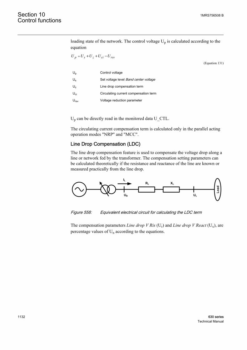
loading state of the network. The control voltage Up is calculated according to theequation
U U U U Up s z ci rsv= + + −
GUID-86D55536-6EF1-43CB-BA21-EF57280DEBB4 V1 EN (Equation 131)
Up Control voltage
Us Set voltage level Band center voltage
Uz Line drop compensation term
Uci Circulating current compensation term
Ursv Voltage reduction parameter
Up can be directly read in the monitored data U_CTL.
The circulating current compensation term is calculated only in the parallel actingoperation modes "NRP" and "MCC".
Line Drop Compensation (LDC)The line drop compensation feature is used to compensate the voltage drop along aline or network fed by the transformer. The compensation setting parameters canbe calculated theoretically if the resistance and reactance of the line are known ormeasured practically from the line drop.
ILXLRL
UB UL
Load
GUID-552C931B-4A1A-4361-8068-0A151CB99F30 V1 EN
Figure 558: Equivalent electrical circuit for calculating the LDC term
The compensation parameters Line drop V Ris (Ur) and Line drop V React (Ux), arepercentage values of Un according to the equations.
Section 10 1MRS756508 BControl functions
1132 630 seriesTechnical Manual

Line drop V Ris UI R
UUr
n
n
n= [ ] =
× ×
× [ ]%3
100 %
GUID-0DFDA3BA-B1E1-44AE-83C5-C18E097A9936 V1 EN (Equation 132)
Line drop V Re ct UI X
UUx
n
n
na = [ ] =
× ×
× [ ]%3
100 %
GUID-392489AD-AFB9-4540-855A-FB928FA59911 V1 EN (Equation 132)
In Rated current of the power transformer
Un Rated main voltage of the power transformer
R Resistance of the line, Ω/phase
X Reactance of the line, Ω/phase
The general LDC equation can be calculated.
UI
I
U U
z
injected
n
r x= ×
[ ] + [ ]( )[ ]
% cos % sinϕ ϕ
100 xUn
GUID-B004A188-862D-4015-868D-8654F8F5D214 V1 EN (Equation 133)
Iinjected Average of the currents I_A, I_B and I_C
Ur Setting Line drop V Ris
Ux Setting Line drop V React
φ Phase angle between U_A and I_A (ANGL_UA_IA in monitored data)
By default, the line drop compensation (LDC) is not active. LDC is activated bysetting LDC enable to "True". To keep the LDC term within acceptable limits in allsituations, OLATCC has a setting parameter LDC limit, which has a default valueof 0.10 xUn. As a result, this gives the maximum value for Uz in Equation 131.
If more than one line is connected to the LV busbar, the equivalent impedance iscalculated and given as a parameter setting as shown in Figure 558 for theequivalent electrical circuit for calculating LDC. For example, if there are Nnumber of identical lines with identical loads in the substation, the R- and X-valuesneeded for the settings Line drop V React and Line drop V Ris are obtained bydividing the resistance and the reactance of one line by N. Because the voltagedrop is different in lines with different impedances and load currents, it isnecessary to make a compromise when setting the Line drop V React and Line dropV Ris settings. Raising the voltage in the point of lowest voltage must not lead toovervoltage elsewhere.
By default, the line drop compensation is effective only on the normal active powerflow direction. If the active power flow in the transformer turns opposite, that is,from the regulated side towards the system in the upper level, the LDC term isignored, that is, set to zero. In such a case, it is assumed that the feeding units at theregulated side of the transformers maintain proper voltage levels. This can cause a
1MRS756508 B Section 10Control functions
630 series 1133Technical Manual
conflict if the transformer tries to reduce the voltage at the substation. Additionally,it is difficult to predict the actual voltage levels in the feeder lines in such a case,and lowering the voltage at the substation can have harmful effects in the far end ofthe network. However, the Rv Pwr flow allowed setting allows also negative LDCterms to be taken into equation.
The topology changes in the network can cause changes to the equivalentimpedance value of the network. If the change is substantial, the setting groups canbe used to switch between different setting values for Line drop V React and Linedrop V Ris. In practice this means that the boolean-type information from thetopology change is connected to the active setting group change.
The use of the LDC equation in the case of parallel transformers is described in theAutomatic voltage regulation of parallel transformers chapter.
Reduce Set Voltage (RSV) inputThe system frequency decreases when the active power production in the networkis smaller than its consumption. Either the power supply has to be increased orsome loads have to be shed to restore the power balance.
The simplest way to decrease the load is to reduce the voltage level by giving alower band center voltage value to the regulators. For this purpose, OLATCC hasthe setting group parameter Band reduction. The RSV input activation results inreduction. If this input is set to TRUE, a set target voltage value is decreased byBand reduction. If more than one RSV reduction steps are desired, the setting groupchange has to be used where different Band reduction values are supported. Thedecreased value is kept as a target value as long as the RSV input is TRUE.
Because the decrease of frequency indicates a need to reduce the load, it ispractical to connect the start signal of an underfrequency function block to the RSVdigital input.
It depends on the load characteristics how much the load is reduced as the voltagedrops. For instance, purely resistive loads are proportional to the square of thevoltage, whereas motor drives based on frequency controllers may draw constantpower despite small voltage changes.
The status of the RSV input can be read from the RSV input data.
10.6.10 Automatic voltage regulation of parallel transformersIt is likely that a circulating current between transformers occurs if two or moretransformers with slightly different ratios are energized in parallel. This is due tothe unbalanced short circuit impedances of the parallel transformers. To avoid suchcurrents, the tap changers of the transformers should be adjusted to achieveequilibrium. If the transformers are assumed identical, the tap (voltage) steps andtap positions should also match. In this case, the Master/Follower principle can beused. However, unequally rated transformers with different tap steps can beconnected in parallel and these configurations can also be managed by the tap
Section 10 1MRS756508 BControl functions
1134 630 seriesTechnical Manual
changer control function. For these configurations, the Minimizing CirculatingCurrent (MCC) or Negative Reactance Principle (NRP) should be used. The MCCand NRP principles are also suitable for identical transformers.
The circulating current, which is almost purely inductive, is defined as negative ifit flows towards the transformer. Uci in Equation 131 is positive and the controlvoltage Up rises as a result to the RAISE_OWN output signal activation if thecirculating current level is sufficient (see Equation 134 and Equation 136) and theother parameters remain the same. As a result, the voltage rise should diminish thecirculating current.
LDC equation and parallel connectionThe additional challenge in the parallel connection regarding the line dropcompensation is to know the total current which flows through the paralleltransformers.
In the Master/Follower mode, it is easier to know the total current than in otherparallel modes since the transformers are assumed to have identical ratings, that is,the total current (Iinjected in Equation 133) is obtained by multiplying the measuredload current (the average of the secondary currents I_A, I_B and I_C of theconnected own transformer) with the number of parallel transformers. OLATCCcan internally conclude the number of parallel transformers from the connected tapchanger position inputs. On the contrary, if there is no connected positioninformation from the other parallel transformers, the correct number of the paralleltransformers, excluding the own transformer, needs to be set with the Paralleltrafos setting.
In the MCC mode, the horizontal communication transfers the information fromthe measured load currents between the regulators so that the total current neededin the line drop compensation can be summed up accurately. Here, Iinjected isdefined to be the phasor sum of all the parallel power transformer secondary-sidecurrents. The currents from other transformers must be fed via the TRx_I_AMPLand TRx_I_ANGL inputs. If the state of the input TRx_I_VALID is TRUE (1),the good quality for the corresponding inputs TRx_I_AMPL and TRx_I_ANGL isindicated.
In the NRP mode, the parallel transformers have different ratings and there is nocommunication between the regulators. Therefore, when setting Line drop V Reactand Line drop V Ris, the ICT_n1 used in the equation should be the sum of the ratedcurrents of all the transformers operating in parallel. Here, Iinjected is also defined asthe average of the connected secondary currents (I_A, I_B and I_C). The calculatedline drop compensation value can be read from the monitored data LDC.
10.6.10.1 Master/Follower principle M/F
The Master/Follower (M/F) operation principle is suitable for power transformerswith identical ratings and step voltages. One voltage regulator (master) measuresand controls and the other regulators (followers) follow the master, that is, all the
1MRS756508 B Section 10Control functions
630 series 1135Technical Manual

tap changers connected in parallel are synchronized. This parallel operation isobtained by connecting the FLLWx_CTL output of the master to the correspondinginput TAPCHG_FLLW of the followers via a horizontal GOOSE communication.
The values for the FLLWx_CTL command are 1=Lower follower x and 2=Raisefollower x. Consequently, the values for the TAPCHG_FLLW command are1=Lower and 2=Raise.
If several regulators are to act as masters (one at a time), their outputs also have tobe routed to the inputs of other regulators. To start the parallel operation, themaster regulator is set to the "Auto master" mode and the followers to the "Autofollower" mode. To implement this setting, a group changing has to be planned.
To keep all the tap changers in the same position, the master needs to know the tappositions of the followers. In this way the circulating current is kept at itsminimum. The position values of the followers can be brought to the master eithervia the horizontal GOOSE communication or TPOSSLTC.
If it is not possible to use horizontal communication between the IEDs and theposition information cannot be wired from the parallel transformers, the M/Fprinciple can still be used to regulate two or an unlimited number of transformersin parallel. Since the master cannot detect the tap positions of parallel transformers,it just activates the lower and raise outputs for all the followers when it controls itsown tap changer. This is called blind control. In this case, a number of paralleltransformers are regulated as one unit. The tap position inputs 1…3(TR1_TAP_POS..TR3_TAP_POS) must be left unconnected for the master toknow that the tap positions of the followers are unknown. The time delay betweensuccessive commands can be set by the Follower delay time setting. The defaultvalue is six seconds.
When a disconnected transformer is taken into use and the tap position is unknown,the follower should be manually controlled to the same position as the master. Thiscan also take place in the master/follower mode. First, the master gives a controlcommand to its own transformer, that is, it is echoed to the followers (the followertap positions have to be connected). Thereafter, successive control commands tothe followers take place until the master and followers have the same tap positions.
Out-of-step functionThe out-of-step function is usually used in the M/F modes only. The out-of-stepfunction means that the master is able to detect the position values of the followersand control them to the same position as the master is. The detection takes place ifthe master has just issued a control for followers and for itself and after that detectsthat some of the followers are not following. If there was no previous controlaction and there still is difference in tap positions, this must be manually corrected.In this case, the master assumes that the followers also have either Raise block tap> Lower block tap or Lower block tap > Raise block tap because this defines whatis the given command pulse for a follower. If the master has Raise block tap >Lower block tap and the follower has Lower block tap > Raise block tap or viceversa, the corresponding TAPCHG_FLLW included control signals should be
Section 10 1MRS756508 BControl functions
1136 630 seriesTechnical Manual

connected crosswise. This requires an extra logic where dual-point command bitshave to be converted, that is, 0=>0, [01]=1=>[10]=2 and [10]=2=>[01]=1.
M/F is the only parallel mode which has an out-of-step functionality. In the MCCand NRP operation modes, the circulating current is minimized, which mostprobably means different tap positions in the parallel transformers. Moreover, thesemodes allow different ratings and step voltages for the parallel transformers.Therefore, it is reasonable to apply the out-of-step function only to the M/Foperation mode.
The out-of-step function is triggered when the master detects a difference of atleast one step between the tap changer positions in the follower and in the master.The master then sends special raise or lower commands to the diverged follower. Iftwo consecutive commands fail to change the position of the follower to the rightdirection, the master activates the PAR_FAIL output, that is, PAR_FAIL is set toTRUE, and stops the special recovery efforts. However, every time the mastercontrols its own tap changer later, it always sends a controlling pulse to thediverged follower too. Furthermore, if the master notices a correct position changeafter a sent pulse, it restarts the attempt to drive the follower to the same positionand deactivates the PAR_FAIL output, that is, PAR_FAIL is set to FALSE.However, if there still are diverged followers, the reset is not indicated. It isindicated only when no diverged followers exist. Monitoring, and hence theindication of a paralleling failure, is not possible in blind control. The followerswith a parallel failure can be read from the monitored data FAIL_FLLW. Forexample, if only follower 3 is in the parallel failure state, FAIL_FLLW has thevalue "Follower 3". If both followers 1 and 2 are in the parallel failure state,FAIL_FLLW has the value "Followers 1+2". By default, when no failed followersexist, the value is "No failed followers".
10.6.10.2 Negative Reactance Principle NRP
This parallel control scheme is suitable for power transformers with differentratings and step voltages. Since no communication between the regulators isneeded, this principle can be applied even when the parallel transformers arelocated at different substations. To start the parallel operation, the acting operationmode has to be set to "NRP" for all the regulators of the connection. The actingoperation mode can be changed via function block inputs or by setting eitherlocally or remotely.
When applying this principle, each regulator has a phase angle setting φLoad(setting parameter Load phase angle) towards which it tries to regulate the current.The setting value is chosen according to the expected power factor of the load(positive setting value equals inductive load). When the actual phase angle of theload current is the same as the setting and the transformers and their tap changerpositions are identical, the currents of the two or more transformers are in the samephase as the total load current. If the tap changer positions are different, thecirculating current flows and the currents of different transformers either lag orlead the load current. Figure 559 shows that the circulating current is the reactive
1MRS756508 B Section 10Control functions
630 series 1137Technical Manual
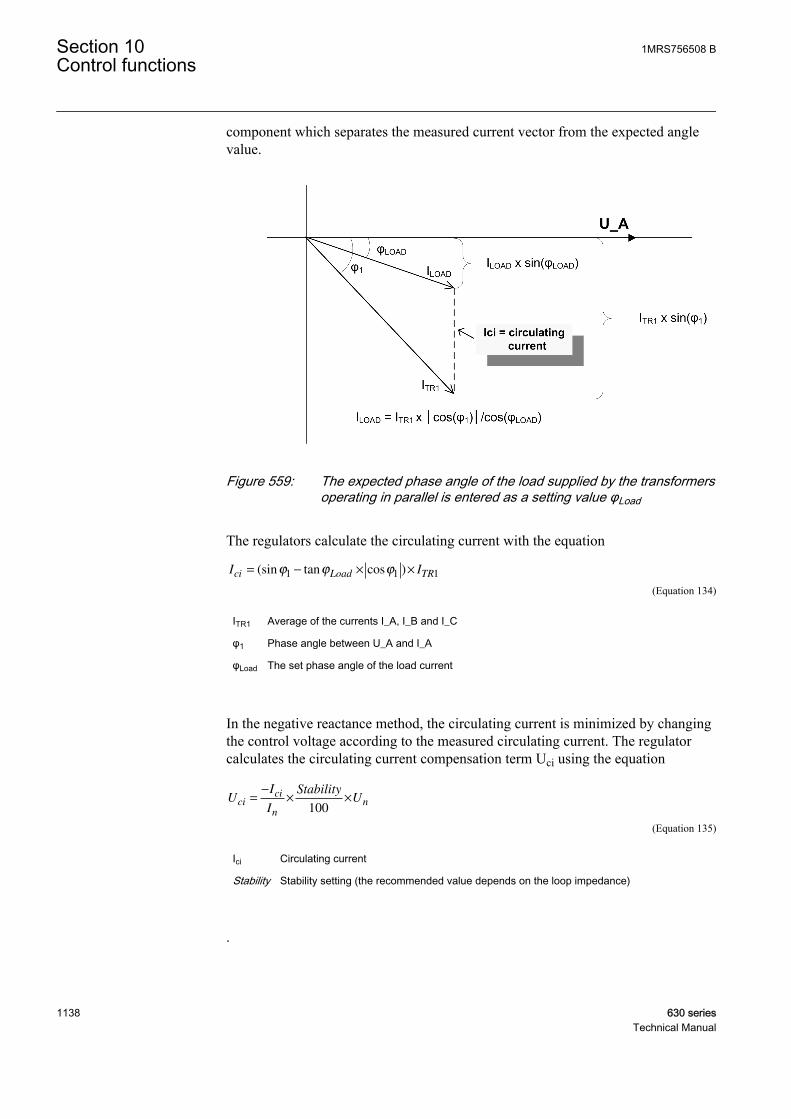
component which separates the measured current vector from the expected anglevalue.
GUID-2B71B160-FB76-4BE0-952F-75F42220401F V1 EN
Figure 559: The expected phase angle of the load supplied by the transformersoperating in parallel is entered as a setting value φLoad
The regulators calculate the circulating current with the equation
I Ici Load TR= − × ×(sin tan cos )ϕ ϕ ϕ1 1 1
GUID-823FAEEA-589B-4C8E-81CD-E5FECF28BF06 V1 EN (Equation 134)
ITR1 Average of the currents I_A, I_B and I_C
φ1 Phase angle between U_A and I_A
φLoad The set phase angle of the load current
In the negative reactance method, the circulating current is minimized by changingthe control voltage according to the measured circulating current. The regulatorcalculates the circulating current compensation term Uci using the equation
UI
I
StabilityUci
ci
n
n=−
× ×
100
GUID-2A7864D3-D59F-47F9-84FD-B3F2C15178EB V1 EN (Equation 135)
Ici Circulating current
Stability Stability setting (the recommended value depends on the loop impedance)
.
Section 10 1MRS756508 BControl functions
1138 630 seriesTechnical Manual

If the transformers operating in parallel have different rated currents, the value ofthe Stability factor setting of the regulator should be proportional to the ratedcurrents, that is, the higher the rated current, the higher the Stability factor settingvalue.
By comparing the reactive components of the currents measured by the differentregulators it is possible to find out if the circulating current has been minimized.The circulating current is minimized when the reactive components are equal.
The negative reactance method gives satisfactory results only if the phase angle ofthe load current is known relatively accurately. If the actual phase angle deviatesfrom the phase angle setting, a regulating error occurs. However, for the caseswhere there is an occasional stepwise change in the phase angle of the load, theregulating error can be suppressed with the logic. This kind of stepwise change canoccur, for example, when a capacitor bank is switched on to compensate a reactivepower flow.
Another possibility is to use an automatic setting group change between settinggroups in different loading situations. The setting groups then have different setvalues for the load phase angle.
10.6.10.3 Minimizing Circulating Current principle MCC
The MCC principle is an optimal solution for controlling the parallel transformersof different ratings or step voltages in substations with varying reactive loads.Since this control scheme allows the exchange of data between regulators, thecirculating current can be calculated more accurately than with other schemes.However, a maximum of four regulators can be connected in parallel. To start theparallel operation, the acting operation mode parameter has to be set to "MCC" forall the regulators of the connection. Furthermore, the signal CON_STATUS mustindicate that the transformers are connected to the network. A unit that isminimizing the circulating current must have the acting operation mode set to"MCC". However, units that have the acting operation mode set to "Manual" do notperform any circulating current minimization operations themselves.
1MRS756508 B Section 10Control functions
630 series 1139Technical Manual

GUID-F73692B0-629D-4C0A-BFAB-648B0A832E42 V1 EN
Figure 560: The circulating current between two parallel transformers
In this case, the circulating current can be calculated with the equation
I I Ici TR TR= × − ×(sin sin ) /ϕ ϕ1 1 2 2 2
GUID-5898550F-0095-4173-91ED-4D5AFFC7B58D V1 EN (Equation 136)
ITR1 Average primary value of the currents I_A, I_B and I_C measured by regulator 1
ITR2 Average primary value of the currents I_A, I_B and I_C measured by regulator 2
φ1 Phase angle between U_A and I_A in regulator 1
φ2 Phase angle between U_A and I_A in regulator 2
The circulation current can be read from the monitored data I_CIR.
Using the circulating current, the compensation term Uci can be calculated with theequation
UI
I
Stability factorUci
ci
CT n
n=
−
× ×
_ 1 100
GUID-173A1FA0-8C07-4BA8-AAEB-62F95E10396C V1 EN
Ici Circulating current
In Nominal current of the transformer
Stability factor Stability setting (the recommended value depends on the loop impedance)
The circulating current can be read from the monitored data I_CIR.
Section 10 1MRS756508 BControl functions
1140 630 seriesTechnical Manual
Using the circulating current, a compensation term Uci can be calculated usingEquation 135. The value of Uci, which can be positive or negative, is considered byadding it to the Band center voltage Us (see Equation 131). According to Figure560 and Equation 136, the phasor information from the other IEDs is needed.
Parallel unit detection and the MCC modeThe network connection status information is essential for the MCC operationmode. The status FALSE needs to be connected to the CON_STATUS input toensure a proper operation of the MCC calculation if the transformer is disconnectedbut OLATCC remains in the MCC mode. This way the disconnected transformer isexcluded from the circulating current calculations.
The CON_STATUS input is used to identify if a certain transformer controller isable to send the current information to other transformer controllers for circulatingcurrent minimization purposes. As a result, this input has effect only in the MCC orManual acting operation modes. In these modes, if CON_STATUS is TRUE, theinformation transmission is started. The circulating current information receiving isallowed only in the MCC acting operation mode when CON_STATUS is TRUE.PAR_UNIT_MCC can be seen in the monitored data view.
Communication and the MCC modeThe phasor information from the other parallel IEDs is needed for the circularcurrent calculation. Therefore, horizontal GOOSE communication is neededbetween IEDs when the MCC principle is used.
The transferred current phasor contains the primary value of the measured current.The received current phasor information can be read from the input dataTRx_I_AMPL and TRx_I_ANGL for the magnitude and angle respectively. Thevalue "x" gives the connected parallel transformer number, a value between 1 and 3.
The sent phasor information always represents the difference between the voltagephasor U_A and I_A. This information regarding the current phasor can be readfrom the output data TR0_I_AMPL and TR0_I_ANGL. The allowed actingoperation modes for sending data are MCC or Manual, both with the inputCON_STATUS activated. The communication can be seen to be active when thesent and received phasor magnitude is not clamped to zero. The communicationphasor magnitude found to be zero results either from a rejected acting operationmode or too low signal magnitudes (see the OLATCC Voltage and currentmeasurements chapter). Active CON_STATUS indicates that the correspondingtransformer is connected to network and its current affects the circular current ofother transformers even when it is itself in the manual operating mode.
10.6.11 Timer characteristics
Operate timer functionalityThe delay times can be set to follow either the definite time characteristic or theinverse time characteristic with the Delay characteristic setting. By default, the
1MRS756508 B Section 10Control functions
630 series 1141Technical Manual
"Definite time" type is selected. The timer mode cannot be changed between cyclesT1 and T2, only either before T1 has started or after T2 has elapsed.
Table 983: Different timer mode delays
Timer mode Setting DescriptionT1 Control delay time 1 First delay when the measured voltage
exceeds or falls below the limit value.
T2 Control delay time 2 Second delay when the first control didnot bring the measured voltage to adesired level.
The delay after the command pulse activation and the restart of the timer is sixseconds. The delay is assumed to be the tap changer operating delay. The timerstatus can also be read from the monitoring data TIMER_STS, where T1 activegives a value "Lower timer1 on" or "Raise timer1 on" while T2 active gives a value"Lower timer2 on" or "Raise timer2 on". Furthermore, the "Fast lower T on" valueindicates that the fast lowering control functionality is active (see the Fast lowercontrol chapter).
IDMT type operationThe IDMT timer can be selected by setting Delay characteristic to "Inverse time".The minimum time at the inverse time characteristic is limited to 1.0 second.However, the minimum recommended setting of the control delay times T1 and T2is 10 seconds when the definite time delay is used and 25 seconds when the inversetime delay is used.
The inverse time function is defined by the equations:
BU
U
d
BW
=
( / )2
GUID-59DE8DA1-7C1D-41A2-98A8-48A91D061FFD V1 EN (Equation 137)
Ud |Um – Up|, differential voltage
UBW Setting parameter Band width voltage
tT
B=
−( )2
1
GUID-18A433AA-B4A7-4DA8-94B2-4FDF12A23FD1 V1 EN (Equation 138)
T T1 or T2
The monitored data UD_CTL shows the differential voltage value Um – Up. If thevalue exceeds half of the Band width voltage setting and has a negative sign, a raisepulse is issued. The UD_CTL monitored data can also be seen in the DT timer mode.
Section 10 1MRS756508 BControl functions
1142 630 seriesTechnical Manual
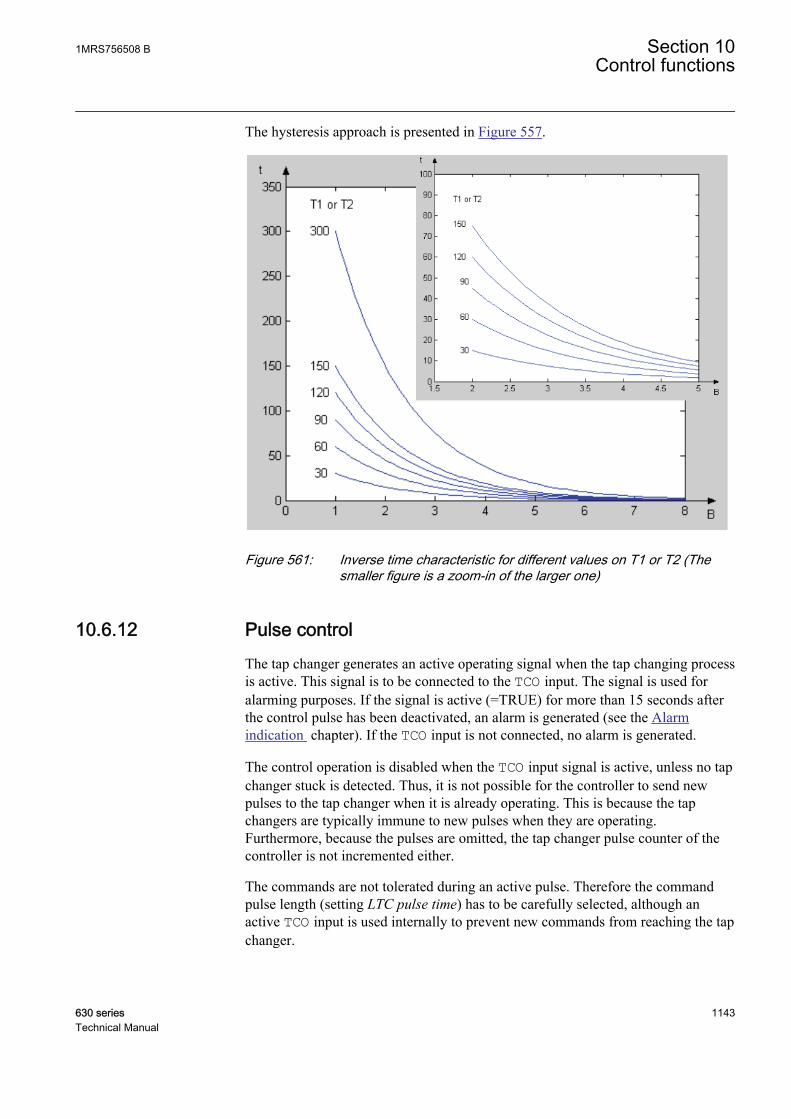
The hysteresis approach is presented in Figure 557.
GUID-6AA3C028-E7DD-4C87-A91C-4B8B1D43CBBA V1 EN
Figure 561: Inverse time characteristic for different values on T1 or T2 (Thesmaller figure is a zoom-in of the larger one)
10.6.12 Pulse controlThe tap changer generates an active operating signal when the tap changing processis active. This signal is to be connected to the TCO input. The signal is used foralarming purposes. If the signal is active (=TRUE) for more than 15 seconds afterthe control pulse has been deactivated, an alarm is generated (see the Alarmindication chapter). If the TCO input is not connected, no alarm is generated.
The control operation is disabled when the TCO input signal is active, unless no tapchanger stuck is detected. Thus, it is not possible for the controller to send newpulses to the tap changer when it is already operating. This is because the tapchangers are typically immune to new pulses when they are operating.Furthermore, because the pulses are omitted, the tap changer pulse counter of thecontroller is not incremented either.
The commands are not tolerated during an active pulse. Therefore the commandpulse length (setting LTC pulse time) has to be carefully selected, although anactive TCO input is used internally to prevent new commands from reaching the tapchanger.
1MRS756508 B Section 10Control functions
630 series 1143Technical Manual
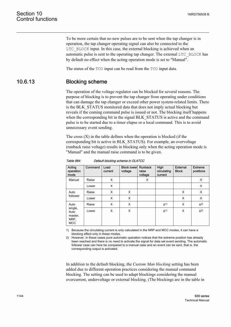
To be more certain that no new pulses are to be sent when the tap changer is inoperation, the tap changer operating signal can also be connected to theLTC_BLOCK input. In this case, the external blocking is achieved when anautomatic pulse is sent to the operating tap changer. The external LTC_BLOCK hasby default no effect when the acting operation mode is set to "Manual".
The status of the TCO input can be read from the TCO input data.
10.6.13 Blocking schemeThe operation of the voltage regulator can be blocked for several reasons. Thepurpose of blocking is to prevent the tap changer from operating under conditionsthat can damage the tap changer or exceed other power system-related limits. Thereis the BLK_STATUS monitored data that does not imply actual blocking butreveals if the coming command pulse is issued or not. The blocking itself happenswhen the corresponding bit in the signal BLK_STATUS is active and the commandpulse is to be started due to a timer elapse or a local command. This is to avoidunnecessary event sending.
The cross (X) in the table defines when the operation is blocked (if thecorresponding bit is active in BLK_STATUS). For example, an overvoltage(runback raise voltage) results in blocking only when the acting operation mode is"Manual" and the manual raise command is to be given.
Table 984: Default blocking schema in OLATCC
Actingoperationmode
Command Loadcurrent
Block lowervoltage
Runbackraisevoltage
Highcirculatingcurrent
ExternalBlock
Extremepositions
Manual Raise X X X
Lower X X
Autofollower
Raise X X X X
Lower X X X X
Autosingle,Automaster,NRP,MCC
Raise X X X1) X X2)
Lower X X X1) X X2)
1) Because the circulating current is only calculated in the NRP and MCC modes, it can have ablocking effect only in these modes.
2) However, in these cases pure automatic operation notices that the extreme position has alreadybeen reached and there is no need to activate the signal for data set event sending. The automaticfollower case can here be compared to a manual case and an event can be sent, that is, thecorresponding output is activated.
In addition to the default blocking, the Custom Man blocking setting has beenadded due to different operation practices considering the manual commandblocking. The setting can be used to adapt blockings considering the manualovercurrent, undervoltage or external blocking. (The blockings are in the table in
Section 10 1MRS756508 BControl functions
1144 630 seriesTechnical Manual

columns Load current, Block lower voltage and External block for the manualoperating mode.) The default value for the parameter is "OC". This means that thetable explaining the default blocking schema operates as such. However, there arealso other alternatives that cause different operation when compared to that table.
Table 985: Customized manual blocking schema
Manualblockingtype
Enumeration Description
1 Custom disabled No Load current, blocking of lower (under) voltage or externalblocking have effect in the manual.
2 OC Load current blocking has an effect in the manual operation mode
3 UV Block lower (under) voltage blocking has an effect in the manualoperation mode
4 OC, UV Conditions 2 and 3 together: Load current and block lower(under) voltage blocking have effect in the manual operation mode
5 EXT External blocking has an effect in the manual operation mode
6 OC, EXT Conditions 2 and 5 together: Load current and external blockinghave effect in the manual operation mode
7 UV, EXT Conditions 3 and 5 together: Block lower (under) voltage andexternal blocking have effect in the manual operation mode
8 OC, UV, EXT All conditions 2, 3 and 5 together: Load current and block lower(under) voltage and external blocking have effect in the manualoperation mode
If the Custom Man blocking setting is "Custom disabled", the blocking schemaregarding the acting operation mode "Manual" is as given in Table 986. Otheroperation modes follow the default schema.
Table 986: Blocking schema for selection "Custom disabled"
Actingoperationmode
Command Loadcurrent
Block lowervoltage
Runbackraisevoltage
Highcirculatingcurrent
ExternalBlock
Extremepositions
Manual Raise X X
Lower X
Table 987: Blocking schema for selection "OC, UV, EXT"
Actingoperationmode
Command Loadcurrent
Block lowervoltage
Runbackraisevoltage
Highcirculatingcurrent
ExternalBlock
Extremepositions
Manual Raise X X X X X
Lower X X X X
1MRS756508 B Section 10Control functions
630 series 1145Technical Manual

Table 988: Blocking schema for selection “UV, EXT”
Actingoperationmode
Command Loadcurrent
Block lowervoltage
Runbackraisevoltage
Highcirculatingcurrent
ExternalBlock
Extremepositions
Manual Raise X X X X
Lower X X X
Load currentThe load current blocking is mainly used for preventing the tap changer fromoperating in an overcurrent situation. For example, if the current is not high enoughto activate the protective IED of the substation, it can still be fatal for the diverterswitch of the tap changer. This operation can be adjusted with the setting parameterLoad current limit. The maximum of measurements from the secondary-sidecurrent phases is used for blocking. By default, both the automatic operation andthe manual operation are blocked (see Table 984) when the set limit is exceeded.
The blocking status can be read from the monitored data BLKD_I_LOD.
Block lower voltageThe block lower voltage feature blocks both raise and lower voltage commands ifthe measured voltage is too low to be corrected by operating the tap changer. Sucha situation can occur due to a faulty measuring circuit, an earth fault or anovercurrent situation. By default, only the automatic (also automatic follower)operation is blocked when the undervoltage condition is met (see Table 984). Thisoperation can be adjusted with the setting parameter Block lower voltage.
The blocking status can be read from the monitored data BLKD_U_UN.
However, there is no minimum limit for the undervoltage blocking. The blocking isallowed even if the measured voltage is not connected or it has temporarily a verylow value. There is a minimum limit for the phase angle calculation based on thevoltage phasor magnitude.
Runback raise voltageThe manual raise command is blocked if the overvoltage limit is exceeded (seeTable 984). However, in the automatic operation mode, the overvoltage situationtriggers the fast lower feature. For more information, see the Manual voltageregulation chapter. This operation can be adjusted with the setting parameterRunback raise V.
The blocking status can be read from the monitored data RNBK_U_OV.
High Circulating CurrentThe circulating current value is calculated in the operation modes NegativeReactance Principle (NRP) and Minimizing Circulating Current (MCC). Only theautomatic operation in these modes is blocked when the high circulating current is
Section 10 1MRS756508 BControl functions
1146 630 seriesTechnical Manual

measured (see Table 984). This operation can be adjusted with the settingparameter Cir current limit.
The blocking status can be read from the monitored data BLKD_I_CIR.
LTC_BLOCK – external block inputWith the PCM600 tool configuration possibilities, a desired blocking condition canbe built by connecting an outcome to this input. The blocking status can be readfrom the monitored data BLKD_LTCBLK. When activated, this input blocks onlythe automatic operation of the regulator by default (see Table 984). For the fullyautomatic modes, the signal activation resets the timer, and the monitored dataBLKD_LTCBLK is not activated.
Extreme positionsThis blocking function supervises the extreme positions of the tap changer. Theseextreme positions can be adjusted with the setting parameters Raise block tap andLower block tap. When the tap changer reaches one of these two positions, thecommands in the corresponding direction are blocked (see Table 984). Here itdepends on the comparison between the Raise block tap and Lower block tapsettings, which direction is blocked (see the Voltage control vs. tap changermoving direction section). This blocking affects both the automatic and manualoperation modes.
However, as shown in Table 984, no blocking indication is to be generated in thefully automatic modes. Here "Auto follower" is not a fully automatic mode. Theunconnected position information does not cause the total block of OLATCC, onlythe extreme position blocking is not working.
The blocking status can be seen in the generated events.
Fast lower controlOLATCC provides the fast lower control in the automatic operation modes. Whenthe set Runback raise V is exceeded, the regulator gives fast lower control pulsesuntil the voltage drops below the specified limit. This fast lower control can beseen with the monitoring data TIMER_STS, where the value "Fast lower T on"indicates this functionality to be active.
To allow the fast lower operation, Runback raise V has to be setalways to a value higher than the control voltage (U_CTL) plus halfof Band width voltage.
Typically, the blockings are reset when the corresponding limit with the hysteresisis undershoot or exceeded. Although blocking is reset after undershooting the above-mentioned limit, the fast lower control operation continues until the measuredvoltage signal difference undershoots half the Band width voltage hysteresis limit(see Figure 557). As a result, normal automatic mode operation is not possiblebefore this happens.
1MRS756508 B Section 10Control functions
630 series 1147Technical Manual
Fast lower control causes successive LOWER_OWN pulses to be activated. The timebetween consecutive pulse starts is the pulse length plus 1.5 seconds. This means that
• There is no tap changer operating delay (otherwise six seconds) taken intoaccount in this cycle (meaning that some command pulses are ineffective dueto tap changer operation, see the Pulse control chapter)
• Timer mode set by Delay characteristic has no effect here (always the DT timer-type operation). Because the minimum pulse length (the LTC pulse timesetting) is 0.5 seconds, the shortest interval between successive pulses can betwo seconds.
In the automatic follower mode, the fast lowering is not triggered. In this way, theawkward dispersion of position values in different units can be avoided. Themaster always decides on the fast lowering on behalf of the follower units.Moreover, master and follower should measure an equal voltage level and havesimilar setting values for the overvoltage blocking limit.
10.6.14 Alarm indication
Tap Changer MonitoringOLATCC supervises the operation of the tap changer and alarms if the alarmcondition is detected. An alarm activation means that the ALARM output isactivated and the alarm reason can be read from the monitored dataALARM_REAS. Alarms are in use by default but they can be set not to be in useby setting Alarms enabled to "False". Three different alarm conditions and theircombinations can be detected by OLATCC.
Command errorOLATCC supervises the tap changer position information of the own transformerwhen a control pulse is given. If the correct position change (direction depends onthe comparison of the settings Raise block tap and Lower block tap comparison) isnot seen by OLATCC in Cmd error delay time after the pulse start, the alarm is issued.
If the position information is not connected, no alarm is generated. The alarm isreset when the correct change in position value is detected after a given pulse or ifa new command pulse is given.
The monitored data ALARM_REAS is set during an alarm. This means that if thealarm reason is active, ALARM_REAS has the value "Cmd error".
TCO signal failsIf the tap changer operating signal TCO stays active for more than 15 seconds afterthe output pulse deactivation, OLATCC concludes this as an abnormal conditionand assumes that the tap changer is stuck. The alarm is reset when the TCO inputsignal deactivates. The monitored data ALARM_REAS is set during the alarm.This means that only if alarm reason is active, ALARM_REAS has the value "TCOerror".
Section 10 1MRS756508 BControl functions
1148 630 seriesTechnical Manual
If the TCO input signal is not connected (indicated by bad quality), this type ofalarm is not possible.
Regulator pumpingIt is possible that faulty settings cause the regulator to give control pulses toofrequently. For example, too low a setting for the Band width voltage (see Figure557) can result in a pumping condition where the regulator has problems to bringthe regulated voltage to a desired level. To detect this, OLATCC has a setting Maxoperations in 1h, which defines the allowed number of lower and raise commandsduring a one-hour sliding time window. The detection is active both in the manualand automatic operation modes. The alarm is reset after the counted number of theoperations during the one-hour time window is less than the set value. The numberof executed operations per last one hour can be read from the monitored dataOP_TM_NUM_H. However, this parameter is updated only in three-minuteintervals. Again, the monitored data ALARM_REAS is set during an alarm. Thismeans that only if alarm reason is active, ALARM_REAS has the value "Pump error".
The operation of OLATCC is not blocked during an alarm situation, but all thealarms mentioned above cause the automatic operation to be delayed. In practice,this means that the set delay times T1 and T2 are doubled.
In addition to the alarm detections, OLATCC provides a nonvolatile operationcounter parameter (monitored data OPR_CNT) for determining the serviceintervals of the tap changer. The counter gives the total number of raise and lowercommands given in the manual and automatic modes. All commands, even thosethat are omitted by the tap changer due to its operation sequence, are calculated in acumulative counter. This data parameter can be reset via the clear menu parameterOLATCC counter.
10.6.15 Base valuesIn this function block, some of the settings are set in per unit (pu). These pu valuesare relational to certain base values, for example the values given in A, kV andkVA. The IED supports alternative base value groups for the phase current or voltage-related settings, for example "Phase Grp 1", "Phase Grp 2" and "Phase Grp 3".One of the groups to be used with the Base value Sel phase setting must be selected.
For more information, see the Basic functions section in this manual.
10.6.16 ApplicationOLATCC is used to control the voltage on the load side of the power transformer.Based on the measured voltage and current, the function block determines whetherthe voltage needs to be increased or decreased. The voltage is regulated by the raiseor lower commands sent to the tap changer.
1MRS756508 B Section 10Control functions
630 series 1149Technical Manual
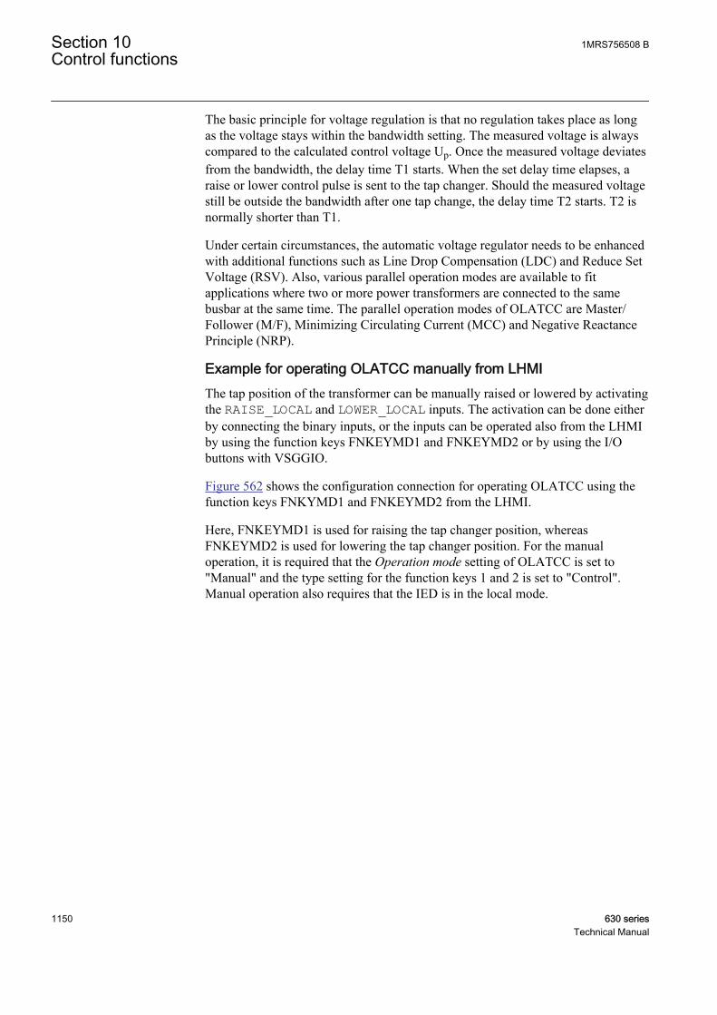
The basic principle for voltage regulation is that no regulation takes place as longas the voltage stays within the bandwidth setting. The measured voltage is alwayscompared to the calculated control voltage Up. Once the measured voltage deviatesfrom the bandwidth, the delay time T1 starts. When the set delay time elapses, araise or lower control pulse is sent to the tap changer. Should the measured voltagestill be outside the bandwidth after one tap change, the delay time T2 starts. T2 isnormally shorter than T1.
Under certain circumstances, the automatic voltage regulator needs to be enhancedwith additional functions such as Line Drop Compensation (LDC) and Reduce SetVoltage (RSV). Also, various parallel operation modes are available to fitapplications where two or more power transformers are connected to the samebusbar at the same time. The parallel operation modes of OLATCC are Master/Follower (M/F), Minimizing Circulating Current (MCC) and Negative ReactancePrinciple (NRP).
Example for operating OLATCC manually from LHMIThe tap position of the transformer can be manually raised or lowered by activatingthe RAISE_LOCAL and LOWER_LOCAL inputs. The activation can be done eitherby connecting the binary inputs, or the inputs can be operated also from the LHMIby using the function keys FNKEYMD1 and FNKEYMD2 or by using the I/Obuttons with VSGGIO.
Figure 562 shows the configuration connection for operating OLATCC using thefunction keys FNKYMD1 and FNKEYMD2 from the LHMI.
Here, FNKEYMD1 is used for raising the tap changer position, whereasFNKEYMD2 is used for lowering the tap changer position. For the manualoperation, it is required that the Operation mode setting of OLATCC is set to"Manual" and the type setting for the function keys 1 and 2 is set to "Control".Manual operation also requires that the IED is in the local mode.
Section 10 1MRS756508 BControl functions
1150 630 seriesTechnical Manual
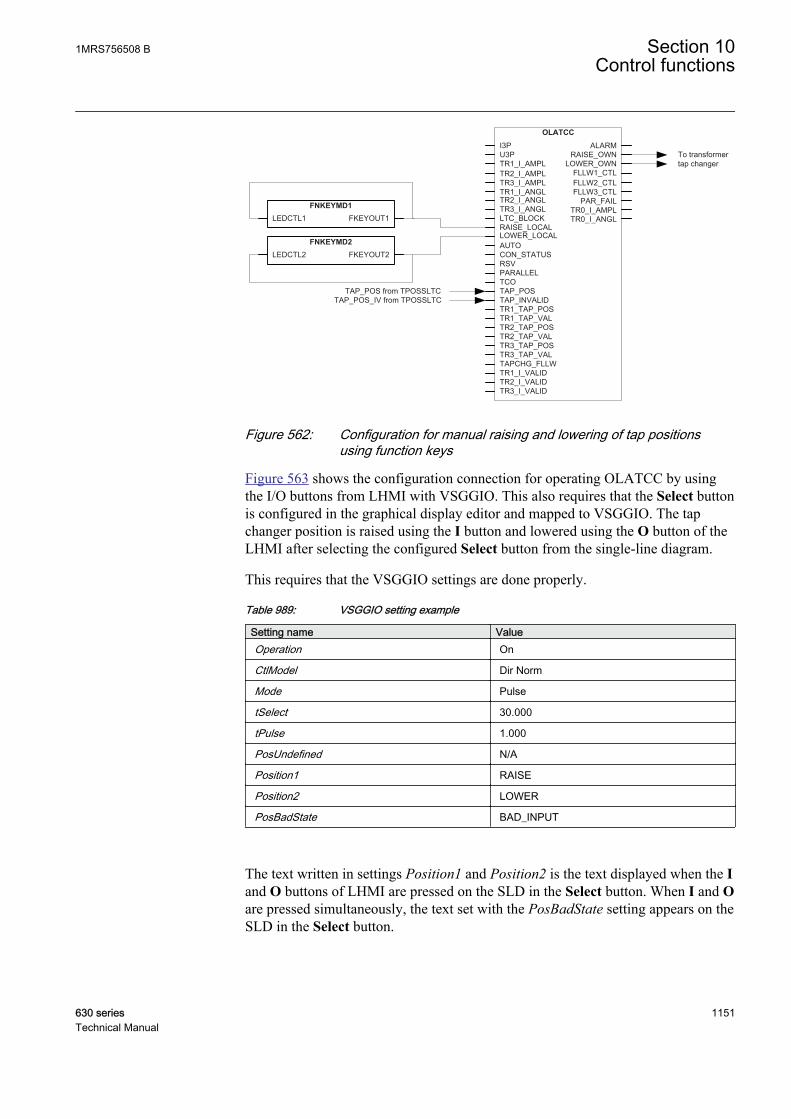
ALARMRAISE_OWN
LOWER_OWN
I3P
OLATCC
FLLW1_CTL
U3PTR1_I_AMPL
TR3_I_ANGL
RAISE_LOCAL
FLLW2_CTLFLLW3_CTL
PAR_FAILTR0_I_AMPLTR0_I_ANGL
LOWER_LOCALAUTOCON_STATUSRSVPARALLEL
TR2_I_AMPLTR3_I_AMPLTR1_I_ANGL
LTC_BLOCK
TR2_I_ANGL
TCOTAP_POSTAP_INVALIDTR1_TAP_POSTR1_TAP_VALTR2_TAP_POSTR2_TAP_VALTR3_TAP_POSTR3_TAP_VALTAPCHG_FLLWTR1_I_VALIDTR2_I_VALIDTR3_I_VALID
FKEYOUT1LEDCTL1FNKEYMD1
FKEYOUT2LEDCTL2FNKEYMD2
TAP_POS from TPOSSLTCTAP_POS_IV from TPOSSLTC
To transformer tap changer
GUID-147E3CE1-6887-406A-834D-F5546CA61F01 V1 EN
Figure 562: Configuration for manual raising and lowering of tap positionsusing function keys
Figure 563 shows the configuration connection for operating OLATCC by usingthe I/O buttons from LHMI with VSGGIO. This also requires that the Select buttonis configured in the graphical display editor and mapped to VSGGIO. The tapchanger position is raised using the I button and lowered using the O button of theLHMI after selecting the configured Select button from the single-line diagram.
This requires that the VSGGIO settings are done properly.
Table 989: VSGGIO setting example
Setting name ValueOperation On
CtlModel Dir Norm
Mode Pulse
tSelect 30.000
tPulse 1.000
PosUndefined N/A
Position1 RAISE
Position2 LOWER
PosBadState BAD_INPUT
The text written in settings Position1 and Position2 is the text displayed when the Iand O buttons of LHMI are pressed on the SLD in the Select button. When I and Oare pressed simultaneously, the text set with the PosBadState setting appears on theSLD in the Select button.
1MRS756508 B Section 10Control functions
630 series 1151Technical Manual

For the manual operation, the Operation mode setting must be set to "Manual" andthe IED must be in the local mode.
ALARMRAISE_OWN
LOWER_OWN
I3P
OLATCC
FLLW1_CTL
U3PTR1_I_AMPL
TR3_I_ANGL
RAISE_LOCAL
FLLW2_CTLFLLW3_CTL
PAR_FAILTR0_I_AMPLTR0_I_ANGL
LOWER_LOCALAUTOCON_STATUSRSVPARALLEL
TR2_I_AMPLTR3_I_AMPLTR1_I_ANGL
LTC_BLOCK
TR2_I_ANGL
TCOTAP_POSTAP_INVALIDTR1_TAP_POSTR1_TAP_VALTR2_TAP_POSTR2_TAP_VALTR3_TAP_POSTR3_TAP_VALTAPCHG_FLLWTR1_I_VALIDTR2_I_VALIDTR3_I_VALID
BLOCKEDBLOCKVSGGIO
TAP_POS from TPOSSLTCTAP_POS_IV from TPOSSLTC
To transformer tap changer
IPOS1IPOS2
POSITIONPOS1POS2
CMDPOS12CMDPOS21
GUID-4728959C-1A12-4616-9920-2075BA683BB3 V1 EN
Figure 563: Configuration for manual raising and lowering of tap positionsusing the I/O buttons
If the tap changer position indicator function TPOSSLTC is used in theconfiguration, the TAP_POS and TAP_INVALID inputs of OLATCC should beconnected.
Configuration example for the Manual and Auto single modes
M
U12b
IL1b, IL2b, IL3b
VT_
CT_REx_ 630
TCO LOWER RAISETAP_POS
Tap position indication (e.g. mA -signal)
Auto /Manual Lower Raise
AUTO RAISE_LOCALLOWER_LOCAL
GUID-760FD4B6-CD98-48DB-9360-7959B1362F93 V1 EN
Figure 564: Basic connection diagram for the voltage regulator
Section 10 1MRS756508 BControl functions
1152 630 seriesTechnical Manual
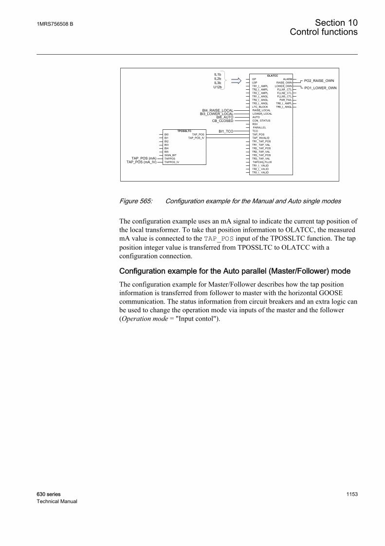
IL1bIL2bIL3bU12b
BI6_AUTO
BI1_TCO
PO2_RAISE_OWN
PO1_LOWER_OWN
BI3_LOWER_LOCALBI4_RAISE_LOCAL
OLATCCI3PU3PTR1_I_ AMPLTR2_I_ AMPLTR3_I_ AMPLTR1_I_ ANGLTR2_I_ ANGLTR3_I_ ANGLLTC_ BLOCKRAISE_ LOCALLOWER_ LOCALAUTOCON_ STATUSRSVPARALLELTCOTAP_POSTAP_ INVALIDTR1_TAP_POSTR1_TAP_VALTR2_TAP_POSTR2_TAP_VALTR3_TAP_POSTR3_TAP_VALTAPCHG_ FLLWTR1_I_ VALIDTR2_I_ VALIDTR3_I_ VALID
ALARMRAISE_OWN
LOWER_OWNFLLW1_CTLFLLW2_CTLFLLW3_CTL
PAR_FAILTR0_I_ AMPLTR0_I_ ANGL
CB_CLOSED
TPOSSLTCBI0BI1BI2BI3BI4BI5SIGN_BITTAPPOSTAPPOS_IV
TAP_POSTAP_POS_IV
TAP_POS (mA)TAP_POS (mA_IV)
GUID-A57739B5-E1A9-4AB4-96A4-248FE46F644C V1 EN
Figure 565: Configuration example for the Manual and Auto single modes
The configuration example uses an mA signal to indicate the current tap position ofthe local transformer. To take that position information to OLATCC, the measuredmA value is connected to the TAP_POS input of the TPOSSLTC function. The tapposition integer value is transferred from TPOSSLTC to OLATCC with aconfiguration connection.
Configuration example for the Auto parallel (Master/Follower) modeThe configuration example for Master/Follower describes how the tap positioninformation is transferred from follower to master with the horizontal GOOSEcommunication. The status information from circuit breakers and an extra logic canbe used to change the operation mode via inputs of the master and the follower(Operation mode = "Input contol").
1MRS756508 B Section 10Control functions
630 series 1153Technical Manual
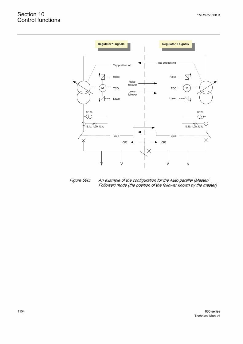
M
U12b
IL1b, IL2b, IL3b
TCO
Tap position ind.
Raise
Lower
M
U12b
IL1b, IL2b, IL3b
TCO
Tap position ind.
Raise
Lower
Regulator 1 signals Regulator 2 signals
CB1 CB3
CB2CB2
Lowerfollower
Raisefollower
GUID-0B2CBB09-9B4C-498A-BB1C-3A3689513BDF V1 EN
Figure 566: An example of the configuration for the Auto parallel (Master/Follower) mode (the position of the follower known by the master)
Section 10 1MRS756508 BControl functions
1154 630 seriesTechnical Manual

AND
CB1
CB2
CB3AND
ANDCB1
CB2
CB3AND
AND
NOT
IED 1 / Regulator 1 (Master)
IED 2 / Regulator 2 (Follower)
OLATCCI3PU3PTR1_I_ AMPLTR2_I_ AMPLTR3_I_ AMPLTR1_I_ ANGLTR2_I_ ANGLTR3_I_ ANGLLTC_ BLOCKRAISE_ LOCALLOWER_ LOCALAUTOCON_ STATUSRSVPARALLELTCOTAP_POSTAP_ INVALIDTR1_TAP_POSTR1_TAP_VALTR2_TAP_POSTR2_TAP_VALTR3_TAP_POSTR3_TAP_VALTAPCHG_ FLLWTR1_I_ VALIDTR2_I_ VALIDTR3_I_ VALID
ALARMRAISE_ OWN
LOWER_ OWNFLLW1_CTLFLLW2_CTLFLLW3_CTL
PAR_FAILTR0_I_ AMPLTR0_I_ ANGL
GOOSE communication
( Regulator 2 tap position )
GOOSEINTRCVBLOCK INTOUT
DATAVALIDCOMMVALID
TEST
AND
OLATCCI3PU3PTR1_I_ AMPLTR2_I_ AMPLTR3_I_ AMPLTR1_I_ ANGLTR2_I_ ANGLTR3_I_ ANGLLTC_ BLOCKRAISE_ LOCALLOWER_ LOCALAUTOCON_ STATUSRSVPARALLELTCOTAP_POSTAP_ INVALIDTR1_TAP_POSTR1_TAP_VALTR2_TAP_POSTR2_TAP_VALTR3_TAP_POSTR3_TAP_VALTAPCHG_ FLLWTR1_I_ VALIDTR2_I_ VALIDTR3_I_ VALID
ALARMRAISE_ OWN
LOWER_ OWNFLLW1_CTLFLLW2_CTLFLLW3_CTL
PAR_FAILTR0_I_ AMPLTR0_I_ ANGL
GOOSE communication
GOOSEINTRCVBLOCK INTOUT
DATAVALIDCOMMVALID
TEST( Raise / Lower follower )
GUID-358DBD34-7926-436B-8606-D7791739ABFD V1 EN
Figure 567: Simplified regulator 1&2 configurations of the Master/Followerexample
Table 990: The automatic selection of operation modes for regulators in the Master/Followerexample
CB1 CB2 CB3 Regulator 1 Regulator 2Open Open Open Manual Manual
Open Open Closed Manual Auto single
Open Closed Open Manual Manual
Open Closed Closed Manual Auto single
Closed Open Open Auto single Manual
Closed Open Closed Auto single Auto single
Closed Closed Open Auto single Manual
Closed Closed Closed Auto parallel(Master)Auto parallelmode = "Master''
Auto parallel(Follower)Auto parallelmode = "Follower"
Configuration example for the Auto parallel (MCC) modeThe purpose of the Auto parallel (MCC) mode is to minimize the circulatingcurrent between the parallel transformers. The data exchange between theregulators can be done with the horizontal GOOSE communication.
1MRS756508 B Section 10Control functions
630 series 1155Technical Manual

IED 1 / Regulator 1 IED 2 / Regulator 2
GOOSE communication
GOOSE communication
OLATCCI3PU3PTR1_I_ AMPLTR2_I_ AMPLTR3_I_ AMPLTR1_I_ ANGLTR2_I_ ANGLTR3_I_ ANGLLTC_ BLOCKRAISE_ LOCALLOWER_ LOCALAUTOCON_ STATUSRSVPARALLELTCOTAP_POSTAP_ INVALIDTR1_TAP_POSTR1_TAP_VALTR2_TAP_POSTR2_TAP_VALTR3_TAP_POSTR3_TAP_VALTAPCHG_ FLLWTR1_I_ VALIDTR2_I_ VALIDTR3_I_ VALID
ALARMRAISE_ OWN
LOWER_ OWNFLLW1_CTLFLLW2_CTLFLLW3_CTL
PAR_FAILTR0_I_ AMPLTR0_I_ ANGL
GOOSEMVRCVBLOCK MVOUT
DATAVALIDCOMMVALID
TEST
GOOSEMVRCVBLOCK MVOUT
DATAVALIDCOMMVALID
TESTAND
GUID-0C34F57F-7C49-433A-AA00-8EFFEB42C025 V1 EN
Figure 568: Two parallel transformers and horizontal connection via GOOSE totransfer current and phase angle information when MCC principleis used.
Configuration example for the Auto parallel (NRP) modeThe advantage of the Negative Reactance Principle (NRP) operation mode is thatno wiring or communication is needed between the IEDs. The voltage regulatorsoperate independently. However, for the cases where there is an occasionalstepwise change in the phase angle of the load, the regulating error can besuppressed by an automatic setting group change or by changing the operationmode with the logic.
Section 10 1MRS756508 BControl functions
1156 630 seriesTechnical Manual

NOTCapacitor bank
connected
FALSE => Auto parallel (NRP)
TRUE => Auto single
OLATCCI3PU3PTR1_I_ AMPLTR2_I_ AMPLTR3_I_ AMPLTR1_I_ ANGLTR2_I_ ANGLTR3_I_ ANGLLTC_ BLOCKRAISE_ LOCALLOWER_ LOCALAUTOCON_ STATUSRSVPARALLELTCOTAP_POSTAP_ INVALIDTR1_TAP_POSTR1_TAP_VALTR2_TAP_POSTR2_TAP_VALTR3_TAP_POSTR3_TAP_VALTAPCHG_ FLLWTR1_I_ VALIDTR2_I_ VALIDTR3_I_ VALID
ALARMRAISE_ OWN
LOWER_ OWNFLLW1_CTLFLLW2_CTLFLLW3_CTL
PAR_FAILTR0_I_ AMPLTR0_I_ ANGL
GUID-39C14282-AB8E-40DD-B072-AEC82DD2F71F V1 EN
Figure 569: Changing the operation mode of OLATCC automatically when thecapacitor bank is connected
Comparison summary between parallel operation modesThe parallel operation modes are needed because if the parallel regulators operatedindependently, at some point the transformers would become out of step with eachother.
The circulating current would increase and the line drop compensation would thusincrease for the transformer giving the highest voltage. Correspondingly, theincreasing circulating current would cause the transformer giving the lowestvoltage to decrease the voltage due to a decreased line drop compensation effect. Inother words, the two transformers would run apart.
However, it is case-specific which parallel operation mode is the most suitable.
1MRS756508 B Section 10Control functions
630 series 1157Technical Manual

Table 991: Different parallel operation modes
Parallel operation modes DescriptionMaster/Follower (follower positions not known bymaster)
Requires power transformers with identicalratings and step voltages- Extra wiring work: raise/lower commands (inputTAPCHG_FLLW connected from outputFLLWx_CTL) from the master to the follower- Manual control needed in the beginning ofoperation- Blind control: follower positions after controlcannot be supervised. It must be relied on thatthe followers are following the commands.+ Parallel transformers are regulated as one unit+ Supports an unlimited number of transformersin parallel
Master/Follower (follower positions known) Requires power transformers with identicalratings and step voltages.- Extra wiring work:raise/lower commands (the TAPCHG_FLLW inputconnected from the FLLWx_CTL output) from themaster to the followerTAP_POS connections from the followers to themaster- Supports not more than four transformers inparallel.
Negative reactance principle The actual phase angle deviating from the phaseangle setting results in a regulating error. Whenthe line drop compensation is used, the settingshould be changed when the number oftransformers in parallel operation is changed.+ The step voltages and short circuitimpedances of the transformers do not need tobe identical.+ No communication or wiring betweenregulators is needed, meaning that the principlecan be applied even when the paralleltransformers are located at different substations.+ Supports an unlimited number of transformersin parallel
Minimizing circulating current - Requires extra configuration efforts since thisprinciple utilizes a horizontal communicationbetween the regulators (the inputs TRx_Iconnected from parallel transformer controller'soutputs TR0_I.+ The step voltages and short circuitimpedances of the transformers do not need tobe identical.+ The phase angle of the load current may varywithout any impact on the regulation accuracy.+ Automatic adjustment for the number oftransformers (for an accurate calculation of linedrop compensation term)
Section 10 1MRS756508 BControl functions
1158 630 seriesTechnical Manual
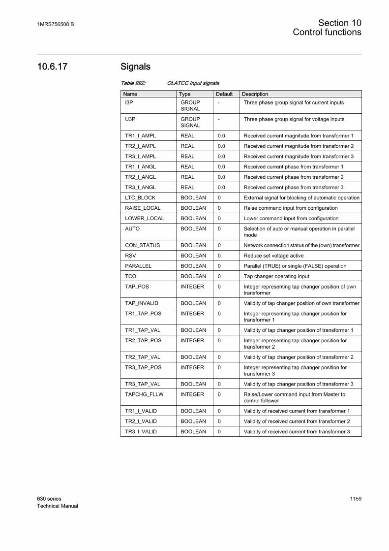
10.6.17 SignalsTable 992: OLATCC Input signals
Name Type Default DescriptionI3P GROUP
SIGNAL- Three phase group signal for current inputs
U3P GROUPSIGNAL
- Three phase group signal for voltage inputs
TR1_I_AMPL REAL 0.0 Received current magnitude from transformer 1
TR2_I_AMPL REAL 0.0 Received current magnitude from transformer 2
TR3_I_AMPL REAL 0.0 Received current magnitude from transformer 3
TR1_I_ANGL REAL 0.0 Received current phase from transformer 1
TR2_I_ANGL REAL 0.0 Received current phase from transformer 2
TR3_I_ANGL REAL 0.0 Received current phase from transformer 3
LTC_BLOCK BOOLEAN 0 External signal for blocking of automatic operation
RAISE_LOCAL BOOLEAN 0 Raise command input from configuration
LOWER_LOCAL BOOLEAN 0 Lower command input from configuration
AUTO BOOLEAN 0 Selection of auto or manual operation in parallelmode
CON_STATUS BOOLEAN 0 Network connection status of the (own) transformer
RSV BOOLEAN 0 Reduce set voltage active
PARALLEL BOOLEAN 0 Parallel (TRUE) or single (FALSE) operation
TCO BOOLEAN 0 Tap changer operating input
TAP_POS INTEGER 0 Integer representing tap changer position of owntransformer
TAP_INVALID BOOLEAN 0 Validity of tap changer position of own transformer
TR1_TAP_POS INTEGER 0 Integer representing tap changer position fortransformer 1
TR1_TAP_VAL BOOLEAN 0 Validity of tap changer position of transformer 1
TR2_TAP_POS INTEGER 0 Integer representing tap changer position fortransformer 2
TR2_TAP_VAL BOOLEAN 0 Validity of tap changer position of transformer 2
TR3_TAP_POS INTEGER 0 Integer representing tap changer position fortransformer 3
TR3_TAP_VAL BOOLEAN 0 Validity of tap changer position of transformer 3
TAPCHG_FLLW INTEGER 0 Raise/Lower command input from Master tocontrol follower
TR1_I_VALID BOOLEAN 0 Validity of received current from transformer 1
TR2_I_VALID BOOLEAN 0 Validity of received current from transformer 2
TR3_I_VALID BOOLEAN 0 Validity of received current from transformer 3
1MRS756508 B Section 10Control functions
630 series 1159Technical Manual

Table 993: OLATCC Output signals
Name Type DescriptionALARM BOOLEAN Alarm status
RAISE_OWN BOOLEAN Raise command for own transformer
LOWER_OWN BOOLEAN Lower command for own transformer
FLLW1_CTL INTEGER Lower/Raise for follower 1 in the Master/Followermode
FLLW2_CTL INTEGER Lower/Raise for follower 2 in the Master/Followermode
FLLW3_CTL INTEGER Lower/Raise for follower 3 in the Master/Followermode
PAR_FAIL BOOLEAN Parallel failure detected
TR0_I_AMPL REAL Current magnitude from own transformer
TR0_I_ANGL REAL Current phase angle from own transformer
10.6.18 SettingsTable 994: OLATCC Group settings (basic)
Name Values (Range) Unit Step Default DescriptionAuto parallel mode Master
FollowerNRPMCC
- - Master Parallel mode selection
Band center voltage 0.000 - 2.000 pu 0.001 1.000 The band center voltage, Us
Line drop V Ris 0.0 - 25.0 % 0.1 0.0 Resistive line-drop compensation factor
Line drop V React 0.0 - 25.0 % 0.1 0.0 Reactive line-drop compensation factor
Band reduction 0.0 - 9.0 % 0.1 0.0 Step size for Reduce Set Voltage (RSV)
Stability factor 0.0 - 70.0 % 0.1 0.0 Stability factor in parallel operation
Load phase angle -89 - 89 Deg 1 0 Load phase-shift, used with the NegativeReactance Principle
Control delay time 1 1.0 - 300.0 s 0.1 60.0 Control delay time 1
Control delay time 2 1.0 - 300.0 s 0.1 30.0 Control delay time 2
Section 10 1MRS756508 BControl functions
1160 630 seriesTechnical Manual
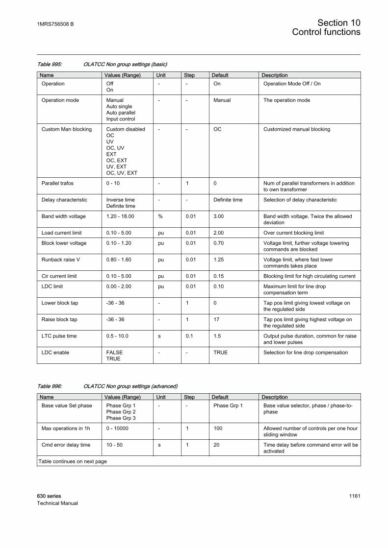
Table 995: OLATCC Non group settings (basic)
Name Values (Range) Unit Step Default DescriptionOperation Off
On- - On Operation Mode Off / On
Operation mode ManualAuto singleAuto parallelInput control
- - Manual The operation mode
Custom Man blocking Custom disabledOCUVOC, UVEXTOC, EXTUV, EXTOC, UV, EXT
- - OC Customized manual blocking
Parallel trafos 0 - 10 - 1 0 Num of parallel transformers in additionto own transformer
Delay characteristic Inverse timeDefinite time
- - Definite time Selection of delay characteristic
Band width voltage 1.20 - 18.00 % 0.01 3.00 Band width voltage. Twice the alloweddeviation
Load current limit 0.10 - 5.00 pu 0.01 2.00 Over current blocking limit
Block lower voltage 0.10 - 1.20 pu 0.01 0.70 Voltage limit, further voltage loweringcommands are blocked
Runback raise V 0.80 - 1.60 pu 0.01 1.25 Voltage limit, where fast lowercommands takes place
Cir current limit 0.10 - 5.00 pu 0.01 0.15 Blocking limit for high circulating current
LDC limit 0.00 - 2.00 pu 0.01 0.10 Maximum limit for line dropcompensation term
Lower block tap -36 - 36 - 1 0 Tap pos limit giving lowest voltage onthe regulated side
Raise block tap -36 - 36 - 1 17 Tap pos limit giving highest voltage onthe regulated side
LTC pulse time 0.5 - 10.0 s 0.1 1.5 Output pulse duration, common for raiseand lower pulses
LDC enable FALSETRUE
- - TRUE Selection for line drop compensation
Table 996: OLATCC Non group settings (advanced)
Name Values (Range) Unit Step Default DescriptionBase value Sel phase Phase Grp 1
Phase Grp 2Phase Grp 3
- - Phase Grp 1 Base value selector, phase / phase-to-phase
Max operations in 1h 0 - 10000 - 1 100 Allowed number of controls per one hoursliding window
Cmd error delay time 10 - 50 s 1 20 Time delay before command error will beactivated
Table continues on next page
1MRS756508 B Section 10Control functions
630 series 1161Technical Manual

Name Values (Range) Unit Step Default DescriptionFollower delay time 6 - 20 s 1 6 Time delay between successive follower
commands by a master
Alarms enabled FALSETRUE
- - TRUE Alarm selection
Rv Pwr flow allowed FALSETRUE
- - FALSE Reverse power flow allowed
10.6.19 Measured valuesTable 997: OLATCC Measured values
Name Type Default DescriptionI_AMPL_A REAL 0.0 Phase A current magnitude on the regulated side
I_AMPL_B REAL 0.0 Phase B current magnitude on the regulated side
I_AMPL_C REAL 0.0 Phase C current magnitude on the regulated side
I_ANGL_A REAL 0.0 Phase A current phase angle on the regulated side
I_ANGL_B REAL 0.0 Phase B current phase angle on the regulated side
I_ANGL_C REAL 0.0 Phase C current phase angle on the regulated side
TR1_I_AMPL REAL 0.0 Received current magnitude from transformer 1
TR2_I_AMPL REAL 0.0 Received current magnitude from transformer 2
TR3_I_AMPL REAL 0.0 Received current magnitude from transformer 3
TR1_I_ANGL REAL 0.0 Received current phase from transformer 1
TR2_I_ANGL REAL 0.0 Received current phase from transformer 2
TR3_I_ANGL REAL 0.0 Received current phase from transformer 3
U_AMPL_AB REAL 0.0 Magnitude of phase-to-phase voltage AB on theregulated side
U_ANGL_AB REAL 0.0 Angle of phase-to-phase voltage AB on theregulated side
LTC_BLOCK BOOLEAN 0 External signal for blocking of automatic operation
RAISE_LOCAL BOOLEAN 0 Raise command input from configuration
LOWER_LOCAL BOOLEAN 0 Lower command input from configuration
AUTO BOOLEAN 0 Selection of auto or manual operation in parallelmode
CON_STATUS BOOLEAN 0 Network connection status of the (own) transformer
RSV BOOLEAN 0 Reduce set voltage active
PARALLEL BOOLEAN 0 Parallel (TRUE) or single (FALSE) operation
TCO BOOLEAN 0 Tap changer operating input
TAP_POS INTEGER 0 Integer representing tap changer position of owntransformer
TAP_INVALID BOOLEAN 0 Validity of tap changer position of own transformer
TR1_TAP_POS INTEGER 0 Integer representing tap changer position fortransformer 1
TR1_TAP_VAL BOOLEAN 0 Validity of tap changer position of transformer 1
Table continues on next page
Section 10 1MRS756508 BControl functions
1162 630 seriesTechnical Manual
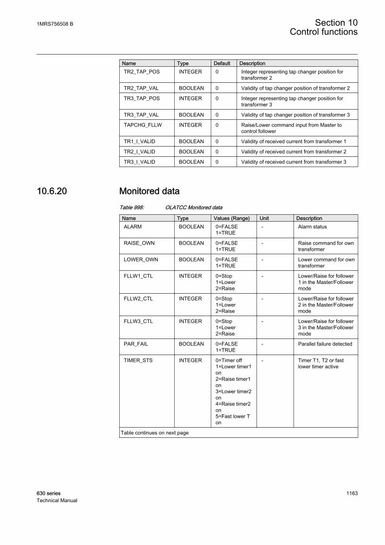
Name Type Default DescriptionTR2_TAP_POS INTEGER 0 Integer representing tap changer position for
transformer 2
TR2_TAP_VAL BOOLEAN 0 Validity of tap changer position of transformer 2
TR3_TAP_POS INTEGER 0 Integer representing tap changer position fortransformer 3
TR3_TAP_VAL BOOLEAN 0 Validity of tap changer position of transformer 3
TAPCHG_FLLW INTEGER 0 Raise/Lower command input from Master tocontrol follower
TR1_I_VALID BOOLEAN 0 Validity of received current from transformer 1
TR2_I_VALID BOOLEAN 0 Validity of received current from transformer 2
TR3_I_VALID BOOLEAN 0 Validity of received current from transformer 3
10.6.20 Monitored dataTable 998: OLATCC Monitored data
Name Type Values (Range) Unit DescriptionALARM BOOLEAN 0=FALSE
1=TRUE- Alarm status
RAISE_OWN BOOLEAN 0=FALSE1=TRUE
- Raise command for owntransformer
LOWER_OWN BOOLEAN 0=FALSE1=TRUE
- Lower command for owntransformer
FLLW1_CTL INTEGER 0=Stop1=Lower2=Raise
- Lower/Raise for follower1 in the Master/Followermode
FLLW2_CTL INTEGER 0=Stop1=Lower2=Raise
- Lower/Raise for follower2 in the Master/Followermode
FLLW3_CTL INTEGER 0=Stop1=Lower2=Raise
- Lower/Raise for follower3 in the Master/Followermode
PAR_FAIL BOOLEAN 0=FALSE1=TRUE
- Parallel failure detected
TIMER_STS INTEGER 0=Timer off1=Lower timer1on2=Raise timer1on3=Lower timer2on4=Raise timer2on5=Fast lower Ton
- Timer T1, T2 or fastlower timer active
Table continues on next page
1MRS756508 B Section 10Control functions
630 series 1163Technical Manual

Name Type Values (Range) Unit DescriptionOPR_MODE_STS INTEGER 0=Not in use
1=Manual2=Auto single3=Auto master4=Auto follower5=MCC6=NRP
- The acting operationmode of the functionblock
PARALLEL BOOLEAN 0=FALSE1=TRUE
- Parallel mode or not
AUTO BOOLEAN 0=FALSE1=TRUE
- Acting automatic/manual
BLK_STATUS INTEGER - - Bit-coded outputshowing the blockingstatus for the nextoperation
BLKD_I_LOD BOOLEAN 0=FALSE1=TRUE
- Indication of load currentblocking
BLKD_U_UN BOOLEAN 0=FALSE1=TRUE
- Indication of undervoltage blocking
BLKD_I_CIR BOOLEAN 0=FALSE1=TRUE
- Indication of highcirculating currentblocking
BLKD_LTCBLK BOOLEAN 0=FALSE1=TRUE
- Indication of externalblocking
RNBK_U_OV BOOLEAN 0=FALSE1=TRUE
- Indication of runbackraise voltage
ALARM_REAS INTEGER 0=No alarm1=Cmd error2=TCO error3=Cmd + TCOerr4=Pump error5=Pump + cmderr6=Pump + TCOerr7=Pmp+TCO+cmd err
- Status and reason foralarm
FAIL_FLLW INTEGER 0=No failed fllws1=Follower 12=Follower 23=Followers 1+24=Follower 35=Followers 1+36=Followers 2+37=Followers1+2+3
- Failed followers
PAR_UNIT_MCC INTEGER 0=No parall units1=Trafo 12=Trafo 23=Trafos 1 and 24=Trafo 35=Trafos 1 and 36=Trafos 2 and 37=Trafos 1+2+3
- Parallel units included inMCC calculation
Table continues on next page
Section 10 1MRS756508 BControl functions
1164 630 seriesTechnical Manual

Name Type Values (Range) Unit DescriptionOPR_CNT INTEGER - - Total number of
commands given,manual and automatic
OP_TM_NUM_H INTEGER - - Number of controls forown tap changer duringlast hour
TR0_I_AMPL REAL - A Current magnitude fromown transformer
TR0_I_ANGL REAL - deg Current phase anglefrom own transformer
U_MEAS REAL - kV Phase-to-phase voltage ,average filtered
ANGL_UA_IA REAL - deg Measured angle valuebetween phase Avoltage and current
U_CTL REAL - kV Control voltage, Up,target voltage level
UD_CTL REAL - kV Voltage differencebetween measured andcontrol Voltage
I_CIR REAL - A Calculated circulatingcurrent - calculated inoperation modes NRPand MCC
LDC REAL - kV Calculated line dropcompensation
10.6.21 Technical dataTable 999: OLATCC Technical data
Characteristic ValueOperation accuracy 1) Depending on the frequency of the current measured: fn ±2 Hz
Differential voltage Ud ± 1.0% of the measured valueor ± 0.004 x Un (in measuredvoltages < 2.0 x Un)
Operation value ± 1.0% of the Ud or ±0.004 xUn for Us = 1.0 x Un
Operate time accuracy in definite time mode 2) ± 1.0% of the set value or 0.11seconds
Operate time accuracy in inverse time mode 3) ± 15.0% of the set value or0.15 s(at theoretical B in range of 1.1…5.0) Also note fixed minimumoperate time (IDMT) 1 s
Reset ratio for control operation Typical 0.80 (1.20)
Reset ratio for analogue based blockings (except run back raisevoltage blocking)
Typical 0.96 (1.04)
1) Default setting values used2) Default setting values used3) Default setting values used
1MRS756508 B Section 10Control functions
630 series 1165Technical Manual

1166
Section 11 General function block features
11.1 Definite time characteristics
11.1.1 Definite time operationThe DT mode is enabled when the Operating curve type setting is selected either as"ANSI Def. Time" or "IEC Def. Time". In the DT mode, the OPERATE output ofthe function is activated when the time calculation exceeds the set Operate delaytime.
The user can determine the reset in the DT mode with the Reset delay time setting,which provides the delayed reset property when needed.
The Type of reset curve setting has no effect on the reset methodwhen the DT mode is selected, but the reset is determined solelywith the Reset delay time setting.
The purpose of the delayed reset is to enable fast clearance of intermittent faults,for example self-sealing insulation faults, and severe faults which may producehigh asymmetrical fault currents that partially saturate the current transformers. Itis typical for an intermittent fault that the fault current contains so called drop-offperiods, during which the fault current falls below the set start current, includinghysteresis. Without the delayed reset function, the operate timer would reset whenthe current drops off. In the same way, an apparent drop-off period of thesecondary current of the saturated current transformer can also reset the operate timer.
1MRS756508 B Section 11General function block features
630 series 1167Technical Manual

A060764 V1 EN
Figure 570: Operation of the counter in drop-off
In case 1, the reset is delayed with the Reset delay time setting and in case 2, thecounter is reset immediately, because the Reset delay time setting is set to zero.
A070421 V1 EN
Figure 571: Drop-off period is longer than the set Reset delay time
Section 11 1MRS756508 BGeneral function block features
1168 630 seriesTechnical Manual

When the drop-off period is longer than the set Reset delay time, as described inFigure 571, the input signal for the definite timer (here: timer input) is active,provided that the current is above the set Start value. The input signal is inactivewhen the current is below the set Start value and the set hysteresis region. Thetimer input rises when a fault current is detected. The definite timer activates theSTART output and the operate timer starts elapsing. The reset (drop-off) timerstarts when the timer input falls, that is, the fault disappears. When the reset (drop-off) timer elapses, the operate timer is reset. Since this happens before another startoccurs, the OPERATE output is not activated.
A070420 V1 EN
Figure 572: Drop-off period is shorter than the set Reset delay time
When the drop-off period is shorter than the set Reset delay time, as described inFigure 572, the input signal for the definite timer (here: timer input) is active,provided that the current is above the set Start value. The input signal is inactivewhen the current is below the set Start value and the set hysteresis region. Thetimer input rises when a fault current is detected. The definite timer activates theSTART output and the operate timer starts elapsing. The Reset (drop-off) timerstarts when the timer input falls, that is, the fault disappears. Another fault situationoccurs before the reset (drop-off) timer has elapsed. This causes the activation ofthe OPERATE output, since the operate timer already has elapsed.
1MRS756508 B Section 11General function block features
630 series 1169Technical Manual
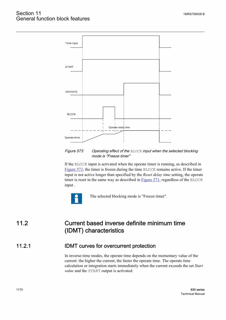
A070422 V1 EN
Figure 573: Operating effect of the BLOCK input when the selected blockingmode is "Freeze timer"
If the BLOCK input is activated when the operate timer is running, as described inFigure 573, the timer is frozen during the time BLOCK remains active. If the timerinput is not active longer than specified by the Reset delay time setting, the operatetimer is reset in the same way as described in Figure 571, regardless of the BLOCKinput .
The selected blocking mode is "Freeze timer".
11.2 Current based inverse definite minimum time(IDMT) characteristics
11.2.1 IDMT curves for overcurrent protectionIn inverse-time modes, the operate time depends on the momentary value of thecurrent: the higher the current, the faster the operate time. The operate timecalculation or integration starts immediately when the current exceeds the set Startvalue and the START output is activated.
Section 11 1MRS756508 BGeneral function block features
1170 630 seriesTechnical Manual

The OPERATE output of the component is activated when the cumulative sum ofthe integrator calculating the overcurrent situation exceeds the value set by theinverse-time mode. The set value depends on the selected curve type and thesetting values used. The user determines the curve scaling with the Time multipliersetting.
The Minimum operate time setting defines the minimum operate time for the IDMTmode, that is, it is possible to limit the IDMT based operate time for not becomingtoo short. For example:
GUID-B1A82AE1-A1DE-457E-B229-F0437336F3F6 V1 EN
Figure 574: Operate time curves based on IDMT characteristic with the valueof the Minimum operate time setting = 0.5 second
1MRS756508 B Section 11General function block features
630 series 1171Technical Manual
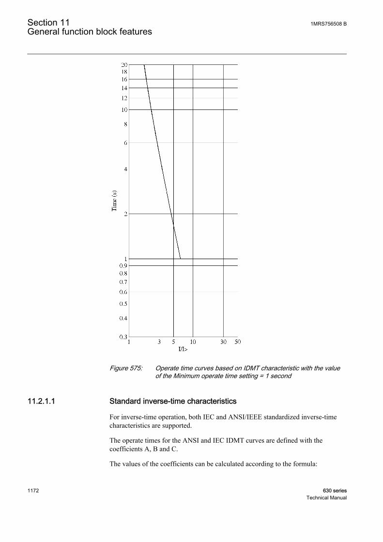
GUID-B1F693FA-DC13-4DFC-81F3-A47FF082492B V1 EN
Figure 575: Operate time curves based on IDMT characteristic with the valueof the Minimum operate time setting = 1 second
11.2.1.1 Standard inverse-time characteristics
For inverse-time operation, both IEC and ANSI/IEEE standardized inverse-timecharacteristics are supported.
The operate times for the ANSI and IEC IDMT curves are defined with thecoefficients A, B and C.
The values of the coefficients can be calculated according to the formula:
Section 11 1MRS756508 BGeneral function block features
1172 630 seriesTechnical Manual

t sA
I
I
B kc
[ ] =
>
−
+
⋅
1
A060821 V2 EN (Equation 139)
t[s] Operate time in seconds
I measured current
I> set Start value
k set Time multiplier
Table 1000: Curve parameters for ANSI and IEC IDMT curves
Curve name A B C(1) ANSI ExtremelyInverse
28.2 0.1217 2.0
(2) ANSI Very Inverse 19.61 0.491 2.0
(3) ANSI NormalInverse
0.0086 0.0185 0.02
(4) ANSI ModeratelyInverse
0.0515 0.1140 0.02
(6) Long TimeExtremely Inverse
64.07 0.250 2.0
(7) Long Time VeryInverse
28.55 0.712 2.0
(8) Long Time Inverse 0.086 0.185 0.02
(9) IEC Normal Inverse 0.14 0.0 0.02
(10) IEC Very Inverse 13.5 0.0 1.0
(11) IEC Inverse 0.14 0.0 0.02
(12) IEC ExtremelyInverse
80.0 0.0 2.0
(13) IEC Short TimeInverse
0.05 0.0 0.04
(14) IEC Long TimeInverse
120 0.0 1.0
The maximum guaranteed measured current is 50 x In for thecurrent protection. When the set Start value exceeds 1.00 x In, theturn point where the theoretical IDMT characteristics are levelingout to the definite time can be calculated with the formula:
Turn poIn
Start value int =
×50
GUID-F9F8D867-11DE-4180-A0CD-ED9FA7E7ABC6 V1 EN (Equation 140)
1MRS756508 B Section 11General function block features
630 series 1173Technical Manual
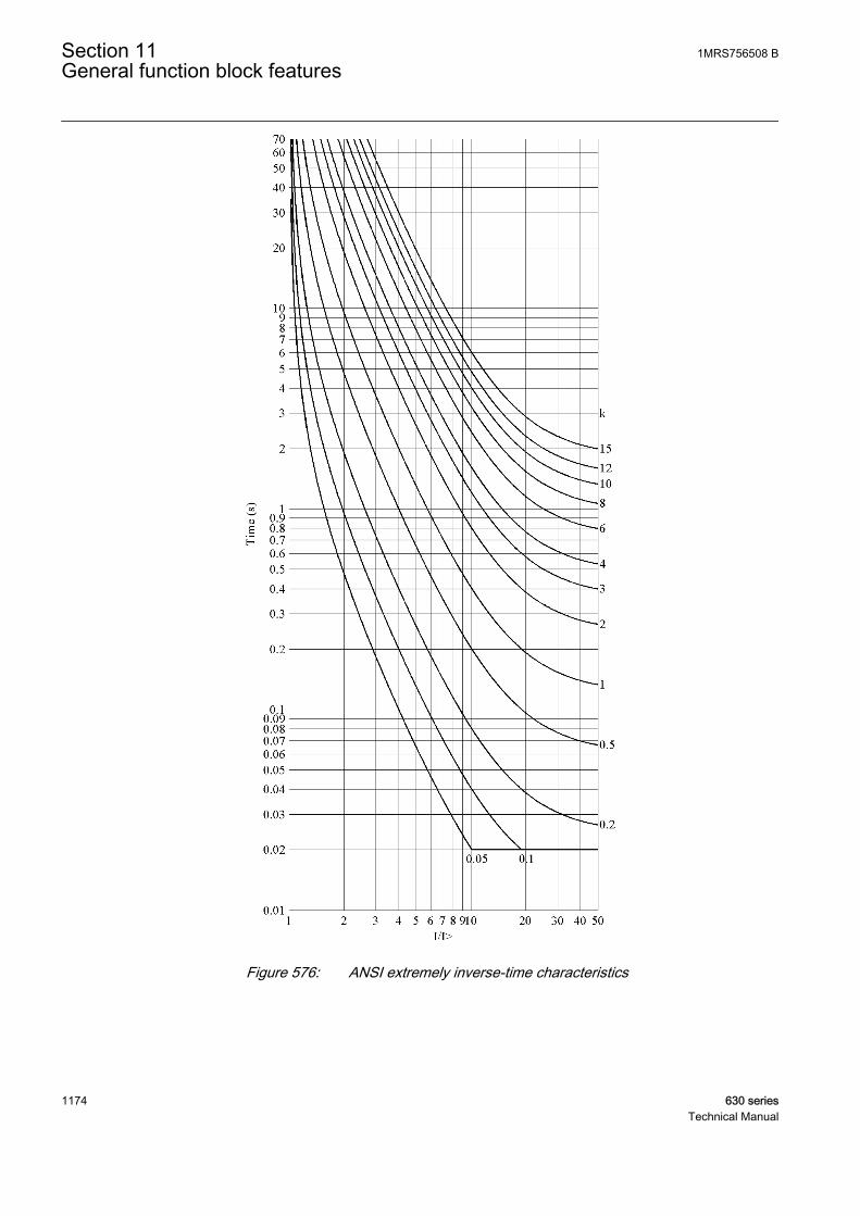
A070750 V2 EN
Figure 576: ANSI extremely inverse-time characteristics
Section 11 1MRS756508 BGeneral function block features
1174 630 seriesTechnical Manual

A070751 V2 EN
Figure 577: ANSI very inverse-time characteristics
1MRS756508 B Section 11General function block features
630 series 1175Technical Manual
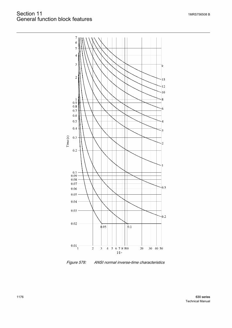
A070752 V2 EN
Figure 578: ANSI normal inverse-time characteristics
Section 11 1MRS756508 BGeneral function block features
1176 630 seriesTechnical Manual
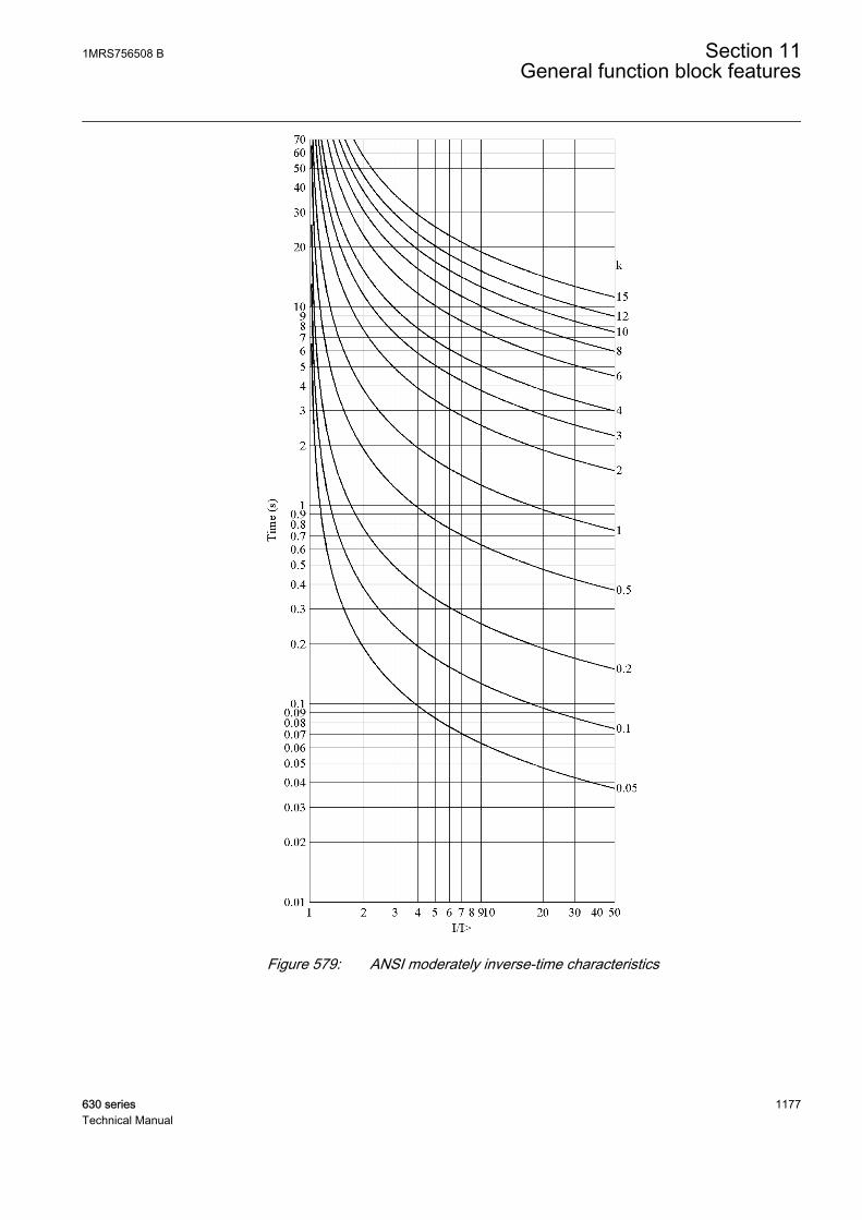
A070753 V2 EN
Figure 579: ANSI moderately inverse-time characteristics
1MRS756508 B Section 11General function block features
630 series 1177Technical Manual
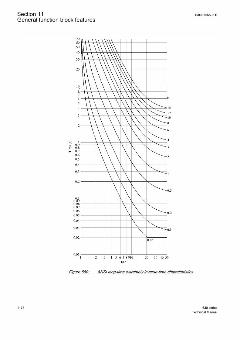
A070817 V2 EN
Figure 580: ANSI long-time extremely inverse-time characteristics
Section 11 1MRS756508 BGeneral function block features
1178 630 seriesTechnical Manual
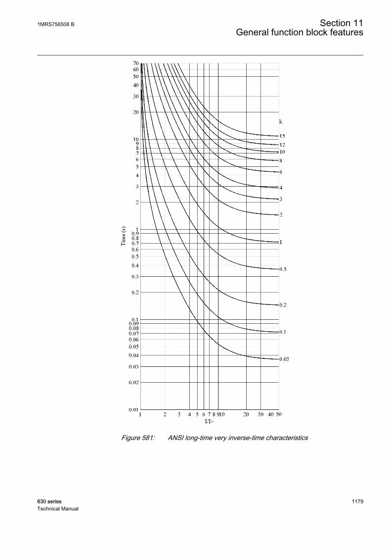
A070818 V2 EN
Figure 581: ANSI long-time very inverse-time characteristics
1MRS756508 B Section 11General function block features
630 series 1179Technical Manual

A070819 V2 EN
Figure 582: ANSI long-time inverse-time characteristics
Section 11 1MRS756508 BGeneral function block features
1180 630 seriesTechnical Manual

A070820 V2 EN
Figure 583: IEC normal inverse-time characteristics
1MRS756508 B Section 11General function block features
630 series 1181Technical Manual

A070821 V2 EN
Figure 584: IEC very inverse-time characteristics
Section 11 1MRS756508 BGeneral function block features
1182 630 seriesTechnical Manual
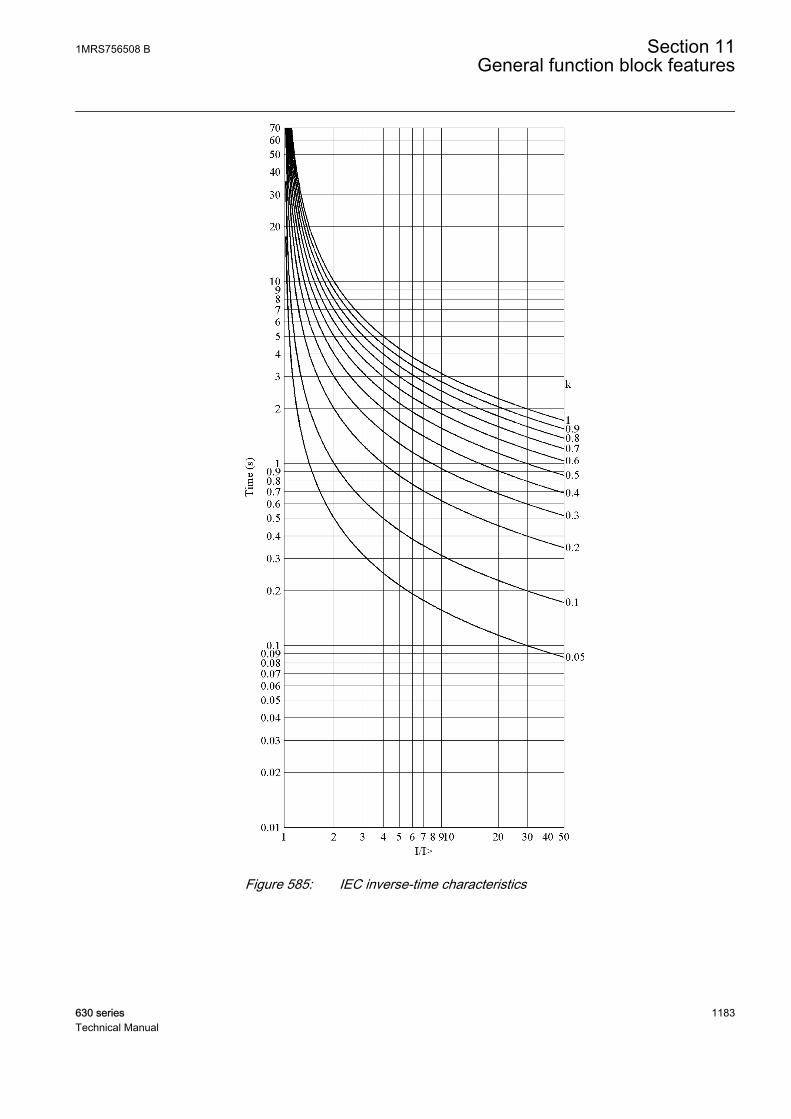
A070822 V2 EN
Figure 585: IEC inverse-time characteristics
1MRS756508 B Section 11General function block features
630 series 1183Technical Manual
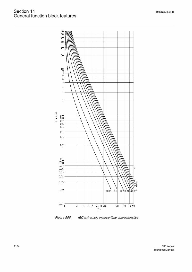
A070823 V2 EN
Figure 586: IEC extremely inverse-time characteristics
Section 11 1MRS756508 BGeneral function block features
1184 630 seriesTechnical Manual

A070824 V2 EN
Figure 587: IEC short-time inverse-time characteristics
1MRS756508 B Section 11General function block features
630 series 1185Technical Manual

A070825 V2 EN
Figure 588: IEC long-time inverse-time characteristics
Section 11 1MRS756508 BGeneral function block features
1186 630 seriesTechnical Manual

11.2.1.2 User-programmable inverse-time characteristics
The user can define curves by entering parameters into the following standardformula:
A060641 V2 EN (Equation 141)
t[s] Operate time (in seconds)
A set Curve parameter A
B set Curve parameter B
C set Curve parameter C
E set Curve parameter E
I Measured current
I> set Start value
k set Time multiplier
11.2.1.3 RI and RD-type inverse-time characteristics
The RI-type simulates the behavior of electromechanical relays. The RD-type is anearth-fault specific characteristic.
The RI-type is calculated using the formula
t sk
I
I
[ ]
. .
=
− ×>
0 339 0 236
A060642 V2 EN (Equation 142)
The RD-type is calculated using the formula
t sI
k I[ ] . .= − ×
× >
5 8 1 35 In
A060643 V2 EN (Equation 143)
1MRS756508 B Section 11General function block features
630 series 1187Technical Manual

t[s] Operate time (in seconds)
k set Time multiplier
I Measured current
I> set Start value
Section 11 1MRS756508 BGeneral function block features
1188 630 seriesTechnical Manual
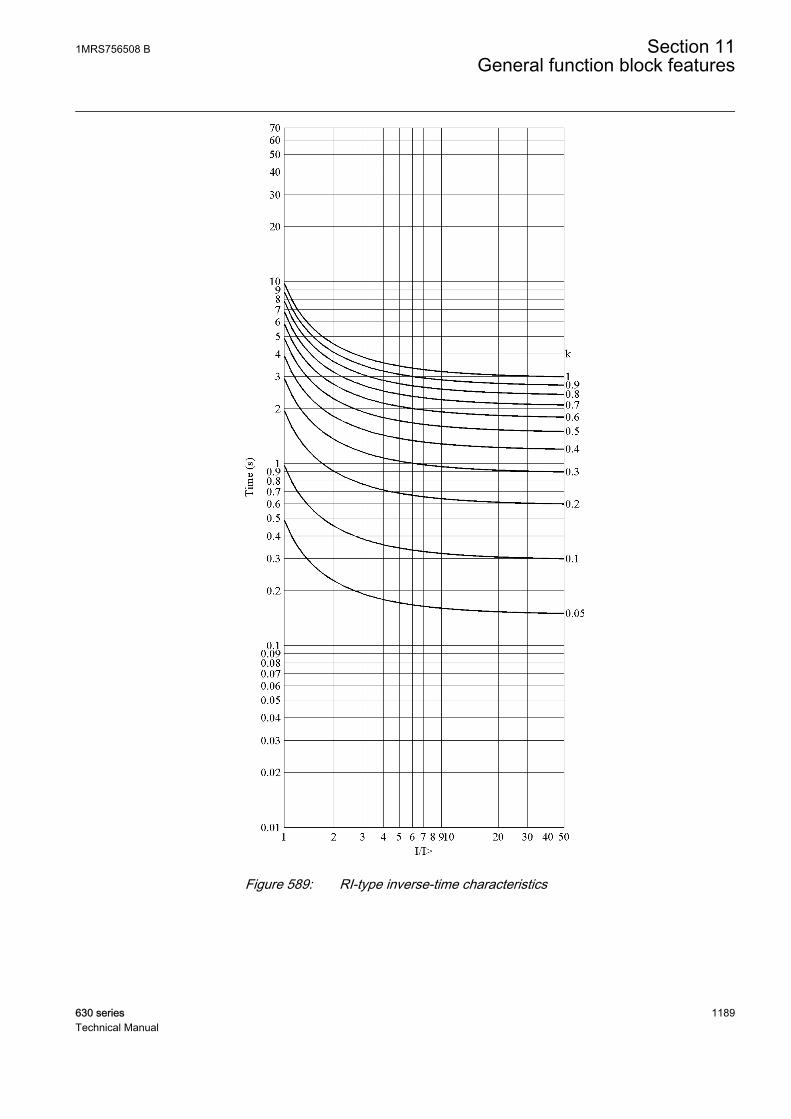
A070826 V2 EN
Figure 589: RI-type inverse-time characteristics
1MRS756508 B Section 11General function block features
630 series 1189Technical Manual
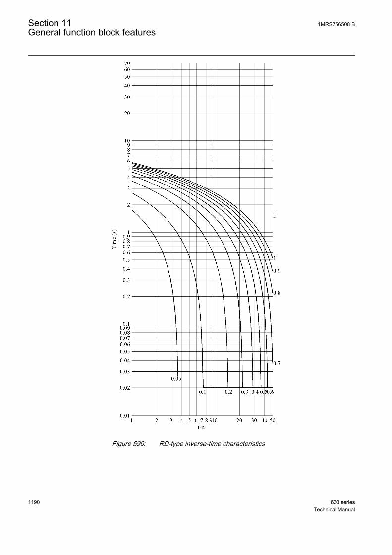
A070827 V2 EN
Figure 590: RD-type inverse-time characteristics
Section 11 1MRS756508 BGeneral function block features
1190 630 seriesTechnical Manual

11.2.2 Reset in inverse-time modesThe user can select the reset characteristics by using the Type of reset curve settingas follows:
Table 1001: Values for reset mode
Setting name Possible valuesType of reset curve 1=Immediate
2=Def time reset3=Inverse reset
Immediate resetIf the Type of reset curve setting in a drop-off case is selected as "Immediate", theinverse timer resets immediately.
Definite time resetThe definite type of reset in the inverse-time mode can be achieved by setting theType of reset curve parameter to “Def time reset”. As a result, the operate inverse-time counter is frozen for the time determined with the Reset delay time settingafter the current drops below the set Start value, including hysteresis.The integralsum of the inverse-time counter is reset, if another start does not occur during thereset delay.
If the Type of reset curve setting is selected as “Def time reset”, thecurrent level has no influence on the reset characteristic.
Inverse reset
Inverse reset curves are available only for ANSI and user-programmable curves. If you use other curve types, immediate resetoccurs.
Standard delayed inverse reset
The reset characteristic required in ANSI (IEEE) inverse-time modes is providedby setting the Type of reset curve parameter to “Inverse reset”. In this mode, thetime delay for reset is given with the following formula using the coefficient D,which has its values defined in the table below.
t sD
I
I
k[ ] =
>
−
⋅2
1
A060817 V3 EN (Equation 144)
1MRS756508 B Section 11General function block features
630 series 1191Technical Manual
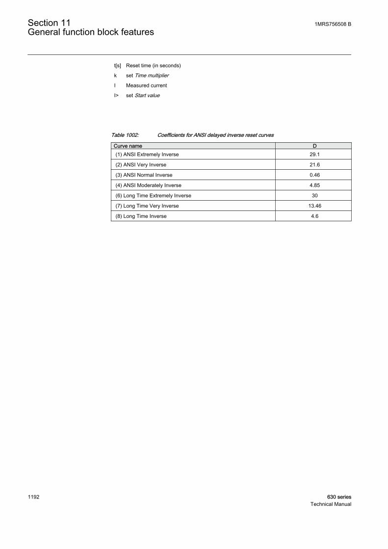
t[s] Reset time (in seconds)
k set Time multiplier
I Measured current
I> set Start value
Table 1002: Coefficients for ANSI delayed inverse reset curves
Curve name D(1) ANSI Extremely Inverse 29.1
(2) ANSI Very Inverse 21.6
(3) ANSI Normal Inverse 0.46
(4) ANSI Moderately Inverse 4.85
(6) Long Time Extremely Inverse 30
(7) Long Time Very Inverse 13.46
(8) Long Time Inverse 4.6
Section 11 1MRS756508 BGeneral function block features
1192 630 seriesTechnical Manual
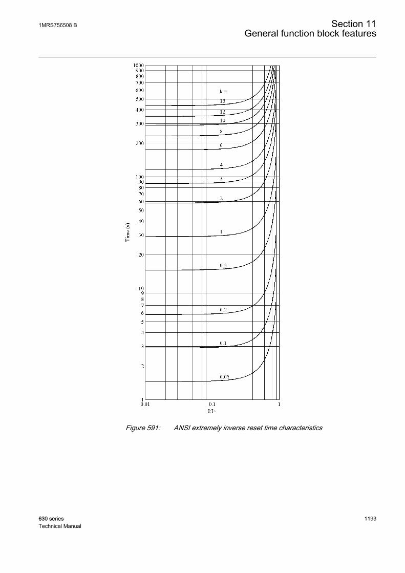
A070828 V1 EN
Figure 591: ANSI extremely inverse reset time characteristics
1MRS756508 B Section 11General function block features
630 series 1193Technical Manual
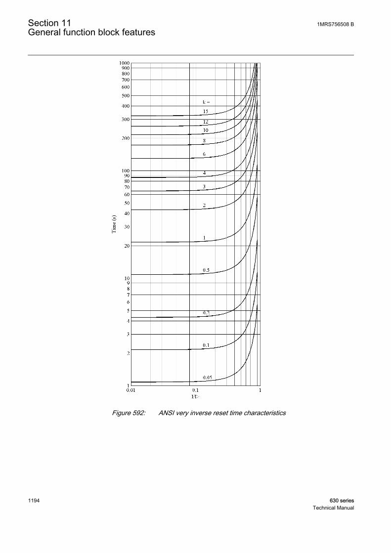
A070829 V1 EN
Figure 592: ANSI very inverse reset time characteristics
Section 11 1MRS756508 BGeneral function block features
1194 630 seriesTechnical Manual

A070830 V1 EN
Figure 593: ANSI normal inverse reset time characteristics
1MRS756508 B Section 11General function block features
630 series 1195Technical Manual
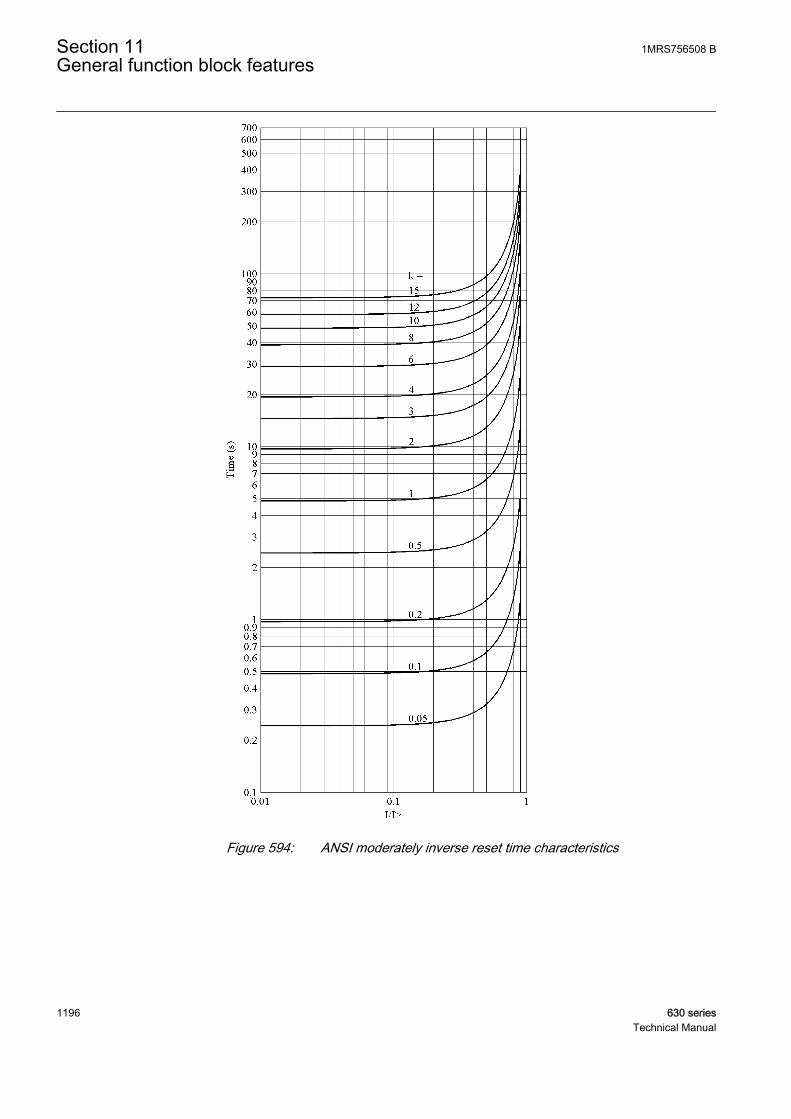
A070831 V1 EN
Figure 594: ANSI moderately inverse reset time characteristics
Section 11 1MRS756508 BGeneral function block features
1196 630 seriesTechnical Manual
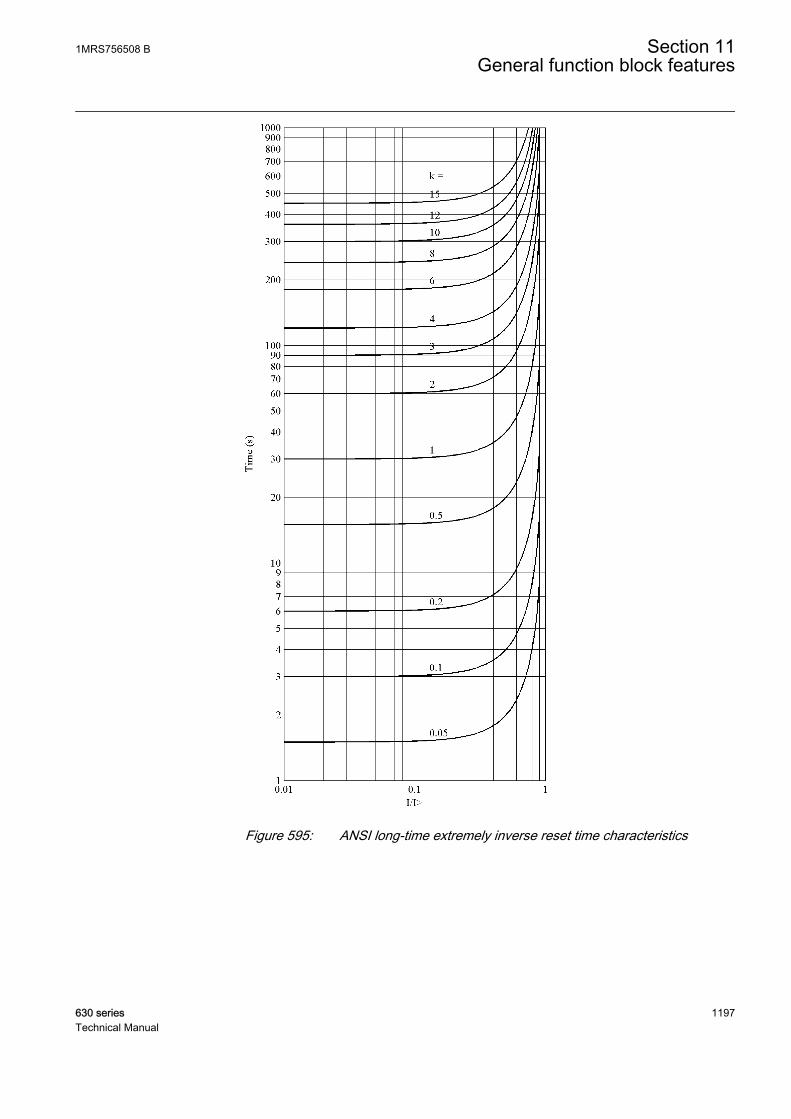
A070832 V1 EN
Figure 595: ANSI long-time extremely inverse reset time characteristics
1MRS756508 B Section 11General function block features
630 series 1197Technical Manual
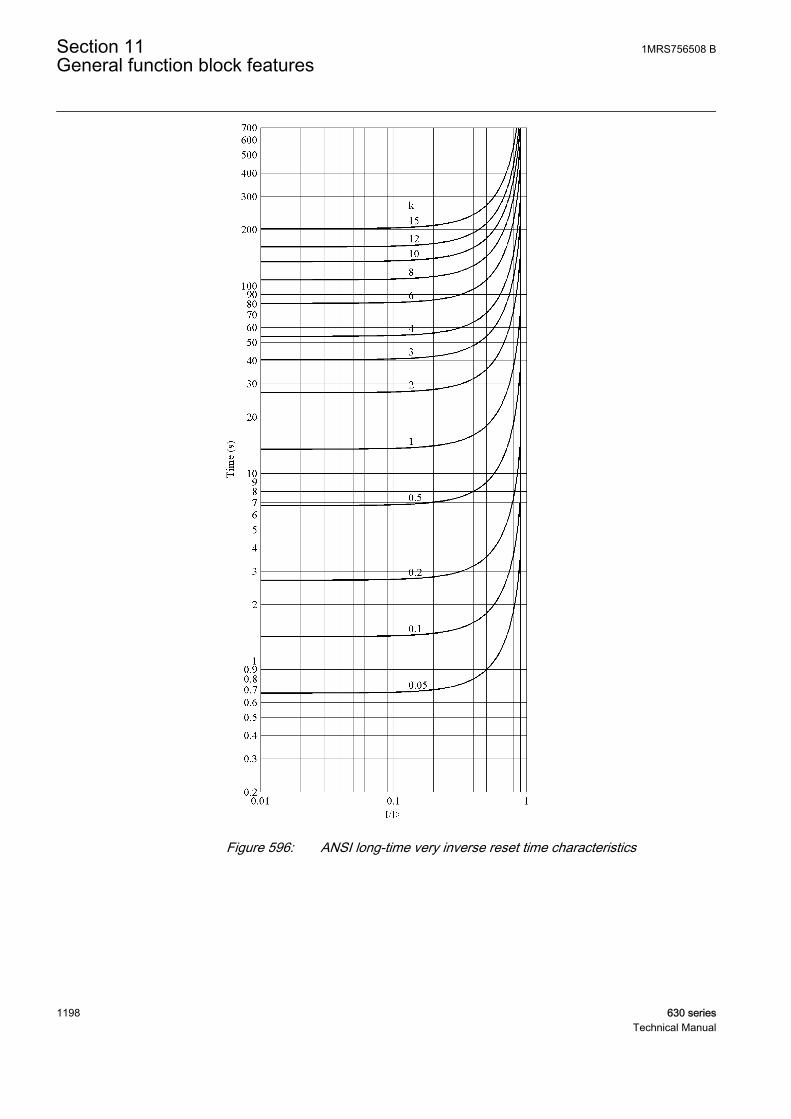
A070833 V1 EN
Figure 596: ANSI long-time very inverse reset time characteristics
Section 11 1MRS756508 BGeneral function block features
1198 630 seriesTechnical Manual

A070834 V1 EN
Figure 597: ANSI long-time inverse reset time characteristics
The delayed inverse-time reset is not available for IEC-type inversetime curves.
User-programmable delayed inverse reset
1MRS756508 B Section 11General function block features
630 series 1199Technical Manual
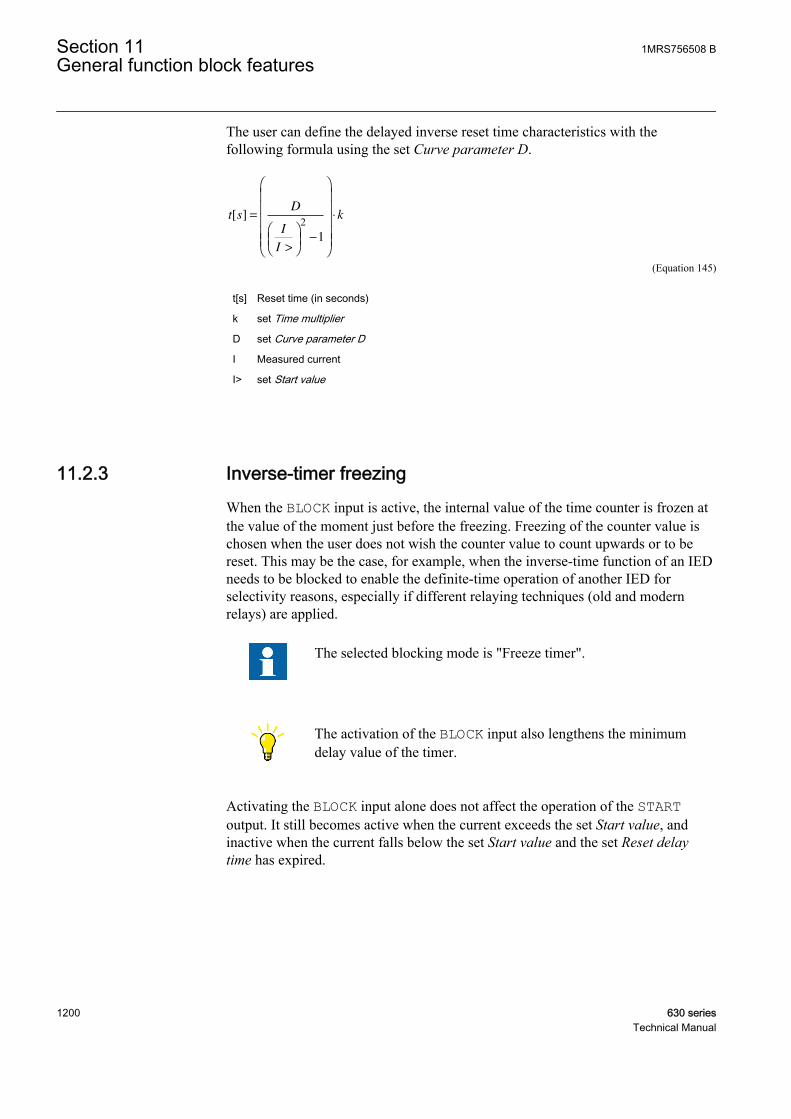
The user can define the delayed inverse reset time characteristics with thefollowing formula using the set Curve parameter D.
t sD
I
I
k[ ] =
>
−
⋅2
1
A060817 V3 EN (Equation 145)
t[s] Reset time (in seconds)
k set Time multiplier
D set Curve parameter D
I Measured current
I> set Start value
11.2.3 Inverse-timer freezingWhen the BLOCK input is active, the internal value of the time counter is frozen atthe value of the moment just before the freezing. Freezing of the counter value ischosen when the user does not wish the counter value to count upwards or to bereset. This may be the case, for example, when the inverse-time function of an IEDneeds to be blocked to enable the definite-time operation of another IED forselectivity reasons, especially if different relaying techniques (old and modernrelays) are applied.
The selected blocking mode is "Freeze timer".
The activation of the BLOCK input also lengthens the minimumdelay value of the timer.
Activating the BLOCK input alone does not affect the operation of the STARToutput. It still becomes active when the current exceeds the set Start value, andinactive when the current falls below the set Start value and the set Reset delaytime has expired.
Section 11 1MRS756508 BGeneral function block features
1200 630 seriesTechnical Manual
11.3 Voltage based inverse definite minimum timecharacteristics
11.3.1 IDMT curves for overvoltage protectionIn inverse-time modes, the operate time depends on the momentary value of thevoltage, the higher the voltage, the faster the operate time. The operate timecalculation or integration starts immediately when the voltage exceeds the set valueof the Start value setting and the START output is activated.
The OPERATE output of the component is activated when the cumulative sum ofthe integrator calculating the overvoltage situation exceeds the value set by theinverse time mode. The set value depends on the selected curve type and the settingvalues used. The user determines the curve scaling with the Time multiplier setting.
The Minimum operate time setting defines the minimum operate time for the IDMTmode, that is, it is possible to limit the IDMT based operate time for not becomingtoo short. For example:
1MRS756508 B Section 11General function block features
630 series 1201Technical Manual
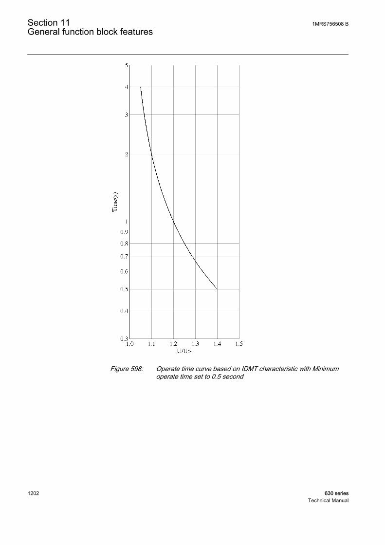
GUID-BCFE3F56-BFA8-4BCC-8215-30C089C80EAD V1 EN
Figure 598: Operate time curve based on IDMT characteristic with Minimumoperate time set to 0.5 second
Section 11 1MRS756508 BGeneral function block features
1202 630 seriesTechnical Manual

GUID-90BAEB05-E8FB-4F8A-8F07-E110DD63FCCF V1 EN
Figure 599: Operate time curve based on IDMT characteristic with Minimumoperate time set to 1 second
11.3.1.1 Standard inverse-time characteristics for overvoltage protection
The operate times for the standard overvoltage IDMT curves are defined with thecoefficients A, B, C, D and E.
The inverse operate time can be calculated with the formula:
1MRS756508 B Section 11General function block features
630 series 1203Technical Manual
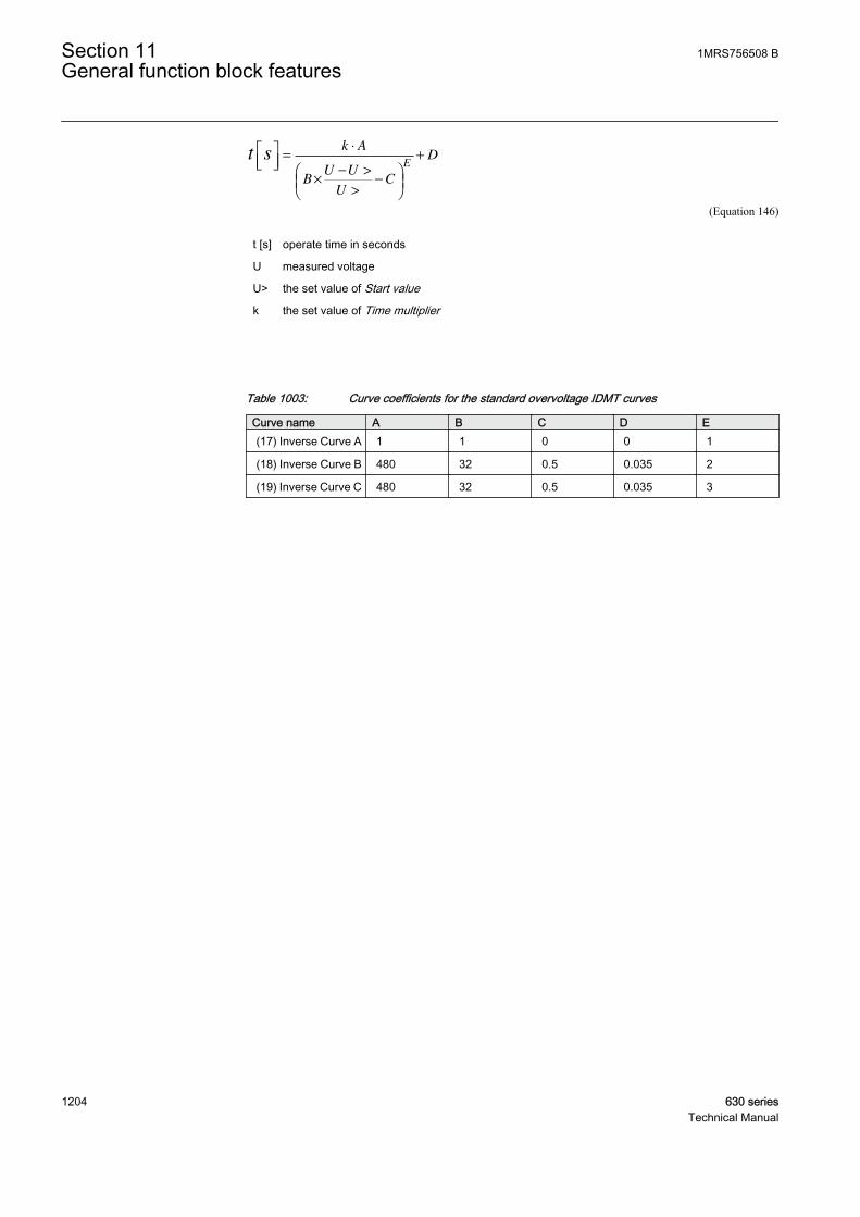
t sk A
BU U
UC
DE
=
⋅
×− >
>
−
+
GUID-6E9DC0FE-7457-4317-9480-8CCC6D63AB35 V2 EN (Equation 146)
t [s] operate time in seconds
U measured voltage
U> the set value of Start value
k the set value of Time multiplier
Table 1003: Curve coefficients for the standard overvoltage IDMT curves
Curve name A B C D E(17) Inverse Curve A 1 1 0 0 1
(18) Inverse Curve B 480 32 0.5 0.035 2
(19) Inverse Curve C 480 32 0.5 0.035 3
Section 11 1MRS756508 BGeneral function block features
1204 630 seriesTechnical Manual
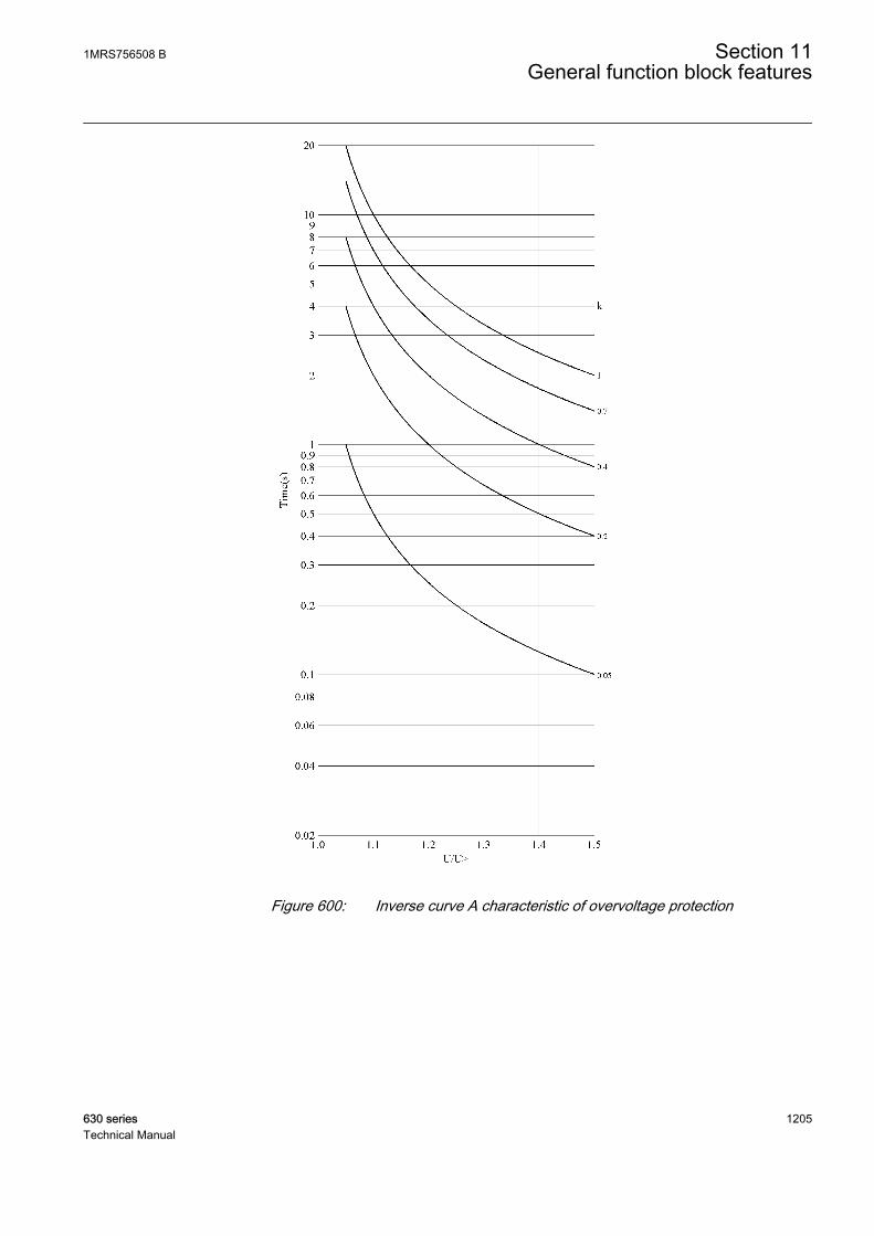
GUID-ACF4044C-052E-4CBD-8247-C6ABE3796FA6 V1 EN
Figure 600: Inverse curve A characteristic of overvoltage protection
1MRS756508 B Section 11General function block features
630 series 1205Technical Manual

GUID-F5E0E1C2-48C8-4DC7-A84B-174544C09142 V1 EN
Figure 601: Inverse curve B characteristic of overvoltage protection
Section 11 1MRS756508 BGeneral function block features
1206 630 seriesTechnical Manual
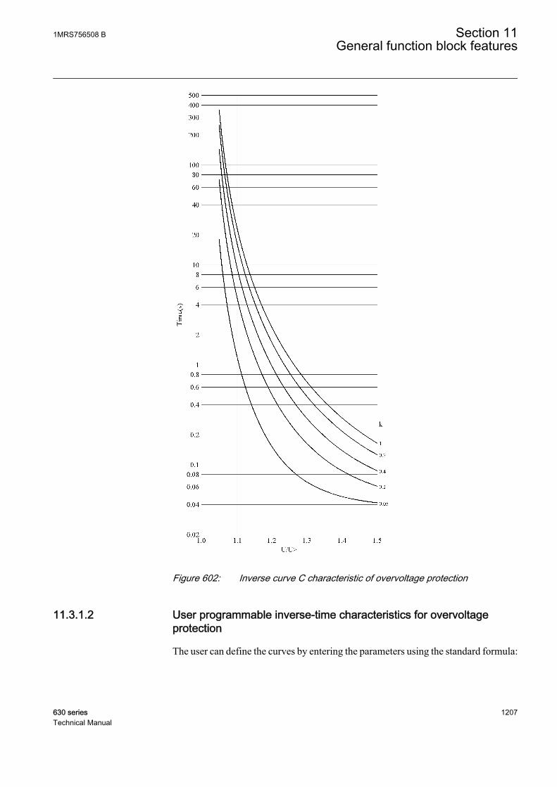
GUID-A9898DB7-90A3-47F2-AEF9-45FF148CB679 V1 EN
Figure 602: Inverse curve C characteristic of overvoltage protection
11.3.1.2 User programmable inverse-time characteristics for overvoltageprotection
The user can define the curves by entering the parameters using the standard formula:
1MRS756508 B Section 11General function block features
630 series 1207Technical Manual
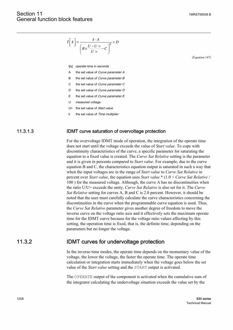
t sk A
BU U
UC
DE
=
⋅
×− >
>
−
+
GUID-6E9DC0FE-7457-4317-9480-8CCC6D63AB35 V2 EN (Equation 147)
t[s] operate time in seconds
A the set value of Curve parameter A
B the set value of Curve parameter B
C the set value of Curve parameter C
D the set value of Curve parameter D
E the set value of Curve parameter E
U measured voltage
U> the set value of Start value
k the set value of Time multiplier
11.3.1.3 IDMT curve saturation of overvoltage protection
For the overvoltage IDMT mode of operation, the integration of the operate timedoes not start until the voltage exceeds the value of Start value. To cope withdiscontinuity characteristics of the curve, a specific parameter for saturating theequation to a fixed value is created. The Curve Sat Relative setting is the parameterand it is given in percents compared to Start value. For example, due to the curveequation B and C, the characteristics equation output is saturated in such a way thatwhen the input voltages are in the range of Start value to Curve Sat Relative inpercent over Start value, the equation uses Start value * (1.0 + Curve Sat Relative /100 ) for the measured voltage. Although, the curve A has no discontinuities whenthe ratio U/U> exceeds the unity, Curve Sat Relative is also set for it. The CurveSat Relative setting for curves A, B and C is 2.0 percent. However, it should benoted that the user must carefully calculate the curve characteristics concerning thediscontinuities in the curve when the programmable curve equation is used. Thus,the Curve Sat Relative parameter gives another degree of freedom to move theinverse curve on the voltage ratio axis and it effectively sets the maximum operatetime for the IDMT curve because for the voltage ratio values affecting by thissetting, the operation time is fixed, that is, the definite time, depending on theparameters but no longer the voltage.
11.3.2 IDMT curves for undervoltage protectionIn the inverse-time modes, the operate time depends on the momentary value of thevoltage, the lower the voltage, the faster the operate time. The operate timecalculation or integration starts immediately when the voltage goes below the setvalue of the Start value setting and the START output is activated.
The OPERATE output of the component is activated when the cumulative sum ofthe integrator calculating the undervoltage situation exceeds the value set by the
Section 11 1MRS756508 BGeneral function block features
1208 630 seriesTechnical Manual
inverse-time mode. The set value depends on the selected curve type and thesetting values used. The user determines the curve scaling with the Time multipliersetting.
The Minimum operate time setting defines the minimum operate time possible forthe IDMT mode. For setting a value for this parameter, the user should carefullystudy the particular IDMT curve.
11.3.2.1 Standard inverse-time characteristics for undervoltage protection
The operate times for the standard undervoltage IDMT curves are defined with thecoefficients A, B, C, D and E.
The inverse operate time can be calculated with the formula:
t sk A
BU U
UC
DE
=
⋅
×< −
<
−
+
GUID-4A433D56-D7FB-412E-B1AB-7FD43051EE79 V2 EN (Equation 148)
t [s] operate time in seconds
U measured voltage
U< the set value of the Start value setting
k the set value of the Time multiplier setting
Table 1004: Curve coefficients for standard undervoltage IDMT curves
Curve name A B C D E(21) InverseCurve A
1 1 0 0 1
(22) InverseCurve B
480 32 0.5 0.055 2
1MRS756508 B Section 11General function block features
630 series 1209Technical Manual
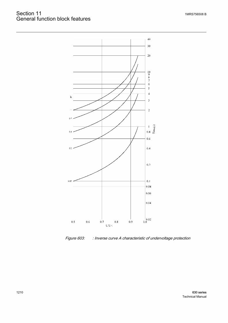
GUID-35F40C3B-B483-40E6-9767-69C1536E3CBC V1 EN
Figure 603: : Inverse curve A characteristic of undervoltage protection
Section 11 1MRS756508 BGeneral function block features
1210 630 seriesTechnical Manual

GUID-B55D0F5F-9265-4D9A-A7C0-E274AA3A6BB1 V1 EN
Figure 604: Inverse curve B characteristic of undervoltage protection
11.3.2.2 User-programmable inverse-time characteristics for undervoltageprotection
The user can define curves by entering parameters into the standard formula:
1MRS756508 B Section 11General function block features
630 series 1211Technical Manual

t sk A
BU U
UC
DE
=
⋅
×< −
<
−
+
GUID-4A433D56-D7FB-412E-B1AB-7FD43051EE79 V2 EN (Equation 149)
t[s] operate time in seconds
A the set value of Curve parameter A
B the set value of Curve parameter B
C the set value of Curve parameter C
D the set value of Curve parameter D
E the set value of Curve parameter E
U measured voltage
U< the set value of Start value
k the set value of Time multiplier
11.3.2.3 IDMT curve saturation of undervoltage protection
For the undervoltage IDMT mode of operation, the integration of the operate timedoes not start until the voltage falls below the value of Start value. To cope withdiscontinuity characteristics of the curve, a specific parameter for saturating theequation to a fixed value is created. The Curve Sat Relative setting is the parameterand it is given in percents compared with Start value. For example, due to thecurve equation B, the characteristics equation output is saturated in such a way thatwhen input voltages are in the range from Start value to Curve Sat Relative inpercents under Start value, the equation uses Start value * (1.0 - Curve SatRelative / 100 ) for the measured voltage. Although, the curve A has nodiscontinuities when the ratio U/U> exceeds the unity, Curve Sat Relative is set forit as well. The Curve Sat Relative setting for curves A, B and C is 2.0 percent.However, it should be noted that the user must carefully calculate the curvecharacteristics concerning also discontinuities in the curve when the programmablecurve equation is used. Thus, the Curve Sat Relative parameter gives anotherdegree of freedom to move the inverse curve on the voltage ratio axis and iteffectively sets the maximum operate time for the IDMT curve because for thevoltage ratio values affecting by this setting, the operation time is fixed, that is, thedefinite time, depending on the parameters but no longer the voltage.
11.4 Measurement modes
In many current or voltage dependent function blocks, there are four alternativemeasuring principles:
Section 11 1MRS756508 BGeneral function block features
1212 630 seriesTechnical Manual
• RMS• DFT which is a numerically calculated fundamental component of the signal• Peak-to-peak• Peak-to-peak with peak backup
Consequently, the measurement mode can be selected according to the application.
In extreme cases, for example with high overcurrent or harmonic content, themeasurement modes function in a slightly different way. The operation accuracy isdefined with the frequency range of f/fn=0.95...1.05. In peak-to-peak and RMSmeasurement modes, the harmonics of the phase currents are not suppressed,whereas in the fundamental frequency measurement the suppression of harmonicsis at least -50 dB at the frequency range of f= n x fn, where n = 2, 3, 4, 5,...
RMSThe RMS measurement principle is selected with the Measurement mode settingusing the value "RMS". RMS consists of both AC and DC components. The ACcomponent is the effective mean value of the positive and negative peak values.RMS is used in applications where the effect of the DC component must be takeninto account.
RMS is calculated according to the formula:
IRMS i
i
n
nI=
=
∑1 2
1
A070883 V2 EN (Equation 150)
n the number of samples in a calculation cycle
Ii the current sample value
DFTThe DFT measurement principle is selected with the Measurement mode settingusing the value "DFT". In the DFT mode, the fundamental frequency component ofthe measured signal is numerically calculated from the samples. In someapplications, for example, it can be difficult to accomplish sufficiently sensitivesettings and accurate operation of the low stage, which may be due to aconsiderable amount of harmonics on the primary side currents. In such a case, theoperation can be based solely on the fundamental frequency component of thecurrent. In addition, the DFT mode has slightly higher CT requirements than the peak-to-peak mode, if used with high and instantaneous stages.
Peak-to-peakThe peak-to-peak measurement principle is selected with the Measurement modesetting using the value "Peak-to-Peak". It is the fastest measurement mode, inwhich the measurement quantity is made by calculating the average from the
1MRS756508 B Section 11General function block features
630 series 1213Technical Manual

positive and negative peak values. The DC component is not included. Theretardation time is short. The damping of the harmonics is quite low and practicallydetermined by the characteristics of the anti-aliasing filter of the IED inputs.Consequently, this mode is usually used in conjunction with high and instantaneousstages, where the suppression of harmonics is not so important. In addition, the peak-to-peak mode allows considerable CT saturation without impairing theperformance of the operation.
Peak-to-peak with peak backupThe peak-to-peak with peak backup measurement principle is selected with theMeasurement mode setting using the value "P-to-P+backup". It is similar to the peak-to-peak mode, with the exception that it has been enhanced with the peak backup.In the peak-to-peak with peak backup mode, the function starts with twoconditions: the peak-to-peak value is above the set start current or the peak value isabove two times the set Start value. The peak backup is enabled only when thefunction is used in the DT mode in high and instantaneous stages for faster operation.
Section 11 1MRS756508 BGeneral function block features
1214 630 seriesTechnical Manual

Section 12 Requirements for measurementtransformers
12.1 Current transformers
12.1.1 Current transformer requirements for non-directionalovercurrent protectionFor reliable and correct operation of the overcurrent protection, the CT has to bechosen carefully. The distortion of the secondary current of a saturated CT mayendanger the operation, selectivity, and co-ordination of protection. However,when the CT is correctly selected, a fast and reliable short circuit protection can beenabled.
The selection of a CT depends not only on the CT specifications but also on thenetwork fault current magnitude, desired protection objectives, and the actual CTburden. The protection settings of the IED should be defined in accordance withthe CT performance as well as other factors.
12.1.1.1 Current transformer accuracy class and accuracy limit factor
The rated accuracy limit factor (Fn) is the ratio of the rated accuracy limit primarycurrent to the rated primary current. For example, a protective current transformerof type 5P10 has the accuracy class 5P and the accuracy limit factor 10. Forprotective current transformers, the accuracy class is designed by the highestpermissible percentage composite error at the rated accuracy limit primary currentprescribed for the accuracy class concerned, followed by the letter "P" (meaningprotection).
Table 1005: Limits of errors according to IEC 60044-1 for protective current transformers
Accuracy class Current error atrated primarycurrent (%)
Phase displacement at rated primarycurrent
Composite error atrated accuracy limitprimary current (%)minutes centiradians
5P ±1 ±60 ±1.8 5
10P ±3 - - 10
The accuracy classes 5P and 10P are both suitable for non-directional overcurrentprotection. The 5P class provides a better accuracy. This should be noted also ifthere are accuracy requirements for the metering functions (current metering,power metering, and so on) of the IED.
1MRS756508 B Section 12Requirements for measurement transformers
630 series 1215Technical Manual

The CT accuracy primary limit current describes the highest fault currentmagnitude at which the CT fulfils the specified accuracy. Beyond this level, thesecondary current of the CT is distorted and it might have severe effects on theperformance of the protection IED.
In practise, the actual accuracy limit factor (Fa) differs from the rated accuracylimit factor (Fn) and is proportional to the ratio of the rated CT burden and theactual CT burden.
The actual accuracy limit factor is calculated using the formula:
F FS S
S Sa n
in n
in
≈ ×
+
+
A071141 V1 EN
Fn the accuracy limit factor with the nominal external burden Sn
Sin the internal secondary burden of the CT
S the actual external burden
12.1.1.2 Non-directional overcurrent protection
The current transformer selectionNon-directional overcurrent protection does not set high requirements on theaccuracy class or on the actual accuracy limit factor (Fa) of the CTs. It is, however,recommended to select a CT with Fa of at least 20.
The nominal primary current I1n should be chosen in such a way that the thermaland dynamic strength of the current measuring input of the IED is not exceeded.This is always fulfilled when
I1n > Ikmax / 100,
Ikmax is the highest fault current.
The saturation of the CT protects the measuring circuit and the current input of theIED. For that reason, in practice, even a few times smaller nominal primary currentcan be used than given by the formula.
Recommended start current settingsIf Ikmin is the lowest primary current at which the highest set overcurrent stage is tooperate, the start current should be set using the formula:
Current start value < 0.7 x (Ikmin / I1n)
I1n is the nominal primary current of the CT.
Section 12 1MRS756508 BRequirements for measurement transformers
1216 630 seriesTechnical Manual
The factor 0.7 takes into account the protection IED inaccuracy, currenttransformer errors, and imperfections of the short circuit calculations.
The adequate performance of the CT should be checked when the setting of thehigh set stage overcurrent protection is defined. The operate time delay caused bythe CT saturation is typically small enough when the overcurrent setting isnoticeably lower than Fa.
When defining the setting values for the low set stages, the saturation of the CTdoes not need to be taken into account and the start current setting is simplyaccording to the formula.
Delay in operation caused by saturation of current transformersThe saturation of CT may cause a delayed IED operation. To ensure the timeselectivity, the delay must be taken into account when setting the operate times ofsuccessive IEDs.
With definite time mode of operation, the saturation of CT may cause a delay thatis as long as the time the constant of the DC component of the fault current, whenthe current is only slightly higher than the starting current. This depends on theaccuracy limit factor of the CT, on the remanence flux of the core of the CT, andon the operate time setting.
With inverse time mode of operation, the delay should always be considered asbeing as long as the time constant of the DC component.
With inverse time mode of operation and when the high-set stages are not used, theAC component of the fault current should not saturate the CT less than 20 times thestarting current. Otherwise, the inverse operation time can be further prolonged.Therefore, the accuracy limit factor Fa should be chosen using the formula:
Fa > 20*Current start value / I1n
The Current start value is the primary pickup current setting of the IED.
12.1.1.3 Example for non-directional overcurrent protection
The following figure describes a typical medium voltage feeder. The protection isimplemented as three-stage definite time non-directional overcurrent protection.
1MRS756508 B Section 12Requirements for measurement transformers
630 series 1217Technical Manual

A071142 V1 EN
Figure 605: Example of three-stage overcurrent protection
The maximum three-phase fault current is 41.7 kA and the minimum three-phaseshort circuit current is 22.8 kA. The actual accuracy limit factor of the CT iscalculated to be 59.
The start current setting for low-set stage (3I>) is selected to be about twice thenominal current of the cable. The operate time is selected so that it is selective withthe next IED (not visible in the figure above). The settings for the high-set stageand instantaneous stage are defined also so that grading is ensured with thedownstream protection. In addition, the start current settings have to be defined sothat the IED operates with the minimum fault current and it does not operate withthe maximum load current. The settings for all three stages are as in the figure above.
For the application point of view, the suitable setting for instantaneous stage (I>>>)in this example is 3 500 A (5.83 x I2n). For the CT characteristics point of view, thecriteria given by the current transformer selection formula is fulfilled and also theIED setting is considerably below the Fa. In this application, the CT rated burdencould have been selected much lower than 10 VA for economical reasons.
Section 12 1MRS756508 BRequirements for measurement transformers
1218 630 seriesTechnical Manual
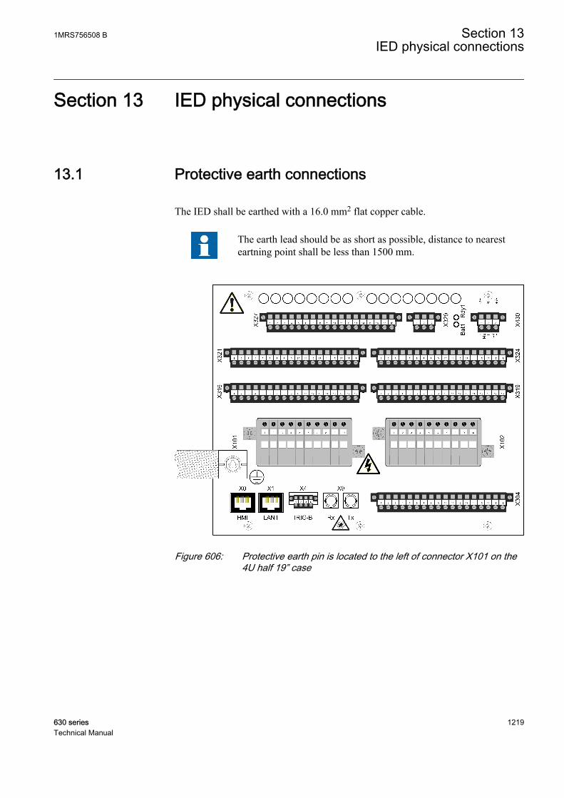
Section 13 IED physical connections
13.1 Protective earth connections
The IED shall be earthed with a 16.0 mm2 flat copper cable.
The earth lead should be as short as possible, distance to nearesteartning point shall be less than 1500 mm.
GUID-B1C6B787-D2D4-450C-A18B-18131ECBC88A V1 EN
Figure 606: Protective earth pin is located to the left of connector X101 on the4U half 19” case
1MRS756508 B Section 13IED physical connections
630 series 1219Technical Manual
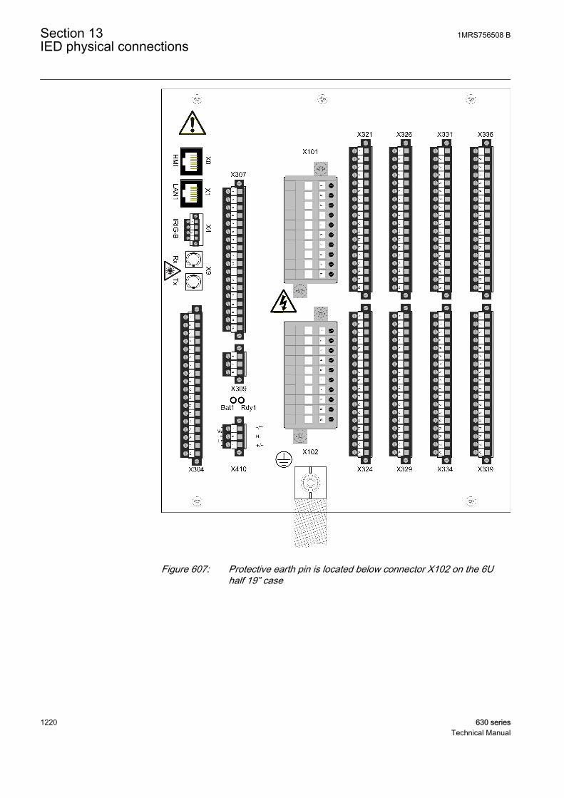
GUID-C75F6FD4-485D-464D-B7B0-55FD1AA608E9 V1 EN
Figure 607: Protective earth pin is located below connector X102 on the 6Uhalf 19” case
Section 13 1MRS756508 BIED physical connections
1220 630 seriesTechnical Manual

13.2 Inputs
13.2.1 Measuring inputs
Each terminal for CTs/VTs is dimensioned for one 0.5...6.0 mm2 wire or for twowires of maximum 2.5 mm2.
Table 1006: REF630 modules
Terminal AIMA01A1KHL178012R0008
AIMA03A1KHL178012R0009
AIMA02A1KHL178012R0010
X101-1, 2 CT CT CT
X101-3, 4 CT CT CT
X101-5, 6 CT CT CT
X101-7, 8 CT None CT
X101-9, 10 None CTS1) CTS
1)
X102-1, 2 VT VT None
X102-3, 4 VT VT VT
X102-5, 6 VT VT VT
X102-7, 8 VT VT VT
X102-9, 10 VT VT VT
1) Current Transducer for 0.1 A / 0.5 A
Table 1007: REM630 modules
Terminal AIMA02A1KHL178012R0
010
AIMA04A1KHL178012R0005
AIMA05A1KHL178012R0013
X101-1, 2 CT CT CT
X101-3, 4 CT CT CT
X101-5, 6 CT CT CT
X101-7, 8 CT CT CT
X101-9, 10 CTS1) CT CT
X102-1, 2 None CT CT
X102-3, 4 VT CT CT
X102-5, 6 VT VT CT
X102-7, 8 VT VT VT
X102-9, 10 VT VT VT
1) Current Transducer for 0.1 A / 0.5 A
1MRS756508 B Section 13IED physical connections
630 series 1221Technical Manual
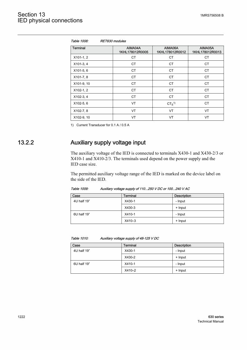
Table 1008: RET630 modules
Terminal AIMA04A1KHL178012R0005
AIMA06A1KHL178012R0012
AIMA05A1KHL178012R0013
X101-1, 2 CT CT CT
X101-3, 4 CT CT CT
X101-5, 6 CT CT CT
X101-7, 8 CT CT CT
X101-9, 10 CT CT CT
X102-1, 2 CT CT CT
X102-3, 4 CT CT CT
X102-5, 6 VT CTS1) CT
X102-7, 8 VT VT VT
X102-9, 10 VT VT VT
1) Current Transducer for 0.1 A / 0.5 A
13.2.2 Auxiliary supply voltage inputThe auxiliary voltage of the IED is connected to terminals X430-1 and X430-2/3 orX410-1 and X410-2/3. The terminals used depend on the power supply and theIED case size.
The permitted auxiliary voltage range of the IED is marked on the device label onthe side of the IED.
Table 1009: Auxiliary voltage supply of 110...250 V DC or 100...240 V AC
Case Terminal Description4U half 19” X430-1 - Input
X430-3 + Input
6U half 19” X410-1 - Input
X410–3 + Input
Table 1010: Auxiliary voltage supply of 48-125 V DC
Case Terminal Description4U half 19” X430-1 - Input
X430-2 + Input
6U half 19” X410-1 - Input
X410–2 + Input
Section 13 1MRS756508 BIED physical connections
1222 630 seriesTechnical Manual
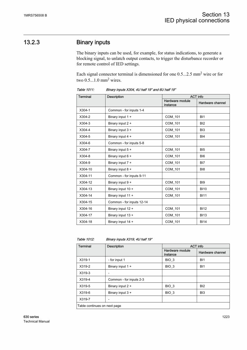
13.2.3 Binary inputsThe binary inputs can be used, for example, for status indications, to generate ablocking signal, to unlatch output contacts, to trigger the disturbance recorder orfor remote control of IED settings.
Each signal connector terminal is dimensioned for one 0.5...2.5 mm2 wire or fortwo 0.5...1.0 mm2 wires.
Table 1011: Binary inputs X304, 4U half 19” and 6U half 19”
Terminal Description ACT info
Hardware moduleinstance Hardware channel
X304-1 Common - for inputs 1-4
X304-2 Binary input 1 + COM_101 BI1
X304-3 Binary input 2 + COM_101 BI2
X304-4 Binary input 3 + COM_101 BI3
X304-5 Binary input 4 + COM_101 BI4
X304-6 Common - for inputs 5-8
X304-7 Binary input 5 + COM_101 BI5
X304-8 Binary input 6 + COM_101 BI6
X304-9 Binary input 7 + COM_101 BI7
X304-10 Binary input 8 + COM_101 BI8
X304-11 Common - for inputs 9-11
X304-12 Binary input 9 + COM_101 BI9
X304-13 Binary input 10 + COM_101 BI10
X304-14 Binary input 11 + COM_101 BI11
X304-15 Common - for inputs 12-14
X304-16 Binary input 12 + COM_101 BI12
X304-17 Binary input 13 + COM_101 BI13
X304-18 Binary input 14 + COM_101 BI14
Table 1012: Binary inputs X319, 4U half 19”
Terminal Description ACT infoHardware moduleinstance Hardware channel
X319-1 - for input 1 BIO_3 BI1
X319-2 Binary input 1 + BIO_3 BI1
X319-3 -
X319-4 Common - for inputs 2-3
X319-5 Binary input 2 + BIO_3 BI2
X319-6 Binary input 3 + BIO_3 BI3
X319-7 -
Table continues on next page
1MRS756508 B Section 13IED physical connections
630 series 1223Technical Manual

Terminal Description ACT infoHardware moduleinstance Hardware channel
X319-8 Common - for inputs 4-5
X319-9 Binary input 4 + BIO_3 BI4
X319-10 Binary input 5 + BIO_3 BI5
X319-11 -
X319-12 Common - for inputs 6-7
X319-13 Binary input 6 + BIO_3 BI6
X319-14 Binary input 7 + BIO_3 BI7
X319-15 -
X319-16 Common - for inputs 8-9
X319-17 Binary input 8 + BIO_3 BI8
X319-18 Binary input 9 + BIO_3 BI9
Table 1013: Binary inputs X324, 4U half 19”
Terminal Description ACT info
Hardware moduleinstance Hardware channel
X324-1 - for input 1 BIO_4 BI1
X324-2 Binary input 1 + BIO_4 BI1
X324-3 -
X324-4 Common - for inputs 2-3
X324-5 Binary input 2 + BIO_4 BI2
X324-6 Binary input 3 + BIO_4 BI3
X324-7 -
X324-8 Common - for inputs 4-5
X324-9 Binary input 4 + BIO_4 BI4
X324-10 Binary input 5 + BIO_4 BI5
X324-11 -
X324-12 Common - for inputs 6-7
X324-13 Binary input 6 + BIO_4 BI6
X324-14 Binary input 7 + BIO_4 BI7
X324-15 -
X324-16 Common - for inputs 8-9
X324-17 Binary input 8 + BIO_4 BI8
X324-18 Binary input 9 + BIO_4 BI9
Section 13 1MRS756508 BIED physical connections
1224 630 seriesTechnical Manual
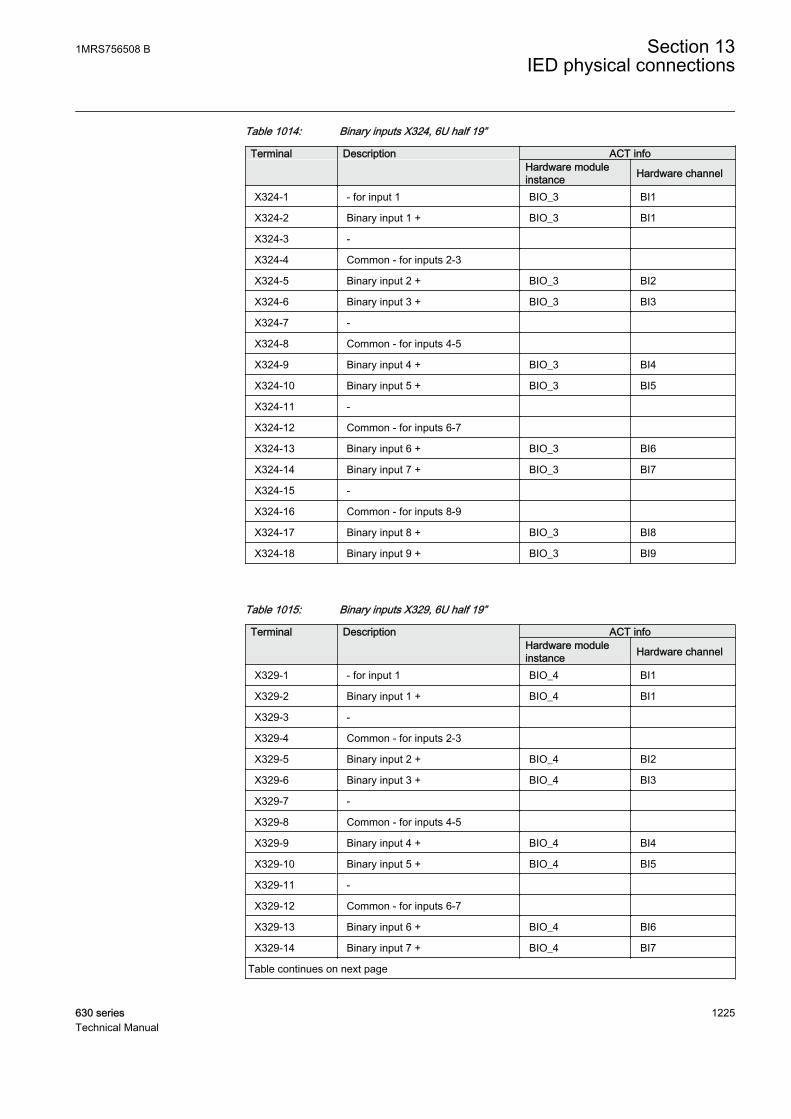
Table 1014: Binary inputs X324, 6U half 19”
Terminal Description ACT info
Hardware moduleinstance Hardware channel
X324-1 - for input 1 BIO_3 BI1
X324-2 Binary input 1 + BIO_3 BI1
X324-3 -
X324-4 Common - for inputs 2-3
X324-5 Binary input 2 + BIO_3 BI2
X324-6 Binary input 3 + BIO_3 BI3
X324-7 -
X324-8 Common - for inputs 4-5
X324-9 Binary input 4 + BIO_3 BI4
X324-10 Binary input 5 + BIO_3 BI5
X324-11 -
X324-12 Common - for inputs 6-7
X324-13 Binary input 6 + BIO_3 BI6
X324-14 Binary input 7 + BIO_3 BI7
X324-15 -
X324-16 Common - for inputs 8-9
X324-17 Binary input 8 + BIO_3 BI8
X324-18 Binary input 9 + BIO_3 BI9
Table 1015: Binary inputs X329, 6U half 19”
Terminal Description ACT infoHardware moduleinstance Hardware channel
X329-1 - for input 1 BIO_4 BI1
X329-2 Binary input 1 + BIO_4 BI1
X329-3 -
X329-4 Common - for inputs 2-3
X329-5 Binary input 2 + BIO_4 BI2
X329-6 Binary input 3 + BIO_4 BI3
X329-7 -
X329-8 Common - for inputs 4-5
X329-9 Binary input 4 + BIO_4 BI4
X329-10 Binary input 5 + BIO_4 BI5
X329-11 -
X329-12 Common - for inputs 6-7
X329-13 Binary input 6 + BIO_4 BI6
X329-14 Binary input 7 + BIO_4 BI7
Table continues on next page
1MRS756508 B Section 13IED physical connections
630 series 1225Technical Manual
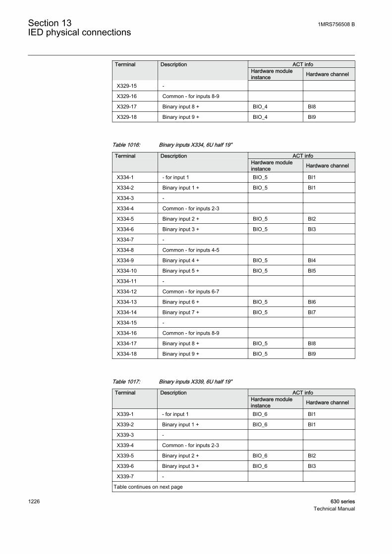
Terminal Description ACT infoHardware moduleinstance Hardware channel
X329-15 -
X329-16 Common - for inputs 8-9
X329-17 Binary input 8 + BIO_4 BI8
X329-18 Binary input 9 + BIO_4 BI9
Table 1016: Binary inputs X334, 6U half 19”
Terminal Description ACT info
Hardware moduleinstance Hardware channel
X334-1 - for input 1 BIO_5 BI1
X334-2 Binary input 1 + BIO_5 BI1
X334-3 -
X334-4 Common - for inputs 2-3
X334-5 Binary input 2 + BIO_5 BI2
X334-6 Binary input 3 + BIO_5 BI3
X334-7 -
X334-8 Common - for inputs 4-5
X334-9 Binary input 4 + BIO_5 BI4
X334-10 Binary input 5 + BIO_5 BI5
X334-11 -
X334-12 Common - for inputs 6-7
X334-13 Binary input 6 + BIO_5 BI6
X334-14 Binary input 7 + BIO_5 BI7
X334-15 -
X334-16 Common - for inputs 8-9
X334-17 Binary input 8 + BIO_5 BI8
X334-18 Binary input 9 + BIO_5 BI9
Table 1017: Binary inputs X339, 6U half 19”
Terminal Description ACT infoHardware moduleinstance Hardware channel
X339-1 - for input 1 BIO_6 BI1
X339-2 Binary input 1 + BIO_6 BI1
X339-3 -
X339-4 Common - for inputs 2-3
X339-5 Binary input 2 + BIO_6 BI2
X339-6 Binary input 3 + BIO_6 BI3
X339-7 -
Table continues on next page
Section 13 1MRS756508 BIED physical connections
1226 630 seriesTechnical Manual

Terminal Description ACT infoHardware moduleinstance Hardware channel
X339-8 Common - for inputs 4-5
X339-9 Binary input 4 + BIO_6 BI4
X339-10 Binary input 5 + BIO_6 BI5
X339-11 -
X339-12 Common - for inputs 6-7
X339-13 Binary input 6 + BIO_6 BI6
X339-14 Binary input 7 + BIO_6 BI7
X339-15 -
X339-16 Common - for inputs 8-9
X339-17 Binary input 8 + BIO_6 BI8
X339-18 Binary input 9 + BIO_6 BI9
13.2.4 RTD inputsTable 1018: REM/ REF/ RET630 module inputs, 4U half 19”
Terminal 600RTD01X316 – 1,2,3 Sensor/ R/ V/ mA input
X316 - 4 GND
X316 – 5,6,7 Sensor/ R/ V/ mA input
X316 – 8,9,10 Sensor/ R/ V/ mA input
X316 – 11 GND
X316 – 12,13,14 Sensor/ R/ V/ mA input
X316 – 15,16,17 Sensor/ R/ V/ mA input
X316 – 18 GND
Table 1019: REM/ REF/ RET630 module inputs, 4U half 19”
Terminal 600RTD01X319 – 1,2,3 Sensor/ R/ V/ mA input
X319 – 4,5,6 Sensor/ R/ V/ mA input
X319 – 7 GND
X319 – 8,9,10 Sensor/ R/ V/ mA input
Table 1020: REM/ REF/ RET630 module inputs, 6U half 19”
Terminal 600RTD01X321 – 1,2,3 Sensor/ R/ V/ mA input
X321 - 4 GND
X321 – 5,6,7 Sensor/ R/ V/ mA input
Table continues on next page
1MRS756508 B Section 13IED physical connections
630 series 1227Technical Manual

Terminal 600RTD01X321 – 8,9,10 Sensor/ R/ V/ mA input
X321 – 11 GND
X321 – 12,13,14 Sensor/ R/ V/ mA input
X321 – 15,16,17 Sensor/ R/ V/ mA input
X321 – 18 GND
Table 1021: REM/ REF/ RET630 module inputs, 6U half 19”
Terminal 600RTD01X324 – 1,2,3 Sensor/ R/ V/ mA input
X324 – 4,5,6 Sensor/ R/ V/ mA input
X324 – 7 GND
X324 – 8,9,10 Sensor/ R/ V/ mA input
13.3 Outputs
13.3.1 Outputs for tripping and controllingOutput contacts PO1, PO2 and PO3 are power output contacts used, for example,for controlling circuit breakers.
Each signal connector terminal is dimensioned for one 0.5...2.5 mm2 wire or fortwo 0.5...1.0 mm2 wires.
Check the DC polarity of the TCS outputs.
Table 1022: Output contacts X307, 6U half 19”
Terminal Description ACT info Hardware module
instanceHardware channel
Power output 1, normally open(TCS)
X307-1 - PSM_102 BO1_PO_TCS
X307-2 +
Power output 2, normally open(TCS)
X307-3 - PSM_102 BO2_PO_TCS
X307-4 +
Power output 3, normally open(TCS)
Table continues on next page
Section 13 1MRS756508 BIED physical connections
1228 630 seriesTechnical Manual

Terminal Description ACT info Hardware module
instanceHardware channel
X307-5 - PSM_102 BO3_PO_TCS
X307-6 +
X307-7 Power output 4, normally open PSM_102 BO4_PO
X307-8
X307-9 Power output 5, normally open PSM_102 BO5_PO
X307-10
X307-11 Power output 6, normally open PSM_102 BO6_PO
X307-12
Table 1023: Output contacts X316, 4U half 19”
Terminal Description ACT info Hardware module
instanceHardware channel
X316-1 Power output 1, normally open BIO_3 BO1_PO
X316-2
X316-3 Power output 2, normally open BIO_3 BO2_PO
X316-4
X316-5 Power output 3, normally open BIO_3 BO3_PO
X316-6
Table 1024: Output contacts X321, 4U half 19”
Terminal Description ACT info Hardware module
instanceHardware channel
X321-1 Power output 1, normally open BIO_4 BO1_PO
X321-2
X321-3 Power output 2, normally open BIO_4 BO2_PO
X321-4
X321-5 Power output 3, normally open BIO_4 BO3_PO
X321-6
Table 1025: Output contacts X321, 6U half 19”
Terminal Description ACT info Hardware module
instanceHardware channel
X321-1 Power output 1, normally open BIO_3 BO1_PO
X321-2
X321-3 Power output 2, normally open BIO_3 BO2_PO
Table continues on next page
1MRS756508 B Section 13IED physical connections
630 series 1229Technical Manual
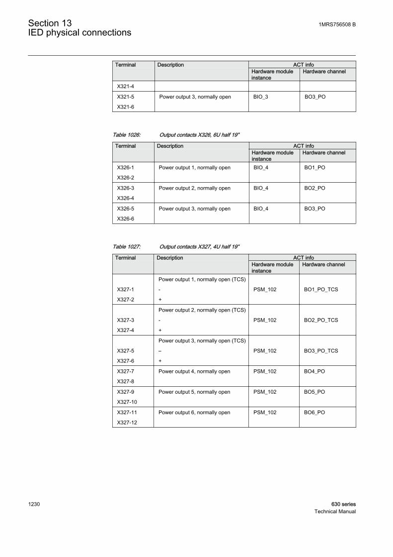
Terminal Description ACT info Hardware module
instanceHardware channel
X321-4
X321-5 Power output 3, normally open BIO_3 BO3_PO
X321-6
Table 1026: Output contacts X326, 6U half 19”
Terminal Description ACT info Hardware module
instanceHardware channel
X326-1 Power output 1, normally open BIO_4 BO1_PO
X326-2
X326-3 Power output 2, normally open BIO_4 BO2_PO
X326-4
X326-5 Power output 3, normally open BIO_4 BO3_PO
X326-6
Table 1027: Output contacts X327, 4U half 19”
Terminal Description ACT info Hardware module
instanceHardware channel
Power output 1, normally open (TCS)
X327-1 - PSM_102 BO1_PO_TCS
X327-2 +
Power output 2, normally open (TCS)
X327-3 - PSM_102 BO2_PO_TCS
X327-4 +
Power output 3, normally open (TCS)
X327-5 – PSM_102 BO3_PO_TCS
X327-6 +
X327-7 Power output 4, normally open PSM_102 BO4_PO
X327-8
X327-9 Power output 5, normally open PSM_102 BO5_PO
X327-10
X327-11 Power output 6, normally open PSM_102 BO6_PO
X327-12
Section 13 1MRS756508 BIED physical connections
1230 630 seriesTechnical Manual

Table 1028: Output contacts X331, 6U half 19”
Terminal Description ACT info Hardware module
instanceHardware channel
X331-1 Power output 1, normally open BIO_5 BO1_PO
X331-2
X331-3 Power output 2, normally open BIO_5 BO2_PO
X331-4
X331-5 Power output 3, normally open BIO_5 BO3_PO
X331-6
Table 1029: Output contacts X336, 6U half 19”
Terminal Description ACT info Hardware module
instanceHardware channel
X336-1 Power output 1, normally open BIO_6 BO1_PO
X336-2
X336-3 Power output 2, normally open BIO_6 BO2_PO
X336-4
X336-5 Power output 3, normally open BIO_6 BO3_PO
X336-6
13.3.2 Outputs for signallingSignal output contacts are used for signalling on starting and tripping of the IED. Ifthe IED is ordered with pre-configuration, the necessary start and alarm signalsfrom used functions are routed to signalling outputs. See the application manual formore details.
Each signal connector terminal is dimensioned for one 0.5...2.5 mm2 wire or fortwo 0.5...1.0 mm2 wires.
Table 1030: Output contacts X307, 6U half 19”
Terminal Description ACT info Hardware module
instanceHardware channel
X307-13 Signal output 1, normally open PSM_102 BO7_SO
X307-14
X307-15 Signal output 2, normally open PSM_102 BO8_SO
X307-16
X307-17 Signal output 3, normally open PSM_102 BO9_SO
X307-18
1MRS756508 B Section 13IED physical connections
630 series 1231Technical Manual
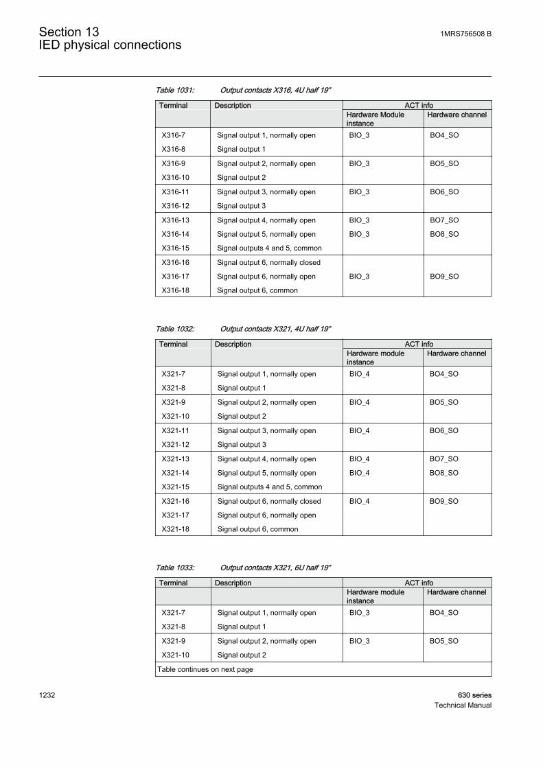
Table 1031: Output contacts X316, 4U half 19”
Terminal Description ACT info Hardware Module
instanceHardware channel
X316-7 Signal output 1, normally open BIO_3 BO4_SO
X316-8 Signal output 1
X316-9 Signal output 2, normally open BIO_3 BO5_SO
X316-10 Signal output 2
X316-11 Signal output 3, normally open BIO_3 BO6_SO
X316-12 Signal output 3
X316-13 Signal output 4, normally open BIO_3 BO7_SO
X316-14 Signal output 5, normally open BIO_3 BO8_SO
X316-15 Signal outputs 4 and 5, common
X316-16 Signal output 6, normally closed
X316-17 Signal output 6, normally open BIO_3 BO9_SO
X316-18 Signal output 6, common
Table 1032: Output contacts X321, 4U half 19”
Terminal Description ACT info Hardware module
instanceHardware channel
X321-7 Signal output 1, normally open BIO_4 BO4_SO
X321-8 Signal output 1
X321-9 Signal output 2, normally open BIO_4 BO5_SO
X321-10 Signal output 2
X321-11 Signal output 3, normally open BIO_4 BO6_SO
X321-12 Signal output 3
X321-13 Signal output 4, normally open BIO_4 BO7_SO
X321-14 Signal output 5, normally open BIO_4 BO8_SO
X321-15 Signal outputs 4 and 5, common
X321-16 Signal output 6, normally closed BIO_4 BO9_SO
X321-17 Signal output 6, normally open
X321-18 Signal output 6, common
Table 1033: Output contacts X321, 6U half 19”
Terminal Description ACT info Hardware module
instanceHardware channel
X321-7 Signal output 1, normally open BIO_3 BO4_SO
X321-8 Signal output 1
X321-9 Signal output 2, normally open BIO_3 BO5_SO
X321-10 Signal output 2
Table continues on next page
Section 13 1MRS756508 BIED physical connections
1232 630 seriesTechnical Manual
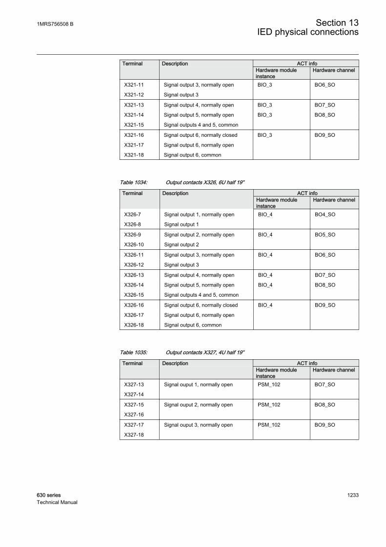
Terminal Description ACT info Hardware module
instanceHardware channel
X321-11 Signal output 3, normally open BIO_3 BO6_SO
X321-12 Signal output 3
X321-13 Signal output 4, normally open BIO_3 BO7_SO
X321-14 Signal output 5, normally open BIO_3 BO8_SO
X321-15 Signal outputs 4 and 5, common
X321-16 Signal output 6, normally closed BIO_3 BO9_SO
X321-17 Signal output 6, normally open
X321-18 Signal output 6, common
Table 1034: Output contacts X326, 6U half 19”
Terminal Description ACT infoHardware moduleinstance
Hardware channel
X326-7 Signal output 1, normally open BIO_4 BO4_SO
X326-8 Signal output 1
X326-9 Signal output 2, normally open BIO_4 BO5_SO
X326-10 Signal output 2
X326-11 Signal output 3, normally open BIO_4 BO6_SO
X326-12 Signal output 3
X326-13 Signal output 4, normally open BIO_4 BO7_SO
X326-14 Signal output 5, normally open BIO_4 BO8_SO
X326-15 Signal outputs 4 and 5, common
X326-16 Signal output 6, normally closed BIO_4 BO9_SO
X326-17 Signal output 6, normally open
X326-18 Signal output 6, common
Table 1035: Output contacts X327, 4U half 19”
Terminal Description ACT info Hardware module
instanceHardware channel
X327-13 Signal ouput 1, normally open PSM_102 BO7_SO
X327-14
X327-15 Signal ouput 2, normally open PSM_102 BO8_SO
X327-16
X327-17 Signal ouput 3, normally open PSM_102 BO9_SO
X327-18
1MRS756508 B Section 13IED physical connections
630 series 1233Technical Manual

Table 1036: Output contacts X331, 6U half 19”
Terminal Description ACT info Hardware module
instanceHardware channel
X331-7 Signal output 1, normally open BIO_5 BO4_SO
X331-8 Signal output 1
X331-9 Signal output 2, normally open BIO_5 BO5_SO
X331-10 Signal output 2
X331-11 Signal output 3, normally open BIO_5 BO6_SO
X331-12 Signal output 3
X331-13 Signal output 4, normally open BIO_5 BO7_SO
X331-14 Signal output 5, normally open BIO_5 BO8_SO
X331-15 Signal outputs 4 and 5, common
X331-16 Signal output 6, normally closed BIO_5 BO9_SO
X331-17 Signal output 6, normally open
X331-18 Signal output 6, common
Table 1037: Output contacts X336, 6U half 19”
Terminal Description ACT info Hardware module
instanceHardware channel
X336-7 Signal output 1, normally open BIO_6 BO4_SO
X336-8 Signal output 1
X336-9 Signal output 2, normally open BIO_6 BO5_SO
X336-10 Signal output 2
X336-11 Signal output 3, normally open BIO_6 BO6_SO
X336-12 Signal output 3
X337-13 Signal output 4, normally open BIO_6 BO7_SO
X336-14 Signal output 5, normally open BIO_6 BO8_SO
X336-15 Signal outputs 4 and 5, common
X336-16 Signal output 6, normally closed BIO_6 BO9_SO
X336-17 Signal output 6, normally open
X336-18 Signal output 6, common
13.3.3 mA outputsTable 1038: REM/ REF/ RET630 module outputs, 4U half 19”
Terminal 600RTD01X319 – 11,12 mA output
X319 – 13,14 mA output
X319 – 15,16 mA output
X319 – 17,18 mA output
Section 13 1MRS756508 BIED physical connections
1234 630 seriesTechnical Manual
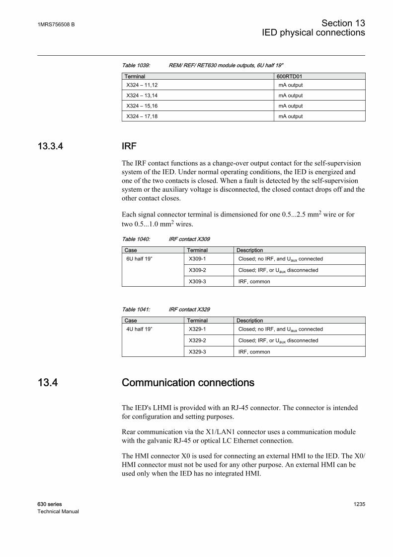
Table 1039: REM/ REF/ RET630 module outputs, 6U half 19”
Terminal 600RTD01X324 – 11,12 mA output
X324 – 13,14 mA output
X324 – 15,16 mA output
X324 – 17,18 mA output
13.3.4 IRFThe IRF contact functions as a change-over output contact for the self-supervisionsystem of the IED. Under normal operating conditions, the IED is energized andone of the two contacts is closed. When a fault is detected by the self-supervisionsystem or the auxiliary voltage is disconnected, the closed contact drops off and theother contact closes.
Each signal connector terminal is dimensioned for one 0.5...2.5 mm2 wire or fortwo 0.5...1.0 mm2 wires.
Table 1040: IRF contact X309
Case Terminal Description6U half 19” X309-1 Closed; no IRF, and Uaux connected
X309-2 Closed; IRF, or Uaux disconnected
X309-3 IRF, common
Table 1041: IRF contact X329
Case Terminal Description4U half 19” X329-1 Closed; no IRF, and Uaux connected
X329-2 Closed; IRF, or Uaux disconnected
X329-3 IRF, common
13.4 Communication connections
The IED's LHMI is provided with an RJ-45 connector. The connector is intendedfor configuration and setting purposes.
Rear communication via the X1/LAN1 connector uses a communication modulewith the galvanic RJ-45 or optical LC Ethernet connection.
The HMI connector X0 is used for connecting an external HMI to the IED. The X0/HMI connector must not be used for any other purpose. An external HMI can beused only when the IED has no integrated HMI.
1MRS756508 B Section 13IED physical connections
630 series 1235Technical Manual
13.4.1 Ethernet RJ-45 front connectionThe IED's LHMI is provided with an RJ-45 connector designed for point-to-pointuse. The connector is intended for configuration and setting purposes. The interfaceon the PC side has to be configured in a way that it obtains the IP addressautomatically. There is a DHCP server inside IED for the front interface only.
The events and setting values and all input data such as memorized values anddisturbance records can be read via the front communication port.
Only one of the possible clients can be used for parametrization at a time.
• PCM600• LHMI• WHMI
The default IP address of the IED through this port is 192.168.0.254.
The front port supports TCP/IP protocol. A standard Ethernet CAT 5 crossovercable is used with the front port.
If IED is ordered without LHMI then LAN1 port has to be used forconfiguration and setting purposes. The default IP address for theLAN1 port is 192.168.2.10. DHCP is not available from LAN1 port.
13.4.2 Ethernet connection for station communicationThe default IP address of the IED through the Ethernet connection is 192.168.2.10.The physical connector is X1/LAN1. The interface speed is 100 Mbps both for the100BASE-FX LC alternative and for the 100BASE-TX RJ-45 alternative.
13.4.3 Optical serial rear connectionSerial communication can be used via optical connection in star topology.Connector type is either glass (ST connector) or plastic (snap-in connector).Connection's idle state is indicated either with light on or light off. The physicalconnector is X9/Rx,Tx.
Section 13 1MRS756508 BIED physical connections
1236 630 seriesTechnical Manual
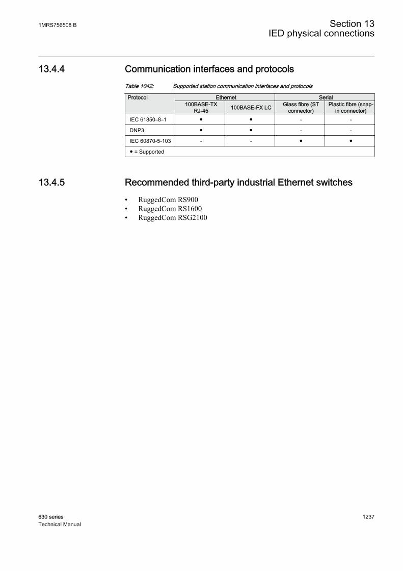
13.4.4 Communication interfaces and protocolsTable 1042: Supported station communication interfaces and protocols
Protocol Ethernet Serial100BASE-TX
RJ-45 100BASE-FX LC Glass fibre (STconnector)
Plastic fibre (snap-in connector)
IEC 61850–8–1 ● ● - -
DNP3 ● ● - -
IEC 60870-5-103 - - ● ●
● = Supported
13.4.5 Recommended third-party industrial Ethernet switches• RuggedCom RS900• RuggedCom RS1600• RuggedCom RSG2100
1MRS756508 B Section 13IED physical connections
630 series 1237Technical Manual
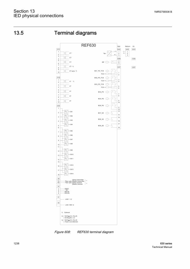
13.5 Terminal diagrams
GUID-88CD16F3-27E5-4657-BDAF-46D27B4970D8 V1 EN
Figure 608: REF630 terminal diagram
Section 13 1MRS756508 BIED physical connections
1238 630 seriesTechnical Manual
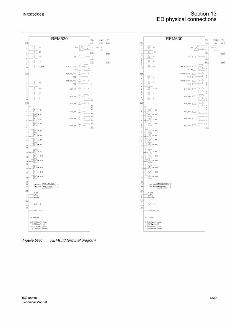
GUID-28C73256-8E73-434F-BA71-FE0AF16DBA64 V1 EN
Figure 609: REM630 terminal diagram
1MRS756508 B Section 13IED physical connections
630 series 1239Technical Manual
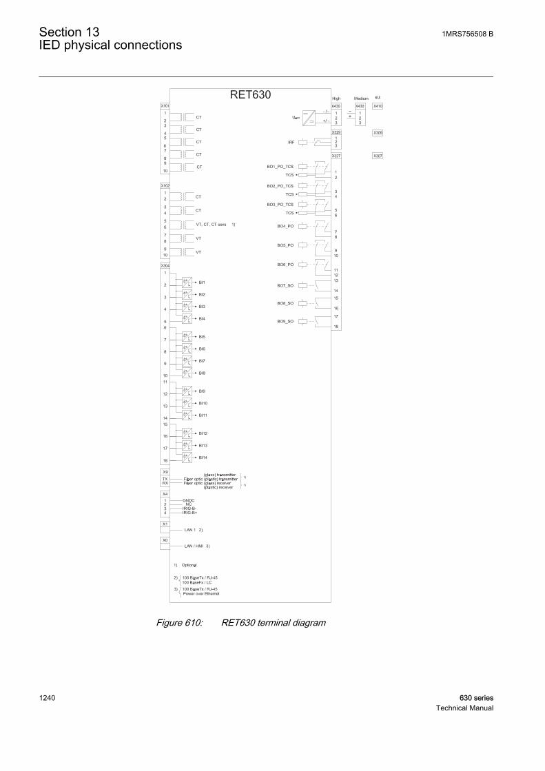
GUID-3901C29E-BCA6-44AE-B6BC-B2FA10958F19 V1 EN
Figure 610: RET630 terminal diagram
Section 13 1MRS756508 BIED physical connections
1240 630 seriesTechnical Manual
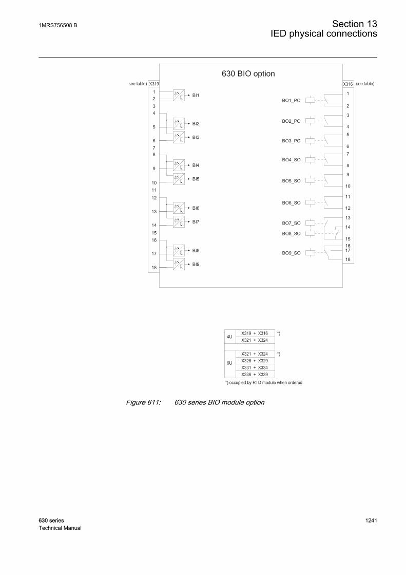
GUID-5E27DD50-FD15-4824-BDFB-DD52E29730EA V1 EN
Figure 611: 630 series BIO module option
1MRS756508 B Section 13IED physical connections
630 series 1241Technical Manual
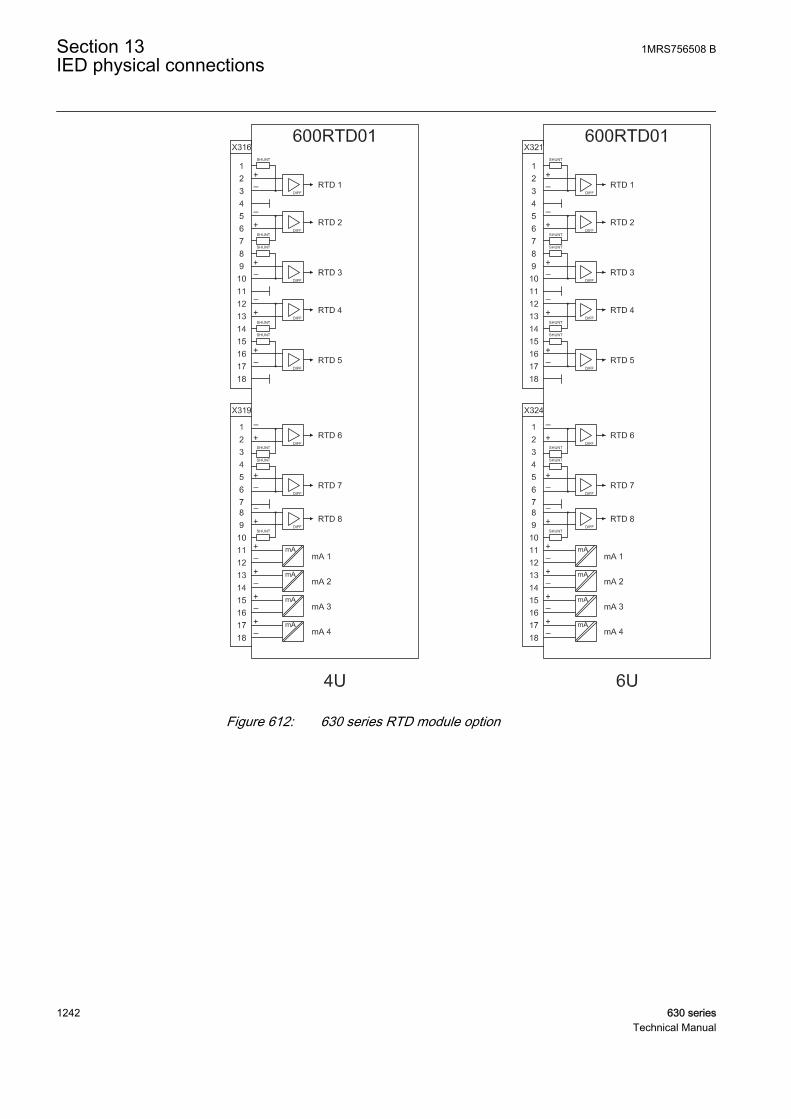
GUID-CB7B1CF8-A0E4-42F5-998C-701641515127 V1 EN
Figure 612: 630 series RTD module option
Section 13 1MRS756508 BIED physical connections
1242 630 seriesTechnical Manual
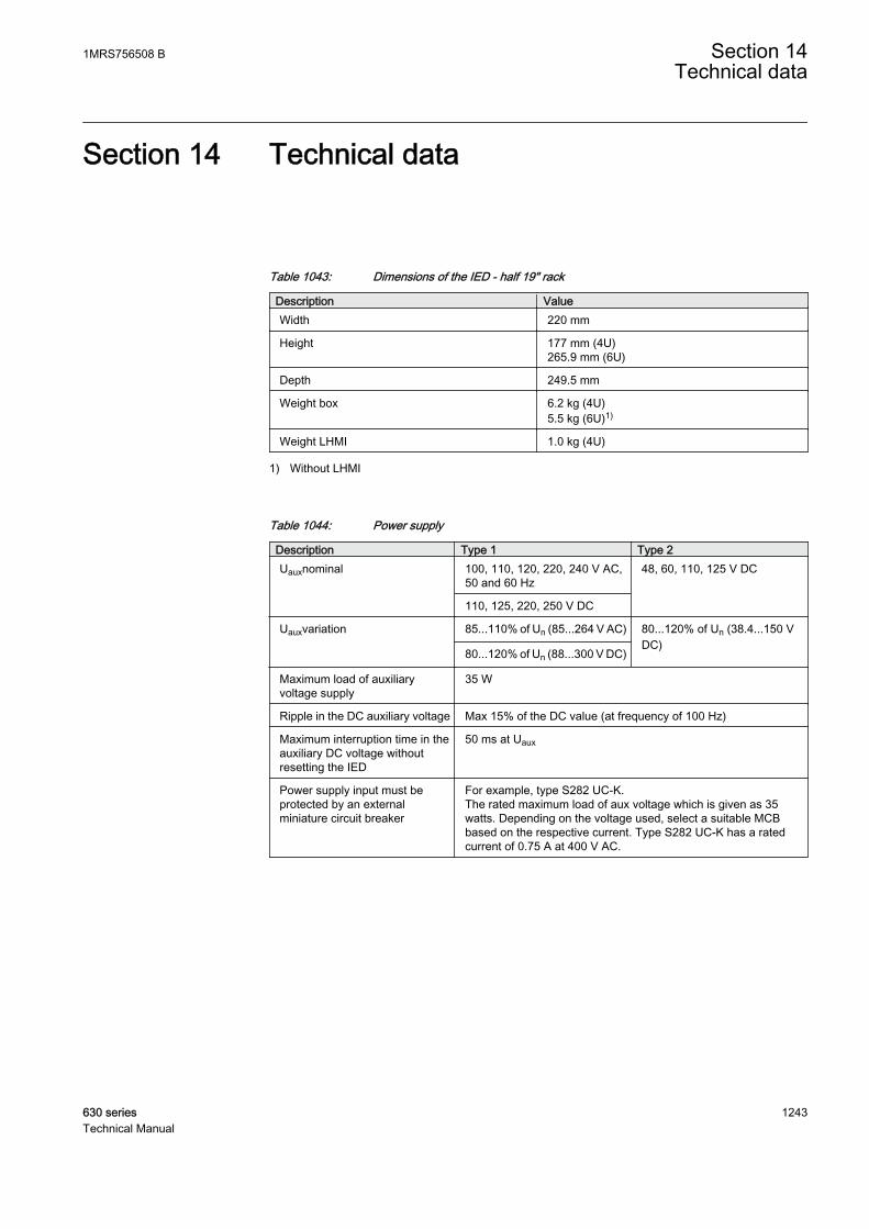
Section 14 Technical data
Table 1043: Dimensions of the IED - half 19" rack
Description ValueWidth 220 mm
Height 177 mm (4U)265.9 mm (6U)
Depth 249.5 mm
Weight box 6.2 kg (4U)5.5 kg (6U)1)
Weight LHMI 1.0 kg (4U)
1) Without LHMI
Table 1044: Power supply
Description Type 1 Type 2Uauxnominal 100, 110, 120, 220, 240 V AC,
50 and 60 Hz48, 60, 110, 125 V DC
110, 125, 220, 250 V DC
Uauxvariation 85...110% of Un (85...264 V AC) 80...120% of Un (38.4...150 VDC)
80...120% of Un (88...300 V DC)
Maximum load of auxiliaryvoltage supply
35 W
Ripple in the DC auxiliary voltage Max 15% of the DC value (at frequency of 100 Hz)
Maximum interruption time in theauxiliary DC voltage withoutresetting the IED
50 ms at Uaux
Power supply input must beprotected by an externalminiature circuit breaker
For example, type S282 UC-K.The rated maximum load of aux voltage which is given as 35watts. Depending on the voltage used, select a suitable MCBbased on the respective current. Type S282 UC-K has a ratedcurrent of 0.75 A at 400 V AC.
1MRS756508 B Section 14Technical data
630 series 1243Technical Manual

Table 1045: Energizing inputs
Description ValueRated frequency 50/60 Hz
Operating range Rated frequency ± 5 Hz
Current inputs Rated current, In 0.1/0.5 A1) 1/5 A2)
Thermal withstand capability:
• Continuously 4 A 20 A
• For 1 s 100 A 500 A
• For 10 s 25 A 100 A
Dynamic current withstand:
• Half-wave value 250 A 1250 A
Input impedance <100 mΩ <20 mΩ
Voltage inputs Rated voltage, Un 100 V AC/ 110 V AC/ 115 V AC/ 120 V AC
Voltage withstand:
• Continuous 425 V AC
• For 10 s 450 V AC
Burden at rated voltage <0.05 VA
1) Residual current2) Phase currents or residual current
Table 1046: Binary inputs
Description ValueOperating range Maximum input voltage 300 V DC
Rated voltage 24...250 V DC
Current drain 1.6...1.8 mA
Power consumption/input <0.3 W
Threshold voltage 15...221 V DC (parametrizable in the range in stepsof 1% of the rated voltage)
Section 14 1MRS756508 BTechnical data
1244 630 seriesTechnical Manual
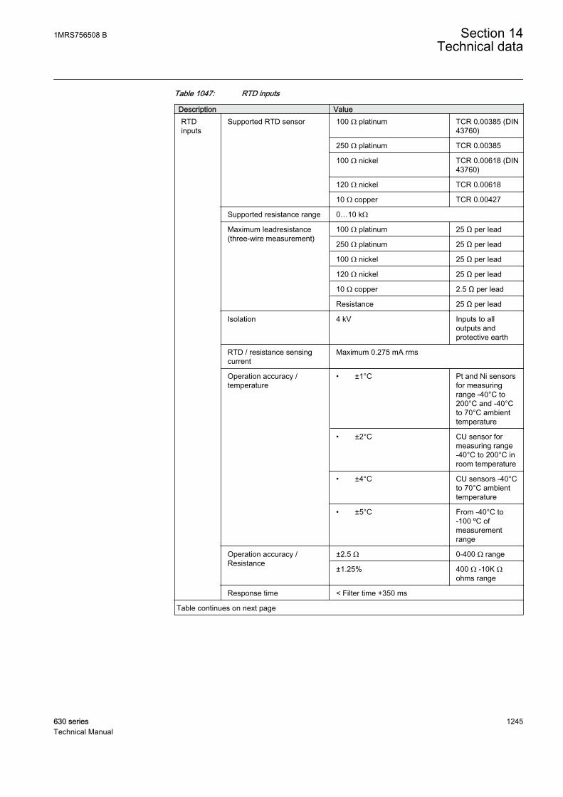
Table 1047: RTD inputs
Description ValueRTDinputs
Supported RTD sensor 100 Ω platinum TCR 0.00385 (DIN43760)
250 Ω platinum TCR 0.00385
100 Ω nickel TCR 0.00618 (DIN43760)
120 Ω nickel TCR 0.00618
10 Ω copper TCR 0.00427
Supported resistance range 0…10 kΩ
Maximum leadresistance(three-wire measurement)
100 Ω platinum 25 Ω per lead
250 Ω platinum 25 Ω per lead
100 Ω nickel 25 Ω per lead
120 Ω nickel 25 Ω per lead
10 Ω copper 2.5 Ω per lead
Resistance 25 Ω per lead
Isolation 4 kV Inputs to alloutputs andprotective earth
RTD / resistance sensingcurrent
Maximum 0.275 mA rms
Operation accuracy /temperature
• ±1°C Pt and Ni sensorsfor measuringrange -40°C to200°C and -40°Cto 70°C ambienttemperature
• ±2°C CU sensor formeasuring range-40°C to 200°C inroom temperature
• ±4°C CU sensors -40°Cto 70°C ambienttemperature
• ±5°C From -40°C to-100 ºC ofmeasurementrange
Operation accuracy /Resistance
±2.5 Ω 0-400 Ω range
±1.25% 400 Ω -10K Ωohms range
Response time < Filter time +350 ms
Table continues on next page
1MRS756508 B Section 14Technical data
630 series 1245Technical Manual
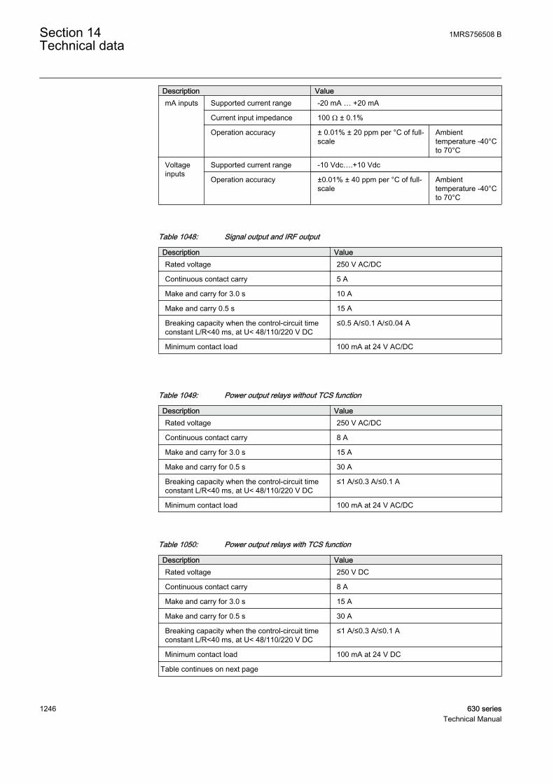
Description ValuemA inputs Supported current range -20 mA … +20 mA
Current input impedance 100 Ω ± 0.1%
Operation accuracy ± 0.01% ± 20 ppm per °C of full-scale
Ambienttemperature -40°Cto 70°C
Voltageinputs
Supported current range -10 Vdc….+10 Vdc
Operation accuracy ±0.01% ± 40 ppm per °C of full-scale
Ambienttemperature -40°Cto 70°C
Table 1048: Signal output and IRF output
Description ValueRated voltage 250 V AC/DC
Continuous contact carry 5 A
Make and carry for 3.0 s 10 A
Make and carry 0.5 s 15 A
Breaking capacity when the control-circuit timeconstant L/R<40 ms, at U< 48/110/220 V DC
≤0.5 A/≤0.1 A/≤0.04 A
Minimum contact load 100 mA at 24 V AC/DC
Table 1049: Power output relays without TCS function
Description ValueRated voltage 250 V AC/DC
Continuous contact carry 8 A
Make and carry for 3.0 s 15 A
Make and carry for 0.5 s 30 A
Breaking capacity when the control-circuit timeconstant L/R<40 ms, at U< 48/110/220 V DC
≤1 A/≤0.3 A/≤0.1 A
Minimum contact load 100 mA at 24 V AC/DC
Table 1050: Power output relays with TCS function
Description ValueRated voltage 250 V DC
Continuous contact carry 8 A
Make and carry for 3.0 s 15 A
Make and carry for 0.5 s 30 A
Breaking capacity when the control-circuit timeconstant L/R<40 ms, at U< 48/110/220 V DC
≤1 A/≤0.3 A/≤0.1 A
Minimum contact load 100 mA at 24 V DC
Table continues on next page
Section 14 1MRS756508 BTechnical data
1246 630 seriesTechnical Manual
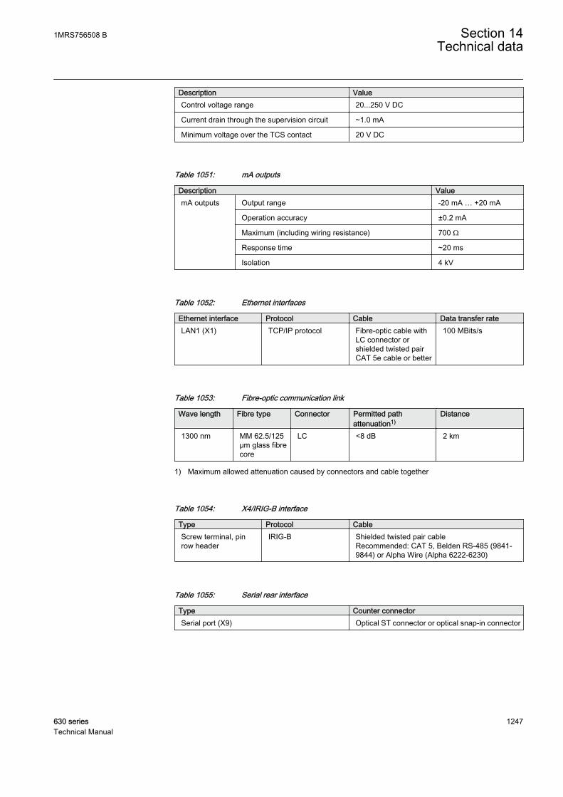
Description ValueControl voltage range 20...250 V DC
Current drain through the supervision circuit ~1.0 mA
Minimum voltage over the TCS contact 20 V DC
Table 1051: mA outputs
Description ValuemA outputs Output range -20 mA … +20 mA
Operation accuracy ±0.2 mA
Maximum (including wiring resistance) 700 Ω
Response time ~20 ms
Isolation 4 kV
Table 1052: Ethernet interfaces
Ethernet interface Protocol Cable Data transfer rateLAN1 (X1) TCP/IP protocol Fibre-optic cable with
LC connector orshielded twisted pairCAT 5e cable or better
100 MBits/s
Table 1053: Fibre-optic communication link
Wave length Fibre type Connector Permitted pathattenuation1)
Distance
1300 nm MM 62.5/125μm glass fibrecore
LC <8 dB 2 km
1) Maximum allowed attenuation caused by connectors and cable together
Table 1054: X4/IRIG-B interface
Type Protocol CableScrew terminal, pinrow header
IRIG-B Shielded twisted pair cableRecommended: CAT 5, Belden RS-485 (9841-9844) or Alpha Wire (Alpha 6222-6230)
Table 1055: Serial rear interface
Type Counter connectorSerial port (X9) Optical ST connector or optical snap-in connector
1MRS756508 B Section 14Technical data
630 series 1247Technical Manual
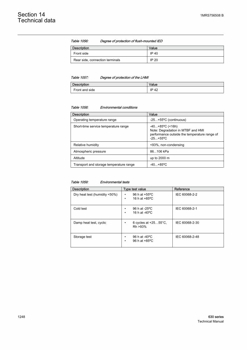
Table 1056: Degree of protection of flush-mounted IED
Description ValueFront side IP 40
Rear side, connection terminals IP 20
Table 1057: Degree of protection of the LHMI
Description ValueFront and side IP 42
Table 1058: Environmental conditions
Description ValueOperating temperature range -25...+55ºC (continuous)
Short-time service temperature range -40...+85ºC (<16h)Note: Degradation in MTBF and HMIperformance outside the temperature range of-25...+55ºC
Relative humidity <93%, non-condensing
Atmospheric pressure 86...106 kPa
Altitude up to 2000 m
Transport and storage temperature range -40...+85ºC
Table 1059: Environmental tests
Description Type test value ReferenceDry heat test (humidity <50%) • 96 h at +55ºC
• 16 h at +85ºCIEC 60068-2-2
Cold test • 96 h at -25ºC• 16 h at -40ºC
IEC 60068-2-1
Damp heat test, cyclic • 6 cycles at +25…55°C,Rh >93%
IEC 60068-2-30
Storage test • 96 h at -40ºC• 96 h at +85ºC
IEC 60068-2-48
Section 14 1MRS756508 BTechnical data
1248 630 seriesTechnical Manual
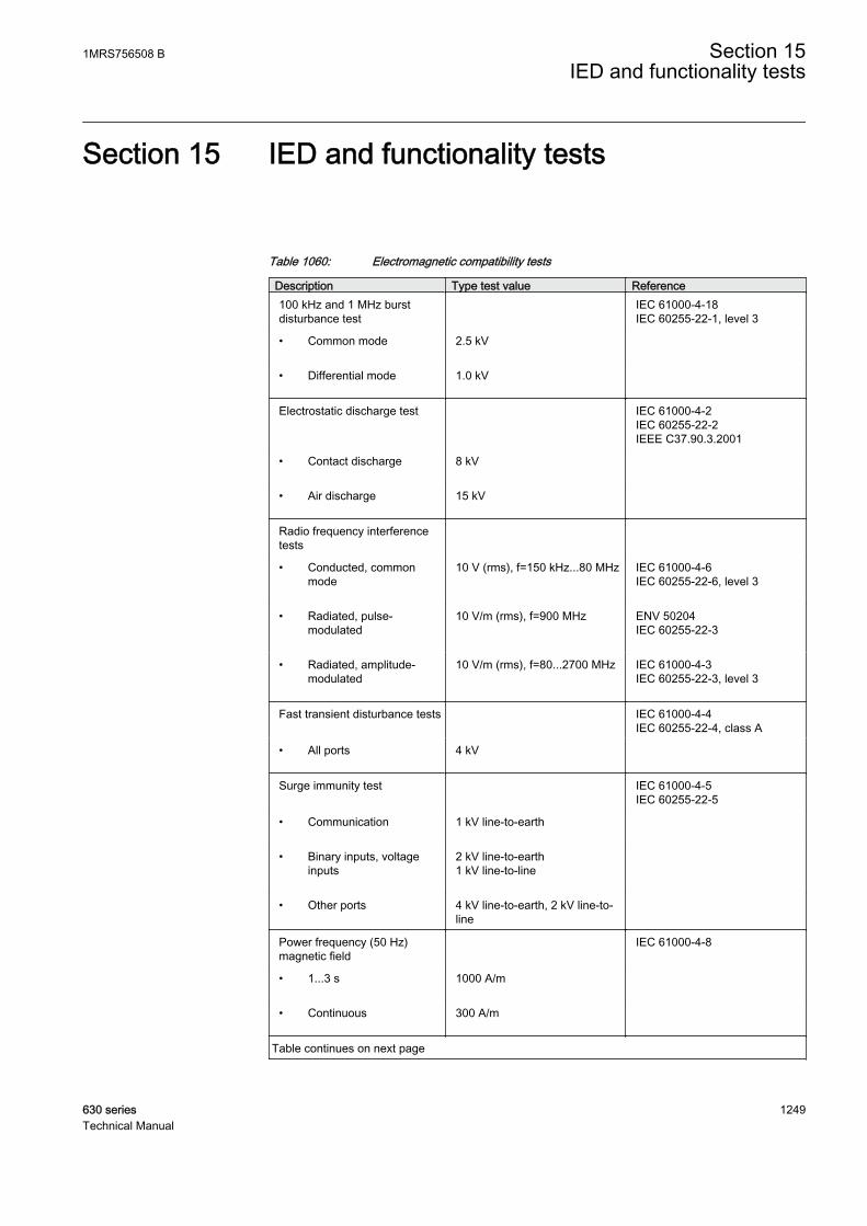
Section 15 IED and functionality tests
Table 1060: Electromagnetic compatibility tests
Description Type test value Reference100 kHz and 1 MHz burstdisturbance test
IEC 61000-4-18IEC 60255-22-1, level 3
• Common mode 2.5 kV
• Differential mode 1.0 kV
Electrostatic discharge test IEC 61000-4-2IEC 60255-22-2IEEE C37.90.3.2001
• Contact discharge 8 kV
• Air discharge 15 kV
Radio frequency interferencetests
• Conducted, commonmode
10 V (rms), f=150 kHz...80 MHz IEC 61000-4-6IEC 60255-22-6, level 3
• Radiated, pulse-modulated
10 V/m (rms), f=900 MHz ENV 50204IEC 60255-22-3
• Radiated, amplitude-modulated
10 V/m (rms), f=80...2700 MHz IEC 61000-4-3IEC 60255-22-3, level 3
Fast transient disturbance tests IEC 61000-4-4IEC 60255-22-4, class A
• All ports 4 kV
Surge immunity test IEC 61000-4-5IEC 60255-22-5
• Communication 1 kV line-to-earth
• Binary inputs, voltageinputs
2 kV line-to-earth1 kV line-to-line
• Other ports 4 kV line-to-earth, 2 kV line-to-line
Power frequency (50 Hz)magnetic field
IEC 61000-4-8
• 1...3 s 1000 A/m
• Continuous 300 A/m
Table continues on next page
1MRS756508 B Section 15IED and functionality tests
630 series 1249Technical Manual
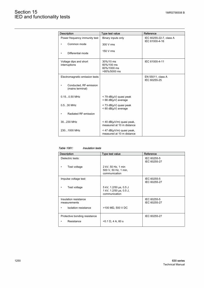
Description Type test value ReferencePower frequency immunity test
• Common mode
• Differential mode
Binary inputs only 300 V rms 150 V rms
IEC 60255-22-7, class AIEC 61000-4-16
Voltage dips and shortinterruptions
30%/10 ms60%/100 ms60%/1000 ms>95%/5000 ms
IEC 61000-4-11
Electromagnetic emission tests EN 55011, class AIEC 60255-25
• Conducted, RF-emission(mains terminal)
0.15...0.50 MHz < 79 dB(µV) quasi peak< 66 dB(µV) average
0.5...30 MHz < 73 dB(µV) quasi peak< 60 dB(µV) average
• Radiated RF-emission
30...230 MHz < 40 dB(µV/m) quasi peak,measured at 10 m distance
230...1000 MHz < 47 dB(µV/m) quasi peak,measured at 10 m distance
Table 1061: Insulation tests
Description Type test value ReferenceDielectric tests: IEC 60255-5
IEC 60255-27
• Test voltage 2 kV, 50 Hz, 1 min500 V, 50 Hz, 1 min,communication
Impulse voltage test: IEC 60255-5IEC 60255-27
• Test voltage 5 kV, 1.2/50 μs, 0.5 J1 kV, 1.2/50 μs, 0.5 J,communication
Insulation resistancemeasurements
IEC 60255-5IEC 60255-27
• Isolation resistance >100 MΏ, 500 V DC
Protective bonding resistance IEC 60255-27
• Resistance <0.1 Ώ, 4 A, 60 s
Section 15 1MRS756508 BIED and functionality tests
1250 630 seriesTechnical Manual
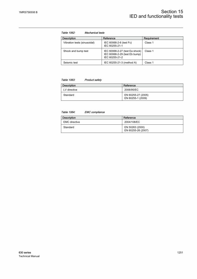
Table 1062: Mechanical tests
Description Reference RequirementVibration tests (sinusoidal) IEC 60068-2-6 (test Fc)
IEC 60255-21-1Class 1
Shock and bump test IEC 60068-2-27 (test Ea shock)IEC 60068-2-29 (test Eb bump)IEC 60255-21-2
Class 1
Seismic test IEC 60255-21-3 (method A) Class 1
Table 1063: Product safety
Description ReferenceLV directive 2006/95/EC
Standard EN 60255-27 (2005)EN 60255-1 (2009)
Table 1064: EMC compliance
Description ReferenceEMC directive 2004/108/EC
Standard EN 50263 (2000)EN 60255-26 (2007)
1MRS756508 B Section 15IED and functionality tests
630 series 1251Technical Manual

1252

Section 16 Applicable standards and regulations
EN 50263
EN 60255-26
EN 60255-27
EMC council directive 2004/108/EC
EU directive 2002/96/EC/175
IEC 60255
Low-voltage directive 2006/95/EC
1MRS756508 B Section 16Applicable standards and regulations
630 series 1253Technical Manual

1254
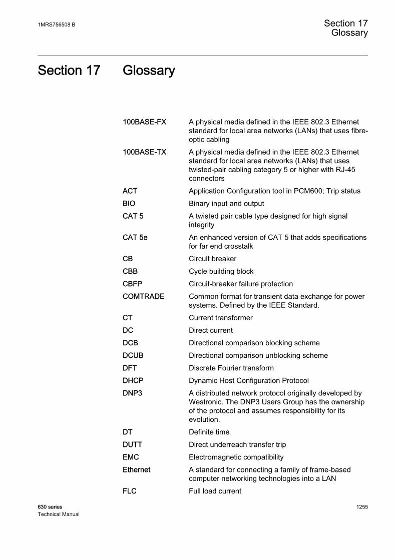
Section 17 Glossary
100BASE-FX A physical media defined in the IEEE 802.3 Ethernetstandard for local area networks (LANs) that uses fibre-optic cabling
100BASE-TX A physical media defined in the IEEE 802.3 Ethernetstandard for local area networks (LANs) that usestwisted-pair cabling category 5 or higher with RJ-45connectors
ACT Application Configuration tool in PCM600; Trip statusBIO Binary input and outputCAT 5 A twisted pair cable type designed for high signal
integrityCAT 5e An enhanced version of CAT 5 that adds specifications
for far end crosstalkCB Circuit breakerCBB Cycle building blockCBFP Circuit-breaker failure protectionCOMTRADE Common format for transient data exchange for power
systems. Defined by the IEEE Standard.CT Current transformerDC Direct currentDCB Directional comparison blocking schemeDCUB Directional comparison unblocking schemeDFT Discrete Fourier transformDHCP Dynamic Host Configuration ProtocolDNP3 A distributed network protocol originally developed by
Westronic. The DNP3 Users Group has the ownershipof the protocol and assumes responsibility for itsevolution.
DT Definite timeDUTT Direct underreach transfer tripEMC Electromagnetic compatibilityEthernet A standard for connecting a family of frame-based
computer networking technologies into a LANFLC Full load current
1MRS756508 B Section 17Glossary
630 series 1255Technical Manual
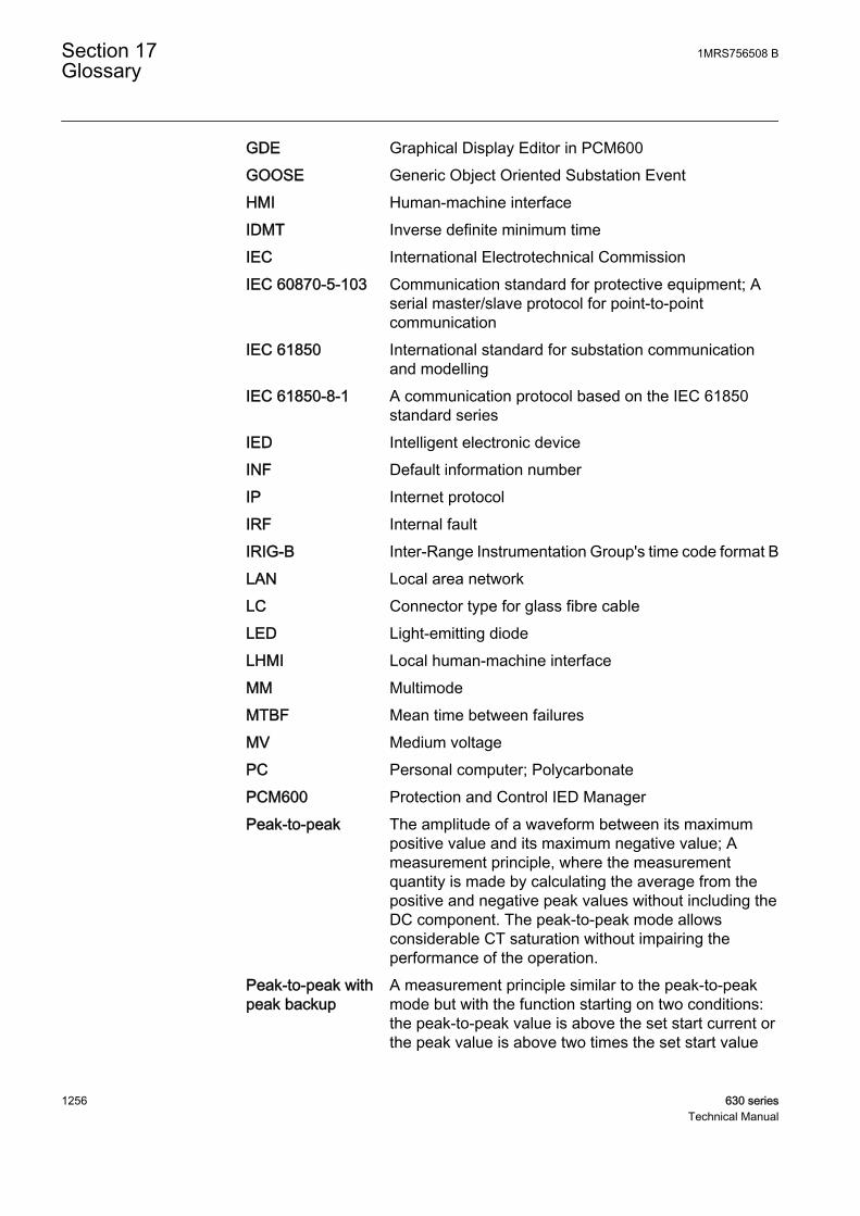
GDE Graphical Display Editor in PCM600GOOSE Generic Object Oriented Substation EventHMI Human-machine interfaceIDMT Inverse definite minimum timeIEC International Electrotechnical CommissionIEC 60870-5-103 Communication standard for protective equipment; A
serial master/slave protocol for point-to-pointcommunication
IEC 61850 International standard for substation communicationand modelling
IEC 61850-8-1 A communication protocol based on the IEC 61850standard series
IED Intelligent electronic deviceINF Default information numberIP Internet protocolIRF Internal faultIRIG-B Inter-Range Instrumentation Group's time code format BLAN Local area networkLC Connector type for glass fibre cableLED Light-emitting diodeLHMI Local human-machine interfaceMM MultimodeMTBF Mean time between failuresMV Medium voltagePC Personal computer; PolycarbonatePCM600 Protection and Control IED ManagerPeak-to-peak The amplitude of a waveform between its maximum
positive value and its maximum negative value; Ameasurement principle, where the measurementquantity is made by calculating the average from thepositive and negative peak values without including theDC component. The peak-to-peak mode allowsconsiderable CT saturation without impairing theperformance of the operation.
Peak-to-peak withpeak backup
A measurement principle similar to the peak-to-peakmode but with the function starting on two conditions:the peak-to-peak value is above the set start current orthe peak value is above two times the set start value
Section 17 1MRS756508 BGlossary
1256 630 seriesTechnical Manual

POTT Permissive overreach transfer tripPST Parameter Setting tool in PCM600PUTT Permissive underreach transfer tripRCA Also known as MTA or base angle. Characteristic angle.RJ-45 Galvanic connector typeRMS Root-mean-square (value)RS-485 Serial link according to EIA standard RS485RTD Resistance temperature detectorRx Receive/ReceivedSNTP Simple Network Time ProtocolSOTF Switch on to faultST Connector type for glass fibre cableTCP/IP Transmission Control Protocol/Internet ProtocolTCS Trip-circuit supervisionTRMS True root-mean-square (value)Tx Transmit/TransmittedUTC Coordinated universal timeVT Voltage transformerWAN Wide area networkWEI Weak-end infeed logicWHMI Web human-machine interface
1MRS756508 B Section 17Glossary
630 series 1257Technical Manual

1258

1259


Contact us
ABB OyDistribution AutomationP.O. Box 699FI-65101 VAASA, FinlandPhone +358 10 22 11Fax +358 10 22 41094
www.abb.com/substationautomation
1MR
S75
6508
B©
Cop
yrig
ht 2
011
AB
B. A
ll rig
hts
rese
rved
.