PCS100 AVC-40 1B UL Technical Catalogue - ABB
29
— 2UCD074000E009_B PCS100 AVC-40 1B UL Active Voltage Conditioner Technical Catalogue © Copyright 2022 ABB, All rights reserved. — PCS100 AVC-40 225 kVA to 300 kVA
-
Upload
khangminh22 -
Category
Documents
-
view
0 -
download
0
Transcript of PCS100 AVC-40 1B UL Technical Catalogue - ABB

— 2UCD074000E009_B
PCS100 AVC-40 1B UL
Active Voltage Conditioner
Technical Catalogue
© Copyright 2022 ABB, All rights reserved. —
PC
S1
00
AV
C-4
0
22
5 k
VA
to
30
0 k
VA

2 PCS100 AVC-40 1B UL Technical Catalogue
— ABOUT THIS DOCUMENT
ABB Power Conditioning Leading the industry in innovation and technology, ABB provides power conditioning for many of the world’s
foremost organizations, ensuring the continuous operation of small, medium to large businesses are protected
on a global scale.
ABB’s Power Conditioning portfolio is a unique line up of low and medium voltage power conversion technology
that is part of the product group, Power Protection.
The portfolio consists of static frequency converters, UPSs, voltage and power conditioners that demonstrate
highly reliable and cost-effective performance. With this product portfolio, ABB offer efficient power conditioning
solutions that are specifically designed to solve power quality problems and stabilize networks.
Covering applications from data centers through to complete industrial plant protection, micro grid systems and
shore-to-ship supply, ABB have the power conversion technology for every need. Starting from a few kVA to many
MVA and a wide range of supply voltages.
It’s business as usual with power conditioning technologies in place
Power Conditioning Product Portfolio
Product Line Typical Problems Product
Industrial UPS
Utility deep sag and surge
correction
Utility outage protection
PCS100 UPS-I Industrial UPS
HiPerGuard MV UPS
Voltage conditioning Utility sag and surge correction
Load voltage regulation
PCS100 AVC-40 Active Voltage Conditioner for sag correction
PCS100 AVC-20 Active Voltage Conditioner for voltage regulation
Frequency
Conversion
50/60 Hz conversion
Frequency fluctuation
PCS100 SFC Static Frequency Converter
SureWave SFC
htt
ps:
//
ne
w.a
bb
.co
m/
up
s/

PCS100 AVC-40 1B UL Technical Catalogue 3
—
Document Information
Copyright notice The information in this manual is subject to change without notice. This manual and parts thereof must not be re-
produced or copied, or disclosed to third parties, nor used for any unauthorized purpose without written permis-
sion from ABB Ltd. The hardware and software described in this manual are provided under a license and may be
used, copied, or disclosed only in accordance with the terms of such license.
Document identification Ownership: ABB Ltd., Power Conditioning Products
Document number: 2UCD74000E009
Ownership: ABB Ltd., Power Conditioning Products
Issue date: 3/31/2022
Revision: Rev B
Contact information Address: ABB Ltd. 111 Main North Road, Napier, New Zealand.
Website: https://new.abb.com/ups
htt
ps:
//
ne
w.a
bb
.co
m/
up
s/

4 PCS100 AVC-40 1B UL Technical Catalogue
—
Contents
About This Document ......................................................................................................................................................... 2 ABB Power Conditioning ........................................................................................................................................................................................ 2 Power Conditioning Product Portfolio ............................................................................................................................................................... 2 Document Information ........................................................................................................................................................................................... 3
Voltage Sags – The Problem .............................................................................................................................................. 6
PCS100 AVC-40 1B Active Voltage Conditioner .............................................................................................................. 7 How it works .............................................................................................................................................................................................................. 7
PCS100 AVC-40 1B Benefits ............................................................................................................................................... 8 Reduce the cost of sag events .............................................................................................................................................................................. 8 Improve plant operation ........................................................................................................................................................................................ 8 Faster return on investment ................................................................................................................................................................................. 8 Reduce damage to equipment.............................................................................................................................................................................. 8
Industries and Applications ............................................................................................................................................... 9
Features 10 No energy storage ................................................................................................................................................................................................. 10 Very high efficiency ............................................................................................................................................................................................... 10 Continuous online regulation .............................................................................................................................................................................. 10 Industrial design .................................................................................................................................................................................................... 10 Small footprint ....................................................................................................................................................................................................... 10 Regenerative load support .................................................................................................................................................................................. 10 Internal bypass ....................................................................................................................................................................................................... 10 Connectivity ............................................................................................................................................................................................................ 10 Modular construction ........................................................................................................................................................................................... 10 Sophisticated control software .......................................................................................................................................................................... 10
Functional Description ..................................................................................................................................................... 11 PCS100 AVC-40 Correction Capabilities ............................................................................................................................................................ 11 PCS100 AVC-40 Performance Curve ................................................................................................................................................................... 11 PCS100 AVC-40 Operation Details ...................................................................................................................................................................... 12
Technical Specification .................................................................................................................................................... 14
How to Select a PCS100 AVC-40 ..................................................................................................................................... 16 Type Code ................................................................................................................................................................................................................ 16 Type Code Parameters: ........................................................................................................................................................................................ 16 PCS100 AVC Sizing Tool ....................................................................................................................................................................................... 16
PCS100 AVC-40 1B Model Range ..................................................................................................................................... 17
Layout Plans and Dimensions .......................................................................................................................................... 18 Layout Plans ............................................................................................................................................................................................................ 18 Clearance ................................................................................................................................................................................................................. 19 Weights .................................................................................................................................................................................................................... 19
Options 20 Roof Kit (RK)............................................................................................................................................................................................................ 20 ShellPlus (SP) .......................................................................................................................................................................................................... 20 Redundant Power Supply Unit (PS) .................................................................................................................................................................... 20
User Interface .................................................................................................................................................................... 21 Graphic Display Module ......................................................................................................................................................................................... 21 Remote Monitoring ................................................................................................................................................................................................ 21 Remote Web Pages ................................................................................................................................................................................................ 22 Modbus TCP ............................................................................................................................................................................................................ 22 E-mail ........................................................................................................................................................................................................................ 22
User Connections .............................................................................................................................................................. 23 Power Connections ............................................................................................................................................................................................... 23
htt
ps:
//
ne
w.a
bb
.co
m/
up
s/

PCS100 AVC-40 1B UL Technical Catalogue 5
Control Connections ............................................................................................................................................................................................. 23
Installation Requirements................................................................................................................................................ 25 Input Circuit Protection ........................................................................................................................................................................................ 25 Maintenance Bypass ............................................................................................................................................................................................. 25 Floor Requirements ............................................................................................................................................................................................... 25 Location ................................................................................................................................................................................................................... 25 Power System ......................................................................................................................................................................................................... 25 Electromagnetic Compatibility (EMC) .............................................................................................................................................................. 25 Harmonics ............................................................................................................................................................................................................... 25 Downstream Capacitor Banks ............................................................................................................................................................................ 26
Service and Technical Support ........................................................................................................................................ 27 Comprehensive global services portfolio ......................................................................................................................................................... 27 Custom tailored service contracts ..................................................................................................................................................................... 27 Life cycle management ......................................................................................................................................................................................... 27 Training .................................................................................................................................................................................................................... 27 Engineering and technical support .................................................................................................................................................................... 27
Additional Documents ...................................................................................................................................................... 28

6 PCS100 AVC-40 1B UL Technical Catalogue
— VOLTAGE SAGS – THE PROBLEM Modern industries are becoming more automated
and the sensitivity of processes to power quality
events is increasing. Although utilities endeavor to
supply reliable, high-quality power, voltage sags and
surges will continue to be a fact of life, even with
modern power networks. Even a short event of less
than one cycle can cause processes to unexpectedly
stop, potentially resulting in product damage,
wastage, and production shortages.
A voltage sag is not a complete interruption of
power; it is a temporary drop below 90 percent of
the nominal voltage level. Most voltage sags do not
go below 50 percent of the nominal voltage, and
they normally last from 2 to 10 cycles - or from 32 to
200 milliseconds.
There are two sources of voltage sags: external, on
the utility’s transmission and distribution lines, and
internal within the customer’s facility.
Utilities continuously strive to provide the most
reliable and consistent electric power possible. In
the course of normal utility operations, however,
many things can cause voltage sags.
Weather is the most common cause of external sags
and momentary interruptions all around the world.
Thunderstorms and lightning strikes on power lines
create line to ground faults causing voltage sags in a
wide area.
High winds can blow tree branches into power lines,
connecting the line with the ground and shorting
between phases. A series of sags will occur as the
branches repeatedly touch the power lines.
Snow and ice buildup on power lines can cause flash
overs on the insulators.
Other external causes are traffic accidents,
construction works and animals impacting the
power lines.
Internal causes of voltage sags can include starting
major loads and grounding or wiring problems.
Whether or not a voltage sag causes a problem will
depend on the magnitude and duration of the sag
and on the sensitivity of your equipment. Many
types of electronic equipment are sensitive to
voltage sags, including variable speed drive controls,
motor starter contactors, robotics, programmable
logic controllers, controller power supplies, and
control relays. Much of this equipment is used in
applications that are critical to an overall process,
which can lead to very expensive downtime when
voltage sags occur.

PCS100 AVC-40 1B UL Technical Catalogue 7
— PCS100 AVC-40 1B ACTIVE VOLTAGE CONDITIONER The ABB PCS100 AVC-40 1B is an inverter-based
system that protects sensitive industrial and
commercial loads from voltage disturbances.
Providing fast, accurate voltage sag and surge
correction as well as continuous voltage regulation
and load voltage compensation. The PCS100 AVC-40
1B has been optimally designed to provide
equipment immunity from power quality events on
the supply network.
Power supply after PCS100 AVC-40 1B
Sag Corrected
Power supply before PCS100 AVC-40 1B
Sag Occurs
How it works The PCS100 AVC-40 1B consists of two converters
that are not on the current path between the load
and the utility. Instead, the corrective voltage
injection is achieved by means of a transformer
winding between the utility and the sensitive load.
This configuration results in a very efficient and
effective method to provide voltage correction with
reduced risk of negative impacts on the load.
The PCS100 AVC-40 1B requires no batteries as it
draws the additional energy required during sag to
make up the correction voltage from the utility
supply. With no ongoing maintenance costs
typically associated with batteries the cost of
ownership for PCS100 AVC-40 1B systems is very
small.
Furthermore, the PCS100 AVC-40 1B contains a
redundant internal bypass system that, in the event
of overload or internal fault condition, ensures that
the load is continued to be supplied from the utility
Autotransformer(208 V models only)
Bypass
Inverter
Rectifier
Distribution Transformer
PCS100 AVC-40 1B
Input Circuit
Breaker
3-phase Utility Supply
3-phase Load
Injection Transformer
Neutral connection to
load if required

8 PCS100 AVC-40 1B UL Technical Catalogue
— PCS100 AVC-40 1B BENEFITS
Reduce the cost of sag events The PCS100 AVC-40 1B closes the electrical
compatibility gap between the supply and plant by
protecting the load from utility induced voltage sag
events. The PCS100 AVC-40 1B minimizes the undue
stress to the expensive equipment, thus increasing
the equipment lifetime.
With high power capacity, the PCS100 AVC-40 1B is a
perfect solution for industrial loads using significant
power as well as large commercial buildings where
continuity of service is paramount. The PCS100 AVC-
40 1B is designed to target voltage sag events while
also providing protection against swells. Sag events
is the major cause of lost production.
Improve plant operation The PCS100 AVC-40 1B regulates the voltage,
removing long term undervoltage, overvoltage and
voltage imbalance to reduce waste and damage to
the expensive equipment. It also removes voltage
fluctuations, which can cause process variation,
improving the quality of operation of the plant or
the facility.
Faster return on investment With industry leading efficiency exceeding 98
percent the PCS100 AVC-40 1B requires minimal
costs for electricity and cooling. With no energy
storage the ongoing maintenance cost is minimized,
resulting low total cost of ownership.
Reduce damage to equipment Protect expensive equipment by regulating the
voltage to remove long term undervoltage,
overvoltage and voltage imbalance
PCS100 AVC-40 1B UL Technical Catalogue 9
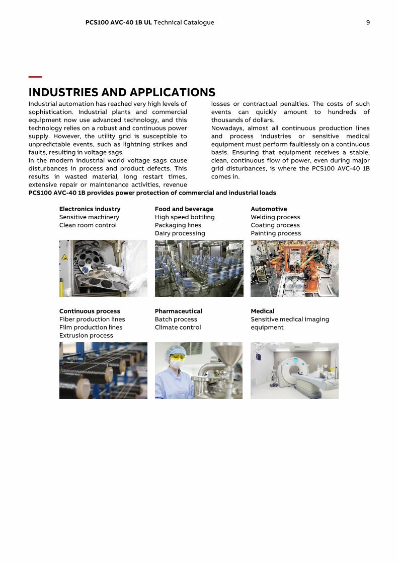
— INDUSTRIES AND APPLICATIONS Industrial automation has reached very high levels of
sophistication. Industrial plants and commercial
equipment now use advanced technology, and this
technology relies on a robust and continuous power
supply. However, the utility grid is susceptible to
unpredictable events, such as lightning strikes and
faults, resulting in voltage sags.
In the modern industrial world voltage sags cause
disturbances in process and product defects. This
results in wasted material, long restart times,
extensive repair or maintenance activities, revenue
losses or contractual penalties. The costs of such
events can quickly amount to hundreds of
thousands of dollars.
Nowadays, almost all continuous production lines
and process industries or sensitive medical
equipment must perform faultlessly on a continuous
basis. Ensuring that equipment receives a stable,
clean, continuous flow of power, even during major
grid disturbances, is where the PCS100 AVC-40 1B
comes in.
PCS100 AVC-40 1B provides power protection of commercial and industrial loads
Electronics industry
Sensitive machinery
Clean room control
Food and beverage
High speed bottling
Packaging lines
Dairy processing
Automotive
Welding process
Coating process
Painting process
Continuous process
Fiber production lines
Film production lines
Extrusion process
Pharmaceutical
Batch process
Climate control
Medical
Sensitive medical imaging
equipment

10 PCS100 AVC-40 1B UL Technical Catalogue
— FEATURES
No energy storage Increased system reliability with minimized
maintenance
Very high efficiency Typically, >98% even on partial loading
Continuous online regulation Continuous regulation within ±10% with response
less than 250 μs and correction in less than ½ cycle
Industrial design Rugged overload capability, industrial grade fault
capacity, designed for industrial loads
Small footprint Industry leading power density
Regenerative load support Bidirectional power module design allows
connection of regenerative loads such as lifts and
cranes
Internal bypass Redundant internal bypass design guaranteeing
continuity of load supply in case of PCS100 AVC-40
1B fault
Connectivity Ethernet
Modbus TCP
Integrated web server
E-mail notifications
Modular construction Proven PCS100 power converter platform, with more
than 1800 MVA installed base, enabling fast and easy
maintenance
Sophisticated control software Based on 20 years voltage conditioning industry
experience

PCS100 AVC-40 1B UL Technical Catalogue 11
— FUNCTIONAL DESCRIPTION
PCS100 AVC-40 Correction Capabilities The PCS100 AVC-40 responds to voltage sags or
swells within several milliseconds and can inject up
to 40 percent voltage correction. If a facility was
faced with a voltage sag to 60 percent of nominal
voltage the PCS100 AVC-40 would boost the voltage
back to 100 percent. Voltage sags with 50 per-cent
of nominal voltage are corrected back to 90 percent.
No process interruption, no equipment would trip,
just business as usual.
Performance is even better for single phase sags
(the most common type), voltage sags down to 40
percent of the nominal voltage are fully corrected.
In case of deeper voltage sags, The PCS100 AVC-40
provides a partial correction, which will often
prevent loads tripping. In addition, it can
continuously correct voltage fluctuations of ±10
percent of nominal and remove imbalances.
Utility Supply Problem Input Output Correction Time
Three-phase utility sags correction
from
60% remaining supply voltage 100% 30 seconds
50% remaining supply voltage 90% 10 seconds
40% remaining supply voltage 70% 600 milliseconds
Single-phase utility sags correction
from
40% remaining voltage 100% 30 seconds
0% remaining voltage 57% 600 milliseconds
Single-phase utility swells correction from 115% voltage 100% Continuous
Three-phase utility undervoltage to 90% of the nominal supply voltage 100% Continuous
Three-phase utility overvoltage up to 110% of the nominal supply voltage 100% Continuous
Correction of phase angle errors created by faults in the supply system Yes
Correction of voltage imbalance from utility supply Yes
Attenuation of flicker voltages in the utility supply Yes
PCS100 AVC-40 Performance Curve
10%
20%
30%
40%
50%
60%
70%
80%
90%
100%
110%
0%
120%
20%
30%
40%
50%
60%
70%
80%
90%
100% 110%10%
10
20
30
40
50
0
60
70
80
90
PC
S10
0 A
VC
-40
co
rre
cti
on
tim
e (
s)
PCS100 AVC-40 Output Voltage (Line to Line)
PCS100 AVC-40 Input Voltage (Line to Line)
600 ms
PCS100 AVC-40 Bypass Operation
Region
PCS100 AVC-40 Continuous Regulation
Region
1.0 Power Factor 480 V models0.8 Power Factor 400 V and 208 V models
PC
S10
0 A
VC
-40
By
pa
ss
Op
era
tio
n R
eg
ion
PCS100 AVC-40 Output Voltage
Correction time
Three Phase Balanced Events
The performance curves on the left
apply to three phase balanced supply
voltage disturbances upstream of
the PCS100 AVC-40.

12 PCS100 AVC-40 1B UL Technical Catalogue
10%
20%
30%
40%
50%
60%
70%
80%
90%
100%
110%
0%
120%
20% 30% 40% 50% 60% 70% 80% 90% 100% 110%10%
10
20
30
40
50
0
60
70
80
90
PC
S10
0 A
VC
-40
co
rre
cti
on
tim
e (
s)
PCS100 AVC-40 Output Voltage (Line to Line)
L-N Utility Voltage (Line to Neutral)
600 ms
1.0 Power Factor 480 V models0.8 Power Factor 400 V and 208 V models
PCS100 AVC-40 Continuous Regulation
Region
Correction time
PCS100 AVC-40 Output Voltage L1-L2, L2-L3
PCS100 AVC-40 Output Voltage L3-L1
Single-Line-To-Ground Events
The performance curves on the left
apply to single-line-to-ground supply
voltage disturbances upstream of
the Dyn11 distribution transformer
upstream of PCS100 AVC-40.
PCS100 AVC-40 Operation Details The following diagrams show the PCS100 AVC-40 operation when a utility disturbance occurs, and operation of
the internal bypass.
Utility Disturbance Occurs
When the utility voltage deviates from
nominal or the set point due to a power
quality event, the inverter will inject a
correcting voltage via the Injection
Transformer. The correcting voltage level is
based on the disturbance level and the
energy needed for correction is sourced
from the utility via the PCS100 AVC-40
rectifier.
Diagrams on the left show cases with utility
voltage below and above nominal level.
Utility voltagePCS100 AVC-40 compensating voltage Load voltage
Distribution Transformer
Injection Transformer
3-phaseLoad
Bypass open
3-phase Utility Supply
Utility voltagePCS100 AVC-40 compensating voltage Load voltage
Distribution Transformer
Injection Transformer
3-phaseLoad
Bypass open
3-phase Utility Supply

PCS100 AVC-40 1B UL Technical Catalogue 13
Utility Voltage within Continuous
Regulation Range
When the utility voltage is within continuous
regulation region (< ±10%), the PCS100 AVC-
40 can indefinitely add compensating
voltage. Distribution Transformer
Injection Transformer
3-phaseLoad
Bypass open
3-phase Utility Supply
Utility voltagePCS100 AVC-40 compensating voltage Load voltage
Internal Bypass Operation
In the case of an overload or internal fault
condition the internal bypass circuit will
shunt the inverter side of the Injection
Transformer, bypassing the inverter and
effectively providing a direct connection
from the utility supply to Distribution Transformer
Injection Transformer
3-phaseLoad
Bypass closed
3-phase Utility Supply
Utility voltagePCS100 AVC-40
compensating voltageLoad voltage
14 PCS100 AVC-40 1B UL Technical Catalogue
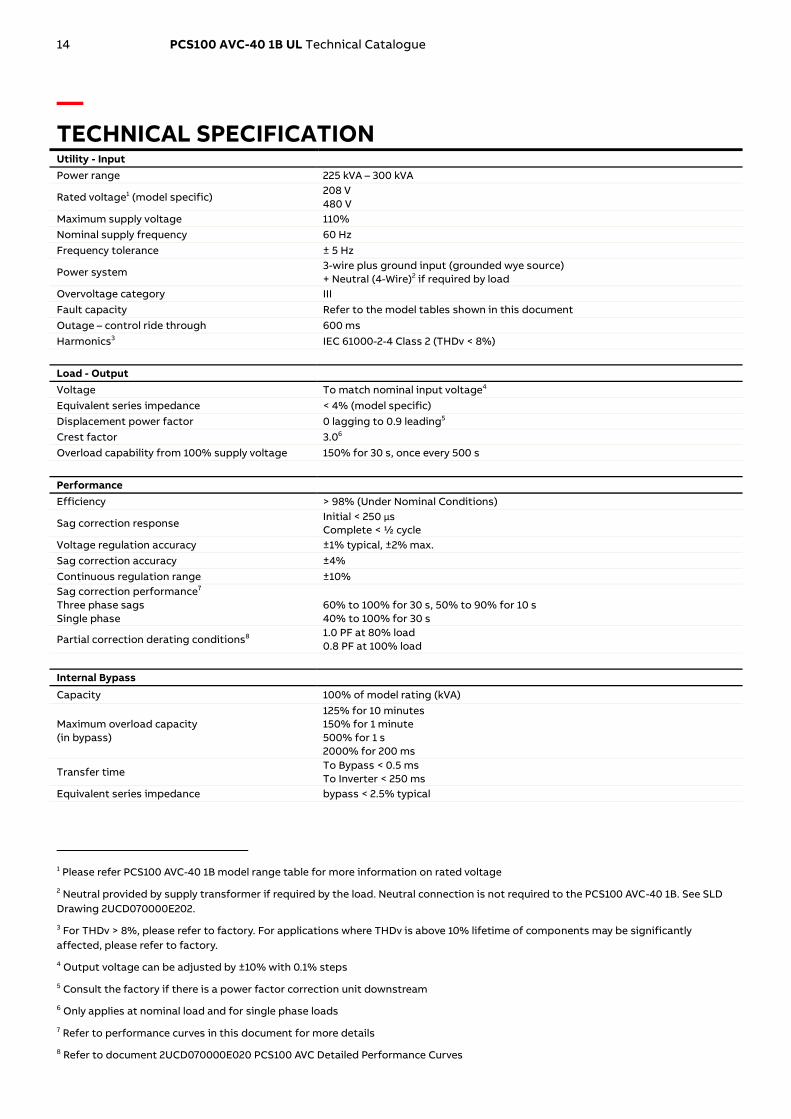
— TECHNICAL SPECIFICATION Utility - Input
Power range 225 kVA – 300 kVA
Rated voltage1 (model specific) 208 V
480 V
Maximum supply voltage 110%
Nominal supply frequency 60 Hz
Frequency tolerance ± 5 Hz
Power system 3-wire plus ground input (grounded wye source) + Neutral (4-Wire)2 if required by load
Overvoltage category III
Fault capacity Refer to the model tables shown in this document
Outage – control ride through 600 ms
Harmonics3 IEC 61000-2-4 Class 2 (THDv < 8%)
Load - Output
Voltage To match nominal input voltage4
Equivalent series impedance < 4% (model specific)
Displacement power factor 0 lagging to 0.9 leading5
Crest factor 3.06
Overload capability from 100% supply voltage 150% for 30 s, once every 500 s
Performance
Efficiency > 98% (Under Nominal Conditions)
Sag correction response Initial < 250 μs
Complete < ½ cycle
Voltage regulation accuracy ±1% typical, ±2% max.
Sag correction accuracy ±4%
Continuous regulation range ±10%
Sag correction performance7
Three phase sags
Single phase
60% to 100% for 30 s, 50% to 90% for 10 s
40% to 100% for 30 s
Partial correction derating conditions8 1.0 PF at 80% load
0.8 PF at 100% load
Internal Bypass
Capacity 100% of model rating (kVA)
Maximum overload capacity
(in bypass)
125% for 10 minutes
150% for 1 minute
500% for 1 s
2000% for 200 ms
Transfer time To Bypass < 0.5 ms
To Inverter < 250 ms
Equivalent series impedance bypass < 2.5% typical
1 Please refer PCS100 AVC-40 1B model range table for more information on rated voltage
2 Neutral provided by supply transformer if required by the load. Neutral connection is not required to the PCS100 AVC-40 1B. See SLD
Drawing 2UCD070000E202.
3 For THDv > 8%, please refer to factory. For applications where THDv is above 10% lifetime of components may be significantly
affected, please refer to factory.
4 Output voltage can be adjusted by ±10% with 0.1% steps
5 Consult the factory if there is a power factor correction unit downstream
6 Only applies at nominal load and for single phase loads
7 Refer to performance curves in this document for more details
8 Refer to document 2UCD070000E020 PCS100 AVC Detailed Performance Curves

PCS100 AVC-40 1B UL Technical Catalogue 15
Injection Transformer
Transformer type Dry
Insulation IEC 60085 Thermal class 200
Frequency 60 Hz
Vector group Diii (delta + 3 independent windings)
Environmental
Operating temperature range 0° C to 40° C (32 °F to 104 °F)
Operating altitude <1000 m (3280 ft) without derating
Capacity derating with altitude 1% every 100 m (328 ft) above 1000 m (3281 ft)
2000 m (6562 ft) maximum
Inverter cooling Forced ventilation
Transformer cooling Natural convection
Humidity < 95%, non-condensing
Pollution degree rating 2
Noise < 75dBA @ 2 m (6.56 ft)
Enclosure
Enclosure rating IP20 (IP21 with optional roof kit) [NEMA1 (NEMA 2 with optional roof kit)]
Material Bright Zinc Galv Steel
Panel thickness
Side and rear
Door
0.063” (1.6 mm)
0.063” (1.6mm)
Finish Powder Coated Ripple Finish
Color RAL7035 Light Grey
Enclosure access Lockable, full sized door that opens 120 degrees
Service
MTTR 30 min typical by module exchange
Diagnostics Non-volatile event & service log
Remote monitoring E-mail
User Interface
User interface 256.4 mm (10.1”) color touch panel, multilingual
Touch panel Full parameter control, system event log, voltage event log
Control inputs Start / Stop / Reset digital inputs
Control outputs Run, warning and fault relays
Communication
Ethernet
Modbus TCP
Power Quality Event Monitor
Events recorded Voltage Sag (RMS)
Voltage Surge (RMS)
Measurement type Half-cycle RMS according to IEC 61000-4-30
Event detection Input Voltage
Sag threshold 90% of Utility voltage default setting (user adjustable)
Surge threshold 110% of Utility voltage default setting (user adjustable)
Accuracy Voltage: ±2%
Duration: 10 ms
Remote monitoring E-mail notification
Standards and Certifications
Quality ISO 9001
UL recognized or Certified UL508
Environmental ISO 14001
Marking UL, CE, C-Tick
Safety IEC 62477-1
Electromagnetic compatibility Emissions: CISPR 11 Class A Group 1
Immunity: IEC 61000-6-2
Performance IEC 61000-4-34

16 PCS100 AVC-40 1B UL Technical Catalogue
— HOW TO SELECT A PCS100 AVC-40 To select the correct size of the PCS100 AVC-40 for
the application the following information should be
known.
• Utility voltage
• Power rating of the load (kVA and kW, or kVA and
power factor)
The product tables in the following section can then
be used to look up the required model for the given
application. Each model has a specific type code.
Type Code The PCS100 AVC-40 type code is given in the
product tables. The type code is a unique code for
the specific PCS100 AVC-40 model and specifies all
the components that are used to construct the
model. From the base code given in the product
tables options can be added to the type code. These
options are called plus (+) codes.
The following diagram outlines the structure of the
type code:
PCS100-07 480 01B- - - 40 - -
PCS100 AVC-40
Rated Voltage
Power Rating
Correction Performance
Termination Side
Market
Options
RKUL/60L +
Type Code Parameters: Rated Voltage
This is the rated voltage of the PCS100 AVC-40 1B UL
certified product. Options are 480 V, and 208 V.
Power Rating
Rated power of the system is based on the number
of power module pairs. The power module pair
operating on rated voltage provides 300 kVA of
power9
Correction Performance
Defines sag correction performance. Correction
performance of the PCS100 AVC-1B UL is 40%.
Termination Side
The location of the power terminals (input and
output) when viewed from the front of the
Enclosure10.
9 Operation at lower than the rated voltage results in less kVA
per module pair. Consult the rating tables for more
information.
10 Without additional termination related options termination
side can be from left, right or bottom as the transformer
terminals are facing front.
Market
Indicates that the system is for UL, 60 Hz market.
208 V/480 V, 60 Hz, 300 kVA or less PCS100 AVC-40
systems are certified UL markets
Options
Options as described in this catalogue are then
added as plus codes to the main type code.
PCS100 AVC Sizing Tool In addition, ABB provides a Windows PC application
PCS100 AVC Sizing Tool that can be used to
dimension the correct PCS100 AVC-40 model
required for the application.
For further information and tool availability please
contact your local ABB sales office.

PCS100 AVC-40 1B UL Technical Catalogue 17
— PCS100 AVC-40 1B MODEL RANGE
UL Model Range
*Please refer to document 2UCD074000E0091 for the IEC range.
11 At 90% utility voltage
12 Typical value
13 Typical value
Ra
ted
Po
we
r [k
VA
]
Ra
ted
In
pu
t C
urr
en
t [A
]11
Ra
ted
Ou
tpu
t C
urr
en
t [A
]
Fa
ult
Ca
pa
cit
y [
kA
]
Lo
ss
es
[k
W]12
Eff
icie
nc
y [
%]13
Air
flo
w [
m3/
min
(ft
3/
min
)]
Fra
me
Siz
e
Type Code
Place R for right termination side
or L for left termination side
instead of x
208 V Models (Utility Voltage: 208 V, 60 Hz)
225 710 625 31.5 6.5 97.2 18 (635) 1B PCS100-07-208-0B75-40-UL/60-x
300 946 833 31.5 7.1 97.7 18 (635) 1B PCS100-07-208-01B-40-UL/60-x
480 V Models (Utility Voltage: 480 V, 60 Hz)
225 315 271 20 6.1 97.3 18 (635) 1B PCS100-07-480-0B75-40-UL/60-x
300 415 361 20 6.6 97.8 18 (635) 1B PCS100-07-480-01B-40-UL/60-x

18 PCS100 AVC-40 1B UL Technical Catalogue
— LAYOUT PLANS AND DIMENSIONS
Layout Plans The following plans relate to the PCS100 AVC-40 in a 1B frame size.
1B frame size14
14 Termination side can be from left, right or bottom as the Injection Transformer terminals (customer’s connection terminals) are
facing front.
PCS100 AVC-40 1B UL Technical Catalogue 19
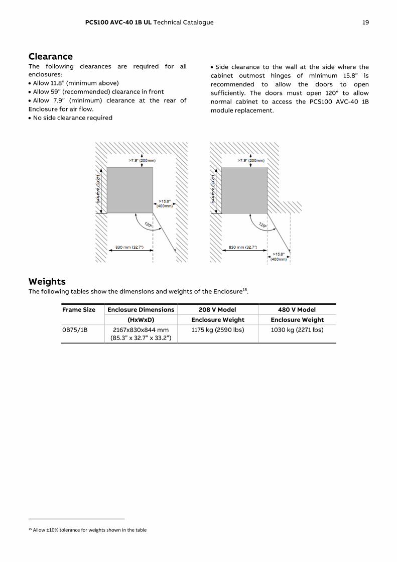
Clearance The following clearances are required for all
enclosures:
• Allow 11.8” (minimum above)
• Allow 59” (recommended) clearance in front
• Allow 7.9” (minimum) clearance at the rear of
Enclosure for air flow.
• No side clearance required
• Side clearance to the wall at the side where the
cabinet outmost hinges of minimum 15.8” is
recommended to allow the doors to open
sufficiently. The doors must open 120° to allow
normal cabinet to access the PCS100 AVC-40 1B
module replacement.
Weights The following tables show the dimensions and weights of the Enclosure15.
Frame Size Enclosure Dimensions 208 V Model 480 V Model
(HxWxD) Enclosure Weight Enclosure Weight
0B75/1B 2167x830x844 mm
(85.3” x 32.7” x 33.2”)
1175 kg (2590 lbs) 1030 kg (2271 lbs)
15 Allow ±10% tolerance for weights shown in the table
20 PCS100 AVC-40 1B UL Technical Catalogue
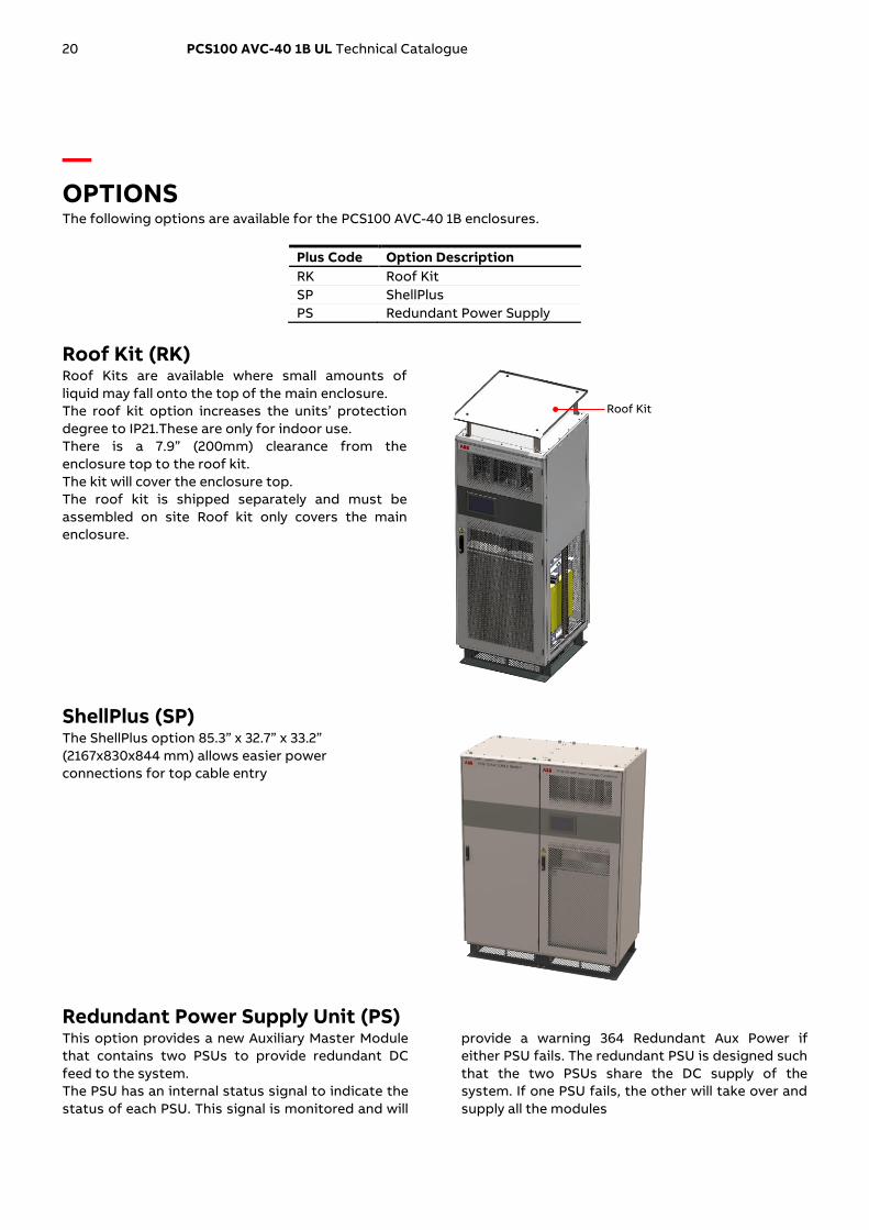
— OPTIONS The following options are available for the PCS100 AVC-40 1B enclosures.
Plus Code Option Description
RK Roof Kit
SP ShellPlus
PS Redundant Power Supply
Roof Kit (RK) Roof Kits are available where small amounts of
liquid may fall onto the top of the main enclosure.
The roof kit option increases the units’ protection
degree to IP21.These are only for indoor use.
There is a 7.9” (200mm) clearance from the
enclosure top to the roof kit.
The kit will cover the enclosure top.
The roof kit is shipped separately and must be
assembled on site Roof kit only covers the main
enclosure.
ShellPlus (SP) The ShellPlus option 85.3” x 32.7” x 33.2”
(2167x830x844 mm) allows easier power
connections for top cable entry
Redundant Power Supply Unit (PS) This option provides a new Auxiliary Master Module
that contains two PSUs to provide redundant DC
feed to the system.
The PSU has an internal status signal to indicate the
status of each PSU. This signal is monitored and will
provide a warning 364 Redundant Aux Power if
either PSU fails. The redundant PSU is designed such
that the two PSUs share the DC supply of the
system. If one PSU fails, the other will take over and
supply all the modules
Roof Kit

PCS100 AVC-40 1B UL Technical Catalogue 21
— USER INTERFACE
Graphic Display Module The primary user interface for configuration of the
PCS100 AVC-40 is via the Graphic Display Module
(GDM). The GDM is a 10.1’’ touchscreen user-friendly
intuitive interface. The integrated navigation screen
gives easy accessibility to any information on the
PCS100 AVC-40, shows the system status and
provides access to the operating parameters and
event history. The mimic diagram gives the users a
clear view of the status of the system.
The supported languages are: English, French,
Italian, Malaysian, Turkish, Russian, German,
Vietnamese, Spanish, Simplified Chinese, Japanese,
Traditional Chinese, Swedish, Indonesian,
Portuguese, Arabic and Korean.
Features GDM
Display resolution 1024 × 600 pixels
Display size 10.1”
Color graphic display yes
Touch sensitive display yes
Full descriptions of status and faults yes
Local Start/Stop Reset Control yes
Status Display yes
Parameter adjustment yes
Number of Event Log records stored 10,000
Event log can be downloaded to a PC yes
Remote Web Pages yes
Modbus TCP connection yes
Multilanguage selection yes
E-mail monitoring yes
Remote Monitoring The GDM provides remote access for monitoring purpose. The following monitoring connections are available.
Communication Type Description Connection
Remote Web Pages HTML server - Ethernet connection Standard RJ45
Monitoring system Modbus TCP Standard RJ45
Remote notifications E-mail Standard RJ45

22 PCS100 AVC-40 1B UL Technical Catalogue
Remote Web Pages The Remote Web Pages are a set of web pages that
are similar in format to the standard GDM and can
viewed with any standard web browser on a device
connected to the same network. Through this
interface the users can remotely access the status
and operating parameters. Viewing and
downloading of the event history and service logs is
also available. The Remote Web Pages enable users
to select different languages for each remote client.
Modbus TCP A Modbus TCP connection is also provided via the
Ethernet port of the GDM user interface. Read Only
access is available to operating parameters such as
voltages, currents and power levels.
E-mail The PCS100 AVC-40 1B is configurable for sending e-
mail notifications in case of power quality events or
systems internal events such as faults and warnings.
Automatic sending of the service logs via e-mail to
ABB Service can also be enabled.
Remote PC
Plant Control System
Remote PC
FirewallNetwork Switch
Local Ethernet
VPN
Local Ethernet
Modbus TCP

PCS100 AVC-40 1B UL Technical Catalogue 23
— USER CONNECTIONS
Power Connections The PCS100 AVC-40 1B utility supply (input) and load
(output) connections are connected directly to the
Injection Transformer terminals in the Enclosure.
The following table defines connection sides.
Transformer terminals Connections
Top terminals Utility Supply (Input)
Bottom terminals Load (Output)
Control Connections The PCS100 AVC-40 1B includes control connections
for local control or monitoring of the system.
Control connection terminals are located on the
Auxiliary Master Module in the Master Controller
Enclosure.
Control Connection Description
3 Relay Outputs PCS100 AVC-40 1B status information
250 VAC/30 VDC, 1 A
1 Isolated Thermal Switch Transformer over temperature information
24 VDC/24 VAC, 1 A
Normally closed (NC) contact
2 Digital Inputs PCS100 AVC-40 1B Remote control
Start/Stop/Inhibit
Dry contacts

24 PCS100 AVC-40 1B UL Technical Catalogue
1 NC
2 C
3 NO
4
5
6
7
8
9
10
11
12
13
14
15
16
NC
C
NO
NC
C
NO
0 V
RUN250 VAC / 30 VDC
1 A
WARNING250 VAC / 30 VDC
1 A
FAULT250 VAC / 30 VDC
1 A
TX ALARM24 VAC/VDC,
1 A
START
0 V
STOP / RESET / INHIBIT
LOOP
1
2
3
4
5
6
7
8
9
10
11
12
13
14
15
16
NC
NC
Inhibit switch;Located insideinverter cabinet door (fitted at factory)
PCS100 AVC-40 1B
200º C
Cu
sto
me
r M
on
ito
rin
g
an
d A
larm
Sy
ste
ms
Re
mo
te
Co
ntr
ol
- +
PCS100 AVC-40 1B UL Technical Catalogue 25
— INSTALLATION REQUIREMENTS
Input Circuit Protection The PCS100 AVC-40 1B relies upon upstream
protection for current overload and short circuit
protection. Upstream protection should be provided
by a circuit breaker.
Overload protection must not be set greater than
the PCS100 AVC-40 1B rated load current. Short
circuit and arc fault calculations should include
allowance for the additional PCS100 AVC-40 1B
impedance (typically < 2.5%). Circuit breakers should
be set to trip without any delay on short circuit or
arc fault currents.
Coarse ground fault detection is recommended for
high current systems where it may be difficult to
assure ground or arc fault currents of sufficient
magnitude to instantaneously trip the breaker.
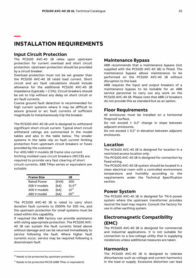
The PCS100 AVC-40 1B unit is designed to withstand
significant short circuit current. Typical short circuit
withstand ratings are summarized in the model
tables and also in the table below. The smaller
systems in the table rely on fault current limiting
protection from upstream circuit breakers or fuses
provided by the customer.
For 400/480 V models 1B frame size current
limiting molded case circuit breakers (MCCB) are
required to provide very fast clearing of short
circuit currents. ABB TMax series or equivalent are
suitable
Frame Size 1B
Rated Power [kVA] 300
208 V models [kA] 31.516
400 V models [kA] 1517
480 V model [kA] 2017
The PCS100 AVC-40 1B is rated to carry short
duration fault currents to 2000% for 200 ms, and
the upstream protection for small systems must be
sized within this capability.
If required the ABB factory can provide assistance
with sizing appropriate protection. The PCS100 AVC-
40 1B can sustain the fault currents listed above
without damage and can be returned immediately to
service following the fault. Where higher fault
currents occur, service may be required following a
downstream fault
16 Needs to be protected by upstream protection
17 Needs to be protected MCCB (ABB TMax or equivalent)
Maintenance Bypass ABB recommends that a maintenance bypass (not
supplied with the PCS100 AVC-40 1B) is fitted. The
maintenance bypass allows maintenance to be
performed on the PCS100 AVC-40 1B without
disruption to the load.
ABB requires the input and output breakers of a
maintenance bypass to be lockable for an ABB
service personnel to carry out any work on the
PCS100 AVC-40 1B. Please note that ABB LV breakers
do not provide this as standard but as an option.
Floor Requirements All enclosures must be installed on a horizontal
fireproof surface.
Do not exceed ± 0.2° change in slope between
adjacent enclosures.
Do not exceed ± 0.2” in elevation between adjacent
enclosures.
Location The PCS100 AVC-40 1B is designed for location in a
restricted access location only.
The PCS100 AVC-40 1B is designed for connection by
fixed wiring.
The PCS100 AVC-40 1B system should be located in a
clean electrical room with a controlled environment
temperature and humidity according to the
requirements under the Technical Specification
section.
Power System The PCS100 AVC-40 1B is designed for TN-S power
system where the upstream transformer provides
neutral the load may require. Consult the factory for
use in other earthing system.
Electromagnetic Compatibility
(EMC) The PCS100 AVC-40 1B is designed for commercial
and industrial applications. It is not suitable for
connection to a low-voltage utility that is supplying
residences unless additional measures are taken.
Harmonics The PCS100 AVC-40 1B is designed to tolerate
disturbances such as voltage and current harmonics
in the load or supply. Excessive distortion can lead

26 PCS100 AVC-40 1B UL Technical Catalogue
to the stressing of components leading to reduction
in the lifetime of the rectifier and inverter modules.
ABB recommends the harmonic contents on the
input and the output of the system to meet IEC
61000-2-4 Class 2, THDV up to 8%. Contact the
factory for THDV > 8% as the lifetime of components
may be affected.
Downstream Capacitor Banks A care must be taken when installing the PCS100
AVC-40 1B with a capacitor bank downstream of the
system. ABB recommends the capacitor bank to be
installed upstream of the PCS100 AVC-40 1B.
Contact ABB for more information.

PCS100 AVC-40 1B UL Technical Catalogue 27
— SERVICE AND TECHNICAL SUPPORT ABB Power Conditioning provide global service and support of installation
and commissioning of PCS100 products
Comprehensive global services
portfolio ABB services span the entire product ownership life
cycle:
• Pre-purchase engineering
• Installation and commissioning
• Technical support
• Training
• Preventive and corrective maintenance and
maintenance spare parts kits
• Retrofit and refurbishment
• Globally available, supported by regional service
hubs and operating in more than 100 countries
• Spare part availability and stocking
• On-site repairs
• 24 x 365 local support line
Custom tailored service contracts • 24 x 365 local support line
• ABB services can be packaged into a custom
service contract
• Tailored to the specific needs of each customer
• Contracts can be made at any stage of ABB
product ownership
Service contracts provide customers with improved
cost controls, increased operational efficiency, lower
capital expenditures, and extend ABB product life
time.
Life cycle management ABB’s life cycle management model maximizes the
value of the equipment and maintenance investment
by maintaining high availability, eliminating
unplanned repair costs and extending the lifetime of
the system. Life cycle management includes:
• Spare parts and expertise throughout the life cycle
• Efficient product support and maintenance for
improved reliability
• Functionality upgrades to the initial product
Training • Product training includes installation,
commissioning, and maintenance
• Training either at ABB Universities or at a customer
site
• Training can be included in an ABB services
contract
Engineering and technical support ABB’s engineering team provides the necessary
electrical, protective and monitoring equipment,
delivering a high level of energy continuity and
superior power quality in a safe and cost-effective
system. The PCS100 is available in several capacities,
depending on the scope of application.
• Pre-purchase engineering to help select and
integrate ABB PCS100 products
• Customer assistance in sizing and modeling of
systems
• Other life cycle engineering and technical support
is available by phone, email, or on-site visits, or as
agreed in an ABB services contract
• Redundant internal bypass design increases
reliability and availability and is part of a proven
family of global ABB products
• Scalable building block design

28 PCS100 AVC-40 1B UL Technical Catalogue
— ADDITIONAL DOCUMENTS
Document Number Document Name
2UCD074000E013 PCS100 AVC-40 1B User Manual
2UCD074000E002 PCS100 AVC-40 Installation Checklist
2UCD074000E004 PCS100 AVC-40 Commissioning Checklist
2UCD070000E020 PCS100 AVC Detailed Performance Curves
2UCD200000E007 PCS100 Environment Specification

29
htt
ps
://
lib
rary
.ab
b.c
om
—
ABB Ltd.
111 Main North Road
4110, Napier
New Zealand
abb.com/ups
© Copyright 2020 ABB. All rights reserved.
Specifications subject to change without notice.
2U
CD
07
40
00
E0
09
_B