Underwriters Laboratories (UL LLC) Safety Report
14
Underwriters Laboratories (UL LLC) Safety Report Model: CUS150M (may be prefixed and followed by alphanumeric characters - See model differences section for details of nomenclature) CUS100ME (may be prefixed and followed by alphanumeric characters - See model differences section for details of nomenclature) Device Description: Switch-mode power supplies Applicant: TDK-Lambda UK Ltd Kingsley Avenue, Ilfracombe Devon, EX34 8ES UNITED KINGDOM Manufacturer: Same as Applicant Manufacturing Facility(ies): TDK-Lambda UK Ltd Kingsley Avenue, Ilfracombe Devon, EX34 8ES UNITED KINGDOM PANYU TRIO MICROTRONIC CO. LTD SHIJI INDUSTRIAL ESTATE DONGYONG, NANSHA, GUANGZHOU GUANGDONG CHINA Report No.: E349607-D1003-1/A2/C0-ULCB Report (Re)Issue Date: 2017-04-14; 2017-09-25 (A1); 2018-03-21 (A2) Base Standard(s): ANSI/AAMI ES60601-1: A1:2012, C1:2009/(R)2012 and A2:2010/(R)2012, CSA CAN/CSA-C22.2 NO. 60601-1:14, IEC 60601-1 Edition 3.1 (2012) Additional Standards: EN 60601-1:2006/A1:2013, KS C IEC 60601-1, ANSI/AAMI ES60601-1: A1:2012, C1:2009/(R)2012 and A2:2010/(R)2012, CSA CAN/CSA-C22.2 NO. 60601-1:14, BS EN 60601:2006 A1, SS-EN 60601- 1:2006+A11:2011+A1:2013+AC1:2014+A12:2014 Report Types: This report consists of the following report types: [ Yes ] US Certification (UL Recognition) [ Yes ] CAN Certification (cUL Recognition) [ Yes ] CB Report & Certificate [ No ] IEC/EN Informative Report This report covers the Safety evaluation of the referenced model(s) according to the standard(s) specified above. The CB Certificate is provided as a separate enclosure to this report and not provided in the body of this report.
-
Upload
khangminh22 -
Category
Documents
-
view
1 -
download
0
Transcript of Underwriters Laboratories (UL LLC) Safety Report

Underwriters Laboratories (UL LLC) Safety Report
Model: CUS150M (may be prefixed and followed by alphanumeric characters - See model differences section for details of nomenclature)
CUS100ME (may be prefixed and followed by alphanumeric characters - See model differences section for details of nomenclature)
Device Description: Switch-mode power supplies
Applicant: TDK-Lambda UK Ltd
Kingsley Avenue, Ilfracombe
Devon, EX34 8ES UNITED KINGDOM
Manufacturer: Same as Applicant
Manufacturing Facility(ies):
TDK-Lambda UK Ltd
Kingsley Avenue, Ilfracombe
Devon, EX34 8ES UNITED KINGDOM
PANYU TRIO MICROTRONIC CO. LTD
SHIJI INDUSTRIAL ESTATE
DONGYONG, NANSHA, GUANGZHOU GUANGDONG CHINA
Report No.: E349607-D1003-1/A2/C0-ULCB
Report (Re)Issue Date:
2017-04-14; 2017-09-25 (A1); 2018-03-21 (A2)
Base Standard(s): ANSI/AAMI ES60601-1: A1:2012, C1:2009/(R)2012 and A2:2010/(R)2012, CSA CAN/CSA-C22.2 NO. 60601-1:14, IEC 60601-1 Edition 3.1 (2012)
Additional Standards: EN 60601-1:2006/A1:2013, KS C IEC 60601-1, ANSI/AAMI ES60601-1: A1:2012, C1:2009/(R)2012 and A2:2010/(R)2012, CSA CAN/CSA-C22.2 NO. 60601-1:14, BS EN 60601:2006 A1, SS-EN 60601-1:2006+A11:2011+A1:2013+AC1:2014+A12:2014
Report Types: This report consists of the following report types:
[ Yes ] US Certification (UL Recognition)
[ Yes ] CAN Certification (cUL Recognition)
[ Yes ] CB Report & Certificate
[ No ] IEC/EN Informative Report This report covers the Safety evaluation of the referenced model(s) according to the standard(s) specified above. The CB Certificate is provided as a separate enclosure to this report and not provided in the body of this report.

Page ii Report No.: E349607-D1003-1/A2/C0-ULCB
Table of Contents
CB - IEC REPORT: ........................................................................................................................................................ 1Test Report ................................................................................................................................................................ 1
TABLE: List of critical components .................................................................................................................... 166National Differences............................................................................................................................................... 171APPENDIX A: Enclosures (Page Section: A) ....................................................................................................... 1Collateral/Particular Standard Enclosures ................................................................................................................. 1Other Enclosures ....................................................................................................................................................... 2
Diagrams - (01) 01 TX100 (CUS150M-12) .............................................................................................................................................................4Diagrams - (02) 02 Common mode choke L1 ........................................................................................................................................................6Diagrams - (03) 03 PFC choke L2 ..........................................................................................................................................................................7Diagrams - (04) 04 Differential mode choke L3 .....................................................................................................................................................9Diagrams - (05) 05 Chassis ................................................................................................................................................................................. 10Diagrams - (06) 06 TX100 (CUS150M-48) .......................................................................................................................................................... 13Insulation diagram - (01) Insulation Diagram ...................................................................................................................................................... 15Licences - (01) 01 X capacitor Carli MPX Certificate .......................................................................................................................................... 16Licences - (02) 02 Y capacitor Kemet ERP 610 certificate ................................................................................................................................. 17Licences - (03) 03 X capacitor Kemet R46 certificate ......................................................................................................................................... 21Licences - (04) 04 Y capacitor Murata KX certificate .......................................................................................................................................... 24Licences - (05) 05 X capacitor Xiamen MKP62 certificate .................................................................................................................................. 25Licences - (06) 06 Y capacitor Xiamen (Faratronic) MKP67 certificate .............................................................................................................. 26Licences - (07) 07 X capacitor Vishay MKP338 certificate ................................................................................................................................. 28Licences - (08) 08 X capacitor Okaya Electric LE certificate .............................................................................................................................. 29Licences - (09) 09 X capacitors Kemet PHE840 certificate ................................................................................................................................ 30Licences - (10) 10 Y capacitor Kemet PME295 certificate .................................................................................................................................. 32Licences - (11) 11 Y capacitor Vishay VY1 certificate ........................................................................................................................................ 34Licences - (12) 12 Thermistor Murata PRF18 certificate .................................................................................................................................... 35Licences - (13) 13 TIW Furukawa TEX-E certificate ........................................................................................................................................... 36Licences - (14) 14 TIW-2LZ and 3LZ SIQ test report .......................................................................................................................................... 37Manuals - (01) CUS100ME Handbook ................................................................................................................................................................ 59Manuals - (02) CUS150M Handbook .................................................................................................................................................................. 66Marking label - (01) CUS100ME Marking label ................................................................................................................................................... 73Marking label - (02) CUS150M Marking label ..................................................................................................................................................... 74Marking label - (03) CUS150MD Marking label ................................................................................................................................................... 75Miscellaneous - (01) 01 Declaration of manufacturing locations ........................................................................................................................ 76Miscellaneous - (02) 02 Output parameters table ............................................................................................................................................... 77Photographs - (01) 01 Overall view, open frame ................................................................................................................................................ 79Photographs - (02) 02 Overall view, U chassis ................................................................................................................................................... 80Photographs - (03) 03 Overall view, top cover .................................................................................................................................................... 81Photographs - (04) 04 Overall view, top fan ........................................................................................................................................................ 82Photographs - (05) 05 PWB top .......................................................................................................................................................................... 83Photographs - (06) 06 PWB bottom .................................................................................................................................................................... 84Photographs - (07) 07 Top view, top cover ......................................................................................................................................................... 85Photographs - (08) 08 Top view, top fan ............................................................................................................................................................. 86Photographs - (09) 09 U chassis ......................................................................................................................................................................... 87Photographs - (10) 10 Top cover ......................................................................................................................................................................... 88Photographs - (11) 11 Top fan ............................................................................................................................................................................ 89Photographs - (12) 12 Chassis insulation (U chassis, top cover version) .......................................................................................................... 90Photographs - (13) 13 Chassis insulation (top fan version) ................................................................................................................................ 91Schematics and PWB - (01) 01 PWB top layout ................................................................................................................................................. 92Schematics and PWB - (02) 02 PWB bottom layout ........................................................................................................................................... 93Schematics and PWB - (03) CUS100ME top and bottom PWB ......................................................................................................................... 94Schematics and PWB - (04) CUS150M and CUS100ME Schematics ............................................................................................................... 96
UL CERTIFICATION DOCUMENTATION: .................................................................................................................... 1APPENDIX B: UL Certification Documentation (Page Section: B)..................................................................... 1
Test Record ........................................................................................................................................................... 2APPENDIX C: Follow-Up Service Documentation (Page Section: C) ................................................................ 1
Follow-Up Service Procedure ................................................................................................................................ 2UL Authorization Page .......................................................................................................................................... 3UL Appendix: ......................................................................................................................................................... 6
GENERIC INSPECTION INSTRUCTIONS .............................................................................................................................................................6INSTRUCTIONS AND DUTIES FOR UL REPRESENTATIVE ...............................................................................................................................7INSTRUCTIONS FOR FOLLOW-UP TESTS AT UL ........................................................................................................................................... 13RESPONSIBILITIES AND REQUIREMENTS FOR MANUFACTURER ............................................................................................................. 14GENERAL TERMINOLOGY ................................................................................................................................................................................. 18GENERAL PRODUCT CONSTRUCTION REQUIREMENTS ............................................................................................................................. 19UL CERTIFICATION MARK ................................................................................................................................................................................. 28
Description .......................................................................................................................................................... 29Markings and instructions ..................................................................................................................................................................................... 35Special Instructions to UL Representative ........................................................................................................................................................... 35Production-Line Testing Requirements ................................................................................................................................................................ 35TABLE: List of Critical Components ..................................................................................................................................................................... 37
TEST RESULTS: ........................................................................................................................................................... 1APPENDIX D: Test Datasheets Enclosures (Page Section: D) .......................................................................... 1
CERTIFICATE OF COMPLIANCE ................................................................................................................................ 1

Page iii Report No.: E349607-D1003-1/A2/C0-ULCB
The following changes were made to this report. If none listed in the below table, this report is the originally issued report.
The following scheme is used throughout this report to reflect the Report No.:
(File No.) (Report Ref. No.) (x) / A(y) / C(z) YYY, where: (x) = Report (Re)Issue No. (y) = Amendment No. (z) = Correction No. YYY = Report Type (UL/CB/IEC)
NOTE: The CB Certificate contents; therefore if this report includes a correction number (z), it may not be reflected in the CB Certificate.
Date Modified (Year-Month-Day)
Modifications Made (include Report Reference Number) Modified By
2017-08-29 Amendment 1: measurements of earth leakage current and touch current repeated per client's request (E349607-D1003-1/A1/C0-ULCB)
Hubert Koszewski
2018-03-21
Amendment 2: Technical amendment was issued in order to add CUS100ME, CUS150M-15, CUS150M-18, CUS150M-28, CUS150M-36 and DC rated version of CUS150M series. Due to the modification following report sections were modified: general product information, insulation table, clause list and test tables. Only limited testing was considered necessary due to similarity to previously evaluated construction. This amendment shall be read in conjunction with the Original CB Report No.E349607-D1003-1/A0/C0-ULCB and Amendment-1 issue 2017-08-29.
Krzysztof Wasilewski

Page 1 of 177 Report No.: E349607-D1003-1/A2/C0-ULCB
TRF No. IEC60601_1K
Test Report issued under the responsibility of:
IEC 60601-1 Medical electrical equipment
Part 1: General requirements for basic safety and essential performance
Report Reference No. ...................... : E349607-D1003-1/A2/C0-ULCB
Date of issue .................................... : 2017-04-14; 2017-09-25 (A1); 2018-03-21 (A2)
Total number of pages ..................... : 177
CB Testing Laboratory ..................... : UL International Polska Sp. z o.o. Aleja Krakowska 81 05-090 Sekocin Nowy Warszawy POLAND
Address ............................................ :
.............................. : TDK-Lambda UK Ltd
Address ............................................ : Kingsley Avenue, Ilfracombe
Devon, EX34 8ES UNITED KINGDOM
Test specification:
Standard ........................................... : IEC 60601-1:2005 (Third Edition) + CORR. 1:2006 + CORR. 2:2007 + A1:2012
(or IEC 60601-1: 2012 reprint)
Test procedure ................................. : CB Scheme
Non- N/A
Test Report Form No. ....................... : IEC60601_1K
Test Report Form Originator ............ : UL(US)
Master TRF ...................................... : 2015-11
Copyright © 2015 Worldwide System for Conformity Testing and Certification of Electrotechnical Equipment and Components (IECEE), Geneva, Switzerland. All rights reserved.
This publication may be reproduced in whole or in part for non-commercial purposes as long as the IECEE is acknowledged as copyright owner and source of the material. IECEE takes no responsibility for and will not assume liability for damages resulting from the reader's interpretation of the reproduced material due to its placement and context.
This report is not valid as a CB Test Report unless signed by an approved CB Testing Laboratory and appended to a CB Test Certificate issued by an NCB in accordance with IECEE 02.
General disclaimer:
The test results presented in this report relate only to the object tested.
This report shall not be reproduced, except in full, without the written approval of the Issuing CB testing laboratory. The authenticity of this Test Report and its contents can be verified by contacting the NCB, responsible for this Test Report.

Page 2 of 177 Report No.: E349607-D1003-1/A2/C0-ULCB
TRF No. IEC60601_1K
Test item description: Switch-mode power supplies
Trade Mark: Trademark image(s):
Manufacturer: Same as Applicant
Model/Type reference: CUS150M (may be prefixed and followed by alphanumeric characters - See model differences section for details of nomenclature)
CUS100ME (may be prefixed and followed by alphanumeric characters - See model differences section for details of nomenclature)
Ratings: Input:
CUS150M-xxVx/yyyy
100-240Vac; 47-63Hz; 2.2Arms Max.
CUS150MD-xxVx/yyyy
133-318Vdc, 1.8A
CUS100ME-xxVx/yyyy
100-240Vac; 47-63Hz; 1.4Arms Max.
Output: CUS100ME-12/yyyy output: 12-13.2Vdc 8.33A
CUS100ME-15/yyyy output: 15-16.5Vdc 6.66A
CUS100ME-18/yyyy output: 18-19.8Vdc 5.55A
CUS100ME-24/yyyy output: 24-26.4Vdc 4.16A
CUS100ME-28/yyyy output: 28-30.8Vdc 3.57A CUS100ME-36/yyyy output: 36-39.6Vdc 2.77A CUS100ME-48/yyyy output: 48-50Vdc 2.08A
CUS150M-12/yyyy output: 12-13.2Vdc 12.5A
CUS150M-15/yyyy output: 15-16.5Vdc 10A
CUS150M-18/yyyy output: 18-19.8Vdc 8.33A CUS150M-24/yyyy output: 24-26.4Vdc 6.25A
CUS150M-28/yyyy output: 28-30.8Vdc 5.4A
CUS150M-36/yyyy output: 36-39.6Vdc 4.2A CUS150M-48/yyyy output: 48-50Vdc 3.125A
Each output has a range shown in the table above which is factory configurable only.
For further details please see model differences section.
Testing procedure and testing location:

Page 3 of 177 Report No.: E349607-D1003-1/A2/C0-ULCB
TRF No. IEC60601_1K
[X] CB Testing Laboratory:
Testing location/ address: UL International Polska Sp. z o.o. Aleja Krakowska 81 05-090 Sekocin Nowy Warszawy POLAND
[ ] Associated CB Testing Laboratory:
Testing location/ address:
Tested by (name, function, signature): Krzysztof Wasilewski, Project Handler
Approved by (name, function, signature): Bruno Motta, Reviewer
[ ] Testing procedure: CTF Stage 1:
Testing location/ address:
Tested by (name, function, signature):
Approved by (name, function, signature):
[ ] Testing procedure: CTF Stage 2
Testing location/ address:
Tested by (name, function, signature):
Witnessed by (name, function, signature):
Approved by (name, function, signature):
[ ] Testing procedure: CTF Stage 3:
[ ] Testing procedure: CTF Stage 4:
Testing location/ address:
Tested by (name, function, signature):
Witnessed by (name, function, signature):
Approved by (name, function, signature):
Supervised by (name, function, signature):

Page 4 of 177 Report No.: E349607-D1003-1/A2/C0-ULCB
TRF No. IEC60601_1K
List of Attachments (including a total number of pages in each attachment):
Refer to Appendix A of this report. All attachments are included within this report.
Summary of testing
Tests performed (name of test and test clause): Testing location:
Refer to the Test List in Appendix D of this report if testing was performed as part of this evaluation.
Summary of compliance with National Differences
List of countries addressed: Austria, Korea, Republic of, USA, Canada, United Kingdom, Sweden
[X] The product fulfils the requirements of IEC 60601-1:2005 (Third Edition) + CORR. 1:2006 + CORR. 2:2007 + A1:2012
(or IEC 60601-1: 2012 reprint) .

Page 5 of 177 Report No.: E349607-D1003-1/A2/C0-ULCB
TRF No. IEC60601_1K
Copy of marking plate The artwork below may be only a draft. The use of certification marks on a product must be authorized by the respective NCBs that own these marks. Refer to the enclosure(s) titled Marking Label in the Enclosures section in Appendix A of this report for a copy.

Page 6 of 177 Report No.: E349607-D1003-1/A2/C0-ULCB
TRF No. IEC60601_1K
GENERAL INFORMATION
Test item particulars (see also Clause 6):
Classification of Installation and Use: Component part of host equipment
Device type (component/sub-assembly/ equipment/ system): Component Switch Mode Power Supply
Intended use (Including type of patient, application location): To supply regulated power
Mode of Operation: Continuous
Supply Connection: Connection to Mains via host equipment
Accessories and detachable parts included: None
Other Options Include: None
Testing
Date of receipt of test item(s) ................................................. : 2017-01-12, 2017-01-19, 2017-01-27; 2017-07-11 (A1); 2018-01-03, 2018-01-12, 2018-01-15 (A2)
Dates tests performed ............................................................ : 2017-02-17 to 2017-02-28, 2017-03-3 to 2017-03-06, 2017-04-04; 2017-07-20 (A1); 2018-02-22 to 2018-03-14 (A2)
Possible test case verdicts:
- test case does not apply to the test object .......................... : N/A
- test object does meet the requirement ................................. : Pass (P)
- test object was not evaluated for the requirement ................. : N/E
- test object does not meet the requirement ........................... : Fail (F)
Abbreviations used in the report:
- normal condition: N.C. - single fault condition: S.F.C.
- means of Operator protection: MOOP - means of Patient protection: MOPP
General remarks: Before starting to use the TRF please read carefully the 4 instructions pages at the end of the report on
-1 3rd edition with Amendment 1. "(See Attachment #)" refers to additional information appended to the report. "(See appended table)" refers to a table appended to the report. The tests results presented in this report relate only to the object tested. This report shall not be reproduced except in full without the written approval of the testing laboratory. List of test equipment must be kept on file and available for review. Additional test data and/or information provided in the attachments to this report. Throughout this report a point is used as the decimal separator.
-clause 4.2.5 of IECEE 02:2012
The application for obtaining a CB Test Certificate includes more than one factory location and a declaration from the Manufacturer stating that the sample(s) submitted for evaluation is (are) representative of the products from each factory has been provided ................................................................ :
Yes
When differences exist; they shall be identified in the General product information section.

Page 7 of 177 Report No.: E349607-D1003-1/A2/C0-ULCB
TRF No. IEC60601_1K
Name and address of factory (ies) ............................. : TDK-Lambda UK Ltd
Kingsley Avenue, Ilfracombe
Devon, EX34 8ES UNITED KINGDOM
PANYU TRIO MICROTRONIC CO. LTD
SHIJI INDUSTRIAL ESTATE
DONGYONG, NANSHA, GUANGZHOU GUANGDONG CHINA
GENERAL PRODUCT INFORMATION:
Report Summary All applicable tests according to the referenced standard(s) have been carried out.
Refer to the Report Modifications for any modifications made to this report.
Product Description The CUS150M is a power supply for building in to end equipment. It is available as open frame, U chassis, U chassis and lid, base plate and with a top fan version.
The power supply can be used as either a Class I or a Class II construction.
- For Class I construction, the power supply will need to be reliably earthed, professionally installed and fixed with suitable, metal screws.
-For Class II construction no earthing connection is required. The power supply needs to be fixed so that it is insulated from any unearthed accessible conductive part by reinforced insulation.
The power supply provides two fuses for input protection. One in the Live line and one in the Neutral line. Option E uses one fuse only. This is fitted in the live line only.
The power supply can be forced air (top fan or customer air), convection or conduction cooled. Due to the fact that air flow for cooling depends on end product use, only convection cooling and top fan configurations were considered during temperature measurement.
The component temperatures listed in the additional information shall not be exceeded.
Model Differences
The CUS has two ranges of 100W and 150W each with seven nominal output voltages of 12, 15, 18, 24, 28, 36 and 48 Volt. Each output has a range shown in the table below which is factory configurable only.
CUS models as described below: Units may be marked with a Product Code: CUSZ-xxVx/yyyy where Z is 100ME or 150M and x may be any number of numbers or left blank to indicate the output voltage. V represents a decimal place when required or can left be left blank. y can be blank or any number of numbers or letters (excluding M, E, U, A, F, B, H) when indicating non-safety related model differences. y can be M, E, U, A, F, B when indicating the standard options as listed below.
Unit Product Code may be prefixed by K, SP # and/or NS # followed by / or - (where # may be any number of characters indicating non-safety related model differences).
Unit Product Code:

Page 8 of 177 Report No.: E349607-D1003-1/A2/C0-ULCB
TRF No. IEC60601_1K
CUSZ-xxVx/yyyy
Where: xxVx = Channel 1 output voltage from within the output voltage adjustment range from the Output Parameters Tables below.
yyyy = Unit options from list of standard unit options below, or non-safety related model differences: /M = Molex connectors
/E = Single fuse in the live line /U = U chassis
/A = Cover and U chassis
/F = Top fan, cover and U chassis (CUS150M model only)
/B = Baseplate
Input Parameters Nominal input voltage: 100 - 240Vac, 133 - 318Vdc*
Input voltage range : 85 - 264Vac, 120 - 350Vdc*
Input frequency range: 47 - 63Hz, DC*
Maximum input current: 2.2A rms (CUS150M), 1.4A rms (CUS100ME) 1.8A*
* 60601-1 2nd ed, 300Vdc input max. DC rating applies for CUS150M family only. All ratings apply for ambient temperatures up to 50°C. (see Variations and Limitations below)
Output power is reduced linearly by 10% for input voltages from 90 to 85Vac
Output Parameters
There are seven CUS150M and CUS100ME standard models as shown in the tables below. All of these models may be fan(CUS150M model only), forced air, conduction or convection cooled. The output parameters are shown in the tables below.
Outputs are not user adjustable but can be factory set.
CUS150M
Vout *Fan Max Max *Fan Output ratings Model Range (V) Vnom (V) Iout (A) Pout (W) Inom (A) Pnom (W)
12 12-13.2 11.6 12.5 150 0.5 5.8
15 15-16.5 9.8 10 150 0.5 4.9
18 18-19.8 11.6 8.33 150 0.5 5.8
24 24-26.4 11.6 6.25 150 0.5 5.8 28 28-30.8 10.8 5.4 150 0.5 5.4 36 36-39.6 11.6 4.2 150 0.5 5.8
48 48-50 11.6 3.125 150 0.5 5.8
* Fan output tracks Vout Range
Variation and Limitations:
Customer Forced Air Cooling max ambient 85°C (note 1) Convection and conduction/cold plate Cooling (U chassis with lid-Option A) max ambient 75°C (note 1)
Convection and conduction/cold plate Cooling (U chassis and open frame) max ambient 80°C (note 1)
Fan supplied ratings/Option F max ambient 70°C, from 50°C to 70°C the output power is de-rated by 0.5°C per watt
Note 1. Maximum output power and current ratings are dependent on the ambient used in the end equipment.

Page 9 of 177 Report No.: E349607-D1003-1/A2/C0-ULCB
TRF No. IEC60601_1K
CUS100M
Vout Max Max Model Range (V) Iout (A) Pout (W) 12 12-13.2 8.33 100
15 15-16.5 6.66 100
18 18-19.8 5.55 100
24 24-26.4 4.16 100
28 28-30.8 3.57 100 36 36-39.6 2.77 100 48 48-50 2.08 100
Variation and Limitations:
Customer Forced Air Cooling max ambient 85°C (note 1)
Convection and conduction/cold plate Cooling (U chassis with lid-Option A) max ambient 75°C (note 1) Convection and conduction/cold plate Cooling (U chassis and open frame) max ambient 80°C (note 1)
Note 1. Maximum output power and current ratings are dependent on the ambient used in the end equipment.
Additional Information Cooling for units with forced air cooling (Except option F)
The product can also operate at input voltage lowered to 85Vac with linear output de-rating to -10%.
The following method must be used for determining the safe operation of PSUs.
The components listed in the following table must not exceed the temperatures given. To determine the component temperatures the heating tests must be conducted in accordance with the requirements of the standard in question. Consideration should also be given to the requirements of other safety standards.
Test requirements include: PSU to be fitted in its end-use equipment and operated under the most adverse conditions permitted in the end-use equipment handbook/specification and which will result in the highest temperatures in the PSU. To determine the most adverse conditions consideration should be given to the end use equipment maximum operating ambient, the PSU loading and input voltage, ventilation, end use equipment orientation, the position of doors & covers, etc. Temperatures should be monitored using type K fine wire thermocouples (secured with cyanoacrylate adhesive or similar) placed on the hottest part of the component (out of any direct airflow) and the equipment should be run until all temperatures have stabilized.
CUS150M Cooling for Unit Temperature Table:
Circuit Ref. Description Max. Temperature (°C)
L1 Common Mode Choke 110 (130) L2 PFC choke 125 (130)
L3 Differential mode choke 125 (130)
C1 Film capacitor 105 C2, C110 Electrolytic Capacitors 86 (105)

Page 10 of 177 Report No.: E349607-D1003-1/A2/C0-ULCB
TRF No. IEC60601_1K
C6, C102, C104, C105 Electrolytic Capacitors 92 (105)
C3 X Capacitor 100
C5, C100, C101, C103, Y Capacitors 105 TX100 Transformer Winding 110 XU101, XU102 Opto-Coupler 100 (110)
XD8 Diode 130
J1 Input Connector 105
J100 Output Connector 105
CUS100ME Cooling for Unit Temperature Table: Circuit Ref. Description Max. Temperature(°C)
L1 Common Mode Choke 110 (130)
L2 PFC choke 125 (130)
L3 Differential mode choke 125 (130)
C1 Film capacitor 105 C2 Electrolytic Capacitors 90 (105)
C104, C105 Electrolytic Capacitors 92 (105)
C6, C102 Electrolytic Capacitors 93 (105) C3 X Capacitor 100
C5, C100, C101, C103, Y Capacitors 105 TX100 Transformer Winding 110
XU101, XU102 Opto-Coupler 100 (110)
XD8 Diode 130
J1 Input Connector 105
J100 Output Connector 105 Higher temperature limits (in brackets) may be used but product life may be reduced.
Technical Considerations The product was investigated to the following standards:
Main Standard(s):
ANSI/AAMI ES60601-1: A1:2012, C1:2009/(R)2012 and A2:2010/(R)2012, CSA CAN/CSA-
C22.2 NO. 60601-1:14, IEC 60601-1 Edition 3.1 (2012)
From Country Differences:
- Austria: EN 60601-1:2006/A1:2013
- Korea, Republic of: KS C IEC 60601-1
- USA: ANSI/AAMI ES60601-1: A1:2012, C1:2009/(R)2012 and A2:2010/(R)2012
- Canada: CSA CAN/CSA-C22.2 NO. 60601-1:14
- United Kingdom: BS EN 60601:2006 A1
- Sweden: SS-EN 60601-1:2006+A11:2011+A1:2013+AC1:2014+A12:2014
Additional Standards:
EN 60601-1:2006/A1:2013, KS C IEC 60601-1, ANSI/AAMI ES60601-1: A1:2012,
C1:2009/(R)2012 and A2:2010/(R)2012, CSA CAN/CSA-C22.2 NO. 60601-1:14, BS EN
60601:2006 A1, SS-EN 60601-1:2006+A11:2011+A1:2013+AC1:2014+A12:2014
The following additional investigations were conducted: n/a
Page 11 of 177 Report No.: E349607-D1003-1/A2/C0-ULCB
TRF No. IEC60601_1K
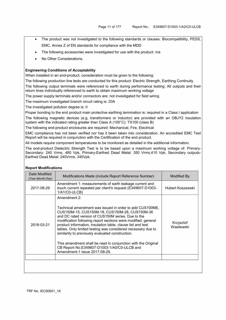
The product was not investigated to the following standards or clauses: Biocompatibility, PESS,
EMC, Annex Z of EN standards for compliance with the MDD
The following accessories were investigated for use with the product: n/a
No Other Considerations.
Engineering Conditions of Acceptability When installed in an end-product, consideration must be given to the following:
The following production line tests are conducted for this product: Electric Strength, Earthing Continuity
The following output terminals were referenced to earth during performance testing: All outputs and their return lines individually referenced to earth to obtain maximum working voltage
The power supply terminals and/or connectors are: not investigated for field wiring
The maximum investigated branch circuit rating is: 20A
The investigated pollution degree is: II
Proper bonding to the end product main protective earthing termination is: required in a Class I application
The following magnetic devices (e.g. transformers or inductor) are provided with an OBJY2 insulation system with the indicated rating greater than Class A (105°C): TX100 (class B)
The following end-product enclosures are required: Mechanical, Fire, Electrical
EMC compliance has not been verified nor has it been taken into consideration. An accredited EMC Test Report will be required in conjunction with the Certification of the end product.
All models require component temperatures to be monitored as detailed in the additional information.
The end-product Dielectric Strength Test is to be based upon a maximum working voltage of: Primary-Secondary: 240 Vrms, 480 Vpk, Primary-Earthed Dead Metal: 350 Vrms,410 Vpk, Secondary outputs-Earthed Dead Metal: 240Vrms, 340Vpk.
Report Modifications
Date Modified (Year-Month-Day)
Modifications Made (include Report Reference Number) Modified By
2017-08-29 Amendment 1: measurements of earth leakage current and touch current repeated per client's request (E349607-D1003-1/A1/C0-ULCB)
Hubert Koszewski
2018-03-21
Amendment 2: Technical amendment was issued in order to add CUS100ME, CUS150M-15, CUS150M-18, CUS150M-28, CUS150M-36 and DC rated version of CUS150M series. Due to the modification following report sections were modified: general product information, insulation table, clause list and test tables. Only limited testing was considered necessary due to similarity to previously evaluated construction. This amendment shall be read in conjunction with the Original CB Report No.E349607-D1003-1/A0/C0-ULCB and Amendment-1 issue 2017-08-29.
Krzysztof Wasilewski