Huawei DBS3900 Commissioning Procedure Huawei DBS3900 Commissioning Procedure
Upload
khangminh22Category
view
6download
0
File E350024 Vol X4 Auth. Page 1 Issued: 2019-06-18 Revised: 2020-09-14
FOLLOW-UP SERVICE PROCEDURE (TYPE R)
AUDIO/VIDEO, INFORMATION AND COMMUNICATION TECHNOLOGY EQUIPMENT (AZOT,AZOT7)
Manufacturer: SEE ADDENDUM FOR MANUFACTURER LOCATIONS
354116 (Party Site) Applicant: C-PRO ELECTRONICS CO LTD (352679-001) 5F 214 Galmachi-ro Jungwon-gu Seongnam-si Gyeonggi-do 13216 KOREA
2282350 (Party Site) Listee: Digital Watchdog (E507366) 16220 Bloomfield Avenue Cerritos CA 90703
Use of the Mark
This Follow-Up Service Procedure authorizes the above Manufacturer(s) to use the marking specified by UL LLC, or any authorized licensee of UL LLC, including the UL Contracting Party, only on products when constructed, tested and found to be in compliance with the requirements of this Follow-Up Service Procedure and in accordance with the terms of the applicable service agreement with UL Contracting Party. The UL Contracting Party for Follow-Up Services is listed in the addendum to this Follow-Up Service Procedure ("UL Contracting Party"). UL Contracting Party and UL LLC are referred to jointly herein as "UL."
It is the responsibility of the Applicant, Manufacturer(s), and Listee/Classified Co. to make sure that only the products meeting the aforementioned requirements bear the authorized Marks of UL LLC, or any authorized licensee of UL LLC.
Generated 2020-12-04

File E350024 Vol X4 Auth. Page 2 Issued: 2019-06-18 Revised: 2020-09-14
Additional Responsibilities
Additional responsibilities, duties and requirements for the Applicant and Manufacturers are defined under Additional Resources at the following web-site: http://www.ul.com/fus . Manufacturers without Internet access may obtain the current version of these documents from their local UL customer service representative or UL field representative. For assistance, or to obtain a paper copy of these documents or the Follow-Up Service Terms referenced below, please contact UL's Customer Service at http://www.ul.com/aboutul/locations/ , select a location and enter your request, or call the number listed for that location.
Acceptance of Follow-Up Services
The Applicant and the specified Manufacturer(s) and any Listee/Classified Co. in this Follow-Up Service Procedure must agree to receive Follow-Up Services from UL Contracting Party. If your applicable service agreement is a Global Services Agreement ("GSA"), the Applicant, the specified Manufacturer(s) and any Listee/Classified Co. will be bound to a Service Agreement for Follow-Up Services upon the earliest by any Subscriber of a) use of the prescribed UL Mark, b) acceptance of the factory inspection, or c) payment of the Follow-Up Service fees. The Service Agreement incorporates such GSA, this Follow-Up Service Procedure and the Follow-Up Service Terms which can be accessed by clicking the following link: http://services.ul.com/fus-service-terms. In all other events, Follow-Up Services will be governed by and incorporate the terms of your applicable service agreement and this Follow-Up Service Procedure.
Use and Ownership of the Follow-Up Service Procedure
This Follow-Up Service Procedure, and any subsequent revisions, is the property of UL and is not transferable. This Follow-Up Service Procedure contains confidential information for use only by the Applicant, the specified Manufacturer(s), and representatives of UL and is not to be used for any other purpose. It is provided to the Subscribers with the understanding that it is not to be copied, either wholly or in part unless specifically allowed, and that it will be returned to UL, upon request.
Definition of Terms
Capitalized terms used but not defined herein have the meanings set forth in the GSA and the applicable Service Terms or any other applicable UL service agreement.
No Third Party Liability
UL shall not incur any obligation or liability for any loss, expense or damages, including incidental, consequential or punitive damages arising out of or in connection with the use or reliance upon this Follow-Up Service Procedure to anyone other than the above Manufacturer(s) as provided in the agreement between UL LLC or an authorized licensee of UL LLC, including UL Contracting Party, and the Manufacturer(s).
Certification Body
UL LLC has signed below solely in its capacity as the certification body to indicate that this Follow-Up Service Procedure fulfills the requirements for certification documentation issued by the certification body.
Bruce A. MahrenholzDirectorConformity Assessment Programs (CPO)UL LLC

File E350024 Vol X4 Addendum To Page 1 Issued: 2019-06-18 Authorization Page Revised: 2020-09-14
LOCATION
1893743 (Party Site) C-PRO VIETNAM COMPANY LIMITED Dong Tho Industrial Cluster Dong Tho commune Yen Phong District Bac Ninh province VIETNAMFactory ID: CPROVNUL Contracting Party for above site is: UL GmbH
354116 (Party Site)(352679-001) C-PRO ELECTRONICS CO LTD 5F 214 Galmachi-ro Jungwon-gu Seongnam-si Gyeonggi-do 13216 KOREAFactory ID: CPROKRUL Contracting Party for above site is: UL GmbH

Page: 1
Multiple Listing Correlation Sheet
ML FILE NO. E472318Issued: 2020-07-15Revised: 2020-07-16
This page replaces the Multiple Listing Correlation Sheet between files E472318 and E350024, Vol X4.
WITHDRAWN

File Volume Page Date:E350024 Index X4 1 23-Nov-20
Index
Product Type Model/Type Reference Report Reference # Status Outdoor Vandal IP Camera
DWC-MF4Wi (a), DWC-MV84WiA, DWC-MF4Wi (a)C(b), DWC-MV84WiAC(b)
(a) can be any alphanumeric (b) can be any alphanumeric
E350024-A6001-UL
Outdoor Bullet IP Camera
DWC-PB6M4T E350024-A6002-UL
Outdoor Vandal DOME IP Camera
DWC-PVF5M1TIR, DWC-PVF5M1TIRC(a).
E350024-A6003-UL
Bullet IP Camera DWC-MB44WiA, DWC-MB44WiAC(a), DWC-MB44Wi650, DWC-MB44Wi650C(a), DWC-MB44iALPR, DWC-MB44LPRC(a)
(a) - Presence/Capacity of SD Card (can be any alphanumeric)
E350024-A6004-UL
Outdoor Vandal DOME IP Camera
DWC-MV44WiA(a), DWC-MV44WA(a)
(a) can be Blank or B (as enclosure color).
E350024-A6005-UL
Outdoor Vandal DOME IP Camera
DWC-PVX16W, DWC-PVX16W4
E350024-A6006-UL
Outdoor Bullet IP Camera
DWC-MB721M4TIR, DWC-MB721M6TIR, DWC-MB721M8TIR, DWC-MB721M4TIRDMP, DWC-MB721M6TIRDMP, DWC-MB721M8TIRDMP
E350024-A6007-UL
Vandal IP Camera DWC-PZ21M69T E350024-A6008-UL
IP CAMERA DWC-MVA5Wi(a)T, DWC-MPVA5Wi(a)T
E350024-A6031-UL
IP CAMERA DWC-MVA2Wi(a)T, DWC-MPVA2Wi(a)T
E350024-A6033-UL
IP CAMERA DWC-MV72Di(a)T(b) E350024-A6041-ULIP CAMERA DWC-MD72Di(a)T(b) E350024-A6042-ULIP CAMERA DWC-MB62DiVT E350024-A6043-UL

Issue Date: 2020-11-22 Page 1 of 7 Report Reference # E350024-A6042-UL
Copyright © 2019 1 1
UL TEST REPORT AND PROCEDURE
Standard: UL 62368-1, 3rd Ed, Issued: 2019-12-13 (Audio/video, information and communication technology equipment Part 1: Safety requirements)CAN/CSA C22.2 No. 62368-1:19, 3rd Ed, Issued: 2019-12-13 (Audio/video, information and communication technology equipment Part 1: Safety requirements)
Certification Type: Listing
CCN: AZOT, AZOT7 (Audio/video, Information and Communication Technology Equipment)
Complementary CCN: N/A
Product: IP CAMERA
Model: DWC-MD72Di(a)T(b)
Rating: 12 Vdc, 0.32 A or PoE(802.3af), 0.11 A
Applicant Name and Address:C-PRO ELECTRONICS CO LTD5F 214 GALMACHI-RO JUNGWON-GUSEONGNAM-SI GYEONGGI-DO 13216 KOREA
This is to certify that representative samples of the products covered by this Test Report have been investigated in accordance with the above referenced Standards. The products have been found to comply with the requirements covering the category and the products are judged to be eligible for Follow-Up Service under the indicated Test Procedure. The manufacturer is authorized to use the UL Mark on such products which comply with this Test Report and any other applicable requirements of UL LLC ('UL') in accordance with the Follow-Up Service Agreement. Only those products which properly bear the UL Mark are considered as being covered by UL's Follow-Up Service under the indicated Test Procedure.
The applicant is authorized to reproduce the referenced Test Report provided it is reproduced in its entirety.
UL authorizes the applicant to reproduce the latest pages of the referenced Test Report consisting of the first page of the Specific Technical Criteria through to the end of the Conditions of Acceptability.
Any information and documentation involving UL Mark services are provided on behalf of UL LLC (UL) or any authorized licensee of UL.
Prepared By: Lawrence Lee / Project Handler Reviewed By: SeulKi Park / Reviewer

Issue Date: 2020-11-22 Page 2 of 7 Report Reference # E350024-A6042-UL
2 2
Supporting Documentation
The following documents located at the beginning of this Procedure supplement the requirements of this Test Report:
A. Authorization - The Authorization page may include additional Factory Identification Code markings.
B. Generic Inspection Instructions -
i. Part AC details important information which may be applicable to products covered by this Procedure. Products described in this Test Report must comply with any applicable items listed unless otherwise stated in the body of this Test Report.
ii. Part AE details any requirements which may be applicable to all products covered by this Procedure. Products described in this Test Report must comply with any applicable items listed unless otherwise stated in the body of each Test Report.
iii. Part AF details the requirements for the UL Certification Mark which is not controlled by the technical standard used to investigate these products. Products are permitted to bear only the Certification Mark(s) corresponding to the countries for which it is certified, as indicated in each Test Report.
Product DescriptionIP CAMERA intended for indoor use and integrated wall or ceiling mount.Electronic components were mounted on PWB, supplied by 12 Vdc or PoE (Supplied by ES1, LPS) and installed by instructed personnel.
Model DifferencesDWC-MD72Di(a)T(b)
The symbol (a) and (b) can be Alphanumeric, hyphen or blank not affecting safety.
Test Item ParticularsProduct group end productClassification of use by Instructed personSupply Connection not mains connected:
ES1Supply tolerance NoneSupply connection – type 12Vdc, PoE (Power over Ethernet)Considered current rating of protective device N/AEquipment mobility wall/ceiling-mountedOver voltage category (OVC) OVC IClass of equipment Class IIISpecial installation location N/APollution degree (PD) PD 2Manufacturer’s specified Tma (°C) 50IP protection class IPX0Power systems not AC mainsAltitude during operation (m) 2000 m or lessAltitude of test laboratory (m) 2000 m or less Mass of equipment (kg) 0.19Technical Considerations

Issue Date: 2020-11-22 Page 3 of 7 Report Reference # E350024-A6042-UL
2 3
The product was submitted and evaluated for use at the maximum ambient temperature (Tma) permitted by the manufacturer’s specification of : 50°C
The Risk Group of a lamp or lamp system (including LEDs) is : RG 1 The following are available from the Applicant upon request : Installation (Safety) Instructions / Manual
Additional Information4789627717- Maximum Normal Load: Continuous operation with LED on.
Additional StandardsThe product fulfills the requirements of: N/A
Markings and Instructions
Clause Title Marking or Instruction Details
Equipment identification marking – Manufacturer identification
Listee’s or Recognized Company’s name, Trade Name, Trademark or File Number
Equipment identification marking – model identification
Model Number
Equipment rating marking –ratings
Input Ratings (voltage, frequency/dc, current/power) Output Ratings (voltage, frequency/dc, current/power)
Hard Copy Hard Copy A. ATTENTION or IMPORTANT B. Please check 'Manuals' from out website, before connecting to the supply.C. Company website URL (https://www.~~)
Website Manual-1 This product is intended to be supplied by a Listed Power Supply Unit marked “Class 2” or “LPS” or “PS2” and 12 Vdc, 0.32 A or PoE(802.3af), 0.11 A.
Website Manual-2 The wired LAN hub providing power over the Ethernet (PoE) in accordance with IEEE 802.3.af shall be a UL Listed device with the output evaluated as a Limited Power Source as defined in UL 60950-1 or PS2 as defined in UL 62368-1.
Special Instructions to UL RepresentativeN/A

Issue Date: 2020-11-22 Page 4 of 7 Report Reference # E350024-A6042-UL
1 4
BD1.0 TABLE: Production-Line Testing RequirementsBD1.1 Electric Strength Test Special Constructions – Refer to Generic Inspection Instructions,
Part AC for further information.Model Component Removable parts Test probe
locationTest V rms Test V
dcTest
Time, sN/A N/A N/A N/A N/A N/A N/A
Earthing Continuity Test Exemptions – This test is not required for the following models:BD1.2All model
Electric Strength Test Exemptions – This test is not required for the following models:BD1.3All model
Electric Strength Test Component Exemptions – The following solid-state components may be disconnected from the remainder of the circuitry during the performance of this
test.
BD1.4
All model
BE1.0 Sample and Test Specifics for Follow-Up Tests at ULModel Component Material Test Sample (s) Test Specifics
N/A N/A N/A N/A N/A N/A

Issue Date: 2020-11-22 Page 5 of 7 Report Reference # E350024-A6042-UL
2 5
4.1.2 TABLE: List of critical components Pass
Object / part No. Manufacturer/trademark
Type / model Technical data Product Category CCN(s)
Mark(s) of conformity
Supplement ID
Plastic enclosure (Body)
Interchangeable Interchangeable Min. HB, see enclosure for dimension.
QMFZ2/8 UL
Plastic enclosure (Window)
Interchangeable Interchangeable Min. HB, see enclosure for dimension.
QMFZ2/8 UL
Internal Plastic Interchangeable Interchangeable Min. HB QMFZ2 UL
Transformer (Trans2)
BOB TECH CP-1106A 130 deg. C, see enclosure for more detail.
- -
Transformer (Trans2) - Alternate
SH.E CO. CP-1106A 130 deg. C, see enclosure for more detail.
- -
Opto-coupler (PC3) EVERLIGHT ELECTRONICS CO LTD
EL357N Double protection optical isolators, providing 3750 Vac isolation
FPQU2/8 UL/cUL (E214129)
Opto-coupler (PC3) - Alternate
TOSHIBA ELECTRONIC DEVICES & STORAGE CORPORATION
P181 (f), (f) - May be followed by A through L, may be prefixed by TL.
Single protection optical isolators, providing 3750 Vac isolation
FPQU2/8 UL/cUL (E67349)
Internal wiring Interchangeable Interchangeable Low voltage, rated minimum 80 deg. C, 30 V, marked VW-1
AVLV2 UL
Thermal pad Interchangeable Interchangeable Min HB, Min 100 deg. C
QMFZ2 UL
PWB Interchangeable Interchangeable V-0, 130 deg. C ZPMV2 UL
Label Interchangeable Interchangeable Suitable for use on each type of surface to which applied, rated for maximum surface temperature specified,
PGDQ2 or PGJI2 UL
Issue Date: 2020-11-22 Page 6 of 7 Report Reference # E350024-A6042-UL
2 6
or 50 deg. C if not specified.
LED NEW LIGHT SEMICONDUCTOR CO., LTD.
NLN1561DN-5N8512
Vf: 1.9 Vdc (Max.), wavelength: 850 nm (typical)
- -

Issue Date: 2020-11-22 Page 7 of 7 Report Reference # E350024-A6042-UL
1 7
Enclosures
Type Supplement Id Description
Photographs 03-01 Front Veiw
Photographs 03-02 Rear View
Photographs 03-03 Internal View
Photographs 03-04 Image sensor board
Photographs 03-05 Main board top
Photographs 03-06 Main board bottom
Photographs 03-07 IR LED board
Diagrams 04-01 Diagram
Manuals 06-01 Manual
Miscellaneous 07-01 Dual language safety labeling CRD
Miscellaneous 07-02 Transformer (Trans2) Specification (BOB TECH)
Miscellaneous 07-03 Transformer (Trans2) Specification (SH.E CO)
Miscellaneous 07-04 Label

69.0
74
38.
7
105.0
2- 4.0 81.0
REV.
APPROVEDCHECKED
MATERIALDATE
DESIGNED
SCALE
DESCRIPTION
DWG-NO.
DIMENSION
1 : 22020.09.08
VP3
PC MOLD 제품에 대한 공차
100以上 300以下
50以上 100以下
0.15
0.10
0.0710以上 50以下
0.0510以下
치수 범위 공 차
J.M.LEE J.W.JUNG2020.09.082020.09.08
DWC-MD72Di28T
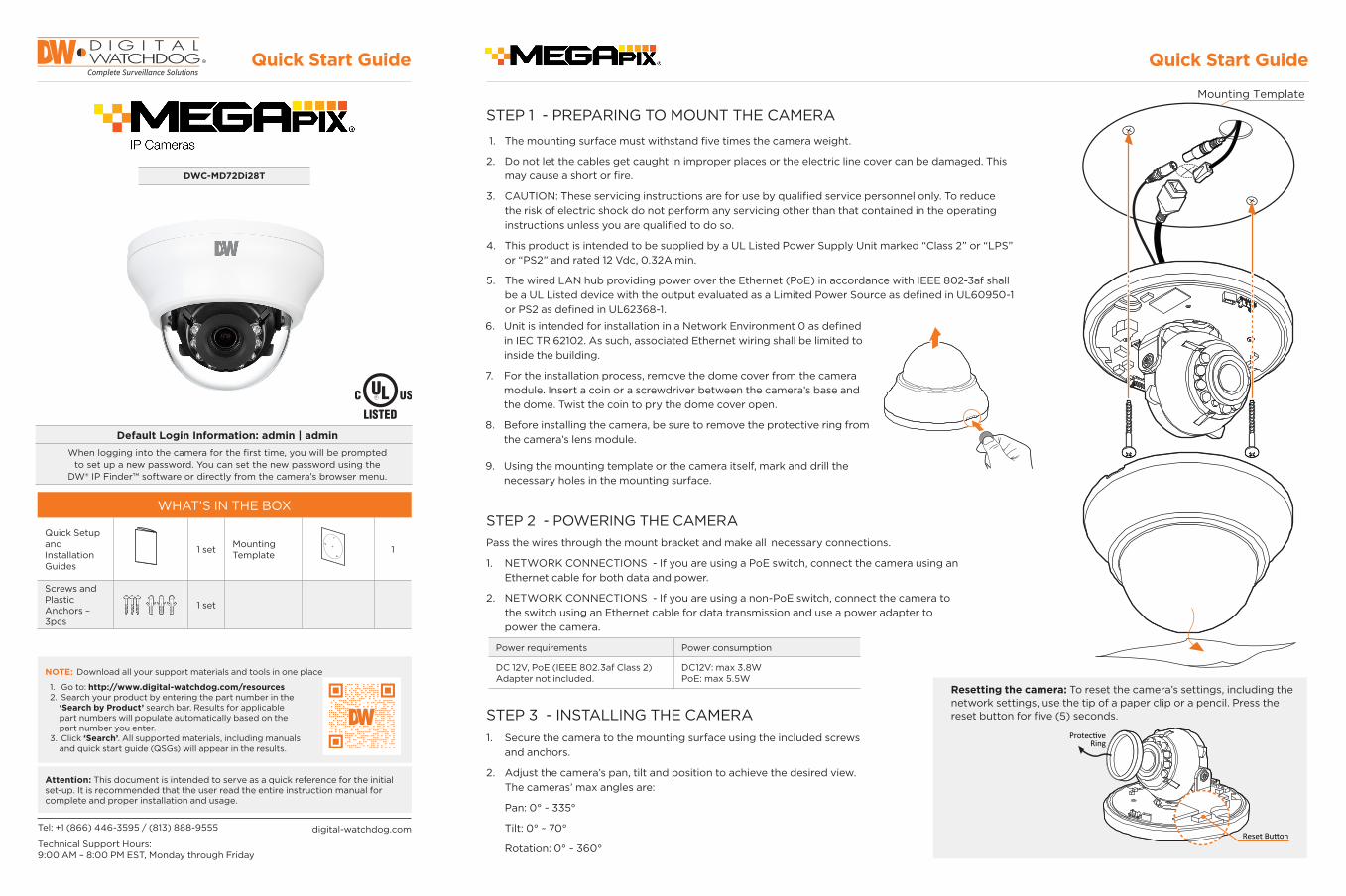
STEP 1 - PREPARING TO MOUNT THE CAMERA
STEP 3 - INSTALLING THE CAMERA
STEP 2 - POWERING THE CAMERA
1. The mounting surface must withstand five times the camera weight.
2. Do not let the cables get caught in improper places or the electric line cover can be damaged. This may cause a short or fire.
3. CAUTION: These servicing instructions are for use by qualified service personnel only. To reduce the risk of electric shock do not perform any servicing other than that contained in the operating instructions unless you are qualified to do so.
4. This product is intended to be supplied by a UL Listed Power Supply Unit marked “Class 2” or “LPS” or “PS2” and rated 12 Vdc, 0.32A min.
5. The wired LAN hub providing power over the Ethernet (PoE) in accordance with IEEE 802-3af shall be a UL Listed device with the output evaluated as a Limited Power Source as defined in UL60950-1 or PS2 as defined in UL62368-1.
1. Secure the camera to the mounting surface using the included screws and anchors.
2. Adjust the camera’s pan, tilt and position to achieve the desired view. The cameras’ max angles are:
Pan: 0° ~ 335°
Tilt: 0° ~ 70°
Rotation: 0° ~ 360°
Pass the wires through the mount bracket and make all necessary connections.
1. NETWORK CONNECTIONS - If you are using a PoE switch, connect the camera using an Ethernet cable for both data and power.
2. NETWORK CONNECTIONS - If you are using a non-PoE switch, connect the camera to the switch using an Ethernet cable for data transmission and use a power adapter to power the camera.
Power requirements Power consumption
DC 12V, PoE (IEEE 802.3af Class 2) Adapter not included.
DC12V: max 3.8WPoE: max 5.5W
Quick Start Guide Quick Start Guide
Resetting the camera: To reset the camera’s settings, including the network settings, use the tip of a paper clip or a pencil. Press the reset button for five (5) seconds.
Reset Button
ProtectiveRing
WHAT’S IN THE BOX
Quick Setup and Installation Guides
1 set Mounting Template 1
Screws and Plastic Anchors – 3pcs
1 set
Tel: +1 (866) 446-3595 / (813) 888-9555
Technical Support Hours: 9:00 AM – 8:00 PM EST, Monday through Friday
digital-watchdog.com
Attention: This document is intended to serve as a quick reference for the initial set-up. It is recommended that the user read the entire instruction manual for complete and proper installation and usage.
NOTE: Download all your support materials and tools in one place
1. Go to: http://www.digital-watchdog.com/resources 2. Search your product by entering the part number in the ‘Search by Product’ search bar. Results for applicable part numbers will populate automatically based on the part number you enter. 3. Click ‘Search’. All supported materials, including manuals and quick start guide (QSGs) will appear in the results.
Mounting Template
Default Login Information: admin | adminWhen logging into the camera for the first time, you will be prompted
to set up a new password. You can set the new password using the DW® IP Finder™ software or directly from the camera’s browser menu.
6. Unit is intended for installation in a Network Environment 0 as defined in IEC TR 62102. As such, associated Ethernet wiring shall be limited to inside the building.
7. For the installation process, remove the dome cover from the camera module. Insert a coin or a screwdriver between the camera’s base and the dome. Twist the coin to pry the dome cover open.
8. Before installing the camera, be sure to remove the protective ring from the camera’s lens module.
9. Using the mounting template or the camera itself, mark and drill the necessary holes in the mounting surface.

Quick Start Guide
Rev: 08/20Copyright © Digital Watchdog. All rights reserved.
Specifications and pricing are subject to change without notice.
STEP 5 – WEB VIEWER
*
The GUI display may differ by camera models.
STEP 4 – DW® IP FINDER™
Thumbnail view
Firmware version
DHCP status
Camera’s uptimeOpen IP configuration settings
Ping camera
Port information
Gateway address
Netmask address
Camera’s MAC address
Filter results
Scan network
Select network to scan
Show/hide thumbnail view
Refresh thumbnail view
Bulk password assignmentBulk IP assignment
Firmware upgrade
Camera’s name
Camera’s IP address
Part number
Use the DW IP Finder software to scan the network and detect all MEGApix® cameras, set the camera’s network settings or access the camera’s web client.
Network Setup1. To install the DW IP Finder, go to
http://www.digital-watchdog.com2. Enter “DW IP Finder” on the search box at the top of the page.3. Go to the “Software” tab on the DW IP Finder page to download
the installation file.4. Follow the installation to install the DW IP Finder. Open the DW IP
Finder and click ‘Scan Devices’. It will scan the selected network for all supported devices and list the results in the table. During the scan, the DW® logo will turn gray.
‘Port forwarding’ has to be set in your network’s router for external access to the camera.
Select DHCP to allow the camera to receive its IP address automatically from the DHCP server.
Select “Static” to manually enter the camera’s IP address, (Sub)Netmask, Gateway and DNS information.* The camera’s IP must be set to Static if connecting to Spectrum® IPVMS
Contact your network administrator for more information.
Default TCP/IP information: DHCP
5. When connecting to the camera for the first time, a password must be set. To set up a password for your new camera:
a. Check the box next to your new camera from the IP Finder’s search results. You can select multiple cameras. b. Click “Bulk Password Assign” on the left.
c. In the pop-up window, enter admin/ admin in the current username and password fields. Enter a new username and password to the right. d. Press “change” to apply all changes.6. Select a camera from the list by double-
clicking on the camera’s image or clicking on the ‘Click’ button under the IP Conf. column. The pop-up window will show the camera’s current network settings, allowing admin users to adjust the settings as needed.
7. To access the camera’s web page, go to the IP Config page and click on the ‘View Camera Website’.
8. To save the changes made to the camera’s setting, input the username and password of the camera and click Apply.
NOTE: Please see the full product manual for web viewer setup, functions and camera settings options.
* NOTE: Some menu options may not be available based on the camera model. See the full manual for more information.
Once the camera’s network settings have been setup properly, you can access the camera’s web viewer using the DW IP Finder.
To open the camera’s web viewer:
1. Find the camera using the DW IP Finder.
2. Double-click on the camera’s view in the results table.
3. Press the ‘View Camera Website’. The camera’s web viewer will open up in your default web browser.
4. Enter the camera’s username and password you setup in the DW IP Finder. If you did not setup a new username and password via the DW IP Finder, you will not be able to view video from the camera. A message will direct you to setup a new password for the camera to view video.
5. When accessing the camera for the first time, install the VLC player for web files to view video from the camera.
NOTE: 32bit version of VLC player must to be installed. If you are using 64bit system, uninstall the previous 64bit version and reinstall using the 32bit version.


Project No. 4789627717 File E158873 Page 1 Compliance Review Conducted by: Date Printed Name Signature
Standard SCC Requirements and Guidance – Product Certification Body Accreditation Program
Edition/ Revision Date 2016-04-06
Clause/Par. Reference and Construction Requirement
Comply Comments/Measurements
Inst. ID No. Yes No N/A
9.2.3 CBs shall include dual language safety labeling within their product certification requirements, if so required by the standard or by the authority having jurisdiction. The manufacturer has confirmed they have the ability to include English and French safety labeling exactly as specified in the product standard; or, if NOT specified in the product standard, the ability to include English and French safety labelling consisting of markings associated with the signal words DANGER, WARNING, and CAUTION when required.
X The ability of the manufacturer to include these markings was verified by either (1) visual inspection of the markings on the actual product or (2) draft of labels that will be applied to the product or (3) written confirmation from the customer of the markings that will appear on the product. If the product standard provides the exact translation, the evidence must match the exact translation. If the product standard does NOT provide the exact translation, the evidence must simply include both the English and French text (no verification of translation is required).
N/A

Project No. 4789627717 File E158873 Page 2 Compliance Review Conducted by: Date Printed Name Signature
Clause/Par. Reference and Construction Requirement
Comply Comments/Measurements
Inst. ID No. Yes No N/A
Manufacturer has a method to manage distribution of products, IF all products with the Canadian certification mark are NOT going to include the dual language.
X Evaluation staff are to only verify that the manufacturer has a method to control distribution. Evaluation staff do not have to record the method of control nor are the evaluation staff expected to verify the effectiveness of the method of control. This requirement to verify that a method exists will be noted in the FUS Procedure. The UL Field Engineer will verify the method during surveillance. If the manufacturer is going to include the dual language on all products with the Canadian certification mark, then this item is N/A; no further action required.
N/A


±0.3
E 0.7 ±0.1
C 6.0 MAX
B
D 2.0
dimension and tolerance
A 13.0 MAX
12.5 MAX
1. SCHEMATIC DIAGRAM (UNIT:mm)BOB TECH P/N:
CUSTOMER:
SPECIFICATION CUSTOMER P/N: CP-1106A ER11.5
C-PRO ELECTRONICS CO., LTD.
REV: A
TYPE:
#6 #10
CP-1106A A
TOP VIEW
FRONT VIEW
底视图
D E
#1 #5
#6 #10
BOTTOM VIEW
侧视图 10PIN 1PIN SIDE VIEW
#1 #5
#1 PIN 표시
Page:3/6

2. CONSTRUCTION 3.CUTAWAY VIEW
6. MATERIALS LIST
NO.
1
2
3
4
5
turns
18
REMARK
AC 0.5KV/SECAN9632W
5mA
CORE wrapping tape: 25u*5.5mm (yellow) 2turns
TERMINAL
LCR-3302
1KHz,1V
2
1 INDUCTANCE
HI-POT
TYPE:
remark
2UEW
0.28Φ
winding
way
"●"Mean Start
No wind tape
W1
SPECIFICATION CUSTOMER:
CUSTOMER P/N:
BOB TECH P/N:
100MΩ MINAN9632W
DC 500V
E59481
N/AACME ELECTRONICS CORPORATION OR EQV
MANUFACTURES
CP-1106A
E165111
E194410
E239866
CHUANG CHUN PLASTICS CO.,LTD OR EQV
VARNISH
WIRE
4.WINDING TABLE
S --- F wire or other
REMARKS
5.ELECTRICAL CHARACTERISTIC
NO.
3
turns
AREV:
ER11.5
C-PRO ELECTRONICS CO., LTD.
JIANGYIN CITY DENGFENG ELECTRICAL
MATERIAL CO LTD OR EQV
CT
319-5F
SHANDONG SAINT ELECTRIC CO LTD OR EQVUEW
JINGJIANG YAHUA PRESSURE SENSITIVE
GLUE CO LTD OR EQV
INDUCTANCE
RESISTANCE
P COIL---S COIL
COIL---CORE
CORE P4
BOBBIN
COMPONENT MATERIALS
T375J
1 --- 5
W2 7 --- 9 9
INSULATION
TAPE
SOLENOID
SOLENOID
P COIL---S COIL
COIL---CORE
P/S TAPE
0.025T×2.02
ITEM
1---5 47uH±10%
SPEC.
2UEW
0.28Φ
Mean mylay tape
W2
7
9
W1
1
5 TOP BOTTOM
CORE(gap) CORE(no gap)
BOBBIN
W1
W2
Page:4/6


3 / 7
1. DIMENSION(UNIT : mm)
0
Page-No.Rev. No. Date .
2020-09-15
Model name. Parts name. Specification.
SMD TRANSFORMER CP-1106A SMD EER11.5(V)-10P
PIN(1) 表示
2. SCHEMATIC DIAGRAM (Bottom-View)
Remove-Pin(無)
S.H.E CO., LTD. A4 (210x297)

4 / 7
3. WINDING SPECIFICATION
B i (t / W) Wi di
2020-09-15SMD TRANSFORMER
T i l I l ti TWi di
Page-No.
0
Rev. No. Date .Model name. Parts name. Specification.
CP-1106A SMD EER11.5(V)-10P
S F TsPRI (1~5)
X
X
SEC (6~10)
Barrier (t / W) Winding
Class & gage
2UEW Φ0 28x 1P
2UEW Φ0.28x 1P
9
18
Ts
W2 7 9 SOLENOID
XSOLENOID
0.025t / 2.0mmX
X
Thick(t)/Width(mm)
51W1
(YL) 2
X
Terminal Insulation TapeWinding
No Method
(YL) 2
4. ELECTRICAL CHARACTERISTIC
X 2UEW Φ0.28x 1P 97 9 0.025t / 2.0mm
0.025t / 6.0mm
X (YL) 2
**Attention ** 1) TUBE-Pin: (無) 2) Remove-Pin: (無) 3) Cutting-pin:(無)
CORE FIXING (CENTER AIR GAP - GAP-CORE-VIEW : TOP)
No.
1
2
ITEM Related conditionsSpec
PIN( 1-5 )LCR METER
Cut of Current5mA
Withstanding Voltage
Terminal
at 1KHz/1V47uH ± 10%
PRI-SEC
PRI-CORE
TOS-8850AC 0.5kVrms 1SEC
HIOKI 3522
Inductance
AC 0.5kVrms 1SEC
3
Cut of Current5mA
Insulation resistance MEGA OHM METER100MΩ min at DC 500v
PRI CORE
PRI-SEC
AC 0.5kVrms 1SECSEC-CORE
AC 0.5kVrms 1SEC
S.H.E CO., LTD. A4 (210x297)

5 / 7
5. MATERIAL LIST
N ITEM
0
Date .
2020-09-15
Rev. No. Page-No.
UL S f t N M f tM t i l & Di i
Model name. Parts name. Specification.
SMD TRANSFORMER CP-1106A SMD EER11.5(V)-10P
No
1
2
TD4 ZHEJIANG TONGDA MAGNETISM INDUSTRY CO.,LTD.
ITEM
BOBBIN E59481PHENOL T375HF
UL Safety No. Manufacturer
CORE not applicableP4 ACME ELECTRONICS CO.,LTD.
or Equivalent.
EER11.5
CHANG CHUN PLASTICS CO., LTD.
Material & Dimension
SMD-TYPE
3
SHANDONG SAINT ELECTRIC CO.,LTD E194410
E336659PolyurethaneEnamelled WIRE
UEW/155 Φ0.28 E221719ZHEJIANG HONGBO TECHNOLOGY CO.,LTD.
ZHEJIANG WUGU COPPER INDUSTRY CO.,LTD
EER11.5(V)-10P(5+5) or Equivalent.
4 (YL)
5 (YL)
TAPE
PS 0.025t / 2.0mm
or Equivalent.
Insulation
CORE FIXING
GUANGDONG KANGLI NEW ENERGY MATERIAL TECHNOLOGY CO.,LTD.
GUANGDONG KANGLI NEW ENERGY MATERIAL TECHNOLOGY CO.,LTD.PS 0.025t / 6.0mm
JINGJIANG YAHUA PRESSURE SENSITIVE GLUE CO.,LTD.
E511186
E165111
E511186
or Equivalent.
5 (YL)
6
S 98 C 2
E165111TAPE
CORE FIXING ,
or Equivalent.
JINGJIANG YAHUA PRESSURE SENSITIVE GLUE CO.,LTD.
PS 0.025t / 6.0mm E511186
SOLDER LEAD-FREETIAJIN SONGBEN ENVIRONMENTIAL SCIENCE & TECHCO.,LTD.
not applicable
E i l tSn98+Cu2
7
or Equivalent.
E228349
JIANGYIN CITY DENGFENG ELECTRICAL MATERIAL CO, LTD
VARNISH T4260(a) SUZHOU TAIHU ELECTRIC ADVANCED MATERIAL CO.,LTD.
E239866
or Equivalent.
S.H.E CO., LTD. A4 (210x297)


Photographs-01 Page-1
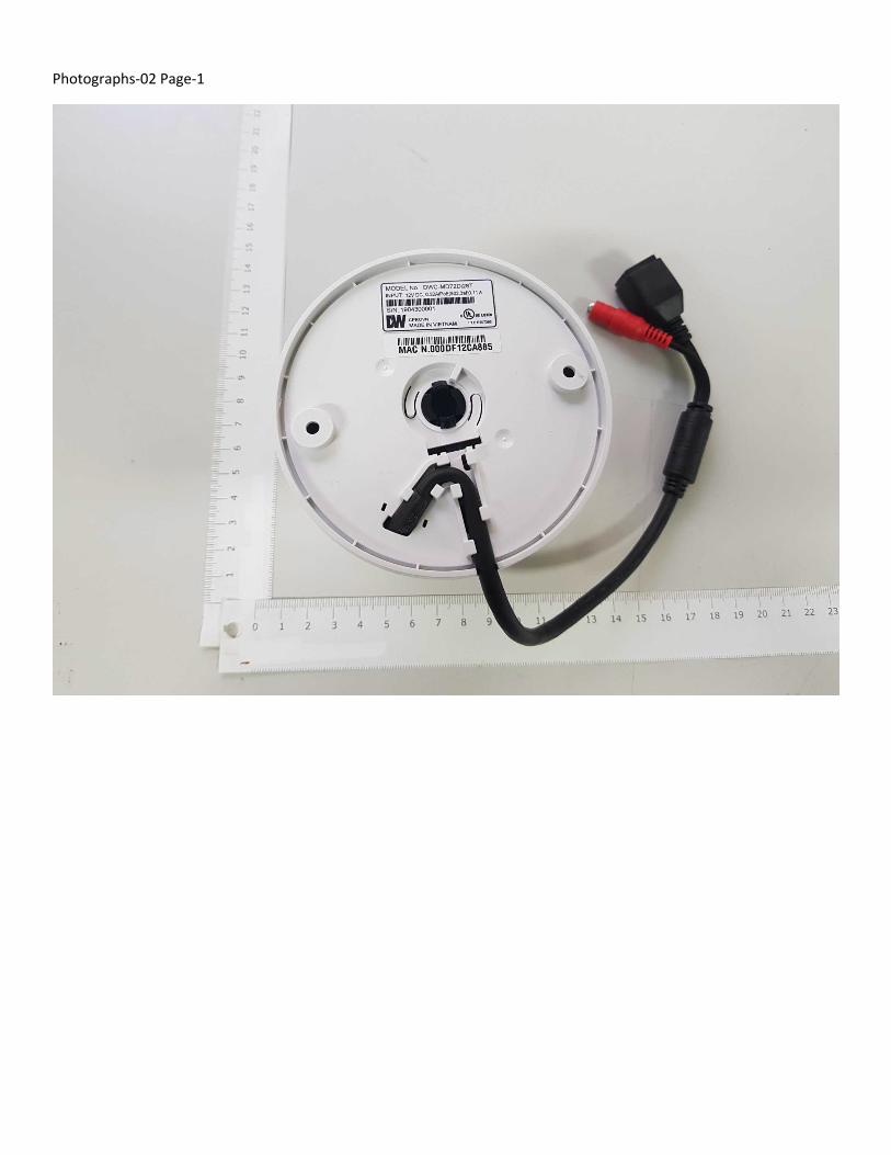
Photographs-02 Page-1

Photographs-03 Page-1
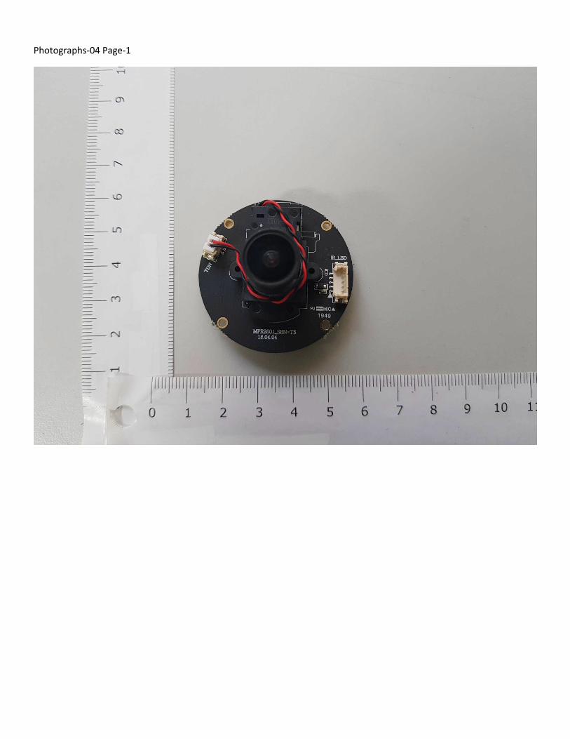
Photographs-04 Page-1

Photographs-05 Page-1

Photographs-06 Page-1

Photographs-07 Page-1
Copyright © 2022 FDOKUMEN