Application manual - ABB
750
— RELION® 670 SERIES Line distance protection REL670 Version 2. 1 IEC Application manual
-
Upload
khangminh22 -
Category
Documents
-
view
2 -
download
0
Transcript of Application manual - ABB

— RELION® 670 SERIES
Line distance protection REL670 Version 2.1 IEC Application manual


Document ID: 1MRK 506 353-UENIssued: March 2019
Revision: BProduct version: 2.1
© Copyright 2016 ABB. All rights reserved

Copyright
This document and parts thereof must not be reproduced or copied without writtenpermission from ABB, and the contents thereof must not be imparted to a third party, norused for any unauthorized purpose.
The software and hardware described in this document is furnished under a license and maybe used or disclosed only in accordance with the terms of such license.
This product includes software developed by the OpenSSL Project for use in the OpenSSLToolkit. (http://www.openssl.org/) This product includes cryptographic software written/developed by: Eric Young ([email protected]) and Tim Hudson ([email protected]).
Trademarks
ABB and Relion are registered trademarks of the ABB Group. All other brand or product namesmentioned in this document may be trademarks or registered trademarks of their respectiveholders.
Warranty
Please inquire about the terms of warranty from your nearest ABB representative.

Disclaimer
The data, examples and diagrams in this manual are included solely for the concept or productdescription and are not to be deemed as a statement of guaranteed properties. All personsresponsible for applying the equipment addressed in this manual must satisfy themselves thateach intended application is suitable and acceptable, including that any applicable safety orother operational requirements are complied with. In particular, any risks in applications wherea system failure and/or product failure would create a risk for harm to property or persons(including but not limited to personal injuries or death) shall be the sole responsibility of theperson or entity applying the equipment, and those so responsible are hereby requested toensure that all measures are taken to exclude or mitigate such risks.
This document has been carefully checked by ABB but deviations cannot be completely ruledout. In case any errors are detected, the reader is kindly requested to notify the manufacturer.Other than under explicit contractual commitments, in no event shall ABB be responsible orliable for any loss or damage resulting from the use of this manual or the application of theequipment.

Conformity
This product complies with the directive of the Council of the European Communities on theapproximation of the laws of the Member States relating to electromagnetic compatibility(EMC Directive 2004/108/EC) and concerning electrical equipment for use within specifiedvoltage limits (Low-voltage directive 2006/95/EC). This conformity is the result of testsconducted by ABB in accordance with the product standard EN 60255-26 for the EMC directive,and with the product standards EN 60255-1 and EN 60255-27 for the low voltage directive. Theproduct is designed in accordance with the international standards of the IEC 60255 series.
Table of contents
Section 1 Introduction.......................................................................................................231.1 This manual....................................................................................................................................... 231.2 Intended audience........................................................................................................................... 231.3 Product documentation................................................................................................................. 241.3.1 Product documentation set...................................................................................................... 241.3.2 Document revision history.........................................................................................................251.3.3 Related documents..................................................................................................................... 251.4 Document symbols and conventions...........................................................................................261.4.1 Symbols......................................................................................................................................... 261.4.2 Document conventions...............................................................................................................271.5 IEC61850 edition 1 / edition 2 mapping...................................................................................... 27
Section 2 Application........................................................................................................ 352.1 General IED application.................................................................................................................. 352.2 Main protection functions............................................................................................................. 362.3 Back-up protection functions....................................................................................................... 382.4 Control and monitoring functions............................................................................................... 402.5 Communication................................................................................................................................452.6 Basic IED functions..........................................................................................................................48
Section 3 Configuration.................................................................................................... 513.1 Introduction.......................................................................................................................................513.2 Description of configuration REL670.......................................................................................... 523.2.1 Introduction..................................................................................................................................523.2.1.1 Description of configuration A21.......................................................................................... 523.2.1.2 Description of configuration A31..........................................................................................543.2.1.3 Description of configuration A32..........................................................................................553.2.1.4 Description of configuration B31.......................................................................................... 573.2.1.5 Description of configuration B32......................................................................................... 59
Section 4 Analog inputs.................................................................................................... 634.1 Introduction...................................................................................................................................... 634.2 Setting guidelines............................................................................................................................634.2.1 Setting of the phase reference channel..................................................................................634.2.1.1 Example......................................................................................................................................644.2.2 Setting of current channels.......................................................................................................644.2.2.1 Example 1...................................................................................................................................644.2.2.2 Example 2...................................................................................................................................654.2.2.3 Example 3...................................................................................................................................664.2.2.4 Examples on how to connect, configure and set CT inputs for most commonly
used CT connections............................................................................................................... 704.2.2.5 Example on how to connect a star connected three-phase CT set to the IED.............71
Table of contents
1Application manual

4.2.2.6 Example how to connect delta connected three-phase CT set to the IED................... 744.2.2.7 Example how to connect single-phase CT to the IED....................................................... 764.2.3 Relationships between setting parameter Base Current, CT rated primary
current and minimum pickup of a protection IED.................................................................774.2.4 Setting of voltage channels.......................................................................................................784.2.4.1 Example......................................................................................................................................784.2.4.2 Examples how to connect, configure and set VT inputs for most commonly
used VT connections................................................................................................................784.2.4.3 Examples on how to connect a three phase-to-earth connected VT to the IED......... 794.2.4.4 Example on how to connect a phase-to-phase connected VT to the IED..................... 814.2.4.5 Example on how to connect an open delta VT to the IED for high impedance
earthed or unearthed netwoeks............................................................................................834.2.4.6 Example how to connect the open delta VT to the IED for low impedance
earthed or solidly earthed power systems......................................................................... 844.2.4.7 Example on how to connect a neutral point VT to the IED..............................................86
Section 5 Local HMI........................................................................................................... 895.1 Display............................................................................................................................................... 905.2 LEDs.................................................................................................................................................... 915.3 Keypad................................................................................................................................................925.4 Local HMI functionality...................................................................................................................945.4.1 Protection and alarm indication...............................................................................................945.4.2 Parameter management ........................................................................................................... 955.4.3 Front communication.................................................................................................................95
Section 6 Differential protection.....................................................................................976.1 High impedance differential protection, single phase HZPDIF .............................................976.1.1 Identification................................................................................................................................ 976.1.2 Application....................................................................................................................................976.1.2.1 The basics of the high impedance principle.......................................................................986.1.3 Connection examples for high impedance differential protection.................................1036.1.3.1 Connections for three-phase high impedance differential protection.......................1036.1.3.2 Connections for 1Ph High impedance differential protection HZPDIF.......................1046.1.4 Setting guidelines..................................................................................................................... 1056.1.4.1 Configuration..........................................................................................................................1056.1.4.2 Settings of protection function.......................................................................................... 1056.1.4.3 T-feeder protection............................................................................................................... 1056.1.4.4 Tertiary reactor protection.................................................................................................. 1076.1.4.5 Alarm level operation.............................................................................................................1096.2 Line differential protection.......................................................................................................... 1106.2.1 Identification.............................................................................................................................. 1106.2.2 Application.................................................................................................................................. 1106.2.2.1 Power transformers in the protected zone....................................................................... 1116.2.2.2 Small power transformers in a tap......................................................................................1126.2.2.3 Charging current compensation..........................................................................................1136.2.2.4 Time synchronization.............................................................................................................1146.2.2.5 Analog signal communication for line differential protection...................................... 115
Table of contents
2Application manual

6.2.2.6 Configuration of analog signals.......................................................................................... 1166.2.2.7 Configuration of LDCM output signals.............................................................................. 1166.2.2.8 Open CT detection..................................................................................................................1176.2.3 Setting guidelines...................................................................................................................... 1186.2.3.1 General settings......................................................................................................................1186.2.3.2 Percentage restrained differential operation...................................................................1196.2.3.3 The 2nd and 5th harmonic analysis.....................................................................................1226.2.3.4 Internal/external fault discriminator..................................................................................1236.2.3.5 Power transformer in the protected zone.........................................................................1246.2.3.6 Settings examples..................................................................................................................1286.3 Additional security logic for differential protection LDRGFC ..............................................1366.3.1 Identification.............................................................................................................................. 1366.3.2 Application.................................................................................................................................. 1366.3.3 Setting guidelines......................................................................................................................137
Section 7 Impedance protection....................................................................................1397.1 Distance measuring zone, quadrilateral characteristic for series compensated
lines ZMCPDIS, ZMCAPDIS, ZDSRDIR......................................................................................... 1397.1.1 Identification.............................................................................................................................. 1397.1.2 Application.................................................................................................................................. 1397.1.2.1 Introduction.............................................................................................................................1397.1.2.2 System earthing......................................................................................................................1397.1.2.3 Fault infeed from remote end.............................................................................................. 1417.1.2.4 Load encroachment............................................................................................................... 1427.1.2.5 Long transmission line application.................................................................................... 1427.1.2.6 Parallel line application with mutual coupling..................................................................1437.1.2.7 Tapped line application........................................................................................................ 1497.1.2.8 Series compensation in power systems............................................................................ 1517.1.2.9 Challenges in protection of series compensated and adjacent power lines............. 1577.1.2.10 Impact of series compensation on protective IED of adjacent lines...........................1667.1.2.11 Distance protection...............................................................................................................1687.1.3 Setting guidelines......................................................................................................................1747.1.3.1 General......................................................................................................................................1747.1.3.2 Setting of zone1...................................................................................................................... 1747.1.3.3 Setting of overreaching zone...............................................................................................1747.1.3.4 Setting of reverse zone......................................................................................................... 1757.1.3.5 Series compensated and adjacent lines............................................................................ 1757.1.3.6 Setting of zones for parallel line application.................................................................... 1797.1.3.7 Setting of reach in resistive direction................................................................................ 1817.1.3.8 Load impedance limitation, without load encroachment function..............................1817.1.3.9 Load impedance limitation, with load encroachment function activated................. 1837.1.3.10 Setting of minimum operating currents........................................................................... 1837.1.3.11 Setting of timers for distance protection zones............................................................. 1837.2 Phase selection, quadrilateral characteristic with fixed angle FDPSPDIS..........................1847.2.1 Identification..............................................................................................................................1847.2.1.1 Identification...........................................................................................................................1847.2.2 Application..................................................................................................................................184
Table of contents
3Application manual
7.2.3 Setting guidelines..................................................................................................................... 1847.2.3.1 Load encroachment characteristics...................................................................................1847.2.3.2 Resistive reach with load encroachment characteristic................................................ 1907.2.3.3 Minimum operate currents.................................................................................................. 1907.3 Distance measuring zones, quadrilateral characteristic ZMQPDIS,
ZMQAPDIS, ZDRDIR........................................................................................................................ 1917.3.1 Identification.............................................................................................................................. 1917.3.2 Application.................................................................................................................................. 1917.3.2.1 System earthing......................................................................................................................1917.3.2.2 Fault infeed from remote end............................................................................................. 1947.3.2.3 Load encroachment............................................................................................................... 1957.3.2.4 Short line application............................................................................................................ 1967.3.2.5 Long transmission line application.................................................................................... 1967.3.2.6 Parallel line application with mutual coupling..................................................................1977.3.2.7 Tapped line application........................................................................................................ 2037.3.3 Setting guidelines..................................................................................................................... 2057.3.3.1 General..................................................................................................................................... 2057.3.3.2 Setting of zone 1.................................................................................................................... 2057.3.3.3 Setting of overreaching zone.............................................................................................. 2057.3.3.4 Setting of reverse zone.........................................................................................................2067.3.3.5 Setting of zones for parallel line application....................................................................2077.3.3.6 Setting of reach in resistive direction............................................................................... 2087.3.3.7 Load impedance limitation, without load encroachment function.............................2087.3.3.8 Load impedance limitation, with Phase selection with load encroachment,
quadrilateral characteristic function activated .............................................................. 2107.3.3.9 Setting of minimum operating currents........................................................................... 2107.3.3.10 Directional impedance element for quadrilateral characteristics............................... 2107.3.3.11 Setting of timers for distance protection zones............................................................. 2127.4 Full-scheme distance measuring, Mho characteristic ZMHPDIS ......................................... 2137.4.1 Identification.............................................................................................................................. 2137.4.2 Application.................................................................................................................................. 2137.4.2.1 Functionality............................................................................................................................2137.4.2.2 System earthing......................................................................................................................2137.4.2.3 Fault infeed from remote end..............................................................................................2167.4.2.4 Load encroachment............................................................................................................... 2177.4.2.5 Short line application.............................................................................................................2187.4.2.6 Long transmission line application.................................................................................... 2197.4.2.7 Parallel line application with mutual coupling..................................................................2197.4.2.8 Tapped line application.........................................................................................................2237.4.3 Setting guidelines..................................................................................................................... 2257.4.3.1 General......................................................................................................................................2257.4.3.2 Setting of zone 1.....................................................................................................................2267.4.3.3 Setting of zone 2.................................................................................................................... 2267.4.3.4 Setting of zone 3.................................................................................................................... 2267.4.3.5 Setting of reverse zone......................................................................................................... 2267.4.3.6 Consideration of zero sequence mutual coupling for parallel circuits........................232
Table of contents
4Application manual

7.4.3.7 Load impedance limitation, without load encroachment function............................. 2327.4.3.8 Load impedance limitation, with load encroachment function activated................. 2337.4.3.9 Setting of minimum operate currents...............................................................................2347.4.3.10 Setting of directional mode.................................................................................................2347.4.3.11 Setting of direction for offset mho....................................................................................2347.4.3.12 Setting of timers for distance protection zones.............................................................2347.5 Full-scheme distance protection, quadrilateral for earth faults ZMMPDIS, ZMMAPDIS. 2357.5.1 Identification..............................................................................................................................2357.5.2 Application..................................................................................................................................2357.5.2.1 Introduction............................................................................................................................ 2357.5.2.2 System earthing..................................................................................................................... 2357.5.2.3 Fault infeed from remote end............................................................................................. 2387.5.2.4 Load encroachment...............................................................................................................2397.5.2.5 Short line application............................................................................................................2407.5.2.6 Long transmission line application....................................................................................2407.5.2.7 Parallel line application with mutual coupling..................................................................2417.5.2.8 Tapped line application........................................................................................................ 2467.5.3 Setting guidelines..................................................................................................................... 2487.5.3.1 General..................................................................................................................................... 2487.5.3.2 Setting of zone1..................................................................................................................... 2487.5.3.3 Setting of overreaching zone.............................................................................................. 2487.5.3.4 Setting of reverse zone.........................................................................................................2497.5.3.5 Setting of zones for parallel line application................................................................... 2497.5.3.6 Setting of reach in resistive direction................................................................................ 2517.5.3.7 Load impedance limitation, without load encroachment function............................. 2517.5.3.8 Load impedance limitation, with load encroachment function activated................. 2527.5.3.9 Setting of minimum operating currents........................................................................... 2527.5.3.10 Setting of timers for distance protection zones............................................................. 2537.6 Additional distance protection directional function for earth faults ZDARDIR................ 2537.6.1 Identification..............................................................................................................................2537.6.2 Application..................................................................................................................................2537.6.3 Setting guidelines..................................................................................................................... 2537.7 Mho impedance supervision logic ZSMGAPC...........................................................................2557.7.1 Identification..............................................................................................................................2557.7.2 Application..................................................................................................................................2557.7.3 Setting guidelines..................................................................................................................... 2567.8 Faulty phase identification with load encroachment FMPSPDIS.........................................2567.8.1 Identification..............................................................................................................................2567.8.2 Application..................................................................................................................................2567.8.3 Setting guidelines......................................................................................................................2577.8.3.1 Load encroachment...............................................................................................................2587.9 Distance protection zone, quadrilateral characteristic, separate settings ZMRPDIS,
ZMRAPDIS and ZDRDIR................................................................................................................. 2597.9.1 Identification..............................................................................................................................2597.9.2 Application..................................................................................................................................2597.9.2.1 System earthing.....................................................................................................................260
Table of contents
5Application manual

7.9.2.2 Fault infeed from remote end............................................................................................. 2627.9.2.3 Load encroachment...............................................................................................................2637.9.2.4 Short line application............................................................................................................ 2647.9.2.5 Long transmission line application.................................................................................... 2657.9.2.6 Parallel line application with mutual coupling................................................................. 2657.9.2.7 Tapped line application........................................................................................................ 2707.9.3 Setting guidelines......................................................................................................................2727.9.3.1 General......................................................................................................................................2727.9.3.2 Setting of zone 1..................................................................................................................... 2727.9.3.3 Setting of overreaching zone...............................................................................................2727.9.3.4 Setting of reverse zone......................................................................................................... 2737.9.3.5 Setting of zones for parallel line application....................................................................2747.9.3.6 Setting of reach in resistive direction................................................................................2757.9.3.7 Load impedance limitation, without load encroachment function............................. 2757.9.3.8 Load impedance limitation, with Phase selection with load encroachment,
quadrilateral characteristic function activated ...............................................................2777.9.3.9 Setting of minimum operating currents............................................................................2777.9.3.10 Setting of timers for distance protection zones............................................................. 2777.10 Phase selection, quadrilateral characteristic with settable angle FRPSPDIS.................... 2787.10.1 Identification..............................................................................................................................2787.10.2 Application..................................................................................................................................2787.10.3 Load encroachment characteristics......................................................................................2827.10.3.1 Phase-to-earth fault in forward direction.........................................................................2837.10.3.2 Phase-to-earth fault in reverse direction..........................................................................2847.10.3.3 Phase-to-phase fault in forward direction....................................................................... 2857.10.4 Setting guidelines..................................................................................................................... 2867.10.4.1 Resistive reach with load encroachment characteristic................................................ 2867.10.4.2 Minimum operate currents.................................................................................................. 2877.11 Phase selection, quadrilateral characteristic with fixed angle FDPSPDIS......................... 2887.11.1 Identification..............................................................................................................................2887.11.1.1 Identification.......................................................................................................................... 2887.11.2 Application..................................................................................................................................2887.11.3 Setting guidelines..................................................................................................................... 2887.11.3.1 Load encroachment characteristics.................................................................................. 2887.11.3.2 Resistive reach with load encroachment characteristic................................................ 2947.11.3.3 Minimum operate currents.................................................................................................. 2947.12 High speed distance protection ZMFPDIS............................................................................... 2957.12.1 Identification..............................................................................................................................2957.12.2 Application..................................................................................................................................2957.12.2.1 System earthing..................................................................................................................... 2957.12.2.2 Fault infeed from remote end............................................................................................. 2987.12.2.3 Load encroachment...............................................................................................................2997.12.2.4 Short line application............................................................................................................ 2997.12.2.5 Long transmission line application....................................................................................3007.12.2.6 Parallel line application with mutual coupling.................................................................3007.12.2.7 Tapped line application........................................................................................................ 306
Table of contents
6Application manual

7.12.3 Setting guidelines..................................................................................................................... 3087.12.3.1 General..................................................................................................................................... 3087.12.3.2 Setting of zone 1.................................................................................................................... 3087.12.3.3 Setting of overreaching zone.............................................................................................. 3087.12.3.4 Setting of reverse zone.........................................................................................................3097.12.3.5 Setting of zones for parallel line application....................................................................3107.12.3.6 Setting the reach with respect to load...............................................................................3117.12.3.7 Zone reach setting lower than minimum load impedance............................................ 3127.12.3.8 Zone reach setting higher than minimum load impedance...........................................3137.12.3.9 Other settings.........................................................................................................................3147.13 High speed distance protection for series compensated lines ZMFCPDIS .......................3177.13.1 Identification.............................................................................................................................. 3177.13.2 Application.................................................................................................................................. 3177.13.2.1 System earthing......................................................................................................................3177.13.2.2 Fault infeed from remote end..............................................................................................3197.13.2.3 Load encroachment...............................................................................................................3207.13.2.4 Short line application.............................................................................................................3217.13.2.5 Long transmission line application.....................................................................................3217.13.2.6 Parallel line application with mutual coupling..................................................................3227.13.2.7 Tapped line application........................................................................................................ 3287.13.3 Series compensation in power systems...............................................................................3307.13.3.1 Steady state voltage regulation and increase of voltage collapse limit.....................3307.13.3.2 Increase in power transfer....................................................................................................3317.13.3.3 Voltage and current inversion..............................................................................................3327.13.3.4 Impact of series compensation on protective IED of adjacent lines...........................3387.13.3.5 Distance protection.............................................................................................................. 3407.13.3.6 Underreaching and overreaching schemes......................................................................3407.13.4 Setting guidelines..................................................................................................................... 3467.13.4.1 General..................................................................................................................................... 3467.13.4.2 Setting of zone 1.................................................................................................................... 3467.13.4.3 Setting of overreaching zone.............................................................................................. 3467.13.4.4 Setting of reverse zone......................................................................................................... 3477.13.4.5 Series compensated and adjacent lines............................................................................3477.13.4.6 Setting of zones for parallel line application.................................................................... 3517.13.4.7 Setting of reach in resistive direction................................................................................3527.13.4.8 Load impedance limitation, without load encroachment function............................. 3537.13.4.9 Zone reach setting higher than minimum load impedance.......................................... 3547.13.4.10 Parameter setting guidelines.............................................................................................. 3557.14 Power swing detection ZMRPSB ................................................................................................3577.14.1 Identification.............................................................................................................................. 3577.14.2 Application..................................................................................................................................3577.14.2.1 General......................................................................................................................................3577.14.2.2 Basic characteristics............................................................................................................. 3587.14.3 Setting guidelines..................................................................................................................... 3587.15 Power swing logic PSLPSCH .......................................................................................................3647.15.1 Identification..............................................................................................................................364
Table of contents
7Application manual
7.15.2 Application................................................................................................................................. 3647.15.3 Setting guidelines..................................................................................................................... 3667.15.3.1 Scheme communication and tripping for faults occurring during power
swinging over the protected line........................................................................................3667.15.3.2 Blocking and tripping logic for evolving power swings.................................................3697.16 Pole slip protection PSPPPAM .................................................................................................... 3717.16.1 Identification.............................................................................................................................. 3717.16.2 Application.................................................................................................................................. 3717.16.3 Setting guidelines..................................................................................................................... 3747.16.3.1 Setting example for line application.................................................................................. 3757.16.3.2 Setting example for generator application...................................................................... 3787.17 Out-of-step protection OOSPPAM ............................................................................................ 3827.17.1 Identification..............................................................................................................................3827.17.2 Application..................................................................................................................................3827.17.3 Setting guidelines..................................................................................................................... 3847.18 Automatic switch onto fault logic ZCVPSOF ...........................................................................3877.18.1 Identification..............................................................................................................................3877.18.2 Application..................................................................................................................................3877.18.3 Setting guidelines..................................................................................................................... 3887.19 Phase preference logic PPLPHIZ.................................................................................................3897.19.1 Identification..............................................................................................................................3897.19.2 Application..................................................................................................................................3897.19.3 Setting guidelines..................................................................................................................... 392
Section 8 Current protection......................................................................................... 3938.1 Instantaneous phase overcurrent protection PHPIOC ..........................................................3938.1.1 Identification..............................................................................................................................3938.1.2 Application..................................................................................................................................3938.1.3 Setting guidelines..................................................................................................................... 3938.1.3.1 Meshed network without parallel line............................................................................... 3948.1.3.2 Meshed network with parallel line......................................................................................3968.2 Four step phase overcurrent protection OC4PTOC............................................................... 3978.2.1 Identification..............................................................................................................................3978.2.2 Application..................................................................................................................................3978.2.3 Setting guidelines..................................................................................................................... 3988.2.3.1 Settings for each step...........................................................................................................3998.2.3.2 2nd harmonic restrain...........................................................................................................4028.3 Instantaneous residual overcurrent protection EFPIOC ...................................................... 4068.3.1 Identification..............................................................................................................................4078.3.2 Application................................................................................................................................. 4078.3.3 Setting guidelines..................................................................................................................... 4078.4 Four step residual overcurrent protection, (Zero sequence or negative sequence
directionality) EF4PTOC ..............................................................................................................4098.4.1 Identification............................................................................................................................. 4098.4.2 Application................................................................................................................................. 4098.4.3 Setting guidelines......................................................................................................................4118.4.3.1 Settings for each step (x = 1, 2, 3 and 4)............................................................................ 411
Table of contents
8Application manual

8.4.3.2 Common settings for all steps............................................................................................ 4138.4.3.3 2nd harmonic restrain........................................................................................................... 4148.4.3.4 Parallel transformer inrush current logic.......................................................................... 4148.4.3.5 Switch onto fault logic.......................................................................................................... 4158.4.3.6 Line application example......................................................................................................4168.5 Four step directional negative phase sequence overcurrent protection NS4PTOC .......4208.5.1 Identification..............................................................................................................................4208.5.2 Application................................................................................................................................. 4208.5.3 Setting guidelines..................................................................................................................... 4228.5.3.1 Settings for each step ..........................................................................................................4228.5.3.2 Common settings for all steps............................................................................................4248.6 Sensitive directional residual overcurrent and power protection SDEPSDE ....................4258.6.1 Identification..............................................................................................................................4258.6.2 Application..................................................................................................................................4268.6.3 Setting guidelines..................................................................................................................... 4278.7 Thermal overload protection, one time constant, Celsius/Fahrenheit
LCPTTR/LFPTTR............................................................................................................................ 4348.7.1 Identification..............................................................................................................................4348.7.2 Application................................................................................................................................. 4348.7.3 Setting guideline....................................................................................................................... 4358.8 Breaker failure protection CCRBRF............................................................................................4368.8.1 Identification..............................................................................................................................4368.8.2 Application................................................................................................................................. 4368.8.3 Setting guidelines..................................................................................................................... 4368.9 Stub protection STBPTOC .......................................................................................................... 4398.9.1 Identification..............................................................................................................................4398.9.2 Application................................................................................................................................. 4398.9.3 Setting guidelines.....................................................................................................................4408.10 Pole discordance protection CCPDSC...................................................................................... 4408.10.1 Identification..............................................................................................................................4418.10.2 Application..................................................................................................................................4418.10.3 Setting guidelines..................................................................................................................... 4418.11 Directional underpower protection GUPPDUP........................................................................4428.11.1 Identification..............................................................................................................................4428.11.2 Application................................................................................................................................. 4428.11.3 Setting guidelines.....................................................................................................................4448.12 Directional overpower protection GOPPDOP ......................................................................... 4478.12.1 Identification..............................................................................................................................4478.12.2 Application..................................................................................................................................4478.12.3 Setting guidelines.....................................................................................................................4498.13 Broken conductor check BRCPTOC ...........................................................................................4528.13.1 Identification..............................................................................................................................4528.13.2 Application..................................................................................................................................4528.13.3 Setting guidelines..................................................................................................................... 4528.14 Voltage-restrained time overcurrent protection VRPVOC.................................................... 4538.14.1 Identification..............................................................................................................................453
Table of contents
9Application manual

8.14.2 Application..................................................................................................................................4538.14.2.1 Base quantities.......................................................................................................................4538.14.2.2 Application possibilities.......................................................................................................4548.14.2.3 Undervoltage seal-in............................................................................................................. 4548.14.3 Setting guidelines.....................................................................................................................4548.14.3.1 Explanation of the setting parameters............................................................................. 4558.14.3.2 Voltage-restrained overcurrent protection for generator and step-up
transformer.............................................................................................................................4558.14.3.3 Overcurrent protection with undervoltage seal-in......................................................... 456
Section 9 Voltage protection.........................................................................................4599.1 Two step undervoltage protection UV2PTUV .........................................................................4599.1.1 Identification..............................................................................................................................4599.1.2 Application................................................................................................................................. 4599.1.3 Setting guidelines..................................................................................................................... 4599.1.3.1 Equipment protection, such as for motors and generators.........................................4609.1.3.2 Disconnected equipment detection..................................................................................4609.1.3.3 Power supply quality ............................................................................................................4609.1.3.4 Voltage instability mitigation............................................................................................. 4609.1.3.5 Backup protection for power system faults.................................................................... 4609.1.3.6 Settings for Two step undervoltage protection............................................................. 4609.2 Two step overvoltage protection OV2PTOV ........................................................................... 4629.2.1 Identification..............................................................................................................................4629.2.2 Application..................................................................................................................................4629.2.3 Setting guidelines..................................................................................................................... 4639.2.3.1 Equipment protection, such as for motors, generators, reactors and
transformers...........................................................................................................................4639.2.3.2 Equipment protection, capacitors..................................................................................... 4639.2.3.3 Power supply quality............................................................................................................. 4639.2.3.4 High impedance earthed systems..................................................................................... 4649.2.3.5 The following settings can be done for the two step overvoltage protection.........4649.3 Two step residual overvoltage protection ROV2PTOV ......................................................... 4659.3.1 Identification..............................................................................................................................4659.3.2 Application................................................................................................................................. 4659.3.3 Setting guidelines.....................................................................................................................4669.3.3.1 Equipment protection, such as for motors, generators, reactors and
transformers...........................................................................................................................4669.3.3.2 Equipment protection, capacitors.....................................................................................4669.3.3.3 Power supply quality.............................................................................................................4669.3.3.4 High impedance earthed systems..................................................................................... 4669.3.3.5 Direct earthed system...........................................................................................................4679.3.3.6 Settings for Two step residual overvoltage protection................................................ 4689.4 Overexcitation protection OEXPVPH ........................................................................................4709.4.1 Identification..............................................................................................................................4709.4.2 Application................................................................................................................................. 4709.4.3 Setting guidelines......................................................................................................................4719.4.3.1 Recommendations for input and output signals.............................................................471
Table of contents
10Application manual

9.4.3.2 Settings....................................................................................................................................4729.4.3.3 Service value report............................................................................................................... 4739.4.3.4 Setting example..................................................................................................................... 4739.5 Voltage differential protection VDCPTOV ............................................................................... 4749.5.1 Identification..............................................................................................................................4749.5.2 Application..................................................................................................................................4759.5.3 Setting guidelines..................................................................................................................... 4769.6 Loss of voltage check LOVPTUV ................................................................................................ 4779.6.1 Identification.............................................................................................................................. 4779.6.2 Application..................................................................................................................................4779.6.3 Setting guidelines..................................................................................................................... 4779.6.3.1 Advanced users settings...................................................................................................... 4789.7 Radial feeder protection PAPGAPC............................................................................................ 4789.7.1 Identification..............................................................................................................................4789.7.2 Application..................................................................................................................................4789.7.3 Setting guidelines..................................................................................................................... 478
Section 10 Frequency protection.....................................................................................48110.1 Underfrequency protection SAPTUF .........................................................................................48110.1.1 Identification..............................................................................................................................48110.1.2 Application..................................................................................................................................48110.1.3 Setting guidelines..................................................................................................................... 48110.2 Overfrequency protection SAPTOF ...........................................................................................48210.2.1 Identification..............................................................................................................................48210.2.2 Application..................................................................................................................................48210.2.3 Setting guidelines..................................................................................................................... 48310.3 Rate-of-change frequency protection SAPFRC ...................................................................... 48310.3.1 Identification..............................................................................................................................48310.3.2 Application................................................................................................................................. 48310.3.3 Setting guidelines.....................................................................................................................484
Section 11 Multipurpose protection............................................................................... 48511.1 General current and voltage protection CVGAPC................................................................... 48511.1.1 Identification............................................................................................................................. 48511.1.2 Application................................................................................................................................. 48511.1.2.1 Current and voltage selection for CVGAPC function......................................................48611.1.2.2 Base quantities for CVGAPC function............................................................................... 48811.1.2.3 Application possibilities.......................................................................................................48811.1.2.4 Inadvertent generator energization.................................................................................. 48911.1.3 Setting guidelines.....................................................................................................................49011.1.3.1 Directional negative sequence overcurrent protection.................................................49011.1.3.2 Negative sequence overcurrent protection......................................................................49111.1.3.3 Generator stator overload protection in accordance with IEC or ANSI standards.. 49311.1.3.4 Open phase protection for transformer, lines or generators and circuit
breaker head flashover protection for generators......................................................... 49511.1.3.5 Voltage restrained overcurrent protection for generator and step-up
transformer.............................................................................................................................496
Table of contents
11Application manual

11.1.3.6 Loss of excitation protection for a generator................................................................. 496
Section 12 System protection and control.................................................................... 49912.1 Multipurpose filter SMAIHPAC....................................................................................................49912.1.1 Identification............................................................................................................................. 49912.1.2 Application................................................................................................................................. 49912.1.3 Setting guidelines.....................................................................................................................50012.1.3.1 Setting example.....................................................................................................................500
Section 13 Secondary system supervision.....................................................................50313.1 Current circuit supervision CCSSPVC........................................................................................50313.1.1 Identification..............................................................................................................................50313.1.2 Application................................................................................................................................. 50313.1.3 Setting guidelines..................................................................................................................... 50313.2 Fuse failure supervision FUFSPVC............................................................................................. 50413.2.1 Identification............................................................................................................................. 50413.2.2 Application................................................................................................................................. 50413.2.3 Setting guidelines..................................................................................................................... 50513.2.3.1 General..................................................................................................................................... 50513.2.3.2 Setting of common parameters......................................................................................... 50513.2.3.3 Negative sequence based.................................................................................................... 50513.2.3.4 Zero sequence based............................................................................................................50613.2.3.5 Delta U and delta I .................................................................................................................50713.2.3.6 Dead line detection................................................................................................................50713.3 Fuse failure supervision VDSPVC................................................................................................50713.3.1 Identification..............................................................................................................................50713.3.2 Application..................................................................................................................................50713.3.3 Setting guidelines.....................................................................................................................508
Section 14 Control..............................................................................................................51114.1 Synchrocheck, energizing check, and synchronizing SESRSYN............................................ 51114.1.1 Identification...............................................................................................................................51114.1.2 Application.................................................................................................................................. 51114.1.2.1 Synchronizing.......................................................................................................................... 51114.1.2.2 Synchrocheck...........................................................................................................................51214.1.2.3 Energizing check.....................................................................................................................51414.1.2.4 Voltage selection....................................................................................................................51414.1.2.5 External fuse failure............................................................................................................... 51514.1.3 Application examples................................................................................................................51614.1.3.1 Single circuit breaker with single busbar.......................................................................... 51614.1.3.2 Single circuit breaker with double busbar, external voltage selection........................51714.1.3.3 Single circuit breaker with double busbar, internal voltage selection........................ 51714.1.3.4 Double circuit breaker........................................................................................................... 51814.1.3.5 1 1/2 circuit breaker............................................................................................................... 51814.1.4 Setting guidelines..................................................................................................................... 52014.2 Autorecloser for 1 phase, 2 phase and/or 3 phase operation SMBRREC .......................... 52414.2.1 Identification..............................................................................................................................524
Table of contents
12Application manual

14.2.2 Application..................................................................................................................................52514.2.2.1 Auto-reclosing operation OFF and ON.............................................................................. 52714.2.2.2 Start auto-reclosing and conditions for start of a reclosing cycle.............................. 52814.2.2.3 Start auto-reclosing from CB open information............................................................. 52814.2.2.4 Blocking of the autorecloser................................................................................................52814.2.2.5 Control of the auto-reclosing open time for shot 1........................................................ 52814.2.2.6 Long trip signal.......................................................................................................................52914.2.2.7 Maximum number of reclosing shots................................................................................ 52914.2.2.8 ARMode=3ph, (normal setting for a single 3 phase shot)............................................. 52914.2.2.9 ARMode=1/2/3ph...................................................................................................................52914.2.2.10 ARMode=1/2ph, 1-phase or 2-phase reclosing in the first shot................................... 53014.2.2.11 ARMode=1ph + 1*2ph, 1-phase or 2-phase reclosing in the first shot.........................53014.2.2.12 ARMode=1/2ph + 1*3ph, 1-phase, 2-phase or 3-phase reclosing in the first shot.... 53014.2.2.13 ARMode=1ph + 1*2/3ph, 1-phase, 2-phase or 3-phase reclosing in the first shot.... 53014.2.2.14 External selection of auto-reclose mode...........................................................................53114.2.2.15 Reclosing reclaim timer.........................................................................................................53114.2.2.16 Pulsing of the CB closing command and Counter...........................................................53214.2.2.17 Transient fault........................................................................................................................ 53214.2.2.18 Permanent fault and reclosing unsuccessful signal........................................................53214.2.2.19 Lock-out initiation..................................................................................................................53214.2.2.20 Evolving fault...........................................................................................................................53314.2.2.21 Automatic continuation of the reclosing sequence .......................................................53414.2.2.22 Thermal overload protection holding the auto-reclosing function back .................. 53414.2.3 Setting guidelines..................................................................................................................... 53414.2.3.1 Configuration......................................................................................................................... 53414.2.3.2 Auto-recloser parameter settings......................................................................................53914.3 Apparatus control APC................................................................................................................. 54214.3.1 Application..................................................................................................................................54214.3.1.1 Bay control (QCBAY)..............................................................................................................54514.3.1.2 Switch controller (SCSWI).................................................................................................... 54614.3.1.3 Switches (SXCBR/SXSWI).....................................................................................................54714.3.1.4 Reservation function (QCRSV and RESIN).........................................................................54714.3.2 Interaction between modules................................................................................................ 54914.3.3 Setting guidelines..................................................................................................................... 55014.3.3.1 Bay control (QCBAY)..............................................................................................................55014.3.3.2 Switch controller (SCSWI).....................................................................................................55114.3.3.3 Switch (SXCBR/SXSWI)......................................................................................................... 55214.3.3.4 Bay Reserve (QCRSV).............................................................................................................55214.3.3.5 Reservation input (RESIN).................................................................................................... 55214.4 Interlocking .................................................................................................................................... 55214.4.1 Configuration guidelines......................................................................................................... 55314.4.2 Interlocking for line bay ABC_LINE ........................................................................................55314.4.2.1 Application.............................................................................................................................. 55414.4.2.2 Signals from bypass busbar................................................................................................ 55414.4.2.3 Signals from bus-coupler..................................................................................................... 55514.4.2.4 Configuration setting............................................................................................................557
Table of contents
13Application manual

14.4.3 Interlocking for bus-coupler bay ABC_BC ........................................................................... 55814.4.3.1 Application.............................................................................................................................. 55814.4.3.2 Configuration......................................................................................................................... 55914.4.3.3 Signals from all feeders........................................................................................................ 55914.4.3.4 Signals from bus-coupler......................................................................................................56114.4.3.5 Configuration setting........................................................................................................... 56214.4.4 Interlocking for transformer bay AB_TRAFO ...................................................................... 56314.4.4.1 Application.............................................................................................................................. 56314.4.4.2 Signals from bus-coupler..................................................................................................... 56414.4.4.3 Configuration setting........................................................................................................... 56514.4.5 Interlocking for bus-section breaker A1A2_BS.................................................................... 56514.4.5.1 Application.............................................................................................................................. 56514.4.5.2 Signals from all feeders........................................................................................................ 56514.4.5.3 Configuration setting........................................................................................................... 56814.4.6 Interlocking for bus-section disconnector A1A2_DC ........................................................ 56814.4.6.1 Application.............................................................................................................................. 56914.4.6.2 Signals in single breaker arrangement..............................................................................56914.4.6.3 Signals in double-breaker arrangement............................................................................ 57214.4.6.4 Signals in 1 1/2 breaker arrangement................................................................................ 57414.4.7 Interlocking for busbar earthing switch BB_ES ..................................................................57514.4.7.1 Application...............................................................................................................................57514.4.7.2 Signals in single breaker arrangement.............................................................................. 57514.4.7.3 Signals in double-breaker arrangement............................................................................57914.4.7.4 Signals in 1 1/2 breaker arrangement................................................................................58014.4.8 Interlocking for double CB bay DB ........................................................................................58014.4.8.1 Application.............................................................................................................................. 58014.4.8.2 Configuration setting............................................................................................................58114.4.9 Interlocking for 1 1/2 CB BH ....................................................................................................58114.4.9.1 Application.............................................................................................................................. 58214.4.9.2 Configuration setting........................................................................................................... 58214.5 Logic rotating switch for function selection and LHMI presentation SLGAPC.................58314.5.1 Identification..............................................................................................................................58314.5.2 Application..................................................................................................................................58314.5.3 Setting guidelines..................................................................................................................... 58314.6 Selector mini switch VSGAPC......................................................................................................58414.6.1 Identification............................................................................................................................. 58414.6.2 Application................................................................................................................................. 58414.6.3 Setting guidelines.....................................................................................................................58414.7 Generic communication function for Double Point indication DPGAPC............................ 58514.7.1 Identification..............................................................................................................................58514.7.2 Application..................................................................................................................................58514.7.3 Setting guidelines..................................................................................................................... 58614.8 Single point generic control 8 signals SPC8GAPC.................................................................. 58614.8.1 Identification..............................................................................................................................58614.8.2 Application................................................................................................................................. 58614.8.3 Setting guidelines..................................................................................................................... 586
Table of contents
14Application manual
14.9 AutomationBits, command function for DNP3.0 AUTOBITS................................................ 58614.9.1 Identification..............................................................................................................................58714.9.2 Application..................................................................................................................................58714.9.3 Setting guidelines..................................................................................................................... 58714.10 Single command, 16 signals SINGLECMD................................................................................. 58714.10.1 Identification..............................................................................................................................58714.10.2 Application..................................................................................................................................58714.10.3 Setting guidelines..................................................................................................................... 589
Section 15 Scheme communication.................................................................................59115.1 Scheme communication logic for distance or overcurrent protection ZCPSCH.............. 59115.1.1 Identification.............................................................................................................................. 59115.1.2 Application..................................................................................................................................59115.1.2.1 Blocking schemes...................................................................................................................59115.1.2.2 Delta blocking scheme..........................................................................................................59215.1.2.3 Permissive schemes.............................................................................................................. 59315.1.2.4 Intertrip scheme.....................................................................................................................59515.1.3 Setting guidelines..................................................................................................................... 59615.1.3.1 Blocking scheme.................................................................................................................... 59615.1.3.2 Delta blocking scheme..........................................................................................................59615.1.3.3 Permissive underreaching scheme.....................................................................................59715.1.3.4 Permissive overreaching scheme....................................................................................... 59715.1.3.5 Unblocking scheme............................................................................................................... 59715.1.3.6 Intertrip scheme.....................................................................................................................59715.2 Phase segregated scheme communication logic for distance protection ZC1PPSCH ...59715.2.1 Identification..............................................................................................................................59715.2.2 Application................................................................................................................................. 59815.2.2.1 Blocking scheme.................................................................................................................... 59915.2.2.2 Permissive schemes..............................................................................................................60015.2.2.3 Intertrip scheme.....................................................................................................................60115.2.3 Setting guidelines..................................................................................................................... 60115.2.3.1 Permissive underreache scheme........................................................................................ 60115.2.3.2 Permissive overreach scheme............................................................................................. 60115.2.3.3 Blocking scheme.................................................................................................................... 60215.2.3.4 Intertrip scheme.....................................................................................................................60215.3 Current reversal and Weak-end infeed logic for distance protection 3-phase
ZCRWPSCH .....................................................................................................................................60215.3.1 Identification..............................................................................................................................60215.3.2 Application................................................................................................................................. 60215.3.2.1 Current reversal logic............................................................................................................60215.3.2.2 Weak-end infeed logic.......................................................................................................... 60315.3.3 Setting guidelines.....................................................................................................................60415.3.3.1 Current reversal logic............................................................................................................60415.3.3.2 Weak-end infeed logic.......................................................................................................... 60415.4 Current reversal and weak-end infeed logic for phase segregated communication
ZC1WPSCH ..................................................................................................................................... 60515.4.1 Identification............................................................................................................................. 605
Table of contents
15Application manual

15.4.2 Application................................................................................................................................. 60515.4.3 Setting guidelines.....................................................................................................................60615.5 Local acceleration logic ZCLCPSCH...........................................................................................60715.5.1 Identification..............................................................................................................................60715.5.2 Application..................................................................................................................................60715.5.3 Setting guidelines..................................................................................................................... 60715.6 Scheme communication logic for residual overcurrent protection ECPSCH ...................60815.6.1 Identification............................................................................................................................. 60815.6.2 Application................................................................................................................................. 60815.6.3 Setting guidelines.....................................................................................................................60915.7 Current reversal and weak-end infeed logic for residual overcurrent protection
ECRWPSCH...................................................................................................................................... 61015.7.1 Identification..............................................................................................................................61015.7.2 Application..................................................................................................................................61015.7.2.1 Fault current reversal logic...................................................................................................61015.7.2.2 Weak-end infeed logic........................................................................................................... 61115.7.3 Setting guidelines......................................................................................................................61115.7.3.1 Current reversal.......................................................................................................................61115.7.3.2 Weak-end infeed..................................................................................................................... 61215.8 Direct transfer trip logic............................................................................................................... 61215.8.1 Application.................................................................................................................................. 61215.8.2 Setting guidelines..................................................................................................................... 61415.8.3 Low active power and power factor protection LAPPGAPC.............................................61415.8.3.1 Identification...........................................................................................................................61415.8.3.2 Application...............................................................................................................................61515.8.3.3 Setting guidelines.................................................................................................................. 61515.8.4 Compensated over and undervoltage protection COUVGAPC........................................ 61515.8.4.1 Identification...........................................................................................................................61615.8.4.2 Application...............................................................................................................................61615.8.4.3 Setting guidelines.................................................................................................................. 61715.8.5 Sudden change in current variation SCCVPTOC................................................................. 61815.8.5.1 Identification...........................................................................................................................61815.8.5.2 Application...............................................................................................................................61815.8.5.3 Setting guidelines.................................................................................................................. 61815.8.6 Carrier receive logic LCCRPTRC..............................................................................................61915.8.6.1 Identification...........................................................................................................................61915.8.6.2 Application...............................................................................................................................61915.8.6.3 Setting guidelines.................................................................................................................. 61915.8.7 Negative sequence overvoltage protection LCNSPTOV....................................................61915.8.7.1 Identification.......................................................................................................................... 62015.8.7.2 Application.............................................................................................................................. 62015.8.7.3 Setting guidelines..................................................................................................................62015.8.8 Zero sequence overvoltage protection LCZSPTOV............................................................62015.8.8.1 Identification.......................................................................................................................... 62015.8.8.2 Application.............................................................................................................................. 62015.8.8.3 Setting guidelines.................................................................................................................. 621
Table of contents
16Application manual

15.8.9 Negative sequence overcurrent protection LCNSPTOC.................................................... 62115.8.9.1 Identification...........................................................................................................................62115.8.9.2 Application...............................................................................................................................62115.8.9.3 Setting guideline.................................................................................................................... 62215.8.10 Zero sequence overcurrent protection LCZSPTOC............................................................ 62215.8.10.1 Identification...........................................................................................................................62215.8.10.2 Application.............................................................................................................................. 62215.8.10.3 Setting guidelines.................................................................................................................. 62215.8.11 Three phase overcurrent LCP3PTOC..................................................................................... 62315.8.11.1 Identification...........................................................................................................................62315.8.11.2 Application.............................................................................................................................. 62315.8.11.3 Setting guidelines.................................................................................................................. 62315.8.12 Three phase undercurrent LCP3PTUC...................................................................................62315.8.12.1 Identification...........................................................................................................................62315.8.12.2 Application.............................................................................................................................. 62315.8.12.3 Setting guidelines..................................................................................................................624
Section 16 Logic.................................................................................................................62516.1 Tripping logic SMPPTRC ..............................................................................................................62516.1.1 Identification..............................................................................................................................62516.1.2 Application..................................................................................................................................62516.1.2.1 Three-phase tripping ........................................................................................................... 62616.1.2.2 Single- and/or three-phase tripping..................................................................................62616.1.2.3 Single-, two- or three-phase tripping................................................................................ 62816.1.2.4 Lock-out...................................................................................................................................62816.1.2.5 Blocking of the function block............................................................................................ 62816.1.3 Setting guidelines..................................................................................................................... 62816.2 Trip matrix logic TMAGAPC......................................................................................................... 62916.2.1 Identification..............................................................................................................................62916.2.2 Application..................................................................................................................................62916.2.3 Setting guidelines..................................................................................................................... 62916.3 Logic for group alarm ALMCALH................................................................................................ 62916.3.1 Identification..............................................................................................................................62916.3.2 Application................................................................................................................................. 63016.3.3 Setting guidelines..................................................................................................................... 63016.4 Logic for group alarm WRNCALH............................................................................................... 63016.4.1 Logic for group warning WRNCALH...................................................................................... 63016.4.1.1 Identification.......................................................................................................................... 63016.4.1.2 Application.............................................................................................................................. 63016.4.1.3 Setting guidelines..................................................................................................................63016.5 Logic for group indication INDCALH......................................................................................... 63016.5.1 Logic for group indication INDCALH.....................................................................................63016.5.1.1 Identification.......................................................................................................................... 63016.5.1.2 Application.............................................................................................................................. 63016.5.1.3 Setting guidelines.................................................................................................................. 63116.6 Configurable logic blocks.............................................................................................................631
Table of contents
17Application manual

16.6.1 Application.................................................................................................................................. 63116.6.2.1 Configuration..........................................................................................................................63116.7 Fixed signal function block FXDSIGN.........................................................................................63216.7.1 Identification..............................................................................................................................63216.7.2 Application..................................................................................................................................63316.8 Boolean 16 to Integer conversion B16I...................................................................................... 63416.8.1 Identification..............................................................................................................................63416.8.2 Application................................................................................................................................. 63416.9 Boolean to integer conversion with logical node representation, 16 bit BTIGAPC.......... 63516.9.1 Identification..............................................................................................................................63516.9.2 Application..................................................................................................................................63516.10 Integer to Boolean 16 conversion IB16...................................................................................... 63616.10.1 Identification..............................................................................................................................63616.10.2 Application..................................................................................................................................63616.11 Integer to Boolean 16 conversion with logic node representation ITBGAPC.................... 63716.11.1 Identification..............................................................................................................................63716.11.2 Application..................................................................................................................................63716.12 Elapsed time integrator with limit transgression and overflow supervision TEIGAPC.. 63816.12.1 Identification..............................................................................................................................63816.12.2 Application..................................................................................................................................63816.12.3 Setting guidelines..................................................................................................................... 63816.13 Comparator for integer inputs - INTCOMP.............................................................................. 63916.13.1 Identification..............................................................................................................................63916.13.2 Application..................................................................................................................................63916.13.3 Setting guidelines..................................................................................................................... 63916.13.4 Setting example........................................................................................................................ 64016.14 Comparator for real inputs - REALCOMP................................................................................. 64016.14.1 Identification............................................................................................................................. 64016.14.2 Application................................................................................................................................. 64016.14.3 Setting guidelines.....................................................................................................................64016.14.4 Setting example.........................................................................................................................641
Section 17 Monitoring.......................................................................................................64317.1 Measurement..................................................................................................................................64317.1.1 Identification..............................................................................................................................64317.1.2 Application................................................................................................................................. 64317.1.3 Zero clamping............................................................................................................................64417.1.4 Setting guidelines..................................................................................................................... 64517.1.4.1 Setting examples................................................................................................................... 64717.2 Gas medium supervision SSIMG................................................................................................. 65317.2.1 Identification..............................................................................................................................65317.2.2 Application..................................................................................................................................65317.3 Liquid medium supervision SSIML............................................................................................. 65317.3.1 Identification..............................................................................................................................65317.3.2 Application................................................................................................................................. 65417.4 Breaker monitoring SSCBR..........................................................................................................654
Table of contents
18Application manual

17.4.1 Identification..............................................................................................................................65417.4.2 Application................................................................................................................................. 65417.4.3 Setting guidelines..................................................................................................................... 65617.4.3.1 Setting procedure on the IED..............................................................................................65617.5 Event function EVENT................................................................................................................... 65717.5.1 Identification..............................................................................................................................65717.5.2 Application..................................................................................................................................65717.5.3 Setting guidelines..................................................................................................................... 65817.6 Disturbance report DRPRDRE..................................................................................................... 65817.6.1 Identification..............................................................................................................................65817.6.2 Application................................................................................................................................. 65917.6.3 Setting guidelines..................................................................................................................... 65917.6.3.1 Recording times..................................................................................................................... 66117.6.3.2 Binary input signals............................................................................................................... 66217.6.3.3 Analog input signals..............................................................................................................66217.6.3.4 Sub-function parameters.....................................................................................................66317.6.3.5 Consideration......................................................................................................................... 66317.7 Logical signal status report BINSTATREP................................................................................ 66417.7.1 Identification............................................................................................................................. 66417.7.2 Application................................................................................................................................. 66417.7.3 Setting guidelines.....................................................................................................................66417.8 Fault locator LMBRFLO.................................................................................................................66517.8.1 Identification..............................................................................................................................66517.8.2 Application................................................................................................................................. 66517.8.3 Setting guidelines..................................................................................................................... 66517.8.3.1 Connection of analog currents........................................................................................... 66617.9 Limit counter L4UFCNT................................................................................................................66717.9.1 Identification..............................................................................................................................66717.9.2 Application..................................................................................................................................66717.9.3 Setting guidelines.....................................................................................................................66817.10 Running hour-meter TEILGAPC...................................................................................................66817.10.1 Identification............................................................................................................................. 66817.10.2 Application................................................................................................................................. 66817.10.3 Setting guidelines.....................................................................................................................668
Section 18 Metering.......................................................................................................... 66918.1 Pulse-counter logic PCFCNT....................................................................................................... 66918.1.1 Identification............................................................................................................................. 66918.1.2 Application................................................................................................................................. 66918.1.3 Setting guidelines.....................................................................................................................66918.2 Function for energy calculation and demand handling ETPMMTR......................................67018.2.1 Identification..............................................................................................................................67018.2.2 Application..................................................................................................................................67018.2.3 Setting guidelines......................................................................................................................671
Section 19 Station communication................................................................................. 67319.1 Communication protocols........................................................................................................... 673
Table of contents
19Application manual
19.2 IEC 61850-8-1 communication protocol....................................................................................67319.2.1 Application IEC 61850-8-1........................................................................................................ 67319.2.2 Horizontal communication via GOOSE for interlocking GOOSEINTLKRCV................... 67519.2.3 Setting guidelines..................................................................................................................... 67519.2.4 Generic communication function for Single Point indication SPGAPC, SP16GAPC..... 67519.2.4.1 Application.............................................................................................................................. 67519.2.4.2 Setting guidelines.................................................................................................................. 67519.2.5 Generic communication function for Measured Value MVGAPC..................................... 67519.2.5.1 Application.............................................................................................................................. 67519.2.5.2 Setting guidelines.................................................................................................................. 67519.2.6 IEC 61850-8-1 redundant station bus communication...................................................... 67619.2.6.1 Identification.......................................................................................................................... 67619.2.6.2 Application.............................................................................................................................. 67619.2.6.3 Setting guidelines.................................................................................................................. 67719.3 IEC 61850-9-2LE communication protocol...............................................................................67819.3.1 Introduction................................................................................................................................67819.3.2 Setting guidelines.....................................................................................................................68019.3.2.1 Specific settings related to the IEC 61850-9-2LE communication.............................. 68119.3.2.2 Loss of communication........................................................................................................ 68119.3.2.3 Setting examples for IEC 61850-9-2LE and time synchronization...............................68519.4 LON communication protocol.................................................................................................... 68819.4.1 Application................................................................................................................................. 68819.4.2 MULTICMDRCV and MULTICMDSND..................................................................................... 68919.4.2.1 Identification.......................................................................................................................... 69019.4.2.2 Application..............................................................................................................................69019.4.2.3 Setting guidelines................................................................................................................. 69019.5 SPA communication protocol..................................................................................................... 69019.5.1 Application................................................................................................................................. 69019.5.2 Setting guidelines..................................................................................................................... 69119.6 IEC 60870-5-103 communication protocol...............................................................................69219.6.1 Application..................................................................................................................................69219.7 DNP3 Communication protocol..................................................................................................69819.7.1 Application................................................................................................................................. 698
Section 20 Remote communication................................................................................ 69920.1 Binary signal transfer....................................................................................................................69920.1.1 Identification............................................................................................................................. 69920.1.2 Application................................................................................................................................. 69920.1.2.1 Communication hardware solutions................................................................................. 69920.1.3 Setting guidelines..................................................................................................................... 700
Section 21 Security............................................................................................................70521.1 Authority status ATHSTAT...........................................................................................................70521.1.1 Application..................................................................................................................................70521.2 Self supervision with internal event list INTERRSIG............................................................... 70521.2.1 Application..................................................................................................................................70521.3 Change lock CHNGLCK................................................................................................................. 706
Table of contents
20Application manual

21.3.1 Application..................................................................................................................................70621.4 Denial of service DOS....................................................................................................................70621.4.1 Application..................................................................................................................................70621.4.2 Setting guidelines..................................................................................................................... 707
Section 22 Basic IED functions.........................................................................................70922.1 IED identifiers.................................................................................................................................70922.1.1 Application..................................................................................................................................70922.2 Product information..................................................................................................................... 70922.2.1 Application..................................................................................................................................70922.2.2 Factory defined settings......................................................................................................... 70922.3 Measured value expander block RANGE_XP............................................................................. 71022.3.1 Identification.............................................................................................................................. 71022.3.2 Application.................................................................................................................................. 71022.3.3 Setting guidelines......................................................................................................................71022.4 Parameter setting groups.............................................................................................................71122.4.1 Application...................................................................................................................................71122.4.2 Setting guidelines...................................................................................................................... 71122.5 Rated system frequency PRIMVAL.............................................................................................. 71122.5.1 Identification...............................................................................................................................71122.5.2 Application...................................................................................................................................71122.5.3 Setting guidelines...................................................................................................................... 71222.6 Summation block 3 phase 3PHSUM............................................................................................71222.6.1 Application.................................................................................................................................. 71222.6.2 Setting guidelines...................................................................................................................... 71222.7 Global base values GBASVAL........................................................................................................71222.7.1 Identification.............................................................................................................................. 71222.7.2 Application.................................................................................................................................. 71322.7.3 Setting guidelines......................................................................................................................71322.8 Signal matrix for binary inputs SMBI..........................................................................................71322.8.1 Application.................................................................................................................................. 71322.8.2 Setting guidelines......................................................................................................................71322.9 Signal matrix for binary outputs SMBO .................................................................................... 71322.9.1 Application.................................................................................................................................. 71322.9.2 Setting guidelines......................................................................................................................71422.10 Signal matrix for mA inputs SMMI.............................................................................................. 71422.10.1 Application.................................................................................................................................. 71422.10.2 Setting guidelines......................................................................................................................71422.11 Signal matrix for analog inputs SMAI.........................................................................................71422.11.1 Application.................................................................................................................................. 71422.11.2 Frequency values........................................................................................................................71422.11.3 Setting guidelines......................................................................................................................71522.12 Test mode functionality TEST..................................................................................................... 71922.12.1 Application.................................................................................................................................. 71922.12.1.1 IEC 61850 protocol test mode.............................................................................................72022.12.2 Setting guidelines......................................................................................................................721
Table of contents
21Application manual

22.13 Time synchronization.................................................................................................................... 72122.13.1 Application.................................................................................................................................. 72122.13.2 Setting guidelines......................................................................................................................72222.13.2.1 System time.............................................................................................................................72222.13.2.2 Synchronization...................................................................................................................... 72222.13.2.3 Process bus IEC 61850-9-2LE synchronization.................................................................72322.13.2.4 Time synchronization for differential protection and IEC 61850-9-2LE sampled
data........................................................................................................................................... 723
Section 23 Requirements.................................................................................................. 72523.1 Current transformer requirements............................................................................................ 72523.1.1 Current transformer classification........................................................................................ 72523.1.2 Conditions...................................................................................................................................72523.1.3 Fault current............................................................................................................................... 72623.1.4 Secondary wire resistance and additional load.................................................................. 72623.1.5 General current transformer requirements..........................................................................72723.1.6 Rated equivalent secondary e.m.f. requirements............................................................... 72723.1.6.1 Line differential protection.................................................................................................. 72723.1.6.2 Distance protection...............................................................................................................72823.1.6.3 Breaker failure protection.................................................................................................... 73023.1.7 Current transformer requirements for CTs according to other standards.................. 73023.1.7.1 Current transformers according to IEC 61869-2, class P, PR........................................ 73023.1.7.2 Current transformers according to IEC 61869-2, class PX, PXR (and old IEC
60044-6, class TPS and old British Standard, class X)................................................... 73023.1.7.3 Current transformers according to ANSI/IEEE................................................................ 73123.2 Voltage transformer requirements.............................................................................................73123.3 SNTP server requirements........................................................................................................... 73223.4 Sample specification of communication requirements for the protection and
control terminals in digital telecommunication networks.................................................... 73223.5 IEC 61850-9-2LE Merging unit requirements ...........................................................................733
Section 24 Glossary............................................................................................................735
Table of contents
22Application manual

Section 1 Introduction
1.1 This manualGUID-AB423A30-13C2-46AF-B7FE-A73BB425EB5F v19
The application manual contains application descriptions and setting guidelines sorted perfunction. The manual can be used to find out when and for what purpose a typical protectionfunction can be used. The manual can also provide assistance for calculating settings.
1.2 Intended audienceGUID-C9B8127F-5748-4BEA-9E4F-CC762FE28A3A v10
This manual addresses the protection and control engineer responsible for planning, pre-engineering and engineering.
The protection and control engineer must be experienced in electrical power engineering andhave knowledge of related technology, such as protection schemes and communicationprinciples.
1MRK 506 353-UEN B Section 1Introduction
23Application manual

1.3 Product documentation
1.3.1 Product documentation setGUID-3AA69EA6-F1D8-47C6-A8E6-562F29C67172 v15
IEC07000220-4-en.vsd
Plan
ning
& p
urch
ase
Engi
neer
ing
Inst
allin
g
Com
mis
sion
ing
Ope
ratio
n
Mai
nten
ance
Dec
omm
issi
onin
gD
eins
tallin
g &
disp
osal
Application manual
Operation manual
Installation manual
Engineering manual
Communication protocol manual
Cyber security deployment guideline
Technical manual
Commissioning manual
IEC07000220 V4 EN-US
Figure 1: The intended use of manuals throughout the product lifecycle
The engineering manual contains instructions on how to engineer the IEDs using the varioustools available within the PCM600 software. The manual provides instructions on how to setup a PCM600 project and insert IEDs to the project structure. The manual also recommends asequence for the engineering of protection and control functions, LHMI functions as well ascommunication engineering for IEC 60870-5-103, IEC 61850, DNP3, LON and SPA.
The installation manual contains instructions on how to install the IED. The manual providesprocedures for mechanical and electrical installation. The chapters are organized in thechronological order in which the IED should be installed.
The commissioning manual contains instructions on how to commission the IED. The manualcan also be used by system engineers and maintenance personnel for assistance during thetesting phase. The manual provides procedures for the checking of external circuitry andenergizing the IED, parameter setting and configuration as well as verifying settings bysecondary injection. The manual describes the process of testing an IED in a substation whichis not in service. The chapters are organized in the chronological order in which the IED shouldbe commissioned. The relevant procedures may be followed also during the service andmaintenance activities.
The operation manual contains instructions on how to operate the IED once it has beencommissioned. The manual provides instructions for the monitoring, controlling and setting ofthe IED. The manual also describes how to identify disturbances and how to view calculatedand measured power grid data to determine the cause of a fault.
Section 1 1MRK 506 353-UEN BIntroduction
24Application manual

The application manual contains application descriptions and setting guidelines sorted perfunction. The manual can be used to find out when and for what purpose a typical protectionfunction can be used. The manual can also provide assistance for calculating settings.
The technical manual contains operation principle descriptions, and lists function blocks, logicdiagrams, input and output signals, setting parameters and technical data, sorted perfunction. The manual can be used as a technical reference during the engineering phase,installation and commissioning phase, and during normal service.
The communication protocol manual describes the communication protocols supported bythe IED. The manual concentrates on the vendor-specific implementations.
The point list manual describes the outlook and properties of the data points specific to theIED. The manual should be used in conjunction with the corresponding communicationprotocol manual.
The cyber security deployment guideline describes the process for handling cyber securitywhen communicating with the IED. Certification, Authorization with role based access control,and product engineering for cyber security related events are described and sorted byfunction. The guideline can be used as a technical reference during the engineering phase,installation and commissioning phase, and during normal service.
1.3.2 Document revision historyGUID-C8027F8A-D3CB-41C1-B078-F9E59BB73A6C v2.1.1
Document revision/date History
January 2016 First Release
March 2019 Maintenance Release
1.3.3 Related documentsGUID-94E8A5CA-BE1B-45AF-81E7-5A41D34EE112 v4
Documents related to REL670 Document numbers
Application manual 1MRK 506 353-UEN
Commissioning manual 1MRK 506 355-UEN
Product guide 1MRK 506 356-BEN
Technical manual 1MRK 506 354-UEN
Type test certificate 1MRK 506 356-TEN
670 series manuals Document numbers
Operation manual 1MRK 500 123-UEN
Engineering manual 1MRK 511 355-UEN
Installation manual 1MRK 514 024-UEN
Communication protocol manual, DNP3 1MRK 511 348-UUS
Communication protocol manual, IEC 60870-5-103 1MRK 511 351-UEN
Communication protocol manual, IEC 61850 Edition 1 1MRK 511 349-UEN
Communication protocol manual, IEC 61850 Edition 2 1MRK 511 350-UEN
Communication protocol manual, LON 1MRK 511 352-UEN
Communication protocol manual, SPA 1MRK 511 353-UEN
Point list manual, DNP3 1MRK 511 354-UUS
Accessories guide 1MRK 514 012-BEN
Table continues on next page
1MRK 506 353-UEN B Section 1Introduction
25Application manual

670 series manuals Document numbers
Cyber security deployment guideline 1MRK 511 356-UEN
Connection and Installation components 1MRK 513 003-BEN
Test system, COMBITEST 1MRK 512 001-BEN
1.4 Document symbols and conventions
1.4.1 SymbolsGUID-2945B229-DAB0-4F15-8A0E-B9CF0C2C7B15 v12
The electrical warning icon indicates the presence of a hazard which couldresult in electrical shock.
The warning icon indicates the presence of a hazard which could result inpersonal injury.
The caution hot surface icon indicates important information or warning aboutthe temperature of product surfaces.
Class 1 Laser product. Take adequate measures to protect the eyes and do notview directly with optical instruments.
The caution icon indicates important information or warning related to theconcept discussed in the text. It might indicate the presence of a hazard whichcould result in corruption of software or damage to equipment or property.
The information icon alerts the reader of important facts and conditions.
The tip icon indicates advice on, for example, how to design your project orhow to use a certain function.
Although warning hazards are related to personal injury, it is necessary to understand thatunder certain operational conditions, operation of damaged equipment may result indegraded process performance leading to personal injury or death. It is important that theuser fully complies with all warning and cautionary notices.
Section 1 1MRK 506 353-UEN BIntroduction
26Application manual

1.4.2 Document conventionsGUID-96DFAB1A-98FE-4B26-8E90-F7CEB14B1AB6 v8
• Abbreviations and acronyms in this manual are spelled out in the glossary. The glossaryalso contains definitions of important terms.
• Push button navigation in the LHMI menu structure is presented by using the push buttonicons.
For example, to navigate between the options, use and .• HMI menu paths are presented in bold.
For example, select Main menu/Settings.• LHMI messages are shown in Courier font.
For example, to save the changes in non-volatile memory, select Yes and press .• Parameter names are shown in italics.
For example, the function can be enabled and disabled with the Operation setting.• Each function block symbol shows the available input/output signal.
• the character ^ in front of an input/output signal name indicates that the signalname may be customized using the PCM600 software.
• the character * after an input signal name indicates that the signal must beconnected to another function block in the application configuration to achieve avalid application configuration.
• Dimensions are provided both in inches and millimeters. If it is not specifically mentionedthen the dimension is in millimeters.
1.5 IEC61850 edition 1 / edition 2 mappingGUID-C5133366-7260-4C47-A975-7DBAB3A33A96 v2
Table 1: IEC61850 edition 1 / edition 2 mapping
Function block name Edition 1 logical nodes Edition 2 logical nodes
AEGPVOC AEGGAPC AEGPVOC
AGSAL AGSALSECLLN0
AGSAL
ALMCALH ALMCALH ALMCALH
ALTIM ALTIM
ALTMS ALTMS
ALTRK ALTRK
BCZSPDIF BCZSPDIF BCZSPDIF
BCZTPDIF BCZTPDIF BCZTPDIF
BDCGAPC SWSGGIO BBCSWIBDCGAPC
BRCPTOC BRCPTOC BRCPTOC
BRPTOC BRPTOC BRPTOC
BTIGAPC B16IFCVI BTIGAPC
BUSPTRC_B1 BUSPTRCBBSPLLN0
BUSPTRC
BUSPTRC_B2 BUSPTRC BUSPTRC
BUSPTRC_B3 BUSPTRC BUSPTRC
BUSPTRC_B4 BUSPTRC BUSPTRC
BUSPTRC_B5 BUSPTRC BUSPTRC
BUSPTRC_B6 BUSPTRC BUSPTRC
BUSPTRC_B7 BUSPTRC BUSPTRC
Table continues on next page
1MRK 506 353-UEN B Section 1Introduction
27Application manual

Function block name Edition 1 logical nodes Edition 2 logical nodes
BUSPTRC_B8 BUSPTRC BUSPTRC
BUSPTRC_B9 BUSPTRC BUSPTRC
BUSPTRC_B10 BUSPTRC BUSPTRC
BUSPTRC_B11 BUSPTRC BUSPTRC
BUSPTRC_B12 BUSPTRC BUSPTRC
BUSPTRC_B13 BUSPTRC BUSPTRC
BUSPTRC_B14 BUSPTRC BUSPTRC
BUSPTRC_B15 BUSPTRC BUSPTRC
BUSPTRC_B16 BUSPTRC BUSPTRC
BUSPTRC_B17 BUSPTRC BUSPTRC
BUSPTRC_B18 BUSPTRC BUSPTRC
BUSPTRC_B19 BUSPTRC BUSPTRC
BUSPTRC_B20 BUSPTRC BUSPTRC
BUSPTRC_B21 BUSPTRC BUSPTRC
BUSPTRC_B22 BUSPTRC BUSPTRC
BUSPTRC_B23 BUSPTRC BUSPTRC
BUSPTRC_B24 BUSPTRC BUSPTRC
BUTPTRC_B1 BUTPTRCBBTPLLN0
BUTPTRC
BUTPTRC_B2 BUTPTRC BUTPTRC
BUTPTRC_B3 BUTPTRC BUTPTRC
BUTPTRC_B4 BUTPTRC BUTPTRC
BUTPTRC_B5 BUTPTRC BUTPTRC
BUTPTRC_B6 BUTPTRC BUTPTRC
BUTPTRC_B7 BUTPTRC BUTPTRC
BUTPTRC_B8 BUTPTRC BUTPTRC
BZISGGIO BZISGGIO BZISGAPC
BZITGGIO BZITGGIO BZITGAPC
BZNSPDIF_A BZNSPDIF BZASGAPCBZASPDIFBZNSGAPCBZNSPDIF
BZNSPDIF_B BZNSPDIF BZBSGAPCBZBSPDIFBZNSGAPCBZNSPDIF
BZNTPDIF_A BZNTPDIF BZATGAPCBZATPDIFBZNTGAPCBZNTPDIF
BZNTPDIF_B BZNTPDIF BZBTGAPCBZBTPDIFBZNTGAPCBZNTPDIF
Table continues on next page
Section 1 1MRK 506 353-UEN BIntroduction
28Application manual

Function block name Edition 1 logical nodes Edition 2 logical nodes
CBPGAPC CBPLLN0CBPMMXUCBPPTRCHOLPTOVHPH1PTOVPH3PTUCPH3PTOCRP3PDOP
CBPMMXUCBPPTRCHOLPTOVHPH1PTOVPH3PTOCPH3PTUCRP3PDOP
CCPDSC CCRPLD CCPDSC
CCRBRF CCRBRF CCRBRF
CCRWRBRF CCRWRBRF CCRWRBRF
CCSRBRF CCSRBRF CCSRBRF
CCSSPVC CCSRDIF CCSSPVC
CMMXU CMMXU CMMXU
CMSQI CMSQI CMSQI
COUVGAPC COUVLLN0COUVPTOVCOUVPTUV
COUVPTOVCOUVPTUV
CVGAPC GF2LLN0GF2MMXNGF2PHARGF2PTOVGF2PTUCGF2PTUVGF2PVOCPH1PTRC
GF2MMXNGF2PHARGF2PTOVGF2PTUCGF2PTUVGF2PVOCPH1PTRC
CVMMXN CVMMXN CVMMXN
D2PTOC D2LLN0D2PTOCPH1PTRC
D2PTOCPH1PTRC
DPGAPC DPGGIO DPGAPC
DRPRDRE DRPRDRE DRPRDRE
ECPSCH ECPSCH ECPSCH
ECRWPSCH ECRWPSCH ECRWPSCH
EF2PTOC EF2LLN0EF2PTRCEF2RDIRGEN2PHARPH1PTOC
EF2PTRCEF2RDIRGEN2PHARPH1PTOC
EF4PTOC EF4LLN0EF4PTRCEF4RDIRGEN4PHARPH1PTOC
EF4PTRCEF4RDIRGEN4PHARPH1PTOC
EFPIOC EFPIOC EFPIOC
EFRWPIOC EFRWPIOC EFRWPIOC
ETPMMTR ETPMMTR ETPMMTR
FDPSPDIS FDPSPDIS FDPSPDIS
FMPSPDIS FMPSPDIS FMPSPDIS
FRPSPDIS FPSRPDIS FPSRPDIS
FTAQFVR FTAQFVR FTAQFVR
FUFSPVC SDDRFUF FUFSPVCSDDSPVC
Table continues on next page
1MRK 506 353-UEN B Section 1Introduction
29Application manual

Function block name Edition 1 logical nodes Edition 2 logical nodes
GENPDIF GENPDIF GENGAPCGENPDIFGENPHARGENPTRC
GOOSEBINRCV BINGREC
GOOSEDPRCV DPGREC
GOOSEINTLKRCV INTGREC
GOOSEINTRCV INTSGREC
GOOSEMVRCV MVGREC
GOOSESPRCV BINSGREC
GOOSEVCTRRCV VCTRGREC
GOPPDOP GOPPDOP GOPPDOPPH1PTRC
GRPTTR GRPTTR GRPTTR
GSPTTR GSPTTR GSPTTR
GUPPDUP GUPPDUP GUPPDUPPH1PTRC
HZPDIF HZPDIF HZPDIF
INDCALCH INDCALH INDCALH
ITBGAPC IB16FCVB ITBGAPC
L3CPDIF L3CPDIF L3CGAPCL3CPDIFL3CPHARL3CPTRC
L4UFCNT L4UFCNT L4UFCNT
L6CPDIF L6CPDIF L6CGAPCL6CPDIFL6CPHARL6CPTRC
LAPPGAPC LAPPLLN0LAPPPDUPLAPPPUPF
LAPPPDUPLAPPPUPF
LCCRPTRC LCCRPTRC LCCRPTRC
LCNSPTOC LCNSPTOC LCNSPTOC
LCNSPTOV LCNSPTOV LCNSPTOV
LCP3PTOC LCP3PTOC LCP3PTOC
LCP3PTUC LCP3PTUC LCP3PTUC
LCPTTR LCPTTR LCPTTR
LCZSPTOC LCZSPTOC LCZSPTOC
LCZSPTOV LCZSPTOV LCZSPTOV
LD0LLN0 LLN0
LDLPSCH LDLPDIF LDLPSCH
LDRGFC STSGGIO LDRGFC
LEXPDIS LEXPDIS LEXPDISLEXPTRC
LFPTTR LFPTTR LFPTTR
LMBRFLO LMBRFLO LMBRFLO
LOVPTUV LOVPTUV LOVPTUV
Table continues on next page
Section 1 1MRK 506 353-UEN BIntroduction
30Application manual

Function block name Edition 1 logical nodes Edition 2 logical nodes
LPHD LPHD
LPTTR LPTTR LPTTR
LT3CPDIF LT3CPDIF LT3CGAPCLT3CPDIFLT3CPHARLT3CPTRC
LT6CPDIF LT6CPDIF LT6CGAPCLT6CPDIFLT6CPHARLT6CPTRC
MVGAPC MVGGIO MVGAPC
NS2PTOC NS2LLN0NS2PTOCNS2PTRC
NS2PTOCNS2PTRC
NS4PTOC EF4LLN0EF4PTRCEF4RDIRGEN4PHARPH1PTOC
EF4PTRCEF4RDIRPH1PTOC
O2RWPTOV GEN2LLN0O2RWPTOVPH1PTRC
O2RWPTOVPH1PTRC
OC4PTOC OC4LLN0GEN4PHARPH3PTOCPH3PTRC
GEN4PHARPH3PTOCPH3PTRC
OEXPVPH OEXPVPH OEXPVPH
OOSPPAM OOSPPAM OOSPPAMOOSPTRC
OV2PTOV GEN2LLN0OV2PTOVPH1PTRC
OV2PTOVPH1PTRC
PAPGAPC PAPGAPC PAPGAPC
PCFCNT PCGGIO PCFCNT
PH4SPTOC GEN4PHAROCNDLLN0PH1BPTOCPH1PTRC
GEN4PHARPH1BPTOCPH1PTRC
PHPIOC PHPIOC PHPIOC
PRPSTATUS RCHLCCH RCHLCCHSCHLCCH
PSLPSCH ZMRPSL PSLPSCH
PSPPPAM PSPPPAM PSPPPAMPSPPTRC
QCBAY QCBAY
QCRSV QCRSV QCRSV
REFPDIF REFPDIF REFPDIF
ROTIPHIZ ROTIPHIZ ROTIPHIZROTIPTRC
ROV2PTOV GEN2LLN0PH1PTRCROV2PTOV
PH1PTRCROV2PTOV
SAPFRC SAPFRC SAPFRC
Table continues on next page
1MRK 506 353-UEN B Section 1Introduction
31Application manual

Function block name Edition 1 logical nodes Edition 2 logical nodes
SAPTOF SAPTOF SAPTOF
SAPTUF SAPTUF SAPTUF
SCCVPTOC SCCVPTOC SCCVPTOC
SCILO SCILO SCILO
SCSWI SCSWI SCSWI
SDEPSDE SDEPSDE SDEPSDESDEPTOCSDEPTOVSDEPTRC
SESRSYN RSY1LLN0AUT1RSYNMAN1RSYNSYNRSYN
AUT1RSYNMAN1RSYNSYNRSYN
SINGLELCCH SCHLCCH
SLGAPC SLGGIO SLGAPC
SMBRREC SMBRREC SMBRREC
SMPPTRC SMPPTRC SMPPTRC
SP16GAPC SP16GGIO SP16GAPC
SPC8GAPC SPC8GGIO SPC8GAPC
SPGAPC SPGGIO SPGAPC
SSCBR SSCBR SSCBR
SSIMG SSIMG SSIMG
SSIML SSIML SSIML
STBPTOC STBPTOC BBPMSSSTBPTOC
STEFPHIZ STEFPHIZ STEFPHIZ
STTIPHIZ STTIPHIZ STTIPHIZ
SXCBR SXCBR SXCBR
SXSWI SXSWI SXSWI
T2WPDIF T2WPDIF T2WGAPCT2WPDIFT2WPHART2WPTRC
T3WPDIF T3WPDIF T3WGAPCT3WPDIFT3WPHART3WPTRC
TCLYLTC TCLYLTC TCLYLTCTCSLTC
TCMYLTC TCMYLTC TCMYLTC
TEIGAPC TEIGGIO TEIGAPCTEIGGIO
TEILGAPC TEILGGIO TEILGAPC
TMAGAPC TMAGGIO TMAGAPC
TPPIOC TPPIOC TPPIOC
TR1ATCC TR1ATCC TR1ATCC
TR8ATCC TR8ATCC TR8ATCC
TRPTTR TRPTTR TRPTTR
Table continues on next page
Section 1 1MRK 506 353-UEN BIntroduction
32Application manual

Function block name Edition 1 logical nodes Edition 2 logical nodes
U2RWPTUV GEN2LLN0PH1PTRCU2RWPTUV
PH1PTRCU2RWPTUV
UV2PTUV GEN2LLN0PH1PTRCUV2PTUV
PH1PTRCUV2PTUV
VDCPTOV VDCPTOV VDCPTOV
VDSPVC VDRFUF VDSPVC
VMMXU VMMXU VMMXU
VMSQI VMSQI VMSQI
VNMMXU VNMMXU VNMMXU
VRPVOC VRLLN0PH1PTRCPH1PTUVVRPVOC
PH1PTRCPH1PTUVVRPVOC
VSGAPC VSGGIO VSGAPC
WRNCALH WRNCALH WRNCALH
ZC1PPSCH ZPCPSCH ZPCPSCH
ZC1WPSCH ZPCWPSCH ZPCWPSCH
ZCLCPSCH ZCLCPLAL ZCLCPSCH
ZCPSCH ZCPSCH ZCPSCH
ZCRWPSCH ZCRWPSCH ZCRWPSCH
ZCVPSOF ZCVPSOF ZCVPSOF
ZGVPDIS ZGVLLN0PH1PTRCZGVPDISZGVPTUV
PH1PTRCZGVPDISZGVPTUV
ZMCAPDIS ZMCAPDIS ZMCAPDIS
ZMCPDIS ZMCPDIS ZMCPDIS
ZMFCPDIS ZMFCLLN0PSFPDISZMFPDISZMFPTRCZMMMXU
PSFPDISZMFPDISZMFPTRCZMMMXU
ZMFPDIS ZMFLLN0PSFPDISZMFPDISZMFPTRCZMMMXU
PSFPDISPSFPDISZMFPDISZMFPTRCZMMMXU
ZMHPDIS ZMHPDIS ZMHPDIS
ZMMAPDIS ZMMAPDIS ZMMAPDIS
ZMMPDIS ZMMPDIS ZMMPDIS
ZMQAPDIS ZMQAPDIS ZMQAPDIS
ZMQPDIS ZMQPDIS ZMQPDIS
ZMRAPDIS ZMRAPDIS ZMRAPDIS
ZMRPDIS ZMRPDIS ZMRPDIS
ZMRPSB ZMRPSB ZMRPSB
ZSMGAPC ZSMGAPC ZSMGAPC
1MRK 506 353-UEN B Section 1Introduction
33Application manual

34

Section 2 Application
2.1 General IED applicationM13636-3 v12
Distance protection with quadrilateral or mho characteristics is available. The full schemedistance protection provides protection of power lines with high sensitivity and lowrequirement on remote end communication. The six zones have fully independent measuringand setting which gives high flexibility for all types of lines. Load encroachment and adaptivereach compensation are included.
The modern technical solution offers fast operating time of typically less than one cycle.
The IED also includes an alternative for use on impedance earthed or isolated networks. Itincludes phase preference logic to select and trip only one line at cross-country faults.
The autorecloser for single-, two-, and/or three-phase tripping and autoreclosing includespriority features for multi-breaker arrangements. It co-operates with the synchrocheckfunction with high-speed or delayed reclosing.
A high impedance differential protection can be used to protect T-feeders or line reactors.
High set instantaneous phase and earth overcurrent, four step directional or non-directionaldelayed phase and earth overcurrent, sensitive earth fault for not direct earthed systems,thermal overload and two step under and overvoltage protection are examples of the availablefunctions allowing the user to fulfill any application requirement.
The distance phase and earth fault protection, and the directional earth overcurrentprotection can communicate with remote end in any teleprotection communication scheme.With the included remote communication, following the IEEE C37.94 standard, 6 x 32 channelsfor intertrip and binary signals are available per LDCM communication module in thecommunication between the IEDs.
The IED can also be provided with full bay control and interlocking functionality including co-operation with the synchrocheck function to allow integration of the main or back-up control.
Out of Step function is available to separate power system sections close to electrical centreat occurring out of step.
The IED can be used in applications with IEC 61850-9-2LE process bus with up to six mergingunits (MU) depending on other functionality included in the IED. Each MU has eight analoguechannels, normally four currents and four voltages. Conventional and Merging Unit channelscan be mixed freely in the application.
Logic is prepared with a graphical tool. The advanced logic capability allows specialapplications such as automatic opening of disconnectors in multi-breaker arrangements,closing of breaker rings, load transfer logics and so on. The graphical configuration tool withdelay mode, ensures simple and fast testing and commissioning.
Disturbance recorder and fault locator are available to allow independent post-fault analysisafter primary disturbances.
Forcing of binary inputs and outputs is a convenient way to test wiring in substations as wellas testing configuration logic in the IEDs. Basically it means that all binary inputs and outputson the IED I/O modules (BOM, BIM, IOM & SOM) can be forced to arbitrary values.
1MRK 506 353-UEN B Section 2Application
35Application manual

Central Account Management is an authentication infrastructure that offers a secure solutionfor enforcing access control to IEDs and other systems within a substation. This incorporatesmanagement of user accounts, roles and certificates and the distribution of such, a procedurecompletely transparent to the user.
Flexible Product Naming allows the customer to use an IED-vendor independent 61850 modelof the IED. This customer model will be used as the IEC 61850 data model, but all other aspectsof the IED will remain unchanged (e.g., names on the local HMI and names in the tools). Thisoffers significant flexibility to adapt the IED to the customers system and standard solution
M11788-3 v10
Communication via optical connections ensures immunity against disturbances.
2.2 Main protection functionsGUID-66BAAD98-851D-4AAC-B386-B38B57718BD2 v12.1.1
Table 2: Example of quantities
2 = number of basic instances
0-3 = option quantities
3-A03 = optional function included in packages A03 (refer to ordering details)
IEC 61850 ANSI Function description Line Distance
REL670(Customized)
REL6
70 (A
21)
REL6
70 (A
31)
REL6
70 (B
31)
REL6
70 (A
32)
REL6
70 (B
32)
Differential protection
HZPDIF 87 1Ph high impedancedifferentialprotection
0-3 3-A02 3-A02 3-A02 3-A02
L3CPDIF 87L Line differentialprotection, 3 CT sets,2–3 line ends
LDRGFC 11REL Additional securitylogic for differentialprotection
0-1
Impedance protection
ZMQPDIS,ZMQAPDIS
21 Distance protectionzone, quadrilateralcharacteristic
1-5 5
ZDRDIR 21D Directionalimpedancequadrilateral
1-2 1
ZMCAPDIS 21 Additional distancemeasuring zone,quadrilateralcharacteristic
1
ZMCPDIS,ZMCAPDIS
21 Distance measuringzone, quadrilateralcharacteristic forseries compensatedlines
1-5
ZDSRDIR 21D Directionalimpedancequadrilateral,including seriescompensation
1-2
Table continues on next page
Section 2 1MRK 506 353-UEN BApplication
36Application manual

IEC 61850 ANSI Function description Line Distance
REL670(Customized)
REL6
70 (A
21)
REL6
70 (A
31)
REL6
70 (B
31)
REL6
70 (A
32)
REL6
70 (B
32)
FDPSPDIS 21 Phase selection,quadrilateralcharacteristic withfixed angle
2 2
ZMHPDIS 21 Fullscheme distanceprotection, mhocharacteristic
1-5
ZMMPDIS,ZMMAPDIS
21 Fullscheme distanceprotection,quadrilateral forearth faults
1-5
ZDMRDIR 21D Directionalimpedance elementfor mhocharacteristic
1-2
ZDARDIR Additional distanceprotection directionalfunction for earthfaults
1-2
ZSMGAPC Mho impedancesupervision logic
1
FMPSPDIS 21 Faulty phaseidentification withload enchroachment
2
ZMRPDIS,ZMRAPDIS
21 Distance protectionzone, quadrilateralcharacteristic,separate settings
1-5
FRPSPDIS 21 Phase selection,quadrilateralcharacteristic withfixed angle
2
ZMFPDIS 21 High speed distanceprotection,quadrilateral andmho - 6 zones
1 1 1 1 1
ZMFCPDIS 21 High speed distanceprotection for seriescompensated lines,quadrilateral andmho - 6 zones
1
ZMRPSB 68 Power swingdetection
0-1 1 1 1 1
PSLPSCH Power swing logic 0-1 1-B03 1-B03 1-B03 1-B03
PSPPPAM 78 Pole slip/out-of-stepprotection
0-2 1-B22 1-B22 1-B22 1-B22
Table continues on next page
1MRK 506 353-UEN B Section 2Application
37Application manual

IEC 61850 ANSI Function description Line Distance
REL670(Customized)
REL6
70 (A
21)
REL6
70 (A
31)
REL6
70 (B
31)
REL6
70 (A
32)
REL6
70 (B
32)
OOSPPAM 78 Out-of-stepprotection
0–1 1-B22 1-B22 1-B22 1-B22
ZCVPSOF Automatic switchonto fault logic,voltage and currentbased
1 1 1 1 1 1
PPLPHIZ Phase preferencelogic
0-1 1
2.3 Back-up protection functionsGUID-A8D0852F-807F-4442-8730-E44808E194F0 v10
IEC 61850 ANSI Function description Line Distance
REL670(Customized)
REL6
70 (A
21)
REL6
70 (A
31)
REL6
70 (B
31)
REL6
70 (A
32)
REL6
70 (B
32)
Current protection
PHPIOC 50 Instantaneous phaseovercurrentprotection
0-3 1 1 1 1 1
OC4PTOC 51_671) Four step phaseovercurrentprotection
0-3 1 1 1 1 1
EFPIOC 50N Instantaneousresidual overcurrentprotection
0-3 1 1 1 1 1
EF4PTOC 51N67N2)
Four step residualovercurrentprotection
0-3 1 1 1 1
NS4PTOC 46I2 Four step directionalnegative phasesequenceovercurrentprotection
0-2 1-C41 1-C41 1-C41 1-C41
SDEPSDE 67N Sensitive directionalresidual overcurrentand powerprotection
0-1 1 1-C16 1-C16 1-C16 1-C16
LCPTTR 26 Thermal overloadprotection, one timeconstant, Celsius
0–2 1 1 1 1 1
LFPTTR 26 Thermal overloadprotection, one timeconstant, Fahrenheit
0–2 1 1 1 1 1
CCRBRF 50BF Breaker failureprotection
0-2 1 1 2 1 2
STBPTOC 50STB Stub protection 0-1 1 1
CCPDSC 52PD Pole discordanceprotection
0-2 1 2 1 2
Table continues on next page
Section 2 1MRK 506 353-UEN BApplication
38Application manual

IEC 61850 ANSI Function description Line Distance
REL670(Customized)
REL6
70 (A
21)
REL6
70 (A
31)
REL6
70 (B
31)
REL6
70 (A
32)
REL6
70 (B
32)
GUPPDUP 37 Directionalunderpowerprotection
0-2 1-C17 1-C17 1-C17 1-C17
GOPPDOP 32 Directionaloverpowerprotection
0-2 1-C17 1-C17 1-C17 1-C17
BRCPTOC 46 Broken conductorcheck
1 1 1 1 1 1
VRPVOC 51V Voltage restrainedovercurrentprotection
0-3
Voltage protection
UV2PTUV 27 Two stepundervoltageprotection
0-2 1 1 1 1
OV2PTOV 59 Two stepovervoltageprotection
0-2 1 1 1 1
ROV2PTOV 59N Two step residualovervoltageprotection
0-2 1 1 1 1 1
OEXPVPH 24 Overexcitationprotection
0-1 1-D03 1-D03 1-D03 1-D03
VDCPTOV 60 Voltage differentialprotection
0-2 2 2 2 2
LOVPTUV 27 Loss of voltagecheck
1 1 1 1 1 1
PAPGAPC 27 Radial feederprotection
0-1
Frequency protection
SAPTUF 81 Underfrequencyprotection
0-6 2-E02 2-E02 2-E02 2-E02
SAPTOF 81 Overfrequencyprotection
0-6 2-E02 2-E02 2-E02 2-E02
SAPFRC 81 Rate-of-changefrequencyprotection
0-2 2-E02 2-E02 2-E02 2-E02
Multipurpose protection
CVGAPC General current andvoltage protection
0-4 1 4-F01 4-F01 4-F01 4-F01
General calculation
SMAIHPAC Multipurpose filter 0-6
1) 67 requires voltage2) 67N requires voltage
1MRK 506 353-UEN B Section 2Application
39Application manual

2.4 Control and monitoring functionsGUID-E3777F16-0B76-4157-A3BF-0B6B978863DE v12
IEC 61850 ANSI Function description Line Distance
REL670
REL6
70 (A
21)
REL6
70 (A
31)
REL6
70 (B
31)
REL6
70 (A
32)
REL6
70 (B
32)
Control
SESRSYN 25 Synchrocheck,energizing checkand synchronizing
0-2 1 1 2 1 2
SMBRREC 79 Autorecloser 0-4 1 1B, 1-H04
2B, 2-H05
1B, 1-H04
2B, 2-H05
APC10 3 Apparatus controlfor single bay, max10 apparatuses(1CB) incl.interlocking
0-1 1-H27 1-H27 1-H27
APC15 3 Apparatus controlfor single bay, max15 apparatuses(2CBs) incl.interlocking
0-1 1-H08 1-H08
QCBAY Apparatus control 1 1 1 1 1 1
LOCREM Handling ofLRswitch positions
1 1 1 1 1 1
LOCREMCTRL LHMI control ofPSTO
1 1 1 1 1 1
SLGAPC Logic rotatingswitch for functionselection and LHMIpresentation
15 15 15 15 15 15
VSGAPC Selector miniswitch
20 20 20 20 20 20
DPGAPC Genericcommunicationfunction for DoublePoint indication
16 16 16 16 16 16
SPC8GAPC Single point genericcontrol 8 signals
5 5 5 5 5 5
AUTOBITS AutomationBits,command functionfor DNP3.0
3 3 3 3 3 3
SINGLECMD Single command, 16signals
4 4 4 4 4 4
I103CMD Functioncommands for IEC60870-5-103
1 1 1 1 1 1
I103GENCMD Functioncommands genericfor IEC 60870-5-103
50 50 50 50 50 50
I103POSCMD IED commands withposition and selectfor IEC 60870-5-103
50 50 50 50 50 50
Table continues on next page
Section 2 1MRK 506 353-UEN BApplication
40Application manual

IEC 61850 ANSI Function description Line Distance
REL670
REL6
70 (A
21)
REL6
70 (A
31)
REL6
70 (B
31)
REL6
70 (A
32)
REL6
70 (B
32)
I103POSCMDV IED directcommands withposition for IEC60870-5-103
10 10 10 10 10 10
I103IEDCMD IED commands forIEC 60870-5-103
1 1 1 1 1 1
I103USRCMD Functioncommands userdefined for IEC60870-5-103
1 1 1 1 1 1
Secondarysystemsupervision
CCSSPVC 87 Current circuitsupervision
0-2 1 2 1 2
FUFSPVC Fuse failuresupervision
0-3 1 3 3 3 3
VDSPVC 60 Fuse failuresupervision basedon voltagedifference
0-3 1-G03 1-G03 1-G03 1-G03 1-G03
Logic
SMPPTRC 94 Tripping logic 6 6 6 6 6 6
TMAGAPC Trip matrix logic 12 12 12 12 12 12
ALMCALH Logic for groupalarm
5 5 5 5 5 5
WRNCALH Logic for groupwarning
5 5 5 5 5 5
INDCALH Logic for groupindication
5 5 5 5 5 5
AND, GATE, INV,LLD, OR,PULSETIMER,RSMEMORY,SRMEMORY,TIMERSET, XOR
Basic configurablelogic blocks (seeTable 3)
40-420 40-420
40-420
40-420
40-420
40-420
ANDQT,INDCOMBSPQT,INDEXTSPQT,INVALIDQT,INVERTERQT,ORQT,PULSETIMERQT,RSMEMORYQT,SRMEMORYQT,TIMERSETQT,XORQT
Configurable logicblocks Q/T (seeTable 4)
0–1
AND, GATE, INV,LLD, OR,PULSETIMER,SLGAPC,SRMEMORY,TIMERSET,VSGAPC, XOR
Extension logicpackage (see Table5)
0–1
Table continues on next page
1MRK 506 353-UEN B Section 2Application
41Application manual

IEC 61850 ANSI Function description Line Distance
REL670
REL6
70 (A
21)
REL6
70 (A
31)
REL6
70 (B
31)
REL6
70 (A
32)
REL6
70 (B
32)
FXDSIGN Fixed signalfunction block
1 1 1 1 1 1
B16I Boolean 16 toInteger conversion
18 18 18 18 18 18
BTIGAPC Boolean 16 toInteger conversionwith Logic Noderepresentation
16 16 16 16 16 16
IB16 Integer to Boolean16 conversion
18 18 18 18 18 18
ITBGAPC Integer to Boolean16 conversion withLogic Noderepresentation
16 16 16 16 16 16
TEIGAPC Elapsed timeintegrator withlimit transgressionand overflowsupervision
12 12 12 12 12 12
INTCOMP Comparator forinteger inputs
12 12 12 12 12 12
REALCOMP Comparator for realinputs
12 12 12 12 12 12
Monitoring
CVMMXN,VMMXU, CMSQI,VMSQI, VNMMXU
Measurements 6 6 6 6 6 6
CMMXU Measurements 10 10 10 10 10 10
AISVBAS Function block forservice valuepresentation ofsecondary analoginputs
1 1 1 1 1 1
EVENT Event function 20 20 20 20 20 20
DRPRDRE,A1RADR-A4RADR,B1RBDR-B8RBDR
Disturbance report 1 1 1 1 1 1
SPGAPC Genericcommunicationfunction for SinglePoint indication
64 64 64 64 64 64
SP16GAPC Genericcommunicationfunction for SinglePoint indication 16inputs
16 16 16 16 16 16
MVGAPC Genericcommunicationfunction forMeasured Value
24 24 24 24 24 24
BINSTATREP Logical signalstatus report
3 3 3 3 3 3
Table continues on next page
Section 2 1MRK 506 353-UEN BApplication
42Application manual

IEC 61850 ANSI Function description Line Distance
REL670
REL6
70 (A
21)
REL6
70 (A
31)
REL6
70 (B
31)
REL6
70 (A
32)
REL6
70 (B
32)
RANGE_XP Measured valueexpander block
66 66 66 66 66 66
SSIMG 63 Gas mediumsupervision
21 21 21 21 21 21
SSIML 71 Liquid mediumsupervision
3 3 3 3 3 3
SSCBR Circuit breakermonitoring
0-6 3-M13 3-M13 6-M15 3-M13 6-M15
LMBRFLO Fault locator 1 1 1 1 1 1
I103MEAS Measurands for IEC60870-5-103
1 1 1 1 1 1
I103MEASUSR Measurands userdefined signals forIEC 60870-5-103
3 3 3 3 3 3
I103AR Function statusauto-recloser forIEC 60870-5-103
1 1 1 1 1 1
I103EF Function statusearth-fault for IEC60870-5-103
1 1 1 1 1 1
I103FLTPROT Function statusfault protection forIEC 60870-5-103
1 1 1 1 1 1
I103IED IED status for IEC60870-5-103
1 1 1 1 1 1
I103SUPERV Supervison statusfor IEC 60870-5-103
1 1 1 1 1 1
I103USRDEF Status for userdefined signals forIEC 60870-5-103
20 20 20 20 20 20
L4UFCNT Event counter withlimit supervision
30 30 30 30 30 30
TEILGAPC Running hour-meter
9 9 9 9 9 9
Metering
PCFCNT Pulse-counter logic 16 16 16 16 16 16
ETPMMTR Function for energycalculation anddemand handling
6 6 6 6 6 6
Table 3: Total number of instances for basic configurable logic blocks
Basic configurable logic block Total number of instances
AND 280
GATE 40
INV 420
LLD 40
Table continues on next page
1MRK 506 353-UEN B Section 2Application
43Application manual

Basic configurable logic block Total number of instances
OR 280
PULSETIMER 40
RSMEMORY 40
SRMEMORY 40
TIMERSET 60
XOR 40
Table 4: Total number of instances for configurable logic blocks Q/T
Configurable logic blocks Q/T Total number of instances
ANDQT 120
INDCOMBSPQT 20
INDEXTSPQT 20
INVALIDQT 22
INVERTERQT 120
ORQT 120
PULSETIMERQT 40
RSMEMORYQT 40
SRMEMORYQT 40
TIMERSETQT 40
XORQT 40
Table 5: Total number of instances for extended logic package
Extended configurable logic block Total number of instances
AND 180
GATE 49
INV 180
LLD 49
OR 180
PULSETIMER 59
SLGAPC 74
SRMEMORY 110
TIMERSET 49
VSGAPC 130
XOR 49
Section 2 1MRK 506 353-UEN BApplication
44Application manual

2.5 CommunicationGUID-5F144B53-B9A7-4173-80CF-CD4C84579CB5 v12
IEC 61850 ANSI Function description Line Distance
REL670(Customized)
REL6
70 (A
21)
REL6
70 (A
31)
REL6
70 (B
31)
REL6
70 (A
32)
REL6
70 (B
32)
Station communication
LONSPA, SPA SPA communicationprotocol
1 1 1 1 1 1
ADE LON communicationprotocol
1 1 1 1 1 1
HORZCOMM Network variables viaLON
1 1 1 1 1 1
PROTOCOL Operation selectionbetween SPA and IEC60870-5-103 for SLM
1 1 1 1 1 1
RS485PROT Operation selection forRS485
1 1 1 1 1 1
RS485GEN RS485 1 1 1 1 1 1
DNPGEN DNP3.0 communicationgeneral protocol
1 1 1 1 1 1
DNPGENTCP DNP3.0 communicationgeneral TCP protocol
1 1 1 1 1 1
CHSERRS485 DNP3.0 for EIA-485communicationprotocol
1 1 1 1 1 1
CH1TCP, CH2TCP,CH3TCP, CH4TCP
DNP3.0 for TCP/IPcommunicationprotocol
1 1 1 1 1 1
CHSEROPT DNP3.0 for TCP/IP andEIA-485communicationprotocol
1 1 1 1 1 1
MST1TCP,MST2TCP,MST3TCP,MST4TCP
DNP3.0 for serialcommunicationprotocol
1 1 1 1 1 1
DNPFREC DNP3.0 fault recordsfor TCP/IP and EIA-485communicationprotocol
1 1 1 1 1 1
IEC 61850-8-1 Parameter settingfunction for IEC 61850
1 1 1 1 1 1
GOOSEINTLKRCV Horizontalcommunication viaGOOSE for interlocking
59 59 59 59 59 59
GOOSEBINRCV GOOSE binary receive 16 16 16 16 16 16
GOOSEDPRCV GOOSE function blockto receive a doublepoint value
64 64 64 64 64 64
GOOSEINTRCV GOOSE function blockto receive an integervalue
32 32 32 32 32 32
Table continues on next page
1MRK 506 353-UEN B Section 2Application
45Application manual

IEC 61850 ANSI Function description Line Distance
REL670(Customized)
REL6
70 (A
21)
REL6
70 (A
31)
REL6
70 (B
31)
REL6
70 (A
32)
REL6
70 (B
32)
GOOSEMVRCV GOOSE function blockto receive a measurandvalue
60 60 60 60 60 60
GOOSESPRCV GOOSE function blockto receive a singlepoint value
64 64 64 64 64 64
MULTICMDRCV,MULTICMDSND
Multiple command andtransmit
60/10 60/10 60/10 60/10 60/10 60/10
FRONT, LANABI,LANAB, LANCDI,LANCD
Ethernet configurationof links
1 1 1 1 1 1
GATEWAY Ethernet configurationof link one
1 1 1 1 1 1
OPTICAL103 IEC 60870-5-103Optical serialcommunication
1 1 1 1 1 1
RS485103 IEC 60870-5-103 serialcommunication forRS485
1 1 1 1 1 1
AGSAL Generic securityapplication component
1 1 1 1 1 1
LD0LLN0 IEC 61850 LD0 LLN0 1 1 1 1 1 1
SYSLLN0 IEC 61850 SYS LLN0 1 1 1 1 1 1
LPHD Physical deviceinformation
1 1 1 1 1 1
PCMACCS IED ConfigurationProtocol
1 1 1 1 1 1
SECALARM Component formapping securityevents on protocolssuch as DNP3 andIEC103
1 1 1 1 1 1
FSTACCSFSTACCSNA
Field service toolaccess via SPA protocolover ethernetcommunication
1 1 1 1 1 1
ACTIVLOG Activity loggingparameters
1 1 1 1 1 1
ALTRK Service Tracking 1 1 1 1 1 1
SINGLELCCH Single ethernet portlink status
1 1 1 1 1 1
PRPSTATUS Dual ethernet port linkstatus
1 1 1 1 1 1
Process buscommunication IEC61850-9-2 1)
PRP IEC 62439-3 parallelredundancy protocol
0-1 1-P03 1-P03 1-P03 1-P03 1-P03
Remote communication
Table continues on next page
Section 2 1MRK 506 353-UEN BApplication
46Application manual
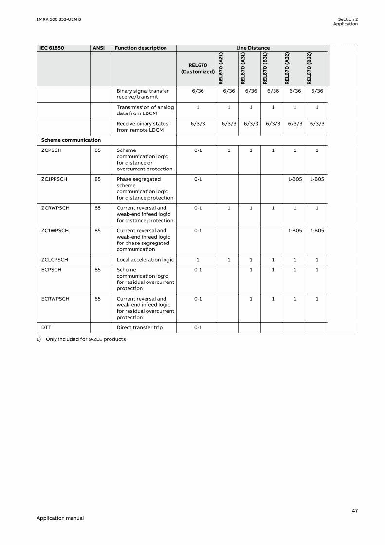
IEC 61850 ANSI Function description Line Distance
REL670(Customized)
REL6
70 (A
21)
REL6
70 (A
31)
REL6
70 (B
31)
REL6
70 (A
32)
REL6
70 (B
32)
Binary signal transferreceive/transmit
6/36 6/36 6/36 6/36 6/36 6/36
Transmission of analogdata from LDCM
1 1 1 1 1 1
Receive binary statusfrom remote LDCM
6/3/3 6/3/3 6/3/3 6/3/3 6/3/3 6/3/3
Scheme communication
ZCPSCH 85 Schemecommunication logicfor distance orovercurrent protection
0-1 1 1 1 1 1
ZC1PPSCH 85 Phase segregatedschemecommunication logicfor distance protection
0-1 1-B05 1-B05
ZCRWPSCH 85 Current reversal andweak-end infeed logicfor distance protection
0-1 1 1 1 1 1
ZC1WPSCH 85 Current reversal andweak-end infeed logicfor phase segregatedcommunication
0-1 1-B05 1-B05
ZCLCPSCH Local acceleration logic 1 1 1 1 1 1
ECPSCH 85 Schemecommunication logicfor residual overcurrentprotection
0-1 1 1 1 1
ECRWPSCH 85 Current reversal andweak-end infeed logicfor residual overcurrentprotection
0-1 1 1 1 1
DTT Direct transfer trip 0-1
1) Only included for 9-2LE products
1MRK 506 353-UEN B Section 2Application
47Application manual

2.6 Basic IED functionsGUID-C8F0E5D2-E305-4184-9627-F6B5864216CA v9
Table 6: Basic IED functions
IEC 61850 or functionname
Description
INTERRSIGSELFSUPEVLST Self supervision with internal event list
TIMESYNCHGEN Time synchronization module
BININPUT,SYNCHCAN,SYNCHGPS,SYNCHCMPPS,SYNCHLON,SYNCHPPH,SYNCHPPS, SNTP,SYNCHSPA
Time synchronization
TIMEZONE Time synchronization
DSTBEGIN,DSTENABLE, DSTEND
GPS time synchronization module
IRIG-B Time synchronization
SETGRPS Number of setting groups
ACTVGRP Parameter setting groups
TESTMODE Test mode functionality
CHNGLCK Change lock function
SMBI Signal matrix for binary inputs
SMBO Signal matrix for binary outputs
SMMI Signal matrix for mA inputs
SMAI1 - SMAI12 Signal matrix for analog inputs
3PHSUM Summation block 3 phase
ATHSTAT Authority status
ATHCHCK Authority check
AUTHMAN Authority management
FTPACCS FTP access with password
SPACOMMMAP SPA communication mapping
SPATD Date and time via SPA protocol
DOSFRNT Denial of service, frame rate control for front port
DOSLANAB Denial of service, frame rate control for OEM port AB
DOSLANCD Denial of service, frame rate control for OEM port CD
DOSSCKT Denial of service, socket flow control
GBASVAL Global base values for settings
PRIMVAL Primary system values
ALTMS Time master supervision
ALTIM Time management
MSTSER DNP3.0 for serial communication protocol
PRODINF Product information
RUNTIME IED Runtime Comp
CAMCONFIG Central account management configuration
Table continues on next page
Section 2 1MRK 506 353-UEN BApplication
48Application manual

IEC 61850 or functionname
Description
CAMSTATUS Central account management status
TOOLINF Tools Information component
SAFEFILECOPY Safe file copy function
Table 7: Local HMI functions
IEC 61850 or functionname
ANSI Description
LHMICTRL Local HMI signals
LANGUAGE Local human machine language
SCREEN Local HMI Local human machine screen behavior
FNKEYTY1–FNKEYTY5FNKEYMD1–FNKEYMD5
Parameter setting function for HMI in PCM600
LEDGEN General LED indication part for LHMI
OPENCLOSE_LED LHMI LEDs for open and close keys
GRP1_LED1–GRP1_LED15GRP2_LED1–GRP2_LED15GRP3_LED1–GRP3_LED15
Basic part for CP HW LED indication module
1MRK 506 353-UEN B Section 2Application
49Application manual

50

Section 3 Configuration
3.1 IntroductionSEMOD120082-1 v1
SEMOD120089-4 v8
There are four different software alternatives with which the IED can be ordered. The intentionis that these configurations shall suit most applications with minor or no changes. The fewchanges required on binary input and outputs can be done from the signal matrix tool in thePCM600 engineering platform.
The main protection functions are switched Off at delivery. Back-up functions that are notgenerally used are also set to Off.
The configurations are:
• Single-breaker arrangement. Three-phase tripping arrangement.• Single breaker arrangement. Single-phase tripping arrangement.• Multi breaker arrangement. Three-phase tripping arrangement.• Multi breaker arrangement. Single-phase tripping arrangement.
The Multi-breaker arrangement includes one-and-a-half and ring-breaker arrangements.
The number of IO must be ordered to the application where more IO is foreseen for the single-phase tripping arrangements respectively the multi-breaker arrangement.
The basic delivery includes one binary input module and one binary output module, which issufficient for the default configured IO to trip and close circuit breaker.
All IEDs can be reconfigured with the help of the ACT configuration tool in the PCM600engineering platform. The IED can be adapted to special applications and special logic can bedeveloped, such as logic for automatic opening of disconnectors and closing of ring bays,automatic load transfer from one busbar to the other, and so on.
On request, ABB is available to support the re-configuration work, either directly or to do thedesign checking.
Optional functions and optional IO ordered will not be configured at delivery. It should benoted that the standard only includes one binary input and one binary output module and onlythe key functions such as tripping are connected to the outputs. The required total IO must becalculated and specified at ordering.
Hardware modules are configured with the hardware configuration tool in the PCM600engineering platform.
The application configuration tool, which is part of the PCM600 engineering platform, willfurther to the four arrangements above include also alternatives for each of them with all ofthe software options configured. These can then be used directly or as assistance of how toconfigure the options. As the number of options can vary all alternatives possible cannot behandled.
The configurations are as far as found necessary provided with application comments toexplain why the signals have been connected in the special way. This is of course for thespecial application features created, not “standard” functionality.
Application configuration diagrams and connection diagrams for the maximum applicationcan be found in separate document, refer to section ""
1MRK 506 353-UEN B Section 3Configuration
51Application manual

SEMOD172508-5 v6
The IED is available to be ordered in four different alternatives with the configuration suitablefor the application. Normally these configurations should be acceptable to use with only fewchanges of binary input and outputs, which can be done from the signal matrix tool in thePCM600 engineering platform.
The main protection functions are switched Off at delivery. Back-up functions not generallyused are also set to Off.
The configurations are:
• Single-breaker arrangement. Three phase tripping arrangement for non directly earthedsystems.
• Single-breaker arrangement. Three phase tripping arrangement.• Single-breaker arrangement. Single phase tripping arrangement.• Multi-breaker arrangement. Three phase tripping arrangement.• Multi-breaker arrangement. Single phase tripping arrangement.
The Multi-breaker arrangement includes one-and-a-half breaker and ring-breakerarrangements.
The number of IO must be ordered to the application where more IO is foreseen for the single-phase tripping arrangements respectively the multi-breaker arrangement. The basic deliveryincludes one binary input module and one binary output module, which is sufficient for thedefault configured IO to trip and close the circuit breaker.
However, all IEDs can be reconfigured with help of the application configuration tool, beingpart of the PCM600 platform. This way the IED can be made suitable for special applicationsand special logic can be developed, such as logic for automatic opening of disconnectors andclosing of ring bays, automatic load transfer from one busbar to the other, and so on.
3.2 Description of configuration REL670IP14802-1 v2
3.2.1 IntroductionIP14803-1 v1
3.2.1.1 Description of configuration A21SEMOD172515-5 v5
The configuration of the IED is shown in Figure 2
This configuration is used in applications on non-direct earthed systems with single breakersand single or double busbars.
The protection scheme includes a 3–phase tripping and 3–phase autoreclosing scheme with asynchronism check. The configuration is prepared with a zone extension scheme where thezone is extended when the autoreclose is ready and a quick autoreclose attempt will follow.
The distance protection is the main protection function. It has five zones and a loadencroachment function to allow coverage of high resistive faults even on long, heavily loadedlines.
A phase preference logic is provided to provide correct tripping of one phase at a two-phasecross-country faults. This will allow the power system to maintain service on one of the faultyphases.
Measuring functions for S, P, Q, I, U, PF, f and E are available for local presentation on the HMIand/or remote presentation. The availability of additional analog inputs allows connection ofseparate metering cores and a calibration parameter on the measurement function allowscalibration at site to very high accuracy.
Section 3 1MRK 506 353-UEN BConfiguration
52Application manual

The outputs from P and Q are fed to an energy metering function for statistic metering. Itmeasures the energy in all quadrants. A maximum demand power presentation is alsoavailable.
The following should be noted. The configuration is made with the binary input and binaryoutput boards in the basic IED delivery. In many cases this is sufficient, in other cases e.g. withfull control of all apparatuses included more IO cards are required. Our proposal for a fullversion with control is to use optionally one binary input module and one binary outputmodule.
QB1 QB2
QA1
QB9
QC9
WA1
WA2REL670 A21 – Single Breaker with three phase tripping for high
ohmic and resonance earthed systems 12AI (6I+6U)
ZCLC PSCH
85
67N
SDE PSDE
IN>
OC4 PTOC
51_67 4(3I>)
LC PTTR
26 θ>
BRC PTOC
46 Iub>
PH PIOC
50 3I>>
CC RBRF
50BF 3I>BF
Other Functions available from the function library
ROV2 PTOV
59N 2(U0>)
EF4 PTOC
51N_67N 4(IN>)
EF PIOC
50N IN>>
ZMCA PDIS
21 Z<
VN MMXU
MET UN
VN MMXU
MET UN
Optional Functions
S SIMG
63
ZC PSCH
85
ZCRW PSCH
85
S SIML
71
Q CBAY
3 Control
WA2_VT
WA1_VT
LINE_CT
LINE_VT
SMP PTRC
94 1->0
SMB RREC
79 5(0→1)
SMP PTRC
94 1→0
SES RSYN
25 SC/VC
ZCV PSOF
LOV PTUV
27 3U<
V MSQI
MET Usqi
VN MMXU
MET UN
DRP RDRE
DFR/SER DR
V MMXU
MET U
LMB RFLO
21FL FL
PPL PHIZ ZD RDIR
21D Z<_>
FDPS PDIS
21
ZMQ PDIS
21 Z<
ZMQ PDIS
21 3Z<
ZMQ PDIS
21 3Z<
ZMQ PDIS
21 3Z<
ZMQA PDIS
21 Z<
FUF SPVC
U>/I<
C MMXU
MET I
C MSQI
MET Isqi
CV MMXN
MET P/Q
ETP MMTR
MET W/Varh
S CILO
3 Control
S CSWI
3 Control
S SCBR
VD SPVC
60 Ud>
CV GAPC
2(I>/U<)
S XCBR
3 Control
Q CRSV
3 Control
S XSWI
3 Control
UV2 PTUV
27 2(3U<)
OV2 PTOV
59 2(3U>)
IEC07000013-4-en.vsd
IEC07000013 V4 EN-US
Figure 2: Configuration diagram for configuration A21
1MRK 506 353-UEN B Section 3Configuration
53Application manual
3.2.1.2 Description of configuration A31M15202-3 v5
The configuration of the IED is shown in figure 3.
This configuration is used in applications with a double or single busbar with a single breaker.The protection scheme includes a 3–phase tripping and 3–phase autoreclosing scheme with asynchronism check.
The distance protection is the main protection function. It has five zones and a loadencroachment functionality to allow coverage of high resistive faults even on heavily loadedlines. A power swing blocking function is included to prevent unnecessary tripping in multi-sourced networks.
Measuring functions for S, P, Q, I, U, PF, f are available for local presentation on the local HMIand/or remote presentation. The availability of additional analog inputs allows connection ofseparate metering cores and a calibration parameter on the measurement function allowscalibration at site to very high accuracy.
The outputs from P and Q are fed to an energy metering function for statistic metering. Itmeasures the energy in all quadrants. A maximum demand power presentation is alsoavailable.
Optional functions can be ordered and include functions such as full control, local and remote,out-of-step protection, frequency protection, and so on. These optional functions must beadded to the configuration and loaded into the IED after delivery.
The following should be noted. The configuration is made with the binary input and binaryoutput boards in the basic IED delivery. In many cases this is sufficient, in other cases, forexample with full control of all apparatuses included more IO cards are required. Our proposalfor a full version with control is to use two binary input modules and 1 binary output module.For systems without substation automation, a second binary output board might be required.
Section 3 1MRK 506 353-UEN BConfiguration
54Application manual
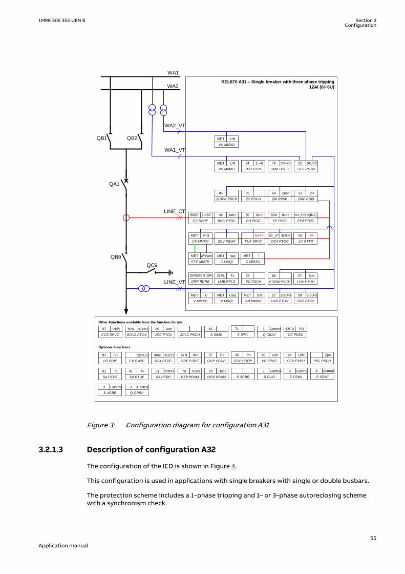
QB1 QB2
QA1
QB9
QC9
WA1
WA2REL670 A31 – Single breaker with three phase tripping
12AI (6I+6U)
CC RBRF
50BF 3I>BF
26
LC PTTR
θ>
OC4 PTOC
51_67 4(3I>)
EF4 PTOC
51N_67N 4(IN>)
EF PIOC
50N IN>>
PH PIOC
50 3I>>
BRC PTOC
46 Iub>
Other Functions available from the function library
CC PDSC
52PD PD
S CILO
3 Control
S CSWI
3 Control
ROV2 PTOV
59N 2(U0>)
CCS SPVC
87 INd/I
VDC PTOV
60 Ud>
NS4 PTOC
46I2 4(I2>)
HZ PDIF
87 Id>
CV GAPC
2(I>/U<)
VN MMXU
MET UN
VN MMXU
MET UN
Optional Functions
S SIMG
63
ZCLC PSCH S SIML
71
Q CBAY
3 Control
Q CRSV
3 Control
S XCBR
3 Control
S XSWI
3 Control
WA2_VT
WA1_VT
LINE_CT
LINE_VT
SMP PTRC
94 1->0
SMB RREC
79 5(0→1)
SMP PTRC
94 1→0
SES RSYN
25 SC/VC
UV2 PTUV
27 2(3U<)
V MSQI
MET Usqi
VN MMXU
MET UN
V MMXU
MET U
LMB RFLO
21FL FL
EC PSCH
85
ZCRW PSCH
85
ZC PSCH
85
ZM RPSB
68 Zpsb
ZMF PDIS
21 Z<
ZCV PSOF FUF SPVC
U>/I<
SDE PSDE
67N IN>
GUP PDUP
37 P<
PSL PSCH
Zpsl
VD SPVC
60 Ud>
OEX PVPH
24 U/f>
GOP PDOP
32 P>
SA PFRC
81 df/dt<>
SA PTOF
81 f>
SA PTUF
81 f>
PSP PPAM
78 Ucos
OOS PPAM
78 Ucos
S SCBR
DRP RDRE
DFR/SER DR
OV2 PTOV
59 2(3U>)
ECRW PSCH
85
LOV PTUV
27 3U<
C MMXU
MET I
C MSQI
MET Isqi
ETP MMTR
MET W/Varh
CV MMXN
MET P/Q
IEC05000846 V4 EN-US
Figure 3: Configuration diagram for configuration A31
3.2.1.3 Description of configuration A32M15202-24 v5
The configuration of the IED is shown in Figure 4.
This configuration is used in applications with single breakers with single or double busbars.
The protection scheme includes a 1–phase tripping and 1– or 3–phase autoreclosing schemewith a synchronism check.
1MRK 506 353-UEN B Section 3Configuration
55Application manual

The distance protection is the main protection function. It has five zones and a loadencroachment functionality to allow coverage of high resistive faults even on heavily loadedlines. A power swing blocking function included preventing unnecessary tripping in multi-sourced networks.
The phase selection will define the faulty phases. It is connected to the first and second zoneas they are expected to be underreaching respectively used in accelerated schemes. The phaseselection should always be limited in reach to avoid unnecessary pick-up of healthy phases.Therefore the release of back-up zones is configured to be the current release only and notphase selective.
Measuring functions S, P, Q, I, U, PF, f are available for local presentation on the local HMIand/or remote presentation. The availability of additional analog inputs allows connection ofseparate metering cores and a calibration parameter on the measurement function allowscalibration at site to very high accuracy.
The outputs from P and Q are fed to an energy metering function for statistic metering. Itmeasures the energy in all quadrants. A maximum demand power presentation is alsoavailable.
Optional functions can be ordered and include functions such as full control, local and remote,out-of-step protection, frequency protection etc. These optional functions must be added tothe configuration and loaded into the IED after delivery.
The following should be noted. The configuration is made with the binary input and binaryoutput boards in the basic IED delivery. In many cases this is sufficient, in other cases, forexample with full control of all apparatuses included more IO cards are required. Our proposalfor a full version with control is to use three binary input modules and two binary outputmodule. For systems without substation automation, a second binary output board might berequired.
Section 3 1MRK 506 353-UEN BConfiguration
56Application manual
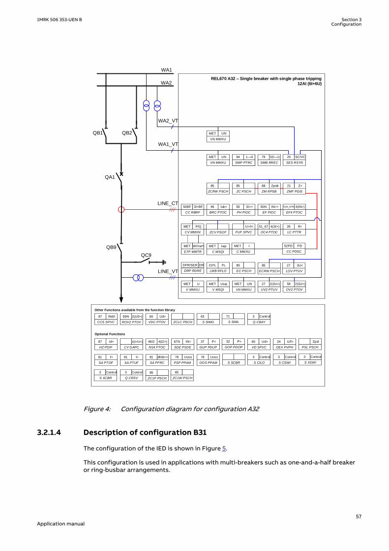
QB1 QB2
QA1
QB9
QC9
WA1
WA2REL670 A32 – Single breaker with single phase tripping
12AI (6I+6U)
CC RBRF
50BF 3I>BF
26
LC PTTR
θ>
OC4 PTOC
51_67 4(3I>)
EF4 PTOC
51N_67N 4(IN>)
EF PIOC
50N IN>>
PH PIOC
50 3I>>
BRC PTOC
46 Iub>
Other Functions available from the function library
S CILO
3 Control
S CSWI
3 Control
ROV2 PTOV
59N 2(U0>)
CCS SPVC
87 INd/I
VDC PTOV
60 Ud>
NS4 PTOC
46I2 4(I2>)
HZ PDIF
87 Id>
CV GAPC
2(I>/U<)
VN MMXU
MET UN
VN MMXU
MET UN
Optional Functions
S SIMG
63
ZCLC PSCH S SIML
71
Q CBAY
3 Control
Q CRSV
3 Control
S XCBR
3 Control
S XSWI
3 Control
WA2_VT
WA1_VT
LINE_CT
LINE_VT
SMP PTRC
94 1->0
SMB RREC
79 5(0→1)
SMP PTRC
94 1→0
SES RSYN
25 SC/VC
UV2 PTUV
27 2(3U<)
V MSQI
MET Usqi
VN MMXU
MET UN
V MMXU
MET U
LMB RFLO
21FL FL
EC PSCH
85
ZCRW PSCH
85
ZC PSCH
85
ZM RPSB
68 Zpsb
ZMF PDIS
21 Z<
ZCV PSOF FUF SPVC
U>/I<
SDE PSDE
67N IN>
GUP PDUP
37 P<
PSL PSCH
Zpsl
VD SPVC
60 Ud>
OEX PVPH
24 U/f>
GOP PDOP
32 P>
SA PFRC
81 df/dt<>
SA PTOF
81 f>
SA PTUF
81 f>
PSP PPAM
78 Ucos
OOS PPAM
78 Ucos
S SCBR
DRP RDRE
DFR/SER DR
OV2 PTOV
59 2(3U>)
ECRW PSCH
85
LOV PTUV
27 3U<
C MMXU
MET I
C MSQI
MET Isqi
ETP MMTR
MET W/Varh
CV MMXN
MET P/Q
ZC1P PSCH
85
ZC1W PSCH
85
CC PDSC
52PD PD
IEC05000844 V4 EN-US
Figure 4: Configuration diagram for configuration A32
3.2.1.4 Description of configuration B31M15202-46 v5
The configuration of the IED is shown in Figure 5.
This configuration is used in applications with multi-breakers such as one-and-a-half breakeror ring-busbar arrangements.
1MRK 506 353-UEN B Section 3Configuration
57Application manual

The protection scheme includes a 3–phase tripping and 3–phase autoreclosing scheme with asynchronism check. Due to the multi-breakers involvement there are two autoreclosers andtwo synchronism check devices with a priority circuit to allow one to close first.
The distance protection is the main protection function. It has five zones and a loadencroachment functionality to allow coverage of high resistive faults even on heavily loadedlines. A power swing blocking function is included preventing unnecessary tripping in multi-sourced networks.
Measuring functions for S, P, Q, I, U, PF, f are available for local presentation on the local HMIand/or remote presentation. The availability of additional analog inputs allows connection ofseparate metering cores and a calibration parameter on the measurement function allowscalibration at site to very high accuracy.
The outputs from P and Q are fed to an energy metering function for statistic metering. Itmeasures the energy in all quadrants. A maximum demand power presentation is alsoavailable.
Optional functions can be ordered and include functions such as full control, local and remote,Out of step protection, Frequency protection, and so on. These optional functions must beadded to the configuration and loaded into the IED after delivery.
The following should be noted. The configuration is made with the binary input and binaryoutput boards in the basic IED delivery. In many cases this is sufficient, in other cases, forexample with full control of all apparatuses included more IO cards are required. Our proposalfor a full version with control is to use 2 binary input modules and 1 binary output module. Forsystems without substation automation, a second binary output board might be required.
Section 3 1MRK 506 353-UEN BConfiguration
58Application manual

QB1
WA1_QB6
LINE1_QB9
QB61
QB62
LINE2_QB9
WA2_QB6
WA1_QA1
TIE_QA1
REL670 B31 – Multi Breaker with Three phase tripping
12AI (6I+6U)
VN MMXU
MET UN
LMB RFLO
21FL FL
ETP MMTR
MET W/Varh
QB2
WA2_QA1
ZMF PDIS
21 Z<
V MSQI
MET Usqi
STB PTOC
50STB3I>STB
C MSQI
MET Isqi
BRC PTOC
46 Iub>
LC PTTR
26 3I>STBθ>
EF PIOC
50N IN>>
Other Functions available from the function library
SA PTUF
81 f<
SA PFRC
81 f<
GUP PDUP
37 P<
NS4 PTOC
46I2 4(I2>)
CV GAPC
2(I>/U<)
VD SPVC
60 Ud>
SA PTOF
81 f>
Optional Functions
ROV2 PTOV
59N 2(U0>)
VDC PTOV
60 Ud>
PSP PPAM
78 Ucos
GOP PDOP
32 P>
ZM RPSB
68 Zpsb
UV2 PTUV
27 2(3U<)
V MMXU
MET U
CV MMXN
MET P/Q
CCS SPVC
87 INd/I
OEX PVPH
24 U/f>
ZCLC PSCH
SDE PSDE
67N IN>
HZ PDIF
87 Id>
SA PFRC
81 df/dt<>
OOS PPAM
78 Ucos
S SCBR
PSL PSCH
Zpsl
ZC PSCH
85
SMB RREC
79 0→1
SMP PTRC
94 1→0
SES RSYN
25 SC
SMB RREC
79 5(0→1)
SMP PTRC
94 1→0
SES RSYN
25 SC/VC
FUF SPVC
U>/I<
Σ
CC PDSC
52PD PD
S CILO
3 Control
S SIML
71
Q CBAY
3 Control
S CSWI
3 Control
Q CRSV
3 Control
S XSWI
3 Control
S XCBR
3 Control
S SIMG
63
CC RBRF
50BF 3I>BF
CC RBRF
50BF 3I>BF
ZCV PSOF
PH PIOC
50 3I>>
EF4 PTOC
51N_67N 4(IN>)
OC4 PTOC
51_67 4(3I>)
C MMXU
MET I
OV2 PTOV
59 2(3U>)
EC PSCH
85
LOV PTUV
27 3U<
ECRW PSCH
85
VN MMXU
MET UN
VN MMXU
MET UN
VN MMXU
MET UN
WA1
WA1_VT
WA1_CT
TIE_CT
LINE1_VT
WA2
WA2_VT
LINE2_VT
ZCRW PSCH
85
DRP RDRE
DFR/SER DR
IEC05000847 V4 EN-US
Figure 5: Configuration diagram for configuration B31
3.2.1.5 Description of configuration B32M15202-65 v6
The configuration of the IED is shown in Figure 6.
This configuration is used in applications with multi-breakers such as one-and-a-half breakeror ring-busbar arrangements.
1MRK 506 353-UEN B Section 3Configuration
59Application manual

The protection scheme includes a 1– or 3–phase tripping and 1– or 3–phase autoreclosingscheme with a synchronism check. Due to the multi-breaker involved there are twoautoreclosers and two synchronism check devices with a priority circuit to allow one to closefirst.
The distance protection is the main protection function. It has five zones and a loadencroachment functionality to allow coverage of high resistive faults even on heavily loadedlines. A power swing blocking function included preventing unnecessary tripping in multi-sourced networks.
Measuring functions for S, P, Q, I, U, PF, f are available for local presentation on the local HMIand/or remote presentation. The availability of additional analog inputs allows connection ofseparate metering cores and a calibration parameter on the measurement function allowscalibration at site to very high accuracy.
The outputs from P and Q are fed to an energy metering function for statistic metering. Itmeasures the energy in all quadrants. A maximum demand power presentation is alsoavailable.
Optional functions can be ordered and include functions such as full control, local and remote,out-of-step protection, frequency protection, and so on. These optional functions must beadded to the configuration and loaded into the IED after delivery.
The following should be noted. The configuration is made with the binary input and binaryoutput boards in the basic IED delivery. In many cases this is sufficient, in other cases, forexample with full control of all apparatuses included more IO cards are required. Our proposalfor a full version with control is to use two binary input modules and two binary outputmodules. For systems without substation automation a second binary output board might berequired.
Section 3 1MRK 506 353-UEN BConfiguration
60Application manual

QB1
WA1_QB6
LINE1_QB9
QB61
QB62
LINE2_QB9
WA2_QB6
WA1_QA1
TIE_QA1
REL670 B32 – Multi breaker with single phase tripping 12AI (6I+6U)
VN MMXU
MET UN
LMB RFLO
21FL FL
ETP MMTR
MET W/Varh
QB2
WA2_QA1
ZMF PDIS
21 Z<
V MSQI
MET Usqi
STB PTOC
50STB 3I>STBC MSQI
MET IsqiBRC PTOC
46 Iub>LC PTTR
26 3I>STB?>
EF PIOC
50N IN>>
Other Functions available from the function library
SA PTUF
81 f<SA PFRC
81 f<
GUP PDUP
37 P<NS4 PTOC
46I2 4(I2>)CV GAPC
2(I>/U<)
VD SPVC
60 Ud>SA PTOF
81 f>
Optional Functions
ROV2 PTOV
59N 2(U0>)VDC PTOV
60 Ud>
PSP PPAM
78 Ucos
GOP PDOP
32 P>
ZM RPSB
68 Zpsb
UV2 PTUV
27 2(3U<)V MMXU
MET U
CV MMXN
MET P/Q
CCS SPVC
87 INd/I
OEX PVPH
24 U/f>
ZCLC PSCH
SDE PSDE
67N IN>HZ PDIF
87 Id>
SA PFRC
81 df/dt<>
OOS PPAM
78 UcosS SCBR
PSL PSCH
Zpsl
ZC PSCH
85
SMB RREC
79 0? 1SMP PTRC
94 1? 0SES RSYN
25 SC
SMB RREC
79 5(0? 1)
SMP PTRC
94 1? 0SES RSYN
25 SC/VC
FUF SPVC
U>/I<
SCC PDSC
52PD PD
S CILO
3 Control
S SIML
71
Q CBAY
3 Control
S CSWI
3 Control
Q CRSV
3 Control
S XSWI
3 Control
S XCBR
3 Control
S SIMG
63
CC RBRF
50BF 3I>BF
CC RBRF
50BF 3I>BF
ZCV PSOF
PH PIOC
50 3I>>EF4 PTOC
51N_67N 4(IN>)OC4 PTOC
51_67 4(3I>)
C MMXU
MET I
OV2 PTOV
59 2(3U>)
EC PSCH
85LOV PTUV
27 3U<ECRW PSCH
85
VN MMXU
MET UN
VN MMXU
MET UN
VN MMXU
MET UN
WA1
WA1_VT
WA1_CT
TIE_CT
LINE1_VT
WA2
WA2_VT
LINE2_VT
ZCRW PSCH
85
DRP RDRE
DFR/SER DR
CC PDSC
52PD PD
ZC1P PSCH
85ZC1W PSCH
85
IEC05000845 V4 EN-US
Figure 6: Configuration diagram for configuration B32
1MRK 506 353-UEN B Section 3Configuration
61Application manual

62
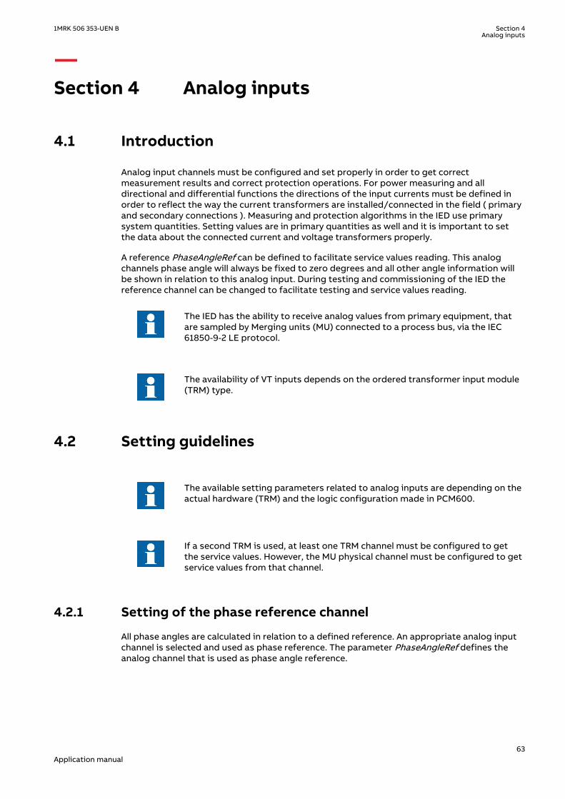
Section 4 Analog inputs
4.1 IntroductionSEMOD55003-5 v10
Analog input channels must be configured and set properly in order to get correctmeasurement results and correct protection operations. For power measuring and alldirectional and differential functions the directions of the input currents must be defined inorder to reflect the way the current transformers are installed/connected in the field ( primaryand secondary connections ). Measuring and protection algorithms in the IED use primarysystem quantities. Setting values are in primary quantities as well and it is important to setthe data about the connected current and voltage transformers properly.
A reference PhaseAngleRef can be defined to facilitate service values reading. This analogchannels phase angle will always be fixed to zero degrees and all other angle information willbe shown in relation to this analog input. During testing and commissioning of the IED thereference channel can be changed to facilitate testing and service values reading.
The IED has the ability to receive analog values from primary equipment, thatare sampled by Merging units (MU) connected to a process bus, via the IEC61850-9-2 LE protocol.
The availability of VT inputs depends on the ordered transformer input module(TRM) type.
4.2 Setting guidelinesSEMOD55068-1 v1
SEMOD130348-4 v5
The available setting parameters related to analog inputs are depending on theactual hardware (TRM) and the logic configuration made in PCM600.
If a second TRM is used, at least one TRM channel must be configured to getthe service values. However, the MU physical channel must be configured to getservice values from that channel.
4.2.1 Setting of the phase reference channelSEMOD55055-5 v3
All phase angles are calculated in relation to a defined reference. An appropriate analog inputchannel is selected and used as phase reference. The parameter PhaseAngleRef defines theanalog channel that is used as phase angle reference.
1MRK 506 353-UEN B Section 4Analog inputs
63Application manual

4.2.1.1 ExampleSEMOD55055-11 v4
Usually the L1 phase-to-earth voltage connected to the first VT channel number of thetransformer input module (TRM) is selected as the phase reference. The first VT channelnumber depends on the type of transformer input module.
For a TRM with 6 current and 6 voltage inputs the first VT channel is 7. The settingPhaseAngleRef=7 shall be used if the phase reference voltage is connected to that channel.
4.2.2 Setting of current channelsSEMOD55055-16 v5
The direction of a current to the IED is depending on the connection of the CT. Unlessindicated otherwise, the main CTs are supposed to be star connected and can be connectedwith the earthing point to the object or from the object. This information must be set in theIED. The convention of the directionality is defined as follows: A positive value of current,power, and so on means that the quantity has the direction into the object and a negativevalue means direction out from the object. For directional functions the direction into theobject is defined as Forward and the direction out from the object is defined as Reverse. Seefigure 7
A positive value of current, power, and so on (forward) means that the quantity has a directiontowards the object. - A negative value of current, power, and so on (reverse) means a directionaway from the object. See figure 7.
Protected ObjectLine, transformer, etc
ForwardReverse
Definition of directionfor directional functions
Measured quantity ispositive when flowing
towards the object
e.g. P, Q, I
ReverseForward
Definition of directionfor directional functions
e.g. P, Q, IMeasured quantity ispositive when flowing
towards the object
Set parameterCTStarPoint
Correct Setting is"ToObject"
Set parameterCTStarPoint
Correct Setting is"FromObject" en05000456.vsd
IEC05000456 V1 EN-US
Figure 7: Internal convention of the directionality in the IED
With correct setting of the primary CT direction, CTStarPoint set to FromObject or ToObject, apositive quantities always flowing towards the object and a direction defined as Forwardalways is looking towards the object. The following examples show the principle.
4.2.2.1 Example 1SEMOD55055-23 v5
Two IEDs used for protection of two objects.
Section 4 1MRK 506 353-UEN BAnalog inputs
64Application manual

Transformer
protection
Transformer
Line
Line
Setting of current input:
Set parameter
CTStarPoint with
Transformer as
reference object.
Correct setting is
"ToObject"
ForwardReverse
Definition of direction
for directional functions
Line protection
Setting of current input:
Set parameter
CTStarPoint with
Transformer as
reference object.
Correct setting is
"ToObject"
Setting of current input:
Set parameter
CTStarPoint with
Line as
reference object.
Correct setting is
"FromObject"
IEC05000753=IEC05
000753=1=en=Origin
al[1].vsd
IsIs
Ip Ip Ip
IED IED
IEC05000753 V2 EN-US
Figure 8: Example how to set CTStarPoint parameters in the IED
The figure 8 shows the normal case where the objects have their own CTs. The settings for CTdirection shall be done according to the figure. To protect the line the direction of thedirectional functions of the line protection shall be set to Forward. This means that theprotection is looking towards the line.
4.2.2.2 Example 2SEMOD55055-29 v5
Two IEDs used for protection of two objects and sharing a CT.
1MRK 506 353-UEN B Section 4Analog inputs
65Application manual
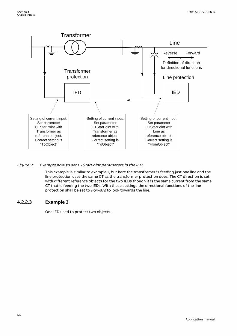
Transformer
protection
Transformer
Line
Setting of current input:
Set parameter
CTStarPoint with
Transformer as
reference object.
Correct setting is
"ToObject"
ForwardReverse
Definition of direction
for directional functions
Line protection
Setting of current input:
Set parameter
CTStarPoint with
Transformer as
reference object.
Correct setting is
"ToObject"
Setting of current input:
Set parameter
CTStarPoint with
Line as
reference object.
Correct setting is
"FromObject"
IED IED
IEC05000460 V2 EN-US
Figure 9: Example how to set CTStarPoint parameters in the IED
This example is similar to example 1, but here the transformer is feeding just one line and theline protection uses the same CT as the transformer protection does. The CT direction is setwith different reference objects for the two IEDs though it is the same current from the sameCT that is feeding the two IEDs. With these settings the directional functions of the lineprotection shall be set to Forward to look towards the line.
4.2.2.3 Example 3SEMOD55055-35 v5
One IED used to protect two objects.
Section 4 1MRK 506 353-UEN BAnalog inputs
66Application manual

Transformer and
Line protection
Transformer
Line
Setting of current input:
Set parameter
CTStarPoint with
Transformer as
reference object.
Correct setting is
"ToObject"
ReverseForward
Definition of direction
for directional
line functions
Setting of current input:
Set parameter
CTStarPoint with
Transformer as
reference object.
Correct setting is
"ToObject"
IED
IEC05000461 V2 EN-US
Figure 10: Example how to set CTStarPoint parameters in the IED
In this example one IED includes both transformer and line protection and the line protectionuses the same CT as the transformer protection does. For both current input channels the CTdirection is set with the transformer as reference object. This means that the directionForward for the line protection is towards the transformer. To look towards the line thedirection of the directional functions of the line protection must be set to Reverse. Thedirection Forward/Reverse is related to the reference object that is the transformer in thiscase.
When a function is set to Reverse and shall protect an object in reverse direction it shall benoted that some directional functions are not symmetrical regarding the reach in forward andreverse direction. It is in first hand the reach of the directional criteria that can differ. Normallyit is not any limitation but it is advisable to have it in mind and check if it is acceptable for theapplication in question.
If the IED has a sufficient number of analog current inputs an alternative solution is shown infigure 11. The same currents are fed to two separate groups of inputs and the line andtransformer protection functions are configured to the different inputs. The CT direction forthe current channels to the line protection is set with the line as reference object and thedirectional functions of the line protection shall be set to Forward to protect the line.
1MRK 506 353-UEN B Section 4Analog inputs
67Application manual

Transformer and
Line protection
Transformer
Line
Setting of current input
for transformer functions:
Set parameter
CTStarPoint with
Transformer as
reference object.
Correct setting is
"ToObject"
ForwardReverse
Definition of direction
for directional
line functions
Setting of current input
for transformer functions:
Set parameter
CTStarPoint with
Transformer as
reference object.
Correct setting is
"ToObject"
Setting of current input
for line functions:
Set parameter
CTStarPoint with
Line as
reference object.
Correct setting is
"FromObject"
IED
IEC05000462 V2 EN-US
Figure 11: Example how to set CTStarPoint parameters in the IED
Section 4 1MRK 506 353-UEN BAnalog inputs
68Application manual

BusbarProtection
Busbar
1
2
2
1
en06000196.vsd
IED
1
IEC06000196 V2 EN-US
Figure 12: Example how to set CTStarPoint parameters in the IED
For busbar protection it is possible to set the CTStarPoint parameters in two ways.
The first solution will be to use busbar as a reference object. In that case for all CT inputsmarked with 1 in figure 12, set CTStarPoint = ToObject, and for all CT inputs marked with 2 infigure 12, set CTStarPoint = FromObject.
The second solution will be to use all connected bays as reference objects. In that case for allCT inputs marked with 1 in figure 12, set CTStarPoint = FromObject, and for all CT inputsmarked with 2 in figure 12, set CTStarPoint = ToObject.
Regardless which one of the above two options is selected busbar differential protection willbehave correctly.
The main CT ratios must also be set. This is done by setting the two parameters CTsec andCTprim for each current channel. For a 1000/1 A CT the following setting shall be used:
• CTprim = 1000 (value in A)• CTsec =1 (value in A).
1MRK 506 353-UEN B Section 4Analog inputs
69Application manual

4.2.2.4 Examples on how to connect, configure and set CT inputs for mostcommonly used CT connections
SEMOD55055-296 v5
Figure 13 defines the marking of current transformer terminals commonly used around theworld:
In the SMAI function block, you have to set if the SMAI block is measuringcurrent or voltage. This is done with the parameter: AnalogInputType: Current/voltage. The ConnectionType: phase -phase/phase-earth and GlobalBaseSel.
ISec
I Pri
S1 (X1)
P1(H1)
P2(H2)
S2 (X2)
P2(H2)
P1(H1)
x x
a) b) c)
en06000641.vsd
S2 (X2) S1 (X1)
IEC06000641 V1 EN-US
Figure 13: Commonly used markings of CT terminals
Where:
a) is symbol and terminal marking used in this document. Terminals marked with a squareindicates the primary and secondary winding terminals with the same (that is, positive)polarity
b) andc)
are equivalent symbols and terminal marking used by IEC (ANSI) standard for CTs. Notethat for these two cases the CT polarity marking is correct!
It shall be noted that depending on national standard and utility practices, the rated secondarycurrent of a CT has typically one of the following values:
• 1A• 5A
However in some cases the following rated secondary currents are used as well:
• 2A• 10A
The IED fully supports all of these rated secondary values.
It is recommended to:
• use 1A rated CT input into the IED in order to connect CTs with 1A and 2Asecondary rating
• use 5A rated CT input into the IED in order to connect CTs with 5A and 10Asecondary rating
Section 4 1MRK 506 353-UEN BAnalog inputs
70Application manual

4.2.2.5 Example on how to connect a star connected three-phase CT set to theIED
SEMOD55055-352 v9
Figure 14 gives an example about the wiring of a star connected three-phase CT set to the IED.It gives also an overview of the actions which are needed to make this measurement availableto the built-in protection and control functions within the IED as well.
For correct terminal designations, see the connection diagrams valid for thedelivered IED.
L1
IL1
IL2
IL3
L2 L3
Protected Object
CT 600/5Star Connected
IL1
IL2
IL3
IED
IEC13000002-4-en.vsdx
1 2
3
4
SMAI2
BLOCK
REVROT
^GRP2L1
^GRP2L2
^GRP2L3
^GRP2N
AI3P
AI1
AI2
AI3
AI4
AIN
5
IN
IEC13000002 V4 EN-US
Figure 14: Star connected three-phase CT set with star point towards the protected object
Where:
1) The drawing shows how to connect three individual phase currents from a star connected three-phase CT set to the three CT inputs of the IED.
2) The current inputs are located in the TRM. It shall be noted that for all these current inputs thefollowing setting values shall be entered for the example shown in Figure14.'
• CTprim=600A• CTsec=5A• CTStarPoint=ToObject
Inside the IED only the ratio of the first two parameters is used. The third parameter(CTStarPoint=ToObject) as set in this example causes no change on the measured currents. In otherwords, currents are already measured towards the protected object.
Table continues on next page
1MRK 506 353-UEN B Section 4Analog inputs
71Application manual

3) These three connections are the links between the three current inputs and the three input channelsof the preprocessing function block 4). Depending on the type of functions, which need this currentinformation, more than one preprocessing block might be connected in parallel to the same threephysical CT inputs.
4) The preprocessing block that has the task to digitally filter the connected analog inputs andcalculate:
• fundamental frequency phasors for all three input channels• harmonic content for all three input channels• positive, negative and zero sequence quantities by using the fundamental frequency phasors
for the first three input channels (channel one taken as reference for sequence quantities)
These calculated values are then available for all built-in protection and control functions within theIED, which are connected to this preprocessing function block. For this application most of thepreprocessing settings can be left to the default values.If frequency tracking and compensation is required (this feature is typically required only for IEDsinstalled in power plants), then the setting parameters DFTReference shall be set accordingly.Section SMAI in this manual provides information on adaptive frequency tracking for the signalmatrix for analogue inputs (SMAI).
5) AI3P in the SMAI function block is a grouped signal which contains all the data about the phases L1,L2, L3 and neutral quantity; in particular the data about fundamental frequency phasors, harmoniccontent and positive sequence, negative and zero sequence quantities are available.AI1, AI2, AI3, AI4 are the output signals from the SMAI function block which contain the fundamentalfrequency phasors and the harmonic content of the corresponding input channels of thepreprocessing function block.AIN is the signal which contains the fundamental frequency phasors and the harmonic content ofthe neutral quantity. In this example GRP2N is not connected so this data is calculated by thepreprocessing function block on the basis of the inputs GRPL1, GRPL2 and GRPL3. If GRP2N isconnected, the data reflects the measured value of GRP2N.
Another alternative is to have the star point of the three-phase CT set as shown in the figurebelow:
L1
IL1
IL2
IL3
L2 L3
Protected Object
CT 800/1Star Connected
IL1
IL2
IL3
IED
IEC11000026-4-en.vsdx
4 12
3
SMAI2
BLOCK
REVROT
^GRP2L1
^GRP2L2
^GRP2L3
^GRP2N
AI3P
AI1
AI2
AI3
AI4
AIN
5
IN
IEC11000026 V4 EN-US
Figure 15: Star connected three-phase CT set with its star point away from the protected object
Section 4 1MRK 506 353-UEN BAnalog inputs
72Application manual

In the example in figure 15 case everything is done in a similar way as in the above describedexample (figure 14). The only difference is the setting of the parameter CTStarPoint of theused current inputs on the TRM (item 2 in the figure):
• CTprim=600A• CTsec=5A• CTStarPoint=FromObject
Inside the IED only the ratio of the first two parameters is used. The third parameter as set inthis example will negate the measured currents in order to ensure that the currents aremeasured towards the protected object within the IED.
A third alternative is to have the residual/neutral current from the three-phase CT setconnected to the IED as shown in the figure below.
L1
IL1
IL2
IL3
L2 L3
Protected Object
CT 800/1
Star ConnectedIL1
IL2
IL3
IN
IED
1
3
4
2
5
IEC06000644-4-en.vsdx
6
SMAI2
BLOCK
REVROT
^GRP2L1
^GRP2L2
^GRP2L3
^GRP2N
AI3P
AI1
AI2
AI3
AI4
AIN
IEC06000644 V4 EN-US
Figure 16: Star connected three-phase CT set with its star point away from the protected object andthe residual/neutral current connected to the IED
Where:
1) The drawing shows how to connect three individual phase currents from a star connected three-phase CT set to the three CT inputs of the IED.
2) shows how to connect residual/neutral current from the three-phase CT set to the fourth inputs inthe IED. It shall be noted that if this connection is not made, the IED will still calculate this currentinternally by vectorial summation of the three individual phase currents.
Table continues on next page
1MRK 506 353-UEN B Section 4Analog inputs
73Application manual

3) is the TRM where these current inputs are located. It shall be noted that for all these current inputsthe following setting values shall be entered.
• CTprim=800A• CTsec=1A• CTStarPoint=FromObject• ConnectionType=Ph-N
Inside the IED only the ratio of the first two parameters is used. The third parameter as set in thisexample will have no influence on the measured currents (that is, currents are already measuredtowards the protected object).
4) are three connections made in the Signal Matrix tool (SMT), Application configuration tool (ACT),which connects these three current inputs to the first three input channels on the preprocessingfunction block 6). Depending on the type of functions, which need this current information, morethan one preprocessing block might be connected in parallel to these three CT inputs.
5) is a connection made in the Signal Matrix tool (SMT), Application configuration tool (ACT), whichconnects the residual/neutral current input to the fourth input channel of the preprocessingfunction block 6). Note that this connection in SMT shall not be done if the residual/neutral currentis not connected to the IED. In that case the pre-processing block will calculate it by vectorialsummation of the three individual phase currents.
6) is a Preprocessing block that has the task to digitally filter the connected analog inputs andcalculate:
• fundamental frequency phasors for all four input channels• harmonic content for all four input channels• positive, negative and zero sequence quantities by using the fundamental frequency phasors
for the first three input channels (channel one taken as reference for sequence quantities)
These calculated values are then available for all built-in protection and control functions within theIED, which are connected to this preprocessing function block in the configuration tool. For thisapplication most of the preprocessing settings can be left to the default values.If frequency tracking and compensation is required (this feature is typically required only for IEDsinstalled in the generating stations), then the setting parameters DFTReference shall be setaccordingly.
4.2.2.6 Example how to connect delta connected three-phase CT set to the IEDSEMOD55055-392 v7
Figure 17 gives an example how to connect a delta connected three-phase CT set to the IED. Itgives an overview of the required actions by the user in order to make this measurementavailable to the built-in protection and control functions in the IED as well.
For correct terminal designations, see the connection diagrams valid for thedelivered IED.
Section 4 1MRK 506 353-UEN BAnalog inputs
74Application manual

L1IL
1
IL2
IL3
L2 L3
Protected Object
IED
CT 6
00/5
in D
elta
DA
B C
onn
ecte
d
IL1-IL2
IL2-IL3
IL3-IL1
1 2
3 4
IEC11000027-3-en.vsdx
SMAI2
BLOCK
REVROT
^GRP2L1
^GRP2L2
^GRP2L3
^GRP2N
AI3P
AI1
AI2
AI3
AI4
AIN
IEC11000027 V3 EN-US
Figure 17: Delta DAB connected three-phase CT set
Where:
1) shows how to connect three individual phase currents from a delta connected three-phase CT set tothree CT inputs of the IED.
2) is the TRM where these current inputs are located. It shall be noted that for all these current inputsthe following setting values shall be entered.CTprim=600ACTsec=5A
• CTStarPoint=ToObject• ConnectionType=Ph-Ph
3) are three connections made in Signal Matrix Tool (SMT), Application configuration tool (ACT), whichconnect these three current inputs to first three input channels of the preprocessing function block4). Depending on the type of functions which need this current information, more then onepreprocessing block might be connected in parallel to these three CT inputs.
4) is a Preprocessing block that has the task to digitally filter the connected analog inputs andcalculate:
• fundamental frequency phasors for all three input channels• harmonic content for all three input channels• positive, negative and zero sequence quantities by using the fundamental frequency phasors
for the first three input channels (channel one taken as reference for sequence quantities)
These calculated values are then available for all built-in protection and control functions within theIED, which are connected to this preprocessing function block. For this application most of thepreprocessing settings can be left to the default values.If frequency tracking and compensation is required (this feature is typically required only for IEDsinstalled in the generating stations) then the setting parameters DFTReference shall be setaccordingly.
1MRK 506 353-UEN B Section 4Analog inputs
75Application manual
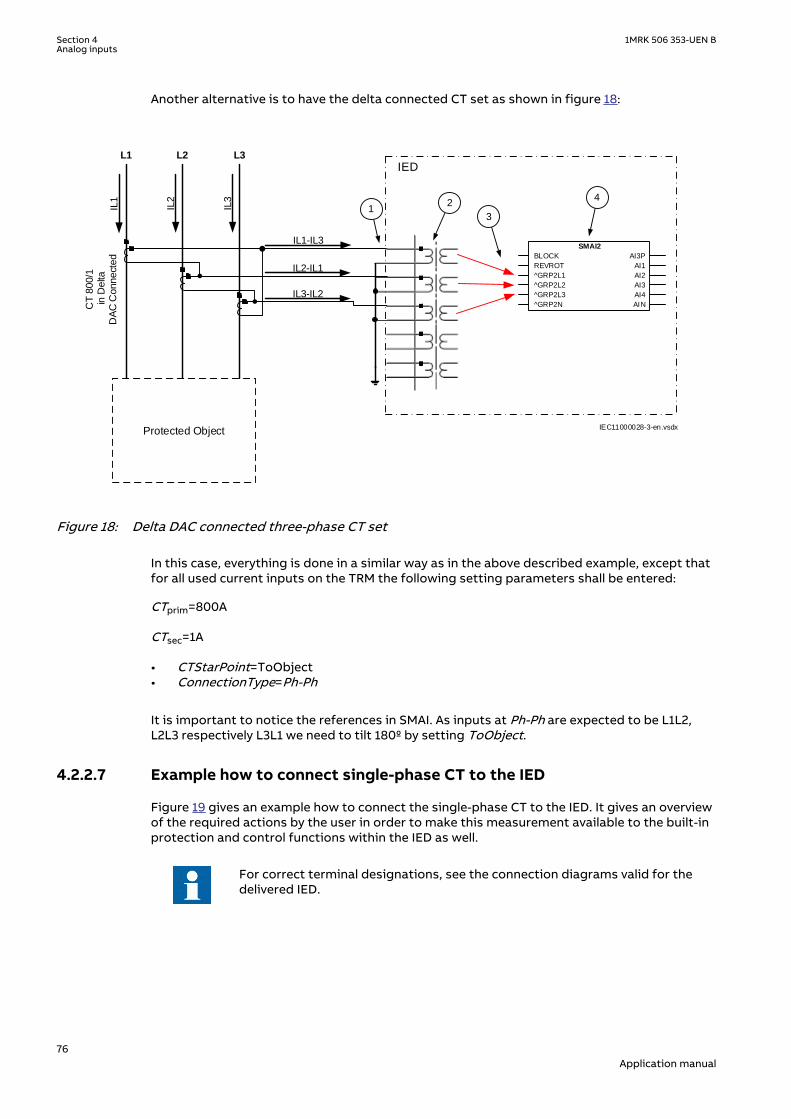
Another alternative is to have the delta connected CT set as shown in figure 18:
L1
IL1
IL2
IL3
L2 L3
Protected Object
IED
CT 8
00/1
in D
elta
DA
C C
onnect
ed
IL3-IL2
IL2-IL1
IL1-IL3
2
3
4
IEC11000028-3-en.vsdx
SMAI2
BLOCK
REVROT
^GRP2L1
^GRP2L2
^GRP2L3
^GRP2N
AI3P
AI1
AI2
AI3
AI4
AIN
1
IEC11000028 V3 EN-US
Figure 18: Delta DAC connected three-phase CT set
In this case, everything is done in a similar way as in the above described example, except thatfor all used current inputs on the TRM the following setting parameters shall be entered:
CTprim=800A
CTsec=1A
• CTStarPoint=ToObject• ConnectionType=Ph-Ph
It is important to notice the references in SMAI. As inputs at Ph-Ph are expected to be L1L2,L2L3 respectively L3L1 we need to tilt 180º by setting ToObject.
4.2.2.7 Example how to connect single-phase CT to the IEDSEMOD55055-431 v7
Figure 19 gives an example how to connect the single-phase CT to the IED. It gives an overviewof the required actions by the user in order to make this measurement available to the built-inprotection and control functions within the IED as well.
For correct terminal designations, see the connection diagrams valid for thedelivered IED.
Section 4 1MRK 506 353-UEN BAnalog inputs
76Application manual

Protected Object
L1 L2 L3
IED
INP
INS
INS
2
IEC11000029-4-en.vsdx
4
3
CT
10
00
/1
a)
b)
(+)
(+)
(-)
(-)(+)
(-)
1 SMAI2
BLOCK
REVROT
^GRP2L1
^GRP2L2
^GRP2L3
^GRP2N
AI3P
AI1
AI2
AI3
AI4
AIN
IEC11000029 V4 EN-US
Figure 19: Connections for single-phase CT input
Where:
1) shows how to connect single-phase CT input in the IED.
2) is TRM where these current inputs are located. It shall be noted that for all these current inputsthe following setting values shall be entered.For connection (a) shown in figure 19:CTprim = 1000 ACTsec = 1ACTStarPoint=ToObject For connection (b) shown in figure 19:CTprim = 1000 ACTsec = 1ACTStarPoint=FromObject
3) shows the connection made in SMT tool, which connect this CT input to the fourth input channelof the preprocessing function block 4).
4) is a Preprocessing block that has the task to digitally filter the connected analog inputs andcalculate values. The calculated values are then available for all built-in protection and controlfunctions within the IED, which are connected to this preprocessing function block.If frequency tracking and compensation is required (this feature is typically required only forIEDs installed in the power plants) then the setting parameters DFTReference shall be setaccordingly.
4.2.3 Relationships between setting parameter Base Current, CTrated primary current and minimum pickup of a protection IED
GUID-8EB19363-9178-4F04-A6AC-AF0C2F99C5AB v1
Note that for all line protection applications (e.g. distance protection or line differentialprotection) the parameter Base Current (i.e. IBase setting in the IED) used by the relevantprotection function, shall always be set equal to the largest rated CT primary current among all
1MRK 506 353-UEN B Section 4Analog inputs
77Application manual

CTs involved in the protection scheme. The rated CT primary current value is set as parameterCTPrim under the IED TRM settings.
For all other protection applications (e.g. generator, shunt reactor, shunt capacitor andtransformer protection) it is typically desirable to set IBase parameter equal to the ratedcurrent of the protected object. However this is only recommended to do if the rated currentof the protected object is within the range of 40% to 120% of the selected CT rated primarycurrent. If for any reason (e.g. high maximum short circuit current) the rated current of theprotected object is less than 40% of the rated CT primary current, it is strongly recommendedto set the parameter IBase in the IED to be equal to the largest rated CT primary currentamong all CTs involved in the protection scheme and installed on the same voltage level. Thiswill effectively make the protection scheme less sensitive; however, such measures arenecessary in order to avoid possible problems with loss of the measurement accuracy in theIED.
Regardless of the applied relationship between the IBase parameter and the rated CT primarycurrent, the corresponding minimum pickup of the function on the CT secondary side mustalways be verified. It is strongly recommended that the minimum pickup of any instantaneousprotection function (e.g. differential, restricted earth fault, distance, instantaneousovercurrent, etc.) shall under no circumstances be less than 4% of the used IED CT input rating(i.e. 1A or 5A). This corresponds to 40mA secondary for IED 1A rated inputs and to 200mAsecondary for IED 5A rated inputs used by the function. This shall be individually verified for allcurrent inputs involved in the protection scheme.
Note that exceptions from the above 4% rule may be acceptable for very special applications(e.g. when Multipurpose filter SMAIHPAC is involved in the protection scheme).
4.2.4 Setting of voltage channelsSEMOD55055-44 v3
As the IED uses primary system quantities the main VT ratios must be known to the IED. This isdone by setting the two parameters VTsec and VTprim for each voltage channel. The phase-to-phase value can be used even if each channel is connected to a phase-to-earth voltage fromthe VT.
4.2.4.1 ExampleSEMOD55055-47 v2
Consider a VT with the following data:
132 1103 3kV V
EQUATION2016 V1 EN-US (Equation 1)
The following setting should be used: VTprim=132 (value in kV) VTsec=110 (value in V)
4.2.4.2 Examples how to connect, configure and set VT inputs for mostcommonly used VT connections
SEMOD55055-60 v5
Figure 20 defines the marking of voltage transformer terminals commonly used around theworld.
Section 4 1MRK 506 353-UEN BAnalog inputs
78Application manual
A(H1)
B(H2)
b(X2)
a(X1)
A(H1)
N(H2)
n(X2)
a(X1)
b) c)
A(H1)
N(H2)
dn(X2)
da(X1)
d)
UPri
+ +USec
a)
en06000591.vsdIEC06000591 V1 EN-US
Figure 20: Commonly used markings of VT terminals
Where:
a) is the symbol and terminal marking used in this document. Terminals marked with a square indicatethe primary and secondary winding terminals with the same (positive) polarity
b) is the equivalent symbol and terminal marking used by IEC (ANSI) standard for phase-to-earthconnected VTs
c) is the equivalent symbol and terminal marking used by IEC (ANSI) standard for open deltaconnected VTs
d) is the equivalent symbol and terminal marking used by IEC (ANSI) standard for phase-to-phaseconnected VTs
It shall be noted that depending on national standard and utility practices the rated secondaryvoltage of a VT has typically one of the following values:
• 100 V• 110 V• 115 V• 120 V• 230 V
The IED fully supports all of these values and most of them will be shown in the followingexamples.
4.2.4.3 Examples on how to connect a three phase-to-earth connected VT to theIED
SEMOD55055-87 v8
Figure 21 gives an example on how to connect a three phase-to-earth connected VT to the IED.It as well gives overview of required actions by the user in order to make this measurementavailable to the built-in protection and control functions within the IED.
For correct terminal designations, see the connection diagrams valid for thedelivered IED.
1MRK 506 353-UEN B Section 4Analog inputs
79Application manual
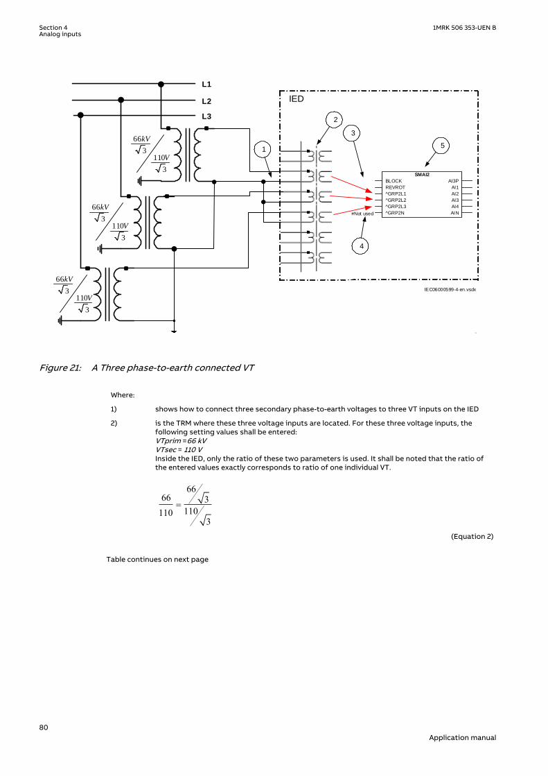
L1
IED L2
L3
66
3110
3
kV
V
1
3
2
66
3110
3
kV
V
66
3110
3
kV
V
.
#Not used
5
IEC06000599-4-en.vsdx
4
SMAI2
BLOCK
REVROT
^GRP2L1
^GRP2L2
^GRP2L3
^GRP2N
AI3P
AI1
AI2
AI3
AI4
AIN
IEC06000599 V4 EN-US
Figure 21: A Three phase-to-earth connected VT
Where:
1) shows how to connect three secondary phase-to-earth voltages to three VT inputs on the IED
2) is the TRM where these three voltage inputs are located. For these three voltage inputs, thefollowing setting values shall be entered:VTprim =66 kVVTsec = 110 VInside the IED, only the ratio of these two parameters is used. It shall be noted that the ratio ofthe entered values exactly corresponds to ratio of one individual VT.
6666 3
1101103
=
EQUATION1903 V1 EN-US (Equation 2)
Table continues on next page
Section 4 1MRK 506 353-UEN BAnalog inputs
80Application manual

3) are three connections made in Signal Matrix Tool (SMT), which connect these three voltageinputs to first three input channels of the preprocessing function block 5). Depending on thetype of functions which need this voltage information, more then one preprocessing block mightbe connected in parallel to these three VT inputs.
4) shows that in this example the fourth (that is, residual) input channel of the preprocessing blockis not connected in SMT tool. Thus the preprocessing block will automatically calculate 3Uoinside by vectorial sum from the three phase to earth voltages connected to the first three inputchannels of the same preprocessing block. Alternatively, the fourth input channel can beconnected to open delta VT input, as shown in figure 23.
5) is a Preprocessing block that has the task to digitally filter the connected analog inputs andcalculate:
• fundamental frequency phasors for all four input channels• harmonic content for all four input channels• positive, negative and zero sequence quantities by using the fundamental frequency
phasors for the first three input channels (channel one taken as reference for sequencequantities)
These calculated values are then available for all built-in protection and control functions withinthe IED, which are connected to this preprocessing function block in the configuration tool. Forthis application most of the preprocessing settings can be left to the default values. However thefollowing settings shall be set as shown here:UBase=66 kV (that is, rated Ph-Ph voltage)If frequency tracking and compensation is required (this feature is typically required only for IEDsinstalled in the generating stations) then the setting parameters DFTReference shall be setaccordingly.
4.2.4.4 Example on how to connect a phase-to-phase connected VT to the IEDSEMOD55055-134 v6
Figure 22 gives an example how to connect a phase-to-phase connected VT to the IED. It givesan overview of the required actions by the user in order to make this measurement available tothe built-in protection and control functions within the IED as well. It shall be noted that thisVT connection is only used on lower voltage levels (that is, rated primary voltage below 40 kV).
1MRK 506 353-UEN B Section 4Analog inputs
81Application manual
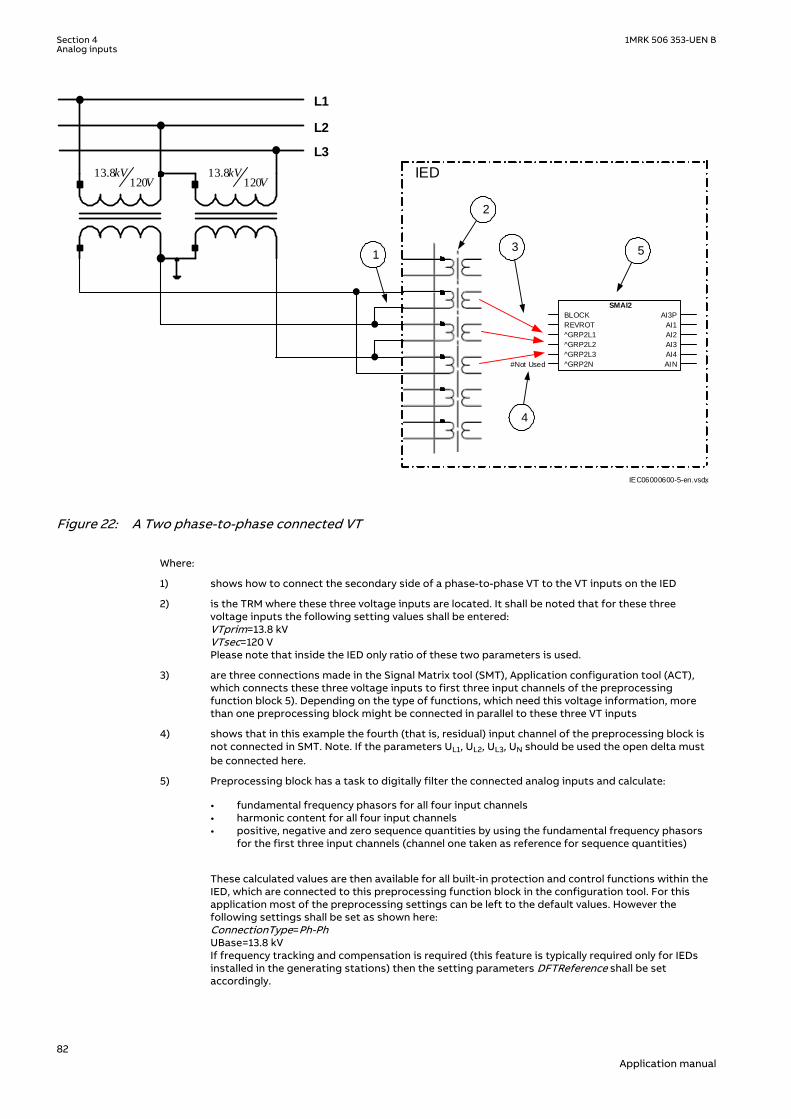
L1
IED
L2
L3
13.8120
kVV
1
2
#Not Used
13.8120
kVV
.
5
IEC06000600-5-en.vsdx
4
SMAI2
BLOCK
REVROT
^GRP2L1
^GRP2L2
^GRP2L3
^GRP2N
AI3P
AI1
AI2
AI3
AI4
AIN
3
IEC06000600 V5 EN-US
Figure 22: A Two phase-to-phase connected VT
Where:
1) shows how to connect the secondary side of a phase-to-phase VT to the VT inputs on the IED
2) is the TRM where these three voltage inputs are located. It shall be noted that for these threevoltage inputs the following setting values shall be entered:VTprim=13.8 kVVTsec=120 VPlease note that inside the IED only ratio of these two parameters is used.
3) are three connections made in the Signal Matrix tool (SMT), Application configuration tool (ACT),which connects these three voltage inputs to first three input channels of the preprocessingfunction block 5). Depending on the type of functions, which need this voltage information, morethan one preprocessing block might be connected in parallel to these three VT inputs
4) shows that in this example the fourth (that is, residual) input channel of the preprocessing block isnot connected in SMT. Note. If the parameters UL1, UL2, UL3, UN should be used the open delta mustbe connected here.
5) Preprocessing block has a task to digitally filter the connected analog inputs and calculate:
• fundamental frequency phasors for all four input channels• harmonic content for all four input channels• positive, negative and zero sequence quantities by using the fundamental frequency phasors
for the first three input channels (channel one taken as reference for sequence quantities)
These calculated values are then available for all built-in protection and control functions within theIED, which are connected to this preprocessing function block in the configuration tool. For thisapplication most of the preprocessing settings can be left to the default values. However thefollowing settings shall be set as shown here:ConnectionType=Ph-PhUBase=13.8 kVIf frequency tracking and compensation is required (this feature is typically required only for IEDsinstalled in the generating stations) then the setting parameters DFTReference shall be setaccordingly.
Section 4 1MRK 506 353-UEN BAnalog inputs
82Application manual

4.2.4.5 Example on how to connect an open delta VT to the IED for highimpedance earthed or unearthed netwoeks
SEMOD55055-163 v8
Figure 23 gives an example about the wiring of an open delta VT to the IED for high impedanceearthed or unearthed power systems. It shall be noted that this type of VT connectionpresents a secondary voltage proportional to 3U0 to the IED.
In case of a solid earth fault close to the VT location the primary value of 3Uo will be equal to:
3 0 3 3Ph Ph Ph NU U U- -= × = ×EQUATION1921 V3 EN-US (Equation 3)
The primary rated voltage of an open Delta VT is always equal to UPh-E. Three series connectedVT secondary windings gives a secondary voltage equal to three times the individual VTsecondary winding rating. Thus the secondary windings of open delta VTs quite often have asecondary rated voltage equal to one third of the rated phase-to-phase VT secondary voltage(110/3V in this particular example).
Figure 23 gives overview of required actions by the user in order to make this measurementavailable to the built-in protection and control functions within the IED as well.
L1
IED L2
L3
6.6
3110
3
kV
V
+3Uo
6.6
3110
3
kV
V
6.6
3110
3
kV
V
1
2
4
3
# Not Used
5
IEC06000601-4-en.vsdx
# Not Used
# Not Used
SMAI2
BLOCK
REVROT
^GRP2L1
^GRP2L2
^GRP2L3
^GRP2N
AI3P
AI1
AI2
AI3
AI4
AIN
IEC06000601 V4 EN-US
Figure 23: Open delta connected VT in high impedance earthed power system
1MRK 506 353-UEN B Section 4Analog inputs
83Application manual

Where:
1) shows how to connect the secondary side of the open delta VT to one VT input on the IED.
+3U0 shall be connected to the IED
2) is the TRM where this voltage input is located. It shall be noted that for this voltage input thefollowing setting values shall be entered:
3 6.6 11.43VTprim kV= × =
EQUATION1923 V1 EN-US (Equation 4)
110sec 3 110
3VT V= × =
EQUATION1924 V1 EN-US (Equation 5)
Inside the IED, only the ratio of these two parameters is used. It shall be noted that the ratio ofthe entered values exactly corresponds to ratio of one individual open delta VT.
6.63 6.6 3
1101103
×=
EQUATION1925 V1 EN-US (Equation 6)
3) shows that in this example the first three input channel of the preprocessing block is notconnected in SMT tool or ACT tool.
4) shows the connection made in Signal Matrix Tool (SMT), Application configuration tool (ACT),which connect this voltage input to the fourth input channel of the preprocessing function block5).
5) is a Preprocessing block that has the task to digitally filter the connected analog input andcalculate:
• fundamental frequency phasors for all four input channels• harmonic content for all four input channels• positive, negative and zero sequence quantities by using the fundamental frequency
phasors for the first three input channels (channel one taken as reference for sequencequantities)
These calculated values are then available for all built-in protection and control functions withinthe IED, which are connected to this preprocessing function block in the configuration tool. Forthis application most of the preprocessing settings can be left to the default values.If frequency tracking and compensation is required (this feature is typically required only for IEDsinstalled in the generating stations ) then the setting parameters DFTReference shall be setaccordingly.
4.2.4.6 Example how to connect the open delta VT to the IED for low impedanceearthed or solidly earthed power systems
SEMOD55055-199 v6
Figure 24 gives an example about the connection of an open delta VT to the IED for lowimpedance earthed or solidly earthed power systems. It shall be noted that this type of VTconnection presents secondary voltage proportional to 3U0 to the IED.
In case of a solid earth fault close to the VT location the primary value of 3Uo will be equal to:
Section 4 1MRK 506 353-UEN BAnalog inputs
84Application manual

33
Ph PhPh E
UUo U-
-= =
EQUATION1926 V1 EN-US (Equation 7)
The primary rated voltage of such VT is always equal to UPh-E Therefore, three seriesconnected VT secondary windings will give the secondary voltage equal only to one individualVT secondary winding rating. Thus the secondary windings of such open delta VTs quite oftenhas a secondary rated voltage close to rated phase-to-phase VT secondary voltage, that is,115V or 115/√3V as in this particular example. Figure 24 gives an overview of the actions whichare needed to make this measurement available to the built-in protection and controlfunctions within the IED.
1
L1
IED L2
L3
138
3115
3
kV
V
+3Uo
138
3115
3
kV
V
138
3115
3
kV
V
IEC06000602-4-en.vsdx
# Not Used
# Not Used
# Not Used
SMAI2
BLOCK
REVROT
^GRP2L1
^GRP2L2
^GRP2L3
^GRP2N
AI3P
AI1
AI2
AI3
AI4
AIN
2
3
4
5
IEC06000602 V4 EN-US
Figure 24: Open delta connected VT in low impedance or solidly earthed power system
1MRK 506 353-UEN B Section 4Analog inputs
85Application manual

Where:
1) shows how to connect the secondary side of open delta VT to one VT input inthe IED.
+3Uo shall be connected to the IED.
2) is TRM where this voltage input is located. It shall be noted that for this voltageinput the following setting values shall be entered:
1383 138
3VTprim kV= × =
EQUATION1928 V1 EN-US (Equation 8)
115sec 3 115
3VT V= × =
EQUATION1929 V1 EN-US (Equation 9)
Inside the IED, only the ratio of these two parameters is used. It shall be notedthat the ratio of the entered values exactly corresponds to ratio of oneindividual open delta VT.
138138 3
1151153
=
EQUATION1930 V1 EN-US (Equation 10)
3) shows that in this example the first three input channel of the preprocessingblock is not connected in SMT tool.
4) shows the connection made in Signal Matrix Tool (SMT), which connect thisvoltage input to the fourth input channel of the preprocessing function block 4).
5) preprocessing block has a task to digitally filter the connected analog inputsand calculate:
• fundamental frequency phasors for all four input channels• harmonic content for all four input channels• positive, negative and zero sequence quantities by using the fundamental
frequency phasors for the first three input channels (channel one taken asreference for sequence quantities)
These calculated values are then available for all built-in protection and controlfunctions within the IED, which are connected to this preprocessing functionblock in the configuration tool. For this application most of the preprocessingsettings can be left to the default values.If frequency tracking and compensation is required (this feature is typicallyrequired only for IEDs installed in the generating stations) then the settingparameters DFTReference shall be set accordingly.
4.2.4.7 Example on how to connect a neutral point VT to the IEDSEMOD55055-232 v7
Figure 25 gives an example on how to connect a neutral point VT to the IED. This type of VTconnection presents secondary voltage proportional to U0 to the IED.
Section 4 1MRK 506 353-UEN BAnalog inputs
86Application manual
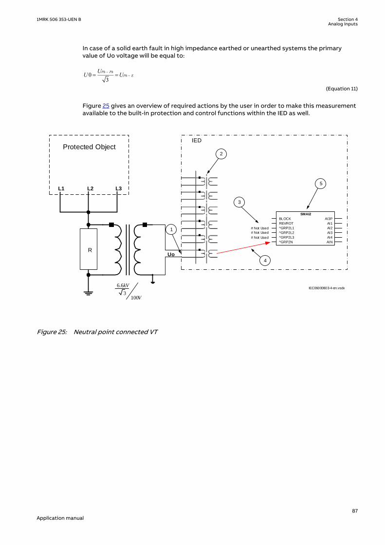
In case of a solid earth fault in high impedance earthed or unearthed systems the primaryvalue of Uo voltage will be equal to:
03
Ph PhPh E
UU U--= =
EQUATION1931 V2 EN-US (Equation 11)
Figure 25 gives an overview of required actions by the user in order to make this measurementavailable to the built-in protection and control functions within the IED as well.
L1 L2 L3
IED
6.6
3100
kV
V
RUo
IEC06000603-4-en.vsdx
# Not Used
# Not Used
# Not Used
Protected Object
SMAI2
BLOCK
REVROT
^GRP2L1
^GRP2L2
^GRP2L3
^GRP2N
AI3P
AI1
AI2
AI3
AI4
AIN
1
2
3
4
5
IEC06000603 V4 EN-US
Figure 25: Neutral point connected VT
1MRK 506 353-UEN B Section 4Analog inputs
87Application manual

Where:
1) shows how to connect the secondary side of neutral point VT to one VT input in the IED.
U0 shall be connected to the IED.
2) is the TRM or AIM where this voltage input is located. For this voltage input the following settingvalues shall be entered:
6.63.81
3VTprim kV= =
EQUATION1933 V1 EN-US (Equation 12)
sec 100VT V=
EQUATION1934 V1 EN-US (Equation 13)
Inside the IED, only the ratio of these two parameters is used. It shall be noted that the ratio of theentered values exactly corresponds to ratio of the neutral point VT.
3) shows that in this example the first three input channel of the preprocessing block is not connectedin SMT tool or ACT tool.
4) shows the connection made in Signal Matrix Tool (SMT), Application configuration tool (ACT), whichconnects this voltage input to the fourth input channel of the preprocessing function block 5).
5) is a preprocessing block that has the task to digitally filter the connected analog inputs andcalculate:
• fundamental frequency phasors for all four input channels• harmonic content for all four input channels• positive, negative and zero sequence quantities by using the fundamental frequency phasors
for the first three input channels (channel one taken as reference for sequence quantities)
These calculated values are then available for all built-in protection and control functions within theIED, which are connected to this preprocessing function block in the configuration tool. For thisapplication most of the preprocessing settings can be left to the default values.If frequency tracking and compensation is required (this feature is typically required only for IEDsinstalled in the generating stations) then the setting parameters DFTReference shall be setaccordingly.
Section 4 1MRK 506 353-UEN BAnalog inputs
88Application manual

Section 5 Local HMIAMU0600442 v14
IEC13000239-2-en.vsd
IEC13000239 V2 EN-US
Figure 26: Local human-machine interface
The LHMI of the IED contains the following elements:
• Keypad• Display (LCD)• LED indicators• Communication port for PCM600
The LHMI is used for setting, monitoring and controlling.
1MRK 506 353-UEN B Section 5Local HMI
89Application manual

5.1 DisplayGUID-55739D4F-1DA5-4112-B5C7-217AAF360EA5 v10
The LHMI includes a graphical monochrome liquid crystal display (LCD) with a resolution of 320x 240 pixels. The character size can vary. The amount of characters and rows fitting the viewdepends on the character size and the view that is shown.
The display view is divided into four basic areas.
IEC15000270-1-en.vsdx
IEC15000270 V1 EN-US
Figure 27: Display layout
1 Path
2 Content
3 Status
4 Scroll bar (appears when needed)
The function key button panel shows on request what actions are possible with the functionbuttons. Each function button has a LED indication that can be used as a feedback signal forthe function button control action. The LED is connected to the required signal with PCM600.
Section 5 1MRK 506 353-UEN BLocal HMI
90Application manual

IEC13000281-1-en.vsdGUID-C98D972D-D1D8-4734-B419-161DBC0DC97B V1 EN-US
Figure 28: Function button panel
The indication LED panel shows on request the alarm text labels for the indication LEDs. Threeindication LED pages are available.
IEC13000240-1-en.vsdGUID-5157100F-E8C0-4FAB-B979-FD4A971475E3 V1 EN-US
Figure 29: Indication LED panel
The function button and indication LED panels are not visible at the same time. Each panel isshown by pressing one of the function buttons or the Multipage button. Pressing the ESCbutton clears the panel from the display. Both panels have a dynamic width that depends onthe label string length.
5.2 LEDsAMU0600427 v12
The LHMI includes three status LEDs above the display: Ready, Start and Trip.
There are 15 programmable indication LEDs on the front of the LHMI. Each LED can indicatethree states with the colors: green, yellow and red. The texts related to each three-color LEDare divided into three panels.
There are 3 separate panels of LEDs available. The 15 physical three-color LEDs in one LEDgroup can indicate 45 different signals. Altogether, 135 signals can be indicated since there are
1MRK 506 353-UEN B Section 5Local HMI
91Application manual

three LED groups. The LEDs are lit according to priority, with red being the highest and greenthe lowest priority. For example, if on one panel there is an indication that requires the greenLED to be lit, and on another panel there is an indication that requires the red LED to be lit, thered LED takes priority and is lit. The LEDs can be configured with PCM600 and the operationmode can be selected with the LHMI or PCM600.
Information panels for the indication LEDs are shown by pressing the Multipage button.Pressing that button cycles through the three pages. A lit or un-acknowledged LED is indicatedwith a highlight. Such lines can be selected by using the Up/Down arrow buttons. Pressing theEnter key shows details about the selected LED. Pressing the ESC button exits frominformation pop-ups as well as from the LED panel as such.
The Multipage button has a LED. This LED is lit whenever any LED on any panel is lit. If there areun-acknowledged indication LEDs, then the Multipage LED blinks. To acknowledge LEDs, pressthe Clear button to enter the Reset menu (refer to description of this menu for details).
There are two additional LEDs which are next to the control buttons and . They can,for example, represent the status of a circuit breaker. The LEDs are controlled by the functionblock OPENCLOSE_LED which must be configured to show the status of the breaker.
5.3 KeypadAMU0600428 v17
The LHMI keypad contains push-buttons which are used to navigate in different views ormenus. The push-buttons are also used to acknowledge alarms, reset indications, provide helpand switch between local and remote control mode.
The keypad also contains programmable push-buttons that can be configured either as menushortcut or control buttons.
Section 5 1MRK 506 353-UEN BLocal HMI
92Application manual

1
18
19
7
6
5
4
3
2
8
20
21
22
17161514131211109
23
24
IEC15000157-1-en.vsdIEC15000157 V1 EN-US
Figure 30: LHMI keypad with object control, navigation and command push-buttons andRJ-45 communication port
1...5 Function button
6 Close
7 Open
8 Escape
9 Left
10 Down
11 Up
12 Right
13 Key
14 Enter
15 Remote/Local
16 Uplink LED
17 Not in use
18 Multipage
19 Menu
20 Clear
21 Help
22 Communication port
23 Programmable indication LEDs
1MRK 506 353-UEN B Section 5Local HMI
93Application manual

24 IED status LEDs
5.4 Local HMI functionality
5.4.1 Protection and alarm indicationGUID-09CCB9F1-9B27-4C12-B253-FBE95EA537F5 v15
Protection indicators
The protection indicator LEDs are Ready, Start and Trip.
The start and trip LEDs are configured via the disturbance recorder.The yellow and red status LEDs are configured in the disturbance recorderfunction, DRPRDRE, by connecting a start or trip signal from the actual functionto a BxRBDR binary input function block using the PCM600 and configure thesetting to Off, Start or Trip for that particular signal.
Table 8: Ready LED (green)
LED state Description
Off Auxiliary supply voltage is disconnected.
On Normal operation.
Flashing Internal fault has occurred.
Table 9: Start LED (yellow)
LED state Description
Off Normal operation.
On A protection function has started and an indication message is displayed.The start indication is latching and must be reset via communication, LHMI orbinary input on the LEDGEN component. To open the reset menu on the LHMI,
press .
Flashing The IED is in test mode and protection functions are blocked, or the IEC61850protocol is blocking one or more functions.The indication disappears when the IED is no longer in test mode and blockingis removed. The blocking of functions through the IEC61850 protocol can bereset in Main menu/Test/Reset IEC61850 Mod. The yellow LED changes toeither On or Off state depending on the state of operation.
Table 10: Trip LED (red)
LED state Description
Off Normal operation.
On A protection function has tripped. An indication message is displayed if theauto-indication feature is enabled in the local HMI.The trip indication is latching and must be reset via communication, LHMI orbinary input on the LEDGEN component. To open the reset menu on the LHMI,
press .
Flasing Configuration mode.
Section 5 1MRK 506 353-UEN BLocal HMI
94Application manual

Alarm indicators
The 15 programmable three-color LEDs are used for alarm indication. An individual alarm/status signal, connected to any of the LED function blocks, can be assigned to one of the threeLED colors when configuring the IED.
Table 11: Alarm indications
LED state Description
Off Normal operation. All activation signals are off.
On • Follow-S sequence: The activation signal is on.• LatchedColl-S sequence: The activation signal is on, or it is off but the indication has not
been acknowledged.• LatchedAck-F-S sequence: The indication has been acknowledged, but the activation
signal is still on.• LatchedAck-S-F sequence: The activation signal is on, or it is off but the indication has
not been acknowledged.• LatchedReset-S sequence: The activation signal is on, or it is off but the indication has
not been acknowledged.
Flashing • Follow-F sequence: The activation signal is on.• LatchedAck-F-S sequence: The activation signal is on, or it is off but the indication has
not been acknowledged.• LatchedAck-S-F sequence: The indication has been acknowledged, but the activation
signal is still on.
5.4.2 Parameter managementGUID-5EE466E3-932B-4311-9FE1-76ECD8D6E245 v9
The LHMI is used to access the relay parameters. Three types of parameters can be read andwritten.
• Numerical values• String values• Enumerated values
Numerical values are presented either in integer or in decimal format with minimum andmaximum values. Character strings can be edited character by character. Enumerated valueshave a predefined set of selectable values.
5.4.3 Front communicationGUID-FD72A445-C8C1-4BFE-90E3-0AC78AE17C45 v10
The RJ-45 port in the LHMI enables front communication.
• The green uplink LED on the left is lit when the cable is successfully connected to the port.• The yellow LED is not used; it is always off.
1MRK 506 353-UEN B Section 5Local HMI
95Application manual

IEC13000280-1-en.vsd
1
2
GUID-AACFC753-BFB9-47FE-9512-3C4180731A1B V1 EN-US
Figure 31: RJ-45 communication port and green indicator LED
1 RJ-45 connector
2 Green indicator LED
The default IP address for the IED front port is 10.1.150.3 and the corresponding subnetworkmask is 255.255.255.0. It can be set through the local HMI path Main menu/Configuration/Communication/Ethernet configuration/FRONT:1.
Do not connect the IED front port to a LAN. Connect only a single local PC withPCM600 to the front port. It is only intended for temporary use, such ascommissioning and testing.
Section 5 1MRK 506 353-UEN BLocal HMI
96Application manual

Section 6 Differential protection
6.1 High impedance differential protection, single phaseHZPDIF
IP14239-1 v4
6.1.1 IdentificationM14813-1 v4
Function description IEC 61850identification
IEC 60617identification
ANSI/IEEE C37.2device number
High impedance differentialprotection, single phase HZPDIF Id
SYMBOL-CC V2 EN-US
87
6.1.2 ApplicationIP14944-1 v3
SEMOD54734-4 v8
The 1Ph High impedance differential protection function HZPDIF can be used as:
• Generator differential protection• Reactor differential protection• Busbar differential protection• Autotransformer differential protection (for common and serial windings only)• T-feeder differential protection• Capacitor differential protection• Restricted earth fault protection for transformer, generator and shunt reactor windings• Restricted earth fault protection
The application is dependent on the primary system arrangements and location of breakers,available CT cores and so on.
1MRK 506 353-UEN B Section 6Differential protection
97Application manual

3·Id
3·IdId
3·Id
3·Id
G
3·Id
IEC05000163-4-en.vsdIEC05000163 V4 EN-US
Figure 32: Different applications of a 1Ph High impedance differential protection HZPDIFfunction
6.1.2.1 The basics of the high impedance principleSEMOD54734-153 v9
The high impedance differential protection principle has been used for many years and is welldocumented in literature publicly available. Its operating principle provides very goodsensitivity and high speed operation. One main benefit offered by the principle is an absolutestability (that is, no operation) for external faults even in the presence of heavy CT saturation.The principle is based on the CT secondary current circulating between involved currenttransformers and not through the IED due to high impedance in the measuring branch. Thisstabilizing resistance is in the range of hundreds of ohms and sometimes above one kilo Ohm.When an internal fault occurs the current cannot circulate and is forced through the measuringbranch causing relay operation.
It should be remembered that the whole scheme, its built-in components and wiring must beadequately maintained throughout the lifetime of the equipment in order to be able to
Section 6 1MRK 506 353-UEN BDifferential protection
98Application manual

withstand the high voltage peaks (that is, pulses) which may appear during an internal fault.Otherwise any flash-over in CT secondary circuits or any other part of the scheme may preventcorrect operation of the high impedance differential relay for an actual internal fault.
Id
IEC05000164-2-en.vsd
R
Metrosil
IEC05000164 V3 EN-US
Figure 33: Example for the high impedance restricted earth fault protection application
For a through fault one current transformer might saturate when the other CTs still will feedcurrent. For such a case a voltage will be developed across the measuring branch. Thecalculations are made with the worst situations in mind and a minimum operating voltage URis calculated according to equation 14
( )maxUR IF Rct Rl> × +EQUATION1531 V1 EN-US (Equation 14)
where:
IFmax is the maximum through fault current at the secondary side of the CT
Rct is the current transformer secondary winding resistance and
Rl is the maximum loop resistance of the circuit at any CT.
The minimum operating voltage has to be calculated (all loops) and the IED function is sethigher than the highest achieved value (setting U>Trip). As the loop resistance is the value to
1MRK 506 353-UEN B Section 6Differential protection
99Application manual

the connection point from each CT, it is advisable to do all the CT core summations in theswitchgear to have shortest possible loops. This will give lower setting values and also a betterbalanced scheme. The connection in to the control room can then be from the most centralbay.
For an internal fault, all involved CTs will try to feed current through the measuring branch.Depending on the size of current transformer, relatively high voltages will be developed acrossthe series resistor. Note that very high peak voltages can appear. To prevent the risk offlashover in the circuit, a voltage limiter must be included. The voltage limiter is a voltagedependent resistor (Metrosil).
The external unit with stabilizing resistor has a value of either 6800 ohms or 1800 ohms(depending on ordered alternative) with a sliding link to allow adjustment to the requiredvalue. Select a suitable value of the resistor based on the UR voltage calculated. A higherresistance value will give a higher sensitivity and a lower value a lower sensitivity of the relay.
The function has a recommended operating current range 40 mA to 1.0A for 1 A inputs and 200mA to 5A for 5A inputs. This, together with the selected and set value, is used to calculate therequired value of current at the set U>Trip and SeriesResitor values.
The CT inputs used for 1Ph High impedance differential protection HZPDIFfunction, shall be set to have ratio 1:1. So the parameters CTsecx and CTprimx ofthe relevant channel x of TRM and/or AIM shall be set equal to 1 A by PST inPCM600; The parameter CTStarPointx may be set to ToObject.
The tables 12, 13 below show, the operating currents for different settings of operatingvoltages and selected resistances. Adjust as required based on tables 12, 13 or to values inbetween as required for the application.
Minimum ohms can be difficult to adjust due to the small value compared tothe total value.
Normally the voltage can be increased to higher values than the calculated minimum U>Tripwith a minor change of total operating values as long as this is done by adjusting the resistorto a higher value. Check the sensitivity calculation below for reference.
Table 12: 1 A channels: input with minimum operating down to 40 mA
OperatingvoltageU>Trip
Stabilizingresistor Rohms
Operatingcurrent level1 A
Stabilizingresistor Rohms
Operatingcurrent level1 A
20 V 500 0.040 A -- --
40 V 1000 0.040 A -- --
60 V 1500 0.040 A 600 0.100 A
80 V 2000 0.040 A 800 0.100 A
100 V 2500 0.040 A 1000 0.100 A
150 V 3750 0.040 A 1500 0.100 A
200 V 5000 0.040 A 2000 0.100 A
Section 6 1MRK 506 353-UEN BDifferential protection
100Application manual

Table 13: 5 A channels: input with minimum operating down to 100 mA
OperatingvoltageU>Trip
Stabilizingresistor R1ohms
Operatingcurrent level5 A
Stabilizingresistor R1ohms
Operatingcurrent level5 A
Stabilizingresistor R1ohms
Operatingcurrent level5 A
20 V 200 0.100 A 100 0.200 A -- --
40 V 400 0.100 A 200 0.200 A 100 0.400
60 V 600 0.100 A 300 0.200 A 150 0.400 A
80 V 800 0.100 A 400 0.200 A 200 0.400 A
100 V 1000 0.100 A 500 0.200 A 250 0.400 A
150 V 1500 0.100 A 750 0.200 A 375 0.400 A
200 V 2000 0.100 A 1000 0.200 A 500 0.400 A
The current transformer saturation voltage must be at least 2 ˣ U>Trip to have sufficientoperating margin. This must be checked after calculation of U>Trip.
When the R value has been selected and the U>Trip value has been set, the sensitivity of thescheme IP can be calculated. The IED sensitivity is decided by the total current in the circuitaccording to equation 15.
( )IP n IR Ires lmag= × + + åEQUATION1747 V1 EN-US (Equation 15)
where:
n is the CT ratio
IP primary current at IED pickup,
IR IED pickup current (U>Trip/SeriesResistor)
Ires is the current through the voltage limiter and
ΣImag is the sum of the magnetizing currents from all CTs in the circuit (for example, 4 forrestricted earth fault protection, 2 for reactor differential protection, 3-5 forautotransformer differential protection).
It should be remembered that the vectorial sum of the currents must be used (IEDs, Metrosiland resistor currents are resistive). The current measurement is insensitive to DC componentin fault current to allow the use of only the AC components of the fault current in the abovecalculations.
The voltage dependent resistor (Metrosil) characteristic is shown in Figure 39.
Series resistor thermal capacitySEMOD54734-336 v6
The series resistor is dimensioned for 200 W. Preferable the U>Trip2/SeriesResistor shouldalways be lower than 200 W to allow continuous activation during testing. If this value isexceeded, testing should be done with a transient faults.
1MRK 506 353-UEN B Section 6Differential protection
101Application manual

I>
R
Rres
Rl
Rct Rct
Rl
UR
a) Through load situation
b) Through fault situation
UR
UR
c) Internal faults
UR
Protected Object
IEC05000427-2-en.vsdIEC05000427 V2 EN-US
Figure 34: The high impedance principle for one phase with two current transformerinputs
Section 6 1MRK 506 353-UEN BDifferential protection
102Application manual

6.1.3 Connection examples for high impedance differentialprotection
GUID-8C58A73D-7C2E-4BE5-AB87-B4C93FB7D62B v5
WARNING! USE EXTREME CAUTION! Dangerously high voltages might bepresent on this equipment, especially on the plate with resistors. De-energizethe primary object protected with this equipment before connecting ordisconnecting wiring or performing any maintenance. The plate with resistorsshould be provided with a protective cover, mounted in a separate box or in alocked cubicle. National law and standards shall be followed.
6.1.3.1 Connections for three-phase high impedance differential protectionGUID-C12CCAAF-5AE5-4A9C-AC9C-F56A66FD2C14 v8
Generator, reactor or busbar differential protection is a typical application for three-phasehigh impedance differential protection. Typical CT connections for three-phase highimpedance differential protection scheme are shown in figure 35.
L1(A)
L2(B)
L3(C)
Protected Object
CT 1200/1Star/Wye
Connected
L1(A)
L2(B)
L3(C)
CT 1200/1Star/Wye
Connected
7
8
9101112
1
2
3
4
5
6
AI01(I)
AI02(I)
AI03(I)
AI04(I)
AI05(I)
AI06(I)
7
6
X1
R4
R5
R6
12
12
12
11 12 13 14
U U U R1
13
4
2
13
R2
2
4
13
R3
2
4
1 2 3 4 5 6 7
L1 (A)
L2 (B)
L3 (C)N
3-Ph Plate with Metrosils and Resistors
2
3
5
4
X X
L1 (A)
L2 (B)
L3 (C)N
1
IED
IEC07000193_4_en.vsd
AI3P
AI1
AI2
AI3
AI4
AIN
SMAI2
BLOCK
^GRP2L1
^GRP2L2
^GRP2L3
^GRP2N
TYPE
IEC07000193 V4 EN-US
Figure 35: CT connections for high impedance differential protection
Pos Description
1 Scheme earthing point
It is important to insure that only one earthing point exist in this scheme.
2 Three-phase plate with setting resistors and metrosils. Protective earth is a separate 4 mm screwterminal on the plate.
3 Necessary connection for three-phase metrosil set.
4 Position of optional test switch for secondary injection into the high impedance differential IED.
1MRK 506 353-UEN B Section 6Differential protection
103Application manual
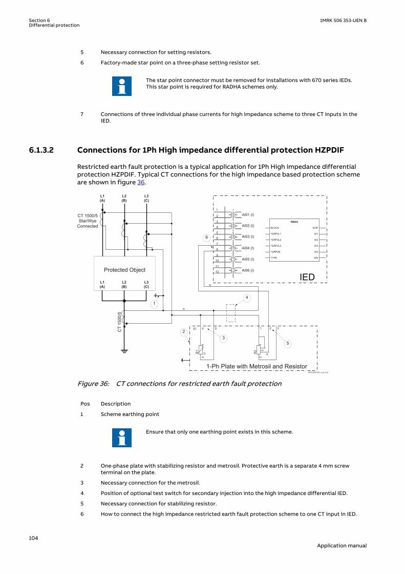
5 Necessary connection for setting resistors.
6 Factory-made star point on a three-phase setting resistor set.
The star point connector must be removed for installations with 670 series IEDs.This star point is required for RADHA schemes only.
7 Connections of three individual phase currents for high impedance scheme to three CT inputs in theIED.
6.1.3.2 Connections for 1Ph High impedance differential protection HZPDIFGUID-D68A237F-610C-4AF0-870F-273117F64D92 v10
Restricted earth fault protection is a typical application for 1Ph High impedance differentialprotection HZPDIF. Typical CT connections for the high impedance based protection schemeare shown in figure 36.
L1(A)
L2(B)
L3(C)
Protected Object
CT 1500/5Star/Wye
Connected
7
8
9
10
11
12
1
2
3
4
5
6
AI01 (I)
AI02 (I)
AI03 (I)
AI04 (I)
AI05 (I)
AI06 (I)
6
X1
R1
12
4 5
U R2
13
4
2
1 2 3
N
1-Ph Plate with Metrosil and Resistor
23
5
4
N
L1(A)
L2(B)
L3(C)
CT
1500
/5
1
IEC07000194_4_en.vsd
AI3P
AI1
AI2
AI3
AI4
AIN
SMAI2
BLOCK
^GRP2L1
^GRP2L2
^GRP2L3
^GRP2N
TYPE
IEC07000194 V4 EN-US
Figure 36: CT connections for restricted earth fault protection
Pos Description
1 Scheme earthing point
Ensure that only one earthing point exists in this scheme.
2 One-phase plate with stabilizing resistor and metrosil. Protective earth is a separate 4 mm screwterminal on the plate.
3 Necessary connection for the metrosil.
4 Position of optional test switch for secondary injection into the high impedance differential IED.
5 Necessary connection for stabilizing resistor.
6 How to connect the high impedance restricted earth fault protection scheme to one CT input in IED.
Section 6 1MRK 506 353-UEN BDifferential protection
104Application manual
6.1.4 Setting guidelinesIP14945-1 v1
M13076-3 v2
The setting calculations are individual for each application. Refer to the different applicationdescriptions below.
6.1.4.1 ConfigurationM13076-5 v4
The configuration is done in the Application Configuration tool.
6.1.4.2 Settings of protection functionM13076-10 v6
Operation: The operation of the high impedance differential function can be switched On orOff.
U>Alarm: Set the alarm level. The sensitivity can roughly be calculated as a certain percentageof the selected Trip level. A typical setting is 10% of U>Trip This alarm stage can be used forscheme CT supervision.
tAlarm: Set the time delay for the alarm. A typical setting is 2-3 seconds.
U>Trip: Set the trip level according to the calculations (see examples below for a guidance).The level is selected with margin to the calculated required voltage to achieve stability. Valuescan be within 20V - 400V range dependent on the application.
SeriesResistor: Set the value of the used stabilizing series resistor. Calculate the valueaccording to the examples for each application. Adjust the resistor as close as possible to thecalculated value. Measure the value achieved and set this value for this parameter.
The value shall always be high impedance. This means for example, for 1Acircuits say bigger than 400 ohms (400 VA) and for 5 A circuits say bigger than100 ohms (2500 VA). This ensures that the current will circulate and not gothrough the differential circuit at through faults.
That the settings of U>Alarm, U>Trip and SeriesResistor must be chosen suchthat both U>Alarm/SeriesResistor and U>Trip/SeriesResistor are >4% ofIRated of the used current input. Normally the settings shall also be such thatU>Alarm/SeriesResistor and U>Trip/SeriesResistor both gives a value<4*IRated of the used current input. If not, the limitation in how long time theactual current is allowed to persist not to overload the current input must beconsidered especially during the secondary testing.
6.1.4.3 T-feeder protectionM16850-4 v7
In many busbar arrangements such as one-and a half breaker, ring breaker, mesh corner, therewill be a T-feeder from the current transformer at the breakers up to the current transformersin the feeder circuit (for example, in the transformer bushings). It is often required to separatethe protection zones that the feeder is protected with one scheme while the T-zone isprotected with a separate differential protection scheme. The 1Ph high impedance differentialHZPDIF function in the IED allows this to be done efficiently, see Figure 37.
1MRK 506 353-UEN B Section 6Differential protection
105Application manual

3·Id
IEC05000165-2-en.vsdIEC05000165 V2 EN-US
Figure 37: The protection scheme utilizing the high impedance function for the T-feeder
Normally this scheme is set to achieve a sensitivity of around 20 percent of the used CTprimary rating so that a low ohmic value can be used for the series resistor.
It is strongly recommended to use the highest tap of the CT whenever highimpedance protection is used. This helps in utilizing maximum CT capability,minimize the secondary fault current, thereby reducing the stability voltagelimit. Another factor is that during internal faults, the voltage developed acrossthe selected tap is limited by the non-linear resistor but in the unused taps,owing to auto-transformer action, voltages induced may be much higher thandesign limits.
Setting example
Basic data: Current transformer ratio: 2000/1 A
CT Class: 20 VA 5P20
Secondary resistance: 6.2 ohms
Cable loop resistance: <100 m 2.5 mm2 (one way) gives 2 ˣ 0.8 ohm at 75° C
Max fault current: Equal to switchgear rated fault current 40 kA
Section 6 1MRK 506 353-UEN BDifferential protection
106Application manual
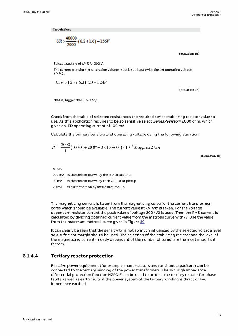
Calculation:
EQUATION1207 V2 EN-US (Equation 16)
Select a setting of U>Trip=200 V.
The current transformer saturation voltage must be at least twice the set operating voltageU>Trip.
( )5 20 6.2 20 524E P V> + × =
EQUATION1208 V1 EN-US (Equation 17)
that is, bigger than 2 ˣU>Trip
Check from the table of selected resistances the required series stabilizing resistor value touse. As this application requires to be so sensitive select SeriesResistor= 2000 ohm, whichgives an IED operating current of 100 mA.
Calculate the primary sensitivity at operating voltage using the following equation.
IP approx A= ° + ° + × − °( ) × ≤−2000
1100 0 20 0 3 10 60 10 275
3
EQUATION1209 V2 EN-US (Equation 18)
where
100 mA is the current drawn by the IED circuit and
10 mA is the current drawn by each CT just at pickup
20 mA is current drawn by metrosil at pickup
The magnetizing current is taken from the magnetizing curve for the current transformercores which should be available. The current value at U>Trip is taken. For the voltagedependent resistor current the peak value of voltage 200 ˣ √2 is used. Then the RMS current iscalculated by dividing obtained current value from the metrosil curve with√2. Use the valuefrom the maximum metrosil curve given in Figure 39
It can clearly be seen that the sensitivity is not so much influenced by the selected voltage levelso a sufficient margin should be used. The selection of the stabilizing resistor and the level ofthe magnetizing current (mostly dependent of the number of turns) are the most importantfactors.
6.1.4.4 Tertiary reactor protectionM16850-118 v5
Reactive power equipment (for example shunt reactors and/or shunt capacitors) can beconnected to the tertiary winding of the power transformers. The 1Ph High impedancedifferential protection function HZPDIF can be used to protect the tertiary reactor for phasefaults as well as earth faults if the power system of the tertiary winding is direct or lowimpedance earthed.
1MRK 506 353-UEN B Section 6Differential protection
107Application manual

3·Id
IEC05000176-3-en.vsd
IEC05000176 V3 EN-US
Figure 38: Application of the1Ph High impedance differential protection HZPDIF function on a reactor
Setting example
It is strongly recommended to use the highest tap of the CT whenever highimpedance protection is used. This helps in utilizing maximum CT capability,minimize the secondary fault, thereby reducing the stability voltage limit.Another factor is that during internal faults, the voltage developed across theselected tap is limited by the non-linear resistor but in the unused taps, owingto auto-transformer action, voltages much higher than design limits might beinduced.
Section 6 1MRK 506 353-UEN BDifferential protection
108Application manual

Basic data: Current transformer ratio: 100/5 A (Note: Must be the same at all locations)
CT Class: 10 VA 5P20
Secondary resistance: 0.26 ohms
Cable loop resistance: <50 m 2.5mm2 (one way) gives 1 ˣ 0.4 ohm at 75° CNote! Only one way as the tertiary power system earthing is limitingthe earth-fault current. If high earth-fault current exists use two waycable length.
Max fault current: The maximum through fault current is limited by the reactorreactance and the inrush will be the worst for a reactor for example,800 A.
Calculation:
UR > × + =800
100 50 26 0 4 26 4
/( . . ) ,
EQUATION1216 V2 EN-US (Equation 19)
Select a setting of U>Trip=30 V.
The current transformer saturation voltage must be at least, twice the set operating voltageU>Trip .
U CT Saturation V_ _ .> +
× × =
10
250 26 20 5 66
EQUATION1217 V2 EN-US (Equation 20)
that is, greater than 2 ˣ U>Trip.
Check from the table of selected resistances the required series stabilizing resistor value touse. Since this application requires good sensitivity, select SeriesResistor = 300 ohm, whichgives an IED current of 100 mA.
To calculate the sensitivity at operating voltage, refer to equation 21, which gives anacceptable value. A little lower sensitivity could be selected by using a lower resistance value.
IP approx A= × ° + ° + × − °( ) × ≤−100
5100 0 5 0 2 100 60 10 5
3
EQUATION1218 V2 EN-US (Equation 21)
The magnetizing current is taken from the magnetizing curve of the current transformer cores,which should be available. The current value at U>Trip is taken. For the voltage dependentresistor current the peak value of voltage 30 ˣ √2 is used. Then the RMS current is calculated bydividing obtained current value from the metrosil curve with √2. Use the maximum value fromthe metrosil curve given in Figure 39.
6.1.4.5 Alarm level operationM16850-196 v6
The 1Ph High impedance differential protection HZPDIF function has a separate alarm level,which can be used to give alarm for problems with an involved current transformer circuit. Thesetting level is normally selected to be around 10% of the operating voltage U>Trip.
As seen in the setting examples above the sensitivity of HZPDIF function is normally high,which means that the function will in many cases operate also for short circuits or open
1MRK 506 353-UEN B Section 6Differential protection
109Application manual

current transformer secondary circuits. However the stabilizing resistor can be selected toachieve sensitivity higher than normal load current and/or separate criteria can be added tothe operation, like a check zone. This can be either another IED, with the same HZPDIFfunction, or be a check about the fault condition, which is performed by an earth overcurrentfunction or neutral point voltage function.
For such cases where operation is not expected during normal service the alarm output shouldbe used to activate an external shorting of the differential circuit avoiding continuous highvoltage in the circuit. A time delay of a few seconds is used before the shorting and alarm areactivated. Auxiliary relays with contacts that can withstand high voltage shall be used, likeRXMVB types.
The metrosil operating characteristic is given in the following figure.
IEC05000749 V1 EN-US
Figure 39: Current voltage characteristics for the non-linear resistors, in the range 10-200 V, theaverage range of current is: 0.01–10 mA
6.2 Line differential protectionIP13934-1 v1
6.2.1 IdentificationM14844-1 v4
Function description IEC 61850identification
IEC 60617identification
ANSI/IEEE C37.2device number
Line differential protection, 3 CTsets, 2-3 line ends L3CPDIF 3Id/I>
SYMBOL-HH V1 EN-US
87L
6.2.2 ApplicationIP14947-1 v1
M12022-3 v5
Line differential protection can be applied on overhead lines and cables. It is an absoluteselective unit protection with a number of advantages. Coordination with other protections isnormally simple. All faults on the line, between the line bay CTs, can be cleared
Section 6 1MRK 506 353-UEN BDifferential protection
110Application manual

instantaneously. The sensitivity can be made high, which is especially important for the abilityto detect high resistive earth faults. It is not influenced by possible voltage and/or currentinversion, associated with faults in series compensated networks. It is not influenced by faultcurrent reversal at earth faults on parallel lines. As it is phase-segregated, the identification offaulted phases is inherent, and thus the application of single- or two-phase trip and auto-reclosing can be made robust and reliable. Note that if an in-line or shunt power transformer isincluded in the protected circuit, of the type Dy or Yd, then the protection cannot be phase-segregated. Single-phase automatic re-closing will not be possible.
Line differential protection can be applied on multi-terminal lines with maximum five line ends.Depending on the actual network, reliable fault clearance can often be difficult to achieve withconventional distance protection schemes in these types of applications.
It is recommended to use the same firmware version as well as hardwareversion for a specific line differential scheme.
With 1½ breaker configurations, normally the line protection is fed from two CTs. Avoiding toadd the currents from the two CTs externally before entering the IED is important as this willenable possible bias current from both CTs to be considered in the current differentialalgorithm, and in that way assuring that the correct restrain will be possible, as shown infigure 40.
en05000428.vsd
RED670
RED670
RED670
64 kbit/s
64 kbit/s
64 kbit/s
Protected zone
IEC05000428 V1 EN-US
Figure 40: Line protection with 1½ breaker configurations, fed from two CTs
6.2.2.1 Power transformers in the protected zoneM12022-47 v6
Line differential protection can also be applied with in-line power transformers in theprotected zone. Such an in-line power transformer can be situated in tap, as shown inFigure 41 or in one end of a two-terminal line. Observe that the currents of the in-line powertransformer are measured by the IED on the low voltage side. Up to two two-windingtransformers, or alternatively one three-winding transformer can be included.
1MRK 506 353-UEN B Section 6Differential protection
111Application manual

en05000429.vsd
RED670
RED670
RED670
64 kbit/s
64 kbit/s
64 kbit/s
Protected zone
IEC05000429 V1 EN-US
Figure 41: Transformer situated in tap
A current differential protection including power transformers must be compensated fortransformer turns ratio and phase shift/vector group. In the line differential function thiscompensation is made in the software algorithm, which eliminates the need for auxiliaryinterposing current transformers. Necessary parameters, such as transformer rated voltagesand phase shift, must be entered via the Parameter Setting tool or the LHMI.
Another concern with differential protection on power transformers is that a differentialprotection may operate unwanted due to external earth faults in cases where the zero-sequence current can flow only on one side of the power transformer but not on the otherside, as in the case of Yd or Dy phase shift/vector groups. This is the situation when the zero-sequence current cannot be transformed from one side to the other side of the transformer.To make the differential protection insensitive to external earth faults in these situations, thezero-sequence current must be eliminated from the terminal currents so that it does notappear as a differential current. This was previously achieved by means of intermediatecurrent transformers. The elimination of zero-sequence current is done numerically and noauxiliary transformers are necessary. Instead it is necessary to eliminate the zero-sequencecurrent by proper setting of the parameter ZerSeqCurSubtr. If the power transformer is of thetype Dyn, where yn-windings currents are measured, then the zero-sequence component willbe subtracted when these currents are transformed to the HV-side.
6.2.2.2 Small power transformers in a tapM12022-54 v5
If there is a line tap with a comparatively small power transformer (say 1-20MVA) , linedifferential protection can be applied without the need of current measurement from the tap.It works such that line differential protection function will be time delayed for smalldifferential currents below a set limit, making coordination with downstream short circuitprotection in the tap possible. For differential currents above that limit, the operation will beinstantaneous in the normal way. Under the condition that the load current in the tap will benegligible, normal line faults, with a fault current higher than the fault current on the LV side ofthe transformer, will be cleared instantaneously.
For faults on the LV side of the transformer the function will be time delayed, with the delaycharacteristic selected, thus providing selectivity to the downstream functions, see figure 42.The scheme will solve the problem with back-up protection for faults on the transformer LVside where many expensive solutions have been applied such as intertripping or a local HVbreaker. In many such applications the back-up protection has been lacking due to thecomplexity in cost implications to arrange it. Refer also to the setting example below.
Section 6 1MRK 506 353-UEN BDifferential protection
112Application manual

en05000435.vsd
RED670
RED670
64 kbit/s
Protected zone in instantaneous function
IEC05000435 V1 EN-US
Figure 42: Line tap with a small power transformer, the currents of which are notmeasured, and consequently contribute to a (false) differential current
6.2.2.3 Charging current compensationM12022-58 v6
There are capacitances between the line phase conductors and between phase conductors andearth. These capacitances give rise to line charging currents which are seen by the differentialprotection as “false” differential currents, as shown in figure 43.
RED 670
RED 670
Communication
Ic1 Ic2Idiff,false = Ic1 + Ic2
en05000436.vsdIEC05000436 V1 EN-US
Figure 43: Charging currents
The magnitude of the charging current is dependent of the line capacitance and the systemvoltage. For earth cables and long overhead lines, the magnitude can be such that it affectsthe possibility to achieve the wanted sensitivity of the differential protection. To overcomethis, a charging current compensation is available in line differential protection. When enabled,this algorithm will measure the fundamental frequency differential current under steady stateundisturbed conditions and then subtract it, making the resulting differential current zero (orclose to zero). Note that all small pre-fault differential currents are subtracted, no matter whattheir origin. This action is made separately for each phase.
When a disturbance occurs, values of the pre-fault differential currents are not updated, andthe updating process is only resumed 100 ms after normal conditions have been restored.Normal conditions are then considered when there are no start signals, neither internal norexternal fault is detected, the power system is symmetrical and so on. If an Open CT conditionis detected, the compensation of charging currents is stopped immediately and the chargingcurrents are temporarily memorized by the function. When Open CT signal resets, the processof compensation is resumed with the same charging current as before. The consequence offreezing the pre-fault values during fault conditions in this way will actually introduce a smallerror in the resulting calculated differential current under fault conditions. However, this willnot have any practical negative consequences, while the positive effect of maintaining highsensitivity even with high charging currents will be achieved. To demonstrate this, two casescan be studied, one with a low resistive short circuit, and one with a high resistive short circuit.
1MRK 506 353-UEN B Section 6Differential protection
113Application manual

The charging current is generated because there is a voltage applied over the line capacitanceas seen in figure 43. If an external short circuit with negligible fault resistance occurs close tothe line, the voltage in the fault location will be approximately zero. Consequently, zero voltagewill also be applied over part of the line capacitance, which in turn will decrease the chargingcurrent compared to the pre-fault value. As mentioned above, the value of the pre-fault “false”differential current will be frozen when a fault is detected, and, as a consequence, the value ofthe subtracted charging current will be too high in this case. However, as it is a low resistivefault, the bias current will be comparatively high, while the charging current and any errors inthe approximation of this will be comparatively low. Thus, the overestimated charging currentwill not jeopardize stability as can be seen from figure 44, showing the characteristic of linedifferential protection. In this figure, the considered fault will appear in the section well in therestrain area.
Section 1
UnrestrainedLimit
Section 2 Section 3
Restrain
Operateunconditionally
5
4
3
2
1
00 1 2 3 4 5
IdMin
EndSection1
EndSection2Restrain current[ in pu of IBase]
Operate current[ in pu of IBase]
SlopeSection2
SlopeSection3
en05000300.vsd
Operateconditionally
IdMinHigh
A
C
B
IEC05000300 V1 EN-US
Figure 44: Overestimated charging current
If a high resistive fault is considered, the voltage in the fault location will not be much reduced.Consequently, the value of the pre-fault “false” differential current will be a good estimation ofthe actual charging current.
Subtracting the pre-fault charging current from the differential current under fault conditionswill make it possible to set Idmin mainly without considering the charging current in order toachieve maximum sensitivity. The stability at external faults will not be affected.
6.2.2.4 Time synchronizationM12022-66 v3
Time synchronization of sampled current values is a crucial matter in numerical line differentialprotections. The synchronization is made with the so called echo method, which can becomplemented with GPS synchronization. In applications with symmetrical communicationdelay, that is, send and receive times are equal, the echo method is sufficient. When used innetworks with asymmetrical transmission times, the optional GPS synchronization is required.
Section 6 1MRK 506 353-UEN BDifferential protection
114Application manual

6.2.2.5 Analog signal communication for line differential protectionM12022-69 v6
Line differential protection uses digital 64 kbit/s communication channels to exchangetelegrams between the protection IEDs. These telegrams contain current sample values, timeinformation, trip signals, block signals, alarm signals and eight binary signals, which can beused for any purpose. Each IED can have a maximum of four communication channels.
On a two terminal line there is a need of one 64 kbit/s communication channel provided thatthere is only one CT in each line end, as shown in Figure 45.
RED670
RED670
64 kbit/s
Protected zone
en05000437.vsdIEC05000437 V1 EN-US
Figure 45: Two-terminal line
In case of 1½ breaker arrangements or ring buses, a line end has two CTs, as shown inFigure 46.
RED670
64 kbit/s
Protected zone
64 kbit/s
RED670
en05000438.vsdIEC05000438 V1 EN-US
Figure 46: Two-terminal line with 1½ breaker
Observe that in Figure 46, each of the two local CTs on the left side is treatedas a separate end by the differential protection.
In this case, current values from two CTs in the double breakers, ring main or breaker-and-a-half systems end with dual breaker arrangement need to be sent to the remote end. As a 64kbit/s channel only has capacity for one three-phase current (duplex), this implies that twocommunication channels are needed in both ends, and this is also the normal solution.Alternatively, but not recommended, it is possible to add together the two local currentsbefore sending them and in that way reduce the number of communication channels needed.This is then done in software in the IED, but by doing it this way there is reduced informationabout bias currents. The bias current is considered the greatest phase current in any line endand it is common for all three phases. When sending full information from both local CTs tothe remote end, this principle works, but when the two local currents are added togetherbefore sending the single resulting current on the single communication channel, informationabout the real phase currents from the two local CTs are not available in the remote line end.
Whether it is possible to use one communication channel instead of two (as show in Figure 46)must be decided from case to case. It must be realized that correct information about biascurrents is always available locally, while only distorted information is available in the end thatreceives the limited information over only one channel.
For more details about the remote communication, refer to section "".
1MRK 506 353-UEN B Section 6Differential protection
115Application manual

6.2.2.6 Configuration of analog signalsM12022-86 v5
Currents from the local end enter the IED as analog values via the Analog input modules. Thesecurrents are converted to digital values and then forwarded to the line differential protectionfunction in the local IED. From there, they are transmitted to remote IEDs via a Line differentialcommunication module (LDCM). Currents coming from a remote IED are received as digitalvalues via local IED's LDCM, and they are then forwarded to the protection function in the localIED.
LDLPSCH acts as the interface to and from the protection function.
Configuration of this data flow is made in the SMT tool as shown in Figure 47.
Currents from remote end 1
Currents to remote end 1
Currents from remote end 2
Currents to remote end 2
LDCM 2
LDCM 1
Currents from local CT
A/D
SMAI
Pre-processing block
Line Differential function
L3DPDIF
IEC05000533-2-en.vsd
IEC05000533-NEW V2 EN-US
Figure 47: Typical configuration of analog signals for a three-terminal line
Figure 47 shows how one IED in a three-terminal line differential protection can be configured.There are two LDCMs each supporting a duplex connection with a remote line end. Thus, thesame local current is configured to both LDCMs, while the received currents from the LDCMsare configured separately to the line differential protection function.
6.2.2.7 Configuration of LDCM output signalsM12022-93 v2
There are a number of signals available from the LDCM that can be connected to the virtualbinary inputs (SMBI) and used internally in the configuration. The signals appear only in theSignal Matrix tool where they can be mapped to the desired virtual input.
For explanation of the signals, refer to section Remote communication, Binary signal transferto remote end in the technical reference manual. The signal name is found in the ObjectProperties window by clicking on the input signal number in the Signal Matrix tool. Connectthe signals to the virtual inputs as desired, as shown in figure
Section 6 1MRK 506 353-UEN BDifferential protection
116Application manual
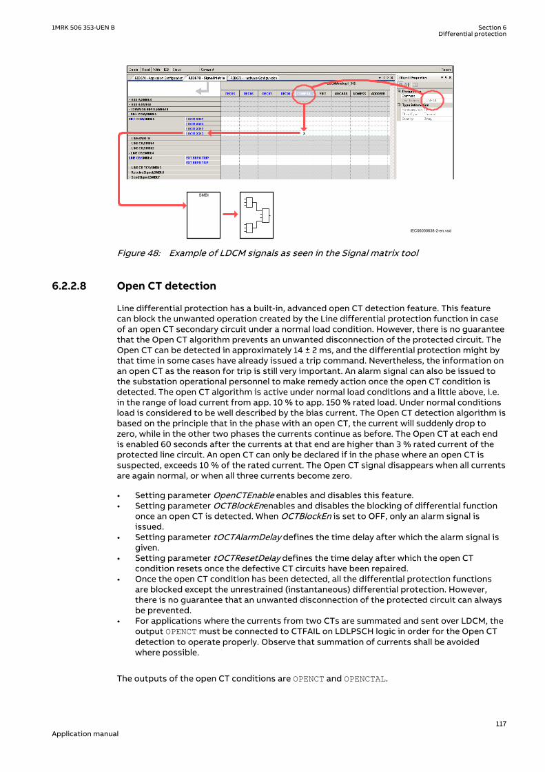
SMBI
IEC06000638-2-en.vsd
IEC06000638 V2 EN-US
Figure 48: Example of LDCM signals as seen in the Signal matrix tool
6.2.2.8 Open CT detectionGUID-DB3841A9-5B55-490E-8A2D-EBF0CB263378 v7
Line differential protection has a built-in, advanced open CT detection feature. This featurecan block the unwanted operation created by the Line differential protection function in caseof an open CT secondary circuit under a normal load condition. However, there is no guaranteethat the Open CT algorithm prevents an unwanted disconnection of the protected circuit. TheOpen CT can be detected in approximately 14 ± 2 ms, and the differential protection might bythat time in some cases have already issued a trip command. Nevertheless, the information onan open CT as the reason for trip is still very important. An alarm signal can also be issued tothe substation operational personnel to make remedy action once the open CT condition isdetected. The open CT algorithm is active under normal load conditions and a little above, i.e.in the range of load current from app. 10 % to app. 150 % rated load. Under normal conditionsload is considered to be well described by the bias current. The Open CT detection algorithm isbased on the principle that in the phase with an open CT, the current will suddenly drop tozero, while in the other two phases the currents continue as before. The Open CT at each endis enabled 60 seconds after the currents at that end are higher than 3 % rated current of theprotected line circuit. An open CT can only be declared if in the phase where an open CT issuspected, exceeds 10 % of the rated current. The Open CT signal disappears when all currentsare again normal, or when all three currents become zero.
• Setting parameter OpenCTEnable enables and disables this feature.• Setting parameter OCTBlockEnenables and disables the blocking of differential function
once an open CT is detected. When OCTBlockEn is set to OFF, only an alarm signal isissued.
• Setting parameter tOCTAlarmDelay defines the time delay after which the alarm signal isgiven.
• Setting parameter tOCTResetDelay defines the time delay after which the open CTcondition resets once the defective CT circuits have been repaired.
• Once the open CT condition has been detected, all the differential protection functionsare blocked except the unrestrained (instantaneous) differential protection. However,there is no guarantee that an unwanted disconnection of the protected circuit can alwaysbe prevented.
• For applications where the currents from two CTs are summated and sent over LDCM, theoutput OPENCT must be connected to CTFAIL on LDLPSCH logic in order for the Open CTdetection to operate properly. Observe that summation of currents shall be avoidedwhere possible.
The outputs of the open CT conditions are OPENCT and OPENCTAL.
1MRK 506 353-UEN B Section 6Differential protection
117Application manual

• OPENCT: Open CT detected• OPENCTAL: Alarm issued after the setting delay
Outputs (positive integer) for information on the local HMI:
• OPENCTIN: Open CT in CT group inputs (1 for input 1 and 2 for input 2)• OPENCTPH: Open CT with phase information (1 for phase L1, 2 for phase L2, 3 for phase L3)
6.2.3 Setting guidelinesSEMOD54832-1 v2
M12541-86 v4
Line differential protection receives information about currents from all line terminals andevaluates this information in three different analysis blocks. The results of these analyses arethen forwarded to an output logic, where the conditions for trip or no trip are checked.
The three current analyses are:
• Percentage restrained differential analysis• The 2nd and 5th harmonic analysis (only if there is a power transformer included in the
protected circuit)• Internal/external fault discriminator
6.2.3.1 General settingsM12541-93 v2
IBase set in primary AmpM12541-95 v3
Set a common IBase in Global base for the protected line (circuit). Most current settings forthe protection function are then related to the IBase. The setting of IBase is normally made sothat it corresponds to the maximum rated CT in any of the line terminals. For example, if allCTs used in a protected circuit are 1000A/1A, that is, the primary current rating is 1000 A, thenIBase = 1000 A is a good choice.
NoOfUsedCTsM12541-98 v6
NoOfUsedCTs indicates to the function the number of three-phase CT sets included in theprotected circuit. Note that one IED can process one or two local current terminals of theprotected circuit. This is the case, for example, in 1½ breaker configurations in the line bay,where each of the two CT sets will be represented as one separate current terminal. Aprotected line with 1½ breaker configurations at each line end must consequently haveNoOfUsedCTs = 4.
NoOfUsedCTs indicates to the function the number of three-phase CT sets included in theprotected circuit. Note that one IED can process one or two local current terminals of theprotected circuit. This is the case, for example, in 1½ breaker configurations in the line bay,where one of the two CT sets will be represented as one separate current terminal. A two-terminal line with 1½ breaker configurations at one line end must consequently haveNoOfUsedCTs = 3.
IEC09000973-2-en.vsdIEC09000973 V2 EN-US
Figure 49: Example when setting NoOfUsedCTs = 4 in 1½ breaker configurations
Section 6 1MRK 506 353-UEN BDifferential protection
118Application manual

6.2.3.2 Percentage restrained differential operationM12541-104 v4
Line differential protection is phase-segregated where the operate current is the vector sumof all measured currents taken separately for each phase. The restrain current, on the otherhand, is considered the greatest phase current in any line end and it is common for all threephases. Observe that the protection may no more be phase-segregated when there is an in-line power transformer included in the protected circuit. These are usually of the Dy or Yd typeand the three phases are related in a complicated way. For example, a single-phase earth faulton the wye side of the power transformer is seen as a two-phase fault on the delta side of thetransformer.
Operation: Line differential protection function is switched on or off with this setting. If theparameter Operation is set to Off this IED is switched over to Slave mode and trip is initiatedby the remote end IED.
The characteristic of the restrained differential function is shown in Figure 50. The restrainedcharacteristic is defined by the settings:
1. IdMin2. EndSection13. EndSection24. SlopeSection25. SlopeSection3
1MRK 506 353-UEN B Section 6Differential protection
119Application manual

Section 1
UnrestrainedLimit
Section 2 Section 3
Restrain
Operateunconditionally
5
4
3
2
1
00 1 2 3 4 5
IdMin
EndSection1
EndSection2Restrain current[ in pu of IBase]
Operate current[ in pu of IBase]
SlopeSection2
SlopeSection3
en05000300.vsd
Operateconditionally
IdMinHigh
A
C
B
IEC05000300 V1 EN-US
Figure 50: Restrained differential function characteristic (reset ratio 0.95)
where:
100%Ioperateslope IrestrainD= D ×
EQUATION1246 V1 EN-US
Line differential protection is phase-segregated where the operate current is the vector sumof all measured currents taken separately for each phase. The restrain current, on the otherhand, is considered as the greatest phase current in any line end and it is common for all threephases.
IdMinM12541-121 v6
This setting is a multiple of IBase and must take into account the fundamental frequency linecharging current, and whether a power transformer is included in the protected zone or not.
The positive sequence line charging current is calculated according to equation 23.
Section 6 1MRK 506 353-UEN BDifferential protection
120Application manual
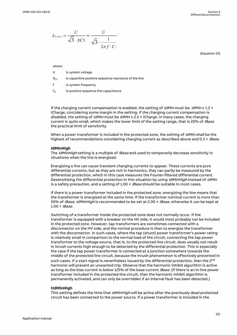
arg
1
112
3 3Ch e
U UI
XCf Cp
=×
×
=×
EQUATION1417 V2 EN-US (Equation 23)
where:
U is system voltage
XC1 is capacitive positive sequence reactance of the line
f is system frequency
C1 is positive sequence line capacitance
If the charging current compensation is enabled, the setting of IdMin must be: IdMin ≥ 1.2 ×ICharge, concidering some margin in the setting. If the charging current compensation isdisabled, the setting of IdMin must be IdMin ≥ 2.5 × ICharge. In many cases, the chargingcurrent is quite small, which makes the lower limit of the setting range, that is 20% of IBasethe practical limit of sensitivity.
When a power transformer is included in the protected zone, the setting of IdMin shall be thehighest of recommendations considering charging current as described above and 0.3 × IBase.
IdMinHighM12541-165 v5
The IdMinHigh setting is a multiple of IBase and used to temporarily decrease sensitivity insituations when the line is energized.
Energizing a line can cause transient charging currents to appear. These currents are puredifferential currents, but as they are rich in harmonics, they can partly be measured by thedifferential protection, which in this case measures the Fourier-filtered differential current.Desensitizing the differential protection in this situation by using IdMinHigh instead of IdMinis a safety precaution, and a setting of 1.00 × IBase should be suitable in most cases.
If there is a power transformer included in the protected zone, energizing the line means thatthe transformer is energized at the same time. If the transformer nominal current is more than50% of IBase, IdMinHigh is recommended to be set at 2.00 × IBase, otherwise it can be kept at1.00 × IBase.
Switching of a transformer inside the protected zone does not normally occur. If thetransformer is equipped with a breaker on the HV side, it would most probably not be includedin the protected zone. However, tap transformers are sometimes connected with adisconnector on the HV side, and the normal procedure is then to energize the transformerwith the disconnector. In such cases, where the tap (shunt) power transformer's power ratingis relatively small in comparison to the normal load of the circuit, connecting the tap powertransformer to the voltage source, that is, to the protected line circuit, does usually not resultin inrush currents high enough to be detected by the differential protection. This is especiallythe case if the tap power transformer is connected at a junction somewhere towards themiddle of the protected line circuit, because the inrush phenomenon is effectively prevented insuch cases. If a start signal is nevertheless issued by the differential protection, then the 2nd
harmonic will prevent an unwanted trip. Observe that the harmonic inhibit algorithm is activeas long as the bias current is below 125% of the base current IBase. (If there is an in-line powertransformer included in the protected line circuit, then the harmonic inhibit algorithm ispermanently activated, and can only be overridden if an internal fault has been detected.)
tIdMinHighM12541-177 v4
This setting defines the time that IdMinHigh will be active after the previously dead protectedcircuit has been connected to the power source. If a power transformer is included in the
1MRK 506 353-UEN B Section 6Differential protection
121Application manual

protection zone, due to long duration of transformer inrush current the parameter should beset to 60 s. Otherwise a setting of 1 s is sufficient.
IdUnreM12541-180 v5
IdUnre is set as a multiple of IBase. Values of differential currents above the unrestrained limitgenerate a trip disregarding all other criteria, that is, irrespective of the internal or externalfault discriminator and any presence of harmonics. It is intended for fast tripping of internalfaults with high fault currents. The recommended setting is 120% of the highest through faultcurrent that can appear on the protected line. Consequently, to set this value properly, thefault current must be calculated in each specific case.
For a short line or a situation with a 1½ breaker bay, the through fault current might bepractically the same as the differential current at an internal fault. Extreme unequal CTsaturation at external faults could then be a risk of unwanted operation if the unrestrainedoperation is used. Consequently, if the through fault currents can be of the same order as themaximum differential currents at internal faults, for example, when there is a source of poweronly on one side (in the branch with the first CT), and only load on the other side (in the branchwith the other CT), it is recommended to refrain from using the unrestrained operation, bysetting the max value IdUnre = 50 × IBase.
On long lines, the through fault current is often considerably less than the maximumdifferential current at internal faults, and a suitable setting of the unrestrained level is theneasy to calculate.
When a transformer is included in the protected zone, the maximum inrush current must beconsidered when the unrestrained level is calculated. The inrush current appears from one sideof the transformer, while the maximum differential current at internal faults is limited by thesource impedances on all sides of the transformer. Observe that if the power transformer isenergized via a power line, even a short one, the inrush phenomenon is much less pronounced.The fundamental frequency of the inrush current will not be as high as when the powertransformer is connected directly to a source with very low internal impedance.
EndSection1M12541-186 v3
EndSection1 is set as a multiple of IBase. The default value 1.25 is generally recommended. Ifthe conditions are known more in detail, other values can be chosen in order to increase ordecrease the sensitivity.
EndSection2M12541-189 v3
EndSection2 is set as a multiple of IBase. The default value 3.00 is generally recommended. Ifthe conditions are known more in detail, other values can be chosen in order to increase ordecrease the sensitivity.
SlopeSection2M12541-192 v4
SlopeSection2 is set as a percentage value: [delta operate current/delta restrain current] ×100%. The default value 40.0 is generally recommended. If the conditions are known more indetail, other values can be chosen in order to increase or decrease the sensitivity.
SlopeSection3M12541-195 v4
SlopeSection3 is set as a percentage value: [delta operate current/delta restrain current] ×100%. The default value 80.0 is generally recommended. If the conditions are known more indetail, other values can be chosen in order to increase or decrease the sensitivity.
6.2.3.3 The 2nd and 5th harmonic analysisM12541-198 v5
The 2nd and 5th harmonic block scheme is permanently active only if an in-line powertransformer (A or B, alternatively both A and B) is part of the protected circuit. This is a mustdue to phenomena specific for power transformers, such as inrush and over-excitation. If thereis no power transformer included in the protected multi-terminal line circuit, then the 2nd and5th harmonic block scheme is only active under the following conditions:
Section 6 1MRK 506 353-UEN BDifferential protection
122Application manual

• If the bias current is lower than 1.25 times IBase.• Under external fault conditions.• If NegSeqDiffEn = Off (the default is On )
When the harmonic content is above the set level, the restrained differential operation isblocked. However, if a fault has been classified as internal by the negative sequence faultdiscriminator, any harmonic restraint is overridden.
I2/I1RatioM12541-201 v4
The set value is the ratio of the 2nd harmonic component of the differential current to thefundamental frequency component of the differential current. To obtain this information, theinstantaneous differential current must be analyzed.
Transformer inrush currents cause high degrees of the 2nd harmonic in the differential current.The default value of 15% is a reliable value to detect power transformer inrush currents.
CT saturation causes 2nd harmonics of considerable value on the CT secondary side, whichcontributes to the stabilization of the relay at through fault conditions. It is stronglyrecommended to maintain a sensitive setting of the I2/I1Ratio also when a power transformeris not included in the protected zone.
I5/I1RatioM12541-206 v4
The set value is the ratio of the 5th harmonic of the differential current to the fundamentalfrequency of the differential current. To obtain this information, the instantaneous differentialcurrent must be analyzed.
A 20...30% over-excitation of a transformer can cause an increase in the excitation current of10...100 times the normal value. This excitation current is a true differential current if thetransformer is inside the protected zone. It has a high degree of the 5th harmonic, and thedefault setting of 25% will be suitable in most cases to detect the phenomenon. As CTsaturation also causes 5th harmonics on the secondary side, it is recommended to maintainthis setting at 25% or lower even if no power transformer is included in the protected zone.
6.2.3.4 Internal/external fault discriminatorM12541-210 v2
NegSeqDiffEnM12541-213 v4
The negative sequence fault discriminator can be set On/Off. It is an important complementto the percentage restrained differential function. As it is directional, it can distinguishbetween external and internal faults also in difficult conditions, such as CT saturation, and soon. It is strongly recommended that it is always activated (On).
NegSeqROAM12541-218 v4
This is the setting of the relay operate angle of the negative sequence current based internal/external fault discriminator. The directional test is made so that the end with the highestnegative sequence current is found. Then, the sum of the negative sequence currents at allother circuit ends is calculated. Finally, the relative phase angle between these two negativesequence currents is determined. See figure 51. Ideally the angle is zero degrees for internalfaults and 180 degrees for external faults. However, measuring errors caused by, for example,CT saturation as well as different phase angles of the negative sequence impedances, requirea safety margin, expressed as the ROA (Relay Operate Angle). The default value 60 degrees isrecommended in most cases. The setting NegSeqROA is a compromise between the securityand dependability of the differential protection. The value NegSeqROA = 60 degreesemphasizes security against dependability. Tests have proven that 60 degrees is a goodchoice.
1MRK 506 353-UEN B Section 6Differential protection
123Application manual
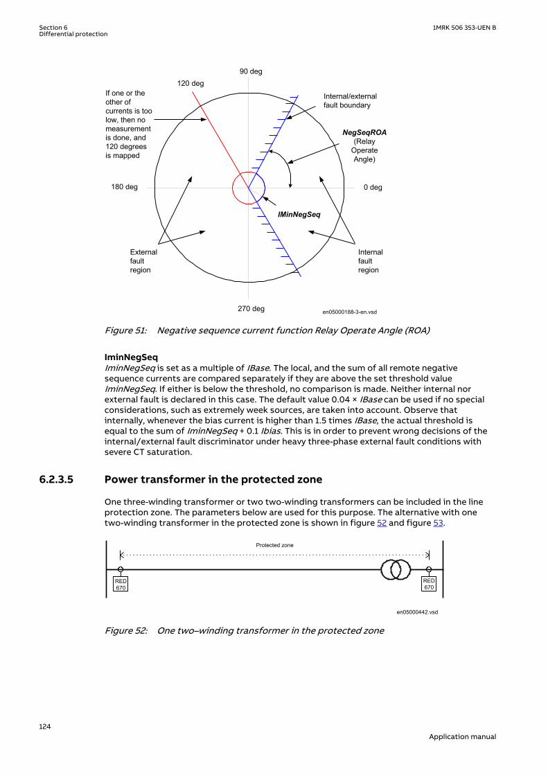
0 deg180 deg
90 deg
270 deg
120 deg
IMinNegSeq
If one or the other of currents is too low, then no measurement is done, and 120 degrees is mapped
External fault region
Internal fault region
Internal/external fault boundary
NegSeqROA (Relay
Operate Angle)
en05000188-3-en.vsdIEC05000188 V3 EN-US
Figure 51: Negative sequence current function Relay Operate Angle (ROA)
IminNegSeqM12541-223 v4
IminNegSeq is set as a multiple of IBase. The local, and the sum of all remote negativesequence currents are compared separately if they are above the set threshold valueIminNegSeq. If either is below the threshold, no comparison is made. Neither internal norexternal fault is declared in this case. The default value 0.04 × IBase can be used if no specialconsiderations, such as extremely week sources, are taken into account. Observe thatinternally, whenever the bias current is higher than 1.5 times IBase, the actual threshold isequal to the sum of IminNegSeq + 0.1 Ibias. This is in order to prevent wrong decisions of theinternal/external fault discriminator under heavy three-phase external fault conditions withsevere CT saturation.
6.2.3.5 Power transformer in the protected zoneM12541-6 v5
One three-winding transformer or two two-winding transformers can be included in the lineprotection zone. The parameters below are used for this purpose. The alternative with onetwo-winding transformer in the protected zone is shown in figure 52 and figure 53.
RED670
RED670
Protected zone
en05000442.vsdIEC05000442 V1 EN-US
Figure 52: One two–winding transformer in the protected zone
Section 6 1MRK 506 353-UEN BDifferential protection
124Application manual

RED670
RED670
RED670
Protected zone
en04000209.vsdIEC04000209 V1 EN-US
Figure 53: One two–winding transformer in the protected zone
An alternative with two two-winding transformers in the protected zone is shown in figure 54.
RED670
RED670
RED670
Protected zone
RED670
A B
en04000210.vsdIEC04000210 V1 EN-US
Figure 54: Two two–winding transformers in the protected zone
An alternative with one three-winding transformer in the protected zone is shown in figure 55.Observe that in this case, the three-winding power transformer is seen by the differentialprotection as two separate power transformers, A and B, which have one common winding onthe HV side.
RED670
RED670
RED670
Protected zone
A B
en04000211.vsdIEC04000211 V1 EN-US
Figure 55: One three–winding transformer in the protected zone
1MRK 506 353-UEN B Section 6Differential protection
125Application manual

IEC15000451-1-en.vsd
RED
670
RED
670
A
B
T
T
Protected zone
IEC15000451 V1 EN-US
Figure 56: One three–winding transformer in the protected zone
TraAOnInpChM12541-239 v6
This parameter is used to indicate that a power transformer is included in the protection zoneat current terminal X. This can be either a two-winding transformer or the first secondarywinding of a three-winding transformer. The current transformer feeding the IED is located atthe low voltage side of the transformer. The parameter is set within the range 0...3 or 0...6,where 0 (zero) is used if no transformer A is included in the protection zone. This is the onlysetting that is different for each separate IED.
The setting specifies the current input on the differential current function block where theinput current must be recalculated, that is, referred to the high voltage side, which is thereference side of the differential protection. The measured current, fed to the input channeldetermined by the setting TraAOnInpCh, will be recalculated to I ·RatVoltW2TraA/RatVoltW1TraA and shifted counterclockwise by the angle, determined by the productClockNumTransA × 30 degrees.
RatVoltW1TraAM12541-279 v3
The rated voltage (kV) of the primary side (line side = high voltage side) of the powertransformer A.
RatVoltW2TraAM12541-282 v3
The rated voltage (kV) of the secondary side (non-line side = low voltage side) of the powertransformer A.
ClockNumTransAM12541-285 v3
This is the phase shift from primary to secondary side for power transformer A. The phaseshift is given in intervals of 30 degrees, where 1 is -30 degrees, 2 is -60 degrees, and so on. Theparameter can be set within the range 0...11.
TraBOnInpChM12541-292 v5
This parameter is used to indicate that a power transformer is included in the protection zoneat current terminal Y. This can be either a two-winding transformer or the second secondarywinding of a three-winding transformer. The current transformer feeding the IED is located atthe low voltage side of the transformer. The parameter is set within the range 0...3 or 0...6,where zero is used if no transformer B is included in the protection zone.
The setting specifies the current input on the differential current function block where theinput current must be recalculated, that is, referred to the high voltage side, which is thereference side of the differential protection. The set input measured current I will berecalculated to I × RatVoltW2TraB/RatVoltW1TraB and shifted counterclockwise by the angle,determined by the product ClockNumTransB × 30 degrees.
RatVoltW1TraBM12541-295 v3
The rated voltage (kV) of the primary side (line side = high voltage side) of the powertransformer B.
Section 6 1MRK 506 353-UEN BDifferential protection
126Application manual

RatVoltW2TraBM12541-298 v3
The rated voltage (kV) of the secondary side (non-line side = low voltage side) of the powertransformer B.
ClockNumTransBM12541-301 v2
This is the phase shift from primary to secondary side for power transformer B. The phaseshift is given in intervals of 30 degrees, where 1 is -30 degrees, 2 is -60 degrees and so on. Theparameter can be set within the range 0 – 11.
ZerSeqCurSubtrM12541-307 v4
The elimination of zero sequence currents in the differential protection can be set On/Off. Incase of a power transformer in the protected zone, where the zero sequence current cannot betransformed through the transformer, that is, in the great majority of cases, the zero sequencecurrent must be eliminated.
ZerSeqCurSubtr must be set On if there is a transformer in the zone. The zero sequencecurrents are then subtracted from all current terminals.
CrossBlockEnM12541-310 v3
The possibility of cross-blocking can be set On/Off. The meaning of cross-blocking is that the2nd and 5th harmonic blocking in one phase also blocks the differential function of the otherphases. It is recommended to enable the cross-blocking if a power transformer is included inthe protection zone, otherwise not.
IMaxAddDelayM12541-313 v4
IMaxAddDelay is set as a multiple of IBase. The current level, under which a possible extraadded time delay (of the output trip command), can be applied. The possibility for delayedoperation for small differential currents is typically used for lines with a (minor) tappedtransformer somewhere in the protected circuit and where no protection terminal of the multi-terminal differential protection is applied at the transformer site. If such a minor taptransformer is equipped with a circuit breaker and its own local protection, then thisprotection must operate before the line differential protection to achieve selectivity for faultson the low voltage side of the transformer. To ensure selectivity, the current setting must behigher than the greatest fault current for faults at the high voltage side of the transformer.
AddDelayM12541-316 v2
The possibility of delayed operation for small differential currents can be set On/Off.
CurveTypeM12541-321 v3
This is the setting of type of delay for low differential currents.
tMinInvM12541-324 v4
This setting limits the shortest delay when inverse time delay is used. Operation faster thanthe set value of tMinInv is prevented.
If the user-programmable curve is chosen the characteristic of the curve is defined byequation 24.
1MRK 506 353-UEN B Section 6Differential protection
127Application manual

op pMeasured
at k b
Ic
IMaxAddDelay
= × +
-
æ öç ÷ç ÷ç ÷æ öç ÷ç ÷ç ÷è øè ø
EQUATION1418 V1 EN-US (Equation 24)
where:
top is operate time
k is time multiplier of the inverse time curve
a, b, c, p are settings that will model the inverse time characteristic
6.2.3.6 Settings examplesM12541-349 v3
M12941-3 v6
Setting example for line with power transformer in the protected zone
In this section it is described how setting parameters can be chosen for a line with a powertransformer in the protected zone. The line is shown in Figure 57, and the circuit impedancesare shown in Figure 58. The protection zone is limited by the current transformers CT1, CT2and CT3. The terminals are situated in two separate substations, Substation 1 and Substation2. The circuit is protected by two protection terminals, Protection Terminal 1, and ProtectionTerminal 2. Except for a minor distortion of data due to the communication between the twoprotection terminals, the protection terminals process the same data. Both protectionterminals are masters. If at least one of them signalizes an internal fault, the protected circuitis disconnected. Settings of Protection Terminal 1 and Protection Terminal 2 must be equal,except for a few parameters, which can be pointed out.
IEC05000534 V1 EN-US
Figure 57: Line differential protection with power transformer in protected zone
Section 6 1MRK 506 353-UEN BDifferential protection
128Application manual

ZL ZT Zsource 2/3Zsource 1
en05000444.vsdIEC05000444 V1 EN-US
Figure 58: System impedances
where:
Line data is 15.0L LZ X» = WEQUATION1419 V1 EN-US
Transformer data is
2
22010 220
% 10% 24.2100 200TX X= Þ = × = W
EQUATION1420 V1 EN-US
Source impedance is1 7.0SourceZ = W
EQUATION1421 V1 EN-US
2
Source2 / 3 Source2 / 3 220220
Z 5 (Z ) 5 49.470
= W Þ = × = Wæ öç ÷è ø
EQUATION1422 V1 EN-US
Table 14: General settings
Setting IED 1 IED 2 Remarks
Operation On On Operation Mode: On(active)
NoOfTerminals 3 3 Number of current sources,ends of the circuit
IBase (Global base) 600 A 600 A Reference current of theprotection in the primary(system) Amperes (Remark1)IBase is set in the Globalbase values function(GBASVAL).
TransfAonInpCh 2 1 Input currents on theseinput channels will bereferred to the high voltageside (Remark 2)
TraAWind1Volt 220 kV 220 kV Transformer A, Y-sidevoltage in kV
TraAWind2Volt 70 kV 70 kV Transformer A, d-sidevoltage in kV
ClockNumTransA 1 1 LV d-side lags Y-side by 30degrees
TransfBonInpCh 3 2 Input currents on theseinput channels will bereferred to the high voltageside (Remark 2)
TraBWind1Volt 220 kV 220 kV Transformer B, Y-sidevoltage in kV
Table continues on next page
1MRK 506 353-UEN B Section 6Differential protection
129Application manual

Setting IED 1 IED 2 Remarks
TraBWind2Volt 70 kV 70 kV Transformer B, d-sidevoltage in kV
ClockNumTransB 1 1 LV d-side lags Y-side by 30degrees
ZerSeqCurSubtr On On Zero-sequence currents aresubtracted fromdifferential and biascurrents (Remark 3)
Table 15: Setting group N
Setting IED 1 IED 2 Remarks
ChargCurEnable Off Off Charging current noteliminated (Default)
IdMin 0.35 · IBase 0.35 · IBase Sensitivity in Section 1of the operate -restrain characteristic
EndSection1 1.25 · IBase 1.25 · IBase End of section 1 of theoperate - restraincharacteristic, asmultiple of IBase
EndSection2 3.00 · IBase 3.00 · IBase End of section 2 of theoperate - restraincharacteristic, asmultiple of IBase
SlopeSection2 40% 40% Slope of the operate -restrain characteristicin Section 2, inpercent
SlopeSection3 80% 80% Slope of the operate -restrain characteristicin Section 3, inpercent
IdMinHigh 2.00 · IBase 2.00 · IBase Temporarilydecreased sensitivity,used when theprotected circuit isconnected to a powersource (Remark 4)
IntervIdMinHig 30.000 s 30.000 s Time interval whenIdMinHig is active(Remark 5)
Idunre 5.50 · IBase 5.50 · IBase Unrestrained operate,(differential) currentlimit (Remark 6)
CrossBlock 1 1 CrossBlock logicscheme applied(Remark 7)
I2/I1Ratio 15% 15% Second tofundamentalharmonic ratio limit
I5/I1Ratio 25% 25% Fifth to fundamentalharmonic ratio limit
NegSeqDiff On On Internal/external faultdiscriminator On(Default)
Table continues on next page
Section 6 1MRK 506 353-UEN BDifferential protection
130Application manual

Setting IED 1 IED 2 Remarks
IminNegSeq 0.04 · IBase 0.04 · IBase Minimum value ofnegative-sequencecurrent, as multiple ofIBase
NegSeqROA 60.0 deg 60.0 deg Internal/external faultdiscriminator operateangle (ROA), indegrees (Default)
AddDelay Off Off Additional delay Off(Default)
ImaxAddDelay 1.00 · IBase 1.00 · IBase Not applicable in thiscase (Default)
CurveType 15 15 Not applicable in thiscase (Default)
DefDelay 0.100 s 0.100 s Not applicable in thiscase (Default)
IDMTtMin 0.010 s 0.010 s Not applicable in thiscase (Default)
TD 0.00 0.00 Not applicable in thiscase (Default)
p 0.02 0.02 Not applicable in thiscase (Default)
a 0.14 0.14 Not applicable in thiscase (Default)
b 1.00 1.00 Not applicable in thiscase (Default)
c 1.00 1.00 Not applicable in thiscase (Default)
Remarks:
1 The parameter IBase (set in the Global base values function (GBASVAL).) is the referencecurrent of Line differential protection given in primary Amperes. CT1 in terminal 1 (at end1) has ratio 600/1 and, based on that, we chose IBase to 600 A in this case.
2 In this case, only one physical power transformer is included in the protected circuit.However, in order to handle the situation with two CTs on the low-voltage side of thetransformer, one more fictitious power transformer is introduced. Thus, transformer Acan be thought of as being installed at the current terminal (end) 2, and transformer B,which is identical to A, can be thought of as being installed at the current terminal (end)3. The currents, measured at current terminals (current sources) 2 and 3, are internallyseparately referred by the multi-terminal differential algorithm to the high-voltage side ofthe transformer, using one and the same transformation rule. This rule is defined by thepower transformer transformation ratio and its type, which is Yd1 in this example. If anin-line power transformer is included in the protected zone, then the protected powerlines are usually on the high-voltage side of the in-line power transformer. The differentialalgorithm always transforms the low-voltage side currents to the high-voltage side.
3 Earth faults on the Y-side of the transformer will cause a zero sequence current that willflow in the Y-winding of the power transformer. This zero sequence current will notappear outside the transformer on the d-side, and will consequently not be measured byCT 2 and CT 3. Thus, in case a Y-side earth fault is external to the protected zone, the zerosequence current that passes the neutral point of the transformer will appear as falsedifferential current. This could cause an unwanted trip if the zero sequence currents arenot subtracted from all three fundamental frequency differential currents.
4 Energizing the circuit means that the power transformer will be energized at the sametime. This is assumed to be made always from the high-voltage side, and the harmonicrestraint will detect the inrush current and prevent a trip. Setting IdMinHigh = 2.00 · IBaseis motivated in this case as the transformer is large.
Table continues on next page
1MRK 506 353-UEN B Section 6Differential protection
131Application manual

5 The interval when IdMinHigh is active is set to 60 s because a power transformer isincluded in the protected circuit. As both IEDs process the same currents, both must havethe same value set for IdMinHigh.
6 The unrestrained operate differential current value shall be greater than the highestthrough fault current. This current appears at a three-phase short circuit on the 33 kVside of the transformer and can be calculated as:
2202.75
3 (7.0 15.0 24.2)ThroughI kA= =
× + +
EQUATION1423 V1 EN-US (Equation 29)
With a safety margin of 20% we get:
1.2 1.2 2.75 3.305.50
0.6 0.6ThroughI kA kA
IdunreIbase kA kA
× ×= = = =
EQUATION1424 V1 EN-US (Equation 30)
7 The cross block logic shall always be active when there is a power transformer in theprotected zone.
Setting example for a small Tap-off transformer
A typical example can be as per single line diagram below.
IEC12000193-2-en.vsd
3Id> 3Id>
SA1700MVA
SA1280MVA
10MVAek=10%138/10kV
3Id>
3Id>
A B
IEC12000193 V2 EN-US
Figure 59: Setting example
Input data to the calculation
Apparent source power at A side: SsA = 1700 MVA
Line impedance from A to tap: ZlA = 2.8 Ω
Line impedance from tap to B side: ZlB = 1.2 Ω
Apparent source power at B side: SsB = 1280 MVA
Base current of differential current protection: IBase = 42 A
Section 6 1MRK 506 353-UEN BDifferential protection
132Application manual

Apparent power of transformer: Sn = 10 MVA
Short circuit impedance of transformer: ek = 10%
Nominal voltage on transformer high voltage winding: Un = 138 kV
Calculating of fault current at HV (High Voltage) side of the taped transformer for threephase fault on LV side
For convenience we choose calculation voltage to 138 kV.
ZsA ZsB
ZtrfE
ZlA ZlB
IEC14000046-1-en.vsdIEC14000046 V1 EN-US
Figure 60: Thevenin equivalent for tap transformer
Converting of the sources into impedances gives:
ZSA
= =138
170011 2
2
. Ω
EQUATION14000034 V1 EN-US (Equation 31)
ZSB
= =138
120015 9
2
. Ω
EQUATION14000035 V1 EN-US (Equation 32)
Calculating of the short circuit impedance of the transformer gives:
Ze U
Strf
k n
n
= × = × =100
0 1138
10190 4
2 2
. . Ω
EQUATION14000036 V1 EN-US (Equation 33)
Based on the Thevenin equivalent below we calculate the fault current at HV side of thetransformer as:
IfZ
res
138
138
3=
×
EQUATION14000037 V1 EN-US (Equation 34)
where:
ZZs Zl Zs Zl
Zs Zl Zs ZlZ
res
A B B
A a B B
trf
a=
+( ) × +( )
+ + ++ = 198Ω
EQUATION14000039 V1 EN-US (Equation 35)
1MRK 506 353-UEN B Section 6Differential protection
133Application manual

The numerical value for Zres input in the formula for If138 gives If138 = 403 A
To avoid unwanted operation of the differential protection for fault on LV side of thetransformer, the setting of IdMin must be set to:
> ×1 2138
.If
IBase
EQUATION14000038 V1 EN-US (Equation 36)
IdMinIf
IBase
= × =1 2 11 5138
. .
EQUATION14000040 V1 EN-US (Equation 37)
In order to allow the differential protection to be backup protection for internal faults andfaults on the LV side of the transformer, we activate the function AddDelay by setting it to Onand calculate suitable setting for the parameter Imax AddDelay. Differential currents below thethreshold Imax AddDelay will be time delayed. We choose the value 2 times the rated current ofthe transformer on HV side. The setting will be:
ImaxAddDelayS
U I
n
n Base
= ×× ×
=23
2 0.
EQUATION14000041 V1 EN-US (Equation 38)
Table 16: Backup protection example data
Station Tap transformer 10 MVA
Type of fault Three phase fault
Object 1 = 10 kV Line A 2 = T1 10 kV 50/51 3 = 130 kV 87L(ImaxAddDelay)
Settings 2 MVA 14 MVA 20 MVA
Characteristic IEC Extr.inverse, k=0.5,A=80, p=2
IEC Norm.inverse k=0.12,A=0.14, p=0.02
IEC Norm.inverse k=0.18,A=0.14, p=0.02
High set stage 14 MVA - - - - - - - -
It is then important to achieve a proper back-up protection. The Short circuit protection on theoutgoing bays and on the transformer LV side are set according to a prepared selectivitychart. An example is prepared and shown in Figure 61 where the setting of the short circuitprotection on the LV side is 14 MVA and Normal Inverse with k=0.12 to give back-up tooutgoing bays relays which are extremely inverse, selective to remote fuses.
Section 6 1MRK 506 353-UEN BDifferential protection
134Application manual

IEC14000047 -1-en.aiIEC14000047 V1 EN-US
Figure 61: Selectivity chart
Setting example for two transformers in the zone, Master- Slave differential operation
IEC13000295-1-en.vsd
AB
CT
T
IEC13000295 V1 EN-US
Figure 62: Master- Slave differential operation
Settings Station A Station B Station C
PDIF L3TC PDIF
NoOfUsedCTs 3
TraAOnInpCh 2
TraBOnInpCh 3
The protection at B and C are operating as Slaves (differential function switched off) and thecurrents are sent to the protection at A and received on channel 2 and 3. To inform thedifferential algorithm that the currents are from the low voltage sides of the transformers,TraAOnInpCh has to set to 2 and TraBOnInpCh to 3 (channel1 is reserved for localmeasurement) so that the proper turn ratio and vector group correction can be done.
Setting example for three-winding transformer in the zone
1MRK 506 353-UEN B Section 6Differential protection
135Application manual

IEC13000296-1-en.vsd
RED670
RED670
A
B
T
T
IEC13000296 V1 EN-US
Figure 63: Three-winding transformer in the zone
Settings Station A Station B
PDIF L3TC PDIF L3TC PDIF
NoOfUsedCTs 3 3
TraAOnInpCh 2 1
TraBOnInpCh 3 2
The currents from the secondary and tertiary windings of the power transformer areconnected to one RED670. The currents for each CT group are sent to the RED670 at A stationby the LDCM. To inform the differential algorithm that the currents are from the low voltagesides of the transformer, TraAOnInpCh has to be set to 2 and TraBOnInpCh to 3 (channel1 isreserved for local measurement) so that the proper turn ratio and vector group correction canbe done.
6.3 Additional security logic for differential protectionLDRGFC
GUID-0E064528-0E70-4FA1-87C7-581DADC1EB55 v2
6.3.1 IdentificationGUID-3081E62B-3E96-4615-97B8-2CCA92752658 v2
Function description IEC 61850identification
IEC 60617identification
ANSI/IEEE C37.2device number
Additional security logic fordifferential protection
LDRGFC - 11
6.3.2 ApplicationGUID-93AF4444-C7ED-4DF5-9379-176DF17AE22C v4
Additional security logic for differential protection LDRGFC can help the security of theprotection especially when the communication system is in abnormal status or for examplewhen there is unspecified asymmetry in the communication link. It reduces the probability formal-operation of the protection. LDRGFC is more sensitive than the main protection logic toalways release operation for all faults detected by the differential function. LDRGFC consistsof four sub functions:
• Phase-to-phase current variation• Zero sequence current criterion• Low voltage criterion• Low current criterion
Section 6 1MRK 506 353-UEN BDifferential protection
136Application manual

Phase-to-phase current variation takes the current samples (IL1–IL2, IL2–IL3, etc.) as input andit calculates the variation using the sampling value based algorithm. Phase-to-phase currentvariation function is major one to fulfil the objectives of the start up element.
Zero sequence criterion takes the zero sequence current as input. It increases security ofprotection during the high impedance fault conditions.
Low voltage criterion takes the phase voltages and phase to phase voltages as inputs. Itincreases the security of protection when the three phase fault occurred on the weak end side.
Low current criterion takes the phase currents as inputs and it increases the dependabilityduring the switch onto fault case of unloaded line.
The differential function can be allowed to trip as no load is fed through the line andprotection is not working correctly.
Features:
• Startup element is sensitive enough to detect the abnormal status of the protectedsystem
• Startup element does not influence the operation speed of main protection• Startup element detects the evolving faults, high impedance faults and three phase fault
on weak side• It is possible to block the each sub function of startup element• Startup signal has a settable pulse time
The Additional security logic for differential protection LDRGFC is connected as a localcriterion to release the tripping from line differential protection. LDRGFC is connected with anAND gate to the trip signals from LDLPDIF function. Figure 64 shows a configuration for threephase tripping, but LDRGFC can be configured with individual release to all phases trip. TheSTART signal can also, through one of the available binary signal transfer channels, be sent toremote end and there connected to input REMSTUP. Normally, the local criterion is sufficient.
Start signal from remote side IEC11000232-3-en.vsd
ANDINPUT1INPUT2INPUT3INPUT4N
OUTNOUT
Start signal to remote side
Release of line differential
protection tripLDLPSCHCTFAILOUTSERVBLOCK
TRIPTRL1TRL2TRL3
TRLOCALTRLOCL1TRLOCL2TRLOCL3
TRREMOTEDIFLBLKD
LDRGFCI3P*U3P*BLOCKBLKCVBLKUCBLK3I0BLKUVREMSTUP
STARTSTCVL1L2STCVL2L3STCVL3L1
STUCST3I0STUV
IEC11000232 V3 EN-US
Figure 64: Local release criterion configuration for line differential protection
6.3.3 Setting guidelinesGUID-3C315FA5-8262-416D-A8ED-927FE0BFAB8F v3
GlobalBaseSel: Selects the global base value group used by the function to define (IBase),(UBase) and (SBase).
tStUpReset: Reset delay of the startup signal. The default value is recommended.
1MRK 506 353-UEN B Section 6Differential protection
137Application manual

Settings for phase-phase current variation subfunction are described below.
OperationCV: On/Off, is set On in most applications
ICV>: Level of fixed threshold given in % of IBase. This setting should be based on faultcalculations to find the current increase in case of a fault at the point on the protected linegiving the smallest fault current to the protection. The phase current shall be calculated fordifferent types of faults (single phase-to-earth, phase-to-phase to earth, phase-to-phase andthree phase short circuits) at different switching states in the network. In case of switching oflarge objects (shunt capacitor banks, transformers, and so on) large change in current canoccur. The ICV> setting should ensure that all multi-phase faults are detected.
tCV: Time delay of zero sequence overcurrent criterion. Default value 0.002 s is recommended
Settings for zero sequence current criterion subfunction are described below.
Operation3I0: On/Off, is set On for detection of phase-to-earth faults with high sensitivity
3I0> : Level of high zero sequence current detection given in % of IBase. This setting should bebased on fault calculations to find the zero sequence current in case of a fault at the point onthe protected line giving the smallest fault current to the protection. The zero sequencecurrent shall be calculated for different types of faults (single phase-to-earthand phase tophase to earth) at different switching states in the network.
t3I0: Time delay of zero sequence overcurrent criterion. Default value 0.0 s is recommended
Setting for low voltage criterion subfunction are described below.
OperationUV: On/Off, is set On for detection of faults by means of low phase-to-earth orphase-to-phase voltage
UPhN<: Level of low phase-earth voltage detection, given in % of UBase. This setting should bebased on fault calculations to find the phase-earth voltage decrease in case of a fault at themost remote point where the differential protection shall be active. The phase-earth voltagesshall be calculated for different types of faults (single phase-to-earth and phase to phase toearth) at different switching states in the network. The setting must be higher than the lowestphase-earth voltage during non-faulted operation.
UPhPh<: Level of low phase-phase voltage detection, given in % of UBase. This setting shouldbe based on fault calculations to find the phase-phase voltage decrease in case of a fault atthe most remote point where the differential protection shall be active. The phase-phasevoltages shall be calculated for different types of faults (single phase to earth and phase tophase to earth) at different switching states in the network. The setting must be higher thanthe lowest phase-phase voltage during non-faulted operation.
tUV: Time delay of undervoltage criterion. Default value 0.0 s is recommended
Settings for low current criterion subfunction are described below.
OperationUC: On/Off, is set On when tripping is preferred at energizing of the line ifdifferential does not behave correctly.
IUC<: Level of low phase current detection given in % of IBase. This setting shall detect openline ends and be below normal minimum load.
tUC: Time delay of undercurrent criterion. Default value is recommended to verify that the lineis open.
Section 6 1MRK 506 353-UEN BDifferential protection
138Application manual

Section 7 Impedance protection
7.1 Distance measuring zone, quadrilateral characteristicfor series compensated lines ZMCPDIS, ZMCAPDIS,ZDSRDIR
SEMOD168167-1 v3
7.1.1 IdentificationSEMOD168165-2 v2
Function description IEC 61850identification
IEC 60617identification
ANSI/IEEE C37.2device number
Distance measuring zone,quadrilateral characteristic for seriescompensated lines (zone 1)
ZMCPDIS
S00346 V1 EN-US
21
Distance measuring zone,quadrilateral characteristic for seriescompensated lines (zone 2-5)
ZMCAPDIS
S00346 V1 EN-US
21
Directional impedance quadrilateral,including series compensation
ZDSRDIR
Z<->
IEC09000167 V1 EN-US
21D
7.1.2 ApplicationSEMOD168236-1 v1
7.1.2.1 IntroductionSEMOD168232-4 v2
Sub transmission networks are being extended and often become more and more complex,consisting of a high number of multi-circuit and/or multi terminal lines of very differentlengths. These changes in the network will normally impose more stringent demands on thefault clearing equipment in order to maintain an unchanged or increased security level of thepower system.
The distance protection function is designed to meet basic requirements for application ontransmission and sub transmission lines (solid earthed systems) although it also can be usedon distribution levels.
7.1.2.2 System earthingSEMOD168232-11 v2
The type of system earthing plays an important roll when designing the protection system. Inthe following sections, some hints with respect to distance protection are highlighted.
Solid earthed networksSEMOD168232-14 v2
In solid earthed systems the transformer neutrals are connected solidly to earth without anyimpedance between the transformer neutral and earth.
1MRK 506 353-UEN B Section 7Impedance protection
139Application manual
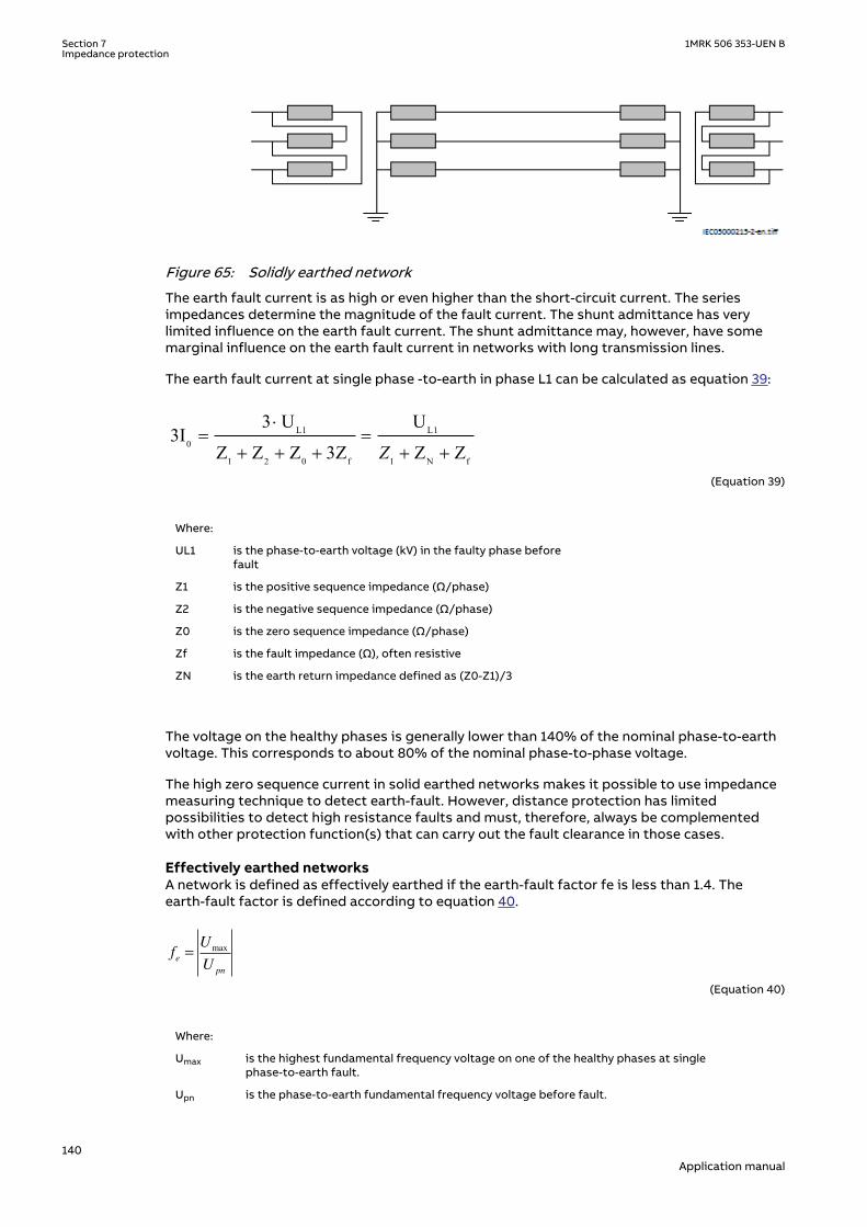
IEC05000215 V2 EN-US
Figure 65: Solidly earthed network
The earth fault current is as high or even higher than the short-circuit current. The seriesimpedances determine the magnitude of the fault current. The shunt admittance has verylimited influence on the earth fault current. The shunt admittance may, however, have somemarginal influence on the earth fault current in networks with long transmission lines.
The earth fault current at single phase -to-earth in phase L1 can be calculated as equation 39:
L1 L10
1 2 0 f 1 N f
3 U U3I
Z Z Z 3Z Z ZZ
×= =
+ + + + +EQUATION1267 V3 EN-US (Equation 39)
Where:
UL1 is the phase-to-earth voltage (kV) in the faulty phase beforefault
Z1 is the positive sequence impedance (Ω/phase)
Z2 is the negative sequence impedance (Ω/phase)
Z0 is the zero sequence impedance (Ω/phase)
Zf is the fault impedance (Ω), often resistive
ZN is the earth return impedance defined as (Z0-Z1)/3
The voltage on the healthy phases is generally lower than 140% of the nominal phase-to-earthvoltage. This corresponds to about 80% of the nominal phase-to-phase voltage.
The high zero sequence current in solid earthed networks makes it possible to use impedancemeasuring technique to detect earth-fault. However, distance protection has limitedpossibilities to detect high resistance faults and must, therefore, always be complementedwith other protection function(s) that can carry out the fault clearance in those cases.
Effectively earthed networksSEMOD168232-40 v2
A network is defined as effectively earthed if the earth-fault factor fe is less than 1.4. Theearth-fault factor is defined according to equation 40.
fU
Ue
pn
=max
EQUATION1268 V4 EN-US (Equation 40)
Where:
Umax is the highest fundamental frequency voltage on one of the healthy phases at singlephase-to-earth fault.
Upn is the phase-to-earth fundamental frequency voltage before fault.
Section 7 1MRK 506 353-UEN BImpedance protection
140Application manual

Another definition for effectively earthed network is when the following relationships betweenthe symmetrical components of the network impedances are valid, as shown in equation 41and equation 42.
X X0 13≤ ⋅
EQUATION1269 V4 EN-US (Equation 41)
R X£0 1
EQUATION1270 V4 EN-US (Equation 42)
The magnitude of the earth fault current in effectively earthed networks is high enough forimpedance measuring element to detect earth-fault. However, in the same way as for solidearthed networks, distance protection has limited possibilities to detect high resistance faultsand must, therefore, always be complemented with other protection function(s) that can carryout the fault clearance in this case.
7.1.2.3 Fault infeed from remote endSEMOD168232-84 v2
All transmission and most all sub transmission networks are operated meshed. Typical for thistype of network is that we will have fault infeed from remote end when fault occurs on theprotected line. The fault infeed may enlarge the fault impedance seen by the distanceprotection. This effect is very important to keep in mind when both planning the protectionsystem and making the settings.
With reference to figure 66, we can draw the equation for the bus voltage Va at left side as:
( )A A L A B fV I p Z I I R= × × + + ×EQUATION1273 V1 EN-US (Equation 43)
If we divide Va by IA we get Z present to the IED at A side
a A BA L f
A A
V I IZ p Z R
I I
+= = × + ×
EQUATION1274 V2 EN-US (Equation 44)
The infeed factor (IA+IB)/IA can be very high, 10-20 depending on the differences in sourceimpedances at local and remote end.
Z <
ZL
Z <
EsAVA VAA B EsB
IA IB
Rf
p*ZL (1-p)*ZLZSA ZSB
en05000217.vsdIEC05000217 V1 EN-US
Figure 66: Influence of fault infeed from remote end
1MRK 506 353-UEN B Section 7Impedance protection
141Application manual

The effect of fault current infeed from remote end is one of the most driving factors to justifycomplementary protection to distance protection.
7.1.2.4 Load encroachmentSEMOD168232-97 v3
Sometimes the load impedance might enter the zone characteristic without any fault on theprotected line. The phenomenon is called load encroachment and it might occur when anexternal fault is cleared and high emergency load is transferred on the protected line. Theeffect of load encroachment is illustrated to the left in figure 67. The entrance of the loadimpedance inside the characteristic is not allowed and the way to handle this withconventional distance protection is to consider this with the settings that is, to have a securitymargin between the distance zone and the minimum load impedance. This has the drawbackthat it will reduce the sensitivity of the protection that is, the ability to detect resistive faults.
The IED has a built in function which shapes the characteristic according to the right figure 67.The load encroachment algorithm increases the possibility to detect high fault resistances,especially for line to earth faults at remote end. For example, for a given setting of the loadangle ARGLd for the load encroachment function, the resistive blinder for the zonemeasurement can be expanded according to the right in figure 67 given higher fault resistancecoverage without risk for unwanted operation due to load encroachment. This is valid in bothdirections.
The use of the load encroachment feature is essential for long heavy loaded lines, where theremight be a conflict between the necessary emergency load transfer and necessary sensitivityof the distance protection. The function can also preferably be used on heavy loaded mediumlong lines. For short lines the major concern is to get sufficient fault resistance coverage andload encroachment is not a major problem. So, for short lines, the load encroachment functioncould preferable be switched off.
The settings of the parameters for load encroachment are done in the Phase selection withload enchroachment, quadrilateral characteristic (FDPSPDIS) function.
R
X
Zm
Load impedancearea in forward
direction
RLdRv
R
Zm
ARGLdARGLd
ARGLd ARGLd
RLdFw
ZL
en05000495.vsdIEC05000495 V1 EN-US
Figure 67: Load encroachment phenomena and shaped load encroachmentcharacteristic
7.1.2.5 Long transmission line applicationSEMOD168232-128 v3
For long transmission lines the margin to the load impedance that is, to avoid loadencroachment, will normally be a major concern. It is difficult to achieve high sensitivity for lineto earth-fault at remote end of a long lines when the line is heavy loaded.
Section 7 1MRK 506 353-UEN BImpedance protection
142Application manual

Definition of long lines with respect to the performance of distance protection can generallybe described as in table 17, long lines have SIR’s less than 0.5.
Table 17: Definition of long lines
Line category
Un Un110 kV 500 kV
Long lines 77 km - 99 km 350 km - 450 km
Very long lines > 99 km > 450 km
The possibility in IED to set resistive and reactive reach independent for positive and zerosequence fault loops and individual fault resistance settings for phase-to-phase and phase-to-earth fault together with load encroachment algorithm improves the possibility to detect highresistive faults at the same time as the security is improved (risk for unwanted trip due to loadencroachment is eliminated), as shown in figure 68.
en05000220.vsd
R
Zm
ARGLdARGLd
ARGLd ARGLd
RLdFwRLdRv
ZL
IEC05000220 V1 EN-US
Figure 68: Characteristic for zone measurement for long line with load encroachmentactivated
7.1.2.6 Parallel line application with mutual couplingSEMOD168232-149 v2
GeneralSEMOD168232-151 v2
Introduction of parallel lines in the network is increasing due to difficulties to get necessaryarea for new lines.
Parallel lines introduce an error in the measurement due to the mutual coupling between theparallel lines. The lines need not be of the same voltage to experience mutual coupling, andsome coupling exists even for lines that are separated by 100 meters or more. The reason tothe introduced error in measuring due to mutual coupling is the zero sequence voltageinversion that occurs.
It can be shown from analytical calculations of line impedances that the mutual impedancesfor positive and negative sequence are very small (< 1-2%) of the self impedance and it ispractice to neglect them.
1MRK 506 353-UEN B Section 7Impedance protection
143Application manual

From an application point of view there exists three types of network configurations (classes)that must be considered when making the settings for the protection function. Those are:
• Parallel line with common positive and zero sequence network• Parallel circuits with common positive but isolated zero-sequence network• Parallel circuits with positive and zero sequence sources isolated
One example of class3 networks could be the mutual coupling between a 400 kV line and railroad overhead lines. This type of mutual coupling is not so common although it exists and isnot treated any further in this manual.
For each type of network class we can have three different topologies; the parallel line can bein service, out of service, out of service and earthed in both ends.
The reach of the distance protection zone1 will be different depending on the operationcondition of the parallel line. It is therefore recommended to use the different setting groupsto handle the cases when the parallel line is in operation and out of service and earthed at bothends.
The distance protection within the IED can compensate for the influence of a zero-sequencemutual coupling on the measurement at single phase-to-earth faults in the following ways, byusing:
• The possibility of different setting values that influence the earth-return compensationfor different distance zones within the same group of setting parameters.
• Different groups of setting parameters for different operating conditions of a protectedmulti circuit line.
Most multi circuit lines have two parallel operating circuits. The application guide mentionedbelow recommends in more detail the setting practice for this particular type of line. The basicprinciples also apply to other multi circuit lines.
Parallel line applicationsSEMOD168232-169 v2
This type of networks are defined as those networks where the parallel transmission linesterminate at common nodes at both ends. We consider the three most common operationmodes:
• parallel line in service• parallel line out of service and earthed• parallel line out of service and not earthed
Parallel line in serviceSEMOD168232-176 v3
This type of application is very common and applies to all normal sub-transmission andtransmission networks.
Here is the description of what happens when a fault occurs on the parallel line, as shown infigure 69.
From symmetrical components, it is possible to derive the impedance Z at the IED point fornormal lines without mutual coupling according to equation 45.
ph ph
0 1 ph N
ph 0
1
0
V V
Z Z I 3 KI 3I
3 Z
IZ = =
- + ×+ ×
×EQUATION1275 V3 EN-US (Equation 45)
Section 7 1MRK 506 353-UEN BImpedance protection
144Application manual

Where:
Vph is phase-to-earth voltage at the IED point
Iph is phase current in the faulty phase
3I0 is earth-fault current
Z1 is positive sequence impedance
Z0 is zero sequence impedance
Z0m
A B
Z< Z< en05000221.vsd
IEC05000221 V1 EN-US
Figure 69: Class 1, parallel line in service
The equivalent circuit of the lines can be simplified, as shown in figure 70.
A
B
CZ0m
Z0Z0 m-
Z0Z0 m-
99000038.vsdIEC99000038 V1 EN-US
Figure 70: Equivalent zero sequence impedance circuit of the double-circuit, parallel,operating line with a single phase-to-earth-fault at the remote busbar
When mutual coupling is introduced, the voltage at the IED point A is changed, according toequation 46.
0 000 11 3 3
3 1 3 1mL L
ph pph LL L
ZZ ZV Z I I IZ Z
æ ö-= × + × +ç ÷
× ×è øEQUATION1276 V4 EN-US (Equation 46)
By dividing equation 46 by equation 45 and after some simplification we can write theimpedance present to the IED at A side as:
3 01 13 0
æ ö×= +ç ÷+ ×è ø
LI KNmZ Z
I ph I KNEQUATION1277 V3 EN-US (Equation 47)
Where:
KNm = Z0m/(3 · Z1L)
1MRK 506 353-UEN B Section 7Impedance protection
145Application manual

The second part in the parentheses is the error introduced to the measurement of the lineimpedance.
If the current on the parallel line has negative sign compared to the current on the protectedline that is, the current on the parallel line has an opposite direction compared to the currenton the protected line, the distance function overreaches. If the currents have the samedirection, the distance protection underreaches.
Maximum overreach occurs if the fault infeed from remote end is weak. If we consider a singlephase-to-earth fault at "p" unit of the line length from A to B on the parallel line for the casewhen the fault infeed from remote end is zero, we can draw the voltage V in the faulty phase atA side as in equation 48.
( )0 0p 3 3= 1 +A L ph N Nm pV Z I K I K I× × + ×
EQUATION1278 V4 EN-US (Equation 48)
Notice that the following relationship exists between the zero sequence currents:
3 0 3 0 0 20
I Z I Z pL p L
⋅ = ⋅ −( )EQUATION1279 V3 EN-US (Equation 49)
Simplification of equation 49, solving it for 3I0p and substitution of the result into equation 48gives that the voltage can be drawn as:
00
3 pp 3
2 p1A L ph N Nm
IV Z I K I K
×= × + × + ×
-
æ öç ÷è ø
EQUATION1280 V2 EN-US (Equation 50)
If we finally divide equation 50 with equation 45 we can draw the impedance present to theIED as
Z p ZI
I KN I KNI p
p
I I KNL
ph m
ph
= ⋅
+ ⋅ + ⋅⋅
−
+ ⋅
33
2
3
0
0
0
EQUATION1379 V3 EN-US (Equation 51)
Calculation for a 400 kV line, where we for simplicity have excluded the resistance, gives withX1L=0.303 Ω/km, X0L=0.88 Ω/km, zone 1 reach is set to 90% of the line reactance p=71% thatis, the protection is underreaching with approximately 20%.
The zero-sequence mutual coupling can reduce the reach of distance protection on theprotected circuit when the parallel line is in normal operation. The reduction of the reach ismost pronounced with no infeed in the line IED closest to the fault. This reach reduction isnormally less than 15%. But when the reach is reduced at one line end, it is proportionallyincreased at the opposite line end. So this 15% reach reduction does not significantly affectthe operation of a permissive under-reach scheme.
Parallel line out of service and earthedSEMOD168232-227 v3SEMOD168232-229 v3
Section 7 1MRK 506 353-UEN BImpedance protection
146Application manual

Z0m
A B
Z< Z<en05000222.vsd
DOCUMENT11520-IMG867 V1 EN-US
Figure 71: The parallel line is out of service and earthed
When the parallel line is out of service and earthed at both ends on the bus bar side of the lineCT so that zero sequence current can flow on the parallel line, the equivalent zero sequencecircuit of the parallel lines will be according to figure 71.
Z Z0 m0
Z Z0 m0
Zm0
A
B
C
99000039.vsd
I0
I0
DOCUMENT11520-IMG7100 V1 EN-US
Figure 72: Equivalent zero-sequence impedance circuit for the double-circuit line thatoperates with one circuit disconnected and earthed at both ends
Here the equivalent zero sequence impedance is equal to Z0-Z0m in parallel with (Z0-Z0m)/Z0-Z0m+Z0m which is equal to equation 52.
2 2
0
0
omE
Z ZZ
Z
-=
EQUATION2002 V4 EN-US (Equation 52)
The influence on the distance measurement can be a considerable overreach, which must beconsidered when calculating the settings. All expressions below are proposed for practical use.They assume the value of zero sequence, mutual resistance R0m equals to zero. They consideronly the zero-sequence, mutual reactance X0m. Calculate the equivalent X0E and R0E zero-sequence parameters according to equation 53 and equation 54 for each particular line sectionand use them for calculating the reach for the underreaching zone.
R RX
R XE
m0 0
0
2
0
2
0
21= ⋅ +
+
DOCUMENT11520-IMG3502 V2 EN-US (Equation 53)
X XX
R XE
m0 0
0
2
0
2
0
21= ⋅ −
+
DOCUMENT11520-IMG3503 V2 EN-US (Equation 54)
1MRK 506 353-UEN B Section 7Impedance protection
147Application manual

Parallel line out of service and not earthedSEMOD168232-243 v3
Z0m
A B
Z< Z<en05000223.vsd
IEC05000223 V1 EN-US
Figure 73: Parallel line is out of service and not earthed
When the parallel line is out of service and not earthed, the zero sequence on that line can onlyflow through the line admittance to the earth. The line admittance is high which limits the zerosequence current on the parallel line to very low values. In practice, the equivalent zerosequence impedance circuit for faults at the remote bus bar can be simplified to the circuitshown in figure 73.
The line zero-sequence mutual impedance does not influence the measurement of the distanceprotection in a faulty circuit. This means that the reach of the underreaching distanceprotection zone is reduced if, due to operating conditions, the equivalent zero sequenceimpedance is set according to the conditions when the parallel system is out of operation andearthed at both ends.
Z Z00 m
Z Z00 m
Z0m
A
B
C
99000040.vsd
I0
I0
IEC99000040 V1 EN-US
Figure 74: Equivalent zero-sequence impedance circuit for a double-circuit line with onecircuit disconnected and not earthed
The reduction of the reach is equal to equation 55.
( )( ) ( )
21 0
0
1 001 0
1 23 11 2 323
E fm
U
ff
Z Z R ZKZ Z Z RZ Z R
× × + += = -
× × + +× × + +
EQUATION1284 V1 EN-US (Equation 55)
This means that the reach is reduced in reactive and resistive directions. If the real andimaginary components of the constant A are equal to equation 56 and equation 57.
Re( ) 0 (2 1 0 3 ) 0 ( 0 2 1)A R R R Rf X X X= × × + + × - × + ×EQUATION1285 V1 EN-US (Equation 56)
0 1 0 1 0 1 0Im( ) (2 3 ) (2 )A X R R R R X X= × × + + × + × × +EQUATION1286 V1 EN-US (Equation 57)
Section 7 1MRK 506 353-UEN BImpedance protection
148Application manual

The real component of the KU factor is equal to equation 58.
Re
Re
Re Im
KA X
A A
u
m
( ) = +( ) ⋅
( )
+ ( )
1
0
2
2 2
EQUATION1287 V3 EN-US (Equation 58)
The imaginary component of the same factor is equal to equation 59.
( ) ( )( ) ( )
20
2 2
ImIm
Re Im
mU
A XK
A A
×=
+é ù é ùë û ë ûEQUATION1288 V2 EN-US (Equation 59)
Ensure that the underreaching zones from both line ends will overlap a sufficient amount (atleast 10%) in the middle of the protected circuit.
7.1.2.7 Tapped line applicationSEMOD168232-266 v2
SEMOD168232-268 v2
A B
Z< Z<
Z<C
T
IC
IA IB
-IB
en05000224.vsdDOCUMENT11524-IMG869 V1 EN-US
Figure 75: Example of tapped line with Auto transformer
This application gives rise to similar problem that was highlighted in section "Fault infeedfrom remote end" that is, increased measured impedance due to fault current infeed. Forexample, for faults between the T point and B station the measured impedance at A and C is asfollows:
1MRK 506 353-UEN B Section 7Impedance protection
149Application manual
ZA =ZAT + ·ZTFIA + IC
IADOCUMENT11524-IMG3509 V3 EN-US (Equation 60)
Z Z ZI I
IZ
U
UC Trf CT
A C
C
TF= + ++
⋅
⋅
2
1
2
DOCUMENT11524-IMG3510 V3 EN-US (Equation 61)
Where:
ZAT and ZCT is the line impedance from the B respective C station to the T point.
IA and IC is fault current from A respective C station for fault between T and B.
U2/U1 Transformation ratio for transformation of impedance at U1 side of thetransformer to the measuring side U2 (it is assumed that current and voltagedistance function is taken from U2 side of the transformer).
For this example with a fault between T and B, the measured impedance from the T point tothe fault can be increased by a factor defined as the sum of the currents from T point to thefault divided by the IED current. For the IED at C, the impedance on the high voltage side U1has to be transferred to the measuring voltage level by the transformer ratio.
Another complication that might occur depending on the topology is that the current from oneend can have a reverse direction for fault on the protected line. For example, for faults at T thecurrent from B might go in reverse direction from B to C depending on the system parameters(as shown in the dotted line in figure 75), given that the distance protection in B to T willmeasure wrong direction.
In three-end application, depending on the source impedance behind the IEDs, the impedancesof the protected object and the fault location, it might be necessary to accept zone2 trip in oneend or sequential trip in one end.
Generally for this type of application it is difficult to select settings of zone1 that both givesoverlapping of the zones with enough sensitivity without interference with other zone1settings that is, without selectivity conflicts. Careful fault calculations are necessary todetermine suitable settings and selection of proper scheme communication.
Fault resistanceSEMOD168232-289 v2
The performance of distance protection for single phase-to-earth faults is very important,because normally more than 70% of the faults on transmission lines are single phase-to-earthfaults. At these faults, the fault resistance is composed of three parts: arc resistance,resistance of a tower construction, and tower-footing resistance. The arc resistance can becalculated according to Warrington's formula:
1.428707 LRarc
I×
=
EQUATION1456 V1 EN-US (Equation 62)
where:
L represents the length of the arc (in meters). This equation applies for the distance protection zone 1.Consider approximately three-times arc foot spacing for the zone 2 and wind speed of approximately50 km/h
I is the actual fault current in A.
Section 7 1MRK 506 353-UEN BImpedance protection
150Application manual

In practice, the setting of fault resistance for both phase-to-earth (RFPE) and phase-to-phase(RFPP) must be as high as possible without interfering with the load impedance to obtainreliable fault detection.
7.1.2.8 Series compensation in power systemsSEMOD168320-4 v2
The main purpose of series compensation in power systems is virtual reduction of linereactance in order to enhance the power system stability and increase loadability oftransmission corridors. The principle is based on compensation of distributed line reactanceby insertion of series capacitor (SC). The generated reactive power provided by the capacitoris continuously proportional to the square of the current flowing at the same time through thecompensated line and series capacitor. This means that the series capacitor has a self-regulating effect. When the system loading increases, the reactive power generated by seriescapacitors increases as well. The response of SCs is automatic, instantaneous and continuous.
The main benefits of incorporating series capacitors in transmission lines are:
• Steady state voltage regulation and raise of voltage collapse limit• Increase power transfer capability by raising the transient stability limit• Improved reactive power balance• Increase in power transfer capacity• Active load sharing between parallel circuits and loss reduction• Reduced costs of power transmission due to decreased investment costs for new power
lines
Steady state voltage regulation and increase of voltage collapse limitSEMOD168320-24 v2
A series capacitor is capable of compensating the voltage drop of the series inductance in atransmission line, as shown in figure 76. During low loading, the system voltage drop is lowerand at the same time, the voltage drop on the series capacitor is lower. When the loadingincreases and the voltage drop become larger, the contribution of the series capacitorincreases and therefore the system voltage at the receiving line end can be regulated.
Series compensation also extends the region of voltage stability by reducing the reactance ofthe line and consequently the SC is valuable for prevention of voltage collapse. Figure 77presents the voltage dependence at receiving bus B (as shown in figure 76) on line loading andcompensation degree KC, which is defined according to equation 63. The effect of seriescompensation is in this particular case obvious and self explanatory.
= CC
Line
XK
XEQUATION1895 V1 EN-US (Equation 63)
A typical 500 km long 500 kV line is considered with source impedance
1 0=SAZEQUATION1896 V1 EN-US (Equation 64)
~EA
ZSA1 Power line
A B
Seirescapacitor
Load
en06000585.vsdIEC06000585 V1 EN-US
Figure 76: A simple radial power system
1MRK 506 353-UEN B Section 7Impedance protection
151Application manual

en06000586.vsd
0 200 400 600 800 1000 1200 1400 1600 1800
100
200
300
400
500
P[MW]
U[k
V]
U limit
P0 P30
P50
P70
IEC06000586 V1 EN-US
Figure 77: Voltage profile for a simple radial power line with 0, 30, 50 and 70% ofcompensation
Increased power transfer capability by raising the first swing stability limitSEMOD168320-32 v2
Consider the simple one-machine and infinite bus system shown in figure 78.
en06000587.vsd
~EA
ZSA1
A B
PMech +jXLine-jXC
System
IEC06000587 V1 EN-US
Figure 78: One machine and infinite bus system
The equal-areas criterion is used to show the effectiveness of a series capacitor forimprovement of first swing transient stability (as shown in figure 79).
In steady state, the mechanical input power to the generator (PMech) is equal to the electricaloutput power from the generator (PE ) and the generator angle is d0. If a 3-phase fault occursat a point near the machine, the electrical output of the generator reduces to zero. This meansthat the speed of the generator increases and the angle difference between the generator andthe infinite bus increases during the fault. At the time of fault clearing, the angle difference hasincreased to δC. After reclosing of the system, the transmitted power exceeds the mechanicalinput power and the generator deaccelerates. The generator decelerates as long as equal areacondition AACC=ADEC has not been fulfilled. The critical condition for post-fault system stabilityis that the angular displacement after fault clearing and during the deceleration does notexceed its critical limit δCR, because if it does, the system cannot get back to equilibrium andthe synchronism is lost. The first swing stability and the stability margin can be evaluated bystudying the different areas in figure 79 for the same system, once without SC and once withseries compensation. The areas under the corresponding P – δ curves correspond to energyand the system remains stable if the accelerating energy that the generator picks up duringthe fault is lower than the decelerating energy that is transferred across the transmission lineduring the first system swing upon fault clearing.
Section 7 1MRK 506 353-UEN BImpedance protection
152Application manual

en06000588.vsd
0 C EA
AACC
A DEC ASM
CR
PMech P Mech
P[p
u]
P[p
u]
with SCwithout SC
AACC
ADEC
ASM
0 C EA CR
IEC06000588 V1 EN-US
Figure 79: Equal area criterion and first swing stability without and with seriescompensation
This means that the system is stable if AACC ≤ (ADEC + ASM). The stability margin is given by thedifference between the available decelerating energy (area between the P (δ) and PMech and theangular difference between δC and δCR ) and the accelerating energy. It is represented in figure79 by the area ASM. Notice that a substantial increase in the stability margin is obtained byinstalling a series capacitor. The series compensation can improve the situation in two ways, itcan decrease the initial angle difference δ0 corresponding to a certain power transfer and italso shifts the P – δ curve upwards.
Improve reactive power balanceSEMOD168320-43 v2
A series capacitor increases its output of reactive power instantaneously, continuously andautomatically with increasing line load. It is thus a self-regulating device, which improvesvoltage regulation and reduces the need for other means of voltage control for example, shuntcompensation. The reactive power balance of a series compensated line is shown in figure 80as an example for 500 km long 500 kV transmission line with 50% compensation degree.
Capacitive
Inductive200
400
600
800
1000
200
400
600Q
(Mvar)
500 1000 1500
Power flow(MW)
(T.L.)
(S.C.)
(T.L. + S.C.)
TransmissionLineSeriesCompensation
500 kV500 km
k = 50 %
en06000589.vsdIEC06000589 V1 EN-US
Figure 80: Self-regulating effect of reactive power balance
1MRK 506 353-UEN B Section 7Impedance protection
153Application manual

Increase in power transferSEMOD168320-45 v2
The increase in power transfer capability as a function of the degree of compensation for atransmission line can be explained by studying the circuit shown in figure 81. The powertransfer on the transmission line is given by the equation 65:
( ) ( )( )
sin sin1
d d× × × ×= =
- × -A B A B
Line C Line C
U U U UP
X X X KEQUATION1897 V1 EN-US (Equation 65)
The compensation degree Kc is defined as equation
A B-jX C
PA
QA
PB
QB
UA UBU
+jXL
UA UB
d
D
en06000590.vsdIEC06000590 V1 EN-US
Figure 81: Transmission line with series capacitor
The effect on the power transfer when considering a constant angle difference (δ) betweenthe line ends is illustrated in figure 82. Practical compensation degree runs from 20 to 70percent. Transmission capability increases of more than two times can be obtained in practice.
IEC06000592-2-en.vsd
0 0.1 0.2 0.3 0.4 0.5 0.6 0.71
1.5
2
2.5
3
3.5
Degree of series compensation [%]
Incre
ase
in p
ow
er transfe
r
Power transfer with constant angle difference
Degree of compensation
Multiple of power over a non-compensated line
IEC06000592 V2 EN-US
Figure 82: Increase in power transfer over a transmission line depending on degree ofseries compensation
Active load sharing between parallel circuits and loss reductionSEMOD168320-79 v2
A series capacitor can be used to control the distribution of active power between paralleltransmission circuits. The compensation of transmission lines with sufficient thermal capacitycan relieve the possible overloading of other parallel lines. This distribution is governed by thereactance, while the losses are determined by the resistance. A properly designed seriescompensation system can considerably reduce the total transmission system losses, as shownin figure 83.
Section 7 1MRK 506 353-UEN BImpedance protection
154Application manual

en06000593.vsd
RL1jXL1-jXC
Line 1
jXL2 RL2
Line 2
IEC06000593 V1 EN-US
Figure 83: Two parallel lines with series capacitor for optimized load sharing and lossreduction
To minimize the losses, the series capacitor must be installed in the transmission line with thelower resistance. The size of the series capacitor that minimizes the total losses is given thefollowing expression:
1 1
2 2
-=L C L
L L
X X RX R
EQUATION1899 V1 EN-US (Equation 66)
Reduced costs of power transmission due to decreased investment costs for new powerline
SEMOD168320-88 v2
As shown in figure 82 the line loading can easily be increased 1.5-2 times by seriescompensation. Thus, the required number of transmission lines needed for a certain powertransfer can be significantly reduced. The cost of series compensation is small compared tothe cost of a transmission line. When evaluating the cost of a transmission system upgradealso the cost of secondary equipment such as eventual upgrading of line protections on thecompensated as well as, adjacent lines should be considered. The main advantages of seriescompensation against the new transmission line within the same corridor are:
• Significantly reduced investment costs; the same increase in power transmission for up to90% reduced costs
• In many cases, the only practical way to increase the transmission capacity of a corridor• Series compensation shortens the lead times• Environmental impact
~EA ~ EB
New transmission line
Series compensation
en06000594.vsdIEC06000594 V1 EN-US
Figure 84: Series compensation is an important alternative to new transmission lines
Advancements in series compensation using thyristor switching technologySEMOD168320-102 v3
A thyristor switched series capacitor (TSSC) can be used for power flow control. This isperformed by changing the reactance of the transmission circuit in discrete steps, as shown infigure 85. A TSSC typically consists of a few segments in series that can be insertedindependently of each other in order to achieve different total series capacitor reactance.
1MRK 506 353-UEN B Section 7Impedance protection
155Application manual

en06000595.vsd
Fw
Rv
-jXC
Fw
Rv
-jX C
Fw
Rv
-jXC
IEC06000595 V1 EN-US
Figure 85: Thyristor switched series capacitor
en06000596.vsd
+ -
-jXCIL
UCjXL
FW
Rv
I V
IEC06000596 V1 EN-US
Figure 86: Thyristor controlled series capacitor
IL Line current
IV Current through the thyristor
UC Voltage over the series capacitor
XC Rated reactance of the series capacitor
A thyristor controlled series capacitor (TCSC) allows continuous control of the series capacitorreactance. This is achieved by adding current through the capacitor via the parallel thyristorvalve path see figure 86. The main circuit of the TCSC consists of a capacitor bank and athyristor controlled inductive branch connected in parallel. The capacitor bank may have avalue of for example, 10...30 Ω/phase and a rated continuous current of 1500...3000 A. Thecapacitor bank for each phase is mounted on a platform providing full insulation towardsearth. The thyristor valve contains a string of series connected high power thyristors with amaximum total blocking voltage in the range of hundreds of kV. The inductor is an air-corereactor with a few mH inductance. The wave forms of a TCSC in capacitive boost mode areshown in figure 87.
en06000597.vsd
UC
XC
0 0.02 0.04 0.06 0.08 0.1 0.12 0.14 0.16 0.18 0.2-2
0
2
0 0.02 0.04 0.06 0.08 0.1 0.12 0.14 0.16 0.18 0.2-5
0
5
0 0.02 0.04 0.06 0.08 0.1 0.12 0.14 0.16 0.18 0.2-50
0
50
0 0.02 0.04 0.06 0.08 0.1 0.12 0.14 0.16 0.18 0.2-40
-20
0
IL
IV
0 0.02 0.04 0.06 0.08 0.1 0.12 0.14 0.16 0.18 0.2-2
2
0 0.02 0.04 0.06 0.08 0.1 0.12 0.14 0.16 0.18 0.2-5
5
0 0.02 0.04 0.06 0.08 0.1 0.12 0.14 0.16 0.18 0.2-50
50
0 0.02 0.04 0.06 0.08 0.1 0.12 0.14 0.16 0.18 0.2-40
-20
0
0
0
0
IEC06000597 V1 EN-US
Figure 87: TCSC wave forms presented in capacitive boost mode for a typical 50Hzsystem
Section 7 1MRK 506 353-UEN BImpedance protection
156Application manual

The apparent impedance of the TCSC (the impedance seen by the power system) can typicallybe increased to up to 3 times the physical impedance of the capacitor, see figure 88. This highapparent reactance will mainly be used for damping of power oscillations.
en06000598.vsd
Imperatriz TCSC, Operating range
-0.4
-0.2
0
0.2
0.4
0.6
0.8
1
1.2
1.4
1.6
1.8
2
2.2
2.4
2.6
2.8
3
3.2
0 300 600 900 1200 1500 1800 2100 2400 2700 3000
Line current (Arms)
Xtcs
c/Xc
(pu)
Continuous30 min. overload10s overloadBypass modeSeries5
Continuous 30 min 10s
B C D
E F G
A
IEC06000598 V1 EN-US
Figure 88: Operating range of a TCSC installed for damping of power oscillations(example)
During continuous valve bypass the TCSC represents an inductive impedance of about 20% ofthe capacitor impedance. Both operation in capacitive boost mode and valve bypass mode canbe used for damping of power swings. The utilization of valve bypass increases the dynamicrange of the TCSC and improves the TCSC effectiveness in power oscillation damping.
7.1.2.9 Challenges in protection of series compensated and adjacent power linesSEMOD168320-10 v2
System planning does not consider any more possible protection issues and difficulties, whendeciding for a particular, non conventional solution of certain operation and stabilityproblems. It is supposed that modern communication and state of the art computertechnologies provides good basis for the required solution. This applies also to protectionissues in series compensated networks. Different physical phenomena, which influenceconventional principles of IED protection, like distance protection, phase comparisonprotection, are well known and accordingly considered in IED design. Some other issues, likeinfluence of controlled thyristors in series capacitor banks are getting increased importance,although not as high as they would deserve.
The most important challenges, which influence the operation of different protectionfunctions in the greatest extent, are described in this chapter.
Voltage and current inversionSEMOD168320-168 v2
Series capacitors influence the magnitude and the direction of fault currents in seriescompensated networks. They consequently influence phase angles of voltages measured indifferent points of series compensated networks and this performances of differentprotection functions, which have their operation based on properties of measured voltage andcurrent phasors.
Voltage inversionSEMOD168320-171 v2
Figure 89 presents a part of series compensated line with reactance XL1 between the IED pointand the fault in point F of series compensated line. The voltage measurement is supposed to
1MRK 506 353-UEN B Section 7Impedance protection
157Application manual

be on the bus side, so that series capacitor appears between the IED point and fault on theprotected line. Figure 90 presents the corresponding phasor diagrams for the cases withbypassed and fully inserted series capacitor.
Voltage distribution on faulty lossless serial compensated line from fault point F to the bus islinearly dependent on distance from the bus, if there is no capacitor included in scheme (asshown in figure 90). Voltage UM measured at the bus is equal to voltage drop D UL on the faultyline and lags the current IF by 90 electrical degrees.
The situation changes with series capacitor included in circuit between the IED point and thefault position. The fault current IF (see figure 90) is increased due to the series capacitor,generally decreases total impedance between the sources and the fault. The reactive voltagedrop D UL on XL1 line impedance leads the current by 90 degrees. Voltage drop DUC on seriescapacitor lags the fault current by 90 degrees. Note that line impedance XL1 could be dividedinto two parts: one between the IED point and the capacitor and one between the capacitorand the fault position. The resulting voltage UM in IED point is this way proportional to sum ofvoltage drops on partial impedances between the IED point and the fault position F, aspresented by
( )1= × -M F L CU I j X XEQUATION1901 V1 EN-US (Equation 67)
en06000605.vsd
~
Z<
XS XL1
IF
UUM
Source
Fault voltage
Pre -fault voltage
XC
Source voltage
U’M
With bypassedcapacitor
With insertedcapacitor
F
IEC06000605 V1 EN-US
Figure 89: Voltage inversion on series compensated line
en06000606.vsd
IF
U S
U’ M=
xUL
xUS
IF
xU L
U S
xU
C
UM
xUS
With bypassedcapacitor
With insertedcapacitor
IEC06000606 V1 EN-US
Figure 90: Phasor diagrams of currents and voltages for the bypassed and insertedseries capacitor during voltage inversion
Section 7 1MRK 506 353-UEN BImpedance protection
158Application manual

It is obvious that voltage UM will lead the fault current IF as long as XL1> XC. This situationcorresponds, from the directionality point of view, to fault conditions on line without seriescapacitor. Voltage UM in IED point will lag the fault current IF in case when:
L1 C S L1X X X X< < +
EQUATION1902 V1 EN-US (Equation 68)
Where
XS is the source impedance behind the IED
The IED point voltage inverses its direction due to presence of series capacitor and itsdimension. It is a common practice to call this phenomenon voltage inversion. Itsconsequences on operation of different protections in series compensated networks dependon their operating principle. The most known effect has voltage inversion on directionalmeasurement of distance IEDs (see chapter "Distance protection" for more details), whichmust for this reason comprise special measures against this phenomenon.
There will be no voltage inversion phenomena for reverse faults in system with VTs located onthe bus side of series capacitor. The allocation of VTs to the line side does not eliminate thephenomenon, because it appears again for faults on the bus side of IED point.
Current inversionSEMOD168320-206 v2
Figure 91 presents part of a series compensated line with corresponding equivalent voltagesource. It is generally anticipated that fault current IF flows on non-compensated lines frompower source towards the fault F on the protected line. Series capacitor may change thesituation.
en06000607.vsd
~
Z<
XS XL1
IF
UUM
Source
Fault voltage
Pre -fault voltage
XC
Source voltage
U’MWith bypassed
capacitor
With insertedcapacitor
F
IEC06000607 V1 EN-US
Figure 91: Current inversion on series compensated line
The relative phase position of fault current IF compared to the source voltage US depends ingeneral on the character of the resultant reactance between the source and the fault position.Two possibilities appear:
1
1
00
- + >
- + <S C L
S C L
X X X
X X XEQUATION1935 V1 EN-US (Equation 69)
1MRK 506 353-UEN B Section 7Impedance protection
159Application manual

The first case corresponds also to conditions on non compensated lines and in cases, whenthe capacitor is bypassed either by spark gap or by the bypass switch, as shown in phasordiagram in figure 92. The resultant reactance is in this case of inductive nature and the faultcurrents lags source voltage by 90 electrical degrees.
The resultant reactance is of capacitive nature in the second case. Fault current will for thisreason lead the source voltage by 90 electrical degrees, which means that reactive current willflow from series compensated line to the system. The system conditions are in such casepresented by equation 70
1> +C S LX X XEQUATION1936 V1 EN-US (Equation 70)
en06000608.vsd
IF
U S
U’ M=
HUL
HU S
With bypassedcapacitor
IF
HU L
U SH
U C
UM
HUS
With insertedcapacitor
IEC06000608 V1 EN-US
Figure 92: Phasor diagrams of currents and voltages for the bypassed and insertedseries capacitor during current inversion
It is a common practice to call this phenomenon current inversion. Its consequences onoperation of different protections in series compensated networks depend on their operatingprinciple. The most known effect has current inversion on operation of distance IEDs (asshown in section "Distance protection" for more details), which cannot be used for theprotection of series compensated lines with possible current inversion. Equation 70 showsalso big dependence of possible current inversion on series compensated lines on location ofseries capacitors. XL1 = 0 for faults just behind the capacitor when located at line IED and onlythe source impedance prevents current inversion. Current inversion has been considered formany years only a theoretical possibility due to relatively low values of source impedances (bigpower plants) compared to the capacitor reactance. The possibility for current inversion inmodern networks is increasing and must be studied carefully during system preparatorystudies.
The current inversion phenomenon should not be studied only for the purposes of protectiondevices measuring phase currents. Directional comparison protections, based on residual(zero sequence) and negative sequence currents should be considered in studies as well.Current inversion in zero sequence systems with low zero sequence source impedance (anumber of power transformers connected in parallel) must be considered as practicalpossibility in many modern networks.
Low frequency transientsSEMOD168320-220 v2
Series capacitors introduce in power systems oscillations in currents and voltages, which arenot common in non-compensated systems. These oscillations have frequencies lower than therated system frequency and may cause delayed increase of fault currents, delayed operation ofspark gaps as well as, delayed operation of protective IEDs. The most obvious difference isgenerally seen in fault currents. Figure 93 presents a simplified picture of a seriescompensated network with basic line parameters during fault conditions. We study the basic
Section 7 1MRK 506 353-UEN BImpedance protection
160Application manual

performances for the same network with and without series capacitor. Possible effects ofspark gap flashing or MOV conducting are neglected. The time dependence of fault currentsand the difference between them are of interest.
en06000609.vsd
~eG(t)
iL(t)RL jXL
-jXC
F
IEC06000609 V1 EN-US
Figure 93: Simplified equivalent scheme of SC network during fault conditions
We consider the instantaneous value of generator voltage following the sine wave accordingto equation 71
( )sin w l= × × +G Ge E tEQUATION1904 V1 EN-US (Equation 71)
The basic loop differential equation describing the circuit in figure 93 without series capacitoris presented by equation 72
( )sin w l× + × = × × +LL L L G
diL R i E tdt
EQUATION1905 V1 EN-US (Equation 72)
The solution over line current is presented by group of equations 73
( ) ( ) ( )
( )
0
22
sin sinw l j l j
w
wj
- ×
=é ù= × × + - + - × - ×ê úë û
= + ×
æ ö×= ç ÷
è ø
L
L
RtLG G
L L t
L L
L
L
E Ei t I eZ Z
Z R L
LatgR
EQUATION1906 V1 EN-US (Equation 73)
The line fault current consists of two components:
• The steady-state component which magnitude depends on generator voltage andabsolute value of impedance included in the circuit
• The transient DC component, which magnitude depends on the fault incident angledecays with the circuit time constant
[ ]L LL R sEQUATION1907 V1 EN-US (Equation 74)
The basic loop differential equation describing the circuit in figure 93 with series capacitor ispresented by equation 75.
( )2
21 ( ) cosw w l× + × + = × × × +l L
L L L GL
d i diL R i t E tdt dt C
EQUATION1908 V1 EN-US (Equation 75)
1MRK 506 353-UEN B Section 7Impedance protection
161Application manual

The solution over line current is in this case presented by group of equations 76. The faultcurrent consists also here from the steady-state part and the transient part. The differencewith non-compensated conditions is that
• The total loop impedance decreases for the negative reactance of the series capacitor,which in fact increases the magnitude of the fault current
• The transient part consists of the damped oscillation, which has an angular frequency band is dying out with a time constant a
( ) ( ) ( )[ ]
( )
( ) ( )
( )
1 2
2
2
1 ( 0)
( 0) ( 0)
2
2
sin cos sin
1
sin
sin cos21
sin2
2
14
aw l j b b
ww
l j
wl l j
bl j
a
b
- ×
=
= =
= × × + - + × × + × × ×
= + × -×
= - × -
× ×× - - × - × - -
=××
- × -×
=×
= -× ×
æ öç ÷è ø
é ùê úê úê úê úë û
tGL
SC
SC L LL
GL t
SC
G LLG C t L t
SC
G LL
SC
L
L
L
L L
Ei t K t K t e
Z
Z R LC
EK I
Z
E LRE U I
ZK
E RLZ
RL
RL C L2
L
EQUATION1909 V1 EN-US (Equation 76)
The transient part has an angular frequency b and is damped out with the time-constant α.
The difference in performance of fault currents for a three-phase short circuit at the end of atypical 500 km long 500 kV line is presented in figure 94.
The short circuit current on a non-compensated line is lower in magnitude, but comprises atthe beginning only a transient DC component, which diminishes completely in approximately120ms. The final magnitude of the fault current on compensated line is higher due to thedecreased apparent impedance of a line (60% compensation degree has been considered for aparticular case), but the low frequency oscillation is also obvious. The increase of fault currentimmediately after the fault incidence (on figure 94 at approximately 21ms) is much slower thanon non-compensated line. This occurs due to the energy stored in capacitor before the fault.
Section 7 1MRK 506 353-UEN BImpedance protection
162Application manual

0 0.02 0.04 0.06 0.08 0.1 0.12 0.14 0.16 0.18 0.2
10
5
5
10
t[ms ]
I[pu
]
en06000610.vsd
IEC06000610 V1 EN-US
Figure 94: Short circuit currents for the fault at the end of 500 km long 500 kV linewithout and with SC
Location of instrument transformersSEMOD168320-261 v2
Location of instrument transformers relative to the line end series capacitors plays animportant role regarding the dependability and security of a complete protection scheme. It ison the other hand necessary to point out the particular dependence of those protectionschemes, which need for their operation information on voltage in IED point.
Protection schemes with their operating principle depending on current measurement only,like line current differential protection are relatively independent on CT location. Figure 95shows schematically the possible locations of instrument transformers related to the positionof line-end series capacitor.
- jX CCT1 CT2
VT1 VT 2
en06000611.vsdIEC06000611 V1 EN-US
Figure 95: Possible positions of instrument transformers relative to line end seriescapacitor
Bus side instrument transformersSEMOD168320-266 v2
CT1 and VT1 on figure 95 represent the case with bus side instrument transformers. Theprotection devices are in this case exposed to possible voltage and current inversion for linefaults, which decreases the required dependability. In addition to this may series capacitorcause negative apparent impedance to distance IEDs on protected and adjacent lines as wellfor close-in line faults (see also figure 97 LOC=0%), which requires special design of distancemeasuring elements to cope with such phenomena. The advantage of such installation is thatthe protection zone covers also the series capacitor as a part of protected power line, so thatline protection will detect and cleared also parallel faults on series capacitor.
Line side instrument transformersSEMOD168320-271 v2
CT2 and VT2 on figure 95 represent the case with line side instrument transformers. Theprotective devices will not be exposed to voltage and current inversion for faults on theprotected line, which increases the dependability. Distance protection zone 1 may be active inmost applications, which is not the case when the bus side instrument transformers are used.
1MRK 506 353-UEN B Section 7Impedance protection
163Application manual
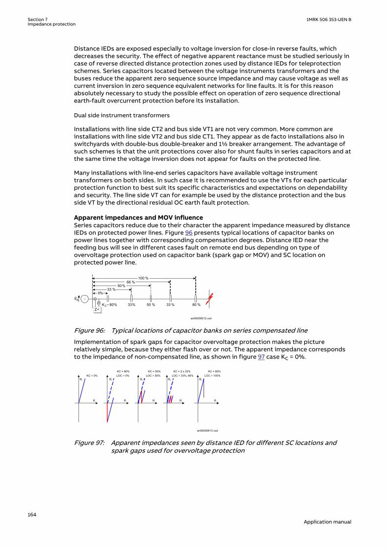
Distance IEDs are exposed especially to voltage inversion for close-in reverse faults, whichdecreases the security. The effect of negative apparent reactance must be studied seriously incase of reverse directed distance protection zones used by distance IEDs for teleprotectionschemes. Series capacitors located between the voltage instruments transformers and thebuses reduce the apparent zero sequence source impedance and may cause voltage as well ascurrent inversion in zero sequence equivalent networks for line faults. It is for this reasonabsolutely necessary to study the possible effect on operation of zero sequence directionalearth-fault overcurrent protection before its installation.
Dual side instrument transformersSEMOD168320-277 v2
Installations with line side CT2 and bus side VT1 are not very common. More common areinstallations with line side VT2 and bus side CT1. They appear as de facto installations also inswitchyards with double-bus double-breaker and 1½ breaker arrangement. The advantage ofsuch schemes is that the unit protections cover also for shunt faults in series capacitors and atthe same time the voltage inversion does not appear for faults on the protected line.
Many installations with line-end series capacitors have available voltage instrumenttransformers on both sides. In such case it is recommended to use the VTs for each particularprotection function to best suit its specific characteristics and expectations on dependabilityand security. The line side VT can for example be used by the distance protection and the busside VT by the directional residual OC earth fault protection.
Apparent impedances and MOV influenceSEMOD168320-285 v2
Series capacitors reduce due to their character the apparent impedance measured by distanceIEDs on protected power lines. Figure 96 presents typical locations of capacitor banks onpower lines together with corresponding compensation degrees. Distance IED near thefeeding bus will see in different cases fault on remote end bus depending on type ofovervoltage protection used on capacitor bank (spark gap or MOV) and SC location onprotected power line.
en06000612.vsd
~EA
0%33 %
50%66 %
KC = 80% 33% 33 %50 %Z<
100 %
80 %
IEC06000612 V1 EN-US
Figure 96: Typical locations of capacitor banks on series compensated line
Implementation of spark gaps for capacitor overvoltage protection makes the picturerelatively simple, because they either flash over or not. The apparent impedance correspondsto the impedance of non-compensated line, as shown in figure 97 case KC = 0%.
en06000613.vsd
jX
R
KC = 0%KC = 80%LOC = 0%
KC = 50%LOC = 50%
jX jX
R R
KC = 2 x 33%LOC = 33%, 66%
KC = 80%LOC = 100%
jX jX
R R
IEC06000613 V1 EN-US
Figure 97: Apparent impedances seen by distance IED for different SC locations andspark gaps used for overvoltage protection
Section 7 1MRK 506 353-UEN BImpedance protection
164Application manual

en06000614.vsd
MOV protected series capacitor
M OV
iL iC
iM
uC
-jXC
0 10 20 30 40 50 60
20
10
10
20
0 10 20 30 40 50 60
100
50
50
100
0 10 20 30 40 50 60
20
10
10
20
0 10 20 30 40 50 60
20
10
10
20
Line current as a function of time Capacitor voltage as a function of time
Capacitor current as a function of time MOV current as a function of time
IEC06000614 V1 EN-US
Figure 98: MOV protected capacitor with examples of capacitor voltage andcorresponding currents
The impedance apparent to distance IED is always reduced for the amount of capacitivereactance included between the fault and IED point, when the spark gap does not flash over, aspresented for typical cases in figure 97. Here it is necessary to distinguish between two typicalcases:
• Series capacitor only reduces the apparent impedance, but it does not cause wrongdirectional measurement. Such cases are presented in figure 97 for 50% compensation at50% of line length and 33% compensation located on 33% and 66% of line length. Theremote end compensation has the same effect.
• The voltage inversion occurs in cases when the capacitor reactance between the IED pointand fault appears bigger than the corresponding line reactance, Figure 23, 80%compensation at local end. A voltage inversion occurs in IED point and the distance IEDwill see wrong direction towards the fault, if no special measures have been introduced inits design.
The situation differs when metal oxide varistors (MOV) are used for capacitor overvoltageprotection. MOVs conduct current, for the difference of spark gaps, only when theinstantaneous voltage drop over the capacitor becomes higher than the protective voltagelevel in each half-cycle separately, see figure 98.
Extensive studies at Bonneville Power Administration in USA ( ref. Goldsworthy, D,L “ALinearized Model for MOV-Protected series capacitors” Paper 86SM357–8 IEEE/PES summermeeting in Mexico City July 1986) have resulted in construction of a non-linear equivalentcircuit with series connected capacitor and resistor. Their value depends on complete line(fault) current and protection factor kp. The later is defined by equation 77.
1MRK 506 353-UEN B Section 7Impedance protection
165Application manual

= MOVp
NC
UkU
EQUATION1910 V1 EN-US (Equation 77)
Where
UMOV is the maximum instantaneous voltage expected between the capacitor immediately before the MOVhas conducted or during operation of the MOV, divaded by √2
UNC is the rated voltage in RMS of the series capacitor
en06000615.vsd
R
jX
1I
£
R
jX
2I
=
R
jX10
I=
Kp × In Kp × In
Kp × In
IEC06000615 V1 EN-US
Figure 99: Equivalent impedance of MOV protected capacitor in dependence ofprotection factor KP
Figure 99 presents three typical cases for series capacitor located at line end (case LOC=0% infigure 97).
• Series capacitor prevails the scheme as long as the line current remains lower or equal toits protective current level (I £ kp · INC). Line apparent impedance is in this case reduced forthe complete reactance of a series capacitor.
• 50% of capacitor reactance appears in series with resistance, which corresponds toapproximately 36% of capacitor reactance when the line current equals two times theprotective current level (I £ 2· kp· INC). This information has high importance for setting ofdistance protection IED reach in resistive direction, for phase to earth fault measurementas well as for phase to phase measurement.
• Series capacitor becomes nearly completely bridged by MOV when the line currentbecomes higher than 10-times the protective current level (I £ 10· kp· INC).
7.1.2.10 Impact of series compensation on protective IED of adjacent linesSEMOD168320-318 v2
Voltage inversion is not characteristic for the buses and IED points closest to the seriescompensated line only. It can spread also deeper into the network and this way influences theselection of protection devices (mostly distance IEDs) on remote ends of lines adjacent to theseries compensated circuit, and sometimes even deeper in the network.
Section 7 1MRK 506 353-UEN BImpedance protection
166Application manual

en06000616.vsd
~
~
F
B
EB
EAZSA
UA
AZLA
IAUD
D
ZLB
IBUB
ZSB
ZLF
IF-jXC
IEC06000616 V1 EN-US
Figure 100: Voltage inversion in series compensated network due to fault current infeed
Voltage at the B bus (as shown in figure 100) is calculated for the loss-less system accordingto the equation below.
U U I jX I I j X X I jXB D B LB A B LF C B LB= + ⋅ = +( ) ⋅ −( ) + ⋅
EQUATION1911 V2 EN-US (Equation 78)
Further development of equation 78 gives the following expressions:
U jI XI
IX XB B LB
A
BLF C= ⋅ + +
⋅ −( )
1
EQUATION1912 V2 EN-US (Equation 79)
( )01
= = ++
LBC B LF
A
B
XX U XII
EQUATION1913 V1 EN-US (Equation 80)
Equation 79 indicates the fact that the infeed current IA increases the apparent value ofcapacitive reactance in system: bigger the infeed of fault current, bigger the apparent seriescapacitor in a complete series compensated network. It is possible to say that equation 80indicates the deepness of the network to which it will feel the influence of seriescompensation through the effect of voltage inversion.
It is also obvious that the position of series capacitor on compensated line influences in greatextent the deepness of voltage inversion in adjacent system. Line impedance XLF between Dbus and the fault becomes equal to zero, if the capacitor is installed near the bus and the faultappears just behind the capacitor. This may cause the phenomenon of voltage inversion to beexpanded very deep into the adjacent network, especially if on one hand the compensated lineis very long with high degree of compensation, and the adjacent lines are, on the other hand,relatively short.
Extensive system studies are necessary before final decision is made on implementation andlocation of series capacitors in network. It requires to correctly estimate their influence onperformances of (especially) existing distance IEDs. It is possible that the costs for number ofprotective devices, which should be replaced by more appropriate ones due to the effect ofapplied series compensation, influences the future position of series capacitors in powernetwork.
Possibilities for voltage inversion at remote buses should not be studied for short circuits withzero fault resistance only. It is necessary to consider cases with higher fault resistances, forwhich spark gaps or MOVs on series capacitors will not conduct at all. At the same time thiskind of investigation must consider also the maximum sensitivity and possible resistive reachof distance protection devices, which on the other hand simplifies the problem.
1MRK 506 353-UEN B Section 7Impedance protection
167Application manual

Application of MOVs as non-linear elements for capacitor overvoltage protection makes simplecalculations often impossible. Different kinds of steady-state network simulations are in suchcases unavoidable.
7.1.2.11 Distance protectionSEMOD168320-338 v3
Distance protection due to its basic characteristics, is the most used protection principle onseries compensated and adjacent lines worldwide. It has at the same time caused a lot ofchallenges to protection society, especially when it comes to directional measurement andtransient overreach.
Distance IED in fact does not measure impedance or quotient between line current andvoltage. Quantity 1= Operating quantity - Restraing quantity Quantity 2= Polarizing quantity.Typically Operating quantity is the replica impedance drop. Restraining quantity is the systemvoltage Polarizing quantity shapes the characteristics in different way and is not discussedhere.
Distance IEDs comprise in their replica impedance only the replicas of line inductance andresistance, but they do not comprise any replica of series capacitor on the protected line andits protection circuits (spark gap and or MOV). This way they form wrong picture of theprotected line and all “solutions” related to distance protection of series compensated andadjacent lines are concentrated on finding some parallel ways, which may help eliminating thebasic reason for wrong measurement. The most known of them are decrease of the reach dueto presence of series capacitor, which apparently decreases the line reactance, andintroduction of permanent memory voltage in directional measurement.
Series compensated and adjacent lines are often the more important links in a transmissionnetworks and delayed fault clearance is undesirable. This makes it necessary to install distanceprotection in combination with telecommunication. The most common is distance protectionin Permissive Overreaching Transfer Trip mode (POTT).
Underreaching and overreaching schemesSEMOD168320-348 v2
It is a basic rule that the underreaching distance protection zone should under nocircumstances overreach for the fault at the remote end bus, and the overreaching zone shouldalways, under all system conditions, cover the same fault. In order to obtain section selectivity,the first distance (underreaching) protection zone must be set to a reach less than thereactance of the compensated line in accordance with figure 101.
en06000618.vsd
X11
X 12-jXC
A B
DA DB
Zone 1A
Zone 1B
Zone 2A
Zone 2B
G
IEC06000618 V1 EN-US
Figure 101: Underreaching (Zone 1) and overreaching (Zone 2) on series compensated line
The underreaching zone will have reduced reach in cases of bypassed series capacitor, asshown in the dashed line in figure 101. The overreaching zone (Zone 2) can this way coverbigger portion of the protected line, but must always cover with certain margin the remoteend bus. Distance protection Zone 1 is often set to
( )1 11 12= × + -Z S CX K X X XEQUATION1914 V1 EN-US (Equation 81)
Here KS is a safety factor, presented graphically in figure 102, which covers for possibleoverreaching due to low frequency (sub-harmonic) oscillations. Here it should be noted
Section 7 1MRK 506 353-UEN BImpedance protection
168Application manual

separately that compensation degree KC in figure 102 relates to total system reactance,inclusive line and source impedance reactance. The same setting applies regardless MOV orspark gaps are used for capacitor overvoltage protection.
Equation 81 is applicable for the case when the VTs are located on the bus side of seriescapacitor. It is possible to remove XC from the equation in cases of VTs installed in line side,but it is still necessary to consider the safety factor KS .
If the capacitor is out of service or bypassed, the reach with these settings can be less than50% of protected line dependent on compensation degree and there will be a section, G infigure 101, of the power line where no tripping occurs from either end.
en06000619.vsd
K S
1.0
0.8
0.6
0.4
0.2
0 20 40 60 80 100
KC[%]
IEC06000619 V1 EN-US
Figure 102: Underreaching safety factor KS in dependence on system compensationdegree KC
For that reason permissive underreaching schemes can hardly be used as a main protection.Permissive overreaching distance protection or some kind of directional or unit protectionmust be used.
The overreach must be of an order so it overreaches when the capacitor is bypassed or out ofservice. Figure 103 shows the permissive zones. The first underreaching zone can be kept inthe total protection but it only has the feature of a back-up protection for close up faults. Theoverreach is usually of the same order as the permissive zone. When the capacitor is inoperation the permissive zone will have a very high degree of overreach which can beconsidered as a disadvantage from a security point of view.
en06000620.vsd
X11
X12
- jXC
A B
DA DB
Permissive Zone A
Permissive Zone B
IEC06000620 V1 EN-US
Figure 103: Permissive overreach distance protection scheme
Negative IED impedance, positive fault current (voltage inversion)SEMOD168320-367 v3
Assume in equation 82
11 11< < +C SX X X XEQUATION1898 V1 EN-US (Equation 82)
and in figure 104
a three phase fault occurs beyond the capacitor. The resultant IED impedance seen from theDB IED location to the fault may become negative (voltage inversion) until the spark gap hasflashed.
1MRK 506 353-UEN B Section 7Impedance protection
169Application manual

Distance protections of adjacent power lines shown in figure 104 are influenced by thisnegative impedance. If the intermediate infeed of short circuit power by other lines is takeninto consideration, the negative voltage drop on XC is amplified and a protection far awayfrom the faulty line can maloperate by its instantaneous operating distance zone, if noprecaution is taken. Impedances seen by distance IEDs on adjacent power lines are presentedby equations 83 to 86.
1 2 3= + +I I I IEQUATION1915 V1 EN-US (Equation 83)
X XI
I
X XDA A
F
A
C1 1
1
11= + ⋅ −( )
EQUATION1916 V2 EN-US (Equation 84)
X XI
I
X XDA A
F
A
C2 2
2
11= + ⋅ −( )
EQUATION1917 V2 EN-US (Equation 85)
X XI
I
X XDA A
F
A
C3 3
3
11= + ⋅ −( )
EQUATION1918 V2 EN-US (Equation 86)
en06000621.vsd
BA1
A2
A3
DB
DA3
DA2
DA1
jX11
IA1
IA2
IA3
IF
-jXC
jX1
jX2
jX3
F
IEC06000621 V1 EN-US
Figure 104: Distance IED on adjacentpower lines are influenced bythe negative impedance
Normally the first zone of this protection must be delayed until the gap flashing has takenplace. If the delay is not acceptable, some directional comparison must also be added to theprotection of all adjacent power lines. As stated above, a good protection system must be ableto operate correctly both before and after gap flashing occurs. Distance protection can beused, but careful studies must be made for each individual case. The rationale describedapplies to both conventional spark gap and MOV protected capacitors.
Special attention should be paid to selection of distance protection on shorter adjacent powerlines in cases of series capacitors located at the line end. In such case the reactance of a shortadjacent line may be lower than the capacitor reactance and voltage inversion phenomenonmay occur also on remote end of adjacent lines. Distance protection of such line must havebuilt-in functionality which applies normally to protection of series compensated lines.
Section 7 1MRK 506 353-UEN BImpedance protection
170Application manual

It usually takes a bit of a time before the spark gap flashes, and sometimes the fault currentwill be of such a magnitude that there will not be any flashover and the negative impedancewill be sustained. If equation 87
11 11< < +C SX X X XEQUATION1898 V1 EN-US (Equation 87)
in figure 105, the fault current will have the same direction as when the capacitor is bypassed.So, the directional measurement is correct but the impedance measured is negative and if thecharacteristic crosses the origin shown in figure 105 the IED cannot operate. However, if thereis a memory circuit designed so it covers the negative impedance, a three phase fault can besuccessfully cleared by the distance protection. As soon as the spark gap has flashed thesituation for protection will be as for an ordinary fault. However, a good protection systemshould be able to operate correctly before and after gap flashing occurs.
en06000625.vsd
jX
R
X11
X12
XC
ZS
IEC06000625 V1 EN-US
Figure 105: Cross-polarizedquadrilateralcharacteristic
en06000584_small.vsd
jX
R
X11
X12
XC
ZS
XFW
XRV
RFW
RRV
IEC06000584-SMALL V1 EN-US
Figure 106: Quadrilateralcharacteristic withseparate impedance anddirectional measurement
If the distance protection is equipped with an earth-fault measuring unit, the negativeimpedance occurs when
1_11 0 _113 2× > × +CX X XEQUATION1919 V1 EN-US (Equation 88)
Cross-polarized distance protection (either with mho or quadrilateral characteristic) willnormally handle earth-faults satisfactory if the negative impedance occurs inside thecharacteristic. The operating area for negative impedance depends upon the magnitude of thesource impedance and calculations must be made on a case by case basis, as shown in figure105. Distance IEDs with separate impedance and directional measurement offer additionalsetting and operational flexibility when it comes to measurement of negative apparentimpedance (as shown in figure 106).
Negative IED impedance, negative fault current (current inversion)SEMOD168320-408 v2
If equation 89
X X XC S> + 11
EQUATION2036 V2 EN-US (Equation 89)
1MRK 506 353-UEN B Section 7Impedance protection
171Application manual

in figure 91 and a fault occurs behind the capacitor, the resultant reactance becomes negativeand the fault current will have an opposite direction compared with fault current in a powerline without a capacitor (current inversion). The negative direction of the fault current willpersist until the spark gap has flashed. Sometimes there will be no flashover at all, because thefault current is less than the setting value of the spark gap. The negative fault current willcause a high voltage on the network. The situation will be the same even if a MOV is used.However, depending upon the setting of the MOV, the fault current will have a resistivecomponent.
The problems described here are accentuated with a three phase or phase-to-phase fault, butthe negative fault current can also exist for a single-phase fault. The condition for a negativecurrent in case of an earth fault can be written as follows:
1_ 1 0 _ 1 0 _ 1_3 2 2× > × + + × +C L L S SX X X X XEQUATION1920 V1 EN-US (Equation 90)
All designations relates to figure 91. A good protection system must be able to cope with bothpositive and negative direction of the fault current, if such conditions can occur. A distanceprotection cannot operate for negative fault current. The directional element gives the wrongdirection. Therefore, if a problem with negative fault current exists, distance protection is nota suitable solution. In practice, negative fault current seldom occurs. In normal networkconfigurations the gaps will flash in this case.
Double circuit, parallel operating series compensated linesSEMOD168320-417 v2
Two parallel power lines running in electrically close vicinity to each other and ending at thesame busbar at both ends (as shown in figure 107) causes some challenges for distanceprotection because of the mutual impedance in the zero sequence system. The current reversalphenomenon also raises problems from the protection point of view, particularly when thepower lines are short and when permissive overreach schemes are used.
en06000627.vsd
-jXC
-jXC
ZAC ZCB
ZAC ZCB
A B
Zm0AC Zm0CB
IEC06000627 V1 EN-US
Figure 107: Double circuit, parallel operating line
Zero sequence mutual impedance Zm0 cannot significantly influence the operation of distanceprotection as long as both circuits are operating in parallel and all precautions related tosettings of distance protection on series compensated line have been considered. Influence ofdisconnected parallel circuit, which is earthed at both ends, on operation of distanceprotection on operating circuit is known.
Series compensation additionally exaggerates the effect of zero sequence mutual impedancebetween two circuits, see figure 108. It presents a zero sequence equivalent circuit for a faultat B bus of a double circuit line with one circuit disconnected and earthed at both IEDs. Theeffect of zero sequence mutual impedance on possible overreaching of distance IEDs at A busis increased compared to non compensated operation, because series capacitor does notcompensate for this reactance. The reach of underreaching distance protection zone 1 forphase-to-earth measuring loops must further be decreased for such operating conditions.
Section 7 1MRK 506 353-UEN BImpedance protection
172Application manual

en06000628.vsd
jXm0
j(X0L-Xm0)
j(X0L-Xm0)
-jXC
-jXC
A B
IEC06000628 V1 EN-US
Figure 108: Zero sequence equivalent circuit of a series compensated double circuit linewith one circuit disconnected and earthed at both IEDs
Zero sequence mutual impedance may disturb also correct operation of distance protectionfor external evolving faults, when one circuit has already been disconnected in one phase andruns non-symmetrical during dead time of single pole autoreclosing cycle. All such operatingconditions must carefully be studied in advance and simulated by dynamic simulations in orderto fine tune settings of distance IEDs.
If the fault occurs in point F of the parallel operating circuits, as presented in figure 109, thanalso one distance IED (operating in POTT teleprotection scheme) on parallel, healthy circuit willsend a carrier signal CSAB to the remote line end, where this signal will be received as a carrierreceive signal CRBB.
en06000629.vsd
RAA RBAIFC1 IFC1
F
RAB RBBIFC2
CSAB CRBB
RAA RBAIFC1
F
RAB RBBIFC2
CSAB CRBB
IEC06000629 V1 EN-US
Figure 109: Current reversal phenomenon on parallel operating circuits
It is possible to expect faster IED operation and breaker opening at the bus closer to fault,which will reverse the current direction in healthy circuit. Distance IED RBB will suddenly detectfault in forward direction and, if CRBB signal is still present due to long reset time of IED RABand especially telecommunication equipment, trip its related circuit breaker, since allconditions for POTT have been fulfilled. Zero sequence mutual impedance will additionallyinfluence this process, since it increases the magnitude of fault current in healthy circuit afterthe opening of first circuit breaker. The so called current reversal phenomenon may causeunwanted operation of protection on healthy circuit and this way endangers even more thecomplete system stability.
To avoid the unwanted tripping, some manufacturers provide a feature in their distanceprotection which detects that the fault current has changed in direction and temporarilyblocks distance protection. Another method employed is to temporarily block the signalsreceived at the healthy line as soon as the parallel faulty line protection initiates tripping. Thesecond mentioned method has an advantage in that not the whole protection is blocked forthe short period. The disadvantage is that a local communication is needed between twoprotection devices in the neighboring bays of the same substation.
Distance protection used on series compensated lines must have a high overreach to cover thewhole transmission line also when the capacitors are bypassed or out of service. When thecapacitors are in service, the overreach will increase tremendously and the whole system willbe very sensitive for false teleprotection signals. Current reversal difficulties will beaccentuated because the ratio of mutual impedance against self-impedance will be muchhigher than for a non-compensated line.
If non-unit protection is to be used in a directional comparison mode, schemes based onnegative sequence quantities offer the advantage that they are insensitive to mutual coupling.However, they can only be used for phase-to-earth and phase-to-phase faults. For three-phasefaults an additional protection must be provided.
1MRK 506 353-UEN B Section 7Impedance protection
173Application manual

7.1.3 Setting guidelinesSEMOD168241-1 v2
7.1.3.1 GeneralSEMOD168247-4 v2
The settings for the distance protection function are done in primary values. The instrumenttransformer ratio that has been set for the analog input card is used to automatically convertthe measured secondary input signals to primary values used in the distance protectionfunction.
The following basics should be considered, depending on application, when doing the settingcalculations:
• Errors introduced by current and voltage instrument transformers, particularly undertransient conditions.
• Inaccuracies in the line zero-sequence impedance data, and their effect on the calculatedvalue of the earth-return compensation factor.
• The effect of infeed between the IED and the fault location, including the influence ofdifferent Z0/Z1 ratios of the various sources.
• The phase impedance of non transposed lines is not identical for all fault loops. Thedifference between the impedances for different phase-to-earth loops can be as large as5-10% of the total line impedance.
• The effect of a load transfer between the IEDs of the protected fault resistance isconsiderable, the effect must be recognized.
• Zero-sequence mutual coupling from parallel lines.
7.1.3.2 Setting of zone1SEMOD168247-15 v2
The different errors mentioned earlier usually require a limitation of the underreaching zone(normally zone 1) to 75 - 90% of the protected line.
In case of parallel lines, consider the influence of the mutual coupling according to section"Parallel line application with mutual coupling" and select the case(s) that are valid in yourapplication. We recommend to compensate setting for the cases when the parallel line is inoperation, out of service and not earthed and out of service and earthed in both ends. Thesetting of earth fault reach should be selected to be <85% also when parallel line is out ofservice and earthed at both ends (worst case).
7.1.3.3 Setting of overreaching zoneSEMOD168247-19 v3
The first overreaching zone (normally zone2) must detect faults on the whole protected line.Considering the different errors that might influence the measurement in the same way as forzone1, it is necessary to increase the reach of the overreaching zone to at least 120% of theprotected line. The zone2 reach can be even higher if the fault infeed from adjacent lines atremote end are considerable higher than the fault current at the IED location.
The setting must not exceed 80% of the following impedances:
• The impedance corresponding to the protected line, plus the first zone reach of theshortest adjacent line.
• The impedance corresponding to the protected line, plus the impedance of the maximumnumber of transformers operating in parallel on the bus at the remote end of theprotected line.
If the requirements in the bullet—listed paragraphs above gives a zone2 reach less than 120%,the time delay of zone2 must be increased by approximately 200ms to avoid unwantedoperation in cases when the telecommunication for the short adjacent line at remote end is
Section 7 1MRK 506 353-UEN BImpedance protection
174Application manual

down during faults. The zone2 must not be reduced below 120% of the protected line section.The whole line must be covered under all conditions.
The requirement that the zone 2 shall not reach more than 80% of the shortest adjacent line atremote end is highlighted with a simple example below.
If a fault occurs at point F (as shown in figure 110, also for the explanation of all abbreviationsused), the IED at point A senses the impedance:
ZV
IZ
I I
IZ
I I I
IR Z
I
IZAF
A
A
AC
A C
A
CF
A C B
A
FAC
C
A
C= = ++
⋅ ++ +
⋅ = + +
⋅1 FF
C B
A
F
I I
IR+ +
+
⋅1
EQUATION302 V5 EN-US (Equation 91)
A B
Z<
CIA
IC
Z AC Z CB
Z CF
IA+ IC
IEC05000457-2-en.vsd
F
IB
IEC05000457 V2 EN-US
Figure 110: Setting of overreaching zone
7.1.3.4 Setting of reverse zoneSEMOD168247-33 v2
The reverse zone is applicable for purposes of scheme communication logic, current reversallogic, weak-end-infeed logic, and so on. The same applies to the back-up protection of the busbar or power transformers. It is necessary to secure, that it always covers the overreachingzone, used at the remote line IED for the telecommunication purposes.
Consider the possible enlarging factor that might exist due to fault infeed from adjacent lines.Equation 92 can be used to calculate the reach in reverse direction when the zone is used forblocking scheme, weak-end infeed and so on.
( )1.2 2³ × -Zrev ZL Z remEQUATION1525 V5 EN-US (Equation 92)
Where:
ZL is the protected line impedance
Z2rem is zone2 setting at remote end of protected line.
In some applications it might be necessary to consider the enlarging factor due to faultcurrent infeed from adjacent lines in the reverse direction to obtain certain sensitivity.
7.1.3.5 Series compensated and adjacent linesSEMOD168247-142 v2
1MRK 506 353-UEN B Section 7Impedance protection
175Application manual

Directional controlSEMOD168247-145 v2
The directional function (ZDSRDIR) which is able to cope with the condition at voltage reversal,shall be used in all IEDs with conventional distance protection (ZMCPDIS,ZMCAPDIS). Thisfunction is necessary in the protection on compensated lines as well as all non-compensatedlines connected to this busbar (adjacent lines). All protections that can be exposed to voltagereversal must have the special directional function, including the protections on busbar wherethe voltage can be reversed by series compensated lines not terminated to this busbar.
The directional function is controlled by faulty phase criteria. These criteria must identify allforward and reverse faults that can cause voltage reversal. Setting of the corresponding reachof the impedance measuring elements is separate for reactive and resistive reach andindependent of each other for phase-to-earth and for phase-to-phase measurement.
It is also necessary to consider the minimum load impedance limiting conditions:
Setting of zone 1SEMOD168247-150 v3
A voltage reversal can cause an artificial internal fault (voltage zero) on faulty line as well as onthe adjacent lines. This artificial fault always have a resistive component, this is however smalland can mostly not be used to prevent tripping of a healthy adjacent line.
An independent tripping zone 1 facing a bus which can be exposed to voltage reversal have tobe set with reduced reach with respect to this false fault. When the fault can move and passthe bus, the zone 1 in this station must be blocked. Protection further out in the net must beset with respect to this apparent fault as the protection at the bus.
Different settings of the reach for the zone (ZMCPDIS) characteristic in forward and reversedirection makes it possible to optimize the settings in order to maximize dependability andsecurity for independent zone1.
Due to the sub-harmonic oscillation swinging caused by the series capacitor at faultconditions the reach of the under-reaching zone 1 must be further reduced. Zone 1 can only beset with a percentage reach to the artificial fault according to the curve in 111
99000202.vsd
p
100
80
60
40
20
0
100 %80604020
C
%
IEC99000202 V1 EN-US
Figure 111: Reduced reach due to the expected sub-harmonic oscillations at differentdegrees of compensation
Section 7 1MRK 506 353-UEN BImpedance protection
176Application manual

c
l
Xc degreeof compensationX
æ ö= ç ÷ç ÷
è øEQUATION1894 V1 EN-US (Equation 93)
Xc is the reactance of the series capacitor
p is the maximum allowable reach for an under-reaching zone with respect to the sub-harmonic swinging related to the resulting fundamental frequency reactance the zone is notallowed to over-reach.
The degree of compensation C in figure 111 has to be interpreted as the relation betweenseries capacitor reactance XC and the total positive sequence reactance X1 to the drivingsource to the fault. If only the line reactance is used the degree of compensation will be toohigh and the zone 1 reach unnecessary reduced. The highest degree of compensation will occurat three phase fault and therefore the calculation need only to be performed for three phasefaults.
The compensation degree in earth return path is different than in phases. It is for this reasonpossible to calculate a compensation degree separately for the phase-to-phase and three-phase faults on one side and for the single phase-to-earth fault loops on the other side.Different settings of the reach for the ph-ph faults and ph-E loops makes it possible tominimise the necessary decrease of the reach for different types of faults.
Reactive Reach
Compensated lines with the capacitor into the zone 1 reach :
XCA
XLLOC
XL
B
en07000063.vsdIEC07000063 V1 EN-US
Figure 112: Simplified single line diagram of series capacitor located at XLLOC ohm from Astation
1MRK 506 353-UEN B Section 7Impedance protection
177Application manual

jX
R
XC
ZS
X1RV
RFW
RRV
ZS
en06000584-2.vsd
XLLOC
X1FW
X C
Xline - XC
IEC06000584 V2 EN-US
Figure 113: Measured impedance at voltage inversion
Forward direction:
Where
XLLoc equals line reactance up to the series capacitor(in the pictureapproximate 33% of XLine)
X1 is set to (XLindex-XC) · p/100.
p is defined according to figure 111
1,2 is safety factor for fast operation of Zone 1
Compensated line with the seriescapacitor not into the reach of zone 1. Thesetting is thus:
X1 is set to (XLine-XC) · p/100.
When the calculation of XFw gives a negative value the zone 1 must bepermanently blocked.
For protection on non compensated lines facing series capacitor on next line. The setting isthus:
• X1 is set to (XLine-XC · K) · p/100.
• K equals side infeed factor at next busbar.
Section 7 1MRK 506 353-UEN BImpedance protection
178Application manual

When the calculation of XFw gives a negative value the zone 1 must bepermanently blocked.
Fault resistanceSEMOD168247-201 v2
The resistive reach is, for all affected applications, restricted by the set reactive reach and theload impedance and same conditions apply as for a non-compensated network.
However, special notice has to be taken during settings calculations due to the ZnO because50% of capacitor reactance appears in series with resistance, which corresponds toapproximately 36% of capacitor reactance when the line current equals two times theprotective current level. This information has high importance for setting of distanceprotection IED reach in resistive direction, for phase to earth- fault measurement as well as,for phase-to-phase measurement.
Overreaching zone 2SEMOD168247-211 v2
In series compensated network where independent tripping zones will have reduced reach dueto the negative reactance in the capacitor and the sub-harmonic swinging the tripping will to ahigh degree be achieved by the communication scheme.
With the reduced reach of the under-reaching zones not providing effective protection for allfaults along the length of the line, it becomes essential to provide over-reaching schemes likepermissive overreach transfer trip (POTT) or blocking scheme can be used.
Thus it is of great importance that the zone 2 can detect faults on the whole line both with theseries capacitor in operation and when the capacitor is bridged (short circuited). It issupposed also in this case that the reactive reach for phase-to-phase and for phase-to-earthfaults is the same. The X1Fw, for all lines affected by the series capacito, are set to:
• X1 >= 1,5 · XLine
The safety factor of 1.5 appears due to speed requirements and possible under reachingcaused by the sub harmonic oscillations.
The increased reach related to the one used in non compensated system is recommended forall protections in the vicinity of series capacitors to compensate for delay in the operationcaused by the sub harmonic swinging.
Settings of the resistive reaches are limited according to the minimum load impedance.
Reverse zoneSEMOD168247-222 v3
The reverse zone that is normally used in the communication schemes for functions like faultcurrent reversal logic, weak-in-feed logic or issuing carrier send in blocking scheme mustdetect all faults in the reverse direction which is detected in the opposite IED by theoverreaching zone 2. The maximum reach for the protection in the opposite IED can beachieved with the series capacitor in operation.
The reactive reach can be set according to the following formula: X1 = 1.3 · (X12Rem - 0.5 · (X1L -XC))
Settings of the resistive reaches are according to the minimum load impedance:
Optional higher distance protection zonesSEMOD168247-226 v2
When some additional distance protection zones (zone 4, for example) are used they must beset according to the influence of the series capacitor.
7.1.3.6 Setting of zones for parallel line applicationSEMOD168247-48 v2
1MRK 506 353-UEN B Section 7Impedance protection
179Application manual

Parallel line in service – Setting of zone1SEMOD168247-50 v2
With reference to section "Parallel line application with mutual coupling", the zone reach can beset to 85% of protected line.
Parallel line in service – setting of zone2SEMOD168247-53 v2
Overreaching zones (in general, zones 2 and 3) must overreach the protected circuit in allcases. The greatest reduction of a reach occurs in cases when both parallel circuits are inservice with a single phase-to-earth fault located at the end of a protected line. The equivalentzero-sequence impedance circuit for this case is equal to the one in figure 70 in section"Parallel line in service".
The components of the zero-sequence impedance for the overreaching zones must be equal toat least:
R0E R0 Rm0+=
EQUATION553 V1 EN-US (Equation 94)
X0E X0 Xm0+=
EQUATION554 V1 EN-US (Equation 95)
Check the reduction of a reach for the overreaching zones due to the effect of the zerosequence mutual coupling. The reach is reduced for a factor:
00 12 1 0
m
f
ZKZ Z R
= -× + +
EQUATION1426 V1 EN-US (Equation 96)
If the denominator in equation 96 is called B and Z0m is simplified to X0m, then the real andimaginary part of the reach reduction factor for the overreaching zones can be written as:
( ) ( )( ) ( )2 2
0 ReRe 0 1
Re ImX m B
KB B
×= -
+
EQUATION1427 V2 EN-US (Equation 97)
( ) ( )( ) ( )2 2
0 ImIm 0
Re ImX m B
KB B
×=
+
EQUATION1428 V2 EN-US (Equation 98)
Parallel line is out of service and earthed in both endsSEMOD168247-69 v2
Apply the same measures as in the case with a single set of setting parameters. This meansthat an underreaching zone must not overreach the end of a protected circuit for the singlephase-to-earth-faults. Set the values of the corresponding zone (zero-sequence resistance andreactance) equal to:
R0E R0 1Xm0
2
R02 X0
2+--------------------------+
è øç ÷æ ö
×=
EQUATION561 V1 EN-US (Equation 99)
Section 7 1MRK 506 353-UEN BImpedance protection
180Application manual

X0E X0 1Xm0
2
R02 X0
2+--------------------------–
è øç ÷æ ö
×=
EQUATION562 V1 EN-US (Equation 100)
7.1.3.7 Setting of reach in resistive directionSEMOD168247-76 v2
Set the resistive reach independently for each zone, and separately for phase-to-phase (R1PP),and phase-to-earth loop (R1PE) measurement.
Set separately the expected fault resistance for phase-to-phase faults (R1PP) and for thephase-to-earth faults (RFPE) for each zone. Set all remaining reach setting parametersindependently of each other for each distance zone.
The final reach in resistive direction for phase-to-earth fault loop measurement automaticallyfollows the values of the line-positive and zero-sequence resistance, and at the end of theprotected zone is equal to equation 101.
R 13--- 2 R1PE× R0PE+( ) RFPE+=
EQUATION567 V1 EN-US (Equation 101)
2 X1PE +X0arctan2 R1PE +R0
loopj é ù×ê ú=×ê úë û
EQUATION1457 V1 EN-US (Equation 102)
Setting of the resistive reach for the underreaching zone1 must follow the following condition:
4.5 1RFPE X£ ×EQUATION569 V2 EN-US (Equation 103)
The fault resistance for phase-to-phase faults is normally quite low, compared to the faultresistance for phase-to-earth faults. Limit the setting of the zone1 reach in resistive directionfor phase-to-phase loop measurement to:
3 1RFPP X£ ×EQUATION570 V2 EN-US (Equation 104)
7.1.3.8 Load impedance limitation, without load encroachment functionSEMOD168247-91 v3
The following instructions is valid when the load encroachment function is not activated,which is done by setting the parameter Rld for the Phase Selector to its upper limit. If the loadencroachment function is to be used for all or some of the measuring zones, the loadlimitation for those zones according to this chapter can be omitted. Check the maximumpermissible resistive reach for any zone to ensure that there is a sufficient setting marginbetween the IED boundary and the minimum load impedance. The minimum load impedance(Ω/phase) is calculated as:
1MRK 506 353-UEN B Section 7Impedance protection
181Application manual

Z loadminU2
S-------=
EQUATION571 V1 EN-US (Equation 105)
Where:
U is the minimum phase-to-phase voltage in kV
S is the maximum apparent power in MVA.
The load impedance [Ω/phase] is a function of the minimum operation voltage and themaximum load current:
Z loadUmin
3 Imax×----------------------=
EQUATION574 V1 EN-US (Equation 106)
Minimum voltage Umin and maximum current Imax are related to the same operatingconditions. Minimum load impedance occurs normally under emergency conditions.
Because a safety margin is required to avoid load encroachment under three-phase conditions and to guarantee correct healthy phase IED operation undercombined heavy three-phase load and earth faults, consider both: phase-to-phase and phase-to-earth fault operating characteristics.
To avoid load encroachment for the phase-to-earth measuring elements, the set resistivereach of any distance protection zone must be less than 80% of the minimum load impedance.
RFPE 0.8 Zload×£
EQUATION792 V1 EN-US (Equation 107)
This equation is applicable only when the loop characteristic angle for the single phase-to-earth faults is more than three times as large as the maximum expected load-impedanceangle. More accurate calculations are necessary according to the equation below:
min
2 1 00.8 cos sin
2 1 0load
R RRFPE Z
X XJ J
× +£ × × - ×
× +é ùê úë û
EQUATION578 V4 EN-US (Equation 108)
Where:
ϑ is a maximum load-impedance angle, related to the minimum load impedance conditions.
To avoid load encroachment for the phase-to-phase measuring elements, the set resistivereach of any distance protection zone must be less than 160% of the minimum loadimpedance.
Section 7 1MRK 506 353-UEN BImpedance protection
182Application manual

RFPP 1.6 Zload£ ×load1.6 Z£ ×RFPP
EQUATION579 V2 EN-US (Equation 109)
Equation 109 is applicable only when the loop characteristic angle for the phase-to-phasefaults is more than three times as large as the maximum expected load-impedance angle. Moreaccurate calculations are necessary according to equation 110.
RFPP 1.6 Z loadmin cosJ R1PPX1PP---------------– sinJ×× ×£
EQUATION580 V1 EN-US (Equation 110)
All this is applicable for all measuring zones when no power swing detection element is in theprotection scheme. Use an additional safety margin of approximately 20% in cases when apower swing detection element is in the protection scheme, refer to the description of Powerswing detection (ZMRPSB) function.
7.1.3.9 Load impedance limitation, with load encroachment function activatedSEMOD168247-129 v2
The parameters for load encroachment shaping of the characteristic are found in thedescription of the phase selection with load encroachment function, section "Settingguidelines". If the characteristic for the impedance measurement is shaped with the loadencroachment algorithm, the parameter RLdFw and the corresponding load angle ArgLd mustbe set according to the minimum load impedance.
7.1.3.10 Setting of minimum operating currentsSEMOD168247-132 v2
The operation of the distance function can be blocked if the magnitude of the currents isbelow the set value of the parameter IMinOpPP and IMinOpPE.
The default setting of IMinOpPP and IMinOpPE is 20% of IBase where IBase is the chosen basecurrent for the analog input channels. The value has been proven in practice to be suitable inmost of the applications. However, there might be applications where it is necessary toincrease the sensitivity by reducing the minimum operating current down to 10% of IED basecurrent. This happens especially in cases, when the IED serves as a remote back-up protectionon series of very long transmission lines.
If the load current compensation is activated, there is an additional criteria IMinOpIN that willblock the phase-earth loop if the 3I0<IMinOpIN. The default setting of IMinOpIN is 5% of theIED base current IBase.
The minimum operating fault current is automatically reduced to 75% of its set value, if thedistance protection zone has been set for the operation in reverse direction.
7.1.3.11 Setting of timers for distance protection zonesSEMOD168247-138 v2
The required time delays for different distance-protection zones are independent of eachother. Distance protection zone1 can also have a time delay, if so required for selectivityreasons. One can set the time delays for all zones (basic and optional) in a range of 0 to 60seconds. The tripping function of each particular zone can be inhibited by setting thecorresponding Operation parameter to Off. Different time delays are possible for the ph-E
1MRK 506 353-UEN B Section 7Impedance protection
183Application manual

(tPE) and for the ph-ph (tPP) measuring loops in each distance protection zone separately, tofurther increase the total flexibility of a distance protection.
7.2 Phase selection, quadrilateral characteristic with fixedangle FDPSPDIS
IP12400-1 v3
7.2.1 Identification
7.2.1.1 IdentificationM14850-1 v5
Function description IEC 61850identification
IEC 60617identification
ANSI/IEEE C37.2device number
Phase selection with loadencroachment, quadrilateralcharacteristic
FDPSPDIS
Z<phs
SYMBOL-DD V1 EN-US
21
7.2.2 ApplicationM13138-3 v3
The operation of transmission networks today is in many cases close to the stability limit. Theability to accurately and reliably classify the different types of fault, so that single pole trippingand autoreclosing can be used plays an important role in this matter. Phase selection with loadencroachment function FDPSPDIS is designed to accurately select the proper fault loop in thedistance measuring function depending on the fault type.
The heavy load transfer that is common in many transmission networks may in some cases bein opposite to the wanted fault resistance coverage. Therefore, the function has a built inalgorithm for load encroachment, which gives the possibility to enlarge the resistive setting ofboth the Phase selection with load encroachment and the measuring zones without interferingwith the load.
A current-based phase selection is also included. The measuring elements continuouslymeasure three phase currents and the residual current and, compare them with the set values.
The extensive output signals from FDPSPDIS give also important information about faultyphase(s), which can be used for fault analysis.
7.2.3 Setting guidelinesIP14959-1 v2
The following setting guideline consider normal overhead lines applications where φloop andφline is greater than 60°.
7.2.3.1 Load encroachment characteristicsM13142-3 v6
The phase selector must at least cover the overreaching zone 2 in order to achieve correctphase selection for utilizing single-phase autoreclosing for faults on the entire line. It is notnecessary to cover all distance protection zones. A safety margin of at least 10% isrecommended. In order to get operation from distance zones , the phase selection outputsSTCNDZ or STCNDLE must be connected to input on ZMQPDIS, distance measuring block.
For normal overhead lines, the angle for the loop impedance φ for phase-to-earth fault isdefined according to equation 111.
Section 7 1MRK 506 353-UEN BImpedance protection
184Application manual

L
L
X1arctanR1
+j =
+XNRN
EQUATION2115 V1 EN-US (Equation 111)
In some applications, for instance cable lines, the angle of the loop might be less than 60°. Inthese applications, the settings of fault resistance coverage in forward and reverse direction,RFFwPE and RFRvPE for phase-to-earth faults and RFFwPP and RFRvPP for phase-to-phasefaults have to be increased to avoid that FDPSPDIS characteristic shall cut off some part of thezone characteristic. The necessary increased setting of the fault resistance coverage can bederived from trigonometric evaluation of the basic characteristic for respectively fault type.
Phase-to-earth fault in forward directionM13142-6 v7
With reference to figure 114, the following equations for the setting calculations can beobtained.
Index PHS in images and equations reference settings for Phase selection withload encroachment function FDPSPDIS and index Zm reference settings forDistance protection function (ZMQPDIS).
1MRK 506 353-UEN B Section 7Impedance protection
185Application manual

R
X
60°
60°
1
2
3 5
6 6
6 6
7
7
8
8
4
IEC09000043_1_en.vsd
W( / loop)
W( / loop)
43 5
IEC09000043 V1 EN-US
Figure 114: Relation between distance protection phase selection (FDPSPDIS) andimpedance zone (ZMQPDIS) for phase-to-earth fault φloop>60° (settingparameters in italic)
1 FDPSPDIS (phase selection)(red line)
2 ZMQPDIS (Impedance protection zone)
3 RFltRevPGPHS
4 (X1PHS+XN)/tan(60°)
5 RFltFwdPGPHS
6 RFPGZM
7 X1PHS+XN
8 φloop
9 X1ZM+XN
Reactive reachM13142-9 v4
The reactive reach in forward direction must as minimum be set to cover the measuring zoneused in the Teleprotection schemes, mostly zone 2. Equation 112 and equation 113 gives theminimum recommended reactive reach.
PHS ZmX1 1.44 X1³ ×EQUATION1309 V1 EN-US (Equation 112)
Section 7 1MRK 506 353-UEN BImpedance protection
186Application manual

PHS ZmX0 1.44 X0³ ×EQUATION1310 V1 EN-US (Equation 113)
where:
X1Zm is the reactive reach for the zone to be covered by FDPSPDIS, and the constant
1.44 is a safety margin
X0Zm is the zero-sequence reactive reach for the zone to be covered by FDPSPDIS
The reactive reach in reverse direction is automatically set to the same reach as for forwarddirection. No additional setting is required.
Fault resistance reachM13142-103 v5
The resistive reach must cover RFPE for the overreaching zone to be covered, mostly zone 2.Consider the longest overreaching zone if correct fault selection is important in theapplication. Equation 114 gives the minimum recommended resistive reach.
min 1.1 zmRFFwPE RFPE³ ×EQUATION1312 V2 EN-US (Equation 114)
where:
RFPEZm is the setting RFPE for the longest overreaching zone to be covered by FDPSPDIS .
The security margin has to be increased to at least 1.2 in the case where φloop<60° to avoidthat FDPSPDIS characteristic shall cut off some part of the zone measurement characteristic.
Phase-to-earth fault in reverse directionM13142-151 v4
Reactive reachM13142-153 v2
The reactive reach in reverse direction is the same as for forward so no additional setting isrequired.
Resistive reachM13142-156 v4
The resistive reach in reverse direction must be set longer than the longest reverse zones. Inblocking schemes it must be set longer than the overreaching zone at remote end that is usedin the communication scheme. In equation 115 the index ZmRv references the specific zone tobe coordinated to.
min ZmRvRFRvPE 1.2 RFPE³ ×
EQUATION1316 V1 EN-US (Equation 115)
Phase-to-phase fault in forward directionM13142-168 v2
Reactive reachM13142-170 v3
The reach in reactive direction is determined by phase-to-earth reach setting X1. No extrasetting is required.
Resistive reachM13142-173 v4
In the same way as for phase-to-earth fault, the reach is automatically calculated based onsetting X1. The reach will be X1/tan(60°) =X1/√(3).
1MRK 506 353-UEN B Section 7Impedance protection
187Application manual

Fault resistance reachM13142-176 v7
The fault resistance reaches in forward direction RFFwPP, must cover RFPPZm with at least25% margin. RFPPZm is the setting of fault resistance for phase-to-phase fault for the longestoverreaching zone to be covered by FDPSPDIS, see Figure 115. The minimum recommendedreach can be calculated according to equation 116.
1.25 zmRFFwPP RFPP³ ×
EQUATION1318 V3 EN-US (Equation 116)
where:
RFPPZm is the setting of the longest reach of the overreaching zones that must be covered by FDPSPDIS .
Equation 116 modified is applicable also for the RFRvPP as follows:
min 1.25 zmRvRFRvPP RFPP³ ×EQUATION2264 V1 EN-US (Equation 117)
Equation 116 is also valid for three-phase fault. The proposed margin of 25% will cater for therisk of cut off of the zone measuring characteristic that might occur at three-phase fault whenFDPSPDIS characteristic angle is changed from 60 degrees to 90 degrees (rotated 30° anti-clock wise).
Section 7 1MRK 506 353-UEN BImpedance protection
188Application manual

R
X
60°
60°
1
2
3 54
6 6
6 6
6 6
7
7
W( /phase)
IEC09000257_1_en.vsd
W( / phase)
53
8
4
8
IEC09000257 V1 EN-US
Figure 115: Relation between distance protection (ZMQPDIS) and FDPSPDIScharacteristic for phase-to-phase fault for φline>60° (setting parameters initalic)
1 FDPSPDIS (phase selection) (red line)
2 ZMQPDIS (Impedance protection zone)
3 0.5 · RFRvPP PHS
4
( )60tan °PHSX1
5 0.5 · RFFwPPPHS
6 0.5 · RFPPZm
7 X1PHS
8 X1Zm
1MRK 506 353-UEN B Section 7Impedance protection
189Application manual

7.2.3.2 Resistive reach with load encroachment characteristicM13142-312 v4
The procedure for calculating the settings for the load encroachment consist basically todefine the load angle ArgLd, the blinder RLdFw in forward direction and blinder RLdRv inreverse direction, as shown in figure 116.
R
X
RLdFw
RLdRvArgLd
ArgLdArgLd
ArgLd
IEC09000050-1-en.vsd
IEC09000050 V1 EN-US
Figure 116: Load encroachment characteristic
The load angle ArgLd is the same in forward and reverse direction, so it could be suitable tobegin to calculate the setting for that parameter. Set the parameter to the maximum possibleload angle at maximum active load. A value bigger than 20° must be used.
The blinder in forward direction, RLdFw, can be calculated according to equation 118.
2 min0.8
expmaxU
RLdFwP
= ×
where:
Pexp max is the maximum exporting active power
Umin is the minimum voltage for which the Pexp max occurs
0.8 is a security factor to ensure that the setting of RLdFw can be lesser than the calculated minimalresistive load.
The resistive boundary RLdRv for load encroachment characteristic in reverse direction can becalculated in the same way as RLdFw, but use maximum importing power that might occurinstead of maximum exporting power and the relevant Umin voltage for this condition.
7.2.3.3 Minimum operate currentsM13142-334 v5
FDPSPDIShas two current setting parameters which blocks the respective phase-to-earth loopand phase-to-phase loop if the RMS value of the phase current (ILn) and phase differencecurrent (ILmILn) is below the settable threshold.
The threshold to activate the phase selector for phase-to-earth (IMinOpPE) is set to securelydetect a single phase-to-earth fault at the furthest reach of the phase selection. It isrecommended to set IMinOpPP to double value of IMinOpPE.
The threshold for opening the measuring loop for phase-to-earth fault (INReleasePE) is setsecurely detect single line-to-earth fault at remote end on the protected line. It isrecommended to set INBlockPP to double value of INReleasePE.
Section 7 1MRK 506 353-UEN BImpedance protection
190Application manual

7.3 Distance measuring zones, quadrilateral characteristicZMQPDIS, ZMQAPDIS, ZDRDIR
IP14498-1 v4
7.3.1 IdentificationM14852-1 v6
Function description IEC 61850identification
IEC 60617identification
ANSI/IEEE C37.2device number
Distance protection zone,quadrilateral characteristic (zone 1)
ZMQPDIS
S00346 V1 EN-US
21
Distance protection zone,quadrilateral characteristic (zone2-5)
ZMQAPDIS
S00346 V1 EN-US
21
Directional impedance quadrilateral ZDRDIR
Z<->
IEC09000167 V1 EN-US
21D
7.3.2 ApplicationIP14961-1 v2
M17048-3 v7
Sub-transmission networks are being extended and often become more and more complex,consisting of a high number of multi-circuit and/or multi terminal lines of very differentlengths. These changes in the network will normally impose more stringent demands on thefault clearing equipment in order to maintain an unchanged or increased security level of thepower system.
The distance protection function in the IED is designed to meet basic requirements forapplication on transmission and sub-transmission lines (solid earthed systems) although italso can be used on distribution levels.
The two inputs I3P — Three phase group signal for current and U3P — Threephase group signal for voltage, must be connected to non-adaptive SMAIblocks if ANY OF THE ZONES are set for directional operation. That is, theparameter DFTReference in used SMAI must be set to InternalDFTRef. Ifadaptive SMAI block is used this might result in a wrong directional and reachevaluation.
7.3.2.1 System earthingM17048-9 v4
The type of system earthing plays an important role when designing the protection system.Some hints with respect to distance protection are highlighted below.
Solidly earthed networksM17048-12 v6
In solidly earthed systems, the transformer neutrals are connected directly to earth withoutany impedance between the transformer neutral and earth.
1MRK 506 353-UEN B Section 7Impedance protection
191Application manual

IEC05000215 V2 EN-US
Figure 117: Solidly earthed network
The earth-fault current is as high or even higher than the short-circuit current. The seriesimpedances determine the magnitude of the fault current. The shunt admittance has verylimited influence on the earth-fault current. The shunt admittance may, however, have somemarginal influence on the earth-fault current in networks with long transmission lines.
The earth-fault current at single phase-to-earth in phase L1 can be calculated as equation 119:
L1 L10
1 2 0 f 1 N f
3 U U3I
Z Z Z 3Z Z ZZ
×= =
+ + + + +
EQUATION1267 V3 EN-US (Equation 119)
Where:
UL1 is the phase-to-earth voltage (kV) in the faulty phase beforefault
Z1 is the positive sequence impedance (Ω/phase)
Z2 is the negative sequence impedance (Ω/phase), is consideredto be equal to Z1
Z0 is the zero sequence impedance (Ω/phase)
Zf is the fault impedance (Ω), often resistive
ZN is the earth-return impedance defined as (Z0-Z1)/3
The voltage on the healthy phases is generally lower than 140% of the nominal phase-to-earthvoltage. This corresponds to about 80% of the nominal phase-to-phase voltage.
The high zero-sequence current in solidly earthed networks makes it possible to useimpedance measuring techniques to detect earth faults. However, distance protection haslimited possibilities to detect high resistance faults and should therefore always becomplemented with other protection function(s) that can carry out the fault clearance in thosecases.
Effectively earthed networksM17048-38 v6
A network is defined as effectively earthed if the earth-fault factor fe is less than 1.4. The earth-fault factor is defined according to equation 120.
fU
Ue
pn
=max
EQUATION1268 V4 EN-US (Equation 120)
Section 7 1MRK 506 353-UEN BImpedance protection
192Application manual
Where:
Umax is the highest fundamental frequency voltage on one of the healthy phases at singlephase-to-earth fault.
Upn is the phase-to-earth fundamental frequency voltage before fault.
Another definition for effectively earthed network is when the following relationships betweenthe symmetrical components of the network impedances are valid, see equation 121 andequation 122.
0 1X 3 X< ×
EQUATION2122 V1 EN-US (Equation 121)
0 1R R£
EQUATION2123 V1 EN-US (Equation 122)
Where
R0 is the zero sequence source resistance
X0 is the zero sequence source reactance
R1 is the positive sequence source resistance
X1 is the positive sequence source reactance
The magnitude of the earth-fault current in effectively earthed networks is high enough forimpedance measuring elements to detect earth faults. However, in the same way as forsolidlyearthed networks, distance protection has limited possibilities to detect high resistancefaults and should therefore always be complemented with other protection function(s) thatcan carry out the fault clearance in this case.
High impedance earthed networksM17048-57 v6
In high impedance networks, the neutral of the system transformers are connected to theearth through high impedance, mostly a reactance in parallel with a high resistor.
This type of network is many times operated in radial, but can also be found operating meshednetworks.
What is typical for this type of network is that the magnitude of the earth-fault current is verylow compared to the short circuit current. The voltage on the healthy phases will get amagnitude of √3 times the phase voltage during the fault. The zero sequence voltage (3U0) willhave the same magnitude in different places in the network due to low voltage dropdistribution.
The magnitude of the total fault current can be calculated according to equation 123.
( )22R L C03I I I I= + -
EQUATION1271 V3 EN-US (Equation 123)
1MRK 506 353-UEN B Section 7Impedance protection
193Application manual
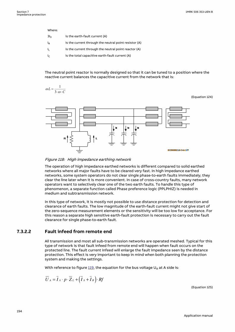
Where:
3I0 is the earth-fault current (A)
IR is the current through the neutral point resistor (A)
IL is the current through the neutral point reactor (A)
IC is the total capacitive earth-fault current (A)
The neutral point reactor is normally designed so that it can be tuned to a position where thereactive current balances the capacitive current from the network that is:
13
LC
ww
=× ×
EQUATION1272 V1 EN-US (Equation 124)
IEC05000216 V2 EN-US
Figure 118: High impedance earthing network
The operation of high impedance earthed networks is different compared to solid earthednetworks where all major faults have to be cleared very fast. In high impedance earthednetworks, some system operators do not clear single phase-to-earth faults immediately; theyclear the line later when it is more convenient. In case of cross-country faults, many networkoperators want to selectively clear one of the two earth faults. To handle this type ofphenomenon, a separate function called Phase preference logic (PPLPHIZ) is needed inmedium and subtransmission network.
In this type of network, it is mostly not possible to use distance protection for detection andclearance of earth faults. The low magnitude of the earth-fault current might not give start ofthe zero-sequence measurement elements or the sensitivity will be too low for acceptance. Forthis reason a separate high sensitive earth-fault protection is necessary to carry out the faultclearance for single phase-to-earth fault.
7.3.2.2 Fault infeed from remote endM17048-83 v5
All transmission and most all sub-transmission networks are operated meshed. Typical for thistype of network is that fault infeed from remote end will happen when fault occurs on theprotected line. The fault current infeed will enlarge the fault impedance seen by the distanceprotection. This effect is very important to keep in mind when both planning the protectionsystem and making the settings.
With reference to figure 119, the equation for the bus voltage UA at A side is:
U I p Z I I RfA A L A B= ⋅ ⋅ + +( ) ⋅
EQUATION1273-IEC-650 V2 EN-US (Equation 125)
Section 7 1MRK 506 353-UEN BImpedance protection
194Application manual
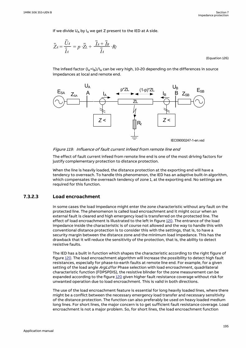
If we divide UA by IA we get Z present to the IED at A side.
IA + IBUA
IA IA ZA = = p ·ZL + ·Rf
EQUATION1274-IEC-650 V1 EN-US (Equation 126)
The infeed factor (IA+IB)/IA can be very high, 10-20 depending on the differences in sourceimpedances at local and remote end.
Z <
ZL
Z <
ESA
UA UBA B ESBIA IB
Rf
p*ZL (1-p)*ZLZSA ZSB
IEC09000247-1-en.vsdIEC09000247 V1 EN-US
Figure 119: Influence of fault current infeed from remote line end
The effect of fault current infeed from remote line end is one of the most driving factors forjustify complementary protection to distance protection.
When the line is heavily loaded, the distance protection at the exporting end will have atendency to overreach. To handle this phenomenon, the IED has an adaptive built-in algorithm,which compensates the overreach tendency of zone 1, at the exporting end. No settings arerequired for this function.
7.3.2.3 Load encroachmentM17048-589 v8
In some cases the load impedance might enter the zone characteristic without any fault on theprotected line. The phenomenon is called load encroachment and it might occur when anexternal fault is cleared and high emergency load is transferred on the protected line. Theeffect of load encroachment is illustrated to the left in figure 120. The entrance of the loadimpedance inside the characteristic is of course not allowed and the way to handle this withconventional distance protection is to consider this with the settings, that is, to have asecurity margin between the distance zone and the minimum load impedance. This has thedrawback that it will reduce the sensitivity of the protection, that is, the ability to detectresistive faults.
The IED has a built in function which shapes the characteristic according to the right figure offigure 120. The load encroachment algorithm will increase the possibility to detect high faultresistances, especially for phase-to-earth faults at remote line end. For example, for a givensetting of the load angle ArgLd for Phase selection with load encroachment, quadrilateralcharacteristic function (FDPSPDIS), the resistive blinder for the zone measurement can beexpanded according to the figure 120 given higher fault resistance coverage without risk forunwanted operation due to load encroachment. This is valid in both directions.
The use of the load encroachment feature is essential for long heavily loaded lines, where theremight be a conflict between the necessary emergency load transfer and necessary sensitivityof the distance protection. The function can also preferably be used on heavy loaded mediumlong lines. For short lines, the major concern is to get sufficient fault resistance coverage. Loadencroachment is not a major problem. So, for short lines, the load encroachment function
1MRK 506 353-UEN B Section 7Impedance protection
195Application manual

could preferably be switched off. See section "Load impedance limitation, without loadencroachment function".
The settings of the parameters for load encroachment are done in FDPSPDIS function.
R
X
Z1
Load impedance
area in forward
direction
RLdRv
R
Z1
ArgLd
RLdFw
IEC09000248-2-en.vsd
X
IEC09000248 V2 EN-US
Figure 120: Load encroachment phenomena and shaped load encroachmentcharacteristic defined in Phase selection with load encroachment functionFDPSPDIS
7.3.2.4 Short line applicationM17048-97 v4
In short line applications, the major concern is to get sufficient fault resistance coverage. Loadencroachment is not so common. The line length that can be recognized as a short line is not afixed length; it depends on system parameters such as voltage and source impedance, seetable 18.
Table 18: Definition of short and very short line
Line category
Un Un110 kV 500 kV
Very short line 1.1-5.5 km 5-25 km
Short line 5.5-11 km 25-50 km
The IED's ability to set resistive and reactive reach independent for positive and zero sequencefault loops and individual fault resistance settings for phase-to-phase and phase-to-earth faulttogether with load encroachment algorithm improves the possibility to detect high resistivefaults without conflict with the load impedance, see figure 120.
For very short line applications, the underreaching zone 1 can not be used due to the voltagedrop distribution throughout the line will be too low causing risk for overreaching.
Load encroachment is normally no problem for short line applications.
7.3.2.5 Long transmission line applicationM17048-516 v5
For long transmission lines, the margin to the load impedance, that is, to avoid loadencroachment, will normally be a major concern. It is well known that it is difficult to achievehigh sensitivity for phase-to-earth fault at remote line end of long lines when the line is heavyloaded.
Section 7 1MRK 506 353-UEN BImpedance protection
196Application manual

What can be recognized as long lines with respect to the performance of distance protectioncan generally be described as in table 19, long lines have Source impedance ratio (SIR’s) lessthan 0.5.
Table 19: Definition of long and very long lines
Line category
Un Un110 kV 500 kV
Long lines 77 km - 99 km 350 km - 450 km
Very long lines > 99 km > 450 km
The IED's ability to set resistive and reactive reach independent for positive and zero sequencefault loops and individual fault resistance settings for phase-to-phase and phase-to-earth faulttogether with load encroachment algorithm improves the possibility to detect high resistivefaults at the same time as the security is improved (risk for unwanted trip due to loadencroachment is eliminated), see figure 121.
en05000220.vsd
R
Zm
ARGLdARGLd
ARGLd ARGLd
RLdFwRLdRv
ZL
IEC05000220 V1 EN-US
Figure 121: Characteristic for zone measurement for a long line
7.3.2.6 Parallel line application with mutual couplingM17048-417 v2
GeneralM17048-567 v3
Introduction of parallel lines in the network is increasing due to difficulties to get necessaryarea for new lines.
Parallel lines introduce an error in the measurement due to the mutual coupling between theparallel lines. The lines need not be of the same voltage in order to experience mutual coupling,and some coupling exists even for lines that are separated by 100 meters or more. The mutualcoupling does influence the zero sequence impedance to the fault point but it does notnormally cause voltage inversion.
It can be shown from analytical calculations of line impedances that the mutual impedancesfor positive and negative sequence are very small (< 1-2%) of the self impedance and it is apractice to neglect them.
1MRK 506 353-UEN B Section 7Impedance protection
197Application manual

From an application point of view there exists three types of network configurations (classes)that must be considered when making the settings for the protection function.
The different network configuration classes are:
1. Parallel line with common positive and zero sequence network2. Parallel circuits with common positive but isolated zero sequence network3. Parallel circuits with positive and zero sequence sources isolated.
One example of class 3 networks could be the mutual coupling between a 400kV line and railroad overhead lines. This type of mutual coupling is not so common although it exists and isnot treated any further in this manual.
For each type of network class, there are three different topologies; the parallel line can be inservice, out of service, out of service and earthed in both ends.
The reach of the distance protection zone 1 will be different depending on the operationcondition of the parallel line. This can be handled by the use of different setting groups forhandling the cases when the parallel line is in operation and out of service and earthed at bothends.
The distance protection within the IED can compensate for the influence of a zero sequencemutual coupling on the measurement at single phase-to-earth faults in the following ways, byusing:
• The possibility of different setting values that influence the earth-return compensationfor different distance zones within the same group of setting parameters.
• Different groups of setting parameters for different operating conditions of a protectedmulti circuit line.
Most multi circuit lines have two parallel operating circuits.
Parallel line applicationsM17048-560 v4
This type of networks is defined as those networks where the parallel transmission linesterminate at common nodes at both ends.
The three most common operation modes are:
1. Parallel line in service.2. Parallel line out of service and earthed.3. Parallel line out of service and not earthed.
Parallel line in serviceM17048-424 v5
This type of application is very common and applies to all normal sub-transmission andtransmission networks.
Let us analyze what happens when a fault occurs on the parallel line see figure 122.
From symmetrical components, we can derive the impedance Z at the relay point for normallines without mutual coupling according to equation 127.
ZU
I IZ Z
Z
U
I I K
ph
ph
ph
ph N
=
+ ⋅−
⋅
=+ ⋅
33
30
0 1
1
0
IECEQUATION1275 V2 EN-US (Equation 127)
Section 7 1MRK 506 353-UEN BImpedance protection
198Application manual

Where:
Uph is phase to earth voltage at the relay point
Iph is phase current in the faulty phase
3I0 is earth fault current
Z1 is positive sequence impedance
Z0 is zero sequence impedance
Z0m
A B
Z< Z< IEC09000250_1_en.vsdIEC09000250 V1 EN-US
Figure 122: Class 1, parallel line in service
The equivalent circuit of the lines can be simplified, see figure 123.
A
B
CZ0m
Z0mZ0 -
Z0mZ0 -
IEC09000253_1_en.vsdIEC09000253 V1 EN-US
Figure 123: Equivalent zero sequence impedance circuit of the double-circuit, parallel,operating line with a single phase-to-earth fault at the remote busbar
When mutual coupling is introduced, the voltage at the relay point A will be changed accordingto equation 128.
0 000 11 3 3
3 1 3 1mL L
ph pph LL L
ZZ ZU Z I I IZ Z
æ ö-= × + × +ç ÷
× ×è øIECEQUATION1276 V3 EN-US (Equation 128)
By dividing equation 128 by equation 127 and after some simplification we can write theimpedance present to the relay at A side as:
3 01 13 0
æ ö×= +ç ÷+ ×è ø
LI KNmZ Z
I ph I KNEQUATION1277 V3 EN-US (Equation 129)
Where:
KNm = Z0m/(3 · Z1L)
The second part in the parentheses is the error introduced to the measurement of the lineimpedance.
1MRK 506 353-UEN B Section 7Impedance protection
199Application manual

If the current on the parallel line has negative sign compared to the current on the protectedline, that is, the current on the parallel line has an opposite direction compared to the currenton the protected line, the distance function will overreach. If the currents have the samedirection, the distance protection will underreach.
Maximum overreach will occur if the fault current infeed from remote line end is weak. Ifconsidering a single phase-to-earth fault at 'p' unit of the line length from A to B on the parallelline for the case when the fault current infeed from remote line end is zero, the voltage UA inthe faulty phase at A side as in equation 130.
U p ZI I K I K IA L ph N Nm p= ⋅ + ⋅ + ⋅( )3 3
0 0
IECEQUATION1278 V2 EN-US (Equation 130)
One can also notice that the following relationship exists between the zero sequence currents:
3 0 3 0 0 20
I Z I Z pL p L
⋅ = ⋅ −( )EQUATION1279 V3 EN-US (Equation 131)
Simplification of equation 131, solving it for 3I0p and substitution of the result into equation130 gives that the voltage can be drawn as:
U p ZI I K I KI p
pA L ph N Nm
= ⋅ + ⋅ + ⋅⋅
−
3
3
20
0
IECEQUATION1280 V2 EN-US (Equation 132)
If we finally divide equation 132 with equation 127 we can draw the impedance present to theIED as
Z p ZI
I KN I KNI p
p
I I KNL
ph m
ph
= ⋅
+ ⋅ + ⋅⋅
−
+ ⋅
33
2
3
0
0
0
EQUATION1379 V3 EN-US (Equation 133)
Calculation for a 400 kV line, where we for simplicity have excluded the resistance, gives withX1L=0.303 Ω/km, X0L=0.88 Ω/km, zone 1 reach is set to 90% of the line reactance p=71% thatis, the protection is underreaching with approximately 20%.
The zero sequence mutual coupling can reduce the reach of distance protection on theprotected circuit when the parallel line is in normal operation. The reduction of the reach ismost pronounced with no current infeed in the IED closest to the fault. This reach reduction isnormally less than 15%. But when the reach is reduced at one line end, it is proportionallyincreased at the opposite line end. So this 15% reach reduction does not significantly affectthe operation of a permissive underreaching scheme.
Parallel line out of service and earthedM17048-477 v3M17048-479 v7
Section 7 1MRK 506 353-UEN BImpedance protection
200Application manual
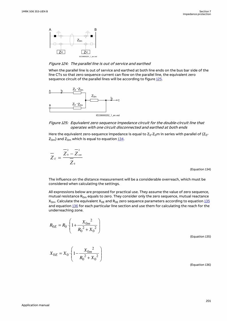
Z0m
A B
Z< Z<IEC09000251_1_en.vsd
IEC09000251 V1 EN-US
Figure 124: The parallel line is out of service and earthed
When the parallel line is out of service and earthed at both line ends on the bus bar side of theline CTs so that zero sequence current can flow on the parallel line, the equivalent zerosequence circuit of the parallel lines will be according to figure 125.
A
B
C
IEC09000252_1_en.vsd
I0
I0
Z0mZ0 -
Z0mZ0 -
Z0m
IEC09000252 V1 EN-US
Figure 125: Equivalent zero sequence impedance circuit for the double-circuit line thatoperates with one circuit disconnected and earthed at both ends
Here the equivalent zero-sequence impedance is equal to Z0-Z0m in series with parallel of (Z0-Z0m) and Z0m which is equal to equation 134.
2 2
0
0
omE
Z ZZ
Z
-=
EQUATION2002 V4 EN-US (Equation 134)
The influence on the distance measurement will be a considerable overreach, which must beconsidered when calculating the settings.
All expressions below are proposed for practical use. They assume the value of zero sequence,mutual resistance R0m equals to zero. They consider only the zero sequence, mutual reactanceX0m. Calculate the equivalent X0E and R0E zero sequence parameters according to equation 135and equation 136 for each particular line section and use them for calculating the reach for theunderreaching zone.
R RX
R XE
m0 0
0
2
0
2
0
21= ⋅ +
+
DOCUMENT11520-IMG3502 V2 EN-US (Equation 135)
X XX
R XE
m0 0
0
2
0
2
0
21= ⋅ −
+
DOCUMENT11520-IMG3503 V2 EN-US (Equation 136)
1MRK 506 353-UEN B Section 7Impedance protection
201Application manual

Parallel line out of service and not earthedM17048-537 v5
Z0m
A B
Z< Z<IEC09000254_1_en.vsd
IEC09000254 V1 EN-US
Figure 126: Parallel line is out of service and not earthed
When the parallel line is out of service and not earthed, the zero sequence on that line can onlyflow through the line admittance to the earth. The line admittance is high which limits thezero-sequence current on the parallel line to very low values. In practice, the equivalent zero-sequence impedance circuit for faults at the remote bus bar can be simplified to the circuitshown in figure 126
The line zero sequence mutual impedance does not influence the measurement of the distanceprotection in a faulty circuit. This means that the reach of the underreaching distanceprotection zone is reduced if, due to operating conditions, the equivalent zero sequenceimpedance is set according to the conditions when the parallel system is out of operation andearthed at both ends.
A
B
C
IEC09000255_1_en.vsd
I0
I0
Z0mZ0 -
Z0m
Z0mZ0 -
IEC09000255 V1 EN-US
Figure 127: Equivalent zero-sequence impedance circuit for a double-circuit line with onecircuit disconnected and not earthed
The reduction of the reach is equal to equation 137.
( )( ) ( )
21 0
0
1 001 0
1 23 11 2 323
E fm
U
ff
Z Z R ZKZ Z Z RZ Z R
× × + += = -
× × + +× × + +
EQUATION1284 V1 EN-US (Equation 137)
This means that the reach is reduced in reactive and resistive directions. If the real andimaginary components of the constant A are equal to equation 138 and equation 139.
Re( ) 0 (2 1 0 3 ) 0 ( 0 2 1)A R R R Rf X X X= × × + + × - × + ×EQUATION1285 V1 EN-US (Equation 138)
0 1 0 1 0 1 0Im( ) (2 3 ) (2 )A X R R R R X X= × × + + × + × × +EQUATION1286 V1 EN-US (Equation 139)
The real component of the KU factor is equal to equation 140.
Section 7 1MRK 506 353-UEN BImpedance protection
202Application manual

Re
Re
Re Im
KA X
A A
u
m
( ) = +( ) ⋅
( )
+ ( )
1
0
2
2 2
EQUATION1287 V3 EN-US (Equation 140)
The imaginary component of the same factor is equal to equation 141.
( ) ( )( ) ( )
20
2 2
ImIm
Re Im
mU
A XK
A A
×=
+é ù é ùë û ë ûEQUATION1288 V2 EN-US (Equation 141)
Ensure that the underreaching zones from both line ends will overlap a sufficient amount (atleast 10%) in the middle of the protected circuit.
7.3.2.7 Tapped line applicationM17048-243 v3
M17048-245 v4
C
B
BC
IEC09000160-3-en.vsd
A
IEC09000160 V3 EN-US
Figure 128: Example of tapped line with Auto transformer
This application gives rise to similar problem that was highlighted in section "Fault infeedfrom remote end" , that is increased measured impedance due to fault current infeed. Forexample, for faults between the T point and B station the measured impedance at A and C willbe
ZA =ZAT + ·ZTFIA + IC
IADOCUMENT11524-IMG3509 V3 EN-US (Equation 142)
1MRK 506 353-UEN B Section 7Impedance protection
203Application manual
Z Z ZI I
IZ
U
UC Trf CT
A C
C
TF= + ++
⋅
⋅
2
1
2
DOCUMENT11524-IMG3510 V3 EN-US (Equation 143)
Where:
ZAT and ZCT is the line impedance from the A respective C station to the T point.
IA and IC is fault current from A respective C station for fault between T and B.
U2/U1 Transformation ratio for transformation of impedance at U1 side of thetransformer to the measuring side U2 (it is assumed that current and voltagedistance function is taken from U2 side of the transformer).
ZTF is the line impedance from the T point to the fault (F).
ZTrf Transformer impedance
For this example with a fault between T and B, the measured impedance from the T point tothe fault will be increased by a factor defined as the sum of the currents from T point to thefault divided by the IED current. For the IED at C, the impedance on the high voltage side U1has to be transferred to the measuring voltage level by the transformer ratio.
Another complication that might occur depending on the topology is that the current from oneend can have a reverse direction for fault on the protected line. For example, for faults at T thecurrent from B might go in reverse direction from B to C depending on the system parameters(see the dotted line in figure 128), given that the distance protection in B to T will measurewrong direction.
In three-end application, depending on the source impedance behind the IEDs, the impedancesof the protected object and the fault location, it might be necessary to accept zone 2 trip inone end or sequential trip in one end.
Generally for this type of application it is difficult to select settings of zone 1 that both givesoverlapping of the zones with enough sensitivity without interference with other zone 1settings, that is, without selectivity conflicts. Careful fault calculations are necessary todetermine suitable settings and selection of proper scheme communication.
Fault resistanceM17048-597 v8
The performance of distance protection for single phase-to-earth faults is very important,because normally more than 70% of the faults on transmission lines are single phase-to-earthfaults. At these faults, the fault resistance is composed of three parts: arc resistance,resistance of a tower construction, and tower-footing resistance. The arc resistance can becalculated according to Warrington's formula:
1.428707 LRarc
I×
=
EQUATION1456 V1 EN-US (Equation 144)
where:
L represents the length of the arc (in meters). This equation applies for the distance protection zone 1.Consider approximately three times arc foot spacing for the zone 2 and to give extra margin to theinfluence of wind speed and temperature.
I is the actual fault current in A.
Section 7 1MRK 506 353-UEN BImpedance protection
204Application manual

In practice, the setting of fault resistance for both phase-to-earth RFPE and phase-to-phaseRFPP should be as high as possible without interfering with the load impedance in order toobtain reliable fault detection. However for zone1 it is necessary to limit the reach according tosetting instructions in order to avoid overreach.
7.3.3 Setting guidelinesIP14962-1 v1
7.3.3.1 GeneralSEMOD55087-5 v7
The settings for Distance measuring zones, quadrilateral characteristic (ZMQPDIS) are done inprimary values. The instrument transformer ratio that has been set for the analog input card isused to automatically convert the measured secondary input signals to primary values used inZMQPDIS.
The following basics must be considered, depending on application, when doing the settingcalculations:
• Errors introduced by current and voltage instrument transformers, particularly undertransient conditions.
• Inaccuracies in the line zero-sequence impedance data, and their effect on the calculatedvalue of the earth-return compensation factor.
• The effect of infeed between the IED and the fault location, including the influence ofdifferent Z0/Z1 ratios of the various sources.
• The phase impedance of non transposed lines is not identical for all fault loops. Thedifference between the impedances for different phase-to-earth loops can be as large as5-10% of the total line impedance.
• The effect of a load transfer between the IEDs of the protected fault resistance isconsiderable, the effect must be recognized.The load transfer on the protected line shouldbe considered for resistive phase to earth faults
• Zero-sequence mutual coupling from parallel lines.
7.3.3.2 Setting of zone 1SEMOD55087-22 v3
The different errors mentioned earlier usually require a limitation of the underreaching zone(normally zone 1) to 75 - 90% of the protected line.
In case of parallel lines, consider the influence of the mutual coupling according to section"Parallel line application with mutual coupling" and select the case(s) that are valid in theparticular application. By proper setting it is possible to compensate for the cases when theparallel line is in operation, out of service and not earthed and out of service and earthed inboth ends. The setting of earth-fault reach should be selected to be <95% also when parallelline is out of service and earthed at both ends (worst case).
7.3.3.3 Setting of overreaching zoneSEMOD55087-26 v6
The first overreaching zone (normally zone 2) must detect faults on the whole protected line.Considering the different errors that might influence the measurement in the same way as forzone 1, it is necessary to increase the reach of the overreaching zone to at least 120% of theprotected line. The zone 2 reach can be even higher if the fault infeed from adjacent lines atremote end is considerable higher than the fault current at the IED location.
The setting shall generally not exceed 80% of the following impedances:
1MRK 506 353-UEN B Section 7Impedance protection
205Application manual

• The impedance corresponding to the protected line, plus the first zone reach of theshortest adjacent line.
• The impedance corresponding to the protected line, plus the impedance of the maximumnumber of transformers operating in parallel on the bus at the remote end of theprotected line.
Larger overreach than the mentioned 80% can often be acceptable due to fault current infeedfrom other lines. This requires however analysis by means of fault calculations.
If any of the above gives a zone 2 reach less than 120%, the time delay of zone 2 must beincreased by approximately 200ms to avoid unwanted operation in cases when thetelecommunication for the short adjacent line at remote end is down during faults. The zone 2must not be reduced below 120% of the protected line section. The whole line must be coveredunder all conditions.
The requirement that the zone 2 shall not reach more than 80% of the shortest adjacent line atremote end is highlighted in the example below.
If a fault occurs at point F see figure 129, the IED at point A senses the impedance:
ZV
IZ
I I
IZ
I I I
IR Z
I
IZAF
A
A
AC
A C
A
CF
A C B
A
FAC
C
A
C= = ++
⋅ ++ +
⋅ = + +
⋅1 FF
C B
A
F
I I
IR+ +
+
⋅1
EQUATION302 V5 EN-US (Equation 145)
A B
Z<
C
IC
ZAC ZCB
Z CF
IA+ I C
IEC09000256-2-en.vsd
FI A
I B
IEC09000256 V2 EN-US
Figure 129: Setting of overreaching zone
7.3.3.4 Setting of reverse zoneSEMOD55087-74 v4
The reverse zone is applicable for purposes of scheme communication logic, current reversallogic, weak-end infeed logic, and so on. The same applies to the back-up protection of the busbar or power transformers. It is necessary to secure, that it always covers the overreachingzone, used at the remote line IED for the telecommunication purposes.
Consider the possible enlarging factor that might exist due to fault infeed from adjacent lines.Equation 146 can be used to calculate the reach in reverse direction when the zone is used forblocking scheme, weak-end infeed, and so on.
( )1.2 2³ × -Zrev ZL Z remEQUATION1525 V5 EN-US (Equation 146)
Where:
ZL is the protected line impedance
Z2rem is zone 2 setting at remote end of protected line.
Section 7 1MRK 506 353-UEN BImpedance protection
206Application manual

In many applications it might be necessary to consider the enlarging factor due to faultcurrent infeed from adjacent lines in the reverse direction in order to obtain certain sensitivity.
7.3.3.5 Setting of zones for parallel line applicationSEMOD55087-50 v2
Parallel line in service – Setting of zone 1SEMOD55087-52 v3
With reference to section "Parallel line applications", the zone reach can be set to 85% of theprotected line.
However, influence of mutual impedance has to be taken into account.
Parallel line in service – setting of zone 2SEMOD55087-55 v4
Overreaching zones (in general, zones 2 and 3) must overreach the protected circuit in allcases. The greatest reduction of a reach occurs in cases when both parallel circuits are inservice with a single phase-to-earth fault located at the end of a protected line. The equivalentzero sequence impedance circuit for this case is equal to the one in figure 123 in section"Parallel line in service".
The components of the zero sequence impedance for the overreaching zones must be equal toat least:
R0E R0 Rm0+=
EQUATION553 V1 EN-US (Equation 147)
X0E X0 Xm0+=
EQUATION554 V1 EN-US (Equation 148)
Check the reduction of a reach for the overreaching zones due to the effect of the zerosequence mutual coupling. The reach is reduced for a factor:
00 12 1 0
m
f
ZKZ Z R
= -× + +
EQUATION1426 V1 EN-US (Equation 149)
If the denominator in equation 149 is called B and Z0m is simplified to X0m, then the real andimaginary part of the reach reduction factor for the overreaching zones can be written as:
( ) ( )( ) ( )2 2
0 ReRe 0 1
Re ImX m B
KB B
×= -
+
EQUATION1427 V2 EN-US (Equation 150)
( ) ( )( ) ( )2 2
0 ImIm 0
Re ImX m B
KB B
×=
+
EQUATION1428 V2 EN-US (Equation 151)
Parallel line is out of service and earthed in both endsSEMOD55087-77 v3
Apply the same measures as in the case with a single set of setting parameters. This meansthat an underreaching zone must not overreach the end of a protected circuit for the singlephase-to-earth faults.
Set the values of the corresponding zone (zero-sequence resistance and reactance) equal to:
1MRK 506 353-UEN B Section 7Impedance protection
207Application manual

R0E R0 1Xm0
2
R02 X0
2+--------------------------+
è øç ÷æ ö
×=
EQUATION561 V1 EN-US (Equation 152)
X0E X0 1Xm0
2
R02 X0
2+--------------------------–
è øç ÷æ ö
×=
EQUATION562 V1 EN-US (Equation 153)
7.3.3.6 Setting of reach in resistive directionSEMOD55087-84 v7
Set the resistive reach R1 independently for each zone.
Set separately the expected fault resistance for phase-to-phase faults RFPP and for the phase-to-earth faults RFPE for each zone. For each distance zone, set all remaining reach settingparameters independently of each other.
The final reach in resistive direction for phase-to-earth fault loop measurement automaticallyfollows the values of the line-positive and zero-sequence resistance, and at the end of theprotected zone is equal to equation 154.
( )1R 2 R1 R0 RFPE
3= × + +
IECEQUATION2303 V1 EN-US (Equation 154)
2 X1 X0arctan
2 R1 R0loopj
× +=
× +é ùê úë û
EQUATION2304 V1 EN-US (Equation 155)
Setting of the resistive reach for the underreaching zone 1 should follow the condition tominimize the risk for overreaching:
RFPE 4.5 X1£ ×IECEQUATION2305 V1 EN-US (Equation 156)
The fault resistance for phase-to-phase faults is normally quite low, compared to the faultresistance for phase-to-earth faults. To minimize the risk for overreaching, limit the setting ofthe zone 1 reach in resistive direction for phase-to-phase loop measurement in the phasedomain to:
RFPP X≤ ⋅6 1
IECEQUATION2306 V2 EN-US (Equation 157)
7.3.3.7 Load impedance limitation, without load encroachment functionSEMOD55087-97 v9
The following instructions are valid when Phase selection with load encroachment,quadrilateral characteristic function FDPSPDIS is not used. The setting of the load resistanceRLdFw and RLdRv in FDPSPDIS must in this case be set to max value (3000). If FDPSPDISis tobe used for all or some of the measuring zones, the load limitation for those zones accordingto this chapter can be omitted. Check the maximum permissible resistive reach for any zone to
Section 7 1MRK 506 353-UEN BImpedance protection
208Application manual

ensure that there is a sufficient setting margin between the boundary and the minimum loadimpedance. The minimum load impedance (Ω/phase) is calculated as:
Z loadminU2
S-------=
EQUATION571 V1 EN-US (Equation 158)
Where:
U is the minimum phase-to-phase voltage in kV
S is the maximum apparent power in MVA.
The load impedance [Ω/phase] is a function of the minimum operation voltage and themaximum load current:
Z loadUmin
3 Imax×----------------------=
EQUATION574 V1 EN-US (Equation 159)
Minimum voltage Umin and maximum current Imax are related to the same operatingconditions. Minimum load impedance occurs normally under emergency conditions.
As a safety margin is required to avoid load encroachment under three-phaseconditions and to guarantee correct healthy phase IED operation undercombined heavy three-phase load and earth faults, consider both: phase-to-phase and phase-to-earth fault operating characteristics.
To avoid load encroachment for the phase-to-earth measuring elements, the set resistivereach of any distance protection zone must be less than 80% of the minimum load impedance.
RFFwPE Zload≤ ⋅0 8.
IEC13000273 V1 EN-US (Equation 160)
This equation is applicable only when the loop characteristic angle for the single phase-to-earth faults is more than three times as large as the maximum expected load-impedanceangle. For the case when the loop characteristic angle is less than three times the load-impedance angle, more accurate calculations are necessary according to equation 161.
RFFwPE ZR R
X Xload≤ ⋅ ⋅ ∂ −
⋅ +
⋅ +⋅ ∂
0 8
2 1 0
2 1 0
. cos sinmin
IEC13000274 V1 EN-US (Equation 161)
Where:
∂ is a maximum load-impedance angle, related to the maximum load power.
To avoid load encroachment for the phase-to-phase measuring elements, the set resistivereach of any distance protection zone must be less than 160% of the minimum loadimpedance.
1MRK 506 353-UEN B Section 7Impedance protection
209Application manual

RFFwPE Zload≤ ⋅1 6.
IEC13000275 V1 EN-US (Equation 162)
Equation 162 is applicable only when the loop characteristic angle for the phase-to-phasefaults is more than three times as large as the maximum expected load-impedance angle. Moreaccurate calculations are necessary according to equation 163.
RFFwPP ZR
Xload≤ ⋅ ⋅ ∂ − ⋅ ∂
1 6
1
1
. cos sinmin
IEC13000276 V1 EN-US (Equation 163)
Set the fault resistance coverage RFRwPP and RFRwPE to the same value as in forwarddirection, if that suits the application. All this is applicable for all measuring zones when noPower swing detection function ZMRPSB is activated in the IED. Use an additional safetymargin of approximately 20% in cases when a ZMRPSB function is activated in the IED, refer tothe description of Power swing detection function ZMRPSB.
7.3.3.8 Load impedance limitation, with Phase selection with loadencroachment, quadrilateral characteristic function activated
SEMOD55087-138 v5
The parameters for shaping of the load encroachment characteristic are found in thedescription of Phase selection with load encroachment, quadrilateral characteristic function(FDPSPDIS).
7.3.3.9 Setting of minimum operating currentsSEMOD55087-141 v5
The operation of Distance protection zone, quadrilateral characteristic (ZMQPDIS) can beblocked if the magnitude of the currents is below the set value of the parameter IMinOpPP andIMinOpPE.
The default setting of IMinOpPP and IMinOpPE is 20% of IBase where IBase is the chosencurrent for the analogue input channels. The value has been proven in practice to be suitable inmost of the applications. However, there might be applications where it is necessary toincrease the sensitivity by reducing the minimum operating current down to 10% of IBase. Thishappens especially in cases, when the IED serves as a remote back-up protection on series ofvery long transmission lines.
Setting IMinOpIN blocks the phase-to-earth loop if 3I0<IMinOpIN. The default setting ofIMinOpIN is 5% of IBase.
The minimum operating fault current is automatically reduced to 75% of its set value, if thedistance protection zone has been set for the operation in reverse direction.
7.3.3.10 Directional impedance element for quadrilateral characteristicsM16923-139 v6
The evaluation of the directionality takes place in Directional impedance quadrilateral functionZDRDIR. Equation 164 and equation 165 are used to classify that the fault is in forwarddirection for phase-to-earth fault and phase-to-phase fault.
1 1
1
0.8 1 0.2 1arg ReL L M
L
U UArgDir ArgNeg s
I
× + ×- < <
EQUATION725 V2 EN-US (Equation 164)
For the L1-L2 element, the equation in forward direction is according to.
Section 7 1MRK 506 353-UEN BImpedance protection
210Application manual

1 2 1 2
1 2
0.8 1 0.2 1arg ReL L L L M
L L
U UArgDir ArgNeg s
I
× + ×- < <
EQUATION726 V2 EN-US (Equation 165)
where:
ArgDir is the setting for the lower boundary of the forward directional characteristic, by default set to15 (= -15 degrees) and
ArgNegRes is the setting for the upper boundary of the forward directional characteristic, by default set to115 degrees, see figure 130.
11LUis positive sequence phase voltage in phase L1
11L MUis positive sequence memorized phase voltage in phase L1
1LIis phase current in phase L1
1 21L LUis voltage difference between phase L1 and L2 (L2 lagging L1)
1 21L L MUis memorized voltage difference between phase L1 and L2 (L2 lagging L1)
1 2L LIis current difference between phase L1 and L2 (L2 lagging L1)
The setting of ArgDir and ArgNegRes is by default set to 15 (= -15) and 115 degrees respectively(as shown in figure 130). It should not be changed unless system studies have shown thenecessity.
ZDRDIR gives binary coded directional information per measuring loop on the outputSTDIRCND.
STDIR= STFWL1*1+STFWL2*2+STFWL3*4+STFWL1L2*8++STFWL2L3*16+STFWL3L1*32+STRVL1*64+STRVL2*128++STRVL3*256+STRVL1L2*512+STRVL2L3*1024+STRVL3L1*2048
1MRK 506 353-UEN B Section 7Impedance protection
211Application manual

R
X
ArgDir
ArgNegRes
en05000722.vsdIEC05000722 V1 EN-US
Figure 130: Setting angles for discrimination of forward and reverse fault in Directionalimpedance quadrilateral function ZDRDIR
The reverse directional characteristic is equal to the forward characteristic rotated by 180degrees.
The polarizing voltage is available as long as the positive sequence voltage exceeds 5% of theset base voltage UBase. So the directional element can use it for all unsymmetrical faultsincluding close-in faults.
For close-in three-phase faults, the U1L1M memory voltage, based on the same positivesequence voltage, ensures correct directional discrimination.
The memory voltage is used for 100 ms or until the positive sequence voltage is restored.
After 100 ms the following occurs:
• If the current is still above the set value of the minimum operating current (between 10and 30% of the set IED rated current IBase), the condition seals in.
• If the fault has caused tripping, the trip endures.• If the fault was detected in the reverse direction, the measuring element in the
reverse direction remains in operation.
• If the current decreases below the minimum operating value, the memory resets until thepositive sequence voltage exceeds 10% of its rated value.
7.3.3.11 Setting of timers for distance protection zonesSEMOD55087-147 v6
The required time delays for different distance protection zones are independent of eachother . Distance protection zone 1 can also have a time delay, if so required for selectivityreasons. Time delays for all zones can be set in a range of 0 to 60 seconds. The trippingfunction of each particular zone can be inhibited by setting the corresponding Operationparameter to Off. Different time delays are possible for the phase-to-earthtPE and for thephase-to-phase tPP measuring loops in each distance protection zone separately, to furtherincrease the total flexibility of a distance protection.
Section 7 1MRK 506 353-UEN BImpedance protection
212Application manual

7.4 Full-scheme distance measuring, Mho characteristicZMHPDIS
SEMOD154227-1 v4
7.4.1 IdentificationSEMOD154447-2 v2
Function description IEC 61850identification
IEC 60617identification
ANSI/IEEEC37.2 devicenumber
Full-scheme distance protection,mho characteristic
ZMHPDIS
S00346 V1 EN-US
21
7.4.2 ApplicationSEMOD154444-1 v1
7.4.2.1 FunctionalitySEMOD154453-4 v6
Transmission and sub-transmission networks are being extended and often become more andmore complex, consisting of a high number of multi-circuit and/or multi terminal lines of verydifferent lengths. These changes in the network will normally impose more stringent demandson the fault clearing equipment in order to maintain an unchanged or increased security levelof the power system.
Full-scheme distance measuring, mho characteristic function (ZMHPDIS) in the IED is designedto meet basic requirements for application on transmission and sub-transmission lines (solidearthed systems) although it also can be used on distribution levels.
7.4.2.2 System earthingSEMOD154453-11 v3
The type of system earthing plays an important role when designing the protection system. Inthe following some hints with respect to distance protection are highlighted.
Solid earthed networksSEMOD154453-14 v5
In solid earthed systems the transformer neutrals are connected solidly to earth without anyimpedance between the transformer neutral and earth.
IEC05000215 V2 EN-US
Figure 131: Solidly earthed network
The earth-fault current is as high as or even higher than the short-circuit current. The seriesimpedances determine the magnitude of the earth-fault current. The shunt admittance hasvery limited influence on the earth-fault current. The shunt admittance may, however, havesome marginal influence on the earth-fault current in networks with long transmission lines.
1MRK 506 353-UEN B Section 7Impedance protection
213Application manual

The earth-fault current at single phase-to-earth in phase L1 can be calculated as equation 166:
L1 L10
1 2 0 f 1 N f
3 U U3I
Z Z Z 3Z Z ZZ
×= =
+ + + + +EQUATION1267 V3 EN-US (Equation 166)
Where:
UL1 is the phase to earth voltage (kV) in the faulty phase beforefault
Z1 is the positive sequence impedance (Ω/phase)
Z2 is the negative sequence impedance (Ω/phase)
Z0 is the zero sequence impedance (Ω/phase)
Zf is the fault impedance (Ω), often resistive
ZN is the earth return impedance defined as (Z0-Z1)/3
The voltage on the healthy phases is generally lower than 140% of the nominal phase-to-earthvoltage. This corresponds to about 80% of the nominal phase-to-phase voltage.
The high zero-sequence current in solid earthed networks makes it possible to use impedancemeasuring technique to detect earth fault. However, distance protection has limitedpossibilities to detect high resistance faults and should therefore always be complementedwith other protection function(s) that can carry out the fault clearance in those cases.
Effectively earthed networksSEMOD154453-40 v5
A network is defined as effectively earthed if the earth-fault factor fe is less than 1.4. The earth-fault factor is defined according to equation 167.
fU
Ue
pn
=max
EQUATION1268 V4 EN-US (Equation 167)
Where:
Umax is the highest fundamental frequency voltage on one of the healthy phases at singlephase-to-earth fault.
Upn is the phase-to-earth fundamental frequency voltage before fault.
Another definition for effectively earthed network is when the following relationships betweenthe symmetrical components of the network impedances are valid, see equation 168 andequation 169.
X X0 13≤ ⋅
EQUATION1269 V4 EN-US (Equation 168)
R X£0 1
EQUATION1270 V4 EN-US (Equation 169)
Section 7 1MRK 506 353-UEN BImpedance protection
214Application manual

Where
R0 is the zero sequence resistance
X0 is the zero sequence reactance
X1 is the positive sequence reactance
The magnitude of the earth-fault current in effectively earthed networks is high enough forimpedance measuring element to detect earth fault. However, in the same way as for solidearthed networks, distance protection has limited possibilities to detect high resistance faultsand should therefore always be complemented with other protection function(s) that can carryout the fault clearance in this case.
High impedance earthed networksSEMOD154453-58 v4
In high impedance networks the neutral of the system transformers are connected to the earththrough high impedance, mostly a reactance in parallel with a high resistor.
This type of network is many times operated in radial, but can also be found operating meshednetworks.
What is typical for this type of network is that the magnitude of the earth-fault current is verylow compared to the short-circuit current. The voltage on the healthy phases will get amagnitude of √3 times the phase voltage during the fault. The zero-sequence voltage (3U0) willhave the same magnitude in different places in the network due to low voltage dropdistribution.
The magnitude of the total fault current can be calculated according to equation 170.
( )22R L C03I I I I= + -
EQUATION1271 V3 EN-US (Equation 170)
where
3I0 is the earth-fault current (A)
IR is the current through the neutral point resistor (A)
IL is the current through the neutral point reactor (A)
IC is the total capacitive earth-fault current (A)
The neutral point reactor is normally designed so that it can be tuned to a position where theinductive current balances the capacitive current from the network that is:
13
LC
ww
=× ×
EQUATION1272 V1 EN-US (Equation 171)
1MRK 506 353-UEN B Section 7Impedance protection
215Application manual
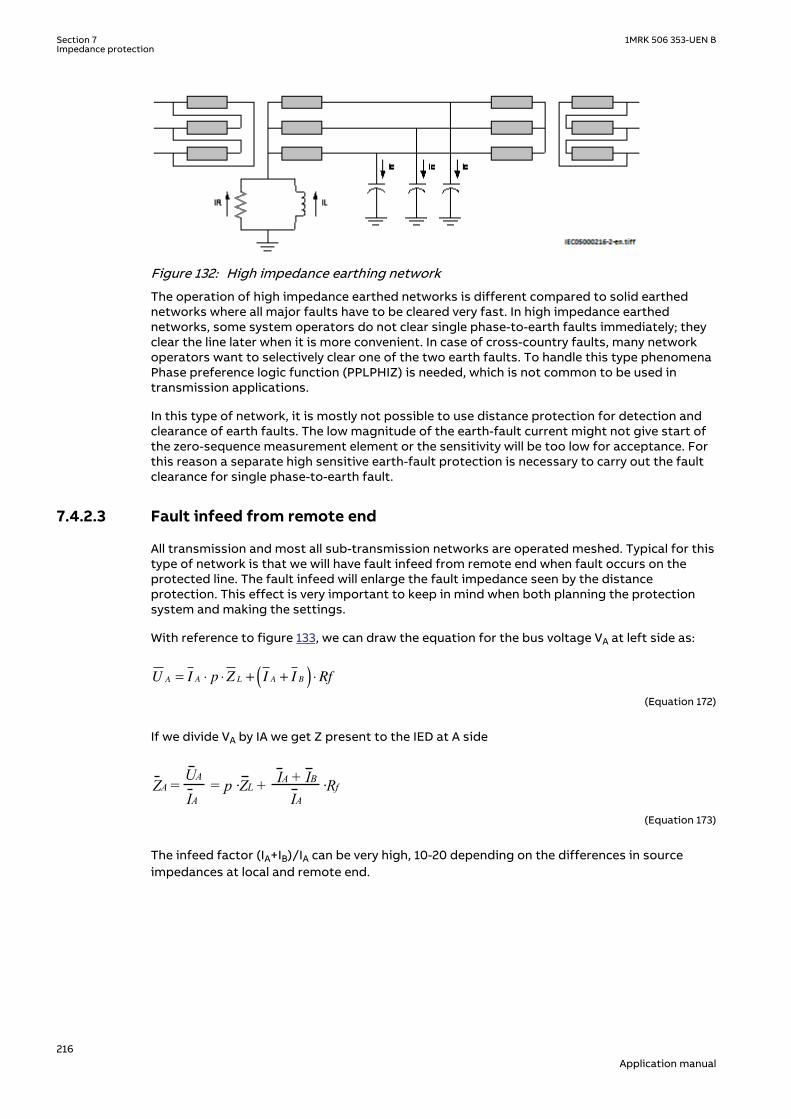
IEC05000216 V2 EN-US
Figure 132: High impedance earthing network
The operation of high impedance earthed networks is different compared to solid earthednetworks where all major faults have to be cleared very fast. In high impedance earthednetworks, some system operators do not clear single phase-to-earth faults immediately; theyclear the line later when it is more convenient. In case of cross-country faults, many networkoperators want to selectively clear one of the two earth faults. To handle this type phenomenaPhase preference logic function (PPLPHIZ) is needed, which is not common to be used intransmission applications.
In this type of network, it is mostly not possible to use distance protection for detection andclearance of earth faults. The low magnitude of the earth-fault current might not give start ofthe zero-sequence measurement element or the sensitivity will be too low for acceptance. Forthis reason a separate high sensitive earth-fault protection is necessary to carry out the faultclearance for single phase-to-earth fault.
7.4.2.3 Fault infeed from remote endSEMOD154453-84 v4
All transmission and most all sub-transmission networks are operated meshed. Typical for thistype of network is that we will have fault infeed from remote end when fault occurs on theprotected line. The fault infeed will enlarge the fault impedance seen by the distanceprotection. This effect is very important to keep in mind when both planning the protectionsystem and making the settings.
With reference to figure 133, we can draw the equation for the bus voltage VA at left side as:
U I p Z I I RfA A L A B= ⋅ ⋅ + +( ) ⋅
EQUATION1273-IEC-650 V2 EN-US (Equation 172)
If we divide VA by IA we get Z present to the IED at A side
IA + IBUA
IA IA ZA = = p ·ZL + ·Rf
EQUATION1274-IEC-650 V1 EN-US (Equation 173)
The infeed factor (IA+IB)/IA can be very high, 10-20 depending on the differences in sourceimpedances at local and remote end.
Section 7 1MRK 506 353-UEN BImpedance protection
216Application manual

Z <
ZL
Z <
ESA
UA UBA B ESBIA IB
Rf
p*ZL (1-p)*ZLZSA ZSB
IEC09000247-1-en.vsdIEC09000247 V1 EN-US
Figure 133: Influence of fault current infeed from remote end.
The effect of fault current infeed from remote end is one of the most driving factors for justifycomplementary protection to distance protection.
7.4.2.4 Load encroachmentSEMOD154453-97 v4
In some cases the load impedance might enter the zone characteristic without any fault on theprotected line. The phenomenon is called load encroachment and it might occur when anexternal fault is cleared and high emergency load is transferred on the protected line. Theeffect of load encroachment for the mho circle is illustrated to the left in figure 134. Theentrance of the load impedance inside the characteristic is of course not allowed and the wayto handle this with conventional distance protection is to consider this with the settings, thatis, to have a security margin between the distance zone and the minimum load impedance.This has the drawback that it will reduce the sensitivity of the protection, that is, the ability todetect resistive faults.
jX
RLoad
Load
Load
Load
jX
RLoad
Load
Load
Load
Nooperation
en06000403.vsdIEC06000403 V1 EN-US
Figure 134: Load encroachment phenomena and shaped load encroachmentcharacteristic
The Faulty phase identification with load encroachment for mho (FMPSPDIS) function shapesthe characteristic according to the diagram on the right in figure 134. The load encroachmentalgorithm will increase the possibility to detect high fault resistances, especially for phase-to-earth faults at remote line end. For example, for a given setting of the load angle ArgLd (seefigure 135) for the Faulty phase identification with load encroachment for mho function(FMPSPDIS), the zone reach can be expanded according to the diagram on the right infigure 134 given higher fault resistance coverage without risk for unwanted operation due toload encroachment. The part of the load encroachment sector that comes inside the mhocircle will not cause a trip if FMPSPDIS is activated for the zone measurement. This is valid inboth directions.
1MRK 506 353-UEN B Section 7Impedance protection
217Application manual
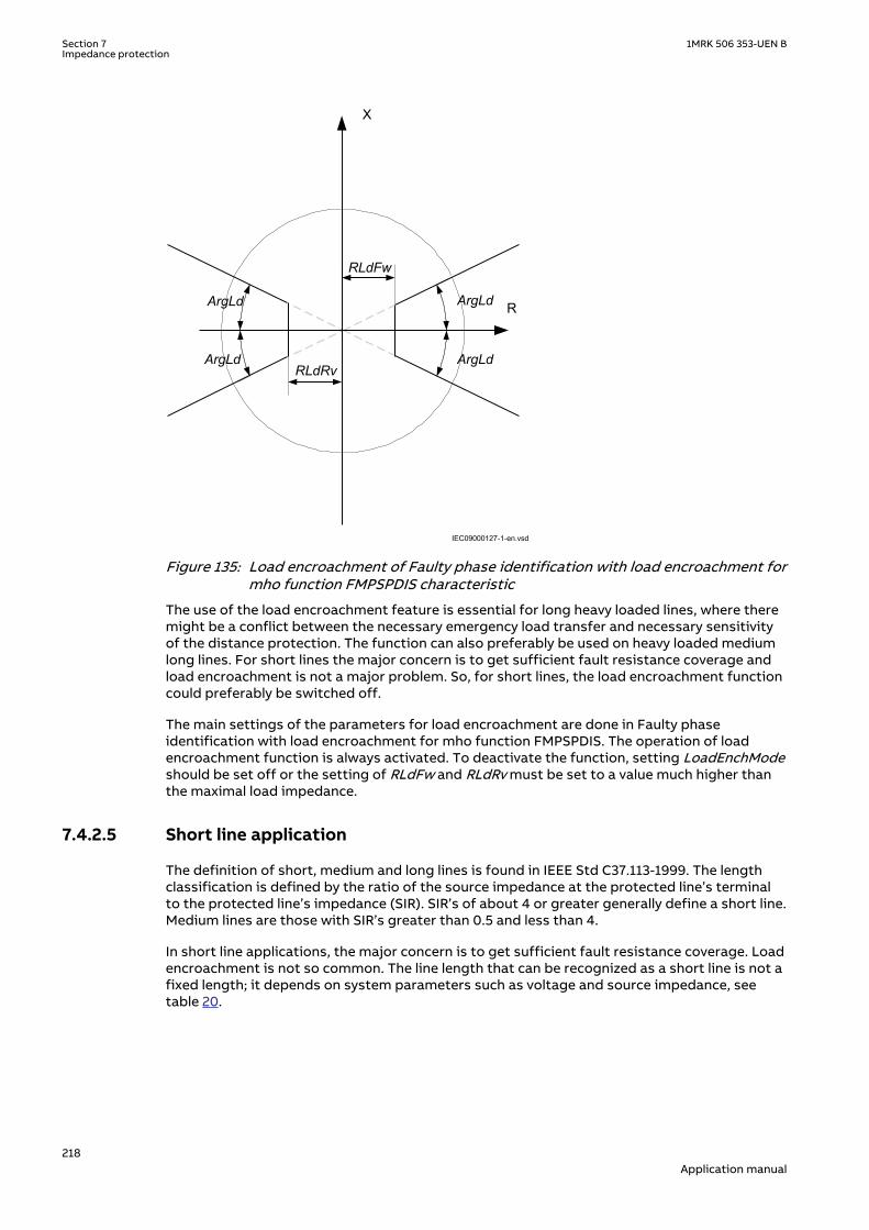
R
X
RLdFw
RLdRvArgLd
ArgLdArgLd
ArgLd
IEC09000127-1-en.vsdIEC09000127 V1 EN-US
Figure 135: Load encroachment of Faulty phase identification with load encroachment formho function FMPSPDIS characteristic
The use of the load encroachment feature is essential for long heavy loaded lines, where theremight be a conflict between the necessary emergency load transfer and necessary sensitivityof the distance protection. The function can also preferably be used on heavy loaded mediumlong lines. For short lines the major concern is to get sufficient fault resistance coverage andload encroachment is not a major problem. So, for short lines, the load encroachment functioncould preferably be switched off.
The main settings of the parameters for load encroachment are done in Faulty phaseidentification with load encroachment for mho function FMPSPDIS. The operation of loadencroachment function is always activated. To deactivate the function, setting LoadEnchModeshould be set off or the setting of RLdFw and RLdRv must be set to a value much higher thanthe maximal load impedance.
7.4.2.5 Short line applicationSEMOD154453-105 v6
The definition of short, medium and long lines is found in IEEE Std C37.113-1999. The lengthclassification is defined by the ratio of the source impedance at the protected line’s terminalto the protected line’s impedance (SIR). SIR’s of about 4 or greater generally define a short line.Medium lines are those with SIR’s greater than 0.5 and less than 4.
In short line applications, the major concern is to get sufficient fault resistance coverage. Loadencroachment is not so common. The line length that can be recognized as a short line is not afixed length; it depends on system parameters such as voltage and source impedance, seetable 20.
Section 7 1MRK 506 353-UEN BImpedance protection
218Application manual

Table 20: Definition of short and very short line
Line category
Un Un110 kV 500 kV
Very short line 1.1-5.5 km 5-25 km
Short line 5-11 km 25-50 km
The use of load encroachment algorithm in Full-scheme distance protection, mhocharacteristic function (ZMHPDIS) improves the possibility to detect high resistive faultswithout conflict with the load impedance (see to the right of figure 134).
For very short line applications the underreaching zone 1 can not be used due to that thevoltage drop distribution through out the line will be too low causing risk for overreaching.
Load encroachment is normally not a problem for short line applications so the loadencroachment function could be switched off meaning LoadEnchMode = Off. This will increasethe possibility to detect resistive close-in faults.
7.4.2.6 Long transmission line applicationSEMOD154453-127 v5
For long transmission lines the load encroachment will normally be a major concern. It is wellknown that it is difficult to achieve high sensitivity for phase-to-earth fault at remote end of along line when the line is heavily loaded.
What can be recognized as long lines with respect to the performance of distance protection isnoted in table 21.
Table 21: Definition of long lines
Line category
Un Un110 kV 500 kV
Long lines 77 km - 99 km 350 km - 450 km
Very long lines > 99 km > 450 km
The possibility to use the binary information from the load encroachment algorithm improvesthe possibility to detect high resistive faults at the same time as the security is improved (riskfor unwanted trip due to load encroachment is eliminated). The possibility to also use theblinder together with the load encroachment algorithm will considerably increase the securitybut might also lower the dependability since the blinder might cut off a larger part of theoperating area of the circle (see to the right of figure 134).
It is recommended to use at least one of the load discrimination functions for long heavyloaded transmission lines.
7.4.2.7 Parallel line application with mutual couplingSEMOD154453-148 v2
GeneralSEMOD154453-150 v4
Introduction of parallel lines in the network is increasing due to difficulties to get necessaryarea for new lines.
Parallel lines introduce an error in the measurement due to the mutual coupling between thelines. The lines need not to be of the same voltage in order to experience mutual coupling, andsome coupling exists even for lines that are separated by 100 meters or more. The reason tothe introduced error in measuring due to mutual coupling is the zero sequence voltageinversion that occurs.
1MRK 506 353-UEN B Section 7Impedance protection
219Application manual

It can be shown from analytical calculations of line impedances that the mutual impedancesfor positive and negative sequence are very small and it is a practice to neglect them.
Mutual coupling effect
The mutual coupling is based on the known induction law, that a current induces a longitudinalvoltage in the parallel circuit.
The induced voltage is:
MU Z I= ×
IECEQUATION14002 V1 EN-US (Equation 174)
E
ZM
I
U
IEC13000253-1-en.vsdIEC13000253 V1 EN-US
Figure 136: Mutual coupling
Mutual induction on three-phase transmission lines
In case of three phase lines, mutual coupling in the positive and negative sequencecomponents is relatively weak and can be neglected. These are of the order of 5% of therelated self-impedance for non-transposed and lower than 3% for transposed lines. The zero-sequence currents are equal and in phase in all the three conductors of the three-phase line. Inthis case, the three-phase conductors can be replaced by a representative single conductor foreach parallel line and the mutual coupling between lines and their earth return wires is thenreduced to a single-phase problem.
E
I
U
IEC13000254-1-en.vsd
O
IO
IO
O
O
IEC13000254 V1 EN-US
Figure 137: Mutual coupling of two three-phase lines
00
0
3 MmZ ZUI
= = ×
IECEQUATION14003 V1 EN-US (Equation 175)
Where ZM is the mutual impedance between two conductors with earth return as definedabove. This zero sequence mutual impedance can be as high as 70% of the self-zero sequenceimpedance of a protected line when the parallel lines are mounted on the same tower. Themutual coupling effect has therefore a strong impact on the earth-fault relaying.
Section 7 1MRK 506 353-UEN BImpedance protection
220Application manual

It can be shown from analytical calculations of line impedances that the mutual impedancesfor positive and negative sequence are very small (< 1-2% of the self impedance) and it is apractice to neglect them.
Classes of networks
From an application point-of-view, there are three types of network configurations (classes)which must be considered when making the settings for the protection function.
The different network configuration classes are:
1. Class 1: Parallel line with common positive and zero-sequence network2. Class 2: Parallel circuits with common positive but isolated or separated zero-sequence
network3. Class 3: Parallel circuits with positive and zero-sequence sources isolated or separated.
One example of class 3 networks could be the mutual coupling between a 400 kV line and railroad overhead lines. This type of mutual coupling is not so common although it exists and isnot treated any further in this manual.
The most used configuration is class 1 network: Parallel circuit with common positive and zero-sequence sources. In this type of networks, the parallel transmission lines terminate atcommon nodes at both ends.
For each type of network class we can have three different topologies; the parallel line can bein service, out of service, out of service and earthed in both ends.
The reach of the distance protection zone 1 will be different depending on the operationcondition of the parallel line. It is therefore recommended to use the different setting groupsto handle the cases when the parallel line is in operation and out of service and earthed at bothends.
Impact on distance protection
Distance relaying of ph-ph and three-phase faults is not influenced by the parallel line. Forprotection of phase-to-earth faults, however a measuring error occurs. In principle, this errorappears due to the fact that the parallel line earth-current (IEP = 3.I0P) induces a voltage IEP.Z0m/3 in to the fault loop.
The distance relay phase-to-earth units measure:
ph
ph N E
ZU
I K I=
+ ×IECEQUATION14004 V1 EN-US (Equation 176)
Where:
Uph is phase to earth short circuit voltage at the relay location inthe faulted phase
Iph is short circuit current in the faulted phase
IE earth current of faulty line
KN is earth compensation factor for single circuit set at the relaygiven by equation
0 1
13NZ ZK
Z=
-×
IECEQUATION14005 V1 EN-US (Equation 177)
1MRK 506 353-UEN B Section 7Impedance protection
221Application manual

The short circuit voltage can be calculated as:
0 1 0 0 1 01 1
1 1
( )3 3 3 3
m mph ph E Ep ph E EpI
Z Z Z Z Z ZU Z I I Z I I IZ Z
=- -
× + × + × = + × + ×
IECEQUATION14006 V1 EN-US (Equation 178)
Where IEp is the ground current in the parallel line.
As explained above, the distance relay phase-to-earth measures:
ph
ph N E
ZU
I K I=
+ ×IECEQUATION14004 V1 EN-US (Equation 179)
0 1 0
1 11
3 3m
ph E Epph
ph n E ph n E
Z
Z Z ZI I IU Z ZZI K I I K I
=
-+ × + ×= ×
+ × + ×IECEQUATION14007 V1 EN-US (Equation 180)
Taking earth compensation factor
0 1
13NZ Z
KZ
-=
for single circuit and
0
13m
NmZ
KZ
= impedance
measured by distance relay can be written as:
1 1 Nm Ep
ph N E
Z ZK I
I K I=
é ù×+ê ú+ ×ê úë û
IECEQUATION14010 V1 EN-US (Equation 181)
Where:
IE earth current of faulty line
IEP is earth current of the parallel line
Z1 is line positive sequence impedance
KN is earth compensation factor for single circuit set at the relaygiven by equation
Z0m is the zero sequence mutual coupling between the faulted andthe parallel line
0 1
13NZ ZK
Z=
-×
IECEQUATION14005 V1 EN-US (Equation 182)
KZ
ZNm
m=⋅
0
13
IEC13000297 V1 EN-US (Equation 183)
Section 7 1MRK 506 353-UEN BImpedance protection
222Application manual

From the above it can be deduced:
• Error is proportional to the mutual coupling factor K0m• The error increases with the parallel line earth current in relation to the relay current• The relay underreaches when IEP is in phase with Iph + KN . IE .
For a remote end terminal fault, this underreaching effect can be as high as 25%.
The distance protection zone reaches vary with the switching state of the parallel lineconfiguration. We consider the three most common operation modes:
1. Case 1: Parallel line out of service and earthed at both ends2. Case 2: Parallel line switched off and not earthed or earthed only at one line end3. Case 3: Both lines in service.
The reach of the distance protection zone 1 will be different depending on the operationcondition of the parallel line.
Compensation of the mutual zero sequence impedance of parallel circuit can be achieved byappropriate selection of zero-sequence compensation factor KN when parallel line can be inservice, out of service, or out of service and earthed at both ends.
Five zone distance protection, mho characteristic function (ZMHPDIS) can compensate for theinfluence of a zero sequence mutual coupling on the measurement at single phase-to-earthfaults in the following two ways, by using:
• Different setting values that influence the earth -return compensation for differentdistance zones within the same group of setting parameters.
• Different groups of setting parameters for different operating conditions of a protectedmulti circuit line.
7.4.2.8 Tapped line applicationSEMOD154453-265 v2
1MRK 506 353-UEN B Section 7Impedance protection
223Application manual

SEMOD154453-267 v4
C
B
BC
IEC09000160-3-en.vsd
A
IEC09000160 V3 EN-US
Figure 138: Example of tapped line with Auto transformer
This application gives rise to similar problem that was highlighted in section "Fault infeedfrom remote end", that is, increased measured impedance due to fault current infeed. Forexample, for faults between the T point and B station the measured impedance at A and C willbe
A CA AT TF
A
I IZ Z Z
I
+= + ×
EQUATION2302 V1 EN-US (Equation 184)
2
A CC Trf CT TF
C
I I U2Z Z Z Z
I U1
+= + + × ×
æ ö æ öç ÷ç ÷ è øè ø
IECEQUATION1750 V1 EN-US (Equation 185)
where
ZAT and ZCT is the line impedance from the A respective C station to the T point.
IA and IC is fault current from A respective C station for fault between T and B.
U2/U1 Transformation ratio for transformation of impedance at U1 side of thetransformer to the measuring side U2 (it is assumed that current and voltagedistance function is taken from U2 side of the transformer).
For this example with a fault between T and B, the measured impedance from the T point tothe fault will be increased by a factor defined as the sum of the currents from T point to thefault divided by the IED current. For the IED at C, the impedance on the high voltage side U1has to be transferred to the measuring voltage level by the transformer ratio.
Another complication that might occur depending on the topology is that the current from oneend can have a reverse direction for fault on the protected line. For example, for faults at T the
Section 7 1MRK 506 353-UEN BImpedance protection
224Application manual

current from B might go in reverse direction from B to C depending on the system parameters(see the dotted line in figure 138), given that the distance protection in B to T will measurewrong direction.
In three-end application, depending on the source impedance behind the IEDs, the impedancesof the protected object and the fault location, it might be necessary to accept zone 2 trip inone end or sequential trip in one end.
Generally for this type of application it is difficult to select settings of zone 1 that both givesoverlapping of the zones with enough sensitivity without interference with other zone 1settings, that is, without selectivity conflicts. Careful fault calculations are necessary todetermine suitable settings and selection of proper scheme communication.
7.4.3 Setting guidelinesSEMOD154496-1 v2
7.4.3.1 GeneralSEMOD154469-4 v7
The settings for Full-scheme distance protection, mho characteristic function (ZMHPDIS) aredone in primary values. The instrument transformer ratio that has been set for the analoginput card is used to automatically convert the measured secondary input signals to primaryvalues used in ZMHPDIS.
The following basics should be considered, depending on application, when doing the settingcalculations:
• Errors introduced by current and voltage instrument transformers, particularly undertransient conditions.
• Inaccuracies in the line zero-sequence impedance data, and their effect on the calculatedvalue of the earth-return compensation factor.
• The effect of infeed between the IED and the fault location, including the influence ofdifferent Z0/Z1 ratios of the various sources.
• The phase impedance of non transposed lines is not identical for all fault loops. Thedifference between the impedances for different phase-to-earth loops can be as large as5-10% of the total line impedance.
• The effect of a load transfer between the terminals of the protected line, the faultresistance is considerable and the effect must be recognized.
• Zero-sequence mutual coupling from parallel lines.
The setting values of all parameters that belong to ZMHPDIS must correspond to theparameters of the protected line and be coordinated to the selectivity plan for the network.
Use different setting groups for the cases when the parallel line is in operation, out of serviceand not earthed and out of service and earthed in both ends. In this way it is possible tooptimize the settings for each system condition.
Appropriate selection of zero sequence compensation factor KNMagx and KNAngx (wherex=1-5) when parallel line can be in service, out of service, or out of service and earthed at bothends.
1MRK 506 353-UEN B Section 7Impedance protection
225Application manual

When Directional impedance element for mho characteristic (ZDMRDIR) is usedtogether with Fullscheme distance protection, mho characteristic (ZMHPDIS)the following settings for parameter DirEvalType in ZDMRDIR is vital:
• alternative Comparator is strongly recommended• alternative Imp/Comp should generally not be used• alternative Impedance should not be used. This alternative is intended for
use together with Distance protection zone, quadrilateral characteristic(ZMQPDIS)
7.4.3.2 Setting of zone 1GUID-4A9FE32F-DA27-401A-ADA1-94060A9F6C76 v1
The zone 1 distance elements must be set to underreach a protected circuit to ensure externalfault security.
The different errors mentioned earlier usually require a limitation of the underreaching zone(normally zone 1) to 75 - 90% of the protected line.
In case of parallel lines, consider the influence of the mutual coupling according to section“Setting of zones for parallel line application” and select the case(s) / options that are valid inthe particular application.
By proper setting it is possible to compensate for the cases when the parallel line is inoperation, out of service and not earthed and out of service and earthed in both ends.
7.4.3.3 Setting of zone 2GUID-5A41709F-8AB2-4A4B-9B3E-3B48EBD0DE0D v1
Zone 2 distance elements must be set according to the following criteria:
• Zone 2 should overreach all terminals of the protected circuit by an acceptable margin(typically 20% of highest impedance seen) for all fault conditions and for all intendedmodes of system operation
• As far as possible, zone 2 reach should be less than zone 1 coverage of all adjacent lines tominimize the required zone 2 time delay setting.
It is necessary to consider the underreaching effects of zero sequence mutual coupling onearth-fault impedance measurement when setting the reach of zone 2 distance protection tomeet the primary reach criterion for parallel circuits.
7.4.3.4 Setting of zone 3GUID-9FAC19EC-3334-4CA5-80A7-4CF8404E9383 v1
Zone 3 distance elements must be set according to the following criteria where possible:
• Zone 3 should overreach the remote terminal of the longest adjacent line by an acceptablemargin (typically 20% of highest impedance seen) for all fault conditions and in feedconditions associated with all intended modes of system operation
• Zone 3 reach should be less than the zone 2 protection coverage of the shortest adjacenttransmission circuit, and it should not see through power transformers into distributionsystems in order to minimize the required zone 3 time delay setting.
7.4.3.5 Setting of reverse zoneGUID-F79912AC-E34A-4A6B-90B4-5F4619613CE5 v1
The criterion for setting zone 4 reverse reach would be as under.
Section 7 1MRK 506 353-UEN BImpedance protection
226Application manual

• The zone 4 reverse reach must adequately cover expected levels of apparent bus bar faultresistance when allowing for multiple in feeds from other circuits.
It is difficult to precisely apply the above criterion and in such cases the practice is to set zone4 reverse reach to about 25% of the associated zone 1 forward reach.
With a reverse reach setting of less than the zone 1 reach of distance protection for theshortest line connected to the local bus bar, the zone 4 time delay would only need to co-ordinate with bus bar main protection fault clearance and with zone 1 fault clearance for linesout of the same substation. This would be according to the zone 2 time setting guidelines.
Parallel line in service
Setting of zones for parallel line applicationGUID-27298DF4-E681-47D4-BD44-709F76B85344 v2
The distance protection zone reaches vary with the switching state of the parallel lineconfiguration. Below the configurations and the corresponding formulas for the reachcalculation are given for the most important cases. In these equations, x stands for ratio ofdistance to fault and length of the line, and Z stands for the impedance seen by the relay.
Case 1: Parallel line switched-off and earthed at both ends:
Z0m
A B
Z< Z<
IEC13000255-1-en.vsd
x Ph-G
IEC13000255 V1 EN-US
Figure 139: The parallel line is out of service and earthed
0 1 0
1 01
1 (
1
)3 Nm
N
mKZ x Z
K
Z Z ZZ Z
+
= ×+
- -×
IECEQUATION14011 V1 EN-US (Equation 186)
Where:
Z1 is line positive sequence impedance
KN is earth compensation factor for single circuit set at the relaygiven by equation
Z0m is the zero sequence mutual coupling between the faulted andthe parallel line
Table continues on next page
1MRK 506 353-UEN B Section 7Impedance protection
227Application manual

x is the ratio of distance to fault and length of the line
0 1
13NZ ZK
Z=
-×
IECEQUATION14005 V1 EN-US (Equation 187)
KZ
ZNm
m=⋅
0
13
IEC13000297 V1 EN-US (Equation 188)
Case 2: Parallel line switched off and not earthed or earthed at one line end
Z0m
A B
Z< Z<
IEC13000256-1-en.vsd
x Ph-G
IEC13000256 V1 EN-US
Figure 140: Parallel line is out of service and not earthed
0 1
11
1
13
N
Z x ZK
Z ZZ
+
= ×+
-
×
IECEQUATION14012 V1 EN-US (Equation 189)
Case 3: Both lines in service
Z0m
A B
Z< Z< IEC13000257-1-en.vsd
x Ph-G
IEC13000257 V1 EN-US
Figure 141: Class 1, parallel line in service
GUID-354B9143-D19E-4835-BCEA-737D7C5E02AA V1 EN-US (Equation 190)
Section 7 1MRK 506 353-UEN BImpedance protection
228Application manual

Some observations from above equations for case 1, 2, and 3GUID-6B411616-EB82-4447-BC2D-375D042BE110 v1
In case 1, the lowest impedance is measured, that is, the highest reach occurs due to theparallel connection of the zero-sequence systems of both lines.
In case 3, the highest impedance is measured, which corresponds to the shortest reach.
The mutual impedance will influence the distance measurement of ground faults and causeeither an extension or a reduction of the reach relative to the set reach.
The maximum overreach will occur when the parallel line is out of service and earthed at bothends. During an earth fault, a counteracting current is induced in the earthed line. The countercurrent will reduce the apparent zero sequence impedance seen by the relay in the faulty line.
When both lines are in service under normal generating conditions, the distance relay willunderreach, but in the case of an extremely weak source behind the relay, an overreach mayoccur. However, this overreach will not cause the relay to operate for faults beyond the end ofthe protected line.
From the operational point-of-view, an extension of the zone 1 beyond the end of the line isnot acceptable.
Alternatives for underreaching and overreaching zonesGUID-A881F22E-D827-4B20-9C0F-477B3A20B0EA v2
As stated earlier, the distance protection within the IED can compensate for the influence of azero sequence mutual coupling on the measurement at single phase-to-earth faults in thefollowing ways, by using:
• Alternative 1: The possibility of different setting values that influence the earth-returncompensation for different distance zones within the same group of setting parameters
• Alternative 2: Different groups of setting parameters for different operating conditions ofa protected multi circuit line.
Alternative 1: Different kN setting values within the same setting groupSetting of underreaching zone
GUID-68709DD6-D5A7-4F04-ACE5-350B1F835364 v1
The set zone should fulfill two criteria:
• It should avoid overreach beyond the remote line terminal in case 1• It should cover as much of the line as possible, at least 50% plus a safety margin in the
most unfavorable case 3.
A possible setting strategy is to set the zone to for example 85% of line length for case 1 andcheck afterwards if sufficient reach exists in the cases 2 and 3.
Setting of zone 1GUID-B0D8E294-C850-4776-B31A-2669D2684C4C v2
For case 1, parallel line having both ends earthed , zone 1 overreach caused by the earthedparallel line can be avoided by the KN factor setting for zone 1 suitably.
The compensation factor KN compensates for the additional loop impedance under earth faultconditions. To eliminate the overreach caused by the earthed parallel line, set the KN1 for thezone 1 as:
0 1 01
1 03m
N NmKZ Z ZK
Z Z=
--
IECEQUATION14018 V1 EN-US (Equation 191)
This KN1 setting for zone 1 only affects the reach for earth faults while the reach for two andthree-phase faults are unaffected.
1MRK 506 353-UEN B Section 7Impedance protection
229Application manual

For case 2, when the parallel line is out of operation but not earthed, the zone 1 nominal reachfor earth faults is reduced. The measured impedance can be calculated:
1
0 1
11
1
13
N
Z x ZK
Z ZZ
+
= ×+
-
×
IECEQUATION14015 V1 EN-US (Equation 192)
The reduced reach must be taken into account when using a permissive underreachingscheme.
For case 3, when the parallel line is in service, the reach for earth faults can further reducebecause of the mutual coupling. The measured impedance can be calculated:
1
0 1
11
1
13 2
N
Nm
Z x ZK
Z Z x KZ x
+
= ×+
- +-×
IECEQUATION14014 V1 EN-US (Equation 193)
This reduction of the reach is most pronounced with no in-feed in the line terminal nearestfault. When the reach is reduced at one line end, it is extended in the opposite one. Therefore,this reach reduction does not affect a permissive underreaching scheme.
Setting of overreaching zoneGUID-1C500D3E-12A2-4F0F-A5A8-A8054677DF4D v1
Zone 1 is not allowed to overreach under any condition. Overreaching zones 2 and 3 are notallowed to underreach the whole line under any condition.
Setting of zone 2GUID-DB83C2EF-A40F-4E18-BFC5-D617CE0C0438 v2
The overreaching zone 2 for backup or permissive overreaching distance protection schemesmust at least safely cover 100% of the line with a safety margin of about 20%. This must beguaranteed for the most unfavorable condition of case 3.
The earth-fault compensation factor must be adjusted to the case of parallel line in service(case 3) where the highest earth-fault impedance occurs.
0 12
13N NmKZ Z K
Z=
--
IECEQUATION14019 V1 EN-US (Equation 194)
For case 1, the measured impedance can be calculated by the following expression:
2
0 1 0
1 01
1 (
1
)3
N
mNm
Z x ZK
Z Z ZKZ Z
+
= ×+
- -×
IECEQUATION14017 V1 EN-US (Equation 195)
For case 2, the measured impedance can be calculated by the following expression:
Section 7 1MRK 506 353-UEN BImpedance protection
230Application manual

2
0 1
11
1
13
N
Z x ZK
Z ZZ
+
= ×+
-
×
IECEQUATION14016 V1 EN-US (Equation 196)
For both case 1 and 2, the overreach would be much higher. For case 3, the function measuresthe correct impedance.
The normal influence of infeeds is to be added to these influences of the mutual coupling forsetting of remote backup zones.
Setting of zone 3GUID-3F20E209-A29C-4D16-84AB-F0594DC10AC0 v1
The reach of zone 3 is affected as well, but when zone is normally set with sufficient margin toalways overreach the remote line end, KN3 for zone 3 can be set as for a single line, that is:
0 13
13NKZ Z
Z=
-
IECEQUATION14020 V1 EN-US (Equation 197)
Alternative 2: Different groups of setting parameters for different operating conditions of aprotected multi circuit line
GUID-DB67F163-289C-40C6-A850-074FFE61DEBC v2
Different group of setting parameters can be used for the three cases:
• Parallel line switched off and earthed at both ends• Parallel line switched off and not earthed or earthed at only one end• Both lines in service.
With this method of setting the zero sequence compensation factor KN can for zone 1 and zone2 be even better adapted for the real system conditions.
The table describes earth-fault compensation settings to be adopted for different groups.
Table 22: Different groups of settings
Group Operation mode Zone 1 and Zone 2 Zone 3 and Reverse Zone
Group1 Case 1: Parallelline switched offand earthed atboth ends
0 1 01
1 03m
N NmKZ Z ZK
Z Z=
-- 0 1
13NZ ZK
Z=
-×
Group2 Case 2: Parallelline switched offand not earthedor earthed at onlyone end
0 1
13NZ ZK
Z=
-×
0 1
13NZ ZK
Z=
-×
Group3 Both lines inservice 0 1
13N NmKZ Z K
Z=
-- 0
3L L
NL
KZ Z
Z=
-
For a discussion on other options of settings, refer to CIGRE SC34 report, WG-04 November1991 “Application guide on protection of complex transmission network configuration”.
1MRK 506 353-UEN B Section 7Impedance protection
231Application manual

7.4.3.6 Consideration of zero sequence mutual coupling for parallel circuitsGUID-D25BD616-CED9-4B82-8958-F90C4F819692 v1
For both zone 2 and zone 3 elements, the underreaching effect of zero sequence mutualcoupling for remote earth faults must also be considered in relation to the primary reachsetting criterion.
7.4.3.7 Load impedance limitation, without load encroachment functionSEMOD154469-91 v5
The following instruction is valid when the load encroachment function or blinder function isnot activated (BlinderMode=Off).The load encroachment function will not be activated ifRLdFw and RLdRv is set to a value higher than expected minimal load impedance. If the loadencroachment or blinder function is to be used for all or some of the measuring zones, theload limitation for those zones according to this chapter can be omitted. Check the maximumpermissible resistive reach for any zone to ensure that there is a sufficient setting marginbetween the relay boundary and the minimum load impedance. The minimum load impedance(Ω/phase) is calculated as:
Z loadminU2
S-------=
EQUATION571 V1 EN-US (Equation 198)
Where:
U is the minimum phase-to-phase voltage in kV
S is the maximum apparent power in MVA.
The load impedance [Ω/phase] is a function of the minimum operation voltage and themaximum load current:
Z loadUmin
3 Imax×----------------------=
EQUATION574 V1 EN-US (Equation 199)
Minimum voltage Umin and maximum current Imax are related to the same operatingconditions. Minimum load impedance occurs normally under emergency conditions.
To avoid load encroachment for the phase-to-earth measuring elements, the set impedancereach of any distance protection zone must be less than 80% of the minimum load impedance.
For setting of the earth-fault loop, the following formula can be used:
LoadZZPE 1.6
2(1 cos( ))b£ ×
-
EQUATION1604 V1 EN-US (Equation 200)
where:
Zload = magnitude of minimum load impedance
ZPE = 180°-2·g =180°–2(ArgPE-QLoad)
Section 7 1MRK 506 353-UEN BImpedance protection
232Application manual

The formula is derived by trigonometric analyze of the figure 142. The length of the vectorfrom the origin O to the point F on the circle is defined by the law of cosine. The result givesthe maximum diameter (RFPE) for which the load impedance touch the circle with the givenload condition. Use an extra margin of 20% to give sufficient distance between the calculatedminimum load impedance and relay boundary.
jX
R
ZPE/2
ßArgLd
(Ref)
?
O
rc
F
φ
Load
|Zload||Zload|/2 Ohm/phase
en06000406.vsdIEC06000406 V1 EN-US
Figure 142: Definition of the setting condition to avoid load encroachment for earth-faultloop
The maximum setting for phase-to-phase fault can be defined by trigonometric analyze of thesame figure 142. The formula to avoid load encroachment for the phase-to-phase measuringelements will thus be according to equation 201.
LoadZZPP 1.6
2 (1 cos( PP))j£ ×
× -EQUATION1605 V1 EN-US (Equation 201)
where:
jPP = 180°–2·(ArgPP-QLoad)
All this is applicable for all measuring zones when no power swing detection element or blinderis activated for the protection zones. Use an additional safety margin of approximately 20% incases when a power swing detection element is in the protection scheme, refer to thedescription of the power swing detection function.
7.4.3.8 Load impedance limitation, with load encroachment function activatedSEMOD154469-129 v3
The parameters for load encroachment shaping of the characteristic are found in thedescription of Faulty phase identification with load encroachment for mho (FMPSPDIS), referto section "Load encroachment characteristics".
1MRK 506 353-UEN B Section 7Impedance protection
233Application manual

7.4.3.9 Setting of minimum operate currentsSEMOD154469-132 v5
The operation of the distance function will be blocked if the magnitude of the currents isbelow the set value of the parameter IMinOpPP and IMinOpPE.
The default setting of IMinOpPP and IMinOpPE is 20% of IBase where IBase is the chosen basecurrent for the analog input channels. The values have been proven in practice to be suitable inmost of the applications. However, there might be applications where it is necessary toincrease the sensitivity by reducing the minimum operate current down to 10% of IBase.
The minimum operate fault current is automatically reduced to 75% of its set value, if thedistance protection zone has been set for the operation in reverse direction.
7.4.3.10 Setting of directional modeSEMOD154469-176 v3
Setting of the directional mode is by default set to forward by setting the parameter DirModeto Forward.
The selection of Offset mho can be used for sending block signal in blocking teleprotectionscheme, switch onto fault application and so on.
The Reverse mode might be use in comparison schemes where it is necessary to absolutediscriminate between forward and reverse fault.
7.4.3.11 Setting of direction for offset mhoSEMOD154469-181 v3
If offset mho has been selected, one can select if the offset mho shall be Non-Directional,Forward or Reverse by setting the parameter OfffsetMhoDir.
When forward or reverse operation is selected, then the operation characteristic will be cut offby the directional lines used for the mho characteristic. The setting is by default set to Non-Directional.
7.4.3.12 Setting of timers for distance protection zonesSEMOD154469-138 v7
The required time delays for different distance protection zones are independent of eachother. Distance protection zone 1 can also have a time delay if so required for selectivityreasons. One can set the time delays for all zones in a range of 0 to 60 seconds. The trippingfunction of each particular zone can be inhibited by setting the corresponding Operationparameter to Off.
Different time delays are possible for the phase-to-earth tPE and for the phase-to-phase tPPmeasuring loops in each distance protection zone separately, to further increase the totalflexibility of a distance protection.
In the case of evolving faults or momentary current transformer saturation conditions, the pickup of the zones may get delayed. Zone timer logic improves the operating time in suchconditions. The zone timer logic can be set using the parameter ZnTimerSel. The triggeringsignal of phase-to-earth and phase-to-phase timers can be selected using ZnTimerSel.
Section 7 1MRK 506 353-UEN BImpedance protection
234Application manual

7.5 Full-scheme distance protection, quadrilateral forearth faults ZMMPDIS, ZMMAPDIS
SEMOD154561-1 v2
7.5.1 IdentificationSEMOD154542-2 v2
Function description IEC 61850identification
IEC 60617identification
ANSI/IEEE C37.2device number
Fullscheme distance protection,quadrilateral for earth faults (zone 1)
ZMMPDIS
S00346 V1 EN-US
21
Fullscheme distance protection,quadrilateral for earth faults (zone2-5)
ZMMAPDIS
S00346 V1 EN-US
21
7.5.2 ApplicationSEMOD154697-1 v1
7.5.2.1 IntroductionSEMOD154680-4 v2
Sub transmission networks are being extended and often become more and more complex,consisting of a high number of multi-circuit and/or multi terminal lines of very differentlengths. These changes in the network will normally impose more stringent demands on thefault clearing equipment in order to maintain an unchanged or increased security level of thepower system.
The distance protection function in IED is designed to meet basic requirements for applicationon transmission and sub transmission lines (solid earthed systems) although it also can beused on distribution levels.
7.5.2.2 System earthingSEMOD154680-11 v2
The type of system earthing plays an important roll when designing the protection system. Inthe following some hints with respect to distance protection are highlighted.
Solid earthed networksSEMOD154680-14 v3
In solid earthed systems the transformer neutrals are connected solidly to earth without anyimpedance between the transformer neutral and earth.
IEC05000215 V2 EN-US
Figure 143: Solidly earthed network
The earth fault current is as high or even higher than the short-circuit current. The seriesimpedances determine the magnitude of the earth fault current. The shunt admittance has
1MRK 506 353-UEN B Section 7Impedance protection
235Application manual

very limited influence on the earth fault current. The shunt admittance may, however, havesome marginal influence on the earth fault current in networks with long transmission lines.
The earth fault current at single phase-to-earth in phase L1 can be calculated as equation202:
L1 L10
1 2 0 f 1 N f
3 U U3I
Z Z Z 3Z Z ZZ
×= =
+ + + + +EQUATION1267 V3 EN-US (Equation 202)
Where:
UL1 is the phase-to-earth voltage (kV) in the faulty phase beforefault
Z1 is the positive sequence impedance (Ω/phase)
Z2 is the negative sequence impedance (Ω/phase)
Z0 is the zero sequence impedance (Ω/phase)
Zf is the fault impedance (Ω), often resistive
ZN is the earth return impedance defined as (Z0-Z1)/3
The voltage on the healthy phases is generally lower than 140% of the nominal phase-to-earthvoltage. This corresponds to about 80% of the nominal phase-to-phase voltage.
The high zero sequence current in solid earthed networks makes it possible to use impedancemeasuring technique to detect earth fault. However, distance protection has limitedpossibilities to detect high resistance faults and should therefore always be complementedwith other protection function(s) that can carry out the fault clearance in those cases.
Effectively earthed networksSEMOD154680-40 v4
A network is defined as effectively earthed if the earth fault factor fe is less than 1.4. The earthfault factor is defined according to equation 203.
fU
Ue
pn
=max
EQUATION1268 V4 EN-US (Equation 203)
Where:
Umax is the highest fundamental frequency voltage on one of the healthy phases at singlephase-to-earth fault.
Upn is the phase-to-earth fundamental frequency voltage before fault.
Another definition for effectively earthed network is when the following relationships betweenthe symmetrical components of the network impedances are valid, see equation 204 andequation 205.
X X0 13≤ ⋅EQUATION1269 V4 EN-US (Equation 204)
Section 7 1MRK 506 353-UEN BImpedance protection
236Application manual

R X£0 1
EQUATION1270 V4 EN-US (Equation 205)
The magnitude of the earth fault current in effectively earthed networks is high enough forimpedance measuring element to detect fault. However, in the same way as for solid earthednetworks, distance protection has limited possibilities to detect high resistance faults andshould therefore always be complemented with other protection function(s) that can carry outthe fault clearance in this case.
High impedance earthed networksSEMOD154680-58 v3
In high impedance networks the neutral of the system transformers are connected to the earththrough high impedance, mostly a reactance in parallel with a high resistor.
This type of network is many times operated in radial, but can also be found operatingmeshed.
Typically, for this type of network is that the magnitude of the earth fault current is very lowcompared to the short circuit current. The voltage on the healthy phases will get a magnitudeof √3 times the phase voltage during the fault. The zero sequence voltage (3U0) will have thesame magnitude in different places in the network due to low voltage drop distribution.
The magnitude of the total fault current can be calculated according to the formula below:
( )22R L C03I I I I= + -
EQUATION1271 V3 EN-US (Equation 206)
Where:
3I0 is the earth-fault current (A)
IR is the current through the neutral point resistor (A)
IL is the current through the neutral point reactor (A)
IC is the total capacitive earth-fault current (A)
The neutral point reactor is normally designed so that it can be tuned to a position where thereactive current balances the capacitive current from the network that is:
13
LC
ww
=× ×
EQUATION1272 V1 EN-US (Equation 207)
1MRK 506 353-UEN B Section 7Impedance protection
237Application manual

IEC05000216 V2 EN-US
Figure 144: High impedance earthing network
The operation of high impedance earthed networks is different compare to solid earthednetworks where all major faults have to be cleared very fast. In high impedance earthednetworks, some system operators do not clear single phase-to-earth faults immediately; theyclear the line later when it is more convenient. In case of cross country faults, many networkoperators want to selectively clear one of the two earth-faults. To handle this type phenomenaa separate function called Phase preference logic (PPLPHIZ) is needed, which is not commonto be used in transmission applications.
In this type of network, it is mostly not possible to use distance protection for detection andclearance of earth-faults. The low magnitude of the earth-fault current might not give start ofthe zero sequence measurement element or the sensitivity will be too low for acceptance. Forthis reason a separate high sensitive earth-fault protection is necessary to carry out the faultclearance for single phase-to-earth fault.
7.5.2.3 Fault infeed from remote endSEMOD154680-84 v2
All transmission and most all sub transmission networks are operated meshed. Typical for thistype of network is that we will have fault infeed from remote end when fault occurs on theprotected line. The fault infeed will enlarge the fault impedance seen by the distanceprotection. This effect is very important to keep in mind when both planning the protectionsystem and making the settings.
With reference to figure 145, we can draw the equation for the bus voltage Va at left side as:
( )A A L A B fV I p Z I I R= × × + + ×EQUATION1273 V1 EN-US (Equation 208)
If we divide Va by IA we get Z present to the IED at A side
a A BA L f
A A
V I IZ p Z R
I I
+= = × + ×
EQUATION1274 V2 EN-US (Equation 209)
The infeed factor (IA+IB)/IA can be very high, 10-20 depending on the differences in sourceimpedances at local and remote end.
Section 7 1MRK 506 353-UEN BImpedance protection
238Application manual

Z <
ZL
Z <
EsAVA VAA B EsB
IA IB
Rf
p*ZL (1-p)*ZLZSA ZSB
en05000217.vsdIEC05000217 V1 EN-US
Figure 145: Influence of fault infeed from remote end.
The effect of fault current infeed from remote end is one of the most driving factors for justifycomplementary protection to distance protection.
7.5.2.4 Load encroachmentSEMOD154680-97 v3
In some cases the load impedance might enter the zone characteristic without any fault on theprotected line. The phenomenon is called load encroachment and it might occur when anexternal fault is cleared and high emergency load is transferred on the protected line. Theeffect of load encroachment is illustrated to the left in figure 146. The entrance of the loadimpedance inside the characteristic is of cause not allowed and the way to handle this withconventional distance protection is to consider this with the settings that is, to have a securitymargin between the distance zone and the minimum load impedance. This has the drawbackthat it will reduce the sensitivity of the protection that is, the ability to detect resistive faults.
The IED has a built in function which shapes the characteristic according to the right figure 4.The load encroachment algorithm will increase the possibility to detect high fault resistances,especially for phase-to-earth faults at remote end. For example for a given setting of the loadangle ARGLd for the load encroachment function, the resistive blinder for the zonemeasurement can be expanded according to the right in figure 146 given higher faultresistance coverage without risk for unwanted operation due to load encroachment. This isvalid in both directions.
The use of the load encroachment feature is essential for long heavy loaded lines, where theremight be a conflict between the necessary emergency load transfer and necessary sensitivityof the distance protection. ZMMPDIS function can also preferably be used on heavy loadedmedium long lines. For short lines the major concern is to get sufficient fault resistancecoverage and load encroachment is not a major problem. So, for short lines, the loadencroachment function could preferable be switched off.
The settings of the parameters for load encroachment are done in the Phase selection withload enchroachment, quadrilateral characteristic (FDPSPDIS).
1MRK 506 353-UEN B Section 7Impedance protection
239Application manual

R
X
Zm
Load impedancearea in forward
direction
RLdRv
R
Zm
ARGLdARGLd
ARGLd ARGLd
RLdFw
ZL
en05000495.vsdIEC05000495 V1 EN-US
Figure 146: Load encroachment phenomena and shaped load encroachmentcharacteristic
7.5.2.5 Short line applicationSEMOD154680-105 v2
In short line applications, the major concern is to get sufficient fault resistance coverage. Loadencroachment is not so common. The line length that can be recognized as a short line is not afixed length; it depends on system parameters such as voltage and source impedance, seetable "Short line application".
Table 23: Definition of short and very short line
Line category
Un Un
110 kV 500 kV
Very short lineShort line
1.1-5.5 km 5-25 km
5.5-11 km 25-50 km
The possibility in IED to set resistive and reactive reach independent for positive and zerosequence fault loops and individual fault resistance settings for phase-to-phase and phase-to-earth fault together with load encroachment algorithm improves the possibility to detect highresistive faults without conflict with the load impedance, see figure 146.
For very short line applications the underreaching zone 1 can not be used due to that thevoltage drop distribution through out the line will be too low causing risk for overreaching.
Load encroachment is normally no problems for short line applications so the loadencroachment function could be switched off (OperationLdCmp = Off). This will increase thepossibility to detect resistive close-in faults.
7.5.2.6 Long transmission line applicationSEMOD154680-127 v2
For long transmission lines the margin to the load impedance that is, to avoid loadencroachment, will normally be a major concern. It is difficult to achieve high sensitivity forphase-to-earth fault at remote end of a long lines when the line is heavy loaded.
The definition of long lines with respect to the performance of distance protection is noted intable 24.
Section 7 1MRK 506 353-UEN BImpedance protection
240Application manual

Table 24: Definition of long lines
Line category
Un Un110 kV 500 kV
Long lines 77 km - 99 km 350 km - 450 km
Very long lines > 99 km > 450 km
As mentioned in the previous chapter, the possibility in IED to set resistive and reactive reachindependent for positive and zero sequence fault loops and individual fault resistance settingsfor phase-to-phase and phase-to-earth fault together with load encroachment algorithmimproves the possibility to detect high resistive faults at the same time as the security isimproved (risk for unwanted trip due to load encroachment is eliminated).
7.5.2.7 Parallel line application with mutual couplingSEMOD154680-148 v1
GeneralSEMOD154680-150 v2
Introduction of parallel lines in the network is increasing due to difficulties to get necessaryarea for new lines.
Parallel lines introduce an error in the measurement due to the mutual coupling between theparallel lines. The lines need not to be of the same voltage in order to experience mutualcoupling, and some coupling exists even for lines that are separated by 100 meters or more.The reason to the introduced error in measuring due to mutual coupling is the zero sequencevoltage inversion that occurs.
It can be shown from analytical calculations of line impedances that the mutual impedancesfor positive and negative sequence are very small (< 1-2%) of the self impedance and it ispractice to neglect them.
From an application point of view there exists three types of network configurations (classes)that must be considered when making the settings for the protection function. Those are:
1. Parallel line with common positive and zero sequence network2. Parallel circuits with common positive but isolated zero-sequence network3. Parallel circuits with positive and zero sequence sources isolated.
One example of class3 networks could be the mutual coupling between a 400 kV line and railroad overhead lines. This type of mutual coupling is not so common although it exists and isnot treated any further in this manual.
For each type of network class we can have three different topologies; the parallel line can bein service, out of service, out of service and earthed in both ends.
The reach of the distance protection zone1 will be different depending on the operationcondition of the parallel line. It is therefore recommended to use the different setting groupsto handle the cases when the parallel line is in operation and out of service and earthed at bothends.
The distance protection within the IED can compensate for the influence of a zero-sequencemutual coupling on the measurement at single phase-to-earth faults in the following ways, byusing:
• The possibility of different setting values that influence the earth-return compensationfor different distance zones within the same group of setting parameters.
• Different groups of setting parameters for different operating conditions of a protectedmulti circuit line.
1MRK 506 353-UEN B Section 7Impedance protection
241Application manual

Most multi circuit lines have two parallel operating circuits. The application guide mentionedbelow recommends in more detail the setting practice for this particular type of line. The basicprinciples also apply to other multi circuit lines.
Parallel line applicationsSEMOD154680-168 v2
This type of networks are defined as those networks where the parallel transmission linesterminate at common nodes at both ends. We consider the three most common operationmodes:
1. parallel line in service.2. parallel line out of service and earthed.3. parallel line out of service and not earthed.
Parallel line in serviceSEMOD154680-175 v2
This type of application is very common and applies to all normal sub-transmission andtransmission networks.
A simplified single line diagram is shown in figure 147.
ph ph
0 1 ph N
ph 0
1
0
V V
Z Z I 3 KI 3I
3 Z
IZ = =
- + ×+ ×
×EQUATION1275 V3 EN-US (Equation 210)
Where:
Vph is phase-to-earth voltage at the IED point
Iph is phase current in the faulty phase
3I0 is earth to fault current
Z1 is positive sequence impedance
Z0 is zero sequence impedance
Z0m
A B
Z< Z< en05000221.vsd
IEC05000221 V1 EN-US
Figure 147: Class 1, parallel line in service.
The equivalent circuit of the lines can be simplified, see figure 148.
Section 7 1MRK 506 353-UEN BImpedance protection
242Application manual

A
B
CZ0m
Z0Z0 m-
Z0Z0 m-
99000038.vsdIEC99000038 V1 EN-US
Figure 148: Equivalent zero sequence impedance circuit of the double-circuit, parallel,operating line with a single phase-to-earth fault at the remote busbar
When mutual coupling is introduced, the voltage at the IED point A will be changed.
If the current on the parallel line have negative sign compare to the current on the protectedline that is, the current on the parallel line has an opposite direction compare to the current onthe protected line, the distance function will overreach. If the currents have the same direction,the distance protection will underreach.
Calculation for a 400 kV line, where we for simplicity have excluded the resistance, gives withX1L=0.303 Ω/km, X0L=0.88 Ω/km, zone 1 reach is set to 90% of the line reactance p=71% thatis, the protection is underreaching with approximately 20%.
The zero-sequence mutual coupling can reduce the reach of distance protection on theprotected circuit when the parallel line is in normal operation. The reduction of the reach ismost pronounced with no infeed in the line IED closest to the fault. This reach reduction isnormally less than 15%. But when the reach is reduced at one line end, it is proportionallyincreased at the opposite line end. So this 15% reach reduction does not significantly affectthe operation of a permissive under-reach scheme.
Parallel line out of service and earthedSEMOD154680-226 v2SEMOD154680-228 v1
Z0m
A B
Z< Z<en05000222.vsd
DOCUMENT11520-IMG867 V1 EN-US
Figure 149: The parallel line is out of service and earthed.
When the parallel line is out of service and earthed at both ends on the bus bar side of the lineCT so that zero sequence current can flow on the parallel line, the equivalent zero sequencecircuit of the parallel lines will be according to figure 149.
1MRK 506 353-UEN B Section 7Impedance protection
243Application manual

Z Z0 m0
Z Z0 m0
Zm0
A
B
C
99000039.vsd
I0
I0
DOCUMENT11520-IMG7100 V1 EN-US
Figure 150: Equivalent zero-sequence impedance circuit for the double-circuit line thatoperates with one circuit disconnected and earthed at both ends.
Here the equivalent zero sequence impedance is equal to Z0-Z0m in parallel with (Z0-Z0m)/Z0-Z0m+Z0m which is equal to equation 211.
2 2
0
0
omE
Z ZZ
Z
-=
EQUATION2002 V4 EN-US (Equation 211)
The influence on the distance measurement will be a considerable overreach, which must beconsidered when calculating the settings. It is a recommendation to use a separate settinggroup for this operation condition since it will reduce the reach considerable when the line is inoperation. All expressions below are proposed for practical use. They assume the value of zerosequence, mutual resistance R0m equals to zero. They consider only the zero-sequence, mutualreactance X0m. Calculate the equivalent X0E and R0E zero-sequence parameters according toequation 212 and equation 213 for each particular line section and use them for calculating thereach for the underreaching zone.
R RX
R XE
m0 0
0
2
0
2
0
21= ⋅ +
+
DOCUMENT11520-IMG3502 V2 EN-US (Equation 212)
X XX
R XE
m0 0
0
2
0
2
0
21= ⋅ −
+
DOCUMENT11520-IMG3503 V2 EN-US (Equation 213)
Parallel line out of service and not earthedSEMOD154680-242 v2
Z0m
A B
Z< Z<en05000223.vsd
IEC05000223 V1 EN-US
Figure 151: Parallel line is out of service and not earthed.
Section 7 1MRK 506 353-UEN BImpedance protection
244Application manual

When the parallel line is out of service and not earthed, the zero sequence on that line can onlyflow through the line admittance to the earth. The line admittance is high which limits the zerosequence current on the parallel line to very low values. In practice, the equivalent zerosequence impedance circuit for faults at the remote bus bar can be simplified to the circuitshown in figure 151
The line zero-sequence mutual impedance does not influence the measurement of the distanceprotection in a faulty circuit. This means that the reach of the underreaching distanceprotection zone is reduced if, due to operating conditions, the equivalent zero sequenceimpedance is set according to the conditions when the parallel system is out of operation andearthed at both ends.
Z Z00 m
Z Z00 m
Z0m
A
B
C
99000040.vsd
I0
I0
IEC99000040 V1 EN-US
Figure 152: Equivalent zero-sequence impedance circuit for a double-circuit line with onecircuit disconnected and not earthed.
The reduction of the reach is equal to equation 214.
( )( ) ( )
21 0
0
1 001 0
1 23 11 2 323
E fm
U
ff
Z Z R ZKZ Z Z RZ Z R
× × + += = -
× × + +× × + +
EQUATION1284 V1 EN-US (Equation 214)
This means that the reach is reduced in reactive and resistive directions. If the real andimaginary components of the constant A are equal to equation 215 and equation 216.
Re( ) 0 (2 1 0 3 ) 0 ( 0 2 1)A R R R Rf X X X= × × + + × - × + ×EQUATION1285 V1 EN-US (Equation 215)
0 1 0 1 0 1 0Im( ) (2 3 ) (2 )A X R R R R X X= × × + + × + × × +EQUATION1286 V1 EN-US (Equation 216)
The real component of the KU factor is equal to equation 217.
Re
Re
Re Im
KA X
A A
u
m
( ) = +( ) ⋅
( )
+ ( )
1
0
2
2 2
EQUATION1287 V3 EN-US (Equation 217)
The imaginary component of the same factor is equal to equation 218.
1MRK 506 353-UEN B Section 7Impedance protection
245Application manual
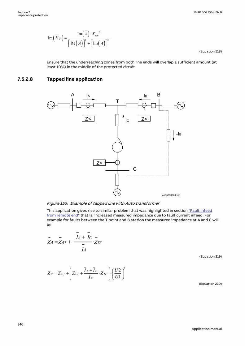
( ) ( )( ) ( )
20
2 2
ImIm
Re Im
mU
A XK
A A
×=
+é ù é ùë û ë ûEQUATION1288 V2 EN-US (Equation 218)
Ensure that the underreaching zones from both line ends will overlap a sufficient amount (atleast 10%) in the middle of the protected circuit.
7.5.2.8 Tapped line applicationSEMOD154680-265 v1
SEMOD154680-267 v2
A B
Z< Z<
Z<C
T
IC
IA IB
-IB
en05000224.vsdDOCUMENT11524-IMG869 V1 EN-US
Figure 153: Example of tapped line with Auto transformer
This application gives rise to similar problem that was highlighted in section "Fault infeedfrom remote end" that is, increased measured impedance due to fault current infeed. Forexample for faults between the T point and B station the measured impedance at A and C willbe
ZA =ZAT + ·ZTFIA + IC
IADOCUMENT11524-IMG3509 V3 EN-US (Equation 219)
Z Z ZI I
IZ
U
UC Trf CT
A C
C
TF= + ++
⋅
⋅
2
1
2
DOCUMENT11524-IMG3510 V3 EN-US (Equation 220)
Section 7 1MRK 506 353-UEN BImpedance protection
246Application manual

Where:
ZAT and ZCT is the line impedance from the B respective C station to the T point.
IA and IC is fault current from A respective C station for fault between T and B.
U2/U1 Transformation ratio for transformation of impedance at U1 side of thetransformer to the measuring side U2 (it is assumed that current and voltagedistance function is taken from U2 side of the transformer).
For this example with a fault between T and B, the measured impedance from the T point tothe fault will be increased by a factor defined as the sum of the currents from T point to thefault divided by the IED current. For the IED at C, the impedance on the high voltage side U1has to be transferred to the measuring voltage level by the transformer ratio.
Another complication that might occur depending on the topology is that the current from oneend can have a reverse direction for fault on the protected line. For example for faults at T thecurrent from B might go in reverse direction from B to C depending on the system parameters(see the dotted line in figure 153), given that the distance protection in B to T will measurewrong direction.
In three-end application, depending on the source impedance behind the IEDs, the impedancesof the protected object and the fault location, it might be necessary to accept zone2 trip in oneend or sequential trip in one end.
Generally for this type of application it is difficult to select settings of zone1 that both givesoverlapping of the zones with enough sensitivity without interference with other zone1settings that is, without selectivity conflicts. Careful fault calculations are necessary todetermine suitable settings and selection of proper scheme communication.
Fault resistanceSEMOD154680-288 v2
The performance of distance protection for single phase-to-earth faults is very important,because normally more than 70% of the faults on transmission lines are single phase-to-earthfaults. At these faults, the fault resistance is composed of three parts: arc resistance,resistance of a tower construction, and tower-footing resistance. The arc resistance can becalculated according to Warrington's formula:
1.428707 LRarc
I×
=
EQUATION1456 V1 EN-US (Equation 221)
where:
L represents the length of the arc (in meters). This equation applies for the distance protection zone 1.Consider approximately three-times arc foot spacing for the zone 2 and wind speed of approximately50 km/h
I is the actual fault current in A.
In practice, the setting of fault resistance for both phase-to-earth (RFPE) and phase-to-phase(RFPP) should be as high as possible without interfering with the load impedance in order toobtain reliable fault detection.
1MRK 506 353-UEN B Section 7Impedance protection
247Application manual

7.5.3 Setting guidelinesSEMOD154701-1 v1
7.5.3.1 GeneralSEMOD154704-4 v2
The settings for the Full-scheme distance protection, quadrilateral for earth faults (ZMMPDIS)function are done in primary values. The instrument transformer ratio that has been set for theanalogue input card is used to automatically convert the measured secondary input signals toprimary values used in ZMMPDIS function.
The following basics should be considered, depending on application, when doing the settingcalculations:
• Errors introduced by current and voltage instrument transformers, particularly undertransient conditions.
• Inaccuracies in the line zero-sequence impedance data, and their effect on the calculatedvalue of the earth-return compensation factor.
• The effect of infeed between the IED and the fault location, including the influence ofdifferent Z0/Z1 ratios of the various sources.
• The phase impedance of non transposed lines is not identical for all fault loops. Thedifference between the impedances for different phase-to-earth loops can be as large as5-10% of the total line impedance.
• The effect of a load transfer between the IEDs of the protected fault resistance isconsiderable, the effect must be recognized.
• Zero-sequence mutual coupling from parallel lines.
7.5.3.2 Setting of zone1SEMOD154704-15 v1
The different errors mentioned earlier usually require a limitation of the underreaching zone(normally zone 1) to 75 - 90% of the protected line.
In case of parallel lines, consider the influence of the mutual coupling accordingtosection"Parallel line application with mutual coupling" and select the case(s) that are valid inyour application. We recommend to compensate setting for the cases when the parallel line isin operation, out of service and not earthed and out of service and earthed in both ends. Thesetting of earthed fault reach should be selected to be <95% also when parallel line is out ofservice and earthed at both ends (worst case).
7.5.3.3 Setting of overreaching zoneSEMOD154704-19 v4
The first overreaching zone (normally zone2) must detect faults on the whole protected line.Considering the different errors that might influence the measurement in the same way as forzone1, it is necessary to increase the reach of the overreaching zone to at least 120% of theprotected line. The zone2 reach can be even higher if the fault infeed from adjacent lines atremote end are considerable higher than the fault current at the IED location.
The setting shall generally not exceed 80% of the following impedances:
• The impedance corresponding to the protected line, plus the first zone reach of theshortest adjacent line.
• The impedance corresponding to the protected line, plus the impedance of the maximumnumber of transformers operating in parallel on the bus at the remote end of theprotected line.
If the requirements in the dotted paragraphs above gives a zone2 reach less than 120%, thetime delay of zone2 must be increased by approximately 200ms to avoid unwanted operationin cases when the telecommunication for the short adjacent line at remote end is down during
Section 7 1MRK 506 353-UEN BImpedance protection
248Application manual

faults. The zone2 must not be reduced below 120% of the protected line section. The whole linemust be covered under all conditions.
The requirement that the zone 2 shall not reach more than 80% of the shortest adjacent line atremote end is highlighted wit a simple example below.
If a fault occurs at point F, the IED at point A senses the impedance:
ZV
IZ
I I
IZ
I I I
IR Z
I
IZAF
A
A
AC
A C
A
CF
A C B
A
FAC
C
A
C= = ++
⋅ ++ +
⋅ = + +
⋅1 FF
C B
A
F
I I
IR+ +
+
⋅1
EQUATION302 V5 EN-US (Equation 222)
A B
Z<
CIA
IC
Z AC Z CB
Z CF
IA+ IC
IEC05000457-2-en.vsd
F
IB
IEC05000457 V2 EN-US
Figure 154: Setting of overreaching zone
7.5.3.4 Setting of reverse zoneSEMOD154704-33 v3
The reverse zone is applicable for purposes of scheme communication logic, current reversallogic, weak-end-infeed logic, and so on. The same applies to the back-up protection of the busbar or power transformers. It is necessary to secure, that it always covers the overreachingzone, used at the remote line IED for the telecommunication purposes.
Consider the possible enlarging factor that might exist due to fault infeed from adjacent lines.Equation 223 can be used to calculate the reach in reverse direction when the zone is used forblocking scheme, weak-end infeed and so on.
( )1.2 2³ × -Zrev ZL Z remEQUATION1525 V5 EN-US (Equation 223)
Where:
ZL is the protected line impedance
Z2rem is zone2 setting at remote end of protected line
In some applications it might be necessary to consider the enlarging factor due to faultcurrent infeed from adjacent lines in the reverse direction in order to obtain certain sensitivity.
7.5.3.5 Setting of zones for parallel line applicationSEMOD154704-48 v1
1MRK 506 353-UEN B Section 7Impedance protection
249Application manual

Parallel line in service – Setting of zone1SEMOD154704-50 v1
With reference to section "Parallel line applications", the zone reach can be set to 85% ofprotected line.
Parallel line in service – setting of zone2SEMOD154704-53 v2
Overreaching zones (in general, zones 2 and 3) must overreach the protected circuit in allcases. The greatest reduction of a reach occurs in cases when both parallel circuits are inservice with a single phase-to-earth fault located at the end of a protected line. The equivalentzero-sequence impedance circuit for this case is equal to the one in figure 148 in section"Parallel line applications".
The components of the zero-sequence impedance for the overreaching zones must be equal toat least:
R0E R0 Rm0+=
EQUATION553 V1 EN-US (Equation 224)
X0E X0 Xm0+=
EQUATION554 V1 EN-US (Equation 225)
Check the reduction of a reach for the overreaching zones due to the effect of the zerosequence mutual coupling. The reach is reduced for a factor:
00 12 1 0
m
f
ZKZ Z R
= -× + +
EQUATION1426 V1 EN-US (Equation 226)
If the denominator in equation 226 is called B and Z0m is simplified to X0m, then the real andimaginary part of the reach reduction factor for the overreaching zones can be written as:
( ) ( )( ) ( )2 2
0 ReRe 0 1
Re ImX m B
KB B
×= -
+
EQUATION1427 V2 EN-US (Equation 227)
( ) ( )( ) ( )2 2
0 ImIm 0
Re ImX m B
KB B
×=
+
EQUATION1428 V2 EN-US (Equation 228)
Parallel line is out of service and earthed in both endsSEMOD154704-69 v3
Apply the same measures as in the case with a single set of setting parameters. This meansthat an underreaching zone must not overreach the end of a protected circuit for the singlephase-to-earth faults. Set the values of the corresponding zone (zero-sequence resistance andreactance) equal to:
R0E R0 1Xm0
2
R02 X0
2+--------------------------+
è øç ÷æ ö
×=
EQUATION561 V1 EN-US (Equation 229)
Section 7 1MRK 506 353-UEN BImpedance protection
250Application manual

X0E X0 1Xm0
2
R02 X0
2+--------------------------–
è øç ÷æ ö
×=
EQUATION562 V1 EN-US (Equation 230)
7.5.3.6 Setting of reach in resistive directionSEMOD154704-76 v1
Set the resistive reach independently for each zone, for phase-to-earth loop (RIPE)measurement.
Set separately the expected fault resistance for the phase-to-earth faults (RFPE) for each zone.Set all remaining reach setting parameters independently of each other for each distance zone.
The final reach in resistive direction for phase-to-earth fault loop measurement automaticallyfollows the values of the line-positive and zero-sequence resistance, and at the end of theprotected zone is equal to equation 231.
R 13--- 2 R1PE× R0PE+( ) RFPE+=
EQUATION567 V1 EN-US (Equation 231)
2 X1PE +X0arctan2 R1PE +R0
loopj é ù×ê ú=×ê úë û
EQUATION1457 V1 EN-US (Equation 232)
Setting of the resistive reach for the underreaching zone1 should follow the condition:
4.5 1RFPE X£ ×EQUATION569 V2 EN-US (Equation 233)
7.5.3.7 Load impedance limitation, without load encroachment functionSEMOD154704-91 v2
The following instructions is valid when the load encroachment function is not activated(OperationLdCmp is set to Off). If the load encroachment function is to be used for all or someof the measuring zones, the load limitation for those zones according to this chapter can beomitted. Check the maximum permissible resistive reach for any zone to ensure that there is asufficient setting margin between the IED boundary and the minimum load impedance. Theminimum load impedance (Ω/phase) is calculated as:
Z loadminU2
S-------=
EQUATION571 V1 EN-US (Equation 234)
Where:
U is the minimum phase-to-phase voltage in kV
S is the maximum apparent power in MVA.
The load impedance [Ω/phase] is a function of the minimum operation voltage and themaximum load current:
1MRK 506 353-UEN B Section 7Impedance protection
251Application manual

Z loadUmin
3 Imax×----------------------=
EQUATION574 V1 EN-US (Equation 235)
Minimum voltage Umin and maximum current Imax are related to the same operatingconditions. Minimum load impedance occurs normally under emergency conditions.
Because a safety margin is required to avoid load encroachment under three-phase conditions and to guarantee correct healthy phase IED operation undercombined heavy three-phase load and earth faults, consider both: phase-to-phase and phase-to-earth fault operating characteristics.
To avoid load encroachment for the phase-to-earth measuring elements, the set resistivereach of any distance protection zone must be less than 80% of the minimum load impedance.
RFPE 0.8 Zload×£
EQUATION792 V1 EN-US (Equation 236)
This equation is applicable only when the loop characteristic angle for the single phase-to-earth faults is more than three times as large as the maximum expected load-impedanceangle. More accurate calculations are necessary according to the equation below:
min
2 1 00.8 cos sin
2 1 0load
R RRFPE Z
X XJ J
× +£ × × - ×
× +é ùê úë û
EQUATION578 V4 EN-US (Equation 237)
Where:
ϑ is a maximum load-impedance angle, related to the minimum load impedance conditions.
All this is applicable for all measuring zones when no power swing detection element is in theprotection scheme. Use an additional safety margin of approximately 20% in cases when apower swing detection element is in the protection scheme, refer to the description of thepower swing detection (ZMRPSB) function.
7.5.3.8 Load impedance limitation, with load encroachment function activatedSEMOD154704-129 v1
The parameters for load encroachment shaping of the characteristic are found in thedescription of the phase selection with load encroachment function, section "Resistive reachwith load encroachment characteristic". If the characteristic for the impedance measurementshall be shaped with the load encroachment algorithm, the parameter OperationLdCmp in thephase selection has to be switched On.
7.5.3.9 Setting of minimum operating currentsSEMOD154704-132 v2
The operation of the distance function will be blocked if the magnitude of the currents isbelow the set value of the parameter IMinOpPE.
The default setting of IMinOpPE is 20% of IBase where IBase is the chosen base current for theanalog input channels. The value have been proven in practice to be suitable in most of theapplications. However, there might be applications where it is necessary to increase the
Section 7 1MRK 506 353-UEN BImpedance protection
252Application manual

sensitivity by reducing the minimum operating current down to 10% of the IED base current.This happens especially in cases, when the IED serves as a remote back-up protection on seriesof very long transmission lines.
If the load current compensation is activated, there is an additional criteria IMinOpIN that willblock the phase-earth loop if the 3I0<IMinOpIN. The default setting of IMinOpIN is 5% of theIED base current IBase.
The minimum operating fault current is automatically reduced to 75% of its set value, if thedistance protection zone has been set for the operation in reverse direction.
7.5.3.10 Setting of timers for distance protection zonesSEMOD154704-138 v1
The required time delays for different distance-protection zones are independent of eachother. Distance protection zone1 can also have a time delay, if so required for selectivityreasons. One can set the time delays for all zones (basic and optional) in a range of 0 to 60seconds. The tripping function of each particular zone can be inhibited by setting thecorresponding Operation parameter to Off. Different time delays are possible for the ph-E(tPE) measuring loops in each distance protection zone separately, to further increase thetotal flexibility of a distance protection.
7.6 Additional distance protection directional function forearth faults ZDARDIR
SEMOD175630-1 v3
7.6.1 IdentificationGUID-39299546-12A2-4D9D-86D0-A33F423944E4 v2
Function description IEC 61850identification
IEC 60617identification
ANSI/IEEE C37.2device number
Additional distance protectiondirectional function for earth faults
ZDARDIR
S00346 V1 EN-US
-
7.6.2 ApplicationSEMOD154885-5 v9
The phase-to-earth impedance elements can be supervised by a phase unselective directionalfunction based on symmetrical components (option).
7.6.3 Setting guidelinesSEMOD154897-5 v6
AngleRCA and AngleOp: these settings define the operation characteristic. Setting AngleRCA isused to turn the directional characteristic, if the expected fault current angle does notcoincide with the polarizing quantity to produce the maximum torque. The angle is positive, ifoperating quantity lags the polarizing quantity and negative if it leads the polarizing quantity.The setting AngleOp (max. 180 degrees) defines the wideness of the operating sector. Thesector is mirror-symmetric along the MTA (Maximum Torque Axis).
Directional elements for earth-faults must operate at fault current values below the magnitudeof load currents. As phase quantities are adversely affected by load, the use of sequencequantities are preferred as polarizing quantities for the earth directional elements. Optionallysix modes are available:
1MRK 506 353-UEN B Section 7Impedance protection
253Application manual

• Zero-sequence voltage polarized (-U0)• Negative-sequence voltage polarized (-U2)• Zero-sequence current (I0)• Dual polarization (-U0/I0)• Zero-sequence voltage with zero-sequence current compensation (-U0Comp)• Negative-sequence voltage with negative-sequence current compensation (-U2Comp)
The zero-sequence voltage polarized earth directional unit compares the phase angles of zerosequence current I0 with zero sequence voltage -U0 at the location of the protection.
The negative-sequence voltage polarized earth directional unit compares correspondingly I2with -U2.
In general the zero sequence voltage is higher than the negative sequence voltage at the fault,but decreases more rapidly the further away from the fault it is measured. This makes the -U0polarization preferable in short line applications, where no mutual coupling problems exist.
Negative sequence polarization has the following advantages compared to zero sequencepolarization:
• on solidly earthed systems U2 may be larger than U0. If the bus behind the IED location is astrong zero-sequence source, the negative sequence voltage available at the IED locationis higher than the zero-sequence voltage.
• negative sequence polarization is not affected by zero sequence mutual coupling (zerosequence polarized directional elements may misoperate in parallel lines with high zero-sequence mutual coupling and isolated zero sequence sources).
• negative sequence polarization is less affected by the effects of VT neutral shift (possiblecaused by unearthed or multiple earths on the supplying VT neutral)
• no open-delta winding is needed in VTs as only 2 VTs are required (U2 = (UL12 - a · UL23)/3)
The zero sequence current polarized earth directional unit compares zero sequence current I0of the line with some reference zero-sequence current, for example the current in the neutralof a power transformer. The relay characteristic AngleRCA is fixed and equals 0 degrees. Caremust be taken to ensure that neutral current direction remains unchanged during all networkconfigurations and faults, and therefore all transformer configurations/constructions are notsuitable for polarization.
In dual polarization, zero sequence voltage polarization and zero sequence current polarizationelements function in a “one-out-of-two mode”. Typically when the zero sequence current ishigh, then the zero sequence voltage is low and vice versa. Thus combining a zero sequencevoltage polarized and a zero sequence current polarized (neutral current polarized) directionalelement into one element, the IED can benefit from both elements as the two polarizationmeasurements function in a “one-out-of-two mode” complementing each other. In this mode,if IPOL is greater than IPOL> setting, then only IPOL based direction is detected and UPOLbased direction will be blocked. Flexibility is also increased as zero sequence voltagepolarization can be used, if the zero sequence current polarizing source is switched out ofservice. When the zero sequence polarizing current exceeds the set value for IPOL>, zerosequence current polarizing is used. For values of zero sequence polarizing current less thanthe set value for startPolCurrLevel, zero sequence voltage polarizing is used.
Zero-sequence voltage polarization with zero-sequence current compensation (-U0Comp)compares the phase angles of zero sequence current I0 with zero-sequence voltage added by aphase-shifted portion of zero-sequence current (see equation 238) at the location of theprotection. The factor k = setting Kmag. This type of polarization is intended for use inapplications where the zero sequence voltage can be too small to be used as the polarizingquantity, and there is no zero sequence polarizing current (transformer neutral current)available. The zero sequence voltage is “boosted” by a portion of the measured line zerosequence current to form the polarizing quantity. This method requires that a significant
Section 7 1MRK 506 353-UEN BImpedance protection
254Application manual

difference must exist in the magnitudes of the zero sequence currents for close-up forwardand reverse faults, that is, it is a requirement that |U0| >> |k · I0| for reverse faults, otherwisethere is a risk that reverse faults can be seen as forward.
AngleRCA
0 0U k I e- + × ×EQUATION1638 V2 EN-US (Equation 238)
The negative-sequence voltage polarization with negative-sequence current compensation (-U2Comp) compares correspondingly I2 with (see equation 239), and similarly it must beensured that |U2| >> |k · I2| for reverse faults.
AngleRCA
2 2U k I e- + × ×EQUATION1639 V2 EN-US (Equation 239)
7.7 Mho impedance supervision logic ZSMGAPCSEMOD153841-1 v3
7.7.1 IdentificationGUID-030C086A-8301-481E-BA0A-6550A9C1482E v2
Function description IEC 61850identification
IEC 60617identification
ANSI/IEEE C37.2device number
Mho Impedance supervision logic ZSMGAPC - -
7.7.2 ApplicationSEMOD154555-4 v3
The Mho impedance supervision logic (ZSMGAPC) includes features for fault inceptiondetection and high SIR detection. It also includes the functionality for loss of potential logic aswell as for the pilot channel blocking scheme.
One part of ZSMGAPC function identifies a loss of phase potential that is the result of a longterm (steady state) condition such as a blown fuse or an open voltage transformer winding orconnection. This will block all trips by the distance protection since they are based on voltagemeasurement.
In the pilot channel blocking scheme a fault inception detected by a fast acting changedetector is used to send a block signal to the remote end in order to block an overreachingzone. If the fault is later detected as a forward fault the earlier sent blocking signal is stopped.
The blocking scheme is very dependable because it will operate for faults anywhere on theprotected line if the communication channel is out of service. Conversely, it is less secure thanpermissive schemes because it will trip for external faults within the reach of the trippingfunction if the communication channel is out of service. Inadequate speed or dependabilitycan cause spurious tripping for external faults. Inadequate security can cause delayed trippingfor internal faults.
ZSMGAPC function also includes functionality for blocking the sample based distanceprotection due to high SIR. SIR directly influences the fault voltage level for a given voltagelevel, and this is the major factor that affects the severity of CVT transients. Therefore, incases where the SIR value is too high, further filtering of the measured signals will be needed.
1MRK 506 353-UEN B Section 7Impedance protection
255Application manual

7.7.3 Setting guidelinesSEMOD174968-1 v1
SEMOD154558-7 v4
GlobalBaseSel: Selects the global base value group used by the function to define (IBase),(UBase) and (SBase).
PilotMode: Set PilotMode to On when pilot scheme is to be used. In this mode fault inceptionfunction will send a block signal to remote end to block the overreaching zones, whenoperated.
DeltaI: The setting of DeltaI for fault inception detection is by default set to 10% of IBase,which is suitable in most cases.
Delta3I0: The setting of the parameter Delta3I0 for fault inception detection is by default setto 10% of UBase, which is suitable in most cases.
DeltaU: The setting of DeltaU for fault inception detection is by default set to 5% of IBase,which is suitable in most cases.
Delta3U0: The setting of Delta3U0 for fault inception detection is by default set to 5% ofUBase, which is suitable in most cases.
Zreach: The setting of Zreach must be adopted to the specific application. The setting is usedin the SIR calculation for detection of high SIR.
SIRLevel: The setting of the parameter SIRLevel is by default set to 10. This is a suitable settingfor applications with CVT to avoid transient overreach due to the CVT dynamics. If magneticvoltage transformers are used, set SIRLevel to 15 the highest level.
IMinOp: The minimum operate current for the SIR measurement is by default set to 20% ofIBase.
7.8 Faulty phase identification with load encroachmentFMPSPDIS
SEMOD153819-1 v5
7.8.1 IdentificationSEMOD155879-2 v3
Function description IEC 61850identification
IEC 60617identification
ANSI/IEEE C37.2device number
Faulty phase identification with loadencroachment for mho
FMPSPDIS
S00346 V1 EN-US
21
7.8.2 ApplicationSEMOD154764-4 v6
The operation of transmission networks today is in many cases close to the stability limit. Dueto environmental considerations the rate of expansion and reinforcement of the power systemis reduced for example, difficulties to get permission to build new power lines.
The ability to accurately and reliably classifying different types of fault so that single poletripping and autoreclosing can be used which plays an important roll in this matter.
Faulty phase identification with load encroachment for mho (FMPSPDIS) function is designedto accurately select the proper fault loop in the Distance protection function dependent on thefault type.
Section 7 1MRK 506 353-UEN BImpedance protection
256Application manual

The heavy load transfer that is common in many transmission networks may in some cases bein opposite to the wanted fault resistance coverage. Therefore, FMPSPDIS has an built-inalgorithm for load encroachment, which gives the possibility to enlarge the resistive setting ofboth the Phase selection with load encroachment and the measuring zones without interferingwith the load.
The load encroachment algorithm and the blinder functions are always activated in the phaseselector. The influence from these functions on the zone measurement characteristic has to beactivated by switching the setting parameter LoadEnchMode for the respective measuringzone(s) to On.
7.8.3 Setting guidelinesSEMOD154771-1 v2
SEMOD154782-4 v6
GlobalBaseSel: Selects the global base value group used by the function to define (IBase),(UBase) and (SBase).
INRelPE: The setting of INRelPE for release of the phase-to-earth loop is by default set to 20%of IBase. The default setting is suitable in most applications.
The setting must normally be set to at least 10% lower than the setting of INBlockPPto givepriority to open phase-to-earth loop. INRelPE must be above the normal un-balance current(3I0) that might exist due to un-transposed lines.
The setting must also be set higher than the 3I0 that occurs when one pole opens in single poletrip applications.
INBlockPP: The setting of INBlockPP is by default set to 40% of IBase, which is suitable in mostapplications.
I1LowLevel: The setting of the positive current threshold I1LowLevel used in the sequencebased part of the phase selector for identifying three-phase fault, is by default set to 10% ofIBase.
The default setting is suitable in most cases, but must be checked against the minimum three-phase current that occurs at remote end of the line with reasonable fault resistance.
IMaxLoad: The setting IMaxLoad must be set higher than the maximum load current transferduring emergency conditions including a safety margin of at least 20%. The setting isproposed to be according to equation 240:
IMaxLoad =1.2 ILoadEQUATION1614 V2 EN-US (Equation 240)
where:
1.2 is the security margin against the load current and
ILoad is the maximal load current during emergency conditions.
The current ILoad can be defined according to equation 241.
1MRK 506 353-UEN B Section 7Impedance protection
257Application manual

max
3
SILoad
ULmn=
×EQUATION1615 V1 EN-US (Equation 241)
where:
Smax is the maximal apparent power transfer during emergency conditions and
ULmn is the phase-to-phase voltage during the emergency conditions at the IED location.
7.8.3.1 Load encroachmentSEMOD154782-39 v4
The load encroachment function has two setting parameters, RLd for the load resistance andArgLd for the inclination of the load sector (see figure 155).
R
X
RLdFw
RLdRvARGLd
ARGLdARGLd
ARGLd
en05000226.vsdIEC05000226 V1 EN-US
Figure 155: Load encroachment characteristic
The calculation of the apparent load impedance Zload and minimum load impedance Zloadmincan be done according to equations:
Z loadUmin
3 Imax×----------------------=
EQUATION574 V1 EN-US (Equation 242)
Z loadminU2
S-------=
EQUATION571 V1 EN-US (Equation 243)
Where:
U is the minimum phase-to-phase voltage in kV
S is the maximum apparent power in MVA.
The load angle ArgLd can be derived according to equation 244:
Section 7 1MRK 506 353-UEN BImpedance protection
258Application manual

maxcos
maxP
ArgLd aS
= æ öç ÷è ø
EQUATION1623 V1 EN-US (Equation 244)
where:
Pmax is the maximal active power transfer during emergency conditions and
Smax is the maximal apparent power transfer during emergency conditions.
The RLd can be calculated according to equation 245:
cos( )RLd ZLoad ArgLd= ×
EQUATION1624 V1 EN-US (Equation 245)
The setting of RLd and ArgLd is by default set to 80 ohm/phase and 20 degrees. Those valuesmust be adapted to the specific application.
7.9 Distance protection zone, quadrilateral characteristic,separate settings ZMRPDIS, ZMRAPDIS and ZDRDIR
GUID-7308DB86-32CE-4615-95DC-92BEEF69E184 v1
7.9.1 IdentificationGUID-420DD49A-C65B-4F04-B317-9558DCCE7A52 v1
Function description IEC 61850identification
IEC 60617identification
ANSI/IEEE C37.2device number
Distance protection zone,quadrilateral characteristic, separatesettings (zone 1)
ZMRPDIS
S00346 V1 EN-US
21
Distance protection zone,quadrilateral characteristic, separatesettings (zone 2-5)
ZMRAPDIS
S00346 V1 EN-US
21
GUID-119120A5-8600-44C6-9C85-81136DBBE280 v1
Function description IEC 61850identification
IEC 60617identification
ANSI/IEEE C37.2device number
Directional impedance quadrilateral ZDRDIR Z<-> 21D
7.9.2 ApplicationIP14961-1 v2
GUID-FC735AD1-D8C5-4513-87B3-7313AF09CBB3 v1
Sub-transmission networks are being extended and often become more and more complex,consisting of a high number of multi-circuit and/or multi terminal lines of very differentlengths. These changes in the network will normally impose more stringent demands on thefault clearing equipment in order to maintain an unchanged or increased security level of thepower system.
1MRK 506 353-UEN B Section 7Impedance protection
259Application manual

The distance protection function in the IED is designed to meet basic requirements forapplication on transmission and sub-transmission lines although it also can be used ondistribution levels.
7.9.2.1 System earthingGUID-AA9E698B-D0B5-45FC-ABA5-6A2CD988E16D v1
The type of system earthing plays an important role when designing the protection system.Some hints with respect to distance protection are highlighted below.
Solid earthed networksGUID-02632014-090D-4D95-B678-6DFC7DE998A7 v1
In solidly earthed systems, the transformer neutrals are connected solidly to earth without anyimpedance between the transformer neutral and earth.
IEC05000215 V2 EN-US
Figure 156: Solidly earthed network.
The earth-fault current is as high or even higher than the short-circuit current. The seriesimpedances determine the magnitude of the fault current. The shunt admittance has verylimited influence on the earth-fault current. The shunt admittance may, however, have somemarginal influence on the earth-fault current in networks with long transmission lines.
The earth-fault current at single phase-to- earth in phase L1 can be calculated as equation :
L1 L10
1 2 0 f 1 N f
3 U U3I
Z Z Z 3Z Z ZZ
×= =
+ + + + +EQUATION1267 V3 EN-US (Equation 246)
Where:
UL1 is the phase-to- earth voltage (kV) in the faulty phase beforefault
Z1 is the positive sequence impedance (Ω/phase)
Z2 is the negative sequence impedance (Ω/phase)
Z0 is the zero sequence impedance (Ω/phase)
Zf is the fault impedance (Ω), often resistive
ZN is the earth return impedance defined as (Z0-Z1)/3
The voltage on the healthy phases is generally lower than 140% of the nominal phase-to-earthvoltage. This corresponds to about 80% of the nominal phase-to-phase voltage.
The high zero sequence current in solid earthed networks makes it possible to use impedancemeasuring technique to detect earth-fault. However, distance protection has limitedpossibilities to detect high resistance faults and should therefore always be complementedwith other protection function(s) that can carry out the fault clearance in those cases.
Section 7 1MRK 506 353-UEN BImpedance protection
260Application manual

Effectively earthed networksGUID-5F4CCC18-2BAC-4140-B56C-B9002CD36318 v1
A network is defined as effectively earthed if the earth-fault factor fe is less than 1.4. The earth-fault factor is defined according to equation 247.
fU
Ue
pn
=max
EQUATION1268 V4 EN-US (Equation 247)
Where:
Umax is the highest fundamental frequency voltage on one of the healthy phases at singlephase-to-earth fault.
Upn is the phase-to-earth fundamental frequency voltage before fault.
Another definition for effectively earthed network is when the following relationships betweenthe symmetrical components of the network source impedances are valid, see equation 248and equation 249.
0 1X 3 X< ×
EQUATION2122 V1 EN-US (Equation 248)
0 1R R£
EQUATION2123 V1 EN-US (Equation 249)
Where
R0 is the resistive zero sequence source impedance
X0 is the reactive zero sequence source impedance
R1 is the resistive positive sequence source impedance
X1 is the reactive positive sequence source impedance
The magnitude of the earth-fault current in effectively earthed networks is high enough forimpedance measuring element to detect earth-fault. However, in the same way as for solidearthed networks, distance protection has limited possibilities to detect high resistance faultsand should therefore always be complemented with other protection function(s) that can carryout the fault clearance in this case.
High impedance earthed networksGUID-099F53F9-7CD8-4D96-811D-7B55EF249FFF v1
In high impedance networks, the neutral of the system transformers are connected to theearth through high impedance, mostly a reactance in parallel with a high resistor.
This type of network is many times operated in radial, but can also be found operating meshednetworks.
What is typical for this type of network is that the magnitude of the earth fault current is verylow compared to the short circuit current. The voltage on the healthy phases will get amagnitude of √3 times the phase voltage during the fault. The zero sequence voltage (3U0) willhave the same magnitude in different places in the network due to low voltage dropdistribution.
The magnitude of the total fault current can be calculated according to equation 250.
1MRK 506 353-UEN B Section 7Impedance protection
261Application manual

( )22R L C03I I I I= + -
EQUATION1271 V3 EN-US (Equation 250)
Where:
3I0 is the earth-fault current (A)
IR is the current through the neutral point resistor (A)
IL is the current through the neutral point reactor (A)
IC is the total capacitive earth-fault current (A)
The neutral point reactor is normally designed so that it can be tuned to a position where thereactive current balances the capacitive current from the network that is:
13
LC
ww
=× ×
EQUATION1272 V1 EN-US (Equation 251)
IEC05000216 V2 EN-US
Figure 157: High impedance earthing network.
The operation of high impedance earthed networks is different compared to solid earthednetworks where all major faults have to be cleared very fast. In high impedance earthednetworks, some system operators do not clear single phase-to- earth faults immediately; theyclear the line later when it is more convenient. In case of cross-country faults, many networkoperators want to selectively clear one of the two earth-faults. To handle this type phenomena,a separate function called Phase preference logic (PPLPHIZ) is needed, which is not commonto be used in transmission applications.
In this type of network, it is mostly not possible to use distance protection for detection andclearance of earth-faults. The low magnitude of the earth-fault current might not give start ofthe zero sequence measurement element or the sensitivity will be too low for acceptance. Forthis reason a separate high sensitive earth-fault protection is necessary to carry out the faultclearance for single phase-to-earth fault.
7.9.2.2 Fault infeed from remote endGUID-4380CD3A-BCB0-45F1-A821-BC3E6D070C04 v1
All transmission and most all sub-transmission networks are operated meshed. Typical for thistype of network is that fault infeed from remote end will happen when fault occurs on theprotected line. The fault current infeed will enlarge the fault impedance seen by the distanceprotection. This effect is very important to keep in mind when both planning the protectionsystem and making the settings.
With reference to figure 158, the equation for the bus voltage UA at A side is:
Section 7 1MRK 506 353-UEN BImpedance protection
262Application manual

( )A A L A B fV I p Z I I R= × × + + ×EQUATION1273 V1 EN-US (Equation 252)
If we divide UA by IA we get Z present to the IED at A side.
a A BA L f
A A
V I IZ p Z R
I I
+= = × + ×
EQUATION1274 V2 EN-US (Equation 253)
The infeed factor (IA+IB)/IA can be very high, 10-20 depending on the differences in sourceimpedances at local and remote end.
Z <
ZL
Z <
ESA
UA UBA B ESBIA IB
Rf
p*ZL (1-p)*ZLZSA ZSB
IEC09000247-1-en.vsdIEC09000247 V1 EN-US
Figure 158: Influence of fault current infeed from remote line end
The effect of fault current infeed from remote line end is one of the most driving factors forjustify complementary protection to distance protection.
When the line is heavily loaded, the distance protection at the exporting end will have atendency to overreach. To handle this phenomenon, the IED has an adaptive built in algorithmwhich compensates the overreach tendency of zone 1, at the exporting end. No settings arerequired for this function.
7.9.2.3 Load encroachmentGUID-86D5DE98-621C-40E6-9EBB-F23363C1DB4F v2
In some cases the load impedance might enter the zone characteristic without any fault on theprotected line. The phenomenon is called load encroachment and it might occur when anexternal fault is cleared and high emergency load is transferred on the protected line. Theeffect of load encroachment is illustrated to the left in figure 159. The entrance of the loadimpedance inside the characteristic is of course not allowed and the way to handle this withconventional distance protection is to consider this with the settings, that is, to have asecurity margin between the distance zone and the minimum load impedance. This has thedrawback that it will reduce the sensitivity of the protection, that is, the ability to detectresistive faults.
The IED has a built in function which shapes the characteristic according to the right figure offigure 159. The load encroachment algorithm will increase the possibility to detect high faultresistances, especially for phase-to-earth faults at remote line end. For example, for a givensetting of the load angle ArgLd for Phase selection with load encroachment, quadrilateralcharacteristic function (FRPSPDIS), the resistive blinder for the zone measurement can beexpanded according to the figure 159 given higher fault resistance coverage without risk forunwanted operation due to load encroachment. This is valid in both directions.
1MRK 506 353-UEN B Section 7Impedance protection
263Application manual

The use of the load encroachment feature is essential for long heavy loaded lines, where theremight be a conflict between the necessary emergency load transfer and necessary sensitivityof the distance protection. The function can also preferably be used on heavy loaded mediumlong lines. For short lines, the major concern is to get sufficient fault resistance coverage andload encroachment is not a major problem. So, for short lines, the load encroachment functioncould preferably be switched off. See section "Load impedance limitation, without loadencroachment function".
The settings of the parameters for load encroachment are done in , FRPSPDIS function.
R
X
Z1
Load impedance
area in forward
direction
RLdRv
R
Z1
ArgLd
RLdFw
IEC09000248-2-en.vsd
X
IEC09000248 V2 EN-US
Figure 159: Load encroachment phenomena and shaped load encroachmentcharacteristic defined in Phase selection and load encroachment function(FRPSPDIS)
7.9.2.4 Short line applicationGUID-504F03E4-37CA-4CCF-9DBB-82B8F1C3B3DD v1
In short line applications, the major concern is to get sufficient fault resistance coverage. Loadencroachment is not so common. The line length that can be recognized as a short line is not afixed length; it depends on system parameters such as voltage and source impedance, seetable 25.
Table 25: Typical length of short and very short line
Line category
Un Un110 kV 500 kV
Very short line 1.1-5.5 km 5-25 km
Short line 5.5-11 km 25-50 km
The IED's ability to set resistive and reactive reach independent for positive and zero sequencefault loops and individual fault resistance settings for phase-to-phase and phase-to-earth faulttogether with load encroachment algorithm improves the possibility to detect high resistivefaults without conflict with the load impedance, see figure 159.
For very short line applications, the underreaching zone 1 can not be used due to the voltagedrop distribution throughout the line will be too low causing risk for overreaching.
Load encroachment is normally no problems for short line applications.
Section 7 1MRK 506 353-UEN BImpedance protection
264Application manual

7.9.2.5 Long transmission line applicationGUID-40F06841-F192-4159-87BA-7BC7E4B014AA v1
For long transmission lines, the margin to the load impedance, that is, to avoid loadencroachment, will normally be a major concern. It is well known that it is difficult to achievehigh sensitivity for phase-to-earth fault at remote line end of a long line when the line is heavyloaded.
What can be recognized as long lines with respect to the performance of distance protectioncan generally be described as in table 26, long lines have Source impedance ratio (SIR’s) lessthan 0.5.
Table 26: Typical length of long and very long lines
Line category
Un Un110 kV 500 kV
Long lines 77 km - 99 km 350 km - 450 km
Very long lines > 99 km > 450 km
The IED's ability to set resistive and reactive reach independent for positive and zero sequencefault loops and individual fault resistance settings for phase-to-phase and phase-to-earth faulttogether with load encroachment algorithm improves the possibility to detect high resistivefaults at the same time as the security is improved (risk for unwanted trip due to loadencroachment is eliminated), see figure 159.
7.9.2.6 Parallel line application with mutual couplingM17048-417 v2
GeneralGUID-8136A6E6-085F-46A1-9BB4-F02730393D02 v1
Introduction of parallel lines in the network is increasing due to difficulties to get necessaryarea for new lines.
Parallel lines introduce an error in the measurement due to the mutual coupling between theparallel lines. The lines need not be of the same voltage in order to experience mutual coupling,and some coupling exists even for lines that are separated by 100 meters or more. The mutualcoupling does influence the zero sequence impedance to the fault point but it does notnormally cause voltage inversion.
It can be shown from analytical calculations of line impedances that the mutual impedancesfor positive and negative sequence are very small (< 1-2%) of the self impedance and it is apractice to neglect them.
From an application point of view there exists three types of network configurations (classes)that must be considered when making the settings for the protection function.
The different network configuration classes are:
1. Parallel line with common positive and zero sequence network2. Parallel circuits with common positive but isolated zero sequence network3. Parallel circuits with positive and zero sequence sources isolated.
One example of class 3 networks could be the mutual coupling between a 400kV line and railroad overhead lines. This type of mutual coupling is not so common although it exists and isnot treated any further in this manual.
For each type of network class, there are three different topologies; the parallel line can be inservice, out of service, out of service and earthed in both ends.
1MRK 506 353-UEN B Section 7Impedance protection
265Application manual

The reach of the distance protection zone 1 will be different depending on the operationcondition of the parallel line. This can be handled by the use of different setting groups forhandling the cases when the parallel line is in operation and out of service and earthed at bothends.
The distance protection within the IED can compensate for the influence of a zero sequencemutual coupling on the measurement at single phase-to-earth faults in the following ways, byusing:
• The possibility of different setting values that influence the earth-return compensationfor different distance zones within the same group of setting parameters.
• Different groups of setting parameters for different operating conditions of a protectedmulti circuit line.
Most multi circuit lines have two parallel operating circuits.
Parallel line applicationsGUID-9980E92C-EDB1-4E0C-A4BD-167C896199A1 v1
This type of networks are defined as those networks where the parallel transmission linesterminate at common nodes at both ends.
The three most common operation modes are:
1. parallel line in service.2. parallel line out of service and earthed.3. parallel line out of service and not earthed.
Parallel line in serviceGUID-F792E7FD-2265-4250-9026-1F03039FB0B5 v1
This type of application is very common and applies to all normal sub-transmission andtransmission networks.
Let us analyze what happens when a fault occurs on the parallel line see figure 160.
From symmetrical components, we can derive the impedance Z at the relay point for normallines without mutual coupling according to equation 254.
ph ph
0 1 ph 0 N
ph 0
1
U U
Z Z I 3I KI 3I
3 Z
Z = =- + ×
+ ××
EQUATION2311 V1 EN-US (Equation 254)
ph ph
0 1 ph N
ph 0
1
0
V V
Z Z I 3 KI 3I
3 Z
IZ = =
- + ×+ ×
×EQUATION1275 V3 EN-US (Equation 254)
Where:
Uph is phase to earth voltage at the relay point
Iph is phase current in the faulty phase
3I0 is earth fault current
Z1 is positive sequence impedance
Z0 is zero sequence impedance
Section 7 1MRK 506 353-UEN BImpedance protection
266Application manual

Z0m
A B
Z< Z< IEC09000250_1_en.vsdIEC09000250 V1 EN-US
Figure 160: Class 1, parallel line in service.
The equivalent zero sequence circuit of the lines can be simplified, see figure 161.
A
B
CZ0m
Z0mZ0 -
Z0mZ0 -
IEC09000253_1_en.vsdIEC09000253 V1 EN-US
Figure 161: Equivalent zero sequence impedance circuit of the double-circuit, parallel,operating line with a single phase-to-earth fault at the remote busbar.
When mutual coupling is introduced, the voltage at the relay point A will be changed accordingto equation 255.
L L m
L ph 0 0p
L L
Z0 Z1 Z0Z1 I 3I 3I
3 Z1 3 Z1phU
-= × + × +
× ×
æ öç ÷è ø
EQUATION2312 V1 EN-US (Equation 255)
By dividing equation 255 by equation 254 and after some simplification we can write theimpedance present to the relay at A side as:
3 01 13 0
æ ö×= +ç ÷+ ×è ø
LI KNmZ Z
I ph I KNEQUATION1277 V3 EN-US (Equation 256)
Where:
KNm = Z0m/(3 · Z1L)
The second part in the parentheses is the error introduced to the measurement of the lineimpedance.
If the current on the parallel line has negative sign compared to the current on the protectedline, that is, the current on the parallel line has an opposite direction compared to the currenton the protected line, the distance function will overreach. If the currents have the samedirection, the distance protection will underreach.
Maximum overreach will occur if the fault current infeed from remote line end is weak. Ifconsidering a single phase-to-earth fault at 'p' unit of the line length from A to B on the parallelline for the case when the fault current infeed from remote line end is zero, the voltage UA inthe faulty phase at A side as in equation 257.
1MRK 506 353-UEN B Section 7Impedance protection
267Application manual

( )L ph N 0 Nm 0pp Z1 I K 3I K 3IAU = × + × + ×
EQUATION2313 V1 EN-US (Equation 257)
One can also notice that the following relationship exists between the zero sequence currents:
3 0 3 0 0 20
I Z I Z pL p L
⋅ = ⋅ −( )EQUATION1279 V3 EN-US (Equation 258)
Simplification of equation 258, solving it for 3I0p and substitution of the result into equation257 gives that the voltage can be drawn as:
00
3 pp 3
2 p1A L ph N Nm
IV Z I K I K
×= × + × + ×
-
æ öç ÷è ø
EQUATION1280 V2 EN-US (Equation 259)
If we finally divide equation 259 with equation 254 we can draw the impedance present to theIED as
Z p ZI
I KN I KNI p
p
I I KNL
ph m
ph
= ⋅
+ ⋅ + ⋅⋅
−
+ ⋅
33
2
3
0
0
0
EQUATION1379 V3 EN-US (Equation 260)
Calculation for a 400 kV line, where we for simplicity have excluded the resistance, gives withX1L=0.303 Ω/km, X0L=0.88 Ω/km, zone 1 reach is set to 90% of the line reactance p=71% thatis, the protection is underreaching with approximately 20%.
The zero sequence mutual coupling can reduce the reach of distance protection on theprotected circuit when the parallel line is in normal operation. The reduction of the reach ismost pronounced with no current infeed in the IED closest to the fault. This reach reduction isnormally less than 15%. But when the reach is reduced at one line end, it is proportionallyincreased at the opposite line end. So this 15% reach reduction does not significantly affectthe operation of a permissive underreaching scheme.
Parallel line out of service and earthedGUID-0242E2DB-A7F8-4D7F-91D1-1C744E3378BF v1
Z0m
A B
Z< Z<IEC09000251_1_en.vsd
IEC09000251 V1 EN-US
Figure 162: The parallel line is out of service and earthed.
When the parallel line is out of service and earthed at both line ends on the bus bar side of theline CTs so that zero sequence current can flow on the parallel line, the equivalent zerosequence circuit of the parallel lines will be according to figure 163.
Section 7 1MRK 506 353-UEN BImpedance protection
268Application manual

A
B
C
IEC09000252_1_en.vsd
I0
I0
Z0mZ0 -
Z0mZ0 -
Z0m
IEC09000252 V1 EN-US
Figure 163: Equivalent zero sequence impedance circuit for the double-circuit line thatoperates with one circuit disconnected and earthed at both ends.
Here the equivalent zero sequence impedance is equal to Z0-Z0m in parallel with (Z0-Z0m)/Z0-Z0m+Z0m which is equal to equation 261.
2 2
0
0
omE
Z ZZ
Z
-=
EQUATION2002 V4 EN-US (Equation 261)
The influence on the distance measurement will be a considerable overreach, which must beconsidered when calculating the settings. It is recommended to use a separate setting groupfor this operation condition since it will reduce the reach considerably when the line is inoperation.
All expressions below are proposed for practical use. They assume the value of zero sequence,mutual resistance R0m equals to zero. They consider only the zero sequence, mutual reactanceX0m. Calculate the equivalent X0E and R0E zero sequence parameters according to equation 262and equation 263 for each particular line section and use them for calculating the reach for theunderreaching zone.
R RX
R XE
m0 0
0
2
0
2
0
21= ⋅ +
+
DOCUMENT11520-IMG3502 V2 EN-US (Equation 262)
X XX
R XE
m0 0
0
2
0
2
0
21= ⋅ −
+
DOCUMENT11520-IMG3503 V2 EN-US (Equation 263)
Parallel line out of service and not earthedGUID-0458F8AF-BDAC-4F07-B289-15B172FB39D9 v1
Z0m
A B
Z< Z<IEC09000254_1_en.vsd
IEC09000254 V1 EN-US
Figure 164: Parallel line is out of service and not earthed.
When the parallel line is out of service and not earthed, the zero sequence on that line can onlyflow through the line admittance to the earth. The line admittance is high which limits the zerosequence current on the parallel line to very low values. In practice, the equivalent zero
1MRK 506 353-UEN B Section 7Impedance protection
269Application manual

sequence impedance circuit for faults at the remote bus bar can be simplified to the circuitshown in figure 164
The line zero sequence mutual impedance does not influence the measurement of the distanceprotection in a faulty circuit.
A
B
C
IEC09000255_1_en.vsd
I0
I0
Z0mZ0 -
Z0m
Z0mZ0 -
IEC09000255 V1 EN-US
Figure 165: Equivalent zero sequence impedance circuit for a double-circuit line with onecircuit disconnected and not earthed.
7.9.2.7 Tapped line applicationGUID-1230B60C-8C3C-4405-8209-E089CAF07847 v1
C
B
BC
IEC09000160-3-en.vsd
A
IEC09000160 V3 EN-US
Figure 166: Example of tapped line with Auto transformer.
This application gives rise to similar problem that was highlighted in section "Fault infeedfrom remote end" , that is increased measured impedance due to fault current infeed. Forexample, for faults between the T point and B station the measured impedance at A and C willbe
ZA =ZAT + ·ZTFIA + IC
IADOCUMENT11524-IMG3509 V3 EN-US (Equation 264)
Section 7 1MRK 506 353-UEN BImpedance protection
270Application manual
Z Z ZI I
IZ
U
UC Trf CT
A C
C
TF= + ++
⋅
⋅
2
1
2
DOCUMENT11524-IMG3510 V3 EN-US (Equation 265)
Where:
ZAT and ZCT is the line impedance from the A respective C station to the T point.
IA and IC is fault current from A respective C station for fault between T and B.
U2/U1 Transformation ratio for transformation of impedance at U1 side of thetransformer to the measuring side U2 (it is assumed that current and voltagedistance function is taken from U2 side of the transformer).
ZTF is the line impedance from the T point to the fault (F).
ZTrf Transformer impedance
For this example with a fault between T and B, the measured impedance from the T point tothe fault will be increased by a factor defined as the sum of the currents from T point to thefault divided by the IED current. For the IED at C, the impedance on the high voltage side U1has to be transferred to the measuring voltage level by the transformer ratio.
Another complication that might occur depending on the topology is that the current from oneend can have a reverse direction for fault on the protected line. For example, for faults at T thecurrent from B might go in reverse direction from B to C depending on the system parameters(see the dotted line in figure 166), given that the distance protection in B to T will measurewrong direction.
In three-end application, depending on the source impedance behind the IEDs, the impedancesof the protected object and the fault location, it might be necessary to accept zone 2 trip inone end or sequential trip in one end.
Generally for this type of application it is difficult to select settings of zone 1 that both givesoverlapping of the zones with enough sensitivity without interference with other zone 1settings, that is without selectivity conflicts. Careful fault calculations are necessary todetermine suitable settings and selection of proper scheme communication.
Fault resistanceGUID-115D7410-1398-45FB-BDDD-E778740E1641 v1
The performance of distance protection for single phase-to-earth faults is very important,because normally more than 70% of the faults on transmission lines are single phase-to-earthfaults. At these faults, the fault resistance is composed of three parts: arc resistance,resistance of a tower construction, and tower-footing resistance.The resistance is alsodepending on the presence of earth shield conductor at the top of the tower, connectingtower-footing resistance in parallel. The arc resistance can be calculated according toWarrington's formula:
1.428707 LRarc
I×
=
EQUATION1456 V1 EN-US (Equation 266)
where:
L represents the length of the arc (in meters). This equation applies for the distance protection zone 1.Consider approximately three times arc foot spacing for the zone 2 and wind speed of approximately50 km/h
I is the actual fault current in A.
1MRK 506 353-UEN B Section 7Impedance protection
271Application manual

In practice, the setting of fault resistance for both phase-to-earth RFPE and phase-to-phaseRFPP should be as high as possible without interfering with the load impedance in order toobtain reliable fault detection.
7.9.3 Setting guidelinesIP14962-1 v1
7.9.3.1 GeneralGUID-FE2F8421-83BA-47FF-AB07-77C242D9650D v1
The settings for Distance measuring zones, quadrilateral characteristic ((ZMRPDIS) are done inprimary values. The instrument transformer ratio that has been set for the analogue inputmodule is used to automatically convert the measured secondary input signals to primaryvalues used in (ZMRPDIS).
The following basics must be considered, depending on application, when doing the settingcalculations:
• Errors introduced by current and voltage instrument transformers, particularly undertransient conditions.
• Inaccuracies in the line zero sequence impedance data, and their effect on the calculatedvalue of the earth-return compensation factor.
• The effect of infeed between the IED and the fault location, including the influence ofdifferent Z0/Z1 ratios of the various sources.
• The phase impedance of non transposed lines is not identical for all fault loops. Thedifference between the impedances for different phase-to-earth loops can be as large as5-10% of the total line impedance.
• The effect from load transfer together with fault resistance may be considerable in someextreme cases.
• Zero sequence mutual coupling from parallel lines.
7.9.3.2 Setting of zone 1GUID-36A888E8-F209-478E-B8C4-76370B644386 v1
The different errors mentioned earlier usually require a limitation of the underreaching zone(normally zone 1) to 75 - 90% of the protected line.
In case of parallel lines, consider the influence of the mutual coupling according to section"Parallel line application with mutual coupling" and select the case(s) that are valid in theparticular application. By proper setting it is possible to compensate for the cases when theparallel line is in operation, out of service and not earthed and out of service and earthed inboth ends. The setting of earth-fault reach should be selected to be <95% also when parallelline is out of service and earthed at both ends (worst case).
7.9.3.3 Setting of overreaching zoneGUID-2C36623A-7A29-4881-9F33-DA5F5FD36DE5 v1
The first overreaching zone (normally zone 2) must detect faults on the whole protected line.Considering the different errors that might influence the measurement in the same way as forzone 1, it is necessary to increase the reach of the overreaching zone to at least 120% of theprotected line. The zone 2 reach can be even longer if the fault infeed from adjacent lines atremote end are considerable higher than the fault current at the IED location.
The setting shall generally not exceed 80% of the following impedances:
• The impedance corresponding to the protected line, plus the first zone reach of theshortest adjacent line.
• The impedance corresponding to the protected line, plus the impedance of the maximumnumber of transformers operating in parallel on the bus at the remote end of theprotected line.
Section 7 1MRK 506 353-UEN BImpedance protection
272Application manual

Larger overreach than the mentioned 80% can often be acceptable due to fault current infeedfrom other lines. This requires however analysis by means of fault calculations.
If any of the above indicates a zone 2 reach less than 120%, the time delay of zone 2 must beincreased by approximately 200ms to avoid unwanted operation in cases when thetelecommunication for the short adjacent line at remote end is down during faults. The zone 2must not be reduced below 120% of the protected line section. The whole line must be coveredunder all conditions.
The requirement that the zone 2 shall not reach more than 80% of the shortest adjacent line atremote end is highlighted in the example below.
If a fault occurs at point F see figure 167, the IED at point A senses the impedance:
ZV
IZ
I I
IZ
I I I
IR Z
I
IZAF
A
A
AC
A C
A
CF
A C B
A
FAC
C
A
C= = ++
⋅ ++ +
⋅ = + +
⋅1 FF
C B
A
F
I I
IR+ +
+
⋅1
EQUATION302 V5 EN-US (Equation 267)
A B
Z<
C
IC
ZAC ZCB
Z CF
IA+ I C
IEC09000256-2-en.vsd
FI A
I B
IEC09000256 V2 EN-US
Figure 167: Setting of overreaching zone
7.9.3.4 Setting of reverse zoneGUID-0EDCDC8F-A2C9-4625-A6BD-0E7D2B4B1F04 v1
The reverse zone is applicable for purposes of scheme communication logic, current reversallogic, weak-end infeed logic, and so on. The same applies to the back-up protection of the busbar or power transformers. It is necessary to secure, that it always covers the overreachingzone, used at the remote line IED for the telecommunication purposes.
Consider the possible enlarging factor that might exist due to fault infeed from adjacent lines.Equation 268 can be used to calculate the reach in reverse direction when the zone is used forblocking scheme, weak-end infeed etc.
rem L1.2 Z2 Z-revZ ³ ×
EQUATION2314 V1 EN-US (Equation 268)
Where:
ZL is the protected line impedance
Z2rem is zone 2 setting at remote end of protected line.
In many applications it might be necessary to consider the enlarging factor due to faultcurrent infeed from adjacent lines in the reverse direction in order to obtain certain sensitivity.
1MRK 506 353-UEN B Section 7Impedance protection
273Application manual

7.9.3.5 Setting of zones for parallel line applicationSEMOD55087-50 v2
Parallel line in service – Setting of zone 1GUID-F10BF2FF-7B0F-40B0-877B-081E1D5B067B v1
With reference to section "Parallel line applications", the zone reach can be set to 85% ofprotected line.
However, influence of mutual impedance has to be taken into account.
Parallel line in service – setting of zone 2GUID-8EAD617A-D33B-453C-83FC-21E3CFC37CB1 v1
Overreaching zones (in general, zones 2 and 3) must overreach the protected circuit in allcases. The greatest reduction of a reach occurs in cases when both parallel circuits are inservice with a single phase-to-earth fault located at the end of a protected line. The equivalentzero sequence impedance circuit for this case is equal to the one in figure 123 in section"Parallel line applications".
The components of the zero sequence impedance for the overreaching zones must be equal toat least:
R0E R0 Rm0+=
EQUATION553 V1 EN-US (Equation 269)
X0E X0 Xm0+=
EQUATION554 V1 EN-US (Equation 270)
Check the reduction of a reach for the overreaching zones due to the effect of the zerosequence mutual coupling. The reach is reduced for a factor:
00 12 1 0
m
f
ZKZ Z R
= -× + +
EQUATION1426 V1 EN-US (Equation 271)
If the denominator in equation 271 is called B and Z0m is simplified to X0m, then the real andimaginary part of the reach reduction factor for the overreaching zones can be written as:
( ) ( )( ) ( )2 2
0 ReRe 0 1
Re ImX m B
KB B
×= -
+
EQUATION1427 V2 EN-US (Equation 272)
( ) ( )( ) ( )2 2
0 ImIm 0
Re ImX m B
KB B
×=
+
EQUATION1428 V2 EN-US (Equation 273)
Parallel line is out of service and earthed in both endsGUID-AEF4E5D3-A486-4DC7-8B95-83AADE67F966 v1
Apply the same measures as in the case with a single set of setting parameters. This meansthat an underreaching zone must not overreach the end of a protected circuit for the singlephase-to-earth faults.
Set the values of the corresponding zone (zero-sequence resistance and reactance) equal to:
Section 7 1MRK 506 353-UEN BImpedance protection
274Application manual

R0E R0 1Xm0
2
R02 X0
2+--------------------------+
è øç ÷æ ö
×=
EQUATION561 V1 EN-US (Equation 274)
X0E X0 1Xm0
2
R02 X0
2+--------------------------–
è øç ÷æ ö
×=
EQUATION562 V1 EN-US (Equation 275)
7.9.3.6 Setting of reach in resistive directionGUID-3BFE80FD-8A51-4B71-8762-73DFA73AB28B v2
Set the resistive independently for each zone.
Set separately the expected fault resistance for phase-to-phase faults RFPP and for the phase-to-earth faults RFPE for each zone. For each distance zone, set all remaining reach settingparameters independently of each other.
The final reach in resistive direction for phase-to-earth fault loop measurement automaticallyfollows the values of the line-positive and zero-sequence resistance, and at the end of theprotected zone is equal to equation 276.
( )1R 2 R1 R0 RFPE
3= × + +
IECEQUATION2303 V1 EN-US (Equation 276)
2 X1 X0arctan
2 R1 R0loopj
× +=
× +é ùê úë û
EQUATION2304 V1 EN-US (Equation 277)
Setting of the resistive reach for the underreaching zone 1 should follow the condition tominimize the risk for overreaching:
RFPE 4.5 X1£ ×IECEQUATION2305 V1 EN-US (Equation 278)
The fault resistance for phase-to-phase faults is normally quite low, compared to the faultresistance for phase-to-earth faults. To minimize the risk for overreaching, limit the setting ofthe zone1 reach in resistive direction for phase-to-phase loop measurement in the phasedomain to:
RFPP X≤ ⋅6 1
IECEQUATION2306 V2 EN-US (Equation 279)
7.9.3.7 Load impedance limitation, without load encroachment functionGUID-A7CDE76A-D5B5-4641-9324-2E9A99071DF5 v1
The following instructions are valid when Phase selection with load enchroachment,quadrilateral characteristic function FRPSPDIS is not activated. To deactivate the function, thesetting of the load resistance RLdFw and RLdRv in FRPSPDIS must be set to max value (3000).If FRPSPDIS is to be used for all or some of the measuring zones, the load limitation for thosezones according to this chapter can be omitted. Check the maximum permissible resistive
1MRK 506 353-UEN B Section 7Impedance protection
275Application manual

reach for any zone to ensure that there is a sufficient setting margin between the boundaryand the minimum load impedance. The minimum load impedance (Ω/phase) is calculated as:
Z loadminU2
S-------=
EQUATION571 V1 EN-US (Equation 280)
Where:
U is the minimum phase-to-phase voltage in kV
S is the maximum apparent power in MVA.
The load impedance [Ω/phase] is a function of the minimum operation voltage and themaximum load current:
Z loadUmin
3 Imax×----------------------=
EQUATION574 V1 EN-US (Equation 281)
Minimum voltage Umin and maximum current Imax are related to the same operatingconditions. Minimum load impedance occurs normally under emergency conditions.
As a safety margin is required to avoid load encroachment under three-phaseconditions and to guarantee correct healthy phase IED operation undercombined heavy three-phase load and earth faults, consider both: phase-to-phase and phase-to-earth fault operating characteristics.
To avoid load encroachment for the phase-to-earth measuring elements, the set resistivereach of any distance protection zone must be less than 80% of the minimum load impedance.
RFPE 0.8 Zload×£
EQUATION792 V1 EN-US (Equation 282)
This equation is applicable only when the loop characteristic angle for the single phase-to-earth faults is more than three times as large as the maximum expected load-impedanceangle. For the case when the loop characteristic angle is less than three times the load-impedance angle, more accurate calculations are necessary according to equation 283.
min
2 1 00.8 cos sin
2 1 0load
R RRFPE Z
X XJ J
× +£ × × - ×
× +é ùê úë û
EQUATION578 V4 EN-US (Equation 283)
Where:
∂ is a maximum load-impedance angle, related to the maximum load power.
To avoid load encroachment for the phase-to-phase measuring elements, the set resistivereach of any distance protection zone must be less than 160% of the minimum loadimpedance.
Section 7 1MRK 506 353-UEN BImpedance protection
276Application manual

RFPP 1.6 Zload£ ×load1.6 Z£ ×RFPP
EQUATION579 V2 EN-US (Equation 284)
Equation 284 is applicable only when the loop characteristic angle for the phase-to-phasefaults is more than three times as large as the maximum expected load-impedance angle. Moreaccurate calculations are necessary according to equation 285.
load minR1
RFPP 1.6 Z cos sinX1
J J£ × - ×é ù× ê úë ûIECEQUATION2307 V1 EN-US (Equation 285)
All this is applicable for all measuring zones when no Power swing detection function ZMRPSBis activated in the IED. Use an additional safety margin of approximately 20% in cases when aZMRPSB function is activated in the IED, refer to the description of Power swing detectionfunction ZMRPSB.
7.9.3.8 Load impedance limitation, with Phase selection with loadencroachment, quadrilateral characteristic function activated
GUID-68C89E77-77E1-47A2-A0D2-B6236CB63AB1 v1
The parameters for shaping of the load encroachment characteristic are found in thedescription of Phase selection with load encroachment, quadrilateral characteristic function(FRPSPDIS).
7.9.3.9 Setting of minimum operating currentsGUID-DAFBA182-ABD1-42F7-B958-E292B8E0E161 v1
The operation of Distance protection zone, quadrilateral characteristic (ZMQPDIS) can beblocked if the magnitude of the currents is below the set value of the parameter IMinOpPP andIMinOpPE.
The default setting of IMinOpPP and IMinOpPE is 20% of IBase where IBase is the chosencurrent for the analogue input channels. The value has been proven in practice to be suitable inmost of the applications. However, there might be applications where it is necessary toincrease the sensitivity by reducing the minimum operating current down to 10% of IBase. Thishappens especially in cases, when the IED serves as a remote back-up protection on series ofvery long transmission lines.
Setting IMinOpIN blocks the phase-to-earth loop if 3I0<IMinOpIN. The default setting ofIMinOpIN is 5% of IBase.
The minimum operating fault current is automatically reduced to 75% of its set value, if thedistance protection zone has been set for the operation in reverse direction.
7.9.3.10 Setting of timers for distance protection zonesGUID-E6DD460D-2189-45E9-AD4D-E127DCA8EBAC v1
The required time delays for different distance protection zones are independent of eachother. Distance protection zone 1 can also have a time delay, if so required for selectivityreasons. Time delays for all zones can be set in a range of 0 to 60 seconds. The trippingfunction of each particular zone can be inhibited by setting the corresponding Operationparameter to Off. Different time delays are possible for the phase-to-earthtPE and for the
1MRK 506 353-UEN B Section 7Impedance protection
277Application manual

phase-to-phase tPP measuring loops in each distance protection zone separately, to furtherincrease the total flexibility of a distance protection.
7.10 Phase selection, quadrilateral characteristic withsettable angle FRPSPDIS
GUID-29E9C424-5AF7-40EE-89D9-F6BB4F0A0836 v2
7.10.1 IdentificationGUID-07DB9506-656C-4E5F-A043-3DAA624313C7 v2
Function description IEC 61850identification
IEC 60617identification
ANSI/IEEE C37.2device number
Phase selection, quadrilateralcharacteristic with settable angle
FRPSPDIS
Z<phs
SYMBOL-DD V1 EN-US
21
7.10.2 ApplicationGUID-D07A7B62-FDB9-4728-859A-9CE7423BE128 v1
The operation of transmission networks today is in many cases close to the stability limit. Theability to accurately and reliably classify the different types of fault, so that single pole trippingand autoreclosing can be used plays an important role in this matter. Phase selection,quadrilateral characteristic with settable angle (FRPSPDIS) is designed to accurately select theproper fault loop in the distance measuring function depending on the fault type.
The heavy load transfer that is common in many transmission networks may in some cases bein opposite to the wanted fault resistance coverage. Therefore, the function has a built inalgorithm for load encroachment, which gives the possibility to enlarge the resistive setting ofboth the Phase selection with load encroachment and the measuring zones without interferingwith the load.
A current-based phase selection is also included. The measuring elements continuouslymeasure three phase currents and the residual current and, compare them with the set values.
The extensive output signals from FRPSPDIS give also important information about faultyphase(s), which can be used for fault analysis.
Load encroachment
Each of the six measuring loops has its own load (encroachment) characteristic based on thecorresponding loop impedance. The load encroachment functionality is always active, but canbe switched off by selecting a high setting.
The outline of the characteristic is presented in figure 168. As illustrated, the resistive blindersare set individually in forward and reverse direction while the angle of the sector is the same inall four quadrants.
Section 7 1MRK 506 353-UEN BImpedance protection
278Application manual

R
X
RLdFw
RLdRvARGLd
ARGLdARGLd
ARGLd
en05000196.vsdIEC05000196 V1 EN-US
Figure 168: Characteristic of load encroachment function
The influence of load encroachment function on the operation characteristic is dependent onthe chosen operation mode of the FRPSPDIS function. When output signal STCNDZis selected,the characteristic for the FRPSPDIS (and also zone measurement depending on settings) canbe reduced by the load encroachment characteristic (as shown in figure 169).
R
X
STCNDZ STCNDLE
R
X
IEC10000099-1-en.vsd
IEC10000099 V1 EN-US
Figure 169: Operating characteristic when load encroachment is activated
When the "phase selection" is set to operate together with a distance measuring zone theresultant operate characteristic could look something like in figure 170. The figure shows adistance measuring zone operating in forward direction. Thus, the operating area of the zonetogether with the load encroachment area is highlighted in black.
1MRK 506 353-UEN B Section 7Impedance protection
279Application manual

R
X
Distance measuring zone
Directional line
Load encroachmentcharacteristic
"Phase selection""quadrilateral" zone
en05000673.vsdIEC05000673 V1 EN-US
Figure 170: Operation characteristic in forward direction when load encroachment isenabled
Figure 170 is valid for phase-to-earth. During a three-phase fault, or load, when the"quadrilateral" phase-to-phase characteristic is subject to enlargement and rotation theoperate area is transformed according to figure 171. Notice in particular what happens withthe resistive blinders of the "phase selection" "quadrilateral" zone. Due to the 30-degreerotation, the angle of the blinder in quadrant one is now 100 degrees instead of the original 70degrees. The blinder that is nominally located to quadrant four will at the same time tiltoutwards and increase the resistive reach around the R-axis. Consequently, it will be more orless necessary to use the load encroachment characteristic in order to secure a margin to theload impedance.
Section 7 1MRK 506 353-UEN BImpedance protection
280Application manual

R
X
Distance measuring zone
Phase selection”Quadrilateral” zone
(ohm/phase)
(ohm/phase)
en05000674.vsdIEC05000674 V1 EN-US
Figure 171: Operation characteristic for FRPSPDIS in forward direction for three-phasefault, ohm/phase domain
The result from rotation of the load characteristic at a fault between two phases is presentedin fig 172. Since the load characteristic is based on the same measurement as the quadrilateralcharacteristic, it will rotate with the quadrilateral characteristic clockwise by 30 degrees whensubject to a pure phase-to-phase fault. At the same time, the characteristic "shrinks" by 2/√3,from the full RLdFw/RLdRv reach, which is valid at load or three-phase fault.
1MRK 506 353-UEN B Section 7Impedance protection
281Application manual

R
X
IEC08000437.vsd
IEC08000437 V1 EN-US
Figure 172: Rotation of load characteristic for a fault between two phases
This rotation may seem a bit awkward, but there is a gain in selectivity by using the samemeasurement as for the quadrilateral characteristic since not all phase-to-phase loops will befully affected by a fault between two phases. It should also provide better fault resistivecoverage in quadrant 1. The relative loss of fault resistive coverage in quadrant 4 should not bea problem even for applications on series compensated lines.
7.10.3 Load encroachment characteristicsGUID-DD9A62C3-A56D-411B-8303-6F7BC4C6092D v1
The phase selector must at least cover the overreaching zone 2 in order to achieve correctphase selection for utilizing single-phase autoreclosing for faults on the entire line. It is notnecessary to cover all distance protection zones. A safety margin of at least 10% isrecommended. In order to get operation from distance zones, the phase selection outputSTCNDZ or STCNDLE must be connected to input STCND on distance zones.
For normal overhead lines, the angle for the loop impedance φ for phase-to-earth fault definedaccording to equation 286.
L
L
X1arctanR1
+j =
+XNRN
EQUATION2115 V1 EN-US (Equation 286)
But in some applications, for instance cable lines, the angle of the loop might be less than theset angle. In these applications, the settings of fault resistance coverage in forward andreverse direction, RFFwPE and RFRvPE for phase-to-earth faults and RFFwPP and RFRvPP forphase-to-phase faults have to be increased to avoid that the phase selection characteristicmust cut off some part of the zone characteristic. The necessary increased setting of the fault
Section 7 1MRK 506 353-UEN BImpedance protection
282Application manual

resistance coverage can be derived from trigonometric evaluation of the basic characteristicfor respectively fault type.
The following setting guideline considers normal overhead lines applications and provides twodifferent setting alternatives:
A) A recommended characteristic angle of 60 degreesfor the phase selection
B) A characteristic angle of 90 and 70 degrees forphase-to-earth and phase-to-phase respectively, likeimplemented in the REL500 series
The following figures illustrate alternative B).
7.10.3.1 Phase-to-earth fault in forward directionGUID-47B1D249-60C8-4F71-A4FF-D57594219952 v1
With reference to figure 173, the following equations for the setting calculations can beobtained.
Index PHS in images and equations reference settings for Phase selection withload encroachment function (FRPSPDIS) and index Zm reference settings forDistance protection function (ZMRPDIS).
RFPEZm
X1Zm+XNZm
X1Zm+XNZm
RFPEZm
R1Zm+RN
RFPEZm
RFPEZm
R
X
PHS
Zm
90°
R1Zm+RN
X1PHS+XNPHS
X1PHS+XNPHS
RFFwPEPHSRFRvPEPHS
loopφloopφ
IEC08000435.vsd
(Ohm/loop)
1 PHS PHSR PE RN+(Minimum setting)
0 13
PHS PHSPHS
R PE R PERN -=
IEC08000435 V1 EN-US
Figure 173: Relation between measuring zone and FRPSPDIS characteristic
1MRK 506 353-UEN B Section 7Impedance protection
283Application manual

Reactive reachGUID-8C693495-10FA-47D5-BEFC-E72C8577E88B v1
The reactive reach in forward direction must as minimum be set to cover the measuring zoneused in the Teleprotection schemes, mostly zone 2. Equation 287 and equation 288 gives theminimum recommended reactive reach.
These recommendations are valid for both 60 and 90 deg. characteristic angle.
PHS ZmX1 1.44 X1³ ×EQUATION1309 V1 EN-US (Equation 287)
PHS ZmX0 1.44 X0³ ×EQUATION1310 V1 EN-US (Equation 288)
where:
X1Zm is the reactive reach for the zone to be covered by FRPSPDIS, and the constant
1.44 is a safety margin
X0Zm is the zero-sequence reactive reach for the zone to be covered by FRPSPDIS
The reactive reach in reverse direction is automatically set to the same reach as for forwarddirection. No additional setting is required.
Fault resistance reachGUID-CB13A35F-0BF8-4CFA-9311-EADE194C1D85 v1
The resistive reach must cover RFPE for the overreaching zone to be covered, mostly zone 2.Consider the longest overreaching zone if correct fault selection is important in theapplication. Equation 289 and 290 gives the minimum recommended resistive reach.
A) 60 degrees
1.1 ZmRFFwPE RFPE³ ×EQUATION2223 V2 EN-US (Equation 289)
B) 90 degrees
( )12 1 0
3Zm Zm ZmRFFwPE R PE R PE RFPE> × × + +
EQUATION2224 V2 EN-US (Equation 290)
The security margin has to be increased in the case where φloop<60° to avoid that FRPSPDIScharacteristic cuts off some part of the zone measurement characteristic.
RFFwPP and RFFRvPP must be set in a way that the loop characteristic angle can be 60degrees (or alternatively the same or lower compared to the measuring zone that must becovered). If the characteristic angle for IEDs in the 500 series of 90 degrees is desired, RFFwPPand RFFRvPP must be set to minimum setting values.
7.10.3.2 Phase-to-earth fault in reverse directionM13142-151 v4
Reactive reachM13142-153 v2
The reactive reach in reverse direction is the same as for forward so no additional setting isrequired.
Section 7 1MRK 506 353-UEN BImpedance protection
284Application manual

Resistive reachM13142-156 v4
The resistive reach in reverse direction must be set longer than the longest reverse zones. Inblocking schemes it must be set longer than the overreaching zone at remote end that is usedin the communication scheme. In equation 291 the index ZmRv references the specific zone tobe coordinated to.
min ZmRvRFRvPE 1.2 RFPE³ ×
EQUATION1316 V1 EN-US (Equation 291)
7.10.3.3 Phase-to-phase fault in forward directionM13142-168 v2
Reactive reachM13142-170 v3
The reach in reactive direction is determined by phase-to-earth reach setting X1. No extrasetting is required.
Resistive reachGUID-01D7AB58-12CD-44EB-89E4-4D11828141D1 v1
R1PE and R0PE must be set in a way that the loop characteristic angle can be 60 deg (this givesa characteristic angle of 90 deg. at three-phase faults). If the 500-series characteristic angle of70 deg. is desired, R1PE and R0PE must be set accordingly.
Fault resistance reachGUID-CA51D9C7-7D9A-4DE5-92F1-FA1280BB899D v1
The fault resistance reaches in forward direction RFFwPP, must cover RFPPZm with at least25% margin. RFPPZm is the setting of fault resistance for phase-to-phase fault for the longestoverreaching zone to be covered by FRPSPDIS, as shown in figure 174. The minimumrecommended reach can be calculated according to equation 292 and 293.
Index PHS in images and equations reference settings for Phase selection,quadrilateral characteristic with settable angle function FRPSPDISand index Zmreference settings for Distance protection function ZMRPDIS.
A) 60°
1.25 zmRFFwPP RFPP³ ×EQUATION1318 V3 EN-US (Equation 292)
B) 70°
1.82 1 0.32 1 0.91Zm Zm ZmRFFwPP R PP X PP RFPP> × + × + ×EQUATION2226 V1 EN-US (Equation 293)
where:
RFPPZm is the setting of the longest reach of the overreaching zones that must be covered by FRPSPDIS.
Equation 292 and 293 are is also valid for three-phase fault. The proposed margin of 25% willcater for the risk of cut off of the zone measuring characteristic that might occur at three-phase fault when FRPSPDIScharacteristic angle is changed from 60 degrees to 90 degrees orfrom 70 degrees to 100 degrees (rotated 30° anti-clock wise).
1MRK 506 353-UEN B Section 7Impedance protection
285Application manual

R1Zm
X1Zm
X1Zm
0.5*RFPPZmR1Zm0.5*RFPPZM
0.5*RFPPZm
0.5*RFPPPm
0.5*RFPPZm
R
70j
)phase/( W70j
PHS
Zm
RFFwPP5.0 ×RFRvPP5.0 ×
RFRvPP5.0 ×
0.5*RFPPZm
en08000249.vsd
tan 70°1X PHS
tan 70°1X PHS
X1
R1PP=
R1PP=
X )phase/( W
IEC08000249 V1 EN-US
Figure 174: Relation between measuring zone and FRPSPDIS characteristic for phase-to-phase fault for φline>70° (setting parameters in italic)
7.10.4 Setting guidelinesIP14959-1 v2
The following setting guideline consider normal overhead lines applications where φloop andφline is greater than 60°.
7.10.4.1 Resistive reach with load encroachment characteristicM13142-312 v4
The procedure for calculating the settings for the load encroachment consist basically todefine the load angle ArgLd, the blinder RLdFw in forward direction and blinder RLdRv inreverse direction, as shown in figure 175.
Section 7 1MRK 506 353-UEN BImpedance protection
286Application manual

R
X
RLdFw
RLdRvArgLd
ArgLdArgLd
ArgLd
IEC09000050-1-en.vsd
IEC09000050 V1 EN-US
Figure 175: Load encroachment characteristic
The load angle ArgLd is the same in forward and reverse direction, so it could be suitable tobegin to calculate the setting for that parameter. Set the parameter to the maximum possibleload angle at maximum active load. A value bigger than 20° must be used.
The blinder in forward direction, RLdFw, can be calculated according to equation 295.
2 min0.8
expmaxU
RLdFwP
= ×
where:
Pexp max is the maximum exporting active power
Umin is the minimum voltage for which the Pexp max occurs
0.8 is a security factor to ensure that the setting of RLdFw can be lesser than the calculated minimalresistive load.
The resistive boundary RLdRv for load encroachment characteristic in reverse direction can becalculated in the same way as RLdFw, but use maximum importing power that might occurinstead of maximum exporting power and the relevant Umin voltage for this condition.
7.10.4.2 Minimum operate currentsGUID-5B4DF48C-48ED-433D-92D8-B146E8A8A7E0 v1
FRPSPDIS has two current setting parameters, which blocks the respective phase-to-earthloop and phase-to-phase loop if the RMS value of the phase current (ILn) and phase differencecurrent (ILmILn) is below the settable threshold.
The threshold to activate the phase selector for phase-to-earth (IMinOpPE) is set to thedefault value or a level to securely detect a single line-to-earth fault at the furthest reach of thephase selection. It is recommended to set IMinOpPP to double value of IMinOpPE.
The threshold for opening the measuring loop for phase-to-earth fault (INReleasePE) is setsecurely detect single line-to-earth fault at remote end on the protected line. It isrecommended to set INBlockPP to double value of INReleasePE.
1MRK 506 353-UEN B Section 7Impedance protection
287Application manual
7.11 Phase selection, quadrilateral characteristic with fixedangle FDPSPDIS
IP12400-1 v3
7.11.1 Identification
7.11.1.1 IdentificationM14850-1 v5
Function description IEC 61850identification
IEC 60617identification
ANSI/IEEE C37.2device number
Phase selection with loadencroachment, quadrilateralcharacteristic
FDPSPDIS
Z<phs
SYMBOL-DD V1 EN-US
21
7.11.2 ApplicationM13138-3 v3
The operation of transmission networks today is in many cases close to the stability limit. Theability to accurately and reliably classify the different types of fault, so that single pole trippingand autoreclosing can be used plays an important role in this matter. Phase selection with loadencroachment function FDPSPDIS is designed to accurately select the proper fault loop in thedistance measuring function depending on the fault type.
The heavy load transfer that is common in many transmission networks may in some cases bein opposite to the wanted fault resistance coverage. Therefore, the function has a built inalgorithm for load encroachment, which gives the possibility to enlarge the resistive setting ofboth the Phase selection with load encroachment and the measuring zones without interferingwith the load.
A current-based phase selection is also included. The measuring elements continuouslymeasure three phase currents and the residual current and, compare them with the set values.
The extensive output signals from FDPSPDIS give also important information about faultyphase(s), which can be used for fault analysis.
7.11.3 Setting guidelinesIP14959-1 v2
The following setting guideline consider normal overhead lines applications where φloop andφline is greater than 60°.
7.11.3.1 Load encroachment characteristicsM13142-3 v6
The phase selector must at least cover the overreaching zone 2 in order to achieve correctphase selection for utilizing single-phase autoreclosing for faults on the entire line. It is notnecessary to cover all distance protection zones. A safety margin of at least 10% isrecommended. In order to get operation from distance zones , the phase selection outputsSTCNDZ or STCNDLE must be connected to input on ZMQPDIS, distance measuring block.
For normal overhead lines, the angle for the loop impedance φ for phase-to-earth fault isdefined according to equation 296.
L
L
X1arctanR1
+j =
+XNRN
EQUATION2115 V1 EN-US (Equation 296)
Section 7 1MRK 506 353-UEN BImpedance protection
288Application manual

In some applications, for instance cable lines, the angle of the loop might be less than 60°. Inthese applications, the settings of fault resistance coverage in forward and reverse direction,RFFwPE and RFRvPE for phase-to-earth faults and RFFwPP and RFRvPP for phase-to-phasefaults have to be increased to avoid that FDPSPDIS characteristic shall cut off some part of thezone characteristic. The necessary increased setting of the fault resistance coverage can bederived from trigonometric evaluation of the basic characteristic for respectively fault type.
Phase-to-earth fault in forward directionM13142-6 v7
With reference to figure 176, the following equations for the setting calculations can beobtained.
Index PHS in images and equations reference settings for Phase selection withload encroachment function FDPSPDIS and index Zm reference settings forDistance protection function (ZMQPDIS).
1MRK 506 353-UEN B Section 7Impedance protection
289Application manual
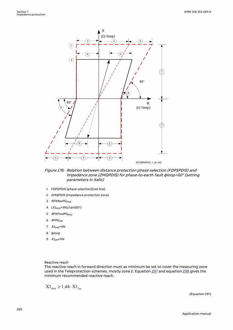
R
X
60°
60°
1
2
3 5
6 6
6 6
7
7
8
8
4
IEC09000043_1_en.vsd
W( / loop)
W( / loop)
43 5
IEC09000043 V1 EN-US
Figure 176: Relation between distance protection phase selection (FDPSPDIS) andimpedance zone (ZMQPDIS) for phase-to-earth fault φloop>60° (settingparameters in italic)
1 FDPSPDIS (phase selection)(red line)
2 ZMQPDIS (Impedance protection zone)
3 RFltRevPGPHS
4 (X1PHS+XN)/tan(60°)
5 RFltFwdPGPHS
6 RFPGZM
7 X1PHS+XN
8 φloop
9 X1ZM+XN
Reactive reachM13142-9 v4
The reactive reach in forward direction must as minimum be set to cover the measuring zoneused in the Teleprotection schemes, mostly zone 2. Equation 297 and equation 298 gives theminimum recommended reactive reach.
PHS ZmX1 1.44 X1³ ×EQUATION1309 V1 EN-US (Equation 297)
Section 7 1MRK 506 353-UEN BImpedance protection
290Application manual

PHS ZmX0 1.44 X0³ ×EQUATION1310 V1 EN-US (Equation 298)
where:
X1Zm is the reactive reach for the zone to be covered by FDPSPDIS, and the constant
1.44 is a safety margin
X0Zm is the zero-sequence reactive reach for the zone to be covered by FDPSPDIS
The reactive reach in reverse direction is automatically set to the same reach as for forwarddirection. No additional setting is required.
Fault resistance reachM13142-103 v5
The resistive reach must cover RFPE for the overreaching zone to be covered, mostly zone 2.Consider the longest overreaching zone if correct fault selection is important in theapplication. Equation 299 gives the minimum recommended resistive reach.
min 1.1 zmRFFwPE RFPE³ ×EQUATION1312 V2 EN-US (Equation 299)
where:
RFPEZm is the setting RFPE for the longest overreaching zone to be covered by FDPSPDIS .
The security margin has to be increased to at least 1.2 in the case where φloop<60° to avoidthat FDPSPDIS characteristic shall cut off some part of the zone measurement characteristic.
Phase-to-earth fault in reverse directionM13142-151 v4
Reactive reachM13142-153 v2
The reactive reach in reverse direction is the same as for forward so no additional setting isrequired.
Resistive reachM13142-156 v4
The resistive reach in reverse direction must be set longer than the longest reverse zones. Inblocking schemes it must be set longer than the overreaching zone at remote end that is usedin the communication scheme. In equation 300 the index ZmRv references the specific zone tobe coordinated to.
min ZmRvRFRvPE 1.2 RFPE³ ×
EQUATION1316 V1 EN-US (Equation 300)
Phase-to-phase fault in forward directionM13142-168 v2
Reactive reachM13142-170 v3
The reach in reactive direction is determined by phase-to-earth reach setting X1. No extrasetting is required.
Resistive reachM13142-173 v4
In the same way as for phase-to-earth fault, the reach is automatically calculated based onsetting X1. The reach will be X1/tan(60°) =X1/√(3).
1MRK 506 353-UEN B Section 7Impedance protection
291Application manual

Fault resistance reachM13142-176 v7
The fault resistance reaches in forward direction RFFwPP, must cover RFPPZm with at least25% margin. RFPPZm is the setting of fault resistance for phase-to-phase fault for the longestoverreaching zone to be covered by FDPSPDIS, see Figure 177. The minimum recommendedreach can be calculated according to equation 301.
1.25 zmRFFwPP RFPP³ ×
EQUATION1318 V3 EN-US (Equation 301)
where:
RFPPZm is the setting of the longest reach of the overreaching zones that must be covered by FDPSPDIS .
Equation 301 modified is applicable also for the RFRvPP as follows:
min 1.25 zmRvRFRvPP RFPP³ ×EQUATION2264 V1 EN-US (Equation 302)
Equation 301 is also valid for three-phase fault. The proposed margin of 25% will cater for therisk of cut off of the zone measuring characteristic that might occur at three-phase fault whenFDPSPDIS characteristic angle is changed from 60 degrees to 90 degrees (rotated 30° anti-clock wise).
Section 7 1MRK 506 353-UEN BImpedance protection
292Application manual

R
X
60°
60°
1
2
3 54
6 6
6 6
6 6
7
7
W( /phase)
IEC09000257_1_en.vsd
W( / phase)
53
8
4
8
IEC09000257 V1 EN-US
Figure 177: Relation between distance protection (ZMQPDIS) and FDPSPDIScharacteristic for phase-to-phase fault for φline>60° (setting parameters initalic)
1 FDPSPDIS (phase selection) (red line)
2 ZMQPDIS (Impedance protection zone)
3 0.5 · RFRvPP PHS
4
( )60tan °PHSX1
5 0.5 · RFFwPPPHS
6 0.5 · RFPPZm
7 X1PHS
8 X1Zm
1MRK 506 353-UEN B Section 7Impedance protection
293Application manual

7.11.3.2 Resistive reach with load encroachment characteristicM13142-312 v4
The procedure for calculating the settings for the load encroachment consist basically todefine the load angle ArgLd, the blinder RLdFw in forward direction and blinder RLdRv inreverse direction, as shown in figure 178.
R
X
RLdFw
RLdRvArgLd
ArgLdArgLd
ArgLd
IEC09000050-1-en.vsd
IEC09000050 V1 EN-US
Figure 178: Load encroachment characteristic
The load angle ArgLd is the same in forward and reverse direction, so it could be suitable tobegin to calculate the setting for that parameter. Set the parameter to the maximum possibleload angle at maximum active load. A value bigger than 20° must be used.
The blinder in forward direction, RLdFw, can be calculated according to equation 303.
2 min0.8
expmaxU
RLdFwP
= ×
where:
Pexp max is the maximum exporting active power
Umin is the minimum voltage for which the Pexp max occurs
0.8 is a security factor to ensure that the setting of RLdFw can be lesser than the calculated minimalresistive load.
The resistive boundary RLdRv for load encroachment characteristic in reverse direction can becalculated in the same way as RLdFw, but use maximum importing power that might occurinstead of maximum exporting power and the relevant Umin voltage for this condition.
7.11.3.3 Minimum operate currentsM13142-334 v5
FDPSPDIShas two current setting parameters which blocks the respective phase-to-earth loopand phase-to-phase loop if the RMS value of the phase current (ILn) and phase differencecurrent (ILmILn) is below the settable threshold.
The threshold to activate the phase selector for phase-to-earth (IMinOpPE) is set to securelydetect a single phase-to-earth fault at the furthest reach of the phase selection. It isrecommended to set IMinOpPP to double value of IMinOpPE.
The threshold for opening the measuring loop for phase-to-earth fault (INReleasePE) is setsecurely detect single line-to-earth fault at remote end on the protected line. It isrecommended to set INBlockPP to double value of INReleasePE.
Section 7 1MRK 506 353-UEN BImpedance protection
294Application manual

7.12 High speed distance protection ZMFPDISGUID-CC4F7338-2281-411D-B55A-67BF03F31681 v3
7.12.1 IdentificationGUID-8ACD3565-C607-4399-89D2-A05657840E6D v3
Function description IEC 61850identification
IEC 60617identification
ANSI/IEEE C37.2device number
High speed distance protection zone ZMFPDIS
S00346 V1 EN-US
21
7.12.2 ApplicationIP14961-1 v2
GUID-2F952D87-6BEB-4425-B823-DF8511B9E742 v3
The fast distance protection function ZMFPDIS in the IED is designed to provide sub-cycle,down to half-cycle operating time for basic faults. At the same time, it is specifically designedfor extra care during difficult conditions in high-voltage transmission networks, like faults onlong heavily loaded lines and faults generating heavily distorted signals. These faults arehandled with utmost security and dependability, although sometimes with a reducedoperating speed.
7.12.2.1 System earthingGUID-EB5B5594-AA81-4FC5-BBC0-7627A8609A23 v1
The type of system earthing plays an important role when designing the protection system.Some hints with respect to distance protection are highlighted below.
Solidly earthed networksGUID-6B0F02F4-18ED-415E-8D48-0A1648F7CE00 v2
In solidly earthed systems, the transformer neutrals are connected directly to earth withoutany impedance between the transformer neutral and earth.
IEC05000215 V2 EN-US
Figure 179: Solidly earthed network
The earth-fault current is as high or even higher than the short-circuit current. The seriesimpedances determine the magnitude of the fault current. The shunt admittance has verylimited influence on the earth-fault current. The shunt admittance may, however, have somemarginal influence on the earth-fault current in networks with long transmission lines.
The earth-fault current at single phase-to-earth in phase L1 can be calculated as equation 304:
L1 L10
1 2 0 f 1 N f
3 U U3I
Z Z Z 3Z Z ZZ
×= =
+ + + + +
EQUATION1267 V3 EN-US (Equation 304)
1MRK 506 353-UEN B Section 7Impedance protection
295Application manual

Where:
UL1 is the phase-to-earth voltage (kV) in the faulty phase beforefault
Z1 is the positive sequence impedance (Ω/phase)
Z2 is the negative sequence impedance (Ω/phase)
Z0 is the zero sequence impedance (Ω/phase)
Zf is the fault impedance (Ω), often resistive
ZN is the earth-return impedance defined as (Z0-Z1)/3
The high zero-sequence current in solidly earthed networks makes it possible to useimpedance measuring techniques to detect earth faults. However, distance protection haslimited possibilities to detect high resistance faults and should therefore always becomplemented with other protection function(s) that can carry out the fault clearance in thosecases.
Effectively earthed networksGUID-39CAF169-315E-4E3E-9EE6-28CBF624B90E v4
A network is defined as effectively earthed if the earth-fault factor fe is less than 1.4. The earth-fault factor is defined according to Equation 305.
fU
Ue
pn
=max
EQUATION1268 V4 EN-US (Equation 305)
Where:
Umax is the highest fundamental frequency voltage on one of the healthy phases at singlephase-to-earth fault.
Upn is the phase-to-earth fundamental frequency voltage before fault.
Another definition for effectively earthed network is when the following relationships betweenthe symmetrical components of the network impedances are valid, see Equation 306 andEquation 307.
0 1X 3 X< ×
EQUATION2122 V1 EN-US (Equation 306)
0 1R R£
EQUATION2123 V1 EN-US (Equation 307)
Where
R0 is the resistive zero sequence of the source
X0 is the reactive zero sequence of the source
R1 is the resistive positive sequence of the source
X1 is the reactive positive sequence of the source
The magnitude of the earth-fault current in effectively earthed networks is high enough forimpedance measuring elements to detect earth faults. However, in the same way as for solidly
Section 7 1MRK 506 353-UEN BImpedance protection
296Application manual

earthed networks, distance protection has limited possibilities to detect high resistance faultsand should therefore always be complemented with other protection function(s) that can carryout the fault clearance in this case.
High impedance earthed networksGUID-02F306F5-1038-42AC-AFAE-3F8423C4C066 v4
In high impedance networks, the neutral of the system transformers are connected to theearth through high impedance, mostly a reactance in parallel with a high resistor.
This type of network is often operated radially, but can also be found operating as a meshednetwork.
What is typical for this type of network is that the magnitude of the earth -fault current is verylow compared to the short circuit current. The voltage on the healthy phases will get amagnitude of √3 times the phase voltage during the fault. The zero sequence voltage (3U0) willhave the same magnitude in different places in the network due to low voltage dropdistribution.
The magnitude of the total fault current can be calculated according to equation308.
( )22R L C03I I I I= + -
EQUATION1271 V3 EN-US (Equation 308)
Where:
3I0 is the earth-fault current (A)
IR is the current through the neutral point resistor (A)
IL is the current through the neutral point reactor (A)
IC is the total capacitive earth-fault current (A)
The neutral point reactor is normally designed so that it can be tuned to a position where thereactive current balances the capacitive current from the network:
13
LC
ww
=× ×
EQUATION1272 V1 EN-US (Equation 309)
IEC05000216 V2 EN-US
Figure 180: High impedance earthing network
The operation of high impedance earthed networks is different compared to solid earthednetworks, where all major faults have to be cleared very fast. In high impedance earthednetworks, some system operators do not clear single phase-to-earth faults immediately; theyclear the line later when it is more convenient. In case of cross-country faults, many networkoperators want to selectively clear one of the two earth faults.
1MRK 506 353-UEN B Section 7Impedance protection
297Application manual

In this type of network, it is mostly not possible to use distance protection for detection andclearance of earth faults. The low magnitude of the earth-fault current might not give start ofthe zero-sequence measurement elements or the sensitivity will be too low for acceptance. Forthis reason a separate high sensitive earth-fault protection is necessary to carry out the faultclearance for single phase-to-earth fault.
7.12.2.2 Fault infeed from remote endGUID-E28CCC52-497F-4B79-9430-8A2155FED936 v3
All transmission and most all sub-transmission networks are operated meshed. Typical for thistype of network is that fault infeed from remote end will happen when fault occurs on theprotected line. The fault current infeed will enlarge the fault impedance seen by the distanceprotection. This effect is very important to keep in mind when both planning the protectionsystem and making the settings.
With reference to Figure 181, the equation for the bus voltage UA at A side is:
U I p Z I I RfA A L A B= ⋅ ⋅ + +( ) ⋅
EQUATION1273-IEC-650 V2 EN-US (Equation 310)
If we divide UA by IA we get Z present to the IED at A side.
IA + IBUA
IA IA ZA = = p ·ZL + ·Rf
EQUATION1274-IEC-650 V1 EN-US (Equation 311)
The infeed factor (IA+IB)/IA can be very high, 10-20 depending on the differences in sourceimpedances at local and remote end.
Z <
ZL
Z <
ESA
UA UBA B ESBIA IB
Rf
p*ZL (1-p)*ZLZSA ZSB
IEC09000247-1-en.vsdIEC09000247 V1 EN-US
Figure 181: Influence of fault current infeed from remote line end
The effect of fault current infeed from the remote line end is one of the most driving factors tojustify complementary protection for distance protection.
When the line is heavily loaded, the distance protection at the exporting end will have atendency to overreach. To handle this phenomenon, the IED has an adaptive built-in algorithm,which compensates the overreach tendency of zone 1 at the exporting end. No settings arerequired for this feature.
Section 7 1MRK 506 353-UEN BImpedance protection
298Application manual

7.12.2.3 Load encroachmentGUID-6785BF05-2775-4422-8077-A663D01C6C07 v4
In some cases the measured load impedance might enter the set zone characteristic withoutany fault on the protected line. This phenomenon is called load encroachment and it mightoccur when an external fault is cleared and high emergency load is transferred onto theprotected line. The effect of load encroachment is illustrated on the left in figure182. Theentrance of the load impedance inside the characteristic is of course not desirable and the wayto handle this with conventional distance protection is to consider this with the resistive reachsettings, that is, to have a security margin between the distance zone characteristic and theminimum load impedance. Such a solution has the drawback that it will reduce the sensitivityof the distance protection, that is, the ability to detect resistive faults.
The IED has a built in feature which shapes the characteristic according to the characteristicshown in figure182. The load encroachment algorithm will increase the possibility to detecthigh fault resistances, especially for phase-to-earth faults at the remote line end. For example,for a given setting of the load angle ArgLd, the resistive blinder for the zone measurement canbe set according to figure182 affording higher fault resistance coverage without risk forunwanted operation due to load encroachment. Separate resistive blinder settings areavailable in forward and reverse direction.
The use of the load encroachment feature is essential for long heavily loaded lines, where theremight be a conflict between the necessary emergency load transfer and necessary sensitivityof the distance protection. The function can also preferably be used on heavy loaded, mediumlong lines. For short lines, the major concern is to get sufficient fault resistance coverage. Loadencroachment is not a major problem. See section "".
R
X
Z1
Load impedance
area in forward
direction
RLdRv
R
Z1
ArgLd
RLdFw
IEC09000248-2-en.vsd
X
IEC09000248 V2 EN-US
Figure 182: Load encroachment phenomena and shaped load encroachmentcharacteristic
[1]
7.12.2.4 Short line applicationGUID-331451C9-EA93-481A-BA2E-D729EDB98828 v3
In short line applications, the major concern is to get sufficient fault resistance coverage. Loadencroachment is not such a common problem. The line length that can be recognized as ashort line is not a fixed length; it depends on system parameters such as voltage and sourceimpedance, see table27.
[1] RLdRv=RLdRvFactor*RLdFw
1MRK 506 353-UEN B Section 7Impedance protection
299Application manual

Table 27: Definition of short and very short line
Line category
Un Un110 kV 500 kV
Very short line 1.1-5.5 km 5-25 km
Short line 5.5-11 km 25-50 km
The IED's ability to set resistive and reactive reach independent for positive and zero sequencefault loops and individual fault resistance settings for phase-to-phase and phase-to-earth faulttogether with load encroachment algorithm improves the possibility to detect high resistivefaults without conflict with the load impedance.
For very short line applications, the underreaching zone 1 can not be used due to the fact thatthe voltage drop distribution throughout the line will be too low causing risk for overreaching.
7.12.2.5 Long transmission line applicationGUID-0C99A197-06CD-4668-A017-3CA9E5E01ED2 v3
For long transmission lines, the margin to the load impedance, that is, to avoid loadencroachment, will normally be a major concern. It is well known that it is difficult to achievehigh sensitivity for phase-to-earth fault at remote line end of long lines when the line is heavyloaded.
What can be recognized as long lines with respect to the performance of distance protectioncan generally be described as in Table 28. Long lines have Source impedance ratio (SIR’s) lessthan 0.5.
Table 28: Definition of long and very long lines
Line category
Un Un110 kV 500 kV
Long lines 77 km - 99 km 350 km - 450 km
Very long lines > 99 km > 450 km
The IED's ability to set resistive and reactive reach independent for positive and zero sequencefault loops and individual fault resistance settings for phase-to-phase and phase-to-earth faulttogether with load encroachment algorithm improves the possibility to detect high resistivefaults at the same time as the security is improved (risk for unwanted trip due to loadencroachment is eliminated), see Figure 182.
7.12.2.6 Parallel line application with mutual couplingGUID-4720AB55-0E59-4531-AE14-6A6EEC72C924 v1
GeneralGUID-E2FFF4A4-7D81-4440-87CE-3DCEAE2E42BD v2
Introduction of parallel lines in the network is increasing due to difficulties to get necessaryland to build new lines.
Parallel lines introduce an error in the measurement due to the mutual coupling between theparallel lines. The lines need not be of the same voltage level in order to experience mutualcoupling, and some coupling exists even for lines that are separated by 100 meters or more.The mutual coupling does influence the zero sequence impedance to the fault point but it doesnot normally cause voltage inversion.
It can be shown from analytical calculations of line impedances that the mutual impedancesfor positive and negative sequence are very small (< 1-2%) of the self impedance and it is acommon practice to neglect them.
Section 7 1MRK 506 353-UEN BImpedance protection
300Application manual

From an application point of view there exists three types of network configurations (classes)that must be considered when making the settings for the protection function.
The different network configuration classes are:
1. Parallel line with common positive and zero sequence network2. Parallel circuits with common positive but isolated zero sequence network3. Parallel circuits with positive and zero sequence sources isolated.
One example of class 3 networks could be the mutual coupling between a 400 kV line and railroad overhead lines. This type of mutual coupling is not so common although it exists and isnot treated any further in this manual.
For each type of network class, there are three different topologies; the parallel line can be inservice, out of service, out of service and earthed in both ends.
The reach of the distance protection zone 1 shall be different depending on the operationcondition of the parallel line. This can be handled by the use of different setting groups forhandling the cases when the parallel line is in operation and out of service and earthed at bothends.
The distance protection within the IED can compensate for the influence of a zero sequencemutual coupling on the measurement at single phase-to-earth faults in the following ways, byusing:
• The possibility of different setting values that influence the earth-return compensationfor different distance zones within the same group of setting parameters.
• Different groups of setting parameters for different operating conditions of a protectedmulti circuit line.
Most multi circuit lines have two parallel operating circuits.
Parallel line applicationsGUID-905ACED8-CD00-4651-90F1-96D1885BA856 v1
This type of networks is defined as those networks where the parallel transmission linesterminate at common nodes at both ends.
The three most common operation modes are:
1. Parallel line in service.2. Parallel line out of service and earthed.3. Parallel line out of service and not earthed.
Parallel line in serviceGUID-22E1A46C-92BD-4EE4-9A2D-9EFE2DB7B4D8 v3
This type of application is very common and applies to all normal sub-transmission andtransmission networks.
Let us analyze what happens when a fault occurs on the parallel line see figure 183.
From symmetrical components, we can derive the impedance Z at the relay point for normallines without mutual coupling according to equation 312.
ZU
I IZ Z
Z
U
I I K
ph
ph
ph
ph N
=
+ ⋅−
⋅
=+ ⋅
33
30
0 1
1
0
IECEQUATION1275 V2 EN-US (Equation 312)
1MRK 506 353-UEN B Section 7Impedance protection
301Application manual

Where:
Uph is phase to earth voltage at the relay point
Iph is phase current in the faulty phase
3I0 is earth fault current
Z1 is positive sequence impedance
Z0 is zero sequence impedance
Z0m
A B
Z< Z< IEC09000250_1_en.vsdIEC09000250 V1 EN-US
Figure 183: Class 1, parallel line in service
The equivalent circuit of the lines can be simplified, see figure 184.
A
B
CZ0m
Z0mZ0 -
Z0mZ0 -
IEC09000253_1_en.vsdIEC09000253 V1 EN-US
Figure 184: Equivalent zero sequence impedance circuit of the double-circuit, parallel,operating line with a single phase-to-earth fault at the remote busbar
When mutual coupling is introduced, the voltage at the relay point A will be changed accordingto equation 313.
0 000 11 3 3
3 1 3 1mL L
ph pph LL L
ZZ ZU Z I I IZ Z
æ ö-= × + × +ç ÷
× ×è øIECEQUATION1276 V3 EN-US (Equation 313)
By dividing equation 313 by equation 312 and after some simplification we can write theimpedance present to the relay at A side as:
3 01 13 0
æ ö×= +ç ÷+ ×è ø
LI KNmZ Z
I ph I KNEQUATION1277 V3 EN-US (Equation 314)
Where:
KNm = Z0m/(3 · Z1L)
The second part in the parentheses is the error introduced to the measurement of the lineimpedance.
Section 7 1MRK 506 353-UEN BImpedance protection
302Application manual
If the current on the parallel line has negative sign compared to the current on the protectedline, that is, the current on the parallel line has an opposite direction compared to the currenton the protected line, the distance function will overreach. If the currents have the samedirection, the distance protection will underreach.
Maximum overreach will occur if the fault current infeed from remote line end is weak. Ifconsidering a single phase-to-earth fault at 'p' unit of the line length from A to B on the parallelline for the case when the fault current infeed from remote line end is zero, the voltage UA inthe faulty phase at A side as in equation 315.
U p ZI I K I K IA L ph N Nm p= ⋅ + ⋅ + ⋅( )3 3
0 0
IECEQUATION1278 V2 EN-US (Equation 315)
One can also notice that the following relationship exists between the zero sequence currents:
3 0 3 0 0 20
I Z I Z pL p L
⋅ = ⋅ −( )EQUATION1279 V3 EN-US (Equation 316)
Simplification of equation 316, solving it for 3I0p and substitution of the result into equation315 gives that the voltage can be drawn as:
U p ZI I K I KI p
pA L ph N Nm
= ⋅ + ⋅ + ⋅⋅
−
3
3
20
0
IECEQUATION1280 V2 EN-US (Equation 317)
If we finally divide equation 317 with equation 312 we can draw the impedance present to theIED as
Z p ZI
I KN I KNI p
p
I I KNL
ph m
ph
= ⋅
+ ⋅ + ⋅⋅
−
+ ⋅
33
2
3
0
0
0
EQUATION1379 V3 EN-US (Equation 318)
Calculation for a 400 kV line, where we for simplicity have excluded the resistance, gives withX1L=0.303 Ω/km, X0L=0.88 Ω/km, zone 1 reach is set to 90% of the line reactance p=71% thatis, the protection is underreaching with approximately 20%.
The zero sequence mutual coupling can reduce the reach of distance protection on theprotected circuit when the parallel line is in normal operation. The reduction of the reach ismost pronounced with no current infeed in the IED closest to the fault. This reach reduction isnormally less than 15%. But when the reach is reduced at one line end, it is proportionallyincreased at the opposite line end. So this 15% reach reduction does not significantly affectthe operation of a permissive underreaching scheme.
Parallel line out of service and earthedGUID-574F8EE5-EAEC-40B8-A615-FDAD2808CD6D v1GUID-8EB3A8EF-119D-4530-8F01-0879A7478E1F v1
1MRK 506 353-UEN B Section 7Impedance protection
303Application manual

Z0m
A B
Z< Z<IEC09000251_1_en.vsd
IEC09000251 V1 EN-US
Figure 185: The parallel line is out of service and earthed
When the parallel line is out of service and earthed at both line ends on the bus bar side of theline CTs so that zero sequence current can flow on the parallel line, the equivalent zerosequence circuit of the parallel lines will be according to figure 186.
A
B
C
IEC09000252_1_en.vsd
I0
I0
Z0mZ0 -
Z0mZ0 -
Z0m
IEC09000252 V1 EN-US
Figure 186: Equivalent zero sequence impedance circuit for the double-circuit line thatoperates with one circuit disconnected and earthed at both ends
Here the equivalent zero-sequence impedance is equal to Z0-Z0m in parallel with (Z0-Z0m)/Z0-Z0m+Z0m which is equal to equation 319.
2 2
0
0
omE
Z ZZ
Z
-=
EQUATION2002 V4 EN-US (Equation 319)
The influence on the distance measurement will be a considerable overreach, which must beconsidered when calculating the settings. It is recommended to use a separate setting groupfor this operation condition since it will reduce the reach considerably when the line is inoperation.
All expressions below are proposed for practical use. They assume the value of zero sequence,mutual resistance R0m equals to zero. They consider only the zero sequence, mutual reactanceX0m. Calculate the equivalent X0E and R0E zero sequence parameters according to equation 320and equation 321 for each particular line section and use them for calculating the reach for theunderreaching zone.
R RX
R XE
m0 0
0
2
0
2
0
21= ⋅ +
+
DOCUMENT11520-IMG3502 V2 EN-US (Equation 320)
X XX
R XE
m0 0
0
2
0
2
0
21= ⋅ −
+
DOCUMENT11520-IMG3503 V2 EN-US (Equation 321)
Section 7 1MRK 506 353-UEN BImpedance protection
304Application manual

Parallel line out of service and not earthedGUID-949669D3-8B9F-4ECA-8F09-52A783A494E1 v2
Z0m
A B
Z< Z<IEC09000254_1_en.vsd
IEC09000254 V1 EN-US
Figure 187: Parallel line is out of service and not earthed
When the parallel line is out of service and not earthed, the zero sequence on that line can onlyflow through the line admittance to the earth. The line admittance is high which limits thezero-sequence current on the parallel line to very low values. In practice, the equivalent zero-sequence impedance circuit for faults at the remote bus bar can be simplified to the circuitshown in figure 187
The line zero sequence mutual impedance does not influence the measurement of the distanceprotection in a faulty circuit. This means that the reach of the underreaching distanceprotection zone is reduced if, due to operating conditions, the equivalent zero sequenceimpedance is set according to the conditions when the parallel system is out of operation andearthed at both ends.
A
B
C
IEC09000255_1_en.vsd
I0
I0
Z0mZ0 -
Z0m
Z0mZ0 -
IEC09000255 V1 EN-US
Figure 188: Equivalent zero-sequence impedance circuit for a double-circuit line with onecircuit disconnected and not earthed
The reduction of the reach is equal to equation 322.
( )( ) ( )
21 0
0
1 001 0
1 23 11 2 323
E fm
U
ff
Z Z R ZKZ Z Z RZ Z R
× × + += = -
× × + +× × + +
EQUATION1284 V1 EN-US (Equation 322)
This means that the reach is reduced in reactive and resistive directions. If the real andimaginary components of the constant A are equal to equation 323 and equation 324.
Re( ) 0 (2 1 0 3 ) 0 ( 0 2 1)A R R R Rf X X X= × × + + × - × + ×EQUATION1285 V1 EN-US (Equation 323)
0 1 0 1 0 1 0Im( ) (2 3 ) (2 )A X R R R R X X= × × + + × + × × +EQUATION1286 V1 EN-US (Equation 324)
The real component of the KU factor is equal to equation 325.
1MRK 506 353-UEN B Section 7Impedance protection
305Application manual

Re
Re
Re Im
KA X
A A
u
m
( ) = +( ) ⋅
( )
+ ( )
1
0
2
2 2
EQUATION1287 V3 EN-US (Equation 325)
The imaginary component of the same factor is equal to equation 326.
( ) ( )( ) ( )
20
2 2
ImIm
Re Im
mU
A XK
A A
×=
+é ù é ùë û ë ûEQUATION1288 V2 EN-US (Equation 326)
Ensure that the underreaching zones from both line ends will overlap a sufficient amount (atleast 10%) in the middle of the protected circuit.
7.12.2.7 Tapped line applicationGUID-740E8C46-45EE-4CE8-8718-9FAE658E9FCE v1
GUID-7AA566A4-B6E9-41A7-9927-4DAB50BE8D1A v1
C
B
BC
IEC09000160-3-en.vsd
A
IEC09000160 V3 EN-US
Figure 189: Example of tapped line with Auto transformer
This application gives rise to similar problem that was highlighted in section "Fault infeedfrom remote end", that is increased measured impedance due to fault current infeed. Forexample, for faults between the T point and B station the measured impedance at A and C willbe
ZA =ZAT + ·ZTFIA + IC
IADOCUMENT11524-IMG3509 V3 EN-US (Equation 327)
Section 7 1MRK 506 353-UEN BImpedance protection
306Application manual

Z Z ZI I
IZ
U
UC Trf CT
A C
C
TF= + ++
⋅
⋅
2
1
2
DOCUMENT11524-IMG3510 V3 EN-US (Equation 328)
Where:
ZAT and ZCT is the line impedance from the A respective C station to the T point.
IA and IC is fault current from A respective C station for fault between T and B.
U2/U1 Transformation ratio for transformation of impedance at U1 side of thetransformer to the measuring side U2 (it is assumed that current and voltagedistance function is taken from U2 side of the transformer).
ZTF is the line impedance from the T point to the fault (F).
ZTrf Transformer impedance
For this example with a fault between T and B, the measured impedance from the T point tothe fault will be increased by a factor defined as the sum of the currents from T point to thefault divided by the IED current. For the IED at C, the impedance on the high voltage side U1has to be transferred to the measuring voltage level by the transformer ratio.
Another complication that might occur depending on the topology is that the current from oneend can have a reverse direction for fault on the protected line. For example, for faults at T thecurrent from B might go in reverse direction from B to C depending on the system parameters(see the dotted line in figure 189), given that the distance protection in B to T will measurewrong direction.
In three-end application, depending on the source impedance behind the IEDs, the impedancesof the protected object and the fault location, it might be necessary to accept zone 2 trip inone end or sequential trip in one end.
Generally for this type of application it is difficult to select settings of zone 1 that both givesoverlapping of the zones with enough sensitivity without interference with other zone 1settings, that is, without selectivity conflicts. Careful fault calculations are necessary todetermine suitable settings and selection of proper scheme communication.
Fault resistanceGUID-83E3E475-3243-4308-9A91-B8DD9B47C276 v3
The performance of distance protection for single phase-to-earth faults is very important,because normally more than 70% of the faults on transmission lines are single phase-to-earthfaults. At these faults, the fault resistance is composed of three parts: arc resistance,resistance of a tower construction, and tower-footing resistance.The resistance is alsodepending on the presence of earth shield conductor at the top of the tower, connectingtower-footing resistance in parallel. The arc resistance can be calculated according toWarrington's formula:
1.428707 LRarc
I×
=
EQUATION1456 V1 EN-US (Equation 329)
where:
L represents the length of the arc (in meters). This equation applies for the distance protection zone 1.Consider approximately three times arc foot spacing for the zone 2 and wind speed of approximately50 km/h
I is the actual fault current in A.
1MRK 506 353-UEN B Section 7Impedance protection
307Application manual
In practice, the setting of fault resistance for both phase-to-earth RFPE and phase-to-phaseRFPP should be as high as possible without interfering with the load impedance in order toobtain reliable fault detection.
7.12.3 Setting guidelinesIP14962-1 v1
7.12.3.1 GeneralGUID-BA20D421-4435-44CA-A6E9-743E461F8C59 v2
The settings for Distance measuring zones, quadrilateral characteristic (ZMFPDIS) are done inprimary values. The instrument transformer ratio that has been set for the analog input card isused to automatically convert the measured secondary input signals to primary values used inZMFPDIS .
The following basics must be considered, depending on application, when doing the settingcalculations:
• Errors introduced by current and voltage instrument transformers, particularly undertransient conditions.
• Inaccuracies in the line zero-sequence impedance data, and their effect on the calculatedvalue of the earth-return compensation factor.
• The effect of infeed between the IED and the fault location, including the influence ofdifferent Z0/Z1 ratios of the various sources.
• The phase impedance of non transposed lines is not identical for all fault loops. Thedifference between the impedances for different phase-to-earth loops can be as large as5-10% of the total line impedance.
• The effect of a load transfer between the IEDs of the protected fault resistance isconsiderable, the effect must be recognized.
• Zero-sequence mutual coupling from parallel lines.
7.12.3.2 Setting of zone 1GUID-ABD9A3B1-E420-471E-A798-4A56371E715E v1
The different errors mentioned earlier usually require a limitation of the underreaching zone(normally zone 1) to 75 - 90% of the protected line.
In case of parallel lines, consider the influence of the mutual coupling according to section"Parallel line application with mutual coupling" and select the case(s) that are valid in theparticular application. By proper setting it is possible to compensate for the cases when theparallel line is in operation, out of service and not earthed and out of service and earthed inboth ends. The setting of earth-fault reach should be selected to be <95% also when parallelline is out of service and earthed at both ends (worst case).
7.12.3.3 Setting of overreaching zoneGUID-8D7D4C9D-468B-465F-85D9-3D64500474DB v2
The first overreaching zone (normally zone 2) must detect faults on the whole protected line.Considering the different errors that might influence the measurement in the same way as forzone 1, it is necessary to increase the reach of the overreaching zone to at least 120% of theprotected line. The zone 2 reach can be even higher if the fault infeed from adjacent lines atremote end is considerable higher than the fault current at the IED location.
The setting shall generally not exceed 80% of the following impedances:
• The impedance corresponding to the protected line, plus the first zone reach of theshortest adjacent line.
• The impedance corresponding to the protected line, plus the impedance of the maximumnumber of transformers operating in parallel on the bus at the remote end of theprotected line.
Section 7 1MRK 506 353-UEN BImpedance protection
308Application manual

Larger overreach than the mentioned 80% can often be acceptable due to fault current infeedfrom other lines. This requires however analysis by means of fault calculations.
If any of the above gives a zone 2 reach less than 120%, the time delay of zone 2 must beincreased by approximately 200ms to avoid unwanted operation in cases when thetelecommunication for the short adjacent line at remote end is down during faults. The zone 2must not be reduced below 120% of the protected line section. The whole line must be coveredunder all conditions.
The requirement that the zone 2 shall not reach more than 80% of the shortest adjacent line atremote end is highlighted in the example below.
If a fault occurs at point F see figure 190, the IED at point A senses the impedance:
ZV
IZ
I I
IZ
I I I
IR Z
I
IZAF
A
A
AC
A C
A
CF
A C B
A
FAC
C
A
C= = ++
⋅ ++ +
⋅ = + +
⋅1 FF
C B
A
F
I I
IR+ +
+
⋅1
EQUATION302 V5 EN-US (Equation 330)
A B
Z<
C
IC
ZAC ZCB
Z CF
IA+ I C
IEC09000256-2-en.vsd
FI A
I B
IEC09000256 V2 EN-US
Figure 190: Setting of overreaching zone
7.12.3.4 Setting of reverse zoneGUID-B633CF2C-28B2-4FDD-BE0E-D09CA434F01F v1
The reverse zone is applicable for purposes of scheme communication logic, current reversallogic, weak-end infeed logic, and so on. The same applies to the back-up protection of the busbar or power transformers. It is necessary to secure, that it always covers the overreachingzone, used at the remote line IED for the telecommunication purposes.
Consider the possible enlarging factor that might exist due to fault infeed from adjacent lines.Equation 331 can be used to calculate the reach in reverse direction when the zone is used forblocking scheme, weak-end infeed, and so on.
( )1.2 2³ × -Zrev ZL Z remEQUATION1525 V5 EN-US (Equation 331)
Where:
ZL is the protected line impedance
Z2rem is zone 2 setting at remote end of protected line.
In many applications it might be necessary to consider the enlarging factor due to faultcurrent infeed from adjacent lines in the reverse direction in order to obtain certain sensitivity.
1MRK 506 353-UEN B Section 7Impedance protection
309Application manual

7.12.3.5 Setting of zones for parallel line applicationGUID-4E0C3824-41B6-410F-A10E-AB9C3BFE9B12 v1
Parallel line in service – Setting of zone 1GUID-8A62367C-2636-4EC1-90FF-397A51F586F7 v1
With reference to section "Parallel line applications", the zone reach can be set to 85% of theprotected line.
However, influence of mutual impedance has to be taken into account.
Parallel line in service – setting of zone 2GUID-98D11A72-C5BE-4C67-ADB5-95124C2AF987 v1
Overreaching zones (in general, zones 2 and 3) must overreach the protected circuit in allcases. The greatest reduction of a reach occurs in cases when both parallel circuits are inservice with a single phase-to-earth fault located at the end of a protected line. The equivalentzero sequence impedance circuit for this case is equal to the one in figure 184 in sectionParallel line in service.
The components of the zero sequence impedance for the overreaching zones must be equal toat least:
R0E R0 Rm0+=
EQUATION553 V1 EN-US (Equation 332)
X0E X0 Xm0+=
EQUATION554 V1 EN-US (Equation 333)
Check the reduction of a reach for the overreaching zones due to the effect of the zerosequence mutual coupling. The reach is reduced for a factor:
00 12 1 0
m
f
ZKZ Z R
= -× + +
EQUATION1426 V1 EN-US (Equation 334)
If the denominator in equation 334 is called B and Z0m is simplified to X0m, then the real andimaginary part of the reach reduction factor for the overreaching zones can be written as:
( ) ( )( ) ( )2 2
0 ReRe 0 1
Re ImX m B
KB B
×= -
+
EQUATION1427 V2 EN-US (Equation 335)
( ) ( )( ) ( )2 2
0 ImIm 0
Re ImX m B
KB B
×=
+
EQUATION1428 V2 EN-US (Equation 336)
Parallel line is out of service and earthed in both endsGUID-345B36A6-B5FB-46DD-B5AE-81A1599FFC6E v1
Apply the same measures as in the case with a single set of setting parameters. This meansthat an underreaching zone must not overreach the end of a protected circuit for the singlephase-to-earth faults.
Set the values of the corresponding zone (zero-sequence resistance and reactance) equal to:
Section 7 1MRK 506 353-UEN BImpedance protection
310Application manual

R0E R0 1Xm0
2
R02 X0
2+--------------------------+
è øç ÷æ ö
×=
EQUATION561 V1 EN-US (Equation 337)
X0E X0 1Xm0
2
R02 X0
2+--------------------------–
è øç ÷æ ö
×=
EQUATION562 V1 EN-US (Equation 338)
7.12.3.6 Setting the reach with respect to loadGUID-ED84BDE6-16CD-45ED-A45D-5CFB828A9040 v4
Set separately the expected fault resistance for phase-to-phase faults RFPP and for the phase-to-earth faults RFPE for each zone. For each distance zone, set all remaining reach settingparameters independently of each other.
The final reach in the resistive direction for phase-to-earth fault loop measurementautomatically follows the values of the line-positive and zero-sequence resistance, and at theend of the protected zone is equal to equation 339.
( )1R 2 R1 R0 RFPE
3= × + +
IECEQUATION2303 V1 EN-US (Equation 339)
2 X1 X0arctan
2 R1 R0loopj
× +=
× +é ùê úë û
EQUATION2304 V1 EN-US (Equation 340)
Setting of the resistive reach for the underreaching zone 1 should follow the condition tominimize the risk for overreaching:
RFPE 4.5 X1£ ×IECEQUATION2305 V1 EN-US (Equation 341)
The fault resistance for phase-to-phase faults is normally quite low compared to the faultresistance for phase-to-earth faults. To minimize the risk for overreaching, limit the setting ofthe zone1 reach in the resistive direction for phase-to-phase loop measurement based on theequation.
RFPP X≤ ⋅6 1
IECEQUATION2306 V2 EN-US (Equation 342)
The setting XLd is primarily there to define the border between what is considered a fault andwhat is just normal operation. See figure191 In this context, the main examples of normaloperation are reactive load from reactive power compensation equipment or the capacitivecharging of a long high-voltage power line. XLd needs to be set with some margin towardsnormal apparent reactance; not more than 90% of the said reactance or just as much as isneeded from a zone reach point of view.
As with the settings RLdFw and RLdRv [2], XLd is representing a per-phase load impedance of asymmetrical star-coupled representation. For a symmetrical load or three-phase and phase-to-
1MRK 506 353-UEN B Section 7Impedance protection
311Application manual

phase faults, this means per-phase, or positive-sequence, impedance. During a phase-to-earthfault, it means the per-loop impedance, including the earth return impedance.
7.12.3.7 Zone reach setting lower than minimum load impedanceGUID-68C336F4-5285-4167-B3F8-B0963BD85439 v4
Even if the resistive reach of all protection zones is set lower than the lowest expected loadimpedance and there is no risk for load encroachment, it is still necessary to set RLdFw, RLdRv[3] and ArgLd according to the expected load situation, since these settings are used internallyin the function as reference points to improve the performance of the phase selection.
The maximum permissible resistive reach for any zone must be checked to ensure that there isa sufficient setting margin between the boundary and the minimum load impedance. Theminimum load impedance (Ω/phase) is calculated with the equation.
Z loadminU2
S-------=
EQUATION571 V1 EN-US (Equation 343)
Where:
U the minimum phase-to-phase voltage in kV
S the maximum apparent power in MVA.
The load impedance [Ω/phase] is a function of the minimum operation voltage and themaximum load current:
Z loadUmin
3 Imax×----------------------=
EQUATION574 V1 EN-US (Equation 344)
Minimum voltage Umin and maximum current Imax are related to the same operatingconditions. Minimum load impedance occurs normally under emergency conditions.
As a safety margin, it is required to avoid load encroachment under three-phase conditions. To guarantee correct, healthy phase IED operation undercombined heavy three-phase load and earth faults, both phase-to-phase andphase-to-earth fault operating characteristics should be considered.
To avoid load encroachment for the phase-to-earth measuring elements, the set resistivereach of any distance protection zone must be less than 80% of the minimum load impedance.
RFPE 0.8 Zload×£
EQUATION792 V1 EN-US (Equation 345)
This equation is applicable only when the loop characteristic angle for the single phase-to-earth faults is more than three times as large as the maximum expected load-impedanceangle. For the case when the loop characteristic angle is less than three times the load-impedance angle, more accurate calculations are necessary according to equation 346.
[2] RLdRv=RLdRvFactor*RLdFw[3] RLdRv=RLdRvFactor*RLdFw
Section 7 1MRK 506 353-UEN BImpedance protection
312Application manual

min
2 1 00.8 cos sin
2 1 0load
R RRFPE Z
X XJ J
× +£ × × - ×
× +é ùê úë û
EQUATION578 V4 EN-US (Equation 346)
Where:
∂ is a maximum load-impedance angle, related to the maximum load power.
To avoid load encroachment for the phase-to-phase measuring elements, the set resistivereach of any distance protection zone must be less than 160% of the minimum loadimpedance.
RFPP 1.6 Zload£ ×load1.6 Z£ ×RFPP
EQUATION579 V2 EN-US (Equation 347)
Equation 347 is applicable only when the loop characteristic angle for the phase-to-phasefaults is more than three times as large as the maximum expected load-impedance angle. Forother cases a more accurate calculations are necessary according to equation 348.
load minR1
RFPP 1.6 Z cos sinX1
J J£ × - ×é ù× ê úë ûIECEQUATION2307 V1 EN-US (Equation 348)
All this is applicable for all measuring zones when no Power swing detection function ZMRPSBis activated in the IED. Use an additional safety margin of approximately 20% in cases when aZMRPSB function is activated in the IED, refer to the description of Power swing detectionfunction ZMRPSB.
7.12.3.8 Zone reach setting higher than minimum load impedanceGUID-78D0227F-2568-4C9A-8921-45812B4ABAF2 v4
The impedance zones are enabled as soon as the (symmetrical) load impedance crosses thevertical boundaries defined by RLdFw and RLdRv [4] or the lines defined by ArgLd. So, it isnecessary to consider some margin. It is recommended to set RLdFw and RLdRv to 90% of theper-phase resistance that corresponds to maximum load.
min0.9 loadRLdFw R< ×
IECEQUATION2419 V2 EN-US (Equation 349)
min0.9 loadRLdRv R< ×
IECEQUATION2420 V2 EN-US (Equation 350)
The absolute value of the margin to the closest ArgLd line should be of the same order, that is,at least 0.1 • Zload min.
The load encroachment settings are related to a per-phase load impedance in a symmetricalstar-coupled representation. For symmetrical load or three-phase and phase-to-phase faults,
[4] RLdRv=RLdRvFactor*RLdFw
1MRK 506 353-UEN B Section 7Impedance protection
313Application manual

this corresponds to the per-phase, or positive-sequence, impedance. For a phase-to-earthfault, it corresponds to the per-loop impedance, including the earth return impedance.
R
X
RLdFw
RLdRv
ArgLd
90%10%
10%
ARGLd
Possible load
ARGLd
ARGLd
R
X
RLdFw
RLdRv
XLd
XLd
ARGLd
ARGLd ARGLd
ARGLd
IEC12000176-2-en.vsdIEC12000176 V2 EN-US
Figure 191: Load impedance limitation with load encroachment
During the initial current change for phase-to-phase and for phase-to-earth faults, operationmay be allowed also when the apparent impedance of the load encroachment element islocated in the load area. This improves the dependability for fault at the remote end of the lineduring high load. Although it is not associated to any standard event, there is one potentiallyhazardous situation that should be considered. Should one phase of a parallel circuit open asingle pole, even though there is no fault, and the load current of that phase increase, there isactually no way of distinguish this from a real fault with similar characteristics. Should thisaccidental event be given precaution, the phase-to-earth reach (RFPE) of all instantaneouszones has to be set below the emergency load for the pole-open situation. Again, this is onlyfor the application where there is a risk that one breaker pole would open without a precedingfault. If this never happens, for example when there is no parallel circuit, there is no need tochange any phase-to-earth reach according to the pole-open scenario.
7.12.3.9 Other settingsGUID-9D65B411-6FE2-433B-AE6C-C6DD716D1181 v5
IMinOpPE and IMinOpPP
The ability for a specific loop and zone to issue a start or a trip is inhibited if the magnitude ofthe input current for this loop falls below the threshold value defined by these settings. Theoutput of a phase-to-earth loop Ln is blocked if ILn < IminOpPE(Zx). In is the RMS value of thefundamental current in phase n.
The output of a phase-to-phase loop LmLn is blocked if ILmLn < IMinOpPP(Zx). ILmLn is theRMS value of the vector difference between phase currents Lm and Ln.
Both current limits IMinOpPE and IMinOpPP are automatically reduced to 75% of regular setvalues if the zone is set to operate in reverse direction, that is, OperationDir is set to Reverse.
OpModePPZx and OpModePEZx
These settings, two per zone (x=1,2..5&RV), with options Off, Quadrilateral, Mho, Offset, areused to set the operation and characteristic for phase-to-earth and phase-to-phase faults,respectively.
For example, in one zone it is possible to choose Mho characteristic for the three Ph-Phmeasuring loops and Quadrilateral characteristic for the three Ph-E measuring loops.
DirModeZx
Section 7 1MRK 506 353-UEN BImpedance protection
314Application manual

This setting defines the operating direction for zones Z3, Z4 and Z5 (the directionality of zonesZ1, Z2 and ZRV is fixed). The options are Non-directional, Forward or Reverse. The result fromrespective set value is illustrated in Figure 192, where the positive impedance corresponds tothe direction out on the protected line.
IEC05000182-2-en.vsdx
R
X
R
X
R
X
Non-directional Forward Reverse
IEC05000182 V2 EN-US
Figure 192: Directional operating modes of the distance measuring zones 3 to 5
tPPZx, tPEZx, TimerModeZx, ZoneLinkStart and TimerLinksZx
The logic for the linking of the timer settings can be described with a module diagram. Thefollowing figure shows only the case when TimerModeZx is selected to Ph-Ph and Ph-E.
1MRK 506 353-UEN B Section 7Impedance protection
315Application manual

TZxt
tPPZx
t
tPEZx
BLOCK
PPZx
PEZx
TimerLinksZx
LoopLink (tPP-tPE)
LoopLink & ZoneLink
No Links
LNKZ1 FALSE (0)
TimerLinksZx =
LoopLink & ZoneLink
LNKZRV
LNKZ2LNKZx
ORLNKZ3
LNKZ4
LNKZ5
ZoneLinkStart
STPHS Phase Selection
1st starting zone
VTSZ
BLKZx
BLKTRZxOR
OR
OR
OR
OR
AND
AND
OR
AND
AND
AND
TimerModeZx =
Enable Ph-Ph,
Ph-E
AND
AND
IEC12000139-3-en.vsdx
IEC12000139 V3 EN-US
Figure 193: Logic for linking of timers
CVTtype
If possible, the type of capacitive voltage transformer (CVT) used for measurement should beidentified. The alternatives are strongly related to the type of ferro-resonance suppressioncircuit included in the CVT. There are two main choices:
Passive type For CVTs that use a nonlinear component, like a saturable inductor, to limit overvoltages(caused by ferro-resonance). This component is practically idle during normal load and faultconditions, hence the name "passive." CVTs that have a high resistive burden to mitigateferro-resonance also fall into this category.
Any This option is primarily related to the so-called active type CVT, which uses a set of reactivecomponents to form a filter circuit that essentially attenuates frequencies other than thenominal to restrain the ferro-resonance. The name "active" refers to this circuit always beinginvolved during transient conditions, regardless of the voltage level. This option should alsobe used for the types that do not fall under the other two categories, for example, CVTs withpower electronic damping devices, or if the type cannot be identified at all.
None(Magnetic)
This option should be selected if the voltage transformer is fully magnetic.
INReleasePE
This setting opens an opportunity to enable phase-to-earth measurement for phase-to-phase-earth faults. It determines the level of residual current (3I0) above which phase-to-earthmeasurement is activated (and phase-to-phase measurement is blocked). The relations aredefined with the equation.
Section 7 1MRK 506 353-UEN BImpedance protection
316Application manual

0 maxRe
3100
phIN leasePE
I I× ³ ×
EQUATION2548 V1 EN-US (Equation 351)
Where:
INReleasePE the setting for the minimum residual current needed to enable operation in the phase-to-earth fault loops in %
Iphmax the maximum phase current in any of the three phases
By default, this setting is set excessively high to always enable phase-to-phase measurementfor phase-to-phase-earth faults. This default setting value must be maintained unless thereare very specific reasons to enable phase-to-earth measurement. Even with the default settingvalue, phase-to-earth measurement is activated whenever appropriate, like in the case ofsimultaneous faults: two earth faults at the same time, one each on the two circuits of adouble line.
7.13 High speed distance protection for seriescompensated lines ZMFCPDIS
GUID-ED71CF5A-1453-4F2F-9C64-3A73C59EA948 v3
7.13.1 IdentificationGUID-0F03DA72-0687-4762-91CB-EC8E59B86E06 v2
Function description IEC 61850identification
IEC 60617identification
ANSI/IEEE C37.2device number
High speed distance protection zone(zone 1-6)
ZMFCPDIS
S00346 V1 EN-US
21
7.13.2 ApplicationIP14961-1 v2
GUID-12188AB4-5922-428B-86F5-5F3897D29807 v3
Sub-transmission networks are being extended and often become more and more complex,consisting of a high number of multi-circuit and/or multi terminal lines of very differentlengths. These changes in the network will normally impose more stringent demands on thefault clearing equipment in order to maintain an unchanged or increased security level of thepower system.
The high speed distance protection function (ZMFCPDIS) in the IED is designed to provide sub-cycle, down to half-cycle operate time for basic faults. At the same time, it is specificallydesigned for extra care during difficult conditions in high voltage transmission networks, likefaults on long heavily loaded lines and faults generating heavily distorted signals. These faultsare handled with outmost security and dependability, although sometimes with reducedoperating speed.
7.13.2.1 System earthingGUID-FC9BF10E-8CA1-4B23-887D-2EAB6A2A0A6E v1
The type of system earthing plays an important role when designing the protection system.Some hints with respect to distance protection are highlighted below.
1MRK 506 353-UEN B Section 7Impedance protection
317Application manual

Solidly earthed networksGUID-6870F6A8-EB28-47CF-AF26-7CE758BF934E v1
In solidly earthed systems, the transformer neutrals are connected directly to earth withoutany impedance between the transformer neutral and earth.
IEC05000215 V2 EN-US
Figure 194: Solidly earthed network
The earth-fault current is as high or even higher than the short-circuit current. The seriesimpedances determine the magnitude of the fault current. The shunt admittance has verylimited influence on the earth-fault current. The shunt admittance may, however, have somemarginal influence on the earth-fault current in networks with long transmission lines.
The earth-fault current at single phase-to-earth in phase L1 can be calculated as equation 352:
L1 L10
1 2 0 f 1 N f
3 U U3I
Z Z Z 3Z Z ZZ
×= =
+ + + + +
EQUATION1267 V3 EN-US (Equation 352)
Where:
UL1 is the phase-to-earth voltage (kV) in the faulty phase beforefault.
Z1 is the positive sequence impedance (Ω/phase).
Z2 is the negative sequence impedance (Ω/phase).
Z0 is the zero sequence impedance (Ω/phase).
Zf is the fault impedance (Ω), often resistive.
ZN is the earth-return impedance defined as (Z0-Z1)/3.
The voltage on the healthy phases is generally lower than 140% of the nominal phase-to-earthvoltage. This corresponds to about 80% of the nominal phase-to-phase voltage.
The high zero-sequence current in solidly earthed networks makes it possible to useimpedance measuring techniques to detect earth faults. However, distance protection haslimited possibilities to detect high resistance faults and should therefore always becomplemented with other protection function(s) that can carry out the fault clearance in thosecases.
Effectively earthed networksGUID-613296E6-A612-4B8B-9F23-311D07CFDB0E v2
A network is defined as effectively earthed if the earth-fault factor fe is less than 1.4. The earth-fault factor is defined according to equation 353:
fU
Ue
pn
=max
EQUATION1268 V4 EN-US (Equation 353)
Section 7 1MRK 506 353-UEN BImpedance protection
318Application manual

Where:
Umax is the highest fundamental frequency voltage on one of the healthy phases at singlephase-to-earth fault.
Upn is the phase-to-earth fundamental frequency voltage before fault.
Another definition for effectively earthed network is when the following relationships betweenthe symmetrical components of the network impedances are valid, see equations 354 and 355:
0 1X 3 X< ×
EQUATION2122 V1 EN-US (Equation 354)
0 1R R£
EQUATION2123 V1 EN-US (Equation 355)
Where
R0 is the resistive zero sequence of the source
X0 is the reactive zero sequence of the source
R1 is the resistive positive sequence of the source
X1 is the reactive positive sequence of the source
The magnitude of the earth-fault current in effectively earthed networks is high enough forimpedance measuring elements to detect earth faults. However, in the same way as for solidlyearthed networks, distance protection has limited possibilities to detect high resistance faultsand should therefore always be complemented with other protection function(s) that can carryout the fault clearance in this case.
High impedance earthed networksGUID-123D2D9D-8055-4A2F-9CC2-6EAE0C9F905B v1
In this type of network, it is mostly not possible to use distance protection for detection andclearance of earth faults. The low magnitude of the earth-fault current might not give start ofthe zero-sequence measurement elements or the sensitivity will be too low for acceptance. Forthis reason a separate high sensitive earth-fault protection is necessary to carry out the faultclearance for single phase-to-earth fault.
ZMFCPDIS is not designed for high impedance earthed networks. We recommend using theZMQPDIS distance function instead, possibly together with the Phase preference logic(PPLPHIZ).
7.13.2.2 Fault infeed from remote endGUID-DDFE8B5C-A064-4956-B8BB-49DEAC38558E v2
All transmission and most sub-transmission networks are operated meshed. Typical for thistype of network is that fault infeed from remote end will happen when fault occurs on theprotected line. The fault current infeed will enlarge the fault impedance seen by the distanceprotection. This effect is very important to keep in mind when both planning the protectionsystem and making the settings.
The equation for the bus voltage UA at A side is:
U I p Z I I RfA A L A B= ⋅ ⋅ + +( ) ⋅
EQUATION1273-IEC-650 V2 EN-US (Equation 356)
1MRK 506 353-UEN B Section 7Impedance protection
319Application manual

If we divide UA by IA we get Z present to the IED at A side:
IA + IBUA
IA IA ZA = = p ·ZL + ·Rf
EQUATION1274-IEC-650 V1 EN-US (Equation 357)
The infeed factor (IA+IB)/IA can be very high, 10-20 depending on the differences in sourceimpedances at local and remote end.
Z <
ZL
Z <
ESA
UA UBA B ESBIA IB
Rf
p*ZL (1-p)*ZLZSA ZSB
IEC09000247-1-en.vsdIEC09000247 V1 EN-US
Figure 195: Influence of fault current infeed from remote line end
The effect of fault current infeed from remote line end is one of the most driving factors forjustify complementary protection to distance protection.
When the line is heavily loaded, the distance protection at the exporting end will have atendency to overreach. To handle this phenomenon, the IED has an adaptive built-in algorithm,which compensates the overreach tendency of zone 1 at the exporting end and reduces theunderreach at the importing end. No settings are required for this function.
7.13.2.3 Load encroachmentGUID-D846C3D9-4C79-40B5-9ED2-23934214AADB v5
In some cases the load impedance might enter the zone characteristic without any fault on theprotected line. The phenomenon is called load encroachment and it might occur when anexternal fault is cleared and high emergency load is transferred on the protected line. Theeffect of load encroachment is illustrated in the left part of figure 196. The entrance of the loadimpedance inside the characteristic is not allowed and the previous way of handling this wasto consider it with the settings, that is, with a security margin between the distance zone andthe minimum load impedance. This has the drawback that it will reduce the sensitivity of theprotection, that is, the ability to detect resistive faults.
The IED has a built-in function which shapes the characteristic according to the right part offigure 196. The load encroachment algorithm will increase the possibility to detect high faultresistances, especially for phase-to-earth faults at the remote line end. For example, for agiven setting of the load angle ArgLd the resistive blinder for the zone measurement can beexpanded according to the right part of the figure 196, given higher fault resistance coveragewithout risk for unwanted operation due to load encroachment. This is valid in both directions.
The use of the load encroachment feature is essential for long heavily loaded lines, where theremight be a conflict between the necessary emergency load transfer and necessary sensitivityof the distance protection. The function can also preferably be used on heavy loaded mediumlong lines. For short lines, the major concern is to get sufficient fault resistance coverage. Loadencroachment is not a major problem. Nevertheless, always set RLdFw, RLdRv [5] and ArgLd
[5] RLdRv=RLdRvFactor*RLdFw.
Section 7 1MRK 506 353-UEN BImpedance protection
320Application manual

according to the expected maximum load since these settings are used internally in thefunction as reference points to improve the performance of the phase selection.
R
X
Z1
Load impedance
area in forward
direction
RLdRv
R
Z1
ArgLd
RLdFw
IEC09000248-2-en.vsd
X
IEC09000248 V2 EN-US
Figure 196: Load encroachment phenomena and shaped load encroachmentcharacteristic
7.13.2.4 Short line applicationGUID-7FA1B585-C979-4D51-A502-9C4070B99F0E v2
In short line applications, the major concern is to get sufficient fault resistance coverage. Loadencroachment is not so common. The line length that can be recognized as a short line is not afixed length; it depends on system parameters such as voltage and source impedance, seetable 29.
Table 29: Definition of short and very short line
Line category
Un Un110 kV 500 kV
Very short line 1.1-5.5 km 5-25 km
Short line 5.5-11 km 25-50 km
The IED's ability to set resistive and reactive reach independent for positive and zero sequencefault loops and individual fault resistance settings for phase-to-phase and phase-to-earth faulttogether with load encroachment algorithm improves the possibility to detect high resistivefaults without conflict with the load impedance, see figure 196.
For very short line applications, the underreaching zone 1 cannot be used due to the voltagedrop distribution throughout the line will be too low causing risk for overreaching.
Load encroachment is normally no problem for short line applications.
7.13.2.5 Long transmission line applicationGUID-AD1A1A5B-B4F5-4B48-9DBD-59D28D71BA9C v2
For long transmission lines, the margin to the load impedance, that is, to avoid loadencroachment, will normally be a major concern. It is well known that it is difficult to achievehigh sensitivity for phase-to-earth fault at remote line end of long lines when the line is heavyloaded.
What can be recognized as long lines with respect to the performance of distance protectioncan generally be described as in table 30, long lines have Source impedance ratio (SIR’s) lessthan 0.5.
1MRK 506 353-UEN B Section 7Impedance protection
321Application manual
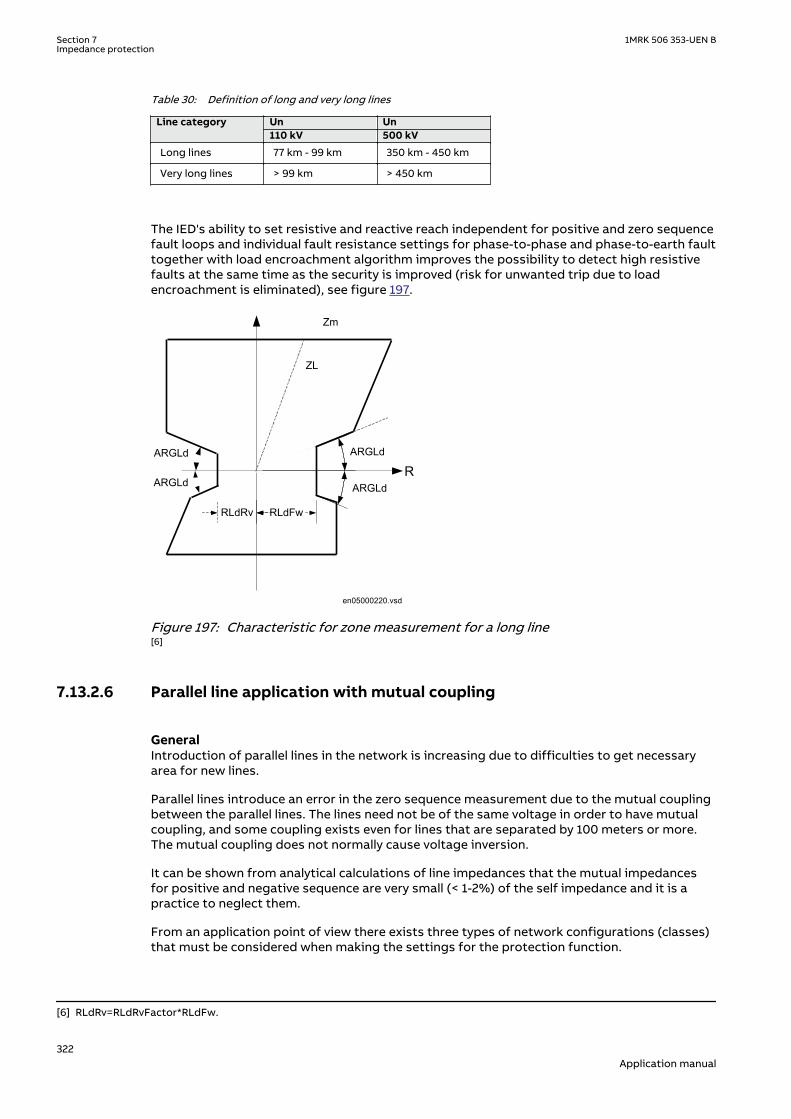
Table 30: Definition of long and very long lines
Line category
Un Un110 kV 500 kV
Long lines 77 km - 99 km 350 km - 450 km
Very long lines > 99 km > 450 km
The IED's ability to set resistive and reactive reach independent for positive and zero sequencefault loops and individual fault resistance settings for phase-to-phase and phase-to-earth faulttogether with load encroachment algorithm improves the possibility to detect high resistivefaults at the same time as the security is improved (risk for unwanted trip due to loadencroachment is eliminated), see figure 197.
en05000220.vsd
R
Zm
ARGLdARGLd
ARGLd ARGLd
RLdFwRLdRv
ZL
IEC05000220 V1 EN-US
Figure 197: Characteristic for zone measurement for a long line[6]
7.13.2.6 Parallel line application with mutual couplingGUID-1F856628-0CEE-4679-BB71-40177187390D v1
GeneralGUID-1D633249-8BF6-4992-A06E-E8BD23B2C315 v2
Introduction of parallel lines in the network is increasing due to difficulties to get necessaryarea for new lines.
Parallel lines introduce an error in the zero sequence measurement due to the mutual couplingbetween the parallel lines. The lines need not be of the same voltage in order to have mutualcoupling, and some coupling exists even for lines that are separated by 100 meters or more.The mutual coupling does not normally cause voltage inversion.
It can be shown from analytical calculations of line impedances that the mutual impedancesfor positive and negative sequence are very small (< 1-2%) of the self impedance and it is apractice to neglect them.
From an application point of view there exists three types of network configurations (classes)that must be considered when making the settings for the protection function.
[6] RLdRv=RLdRvFactor*RLdFw.
Section 7 1MRK 506 353-UEN BImpedance protection
322Application manual

The different network configuration classes are:
1. Parallel line with common positive and zero sequence network2. Parallel circuits with common positive but separated zero sequence network3. Parallel circuits with positive and zero sequence sources separated.
One example of class 3 networks could be the mutual coupling between a 400 kV line and railroad overhead lines. This type of mutual coupling is not so common although it exists and isnot treated any further in this manual.
For each type of network class, there are three different topologies; the parallel line can be inservice, out of service, out of service and earthed in both ends.
The reach of the distance protection zone 1 will be different depending on the operationcondition of the parallel line. This can be handled by the use of different setting groups forhandling the cases when the parallel line is in operation and out of service and earthed at bothends.
The distance protection within the IED can compensate for the influence of a zero sequencemutual coupling on the measurement at single phase-to-earth faults in the following ways, byusing:
• The possibility of different setting values that influence the earth-return compensationfor different distance zones within the same group of setting parameters.
• Different groups of setting parameters for different operating conditions of a protectedmulti circuit line.
Most multi circuit lines have two parallel operating circuits.
Parallel line applicationsGUID-74355B21-61D3-47A9-A3AE-2D56B2EDDC3C v1
This type of networks is defined as those networks where the parallel transmission linesterminate at common nodes at both ends.
The three most common operation modes are:
1. Parallel line in service.2. Parallel line out of service and earthed.3. Parallel line out of service and not earthed.
Parallel line in serviceGUID-0C0B1323-C69D-4EFE-A3CF-C81D762ED146 v2
This type of application is very common and applies to all normal sub-transmission andtransmission networks.
Let us analyze what happens when a fault occurs on the parallel line see figure 198.
From symmetrical components, we can derive the impedance Z at the relay point for normallines without mutual coupling according to equation 358.
ZU
I IZ Z
Z
U
I I K
ph
ph
ph
ph N
=
+ ⋅−
⋅
=+ ⋅
33
30
0 1
1
0
IECEQUATION1275 V2 EN-US (Equation 358)
1MRK 506 353-UEN B Section 7Impedance protection
323Application manual

Where:
Uph is phase to earth voltage at the relay point.
Iph is phase current in the faulty phase.
3I0 is earth fault current.
Z1 is positive sequence impedance.
Z0 is zero sequence impedance.
Z0m
A B
Z< Z< IEC09000250_1_en.vsdIEC09000250 V1 EN-US
Figure 198: Class 1, parallel line in service
The equivalent circuit of the lines can be simplified, see figure 199.
A
B
CZ0m
Z0mZ0 -
Z0mZ0 -
IEC09000253_1_en.vsdIEC09000253 V1 EN-US
Figure 199: Equivalent zero sequence impedance circuit of the double-circuit, parallel,operating line with a single phase-to-earth fault at the remote busbar
When mutual coupling is introduced, the voltage at the relay point A will be changed accordingto equation 359.
0 000 11 3 3
3 1 3 1mL L
ph pph LL L
ZZ ZU Z I I IZ Z
æ ö-= × + × +ç ÷
× ×è øIECEQUATION1276 V3 EN-US (Equation 359)
By dividing equation 359 by equation 358 and after some simplification we can write theimpedance present to the relay at A side as:
3 01 13 0
æ ö×= +ç ÷+ ×è ø
LI KNmZ Z
I ph I KNEQUATION1277 V3 EN-US (Equation 360)
Where:
KNm = Z0m/(3 · Z1L)
The second part in the parentheses is the error introduced to the measurement of the lineimpedance.
Section 7 1MRK 506 353-UEN BImpedance protection
324Application manual

If the current on the parallel line has negative sign compared to the current on the protectedline, that is, the current on the parallel line has an opposite direction compared to the currenton the protected line, the distance function will overreach. If the currents have the samedirection, the distance protection will underreach.
Maximum overreach will occur if the fault current infeed from remote line end is weak. Ifconsidering a single phase-to-earth fault at 'p' unit of the line length from A to B on the parallelline for the case when the fault current infeed from remote line end is zero, the voltage UA inthe faulty phase at A side as in equation 361.
U p ZI I K I K IA L ph N Nm p= ⋅ + ⋅ + ⋅( )3 3
0 0
IECEQUATION1278 V2 EN-US (Equation 361)
One can also notice that the following relationship exists between the zero sequence currents:
3 0 3 0 0 20
I Z I Z pL p L
⋅ = ⋅ −( )EQUATION1279 V3 EN-US (Equation 362)
Simplification of equation 362, solving it for 3I0p and substitution of the result into equation361 gives that the voltage can be drawn as:
U p ZI I K I KI p
pA L ph N Nm
= ⋅ + ⋅ + ⋅⋅
−
3
3
20
0
IECEQUATION1280 V2 EN-US (Equation 363)
If we finally divide equation 363 with equation 358 we can draw the impedance present to theIED as
Z p ZI
I KN I KNI p
p
I I KNL
ph m
ph
= ⋅
+ ⋅ + ⋅⋅
−
+ ⋅
33
2
3
0
0
0
EQUATION1379 V3 EN-US (Equation 364)
Calculation for a 400 kV line, where we for simplicity have excluded the resistance, gives withX1L=0.303 Ω/km, X0L=0.88 Ω/km, zone 1 reach is set to 90% of the line reactance p=71% thatis, the protection is underreaching with approximately 20%.
The zero sequence mutual coupling can reduce the reach of distance protection on theprotected circuit when the parallel line is in normal operation. The reduction of the reach ismost pronounced with no current infeed in the IED closest to the fault. This reach reduction isnormally less than 15%. But when the reach is reduced at one line end, it is proportionallyincreased at the opposite line end. So this 15% reach reduction does not significantly affectthe operation of a permissive underreaching scheme.
Parallel line out of service and earthedGUID-DFB5C5AD-407D-4325-BE46-092F5F5D2F59 v1GUID-A93E0062-A4E1-447B-A3A3-74B49581AD70 v1
1MRK 506 353-UEN B Section 7Impedance protection
325Application manual

Z0m
A B
Z< Z<IEC09000251_1_en.vsd
IEC09000251 V1 EN-US
Figure 200: The parallel line is out of service and earthed
When the parallel line is out of service and earthed at both line ends on the bus bar side of theline CTs so that zero sequence current can flow on the parallel line, the equivalent zerosequence circuit of the parallel lines will be according to figure 201.
A
B
C
IEC09000252_1_en.vsd
I0
I0
Z0mZ0 -
Z0mZ0 -
Z0m
IEC09000252 V1 EN-US
Figure 201: Equivalent zero sequence impedance circuit for the double-circuit line thatoperates with one circuit disconnected and earthed at both ends
Here the equivalent zero-sequence impedance is equal to Z0-Z0m in parallel with (Z0-Z0m)/Z0-Z0m+Z0m which is equal to equation 365.
2 2
0
0
omE
Z ZZ
Z
-=
EQUATION2002 V4 EN-US (Equation 365)
The influence on the distance measurement will be a considerable overreach, which must beconsidered when calculating the settings. It is recommended to use a separate setting groupfor this operation condition since it will reduce the reach considerably when the line is inoperation.
All expressions below are proposed for practical use. They assume the value of zero sequence,mutual resistance R0m equals to zero. They consider only the zero sequence, mutual reactanceX0m. Calculate the equivalent X0E and R0E zero sequence parameters according to equation 366and equation 367 for each particular line section and use them for calculating the reach for theunderreaching zone.
R RX
R XE
m0 0
0
2
0
2
0
21= ⋅ +
+
DOCUMENT11520-IMG3502 V2 EN-US (Equation 366)
X XX
R XE
m0 0
0
2
0
2
0
21= ⋅ −
+
DOCUMENT11520-IMG3503 V2 EN-US (Equation 367)
Section 7 1MRK 506 353-UEN BImpedance protection
326Application manual

Parallel line out of service and not earthedGUID-DF8B0C63-E6D1-4E11-A8CB-D0C8EAE10FF0 v1
Z0m
A B
Z< Z<IEC09000254_1_en.vsd
IEC09000254 V1 EN-US
Figure 202: Parallel line is out of service and not earthed
When the parallel line is out of service and not earthed, the zero sequence on that line can onlyflow through the line admittance to the earth. The line admittance is high which limits thezero-sequence current on the parallel line to very low values. In practice, the equivalent zero-sequence impedance circuit for faults at the remote bus bar can be simplified to the circuitshown in figure 202
The line zero sequence mutual impedance does not influence the measurement of the distanceprotection in a faulty circuit. This means that the reach of the underreaching distanceprotection zone is reduced if, due to operating conditions, the equivalent zero sequenceimpedance is set according to the conditions when the parallel system is out of operation andearthed at both ends.
A
B
C
IEC09000255_1_en.vsd
I0
I0
Z0mZ0 -
Z0m
Z0mZ0 -
IEC09000255 V1 EN-US
Figure 203: Equivalent zero-sequence impedance circuit for a double-circuit line with onecircuit disconnected and not earthed
The reduction of the reach is equal to equation 368.
( )( ) ( )
21 0
0
1 001 0
1 23 11 2 323
E fm
U
ff
Z Z R ZKZ Z Z RZ Z R
× × + += = -
× × + +× × + +
EQUATION1284 V1 EN-US (Equation 368)
This means that the reach is reduced in reactive and resistive directions. If the real andimaginary components of the constant A are equal to equation 369 and equation 370.
Re( ) 0 (2 1 0 3 ) 0 ( 0 2 1)A R R R Rf X X X= × × + + × - × + ×EQUATION1285 V1 EN-US (Equation 369)
0 1 0 1 0 1 0Im( ) (2 3 ) (2 )A X R R R R X X= × × + + × + × × +EQUATION1286 V1 EN-US (Equation 370)
The real component of the KU factor is equal to equation 371.
1MRK 506 353-UEN B Section 7Impedance protection
327Application manual
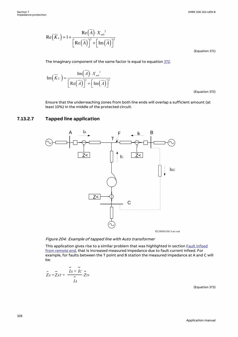
Re
Re
Re Im
KA X
A A
u
m
( ) = +( ) ⋅
( )
+ ( )
1
0
2
2 2
EQUATION1287 V3 EN-US (Equation 371)
The imaginary component of the same factor is equal to equation 372.
( ) ( )( ) ( )
20
2 2
ImIm
Re Im
mU
A XK
A A
×=
+é ù é ùë û ë ûEQUATION1288 V2 EN-US (Equation 372)
Ensure that the underreaching zones from both line ends will overlap a sufficient amount (atleast 10%) in the middle of the protected circuit.
7.13.2.7 Tapped line applicationGUID-4DFD6015-E97C-4F7E-84CA-C7CD2438C55A v1
GUID-77388095-4EE8-4915-A1D4-D0767D1E04F5 v1
C
B
BC
IEC09000160-3-en.vsd
A
IEC09000160 V3 EN-US
Figure 204: Example of tapped line with Auto transformer
This application gives rise to a similar problem that was highlighted in section Fault infeedfrom remote end, that is increased measured impedance due to fault current infeed. Forexample, for faults between the T point and B station the measured impedance at A and C willbe:
ZA =ZAT + ·ZTFIA + IC
IADOCUMENT11524-IMG3509 V3 EN-US (Equation 373)
Section 7 1MRK 506 353-UEN BImpedance protection
328Application manual

Z Z ZI I
IZ
U
UC Trf CT
A C
C
TF= + ++
⋅
⋅
2
1
2
DOCUMENT11524-IMG3510 V3 EN-US (Equation 374)
Where:
ZAT and ZCT is the line impedance from the A respective C station to the T point.
IA and IC is fault current from A respective C station for fault between T and B.
U2/U1 Transformation ratio for transformation of impedance at U1 side of thetransformer to the measuring side U2 (it is assumed that current and voltagedistance function is taken from U2 side of the transformer).
ZTF is the line impedance from the T point to the fault (F).
ZTrf is transformer impedance.
For this example with a fault between T and B, the measured impedance from the T point tothe fault will be increased by a factor defined as the sum of the currents from T point to thefault divided by the IED current. For the IED at C, the impedance on the high voltage side U1has to be transferred to the measuring voltage level by the transformer ratio.
Another complication that might occur depending on the topology is that the current from oneend can have a reverse direction for fault on the protected line. For example, for faults at T thecurrent from B might go in reverse direction from B to C depending on the system parameters(see the dotted line in figure 204), given that the distance protection in B to T will measurewrong direction.
In three-end application, depending on the source impedance behind the IEDs, the impedancesof the protected object and the fault location, it might be necessary to accept zone 2 trip inone end or sequential trip in one end.
Generally for this type of application it is difficult to select settings of zone 1 that both givesoverlapping of the zones with enough sensitivity without interference with other zone 1settings, that is, without selectivity conflicts. Careful fault calculations are necessary todetermine suitable settings and selection of proper scheme communication.
Fault resistanceGUID-D42B3721-E63B-411E-A7DD-5F606ECA4576 v1
The performance of distance protection for single phase-to-earth faults is very important,because normally more than 70% of the faults on transmission lines are single phase-to-earthfaults. At these faults, the fault resistance is composed of three parts: arc resistance,resistance of a tower construction, and tower-footing resistance. The arc resistance can becalculated according to Warrington's formula:
1.428707 LRarc
I×
=
EQUATION1456 V1 EN-US (Equation 375)
Where:
L represents the length of the arc (in meters). This equation applies for the distance protection zone 1.Consider approximately three times arc foot spacing for zone 2 to get a reasonable margin againstthe influence of wind.
I is the actual fault current in A.
1MRK 506 353-UEN B Section 7Impedance protection
329Application manual

In practice, the setting of fault resistance for both phase-to-earth RFPE and phase-to-phaseRFPP should be as high as possible without interfering with the load impedance in order toobtain reliable fault detection.
7.13.3 Series compensation in power systemsGUID-7F3BBF91-4A17-4B31-9828-F2757672C440 v2
The main purpose of series compensation in power systems is virtual reduction of linereactance in order to enhance the power system stability and increase loadability oftransmission corridors. The principle is based on compensation of distributed line reactanceby insertion of series capacitor (SC). The generated reactive power provided by the capacitoris continuously proportional to the square of the current flowing at the same time through thecompensated line and series capacitor. This means that the series capacitor has a self-regulating effect. When the system loading increases, the reactive power generated by seriescapacitors increases as well. The response of SCs is automatic, instantaneous and continuous.
The main benefits of incorporating series capacitors in transmission lines are:
• Steady state voltage regulation and raise of voltage collapse limit• Increase power transfer capability by raising the dynamic stability limit• Improved reactive power balance• Increase in power transfer capacity• Reduced costs of power transmission due to decreased investment costs for new power
lines
7.13.3.1 Steady state voltage regulation and increase of voltage collapse limitGUID-0AB9B4B5-92DF-4A3B-9046-FC3A460DA658 v1
A series capacitor is capable of compensating the voltage drop of the series inductance in atransmission line, as shown in figure 205. During low loading, the system voltage drop is lowerand at the same time, the voltage drop on the series capacitor is lower. When the loadingincreases and the voltage drop become larger, the contribution of the series capacitorincreases and therefore the system voltage at the receiving line end can be regulated.
Series compensation also extends the region of voltage stability by reducing the reactance ofthe line and consequently the SC is valuable for prevention of voltage collapse. Figure 206presents the voltage dependence at receiving bus B (as shown in figure 205) on line loadingand compensation degree KC, which is defined according to equation 376. The effect of seriescompensation is in this particular case obvious and self explanatory.
= CC
Line
XK
XEQUATION1895 V1 EN-US (Equation 376)
A typical 500 km long 500 kV line is considered with source impedance
1 0=SAZEQUATION1896 V1 EN-US (Equation 377)
~EA
ZSA1 Power line
A B
Seirescapacitor
Load
en06000585.vsdIEC06000585 V1 EN-US
Figure 205: A simple radial power system
Section 7 1MRK 506 353-UEN BImpedance protection
330Application manual

en06000586.vsd
0 200 400 600 800 1000 1200 1400 1600 1800
100
200
300
400
500
P[MW]
U[k
V]
U limit
P0 P30
P50
P70
IEC06000586 V1 EN-US
Figure 206: Voltage profile for a simple radial power line with 0, 30, 50 and 70% ofcompensation
7.13.3.2 Increase in power transferGUID-C9163D4E-CC2B-4645-B2AC-2C8A3FE3D337 v3
The increase in power transfer capability as a function of the degree of compensation for atransmission line can be explained by studying the circuit shown in figure 207. The powertransfer on the transmission line is given by the equation 378:
( ) ( )( )
sin sin1
d d× × × ×= =
- × -A B A B
Line C Line C
U U U UP
X X X KEQUATION1897 V1 EN-US (Equation 378)
The compensation degree Kc is defined as equation
A B-jX C
PA
QA
PB
QB
UA UBU
+jXL
UA UB
d
D
en06000590.vsdIEC06000590 V1 EN-US
Figure 207: Transmission line with series capacitor
The effect on the power transfer when considering a constant angle difference (δ) betweenthe line ends is illustrated in figure 208. Practical compensation degree runs from 20 to 70percent. Transmission capability increases of more than two times can be obtained in practice.
1MRK 506 353-UEN B Section 7Impedance protection
331Application manual

IEC06000592-2-en.vsd
0 0.1 0.2 0.3 0.4 0.5 0.6 0.71
1.5
2
2.5
3
3.5
Degree of series compensation [%]
Incre
ase
in p
ow
er transfe
r
Power transfer with constant angle difference
Degree of compensation
Multiple of power over a non-compensated line
IEC06000592 V2 EN-US
Figure 208: Increase in power transfer over a transmission line depending on degree ofseries compensation
7.13.3.3 Voltage and current inversionGUID-CB215C0F-F4FA-4646-9235-AE6DB0255E80 v1
Series capacitors influence the magnitude and the direction of fault currents in seriescompensated networks. They consequently influence phase angles of voltages measured indifferent points of series compensated networks and this performances of differentprotection functions, which have their operation based on properties of measured voltage andcurrent phasors.
Voltage inversionGUID-E649A7CB-9877-48F7-8AB3-25D5E8695673 v1
Figure 209 presents a part of series compensated line with reactance XL1 between the IEDpoint and the fault in point F of series compensated line. The voltage measurement issupposed to be on the bus side, so that series capacitor appears between the IED point andfault on the protected line. Figure 210 presents the corresponding phasor diagrams for thecases with bypassed and fully inserted series capacitor.
Voltage distribution on faulty lossless serial compensated line from fault point F to the bus islinearly dependent on distance from the bus, if there is no capacitor included in scheme (asshown in figure 210). Voltage UM measured at the bus is equal to voltage drop D UL on thefaulty line and lags the current IF by 90 electrical degrees.
The situation changes with series capacitor included in circuit between the IED point and thefault position. The fault current IF (see figure 210) is increased due to the series capacitor,generally decreases total impedance between the sources and the fault. The reactive voltagedrop D UL on XL1 line impedance leads the current by 90 degrees. Voltage drop DUC on seriescapacitor lags the fault current by 90 degrees. Note that line impedance XL1 could be dividedinto two parts: one between the IED point and the capacitor and one between the capacitorand the fault position. The resulting voltage UM in IED point is this way proportional to sum ofvoltage drops on partial impedances between the IED point and the fault position F, aspresented by
( )1= × -M F L CU I j X XEQUATION1901 V1 EN-US (Equation 379)
Section 7 1MRK 506 353-UEN BImpedance protection
332Application manual

en06000605.vsd
~
Z<
XS XL1
IF
UUM
Source
Fault voltage
Pre -fault voltage
XC
Source voltage
U’M
With bypassedcapacitor
With insertedcapacitor
F
IEC06000605 V1 EN-US
Figure 209: Voltage inversion on series compensated line
en06000606.vsd
IF
U S
U’ M=
xUL
xUS
IF
xU L
U S
xU
C
UM
xUS
With bypassedcapacitor
With insertedcapacitor
IEC06000606 V1 EN-US
Figure 210: Phasor diagrams of currents and voltages for the bypassed and insertedseries capacitor during voltage inversion
It is obvious that voltage UM will lead the fault current IF as long as XL1> XC. This situationcorresponds, from the directionality point of view, to fault conditions on line without seriescapacitor. Voltage UM in IED point will lag the fault current IF in case when:
L1 C S L1X X X X< < +
EQUATION1902 V1 EN-US (Equation 380)
Where
XS is the source impedance behind the IED
The IED point voltage inverses its direction due to presence of series capacitor and itsdimension. It is a common practice to call this phenomenon voltage inversion. Itsconsequences on operation of different protections in series compensated networks dependon their operating principle. The most known effect has voltage inversion on directionalmeasurement of distance IEDs (see chapter "Distance protection" for more details), whichmust for this reason comprise special measures against this phenomenon.
There will be no voltage inversion phenomena for reverse faults in system with VTs located onthe bus side of series capacitor. The allocation of VTs to the line side does not eliminate thephenomenon, because it appears again for faults on the bus side of IED point.
1MRK 506 353-UEN B Section 7Impedance protection
333Application manual

Current inversionGUID-9F7FDF59-D0B4-4972-9CB0-B3D56DACA09E v1
Figure 211 presents part of a series compensated line with corresponding equivalent voltagesource. It is generally anticipated that fault current IF flows on non-compensated lines frompower source towards the fault F on the protected line. Series capacitor may change thesituation.
en06000607.vsd
~
Z<
XS XL1
IF
UUM
Source
Fault voltage
Pre -fault voltage
XC
Source voltage
U’MWith bypassed
capacitor
With insertedcapacitor
F
IEC06000607 V1 EN-US
Figure 211: Current inversion on series compensated line
The relative phase position of fault current IF compared to the source voltage US depends ingeneral on the character of the resultant reactance between the source and the fault position.Two possibilities appear:
1
1
00
- + >
- + <S C L
S C L
X X X
X X XEQUATION1935 V1 EN-US (Equation 381)
The first case corresponds also to conditions on non compensated lines and in cases, whenthe capacitor is bypassed either by spark gap or by the bypass switch, as shown in phasordiagram in figure 212. The resultant reactance is in this case of inductive nature and the faultcurrents lags source voltage by 90 electrical degrees.
The resultant reactance is of capacitive nature in the second case. Fault current will for thisreason lead the source voltage by 90 electrical degrees, which means that reactive current willflow from series compensated line to the system. The system conditions are in such casepresented by equation 382
1> +C S LX X XEQUATION1936 V1 EN-US (Equation 382)
Section 7 1MRK 506 353-UEN BImpedance protection
334Application manual

en06000608.vsd
IF
U S
U’ M=
HUL
HU S
With bypassedcapacitor
IF
HU L
U SH
U C
UM
HUS
With insertedcapacitor
IEC06000608 V1 EN-US
Figure 212: Phasor diagrams of currents and voltages for the bypassed and insertedseries capacitor during current inversion
It is a common practice to call this phenomenon current inversion. Its consequences onoperation of different protections in series compensated networks depend on their operatingprinciple. The most known effect has current inversion on operation of distance IEDs (asshown in section "Distance protection" for more details), which cannot be used for theprotection of series compensated lines with possible current inversion. Equation 382 showsalso big dependence of possible current inversion on series compensated lines on location ofseries capacitors. XL1 = 0 for faults just behind the capacitor when located at line IED and onlythe source impedance prevents current inversion. Current inversion has been considered formany years only a theoretical possibility due to relatively low values of source impedances (bigpower plants) compared to the capacitor reactance. The possibility for current inversion inmodern networks is increasing and must be studied carefully during system preparatorystudies.
The current inversion phenomenon should not be studied only for the purposes of protectiondevices measuring phase currents. Directional comparison protections, based on residual(zero sequence) and negative sequence currents should be considered in studies as well.Current inversion in zero sequence systems with low zero sequence source impedance (anumber of power transformers connected in parallel) must be considered as practicalpossibility in many modern networks.
Location of instrument transformersGUID-A8283D59-622B-4EB3-8C0A-8C886C3CF9D0 v1
Location of instrument transformers relative to the line end series capacitors plays animportant role regarding the dependability and security of a complete protection scheme. It ison the other hand necessary to point out the particular dependence of those protectionschemes, which need for their operation information on voltage in IED point.
Protection schemes with their operating principle depending on current measurement only,like line current differential protection are relatively independent on CT location. Figure 213shows schematically the possible locations of instrument transformers related to the positionof line-end series capacitor.
- jX CCT1 CT2
VT1 VT 2
en06000611.vsdIEC06000611 V1 EN-US
Figure 213: Possible positions of instrument transformers relative to line end seriescapacitor
1MRK 506 353-UEN B Section 7Impedance protection
335Application manual

Bus side instrument transformersGUID-B7D1F10A-5467-4F91-9BC1-AB8906357428 v1
CT1 and VT1 on figure 213 represent the case with bus side instrument transformers. Theprotection devices are in this case exposed to possible voltage and current inversion for linefaults, which decreases the required dependability. In addition to this may series capacitorcause negative apparent impedance to distance IEDs on protected and adjacent lines as wellfor close-in line faults (see also figure 215 LOC=0%), which requires special design of distancemeasuring elements to cope with such phenomena. The advantage of such installation is thatthe protection zone covers also the series capacitor as a part of protected power line, so thatline protection will detect and cleared also parallel faults on series capacitor.
Line side instrument transformersGUID-3E5897C4-9A15-4A51-90C2-F619D4E083A6 v1
CT2 and VT2 on figure 213 represent the case with line side instrument transformers. Theprotective devices will not be exposed to voltage and current inversion for faults on theprotected line, which increases the dependability. Distance protection zone 1 may be active inmost applications, which is not the case when the bus side instrument transformers are used.
Distance IEDs are exposed especially to voltage inversion for close-in reverse faults, whichdecreases the security. The effect of negative apparent reactance must be studied seriously incase of reverse directed distance protection zones used by distance IEDs for teleprotectionschemes. Series capacitors located between the voltage instruments transformers and thebuses reduce the apparent zero sequence source impedance and may cause voltage as well ascurrent inversion in zero sequence equivalent networks for line faults. It is for this reasonabsolutely necessary to study the possible effect on operation of zero sequence directionalearth-fault overcurrent protection before its installation.
Dual side instrument transformersGUID-3B737D75-F1D0-45AB-92A1-E0AEA9A1CCFD v1
Installations with line side CT2 and bus side VT1 are not very common. More common areinstallations with line side VT2 and bus side CT1. They appear as de facto installations also inswitchyards with double-bus double-breaker and 1½ breaker arrangement. The advantage ofsuch schemes is that the unit protections cover also for shunt faults in series capacitors and atthe same time the voltage inversion does not appear for faults on the protected line.
Many installations with line-end series capacitors have available voltage instrumenttransformers on both sides. In such case it is recommended to use the VTs for each particularprotection function to best suit its specific characteristics and expectations on dependabilityand security. The line side VT can for example be used by the distance protection and the busside VT by the directional residual OC earth fault protection.
Apparent impedances and MOV influenceGUID-A0FBC954-D581-4B24-81CD-AD69661A020D v2
Series capacitors reduce due to their character the apparent impedance measured by distanceIEDs on protected power lines. Figure 214 presents typical locations of capacitor banks onpower lines together with corresponding compensation degrees. Distance IED near thefeeding bus will see in different cases fault on remote end bus depending on type ofovervoltage protection used on capacitor bank (spark gap or MOV) and SC location onprotected power line.
en06000612.vsd
~EA
0%33 %
50%66 %
KC = 80% 33% 33 %50 %Z<
100 %
80 %
IEC06000612 V1 EN-US
Figure 214: Typical locations of capacitor banks on series compensated line
Implementation of spark gaps for capacitor overvoltage protection makes the picturerelatively simple, because they either flash over or not. The apparent impedance correspondsto the impedance of non-compensated line, as shown in figure 215 case KC = 0%.
Section 7 1MRK 506 353-UEN BImpedance protection
336Application manual

en06000613.vsd
jX
R
KC = 0%KC = 80%LOC = 0%
KC = 50%LOC = 50%
jX jX
R R
KC = 2 x 33%LOC = 33%, 66%
KC = 80%LOC = 100%
jX jX
R R
IEC06000613 V1 EN-US
Figure 215: Apparent impedances seen by distance IED for different SC locations andspark gaps used for overvoltage protection
en06000614.vsd
MOV protected series capacitor
M OV
iL iC
iM
uC
-jXC
0 10 20 30 40 50 60
20
10
10
20
0 10 20 30 40 50 60
100
50
50
100
0 10 20 30 40 50 60
20
10
10
20
0 10 20 30 40 50 60
20
10
10
20
Line current as a function of time Capacitor voltage as a function of time
Capacitor current as a function of time MOV current as a function of time
IEC06000614 V1 EN-US
Figure 216: MOV protected capacitor with examples of capacitor voltage andcorresponding currents
The impedance apparent to distance IED is always reduced for the amount of capacitivereactance included between the fault and IED point, when the spark gap does not flash over, aspresented for typical cases in figure 215. Here it is necessary to distinguish between twotypical cases:
• Series capacitor only reduces the apparent impedance, but it does not cause wrongdirectional measurement. Such cases are presented in figure 215 for 50% compensation at50% of line length and 33% compensation located on 33% and 66% of line length. Theremote end compensation has the same effect.
• The voltage inversion occurs in cases when the capacitor reactance between the IED pointand fault appears bigger than the corresponding line reactance, Figure 215, 80%compensation at local end. A voltage inversion occurs in IED point and the distance IEDwill see wrong direction towards the fault, if no special measures have been introduced inits design.
The situation differs when metal oxide varistors (MOV) are used for capacitor overvoltageprotection. MOVs conduct current, for the difference of spark gaps, only when the
1MRK 506 353-UEN B Section 7Impedance protection
337Application manual

instantaneous voltage drop over the capacitor becomes higher than the protective voltagelevel in each half-cycle separately, see figure 216.
Extensive studies at Bonneville Power Administration in USA ( ref. Goldsworthy, D,L “ALinearized Model for MOV-Protected series capacitors” Paper 86SM357–8 IEEE/PES summermeeting in Mexico City July 1986) have resulted in construction of a non-linear equivalentcircuit with series connected capacitor and resistor. Their value depends on complete line(fault) current and protection factor kp. The later is defined by equation 383.
= MOVp
NC
UkU
EQUATION1910 V1 EN-US (Equation 383)
Where
UMOV is the maximum instantaneous voltage expected between the capacitor immediately before the MOVhas conducted or during operation of the MOV, divaded by √2
UNC is the rated voltage in RMS of the series capacitor
en06000615.vsd
R
jX
1I
£
R
jX
2I
=
R
jX
10I
=
Kp × In Kp × In
Kp × In
IEC06000615 V1 EN-US
Figure 217: Equivalent impedance of MOV protected capacitor in dependence ofprotection factor KP
Figure 217 presents three typical cases for series capacitor located at line end (case LOC=0%in figure 215).
• Series capacitor prevails the scheme as long as the line current remains lower or equal toits protective current level (I £ kp · INC). Line apparent impedance is in this case reduced forthe complete reactance of a series capacitor.
• 50% of capacitor reactance appears in series with resistance, which corresponds toapproximately 36% of capacitor reactance when the line current equals two times theprotective current level (I £ 2· kp· INC). This information has high importance for setting ofdistance protection IED reach in resistive direction, for phase to earth fault measurementas well as for phase to phase measurement.
• Series capacitor becomes nearly completely bridged by MOV when the line currentbecomes higher than 10-times the protective current level (I £ 10· kp· INC).
7.13.3.4 Impact of series compensation on protective IED of adjacent linesGUID-DA1DBB5B-0AFD-49F4-87C7-0E8AB5006051 v2
Voltage inversion is not characteristic for the buses and IED points closest to the seriescompensated line only. It can spread also deeper into the network and this way influences the
Section 7 1MRK 506 353-UEN BImpedance protection
338Application manual

selection of protection devices (mostly distance IEDs) on remote ends of lines adjacent to theseries compensated circuit, and sometimes even deeper in the network.
en06000616.vsd
~
~
F
B
EB
EAZSA
UA
AZLA
IAUD
D
ZLB
IBUB
ZSB
ZLF
IF-jXC
IEC06000616 V1 EN-US
Figure 218: Voltage inversion in series compensated network due to fault current infeed
Voltage at the B bus (as shown in figure 218) is calculated for the loss-less system according tothe equation below.
U U I jX I I j X X I jXB D B LB A B LF C B LB= + ⋅ = +( ) ⋅ −( ) + ⋅
EQUATION1911 V2 EN-US (Equation 384)
Further development of equation 384 gives the following expressions:
U jI XI
IX XB B LB
A
BLF C= ⋅ + +
⋅ −( )
1
EQUATION1912 V2 EN-US (Equation 385)
( )01
= = ++
LBC B LF
A
B
XX U XII
EQUATION1913 V1 EN-US (Equation 386)
Equation 385 indicates the fact that the infeed current IA increases the apparent value ofcapacitive reactance in system: bigger the infeed of fault current, bigger the apparent seriescapacitor in a complete series compensated network. It is possible to say that equation 386indicates the deepness of the network to which it will feel the influence of seriescompensation through the effect of voltage inversion.
It is also obvious that the position of series capacitor on compensated line influences in greatextent the deepness of voltage inversion in adjacent system. Line impedance XLF between Dbus and the fault becomes equal to zero, if the capacitor is installed near the bus and the faultappears just behind the capacitor. This may cause the phenomenon of voltage inversion to beexpanded very deep into the adjacent network, especially if on one hand the compensated lineis very long with high degree of compensation, and the adjacent lines are, on the other hand,relatively short.
Extensive system studies are necessary before final decision is made on implementation andlocation of series capacitors in network. It requires to correctly estimate their influence onperformances of (especially) existing distance IEDs. It is possible that the costs for number ofprotective devices, which should be replaced by more appropriate ones due to the effect ofapplied series compensation, influences the future position of series capacitors in powernetwork.
Possibilities for voltage inversion at remote buses should not be studied for short circuits withzero fault resistance only. It is necessary to consider cases with higher fault resistances, forwhich spark gaps or MOVs on series capacitors will not conduct at all. At the same time this
1MRK 506 353-UEN B Section 7Impedance protection
339Application manual

kind of investigation must consider also the maximum sensitivity and possible resistive reachof distance protection devices, which on the other hand simplifies the problem.
Application of MOVs as non-linear elements for capacitor overvoltage protection makes simplecalculations often impossible. Different kinds of transient or dynamic network simulations arein such cases unavoidable.
7.13.3.5 Distance protectionGUID-B8441469-8B23-494F-9BA8-D6A88DB2DC38 v2
Distance protection due to its basic characteristics, is the most used protection principle onseries compensated and adjacent lines worldwide. It has at the same time caused a lot ofchallenges to protection society, especially when it comes to directional measurement andtransient overreach.
Distance IED in fact does not measure impedance or quotient between line current andvoltage. Quantity 1= Operating quantity - Restrain quantity Quantity 2= Polarizing quantity.Typically Operating quantity is the replica impedance drop. Restraining quantity is the systemvoltage Polarizing quantity shapes the characteristics in different way and is not discussedhere.
Distance IEDs comprise in their replica impedance only the replicas of line inductance andresistance, but they do not comprise any replica of series capacitor on the protected line andits protection circuits (spark gap and or MOV). This way they form wrong picture of theprotected line and all “solutions” related to distance protection of series compensated andadjacent lines are concentrated on finding some parallel ways, which may help eliminating thebasic reason for wrong measurement. The most known of them are decrease of the reach dueto presence of series capacitor, which apparently decreases the line reactance, andintroduction of permanent memory voltage in directional measurement.
Series compensated and adjacent lines are often the more important links in a transmissionnetworks and delayed fault clearance is undesirable. This makes it necessary to install distanceprotection in combination with telecommunication. The most common is distance protectionin Permissive Overreaching Transfer Trip mode (POTT).
7.13.3.6 Underreaching and overreaching schemesGUID-3090702F-508B-480C-9AC7-2D5A82B9AD1E v1
It is a basic rule that the underreaching distance protection zone should under nocircumstances overreach for the fault at the remote end bus, and the overreaching zone shouldalways, under all system conditions, cover the same fault. In order to obtain section selectivity,the first distance (underreaching) protection zone must be set to a reach less than thereactance of the compensated line in accordance with figure 219.
en06000618.vsd
X11
X 12-jXC
A B
DA DB
Zone 1A
Zone 1B
Zone 2A
Zone 2B
G
IEC06000618 V1 EN-US
Figure 219: Underreaching (Zone 1) and overreaching (Zone 2) on series compensated line
The underreaching zone will have reduced reach in cases of bypassed series capacitor, asshown in the dashed line in figure 219. The overreaching zone (Zone 2) can this way coverbigger portion of the protected line, but must always cover with certain margin the remoteend bus. Distance protection Zone 1 is often set to
Section 7 1MRK 506 353-UEN BImpedance protection
340Application manual

( )1 11 12= × + -Z S CX K X X XEQUATION1914 V1 EN-US (Equation 387)
Here KS is a safety factor, presented graphically in figure 220, which covers for possibleoverreaching due to low frequency (sub-harmonic) oscillations. Here it should be notedseparately that compensation degree KC in figure 220 relates to total system reactance,inclusive line and source impedance reactance. The same setting applies regardless MOV orspark gaps are used for capacitor overvoltage protection.
Equation 387 is applicable for the case when the VTs are located on the bus side of seriescapacitor. It is possible to remove XC from the equation in cases of VTs installed in line side,but it is still necessary to consider the safety factor KS .
If the capacitor is out of service or bypassed, the reach with these settings can be less than50% of protected line dependent on compensation degree and there will be a section, G infigure 219, of the power line where no tripping occurs from either end.
en06000619.vsd
K S
1.0
0.8
0.6
0.4
0.2
0 20 40 60 80 100
KC[%]
IEC06000619 V1 EN-US
Figure 220: Underreaching safety factor KS in dependence on system compensationdegree KC
For that reason permissive underreaching schemes can hardly be used as a main protection.Permissive overreaching distance protection or some kind of directional or unit protectionmust be used.
The overreach must be of an order so it overreaches when the capacitor is bypassed or out ofservice. Figure 221 shows the permissive zones. The first underreaching zone can be kept in thetotal protection but it only has the feature of a back-up protection for close up faults. Theoverreach is usually of the same order as the permissive zone. When the capacitor is inoperation the permissive zone will have a very high degree of overreach which can beconsidered as a disadvantage from a security point of view.
en06000620.vsd
X11
X12
- jXC
A B
DA DB
Permissive Zone A
Permissive Zone B
IEC06000620 V1 EN-US
Figure 221: Permissive overreach distance protection scheme
Negative IED impedance, positive fault current (voltage inversion)GUID-4FB71D72-36F1-4FCD-9321-D069CF6E9835 v2
Assume in equation 388
11 11< < +C SX X X XEQUATION1898 V1 EN-US (Equation 388)
1MRK 506 353-UEN B Section 7Impedance protection
341Application manual

and in figure 222
a three phase fault occurs beyond the capacitor. The resultant IED impedance seen from theDB IED location to the fault may become negative (voltage inversion) until the spark gap hasflashed.
Distance protections of adjacent power lines shown in figure 222 are influenced by thisnegative impedance. If the intermediate infeed of short circuit power by other lines is takeninto consideration, the negative voltage drop on XC is amplified and a protection far awayfrom the faulty line can maloperate by its instantaneous operating distance zone, if noprecaution is taken. Impedances seen by distance IEDs on adjacent power lines are presentedby equations 389 to 392.
1 2 3= + +I I I IEQUATION1915 V1 EN-US (Equation 389)
X XI
I
X XDA A
F
A
C1 1
1
11= + ⋅ −( )
EQUATION1916 V2 EN-US (Equation 390)
X XI
I
X XDA A
F
A
C2 2
2
11= + ⋅ −( )
EQUATION1917 V2 EN-US (Equation 391)
X XI
I
X XDA A
F
A
C3 3
3
11= + ⋅ −( )
EQUATION1918 V2 EN-US (Equation 392)
en06000621.vsd
BA1
A2
A3
DB
DA3
DA2
DA1
jX11
IA1
IA2
IA3
IF
-jXC
jX1
jX2
jX3
F
IEC06000621 V1 EN-US
Figure 222: Distance IED on adjacentpower lines are influenced bythe negative impedance
Normally the first zone of this protection must be delayed until the gap flashing has takenplace. If the delay is not acceptable, some directional comparison must also be added to theprotection of all adjacent power lines. As stated above, a good protection system must be ableto operate correctly both before and after gap flashing occurs. Distance protection can beused, but careful studies must be made for each individual case. The rationale describedapplies to both conventional spark gap and MOV protected capacitors.
Special attention should be paid to selection of distance protection on shorter adjacent powerlines in cases of series capacitors located at the line end. In such case the reactance of a short
Section 7 1MRK 506 353-UEN BImpedance protection
342Application manual

adjacent line may be lower than the capacitor reactance and voltage inversion phenomenonmay occur also on remote end of adjacent lines. Distance protection of such line must havebuilt-in functionality which applies normally to protection of series compensated lines.
It usually takes a bit of a time before the spark gap flashes, and sometimes the fault currentwill be of such a magnitude that there will not be any flashover and the negative impedancewill be sustained. If equation 393 is valid
11 11< < +C SX X X XEQUATION1898 V1 EN-US (Equation 393)
in figure 223, the fault current will have the same direction as when the capacitor is bypassed.So, the directional measurement is correct but the impedance measured is negative and if thecharacteristic crosses the origin shown in figure 223 the IED cannot operate. However, if thereis a memory circuit designed so it covers the negative impedance, a three phase fault can besuccessfully cleared by the distance protection. As soon as the spark gap has flashed thesituation for protection will be as for an ordinary fault. However, a good protection systemshould be able to operate correctly before and after gap flashing occurs.
en06000625.vsd
jX
R
X11
X12
XC
ZS
IEC06000625 V1 EN-US
Figure 223: Cross-polarizedquadrilateralcharacteristic
en06000584_small.vsd
jX
R
X11
X12
XC
ZS
XFW
XRV
RFW
RRV
IEC06000584-SMALL V1 EN-US
Figure 224: Quadrilateralcharacteristic withseparate impedance anddirectional measurement
If the distance protection is equipped with an earth-fault measuring unit, the negativeimpedance occurs when
1_11 0 _113 2× > × +CX X XEQUATION1919 V1 EN-US (Equation 394)
Cross-polarized distance protection (either with mho or quadrilateral characteristic) willnormally handle earth-faults satisfactory if the negative impedance occurs inside thecharacteristic. The operating area for negative impedance depends upon the magnitude of thesource impedance and calculations must be made on a case by case basis, as shown in figure223. Distance IEDs with separate impedance and directional measurement offer additionalsetting and operational flexibility when it comes to measurement of negative apparentimpedance (as shown in figure 224).
Negative IED impedance, negative fault current (current inversion)GUID-F858877A-E736-4B1C-97B4-8A2B5F8EE644 v2
If equation 395 is valid in Figure 211 and a fault occurs behind the capacitor, the resultantreactance becomes negative and the fault current will have an opposite direction compared
1MRK 506 353-UEN B Section 7Impedance protection
343Application manual

with fault current in a power line without a capacitor (current inversion). The negativedirection of the fault current will persist until the spark gap has flashed. Sometimes there willbe no flashover at all, because the fault current is less than the setting value of the spark gap.The negative fault current will cause a high voltage on the network. The situation will be thesame even if a MOV is used. However, depending upon the setting of the MOV, the faultcurrent will have a resistive component.
X X XC S> + 11
EQUATION2036 V2 EN-US (Equation 395)
The problems described here are accentuated with a three phase or phase-to-phase fault, butthe negative fault current can also exist for a single-phase fault. The condition for a negativecurrent in case of an earth fault can be written as follows:
1_ 1 0 _ 1 0 _ 1_3 2 2× > × + + × +C L L S SX X X X XEQUATION1920 V1 EN-US (Equation 396)
All designations relates to figure 211. A good protection system must be able to cope withboth positive and negative direction of the fault current, if such conditions can occur. Adistance protection cannot operate for negative fault current. The directional element givesthe wrong direction. Therefore, if a problem with negative fault current exists, distanceprotection is not a suitable solution. In practice, negative fault current seldom occurs. Innormal network configurations the gaps will flash in this case.
Double circuit, parallel operating series compensated linesGUID-7A384A24-143F-4695-8214-33E181AD0AB7 v2
Two parallel power lines running in electrically close vicinity to each other and ending at thesame busbar at both ends (as shown in figure 225) causes some challenges for distanceprotection because of the mutual impedance in the zero sequence system. The current reversalphenomenon also raises problems from the protection point of view, particularly when thepower lines are short and when permissive overreach schemes are used.
en06000627.vsd
-jXC
-jXC
ZAC ZCB
ZAC ZCB
A B
Zm0AC Zm0CB
IEC06000627 V1 EN-US
Figure 225: Double circuit, parallel operating line
Zero sequence mutual impedance Zm0 cannot significantly influence the operation of distanceprotection as long as both circuits are operating in parallel and all precautions related tosettings of distance protection on series compensated line have been considered. Influence ofdisconnected parallel circuit, which is earthed at both ends, on operation of distanceprotection on operating circuit is known.
Series compensation additionally exaggerates the effect of zero sequence mutual impedancebetween two circuits, see figure 226. It presents a zero sequence equivalent circuit for a faultat B bus of a double circuit line with one circuit disconnected and earthed at both IEDs. Theeffect of zero sequence mutual impedance on possible overreaching of distance IEDs at A busis increased compared to non compensated operation, because series capacitor does notcompensate for this reactance. The reach of underreaching distance protection zone 1 forphase-to-earth measuring loops must further be decreased for such operating conditions.
Section 7 1MRK 506 353-UEN BImpedance protection
344Application manual

en06000628.vsd
jXm0
j(X0L-Xm0)
j(X0L-Xm0)
-jXC
-jXC
A B
IEC06000628 V1 EN-US
Figure 226: Zero sequence equivalent circuit of a series compensated double circuit linewith one circuit disconnected and earthed at both IEDs
Zero sequence mutual impedance may disturb also correct operation of distance protectionfor external evolving faults, when one circuit has already been disconnected in one phase andruns non-symmetrical during dead time of single pole autoreclosing cycle. All such operatingconditions must carefully be studied in advance and simulated by dynamic simulations in orderto fine tune settings of distance IEDs.
If the fault occurs in point F of the parallel operating circuits, as presented in figure 227, thanalso one distance IED (operating in POTT teleprotection scheme) on parallel, healthy circuit willsend a carrier signal CSAB to the remote line end, where this signal will be received as a carrierreceive signal CRBB.
en06000629.vsd
RAA RBAIFC1 IFC1
F
RAB RBBIFC2
CSAB CRBB
RAA RBAIFC1
F
RAB RBBIFC2
CSAB CRBB
IEC06000629 V1 EN-US
Figure 227: Current reversal phenomenon on parallel operating circuits
It is possible to expect faster IED operation and breaker opening at the bus closer to fault,which will reverse the current direction on the healthy circuit. Distance IED RBB will suddenlydetect fault in forward direction and, if CRBB signal is still present due to long reset time ofIED RAB and especially telecommunication equipment, trip its related circuit breaker, since allconditions for POTT have been fulfilled. Zero sequence mutual impedance will additionallyinfluence this process, since it increases the magnitude of fault current in healthy circuit afterthe opening of first circuit breaker. The so called current reversal phenomenon may causeunwanted operation of protection on healthy circuit and this way endangers even more thecomplete system stability.
To avoid the unwanted tripping, some manufacturers provide a feature in their distanceprotection which detects that the fault current has changed in direction and temporarilyblocks distance protection. Another method employed is to temporarily block the signalsreceived at the healthy line as soon as the parallel faulty line protection initiates tripping. Thesecond mentioned method has an advantage in that not the whole protection is blocked forthe short period. The disadvantage is that a local communication is needed between twoprotection devices in the neighboring bays of the same substation.
Distance protection used on series compensated lines must have a high overreach to cover thewhole transmission line also when the capacitors are bypassed or out of service. When thecapacitors are in service, the overreach will increase tremendously and the whole system willbe very sensitive for false teleprotection signals. Current reversal difficulties will beaccentuated because the ratio of mutual impedance against self-impedance will be muchhigher than for a non-compensated line.
If non-unit protection is to be used in a directional comparison mode, schemes based onnegative sequence quantities offer the advantage that they are insensitive to mutual coupling.However, they can only be used for phase-to-earth and phase-to-phase faults. For three-phasefaults an additional protection must be provided.
1MRK 506 353-UEN B Section 7Impedance protection
345Application manual

7.13.4 Setting guidelinesIP14962-1 v1
7.13.4.1 GeneralGUID-B9958CEF-90ED-4644-B169-C6B4A018193B v1
The settings for Distance measuring zones, quadrilateral characteristic (ZMFCPDIS) are donein primary values. The instrument transformer ratio that has been set for the analog input cardis used to automatically convert the measured secondary input signals to primary values usedin ZMFCPDIS.
The following basics must be considered, depending on application, when doing the settingcalculations:
• Errors introduced by current and voltage instrument transformers, particularly undertransient conditions.
• Inaccuracies in the line zero-sequence impedance data, and their effect on the calculatedvalue of the earth-return compensation factor.
• The effect of infeed between the IED and the fault location, including the influence ofdifferent Z0/Z1 ratios of the various sources.
• The phase impedance of non transposed lines is not identical for all fault loops. Thedifference between the impedances for different phase-to-earth loops can be as large as5-10% of the total line impedance.
• The effect of a load transfer between the IEDs of the protected fault resistance isconsiderable, the effect must be recognized.
• Zero-sequence mutual coupling from parallel lines.
7.13.4.2 Setting of zone 1GUID-12E84C05-93A2-4FA3-B7BA-0963FB1C098F v1
The different errors mentioned earlier usually require a limitation of the underreaching zone(zone 1) to 75%...90% of the protected line.
In case of parallel lines, consider the influence of the mutual coupling according to section"Parallel line application with mutual coupling" and select the case(s) that are valid in theparticular application. By proper setting it is possible to compensate for the cases when theparallel line is in operation, out of service and not earthed and out of service and earthed inboth ends. The setting of the earth-fault reach should be <85% also when the parallel line isout of service and earthed at both ends (the worst case).
7.13.4.3 Setting of overreaching zoneGUID-E5F09722-47BB-47E2-80B1-8D47DA44A158 v1
The first overreaching zone (zone 2) must detect faults on the whole protected line.Considering the different errors that might influence the measurement in the same way as forzone 1, it is necessary to increase the reach of the overreaching zone to at least 120% of theprotected line. The zone 2 reach can be even higher if the fault infeed from adjacent lines at theremote end is considerably higher than the fault current that comes from behind of the IEDtowards the fault.
The setting must not exceed 80% of the following impedances:
• The impedance corresponding to the protected line, plus the first zone reach of theshortest adjacent line.
• The impedance corresponding to the protected line, plus the impedance of the maximumnumber of transformers operating in parallel on the bus at the remote end of theprotected line.
Larger overreach than the mentioned 80% can often be acceptable due to fault current infeedfrom other lines. This requires however analysis by means of fault calculations.
Section 7 1MRK 506 353-UEN BImpedance protection
346Application manual

If the chosen zone 2 reach gives such a value that it will interfere with zone 2 on adjacent lines,the time delay of zone 2 must be increased by approximately 200 ms to avoid unwantedoperation in cases when the telecommunication for the short adjacent line at the remote endis down during faults. The zone 2 must not be reduced below 120% of the protected linesection. The whole line must be covered under all conditions.
The requirement that the zone 2 shall not reach more than 80% of the shortest adjacent line atremote end is highlighted in the example below.
If a fault occurs at point F, see figure 228, the IED at point A senses the impedance:
ZV
IZ
I I
IZ
I I I
IR Z
I
IZAF
A
A
AC
A C
A
CF
A C B
A
FAC
C
A
C= = ++
⋅ ++ +
⋅ = + +
⋅1 FF
C B
A
F
I I
IR+ +
+
⋅1
EQUATION302 V5 EN-US (Equation 397)
A B
Z<
C
IC
ZAC ZCB
Z CF
IA+ I C
IEC09000256-2-en.vsd
FI A
I B
IEC09000256 V2 EN-US
Figure 228: Setting of overreaching zone
7.13.4.4 Setting of reverse zoneGUID-C08EC148-B90C-4A20-8993-707E63545946 v2
The reverse zone (zone RV) is applicable for purposes of scheme communication logic, currentreversal logic, weak-end infeed logic, and so on. The same applies to the back-up protection ofthe bus bar or power transformers. It is necessary to secure, that it always covers theoverreaching zone, used at the remote line IED for the telecommunication purposes.
Consider the possible enlarging factor that might exist due to fault infeed from adjacent lines.The equation can be used to calculate the reach in reverse direction when the zone is used forblocking scheme, weak-end infeed, and so on.
Zrev 1.2 × (Z2rem - ZL)>_
GUID-ABFB1C53-F12A-45D5-90CC-907C9FA0EFC3 V1 EN-US (Equation 398)
Where:
ZL is the protected line impedance.
Z2rem is the zone 2 setting (zone used in the POTT scheme) at the remote end of the protected line.
In many applications it might be necessary to consider the enlarging factor due to the faultcurrent infeed from adjacent lines in the reverse direction in order to obtain certain sensitivity.
7.13.4.5 Series compensated and adjacent linesGUID-33C23BA9-5807-4E9E-859A-12D6A76304C0 v1
1MRK 506 353-UEN B Section 7Impedance protection
347Application manual

Setting of zone 1GUID-69E8535D-F3E2-483D-8463-089063712C67 v2
A voltage reversal can cause an artificial internal fault (voltage zero) on faulty line as well as onthe adjacent lines. This artificial fault always have a resistive component, this is however smalland can mostly not be used to prevent tripping of a healthy adjacent line.
An independent tripping zone 1 facing a bus which can be exposed to voltage reversal have tobe set with reduced reach with respect to this false fault. When the fault can move and passthe bus, the zone 1 in this station must be blocked. Protection further out in the net must beset with respect to this apparent fault as the protection at the bus.
Different settings of the reach for the zone (ZMFCPDIS) characteristic in forward and reversedirection makes it possible to optimize the settings in order to maximize dependability andsecurity for independent zone1.
Due to the sub-harmonic oscillation swinging caused by the series capacitor at faultconditions the reach of the under-reaching zone 1 must be further reduced. Zone 1 can only beset with a percentage reach to the artificial fault according to the curve in 229
99000202.vsd
p
100
80
60
40
20
0
100 %80604020
C
%
IEC99000202 V1 EN-US
Figure 229: Reduced reach due to the expected sub-harmonic oscillations at differentdegrees of compensation
c
l
Xc degreeof compensationX
æ ö= ç ÷ç ÷
è øEQUATION1894 V1 EN-US (Equation 399)
Xc is the reactance of the series capacitor
p is the maximum allowable reach for an under-reaching zone with respect to the sub-harmonic swinging related to the resulting fundamental frequency reactance the zone is notallowed to over-reach.
The degree of compensation C in figure 229 has to be interpreted as the relation betweenseries capacitor reactance XC and the total positive sequence reactance X1 to the drivingsource to the fault. If only the line reactance is used the degree of compensation will be toohigh and the zone 1 reach unnecessary reduced. The highest degree of compensation will occur
Section 7 1MRK 506 353-UEN BImpedance protection
348Application manual

at three phase fault and therefore the calculation need only to be performed for three phasefaults.
The compensation degree in earth return path is different than in phases. It is for this reasonpossible to calculate a compensation degree separately for the phase-to-phase and three-phase faults on one side and for the single phase-to-earth fault loops on the other side.Different settings of the reach for the ph-ph faults and ph-E loops makes it possible tominimise the necessary decrease of the reach for different types of faults.
Reactive Reach
jX
R
XC
ZS
X1RV
RFW
RRV
ZS
en06000584-2.vsd
XLLOC
X1FW
X C
Xline - XC
IEC06000584 V2 EN-US
Figure 230: Measured impedance at voltage inversion
Forward direction:
Where
XLLoc equals line reactance up to the series capacitor(in the picture approximate33% of XLine)
X1Fw is set to (XLine-XC) · p/100.
X1Rv = max( 1.5 x (XC-XLLOCC); X1Fw is defined according to figure 229
When the calculation of X1Fwgives a negative value the zone 1 must bepermanently blocked.
For protection on non compensated lines facing series capacitor on next line. The setting isthus:
1MRK 506 353-UEN B Section 7Impedance protection
349Application manual

• X1Fw is set to (XLine-XC · K) · p/100.
• X1Rvcan be set to the same value as X1Fw
• K equals side infeed factor at next busbar.
When the calculation of X1Fwgives a negative value the zone 1 must bepermanently blocked.
Fault resistanceGUID-5F350226-4C8C-400E-93B3-7975CF1456B9 v1
The resistive reach is, for all affected applications, restricted by the set reactive reach and theload impedance and same conditions apply as for a non-compensated network.
However, special notice has to be taken during settings calculations due to the ZnO because50% of capacitor reactance appears in series with resistance, which corresponds toapproximately 36% of capacitor reactance when the line current equals two times theprotective current level. This information has high importance for setting of distanceprotection IED reach in resistive direction, for phase to earth- fault measurement as well as,for phase-to-phase measurement.
Overreaching zone 2GUID-F3704F5E-5604-470D-829F-C4594329ABFB v2
In series compensated network where independent tripping zones will have reduced reach dueto the negative reactance in the capacitor and the sub-harmonic swinging the tripping will to ahigh degree be achieved by the communication scheme.
With the reduced reach of the under-reaching zones not providing effective protection for allfaults along the length of the line, it becomes essential to provide over-reaching schemes likepermissive overreach transfer trip (POTT) or blocking scheme can be used.
Thus it is of great importance that the zone 2 can detect faults on the whole line both with theseries capacitor in operation and when the capacitor is bridged (short circuited). It issupposed also in this case that the reactive reach for phase-to-phase and for phase-to-earthfaults is the same. The X1Fw, for all lines affected by the series capacitor, are set to:
• X1 >= 1,5 · XLine
The safety factor of 1.5 appears due to speed requirements and possible under reachingcaused by the sub harmonic oscillations.
The increased reach related to the one used in non compensated system is recommended forall protections in the vicinity of series capacitors to compensate for delay in the operationcaused by the sub harmonic swinging.
Settings of the resistive reaches are limited according to the minimum load impedance.
Reverse zoneGUID-BDDB2E91-3E37-4F78-99C2-8A9C3E3B275B v2
The reverse zone that is normally used in the communication schemes for functions like faultcurrent reversal logic, weak-in-feed logic or issuing carrier send in blocking scheme mustdetect all faults in the reverse direction which is detected in the opposite IED by theoverreaching zone 2. The maximum reach for the protection in the opposite IED can beachieved with the series capacitor in operation.
The reactive reach can be set according to the following formula: X1=1.3·(X12Rem-0.5(X1L-XC))
Settings of the resistive reaches are according to the minimum load impedance:
Section 7 1MRK 506 353-UEN BImpedance protection
350Application manual

Optional higher distance protection zonesGUID-506F93E2-1E1C-4EEC-B260-F362F3897C4F v1
When some additional distance protection zones (zone 4, for example) are used they must beset according to the influence of the series capacitor.
7.13.4.6 Setting of zones for parallel line applicationGUID-E1228762-EBF7-4E58-9A52-96C5D22A0F0D v1
Parallel line in service – Setting of zone 1GUID-1EDD265C-43D4-4D1A-A9DC-830E18B3267C v1
With reference to section "Parallel line applications", the zone reach can be set to 85% of theprotected line.
However, influence of mutual impedance has to be taken into account.
Parallel line in service – setting of zone 2GUID-0985014F-B0CB-4872-8644-F87B34973B1F v1
Overreaching zones (in general, zones 2 and 3) must overreach the protected circuit in allcases. The greatest reduction of a reach occurs in cases when both parallel circuits are inservice with a single phase-to-earth fault located at the end of a protected line. The equivalentzero sequence impedance circuit for this case is equal to the one in figure 199.
The components of the zero sequence impedance for the overreaching zones must be equal toat least:
R0E R0 Rm0+=
EQUATION553 V1 EN-US (Equation 400)
X0E X0 Xm0+=
EQUATION554 V1 EN-US (Equation 401)
Check the reduction of a reach for the overreaching zones due to the effect of the zerosequence mutual coupling. The reach is reduced for a factor:
00 12 1 0
m
f
ZKZ Z R
= -× + +
EQUATION1426 V1 EN-US (Equation 402)
If the denominator in equation 402 is called B and Z0m is simplified to X0m, then the real andimaginary part of the reach reduction factor for the overreaching zones can be written as:
( ) ( )( ) ( )2 2
0 ReRe 0 1
Re ImX m B
KB B
×= -
+
EQUATION1427 V2 EN-US (Equation 403)
( ) ( )( ) ( )2 2
0 ImIm 0
Re ImX m B
KB B
×=
+
EQUATION1428 V2 EN-US (Equation 404)
Parallel line is out of service and earthed in both endsGUID-EC052207-C9AF-47EC-999A-BD485378FD9E v1
Apply the same measures as in the case with a single set of setting parameters. This meansthat an underreaching zone must not overreach the end of a protected circuit for the singlephase-to-earth faults.
1MRK 506 353-UEN B Section 7Impedance protection
351Application manual
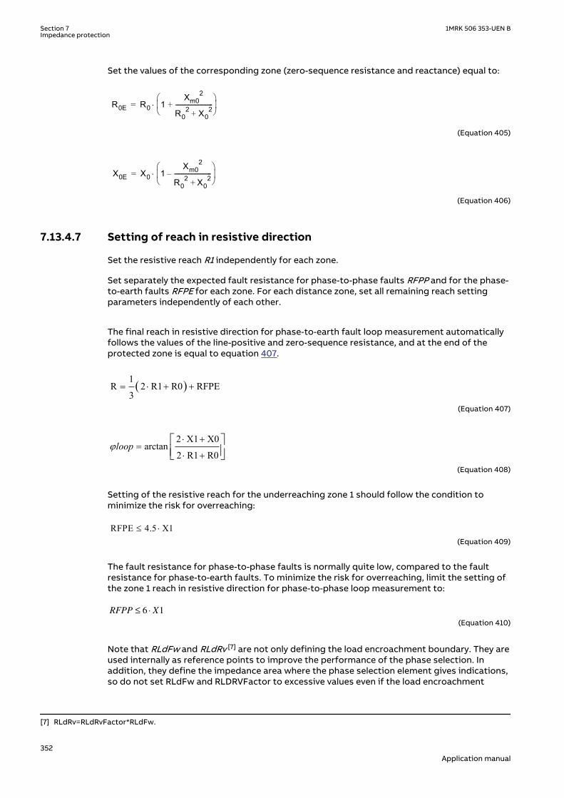
Set the values of the corresponding zone (zero-sequence resistance and reactance) equal to:
R0E R0 1Xm0
2
R02 X0
2+--------------------------+
è øç ÷æ ö
×=
EQUATION561 V1 EN-US (Equation 405)
X0E X0 1Xm0
2
R02 X0
2+--------------------------–
è øç ÷æ ö
×=
EQUATION562 V1 EN-US (Equation 406)
7.13.4.7 Setting of reach in resistive directionGUID-43EE13AF-BEBC-4A13-95B3-53C28B9164CB v3
Set the resistive reach R1 independently for each zone.
Set separately the expected fault resistance for phase-to-phase faults RFPP and for the phase-to-earth faults RFPE for each zone. For each distance zone, set all remaining reach settingparameters independently of each other.
The final reach in resistive direction for phase-to-earth fault loop measurement automaticallyfollows the values of the line-positive and zero-sequence resistance, and at the end of theprotected zone is equal to equation 407.
( )1R 2 R1 R0 RFPE
3= × + +
IECEQUATION2303 V1 EN-US (Equation 407)
2 X1 X0arctan
2 R1 R0loopj
× +=
× +é ùê úë û
EQUATION2304 V1 EN-US (Equation 408)
Setting of the resistive reach for the underreaching zone 1 should follow the condition tominimize the risk for overreaching:
RFPE 4.5 X1£ ×IECEQUATION2305 V1 EN-US (Equation 409)
The fault resistance for phase-to-phase faults is normally quite low, compared to the faultresistance for phase-to-earth faults. To minimize the risk for overreaching, limit the setting ofthe zone 1 reach in resistive direction for phase-to-phase loop measurement to:
RFPP X≤ ⋅6 1
IECEQUATION2306 V2 EN-US (Equation 410)
Note that RLdFw and RLdRv [7] are not only defining the load encroachment boundary. They areused internally as reference points to improve the performance of the phase selection. Inaddition, they define the impedance area where the phase selection element gives indications,so do not set RLdFw and RLDRVFactor to excessive values even if the load encroachment
[7] RLdRv=RLdRvFactor*RLdFw.
Section 7 1MRK 506 353-UEN BImpedance protection
352Application manual

functionality is not needed (that is, when the load is not encroaching on the distance zones).Always define the load encroachment boundary according to the actual load or inconsideration of how far the phase selection must actually reach.
7.13.4.8 Load impedance limitation, without load encroachment functionGUID-16C2EB30-7FEA-42E4-98C8-52CCC36644C6 v4
The following instructions are valid when setting the resistive reach of the distance zone itselfwith a sufficient margin towards the maximum load, that is, without the common loadencroachment characteristic (set by RLdFw, RLdRv [8] and ArgLd). Observe that even thoughthe zones themselves are set with a margin, RLdFw and RLDRVFactor still have to be setaccording to maximum load for the phase selection to achieve the expected performance.
Check the maximum permissible resistive reach for any zone to ensure that there is a sufficientsetting margin between the boundary and the minimum load impedance. The minimum loadimpedance (Ω/phase) is calculated as:
Z loadminU2
S-------=
EQUATION571 V1 EN-US (Equation 411)
Where:
U is the minimum phase-to-phase voltage in kV
S is the maximum apparent power in MVA.
The load impedance [Ω/phase] is a function of the minimum operation voltage and themaximum load current:
Z loadUmin
3 Imax×----------------------=
EQUATION574 V1 EN-US (Equation 412)
Minimum voltage Umin and maximum current Imax are related to the same operatingconditions. Minimum load impedance occurs normally under emergency conditions.
To avoid load encroachment for the phase-to-earth measuring elements, the set resistivereach of any distance protection zone must be less than 80% of the minimum load impedance.
RFPE 0.8 Zload×£
EQUATION792 V1 EN-US (Equation 413)
This equation is applicable only when the loop characteristic angle for the single phase-to-earth faults is more than three times as large as the maximum expected load-impedanceangle. For the case when the loop characteristic angle is less than three times the load-impedance angle, more accurate calculations are necessary according to equation 414.
[8] RLdRv=RLdRvFactor*RLdFw.
1MRK 506 353-UEN B Section 7Impedance protection
353Application manual

min
2 1 00.8 cos sin
2 1 0load
R RRFPE Z
X XJ J
× +£ × × - ×
× +é ùê úë û
EQUATION578 V4 EN-US (Equation 414)
Where:
ϑ is a maximum load-impedance angle, related to the maximum load power.
To avoid load encroachment for the phase-to-phase measuring elements, the set resistivereach of any distance protection zone must be less than 160% of the minimum loadimpedance.
RFPP 1.6 Zload£ ×load1.6 Z£ ×RFPP
EQUATION579 V2 EN-US (Equation 415)
Equation 415 is applicable only when the loop characteristic angle for the phase-to-phasefaults is more than three times as large as the maximum expected load-impedance angle. Moreaccurate calculations are necessary according to equation 416.
load minR1
RFPP 1.6 Z cos sinX1
J J£ × - ×é ù× ê úë ûIECEQUATION2307 V1 EN-US (Equation 416)
All this is applicable for all measuring zones when no Power swing detection function ZMRPSBis activated in the IED. Use an additional safety margin of approximately 20% in cases when aZMRPSB function is activated in the IED, refer to the description of Power swing detectionfunction ZMRPSB.
7.13.4.9 Zone reach setting higher than minimum load impedanceGUID-78D0227F-2568-4C9A-8921-45812B4ABAF2 v4
The impedance zones are enabled as soon as the (symmetrical) load impedance crosses thevertical boundaries defined by RLdFw and RLdRv [9] or the lines defined by ArgLd. So, it isnecessary to consider some margin. It is recommended to set RLdFw and RLdRv to 90% of theper-phase resistance that corresponds to maximum load.
min0.9 loadRLdFw R< ×
IECEQUATION2419 V2 EN-US (Equation 417)
min0.9 loadRLdRv R< ×
IECEQUATION2420 V2 EN-US (Equation 418)
The absolute value of the margin to the closest ArgLd line should be of the same order, that is,at least 0.1 • Zload min.
The load encroachment settings are related to a per-phase load impedance in a symmetricalstar-coupled representation. For symmetrical load or three-phase and phase-to-phase faults,
[9] RLdRv=RLdRvFactor*RLdFw
Section 7 1MRK 506 353-UEN BImpedance protection
354Application manual

this corresponds to the per-phase, or positive-sequence, impedance. For a phase-to-earthfault, it corresponds to the per-loop impedance, including the earth return impedance.
R
X
RLdFw
RLdRv
ArgLd
90%10%
10%
ARGLd
Possible load
ARGLd
ARGLd
R
X
RLdFw
RLdRv
XLd
XLd
ARGLd
ARGLd ARGLd
ARGLd
IEC12000176-2-en.vsdIEC12000176 V2 EN-US
Figure 231: Load impedance limitation with load encroachment
During the initial current change for phase-to-phase and for phase-to-earth faults, operationmay be allowed also when the apparent impedance of the load encroachment element islocated in the load area. This improves the dependability for fault at the remote end of the lineduring high load. Although it is not associated to any standard event, there is one potentiallyhazardous situation that should be considered. Should one phase of a parallel circuit open asingle pole, even though there is no fault, and the load current of that phase increase, there isactually no way of distinguish this from a real fault with similar characteristics. Should thisaccidental event be given precaution, the phase-to-earth reach (RFPE) of all instantaneouszones has to be set below the emergency load for the pole-open situation. Again, this is onlyfor the application where there is a risk that one breaker pole would open without a precedingfault. If this never happens, for example when there is no parallel circuit, there is no need tochange any phase-to-earth reach according to the pole-open scenario.
7.13.4.10 Parameter setting guidelinesGUID-B28677F4-B909-42C1-B1B7-1C118B26E67D v3
IMinOpPE and IMinOpPP
The ability for a specific loop and zone to issue start or trip is inhibited if the magnitude of theinput current for this loop falls below the threshold value defined by these settings. Theoutput of a phase-to-earth loop Ln is blocked if ILn < IminOpPE(Zx). ILn is the RMS value of thefundamental current in phase Ln.
The output of a phase-to-phase loop LmLn is blocked if ILmLn < IMinOpPP(Zx). ILmLn is theRMS value of the vector difference between phase currents Lm and Ln.
Both current limits IMinOpPE and IMinOpPP are automatically reduced to 75% of regular setvalues if the zone is set to operate in reverse direction, that is, OperationDir=Reverse.
OpModePPZx and OpModePEZx
These settings, two per zone (x=1,2..5&RV), with options Off, Quadrilateral, Mho, Offset, areused to set the operation and characteristic for phase-to-earth and phase-to-phase faults,respectively.
For example, in one zone it is possible to choose Mho characteristic for the three Ph-Phmeasuring loops and Quadrilateral characteristic for the three Ph-E measuring loops.
DirModeZx
1MRK 506 353-UEN B Section 7Impedance protection
355Application manual

These settings define the operating direction for Zones Z3, Z4 and Z5 (the directionality ofzones Z1, Z2 and ZRV is fixed). The options are Non-directional, Forward or Reverse. The resultfrom respective set value is illustrated in figure 232 below, where positive impedancecorresponds to the direction out on the protected line.
IEC05000182-2-en.vsdx
R
X
R
X
R
X
Non-directional Forward Reverse
IEC05000182 V2 EN-US
Figure 232: Directional operating modes of the distance measuring zones 3 to 5
tPPZx, tPEZx, TimerModeZx, ZoneLinkStart and TimerLinksZx
Refer to chapter Simplified logic schemes in Technical Manual for the application of thesesettings.
OperationSC
Choose the setting value SeriesComp if the protected line or adjacent lines are compensatedwith series capacitors. Otherwise maintain the NoSeriesComp setting value.
CVTtype
If possible, the type of capacitive voltage transformer (CVT) that is used for measurementshould be identified. Note that the alternatives are strongly related to the type of ferro-resonance suppression circuit that is included in the CVT. There are two main choices:
Passive type For CVTs that use a non-linear component, like a saturable inductor, to limit overvoltages(caused by ferro-resonance). This component is practically idle during normal load and faultconditions, hence the name ‘passive’. CVTs that have a high resistive burden to mitigate ferro-resonance also fall in to this category.
Any This option is primarily related to the so-called active type CVT, which uses a set of reactivecomponents to form a filter circuit that essentially attenuates frequencies other than thenominal in order to restrain the ferro-resonance. The name ‘active’ refers to the fact that thiscircuit is always involved during transient conditions, regardless of voltage level. This optionshould also be used for types that do not fall under the other two categories, for example,CVTs with power electronic damping devices, or if the type cannot be identified at all.
None(Magnetic)
This option should be selected if the voltage transformer is fully magnetic.
INReleasePE
This setting opens up an opportunity to enable phase-to-earth measurement for phase-to-phase-earth faults. It determines the level of residual current (3I0) above which phase-to-earth
Section 7 1MRK 506 353-UEN BImpedance protection
356Application manual
measurement is activated (and phase-to-phase measurement is blocked). The relations aredefined by the following equation.
0 maxRe
3100
phIN leasePE
I I× ³ ×
EQUATION2548 V1 EN-US (Equation 419)
Where:
INReleasePE is the setting for the minimum residual current needed to enable operation in the phase-to-earth fault loops in %
Iphmax is the maximum phase current in any of three phases
By default this setting is set excessively high to always enable phase-to-phase measurementfor phase-to-phase-earth faults. Maintain this default setting value unless there are veryspecific reasons to enable phase-to-earth measurement. Please note that, even with thedefault setting value, phase-to-earth measurement is activated whenever appropriate, like inthe case of simultaneous faults: two earth faults at the same time, one each on the twocircuits of a double line.
7.14 Power swing detection ZMRPSBIP14499-1 v3
7.14.1 IdentificationM14853-1 v3
Function description IEC 61850identification
IEC 60617identification
ANSI/IEEE C37.2device number
Power swing detection ZMRPSB
Zpsb
SYMBOL-EE V1 EN-US
68
7.14.2 ApplicationIP14969-1 v1
7.14.2.1 GeneralM13874-3 v3
Various changes in power system may cause oscillations of rotating units. The most typicalreasons for these oscillations are big changes in load or changes in power systemconfiguration caused by different faults and their clearance. As the rotating masses strive tofind a stable operate condition, they oscillate with damped oscillations until they reach thefinal stability.
The extent of the oscillations depends on the extent of the disturbances and on the naturalstability of the system.
The oscillation rate depends also on the inertia of the system and on the total systemimpedance between different generating units. These oscillations cause changes in phase andamplitude of the voltage difference between the oscillating generating units in the powersystem, which reflects further on in oscillating power flow between two parts of the system -the power swings from one part to another - and vice versa.
Distance IEDs located in interconnected networks see these power swings as the swinging ofthe measured impedance in relay points. The measured impedance varies with time along a
1MRK 506 353-UEN B Section 7Impedance protection
357Application manual

locus in an impedance plane, see figure 233. This locus can enter the operating characteristicof a distance protection and cause, if no preventive measures have been considered, itsunwanted operation.
R
jX
Operating characteristic
Impedance locus atpower swing
IEC09000224_1_en.vsdIEC09000224 V1 EN-US
Figure 233: Impedance plane with Power swing detection operating characteristic andimpedance locus at power swing
7.14.2.2 Basic characteristicsM13874-11 v5
Power swing detection function (ZMRPSB) detects reliably power swings with periodic time ofswinging as low as 200 ms (which means slip frequency as high as 10% of the rated frequencyon the 50 Hz basis). It detects the swings under normal system operate conditions as well asduring dead time of a single-pole automatic reclosing cycle.
ZMRPSB function is able to secure selective operation for internal faults during power. Theoperation of the distance protection function remains stable for external faults during thepower swing condition, even with the swing (electrical) centre located on the protected powerline.
The operating characteristic of the ZMRPSB function is easily adjustable to the selectedimpedance operating characteristics of the corresponding controlled distance protectionzones as well as to the maximum possible load conditions of the protected power lines. Seethe corresponding description in “Technical reference manual” for the IEDs.
7.14.3 Setting guidelinesSEMOD52042-5 v4
Setting guidelines are prepared in the form of a setting example for the protected power lineas part of a two-machine system presented in figure 234.
99001019.vsd
~~
EA
dA= const dB= f(t)
EB
A BZSA ZSBZL
R
IEC99001019 V1 EN-US
Figure 234: Protected power line as part of a two-machine system
Section 7 1MRK 506 353-UEN BImpedance protection
358Application manual

Reduce the power system with protected power line into equivalent two-machine system withpositive sequence source impedances ZSA behind the IED and ZSB behind the remote end busB. Observe a fact that these impedances can not be directly calculated from the maximumthree-phase short circuit currents for faults on the corresponding busbar. It is necessary toconsider separate contributions of different connected circuits.
The required data is as follows:
400rU kV=EQUATION1321 V1 EN-US
Rated system voltage
min 380U kV=EQUATION1322 V1 EN-US
Minimum expected system voltage under critical systemconditions
50rf Hz=EQUATION1323 V1 EN-US
Rated system frequency
4003pU kV=
EQUATION1324 V1 EN-US
Rated primary voltage of voltage protection transformersused
0.113sU kV=
EQUATION1325 V1 EN-US
Rated secondary voltage of voltage instrumenttransformers used
1200pI A=EQUATION1326 V1 EN-US
Rated primary current of current protection transformersused
1sI A=EQUATION1327 V1 EN-US
Rated secondary current of current protection transformersused
( )1 10.71 75.6LZ j= + WEQUATION1328 V1 EN-US
Line positive sequence impedance
( )1 1.15 43.5SAZ j= + WEQUATION1329 V1 EN-US
Positive sequence source impedance behind A bus
( )1 5.3 35.7SBZ j= + WEQUATION1330 V1 EN-US
Positive sequence source impedance behind B bus
max 1000S MVA=EQUATION1331 V1 EN-US
Maximum expected load in direction from A to B (withminimum system operating voltage Umin)
( )maxcos 0.95j =EQUATION1332 V1 EN-US
Power factor at maximum line loading
max 25j = °EQUATION1333 V1 EN-US
Maximum expected load angle
2.5sif Hz=EQUATION1334 V1 EN-US
Maximum possible initial frequency of power oscillation
7.0scf Hz=EQUATION1335 V1 EN-US
Maximum possible consecutive frequency of poweroscillation
The impedance transformation factor, which transforms the primary impedances to thecorresponding secondary values is calculated according to equation 420. Consider a fact that
1MRK 506 353-UEN B Section 7Impedance protection
359Application manual

all settings are performed in primary values. The impedance transformation factor ispresented for orientation and testing purposes only.
1200 0.11 0.331 400
p s
s p
I UKIMPI U
= × = × =
EQUATION1336 V1 EN-US (Equation 420)
The minimum load impedance at minimum expected system voltage is equal to equation 421.
2 2min
minmax
380 144.41000L
UZS
= = = W
EQUATION1337 V1 EN-US (Equation 421)
The minimum load resistance RLmin at maximum load and minimum system voltage is equal toequation 422.
( )min min maxcos 144.4 0.95 137.2L LR Z j= × = × = WEQUATION1338 V1 EN-US (Equation 422)
The system impedance ZS is determined as a sum of all impedance in an equivalent two-machine system, see figure 234. Its value is calculated according to equation 423.
( )1 1 1 17.16 154.8S SA L SBZ Z Z Z j= + + = + WEQUATION1339 V1 EN-US (Equation 423)
The calculated value of the system impedance is of informative nature and helps determiningthe position of oscillation center, see figure 235, which is for general case calculated accordingto equation 424.
1
1
SCO SA
B
A
ZZ ZEE
= -
+
EQUATION1340 V1 EN-US (Equation 424)
In particular cases, when
A BE E=EQUATION1342 V1 EN-US (Equation 425)
resides the center of oscillation on impedance point, see equation 426.
( )1 7.43 33.92
SCO SA
ZZ Z j= - = + W
EQUATION1341 V1 EN-US (Equation 426)
Section 7 1MRK 506 353-UEN BImpedance protection
360Application manual
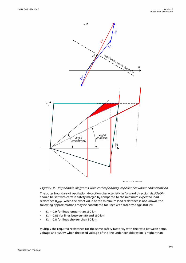
R
jX
ArgLd(ZMRPSB)ArgLd
(FDPSPDIS)
Z S1
jXZ SA
1
Z L1
Z SB
1
Impedance locus for |EA| = |E
B|R
Z CO
IEC09000225-1-en.vsdIEC09000225 V1 EN-US
Figure 235: Impedance diagrams with corresponding impedances under consideration
The outer boundary of oscillation detection characteristic in forward direction RLdOutFwshould be set with certain safety margin KL compared to the minimum expected loadresistance RLmin. When the exact value of the minimum load resistance is not known, thefollowing approximations may be considered for lines with rated voltage 400 kV:
• KL = 0.9 for lines longer than 150 km• KL = 0.85 for lines between 80 and 150 km• KL = 0.8 for lines shorter than 80 km
Multiply the required resistance for the same safety factor KL with the ratio between actualvoltage and 400kV when the rated voltage of the line under consideration is higher than
1MRK 506 353-UEN B Section 7Impedance protection
361Application manual

400kV. The outer boundary RLdOutFw obtains in this particular case its value according toequation 427.
min 0.9 137.2 123.5L LRLdOutFw K R= × = × = WEQUATION1343 V1 EN-US (Equation 427)
It is a general recommendation to set the inner boundary RLdInFw of the oscillation detectioncharacteristic to 80% or less of its outer boundary. Exceptions are always possible, but mustbe considered with special care especially when it comes to settings of timers tP1 and tP2included in oscillation detection logic. This requires the maximum permitted setting values offactor kLdRFw = 0.8. Equation 428 presents the corresponding maximum possible value ofRLdInFw.
98.8= × = WRLdInFw kLdRFw RLdOutFwEQUATION1344 V3 EN-US (Equation 428)
The load angles, which correspond to external δOut and internal δIn boundary of proposedoscillation detection characteristic in forward direction, are calculated with sufficient accuracyaccording to equation 429 and 430 respectively.
155.752 arc tan 2 arc tan 64.52 2 123.5
dæ ö æ öç ÷= × = × = °ç ÷ç ÷× ×è øè ø
SOut
ZRLdOutFw
EQUATION1345 V1 EN-US (Equation 429)
max
155.752 arc tan 2 arc tan 76.52 2 98.8
dæ ö æ öç ÷= × = × = °ç ÷ç ÷× ×è øè ø
SIn
ZRLdInFw
EQUATION1346 V1 EN-US (Equation 430)
The required setting tP1 of the initial oscillation detection timer depends on the load angledifference according to equation 431.
76.5 64.51 13.3360 2.5 360
In Out
si
tP msf
d d- ° - °= = =
× ° × °EQUATION1347 V1 EN-US (Equation 431)
The general tendency should be to set the tP1 time to at least 30 ms, if possible. Since it is notpossible to further increase the external load angle δOut, it is necessary to reduce the innerboundary of the oscillation detection characteristic. The minimum required value is calculatedaccording to the procedure listed in equation 432, 433, 434 and 435.
min1 30tP ms=EQUATION1348 V1 EN-US (Equation 432)
min min360 1 360 2.5 0.030 64.5 91.5In si Outf tPd d- = ° × × + = ° × × + ° = °EQUATION1349 V1 EN-US (Equation 433)
Section 7 1MRK 506 353-UEN BImpedance protection
362Application manual

max1min
155.75 75.891.52 tan2 tan
22d -
= = = Wæ ö æ ö×× ç ÷ç ÷ è øè ø
S
in
ZRLdInFw
EQUATION1350 V1 EN-US (Equation 434)
max1 75.8 0.61123.5
= = =RLdInFwkLdRFwRLdOutFw
EQUATION1351 V1 EN-US (Equation 435)
Also check if this minimum setting satisfies the required speed for detection of consecutiveoscillations. This requirement will be satisfied if the proposed setting of tP2 time remainshigher than 10 ms, see equation 436.
max91.5 64.52 10.7
360 7 360In Out
sc
tP msf
d d- ° - °= = =
× ° × °EQUATION1352 V1 EN-US (Equation 436)
The final proposed settings are as follows:
RLdOutFw = 123.5Ω
kLdRFw = 0.61
tP1 = 30 ms
tP2 = 10 ms
Consider RLdInFw = 75.0Ω.
Do not forget to adjust the setting of load encroachment resistance RLdFw inPhase selection with load encroachment (FDPSPDIS or FRPSPDIS) to the valueequal to or less than the calculated value RLdInFw. It is at the same timenecessary to adjust the load angle in FDPSPDIS or FRPSPDIS to follow thecondition presented in equation 437.
Index PHS designates correspondence to FDPSPDIS or FRPSPDIS function andindex PSD the correspondence to ZMRPSB function.
( )tanarc tan³ PSD
PHS
ArgLdArgLd
kLdRFwEQUATION1353 V2 EN-US (Equation 437)
Consider equation 438,
max 25PSDArgLd j= = °EQUATION1354 V1 EN-US (Equation 438)
1MRK 506 353-UEN B Section 7Impedance protection
363Application manual

then it is necessary to set the load argument in FDPSPDIS or FRPSPDIS function to not lessthan equation 439.
( ) ( )tan tan 25arc tan arc tan 37.5
0.61é ù é ù°
³ = = °ê ú ê úë û ë û
PSDPHS
ArgLdArgLd
kLdRFwEQUATION1355 V1 EN-US (Equation 439)
It is recommended to set the corresponding resistive reach parameters in reverse direction(RLdOutRv and kLdRRv) to the same values as in forward direction, unless the systemoperating conditions, which dictate motoring and generating types of oscillations, requiresdifferent values. This decision must be made on basis of possible system contingency studiesespecially in cases, when the direction of transmitted power may change fast in short periodsof time. It is recommended to use different setting groups for operating conditions, which arechanging only between different periods of year (summer, winter).
System studies should determine the settings for the hold timer tH. The purpose of this timeris, to secure continuous output signal from Power swing detection function (ZMRPSB) duringthe power swing, even after the transient impedance leaves ZMRPSB operating characteristicand is expected to return within a certain time due to continuous swinging. Consider theminimum possible speed of power swinging in a particular system.
The tR1 inhibit timer delays the influence of the detected residual current on the inhibit criteriafor ZMRPSB. It prevents operation of the function for short transients in the residual currentmeasured by the IED.
The tR2 inhibit timer disables the output START signal from ZMRPSB function, if the measuredimpedance remains within ZMRPSB operating area for a time longer than the set tR2 value.This time delay was usually set to approximately two seconds in older power-swing devices.
The setting of the tEF timer must cover, with sufficient margin, the opening time of a circuitbreaker and the dead-time of a single-phase autoreclosing together with the breaker closingtime.
7.15 Power swing logic PSLPSCHSEMOD153597-1 v3
7.15.1 IdentificationSEMOD175682-2 v3
Function description IEC 61850identification
IEC 60617identification
ANSI/IEEE C37.2device number
Power swing logic PSLPSCH - -
7.15.2 ApplicationSEMOD131359-4 v3
Power Swing Logic (PSLPSCH) is a complementary function to Power Swing Detection(ZMRPSB) function. It enables a reliable fault clearing for different faults on protected linesduring power swings in power systems.
It is a general goal, to secure fast and selective operation of the distance protection schemefor the faults, which occur on power lines during power swings. It is possible to distinguishbetween the following main cases:
Section 7 1MRK 506 353-UEN BImpedance protection
364Application manual
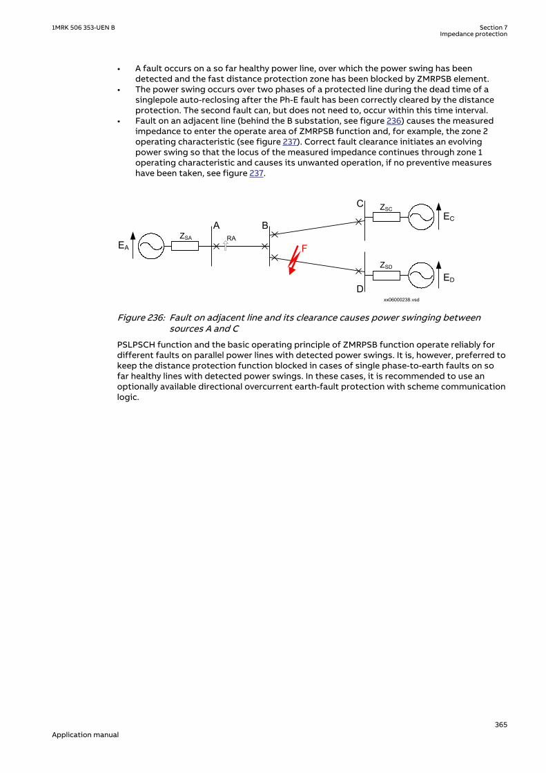
• A fault occurs on a so far healthy power line, over which the power swing has beendetected and the fast distance protection zone has been blocked by ZMRPSB element.
• The power swing occurs over two phases of a protected line during the dead time of asinglepole auto-reclosing after the Ph-E fault has been correctly cleared by the distanceprotection. The second fault can, but does not need to, occur within this time interval.
• Fault on an adjacent line (behind the B substation, see figure 236) causes the measuredimpedance to enter the operate area of ZMRPSB function and, for example, the zone 2operating characteristic (see figure 237). Correct fault clearance initiates an evolvingpower swing so that the locus of the measured impedance continues through zone 1operating characteristic and causes its unwanted operation, if no preventive measureshave been taken, see figure 237.
EA
A B
C
D
FZSA RA
EC
ED
xx06000238.vsd
ZSC
ZSD
IEC06000238 V1 EN-US
Figure 236: Fault on adjacent line and its clearance causes power swinging betweensources A and C
PSLPSCH function and the basic operating principle of ZMRPSB function operate reliably fordifferent faults on parallel power lines with detected power swings. It is, however, preferred tokeep the distance protection function blocked in cases of single phase-to-earth faults on sofar healthy lines with detected power swings. In these cases, it is recommended to use anoptionally available directional overcurrent earth-fault protection with scheme communicationlogic.
1MRK 506 353-UEN B Section 7Impedance protection
365Application manual

R
jX
B
A
Measured impedance at initital fault position
Impedance locus at initial power swing after the fault clearance
ZMRPSB operating characteristic
Zone 2
Zone 1
IEC99000181_2_en.vsdIEC99000181 V2 EN-US
Figure 237: Impedance trajectory within the distance protection zones 1 and 2 during andafter the fault on line B – D
7.15.3 Setting guidelinesSEMOD171741-1 v1
7.15.3.1 Scheme communication and tripping for faults occurring during powerswinging over the protected line
SEMOD131360-4 v2
The IED includes generally up to five distance protection zones. It is possible to use one or twoof them intentionally for selective fault clearing during power swings only. Following are thebasic conditions for the operation of the so called (underreaching and overreaching) power-swing zones:
• They must generally be blocked during normal operation and released during powerswings.
• Their operation must be time delayed but shorter (with sufficient margin) than the settime delay of normal distance protection zone 2, which is generally blocked by the powerswing.
• Their resistive reach setting must secure, together with the set time delay for theiroperation, that the slowest expected swings pass the impedance operate area withoutinitiating their operation.
Communication and tripping logic as used by the power swing distance protection zones isschematically presented in figure 238.
The operation of the power swing zones is conditioned by the operation of Power swingdetection (ZMRPSB) function. They operate in PUTT or POTT communication scheme withcorresponding distance protection zones at the remote line end. It is preferred to use thecommunication channels over the optionally available “Line Data Communication Module -
Section 7 1MRK 506 353-UEN BImpedance protection
366Application manual

LDCM” and the “Binary signal transfer to remote end” function. It is also possible to include, inan easy way (by means of configuration possibilities), the complete functionality into regularscheme communication logic for the distance protection function. The communicationscheme for the regular distance protection does not operate during the power-swingconditions, because the distance protection zones included in the scheme are normallyblocked. The powerswing zones can for this reason use the same communication facilitiesduring the power-swing conditions.
Only one power swing zone is necessary in distance protection at each line terminal, if thePOTT communication scheme is applied. One underreaching power swing zone, which sendsthe time delayed carrier signal, and one overreaching power swing zone, which performs thelocal tripping condition, are necessary with PUTT schemes.
The operation of the distance protection zones with long time delay (for example, zone 3) is inmany cases not blocked by the power swing detection elements. This allows in such cases thedistance protection zone 3 (together with the full-scheme design of the distance protectionfunction) to be used at the same time as the overreaching power-swing zone.
STDEFAR1P1 &
STPSDBLOCK & t
tCS&
CSUR
CS
ttBlkTr
&
ttTrip
CRCACC >1
& BLKZMPS
TRIP
en06000236.vsdIEC06000236 V1 EN-US
Figure 238: Simplified logic diagram - power swing communication and tripping logic
ConfigurationSEMOD131360-17 v2
Configure the BLOCK input to any combination of conditions, which are supposed to block theoperation of logic. Connection to detected fuse failure conditions is required as a minimum.
The STDEF functional input should be configured to the START signal of any line earth faultovercurrent protection function within the IED. When the directional earth fault O/C functionis used an OR combination of forward and reverse operation should be used.
Connect the AR1P1 to the output signal of the autoreclosing function, which signals theactivation of the single pole autoreclosing dead time.
The STPSD input should be connected to the starting signal of the power swing detection(ZMRPSB) function, which becomes active in cases of detected system oscillations.
The CSUR functional input should be connected to the starting output of the power swingdistance protection zone, which is used as a local tripping criteria during power swings inPUTT schemes. When the POTT scheme is used (also on series compensated networks) thelocal criteria and the carrier sending zone are one and the same. It is preferred to use separatecommunication facilities for distance protection and for power swing communication logic,but combination of functionality within the same communication channel is possible as well.
1MRK 506 353-UEN B Section 7Impedance protection
367Application manual

Connect the CACC functional input to start output signal of the local overreaching powerswing distance protection zone, which serves as a local criteria at receiving of carrier signalduring the power swing cycle.
The CR signal should be configured to the functional input which provides the logic withinformation on received carrier signal sent by the remote end power swing distance protectionzone.
The CS functional output signal should be configured to either output relay or tocorresponding input of the “Binary signal transfer to remote end” function.
The BLKZMPS output signal should be configured to BLOCK input of the power swing distanceprotection zones.
The TRIP signal should be connected correspondingly towards the tripping functionality of thecomplete distance protection within the IED.
Setting calculationsSEMOD131360-29 v1
Time delay of power swing carrier send distance protection zonesSEMOD131360-32 v2
Time delay for the underreaching or overreaching carrier send power swing zone should be setshorter (with sufficient margin) than the time delay of normal distance protection zone 2 toobtain selective time grading also in cases of faults during power swings. The necessary timedifference depends mostly on the speed of the communication channel used, speed of thecircuit breaker used, etc. Time difference between 100 ms and 150 ms is generally sufficient.
Reactive reach setting of power swing distance protection zonesSEMOD131360-37 v2
Set the reactive reach for the power swing zones according to the system selectivity planning.The reach of the underreaching zone should not exceed 85% of the protected line length. Thereach of the overreaching zone should be at least 120% of the protected line length.
Resistive reach setting of carrier send power swing distance protection zoneSEMOD131360-40 v2
Determine the minimum possible speed of impedance ΔZ / Δt in primary Ω / s of the expectedpower swings. When better information is not available from system studies, the followingequation may be used:
min min2z L sv Z f= × ×EQUATION1537 V1 EN-US (Equation 440)
Where:
vz is a minimum expected speed of swing impedance in Ω / s
ZLmin is a minimum expected primary load impedance in Ω
fsmin is a minimum expected oscillation (swing) frequency in Hz
Calculate the maximum permissible resistive reach for each power swing zone separatelyaccording to the following equations.
0.8n zRFPP v tnPP= × ×EQUATION1538 V1 EN-US (Equation 441)
Section 7 1MRK 506 353-UEN BImpedance protection
368Application manual

0.82
zn
v tnPERFPE ×= ×
EQUATION1539 V1 EN-US (Equation 442)
Here is factor 0.8considered for safetyreasons and:
RFPEn phase-to-earth resistive reach setting for a power swing distance protection zone nin Ω
RFPPn phase-to-phase resistive reach setting for a power swing distance protection zonen in Ω
tnPE time delay for phase-to-earth fault measurement of power swing distanceprotection zone n in s
tnPP time delay for phase-to-phase fault measurement of power swing distanceprotection zone n in s
Time-delay for the overreaching power swing zoneSEMOD131360-43 v2
Time delay for the overreaching power swing zone is not an important parameter, if the zoneis used only for the protection purposes at power-swings.
Consider the normal time grading, if the overreaching zone serves as a time delayed back-upzone, which is not blocked by the operation of Power swing detection (ZMRPSB) function.
Timers within the power swing logicSEMOD131360-47 v3
Settings of the timers within Power swing logic (PSLPSCH) depend to a great extent on thesettings of other time delayed elements within the complete protection system. Thesesettings differ within different power systems. The recommended settings consider only thegeneral system conditions and the most used practice at different utilities. It is alwaysnecessary to check the local system conditions.
The carrier send timer tCS is used for safety reasons within the logic. It requires continuouspresence of the input signal STPSD, before it can issue a carrier send signal. A time delaybetween 50 and 100 ms is generally sufficient.
The trip timer tTrip is used for safety reasons within the logic. It requires continuous presenceof the input signal STPSD, before it can issue a tripping command during the power swings. Atime delay between 50 and 100 ms is generally sufficient.
The blocking timer tBlkTr prolongs the presence of the BLKZMOR output signals, which can beused to block the operation of the power swing zones after the detected single-phase-to-earthfaults during the power swings. It is necessary to permit the O/C EF protection to eliminatethe initial fault and still make possible for the power swing zones to operate for possibleconsecutive faults. A time delay between 150 and 300 ms is generally sufficient.
7.15.3.2 Blocking and tripping logic for evolving power swingsSEMOD131360-55 v3
The second part of a complete Power swing logic (PSLPSCH) functionality is a blocking andtripping logic for evolving power swings, see figure 236 and figure 237. The simplified logic ispresented in figure 239. The logic controls the operation of the underreaching distanceprotection zone (Zone 1) at power swings, caused by the faults and their clearance on theadjacent power lines. The logic should generally be configured between distance protectionzones 1 and 2.
ConfigurationSEMOD131360-60 v2
The fault impedance should be detected within the external boundary of Power SwingDetection (ZMRPSB) function without power swing detected during the entire fault duration.
1MRK 506 353-UEN B Section 7Impedance protection
369Application manual

Configure for this reason the STZMPSD to the functional output signal of ZMRPSB function,which indicates the measured impedance within its external boundaries.
STZMLBLOCK
&STMZHSTZMPSDSTPSD
ttDZ
ttZL
&
>1
&
&
&
-loop
>1 STZMLL
BLKZMH
&
en06000237.vsdIEC06000237 V1 EN-US
Figure 239: Blocking and tripping logic for evolving power swings
No system oscillation should be detected in power system. Configure for this reason theSTPSD functional input to the START functional output of ZMRPSB function or to any binaryinput signal indicating the detected oscillations within the power system.
Configure the functional input STZMUR to the start output of the instantaneousunderreaching distance protection zone (usually START of distance protection zone 1). Thefunction will determine whether the start signal of this zone is permitted to be used in furtherlogic or not, dependent on time difference on appearance of overreaching distance protectionzone (usually zone 2).
Configure for this reason the functional output signal STZMURPS to the start output of theoverreaching distance protection zone (usually START of distance protection zone 2).
Functional output PUZMLL replaces the start (and trip) signals of the distance protection zone1 in all following logic. Configure it accordingly within the logic.
Functional output signal BLKZMOR should be configured to block the overreach distanceprotection zone (generally zone 2) in order to prevent its maloperation during the firstswinging of the system. Configure it accordingly to BLOCK functional input of distanceprotection zone 2.
Setting calculationsSEMOD131360-70 v1
Setting of the differentiating timer tDZ influences to a great extent the performance of theprotection during the power swings, which develops by occurrence and clearance of the faultson adjacent power lines. It is necessary to consider the possibility for the faults to occur closeto the set reach of the underreaching distance protection zone, which might result inprolonged operate times of zone 1 (underreaching zone) compared to zone 2 starting time(overreaching zone). A setting between 80 and 150 ms is generally sufficient.
The release timer tZL permits unconditional operation of the underreaching zone, if themeasured impedance remains within its operate characteristic longer than the set time tZL. Itssetting depends on the expected speed of the initial swings and on the setting of the timedelay for the overreaching zone 2. The release timer must still permit selective tripping of thedistance protection within the complete network. A setting between 200 and 300 ms isgenerally sufficient.
Section 7 1MRK 506 353-UEN BImpedance protection
370Application manual

7.16 Pole slip protection PSPPPAMSEMOD156709-1 v2
7.16.1 IdentificationSEMOD158949-2 v4
Function description IEC 61850identification
IEC 60617identification
ANSI/IEEE C37.2device number
Pole slip protection PSPPPAM Ucos 78
7.16.2 ApplicationSEMOD143248-4 v3
Normally, the generator operates synchronously with the power system, that is, all thegenerators in the system have the same angular velocity and approximately the same phaseangle difference. If the phase angle between the generators gets too large the stableoperation of the system cannot be maintained. In such a case the generator loses thesynchronism (pole slip) to the external power system.
The situation with pole slip of a generator can be caused by different reasons.
A short circuit occurs in the external power grid, close to the generator. If the fault clearancetime is too long, the generator will accelerate so much, so the synchronism cannot bemaintained. The relative generator phase angle at a fault and pole slip, relative to the externalpower system, is shown in figure 240.
1MRK 506 353-UEN B Section 7Impedance protection
371Application manual

en06000313.vsdIEC06000313 V1 EN-US
Figure 240: Relative generator phase angle at a fault and pole slip relative to the externalpower system
The relative angle of the generator is shown for different fault duration at a three-phase shortcircuit close to the generator. As the fault duration increases the angle swing amplitudeincreases. When the critical fault clearance time is reached the stability cannot be maintained.
Un-damped oscillations occur in the power system, where generator groups at differentlocations, oscillate against each other. If the connection between the generators is too weakthe amplitude of the oscillations will increase until the angular stability is lost. At the momentof pole slip there will be a centre of this pole slip, which is equivalent with distance protectionimpedance measurement of a three-phase. If this point is situated in the generator itself, thegenerator should be tripped as fast as possible. If the locus of the out of step centre is locatedin the power system outside the generators the power system should, if possible, be split intotwo parts, and the generators should be kept in service. This split can be made at predefinedlocations (trip of predefined lines) after function from pole slip protection (PSPPPAM) in theline protection IED.
Section 7 1MRK 506 353-UEN BImpedance protection
372Application manual

en06000314.vsdIEC06000314 V1 EN-US
Figure 241: Undamped oscillations causing pole slip
The relative angle of the generator is shown a contingency in the power system, causing un-damped oscillations. After a few periods of the oscillation the swing amplitude gets to largeand the stability cannot be maintained.
If the excitation of the generator gets too low there is a risk that the generator cannotmaintain synchronous operation. The generator will slip out of phase and operate as aninduction machine. Normally the under-excitation protection will detect this state and trip thegenerator before the pole slip. For this fault the under-excitation protection and PSPPPAMfunction will give mutual redundancy.
The operation of a generator having pole slip will give risk of damages to the generator block.
• At each pole slip there will be significant torque impact on the generator-turbine shaft.• In asynchronous operation there will be induction of currents in parts of the generator
normally not carrying current, thus resulting in increased heating. The consequence can bedamages on insulation and stator/rotor iron.
• At asynchronous operation the generator will absorb a significant amount of reactivepower, thus risking overload of the windings.
PSPPPAM function shall detect out of step conditions and trip the generator as fast aspossible if the locus of the pole slip is inside the generator. If the centre of pole slip is outsidethe generator, situated out in the power grid, the first action should be to split the networkinto two parts, after line protection action. If this fails there should be operation of thegenerator pole slip protection, to prevent further damages to the generator block.
1MRK 506 353-UEN B Section 7Impedance protection
373Application manual

7.16.3 Setting guidelinesSEMOD167596-1 v1
SEMOD167582-4 v4
GlobalBaseSel: Selects the global base value group used by the function to define (IBase),(UBase) and (SBase).
Operation: With the parameter Operation the function can be set On or Off.
MeasureMode: The voltage and current used for the impedance measurement is set by theparameter MeasureMode. The setting possibilities are: PosSeq, L1-L2, L2-L3, or L3-L1. If allphase voltages and phase currents are fed to the IED the PosSeq alternative is recommended(default).
Further settings can be illustrated in figure 242.
IEC06000548_2_en.vsd
IEDB A
EB EAX’d XT ZS
Zone 1 Zone 2
jX
R
ZB
ZA
Pole slip impedance movement Zone 2
Zone 1
WarnAngle
TripAngle
f
ZC
IEC06000548 V2 EN-US
Figure 242: Settings for the Pole slip detection function
The ImpedanceZA is the forward impedance as show in figure 242. ZA should be the sum of thetransformer impedance XT and the equivalent impedance of the external system ZS. Theimpedance is given in % of the base impedance, according to equation 444.
Section 7 1MRK 506 353-UEN BImpedance protection
374Application manual

3Base
UBaseZ
IBase=
EQUATION1883 V1 EN-US (Equation 444)
The ImpedanceZB is the reverse impedance as show in figure 242. ZB should be equal to thegenerator transient reactance X'd. The impedance is given in % of the base impedance, seeequation 444.
The ImpedanceZC is the forward impedance giving the borderline between zone 1 and zone 2.ZC should be equal to the transformer reactance ZT. The impedance is given in % of the baseimpedance, see equation 444.
The angle of the impedance line ZB – ZA is given as AnglePhi in degrees. This angle is normallyclose to 90°.
StartAngle: An alarm is given when movement of the rotor is detected and the rotor angleexceeds the angle set for StartAngle. The default value 110° is recommended. It should bechecked so that the points in the impedance plane, corresponding to the chosen StartAngledoes not interfere with apparent impedance at maximum generator load.
TripAngle: If a pole slip has been detected: change of rotor angle corresponding to slipfrequency 0.2 – 8 Hz, the slip line ZA – ZB is crossed and the direction of rotation is the same asat start, a trip is given when the rotor angle gets below the set TripAngle. The default value 90°is recommended.
N1Limit: The setting N1Limit gives the number of pole slips that should occur before trip, if thecrossing of the slip line ZA – ZB is within zone 1, that is, the node of the pole slip is within thegenerator transformer block. The default value 1 is recommended to minimize the stress onthe generator and turbine at out of step conditions.
N2Limit: The setting N2Limit gives the number of pole slips that should occur before trip, if thecrossing of the slip line ZA – ZB is within zone 2, that is, the node of the pole slip is in theexternal network. The default value 3 is recommended give external protections possibility tosplit the network and thus limit the system consequencies.
ResetTime: The setting ResetTime gives the time for (PSPPPAM) function to reset after startwhen no pole slip been detected. The default value 5s is recommended.
7.16.3.1 Setting example for line applicationSEMOD172162-25 v3
In case of out of step conditions this shall be detected and the line between substation 1 and 2shall be tripped.
IED
ZBLine impedance = ZC
ZA = forward source impedance
IEC07000014_2_en.vsdIEC07000014 V2 EN-US
Figure 243: Line application of pole slip protection
If the apparent impedance crosses the impedance line ZB – ZA this is the detection criterion ofout of step conditions, see figure 244.
1MRK 506 353-UEN B Section 7Impedance protection
375Application manual

R
X
Apparent impedance at normal load
ZC
ZA
ZB
anglePhi
IEC07000015_2_en.vsdIEC07000015 V2 EN-US
Figure 244: Impedances to be set for pole slip protection
The setting parameters of the protection is:
ZA: Line + source impedance in the forward direction
ZB: The source impedance in the reverse direction
ZC: The line impedance in the forward direction
AnglePhi: The impedance phase angle
Use the following data:
UBase: 400 kV
SBase set to 1000 MVA
Short circuit power at station 1 without infeed from the protected line: 5000 MVA (assumed to apure reactance)
Short circuit power at station 2 without infeed from the protected line: 5000 MVA (assumed to apure reactance
Line impedance: 2 + j20 ohm
With all phase voltages and phase currents available and fed to the protection IED, it isrecommended to set the MeasureMode to positive sequence.
The impedance settings are set in pu with ZBase as reference:
Section 7 1MRK 506 353-UEN BImpedance protection
376Application manual

2 2400160
1000= = =
UBaseZBase ohm
SBaseEQUATION1960 V1 EN-US (Equation 445)
2400( ) ( 2) 2 20 2 52
5000ZA Z line Zsc station j j j ohm= + = + + = +
EQUATION1961 V1 EN-US (Equation 446)
This corresponds to:
2 520.0125 0.325 0.325 88
160j
ZA j pu pu+
= = + = Ð °
EQUATION1962 V1 EN-US (Equation 447)
Set ZA to 0.32.
2400( 1) 32
5000ZB Zsc station j j ohm= = =
EQUATION1963 V1 EN-US (Equation 448)
This corresponds to:
320.20 0.20 90
160j
ZB j pu pu= = = Ð °
EQUATION1964 V1 EN-US (Equation 449)
Set ZB to 0.2
This corresponds to:
2 200.0125 0.125 0.126 84
160j
ZC j pu pu+
= = + = Ð °
EQUATION1966 V1 EN-US (Equation 450)
Set ZC to 0.13 and AnglePhi to 88°
The warning angle (StartAngle) should be chosen not to cross into normal operating area. Themaximum line power is assumed to be 2000 MVA. This corresponds to apparent impedance:
2 240080
2000U
Z ohmS
= = =
EQUATION1967 V1 EN-US (Equation 451)
Simplified, the example can be shown as a triangle, see figure 245.
1MRK 506 353-UEN B Section 7Impedance protection
377Application manual

ZA
ZB
Zload
R
X
en07000016.vsdIEC07000016 V1 EN-US
Figure 245: Simplified figure to derive StartAngle
0 032 52arctan arctan arctan + arctan = 21.8 + 33.0 5580 80
³ = »ZB ZAangleStart +
Zload ZloadEQUATION1968 V2 EN-US (Equation 452)
In case of minor damped oscillations at normal operation we do not want the protection tostart. Therefore we set the start angle with large margin.
Set StartAngle to 110°
For the TripAngle it is recommended to set this parameter to 90° to assure limited stress forthe circuit breaker.
In a power system it is desirable to split the system into predefined parts in case of pole slip.The protection is therefore situated at lines where this predefined split shall take place.
Normally the N1Limit is set to 1 so that the line will be tripped at the first pole slip.
If the line shall be tripped at all pole slip situations also the parameter N2Limit is set to 1. Inother cases a larger number is recommended.
7.16.3.2 Setting example for generator applicationSEMOD172162-90 v4
In case of out of step conditions this shall be checked if the pole slip centre is inside thegenerator (zone 1) or if it is situated in the network (zone 2).
Section 7 1MRK 506 353-UEN BImpedance protection
378Application manual

ZC
ZAZB
en07000017.vsdIEC07000017 V1 EN-US
Figure 246: Generator application of pole slip protection
If the apparent impedance crosses the impedance line ZB – ZA this is the detected criterion ofout of step conditions, see figure 247.
R
X
Apparent impedance at normal load
ZC
ZA
ZB
anglePhi
IEC07000015_2_en.vsdIEC07000015 V2 EN-US
Figure 247: Impedances to be set for pole slip protection PSPPPAM
The setting parameters of the protection are:
ZA Block transformer + source impedance in the forward direction
ZB The generator transient reactance
ZC The block transformer reactance
AnglePhi The impedance phase angle
Use the following generator data:
UBase: 20 kV
SBase set to 200 MVA
Xd': 25%
1MRK 506 353-UEN B Section 7Impedance protection
379Application manual
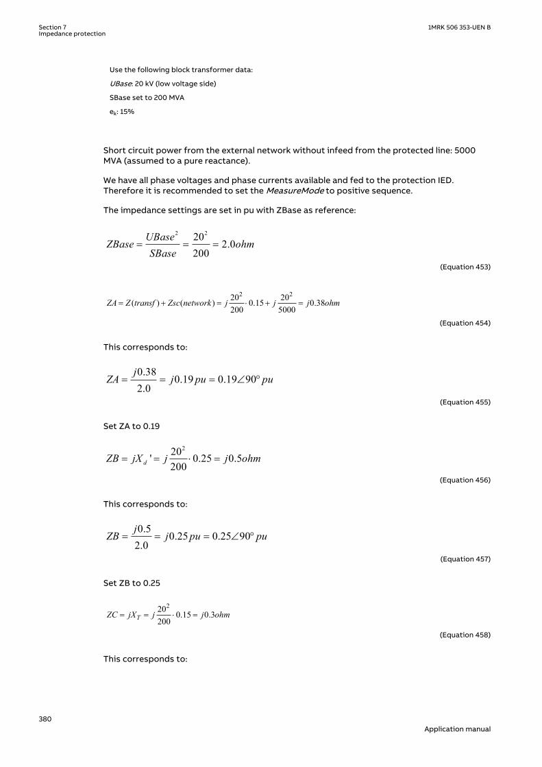
Use the following block transformer data:
UBase: 20 kV (low voltage side)
SBase set to 200 MVA
ek: 15%
Short circuit power from the external network without infeed from the protected line: 5000MVA (assumed to a pure reactance).
We have all phase voltages and phase currents available and fed to the protection IED.Therefore it is recommended to set the MeasureMode to positive sequence.
The impedance settings are set in pu with ZBase as reference:
2 2202.0
200UBase
ZBase ohmSBase
= = =
EQUATION1969 V1 EN-US (Equation 453)
2 220 20( ) ( ) 0.15 0.38200 5000
ZA Z transf Zsc network j j j ohm= + = × + =
EQUATION1970 V1 EN-US (Equation 454)
This corresponds to:
0.380.19 0.19 90
2.0j
ZA j pu pu= = = Ð °
EQUATION1971 V1 EN-US (Equation 455)
Set ZA to 0.19
220' 0.25 0.5200dZB jX j j ohm= = × =
EQUATION1972 V2 EN-US (Equation 456)
This corresponds to:
0.50.25 0.25 90
2.0j
ZB j pu pu= = = Ð °
EQUATION1973 V1 EN-US (Equation 457)
Set ZB to 0.25
220 0.15 0.3200TZC jX j j ohm= = × =
EQUATION1974 V1 EN-US (Equation 458)
This corresponds to:
Section 7 1MRK 506 353-UEN BImpedance protection
380Application manual

0.3 0.15 0.15 902.0jZC j pu pu= = = Ð o
EQUATION1975 V2 EN-US (Equation 459)
Set ZC to 0.15 and AnglePhi to 90°.
The warning angle (StartAngle) should be chosen not to cross into normal operating area. Themaximum line power is assumed to be 200 MVA. This corresponds to apparent impedance:
2 2202
200U
Z ohmS
= = =
EQUATION1976 V1 EN-US (Equation 460)
Simplified, the example can be shown as a triangle, see figure 248.
ZA
ZB
Zload
R
X
en07000016.vsdIEC07000016 V1 EN-US
Figure 248: Simplified figure to derive StartAngle
0 0arctan arctan arctan + arctan = 7.1 + 5.40.25 0.19 132 2
³ = »ZB ZAangleStart +
Zload ZloadEQUATION1977 V2 EN-US (Equation 461)
In case of minor damped oscillations at normal operation we do not want the protection tostart. Therefore we set the start angle with large margin.
Set StartAngle to 110°.
For the TripAngle it is recommended to set this parameter to 90° to assure limited stress forthe circuit breaker.
1MRK 506 353-UEN B Section 7Impedance protection
381Application manual

If the centre of pole slip is within the generator block set N1Limit to 1 to get trip at first poleslip.
If the centre of pole slip is within the network set N2Limit to 3 to get enable split of the systembefore generator trip.
7.17 Out-of-step protection OOSPPAMGUID-8321AC72-187C-4E43-A0FC-AAC7829397C3 v1
7.17.1 IdentificationGUID-BF2F1533-BA39-48F0-A55C-0B13A393F780 v2
Function description IEC 61850identification
IEC 60617identification
ANSI/IEEE C37.2device number
Out-of-step protection OOSPPAM
<78
7.17.2 ApplicationGUID-11643CF1-4EF5-47F0-B0D4-6715ACEEC8EC v6
Under balanced and stable conditions, a generator operates with a constant rotor (power)angle, delivering an active electrical power to the power system, which is equal to themechanical input power on the generator axis, minus the small losses in the generator. In thecase of a three-phase fault electrically close to the generator, no active power can be delivered.Almost all mechanical power from the turbine is under this condition used to accelerate themoving parts, that is, the rotor and the turbine. If the fault is not cleared quickly, the generatormay not remain in synchronism after the fault has been cleared. If the generator losessynchronism (Out-of-step) with the rest of the system, pole slipping occurs. This ischaracterized by a wild flow of synchronizing power, which reverses in direction twice for everyslip cycle.
The out-of-step phenomenon occurs when a phase opposition occurs periodically betweendifferent parts of a power system. This is often shown in a simplified way as two equivalentgenerators connected to each other via an equivalent transmission line and the phasedifference between the equivalent generators is 180 electrical degrees.
SM1
Synchronousmachine 1
Centre of oscillation
U, I
SM2
E1 E2
Synchronousmachine 2
E1
E2
Voltages of all phases to earth are zero in the centre of oscillation
SM1
Synchronousmachine 1
Centre of oscillation
U, I
SM2
E1 E2
Synchronousmachine 2
E1
E2
Voltages of all phases to earth are zero in the centre of oscillation
IEC10000107-1-en.vsdIEC10000107 V1 EN-US
Figure 249: The centre of electromechanical oscillation
Section 7 1MRK 506 353-UEN BImpedance protection
382Application manual

The center of the electromechanical oscillation can be in the generator unit (or generator-transformer unit) or outside, somewhere in the power system. When the center of theelectromechanical oscillation occurs within the generator it is essential to trip the generatorimmediately. If the center of the electromechanical oscillation is outside any of the generatorsin the power system, the power system should be split into two different parts; so each partmay have the ability to restore stable operating conditions. This is sometimes called“islanding”. The objective of islanding is to prevent an out-of-step condition from spreading tothe healthy parts of the power system. For this purpose, uncontrolled tripping ofinterconnections or generators must be prevented. It is evident that a reasonable strategy forout-of-step relaying as well as, appropriate choice of other protection relays, their locationsand settings require detailed stability studies for each particular power system and/orsubsystem. On the other hand, if severe swings occur, from which a fast recovery isimprobable, an attempt should be made to isolate the affected area from the rest of thesystem by opening connections at predetermined points. The electrical system parts swingingto each other can be separated with the lines closest to the center of the power swing allowingthe two systems to be stable as separated islands. The main problem involved with systemicislanding of the power system is the difficulty, in some cases, of predicting the optimumsplitting points, because they depend on the fault location and the pattern of generation andload at the respective time. It is hardly possible to state general rules for out-of-step relaying,because they shall be defined according to the particular design and needs of each electricalnetwork. The reason for the existence of two zones of operation is selectivity, required forsuccessful islanding. If there are several out-of-step relays in the power system, thenselectivity between separate relays is obtained by the relay reach (for example zone 1) ratherthen by time grading.
The out-of-step condition of a generator can be caused by different reasons. Sudden events inan electrical power system such as large changes in load, fault occurrence or slow faultclearance, can cause power oscillations, that are called power swings. In a non-recoverablesituation, the power swings become so severe that the synchronism is lost: this condition iscalled pole slipping.
Undamped oscillations occur in power systems, where generator groups at different locationsare not strongly electrically connected and can oscillate against each other. If the connectionbetween the generators is too weak the magnitude of the oscillations may increase until theangular stability is lost. More often, a three-phase short circuit (unsymmetrical faults are muchless dangerous in this respect) may occur in the external power grid, electrically close to thegenerator. If the fault clearing time is too long, the generator accelerates so much, that thesynchronism cannot be maintained even if the power system is restored to the pre-faultconfiguration, see Figure 250.
1MRK 506 353-UEN B Section 7Impedance protection
383Application manual

0 500 1000 1500 2000 2500 30000.95
1
1.05
1.1
time in milliseconds →
Gen
erat
or ro
tatio
nal s
peed
in p
er u
nit→
unstablestable
260 ms
200 ms
3-phfault
← For fault clearing time 200 ms generator remains stable and in synchronism. After oscillations around the nominal speed, the rotational speed returns to the nominal, corresponding to 50 or 60 Hz
← damped oscillations
← 3-rd pole-slip
1 correspondsto 50 or 60 Hz
← 2-nd pole-slip
1-stpole-slip
← For 260 ms long 3-phase fault generator loses synchronism. Generator operates in asynchronous mode at speeds > nominal
IEC10000108-2-en.vsdIEC10000108 V2 EN-US
Figure 250: Stable and unstable case. For the fault clearing time tcl = 200 ms, thegenerator remains in synchronism, for tcl = 260 ms, the generator loses step.
A generator out-of-step condition, with successive pole slips, can result in damages to thegenerator, shaft and turbine.
• Stator windings are under high stress due to electrodynamic forces.• The current levels during an out-of-step condition can be higher than those during a three-
phase fault and, therefore, there is significant torque impact on the generator-turbineshaft.
• In asynchronous operation there is induction of currents in parts of the generatornormally not carrying current, thus resulting in increased heating. The consequence can bedamages on insulation and iron core of both rotor and stator.
Measurement of the magnitude, direction and rate-of-change of load impedance relative to agenerator’s terminals provides a convenient and generally reliable means of detecting whetherpole-slipping is taking place. The out-of-step protection should protect a generator or motor(or two weakly connected power systems) against pole-slipping with severe consequences forthe machines and stability of the power system. In particular it should:
1. Remain stable for normal steady state load.2. Distinguish between stable and unstable rotor swings.3. Locate electrical centre of a swing.4. Detect the first and the subsequent pole-slips.5. Prevent stress on the circuit breaker.6. Distinguish between generator and motor out-of-step conditions.7. Provide information for post-disturbance analysis.
7.17.3 Setting guidelinesGUID-CB86FCF6-8718-40BE-BDF2-028C24AB367D v6
The setting example for generator protection application shows how to calculate the mostimportant settings ForwardR, ForwardX, ReverseR, and ReverseX.
Section 7 1MRK 506 353-UEN BImpedance protection
384Application manual

Table 31: An example how to calculate values for the settings ForwardR, ForwardX, ReverseR, and ReverseX
Turbine(hydro)
Generator200 MVA
Transformer300 MVA
Double power line230 kV, 300 km
Equivalentpowersystem
CT 1To OOS relay
CT 2
13.8 kV
IEC10000117-2-en.vsd
to OOS relay
IEC10000117 V2 EN-US
Generator Step-up transformer Single power line Power system
Datarequired
UBase = Ugen = 13.8 kV IBase = Igen = 8367 A Xd' = 0.2960 puRs = 0.0029 pu
U1 = 13.8 kVU2 = 230 kVusc = 10%I1 = 12 551 A Xt = 0.1000 pu (transf. ZBase)Rt = 0.0054 pu (transf. ZBase)
Uline = 230 kV Xline/km = 0.4289 Ω/kmRline/km = 0.0659 Ω/km
Unom = 230 kVSC level = 5000 MVASC current = 12 551 Aφ = 84.289°Ze = 10.5801 Ω
1-st step incalculation
ZBase = 0.9522 Ω (generator)Xd' = 0.2960 · 0.952 = 0.282 ΩRs = 0.0029 · 0.952 = 0.003 Ω
ZBase (13.8 kV) = 0.6348 ΩXt = 0.100 · 0.6348 = 0.064 ΩRt = 0.0054 · 0.635 = 0.003 Ω
Xline = 300 · 0.4289 = 128.7 ΩRline = 300 · 0.0659 = 19.8 Ω(X and R above on 230 kVbasis)
Xe = Ze · sin (φ) = 10.52 ΩRe = Ze · cos (φ) = 1.05 Ω(Xe and Re on 230 kV basis)
2-nd step incalculation
Xd' = 0.2960 · 0.952 = 0.282 ΩRs = 0.0029 · 0.952 = 0.003 Ω
Xt = 0.100 · 0.6348 = 0.064 ΩRt = 0.0054 · 0.635 = 0.003 Ω
Xline= 128.7 · (13.8/230)2 =0.463 ΩRline = 19.8 · (13.8/230)2 =0.071 Ω(X and R referred to 13.8 kV)
Xe = 10.52 · (13.8/230)2 = 0.038ΩRe = 1.05 · (13.8/230)2 = 0.004Ω(X and R referred to 13.8 kV)
3-rd step incalculation
ForwardX = Xt + Xline + Xe = 0.064 + 0.463 + 0.038 = 0.565 Ω; ReverseX = Xd' = 0.282 Ω (all referred to gen. voltage 13.8 kV)ForwardR = Rt + Rline + Re = 0.003 + 0.071 + 0.004 = 0.078 Ω; ReverseR = Rs = 0.003 Ω (all referred to gen. voltage 13.8 kV)
Finalresultedsettings
ForwardX = 0.565/0.9522 · 100 = 59.33 in % ZBase; ReverseX = 0.282/0.9522 · 100 = 29.6 in % ZBase (all referred to 13.8 kV)ForwardR = 0.078/0.9522 · 100 = 8.19 in % ZBase; ReverseR = 0.003/0.9522 · 100 = 0.29 in % ZBase (all referred to 13.8 kV)
Settings ForwardR, ForwardX, ReverseR, and ReverseX.
• A precondition in order to be able to use the Out-of-step protection and construct asuitable lens characteristic is that the power system in which the Out-of-step protectionis installed, is modeled as a two-machine equivalent system, or as a single machine –infinite bus equivalent power system. Then the impedances from the position of the Out-of-step protection in the direction of the normal load flow can be taken as forward.
• The settings ForwardX, ForwardR, ReverseX and ReverseR must, if possible, take intoaccount, the post-disturbance configuration of the simplified power system. This is notalways easy, in particular with islanding. But for the two machine model as in Table 31, themost probable scenario is that only one line is in service after the fault on one power linehas been cleared by line protections. The settings ForwardX, ForwardR must thereforetake into account the reactance and resistance of only one power line.
• All the reactances and resistances (ForwardX, ForwardR, ReverseX and ReverseR) must bereferred to the voltage level where the Out-of-step relay is installed; for the example caseshown in Table 31, this is the generator nominal voltage UBase = 13.8 kV. This affects allthe forward reactances and resistances in Table 31.
• All reactances and resistances must be finally expressed in percent of ZBase, where ZBaseis for the example shown in Table 31 the base impedance of the generator, ZBase = 0.9522Ω. Observe that the power transformer’s base impedance is different, ZBase = 0.6348 Ω.Observe that this latter power transformer ZBase = 0.6348 Ω must be used when thepower transformer reactance and resistance are transformed.
1MRK 506 353-UEN B Section 7Impedance protection
385Application manual
• For the synchronous machines as the generator in Table 31, the transient reactance Xd'shall be used. This due to the relatively slow electromechanical oscillations under out-of-step conditions.
• Sometimes the equivalent resistance of the generator is difficult to get. A good estimateis 1 percent of transient reactance Xd'. No great error is done if this resistance is set tozero (0).
• Inclination of the Z-line, connecting points SE and RE, against the real (R) axis can becalculated as arctan ((ReverseX + ForwardX) / (ReverseR + ForwardR)), and is for the casein Table 31 equal to 84.55 degrees, which is a typical value.
Other settings:
• ReachZ1: Determines the reach of the zone 1 in the forward direction. Determines theposition of the X-line which delimits zone 1 from zone 2. Set in % of ForwardX. In the caseshown in Table 31, where the reactance of the step-up power transformer is 11.32 % of thetotal ForwardX, the setting ReachZ1 should be set to ReachZ1 = 12 %. This means that thegenerator – step-up transformer unit would be in the zone 1. In other words, if the centreof oscillation would be found to be within the zone 1, only a very limited number of pole-slips would be allowed, usually only one.
• StartAngle: Angle between the two equivalent rotors induced voltages (that is, the anglebetween the two internal induced voltages E1 and E2 in an equivalent simplified two-machine system) to get the start signal, in degrees. The width of the lens characteristic isdetermined by the value of this setting. Whenever the complex impedance Z(R, X) entersthe lens, this is a sign of instability. The angle recommended is 110 or 120 degrees,because it is at this rotor angle where problems with dynamic stability usually begin.Power angle 120 degrees is sometimes called “the angle of no return” because if this angleis reached under generator swings, the generator is most likely to lose synchronism. Whenthe complex impedance Z(R, X) enters the lens the start output signal (START) is set to 1(TRUE).
• TripAngle: The setting TripAngle specifies the value of the rotor angle where the tripcommand is sent to the circuit breaker in order to minimize the stress to which thebreaker is exposed when breaking the currents. The range of this value is from 15° to 90°,with higher values suitable for longer breaker opening times. If a breaker opening isinitiated at for example 60°, then the circuit breaker opens its contacts closer to 0°, wherethe currents are smaller. If the breaker opening time tBreaker is known, then it is possibleto calculate more exactly when opening must be initiated in order to open the circuitbreaker contacts as close as possible to 0°, where the currents are smallest. If the breakeropening time tBreaker is specified (that is, higher than the default 0.0 s, where 0.0 smeans that tBreaker is unknown), then this alternative way to determine the momentwhen a command to open the breaker is sent, is automatically chosen instead of the moreapproximate method, based on the TripAngle.
• tReset: Interval of time since the last pole-slip detected, when the Out-of-step protectionis reset. If there is no more pole slips detected under the time interval specified by tResetsince the previous one, the function is reset. All outputs are set to 0 (FALSE). If no pole slipat all is detected under interval of time specified by tReset since the start signal has beenset (for example a stable case with synchronism retained), the function is as well reset,which includes the start output signal (START), which is reset to 0 (FALSE) after tResetinterval of time has elapsed. However, the measurements of analogue quantities such asR, X, P, Q, and so on continue without interruptions. Recommended setting of tReset is inthe range of 6 to 12 seconds.
• NoOfSlipsZ1: Maximum number of pole slips with centre of electromechanical oscillationwithin zone 1 required for a trip. Usually, NoOfSlipsZ1= 1.
• NoOfSlipsZ2: Maximum number of pole slips with centre of electromechanical oscillationwithin zone 2 required for a trip. The reason for the existence of two zones of operation isselectivity, required particularly for successful islanding. If there are several pole slip (out-of-step) relays in the power system, then selectivity between relays is obtained by therelay reach (for example zone 1) rather then by time grading. In a system, as in Table 31,the number of allowed pole slips in zone 2 can be the same as in zone 1. Recommendedvalue: NoOfSlipsZ2 = 2 or 3.
Section 7 1MRK 506 353-UEN BImpedance protection
386Application manual

• Operation: With the setting Operation OOSPPAM function can be set On/Off.• OperationZ1: Operation zone 1 On, Off. If OperationZ1 = Off, all pole-slips with centre of
the electromechanical oscillation within zone 1 are ignored. Default setting = On. Morelikely to be used is the option to extend zone 1 so that zone 1 even covers zone 2. Thisfeature is activated by the input to extend the zone 1 (EXTZ1).
• OperationZ2: Operation zone 2 On, Off. If OperationZ1 = Off, all pole-slips with centre ofthe electromechanical oscillation within zone 2 are ignored. Default setting = On.
• tBreaker: Circuit breaker opening time. Use the default value tBreaker = 0.000 s ifunknown. If the value is known, then a value higher than 0.000 is specified, for exampletBreaker = 0.040 s: the out-of-step function gives a trip command approximately 0.040seconds before the currents reach their minimum value. This in order to decrease thestress imposed to the circuit breaker.
• GlobalBaseSel: This setting identifies the Global Base Values Group where UBase andIBase are defined. In particular: UBase is the voltage at the point where the Out-of-stepprotection is connected. If the protection is connected to the generator output terminals,then UBase is the nominal (rated) phase to phase voltage of the protected generator. Allthe resistances and reactances are measured and displayed referred to voltage Ubase.Observe that ReverseX, ForwardX, ReverseR, and ForwardR must be given referred toUBase.IBase is the protected generator nominal (rated) current, if the Out-of-stepprotection belongs to a generator protection scheme.
• InvertCTCurr: If the currents fed to the Out-of-step protection are measured on theprotected generator neutral side (LV-side) then inversion is not necessary (InvertCTCurr =Off), provided that the CT’s star point earthing complies with ABB recommendations, as itis shown in Table 31. If the currents fed to the Out-of-step protection are measured on theprotected generator terminals side, then invertion is necessary (InvertCTCurr = On),provided that the CT’s star point earthing complies with ABB recommendations, as it isshown in Table 31.
7.18 Automatic switch onto fault logic ZCVPSOFSEMOD153633-1 v3
7.18.1 IdentificationSEMOD155890-2 v4
Function description IEC 61850identification
IEC 60617identification
ANSI/IEEE C37.2device number
Automatic switch onto fault logic ZCVPSOF - -
7.18.2 ApplicationM13830-3 v5
Automatic switch onto fault logic, voltage- and current-based function ZCVPSOF is acomplementary function to impedance measuring functions, but may use the informationfrom such functions.
With ZCVPSOF, a fast trip is achieved for a fault on the whole line when the line is beingenergized. The ZCVPSOF tripping is generally non-directional to secure a trip at faultsituations where directional information cannot be established, for example, due to lack ofpolarizing voltage when a line potential transformer is used.
Automatic activation based on dead-line detection can only be used when the voltagetransformer is situated on the line side of a circuit breaker.
When line side voltage transformers are used, the use of the nondirectional distance zonessecures switch onto fault tripping for close-in three-phase short circuits. The use of the
1MRK 506 353-UEN B Section 7Impedance protection
387Application manual

nondirectional distance zones also gives a fast fault clearance when energizing a bus from theline with a short circuit fault on the bus.
Other protection functions like time-delayed phase and zero-sequence overcurrent functioncan be connected to ZCVPSOF to increase the dependability in the scheme.
When the voltage transformers are situated on the bus side, the automatic switch onto faultdetection based on dead-line detection is not possible. In such cases the deadline detection isbypassed using the breaker closing status and the switch onto fault logic is activated.
7.18.3 Setting guidelinesM13855-4 v8
The parameters for automatic switch onto fault logic, voltage- and current-based functionZCVPSOF are set via the local HMI or Protection and Control Manager PCM600.
The distance protection zone used for instantaneous trip by ZCVPSOF has to be set to coverthe entire protected line with a safety margin of minimum 20%.
Common base IED values for primary current (IBase), primary voltage (UBase) and primarepower (SBase) are set in the global base values for settings function GBASVAL.
GlobalBaseSel is used to select GBASVAL for reference of base values.
Operation: The operation of ZCVPSOF is by default set to On. The parameter must be set toOff if ZCVPSOF is not to be used.
IPh< is used to set the current level for the detection of a dead line. IPh< is, by default, set to20% of IBase. It shall be set with a sufficient margin (15–20%) below the minimum expectedload current. In many cases, the minimum load current of a line is close to zero and even can bezero. The operating value must exceed the maximum charging current of an overhead linewhen only one phase is disconnected (mutual coupling in the other phases).
UPh< is used to set the voltage level for the detection of a dead line. UPh< is, by default, set to70% of UBase. This is a suitable setting in most cases, but it is recommended to check thesuitability in the actual application.
AutoInitMode: automatic activating of ZCVPSOF is, by default, set to DLD disabled, whichmeans the dead-line logic detection is disabled. If an automatic activation of the dead-linedetection is required, the parameter AutoInitMode has to be set to either Voltage, Current orCurrent & Voltage.
When AutoInitMode is set to Voltage, the dead-line detection logic checks that the three-phasevoltages are lower than the set UPh< level.
When AutoInitMode is set to Current, the dead-line detection logic checks if the three-phasecurrents are lower than the set IPh< level.
When AutoInitMode is set to Current & Voltage, the dead-line detection logic checks that boththree-phase currents and three-phase voltages are lower than the set IPh< and UPh< levels.
Otherwise, the logic is activated by an external BC input.
tSOTF: the drop delay of ZCVPSOF is, by default, set to 1.0 seconds, which is suitable for mostapplications.
tDLD: The time delay for activating ZCVPSOF by the internal dead-line detection is, by default,set to 0.2 seconds. It is suitable in most applications. The delay shall not be set too short toavoid unwanted activations during transients in the system.
Mode: The operation of ZCVPSOF has three modes for defining the criteria for tripping. Thesetting of Mode is, by default, UlLevel, which means that the tripping criterion is based on the
Section 7 1MRK 506 353-UEN BImpedance protection
388Application manual

setting of IPh< and UPh<. The choice of UlLevel gives a faster and more sensitive operation ofthe function, which is important for reducing the stress that might occur when energizingonto a fault. However, the voltage recovery can be slow in some systems when energizing theline. Therefore, if the timer tDuration is set too short, ZCVPSOF can interpret this as a faultand release a trip.
When Mode is set to Impedance, the operate criterion is based on the BC input (breakerclosing), which can be the start of the overreaching zone from the impedance zonemeasurement or a tOperate-delayed START_DLYD input. A nondirectional output signal shouldbe used from an overreaching zone. The selection of the Impedance mode gives increasedsecurity.
When Mode is set to UlLvl&Imp, the condition for tripping is an ORed between UlLevel andImpedance.
tDuration: The setting of the timer for the release of UlLevel is, by default, 0.02 seconds, whichhas proven to be suitable in most cases from field experience. If a shorter time delay is to beset, it is necessary to consider the voltage recovery time during line energization.
tOperate: The time delay for the START_DLYD input to activate TRIP when Mode is set toImpedance or UlLvl&Imp is, by default, set to 0.03 seconds.
7.19 Phase preference logic PPLPHIZSEMOD151920-1 v2
7.19.1 IdentificationSEMOD151937-2 v2
Function description IEC 61850identification
IEC 60617identification
ANSI/IEEE C37.2device number
Phase preference logic PPLPHIZ - -
7.19.2 ApplicationSEMOD167856-4 v5
Phase preference logic function PPLPHIZ is an auxiliary function to Distance protection zone,quadrilateral characteristic ZMQPDIS and Phase selection with load encroachment,quadrilateral characteristic function FDPSPDIS. The purpose is to create the logic in resonanceor high resistive earthed systems (normally sub-transmission) to achieve the correct phaseselective tripping during two simultaneous single-phase earth-faults in different phases ondifferent line sections.
Due to the resonance/high resistive earthing principle, the earth faults in the system givesvery low fault currents, typically below 25 A. At the same time, the occurring system voltageson the healthy phases will increase to line voltage level as the neutral displacement is equal tothe phase voltage level at a fully developed earth fault. This increase of the healthy phasevoltage, together with slow tripping, gives a considerable increase of the risk of a second faultin a healthy phase and the second fault can occur at any location. When it occurs on anotherfeeder, the fault is commonly called cross-country fault.
Different practices for tripping is used by different utilities. The main use of this logic is insystems where single phase-to-earth faults are not automatically cleared, only alarm is givenand the fault is left on until a suitable time to send people to track down and repair the fault.When cross-country faults occur, the practice is to trip only one of the faulty lines. In othercases, a sensitive, directional earth-fault protection is provided to trip, but due to the low faultcurrents long tripping times are utilized.
1MRK 506 353-UEN B Section 7Impedance protection
389Application manual

Figure 251 shows an occurring cross-country fault. Figure 252 shows the achievement of linevoltage on healthy phases and an occurring cross-country fault.
L1N
L3N
Load
Load
en06000550.vsdIEC06000550 V1 EN-US
Figure 251: An occurring cross-country fault on different feeders in a sub-transmissionnetwork, high impedance (resistance, reactance) earthed
3U0
UL1
UL2UL3
UL2FUL
3 F
UL3 F
en06000551.vsdIEC06000551 V1 EN-US
Figure 252: The voltage increase on healthy phases and occurring neutral point voltage(3U0) at a single phase-to-earth fault and an occurring cross-country fault ondifferent feeders in a sub-transmission network, high impedance (resistance,reactance) earthed
PPLPHIZ is connected between Distance protection zone, quadrilateral characteristic functionZMQPDIS and ZMQAPDIS and Phase selection with load encroachment, quadrilateralcharacteristic function FDPSPDIS as shown in figure 253. The integer from the phase selectionfunction, which gives the type of fault undergoes a check and will release the distanceprotection zones as decided by the logic. The logic includes a check of the fault loops given bythe phase selection and if the fault type indicates a two or three phase fault the integerreleasing the zone is not changed.
If the fault indicates and earth-fault checks are done which mode of tripping to be used, forexample 1231c, which means that fault in the phases are tripped in the cyclic order L1 before L2before L3 before L1. Local conditions to check the phase-to-earth voltage levels and occurringzero sequence current and voltages completes the logic.
Section 7 1MRK 506 353-UEN BImpedance protection
390Application manual

PPLPHIZI3P*U3P*BLOCKRELL1NRELL2NRELL3NSTCND
STARTZREL
I3P*U3P*BLOCKVTSZBLKTRSTCNDDIRCND
W2_CT_B_I3PW2_VT_B_U3P
FALSEW2_FSD1-BLKZ
FALSE
ZMQPDISI3P*U3P*BLOCKVTSZBLKTRSTCNDDIRCND
TRIPTRL1TRL2TRL3
STARTSTL1STL2STL3
STND
W2_CT_B_I3PW2_VT_B_U3P
FALSEW2_FSD1-BLKZ
FALSE
W2_CT_B_I3PW2_VT_B_U3P
FALSEFALSE
FALSEFALSE
PHS_L1PHS_L2PHS_L3
IEC06000552-3-en.vsd
FDPSPDISI3P*U3P*BLOCKDIRCND
TRIPSTART
STFWL1STFWL2STFWL3STFWPESTRVL1STRVL2STRVL3STRVPESTNDL1STNDL2STNDL3STNDPE
STFW1PHSTFW2PHSTFW3PH
STPESTPP
STCNDZSTCNDLE
ZMQAPDISTRIPTRL1TRL2TRL3
STARTSTL1STL2STL3
STND
IEC06000552 V3 EN-US
Figure 253: The connection of Phase preference logic function PPLPHIZ between Distanceprotection zone, quadrilateral characteristic ZMQPDIS and ZMQAPDIS andPhase selection with load encroachment, quadrilateral characteristic functionFDPSPDIS
As the fault is a double earth-faults at different locations of the network, the fault current inthe faulty phase on each of the lines will be seen as a phase current and at the same time as aneutral current as the remaining phases on each feeder virtually carries no (load) current. Acurrent through the earthing impedance does not exist. It is limited by the impedance to belowthe typical, say 25 to 40 A. Occurring neutral current is thus a sign of a cross-country fault (adouble earth- fault)
IL3=IN
IL1=IN
en06000553.vsdIEC06000553 V1 EN-US
Figure 254: The currents in the phases at a double earth fault
The function has a block input (BLOCK) to block start from the function if required in certainconditions.
1MRK 506 353-UEN B Section 7Impedance protection
391Application manual

7.19.3 Setting guidelinesSEMOD167997-4 v5
The parameters for the Phase preference logic function PPLPHIZ are set via the local HMI orPCM600.
Phase preference logic function is an intermediate logic between Distanceprotection zone, quadrilateral characteristic function ZMQPDIS and Phaseselection with load encroachment, quadrilateral characteristic functionFDPSPDIS. Phase selection and zones are set according to normal praxis,including earth-fault loops, although earth-fault loops will only be active duringa cross-country fault.
GlobalBaseSel: Selects the global base value group used by the function to define (IBase),(UBase) and (SBase).
OperMode: The operating mode is selected. Choices includes cyclic or acyclic phase selectionin the preferred mode. This setting must be identical for all IEDs in the same galvanicconnected network part.
UPN<: The setting of the phase-to- earth voltage level (phase voltage) which is used by theevaluation logic to verify that a fault exists in the phase. Normally in a high impedance earthedsystem, the voltage drop is big and the setting can typically be set to 70% of base voltage(UBase)
UPP<: The setting of the phase-to-phase voltage level (line voltage) which is used by theevaluation logic to verify that a fault exists in two or more phases. The voltage must be set toavoid that a partly healthy phase-to-phase voltage, for example, L2-L3 for a L1-L2 fault, picks-up and gives an incorrect release of all loops. The setting can typically be 40 to 50% of ratedvoltage (UBase) divided by √3, that is 40%.
3U0>: The setting of the residual voltage level (neutral voltage) which is used by the evaluationlogic to verify that an earth-fault exists. The setting can typically be 20% of base voltage(UBase).
IN>: The setting of the residual current level (neutral current) which is used by the evaluationlogic to verify that a cross-country fault exists. The setting can typically be 20% of basecurrent (IBase) but the setting shall be above the maximum current generated by the systemearthing. Note that the systems are high impedance earthed which means that the earth-faultcurrents at earth-faults are limited and the occurring IN above this level shows that thereexists a two-phase fault on this line and a parallel line where the IN is the fault current level inthe faulty phase. A high sensitivity need not to be achieved as the two-phase fault levelnormally is well above base current.
tIN: The time delay for detecting that the fault is cross-country. Normal time setting is 0.1 -0.15 s.
tUN: The time delay for a secure UN detecting that the fault is an earth-fault or double earth-fault with residual voltage. Normal time setting is 0.1 - 0.15 s.
tOffUN: The UN voltage has a reset drop-off to ensure correct function without timingproblems. Normal time setting is 0.1 s
Section 7 1MRK 506 353-UEN BImpedance protection
392Application manual

Section 8 Current protection
8.1 Instantaneous phase overcurrent protection PHPIOCIP14506-1 v6
8.1.1 IdentificationM14880-1 v4
Function description IEC 61850identification
IEC 60617identification
ANSI/IEEE C37.2device number
Instantaneous phase overcurrentprotection 3-phase output
PHPIOC
3I>>
SYMBOL-Z V1 EN-US
50
8.1.2 ApplicationM12911-3 v5
Long transmission lines often transfer great quantities of electric power from production toconsumption areas. The unbalance of the produced and consumed electric power at each endof the transmission line is very large. This means that a fault on the line can easily endangerthe stability of a complete system.
The transient stability of a power system depends mostly on three parameters (at constantamount of transmitted electric power):
• The type of the fault. Three-phase faults are the most dangerous, because no power canbe transmitted through the fault point during fault conditions.
• The magnitude of the fault current. A high fault current indicates that the decrease oftransmitted power is high.
• The total fault clearing time. The phase angles between the EMFs of the generators onboth sides of the transmission line increase over the permitted stability limits if the totalfault clearing time, which consists of the protection operating time and the breakeropening time, is too long.
The fault current on long transmission lines depends mostly on the fault position anddecreases with the distance from the generation point. For this reason the protection mustoperate very quickly for faults very close to the generation (and relay) point, for which veryhigh fault currents are characteristic.
The instantaneous phase overcurrent protection 3-phase output PHPIOC can operate in 10 msfor faults characterized by very high currents.
8.1.3 Setting guidelinesIP14979-1 v1
M12915-4 v8
The parameters for instantaneous phase overcurrent protection 3-phase output PHPIOC areset via the local HMI or PCM600.
This protection function must operate only in a selective way. So check all system andtransient conditions that could cause its unwanted operation.
1MRK 506 353-UEN B Section 8Current protection
393Application manual

Only detailed network studies can determine the operating conditions under which thehighest possible fault current is expected on the line. In most cases, this current appearsduring three-phase fault conditions. But also examine single-phase-to-earth and two-phase-to-earth conditions.
Also study transients that could cause a high increase of the line current for short times. Atypical example is a transmission line with a power transformer at the remote end, which cancause high inrush current when connected to the network and can thus also cause theoperation of the built-in, instantaneous, overcurrent protection.
GlobalBaseSel: Selects the global base value group used by the function to define (IBase),(UBase) and (SBase).
OpMode: This parameter can be set to 2 out of 3 or 1 out of 3. The setting controls theminimum number of phase currents that must be larger than the set operate current IP>> foroperation. Normally this parameter is set to 1 out of 3and will thus detect all fault types. If theprotection is to be used mainly for multi phase faults, 2 out of 3 should be chosen.
IP>>: Set operate current in % of IBase.
StValMult: The operate current can be changed by activation of the binary input ENMULT tothe set factor StValMult.
IP>>MinEd2Set: Minimum settable operate phase current level in % of IBase, for IEC 61850 Ed.2 settings.
IP>>MaxEd2Set: Maximum settable operate phase current level in % of IBase, for IEC 61850 Ed.2 settings.
8.1.3.1 Meshed network without parallel lineM12915-9 v7
The following fault calculations have to be done for three-phase, single-phase-to-earth andtwo-phase-to-earth faults. With reference to figure 255, apply a fault in B and then calculatethe current through-fault phase current IfB. The calculation should be done using the minimumsource impedance values for ZA and the maximum source impedance values for ZB in order toget the maximum through fault current from A to B.
~ ~ZA ZBZ L
A B
IED
I fB
Fault
IEC09000022-1-en.vsdIEC09000022 V1 EN-US
Figure 255: Through fault current from A to B: IfB
Then a fault in A has to be applied and the through fault current IfA has to be calculated,figure 256. In order to get the maximum through fault current, the minimum value for ZB andthe maximum value for ZA have to be considered.
Section 8 1MRK 506 353-UEN BCurrent protection
394Application manual
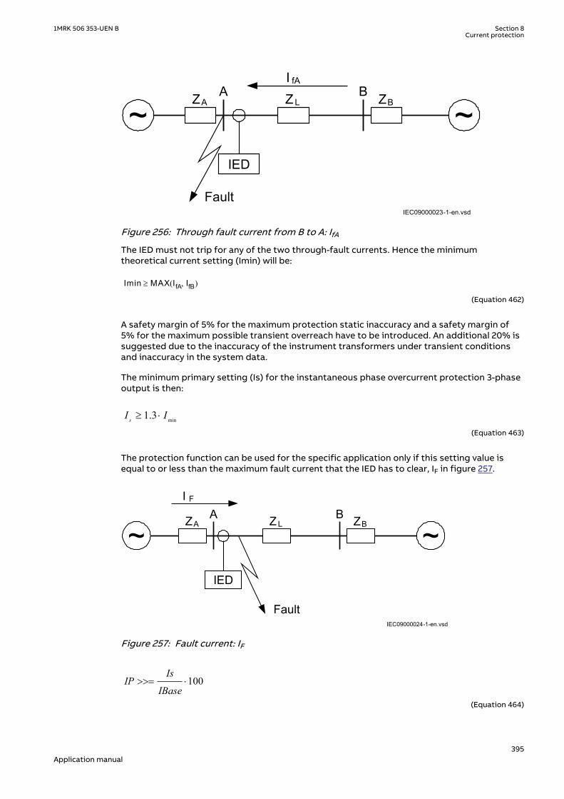
IEC09000023-1-en.vsd
~ ~ZA ZBZ L
A B
IED
I fA
FaultIEC09000023 V1 EN-US
Figure 256: Through fault current from B to A: IfA
The IED must not trip for any of the two through-fault currents. Hence the minimumtheoretical current setting (Imin) will be:
Imin MAX IfA IfB,( )³
EQUATION78 V1 EN-US (Equation 462)
A safety margin of 5% for the maximum protection static inaccuracy and a safety margin of5% for the maximum possible transient overreach have to be introduced. An additional 20% issuggested due to the inaccuracy of the instrument transformers under transient conditionsand inaccuracy in the system data.
The minimum primary setting (Is) for the instantaneous phase overcurrent protection 3-phaseoutput is then:
min1.3sI I³ ×
EQUATION79 V3 EN-US (Equation 463)
The protection function can be used for the specific application only if this setting value isequal to or less than the maximum fault current that the IED has to clear, IF in figure 257.
IEC09000024-1-en.vsd
~ ~ZA ZBZ L
A B
IED
I F
FaultIEC09000024 V1 EN-US
Figure 257: Fault current: IF
100Is
IPIBase
>>= ×
EQUATION1147 V3 EN-US (Equation 464)
1MRK 506 353-UEN B Section 8Current protection
395Application manual

8.1.3.2 Meshed network with parallel lineM12915-34 v6
In case of parallel lines, the influence of the induced current from the parallel line to theprotected line has to be considered. One example is given in figure 258 where the two lines areconnected to the same busbars. In this case the influence of the induced fault current from thefaulty line (line 1) to the healthy line (line 2) is considered together with the two through faultcurrents IfA and IfB mentioned previously. The maximal influence from the parallel line for theIED in figure 258 will be with a fault at the C point with the C breaker open.
A fault in C has to be applied, and then the maximum current seen from the IED (IM ) on thehealthy line (this applies for single-phase-to-earth and two-phase-to-earth faults) iscalculated.
IEC09000025-1-en.vsd
~ ~ZA ZB
ZL1A B
I M
Fault
IED
ZL2
M
CLine 1
Line 2
IEC09000025 V1 EN-US
Figure 258: Two parallel lines. Influence from parallel line to the through fault current: IM
The minimum theoretical current setting for the overcurrent protection function (Imin) will be:
Imin MAX IfA IfB IM, ,( )³
EQUATION82 V1 EN-US (Equation 465)
Where IfA and IfB have been described in the previous paragraph. Considering the safetymargins mentioned previously, the minimum setting (Is) for the instantaneous phaseovercurrent protection 3-phase output is then:
Is ³1.3·IminEQUATION83 V2 EN-US (Equation 466)
The protection function can be used for the specific application only if this setting value isequal or less than the maximum phase fault current that the IED has to clear.
The IED setting value IP>> is given in percentage of the primary base current value, IBase. Thevalue for IP>> is given from this formula:
100Is
IPIBase
>>= ×
EQUATION1147 V3 EN-US (Equation 467)
Section 8 1MRK 506 353-UEN BCurrent protection
396Application manual
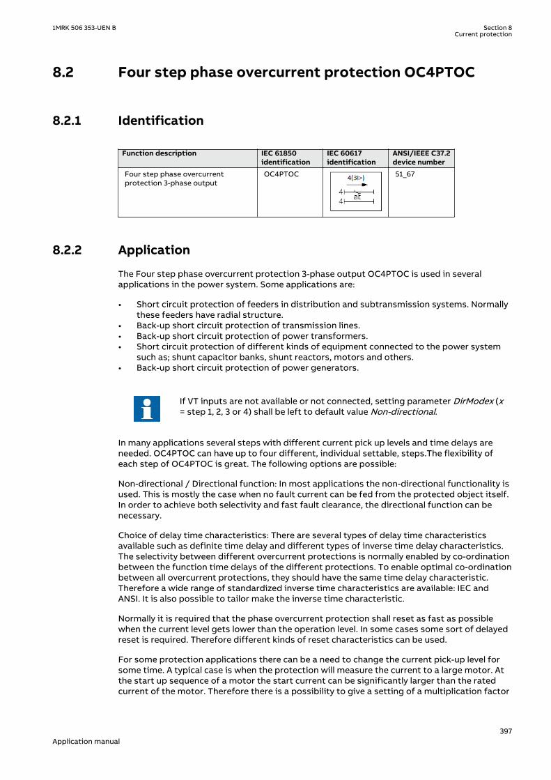
8.2 Four step phase overcurrent protection OC4PTOCSEMOD129998-1 v7
8.2.1 IdentificationM14885-1 v5
Function description IEC 61850identification
IEC 60617identification
ANSI/IEEE C37.2device number
Four step phase overcurrentprotection 3-phase output
OC4PTOC
TOC-REVA V2 EN-US
51_67
8.2.2 ApplicationM15335-3 v8
The Four step phase overcurrent protection 3-phase output OC4PTOC is used in severalapplications in the power system. Some applications are:
• Short circuit protection of feeders in distribution and subtransmission systems. Normallythese feeders have radial structure.
• Back-up short circuit protection of transmission lines.• Back-up short circuit protection of power transformers.• Short circuit protection of different kinds of equipment connected to the power system
such as; shunt capacitor banks, shunt reactors, motors and others.• Back-up short circuit protection of power generators.
If VT inputs are not available or not connected, setting parameter DirModex (x= step 1, 2, 3 or 4) shall be left to default value Non-directional.
In many applications several steps with different current pick up levels and time delays areneeded. OC4PTOC can have up to four different, individual settable, steps.The flexibility ofeach step of OC4PTOC is great. The following options are possible:
Non-directional / Directional function: In most applications the non-directional functionality isused. This is mostly the case when no fault current can be fed from the protected object itself.In order to achieve both selectivity and fast fault clearance, the directional function can benecessary.
Choice of delay time characteristics: There are several types of delay time characteristicsavailable such as definite time delay and different types of inverse time delay characteristics.The selectivity between different overcurrent protections is normally enabled by co-ordinationbetween the function time delays of the different protections. To enable optimal co-ordinationbetween all overcurrent protections, they should have the same time delay characteristic.Therefore a wide range of standardized inverse time characteristics are available: IEC andANSI. It is also possible to tailor make the inverse time characteristic.
Normally it is required that the phase overcurrent protection shall reset as fast as possiblewhen the current level gets lower than the operation level. In some cases some sort of delayedreset is required. Therefore different kinds of reset characteristics can be used.
For some protection applications there can be a need to change the current pick-up level forsome time. A typical case is when the protection will measure the current to a large motor. Atthe start up sequence of a motor the start current can be significantly larger than the ratedcurrent of the motor. Therefore there is a possibility to give a setting of a multiplication factor
1MRK 506 353-UEN B Section 8Current protection
397Application manual

to the current pick-up level. This multiplication factor is activated from a binary input signal tothe function.
Power transformers can have a large inrush current, when being energized. This phenomenonis due to saturation of the transformer magnetic core during parts of the period. There is arisk that inrush current will reach levels above the pick-up current of the phase overcurrentprotection. The inrush current has a large 2nd harmonic content. This can be used to avoidunwanted operation of the protection. Therefore, OC4PTOC have a possibility of 2nd harmonicrestrain if the level of this harmonic current reaches a value above a set percentage of thefundamental current.
The phase overcurrent protection is often used as protection for two and three phase shortcircuits. In some cases it is not wanted to detect single-phase earth faults by the phaseovercurrent protection. This fault type is detected and cleared after operation of earth faultprotection. Therefore it is possible to make a choice how many phases, at minimum, that haveto have current above the pick-up level, to enable operation. If set 1 of 3 it is sufficient to havehigh current in one phase only. If set 2 of 3 or 3 of 3 single-phase earth faults are not detected.
8.2.3 Setting guidelinesIP14982-1 v1
M12982-4 v14
When inverse time overcurrent characteristic is selected, the operate time ofthe stage will be the sum of the inverse time delay and the set definite timedelay. Thus, if only the inverse time delay is required, it is important to set thedefinite time delay for that stage to zero.
The parameters for the directional phase overcurrent protection, four steps OC4PTOC are setvia the local HMI or PCM600.
The following settings can be done for OC4PTOC.
GlobalBaseSel: Selects the global base value group used by the function to define (IBase),(UBase) and (SBase).
MeasType: Selection of discrete Fourier filtered (DFT) or true RMS filtered (RMS) signals. RMSis used when the harmonic contents are to be considered, for example in applications withshunt capacitors.
Operation: The protection can be set to On or Off.
AngleRCA: Protection characteristic angle set in degrees. If the angle of the fault loop currenthas the angle RCA, the direction to the fault is forward.
AngleROA: Angle value, given in degrees, to define the angle sector of the directional function,shown in Figure 259.
StartPhSel: Number of phases, with high current, required for operation. The settingpossibilities are: 1 out of 3, 2 out of 3 and 3 out of 3. The default setting is 1 out of 3.
IMinOpPhSel: Minimum current setting level for releasing the directional start signals in % ofIB. This setting should be less than the lowest step setting. The default setting is 7% of IB.
2ndHarmStab: Operate level of 2nd harmonic current restrain set in % of the fundamentalcurrent. The setting range is 5 - 100% in steps of 1%. The default setting is 20%.
Section 8 1MRK 506 353-UEN BCurrent protection
398Application manual
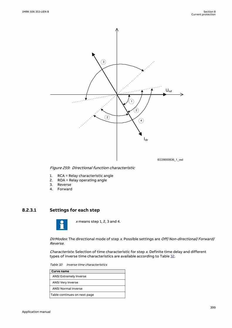
Uref
Idir
IEC09000636_1_vsd
1
2
2
3
4
IEC09000636 V1 EN-US
Figure 259: Directional function characteristic
1. RCA = Relay characteristic angle2. ROA = Relay operating angle3. Reverse4. Forward
8.2.3.1 Settings for each stepM12982-19 v10.1.1
x means step 1, 2, 3 and 4.
DirModex: The directional mode of step x. Possible settings are Off/Non-directional/Forward/Reverse.
Characteristx: Selection of time characteristic for step x. Definite time delay and differenttypes of inverse time characteristics are available according to Table 32.
Table 32: Inverse time characteristics
Curve name
ANSI Extremely Inverse
ANSI Very Inverse
ANSI Normal Inverse
Table continues on next page
1MRK 506 353-UEN B Section 8Current protection
399Application manual

Curve name
ANSI Moderately Inverse
ANSI/IEEE Definite time
ANSI Long Time Extremely Inverse
ANSI Long Time Very Inverse
ANSI Long Time Inverse
IEC Normal Inverse
IEC Very Inverse
IEC Inverse
IEC Extremely Inverse
IEC Short Time Inverse
IEC Long Time Inverse
IEC Definite Time
User Programmable
ASEA RI
RXIDG or RD (logarithmic)
The different characteristics are described in Technical manual.
Ix>: Operate phase current level for step x given in % of IB.
Ix>MaxEd2Set and Ix>MinEd2Set should only be changed if remote setting of operationcurrent level, Ix>, is used. The limits are used for decreasing the used range of the Ix> setting.If Ix> is set outside Ix>MaxEd2Set and Ix>MinEd2Set, the closest of the limits to Ix> is used bythe function. If Ix>MaxEd2Set is smaller than Ix>MinEd2Set, the limits are swapped.
tx: Definite time delay for step x. The definite time tx is added to the inverse time when inversetime characteristic is selected. Note that the value set is the time between activation of thestart and the trip outputs.
kx: Time multiplier for inverse time delay for step x.
IMinx: Minimum operate current in % of IB for all inverse time characteristics, below which nooperation takes place.
IMinx: Minimum operate current for step x in % of IBase. Set IMinx below Ix> for every step toachieve ANSI reset characteristic according to standard. If IMinx is set above Ix> for any stepthe ANSI reset works as if current is zero when current drops below IMinx.
txMin: Minimum operate time for all inverse time characteristics. At high currents the inversetime characteristic might give a very short operation time. By setting this parameter theoperation time of the step can never be shorter than the setting. Setting range: 0.000 -60.000s in steps of 0.001s.
IxMult: Multiplier for scaling of the current setting value. If a binary input signal ENMULTx(enableMultiplier) is activated the current operation level is increased by this setting constant.Setting range: 1.0-10.0
Section 8 1MRK 506 353-UEN BCurrent protection
400Application manual

IMinx
Operate time
Current
tx
txMin
IEC10000058
IEC10000058 V2 EN-US
Figure 260: Minimum operate current and operate time for inverse time characteristics
In order to fully comply with the definition of the curve, the setting parameter txMin shall beset to a value equal to the operating time of the selected inverse curve for twenty times the setcurrent pickup value. Note that the operate time is dependent on the selected time multipliersetting kx.
ResetTypeCrvx: The reset of the delay timer can be made as shown in Table 33.
Table 33: Reset possibilities
Curve name Curve index no.
Instantaneous 1
IEC Reset (constant time) 2
ANSI Reset (inverse time) 3
The delay characteristics are described in Technical manual. There are some restrictionsregarding the choice of the reset delay.
For the definite time delay characteristics, the possible delay time setting instantaneous (1)and IEC (2 = set constant time reset).
For ANSI inverse time characteristics, all three types of reset time characteristics are available:instantaneous (1), IEC (2 = set constant time reset) and ANSI (3 = current dependent resettime).
For IEC inverse time characteristics, the possible delay time settings are instantaneous (1) andIEC (2 = set constant time reset).
For the customer tailor-made inverse time delay characteristics (type 17), all three types ofreset time characteristics are available: instantaneous (1), IEC (2 = set constant time reset) andANSI (3 = current dependent reset time). If the current-dependent type is used, settings pr, trand cr must be given.
tResetx: Constant reset time delay in seconds for step x.
tPCrvx, tACrvx, tBCrvx, tCCrvx: These parameters are used by the customer to create theinverse time characteristic curve. See equation 468 for the time characteristic equation. Formore information, refer to Technical manual.
1MRK 506 353-UEN B Section 8Current protection
401Application manual
[ ]
>
p
At s B IxMult
iC
in
= + ×
-
æ öç ÷ç ÷ç ÷æ öç ÷ç ÷è øè ø
EQUATION1261 V2 EN-US (Equation 468)
tPRCrvx, tTRCrvx, tCRCrvx: These parameters are used by the customer to create the inversereset time characteristic curve. For more information, refer to Technical manual.
HarmRestrainx: Enables the block of step x from the harmonic restrain function (2ndharmonic). This function should be used when there is a risk of an unwanted trip caused bypower transformer inrush currents. It can be set to Off/On.
8.2.3.2 2nd harmonic restrainM12982-91 v8
If a power transformer is energized there is a risk that the transformer core will saturateduring part of the period, resulting in an inrush transformer current. This will give a decliningresidual current in the network, as the inrush current is deviating between the phases. There isa risk that the phase overcurrent function will give an unwanted trip. The inrush current has arelatively large ratio of 2nd harmonic component. This component can be used to create arestrain signal to prevent this unwanted function.
The settings for the 2nd harmonic restrain are described below.
2ndHarmStab: The rate of 2nd harmonic current content for activation of the 2nd harmonicrestrain signal, to block chosen steps. The setting is given in % of the fundamental frequencyresidual current. The setting range is 5 - 100% in steps of 1%. The default setting is 20% andcan be used if a deeper investigation shows that no other value is needed..
HarmRestrainx: This parameter can be set Off/On, to disable or enable the 2nd harmonicrestrain.
The four step phase overcurrent protection 3-phase output can be used in different ways,depending on the application where the protection is used. A general description is givenbelow.
The operating current setting of the inverse time protection, or the lowest current step of thedefinite time protection, must be defined so that the highest possible load current does notcause protection operation. Here consideration also has to be taken to the protection resetcurrent, so that a short peak of overcurrent does not cause operation of the protection evenwhen the overcurrent has ceased. This phenomenon is described in figure 261.
Section 8 1MRK 506 353-UEN BCurrent protection
402Application manual
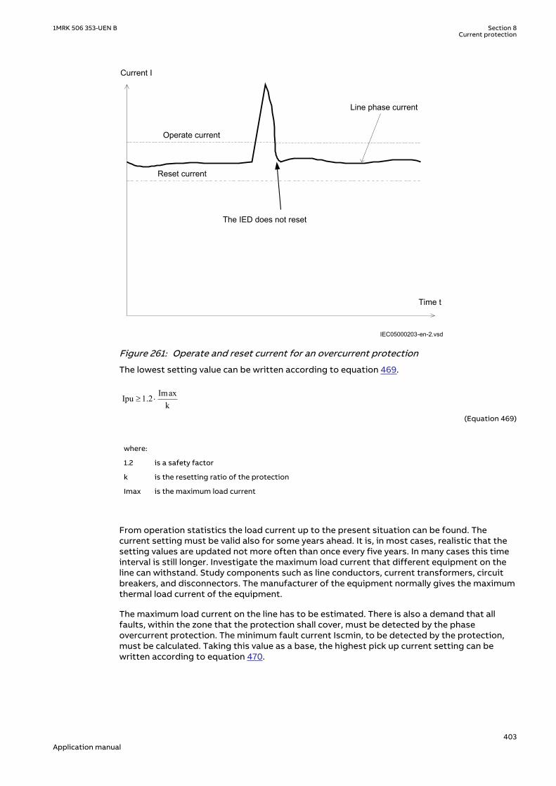
Operate current
Current I
The IED does not reset
Line phase current
Time t
Reset current
IEC05000203-en-2.vsdIEC05000203 V3 EN-US
Figure 261: Operate and reset current for an overcurrent protection
The lowest setting value can be written according to equation 469.
ImaxIpu 1.2k
³ ×
EQUATION1262 V2 EN-US (Equation 469)
where:
1.2 is a safety factor
k is the resetting ratio of the protection
Imax is the maximum load current
From operation statistics the load current up to the present situation can be found. Thecurrent setting must be valid also for some years ahead. It is, in most cases, realistic that thesetting values are updated not more often than once every five years. In many cases this timeinterval is still longer. Investigate the maximum load current that different equipment on theline can withstand. Study components such as line conductors, current transformers, circuitbreakers, and disconnectors. The manufacturer of the equipment normally gives the maximumthermal load current of the equipment.
The maximum load current on the line has to be estimated. There is also a demand that allfaults, within the zone that the protection shall cover, must be detected by the phaseovercurrent protection. The minimum fault current Iscmin, to be detected by the protection,must be calculated. Taking this value as a base, the highest pick up current setting can bewritten according to equation 470.
1MRK 506 353-UEN B Section 8Current protection
403Application manual

Ipu 0.7 Iscmin£ ×EQUATION1263 V2 EN-US (Equation 470)
where:
0.7 is a safety factor
Iscmin is the smallest fault current to be detected by the overcurrent protection.
As a summary the operating current shall be chosen within the interval stated in equation 471.
Imax1.2 Ipu 0.7 Iscmink
× £ £ ×
EQUATION1264 V2 EN-US (Equation 471)
The high current function of the overcurrent protection, which only has a short delay of theoperation, must be given a current setting so that the protection is selective to otherprotection in the power system. It is desirable to have a rapid tripping of faults within as largeportion as possible of the part of the power system to be protected by the protection (primaryprotected zone). A fault current calculation gives the largest current of faults, Iscmax, at themost remote part of the primary protected zone. Considerations have to be made to the riskof transient overreach, due to a possible DC component of the short circuit current. The lowestcurrent setting of the most rapid stage, of the phase overcurrent protection, can be writtenaccording to
max1.2 t schighI k I³ × ×
EQUATION1265 V1 EN-US (Equation 472)
where:
1.2 is a safety factor
kt is a factor that takes care of the transient overreach due to the DC component of the fault currentand can be considered to be less than 1.05
Iscmax is the largest fault current at a fault at the most remote point of the primary protection zone.
The operate times of the phase overcurrent protection has to be chosen so that the fault timeis so short that protected equipment will not be destroyed due to thermal overload, at thesame time as selectivity is assured. For overcurrent protection, in a radial fed network, thetime setting can be chosen in a graphical way. This is mostly used in the case of inverse timeovercurrent protection. Figure 262 shows how the time-versus-current curves are plotted in adiagram. The time setting is chosen to get the shortest fault time with maintained selectivity.Selectivity is assured if the time difference between the curves is larger than a critical timedifference.
Section 8 1MRK 506 353-UEN BCurrent protection
404Application manual

en05000204.wmfIEC05000204 V1 EN-US
Figure 262: Fault time with maintained selectivity
The operation time can be set individually for each overcurrent protection.
To assure selectivity between different protections, in the radial network, there have to be aminimum time difference Dt between the time delays of two protections. The minimum timedifference can be determined for different cases. To determine the shortest possible timedifference, the operation time of protections, breaker opening time and protection resettingtime must be known. These time delays can vary significantly between different protectiveequipment. The following time delays can be estimated:
Protection operationtime:
15-60 ms
Protection resettingtime:
15-60 ms
Breaker opening time: 20-120 ms
Example for time coordination
Assume two substations A and B directly connected to each other via one line, as shown in thefigure 263. Consider a fault located at another line from the station B. The fault current to theovercurrent protection of IED B1 has a magnitude so that the protection will haveinstantaneous function. The overcurrent protection of IED A1 must have a delayed function.The sequence of events during the fault can be described using a time axis, see figure 263.
1MRK 506 353-UEN B Section 8Current protection
405Application manual

I> I>
A1 B1 Feeder
Time axis
t=0 t=t1 t=t2 t=t3The faultoccurs
ProtectionB1 trips
Breaker atB1 opens
ProtectionA1 resets
en05000205.vsdIEC05000205 V1 EN-US
Figure 263: Sequence of events during fault
where:
t=0 is when the fault occurs
t=t1 is when the trip signal from the overcurrent protection at IED B1 is sent to the circuit breaker. Theoperation time of this protection is t1
t=t2 is when the circuit breaker at IED B1 opens. The circuit breaker opening time is t2 - t1
t=t3 is when the overcurrent protection at IED A1 resets. The protection resetting time is t3 - t2.
To ensure that the overcurrent protection at IED A1, is selective to the overcurrent protectionat IED B1, the minimum time difference must be larger than the time t3. There are uncertaintiesin the values of protection operation time, breaker opening time and protection resettingtime. Therefore a safety margin has to be included. With normal values the needed timedifference can be calculated according to equation 473.
40 100 40 40 220t ms ms ms ms msD ³ + + + =EQUATION1266 V1 EN-US (Equation 473)
where it is considered that:
the operate time of overcurrent protection B1 is 40 ms
the breaker open time is 100 ms
the resetting time of protection A1 is 40 ms and
the additional margin is 40 ms
8.3 Instantaneous residual overcurrent protection EFPIOCIP14508-1 v3
Section 8 1MRK 506 353-UEN BCurrent protection
406Application manual

8.3.1 IdentificationM14887-1 v4
Function description IEC 61850identification
IEC 60617identification
ANSI/IEEE C37.2device number
Instantaneous residual overcurrentprotection
EFPIOC
IN>>
IEF V1 EN-US
50N
8.3.2 ApplicationM12699-3 v5
In many applications, when fault current is limited to a defined value by the object impedance,an instantaneous earth-fault protection can provide fast and selective tripping.
The Instantaneous residual overcurrent EFPIOC, which can operate in 15 ms (50 Hz nominalsystem frequency) for faults characterized by very high currents, is included in the IED.
8.3.3 Setting guidelinesIP14985-1 v1
M12762-44 v2M12762-4 v4
The parameters for the Instantaneous residual overcurrent protection EFPIOC are set via thelocal HMI or PCM600.
Some guidelines for the choice of setting parameter for EFPIOC is given.M12762-6 v7
GlobalBaseSel: Selects the global base value group used by the function to define (IBase),(UBase) and (SBase).
The setting of the function is limited to the operate residual current to the protection (IN>>).
The basic requirement is to assure selectivity, that is EFPIOC shall not be allowed to operatefor faults at other objects than the protected object (line).
For a normal line in a meshed system single phase-to-earth faults and phase-to-phase-to-earthfaults shall be calculated as shown in figure 264 and figure 265. The residual currents (3I0) tothe protection are calculated. For a fault at the remote line end this fault current is IfB. In thiscalculation the operational state with high source impedance ZA and low source impedance ZBshould be used. For the fault at the home busbar this fault current is IfA. In this calculation theoperational state with low source impedance ZA and high source impedance ZB should beused.
~ ~ZA ZBZ L
A B
IED
I fB
Fault
IEC09000022-1-en.vsdIEC09000022 V1 EN-US
Figure 264: Through fault current from A to B: IfB
1MRK 506 353-UEN B Section 8Current protection
407Application manual

IEC09000023-1-en.vsd
~ ~ZA ZBZ L
A B
IED
I fA
FaultIEC09000023 V1 EN-US
Figure 265: Through fault current from B to A: IfA
The function shall not operate for any of the calculated currents to the protection. Theminimum theoretical current setting (Imin) will be:
Imin MAX IfA IfA,( )³
EQUATION284 V1 EN-US (Equation 474)
A safety margin of 5% for the maximum static inaccuracy and a safety margin of 5% formaximum possible transient overreach have to be introduced. An additional 20% is suggesteddue to inaccuracy of instrument transformers under transient conditions and inaccuracy in thesystem data.
The minimum primary current setting (Is) is:
Is = 1.3 × Imin EQUATION285 V3 EN-US (Equation 475)
In case of parallel lines with zero sequence mutual coupling a fault on the parallel line, asshown in figure 266, should be calculated.
IEC09000025-1-en.vsd
~ ~ZA ZB
ZL1A B
I M
Fault
IED
ZL2
M
CLine 1
Line 2
IEC09000025 V1 EN-US
Figure 266: Two parallel lines. Influence from parallel line to the through fault current: IM
The minimum theoretical current setting (Imin) will in this case be:
Section 8 1MRK 506 353-UEN BCurrent protection
408Application manual

I m in M AX IfA I fB IM, ,( )³
EQUATION287 V1 EN-US (Equation 476)
Where:
IfA and IfB have been described for the single line case.
Considering the safety margins mentioned previously, the minimum setting (Is) is:
Is = 1.3 × Imin EQUATION288 V3 EN-US (Equation 477)
Transformer inrush current shall be considered.
The setting of the protection is set as a percentage of the base current (IBase).
Operation: set the protection to On or Off.
IN>>: Set operate current in % of IBase.
StValMult: The operate current can be changed by activation of the binary input ENMULT tothe set factor StValMult.
8.4 Four step residual overcurrent protection, (Zerosequence or negative sequence directionality)EF4PTOC
IP14509-1 v6
8.4.1 IdentificationM14881-1 v5
Function description IEC 61850identification
IEC 60617identification
ANSI/IEEE C37.2device number
Four step residual overcurrentprotection
EF4PTOC 4(IN>)
4 alt4TEF-REVA V2 EN-US
51N_67N
8.4.2 ApplicationM12509-12 v9
The four step residual overcurrent protection EF4PTOC is used in several applications in thepower system. Some applications are:
• Earth-fault protection of feeders in effectively earthed distribution and subtransmissionsystems. Normally these feeders have radial structure.
• Back-up earth-fault protection of transmission lines.• Sensitive earth-fault protection of transmission lines. EF4PTOC can have better sensitivity
to detect resistive phase-to-earth-faults compared to distance protection.• Back-up earth-fault protection of power transformers.• Earth-fault protection of different kinds of equipment connected to the power system
such as shunt capacitor banks, shunt reactors and others.
1MRK 506 353-UEN B Section 8Current protection
409Application manual

In many applications several steps with different current operating levels and time delays areneeded. EF4PTOC can have up to four, individual settable steps. The flexibility of each step ofEF4PTOC is great. The following options are possible:
Non-directional/Directional function: In some applications the non-directional functionality isused. This is mostly the case when no fault current can be fed from the protected object itself.In order to achieve both selectivity and fast fault clearance, the directional function can benecessary. This can be the case for earth-fault protection in meshed and effectively earthedtransmission systems. The directional residual overcurrent protection is also well suited tooperate in teleprotection communication schemes, which enables fast clearance of earthfaults on transmission lines. The directional function uses the polarizing quantity as decidedby setting. Voltage polarizing is most commonly used, but alternatively current polarizingwhere currents in transformer neutrals providing the neutral source (ZN) is used to polarize (IN· ZN) the function. Dual polarizing where the sum of both voltage and current components isallowed to polarize can also be selected.
Choice of time characteristics: There are several types of time characteristics available such asdefinite time delay and different types of inverse time characteristics. The selectivity betweendifferent overcurrent protections is normally enabled by co-ordination between the operatetime of the different protections. To enable optimal co-ordination all overcurrent protections,to be co-ordinated against each other, should have the same time characteristic. Therefore awide range of standardized inverse time characteristics are available: IEC and ANSI.
Table 34: Time characteristics
Curve name
ANSI Extremely Inverse
ANSI Very Inverse
ANSI Normal Inverse
ANSI Moderately Inverse
ANSI/IEEE Definite time
ANSI Long Time Extremely Inverse
ANSI Long Time Very Inverse
ANSI Long Time Inverse
IEC Normal Inverse
IEC Very Inverse
IEC Inverse
IEC Extremely Inverse
IEC Short Time Inverse
IEC Long Time Inverse
IEC Definite Time
User Programmable
ASEA RI
RXIDG (logarithmic)
It is also possible to tailor make the inverse time characteristic.
Normally it is required that EF4PTOC shall reset as fast as possible when the current level getslower than the operation level. In some cases some sort of delayed reset is required. Thereforedifferent kinds of reset characteristics can be used.
For some protection applications there can be a need to change the current operating level forsome time. Therefore there is a possibility to give a setting of a multiplication factor INxMult
Section 8 1MRK 506 353-UEN BCurrent protection
410Application manual

to the residual current pick-up level. This multiplication factor is activated from a binary inputsignal ENMULTx to the function.
Power transformers can have a large inrush current, when being energized. This inrush currentcan have residual current components. The phenomenon is due to saturation of thetransformer magnetic core during parts of the cycle. There is a risk that inrush current will givea residual current that reaches level above the operating current of the residual overcurrentprotection. The inrush current has a large second harmonic content. This can be used to avoidunwanted operation of the protection. Therefore, EF4PTOC has a possibility of secondharmonic restrain 2ndHarmStab if the level of this harmonic current reaches a value above aset percentage of the fundamental current.
8.4.3 Setting guidelinesIP14988-1 v1
M15282-3 v12
When inverse time overcurrent characteristic is selected, the operate time ofthe stage will be the sum of the inverse time delay and the set definite timedelay. Thus, if only the inverse time delay is required, it is important to set thedefinite time delay for that stage to zero.
The parameters for the four step residual overcurrent protection are set via the local HMI orPCM600. The following settings can be done for the function.
GlobalBaseSel: Selects the global base value group used by the function to define (IBase),(UBase) and (SBase).
SeqTypeUPol: This is used to select the type of voltage polarising quantity i.e. Zero seq or Negseq for direction detection.
SeqTypeIPol: This is used to select the type of current polarising quantity i.e. Zero seq or Negseq for direction detection.
SeqTypeIDir: This is used to select the type of operating current quantity i.e. Zero seq or Negseq for direction detection.
8.4.3.1 Settings for each step (x = 1, 2, 3 and 4)M15282-9 v12.1.1
Operation: Sets the protection to On or Off.
DirModex: The directional mode of step x. Possible settings are Off/Non-directional/Forward/Reverse.
Characteristx: Selection of time characteristic for step x. Definite time delay and differenttypes of inverse time characteristics are available.
Inverse time characteristic enables fast fault clearance of high current faults at the same timeas selectivity to other inverse time phase overcurrent protections can be assured. This ismainly used in radial fed networks but can also be used in meshed networks. In meshednetworks, the settings must be based on network fault calculations.
To assure selectivity between different protections, in the radial network, there has to be aminimum time difference Dt between the time delays of two protections. To determine theshortest possible time difference, the operation time of protections, breaker opening timeand protection resetting time must be known. These time delays can vary significantlybetween different protective equipment. The following time delays can be estimated:
1MRK 506 353-UEN B Section 8Current protection
411Application manual

Protection operate time: 15-60 ms
Protection resetting time: 15-60 ms
Breaker opening time: 20-120 ms
The different characteristics are described in the technical reference manual.
tx: Definite time delay for step x. The definite time tx is added to the inverse time when inversetime characteristic is selected. Note that the value set is the time between activation of thestart and the trip outputs.
INx>: Operate residual current level for step x given in % of IB.
INx>MaxEd2Set and INx>MinEd2Set should only be changed if remote setting of operationcurrent level, INx>, is used. The limits are used for decreasing the used range of the INx>setting. If INx> is set outside INx>MaxEd2Set and INx>MinEd2Set, the closest of the limits toINx> is used by the function. If INx>MaxEd2Set is smaller than INx>MinEd2Set, the limits areswapped.
kx: Time multiplier for the dependent (inverse) characteristic for step x.
IMinx: Minimum operate current for step x in % of IB. Set IMinx below INx> for every step toachieve ANSI reset characteristic according to standard. If IMinx is set above INx> for any step,signal will reset at current equals to zero.
txMin: Minimum operating time for inverse time characteristics. At high currents, the inversetime characteristic might give a very short operation time. By setting this parameter, theoperation time of the step can never be shorter than the setting.
IMinx
Operate time
Current
tx
txMin
IEC10000058
IEC10000058 V2 EN-US
Figure 267: Minimum operate current and operate time for inverse time characteristics
In order to fully comply with the curves definition, the setting parameter txMin shall be set tothe value which is equal to the operate time of the selected IEC inverse curve for measuredcurrent of twenty times the set current pickup value. Note that the operate time value isdependent on the selected setting value for time multiplier kx.
INxMult: Multiplier for scaling of the current setting value. If a binary input signal (ENMULTx) isactivated, the current operation level is increased by this setting constant.
ResetTypeCrvx: The reset of the delay timer can be made in different ways. The possibilitiesare described in the technical reference manual.
Section 8 1MRK 506 353-UEN BCurrent protection
412Application manual

tResetx: Constant reset time delay in s for step x.
HarmBlockx: This is used to enable block of step x from 2nd harmonic restrain function.
tPCrvx, tACrvx, tBCrvx, tCCrvx: Parameters for user programmable of inverse timecharacteristic curve. The time characteristic equation is according to equation 478:
[ ] = + ×
->
æ öç ÷ç ÷ç ÷æ ö
ç ÷ç ÷è øè ø
p
At s B k
iC
inEQUATION1189 V1 EN-US (Equation 478)
Further description can be found in the technical reference manual.
tPRCrvx, tTRCrvx, tCRCrvx: Parameters for user programmable of inverse reset timecharacteristic curve. Further description can be found in the technical reference manual.
8.4.3.2 Common settings for all stepsM15282-81 v9
AngleRCA: Relay characteristic angle given in degree. This angle is defined as shown infigure 268. The angle is defined positive when the residual current lags the reference voltage(Upol = 3U0 or U2)
Upol = 3U0 or U2
I>Dir
RCA
Operation
en 05000135-4-nsi.vsd
IEC05000135 V4 EN-US
Figure 268: Relay characteristic angle given in degree
In a normal transmission network a normal value of RCA is about 65°. The setting range is -180°to +180°.
polMethod: Defines if the directional polarization is from
1MRK 506 353-UEN B Section 8Current protection
413Application manual

• Voltage (3U0 or U2)• Current (3I0 · ZNpol or 3I2 ·ZNpol where ZNpol is RNpol + jXNpol), or• both currents and voltage, Dual (dual polarizing, (3U0 + 3I0 · ZNpol) or (U2 + I2 · ZNpol)).
Normally voltage polarizing from the internally calculated residual sum or an external opendelta is used.
Current polarizing is useful when the local source is strong and a high sensitivity is required. Insuch cases the polarizing voltage (3U0) can be below 1% and it is then necessary to use currentpolarizing or dual polarizing. Multiply the required set current (primary) with the minimumimpedance (ZNpol) and check that the percentage of the phase-to-earth voltage is definitelyhigher than 1% (minimum 3U0>UPolMin setting) as a verification.
RNPol, XNPol: The zero-sequence source is set in primary ohms as base for the currentpolarizing. The polarizing voltage is then achieved as 3I0 · ZNpol. The ZNpol can be defined as(ZS1-ZS0)/3, that is the earth return impedance of the source behind the protection. Themaximum earth-fault current at the local source can be used to calculate the value of ZN asU/(√3 · 3I0) Typically, the minimum ZNPol (3 · zero sequence source) is set. Setting is in primaryohms.
When the dual polarizing method is used it is important that the settingINx>or the product 3I0· ZNpol is not greater than 3U0. If so, there is a risk for incorrect operation for faults in thereverse direction.
IPolMin: is the minimum earth-fault current accepted for directional evaluation. For smallercurrents than this value the operation will be blocked. Typical setting is 5-10% of IBase.
UPolMin: Minimum polarization (reference) polarizing voltage for the directional function,given in % of UBase/√3.
I>Dir: Operate residual current release level in % of IBase for directional comparison scheme.The setting is given in % of IBase and must be set below the lowest INx> setting, set for thedirectional measurement. The output signals, STFW and STRV can be used in a teleprotectionscheme. The appropriate signal should be configured to the communication scheme block.
8.4.3.3 2nd harmonic restrainM15282-90 v5
If a power transformer is energized there is a risk that the current transformer core willsaturate during part of the period, resulting in a transformer inrush current. This will give adeclining residual current in the network, as the inrush current is deviating between thephases. There is a risk that the residual overcurrent function will give an unwanted trip. Theinrush current has a relatively large ratio of 2nd harmonic component. This component can beused to create a restrain signal to prevent this unwanted function.
At current transformer saturation a false residual current can be measured by the protection.Also here the 2nd harmonic restrain can prevent unwanted operation.
2ndHarmStab: The rate of 2nd harmonic current content for activation of the 2nd harmonicrestrain signal. The setting is given in % of the fundamental frequency residual current.
HarmRestrainx: Enable block of step x from the harmonic restrain function.
8.4.3.4 Parallel transformer inrush current logicM15282-97 v5
In case of parallel transformers there is a risk of sympathetic inrush current. If one of thetransformers is in operation, and the parallel transformer is switched in, the asymmetricinrush current of the switched in transformer will cause partial saturation of the transformeralready in service. This is called transferred saturation. The 2nd harmonic of the inrush currents
Section 8 1MRK 506 353-UEN BCurrent protection
414Application manual

of the two transformers will be in phase opposition. The summation of the two currents willthus give a small 2nd harmonic current. The residual fundamental current will however besignificant. The inrush current of the transformer in service before the parallel transformerenergizing, will be a little delayed compared to the first transformer. Therefore we will havehigh 2nd harmonic current initially. After a short period this current will however be small andthe normal 2nd harmonic blocking will reset.
en05000136.vsd
Power System
IN>IN>
IEC05000136 V1 EN-US
Figure 269: Application for parallel transformer inrush current logic
If the BlkParTransf function is activated the 2nd harmonic restrain signal will latch as long asthe residual current measured by the relay is larger than a selected step current level. Assumethat step 4 is chosen to be the most sensitive step of the four step residual overcurrentprotection function EF4PTOC. The harmonic restrain blocking is enabled for this step. Also thesame current setting as this step is chosen for the blocking at parallel transformer energizing.
Below the settings for the parallel transformer logic are described.
UseStartValue: Gives which current level that should be used for activation of the blockingsignal. This is given as one of the settings of the steps: Step 1/2/3/4. Normally the step havingthe lowest operation current level should be set.
BlkParTransf: This parameter can be set Off/On, the parallel transformer logic.
8.4.3.5 Switch onto fault logicM15282-106 v3
In case of energizing a faulty object there is a risk of having a long fault clearance time, if thefault current is too small to give fast operation of the protection. The switch on to faultfunction can be activated from auxiliary signals from the circuit breaker, either the closecommand or the open/close position (change of position).
This logic can be used to issue fast trip if one breaker pole does not close properly at a manualor automatic closing.
SOTF and Under Time are similar functions to achieve fast clearance at asymmetrical closingbased on requirements from different utilities.
The function is divided into two parts. The SOTF function will give operation from step 2 or 3during a set time after change in the position of the circuit breaker. The SOTF function has aset time delay. The Under Time function, which has 2nd harmonic restrain blocking, will giveoperation from step 4. The 2nd harmonic restrain will prevent unwanted function in case oftransformer inrush current. The Under Time function has a set time delay.
Below the settings for switch on to fault logics are described.
SOTF operation mode: This parameter can be set: Off/SOTF/Under Time/SOTF+Under Time.
1MRK 506 353-UEN B Section 8Current protection
415Application manual

ActivationSOTF: This setting will select the signal to activate SOTF function; CB positionopen/CB position closed/CB close command.
tSOTF: Time delay for operation of the SOTF function. The setting range is 0.000 - 60.000 s instep of 0.001 s. The default setting is 0.100 s
StepForSOTF: If this parameter is set on the step 3 start signal will be used as current set level.If set off step 2 start signal will be used as current set level.
t4U: Time interval when the SOTF function is active after breaker closing. The setting range is0.000 - 60.000 s in step of 0.001 s. The default setting is 1.000 s.
ActUnderTime: Describes the mode to activate the sensitive undertime function. The functioncan be activated by Circuit breaker position (change) or Circuit breaker command.
tUnderTime: Time delay for operation of the sensitive undertime function. The setting range is0.000 - 60.000 s in step of 0.001 s. The default setting is 0.300 s
8.4.3.6 Line application exampleM15282-184 v7
The Four step residual overcurrent protection EF4PTOC can be used in different ways. Below isdescribed one application possibility to be used in meshed and effectively earthed systems.
The protection measures the residual current out on the protected line. The protectionfunction has a directional function where the polarizing voltage (zero-sequence voltage) is thepolarizing quantity.
The polarizing voltage and current can be internally generated when a three-phase set ofvoltage transformers and current transformers are used.
xx05000149.vsd
IN>
IEC05000149 V1 EN-US
Figure 270: Connection of polarizing voltage from an open delta
The different steps can be described as follows.
Section 8 1MRK 506 353-UEN BCurrent protection
416Application manual

Step 1M15282-123 v5
This step has directional instantaneous function. The requirement is that overreaching of theprotected line is not allowed.
IEC05000150-3-en.vsd
IN
3I0
One- or two-phase earth-faultor unsymmetric short circuitwithout earth connection
IEC05000150 V4 EN-US
Figure 271: Step 1, first calculation
The residual current out on the line is calculated at a fault on the remote busbar (one- or two-phase-to-earth fault). To assure selectivity it is required that step 1 shall not give a trip at thisfault. The requirement can be formulated according to equation 479.
step1 0I 1.2 3I (remote busbar)³ ×
EQUATION1199 V3 EN-US (Equation 479)
As a consequence of the distribution of zero sequence current in the power system, thecurrent to the protection might be larger if one line out from the remote busbar is taken out ofservice, see figure 272.
IEC05000151-en-2.vsd
IN >
One- or two-phase-earth-fault
3I0
IEC05000151 V2 EN-US
Figure 272: Step 1, second calculation. Remote busbar with, one line taken out of service
The requirement is now according to equation 480.
step1 0I 1.2 3I (remote busbar with one line out)³ ×
EQUATION1200 V3 EN-US (Equation 480)
1MRK 506 353-UEN B Section 8Current protection
417Application manual

A higher value of step 1 might be necessary if a big power transformer (Y0/D) at remote busbar is disconnected.
A special case occurs at double circuit lines, with mutual zero-sequence impedance betweenthe parallel lines, see figure 273.
IN >
One phase-to-earth fault
3I0
IEC05000152-en-2.vsdIEC05000152 V2 EN-US
Figure 273: Step 1, third calculation
In this case the residual current out on the line can be larger than in the case of earth fault onthe remote busbar.
step1 0I 1.2 3I³ ×EQUATION1201 V3 EN-US (Equation 481)
The current setting for step 1 is chosen as the largest of the above calculated residualcurrents, measured by the protection.
Step 2M15282-144 v6
This step has directional function and a short time delay, often about 0.4 s. Step 2 shallsecurely detect all earth faults on the line, not detected by step 1.
IN >
One- or two-phase earth-fault
3I0
IEC05000154-en-2.vsdIEC05000154 V2 EN-US
Figure 274: Step 2, check of reach calculation
Section 8 1MRK 506 353-UEN BCurrent protection
418Application manual

The residual current, out on the line, is calculated at an operational case with minimal earth-fault current. The requirement that the whole line shall be covered by step 2 can be formulatedaccording to equation 482.
step2 0I 0.7 3I (at remote busbar)³ ×EQUATION1202 V4 EN-US (Equation 482)
To assure selectivity the current setting must be chosen so that step 2 does not operate atstep 2 for faults on the next line from the remote substation. Consider a fault as shown inFigure 275.
IN >
One phase-to-earth fault
3I0
IN >
3I01
IEC05000155-en-2.vsdIEC05000155 V3 EN-US
Figure 275: Step 2, selectivity calculation
A second criterion for step 2 is according to equation 483.
11 0
step2 step10
3I I .2 I3I
³ × ×
EQUATION1203 V4 EN-US (Equation 483)
where:
Istep1 is the current setting for step 1 on the faulted line.
Step 3M15282-164 v6
This step has directional function and a time delay slightly larger than step 2, often 0.8 s. Step3 shall enable selective trip of earth faults having higher fault resistance to earth, compared tostep 2. The requirement on step 3 is selectivity to other earth-fault protections in the network.One criterion for setting is shown in Figure 276.
IEC05000156-3-en.vsd
IN >
One phase-to-earth fault
3I0
IN >
3I02
IEC05000156 V3 EN-US
Figure 276: Step 3, Selectivity calculation
1MRK 506 353-UEN B Section 8Current protection
419Application manual

1 0step3 step2
02
3I I .2 I3I
³ × ×
EQUATION1204 V4 EN-US (Equation 484)
where:
Istep2 is the chosen current setting for step 2 on the faulted line.
Step 4M15282-177 v4
This step normally has non-directional function and a relatively long time delay. The task forstep 4 is to detect and initiate trip for earth faults with large fault resistance, for example treefaults. Step 4 shall also detect series faults where one or two poles, of a breaker or otherswitching device, are open while the other poles are closed.
Both high resistance earth faults and series faults give zero-sequence current flow in thenetwork. Such currents give disturbances on telecommunication systems and current to earth.It is important to clear such faults both concerning personal security as well as risk of fire.
The current setting for step 4 is often set down to about 100 A (primary 3I0). In manyapplications definite time delay in the range 1.2 - 2.0 s is used. In other applications a currentdependent inverse time characteristic is used. This enables a higher degree of selectivity alsofor sensitive earth-fault current protection.
8.5 Four step directional negative phase sequenceovercurrent protection NS4PTOC
GUID-E8CF8AA2-AF54-4FD1-A379-3E55DCA2FA3A v1
8.5.1 IdentificationGUID-E1720ADA-7F80-4F2C-82A1-EF2C9EF6A4B4 v1
Function description IEC 61850identification
IEC 60617identification
ANSI/IEEE C37.2device number
Four step negative sequenceovercurrent protection
NS4PTOC I24
4alt
IEC10000053 V1 EN-US
46I2
8.5.2 ApplicationGUID-343023F8-AFE3-41C2-8440-1779DD7F5621 v2
Four step negative sequence overcurrent protection NS4PTOC is used in several applicationsin the power system. Some applications are:
• Earth-fault and phase-phase short circuit protection of feeders in effectively eartheddistribution and subtransmission systems. Normally these feeders have radial structure.
• Back-up earth-fault and phase-phase short circuit protection of transmission lines.• Sensitive earth-fault protection of transmission lines. NS4PTOC can have better
sensitivity to detect resistive phase-to-earth-faults compared to distance protection.• Back-up earth-fault and phase-phase short circuit protection of power transformers.• Earth-fault and phase-phase short circuit protection of different kinds of equipment
connected to the power system such as shunt capacitor banks, shunt reactors and others.
Section 8 1MRK 506 353-UEN BCurrent protection
420Application manual

In many applications several steps with different current operating levels and time delays areneeded. NS4PTOC can have up to four, individual settable steps. The flexibility of each step ofNS4PTOC function is great. The following options are possible:
Non-directional/Directional function: In some applications the non-directional functionality isused. This is mostly the case when no fault current can be fed from the protected object itself.In order to achieve both selectivity and fast fault clearance, the directional function can benecessary. This can be the case for unsymmetrical fault protection in meshed and effectivelyearthed transmission systems. The directional negative sequence overcurrent protection isalso well suited to operate in teleprotection communication schemes, which enables fastclearance of unsymmetrical faults on transmission lines. The directional function uses thevoltage polarizing quantity.
Choice of time characteristics: There are several types of time characteristics available such asdefinite time delay and different types of inverse time characteristics. The selectivity betweendifferent overcurrent protections is normally enabled by co-ordination between the operatingtime of the different protections. To enable optimal co-ordination all overcurrent relays, to beco-ordinated against each other, should have the same time characteristic. Therefore a widerange of standardized inverse time characteristics are available: IEC and ANSI.
Table 35: Inverse time characteristics
Curve name
ANSI Extremely Inverse
ANSI Very Inverse
ANSI Normal Inverse
ANSI Moderately Inverse
ANSI/IEEE Definite time
ANSI Long Time Extremely Inverse
ANSI Long Time Very Inverse
ANSI Long Time Inverse
IEC Normal Inverse
IEC Very Inverse
IEC Inverse
IEC Extremely Inverse
IEC Short Time Inverse
IEC Long Time Inverse
IEC Definite Time
User Programmable
ASEA RI
RXIDG (logarithmic)
There is also a user programmable inverse time characteristic.
Normally it is required that the negative sequence overcurrent function shall reset as fast aspossible when the current level gets lower than the operation level. In some cases some sort ofdelayed reset is required. Therefore different kinds of reset characteristics can be used.
For some protection applications there can be a need to change the current operating level forsome time. Therefore there is a possibility to give a setting of a multiplication factor IxMult tothe negative sequence current pick-up level. This multiplication factor is activated from abinary input signal ENMULTx to the function.
1MRK 506 353-UEN B Section 8Current protection
421Application manual

8.5.3 Setting guidelinesGUID-460D6C58-598C-421E-AA9E-FD240210A6CC v3
The parameters for Four step negative sequence overcurrent protection NS4PTOC are set viathe local HMI or Protection and Control Manager (PCM600).
The following settings can be done for the four step negative sequence overcurrentprotection:
Operation: Sets the protection to On or Off.
GlobalBaseSel: Selects the global base value group used by the function to define (IBase),(UBase) and (SBase).
GUID-F7AA2194-4D1C-4475-8853-C7D064912614 v4
When inverse time overcurrent characteristic is selected, the operate time ofthe stage will be the sum of the inverse time delay and the set definite timedelay. Thus, if only the inverse time delay is required, it is important to set thedefinite time delay for that stage to zero.
8.5.3.1 Settings for each stepGUID-CFB327EF-C5C4-44B5-AB4B-9C2916355FC5 v5
x means step 1, 2, 3 and 4.
DirModeSelx: The directional mode of step x. Possible settings are off/nondirectional/forward/reverse.
Characteristx: Selection of time characteristic for step x. Definite time delay and differenttypes of inverse time characteristics are available.
Table 36: Inverse time characteristics
Curve name
ANSI Extremely Inverse
ANSI Very Inverse
ANSI Normal Inverse
ANSI Moderately Inverse
ANSI/IEEE Definite time
ANSI Long Time Extremely Inverse
ANSI Long Time Very Inverse
ANSI Long Time Inverse
IEC Normal Inverse
IEC Very Inverse
IEC Inverse
IEC Extremely Inverse
IEC Short Time Inverse
IEC Long Time Inverse
IEC Definite Time
User Programmable
ASEA RI
RXIDG (logarithmic)
Section 8 1MRK 506 353-UEN BCurrent protection
422Application manual

The different characteristics are described in the Technical Reference Manual (TRM).
Ix>: Operation negative sequence current level for step x given in % of IBase.
tx: Definite time delay for step x. The definite time tx is added to the inverse time when inversetime characteristic is selected. Note that the value set is the time between activation of thestart and the trip outputs.
kx: Time multiplier for the dependent (inverse) characteristic.
IMinx: Minimum operate current for step x in % of IBase. Set IMinx below Ix> for every step toachieve ANSI reset characteristic according to standard. If IMinx is set above Ix> for any stepthe ANSI reset works as if current is zero when current drops below IMinx.
IxMult: Multiplier for scaling of the current setting value. If a binary input signal (ENMULTx) isactivated the current operation level is multiplied by this setting constant.
txMin: Minimum operation time for inverse time characteristics. At high currents the inversetime characteristic might give a very short operation time. By setting this parameter theoperation time of the step can never be shorter than the setting.
IMinx
Operate time
Current
tx
txMin
IEC10000058
IEC10000058 V2 EN-US
Figure 277: Minimum operate current and operation time for inverse time characteristics
ResetTypeCrvx: The reset of the delay timer can be made in different ways. By choosingsetting there are the following possibilities:
Curve name
Instantaneous
IEC Reset (constant time)
ANSI Reset (inverse time)
The different reset characteristics are described in the Technical Reference Manual (TRM).There are some restrictions regarding the choice of reset delay.
For the independent time delay characteristics the possible delay time settings areinstantaneous (1) and IEC (2 = set constant time reset).
For ANSI inverse time delay characteristics all three types of reset time characteristics areavailable; instantaneous (1), IEC (2 = set constant time reset) and ANSI (3 = current dependentreset time).
1MRK 506 353-UEN B Section 8Current protection
423Application manual
For IEC inverse time delay characteristics the possible delay time settings are instantaneous(1) and IEC (2 = set constant time reset).
For the programmable inverse time delay characteristics all three types of reset timecharacteristics are available; instantaneous (1), IEC (2 = set constant time reset) and ANSI (3 =current dependent reset time). If the current dependent type is used settings pr, tr and crmust be given.
tPCrvx, tACrvx, tBCrvx, tCCrvx: Parameters for programmable inverse time characteristiccurve. The time characteristic equation is according to equation 485:
[ ] = + ×
->
æ öç ÷ç ÷ç ÷æ ö
ç ÷ç ÷è øè ø
p
At s B k
iC
inEQUATION1189 V1 EN-US (Equation 485)
Further description can be found in the Technical reference manual (TRM).
tPRCrvx, tTRCrvx, tCRCrvx: Parameters for customer creation of inverse reset timecharacteristic curve. Further description can be found in the Technical Reference Manual.
8.5.3.2 Common settings for all stepsGUID-A00A942B-E760-42EE-8FEB-F723426783F3 v1
x means step 1, 2, 3 and 4.
AngleRCA: Relay characteristic angle given in degrees. This angle is defined as shown infigure 278. The angle is defined positive when the residual current lags the reference voltage(Upol = -U2)
Section 8 1MRK 506 353-UEN BCurrent protection
424Application manual

AngleRCA
ForwardArea
Iop = I2
Upol=-U2
ReverseArea
IEC10000031-1-en.vsdIEC10000031 V1 EN-US
Figure 278: Relay characteristic angle given in degree
In a transmission network a normal value of RCA is about 80°.
UPolMin: Minimum polarization (reference) voltage % of UBase.
I>Dir: Operate residual current level for directional comparison scheme. The setting is given in% of IBase. The start forward or start reverse signals can be used in a communication scheme.The appropriate signal must be configured to the communication scheme block.
8.6 Sensitive directional residual overcurrent and powerprotection SDEPSDE
SEMOD171436-1 v4
8.6.1 IdentificationSEMOD172025-2 v4
Function description IEC 61850identification
IEC 60617identification
ANSI/IEEE C37.2device number
Sensitive directional residual overcurrent and power protection
SDEPSDE - 67N
1MRK 506 353-UEN B Section 8Current protection
425Application manual

8.6.2 ApplicationSEMOD171959-4 v11
In networks with high impedance earthing, the phase-to-earth fault current is significantlysmaller than the short circuit currents. Another difficulty for earth fault protection is that themagnitude of the phase-to-earth fault current is almost independent of the fault location inthe network.
Directional residual current can be used to detect and give selective trip of phase-to-earthfaults in high impedance earthed networks. The protection uses the residual currentcomponent 3I0 · cos φ, where φ is the angle between the residual current and the residualvoltage (-3U0), compensated with a characteristic angle. Alternatively, the function can be setto strict 3I0 level with a check of angle φ.
Directional residual power can also be used to detect and give selective trip of phase-to-earthfaults in high impedance earthed networks. The protection uses the residual powercomponent 3I0 · 3U0 · cos φ, where φ is the angle between the residual current and thereference residual voltage, compensated with a characteristic angle.
A normal non-directional residual current function can also be used with definite or inversetime delay.
A backup neutral point voltage function is also available for non-directional residualovervoltage protection.
In an isolated network, that is, the network is only coupled to earth via the capacitancesbetween the phase conductors and earth, the residual current always has -90º phase shiftcompared to the residual voltage (3U0). The characteristic angle is chosen to -90º in such anetwork.
In resistance earthed networks or in Petersen coil earthed, with a parallel resistor, the activeresidual current component (in phase with the residual voltage) should be used for the earthfault detection. In such networks, the characteristic angle is chosen to 0º.
As the amplitude of the residual current is independent of the fault location, the selectivity ofthe earth fault protection is achieved by time selectivity.
When should the sensitive directional residual overcurrent protection be used and whenshould the sensitive directional residual power protection be used? Consider the following:
• Sensitive directional residual overcurrent protection gives possibility for better sensitivity.The setting possibilities of this function are down to 0.25 % of IBase, 1 A or 5 A. Thissensitivity is in most cases sufficient in high impedance network applications, if themeasuring CT ratio is not too high.
• Sensitive directional residual power protection gives possibility to use inverse timecharacteristics. This is applicable in large high impedance earthed networks, with largecapacitive earth fault currents. In such networks, the active fault current would be smalland by using sensitive directional residual power protection, the operating quantity iselevated. Therefore, better possibility to detect earth faults. In addition, in low impedanceearthed networks, the inverse time characteristic gives better time-selectivity in case ofhigh zero-resistive fault currents.
Section 8 1MRK 506 353-UEN BCurrent protection
426Application manual
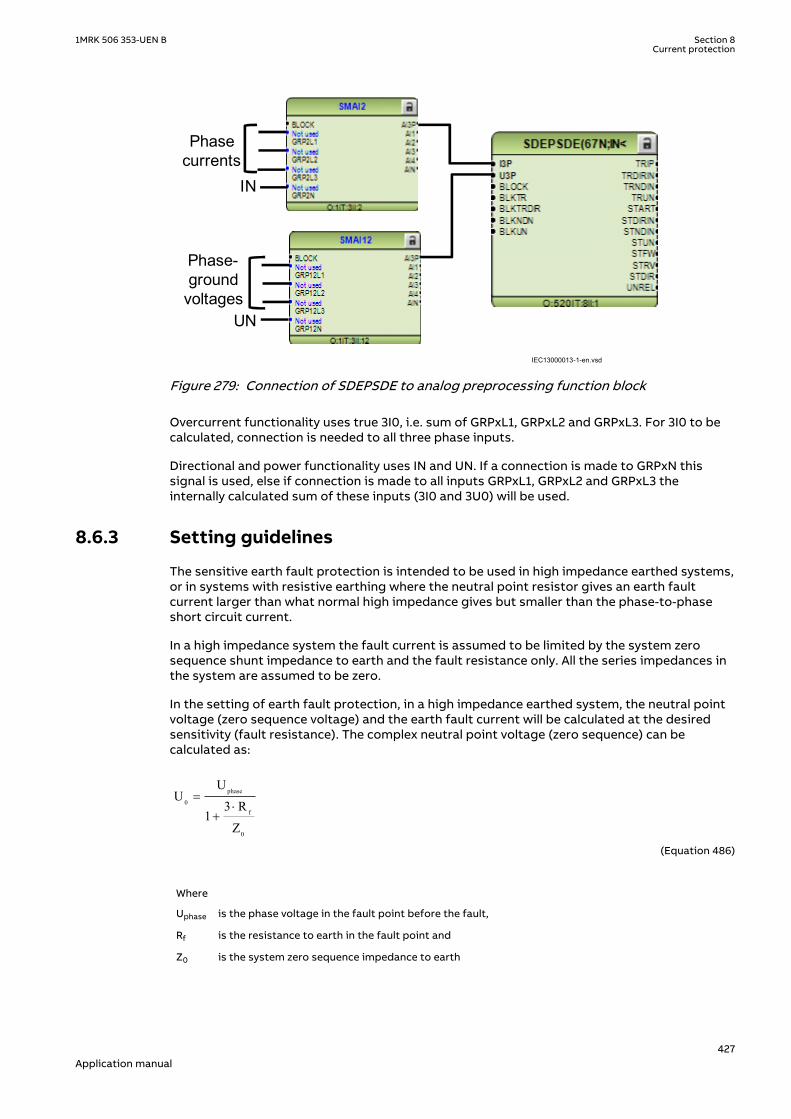
Phase currents
Phase-ground
voltages
IN
UN
IEC13000013-1-en.vsdIEC13000013 V1 EN-US
Figure 279: Connection of SDEPSDE to analog preprocessing function block
Overcurrent functionality uses true 3I0, i.e. sum of GRPxL1, GRPxL2 and GRPxL3. For 3I0 to becalculated, connection is needed to all three phase inputs.
Directional and power functionality uses IN and UN. If a connection is made to GRPxN thissignal is used, else if connection is made to all inputs GRPxL1, GRPxL2 and GRPxL3 theinternally calculated sum of these inputs (3I0 and 3U0) will be used.
8.6.3 Setting guidelinesSEMOD171961-4 v8
The sensitive earth fault protection is intended to be used in high impedance earthed systems,or in systems with resistive earthing where the neutral point resistor gives an earth faultcurrent larger than what normal high impedance gives but smaller than the phase-to-phaseshort circuit current.
In a high impedance system the fault current is assumed to be limited by the system zerosequence shunt impedance to earth and the fault resistance only. All the series impedances inthe system are assumed to be zero.
In the setting of earth fault protection, in a high impedance earthed system, the neutral pointvoltage (zero sequence voltage) and the earth fault current will be calculated at the desiredsensitivity (fault resistance). The complex neutral point voltage (zero sequence) can becalculated as:
phase
0f
0
UU
3 R1
Z
=×
+
EQUATION1943 V1 EN-US (Equation 486)
Where
Uphase is the phase voltage in the fault point before the fault,
Rf is the resistance to earth in the fault point and
Z0 is the system zero sequence impedance to earth
1MRK 506 353-UEN B Section 8Current protection
427Application manual

The fault current, in the fault point, can be calculated as:
phase
j 0
0 f
3 UI 3I
Z 3 R
×= =
+ ×
EQUATION1944 V1 EN-US (Equation 487)
The impedance Z0 is dependent on the system earthing. In an isolated system (without neutralpoint apparatus) the impedance is equal to the capacitive coupling between the phaseconductors and earth:
phase
0 c
j
3 UZ jX j
I
×= - = -
EQUATION1945 V1 EN-US (Equation 488)
Where
Ij is the capacitive earth fault current at a non-resistive phase-to-earth fault
Xc is the capacitive reactance to earth
In a system with a neutral point resistor (resistance earthed system) the impedance Z0 can becalculated as:
c n0
c n
jX 3RZ
jX 3R
- ×=
- +
EQUATION1946 V1 EN-US (Equation 489)
Where
Rn is the resistance of the neutral point resistor
In many systems there is also a neutral point reactor (Petersen coil) connected to one or moretransformer neutral points. In such a system the impedance Z0 can be calculated as:
( )n n c
0 c n n
n c n n c
9R X XZ jX // 3R // j3X
3X X j3R 3X X= - =
+ × -
EQUATION1947 V1 EN-US (Equation 490)
Where
Xn is the reactance of the Petersen coil. If the Petersen coil is well tuned we have 3Xn = Xc In this case theimpedance Z0 will be: Z0 = 3Rn
Now consider a system with an earthing via a resistor giving higher earth fault current than thehigh impedance earthing. The series impedances in the system can no longer be neglected.The system with a single phase to earth fault can be described as in Figure 280.
Section 8 1MRK 506 353-UEN BCurrent protection
428Application manual

Substation A
Substation B
ZlineAB,1 (pos. seq)ZlineAB,0 (zero seq)
ZlineBC,1 (pos. seq)ZlineBC,0 (zero seq)
U0A
U0B
3I0
Phase to earth fault
RNZT,1 (pos. seq)ZT,0 (zero seq)
Source impedanceZsc (pos. seq)
en06000654.vsdIEC06000654 V1 EN-US
Figure 280: Equivalent of power system for calculation of setting
The residual fault current can be written:
phase
0
1 0 f
3U3I
2 Z Z 3 R=
× + + ×
EQUATION1948 V1 EN-US (Equation 491)
Where
Uphase is the phase voltage in the fault point before the fault
Z1 is the total positive sequence impedance to the fault point. Z1 = Zsc+ZT,1+ZlineAB,1+ZlineBC,1
Z0 is the total zero sequence impedance to the fault point. Z0 = ZT,0+3RN+ZlineAB,0+ZlineBC,0
Rf is the fault resistance.
The residual voltages in stations A and B can be written:
( )0 A 0 T,0 NU 3I Z 3R= × +
EQUATION1949 V1 EN-US (Equation 492)
OB 0 T,0 N lineAB,0U 3I (Z 3R Z )= × + +
EQUATION1950 V1 EN-US (Equation 493)
The residual power, measured by the sensitive earth fault protections in A and B will be:
1MRK 506 353-UEN B Section 8Current protection
429Application manual

0 A 0A 0S 3U 3I= ×
EQUATION1951 V1 EN-US (Equation 494)
0 B 0B 0S 3U 3I= ×
EQUATION1952 V1 EN-US (Equation 495)
The residual power is a complex quantity. The protection will have a maximum sensitivity inthe characteristic angle RCA. The apparent residual power component in the characteristicangle, measured by the protection, can be written:
0 A ,prot 0A 0 AS 3U 3I cosj= × ×
EQUATION1953 V1 EN-US (Equation 496)
0 B,prot 0B 0 BS 3U 3I cosj= × ×
EQUATION1954 V1 EN-US (Equation 497)
The angles φA and φB are the phase angles between the residual current and the residualvoltage in the station compensated with the characteristic angle RCA.
The protection will use the power components in the characteristic angle direction formeasurement, and as base for the inverse time delay.
The inverse time delay is defined as:
0 0inv
0 0
kSN (3I 3U cos (reference))t3I 3U cos (measured)
× × × j=
× × j
EQUATION1942 V2 EN-US (Equation 498)
The function can be set On/Off with the setting of Operation.
Common base IED values for primary current (IBase), primary voltage (UBase) and primarypower (SBase) are set in a Global base values for settings function GBASVAL.
GlobalBaseSel: It is used to select a GBASVAL function for reference of base values.
RotResU: It is a setting for rotating the polarizing quantity ( 3U0) by 0 or 180 degrees. Thisparameter is set to 180 degrees by default in order to inverse the residual voltage ( 3U0) tocalculate the reference voltage (-3U0 e-jRCADir). Since the reference voltage is used as thepolarizing quantity for directionality, it is important to set this parameter correctly.
With the setting OpMode the principle of directional function is chosen.
With OpMode set to 3I0cosfi the current component in the direction equal to the characteristicangleRCADir has the maximum sensitivity. The characteristic for RCADir is equal to 0° is shownin Figure 281.
Section 8 1MRK 506 353-UEN BCurrent protection
430Application manual

= =o o0 , 90RCADir ROADir
03I
j = -0 refang(3I ) ang(3U )- =0 ref3U U
03I cos× j
IEC06000648-4-en.vsdIEC06000648 V4 EN-US
Figure 281: Characteristic for RCADir equal to 0°
The characteristic is for RCADir equal to -90° is shown in Figure 282.
IEC06000649_3_en.vsd
refU= − = 90 , 90RCADir ROADir
03I
03 ⋅ ϕI cos
ϕ = −0(3 ) ( )refang I ang U
− 03U
IEC06000649 V3 EN-US
Figure 282: Characteristic for RCADir equal to -90°
When OpMode is set to 3U03I0cosfi the apparent residual power component in the direction ismeasured.
When OpMode is set to 3I0 and fi the function will operate if the residual current is larger thanthe setting INDir> and the residual current angle is within the sector RCADir ± ROADir.
The characteristic for this OpMode when RCADir = 0° and ROADir = 80° is shown in figure 283.
1MRK 506 353-UEN B Section 8Current protection
431Application manual

-3U0
Operate area
3I0
RCADir = 0º
ROADir = 80º
IEC06000652-3-en.vsdIEC06000652 V3 EN-US
Figure 283: Characteristic for RCADir = 0° and ROADir = 80°
DirMode is set Forward or Reverse to set the direction of the operation for the directionalfunction selected by the OpMode.
All the directional protection modes have a residual current release level setting INRel> whichis set in % of IBase. This setting should be chosen smaller than or equal to the lowest faultcurrent to be detected.
All the directional protection modes have a residual voltage release level setting UNRel> whichis set in % of UBase. This setting should be chosen smaller than or equal to the lowest faultresidual voltage to be detected.
tDef is the definite time delay, given in s, for the directional residual current protection.
tReset is the time delay before the definite timer gets reset, given in s. With a tReset time offew cycles, there is an increased possibility to clear intermittent earth faults correctly. Thesetting shall be much shorter than the set trip delay. In case of intermittent earth faults, thefault current is intermittently dropping below the set value during consecutive cycles.Therefore the definite timer should continue for a certain time equal to tReset even though thefault current has dropped below the set value.
The characteristic angle of the directional functions RCADir is set in degrees. RCADir isnormally set equal to 0° in a high impedance earthed network with a neutral point resistor asthe active current component is appearing out on the faulted feeder only. RCADir is set equalto -90° in an isolated network as all currents are mainly capacitive.
ROADir is Relay Operating Angle. ROADir is identifying a window around the referencedirection in order to detect directionality. ROADir is set in degrees. For angles differing morethan ROADir from RCADir the function is blocked. The setting can be used to preventunwanted operation for non-faulted feeders, with large capacitive earth fault currentcontributions, due to CT phase angle error.
INCosPhi> is the operate current level for the directional function when OpMode is set3I0Cosfi. The setting is given in % of IBase. The setting should be based on calculation of theactive or capacitive earth fault current at required sensitivity of the protection.
Section 8 1MRK 506 353-UEN BCurrent protection
432Application manual

SN> is the operate power level for the directional function when OpMode is set 3I03U0Cosfi.The setting is given in % of SBase. The setting should be based on calculation of the active orcapacitive earth fault residual power at required sensitivity of the protection.
The input transformer for the Sensitive directional residual over current and power protectionfunction has the same short circuit capacity as the phase current transformers. Hence, there isno specific requirement for the external CT core, i.e. any CT core can be used.
If the time delay for residual power is chosen the delay time is dependent on two settingparameters. SRef is the reference residual power, given in % of SBase. kSN is the timemultiplier. The time delay will follow the following expression:
inv0 0
kSN Sreft
3I 3U cos (measured)j×
=× ×
EQUATION1957 V1 EN-US (Equation 499)
INDir> is the operate current level for the directional function when OpMode is set 3I0 and fi.The setting is given in % of IBase. The setting should be based on calculation of the earth faultcurrent at required sensitivity of the protection.
OpINNonDir> is set On to activate the non-directional residual current protection.
INNonDir> is the operate current level for the non-directional function. The setting is given in% of IBase. This function can be used for detection and clearance of cross-country faults in ashorter time than for the directional function. The current setting should be larger than themaximum single-phase residual current on the protected line.
TimeChar is the selection of time delay characteristic for the non-directional residual currentprotection. Definite time delay and different types of inverse time characteristics are available:
Table 37: Inverse time characteristics
Curve name
ANSI Extremely Inverse
ANSI Very Inverse
ANSI Normal Inverse
ANSI Moderately Inverse
ANSI/IEEE Definite time
ANSI Long Time Extremely Inverse
ANSI Long Time Very Inverse
ANSI Long Time Inverse
IEC Normal Inverse
IEC Very Inverse
IEC Inverse
IEC Extremely Inverse
IEC Short Time Inverse
IEC Long Time Inverse
IEC Definite Time
User Programmable
ASEA RI
RXIDG (logarithmic)
1MRK 506 353-UEN B Section 8Current protection
433Application manual

See chapter “Inverse time characteristics” in Technical Manual for the description of differentcharacteristics
tPCrv, tACrv, tBCrv, tCCrv: Parameters for customer creation of inverse time characteristiccurve (Curve type = 17). The time characteristic equation is:
[ ] = + ×
->
æ öç ÷ç ÷ç ÷æ ö
ç ÷ç ÷è øè ø
p
At s B InMult
iC
inEQUATION1958 V1 EN-US (Equation 500)
tINNonDir is the definite time delay for the non directional earth fault current protection, givenin s.
OpUN> is set On to activate the trip function of the residual over voltage protection.
tUN is the definite time delay for the trip function of the residual voltage protection, given in s.
8.7 Thermal overload protection, one time constant,Celsius/Fahrenheit LCPTTR/LFPTTR
IP14512-1 v7
8.7.1 IdentificationM17106-1 v7
Function description IEC 61850identification
IEC 60617identification
ANSI/IEEE C37.2device number
Thermal overload protection, onetime constant, Celsius
LCPTTR 26
Thermal overload protection, onetime constant, Fahrenheit
LFPTTR 26
8.7.2 ApplicationM15283-3 v8
Lines and cables in the power system are designed for a certain maximum load current level. Ifthe current exceeds this level the losses will be higher than expected. As a consequence thetemperature of the conductors will increase. If the temperature of the lines and cables reachestoo high values the equipment might be damaged:
• The sag of overhead lines can reach unacceptable value.• If the temperature of conductors, for example aluminium conductors, gets too high the
material will be destroyed.• In cables the insulation can be damaged as a consequence of the overtemperature. As a
consequence of this phase to phase or phase to earth faults can occur.
Section 8 1MRK 506 353-UEN BCurrent protection
434Application manual

In stressed situations in the power system it can be required to overload lines and cables for alimited time. This should be done while managing the risks safely.
The thermal overload protection provides information that makes a temporary overloading ofcables and lines possible. The thermal overload protection estimates the conductortemperature continuously, in Celsius or Fahrenheit depending on whether LCPTTR or LFPTTRis chosen. This estimation is made by using a thermal model of the line/cable based on thecurrent measurement.
If the temperature of the protected object reaches a set warning level AlarmTemp, a signalALARM can be given to the operator. This enables actions in the power system to be takenbefore dangerous temperatures are reached. If the temperature continues to increase to thetrip value TripTemp, the protection initiates trip of the protected line.
8.7.3 Setting guidelineIP14994-1 v1
M15094-3 v7
The parameters for the Thermal overload protection, one time constant, Celsius/FahrenheitLCPTTR/LFPTTR are set via the local HMI or PCM600.
M15094-5 v8
The following settings can be done for the thermal overload protection.
Operation: Off/On
GlobalBaseSel is used to select a GBASVAL function for reference of base values, primarycurrent (IBase), primary voltage (UBase) and primary power (SBase).
Imult: Enter the number of lines in case the protection function is applied on multiple parallellines sharing one CT.
IRef: Reference, steady state current, given in % of IBase that will give a steady state (end)temperature rise TRef. It is suggested to set this current to the maximum steady state currentallowed for the line/cable under emergency operation (a few hours per year).
TRef: Reference temperature rise (end temperature) corresponding to the steady state currentIRef. From cable manuals current values with corresponding conductor temperature are oftengiven. These values are given for conditions such as earth temperature, ambient airtemperature, way of laying of cable and earth thermal resistivity. From manuals for overheadconductor temperatures and corresponding current is given.
Tau: The thermal time constant of the protected circuit given in minutes. Please refer tomanufacturers manuals for details.
TripTemp: Temperature value for trip of the protected circuit. For cables, a maximum allowedconductor temperature is often stated to be 90°C (194°F). For overhead lines, the criticaltemperature for aluminium conductor is about 90 - 100°C (194-212°F). For a copper conductora normal figure is 70°C (158°F).
AlarmTemp: Temperature level for alarm of the protected circuit. ALARM signal can be used asa warning before the circuit is tripped. Therefore the setting shall be lower than the trip level.It shall at the same time be higher than the maximum conductor temperature at normaloperation. For cables this level is often given to 65°C (149°F). Similar values are stated foroverhead lines. A suitable setting can be about 15°C (59°F) below the trip value.
ReclTemp: Temperature where lockout signal LOCKOUT from the protection is released. Whenthe thermal overload protection trips a lock-out signal is activated. This signal is intended toblock switch in of the protected circuit as long as the conductor temperature is high. Thesignal is released when the estimated temperature is below the set value. This temperaturevalue should be chosen below the alarm temperature.
1MRK 506 353-UEN B Section 8Current protection
435Application manual

8.8 Breaker failure protection CCRBRFIP14514-1 v6
8.8.1 IdentificationM14878-1 v5
Function description IEC 61850identification
IEC 60617identification
ANSI/IEEE C37.2device number
Breaker failure protection, 3-phaseactivation and output
CCRBRF
3I>BF
SYMBOL-U V1 EN-US
50BF
8.8.2 ApplicationM13916-3 v6
In the design of the fault clearance system the N-1 criterion is often used. This means that afault needs to be cleared even if any component in the fault clearance system is faulty. Onenecessary component in the fault clearance system is the circuit breaker. It is from practicaland economical reason not feasible to duplicate the circuit breaker for the protectedcomponent. Instead a breaker failure protection is used.
Breaker failure protection, 3-phase activation and output (CCRBRF) will issue a back-up tripcommand to adjacent circuit breakers in case of failure to trip of the “normal” circuit breakerfor the protected component. The detection of failure to break the current through thebreaker is made by means of current measurement or as detection of remaining trip signal(unconditional).
CCRBRF can also give a re-trip. This means that a second trip signal is sent to the protectedcircuit breaker. The re-trip function can be used to increase the probability of operation of thebreaker, or it can be used to avoid back-up trip of many breakers in case of mistakes duringrelay maintenance and test.
8.8.3 Setting guidelinesM11546-4 v8.1.1
The parameters for Breaker failure protection 3-phase activation and output CCRBRF are setvia the local HMI or PCM600.
The following settings can be done for the breaker failure protection.
GlobalBaseSel: Selects the global base value group used by the function to define (IBase),(UBase) and (SBase).
Operation: Off/On
FunctionMode This parameter can be set Current or Contact. This states the way the detectionof failure of the breaker is performed. In the mode current the current measurement is usedfor the detection. In the mode Contact the long duration of breaker position signal is used asindicator of failure of the breaker. The mode Current&Contact means that both ways ofdetections are activated. Contact mode can be usable in applications where the fault currentthrough the circuit breaker is small. This can be the case for some generator protectionapplication (for example reverse power protection) or in case of line ends with weak endinfeed.
RetripMode: This setting states how the re-trip function shall operate. Retrip Off means thatthe re-trip function is not activated. CB Pos Check (circuit breaker position check) and Current
Section 8 1MRK 506 353-UEN BCurrent protection
436Application manual

means that a phase current must be larger than the operate level to allow re-trip. CB Pos Check(circuit breaker position check) and Contact means re-trip is done when circuit breaker isclosed (breaker position is used). No CBPos Check means re-trip is done without check ofbreaker position.
Table 38: Dependencies between parameters RetripMode and FunctionMode
RetripMode FunctionMode Description
Retrip Off N/A the re-trip function is notactivated
CB Pos Check Current re-trip is done if phase current islarger than the operate level afterre-trip time has elapsed
Contact re-trip is done when auxiliarycontact position indicates thatbreaker is still closed after re-triptime has elapsed
Current&Contact both methods according to aboveare used but taken into accountalso I>BlkCont
No CBPos Check Current re-trip is done without check ofcurrent level
Contact re-trip is done without check ofauxiliary contact position
Current&Contact re-trip is done without check ofcurrent level or auxiliary contactposition
BuTripMode: Back-up trip mode is given to state sufficient current criteria to detect failure tobreak. For Current operation 2 out of 4 means that at least two currents, of the three-phasecurrents and the residual current, shall be high to indicate breaker failure. 1 out of 3 meansthat at least one current of the three-phase currents shall be high to indicate breaker failure. 1out of 4 means that at least one current of the three-phase currents or the residual currentshall be high to indicate breaker failure. In most applications 1 out of 3 is sufficient. ForContact operation means back-up trip is done when circuit breaker is closed (breaker positionis used).
IP>: Current level for detection of breaker failure, set in % of IBase. This parameter should beset so that faults with small fault current can be detected. The setting can be chosen inaccordance with the most sensitive protection function to start the breaker failure protection.Typical setting is 10% of IBase. Set the parameter IP> lower than the parameter I>BlkCont.
I>BlkCont: If any contact based detection of breaker failure is used this function can beblocked if any phase current is larger than this setting level. If the FunctionMode is setCurrent&Contact breaker failure for high current faults are safely detected by the currentmeasurement function. To increase security the contact based function should be disabled forhigh currents. The setting can be given within the range 5 – 200% of IBase.
IN>: Residual current level for detection of breaker failure set in % of IBase. In high impedanceearthed systems the residual current at phase- to-earth faults are normally much smaller thanthe short circuit currents. In order to detect breaker failure at single-phase-earth faults inthese systems it is necessary to measure the residual current separately. Also in effectivelyearthed systems the setting of the earth-fault current protection can be chosen to relativelylow current level. The BuTripMode is set 1 out of 4. The current setting should be chosen inaccordance to the setting of the sensitive earth-fault protection. The setting can be givenwithin the range 2 – 200 % of IBase.
t1: Time delay of the re-trip. The setting can be given within the range 0 – 60s in steps of 0.001s. Typical setting is 0 – 50ms.
1MRK 506 353-UEN B Section 8Current protection
437Application manual
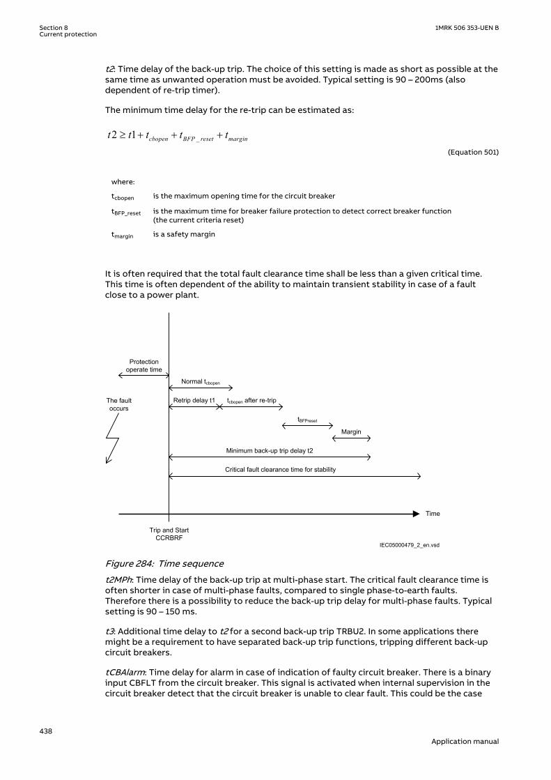
t2: Time delay of the back-up trip. The choice of this setting is made as short as possible at thesame time as unwanted operation must be avoided. Typical setting is 90 – 200ms (alsodependent of re-trip timer).
The minimum time delay for the re-trip can be estimated as:
_2 1³ + + +cbopen BFP reset margint t t t tEQUATION1430 V1 EN-US (Equation 501)
where:
tcbopen is the maximum opening time for the circuit breaker
tBFP_reset is the maximum time for breaker failure protection to detect correct breaker function(the current criteria reset)
tmargin is a safety margin
It is often required that the total fault clearance time shall be less than a given critical time.This time is often dependent of the ability to maintain transient stability in case of a faultclose to a power plant.
Time
The fault occurs
Protection operate time
Trip and Start CCRBRF
Normal tcbopen
Margin
Retrip delay t1 tcbopen after re-trip
tBFPreset
Minimum back-up trip delay t2
Critical fault clearance time for stability
IEC05000479_2_en.vsdIEC05000479 V2 EN-US
Figure 284: Time sequence
t2MPh: Time delay of the back-up trip at multi-phase start. The critical fault clearance time isoften shorter in case of multi-phase faults, compared to single phase-to-earth faults.Therefore there is a possibility to reduce the back-up trip delay for multi-phase faults. Typicalsetting is 90 – 150 ms.
t3: Additional time delay to t2 for a second back-up trip TRBU2. In some applications theremight be a requirement to have separated back-up trip functions, tripping different back-upcircuit breakers.
tCBAlarm: Time delay for alarm in case of indication of faulty circuit breaker. There is a binaryinput CBFLT from the circuit breaker. This signal is activated when internal supervision in thecircuit breaker detect that the circuit breaker is unable to clear fault. This could be the case
Section 8 1MRK 506 353-UEN BCurrent protection
438Application manual

when gas pressure is low in a SF6 circuit breaker, of others. After the set time an alarm isgiven, so that actions can be done to repair the circuit breaker. The time delay for back-up tripis bypassed when the CBFLT is active. Typical setting is 2.0 seconds.
tPulse: Trip pulse duration. This setting must be larger than the critical impulse time of circuitbreakers to be tripped from the breaker failure protection. Typical setting is 200 ms.
8.9 Stub protection STBPTOCIP14515-1 v3
8.9.1 IdentificationM17108-1 v2
Function description IEC 61850identification
IEC 60617identification
ANSI/IEEE C37.2device number
Stub protection STBPTOC
3I>STUB
SYMBOL-T V1 EN-US
50STB
8.9.2 ApplicationM12904-3 v5
In a 1½-breaker switchyard the line protection and the busbar protection normally haveoverlap when a connected object is in service. When an object is taken out of service it isnormally required to keep the diagonal of the 1½-breaker switchyard in operation. This is doneby opening the disconnector to the protected object. This will, however, disable the normalobject protection (for example the distance protection) of the energized part between thecircuit breakers and the open disconnector.
Stub protection STBPTOC is a simple phase overcurrent protection, fed from the two currenttransformer groups feeding the object taken out of service. The stub protection is onlyactivated when the disconnector of the object is open. STBPTOCenables fast fault clearance offaults at the section between the CTs and the open disconnector.
1MRK 506 353-UEN B Section 8Current protection
439Application manual

IEC05000465 V2 EN-US
Figure 285: Typical connection for STBPTOC in 1½-breaker arrangement.
8.9.3 Setting guidelinesM12909-3 v5
The parameters for Stub protection STBPTOC are set via the local HMI or PCM600.
The following settings can be done for the stub protection.
GlobalBaseSel: Selects the global base value group used by the function to define (IBase),(UBase) and (SBase).
Operation: Off/On
ReleaseMode: This parameter can be set Release or Continuous. With theRelease setting thefunction is only active when a binary release signal RELEASE into the function is activated. Thissignal is normally taken from an auxiliary contact (normally closed) of the line disconnectorand connected to a binary input RELEASE of the IED. With the settingContinuous the functionis activated independent of presence of any external release signal.
I>: Current level for the Stub protection, set in % of IBase. This parameter should be set so thatall faults on the stub can be detected. The setting should thus be based on fault calculations.
t: Time delay of the operation. Normally the function shall be instantaneous.
8.10 Pole discordance protection CCPDSCIP14516-1 v5
Section 8 1MRK 506 353-UEN BCurrent protection
440Application manual

8.10.1 IdentificationM14888-1 v4
Function description IEC 61850identification
IEC 60617identification
ANSI/IEEE C37.2device number
Pole discordance protection CCPDSC
PD
SYMBOL-S V1 EN-US
52PD
8.10.2 ApplicationM13270-3 v6
There is a risk that a circuit breaker will get discordance between the poles at circuit breakeroperation: closing or opening. One pole can be open and the other two closed, or two polescan be open and one closed. Pole discordance of a circuit breaker will cause unsymmetricalcurrents in the power system. The consequence of this can be:
• Negative sequence currents that will give stress on rotating machines• Zero sequence currents that might give unwanted operation of sensitive earth-fault
protections in the power system.
It is therefore important to detect situations with pole discordance of circuit breakers. Whenthis is detected the breaker should be tripped directly.
Pole discordance protection CCPDSC will detect situation with deviating positions of the polesof the protected circuit breaker. The protection has two different options to make thisdetection:
• By connecting the auxiliary contacts in the circuit breaker so that logic is created, a signalcan be sent to the protection, indicating pole discordance. This logic can also be realizedwithin the protection itself, by using opened and close signals for each circuit breakerpole, connected to the protection.
• Each phase current through the circuit breaker is measured. If the difference between thephase currents is larger than a CurrUnsymLevel this is an indication of pole discordance,and the protection will operate.
8.10.3 Setting guidelinesM13274-3 v8
The parameters for the Pole discordance protection CCPDSC are set via the local HMI orPCM600.
The following settings can be done for the pole discordance protection.
GlobalBaseSel: Selects the global base value group used by the function to define (IBase),(UBase) and (SBase).
Operation: Off or On
tTrip: Time delay of the operation.
ContSel: Operation of the contact based pole discordance protection. Can be set: Off/PDsignal from CB. If PD signal from CB is chosen the logic to detect pole discordance is made inthe vicinity to the breaker auxiliary contacts and only one signal is connected to the polediscordance function. If the Pole pos aux cont. alternative is chosen each open close signal isconnected to the IED and the logic to detect pole discordance is realized within the functionitself.
1MRK 506 353-UEN B Section 8Current protection
441Application manual

CurrSel: Operation of the current based pole discordance protection. Can be set: Off/CB opermonitor/Continuous monitor. In the alternative CB oper monitor the function is activated onlydirectly in connection to breaker open or close command (during 200 ms). In the alternativeContinuous monitor function is continuously activated.
CurrUnsymLevel: Unsymmetrical magnitude of lowest phase current compared to the highest,set in % of the highest phase current. Natural difference between phase currents in 1 1/2breaker installations must be considered. For circuit breakers in 1 1/2 breaker configuredswitch yards there might be natural unbalance currents through the breaker. This is due to theexistence of low impedance current paths in the switch yard. This phenomenon must beconsidered in the setting of the parameter.
CurrRelLevel: Current magnitude for release of the function in % of IBase.
8.11 Directional underpower protection GUPPDUPSEMOD156693-1 v4
8.11.1 IdentificationSEMOD158941-2 v4
Function description IEC 61850identification
IEC 60617identification
ANSI/IEEE C37.2device number
Directional underpower protection GUPPDUPP <
2SYMBOL-LL V2 EN-US
37
8.11.2 ApplicationSEMOD151283-4 v5
The task of a generator in a power plant is to convert mechanical energy available as a torqueon a rotating shaft to electric energy.
Sometimes, the mechanical power from a prime mover may decrease so much that it does notcover bearing losses and ventilation losses. Then, the synchronous generator becomes asynchronous motor and starts to take electric power from the rest of the power system. Thisoperating state, where individual synchronous machines operate as motors, implies no risk forthe machine itself. If the generator under consideration is very large and if it consumes lots ofelectric power, it may be desirable to disconnect it to ease the task for the rest of the powersystem.
Often, the motoring condition may imply that the turbine is in a very dangerous state. The taskof the reverse power protection is to protect the turbine and not to protect the generatoritself.
Steam turbines easily become overheated if the steam flow becomes too low or if the steamceases to flow through the turbine. Therefore, turbo-generators should have reverse powerprotection. There are several contingencies that may cause reverse power: break of a mainsteam pipe, damage to one or more blades in the steam turbine or inadvertent closing of themain stop valves. In the last case, it is highly desirable to have a reliable reverse powerprotection. It may prevent damage to an otherwise undamaged plant.
During the routine shutdown of many thermal power units, the reverse power protection givesthe tripping impulse to the generator breaker (the unit breaker). By doing so, one prevents thedisconnection of the unit before the mechanical power has become zero. Earlier disconnectionwould cause an acceleration of the turbine generator at all routine shutdowns. This shouldhave caused overspeed and high centrifugal stresses.
Section 8 1MRK 506 353-UEN BCurrent protection
442Application manual

When the steam ceases to flow through a turbine, the cooling of the turbine blades willdisappear. Now, it is not possible to remove all heat generated by the windage losses. Instead,the heat will increase the temperature in the steam turbine and especially of the blades. Whena steam turbine rotates without steam supply, the electric power consumption will be about2% of rated power. Even if the turbine rotates in vacuum, it will soon become overheated anddamaged. The turbine overheats within minutes if the turbine loses the vacuum.
The critical time to overheating a steam turbine varies from about 0.5 to 30 minutesdepending on the type of turbine. A high-pressure turbine with small and thin blades willbecome overheated more easily than a low-pressure turbine with long and heavy blades. Theconditions vary from turbine to turbine and it is necessary to ask the turbine manufacturer ineach case.
Power to the power plant auxiliaries may come from a station service transformer connectedto the secondary side of the step-up transformer. Power may also come from a start-upservice transformer connected to the external network. One has to design the reverse powerprotection so that it can detect reverse power independent of the flow of power to the powerplant auxiliaries.
Hydro turbines tolerate reverse power much better than steam turbines do. Only Kaplanturbine and bulb turbines may suffer from reverse power. There is a risk that the turbinerunner moves axially and touches stationary parts. They are not always strong enough towithstand the associated stresses.
Ice and snow may block the intake when the outdoor temperature falls far below zero.Branches and leaves may also block the trash gates. A complete blockage of the intake maycause cavitations. The risk for damages to hydro turbines can justify reverse power protectionin unattended plants.
A hydro turbine that rotates in water with closed wicket gates will draw electric power fromthe rest of the power system. This power will be about 10% of the rated power. If there is onlyair in the hydro turbine, the power demand will fall to about 3%.
Diesel engines should have reverse power protection. The generator will take about 15% of itsrated power or more from the system. A stiff engine may require perhaps 25% of the ratedpower to motor it. An engine that is good run in might need no more than 5%. It is necessaryto obtain information from the engine manufacturer and to measure the reverse power duringcommissioning.
Gas turbines usually do not require reverse power protection.
Figure 286 illustrates the reverse power protection with underpower protection and withoverpower protection. The underpower protection gives a higher margin and should providebetter dependability. On the other hand, the risk for unwanted operation immediately aftersynchronization may be higher. One should set the underpower protection (reference angle setto 0) to trip if the active power from the generator is less than about 2%. One should set theoverpower protection (reference angle set to 180) to trip if the power flow from the networkto the generator is higher than 1%.
1MRK 506 353-UEN B Section 8Current protection
443Application manual

Underpower protection Overpower protection
Q Q
P P
Operating point without turbine torque
Margin Margin
OperateLine
OperateLine
Operating point without turbine torque
IEC09000019-2-en.vsdIEC09000019 V2 EN-US
Figure 286: Reverse power protection with underpower or overpower protection
8.11.3 Setting guidelinesSEMOD172134-4 v7
GlobalBaseSel: Selects the global base value group used by the function to define (IBase),(UBase) and (SBase).
Operation: With the parameter Operation the function can be set On/Off.
Mode: The voltage and current used for the power measurement. The setting possibilities areshown in table 39.
Table 39: Complex power calculation
Set value Mode Formula used for complex power calculation
L1, L2, L3 * * *1 1 2 2 3 3L L L L L LS U I U I U I= × + × + ×
EQUATION1697 V1 EN-US (Equation 503)
Arone * *1 2 1 2 3 3L L L L L LS U I U I= × - ×
EQUATION1698 V1 EN-US (Equation 504)
PosSeq *3 PosSeq PosSeqS U I= × ×
EQUATION1699 V1 EN-US (Equation 505)
L1L2 * *1 2 1 2( )L L L LS U I I= × -
EQUATION1700 V1 EN-US (Equation 506)
L2L3 * *2 3 2 3( )L L L LS U I I= × -
EQUATION1701 V1 EN-US (Equation 507)
L3L1 * *3 1 3 1( )L L L LS U I I= × -
EQUATION1702 V1 EN-US (Equation 508)
L1 *1 13 L LS U I= × ×
EQUATION1703 V1 EN-US (Equation 509)
L2 *2 23 L LS U I= × ×
EQUATION1704 V1 EN-US (Equation 510)
L3 *3 33 L LS U I= × ×
EQUATION1705 V1 EN-US (Equation 511)
Section 8 1MRK 506 353-UEN BCurrent protection
444Application manual

The function has two stages that can be set independently.
With the parameter OpMode1(2) the function can be set On/Off.
The function gives trip if the power component in the direction defined by the settingAngle1(2) is smaller than the set pick up power value Power1(2)
Operate
Angle1(2)
Power1(2)
P
Q
en06000441.vsdIEC06000441 V1 EN-US
Figure 287: Underpower mode
The setting Power1(2) gives the power component pick up value in the Angle1(2) direction. Thesetting is given in p.u. of the generator rated power, see equation 512.
Minimum recommended setting is 0.2% of SN when metering class CT inputs into the IED areused.
3NS UBase IBase= × ×
EQUATION1708 V1 EN-US (Equation 512)
The setting Angle1(2) gives the characteristic angle giving maximum sensitivity of the powerprotection function. The setting is given in degrees. For active power the set angle should be0° or 180°. 0° should be used for generator low forward active power protection.
1MRK 506 353-UEN B Section 8Current protection
445Application manual
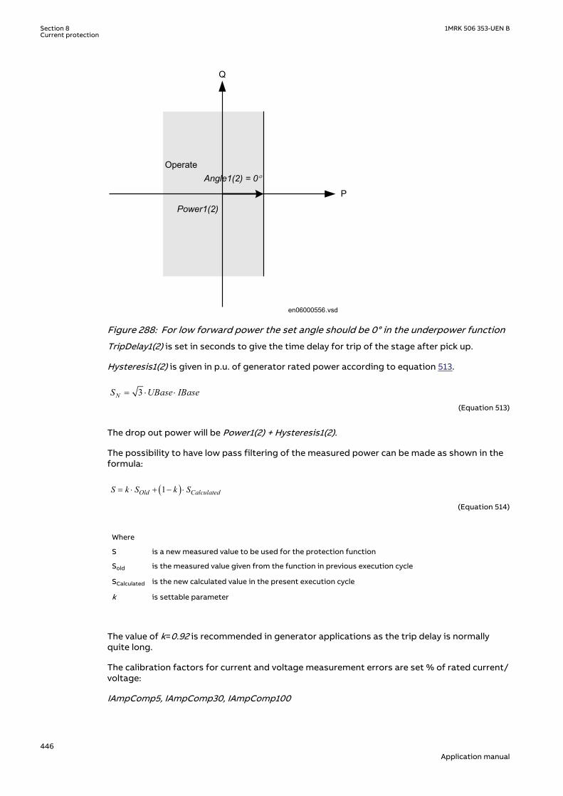
OperateAngle1(2) = 0°
Power1(2)
P
Q
en06000556.vsdIEC06000556 V1 EN-US
Figure 288: For low forward power the set angle should be 0° in the underpower function
TripDelay1(2) is set in seconds to give the time delay for trip of the stage after pick up.
Hysteresis1(2) is given in p.u. of generator rated power according to equation 513.
3NS UBase IBase= × ×
EQUATION1708 V1 EN-US (Equation 513)
The drop out power will be Power1(2) + Hysteresis1(2).
The possibility to have low pass filtering of the measured power can be made as shown in theformula:
( )1Old CalculatedS k S k S= × + - ×
EQUATION1893 V1 EN-US (Equation 514)
Where
S is a new measured value to be used for the protection function
Sold is the measured value given from the function in previous execution cycle
SCalculated is the new calculated value in the present execution cycle
k is settable parameter
The value of k=0.92 is recommended in generator applications as the trip delay is normallyquite long.
The calibration factors for current and voltage measurement errors are set % of rated current/voltage:
IAmpComp5, IAmpComp30, IAmpComp100
Section 8 1MRK 506 353-UEN BCurrent protection
446Application manual

UAmpComp5, UAmpComp30, UAmpComp100
IAngComp5, IAngComp30, IAngComp100
The angle compensation is given as difference between current and voltage angle errors.
The values are given for operating points 5, 30 and 100% of rated current/voltage. The valuesshould be available from instrument transformer test protocols.
8.12 Directional overpower protection GOPPDOPSEMOD172360-1 v4
8.12.1 IdentificationSEMOD176574-2 v4
Function description IEC 61850identification
IEC 60617identification
ANSI/IEEE C37.2device number
Directional overpower protection GOPPDOPP >
2DOCUMENT172362-IMG158942V2 EN-US
32
8.12.2 ApplicationSEMOD172358-4 v2
The task of a generator in a power plant is to convert mechanical energy available as a torqueon a rotating shaft to electric energy.
Sometimes, the mechanical power from a prime mover may decrease so much that it does notcover bearing losses and ventilation losses. Then, the synchronous generator becomes asynchronous motor and starts to take electric power from the rest of the power system. Thisoperating state, where individual synchronous machines operate as motors, implies no risk forthe machine itself. If the generator under consideration is very large and if it consumes lots ofelectric power, it may be desirable to disconnect it to ease the task for the rest of the powersystem.
Often, the motoring condition may imply that the turbine is in a very dangerous state. The taskof the reverse power protection is to protect the turbine and not to protect the generatoritself.
Steam turbines easily become overheated if the steam flow becomes too low or if the steamceases to flow through the turbine. Therefore, turbo-generators should have reverse powerprotection. There are several contingencies that may cause reverse power: break of a mainsteam pipe, damage to one or more blades in the steam turbine or inadvertent closing of themain stop valves. In the last case, it is highly desirable to have a reliable reverse powerprotection. It may prevent damage to an otherwise undamaged plant.
During the routine shutdown of many thermal power units, the reverse power protection givesthe tripping impulse to the generator breaker (the unit breaker). By doing so, one prevents thedisconnection of the unit before the mechanical power has become zero. Earlier disconnectionwould cause an acceleration of the turbine generator at all routine shutdowns. This shouldhave caused overspeed and high centrifugal stresses.
When the steam ceases to flow through a turbine, the cooling of the turbine blades willdisappear. Now, it is not possible to remove all heat generated by the windage losses. Instead,the heat will increase the temperature in the steam turbine and especially of the blades. Whena steam turbine rotates without steam supply, the electric power consumption will be about
1MRK 506 353-UEN B Section 8Current protection
447Application manual

2% of rated power. Even if the turbine rotates in vacuum, it will soon become overheated anddamaged. The turbine overheats within minutes if the turbine loses the vacuum.
The critical time to overheating of a steam turbine varies from about 0.5 to 30 minutesdepending on the type of turbine. A high-pressure turbine with small and thin blades willbecome overheated more easily than a low-pressure turbine with long and heavy blades. Theconditions vary from turbine to turbine and it is necessary to ask the turbine manufacturer ineach case.
Power to the power plant auxiliaries may come from a station service transformer connectedto the primary side of the step-up transformer. Power may also come from a start-up servicetransformer connected to the external network. One has to design the reverse powerprotection so that it can detect reverse power independent of the flow of power to the powerplant auxiliaries.
Hydro turbines tolerate reverse power much better than steam turbines do. Only Kaplanturbine and bulb turbines may suffer from reverse power. There is a risk that the turbinerunner moves axially and touches stationary parts. They are not always strong enough towithstand the associated stresses.
Ice and snow may block the intake when the outdoor temperature falls far below zero.Branches and leaves may also block the trash gates. A complete blockage of the intake maycause cavitations. The risk for damages to hydro turbines can justify reverse power protectionin unattended plants.
A hydro turbine that rotates in water with closed wicket gates will draw electric power fromthe rest of the power system. This power will be about 10% of the rated power. If there is onlyair in the hydro turbine, the power demand will fall to about 3%.
Diesel engines should have reverse power protection. The generator will take about 15% of itsrated power or more from the system. A stiff engine may require perhaps 25% of the ratedpower to motor it. An engine that is well run in might need no more than 5%. It is necessary toobtain information from the engine manufacturer and to measure the reverse power duringcommissioning.
Gas turbines usually do not require reverse power protection.
Figure 289 illustrates the reverse power protection with underpower IED and with overpowerIED. The underpower IED gives a higher margin and should provide better dependability. Onthe other hand, the risk for unwanted operation immediately after synchronization may behigher. One should set the underpower IED to trip if the active power from the generator isless than about 2%. One should set the overpower IED to trip if the power flow from thenetwork to the generator is higher than 1%.
Underpower IED Overpower IED
Q Q
P P
Operating point without turbine torque
Margin Margin
OperateLine
OperateLine
Operating point without turbine torque
IEC06000315-2-en.vsdIEC06000315 V2 EN-US
Figure 289: Reverse power protection with underpower IED and overpower IED
Section 8 1MRK 506 353-UEN BCurrent protection
448Application manual
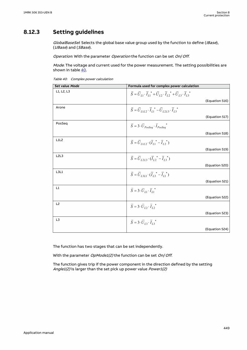
8.12.3 Setting guidelinesSEMOD172150-4 v7
GlobalBaseSel: Selects the global base value group used by the function to define (IBase),(UBase) and (SBase).
Operation: With the parameter Operation the function can be set On/Off.
Mode: The voltage and current used for the power measurement. The setting possibilities areshown in table 40.
Table 40: Complex power calculation
Set value Mode Formula used for complex power calculation
L1, L2, L3 * * *1 1 2 2 3 3L L L L L LS U I U I U I= × + × + ×
EQUATION1697 V1 EN-US (Equation 516)
Arone * *1 2 1 2 3 3L L L L L LS U I U I= × - ×
EQUATION1698 V1 EN-US (Equation 517)
PosSeq *3 PosSeq PosSeqS U I= × ×
EQUATION1699 V1 EN-US (Equation 518)
L1L2 * *1 2 1 2( )L L L LS U I I= × -
EQUATION1700 V1 EN-US (Equation 519)
L2L3 * *2 3 2 3( )L L L LS U I I= × -
EQUATION1701 V1 EN-US (Equation 520)
L3L1 * *3 1 3 1( )L L L LS U I I= × -
EQUATION1702 V1 EN-US (Equation 521)
L1 *1 13 L LS U I= × ×
EQUATION1703 V1 EN-US (Equation 522)
L2 *2 23 L LS U I= × ×
EQUATION1704 V1 EN-US (Equation 523)
L3 *3 33 L LS U I= × ×
EQUATION1705 V1 EN-US (Equation 524)
The function has two stages that can be set independently.
With the parameter OpMode1(2) the function can be set On/Off.
The function gives trip if the power component in the direction defined by the settingAngle1(2) is larger than the set pick up power value Power1(2)
1MRK 506 353-UEN B Section 8Current protection
449Application manual

Operate
Angle1(2)
Power1(2)
P
Q
en06000440.vsdIEC06000440 V1 EN-US
Figure 290: Overpower mode
The setting Power1(2) gives the power component pick up value in the Angle1(2) direction. Thesetting is given in p.u. of the generator rated power, see equation 525.
Minimum recommended setting is 0.2% of SN when metering class CT inputs into the IED areused.
3NS UBase IBase= × ×
EQUATION1708 V1 EN-US (Equation 525)
The setting Angle1(2) gives the characteristic angle giving maximum sensitivity of the powerprotection function. The setting is given in degrees. For active power the set angle should be0° or 180°. 180° should be used for generator reverse power protection.
Section 8 1MRK 506 353-UEN BCurrent protection
450Application manual

Operate Angle1(2 ) = 180 o
Power1(2)
P
Q
IEC06000557-2-en.vsdIEC06000557 V2 EN-US
Figure 291: For reverse power the set angle should be 180° in the overpower function
TripDelay1(2) is set in seconds to give the time delay for trip of the stage after pick up.
Hysteresis1(2) is given in p.u. of generator rated power according to equation 526.
3NS UBase IBase= × ×
EQUATION1708 V1 EN-US (Equation 526)
The drop out power will be Power1(2) - Hysteresis1(2).
The possibility to have low pass filtering of the measured power can be made as shown in theformula:
( )1Old CalculatedS k S k S= × + - ×
EQUATION1893 V1 EN-US (Equation 527)
Where
S is a new measured value to be used for the protection function
Sold is the measured value given from the function in previous execution cycle
SCalculated is the new calculated value in the present execution cycle
k is settable parameter
The value of k=0.92 is recommended in generator applications as the trip delay is normallyquite long.
The calibration factors for current and voltage measurement errors are set % of rated current/voltage:
1MRK 506 353-UEN B Section 8Current protection
451Application manual

IAmpComp5, IAmpComp30, IAmpComp100
UAmpComp5, UAmpComp30, UAmpComp100
IAngComp5, IAngComp30, IAngComp100
The angle compensation is given as difference between current and voltage angle errors.
The values are given for operating points 5, 30 and 100% of rated current/voltage. The valuesshould be available from instrument transformer test protocols.
8.13 Broken conductor check BRCPTOCSEMOD171761-1 v3
8.13.1 IdentificationSEMOD172362-2 v2
Function description IEC 61850identification
IEC 60617identification
ANSI/IEEE C37.2device number
Broken conductor check BRCPTOC - 46
8.13.2 ApplicationSEMOD171858-5 v3
Conventional protection functions can not detect the broken conductor condition. Brokenconductor check (BRCPTOC) function, consisting of continuous current unsymmetrical checkon the line where the IED connected will give alarm or trip at detecting broken conductors.
8.13.3 Setting guidelinesSEMOD171866-5 v4
Broken conductor check BRCPTOC must be set to detect open phase/s (series faults) withdifferent loads on the line. BRCPTOC must at the same time be set to not operate formaximum asymmetry which can exist due to, for example, not transposed power lines.
All settings are in primary values or percentage.
Set IBase (given in GlobalBaseSel) to power line rated current or CT rated current.
Set minimum operating level per phase IP> to typically 10-20% of rated current.
Set the unsymmetrical current, which is relation between the difference of the minimum andmaximum phase currents to the maximum phase current to typical Iub> = 50%.
Note that it must be set to avoid problem with asymmetry under minimumoperating conditions.
Set the time delay tOper = 5 - 60 seconds and reset time tReset = 0.010 - 60.000 seconds.
Section 8 1MRK 506 353-UEN BCurrent protection
452Application manual

8.14 Voltage-restrained time overcurrent protectionVRPVOC
GUID-613620B1-4092-4FB6-901D-6810CDD5C615 v4
8.14.1 IdentificationGUID-7835D582-3FF4-4587-81CE-3B40D543E287 v4
Function description IEC 61850identification
IEC 60617identification
ANSI/IEEE C37.2device number
Voltage-restrained time overcurrentprotection
VRPVOC I>/U< 51V
8.14.2 ApplicationGUID-622CDDDD-6D03-430E-A82D-861A4CBE067C v7
A breakdown of the insulation between phase conductors or a phase conductor and earthresults in a short-circuit or an earth fault. Such faults can result in large fault currents and maycause severe damage to the power system primary equipment.
A typical application of the voltage-restrained time overcurrent protection is in the generatorprotection system, where it is used as backup protection. If a phase-to-phase fault affects agenerator, the fault current amplitude is a function of time, and it depends on generatorcharacteristic (reactances and time constants), its load conditions (immediately before thefault) and excitation system performance and characteristic. So the fault current amplitudemay decay with time. A voltage-restrained overcurrent relay can be set in order to remain inthe picked-up state in spite of the current decay, and perform a backup trip in case of failureof the main protection.
The IED can be provided with a voltage-restrained time overcurrent protection (VRPVOC). TheVRPVOC function is always connected to three-phase current and three-phase voltage input inthe configuration tool, but it will always measure the maximum phase current and theminimum phase-to-phase voltage.
VRPVOC function module has two independent protection each consisting of:
• One overcurrent step with the following built-in features:
• Selectable definite time delay or Inverse Time IDMT characteristic• Voltage restrained/controlled feature is available in order to modify the start level of
the overcurrent stage in proportion to the magnitude of the measured voltage
• One undervoltage step with the following built-in feature:
• Definite time delay
The undervoltage function can be enabled or disabled. Sometimes in order to obtain thedesired application functionality it is necessary to provide interaction between the twoprotection elements within the VRPVOC function by appropriate IED configuration (forexample, overcurrent protection with under-voltage seal-in). Sometimes in order to obtain thedesired application functionality it is necessary to provide interaction between the twoprotection elements within the D2PTOC function by appropriate IED configuration (forexample, overcurrent protection with under-voltage seal-in).
8.14.2.1 Base quantitiesGUID-08944177-73CF-4FB4-818E-3B7AC4F625EE v4
GlobalBaseSel defines the particular Global Base Values Group where the base quantities ofthe function are set. In that Global Base Values Group:
IBase shall be entered as rated phase current of the protected object in primary amperes.
1MRK 506 353-UEN B Section 8Current protection
453Application manual

UBase shall be entered as rated phase-to-phase voltage of the protected object in primary kV.
8.14.2.2 Application possibilitiesGUID-5053F964-C2D6-4611-B5EF-AC3DB0889F51 v5
VRPVOC function can be used in one of the following applications:
• voltage controlled over-current• voltage restrained over-current
In both applications a seal-in of the overcurrent function at under-voltage can be included byconfiguration.
8.14.2.3 Undervoltage seal-inGUID-13BE02D3-1322-4075-859B-617CFF608657 v7
In the case of a generator with a static excitation system, which receives its power from thegenerator terminals, the magnitude of a sustained phase short-circuit current depends on thegenerator terminal voltage. In case of a nearby multi-phase fault, the generator terminalvoltage may drop to quite low level, for example, less than 25%, and the generator fault currentmay consequently fall below the pickup level of the overcurrent protection. The short-circuitcurrent may drop below the generator rated current after 0.5...1 s. Also, for generators with anexcitation system not fed from the generator terminals, a fault can occur when the automaticvoltage regulator is out of service. In such cases, to ensure tripping under such conditions,overcurrent protection with undervoltage seal-in can be used.
To apply the VRPVOC function, the configuration is done according to figure 292. As seen inthe figure, the pickup of the overcurrent stage will enable the undervoltage stage. Onceenabled, the undervoltage stage will start a timer, which causes function tripping, if thevoltage does not recover above the set value. To ensure a proper reset, the function is blockedtwo seconds after the trip signal is issued.
Trip output
OR
OR t
IEC12000183-1-en.vsd
VRPVOCI3P*
U3P*
BLOCKBLKOC
BLKUV
TRIP
TROC
TRUVSTART
STOC
STUV
IEC12000183 V1 EN-US
Figure 292: Undervoltage seal-in of current start
8.14.3 Setting guidelinesGUID-2AE85EC4-669E-47C0-ADD4-3DBA83581096 v3
GlobalBaseSel: Selects the global base value group used by the function to define (IBase),(UBase) and (SBase).
Section 8 1MRK 506 353-UEN BCurrent protection
454Application manual

8.14.3.1 Explanation of the setting parametersGUID-9B777E6D-602B-4214-9170-A44ED2D725BF v3
Operation: Set to On in order to activate the function; set to Off to switch off the completefunction.
StartCurr: Operation phase current level given in % of IBase.
Characterist: Selection of time characteristic: Definite time delay and different types of inversetime characteristics are available; see Technical Manual for details.
tDef_OC: Definite time delay. It is used if definite time characteristic is chosen; it shall be setto 0 s if the inverse time characteristic is chosen and no additional delay shall be added. Notethat the value set is the time between activation of the start and the trip outputs.
k: Time multiplier for inverse time delay.
tMin: Minimum operation time for all inverse time characteristics. At high currents the inversetime characteristic might give a very short operation time. By setting this parameter theoperation time of the step can never be shorter than the setting.
Operation_UV: it sets On/Off the operation of the under-voltage stage.
StartVolt: Operation phase-to-phase voltage level given in % of UBase for the under-voltagestage. Typical setting may be, for example, in the range from 70% to 80% of the rated voltageof the generator.
tDef_UV: Definite time delay. Since it is related to a backup protection function, a long timedelay (for example 0.5 s or more) is typically used. Note that the value set is the time betweenactivation of the start and the trip outputs.
EnBlkLowV: This parameter enables the internal block of the undervoltage stage for lowvoltage condition; the voltage level is defined by the parameter BlkLowVolt.
BlkLowVolt: Voltage level under which the internal blocking of the undervoltage stage isactivated; it is set in % of UBase. This setting must be lower than the setting StartVolt. Thesetting can be very low, for example, lower than 10%.
VDepMode: Selection of the characteristic of the start level of the overcurrent stage as afunction of the phase-to-phase voltage; two options are available: Slope and Step. SeeTechnical Manual for details about the characteristics.
VDepFact: Slope mode: it is the start level of the overcurrent stage given in % of StartCurrwhen the voltage is lower than 25% of UBase; so it defines the first point of the characteristic(VDepFact*StartCurr/100*IBase ; 0.25*UBase). Step mode: it is the start level of theovercurrent stage given in % of StartCurr when the voltage is lower than UHighLimit/100*UBase.
UHighLimit: when the measured phase-to-phase voltage is higher than UHighLimit/100*UBase, than the start level of the overcurrent stage is StartCurr/100*IBase. In particular, inSlope mode it define the second point of the characteristic (StartCurr/100*IBase ; UHighLimit/100*UBase).
8.14.3.2 Voltage-restrained overcurrent protection for generator and step-uptransformer
GUID-263B960B-2280-461C-B455-F17B7D278F60 v8
An example of how to use VRPVOC function to provide voltage restrained overcurrentprotection for a generator is given below. Let us assume that the time coordination studygives the following required settings:
1MRK 506 353-UEN B Section 8Current protection
455Application manual

• Inverse Time Over Current IDMT curve: IEC very inverse, with multiplier k=1• Start current of 185% of generator rated current at rated generator voltage• Start current 25% of the original start current value for generator voltages below 25% of
rated voltage
To ensure proper operation of the function:
1. Set Operation to On2. Set GlobalBaseSel to the right value in order to select the Global Base Values Group with
UBase and IBase equal to the rated phase-to-phase voltage and the rated phase current ofthe generator.
3. Connect three-phase generator currents and voltages to VRPVOC in the applicationconfiguration.
4. Select Characterist to match the type of overcurrent curves used in the network IEC Veryinv.
5. Set the multiplier k = 1 (default value).6. Set tDef_OC = 0.00 s, in order to add no additional delay to the trip time defined by the
inverse time characteristic.7. If required, set the minimum operating time for this curve by using the parameter tMin
(default value 0.05 s).8. Set StartCurr to the value 185%.9. Set VDepMode to Slope (default value).10. Set VDepFact to the value 25% (default value).11. Set UHighLimit to the value 100% (default value).
All other settings can be left at the default values.
8.14.3.3 Overcurrent protection with undervoltage seal-inGUID-B58E1CD6-F9AE-4301-ABE7-90DBFC987D69 v6
To obtain this functionality, the IED application configuration shall include a logic inaccordance to figure 292 and, of course, the relevant three-phase generator currents andvoltages shall be connected to VRPVOC. Let us assume that, taking into account thecharacteristic of the generator, the excitation system and the short circuit study, the followingsettings are required:
• Start current of the overcurrent stage: 150% of generator rated current at rated generatorvoltage;
• Start voltage of the undervoltage stage: 70% of generator rated voltage;• Trip time: 3.0 s.
The overcurrent stage and the undervoltage stage shall be set in the following way:
1. Set Operation to On.2. Set GlobalBaseSel to the right value in order to select the Global Base Values Group with
UBase and IBase equal to the rated phase-to-phase voltage and the rated phase current ofthe generator.
3. Set StartCurr to the value 150%.4. Set Characteristic to IEC Def. Time.5. Set tDef_OC to 6000.00 s, if no trip of the overcurrent stage is required.6. Set VDepFact to the value 100% in order to ensure that the start value of the overcurrent
stage is constant, irrespective of the magnitude of the generator voltage.7. Set Operation_UV to On to activate the undervoltage stage.8. Set StartVolt to the values 70%.9. Set tDef_UV to 3.0 s.10. Set EnBlkLowV to Off (default value) to disable the cut-off level for low-voltage of the
undervoltage stage.
Section 8 1MRK 506 353-UEN BCurrent protection
456Application manual

The other parameters may be left at their default value.
1MRK 506 353-UEN B Section 8Current protection
457Application manual

458

Section 9 Voltage protection
9.1 Two step undervoltage protection UV2PTUVIP14544-1 v3
9.1.1 IdentificationM16876-1 v6
Function description IEC 61850identification
IEC 60617identification
ANSI/IEEE C37.2device number
Two step undervoltage protection UV2PTUV
3U<
SYMBOL-R-2U-GREATER-THANV2 EN-US
27
9.1.2 ApplicationM13790-3 v7
Two-step undervoltage protection function (UV2PTUV) is applicable in all situations, wherereliable detection of low phase voltages is necessary. It is used also as a supervision and faultdetection function for other protection functions, to increase the security of a completeprotection system.
UV2PTUV is applied to power system elements, such as generators, transformers, motors andpower lines in order to detect low voltage conditions. Low voltage conditions are caused byabnormal operation or fault in the power system. UV2PTUV is used in combination withovercurrent protections, either as restraint or in logic "and gates" of the trip signals issued bythe two functions. Other applications are the detection of "no voltage" condition, for example,before the energization of a HV line or for automatic breaker trip in case of a blackout.UV2PTUV is also used to initiate voltage correction measures, like insertion of shunt capacitorbanks to compensate for reactive load and thereby increasing the voltage. The function has ahigh measuring accuracy and setting hysteresis to allow applications to control reactive load.
UV2PTUV is used to disconnect apparatuses, like electric motors, which will be damaged whensubject to service under low voltage conditions. UV2PTUV deals with low voltage conditions atpower system frequency, which can be caused by the following reasons:
1. Malfunctioning of a voltage regulator or wrong settings under manual control(symmetrical voltage decrease).
2. Overload (symmetrical voltage decrease).3. Short circuits, often as phase-to-earth faults (unsymmetrical voltage decrease).
UV2PTUV prevents sensitive equipment from running under conditions that could cause theiroverheating and thus shorten their life time expectancy. In many cases, it is a useful function incircuits for local or remote automation processes in the power system.
9.1.3 Setting guidelinesM13851-3 v8
All the voltage conditions in the system where UV2PTUV performs its functions should beconsidered. The same also applies to the associated equipment, its voltage and timecharacteristic.
1MRK 506 353-UEN B Section 9Voltage protection
459Application manual

There is a very wide application area where general undervoltage functions are used. Allvoltage related settings are made as a percentage of the global settings base voltage UBase,which normally is set to the primary rated voltage level (phase-to-phase) of the power systemor the high voltage equipment under consideration.
The setting for UV2PTUV is normally not critical, since there must be enough time available forthe main protection to clear short circuits and earth faults.
Some applications and related setting guidelines for the voltage level are described in thefollowing sections.
9.1.3.1 Equipment protection, such as for motors and generatorsM13851-50 v3
The setting must be below the lowest occurring "normal" voltage and above the lowestacceptable voltage for the equipment.
9.1.3.2 Disconnected equipment detectionM13851-53 v3
The setting must be below the lowest occurring "normal" voltage and above the highestoccurring voltage, caused by inductive or capacitive coupling, when the equipment isdisconnected.
9.1.3.3 Power supply qualityM13851-56 v3
The setting must be below the lowest occurring "normal" voltage and above the lowestacceptable voltage, due to regulation, good practice or other agreements.
9.1.3.4 Voltage instability mitigationM13851-59 v3
This setting is very much dependent on the power system characteristics, and thoroughstudies have to be made to find the suitable levels.
9.1.3.5 Backup protection for power system faultsM13851-62 v3
The setting must be below the lowest occurring "normal" voltage and above the highestoccurring voltage during the fault conditions under consideration.
9.1.3.6 Settings for Two step undervoltage protectionM13851-65 v12
The following settings can be done for Two step undervoltage protection UV2PTUV:
ConnType: Sets whether the measurement shall be phase-to-earth fundamental value, phase-to-phase fundamental value, phase-to-earth RMS value or phase-to-phase RMS value.
Operation: Off or On.
UBase (given in GlobalBaseSel): Base voltage phase-to-phase in primary kV. This voltage isused as reference for voltage setting. UV2PTUV measures selectively phase-to-earth voltages,or phase-to-phase voltage chosen by the setting ConnType. The function will operate if thevoltage gets lower than the set percentage of UBase. When ConnType is set to PhN DFT or PhNRMS then the IED automatically divides set value for UBase by √3. UBase is used whenConnType is set to PhPh DFT or PhPh RMS. Therefore, always set UBase as rated primaryphase-to-phase voltage of the protected object. This means operation for phase-to-earthvoltage under:
Section 9 1MRK 506 353-UEN BVoltage protection
460Application manual

(%) ( )3
U UBase kV< ×
EQUATION1447 V1 EN-US (Equation 528)
and operation for phase-to-phase voltage under:
U (%) UBase(kV)< ×EQUATION1990 V1 EN-US (Equation 529)
The below described setting parameters are identical for the two steps (n = 1 or 2). Therefore,the setting parameters are described only once.
Characteristicn: This parameter gives the type of time delay to be used. The setting can beDefinite time, Inverse Curve A, Inverse Curve B, Prog. inv. curve. The selection is dependent onthe protection application.
OpModen: This parameter describes how many of the three measured voltages that should bebelow the set level to give operation for step n. The setting can be 1 out of 3, 2 out of 3 or 3 outof 3. In most applications, it is sufficient that one phase voltage is low to give operation. IfUV2PTUV shall be insensitive for single phase-to-earth faults, 2 out of 3 can be chosen. Insubtransmission and transmission networks the undervoltage function is mainly a systemsupervision function and 3 out of 3 is selected.
Un<: Set operate undervoltage operation value for step n, given as % of the parameter UBase.The setting is highly dependent of the protection application. It is essential to consider theminimum voltage at non-faulted situations. Normally this voltage is larger than 90% ofnominal voltage.
tn: time delay of step n, given in s. This setting is dependent of the protection application. Inmany applications the protection function shall not directly trip when there is a short circuit orearth faults in the system. The time delay must be coordinated to the short circuit protections.
tResetn: Reset time for step n if definite time delay is used, given in s. The default value is 25ms.
tnMin: Minimum operation time for inverse time characteristic for step n, given in s. Whenusing inverse time characteristic for the undervoltage function during very low voltages cangive a short operation time. This might lead to unselective trip. By setting t1Min longer thanthe operation time for other protections such unselective tripping can be avoided.
ResetTypeCrvn: This parameter for inverse time characteristic can be set to Instantaneous,Frozen time, Linearly decreased. The default setting isInstantaneous.
tIResetn: Reset time for step n if inverse time delay is used, given in s. The default value is 25ms.
kn: Time multiplier for inverse time characteristic. This parameter is used for coordinationbetween different inverse time delayed undervoltage protections.
ACrvn, BCrvn, CCrvn, DCrvn, PCrvn: Parameters to set to create programmable under voltageinverse time characteristic. Description of this can be found in the technical reference manual.
CrvSatn: When the denominator in the expression of the programmable curve is equal to zerothe time delay will be infinity. There will be an undesired discontinuity. Therefore, a tuningparameter CrvSatn is set to compensate for this phenomenon. In the voltage interval Un<down to Un< · (1.0 - CrvSatn/100) the used voltage will be: Un< · (1.0 - CrvSatn/100). If theprogrammable curve is used this parameter must be calculated so that:
1MRK 506 353-UEN B Section 9Voltage protection
461Application manual

0100
CrvSatnB C× - >
EQUATION1448 V1 EN-US (Equation 530)
IntBlkSeln: This parameter can be set to Off, Block of trip, Block all. In case of a low voltage theundervoltage function can be blocked. This function can be used to prevent function when theprotected object is switched off. If the parameter is set Block of trip or Block all unwanted tripis prevented.
IntBlkStValn: Voltage level under which the blocking is activated set in % of UBase. This settingmust be lower than the setting Un<. As switch of shall be detected the setting can be very low,that is, about 10%.
tBlkUVn: Time delay to block the undervoltage step n when the voltage level is belowIntBlkStValn, given in s. It is important that this delay is shorter than the operate time delay ofthe undervoltage protection step.
9.2 Two step overvoltage protection OV2PTOVIP14545-1 v3
9.2.1 IdentificationM17002-1 v7
Function description IEC 61850identification
IEC 60617identification
ANSI/IEEE C37.2device number
Two step overvoltage protection OV2PTOV
3U>
SYMBOL-C-2U-SMALLER-THAN V2 EN-US
59
9.2.2 ApplicationM13799-3 v8
Two step overvoltage protection OV2PTOV is applicable in all situations, where reliabledetection of high voltage is necessary. OV2PTOV is used for supervision and detection ofabnormal conditions, which, in combination with other protection functions, increase thesecurity of a complete protection system.
High overvoltage conditions are caused by abnormal situations in the power system. OV2PTOVis applied to power system elements, such as generators, transformers, motors and powerlines in order to detect high voltage conditions. OV2PTOV is used in combination with lowcurrent signals, to identify a transmission line, open in the remote end. In addition to that,OV2PTOV is also used to initiate voltage correction measures, like insertion of shunt reactors,to compensate for low load, and thereby decreasing the voltage. The function has a highmeasuring accuracy and hysteresis setting to allow applications to control reactive load.
OV2PTOV is used to disconnect apparatuses, like electric motors, which will be damaged whensubject to service under high voltage conditions. It deals with high voltage conditions atpower system frequency, which can be caused by:
1. Different kinds of faults, where a too high voltage appears in a certain power system, likemetallic connection to a higher voltage level (broken conductor falling down to a crossing
Section 9 1MRK 506 353-UEN BVoltage protection
462Application manual

overhead line, transformer flash over fault from the high voltage winding to the lowvoltage winding and so on).
2. Malfunctioning of a voltage regulator or wrong settings under manual control(symmetrical voltage decrease).
3. Low load compared to the reactive power generation (symmetrical voltage decrease).4. Earth-faults in high impedance earthed systems causes, beside the high voltage in the
neutral, high voltages in the two non-faulted phases, (unsymmetrical voltage increase).
OV2PTOV prevents sensitive equipment from running under conditions that could cause theiroverheating or stress of insulation material, and, thus, shorten their life time expectancy. Inmany cases, it is a useful function in circuits for local or remote automation processes in thepower system.
9.2.3 Setting guidelinesM13852-4 v9
The parameters for Two step overvoltage protection (OV2PTOV) are set via the local HMI orPCM600.
All the voltage conditions in the system where OV2PTOV performs its functions should beconsidered. The same also applies to the associated equipment, its voltage and timecharacteristic.
There is a very wide application area where general overvoltage functions are used. All voltagerelated settings are made as a percentage of a settable base primary voltage, which normallyis set to the nominal voltage level (phase-to-phase) of the power system or the high voltageequipment under consideration.
The time delay for the OV2PTOV can sometimes be critical and related to the size of theovervoltage - a power system or a high voltage component can withstand smaller overvoltagesfor some time, but in case of large overvoltages the related equipment should be disconnectedmore rapidly.
Some applications and related setting guidelines for the voltage level are given below:
The hysteresis is for overvoltage functions very important to prevent that a transient voltageover set level is not “sealed-in” due to a high hysteresis. Typical values should be ≤ 0.5%.
9.2.3.1 Equipment protection, such as for motors, generators, reactors andtransformers
M13852-10 v2
High voltage will cause overexcitation of the core and deteriorate the winding insulation. Thesetting has to be well above the highest occurring "normal" voltage and well below the highestacceptable voltage for the equipment.
9.2.3.2 Equipment protection, capacitorsM13852-13 v1
High voltage will deteriorate the dielectricum and the insulation. The setting has to be wellabove the highest occurring "normal" voltage and well below the highest acceptable voltagefor the capacitor.
9.2.3.3 Power supply qualityM13852-16 v1
The setting has to be well above the highest occurring "normal" voltage and below the highestacceptable voltage, due to regulation, good practice or other agreements.
1MRK 506 353-UEN B Section 9Voltage protection
463Application manual

9.2.3.4 High impedance earthed systemsM13852-19 v5
In high impedance earthed systems, earth-faults cause a voltage increase in the non-faultyphases. Two step overvoltage protection (OV2PTOV) is used to detect such faults. The settingmust be above the highest occurring "normal" voltage and below the lowest occurring voltageduring faults. A metallic single-phase earth-fault causes the non-faulted phase voltages toincrease a factor of √3.
9.2.3.5 The following settings can be done for the two step overvoltageprotection
M13852-22 v8
ConnType: Sets whether the measurement shall be phase-to-earth fundamental value, phase-to-phase fundamental value, phase-to-earth RMS value or phase-to-phase RMS value.
Operation: Off/On.
UBase (given in GlobalBaseSel): Base voltage phase to phase in primary kV. This voltage is usedas reference for voltage setting. OV2PTOV measures selectively phase-to-earth voltages, orphase-to-phase voltage chosen by the setting ConnType. The function will operate if thevoltage gets lower than the set percentage of UBase. When ConnType is set to PhN DFT or PhNRMS then the IED automatically divides set value for UBase by √3. When ConnType is set toPhPh DFT or PhPh RMS then set value for UBase is used. Therefore, always set UBase as ratedprimary phase-to-phase voltage of the protected object. If phase to neutral (PhN)measurement is selected as setting, the operation of phase-to-earth over voltage isautomatically divided by sqrt3. This means operation for phase-to-earth voltage over:
(%) ( ) / 3U UBase kV> ×
and operation for phase-to-phase voltage over:
U (%) UBase(kV)> ×EQUATION1993 V1 EN-US (Equation 532)
The below described setting parameters are identical for the two steps (n = 1 or 2). Thereforethe setting parameters are described only once.
Characteristicn: This parameter gives the type of time delay to be used. The setting can beDefinite time, Inverse Curve A, Inverse Curve B, Inverse Curve C or I/Prog. inv. curve. The choiceis highly dependent of the protection application.
OpModen: This parameter describes how many of the three measured voltages that should beabove the set level to give operation. The setting can be 1 out of 3, 2 out of 3, 3 out of 3. Inmost applications it is sufficient that one phase voltage is high to give operation. If thefunction shall be insensitive for single phase-to-earth faults 1 out of 3 can be chosen, becausethe voltage will normally rise in the non-faulted phases at single phase-to-earth faults. Insubtransmission and transmission networks the UV function is mainly a system supervisionfunction and 3 out of 3 is selected.
Un>: Set operate overvoltage operation value for step n, given as % of UBase. The setting ishighly dependent of the protection application. Here it is essential to consider the maximumvoltage at non-faulted situations. Normally this voltage is less than 110% of nominal voltage.
tn: time delay of step n, given in s. The setting is highly dependent of the protectionapplication. In many applications the protection function is used to prevent damages to theprotected object. The speed might be important for example in case of protection oftransformer that might be overexcited. The time delay must be co-ordinated with otherautomated actions in the system.
Section 9 1MRK 506 353-UEN BVoltage protection
464Application manual

tResetn: Reset time for step n if definite time delay is used, given in s. The default value is 25ms.
tnMin: Minimum operation time for inverse time characteristic for step n, given in s. For veryhigh voltages the overvoltage function, using inverse time characteristic, can give very shortoperation time. This might lead to unselective trip. By setting t1Min longer than the operationtime for other protections such unselective tripping can be avoided.
ResetTypeCrvn: This parameter for inverse time characteristic can be set: Instantaneous,Frozen time, Linearly decreased. The default setting is Instantaneous.
tIResetn: Reset time for step n if inverse time delay is used, given in s. The default value is 25ms.
kn: Time multiplier for inverse time characteristic. This parameter is used for co-ordinationbetween different inverse time delayed undervoltage protections.
ACrvn, BCrvn, CCrvn, DCrvn, PCrvn: Parameters to set to create programmable under voltageinverse time characteristic. Description of this can be found in the technical reference manual.
CrvSatn: When the denominator in the expression of the programmable curve is equal to zerothe time delay will be infinity. There will be an undesired discontinuity. Therefore a tuningparameter CrvSatn is set to compensate for this phenomenon. In the voltage interval Un> upto Un> · (1.0 + CrvSatn/100) the used voltage will be: Un> · (1.0 + CrvSatn/100). If theprogrammable curve is used, this parameter must be calculated so that:
0100
CrvSatnB C× - >
EQUATION1448 V1 EN-US (Equation 533)
HystAbsn: Absolute hysteresis set in % of UBase. The setting of this parameter is highlydependent of the application. If the function is used as control for automatic switching ofreactive compensation devices the hysteresis must be set smaller than the voltage changeafter switching of the compensation device.
9.3 Two step residual overvoltage protection ROV2PTOVIP14546-1 v4
9.3.1 IdentificationSEMOD54295-2 v5
Function description IEC 61850identification
IEC 60617identification
ANSI/IEEE C37.2device number
Two step residual overvoltageprotection
ROV2PTOV
3U0TRV V1 EN-US
59N
9.3.2 ApplicationM13809-3 v7
Two step residual overvoltage protection ROV2PTOV is primarily used in high impedanceearthed distribution networks, mainly as a backup for the primary earth-fault protection of thefeeders and the transformer. To increase the security for different earth-fault relatedfunctions, the residual overvoltage signal can be used as a release signal. The residual voltagecan be measured either at the transformer neutral or from a voltage transformer open delta
1MRK 506 353-UEN B Section 9Voltage protection
465Application manual
connection. The residual voltage can also be calculated internally, based on measurement ofthe three-phase voltages.
In high impedance earthed systems the residual voltage will increase in case of any faultconnected to earth. Depending on the type of fault and fault resistance the residual voltagewill reach different values. The highest residual voltage, equal to three times the phase-to-earth voltage, is achieved for a single phase-to-earth fault. The residual voltage increasesapproximately to the same level in the whole system and does not provide any guidance infinding the faulted component. Therefore, ROV2PTOV is often used as a backup protection oras a release signal for the feeder earth-fault protection.
9.3.3 Setting guidelinesM13853-3 v7
All the voltage conditions in the system where ROV2PTOV performs its functions should beconsidered. The same also applies to the associated equipment, its voltage and timecharacteristic.
There is a very wide application area where general single input or residual overvoltagefunctions are used. All voltage related settings are made as a percentage of a settable basevoltage, which can be set to the primary nominal voltage (phase-phase) level of the powersystem or the high voltage equipment under consideration.
The time delay for ROV2PTOV is seldom critical, since residual voltage is related to earth-faultsin a high impedance earthed system, and enough time must normally be given for the primaryprotection to clear the fault. In some more specific situations, where the single overvoltageprotection is used to protect some specific equipment, the time delay is shorter.
Some applications and related setting guidelines for the residual voltage level are given below.
9.3.3.1 Equipment protection, such as for motors, generators, reactors andtransformers
M13853-9 v7
High residual voltage indicates earth-fault in the system, perhaps in the component to whichTwo step residual overvoltage protection (ROV2PTOV) is connected. For selectivity reasons tothe primary protection for the faulted device ROV2PTOV must trip the component with sometime delay. The setting must be above the highest occurring "normal" residual voltage andbelow the highest acceptable residual voltage for the equipment
9.3.3.2 Equipment protection, capacitorsM13853-12 v4
High voltage will deteriorate the dielectric and the insulation. Two step residual overvoltageprotection (ROV2PTOV) has to be connected to a neutral or open delta winding. The settingmust be above the highest occurring "normal" residual voltage and below the highestacceptable residual voltage for the capacitor.
9.3.3.3 Power supply qualityM13853-15 v3
The setting must be above the highest occurring "normal" residual voltage and below thehighest acceptable residual voltage, due to regulation, good practice or other agreements.
9.3.3.4 High impedance earthed systemsM13853-18 v9
In high impedance earthed systems, earth faults cause a neutral voltage in the feedingtransformer neutral. Two step residual overvoltage protection ROV2PTOV is used to trip thetransformer, as a backup protection for the feeder earth-fault protection, and as a backup forthe transformer primary earth-fault protection. The setting must be above the highest
Section 9 1MRK 506 353-UEN BVoltage protection
466Application manual

occurring "normal" residual voltage, and below the lowest occurring residual voltage duringthe faults under consideration. A metallic single-phase earth fault causes a transformer neutralto reach a voltage equal to the nominal phase-to-earth voltage.
The voltage transformers measuring the phase-to-earth voltages measure zero voltage in thefaulty phase. The two healthy phases will measure full phase-to-phase voltage, as the faultyphase will be connected to earth. The residual overvoltage will be three times the phase-to-earth voltage. See figure 293.
IEC07000190 V1 EN-US
Figure 293: Earth fault in Non-effectively earthed systems
9.3.3.5 Direct earthed systemGUID-EA622F55-7978-4D1C-9AF7-2BAB5628070A v7
In direct earthed systems, an earth fault on one phase indicates a voltage collapse in thatphase. The two healthy phases will have normal phase-to-earth voltages. The residual sum willhave the same value as the remaining phase-to-earth voltage. See figure 294.
1MRK 506 353-UEN B Section 9Voltage protection
467Application manual

IEC07000189 V1 EN-US
Figure 294: Earth fault in Direct earthed system
9.3.3.6 Settings for Two step residual overvoltage protectionM13853-21 v12
Operation: Off or On
UBase (given in GlobalBaseSel) is used as voltage reference for the voltage. The voltage can befed to the IED in different ways:
1. The IED is fed from a normal voltage transformer group where the residual voltage iscalculated internally from the phase-to-earth voltages within the protection. The settingof the analog input is given as UBase=Uph-ph.
2. The IED is fed from a broken delta connection normal voltage transformer group. In anopen delta connection the protection is fed by the voltage 3U0 (single input). The Settingchapter in the application manual explains how the analog input needs to be set.
3. The IED is fed from a single voltage transformer connected to the neutral point of a powertransformer in the power system. In this connection the protection is fed by the voltageUN=U0 (single input). The Setting chapter in the application manual explains how theanalog input needs to be set. ROV2PTOV will measure the residual voltage correspondingnominal phase-to-earth voltage for a high impedance earthed system. The measurementwill be based on the neutral voltage displacement.
The below described setting parameters are identical for the two steps (n = step 1 and 2).Therefore the setting parameters are described only once.
Characteristicn: Selected inverse time characteristic for step n. This parameter gives the typeof time delay to be used. The setting can be, Definite time or Inverse curve A or Inverse curve Bor Inverse curve C or Prog. inv. curve. The choice is highly dependent of the protectionapplication.
Un>: Set operate overvoltage operation value for step n, given as % of residual voltagecorresponding to UBase:
Section 9 1MRK 506 353-UEN BVoltage protection
468Application manual

( ) ( )% 3U UBase kV> ×IECEQUATION2290 V1 EN-US (Equation 534)
The setting is dependent of the required sensitivity of the protection and the system earthing.In non-effectively earthed systems the residual voltage can be maximum the rated phase-to-earth voltage, which should correspond to 100%.
In effectively earthed systems this value is dependent of the ratio Z0/Z1. The required settingto detect high resistive earth-faults must be based on network calculations.
tn: time delay of step n, given in s. The setting is highly dependent of the protectionapplication. In many applications, the protection function has the task to prevent damages tothe protected object. The speed might be important for example in case of protection oftransformer that might be overexcited. The time delay must be co-ordinated with otherautomated actions in the system.
tResetn: Reset time for step n if definite time delay is used, given in s. The default value is 25ms.
tnMin: Minimum operation time for inverse time characteristic for step n, given in s. For veryhigh voltages the overvoltage function, using inverse time characteristic, can give very shortoperation time. This might lead to unselective trip. By setting t1Min longer than the operationtime for other protections such unselective tripping can be avoided.
ResetTypeCrvn: Set reset type curve for step n. This parameter can be set:Instantaneous,Frozen time,Linearly decreased. The default setting is Instantaneous.
tIResetn: Reset time for step n if inverse time delay is used, given in s. The default value is 25ms.
kn: Time multiplier for inverse time characteristic. This parameter is used for co-ordinationbetween different inverse time delayed undervoltage protections.
ACrvn, BCrvn, CCrvn, DCrvn, PCrvn: Parameters for step n, to set to create programmableundervoltage inverse time characteristic. Description of this can be found in the technicalreference manual.
CrvSatn: Set tuning parameter for step n. When the denominator in the expression of theprogrammable curve is equal to zero the time delay will be infinity. There will be an undesireddiscontinuity. Therefore, a tuning parameter CrvSatn is set to compensate for thisphenomenon. In the voltage interval U> up to U> · (1.0 + CrvSatn/100) the used voltage will be:U> · (1.0 + CrvSatn/100). If the programmable curve is used this parameter must be calculatedso that:
0100
CrvSatnB C× - >
EQUATION1448 V1 EN-US (Equation 535)
HystAbsn: Absolute hysteresis for step n, set in % of UBase. The setting of this parameter ishighly dependent of the application.
1MRK 506 353-UEN B Section 9Voltage protection
469Application manual
9.4 Overexcitation protection OEXPVPHIP14547-1 v3
9.4.1 IdentificationM14867-1 v3
Function description IEC 61850identification
IEC 60617identification
ANSI/IEEE C37.2device number
Overexcitation protection OEXPVPH
U/f >
SYMBOL-Q V1 EN-US
24
9.4.2 ApplicationM13785-3 v6
When the laminated core of a power transformer is subjected to a magnetic flux densitybeyond its design limits, stray flux will flow into non-laminated components not designed tocarry flux and cause eddy currents to flow. The eddy currents can cause excessive heating andsevere damage to insulation and adjacent parts in a relatively short time.
Overvoltage, or underfrequency, or a combination of both, will result in an excessive fluxdensity level, which is denominated overfluxing or over-excitation.
The greatest risk for overexcitation exists in a thermal power station when the generator-transformer block is disconnected from the rest of the network, or in network “islands”occuring at disturbance where high voltages and/or low frequencies can occur. Overexcitationcan occur during start-up and shut-down of the generator if the field current is not properlyadjusted. Loss-of load or load-shedding can also result in overexcitation if the voltage controland frequency governor is not functioning properly. Loss of load or load-shedding at atransformer substation can result in overexcitation if the voltage control function isinsufficient or out of order. Low frequency in a system isolated from the main network canresult in overexcitation if the voltage regulating system maintains normal voltage.
According to the IEC standards, the power transformers shall be capable of delivering ratedload current continuously at an applied voltage of 105% of rated value (at rated frequency). Forspecial cases, the purchaser may specify that the transformer shall be capable of operatingcontinuously at an applied voltage 110% of rated value at no load, reduced to 105% at ratedsecondary load current.
According to ANSI/IEEE standards, the transformers shall be capable of delivering rated loadcurrent continuously at an output voltage of 105% of rated value (at rated frequency) andoperate continuously with output voltage equal to 110% of rated value at no load.
The capability of a transformer (or generator) to withstand overexcitation can be illustrated inthe form of a thermal capability curve, that is, a diagram which shows the permissible time asa function of the level of over-excitation. When the transformer is loaded, the induced voltageand hence the flux density in the core can not be read off directly from the transformerterminal voltage. Normally, the leakage reactance of each separate winding is not known andthe flux density in the transformer core can then not be calculated. In two-windingtransformers, the low voltage winding is normally located close to the core and the voltageacross this winding reflects the flux density in the core. However, depending on the design, theflux flowing in the yoke may be critical for the ability of the transformer to handle excess flux.
The Overexcitation protection (OEXPVPH) has current inputs to allow calculation of the loadinfluence on the induced voltage. This gives a more exact measurement of the magnetizingflow. For power transformers with unidirectional load flow, the voltage to OEXPVPH shouldtherefore be taken from the feeder side.
Section 9 1MRK 506 353-UEN BVoltage protection
470Application manual
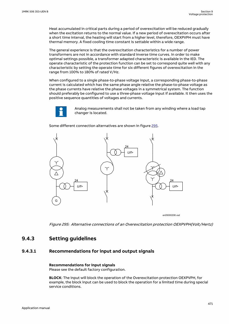
Heat accumulated in critical parts during a period of overexcitation will be reduced graduallywhen the excitation returns to the normal value. If a new period of overexcitation occurs aftera short time interval, the heating will start from a higher level, therefore, OEXPVPH must havethermal memory. A fixed cooling time constant is settable within a wide range.
The general experience is that the overexcitation characteristics for a number of powertransformers are not in accordance with standard inverse time curves. In order to makeoptimal settings possible, a transformer adapted characteristic is available in the IED. Theoperate characteristic of the protection function can be set to correspond quite well with anycharacteristic by setting the operate time for six different figures of overexcitation in therange from 100% to 180% of rated V/Hz.
When configured to a single phase-to-phase voltage input, a corresponding phase-to-phasecurrent is calculated which has the same phase angle relative the phase-to-phase voltage asthe phase currents have relative the phase voltages in a symmetrical system. The functionshould preferably be configured to use a three-phase voltage input if available. It then uses thepositive sequence quantities of voltages and currents.
Analog measurements shall not be taken from any winding where a load tapchanger is located.
Some different connection alternatives are shown in figure 295.
G
U/f>
24
U/f>
24
U/f>
24
en05000208.vsd
IEC05000208 V1 EN-US
Figure 295: Alternative connections of an Overexcitation protection OEXPVPH(Volt/Hertz)
9.4.3 Setting guidelinesIP15039-1 v1
9.4.3.1 Recommendations for input and output signalsM6496-75 v4
Recommendations for Input signalsM6496-79 v5
Please see the default factory configuration.
BLOCK: The input will block the operation of the Overexcitation protection OEXPVPH, forexample, the block input can be used to block the operation for a limited time during specialservice conditions.
1MRK 506 353-UEN B Section 9Voltage protection
471Application manual

RESET: OEXPVPH has a thermal memory, which can take a long time to reset. Activation of theRESET input will reset the function instantaneously.
Recommendations for Output signalsM6496-84 v7
Please see the default factory configuration for examples of configuration.
ERROR: The output indicates a measuring error. The reason, for example, can be configurationproblems where analogue signals are missing.
START: The START output indicates that the level V/Hz>> has been reached. It can be used toinitiate time measurement.
TRIP: The TRIP output is activated after the operate time for the U/f level has expired. TRIPsignal is used to trip the circuit breaker(s).
ALARM: The output is activated when the alarm level has been reached and the alarm timer haselapsed. When the system voltage is high this output sends an alarm to the operator.
9.4.3.2 SettingsM6496-91 v8
GlobalBaseSel: Selects the global base value group used by the function to define (IBase),(UBase) and (SBase).
Operation: The operation of the Overexcitation protection OEXPVPH can be set to On/Off.
MeasuredU: The phases involved in the measurement are set here. Normally the three phasemeasurement measuring the positive sequence voltage should be used but when onlyindividual VT's are used a single phase-to-phase can be used.
MeasuredI: The phases involved in the measurement are set here. MeasuredI: must be inaccordance with MeasuredU.
V/Hz>: Operating level for the inverse characteristic, IEEE or tailor made. The operation isbased on the relation between rated voltage and rated frequency and set as a percentagefactor. Normal setting is around 108-110% depending of the capability curve for thetransformer/generator.
V/Hz>>: Operating level for the tMin definite time delay used at high overvoltages. Theoperation is based on the relation between rated voltage and rated frequency and set as apercentage factor. Normal setting is around 110-180% depending of the capability curve of thetransformer/generator. Setting should be above the knee-point when the characteristic startsto be straight on the high side.
Lower V/Hz limit is always set value V/Hz> in %. Upper V/Hz limit for the inverse timecharacteristic is taken as greater value among the following two values in %:
• 1.10 x V/Hz>• V/Hz>>
The reason behind this is to prevent loss of accuracy of the inverse time characteristic whenthe difference between V/Hz> and V/Hz>> set values is too small.
XLeak: The transformer leakage reactance on which the compensation of voltagemeasurement with load current is based. The setting shall be the transformer leak reactance inprimary ohms. If no current compensation is used (mostly the case) the setting is not used.
TrPulse: The length of the trip pulse. Normally the final trip pulse is decided by the trip functionblock. A typical pulse length can be 50 ms.
Section 9 1MRK 506 353-UEN BVoltage protection
472Application manual

CurveType: Selection of the curve type for the inverse delay. The IEEE curves or tailor madecurve can be selected depending of which one matches the capability curve best.
kForIEEE: The time constant for the inverse characteristic. Select the one giving the bestmatch to the transformer capability.
tCooling: The cooling time constant giving the reset time when voltages drops below the setvalue. Shall be set above the cooling time constant of the transformer. The default value isrecommended to be used if the constant is not known.
tMin: The operating times at voltages higher than the set V/Hz>>. The setting shall matchcapabilities on these high voltages. Typical setting can be 1-10 second.
tMax: For overvoltages close to the set value times can be extremely long if a high K timeconstant is used. A maximum time can then be set to cut the longest times. Typical settingsare 1800-3600 seconds (30-60 minutes)
AlarmLevel: Setting of the alarm level in percentage of the set trip level. The alarm level isnormally set at around 98% of the trip level.
tAlarm: Setting of the time to alarm is given from when the alarm level has been reached.Typical setting is 5 seconds.
9.4.3.3 Service value reportM6496-144 v4
A number of internal parameters are available as service values for use at commissioning andduring service. Remaining time to trip (in seconds) TMTOTRIP, flux density VPERHZ, internalthermal content in percentage of trip value THERMSTA. The values are available at local HMI,Substation SAsystem and PCM600.
9.4.3.4 Setting exampleM6496-108 v5
Sufficient information about the overexcitation capability of the protected object(s) must beavailable when making the settings. The most complete information is given in anoverexcitation capability diagram as shown in figure 296.
The settings V/Hz>> and V/Hz> are made in per unit of the rated voltage of the transformerwinding at rated frequency.
Set the transformer adapted curve for a transformer with overexcitation characteristics inaccording to figure 296.
V/Hz> for the protection is set equal to the permissible continuous overexcitation accordingto figure 296 = 105%. When the overexcitation is equal to V/Hz>, tripping is obtained after atime equal to the setting of t1.
This is the case when UBase is equal to the transformer rated voltages. Forother values, the percentage settings need to be adjusted accordingly.
When the overexcitation is equal to the set value of V/Hz>>, tripping is obtained after a timeequal to the setting of t6. A suitable setting would be V/Hz>> = 140% and t6 = 4 s.
The interval between V/Hz>> and V/Hz> is automatically divided up in five equal steps, and thetime delays t2 to t5 will be allocated to these values of overexcitation. In this example, eachstep will be (140-105) /5 = 7%. The setting of time delays t1 to t6 are listed in table 41.
1MRK 506 353-UEN B Section 9Voltage protection
473Application manual

Table 41: Settings
U/f op (%) Timer Time set (s)
105 t1 7200 (max)
112 t2 600
119 t3 60
126 t4 20
133 t5 8
140 t6 4
Information on the cooling time constant Tcool should be retrieved from the powertransformer manufacturer.
1 2 5 50 200
110
120
130
140
150
1000.05 0.1 0.2 0.5 10 20 100
V/Hz%
Continous
Time(minutes)
t6 t5 t4 t3 t2 t1
transformer capability curverelay operate characteristic
en01000377.vsd
IEC01000377 V1 EN-US
Figure 296: Example on overexcitation capability curve and V/Hz protection settings forpower transformer
9.5 Voltage differential protection VDCPTOVSEMOD153860-1 v2
9.5.1 IdentificationSEMOD167723-2 v2
Function description IEC 61850identification
IEC 60617identification
ANSI/IEEE C37.2device number
Voltage differential protection VDCPTOV - 60
Section 9 1MRK 506 353-UEN BVoltage protection
474Application manual

9.5.2 ApplicationSEMOD153893-5 v3
The Voltage differential protection VDCPTOV functions can be used in some differentapplications.
• Voltage unbalance protection for capacitor banks. The voltage on the bus is supervisedwith the voltage in the capacitor bank, phase- by phase. Difference indicates a fault, eithershort-circuited or open element in the capacitor bank. It is mainly used on elements withexternal fuses but can also be used on elements with internal fuses instead of a currentunbalance protection measuring the current between the neutrals of two half’s of thecapacitor bank. The function requires voltage transformers in all phases of the capacitorbank. Figure 297 shows some different alternative connections of this function.
Ud>L1
Ph L2Ph L3
U1
U2
Ud>L1
Ph L2Ph L3
U1 U2
Ph L3 Ph L2
Single earthed wye
Double wye
IEC06000390_1_en.vsdIEC06000390 V3 EN-US
Figure 297: Connection of voltage differential protection VDCPTOV function to detectunbalance in capacitor banks (one phase only is shown)
VDCPTOV function has a block input (BLOCK) where a fuse failure supervision (or MCB tripped)can be connected to prevent problems if one fuse in the capacitor bank voltage transformerset has opened and not the other (capacitor voltage is connected to input U2). It will alsoensure that a fuse failure alarm is given instead of a Undervoltage or Differential voltage alarmand/or tripping.
Fuse failure supervision (SDDRFUF) function for voltage transformers. In many application thevoltages of two fuse groups of the same voltage transformer or fuse groups of two separatevoltage transformers measuring the same voltage can be supervised with this function. It willbe an alternative for example, generator units where often two voltage transformers aresupplied for measurement and excitation equipment.
1MRK 506 353-UEN B Section 9Voltage protection
475Application manual
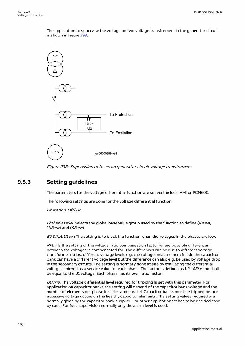
The application to supervise the voltage on two voltage transformers in the generator circuitis shown in figure 298.
Ud>U1
U2
To Protection
To Excitation
Gen en06000389.vsd
IEC06000389 V1 EN-US
Figure 298: Supervision of fuses on generator circuit voltage transformers
9.5.3 Setting guidelinesSEMOD153915-5 v3
The parameters for the voltage differential function are set via the local HMI or PCM600.
The following settings are done for the voltage differential function.
Operation: Off/On
GlobalBaseSel: Selects the global base value group used by the function to define (IBase),(UBase) and (SBase).
BlkDiffAtULow: The setting is to block the function when the voltages in the phases are low.
RFLx: Is the setting of the voltage ratio compensation factor where possible differencesbetween the voltages is compensated for. The differences can be due to different voltagetransformer ratios, different voltage levels e.g. the voltage measurement inside the capacitorbank can have a different voltage level but the difference can also e.g. be used by voltage dropin the secondary circuits. The setting is normally done at site by evaluating the differentialvoltage achieved as a service value for each phase. The factor is defined as U2 · RFLx and shallbe equal to the U1 voltage. Each phase has its own ratio factor.
UDTrip: The voltage differential level required for tripping is set with this parameter. Forapplication on capacitor banks the setting will depend of the capacitor bank voltage and thenumber of elements per phase in series and parallel. Capacitor banks must be tripped beforeexcessive voltage occurs on the healthy capacitor elements. The setting values required arenormally given by the capacitor bank supplier. For other applications it has to be decided caseby case. For fuse supervision normally only the alarm level is used.
Section 9 1MRK 506 353-UEN BVoltage protection
476Application manual

tTrip: The time delay for tripping is set by this parameter. Normally, the delay does not need tobe so short in capacitor bank applications as there is no fault requiring urgent tripping.
tReset: The time delay for reset of tripping level element is set by this parameter. Normally, itcan be set to a short delay as faults are permanent when they occur.
For the advanced users following parameters are also available for setting. Default values arehere expected to be acceptable.
U1Low: The setting of the undervoltage level for the first voltage input is decided by thisparameter. The proposed default setting is 70%.
U2Low: The setting of the undervoltage level for the second voltage input is decided by thisparameter. The proposed default setting is 70%.
tBlock: The time delay for blocking of the function at detected undervoltages is set by thisparameter.
UDAlarm: The voltage differential level required for alarm is set with this parameter. Forapplication on capacitor banks the setting will depend of the capacitor bank voltage and thenumber of elements per phase in series and parallel. Normally values required are given bycapacitor bank supplier.
For fuse supervision normally only this alarm level is used and a suitable voltage level is 3-5% ifthe ratio correction factor has been properly evaluated during commissioning.
For other applications it has to be decided case by case.
tAlarm: The time delay for alarm is set by this parameter. Normally, few seconds delay can beused on capacitor banks alarm. For fuse failure supervision (SDDRFUF) the alarm delay can beset to zero.
9.6 Loss of voltage check LOVPTUVSEMOD171868-1 v2
9.6.1 IdentificationSEMOD171954-2 v2
Function description IEC 61850identification
IEC 60617identification
ANSI/IEEE C37.2device number
Loss of voltage check LOVPTUV - 27
9.6.2 ApplicationSEMOD171876-4 v3
The trip of the circuit breaker at a prolonged loss of voltage at all the three phases is normallyused in automatic restoration systems to facilitate the system restoration after a majorblackout. Loss of voltage check (LOVPTUV) generates a TRIP signal only if the voltage in all thethree phases is low for more than the set time. If the trip to the circuit breaker is not required,LOVPTUV is used for signallization only through an output contact or through the eventrecording function.
9.6.3 Setting guidelinesSEMOD171929-4 v5
Loss of voltage check (LOVPTUV) is in principle independent of the protection functions. Itrequires to be set to open the circuit breaker in order to allow a simple system restorationfollowing a main voltage loss of a big part of the network and only when the voltage is lostwith breakers still closed.
1MRK 506 353-UEN B Section 9Voltage protection
477Application manual
All settings are in primary values or per unit. Set operate level per phase to typically 70% of theglobal parameter UBase level. Set the time delay tTrip=5-20 seconds.
9.6.3.1 Advanced users settingsSEMOD171929-8 v4
For advanced users the following parameters need also to be set. Set the length of the trippulse to typical tPulse=0.15 sec. Set the blocking time tBlock to block Loss of voltage check(LOVPTUV), if some but not all voltage are low, to typical 5.0 seconds and set the time delayfor enabling the function after restoration tRestore to 3 - 40 seconds.
9.7 Radial feeder protection PAPGAPCGUID-831891A3-B5AB-4532-8901-311C541F0ABB v1
9.7.1 IdentificationGUID-1B7B3DC5-DD7B-4017-928D-0C41768E94D9 v1
Function description IEC 61850 identification IEC 60617 identification ANSI/IEEE C37.2 devicenumber
Radial feeder protection PAPGAPC U< 27
9.7.2 ApplicationGUID-7EAA8D3C-F71A-4B97-80C8-31115DF381EE v1
The most common application of the PAPGAPC function is to provide tripping at the remoteend of lines with passive load or with weak end infeed. The function must be included in theterminal at the weak infeed end of the feeder.
Permissive communication schemes can basically operate only when the protection at theremote end of a feeder can detect the fault. The detection requires a minimum of fault current,normally >20% of Ir.
The fault current can be low due to absence of generated power or low short circuit current ofthe source. The fault current can initially be too low due to the fault current distribution.
In this case, the fault current increases when the breaker opens at the strong line end and asequential tripping is achieved.
The detection of the fault by an independent tripping zone 1 is then required.
To avoid sequential tripping as described or when zone 1 is not available, the protectionterminal must be provided with this application function.
9.7.3 Setting guidelinesGUID-D0C8F29C-2C8D-4F9A-BB25-1A93E6E7C392 v2
The parameters for PAPGAPC application function are set via the local HMI or Protection andControl Manager PCM600.
Operation: The function can be set On/Off.
GlobalBaseSel: Used to select a GBASVAL function for reference of base values, primary current(IBase), primary voltage (UBase ) and primary power (SBase).
UPhSel<: Faulted phase voltage in % of quadrature phase – phase voltage divided by sqrt (3).Setting this value to 100% is equivalent to disabling the voltage operation.
Tau: Time constant for reference voltage.
FastOperation: Enabling of fast fault clearing.
Section 9 1MRK 506 353-UEN BVoltage protection
478Application manual

t3Ph: Time delay for three phase operation.
IN>: Residual current detection in % of IBase.
ResCurrCheck: Enabling of residual current check for delayed operation at single phase faults.
Del1PhOp: Enabling of delayed single phase operation.
t1Ph: Time delay for single phase operation.
Del3PhOp: Enabling of delayed three phase operation.
ResCurrOper: Enabling of residual current operation.
tResCurr: Time delay for residual current indication.
1MRK 506 353-UEN B Section 9Voltage protection
479Application manual

480

Section 10 Frequency protection
10.1 Underfrequency protection SAPTUFIP15746-1 v3
10.1.1 IdentificationM14865-1 v5
Function description IEC 61850identification
IEC 60617identification
ANSI/IEEE C37.2device number
Underfrequency protection SAPTUF
f <
SYMBOL-P V1 EN-US
81
10.1.2 ApplicationM13350-3 v4
Underfrequency protection SAPTUF is applicable in all situations, where reliable detection oflow fundamental power system frequency is needed. The power system frequency, and therate of change of frequency, is a measure of the unbalance between the actual generation andthe load demand. Low fundamental frequency in a power system indicates that the availablegeneration is too low to fully supply the power demanded by the load connected to the powergrid. SAPTUF detects such situations and provides an output signal, suitable for loadshedding, generator boosting, HVDC-set-point change, gas turbine start up and so on.Sometimes shunt reactors are automatically switched in due to low frequency, in order toreduce the power system voltage and hence also reduce the voltage dependent part of theload.
SAPTUF is very sensitive and accurate and is used to alert operators that frequency has slightlydeviated from the set-point, and that manual actions might be enough. The underfrequencysignal is also used for overexcitation detection. This is especially important for generator step-up transformers, which might be connected to the generator but disconnected from the grid,during a roll-out sequence. If the generator is still energized, the system will experienceoverexcitation, due to the low frequency.
10.1.3 Setting guidelinesM13355-3 v7
All the frequency and voltage magnitude conditions in the system where SAPTUF performs itsfunctions should be considered. The same also applies to the associated equipment, itsfrequency and time characteristic.
There are two specific application areas for SAPTUF:
1. to protect equipment against damage due to low frequency, such as generators,transformers, and motors. Overexcitation is also related to low frequency
2. to protect a power system, or a part of a power system, against breakdown, by sheddingload, in generation deficit situations.
1MRK 506 353-UEN B Section 10Frequency protection
481Application manual
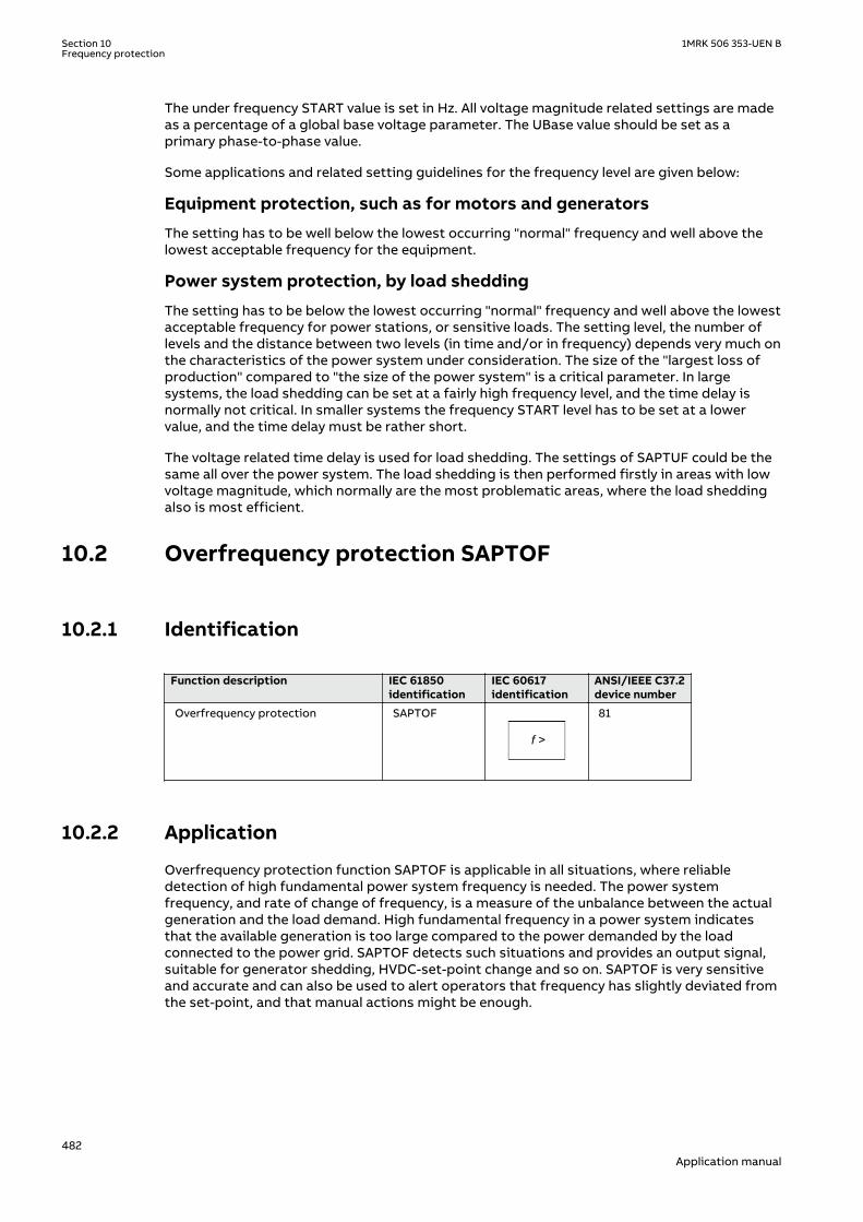
The under frequency START value is set in Hz. All voltage magnitude related settings are madeas a percentage of a global base voltage parameter. The UBase value should be set as aprimary phase-to-phase value.
Some applications and related setting guidelines for the frequency level are given below:
Equipment protection, such as for motors and generators
The setting has to be well below the lowest occurring "normal" frequency and well above thelowest acceptable frequency for the equipment.
Power system protection, by load shedding
The setting has to be below the lowest occurring "normal" frequency and well above the lowestacceptable frequency for power stations, or sensitive loads. The setting level, the number oflevels and the distance between two levels (in time and/or in frequency) depends very much onthe characteristics of the power system under consideration. The size of the "largest loss ofproduction" compared to "the size of the power system" is a critical parameter. In largesystems, the load shedding can be set at a fairly high frequency level, and the time delay isnormally not critical. In smaller systems the frequency START level has to be set at a lowervalue, and the time delay must be rather short.
The voltage related time delay is used for load shedding. The settings of SAPTUF could be thesame all over the power system. The load shedding is then performed firstly in areas with lowvoltage magnitude, which normally are the most problematic areas, where the load sheddingalso is most efficient.
10.2 Overfrequency protection SAPTOFIP15747-1 v3
10.2.1 IdentificationM14866-1 v4
Function description IEC 61850identification
IEC 60617identification
ANSI/IEEE C37.2device number
Overfrequency protection SAPTOF
f >
SYMBOL-O V1 EN-US
81
10.2.2 ApplicationM14952-3 v4
Overfrequency protection function SAPTOF is applicable in all situations, where reliabledetection of high fundamental power system frequency is needed. The power systemfrequency, and rate of change of frequency, is a measure of the unbalance between the actualgeneration and the load demand. High fundamental frequency in a power system indicatesthat the available generation is too large compared to the power demanded by the loadconnected to the power grid. SAPTOF detects such situations and provides an output signal,suitable for generator shedding, HVDC-set-point change and so on. SAPTOF is very sensitiveand accurate and can also be used to alert operators that frequency has slightly deviated fromthe set-point, and that manual actions might be enough.
Section 10 1MRK 506 353-UEN BFrequency protection
482Application manual
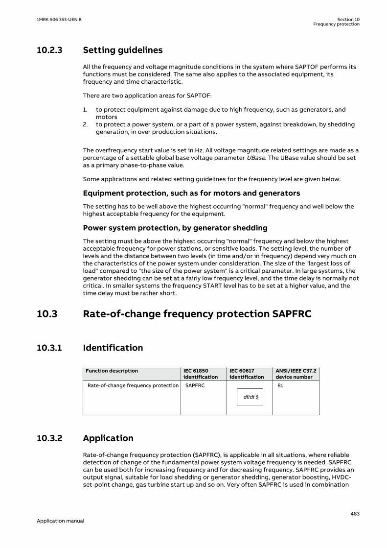
10.2.3 Setting guidelinesM14959-3 v7
All the frequency and voltage magnitude conditions in the system where SAPTOF performs itsfunctions must be considered. The same also applies to the associated equipment, itsfrequency and time characteristic.
There are two application areas for SAPTOF:
1. to protect equipment against damage due to high frequency, such as generators, andmotors
2. to protect a power system, or a part of a power system, against breakdown, by sheddinggeneration, in over production situations.
The overfrequency start value is set in Hz. All voltage magnitude related settings are made as apercentage of a settable global base voltage parameter UBase. The UBase value should be setas a primary phase-to-phase value.
Some applications and related setting guidelines for the frequency level are given below:
Equipment protection, such as for motors and generators
The setting has to be well above the highest occurring "normal" frequency and well below thehighest acceptable frequency for the equipment.
Power system protection, by generator shedding
The setting must be above the highest occurring "normal" frequency and below the highestacceptable frequency for power stations, or sensitive loads. The setting level, the number oflevels and the distance between two levels (in time and/or in frequency) depend very much onthe characteristics of the power system under consideration. The size of the "largest loss ofload" compared to "the size of the power system" is a critical parameter. In large systems, thegenerator shedding can be set at a fairly low frequency level, and the time delay is normally notcritical. In smaller systems the frequency START level has to be set at a higher value, and thetime delay must be rather short.
10.3 Rate-of-change frequency protection SAPFRCIP15748-1 v3
10.3.1 IdentificationM14868-1 v3
Function description IEC 61850identification
IEC 60617identification
ANSI/IEEE C37.2device number
Rate-of-change frequency protection SAPFRC
df/dt ><
SYMBOL-N V1 EN-US
81
10.3.2 ApplicationM14966-3 v4
Rate-of-change frequency protection (SAPFRC), is applicable in all situations, where reliabledetection of change of the fundamental power system voltage frequency is needed. SAPFRCcan be used both for increasing frequency and for decreasing frequency. SAPFRC provides anoutput signal, suitable for load shedding or generator shedding, generator boosting, HVDC-set-point change, gas turbine start up and so on. Very often SAPFRC is used in combination
1MRK 506 353-UEN B Section 10Frequency protection
483Application manual

with a low frequency signal, especially in smaller power systems, where loss of a fairly largegenerator will require quick remedial actions to secure the power system integrity. In suchsituations load shedding actions are required at a rather high frequency level, but incombination with a large negative rate-of-change of frequency the underfrequency protectioncan be used at a rather high setting.
10.3.3 Setting guidelinesM14971-3 v6
The parameters for Rate-of-change frequency protection SAPFRC are set via the local HMI or orthrough the Protection and Control Manager (PCM600).
All the frequency and voltage magnitude conditions in the system where SAPFRC performs itsfunctions should be considered. The same also applies to the associated equipment, itsfrequency and time characteristic.
There are two application areas for SAPFRC:
1. to protect equipment against damage due to high or too low frequency, such asgenerators, transformers, and motors
2. to protect a power system, or a part of a power system, against breakdown by sheddingload or generation, in situations where load and generation are not in balance.
SAPFRC is normally used together with an overfrequency or underfrequency function, in smallpower systems, where a single event can cause a large imbalance between load andgeneration. In such situations load or generation shedding has to take place very quickly, andthere might not be enough time to wait until the frequency signal has reached an abnormalvalue. Actions are therefore taken at a frequency level closer to the primary nominal level, if therate-of-change frequency is large (with respect to sign).
SAPFRCSTART value is set in Hz/s. All voltage magnitude related settings are made as apercentage of a settable base voltage, which normally is set to the primary nominal voltagelevel (phase-phase) of the power system or the high voltage equipment under consideration.
SAPFRC is not instantaneous, since the function needs some time to supply a stable value. It isrecommended to have a time delay long enough to take care of signal noise. However, thetime, rate-of-change frequency and frequency steps between different actions might becritical, and sometimes a rather short operation time is required, for example, down to 70 ms.
Smaller industrial systems might experience rate-of-change frequency as large as 5 Hz/s, dueto a single event. Even large power systems may form small islands with a large imbalancebetween load and generation, when severe faults (or combinations of faults) are cleared - upto 3 Hz/s has been experienced when a small island was isolated from a large system. Formore "normal" severe disturbances in large power systems, rate-of-change of frequency ismuch less, most often just a fraction of 1.0 Hz/s.
Section 10 1MRK 506 353-UEN BFrequency protection
484Application manual
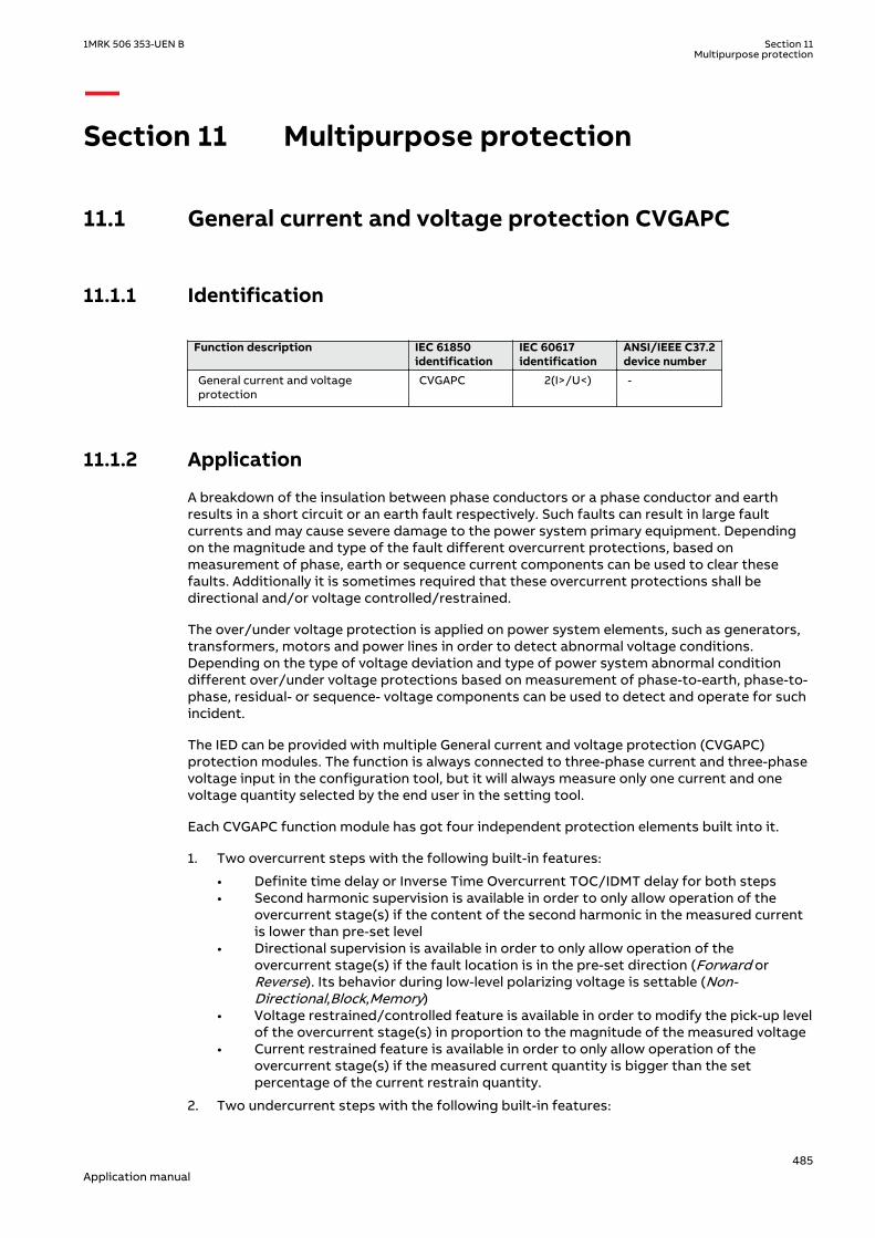
Section 11 Multipurpose protection
11.1 General current and voltage protection CVGAPCIP14552-1 v2
11.1.1 IdentificationM14886-2 v3
Function description IEC 61850identification
IEC 60617identification
ANSI/IEEE C37.2device number
General current and voltageprotection
CVGAPC 2(I>/U<) -
11.1.2 ApplicationIP15008-1 v1
M13084-3 v4
A breakdown of the insulation between phase conductors or a phase conductor and earthresults in a short circuit or an earth fault respectively. Such faults can result in large faultcurrents and may cause severe damage to the power system primary equipment. Dependingon the magnitude and type of the fault different overcurrent protections, based onmeasurement of phase, earth or sequence current components can be used to clear thesefaults. Additionally it is sometimes required that these overcurrent protections shall bedirectional and/or voltage controlled/restrained.
The over/under voltage protection is applied on power system elements, such as generators,transformers, motors and power lines in order to detect abnormal voltage conditions.Depending on the type of voltage deviation and type of power system abnormal conditiondifferent over/under voltage protections based on measurement of phase-to-earth, phase-to-phase, residual- or sequence- voltage components can be used to detect and operate for suchincident.
The IED can be provided with multiple General current and voltage protection (CVGAPC)protection modules. The function is always connected to three-phase current and three-phasevoltage input in the configuration tool, but it will always measure only one current and onevoltage quantity selected by the end user in the setting tool.
Each CVGAPC function module has got four independent protection elements built into it.
1. Two overcurrent steps with the following built-in features:
• Definite time delay or Inverse Time Overcurrent TOC/IDMT delay for both steps• Second harmonic supervision is available in order to only allow operation of the
overcurrent stage(s) if the content of the second harmonic in the measured currentis lower than pre-set level
• Directional supervision is available in order to only allow operation of theovercurrent stage(s) if the fault location is in the pre-set direction (Forward orReverse). Its behavior during low-level polarizing voltage is settable (Non-Directional,Block,Memory)
• Voltage restrained/controlled feature is available in order to modify the pick-up levelof the overcurrent stage(s) in proportion to the magnitude of the measured voltage
• Current restrained feature is available in order to only allow operation of theovercurrent stage(s) if the measured current quantity is bigger than the setpercentage of the current restrain quantity.
2. Two undercurrent steps with the following built-in features:
1MRK 506 353-UEN B Section 11Multipurpose protection
485Application manual

• Definite time delay for both steps
3. Two overvoltage steps with the following built-in features
• Definite time delay or Inverse Time Overcurrent TOC/IDMT delay for both steps
4. Two undervoltage steps with the following built-in features
• Definite time delay or Inverse Time Overcurrent TOC/IDMT delay for both steps
All these four protection elements within one general protection function works independentlyfrom each other and they can be individually enabled or disabled. However it shall be oncemore noted that all these four protection elements measure one selected current quantity andone selected voltage quantity (see table 42 and table 43). It is possible to simultaneously useall four-protection elements and their individual stages. Sometimes in order to obtain desiredapplication functionality it is necessary to provide interaction between two or more protectionelements/stages within one CVGAPC function by appropriate IED configuration (for example,dead machine protection for generators).
11.1.2.1 Current and voltage selection for CVGAPC functionSEMOD53443-6 v3
CVGAPC function is always connected to three-phase current and three-phase voltage input inthe configuration tool, but it will always measure only the single current and the single voltagequantity selected by the end user in the setting tool (selected current quantity and selectedvoltage quantity).
The user can select, by a setting parameter CurrentInput, to measure one of the followingcurrent quantities shown in table 42.
Table 42: Available selection for current quantity within CVGAPC function
Set value for parameter"CurrentInput”
Comment
1 phase1 CVGAPC function will measure the phase L1 current phasor
2 phase2 CVGAPC function will measure the phase L2 current phasor
3 phase3 CVGAPC function will measure the phase L3 current phasor
4 PosSeq CVGAPC function will measure internally calculated positive sequencecurrent phasor
5 NegSeq CVGAPC function will measure internally calculated negative sequencecurrent phasor
6 3 · ZeroSeq CVGAPC function will measure internally calculated zero sequence currentphasor multiplied by factor 3
7 MaxPh CVGAPC function will measure current phasor of the phase withmaximum magnitude
8 MinPh CVGAPC function will measure current phasor of the phase with minimummagnitude
9 UnbalancePh CVGAPC function will measure magnitude of unbalance current, which isinternally calculated as the algebraic magnitude difference between thecurrent phasor of the phase with maximum magnitude and currentphasor of the phase with minimum magnitude. Phase angle will be set to0° all the time
10 phase1-phase2 CVGAPC function will measure the current phasor internally calculated asthe vector difference between the phase L1 current phasor and phase L2current phasor (IL1-IL2)
11 phase2-phase3 CVGAPC function will measure the current phasor internally calculated asthe vector difference between the phase L2 current phasor and phase L3current phasor (IL2-IL3)
Table continues on next page
Section 11 1MRK 506 353-UEN BMultipurpose protection
486Application manual

Set value for parameter"CurrentInput”
Comment
12 phase3-phase1 CVGAPC function will measure the current phasor internally calculated asthe vector difference between the phase L3 current phasor and phase L1current phasor ( IL3-IL1)
13 MaxPh-Ph CVGAPC function will measure ph-ph current phasor with the maximummagnitude
14 MinPh-Ph CVGAPC function will measure ph-ph current phasor with the minimummagnitude
15 UnbalancePh-Ph CVGAPC function will measure magnitude of unbalance current, which isinternally calculated as the algebraic magnitude difference between theph-ph current phasor with maximum magnitude and ph-ph currentphasor with minimum magnitude. Phase angle will be set to 0° all thetime
The user can select, by a setting parameter VoltageInput, to measure one of the followingvoltage quantities shown in table 43.
Table 43: Available selection for voltage quantity within CVGAPC function
Set value for parameter"VoltageInput"
Comment
1 phase1 CVGAPC function will measure the phase L1 voltage phasor
2 phase2 CVGAPC function will measure the phase L2 voltage phasor
3 phase3 CVGAPC function will measure the phase L3 voltage phasor
4 PosSeq CVGAPC function will measure internally calculated positive sequencevoltage phasor
5 -NegSeq CVGAPC function will measure internally calculated negative sequencevoltage phasor. This voltage phasor will be intentionally rotated for 180°in order to enable easier settings for the directional feature when used.
6 -3*ZeroSeq CVGAPC function will measure internally calculated zero sequence voltagephasor multiplied by factor 3. This voltage phasor will be intentionallyrotated for 180° in order to enable easier settings for the directionalfeature when used.
7 MaxPh CVGAPC function will measure voltage phasor of the phase withmaximum magnitude
8 MinPh CVGAPC function will measure voltage phasor of the phase withminimum magnitude
9 UnbalancePh CVGAPC function will measure magnitude of unbalance voltage, which isinternally calculated as the algebraic magnitude difference between thevoltage phasor of the phase with maximum magnitude and voltagephasor of the phase with minimum magnitude. Phase angle will be set to0° all the time
10 phase1-phase2 CVGAPC function will measure the voltage phasor internally calculated asthe vector difference between the phase L1 voltage phasor and phase L2voltage phasor (UL1-UL2)
11 phase2-phase3 CVGAPC function will measure the voltage phasor internally calculated asthe vector difference between the phase L2 voltage phasor and phase L3voltage phasor (UL2-UL3)
12 phase3-phase1 CVGAPC function will measure the voltage phasor internally calculated asthe vector difference between the phase L3 voltage phasor and phase L1voltage phasor (UL3-UL1)
Table continues on next page
1MRK 506 353-UEN B Section 11Multipurpose protection
487Application manual

Set value for parameter"VoltageInput"
Comment
13 MaxPh-Ph CVGAPC function will measure ph-ph voltage phasor with the maximummagnitude
14 MinPh-Ph CVGAPC function will measure ph-ph voltage phasor with the minimummagnitude
15 UnbalancePh-Ph CVGAPC function will measure magnitude of unbalance voltage, which isinternally calculated as the algebraic magnitude difference between theph-ph voltage phasor with maximum magnitude and ph-ph voltagephasor with minimum magnitude. Phase angle will be set to 0° all thetime
It is important to notice that the voltage selection from table 43 is always applicableregardless the actual external VT connections. The three-phase VT inputs can be connected toIED as either three phase-to-earth voltages UL1, UL2 & UL3 or three phase-to-phase voltagesUL1L2, UL2L3 & UL3L1VAB, VBC and VCA. This information about actual VT connection is enteredas a setting parameter for the pre-processing block, which will then take automatically careabout it.
11.1.2.2 Base quantities for CVGAPC functionSEMOD53443-112 v3
The parameter settings for the base quantities, which represent the base (100%) for pickuplevels of all measuring stages shall be entered as setting parameters for every CVGAPCfunction.
Base current shall be entered as:
1. rated phase current of the protected object in primary amperes, when the measuredCurrent Quantity is selected from 1 to 9, as shown in table 42.
2. rated phase current of the protected object in primary amperes multiplied by √3 (1.732 xIphase), when the measured Current Quantity is selected from 10 to 15, as shown in table42.
Base voltage shall be entered as:
1. rated phase-to-earth voltage of the protected object in primary kV, when the measuredVoltage Quantity is selected from 1 to 9, as shown in table 43.
2. rated phase-to-phase voltage of the protected object in primary kV, when the measuredVoltage Quantity is selected from 10 to 15, as shown in table 43.
11.1.2.3 Application possibilitiesSEMOD53443-136 v2
Due to its flexibility the general current and voltage protection (CVGAPC) function can be used,with appropriate settings and configuration in many different applications. Some of possibleexamples are given below:
1. Transformer and line applications:
• Underimpedance protection (circular, non-directional characteristic)• Underimpedance protection (circular mho characteristic)• Voltage Controlled/Restrained Overcurrent protection• Phase or Negative/Positive/Zero Sequence (Non-Directional or Directional)
Overcurrent protection• Phase or phase-to-phase or Negative/Positive/Zero Sequence over/under voltage
protection
Section 11 1MRK 506 353-UEN BMultipurpose protection
488Application manual

• Special thermal overload protection• Open Phase protection• Unbalance protection
2. Generator protection
• 80-95% Stator earth fault protection (measured or calculated 3Uo)• Rotor earth fault protection (with external COMBIFLEX RXTTE4 injection unit)• Underimpedance protection• Voltage Controlled/Restrained Overcurrent protection• Turn-to-Turn & Differential Backup protection (directional Negative Sequence.
Overcurrent protection connected to generator HV terminal CTs looking intogenerator)
• Stator Overload protection• Rotor Overload protection• Loss of Excitation protection (directional pos. seq. OC protection)• Reverse power/Low forward power protection (directional pos. seq. OC protection,
2% sensitivity)• Dead-Machine/Inadvertent-Energizing protection• Breaker head flashover protection• Improper synchronizing detection• Sensitive negative sequence generator over current protection and alarm• Phase or phase-to-phase or Negative/Positive/Zero Sequence over/under voltage
protection• Generator out-of-step detection (based on directional pos. seq. OC)• Inadvertent generator energizing
11.1.2.4 Inadvertent generator energizationSEMOD151947-4 v2
When the generator is taken out of service, and non-rotating, there is a risk that the generatorcircuit breaker is closed by mistake.
Three-phase energizing of a generator, which is at standstill or on turning gear, causes it tobehave and accelerate similarly to an induction motor. The machine, at this point, essentiallyrepresents the subtransient reactance to the system and it can be expected to draw from oneto four per unit current, depending on the equivalent system impedance. Machine terminalvoltage can range from 20% to 70% of rated voltage, again, depending on the systemequivalent impedance (including the block transformer). Higher quantities of machine currentand voltage (3 to 4 per unit current and 50% to 70% rated voltage) can be expected if thegenerator is connected to a strong system. Lower current and voltage values (1 to 2 per unitcurrent and 20% to 40% rated voltage) are representative of weaker systems.
Since a generator behaves similarly to an induction motor, high currents will develop in therotor during the period it is accelerating. Although the rotor may be thermally damaged fromexcessive high currents, the time to damage will be on the order of a few seconds. Of morecritical concern, however, is the bearing, which can be damaged in a fraction of a second dueto low oil pressure. Therefore, it is essential that high speed tripping is provided. This trippingshould be almost instantaneous (< 100 ms).
There is a risk that the current into the generator at inadvertent energization will be limited sothat the “normal” overcurrent or underimpedance protection will not detect the dangeroussituation. The delay of these protection functions might be too long. The reverse powerprotection might detect the situation but the operation time of this protection is normally toolong.
For big and important machines, fast protection against inadvertent energizing should,therefore, be included in the protective scheme.
The protection against inadvertent energization can be made by a combination ofundervoltage, overvoltage and overcurrent protection functions. The undervoltage function
1MRK 506 353-UEN B Section 11Multipurpose protection
489Application manual

will, with a delay for example 10 s, detect the situation when the generator is not connected tothe grid (standstill) and activate the overcurrent function. The overvoltage function will detectthe situation when the generator is taken into operation and will disable the overcurrentfunction. The overcurrent function will have a pick-up value about 50% of the rated current ofthe generator. The trip delay will be about 50 ms.
11.1.3 Setting guidelinesIP15009-1 v2
GUID-F7AA2194-4D1C-4475-8853-C7D064912614 v4
When inverse time overcurrent characteristic is selected, the operate time ofthe stage will be the sum of the inverse time delay and the set definite timedelay. Thus, if only the inverse time delay is required, it is important to set thedefinite time delay for that stage to zero.
M13088-237 v4
The parameters for the general current and voltage protection function (CVGAPC) are set viathe local HMI or Protection and Control Manager (PCM600).
GlobalBaseSel: Selects the global base value group used by the function to define (IBase),(UBase) and (SBase).
The overcurrent steps has a IMinx (x=1 or 2 depending on step) setting to setthe minimum operate current. Set IMinx below StartCurr_OCx for every step toachieve ANSI reset characteristic according to standard. If IMinx is set aboveStartCurr_OCx for any step the ANSI reset works as if current is zero whencurrent drops below IMinx.
11.1.3.1 Directional negative sequence overcurrent protectionM13088-3 v5
Directional negative sequence overcurrent protection is typically used as sensitive earth-faultprotection of power lines where incorrect zero sequence polarization may result from mutualinduction between two or more parallel lines. Additionally, it can be used in applications onunderground cables where zero-sequence impedance depends on the fault current returnpaths, but the cable negative-sequence impedance is practically constant. It shall be notedthat directional negative sequence OC element offers protection against all unbalance faults(phase-to-phase faults as well). Care shall be taken that the minimum pickup of suchprotection function shall be set above natural system unbalance level.
An example will be given, how sensitive-earth-fault protection for power lines can be achievedby using negative-sequence directional overcurrent protection elements within a CVGAPCfunction.
This functionality can be achieved by using one CVGAPC function. The following shall be doneto ensure proper operation of the function:
1. Connect three-phase power line currents and three-phase power line voltages to oneCVGAPC instance (for example, GF04)
2. Set CurrentInput to NegSeq (please note that CVGAPC function measures I2 current andNOT 3I2 current; this is essential for proper OC pickup level setting)
3. Set VoltageInput to -NegSeq (please note that the negative sequence voltage phasor isintentionally inverted in order to simplify directionality
4. Set base current IBase value equal to the rated primary current of power line CTs5. Set base voltage UBase value equal to the rated power line phase-to-phase voltage in kV6. Set RCADir to value +65 degrees (NegSeq current typically lags the inverted NegSeq
voltage for this angle during the fault)7. Set ROADir to value 90 degree8. Set LowVolt_VM to value 2% (NegSeq voltage level above which the directional element
will be enabled)
Section 11 1MRK 506 353-UEN BMultipurpose protection
490Application manual
9. Enable one overcurrent stage (for example, OC1)10. By parameter CurveType_OC1 select appropriate TOC/IDMT or definite time delayed curve
in accordance with your network protection philosophy11. Set StartCurr_OC1 to value between 3-10% (typical values)12. Set tDef_OC1 or parameter “k” when TOC/IDMT curves are used to insure proper time
coordination with other earth-fault protections installed in the vicinity of this power line13. Set DirMode_OC1 to Forward14. Set DirPrinc_OC1 to IcosPhi&U15. Set ActLowVolt1_VM to Block
• In order to insure proper restraining of this element for CT saturations during three-phase faults it is possible to use current restraint feature and enable this element tooperate only when NegSeq current is bigger than a certain percentage (10% istypical value) of measured PosSeq current in the power line. To do this the followingsettings within the same function shall be done:
16. Set EnRestrainCurr to On17. Set RestrCurrInput to PosSeq18. Set RestrCurrCoeff to value 0.10
If required, this CVGAPC function can be used in directional comparison protection scheme forthe power line protection if communication channels to the remote end of this power line areavailable. In that case typically two NegSeq overcurrent steps are required. One for forwardand one for reverse direction. As explained before the OC1 stage can be used to detect faultsin forward direction. The built-in OC2 stage can be used to detect faults in reverse direction.
However the following shall be noted for such application:
• the set values for RCADir and ROADir settings will be as well applicable for OC2 stage• setting DirMode_OC2 shall be set to Reverse• setting parameter StartCurr_OC2 shall be made more sensitive than pickup value of
forward OC1 element (that is, typically 60% of OC1 set pickup level) in order to insureproper operation of the directional comparison scheme during current reversal situations
• start signals from OC1 and OC2 elements shall be used to send forward and reversesignals to the remote end of the power line
• the available scheme communications function block within IED shall be used betweenmultipurpose protection function and the communication equipment in order to insureproper conditioning of the above two start signals
Furthermore the other built-in UC, OV and UV protection elements can be used for otherprotection and alarming purposes.
11.1.3.2 Negative sequence overcurrent protectionM13088-5 v4
Example will be given how to use one CVGAPC function to provide negative sequence inversetime overcurrent protection for a generator with capability constant of 20s, and maximumcontinuous negative sequence rating of 7% of the generator rated current.
The capability curve for a generator negative sequence overcurrent protection, often usedworld-wide, is defined by the ANSI standard in accordance with the following formula:
1MRK 506 353-UEN B Section 11Multipurpose protection
491Application manual

2op
NS
r
ktII
=æ öç ÷è ø
EQUATION1372 V1 EN-US (Equation 536)
where:
top is the operating time in seconds of the negative sequence overcurrent IED
k is the generator capability constant in seconds
INS is the measured negative sequence current
Ir is the generator rated current
By defining parameter x equal to maximum continuous negative sequence rating of thegenerator in accordance with the following formula
7% 0, 07x pu= =EQUATION1373 V1 EN-US (Equation 537)
Equation 536 can be re-written in the following way without changing the value for the operatetime of the negative sequence inverse overcurrent IED:
2
2
1
op
NS
r
kxt
Ix I
×=
æ öç ÷×è ø
EQUATION1374 V1 EN-US (Equation 538)
In order to achieve such protection functionality with one CVGAPC functions the followingmust be done:
1. Connect three-phase generator currents to one CVGAPC instance (for example, GF01)2. Set parameter CurrentInput to value NegSeq3. Set base current value to the rated generator current in primary amperes4. Enable one overcurrent step (for example, OC1)5. Select parameter CurveType_OC1 to value Programmable
op P
At k BM C
æ ö= × +ç ÷-è øEQUATION1375 V1 EN-US (Equation 539)
where:
top is the operating time in seconds of the Inverse Time Overcurrent TOC/IDMT algorithm
k is time multiplier (parameter setting)
M is ratio between measured current magnitude and set pickup current level
A, B, C and P are user settable coefficients which determine the curve used for Inverse Time OvercurrentTOC/IDMT calculation
Section 11 1MRK 506 353-UEN BMultipurpose protection
492Application manual
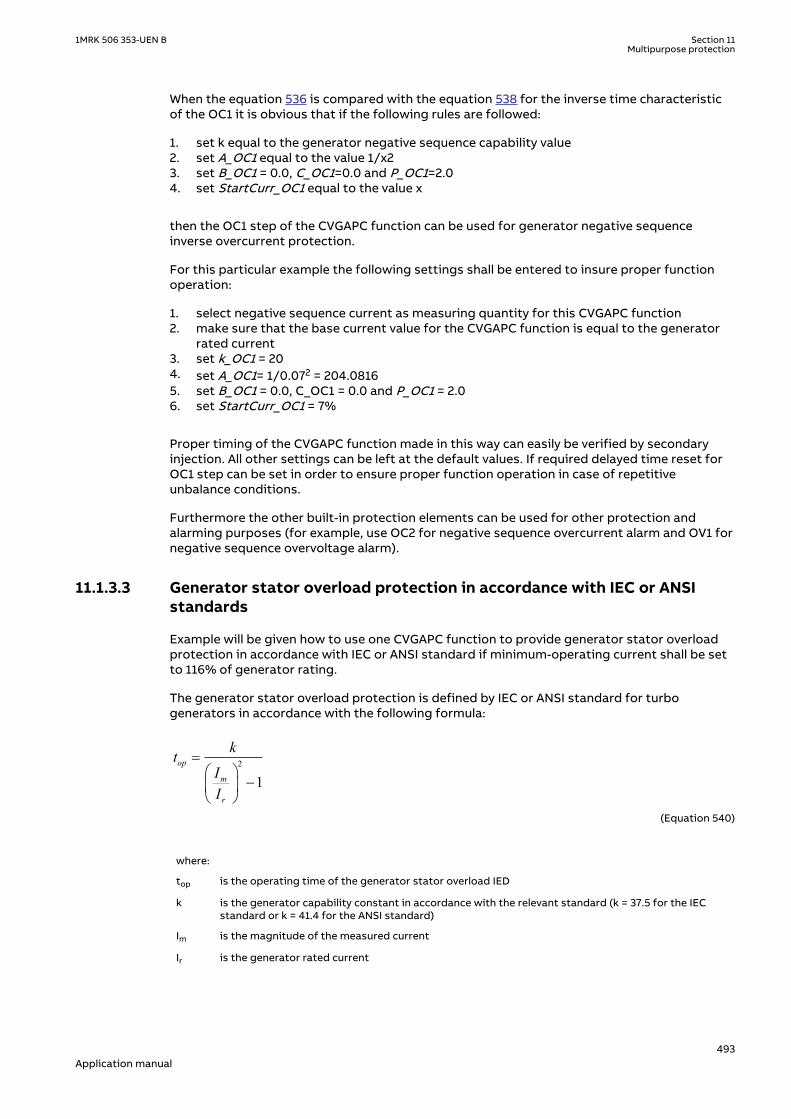
When the equation 536 is compared with the equation 538 for the inverse time characteristicof the OC1 it is obvious that if the following rules are followed:
1. set k equal to the generator negative sequence capability value2. set A_OC1 equal to the value 1/x23. set B_OC1 = 0.0, C_OC1=0.0 and P_OC1=2.04. set StartCurr_OC1 equal to the value x
then the OC1 step of the CVGAPC function can be used for generator negative sequenceinverse overcurrent protection.
For this particular example the following settings shall be entered to insure proper functionoperation:
1. select negative sequence current as measuring quantity for this CVGAPC function2. make sure that the base current value for the CVGAPC function is equal to the generator
rated current3. set k_OC1 = 204. set A_OC1= 1/0.072 = 204.08165. set B_OC1 = 0.0, C_OC1 = 0.0 and P_OC1 = 2.06. set StartCurr_OC1 = 7%
Proper timing of the CVGAPC function made in this way can easily be verified by secondaryinjection. All other settings can be left at the default values. If required delayed time reset forOC1 step can be set in order to ensure proper function operation in case of repetitiveunbalance conditions.
Furthermore the other built-in protection elements can be used for other protection andalarming purposes (for example, use OC2 for negative sequence overcurrent alarm and OV1 fornegative sequence overvoltage alarm).
11.1.3.3 Generator stator overload protection in accordance with IEC or ANSIstandards
M13088-81 v3
Example will be given how to use one CVGAPC function to provide generator stator overloadprotection in accordance with IEC or ANSI standard if minimum-operating current shall be setto 116% of generator rating.
The generator stator overload protection is defined by IEC or ANSI standard for turbogenerators in accordance with the following formula:
2
1op
m
r
ktII
=æ ö
-ç ÷è ø
EQUATION1376 V1 EN-US (Equation 540)
where:
top is the operating time of the generator stator overload IED
k is the generator capability constant in accordance with the relevant standard (k = 37.5 for the IECstandard or k = 41.4 for the ANSI standard)
Im is the magnitude of the measured current
Ir is the generator rated current
1MRK 506 353-UEN B Section 11Multipurpose protection
493Application manual
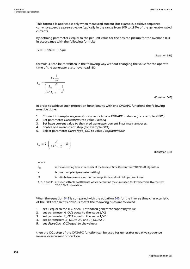
This formula is applicable only when measured current (for example, positive sequencecurrent) exceeds a pre-set value (typically in the range from 105 to 125% of the generator ratedcurrent).
By defining parameter x equal to the per unit value for the desired pickup for the overload IEDin accordance with the following formula:
x = 116% = 1.16 puEQUATION1377 V2 EN-US (Equation 541)
formula 3.5can be re-written in the following way without changing the value for the operatetime of the generator stator overload IED:
2
2
2
1
1op
m
r
kxt
Ix I x
×=
æ ö-ç ÷×è ø
EQUATION1378 V1 EN-US (Equation 542)
In order to achieve such protection functionality with one CVGAPC functions the followingmust be done:
1. Connect three-phase generator currents to one CVGAPC instance (for example, GF01)2. Set parameter CurrentInput to value PosSeq3. Set base current value to the rated generator current in primary amperes4. Enable one overcurrent step (for example OC1)5. Select parameter CurveType_OC1 to value Programmable
op P
At k BM C
æ ö= × +ç ÷-è øEQUATION1375 V1 EN-US (Equation 543)
where:
top is the operating time in seconds of the Inverse Time Overcurrent TOC/IDMT algorithm
k is time multiplier (parameter setting)
M is ratio between measured current magnitude and set pickup current level
A, B, C and P are user settable coefficients which determine the curve used for Inverse Time OvercurrentTOC/IDMT calculation
When the equation 542 is compared with the equation 543 for the inverse time characteristicof the OC1 step in it is obvious that if the following rules are followed:
1. set k equal to the IEC or ANSI standard generator capability value2. set parameter A_OC1 equal to the value 1/x23. set parameter C_OC1 equal to the value 1/x24. set parameters B_OC1 = 0.0 and P_OC1=2.05. set StartCurr_OC1 equal to the value x
then the OC1 step of the CVGAPC function can be used for generator negative sequenceinverse overcurrent protection.
Section 11 1MRK 506 353-UEN BMultipurpose protection
494Application manual

1. select positive sequence current as measuring quantity for this CVGAPC function2. make sure that the base current value for CVGAPC function is equal to the generator rated
current3. set k = 37.5 for the IEC standard or k = 41.4 for the ANSI standard4. set A_OC1= 1/1.162 = 0.74325. set C_OC1= 1/1.162 = 0.74326. set B_OC1 = 0.0 and P_OC1 = 2.07. set StartCurr_OC1 = 116%
Proper timing of CVGAPC function made in this way can easily be verified by secondaryinjection. All other settings can be left at the default values. If required delayed time reset forOC1 step can be set in order to insure proper function operation in case of repetitive overloadconditions.
Furthermore the other built-in protection elements can be used for other protection andalarming purposes.
In the similar way rotor overload protection in accordance with ANSI standard can be achieved.
11.1.3.4 Open phase protection for transformer, lines or generators and circuitbreaker head flashover protection for generators
M13088-142 v3
Example will be given how to use one CVGAPC function to provide open phase protection. Thiscan be achieved by using one CVGAPC function by comparing the unbalance current with a pre-set level. In order to make such a function more secure it is possible to restrain it by requiringthat at the same time the measured unbalance current must be bigger than 97% of themaximum phase current. By doing this it will be insured that function can only pickup if one ofthe phases is open circuited. Such an arrangement is easy to obtain in CVGAPC function byenabling the current restraint feature. The following shall be done in order to insure properoperation of the function:
1. Connect three-phase currents from the protected object to one CVGAPC instance (forexample, GF03)
2. Set CurrentInput to value UnbalancePh3. Set EnRestrainCurr to On4. Set RestrCurrInput to MaxPh5. Set RestrCurrCoeff to value 0.976. Set base current value to the rated current of the protected object in primary amperes7. Enable one overcurrent step (for example, OC1)8. Select parameter CurveType_OC1 to value IEC Def. Time9. Set parameter StartCurr_OC1 to value 5%10. Set parameter tDef_OC1 to desired time delay (for example, 2.0s)
Proper operation of CVGAPC function made in this way can easily be verified by secondaryinjection. All other settings can be left at the default values. However it shall be noted that setvalues for restrain current and its coefficient will as well be applicable for OC2 step as soon asit is enabled.
Furthermore the other built-in protection elements can be used for other protection andalarming purposes. For example, in case of generator application by enabling OC2 step withset pickup to 200% and time delay to 0.1s simple but effective protection against circuitbreaker head flashover protection is achieved.
1MRK 506 353-UEN B Section 11Multipurpose protection
495Application manual

11.1.3.5 Voltage restrained overcurrent protection for generator and step-uptransformer
M13088-158 v3
Example will be given how to use one CVGAPC function to provide voltage restrainedovercurrent protection for a generator. Let us assume that the time coordination study givesthe following required settings:
• Inverse Time Over Current TOC/IDMT curve: ANSI very inverse• Pickup current of 185% of generator rated current at rated generator voltage• Pickup current 25% of the original pickup current value for generator voltages below 25%
of rated voltage
This functionality can be achieved by using one CVGAPC function. The following shall be donein order to insure proper operation of the function:
1. Connect three-phase generator currents and voltages to one CVGAPC instance (forexample, GF05)
2. Set CurrentInput to value MaxPh3. Set VoltageInput to value MinPh-Ph (it is assumed that minimum phase-to-phase voltage
shall be used for restraining. Alternatively, positive sequence voltage can be used forrestraining by selecting PosSeq for this setting parameter)
4. Set base current value to the rated generator current primary amperes5. Set base voltage value to the rated generator phase-to-phase voltage in kV6. Enable one overcurrent step (for example, OC1)7. Select CurveType_OC1 to value ANSI Very inv8. If required set minimum operating time for this curve by using parameter tMin_OC1
(default value 0.05s)9. Set StartCurr_OC1 to value 185%10. Set VCntrlMode_OC1 to On11. Set VDepMode_OC1 to Slope12. Set VDepFact_OC1 to value 0.2513. Set UHighLimit_OC1 to value 100%14. Set ULowLimit_OC1 to value 25%
Proper operation of the CVGAPC function made in this way can easily be verified by secondaryinjection. All other settings can be left at the default values. Furthermore the other built-inprotection elements can be used for other protection and alarming purposes.
11.1.3.6 Loss of excitation protection for a generatorM13088-182 v3
Example will be given how by using positive sequence directional overcurrent protectionelement within a CVGAPC function, loss of excitation protection for a generator can beachieved. Let us assume that from rated generator data the following values are calculated:
• Maximum generator capability to contentiously absorb reactive power at zero activeloading 38% of the generator MVA rating
• Generator pull-out angle 84 degrees
This functionality can be achieved by using one CVGAPC function. The following shall be donein order to insure proper operation of the function:
1. Connect three-phase generator currents and three-phase generator voltages to oneCVGAPC instance (for example, GF02)
2. Set parameter CurrentInput to PosSeq3. Set parameter VoltageInput to PosSeq4. Set base current value to the rated generator current primary amperes5. Set base voltage value to the rated generator phase-to-phase voltage in kV6. Set parameter RCADir to value -84 degree (that is, current lead voltage for this angle)
Section 11 1MRK 506 353-UEN BMultipurpose protection
496Application manual

7. Set parameter ROADir to value 90 degree8. Set parameter LowVolt_VM to value 5%9. Enable one overcurrent step (for example, OC1)10. Select parameter CurveType_OC1 to value IEC Def. Time11. Set parameter StartCurr_OC1 to value 38%12. Set parameter tDef_OC1 to value 2.0s (typical setting)13. Set parameter DirMode_OC1 to Forward14. Set parameter DirPrinc_OC1 to IcosPhi&U15. Set parameter ActLowVolt1_VM to Block
Proper operation of the CVGAPC function made in this way can easily be verified by secondaryinjection. All other settings can be left at the default values. However it shall be noted that setvalues for RCA & ROA angles will be applicable for OC2 step if directional feature is enabled forthis step as well. Figure 299 shows overall protection characteristic
Furthermore the other build-in protection elements can be used for other protection andalarming purposes.
0.2 0.4 0.6
-0.2
0.6
0.8
0.8 1
DILowSet
B
A
C
0.4
0.2
0
1.2 1.4
-0.4
-0.6
-0.8
-rca
Operating Region
Q [pu]
P[pu]
rca
UPS
IPSILowSet
Operating region
en05000535.vsdIEC05000535 V2 EN-US
Figure 299: Loss of excitation
1MRK 506 353-UEN B Section 11Multipurpose protection
497Application manual

498

Section 12 System protection and control
12.1 Multipurpose filter SMAIHPACGUID-6B541154-D56B-452F-B143-4C2A1B2D3A1F v1
12.1.1 IdentificationGUID-8224B870-3DAA-44BF-B790-6600F2AD7C5D v1
Function description IEC 61850identification
IEC 60617identification
ANSI/IEEE C37.2device number
Multipurpose filter SMAIHPAC - -
12.1.2 ApplicationGUID-A1F20DD8-571E-42C3-84F3-C557EC352ED0 v1
The multi-purpose filter, function block with name SMAI HPAC, is arranged as a three-phasefilter. It has very much the same user interface (e.g. function block outputs) as the standardpre-processing function block SMAI. However the main difference is that it can be used toextract any frequency component from the input signal. For all four analogue input signals intothis filter (i.e. three phases and the residual quantity) the input samples from the TRM module,which are coming at rate of 20 samples per fundamental system cycle, are first stored. Whenenough samples are available in the internal memory, the phasor values at set frequencydefined by the setting parameter SetFrequency are calculated. The following values areinternally available for each of the calculated phasors:
• Magnitude• Phase angle• Exact frequency of the extracted signal
The SMAI HPAC filter is always used in conjunction with some other protection function (e.g.multi-purpose protection function or overcurrent function or over-voltage function or over-power function). In this way many different protection applications can be arranged. Forexample the following protection, monitoring or measurement features can be realized:
• Sub-synchronous resonance protection for turbo generators• Sub-synchronous protection for wind turbines/wind farms• Detection of sub-synchronous oscillation between HVDC links and synchronous
generators• Super-synchronous protection• Detection of presence of the geo-magnetic induced currents• Overcurrent or overvoltage protection at specific frequency harmonic, sub-harmonic,
inter-harmonic etc.• Presence of special railway frequencies (e.g. 16.7Hz or 25Hz) in the three-phase power
system• Sensitive reverse power protection• Stator or rotor earth fault protection for special injection frequencies (e.g. 25Hz)• etc.
The filter output can also be connected to the measurement function blocks such as CVMMXN(Measurements), CMMXU (Phase current measurement), VMMXU (Phase-phase voltagemeasurement), etc. in order to report the extracted phasor values to the supervisory system(e.g. MicroSCADA).
1MRK 506 353-UEN B Section 12System protection and control
499Application manual

The following figure shoes typical configuration connections required to utilize this filter inconjunction with multi-purpose function as non-directional overcurrent protection.
IEC13000179-1-en.vsdIEC13000179 V1 EN-US
Figure 300: Required ACT configuration
Such overcurrent arrangement can be for example used to achieve the subsynchronousresonance protection for turbo generators.
12.1.3 Setting guidelines
12.1.3.1 Setting exampleGUID-5A3F67BD-7D48-4734-948C-01DAF9470EF8 v2
A relay type used for generator subsynchronous resonance overcurrent protection shall bereplaced. The relay had inverse time operating characteristic as given with the followingformula:
01op
s
Kt T
I= +
EQUATION13000029 V1 EN-US (Equation 544)
Where:
• top is the operating time of the relay• T01 is fixed time delay (setting)• K is a constant (setting)• IS is measured subsynchronous current in primary amperes
The existing relay was applied on a large 50Hz turbo generator which had shaft mechanicalresonance frequency at 18.5Hz. The relay settings were T01 = 0.64 seconds, K= 35566 Amperesand minimal subsynchronous current trip level was set at IS0=300 Amperes primary.
Solution:
First the IED configuration shall be arranged as shown in Figure 300. Then the settings forSMAI HPAC filter and multipurpose function shall be derived from existing relay settings in thefollowing way:
The subsynchronous current frequency is calculated as follows:
50 18.5 31.5sf Hz Hz Hz= - =EQUATION13000030 V1 EN-US (Equation 545)
Section 12 1MRK 506 353-UEN BSystem protection and control
500Application manual

In order to properly extract the weak subsynchronous signal in presence of the dominating50Hz signal the SMAI HPAC filter shall be set as given in the following table:
Table 44: Proposed settings for SMAIHPAC
I_HPAC_31_5Hz: SMAIHPAC:1
ConnectionType Ph — N
SetFrequency 31.5
FreqBandWidth 0.0
FilterLength 1.0 s
OverLap 75
Operation On
Now the settings for the multi-purpose overcurrent stage one shall be derived in order toemulate the existing relay operating characteristic. To achieve exactly the same inverse timecharacteristic the programmable IDMT characteristic is used which for multi-purposeovercurrent stage one, which has the following equation (for more information see Section“Inverse time characteristics” in the TRM).
[ ] ptAs B k
i Cin
æ öç ÷ç ÷= + ×ç ÷æ ö -ç ÷ç ÷>è øè ø
EQUATION13000031 V1 EN-US (Equation 546)
In order to adapt to the previous relay characteristic the above equation can be re-written inthe following way:
[ ] 011 10
so
s
so
t
KIs T
II
æ öç ÷ç ÷= + ×ç ÷æ öç ÷-ç ÷ç ÷è øè ø
EQUATION13000032 V1 EN-US (Equation 547)
Thus if the following rules are followed when multi-purpose overcurrent stage one is set:
• in > = IS0= 300A• 35566 118.55
300so
AKI
= = =
•01 0.64B T= =
• 0.0C =• 1.0p =• 1.0k =
then exact replica of the existing relay will be achieved. The following table summarizes allrequired settings for the multi-purpose function:
1MRK 506 353-UEN B Section 12System protection and control
501Application manual

Setting Group1
Operation On
CurrentInput MaxPh
IBase 1000
VoltageInput MaxPh
UBase 20.50
OPerHarmRestr Off
I_2ndI_fund 20.0
BlkLevel2nd 5000
EnRestrainCurr Off
RestrCurrInput PosSeq
RestrCurrCoeff 0.00
RCADir -75
ROADir 75
LowVolt_VM 0.5
OC1
Setting Group1
Operation_OC1 On
StartCurr_OC1 30.0
CurrMult_OC1 2.0
CurveType_OC1 Programmable
tDef_OC1 0.00
k_OC1 1.00
tMin1 30
tMin_OC1 1.40
ResCrvType_OC1 Instantaneous
tResetDef_OC1 0.00
P_OC1 1.000
A_OC1 118.55
B_OC1 0.640
C_OC1 0.000
Section 12 1MRK 506 353-UEN BSystem protection and control
502Application manual

Section 13 Secondary system supervision
13.1 Current circuit supervision CCSSPVCIP14555-1 v5
13.1.1 IdentificationM14870-1 v5
Function description IEC 61850identification
IEC 60617identification
ANSI/IEEE C37.2device number
Current circuit supervision CCSSPVC - 87
13.1.2 ApplicationM12395-13 v8
Open or short circuited current transformer cores can cause unwanted operation of manyprotection functions such as differential, earth-fault current and negative-sequence currentfunctions. When currents from two independent three-phase sets of CTs, or CT cores,measuring the same primary currents are available, reliable current circuit supervision can bearranged by comparing the currents from the two sets. If an error in any CT circuit is detected,the protection functions concerned can be blocked and an alarm given.
In case of large currents, unequal transient saturation of CT cores with different remanence ordifferent saturation factor may result in differences in the secondary currents from the two CTsets. Unwanted blocking of protection functions during the transient stage must then beavoided.
Current circuit supervision CCSSPVC must be sensitive and have short operate time in order toprevent unwanted tripping from fast-acting, sensitive numerical protections in case of faultyCT secondary circuits.
Open CT circuits creates extremely high voltages in the circuits which isextremely dangerous for the personnel. It can also damage the insulation andcause new problems.The application shall, thus, be done with this in consideration, especially if theprotection functions are blocked.
13.1.3 Setting guidelinesM12397-17 v7
GlobalBaseSel: Selects the global base value group used by the function to define (IBase),(UBase) and (SBase).
Current circuit supervision CCSSPVC compares the residual current from a three-phase set ofcurrent transformer cores with the neutral point current on a separate input taken fromanother set of cores on the same current transformer.
The minimum operate current, IMinOp, must be set as a minimum to twice the residual currentin the supervised CT circuits under normal service conditions and rated primary current.
1MRK 506 353-UEN B Section 13Secondary system supervision
503Application manual

The parameter Ip>Block is normally set at 150% to block the function during transientconditions.
The FAIL output is connected to the blocking input of the protection function to be blocked atfaulty CT secondary circuits.
13.2 Fuse failure supervision FUFSPVCIP14556-1 v3
13.2.1 IdentificationM14869-1 v4
Function description IEC 61850identification
IEC 60617identification
ANSI/IEEE C37.2device number
Fuse failure supervision FUFSPVC - -
13.2.2 ApplicationSEMOD113803-4 v10
Different protection functions within the protection IED, operates on the basis of themeasured voltage in the relay point. Examples are:
• impedance protection functions• undervoltage function• energizing check function and voltage check for the weak infeed logic
These functions can operate unintentionally if a fault occurs in the secondary circuits betweenthe voltage instrument transformers and the IED.
It is possible to use different measures to prevent such unwanted operations. Miniature circuitbreakers in the voltage measuring circuits should be located as close as possible to thevoltage instrument transformers, and shall be equipped with auxiliary contacts that are wiredto the IEDs. Separate fuse-failure monitoring IEDs or elements within the protection andmonitoring devices are another possibilities. These solutions are combined to get the bestpossible effect in the fuse failure supervision function (FUFSPVC).
FUFSPVC function built into the IED products can operate on the basis of external binarysignals from the miniature circuit breaker or from the line disconnector. The first caseinfluences the operation of all voltage-dependent functions while the second one does notaffect the impedance measuring functions.
The negative sequence detection algorithm, based on the negative-sequence measuringquantities is recommended for use in isolated or high-impedance earthed networks: a highvalue of voltage 3U2 without the presence of the negative-sequence current 3I2 is a conditionthat is related to a fuse failure event.
The zero sequence detection algorithm, based on the zero sequence measuring quantities isrecommended for use in directly or low impedance earthed networks: a high value of voltage3U0 without the presence of the residual current 3I0 is a condition that is related to a fusefailure event. In cases where the line can have a weak-infeed of zero sequence current thisfunction shall be avoided.
A criterion based on delta current and delta voltage measurements can be added to the fusefailure supervision function in order to detect a three phase fuse failure. This is beneficial forexample during three phase transformer switching.
Section 13 1MRK 506 353-UEN BSecondary system supervision
504Application manual

13.2.3 Setting guidelinesIP15000-1 v1
13.2.3.1 GeneralM13683-3 v5
The negative and zero sequence voltages and currents always exist due to different non-symmetries in the primary system and differences in the current and voltage instrumenttransformers. The minimum value for the operation of the current and voltage measuringelements must always be set with a safety margin of 10 to 20%, depending on the systemoperating conditions.
Pay special attention to the dissymmetry of the measuring quantities when the function isused on long untransposed lines, on multicircuit lines and so on.
The settings of negative sequence, zero sequence and delta algorithm are in percent of thebase voltage and base current for the function. Common base IED values for primary current(IBase), primary voltage (UBase) and primary power (SBase) are set in Global Base ValuesGBASVAL. The setting GlobalBaseSel is used to select a particular GBASVAL and used its basevalues.
13.2.3.2 Setting of common parametersM13683-9 v9
Set the operation mode selector Operation to On to release the fuse failure function.
The voltage threshold USealIn< is used to identify low voltage condition in the system. SetUSealIn< below the minimum operating voltage that might occur during emergencyconditions. We propose a setting of approximately 70% of UBase.
The drop off time of 200 ms for dead phase detection makes it recommended to always setSealIn to On since this will secure a fuse failure indication at persistent fuse fail when closingthe local breaker when the line is already energized from the other end. When the remotebreaker closes the voltage will return except in the phase that has a persistent fuse fail. Sincethe local breaker is open there is no current and the dead phase indication will persist in thephase with the blown fuse. When the local breaker closes the current will start to flow and thefunction detects the fuse failure situation. But due to the 200 ms drop off timer the outputBLKZ will not be activated until after 200 ms. This means that distance functions are notblocked and due to the “no voltage but current” situation might issue a trip.
The operation mode selector OpMode has been introduced for better adaptation to systemrequirements. The mode selector enables selecting interactions between the negativesequence and zero sequence algorithm. In normal applications, the OpMode is set to eitherUNsINs for selecting negative sequence algorithm or UZsIZs for zero sequence basedalgorithm. If system studies or field experiences shows that there is a risk that the fuse failurefunction will not be activated due to the system conditions, the dependability of the fusefailure function can be increased if the OpMode is set to UZsIZs OR UNsINs or OptimZsNs. Inmode UZsIZs OR UNsINs both negative and zero sequence based algorithms are activated andworking in an OR-condition. Also in mode OptimZsNs both negative and zero sequencealgorithms are activated and the one that has the highest magnitude of measured negative orzero sequence current will operate. If there is a requirement to increase the security of the fusefailure function OpMode can be selected to UZsIZs AND UNsINs which gives that both negativeand zero sequence algorithms are activated and working in an AND-condition, that is, bothalgorithms must give condition for block in order to activate the output signals BLKU or BLKZ.
13.2.3.3 Negative sequence basedM13683-17 v9
The relay setting value 3U2> is given in percentage of the base voltage UBase and should notbe set lower than the value that is calculated according to equation 548.
1MRK 506 353-UEN B Section 13Secondary system supervision
505Application manual

1003
223
UBase
UU
EQUATION1519 V5 EN-US (Equation 548)
where:
U2 is the maximal negative sequence voltage during normal operation conditions, plus a margin of10...20%
UBase is the base voltage for the function according to the setting GlobalBaseSel
The setting of the current limit 3I2< is in percentage of parameter IBase. The setting of 3I2<must be higher than the normal unbalance current that might exist in the system and can becalculated according to equation 549.
1002
23 IBase
II
EQUATION1520 V5 EN-US (Equation 549)
where:
I2 is the maximal negative sequence current during normal operating conditions, plus a margin of10...20%
IBase is the base current for the function according to the setting GlobalBaseSel
13.2.3.4 Zero sequence basedM13683-43 v8
The IED setting value 3U0> is given in percentage of the base voltage UBase. The setting of3U0> should not be set lower than the value that is calculated according to equation 550.
1003
0303
UBase
UU
EQUATION1521 V4 EN-US (Equation 550)
where:
3U0 is the maximal zero sequence voltage during normal operation conditions, plus a margin of 10...20%
UBase is the base voltage for the function according to the setting GlobalBaseSel
The setting of the current limit 3I0< is done in percentage of IBase. The setting of 3I0< mustbe higher than the normal unbalance current that might exist in the system. The setting can becalculated according to equation 551.
3 03 0 100IIIBase
= × <
EQUATION2293 V3 EN-US (Equation 551)
where:
3I0< is the maximal zero sequence current during normal operating conditions, plus a margin of 10...20%
IBase is the base current for the function according to the setting GlobalBaseSel
Section 13 1MRK 506 353-UEN BSecondary system supervision
506Application manual

13.2.3.5 Delta U and delta IGUID-02336F26-98C0-419D-8759-45F5F12580DE v7
Set the operation mode selector OpDUDI to On if the delta function shall be in operation.
The setting of DU> should be set high (approximately 60% of UBase) and the current thresholdDI< low (approximately 10% of IBase) to avoid unwanted operation due to normal switchingconditions in the network. The delta current and delta voltage function shall always be usedtogether with either the negative or zero sequence algorithm. If USetprim is the primary voltagefor operation of dU/dt and ISetprim the primary current for operation of dI/dt, the setting ofDU> and DI< will be given according to equation 552 and equation 553.
DUUSet
UBaseprim> = 100.
EQUATION1523 V3 EN-US (Equation 552)
DIISetIBase
prim< = 100.
EQUATION1524 V4 EN-US (Equation 553)
The voltage thresholds UPh> is used to identify low voltage condition in the system. Set UPh>below the minimum operating voltage that might occur during emergency conditions. Asetting of approximately 70% of UBase is recommended.
The current threshold IPh> shall be set lower than the IMinOp for the distance protectionfunction. A 5...10% lower value is recommended.
13.2.3.6 Dead line detectionM13683-78 v4
The condition for operation of the dead line detection is set by the parameters IDLD< for thecurrent threshold and UDLD< for the voltage threshold.
Set the IDLD< with a sufficient margin below the minimum expected load current. A safetymargin of at least 15-20% is recommended. The operate value must however exceed themaximum charging current of an overhead line, when only one phase is disconnected (mutualcoupling to the other phases).
Set the UDLD< with a sufficient margin below the minimum expected operating voltage. Asafety margin of at least 15% is recommended.
13.3 Fuse failure supervision VDSPVCGUID-9C5BA1A7-DF2F-49D4-A13A-C6B483DDFCDC v2
13.3.1 IdentificationGUID-109434B0-23E5-4053-9E6E-418530A07F9C v2
Function description IEC 61850identification
IEC 60617identification
ANSI/IEEE C37.2device number
Fuse failure supervision VDSPVC VTS 60
13.3.2 ApplicationGUID-AD63BF6C-0351-4E48-9FB2-9AB5CF0C521E v2
Some protection functions operate on the basis of measured voltage at the relay point.Examples of such protection functions are distance protection function, undervoltage function
1MRK 506 353-UEN B Section 13Secondary system supervision
507Application manual

and energisation-check function. These functions might mal-operate if there is an incorrectmeasured voltage due to fuse failure or other kind of faults in voltage measurement circuit.
VDSPVC is designed to detect fuse failures or faults in voltage measurement circuit based oncomparison of the voltages of the main and pilot fused circuits phase wise. VDSPVC outputcan be configured to block voltage dependent protection functions such as high-speeddistance protection, undervoltage relays, underimpedance relays and so on.
FuseFailSupvnIED
L1 L2 L3
U2L
1
U2L
2
U2L
3
U1L
1
U1L
2
U1L
3
IEC12000143-1-en.vsd
Main Vt circuit
Pilo
t VT
circ
uit
IEC12000143 V1 EN-US
Figure 301: Application of VDSPVC
13.3.3 Setting guidelinesGUID-0D5A517C-1F92-46B9-AC2D-F41ED4E7C39E v1
GUID-52BF4E8E-0B0C-4F75-99C4-0BCB22CDD166 v2
The parameters for Fuse failure supervision VDSPVC are set via the local HMI or PCM600.GUID-0B298162-C939-47E4-A89B-7E6BD7BEBB2C v2
The voltage input type (phase-to-phase or phase-to-neutral) is selected using ConTypeMainand ConTypePilot parameters, for main and pilot fuse groups respectively.
The connection type for the main and the pilot fuse groups must be consistent.
The settings Ud>MainBlock, Ud>PilotAlarm and USealIn are in percentage of the base voltage,UBase. Set UBase to the primary rated phase-to-phase voltage of the potential voltage
Section 13 1MRK 506 353-UEN BSecondary system supervision
508Application manual

transformer. UBase is available in the Global Base Value groups; the particular Global BaseValue group, that is used by VDSPVC, is set by the setting parameter GlobalBaseSel.
The settings Ud>MainBlock and Ud>PilotAlarm should be set low (approximately 30% ofUBase) so that they are sensitive to the fault on the voltage measurement circuit, since thevoltage on both sides are equal in the healthy condition. If USetPrim is the desired pick upprimary phase-to-phase voltage of measured fuse group, the setting of Ud>MainBlock andUd>PilotAlarm will be given according to equation 554.
> or > 100S etPrim
Base
UUd MainBlock Ud PilotAlarmU
= ×
IECEQUATION2424 V2 EN-US (Equation 554)
USetPrim is defined as phase to neutral or phase to phase voltage dependent of the selectedConTypeMain and ConTypePilot. If ConTypeMain and ConTypePilot are set to Ph-N than thefunction performs internally the rescaling of USetPrim.
When SealIn is set to On and the fuse failure has last for more than 5 seconds, the blockedprotection functions will remain blocked until normal voltage conditions are restored abovethe USealIn setting. The fuse failure outputs are deactivated when the normal voltageconditions are restored.
1MRK 506 353-UEN B Section 13Secondary system supervision
509Application manual

510

Section 14 Control
14.1 Synchrocheck, energizing check, and synchronizingSESRSYN
IP14558-1 v4
14.1.1 IdentificationM14889-1 v4
Function description IEC 61850identification
IEC 60617identification
ANSI/IEEE C37.2device number
Synchrocheck, energizing check, andsynchronizing
SESRSYN
sc/vc
SYMBOL-M V1 EN-US
25
14.1.2 ApplicationIP15111-1 v1
14.1.2.1 SynchronizingSEMOD171992-5 v9.1.1
To allow closing of breakers between asynchronous networks, a synchronizing feature isprovided. The breaker close command is issued at the optimum time when conditions acrossthe breaker are satisfied in order to avoid stress on the network and its components.
The systems are defined as asynchronous when the frequency difference between bus and lineis larger than an adjustable parameter. If the frequency difference is less than this thresholdvalue the system is defined to have a parallel circuit and the synchrocheck function is used.
The synchronizing function measures the difference between the U-Line and the U-Bus. Itoperates and enables a closing command to the circuit breaker when the calculated closingangle is equal to the measured phase angle and the following conditions are simultaneouslyfulfilled:
• The voltages U-Line and U-Bus are higher than the set values for UHighBusSynch andUHighLineSynch of the respective base voltages GblBaseSelBus and GblBaseSelLine.
• The difference in the voltage is smaller than the set value of UDiffSynch.• The difference in frequency is less than the set value of FreqDiffMax and larger than the
set value of FreqDiffMin. If the frequency is less than FreqDiffMin the synchrocheck isused and the value of FreqDiffMin must thus be identical to the value FreqDiffM respFreqDiffA for synchrocheck function. The bus and line frequencies must also be within arange of ±5 Hz from the rated frequency. When the synchronizing option is included alsofor autoreclose there is no reason to have different frequency setting for the manual andautomatic reclosing and the frequency difference values for synchronism check should bekept low.
• The frequency rate of change is less than set value for both U-Bus and U-Line.• The difference in the phase angle is smaller than the internally preset value of 15 degrees.• The closing angle is decided by the calculation of slip frequency and required pre-closing
time.
1MRK 506 353-UEN B Section 14Control
511Application manual

The synchronizing function compensates for the measured slip frequency as well as the circuitbreaker closing delay. The phase angle advance is calculated continuously. The calculation ofthe operation pulse sent in advance is using the measured SlipFrequency and the set tBreakertime. To prevent incorrect closing pulses, a maximum closing angle between bus and line ispreset internally to a value of 15 degrees. Table 45 shows the maximum settable value fortBreaker at the preset maximum closing angle of 15 degrees, at different allowed slipfrequencies for synchronizing.
Table 45: Dependencies between tBreaker and SlipFrequency with maximum closing angle of 15 degrees
tBreaker [s] (max settable value) with the internallypreset closing angle of 15 degrees
SlipFrequency [Hz] (BusFrequency - LineFrequency)
0.040 1.000
0.050 0.800
0.080 0.500
0.200 0.200
0.400 0.100
0.800 0.050
1.000 0.040
The reference voltage can be phase-neutral L1, L2, L3 or phase-phase L1-L2, L2-L3, L3-L1 orpositive sequence (Require a three phase voltage, that is UL1, UL2 and UL3) . By setting thephases used for SESRSYN, with the settings SelPhaseBus1, SelPhaseBus2, SelPhaseLine2 andSelPhaseLine2, a compensation is made automatically for the voltage amplitude differenceand the phase angle difference caused if different setting values are selected for the two sidesof the breaker. If needed an additional phase angle adjustment can be done for selected linevoltage with the PhaseShift setting.
14.1.2.2 SynchrocheckM12309-6 v9
The main purpose of the synchrocheck function is to provide control over the closing of circuitbreakers in power networks in order to prevent closing if conditions for synchronism are notdetected. It is also used to prevent the re-connection of two systems, which are divided afterislanding and after a three pole reclosing.
Single pole auto-reclosing does not require any synchrocheck since the systemis tied together by two phases.
SESRSYN function block includes both the synchrocheck function and the energizing functionto allow closing when one side of the breaker is dead. SESRSYN function also includes a built involtage selection scheme which allows adoption to various busbar arrangements.
~ ~~~ ~~
en04000179.vsd
IEC04000179 V1 EN-US
Figure 302: Two interconnected power systems
Figure 302 shows two interconnected power systems. The cloud means that theinterconnection can be further away, that is, a weak connection through other stations. The
Section 14 1MRK 506 353-UEN BControl
512Application manual

need for a check of synchronization increases if the meshed system decreases since the risk ofthe two networks being out of synchronization at manual or automatic closing is greater.
The synchrocheck function measures the conditions across the circuit breaker and comparesthem to set limits. Output is generated only when all measured conditions are within their setlimits simultaneously. The check consists of:
• Live line and live bus.• Voltage level difference.• Frequency difference (slip). The bus and line frequency must also be within a range of ±5
Hz from rated frequency.• Phase angle difference.
A time delay is available to ensure that the conditions are fulfilled for a minimum period oftime.
In very stable power systems the frequency difference is insignificant or zero for manuallyinitiated closing or closing by automatic restoration. In steady conditions a bigger phase angledifference can be allowed as this is sometimes the case in a long and loaded parallel powerline. For this application we accept a synchrocheck with a long operation time and highsensitivity regarding the frequency difference. The phase angle difference setting can be setfor steady state conditions.
Another example is the operation of a power network that is disturbed by a fault event: afterthe fault clearance a highspeed auto-reclosing takes place. This can cause a power swing inthe net and the phase angle difference may begin to oscillate. Generally, the frequencydifference is the time derivative of the phase angle difference and will, typically oscillatebetween positive and negative values. When the circuit breaker needs to be closed by auto-reclosing after fault-clearance some frequency difference should be tolerated, to a greaterextent than in the steady condition mentioned in the case above. But if a big phase angledifference is allowed at the same time, there is some risk that auto-reclosing will take placewhen the phase angle difference is big and increasing. In this case it should be safer to closewhen the phase angle difference is smaller.
To fulfill the above requirements the synchrocheck function is provided with duplicatesettings, one for steady (Manual) conditions and one for operation under disturbed conditions(Auto).
SynchroCheckUHighBusSC > 50 - 120 % of GblBaseSelBusUHighLineSC > 50 - 120 % of GblBaseSelLineUDiffSC < 0.02 – 0.50 p.u.PhaseDiffM < 5 - 90 degreesPhaseDiffA < 5 - 90 degreesFreqDiffM < 3 - 1000 mHzFreqDiffA < 3 - 1000 mHz
Fuse fail
Fuse fail
Line voltage Linereferencevoltage
Bus voltage
IEC10000079-2-en.vsdIEC10000079 V2 EN-US
Figure 303: Principle for the synchrocheck function
1MRK 506 353-UEN B Section 14Control
513Application manual

14.1.2.3 Energizing checkM12310-3 v11
The main purpose of the energizing check function is to facilitate the controlled re-connectionof disconnected lines and buses to energized lines and buses.
The energizing check function measures the bus and line voltages and compares them to bothhigh and low threshold values. The output is given only when the actual measured conditionsmatch the set conditions. Figure 304 shows two substations, where one (1) is energized andthe other (2) is not energized. The line between CB A and CB B is energized (DLLB) fromsubstation 1 via the circuit breaker A and energization of station 2 is done by CB B energizationcheck device for that breaker DBLL. (or Both).
1 2A
EnergizingCheckUHighBusEnerg > 50 - 120 % of GblBaseSelBusUHighLineEnerg > 50 - 120 % of GblBaseSelLineULowBusEnerg < 10 - 80 % of GblBaseSelBusULowLineEnerg < 10 - 80 % of GblBaseSelLineUMaxEnerg < 50 - 180 % of GblBaseSelBus and/or GblBaseSelLine
Line voltageBus voltage
IEC10000078-4-en.vsd
B
IEC10000078 V4 EN-US
Figure 304: Principle for the energizing check function
The energizing operation can operate in the dead line live bus (DLLB) direction, dead bus liveline (DBLL) direction, or in both directions over the circuit breaker. Energizing from differentdirections can be different for automatic reclosing and manual closing of the circuit breaker.For manual closing it is also possible to allow closing when both sides of the breaker are dead,Dead Bus Dead Line (DBDL).
The equipment is considered energized (Live) if the voltage is above the set value forUHighBusEnerg or UHighLineEnerg of the base voltages GblBaseSelBus and GblBaseSelLine,which are defined in the Global Base Value groups; in a similar way, the equipment isconsidered non-energized (Dead) if the voltage is below the set value for ULowBusEnerg orULowLineEnerg of the Global Base Value groups. A disconnected line can have a considerablepotential due to factors such as induction from a line running in parallel, or feeding viaextinguishing capacitors in the circuit breakers. This voltage can be as high as 50% or more ofthe base voltage of the line. Normally, for breakers with single breaking elements (<330 kV) thelevel is well below 30%.
When the energizing direction corresponds to the settings, the situation has to remainconstant for a certain period of time before the close signal is permitted. The purpose of thedelayed operate time is to ensure that the dead side remains de-energized and that thecondition is not due to temporary interference.
14.1.2.4 Voltage selectionM12321-3 v10
The voltage selection function is used for the connection of appropriate voltages to thesynchrocheck, synchronizing and energizing check functions. For example, when the IED isused in a double bus arrangement, the voltage that should be selected depends on the statusof the breakers and/or disconnectors. By checking the status of the disconnectors auxiliary
Section 14 1MRK 506 353-UEN BControl
514Application manual

contacts, the right voltages for the synchronizing, synchrocheck and energizing checkfunctions can be selected.
Available voltage selection types are for single circuit breaker with double busbars and the 1½circuit breaker arrangement. A double circuit breaker arrangement and single circuit breakerwith a single busbar do not need any voltage selection function. Neither does a single circuitbreaker with double busbars using external voltage selection need any internal voltageselection.
Manual energization of a completely open diameter in 1½ circuit breaker switchgear is allowedby internal logic.
The voltages from busbars and lines must be physically connected to the voltage inputs in theIED and connected, using the PCM software, to each of the SESRSYN functions available in theIED.
14.1.2.5 External fuse failureM12322-3 v11
Either external fuse-failure signals or signals from a tripped fuse (or miniature circuit breaker)are connected to HW binary inputs of the IED; these signals are connected to inputs ofSESRSYN function in the application configuration tool of PCM600. The internal fuse failuresupervision function can also be used if a three phase voltage is present. The signal BLKU,from the internal fuse failure supervision function, is then used and connected to the fusesupervision inputs of the SESRSYN function block. In case of a fuse failure, the SESRSYNenergizing function is blocked.
The UB1OK/UB2OK and UB1FF/UB2FF inputs are related to the busbar voltage and theULN1OK/ULN2OK and ULN1FF/ULN2FF inputs are related to the line voltage.
External selection of energizing directionM12322-10 v7
The energizing can be selected by use of the available logic function blocks. Below is anexample where the choice of mode is done from a symbol ,created in the Graphical DesignEditor (GDE) tool on the local HMI, through selector switch function block, but alternativelythere can for example, be a physical selector switch on the front of the panel which isconnected to a binary to integer function block (B16I).
If the PSTO input is used, connected to the Local-Remote switch on the local HMI, the choicecan also be from the station HMI system, typically ABB Microscada through IEC 61850–8–1communication.
The connection example for selection of the manual energizing mode is shown in figure 305.Selected names are just examples but note that the symbol on the local HMI can only show theactive position of the virtual selector.
IEC07000118 V3 EN-US
Figure 305: Selection of the energizing direction from a local HMI symbol through aselector switch function block.
1MRK 506 353-UEN B Section 14Control
515Application manual
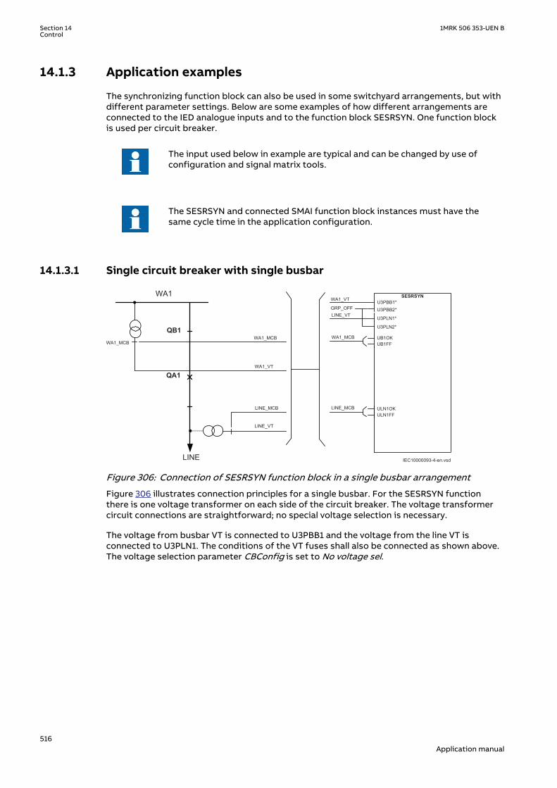
14.1.3 Application examplesM12323-3 v6
The synchronizing function block can also be used in some switchyard arrangements, but withdifferent parameter settings. Below are some examples of how different arrangements areconnected to the IED analogue inputs and to the function block SESRSYN. One function blockis used per circuit breaker.
The input used below in example are typical and can be changed by use ofconfiguration and signal matrix tools.
The SESRSYN and connected SMAI function block instances must have thesame cycle time in the application configuration.
14.1.3.1 Single circuit breaker with single busbarM12324-3 v11
WA1_MCB
LINE
WA1
QB1
QA1
IEC10000093-4-en.vsd
LINE_VT
LINE_MCB
WA1_MCB
SESRSYNU3PBB1*U3PBB2*
U3PLN1*
U3PLN2*
GRP_OFF
UB1OKUB1FF
ULN1OKULN1FF
WA1_VT
WA1_VT
LINE_VT
LINE_MCB
WA1_MCB
IEC10000093 V4 EN-US
Figure 306: Connection of SESRSYN function block in a single busbar arrangement
Figure 306 illustrates connection principles for a single busbar. For the SESRSYN functionthere is one voltage transformer on each side of the circuit breaker. The voltage transformercircuit connections are straightforward; no special voltage selection is necessary.
The voltage from busbar VT is connected to U3PBB1 and the voltage from the line VT isconnected to U3PLN1. The conditions of the VT fuses shall also be connected as shown above.The voltage selection parameter CBConfig is set to No voltage sel.
Section 14 1MRK 506 353-UEN BControl
516Application manual

14.1.3.2 Single circuit breaker with double busbar, external voltage selectionM12325-3 v8
WA1WA2
QB1
QB2
LINE
QA1
IEC10000094-4-en.vsd
WA2_MCBWA1_MCB
LINE_VT
LINE_MCB
SESRSYNU3PBB1*U3PBB2*
U3PLN1*
U3PLN2*
GRP_OFF
UB1OKUB1FF
ULN1OKULN1FF
WA1_VT/WA2_VT
LINE_VT
LINE_MCB
WA1_MCB/WA2_MCB
WA1_MCB / WA2_MCB
WA1_VT / WA2_VT
IEC10000094 V4 EN-US
Figure 307: Connection of SESRSYN function block in a single breaker, double busbararrangement with external voltage selection
In this type of arrangement no internal voltage selection is required. The voltage selection ismade by external relays typically connected according to figure 307. Suitable voltage and VTfuse failure supervision from the two busbars are selected based on the position of the busbardisconnectors. This means that the connections to the function block will be the same as forthe single busbar arrangement. The voltage selection parameter CBConfig is set to No voltagesel.
14.1.3.3 Single circuit breaker with double busbar, internal voltage selectionM12326-3 v7
WA1WA2
QB1
QB2
LINE
QA1
IEC10000095-6-en.vsd
WA1_MCB WA2_MCB
LINE_VT
LINE_MCB
WA1_MCB
WA1_VT
WA2_VT
QB2
QB1
GRP_OFF
SESRSYNU3PBB1*
U3PBB2*
U3PLN1*
U3PLN2*
B1QOPENB1QCLDB2QOPENB2QCLD
UB1OKUB1FFUB2OKUB2FFULN1OKULN1FF
WA1_VT
WA2_VT
LINE_VT
QB1
QB2
WA1_MCB
WA2_MCB
LINE_MCB
IEC10000095 V4 EN-US
Figure 308: Connection of the SESRSYN function block in a single breaker, double busbararrangement with internal voltage selection
When internal voltage selection is needed, the voltage transformer circuit connections aremade according to figure 308. The voltage from the busbar 1 VT is connected to U3PBB1 andthe voltage from busbar 2 is connected to U3PBB2. The voltage from the line VT is connectedto U3PLN1. The positions of the disconnectors and VT fuses shall be connected as shown infigure 308. The voltage selection parameter CBConfig is set to Double bus.
1MRK 506 353-UEN B Section 14Control
517Application manual

14.1.3.4 Double circuit breakerM12329-3 v7
WA1
WA2
WA1_QA1
WA2_QA1
LINE
WA1_MCBWA2_MCB
LINE_MCB
LINE_MCB
WA1_VT
WA1_QA1
GRP_OFF
SESRSYNU3PBB1*
U3PBB2*
U3PLN1*
U3PLN2*
WA1_VT
LINE_VT
UB1OKUB1FF
ULN1OKULN1FF
WA1_MCB
LINE_MCB
WA2_QA1
GRP_OFF
SESRSYNU3PBB1*
U3PBB2*
U3PLN1*
U3PLN2*
WA2_VT
LINE_VT
UB1OKUB1FF
ULN1OKULN1FF
WA2_MCB
LINE_MCB
WA2_MCB
WA1_MCB
WA2_VT
LINE_VT
IEC10000096-6-en.vsdIEC10000096 V4 EN-US
Figure 309: Connections of the SESRSYN function block in a double breaker arrangement
A double breaker arrangement requires two function blocks, one for breaker WA1_QA1 and onefor breaker WA2_QA1. No voltage selection is necessary, because the voltage from busbar 1 VTis connected to U3PBB1 on SESRSYN for WA1_QA1 and the voltage from busbar 2 VT isconnected to U3PBB1 on SESRSYN for WA2_QA1. The voltage from the line VT is connected toU3PLN1 on both function blocks. The condition of VT fuses shall also be connected as shown infigure 308. The voltage selection parameter CBConfig is set to No voltage sel. for bothfunction blocks.
14.1.3.5 1 1/2 circuit breakerM12330-3 v8
Figure 310 describes a 1 ½ breaker arrangement with three SESRSYN functions in the sameIED, each of them handling voltage selection for WA1_QA1, TIE_QA1 and WA2_QA1 breakersrespectively. The voltage from busbar 1 VT is connected to U3PBB1 on all three function blocksand the voltage from busbar 2 VT is connected to U3PBB2 on all three function blocks. Thevoltage from line1 VT is connected to U3PLN1 on all three function blocks and the voltage fromline2 VT is connected to U3PLN2 on all three function blocks. The positions of thedisconnectors and VT fuses shall be connected as shown in Figure 310.
Section 14 1MRK 506 353-UEN BControl
518Application manual

LINE1
QB2QB1
QB61 QB62
WA1
WA2
IEC10000097-4-en.vsd
Setting parameter CBConfig = 1 ½ bus CB
Setting parameter CBConfig = Tie CB
Setting parameter CBConfig = 1 ½ bus alt. CB
WA2_QA1
TIE_QA1
LINE1_QB9
WA1_QA1
WA1_VT
WA2_VT
LINE1_VT
LINE2_VT
TIE_QA1
WA2_QA1
LINE1_QB9
LINE2_QB9
WA1_MCB
WA2_MCB
LINE1_MCB
LINE2_MCB
SESRSYNU3PBB1*
B1 QOPENB1 QCLDB2 QOPENB2 QCLDLN1 QOPENLN1 QCLDLN2 QOPENLN2 QCLDUB1OKUB1FFUB2OKUB2FFULN1OKULN1FFULN2OKULN2FF
U3PLN2*
U3PLN1*
U3PBB2*
WA1_VT
WA2_VT
LINE1_VT
LINE2_VT
WA1_QA1
WA2_QA1
LINE1_QB9
LINE2_QB9
WA1_MCB
WA2_MCB
LINE1_MCB
LINE2_MCB
SESRSYNU3PBB1*
B1 QOPENB1 QCLDB2 QOPENB2 QCLDLN1 QOPENLN1 QCLDLN2 QOPENLN2 QCLDUB1OKUB1FFUB2OKUB2FFULN1OKULN1FFULN2OKULN2FF
U3PLN2*
U3PLN1*
U3PBB2*
WA1_VT
WA2_VT
LINE1_VT
LINE2_VT
WA1_QA1
TIE_QA1
LINE1_QB9
LINE2_QB9
WA1_MCB
WA2_MCB
LINE1_MCB
LINE2_MCB
SESRSYNU3PBB1*
B1 QOPENB1 QCLDB2 QOPENB2 QCLDLN1 QOPENLN1 QCLDLN2 QOPENLN2 QCLDUB1OKUB1FFUB2OKUB2FFULN1OKULN1FFULN2OKULN2FF
U3PLN2*
U3PLN1*
U3PBB2*
LINE1_MCB
TIE_QA1
LINE2
LINE2_MCB
LINE2_VT
LINE1_VT
LINE2_QB9
WA1_QA1
WA2_QA1
WA2_VT
WA2_MCB
WA1_MCB
WA1_VTWA1_QB6 WA2_QB6
LINE1_QB9
WA1_QA1
TIE_QA1
WA2_QA1
LINE2_QB9
IEC10000097 V4 EN-US
Figure 310: Connections of the SESRSYN function block in a 1 ½ breaker arrangement with internalvoltage selection
The connections are similar in all SESRSYN functions, apart from the breaker positionindications. The physical analog connections of voltages and the connection to the IED andSESRSYN function blocks must be carefully checked in PCM600. In all SESRSYN functions theconnections and configurations must abide by the following rules: Normally apparatusposition is connected with contacts showing both open (b-type) and closed positions (a-type).
1MRK 506 353-UEN B Section 14Control
519Application manual
WA1_QA1:
• B1QOPEN/CLD = Position of TIE_QA1 breaker and belonging disconnectors• B2QOPEN/CLD = Position of WA2_QA1 breaker and belonging disconnectors• LN1QOPEN/CLD = Position of LINE1_QB9 disconnector• LN2QOPEN/CLD = Position of LINE2_QB9 disconnector• UB1OK/FF = Supervision of WA1_MCB fuse• UB2OK/FF = Supervision of WA2_MCB fuse• ULN1OK/FF = Supervision of LINE1_MCB fuse• ULN2OK/FF = Supervision of LINE2_MCB fuse• Setting CBConfig = 1 1/2 bus CB
TIE_QA1:
• B1QOPEN/CLD = Position of WA1_QA1 breaker and belonging disconnectors• B2QOPEN/CLD = Position of WA2_QA1 breaker and belonging disconnectors• LN1QOPEN/CLD = Position of LINE1_QB9 disconnector• LN2QOPEN/CLD = Position of LINE2_QB9 disconnector• UB1OK/FF = Supervision of WA1_MCB fuse• UB2OK/FF = Supervision of WA2_MCB fuse• ULN1OK/FF = Supervision of LINE1_MCB fuse• ULN2OK/FF = Supervision of LINE2_MCB fuse• Setting CBConfig = Tie CB
WA2_QA1:
• B1QOPEN/CLD = Position of WA1_QA1 breaker and belonging disconnectors• B2QOPEN/CLD = Position of TIE_QA1 breaker and belonging disconnectors• LN1QOPEN/CLD = Position of LINE1_QB9 disconnector• LN2QOPEN/CLD = Position of LINE2_QB9 disconnector• UB1OK/FF = Supervision of WA1_MCB fuse• UB2OK/FF = Supervision of WA2_MCB fuse• ULN1OK/FF = Supervision of LINE1_MCB fuse• ULN2OK/FF = Supervision of LINE2_MCB fuse• Setting CBConfig = 1 1/2 bus alt. CB
If only two SESRSYN functions are provided in the same IED, the connections and settings areaccording to the SESRSYN functions for WA1_QA1 and TIE_QA1.
14.1.4 Setting guidelinesM12550-3 v13
The setting parameters for the Synchronizing, synchrocheck and energizing check functionSESRSYN are set via the local HMI (LHMI) or PCM600.
This setting guidelines describes the settings of the SESRSYN function via the LHMI.
Common base IED value for primary voltage ( UBase ) is set in a Global base value function,GBASVAL, found under Main menu//Configuration/Power system/GlobalBaseValue/GBASVAL_X/UBase. The SESRSYN function has one setting for the bus reference voltage(GblBaseSelBus) and one setting for the line reference voltage (GblBaseSelLine) whichindependently of each other can be set to select one of the twelve GBASVAL functions used forreference of base values. This means that the reference voltage of bus and line can be set todifferent values. The settings for the SESRSYN function are found under Main menu/Settings/IED Settings/Control/Synchronizing(25,SC/VC)/SESRSYN(25,SC/VC):X has beendivided into four different setting groups: General, Synchronizing, Synchrocheck andEnergizingcheck.
Section 14 1MRK 506 353-UEN BControl
520Application manual

General settings
Operation: The operation mode can be set On or Off. The setting Off disables the wholefunction.
GblBaseSelBus and GblBaseSelLine
These configuration settings are used for selecting one of twelve GBASVAL functions, whichthen is used as base value reference voltage, for bus and line respectively.
SelPhaseBus1 and SelPhaseBus2
Configuration parameters for selecting the measuring phase of the voltage for busbar 1 and 2respectively, which can be a single-phase (phase-neutral), two-phase (phase-phase) or apositive sequence voltage.
SelPhaseLine1 and SelPhaseLine2
Configuration parameters for selecting the measuring phase of the voltage for line 1 and 2respectively, which can be a single-phase (phase-neutral), two-phase (phase-phase) or apositive sequence voltage.
CBConfig
This configuration setting is used to define type of voltage selection. Type of voltage selectioncan be selected as:
• no voltage selection, No voltage sel.• single circuit breaker with double bus, Double bus• 1 1/2 circuit breaker arrangement with the breaker connected to busbar 1, 1 1/2 bus CB• 1 1/2 circuit breaker arrangement with the breaker connected to busbar 2, 1 1/2 bus alt. CB• 1 1/2 circuit breaker arrangement with the breaker connected to line 1 and 2, Tie CB
PhaseShift
This setting is used to compensate the phase shift between the measured bus voltage and linevoltage when:
• a. different phase-neutral voltages are selected (for example UL1 for bus and UL2 for line);• b. one available voltage is phase-phase and the other one is phase-neutral (for example
UL1L2 for bus and UL1 for line).
The set value is added to the measured line phase angle. The bus voltage is reference voltage.
Synchronizing settings
OperationSynch
The setting Off disables the Synchronizing function. With the setting On, the function is in theservice mode and the output signal depends on the input conditions.
UHighBusSynch and UHighLineSynch
The voltage level settings shall be chosen in relation to the bus/line network voltage. Thethreshold voltages UHighBusSynch and UHighLineSynch have to be set lower than the valuewhere the network is expected to be synchronized. A typical value is 80% of the rated voltage.
UDiffSynch
1MRK 506 353-UEN B Section 14Control
521Application manual

Setting of the voltage difference between the line voltage and the bus voltage. The differenceis set depending on the network configuration and expected voltages in the two networksrunning asynchronously. A normal setting is 0.10-0.15 p.u.
FreqDiffMin
The setting FreqDiffMin is the minimum frequency difference where the systems are definedto be asynchronous. For frequency differences lower than this value, the systems areconsidered to be in parallel. A typical value for FreqDiffMin is 10 mHz. Generally, the valueshould be low if both synchronizing and synchrocheck functions are provided, and it is betterto let the synchronizing function close, as it will close at exactly the right instance if thenetworks run with a frequency difference.
To avoid overlapping of the synchronizing function and the synchrocheckfunction the setting FreqDiffMin must be set to a higher value than usedsetting FreqDiffM, respective FreqDiffA used for synchrocheck.
FreqDiffMax
The setting FreqDiffMax is the maximum slip frequency at which synchronizing is accepted. 1/FreqDiffMax shows the time for the vector to move 360 degrees, one turn on thesynchronoscope, and is called Beat time. A typical value for FreqDiffMax is 200-250 mHz, whichgives beat times on 4-5 seconds. Higher values should be avoided as the two networksnormally are regulated to nominal frequency independent of each other, so the frequencydifference shall be small.
FreqRateChange
The maximum allowed rate of change for the frequency.
tBreaker
The tBreaker shall be set to match the closing time for the circuit breaker and should alsoinclude the possible auxiliary relays in the closing circuit. It is important to check that no slowlogic components are used in the configuration of the IED as there then can be big variationsin closing time due to those components. Typical setting is 80-150 ms depending on thebreaker closing time.
tClosePulse
The setting for the duration of the breaker close pulse.
tMaxSynch
The setting tMaxSynch is set to reset the operation of the synchronizing function if theoperation does not take place within this time. The setting must allow for the setting ofFreqDiffMin, which will decide how long it will take maximum to reach phase equality. At thesetting of 10 mHz, the beat time is 100 seconds and the setting would thus need to be at leasttMinSynch plus 100 seconds. If the network frequencies are expected to be outside the limitsfrom the start, a margin needs to be added. A typical setting is 600 seconds.
tMinSynch
The setting tMinSynch is set to limit the minimum time at which the synchronizing closingattempt is given. The synchronizing function will not give a closing command within this time,from when the synchronizing is started, even if a synchronizing condition is fulfilled. A typicalsetting is 200 ms.
Section 14 1MRK 506 353-UEN BControl
522Application manual

Synchrocheck settings
OperationSC
The OperationSC setting Off disables the synchrocheck function and sets the outputsAUTOSYOK, MANSYOK, TSTAUTSY and TSTMANSY to low. With the setting On, the function isin the service mode and the output signal depends on the input conditions.
UHighBusSC and UHighLineSC
The voltage level settings must be chosen in relation to the bus or line network voltage. Thethreshold voltages UHighBusSC and UHighLineSC have to be set lower than the value at whichthe breaker is expected to close with the synchronism check. A typical value can be 80% of thebase voltages.
UDiffSC
The setting for voltage difference between line and bus in p.u. This setting in p.u. is defined as(U-Bus/GblBaseSelBus) - (U-Line/GblBaseSelLine). A normal setting is 0,10-0,15 p.u.
FreqDiffM and FreqDiffA
The frequency difference level settings, FreqDiffM and FreqDiffA, shall be chosen dependingon the condition in the network. At steady conditions a low frequency difference setting isneeded, where the FreqDiffM setting is used. For autoreclosing a bigger frequency differencesetting is preferable, where the FreqDiffA setting is used. A typical value for FreqDiffM canbe10 mHz, and a typical value for FreqDiffA can be 100-200 mHz.
PhaseDiffM and PhaseDiffA
The phase angle difference level settings, PhaseDiffM and PhaseDiffA, shall also be chosendepending on conditions in the network. The phase angle setting must be chosen to allowclosing under maximum load condition. A typical maximum value in heavy-loaded networks canbe 45 degrees, whereas in most networks the maximum occurring angle is below 25 degrees.The PhaseDiffM setting is a limitation to PhaseDiffA setting. Fluctuations occurring at highspeed autoreclosing limit PhaseDiffA setting.
tSCM and tSCA
The purpose of the timer delay settings, tSCM and tSCA, is to ensure that the synchrocheckconditions remains constant and that the situation is not due to a temporary interference.Should the conditions not persist for the specified time, the delay timer is reset and theprocedure is restarted when the conditions are fulfilled again. Circuit breaker closing is thusnot permitted until the synchrocheck situation has remained constant throughout the setdelay setting time. Manual closing is normally under more stable conditions and a longeroperation time delay setting is needed, where the tSCM setting is used. During auto-reclosing,a shorter operation time delay setting is preferable, where the tSCA setting is used. A typicalvalue for tSCM can be 1 second and a typical value for tSCA can be 0.1 seconds.
Energizingcheck settings
AutoEnerg and ManEnerg
Two different settings can be used for automatic and manual closing of the circuit breaker.The settings for each of them are:
• Off, the energizing function is disabled.• DLLB, Dead Line Live Bus, the line voltage is below set value of ULowLineEnerg and the
bus voltage is above set value of UHighBusEnerg.• DBLL, Dead Bus Live Line, the bus voltage is below set value of ULowBusEnerg and the line
voltage is above set value of UHighLineEnerg.• Both, energizing can be done in both directions, DLLB or DBLL.
1MRK 506 353-UEN B Section 14Control
523Application manual

ManEnergDBDL
If the parameter is set to On, manual closing is also enabled when both line voltage and busvoltage are below ULowLineEnerg and ULowBusEnerg respectively, and ManEnerg is set toDLLB, DBLL or Both.
UHighBusEnerg and UHighLineEnerg
The voltage level settings must be chosen in relation to the bus or line network voltage. Thethreshold voltages UHighBusEnerg and UHighLineEnerg have to be set lower than the value atwhich the network is considered to be energized. A typical value can be 80% of the basevoltages.
ULowBusEnerg and ULowLineEnerg
The threshold voltages ULowBusEnerg and ULowLineEnerg, have to be set to a value greaterthan the value where the network is considered not to be energized. A typical value can be 40%of the base voltages.
A disconnected line can have a considerable potential due to, for instance,induction from a line running in parallel, or by being fed via the extinguishingcapacitors in the circuit breakers. This voltage can be as high as 30% or moreof the base line voltage.
Because the setting ranges of the threshold voltages UHighBusEnerg/UHighLineEnerg andULowBusEnerg/ULowLineEnerg partly overlap each other, the setting conditions may be suchthat the setting of the non-energized threshold value is higher than that of the energizedthreshold value. The parameters must therefore be set carefully to avoid overlapping.
UMaxEnerg
This setting is used to block the closing when the voltage on the live side is above the set valueof UMaxEnerg.
tAutoEnerg and tManEnerg
The purpose of the timer delay settings, tAutoEnerg and tManEnerg, is to ensure that the deadside remains de-energized and that the condition is not due to a temporary interference.Should the conditions not persist for the specified time, the delay timer is reset and theprocedure is restarted when the conditions are fulfilled again. Circuit breaker closing is thusnot permitted until the energizing condition has remained constant throughout the set delaysetting time.
14.2 Autorecloser for 1 phase, 2 phase and/or 3 phaseoperation SMBRREC
IP14559-1 v6
14.2.1 IdentificationM14890-1 v6
Function Description IEC 61850identification
IEC 60617identification
ANSI/IEEE C37.2device number
Autorecloser for 1 phase, 2 phase and/or 3phase
SMBRREC
O->I
SYMBOL-L V1 EN-US
79
Section 14 1MRK 506 353-UEN BControl
524Application manual

14.2.2 ApplicationM12391-3 v7
Automatic reclosing is a well-established method for the restoration of service in a powersystem after a transient line fault. The majority of line faults are flashover arcs, which aretransient by nature. When the power line is switched off by the operation of line protectionand line breakers, the arc de-ionizes and recovers its ability to withstand voltage at asomewhat variable rate. Thus, a certain dead time with a de-energized line is necessary. Lineservice can then be resumed by automatic reclosing of the line breakers. The dead timeselected should be long enough to ensure a high probability of arc de-ionization andsuccessful reclosing.
For individual line breakers, auto-reclosing equipment, the auto-reclosing open time is used todetermine line “dead time”. When simultaneous tripping and reclosing at the two line endsoccurs, auto-reclosing open time is approximately equal to the line “dead time”. If the opentime and dead time differ then, the line will be energized until the breakers at both ends haveopened.
Open
Closed
Operate time
Lineprotection
Circuitbreaker
Break time
Trip
com
man
d
Con
tact
s se
para
ted
Are
extin
guis
hers
Fault duration AR open time for breaker Fault duration
Res
ets
Inst
ant o
f fau
lt
Ope
rate
s
Break timeClosing time
Operate time
Faul
t
Ope
rate
s
Res
ets
Clo
se c
omm
and
Con
tact
clo
sed
Set AR open time Reclaim timeAuto-reclosing
function
Star
t AR
Rec
losi
ngco
mm
and
AR re
set
IEC04000146.vsdIEC04000146 V2 EN-US
Figure 311: Single-shot automatic reclosing at a permanent fault
Single-phase tripping and single-phase automatic reclosing is a way of limiting the effect of asingle-phase line fault on power system operation. Especially at higher voltage levels, themajority of faults are of single-phase type (around 90%). To maintain system stability in powersystems with limited meshing or parallel routing single phase auto reclosing is of particularvalue. During the single phase dead time the system is still capable of transmitting load on thetwo healthy phases and the system is still synchronized. It requires that each phase breakeroperates individually, which is usually the case for higher transmission voltages.
A somewhat longer dead time may be required for single-phase reclosing compared to high-speed three-phase reclosing. This is due to the influence on the fault arc from the voltage andthe current in the non-tripped phases.
1MRK 506 353-UEN B Section 14Control
525Application manual

To maximize the availability of the power system it is possible to choose single pole trippingand automatic reclosing during single-phase faults and three pole tripping and automaticreclosing during multi-phase faults. Three-phase automatic reclosing can be performed withor without the use of a synchronicity check, and an energizing check, such as dead line or deadbusbar check.
During the single-pole open time there is an equivalent "series"-fault in the system resulting ina flow of zero sequence current. It is therefore necessary to coordinate the residual currentprotections (earth fault protection) with the single pole tripping and the auto-reclosingfunction. Attention shall also be paid to "pole discordance" that arises when circuit breakersare provided with single pole operating devices. These breakers need pole discordanceprotection. They must also be coordinated with the single pole auto-recloser and blockedduring the dead time when a normal discordance occurs. Alternatively, they should use a triptime longer than the set single phase dead time.
For the individual line breakers and auto-reclosing equipment, the ”auto-reclosing open time”expression is used. This is the dead time setting for the Auto-Recloser. During simultaneoustripping and reclosing at the two line ends, auto-reclosing open time is approximately equal tothe line dead time. Otherwise these two times may differ as one line end might have a slowertrip than the other end which means that the line will not be dead until both ends have opened.
If the fault is permanent, the line protection will trip again when reclosing is attempted inorder to clear the fault.
It is common to use one automatic reclosing function per line circuit-breaker (CB). When oneCB per line end is used, then there is one auto-reclosing function per line end. If auto-reclosingfunctions are included in duplicated line protection, which means two auto-reclosing functionsper CB, one should take measures to avoid uncoordinated reclosing commands. In 1 1/2breaker, double-breaker and ring bus arrangements, two CBs per line end are operated. Oneauto-reclosing function per CB is recommended. Arranged in such a way, sequential reclosingof the two CBs can be arranged with a priority circuit available in the auto-reclose function. Incase of a permanent fault and unsuccessful reclosing of the first CB, reclosing of the secondCB is cancelled and thus the stress on the power system is limited. Another advantage with thebreaker connected auto-recloser is that checking that the breaker closed before the sequence,breaker prepared for an auto-reclose sequence and so on. is much simpler.
The auto-reclosing function can be selected to perform single-phase and/or three-phaseautomatic-reclosing from several single-shot to multiple-shot reclosing programs. The three-phase auto-reclosing open time can be set to give either High-Speed Automatic Reclosing(HSAR) or Delayed Automatic-Reclosing (DAR). These expressions, HSAR and DAR, are mostlyused for three-phase Reclosing as single phase is always high speed to avoid maintaining theunsymmetrical condition. HSAR usually means a dead time of less than 1 second.
In power transmission systems it is common practise to apply single and/or three phase,single-shot Auto-Reclosing. In Sub-transmission and Distribution systems tripping and auto-reclosing are usually three-phase. The mode of automatic-reclosing varies however. Single-shot and multi-shot are in use. The first shot can have a short delay, HSAR, or a longer delay,DAR. The second and following reclosing shots have a rather long delay. When multiple shotsare used the dead time must harmonize with the breaker duty-cycle capacity.
Automatic-reclosing is usually started by the line protection and in particular by instantaneoustripping of such protection. The auto-reclosing function can be inhibited (blocked) whencertain protection functions detecting permanent faults, such as shunt reactor, cable orbusbar protection are in operation. Back-up protection zones indicating faults outside the ownline are also connected to inhibit the Auto-Reclose.
Automatic-reclosing should not be attempted when closing a CB and energizing a line onto afault (SOTF), except when multiple-shots are used where shots 2 etc. will be started at SOTF.Likewise a CB in a multi-breaker busbar arrangement which was not closed when a faultoccurred should not be closed by operation of the Auto-Reclosing function. Auto-Reclosing isoften combined with a release condition from synchrocheck and dead line or dead busbar
Section 14 1MRK 506 353-UEN BControl
526Application manual

check. In order to limit the stress on turbo-generator sets from Auto-Reclosing onto apermanent fault, one can arrange to combine Auto-Reclosing with a synchrocheck on lineterminals close to such power stations and attempt energizing from the side furthest awayfrom the power station and perform the synchrocheck at the local end if the energizing wassuccessful.
Transmission protection systems are usually sub-divided and provided with two redundantprotection IEDs. In such systems it is common to provide auto-reclosing in only one of the sub-systems as the requirement is for fault clearance and a failure to reclose because of the auto-recloser being out of service is not considered a major disturbance. If two auto-reclosers areprovided on the same breaker, the application must be carefully checked and normally onemust be the master and be connected to inhibit the other auto-recloser if it has started. Thisinhibit can for example be done from Autorecloser for 3-phase operation(SMBRREC) Inprogress.
When Single and/or three phase auto-reclosing is considered, there are a number of caseswhere the tripping shall be three phase anyway. For example:
• Evolving fault where the fault during the dead-time spreads to another phase. The othertwo phases must then be tripped and a three phase dead-time and auto-reclose initiated
• Permanent fault• Fault during three phase dead-time• Auto-reclose out of service or CB not ready for an auto-reclosing cycle
“Prepare three-phase tripping” is then used to switch the tripping to three-phase. This signalis generated by the auto-recloser and connected to the trip function block and also connectedoutside the IED through IO when a common auto-recloser is provided for two sub-systems. Analternative signal “Prepare 1 Phase tripping” is also provided and can be used as an alternativewhen the autorecloser is shared with another subsystem. This provides a fail safe connectionso that even a failure in the IED with the auto-recloser will mean that the other sub-system willstart a three-phase trip.
A permanent fault will cause the line protection to trip again when it recloses in an attempt toenergize the line.
The auto-reclosing function allows a number of parameters to be adjusted.
Examples:
• number of auto-reclosing shots• auto-reclosing program• auto-reclosing open times (dead time) for each shot
14.2.2.1 Auto-reclosing operation OFF and ONM12391-91 v5
Operation of the automatic reclosing can be set OFF and ON by a setting parameter and byexternal control. Parameter Operation= Off, or On sets the function OFF and ON. With thesettings Operation = On and ExternalCtrl = On , the control is made by input signal pulses tothe inputs ON and OFF, for example, from the control system or from the binary input (andother systems).
When the function is set ON, the output SETON is set, and it become operative if otherconditions such as CB closed and CB Ready are also fulfilled, the output READY is activated(high). When the function is ready to accept a reclosing start.
1MRK 506 353-UEN B Section 14Control
527Application manual

14.2.2.2 Start auto-reclosing and conditions for start of a reclosing cycleM12391-94 v4
The usual way to start a reclosing cycle, or sequence, is to start it at selective tripping by lineprotection by applying a signal to the input START. Starting signals can be either, General Tripsignals or, only the conditions for Differential, Distance protection Zone 1 and Distanceprotection Aided trip. In some cases also Directional Earth fault function Aided trip can beconnected to start an Auto-Reclose attempt. If general trip is used to start the auto- recloser itis important to block it from other functions that should not start a reclosing sequence.
In cases where one wants to differentiate three-phase “auto-reclosing open time”, (“deadtime”) for different power system configuration or at tripping by different protection stages,one can also use the input STARTHS (Start High-Speed Reclosing). When initiating STARTHS,the auto-reclosing open time for three-phase shot 1, t1 3PhHS is used and the closing is donewithout checking the synchrocheck condition.
A number of conditions need to be fulfilled for the start to be accepted and a new auto-reclosing cycle to be started. They are linked to dedicated inputs. The inputs are:
• CBREADY, CB ready for a reclosing cycle, for example, charged operating gear.• CBPOS to ensure that the CB was closed when the line fault occurred and start was
applied.• No signal at input INHIBIT that is, no blocking or inhibit signal present. After the start has
been accepted, it is latched in and an internal signal “Started” is set. It can be interruptedby certain events, like an “Inhibit” signal.
14.2.2.3 Start auto-reclosing from CB open informationM12391-100 v5
If a user wants to initiate auto-reclosing from the "CB open" position instead of fromprotection trip signals, the function offers such a possibility. This starting mode is selectedwith the setting parameter StartByCBOpen=On. It is then necessary to block reclosing for allmanual trip operations. Typically CBAuxContType=NormClosed is also set and a CB auxiliarycontact of type NC (normally closed) is connected to inputs CBPOS and START. When thesignal changes from “CB closed” to “CB open” an auto-reclosing start pulse is generated andlatched in the function, subject to the usual checks. Then the reclosing sequence continues asusual. One needs to connect signals from manual tripping and other functions, which shall notbe reclosed automatically to the input INHIBIT.
14.2.2.4 Blocking of the autorecloserM12391-103 v3
Auto-Reclose attempts are expected to take place only for faults on the own line. The Auto-Recloser must be blocked by activating the INHIBIT input for the following conditions:
• Tripping from Delayed Distance protection zones• Tripping from Back-up protection functions• Tripping from Breaker failure function• Intertrip received from remote end Breaker failure function• Busbar protection tripping
Depending of the starting principle (General Trip or only Instantaneous trip) adopted abovethe delayed and back-up zones might not be required. Breaker failure trip local and remotemust however always be connected.
14.2.2.5 Control of the auto-reclosing open time for shot 1M12391-113 v4
Up to four different time settings can be used for the first shot, and one extension time. Thereare separate settings for single-, two- and three-phase auto-reclosing open time, t1 1Ph, t12Ph, t1 3Ph. If no particular input signal is applied, and an auto-reclosing program with single-
Section 14 1MRK 506 353-UEN BControl
528Application manual

phase reclosing is selected, the auto-reclosing open time t1 1Ph will be used. If one of theinputs TR2P or TR3P is activated in connection with the start, the auto-reclosing open time fortwo-phase or three-phase reclosing is used. There is also a separate time setting facility forthree-phase high-speed auto-reclosing without Synchrocheck, t1 3PhHS, available for use whenrequired. It is activated by the STARTHS input.
An auto-reclosing open time extension delay, tExtended t1, can be added to the normal shot 1delay. It is intended to come into use if the communication channel for permissive lineprotection is lost. In such a case there can be a significant time difference in fault clearance atthe two ends of the line. A longer “auto-reclosing open time” can then be useful. This extensiontime is controlled by setting parameter Extended t1=On and the input PLCLOST. If thisfunction is used the autorecloser start must also be allowed from distance protection Zone 2time delayed trip.
14.2.2.6 Long trip signalM12391-117 v3
In normal circumstances the trip command resets quickly because of fault clearance. The usercan set a maximum trip pulse duration tTrip.If Extended t1=Off, a long trip signal interruptsthe reclosing sequence in the same way as a signal to input INHIBIT. If Extend t1=On the longtrip time inhibit is disabled and Extend t1 is used instead.
14.2.2.7 Maximum number of reclosing shotsM12391-120 v6
The maximum number of reclosing shots in an auto-reclosing cycle is selected by the settingparameter NoOfShots. The type of reclosing used at the first reclosing shot is set byparameter ARMode. The first alternative is three-phase reclosing. The other alternativesinclude some single-phase or two-phase reclosing. Usually there is no two-phase trippingarranged, and then there will be no two-phase reclosing.
The decision for single and 3 phase trip is also made in the tripping logic (SMPTTRC) functionblock where the setting 3Ph, 1/3Ph (or1/2/3Ph) is selected.
14.2.2.8 ARMode=3ph, (normal setting for a single 3 phase shot)M12391-124 v4
3-phase reclosing, one to five shots according to setting NoOfShots. The output Preparethree-phase trip PREP3P is always set (high). A trip operation is made as a three-phase trip atall types of fault. The reclosing is as a three-phase Reclosing as in mode 1/2/3ph describedbelow. All signals, blockings, inhibits, timers, requirements and so on. are the same as in theexample described below.
14.2.2.9 ARMode=1/2/3phM12391-127 v7
1-phase, 2-phase or 3-phase reclosing first shot, followed by 3-phase reclosing shots, ifselected. Here, the auto-reclosing function is assumed to be "On" and "Ready". The breaker isclosed and the operation gear ready (operating energy stored). Input START (or STARTHS) isreceived and sealed-in. The output READY is reset (set to false). Output ACTIVE is set.
• If inputs TR2P is low and TR3P is low (1-phase trip): The timer for 1-phase reclosing opentime is started and the output 1PT1 (1-phase reclosing in progress) is activated. It can beused to suppress pole disagreement and earth-fault protection trip during the 1-phaseopen interval.
• If TR2P is high and TR3P is low (2-phase trip): The timer for 2-phase reclosing open time isstarted and the output 2PT1 (2-phase reclosing in progress) is activated.
• If TR3P is high (3-phase trip): The timer for 3-phase auto-reclosing open time, t1 3Ph isstarted and output 3PT1 (3-phase auto-reclosing shot 1 in progress) is set.
• If STARTHS is high (3-phase trip): The timer for 3-phase auto-reclosing open time, t13PhHS is started and output 3PT1 (3-phase auto-reclosing shot 1 in progress) is set.
1MRK 506 353-UEN B Section 14Control
529Application manual

While any of the auto-reclosing open time timers are running, the output INPROGR is activated.When the "open time" timer runs out, the respective internal signal is transmitted to theoutput module for further checks and to issue a closing command to the circuit breaker.
When a CB closing command is issued the output prepare 3-phase trip is set. When issuing aCB closing command a “reclaim” timer tReclaim is started. If no tripping takes place duringthat time the auto-reclosing function resets to the “Ready” state and the signal ACTIVE resets.If the first reclosing shot fails, a 3-phase trip will be initiated and 3-phase reclosing can follow,if selected.
14.2.2.10 ARMode=1/2ph, 1-phase or 2-phase reclosing in the first shot.M12391-136 v4
In 1-phase or 2-phase tripping, the operation is as in the above described example, programmode 1/2/3ph. If the first reclosing shot fails, a 3-phase trip will be issued and 3-phasereclosing can follow, if selected. In the event of a 3-phase trip, TR3P high, the auto-reclosingwill be blocked and no reclosing takes place.
14.2.2.11 ARMode=1ph + 1*2ph, 1-phase or 2-phase reclosing in the first shotM12391-139 v4
The 1-phase reclosing attempt can be followed by 3-phase reclosing, if selected. A failure of a2-phase reclosing attempt will block the auto-reclosing. If the first trip is a 3-phase trip theauto-reclosing will be blocked. In the event of a 1-phase trip, (TR2P low and TR3P low), theoperation is as in the example described above, program mode 1/2/3ph. If the first reclosingshot fails, a 3-phase trip will be initiated and 3-phase reclosing can follow, if selected. Amaximum of four additional shots can be done (according to the NoOfShots parameter). At 2-phase trip (TR2P high and TR3P low), the operation is similar to the above. But, if the firstreclosing shot fails, a 3-phase trip will be issued and the auto-reclosing will be blocked. Nomore shots are attempted! The expression 1*2ph should be understood as “Just one shot at 2-phase reclosing” During 3-phase trip (TR2P low and TR3P high) the auto-reclosing will beblocked and no reclosing takes place.
14.2.2.12 ARMode=1/2ph + 1*3ph, 1-phase, 2-phase or 3-phase reclosing in the firstshot
GUID-9C2FB801-F324-465E-8FD2-715A9C3D0BD8 v1
At 1-phase or 2-phase trip, the operation is as described above. If the first reclosing shot fails,a 3-phase trip will be issued and 3-phase reclosing will follow, if selected. At 3-phase trip, theoperation is similar to the above. But, if the first reclosing shot fails, a 3-phase trip commandwill be issued and the auto-reclosing will be blocked. No more shots take place! 1*3ph shouldbe understood as “Just one shot at 3-phase reclosing”.
14.2.2.13 ARMode=1ph + 1*2/3ph, 1-phase, 2-phase or 3-phase reclosing in the firstshot
M12391-146 v4
At 1-phase trip, the operation is as described above. If the first reclosing shot fails, a 3-phasetrip will be issued and 3-phase reclosing will follow, if selected. At 2-phase or 3-phase trip, theoperation is similar as above. But, if the first reclosing shot fails, a 3-phase trip will be issuedand the auto-reclosing will be blocked. No more shots take place! “1*2/3ph” should beunderstood as “Just one shot at 2-phase or 3-phase reclosing”.
Table 46: Type of reclosing shots at different settings of ARMode or integer inputs to MODEINT
MODEINT (integer) ARMode Type of fault 1st shot 2nd-5th shot
1 3ph
1ph 3ph 3ph
2ph 3ph 3ph
3ph 3ph 3ph
Table continues on next page
Section 14 1MRK 506 353-UEN BControl
530Application manual

MODEINT (integer) ARMode Type of fault 1st shot 2nd-5th shot
2 1/2/3ph
1ph 1ph 3ph
2ph 2ph 3ph
3ph 3ph 3ph
3 1/2ph
1ph 1ph 3ph
2ph 2ph 3ph
3ph ..... .....
4 1ph + 1*2ph
1ph 1ph 3ph
2ph 2ph .....
3ph ..... .....
5 1/2ph + 1*3ph
1ph 1ph 3ph
2ph 2ph 3ph
3ph 3ph .....
6 1ph + 1*2/3ph
1ph 1ph 3ph
2ph 2ph .....
3ph 3ph .....
A start of a new reclosing cycle is blocked during the set “reclaim time” after the selectednumber of reclosing shots have been made.
14.2.2.14 External selection of auto-reclose modeM12391-241 v3
The auto-reclose mode can be selected by use of the available logic function blocks. Below isan example where the choice of mode is done from a hardware function key in front of the IEDwith only 3 phase or 1/3 phase mode, but alternatively there can for example, be a physicalselector switch on the front of the panel which is connected to a binary to integer functionblock (BTIGAPC).
The connection example for selection of the auto-reclose mode is shown in Figure.
IEC14000040-1-en.vsdIEC07000119 V3 EN-US
Figure 312: Selection of the auto-reclose mode from a hardware functional key in front ofthe IED
14.2.2.15 Reclosing reclaim timerM12391-202 v3
The reclaim timer tReclaim defines the time it takes from issue of the reclosing command,until the reclosing function resets. Should a new trip occur during this time, it is treated as acontinuation of the first fault. The reclaim timer is started when the CB closing command isgiven.
1MRK 506 353-UEN B Section 14Control
531Application manual

14.2.2.16 Pulsing of the CB closing command and CounterM12391-205 v3
The CB closing command, CLOSECB is given as a pulse with a duration set by parametertPulse. For circuit-breakers without an anti-pumping function, close pulse cutting can be used.It is selected by parameter CutPulse=On. In case of a new trip pulse (start), the closingcommand pulse is then cut (interrupted). The minimum closing pulse length is always 50 ms.At the issue of the Reclosing command, the appropriate Reclosing operation counter isincremented. There is a counter for each type of Reclosing and one for the total number ofReclosing commands.
14.2.2.17 Transient faultM12391-208 v3
After the Reclosing command the reclaim timer keeps running for the set time. If no trippingoccurs within this time, tReclaim, the Auto-Reclosing will reset. The CB remains closed and theoperating gear recharges. The input signals CBPOS and CBREADY will be set
14.2.2.18 Permanent fault and reclosing unsuccessful signalM12391-211 v4
If a new trip occurs, and number of reclosing shots is set to 1, a new input signal START orTRSOTF appears, after the CB closing command, the output UNSUCCL (unsuccessful closing)is set high. The timer for the first shot can no longer be started. Depending on the set numberof Reclosing shots further shots may be made or the Reclosing sequence is ended. Afterreclaim timer time-out the Auto-Reclosing function resets, but the CB remains open. The “CBclosed” information through the input CBPOS is missing. Thus, the reclosing function is notready for a new reclosing cycle.
Normally, the signal UNSUCCL appears when a new trip and start is received after the lastreclosing shot has been made and the auto-reclosing function is blocked. The signal resetsafter reclaim time. The “unsuccessful” signal can also be made to depend on CB position input.The parameter UnsucClByCBChk should then be set to CBCheck, and a timer tUnsucCl shouldbe set too. If the CB does not respond to the closing command and does not close, butremains open, the output UNSUCCL is set high after time tUnsucCl. The Unsuccessful outputcan for example, be used in Multi-Breaker arrangement to cancel the auto-reclosing functionfor the second breaker, if the first breaker closed onto a persistent fault. It can also be used togenerate a Lock-out of manual closing until the operator has reset the Lock-out, see separatesection.
14.2.2.19 Lock-out initiationM12391-214 v7
In many cases there is a requirement that a Lock-out is generated when the auto-reclosingattempt fails. This is done with logic connected to the in- and outputs of the Autoreclosefunction and connected to Binary IO as required. Many alternative ways of performing the logicexist depending on whether manual closing is interlocked in the IED, whether an externalphysical Lock-out relay exists and whether the reset is hardwired, or carried out by means ofcommunication. There are also different alternatives regarding what shall generate Lock-out.Examples of questions are:
• Shall back-up time delayed trip give Lock-out (normally yes)• Shall Lock-out be generated when closing onto a fault (mostly)• Shall Lock-out be generated when the Autorecloser was OFF at the fault or for example, in
Single phase AR mode and the fault was multi-phase (normally not as no closing attempthas been given)
• Shall Lock-out be generated if the Breaker did not have sufficient operating power for anauto-reclosing sequence (normally not as no closing attempt has been given)
Section 14 1MRK 506 353-UEN BControl
532Application manual

In figures 313 and 314 the logic shows how a closing Lock-out logic can be designed with theLock-out relay as an external relay alternatively with the Lock-out created internally with themanual closing going through the Synchro-check function. An example of Lock-out logic.
Lock-out RXMD1
11
1221
MAIN ZAK CLOSE CLOSE COMMAND
SMBO
OR
SMBRREC
OR
CCRBRF
BU-TRIP
ZCVPSOF-TRIP INHIBIT
UNSUCCL
TRBU
IEC05000315-4-en.vsdIEC05000315-WMF V4 EN-US
Figure 313: Lock-out arranged with an external Lock-out relay
CLOSE COMMAND
OR
SMBRREC
OR
CCRBRF
BU-TRIP
ZCVPSOF-TRIP INHIBIT
UNSUCCL
TRBU
SMPPTRC
AND
RESET LOCK-OUT
OR
OR
SESRSYN
Functional key, SOFTWARE
OR IO RESET
MANSYOK
MAN CLOSE
SMBRREC CLOSE
CLLKOUT
RSTLOUT
SETLKOUT
IEC05000316-3-en.vsd
SMBO
MANENOK
IEC05000316-WMF V3 EN-US
Figure 314: Lock-out arranged with internal logic with manual closing going through inIED
14.2.2.20 Evolving faultM12391-217 v3
An evolving fault starts as a single-phase fault which leads to single-phase tripping and thenthe fault spreads to another phase. The second fault is then cleared by three-phase tripping.
The Auto-Reclosing function will first receive a trip and start signal (START) without any three-phase signal (TR3P). The Auto-Reclosing function will start a single-phase reclosing, ifprogrammed to do so. At the evolving fault clearance there will be a new signal START andthree-phase trip information, TR3P. The single-phase reclosing sequence will then be stopped,and instead the timer, t1 3Ph, for three-phase reclosing will be started from zero. The sequencewill continue as a three-phase reclosing sequence, if it is a selected alternative reclosing mode.
The second fault which can be single phase is tripped three phase because trip module (TR) inthe IED has an evolving fault timer which ensures that second fault is always tripped threephase. For other types of relays where the relays do not include this function the outputPREP3PH (or the inverted PERMIT1PH) is used to prepare the other sub-system for three phase
1MRK 506 353-UEN B Section 14Control
533Application manual

tripping. This signal will, for evolving fault situations be activated a short time after the firsttrip has reset and will thus ensure that new trips will be three phase.
14.2.2.21 Automatic continuation of the reclosing sequenceM12391-223 v4
SMBRREC function can be programmed to proceed to the following reclosing shots (if multipleshots are selected) even if start signals are not received from the protection functions, but thebreaker is still not closed. This is done by setting parameter AutoCont = On andtAutoContWait to the required delay for the function to proceed without a new start.
14.2.2.22 Thermal overload protection holding the auto-reclosing function backM12391-226 v2
If the input THOLHOLD (thermal overload protection holding reclosing back) is activated, it willkeep the reclosing function on a hold until it is reset. There may thus be a considerable delaybetween start of Auto-Reclosing and reclosing command to the circuit-breaker. An externallogic limiting the time and sending an inhibit to the INHIBIT input can be used. The input canalso be used to set the Auto-Reclosing on hold for a longer or shorter period.
14.2.3 Setting guidelinesIP14929-1 v1
14.2.3.1 ConfigurationM12399-3 v2
Use the PCM600 configuration tool to configure signals.
Autorecloser function parameters are set via the local HMI or Parameter Setting Tool (PST).Parameter Setting Tool is a part of PCM600.
Recommendations for input signalsM12399-7 v8
Please see figure 315, figure 316 and figure 317 and default factory configuration for examples.
ON and OFF
These inputs can be connected to binary inputs or to a communication interface block forexternal control.
START
It should be connected to the trip output protection function, which starts the autorecloser for1/2/3-phase operation (SMBRREC) function. It can also be connected to a binary input for startfrom an external contact. A logical OR-gate can be used to combine the number of startsources.
If StartByCBOpen is used, the CB Open condition shall also be connected to theinput START.
STARTHS, Start High-speed auto-reclosing
It may be used when one wants to use two different dead times in different protection tripoperations. This input starts the dead time t1 3PhHS. High-speed reclosing shot 1 started bythis input is without a synchronization check.
INHIBIT
To this input shall be connected signals that interrupt a reclosing cycle or prevent a start frombeing accepted. Such signals can come from protection for a line connected shunt reactor,from transfer trip receive, from back-up protection functions, busbar protection trip or from
Section 14 1MRK 506 353-UEN BControl
534Application manual

breaker failure protection. When the CB open position is set to start SMBRREC, then manualopening must also be connected here. The inhibit is often a combination of signals fromexternal IEDs via the IO and internal functions. An OR gate is then used for the combination.
CBPOS and CBREADY
These should be connected to binary inputs to pick-up information from the CB. The CBPOSinput is interpreted as CB Closed, if parameter CBAuxContType is set NormOpen, which is thedefault setting. At three operating gears in the breaker (single pole operated breakers) theconnection should be “All poles closed” (series connection of the NO contacts) or “At least onepole open” (parallel connection of NC contacts) if the CBAuxContType is set to NormClosed.The “CB Ready” is a signal meaning that the CB is ready for a reclosing operation, either Close-Open (CO), or Open-Close-Open (OCO). If the available signal is of type “CB not charged” or“not ready”, an inverter can be inserted in front of the CBREADY input.
SYNC
This is connected to the internal synchrocheck function when required. It can also beconnected to a binary input for synchronization from an external device. If neither internal norexternal synchronism or energizing check is required, it can be connected to a permanentlyhigh source, TRUE. The signal is required for three phase shots 1-5 to proceed (Note! Not theHS step).
PLCLOST
This is intended for line protection permissive signal channel lost (fail) for example, PLC=Power Line Carrier fail. It can be connected, when required to prolong the AutoReclosing timewhen communication is not working, that is, one line end might trip with a zone 2 delay. If thisis used the autorecloser must also be started from Zone2 time delayed trip.
TRSOTF
This is the signal “Trip by Switch Onto Fault”. It is usually connected to the “switch onto fault”output of line protection if multi-shot Auto-Reclose attempts are used. The input will start theshots 2-5.
THOLHOLD
Signal “Thermal overload protection holding back Auto-Reclosing”. It can be connected to athermal overload protection trip signal which resets only when the thermal content has fallento an acceptable level, for example, 70%. As long as the signal is high, indicating that the line ishot, the Auto-Reclosing is held back. When the signal resets, a reclosing cycle will continue.Please observe that this have a considerable delay. Input can also be used for other purposes iffor some reason the Auto-Reclose shot need to be halted.
TR2P and TR3P
Signals for two-phase and three-phase trip. They are usually connected to the correspondingoutput of the TRIP block. They control the choice of dead time and the reclosing cycleaccording to the selected program. Signal TR2P needs to be connected only if the trip has beenselected to give 1/2/3 phase trip and an auto reclosing cycle with two phase reclosing isforeseen.
WAIT
Used to hold back reclosing of the “low priority unit” during sequential reclosing. See“Recommendation for multi-breaker arrangement” below. The signal is activated from outputWFMASTER on the second breaker Auto-Recloser in multi-breaker arrangements.
1MRK 506 353-UEN B Section 14Control
535Application manual

BLKON
Used to block the autorecloser for 3-phase operation (SMBRREC) function for example, whencertain special service conditions arise. When used, blocking must be reset with BLOCKOFF.
BLOCKOFF
Used to Unblock SMBRREC function when it has gone to Block due to activating input BLKONor by an unsuccessful Auto-Reclose attempt if the settingBlockByUnsucCl is set to On.
RESET
Used to Reset SMBRREC to start condition. Possible Thermal overload Hold will be reset.Positions, setting On-Off. will be started and checked with set times.
Recommendations for output signalsM12399-46 v7
Please see figure 315, figure 316 and figure 317 and default factory configuration for examples.
SETON
Indicates that Autorecloser for 1/2/3-phase operation (SMBRREC) function is switched on andoperative.
BLOCKED
Indicates that SMRREC function is temporarily or permanently blocked.
ACTIVE
Indicates that SMBRREC is active, from start until end of Reclaim time.
INPROGR
Indicates that a sequence is in progress, from start until reclosing command.
UNSUCCL
Indicates unsuccessful reclosing.
CLOSECB
Connect to a binary output for circuit-breaker closing command.
READY
Indicates that SMBRREC function is ready for a new and complete reclosing sequence. It can beconnected to the zone extension if a line protection should extended zone reach beforeautomatic reclosing.
1PT1 and 2PT1
Indicates that single-phase or two-phase automatic reclosing is in progress. It is used totemporarily block an earth-fault and/or pole disagreement function during the single-phase ortwo-phase open interval.
3PT1, 3PT2, 3PT3, 3PT4 and 3PT5
Indicates that three-phase automatic reclosing shots 1-5 are in progress. The signals can beused as an indication of progress or for own logic.
Section 14 1MRK 506 353-UEN BControl
536Application manual

PREP3P
Prepare three-phase trip is usually connected to the trip block to force a coming trip to be athree-phase one. If the function cannot make a single-phase or two-phase reclosing, thetripping should be three-phase.
PERMIT1P
Permit single-phase trip is the inverse of PREP3P. It can be connected to a binary output relayfor connection to external protection or trip relays. In case of a total loss of auxiliary power,the output relay drops and does not allow single-phase trip.
WFMASTER
Wait from master is used in high priority units to hold back reclosing of the low priority unitduring sequential reclosing. Refer to the recommendation for multi-breaker arrangements infigure 317.
Other outputs
The other outputs can be connected for indication, disturbance recording, as required.
ON
OFF
BLKON
BLOCKOFF
INHIBIT
BLOCKED
SETON
INPROGR
ACTIVE
UNSUCCL
SUCCL
CLOSECB
CBREADY
CBPOS
PLCLOST
1PT1
WFMASTER
RESET
START
THOLHOLD
READY
TRSOTF
SYNC
INPUT
xx
xx
xx
xx
xx
xx
xx
xx
xx
xx
OR
OR
OUTPUT
xx
xx
xx
xx
xx
xx
xx
xx
xx
xx
PROTECTION
xxxx-TRIP
ZCVPSOF-TRIPZMFPDIS-TRIP
SESRSYN-AUTOOK
IOM IOM
SMBRREC
IEC04000135_3_en.vsd
PERMIT1PPREP3P
F
F
T
STARTHSSKIPHS
F
F
TR2P
TR3P
F
T
WAIT
RSTCOUNT
F
F
3PT12PT1
3PT2
3PT3
3PT4
3PT5
F
IEC04000135 V4 EN-US
Figure 315: Example of I/O-signal connections at a three-phase reclosing function
Setting recommendations for multi-breaker arrangementsM12399-87 v5
Sequential reclosing in multi-breaker arrangements, like 1 1/2-breaker, double breaker and ringbus, is achieved by giving the two line breakers different priorities. Please refer to figure 317. Ina single breaker arrangement the setting is Priority = None. In a multi-breaker arrangement thesetting for the first CB, the Master, is Priority = High and for the other CB Priority = Low.
1MRK 506 353-UEN B Section 14Control
537Application manual

While the reclosing of the master is in progress, it issues the signal WFMASTER. A reset delayof one second ensures that the WAIT signal is kept high for the duration of the breaker closingtime. After an unsuccessful reclosing it is also maintained by the signal UNSUCCL. In the slaveunit, the signal WAIT holds back a reclosing operation. When the WAIT signal is reset at thetime of a successful reclosing of the first CB, the slave unit is released to continue thereclosing sequence. A parameter tWait sets a maximum waiting time for the reset of the WAIT.At time-out it interrupts the reclosing cycle of the slave unit. If reclosing of the first breaker isunsuccessful, the output signal UNSUCCL connected to the input INHIBIT of the slave unitinterrupts the reclosing sequence of the latter.
The signals can be cross-connected to allow simple changing of the priority byjust setting the High and the Low priorities without changing theconfiguration. The inputs CBPOS for each breaker are important in multibreaker arrangements to ensure that the CB was closed at the beginning of thecycle. If the High priority breaker is not closed the High priority moves to thelow priority breaker.
ONOFFBLKONBLOCKOFFINHIBIT
BLOCKEDSETON
INPROGRACTIVE
UNSUCCLSUCCL
CLOSECBPERMIT1P
CBREADYCBPOSPLCLOST
3PT1
WFMASTER
RESET
START1PT12PT1
TRSOTF
TR2PTR3PSYNC
INPUTxxxxxxxxxxxxxxxxxxxx
OR
OR
OUTPUTxx
OR
PROTECTIONxxxx-TRIP
ZCVPSOF-TRIPZMQPDIS--TRIP
TRIP-TR2PTRIP-TR3PSESRSYN-AUTOOK
EF4PTOC-BLOCK
IOM IOMSMBRREC
IEC04000136_3_en.vsd
xxxxxxxxxx
xxxxxxxx
STARTHS
SKIPHSF
F
THOLHOLDF
WAIT
RSTCOUNTF
F
3PT23PT33PT43PT5
FT
F
READYPREP3P TRIP-P3PTR
IEC04000136 V3 EN-US
Figure 316: Example of I/O-signal connections in a single-phase, two-phase or three-phase reclosing function
Section 14 1MRK 506 353-UEN BControl
538Application manual

IEC04000137-3-en.vsd
ACTIVEUNSUCCL
READY
CLOSECB
3PT23PT3
WAIT
CBPOSCBREADY
TRSOTF
START
RESET
BLOCKOFFBLKONOFFON BLOCKED
SETONINPROGR
3PT4SYNC
INHIBIT
Terminal ‘‘ Master ”Priority = High
SMBRREC
CLOSECB
WAIT
Terminal ‘‘ Slave ”Priority = Low
CB1
CB2
WFMASTER
WFMASTER
*) Other input/output signals as in previous singlebreaker arrangements
PLCLOSTSUCCL
SKIPHSSTARTHS
RSTCOUNT
THOLHOLD
PERMIT1PPREP3P
3PT12PT11PT1
3PT5
RESET
BLOCKOFFBLKONOFFON
INHIBIT
PLCLOST
START
SKIPHSSTARTHS
CBPOSCBREADY
SYNC
THOLHOLDTRSOTF
3PT23PT33PT4
PERMIT1PPREP3P
3PT12PT11PT1
3PT5
ACTIVEUNSUCCL
READY
BLOCKEDSETON
INPROGR
x
x
SUCCL
SMBRREC
IEC04000137 V3 EN-US
Figure 317: Additional input and output signals at multi-breaker arrangement. Theconnections can be made "symmetrical" to make it possible to control thepriority by the settings, Priority:High/Low
14.2.3.2 Auto-recloser parameter settingsM12399-95 v1
1MRK 506 353-UEN B Section 14Control
539Application manual

M12399-97 v8
OperationThe operation of the Autorecloser for 1/2/3-phase operation (SMBRREC) function can beswitched On and Off. The setting ExternalCtrl makes it possible to switch it On or Off using anexternal switch via IO or communication ports.
NoOfShots, Number of reclosing shots
In power transmission 1 shot is mostly used. In most cases one reclosing shot is sufficient asthe majority of arcing faults will cease after the first reclosing shot. In power systems withmany other types of faults caused by other phenomena, for example wind, a greater number ofreclose attempts (shots) can be motivated.
First shot and reclosing program
There are six different possibilities in the selection of reclosing programs. The type ofreclosing used for different kinds of faults depends on the power system configuration andthe users practices and preferences. When the circuit-breakers only have three-phaseoperation, then three-phase reclosing has to be chosen. This is usually the case insubtransmission and distribution lines. Three-phase tripping and reclosing for all types offaults is also widely accepted in completely meshed power systems. In transmission systemswith few parallel circuits, single-phase reclosing for single-phase faults is an attractivealternative for maintaining service and system stability.
Auto-reclosing open times, dead times
Single-phase auto-reclosing time: A typical setting is t1 1Ph = 800ms. Due to the influence ofenergized phases the arc extinction may not be instantaneous. In long lines with high voltagethe use of shunt reactors in the form of a star with a neutral reactor improves the arcextinction.
Three-phase shot 1 delay: For three-phase High-Speed Auto-Reclosing (HSAR) a typical opentime is 400ms. Different local phenomena, such as moisture, salt, pollution, can influence therequired dead time. Some users apply Delayed Auto-Reclosing (DAR) with delays of 10s ormore. The delay of reclosing shot 2 and possible later shots are usually set at 30s or more. Acheck that the CB duty cycle can manage the selected setting must be done. The setting can insome cases be restricted by national regulations. For multiple shots the setting of shots 2-5must be longer than the circuit breaker duty cycle time.
Extended t1 and tExtended t1, Extended auto-reclosing open time for shot 1.
The communication link in a permissive (not strict) line protection scheme, for instance apower line carrier (PLC) link, may not always be available. If lost, it can result in delayedtripping at one end of a line. There is a possibility to extend the auto-reclosing open time insuch a case by use of an input to PLCLOST, and the setting parameters. Typical setting in sucha case: Extended t1 = On and tExtended t1 = 0.8 s.
tSync, Maximum wait time for synchronizationcheck
The time window should be coordinated with the operate time and other settings of thesynchronization check function. Attention should also be paid to the possibility of a powerswing when reclosing after a line fault. Too short a time may prevent a potentially successfulreclosing.
tTrip, Long trip pulse
Usually the trip command and start auto-reclosing signal reset quickly as the fault is cleared. Aprolonged trip command may depend on a CB failing to clear the fault. A trip signal presentwhen the CB is reclosed will result in a new trip. Depending on the setting Extended t1 = Off orOn a trip/start pulse longer than the set time tTrip will either block the reclosing or extend theauto-reclosing open time. A trip pulse longer than the set time tTrip will inhibit the reclosing.
Section 14 1MRK 506 353-UEN BControl
540Application manual

At a setting somewhat longer than the auto-reclosing open time, this facility will not influencethe reclosing. A typical setting of tTrip could be close to the auto-reclosing open time.
tInhibit, Inhibit resetting delay
A typical setting is tInhibit = 5.0 s to ensure reliable interruption and temporary blocking of thefunction. Function will be blocked during this time after the tinhibit has been activated.
tReclaim, Reclaim time
The Reclaim time sets the time for resetting the function to its original state, after which a linefault and tripping will be treated as an independent new case with a new reclosing cycle. Onemay consider a nominal CB duty cycle of for instance, O-0.3sec CO- 3 min. – CO. However the 3minute (180 s) recovery time is usually not critical as fault levels are mostly lower than ratedvalue and the risk of a new fault within a short time is negligible. A typical time may betReclaim = 60 or 180 s dependent of the fault level and breaker duty cycle.
StartByCBOpenThe normal setting is Off. It is used when the function is started by protection trip signals. Ifset On the start of the autorecloser is controlled by an CB auxiliary contact.
FollowCBThe usual setting is Follow CB = Off. The setting On can be used for delayed reclosing withlong delay, to cover the case when a CB is being manually closed during the “auto-reclosingopen time” before the auto-reclosing function has issued its CB closing command.
tCBClosedMinA typical setting is 5.0 s. If the CB has not been closed for at least this minimum time, areclosing start will not be accepted.
CBAuxContType, CB auxiliary contact type
It shall be set to correspond to the CB auxiliary contact used. A NormOpen contact isrecommended in order to generate a positive signal when the CB is in the closed position.
CBReadyType, Type of CB ready signal connected
The selection depends on the type of performance available from the CB operating gear. Atsetting OCO (CB ready for an Open – Close – Open cycle), the condition is checked only at thestart of the reclosing cycle. The signal will disappear after tripping, but the CB will still be ableto perform the C-O sequence. For the selection CO (CB ready for a Close – Open cycle) thecondition is also checked after the set auto-reclosing dead time. This selection has a value firstof all at multi-shot reclosing to ensure that the CB is ready for a C-O sequence at shot 2 andfurther shots. During single-shot reclosing, the OCO selection can be used. A breaker shallaccording to its duty cycle always have storing energy for a CO operation after the first trip.(IEC 56 duty cycle is O-0.3sec CO-3minCO).
tPulse, Breaker closing command pulse duration
The pulse should be long enough to ensure reliable operation of the CB. A typical setting maybe tPulse=200 ms. A longer pulse setting may facilitate dynamic indication at testing, forexample, in “Debug” mode of Application Configuration tool (ACT). In CBs without anti-pumping relays, the setting CutPulse = On can be used to avoid repeated closing operationwhen reclosing onto a fault. A new start will then cut the ongoing pulse.
BlockByUnsucClSetting of whether an unsuccessful auto-reclose attempt shall set the Auto-Reclose in block. Ifused the inputs BLOCKOFF must be configured to unblock the function after an unsuccessfulReclosing attempt. Normal setting is Off.
1MRK 506 353-UEN B Section 14Control
541Application manual

UnsucClByCBCheck, Unsuccessful closing by CB check
The normal setting is NoCBCheck. The “auto-reclosing unsuccessful” event is then decided bya new trip within the reclaim time after the last reclosing shot. If one wants to get theUNSUCCL (Unsuccessful closing) signal in the case the CB does not respond to the closingcommand, CLOSECB, one can set UnsucClByCBCheck= CB Check and set tUnsucCl for instanceto 1.0 s.
Priority and time tWaitForMasterIn single CB applications, one sets Priority = None. At sequential reclosing the function of thefirst CB, e.g. near the busbar, is set Priority = High and for the second CB Priority = Low. Themaximum waiting time, tWaitForMaster of the second CB is set longer than the “auto-reclosing open time” and a margin for synchrocheck at the first CB. Typical setting istWaitForMaster=2sec.
AutoCont and tAutoContWait, Automatic continuation to the next shot ifthe CB is not closed within the set time
The normal setting is AutoCont = Off. The tAutoContWait is the length of time SMBRREC waitsto see if the breaker is closed when AutoCont is set to On. Normally, the setting can betAutoContWait = 2 sec.
14.3 Apparatus control APCIP14560-1 v2
14.3.1 ApplicationIP14931-1 v1
M13443-4 v11
The apparatus control is a function for control and supervising of circuit breakers,disconnectors, and earthing switches within a bay. Permission to operate is given afterevaluation of conditions from other functions such as interlocking, synchrocheck, operatorplace selection and external or internal blockings.
Figure 318 gives an overview from what places the apparatus control function receivecommands. Commands to an apparatus can be initiated from the Control Centre (CC), thestation HMI or the local HMI on the IED front.
Section 14 1MRK 506 353-UEN BControl
542Application manual

Station HMI
GW
cc
Station bus
breakers disconnectors earthing switchesIEC08000227.vsd
ApparatusControl
IED
I/O
Local HMI
ApparatusControl
IED
I/O
ApparatusControl
IED
I/O
Local HMI
Local HMI
IEC08000227 V1 EN-US
Figure 318: Overview of the apparatus control functions
Features in the apparatus control function:
• Operation of primary apparatuses• Select-Execute principle to give high security• Selection and reservation function to prevent simultaneous operation• Selection and supervision of operator place• Command supervision• Block/deblock of operation• Block/deblock of updating of position indications• Substitution of position indications• Overriding of interlocking functions• Overriding of synchrocheck• Pole discordance supervision• Operation counter• Suppression of mid position
The apparatus control function is realized by means of a number of function blocksdesignated:
• Switch controller SCSWI• Circuit breaker SXCBR• Circuit switch SXSWI• Bay control QCBAY• Position evaluation POS_EVAL• Bay reserve QCRSV• Reservation input RESIN• Local remote LOCREM• Local remote control LOCREMCTRL
1MRK 506 353-UEN B Section 14Control
543Application manual

The signal flow between the function blocks is shown in Figure 319. To realize the reservationfunction, the function blocks Reservation input (RESIN) and Bay reserve (QCRSV) also areincluded in the apparatus control function. The application description for all these functionscan be found below. The function SCILO in the Figure below is the logical node for interlocking.
Control operation can be performed from the local IED HMI. If the administrator has definedusers with the IED Users tool in PCM600, then the local/remote switch is under authoritycontrol. If not, the default (factory) user is the SuperUser that can perform control operationsfrom the local IED HMI without LogOn. The default position of the local/remote switch is onremote.
en05000116.vsd
SXCBRSCSWI
SCILO
SXCBRSXCBR
SCSWI
SCILO
SXSWI
-QA1
-QB1
-QB9
IEC 61850
QCBAY
IEC05000116 V1 EN-US
Figure 319: Signal flow between apparatus control function blocks
Accepted originator categories for PSTO
If the requested command is accepted by the authority, the value will change. Otherwise theattribute blocked-by-switching-hierarchy is set in the cause signal. If the PSTO value ischanged during a command, then the command is aborted.
The accepted originator categories for each PSTO value are shown in Table 47
Table 47: Accepted originator categories for each PSTO
Permitted Source To Operate Originator (orCat)
0 = Off 4,5,6
1 = Local 1,4,5,6
Table continues on next page
Section 14 1MRK 506 353-UEN BControl
544Application manual

2 = Remote 2,3,4,5,6
3 = Faulty 4,5,6
4 = Not in use 4,5,6
5 = All 1,2,3,4,5,6
6 = Station 2,4,5,6
7 = Remote 3,4,5,6
PSTO = All, then it is no priority between operator places. All operator places are allowed tooperate.
According to IEC61850 standard the orCat attribute in originator category are defined in Table48
Table 48: orCat attribute according to IEC61850
Value Description
0 not-supported
1 bay-control
2 station-control
3 remote-control
4 automatic-bay
5 automatic-station
6 automatic-remote
7 maintenance
8 process
14.3.1.1 Bay control (QCBAY)M16595-3 v7
The Bay control (QCBAY) is used to handle the selection of the operator place per bay. Thefunction gives permission to operate from two main types of locations either from Remote(for example, control centre or station HMI) or from Local (local HMI on the IED) or from all(Local and Remote). The Local/Remote switch position can also be set to Off, which means nooperator place selected that is, operation is not possible either from local or from remote.
For IEC 61850-8-1 communication, the Bay Control function can be set to discriminate betweencommands with orCat station and remote (2 and 3). The selection is then done through theIEC61850-8-1 edition 2 command LocSta.
QCBAY also provides blocking functions that can be distributed to different apparatuseswithin the bay. There are two different blocking alternatives:
• Blocking of update of positions• Blocking of commands
1MRK 506 353-UEN B Section 14Control
545Application manual
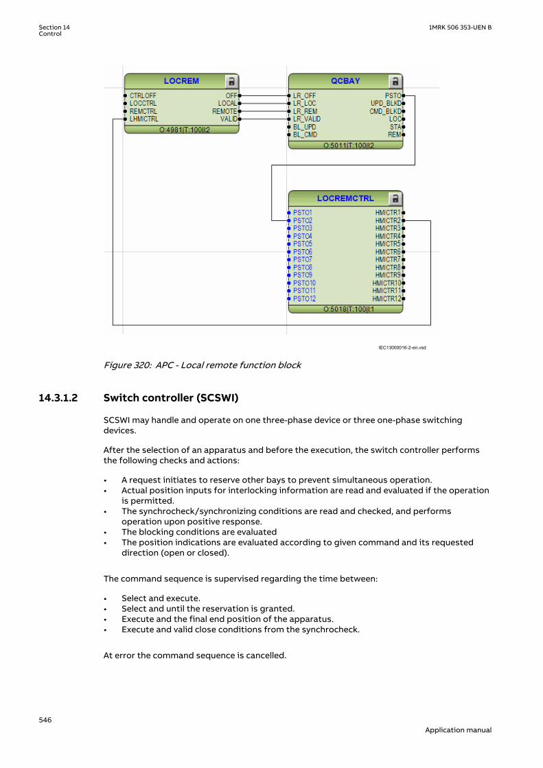
IEC13000016-2-en.vsd IEC13000016 V2 EN-US
Figure 320: APC - Local remote function block
14.3.1.2 Switch controller (SCSWI)M16596-3 v4
SCSWI may handle and operate on one three-phase device or three one-phase switchingdevices.
After the selection of an apparatus and before the execution, the switch controller performsthe following checks and actions:
• A request initiates to reserve other bays to prevent simultaneous operation.• Actual position inputs for interlocking information are read and evaluated if the operation
is permitted.• The synchrocheck/synchronizing conditions are read and checked, and performs
operation upon positive response.• The blocking conditions are evaluated• The position indications are evaluated according to given command and its requested
direction (open or closed).
The command sequence is supervised regarding the time between:
• Select and execute.• Select and until the reservation is granted.• Execute and the final end position of the apparatus.• Execute and valid close conditions from the synchrocheck.
At error the command sequence is cancelled.
Section 14 1MRK 506 353-UEN BControl
546Application manual

In the case when there are three one-phase switches (SXCBR) connected to the switchcontroller function, the switch controller will "merge" the position of the three switches to theresulting three-phase position. In case of a pole discordance situation, that is, the positions ofthe one-phase switches are not equal for a time longer than a settable time; an error signal willbe given.
The switch controller is not dependent on the type of switching device SXCBR or SXSWI. Theswitch controller represents the content of the SCSWI logical node (according to IEC 61850)with mandatory functionality.
14.3.1.3 Switches (SXCBR/SXSWI)M16602-3 v5
Switches are functions used to close and interrupt an ac power circuit under normalconditions, or to interrupt the circuit under fault, or emergency conditions. The intention withthese functions is to represent the lowest level of a power-switching device with or withoutshort circuit breaking capability, for example, circuit breakers, disconnectors, earthingswitches etc.
The purpose of these functions is to provide the actual status of positions and to perform thecontrol operations, that is, pass all the commands to the primary apparatus via output boardsand to supervise the switching operation and position.
Switches have the following functionalities:
• Local/Remote switch intended for the switchyard• Block/deblock for open/close command respectively• Update block/deblock of position indication• Substitution of position indication• Supervision timer that the primary device starts moving after a command• Supervision of allowed time for intermediate position• Definition of pulse duration for open/close command respectively
The realizations of these function are done with SXCBR representing a circuit breaker and withSXSWI representing a circuit switch that is, a disconnector or an earthing switch.
Circuit breaker (SXCBR) can be realized either as three one-phase switches or as one three-phase switch.
The content of this function is represented by the IEC 61850 definitions for the logical nodesCircuit breaker (SXCBR) and Circuit switch (SXSWI) with mandatory functionality.
14.3.1.4 Reservation function (QCRSV and RESIN)M16609-3 v4
The purpose of the reservation function is primarily to transfer interlocking informationbetween IEDs in a safe way and to prevent double operation in a bay, switchyard part, orcomplete substation.
For interlocking evaluation in a substation, the position information from switching devices,such as circuit breakers, disconnectors and earthing switches can be required from the samebay or from several other bays. When information is needed from other bays, it is exchangedover the station bus between the distributed IEDs. The problem that arises, even at a highspeed of communication, is a space of time during which the information about the positionof the switching devices are uncertain. The interlocking function uses this information forevaluation, which means that also the interlocking conditions are uncertain.
To ensure that the interlocking information is correct at the time of operation, a uniquereservation method is available in the IEDs. With this reservation method, the bay that wantsthe reservation sends a reservation request to other bays and then waits for a reservationgranted signal from the other bays. Actual position indications from these bays are then
1MRK 506 353-UEN B Section 14Control
547Application manual

transferred over the station bus for evaluation in the IED. After the evaluation the operationcan be executed with high security.
This functionality is realized over the station bus by means of the function blocks QCRSV andRESIN. The application principle is shown in Figure 321.
The function block QCRSV handles the reservation. It sends out either the reservation requestto other bays or the acknowledgement if the bay has received a request from another bay.
The other function block RESIN receives the reservation information from other bays. Thenumber of instances is the same as the number of involved bays (up to 60 instances areavailable). The received signals are either the request for reservation from another bay or theacknowledgment from each bay respectively, which have received a request from this bay. Alsothe information of valid transmission over the station bus must be received.
en05000117.vsd
IEDIED
From otherSCSWI inthe bay To other
SCSWIin thebay
3
Station bus
. . .
. . .
. . .
3
RESIN
EXCH_OUTEXCH_IN
RESIN
EXCH_OUTEXCH_IN
..
SCSWI
RES_RQRES_GRT
RES_DATA
QCRSVRES_RQ1
RES_RQ8
RES_GRT1
RES_GRT8
..
2
IEC05000117 V2 EN-US
Figure 321: Application principles for reservation over the station bus
The reservation can also be realized with external wiring according to the application examplein Figure 322. This solution is realized with external auxiliary relays and extra binary inputs andoutputs in each IED, but without use of function blocks QCRSV and RESIN.
SCSWI
SELECTEDRES_EXT
+
IED
BI BO
IED
BI BO
OROther SCSWI in the bay
en05000118.vsdIEC05000118 V2 EN-US
Figure 322: Application principles for reservation with external wiring
Section 14 1MRK 506 353-UEN BControl
548Application manual

The solution in Figure 322 can also be realized over the station bus according to theapplication example in Figure 323. The solutions in Figure 322 and Figure 323 do not have thesame high security compared to the solution in Figure 321, but instead have a higheravailability, since no acknowledgment is required.
SCSWI
SELECTED
RES_EXT
IEDIED
OROther SCWI inthe bay
Station bus. . .
SPGAPCIN
RESGRANT
IntlReceive
. . .
. . .
RESGRANT
IntlReceive
IEC05000178-3-en.vsd IEC05000178 V3 EN-US
Figure 323: Application principle for an alternative reservation solution
14.3.2 Interaction between modulesM16626-3 v7
A typical bay with apparatus control function consists of a combination of logical nodes orfunctions that are described here:
• The Switch controller (SCSWI) initializes all operations for one apparatus. It is thecommand interface of the apparatus. It includes the position reporting as well as thecontrol of the position
• The Circuit breaker (SXCBR) is the process interface to the circuit breaker for theapparatus control function.
• The Circuit switch (SXSWI) is the process interface to the disconnector or the earthingswitch for the apparatus control function.
• The Bay control (QCBAY) fulfils the bay-level functions for the apparatuses, such asoperator place selection and blockings for the complete bay.
• The Reservation (QCRSV) deals with the reservation function.• The Protection trip logic (SMPPTRC) connects the "trip" outputs of one or more protection
functions to a common "trip" to be transmitted to SXCBR.• The Autorecloser (SMBRREC) consists of the facilities to automatically close a tripped
breaker with respect to a number of configurable conditions.• The logical node Interlocking (SCILO) provides the information to SCSWI whether it is
permitted to operate due to the switchyard topology. The interlocking conditions areevaluated with separate logic and connected to SCILO .
• The Synchrocheck, energizing check, and synchronizing (SESRSYN) calculates andcompares the voltage phasor difference from both sides of an open breaker withpredefined switching conditions (synchrocheck). Also the case that one side is dead(energizing-check) is included.
• The Generic Automatic Process Control function, GAPC, handles generic commands fromthe operator to the system.
The overview of the interaction between these functions is shown in Figure 324 below.
1MRK 506 353-UEN B Section 14Control
549Application manual

IEC05000120-2-en.vsd
SXCBR(Circuit breaker)
Interlockingfunctionblock
(Not a LN)
SCSWI(Switching control)
QCBAY(Bay control)
SMBRREC
(Auto-reclosure)
I/O
Trip
Close rel.
Res. req.
Star
t AR
Close CB
Position
Res. granted
Operator placeselection
SCSWI(Switching control)
SXSWI(Disconnector)
Open cmdClose cmd
Position
SESRSYN(Synchrocheck & Synchronizer)
SCILO
SCILO
Synchrocheck OK
QCRSV(Reservation) Res. req.
Res. granted
GAPC(Generic
Automatic Process Control) Open/Close
Open/Close
Enable close
Enable open
Open rel.
Close rel.Open rel.
SMPPTRC(Trip logic)
Position
Enab
leop
enEn
able
clos
e
Pos.
from
ot
her b
ays
I/O
Open cmdClose cmd
(Interlocking)
(Interlocking)
Synchronizing in progress
IEC05000120 V2 EN-US
Figure 324: Example overview of the interactions between functions in a typical bay
14.3.3 Setting guidelinesM16669-3 v4
The setting parameters for the apparatus control function are set via the local HMI or PCM600.
14.3.3.1 Bay control (QCBAY)M16670-3 v6
If the parameter AllPSTOValid is set to No priority, all originators from local and remote areaccepted without any priority.
If the parameter RemoteIncStation is set to Yes, commands from IEC61850-8-1 clients at bothstation and remote level are accepted, when the QCBAY function is in Remote. If set to No, thecommand LocSta controls which operator place is accepted when QCBAY is in Remote. If
Section 14 1MRK 506 353-UEN BControl
550Application manual

LocSta is true, only commands from station level are accepted, otherwise only commandsfrom remote level are accepted.
The parameter RemoteIncStation has only effect on the IEC61850-8-1communication. Further, when using IEC61850 edition 1 communication, theparameter should be set to Yes, since the command LocSta is not defined inIEC61850-8-1 edition 1.
14.3.3.2 Switch controller (SCSWI)M16673-3 v6
The parameter CtlModel specifies the type of control model according to IEC 61850. Thedefault for control of circuit breakers, disconnectors and earthing switches the control modelis set to SBO Enh (Select-Before-Operate) with enhanced security.
When the operation shall be performed in one step, and no monitoring of the result of thecommand is desired, the model direct control with normal security is used.
At control with enhanced security there is an additional supervision of the status value by thecontrol object, which means that each command sequence must be terminated by atermination command.
The parameter PosDependent gives permission to operate depending on the positionindication, that is, at Always permitted it is always permitted to operate independent of thevalue of the position. At Not perm at 00/11 it is not permitted to operate if the position is inbad or intermediate state.
tSelect is the maximum allowed time between the select and the execute command signal,that is, the time the operator has to perform the command execution after the selection of theobject to operate. When the time has expired, the selected output signal is set to false and acause-code is given.
The time parameter tResResponse is the allowed time from reservation request to thefeedback reservation granted from all bays involved in the reservation function. When the timehas expired, the control function is reset, and a cause-code is given.
tSynchrocheck is the allowed time for the synchrocheck function to fulfill the close conditions.When the time has expired, the function tries to start the synchronizing function. IftSynchrocheck is set to 0, no synchrocheck is done, before starting the synchronizing function.
The timer tSynchronizing supervises that the signal synchronizing in progress is obtained inSCSWI after start of the synchronizing function. The start signal for the synchronizing is set ifthe synchrocheck conditions are not fulfilled. When the time has expired, the control functionis reset, and a cause-code is given. If no synchronizing function is included, the time is set to 0,which means no start of the synchronizing function is done, and when tSynchrocheck hasexpired, the control function is reset and a cause-code is given.
tExecutionFB is the maximum time between the execute command signal and the commandtermination. When the time has expired, the control function is reset and a cause-code isgiven.
tPoleDiscord is the allowed time to have discrepancy between the poles at control of threeone-phase breakers. At discrepancy an output signal is activated to be used for trip or alarm,and during a command, the control function is reset, and a cause-code is given.
SuppressMidPos when On suppresses the mid-position during the time tIntermediate of theconnected switches.
The parameter InterlockCheck decides if interlock check should be done at both select andoperate, Sel & Op phase, or only at operate, Op phase.
1MRK 506 353-UEN B Section 14Control
551Application manual

14.3.3.3 Switch (SXCBR/SXSWI)M16675-3 v7
tStartMove is the supervision time for the apparatus to start moving after a commandexecution. When the time has expired, the switch function is reset, and a cause-code is given.
During the tIntermediate time the position indication is allowed to be in an intermediate (00)state. When the time has expired, the switch function is reset, and a cause-code is given. Theindication of the mid-position at SCSWI is suppressed during this time period when theposition changes from open to close or vice-versa if the parameter SuppressMidPos is set toOn in the SCSWI function.
If the parameter AdaptivePulse is set to Adaptive the command output pulse resets when anew correct end position is reached. If the parameter is set to Not adaptive the commandoutput pulse remains active until the timer tOpenPulsetClosePulse has elapsed.
tOpenPulse is the output pulse length for an open command. If AdaptivePulse is set toAdaptive, it is the maximum length of the output pulse for an open command. The defaultlength is set to 200 ms for a circuit breaker (SXCBR) and 500 ms for a disconnector (SXSWI).
tClosePulse is the output pulse length for a close command. If AdaptivePulse is set toAdaptive, it is the maximum length of the output pulse for an open command. The defaultlength is set to 200 ms for a circuit breaker (SXCBR) and 500 ms for a disconnector (SXSWI).
14.3.3.4 Bay Reserve (QCRSV)M16677-3 v3
The timer tCancelRes defines the supervision time for canceling the reservation, when thiscannot be done by requesting bay due to for example communication failure.
When the parameter ParamRequestx (x=1-8) is set to Only own bay res. individually for eachapparatus (x) in the bay, only the own bay is reserved, that is, the output for reservationrequest of other bays (RES_BAYS) will not be activated at selection of apparatus x.
14.3.3.5 Reservation input (RESIN)M16678-3 v3
With the FutureUse parameter set to Bay future use the function can handle bays not yetinstalled in the SA system.
14.4 InterlockingIP15572-1 v2
M13530-4 v3
The main purpose of switchgear interlocking is:
• To avoid the dangerous or damaging operation of switchgear• To enforce restrictions on the operation of the substation for other reasons for example,
load configuration. Examples of the latter are to limit the number of parallel transformersto a maximum of two or to ensure that energizing is always from one side, for example,the high voltage side of a transformer.
This section only deals with the first point, and only with restrictions caused by switchingdevices other than the one to be controlled. This means that switch interlock, because ofdevice alarms, is not included in this section.
Disconnectors and earthing switches have a limited switching capacity. Disconnectors maytherefore only operate:
Section 14 1MRK 506 353-UEN BControl
552Application manual

• With basically zero current. The circuit is open on one side and has a small extension. Thecapacitive current is small (for example, < 5A) and power transformers with inrush currentare not allowed.
• To connect or disconnect a parallel circuit carrying load current. The switching voltageacross the open contacts is thus virtually zero, thanks to the parallel circuit (for example, <1% of rated voltage). Paralleling of power transformers is not allowed.
Earthing switches are allowed to connect and disconnect earthing of isolated points. Due tocapacitive or inductive coupling there may be some voltage (for example < 40% of ratedvoltage) before earthing and some current (for example < 100A) after earthing of a line.
Circuit breakers are usually not interlocked. Closing is only interlocked against runningdisconnectors in the same bay, and the bus-coupler opening is interlocked during a busbartransfer.
The positions of all switching devices in a bay and from some other bays determine theconditions for operational interlocking. Conditions from other stations are usually notavailable. Therefore, a line earthing switch is usually not fully interlocked. The operator mustbe convinced that the line is not energized from the other side before closing the earthingswitch. As an option, a voltage indication can be used for interlocking. Take care to avoid adangerous enable condition at the loss of a VT secondary voltage, for example, because of ablown fuse.
The switch positions used by the operational interlocking logic are obtained from auxiliarycontacts or position sensors. For each end position (open or closed) a true indication isneeded - thus forming a double indication. The apparatus control function continuously checksits consistency. If neither condition is high (1 or TRUE), the switch may be in an intermediateposition, for example, moving. This dynamic state may continue for some time, which in thecase of disconnectors may be up to 10 seconds. Should both indications stay low for a longerperiod, the position indication will be interpreted as unknown. If both indications stay high,something is wrong, and the state is again treated as unknown.
In both cases an alarm is sent to the operator. Indications from position sensors shall be self-checked and system faults indicated by a fault signal. In the interlocking logic, the signals areused to avoid dangerous enable or release conditions. When the switching state of a switchingdevice cannot be determined operation is not permitted.
For switches with an individual operation gear per phase, the evaluation must considerpossible phase discrepancies. This is done with the aid of an AND-function for all three phasesin each apparatus for both open and close indications. Phase discrepancies will result in anunknown double indication state.
14.4.1 Configuration guidelinesM13529-4 v4
The following sections describe how the interlocking for a certain switchgear configurationcan be realized in the IED by using standard interlocking modules and their interconnections.They also describe the configuration settings. The inputs for delivery specific conditions(Qx_EXy) are set to 1=TRUE if they are not used, except in the following cases:
• QB9_EX2 and QB9_EX4 in modules BH_LINE_A and BH_LINE_B• QA1_EX3 in module AB_TRAFO
when they are set to 0=FALSE.
14.4.2 Interlocking for line bay ABC_LINEIP14139-1 v2
1MRK 506 353-UEN B Section 14Control
553Application manual

14.4.2.1 ApplicationM13561-3 v8
The interlocking for line bay (ABC_LINE) function is used for a line connected to a doublebusbar arrangement with a transfer busbar according to figure 325. The function can also beused for a double busbar arrangement without transfer busbar or a single busbararrangement with/without transfer busbar.
QB1 QB2QC1
QA1
QC2
QB9QC9
WA1 (A)
WA2 (B)
WA7 (C)
QB7
en04000478.vsdIEC04000478 V1 EN-US
Figure 325: Switchyard layout ABC_LINE
M13560-4 v5
The signals from other bays connected to the module ABC_LINE are described below.
14.4.2.2 Signals from bypass busbarM13560-6 v5
To derive the signals:
Signal BB7_D_OP All line disconnectors on bypass WA7 except in the own bay are open.
VP_BB7_D The switch status of disconnectors on bypass busbar WA7 are valid.
EXDU_BPB No transmission error from any bay containing disconnectors on bypassbusbar WA7
These signals from each line bay (ABC_LINE) except that of the own bay are needed:
Signal QB7OPTR Q7 is open
VPQB7TR The switch status for QB7 is valid.
EXDU_BPB No transmission error from the bay that contains the above information.
For bay n, these conditions are valid:
Section 14 1MRK 506 353-UEN BControl
554Application manual

QB7OPTR (bay 1)QB7OPTR (bay 2)
. . .
. . .QB7OPTR (bay n-1)
& BB7_D_OP
VPQB7TR (bay 1)VPQB7TR (bay 2)
. . .
. . .VPQB7TR (bay n-1)
& VP_BB7_D
EXDU_BPB (bay 1)EXDU_BPB (bay 2)
. . .
. . .EXDU_BPB (bay n-1)
& EXDU_BPB
en04000477.vsd
IEC04000477 V1 EN-US
Figure 326: Signals from bypass busbar in line bay n
14.4.2.3 Signals from bus-couplerM13560-31 v4
If the busbar is divided by bus-section disconnectors into bus sections, the busbar-busbarconnection could exist via the bus-section disconnector and bus-coupler within the other bussection.
Section 1 Section 2
A1A2_DC(BS)B1B2_DC(BS)
ABC_LINE ABC_BCABC_LINE ABC_BC
(WA1)A1(WA2)B1(WA7)C C
B2A2
en04000479.vsdIEC04000479 V1 EN-US
Figure 327: Busbars divided by bus-section disconnectors (circuit breakers)
To derive the signals:
Signal BC_12_CL A bus-coupler connection exists between busbar WA1 and WA2.
BC_17_OP No bus-coupler connection between busbar WA1 and WA7.
BC_17_CL A bus-coupler connection exists between busbar WA1and WA7.
BC_27_OP No bus-coupler connection between busbar WA2 and WA7.
BC_27_CL A bus-coupler connection exists between busbar WA2 and WA7.
VP_BC_12 The switch status of BC_12 is valid.
VP_BC_17 The switch status of BC_17 is valid.
VP_BC_27 The switch status of BC_27 is valid.
EXDU_BC No transmission error from any bus-coupler bay (BC).
These signals from each bus-coupler bay (ABC_BC) are needed:
1MRK 506 353-UEN B Section 14Control
555Application manual

Signal BC12CLTR A bus-coupler connection through the own bus-coupler exists between busbar
WA1 and WA2.
BC17OPTR No bus-coupler connection through the own bus-coupler between busbar WA1and WA7.
BC17CLTR A bus-coupler connection through the own bus-coupler exists between busbarWA1 and WA7.
BC27OPTR No bus-coupler connection through the own bus-coupler between busbar WA2and WA7.
BC27CLTR A bus-coupler connection through the own bus-coupler exists between busbarWA2 and WA7.
VPBC12TR The switch status of BC_12 is valid.
VPBC17TR The switch status of BC_17 is valid.
VPBC27TR The switch status of BC_27 is valid.
EXDU_BC No transmission error from the bay that contains the above information.
These signals from each bus-section disconnector bay (A1A2_DC) are also needed. ForB1B2_DC, corresponding signals from busbar B are used. The same type of module (A1A2_DC)is used for different busbars, that is, for both bus-section disconnector A1A2_DC and B1B2_DC.
Signal DCOPTR The bus-section disconnector is open.
DCCLTR The bus-section disconnector is closed.
VPDCTR The switch status of bus-section disconnector DC is valid.
EXDU_DC No transmission error from the bay that contains the above information.
If the busbar is divided by bus-section circuit breakers, the signals from the bus-sectioncoupler bay (A1A2_BS), rather than the bus-section disconnector bay (A1A2_DC) must be used.For B1B2_BS, corresponding signals from busbar B are used. The same type of module(A1A2_BS) is used for different busbars, that is, for both bus-section circuit breakers A1A2_BSand B1B2_BS.
Signal S1S2OPTR No bus-section coupler connection between bus-sections 1 and 2.
S1S2CLTR A bus-section coupler connection exists between bus-sections 1 and 2.
VPS1S2TR The switch status of bus-section coupler BS is valid.
EXDU_BS No transmission error from the bay that contains the above information.
For a line bay in section 1, these conditions are valid:
Section 14 1MRK 506 353-UEN BControl
556Application manual

BC12CLTR (sect.1)
DCCLTR (A1A2)DCCLTR (B1B2)
>1&
BC12CLTR (sect.2)
&VPBC12TR (sect.1)
VPDCTR (A1A2)VPDCTR (B1B2)
VPBC12TR (sect.2)
>1&
BC17OPTR (sect.1)
DCOPTR (A1A2)BC17OPTR (sect.2)
>1&
BC17CLTR (sect.1)
DCCLTR (A1A2)BC17CLTR (sect.2)
&VPBC17TR (sect.1)
VPDCTR (A1A2)VPBC17TR (sect.2)
>1&
>1&
&
&
BC27OPTR (sect.1)
DCOPTR (B1B2)BC27OPTR (sect.2)
BC27CLTR (sect.1)
DCCLTR (B1B2)BC27CLTR (sect.2)
VPBC27TR (sect.1)VPDCTR (B1B2)
VPBC27TR (sect.2)
EXDU_BC (sect.1)EXDU_DC (A1A2)EXDU_DC (B1B2)EXDU_BC (sect.2)
BC_12_CL
VP_BC_12
BC_17_OP
BC_17_CL
VP_BC_17
BC_27_OP
BC_27_CL
VP_BC_27
EXDU_BC
en04000480.vsd
IEC04000480 V1 EN-US
Figure 328: Signals to a line bay in section 1 from the bus-coupler bays in each section
For a line bay in section 2, the same conditions as above are valid by changing section 1 tosection 2 and vice versa.
14.4.2.4 Configuration settingM13560-108 v4
If there is no bypass busbar and therefore no QB7 disconnector, then the interlocking for QB7is not used. The states for QB7, QC71, BB7_D, BC_17, BC_27 are set to open by setting theappropriate module inputs as follows. In the functional block diagram, 0 and 1 are designated0=FALSE and 1=TRUE:
• QB7_OP = 1• QB7_CL = 0
1MRK 506 353-UEN B Section 14Control
557Application manual
• QC71_OP = 1• QC71_CL = 0
• BB7_D_OP = 1
• BC_17_OP = 1• BC_17_CL = 0• BC_27_OP = 1• BC_27_CL = 0
• EXDU_BPB = 1
• VP_BB7_D = 1• VP_BC_17 = 1• VP_BC_27 = 1
If there is no second busbar WA2 and therefore no QB2 disconnector, then the interlocking forQB2 is not used. The state for QB2, QC21, BC_12, BC_27 are set to open by setting theappropriate module inputs as follows. In the functional block diagram, 0 and 1 are designated0=FALSE and 1=TRUE:
• QB2_OP = 1• QB2_CL = 0
• QC21_OP = 1• QC21_CL = 0
• BC_12_CL = 0• BC_27_OP = 1• BC_27_CL = 0
• VP_BC_12 = 1
14.4.3 Interlocking for bus-coupler bay ABC_BCIP14144-1 v2
14.4.3.1 ApplicationM13555-3 v8
The interlocking for bus-coupler bay (ABC_BC) function is used for a bus-coupler bayconnected to a double busbar arrangement according to figure 329. The function can also beused for a single busbar arrangement with transfer busbar or double busbar arrangementwithout transfer busbar.
Section 14 1MRK 506 353-UEN BControl
558Application manual

QB1 QB2
QC1
QA1
WA1 (A)
WA2 (B)
WA7 (C)
QB7QB20
QC2
en04000514.vsdIEC04000514 V1 EN-US
Figure 329: Switchyard layout ABC_BC
14.4.3.2 ConfigurationM13553-138 v4
The signals from the other bays connected to the bus-coupler module ABC_BC are describedbelow.
14.4.3.3 Signals from all feedersM13553-6 v4
To derive the signals:
Signal BBTR_OP No busbar transfer is in progress concerning this bus-coupler.
VP_BBTR The switch status is valid for all apparatuses involved in the busbar transfer.
EXDU_12 No transmission error from any bay connected to the WA1/WA2 busbars.
These signals from each line bay (ABC_LINE), each transformer bay (AB_TRAFO), and bus-coupler bay (ABC_BC), except the own bus-coupler bay are needed:
Signal QQB12OPTR QB1 or QB2 or both are open.
VPQB12TR The switch status of QB1 and QB2 are valid.
EXDU_12 No transmission error from the bay that contains the above information.
For bus-coupler bay n, these conditions are valid:
1MRK 506 353-UEN B Section 14Control
559Application manual

QB12OPTR (bay 1)QB12OPTR (bay 2)
. . .
. . .QB12OPTR (bay n-1)
& BBTR_OP
VPQB12TR (bay 1)VPQB12TR (bay 2)
. . .
. . .VPQB12TR (bay n-1)
& VP_BBTR
EXDU_12 (bay 1)EXDU_12 (bay 2)
. . .
. . .EXDU_12 (bay n-1)
& EXDU_12
en04000481.vsd
IEC04000481 V1 EN-US
Figure 330: Signals from any bays in bus-coupler bay n
If the busbar is divided by bus-section disconnectors into bus-sections, the signals BBTR areconnected in parallel - if both bus-section disconnectors are closed. So for the basic project-specific logic for BBTR above, add this logic:
Section 1 Section 2
A1A2_DC(BS)B1B2_DC(BS)
ABC_LINEABC_BC
ABC_LINE ABC_BC
(WA1)A1(WA2)B1(WA7)C C
B2A2
en04000482.vsd
AB_TRAFO
IEC04000482 V1 EN-US
Figure 331: Busbars divided by bus-section disconnectors (circuit breakers)
The following signals from each bus-section disconnector bay (A1A2_DC) are needed. ForB1B2_DC, corresponding signals from busbar B are used. The same type of module (A1A2_DC)is used for different busbars, that is, for both bus-section disconnector A1A2_DC and B1B2_DC.
Signal DCOPTR The bus-section disconnector is open.
VPDCTR The switch status of bus-section disconnector DC is valid.
EXDU_DC No transmission error from the bay that contains the above information.
If the busbar is divided by bus-section circuit breakers, the signals from the bus-sectioncoupler bay (A1A2_BS), rather than the bus-section disconnector bay (A1A2_DC), have to beused. For B1B2_BS, corresponding signals from busbar B are used. The same type of module(A1A2_BS) is used for different busbars, that is, for both bus-section circuit breakers A1A2_BSand B1B2_BS.
Signal S1S2OPTR No bus-section coupler connection between bus-sections 1 and 2.
VPS1S2TR The switch status of bus-section coupler BS is valid.
EXDU_BS No transmission error from the bay that contains the above information.
Section 14 1MRK 506 353-UEN BControl
560Application manual

For a bus-coupler bay in section 1, these conditions are valid:
BBTR_OP (sect.1)
DCOPTR (A1A2)DCOPTR (B1B2)
BBTR_OP (sect.2)
&VP_BBTR (sect.1)
VPDCTR (A1A2)VPDCTR (B1B2)
VP_BBTR (sect.2)
EXDU_12 (sect.1)
EXDU_DC (B1B2)EXDU_12 (sect.2)
VP_BBTR
EXDU_12
en04000483.vsd
&EXDU_DC (A1A2)
BBTR_OP
>1&
IEC04000483 V1 EN-US
Figure 332: Signals to a bus-coupler bay in section 1 from any bays in each section
For a bus-coupler bay in section 2, the same conditions as above are valid by changing section1 to section 2 and vice versa.
14.4.3.4 Signals from bus-couplerM13553-58 v5
If the busbar is divided by bus-section disconnectors into bus-sections, the signals BC_12 fromthe busbar coupler of the other busbar section must be transmitted to the own busbar couplerif both disconnectors are closed.
Section 1 Section 2
A1A2_DC(BS)B1B2_DC(BS)
ABC_BCABC_BC
(WA1)A1(WA2)B1(WA7)C C
B2A2
en04000484.vsdIEC04000484 V1 EN-US
Figure 333: Busbars divided by bus-section disconnectors (circuit breakers)
To derive the signals:
Signal BC_12_CL Another bus-coupler connection exists between busbar WA1 and WA2.
VP_BC_12 The switch status of BC_12 is valid.
EXDU_BC No transmission error from any bus-coupler bay (BC).
These signals from each bus-coupler bay (ABC_BC), except the own bay, are needed:
Signal BC12CLTR A bus-coupler connection through the own bus-coupler exists between busbar
WA1 and WA2.
VPBC12TR The switch status of BC_12 is valid.
EXDU_BC No transmission error from the bay that contains the above information.
1MRK 506 353-UEN B Section 14Control
561Application manual

These signals from each bus-section disconnector bay (A1A2_DC) are also needed. ForB1B2_DC, corresponding signals from busbar B are used. The same type of module (A1A2_DC)is used for different busbars, that is, for both bus-section disconnector A1A2_DC and B1B2_DC.
Signal DCCLTR The bus-section disconnector is closed.
VPDCTR The switch status of bus-section disconnector DC is valid.
EXDU_DC No transmission error from the bay that contains the above information.
If the busbar is divided by bus-section circuit breakers, the signals from the bus-sectioncoupler bay (A1A2_BS), rather than the bus-section disconnector bay (A1A2_DC), must be used.For B1B2_BS, corresponding signals from busbar B are used. The same type of module(A1A2_BS) is used for different busbars, that is, for both bus-section circuit breakers A1A2_BSand B1B2_BS.
Signal S1S2CLTR A bus-section coupler connection exists between bus sections 1 and 2.
VPS1S2TR The switch status of bus-section coupler BS is valid.
EXDU_BS No transmission error from the bay containing the above information.
For a bus-coupler bay in section 1, these conditions are valid:
DCCLTR (A1A2)DCCLTR (B1B2)
BC12CLTR (sect.2)
VPDCTR (A1A2)VPDCTR (B1B2)
VPBC12TR (sect.2)
EXDU_DC (A1A2)EXDU_DC (B1B2)EXDU_BC (sect.2)
& BC_12_CL
VP_BC_12
EXDU_BC
en04000485.vsd
&
&
IEC04000485 V1 EN-US
Figure 334: Signals to a bus-coupler bay in section 1 from a bus-coupler bay in anothersection
For a bus-coupler bay in section 2, the same conditions as above are valid by changing section1 to section 2 and vice versa.
14.4.3.5 Configuration settingM13553-107 v4
If there is no bypass busbar and therefore no QB2 and QB7 disconnectors, then theinterlocking for QB2 and QB7 is not used. The states for QB2, QB7, QC71 are set to open bysetting the appropriate module inputs as follows. In the functional block diagram, 0 and 1 aredesignated 0=FALSE and 1=TRUE:
• QB2_OP = 1• QB2_CL = 0
• QB7_OP = 1• QB7_CL = 0
Section 14 1MRK 506 353-UEN BControl
562Application manual

• QC71_OP = 1• QC71_CL = 0
If there is no second busbar B and therefore no QB2 and QB20 disconnectors, then theinterlocking for QB2 and QB20 are not used. The states for QB2, QB20, QC21, BC_12, BBTR areset to open by setting the appropriate module inputs as follows. In the functional blockdiagram, 0 and 1 are designated 0=FALSE and 1=TRUE:
• QB2_OP = 1• QB2_CL = 0
• QB20_OP = 1• QB20_CL = 0
• QC21_OP = 1• QC21_CL = 0
• BC_12_CL = 0• VP_BC_12 = 1
• BBTR_OP = 1• VP_BBTR = 1
14.4.4 Interlocking for transformer bay AB_TRAFOIP14149-1 v2
14.4.4.1 ApplicationM13567-3 v7
The interlocking for transformer bay (AB_TRAFO) function is used for a transformer bayconnected to a double busbar arrangement according to figure 335. The function is used whenthere is no disconnector between circuit breaker and transformer. Otherwise, the interlockingfor line bay (ABC_LINE) function can be used. This function can also be used in single busbararrangements.
1MRK 506 353-UEN B Section 14Control
563Application manual
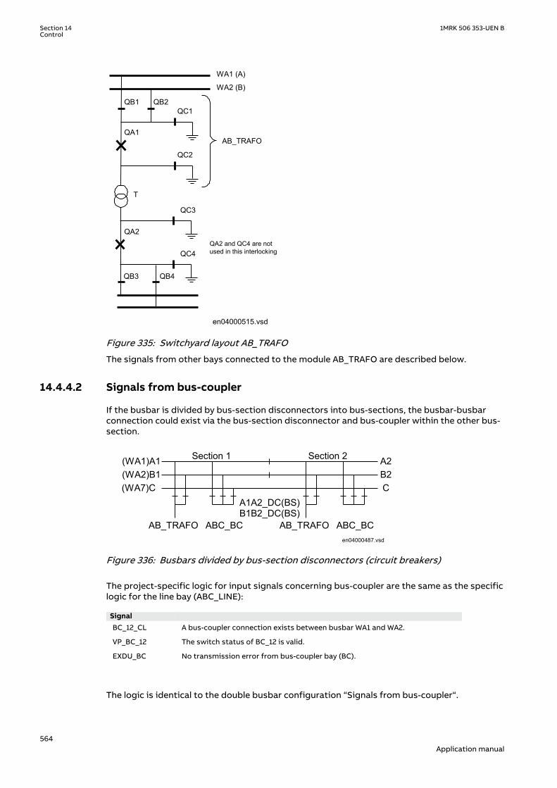
QB1 QB2QC1
QA1
QC2
WA1 (A)
WA2 (B)
QA2
QC3
T
QC4
QB4QB3
QA2 and QC4 are notused in this interlocking
AB_TRAFO
en04000515.vsdIEC04000515 V1 EN-US
Figure 335: Switchyard layout AB_TRAFOM13566-4 v4
The signals from other bays connected to the module AB_TRAFO are described below.
14.4.4.2 Signals from bus-couplerM13566-6 v4
If the busbar is divided by bus-section disconnectors into bus-sections, the busbar-busbarconnection could exist via the bus-section disconnector and bus-coupler within the other bus-section.
Section 1 Section 2
A1A2_DC(BS)B1B2_DC(BS)
AB_TRAFO ABC_BCAB_TRAFO ABC_BC
(WA1)A1(WA2)B1(WA7)C C
B2A2
en04000487.vsdIEC04000487 V1 EN-US
Figure 336: Busbars divided by bus-section disconnectors (circuit breakers)
The project-specific logic for input signals concerning bus-coupler are the same as the specificlogic for the line bay (ABC_LINE):
Signal BC_12_CL A bus-coupler connection exists between busbar WA1 and WA2.
VP_BC_12 The switch status of BC_12 is valid.
EXDU_BC No transmission error from bus-coupler bay (BC).
The logic is identical to the double busbar configuration “Signals from bus-coupler“.
Section 14 1MRK 506 353-UEN BControl
564Application manual
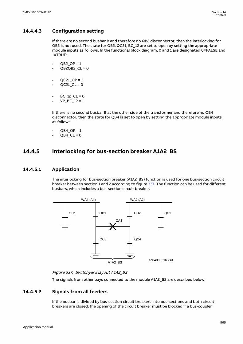
14.4.4.3 Configuration settingM13566-22 v5
If there are no second busbar B and therefore no QB2 disconnector, then the interlocking forQB2 is not used. The state for QB2, QC21, BC_12 are set to open by setting the appropriatemodule inputs as follows. In the functional block diagram, 0 and 1 are designated 0=FALSE and1=TRUE:
• QB2_OP = 1• QB2QB2_CL = 0
• QC21_OP = 1• QC21_CL = 0
• BC_12_CL = 0• VP_BC_12 = 1
If there is no second busbar B at the other side of the transformer and therefore no QB4disconnector, then the state for QB4 is set to open by setting the appropriate module inputsas follows:
• QB4_OP = 1• QB4_CL = 0
14.4.5 Interlocking for bus-section breaker A1A2_BSIP14154-1 v2
14.4.5.1 ApplicationM15110-3 v7
The interlocking for bus-section breaker (A1A2_BS) function is used for one bus-section circuitbreaker between section 1 and 2 according to figure 337. The function can be used for differentbusbars, which includes a bus-section circuit breaker.
QA1
WA1 (A1)
QB2
QC4
QB1
QC3
WA2 (A2)
en04000516.vsd
QC2QC1
A1A2_BSIEC04000516 V1 EN-US
Figure 337: Switchyard layout A1A2_BSM15111-4 v3
The signals from other bays connected to the module A1A2_BS are described below.
14.4.5.2 Signals from all feedersM15111-6 v4
If the busbar is divided by bus-section circuit breakers into bus-sections and both circuitbreakers are closed, the opening of the circuit breaker must be blocked if a bus-coupler
1MRK 506 353-UEN B Section 14Control
565Application manual

connection exists between busbars on one bus-section side and if on the other bus-sectionside a busbar transfer is in progress:
Section 1 Section 2
A1A2_BSB1B2_BS
ABC_LINEABC_BC
ABC_LINEABC_BC
(WA1)A1(WA2)B1(WA7)C C
B2A2
en04000489.vsd
AB_TRAFOAB_TRAFO
IEC04000489 V1 EN-US
Figure 338: Busbars divided by bus-section circuit breakers
To derive the signals:
Signal BBTR_OP No busbar transfer is in progress concerning this bus-section.
VP_BBTR The switch status of BBTR is valid.
EXDU_12 No transmission error from any bay connected to busbar 1(A) and 2(B).
These signals from each line bay (ABC_LINE), each transformer bay (AB_TRAFO), and bus-coupler bay (ABC_BC) are needed:
Signal QB12OPTR QB1 or QB2 or both are open.
VPQB12TR The switch status of QB1 and QB2 are valid.
EXDU_12 No transmission error from the bay that contains the above information.
These signals from each bus-coupler bay (ABC_BC) are needed:
Signal BC12OPTR No bus-coupler connection through the own bus-coupler between busbar WA1
and WA2.
VPBC12TR The switch status of BC_12 is valid.
EXDU_BC No transmission error from the bay that contains the above information.
These signals from the bus-section circuit breaker bay (A1A2_BS, B1B2_BS) are needed.
Signal S1S2OPTR No bus-section coupler connection between bus-sections 1 and 2.
VPS1S2TR The switch status of bus-section coupler BS is valid.
EXDU_BS No transmission error from the bay that contains the above information.
For a bus-section circuit breaker between A1 and A2 section busbars, these conditions arevalid:
Section 14 1MRK 506 353-UEN BControl
566Application manual

S1S2OPTR (B1B2)BC12OPTR (sect.1)
QB12OPTR (bay 1/sect.2)
QB12OPTR (bay n/sect.2)
S1S2OPTR (B1B2)BC12OPTR (sect.2)
QB12OPTR (bay 1/sect.1)
QB12OPTR (bay n /sect.1)
BBTR_OP
VP_BBTR
EXDU_12
en04000490.vsd
>1&
>1&
. . .
. . .
. . .
. . .
&
&
VPS1S2TR (B1B2)VPBC12TR (sect.1)
VPQB12TR (bay 1/sect.2)
VPQB12TR (bay n/sect.1). . .. . .
VPBC12TR (sect.2)VPQB12TR (bay 1/sect.1)
VPQB12TR (bay n/sect.1)
. . .
. . .
&
EXDU_12 (bay 1/sect.2)
EXDU_12 (bay n /sect.2)
EXDU_12(bay 1/sect.1)
EXDU_12 (bay n /sect.1)
EXDU_BS (B1B2)EXDU_BC (sect.1)
EXDU_BC (sect.2)
. . .
. . .
. . .
. . .
IEC04000490 V1 EN-US
Figure 339: Signals from any bays for a bus-section circuit breaker between sections A1and A2
For a bus-section circuit breaker between B1 and B2 section busbars, these conditions arevalid:
1MRK 506 353-UEN B Section 14Control
567Application manual
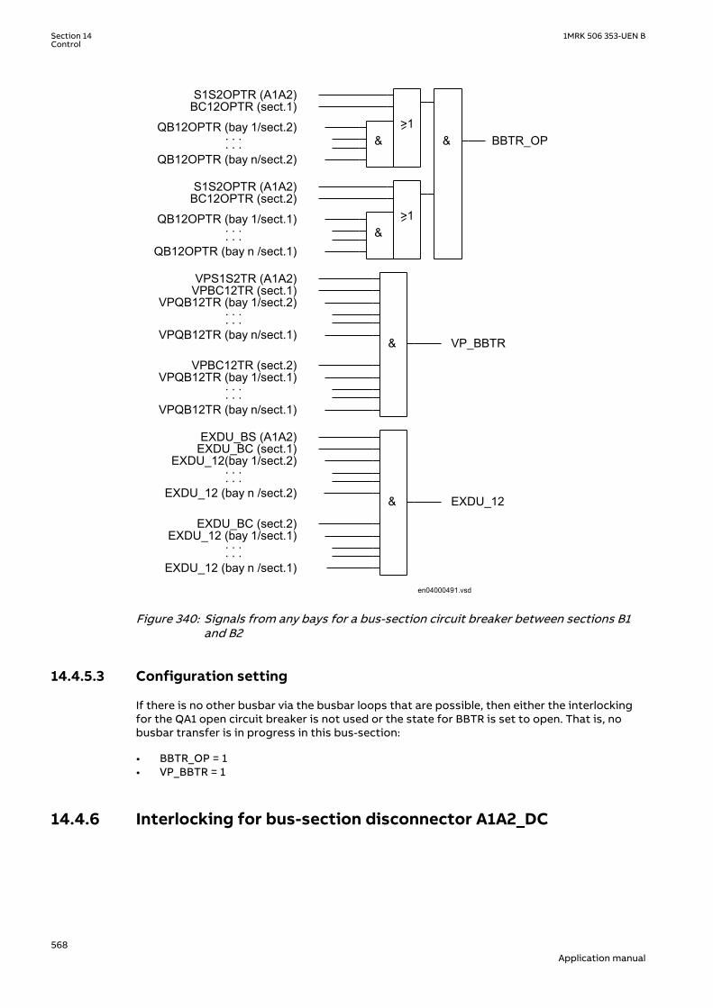
S1S2OPTR (A1A2)BC12OPTR (sect.1)
QB12OPTR (bay 1/sect.2)
QB12OPTR (bay n/sect.2)
S1S2OPTR (A1A2)BC12OPTR (sect.2)
QB12OPTR (bay 1/sect.1)
QB12OPTR (bay n /sect.1)
BBTR_OP
VP_BBTR
EXDU_12
en04000491.vsd
>1&
>1&
. . .
. . .
. . .
. . .
&
&
VPS1S2TR (A1A2)VPBC12TR (sect.1)
VPQB12TR (bay 1/sect.2)
VPQB12TR (bay n/sect.1). . .. . .
VPBC12TR (sect.2)VPQB12TR (bay 1/sect.1)
VPQB12TR (bay n/sect.1)
. . .
. . .
&
EXDU_12(bay 1/sect.2)
EXDU_12 (bay n /sect.2)
EXDU_12 (bay 1/sect.1)
EXDU_12 (bay n /sect.1)
EXDU_BS (A1A2)EXDU_BC (sect.1)
EXDU_BC (sect.2)
. . .
. . .
. . .
. . .
IEC04000491 V1 EN-US
Figure 340: Signals from any bays for a bus-section circuit breaker between sections B1and B2
14.4.5.3 Configuration settingM15111-57 v3
If there is no other busbar via the busbar loops that are possible, then either the interlockingfor the QA1 open circuit breaker is not used or the state for BBTR is set to open. That is, nobusbar transfer is in progress in this bus-section:
• BBTR_OP = 1• VP_BBTR = 1
14.4.6 Interlocking for bus-section disconnector A1A2_DCIP14159-1 v2
Section 14 1MRK 506 353-UEN BControl
568Application manual

14.4.6.1 ApplicationM13544-3 v7
The interlocking for bus-section disconnector (A1A2_DC) function is used for one bus-sectiondisconnector between section 1 and 2 according to figure 341. A1A2_DC function can be usedfor different busbars, which includes a bus-section disconnector.
WA1 (A1) WA2 (A2)
QB
QC1 QC2
A1A2_DC en04000492.vsd
IEC04000492 V1 EN-US
Figure 341: Switchyard layout A1A2_DCM13542-4 v4
The signals from other bays connected to the module A1A2_DC are described below.
14.4.6.2 Signals in single breaker arrangementM13542-6 v5
If the busbar is divided by bus-section disconnectors, the condition no other disconnectorconnected to the bus-section must be made by a project-specific logic.
The same type of module (A1A2_DC) is used for different busbars, that is, for both bus-sectiondisconnector A1A2_DC and B1B2_DC. But for B1B2_DC, corresponding signals from busbar Bare used.
Section 1 Section 2
A1A2_DC(BS)B1B2_DC(BS)
ABC_LINEABC_BC
ABC_LINE
(WA1)A1(WA2)B1(WA7)C C
B3A3
en04000493.vsd
AB_TRAFOAB_TRAFO
A2B2
IEC04000493 V1 EN-US
Figure 342: Busbars divided by bus-section disconnectors (circuit breakers)
To derive the signals:
Signal S1DC_OP All disconnectors on bus-section 1 are open.
S2DC_OP All disconnectors on bus-section 2 are open.
VPS1_DC The switch status of disconnectors on bus-section 1 is valid.
VPS2_DC The switch status of disconnectors on bus-section 2 is valid.
EXDU_BB No transmission error from any bay that contains the above information.
These signals from each line bay (ABC_LINE), each transformer bay (AB_TRAFO), and each bus-coupler bay (ABC_BC) are needed:
1MRK 506 353-UEN B Section 14Control
569Application manual

Signal QB1OPTR QB1 is open.
QB2OPTR QB2 is open (AB_TRAFO, ABC_LINE).
QB220OTR QB2 and QB20 are open (ABC_BC).
VPQB1TR The switch status of QB1 is valid.
VPQB2TR The switch status of QB2 is valid.
VQB220TR The switch status of QB2 and QB20 are valid.
EXDU_BB No transmission error from the bay that contains the above information.
If there is an additional bus-section disconnector, the signal from the bus-sectiondisconnector bay (A1A2_DC) must be used:
Signal DCOPTR The bus-section disconnector is open.
VPDCTR The switch status of bus-section disconnector DC is valid.
EXDU_DC No transmission error from the bay that contains the above information.
If there is an additional bus-section circuit breaker rather than an additional bus-sectiondisconnector the signals from the bus-section, circuit-breaker bay (A1A2_BS) rather than thebus-section disconnector bay (A1A2_DC) must be used:
Signal QB1OPTR QB1 is open.
QB2OPTR QB2 is open.
VPQB1TR The switch status of QB1 is valid.
VPQB2TR The switch status of QB2 is valid.
EXDU_BS No transmission error from the bay BS (bus-section coupler bay) that containsthe above information.
For a bus-section disconnector, these conditions from the A1 busbar section are valid:
QB1OPTR (bay 1/sect.A1) S1DC_OP
VPS1_DC
EXDU_BB
en04000494.vsd
&
&
&
QB1OPTR (bay n/sect.A1)
. . .
. . .
. . .
VPQB1TR (bay 1/sect.A1)
VPQB1TR (bay n/sect.A1)
EXDU_BB (bay 1/sect.A1)
EXDU_BB (bay n/sect.A1)
. . .
. . .
. . .
. . .
. . .
. . .
IEC04000494 V1 EN-US
Figure 343: Signals from any bays in section A1 to a bus-section disconnector
For a bus-section disconnector, these conditions from the A2 busbar section are valid:
Section 14 1MRK 506 353-UEN BControl
570Application manual

QB1OPTR (bay 1/sect.A2) S2DC_OP
VPS2_DC
EXDU_BB
en04000495.vsd
QB1OPTR (bay n/sect.A2)
. . .
. . .
. . .
VPQB1TR (bay 1/sect.A2)
VPQB1TR (bay n/sect.A2)VPDCTR (A2/A3)
EXDU_BB (bay n/sect.A2)
. . .
. . .
. . .
. . .
. . .
. . .
&
&
&
DCOPTR (A2/A3)
EXDU_BB (bay 1/sect.A2)
EXDU_DC (A2/A3)IEC04000495 V1 EN-US
Figure 344: Signals from any bays in section A2 to a bus-section disconnector
For a bus-section disconnector, these conditions from the B1 busbar section are valid:
QB2OPTR (QB220OTR)(bay 1/sect.B1) S1DC_OP
VPS1_DC
EXDU_BB
en04000496.vsd
QB2OPTR (QB220OTR)(bay n/sect.B1)
. . .
. . .
. . .
VPQB2TR (VQB220TR)(bay 1/sect.B1)
VPQB2TR (VQB220TR)(bay n/sect.B1)
EXDU_BB (bay 1/sect.B1)
EXDU_BB (bay n/sect.B1)
. . .
. . .
. . .
. . .
. . .
. . .
&
&
&
IEC04000496 V1 EN-US
Figure 345: Signals from any bays in section B1 to a bus-section disconnector
For a bus-section disconnector, these conditions from the B2 busbar section are valid:
1MRK 506 353-UEN B Section 14Control
571Application manual

QB2OPTR (QB220OTR)(bay 1/sect.B2) S2DC_OP
VPS2_DC
EXDU_BB
en04000497.vsd
QB2OPTR (QB220OTR)(bay n/sect.B2)
. . .
. . .
. . .
VPQB2TR(VQB220TR) (bay 1/sect.B2)
VPQB2TR(VQB220TR) (bay n/sect.B2)VPDCTR (B2/B3)
EXDU_BB (bay n/sect.B2)
. . .
. . .
. . .
. . .
. . .
. . .
&
&
&
DCOPTR (B2/B3)
EXDU_BB (bay 1/sect.B2)
EXDU_DC (B2/B3)IEC04000497 V1 EN-US
Figure 346: Signals from any bays in section B2 to a bus-section disconnector
14.4.6.3 Signals in double-breaker arrangementM13542-80 v5
If the busbar is divided by bus-section disconnectors, the condition for the busbardisconnector bay no other disconnector connected to the bus-section must be made by aproject-specific logic.
The same type of module (A1A2_DC) is used for different busbars, that is, for both bus-sectiondisconnector A1A2_DC and B1B2_DC. But for B1B2_DC, corresponding signals from busbar Bare used.
Section 1 Section 2
A1A2_DC(BS)B1B2_DC(BS)
DB_BUS DB_BUSDB_BUS DB_BUS
(WA1)A1(WA2)B1 B2
A2
en04000498.vsdIEC04000498 V1 EN-US
Figure 347: Busbars divided by bus-section disconnectors (circuit breakers)
To derive the signals:
Signal S1DC_OP All disconnectors on bus-section 1 are open.
S2DC_OP All disconnectors on bus-section 2 are open.
VPS1_DC The switch status of all disconnectors on bus-section 1 is valid.
VPS2_DC The switch status of all disconnectors on bus-section 2 is valid.
EXDU_BB No transmission error from double-breaker bay (DB) that contains the aboveinformation.
These signals from each double-breaker bay (DB_BUS) are needed:
Section 14 1MRK 506 353-UEN BControl
572Application manual
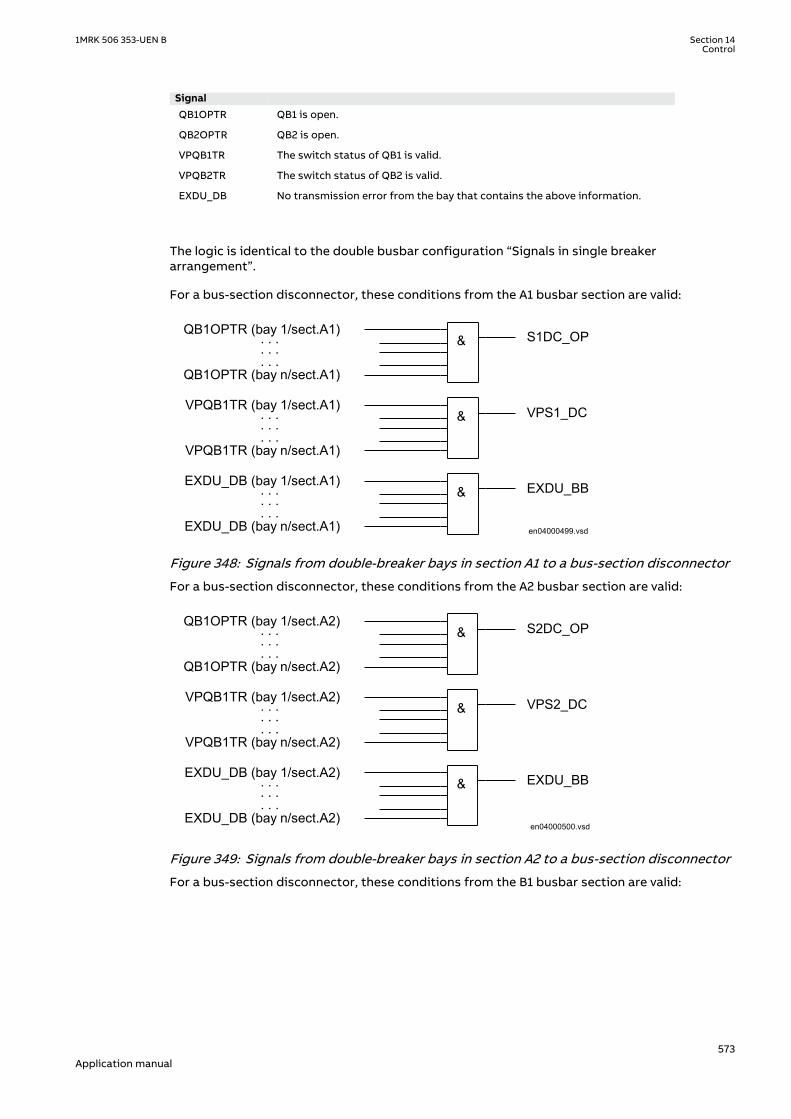
Signal QB1OPTR QB1 is open.
QB2OPTR QB2 is open.
VPQB1TR The switch status of QB1 is valid.
VPQB2TR The switch status of QB2 is valid.
EXDU_DB No transmission error from the bay that contains the above information.
The logic is identical to the double busbar configuration “Signals in single breakerarrangement”.
For a bus-section disconnector, these conditions from the A1 busbar section are valid:
QB1OPTR (bay 1/sect.A1) S1DC_OP
VPS1_DC
EXDU_BB
en04000499.vsd
&
&
&
QB1OPTR (bay n/sect.A1)
. . .
. . .
. . .
VPQB1TR (bay 1/sect.A1)
VPQB1TR (bay n/sect.A1)
EXDU_DB (bay 1/sect.A1)
EXDU_DB (bay n/sect.A1)
. . .
. . .
. . .
. . .
. . .
. . .
IEC04000499 V1 EN-US
Figure 348: Signals from double-breaker bays in section A1 to a bus-section disconnector
For a bus-section disconnector, these conditions from the A2 busbar section are valid:
QB1OPTR (bay 1/sect.A2) S2DC_OP
VPS2_DC
EXDU_BB
en04000500.vsd
&
&
&
QB1OPTR (bay n/sect.A2)
. . .
. . .
. . .
VPQB1TR (bay 1/sect.A2)
VPQB1TR (bay n/sect.A2)
EXDU_DB (bay 1/sect.A2)
EXDU_DB (bay n/sect.A2)
. . .
. . .
. . .
. . .
. . .
. . .
IEC04000500 V1 EN-US
Figure 349: Signals from double-breaker bays in section A2 to a bus-section disconnector
For a bus-section disconnector, these conditions from the B1 busbar section are valid:
1MRK 506 353-UEN B Section 14Control
573Application manual
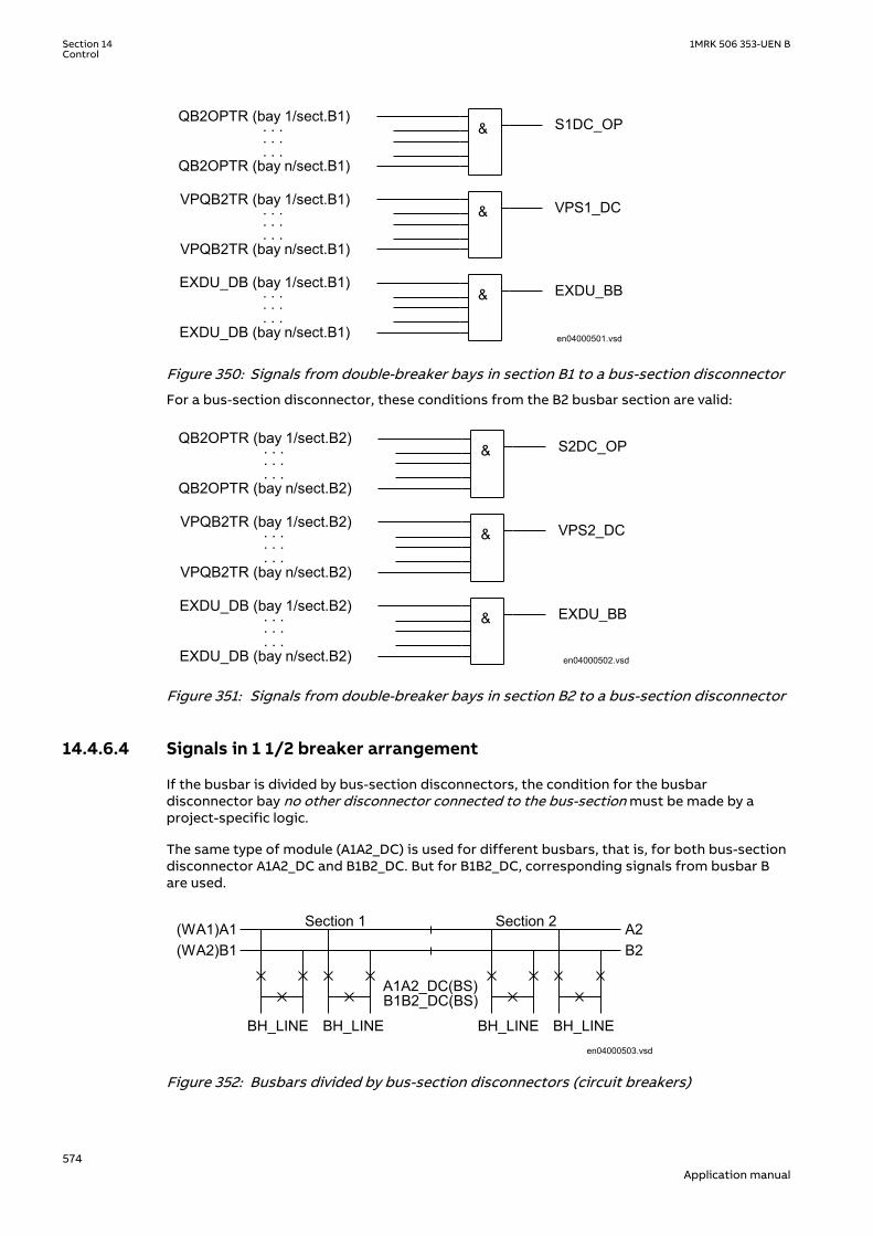
QB2OPTR (bay 1/sect.B1) S1DC_OP
VPS1_DC
EXDU_BB
en04000501.vsd
&
&
&
QB2OPTR (bay n/sect.B1)
. . .
. . .
. . .
VPQB2TR (bay 1/sect.B1)
VPQB2TR (bay n/sect.B1)
EXDU_DB (bay 1/sect.B1)
EXDU_DB (bay n/sect.B1)
. . .
. . .
. . .
. . .
. . .
. . .
IEC04000501 V1 EN-US
Figure 350: Signals from double-breaker bays in section B1 to a bus-section disconnector
For a bus-section disconnector, these conditions from the B2 busbar section are valid:
QB2OPTR (bay 1/sect.B2) S2DC_OP
VPS2_DC
EXDU_BB
en04000502.vsd
&
&
&
QB2OPTR (bay n/sect.B2)
. . .
. . .
. . .
VPQB2TR (bay 1/sect.B2)
VPQB2TR (bay n/sect.B2)
EXDU_DB (bay 1/sect.B2)
EXDU_DB (bay n/sect.B2)
. . .
. . .
. . .
. . .
. . .
. . .
IEC04000502 V1 EN-US
Figure 351: Signals from double-breaker bays in section B2 to a bus-section disconnector
14.4.6.4 Signals in 1 1/2 breaker arrangementM13542-127 v5
If the busbar is divided by bus-section disconnectors, the condition for the busbardisconnector bay no other disconnector connected to the bus-section must be made by aproject-specific logic.
The same type of module (A1A2_DC) is used for different busbars, that is, for both bus-sectiondisconnector A1A2_DC and B1B2_DC. But for B1B2_DC, corresponding signals from busbar Bare used.
Section 1 Section 2
A1A2_DC(BS)B1B2_DC(BS)
BH_LINE
(WA1)A1(WA2)B1 B2
A2
en04000503.vsd
BH_LINE BH_LINE BH_LINE
IEC04000503 V1 EN-US
Figure 352: Busbars divided by bus-section disconnectors (circuit breakers)
Section 14 1MRK 506 353-UEN BControl
574Application manual

The project-specific logic is the same as for the logic for the double-breaker configuration.
Signal S1DC_OP All disconnectors on bus-section 1 are open.
S2DC_OP All disconnectors on bus-section 2 are open.
VPS1_DC The switch status of disconnectors on bus-section 1 is valid.
VPS2_DC The switch status of disconnectors on bus-section 2 is valid.
EXDU_BB No transmission error from breaker and a half (BH) that contains the aboveinformation.
14.4.7 Interlocking for busbar earthing switch BB_ESIP14164-1 v4
14.4.7.1 ApplicationM15015-3 v7
The interlocking for busbar earthing switch (BB_ES) function is used for one busbar earthingswitch on any busbar parts according to figure 353.
QC
en04000504.vsdIEC04000504 V1 EN-US
Figure 353: Switchyard layout BB_ESM15053-4 v4
The signals from other bays connected to the module BB_ES are described below.
14.4.7.2 Signals in single breaker arrangementM15053-6 v5
The busbar earthing switch is only allowed to operate if all disconnectors of the bus-sectionare open.
Section 1 Section 2
A1A2_DC(BS)B1B2_DC(BS)
AB_TRAFO ABC_LINEBB_ES
ABC_LINE
(WA1)A1(WA2)B1(WA7)C C
B2A2
en04000505.vsd
BB_ESABC_BC
IEC04000505 V1 EN-US
Figure 354: Busbars divided by bus-section disconnectors (circuit breakers)
To derive the signals:
Signal BB_DC_OP All disconnectors on this part of the busbar are open.
VP_BB_DC The switch status of all disconnector on this part of the busbar is valid.
EXDU_BB No transmission error from any bay containing the above information.
1MRK 506 353-UEN B Section 14Control
575Application manual

These signals from each line bay (ABC_LINE), each transformer bay (AB_TRAFO), and each bus-coupler bay (ABC_BC) are needed:
Signal QB1OPTR QB1 is open.
QB2OPTR QB2 is open (AB_TRAFO, ABC_LINE)
QB220OTR QB2 and QB20 are open (ABC_BC)
QB7OPTR QB7 is open.
VPQB1TR The switch status of QB1 is valid.
VPQB2TR The switch status of QB2 is valid.
VQB220TR The switch status of QB2and QB20 is valid.
VPQB7TR The switch status of QB7 is valid.
EXDU_BB No transmission error from the bay that contains the above information.
These signals from each bus-section disconnector bay (A1A2_DC) are also needed. ForB1B2_DC, corresponding signals from busbar B are used. The same type of module (A1A2_DC)is used for different busbars, that is, for both bus-section disconnectors A1A2_DC andB1B2_DC.
Signal DCOPTR The bus-section disconnector is open.
VPDCTR The switch status of bus-section disconnector DC is valid.
EXDU_DC No transmission error from the bay that contains the above information.
If no bus-section disconnector exists, the signal DCOPTR, VPDCTR and EXDU_DC are set to 1(TRUE).
If the busbar is divided by bus-section circuit breakers, the signals from the bus-sectioncoupler bay (A1A2_BS) rather than the bus-section disconnector bay (A1A2_DC) must be used.For B1B2_BS, corresponding signals from busbar B are used. The same type of module(A1A2_BS) is used for different busbars, that is, for both bus-section circuit breakers A1A2_BSand B1B2_BS.
Signal QB1OPTR QB1 is open.
QB2OPTR QB2 is open.
VPQB1TR The switch status of QB1 is valid.
VPQB2TR The switch status of QB2 is valid.
EXDU_BS No transmission error from the bay BS (bus-section coupler bay) that containsthe above information.
For a busbar earthing switch, these conditions from the A1 busbar section are valid:
Section 14 1MRK 506 353-UEN BControl
576Application manual
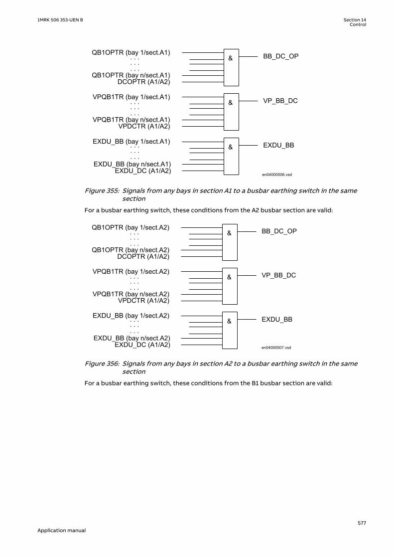
QB1OPTR (bay 1/sect.A1) BB_DC_OP
VP_BB_DC
EXDU_BB
en04000506.vsd
QB1OPTR (bay n/sect.A1)
. . .
. . .
. . .
VPQB1TR (bay 1/sect.A1)
VPQB1TR (bay n/sect.A1)VPDCTR (A1/A2)
EXDU_BB (bay n/sect.A1)
. . .
. . .
. . .
. . .
. . .
. . .
&
&
&
DCOPTR (A1/A2)
EXDU_BB (bay 1/sect.A1)
EXDU_DC (A1/A2)IEC04000506 V1 EN-US
Figure 355: Signals from any bays in section A1 to a busbar earthing switch in the samesection
For a busbar earthing switch, these conditions from the A2 busbar section are valid:
QB1OPTR (bay 1/sect.A2) BB_DC_OP
VP_BB_DC
EXDU_BB
en04000507.vsd
QB1OPTR (bay n/sect.A2)
. . .
. . .
. . .
VPQB1TR (bay 1/sect.A2)
VPQB1TR (bay n/sect.A2)VPDCTR (A1/A2)
EXDU_BB (bay n/sect.A2)
. . .
. . .
. . .
. . .
. . .
. . .
&
&
&
DCOPTR (A1/A2)
EXDU_BB (bay 1/sect.A2)
EXDU_DC (A1/A2)IEC04000507 V1 EN-US
Figure 356: Signals from any bays in section A2 to a busbar earthing switch in the samesection
For a busbar earthing switch, these conditions from the B1 busbar section are valid:
1MRK 506 353-UEN B Section 14Control
577Application manual

QB2OPTR(QB220OTR)(bay 1/sect.B1) BB_DC_OP
VP_BB_DC
EXDU_BB
en04000508.vsd
QB2OPTR (QB220OTR)(bay n/sect.B1)
. . .
. . .
. . .
VPQB2TR(VQB220TR) (bay 1/sect.B1)
VPQB2TR(VQB220TR) (bay n/sect.B1)VPDCTR (B1/B2)
EXDU_BB (bay n/sect.B1)
. . .
. . .
. . .
. . .
. . .
. . .
&
&
&
DCOPTR (B1/B2)
EXDU_BB (bay 1/sect.B1)
EXDU_DC (B1/B2)IEC04000508 V1 EN-US
Figure 357: Signals from any bays in section B1 to a busbar earthing switch in the samesection
For a busbar earthing switch, these conditions from the B2 busbar section are valid:
QB2OPTR(QB220OTR) (bay 1/sect.B2) BB_DC_OP
VP_BB_DC
EXDU_BB
en04000509.vsd
QB2OPTR(QB220OTR) (bay n/sect.B2)
. . .
. . .
. . .
VPQB2TR(VQB220TR) (bay 1/sect.B2)
VPQB2TR(VQB220TR) (bay n/sect.B2)VPDCTR (B1/B2)
EXDU_BB (bay n/sect.B2)
. . .
. . .
. . .
. . .
. . .
. . .
&
&
&
DCOPTR (B1/B2)
EXDU_BB (bay 1/sect.B2)
EXDU_DC (B1/B2)IEC04000509 V1 EN-US
Figure 358: Signals from any bays in section B2 to a busbar earthing switch in the samesection
For a busbar earthing switch on bypass busbar C, these conditions are valid:
Section 14 1MRK 506 353-UEN BControl
578Application manual

QB7OPTR (bay 1) BB_DC_OP
VP_BB_DC
EXDU_BB
en04000510.vsd
&
&
&
QB7OPTR (bay n)
. . .
. . .
. . .
VPQB7TR (bay 1)
VPQB7TR (bay n)
EXDU_BB (bay 1)
EXDU_BB (bay n)
. . .
. . .
. . .
. . .
. . .
. . .
IEC04000510 V1 EN-US
Figure 359: Signals from bypass busbar to busbar earthing switch
14.4.7.3 Signals in double-breaker arrangementM15053-83 v4
The busbar earthing switch is only allowed to operate if all disconnectors of the bus sectionare open.
Section 1 Section 2
A1A2_DC(BS)B1B2_DC(BS) BB_ESBB_ES
DB_BUS
(WA1)A1(WA2)B1 B2
A2
en04000511.vsd
DB_BUS
IEC04000511 V1 EN-US
Figure 360: Busbars divided by bus-section disconnectors (circuit breakers)
To derive the signals:
Signal BB_DC_OP All disconnectors of this part of the busbar are open.
VP_BB_DC The switch status of all disconnectors on this part of the busbar are valid.
EXDU_BB No transmission error from any bay that contains the above information.
These signals from each double-breaker bay (DB_BUS) are needed:
Signal QB1OPTR QB1 is open.
QB2OPTR QB2 is open.
VPQB1TR The switch status of QB1 is valid.
VPQB2TR The switch status of QB2 is valid.
EXDU_DB No transmission error from the bay that contains the above information.
These signals from each bus-section disconnector bay (A1A2_DC) are also needed. ForB1B2_DC, corresponding signals from busbar B are used. The same type of module (A1A2_DC)
1MRK 506 353-UEN B Section 14Control
579Application manual

is used for different busbars, that is, for both bus-section disconnectors A1A2_DC andB1B2_DC.
Signal DCOPTR The bus-section disconnector is open.
VPDCTR The switch status of bus-section disconnector DC is valid.
EXDU_DC No transmission error from the bay that contains the above information.
The logic is identical to the double busbar configuration described in section “Signals in singlebreaker arrangement”.
14.4.7.4 Signals in 1 1/2 breaker arrangementM15053-123 v4
The busbar earthing switch is only allowed to operate if all disconnectors of the bus-sectionare open.
Section 1 Section 2
A1A2_DC(BS)B1B2_DC(BS) BB_ESBB_ES
BH_LINE
(WA1)A1(WA2)B1 B2
A2
en04000512.vsdBH_LINE
IEC04000512 V1 EN-US
Figure 361: Busbars divided by bus-section disconnectors (circuit breakers)
The project-specific logic are the same as for the logic for the double busbar configurationdescribed in section “Signals in single breaker arrangement”.
Signal BB_DC_OP All disconnectors on this part of the busbar are open.
VP_BB_DC The switch status of all disconnectors on this part of the busbar is valid.
EXDU_BB No transmission error from any bay that contains the above information.
14.4.8 Interlocking for double CB bay DBIP14167-1 v2
14.4.8.1 ApplicationM13585-3 v10
The interlocking for a double busbar double circuit breaker bay including DB_BUS_A,DB_BUS_B and DB_LINE functions are used for a line connected to a double busbararrangement according to figure 362.
Section 14 1MRK 506 353-UEN BControl
580Application manual

WA1 (A)
WA2 (B)
QB1QC1
QA1
QC2
QC9
QB61
QB9
QB2QC4
QA2
QC5
QC3
QB62
DB_BUS_B
DB_LINE
DB_BUS_A
en04000518.vsdIEC04000518 V1 EN-US
Figure 362: Switchyard layout double circuit breakerM13584-4 v4
For a double circuit-breaker bay, the modules DB_BUS_A, DB_LINE and DB_BUS_B must beused.
14.4.8.2 Configuration settingM13584-6 v5
For application without QB9 and QC9, just set the appropriate inputs to open state anddisregard the outputs. In the functional block diagram, 0 and 1 are designated 0=FALSE and1=TRUE:
• QB9_OP = 1• QB9_CL = 0
• QC9_OP = 1• QC9_CL = 0
If, in this case, line voltage supervision is added, then rather than setting QB9 to open state,specify the state of the voltage supervision:
• QB9_OP = VOLT_OFF• QB9_CL = VOLT_ON
If there is no voltage supervision, then set the corresponding inputs as follows:
• VOLT_OFF = 1• VOLT_ON = 0
14.4.9 Interlocking for 1 1/2 CB BHIP14173-1 v3
1MRK 506 353-UEN B Section 14Control
581Application manual

14.4.9.1 ApplicationM13570-3 v6
The interlocking for 1 1/2 breaker diameter (BH_CONN, BH_LINE_A, BH_LINE_B) functions areused for lines connected to a 1 1/2 breaker diameter according to figure 363.
WA1 (A)
WA2 (B)
QB1QC1
QA1
QC2
QC9
QB6
QB9
QB2QC1
QA1
QC2
QC3
QB6
QC3
QB62QB61 QA1
QC1 QC2QC9
QB9
BH_LINE_A BH_LINE_B
BH_CONNen04000513.vsd
IEC04000513 V1 EN-US
Figure 363: Switchyard layout 1 1/2 breakerM13570-7 v4
Three types of interlocking modules per diameter are defined. BH_LINE_A and BH_LINE_B arethe connections from a line to a busbar. BH_CONN is the connection between the two lines ofthe diameter in the 1 1/2 breaker switchyard layout.
M13569-4 v4
For a 1 1/2 breaker arrangement, the modules BH_LINE_A, BH_CONN and BH_LINE_B must beused.
14.4.9.2 Configuration settingM13569-6 v5
For application without QB9 and QC9, just set the appropriate inputs to open state anddisregard the outputs. In the functional block diagram, 0 and 1 are designated 0=FALSE and1=TRUE:
• QB9_OP = 1• QB9_CL = 0
• QC9_OP = 1• QC9_CL = 0
If, in this case, line voltage supervision is added, then rather than setting QB9 to open state,specify the state of the voltage supervision:
• QB9_OP = VOLT_OFF• QB9_CL = VOLT_ON
Section 14 1MRK 506 353-UEN BControl
582Application manual

If there is no voltage supervision, then set the corresponding inputs as follows:
• VOLT_OFF = 1• VOLT_ON = 0
14.5 Logic rotating switch for function selection and LHMIpresentation SLGAPC
SEMOD114936-1 v4
14.5.1 IdentificationSEMOD167845-2 v3
Function description IEC 61850identification
IEC 60617identification
ANSI/IEEE C37.2device number
Logic rotating switch for functionselection and LHMI presentation
SLGAPC - -
14.5.2 ApplicationSEMOD114927-4 v6
The logic rotating switch for function selection and LHMI presentation function (SLGAPC) (orthe selector switch function block, as it is also known) is used to get a selector switchfunctionality similar with the one provided by a hardware multi-position selector switch.Hardware selector switches are used extensively by utilities, in order to have differentfunctions operating on pre-set values. Hardware switches are however sources formaintenance issues, lower system reliability and extended purchase portfolio. The virtualselector switches eliminate all these problems.
SLGAPC function block has two operating inputs (UP and DOWN), one blocking input (BLOCK)and one operator position input (PSTO).
SLGAPC can be activated both from the local HMI and from external sources (switches), via theIED binary inputs. It also allows the operation from remote (like the station computer).SWPOSN is an integer value output, giving the actual output number. Since the number ofpositions of the switch can be established by settings (see below), one must be careful incoordinating the settings with the configuration (if one sets the number of positions to x insettings – for example, there will be only the first x outputs available from the block in theconfiguration). Also the frequency of the (UP or DOWN) pulses should be lower than thesetting tPulse.
From the local HMI, the selector switch can be operated from Single-line diagram (SLD).
14.5.3 Setting guidelinesSEMOD115063-294 v6
The following settings are available for the Logic rotating switch for function selection andLHMI presentation (SLGAPC) function:
Operation: Sets the operation of the function On or Off.
NrPos: Sets the number of positions in the switch (max. 32).
OutType: Steady or Pulsed.
tPulse: In case of a pulsed output, it gives the length of the pulse (in seconds).
1MRK 506 353-UEN B Section 14Control
583Application manual

tDelay: The delay between the UP or DOWN activation signal positive front and the outputactivation.
StopAtExtremes: Sets the behavior of the switch at the end positions – if set to Disabled, whenpressing UP while on first position, the switch will jump to the last position; when pressingDOWN at the last position, the switch will jump to the first position; when set to Enabled, nojump will be allowed.
14.6 Selector mini switch VSGAPCSEMOD158754-1 v3
14.6.1 IdentificationSEMOD167850-2 v3
Function description IEC 61850identification
IEC 60617identification
ANSI/IEEE C37.2device number
Selector mini switch VSGAPC - -
14.6.2 ApplicationSEMOD158803-5 v6
Selector mini switch (VSGAPC) function is a multipurpose function used in the configurationtool in PCM600 for a variety of applications, as a general purpose switch. VSGAPC can be usedfor both acquiring an external switch position (through the IPOS1 and the IPOS2 inputs) andrepresent it through the single line diagram symbols (or use it in the configuration through theoutputs POS1 and POS2) as well as, a command function (controlled by the PSTO input), givingswitching commands through the CMDPOS12 and CMDPOS21 outputs.
The output POSITION is an integer output, showing the actual position as an integer number 0– 3.
An example where VSGAPC is configured to switch Autorecloser on–off from a button symbolon the local HMI is shown in figure 364. The I and O buttons on the local HMI are normally usedfor on–off operations of the circuit breaker.
IEC07000112-3-en.vsd
PSTO
CMDPOS12
IPOS1
NAM_POS1NAM_POS2
IPOS2
CMDPOS21OFFON
VSGAPC
SMBRRECONOFF
SETON
INTONE
INVERTERINPUT OUT
IEC07000112 V3 EN-US
Figure 364: Control of Autorecloser from local HMI through Selector mini switch
VSGAPC is also provided with IEC 61850 communication so it can be controlled from SAsystem as well.
14.6.3 Setting guidelinesSEMOD158807-4 v4
Selector mini switch (VSGAPC) function can generate pulsed or steady commands (by settingthe Mode parameter). When pulsed commands are generated, the length of the pulse can be
Section 14 1MRK 506 353-UEN BControl
584Application manual

set using the tPulse parameter. Also, being accessible on the single line diagram (SLD), thisfunction block has two control modes (settable through CtlModel): Dir Norm and SBO Enh.
14.7 Generic communication function for Double Pointindication DPGAPC
SEMOD55384-1 v4
14.7.1 IdentificationGUID-E16EA78F-6DF9-4B37-A92D-5C09827E2297 v3
Function description IEC 61850identification
IEC 60617identification
ANSI/IEEE C37.2device number
Generic communication function forDouble Point indication
DPGAPC - -
14.7.2 ApplicationSEMOD55391-5 v8
Generic communication function for Double Point indication (DPGAPC) function block is usedto send double point position indication to other systems, equipment or functions in thesubstation through IEC 61850-8-1 or other communication protocols. It is especially intendedto be used in the interlocking station-wide logics. To be able to get the signals into othersystems, equipment or functions, one must use other tools, described in the Engineeringmanual, and define which function block in which systems, equipment or functions shouldreceive this information.
More specifically, DPGAPC function reports a combined double point position indicationoutput POSITION, by evaluating the value and the timestamp attributes of the inputs OPENand CLOSE, together with the logical input signal VALID.
When the input signal VALID is active, the values of the OPEN and CLOSE inputs determine thetwo-bit integer value of the output POSITION. The timestamp of the output POSITION will havethe latest updated timestamp of the inputs OPEN and CLOSE.
When the input signal VALID is inactive, DPGAPC function forces the position to intermediatedstate.
When the value of the input signal VALID changes, the timestamp of the output POSITION willbe updated as the time when DPGAPC function detects the change.
Refer to Table 49 for the description of the input-output relationship in terms of the value andthe quality attributes.
Table 49: Description of the input-output relationship
VALID OPEN CLOSE POSITIONValue Description
0 - - 0 Intermediate
1 0 0 0 Intermediate
1 1 0 1 Open
1 0 1 2 Closed
1 1 1 3 Bad State
1MRK 506 353-UEN B Section 14Control
585Application manual

14.7.3 Setting guidelinesSEMOD55398-5 v4
The function does not have any parameters available in the local HMI or PCM600.
14.8 Single point generic control 8 signals SPC8GAPCSEMOD176448-1 v3
14.8.1 IdentificationSEMOD176456-2 v3
Function description IEC 61850identification
IEC 60617identification
ANSI/IEEE C37.2device number
Single point generic control 8 signals SPC8GAPC - -
14.8.2 ApplicationSEMOD176511-4 v4
The Single point generic control 8 signals (SPC8GAPC) function block is a collection of 8 singlepoint commands, designed to bring in commands from REMOTE (SCADA) to those parts of thelogic configuration that do not need complicated function blocks that have the capability toreceive commands (for example SCSWI). In this way, simple commands can be sent directly tothe IED outputs, without confirmation. Confirmation (status) of the result of the commands issupposed to be achieved by other means, such as binary inputs and SPGGIO function blocks.
PSTO is the universal operator place selector for all control functions. Even ifPSTO can be configured to allow LOCAL or ALL operator positions, the onlyfunctional position usable with the SPC8GAPC function block is REMOTE.
14.8.3 Setting guidelinesSEMOD176518-4 v5
The parameters for the single point generic control 8 signals (SPC8GAPC) function are set viathe local HMI or PCM600.
Operation: turning the function operation On/Off.
There are two settings for every command output (totally 8):
Latchedx: decides if the command signal for output x is Latched (steady) or Pulsed.
tPulsex: if Latchedx is set to Pulsed, then tPulsex will set the length of the pulse (in seconds).
14.9 AutomationBits, command function for DNP3.0AUTOBITS
SEMOD158589-1 v3
Section 14 1MRK 506 353-UEN BControl
586Application manual

14.9.1 IdentificationGUID-C3BB63F5-F0E7-4B00-AF0F-917ECF87B016 v4
Function description IEC 61850identification
IEC 60617identification
ANSI/IEEE C37.2device number
AutomationBits, command functionfor DNP3 AUTOBITS - -
14.9.2 ApplicationSEMOD158637-5 v4
Automation bits, command function for DNP3 (AUTOBITS) is used within PCM600 in order toget into the configuration the commands coming through the DNP3.0 protocol.The AUTOBITSfunction plays the same role as functions GOOSEBINRCV (for IEC 61850) and MULTICMDRCV(for LON).AUTOBITS function block have 32 individual outputs which each can be mapped as aBinary Output point in DNP3. The output is operated by a "Object 12" in DNP3. This objectcontains parameters for control-code, count, on-time and off-time. To operate an AUTOBITSoutput point, send a control-code of latch-On, latch-Off, pulse-On, pulse-Off, Trip or Close. Theremaining parameters are regarded as appropriate. For example, pulse-On, on-time=100, off-time=300, count=5 would give 5 positive 100 ms pulses, 300 ms apart.
For description of the DNP3 protocol implementation, refer to the Communication manual.
14.9.3 Setting guidelinesSEMOD158639-5 v3
AUTOBITS function block has one setting, (Operation: On/Off) enabling or disabling thefunction. These names will be seen in the DNP3 communication management tool in PCM600.
14.10 Single command, 16 signals SINGLECMDSEMOD119849-1 v2
14.10.1 IdentificationGUID-2217CCC2-5581-407F-A4BC-266CD6808984 v1
Function description IEC 61850identification
IEC 60617identification
ANSI/IEEE C37.2device number
Single command, 16 signals SINGLECMD - -
14.10.2 ApplicationM12445-3 v3
Single command, 16 signals (SINGLECMD) is a common function and always included in theIED.
The IEDs may be provided with a function to receive commands either from a substationautomation system or from the local HMI. That receiving function block has outputs that canbe used, for example, to control high voltage apparatuses in switchyards. For local controlfunctions, the local HMI can also be used. Together with the configuration logic circuits, theuser can govern pulses or steady output signals for control purposes within the IED or viabinary outputs.
Figure 365 shows an application example of how the user can connect SINGLECMD viaconfiguration logic circuit to control a high-voltage apparatus. This type of command controlis normally carried out by sending a pulse to the binary outputs of the IED. Figure 365 shows a
1MRK 506 353-UEN B Section 14Control
587Application manual

close operation. An open breaker operation is performed in a similar way but without thesynchro-check condition.
SinglecommandfunctionSINGLECMD
CMDOUTy
OUTy
Close CB1
&User-definedconditionsSynchro-check
Configuration logic circuits
en04000206.vsdIEC04000206 V2 EN-US
Figure 365: Application example showing a logic diagram for control of a circuit breakervia configuration logic circuits
Figure 366 and figure 367 show other ways to control functions, which require steady On/Offsignals. Here, the output is used to control built-in functions or external devices.
SinglecommandfunctionSINGLECMD
CMDOUTy
OUTy
Function n
en04000207.vsd
Function n
IEC04000207 V2 EN-US
Figure 366: Application example showing a logic diagram for control of built-in functions
Section 14 1MRK 506 353-UEN BControl
588Application manual

Singlecommandfunction
SINGLESMD
CMDOUTy
OUTy
Device 1
User-definedconditions
Configuration logic circuits
en04000208.vsd
&
IEC04000208 V2 EN-US
Figure 367: Application example showing a logic diagram for control of external devicesvia configuration logic circuits
14.10.3 Setting guidelinesM12448-3 v2
The parameters for Single command, 16 signals (SINGLECMD) are set via the local HMI orPCM600.
Parameters to be set are MODE, common for the whole block, and CMDOUTy which includesthe user defined name for each output signal. The MODE input sets the outputs to be one ofthe types Off, Steady, or Pulse.
• Off, sets all outputs to 0, independent of the values sent from the station level, that is, theoperator station or remote-control gateway.
• Steady, sets the outputs to a steady signal 0 or 1, depending on the values sent from thestation level.
• Pulse, gives a pulse with 100 ms duration, if a value sent from the station level is changedfrom 0 to 1. That means the configured logic connected to the command function blockmay not have a cycle time longer than the cycle time for the command function block.
1MRK 506 353-UEN B Section 14Control
589Application manual

590

Section 15 Scheme communication
15.1 Scheme communication logic for distance orovercurrent protection ZCPSCH
IP15749-1 v3
15.1.1 IdentificationM14854-1 v4
Function description IEC 61850identification
IEC 60617identification
ANSI/IEEE C37.2device number
Scheme communication logic fordistance or overcurrent protection
ZCPSCH - 85
15.1.2 ApplicationIP15020-1 v1
M16866-3 v4
To achieve fast fault clearing for a fault on the part of the line not covered by theinstantaneous zone 1, the stepped distance protection function can be supported with logic,that uses communication channels.
One communication channel in each direction, which can transmit an on/off signal is required.The performance and security of this function is directly related to the transmission channelspeed, and security against false or lost signals. For this reason special channels are used forthis purpose. When power line carrier is used for communication, these special channels arestrongly recommended due to the communication disturbance caused by the primary fault.
Communication speed, or minimum time delay, is always of utmost importance because thepurpose for using communication is to improve the tripping speed of the scheme.
To avoid false signals that could cause false tripping, it is necessary to pay attention to thesecurity of the communication channel. At the same time it is important pay attention to thecommunication channel dependability to ensure that proper signals are communicated duringpower system faults, the time during which the protection schemes must perform their tasksflawlessly.
The logic supports the following communications schemes: blocking schemes (blocking anddelta blocking), permissive schemes (overreaching and underreaching), unblocking schemeand direct intertrip.
A permissive scheme is inherently faster and has better security against false tripping than ablocking scheme. On the other hand, permissive scheme depends on a received CR signal for afast trip, so its dependability is lower than that of a blocking scheme.
15.1.2.1 Blocking schemesM16866-24 v4
In blocking scheme a reverse looking zone is used to send a block signal to remote end toblock an overreaching zone.
Since the scheme is sending the blocking signal during conditions where the protected line ishealthy, it is common to use the line itself as communication media (PLC). The scheme can beused on all line lengths.
1MRK 506 353-UEN B Section 15Scheme communication
591Application manual

The blocking scheme is very dependable because it will operate for faults anywhere on theprotected line if the communication channel is out of service. On the other hand, it is lesssecure than permissive schemes because it will trip for external faults within the reach of thetripping function if the communication channel is out of service.
Inadequate speed or dependability can cause spurious tripping for external faults. Inadequatesecurity can cause delayed tripping for internal faults.
To secure that the send signal will arrive before the zone used in the communication schemewill trip, the trip is released first after the time delay tCoord has elapsed. The setting of tCoordmust be set longer than the maximal transmission time of the channel. A security margin of atleast 10 ms should be considered.
The timer tSendMin for prolonging the send signal is proposed to set to zero.
A B
ORB
Z revA
Z revA CSA TRIPB = ORB+ tCoord+ CR IEC09000015_2_en.vsd
IEC09000015 V2 EN-US
Figure 368: Principle of blocking scheme
OR: Overreaching
CR: Communication signal received
CS: Communication signal send
Z revA: Reverse zone
15.1.2.2 Delta blocking schemeGUID-D699D2D8-6479-4B40-8B09-7B24CA86C24B v1
In the delta blocking scheme a fault inception detection element using delta based quantitiesof voltage and current will send a block signal to the remote end to block an overreachingzone.
The delta based start is very fast and if the transmission channel is fast then there is no needfor delaying the operation of remote distance element. If the fault is in forward direction, thesending is inhibited by a forward directed distance (or directional current or directional earthfault) element.
Since the scheme is sending the blocking signal during conditions where the protected line ishealthy, it is common to use the line itself as communication media (PLC). The scheme can beused on all line lengths.
The blocking scheme is very dependable because it will operate for faults anywhere on theprotected line if the communication channel is out of service. Conversely, it is less secure thanpermissive schemes because it will trip for external faults within the reach of the trippingfunction if the communication channel is out of service.
Section 15 1MRK 506 353-UEN BScheme communication
592Application manual

Inadequate speed or dependability can cause spurious tripping for external faults. Inadequatesecurity can cause delayed tripping for internal faults.
Since the blocking signal is initiated by the delta based detection which is very fast the timedelay tCoord can be set to zero seconds, except in cases where the transmission channel isslow.
The timer tSendMin for prolonging the send signal is proposed to set to zero.
A B
ORB
DeltaBasedDetection (deltaA)
deltaA CS TRIPB = ORB+ tCoord+ CR IEC11000252-1-en.vsd
IEC11000252 V1 EN-US
Figure 369: Principle of delta blocking scheme
OR: Overreaching
CR: Communication signal received
CS: Communication signal send
deltaA: Delta based fault inception detection on A side that gets inhibited for forward faults
15.1.2.3 Permissive schemesM16866-33 v3
In permissive scheme permission to trip is sent from local end to remote end(s), that isprotection at local end have detected a fault on the protected object. The received signal(s) iscombined with an overreaching zone and gives an instantaneous trip if the received signal ispresent during the time the chosen zone is detected a fault in forward direction.
Either end may send a permissive (or command) signal to trip to the other end(s), and theteleprotection equipment need to be able to receive while transmitting.
A general requirement on permissive schemes is that it shall be fast and secure.
Depending on if the sending signal(s) is issued by underreaching or overreaching zone, it isdivided into Permissive underreach or Permissive overreach scheme.
Permissive underreaching schemeM16866-53 v3
Permissive underreaching scheme is not suitable to use on short line length due to difficultiesfor distance protection measurement in general to distinguish between internal and externalfaults in those applications.
The underreaching zones at local and remote end(s) must overlap in reach to prevent a gapbetween the protection zones where faults would not be detected. If the underreaching zonedo not meet required sensitivity due to for instance fault infeed from remote end blocking orpermissive overreaching scheme should be considered.
The received signal (CR) must be received when the overreaching zone is still activated toachieve an instantaneous trip. In some cases, due to the fault current distribution, theoverreaching zone can operate only after the fault has been cleared at the terminal nearest to
1MRK 506 353-UEN B Section 15Scheme communication
593Application manual

the fault. There is a certain risk that in case of a trip from an independent tripping zone, thezone issuing the send signal (CS) resets before the overreaching zone has operated at theremote terminal. To assure a sufficient duration of the received signal (CR), the send signal(CS), can be prolonged by a tSendMin reset timer. The recommended setting of tSendMin is100 ms.
Since the received communication signal is combined with the output from an overreachingzone, there is less concern about false signal causing an incorrect trip. Therefore set the timertCoord to zero.
Failure of the communication channel does not affect the selectivity, but delays tripping at oneend(s) for certain fault locations.
A B
ORA
ORB
URBCSB
URACSA
TRIP: UR, OR+CRIEC09000013-1-en.vsd
IEC09000013 V1 EN-US
Figure 370: Principle of Permissive underreaching scheme
UR: Underreaching
OR: Overreaching
CR: Communication signal received
CS: Communication signal send
Permissive overreaching schemeM16866-41 v3
In permissive overreaching scheme there is an overreaching zone that issues the send signal.At remote end the received signal together with activating of an overreaching zone givesinstantaneous trip of the protected object. The overreaching zone used in the teleprotectionscheme must be activated at the same time as the received signal is present. The scheme canbe used for all line lengths.
In permissive overreaching schemes, the communication channel plays an essential roll toobtain fast tripping at both ends. Failure of the communication channel may affect theselectivity and delay tripping at one end at least, for faults anywhere along the protectedcircuit.
Teleprotection operating in permissive overreaching scheme must beside the generalrequirement of fast and secure operation also consider requirement on dependability.Inadequate security can cause unwanted tripping for external faults. Inadequate speed ordependability can cause delayed tripping for internal faults or even unwanted operations.
This scheme may use virtually any communication media that is not adversely affected byelectrical interference from fault generated noise or by electrical phenomena, such aslightning, that cause faults. Communication media that uses metallic path are particularlysubjected to this type of interference, therefore, they must be properly shielded or otherwisedesigned to provide an adequate communication signal during power system faults.
Section 15 1MRK 506 353-UEN BScheme communication
594Application manual

At the permissive overreaching scheme, the send signal (CS) might be issued in parallel bothfrom an overreaching zone and an underreaching, independent tripping zone. The CS signalfrom the overreaching zone must not be prolonged while the CS signal from zone 1 can beprolonged.
To secure correct operations of current reversal logic in case of parallel lines, when applied, thesend signal CS shall not be prolonged. So set the tSendMin to zero in this case.
There is no need to delay the trip at receipt of the signal, so set the timer tCoord to zero.
A B
ORA
ORB
ORA CSA TRIPB = ORB+ CRB , ORB+ T2
IEC09000014-1-en.vsdIEC09000014 V1 EN-US
Figure 371: Principle of Permissive overreaching scheme
OR: Overreaching
CR: Communication signal received
CS: Communication signal send
T2: Timer step 2
Unblocking schemeM16866-67 v4
Metallic communication paths adversely affected by fault generated noise may not be suitablefor conventional permissive schemes that rely on signal transmitted during a protected linefault. With power line carrier, for example, the communication signal may be attenuated by thefault, especially when the fault is close to the line end, thereby disabling the communicationchannel.
To overcome the lower dependability in permissive schemes, an unblocking function can beused. Use this function at older, less reliable, power-line carrier (PLC) communication, wherethe signal has to be sent through the primary fault. The unblocking function uses a guardsignal CRG, which must always be present, even when no CR signal is received. The absence ofthe CRG signal during the security time is used as a CR signal. This also enables a permissivescheme to operate when the line fault blocks the signal transmission. Set the tSecurity to 35ms.
15.1.2.4 Intertrip schemeM16866-71 v3
In some power system applications, there is a need to trip the remote end breakerimmediately from local protections. This applies, for instance, when transformers or reactorsare connected to the system without circuit-breakers or for remote tripping followingoperation of breaker failure protection.
In intertrip scheme, the send signal is initiated by an underreaching zone or from an externalprotection (transformer or reactor protection). At remote end, the received signals initiate atrip without any further protection criteria. To limit the risk for unwanted trip due to spurious
1MRK 506 353-UEN B Section 15Scheme communication
595Application manual

sending of signals, the timer tCoord should be set to 10-30 ms dependant on type ofcommunication channel.
The general requirement for teleprotection equipment operating in intertripping applicationsis that it should be very secure and very dependable, since both inadequate security anddependability may cause unwanted operation. In some applications the equipment shall beable to receive while transmitting, and commands may be transmitted over longer time periodthan for other teleprotection systems.
15.1.3 Setting guidelinesIP15021-1 v1
M13869-4 v4
The parameters for the scheme communication logic function are set via the local HMI orPCM600.
Configure the zones used for the CS send and for scheme communication tripping by usingthe ACT configuration tool.
The recommended settings of tCoord timer are based on maximal recommended transmissiontime for analogue channels according to IEC 60834-1. It is recommended to coordinate theproposed settings with actual performance for the teleprotection equipment to get optimizedsettings.
15.1.3.1 Blocking schemeM13869-8 v4
Set Operation = On
Set SchemeType = Blocking
Set tCoord 25 ms (10 ms + maximal transmission time)
Set tSendMin = 0 s
Set Unblock = Off(Set to NoRestart if Unblocking scheme with no alarm for loss of guard isto be used.Set to Restart if Unblocking scheme with alarm for loss of guard is to beused)
Set tSecurity = 0.035 s
15.1.3.2 Delta blocking schemeGUID-F4359690-F433-46CB-A173-8C14559E3FCF v1
Set Operation = On
Set SchemeType = DeltaBlocking
Set tCoord = 0 s
Set tSendMin = 0 s
Set Unblock = Off(Set to NoRestart if Unblocking scheme with no alarm for loss of guard isto be used.Set to Restart if Unblocking scheme with alarm for loss of guard is to beused)
Set tSecurity = 0.035 s
Set DeltaI = 10 %IB
Set DeltaU = 5 %UB
Set Delta3I0 = 10 %IB
Set Delta3U0 = 5 %UB
Section 15 1MRK 506 353-UEN BScheme communication
596Application manual

15.1.3.3 Permissive underreaching schemeM13869-25 v4
Set Operation = On
Set SchemeType = Permissive UR
Set tCoord = 0 ms
Set tSendMin = 0.1 s
Set Unblock = Off
Set tSecurity = 0.035 s
15.1.3.4 Permissive overreaching schemeM13869-34 v4
Set Operation = On
Set Scheme type = Permissive OR
Set tCoord = 0 ms
Set tSendMin = 0.1 s (0 s in parallel line applications)
Set Unblock = Off
Set tSecurity = 0.035 s
15.1.3.5 Unblocking schemeM13869-43 v4
Set Unblock = Restart(Loss of guard signal will give both trip and alarmChoose NoRestart if only trip is required)
Set tSecurity = 0.035 s
15.1.3.6 Intertrip schemeM13869-62 v4
Set Operation = On
Set SchemeType = Intertrip
Set tCoord 50 ms (10 ms + maximal transmission time)
Set tSendMin = 0.1 s (0 s in parallel line applications)
Set Unblock = Off
Set tSecurity = 0.015 s
15.2 Phase segregated scheme communication logic fordistance protection ZC1PPSCH
SEMOD141690-1 v2
15.2.1 IdentificationSEMOD141699-2 v2
Function description IEC 61850identification
IEC 60617identification
ANSI/IEEE C37.2device number
Phase segregated Schemecommunication logic for distanceprotection
ZC1PPSCH - 85
1MRK 506 353-UEN B Section 15Scheme communication
597Application manual

15.2.2 ApplicationSEMOD141787-1 v1
SEMOD141790-4 v2
To achieve fast fault clearing for a fault on the part of the line not covered by theinstantaneous zone1, the stepped distance protection function can be supported with logicthat uses communication channels.
For the Phase segregated scheme communication logic for distance protection (ZC1PPSCH)three channels in each direction, which can transmit an on/off signal is required.
The performance and security of this function is directly related to the transmission channelsspeed, and security against false or lost signals. Special communication channels are used forthis purpose. When power line carrier is used for communication, these special channels arestrongly recommended due to the communication disturbance caused by the primary fault.
Communication speed, or minimum time delay, is always of utmost importance because thepurpose for using communication is to improve the total tripping speed of the scheme. Toavoid false signals that could cause false tripping, it is necessary to pay attention to thesecurity of the communication channel. At the same time, it is important pay attention to thecommunication channel dependability to ensure that proper signals are communicated duringpower system faults, the time during which the protection schemes must perform their tasksflawlessly.
The logic supports the following communications schemes:
• blocking scheme• permissive schemes (overreach and underreach)• direct intertrip
A permissive scheme is inherently faster and has better security against false tripping than ablocking scheme. On the other hand, permissive scheme depends on a received CR signal for afast trip, so its dependability is lower than that of a blocking scheme.
When single-pole tripping is required on parallel lines, an unwanted three-phase trip can occurfor simultaneous faults near the line end (typical last 20%). Simultaneous faults are one faulton each of the two lines but in different phases, see figure 372. When simultaneous faultsoccur, the phase selectors at the remote protection IED - relative to the faults, see the A side infigure 372 - cannot discriminate between the fault on the protected line and on the parallel line.The phase selector must be set to cover the whole line with a margin and will also detect afault on the parallel line. Instantaneous phase-selective tripping for simultaneous faults closeto line end is not possible with the information that is available locally in the remote protectionIEDs relative to the faults. The protection IED near the faults detects the faults on theprotected line as a forward fault, and on the parallel line in reverse direction. The directionalphase selector in the two IEDs near the faults can discriminate between the faults and issuecorrect single-pole tripping commands.
Section 15 1MRK 506 353-UEN BScheme communication
598Application manual

L1 L2 L3
Earth
IED IED
L1 L2 L3
Station A Station B
IEC06000309_2_en.vsdIEC06000309 V2 EN-US
Figure 372: Simultaneous faults on two parallel lines
By using phase-segregated channels for the communication scheme, the correct phaseinformation in the protection IED near the faults can be transferred to the other sideprotection IED. A correct single-pole trip can be achieved on both lines and at both line IEDs.
ZC1PPSCH requires three individual channels between the protection IEDs on each line in bothdirections. In case of single-phase faults, only one channel is activated at a time. But in case ofmulti-phase faults, two or three channels are activated simultaneously.
The following descriptions of the schemes generally presents one of the three identicalphases.
When only one channel is available in each direction, use the optionally availablethree phase communication scheme logic ZCPSCH . Note that this logic canissue an unwanted three-pole trip at the described simultaneous faults close toone line end.
15.2.2.1 Blocking schemeSEMOD141790-25 v1
In blocking scheme a reverse looking zone is used to send a block signal to remote end toblock an overreaching zone. Since the scheme is sending the blocking signal during conditionswhere the protected line is healthy, it is common to use the line itself as communication media(PLC). The scheme can be used on all types of line length.
The blocking scheme is very dependable because it will operate for faults anywhere on theprotected line if the communication channel is out of service. Conversely, it is less secure thanpermissive schemes because it will trip for external faults within the reach of the trippingfunction if the communication channel is out of service. Inadequate speed or dependabilitycan cause spurious tripping for external faults. Inadequate security can cause delayed trippingfor internal faults. To secure that the carrier send signal will arrive before the zone used in thecommunication scheme will trip, the trip is released first after the time delay tCoord haselapsed. The setting of tCoord must be set longer than the maximum transmission time of thechannel. A security margin of at least 10 ms should be considered.
The timer tSendMin for prolonging the carrier send signal is proposed to set to zero inblocking schemes.
1MRK 506 353-UEN B Section 15Scheme communication
599Application manual

15.2.2.2 Permissive schemesSEMOD141790-30 v2
In permissive scheme permission to trip is sent from local end to remote end(s) that is,protection at local end have detected a fault on the protected object. The received signal(s) iscombined with an overreaching zone and gives an instantaneous trip if the received signal ispresent during the time the chosen zone is detected a fault in forward direction. Either endmay send a permissive (or command) signal to trip to the other end(s), and the teleprotectionequipment need to be able to receive while transmitting.
Depending on if the sending signal(s) is issued by underreaching or overreaching zone, it isdivided into Permissive underreach (PUR) or Permissive overreach (POR) scheme.
Permissive underreach schemeSEMOD141790-35 v2
Permissive underreach scheme is not suitable to use on short line length due to difficulties fordistance protection measurement in general to distinguish between internal and externalfaults in those applications.
The underreaching zones at local and remote end(s) must overlap in reach to prevent a gapbetween the protection zones where faults would not be detected. If the underreaching zonedo not meet required sensitivity due to for instance fault infeed from remote end blocking orpermissive overreach scheme should be considered.
The carrier received signal (CR) must be received when the overreaching zone is still activatedto achieve an instantaneous trip. In some cases, due to the fault current distribution, theoverreaching zone can operate only after the fault has been cleared at the IED nearest to thefault.
There is a certain risk that in case of a trip from an independent tripping zone, the zone issuingthe carrier send signal (CS) resets before the overreaching zone has operated at the remoteIED. To assure a sufficient duration of the received signal (CR), the send signal (CS), can beprolonged by a tSendMin reset timer. The recommended setting of tSendMin is 100 ms. Sincethe received communication signal is combined with the output from an overreaching zone,there is less concern about false signal causing an incorrect trip. Therefore set the timertCoord to zero. Failure of the communication channel does not affect the selectivity, butdelays tripping at one end(s) for certain fault locations.
Permissive overreach schemeSEMOD141790-41 v1
In permissive overreach scheme there is an overreaching zone that issue the carrier sendsignal. At remote end the received signal together with activating of an overreaching zonegives instantaneous trip of the protected object. The overreaching zone used in theteleprotection scheme must be activated at the same time as the received signal is present.The scheme can be used for all type line lengths.
In permissive overreach schemes, the communication channel plays an essential roll toobtaining fast tripping at both ends. Failure of the communication channel may affect theselectivity and delay tripping at one end at least, for faults anywhere along the protectedcircuit. Teleprotection operating in permissive overreach scheme must beside the generalrequirement of fast and secure operation also requirement on dependability must beconsidered. Inadequate security can cause unwanted tripping for external faults. Inadequatespeed or dependability can cause delayed tripping for internal faults or even unwantedoperations.
This scheme may use virtually any communication media that is not adversely affected byelectrical interference from fault generated noise or by electrical phenomena, such aslightning, that cause faults. Communication media that uses metallic path are particularlysubjected to this type of interference, therefore, they must be properly shielded or otherwisedesigned to provide an adequate communication signal during power system faults. At thepermissive overreaching scheme, the carrier send signal (CS) might be issued in parallel bothfrom an overreaching zone and an underreaching, independent tripping zone. The CS signalfrom the overreaching zone must not be prolonged while the CS signal from zone1 can be
Section 15 1MRK 506 353-UEN BScheme communication
600Application manual
prolonged. To secure correct operations of current reversal logic in case of parallel lines, whenapplied, the carrier send signal CS shall not be prolonged. So set the tSendMin to zero in thiscase. There is no need to delay the trip at receive of the carrier signal, so set the timer tCoordto zero.
Unblocking schemeSEMOD141790-46 v2
Unblocking scheme cannot be used at ZC1PPSCH as a failure of the communication channelcannot give any information about which phase/phases have a fault.
15.2.2.3 Intertrip schemeSEMOD141790-49 v2
In some power system applications, there is a need to trip the remote end breakerimmediately from local protections. This applies, for instance, when transformers or reactorsare connected to the system without circuit-breakers or for remote tripping followingoperation of Breaker failure protection (CCRBRF).
In intertrip scheme, the carrier send signal is initiated by an underreaching zone or from anexternal protection (transformer or reactor protection). At remote end, the received signalsinitiate a trip without any further protection criteria. To limit the risk for unwanted trip due tospurious sending of signals, the timer tCoord should be set to 10-30 ms dependant on typeand security of the communication channel.
The general requirement for teleprotection equipment operating in intertripping applicationsis that it should be very secure and very dependable, since both inadequate security anddependability may cause unwanted operation. In some applications the equipment shall beable to receive while transmitting, and commands may be transmitted over longer time periodthan for other teleprotection systems.
15.2.3 Setting guidelinesSEMOD141796-1 v1
SEMOD141800-4 v2
The parameters for the Phase segregated scheme communication logic for distanceprotection function ZC1PPSCH are set via the local HMI or PCM600.
Configure the zones used for the CS carrier send and for scheme communication tripping byusing the Application Configuration tool. The recommended settings of tCoord timer arebased on maximal recommended transmission time for analog channels according to IEC60834-1. It is recommended to coordinate the proposed settings with actual performance forthe teleprotection equipment to get optimized settings.
15.2.3.1 Permissive underreache schemeSEMOD141800-6 v1
Set Operation = On
Set Schemetype
= Permissive UR
Set tCoord = 0 ms
Set tSendMin = 0.1 s
15.2.3.2 Permissive overreach schemeSEMOD141800-9 v1
Set Operation = On
Set Schemetype
= Permissive OR
Set tCoord = 0 ms
Set tSendMin = 0.1 s
1MRK 506 353-UEN B Section 15Scheme communication
601Application manual
15.2.3.3 Blocking schemeSEMOD141800-12 v1
Set Operation = On
Set Schemetype
= Blocking
Set tCoord = 25 ms (10 ms + maximal transmission time)
Set tSendMin = 0 s
15.2.3.4 Intertrip schemeSEMOD141800-15 v1
Set Operation = On
Set Schemetype
= Intertrip
Set tCoord = 50 ms (10 ms + maximal transmission time)
Set tSendMin = 0.1 s
15.3 Current reversal and Weak-end infeed logic fordistance protection 3-phase ZCRWPSCH
IP15751-1 v4
15.3.1 IdentificationM15073-1 v5
Function description IEC 61850identification
IEC 60617identification
ANSI/IEEE C37.2device number
Current reversal and weak-endinfeed logic for distance protection3-phase
ZCRWPSCH - 85
15.3.2 ApplicationIP15023-1 v1
15.3.2.1 Current reversal logicM13895-4 v5
If parallel lines are connected to common buses at both terminals, overreaching permissivecommunication schemes can trip unselectable due to current reversal. The unwanted trippingaffects the healthy line when a fault is cleared on the parallel line. This lack of security results ina total loss of interconnection between the two buses.
To avoid this kind of disturbances, a fault current reversal logic (transient blocking logic) canbe used.
The unwanted operations that might occur can be explained by looking into Figure 373 andFigure 374. Initially the protection A2 at A side will detect a fault in forward direction and senda communication signal to the protection B2 at remote end, which is measuring a fault inreverse direction.
Section 15 1MRK 506 353-UEN BScheme communication
602Application manual

L1
L2
A1
A2
B1
B2
IEC9900043-2.vsd
IEC99000043 V3 EN-US
Figure 373: Current distribution for a fault close to B side when all breakers are closed
When the breaker B1 opens for clearing the fault, the fault current through B2 bay will invert. Ifthe communication signal has not reset at the same time as the distance protection functionused in the teleprotection scheme has switched on to forward direction, we will have anunwanted operation of breaker B2 at B side.
L1
L2
A1
A2
B1
B2
IEC99000044-2.vsd
IEC99000044 V3 EN-US
Figure 374: Current distribution for a fault close to B side when breaker B1 has opened
To handle this the send signal CS or CSLn from B2 is held back until the reverse zone IRVLn hasreset and the tDelayRev time has been elapsed. To achieve this the reverse zone on thedistance protection shall be connected to input IRV and the output IRVL shall be connected toinput BLKCS on the communication function block ZCPSCH.
The function can be blocked by activating the input IRVBLK or the general BLOCK input.
15.3.2.2 Weak-end infeed logicM13895-16 v6
Permissive communication schemes can basically operate only when the protection in theremote IED can detect the fault. The detection requires a sufficient minimum fault current,normally >20% of Ir. The fault current can be too low due to an open breaker or low short-circuit power of the source. To overcome these conditions, weak-end infeed (WEI) echo logic isused. The fault current can also be initially too low due to the fault current distribution. Here,the fault current increases when the breaker opens at the strong terminal, and a sequentialtripping is achieved. This requires a detection of the fault by an independent tripping zone 1.To avoid sequential tripping as described, and when zone 1 is not available, weak-end infeedtripping logic is used. The weak end infeed function only works together with permissiveoverreach communication schemes as the carrier send signal must cover the hole line length.
The WEI function sends back (echoes) the received signal under the condition that no fault hasbeen detected on the weak-end by different fault detection elements (distance protection inforward and reverse direction).
The WEI function can be extended to trip also the breaker in the weak side. The trip is achievedwhen one or more phase voltages are low during an echo function.
In case of single-pole tripping, the phase voltages are used as phase selectors together withthe received signal CRLn.
Together with the blocking teleprotection scheme some limitations apply:
• Only the trip part of the function can be used together with the blocking scheme. It is notpossible to use the echo function to send the echo signal to the remote line IED. The echo
1MRK 506 353-UEN B Section 15Scheme communication
603Application manual

signal would block the operation of the distance protection at the remote line end and inthis way prevents the correct operation of a complete protection scheme.
• A separate direct intertrip channel must be arranged from remote end when a trip oraccelerated trip is given there. The intertrip receive signal is connect to input CRL.
• The WEI function shall be set to WEI=Echo&Trip. The WEI function block will then givephase selection and trip the local breaker.
Avoid using WEI function at both line ends. It shall only be activated at the weak-end.
15.3.3 Setting guidelinesIP15024-1 v1
M13856-4 v5
The parameters for the current reversal logic and the weak-end infeed logic (WEI) function areset via the local HMI or PCM600.
Common base IED values for primary current (IBase), primary voltage (UBase) and primarypower (SBase) are set in a Global base values for settings function GBASVAL.
GlobalBaseSel: It is used to select a GBASVAL function for reference of base values.
15.3.3.1 Current reversal logicM13856-6 v5
Set CurrRev to On to activate the function.
Set tDelayRev timer at the maximum reset time for the communication equipment that givesthe carrier receive (CRL) signal plus 30 ms. A minimum setting of 40 ms is recommended,typical 60 ms.
A long tDelayRev setting increases security against unwanted tripping, but delay the faultclearing in case of a fault developing from one line that evolves to the other one. Theprobability of this type of fault is small. Therefore set tDelayRev with a good margin.
Set the pick-up delay tPickUpRev to <80% of the breaker operate time, but with a minimum of20 ms.
15.3.3.2 Weak-end infeed logicM13856-10 v6
Set WEI to Echo, to activate the weak-end infeed function with only echo function.
Set WEI to Echo&Trip to obtain echo with trip.
Set tPickUpWEI to 10 ms, a short delay is recommended to avoid that spurious carrier receivedsignals will activate WEI and cause unwanted carrier send (ECHO) signals.
Set the voltage criterion UPP< and UPN< for the weak-end trip to 70% of the system basevoltage UBase. The setting should be below the minimum operate voltage of the system butabove the voltage that occurs for fault on the protected line. The phase-to-phase elementsmust be verified to not operate for phase to earth faults.
When single phase tripping is required a detailed study of the voltages atphase-to-phase respectively phase-to-earth faults, at different fault locations,is normally required.
Section 15 1MRK 506 353-UEN BScheme communication
604Application manual

15.4 Current reversal and weak-end infeed logic for phasesegregated communication ZC1WPSCH
SEMOD155635-1 v2
15.4.1 IdentificationSEMOD156467-2 v2
Function description IEC 61850identification
IEC 60617identification
ANSI/IEEE C37.2device number
Current reversal and weak-endinfeed logic for phase segregatedcommunication
ZC1WPSCH - 85
15.4.2 ApplicationSEMOD156558-1 v1
SEMOD156537-5 v4
Current reversal logic
If parallel lines are connected to common buses at both terminals, overreaching permissivecommunication schemes can trip unselectable due to current reversal. The unwanted trippingaffects the healthy line when a fault is cleared on the other line. This lack of security results in atotal loss of interconnection between the two buses.
To avoid this kind of disturbances, fault current reversal logic (transient blocking logic) can beused.
The unwanted operations that might occur can be explained by looking into Figure 375 andFigure 376. Assume that the fault has been taken place close to breaker B1. At first, theprotection A2 at A side will detect a fault in forward direction and send a communicationsignal to the protection B2 at remote end, which is measuring a fault in reverse direction.
L1
L2
A1
A2
B1
B2
IEC14000002-1-en.vsdIEC14000002 V1 EN-US
Figure 375: Current distribution for a fault close to B side when all breakers are closed
When the breaker B1 opens for clearing the fault, the fault current through B2 bay will invert. Ifthe communication signal has not reset at the same time as the distance protection functionused in the teleprotection scheme has switched on to forward direction, we will have anunwanted operation of breaker B2 at B side.
L1
L2
A1
A2
B1
B2
IEC14000003-1-en.vsdIEC14000003 V1 EN-US
Figure 376: Current distribution for a fault close to B side when breaker B1 is opened
To handle this, the send signal CS or CSLx from B2 is held back until the reverse zone IRVLx hasreset and the tDelayRev time has elapsed. To achieve this, the reverse zone on the distance
1MRK 506 353-UEN B Section 15Scheme communication
605Application manual

protection shall be connected to input IRVLx and the output IRVOPLx shall be connected toinput BLKCS on the communication function block ZCPSCH.
Weak-end infeed logic
Permissive communication schemes can basically operate only when the protection in theremote IED can detect the fault. The detection requires a sufficient minimum fault current,normally >20% of Ir. The fault current can be too low due to an open breaker or low short-circuit power of the source. To overcome these conditions, weak-end infeed (WEI) echo logic isused. The fault current can also be initially too low due to the fault current distribution. Here,the fault current increases when the breaker opens in the strong terminal, and a sequentialtripping is achieved. This requires a detection of the fault by an independent tripping zone 1.To avoid sequential tripping as described, and when zone 1 is not available, weak-end infeedtripping logic is used.
The WEI function sends back (echoes) the received signal under the condition that no fault hasbeen detected on the weak-end by different fault detection elements (distance protection inforward and reverse direction).
The WEI function can be extended to trip also the breaker in the weak side. The trip is achievedwhen one or more phase voltages are low during an echo function.
Together with the blocking teleprotection scheme some limitations apply:
• Only the trip part of the function can be used together with the blocking scheme. It is notpossible to use the echo function to send the echo signal to the remote line IED. The echosignal would block the operation of the distance protection at the remote line end and inthis way prevents the correct operation of a complete protection scheme.
• A separate direct intertrip channel must be arranged from remote end when a trip oraccelerated trip is given there. The intertrip receive signal is connected to input CRL.
• The WEI function shall be set to OperationWEI=Echo&Trip. The WEI function block will thengive phase selection and trip the local breaker.
15.4.3 Setting guidelinesSEMOD156555-1 v2
SEMOD156562-5 v3
The parameters for the current reversal and weak-end infeed logic for phase segregatedcommunication function (ZC1WPSCH) are set via the local HMI or PCM600.
Common base IED values for primary current (IBase), primary voltage (UBase) and primarypower (SBase) are set in Global base values for settings function GBASVAL.
GlobalBaseSel: It is used to select a GBASVAL function for reference of base values.
Current reversal logic
Set OperCurrRev to On to activate the function.
Set tDelayRev timer at the maximum reset time for the communication equipment that givesthe carrier receive (CRLx) signal plus 30ms. A minimum setting of 40ms is recommended,typical 60ms.
A long tDelayRev setting increases security against unwanted tripping, but delay the faultclearing in case of a fault developing from one line to involve the other one. The probability ofthis type of fault is small. Therefore set tDelayRev with a good margin.
Set the pickup delay tPickUpRev to <80% of the breaker operate time, but with a minimum of20ms.
Section 15 1MRK 506 353-UEN BScheme communication
606Application manual

Weak-end infeed logic
Set OperationWEI to Echo, to activate the weak-end infeed function with only echo function.
Set OperationWEI to Echo&Trip to obtain echo with trip.
Set tPickUpWEI to 10 ms, a short delay is recommended to avoid that spurious carrier receivedsignals will activate WEI and cause unwanted communications.
Set the voltage criterion UPP< and UPE< for the weak-end trip to 70% of the system basevoltage UBase. The setting should be below the minimum operate voltage of the system butabove the voltage that occurs for fault on the protected line. The phase-to-phase elementsmust be verified to not operate for phase to earth faults.
When single phase tripping is required a detailed study of the voltages atphase-to-phase respectively phase-to-earth faults, at different fault locations,is normally required.
15.5 Local acceleration logic ZCLCPSCHSEMOD52894-1 v4
15.5.1 IdentificationM14860-1 v4
Function description IEC 61850identification
IEC 60617identification
ANSI/IEEE C37.2device number
Local acceleration logic ZCLCPSCH - -
15.5.2 ApplicationM13821-3 v3
The local acceleration logic (ZCLCPSCH) is used in those applications where conventionalteleprotection scheme is not available (no communication channel), but the user still requirefast clearance for faults on the whole line.
This logic enables fast fault clearing during certain conditions, but naturally, it can not fullyreplace a teleprotection scheme.
The logic can be controlled either by the autorecloser (zone extension) or by the loss-of-loadcurrent (loss-of-load acceleration).
The loss-of-load acceleration gives selected overreach zone permission to operateinstantaneously after check of the different current criteria. It can not operate for three-phasefaults.
15.5.3 Setting guidelinesM13854-4 v3
The parameters for the local acceleration logic functions are set via the local HMI or PCM600.
Set ZoneExtension to On when the first trip from selected overreaching zone shall beinstantaneous and the definitive trip after autoreclosure a normal time-delayed trip.
Set LossOfLoad to On when the acceleration shall be controlled by loss-of-load in healthyphase(s).
1MRK 506 353-UEN B Section 15Scheme communication
607Application manual

LoadCurr must be set below the current that will flow on the healthy phase when one or two ofthe other phases are faulty and the breaker has opened at remote end (three-phase). Calculatethe setting according to equation 555.
min0.5 Load
Base
ILoadCurr
I×
=
EQUATION1320 V1 EN-US (Equation 555)
where:
ILoadmin is the minimum load current on the line during normal operation conditions.
The timer tLoadOn is used to increase the security of the loss-of-load function for example toavoid unwanted release due to transient inrush current when energizing the line powertransformer. The loss-of-load function will be released after the timer tLoadOn has elapsed atthe same time as the load current in all three phases are above the setting LoadCurr. In normalacceleration applications there is no need for delaying the release, so set the tLoadOn to zero.
The drop-out timer tLoadOff is used to determine the window for the current releaseconditions for Loss-of-load. The timer is by default set to 300ms, which is judged to beenough to secure the current release.
The setting of the minimum current detector, MinCurr, should be set higher than theunsymmetrical current that might flow on the non faulty line, when the breaker at remote endhas opened (three-phase). At the same time it should be set below the minimum load currenttransfer during normal operations that the line can be subjected to. By default, MinCurr is setto 5% of IBase.
The pick-up timer tLowCurr determine the window needed for pick-up of the minimum currentvalue used to release the function. The timer is by default set to 200 ms, which is judged to beenough to avoid unwanted release of the function (avoid unwanted trip).
15.6 Scheme communication logic for residual overcurrentprotection ECPSCH
IP14711-1 v2
15.6.1 IdentificationM14882-1 v2
Function description IEC 61850identification
IEC 60617identification
ANSI/IEEE C37.2device number
Scheme communication logic forresidual overcurrent protection
ECPSCH - 85
15.6.2 ApplicationM13919-3 v5
To achieve fast fault clearance of earth faults on the part of the line not covered by theinstantaneous step of the residual overcurrent protection, the directional residual overcurrentprotection can be supported with a logic that uses communication channels.
One communication channel is used in each direction, which can transmit an on/off signal ifrequired. The performance and security of this function is directly related to the transmissionchannel speed and security against false or lost signals.
Section 15 1MRK 506 353-UEN BScheme communication
608Application manual
In the directional scheme, information of the fault current direction must be transmitted tothe other line end.
With directional comparison in permissive schemes, a short operate time of the protectionincluding a channel transmission time, can be achieved. This short operate time enables rapidautoreclosing function after the fault clearance.
During a single-phase reclosing cycle, the autoreclosing device must block the directionalcomparison earth-fault communication scheme.
The communication logic module enables blocking as well as permissive under/overreachingschemes. The logic can also be supported by additional logic for weak-end infeed and currentreversal, included in the Current reversal and weak-end infeed logic for residual overcurrentprotection (ECRWPSCH) function.
Metallic communication paths adversely affected by fault generated noise may not be suitablefor conventional permissive schemes that rely on signal transmitted during a protected linefault. With power line carrier, for example, the communication signal may be attenuated by thefault, especially when the fault is close to the line end, thereby disabling the communicationchannel.
To overcome the lower dependability in permissive schemes, an unblocking function can beused. Use this function at older, less reliable, power line carrier (PLC) communication, wherethe signal has to be sent through the primary fault. The unblocking function uses a guardsignal CRG, which must always be present, even when no CR signal is received. The absence ofthe CRG signal during the security time is used as a CR signal. This also enables a permissivescheme to operate when the line fault blocks the signal transmission. Set the tSecurity to 35ms.
15.6.3 Setting guidelinesM13920-4 v6
The parameters for the scheme communication logic for residual overcurrent protectionfunction are set via the local HMI or PCM600.
The following settings can be done for the scheme communication logic for residualovercurrent protection function:
Operation: Off or On.
SchemeType: This parameter can be set to Off , Intertrip, Permissive UR, Permissive OR orBlocking.
tCoord: Delay time for trip from ECPSCH function. For Permissive under/overreachingschemes, this timer shall be set to at least 20 ms plus maximum reset time of thecommunication channel as a security margin. For Blocking scheme, the setting should be >maximum signal transmission time +10 ms.
Unblock: Select Off if unblocking scheme with no alarm for loss of guard is used. Set to Restartif unblocking scheme with alarm for loss of guard is used.
1MRK 506 353-UEN B Section 15Scheme communication
609Application manual

15.7 Current reversal and weak-end infeed logic for residualovercurrent protection ECRWPSCH
IP14365-1 v4
15.7.1 IdentificationM14883-1 v2
Function description IEC 61850identification
IEC 60617identification
ANSI/IEEE C37.2device number
Current reversal and weak-endinfeed logic for residual overcurrentprotection
ECRWPSCH - 85
15.7.2 ApplicationIP15041-1 v1
15.7.2.1 Fault current reversal logicM15285-3 v6
Figure 377 and Figure 378 show a typical system condition, which can result in a fault currentreversal.
Assume that fault is near the B1 breaker. B1 Relay sees the fault in Zone1 and A1 relay identifiesthe fault in Zone2.
Note that the fault current is reversed in line L2 after the breaker B1 opening.
It can cause an unselective trip on line L2 if the current reversal logic does not block thepermissive overreaching scheme in the IED at B2.
L1
L2
A1
A2
B1
B2
IEC9900043-2.vsd
IEC99000043 V3 EN-US
Figure 377: Current distribution for a fault close to B side when all breakers are closed
L1
L2
A1
A2
B1
B2
IEC99000044-2.vsd
IEC99000044 V3 EN-US
Figure 378: Current distribution for a fault close to B side when breaker at B1 is opened
When the breaker on the parallel line operates, the fault current on the healthy line is reversed.The IED at B2 recognizes the fault in forward direction from reverse direction before breakeroperates. As IED at B2 already received permissive signal from A2 and IED at B2 is nowdetecting the fault as forward fault, it will immediately trip breaker at B2. To ensure thattripping at B2 should not occur, the permissive overreaching function at B2 needs to beblocked by IRVL till the received permissive signal from A2 is reset.
Section 15 1MRK 506 353-UEN BScheme communication
610Application manual
The IED at A2, where the forward direction element was initially activated, must reset beforethe send signal is initiated from B2. The delayed reset of output signal IRVL also ensures thesend signal from IED B2 is held back till the forward direction element is reset in IED A2.
15.7.2.2 Weak-end infeed logicM15285-6 v5
Figure 379 shows a typical system condition that can result in a missing operation. Note thatthere is no fault current from node B. This causes that the IED at B cannot detect the fault andtrip the breaker in B. To cope with this situation, a selectable weak-end infeed logic is providedfor the permissive overreaching scheme.
A B
IEC99000054-3-en.vsd
Strongsource
Weaksource
IEC99000054 V3 EN-US
Figure 379: Initial condition for weak-end infeed
15.7.3 Setting guidelinesIP15042-1 v1
M13933-4 v5
The parameters for the current reversal and weak-end infeed logic for residual overcurrentprotection function are set via the local HMI or PCM600.
Common base IED values for primary current (IBase), primary voltage (UBase) and primarypower (SBase) are set in a Global base values for settings function GBASVAL.
GlobalBaseSel: It is used to select a GBASVAL function for reference of base values.
15.7.3.1 Current reversalM13933-6 v5
The current reversal function is set on or off by setting the parameter CurrRev to On or Off.Time delays shall be set for the timers tPickUpRev and tDelayRev.
tPickUpRev is chosen shorter (<80%) than the breaker opening time, but minimum 20 ms.
tDelayRev is chosen at a minimum to the sum of protection reset time and the communicationreset time. A minimum tDelayRev setting of 40 ms is recommended.
The reset time of the directional residual overcurrent protection (EF4PTOC) is typically 25 ms.If other type of residual overcurrent protection is used in the remote line end, its reset timeshould be used.
The signal propagation time is in the range 3 – 10 ms/km for most types of communicationmedia. In communication networks small additional time delays are added in multiplexers andrepeaters. Theses delays are less than 1 ms per process. It is often stated that the totalpropagation time is less than 5 ms.
When a signal picks-up or drops out there is a decision time to be added. This decision time ishighly dependent on the interface between communication and protection used. In manycases an external interface (teleprotection equipment) is used. This equipment makes adecision and gives a binary signal to the protection device. In case of analog teleprotectionequipment typical decision time is in the range 10 – 30 ms. For digital teleprotectionequipment this time is in the range 2 – 10 ms.
If the teleprotection equipment is integrated in the protection IED the decision time can beslightly reduced.
1MRK 506 353-UEN B Section 15Scheme communication
611Application manual

The principle time sequence of signaling at current reversal is shown.
Protection Function
Protection Function
Tele-ProtectionEquipment
Tele-ProtectionEquipment
Tele-communication
System
CS from the protection
function, operateand reset time
CS initiation to the
communicationsystem, operate and reset time
CS propagation, propagation
CR selection and decision, operate
and reset time
CR to the protection
function, operateand reset time
Time
Faultoccurs
Protectionpick-up CS initiation
CR to teleprot.
eq.
CR to prot.func
Fault current reversal
Sendingprotection
reset
CS to communication
drop
CRreception
dropCR to prot. funcdrop
Minimum setting of tDelay IEC05000536-2-en.vsdIEC05000536 V2 EN-US
Figure 380: Time sequence of signaling at current reversal
15.7.3.2 Weak-end infeedM13933-12 v6
The weak-end infeed can be set by setting the parameter WEI to Off, Echo or Echo & Trip.Operating zero sequence voltage when parameter WEI is set to Echo & Trip is set with 3U0>.
The zero sequence voltage for a fault at the remote line end and appropriate fault resistance iscalculated.
To avoid unwanted trip from the weak-end infeed logic (if spurious signals should occur), setthe operate value of the broken delta voltage level detector (3U0) higher than the maximumfalse network frequency residual voltage that can occur during normal service conditions. Therecommended minimum setting is two times the false zero-sequence voltage during normalservice conditions.
15.8 Direct transfer trip logicGUID-F6AE5927-D93F-4CAD-A6C6-445720C806D8 v1
15.8.1 ApplicationGUID-4D4051FE-B3AC-4394-9234-CC351E95E7F1 v1
The main purpose of the direct transfer trip (DTT) scheme is to provide a local criterion checkon receiving a transfer trip signal from remote end before tripping the local end CB. A typicalapplication for this scheme is a power transformer directly connected, without circuit breaker,to the feeding line. Suppose that an internal symmetrical or non-symmetrical transformer faultappears within the protective area of the transformer differential protection. The lineprotection will, in some cases, not recognize the fault. The transformer differential protectionoperates for the internal fault and initiates a trip of the secondary side circuit breaker. It alsosends the carrier signal to the remote line end in order to open the line circuit breaker.
Section 15 1MRK 506 353-UEN BScheme communication
612Application manual

~IDIFF>
Load
DTT
CSCR TRIP
TRIP
VT1
CT3CT2CT1Power
Transformer
LineXsource
Source
en03000120.vsdIEC03000120 V1 EN-US
Figure 381:
Usually carrier receive (CR) signal trips the line circuit breaker directly in normal direct transfertrip scheme (DTT) but in such cases security would be compromised, due to the risk of a falsecommunication signal. A false CR signal could unnecessarily trip the line. Therefore, a localcriterion is used, to provide an additional trip criterion, at the same location as the line circuitbreaker. The local criterion must detect the abnormal conditions at the end of the protectedline and transformer and permit the CR signal to trip the circuit breaker.
Another application is a line connected shunt reactor, where the reactor is solidly connected tothe line. Shunt reactors are generally protected by differential protection, which operates thelocal line circuit breaker and sends a transfer trip command to the remote line end.
The line protection in the remote end is much less sensitive than the differential protectionand will only operate for low impedance reactor faults very close to the high voltage terminal.To avoid frequent line trips at the local end due to false transfer trip signals, a local criterioncheck is required to be added at the local end.
The trip signal from local criterion will ensure the fault at the remote end and release the tripsignal to the local side circuit breaker. The local criterion must detect the abnormal conditionsand permit the CR signal to trip the circuit breaker.
DTT scheme comprises following local criteria checks as shown in Figure 382.
1MRK 506 353-UEN B Section 15Scheme communication
613Application manual

CB
Trip
out
put
Low impedance protection
Sudden change in current variation
Zero sequence overcurrent protection
Negative sequence overcurrent protection
Zero sequence overvoltage protection
Negative sequence overvoltage protection
Compensated over and undervoltage protection
Three phase undercurrent
Three phase overcurrent
Backup trip of breaker failure protection
OR
Low active power and power factor protection
Anal
og in
put
U3P
I3P
IEC09000773-1-en.vsd
LocalCheck
CR1
CR2
CR1CR2
Impedance protection
Breaker Failure
LCCRPTRC
CarrierReceiveLogic
IEC09000773 V1 EN-US
Figure 382: DTT scheme
15.8.2 Setting guidelinesGUID-9E9CD5E0-1556-4E56-8A5D-5ACC17DAA00F v2
Setting guidelines for Direct transfer trip functions are outlined in the following sections.
15.8.3 Low active power and power factor protection LAPPGAPCGUID-585236C8-583C-4415-9820-A1DD038EA995 v1
15.8.3.1 IdentificationGUID-6F3FADD8-8974-4874-8A43-642C1D540D3E v1
Function description IEC 61850identification
IEC 60617identification
ANSI/IEEE C37.2device number
Low active power and power factorprotection
LAPPGAPC - 37_55
Section 15 1MRK 506 353-UEN BScheme communication
614Application manual

15.8.3.2 ApplicationGUID-66A4DE76-7477-4B1A-A214-0BE14E0289F3 v1
Low active power and power factor protection (LAPPGAPC) is one of the local criteria to bechecked in direct transfer trip (DTT) scheme. In LAPPGAPC, active power and power factor arecalculated from the voltage and current values at this end. On detection of low active power orlow power factor condition, the trip output will be set. All the calculation and comparison aredone per phase.
If there is a fault and the remote end circuit breaker is tripped, a carrier signal is sent to thelocal end and the active power in respective phases will decrease. Hence, detection of lowactive power in at least one of the phases would be one of the factors to ascertain the fault atother end.
The function has two modes, '1 out of 3' and '2 out of 3'. '1 out of 3' mode ensures that there islow active power in at least one of the three phases, while the '2 out of 3' mode the low poweris ensured in at least two phases simultaneously before sending the trip signal.
Line which is tripped at the remote end will have low active power flowing through it whichalso results in low power factor in the respective phase. A low power factor criterion could alsobe an added check of the local criterion in DTT. In this function phase wise power factor iscalculated, and a comparison is made for the low power factor condition to give phasesegregated start and trip.
15.8.3.3 Setting guidelinesGUID-9E340B5A-D007-41F0-BC53-9416028002C7 v2
GlobalBaseSel: Selects the global base value group used by the function to define (IBase),(UBase) and (SBase).
OperationLAP: Used to set the low power function On or Off.
OpMode: Can be set 2 out of 3 or 1 out of 3. If 1 out of 3 is set, the function will send TRIP signalif one or more phases have low power. If 2 out of 3 is set, the function will send TRIP signal iftwo or more phases have low power. When the remote breaker has opened, there shouldtheoretically be zero power at the protection measurement point. However, when fault currentis fed to the fault point the power loss in the fault will be detected. For operation for allunsymmetrical faults 1 out of 3 should be selected.
LAP<: Level of low active power detection, given in % of SBase. This parameter should be setas low as possible to avoid activation during low load conditions at undisturbed networkoperation. The measurement is blocked for current levels below 3 % of IBase and 30% ofUBase. All outputs are blocked.
tOpLAP: Time delay for trip in case of low active power detection.
OperationLPF: Used to set the low power factor function On or Off.
LPF<: Level of low power factor detection. The setting should be set lower than the lowestpower factor at undisturbed network operation. A value lower than 0.4 is normally sufficient.
tOpLPF: Time delay for trip in case of low power factor detection.
15.8.4 Compensated over and undervoltage protection COUVGAPCGUID-41C1AD2A-3E57-40A9-9039-F159A3CE3DF8 v1
1MRK 506 353-UEN B Section 15Scheme communication
615Application manual

15.8.4.1 IdentificationGUID-F5F76C4D-DD25-4695-9FF1-6B45C696CC5E v1
Function description IEC 61850identification
IEC 60617identification
ANSI/IEEE C37.2device number
Compensated over and undervoltageprotection
COUVGAPC - 59_27
15.8.4.2 ApplicationGUID-49CDDFEF-DB8F-4733-AD7C-0A87E0F6BAA1 v1
Compensated over and undervoltage protection (COUVGAPC) function calculates the remoteend voltage of the transmission line utilizing local measured voltage, current and with the helpof transmission line parameters, that is, line resistance, reactance, capacitance and local shuntreactor.
For protection of long transmission line for in zone faults this function can be incorporatedwith other local criteria checks within direct transfer trip logic to ensure tripping of the lineonly under abnormal conditions and to avoid unnecessary tripping during healthy operation ofthe line (for example, lightly loaded or unloaded).
Long transmission line draws substantial quantity of charging current. If such a line is opencircuited or lightly loaded at the remote end, the voltage at remote end may exceeds local endvoltage. This is known as Ferranti effect and is due to the voltage drop across the lineinductance (due to charging current) being in phase with the local end voltages. Bothcapacitance and inductance are responsible for this phenomenon. The capacitance (andcharging current) is negligible in short line but significant in medium line and appreciable inlong line. The percentage voltage rise due to the Ferranti effect between local end and remoteend voltage is proportional to the length of the line and the properties of the transmission line.The Ferranti effect is symmetrical between all three phases for normal balanced loadcondition. The overvoltage caused by Ferranti effect can be reduced by drawing larger loadthrough the line or switching in the shunt reactor (connected either to line or to remote bus) atthe remote end. The calculated compensated voltage at the local end can detect suchovervoltage phenomenon.
The vector representation of local end and remote end voltages are shown below:
R LUs UR
12
C 12
C
O M
NP
C
Ur
UsIcR
IcXIc
IEC09000774-1-en.vsdIEC09000774 V1 EN-US
Figure 383: Vector diagram for local end and remote end voltage at no power transferconditions
Where:
OM Remote end voltage Ur
OP Local end voltage Us
OC Current drawn by capacitance (Ic)
MN Resistance drop (IcR)
NP Inductive reactance drop (IcX)
Section 15 1MRK 506 353-UEN BScheme communication
616Application manual

If there is a transmission line that is opened at the remote end or radial or remote end sourceis weak, then a fault anywhere on the line can result into undervoltage at the remote end. Therecan be undervoltage at remote end also due to heavy loading or poor power factor on laggingside. A fault in a line connected beyond the remote end bus can also produce undervoltage atremote end. The compensated voltage calculated at the local end can detect suchundervoltages. The undervoltage caused by a fault can be asymmetrical while that due tooverloading is symmetrical.
The trip signal issued by compensated over and under voltage function should beaccompanied by a transfer trip signal received from the remote end. The trip signal should beused as a release signal which can permit a remote transfer trip to be used to trip the localcircuit breaker.
Setting of over voltage and under voltage levels for compensated voltage should be same asthe remote end over and under voltage levels. This will ensure proper operation of voltageprotection of the transmission line.
The definite delay time for compensated over and under voltage can be shorter than that atremote end, but not too short. A short delay time would result in frequent operation ofcompensated over and under voltage function without corresponding transfer trip receivedfrom remote end.
Switchable shunt reactors located on both line terminals and substation bus-bars arecommonly used on long radial EHV transmission networks for the purpose of voltage controlduring daily/seasonal load variations.
The function can internally correct for the current through the local shunt reactor. The settingEnShuntReactor should be On if there is a shunt reactor on the line. Change in this setting willbe effected only when IED is restarted. Hence this setting should be configured duringinstalling and then connection and disconnection of shunt reactor breaker should be handledby the input SWIPOS. In figure 384, if the measured current IS is configured in the IED, theninternal shunt reactor correction should be used (The setting EnShuntReactor should be On ifthere is a shunt reactor on the line. Change in this setting will reboot the IED to take effect ofXSR. Hence this setting should be configured during installing and then connection anddisconnection of shunt reactor breaker should be handled by the input SWIPOS). Also, forshunt reactor connected through the breaker or disconnector, status of the same must beconfigured in the IED as shown in figure 384.
Frequently, the input current to the line protection IED is already corrected for the currentthrough the local shunt reactor. In figure 384 if the measured current IL is connected to the IEDthen even if local shunt reactor is present its correction should not be done inside the function,otherwise this will result into incorrect calculation for compensated voltage.
R LIs ILUs URIR
XSRIED
Breaker Status
IEC09000775-1-en.vsdIEC09000775 V1 EN-US
Figure 384: Breaker status configured with IED
15.8.4.3 Setting guidelinesGUID-DE3963D6-016E-41AD-832F-1D10DD26AABA v2
1MRK 506 353-UEN B Section 15Scheme communication
617Application manual

GlobalBaseSel: Selects the global base value group used by the function to define (IBase),(UBase) and (SBase).
OperationUV: Used to set the under-voltage function On or Off.
U<: Level of low voltage detection, given in % of UBase. This setting should be based on faultcalculations to find the voltage decrease in case of a fault at the most remote point where thedirect trip scheme shall be active. The phase voltages shall be calculated for different types offaults (single phase-to-earth, phase-to-phase to earth, phase-to-phase and three-phase shortcircuits) at different switching states in the network.
tUV: Time delay for trip in case of low voltage detection
OperationOV: Used to set the over-voltage function On or Off.
U>: Level of high voltage detection, given in % of UBase. This setting should be based on faultcalculations to find the voltage increase in case of an earth fault at the most remote pointwhere the direct trip scheme shall be active. The phase voltages shall be calculated fordifferent types of faults (single phase-to-earth and phase-to-phase to earth) at differentswitching states in the network. The setting must be higher than the largest phase voltagethat can occur during non-disturbed network operation.
tOV: Time delay for trip in case of high voltage detection.
R1: Positive sequence line resistance given in ohm.
X1: Positive sequence line reactance given in ohm.
Xc: Half the value of the equivalent Positive sequence capacitive shunt reactance of the linegiven in ohm.
EnShuntReactor: Set On or Off to enable the charging current to be involved in the voltagecompensation calculation.
Xsh: Per phase reactance of the line connected shunt reactor given in ohm.
15.8.5 Sudden change in current variation SCCVPTOCGUID-61E9C823-5313-4682-93CB-2BA6AC0A0640 v1
15.8.5.1 IdentificationGUID-3B6E6472-8153-4D8F-874B-DF68891296C8 v1
Function description IEC 61850identification
IEC 60617identification
ANSI/IEEE C37.2device number
Sudden change in current variation
SCCVPTOC - 51
15.8.5.2 ApplicationGUID-C97C2326-98DA-428D-92CD-4FF4658E2142 v1
The Sudden change in current variation (SCCVPTOC) function is fast way of finding anyabnormality in line currents. When there is a fault in the system then current changes fasterthan the voltage. SCCVPTOC finds abnormal condition based on phase-to-phase currentvariation. The main application is as one of local criterion to increase security when transfertrips are used.
15.8.5.3 Setting guidelinesGUID-00CE5289-3789-437D-A9AE-8E4BDD7C9D8A v2
Section 15 1MRK 506 353-UEN BScheme communication
618Application manual

GlobalBaseSel: Selects the global base value group used by the function to define (IBase),(UBase) and (SBase).
I>: Level of fixed threshold given in % of IBase. This setting should be based on faultcalculations to find the current increase in case of a fault at the most remote point where thedirect trip scheme shall be active. The phase to phase current shall be calculated for differenttypes of faults (single phase to earth, phase to phase to earth, phase to phase and three phaseshort circuits) at different switching states in the network. In case of switching of largeobjects (shunt capacitor banks, transformers, etc.) large change in current can occur. The I>setting should be larger than estimated switch in currents measured by the protection.
tHold: Hold time (minimum signal duration). This time setting shall be long enough to assurethat the CR-signal is received. The default value 0.5 s is recommended.
tDelay: Trip time is set according to the individual application.
15.8.6 Carrier receive logic LCCRPTRCGUID-13BF45AF-B04C-4C6D-B59D-79A51241C449 v1
15.8.6.1 IdentificationGUID-D420E532-37DC-442F-B847-8F73EE8527A7 v1
Function description IEC 61850identification
IEC 60617identification
ANSI/IEEE C37.2device number
Carrier receive logic
LCCRPTRC - 94
15.8.6.2 ApplicationGUID-2CAA361A-C3A9-44F0-99DF-FB4E4FA227E3 v1
In the Direct transfer trip scheme, the received CR signal gives the trip to the circuit breakerafter checking certain local criteria functions in order to increase the security of the overalltripping functionality. Carrier receive logic (LCCRPTRC) checks for the CR signals and passesthe local check trip to the circuit breaker.
LCCRPTRC receives the two CR signals, local criterion trip signals and releases the trip to thecircuit breaker based on the input signal status and mode of operation. There are two modesof operation in CR channel logic. In the case of '1 out of 2' mode if any one of the two CR isreceived then the trip signal coming from the local criterion is released, and in case of '2 out of2' mode both the CR’s should be received to release the trip signal coming from the localcriterion. Both the CR signals are validated using the channel error binary flag.
15.8.6.3 Setting guidelinesGUID-FE0C0FC7-461E-476C-8C24-36A49E0E2587 v1
ChMode: This parameter can be set 1 out of 2 or 2 out of 2. The parameter gives the conditionsfor operation of the transfer trip function, i.e. if only one CR signal is required or of both CRsignals are required for trip (in addition to local criteria). If only one channel is available theparameter must be set 1 out of 2. If parallel channels are available 2 out of 2 gives a highdegree of security but can decrease the dependability if one channel is faulted.
tOperate: Trip time is normally set maximum 0.1 s.
15.8.7 Negative sequence overvoltage protection LCNSPTOVGUID-F15A69BA-58B1-4F3E-AE12-11FF71B96021 v1
1MRK 506 353-UEN B Section 15Scheme communication
619Application manual

15.8.7.1 IdentificationGUID-C0F8D64B-FBCD-4115-9A5A-23B252CB7E45 v1
Function description IEC 61850identification
IEC 60617identification
ANSI/IEEE C37.2device number
Negative sequence overvoltageprotection
LCNSPTOV - 47
15.8.7.2 ApplicationGUID-4FDDBF7D-801B-4C7A-AAE1-8D3ED41D950E v1
Negative sequence symmetrical components are present in all types of fault condition. In caseof three phase short circuits the negative sequence voltages and current have transient natureand will therefore decline to zero after some periods.
Negative sequence overvoltage protection (LCNSPTOV) is a definite time stage comparatorfunction. The negative sequence input voltage from the SMAI block is connected as input tothe function through a group connection U3P in PCM600. This voltage is compared against thepreset value and a start signal will be set high if the input negative sequence voltage is morethan the preset value U2>. Trip signal will be set high after a time delay setting of tU2. There isa BLOCK input which will block the complete function. BLKTR will block the trip output.Negative sequence voltage is also available as service value output U2.
15.8.7.3 Setting guidelinesGUID-CB454AA3-ED5F-4D8A-9568-B6A167301B1E v2
GlobalBaseSel: Selects the global base value group used by the function to define (IBase),(UBase) and (SBase).
U2>: Level of high negative sequence voltage detection given in % of UBase. This settingshould be based on fault calculations to find the negative sequence voltage in case of a fault atthe most remote point where the direct trip scheme shall be active. The negative sequencevoltages shall be calculated for different types of faults (single phase to earth, phase to phaseto earth and phase to phase short circuits) at different switching states in the network.
tU2: Time delay for trip in case of high negative sequence voltage detection. The trip functioncan be used as stand alone short circuit protection with a long time delay. The choice of timedelay is depending on the application of the protection as well as network topology.
15.8.8 Zero sequence overvoltage protection LCZSPTOVGUID-5179ADF5-7A85-4B95-972F-F55566B46709 v1
15.8.8.1 IdentificationGUID-0D2A007F-167A-4534-A41B-22C107FEAC46 v1
Function description IEC 61850identification
IEC 60617identification
ANSI/IEEE C37.2device number
Zero sequence overvoltageprotection
LCZSPTOV - 59N
15.8.8.2 ApplicationGUID-07A135B9-F60B-4469-9538-DBBEDF7BF2BD v1
Zero sequence symmetrical components are present in all abnormal conditions involving earth.They have a considerably high value during earth faults.
Section 15 1MRK 506 353-UEN BScheme communication
620Application manual

Zero sequence overvoltage protection (LCZSPTOV) is a definite time stage comparatorfunction. The Zero sequence input voltage from the SMAI block is connected as input to thefunction through a group connection U3P in PCM600. This voltage is compared against thepreset value and a start signal will be set high if the input zero sequence voltage is more thanthe preset value 3U0>. Trip signal will be set high after a time delay setting of t3U0. BLOCKinput will block the complete function. BLKTR will block the trip output . Zero sequence voltagewill be available as service value output as 3U0.
15.8.8.3 Setting guidelinesGUID-9BC4E28B-85CD-4CF7-96C6-C8D9D802A1B3 v2
GlobalBaseSel: Selects the global base value group used by the function to define (IBase),(UBase) and (SBase).
The IED is fed from a normal voltage transformer group where the residual voltage is createdfrom the phase to earth voltages within the protection software or the residual voltage is fedfrom a broken delta-connected VT-group. The setting of analogue inputs always gives 3U0.Therefore set:
3ph phU
UBase -=
EQUATION2268 V1 EN-US (Equation 556)
3U0>: Level of high zero sequence voltage detection given in % of UBase. This setting shouldbe based on fault calculations to find the zero sequence voltage in case of a fault at the mostremote point where the direct trip scheme shall be active. The zero sequence voltages shall becalculated for different types of earth faults (single phase to earth and phase to phase to earthshort circuits) at different switching states in the network.
t3U0: Time delay for trip in case of high zero sequence voltage detection. The trip function canbe used as stand alone earth fault protection with a long time delay. The choice of time delayis depending on the application of the protection as well as network topology.
15.8.9 Negative sequence overcurrent protection LCNSPTOCGUID-0593B07A-4F76-4F92-92E9-EB30FC836ABE v1
15.8.9.1 IdentificationGUID-EDC20AC7-540D-43DE-8ABF-7A463E115950 v1
Function description IEC 61850identification
IEC 60617identification
ANSI/IEEE C37.2device number
Negative sequence overcurrentprotection
LCNSPTOC - 46
15.8.9.2 ApplicationGUID-D47B89E9-2279-4057-B77D-F27CDF84F1CE v1
Negative sequence symmetrical components are present in all types of fault condition.
Negative sequence overcurrent protection (LCNSPTOC) is a definite time stage comparatorfunction. The negative sequence input current from the SMAI block is connected as input tothe function through a group connection I3P in PCM600. This current is compared against thepreset value and a start signal will be set high if the input negative sequence current is greaterthan the preset value I2>. Trip signal will be set high after a time delay setting of tI2. BLOCK
1MRK 506 353-UEN B Section 15Scheme communication
621Application manual
input will block the complete function. BLKTR will block the trip output. Negative sequencecurrent is available as service value output I2.
15.8.9.3 Setting guidelineGUID-377FEADE-375F-4B2D-ADDE-D92C59BDBD41 v2
GlobalBaseSel: Selects the global base value group used by the function to define (IBase),(UBase) and (SBase).
I2>: Level of high negative sequence current detection given in % of IBase. This setting shouldbe based on fault calculations to find the negative sequence current in case of a fault at themost remote point where the direct trip scheme shall be active. The negative sequence currentshall be calculated for different types of faults (single phase to earth, phase to phase to earthand phase to phase short circuits) at different switching states in the network.
tI2: Time delay for trip in case of high negative sequence current detection. The trip functioncan be used as stand alone short circuit protection with a long time delay. The choice of timedelay is depending on the application of the protection as well as network topology.
15.8.10 Zero sequence overcurrent protection LCZSPTOCGUID-6F355F11-2863-4E05-A72C-FB4D6A1A6C0F v1
15.8.10.1 IdentificationGUID-581BA9F0-7886-4E46-84B6-37E8B6962934 v1
Function description IEC 61850identification
IEC 60617identification
ANSI/IEEE C37.2device number
Zero sequence overcurrentprotection
LCZSPTOC - 51N
15.8.10.2 ApplicationGUID-3110A739-C0B9-4C63-96EA-41BC0A1036DA v1
Zero sequence symmetrical components are present in all abnormal conditions involving earth.They are having a considerably high value during earth faults.
Zero sequence overcurrent protection (LCZSPTOC) is a definite time stage comparatorfunction. The zero sequence input current from the SMAI block is connected as input to thefunction through a group connection I3P in PCM600. This current is compared against thepreset value and a start signal will be set high if the input zero sequence current is more thanthe preset value 3I0>. Trip signal will be set high after a time delay setting of t3I0. BLOCK inputwill block the complete function. BLKTR will block the trip output. Zero sequence current isavailable as service value output 3I0.
15.8.10.3 Setting guidelinesGUID-F4045B0D-39D9-46F1-B83D-0E6DD409E989 v2
GlobalBaseSel: Selects the global base value group used by the function to define (IBase),(UBase) and (SBase).
3I0> : Level of high zero sequence current detection given in % of IBase. This setting should bebased on fault calculations to find the zero sequence current in case of a fault at the mostremote point where the direct trip scheme shall be active. The zero sequence current shall becalculated for different types of faults (single phase to earth and phase to phase to earth) atdifferent switching states in the network.
Section 15 1MRK 506 353-UEN BScheme communication
622Application manual

t3I0: Time delay for trip in case of high zero sequence current detection. The trip function canbe used as stand alone short circuit protection with a long time delay. The choice of time delayis depending on the application of the protection as well as network topology.
15.8.11 Three phase overcurrent LCP3PTOCGUID-510F1FCE-39ED-4B44-89D0-338B085DD8C3 v1
15.8.11.1 IdentificationGUID-5FBC4309-C8FB-4CDF-A4D6-84E3A89C81B7 v1
Function description IEC 61850identification
IEC 60617identification
ANSI/IEEE C37.2device number
Three phase overcurrent
LCP3PTOC - 51
15.8.11.2 ApplicationGUID-EFA9F558-B4DA-4DA3-AA49-9139EC4C23FD v1
Three phase overcurrent (LCP3PTOC) is designed for detecting over current conditions due tofault or any other abnormality in the system.
LCP3PTOC could be used as a back up for other local criterion checks.
15.8.11.3 Setting guidelinesGUID-BEC224BD-F45D-4D42-8287-D9D9F4AB3D7B v2
GlobalBaseSel: Selects the global base value group used by the function to define (IBase),(UBase) and (SBase).
IOC>: Level of high phase current detection given in % of IBase. This setting can be based onevaluation of the largest current that can occur during non-faulted network operation: Iloadmax.Fault calculations where the smallest current at relevant faults gives: Ifaultmin. The setting canbe chosen: Iloadmax<IOC> <Ifaultmin
tOC: Time delay for trip in case of high phase current detection. The trip function can be usedas stand alone short circuit protection with a long time delay. The choice of time delay isdepending on the application of the protection as well as network topology.
15.8.12 Three phase undercurrent LCP3PTUCGUID-E8EAE24D-4B69-43DC-BCFC-C4AC63AA66AB v1
15.8.12.1 IdentificationGUID-51A4DEE2-C549-483B-9BDD-8F79AD4CFE23 v1
Function description IEC 61850identification
IEC 60617identification
ANSI/IEEE C37.2device number
Three phase undercurrent
LCP3PTUC - 37
15.8.12.2 ApplicationGUID-CD2DC0C5-B4D6-4041-9A03-1D01C9158628 v1
Three phase undercurrent protection function (LCP3PTUC) is designed for detecting loss ofload conditions.
1MRK 506 353-UEN B Section 15Scheme communication
623Application manual

When the transformer or shunt reactor differential operates and the secondary side circuitbreaker is tripped there will be very low current from this end of the line to the remote end.
LCP3PTUC detects the above low current condition by monitoring the current and helps to tripthe circuit breaker at this end instantaneously or after a time delay according to therequirement.
15.8.12.3 Setting guidelinesGUID-8A4C4842-F9DB-4B44-8114-DCEE18CC6E59 v2
GlobalBaseSel: Selects the global base value group used by the function to define (IBase),(UBase) and (SBase).
IUC<: Level of low phase current detection given in % of IBase. This setting is highly dependingon the application and therefore can no general rules be given.
tUC: Time delay for trip in case of low phase current detection. The trip function can be usedas stand alone short circuit protection with a long time delay. The choice of time delay isdepending on the application of the protection as well as network topology.
Section 15 1MRK 506 353-UEN BScheme communication
624Application manual

Section 16 Logic
16.1 Tripping logic SMPPTRCIP14576-1 v4
16.1.1 IdentificationSEMOD56226-2 v6
Function description IEC 61850identification
IEC 60617identification
ANSI/IEEE C37.2device number
Tripping logic SMPPTRC
I->O
SYMBOL-K V1 EN-US
94
16.1.2 ApplicationM12252-3 v8
All trip signals from the different protection functions shall be routed through the trip logic. Inits simplest alternative the logic will only link the TRIP signal and make sure that it is longenough.
Tripping logic SMPPTRC offers three different operating modes:
• Three-phase tripping for all fault types (3ph operating mode)• Single-phase tripping for single-phase faults and three-phase tripping for multi-phase and
evolving faults (1ph/3ph operating mode). The logic also issues a three-phase trippingcommand when phase selection within the operating protection functions is not possible,or when external conditions request three-phase tripping.
• Two-phase tripping for two-phase faults.
The three-phase trip for all faults offers a simple solution and is often sufficient in well meshedtransmission systems and in sub-transmission systems. Since most faults, especially at thehighest voltage levels, are single phase-to-earth faults, single-phase tripping can be of greatvalue. If only the faulty phase is tripped, power can still be transferred on the line during thedead time that arises before reclosing. Single-phase tripping during single-phase faults mustbe combined with single pole reclosing.
To meet the different double, 1½ breaker and other multiple circuit breaker arrangements, twoidentical SMPPTRC function blocks may be provided within the IED.
One SMPPTRC function block should be used for each breaker, if the line is connected to thesubstation via more than one breaker. Assume that single-phase tripping and autoreclosing isused on the line. Both breakers are then normally set up for 1/3-phase tripping and 1/3-phaseautoreclosing. As an alternative, the breaker chosen as master can have single-phase tripping,while the slave breaker could have three-phase tripping and autoreclosing. In the case of apermanent fault, only one of the breakers has to be operated when the fault is energized asecond time. In the event of a transient fault the slave breaker performs a three-phasereclosing onto the non-faulted line.
The same philosophy can be used for two-phase tripping and autoreclosing.
1MRK 506 353-UEN B Section 16Logic
625Application manual

To prevent closing of a circuit breaker after a trip the function can block the closing.
The two instances of the SMPPTRC function are identical except, for the name of the functionblock (SMPPTRC1 and SMPPTRC2). References will therefore only be made to SMPPTRC1 in thefollowing description, but they also apply to SMPPTRC2.
16.1.2.1 Three-phase trippingM14828-7 v8
A simple application with three-phase tripping from the logic block utilizes part of the functionblock. Connect the inputs from the protection function blocks to the input TRIN. If necessary(normally the case) use a logic OR block to combine the different function outputs to thisinput. Connect the output TRIP to the digital Output/s on the IO board.
This signal can also be used for other purposes internally in the IED. An example could be thestarting of Breaker failure protection. The three outputs TRL1, TRL2, TRL3 will always beactivated at every trip and can be utilized on individual trip outputs if single-phase operatingdevices are available on the circuit breaker even when a three-phase tripping scheme isselected.
Set the function block to Program = 3Ph and set the required length of the trip pulse to forexample, tTripMin = 150ms.
For special applications such as Lock-out refer to the separate section below. The typicalconnection is shown below in figure 385. Signals that are not used are dimmed.
BLOCK
BLKLKOUT
TRIN
TRINL1
TRINL2
TRINL3
PSL1
PSL2
PSL3
1PTRZ
1PTREF
P3PTR
SETLKOUT
RSTLKOUT
SMPPTRC
TRIP
TRL1
TRL2
TRL3
TR1P
TR2P
TR3P
CLLKOUT
³1
Impedance protection zone 1 TRIP
EF4PTOC TRIP
en05000544.vsd
Impedance protection zone 3 TRIP
Impedance protection zone 2 TRIP
IEC05000544 V2 EN-US
Figure 385: Tripping logic SMPPTRC is used for a simple three-phase tripping application
16.1.2.2 Single- and/or three-phase trippingM14828-11 v4
The single-/three-phase tripping will give single-phase tripping for single-phase faults andthree-phase tripping for multi-phase fault. The operating mode is always used together with asingle-phase autoreclosing scheme.
The single-phase tripping can include different options and the use of the different inputs inthe function block.
The inputs 1PTRZ and 1PTREF are used for single-phase tripping for distance protection anddirectional earth fault protection as required.
Section 16 1MRK 506 353-UEN BLogic
626Application manual

The inputs are combined with the phase selection logic and the start signals from the phaseselector must be connected to the inputs PSL1, PSL2 and PSL3 to achieve the tripping on therespective single-phase trip outputs TRL1, TRL2 and TRL3. The Output TRIP is a general tripand activated independent of which phase is involved. Depending on which phases areinvolved the outputs TR1P, TR2P and TR3P will be activated as well.
When single-phase tripping schemes are used a single-phase autoreclosing attempt isexpected to follow. For cases where the autoreclosing is not in service or will not follow forsome reason, the input Prepare Three-phase Trip P3PTR must be activated. This is normallyconnected to the respective output on the Synchrocheck, energizing check, and synchronizingfunction SESRSYN but can also be connected to other signals, for example an external logicsignal. If two breakers are involved, one TR block instance and one SESRSYN instance is usedfor each breaker. This will ensure correct operation and behavior of each breaker.
The output Trip 3 Phase TR3P must be connected to the respective input in SESRSYN to switchSESRSYN to three-phase reclosing. If this signal is not activated SESRSYN will use single-phasereclosing dead time.
Note also that if a second line protection is utilizing the same SESRSYN thethree-phase trip signal must be generated, for example by using the three-triprelays contacts in series and connecting them in parallel to the TR3P outputfrom the trip block.
The trip logic also has inputs TRINL1, TRINL2 and TRINL3 where phase-selected trip signals canbe connected. Examples can be individual phase inter-trips from remote end or internal/external phase selected trip signals, which are routed through the IED to achieve, for exampleSESRSYN, Breaker failure, and so on. Other back-up functions are connected to the input TRINas described above. A typical connection for a single-phase tripping scheme is shown infigure 386.
BLOCK
BLKLKOUT
TRIN
TRINL1
TRINL2
TRINL3
PSL1
PSL2
PSL3
1PTRZ
1PTREF
P3PTR
SETLKOUT
RSTLKOUT
SMPPTRC
TRIP
TRL1
TRL2
TRL3
TR1P
TR2P
TR3P
CLLKOUT
TR3P
SMBRRECPREP3P
³1
TR3P
Phase Selection
PSL1
PSL2
PSL3
Distance protection zone 1 TRIP
Distance protection zone 2 TRIP
Distance protection zone 3 TRIP
Overcurrent protection TRIP
IEC05000545-3-en.vsdIEC05000545 V3 EN-US
Figure 386: The trip logic function SMPPTRC used for single-phase tripping application
1MRK 506 353-UEN B Section 16Logic
627Application manual

16.1.2.3 Single-, two- or three-phase trippingM14828-15 v3
The single-/two-/three-phase tripping mode provides single-phase tripping for single-phasefaults, two-phase tripping for two-phase faults and three-phase tripping for multi-phasefaults. The operating mode is always used together with an autoreclosing scheme with settingProgram = 1/2/3Ph or Program = 1/3Ph attempt.
The functionality is very similar to the single-phase scheme described above. HoweverSESRSYN must in addition to the connections for single phase above be informed that the tripis two phase by connecting the trip logic output TR2P to the respective input in SESRSYN.
16.1.2.4 Lock-outM14828-18 v4
This function block is provided with possibilities to initiate lock-out. The lock-out can be set toonly activate the block closing output CLLKOUT or initiate the block closing output and alsomaintain the trip signal (latched trip).
The lock-out can then be manually reset after checking the primary fault by activating theinput reset Lock-Out RSTLKOUT.
If external conditions are required to initiate Lock-out but not initiate trip this can be achievedby activating input SETLKOUT. The setting AutoLock = Off means that the internal trip will notactivate lock-out so only initiation of the input SETLKOUT will result in lock-out. This isnormally the case for overhead line protection where most faults are transient. Unsuccessfulautoreclose and back-up zone tripping can in such cases be connected to initiate Lock-out byactivating the input SETLKOUT.
16.1.2.5 Blocking of the function blockM14828-21 v3
The function block can be blocked in two different ways. Its use is dependent on theapplication. Blocking can be initiated internally by logic, or by the operator using acommunication channel. Total blockage of the trip function is done by activating the inputBLOCK and can be used to block the output of the trip logic in the event of internal failures.Blockage of lock-out output by activating input BLKLKOUT is used for operator control of thelock-out function.
16.1.3 Setting guidelinesM12274-3 v6
The parameters for Tripping logic SMPPTRC are set via the local HMI or PCM600.
The following trip parameters can be set to regulate tripping.
Operation: Sets the mode of operation. Off switches the tripping off. The normal selection isOn.
Program: Sets the required tripping scheme. Normally 3Ph or 1/2Ph are used.
TripLockout: Sets the scheme for lock-out. Off only activates the lock-out output. On activatesthe lock-out output and latches the output TRIP. The normal selection is Off.
AutoLock: Sets the scheme for lock-out. Off only activates lock-out through the inputSETLKOUT. On additonally allows activation through the trip function itself. The normalselection is Off.
tTripMin: Sets the required minimum duration of the trip pulse. It should be set to ensure thatthe breaker is tripped correctly. Normal setting is 0.150s.
Section 16 1MRK 506 353-UEN BLogic
628Application manual

tWaitForPHS: Sets a duration after any of the inputs 1PTRZ or 1PTREF has been activatedduring which a phase selection must occur to get a single phase trip. If no phase selection hasbeen achieved a three-phase trip will be issued after the time has elapsed.
16.2 Trip matrix logic TMAGAPCIP15121-1 v4
16.2.1 IdentificationSEMOD167882-2 v3
Function description IEC 61850identification
IEC 60617identification
ANSI/IEEE C37.2device number
Trip matrix logic TMAGAPC - -
16.2.2 ApplicationM15321-3 v11
The trip matrix logic TMAGAPC function is used to route trip signals and other logical outputsignals to different output contacts on the IED.
The trip matrix logic function has 3 output signals and these outputs can be connected tophysical tripping outputs according to the specific application needs for settable pulse orsteady output.
16.2.3 Setting guidelinesM15291-3 v5
Operation: Operation of function On/Off.
PulseTime: Defines the pulse time when in Pulsed mode. When used for direct tripping ofcircuit breaker(s) the pulse time delay shall be set to approximately 0.150 seconds in order toobtain satisfactory minimum duration of the trip pulse to the circuit breaker trip coils.
OnDelay: Used to prevent output signals to be given for spurious inputs. Normally set to 0 or alow value.
OffDelay: Defines a delay of the reset of the outputs after the activation conditions no longerare fulfilled. It is only used in Steady mode. When used for direct tripping of circuit breaker(s)the off delay time shall be set to at least 0.150 seconds in order to obtain a satisfactoryminimum duration of the trip pulse to the circuit breaker trip coils.
ModeOutputx: Defines if output signal OUTPUTx (where x=1-3) is Steady or Pulsed.
16.3 Logic for group alarm ALMCALHGUID-64EA392C-950F-486C-8D96-6E7736B592BF v1
16.3.1 IdentificationGUID-64EA392C-950F-486C-8D96-6E7736B592BF v1
Function description IEC 61850identification
IEC 60617identification
ANSI/IEEE C37.2device number
Logic for group alarm ALMCALH - -
1MRK 506 353-UEN B Section 16Logic
629Application manual

16.3.2 ApplicationGUID-70B268A9-B248-422D-9896-89FECFF80B75 v1
Group alarm logic function ALMCALH is used to route alarm signals to different LEDs and/oroutput contacts on the IED.
ALMCALH output signal and the physical outputs allows the user to adapt the alarm signal tophysical tripping outputs according to the specific application needs.
16.3.3 Setting guidelinesGUID-0BDD898A-360B-4443-A5CF-7619C80A17F4 v2
Operation: On or Off
16.4 Logic for group alarm WRNCALH
16.4.1 Logic for group warning WRNCALHGUID-3EBD3D5B-F506-4557-88D7-DFC0BD21C690 v3
16.4.1.1 IdentificationGUID-3EBD3D5B-F506-4557-88D7-DFC0BD21C690 v3
Function description IEC 61850identification
IEC 60617identification
ANSI/IEEE C37.2device number
Logic for group warning WRNCALH - -
16.4.1.2 ApplicationGUID-FC0DBB7B-FF86-44BF-83D6-DDF120A176DE v1
Group warning logic function WRNCALH is used to route warning signals to LEDs and/oroutput contacts on the IED.
WRNCALH output signal WARNING and the physical outputs allows the user to adapt thewarning signal to physical tripping outputs according to the specific application needs.
16.4.1.3 Setting guidelinesGUID-B08F2636-33DA-4937-92EB-1A8AC0909AB4 v2
OperationOn or Off
16.5 Logic for group indication INDCALH
16.5.1 Logic for group indication INDCALHGUID-3B5D4371-420D-4249-B6A4-5A168920D635 v3
16.5.1.1 IdentificationGUID-3B5D4371-420D-4249-B6A4-5A168920D635 v3
Function description IEC 61850identification
IEC 60617identification
ANSI/IEEE C37.2device number
Logic for group indication INDCALH - -
16.5.1.2 ApplicationGUID-9BAD30FB-4B75-4E14-82A8-6A59B09FA6EA v1
Group indication logic function INDCALH is used to route indication signals to different LEDsand/or output contacts on the IED.
Section 16 1MRK 506 353-UEN BLogic
630Application manual

INDCALH output signal IND and the physical outputs allows the user to adapt the indicationsignal to physical outputs according to the specific application needs.
16.5.1.3 Setting guidelinesGUID-7E776D39-1A42-4F90-BF50-9B38F494A01E v2
Operation: On or Off
16.6 Configurable logic blocksIP11009-1 v3
The configurable logic blocks are available in two categories:
• Configurable logic blocks that do not propagate the time stamp and the quality of signals.They do not have the suffix QT at the end of their function block name, for example,SRMEMORY. These logic blocks are also available as part of an extension logic packagewith the same number of instances.
• Configurable logic blocks that propagate the time stamp and the quality of signals. Theyhave the suffix QT at the end of their function block name, for example, SRMEMORYQT.
16.6.1 ApplicationGUID-F5D6F065-441B-4296-AC56-F4DC1F5487E3 v3
A set of standard logic blocks, like AND, OR etc, and timers are available for adapting the IEDconfiguration to the specific application needs. Additional logic blocks that, beside the normallogical function, have the capability to propagate timestamp and quality are also available.Those blocks have a designation including the letters QT, like ANDQT, ORQT etc.
GUID-E6BD982D-9E47-4CC2-9666-6E5CABA414C0 v2
There are no settings for AND gates, OR gates, inverters or XOR gates as well as, for ANDQTgates, ORQT gates or XORQT gates.
For normal On/Off delay and pulse timers the time delays and pulse lengths are set from thelocal HMI or via the PST tool.
Both timers in the same logic block (the one delayed on pick-up and the one delayed on drop-out) always have a common setting value.
For controllable gates, settable timers and SR flip-flops with memory, the setting parametersare accessible via the local HMI or via the PST tool.
16.6.2.1 ConfigurationGUID-D93E383C-1655-46A3-A540-657141F77CF0 v4
Logic is configured using the ACT configuration tool in PCM600.
Execution of functions as defined by the configurable logic blocks runs according to a fixedsequence with different cycle times.
For each cycle time, the function block is given an serial execution number. This is shown whenusing the ACT configuration tool with the designation of the function block and the cycle time,see example below.
1MRK 506 353-UEN B Section 16Logic
631Application manual

IEC09000695_2_en.vsdIEC09000695 V2 EN-US
Figure 387: Example designation, serial execution number and cycle time for logicfunction
IEC09000310-1-en.vsdIEC09000310 V1 EN-US
Figure 388: Example designation, serial execution number and cycle time for logicfunction that also propagates timestamp and quality of input signals
The execution of different function blocks within the same cycle is determined by the order oftheir serial execution numbers. Always remember this when connecting two or more logicalfunction blocks in series.
Always be careful when connecting function blocks with a fast cycle time tofunction blocks with a slow cycle time.Remember to design the logic circuits carefully and always check the executionsequence for different functions. In other cases, additional time delays must beintroduced into the logic schemes to prevent errors, for example, race betweenfunctions.
16.7 Fixed signal function block FXDSIGNIP15080-1 v2
16.7.1 IdentificationSEMOD167904-2 v2
Function description IEC 61850identification
IEC 60617identification
ANSI/IEEE C37.2device number
Fixed signals FXDSIGN - -
Section 16 1MRK 506 353-UEN BLogic
632Application manual
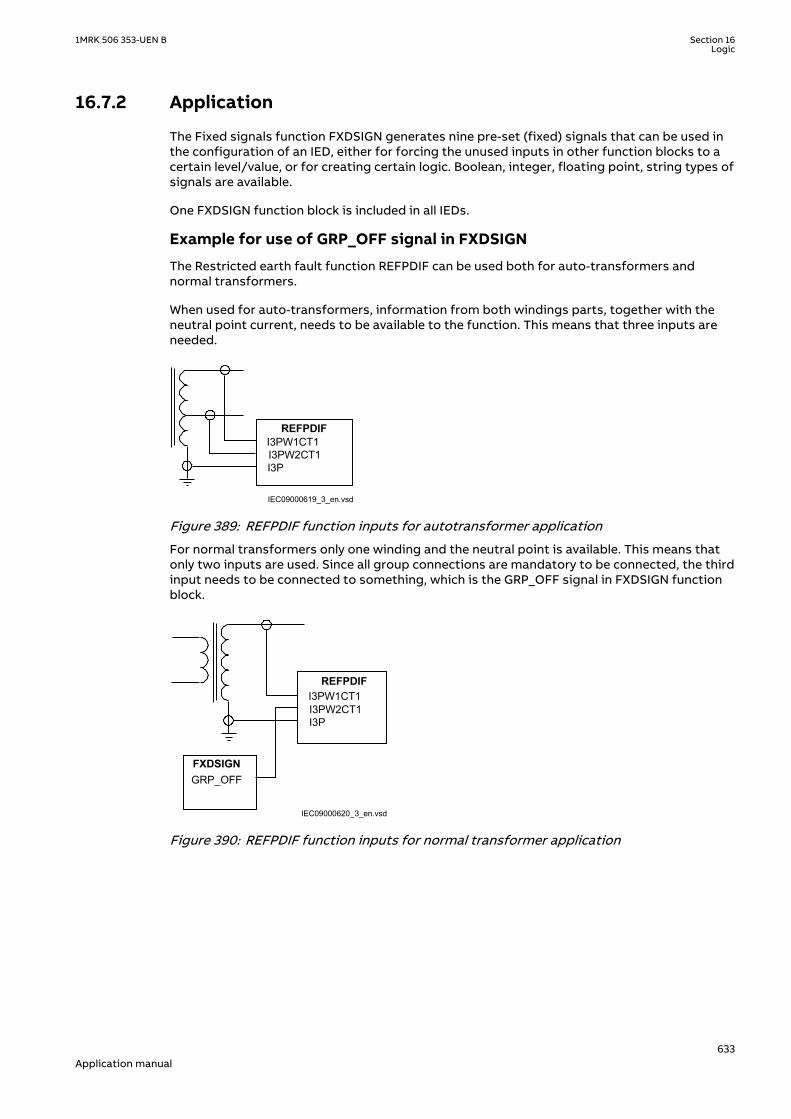
16.7.2 ApplicationM15322-3 v11
The Fixed signals function FXDSIGN generates nine pre-set (fixed) signals that can be used inthe configuration of an IED, either for forcing the unused inputs in other function blocks to acertain level/value, or for creating certain logic. Boolean, integer, floating point, string types ofsignals are available.
One FXDSIGN function block is included in all IEDs.
Example for use of GRP_OFF signal in FXDSIGN
The Restricted earth fault function REFPDIF can be used both for auto-transformers andnormal transformers.
When used for auto-transformers, information from both windings parts, together with theneutral point current, needs to be available to the function. This means that three inputs areneeded.
I3PW1CT1I3PW2CT1 I3P
REFPDIF
IEC09000619_3_en.vsdIEC09000619 V3 EN-US
Figure 389: REFPDIF function inputs for autotransformer application
For normal transformers only one winding and the neutral point is available. This means thatonly two inputs are used. Since all group connections are mandatory to be connected, the thirdinput needs to be connected to something, which is the GRP_OFF signal in FXDSIGN functionblock.
I3PW1CT1I3PW2CT1 I3P
REFPDIF
GRP_OFFFXDSIGN
IEC09000620_3_en.vsdIEC09000620 V3 EN-US
Figure 390: REFPDIF function inputs for normal transformer application
1MRK 506 353-UEN B Section 16Logic
633Application manual

16.8 Boolean 16 to Integer conversion B16ISEMOD175715-1 v1
16.8.1 IdentificationSEMOD175721-2 v2
Function description IEC 61850identification
IEC 60617identification
ANSI/IEEE C37.2device number
Boolean 16 to integer conversion B16I - -
16.8.2 ApplicationSEMOD175832-4 v4
Boolean 16 to integer conversion function B16I is used to transform a set of 16 binary (logical)signals into an integer. It can be used – for example, to connect logical output signals from afunction (like distance protection) to integer inputs from another function (like line differentialprotection). B16I does not have a logical node mapping.
The Boolean 16 to integer conversion function (B16I) will transfer a combination of up to 16binary inputs INx where 1≤x≤16 to an integer. Each INx represents a value according to thetable below from 0 to 32768. This follows the general formula: INx = 2x-1 where 1≤x≤16. The sumof all the values on the activated INx will be available on the output OUT as a sum of the valuesof all the inputs INx that are activated. OUT is an integer. When all INx where 1≤x≤16 areactivated that is = Boolean 1 it corresponds to that integer 65535 is available on the outputOUT. B16I function is designed for receiving up to 16 booleans input locally. If the BLOCK inputis activated, it will freeze the output at the last value.
Values of each of the different OUTx from function block B16I for 1≤x≤16.
The sum of the value on each INx corresponds to the integer presented on the output OUT onthe function block B16I.
Name of input Type Default Description Value whenactivated
Value whendeactivated
IN1 BOOLEAN 0 Input 1 1 0
IN2 BOOLEAN 0 Input 2 2 0
IN3 BOOLEAN 0 Input 3 4 0
IN4 BOOLEAN 0 Input 4 8 0
IN5 BOOLEAN 0 Input 5 16 0
IN6 BOOLEAN 0 Input 6 32 0
IN7 BOOLEAN 0 Input 7 64 0
IN8 BOOLEAN 0 Input 8 128 0
IN9 BOOLEAN 0 Input 9 256 0
IN10 BOOLEAN 0 Input 10 512 0
IN11 BOOLEAN 0 Input 11 1024 0
IN12 BOOLEAN 0 Input 12 2048 0
IN13 BOOLEAN 0 Input 13 4096 0
IN14 BOOLEAN 0 Input 14 8192 0
IN15 BOOLEAN 0 Input 15 16384 0
IN16 BOOLEAN 0 Input 16 32768 0
Section 16 1MRK 506 353-UEN BLogic
634Application manual

The sum of the numbers in column “Value when activated” when all INx (where 1≤x≤16) areactive that is=1; is 65535. 65535 is the highest boolean value that can be converted to aninteger by the B16I function block.
16.9 Boolean to integer conversion with logical noderepresentation, 16 bit BTIGAPC
SEMOD175753-1 v4
16.9.1 IdentificationSEMOD175757-2 v5
Function description IEC 61850identification
IEC 60617identification
ANSI/IEEE C37.2device number
Boolean to integer conversion withlogical node representation, 16 bit
BTIGAPC - -
16.9.2 ApplicationSEMOD175849-4 v5
Boolean 16 to integer conversion with logic node representation function BTIGAPC is used totransform a set of 16 binary (logical) signals into an integer. BTIGAPC can receive an integerfrom a station computer – for example, over IEC 61850–8–1. These functions are very usefulwhen you want to generate logical commands (for selector switches or voltage controllers) byinputting an integer number. BTIGAPC has a logical node mapping in IEC 61850.
The Boolean 16 to integer conversion function (BTIGAPC) will transfer a combination of up to16 binary inputs INx where 1≤x≤16 to an integer. Each INx represents a value according to thetable below from 0 to 32768. This follows the general formula: INx = 2x-1 where 1≤x≤16. The sumof all the values on the activated INx will be available on the output OUT as a sum of the valuesof all the inputs INx that are activated. OUT is an integer. When all INx where 1≤x≤16 areactivated that is = Boolean 1 it corresponds to that integer 65535 is available on the outputOUT. BTIGAPC function is designed for receiving up to 16 booleans input locally. If the BLOCKinput is activated, it will freeze the output at the last value.
Values of each of the different OUTx from function block BTIGAPC for 1≤x≤16.
The sum of the value on each INx corresponds to the integer presented on the output OUT onthe function block BTIGAPC.
Name of input Type Default Description Value whenactivated
Value whendeactivated
IN1 BOOLEAN 0 Input 1 1 0
IN2 BOOLEAN 0 Input 2 2 0
IN3 BOOLEAN 0 Input 3 4 0
IN4 BOOLEAN 0 Input 4 8 0
IN5 BOOLEAN 0 Input 5 16 0
IN6 BOOLEAN 0 Input 6 32 0
IN7 BOOLEAN 0 Input 7 64 0
IN8 BOOLEAN 0 Input 8 128 0
IN9 BOOLEAN 0 Input 9 256 0
IN10 BOOLEAN 0 Input 10 512 0
IN11 BOOLEAN 0 Input 11 1024 0
Table continues on next page
1MRK 506 353-UEN B Section 16Logic
635Application manual

Name of input Type Default Description Value whenactivated
Value whendeactivated
IN12 BOOLEAN 0 Input 12 2048 0
IN13 BOOLEAN 0 Input 13 4096 0
IN14 BOOLEAN 0 Input 14 8192 0
IN15 BOOLEAN 0 Input 15 16384 0
IN16 BOOLEAN 0 Input 16 32768 0
The sum of the numbers in column “Value when activated” when all INx (where 1≤x≤16) areactive that is=1; is 65535. 65535 is the highest boolean value that can be converted to aninteger by the BTIGAPC function block.
16.10 Integer to Boolean 16 conversion IB16SEMOD158367-1 v2
16.10.1 IdentificationSEMOD167941-2 v2
Function description IEC 61850identification
IEC 60617identification
ANSI/IEEE C37.2device number
Integer to boolean 16 conversion IB16 - -
16.10.2 ApplicationSEMOD158499-5 v4
Integer to boolean 16 conversion function (IB16) is used to transform an integer into a set of 16binary (logical) signals. It can be used – for example, to connect integer output signals fromone function to binary (logical) inputs to another function. IB16 function does not have alogical node mapping.
The Boolean 16 to integer conversion function (IB16) will transfer a combination of up to 16binary inputs INx where 1≤x≤16 to an integer. Each INx represents a value according to thetable below from 0 to 32768. This follows the general formula: INx = 2x-1 where 1≤x≤16. The sumof all the values on the activated INx will be available on the output OUT as a sum of the valuesof all the inputs INx that are activated. OUT is an integer. When all INx where 1≤x≤16 areactivated that is = Boolean 1 it corresponds to that integer 65535 is available on the outputOUT. IB16 function is designed for receiving up to 16 booleans input locally. If the BLOCK inputis activated, it will freeze the output at the last value.
Values of each of the different OUTx from function block IB16 for 1≤x≤16.
The sum of the value on each INx corresponds to the integer presented on the output OUT onthe function block IB16.
Name of input Type Default Description Value whenactivated
Value whendeactivated
IN1 BOOLEAN 0 Input 1 1 0
IN2 BOOLEAN 0 Input 2 2 0
IN3 BOOLEAN 0 Input 3 4 0
IN4 BOOLEAN 0 Input 4 8 0
IN5 BOOLEAN 0 Input 5 16 0
Table continues on next page
Section 16 1MRK 506 353-UEN BLogic
636Application manual

Name of input Type Default Description Value whenactivated
Value whendeactivated
IN6 BOOLEAN 0 Input 6 32 0
IN7 BOOLEAN 0 Input 7 64 0
IN8 BOOLEAN 0 Input 8 128 0
IN9 BOOLEAN 0 Input 9 256 0
IN10 BOOLEAN 0 Input 10 512 0
IN11 BOOLEAN 0 Input 11 1024 0
IN12 BOOLEAN 0 Input 12 2048 0
IN13 BOOLEAN 0 Input 13 4096 0
IN14 BOOLEAN 0 Input 14 8192 0
IN15 BOOLEAN 0 Input 15 16384 0
IN16 BOOLEAN 0 Input 16 32768 0
The sum of the numbers in column “Value when activated” when all INx (where 1≤x≤16) areactive that is=1; is 65535. 65535 is the highest boolean value that can be converted to aninteger by the IB16 function block.
16.11 Integer to Boolean 16 conversion with logic noderepresentation ITBGAPC
SEMOD158419-1 v3
16.11.1 IdentificationSEMOD167944-2 v4
Function description IEC 61850identification
IEC 60617identification
ANSI/IEEE C37.2device number
Integer to boolean 16 conversionwith logic node representation
ITBGAPC - -
16.11.2 ApplicationSEMOD158512-5 v6
Integer to boolean 16 conversion with logic node representation function (ITBGAPC) is used totransform an integer into a set of 16 boolean signals. ITBGAPC function can receive an integerfrom a station computer – for example, over IEC 61850–8–1. This function is very useful whenthe user wants to generate logical commands (for selector switches or voltage controllers) byinputting an integer number. ITBGAPC function has a logical node mapping in IEC 61850.
The Integer to Boolean 16 conversion with logic node representation function (ITBGAPC) willtransfer an integer with a value between 0 to 65535 communicated via IEC61850 andconnected to the ITBGAPC function block to a combination of activated outputs OUTx where1≤x≤16.
The values of the different OUTx are according to the Table 50.
If the BLOCK input is activated, it freezes the logical outputs at the last value.
1MRK 506 353-UEN B Section 16Logic
637Application manual

Table 50: Output signals
Name of OUTx Type Description Value whenactivated
Value whendeactivated
OUT1 BOOLEAN Output 1 1 0
OUT2 BOOLEAN Output 2 2 0
OUT3 BOOLEAN Output 3 4 0
OUT4 BOOLEAN Output 4 8 0
OUT5 BOOLEAN Output 5 16 0
OUT6 BOOLEAN Output 6 32 0
OUT7 BOOLEAN Output 7 64 0
OUT8 BOOLEAN Output 8 128 0
OUT9 BOOLEAN Output 9 256 0
OUT10 BOOLEAN Output 10 512 0
OUT11 BOOLEAN Output 11 1024 0
OUT12 BOOLEAN Output 12 2048 0
OUT13 BOOLEAN Output 13 4096 0
OUT14 BOOLEAN Output 14 8192 0
OUT15 BOOLEAN Output 15 16384 0
OUT16 BOOLEAN Output 16 32768 0
The sum of the numbers in column “Value when activated” when all OUTx (1≤x≤16) are activeequals 65535. This is the highest integer that can be converted by the ITBGAPC function block.
16.12 Elapsed time integrator with limit transgression andoverflow supervision TEIGAPC
16.12.1 IdentificationGUID-1913E066-37D1-4689-9178-5B3C8B029815 v2
Function Description IEC 61850identification
IEC 60617identification
ANSI/IEEE C37.2 devicenumber
Elapsed time integrator TEIGAPC - -
16.12.2 ApplicationGUID-B4B47167-C8DE-4496-AEF1-5F0FD1768A87 v2
The function TEIGAPC is used for user-defined logics and it can also be used for differentpurposes internally in the IED. An application example is the integration of elapsed time duringthe measurement of neutral point voltage or neutral current at earth-fault conditions.
Settable time limits for warning and alarm are provided. The time limit for overflow indicationis fixed to 999999.9 seconds.
16.12.3 Setting guidelinesGUID-2911D624-87D5-4427-BB2F-E0D1072394FA v2
The settings tAlarm and tWarning are user settable limits defined in seconds. The achievableresolution of the settings depends on the level of the values defined.
Section 16 1MRK 506 353-UEN BLogic
638Application manual

A resolution of 10 ms can be achieved when the settings are defined within the range
1.00 second ≤ tAlarm ≤ 99 999.99 seconds
1.00 second ≤ tWarning ≤ 99 999.99 seconds.
If the values are above this range the resolution becomes lower
99 999.99 seconds ≤ tAlarm ≤ 999 999.9 seconds
99 999.99 seconds≤ tWarning ≤ 999 999.9 seconds
Note that tAlarm and tWarning are independent settings, that is, there is nocheck if tAlarm > tWarning.
The limit for the overflow supervision is fixed at 999999.9 seconds.
16.13 Comparator for integer inputs - INTCOMP
16.13.1 IdentificationGUID-5992B0F2-FC1B-4838-9BAB-2D2542BB264D v1
Function description IEC 61850identification
IEC 60617identification
ANSI/IEEE C37.2device number
Comparison of integer values INTCOMP Int<=>
16.13.2 ApplicationGUID-4C6D730D-BB1C-45F1-A719-1267234BF1B9 v1
The function gives the possibility to monitor the level of integer values in the system relativeto each other or to a fixed value. It is a basic arithmetic function that can be used formonitoring, supervision, interlocking and other logics.
16.13.3 Setting guidelinesGUID-ADA3E806-BEF1-4D15-B270-207386A0AEE4 v1
For proper operation of comparison the set value should be set within the range of ± 2 ×10⁹.
Setting procedure on the IED:
EnaAbs: This setting is used to select the comparison type between signed and absolutevalues.
• Absolute: The function will do absolute comparison between input and reference value• Signed: The function will do signed comparison between input and reference value
RefSource: This setting is used to select the reference source between input and setting forcomparison.
• REF: The function will take reference value from input REF• SetValue: The function will take reference value from setting SetValue
SetValue: This setting is used to set the reference value for comparison when settingRefSource is selected as SetValue.
1MRK 506 353-UEN B Section 16Logic
639Application manual

16.13.4 Setting exampleGUID-13302FD6-1585-42FE-BD6D-44F231982C59 v1
For absolute comparison between inputs:
Set the EnaAbs = 1
Set the RefSource = 1
Similarly for Signed comparison between inputs
Set the EnaAbs = 0
Set the RefSource =1
For absolute comparison between input and setting
Set the EnaAbs = 1
Set the RefSource = 0
SetValue shall be set between -2000000000 to 2000000000
Similarly for signed comparison between input and setting
Set the EnaAbs = 0
Set the RefSource = 0
SetValue shall be set between -2000000000 to 2000000000.
16.14 Comparator for real inputs - REALCOMP
16.14.1 IdentificationGUID-0D68E846-5A15-4C2C-91A2-F81A74034E81 v1
Function description IEC 61850identification
IEC 60617identification
ANSI/IEEE C37.2device number
Comparator for real inputs REALCOMP Real<=>
16.14.2 ApplicationGUID-5F7B1683-9799-4D27-B333-B184F8861A5B v1
The function gives the possibility to monitor the level of real values in the system relative toeach other or to a fixed value. It is a basic arithmetic function that can be used for monitoring,supervision, interlocking and other logics.
16.14.3 Setting guidelinesGUID-DE69FF5B-7D34-4A30-9060-214E98BFF798 v1
Setting procedure on the IED:
EnaAbs: This setting is used to select the comparison type between signed and absolutevalues.
• Absolute: The function will do absolute comparison between input and reference value.• Signed: The function will do signed comparison between input and reference value.
Section 16 1MRK 506 353-UEN BLogic
640Application manual

RefSource: This setting is used to select the reference source between input and setting forcomparison.
• REF: The function will take reference value from input REF• SetValue: The function will take reference value from setting SetValue
SetValue: This setting is used to set the reference value for comparison when settingRefSource is selected as SetValue. If this setting value is less than 0.2% of the set unit then theoutput INLOW will never pickups.
RefPrefix: This setting is used to set the unit of the reference value for comparison whensetting RefSource is selected as SetValue. It has 5 unit selections and they are Milli, Unity, Kilo,Mega and Giga.
EqualBandHigh: This setting is used to set the equal condition high band limit in % ofreference value. This high band limit will act as reset limit for INHIGH output when INHIGH ishigh in last execution.
EqualBandLow: This setting is used to set the equal condition low band limit in % of referencevalue. This low band limit will act as reset limit for INLOW output when INLOW is high in lastexecution.
16.14.4 Setting exampleGUID-E7070CF6-B44B-4799-BE18-5C75B9FE2A87 v1
Let us consider a comparison is to be done between current magnitudes in the range of 90 to110 with nominal rating is 100 and the order is kA.
For the above condition the comparator can be designed with settings as follows,
EnaAbs = Absolute
RefSource = SetValue
SetValue = 100
RefPrefix = Kilo
EqualBandHigh = 5.0 % of reference value
EqualBandLow = 5.0 % of reference value
Operation
The function will set the outputs for the following conditions,
INEQUAL will set when the INPUT is between the ranges of 95 to 105 kA.
INHIGH will set when the INPUT crosses above 105 kA.
INLOW will set when the INPUT crosses below 95 kA.
If the comparison should be done between two current magnitudes then those current signalsneed to be connected to function inputs, INPUT and REF. Then the settings should be adjustedas below,
EnaAbs = Absolute
RefSource = REF
1MRK 506 353-UEN B Section 16Logic
641Application manual

EqualBandHigh = 5.0 % of reference value
EqualBandLow = 5.0 % of reference value.
Section 16 1MRK 506 353-UEN BLogic
642Application manual

Section 17 Monitoring
17.1 MeasurementGUID-9D2D47A0-FE62-4FE3-82EE-034BED82682A v1
17.1.1 IdentificationSEMOD56123-2 v7
Function description IEC 61850identification
IEC 60617identification
ANSI/IEEE C37.2device number
Measurements CVMMXN
P, Q, S, I, U, f
SYMBOL-RR V1 EN-US
-
Phase current measurement CMMXU
I
SYMBOL-SS V1 EN-US
-
Phase-phase voltage measurement VMMXU
U
SYMBOL-UU V1 EN-US
-
Current sequence componentmeasurement
CMSQI
I1, I2, I0
SYMBOL-VV V1 EN-US
-
Voltage sequence componentmeasurement
VMSQI
U1, U2, U0
SYMBOL-TT V1 EN-US
-
Phase-neutral voltage measurement VNMMXU
U
SYMBOL-UU V1 EN-US
-
17.1.2 ApplicationSEMOD54488-4 v11
Measurement functions are used for power system measurement, supervision and reportingto the local HMI, monitoring tool within PCM600 or to station level for example, via IEC 61850.The possibility to continuously monitor measured values of active power, reactive power,currents, voltages, frequency, power factor etc. is vital for efficient production, transmissionand distribution of electrical energy. It provides to the system operator fast and easy overviewof the present status of the power system. Additionally, it can be used during testing andcommissioning of protection and control IEDs in order to verify proper operation andconnection of instrument transformers (CTs and VTs). During normal service by periodiccomparison of the measured value from the IED with other independent meters the properoperation of the IED analog measurement chain can be verified. Finally, it can be used to verifyproper direction orientation for distance or directional overcurrent protection function.
1MRK 506 353-UEN B Section 17Monitoring
643Application manual

The available measured values of an IED are depending on the actual hardware(TRM) and the logic configuration made in PCM600.
All measured values can be supervised with four settable limits that is, low-low limit, low limit,high limit and high-high limit. A zero clamping reduction is also supported, that is, themeasured value below a settable limit is forced to zero which reduces the impact of noise inthe inputs.
Dead-band supervision can be used to report measured signal value to station level whenchange in measured value is above set threshold limit or time integral of all changes since thelast time value updating exceeds the threshold limit. Measure value can also be based onperiodic reporting.
Main menu/Measurement/Monitoring/Service values/CVMMXN
The measurement function, CVMMXN, provides the following power system quantities:
• P, Q and S: three phase active, reactive and apparent power• PF: power factor• U: phase-to-phase voltage amplitude• I: phase current amplitude• F: power system frequency
,The measuring functions CMMXU, VMMXU and VNMMXU provide physical quantities:
• I: phase currents (amplitude and angle) (CMMXU)• U: voltages (phase-to-earth and phase-to-phase voltage, amplitude and angle) (VMMXU,
VNMMXU)
The CVMMXN function calculates three-phase power quantities by using fundamentalfrequency phasors (DFT values) of the measured current respectively voltage signals. Themeasured power quantities are available either, as instantaneously calculated quantities or,averaged values over a period of time (low pass filtered) depending on the selected settings.
It is possible to calibrate the measuring function above to get better then class 0.5presentation. This is accomplished by angle and amplitude compensation at 5, 30 and 100% ofrated current and at 100% of rated voltage.
The power system quantities provided, depends on the actual hardware, (TRM)and the logic configuration made in PCM600.
The measuring functions CMSQI and VMSQI provide sequence component quantities:
• I: sequence currents (positive, zero, negative sequence, amplitude and angle)• U: sequence voltages (positive, zero and negative sequence, amplitude and angle).
17.1.3 Zero clampingGUID-8DABC3F5-6615-493C-B839-A5C557A2FAE8 v2
The measuring functions, CVMMXN, CMMXU, VMMXU and VNMMXU have no interconnectionsregarding any setting or parameter.
Zero clampings are also entirely handled by the ZeroDb for each and every signal separately foreach of the functions. For example, the zero clamping of U12 is handled by UL12ZeroDb inVMMXU, zero clamping of I1 is handled by IL1ZeroDb in CMMXU ETC.
Section 17 1MRK 506 353-UEN BMonitoring
644Application manual
Example how CVMMXN is operating:
The following outputs can be observed on the local HMI under Monitoring/Servicevalues/SRV1
S Apparent three-phase power
P Active three-phase power
Q Reactive three-phase power
PF Power factor
ILAG I lagging U
ILEAD I leading U
U System mean voltage, calculated according to selected mode
I System mean current, calculated according to selected mode
F Frequency
The settings for this function is found under Setting/General setting/Monitoring/Servicevalues/SRV1
It can be seen that:
• When system voltage falls below UGenZeroDB, the shown value for S, P, Q, PF, ILAG, ILEAD,U and F on the local HMI is forced to zero
• When system current falls below IGenZeroDB, the shown value for S, P, Q, PF, ILAG, ILEAD,U and F on the local HMI is forced to zero
• When the value of a single signal falls below the set dead band for that specific signal, thevalue shown on the local HMI is forced to zero. For example, if apparent three-phasepower falls below SZeroDb the value for S on the local HMI is forced to zero.
17.1.4 Setting guidelinesSEMOD54481-165 v12
The available setting parameters of the measurement function CVMMXN, CMMXU, VMMXU,CMSQI, VMSQI, VNMMXU are depending on the actual hardware (TRM) and the logicconfiguration made in PCM600.
The parameters for the Measurement functions CVMMXN, CMMXU, VMMXU, CMSQI, VMSQI,VNMMXU are set via the local HMI or PCM600.
GlobalBaseSel: Selects the global base value group used by the function to define (IBase),(UBase) and (SBase).
Operation: Off/On. Every function instance (CVMMXN, CMMXU, VMMXU, CMSQI, VMSQI,VNMMXU) can be taken in operation (On) or out of operation (Off).
The following general settings can be set for the Measurement function (CVMMXN).
PowAmpFact: Amplitude factor to scale power calculations.
PowAngComp: Angle compensation for phase shift between measured I & U.
Mode: Selection of measured current and voltage. There are 9 different ways of calculatingmonitored three-phase values depending on the available VT inputs connected to the IED. Seeparameter group setting table.
k: Low pass filter coefficient for power measurement, U and I.
1MRK 506 353-UEN B Section 17Monitoring
645Application manual

UGenZeroDb: Minimum level of voltage in % of UBase used as indication of zero voltage (zeropoint clamping). If measured value is below UGenZeroDb calculated S, P, Q and PF will be zero.
IGenZeroDb: Minimum level of current in % of IBase used as indication of zero current (zeropoint clamping). If measured value is below IGenZeroDb calculated S, P, Q and PF will be zero.
UAmpCompY: Amplitude compensation to calibrate voltage measurements at Y% of Ur, whereY is equal to 5, 30 or 100.
IAmpCompY: Amplitude compensation to calibrate current measurements at Y% of Ir, where Yis equal to 5, 30 or 100.
IAngCompY: Angle compensation to calibrate angle measurements at Y% of Ir, where Y isequal to 5, 30 or 100.
The following general settings can be set for the Phase-phase current measurement(CMMXU).
IAmpCompY: Amplitude compensation to calibrate current measurements at Y% of Ir, where Yis equal to 5, 30 or 100.
IAngCompY: Angle compensation to calibrate angle measurements at Y% of Ir, where Y isequal to 5, 30 or 100.
The following general settings can be set for the Phase-phase voltage measurement(VMMXU).
UAmpCompY: Amplitude compensation to calibrate voltage measurements at Y% of Ur, whereY is equal to 5, 30 or 100.
UAngCompY: Angle compensation to calibrate angle measurements at Y% of Ur, where Y isequal to 5, 30 or 100.
The following general settings can be set for all monitored quantities included in thefunctions (CVMMXN, CMMXU, VMMXU, CMSQI, VMSQI, VNMMXU) X in setting names belowequals S, P, Q, PF, U, I, F, IL1-3, UL1-3UL12-31, I1, I2, 3I0, U1, U2 or 3U0.
Xmin: Minimum value for analog signal X set directly in applicable measuring unit.
Xmax: Maximum value for analog signal X.
XZeroDb: Zero point clamping. A signal value less than XZeroDb is forced to zero.
Observe the related zero point clamping settings in Setting group N for CVMMXN(UGenZeroDb and IGenZeroDb). If measured value is below UGenZeroDb and/or IGenZeroDbcalculated S, P, Q and PF will be zero and these settings will override XZeroDb.
XRepTyp: Reporting type. Cyclic (Cyclic), amplitude deadband (Dead band) or integraldeadband (Int deadband). The reporting interval is controlled by the parameter XDbRepInt.
XDbRepInt: Reporting deadband setting. Cyclic reporting is the setting value and is reportinginterval in seconds. Amplitude deadband is the setting value in % of measuring range. Integraldeadband setting is the integral area, that is, measured value in % of measuring rangemultiplied by the time between two measured values.
XHiHiLim: High-high limit. Set in applicable measuring unit.
XHiLim: High limit.
XLowLim: Low limit.
XLowLowLim: Low-low limit.
Section 17 1MRK 506 353-UEN BMonitoring
646Application manual

XLimHyst: Hysteresis value in % of range and is common for all limits.
All phase angles are presented in relation to defined reference channel. The parameterPhaseAngleRef defines the reference, see section "".
Calibration curves
It is possible to calibrate the functions (CVMMXN, CMMXU, VMMXU and VNMMXU) to get class0.5 presentations of currents, voltages and powers. This is accomplished by amplitude andangle compensation at 5, 30 and 100% of rated current and voltage. The compensation curvewill have the characteristic for amplitude and angle compensation of currents as shown infigure 391 (example). The first phase will be used as reference channel and compared with thecurve for calculation of factors. The factors will then be used for all related channels.
IEC05000652 V2 EN-US
Figure 391: Calibration curves
17.1.4.1 Setting examplesSEMOD54481-4 v4
Three setting examples, in connection to Measurement function (CVMMXN), are provided:
• Measurement function (CVMMXN) application for a OHL• Measurement function (CVMMXN) application on the secondary side of a transformer• Measurement function (CVMMXN) application for a generator
For each of them detail explanation and final list of selected setting parameters values will beprovided.
The available measured values of an IED are depending on the actual hardware(TRM) and the logic configuration made in PCM600.
1MRK 506 353-UEN B Section 17Monitoring
647Application manual

Measurement function application for a 110kV OHLSEMOD54481-12 v9
Single line diagram for this application is given in figure 392:
110kV Busbar
110kV OHL
P Q
600/1 A110 0,1/
3 3kV
IEC09000039-2-en.vsd
IED
IEC09000039-1-EN V2 EN-US
Figure 392: Single line diagram for 110kV OHL application
In order to monitor, supervise and calibrate the active and reactive power as indicated infigure 392 it is necessary to do the following:
1. Set correctly CT and VT data and phase angle reference channel PhaseAngleRef (seesection "") using PCM600 for analog input channels
2. Connect, in PCM600, measurement function to three-phase CT and VT inputs3. Set under General settings parameters for the Measurement function:
• general settings as shown in table 51.• level supervision of active power as shown in table 52.• calibration parameters as shown in table 53.
Table 51: General settings parameters for the Measurement function
Setting Short Description Selectedvalue
Comments
Operation Operation Off/On On Function must be On
PowAmpFact Amplitude factor to scalepower calculations
1.000 It can be used during commissioning toachieve higher measurement accuracy.Typically no scaling is required
PowAngComp Angle compensation for phaseshift between measured I & U
0.0 It can be used during commissioning toachieve higher measurement accuracy.Typically no angle compensation is required.As well here required direction of P & Qmeasurement is towards protected object (asper IED internal default direction)
Mode Selection of measured currentand voltage
L1, L2, L3 All three phase-to-earth VT inputs areavailable
k Low pass filter coefficient forpower measurement, U and I
0.00 Typically no additional filtering is required
UGenZeroDb Zero point clamping in % ofUbase
25 Set minimum voltage level to 25%. Voltagebelow 25% will force S, P and Q to zero.
IGenZeroDb Zero point clamping in % ofIbase
3 Set minimum current level to 3%. Currentbelow 3% will force S, P and Q to zero.
UBase (set inGlobal base)
Base setting for voltage levelin kV
400.00 Set rated OHL phase-to-phase voltage
IBase (set inGlobal base)
Base setting for current levelin A
800 Set rated primary CT current used for OHL
Section 17 1MRK 506 353-UEN BMonitoring
648Application manual

Table 52: Settings parameters for level supervision
Setting Short Description Selectedvalue
Comments
PMin Minimum value -100 Minimum expected load
PMax Minimum value 100 Maximum expected load
PZeroDb Zero point clamping in 0.001%of range
3000 Set zero point clamping to 45 MW that is, 3%of 200 MW
PRepTyp Reporting type db Select amplitude deadband supervision
PDbRepInt Cycl: Report interval (s), Db: In% of range, Int Db: In %s
2 Set ±Δdb=30 MW that is, 2% (larger changesthan 30 MW will be reported)
PHiHiLim High High limit (physical value) 60 High alarm limit that is, extreme overloadalarm
PHiLim High limit (physical value) 50 High warning limit that is, overload warning
PLowLim Low limit (physical value) -50 Low warning limit. Not active
PLowLowlLim Low Low limit (physical value) -60 Low alarm limit. Not active
PLimHyst Hysteresis value in % of range(common for all limits)
2 Set ±Δ Hysteresis MW that is, 2%
Table 53: Settings for calibration parameters
Setting Short Description Selectedvalue
Comments
IAmpComp5 Amplitude factor to calibratecurrent at 5% of Ir
0.00
IAmpComp30 Amplitude factor to calibratecurrent at 30% of Ir
0.00
IAmpComp100 Amplitude factor to calibratecurrent at 100% of Ir
0.00
UAmpComp5 Amplitude factor to calibratevoltage at 5% of Ur
0.00
UAmpComp30 Amplitude factor to calibratevoltage at 30% of Ur
0.00
UAmpComp100 Amplitude factor to calibratevoltage at 100% of Ur
0.00
IAngComp5 Angle calibration for current at5% of Ir
0.00
IAngComp30 Angle pre-calibration forcurrent at 30% of Ir
0.00
IAngComp100 Angle pre-calibration forcurrent at 100% of Ir
0.00
Measurement function application for a power transformerSEMOD54481-61 v7
Single line diagram for this application is given in figure 393.
1MRK 506 353-UEN B Section 17Monitoring
649Application manual

110kV Busbar
200/1
35 / 0,1kV
35kV Busbar
500/5
P Q
31,5 MVA110/36,75/(10,5) kV
Yy0(d5)
UL1L2
IEC09000040-1-en.vsd
IED
IEC09000040-1-EN V1 EN-US
Figure 393: Single line diagram for transformer application
In order to measure the active and reactive power as indicated in figure 393, it is necessary todo the following:
1. Set correctly all CT and VT and phase angle reference channel PhaseAngleRef (see section"") data using PCM600 for analog input channels
2. Connect, in PCM600, measurement function to LV side CT & VT inputs3. Set the setting parameters for relevant Measurement function as shown in the following
table 54:
Section 17 1MRK 506 353-UEN BMonitoring
650Application manual

Table 54: General settings parameters for the Measurement function
Setting Short description Selectedvalue
Comment
Operation Operation Off/On On Function must be On
PowAmpFact Amplitude factor to scalepower calculations
1.000 Typically no scaling is required
PowAngComp Angle compensation for phaseshift between measured I & U
180.0 Typically no angle compensation is required.However here the required direction of P & Qmeasurement is towards busbar (Not per IEDinternal default direction). Therefore anglecompensation have to be used in order to getmeasurements in aliment with the requireddirection.
Mode Selection of measured currentand voltage
L1L2 Only UL1L2 phase-to-phase voltage isavailable
k Low pass filter coefficient forpower measurement, U and I
0.00 Typically no additional filtering is required
UGenZeroDb Zero point clamping in % ofUbase
25 Set minimum voltage level to 25%
IGenZeroDb Zero point clamping in % ofIbase
3 Set minimum current level to 3%
UBase (set inGlobal base)
Base setting for voltage levelin kV
35.00 Set LV side rated phase-to-phase voltage
IBase (set inGlobal base)
Base setting for current levelin A
495 Set transformer LV winding rated current
Measurement function application for a generatorSEMOD54481-110 v7
Single line diagram for this application is given in figure 394.
1MRK 506 353-UEN B Section 17Monitoring
651Application manual

220kV Busbar
300/1
15 / 0,1kV
4000/5
100 MVA242/15,65 kV
Yd5
UL1L2 , UL2L3
G
P Q
100MVA15,65kV
IEC09000041-1-en.vsd
IED
IEC09000041-1-EN V1 EN-US
Figure 394: Single line diagram for generator application
In order to measure the active and reactive power as indicated in figure 394, it is necessary todo the following:
1. Set correctly all CT and VT data and phase angle reference channel PhaseAngleRef(seesection "") using PCM600 for analog input channels
2. Connect, in PCM600, measurement function to the generator CT & VT inputs3. Set the setting parameters for relevant Measurement function as shown in the following
table:
Section 17 1MRK 506 353-UEN BMonitoring
652Application manual

Table 55: General settings parameters for the Measurement function
Setting Short description Selectedvalue
Comment
Operation Operation Off/On On Function must be On
PowAmpFact Amplitude factor to scalepower calculations
1.000 Typically no scaling is required
PowAngComp Angle compensation for phaseshift between measured I & U
0.0 Typically no angle compensation is required.As well here required direction of P & Qmeasurement is towards protected object (asper IED internal default direction)
Mode Selection of measured currentand voltage
Arone Generator VTs are connected between phases(V-connected)
k Low pass filter coefficient forpower measurement, U and I
0.00 Typically no additional filtering is required
UGenZeroDb Zero point clamping in % ofUbase
25% Set minimum voltage level to 25%
IGenZeroDb Zero point clamping in % ofIbase
3 Set minimum current level to 3%
UBase (set inGlobal base)
Base setting for voltage levelin kV
15,65 Set generator rated phase-to-phase voltage
IBase (set inGlobal base)
Base setting for current levelin A
3690 Set generator rated current
17.2 Gas medium supervision SSIMGGUID-358AD8F8-AE06-4AEA-9969-46E5299D5B4B v3
17.2.1 IdentificationGUID-AD96C26E-C3E5-4B21-9ED6-12E540954AC3 v3
Function description IEC 61850identification
IEC 60617identification
ANSI/IEEE C37.2device number
Gas medium supervision SSIMG - 63
17.2.2 ApplicationGUID-A840E38C-CC42-4995-A569-A6092DDB81B2 v5
Gas medium supervision (SSIMG) is used for monitoring the circuit breaker condition. Properarc extinction by the compressed gas in the circuit breaker is very important. When thepressure becomes too low compared to the required value, the circuit breaker operation shallbe blocked to minimize the risk of internal failure. Binary information based on the gaspressure in the circuit breaker is used as an input signal to the function. The functiongenerates alarms based on the received information.
17.3 Liquid medium supervision SSIMLGUID-37669E94-4830-4C96-8A67-09600F847F23 v3
17.3.1 IdentificationGUID-4CE96EF6-42C6-4F2E-A190-D288ABF766F6 v2
Function description IEC 61850identification
IEC 60617identification
ANSI/IEEE C37.2device number
Liquid medium supervision SSIML - 71
1MRK 506 353-UEN B Section 17Monitoring
653Application manual

17.3.2 ApplicationGUID-140AA10C-4E93-4C23-AD57-895FADB0DB29 v5
Liquid medium supervision (SSIML) is used for monitoring the circuit breaker condition. Properarc extinction by the compressed oil in the circuit breaker is very important. When the levelbecomes too low, compared to the required value, the circuit breaker operation is blocked tominimize the risk of internal failures. Binary information based on the oil level in the circuitbreaker is used as input signals to the function. In addition to that, the function generatesalarms based on received information.
17.4 Breaker monitoring SSCBR
17.4.1 IdentificationGUID-0FC081B2-0BC8-4EB8-9529-B941E51F18EE v7
Function description IEC 61850identification
IEC 60617identification
ANSI/IEEE C37.2device number
Breaker monitoring SSCBR - -
17.4.2 ApplicationGUID-45572680-3A39-4B3C-8639-4E4C5A95AA26 v8
The circuit breaker maintenance is usually based on regular time intervals or the number ofoperations performed. This has some disadvantages because there could be a number ofabnormal operations or few operations with high-level currents within the predeterminedmaintenance interval. Hence, condition-based maintenance scheduling is an optimum solutionin assessing the condition of circuit breakers.
Circuit breaker contact travel time
Auxiliary contacts provide information about the mechanical operation, opening time andclosing time of a breaker. Detecting an excessive traveling time is essential to indicate theneed for maintenance of the circuit breaker mechanism. The excessive travel time can be dueto problems in the driving mechanism or failures of the contacts.
Circuit breaker status
Monitoring the breaker status ensures proper functioning of the features within theprotection relay such as breaker control, breaker failure and autoreclosing. The breaker statusis monitored using breaker auxiliary contacts. The breaker status is indicated by the binaryoutputs. These signals indicate whether the circuit breaker is in an open, closed or error state.
Remaining life of circuit breaker
Every time the breaker operates, the circuit breaker life reduces due to wear. The wear in abreaker depends on the interrupted current. For breaker maintenance or replacement at theright time, the remaining life of the breaker must be estimated. The remaining life of a breakercan be estimated using the maintenance curve provided by the circuit breaker manufacturer.
Circuit breaker manufacturers provide the number of make-break operations possible atvarious interrupted currents. An example is shown in Figure395.
Section 17 1MRK 506 353-UEN BMonitoring
654Application manual
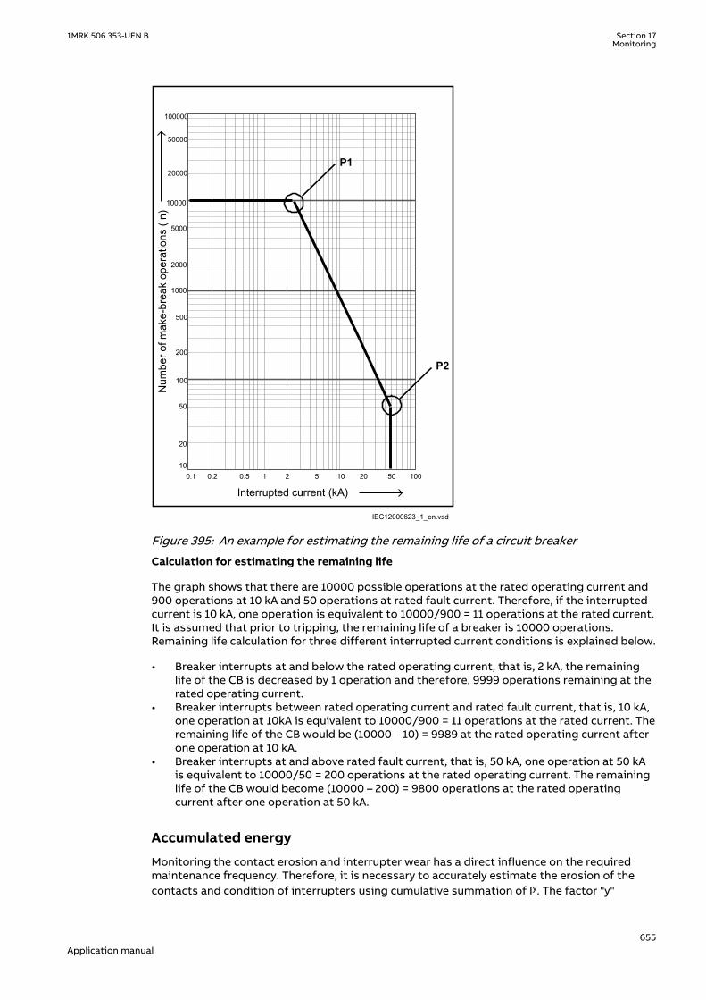
Num
ber o
f mak
e-br
eak
oper
atio
ns (
n)
Interrupted current (kA)
P1
P2
100000
50000
20000
10000
2000
5000
1000
100
200
500
10
20
50
0.1 0.2 0.5 1 2 5 10 20 50 100
IEC12000623_1_en.vsdIEC12000623 V1 EN-US
Figure 395: An example for estimating the remaining life of a circuit breaker
Calculation for estimating the remaining life
The graph shows that there are 10000 possible operations at the rated operating current and900 operations at 10 kA and 50 operations at rated fault current. Therefore, if the interruptedcurrent is 10 kA, one operation is equivalent to 10000/900 = 11 operations at the rated current.It is assumed that prior to tripping, the remaining life of a breaker is 10000 operations.Remaining life calculation for three different interrupted current conditions is explained below.
• Breaker interrupts at and below the rated operating current, that is, 2 kA, the remaininglife of the CB is decreased by 1 operation and therefore, 9999 operations remaining at therated operating current.
• Breaker interrupts between rated operating current and rated fault current, that is, 10 kA,one operation at 10kA is equivalent to 10000/900 = 11 operations at the rated current. Theremaining life of the CB would be (10000 – 10) = 9989 at the rated operating current afterone operation at 10 kA.
• Breaker interrupts at and above rated fault current, that is, 50 kA, one operation at 50 kAis equivalent to 10000/50 = 200 operations at the rated operating current. The remaininglife of the CB would become (10000 – 200) = 9800 operations at the rated operatingcurrent after one operation at 50 kA.
Accumulated energy
Monitoring the contact erosion and interrupter wear has a direct influence on the requiredmaintenance frequency. Therefore, it is necessary to accurately estimate the erosion of thecontacts and condition of interrupters using cumulative summation of Iy. The factor "y"
1MRK 506 353-UEN B Section 17Monitoring
655Application manual

depends on the type of circuit breaker. The energy values were accumulated using the currentvalue and exponent factor for CB contact opening duration. When the next CB openingoperation is started, the energy is accumulated from the previous value. The accumulatedenergy value can be reset to initial accumulation energy value by using the Reset accumulatingenergy input, RSTIPOW.
Circuit breaker operation cycles
Routine breaker maintenance like lubricating breaker mechanism is based on the number ofoperations. A suitable threshold setting helps in preventive maintenance. This can also be usedto indicate the requirement for oil sampling for dielectric testing in case of an oil circuitbreaker.
Circuit breaker operation monitoring
By monitoring the activity of the number of operations, it is possible to calculate the numberof days the breaker has been inactive. Long periods of inactivity degrade the reliability for theprotection system.
Circuit breaker spring charge monitoring
For normal circuit breaker operation, the circuit breaker spring should be charged within aspecified time. Detecting a long spring charging time indicates the time for circuit breakermaintenance. The last value of the spring charging time can be given as a service value.
Circuit breaker gas pressure indication
For proper arc extinction by the compressed gas in the circuit breaker, the pressure of the gasmust be adequate. Binary input available from the pressure sensor is based on the pressurelevels inside the arc chamber. When the pressure becomes too low compared to the requiredvalue, the circuit breaker operation is blocked.
17.4.3 Setting guidelinesGUID-AB93AD9B-E6F8-4F1A-B353-AA1008C15679 v2
The breaker monitoring function is used to monitor different parameters of the circuitbreaker. The breaker requires maintenance when the number of operations has reached apredefined value. For proper functioning of the circuit breaker, it is also essential to monitorthe circuit breaker operation, spring charge indication or breaker wear, travel time, number ofoperation cycles and accumulated energy during arc extinction.
17.4.3.1 Setting procedure on the IEDGUID-4E895FEA-74BF-4B11-A239-0574F8FF5188 v4
The parameters for breaker monitoring (SSCBR) can be set using the local HMI or Protectionand Control Manager (PCM600).
Common base IED values for primary current (IBase), primary voltage (UBase) and primarypower (SBase) are set in Global base values for settings function GBASVAL.
GlobalBaseSel: It is used to select a GBASVAL function for reference of base values.
Operation: On or Off.
IBase: Base phase current in primary A. This current is used as reference for current settings.
OpenTimeCorr: Correction factor for circuit breaker opening travel time.
CloseTimeCorr: Correction factor for circuit breaker closing travel time.
tTrOpenAlm: Setting of alarm level for opening travel time.
Section 17 1MRK 506 353-UEN BMonitoring
656Application manual
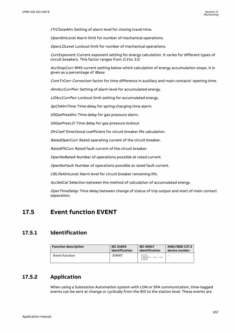
tTrCloseAlm: Setting of alarm level for closing travel time.
OperAlmLevel: Alarm limit for number of mechanical operations.
OperLOLevel: Lockout limit for number of mechanical operations.
CurrExponent: Current exponent setting for energy calculation. It varies for different types ofcircuit breakers. This factor ranges from 0.5 to 3.0.
AccStopCurr: RMS current setting below which calculation of energy accumulation stops. It isgiven as a percentage of IBase.
ContTrCorr: Correction factor for time difference in auxiliary and main contacts' opening time.
AlmAccCurrPwr: Setting of alarm level for accumulated energy.
LOAccCurrPwr: Lockout limit setting for accumulated energy.
SpChAlmTime: Time delay for spring charging time alarm.
tDGasPresAlm: Time delay for gas pressure alarm.
tDGasPresLO: Time delay for gas pressure lockout.
DirCoef: Directional coefficient for circuit breaker life calculation.
RatedOperCurr: Rated operating current of the circuit breaker.
RatedFltCurr: Rated fault current of the circuit breaker.
OperNoRated: Number of operations possible at rated current.
OperNoFault: Number of operations possible at rated fault current.
CBLifeAlmLevel: Alarm level for circuit breaker remaining life.
AccSelCal: Selection between the method of calculation of accumulated energy.
OperTimeDelay: Time delay between change of status of trip output and start of main contactseparation.
17.5 Event function EVENTIP14590-1 v2
17.5.1 IdentificationSEMOD167950-2 v2
Function description IEC 61850identification
IEC 60617identification
ANSI/IEEE C37.2device number
Event function EVENT
S00946 V1 EN-US
-
17.5.2 ApplicationM12805-6 v9
When using a Substation Automation system with LON or SPA communication, time-taggedevents can be sent at change or cyclically from the IED to the station level. These events are
1MRK 506 353-UEN B Section 17Monitoring
657Application manual

created from any available signal in the IED that is connected to the Event function (EVENT).The event function block is used for LON and SPA communication.
Analog and double indication values are also transferred through EVENT function.
17.5.3 Setting guidelinesIP14841-1 v1
M12811-3 v2
The parameters for the Event (EVENT) function are set via the local HMI or PCM600.
EventMask (Ch_1 - 16)M12811-5 v2
The inputs can be set individually as:
• NoEvents• OnSet, at pick-up of the signal• OnReset, at drop-out of the signal• OnChange, at both pick-up and drop-out of the signal• AutoDetect
LONChannelMask or SPAChannelMaskM12811-15 v2
Definition of which part of the event function block that shall generate events:
• Off• Channel 1-8• Channel 9-16• Channel 1-16
MinRepIntVal (1 - 16)M12811-29 v3
A time interval between cyclic events can be set individually for each input channel. This can beset between 0 s to 3600 s in steps of 1 s. It should normally be set to 0, that is, no cycliccommunication.
M12811-34 v1
It is important to set the time interval for cyclic events in an optimized way tominimize the load on the station bus.
17.6 Disturbance report DRPRDREIP14584-1 v2
17.6.1 IdentificationM16055-1 v7
Function description IEC 61850 identification IEC 60617identification
ANSI/IEEE C37.2device number
Disturbance report DRPRDRE - -
Disturbance report A1RADR - A4RADR - -
Disturbance report B1RBDR - B8RBDR - -
Section 17 1MRK 506 353-UEN BMonitoring
658Application manual
17.6.2 ApplicationM12152-3 v7
To get fast, complete and reliable information about disturbances in the primary and/or in thesecondary system it is very important to gather information on fault currents, voltages andevents. It is also important having a continuous event-logging to be able to monitor in anoverview perspective. These tasks are accomplished by the disturbance report functionDRPRDRE and facilitate a better understanding of the power system behavior and relatedprimary and secondary equipment during and after a disturbance. An analysis of the recordeddata provides valuable information that can be used to explain a disturbance, basis for changeof IED setting plan, improve existing equipment, and so on. This information can also be usedin a longer perspective when planning for and designing new installations, that is, adisturbance recording could be a part of Functional Analysis (FA).
Disturbance report DRPRDRE, always included in the IED, acquires sampled data of all selectedanalog and binary signals connected to the function blocks that is,
• Maximum 30 external analog signals,• 10 internal derived analog signals, and• 128 binary signals.
Disturbance report function is a common name for several functions that is, Indications (IND),Event recorder (ER), Event list (EL), Trip value recorder (TVR), Disturbance recorder (DR) andFault locator (FL).
Disturbance report function is characterized by great flexibility as far as configuration,starting conditions, recording times, and large storage capacity are concerned. Thus,disturbance report is not dependent on the operation of protective functions, and it canrecord disturbances that were not discovered by protective functions for one reason oranother. Disturbance report can be used as an advanced stand-alone disturbance recorder.
Every disturbance report recording is saved in the IED. The same applies to all events, whichare continuously saved in a ring-buffer. Local HMI can be used to get information about therecordings, and the disturbance report files may be uploaded in the PCM600 using theDisturbance handling tool, for report reading or further analysis (using WaveWin, that can befound on the PCM600 installation CD). The user can also upload disturbance report files usingFTP or MMS (over 61850–8–1) clients.
If the IED is connected to a station bus (IEC 61850-8-1), the disturbance recorder (record madeand fault number) and the fault locator information are available as GOOSE or Report Controldata. The same information is obtainable if IEC60870-5-103 is used.
17.6.3 Setting guidelinesIP14874-1 v1
M12179-64 v6
The setting parameters for the Disturbance report function DRPRDRE are set via the local HMIor PCM600.
It is possible to handle up to 40 analog and 128 binary signals, either internal signals or signalscoming from external inputs. The binary signals are identical in all functions that is,Disturbance recorder (DR), Event recorder (ER), Indication (IND), Trip value recorder (TVR) andEvent list (EL) function.
User-defined names of binary and analog input signals is set using PCM600. The analog andbinary signals appear with their user-defined names. The name is used in all related functions(Disturbance recorder (DR), Event recorder (ER), Indication (IND), Trip value recorder (TVR) andEvent list (EL)).
Figure 396 shows the relations between Disturbance report, included functions and functionblocks. Event list (EL), Event recorder (ER) and Indication (IND) uses information from thebinary input function blocks (BxRBDR). Trip value recorder (TVR) uses analog information from
1MRK 506 353-UEN B Section 17Monitoring
659Application manual

the analog input function blocks (AxRADR), which is used by Fault locator (FL) after estimationby Trip Value Recorder (TVR). Disturbance report function acquires information from bothAxRADR and BxRBDR.
Trip value rec Fault locator
Event list
Event recorder
Indications
Disturbancerecorder
Disturbance Report
Binary signals
Analog signals
DRPRDRE FL
IEC09000336-3-en.vsdx
AxRADR
BxRBDR
IEC09000336 V3 EN-US
Figure 396: Disturbance report functions and related function blocks
For Disturbance report function there are a number of settings which also influences the sub-functions.
Three LED indications placed above the LCD screen makes it possible to get quick statusinformation about the IED.
Green LED:
Steady light In Service
Flashing light Internal failure
Dark No power supply
Yellow LED:
Steady light A Disturbance Report is triggered
Flashing light The IED is in test mode
Red LED:
Steady light Triggered on binary signal N with SetLEDN = On
Flashing The IED is in configuration mode
Section 17 1MRK 506 353-UEN BMonitoring
660Application manual

OperationM12179-82 v5
The operation of Disturbance report function DRPRDRE has to be set On or Off. If Off isselected, note that no disturbance report is registered, and none sub-function will operate(the only general parameter that influences Event list (EL)).
Operation = Off:
• Disturbance reports are not stored.• LED information (yellow - start, red - trip) is not stored or changed.
Operation = On:
• Disturbance reports are stored, disturbance data can be read from the local HMI and froma PC using PCM600.
• LED information (yellow - start, red - trip) is stored.
Every recording will get a number (0 to 999) which is used as identifier (local HMI, disturbancehandling tool and IEC 61850). An alternative recording identification is date, time andsequence number. The sequence number is automatically increased by one for each newrecording and is reset to zero at midnight. The maximum number of recordings stored in theIED is 100. The oldest recording will be overwritten when a new recording arrives (FIFO).
To be able to delete disturbance records, Operation parameter has to be On.
The maximum number of recordings depend on each recordings totalrecording time. Long recording time will reduce the number of recordings toless than 100.
The IED flash disk should NOT be used to store any user files. This might causedisturbance recordings to be deleted due to lack of disk space.
17.6.3.1 Recording timesM12179-88 v4
The different recording times for Disturbance report are set (the pre-fault time, post-faulttime, and limit time). These recording times affect all sub-functions more or less but not theEvent list (EL) function.
Prefault recording time (PreFaultRecT) is the recording time before the starting point of thedisturbance. The setting should be at least 0.1 s to ensure enough samples for the estimationof pre-fault values in the Trip value recorder (TVR) function.
Postfault recording time (PostFaultRecT) is the maximum recording time after thedisappearance of the trig-signal (does not influence the Trip value recorder (TVR) function).
Recording time limit (TimeLimit) is the maximum recording time after trig. The parameterlimits the recording time if some trigging condition (fault-time) is very long or permanently set(does not influence the Trip value recorder (TVR) function).
Post retrigger (PostRetrig) can be set to On or Off. Makes it possible to choose performanceof Disturbance report function if a new trig signal appears in the post-fault window.
1MRK 506 353-UEN B Section 17Monitoring
661Application manual

PostRetrig = Off
The function is insensitive for new trig signals during post fault time.
PostRetrig = On
The function completes current report and starts a new complete report that is, the latter willinclude:
• new pre-fault- and fault-time (which will overlap previous report)• events and indications might be saved in the previous report too, due to overlap• new fault locator and trip value calculations if installed, in operation and started
Operation in test modeM12179-492 v4
If the IED is in test mode and OpModeTest = Off. Disturbance report function does not saveany recordings and no LED information is displayed.
If the IED is in test mode and OpModeTest = On. Disturbance report function works in normalmode and the status is indicated in the saved recording.
17.6.3.2 Binary input signalsM12179-90 v7
Up to 128 binary signals can be selected among internal logical and binary input signals. Theconfiguration tool is used to configure the signals.
For each of the 128signals, it is also possible to select if the signal is to be used as a trigger forthe start of the Disturbance report and if the trigger should be activated on positive (1) ornegative (0) slope.
OperationN: Disturbance report may trig for binary input N (On) or not (Off).
TrigLevelN: Trig on positive (Trig on 1) or negative (Trig on 0) slope for binary input N.
Func103N: Function type number (0-255) for binary input N according to IEC-60870-5-103, thatis, 128: Distance protection, 160: overcurrent protection, 176: transformer differentialprotection and 192: line differential protection.
Info103N: Information number (0-255) for binary input N according to IEC-60870-5-103, that is,69-71: Trip L1-L3, 78-83: Zone 1-6.
See also description in the chapter IEC 60870-5-103.
17.6.3.3 Analog input signalsM12179-92 v4
Up to 40 analog signals can be selected among internal analog and analog input signals.PCM600 is used to configure the signals.
For retrieving remote data from LDCM module, the Disturbance report functionshould not be connected to a 3 ms SMAI function block if this is the onlyintended use for the remote data.
The analog trigger of Disturbance report is not affected if analog input M is to be included inthe disturbance recording or not (OperationM = On/Off).
If OperationM = Off, no waveform (samples) will be recorded and reported in graph. However,Trip value, pre-fault and fault value will be recorded and reported. The input channel can still beused to trig the disturbance recorder.
Section 17 1MRK 506 353-UEN BMonitoring
662Application manual

If OperationM = On, waveform (samples) will also be recorded and reported in graph.
NomValueM: Nominal value for input M.
OverTrigOpM, UnderTrigOpM: Over or Under trig operation, Disturbance report may trig forhigh/low level of analog input M (On) or not (Off).
OverTrigLeM, UnderTrigLeM: Over or under trig level, Trig high/low level relative nominal valuefor analog input M in percent of nominal value.
17.6.3.4 Sub-function parametersM12179-389 v3
All functions are in operation as long as Disturbance report is in operation.
IndicationsM12179-448 v4
IndicationMaN: Indication mask for binary input N. If set (Show), a status change of thatparticular input, will be fetched and shown in the disturbance summary on local HMI. If not set(Hide), status change will not be indicated.
SetLEDN: Set red LED on local HMI in front of the IED if binary input N changes status.
Disturbance recorderM12179-446 v4
OperationM: Analog channel M is to be recorded by the disturbance recorder (On) or not (Off).
If OperationM = Off, no waveform (samples) will be recorded and reported in graph. However,Trip value, pre-fault and fault value will be recorded and reported. The input channel can still beused to trig the disturbance recorder.
If OperationM = On, waveform (samples) will also be recorded and reported in graph.
Event recorderM12179-444 v4
Event recorder (ER) function has no dedicated parameters.
Trip value recorderM12179-442 v3
ZeroAngleRef: The parameter defines which analog signal that will be used as phase anglereference for all other analog input signals. This signal will also be used for frequencymeasurement and the measured frequency is used when calculating trip values. It is suggestedto point out a sampled voltage input signal, for example, a line or busbar phase voltage(channel 1-30).
Event listM12179-440 v3
Event list (EL) (SOE) function has no dedicated parameters.
17.6.3.5 ConsiderationM12179-420 v5
The density of recording equipment in power systems is increasing, since the number ofmodern IEDs, where recorders are included, is increasing. This leads to a vast number ofrecordings at every single disturbance and a lot of information has to be handled if therecording functions do not have proper settings. The goal is to optimize the settings in eachIED to be able to capture just valuable disturbances and to maximize the number that ispossible to save in the IED.
The recording time should not be longer than necessary (PostFaultrecT and TimeLimit).
• Should the function record faults only for the protected object or cover more?• How long is the longest expected fault clearing time?• Is it necessary to include reclosure in the recording or should a persistent fault generate a
second recording (PostRetrig)?
1MRK 506 353-UEN B Section 17Monitoring
663Application manual

Minimize the number of recordings:
• Binary signals: Use only relevant signals to start the recording that is, protection trip,carrier receive and/or start signals.
• Analog signals: The level triggering should be used with great care, since unfortunatesettings will cause enormously number of recordings. If nevertheless analog inputtriggering is used, chose settings by a sufficient margin from normal operation values.Phase voltages are not recommended for trigging.
Remember that values of parameters set elsewhere are linked to the information on a report.Such parameters are, for example, station and object identifiers, CT and VT ratios.
17.7 Logical signal status report BINSTATREPGUID-E7A2DB38-DD96-4296-B3D5-EB7FBE77CE07 v2
17.7.1 IdentificationGUID-E0247779-27A2-4E6C-A6DD-D4C31516CA5C v3
Function description IEC 61850identification
IEC 60617identification
ANSI/IEEE C37.2device number
Logical signal status report BINSTATREP - -
17.7.2 ApplicationGUID-F9D225B1-68F7-4D15-AA89-C9211B450D19 v2
The Logical signal status report (BINSTATREP) function makes it possible for a SPA master topoll signals from various other function blocks.
BINSTATREP has 16 inputs and 16 outputs. The output status follows the inputs and can beread from the local HMI or via SPA communication.
When an input is set, the respective output is set for a user defined time. If the input signalremains set for a longer period, the output will remain set until the input signal resets.
t t
INPUTn
OUTPUTn
IEC09000732-1-en.vsdIEC09000732 V1 EN-US
Figure 397: BINSTATREP logical diagram
17.7.3 Setting guidelinesGUID-BBDA6900-4C1A-4A7C-AEA5-3C49C2749254 v2
The pulse time t is the only setting for the Logical signal status report (BINSTATREP). Eachoutput can be set or reset individually, but the pulse time will be the same for all outputs in theentire BINSTATREP function.
Section 17 1MRK 506 353-UEN BMonitoring
664Application manual

17.8 Fault locator LMBRFLOIP14592-1 v2
17.8.1 IdentificationM14892-1 v3
Function description IEC 61850identification
IEC 60617identification
ANSI/IEEE C37.2device number
Fault locator LMBRFLO - -
17.8.2 ApplicationM13752-3 v6
The main objective of line protection and monitoring IEDs is fast, selective and reliableoperation for faults on a protected line section. Besides this, information on distance to faultis very important for those involved in operation and maintenance. Reliable information on thefault location greatly decreases the downtime of the protected lines and increases the totalavailability of a power system.
The fault locator is started with the input CALCDIST to which trip signals indicating in-linefaults are connected, typically distance protection zone 1 and accelerating zone or the linedifferential protection. The disturbance report must also be started for the same faults sincethe function uses pre- and post-fault information from the trip value recorder function (TVR).
Beside this information the function must be informed about faulted phases for correct loopselection (phase selective outputs from differential protection, distance protection,directional OC protection, and so on). The following loops are used for different types offaults:
• for 3 phase faults: loop L1 - L2.• for 2 phase faults: the loop between the faulted phases.• for 2 phase-to-earth faults: the loop between the faulted phases.• for phase-to-earth faults: the phase-to-earth loop.
LMBRFLO function indicates the distance to fault as a percentage of the line length, inkilometers or miles as selected on the local HMI. LineLengthUnit setting is used to select theunit of length either, in kilometer or miles for the distance to fault. The distance to the fault,which is calculated with a high accuracy, is stored together with the recorded disturbances.This information can be read on the local HMI, uploaded to PCM600 and is available on thestation bus according to IEC 61850–8–1.
The distance to fault can be recalculated on the local HMI by using the measuring algorithm fordifferent fault loops or for changed system parameters.
17.8.3 Setting guidelinesIP14835-1 v1
M13769-3 v6
The parameters for the Fault locator function are set via the local HMI or PCM600.
The Fault locator algorithm uses phase voltages, phase currents and residual current inobserved bay (protected line) and residual current from a parallel bay (line, which is mutualcoupled to protected line).
The Fault locator has close connection to the Disturbance report function. All external analoginputs (channel 1-30), connected to the Disturbance report function, are available to the Faultlocator and the function uses information calculated by the Trip value recorder. Afterallocation of analog inputs to the Disturbance report function, the user has to point out whichanalog inputs to be used by the Fault locator. According to the default settings the first four
1MRK 506 353-UEN B Section 17Monitoring
665Application manual

analog inputs are currents and next three are voltages in the observed bay (no parallel lineexpected since chosen input is set to zero). Use the Parameter Setting tool within PCM600 forchanging analog configuration.
The measured phase voltages can be fine tuned with the parameters UL1Gain, UL2Gain andUL3Gain to further increase the accuracy of the fault locator.
The list of parameters explains the meaning of the abbreviations. Figure 398 also presentsthese system parameters graphically. Note, that all impedance values relate to their primaryvalues and to the total length of the protected line.
Z0m=Z0m+jX0m
R1A+jX1A
R0L+jX0LR1L+jX1L
R0L+jX0LR1L+jX1L
R1B+jX1B
DRPRDRELMBRFLO
ANSI05000045_2_en.vsdANSI05000045 V2 EN-US
Figure 398: Simplified network configuration with network data, required for settings ofthe fault location-measuring function
For a single-circuit line (no parallel line), the figures for mutual zero-sequence impedance (X0M,R0M) and analog input are set at zero.
Power system specific parameter settings are not general settings but specific settingincluded in the setting groups, that is, this makes it possible to change conditions for theFault locator with short notice by changing setting group.
The source impedance is not constant in the network. However, this has a minor influence onthe accuracy of the distance-to-fault calculation, because only the phase angle of thedistribution factor has an influence on the accuracy. The phase angle of the distribution factoris normally very low and practically constant, because the positive sequence line impedance,which has an angle close to 90°, dominates it. Always set the source impedance resistance tovalues other than zero. If the actual values are not known, the values that correspond to thesource impedance characteristic angle of 85° give satisfactory results.
17.8.3.1 Connection of analog currentsM13769-16 v4
Connection diagram for analog currents included IN from parallel line shown in figure 399
Section 17 1MRK 506 353-UEN BMonitoring
666Application manual

en07000113-1.vsd
L1L2L3
1
2
3
4
5
6
9
10
1
2
3
4
5
6
9
10
I1
I2
I3
I5
I1
I2
I3
I5
IEC07000113 V2 EN-US
Figure 399: Example of connection of parallel line IN for Fault locator LMBRFLO
17.9 Limit counter L4UFCNTGUID-22E141DB-38B3-462C-B031-73F7466DD135 v1
17.9.1 IdentificationGUID-F3FB7B33-B189-4819-A1F0-8AC7762E9B7E v2
Function description IEC 61850identification
IEC 60617identification
ANSI/IEEE C37.2device number
Limit counter L4UFCNT -
17.9.2 ApplicationGUID-41B13135-5069-4A5A-86CE-B7DBE9CFEF38 v2
Limit counter (L4UFCNT) is intended for applications where positive and/or negative flanks ona binary signal need to be counted.
The limit counter provides four independent limits to be checked against the accumulatedcounted value. The four limit reach indication outputs can be utilized to initiate proceedingactions. The output indicators remain high until the reset of the function.
It is also possible to initiate the counter from a non-zero value by resetting the function to thewanted initial value provided as a setting.
If applicable, the counter can be set to stop or rollover to zero and continue counting afterreaching the maximum count value. The steady overflow output flag indicates the next count
1MRK 506 353-UEN B Section 17Monitoring
667Application manual

after reaching the maximum count value. It is also possible to set the counter to rollover andindicate the overflow as a pulse, which lasts up to the first count after rolling over to zero. Inthis case, periodic pulses will be generated at multiple overflow of the function.
17.9.3 Setting guidelinesGUID-5AECCDBC-7385-4D9F-940C-9D4A0E59B106 v1
GUID-DA5DA8D7-4821-4BFB-86CC-28658E376270 v1
The parameters for Limit counter L4UFCNT are set via the local HMI or PCM600.
17.10 Running hour-meter TEILGAPC
17.10.1 IdentificationGUID-3F9EF4FA-74FA-4D1D-88A0-E948B722B64F v1
Function Description IEC 61850identification
IEC 60617identification
ANSI/IEEE C37.2 devicenumber
Running hour-meter TEILGAPC - -
17.10.2 ApplicationGUID-225D8341-2D31-49F1-9B49-571346C0FE26 v1
The function is used for user-defined logics and it can also be used for different purposesinternally in the IED. An application example is to accumulate the total running/energized timeof the generator, transformer, reactor, capacitor bank or even line.
Settable time limits for warning and alarm are provided. The time limit for overflow indicationis fixed to 99999.9 hours. At overflow the accumulated time resets and the accumulationstarts from zero again.
17.10.3 Setting guidelinesGUID-D3BED56A-BA80-486F-B2A8-E47F7AC63468 v1
The settings tAlarm and tWarning are user settable limits defined in hours. The achievableresolution of the settings is 0.1 hours (6 minutes).
tAlarm and tWarning are independent settings, that is, there is no check iftAlarm > tWarning.
The limit for the overflow supervision is fixed at 99999.9 hours.
The setting tAddToTime is a user settable time parameter in hours.
Section 17 1MRK 506 353-UEN BMonitoring
668Application manual
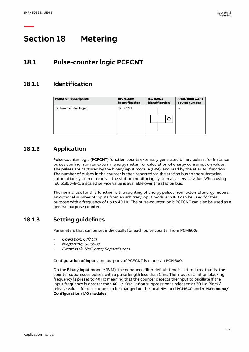
Section 18 Metering
18.1 Pulse-counter logic PCFCNTIP14600-1 v3
18.1.1 IdentificationM14879-1 v4
Function description IEC 61850identification
IEC 60617identification
ANSI/IEEE C37.2device number
Pulse-counter logic PCFCNT
S00947 V1 EN-US
-
18.1.2 ApplicationM13395-3 v6
Pulse-counter logic (PCFCNT) function counts externally generated binary pulses, for instancepulses coming from an external energy meter, for calculation of energy consumption values.The pulses are captured by the binary input module (BIM), and read by the PCFCNT function.The number of pulses in the counter is then reported via the station bus to the substationautomation system or read via the station monitoring system as a service value. When usingIEC 61850–8–1, a scaled service value is available over the station bus.
The normal use for this function is the counting of energy pulses from external energy meters.An optional number of inputs from an arbitrary input module in IED can be used for thispurpose with a frequency of up to 40 Hz. The pulse-counter logic PCFCNT can also be used as ageneral purpose counter.
18.1.3 Setting guidelinesM13396-4 v9
Parameters that can be set individually for each pulse counter from PCM600:
• Operation: Off/On• tReporting: 0-3600s• EventMask: NoEvents/ReportEvents
Configuration of inputs and outputs of PCFCNT is made via PCM600.
On the Binary input module (BIM), the debounce filter default time is set to 1 ms, that is, thecounter suppresses pulses with a pulse length less than 1 ms. The input oscillation blockingfrequency is preset to 40 Hz meaning that the counter detects the input to oscillate if theinput frequency is greater than 40 Hz. Oscillation suppression is released at 30 Hz. Block/release values for oscillation can be changed on the local HMI and PCM600 under Main menu/Configuration/I/O modules.
1MRK 506 353-UEN B Section 18Metering
669Application manual

The setting is common for all input channels on BIM, that is, if limit changes aremade for inputs not connected to the pulse counter, the setting also influencesthe inputs on the same board used for pulse counting.
18.2 Function for energy calculation and demand handlingETPMMTR
SEMOD153638-1 v2
18.2.1 IdentificationSEMOD175537-2 v4
Function description IEC 61850identification
IEC 60617identification
ANSI/IEEE C37.2device number
Function for energy calculation anddemand handling
ETPMMTR W_Varh -
18.2.2 ApplicationSEMOD175546-4 v5
Energy calculation and demand handling function (ETPMMTR) is intended for statistics of theforward and reverse active and reactive energy. It has a high accuracy basically given by themeasurements function (CVMMXN). This function has a site calibration possibility to furtherincrease the total accuracy.
The function is connected to the instantaneous outputs of (CVMMXN) as shown in figure 400.
ETPMMTR
PQSTARTACCSTOPACCRSTACCRSTDMD
ACCINPRGEAFPULSEEARPULSEERFPULSEERRPULSE
EAFALMEARALMERFALMERRALMEAFACCEARACCERFACCERRACC
MAXPAFDMAXPARDMAXPRFDMAXPRRD
IEC13000184-1-en.vsd IEC13000190 V1 EN-US
Figure 400: Connection of energy calculation and demand handling function ETPMMTR tothe measurements function (CVMMXN)
The energy values can be read through communication in MWh and MVArh in monitoring toolof PCM600 and/or alternatively the values can be presented on the local HMI. The local HMIgraphical display is configured with PCM600 Graphical Display Editor tool (GDE) with ameasuring value which is selected to the active and reactive component as preferred. Also allAccumulated Active Forward, Active Reverse, Reactive Forward and Reactive Reverse energyvalues can be presented.
Maximum demand values are presented in MWh or MVArh in the same way.
Alternatively, the energy values can be presented with use of the pulse counters function(PCGGIO). The output energy values are scaled with the pulse output setting values
Section 18 1MRK 506 353-UEN BMetering
670Application manual

EAFAccPlsQty, EARAccPlsQty, ERFAccPlsQty and ERVAccPlsQty of the energy meteringfunction and then the pulse counter can be set-up to present the correct values by scaling inthis function. Pulse counter values can then be presented on the local HMI in the same wayand/or sent to the SA (Substation Automation) system through communication where thetotal energy then is calculated by summation of the energy pulses. This principle is good forvery high values of energy as the saturation of numbers else will limit energy integration toabout one year with 50 kV and 3000 A. After that the accumulation will start on zero again.
18.2.3 Setting guidelinesSEMOD175556-4 v6
The parameters are set via the local HMI or PCM600.
The following settings can be done for the energy calculation and demand handling functionETPMMTR:
GlobalBaseSel: Selects the global base value group used by the function to define (IBase),(UBase) and (SBase).
Operation: Off/On
EnaAcc: Off/On is used to switch the accumulation of energy on and off.
tEnergy: Time interval when energy is measured.
tEnergyOnPls: gives the pulse length ON time of the pulse. It should be at least 100 ms whenconnected to the Pulse counter function block. Typical value can be 100 ms.
tEnergyOffPls: gives the OFF time between pulses. Typical value can be 100 ms.
EAFAccPlsQty and EARAccPlsQty: gives the MWh value in each pulse. It should be selectedtogether with the setting of the Pulse counter (PCGGIO) settings to give the correct total pulsevalue.
ERFAccPlsQty and ERVAccPlsQty : gives the MVArh value in each pulse. It should be selectedtogether with the setting of the Pulse counter (PCGGIO) settings to give the correct total pulsevalue.
For the advanced user there are a number of settings for direction, zero clamping, max limit,and so on. Normally, the default values are suitable for these parameters.
1MRK 506 353-UEN B Section 18Metering
671Application manual

672

Section 19 Station communication
19.1 Communication protocolsM14815-3 v12
Each IED is provided with a communication interface, enabling it to connect to one or manysubstation level systems or equipment, either on the Substation Automation (SA) bus orSubstation Monitoring (SM) bus.
Available communication protocols are:
• IEC 61850-8-1 communication protocol• IEC 61850-9-2LE communication protocol• LON communication protocol• SPA or IEC 60870-5-103 communication protocol• DNP3.0 communication protocol
Several protocols can be combined in the same IED.
19.2 IEC 61850-8-1 communication protocolIP14616-1 v2
19.2.1 Application IEC 61850-8-1IP14865-1 v2
M13912-3 v4
IEC 61850-8-1 communication protocol allows vertical communication to HSI clients and allowshorizontal communication between two or more intelligent electronic devices (IEDs) from oneor several vendors to exchange information and to use it in the performance of their functionsand for correct co-operation.
GOOSE (Generic Object Oriented Substation Event), which is a part of IEC 61850–8–1 standard,allows the IEDs to communicate state and control information amongst themselves, using apublish-subscribe mechanism. That is, upon detecting an event, the IED(s) use a multi-casttransmission to notify those devices that have registered to receive the data. An IED can, bypublishing a GOOSE message, report its status. It can also request a control action to bedirected at any device in the network.
M13913-3 v4
Figure 401 shows the topology of an IEC 61850–8–1 configuration. IEC 61850–8–1 specifies onlythe interface to the substation LAN. The LAN itself is left to the system integrator.
1MRK 506 353-UEN B Section 19Station communication
673Application manual

KIOSK 2 KIOSK 3
Station HSIBase System
EngineeringWorkstation
SMSGateway
Printer
CC
IEC09000135_en.vsd
KIOSK 1
IED 1
IED 2
IED 3
IED 1
IED 2
IED 3
IED 1
IED 2
IED 3
IEC09000135 V1 EN-US
Figure 401: SA system with IEC 61850–8–1M16925-3 v3
Figure 402 shows the GOOSE peer-to-peer communication.
Control Protection Control ProtectionControl and protection
GOOSE
en05000734.vsd
Station HSIMicroSCADA
Gateway
IEDA
IEDA
IEDA
IEDA
IEDA
IEC05000734 V1 EN-US
Figure 402: Example of a broadcasted GOOSE message
Section 19 1MRK 506 353-UEN BStation communication
674Application manual

19.2.2 Horizontal communication via GOOSE for interlockingGOOSEINTLKRCV
SEMOD173197-1 v2
PID-415-SETTINGS v5
Table 56: GOOSEINTLKRCV Non group settings (basic)
Name Values (Range) Unit Step Default Description
Operation OffOn
- - Off Operation Off/On
19.2.3 Setting guidelinesSEMOD55317-5 v6
There are two settings related to the IEC 61850–8–1 protocol:
Operation User can set IEC 61850 communication to On or Off.
GOOSE has to be set to the Ethernet link where GOOSE traffic shall be send and received.
19.2.4 Generic communication function for Single Point indicationSPGAPC, SP16GAPC
SEMOD55999-1 v4
19.2.4.1 ApplicationSEMOD55350-5 v6
Generic communication function for Measured Value (SPGAPC) function is used to send onesingle logical output to other systems or equipment in the substation. It has one visible input,that should be connected in ACT tool.
19.2.4.2 Setting guidelinesSEMOD55376-5 v4
There are no settings available for the user for SPGAPC. However, PCM600 must be used to getthe signals sent by SPGAPC.
19.2.5 Generic communication function for Measured Value MVGAPCSEMOD55402-1 v3
19.2.5.1 ApplicationSEMOD55872-5 v9
Generic communication function for Measured Value MVGAPC function is used to send theinstantaneous value of an analog signal to other systems or equipment in the substation. Itcan also be used inside the same IED, to attach a RANGE aspect to an analog value and topermit measurement supervision on that value.
19.2.5.2 Setting guidelinesSEMOD55424-5 v5
The settings available for Generic communication function for Measured Value (MVGAPC)function allows the user to choose a deadband and a zero deadband for the monitored signal.Values within the zero deadband are considered as zero.
The high and low limit settings provides limits for the high-high-, high, normal, low and low-low ranges of the measured value. The actual range of the measured value is shown on therange output of MVGAPC function block. When a Measured value expander block (RANGE_XP)
1MRK 506 353-UEN B Section 19Station communication
675Application manual

is connected to the range output, the logical outputs of the RANGE_XP are changedaccordingly.
19.2.6 IEC 61850-8-1 redundant station bus communicationGUID-FF43A130-7D2D-4BA3-B51C-80398D73228F v2
19.2.6.1 IdentificationGUID-00C469E6-00D4-4780-BD0D-426647AB8E0F v3.1.1
Function description LHMI and ACTidentification
IEC 61850identification
IEC 60617identification
ANSI/IEEE C37.2device number
Dual ethernet portlink status
PRPSTATUS PRPSTATUS - -
IEC 62439-3 parallelredundancyprotocol
PRP PRP - -
19.2.6.2 ApplicationGUID-5B5581EA-4306-404B-98A7-7BDA6A306E7B v2.1.1
Dual ethernet port link status (PRPSTATUS) together with IEC 62439-3 parallel redundancyprotocol (PRP) are used to supervise and assure redundant Ethernet communication over twochannels. This will secure data transfer even though one communication channel might not beavailable for some reason. Together PRPSTATUS and PRP provide redundant communicationover station bus running IEC 61850-8-1 protocol. The redundant communication use both portAB and CD on OEM module.
Section 19 1MRK 506 353-UEN BStation communication
676Application manual

Switch A Switch B
1 2
DataData
DataData
=IEC09000758=3=en=Original.vsd
IED Configuration
PRP PRPSTATUS
1 2
OEM
AB CD
Duo
Redundancy Supervision
Station Control System
IEC09000758 V3 EN-US
Figure 403: Redundant station bus
19.2.6.3 Setting guidelinesGUID-6AD04F29-9B52-40E7-AA07-6D248EF99FC6 v2
Redundant communication (PRP) is configured in the local HMI under Main menu/Configuration/Communication/Ethernet configuration/PRP
The settings are found in the Parameter Setting tool in PCM600 under IED Configuration/Communication/Ethernet configuration/PRP. By default the settings are read only in theParameter Settings tool, but can be unlocked by right clicking the parameter and selectingLock/Unlock Parameter.
Operation: The redundant communication will be activated when this parameter is set toOn.After confirmation the IED will restart and the setting alternatives Rear OEM - Port AB andCD will not be further displayed in the local HMI. The ETHLANAB and ETHLANCD in theParameter Setting Tool are irrelevant when the redundant communication is activated, onlyPRP IPAdress and IPMask are valid.
1MRK 506 353-UEN B Section 19Station communication
677Application manual

IEC10000057-2-en.vsd
IEC10000057 V2 EN-US
Figure 404: PST screen: PRP Operation is set to On, which affect Rear OEM - Port AB andCD which are both set to PRP
19.3 IEC 61850-9-2LE communication protocolSEMOD172279 v2
19.3.1 IntroductionSEMOD166571-1 v2
SEMOD166590-5 v7
Every IED can be provided with communication interfaces enabling it to connect to theprocess buses in order to get data from analog data acquisition units close to the process(primary apparatus), commonly known as Merging Units (MU). The protocol used in this case isthe IEC/UCA 61850-9-2LE communication protocol.
The IEC/UCA 61850-9-2LE standard does not specify the quality of the sampled values. Thus,the accuracy of the current and voltage inputs to the merging unit and the inaccuracy addedby the merging unit must be coordinated with the requirement for the actual type ofprotection function.
Section 19 1MRK 506 353-UEN BStation communication
678Application manual

Set the CD-port to 9–2LE communication using only LHMI. All other settings are also availablefrom PCM600.
Factors influencing the accuracy of the sampled values from the merging unit are, for example,anti aliasing filters, frequency range, step response, truncating, A/D conversion inaccuracy,time tagging accuracy etc.
In principle, the accuracy of the current and voltage transformers, together with the mergingunit, will have the same quality as the direct input of currents and voltages.
The process bus physical layout can be arranged in several ways, described in Annex B of thestandard, depending on what are the needs for sampled data in a substation.
EngineeringWorkstation
Computer HMIFirewallVPN
Gateway
Network Control CenterMaintenance Center
AFS 6xx
AFS 6xx AFS 6xx
AFS 6xx
SAM600 SAM600 SAM600
IEC 61850
FOX615
WAMSSDM600
IET600 PCM600 ITT600
NSD570
Events Printer Printer
IEC18000011-1-en.vsdx
IEC18000011 V1 EN-US
Figure 405: Example of a station configuration with separated process bus and stationbus
The IED can get analog values simultaneously from a classical CT or VT and from a MergingUnit, like in this example:
The merging units (MU) are called so because they can gather analog values from one or moremeasuring transformers, sample the data and send the data over process bus to other clients(or subscribers) in the system. Some merging units are able to get data from classicalmeasuring transformers, others from non-conventional measuring transducers and yet otherscan pick up data from both types. The electronic part of a non-conventional measuringtransducer (like a Rogowski coil or a capacitive divider) can represent a MU by itself as long asit can send sampled data over process bus.
1MRK 506 353-UEN B Section 19Station communication
679Application manual

CTCT
ABBMerging
Unit
Ethernet Switch
IED
CombiSensor
Conventional VT
IEC61850-9-2LE
IEC61850-9-2LE
SplitterElectrical-to-
Optical Converter
1PPS
1PPS
110 V1 A1 A
IEC61850-8-1
Station Wide SCADA System
Station Wide GPS Clock
Other Relays
IEC61850-8-1
en08000069-3.vsd
IEC08000069 V2 EN-US
Figure 406: Example of a station configuration with the IED receiving analog values fromboth classical measuring transformers and merging units.
19.3.2 Setting guidelinesGUID-29B296B3-6185-459F-B06F-8E7F0C6C9460 v4
Merging Units (MUs) have several settings on local HMI under:
• Main menu/Configuration/Analog modules/MUx:92xx. The corresponding settings arealso available in PST (PCM600).
• Main menu/Configuration/Communication/Merging units configuration/MUx:92xx. Thecorresponding settings are also available in ECT (PCM600).
XX can take value 01–12.
Section 19 1MRK 506 353-UEN BStation communication
680Application manual

19.3.2.1 Specific settings related to the IEC 61850-9-2LE communicationSEMOD166590-24 v5
The process bus communication IEC 61850-9-2LE have specific settings, similar to the analoginputs modules.
Besides the names of the merging unit channels (that can be edited only from PCM600, notfrom the local HMI) there are important settings related to the merging units and timesynchronization of the signals:
When changing the sending (MU unit) MAC address, a reboot of the IED isrequired.
If there are more than one sample group involved, then time synch is mandatory and theprotection functions will be blocked if there is no time synchronization.
SmpGrp – this setting parameter is not used
CTStarPointx: This parameter specifies the direction to or from object. See also section"Setting of current channels".
AppSynch: If this parameter is set to Synch and the IED HW-time synchronization is lost or thesynchronization to the MU time is lost, the protection functions in the list 57 will be blockedand the output SYNCH will be set.
SynchMode: marks how the IED will receive the data coming from a merging unit:
• if it is set to NoSynch, then when the sampled values arrive, there will be no check on the“SmpSynch” flag
• If it is set to Operation, the “SmpSynch” flag will be checked all time.• setting Init, should not be used
For more information on the settings, see “MU1_4I_4U Non group settings (basic)” table.
19.3.2.2 Loss of communicationGUID-29EFBCB7-2B4F-4AA1-B593-8E89838722E0 v2.1.1
If IEC 61850-9-2LE communication is lost, see examples in figures 407, 408 and 409, theprotection functions in table 57are blocked.
Case 1:
IEC13000298-1-en.vsdIEC13000298 V1 EN-US
Figure 407: Normal operation
Case 2:
1MRK 506 353-UEN B Section 19Station communication
681Application manual

Failure of the MU (sample lost) blocks the sending of binary signals through LDCM. Thereceived binary signals are not blocked and processd normally.
→DTT from the remote end is still processed.
IEC13000299-1-en.vsdIEC13000299 V1 EN-US
Figure 408: MU failed, mixed system
Case 3:
Failure of one MU (sample lost) blocks the sending and receiving of binary signals throughLDCM.
→DTT from the remote end is not working.
IEC13000300-1-en.vsdIEC13000300 V1 EN-US
Figure 409: MU failed, 9-2 system
Table 57: Blocked protection functions if IEC 61850-9-2LE communication is interrupted.
Function description IEC 61850 identification Function description IEC 61850 identification
Accidental energizingprotection forsynchronous generator
AEGPVOC Two step overvoltageprotection
OV2PTOV
Broken conductor check BRCPTOC Four step single phaseovercurrent protection
PH4SPTOC
Capacitor bankprotection
CBPGAPC Radial feeder protection PAPGAPC
Pole discordanceprotection
CCPDSC Instantaneous phaseovercurrent protection
PHPIOC
Breaker failureprotection
CCRBRF PoleSlip/Out-of-stepprotection
PSPPPAM
Table continues on next page
Section 19 1MRK 506 353-UEN BStation communication
682Application manual
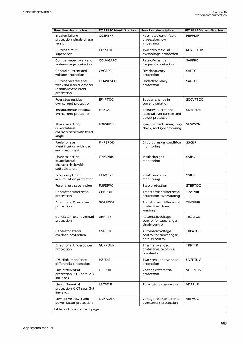
Function description IEC 61850 identification Function description IEC 61850 identification
Breaker failureprotection, single phaseversion
CCSRBRF Restricted earth faultprotection, lowimpedance
REFPDIF
Current circuitsupervison
CCSSPVC Two step residualovervoltage protection
ROV2PTOV
Compensated over- andundervoltage protection
COUVGAPC Rate-of-changefrequency protection
SAPFRC
General currrent andvoltage protection
CVGAPC Overfrequencyprotection
SAPTOF
Current reversal andweakend infeed logic forresidual overcurrentprotection
ECRWPSCH Underfrequencyprotection
SAPTUF
Four step residualovercurrent protection
EF4PTOC Sudden change incurrent variation
SCCVPTOC
Instantaneous residualovercurrent protection
EFPIOC Sensitive Directionalresidual over current andpower protetcion
SDEPSDE
Phase selection,quadrilateralcharacteristic with fixedangle
FDPSPDIS Synchrocheck, energizingcheck, and synchronizing
SESRSYN
Faulty phaseidentification with loadenchroachment
FMPSPDIS Circuit breaker conditionmonitoring
SSCBR
Phase selection,quadrilateralcharacteristic withsettable angle
FRPSPDIS Insulation gasmonitoring
SSIMG
Frequency timeaccumulation protection
FTAQFVR Insulation liquidmonitoring
SSIML
Fuse failure supervision FUFSPVC Stub protection STBPTOC
Generator differentialprotection
GENPDIF Transformer differentialprotection, two winding
T2WPDIF
Directional Overpowerprotection
GOPPDOP Transformer differentialprotection, threewinding
T3WPDIF
Generator rotor overloadprotection
GRPTTR Automatic voltagecontrol for tapchanger,single control
TR1ATCC
Generator statoroverload protection
GSPTTR Automatic voltagecontrol for tapchanger,parallel control
TR8ATCC
Directional Underpowerprotection
GUPPDUP Thermal overloadprotection, two timeconstants
TRPTTR
1Ph High impedancedifferential protection
HZPDIF Two step undervoltageprotection
UV2PTUV
Line differentialprotection, 3 CT sets, 2-3line ends
L3CPDIF Voltage differentialprotection
VDCPTOV
Line differentialprotection, 6 CT sets, 3-5line ends
L6CPDIF Fuse failure supervision VDRFUF
Low active power andpower factor protection
LAPPGAPC Voltage-restrained timeovercurrent protection
VRPVOC
Table continues on next page
1MRK 506 353-UEN B Section 19Station communication
683Application manual

Function description IEC 61850 identification Function description IEC 61850 identification
Negative sequenceovercurrent protection
LCNSPTOC Local acceleration logic ZCLCPSCH
Negative sequenceovervoltage protection
LCNSPTOV Scheme communicationlogic for distance orovercurrent protection
ZCPSCH
Three phase overcurrent LCP3PTOC Current reversal andweak-end infeed logic fordistance protection
ZCRWPSCH
Three phaseundercurrent
LCP3PTUC Automatic switch ontofault logic, voltage andcurrent based
ZCVPSOF
Thermal overloadprotection, one timeconstant
LCPTTR Under impedanceprotection for generator
ZGVPDIS
Zero sequenceovercurrent protection
LCZSPTOC Fast distance protection ZMFCPDIS
Zero sequenceovervoltage protection
LCZSPTOV High speed distanceprotection
ZMFPDIS
Line differentialcoordination
LDLPSCH Distance measuringzone, quadrilateralcharacteristic for seriescompensated lines
ZMCAPDIS
Additional security logicfor differentialprotection
LDRGFC Distance measuringzone, quadrilateralcharacteristic for seriescompensated lines
ZMCPDIS
Loss of excitation LEXPDIS Fullscheme distanceprotection, mhocharacteristic
ZMHPDIS
Thermal overloadprotection, one timeconstant
LFPTTR Fullscheme distanceprotection, quadrilateralfor earth faults
ZMMAPDIS
Loss of voltage check LOVPTUV Fullscheme distanceprotection, quadrilateralfor earth faults
ZMMPDIS
Line differentialprotection 3 CT sets,with inzonetransformers, 2-3 lineends
LT3CPDIF Distance protectionzone, quadrilateralcharacteristic
ZMQAPDIS
Line differentialprotection 6 CT sets,with inzonetransformers, 3-5 lineends
LT6CPDIF Distance protectionzone, quadrilateralcharacteristic
ZMQPDIS
Negativ sequence timeovercurrent protectionfor machines
NS2PTOC Distance protectionzone, quadrilateralcharacteristic, separatesettings
ZMRAPDIS
Four step directionalnegative phase sequenceovercurrent protection
NS4PTOC Distance protectionzone, quadrilateralcharacteristic, separatesettings
ZMRPDIS
Four step phaseovercurrent protection
OC4PTOC Power swing detection ZMRPSB
Overexcitationprotection
OEXPVPH Mho Impedancesupervision logic
ZSMGAPC
Table continues on next page
Section 19 1MRK 506 353-UEN BStation communication
684Application manual

Function description IEC 61850 identification Function description IEC 61850 identification
Out-of-step protection OOSPPAM Busbar differentialprotection, check zone
BCZPDIF
Busbar differentialprotection, dynamic zoneselection
BDZSGAPC Busbar differentialprotection, single phasefeeder xx
BFPTRC_Fx, (1≤x≤24)
Busbar differentialprotection, businterconnection xx
BICPTRC_x, (1≤x≤5) Busbar differentialprotection, zone 1
BZNPDIF_Zx, (1≤x≤6)
19.3.2.3 Setting examples for IEC 61850-9-2LE and time synchronizationGUID-CEDD520A-8A13-41DF-BFF1-8A3B4C00E098 v1
It is important that the IED and the merging units (MU) uses the same time reference. This isespecially true if analog data is used from several sources, for example an internal TRM and aMU. Or if several physical MU is used. The same time reference is important to correlate dataso that channels from different sources refer to correct phase angel.
When only one MU is used as analog source it is theoretically possible to do without time-synchronization. However, this would mean that timestamps for analog and binary data/events would be uncorrelated. Disturbance recordings will appear incorrect since analog datawill be timestamped by MU and binary events will use internal IED time. For this reason it isrecommended to use time synchronization also when analog data emanate from only one MU.
An external time-source can be used to synchronize both the IED and the MU. It is also possibleto use the MU as clock-master to synchronize the IED from the MU. When using an externalclock, it is possible to set the IED to be synchronized via PPS or IRIG-B. It is also possible to usean internal GPS-receiver in the IED (if the external clock is using GPS).
Using the MU as time source for synchronization
IED
MU
Analog data
PPS
IEC 61850-9-2LE
Synchronization
IEC10000061-1-en.vsdIEC10000061 V1 EN-US
Figure 410: Setting example when MU is the synchronizing source
Settings in local HMI under Settings/Time/Synchronization/TIMESYNCHGEN/IEC 61850-9-2:
1MRK 506 353-UEN B Section 19Station communication
685Application manual

• HwSyncSrc: set to PPS since this is what is generated by the MU (ABB MU)• AppSynch : set to Synch, since protection functions should be blocked in case of loss of
timesynchronization• SyncAccLevel: could be set to 4us since this corresponds to a maximum phase-angle error
of 0.072 degrees at 50Hz• fineSyncSource could still be set to something different in order to correlate events and
data to other IED’s in the station
Settings in PST in PCM600 under: Hardware/Analog modules/Merging units/MU01
• SyncMode : set to Operation. This means that the IED will be blocked if the MU loose timesynchronization. Since the MU is set as Time-master, this is unlikely to happen so thesetting of SyncMode is not important in this case
There are 3 signals that monitors state related to time synchronization:
• TSYNCERR signal on the TIMEERR function block. This signal will go high whenever internaltimeQuality goes above the setting SyncAccLevel (4us in this case) and this will block theprotection functions.. This will happen max 4 seconds after an interruption of the PPSfiber from the MU (or if the fineSyncSource is lost).
• SYNCH signal on the MU1_4I_4U function block indicates when protection functions areblocked due to loss of internal time synchronization to the IED (that is loss of thehardware synchSrc)
• MUSYNCH signal on the MU_4I_4U function block monitor the synchronization from theMU (in the datastream). When the MU indicates loss of time synchronization this signalwill go high. In this case the MU is set to master so it can not loose time synchronization.
The SMPLLOSTsignal will of course also be interesting since this indicate blocking due tomissing analog data (interruption of IEC 61850-9-2LE fiber), although this has nothing to dowith time synchronization.
Using an external clock for time synchronization
IED
MU
data
PPS
IEC 61850-9-2LE
PPS / IRIG-B
STATIONCLOCK
IEC10000074-1-en.vsdIEC10000074 V1 EN-US
Figure 411: Setting example with external synchronization
Settings in local HMI under Settings/Time/Synchronization/TIMESYNCHGEN/IEC 61850-9-2:
Section 19 1MRK 506 353-UEN BStation communication
686Application manual

• HwSyncSrc : set to PPS/IRIG-B depending on available outputs on the clock• AppSynch : set to Synch, for blocking protection functions in case of loss of time
synchronization• SyncAccLevel : could be set to 4us since this correspond to a maximum phase-angle error
of 0.072 degrees at 50Hz• fineSyncSource :should be set to IRIG-B if this is available from the clock. If using PPS for
HWSyncSrc , “full-time” has to be acquired from another source. If the station clock is onthe local area network (LAN) and has a sntp-server this is one option.
Settings in PST in PCM600 under: Hardware/Analog modules/Merging units/MU01
• SyncMode: set to Operation. This means that the IED will block if the MU loose timesynchronization.
There are 3 signals that monitors state related to time synchronization:
• TSYNCERR signal on the TIMEERR function block will go high whenever internaltimeQuality goes above the setting SyncAccLevel (4us in this case). This will block theprotection functions after maximum 4 seconds after an interruption in the PPS fibercommunication from the MU.
• SYNCH signal on the MU_4I_4U function block indicate that protection functions areblocked by loss of internal time synchronization to the IED (that is loss of the HW-synchSrc).
• MUSYNCH signal on the MU_4I_4U function block monitors the synchronization flag fromthe MU (in the datastream). When the MU indicates loss of time synchronization, thissignal is set.
A “blockedByTimeSynch” signal could be made by connecting the MUSYNCH and the SYNCHthrough an OR gate. If also the SMPLLOST signal is connected to the same OR gate, it will bemore of a “BlockedByProblemsWith9-2” signal.
No synchronization
IEC 61850-9-2LE
Data
MU
IED
IEC10000075-1-en.vsdIEC10000075 V1 EN-US
Figure 412: Setting example without time synchronization
It is possible to use IEC 61850-9-2LE communication without time synchronization. Settings inthis case under Settings/Time/Synchronization/TIMESYNCHGEN/IEC 61850-9-2 are:
1MRK 506 353-UEN B Section 19Station communication
687Application manual

• HwSyncSrc: set to Off• AppSynch: set to NoSynch. This means that protection functions will not be blocked• SyncAccLevel : set to unspecified
Settings in PST in PCM600 under: Hardware/Analog modules/Merging units/MU01
• SyncMode: set to NoSynch. This means that the IED do not care if the MU indicates loss oftime synchronization.
• TSYNCERR signal will not be set since there is no configured time synchronization source• SYNCH signal on the MU_4I_4U function block indicates when protection functions are
blocked due to loss of internal time synchronization to the IED. Since AppSynch is set toNoSynch this signal will not be set.
• MUSYNCH signal on the MU_4I_4U function block will be set if the datastream indicatestime synchronization is lost. However, protection functions will not be blocked.
To get higher availability in the protection functions, it is possible to avoid blocking if timesynchronization is lost when there is a single source of analog data. This means that if there isonly one physical MU and no TRM, parameter AppSynch can be set to NoSynch but parameterHwSyncSrc can still be set to PPS. This will keep analog and binary data correlated indisturbance recordings while not blocking the protection functions if PPS is lost.
19.4 LON communication protocolIP14420-1 v1
19.4.1 ApplicationIP14863-1 v1
M14804-3 v3
Control Center
IED IEDIED
Gateway
Star couplerRER 111
Station HSIMicroSCADA
IEC05000663-1-en.vsdIEC05000663 V2 EN-US
Figure 413: Example of LON communication structure for a substation automationsystem
An optical network can be used within the substation automation system. This enablescommunication with the IEDs through the LON bus from the operator’s workplace, from thecontrol center and also from other IEDs via bay-to-bay horizontal communication.
The fiber optic LON bus is implemented using either glass core or plastic core fiber opticcables.
Section 19 1MRK 506 353-UEN BStation communication
688Application manual

Table 58: Specification of the fiber optic connectors
Glass fiber Plastic fiber
Cable connector ST-connector snap-in connector
Cable diameter 62.5/125 m 1 mm
Max. cable length 1000 m 10 m
Wavelength 820-900 nm 660 nm
Transmitted power -13 dBm (HFBR-1414) -13 dBm (HFBR-1521)
Receiver sensitivity -24 dBm (HFBR-2412) -20 dBm (HFBR-2521)
The LON ProtocolM14804-32 v2
The LON protocol is specified in the LonTalkProtocol Specification Version 3 from EchelonCorporation. This protocol is designed for communication in control networks and is a peer-to-peer protocol where all the devices connected to the network can communicate with eachother directly. For more information of the bay-to-bay communication, refer to the sectionMultiple command function.
Hardware and software modulesM14804-35 v4
The hardware needed for applying LON communication depends on the application, but onevery central unit needed is the LON Star Coupler and optical fibers connecting the star couplerto the IEDs. To interface the IEDs from the MicroSCADA with Classic Monitor, applicationlibrary LIB520 is required.
The HV Control 670 software module is included in the LIB520 high-voltage process package,which is a part of the Application Software Library in MicroSCADA applications.
The HV Control 670 software module is used for control functions in the IEDs. The modulecontains a process picture, dialogues and a tool to generate a process database for thecontrol application in MicroSCADA.
When using MicroSCADA Monitor Pro instead of the Classic Monitor, SA LIB is used togetherwith 670 series Object Type files.
The HV Control 670 software module and 670 series Object Type files are usedwith both 650 and 670 series IEDs.
Use the LON Network Tool (LNT) to set the LON communication. This is a software toolapplied as one node on the LON bus. To communicate via LON, the IEDs need to know
• The node addresses of the other connected IEDs.• The network variable selectors to be used.
This is organized by LNT.
The node address is transferred to LNT via the local HMI by setting the parameterServicePinMsg = Yes. The node address is sent to LNT via the LON bus, or LNT can scan thenetwork for new nodes.
The communication speed of the LON bus is set to the default of 1.25 Mbit/s. This can bechanged by LNT.
19.4.2 MULTICMDRCV and MULTICMDSNDSEMOD119881-1 v3
1MRK 506 353-UEN B Section 19Station communication
689Application manual

19.4.2.1 IdentificationGUID-1A6E066C-6399-4D37-8CA5-3074537E48B2 v2
Function description IEC 61850identification
IEC 60617identification
ANSI/IEEE C37.2device number
Multiple command and receive MULTICMDRCV - -
Multiple command and send MULTICMDSND - -
19.4.2.2 ApplicationM14790-3 v5
The IED provides two function blocks enabling several IEDs to send and receive signals via theinterbay bus. The sending function block, MULTICMDSND, takes 16 binary inputs. LON enablesthese to be transmitted to the equivalent receiving function block, MULTICMDRCV, which has16 binary outputs.
19.4.2.3 Setting guidelinesSEMOD119915-1 v1
SettingsM14789-4 v3
The parameters for the multiple command function are set via PCM600.
The Mode setting sets the outputs to either a Steady or Pulsed mode.
19.5 SPA communication protocolIP14614-1 v1
19.5.1 ApplicationIP14785-1 v1
SEMOD115767-5 v4
SPA communication protocol as an alternative to IEC 60870-5-103. The same communicationport as for IEC 60870-5-103 is used.
When communicating with a PC connected to the utility substation LAN, via WAN and theutility office LAN, as shown in figure 414, and using the rear Ethernet port on the opticalEthernet module (OEM), the only hardware required for a station monitoring system is:
• Optical fibers from the IED to the utility substation LAN.• PC connected to the utility office LAN.
IED IEDIED
Substation LAN
IEC05000715-3-en.vsd
Remote monitoring
Utility LAN
WAN
IEC05000715 V3 EN-US
Figure 414: SPA communication structure for a remote monitoring system via asubstation LAN, WAN and utility LAN
Section 19 1MRK 506 353-UEN BStation communication
690Application manual

The SPA communication is mainly used for the Station Monitoring System. It can includedifferent IEDs with remote communication possibilities. Connection to a computer (PC) can bemade directly (if the PC is located in the substation) or by telephone modem through atelephone network with ITU (former CCITT) characteristics or via a LAN/WAN connection.
glass <1000 m according to optical budget
plastic <20 m (inside cubicle) according to optical budget
FunctionalitySEMOD115767-25 v2
The SPA protocol V2.5 is an ASCII-based protocol for serial communication. Thecommunication is based on a master-slave principle, where the IED is a slave and the PC is themaster. Only one master can be applied on each fiber optic loop. A program is required in themaster computer for interpretation of the SPA-bus codes and for translation of the data thatshould be sent to the IED.
For the specification of the SPA protocol V2.5, refer to SPA-bus Communication Protocol V2.5.
19.5.2 Setting guidelinesM11876-3 v4.1.1
The setting parameters for the SPA communication are set via the local HMI.
SPA, IEC 60870-5-103 and DNP3 uses the same rear communication port. Set the parameterOperation, under Main menu /Configuration /Communication /SLM configuration /Rearoptical SPA-IEC-DNP port /Protocol selection to the selected protocol.
When the communication protocols have been selected, the IED is automatically restarted.
The most important settings in the IED for SPA communication are the slave number and baudrate (communication speed). These settings are absolutely essential for all communicationcontact to the IED.
These settings can only be done on the local HMI for rear channel communication and for frontchannel communication.
The slave number can be set to any value from 1 to 899, as long as the slave number is uniquewithin the used SPA loop.
The baud rate, which is the communication speed, can be set to between 300 and 38400 baud.Refer to technical data to determine the rated communication speed for the selectedcommunication interfaces. The baud rate should be the same for the whole station, althoughdifferent baud rates in a loop are possible. If different baud rates in the same fiber optical loopor RS485 network are used, consider this when making the communication setup in thecommunication master, the PC.
For local fiber optic communication, 19200 or 38400 baud is the normal setting. If telephonecommunication is used, the communication speed depends on the quality of the connectionand on the type of modem used. But remember that the IED does not adapt its speed to theactual communication conditions, because the speed is set on the local HMI.
1MRK 506 353-UEN B Section 19Station communication
691Application manual

19.6 IEC 60870-5-103 communication protocolIP14615-1 v2
19.6.1 ApplicationIP14864-1 v1
M17109-3 v6
TCP/IP
Control Center
IED IEDIED
Gateway
Star coupler
Station HSI
IEC05000660-4-en.vsdIEC05000660 V4 EN-US
Figure 415: Example of IEC 60870-5-103 communication structure for a substationautomation system
IEC 60870-5-103 communication protocol is mainly used when a protection IED communicateswith a third party control or monitoring system. This system must have software that caninterpret the IEC 60870-5-103 communication messages.
When communicating locally in the station using a Personal Computer (PC) or a RemoteTerminal Unit (RTU) connected to the Communication and processing module, the onlyhardware needed is optical fibers and an opto/electrical converter for the PC/RTU, or a RS-485connection depending on the used IED communication interface.
FunctionalityM17109-38 v2
IEC 60870-5-103 is an unbalanced (master-slave) protocol for coded-bit serial communicationexchanging information with a control system. In IEC terminology a primary station is a masterand a secondary station is a slave. The communication is based on a point-to-point principle.The master must have software that can interpret the IEC 60870-5-103 communicationmessages. For detailed information about IEC 60870-5-103, refer to IEC60870 standard part 5:Transmission protocols, and to the section 103, Companion standard for the informativeinterface of protection equipment.
DesignM17109-41 v1
GeneralM17109-43 v2
The protocol implementation consists of the following functions:
• Event handling• Report of analog service values (measurands)• Fault location• Command handling
Section 19 1MRK 506 353-UEN BStation communication
692Application manual

• Autorecloser ON/OFF• Teleprotection ON/OFF• Protection ON/OFF• LED reset• Characteristics 1 - 4 (Setting groups)
• File transfer (disturbance files)• Time synchronization
HardwareM17109-59 v1
When communicating locally with a Personal Computer (PC) or a Remote Terminal Unit (RTU)in the station, using the SPA/IEC port, the only hardware needed is:· Optical fibers, glass/plastic· Opto/electrical converter for the PC/RTU· PC/RTU
CommandsM17109-62 v3
The commands defined in the IEC 60870-5-103 protocol are represented in a dedicatedfunction blocks. These blocks have output signals for all available commands according to theprotocol.
• IED commands in control direction
Function block with defined IED functions in control direction, I103IEDCMD. This block usePARAMETR as FUNCTION TYPE, and INFORMATION NUMBER parameter is defined for eachoutput signal.
• Function commands in control direction
Function block with pre defined functions in control direction, I103CMD. This block includesthe FUNCTION TYPE parameter, and the INFORMATION NUMBER parameter is defined for eachoutput signal.
• Function commands in control direction
Function block with user defined functions in control direction, I103UserCMD. These functionblocks include the FUNCTION TYPE parameter for each block in the private range, and theINFORMATION NUMBER parameter for each output signal.
StatusM17109-74 v5
The events created in the IED available for the IEC 60870-5-103 protocol are based on the:
• IED status indication in monitor direction
Function block with defined IED functions in monitor direction, I103IED. This block usePARAMETER as FUNCTION TYPE, and INFORMATION NUMBER parameter is defined for eachinput signal.
• Function status indication in monitor direction, user-defined
Function blocks with user defined input signals in monitor direction, I103UserDef. Thesefunction blocks include the FUNCTION TYPE parameter for each block in the private range, andthe INFORMATION NUMBER parameter for each input signal.
• Supervision indications in monitor direction
Function block with defined functions for supervision indications in monitor direction,I103Superv. This block includes the FUNCTION TYPE parameter, and the INFORMATIONNUMBER parameter is defined for each output signal.
1MRK 506 353-UEN B Section 19Station communication
693Application manual

• Earth fault indications in monitor direction
Function block with defined functions for earth fault indications in monitor direction, I103EF.This block includes the FUNCTION TYPE parameter, and the INFORMATION NUMBERparameter is defined for each output signal.
• Fault indications in monitor direction
Function block with defined functions for fault indications in monitor direction, I103FLTPROT.This block includes the FUNCTION TYPE parameter, and the INFORMATION NUMBERparameter is defined for each input signal.
This block is suitable for distance protection, line differential, transformer differential, over-current and earth-fault protection functions.
• Autorecloser indications in monitor direction
Function block with defined functions for autorecloser indications in monitor direction,I103AR. This block includes the FUNCTION TYPE parameter, and the INFORMATION NUMBERparameter is defined for each output signal.
MeasurandsM17109-99 v2
The measurands can be included as type 3.1, 3.2, 3.3, 3.4 and type 9 according to the standard.
• Measurands in public range
Function block that reports all valid measuring types depending on connected signals,I103Meas.
• Measurands in private range
Function blocks with user defined input measurands in monitor direction, I103MeasUsr. Thesefunction blocks include the FUNCTION TYPE parameter for each block in the private range, andthe INFORMATION NUMBER parameter for each block.
Fault locationM17109-108 v1
The fault location is expressed in reactive ohms. In relation to the line length in reactive ohms,it gives the distance to the fault in percent. The data is available and reported when the faultlocator function is included in the IED.
Disturbance recordingsM17109-111 v8
• The transfer functionality is based on the Disturbance recorder function. The analog andbinary signals recorded will be reported to the master by polling. The eight lastdisturbances that are recorded are available for transfer to the master. A file that hasbeen transferred and acknowledged by the master cannot be transferred again.
• The binary signals that are included in the disturbance recorder are those that areconnected to the disturbance function blocks B1RBDR to B6RBDR. These function blocksinclude the function type and the information number for each signal. For moreinformation on the description of the Disturbance report in the Technical referencemanual. The analog channels, that are reported, are those connected to the disturbancefunction blocks A1RADR to A4RADR. The eight first ones belong to the public range andthe remaining ones to the private range.
SettingsM17109-116 v1
Section 19 1MRK 506 353-UEN BStation communication
694Application manual
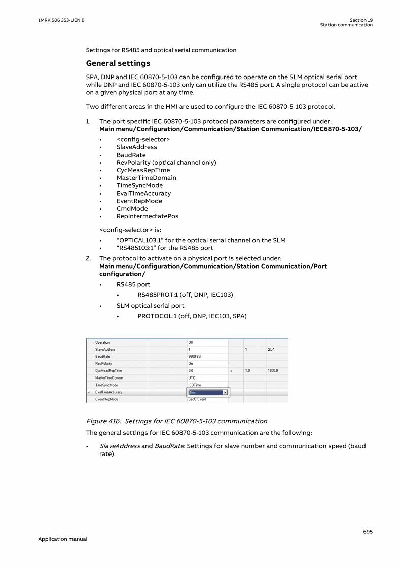
Settings for RS485 and optical serial communicationM17109-118 v10
General settings
SPA, DNP and IEC 60870-5-103 can be configured to operate on the SLM optical serial portwhile DNP and IEC 60870-5-103 only can utilize the RS485 port. A single protocol can be activeon a given physical port at any time.
Two different areas in the HMI are used to configure the IEC 60870-5-103 protocol.
1. The port specific IEC 60870-5-103 protocol parameters are configured under:Main menu/Configuration/Communication/Station Communication/IEC6870-5-103/
• <config-selector>• SlaveAddress• BaudRate• RevPolarity (optical channel only)• CycMeasRepTime• MasterTimeDomain• TimeSyncMode• EvalTimeAccuracy• EventRepMode• CmdMode• RepIntermediatePos
<config-selector> is:
• “OPTICAL103:1” for the optical serial channel on the SLM• “RS485103:1” for the RS485 port
2. The protocol to activate on a physical port is selected under:Main menu/Configuration/Communication/Station Communication/Portconfiguration/
• RS485 port
• RS485PROT:1 (off, DNP, IEC103)
• SLM optical serial port
• PROTOCOL:1 (off, DNP, IEC103, SPA)
GUID-CD4EB23C-65E7-4ED5-AFB1-A9D5E9EE7CA8 V3 ENGUID-CD4EB23C-65E7-4ED5-AFB1-A9D5E9EE7CA8 V3 EN-US
Figure 416: Settings for IEC 60870-5-103 communication
The general settings for IEC 60870-5-103 communication are the following:
• SlaveAddress and BaudRate: Settings for slave number and communication speed (baudrate).
1MRK 506 353-UEN B Section 19Station communication
695Application manual

The slave number can be set to any value between 1 and 254. The communication speed,can be set either to 9600 bits/s or 19200 bits/s.
• RevPolarity: Setting for inverting the light (or not). Standard IEC 60870-5-103 setting isOn.
• CycMeasRepTime: See I103MEAS function block for more information.• EventRepMode: Defines the mode for how events are reported. The event buffer size is
1000 events.
Event reporting mode
If EventRepMode = SeqOfEvent, all GI and spontaneous events will be delivered in the orderthey were generated by BSW. The most recent value is the latest value delivered. All GI datafrom a single block will come from the same cycle.
If EventRepMode = HiPriSpont, spontaneous events will be delivered prior to GI event. Toprevent old GI data from being delivered after a new spontaneous event, the pending GI eventis modified to contain the same value as the spontaneous event. As a result, the GI dataset isnot time-correlated.
Settings from PCM600M17109-132 v2
I103USEDEFGUID-A41170D6-2846-4E5E-8B7F-85B53D4EF6B6 v1
For each input of the I103USEDEF function there is a setting for the information number of theconnected signal. The information number can be set to any value between 0 and 255. To getproper operation of the sequence of events the event masks in the event function is to be setto ON_CHANGE. For single-command signals, the event mask is to be set to ON_SET.
In addition there is a setting on each event block for function type. Refer to description of theMain Function type set on the local HMI.
CommandsM17109-138 v2
As for the commands defined in the protocol there is a dedicated function block with eightoutput signals. Use PCM600 to configure these signals. To realize the BlockOfInformationcommand, which is operated from the local HMI, the output BLKINFO on the IEC commandfunction block ICOM has to be connected to an input on an event function block. This inputmust have the information number 20 (monitor direction blocked) according to the standard.
Disturbance RecordingsM17109-141 v7
For each input of the Disturbance recorder function there is a setting for the informationnumber of the connected signal. The function type and the information number can be set toany value between 0 and 255. To get INF and FUN for the recorded binary signals there areparameters on the disturbance recorder for each input. The user must set these parameters towhatever he connects to the corresponding input.
Refer to description of Main Function type set on the local HMI.
Recorded analog channels are sent with ASDU26 and ASDU31. One information element inthese ASDUs is called ACC and indicates the actual channel to be processed. The channels ondisturbance recorder will be sent with an ACC according to the following table:
DRA#-Input ACC IEC103 meaning
1 1 IL1
2 2 IL2
3 3 IL3
4 4 IN
5 5 UL1
6 6 UL2
7 7 UL3
Table continues on next page
Section 19 1MRK 506 353-UEN BStation communication
696Application manual

DRA#-Input ACC IEC103 meaning
8 8 UN
9 64 Private range
10 65 Private range
11 66 Private range
12 67 Private range
13 68 Private range
14 69 Private range
15 70 Private range
16 71 Private range
17 72 Private range
18 73 Private range
19 74 Private range
20 75 Private range
21 76 Private range
22 77 Private range
23 78 Private range
24 79 Private range
25 80 Private range
26 81 Private range
27 82 Private range
28 83 Private range
29 84 Private range
30 85 Private range
31 86 Private range
32 87 Private range
33 88 Private range
34 89 Private range
35 90 Private range
36 91 Private range
37 92 Private range
38 93 Private range
39 94 Private range
40 95 Private range
Function and information typesM17109-145 v4
Product type IEC103mainFunType value Comment:
REL 128 Compatible range
REC 242 Private range, use default
RED 192 Compatible range
RET 176 Compatible range
1MRK 506 353-UEN B Section 19Station communication
697Application manual

REB 207 Private range
REG 150 Private range
REQ 245 Private range
RES 118 Private range
Refer to the tables in the Technical reference manual /Station communication, specifying theinformation types supported by the communication protocol IEC 60870-5-103.
To support the information, corresponding functions must be included in the protection IED.
There is no representation for the following parts:
• Generating events for test mode• Cause of transmission: Info no 11, Local operation
Glass or plastic fiber should be used. BFOC/2.5 is the recommended interface to use(BFOC/2.5 is the same as ST connectors). ST connectors are used with the optical power asspecified in standard.
For more information, refer to IEC standard IEC 60870-5-103.
19.7 DNP3 Communication protocol
19.7.1 ApplicationGUID-EF1F0C38-9FF6-4683-8B10-AAA372D42185 v1
For more information on the application and setting guidelines for the DNP3 communicationprotocol refer to the DNP3 Communication protocol manual.
Section 19 1MRK 506 353-UEN BStation communication
698Application manual

Section 20 Remote communication
20.1 Binary signal transferIP12423-1 v2
20.1.1 IdentificationM14849-1 v2
Function description IEC 61850identification
IEC 60617identification
ANSI/IEEE C37.2device number
Binary signal transfer BinSignReceive - -
Binary signal transfer BinSignTransm - -
20.1.2 ApplicationIP16245-1 v1
M12844-3 v3
The IEDs can be equipped with communication devices for line differential communicationand/or communication of binary signals between IEDs. The same communication hardware isused for both purposes.
Communication between two IEDs geographically on different locations is a fundamental partof the line differential function.
Sending of binary signals between two IEDs, one in each end of a power line is used inteleprotection schemes and for direct transfer trips. In addition to this, there are applicationpossibilities, for example, blocking/enabling functionality in the remote substation, changingsetting group in the remote IED depending on the switching situation in the local substationand so on.
When equipped with a LDCM, a 64 kbit/s communication channel can be connected to the IED,which will then have the capacity of 192 binary signals to be communicated with a remote IED.
20.1.2.1 Communication hardware solutionsM12844-11 v4
The LDCM (Line Data Communication Module) has an optical connection such that two IEDscan be connected over a direct fiber (multimode), as shown in figure 417. The protocol used isIEEE/ANSI C37.94. The distance with this solution is typical 110 km.
LDCM
LDCM
LDCM
LDCMLDCM
LDCMLDCMLDCM
LDCMLDCM
LDCM
LDCMLD
CMLD
CM
LDCMLDCM
en06000519-2.vsdIEC06000519 V2 EN-US
Figure 417: Direct fiber optical connection between two IEDs with LDCM
The LDCM can also be used together with an external optical to galvanic G.703 converter orwith an alternative external optical to galvanic X.21 converter as shown in figure 418. These
1MRK 506 353-UEN B Section 20Remote communication
699Application manual

solutions are aimed for connections to a multiplexer, which in turn is connected to atelecommunications transmission network (for example, SDH or PDH).
Telecom. Network
*) *)
Multiplexer Multiplexer
en05000527-2.vsd*) Converting optical to galvanic G.703
IEC05000527 V2 EN-US
Figure 418: LDCM with an external optical to galvanic converter and a multiplexer
When an external modem G.703 or X21 is used, the connection between LDCM and the modemis made with a multimode fiber of max. 3 km length. The IEEE/ANSI C37.94 protocol is alwaysused between LDCM and the modem.
Alternatively, a LDCM with X.21 built-in converter and micro D-sub 15-pole connector outputcan be used.
20.1.3 Setting guidelinesM12454-3 v5.1.1
ChannelMode: This parameter can be set Normal or Blocked. Besides this, it can be setOutOfService which signifies that the local LDCM is out of service. Thus, with this setting, thecommunication channel is active and a message is sent to the remote IED that the local IED isout of service, but there is no COMFAIL signal and the analog and binary values are sent aszero.
TerminalNo: This setting shall be used to assign an unique address to each LDCM, in all currentdifferential IEDs. Up to 256 LDCMs can be assigned a unique number. Consider a local IED withtwo LDCMs:
• LDCM for slot 302: Set TerminalNo to 1 and RemoteTermNo to 2• LDCM for slot 303: Set TerminalNo to 3 and RemoteTermNo to 4
In multiterminal current differential applications, with 4 LDCMs in each IED, up to 20 uniqueaddresses must be set.
The unique address is necessary to give high security against incorrectaddressing in the communication system. Using the same number for settingTerminalNo in some of the LDCMs, a loop-back test in the communicationsystem can give incorrect trip.
RemoteTermNo: This setting assigns a number to each related LDCM in the remote IED. Foreach LDCM, the parameter RemoteTermNo shall be set to a different value than parameter
Section 20 1MRK 506 353-UEN BRemote communication
700Application manual

TerminalNo, but equal to the TerminalNo of the remote end LDCM. In the remote IED theTerminalNo and RemoteTermNo settings are reversed as follows:
• LDCM for slot 302: Set TerminalNo to 2 and RemoteTermNo to 1• LDCM for slot 303: Set TerminalNo to 4 and RemoteTermNo to 3
The redundant channel is always configured in the lower position, for example
• Slot 302: Main channel• Slot 303: Redundant channel
The same is applicable for slot 312-313 and slot 322-323.
DiffSync: Here the method of time synchronization, Echo or GPS, for the line differentialfunction is selected.
Using Echo in this situation is safe only as long as there is no risk of varyingtransmission asymmetry.
GPSSyncErr: If GPS synchronization is lost, the synchronization of the line differential functionwill continue during 16 s. based on the stability in the local IED clocks. Thereafter the settingBlock will block the line differential function or the setting Echo will make it continue by usingthe Echo synchronization method. It shall be noticed that using Echo in this situation is onlysafe as long as there is no risk of varying transmission asymmetry.
CommSync: This setting decides the Master or Slave relation in the communication systemand shall not be mistaken for the synchronization of line differential current samples. Whendirect fibre is used, one LDCM is set as Master and the other one as Slave. When a modem andmultiplexer is used, the IED is always set as Slave, as the telecommunication system willprovide the clock master.
OptoPower has two settings: LowPower and HighPower.
Short-range LDCM: Use LowPower for fibers 0 – 1 km and HighPower for fibers greater than 1km.
Medium-range LDCM: Typical distance 80 km for both LowPower and HighPower.
Long-range LDCM: Typical distance 120 km for both LowPower and HighPower.
An optical budget calculation should be made for the actual case. For medium range LDCM andlong range LDCM the recommendation is to use the LowPower setting to minimize the powerconsumption and keep the heat dissipation at minimum.
The HighPower setting adds 3 dBm extra optical power and can be used to increase themargin at distances close to maximum.
Table 59: Optical budgets with C37.94 protocol
Type of LDCM Short range (SR) Short range (SR) Medium range (MR) Long range (LR)
Type of fibre Multi-mode fiberglass 50/125 μm
Multi-mode fiberglass 62.5/125 μm
Single-mode fiberglass 9/125 μm
Single-mode fiberglass 9/125 μm
Modem type 1MRK0002122-AB 1MRK0002122-AB 1MRK002311-AA 1MRK002311-BA
Contact type ST ST FC/PC FC/PC
Table continues on next page
1MRK 506 353-UEN B Section 20Remote communication
701Application manual

Type of LDCM Short range (SR) Short range (SR) Medium range (MR) Long range (LR)
Minimum outputpower1)
–21 dBm –13.7 dBm –3.2 dBm –1.3 dBm
Minimum receiversensitivity
–32.5 dBm –32.5 dBm –30 dBm –30 dBm
Optical linkbudget2)
11.5 dB 18.8 dB 26.8 dB 28.7 dB
1) Minimum output power is measured with 1 m of the selected fiber and the high power mode.2) The optical budget includes a satisfactory margin for aging in transmitter and receiver during 20–30 years.
Table 60: Example of input data for calculating the optical budget (maximum distance)
Type of LDCM Short range (SR) Short range (SR) Medium range (MR) Long range (LR)
Type of fibre Multi-mode fiberglass 50/125 μm
Multi-mode fiberglass 62.5/125 μm
Single-mode fiberglass 9/125 μm
Single-mode fiberglass 9/125 μm
Modem type 1MRK0002122-AB 1MRK0002122-AB 1MRK002311-AA 1MRK002311-BA
Typical attenuationin fibre-opticcables
3 dB/km 3 dB/km 0.32 dB/km 0.21 dB/km
Attenuation/Contact
1.5 dB/ST 1.5 dB/ST 0.3 dB/FC/PC 0.3 dB/FC/PC
Factory spliceattenuation
0.5 dB/splice0.3 splices/km
0.5 dB/splice0.1 splices/km
0.08 dB/splice0.1 splices/km
0.08 dB/splice0.1 splices/km
Repair splices 0.25 dB/splice0.1 splices/km
0.25 dB/splice0.1 splices/km
0.1 dB/splice0.05 splices/km
0.1 dB/splice0.05 splices/km
Fiber margin foraging
0.1 dB/km 0.1 dB/km 0.01 dB/km 0.01 dB/km
Table 61: Example of calculating the optical budget (maximum distance)
Type of LDCM Short range (SR) Short range (SR) Medium range (MR) Long range (LR)
Type of fibre Multi-mode fiberglass 50/125 μm
Multi-mode fiberglass 62.5/125 μm
Single-mode fiberglass 9/125 μm
Single-mode fiberglass 9/125 μm
Modem type 1MRK0002122-AB 1MRK0002122-AB 1MRK002311-AA 1MRK002311-BA
Maximum distance 2 km 3 km 80 km 120 km
Attenuation infibre-optic cables
6 dB 9 dB 25.6 dB 25.2 dB
2 contacts 2 dB 3 dB 0.6 dB 0.6 dB
Factory spliceattenuation
0.3 dB 0.45 dB 0.64 dB 0.96 dB
Repair splices 0.1 dB 0.3 dB 0.8 dB 1.2 dB
Fiber margin foraging
0.2 dB 0.3 dB 0.8 dB 1.2 dB
Total attenuation 8.6 dB 12.05 dB 26.04 dB 28.56 dB
Optical link budget 9 dB 13 dB 26.8 dB 28.7 dB
Link margin 0.4 dB 0.95 dB 0.76 dB 0.14 dB
Section 20 1MRK 506 353-UEN BRemote communication
702Application manual

TransmCurr: This setting decides which of 2 possible local currents that shall be transmitted,or if and how the sum of 2 local currents shall be transmitted, or finally if the channel shall beused as a redundant channel.
In a 1½ breaker arrangement, there will be 2 local currents, and the earthing on the CTs can bedifferent for these. CT-SUM will transmit the sum of the 2 CT groups. CT-DIFF1 will transmit CTgroup 1 minus CT group 2 and CT-DIFF2 will transmit CT group 2 minus CT group 1.
CT-GRP1 or CT-GRP2 will transmit the respective CT group, and the setting RedundantChannelmakes the channel be used as a backup channel.
ComFailAlrmDel: Time delay of communication failure alarm. In communication systems, routeswitching can sometimes cause interruptions with a duration up to 50 ms. Thus, a too shorttime delay setting might cause nuisance alarms in these situations.
ComFailResDel: Time delay of communication failure alarm reset.
RedChSwTime: Time delay before switchover to a redundant channel in case of primarychannel failure.
RedChRturnTime: Time delay before switchback to a the primary channel after channel failure.
AsymDelay: The asymmetry is defined as transmission delay minus receive delay. If a fixedasymmetry is known, the Echo synchronization method can be used if the parameterAsymDelay is properly set. From the definition follows that the asymmetry will always bepositive in one end, and negative in the other end.
AnalogLatency: Local analog latency; A parameter which specifies the time delay (number ofsamples) between actual sampling and the time the sample reaches the local communicationmodule, LDCM. The parameter shall be set to 2 when transmitting analog data from the .
RemAinLatency: Remote analog latency; This parameter corresponds to the LocAinLatency setin the remote IED.
MaxTransmDelay: Data for maximum 40 ms transmission delay can be buffered up. Delaytimes in the range of some ms are common. It shall be noticed that if data arrive in the wrongorder, the oldest data will just be disregarded.
CompRange: The set value is the current peak value over which truncation will be made. To setthis value, knowledge of the fault current levels should be known. The setting is not overlycritical as it considers very high current values for which correct operation normally still can beachieved.
MaxtDiffLevel: Allowed maximum time difference between the internal clocks in respective lineend.
1MRK 506 353-UEN B Section 20Remote communication
703Application manual

704

Section 21 Security
21.1 Authority status ATHSTATSEMOD158575-1 v2
21.1.1 ApplicationSEMOD158527-5 v3
Authority status (ATHSTAT) function is an indication function block, which informs about twoevents related to the IED and the user authorization:
• the fact that at least one user has tried to log on wrongly into the IED and it was blocked(the output USRBLKED)
• the fact that at least one user is logged on (the output LOGGEDON)
The two outputs of ATHSTAT function can be used in the configuration for different indicationand alarming reasons, or can be sent to the station control for the same purpose.
21.2 Self supervision with internal event list INTERRSIGIP1721-1 v2
21.2.1 ApplicationM12625-3 v9
The protection and control IEDs have many functions included. The included self-supervisionwith internal event list function block provides good supervision of the IED. The fault signalsmake it easier to analyze and locate a fault.
Both hardware and software supervision is included and it is also possible to indicate possiblefaults through a hardware contact on the power supply module and/or through thecommunication.
Internal events are generated by the built-in supervisory functions. The supervisory functionssupervise the status of the various modules in the IED and, in case of failure, a correspondingevent is generated. Similarly, when the failure is corrected, a corresponding event is generated.
Apart from the built-in supervision of the various modules, events are also generated when thestatus changes for the:
• built-in real time clock (in operation/out of order).• external time synchronization (in operation/out of order).
Events are also generated:
• whenever any setting in the IED is changed.
The internal events are time tagged with a resolution of 1 ms and stored in a list. The list canstore up to 40 events. The list is based on the FIFO principle, that is, when it is full, the oldestevent is overwritten. The list contents cannot be modified, but the whole list can be clearedusing the Reset menu in the LHMI.
The list of internal events provides valuable information, which can be used duringcommissioning and fault tracing.
1MRK 506 353-UEN B Section 21Security
705Application manual

The information can, in addition to be viewed on the built in HMI, also be retrieved with the aidof a PC with PCM600 installed and by using the Event Monitoring Tool. The PC can either beconnected to the front port, or to the port at the back of the IED.
21.3 Change lock CHNGLCKGUID-B48775D0-ACF0-49C6-A7F6-69AF37F1C68F v1
21.3.1 ApplicationGUID-51EEC9C7-8ECF-4546-BC26-326861654340 v4
Change lock function CHNGLCK is used to block further changes to the IED configuration oncethe commissioning is complete. The purpose is to make it impossible to perform inadvertentIED configuration and setting changes.
However, when activated, CHNGLCK will still allow the following actions that does not involvereconfiguring of the IED:
• Monitoring• Reading events• Resetting events• Reading disturbance data• Clear disturbances• Reset LEDs• Reset counters and other runtime component states• Control operations• Set system time• Enter and exit from test mode• Change of active setting group
The binary input controlling the function is defined in ACT or SMT. The CHNGLCK function isconfigured using ACT.
LOCK Binary input signal that will activate/deactivate the function, defined in ACT or SMT.
GUID-8C333BC0-AA7A-4ED1-A772-18C22E8EEE62 v4
When CHNGLCK has a logical one on its input, then all attempts to modify the IEDconfiguration and setting will be denied and the message "Error: Changes blocked" will bedisplayed on the local HMI; in PCM600 the message will be "Operation denied by activeChangeLock". The CHNGLCK function should be configured so that it is controlled by a signalfrom a binary input card. This guarantees that by setting that signal to a logical zero,CHNGLCK is deactivated. If any logic is included in the signal path to the CHNGLCK input, thatlogic must be designed so that it cannot permanently issue a logical one to the CHNGLCKinput. If such a situation would occur in spite of these precautions, then please contact thelocal ABB representative for remedial action.
21.4 Denial of service DOS
21.4.1 ApplicationGUID-64F4D905-9F73-4073-B8F6-8D373155316A v4
The denial of service functions (DOSFRNT, DOSLANAB and DOSLANCD) are designed to limitthe CPU load that can be produced by Ethernet network traffic on the IED. The communicationfacilities must not be allowed to compromise the primary functionality of the device. Allinbound network traffic will be quota controlled so that too heavy network loads can be
Section 21 1MRK 506 353-UEN BSecurity
706Application manual

controlled. Heavy network load might for instance be the result of malfunctioning equipmentconnected to the network.
DOSFRNT, DOSLANAB and DOSLANCD measure the IED load from communication and, ifnecessary, limit it for not jeopardizing the IEDs control and protection functionality due tohigh CPU load. The function has the following outputs:
• LINKUP indicates the Ethernet link status• WARNING indicates that communication (frame rate) is higher than normal• ALARM indicates that the IED limits communication
21.4.2 Setting guidelinesGUID-CE3344E8-539B-47E0-9C19-8239988BDBCF v2
The function does not have any parameters available in the local HMI or PCM600.
1MRK 506 353-UEN B Section 21Security
707Application manual

708

Section 22 Basic IED functions
22.1 IED identifiersIP15060-1 v1
22.1.1 ApplicationM15324-3 v6
IED identifiers (TERMINALID) function allows the user to identify the individual IED in thesystem, not only in the substation, but in a whole region or a country.
Use only characters A-Z, a-z and 0-9 in station, object and unit names.
22.2 Product informationGUID-F67243CA-2429-4118-BBFF-3D62BF55E080 v1
22.2.1 ApplicationGUID-D78786E6-C34A-4E63-9D1E-0582C8F1F7E1 v6
The Product identifiers function contains constant data (i.e. not possible to change) thatuniquely identifies the IED:
• ProductVer• ProductDef• FirmwareVer• SerialNo• OrderingNo• ProductionDate• IEDProdType
The settings are visible on the local HMI , under Main menu/Diagnostics/IED status/Productidentifiersand underMain menu/Diagnostics/IED Status/IED identifiers
This information is very helpful when interacting with ABB product support (e.g. during repairand maintenance).
22.2.2 Factory defined settingsM11789-39 v10
The factory defined settings are very useful for identifying a specific version and very helpful inthe case of maintenance, repair, interchanging IEDs between different Substation AutomationSystems and upgrading. The factory made settings can not be changed by the customer. Theycan only be viewed. The settings are found in the local HMI under Main menu/Diagnostics/IEDstatus/Product identifiers
The following identifiers are available:
• IEDProdType
• Describes the type of the IED. Example: REL670
• ProductDef
• Describes the release number from the production. Example: 2.1.0
• FirmwareVer
1MRK 506 353-UEN B Section 22Basic IED functions
709Application manual

• Describes the firmware version.• The firmware version can be checked from Main menu/Diagnostics/IED status/
Product identifiers• Firmware version numbers run independently from the release production numbers.
For every release number there can be one or more firmware versions depending onthe small issues corrected in between releases.
• ProductVer
• Describes the product version. Example: 2.1.0
1 is the Major version of the manufactured product this means, new platform of the product
2 is the Minor version of the manufactured product this means, new functions or new hardwareadded to the product
3 is the Major revision of the manufactured product this means, functions or hardware is eitherchanged or enhanced in the product
• IEDMainFunType
• Main function type code according to IEC 60870-5-103. Example: 128 (meaning lineprotection).
• SerialNo• OrderingNo• ProductionDate
22.3 Measured value expander block RANGE_XPSEMOD52451-1 v2
22.3.1 IdentificationSEMOD113212-2 v3
Function description IEC 61850identification
IEC 60617identification
ANSI/IEEE C37.2device number
Measured value expander block RANGE_XP - -
22.3.2 ApplicationSEMOD52434-4 v5
The current and voltage measurements functions (CVMMXN, CMMXU, VMMXU and VNMMXU),current and voltage sequence measurement functions (CMSQI and VMSQI) and IEC 61850generic communication I/O functions (MVGAPC) are provided with measurement supervisionfunctionality. All measured values can be supervised with four settable limits, that is low-lowlimit, low limit, high limit and high-high limit. The measure value expander block ( RANGE_XP)has been introduced to be able to translate the integer output signal from the measuringfunctions to 5 binary signals, that is below low-low limit, below low limit, normal, above high-high limit or above high limit. The output signals can be used as conditions in the configurablelogic.
22.3.3 Setting guidelinesSEMOD113223-4 v1
There are no settable parameters for the measured value expander block function.
Section 22 1MRK 506 353-UEN BBasic IED functions
710Application manual

22.4 Parameter setting groupsIP1745-1 v1
22.4.1 ApplicationM12007-6 v9
Six sets of settings are available to optimize IED operation for different power systemconditions. By creating and switching between fine tuned setting sets, either from the localHMI or configurable binary inputs, results in a highly adaptable IED that can cope with a varietyof power system scenarios.
Different conditions in networks with different voltage levels require highly adaptableprotection and control units to best provide for dependability, security and selectivityrequirements. Protection units operate with a higher degree of availability, especially, if thesetting values of their parameters are continuously optimized according to the conditions inthe power system.
Operational departments can plan for different operating conditions in the primaryequipment. The protection engineer can prepare the necessary optimized and pre-testedsettings in advance for different protection functions. Six different groups of settingparameters are available in the IED. Any of them can be activated through the differentprogrammable binary inputs by means of external or internal control signals.
A function block, SETGRPS, defines how many setting groups are used. Setting is done withparameter MAXSETGR and shall be set to the required value for each IED. Only the number ofsetting groups set will be available in the Parameter Setting tool for activation with theActiveGroup function block.
22.4.2 Setting guidelinesM15259-3 v4
The setting ActiveSetGrp, is used to select which parameter group to be active. The activegroup can also be selected with configured input to the function block SETGRPS.
The length of the pulse, sent out by the output signal SETCHGD when an active group haschanged, is set with the parameter t.
The parameter MAXSETGR defines the maximum number of setting groups in use to switchbetween. Only the selected number of setting groups will be available in the Parameter Settingtool (PST) for activation with the ActiveGroup function block.
22.5 Rated system frequency PRIMVALIP15064-1 v2
22.5.1 IdentificationGUID-B8B3535D-227B-4151-9E98-BEB85F4D54DE v1
Function description IEC 61850identification
IEC 60617identification
ANSI/IEEE C37.2device number
Primary system values PRIMVAL - -
22.5.2 ApplicationM15288-3 v6
The rated system frequency and phase rotation direction are set under Main menu/Configuration/ Power system/ Primary Values in the local HMI and PCM600 parametersetting tree.
1MRK 506 353-UEN B Section 22Basic IED functions
711Application manual

22.5.3 Setting guidelinesM15292-3 v2
Set the system rated frequency. Refer to section "Signal matrix for analog inputs SMAI" fordescription on frequency tracking.
22.6 Summation block 3 phase 3PHSUMSEMOD55968-1 v2
22.6.1 ApplicationSEMOD56004-4 v3
The analog summation block 3PHSUM function block is used in order to get the sum of twosets of 3 phase analog signals (of the same type) for those IED functions that might need it.
22.6.2 Setting guidelinesSEMOD56006-4 v7
The summation block receives the three-phase signals from SMAI blocks. The summation blockhas several settings.
SummationType: Summation type (Group 1 + Group 2, Group 1 - Group 2, Group 2 - Group 1 or –(Group 1 + Group 2)).
DFTReference: The reference DFT block (InternalDFT Ref,DFTRefGrp1 or External DFT ref) .
DFTRefGrp1: This setting means use own internal adaptive DFT reference ( this setting makesthe SUM3PH self DFT adaptive, that is, it will use the measured frequency for the summationsignal to adapt DFT).
InternalDFTRef: Gives fixed window DFT (to nominal system frequency).
ExternalDFTRef: This setting means that the DFT samples-per-cycle (adaptive DFT) will becontrolled by SMAI1 SPFCOUT.
FreqMeasMinVal: The minimum value of the voltage for which the frequency is calculated,expressed as percent of UBasebase voltage setting (for each instance x).
GlobalBaseSel: Selects the global base value group used by the function to define (IBase),(UBase) and (SBase).
22.7 Global base values GBASVALGUID-2FDB0A2C-10FE-4954-B6E4-9DA2EEEF1668 v1
22.7.1 IdentificationGUID-0D5405BE-E669-44C8-A208-3A4C86D39115 v3
Function description IEC 61850identification
IEC 60617identification
ANSI/IEEE C37.2device number
Global base values GBASVAL - -
Section 22 1MRK 506 353-UEN BBasic IED functions
712Application manual
22.7.2 ApplicationGUID-D58ECA9A-9771-443D-BF84-8EF582A346BF v4
Global base values function (GBASVAL) is used to provide global values, common for allapplicable functions within the IED. One set of global values consists of values for current,voltage and apparent power and it is possible to have twelve different sets.
This is an advantage since all applicable functions in the IED use a single source of base values.This facilitates consistency throughout the IED and also facilitates a single point for updatingvalues when necessary.
Each applicable function in the IED has a parameter, GlobalBaseSel, defining one out of thetwelve sets of GBASVAL functions.
22.7.3 Setting guidelinesGUID-E3F5D754-BD17-4729-895B-957A09C2AC75 v3
UBase: Phase-to-phase voltage value to be used as a base value for applicable functionsthroughout the IED.
IBase: Phase current value to be used as a base value for applicable functions throughout theIED.
SBase: Standard apparent power value to be used as a base value for applicable functionsthroughout the IED, typically SBase=√3·UBase·IBase.
22.8 Signal matrix for binary inputs SMBISEMOD55793-1 v2
22.8.1 ApplicationM15310-3 v2
The Signal matrix for binary inputs function SMBI is used within the Application Configurationtool in direct relation with the Signal Matrix tool. SMBI represents the way binary inputs arebrought in for one IED configuration.
22.8.2 Setting guidelinesM15312-3 v3
There are no setting parameters for the Signal matrix for binary inputs SMBI available to theuser in Parameter Setting tool. However, the user shall give a name to SMBI instance and theSMBI inputs, directly in the Application Configuration tool. These names will define SMBIfunction in the Signal Matrix tool. The user defined name for the input or output signal will alsoappear on the respective output or input signal.
22.9 Signal matrix for binary outputs SMBOSEMOD55215-1 v2
22.9.1 ApplicationSEMOD55213-5 v4
The Signal matrix for binary outputs function SMBO is used within the ApplicationConfiguration tool in direct relation with the Signal Matrix tool. SMBO represents the waybinary outputs are sent from one IED configuration.
1MRK 506 353-UEN B Section 22Basic IED functions
713Application manual

22.9.2 Setting guidelinesSEMOD55228-5 v2
There are no setting parameters for the Signal matrix for binary outputs SMBO available to theuser in Parameter Setting tool. However, the user must give a name to SMBO instance andSMBO outputs, directly in the Application Configuration tool. These names will define SMBOfunction in the Signal Matrix tool.
22.10 Signal matrix for mA inputs SMMISEMOD55233-1 v2
22.10.1 ApplicationSEMOD55237-5 v2
The Signal matrix for mA inputs function SMMI is used within the Application Configurationtool in direct relation with the Signal Matrix tool. SMMI represents the way milliamp (mA)inputs are brought in for one IED configuration.
22.10.2 Setting guidelinesSEMOD55247-5 v2
There are no setting parameters for the Signal matrix for mA inputs SMMI available to the userin the Parameter Setting tool. However, the user must give a name to SMMI instance and SMMIinputs, directly in the Application Configuration tool.
22.11 Signal matrix for analog inputs SMAISEMOD55751-1 v2
22.11.1 ApplicationSEMOD55744-4 v10
Signal matrix for analog inputs (SMAI), also known as the preprocessor function block,analyses the connected four analog signals (three phases and neutral) and calculates allrelevant information from them like the phasor magnitude, phase angle, frequency, true RMSvalue, harmonics, sequence components and so on. This information is then used by therespective functions connected to this SMAI block in ACT (for example protection,measurement or monitoring functions).
22.11.2 Frequency valuesGUID-B494B93C-B5AA-4FD6-8080-8611C34C2AD8 v5
The SMAI function includes a functionality based on the level of positive sequence voltage,MinValFreqMeas, to validate if the frequency measurement is valid or not. If the positivesequence voltage is lower than MinValFreqMeas, the function freezes the frequency outputvalue for 500 ms and after that the frequency output is set to the nominal value. A signal isavailable for the SMAI function to prevent operation due to non-valid frequency values.MinValFreqMeas is set as % of UBase/√3
If SMAI setting ConnectionType is Ph-Ph, at least two of the inputs GRPxL1, GRPxL2 andGRPxL3, where 1≤x≤12, must be connected in order to calculate the positive sequence voltage.Note that phase to phase inputs shall always be connected as follows: L1-L2 to GRPxL1, L2-L3to GRPxL2, L3-L1 to GRPxL3. If SMAI setting ConnectionType is Ph-N, all three inputs GRPxL1,GRPxL2 and GRPxL3 must be connected in order to calculate the positive sequence voltage.
If only one phase-phase voltage is available and SMAI setting ConnectionType is Ph-Ph, theuser is advised to connect two (not three) of the inputs GRPxL1, GRPxL2 and GRPxL3 to thesame voltage input as shown in figure 419 to make SMAI calculate a positive sequence voltage.
Section 22 1MRK 506 353-UEN BBasic IED functions
714Application manual

SMAI1
BLOCK
DFTSPFC
REVROT
^GRP1L1
^GRP1L2
^GRP1L3
^GRP1N
SPFCOUT
G1AI3P
G1AI1
G1AI2
G1AI4
G1N
NEUTRAL
PHASEL3
PHASEL2
PHASEL1
UL1L2
SAPTOF
U3P*BLOCK
BLKTRIP
TRIPSTART
BLKDMAGN
FREQTRM_40.CH7(U)
SAPTOF(1)_TRIP
IEC10000060-2-en.vsdx
IEC10000060 V2 EN-US
Figure 419: Connection example
The above described scenario does not work if SMAI setting ConnectionType isPh-N. If only one phase-earth voltage is available, the same type of connectioncan be used but the SMAI ConnectionType setting must still be Ph-Ph and thishas to be accounted for when setting MinValFreqMeas. If SMAI settingConnectionType is Ph-N and the same voltage is connected to all three SMAIinputs, the positive sequence voltage will be zero and the frequency functionswill not work properly.
The outputs from the above configured SMAI block shall only be used forOverfrequency protection (SAPTOF), Underfrequency protection (SAPTUF) andRate-of-change frequency protection (SAPFRC) due to that all otherinformation except frequency and positive sequence voltage might be wronglycalculated.
22.11.3 Setting guidelinesGUID-C8D6C88B-87C6-44C1-804B-CF1594365EE6 v8
The parameters for the signal matrix for analog inputs (SMAI) functions are set via the localHMI or PCM600.
Every SMAI function block can receive four analog signals (three phases and one neutral value),either voltage or current. SMAI outputs give information about every aspect of the 3ph analogsignals acquired (phase angle, RMS value, frequency and frequency derivates, and so on – 244values in total). Besides the block “group name”, the analog inputs type (voltage or current)and the analog input names that can be set directly in ACT.
Application functions should be connected to a SMAI block with same task cycle as theapplication function, except for e.g. measurement functions that run in slow cycle tasks.
DFTRefExtOut: Parameter valid only for function block SMAI1 .
Reference block for external output (SPFCOUT function output).
DFTReference: Reference DFT for the SMAI block use.
These DFT reference block settings decide DFT reference for DFT calculations. The settingInternalDFTRef will use fixed DFT reference based on set system frequency. DFTRefGrp(n) willuse DFT reference from the selected group block, when own group is selected, an adaptiveDFT reference will be used based on calculated signal frequency from own group. The settingExternalDFTRef will use reference based on what is connected to input DFTSPFC.
1MRK 506 353-UEN B Section 22Basic IED functions
715Application manual

The setting ConnectionType: Connection type for that specific instance (n) of the SMAI (if it isPh-N or Ph-Ph). Depending on connection type setting the not connected Ph-N or Ph-Phoutputs will be calculated as long as they are possible to calculate. E.g. at Ph-Ph connection L1,L2 and L3 will be calculated for use in symmetrical situations. If N component should be usedrespectively the phase component during faults IN/UN must be connected to input 4.
Negation: If the user wants to negate the 3ph signal, it is possible to choose to negate only thephase signals Negate3Ph, only the neutral signal NegateN or both Negate3Ph+N. negationmeans rotation with 180° of the vectors.
GlobalBaseSel: Selects the global base value group used by the function to define (IBase),(UBase) and (SBase).
MinValFreqMeas: The minimum value of the voltage for which the frequency is calculated,expressed as percent of UBase (for each instance n).
Settings DFTRefExtOut and DFTReference shall be set to default valueInternalDFTRef if no VT inputs are available.
Even if the user sets the AnalogInputType of a SMAI block to “Current”, theMinValFreqMeas is still visible. However, using the current channel values asbase for frequency measurement is not recommendable for a number ofreasons, not last among them being the low level of currents that one can havein normal operating conditions.
Examples of adaptive frequency tracking
Preprocessing block shall only be used to feed functions within the sameexecution cycles (e.g. use preprocessing block with cycle 1 to feed transformerdifferential protection). The only exceptions are measurement functions(CVMMXN, CMMXU,VMMXU, etc.) which shall be fed by preprocessing blockswith cycle 8.
When two or more preprocessing blocks are used to feed one protectionfunction (e.g. over-power function GOPPDOP), it is of outmost importance thatparameter setting DFTReference has the same set value for all of thepreprocessing blocks involved
Section 22 1MRK 506 353-UEN BBasic IED functions
716Application manual

IEC07000197.vsd
SMAI instance 3 phase groupSMAI1:1 1SMAI2:2 2SMAI3:3 3SMAI4:4 4SMAI5:5 5SMAI6:6 6SMAI7:7 7SMAI8:8 8SMAI9:9 9
SMAI10:10 10SMAI11:11 11SMAI12:12 12
Task time group 1
SMAI instance 3 phase groupSMAI1:13 1SMAI2:14 2SMAI3:15 3SMAI4:16 4SMAI5:17 5SMAI6:18 6SMAI7:19 7SMAI8:20 8SMAI9:21 9
SMAI10:22 10SMAI11:23 11SMAI12:24 12
Task time group 2
SMAI instance 3 phase groupSMAI1:25 1SMAI2:26 2SMAI3:27 3SMAI4:28 4SMAI5:29 5SMAI6:30 6SMAI7:31 7SMAI8:32 8SMAI9:33 9
SMAI10:34 10SMAI11:35 11SMAI12:36 12
Task time group 3
AdDFTRefCh7
AdDFTRefCh4
IEC07000197 V2 EN-US
Figure 420: Twelve SMAI instances are grouped within one task time. SMAI blocks areavailable in three different task times in the IED. Two pointed instances areused in the following examples.
The examples shows a situation with adaptive frequency tracking with one reference selectedfor all instances. In practice each instance can be adapted to the needs of the actualapplication. The adaptive frequency tracking is needed in IEDs that belong to the protectionsystem of synchronous machines and that are active during run-up and shout-down of themachine. In other application the usual setting of the parameter DFTReference of SMAI isInternalDFTRef.
Example 1
1MRK 506 353-UEN B Section 22Basic IED functions
717Application manual

IEC07000198-2-en.vsd
SMAI1:1BLOCKDFTSPFC^GRP1L1^GRP1L2^GRP1L3^GRP1N
SPFCOUTAI3P
AI1AI2AI3AI4AIN
SMAI1:13BLOCKDFTSPFC^GRP1L1^GRP1L2^GRP1L3^GRP1N
SPFCOUTAI3P
AI1AI2AI3AI4AIN
SMAI1:25BLOCKDFTSPFC^GRP1L1^GRP1L2^GRP1L3^GRP1N
SPFCOUTAI3P
AI1AI2AI3AI4AIN
IEC07000198 V3 EN-US
Figure 421: Configuration for using an instance in task time group 1 as DFT reference
Assume instance SMAI7:7 in task time group 1 has been selected in the configuration to controlthe frequency tracking . Observe that the selected reference instance (i.e. frequency trackingmaster) must be a voltage type. Observe that positive sequence voltage is used for thefrequency tracking feature.
For task time group 1 this gives the following settings (see Figure 420 for numbering):
SMAI1:1: DFTRefExtOut = DFTRefGrp7 to route SMAI7:7 reference to the SPFCOUT output,DFTReference = DFTRefGrp7 for SMAI1:1 to use SMAI7:7 as reference (see Figure 421) SMAI2:2 –SMAI12:12: DFTReference = DFTRefGrp7 for SMAI2:2 – SMAI12:12 to use SMAI7:7 as reference.
For task time group 2 this gives the following settings:
SMAI1:13 – SMAI12:24: DFTReference = ExternalDFTRef to use DFTSPFC input of SMAI1:13 asreference (SMAI7:7)
For task time group 3 this gives the following settings:
SMAI1:25 – SMAI12:36: DFTReference = ExternalDFTRef to use DFTSPFC input as reference(SMAI7:7)
Example 2
Section 22 1MRK 506 353-UEN BBasic IED functions
718Application manual

IEC07000199-2-en.vsd
SMAI1:13BLOCKDFTSPFC^GRP1L1^GRP1L2^GRP1L3^GRP1N
SPFCOUTAI3P
AI1AI2AI3AI4AIN
SMAI1:1BLOCKDFTSPFC^GRP1L1^GRP1L2^GRP1L3^GRP1N
SPFCOUTAI3P
AI1AI2AI3AI4AIN
SMAI1:25BLOCKDFTSPFC^GRP1L1^GRP1L2^GRP1L3^GRP1N
SPFCOUTAI3P
AI1AI2AI3AI4AIN
IEC07000199 V3 EN-US
Figure 422: Configuration for using an instance in task time group 2 as DFT reference.
Assume instance SMAI4:16 in task time group 2 has been selected in the configuration tocontrol the frequency tracking for all instances. Observe that the selected reference instance(i.e. frequency tracking master) must be a voltage type. Observe that positive sequencevoltage is used for the frequency tracking feature.
For task time group 1 this gives the following settings (see Figure 420 for numbering):
SMAI1:1 – SMAI12:12: DFTReference = ExternalDFTRef to use DFTSPFC input as reference(SMAI4:16)
For task time group 2 this gives the following settings:
SMAI1:13: DFTRefExtOut = DFTRefGrp4 to route SMAI4:16 reference to the SPFCOUT output,DFTReference = DFTRefGrp4 for SMAI1:13 to use SMAI4:16 as reference (see Figure 422)SMAI2:14 – SMAI12:24: DFTReference = DFTRefGrp4 to use SMAI4:16 as reference.
For task time group 3 this gives the following settings:
SMAI1:25 – SMAI12:36: DFTReference = ExternalDFTRef to use DFTSPFC input as reference(SMAI4:16)
22.12 Test mode functionality TESTIP1647-1 v2
22.12.1 ApplicationM11407-3 v8
The protection and control IEDs may have a complex configuration with many includedfunctions. To make the testing procedure easier, the IEDs include the feature that allowsindividual blocking of a single-, several-, or all functions.
This means that it is possible to see when a function is activated or trips. It also enables theuser to follow the operation of several related functions to check correct functionality and tocheck parts of the configuration, and so on.
1MRK 506 353-UEN B Section 22Basic IED functions
719Application manual

22.12.1.1 IEC 61850 protocol test modeGUID-82998715-6F23-4CAF-92E4-05E1A863CF33 v5
The function block TESTMODE has implemented the extended testing mode capabilities forIEC 61850 Ed2 systems. Operator commands sent to the function block TESTMODE determinethe behavior of the functions. The command can be given remotely from an IEC 61850 client orfrom the LHMI under the Main menu/Test/Function test modes/Communication/StationCommunication/IEC61850 LD0 LLN0/LD0LLN0:1. The possible values of the function blockTESTMODE are described in Communication protocol manual, IEC 61850 Edition 1 and Edition2.
There is no setting in PCM600 via PST for the TESTMODE function block.
To be able to set the function block TESTMODE remotely, the setting via pathon LHMI and in PST: Main menu/Configuration/Communication/ StationCommunication/IEC61850-8-1/IEC61850-8-1:1RemoteModControl may not beset to Off. The possible values of the parameter RemoteModControl are Off,Maintenance or All levels. The Off value denies all access to function blockTESTMODE from remote, Maintenance requires that the category of theoriginator (orCat) is Maintenance and All levels allow any orCat.
The DataObject Mod of the Root LD.LNN0 can be set on the LHMI under Main menu/Test/Function test modes/Communication/Station communication/IEC61850 LD0 LLN0/LD0LLN0:1 to On, Off, TestBlocked,Test or Blocked.
When the setting of the DataObject Mod is changed at this level, all Logical Nodes inside thelogical device update their own behavior according to IEC61850-7-4. The supported values ofthe function block TESTMODE are described in Communication protocol manual, IEC 61850Edition 2. When the function block TESTMODE is in test mode the Start LED on the LHMI isturned on with steady light.
The parameter Mod of any specific function block can be configured under Main menu/Test/Function test modes/Communication/Station Communication
The parameter Mod can be set on the LHMI to the same values as for the DataObject Mod ofthe Root LD.LNN0 to On, Off, TestBlocked,Test or Blocked. For Example, Main menu/ Test/Function test modes/ Differential protection/GeneratorDiff(87G,3Id/I>)/ GENPDIF(87G,3Id/I>):1.
It is possible that the behavior of the function block TESTMODE is also influenced by othersources as well, independent of the mode communicated via the IEC61850-8-1 station bus. Forexample the insertion of the test handle into the test switch with its auxiliary contact isconnected to a BI on the IED and further inside the configuration to the input IED_TEST on thefunction block TESTMODE. Another example is when loss of Service Values appears, or asexplained above the setting via the LHMI.
When setting via PST or LHMI the parameterOperation of any function in an IED is set to Off,the function is not executed and the behavior (beh) is set toOff and it is not possible tooverride it. When a behavior of a function is Off the function will not execute. The related Modkeeps its current state.
When IEC 61850 Mod of a function is set to Off or Blocked, the Start LED on theLHMI will be set to flashing to indicate the abnormal operation of the IED.
The IEC 61850-7-4 gives a detailed overview over all aspects of the test mode and other statesof mode and behavior. The status of a function block behavior Beh is shown on the LHMI under
Section 22 1MRK 506 353-UEN BBasic IED functions
720Application manual

the Main menu/Test/Function status/Function group/Function block descriptive name/LNname/Outputs.
• When the Beh of a function block is set to Test, the function block is not blocked and allcontrol commands with a test bit are accepted.
• When the Beh of a function block is set to Test/blocked, all control commands with a testbit are accepted. Outputs to the process via a non-IEC 61850 link data are blocked by thefunction block. Only process-related outputs on function blocks related to primaryequipment are blocked. If there is an XCBR function block used, the outputs EXC_Openand EXC_Close are blocked.
• When the Beh of a function block is set to Blocked, all control commands with a test bitare accepted. Outputs to the process via a non-IEC 61850 link data are blocked by thefunction block. In addition, the function block can be blocked when their Beh is blocked.This can be done if the function block has a block input.
The block status of a component is shown on the LHMI as the Blk output under the same pathas for Beh:Main menu/Test/Function status/Function group/Function block descriptivename/LN name/Outputs. If the Blk output is not shown, the component cannot be blocked.
22.12.2 Setting guidelinesM15260-3 v7
Remember always that there are two possible ways to place the IED in the TestMode= On”state. If, the IED is set to normal operation (TestMode = Off), but the functions are still shownbeing in the test mode, the input signal IED_TEST on the TESTMODE function block isactivated in the configuration.
Forcing of binary input and output signals is only possible when the IED is in IED test mode.
22.13 Time synchronizationIP1750-1 v1
22.13.1 ApplicationM11345-3 v9
Use time synchronization to achieve a common time base for the IEDs in a protection andcontrol system. This makes it possible to compare events and disturbance data between allIEDs in the system. If a global common source (i.e. GPS) is used in different substations for thetime synchronization, also comparisons and analysis between recordings made at differentlocations can be easily performed and a more accurate view of the actual sequence of eventscan be obtained.
Time-tagging of internal events and disturbances are an excellent help when evaluating faults.Without time synchronization, only the events within one IED can be compared with eachother. With time synchronization, events and disturbances within the whole network, can becompared and evaluated.
In the IED, the internal time can be synchronized from the following sources:
• BIN (Binary Minute Pulse)• DNP• GPS• IEC103• SNTP• IRIG-B• SPA• LON• PPS
1MRK 506 353-UEN B Section 22Basic IED functions
721Application manual

For IEDs using IEC 61850-9-2LE in "mixed mode" a time synchronization from an external clockis recommended to the IED and all connected merging units. The time synchronization fromthe clock to the IED can be either optical PPS or IRIG-B. For IED's using IEC 61850-9-2LE fromone single MU as analog data source, the MU and IED still needs to be synchronized to eachother. This could be done by letting the MU supply a PPS signal to the IED.
Out of these, LON and SPA contains two types of synchronization messages:
• Coarse time messages are sent every minute and contain complete date and time, that isyear, month, day, hour, minute, second and millisecond.
• Fine time messages are sent every second and comprise only seconds and milliseconds.
The selection of the time source is done via the corresponding setting.
It is possible to set a backup time-source for GPS signal, for instance SNTP. In this case, whenthe GPS signal quality is bad, the IED will automatically choose SNTP as the time-source. At agiven point in time, only one time-source will be used.
22.13.2 Setting guidelinesIP15089-1 v3
All the parameters related to time are divided into two categories: System time andSynchronization.
22.13.2.1 System timeM11348-119 v4
The time is set with years, month, day, hour, minute, second and millisecond.
22.13.2.2 SynchronizationM11348-143 v4
The setting parameters for the real-time clock with external time synchronization are set vialocal HMI or PCM600. The path for Time Synchronization parameters on local HMI is Mainmenu/Configuration/Time/Synchronization. The parameters are categorized as TimeSynchronization (TIMESYNCHGEN) and IRIG-B settings (IRIG-B:1) in case that IRIG-B is used asthe external time synchronization source.
TimeSynchM11348-167 v18
When the source of the time synchronization is selected on the local HMI, the parameter iscalled TimeSynch. The time synchronization source can also be set from PCM600. The settingalternatives are:
FineSyncSource can have the following values:
• Off• SPA• LON• BIN (Binary Minute Pulse)• GPS• GPS+SPA• GPS+LON• GPS+BIN• SNTP• GPS+SNTP• IRIG-B• GPS+IRIG-B• PPS
CoarseSyncSrc which can have the following values:
Section 22 1MRK 506 353-UEN BBasic IED functions
722Application manual

• Off• SPA• LON• DNP• IEC 60870-5-103
The function input to be used for minute-pulse synchronization is called BININPUT. For adescription of the BININPUT settings, see the Technical Manual.
The system time can be set manually, either via the local HMI or via any of the communicationports. The time synchronization fine tunes the clock (seconds and milliseconds).
The parameter SyncMaster defines if the IED is a master, or not a master for timesynchronization within a Substation Automation System, for IEDs connected in acommunication network (IEC 61850-8-1). The SyncMaster can have the following values:
• Off• SNTP -Server
Set the course time synchronizing source (CoarseSyncSrc) to Off when GPStime synchronization of line differential function is used. Set the fine timesynchronization source (FineSyncSource) to GPS. The GPS will thus provide thecomplete time synchronization. GPS alone shall synchronize the analoguevalues in such systems.
All protection functions will be blocked if the AppSynch parameter is set toSynch while there is no 9-2 synchronization source. For more informationplease refer to the "IEC/UCA 61850-9-2LE communication protocol" section.
22.13.2.3 Process bus IEC 61850-9-2LE synchronizationGUID-6E384BDB-5598-4108-99B4-0B4A4E1828B2 v3
When process bus communication (IEC 61850-9-2LE protocol) is used, it is essential that themerging units are using the same time source as the IED. To achieve this, a satellite-controlledclock shall provide time synchronization to the IED (either internal GPS or via IRIG-B 00x withIEEE1344 support) and to the merging units (via for instance PPS). For the timesynchronization of the process bus communication, GPS Time Module (GTM) and/or IRIG-Bmodule can be used. If the IED contains a GTM, the merging unit can be synchronized from thePPS output of the GTM.
22.13.2.4 Time synchronization for differential protection and IEC 61850-9-2LEsampled data
GUID-413328FC-47E2-499B-8E11-AD51EF1B525A v2
When using differential communication in conjunction with sampled data received frommerging units (MU) over the IEC 61850-9-2LE process bus, the MU and the IED needs to becontrolled by the same GPS synchronized clock. The required accuracy is +/- 2 µs. The MUneeds to get an optic PPS signal from the clock in order to take samples at the correct timeand the IED needs to get the time-quality information in IRIG-B, using the 1344 protocol, fromthe very same clock in order to be able to block in case of failure in the clock source.
The settings for time synchronization should be CourseSyncSrc = Off, FineSyncSource = IRIG-B,TimeAdjustRate = Fast. The setting for Encoding in SYNCHIRIG-B needs to be set to 1344.
1MRK 506 353-UEN B Section 22Basic IED functions
723Application manual

PPS in
IRIG -B GTM
LDCM diffSync
GPS
3xI 3xI
TRM
GPS
GPS
IED
Satellite-Controlled Clock
Merging unit (MU)
IED
IEC61850-9-2LE
en08000085.vsdIEC08000085 V1 EN-US
Figure 423: Time synchronization of merging unit and IED
The parameter DiffSync for the LDCM needs to be set to GPS and the GPSSyncErr needs to beset to Block.
In "ECHO" mode MU and IED still need to be synchronized. In this case they can besynchronized with either PPS or IRIG-B.
Section 22 1MRK 506 353-UEN BBasic IED functions
724Application manual

Section 23 Requirements
23.1 Current transformer requirementsIP15171-1 v2
M11609-3 v2
The performance of a protection function will depend on the quality of the measured currentsignal. Saturation of the current transformers (CTs) will cause distortion of the current signalsand can result in a failure to operate or cause unwanted operations of some functions.Consequently CT saturation can have an influence on both the dependability and the securityof the protection. This protection IED has been designed to permit heavy CT saturation withmaintained correct operation.
23.1.1 Current transformer classificationM11611-3 v1
M11611-4 v4
To guarantee correct operation, the current transformers (CTs) must be able to correctlyreproduce the current for a minimum time before the CT will begin to saturate. To fulfill therequirement on a specified time to saturation the CTs must fulfill the requirements of aminimum secondary e.m.f. that is specified below.
There are several different ways to specify CTs. Conventional magnetic core CTs are usuallyspecified and manufactured according to some international or national standards, whichspecify different protection classes as well. There are many different standards and a lot ofclasses but fundamentally there are three different types of CTs:
• High remanence type CT• Low remanence type CT• Non remanence type CT
The high remanence type has no limit for the remanent flux. This CT has a magnetic corewithout any airgaps and a remanent flux might remain almost infinite time. In this type oftransformers the remanence can be up to around 80% of the saturation flux. Typical examplesof high remanence type CT are class P, PX, TPX according to IEC, class P, X according to BS (oldBritish Standard) and non gapped class C, K according to ANSI/IEEE.
The low remanence type has a specified limit for the remanent flux. This CT is made with asmall air gap to reduce the remanence to a level that does not exceed 10% of the saturationflux. The small air gap has only very limited influences on the other properties of the CT. ClassPXR, TPY according to IEC are low remanence type CTs.
The non remanence type CT has practically negligible level of remanent flux. This type of CThas relatively big air gaps in order to reduce the remanence to practically zero level. In thesame time, these air gaps reduce the influence of the DC-component from the primary faultcurrent. The air gaps will also decrease the measuring accuracy in the non-saturated region ofoperation. Class TPZ according to IEC is a non remanence type CT.
Different standards and classes specify the saturation e.m.f. in different ways but it is possibleto approximately compare values from different classes. The rated equivalent limitingsecondary e.m.f. Eal according to the IEC 61869–2 standard is used to specify the CTrequirements for the IED. The requirements are also specified according to other standards.
23.1.2 ConditionsM11610-3 v1
M11610-4 v4
The requirements are a result of investigations performed in our network simulator. Thecurrent transformer models are representative for current transformers of high remanence
1MRK 506 353-UEN B Section 23Requirements
725Application manual

and low remanence type. The results may not always be valid for non remanence type CTs(TPZ).
The performances of the protection functions have been checked in the range fromsymmetrical to fully asymmetrical fault currents. Primary time constants of at least 120 mshave been considered at the tests. The current requirements below are thus applicable bothfor symmetrical and asymmetrical fault currents.
Depending on the protection function phase-to-earth, phase-to-phase and three-phase faultshave been tested for different relevant fault positions for example, close in forward andreverse faults, zone 1 reach faults, internal and external faults. The dependability and securityof the protection was verified by checking for example, time delays, unwanted operations,directionality, overreach and stability.
The remanence in the current transformer core can cause unwanted operations or minoradditional time delays for some protection functions. As unwanted operations are notacceptable at all maximum remanence has been considered for fault cases critical for thesecurity, for example, faults in reverse direction and external faults. Because of the almostnegligible risk of additional time delays and the non-existent risk of failure to operate theremanence have not been considered for the dependability cases. The requirements below aretherefore fully valid for all normal applications.
It is difficult to give general recommendations for additional margins for remanence to avoidthe minor risk of an additional time delay. They depend on the performance and economyrequirements. When current transformers of low remanence type (for example, TPY, PR) areused, normally no additional margin is needed. For current transformers of high remanencetype (for example, P, PX, TPX) the small probability of fully asymmetrical faults, together withhigh remanence in the same direction as the flux generated by the fault, has to be kept in mindat the decision of an additional margin. Fully asymmetrical fault current will be achieved whenthe fault occurs at approximately zero voltage (0°). Investigations have shown that 95% of thefaults in the network will occur when the voltage is between 40° and 90°. In addition fullyasymmetrical fault current will not exist in all phases at the same time.
23.1.3 Fault currentM11613-3 v1
M11613-4 v3
The current transformer requirements are based on the maximum fault current for faults indifferent positions. Maximum fault current will occur for three-phase faults or single phase-to-earth faults. The current for a single phase-to-earth fault will exceed the current for a three-phase fault when the zero sequence impedance in the total fault loop is less than the positivesequence impedance.
When calculating the current transformer requirements, maximum fault current for therelevant fault position should be used and therefore both fault types have to be considered.
23.1.4 Secondary wire resistance and additional loadM11614-3 v1
M11614-4 v4
The voltage at the current transformer secondary terminals directly affects the currenttransformer saturation. This voltage is developed in a loop containing the secondary wires andthe burden of all relays in the circuit. For earth faults the loop includes the phase and neutralwire, normally twice the resistance of the single secondary wire. For three-phase faults theneutral current is zero and it is just necessary to consider the resistance up to the point wherethe phase wires are connected to the common neutral wire. The most common practice is touse four wires secondary cables so it normally is sufficient to consider just a single secondarywire for the three-phase case.
The conclusion is that the loop resistance, twice the resistance of the single secondary wire,must be used in the calculation for phase-to-earth faults and the phase resistance, theresistance of a single secondary wire, may normally be used in the calculation for three-phasefaults.
Section 23 1MRK 506 353-UEN BRequirements
726Application manual

As the burden can be considerable different for three-phase faults and phase-to-earth faults itis important to consider both cases. Even in a case where the phase-to-earth fault current issmaller than the three-phase fault current the phase-to-earth fault can be dimensioning for theCT depending on the higher burden.
In isolated or high impedance earthed systems the phase-to-earth fault is not thedimensioning case. Therefore, the resistance of the single secondary wire can always be usedin the calculation for this kind of power systems.
23.1.5 General current transformer requirementsM11615-3 v3
The current transformer ratio is mainly selected based on power system data for example,maximum load and/or maximum fault current. It should be verified that the current to theprotection is higher than the minimum operating value for all faults that are to be detectedwith the selected CT ratio. It should also be verified that the maximum possible fault current iswithin the limits of the IED.
The current error of the current transformer can limit the possibility to use a very sensitivesetting of a sensitive residual overcurrent protection. If a very sensitive setting of this functionwill be used it is recommended that the current transformer should have an accuracy classwhich have an current error at rated primary current that is less than ±1% (for example, 5P). Ifcurrent transformers with less accuracy are used it is advisable to check the actual unwantedresidual current during the commissioning.
23.1.6 Rated equivalent secondary e.m.f. requirementsSEMOD53723-1 v1
M11616-3 v2
With regard to saturation of the current transformer all current transformers of highremanence and low remanence type that fulfill the requirements on the rated equivalentlimiting secondary e.m.f. Eal below can be used. The characteristic of the non remanence typeCT (TPZ) is not well defined as far as the phase angle error is concerned. If no explicitrecommendation is given for a specific function we therefore recommend contacting ABB toconfirm that the non remanence type can be used.
The CT requirements for the different functions below are specified as a rated equivalentlimiting secondary e.m.f. Eal according to the IEC 61869-2 standard. Requirements for CTsspecified according to other classes and standards are given at the end of this section.
23.1.6.1 Line differential protectionSEMOD54649-4 v4
The current transformers must have a rated equivalent limiting secondary e.m.f. Eal that islarger than the maximum of the required rated equivalent limiting secondary e.m.f. Ealreqbelow:
sr Ral alreq k max ct L 2
pr r
I SE E I R RI I
æ ö³ = × × + +ç ÷
è øEQUATION1409 V2 EN-US (Equation 557)
sr Ral alreq t max ct L 2
pr r
I SE E 2 I R RI I
æ ö³ = × × × + +ç ÷
è øEQUATION1410 V2 EN-US (Equation 558)
1MRK 506 353-UEN B Section 23Requirements
727Application manual

where:
Ikmax Maximum primary fundamental frequency fault current for internal close-infaults (A)
Itmax Maximum primary fundamental frequency fault current for through faultcurrent for external faults (A)
Ipr The rated primary CT current (A)
Isr The rated secondary CT current (A)
Ir The rated current of the protection IED (A)
Rct The secondary resistance of the CT (W)
RL The resistance of the secondary wire and additional load (W). The loopresistance containing the phase and neutral wires must be used for faultsin solidly earthed systems. The resistance of a single secondary wire shouldbe used for faults in high impedance earthed systems.
SR The burden of an IED current input channel (VA). SR=0.020 VA/channel forIr=1 A and SR=0.150 VA/channel for Ir=5 A
In substations with breaker-and-a-half or double-busbar double-breaker arrangement, thethrough fault current may pass two main CTs for the line differential protection withoutpassing the protected line. In such cases and if both main CTs have equal ratios andmagnetization characteristics the CTs must satisfy equation 557 and equation 559.
sr Ral alreq tfdb ct L 2
pr r
I SE E I R RI I
æ ö³ = × × + +ç ÷
è øEQUATION1411 V2 EN-US (Equation 559)
where:
Itfdb Maximum primary fundamental frequency through fault current that passes two main CTs (one-and-a-half or double-breaker) without passing the protected line (A)
If a power transformer is included in the protected zone of the line differential protection theCTs must also fulfill equation 560.
sr Ral alreq rt ct L 2
pr r
I SE E 30 I R RI I
æ ö³ = × × × + +ç ÷
è øEQUATION1412 V2 EN-US (Equation 560)
where:
Irt The rated primary current of the power transformer (A)
23.1.6.2 Distance protectionM11619-3 v5
The current transformers must have a rated equivalent limiting secondary e.m.f. Eal that islarger than the maximum of the required rated equivalent limiting secondary e.m.f. Ealreqbelow:
Section 23 1MRK 506 353-UEN BRequirements
728Application manual

k max sr Ral alreq ct L 2
pr r
I I SE E a R RI I
× æ ö³ = × × + +ç ÷
è øEQUATION1080 V2 EN-US (Equation 561)
kzone1 sr Ral alreq ct L 2
pr r
I I SE E k R RI I
× æ ö³ = × × + +ç ÷
è øEQUATION1081 V2 EN-US (Equation 562)
where:
Ikmax Maximum primary fundamental frequency current for close-in forward andreverse faults (A)
Ikzone1 Maximum primary fundamental frequency current for faults at the end ofzone 1 reach (A)
Ipr The rated primary CT current (A)
Isr The rated secondary CT current (A)
Ir The rated current of the protection IED (A)
Rct The secondary resistance of the CT (W)
RL The resistance of the secondary wire and additional load (W). In solidlyearthed systems the loop resistance containing the phase and neutralwires should be used for phase-to-earth faults and the resistance of thephase wire should be used for three-phase faults.In isolated or high impedance earthed systems the resistance of the singlesecondary wire can always be used.
SR The burden of an IED current input channel (VA). SR=0.020 VA/channel forIr=1 A and SR=0.150 VA/channel for Ir=5 A
a This factor depends on the design of the protection function and can be afunction of the primary DC time constant of the close-in fault current.
k This factor depends on the design of the protection function and can be afunction of the primary DC time constant of the fault current for a fault atthe set reach of zone 1.
The a- and k-factors have the following values for the different types ofdistance function:High speed distance: (ZMFPDIS and ZMFCPDIS)Quadrilateral characteristic:a = 1 for primary time constant Tp £ 400 msk = 3 for primary time constant Tp £ 200 msMho characteristic:a = 2 for primary time constant Tp £ 400 ms (For a = 1 the delay inoperation due to saturation is still under 1.5 cycles)k = 3 for primary time constant Tp £ 200 msQuadrilateral distance: (ZMQPDIS, ZMQAPDIS and ZMCPDIS, ZMCAPDISand ZMMPDIS, ZMMAPDIS)a = 1 for primary time constant Tp £ 100 msa = 3 for primary time constant Tp > 100 and £ 400 msk = 4 for primary time constant Tp £ 50 msk = 5 for primary time constant Tp > 50 and £ 150 msMho distance: (ZMHPDIS)a = 1 for primary time constant Tp £ 100 msa = 3 for primary time constant Tp > 100 and £ 400 msk = 4 for primary time constant Tp £ 40 msk = 5 for primary time constant Tp > 40 and £ 150 ms
1MRK 506 353-UEN B Section 23Requirements
729Application manual

23.1.6.3 Breaker failure protectionM11621-3 v5
The CTs must have a rated equivalent limiting secondary e.m.f. Eal that is larger than or equalto the required rated equivalent limiting secondary e.m.f. Ealreq below:
sr Ral alreq op ct L 2
pr r
I SE E 5 I R RI I
æ ö³ = × × × + +ç ÷
è øEQUATION1380 V2 EN-US (Equation 563)
where:
Iop The primary operate value (A)
Ipr The rated primary CT current (A)
Isr The rated secondary CT current (A)
Ir The rated current of the protection IED (A)
Rct The secondary resistance of the CT (W)
RL The resistance of the secondary cable and additional load (W). The loop resistance containing thephase and neutral wires, must be used for faults in solidly earthed systems. The resistance of a singlesecondary wire should be used for faults in high impedance earthed systems.
SR The burden of an IED current input channel (VA). SR=0.020 VA/channel for Ir=1 A and SR=0.150 VA/channel for Ir=5 A
23.1.7 Current transformer requirements for CTs according to otherstandards
SEMOD53771-1 v1
M11623-4 v3
All kinds of conventional magnetic core CTs are possible to use with the IEDs if they fulfill therequirements corresponding to the above specified expressed as the rated equivalent limitingsecondary e.m.f. Eal according to the IEC 61869-2 standard. From different standards andavailable data for relaying applications it is possible to approximately calculate a secondarye.m.f. of the CT comparable with Eal. By comparing this with the required rated equivalentlimiting secondary e.m.f. Ealreq it is possible to judge if the CT fulfills the requirements. Therequirements according to some other standards are specified below.
23.1.7.1 Current transformers according to IEC 61869-2, class P, PRM11623-6 v3
A CT according to IEC 61869-2 is specified by the secondary limiting e.m.f. Ealf. The value of theEalf is approximately equal to the corresponding Eal. Therefore, the CTs according to class Pand PR must have a secondary limiting e.m.f. Ealf that fulfills the following:
2max alreqE max E>EQUATION1383 V3 EN-US (Equation 564)
23.1.7.2 Current transformers according to IEC 61869-2, class PX, PXR (and oldIEC 60044-6, class TPS and old British Standard, class X)
M11623-14 v5
CTs according to these classes are specified approximately in the same way by a rated kneepoint e.m.f. Eknee (Ek for class PX and PXR, EkneeBS for class X and the limiting secondary voltage
Section 23 1MRK 506 353-UEN BRequirements
730Application manual

Ual for TPS). The value of the Eknee is lower than the corresponding Eal according to IEC61869-2. It is not possible to give a general relation between the Eknee and the Eal but normallythe Eknee is approximately 80 % of the Eal. Therefore, the CTs according to class PX, PXR, X andTPS must have a rated knee point e.m.f. Eknee that fulfills the following:
( )knee k kneeBS al alreqE E E U 0.8 maximum of E» » » > ×
EQUATION2100 V2 EN-US (Equation 565)
23.1.7.3 Current transformers according to ANSI/IEEEM11623-22 v6
Current transformers according to ANSI/IEEE are partly specified in different ways. A ratedsecondary terminal voltage UANSI is specified for a CT of class C. UANSI is the secondaryterminal voltage the CT will deliver to a standard burden at 20 times rated secondary currentwithout exceeding 10 % ratio correction. There are a number of standardized UANSI values forexample, UANSI is 400 V for a C400 CT. A corresponding rated equivalent limiting secondarye.m.f. EalANSI can be estimated as follows:
alANSI sr ct ANSI sr ct sr bANSIE 20 I R U 20 I R 20 I Z= × × + = × × + × ×
EQUATION971 V2 EN-US (Equation 566)
where:
ZbANSI The impedance (that is, with a complex quantity) of the standard ANSI burden for the specific C class(W)
UANSI The secondary terminal voltage for the specific C class (V)
The CTs according to class C must have a calculated rated equivalent limiting secondary e.m.f.EalANSI that fulfils the following:
alANSI alreqE maximum of E>
EQUATION1384 V2 EN-US (Equation 567)
A CT according to ANSI/IEEE is also specified by the knee point voltage UkneeANSI that isgraphically defined from an excitation curve. The knee point voltage UkneeANSI normally has alower value than the knee-point e.m.f. according to IEC and BS. UkneeANSI can approximately beestimated to 75 % of the corresponding Eal according to IEC 61869-2. Therefore, the CTsaccording to ANSI/IEEE must have a knee point voltage UkneeANSI that fulfills the following:
kneeANSI alreqV 0.75 (max imum of E )> ×EQUATION2101 V2 EN-US (Equation 568)
23.2 Voltage transformer requirementsM11608-3 v5
The performance of a protection function will depend on the quality of the measured inputsignal. Transients caused by capacitive voltage transformers (CVTs) can affect someprotection functions.
Magnetic or capacitive voltage transformers can be used.
1MRK 506 353-UEN B Section 23Requirements
731Application manual

The capacitive voltage transformers (CVTs) should fulfill the requirements according to the IEC61869-5 standard regarding ferro-resonance and transients. The ferro-resonancerequirements of the CVTs are specified in chapter 6.502 of the standard.
The transient responses for three different standard transient response classes, T1, T2 and T3are specified in chapter 6.503 of the standard. CVTs according to all classes can be used.
The protection IED has effective filters for these transients, which gives secure and correctoperation with CVTs.
23.3 SNTP server requirementsGUID-588FCD12-C494-445E-8488-8287B34EFD9A v4
The SNTP server to be used is connected to the local network, that is not more than 4-5switches or routers away from the IED. The SNTP server is dedicated for its task, or at leastequipped with a real-time operating system, that is not a PC with SNTP server software. TheSNTP server should be stable, that is, either synchronized from a stable source like GPS, orlocal without synchronization. Using a local SNTP server without synchronization as primary orsecondary server in a redundant configuration is not recommended.
23.4 Sample specification of communication requirementsfor the protection and control terminals in digitaltelecommunication networks
GUID-0A9F36AF-3802-42FE-8970-4662798C19D1 v1
The communication requirements are based on echo timing.
Bit Error Rate (BER) according to ITU-T G.821, G.826 and G.828
• <10-6 according to the standard for data and voice transfer
Bit Error Rate (BER) for high availability of the differential protection
• <10-8-10-9 during normal operation• <10-6 during disturbed operation
During disturbed conditions, the trip security function in can cope with high bit error rates upto 10-5 or even up to 10-4. The trip security can be configured to be independent of COMFAILfrom the differential protection communication supervision, or blocked when COMFAIL isissued after receive error >100ms. (Default).
Synchronization in SDH systems with G.703 E1 or IEEE C37.94
The G.703 E1, 2 Mbit shall be set according to ITU-T G.803, G.810-13
• One master clock for the actual network• The actual port Synchronized to the SDH system clock at 2048 kbit• Synchronization; bit synchronized, synchronized mapping• Maximum clock deviation <±50 ppm nominal, <±100 ppm operational• Jitter and Wander according to ITU-T G.823 and G.825• Buffer memory <250 μs, <100 μs asymmetric difference• Format.G 704 frame, structured etc.Format.• No CRC-check
Synchronization in PDH systems connected to SDH systems
Section 23 1MRK 506 353-UEN BRequirements
732Application manual

• Independent synchronization, asynchronous mapping• The actual SDH port must be set to allow transmission of the master clock from the PDH-
system via the SDH-system in transparent mode.• Maximum clock deviation <±50 ppm nominal, <±100 ppm operational• Jitter and Wander according to ITU-T G.823 and G.825• Buffer memory <100 μs• Format: Transparent• Maximum channel delay• Loop time <40 ms continuous (2 x 20 ms)
IED with echo synchronization of differential clock (without GPS clock)
• Both channels must have the same route with maximum asymmetry of 0,2-0,5 ms,depending on set sensitivity of the differential protection.
• A fixed asymmetry can be compensated (setting of asymmetric delay in built in HMI or theparameter setting tool PST).
IED with GPS clock
• Independent of asymmetry.
23.5 IEC 61850-9-2LE Merging unit requirementsSEMOD166590-11 v4
The merging units that supply the IED with measured values via the process bus must fulfill theIEC61850-9-2LE standard.
This part of the IEC61850 is specifying “Communication Service Mapping (SCSM) – Sampledvalues over ISO/IEC 8802”, in other words – sampled data over Ethernet. The 9-2 part of theIEC61850 protocol uses also definitions from 7-2, “Basic communication structure forsubstation and feeder equipment – Abstract communication service interface (ACSI)”. The setof functionality implemented in the IED (IEC61850-9-2LE) is a subset of the IEC61850-9-2. Forexample the IED covers the client part of the standard, not the server part.
The standard does not define the sample rate for data, but in the UCA users grouprecommendations there are indicated sample rates that are adopted, by consensus, in theindustry.
There are two sample rates defined: 80 samples/cycle (4000 samples/sec. at 50Hz or 4800samples/sec. at 60 Hz) for a merging unit “type1” and 256 samples/cycle for a merging unit“type2”. The IED can receive data rates of 80 samples/cycle.
Note that the IEC 61850-9-2 LE standard does not specify the quality of the sampled values,only the transportation. Thus, the accuracy of the current and voltage inputs to the mergingunit and the inaccuracy added by the merging unit must be coordinated with the requirementfor actual type of protection function.
Factors influencing the accuracy of the sampled values from the merging unit are for exampleanti aliasing filters, frequency range, step response, truncating, A/D conversion inaccuracy,time tagging accuracy etc.
In principle the accuracy of the current and voltage transformers, together with the mergingunit, shall have the same quality as direct input of currents and voltages.
1MRK 506 353-UEN B Section 23Requirements
733Application manual

734

Section 24 GlossaryM14893-1 v18
AC Alternating current
ACC Actual channel
ACT Application configuration tool within PCM600
A/D converter Analog-to-digital converter
ADBS Amplitude deadband supervision
ADM Analog digital conversion module, with time synchronization
AI Analog input
ANSI American National Standards Institute
AR Autoreclosing
ASCT Auxiliary summation current transformer
ASD Adaptive signal detection
ASDU Application service data unit
AWG American Wire Gauge standard
BBP Busbar protection
BFOC/2,5 Bayonet fiber optic connector
BFP Breaker failure protection
BI Binary input
BIM Binary input module
BOM Binary output module
BOS Binary outputs status
BR External bistable relay
BS British Standards
BSR Binary signal transfer function, receiver blocks
BST Binary signal transfer function, transmit blocks
C37.94 IEEE/ANSI protocol used when sending binary signals between IEDs
CAN Controller Area Network. ISO standard (ISO 11898) for serialcommunication
CB Circuit breaker
CBM Combined backplane module
CCITT Consultative Committee for International Telegraph and Telephony. AUnited Nations-sponsored standards body within the InternationalTelecommunications Union.
CCM CAN carrier module
CCVT Capacitive Coupled Voltage Transformer
Class C Protection Current Transformer class as per IEEE/ ANSI
CMPPS Combined megapulses per second
CMT Communication Management tool in PCM600
1MRK 506 353-UEN B Section 24Glossary
735Application manual

CO cycle Close-open cycle
Codirectional Way of transmitting G.703 over a balanced line. Involves two twistedpairs making it possible to transmit information in both directions
COM Command
COMTRADE Standard Common Format for Transient Data Exchange format forDisturbance recorder according to IEEE/ANSI C37.111, 1999 / IEC60255-24
Contra-directional Way of transmitting G.703 over a balanced line. Involves four twistedpairs, two of which are used for transmitting data in both directionsand two for transmitting clock signals
COT Cause of transmission
CPU Central processing unit
CR Carrier receive
CRC Cyclic redundancy check
CROB Control relay output block
CS Carrier send
CT Current transformer
CU Communication unit
CVT or CCVT Capacitive voltage transformer
DAR Delayed autoreclosing
DARPA Defense Advanced Research Projects Agency (The US developer of theTCP/IP protocol etc.)
DBDL Dead bus dead line
DBLL Dead bus live line
DC Direct current
DFC Data flow control
DFT Discrete Fourier transform
DHCP Dynamic Host Configuration Protocol
DIP-switch Small switch mounted on a printed circuit board
DI Digital input
DLLB Dead line live bus
DNP Distributed Network Protocol as per IEEE Std 1815-2012
DR Disturbance recorder
DRAM Dynamic random access memory
DRH Disturbance report handler
DSP Digital signal processor
DTT Direct transfer trip scheme
ECT Ethernet configuration tool
EHV network Extra high voltage network
EIA Electronic Industries Association
EMC Electromagnetic compatibility
EMF Electromotive force
Section 24 1MRK 506 353-UEN BGlossary
736Application manual

EMI Electromagnetic interference
EnFP End fault protection
EPA Enhanced performance architecture
ESD Electrostatic discharge
F-SMA Type of optical fiber connector
FAN Fault number
FCB Flow control bit; Frame count bit
FOX 20 Modular 20 channel telecommunication system for speech, data andprotection signals
FOX 512/515 Access multiplexer
FOX 6Plus Compact time-division multiplexer for the transmission of up to sevenduplex channels of digital data over optical fibers
FPN Flexible product naming
FTP File Transfer Protocol
FUN Function type
G.703 Electrical and functional description for digital lines used by localtelephone companies. Can be transported over balanced andunbalanced lines
GCM Communication interface module with carrier of GPS receiver module
GDE Graphical display editor within PCM600
GI General interrogation command
GIS Gas-insulated switchgear
GOOSE Generic object-oriented substation event
GPS Global positioning system
GSAL Generic security application
GSE Generic substation event
HDLC protocol High-level data link control, protocol based on the HDLC standard
HFBR connector type Plastic fiber connector
HLV circuit Hazardous Live Voltage according to IEC60255-27
HMI Human-machine interface
HSAR High speed autoreclosing
HSR High-availability Seamless Redundancy
HV High-voltage
HVDC High-voltage direct current
IDBS Integrating deadband supervision
IEC International Electrical Committee
IEC 60044-6 IEC Standard, Instrument transformers – Part 6: Requirements forprotective current transformers for transient performance
IEC 60870-5-103 Communication standard for protection equipment. A serial master/slave protocol for point-to-point communication
IEC 61850 Substation automation communication standard
IEC 61850–8–1 Communication protocol standard
1MRK 506 353-UEN B Section 24Glossary
737Application manual

IEEE Institute of Electrical and Electronics Engineers
IEEE 802.12 A network technology standard that provides 100 Mbits/s on twisted-pair or optical fiber cable
IEEE P1386.1 PCI Mezzanine Card (PMC) standard for local bus modules. Referencesthe CMC (IEEE P1386, also known as Common Mezzanine Card)standard for the mechanics and the PCI specifications from the PCI SIG(Special Interest Group) for the electrical EMF (Electromotive force).
IEEE 1686 Standard for Substation Intelligent Electronic Devices (IEDs) CyberSecurity Capabilities
IED Intelligent electronic device
IET600 Integrated engineering tool
I-GIS Intelligent gas-insulated switchgear
IOM Binary input/output module
Instance When several occurrences of the same function are available in the IED,they are referred to as instances of that function. One instance of afunction is identical to another of the same kind but has a differentnumber in the IED user interfaces. The word "instance" is sometimesdefined as an item of information that is representative of a type. Inthe same way an instance of a function in the IED is representative of atype of function.
IP 1. Internet protocol. The network layer for the TCP/IP protocol suitewidely used on Ethernet networks. IP is a connectionless, best-effortpacket-switching protocol. It provides packet routing, fragmentationand reassembly through the data link layer.2. Ingression protection, according to IEC 60529
IP 20 Ingression protection, according to IEC 60529, level 20
IP 40 Ingression protection, according to IEC 60529, level 40
IP 54 Ingression protection, according to IEC 60529, level 54
IRF Internal failure signal
IRIG-B: InterRange Instrumentation Group Time code format B, standard 200
ITU International Telecommunications Union
LAN Local area network
LIB 520 High-voltage software module
LCD Liquid crystal display
LDCM Line data communication module
LDD Local detection device
LED Light-emitting diode
LNT LON network tool
LON Local operating network
MCB Miniature circuit breaker
MCM Mezzanine carrier module
MIM Milli-ampere module
MPM Main processing module
MVAL Value of measurement
MVB Multifunction vehicle bus. Standardized serial bus originally developedfor use in trains.
Section 24 1MRK 506 353-UEN BGlossary
738Application manual

NCC National Control Centre
NOF Number of grid faults
NUM Numerical module
OCO cycle Open-close-open cycle
OCP Overcurrent protection
OEM Optical Ethernet module
OLTC On-load tap changer
OTEV Disturbance data recording initiated by other event than start/pick-up
OV Overvoltage
Overreach A term used to describe how the relay behaves during a fault condition.For example, a distance relay is overreaching when the impedancepresented to it is smaller than the apparent impedance to the faultapplied to the balance point, that is, the set reach. The relay “sees” thefault but perhaps it should not have seen it.
PCI Peripheral component interconnect, a local data bus
PCM Pulse code modulation
PCM600 Protection and control IED manager
PC-MIP Mezzanine card standard
PELV circuit Protected Extra-Low Voltage circuit type according to IEC60255-27
PMC PCI Mezzanine card
POR Permissive overreach
POTT Permissive overreach transfer trip
Process bus Bus or LAN used at the process level, that is, in near proximity to themeasured and/or controlled components
PRP Parallel redundancy protocol
PSM Power supply module
PST Parameter setting tool within PCM600
PTP Precision time protocol
PT ratio Potential transformer or voltage transformer ratio
PUTT Permissive underreach transfer trip
RASC Synchrocheck relay, COMBIFLEX
RCA Relay characteristic angle
RISC Reduced instruction set computer
RMS value Root mean square value
RS422 A balanced serial interface for the transmission of digital data in point-to-point connections
RS485 Serial link according to EIA standard RS485
RTC Real-time clock
RTU Remote terminal unit
SA Substation Automation
SBO Select-before-operate
SC Switch or push button to close
1MRK 506 353-UEN B Section 24Glossary
739Application manual
SCL Short circuit location
SCS Station control system
SCADA Supervision, control and data acquisition
SCT System configuration tool according to standard IEC 61850
SDU Service data unit
SELV circuit Safety Extra-Low Voltage circuit type according to IEC60255-27
SFP Small form-factor pluggable (abbreviation)Optical Ethernet port (explanation)
SLM Serial communication module.
SMA connector Subminiature version A, A threaded connector with constantimpedance.
SMT Signal matrix tool within PCM600
SMS Station monitoring system
SNTP Simple network time protocol – is used to synchronize computer clockson local area networks. This reduces the requirement to have accuratehardware clocks in every embedded system in a network. Eachembedded node can instead synchronize with a remote clock,providing the required accuracy.
SOF Status of fault
SPA Strömberg Protection Acquisition (SPA), a serial master/slave protocolfor point-to-point and ring communication.
SRY Switch for CB ready condition
ST Switch or push button to trip
Starpoint Neutral point of transformer or generator
SVC Static VAr compensation
TC Trip coil
TCS Trip circuit supervision
TCP Transmission control protocol. The most common transport layerprotocol used on Ethernet and the Internet.
TCP/IP Transmission control protocol over Internet Protocol. The de factostandard Ethernet protocols incorporated into 4.2BSD Unix. TCP/IPwas developed by DARPA for Internet working and encompasses bothnetwork layer and transport layer protocols. While TCP and IP specifytwo protocols at specific protocol layers, TCP/IP is often used to referto the entire US Department of Defense protocol suite based uponthese, including Telnet, FTP, UDP and RDP.
TEF Time delayed earth-fault protection function
TLS Transport Layer Security
TM Transmit (disturbance data)
TNC connector Threaded Neill-Concelman, a threaded constant impedance version of aBNC connector
TP Trip (recorded fault)
TPZ, TPY, TPX, TPS Current transformer class according to IEC
Section 24 1MRK 506 353-UEN BGlossary
740Application manual

TRM Transformer Module. This module transforms currents and voltagestaken from the process into levels suitable for further signalprocessing.
TYP Type identification
UMT User management tool
Underreach A term used to describe how the relay behaves during a fault condition.For example, a distance relay is underreaching when the impedancepresented to it is greater than the apparent impedance to the faultapplied to the balance point, that is, the set reach. The relay does not“see” the fault but perhaps it should have seen it. See also Overreach.
UTC Coordinated Universal Time. A coordinated time scale, maintained bythe Bureau International des Poids et Mesures (BIPM), which forms thebasis of a coordinated dissemination of standard frequencies and timesignals. UTC is derived from International Atomic Time (TAI) by theaddition of a whole number of "leap seconds" to synchronize it withUniversal Time 1 (UT1), thus allowing for the eccentricity of the Earth'sorbit, the rotational axis tilt (23.5 degrees), but still showing the Earth'sirregular rotation, on which UT1 is based. The Coordinated UniversalTime is expressed using a 24-hour clock, and uses the Gregoriancalendar. It is used for aeroplane and ship navigation, where it is alsosometimes known by the military name, "Zulu time." "Zulu" in thephonetic alphabet stands for "Z", which stands for longitude zero.
UV Undervoltage
WEI Weak end infeed logic
VT Voltage transformer
X.21 A digital signalling interface primarily used for telecom equipment
3IO Three times zero-sequence current.Often referred to as the residual orthe earth-fault current
3UO Three times the zero sequence voltage. Often referred to as theresidual voltage or the neutral point voltage
1MRK 506 353-UEN B Section 24Glossary
741Application manual

742

743

ABB ABSubstation Automation ProductsSE-721 59 Västerås, SwedenPhone +46 (0) 21 32 50 00
www.abb.com/substationautomation
© Copyright 2016 ABB.All rights reserved.
Scan this QR code to visit our website
1MR
K 5
06
353-
UE
N