— 615 series Technical Manual - ABB Group
1222
— RELION® PROTECTION AND CONTROL 615 series Technical Manual
-
Upload
khangminh22 -
Category
Documents
-
view
0 -
download
0
Transcript of — 615 series Technical Manual - ABB Group
—RELION® PROTECTION AND CONTROL
615 seriesTechnical Manual

Document ID: 1MRS756887Issued: 2018-12-20
Revision: NProduct version: 5.0 FP1
© Copyright 2018 ABB. All rights reserved

Copyright
This document and parts thereof must not be reproduced or copied without writtenpermission from ABB, and the contents thereof must not be imparted to a third party,nor used for any unauthorized purpose.
The software or hardware described in this document is furnished under a license andmay be used, copied, or disclosed only in accordance with the terms of such license.
TrademarksABB and Relion are registered trademarks of the ABB Group. All other brand orproduct names mentioned in this document may be trademarks or registeredtrademarks of their respective holders.
WarrantyPlease inquire about the terms of warranty from your nearest ABB representative.
www.abb.com/relion
Disclaimer
The data, examples and diagrams in this manual are included solely for the concept orproduct description and are not to be deemed as a statement of guaranteed properties.All persons responsible for applying the equipment addressed in this manual mustsatisfy themselves that each intended application is suitable and acceptable, includingthat any applicable safety or other operational requirements are complied with. Inparticular, any risks in applications where a system failure and/or product failurewould create a risk for harm to property or persons (including but not limited topersonal injuries or death) shall be the sole responsibility of the person or entityapplying the equipment, and those so responsible are hereby requested to ensure thatall measures are taken to exclude or mitigate such risks.
This product has been designed to be connected and communicate data andinformation via a network interface which should be connected to a secure network.It is the sole responsibility of the person or entity responsible for networkadministration to ensure a secure connection to the network and to take the necessarymeasures (such as, but not limited to, installation of firewalls, application ofauthentication measures, encryption of data, installation of anti virus programs, etc.)to protect the product and the network, its system and interface included, against anykind of security breaches, unauthorized access, interference, intrusion, leakage and/ortheft of data or information. ABB is not liable for any such damages and/or losses.
This document has been carefully checked by ABB but deviations cannot becompletely ruled out. In case any errors are detected, the reader is kindly requested tonotify the manufacturer. Other than under explicit contractual commitments, in noevent shall ABB be responsible or liable for any loss or damage resulting from the useof this manual or the application of the equipment.

Conformity
This product complies with the directive of the Council of the European Communitieson the approximation of the laws of the Member States relating to electromagneticcompatibility (EMC Directive 2004/108/EC) and concerning electrical equipment foruse within specified voltage limits (Low-voltage directive 2006/95/EC). Thisconformity is the result of tests conducted by ABB in accordance with the productstandard EN 60255-26 for the EMC directive, and with the product standards EN60255-1 and EN 60255-27 for the low voltage directive. The product is designed inaccordance with the international standards of the IEC 60255 series.
Table of contents
Section 1 Introduction.....................................................................33This manual...................................................................................... 33Intended audience............................................................................ 33Product documentation.....................................................................34
Product documentation set..........................................................34Document revision history........................................................... 34Related documentation................................................................35
Symbols and conventions.................................................................35Symbols.......................................................................................35Document conventions................................................................36Functions, codes and symbols.................................................... 36
Section 2 615 series overview........................................................43Overview...........................................................................................43
Product series version history..................................................... 44PCM600 and relay connectivity package version........................47
Local HMI......................................................................................... 47Display.........................................................................................48LEDs............................................................................................49Keypad........................................................................................ 49
Web HMI...........................................................................................50Authorization.....................................................................................51
Audit trail......................................................................................52Communication.................................................................................54
Self-healing Ethernet ring............................................................55Ethernet redundancy................................................................... 56Process bus.................................................................................58Secure communication................................................................60
Section 3 Basic functions............................................................... 61General parameters..........................................................................61Self-supervision................................................................................ 72
Internal faults...............................................................................72Warnings..................................................................................... 75
LED indication control.......................................................................76Function block............................................................................. 76Functionality................................................................................ 77
Programmable LEDs........................................................................ 77Function block............................................................................. 77Functionality................................................................................ 77
Table of contents
615 series 1Technical Manual

Signals.........................................................................................80Settings........................................................................................82Monitored data.............................................................................83
Time synchronization........................................................................84Time master supervision GNRLLTMS.........................................84
Function block........................................................................ 84Functionality........................................................................... 84Signals....................................................................................86Settings.................................................................................. 86
Parameter setting groups................................................................. 88Function block............................................................................. 88Functionality................................................................................ 88
Test mode.........................................................................................90Function blocks............................................................................90Functionality................................................................................ 90Application configuration and Test mode.................................... 91Control mode...............................................................................91Application configuration and Control mode................................91Authorization................................................................................92LHMI indications..........................................................................92Signals.........................................................................................92
Fault recorder FLTRFRC..................................................................93Function block............................................................................. 93Functionality ............................................................................... 94Settings........................................................................................94Monitored data.............................................................................95
Nonvolatile memory........................................................................103Sensor inputs for currents and voltages......................................... 103Binary input.....................................................................................105
Binary input filter time................................................................105Binary input inversion................................................................ 106Oscillation suppression..............................................................107
Binary outputs.................................................................................107Power output contacts ..............................................................108
Dual single-pole power outputs PO1 and PO2.....................108Double-pole power outputs PO3 and PO4 with trip circuitsupervision........................................................................... 109Dual single-pole high-speed power outputs HSO1, HSO2and HSO3.............................................................................109
Signal output contacts .............................................................. 110Internal fault signal output IRF ............................................ 110Signal outputs SO1 and SO2 in power supply module........ 111Signal outputs SO1, SO2, SO3 and SO4 in BIO0005..........111Signal outputs SO1, SO2 and SO3 in BIO0006................... 112
Table of contents
2 615 seriesTechnical Manual
RTD/mA inputs............................................................................... 113Functionality.............................................................................. 113Operation principle.................................................................... 113
Selection of input signal type................................................113Selection of output value format...........................................114Input linear scaling............................................................... 114Measurement chain supervision...........................................115Self-supervision....................................................................115Calibration............................................................................ 116Limit value supervision......................................................... 116Deadband supervision..........................................................117RTD temperature vs. resistance...........................................118RTD/mA input connection.................................................... 119RTD/mA card variants.......................................................... 120
Signals.......................................................................................124Settings......................................................................................125Monitored data...........................................................................126
SMV function blocks....................................................................... 127IEC 61850-9-2 LE sampled values sending SMVSENDER...... 127
Functionality......................................................................... 127Settings................................................................................ 128
IEC 61850-9-2 LE sampled values receiving SMVRCV............ 128Function block...................................................................... 128Functionality......................................................................... 128Signals..................................................................................128
ULTVTR function block..............................................................128Function block...................................................................... 128Functionality......................................................................... 129Operation principle............................................................... 129Signals..................................................................................130Settings................................................................................ 130Monitored data..................................................................... 131
RESTVTR function block...........................................................131Function block...................................................................... 131Functionality......................................................................... 131Operation principle............................................................... 131Signals..................................................................................132Settings................................................................................ 132Monitored data..................................................................... 132
GOOSE function blocks..................................................................132GOOSERCV_BIN function block...............................................133
Function block...................................................................... 133Functionality......................................................................... 133
Table of contents
615 series 3Technical Manual

Signals..................................................................................133GOOSERCV_DP function block................................................134
Function block...................................................................... 134Functionality......................................................................... 134Signals..................................................................................134
GOOSERCV_MV function block................................................134Function block...................................................................... 134Functionality......................................................................... 134Signals..................................................................................134
GOOSERCV_INT8 function block............................................. 135Function block...................................................................... 135Functionality......................................................................... 135Signals..................................................................................135
GOOSERCV_INTL function block............................................. 135Function block...................................................................... 135Functionality......................................................................... 135Signals..................................................................................136
GOOSERCV_CMV function block.............................................136Function block...................................................................... 136Functionality......................................................................... 136Signals..................................................................................136
GOOSERCV_ENUM function block.......................................... 137Function block...................................................................... 137Functionality......................................................................... 137Signals..................................................................................137
GOOSERCV_INT32 function block........................................... 137Function block...................................................................... 137Functionality......................................................................... 137Signals..................................................................................137
Type conversion function blocks.................................................... 138QTY_GOOD function block....................................................... 138
Function block...................................................................... 138Functionality......................................................................... 138Signals..................................................................................138
QTY_BAD function block...........................................................139Function block...................................................................... 139Functionality......................................................................... 139Signals..................................................................................139
QTY_GOOSE_COMM function block........................................ 139Function block...................................................................... 139Functionality......................................................................... 140Signals..................................................................................140
T_HEALTH function block......................................................... 140
Table of contents
4 615 seriesTechnical Manual
Function block...................................................................... 140Functionality......................................................................... 140Signals..................................................................................141
T_F32_INT8 function block........................................................141Function block...................................................................... 141Functionality......................................................................... 141Signals..................................................................................141
T_DIR function block................................................................. 142Function block...................................................................... 142Functionality......................................................................... 142Signals..................................................................................142
T_TCMD function block............................................................. 142Function block...................................................................... 142Functionality......................................................................... 143Signals..................................................................................143
T_TCMD_BIN function block..................................................... 143Function block...................................................................... 143Functionality......................................................................... 143Signals..................................................................................144
T_BIN_TCMD function block..................................................... 144Function block...................................................................... 144Functionality......................................................................... 144Signals..................................................................................145
Configurable logic blocks................................................................145Standard configurable logic blocks............................................145
OR function block................................................................. 145AND function block...............................................................148XOR function block...............................................................150NOT function block...............................................................150MAX3 function block.............................................................151MIN3 function block..............................................................152R_TRIG function block......................................................... 153F_TRIG function block..........................................................153T_POS_XX function blocks.................................................. 154SWITCHR function block......................................................155SWITCHI32 function block................................................... 156SR function block................................................................. 157RS function block................................................................. 158
Minimum pulse timer................................................................. 159Minimum pulse timer TPGAPC............................................ 159Minimum pulse timer TPSGAPC.......................................... 161Minimum pulse timer TPMGAPC......................................... 162
Pulse timer function block PTGAPC..........................................163
Table of contents
615 series 5Technical Manual

Function block...................................................................... 163Functionality......................................................................... 163Signals..................................................................................164Settings................................................................................ 164Technical data...................................................................... 165
Time delay off (8 pcs) TOFGAPC..............................................165Function block...................................................................... 165Functionality......................................................................... 165Signals..................................................................................166Settings................................................................................ 166Technical data...................................................................... 167
Time delay on (8 pcs) TONGAPC............................................. 167Function block...................................................................... 167Functionality......................................................................... 167Signals..................................................................................168Settings................................................................................ 168Technical data...................................................................... 169
Set reset (8 pcs) SRGAPC........................................................169Function block...................................................................... 169Functionality......................................................................... 169Signals..................................................................................170Settings................................................................................ 171
Move (8 pcs) MVGAPC............................................................. 171Function block...................................................................... 171Functionality......................................................................... 171Signals..................................................................................172Settings................................................................................ 172
Integer value move MVI4GAPC................................................ 172Function block...................................................................... 172Functionality......................................................................... 173Signals..................................................................................173
Analog value scaling SCA4GAPC.............................................173Function block...................................................................... 173Functionality......................................................................... 173Signals..................................................................................174Settings................................................................................ 175
Local/remote control function block CONTROL........................ 175Function block...................................................................... 175Functionality......................................................................... 175L/R control access................................................................176Station authority level “L,R”.................................................. 176Station authority level “L,R,L+R”.......................................... 177Station authority level “L,S,R”...............................................178
Table of contents
6 615 seriesTechnical Manual

Station authority level “L,S,S+R,L+S,L+S+R”...................... 180Signals..................................................................................181Settings................................................................................ 182Monitored data..................................................................... 183
Generic control point (16 pcs) SPCGAPC.................................184Function block...................................................................... 184Functionality......................................................................... 184Signals..................................................................................185Settings................................................................................ 186
Factory settings restoration............................................................ 188Load profile record LDPRLRC........................................................189
Function block........................................................................... 189Functionality.............................................................................. 189
Quantities............................................................................. 189Length of record................................................................... 191Uploading of record.............................................................. 191Clearing of record.................................................................192
Configuration............................................................................. 193Signals.......................................................................................193Settings......................................................................................194Monitored data...........................................................................207
ETHERNET channel supervision function blocks...........................207Redundant Ethernet channel supervision RCHLCCH...............207
Function block...................................................................... 207Functionality......................................................................... 207Signals..................................................................................207Settings................................................................................ 208Monitored data..................................................................... 208
Ethernet channel supervision SCHLCCH..................................208Function block...................................................................... 208Functionality......................................................................... 208Signals..................................................................................209Settings................................................................................ 210Monitored data..................................................................... 210
Section 4 Protection functions......................................................211Three-phase current protection...................................................... 211
Three-phase non-directional overcurrent protection PHxPTOC211Identification......................................................................... 211Function block...................................................................... 211Functionality......................................................................... 211Operation principle............................................................... 212Measurement modes............................................................214Timer characteristics............................................................ 215
Table of contents
615 series 7Technical Manual

Application............................................................................216Signals..................................................................................223Settings................................................................................ 225Monitored data..................................................................... 227Technical data...................................................................... 228Technical revision history..................................................... 229
Three-phase directional overcurrent protection DPHxPDOC....230Identification......................................................................... 230Function block...................................................................... 230Functionality......................................................................... 230Operation principle .............................................................. 230Measurement modes............................................................235Directional overcurrent characteristics ................................ 236Application............................................................................244Signals..................................................................................246Settings................................................................................ 247Monitored data..................................................................... 251Technical data...................................................................... 252Technical revision history..................................................... 253
Three-phase voltage-dependent overcurrent protectionPHPVOC................................................................................... 253
Identification......................................................................... 253Function block...................................................................... 254Functionality......................................................................... 254Operation principle............................................................... 254Application............................................................................259Signals..................................................................................260Settings................................................................................ 261Monitored data..................................................................... 262Technical data...................................................................... 263
Three-phase thermal protection for feeders, cables anddistribution transformers T1PTTR............................................. 263
Identification......................................................................... 263Function block...................................................................... 263Functionality......................................................................... 264Operation principle............................................................... 264Application............................................................................267Signals..................................................................................268Settings................................................................................ 268Monitored data..................................................................... 269Technical data...................................................................... 270Technical revision history..................................................... 270
Three-phase thermal overload protection, two time constantsT2PTTR.....................................................................................270
Table of contents
8 615 seriesTechnical Manual
Identification......................................................................... 270Function block...................................................................... 270Functionality......................................................................... 271Operation principle............................................................... 271Application............................................................................274Signals..................................................................................276Settings................................................................................ 277Monitored data..................................................................... 278Technical data...................................................................... 278Technical revision history..................................................... 278
Motor load jam protection JAMPTOC........................................279Identification......................................................................... 279Function block...................................................................... 279Functionality......................................................................... 279Operation principle............................................................... 279Application............................................................................281Signals..................................................................................281Settings................................................................................ 281Monitored data..................................................................... 282Technical data...................................................................... 282Technical revision history..................................................... 282
Loss of load supervision LOFLPTUC........................................ 283Identification......................................................................... 283Function block...................................................................... 283Functionality......................................................................... 283Operation principle............................................................... 283Application............................................................................284Signals..................................................................................285Settings................................................................................ 285Monitored data..................................................................... 285Technical data...................................................................... 286Technical revision history..................................................... 286
Thermal overload protection for motors MPTTR....................... 286Identification......................................................................... 286Function block...................................................................... 286Functionality......................................................................... 287Operation principle............................................................... 287Application............................................................................295Signals..................................................................................299Settings................................................................................ 300Monitored data..................................................................... 301Technical data...................................................................... 301Technical revision history..................................................... 301
Table of contents
615 series 9Technical Manual

Earth-fault protection...................................................................... 302Non-directional earth-fault protection EFxPTOC....................... 302
Identification......................................................................... 302Function block...................................................................... 302Functionality......................................................................... 302Operation principle............................................................... 303Measurement modes............................................................304Timer characteristics............................................................ 305Application............................................................................306Signals..................................................................................307Settings................................................................................ 308Monitored data..................................................................... 310Technical data...................................................................... 311Technical revision history..................................................... 312
Directional earth-fault protection DEFxPDEF............................ 313Identification......................................................................... 313Function block...................................................................... 313Functionality......................................................................... 313Operation principle............................................................... 314Directional earth-fault principles........................................... 319Measurement modes............................................................325Timer characteristics............................................................ 326Directional earth-fault characteristics................................... 327Application............................................................................335Signals..................................................................................337Settings................................................................................ 338Monitored data..................................................................... 341Technical data...................................................................... 343Technical revision history..................................................... 344
Transient/intermittent earth-fault protection INTRPTEF............ 344Identification......................................................................... 344Function block...................................................................... 345Functionality......................................................................... 345Operation principle............................................................... 345Application............................................................................350Signals..................................................................................351Settings................................................................................ 352Monitored data..................................................................... 352Technical data...................................................................... 353Technical revision history..................................................... 353
Admittance-based earth-fault protection EFPADM....................353Identification......................................................................... 353Function block...................................................................... 354
Table of contents
10 615 seriesTechnical Manual
Functionality......................................................................... 354Operation principle............................................................... 355Neutral admittance characteristics....................................... 368Application............................................................................374Signals..................................................................................379Settings................................................................................ 380Monitored data..................................................................... 381Technical data...................................................................... 381Technical revision history..................................................... 382
Harmonics-based earth-fault protection HAEFPTOC................382Identification......................................................................... 382Function block...................................................................... 382Functionality......................................................................... 382Operation principle............................................................... 383Application............................................................................386Signals..................................................................................387Settings................................................................................ 388Monitored data..................................................................... 389Technical data...................................................................... 389Technical revision history..................................................... 390
Wattmetric-based earth-fault protection WPWDE..................... 390Identification......................................................................... 390Function block...................................................................... 390Functionality......................................................................... 390Operation principle............................................................... 391Timer characteristics............................................................ 397Measurement modes............................................................399Application............................................................................399Signals..................................................................................401Settings................................................................................ 401Monitored data..................................................................... 402Technical data...................................................................... 403Technical revision history..................................................... 403
Third harmonic based stator earth-fault protection H3EFPSEF 404Identification......................................................................... 404Function block...................................................................... 404Functionality......................................................................... 404Operation principle............................................................... 404Application............................................................................407Signals..................................................................................413Settings................................................................................ 413Monitored data..................................................................... 414Technical data...................................................................... 415
Table of contents
615 series 11Technical Manual

Multifrequency admittance-based earth-fault protectionMFADPSDE...............................................................................415
Identification......................................................................... 415Function block...................................................................... 416Functionality......................................................................... 416Operation principle............................................................... 416Application............................................................................433Signals..................................................................................435Settings................................................................................ 435Monitored data..................................................................... 436Technical data...................................................................... 436
Differential protection......................................................................437Line differential protection with in-zone power transformerLNPLDF.....................................................................................437
Identification......................................................................... 437Function block...................................................................... 437Functionality......................................................................... 437Operation principle............................................................... 438Commissioning.....................................................................459Application............................................................................465Signals..................................................................................471Settings................................................................................ 472Monitored Data.....................................................................474Technical data...................................................................... 475Technical revision history..................................................... 475
Stabilized and instantaneous differential protection for two-winding transformers TR2PTDF................................................476
Identification......................................................................... 476Function block...................................................................... 476Functionality......................................................................... 476Operation principle............................................................... 476Application............................................................................490CT connections and transformation ratio correction.............502Signals..................................................................................506Settings................................................................................ 507Monitored data..................................................................... 509Technical data...................................................................... 511Technical revision history..................................................... 512
Numerically stabilized low-impedance restricted earth-faultprotection LREFPNDF...............................................................512
Identification......................................................................... 512Function block...................................................................... 512Functionality......................................................................... 512Operation principle............................................................... 513
Table of contents
12 615 seriesTechnical Manual

Application............................................................................516Signals..................................................................................521Settings................................................................................ 522Monitored data..................................................................... 522Technical data...................................................................... 523Technical revision history..................................................... 523
High-impedance based restricted earth-fault protectionHREFPDIF.................................................................................523
Identification......................................................................... 523Function block...................................................................... 523Functionality......................................................................... 524Operation principle............................................................... 524Application............................................................................525The measuring configuration................................................528Recommendations for current transformers ........................528Setting examples..................................................................533Signals..................................................................................536Settings................................................................................ 537Monitored data..................................................................... 537Technical data...................................................................... 538Technical revision history..................................................... 538
High-impedance differential protection HIxPDIF....................... 538Identification......................................................................... 538Function block...................................................................... 539Functionality......................................................................... 539Operation principle............................................................... 539Application............................................................................541Example calculations for busbar high-impedancedifferential protection............................................................ 547Signals..................................................................................550Settings................................................................................ 551Monitored data..................................................................... 552Technical data...................................................................... 553Technical revision history..................................................... 553
Stabilized and instantaneous differential protection formachines MPDIF.......................................................................554
Identification......................................................................... 554Function block...................................................................... 554Functionality......................................................................... 554Operation principle............................................................... 554Application............................................................................560Signals..................................................................................569Settings................................................................................ 569Monitored data..................................................................... 570
Table of contents
615 series 13Technical Manual

Technical data...................................................................... 571Unbalance protection......................................................................572
Negative-sequence overcurrent protection NSPTOC................572Identification......................................................................... 572Function block...................................................................... 572Functionality......................................................................... 572Operation principle............................................................... 572Application............................................................................574Signals..................................................................................575Settings................................................................................ 576Monitored data..................................................................... 577Technical data...................................................................... 577Technical revision history..................................................... 578
Phase discontinuity protection PDNSPTOC..............................578Identification......................................................................... 578Function block...................................................................... 578Functionality......................................................................... 578Operation principle............................................................... 578Application............................................................................580Signals..................................................................................581Settings................................................................................ 581Monitored data..................................................................... 582Technical data...................................................................... 582Technical revision history..................................................... 583
Phase reversal protection PREVPTOC.....................................583Identification......................................................................... 583Function block...................................................................... 583Functionality......................................................................... 583Operation principle............................................................... 583Application............................................................................584Signals..................................................................................585Settings................................................................................ 585Monitored data..................................................................... 585Technical data...................................................................... 586Technical revision history..................................................... 586
Negative-sequence overcurrent protection for machinesMNSPTOC.................................................................................586
Identification......................................................................... 586Function block...................................................................... 586Functionality......................................................................... 587Operation principle............................................................... 587Timer characteristics............................................................ 588Application............................................................................593
Table of contents
14 615 seriesTechnical Manual

Signals..................................................................................593Settings................................................................................ 594Monitored data..................................................................... 595Technical data...................................................................... 595Technical revision history..................................................... 595
Voltage protection...........................................................................596Three-phase overvoltage protection PHPTOV..........................596
Identification......................................................................... 596Function block...................................................................... 596Functionality......................................................................... 596Operation principle............................................................... 596Timer characteristics............................................................ 600Application............................................................................600Signals..................................................................................601Settings................................................................................ 602Monitored data..................................................................... 603Technical data...................................................................... 603Technical revision history..................................................... 604
Three-phase undervoltage protection PHPTUV........................604Identification......................................................................... 604Function block...................................................................... 604Functionality......................................................................... 604Operation principle............................................................... 604Timer characteristics............................................................ 608Application............................................................................608Signals..................................................................................609Settings................................................................................ 609Monitored data..................................................................... 611Technical data...................................................................... 611Technical revision history..................................................... 611
Residual overvoltage protection ROVPTOV..............................612Identification......................................................................... 612Function block...................................................................... 612Functionality......................................................................... 612Operation principle............................................................... 612Application............................................................................614Signals..................................................................................614Settings................................................................................ 615Monitored data..................................................................... 615Technical data...................................................................... 615Technical revision history..................................................... 616
Negative-sequence overvoltage protection NSPTOV............... 616Identification......................................................................... 616
Table of contents
615 series 15Technical Manual
Function block...................................................................... 616Functionality......................................................................... 616Operation principle............................................................... 617Application............................................................................618Signals..................................................................................618Settings................................................................................ 619Monitored data..................................................................... 619Technical data...................................................................... 620Technical revision history..................................................... 620
Positive-sequence undervoltage protection PSPTUV............... 620Identification......................................................................... 620Function block...................................................................... 621Functionality......................................................................... 621Operation principle............................................................... 621Application............................................................................622Signals..................................................................................623Settings................................................................................ 623Monitored data..................................................................... 624Technical data...................................................................... 624Technical revision history..................................................... 625
Overexcitation protection OEPVPH...........................................625Identification......................................................................... 625Function block...................................................................... 625Functionality......................................................................... 625Operation principle............................................................... 626Timer characteristics............................................................ 629Application............................................................................634Signals..................................................................................638Settings................................................................................ 639Monitored data..................................................................... 640Technical data...................................................................... 640
Low-voltage ride-through protection LVRTPTUV...................... 641Identification......................................................................... 641Function block...................................................................... 641Functionality......................................................................... 641Operation principle............................................................... 641Application............................................................................645Signals..................................................................................647Settings................................................................................ 647Monitored data..................................................................... 648Technical data...................................................................... 649
Voltage vector shift protection VVSPPAM.................................649Identification......................................................................... 649
Table of contents
16 615 seriesTechnical Manual

Function block...................................................................... 649Functionality......................................................................... 649Operation principle............................................................... 650Application............................................................................651Signals..................................................................................653Settings................................................................................ 653Monitored data..................................................................... 654Technical data...................................................................... 654
Frequency protection......................................................................655Frequency protection FRPFRQ.................................................655
Identification......................................................................... 655Function block...................................................................... 655Functionality......................................................................... 655Operation principle............................................................... 655Application............................................................................659Signals..................................................................................660Settings................................................................................ 660Monitored data..................................................................... 661Technical data...................................................................... 661Technical revision history..................................................... 662
Load-shedding and restoration LSHDPFRQ............................. 662Identification......................................................................... 662Function block...................................................................... 662Functionality......................................................................... 662Operation principle............................................................... 663Application............................................................................667Signals..................................................................................671Settings................................................................................ 671Monitored data..................................................................... 672Technical data...................................................................... 672Technical revision history..................................................... 673
Impedance protection..................................................................... 673Out of step OOSRPSB.............................................................. 673
Identification......................................................................... 673Function block...................................................................... 673Functionality......................................................................... 673Operation principle............................................................... 674Application............................................................................679Signals..................................................................................680Settings................................................................................ 681Monitored data..................................................................... 682Technical data...................................................................... 682
Three-phase underexcitation protection UEXPDIS................... 682
Table of contents
615 series 17Technical Manual
Identification......................................................................... 682Function block...................................................................... 683Functionality......................................................................... 683Operation principle............................................................... 683Application............................................................................686Signals..................................................................................689Settings................................................................................ 690Monitored data..................................................................... 690Technical data...................................................................... 691
Three-phase underimpedance protection UZPDIS................... 692Identification......................................................................... 692Function block...................................................................... 692Functionality......................................................................... 692Operation principle............................................................... 692Application............................................................................695Signals..................................................................................700Settings................................................................................ 700Monitored data..................................................................... 701Technical data...................................................................... 701
Power protection.............................................................................702Underpower protection DUPPDPR............................................702
Identification......................................................................... 702Function block...................................................................... 702Functionality......................................................................... 702Operation principle............................................................... 703Application............................................................................706Signals..................................................................................707Settings................................................................................ 707Monitored data..................................................................... 708Technical data...................................................................... 708
Reverse power/directional overpower protection DOPPDPR....709Identification......................................................................... 709Function block...................................................................... 709Functionality......................................................................... 709Operation principle............................................................... 710Application............................................................................713Signals..................................................................................716Settings................................................................................ 716Monitored data..................................................................... 717Technical data...................................................................... 717
Directional reactive power undervoltage protection DQPTUV...718Identification......................................................................... 718Function block...................................................................... 718
Table of contents
18 615 seriesTechnical Manual

Functionality......................................................................... 718Operation principle............................................................... 718Application............................................................................721Signals..................................................................................722Settings................................................................................ 723Monitored data..................................................................... 724Technical data...................................................................... 724
Arc protection ARCSARC...............................................................724Identification.............................................................................. 724Function block........................................................................... 725Functionality.............................................................................. 725Operation principle.................................................................... 725Application.................................................................................726Signals.......................................................................................731Settings......................................................................................732Monitored data...........................................................................732Technical data........................................................................... 732Technical revision history.......................................................... 733
Motor start-up supervision STTPMSU............................................733Identification.............................................................................. 733Function block........................................................................... 733Functionality.............................................................................. 733Operation principle.................................................................... 734Application.................................................................................739Signals.......................................................................................743Settings......................................................................................743Monitored data...........................................................................744Technical data........................................................................... 745Technical revision history.......................................................... 745
Multipurpose protection MAPGAPC............................................... 745Identification.............................................................................. 745Function block........................................................................... 745Functionality.............................................................................. 746Operation principle.................................................................... 746Application.................................................................................747Signals.......................................................................................748Settings......................................................................................748Monitored data...........................................................................749Technical data........................................................................... 749Technical revision history.......................................................... 749
Capacitor bank protection...............................................................750Three-phase overload protection for shunt capacitor banksCOLPTOC................................................................................. 750
Table of contents
615 series 19Technical Manual
Identification......................................................................... 750Function block...................................................................... 750Functionality ........................................................................ 750Operation principle............................................................... 750Application ...........................................................................756Signals..................................................................................757Settings................................................................................ 757Monitored data..................................................................... 758Technical data...................................................................... 759Technical revision history..................................................... 759
Current unbalance protection for capacitor banks CUBPTOC.. 759Identification......................................................................... 759Function block...................................................................... 760Functionality......................................................................... 760Operation principle............................................................... 760Application............................................................................766Signals..................................................................................769Settings................................................................................ 769Monitored data..................................................................... 770Technical data...................................................................... 771Technical revision history..................................................... 772
Three-phase current unbalance protection for shuntcapacitor banks HCUBPTOC.................................................... 772
Identification......................................................................... 772Function block...................................................................... 772Functionality ........................................................................ 772Operation principle............................................................... 773Application ...........................................................................778Signals..................................................................................780Settings................................................................................ 780Monitored data..................................................................... 782Technical data...................................................................... 783Technical revision history..................................................... 783
Shunt capacitor bank switching resonance protection,current based, SRCPTOC.........................................................783
Identification......................................................................... 783Function block...................................................................... 783Functionality......................................................................... 784Operation principle............................................................... 784Application............................................................................786Signals..................................................................................788Settings................................................................................ 788Monitored data..................................................................... 789Technical data...................................................................... 789
Table of contents
20 615 seriesTechnical Manual

Technical revision history..................................................... 789
Section 5 Protection related functions..........................................791Three-phase inrush detector INRPHAR......................................... 791
Identification.............................................................................. 791Function block........................................................................... 791Functionality.............................................................................. 791Operation principle.................................................................... 791Application.................................................................................793Signals.......................................................................................794Settings......................................................................................794Monitored data...........................................................................794Technical data........................................................................... 795Technical revision history.......................................................... 795
Circuit breaker failure protection CCBRBRF.................................. 795Identification.............................................................................. 795Function block........................................................................... 795Functionality.............................................................................. 796Operation principle.................................................................... 796Application.................................................................................802Signals.......................................................................................804Settings......................................................................................804Monitored data...........................................................................805Technical data........................................................................... 805Technical revision history.......................................................... 805
Master trip TRPPTRC.....................................................................806Identification.............................................................................. 806Function block........................................................................... 806Functionality.............................................................................. 806Operation principle.................................................................... 806Application.................................................................................808Signals.......................................................................................809Settings......................................................................................809Monitored data...........................................................................809Technical revision history.......................................................... 810
High-impedance fault detection PHIZ.............................................810Identification.............................................................................. 810Function block .......................................................................... 810Functionality.............................................................................. 810Operation principle.................................................................... 811Application.................................................................................813Signals.......................................................................................814Settings......................................................................................814Monitored data...........................................................................815
Table of contents
615 series 21Technical Manual
Technical revision history.......................................................... 815Binary signal transfer BSTGGIO.................................................... 815
Identification.............................................................................. 815Function block........................................................................... 815Functionality.............................................................................. 816Operation principle.................................................................... 816Application.................................................................................817Signals.......................................................................................818Settings......................................................................................819Technical data........................................................................... 820Technical revision history.......................................................... 820
Emergency start-up ESMGAPC..................................................... 820Identification.............................................................................. 820Function block........................................................................... 820Functionality.............................................................................. 820Operation principle.................................................................... 821Application.................................................................................821Signals.......................................................................................822Settings......................................................................................822Monitored data...........................................................................823Technical data........................................................................... 823Technical revision history.......................................................... 823
Fault locator SCEFRFLO................................................................823Identification.............................................................................. 823Function block........................................................................... 824Functionality.............................................................................. 824Operation principle.................................................................... 824
Phase selection logic............................................................825Fault impedance and distance calculation........................... 826Trigger detection.................................................................. 841Alarm indication....................................................................842Recorded data......................................................................843Measurement modes............................................................843
Application.................................................................................844Signals.......................................................................................845Settings......................................................................................845Monitored data...........................................................................847Technical data........................................................................... 849Technical revision history.......................................................... 849
Switch onto fault CBPSOF............................................................. 850Identification.............................................................................. 850Function block........................................................................... 850Functionality.............................................................................. 850
Table of contents
22 615 seriesTechnical Manual

Operation principle.................................................................... 850Application.................................................................................851Signals.......................................................................................852Settings......................................................................................852Monitored data...........................................................................852Technical data........................................................................... 853
Section 6 Supervision functions................................................... 855Trip circuit supervision TCSSCBR..................................................855
Identification.............................................................................. 855Function block........................................................................... 855Functionality ............................................................................. 855Operation principle.................................................................... 855Application.................................................................................856Signals.......................................................................................864Settings......................................................................................864Monitored data...........................................................................865Technical revision history.......................................................... 865
Current circuit supervision CCSPVC.............................................. 865Identification.............................................................................. 865Function block........................................................................... 865Functionality.............................................................................. 866Operation principle.................................................................... 866Application.................................................................................868Signals.......................................................................................872Settings......................................................................................873Monitored data...........................................................................873Technical data........................................................................... 873Technical revision history.......................................................... 873
Current transformer supervision for high-impedance protectionscheme HZCCxSPVC.................................................................... 874
Identification.............................................................................. 874Function block........................................................................... 874Functionality.............................................................................. 874Operation principle.................................................................... 875Measuring modes......................................................................876Application.................................................................................876Signals.......................................................................................878Settings......................................................................................879Monitored data...........................................................................880Technical data........................................................................... 880Technical revision history.......................................................... 881
Protection communication supervision PCSITPC.......................... 881Identification.............................................................................. 881
Table of contents
615 series 23Technical Manual
Function block........................................................................... 881Functionality.............................................................................. 881Operation principle.................................................................... 882Application.................................................................................883Signals.......................................................................................884Settings......................................................................................884Monitored data...........................................................................885Technical revision history.......................................................... 885
Fuse failure supervision SEQSPVC............................................... 885Identification.............................................................................. 885Function block........................................................................... 886Functionality.............................................................................. 886Operation principle.................................................................... 886Application.................................................................................890Signals.......................................................................................891Settings......................................................................................891Monitored data...........................................................................892Technical data........................................................................... 892Technical revision history.......................................................... 892
Runtime counter for machines and devices MDSOPT................... 893Identification.............................................................................. 893Function block........................................................................... 893Functionality.............................................................................. 893Operation principle.................................................................... 893Application.................................................................................894Signals.......................................................................................895Settings......................................................................................895Monitored data...........................................................................896Technical data........................................................................... 896Technical revision history.......................................................... 896
Section 7 Condition monitoring functions.....................................897Circuit breaker condition monitoring SSCBR..................................897
Identification.............................................................................. 897Function block........................................................................... 897Functionality.............................................................................. 897Operation principle.................................................................... 898
Circuit breaker status........................................................... 899Circuit breaker operation monitoring.................................... 899Breaker contact travel time...................................................900Operation counter.................................................................902Accumulation of Iyt................................................................903Remaining life of circuit breaker........................................... 905Circuit breaker spring-charged indication.............................906
Table of contents
24 615 seriesTechnical Manual
Gas pressure supervision.....................................................906Application.................................................................................907Signals.......................................................................................910Settings......................................................................................912Monitored data...........................................................................913Technical data........................................................................... 914Technical revision history.......................................................... 914
Section 8 Measurement functions................................................915Basic measurements...................................................................... 915
Functions...................................................................................915Measurement functionality.........................................................916Measurement function applications...........................................923Three-phase current measurement CMMXU............................ 923
Identification......................................................................... 923Function block...................................................................... 924Signals..................................................................................924Settings................................................................................ 924Monitored data..................................................................... 925Technical data...................................................................... 927Technical revision history..................................................... 927
Three-phase voltage measurement VMMXU............................ 927Identification......................................................................... 927Function block...................................................................... 927Signals..................................................................................928Settings................................................................................ 928Monitored data..................................................................... 929Technical data...................................................................... 930Technical revision history..................................................... 931
Residual current measurement RESCMMXU........................... 931Identification......................................................................... 931Function block...................................................................... 931Signals..................................................................................931Settings................................................................................ 932Monitored data..................................................................... 932Technical data...................................................................... 933Technical revision history..................................................... 933
Residual voltage measurement RESVMMXU........................... 933Identification......................................................................... 933Function block...................................................................... 934Signals..................................................................................934Settings................................................................................ 934Monitored data..................................................................... 935Technical data...................................................................... 935
Table of contents
615 series 25Technical Manual
Technical revision history..................................................... 935Frequency measurement FMMXU............................................ 936
Identification......................................................................... 936Function block...................................................................... 936Functionality......................................................................... 936Signals..................................................................................936Settings................................................................................ 936Monitored data..................................................................... 937Technical data...................................................................... 937Technical revision history..................................................... 937
Sequence current measurement CSMSQI................................938Identification......................................................................... 938Function block...................................................................... 938Signals..................................................................................938Settings................................................................................ 938Monitored data..................................................................... 939Technical data...................................................................... 940Technical revision history..................................................... 940
Sequence voltage measurement VSMSQI................................941Identification......................................................................... 941Function block...................................................................... 941Signals..................................................................................941Settings................................................................................ 941Monitored data..................................................................... 942Technical data...................................................................... 943
Three-phase power and energy measurement PEMMXU.........943Identification......................................................................... 943Function block...................................................................... 944Signals..................................................................................944Settings................................................................................ 944Monitored data..................................................................... 945Technical data...................................................................... 947Technical revision history..................................................... 947
Disturbance recorder RDRE...........................................................947Identification.............................................................................. 947Functionality.............................................................................. 947
Recorded analog inputs....................................................... 948Triggering alternatives..........................................................948Length of recordings.............................................................949Sampling frequencies...........................................................950Uploading of recordings....................................................... 950Deletion of recordings.......................................................... 951Storage mode.......................................................................951
Table of contents
26 615 seriesTechnical Manual

Pre-trigger and post-trigger data.......................................... 952Operation modes..................................................................952Exclusion mode.................................................................... 953
Configuration............................................................................. 953Application.................................................................................954Settings......................................................................................955Monitored data...........................................................................958Technical revision history.......................................................... 958
Tap changer position indicator TPOSYLTC................................... 959Identification.............................................................................. 959Function block........................................................................... 959Functionality.............................................................................. 959Operation principle.................................................................... 959Application.................................................................................962Signals.......................................................................................963Settings......................................................................................964Monitored data...........................................................................964Technical data........................................................................... 964Technical revision history.......................................................... 965
Section 9 Control functions.......................................................... 967Circuit breaker control CBXCBR, Disconnector control DCXSWIand Earthing switch control ESXSWI ............................................ 967
Identification.............................................................................. 967Function block........................................................................... 967Functionality.............................................................................. 968Operation principle.................................................................... 968Application.................................................................................974Signals.......................................................................................975Settings......................................................................................977Monitored data...........................................................................979Technical revision history.......................................................... 979
Disconnector position indicator DCSXSWI and earthing switchindication ESSXSWI....................................................................... 980
Identification.............................................................................. 980Function block........................................................................... 980Functionality.............................................................................. 980Operation principle.................................................................... 981Application.................................................................................981Signals.......................................................................................981Settings......................................................................................982Monitored data...........................................................................983Technical revision history.......................................................... 983
Synchronism and energizing check SECRSYN............................. 984
Table of contents
615 series 27Technical Manual
Identification.............................................................................. 984Function block........................................................................... 984Functionality.............................................................................. 984Operation principle.................................................................... 985Application.................................................................................992Signals.......................................................................................995Settings......................................................................................995Monitored data...........................................................................996Technical data........................................................................... 997Technical revision history.......................................................... 997
Autoreclosing DARREC..................................................................997Identification.............................................................................. 997Function block........................................................................... 998Functionality.............................................................................. 998
Protection signal definition................................................... 998Zone coordination.................................................................999Master and slave scheme.................................................... 999Thermal overload blocking................................................. 1000
Operation principle.................................................................. 1000Signal collection and delay logic........................................ 1001Shot initiation......................................................................1005Shot pointer controller........................................................ 1008Reclose controller...............................................................1009Sequence controller........................................................... 1011Protection coordination controller.......................................1012Circuit breaker controller.................................................... 1013
Counters..................................................................................1015Application...............................................................................1015
Shot initiation......................................................................1016Sequence........................................................................... 1020Configuration examples......................................................1021Delayed initiation lines........................................................1024Shot initiation from protection start signal.......................... 1026Fast trip in Switch on to fault.............................................. 1026
Signals.....................................................................................1027Settings....................................................................................1028Monitored data.........................................................................1030Technical data......................................................................... 1032Technical revision history........................................................ 1032
Tap changer control with voltage regulator OLATCC...................1032Identification............................................................................ 1032Function block......................................................................... 1033Functionality............................................................................ 1033
Table of contents
28 615 seriesTechnical Manual

Operation principle.................................................................. 1033Voltage and current measurements................................... 1034Tap changer position inputs............................................... 1035Operation mode selection.................................................. 1036Manual voltage regulation.................................................. 1037Automatic voltage regulation of single transformer............ 1038Automatic voltage regulation of parallel transformers........ 1042Timer characteristics.......................................................... 1049Pulse control.......................................................................1050Blocking scheme................................................................ 1051Alarm indication..................................................................1056
Application...............................................................................1057Signals.....................................................................................1064Settings....................................................................................1065Monitored data.........................................................................1066Technical data......................................................................... 1068Technical revision history........................................................ 1069
Section 10 Power quality measurement functions....................... 1071Current total demand distortion CMHAI........................................1071
Identification............................................................................ 1071Function block......................................................................... 1071Functionality............................................................................ 1071Operation principle.................................................................. 1071Application...............................................................................1072Signals.....................................................................................1073Settings....................................................................................1073Monitored data.........................................................................1074Technical revision history........................................................ 1074
Voltage total harmonic distortion VMHAI......................................1074Identification............................................................................ 1074Function block......................................................................... 1075Functionality............................................................................ 1075Operation principle.................................................................. 1075Application...............................................................................1076Signals.....................................................................................1076Settings....................................................................................1077Monitored data.........................................................................1077Technical revision history........................................................ 1078
Voltage variation PHQVVR...........................................................1078Identification............................................................................ 1078Function block......................................................................... 1078Functionality............................................................................ 1078Operation principle.................................................................. 1079
Table of contents
615 series 29Technical Manual
Phase mode setting............................................................1079Variation detection..............................................................1080Variation validation............................................................. 1081Duration measurement.......................................................1084Three/single-phase selection variation examples.............. 1085
Recorded data.........................................................................1087Application...............................................................................1089Signals.....................................................................................1091Settings....................................................................................1092Monitored data.........................................................................1093Technical data......................................................................... 1096Technical revision history........................................................ 1096
Voltage unbalance VSQVUB........................................................1096Identification............................................................................ 1096Function block......................................................................... 1097Functionality............................................................................ 1097Operation principle.................................................................. 1097Application...............................................................................1102Signals.....................................................................................1103Settings....................................................................................1103Monitored data.........................................................................1104Technical data......................................................................... 1105
Section 11 General function block features................................. 1107Definite time characteristics..........................................................1107
Definite time operation.............................................................1107Current based inverse definite minimum time characteristics...... 1110
IDMT curves for overcurrent protection................................... 1110Standard inverse-time characteristics................................ 1114User-programmable inverse-time characteristics...............1129RI and RD-type inverse-time characteristics...................... 1129
Reset in inverse-time modes...................................................1133Inverse-timer freezing..............................................................1142
Voltage based inverse definite minimum time characteristics...... 1143IDMT curves for overvoltage protection...................................1143
Standard inverse-time characteristics for overvoltageprotection............................................................................1145User programmable inverse-time characteristics forovervoltage protection........................................................ 1149IDMT curve saturation of overvoltage protection................1150
IDMT curves for undervoltage protection................................ 1150Standard inverse-time characteristics for undervoltageprotection............................................................................1151
Table of contents
30 615 seriesTechnical Manual
User-programmable inverse-time characteristics forundervoltage protection......................................................1153IDMT curve saturation of undervoltage protection............. 1154
Frequency measurement and protection......................................1154Frequency adaptivity and generator start-up protection............... 1155Measurement modes....................................................................1157Calculated measurements............................................................1159
Section 12 Requirements for measurement transformers............1161Current transformers.................................................................... 1161
Current transformer requirements for overcurrent protection..1161Current transformer accuracy class and accuracy limitfactor.................................................................................. 1161Non-directional overcurrent protection............................... 1162Example for non-directional overcurrent protection............1163
Current transformer requirements for transformer differentialprotection.................................................................................1164
Section 13 Protection relay's physical connections......................1169Module slot numbering................................................................. 1169Protective earth connections........................................................ 1170Binary and analog connections.................................................... 1170Communication connections........................................................ 1170
Ethernet RJ-45 front connection..............................................1171Ethernet rear connections....................................................... 1172EIA-232 serial rear connection................................................ 1172EIA-485 serial rear connection................................................ 1172Line differential protection communication connection............1173Optical ST serial rear connection............................................ 1173Communication interfaces and protocols................................ 1173Rear communication modules.................................................1174
COM0001-COM0014 jumper locations and connections .. 1179COM0023 jumper locations and connections ....................1182COM0008 and COM0010 jumper locations andconnections........................................................................ 1187COM0032-COM0034 jumper locations and connections... 1190
Section 14 Technical data............................................................1195
Section 15 Protection relay and functionality tests.......................1203
Section 16 Applicable standards and regulations........................ 1207
Section 17 Glossary..................................................................... 1209
Table of contents
615 series 31Technical Manual

32

Section 1 Introduction
1.1 This manual
The technical manual contains application and functionality descriptions and listsfunction blocks, logic diagrams, input and output signals, setting parameters andtechnical data sorted per function. The manual can be used as a technical referenceduring the engineering phase, installation and commissioning phase, and duringnormal service.
1.2 Intended audience
This manual addresses system engineers and installation and commissioningpersonnel, who use technical data during engineering, installation andcommissioning, and in normal service.
The system engineer must have a thorough knowledge of protection systems,protection equipment, protection functions and the configured functional logic in theprotection relays. The installation and commissioning personnel must have a basicknowledge in handling electronic equipment.
1MRS756887 N Section 1Introduction
615 series 33Technical Manual

1.3 Product documentation
1.3.1 Product documentation set
Pla
nnin
g &
pu
rcha
se
Eng
inee
ring
Inst
alla
tion
Com
mis
sion
ing
Ope
ratio
n
Mai
nten
ance
Dec
omm
issi
onin
g,
dein
stal
latio
n &
dis
posa
l
Quick start guideQuick installation guideBrochureProduct guideOperation manualInstallation manualConnection diagramEngineering manualTechnical manualApplication manualCommunication protocol manualIEC 61850 engineering guidePoint list manualCyber security deployment guideline
GUID-12DC16B2-2DC1-48DF-8734-0C8B7116124C V2 EN
Figure 1: The intended use of documents during the product life cycle
Product series- and product-specific manuals can be downloadedfrom the ABB Web site http://www.abb.com/relion.
1.3.2 Document revision historyDocument revision/date Product series version HistoryA/2009-07-03 2.0 First release
B/2009-12-02 2.0 Content updated
C/2010-06-11 3.0 Content updated to correspond to theproduct series version
D/2010-06-29 3.0 Terminology updated
E/2010-09-24 3.0 Content updated
F/2012-05-11 4.0 Content updated to correspond to theproduct series version
G/2013-03-04 4.0 FP1 Content updated to correspond to theproduct series version
Table continues on next page
Section 1 1MRS756887 NIntroduction
34 615 seriesTechnical Manual
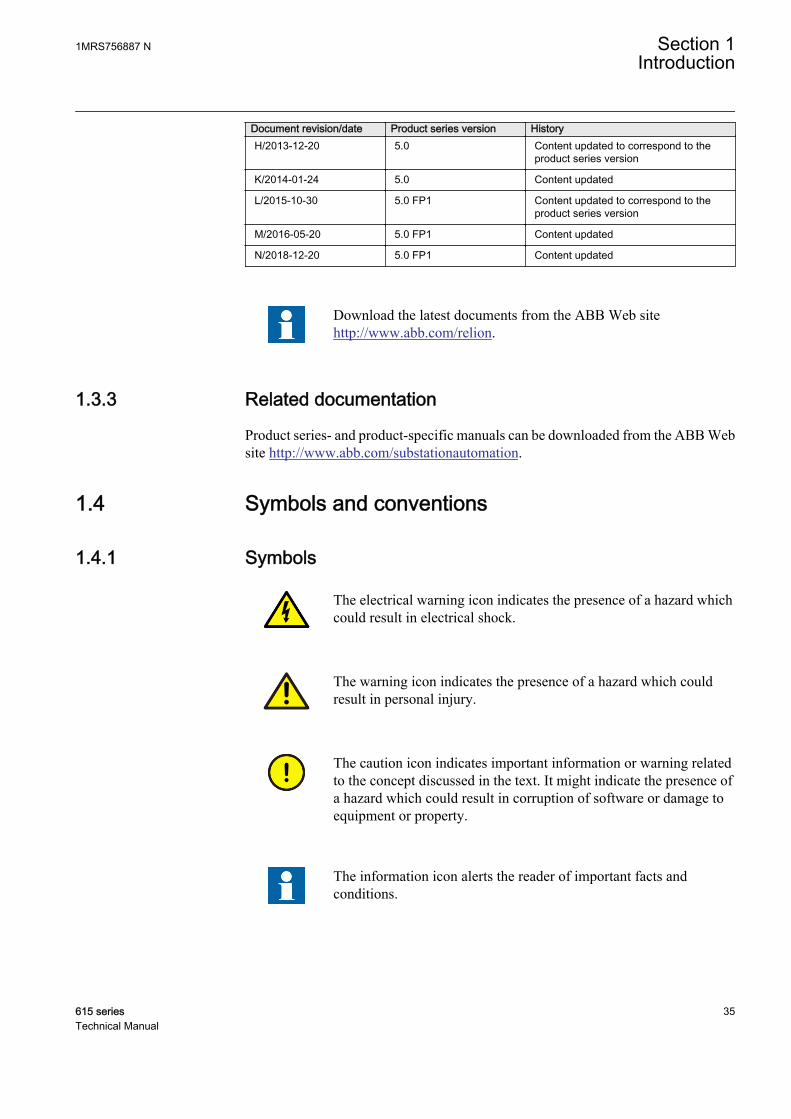
Document revision/date Product series version HistoryH/2013-12-20 5.0 Content updated to correspond to the
product series version
K/2014-01-24 5.0 Content updated
L/2015-10-30 5.0 FP1 Content updated to correspond to theproduct series version
M/2016-05-20 5.0 FP1 Content updated
N/2018-12-20 5.0 FP1 Content updated
Download the latest documents from the ABB Web sitehttp://www.abb.com/relion.
1.3.3 Related documentation
Product series- and product-specific manuals can be downloaded from the ABB Website http://www.abb.com/substationautomation.
1.4 Symbols and conventions
1.4.1 Symbols
The electrical warning icon indicates the presence of a hazard whichcould result in electrical shock.
The warning icon indicates the presence of a hazard which couldresult in personal injury.
The caution icon indicates important information or warning relatedto the concept discussed in the text. It might indicate the presence ofa hazard which could result in corruption of software or damage toequipment or property.
The information icon alerts the reader of important facts andconditions.
1MRS756887 N Section 1Introduction
615 series 35Technical Manual
The tip icon indicates advice on, for example, how to design yourproject or how to use a certain function.
Although warning hazards are related to personal injury, it is necessary to understandthat under certain operational conditions, operation of damaged equipment may resultin degraded process performance leading to personal injury or death. Therefore,comply fully with all warning and caution notices.
1.4.2 Document conventions
A particular convention may not be used in this manual.
• Abbreviations and acronyms are spelled out in the glossary. The glossary alsocontains definitions of important terms.
• Push button navigation in the LHMI menu structure is presented by using thepush button icons.To navigate between the options, use and .
• Menu paths are presented in bold.Select Main menu/Settings.
• LHMI messages are shown in Courier font.To save the changes in nonvolatile memory, select Yes and press .
• Parameter names are shown in italics.The function can be enabled and disabled with the Operation setting.
• Parameter values are indicated with quotation marks.The corresponding parameter values are "On" and "Off".
• Input/output messages and monitored data names are shown in Courier font.When the function starts, the START output is set to TRUE.
• This document assumes that the parameter setting visibility is "Advanced".
1.4.3 Functions, codes and symbols
All available functions are listed in the table. All of them may not be applicable to allproducts.
Table 1: Functions included in the relays
Function IEC 61850 IEC 60617 IEC-ANSIProtection
Three-phase non-directionalovercurrent protection, low stage
PHLPTOC1 3I> (1) 51P-1 (1)
PHLPTOC2 3I> (2) 51P-1 (2)
Three-phase non-directionalovercurrent protection, high stage
PHHPTOC1 3I>> (1) 51P-2 (1)
PHHPTOC2 3I>> (2) 51P-2 (2)
Three-phase non-directionalovercurrent protection,instantaneous stage
PHIPTOC1 3I>>> (1) 50P/51P (1)
PHIPTOC2 3I>>> (2) 50P/51P (2)
Table continues on next page
Section 1 1MRS756887 NIntroduction
36 615 seriesTechnical Manual
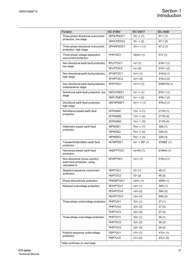
Function IEC 61850 IEC 60617 IEC-ANSIThree-phase directional overcurrentprotection, low stage
DPHLPDOC1 3I> -> (1) 67-1 (1)
DPHLPDOC2 3I> -> (2) 67-1 (2)
Three-phase directional overcurrentprotection, high stage
DPHHPDOC1 3I>> -> (1) 67-2 (1)
Three-phase voltage-dependentovercurrent protection
PHPVOC1 3I(U)> (1) 51V (1)
Non-directional earth-fault protection,low stage
EFLPTOC1 Io> (1) 51N-1 (1)
EFLPTOC2 Io> (2) 51N-1 (2)
Non-directional earth-fault protection,high stage
EFHPTOC1 Io>> (1) 51N-2 (1)
EFHPTOC2 Io>> (2) 51N-2 (2)
Non-directional earth-fault protection,instantaneous stage
EFIPTOC1 Io>>> (1) 50N/51N (1)
Directional earth-fault protection, lowstage
DEFLPDEF1 Io> -> (1) 67N-1 (1)
DEFLPDEF2 Io> -> (2) 67N-1 (2)
Directional earth-fault protection,high stage
DEFHPDEF1 Io>> -> (1) 67N-2 (1)
Admittance-based earth-faultprotection
EFPADM1 Yo> -> (1) 21YN (1)
EFPADM2 Yo> -> (2) 21YN (2)
EFPADM3 Yo> -> (3) 21YN (3)
Wattmetric-based earth-faultprotection
WPWDE1 Po> -> (1) 32N (1)
WPWDE2 Po> -> (2) 32N (2)
WPWDE3 Po> -> (3) 32N (3)
Transient/intermittent earth-faultprotection
INTRPTEF1 Io> -> IEF (1) 67NIEF (1)
Harmonics-based earth-faultprotection
HAEFPTOC1 Io>HA (1) 51NHA (1)
Non-directional (cross-country)earth-fault protection, usingcalculated Io
EFHPTOC1 Io>> (1) 51N-2 (1)
Negative-sequence overcurrentprotection
NSPTOC1 I2> (1) 46 (1)
NSPTOC2 I2> (2) 46 (2)
Phase discontinuity protection PDNSPTOC1 I2/I1> (1) 46PD (1)
Residual overvoltage protection ROVPTOV1 Uo> (1) 59G (1)
ROVPTOV2 Uo> (2) 59G (2)
ROVPTOV3 Uo> (3) 59G (3)
Three-phase undervoltage protection PHPTUV1 3U< (1) 27 (1)
PHPTUV2 3U< (2) 27 (2)
PHPTUV3 3U< (3) 27 (3)
Three-phase overvoltage protection PHPTOV1 3U> (1) 59 (1)
PHPTOV2 3U> (2) 59 (2)
PHPTOV3 3U> (3) 59 (3)
Positive-sequence undervoltageprotection
PSPTUV1 U1< (1) 47U+ (1)
PSPTUV2 U1< (2) 47U+ (2)
Table continues on next page
1MRS756887 N Section 1Introduction
615 series 37Technical Manual
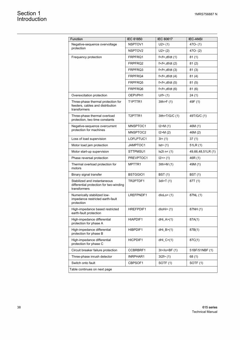
Function IEC 61850 IEC 60617 IEC-ANSINegative-sequence overvoltageprotection
NSPTOV1 U2> (1) 47O- (1)
NSPTOV2 U2> (2) 47O- (2)
Frequency protection FRPFRQ1 f>/f<,df/dt (1) 81 (1)
FRPFRQ2 f>/f<,df/dt (2) 81 (2)
FRPFRQ3 f>/f<,df/dt (3) 81 (3)
FRPFRQ4 f>/f<,df/dt (4) 81 (4)
FRPFRQ5 f>/f<,df/dt (5) 81 (5)
FRPFRQ6 f>/f<,df/dt (6) 81 (6)
Overexcitation protection OEPVPH1 U/f> (1) 24 (1)
Three-phase thermal protection forfeeders, cables and distributiontransformers
T1PTTR1 3Ith>F (1) 49F (1)
Three-phase thermal overloadprotection, two time constants
T2PTTR1 3Ith>T/G/C (1) 49T/G/C (1)
Negative-sequence overcurrentprotection for machines
MNSPTOC1 I2>M (1) 46M (1)
MNSPTOC2 I2>M (2) 46M (2)
Loss of load supervision LOFLPTUC1 3I< (1) 37 (1)
Motor load jam protection JAMPTOC1 Ist> (1) 51LR (1)
Motor start-up supervision STTPMSU1 Is2t n< (1) 49,66,48,51LR (1)
Phase reversal protection PREVPTOC1 I2>> (1) 46R (1)
Thermal overload protection formotors
MPTTR1 3Ith>M (1) 49M (1)
Binary signal transfer BSTGGIO1 BST (1) BST (1)
Stabilized and instantaneousdifferential protection for two-windingtransformers
TR2PTDF1 3dI>T (1) 87T (1)
Numerically stabilized low-impedance restricted earth-faultprotection
LREFPNDF1 dIoLo> (1) 87NL (1)
High-impedance based restrictedearth-fault protection
HREFPDIF1 dIoHi> (1) 87NH (1)
High-impedance differentialprotection for phase A
HIAPDIF1 dHi_A>(1) 87A(1)
High-impedance differentialprotection for phase B
HIBPDIF1 dHi_B>(1) 87B(1)
High-impedance differentialprotection for phase C
HICPDIF1 dHi_C>(1) 87C(1)
Circuit breaker failure protection CCBRBRF1 3I>/Io>BF (1) 51BF/51NBF (1)
Three-phase inrush detector INRPHAR1 3I2f> (1) 68 (1)
Switch onto fault CBPSOF1 SOTF (1) SOTF (1)
Table continues on next page
Section 1 1MRS756887 NIntroduction
38 615 seriesTechnical Manual

Function IEC 61850 IEC 60617 IEC-ANSIMaster trip TRPPTRC1 Master Trip (1) 94/86 (1)
TRPPTRC2 Master Trip (2) 94/86 (2)
TRPPTRC3 Master Trip (3) 94/86 (3)
TRPPTRC4 Master Trip (4) 94/86 (4)
TRPPTRC5 Master Trip (5) 94/86 (5)
TRPPTRC6 Master Trip (6) 94/86 (6)
Arc protection ARCSARC1 ARC (1) 50L/50NL (1)
ARCSARC2 ARC (2) 50L/50NL (2)
ARCSARC3 ARC (3) 50L/50NL (3)
Multipurpose protection MAPGAPC1 MAP (1) MAP (1)
MAPGAPC2 MAP (2) MAP (2)
MAPGAPC3 MAP (3) MAP (3)
MAPGAPC4 MAP (4) MAP (4)
MAPGAPC5 MAP (5) MAP (5)
MAPGAPC6 MAP (6) MAP (6)
MAPGAPC7 MAP (7) MAP (7)
MAPGAPC8 MAP (8) MAP (8)
MAPGAPC9 MAP (9) MAP (9)
MAPGAPC10 MAP (10) MAP (10)
MAPGAPC11 MAP (11) MAP (11)
MAPGAPC12 MAP (12) MAP (12)
MAPGAPC13 MAP (13) MAP (13)
MAPGAPC14 MAP (14) MAP (14)
MAPGAPC15 MAP (15) MAP (15)
MAPGAPC16 MAP (16) MAP (16)
MAPGAPC17 MAP (17) MAP (17)
MAPGAPC18 MAP (18) MAP (18)
Load-shedding and restoration LSHDPFRQ1 UFLS/R (1) 81LSH (1)
LSHDPFRQ2 UFLS/R (2) 81LSH (2)
LSHDPFRQ3 UFLS/R (3) 81LSH (3)
LSHDPFRQ4 UFLS/R (4) 81LSH (4)
LSHDPFRQ5 UFLS/R (5) 81LSH (5)
Fault locator SCEFRFLO1 FLOC (1) 21FL (1)
Three-phase overload protection forshunt capacitor banks
COLPTOC1 3I> 3I< (1) 51C/37 (1)
Current unbalance protection forshunt capacitor banks
CUBPTOC1 dI>C (1) 51NC-1 (1)
Three-phase current unbalanceprotection for shunt capacitor banks
HCUBPTOC1 3dI>C (1) 51NC-2 (1)
Shunt capacitor bank switchingresonance protection, current based
SRCPTOC1 TD> (1) 55TD (1)
Table continues on next page
1MRS756887 N Section 1Introduction
615 series 39Technical Manual

Function IEC 61850 IEC 60617 IEC-ANSILine differential protection with in-zone power transformer
LNPLDF1 3Id/I> (1) 87L (1)
High-impedance fault detection PHIZ1 HIF (1) HIZ (1)
Stabilized and instantaneousdifferential protection for machines
MPDIF1 3dI>G/M (1) 87G/M (1)
Third harmonic-based stator earth-fault protection
H3EFPSEF1 dUo>/Uo3H (1) 27/59THD (1)
Underpower protection DUPPDPR1 P< (1) 32U (1)
DUPPDPR2 P< (2) 32U (2)
Reverse power/directionaloverpower protection
DOPPDPR1 P>/Q> (1) 32R/32O (1)
DOPPDPR2 P>/Q> (2) 32R/32O (2)
DOPPDPR3 P>/Q> (3) 32R/32O (3)
Three-phase underexcitationprotection
UEXPDIS1 X< (1) 40 (1)
Three-phase underimpedanceprotection
UZPDIS1 Z>G (1) 21G (1)
Out-of-step protection OOSRPSB1 OOS (1) 78 (1)
Multifrequency admittance-basedearth-fault protection
MFADPSDE1 Io> ->Y (1) 67YN (1)
Interconnection functions
Directional reactive powerundervoltage protection
DQPTUV1 Q> ->,3U< (1) 32Q,27 (1)
Low-voltage ride-through protection LVRTPTUV1 U<RT (1) 27RT (1)
LVRTPTUV2 U<RT (2) 27RT (2)
LVRTPTUV3 U<RT (3) 27RT (3)
Voltage vector shift protection VVSPPAM1 VS (1) 78V (1)
Power quality
Current total demand distortion CMHAI1 PQM3I (1) PQM3I (1)
Voltage total harmonic distortion VMHAI1 PQM3U (1) PQM3V (1)
Voltage variation PHQVVR1 PQMU (1) PQMV (1)
Voltage unbalance VSQVUB1 PQUUB (1) PQVUB (1)
Control
Circuit-breaker control CBXCBR1 I <-> O CB (1) I <-> O CB (1)
Disconnector control DCXSWI1 I <-> O DCC (1) I <-> O DCC (1)
DCXSWI2 I <-> O DCC (2) I <-> O DCC (2)
Earthing switch control ESXSWI1 I <-> O ESC (1) I <-> O ESC (1)
Disconnector position indication DCSXSWI1 I <-> O DC (1) I <-> O DC (1)
DCSXSWI2 I <-> O DC (2) I <-> O DC (2)
DCSXSWI3 I <-> O DC (3) I <-> O DC (3)
Earthing switch indication ESSXSWI1 I <-> O ES (1) I <-> O ES (1)
ESSXSWI2 I <-> O ES (2) I <-> O ES (2)
Emergency start-up ESMGAPC1 ESTART (1) ESTART (1)
Table continues on next page
Section 1 1MRS756887 NIntroduction
40 615 seriesTechnical Manual

Function IEC 61850 IEC 60617 IEC-ANSIAutoreclosing DARREC1 O -> I (1) 79 (1)
Tap changer position indication TPOSYLTC1 TPOSM (1) 84M (1)
Tap changer control with voltageregulator
OLATCC1 COLTC (1) 90V (1)
Synchronism and energizing check SECRSYN1 SYNC (1) 25 (1)
Condition monitoring and supervision
Circuit-breaker condition monitoring SSCBR1 CBCM (1) CBCM (1)
Trip circuit supervision TCSSCBR1 TCS (1) TCM (1)
TCSSCBR2 TCS (2) TCM (2)
Current circuit supervision CCSPVC1 MCS 3I (1) MCS 3I (1)
Current transformer supervision forhigh-impedance protection schemefor phase A
HZCCASPVC1 MCS I_A(1) MCS I_A(1)
Current transformer supervision forhigh-impedance protection schemefor phase B
HZCCBSPVC1 MCS I_B(1) MCS I_B(1)
Current transformer supervision forhigh-impedance protection schemefor phase C
HZCCCSPVC1 MCS I_C(1) MCS I_C(1)
Fuse failure supervision SEQSPVC1 FUSEF (1) 60 (1)
Protection communicationsupervision
PCSITPC1 PCS (1) PCS (1)
Runtime counter for machines anddevices
MDSOPT1 OPTS (1) OPTM (1)
Measurement
Disturbance recorder RDRE1 DR (1) DFR (1)
Load profile record LDPRLRC1 LOADPROF (1) LOADPROF (1)
Fault record FLTRFRC1 FAULTREC (1) FAULTREC (1)
Three-phase current measurement CMMXU1 3I (1) 3I (1)
CMMXU2 3I (2) 3I (2)
Sequence current measurement CSMSQI1 I1, I2, I0 (1) I1, I2, I0 (1)
Residual current measurement RESCMMXU1 Io (1) In (1)
RESCMMXU2 Io (2) In (2)
Three-phase voltage measurement VMMXU1 3U (1) 3V (1)
VMMXU2 3U (2) 3V (2)
Residual voltage measurement RESVMMXU1 Uo (1) Vn (1)
RESVMMXU2 Uo (2) Vn (2)
Sequence voltage measurement VSMSQI1 U1, U2, U0 (1) V1, V2, V0 (1)
Three-phase power and energymeasurement
PEMMXU1 P, E (1) P, E (1)
RTD/mA measurement XRGGIO130 X130 (RTD) (1) X130 (RTD) (1)
Frequency measurement FMMXU1 f (1) f (1)
IEC 61850-9-2 LE sampled valuesending
SMVSENDER SMVSENDER SMVSENDER
Table continues on next page
1MRS756887 N Section 1Introduction
615 series 41Technical Manual

Function IEC 61850 IEC 60617 IEC-ANSIIEC 61850-9-2 LE sampled valuereceiving (voltage sharing)
SMVRCV SMVRCV SMVRCV
Other
Minimum pulse timer (2 pcs) TPGAPC1 TP (1) TP (1)
TPGAPC2 TP (2) TP (2)
TPGAPC3 TP (3) TP (3)
TPGAPC4 TP (4) TP (4)
Minimum pulse timer (2 pcs, secondresolution)
TPSGAPC1 TPS (1) TPS (1)
Minimum pulse timer (2 pcs, minuteresolution)
TPMGAPC1 TPM (1) TPM (1)
Pulse timer (8 pcs) PTGAPC1 PT (1) PT (1)
PTGAPC2 PT (2) PT (2)
Time delay off (8 pcs) TOFGAPC1 TOF (1) TOF (1)
TOFGAPC2 TOF (2) TOF (2)
TOFGAPC3 TOF (3) TOF (3)
TOFGAPC4 TOF (4) TOF (4)
Time delay on (8 pcs) TONGAPC1 TON (1) TON (1)
TONGAPC2 TON (2) TON (2)
TONGAPC3 TON (3) TON (3)
TONGAPC4 TON (4) TON (4)
Set-reset (8 pcs) SRGAPC1 SR (1) SR (1)
SRGAPC2 SR (2) SR (2)
SRGAPC3 SR (3) SR (3)
SRGAPC4 SR (4) SR (4)
Move (8 pcs) MVGAPC1 MV (1) MV (1)
MVGAPC2 MV (2) MV (2)
Generic control point (16 pcs) SPCGAPC1 SPC (1) SPC (1)
SPCGAPC2 SPC (2) SPC (2)
Analog value scaling SCA4GAPC1 SCA4 (1) SCA4 (1)
SCA4GAPC2 SCA4 (2) SCA4 (2)
SCA4GAPC3 SCA4 (3) SCA4 (3)
SCA4GAPC4 SCA4 (4) SCA4 (4)
Integer value move MVI4GAPC1 MVI4 (1) MVI4 (1)
Section 1 1MRS756887 NIntroduction
42 615 seriesTechnical Manual
Section 2 615 series overview
2.1 Overview
615 series is a product family of relays designed for protection, control, measurementand supervision of utility substations and industrial switchgear and equipment. Thedesign of the relay has been guided by the IEC 61850 standard for communication andinteroperability of substation automation devices.
The relays feature a draw-out-type design with a variety of mounting methods,compact size and ease of use. Depending on the product, optional functionality isavailable at the time of order for both software and hardware, for example,autoreclosing and additional I/Os.
The 615 series relays support a range of communication protocols including IEC61850 with Edition 2 support, process bus according to IEC 61850-9-2 LE, IEC60870-5-103, Modbus® and DNP3. Profibus DPV1 communication protocol issupported by using the protocol converter SPA-ZC 302.
1MRS756887 N Section 2615 series overview
615 series 43Technical Manual
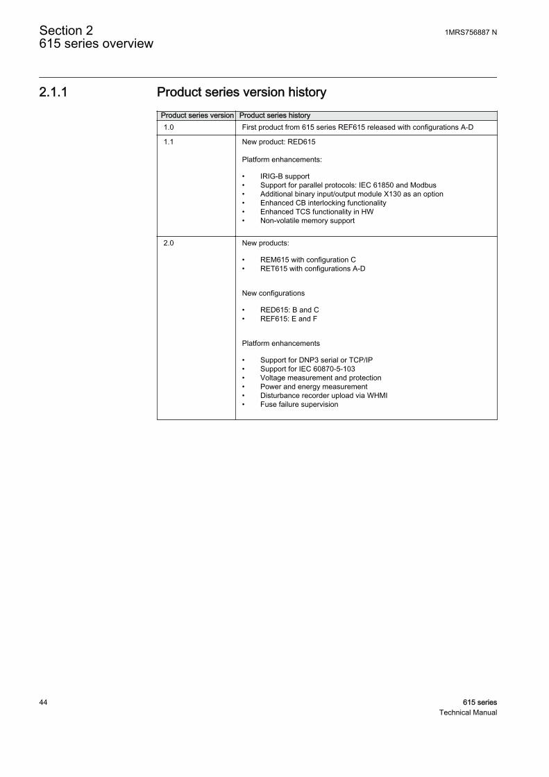
2.1.1 Product series version historyProduct series version Product series history1.0 First product from 615 series REF615 released with configurations A-D
1.1 New product: RED615 Platform enhancements:
• IRIG-B support• Support for parallel protocols: IEC 61850 and Modbus• Additional binary input/output module X130 as an option• Enhanced CB interlocking functionality• Enhanced TCS functionality in HW• Non-volatile memory support
2.0 New products:
• REM615 with configuration C• RET615 with configurations A-D
New configurations
• RED615: B and C• REF615: E and F
Platform enhancements
• Support for DNP3 serial or TCP/IP• Support for IEC 60870-5-103• Voltage measurement and protection• Power and energy measurement• Disturbance recorder upload via WHMI• Fuse failure supervision
Section 2 1MRS756887 N615 series overview
44 615 seriesTechnical Manual
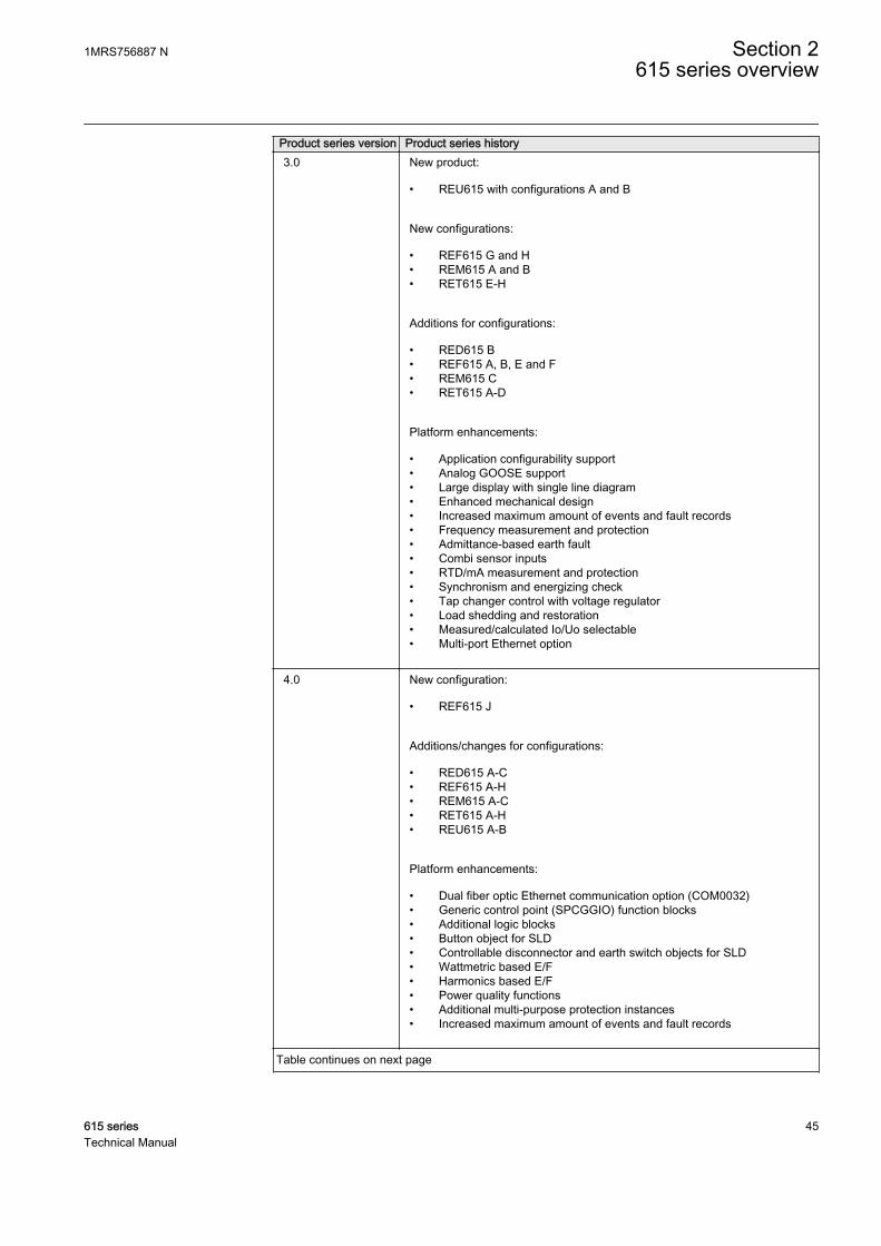
Product series version Product series history3.0 New product:
• REU615 with configurations A and B
New configurations:
• REF615 G and H• REM615 A and B• RET615 E-H
Additions for configurations:
• RED615 B• REF615 A, B, E and F• REM615 C• RET615 A-D
Platform enhancements:
• Application configurability support• Analog GOOSE support• Large display with single line diagram• Enhanced mechanical design• Increased maximum amount of events and fault records• Frequency measurement and protection• Admittance-based earth fault• Combi sensor inputs• RTD/mA measurement and protection• Synchronism and energizing check• Tap changer control with voltage regulator• Load shedding and restoration• Measured/calculated Io/Uo selectable• Multi-port Ethernet option
4.0 New configuration:
• REF615 J
Additions/changes for configurations:
• RED615 A-C• REF615 A-H• REM615 A-C• RET615 A-H• REU615 A-B
Platform enhancements:
• Dual fiber optic Ethernet communication option (COM0032)• Generic control point (SPCGGIO) function blocks• Additional logic blocks• Button object for SLD• Controllable disconnector and earth switch objects for SLD• Wattmetric based E/F• Harmonics based E/F• Power quality functions• Additional multi-purpose protection instances• Increased maximum amount of events and fault records
Table continues on next page
1MRS756887 N Section 2615 series overview
615 series 45Technical Manual
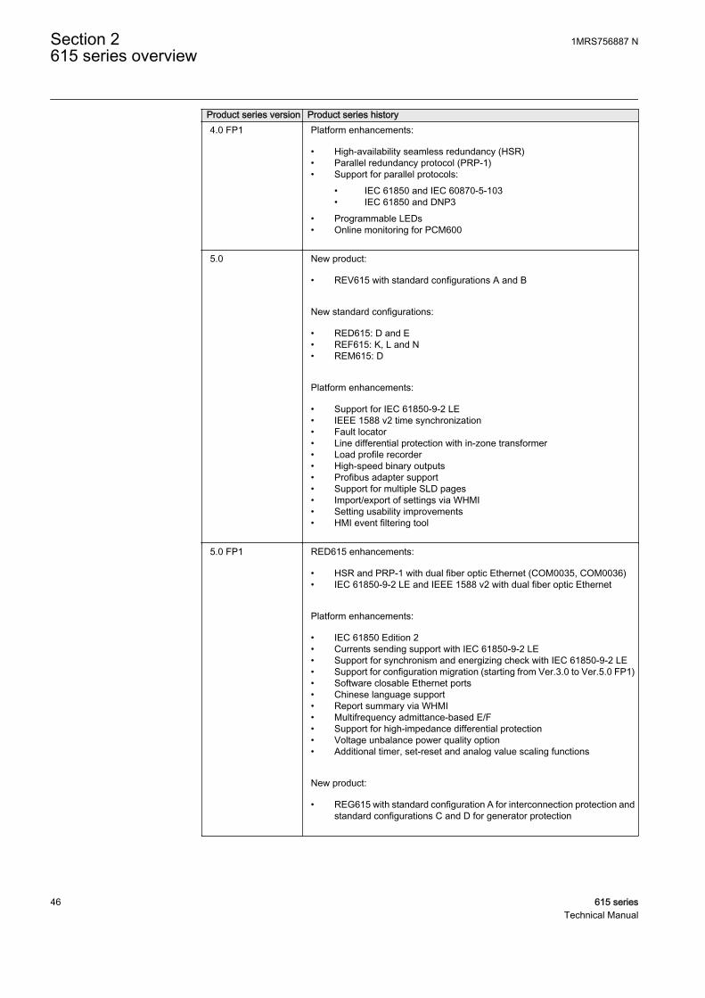
Product series version Product series history4.0 FP1 Platform enhancements:
• High-availability seamless redundancy (HSR)• Parallel redundancy protocol (PRP-1)• Support for parallel protocols:
• IEC 61850 and IEC 60870-5-103• IEC 61850 and DNP3
• Programmable LEDs• Online monitoring for PCM600
5.0 New product:
• REV615 with standard configurations A and B
New standard configurations:
• RED615: D and E• REF615: K, L and N• REM615: D
Platform enhancements:
• Support for IEC 61850-9-2 LE• IEEE 1588 v2 time synchronization• Fault locator• Line differential protection with in-zone transformer• Load profile recorder• High-speed binary outputs• Profibus adapter support• Support for multiple SLD pages• Import/export of settings via WHMI• Setting usability improvements• HMI event filtering tool
5.0 FP1 RED615 enhancements:
• HSR and PRP-1 with dual fiber optic Ethernet (COM0035, COM0036)• IEC 61850-9-2 LE and IEEE 1588 v2 with dual fiber optic Ethernet
Platform enhancements:
• IEC 61850 Edition 2• Currents sending support with IEC 61850-9-2 LE• Support for synchronism and energizing check with IEC 61850-9-2 LE• Support for configuration migration (starting from Ver.3.0 to Ver.5.0 FP1)• Software closable Ethernet ports• Chinese language support• Report summary via WHMI• Multifrequency admittance-based E/F• Support for high-impedance differential protection• Voltage unbalance power quality option• Additional timer, set-reset and analog value scaling functions
New product:
• REG615 with standard configuration A for interconnection protection andstandard configurations C and D for generator protection
Section 2 1MRS756887 N615 series overview
46 615 seriesTechnical Manual
2.1.2 PCM600 and relay connectivity package version
• Protection and Control IED Manager PCM600 2.6 (Rollup 20150626) or later• RED615 Connectivity Package Ver.5.1 or later• REF615 Connectivity Package Ver.5.1 or later• REG615 Connectivity Package Ver.5.1 or later• REM615 Connectivity Package Ver.5.1 or later• RET615 Connectivity Package Ver.5.1 or later• REU615 Connectivity Package Ver.5.1 or later• REV615 Connectivity Package Ver.5.1 or later
Download connectivity packages from the ABB Web sitehttp://www.abb.com/substationautomation or directly with UpdateManager in PCM600.
2.2 Local HMI
The LHMI is used for setting, monitoring and controlling the protection relay. TheLHMI comprises the display, buttons, LED indicators and communication port.
1MRS756887 N Section 2615 series overview
615 series 47Technical Manual
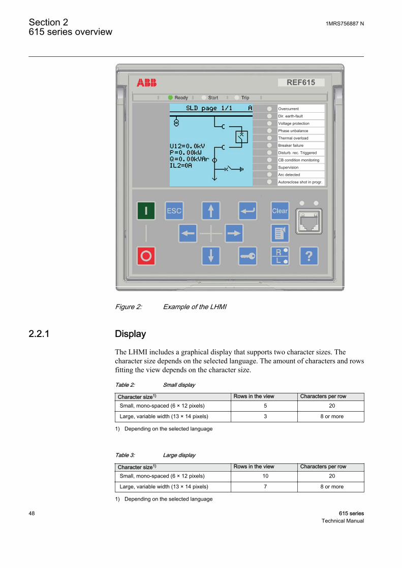
REF615
Overcurrent
Dir. earth-fault
Voltage protection
Phase unbalance
Thermal overload
Breaker failure
Disturb. rec. Triggered
CB condition monitoring
Supervision
Arc detected
Autoreclose shot in progr.
A070704 V4 EN
Figure 2: Example of the LHMI
2.2.1 Display
The LHMI includes a graphical display that supports two character sizes. Thecharacter size depends on the selected language. The amount of characters and rowsfitting the view depends on the character size.
Table 2: Small display
Character size1) Rows in the view Characters per row
Small, mono-spaced (6 × 12 pixels) 5 20
Large, variable width (13 × 14 pixels) 3 8 or more
1) Depending on the selected language
Table 3: Large display
Character size1) Rows in the view Characters per row
Small, mono-spaced (6 × 12 pixels) 10 20
Large, variable width (13 × 14 pixels) 7 8 or more
1) Depending on the selected language
Section 2 1MRS756887 N615 series overview
48 615 seriesTechnical Manual

The display view is divided into four basic areas.
1 2
3 4A070705 V3 EN
Figure 3: Display layout
1 Header
2 Icon
3 Content
4 Scroll bar (displayed when needed)
2.2.2 LEDs
The LHMI includes three protection indicators above the display: Ready, Start andTrip.
There are 11 matrix programmable LEDs on front of the LHMI. The LEDs can beconfigured with PCM600 and the operation mode can be selected with the LHMI,WHMI or PCM600.
2.2.3 Keypad
The LHMI keypad contains push buttons which are used to navigate in different viewsor menus. With the push buttons you can give open or close commands to objects inthe primary circuit, for example, a circuit breaker, a contactor or a disconnector. Thepush buttons are also used to acknowledge alarms, reset indications, provide help andswitch between local and remote control mode.
1MRS756887 N Section 2615 series overview
615 series 49Technical Manual
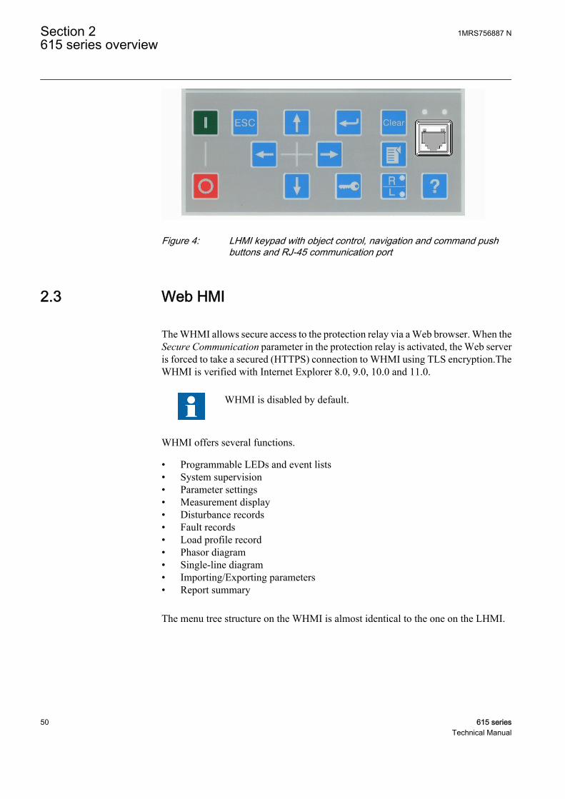
A071176 V1 EN
Figure 4: LHMI keypad with object control, navigation and command pushbuttons and RJ-45 communication port
2.3 Web HMI
The WHMI allows secure access to the protection relay via a Web browser. When theSecure Communication parameter in the protection relay is activated, the Web serveris forced to take a secured (HTTPS) connection to WHMI using TLS encryption.TheWHMI is verified with Internet Explorer 8.0, 9.0, 10.0 and 11.0.
WHMI is disabled by default.
WHMI offers several functions.
• Programmable LEDs and event lists• System supervision• Parameter settings• Measurement display• Disturbance records• Fault records• Load profile record• Phasor diagram• Single-line diagram• Importing/Exporting parameters• Report summary
The menu tree structure on the WHMI is almost identical to the one on the LHMI.
Section 2 1MRS756887 N615 series overview
50 615 seriesTechnical Manual
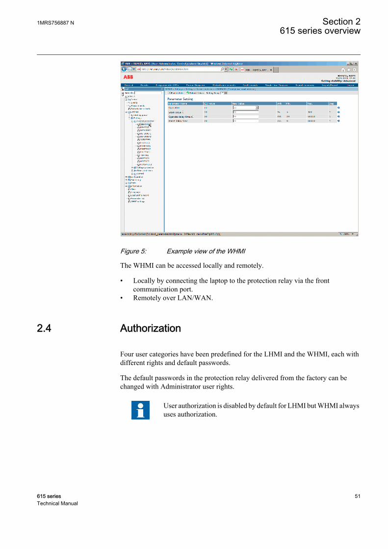
A070754 V6 EN
Figure 5: Example view of the WHMI
The WHMI can be accessed locally and remotely.
• Locally by connecting the laptop to the protection relay via the frontcommunication port.
• Remotely over LAN/WAN.
2.4 Authorization
Four user categories have been predefined for the LHMI and the WHMI, each withdifferent rights and default passwords.
The default passwords in the protection relay delivered from the factory can bechanged with Administrator user rights.
User authorization is disabled by default for LHMI but WHMI alwaysuses authorization.
1MRS756887 N Section 2615 series overview
615 series 51Technical Manual
Table 4: Predefined user categories
Username User rightsVIEWER Read only access
OPERATOR • Selecting remote or local state with (only locally)• Changing setting groups• Controlling• Clearing indications
ENGINEER • Changing settings• Clearing event list• Clearing disturbance records• Changing system settings such as IP address, serial baud rate or
disturbance recorder settings• Setting the protection relay to test mode• Selecting language
ADMINISTRATOR • All listed above• Changing password• Factory default activation
For user authorization for PCM600, see PCM600 documentation.
2.4.1 Audit trail
The protection relay offers a large set of event-logging functions. Critical system andprotection relay security-related events are logged to a separate nonvolatile audit trailfor the administrator.
Audit trail is a chronological record of system activities that allows the reconstructionand examination of the sequence of system and security-related events and changes inthe protection relay. Both audit trail events and process related events can beexamined and analyzed in a consistent method with the help of Event List in LHMIand WHMI and Event Viewer in PCM600.
The protection relay stores 2048 audit trail events to the nonvolatile audit trail.Additionally, 1024 process events are stored in a nonvolatile event list. Both the audittrail and event list work according to the FIFO principle. Nonvolatile memory is basedon a memory type which does not need battery backup nor regular component changeto maintain the memory storage.
Audit trail events related to user authorization (login, logout, violation remote andviolation local) are defined according to the selected set of requirements from IEEE1686. The logging is based on predefined user names or user categories. The user audittrail events are accessible with IEC 61850-8-1, PCM600, LHMI and WHMI.
Section 2 1MRS756887 N615 series overview
52 615 seriesTechnical Manual
Table 5: Audit trail events
Audit trail event DescriptionConfiguration change Configuration files changed
Firmware change Firmware changed
Firmware change fail Firmware change failed
Attached to retrofit test case Unit has been attached to retrofit case
Removed from retrofit test case Removed from retrofit test case
Setting group remote User changed setting group remotely
Setting group local User changed setting group locally
Control remote DPC object control remote
Control local DPC object control local
Test on Test mode on
Test off Test mode off
Reset trips Reset latched trips (TRPPTRC*)
Setting commit Settings have been changed
Time change Time changed directly by the user. Note that this is not usedwhen the protection relay is synchronised properly by theappropriate protocol (SNTP, IRIG-B, IEEE 1588 v2).
View audit log Administrator accessed audit trail
Login Successful login from IEC 61850-8-1 (MMS), WHMI, FTP orLHMI.
Logout Successful logout from IEC 61850-8-1 (MMS), WHMI, FTP orLHMI.
Password change Password changed
Firmware reset Reset issued by user or tool
Audit overflow Too many audit events in the time period
Violation remote Unsuccessful login attempt from IEC 61850-8-1 (MMS),WHMI, FTP or LHMI.
Violation local Unsuccessful login attempt from IEC 61850-8-1 (MMS),WHMI, FTP or LHMI.
PCM600 Event Viewer can be used to view the audit trail events and process relatedevents. Audit trail events are visible through dedicated Security events view. Sinceonly the administrator has the right to read audit trail, authorization must be used inPCM600. The audit trail cannot be reset, but PCM600 Event Viewer can filter data.Audit trail events can be configured to be visible also in LHMI/WHMI Event listtogether with process related events.
To expose the audit trail events through Event list, define theAuthority logging level parameter via Configuration/Authorization/Security. This exposes audit trail events to all users.
1MRS756887 N Section 2615 series overview
615 series 53Technical Manual

Table 6: Comparison of authority logging levels
Audit trail event Authority logging level
NoneConfiguration change
Settinggroup
Settinggroup,control
Settingsedit
All
Configuration change
Firmware change
Firmware change fail
Attached to retrofit testcase
Removed from retrofittest case
Setting group remote
Setting group local
Control remote
Control local
Test on
Test off
Reset trips
Setting commit
Time change
View audit log
Login
Logout
Password change
Firmware reset
Violation local
Violation remote
2.5 Communication
The protection relay supports a range of communication protocols including IEC61850, IEC 61850-9-2 LE, IEC 60870-5-103, Modbus® and DNP3. Profibus DPV1communication protocol is supported by using the protocol converter SPA-ZC 302.Operational information and controls are available through these protocols. However,some communication functionality, for example, horizontal communication betweenthe protection relays, is only enabled by the IEC 61850 communication protocol.
The IEC 61850 communication implementation supports all monitoring and controlfunctions. Additionally, parameter settings, disturbance recordings and fault recordscan be accessed using the IEC 61850 protocol. Disturbance recordings are availableto any Ethernet-based application in the IEC 60255-24 standard COMTRADE fileformat. The protection relay can send and receive binary signals from other devices
Section 2 1MRS756887 N615 series overview
54 615 seriesTechnical Manual
(so-called horizontal communication) using the IEC 61850-8-1 GOOSE profile,where the highest performance class with a total transmission time of 3 ms issupported. Furthermore, the protection relay supports sending and receiving of analogvalues using GOOSE messaging. The protection relay meets the GOOSEperformance requirements for tripping applications in distribution substations, asdefined by the IEC 61850 standard.
The protection relay can support five simultaneous clients. If PCM600 reserves oneclient connection, only four client connections are left, for example, for IEC 61850and Modbus.
All communication connectors, except for the front port connector, are placed onintegrated optional communication modules. The protection relay can be connected toEthernet-based communication systems via the RJ-45 connector (100Base-TX) or thefiber-optic LC connector (100Base-FX).
2.5.1 Self-healing Ethernet ring
For the correct operation of self-healing loop topology, it is essential that the externalswitches in the network support the RSTP protocol and that it is enabled in theswitches. Otherwise, connecting the loop topology can cause problems to thenetwork. The protection relay itself does not support link-down detection or RSTP.The ring recovery process is based on the aging of the MAC addresses, and the link-up/link-down events can cause temporary breaks in communication. For a betterperformance of the self-healing loop, it is recommended that the external switchfurthest from the protection relay loop is assigned as the root switch (bridge priority= 0) and the bridge priority increases towards the protection relay loop. The end linksof the protection relay loop can be attached to the same external switch or to twoadjacent external switches. A self-healing Ethernet ring requires a communicationmodule with at least two Ethernet interfaces for all protection relays.
1MRS756887 N Section 2615 series overview
615 series 55Technical Manual
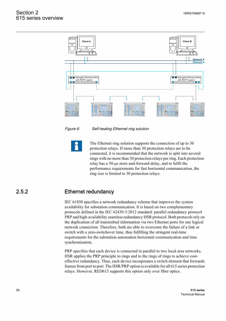
Managed Ethernet switchwith RSTP support
Managed Ethernet switchwith RSTP support
Client BClient A
Network ANetwork B
GUID-283597AF-9F38-4FC7-B87A-73BFDA272D0F V3 EN
Figure 6: Self-healing Ethernet ring solution
The Ethernet ring solution supports the connection of up to 30protection relays. If more than 30 protection relays are to beconnected, it is recommended that the network is split into severalrings with no more than 30 protection relays per ring. Each protectionrelay has a 50-μs store-and-forward delay, and to fulfil theperformance requirements for fast horizontal communication, thering size is limited to 30 protection relays.
2.5.2 Ethernet redundancy
IEC 61850 specifies a network redundancy scheme that improves the systemavailability for substation communication. It is based on two complementaryprotocols defined in the IEC 62439-3:2012 standard: parallel redundancy protocolPRP and high-availability seamless redundancy HSR protocol. Both protocols rely onthe duplication of all transmitted information via two Ethernet ports for one logicalnetwork connection. Therefore, both are able to overcome the failure of a link orswitch with a zero-switchover time, thus fulfilling the stringent real-timerequirements for the substation automation horizontal communication and timesynchronization.
PRP specifies that each device is connected in parallel to two local area networks.HSR applies the PRP principle to rings and to the rings of rings to achieve cost-effective redundancy. Thus, each device incorporates a switch element that forwardsframes from port to port. The HSR/PRP option is available for all 615 series protectionrelays. However, RED615 supports this option only over fiber optics.
Section 2 1MRS756887 N615 series overview
56 615 seriesTechnical Manual
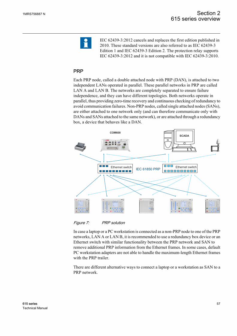
IEC 62439-3:2012 cancels and replaces the first edition published in2010. These standard versions are also referred to as IEC 62439-3Edition 1 and IEC 62439-3 Edition 2. The protection relay supportsIEC 62439-3:2012 and it is not compatible with IEC 62439-3:2010.
PRPEach PRP node, called a double attached node with PRP (DAN), is attached to twoindependent LANs operated in parallel. These parallel networks in PRP are calledLAN A and LAN B. The networks are completely separated to ensure failureindependence, and they can have different topologies. Both networks operate inparallel, thus providing zero-time recovery and continuous checking of redundancy toavoid communication failures. Non-PRP nodes, called single attached nodes (SANs),are either attached to one network only (and can therefore communicate only withDANs and SANs attached to the same network), or are attached through a redundancybox, a device that behaves like a DAN.
Ethernet switchIEC 61850 PRPEthernet switch
SCADACOM600
GUID-334D26B1-C3BD-47B6-BD9D-2301190A5E9D V2 EN
Figure 7: PRP solution
In case a laptop or a PC workstation is connected as a non-PRP node to one of the PRPnetworks, LAN A or LAN B, it is recommended to use a redundancy box device or anEthernet switch with similar functionality between the PRP network and SAN toremove additional PRP information from the Ethernet frames. In some cases, defaultPC workstation adapters are not able to handle the maximum-length Ethernet frameswith the PRP trailer.
There are different alternative ways to connect a laptop or a workstation as SAN to aPRP network.
1MRS756887 N Section 2615 series overview
615 series 57Technical Manual

• Via an external redundancy box (RedBox) or a switch capable of connecting toPRP and normal networks
• By connecting the node directly to LAN A or LAN B as SAN• By connecting the node to the protection relay's interlink port
HSRHSR applies the PRP principle of parallel operation to a single ring, treating the twodirections as two virtual LANs. For each frame sent, a node, DAN, sends two frames,one over each port. Both frames circulate in opposite directions over the ring and eachnode forwards the frames it receives, from one port to the other. When the originatingnode receives a frame sent to itself, it discards that to avoid loops; therefore, no ringprotocol is needed. Individually attached nodes, SANs, such as laptops and printers,must be attached through a “redundancy box” that acts as a ring element. For example,a 615 or 620 series protection relay with HSR support can be used as a redundancybox.
GUID-207430A7-3AEC-42B2-BC4D-3083B3225990 V2 EN
Figure 8: HSR solution
2.5.3 Process bus
Process bus IEC 61850-9-2 defines the transmission of Sampled Measured Valueswithin the substation automation system. International Users Group created aguideline IEC 61850-9-2 LE that defines an application profile of IEC 61850-9-2 tofacilitate implementation and enable interoperability. Process bus is used fordistributing process data from the primary circuit to all process bus compatibledevices in the local network in a real-time manner. The data can then be processed byany protection relay to perform different protection, automation and control functions.
Section 2 1MRS756887 N615 series overview
58 615 seriesTechnical Manual

UniGear Digital switchgear concept relies on the process bus together with currentand voltage sensors. The process bus enables several advantages for the UniGearDigital like simplicity with reduced wiring, flexibility with data availability to alldevices, improved diagnostics and longer maintenance cycles.
With process bus the galvanic interpanel wiring for sharing busbar voltage value canbe replaced with Ethernet communication. Transmitting measurement samples overprocess bus brings also higher error detection because the signal transmission isautomatically supervised. Additional contribution to the higher availability is thepossibility to use redundant Ethernet network for transmitting SMV signals.
Common EthernetStation bus (IEC 61850-8-1), process bus (IEC 61850-9-2 LE) and IEEE 1588 v2 time synchronization
GO
OS
E
SM
V
GO
OS
E
SM
V
SM
V
GO
OS
E
GO
OS
E
SM
V
GO
OS
E
SM
V
SM
V
GO
OS
E
SM
V
GO
OS
E
GUID-2371EFA7-4369-4F1A-A23F-CF0CE2D474D3 V5 EN
Figure 9: Process bus application of voltage sharing and synchrocheck
The 615 series supports IEC 61850 process bus with sampled values of analogcurrents and voltages. The measured values are transferred as sampled values usingthe IEC 61850-9-2 LE protocol which uses the same physical Ethernet network as theIEC 61850-8-1 station bus. The intended application for sampled values is sharing themeasured voltages from one 615 series protection relay to other devices with phasevoltage based functions and 9-2 support.
The 615 series protection relays with process bus based applications use IEEE 1588 v2Precision Time Protocol (PTP) according to IEEE C37.238-2011 Power Profile forhigh accuracy time synchronization. With IEEE 1588 v2, the cabling infrastructurerequirement is reduced by allowing time synchronization information to betransported over the same Ethernet network as the data communications.
1MRS756887 N Section 2615 series overview
615 series 59Technical Manual
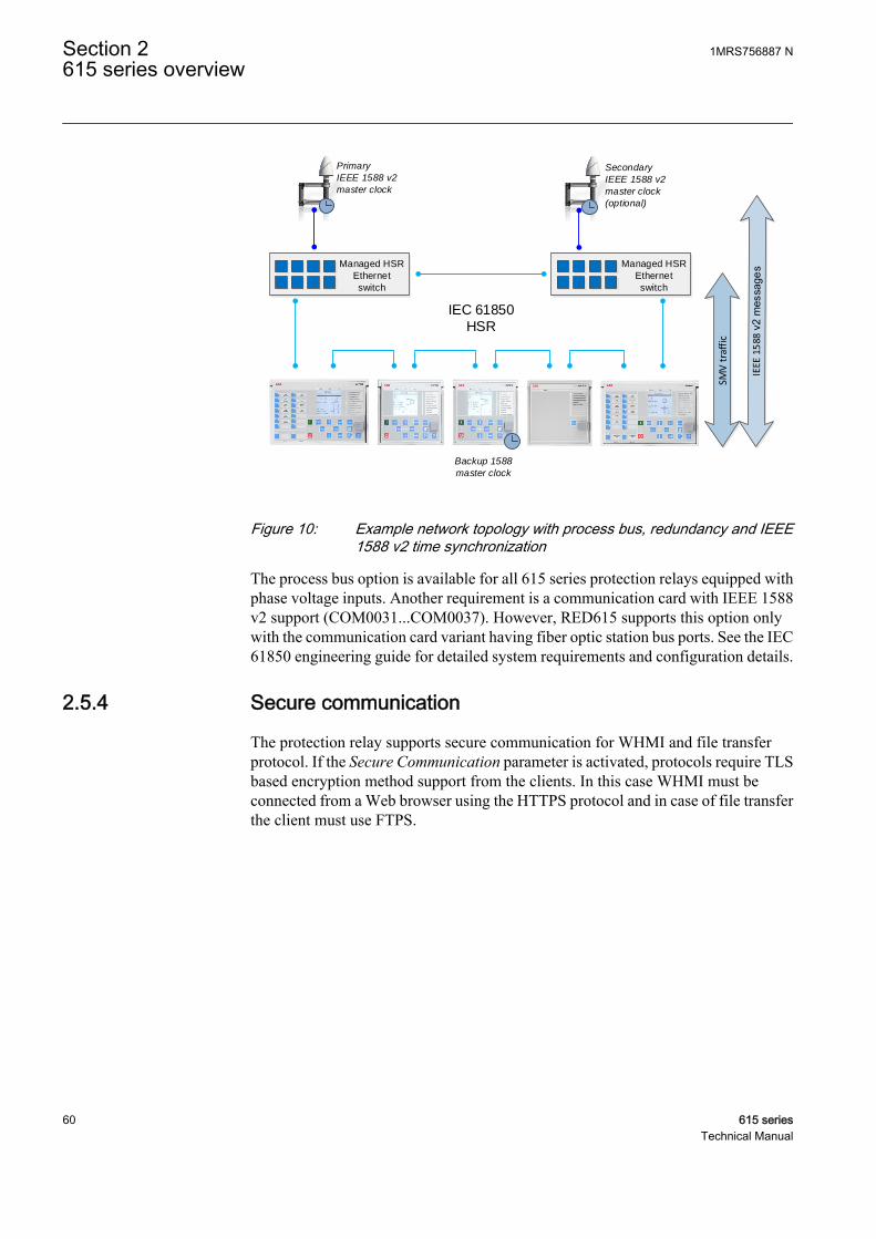
IEC 61850
HSR
SMV
tra
ffic
Backup 1588
master clock
Managed HSR
Ethernet
switch
Primary
IEEE 1588 v2
master clock
Secondary
IEEE 1588 v2
master clock
(optional)
Managed HSR
Ethernet
switch
GUID-7C56BC1F-F1B2-4E74-AB8E-05001A88D53D V5 EN
Figure 10: Example network topology with process bus, redundancy and IEEE1588 v2 time synchronization
The process bus option is available for all 615 series protection relays equipped withphase voltage inputs. Another requirement is a communication card with IEEE 1588v2 support (COM0031...COM0037). However, RED615 supports this option onlywith the communication card variant having fiber optic station bus ports. See the IEC61850 engineering guide for detailed system requirements and configuration details.
2.5.4 Secure communication
The protection relay supports secure communication for WHMI and file transferprotocol. If the Secure Communication parameter is activated, protocols require TLSbased encryption method support from the clients. In this case WHMI must beconnected from a Web browser using the HTTPS protocol and in case of file transferthe client must use FTPS.
Section 2 1MRS756887 N615 series overview
60 615 seriesTechnical Manual
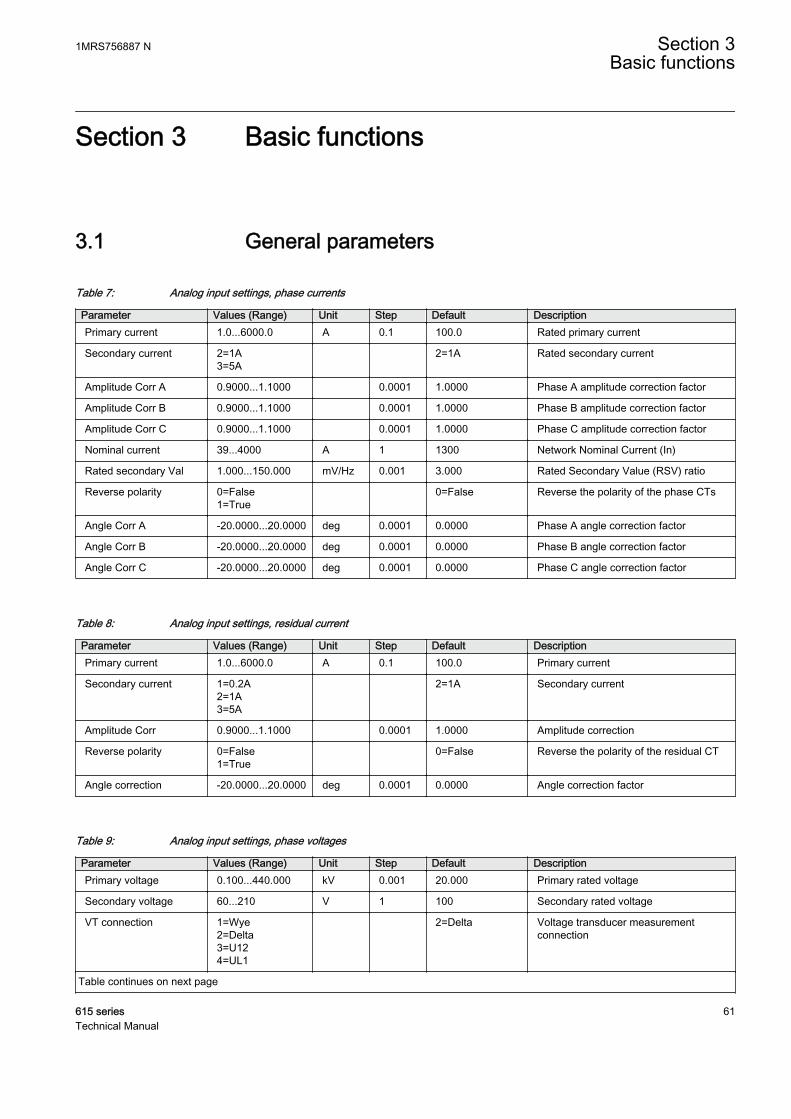
Section 3 Basic functions
3.1 General parameters
Table 7: Analog input settings, phase currents
Parameter Values (Range) Unit Step Default DescriptionPrimary current 1.0...6000.0 A 0.1 100.0 Rated primary current
Secondary current 2=1A3=5A
2=1A Rated secondary current
Amplitude Corr A 0.9000...1.1000 0.0001 1.0000 Phase A amplitude correction factor
Amplitude Corr B 0.9000...1.1000 0.0001 1.0000 Phase B amplitude correction factor
Amplitude Corr C 0.9000...1.1000 0.0001 1.0000 Phase C amplitude correction factor
Nominal current 39...4000 A 1 1300 Network Nominal Current (In)
Rated secondary Val 1.000...150.000 mV/Hz 0.001 3.000 Rated Secondary Value (RSV) ratio
Reverse polarity 0=False1=True
0=False Reverse the polarity of the phase CTs
Angle Corr A -20.0000...20.0000 deg 0.0001 0.0000 Phase A angle correction factor
Angle Corr B -20.0000...20.0000 deg 0.0001 0.0000 Phase B angle correction factor
Angle Corr C -20.0000...20.0000 deg 0.0001 0.0000 Phase C angle correction factor
Table 8: Analog input settings, residual current
Parameter Values (Range) Unit Step Default DescriptionPrimary current 1.0...6000.0 A 0.1 100.0 Primary current
Secondary current 1=0.2A2=1A3=5A
2=1A Secondary current
Amplitude Corr 0.9000...1.1000 0.0001 1.0000 Amplitude correction
Reverse polarity 0=False1=True
0=False Reverse the polarity of the residual CT
Angle correction -20.0000...20.0000 deg 0.0001 0.0000 Angle correction factor
Table 9: Analog input settings, phase voltages
Parameter Values (Range) Unit Step Default DescriptionPrimary voltage 0.100...440.000 kV 0.001 20.000 Primary rated voltage
Secondary voltage 60...210 V 1 100 Secondary rated voltage
VT connection 1=Wye2=Delta3=U124=UL1
2=Delta Voltage transducer measurementconnection
Table continues on next page
1MRS756887 N Section 3Basic functions
615 series 61Technical Manual
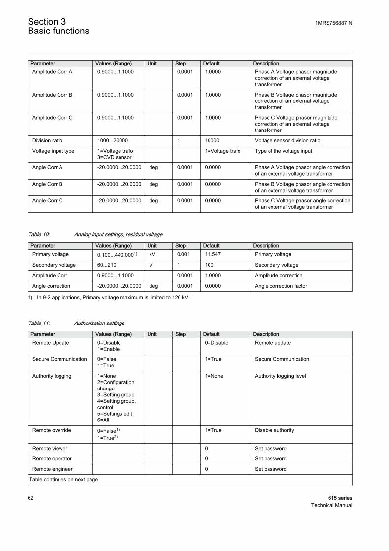
Parameter Values (Range) Unit Step Default DescriptionAmplitude Corr A 0.9000...1.1000 0.0001 1.0000 Phase A Voltage phasor magnitude
correction of an external voltagetransformer
Amplitude Corr B 0.9000...1.1000 0.0001 1.0000 Phase B Voltage phasor magnitudecorrection of an external voltagetransformer
Amplitude Corr C 0.9000...1.1000 0.0001 1.0000 Phase C Voltage phasor magnitudecorrection of an external voltagetransformer
Division ratio 1000...20000 1 10000 Voltage sensor division ratio
Voltage input type 1=Voltage trafo3=CVD sensor
1=Voltage trafo Type of the voltage input
Angle Corr A -20.0000...20.0000 deg 0.0001 0.0000 Phase A Voltage phasor angle correctionof an external voltage transformer
Angle Corr B -20.0000...20.0000 deg 0.0001 0.0000 Phase B Voltage phasor angle correctionof an external voltage transformer
Angle Corr C -20.0000...20.0000 deg 0.0001 0.0000 Phase C Voltage phasor angle correctionof an external voltage transformer
Table 10: Analog input settings, residual voltage
Parameter Values (Range) Unit Step Default DescriptionPrimary voltage 0.100...440.0001) kV 0.001 11.547 Primary voltage
Secondary voltage 60...210 V 1 100 Secondary voltage
Amplitude Corr 0.9000...1.1000 0.0001 1.0000 Amplitude correction
Angle correction -20.0000...20.0000 deg 0.0001 0.0000 Angle correction factor
1) In 9-2 applications, Primary voltage maximum is limited to 126 kV.
Table 11: Authorization settings
Parameter Values (Range) Unit Step Default DescriptionRemote Update 0=Disable
1=Enable 0=Disable Remote update
Secure Communication 0=False1=True
1=True Secure Communication
Authority logging 1=None2=Configurationchange3=Setting group4=Setting group,control5=Settings edit6=All
1=None Authority logging level
Remote override 0=False1)
1=True2) 1=True Disable authority
Remote viewer 0 Set password
Remote operator 0 Set password
Remote engineer 0 Set password
Table continues on next page
Section 3 1MRS756887 NBasic functions
62 615 seriesTechnical Manual
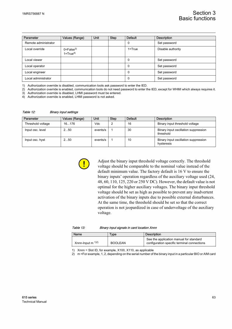
Parameter Values (Range) Unit Step Default DescriptionRemote administrator 0 Set password
Local override 0=False3)
1=True4) 1=True Disable authority
Local viewer 0 Set password
Local operator 0 Set password
Local engineer 0 Set password
Local administrator 0 Set password
1) Authorization override is disabled, communication tools ask password to enter the IED.2) Authorization override is enabled, communication tools do not need password to enter the IED, except for WHMI which always requires it.3) Authorization override is disabled, LHMI password must be entered.4) Authorization override is enabled, LHMI password is not asked.
Table 12: Binary input settings
Parameter Values (Range) Unit Step Default DescriptionThreshold voltage 16...176 Vdc 2 16 Binary input threshold voltage
Input osc. level 2...50 events/s 1 30 Binary input oscillation suppressionthreshold
Input osc. hyst 2...50 events/s 1 10 Binary input oscillation suppressionhysteresis
Adjust the binary input threshold voltage correctly. The thresholdvoltage should be comparable to the nominal value instead of thedefault minimum value. The factory default is 16 V to ensure thebinary inputs’ operation regardless of the auxiliary voltage used (24,48, 60, 110, 125, 220 or 250 V DC). However, the default value is notoptimal for the higher auxiliary voltages. The binary input thresholdvoltage should be set as high as possible to prevent any inadvertentactivation of the binary inputs due to possible external disturbances.At the same time, the threshold should be set so that the correctoperation is not jeopardized in case of undervoltage of the auxiliaryvoltage.
Table 13: Binary input signals in card location Xnnn
Name Type Description
Xnnn-Input m 1)2) BOOLEANSee the application manual for standardconfiguration specific terminal connections
1) Xnnn = Slot ID, for example, X100, X110, as applicable2) m =For example, 1, 2, depending on the serial number of the binary input in a particular BIO or AIM card
1MRS756887 N Section 3Basic functions
615 series 63Technical Manual

Table 14: Binary output signals in card location Xnnn
Name Type Default Description
Xnnn-Pmm1)2) BOOLEAN 0=False
See the applicationmanual for standardconfiguration specificterminal connections
1) Xnnn = Slot ID, for example, X100, X110, as applicable2) Pmm = For example, PO1, PO2, SO1, SO2, as applicable
Table 15: Binary input settings in card location Xnnn
Name 1) Value Unit Step Default
Input m2) filter time 5…1000 ms 5
Input m inversion 0= False1= True
0=False
1) Xnnn = Slot ID, for example, X100, X110, as applicable2) m = For example, 1, 2, depending on the serial number of the binary input in a particular BIO or AIM card
Table 16: Ethernet front port settings
Parameter Values (Range) Unit Step Default DescriptionIP address 192.168.0.254 IP address for front port (fixed)
Mac address XX-XX-XX-XX-XX-XX
Mac address for front port
Table 17: Ethernet rear port settings
Parameter Values (Range) Unit Step Default DescriptionIP address 192.168.2.10 IP address for rear port(s)
Subnet mask 255.255.255.0 Subnet mask for rear port(s)
Default gateway 192.168.2.1 Default gateway for rear port(s)
Mac address XX-XX-XX-XX-XX-XX
Mac address for rear port(s)
Table 18: General system settings
Parameter Values (Range) Unit Step Default DescriptionRated frequency 1=50Hz
2=60Hz 1=50Hz Rated frequency of the network
Phase rotation 1=ABC2=ACB
1=ABC Phase rotation order
Blocking mode 1=Freeze timer2=Block all3=Block OPERATEoutput
1=Freeze timer Behaviour for function BLOCK inputs
Bay name1) REF6152) Bay name in system
Table continues on next page
Section 3 1MRS756887 NBasic functions
64 615 seriesTechnical Manual

Parameter Values (Range) Unit Step Default DescriptionIDMT Sat point 10...50 I/I> 1 50 Overcurrent IDMT saturation point
Frequency adaptivity 3) 0=Disable1=Enable
0=Disable Enabling frequency adaptivity
SMV Max Delay 0=1.90 1.58 ms1=3.15 2.62 ms2=4.40 3.67 ms3=5.65 4.71 ms4=6.90 5.75 ms
1=3.15 2.62 ms SMV Maximum allowed delay
1) Used in the IED main menu header and as part of the disturbance recording identification2) Depending on the product variant3) Available only in REG615
Table 19: HMI settings
Parameter Values (Range) Unit Step Default DescriptionFB naming convention 1=IEC61850
2=IEC606173=IEC-ANSI
1=IEC61850 FB naming convention used in IED
Default view 1=Measurements2=Main menu3=SLD
1=Measurements LHMI default view
Backlight timeout 1...60 min 1 3 LHMI backlight timeout
Web HMI mode 1=Active read only2=Active3=Disabled
3=Disabled Web HMI functionality
Web HMI timeout 1...60 min 1 3 Web HMI login timeout
SLD symbol format 1=IEC2=ANSI
1=IEC Single Line Diagram symbol format
Autoscroll delay 0...30 s 1 0 Autoscroll delay for Measurements view
Setting visibility 1=Basic2=Advanced
1=Basic Setting visibility for HMI
Table 20: IEC 60870-5-103 settings
Parameter Values (Range) Unit Step Default DescriptionOperation 1=on
5=off 5=off Selects if this protocol instance is enabled
or disabled
Serial port 1=COM 12=COM 2
1=COM 1 COM port
Address 1...255 1 1 Unit address
Start delay 0...20 char 1 4 Start frame delay in chars
End delay 0...20 char 1 4 End frame delay in chars
DevFunType 0...255 1 9 Device Function Type
UsrFunType 0...255 1 10 Function type for User Class 2 Frame
UsrInfNo 0...255 1 230 Information Number for User Class2Frame
Table continues on next page
1MRS756887 N Section 3Basic functions
615 series 65Technical Manual

Parameter Values (Range) Unit Step Default DescriptionClass1Priority 0=Ev High
1=Ev/DR Equal2=DR High
0=Ev High Class 1 data sending priority relationshipbetween Events and DisturbanceRecorder data.
Class2Interval 0...86400 s 1 30 Interval in seconds to send class 2response
Frame1InUse -1=Not in use0=User frame1=Standard frame12=Standard frame23=Standard frame34=Standard frame45=Standard frame56=Private frame 67=Private frame 7
6=Private frame 6 Active Class2 Frame 1
Frame2InUse -1=Not in use0=User frame1=Standard frame12=Standard frame23=Standard frame34=Standard frame45=Standard frame56=Private frame 67=Private frame 7
-1=Not in use Active Class2 Frame 2
Frame3InUse -1=Not in use0=User frame1=Standard frame12=Standard frame23=Standard frame34=Standard frame45=Standard frame56=Private frame 67=Private frame 7
-1=Not in use Active Class2 Frame 3
Frame4InUse -1=Not in use0=User frame1=Standard frame12=Standard frame23=Standard frame34=Standard frame45=Standard frame56=Private frame 67=Private frame 7
-1=Not in use Active Class2 Frame 4
Table continues on next page
Section 3 1MRS756887 NBasic functions
66 615 seriesTechnical Manual
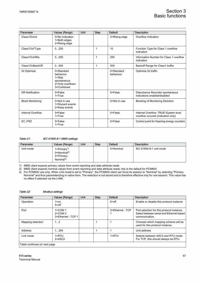
Parameter Values (Range) Unit Step Default DescriptionClass1OvInd 0=No indication
1=Both edges2=Rising edge
2=Rising edge Overflow Indication
Class1OvFType 0...255 1 10 Function Type for Class 1 overflowindication
Class1OvInfNo 0...255 1 255 Information Number for Class 1 overflowindication
Class1OvBackOff 0...500 1 500 Backoff Range for Class1 buffer
GI Optimize 0=Standardbehaviour1=Skipspontaneous2=Only overflown3=Combined
0=Standardbehaviour
Optimize GI traffic
DR Notification 0=False1=True
0=False Disturbance Recorder spontaneousindications enabled/disabled
Block Monitoring 0=Not in use1=Discard events2=Keep events
0=Not in use Blocking of Monitoring Direction
Internal Overflow 0=False1=True
0=False Internal Overflow: TRUE-System leveloverflow occured (indication only)
EC_FRZ 0=False1=True
0=False Control point for freezing energy counters
Table 21: IEC 61850-8-1 MMS settings
Parameter Values (Range) Unit Step Default DescriptionUnit mode 1=Primary1)
0=Nominal2)
2=Primary-Nominal3)
0=Nominal IEC 61850-8-1 unit mode
1) MMS client expects primary values from event reporting and data attribute reads2) MMS client expects nominal values from event reporting and data attribute reads; this is the default for PCM6003) For PCM600 use only, When Unit mode is set to "Primary", the PCM600 client can force its session to "Nominal" by selecting "Primary-
Nominal" and thus parameterizing in native form. The selection is not stored and is therefore effective only for one session. This value hasno effect if selected via the LHMI.
Table 22: Modbus settings
Parameter Values (Range) Unit Step Default DescriptionOperation 1=on
5=off 5=off Enable or disable this protocol instance
Port 1=COM 12=COM 23=Ethernet - TCP 1
3=Ethernet - TCP1
Port selection for this protocol instance.Select between serial and Ethernet basedcommunication.
Mapping selection 1...2 1 1 Chooses which mapping scheme will beused for this protocol instance.
Address 1...254 1 1 Unit address
Link mode 1=RTU2=ASCII
1=RTU Selects between ASCII and RTU mode.For TCP, this should always be RTU.
Table continues on next page
1MRS756887 N Section 3Basic functions
615 series 67Technical Manual

Parameter Values (Range) Unit Step Default DescriptionTCP port 1...65535 1 502 Defines the listening port for the Modbus
TCP server. Default = 502.
Parity 0=none1=odd2=even
2=even Parity for the serial connection.
Start delay 0...20 1 4 Start delay in character times for serialconnection
End delay 0...20 1 4 End delay in character times for serialconnections
CRC order 0=Hi-Lo1=Lo-Hi
0=Hi-Lo Selects between normal or swapped byteorder for checksum for serial connection.Default: Hi-Lo.
Client IP 0.0.0.0 Sets the IP address of the client. If set tozero, connection from any client isaccepted.
Write authority 0=Read only1=Disable 0x write2=Full access
2=Full access Selects the control authority scheme
Time format 0=UTC1=Local
1=Local Selects between UTC and local time forevents and timestamps.
Event ID selection 0=Address1=UID
0=Address Selects whether the events are reportedusing the MB address or the UID number.
Event buffering 0=Keep oldest1=Keep newest
0=Keep oldest Selects whether the oldest or newestevents are kept in the case of event bufferoverflow.
Event backoff 1...500 1 200 Defines how many events have to be readafter event buffer overflow to allow newevents to be buffered. Applicable in "Keepoldest" mode only.
ControlStructPWd 1 **** Password for control operations usingControl Struct mechanism, which isavailable on 4x memory area.
ControlStructPWd 2 **** Password for control operations usingControl Struct mechanism, which isavailable on 4x memory area.
ControlStructPWd 3 **** Password for control operations usingControl Struct mechanism, which isavailable on 4x memory area.
ControlStructPWd 4 **** Password for control operations usingControl Struct mechanism, which isavailable on 4x memory area.
ControlStructPWd 5 **** Password for control operations usingControl Struct mechanism, which isavailable on 4x memory area.
ControlStructPWd 6 **** Password for control operations usingControl Struct mechanism, which isavailable on 4x memory area.
ControlStructPWd 7 **** Password for control operations usingControl Struct mechanism, which isavailable on 4x memory area.
ControlStructPWd 8 **** Password for control operations usingControl Struct mechanism, which isavailable on 4x memory area.
Section 3 1MRS756887 NBasic functions
68 615 seriesTechnical Manual
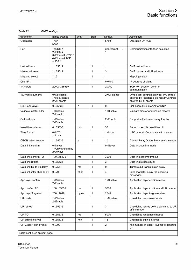
Table 23: DNP3 settings
Parameter Values (Range) Unit Step Default DescriptionOperation 1=on
5=off 5=off Operation Off / On
Port 1=COM 12=COM 23=Ethernet - TCP 14=Ethernet TCP+UDP 1
3=Ethernet - TCP1
Communication interface selection
Unit address 1...65519 1 1 DNP unit address
Master address 1...65519 1 3 DNP master and UR address
Mapping select 1...2 1 1 Mapping select
ClientIP 0.0.0.0 IP address of client
TCP port 20000...65535 1 20000 TCP Port used on ethernetcommunication
TCP write authority 0=No clients1=Reg. clients2=All clients
2=All clients 0=no client controls allowed; 1=Controlsallowed by registered clients; 2=Controlsallowed by all clients
Link keep-alive 0...65535 s 1 0 Link keep-alive interval for DNP
Validate master addr 1=Disable2=Enable
1=Disable Validate master address on receive
Self address 1=Disable2=Enable
2=Enable Support self address query function
Need time interval 0...65535 min 1 30 Period to set IIN need time bit
Time format 0=UTC1=Local
1=Local UTC or local. Coordinate with master.
CROB select timeout 1...65535 s 1 10 Control Relay Output Block select timeout
Data link confirm 0=Never1=Only Multiframe2=Always
0=Never Data link confirm mode
Data link confirm TO 100...65535 ms 1 3000 Data link confirm timeout
Data link retries 0...65535 1 3 Data link retries count
Data link Rx to Tx delay 0...255 ms 1 0 Turnaround transmission delay
Data link inter char delay 0...20 char 1 4 Inter character delay for incomingmessages
App layer confirm 1=Disable2=Enable
1=Disable Application layer confirm mode
App confirm TO 100...65535 ms 1 5000 Application layer confirm and UR timeout
App layer fragment 256...2048 bytes 1 2048 Application layer fragment size
UR mode 1=Disable2=Enable
1=Disable Unsolicited responses mode
UR retries 0...65535 1 3 Unsolicited retries before switching to URoffline mode
UR TO 0...65535 ms 1 5000 Unsolicited response timeout
UR offline interval 0...65535 min 1 15 Unsolicited offline interval
UR Class 1 Min events 0...999 1 2 Min number of class 1 events to generateUR
Table continues on next page
1MRS756887 N Section 3Basic functions
615 series 69Technical Manual
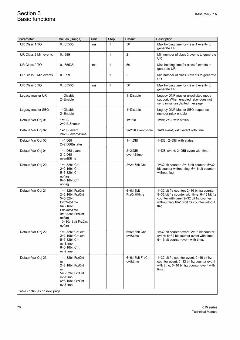
Parameter Values (Range) Unit Step Default DescriptionUR Class 1 TO 0...65535 ms 1 50 Max holding time for class 1 events to
generate UR
UR Class 2 Min events 0...999 1 2 Min number of class 2 events to generateUR
UR Class 2 TO 0...65535 ms 1 50 Max holding time for class 2 events togenerate UR
UR Class 3 Min events 0...999 1 2 Min number of class 3 events to generateUR
UR Class 3 TO 0...65535 ms 1 50 Max holding time for class 3 events togenerate UR
Legacy master UR 1=Disable2=Enable
1=Disable Legacy DNP master unsolicited modesupport. When enabled relay does notsend initial unsolicited message.
Legacy master SBO 1=Disable2=Enable
1=Disable Legacy DNP Master SBO sequencenumber relax enable
Default Var Obj 01 1=1:BI2=2:BI&status
1=1:BI 1=BI; 2=BI with status.
Default Var Obj 02 1=1:BI event2=2:BI event&time
2=2:BI event&time 1=BI event; 2=BI event with time.
Default Var Obj 03 1=1:DBI2=2:DBI&status
1=1:DBI 1=DBI; 2=DBI with status.
Default Var Obj 04 1=1:DBI event2=2:DBIevent&time
2=2:DBIevent&time
1=DBI event; 2=DBI event with time.
Default Var Obj 20 1=1:32bit Cnt2=2:16bit Cnt5=5:32bit Cntnoflag6=6:16bit Cntnoflag
2=2:16bit Cnt 1=32 bit counter; 2=16 bit counter; 5=32bit counter without flag; 6=16 bit counterwithout flag.
Default Var Obj 21 1=1:32bit FrzCnt2=2:16bit FrzCnt5=5:32bitFrzCnt&time6=6:16bitFrzCnt&time9=9:32bit FrzCntnoflag10=10:16bit FrzCntnoflag
6=6:16bitFrzCnt&time
1=32 bit frz counter; 2=16 bit frz counter;5=32 bit frz counter with time; 6=16 bit frzcounter with time; 9=32 bit frz counterwithout flag;10=16 bit frz counter withoutflag.
Default Var Obj 22 1=1:32bit Cnt evt2=2:16bit Cnt evt5=5:32bit Cntevt&time6=6:16bit Cntevt&time
6=6:16bit Cntevt&time
1=32 bit counter event; 2=16 bit counterevent; 5=32 bit counter event with time;6=16 bit counter event with time.
Default Var Obj 23 1=1:32bit FrzCntevt2=2:16bit FrzCntevt5=5:32bit FrzCntevt&time6=6:16bit FrzCntevt&time
6=6:16bit FrzCntevt&time
1=32 bit frz counter event; 2=16 bit frzcounter event; 5=32 bit frz counter eventwith time; 6=16 bit frz counter event withtime.
Table continues on next page
Section 3 1MRS756887 NBasic functions
70 615 seriesTechnical Manual
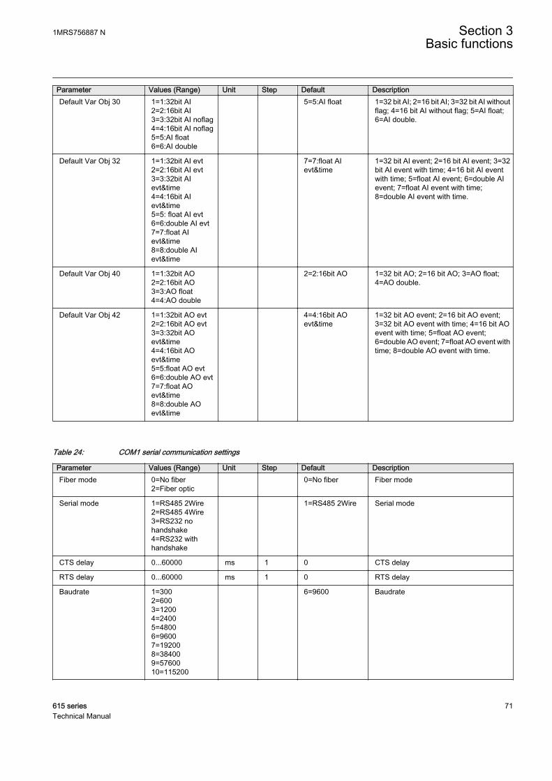
Parameter Values (Range) Unit Step Default DescriptionDefault Var Obj 30 1=1:32bit AI
2=2:16bit AI3=3:32bit AI noflag4=4:16bit AI noflag5=5:AI float6=6:AI double
5=5:AI float 1=32 bit AI; 2=16 bit AI; 3=32 bit AI withoutflag; 4=16 bit AI without flag; 5=AI float;6=AI double.
Default Var Obj 32 1=1:32bit AI evt2=2:16bit AI evt3=3:32bit AIevt&time4=4:16bit AIevt&time5=5: float AI evt6=6:double AI evt7=7:float AIevt&time8=8:double AIevt&time
7=7:float AIevt&time
1=32 bit AI event; 2=16 bit AI event; 3=32bit AI event with time; 4=16 bit AI eventwith time; 5=float AI event; 6=double AIevent; 7=float AI event with time;8=double AI event with time.
Default Var Obj 40 1=1:32bit AO2=2:16bit AO3=3:AO float4=4:AO double
2=2:16bit AO 1=32 bit AO; 2=16 bit AO; 3=AO float;4=AO double.
Default Var Obj 42 1=1:32bit AO evt2=2:16bit AO evt3=3:32bit AOevt&time4=4:16bit AOevt&time5=5:float AO evt6=6:double AO evt7=7:float AOevt&time8=8:double AOevt&time
4=4:16bit AOevt&time
1=32 bit AO event; 2=16 bit AO event;3=32 bit AO event with time; 4=16 bit AOevent with time; 5=float AO event;6=double AO event; 7=float AO event withtime; 8=double AO event with time.
Table 24: COM1 serial communication settings
Parameter Values (Range) Unit Step Default DescriptionFiber mode 0=No fiber
2=Fiber optic 0=No fiber Fiber mode
Serial mode 1=RS485 2Wire2=RS485 4Wire3=RS232 nohandshake4=RS232 withhandshake
1=RS485 2Wire Serial mode
CTS delay 0...60000 ms 1 0 CTS delay
RTS delay 0...60000 ms 1 0 RTS delay
Baudrate 1=3002=6003=12004=24005=48006=96007=192008=384009=5760010=115200
6=9600 Baudrate
1MRS756887 N Section 3Basic functions
615 series 71Technical Manual

Table 25: COM2 serial communication settings
Parameter Values (Range) Unit Step Default DescriptionFiber mode 0=No fiber
2=Fiber optic 0=No fiber Fiber mode
Serial mode 1=RS485 2Wire2=RS485 4Wire3=RS232 nohandshake4=RS232 withhandshake
1=RS485 2Wire Serial mode
CTS delay 0...60000 ms 1 0 CTS delay
RTS delay 0...60000 ms 1 0 RTS delay
Baudrate 1=3002=6003=12004=24005=48006=96007=192008=384009=5760010=115200
6=9600 Baudrate
3.2 Self-supervision
The protection relay's extensive self-supervision system continuously supervises thesoftware and the electronics. It handles run-time fault situation and informs the userabout a fault via the LHMI and through the communication channels.
There are two types of fault indications.
• Internal faults• Warnings
3.2.1 Internal faults
When an internal relay fault is detected, relay protection operation is disabled, thegreen Ready LED begins to flash and the self-supervision output contact is activated.
Internal fault indications have the highest priority on the LHMI. Noneof the other LHMI indications can override the internal faultindication.
An indication about the fault is shown as a message on the LHMI. The textInternal Fault with an additional text message, a code, date and time, is shownto indicate the fault type.
Section 3 1MRS756887 NBasic functions
72 615 seriesTechnical Manual
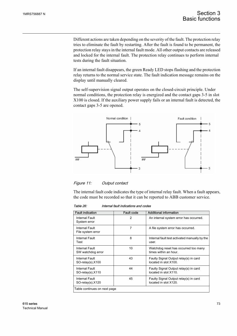
Different actions are taken depending on the severity of the fault. The protection relaytries to eliminate the fault by restarting. After the fault is found to be permanent, theprotection relay stays in the internal fault mode. All other output contacts are releasedand locked for the internal fault. The protection relay continues to perform internaltests during the fault situation.
If an internal fault disappears, the green Ready LED stops flashing and the protectionrelay returns to the normal service state. The fault indication message remains on thedisplay until manually cleared.
The self-supervision signal output operates on the closed-circuit principle. Undernormal conditions, the protection relay is energized and the contact gaps 3-5 in slotX100 is closed. If the auxiliary power supply fails or an internal fault is detected, thecontact gaps 3-5 are opened.
A070789 V1 EN
Figure 11: Output contact
The internal fault code indicates the type of internal relay fault. When a fault appears,the code must be recorded so that it can be reported to ABB customer service.
Table 26: Internal fault indications and codes
Fault indication Fault code Additional informationInternal FaultSystem error
2 An internal system error has occurred.
Internal FaultFile system error
7 A file system error has occurred.
Internal FaultTest
8 Internal fault test activated manually by theuser.
Internal FaultSW watchdog error
10 Watchdog reset has occurred too manytimes within an hour.
Internal FaultSO-relay(s),X100
43 Faulty Signal Output relay(s) in cardlocated in slot X100.
Internal FaultSO-relay(s),X110
44 Faulty Signal Output relay(s) in cardlocated in slot X110.
Internal FaultSO-relay(s),X120
45 Faulty Signal Output relay(s) in cardlocated in slot X120.
Table continues on next page
1MRS756887 N Section 3Basic functions
615 series 73Technical Manual
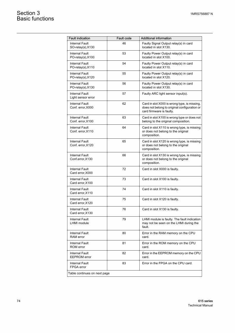
Fault indication Fault code Additional informationInternal FaultSO-relay(s),X130
46 Faulty Signal Output relay(s) in cardlocated in slot X130.
Internal FaultPO-relay(s),X100
53 Faulty Power Output relay(s) in cardlocated in slot X100.
Internal FaultPO-relay(s),X110
54 Faulty Power Output relay(s) in cardlocated in slot X110.
Internal FaultPO-relay(s),X120
55 Faulty Power Output relay(s) in cardlocated in slot X120.
Internal FaultPO-relay(s),X130
56 Faulty Power Output relay(s) in cardlocated in slot X130.
Internal FaultLight sensor error
57 Faulty ARC light sensor input(s).
Internal FaultConf. error,X000
62 Card in slot X000 is wrong type, is missing,does not belong to original configuration orcard firmware is faulty.
Internal FaultConf. error,X100
63 Card in slot X100 is wrong type or does notbelong to the original composition.
Internal FaultConf. error,X110
64 Card in slot X110 is wrong type, is missingor does not belong to the originalcomposition.
Internal FaultConf. error,X120
65 Card in slot X120 is wrong type, is missingor does not belong to the originalcomposition.
Internal FaultConf.error,X130
66 Card in slot X130 is wrong type, is missingor does not belong to the originalcomposition.
Internal FaultCard error,X000
72 Card in slot X000 is faulty.
Internal FaultCard error,X100
73 Card in slot X100 is faulty.
Internal FaultCard error,X110
74 Card in slot X110 is faulty.
Internal FaultCard error,X120
75 Card in slot X120 is faulty.
Internal FaultCard error,X130
76 Card in slot X130 is faulty.
Internal FaultLHMI module
79 LHMI module is faulty. The fault indicationmay not be seen on the LHMI during thefault.
Internal FaultRAM error
80 Error in the RAM memory on the CPUcard.
Internal FaultROM error
81 Error in the ROM memory on the CPUcard.
Internal FaultEEPROM error
82 Error in the EEPROM memory on the CPUcard.
Internal FaultFPGA error
83 Error in the FPGA on the CPU card.
Table continues on next page
Section 3 1MRS756887 NBasic functions
74 615 seriesTechnical Manual

Fault indication Fault code Additional informationInternal FaultRTC error
84 Error in the RTC on the CPU card.
Internal FaultRTD card error,X130
96 RTD card located in slot X130 may havepermanent fault. Temporary error hasoccurred too many times within a shorttime.
Internal FaultCOM card error
116 Error in the COM card.
For further information on internal fault indications, see the operation manual.
3.2.2 Warnings
In case of a warning, the protection relay continues to operate except for thoseprotection functions possibly affected by the fault, and the green Ready LED remainslit as during normal operation.
Warnings are indicated with the text Warning additionally provided with the nameof the warning, a numeric code and the date and time on the LHMI. The warningindication message can be manually cleared.
If a warning appears, record the name and code so that it can beprovided to ABB customer service.
Table 27: Warning indications and codes
Warning indication Warning code Additional informationWarningWatchdog reset
10 A watchdog reset has occurred.
WarningPower down det.
11 The auxiliary supply voltage has droppedtoo low.
WarningIEC61850 error
20 Error when building the IEC 61850 datamodel.
WarningModbus error
21 Error in the Modbus communication.
WarningDNP3 error
22 Error in the DNP3 communication.
WarningDataset error
24 Error in the Data set(s).
WarningReport cont. error
25 Error in the Report control block(s).
WarningGOOSE contr. error
26 Error in the GOOSE control block(s).
WarningSCL config error
27 Error in the SCL configuration file or the fileis missing.
WarningLogic error
28 Too many connections in theconfiguration.
Table continues on next page
1MRS756887 N Section 3Basic functions
615 series 75Technical Manual
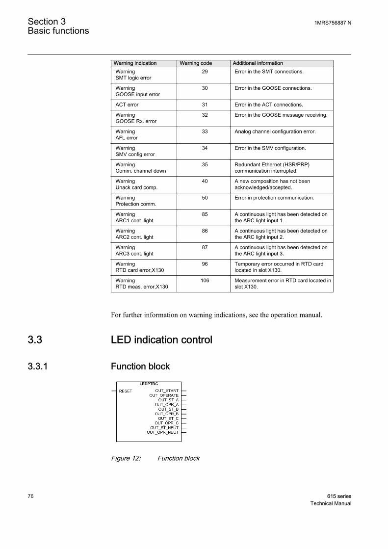
Warning indication Warning code Additional informationWarningSMT logic error
29 Error in the SMT connections.
WarningGOOSE input error
30 Error in the GOOSE connections.
ACT error 31 Error in the ACT connections.
WarningGOOSE Rx. error
32 Error in the GOOSE message receiving.
WarningAFL error
33 Analog channel configuration error.
WarningSMV config error
34 Error in the SMV configuration.
WarningComm. channel down
35 Redundant Ethernet (HSR/PRP)communication interrupted.
WarningUnack card comp.
40 A new composition has not beenacknowledged/accepted.
WarningProtection comm.
50 Error in protection communication.
WarningARC1 cont. light
85 A continuous light has been detected onthe ARC light input 1.
WarningARC2 cont. light
86 A continuous light has been detected onthe ARC light input 2.
WarningARC3 cont. light
87 A continuous light has been detected onthe ARC light input 3.
WarningRTD card error,X130
96 Temporary error occurred in RTD cardlocated in slot X130.
WarningRTD meas. error,X130
106 Measurement error in RTD card located inslot X130.
For further information on warning indications, see the operation manual.
3.3 LED indication control
3.3.1 Function block
GUID-B5D22C6D-951D-4F34-BE68-F5AF08580140 V2 EN
Figure 12: Function block
Section 3 1MRS756887 NBasic functions
76 615 seriesTechnical Manual
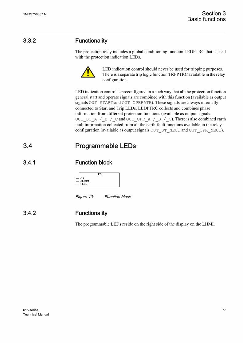
3.3.2 Functionality
The protection relay includes a global conditioning function LEDPTRC that is usedwith the protection indication LEDs.
LED indication control should never be used for tripping purposes.There is a separate trip logic function TRPPTRC available in the relayconfiguration.
LED indication control is preconfigured in a such way that all the protection functiongeneral start and operate signals are combined with this function (available as outputsignals OUT_START and OUT_OPERATE). These signals are always internallyconnected to Start and Trip LEDs. LEDPTRC collects and combines phaseinformation from different protection functions (available as output signalsOUT_ST_A /_B /_C and OUT_OPR_A /_B /_C). There is also combined earthfault information collected from all the earth-fault functions available in the relayconfiguration (available as output signals OUT_ST_NEUT and OUT_OPR_NEUT).
3.4 Programmable LEDs
3.4.1 Function block
GUID-00339108-34E4-496C-9142-5DC69F55EE7A V1 EN
Figure 13: Function block
3.4.2 Functionality
The programmable LEDs reside on the right side of the display on the LHMI.
1MRS756887 N Section 3Basic functions
615 series 77Technical Manual

REF615
Overcurrent
Dir. earth-fault
Voltage protection
Phase unbalance
Thermal overload
Breaker failure
Disturb. rec. Triggered
CB condition monitoring
Supervision
Arc detected
Autoreclose shot in progr.
A070704 V4 EN
Figure 14: Programmable LEDs on the right side of the display
All the programmable LEDs in the HMI of the protection relay have two colors, greenand red. For each LED, the different colors are individually controllable.
Each LED has two control inputs, ALARM and OK. The color setting is common for allthe LEDs. It is controlled with the Alarm colour setting, the default value being "Red".The OK input corresponds to the color that is available, with the default value being"Green".
Changing the Alarm colour setting to "Green" changes the color behavior of the OKinputs to red.
The ALARM input has a higher priority than the OK input.
Each LED is seen in the Application Configuration tool as an individual functionblock. Each LED has user-editable description text for event description. The state("None", "OK", "Alarm") of each LED can also be read under a common monitoreddata view for programmable LEDs.
Section 3 1MRS756887 NBasic functions
78 615 seriesTechnical Manual

The LED status also provides a means for resetting the individual LED viacommunication. The LED can also be reset from configuration with the RESET input.
The resetting and clearing function for all LEDs is under the Clear menu.
The menu structure for the programmable LEDs is presented in Figure 15. Thecommon color selection setting Alarm colour for all ALARM inputs is in the Generalmenu, while the LED-specific settings are under the LED-specific menu nodes.
Alarm modeDescription
LED 1
Programmable LEDsAlarm color Red
Green
Follow-SFollow-FLatched-SLatchedAck-F-S
Programmable LED description
LED 2
General
GUID-0DED5640-4F67-4112-9A54-E8CAADFFE547 V1 EN
Figure 15: Menu structure
Alarm mode alternativesThe ALARM input behavior can be selected with the alarm mode settings from thealternatives "Follow-S", "Follow-F", "Latched-S" and "LatchedAck-F-S". The OKinput behavior is always according to "Follow-S". The alarm input latched modes canbe cleared with the reset input in the application logic.
GUID-58B6C3F2-873A-4B13-9834-9BB21FCA5704 V1 EN
Figure 16: Symbols used in the sequence diagrams
"Follow-S": Follow Signal, ONIn this mode ALARM follows the input signal value, Non-latched.
Activatingsignal
LEDGUID-952BD571-874A-4572-8710-F0E879678552 V1 EN
Figure 17: Operating sequence "Follow-S"
1MRS756887 N Section 3Basic functions
615 series 79Technical Manual

"Follow-F": Follow Signal, FlashingSimilar to "Follow-S", but instead the LED is flashing when the input is active, Non-latched.
"Latched-S": Latched, ONThis mode is a latched function. At the activation of the input signal, the alarm showsa steady light. After acknowledgement by the local operator pressing any key on thekeypad, the alarm disappears.
Activatingsignal
LED
Acknow.GUID-055146B3-780B-43E6-9E06-9FD8D342E881 V1 EN
Figure 18: Operating sequence "Latched-S"
"LatchedAck-F-S": Latched, Flashing-ONThis mode is a latched function. At the activation of the input signal, the alarm startsflashing. After acknowledgement, the alarm disappears if the signal is not present andgives a steady light if the signal is present.
Activatingsignal
LED
Acknow.GUID-1B1414BD-2535-40FA-9642-8FBA4D19BA4A V1 EN
Figure 19: Operating sequence "LatchedAck-F-S"
3.4.3 SignalsTable 28: Input signals
Name Type Default DescriptionOK BOOLEAN 0=False Ok input for LED 1
ALARM BOOLEAN 0=False Alarm input for LED 1
RESET BOOLEAN 0=False Reset input for LED 1
Table continues on next page
Section 3 1MRS756887 NBasic functions
80 615 seriesTechnical Manual
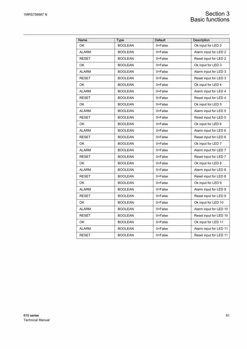
Name Type Default DescriptionOK BOOLEAN 0=False Ok input for LED 2
ALARM BOOLEAN 0=False Alarm input for LED 2
RESET BOOLEAN 0=False Reset input for LED 2
OK BOOLEAN 0=False Ok input for LED 3
ALARM BOOLEAN 0=False Alarm input for LED 3
RESET BOOLEAN 0=False Reset input for LED 3
OK BOOLEAN 0=False Ok input for LED 4
ALARM BOOLEAN 0=False Alarm input for LED 4
RESET BOOLEAN 0=False Reset input for LED 4
OK BOOLEAN 0=False Ok input for LED 5
ALARM BOOLEAN 0=False Alarm input for LED 5
RESET BOOLEAN 0=False Reset input for LED 5
OK BOOLEAN 0=False Ok input for LED 6
ALARM BOOLEAN 0=False Alarm input for LED 6
RESET BOOLEAN 0=False Reset input for LED 6
OK BOOLEAN 0=False Ok input for LED 7
ALARM BOOLEAN 0=False Alarm input for LED 7
RESET BOOLEAN 0=False Reset input for LED 7
OK BOOLEAN 0=False Ok input for LED 8
ALARM BOOLEAN 0=False Alarm input for LED 8
RESET BOOLEAN 0=False Reset input for LED 8
OK BOOLEAN 0=False Ok input for LED 9
ALARM BOOLEAN 0=False Alarm input for LED 9
RESET BOOLEAN 0=False Reset input for LED 9
OK BOOLEAN 0=False Ok input for LED 10
ALARM BOOLEAN 0=False Alarm input for LED 10
RESET BOOLEAN 0=False Reset input for LED 10
OK BOOLEAN 0=False Ok input for LED 11
ALARM BOOLEAN 0=False Alarm input for LED 11
RESET BOOLEAN 0=False Reset input for LED 11
1MRS756887 N Section 3Basic functions
615 series 81Technical Manual

3.4.4 SettingsTable 29: LED settings
Parameter Values (Range) Unit Step Default DescriptionAlarm colour 1=Green
2=Red 2=Red Colour for the alarm state of the LED
Alarm mode 0=Follow-S1=Follow-F2=Latched-S3=LatchedAck-F-S
0=Follow-S Alarm mode for programmable LED 1
Description ProgrammableLEDs LED 1
Programmable LED description
Alarm mode 0=Follow-S1=Follow-F2=Latched-S3=LatchedAck-F-S
0=Follow-S Alarm mode for programmable LED 2
Description ProgrammableLEDs LED 2
Programmable LED description
Alarm mode 0=Follow-S1=Follow-F2=Latched-S3=LatchedAck-F-S
0=Follow-S Alarm mode for programmable LED 3
Description ProgrammableLEDs LED 3
Programmable LED description
Alarm mode 0=Follow-S1=Follow-F2=Latched-S3=LatchedAck-F-S
0=Follow-S Alarm mode for programmable LED 4
Description ProgrammableLEDs LED 4
Programmable LED description
Alarm mode 0=Follow-S1=Follow-F2=Latched-S3=LatchedAck-F-S
0=Follow-S Alarm mode for programmable LED 5
Description ProgrammableLEDs LED 5
Programmable LED description
Alarm mode 0=Follow-S1=Follow-F2=Latched-S3=LatchedAck-F-S
0=Follow-S Alarm mode for programmable LED 6
Description ProgrammableLEDs LED 6
Programmable LED description
Alarm mode 0=Follow-S1=Follow-F2=Latched-S3=LatchedAck-F-S
0=Follow-S Alarm mode for programmable LED 7
Description ProgrammableLEDs LED 7
Programmable LED description
Alarm mode 0=Follow-S1=Follow-F2=Latched-S3=LatchedAck-F-S
0=Follow-S Alarm mode for programmable LED 8
Table continues on next page
Section 3 1MRS756887 NBasic functions
82 615 seriesTechnical Manual
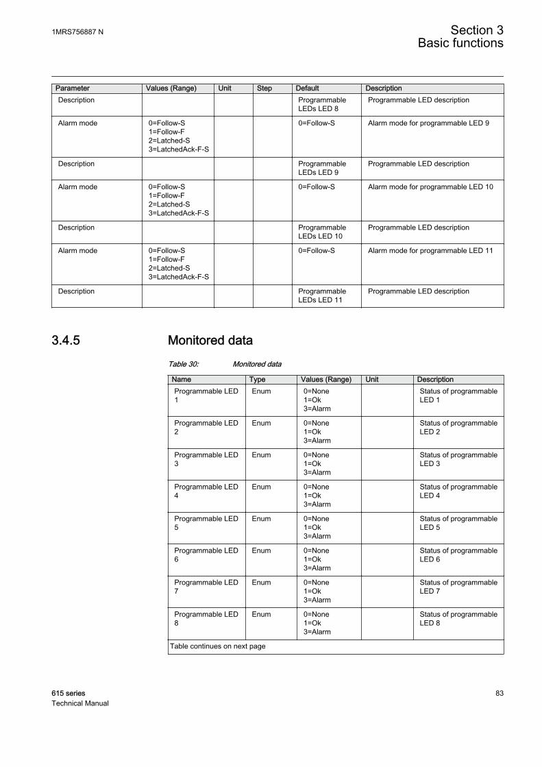
Parameter Values (Range) Unit Step Default DescriptionDescription Programmable
LEDs LED 8Programmable LED description
Alarm mode 0=Follow-S1=Follow-F2=Latched-S3=LatchedAck-F-S
0=Follow-S Alarm mode for programmable LED 9
Description ProgrammableLEDs LED 9
Programmable LED description
Alarm mode 0=Follow-S1=Follow-F2=Latched-S3=LatchedAck-F-S
0=Follow-S Alarm mode for programmable LED 10
Description ProgrammableLEDs LED 10
Programmable LED description
Alarm mode 0=Follow-S1=Follow-F2=Latched-S3=LatchedAck-F-S
0=Follow-S Alarm mode for programmable LED 11
Description ProgrammableLEDs LED 11
Programmable LED description
3.4.5 Monitored dataTable 30: Monitored data
Name Type Values (Range) Unit DescriptionProgrammable LED1
Enum 0=None1=Ok3=Alarm
Status of programmableLED 1
Programmable LED2
Enum 0=None1=Ok3=Alarm
Status of programmableLED 2
Programmable LED3
Enum 0=None1=Ok3=Alarm
Status of programmableLED 3
Programmable LED4
Enum 0=None1=Ok3=Alarm
Status of programmableLED 4
Programmable LED5
Enum 0=None1=Ok3=Alarm
Status of programmableLED 5
Programmable LED6
Enum 0=None1=Ok3=Alarm
Status of programmableLED 6
Programmable LED7
Enum 0=None1=Ok3=Alarm
Status of programmableLED 7
Programmable LED8
Enum 0=None1=Ok3=Alarm
Status of programmableLED 8
Table continues on next page
1MRS756887 N Section 3Basic functions
615 series 83Technical Manual
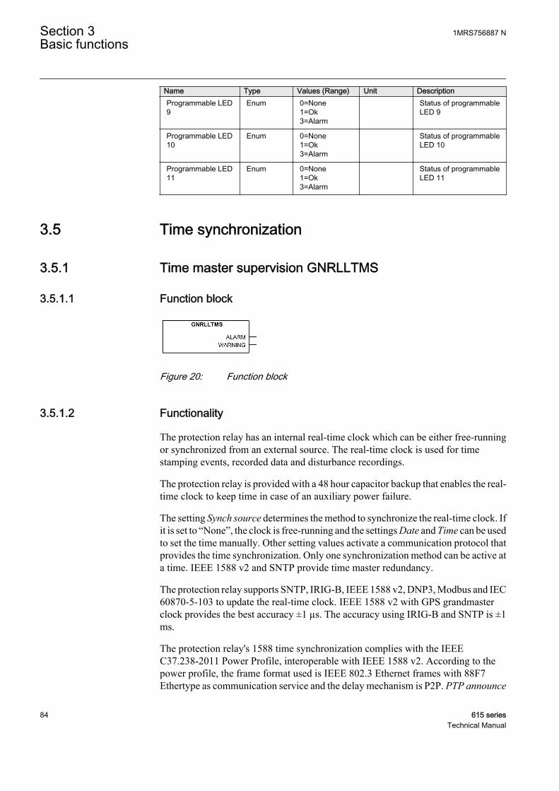
Name Type Values (Range) Unit DescriptionProgrammable LED9
Enum 0=None1=Ok3=Alarm
Status of programmableLED 9
Programmable LED10
Enum 0=None1=Ok3=Alarm
Status of programmableLED 10
Programmable LED11
Enum 0=None1=Ok3=Alarm
Status of programmableLED 11
3.5 Time synchronization
3.5.1 Time master supervision GNRLLTMS
3.5.1.1 Function block
GUID-52938D64-7CEC-4CFC-BBC1-04FA6860EAD1 V1 EN
Figure 20: Function block
3.5.1.2 Functionality
The protection relay has an internal real-time clock which can be either free-runningor synchronized from an external source. The real-time clock is used for timestamping events, recorded data and disturbance recordings.
The protection relay is provided with a 48 hour capacitor backup that enables the real-time clock to keep time in case of an auxiliary power failure.
The setting Synch source determines the method to synchronize the real-time clock. Ifit is set to “None”, the clock is free-running and the settings Date and Time can be usedto set the time manually. Other setting values activate a communication protocol thatprovides the time synchronization. Only one synchronization method can be active ata time. IEEE 1588 v2 and SNTP provide time master redundancy.
The protection relay supports SNTP, IRIG-B, IEEE 1588 v2, DNP3, Modbus and IEC60870-5-103 to update the real-time clock. IEEE 1588 v2 with GPS grandmasterclock provides the best accuracy ±1 µs. The accuracy using IRIG-B and SNTP is ±1ms.
The protection relay's 1588 time synchronization complies with the IEEEC37.238-2011 Power Profile, interoperable with IEEE 1588 v2. According to thepower profile, the frame format used is IEEE 802.3 Ethernet frames with 88F7Ethertype as communication service and the delay mechanism is P2P. PTP announce
Section 3 1MRS756887 NBasic functions
84 615 seriesTechnical Manual

mode determines the format of PTP announce frames sent by the protection relaywhen acting as 1588 master, with options “Basic IEEE1588” and “Power Profile”. Inthe “Power Profile” mode, the TLVs required by the IEEE C37.238-2011 PowerProfile are included in announce frames.
IEEE 1588 v2 time synchronization requires a communication cardwith redundancy support (COM0031...COM0037).
When Modbus TCP or DNP3 over TCP/IP is used, SNTP or IRIG-Btime synchronization should be used for better synchronizationaccuracy.
With the legacy protocols, the synchronization message must bereceived within four minutes from the previous synchronization.Otherwise bad synchronization status is raised for the protectionrelay. With SNTP, it is required that the SNTP server responds to arequest within 12 ms, otherwise the response is considered invalid.
The relay can use one of two SNTP servers, the primary or the secondary server. Theprimary server is mainly in use, whereas the secondary server is used if the primaryserver cannot be reached. While using the secondary SNTP server, the relay tries toswitch back to the primary server on every third SNTP request attempt. If both theSNTP servers are offline, event time stamps have the time invalid status. The time isrequested from the SNTP server every 60 seconds. Supported SNTP versions are 3and 4.
IRIG-B time synchronization requires the IRIG-B format B004/B005 according to the200-04 IRIG-B standard. Older IRIG-B standards refer to these as B000/B001 withIEEE-1344 extensions. The synchronization time can be either UTC time or localtime. As no reboot is necessary, the time synchronization starts immediately after theIRIG-B sync source is selected and the IRIG-B signal source is connected.
IRIG-B time synchronization requires a COM card with an IRIG-Binput.
When using line differential communication between RED615 protection relays, thetime synchronization messages can be received from the other line end protectionrelay within the protection telegrams. The protection relay begins to synchronize itsreal-time clock with the remote end protection relay's time if the Line differential timesynchronization source is selected. This does not affect the protection synchronizationused in the line differential protection or the selection of the remote end protectionrelay's time synchronization method. [1]
[1] The line differential protection is available only in RED615.
1MRS756887 N Section 3Basic functions
615 series 85Technical Manual

3.5.1.3 Signals
Table 31: GNRLLTMS output signals
Name Type DescriptionALARM BOOLEAN Time synchronization alarm
WARNING BOOLEAN Time synchronization warning
3.5.1.4 Settings
Table 32: Time format
Parameter Values (Range) Unit Step Default DescriptionTime format 1=24H:MM:SS:MS
2=12H:MM:SS:MS 1=24H:MM:SS:M
STime format
Date format 1=DD.MM.YYYY2=DD/MM/YYYY3=DD-MM-YYYY4=MM.DD.YYYY5=MM/DD/YYYY6=YYYY-MM-DD7=YYYY-DD-MM8=YYYY/DD/MM
1=DD.MM.YYYY Date format
Table 33: Time settings
Parameter Values (Range) Unit Step Default DescriptionSynch source 0=None
1=SNTP2=Modbus3=IEEE 15885=IRIG-B9=DNP17=IEC60870-5-103
1=SNTP Time synchronization source
PTP domain ID 0...255 1 0 The domain is identified by an integer, thedomainNumber, in the range of 0 to 255.
PTP priority 11) 0...255 1 128 PTP priority 1, in the range of 0 to 255.
PTP priority 2 0...255 1 128 PTP priority 2, in the range of 0 to 255.
PTP announce mode 1=Basic IEEE15882=Power Profile
1=Basic IEEE1588 PTP announce frame mode
1) Smaller value has higher priority
Table 34: Time settings
Parameter Values (Range) Unit Step Default DescriptionDate 0 Date
Time 0 Time
Local time offset -840...840 min 1 0 Local time offset in minutes
Section 3 1MRS756887 NBasic functions
86 615 seriesTechnical Manual
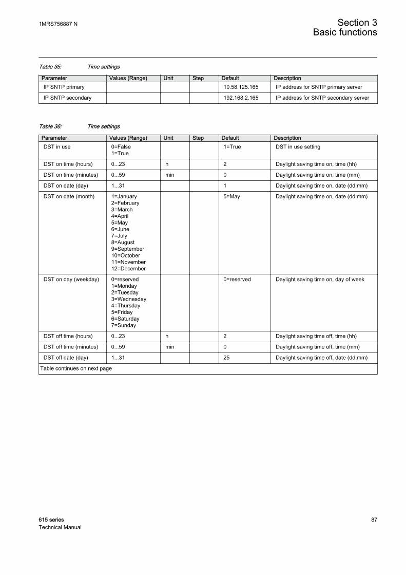
Table 35: Time settings
Parameter Values (Range) Unit Step Default DescriptionIP SNTP primary 10.58.125.165 IP address for SNTP primary server
IP SNTP secondary 192.168.2.165 IP address for SNTP secondary server
Table 36: Time settings
Parameter Values (Range) Unit Step Default DescriptionDST in use 0=False
1=True 1=True DST in use setting
DST on time (hours) 0...23 h 2 Daylight saving time on, time (hh)
DST on time (minutes) 0...59 min 0 Daylight saving time on, time (mm)
DST on date (day) 1...31 1 Daylight saving time on, date (dd:mm)
DST on date (month) 1=January2=February3=March4=April5=May6=June7=July8=August9=September10=October11=November12=December
5=May Daylight saving time on, date (dd:mm)
DST on day (weekday) 0=reserved1=Monday2=Tuesday3=Wednesday4=Thursday5=Friday6=Saturday7=Sunday
0=reserved Daylight saving time on, day of week
DST off time (hours) 0...23 h 2 Daylight saving time off, time (hh)
DST off time (minutes) 0...59 min 0 Daylight saving time off, time (mm)
DST off date (day) 1...31 25 Daylight saving time off, date (dd:mm)
Table continues on next page
1MRS756887 N Section 3Basic functions
615 series 87Technical Manual

Parameter Values (Range) Unit Step Default DescriptionDST off date (month) 1=January
2=February3=March4=April5=May6=June7=July8=August9=September10=October11=November12=December
9=September Daylight saving time off, date (dd:mm)
DST off day (weekday) 0=reserved1=Monday2=Tuesday3=Wednesday4=Thursday5=Friday6=Saturday7=Sunday
0=reserved Daylight saving time off, day of week
DST offset -720...720 min 1 60 Daylight saving time offset
3.6 Parameter setting groups
3.6.1 Function block
GUID-DFF8F71A-895C-4C06-B287-63C3CA26154C V2 EN
Figure 21: Function block
3.6.2 Functionality
The protection relay supports six setting groups. Each setting group containsparameters categorized as group settings inside application functions. The customercan change the active setting group at run time.
The active setting group can be changed by a parameter or via binary inputs dependingon the mode selected with the Configuration/Setting Group/SG operation modesetting.
The default value of all inputs is FALSE, which makes it possible to use only therequired number of inputs and leave the rest disconnected. The setting group selectionis not dependent on the SG_x_ACT outputs.
Section 3 1MRS756887 NBasic functions
88 615 seriesTechnical Manual
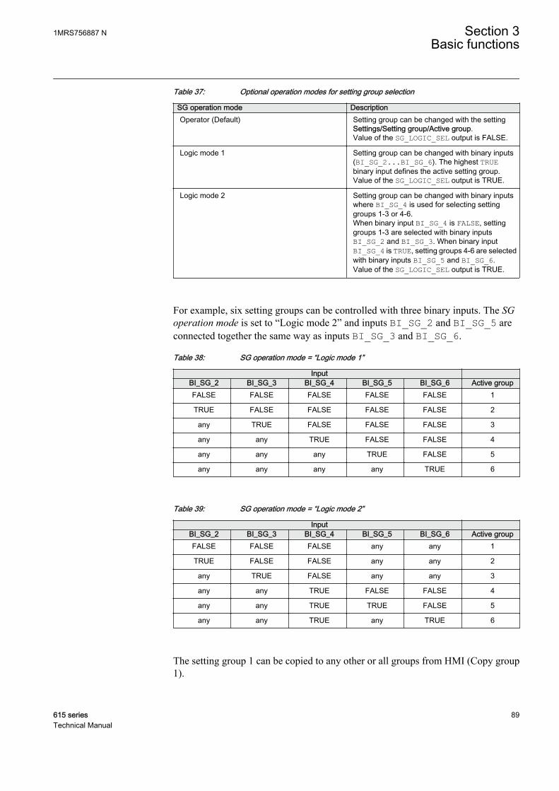
Table 37: Optional operation modes for setting group selection
SG operation mode DescriptionOperator (Default) Setting group can be changed with the setting
Settings/Setting group/Active group.Value of the SG_LOGIC_SEL output is FALSE.
Logic mode 1 Setting group can be changed with binary inputs(BI_SG_2...BI_SG_6). The highest TRUEbinary input defines the active setting group.Value of the SG_LOGIC_SEL output is TRUE.
Logic mode 2 Setting group can be changed with binary inputswhere BI_SG_4 is used for selecting settinggroups 1-3 or 4-6.When binary input BI_SG_4 is FALSE, settinggroups 1-3 are selected with binary inputsBI_SG_2 and BI_SG_3. When binary inputBI_SG_4 is TRUE, setting groups 4-6 are selectedwith binary inputs BI_SG_5 and BI_SG_6.Value of the SG_LOGIC_SEL output is TRUE.
For example, six setting groups can be controlled with three binary inputs. The SGoperation mode is set to “Logic mode 2” and inputs BI_SG_2 and BI_SG_5 areconnected together the same way as inputs BI_SG_3 and BI_SG_6.
Table 38: SG operation mode = “Logic mode 1”
Input BI_SG_2 BI_SG_3 BI_SG_4 BI_SG_5 BI_SG_6 Active groupFALSE FALSE FALSE FALSE FALSE 1
TRUE FALSE FALSE FALSE FALSE 2
any TRUE FALSE FALSE FALSE 3
any any TRUE FALSE FALSE 4
any any any TRUE FALSE 5
any any any any TRUE 6
Table 39: SG operation mode = “Logic mode 2”
Input BI_SG_2 BI_SG_3 BI_SG_4 BI_SG_5 BI_SG_6 Active groupFALSE FALSE FALSE any any 1
TRUE FALSE FALSE any any 2
any TRUE FALSE any any 3
any any TRUE FALSE FALSE 4
any any TRUE TRUE FALSE 5
any any TRUE any TRUE 6
The setting group 1 can be copied to any other or all groups from HMI (Copy group1).
1MRS756887 N Section 3Basic functions
615 series 89Technical Manual

3.7 Test mode
3.7.1 Function blocks
GUID-DFF8F71A-895C-4C06-B287-63C3CA26154C V2 EN
GUID-FA386432-3AEF-468D-B25E-D1C5BDA838E3 V3 EN
Figure 22: Function blocks
3.7.2 Functionality
The mode of all the logical nodes in the relay's IEC 61850 data model can be set withTest mode. Test mode is selected through one common parameter via the WHMI pathTests/IED test. By default, Test mode can only be set locally through LHMI. Testmode is also available via IEC 61850 communication (LD0.LLN0.Mod).
Table 40: Test mode
Test mode Description Protection BEH_BLKNormal mode Normal operation FALSE
IED blocked Protection working as in “Normal mode” but ACTconfiguration can be used to block physicaloutputs to process. Control function commandsblocked.
TRUE
IED test Protection working as in “Normal mode” butprotection functions are working in parallel withtest parameters.
FALSE
IED test and blocked Protection working as in “Normal mode” butprotection functions are working in parallel withtest parameters. ACT configuration can be used toblock physical outputs to process. Control functioncommands blocked.
TRUE
Section 3 1MRS756887 NBasic functions
90 615 seriesTechnical Manual
Behavior data objects in all logical nodes follow LD0.LLN0.Modvalue. If "Normal mode" is selected, behaviour data objects followmode (.Mod) data object of the corresponding logical device.
Vertical and horizontal communication is not blocked by the “IEDblocked” or “IED test and blocked” modes.
3.7.3 Application configuration and Test mode
The physical outputs from control commands to process are blocked with ”IEDblocked” and “IED test and blocked” modes. If physical outputs need to be blockedfrom the protection, the application configuration must be used to block these signals.Blocking scheme needs to use BEH_BLK output of PROTECTION function block.
3.7.4 Control mode
The mode of all logical nodes located under CTRL logical device can be set withControl mode. The Control mode parameter is available via the HMI or PCM600 pathConfiguration/Control/General. By default, Control mode can only be set locallythrough LHMI.Control mode inherits its value from Test mode but Controlmode ”On”, “Blocked” and “Off” can also be set independently. Control mode is alsoavailable via IEC 61850 communication (CTRL.LLN0.Mod).
Table 41: Control mode
Control mode Description Control BEH_BLKOn Normal operation FALSE
Blocked Control function commands blocked TRUE
Off Control functions disabled FALSE
Behavior data objects under CTRL logical device followCTRL.LLN0.Mod value. If "On" is selected, behavior data objectsfollow the mode of the corresponding logical device.
3.7.5 Application configuration and Control mode
The physical outputs from commands to process are blocked with “Blocked“ mode. Ifphysical outputs need to be blocked totally, meaning also commands from the binaryinputs, the application configuration must be used to block these signals. Blockingscheme uses BEH_BLK output of CONTROL function block.
1MRS756887 N Section 3Basic functions
615 series 91Technical Manual

3.7.6 Authorization
By default, Test mode and Control mode can only be changed from LHMI. It ispossible to write test mode by remote client, if it is needed in configuration. This isdone via LHMI only by setting the Remote test mode parameter via Tests/IED test/Test mode. Remote operation is possible only when control position of the relay is inremote position. Local and remote control can be selected with R/L button or viaControl function block in application configuration.
When using the Signal Monitoring tool to force online values, the followingconditions need to be met.
• Remote force is set to “All levels”• Test mode is enabled• Control position of the relay is in remote position
Table 42: Remote test mode
Remote test mode 61850-8-1-MMS WHMI/PCM600Off No access No access
Maintenance Command originator category maintenance No access
All levels All originator categories Yes
3.7.7 LHMI indications
The yellow Start LED flashes when the relay is in “IED blocked” or “IED test andblocked” mode. The green Ready LED flashes to indicate that the “IED test andblocked” mode or "IED test" mode is activated.
3.7.8 SignalsTable 43: PROTECTION input signals
Name Type Default DescriptionBI_SG_2 BOOLEAN 0 Setting group 2 is
active
BI_SG_3 BOOLEAN 0 Setting group 3 isactive
BI_SG_4 BOOLEAN 0 Setting group 4 isactive
BI_SG_5 BOOLEAN 0 Setting group 5 isactive
BI_SG_6 BOOLEAN 0 Setting group 6 isactive
Section 3 1MRS756887 NBasic functions
92 615 seriesTechnical Manual
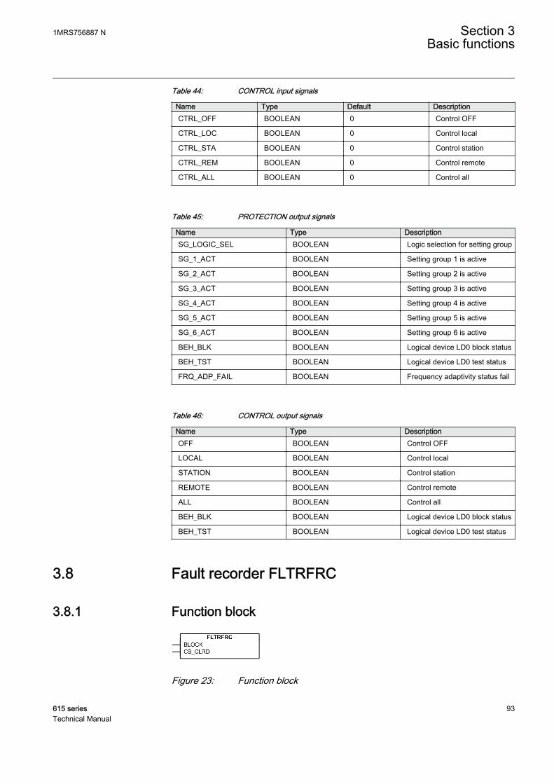
Table 44: CONTROL input signals
Name Type Default DescriptionCTRL_OFF BOOLEAN 0 Control OFF
CTRL_LOC BOOLEAN 0 Control local
CTRL_STA BOOLEAN 0 Control station
CTRL_REM BOOLEAN 0 Control remote
CTRL_ALL BOOLEAN 0 Control all
Table 45: PROTECTION output signals
Name Type DescriptionSG_LOGIC_SEL BOOLEAN Logic selection for setting group
SG_1_ACT BOOLEAN Setting group 1 is active
SG_2_ACT BOOLEAN Setting group 2 is active
SG_3_ACT BOOLEAN Setting group 3 is active
SG_4_ACT BOOLEAN Setting group 4 is active
SG_5_ACT BOOLEAN Setting group 5 is active
SG_6_ACT BOOLEAN Setting group 6 is active
BEH_BLK BOOLEAN Logical device LD0 block status
BEH_TST BOOLEAN Logical device LD0 test status
FRQ_ADP_FAIL BOOLEAN Frequency adaptivity status fail
Table 46: CONTROL output signals
Name Type DescriptionOFF BOOLEAN Control OFF
LOCAL BOOLEAN Control local
STATION BOOLEAN Control station
REMOTE BOOLEAN Control remote
ALL BOOLEAN Control all
BEH_BLK BOOLEAN Logical device LD0 block status
BEH_TST BOOLEAN Logical device LD0 test status
3.8 Fault recorder FLTRFRC
3.8.1 Function block
GUID-6BE3D723-0C52-4047-AA41-73D7C828B02B V1 EN
Figure 23: Function block
1MRS756887 N Section 3Basic functions
615 series 93Technical Manual
3.8.2 Functionality
The protection relay has the capacity to store the records of 128 latest fault events.Fault records include fundamental or RMS current values. The records enable the userto analyze recent power system events. Each fault record (FLTRFRC) is marked withan up-counting fault number and a time stamp that is taken from the beginning of thefault.
The fault recording period begins from the start event of any protection function andends if any protection function trips or the start is restored before the operate event. Ifa start is restored without an operate event, the start duration shows the protectionfunction that has started first.
Start duration that has the value of 100% indicates that a protection function hasoperated during the fault and if none of the protection functions has been operated,Start duration shows always values less than 100%.
The Fault recorded data Protection and Start duration is from the same protectionfunction. The Fault recorded data operate time shows the time of the actual faultperiod. This value is the time difference between the activation of the internal start andoperate signals. The actual operate time also includes the starting time and the delayof the output relay. The Fault recorded data Breaker clear time is the time differencebetween internal operate signal and activation of CB_CLRD input.
If some functions in relay application are sensitive to start frequentlyit might be advisable to set the setting parameter Trig mode to “Fromoperate”. Then only faults that cause an operate event trigger a newfault recording.
The fault-related current, voltage, frequency, angle values, shot pointer and the activesetting group number are taken from the moment of the operate event, or from thebeginning of the fault if only a start event occurs during the fault. The maximumcurrent value collects the maximum fault currents during the fault. In case frequencycannot be measured, nominal frequency is used for frequency and zero for Frequencygradient and validity is set accordingly.
Measuring mode for phase current and residual current values can be selected with theMeasurement mode setting parameter.
3.8.3 SettingsTable 47: FLTRFRC Non group settings (Basic)
Parameter Values (Range) Unit Step Default DescriptionOperation 1=on
5=off 1=on Operation Off / On
Trig mode 0=From all faults1=From operate2=From only start
0=From all faults Triggering mode
Section 3 1MRS756887 NBasic functions
94 615 seriesTechnical Manual
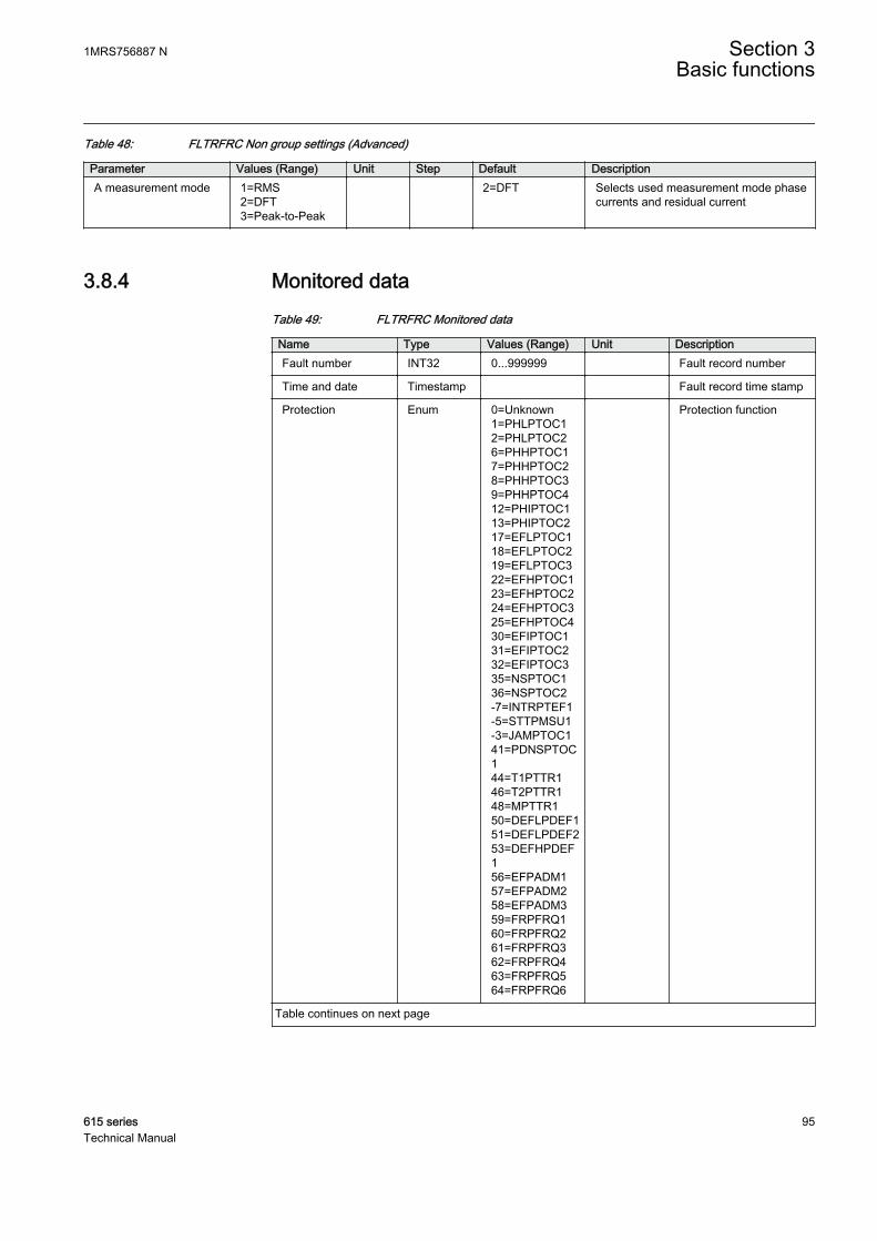
Table 48: FLTRFRC Non group settings (Advanced)
Parameter Values (Range) Unit Step Default DescriptionA measurement mode 1=RMS
2=DFT3=Peak-to-Peak
2=DFT Selects used measurement mode phasecurrents and residual current
3.8.4 Monitored dataTable 49: FLTRFRC Monitored data
Name Type Values (Range) Unit DescriptionFault number INT32 0...999999 Fault record number
Time and date Timestamp Fault record time stamp
Protection Enum 0=Unknown1=PHLPTOC12=PHLPTOC26=PHHPTOC17=PHHPTOC28=PHHPTOC39=PHHPTOC412=PHIPTOC113=PHIPTOC217=EFLPTOC118=EFLPTOC219=EFLPTOC322=EFHPTOC123=EFHPTOC224=EFHPTOC325=EFHPTOC430=EFIPTOC131=EFIPTOC232=EFIPTOC335=NSPTOC136=NSPTOC2-7=INTRPTEF1-5=STTPMSU1-3=JAMPTOC141=PDNSPTOC144=T1PTTR146=T2PTTR148=MPTTR150=DEFLPDEF151=DEFLPDEF253=DEFHPDEF156=EFPADM157=EFPADM258=EFPADM359=FRPFRQ160=FRPFRQ261=FRPFRQ362=FRPFRQ463=FRPFRQ564=FRPFRQ6
Protection function
Table continues on next page
1MRS756887 N Section 3Basic functions
615 series 95Technical Manual
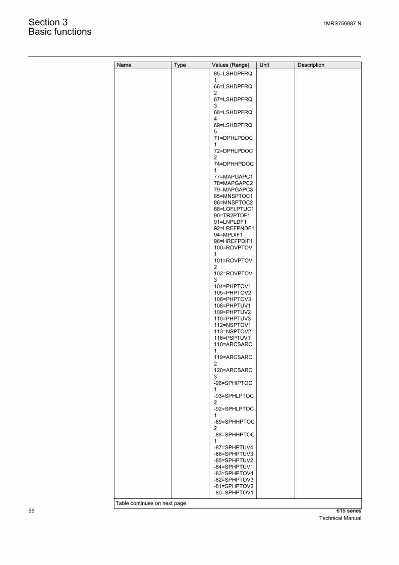
Name Type Values (Range) Unit Description 65=LSHDPFRQ
166=LSHDPFRQ267=LSHDPFRQ368=LSHDPFRQ469=LSHDPFRQ571=DPHLPDOC172=DPHLPDOC274=DPHHPDOC177=MAPGAPC178=MAPGAPC279=MAPGAPC385=MNSPTOC186=MNSPTOC288=LOFLPTUC190=TR2PTDF191=LNPLDF192=LREFPNDF194=MPDIF196=HREFPDIF1100=ROVPTOV1101=ROVPTOV2102=ROVPTOV3104=PHPTOV1105=PHPTOV2106=PHPTOV3108=PHPTUV1109=PHPTUV2110=PHPTUV3112=NSPTOV1113=NSPTOV2116=PSPTUV1118=ARCSARC1119=ARCSARC2120=ARCSARC3-96=SPHIPTOC1-93=SPHLPTOC2-92=SPHLPTOC1-89=SPHHPTOC2-88=SPHHPTOC1-87=SPHPTUV4-86=SPHPTUV3-85=SPHPTUV2-84=SPHPTUV1-83=SPHPTOV4-82=SPHPTOV3-81=SPHPTOV2-80=SPHPTOV1
Table continues on next page
Section 3 1MRS756887 NBasic functions
96 615 seriesTechnical Manual

Name Type Values (Range) Unit Description -25=OEPVPH4
-24=OEPVPH3-23=OEPVPH2-22=OEPVPH1-19=PSPTOV2-18=PSPTOV1-15=PREVPTOC1-12=PHPTUC2-11=PHPTUC1-9=PHIZ15=PHLTPTOC120=EFLPTOC426=EFHPTOC527=EFHPTOC637=NSPTOC338=NSPTOC445=T1PTTR254=DEFHPDEF275=DPHHPDOC289=LOFLPTUC2103=ROVPTOV4117=PSPTUV2-13=PHPTUC33=PHLPTOC310=PHHPTOC511=PHHPTOC628=EFHPTOC729=EFHPTOC8107=PHPTOV4111=PHPTUV4114=NSPTOV3115=NSPTOV4-30=PHDSTPDIS1-29=TR3PTDF1-28=HICPDIF1-27=HIBPDIF1-26=HIAPDIF1-32=LSHDPFRQ8-31=LSHDPFRQ770=LSHDPFRQ680=MAPGAPC481=MAPGAPC582=MAPGAPC683=MAPGAPC7-102=MAPGAPC12-101=MAPGAPC11-100=MAPGAPC10-99=MAPGAPC9
Table continues on next page
1MRS756887 N Section 3Basic functions
615 series 97Technical Manual
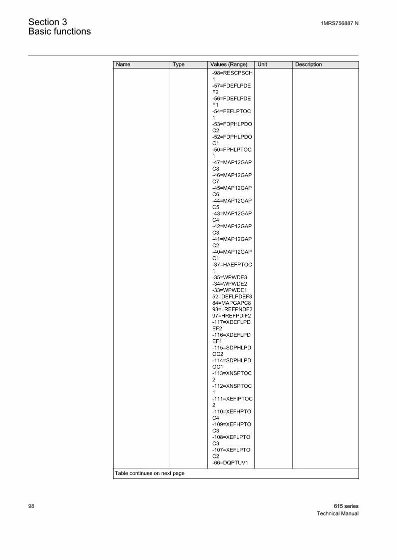
Name Type Values (Range) Unit Description -98=RESCPSCH
1-57=FDEFLPDEF2-56=FDEFLPDEF1-54=FEFLPTOC1-53=FDPHLPDOC2-52=FDPHLPDOC1-50=FPHLPTOC1-47=MAP12GAPC8-46=MAP12GAPC7-45=MAP12GAPC6-44=MAP12GAPC5-43=MAP12GAPC4-42=MAP12GAPC3-41=MAP12GAPC2-40=MAP12GAPC1-37=HAEFPTOC1-35=WPWDE3-34=WPWDE2-33=WPWDE152=DEFLPDEF384=MAPGAPC893=LREFPNDF297=HREFPDIF2-117=XDEFLPDEF2-116=XDEFLPDEF1-115=SDPHLPDOC2-114=SDPHLPDOC1-113=XNSPTOC2-112=XNSPTOC1-111=XEFIPTOC2-110=XEFHPTOC4-109=XEFHPTOC3-108=XEFLPTOC3-107=XEFLPTOC2-66=DQPTUV1
Table continues on next page
Section 3 1MRS756887 NBasic functions
98 615 seriesTechnical Manual

Name Type Values (Range) Unit Description -65=VVSPPAM1
-64=PHPVOC1-63=H3EFPSEF1-60=HCUBPTOC1-59=CUBPTOC1-72=DOPPDPR1-69=DUPPDPR1-61=COLPTOC1-106=MAPGAPC16-105=MAPGAPC15-104=MAPGAPC14-103=MAPGAPC13-76=MAPGAPC18-75=MAPGAPC17-62=SRCPTOC1-74=DOPPDPR3-73=DOPPDPR2-70=DUPPDPR2-58=UZPDIS1-36=UEXPDIS114=MFADPSDE1-10=LVRTPTUV1-8=LVRTPTUV2-6=LVRTPTUV3-122=DPH3LPDOC1-121=DPH3HPDOC2-120=DPH3HPDOC1-119=PH3LPTOC2-118=PH3LPTOC1-79=PH3HPTOC2-78=PH3HPTOC1-77=PH3IPTOC1-127=PHAPTUV1-124=PHAPTOV1-123=DPH3LPDOC2-68=PHPVOC2-67=DQPTUV2-39=UEXPDIS298=MHZPDIF1-4=MREFPTOC1
Start duration FLOAT32 0.00...100.00 % Maximum start durationof all stages during thefault
Table continues on next page
1MRS756887 N Section 3Basic functions
615 series 99Technical Manual

Name Type Values (Range) Unit DescriptionOperate time FLOAT32 0.000...999999.9
99s Operate time
Breaker clear time FLOAT32 0.000...3.000 s Breaker clear time
Fault distance FLOAT32 0.00...3000.00 pu Distance to faultmeasured in pu
Fault resistance FLOAT32 0.00...1000000.00
ohm Fault resistance
Active group INT32 1...6 Active setting group
Shot pointer INT32 1...7 Autoreclosing shotpointer value
Max diff current IL1 FLOAT32 0.000...80.000 pu Maximum phase Adifferential current
Max diff current IL2 FLOAT32 0.000...80.000 pu Maximum phase Bdifferential current
Max diff current IL3 FLOAT32 0.000...80.000 pu Maximum phase Cdifferential current
Diff current IL1 FLOAT32 0.000...80.000 pu Differential current phaseA
Diff current IL2 FLOAT32 0.000...80.000 pu Differential current phaseB
Diff current IL3 FLOAT32 0.000...80.000 pu Differential current phaseC
Max bias current IL1 FLOAT32 0.000...50.000 pu Maximum phase A biascurrent
Max bias current IL2 FLOAT32 0.000...50.000 pu Maximum phase B biascurrent
Max bias current IL3 FLOAT32 0.000...50.000 pu Maximum phase C biascurrent
Bias current IL1 FLOAT32 0.000...50.000 pu Bias current phase A
Bias current IL2 FLOAT32 0.000...50.000 pu Bias current phase B
Bias current IL3 FLOAT32 0.000...50.000 pu Bias current phase C
Diff current Io FLOAT32 0.000...80.000 pu Differential currentresidual
Bias current Io FLOAT32 0.000...50.000 pu Bias current residual
Max current IL1 FLOAT32 0.000...50.000 xIn Maximum phase Acurrent
Max current IL2 FLOAT32 0.000...50.000 xIn Maximum phase Bcurrent
Max current IL3 FLOAT32 0.000...50.000 xIn Maximum phase Ccurrent
Max current Io FLOAT32 0.000...50.000 xIn Maximum residualcurrent
Current IL1 FLOAT32 0.000...50.000 xIn Phase A current
Current IL2 FLOAT32 0.000...50.000 xIn Phase B current
Current IL3 FLOAT32 0.000...50.000 xIn Phase C current
Current Io FLOAT32 0.000...50.000 xIn Residual current
Table continues on next page
Section 3 1MRS756887 NBasic functions
100 615 seriesTechnical Manual
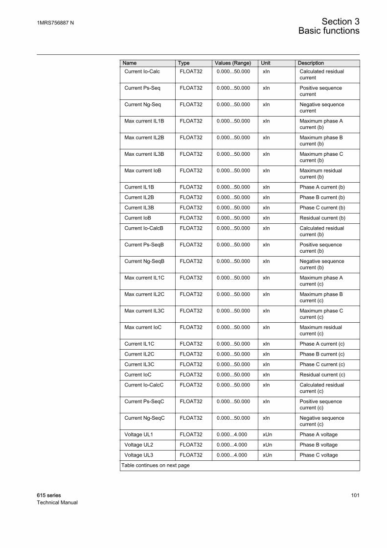
Name Type Values (Range) Unit DescriptionCurrent Io-Calc FLOAT32 0.000...50.000 xIn Calculated residual
current
Current Ps-Seq FLOAT32 0.000...50.000 xIn Positive sequencecurrent
Current Ng-Seq FLOAT32 0.000...50.000 xIn Negative sequencecurrent
Max current IL1B FLOAT32 0.000...50.000 xIn Maximum phase Acurrent (b)
Max current IL2B FLOAT32 0.000...50.000 xIn Maximum phase Bcurrent (b)
Max current IL3B FLOAT32 0.000...50.000 xIn Maximum phase Ccurrent (b)
Max current IoB FLOAT32 0.000...50.000 xIn Maximum residualcurrent (b)
Current IL1B FLOAT32 0.000...50.000 xIn Phase A current (b)
Current IL2B FLOAT32 0.000...50.000 xIn Phase B current (b)
Current IL3B FLOAT32 0.000...50.000 xIn Phase C current (b)
Current IoB FLOAT32 0.000...50.000 xIn Residual current (b)
Current Io-CalcB FLOAT32 0.000...50.000 xIn Calculated residualcurrent (b)
Current Ps-SeqB FLOAT32 0.000...50.000 xIn Positive sequencecurrent (b)
Current Ng-SeqB FLOAT32 0.000...50.000 xIn Negative sequencecurrent (b)
Max current IL1C FLOAT32 0.000...50.000 xIn Maximum phase Acurrent (c)
Max current IL2C FLOAT32 0.000...50.000 xIn Maximum phase Bcurrent (c)
Max current IL3C FLOAT32 0.000...50.000 xIn Maximum phase Ccurrent (c)
Max current IoC FLOAT32 0.000...50.000 xIn Maximum residualcurrent (c)
Current IL1C FLOAT32 0.000...50.000 xIn Phase A current (c)
Current IL2C FLOAT32 0.000...50.000 xIn Phase B current (c)
Current IL3C FLOAT32 0.000...50.000 xIn Phase C current (c)
Current IoC FLOAT32 0.000...50.000 xIn Residual current (c)
Current Io-CalcC FLOAT32 0.000...50.000 xIn Calculated residualcurrent (c)
Current Ps-SeqC FLOAT32 0.000...50.000 xIn Positive sequencecurrent (c)
Current Ng-SeqC FLOAT32 0.000...50.000 xIn Negative sequencecurrent (c)
Voltage UL1 FLOAT32 0.000...4.000 xUn Phase A voltage
Voltage UL2 FLOAT32 0.000...4.000 xUn Phase B voltage
Voltage UL3 FLOAT32 0.000...4.000 xUn Phase C voltage
Table continues on next page
1MRS756887 N Section 3Basic functions
615 series 101Technical Manual
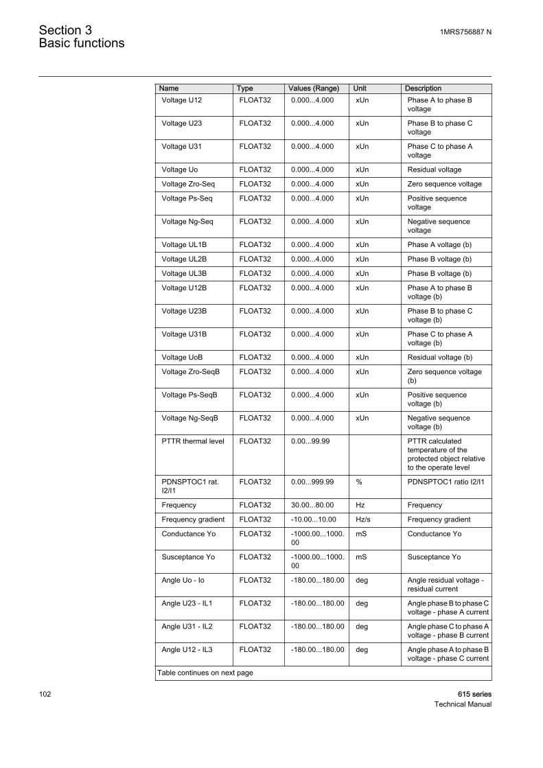
Name Type Values (Range) Unit DescriptionVoltage U12 FLOAT32 0.000...4.000 xUn Phase A to phase B
voltage
Voltage U23 FLOAT32 0.000...4.000 xUn Phase B to phase Cvoltage
Voltage U31 FLOAT32 0.000...4.000 xUn Phase C to phase Avoltage
Voltage Uo FLOAT32 0.000...4.000 xUn Residual voltage
Voltage Zro-Seq FLOAT32 0.000...4.000 xUn Zero sequence voltage
Voltage Ps-Seq FLOAT32 0.000...4.000 xUn Positive sequencevoltage
Voltage Ng-Seq FLOAT32 0.000...4.000 xUn Negative sequencevoltage
Voltage UL1B FLOAT32 0.000...4.000 xUn Phase A voltage (b)
Voltage UL2B FLOAT32 0.000...4.000 xUn Phase B voltage (b)
Voltage UL3B FLOAT32 0.000...4.000 xUn Phase B voltage (b)
Voltage U12B FLOAT32 0.000...4.000 xUn Phase A to phase Bvoltage (b)
Voltage U23B FLOAT32 0.000...4.000 xUn Phase B to phase Cvoltage (b)
Voltage U31B FLOAT32 0.000...4.000 xUn Phase C to phase Avoltage (b)
Voltage UoB FLOAT32 0.000...4.000 xUn Residual voltage (b)
Voltage Zro-SeqB FLOAT32 0.000...4.000 xUn Zero sequence voltage(b)
Voltage Ps-SeqB FLOAT32 0.000...4.000 xUn Positive sequencevoltage (b)
Voltage Ng-SeqB FLOAT32 0.000...4.000 xUn Negative sequencevoltage (b)
PTTR thermal level FLOAT32 0.00...99.99 PTTR calculatedtemperature of theprotected object relativeto the operate level
PDNSPTOC1 rat.I2/I1
FLOAT32 0.00...999.99 % PDNSPTOC1 ratio I2/I1
Frequency FLOAT32 30.00...80.00 Hz Frequency
Frequency gradient FLOAT32 -10.00...10.00 Hz/s Frequency gradient
Conductance Yo FLOAT32 -1000.00...1000.00
mS Conductance Yo
Susceptance Yo FLOAT32 -1000.00...1000.00
mS Susceptance Yo
Angle Uo - Io FLOAT32 -180.00...180.00 deg Angle residual voltage -residual current
Angle U23 - IL1 FLOAT32 -180.00...180.00 deg Angle phase B to phase Cvoltage - phase A current
Angle U31 - IL2 FLOAT32 -180.00...180.00 deg Angle phase C to phase Avoltage - phase B current
Angle U12 - IL3 FLOAT32 -180.00...180.00 deg Angle phase A to phase Bvoltage - phase C current
Table continues on next page
Section 3 1MRS756887 NBasic functions
102 615 seriesTechnical Manual
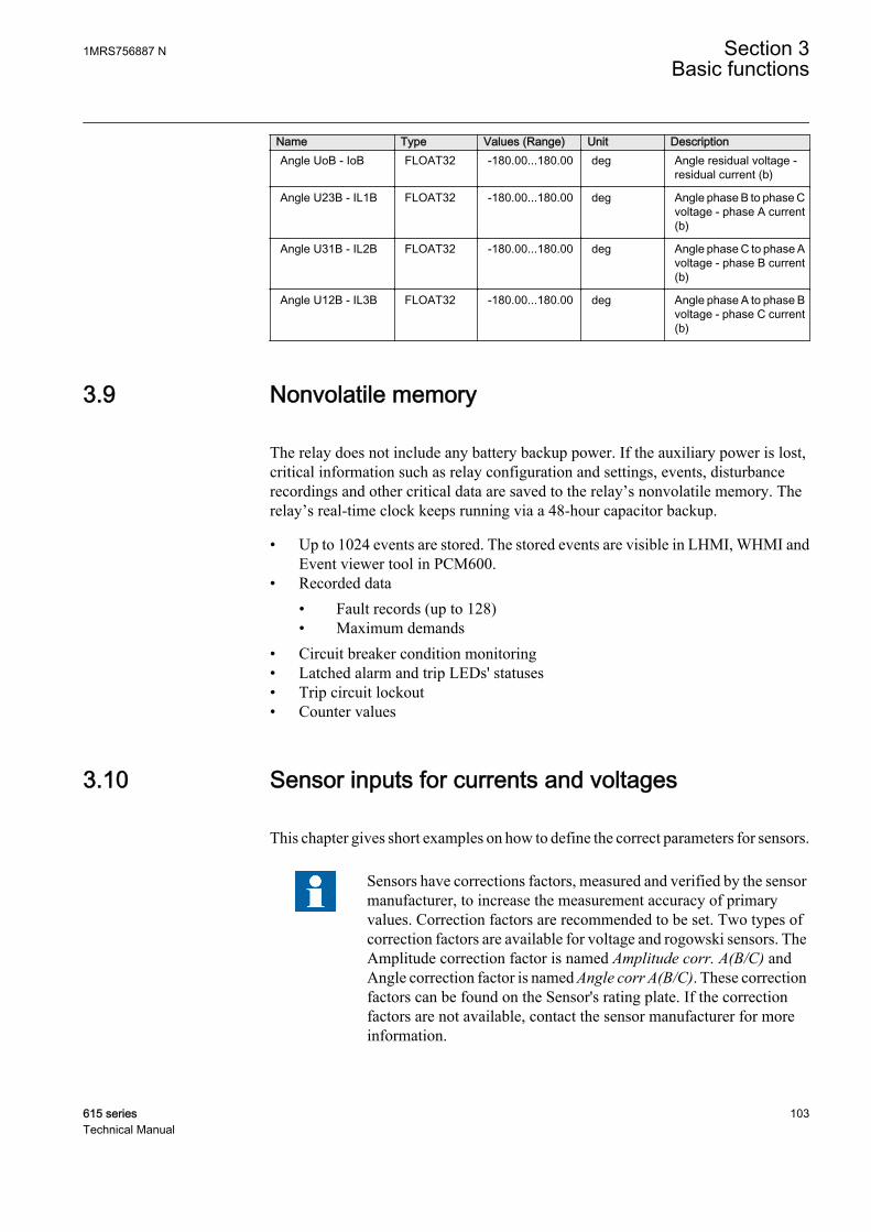
Name Type Values (Range) Unit DescriptionAngle UoB - IoB FLOAT32 -180.00...180.00 deg Angle residual voltage -
residual current (b)
Angle U23B - IL1B FLOAT32 -180.00...180.00 deg Angle phase B to phase Cvoltage - phase A current(b)
Angle U31B - IL2B FLOAT32 -180.00...180.00 deg Angle phase C to phase Avoltage - phase B current(b)
Angle U12B - IL3B FLOAT32 -180.00...180.00 deg Angle phase A to phase Bvoltage - phase C current(b)
3.9 Nonvolatile memory
The relay does not include any battery backup power. If the auxiliary power is lost,critical information such as relay configuration and settings, events, disturbancerecordings and other critical data are saved to the relay’s nonvolatile memory. Therelay’s real-time clock keeps running via a 48-hour capacitor backup.
• Up to 1024 events are stored. The stored events are visible in LHMI, WHMI andEvent viewer tool in PCM600.
• Recorded data• Fault records (up to 128)• Maximum demands
• Circuit breaker condition monitoring• Latched alarm and trip LEDs' statuses• Trip circuit lockout• Counter values
3.10 Sensor inputs for currents and voltages
This chapter gives short examples on how to define the correct parameters for sensors.
Sensors have corrections factors, measured and verified by the sensormanufacturer, to increase the measurement accuracy of primaryvalues. Correction factors are recommended to be set. Two types ofcorrection factors are available for voltage and rogowski sensors. TheAmplitude correction factor is named Amplitude corr. A(B/C) andAngle correction factor is named Angle corr A(B/C). These correctionfactors can be found on the Sensor's rating plate. If the correctionfactors are not available, contact the sensor manufacturer for moreinformation.
1MRS756887 N Section 3Basic functions
615 series 103Technical Manual
Rogowski sensor setting exampleIn this example, an 80 A/0.150 V at 50 Hz sensor is used and the application has a 150A nominal current (In). As the Rogowski sensor is linear and does not saturate, the 80A/0.150 V at 50 Hz sensor also works as a 150 A/0.28125 V at 50 Hz sensor. Whendefining another primary value for the sensor, also the nominal voltage has to beredefined to maintain the same transformation ratio. However, the setting in theprotection relay (Rated Secondary Value) is not in V but in mV/Hz, which makes thesame setting value valid for both 50 and 60 Hz nominal frequency.
RSV
I
IK
f
n
prr
n
=
×
GUID-6A480073-5C35-4319-8B38-402608D4C098 V2 EN (Equation 1)
RSV Rated Secondary Value in mV/Hz
In Application nominal current
Ipr Sensor-rated primary current
fn Network nominal frequency
Kr Sensor-rated voltage at the rated current in mV
In this example, the value is as calculated using the equation.
150
80150
505 625
A
AmV
Hz
mV
Hz
×
= .
GUID-13DE42A0-29C0-4FE0-B00B-1215B37E3B7B V2 EN (Equation 2)
With this information, the protection relay's Rogowski sensor settings can be set.
Table 50: Example setting values for rogowski sensor
Setting ValuePrimary current 150 A
Rated secondary value 5.625 mV/Hz
Nominal current 150 A
Unless otherwise specified, the Nominal Current setting shouldalways be the same as the Primary Current setting.
If the ratio of the application nominal current In and sensor-rated primary current Iprbecomes higher, and the rated secondary value needs to be set higher than 46.875 mV/Hz, the highest value that the relay is able to measure before the current sensor inputis saturated is smaller than the maximum setting value of the current protection.
Section 3 1MRS756887 NBasic functions
104 615 seriesTechnical Manual
Table 51: Maximum current protection setting values
Application nominal current(In)
Rated secondary value with 80 A/0.150 V at 50 Hz
Current protection maximum settingvalue not to be exceeded
...1250 A 1.000...46.875 mV/Hz 40 × In (Also the maximum of thestart value setting range)
1250...2500 A 46.875...93.750 mV/Hz 20 × In
2500...4000 A 93.750...150.000 mV/Hz 12.5 × In
Voltage sensor setting exampleThe voltage sensor is based on the resistive divider or capacitive divider principle.Therefore, the voltage is linear throughout the whole measuring range. The outputsignal is a voltage, directly proportional to the primary voltage. For the voltage sensorall parameters are readable directly from its rating plate and conversions are notneeded.
In this example the system phase-to-phase voltage rating is 10 kV. Thus, the Primaryvoltage parameter is set to 10 kV. For protection relays with sensor measurementsupport the Voltage input type is always set to “CVD sensor” and it cannot be changed.The same applies for the VT connection parameter which is always set to “WYE” type.The division ratio for ABB voltage sensors is most often 10000:1. Thus, the Divisionratio parameter is usually set to “10000”. The primary voltage is proportionallydivided by this division ratio.
Table 52: Example setting values for voltage sensor
Setting ValuePrimary voltage 10 kV
VT connection Wye
Voltage input type 3=CVD sensor
Division ratio 10000
3.11 Binary input
3.11.1 Binary input filter time
The filter time eliminates debounces and short disturbances on a binary input. Thefilter time is set for each binary input of the protection relay.
1MRS756887 N Section 3Basic functions
615 series 105Technical Manual

1 2
3
4
5 5
GUID-13DA5833-D263-4E23-B666-CF38B1011A4B V1 EN
Figure 24: Binary input filtering
1 t0
2 t1
3 Input signal
4 Filtered input signal
5 Filter time
At the beginning, the input signal is at the high state, the short low state is filtered andno input state change is detected. The low state starting from the time t0 exceeds thefilter time, which means that the change in the input state is detected and the time tagattached to the input change is t0. The high state starting from t1 is detected and thetime tag t1 is attached.
Each binary input has a filter time parameter "Input # filter", where # is the number ofthe binary input of the module in question (for example "Input 1 filter").
Table 53: Input filter parameter values
Parameter Values DefaultInput # filter time 5...1000 ms 5 ms
3.11.2 Binary input inversion
The parameter Input # invert is used to invert a binary input.
Table 54: Binary input states
Control voltage Input # invert State of binary inputNo 0 FALSE (0)
Yes 0 TRUE (1)
No 1 TRUE (1)
Yes 1 FALSE (0)
Section 3 1MRS756887 NBasic functions
106 615 seriesTechnical Manual
When a binary input is inverted, the state of the input is TRUE (1) when no controlvoltage is applied to its terminals. Accordingly, the input state is FALSE (0) when acontrol voltage is applied to the terminals of the binary input.
3.11.3 Oscillation suppression
Oscillation suppression is used to reduce the load from the system when a binary inputstarts oscillating. A binary input is regarded as oscillating if the number of valid statechanges (= number of events after filtering) during one second is equal to or greaterthan the set oscillation level value. During oscillation, the binary input is blocked (thestatus is invalid) and an event is generated. The state of the input will not change whenit is blocked, that is, its state depends on the condition before blocking.
The binary input is regarded as non-oscillating if the number of valid state changesduring one second is less than the set oscillation level value minus the set oscillationhysteresis value. Note that the oscillation hysteresis must be set lower than theoscillation level to enable the input to be restored from oscillation. When the inputreturns to a non-oscillating state, the binary input is deblocked (the status is valid) andan event is generated.
Table 55: Oscillation parameter values
Parameter Values DefaultInput osc. level 2...50 events/s 30 events/s
Input osc. hyst 2...50 events/s 10 events/s
3.12 Binary outputs
The protection relay provides a number of binary outputs used for tripping, executinglocal or remote control actions of a breaker or a disconnector, and for connecting theprotection relay to external annunciation equipment for indicating, signalling andrecording.
Power output contacts are used when the current rating requirements of the contactsare high, for example, for controlling a breaker, such as energizing the breaker trip andclosing coils.
The contacts used for external signalling, recording and indicating, the signal outputs,need to adjust to smaller currents, but they can require a minimum current (burden) toensure a guaranteed operation.
The protection relay provides both power output and signal output contacts. Toguarantee proper operation, the type of the contacts used are chosen based on theoperating and reset time, continuous current rating, make and carry for short time,breaking rate and minimum connected burden. A combination of series or parallelcontacts can also be used for special applications. When appropriate, a signal output
1MRS756887 N Section 3Basic functions
615 series 107Technical Manual
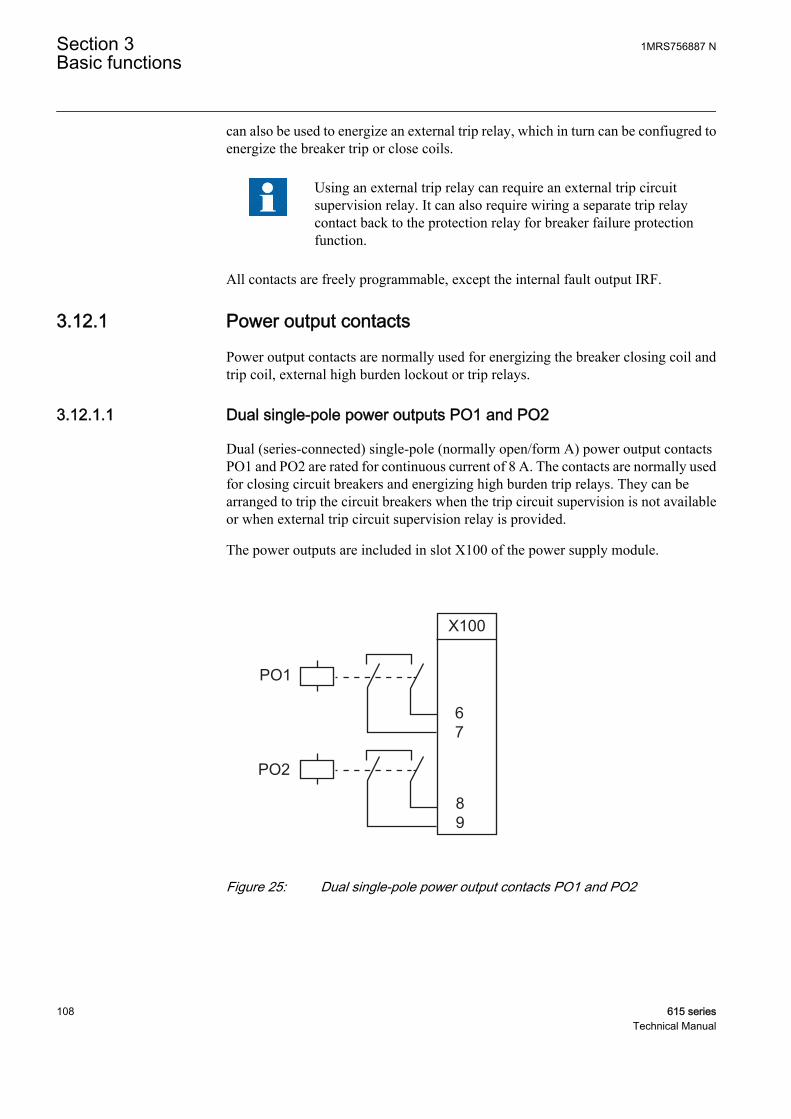
can also be used to energize an external trip relay, which in turn can be confiugred toenergize the breaker trip or close coils.
Using an external trip relay can require an external trip circuitsupervision relay. It can also require wiring a separate trip relaycontact back to the protection relay for breaker failure protectionfunction.
All contacts are freely programmable, except the internal fault output IRF.
3.12.1 Power output contacts
Power output contacts are normally used for energizing the breaker closing coil andtrip coil, external high burden lockout or trip relays.
3.12.1.1 Dual single-pole power outputs PO1 and PO2
Dual (series-connected) single-pole (normally open/form A) power output contactsPO1 and PO2 are rated for continuous current of 8 A. The contacts are normally usedfor closing circuit breakers and energizing high burden trip relays. They can bearranged to trip the circuit breakers when the trip circuit supervision is not availableor when external trip circuit supervision relay is provided.
The power outputs are included in slot X100 of the power supply module.
PO1
PO2
X100
67
89
GUID-4E1E21B1-BEEC-4351-A7BE-9D2DBA451985 V1 EN
Figure 25: Dual single-pole power output contacts PO1 and PO2
Section 3 1MRS756887 NBasic functions
108 615 seriesTechnical Manual
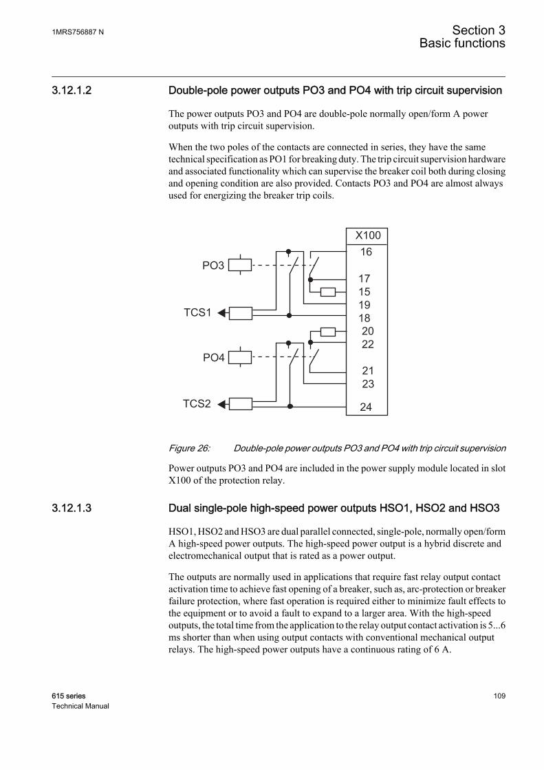
3.12.1.2 Double-pole power outputs PO3 and PO4 with trip circuit supervision
The power outputs PO3 and PO4 are double-pole normally open/form A poweroutputs with trip circuit supervision.
When the two poles of the contacts are connected in series, they have the sametechnical specification as PO1 for breaking duty. The trip circuit supervision hardwareand associated functionality which can supervise the breaker coil both during closingand opening condition are also provided. Contacts PO3 and PO4 are almost alwaysused for energizing the breaker trip coils.
PO3
PO4
TCS1
TCS2
X10016
24
2123
2022
17151918
GUID-5A0502F7-BDC4-424A-BF19-898025FCCBD7 V1 EN
Figure 26: Double-pole power outputs PO3 and PO4 with trip circuit supervision
Power outputs PO3 and PO4 are included in the power supply module located in slotX100 of the protection relay.
3.12.1.3 Dual single-pole high-speed power outputs HSO1, HSO2 and HSO3
HSO1, HSO2 and HSO3 are dual parallel connected, single-pole, normally open/formA high-speed power outputs. The high-speed power output is a hybrid discrete andelectromechanical output that is rated as a power output.
The outputs are normally used in applications that require fast relay output contactactivation time to achieve fast opening of a breaker, such as, arc-protection or breakerfailure protection, where fast operation is required either to minimize fault effects tothe equipment or to avoid a fault to expand to a larger area. With the high-speedoutputs, the total time from the application to the relay output contact activation is 5...6ms shorter than when using output contacts with conventional mechanical outputrelays. The high-speed power outputs have a continuous rating of 6 A.
1MRS756887 N Section 3Basic functions
615 series 109Technical Manual
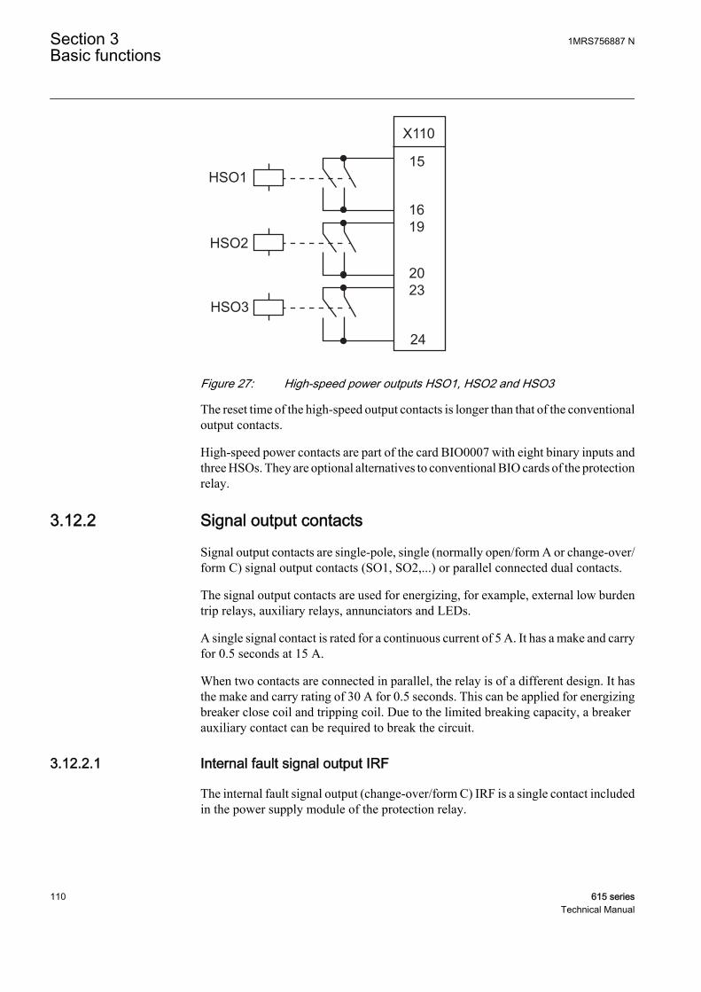
2023
1619
24
15
X110
HSO3
HSO2
HSO1
GUID-38EDD366-7456-4933-B49E-0F43FE1D6C39 V1 EN
Figure 27: High-speed power outputs HSO1, HSO2 and HSO3
The reset time of the high-speed output contacts is longer than that of the conventionaloutput contacts.
High-speed power contacts are part of the card BIO0007 with eight binary inputs andthree HSOs. They are optional alternatives to conventional BIO cards of the protectionrelay.
3.12.2 Signal output contacts
Signal output contacts are single-pole, single (normally open/form A or change-over/form C) signal output contacts (SO1, SO2,...) or parallel connected dual contacts.
The signal output contacts are used for energizing, for example, external low burdentrip relays, auxiliary relays, annunciators and LEDs.
A single signal contact is rated for a continuous current of 5 A. It has a make and carryfor 0.5 seconds at 15 A.
When two contacts are connected in parallel, the relay is of a different design. It hasthe make and carry rating of 30 A for 0.5 seconds. This can be applied for energizingbreaker close coil and tripping coil. Due to the limited breaking capacity, a breakerauxiliary contact can be required to break the circuit.
3.12.2.1 Internal fault signal output IRF
The internal fault signal output (change-over/form C) IRF is a single contact includedin the power supply module of the protection relay.
Section 3 1MRS756887 NBasic functions
110 615 seriesTechnical Manual
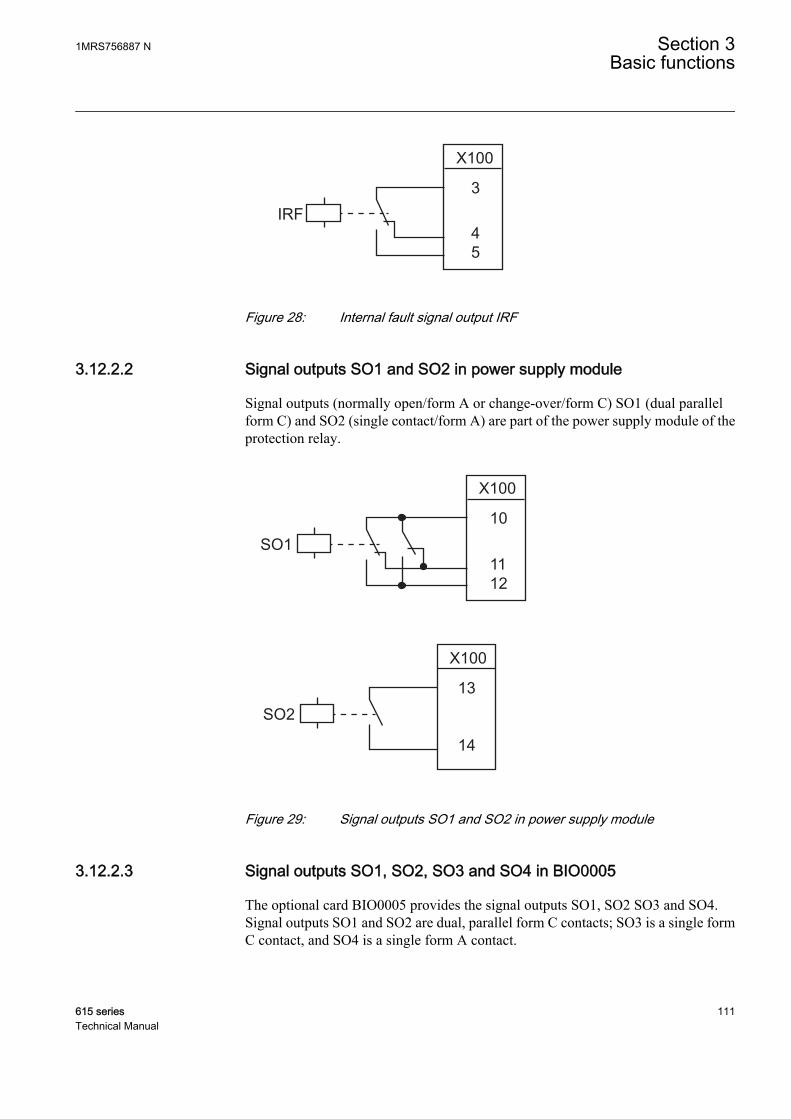
3
45
X100
IRF
GUID-C09595E9-3C42-437A-BDB2-B20C35FA0BD2 V1 EN
Figure 28: Internal fault signal output IRF
3.12.2.2 Signal outputs SO1 and SO2 in power supply module
Signal outputs (normally open/form A or change-over/form C) SO1 (dual parallelform C) and SO2 (single contact/form A) are part of the power supply module of theprotection relay.
10
1112
X100
SO1
14
13
X100
SO2
GUID-83F96C39-652F-494A-A226-FD106568C228 V1 EN
Figure 29: Signal outputs SO1 and SO2 in power supply module
3.12.2.3 Signal outputs SO1, SO2, SO3 and SO4 in BIO0005
The optional card BIO0005 provides the signal outputs SO1, SO2 SO3 and SO4.Signal outputs SO1 and SO2 are dual, parallel form C contacts; SO3 is a single formC contact, and SO4 is a single form A contact.
1MRS756887 N Section 3Basic functions
615 series 111Technical Manual

14
161517
1918
X110
SO1
SO2
20
222123
24
X110
SO3
SO4
GUID-CBA9A48A-2549-455B-907D-8261E2259BF4 V1 EN
Figure 30: Signal output in BIO0005
3.12.2.4 Signal outputs SO1, SO2 and SO3 in BIO0006
The optional card BIO0006 provides the signal outputs SO1, SO2 and SO3. Signaloutputs SO1 and SO2 are dual, parallel form C contacts; SO3 is a single form Ccontact.
Section 3 1MRS756887 NBasic functions
112 615 seriesTechnical Manual
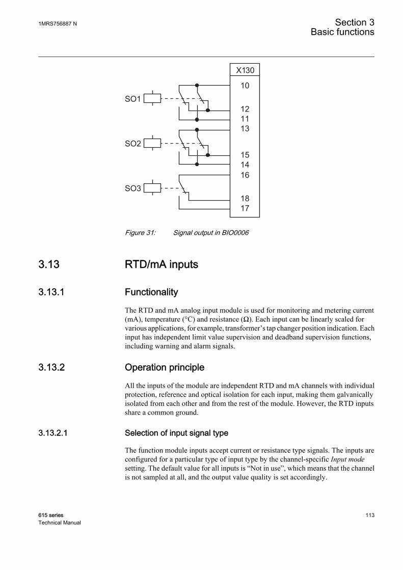
10
121113
1514
X130
SO1
SO2
16
1817
SO3
GUID-C5B5FD1C-617B-4F38-A0D4-D98735E69530 V1 EN
Figure 31: Signal output in BIO0006
3.13 RTD/mA inputs
3.13.1 Functionality
The RTD and mA analog input module is used for monitoring and metering current(mA), temperature (°C) and resistance (Ω). Each input can be linearly scaled forvarious applications, for example, transformer’s tap changer position indication. Eachinput has independent limit value supervision and deadband supervision functions,including warning and alarm signals.
3.13.2 Operation principle
All the inputs of the module are independent RTD and mA channels with individualprotection, reference and optical isolation for each input, making them galvanicallyisolated from each other and from the rest of the module. However, the RTD inputsshare a common ground.
3.13.2.1 Selection of input signal type
The function module inputs accept current or resistance type signals. The inputs areconfigured for a particular type of input type by the channel-specific Input modesetting. The default value for all inputs is “Not in use”, which means that the channelis not sampled at all, and the output value quality is set accordingly.
1MRS756887 N Section 3Basic functions
615 series 113Technical Manual

Table 56: Limits for the RTD/mA inputs
Input mode DescriptionNot in use Default selection. Used when the corresponding input is not used.
0...20 mA Selection for analog DC milliampere current inputs in the input range of 0...20 mA.
Resistance Selection for RTD inputs in the input range of 0...2000 Ω.
Pt100Pt250Ni100Ni120Ni250Cu10
Selection for RTD inputs, when temperature sensor is used. All the selectablesensor types have their resistance vs. temperature characteristics stored in themodule; default measuring range is -40...200°C.
3.13.2.2 Selection of output value format
Each input has independent Value unit settings that are used to select the unit for thechannel output. The default value for the Value unit setting is “Dimensionless”. Inputminimum and Input maximum, and Value maximum and Value minimum settings haveto be adjusted according to the input channel. The default values for these settings areset to their maximum and minimum setting values.
When the channel is used for temperature sensor type, set the Value unit setting to“Degrees celsius”. When Value unit is set to “Degrees celsius”, the linear scaling is notpossible, but the default range (-40…200 °C) can be set smaller with the Valuemaximum and Value minimum settings.
When the channel is used for DC milliampere signal and the application requires alinear scaling of the input range, the Value unit setting value has to be"Dimensionless”, where the input range can be linearly scaled with settings Inputminimum and Input maximum to Value minimum and Value maximum. Whenmilliampere is used as an output unit, Value unit has to be "Ampere”. When Value unitis set to “Ampere”, the linear scaling is not possible, but the default range (0…20 mA)can be set smaller with the Value maximum and Value minimum settings.
When the channel is used for resistance type signals and the application requires alinear scaling of the input range, the Value unit setting value has to be"Dimensionless”, where the input range can be linearly scaled with the setting Inputminimum and Input maximum to Value minimum and Value maximum. Whenresistance is used as an output unit, Value unit has to be "Ohm". When Value unit isset to “Ohm”, the linear scaling is not possible, but the default range (0…2000 Ω) canbe set smaller with the Value maximum and Value minimum settings.
3.13.2.3 Input linear scaling
Each RTD/mA input can be scaled linearly by the construction of a linear outputfunction in respect to the input. The curve consists of two points, where the y-axis(Input minimum and Input maximum) defines the input range and the x-axis (Valueminimum and Value maximum) is the range of the scaled value of the input.
Section 3 1MRS756887 NBasic functions
114 615 seriesTechnical Manual
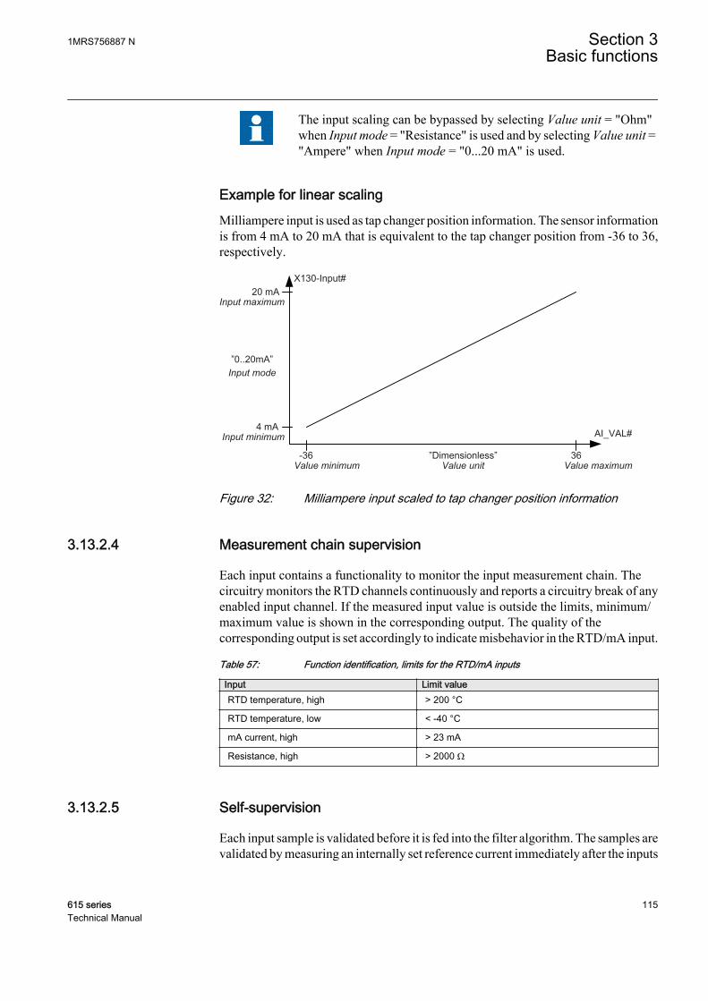
The input scaling can be bypassed by selecting Value unit = "Ohm"when Input mode = "Resistance" is used and by selecting Value unit ="Ampere" when Input mode = "0...20 mA" is used.
Example for linear scalingMilliampere input is used as tap changer position information. The sensor informationis from 4 mA to 20 mA that is equivalent to the tap changer position from -36 to 36,respectively.
Input maximum
Input minimum
Input mode”0..20mA”
4 mA
20 mA
Value minimum-36
AI_VAL#
Value maximum36
Value unit”Dimensionless”
X130-Input#
GUID-85338A5E-3D2F-4031-A598-EA8A525190D3 V1 EN
Figure 32: Milliampere input scaled to tap changer position information
3.13.2.4 Measurement chain supervision
Each input contains a functionality to monitor the input measurement chain. Thecircuitry monitors the RTD channels continuously and reports a circuitry break of anyenabled input channel. If the measured input value is outside the limits, minimum/maximum value is shown in the corresponding output. The quality of thecorresponding output is set accordingly to indicate misbehavior in the RTD/mA input.
Table 57: Function identification, limits for the RTD/mA inputs
Input Limit valueRTD temperature, high > 200 °C
RTD temperature, low < -40 °C
mA current, high > 23 mA
Resistance, high > 2000 Ω
3.13.2.5 Self-supervision
Each input sample is validated before it is fed into the filter algorithm. The samples arevalidated by measuring an internally set reference current immediately after the inputs
1MRS756887 N Section 3Basic functions
615 series 115Technical Manual
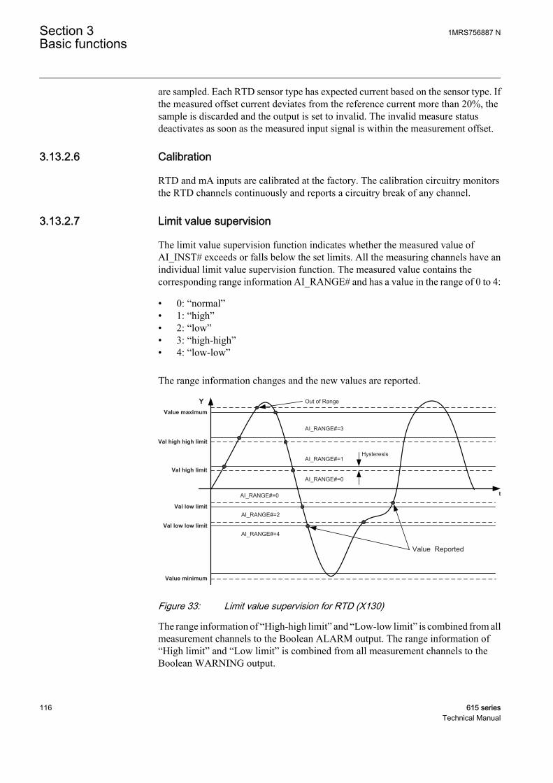
are sampled. Each RTD sensor type has expected current based on the sensor type. Ifthe measured offset current deviates from the reference current more than 20%, thesample is discarded and the output is set to invalid. The invalid measure statusdeactivates as soon as the measured input signal is within the measurement offset.
3.13.2.6 Calibration
RTD and mA inputs are calibrated at the factory. The calibration circuitry monitorsthe RTD channels continuously and reports a circuitry break of any channel.
3.13.2.7 Limit value supervision
The limit value supervision function indicates whether the measured value ofAI_INST# exceeds or falls below the set limits. All the measuring channels have anindividual limit value supervision function. The measured value contains thecorresponding range information AI_RANGE# and has a value in the range of 0 to 4:
• 0: “normal”• 1: “high”• 2: “low”• 3: “high-high”• 4: “low-low”
The range information changes and the new values are reported.
AI_RANGE#=1
AI_RANGE#=3
AI_RANGE#=0
Hysteresis
Val high high limit
Val high limit
Val low limit
Val low low limit
AI_RANGE#=2
AI_RANGE#=4
Y
tAI_RANGE#=0
Value Reported
Value maximum
Value minimum
Out of Range
GUID-6A6033E6-22C8-415D-AABD-D0556D38C986 V1 EN
Figure 33: Limit value supervision for RTD (X130)
The range information of “High-high limit” and “Low-low limit” is combined from allmeasurement channels to the Boolean ALARM output. The range information of“High limit” and “Low limit” is combined from all measurement channels to theBoolean WARNING output.
Section 3 1MRS756887 NBasic functions
116 615 seriesTechnical Manual

Table 58: Settings for X130 (RTD) analog input limit value supervision
Function Settings for limit value supervisionX130 (RTD) analog input Out of range Value maximum
High-high limit Val high high limit
High limit Val high limit
Low limit Val low limit
Low-low limit Val low low limit
Out of range Value minimum
When the measured value exceeds either the Value maximum setting or the Valueminimum setting, the corresponding quality is set to out of range and a maximum orminimum value is shown when the measured value exceeds the added hysteresis,respectively. The hysteresis is added to the extreme value of the range limit to allowthe measurement slightly to exceed the limit value before it is considered out of range.
3.13.2.8 Deadband supervision
Each input has an independent deadband supervision. The deadband supervisionfunction reports the measured value according to integrated changes over a timeperiod.
GUID-63CA9A0F-24D8-4BA8-A667-88632DF53284 V1 EN
Figure 34: Integral deadband supervision
The deadband value used in the integral calculation is configured with the Valuedeadband setting. The value represents the percentage of the difference between themaximum and minimum limits in the units of 0.001 percent * seconds. The reportingdelay of the integral algorithms in seconds is calculated with the formula:
t sY
( )
( )
=
− ⋅Value maximum Value minimumdeadband
s100000
∆
GUID-CC447162-C1B4-4E74-A253-828F388266EB V2 EN (Equation 3)
1MRS756887 N Section 3Basic functions
615 series 117Technical Manual
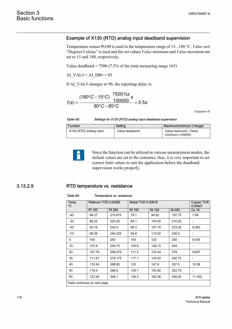
Example of X130 (RTD) analog input deadband supervisionTemperature sensor Pt100 is used in the temperature range of 15...180 °C. Value unit“Degrees Celsius” is used and the set values Value minimum and Value maximum areset to 15 and 180, respectively.
Value deadband = 7500 (7.5% of the total measuring range 165)
AI_VAL# = AI_DB# = 85
If AI_VAL# changes to 90, the reporting delay is:
t s( )
( )
.=
° − ° ⋅
° − °
≈
180 157500
100000
90 852 5
C C%s
s
C Cs
GUID-F47EF6B6-9A14-44A2-AD19-BC067E4A7D78 V3 EN (Equation 4)
Table 59: Settings for X130 (RTD) analog input deadband supervision
Function Setting Maximum/minimum (=range)X130 (RTD) analog input Value deadband Value maximum / Value
minimum (=20000)
Since the function can be utilized in various measurement modes, thedefault values are set to the extremes; thus, it is very important to setcorrect limit values to suit the application before the deadbandsupervision works properly.
3.13.2.9 RTD temperature vs. resistance
Table 60: Temperature vs. resistance
Temp°C
Platinum TCR 0.00385 Nickel TCR 0.00618 Copper TCR0.00427
Pt 100 Pt 250 Ni 100 Ni 120 Ni 250 Cu 10-40 84.27 210.675 79.1 94.92 197.75 7.49
-30 88.22 220.55 84.1 100.92 210.25 -
-20 92.16 230.4 89.3 107.16 223.25 8.263
-10 96.09 240.225 94.6 113.52 236.5 -
0 100 250 100 120 250 9.035
10 103.9 259.75 105.6 126.72 264 -
20 107.79 269.475 111.2 133.44 278 9.807
30 111.67 279.175 117.1 140.52 292.75 -
40 115.54 288.85 123 147.6 307.5 10.58
50 119.4 298.5 129.1 154.92 322.75 -
60 123.24 308.1 135.3 162.36 338.25 11.352
Table continues on next page
Section 3 1MRS756887 NBasic functions
118 615 seriesTechnical Manual

Temp°C
Platinum TCR 0.00385 Nickel TCR 0.00618 Copper TCR0.00427
Pt 100 Pt 250 Ni 100 Ni 120 Ni 250 Cu 1070 127.07 317.675 141.7 170.04 354.25 -
80 130.89 327.225 148.3 177.96 370.75 12.124
90 134.7 336.75 154.9 185.88 387.25 -
100 138.5 346.25 161.8 194.16 404.5 12.897
120 146.06 365.15 176 211.2 440 13.669
140 153.58 383.95 190.9 229.08 477.25 14.442
150 - - 198.6 238.32 496.5 -
160 161.04 402.6 206.6 247.92 516.5 15.217
180 168.46 421.15 223.2 267.84 558 -
200 175.84 439.6 240.7 288.84 601.75 -
3.13.2.10 RTD/mA input connection
RTD inputs can be used with a 2-wire or 3-wire connection with common ground.When using the 3-wire connection, it is important that all three wires connecting thesensor are symmetrical, that is, the wires are of the same type and length. Thus the wireresistance is automatically compensated.
GUID-BC4182F7-F701-4E09-AB3D-EFB48280F097 V1 EN
Figure 35: Three RTD/resistance sensors connected according to the 3-wireconnection
1MRS756887 N Section 3Basic functions
615 series 119Technical Manual

GUID-2702C0B0-99CF-40D0-925C-BEC0725C0E97 V1 EN
Figure 36: Three RTD/resistance sensors connected according to the 2-wireconnection
X130
+
-
1
2
11
12.........
TransducerSensor
Shunt(44 Ω)
...
......
GUID-88E6BD08-06B8-4ED3-B937-4CC549697684 V1 EN
Figure 37: mA wiring connection
3.13.2.11 RTD/mA card variants
The available variants of RTD cards are 6RTD/2mA and 2RTD/1mA. The features aresimilar in both cards.
Section 3 1MRS756887 NBasic functions
120 615 seriesTechnical Manual
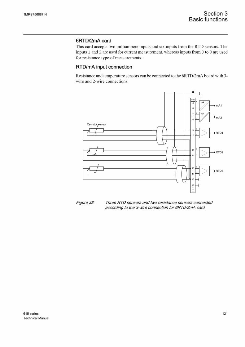
6RTD/2mA cardThis card accepts two milliampere inputs and six inputs from the RTD sensors. Theinputs 1 and 2 are used for current measurement, whereas inputs from 3 to 8 are usedfor resistance type of measurements.
RTD/mA input connectionResistance and temperature sensors can be connected to the 6RTD/2mA board with 3-wire and 2-wire connections.
Resistor sensor
X110
mAmA1
mA
mA2
RTD1
+
-
+
-
+
-
+
-
+
-
5
6
7
8
9
10
11
12
13
14
15
16
RTD2
RTD3
...
...
...
GUID-CEF1FA63-A641-4F5E-89A3-E1529307D198 V2 EN
Figure 38: Three RTD sensors and two resistance sensors connectedaccording to the 3-wire connection for 6RTD/2mA card
1MRS756887 N Section 3Basic functions
615 series 121Technical Manual
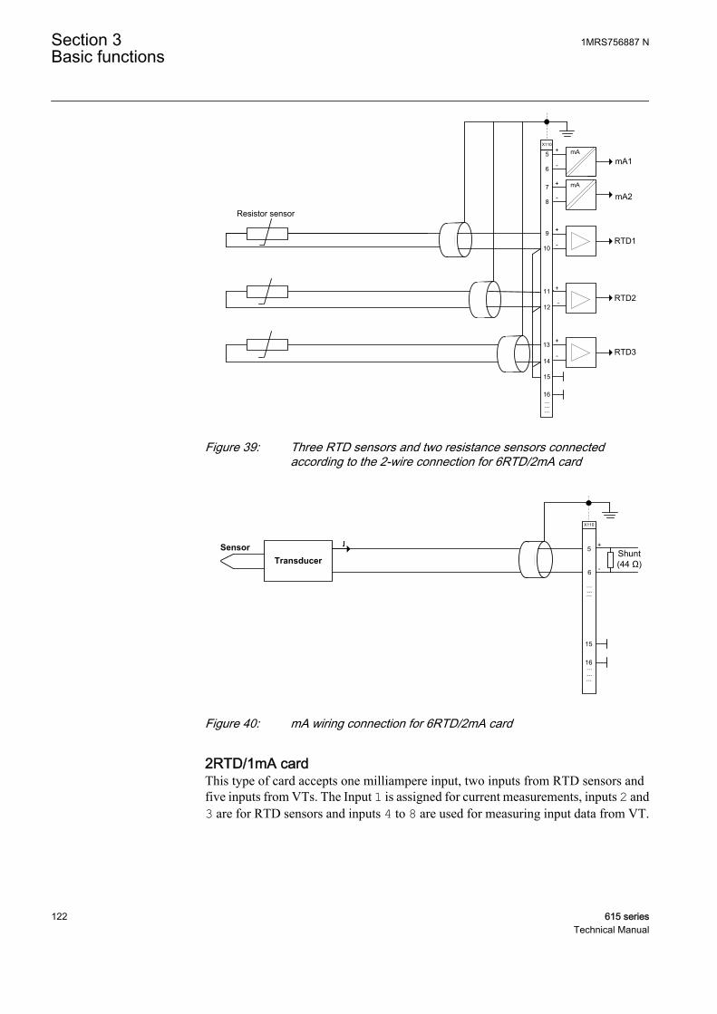
Resistor sensor
X110
mAmA1
mA
mA2
RTD1
+
-
+
-
+
-
+
-
+
-
5
6
7
8
9
10
11
12
13
14
15
16
RTD2
RTD3
...
...
...
GUID-8DAE1E59-160B-4E90-ABB3-952C84E129D2 V2 EN
Figure 39: Three RTD sensors and two resistance sensors connectedaccording to the 2-wire connection for 6RTD/2mA card
X110
+
-
5
6
15
16.........
TransducerSensor
Shunt(44 Ω)
...
......
GUID-FC23D8FC-E9BF-4B62-B8AA-52B4EDE2FF12 V2 EN
Figure 40: mA wiring connection for 6RTD/2mA card
2RTD/1mA cardThis type of card accepts one milliampere input, two inputs from RTD sensors andfive inputs from VTs. The Input 1 is assigned for current measurements, inputs 2 and3 are for RTD sensors and inputs 4 to 8 are used for measuring input data from VT.
Section 3 1MRS756887 NBasic functions
122 615 seriesTechnical Manual
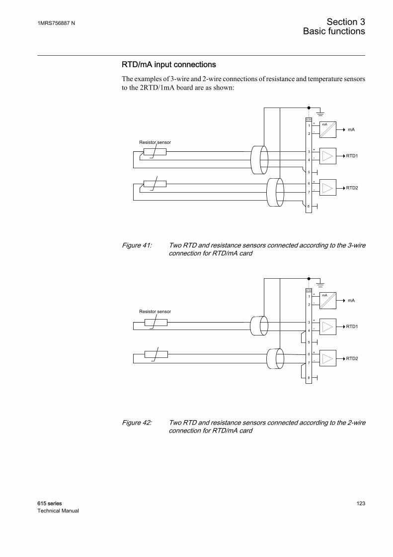
RTD/mA input connectionsThe examples of 3-wire and 2-wire connections of resistance and temperature sensorsto the 2RTD/1mA board are as shown:
Resistor sensor
X130
mAmA
RTD1
+
-
+
-
+
-
1
2
3
4
6
7
8
RTD2
5
GUID-9233377B-F015-46E7-A0D9-2B580F436B2E V2 EN
Figure 41: Two RTD and resistance sensors connected according to the 3-wireconnection for RTD/mA card
Resistor sensor
X130
mAmA
RTD1
+
-
+
-
+
-
1
2
3
4
6
7
8
RTD2
5
GUID-F939E7EE-B932-4002-9D27-1CEA7C595E0B V2 EN
Figure 42: Two RTD and resistance sensors connected according to the 2-wireconnection for RTD/mA card
1MRS756887 N Section 3Basic functions
615 series 123Technical Manual
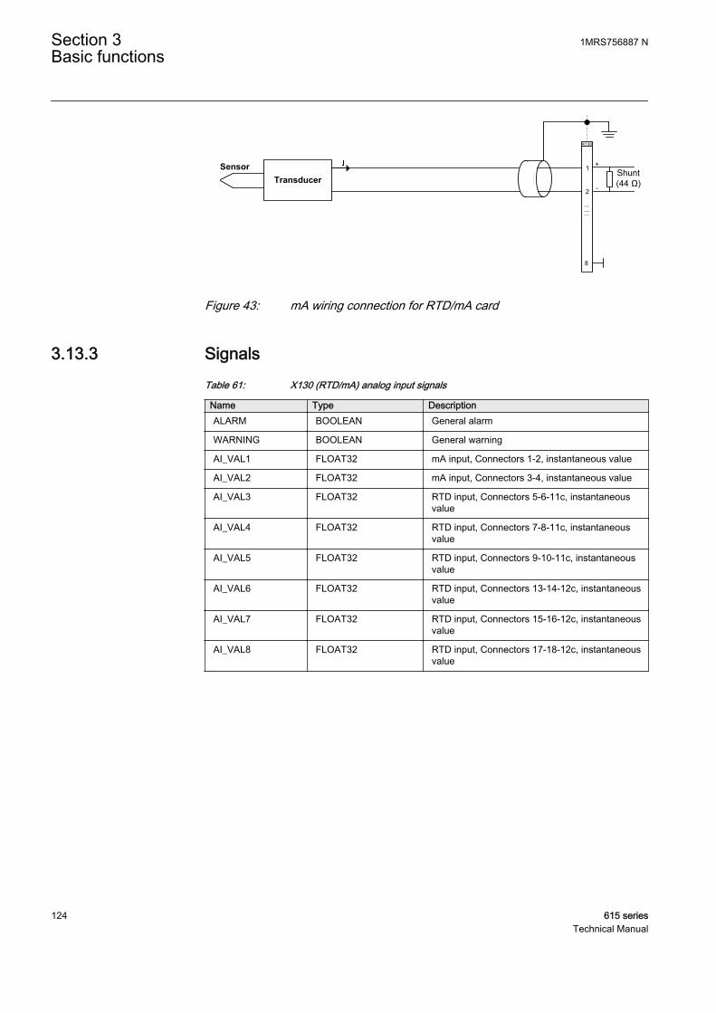
X130
+
-
1
2
8
TransducerSensor
Shunt(44 Ω)
...
......
GUID-FBB50B49-0EFE-4D1C-AB71-204C3E170C1D V2 EN
Figure 43: mA wiring connection for RTD/mA card
3.13.3 SignalsTable 61: X130 (RTD/mA) analog input signals
Name Type DescriptionALARM BOOLEAN General alarm
WARNING BOOLEAN General warning
AI_VAL1 FLOAT32 mA input, Connectors 1-2, instantaneous value
AI_VAL2 FLOAT32 mA input, Connectors 3-4, instantaneous value
AI_VAL3 FLOAT32 RTD input, Connectors 5-6-11c, instantaneousvalue
AI_VAL4 FLOAT32 RTD input, Connectors 7-8-11c, instantaneousvalue
AI_VAL5 FLOAT32 RTD input, Connectors 9-10-11c, instantaneousvalue
AI_VAL6 FLOAT32 RTD input, Connectors 13-14-12c, instantaneousvalue
AI_VAL7 FLOAT32 RTD input, Connectors 15-16-12c, instantaneousvalue
AI_VAL8 FLOAT32 RTD input, Connectors 17-18-12c, instantaneousvalue
Section 3 1MRS756887 NBasic functions
124 615 seriesTechnical Manual

3.13.4 SettingsTable 62: RTD input settings
Parameter Values (Range) Unit Step Default DescriptionInput mode 1=Not in use
2=Resistance10=Pt10011=Pt25020=Ni10021=Ni12022=Ni25030=Cu10
1=Not in use Analogue input mode
Input maximum 0...2000 Ω 1 2000 Maximum analogue input value for mA orresistance scaling
Input minimum 0...2000 Ω 1 0 Minimum analogue input value for mA orresistance scaling
Value unit 1=Dimensionless5=Ampere23=Degreescelsius30=Ohm
1=Dimensionless Selected unit for output value format
Value maximum -10000.0...10000.0 1 10000.0 Maximum output value for scaling andsupervision
Value minimum -10000.0...10000.0 1 -10000.0 Minimum output value for scaling andsupervision
Val high high limit -10000.0...10000.0 1 10000.0 Output value high alarm limit forsupervision
Value high limit -10000.0...10000.0 1 10000.0 Output value high warning limit forsupervision
Value low limit -10000.0...10000.0 1 -10000.0 Output value low warning limit forsupervision
Value low low limit -10000.0...10000.0 1 -10000.0 Output value low alarm limit forsupervision
Value deadband 100...100000 1 1000 Deadband configuration value for integralcalculation. (percentage of differencebetween min and max as 0,001 % s)
Table 63: mA input settings
Parameter Values (Range) Unit Step Default DescriptionInput mode 1=Not in use
5=0..20mA 1=Not in use Analogue input mode
Input maximum 0...20 mA 1 20 Maximum analogue input value for mA orresistance scaling
Input minimum 0...20 mA 1 0 Minimum analogue input value for mA orresistance scaling
Value unit 1=Dimensionless5=Ampere23=Degreescelsius30=Ohm
1=Dimensionless Selected unit for output value format
Table continues on next page
1MRS756887 N Section 3Basic functions
615 series 125Technical Manual
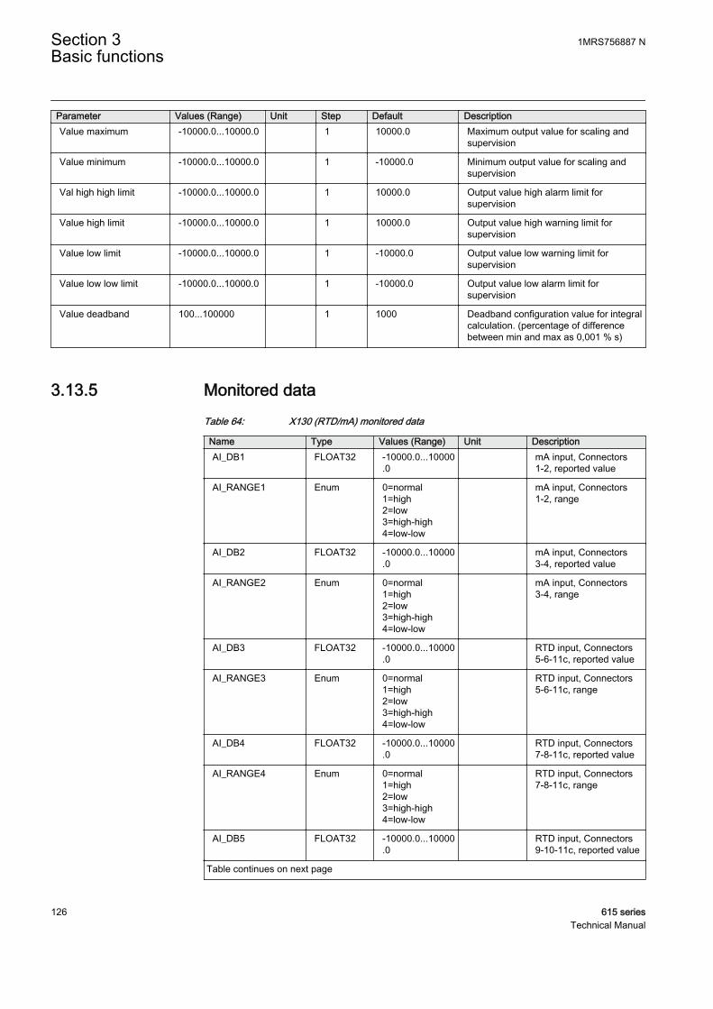
Parameter Values (Range) Unit Step Default DescriptionValue maximum -10000.0...10000.0 1 10000.0 Maximum output value for scaling and
supervision
Value minimum -10000.0...10000.0 1 -10000.0 Minimum output value for scaling andsupervision
Val high high limit -10000.0...10000.0 1 10000.0 Output value high alarm limit forsupervision
Value high limit -10000.0...10000.0 1 10000.0 Output value high warning limit forsupervision
Value low limit -10000.0...10000.0 1 -10000.0 Output value low warning limit forsupervision
Value low low limit -10000.0...10000.0 1 -10000.0 Output value low alarm limit forsupervision
Value deadband 100...100000 1 1000 Deadband configuration value for integralcalculation. (percentage of differencebetween min and max as 0,001 % s)
3.13.5 Monitored dataTable 64: X130 (RTD/mA) monitored data
Name Type Values (Range) Unit DescriptionAI_DB1 FLOAT32 -10000.0...10000
.0 mA input, Connectors
1-2, reported value
AI_RANGE1 Enum 0=normal1=high2=low3=high-high4=low-low
mA input, Connectors1-2, range
AI_DB2 FLOAT32 -10000.0...10000.0
mA input, Connectors3-4, reported value
AI_RANGE2 Enum 0=normal1=high2=low3=high-high4=low-low
mA input, Connectors3-4, range
AI_DB3 FLOAT32 -10000.0...10000.0
RTD input, Connectors5-6-11c, reported value
AI_RANGE3 Enum 0=normal1=high2=low3=high-high4=low-low
RTD input, Connectors5-6-11c, range
AI_DB4 FLOAT32 -10000.0...10000.0
RTD input, Connectors7-8-11c, reported value
AI_RANGE4 Enum 0=normal1=high2=low3=high-high4=low-low
RTD input, Connectors7-8-11c, range
AI_DB5 FLOAT32 -10000.0...10000.0
RTD input, Connectors9-10-11c, reported value
Table continues on next page
Section 3 1MRS756887 NBasic functions
126 615 seriesTechnical Manual
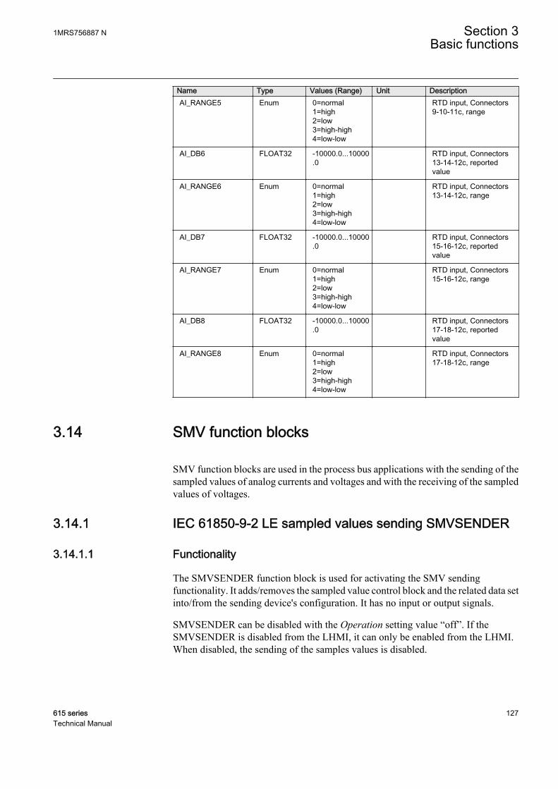
Name Type Values (Range) Unit DescriptionAI_RANGE5 Enum 0=normal
1=high2=low3=high-high4=low-low
RTD input, Connectors9-10-11c, range
AI_DB6 FLOAT32 -10000.0...10000.0
RTD input, Connectors13-14-12c, reportedvalue
AI_RANGE6 Enum 0=normal1=high2=low3=high-high4=low-low
RTD input, Connectors13-14-12c, range
AI_DB7 FLOAT32 -10000.0...10000.0
RTD input, Connectors15-16-12c, reportedvalue
AI_RANGE7 Enum 0=normal1=high2=low3=high-high4=low-low
RTD input, Connectors15-16-12c, range
AI_DB8 FLOAT32 -10000.0...10000.0
RTD input, Connectors17-18-12c, reportedvalue
AI_RANGE8 Enum 0=normal1=high2=low3=high-high4=low-low
RTD input, Connectors17-18-12c, range
3.14 SMV function blocks
SMV function blocks are used in the process bus applications with the sending of thesampled values of analog currents and voltages and with the receiving of the sampledvalues of voltages.
3.14.1 IEC 61850-9-2 LE sampled values sending SMVSENDER
3.14.1.1 Functionality
The SMVSENDER function block is used for activating the SMV sendingfunctionality. It adds/removes the sampled value control block and the related data setinto/from the sending device's configuration. It has no input or output signals.
SMVSENDER can be disabled with the Operation setting value “off”. If theSMVSENDER is disabled from the LHMI, it can only be enabled from the LHMI.When disabled, the sending of the samples values is disabled.
1MRS756887 N Section 3Basic functions
615 series 127Technical Manual
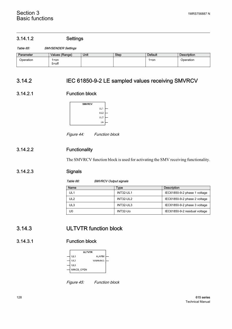
3.14.1.2 Settings
Table 65: SMVSENDER Settings
Parameter Values (Range) Unit Step Default DescriptionOperation 1=on
5=off 1=on Operation
3.14.2 IEC 61850-9-2 LE sampled values receiving SMVRCV
3.14.2.1 Function block
GUID-4C8D5CAB-ECBC-4FB2-BC8B-06FBF0900D73 V1 EN
Figure 44: Function block
3.14.2.2 Functionality
The SMVRCV function block is used for activating the SMV receiving functionality.
3.14.2.3 Signals
Table 66: SMVRCV Output signals
Name Type DescriptionUL1 INT32-UL1 IEC61850-9-2 phase 1 voltage
UL2 INT32-UL2 IEC61850-9-2 phase 2 voltage
UL3 INT32-UL3 IEC61850-9-2 phase 3 voltage
U0 INT32-Uo IEC61850-9-2 residual voltage
3.14.3 ULTVTR function block
3.14.3.1 Function block
GUID-16BA49F4-A98B-40FD-B24A-C2101053E1CA V2 EN
Figure 45: Function block
Section 3 1MRS756887 NBasic functions
128 615 seriesTechnical Manual

3.14.3.2 Functionality
The ULTVTR function is used in the receiver application to perform the supervisionfor the sampled values and to connect the received analog phase voltage inputs to theapplication. Synchronization accuracy, sampled value frame transfer delays andmissing frames are being supervised.
The typical additional operate time increase is +2 ms for all thereceiver application functions (using either local or remote samples)when SMV is used.
3.14.3.3 Operation principle
The ALARM in the receiver is activated if the synchronization accuracy of the senderor the receiver is either unknown or worse than 100 ms. The output is held on for 10seconds after the synchronization accuracy returns within limits.
ALARM is activated when two or more consecutive SMV frames are lost or late. Asingle loss of frame is corrected with a zero-order hold scheme. In this case the effecton protection is considered negligible and the WARNING or ALARM outputs are notactivated. The output is held on for 10 seconds after the conditions return to normal.
The SMV Max Delay parameter defines how long the receiver waits for the SMVframes before activating the ALARM output. This parameter can be accessed viaConfiguration/System/Common. Waiting of the SMV frames also delays the localmeasurements of the receiver to keep them correctly time aligned. The SMV MaxDelay values include sampling, processing and network delay.
The MINCB_OPEN input signal is supposed to be connected through a protectionrelay's binary input to the NC auxiliary contact of the miniature circuit breakerprotecting the VT secondary circuit. The MINCB_OPEN signal sets the FUSEF_Uoutput signal to block all the voltage-related functions when MCB is in the open state.
The WARNING output in the receiver is activated if the synchronization accuracy ofthe sender or the receiver is worse than 4 μs. The output is held on for 10 seconds afterthe synchronization accuracy returns within limits. If the protection relay supportsfrequency adaptivity and it is enabled, the WARNING output is also activated when theadaptivity is not ready.
The WARNING output is always internally active whenever the ALARM output isactive.
The receiver activates the WARNING and ALARM outputs if any of the quality bits,except for the derived bit, is activated. When the receiver is in the test mode, it acceptsSMV frames with test bit without activating the WARNING and ALARM outputs.
1MRS756887 N Section 3Basic functions
615 series 129Technical Manual

3.14.3.4 Signals
Table 67: ULTVTR Input signals
Name Type Default DescriptionUL1 INT32-UL1 0 IEC61850-9-2 phase 1
voltage
UL2 INT32-UL2 0 IEC61850-9-2 phase 2voltage
UL3 INT32-UL3 0 IEC61850-9-2 phase 3voltage
MINCB_OPEN BOOLEAN 0 Active when externalMCB opens protectedvoltage circuit
Table 68: ULTVTR Output signals
Name Type DescriptionALARM BOOLEAN Alarm
WARNING BOOLEAN Warning
3.14.3.5 Settings
Table 69: ULTVTR Non group settings (Basic)
Parameter Values (Range) Unit Step Default DescriptionPrimary voltage 0.100...440.000 kV 0.001 20.000 Primary rated voltage
Secondary voltage 60...210 V 1 100 Secondary rated voltage
VT connection 1=Wye2=Delta3=U124=UL1
2=Delta Voltage transducer measurementconnection
Amplitude Corr A 0.9000...1.1000 0.0001 1.0000 Phase A Voltage phasor magnitudecorrection of an external voltagetransformer
Amplitude Corr B 0.9000...1.1000 0.0001 1.0000 Phase B Voltage phasor magnitudecorrection of an external voltagetransformer
Amplitude Corr C 0.9000...1.1000 0.0001 1.0000 Phase C Voltage phasor magnitudecorrection of an external voltagetransformer
Division ratio 1000...20000 1 10000 Voltage sensor division ratio
Voltage input type 1=Voltage trafo3=CVD sensor
1=Voltage trafo Type of the voltage input
Angle Corr A -20.0000...20.0000 deg 0.0001 0.0000 Phase A Voltage phasor angle correctionof an external voltage transformer
Angle Corr B -20.0000...20.0000 deg 0.0001 0.0000 Phase B Voltage phasor angle correctionof an external voltage transformer
Angle Corr C -20.0000...20.0000 deg 0.0001 0.0000 Phase C Voltage phasor angle correctionof an external voltage transformer
Section 3 1MRS756887 NBasic functions
130 615 seriesTechnical Manual

3.14.3.6 Monitored data
Monitored data is available in three locations.
• Monitoring/I/O status/Analog inputs• Monitoring/IED status/SMV traffic• Monitoring/IED status/SMV accuracy
3.14.4 RESTVTR function block
3.14.4.1 Function block
GUID-2277C7AC-5194-4819-BAC4-A71A32E4C439 V1 EN
Figure 46: Function block
3.14.4.2 Functionality
The RESTVTR function is used in the receiver application to perform the supervisionfor the sampled values of analog residual voltage and to connect the received analogresidual voltage input to the application. Synchronization accuracy, sampled valueframe transfer delays and missing frames are being supervised.
The typical additional operate time increase is +2 ms for all thereceiver application functions (using either local or remote samples)when SMV is used.
3.14.4.3 Operation principle
The ALARM in the receiver is activated if the synchronization accuracy of the senderor the receiver is either unknown or worse than 100 ms. The output is held on for 10seconds after the synchronization accuracy returns within limits.
ALARM is activated when two or more consecutive SMV frames are lost or late. Asingle loss of frame is corrected with a zero-order hold scheme. In this case, the effecton protection is considered negligible and the WARNING or ALARM outputs are notactivated. The output is held on for 10 seconds after the conditions return to normal.
The SMV Max Delay parameter defines how long the receiver waits for the SMVframes before activating the ALARM output. This parameter can be accessed viaConfiguration/System/Common. Waiting of the SMV frames also delays the localmeasurements of the receiver to keep them correctly time aligned. The SMV MaxDelay values include sampling, processing and network delay.
1MRS756887 N Section 3Basic functions
615 series 131Technical Manual
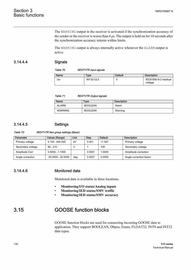
The WARNING output in the receiver is activated if the synchronization accuracy ofthe sender or the receiver is worse than 4 μs. The output is held on for 10 seconds afterthe synchronization accuracy returns within limits.
The WARNING output is always internally active whenever the ALARM output isactive.
3.14.4.4 Signals
Table 70: RESTVTR Input signals
Name Type Default DescriptionUo INT32-UL0 0 IEC61850-9-2 residual
voltage
Table 71: RESTVTR Output signals
Name Type DescriptionALARM BOOLEAN Alarm
WARNING BOOLEAN Warning
3.14.4.5 Settings
Table 72: RESTVTR Non group settings (Basic)
Parameter Values (Range) Unit Step Default DescriptionPrimary voltage 0.100...440.000 kV 0.001 11.547 Primary voltage
Secondary voltage 60...210 V 1 100 Secondary voltage
Amplitude Corr 0.9000...1.1000 0.0001 1.0000 Amplitude correction
Angle correction -20.0000...20.0000 deg 0.0001 0.0000 Angle correction factor
3.14.4.6 Monitored data
Monitored data is available in three locations.
• Monitoring/I/O status/Analog inputs• Monitoring/IED status/SMV traffic• Monitoring/IED status/SMV accuracy
3.15 GOOSE function blocks
GOOSE function blocks are used for connecting incoming GOOSE data toapplication. They support BOOLEAN, Dbpos, Enum, FLOAT32, INT8 and INT32data types.
Section 3 1MRS756887 NBasic functions
132 615 seriesTechnical Manual
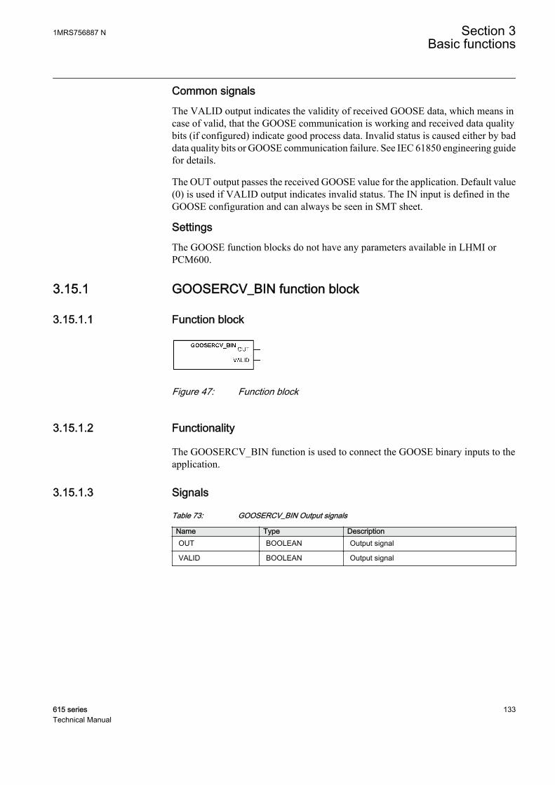
Common signalsThe VALID output indicates the validity of received GOOSE data, which means incase of valid, that the GOOSE communication is working and received data qualitybits (if configured) indicate good process data. Invalid status is caused either by baddata quality bits or GOOSE communication failure. See IEC 61850 engineering guidefor details.
The OUT output passes the received GOOSE value for the application. Default value(0) is used if VALID output indicates invalid status. The IN input is defined in theGOOSE configuration and can always be seen in SMT sheet.
SettingsThe GOOSE function blocks do not have any parameters available in LHMI orPCM600.
3.15.1 GOOSERCV_BIN function block
3.15.1.1 Function block
GUID-44EF4D6E-7389-455C-BDE5-B127678E2CBC V1 EN
Figure 47: Function block
3.15.1.2 Functionality
The GOOSERCV_BIN function is used to connect the GOOSE binary inputs to theapplication.
3.15.1.3 Signals
Table 73: GOOSERCV_BIN Output signals
Name Type DescriptionOUT BOOLEAN Output signal
VALID BOOLEAN Output signal
1MRS756887 N Section 3Basic functions
615 series 133Technical Manual

3.15.2 GOOSERCV_DP function block
3.15.2.1 Function block
GUID-63C0C3EE-1C0E-4F78-A06E-3E84F457FC98 V1 EN
Figure 48: Function block
3.15.2.2 Functionality
The GOOSERCV_DP function is used to connect the GOOSE double binary inputs tothe application.
3.15.2.3 Signals
Table 74: GOOSERCV_DP Output signals
Name Type DescriptionOUT Dbpos Output signal
VALID BOOLEAN Output signal
3.15.3 GOOSERCV_MV function block
3.15.3.1 Function block
GUID-A59BAF25-B9F8-46EA-9831-477AC665D0F7 V1 EN
Figure 49: Function block
3.15.3.2 Functionality
The GOOSERCV_MV function is used to connect the GOOSE measured value inputsto the application.
3.15.3.3 Signals
Table 75: GOOSERCV_MV Output signals
Name Type DescriptionOUT FLOAT32 Output signal
VALID BOOLEAN Output signal
Section 3 1MRS756887 NBasic functions
134 615 seriesTechnical Manual
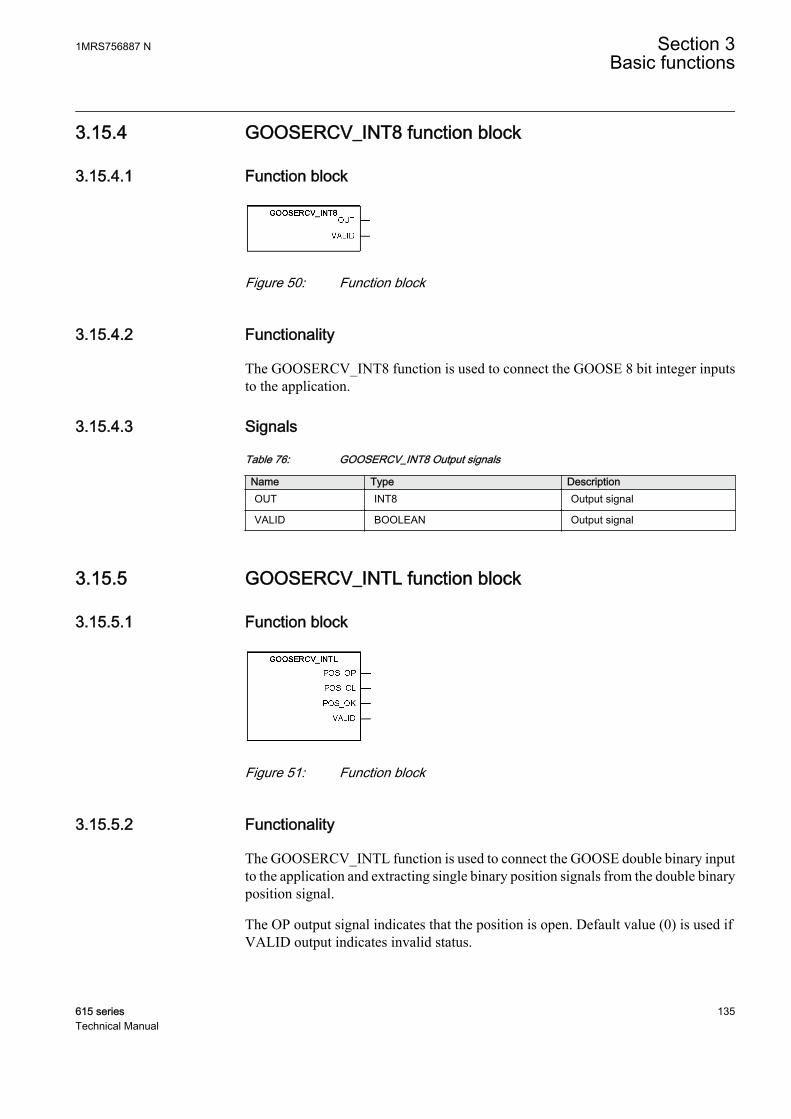
3.15.4 GOOSERCV_INT8 function block
3.15.4.1 Function block
GUID-B4E1495B-F797-4CFF-BD19-AF023EA2D3D9 V1 EN
Figure 50: Function block
3.15.4.2 Functionality
The GOOSERCV_INT8 function is used to connect the GOOSE 8 bit integer inputsto the application.
3.15.4.3 Signals
Table 76: GOOSERCV_INT8 Output signals
Name Type DescriptionOUT INT8 Output signal
VALID BOOLEAN Output signal
3.15.5 GOOSERCV_INTL function block
3.15.5.1 Function block
GUID-241A36E0-1BB9-4323-989F-39668A7B1DAC V1 EN
Figure 51: Function block
3.15.5.2 Functionality
The GOOSERCV_INTL function is used to connect the GOOSE double binary inputto the application and extracting single binary position signals from the double binaryposition signal.
The OP output signal indicates that the position is open. Default value (0) is used ifVALID output indicates invalid status.
1MRS756887 N Section 3Basic functions
615 series 135Technical Manual

The CL output signal indicates that the position is closed. Default value (0) is used ifVALID output indicates invalid status.
The OK output signal indicates that the position is neither in faulty or intermediatestate. The default value (0) is used if VALID output indicates invalid status.
3.15.5.3 Signals
Table 77: GOOSERCV_INTL Output signals
Name Type DescriptionPOS_OP BOOLEAN Position open output signal
POS_CL BOOLEAN Position closed output signal
POS_OK BOOLEAN Position OK output signal
VALID BOOLEAN Output signal
3.15.6 GOOSERCV_CMV function block
3.15.6.1 Function block
GUID-4C3F3A1A-F5D1-42E1-840F-6106C58CB380 V1 EN
Figure 52: Function block
3.15.6.2 Functionality
The GOOSERCV_CMV function is used to connect GOOSE measured value inputsto the application. The MAG_IN (amplitude) and ANG_IN (angle) inputs are definedin the GOOSE configuration (PCM600).
The MAG output passes the received GOOSE (amplitude) value for the application.Default value (0) is used if VALID output indicates invalid status.
The ANG output passes the received GOOSE (angle) value for the application.Default value (0) is used if VALID output indicates invalid status.
3.15.6.3 Signals
Table 78: GOOSERCV_CMV Output signals
Name Type DescriptionMAG FLOAT32 Output signal (amplitude)
ANG FLOAT32 Output signal (angle)
VALID BOOLEAN Output signal
Section 3 1MRS756887 NBasic functions
136 615 seriesTechnical Manual

3.15.7 GOOSERCV_ENUM function block
3.15.7.1 Function block
GUID-E1AE8AD3-ED99-448A-8C11-558BCA68CDC4 V1 EN
Figure 53: Function block
3.15.7.2 Functionality
The GOOSERCV_ENUM function block is used to connect GOOSE enumeratorinputs to the application.
3.15.7.3 Signals
Table 79: GOOSERCV_ENUM Output signals
Name Type DescriptionOUT Enum Output signal
VALID BOOLEAN Output signal
3.15.8 GOOSERCV_INT32 function block
3.15.8.1 Function block
GUID-61FF1ECC-507D-4B6D-8CA5-713A59F58D5C V1 EN
Figure 54: Function block
3.15.8.2 Functionality
The GOOSERCV_INT32 function block is used to connect GOOSE 32 bit integerinputs to the application.
3.15.8.3 Signals
Table 80: GOOSERCV_INT32 Output signals
Name Type DescriptionOUT INT32 Output signal
VALID BOOLEAN Output signal
1MRS756887 N Section 3Basic functions
615 series 137Technical Manual
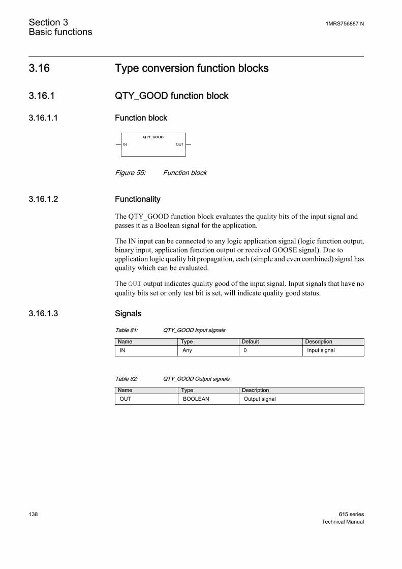
3.16 Type conversion function blocks
3.16.1 QTY_GOOD function block
3.16.1.1 Function block
GUID-1999D6D9-4517-4FFE-A14D-08FDB5E8B9F6 V1 EN
Figure 55: Function block
3.16.1.2 Functionality
The QTY_GOOD function block evaluates the quality bits of the input signal andpasses it as a Boolean signal for the application.
The IN input can be connected to any logic application signal (logic function output,binary input, application function output or received GOOSE signal). Due toapplication logic quality bit propagation, each (simple and even combined) signal hasquality which can be evaluated.
The OUT output indicates quality good of the input signal. Input signals that have noquality bits set or only test bit is set, will indicate quality good status.
3.16.1.3 Signals
Table 81: QTY_GOOD Input signals
Name Type Default DescriptionIN Any 0 Input signal
Table 82: QTY_GOOD Output signals
Name Type DescriptionOUT BOOLEAN Output signal
Section 3 1MRS756887 NBasic functions
138 615 seriesTechnical Manual
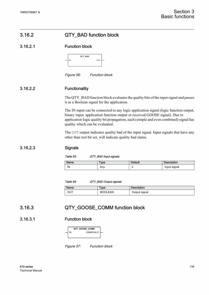
3.16.2 QTY_BAD function block
3.16.2.1 Function block
GUID-8C120145-91B6-4295-98FB-AE78430EB532 V1 EN
Figure 56: Function block
3.16.2.2 Functionality
The QTY_BAD function block evaluates the quality bits of the input signal and passesit as a Boolean signal for the application.
The IN input can be connected to any logic application signal (logic function output,binary input, application function output or received GOOSE signal). Due toapplication logic quality bit propagation, each (simple and even combined) signal hasquality which can be evaluated.
The OUT output indicates quality bad of the input signal. Input signals that have anyother than test bit set, will indicate quality bad status.
3.16.2.3 Signals
Table 83: QTY_BAD Input signals
Name Type Default DescriptionIN Any 0 Input signal
Table 84: QTY_BAD Output signals
Name Type DescriptionOUT BOOLEAN Output signal
3.16.3 QTY_GOOSE_COMM function block
3.16.3.1 Function block
GUID-0FDC082E-C9A8-4B02-9878-6C49E44B7C0E V1 EN
Figure 57: Function block
1MRS756887 N Section 3Basic functions
615 series 139Technical Manual
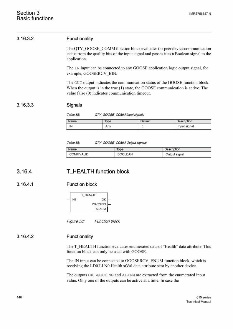
3.16.3.2 Functionality
The QTY_GOOSE_COMM function block evaluates the peer device communicationstatus from the quality bits of the input signal and passes it as a Boolean signal to theapplication.
The IN input can be connected to any GOOSE application logic output signal, forexample, GOOSERCV_BIN.
The OUT output indicates the communication status of the GOOSE function block.When the output is in the true (1) state, the GOOSE communication is active. Thevalue false (0) indicates communication timeout.
3.16.3.3 Signals
Table 85: QTY_GOOSE_COMM Input signals
Name Type Default DescriptionIN Any 0 Input signal
Table 86: QTY_GOOSE_COMM Output signals
Name Type DescriptionCOMMVALID BOOLEAN Output signal
3.16.4 T_HEALTH function block
3.16.4.1 Function block
GUID-B5FCAE66-8026-4D5F-AC38-028E5A8171BB V1 EN
Figure 58: Function block
3.16.4.2 Functionality
The T_HEALTH function evaluates enumerated data of “Health” data attribute. Thisfunction block can only be used with GOOSE.
The IN input can be connected to GOOSERCV_ENUM function block, which isreceiving the LD0.LLN0.Health.stVal data attribute sent by another device.
The outputs OK, WARNING and ALARM are extracted from the enumerated inputvalue. Only one of the outputs can be active at a time. In case the
Section 3 1MRS756887 NBasic functions
140 615 seriesTechnical Manual
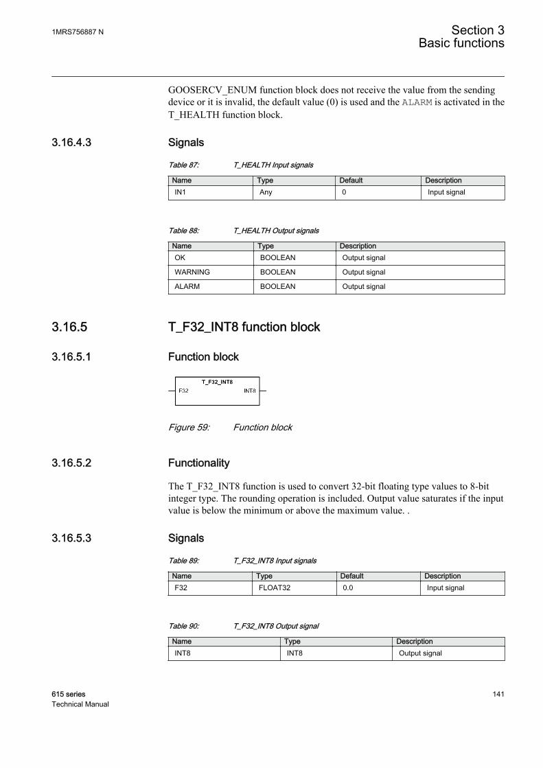
GOOSERCV_ENUM function block does not receive the value from the sendingdevice or it is invalid, the default value (0) is used and the ALARM is activated in theT_HEALTH function block.
3.16.4.3 Signals
Table 87: T_HEALTH Input signals
Name Type Default DescriptionIN1 Any 0 Input signal
Table 88: T_HEALTH Output signals
Name Type DescriptionOK BOOLEAN Output signal
WARNING BOOLEAN Output signal
ALARM BOOLEAN Output signal
3.16.5 T_F32_INT8 function block
3.16.5.1 Function block
GUID-F0F44FBF-FB56-4BC2-B421-F1A7924E6B8C V1 EN
Figure 59: Function block
3.16.5.2 Functionality
The T_F32_INT8 function is used to convert 32-bit floating type values to 8-bitinteger type. The rounding operation is included. Output value saturates if the inputvalue is below the minimum or above the maximum value. .
3.16.5.3 Signals
Table 89: T_F32_INT8 Input signals
Name Type Default DescriptionF32 FLOAT32 0.0 Input signal
Table 90: T_F32_INT8 Output signal
Name Type DescriptionINT8 INT8 Output signal
1MRS756887 N Section 3Basic functions
615 series 141Technical Manual
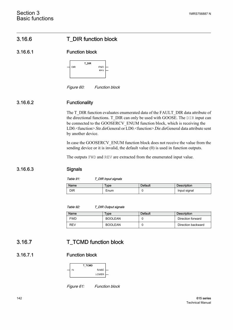
3.16.6 T_DIR function block
3.16.6.1 Function block
GUID-BD31ED40-3A32-4F65-A697-3E7344730096 V1 EN
Figure 60: Function block
3.16.6.2 Functionality
The T_DIR function evaluates enumerated data of the FAULT_DIR data attribute ofthe directional functions. T_DIR can only be used with GOOSE. The DIR input canbe connected to the GOOSERCV_ENUM function block, which is receiving theLD0.<function>.Str.dirGeneral or LD0.<function>.Dir.dirGeneral data attribute sentby another device.
In case the GOOSERCV_ENUM function block does not receive the value from thesending device or it is invalid, the default value (0) is used in function outputs.
The outputs FWD and REV are extracted from the enumerated input value.
3.16.6.3 Signals
Table 91: T_DIR Input signals
Name Type Default DescriptionDIR Enum 0 Input signal
Table 92: T_DIR Output signals
Name Type Default DescriptionFWD BOOLEAN 0 Direction forward
REV BOOLEAN 0 Direction backward
3.16.7 T_TCMD function block
3.16.7.1 Function block
GUID-1CE485AE-2BCA-4D1E-92F5-417340F2589F V1 EN
Figure 61: Function block
Section 3 1MRS756887 NBasic functions
142 615 seriesTechnical Manual
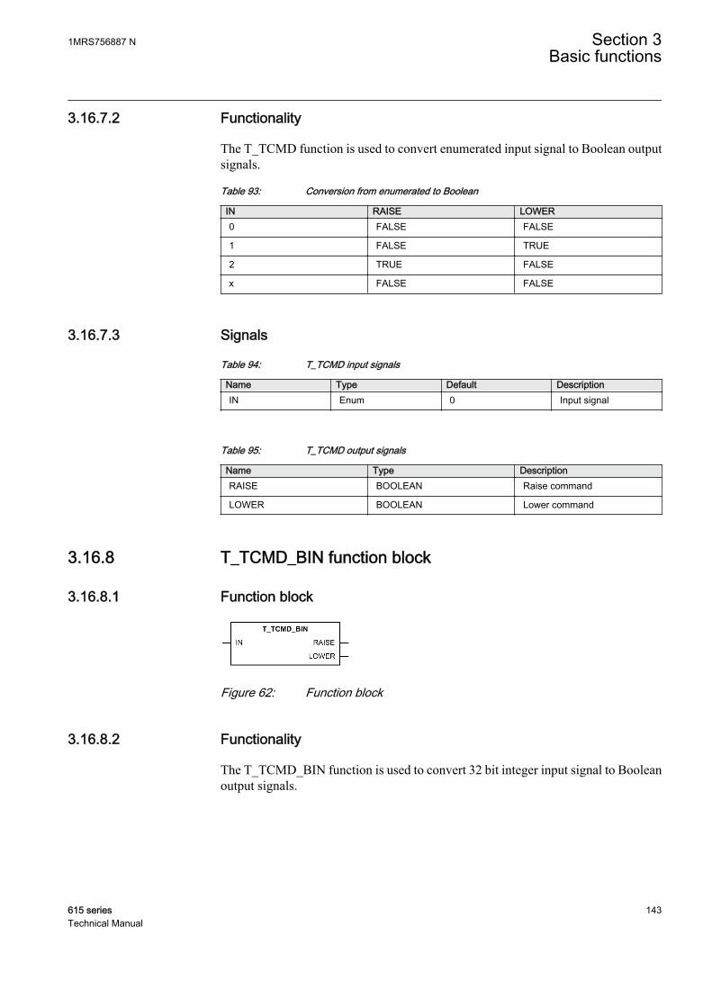
3.16.7.2 Functionality
The T_TCMD function is used to convert enumerated input signal to Boolean outputsignals.
Table 93: Conversion from enumerated to Boolean
IN RAISE LOWER0 FALSE FALSE
1 FALSE TRUE
2 TRUE FALSE
x FALSE FALSE
3.16.7.3 Signals
Table 94: T_TCMD input signals
Name Type Default DescriptionIN Enum 0 Input signal
Table 95: T_TCMD output signals
Name Type DescriptionRAISE BOOLEAN Raise command
LOWER BOOLEAN Lower command
3.16.8 T_TCMD_BIN function block
3.16.8.1 Function block
GUID-A5C813D8-399A-4FBC-B1A0-E62E5C423EA5 V1 EN
Figure 62: Function block
3.16.8.2 Functionality
The T_TCMD_BIN function is used to convert 32 bit integer input signal to Booleanoutput signals.
1MRS756887 N Section 3Basic functions
615 series 143Technical Manual
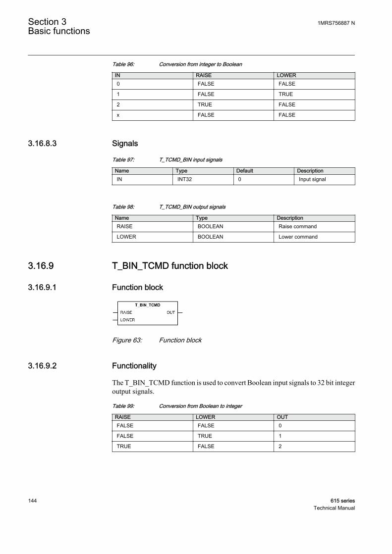
Table 96: Conversion from integer to Boolean
IN RAISE LOWER0 FALSE FALSE
1 FALSE TRUE
2 TRUE FALSE
x FALSE FALSE
3.16.8.3 Signals
Table 97: T_TCMD_BIN input signals
Name Type Default DescriptionIN INT32 0 Input signal
Table 98: T_TCMD_BIN output signals
Name Type DescriptionRAISE BOOLEAN Raise command
LOWER BOOLEAN Lower command
3.16.9 T_BIN_TCMD function block
3.16.9.1 Function block
GUID-54A013A3-E253-4A06-B033-01C7E11EC997 V1 EN
Figure 63: Function block
3.16.9.2 Functionality
The T_BIN_TCMD function is used to convert Boolean input signals to 32 bit integeroutput signals.
Table 99: Conversion from Boolean to integer
RAISE LOWER OUTFALSE FALSE 0
FALSE TRUE 1
TRUE FALSE 2
Section 3 1MRS756887 NBasic functions
144 615 seriesTechnical Manual
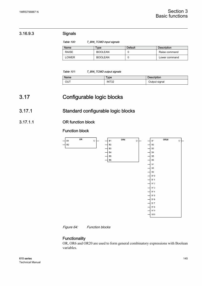
3.16.9.3 Signals
Table 100: T_BIN_TCMD input signals
Name Type Default DescriptionRAISE BOOLEAN 0 Raise command
LOWER BOOLEAN 0 Lower command
Table 101: T_BIN_TCMD output signals
Name Type DescriptionOUT INT32 Output signal
3.17 Configurable logic blocks
3.17.1 Standard configurable logic blocks
3.17.1.1 OR function block
Function block
GUID-A845F2F1-DCC2-40C9-8A77-893EF5694436 V1 EN
Figure 64: Function blocks
FunctionalityOR, OR6 and OR20 are used to form general combinatory expressions with Booleanvariables.
1MRS756887 N Section 3Basic functions
615 series 145Technical Manual

The O output is activated when at least one input has the value TRUE. The defaultvalue of all inputs is FALSE, which makes it possible to use only the required numberof inputs and leave the rest disconnected.
OR has two inputs, OR6 six and OR20 twenty inputs.
Signals
Table 102: OR Input signals
Name Type Default DescriptionB1 BOOLEAN 0 Input signal 1
B2 BOOLEAN 0 Input signal 2
Table 103: OR6 Input signals
Name Type Default DescriptionB1 BOOLEAN 0 Input signal 1
B2 BOOLEAN 0 Input signal 2
B3 BOOLEAN 0 Input signal 3
B4 BOOLEAN 0 Input signal 4
B5 BOOLEAN 0 Input signal 5
B6 BOOLEAN 0 Input signal 6
Table 104: OR20 Input signals
Name Type Default DescriptionB1 BOOLEAN 0 Input signal 1
B2 BOOLEAN 0 Input signal 2
B3 BOOLEAN 0 Input signal 3
B4 BOOLEAN 0 Input signal 4
B5 BOOLEAN 0 Input signal 5
B6 BOOLEAN 0 Input signal 6
B7 BOOLEAN 0 Input signal 7
B8 BOOLEAN 0 Input signal 8
B9 BOOLEAN 0 Input signal 9
B10 BOOLEAN 0 Input signal 10
B11 BOOLEAN 0 Input signal 11
B12 BOOLEAN 0 Input signal 12
B13 BOOLEAN 0 Input signal 13
B14 BOOLEAN 0 Input signal 14
B15 BOOLEAN 0 Input signal 15
B16 BOOLEAN 0 Input signal 16
B17 BOOLEAN 0 Input signal 17
Table continues on next page
Section 3 1MRS756887 NBasic functions
146 615 seriesTechnical Manual
Name Type Default DescriptionB18 BOOLEAN 0 Input signal 18
B19 BOOLEAN 0 Input signal 19
B20 BOOLEAN 0 Input signal 20
Table 105: OR Output signal
Name Type DescriptionO BOOLEAN Output signal
Table 106: OR6 Output signal
Name Type DescriptionO BOOLEAN Output signal
Table 107: OR20 Output signal
Name Type DescriptionO BOOLEAN Output signal
SettingsThe function does not have any parameters available in LHMI or PCM600.
1MRS756887 N Section 3Basic functions
615 series 147Technical Manual

3.17.1.2 AND function block
Function block
GUID-F560A373-4DB9-42E9-B687-DF4A3E45359C V1 EN
Figure 65: Function blocks
FunctionalityAND, AND6 and AND20 are used to form general combinatory expressions withBoolean variables.
The default value in all inputs is logical true, which makes it possible to use only therequired number of inputs and leave the rest disconnected.
AND has two inputs, AND6 six inputs and AND20 twenty inputs.
Signals
Table 108: AND Input signals
Name Type Default DescriptionB1 BOOLEAN 1 Input signal 1
B2 BOOLEAN 1 Input signal 2
Table 109: AND6 Input signals
Name Type Default DescriptionB1 BOOLEAN 1 Input signal 1
B2 BOOLEAN 1 Input signal 2
B3 BOOLEAN 1 Input signal 3
Table continues on next page
Section 3 1MRS756887 NBasic functions
148 615 seriesTechnical Manual
Name Type Default DescriptionB4 BOOLEAN 1 Input signal 4
B5 BOOLEAN 1 Input signal 5
B6 BOOLEAN 1 Input signal 6
Table 110: AND20 Input signals
Name Type Default DescriptionB1 BOOLEAN 0 Input signal 1
B2 BOOLEAN 0 Input signal 2
B3 BOOLEAN 0 Input signal 3
B4 BOOLEAN 0 Input signal 4
B5 BOOLEAN 0 Input signal 5
B6 BOOLEAN 0 Input signal 6
B7 BOOLEAN 0 Input signal 7
B8 BOOLEAN 0 Input signal 8
B9 BOOLEAN 0 Input signal 9
B10 BOOLEAN 0 Input signal 10
B11 BOOLEAN 0 Input signal 11
B12 BOOLEAN 0 Input signal 12
B13 BOOLEAN 0 Input signal 13
B14 BOOLEAN 0 Input signal 14
B15 BOOLEAN 0 Input signal 15
B16 BOOLEAN 0 Input signal 16
B17 BOOLEAN 0 Input signal 17
B18 BOOLEAN 0 Input signal 18
B19 BOOLEAN 0 Input signal 19
B20 BOOLEAN 0 Input signal 20
Table 111: AND Output signal
Name Type DescriptionO BOOLEAN Output signal
Table 112: AND6 Output signal
Name Type DescriptionO BOOLEAN Output signal
Table 113: AND20 Output signal
Name Type DescriptionO BOOLEAN Output signal
1MRS756887 N Section 3Basic functions
615 series 149Technical Manual
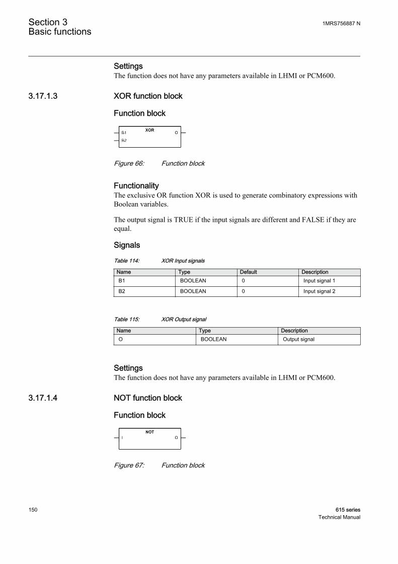
SettingsThe function does not have any parameters available in LHMI or PCM600.
3.17.1.3 XOR function block
Function block
GUID-9C247C8A-03A5-4F08-8329-F08BE7125B9A V1 EN
Figure 66: Function block
FunctionalityThe exclusive OR function XOR is used to generate combinatory expressions withBoolean variables.
The output signal is TRUE if the input signals are different and FALSE if they areequal.
Signals
Table 114: XOR Input signals
Name Type Default DescriptionB1 BOOLEAN 0 Input signal 1
B2 BOOLEAN 0 Input signal 2
Table 115: XOR Output signal
Name Type DescriptionO BOOLEAN Output signal
SettingsThe function does not have any parameters available in LHMI or PCM600.
3.17.1.4 NOT function block
Function block
GUID-0D0FC187-4224-433C-9664-908168EE3626 V1 EN
Figure 67: Function block
Section 3 1MRS756887 NBasic functions
150 615 seriesTechnical Manual
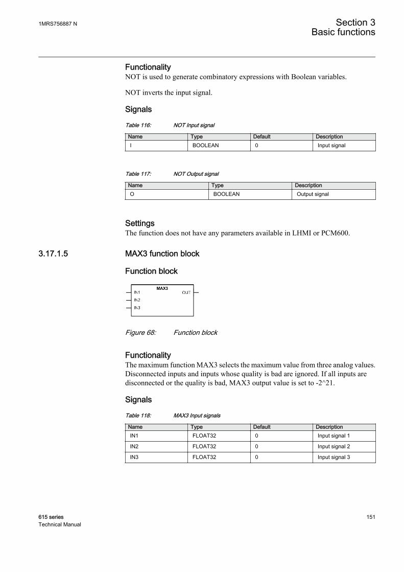
FunctionalityNOT is used to generate combinatory expressions with Boolean variables.
NOT inverts the input signal.
Signals
Table 116: NOT Input signal
Name Type Default DescriptionI BOOLEAN 0 Input signal
Table 117: NOT Output signal
Name Type DescriptionO BOOLEAN Output signal
SettingsThe function does not have any parameters available in LHMI or PCM600.
3.17.1.5 MAX3 function block
Function block
GUID-5454FE1C-2947-4337-AD58-39D266E91993 V1 EN
Figure 68: Function block
FunctionalityThe maximum function MAX3 selects the maximum value from three analog values.Disconnected inputs and inputs whose quality is bad are ignored. If all inputs aredisconnected or the quality is bad, MAX3 output value is set to -2^21.
Signals
Table 118: MAX3 Input signals
Name Type Default DescriptionIN1 FLOAT32 0 Input signal 1
IN2 FLOAT32 0 Input signal 2
IN3 FLOAT32 0 Input signal 3
1MRS756887 N Section 3Basic functions
615 series 151Technical Manual

Table 119: MAX3 Output signal
Name Type DescriptionOUT FLOAT32 Output signal
SettingsThe function does not have any parameters available in LHMI or PCM600.
3.17.1.6 MIN3 function block
Function block
GUID-40218B77-8A30-445A-977E-46CB8783490D V1 EN
Figure 69: Function block
FunctionalityThe minimum function MIN3 selects the minimum value from three analog values.Disconnected inputs and inputs whose quality is bad are ignored. If all inputs aredisconnected or the quality is bad, MIN3 output value is set to 2^21.
Signals
Table 120: MIN3 Input signals
Name Type Default DescriptionIN1 FLOAT32 0 Input signal 1
IN2 FLOAT32 0 Input signal 2
IN3 FLOAT32 0 Input signal 3
Table 121: MIN3 Output signal
Name Type DescriptionOUT FLOAT32 Output signal
SettingsThe function does not have any parameters available in LHMI or PCM600.
Section 3 1MRS756887 NBasic functions
152 615 seriesTechnical Manual

3.17.1.7 R_TRIG function block
Function block
GUID-3D0BBDC3-4091-4D8B-A35C-95F6289E6FD8 V1 EN
Figure 70: Function block
FunctionalityR_TRIGTrig is used as a rising edge detector.
R_TRIG detects the transition from FALSE to TRUE at the CLK input. When therising edge is detected, the element assigns the output to TRUE. At the next executionround, the output is returned to FALSE despite the state of the input.
Signals
Table 122: R_TRIG Input signals
Name Type Default DescriptionCLK BOOLEAN 0 Input signal
Table 123: R_TRIG Output signal
Name Type DescriptionQ BOOLEAN Output signal
SettingsThe function does not have any parameters available in LHMI or PCM600.
3.17.1.8 F_TRIG function block
Function block
GUID-B47152D2-3855-4306-8F2E-73D8FDEC4C1D V1 EN
Figure 71: Function block
FunctionalityF_TRIG is used as a falling edge detector.
1MRS756887 N Section 3Basic functions
615 series 153Technical Manual
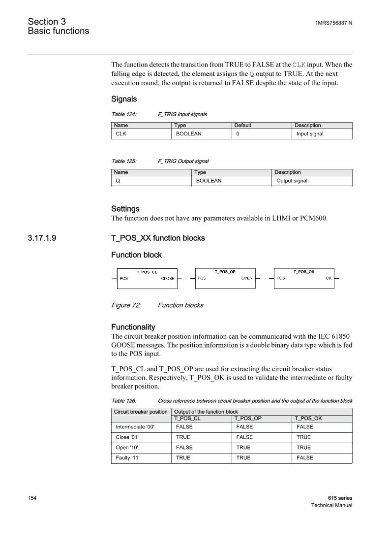
The function detects the transition from TRUE to FALSE at the CLK input. When thefalling edge is detected, the element assigns the Q output to TRUE. At the nextexecution round, the output is returned to FALSE despite the state of the input.
Signals
Table 124: F_TRIG Input signals
Name Type Default DescriptionCLK BOOLEAN 0 Input signal
Table 125: F_TRIG Output signal
Name Type DescriptionQ BOOLEAN Output signal
SettingsThe function does not have any parameters available in LHMI or PCM600.
3.17.1.9 T_POS_XX function blocks
Function block
GUID-4548B304-1CCD-454F-B819-7BC9F404131F V1 EN
Figure 72: Function blocks
FunctionalityThe circuit breaker position information can be communicated with the IEC 61850GOOSE messages. The position information is a double binary data type which is fedto the POS input.
T_POS_CL and T_POS_OP are used for extracting the circuit breaker statusinformation. Respectively, T_POS_OK is used to validate the intermediate or faultybreaker position.
Table 126: Cross reference between circuit breaker position and the output of the function block
Circuit breaker position Output of the function block T_POS_CL T_POS_OP T_POS_OKIntermediate '00' FALSE FALSE FALSE
Close '01' TRUE FALSE TRUE
Open '10' FALSE TRUE TRUE
Faulty '11' TRUE TRUE FALSE
Section 3 1MRS756887 NBasic functions
154 615 seriesTechnical Manual
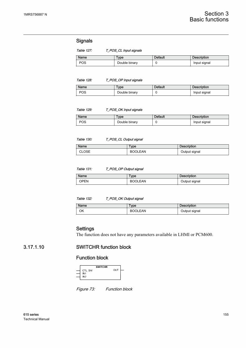
Signals
Table 127: T_POS_CL Input signals
Name Type Default DescriptionPOS Double binary 0 Input signal
Table 128: T_POS_OP Input signals
Name Type Default DescriptionPOS Double binary 0 Input signal
Table 129: T_POS_OK Input signals
Name Type Default DescriptionPOS Double binary 0 Input signal
Table 130: T_POS_CL Output signal
Name Type DescriptionCLOSE BOOLEAN Output signal
Table 131: T_POS_OP Output signal
Name Type DescriptionOPEN BOOLEAN Output signal
Table 132: T_POS_OK Output signal
Name Type DescriptionOK BOOLEAN Output signal
SettingsThe function does not have any parameters available in LHMI or PCM600.
3.17.1.10 SWITCHR function block
Function block
GUID-63F5ED57-E6C4-40A2-821A-4814E1554663 V1 EN
Figure 73: Function block
1MRS756887 N Section 3Basic functions
615 series 155Technical Manual

FunctionalitySWITCHR switching block for REAL data type is operated by the CTL_SW input,selects the output value OUT between the IN1 and IN2 inputs.
CTL_SW OUTFALSE IN2
TRUE IN1
Signals
Table 133: SWITCHR Input signals
Name Type Default DescriptionCTL_SW BOOLEAN 1 Control Switch
IN1 REAL 0.0 Real input 1
IN2 REAL 0.0 Real input 2
Table 134: SWITCHR Output signals
Name Type DescriptionOUT REAL Real switch output
3.17.1.11 SWITCHI32 function block
Function block
GUID-E5DC5DEC-6A0E-4385-9FA9-0F5EFD87304C V1 EN
Figure 74: Function block
FunctionalitySWITCHI32 switching block for 32-bit integer data type is operated by the CTL_SWinput, which selects the output value OUT between the IN1 and IN2 inputs.
Table 135: SWITCHI32
CTL_SW OUTFALSE IN2
TRUE IN1
Section 3 1MRS756887 NBasic functions
156 615 seriesTechnical Manual

Signals
Table 136: SWITCHI32 input signals
Name Type Default DescriptionCTL_SW BOOLEAN 1 Control Switch
IN1 INT32 0 Input signal 1
IN2 INT32 0 Input signal 2
Table 137: SWITCHI32 output signals
Name Type DescriptionOUT INT32 Output signal
3.17.1.12 SR function block
Function block
GUID-0B62CAED-F8A4-4738-B546-677DA362FE24 V2 EN
Figure 75: Function block
FunctionalityThe SR flip-flop output Q can be set or reset from the S or R inputs. S input has a higherpriority over the R input. Output NOTQ is the negation of output Q.
The statuses of outputs Q and NOTQ are not retained in the nonvolatilememory.
Table 138: Truth table for SR flip-flop
S R Q0 0 01)
0 1 0
1 0 1
1 1 1
1) Keep state/no change
1MRS756887 N Section 3Basic functions
615 series 157Technical Manual
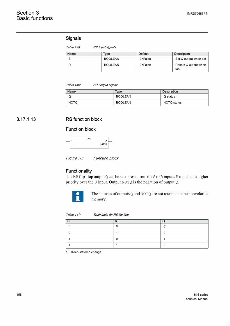
Signals
Table 139: SR Input signals
Name Type Default DescriptionS BOOLEAN 0=False Set Q output when set
R BOOLEAN 0=False Resets Q output whenset
Table 140: SR Output signals
Name Type DescriptionQ BOOLEAN Q status
NOTQ BOOLEAN NOTQ status
3.17.1.13 RS function block
Function block
GUID-3876F400-A7D1-45DA-B20F-DFA5AE863073 V1 EN
Figure 76: Function block
FunctionalityThe RS flip-flop output Q can be set or reset from the S or R inputs. R input has a higherpriority over the S input. Output NOTQ is the negation of output Q.
The statuses of outputs Q and NOTQ are not retained in the nonvolatilememory.
Table 141: Truth table for RS flip-flop
S R Q0 0 01)
0 1 0
1 0 1
1 1 0
1) Keep state/no change
Section 3 1MRS756887 NBasic functions
158 615 seriesTechnical Manual

Signals
Table 142: RS Input signals
Name Type Default DescriptionS BOOLEAN 0=False Set Q output when set
R BOOLEAN 0=False Resets Q output whenset
Table 143: RS Output signals
Name Type DescriptionQ BOOLEAN Q status
NOTQ BOOLEAN NOTQ status
Technical revision history
Table 144: RS Technical revision history
Technical revision ChangeL The name of the function has been changed from
SR to RS.
3.17.2 Minimum pulse timer
3.17.2.1 Minimum pulse timer TPGAPC
Function block
GUID-809F4B4A-E684-43AC-9C34-574A93FE0EBC V1 EN
Figure 77: Function block
FunctionalityThe Minimum pulse timer function TPGAPC contains two independent timers. Thefunction has a settable pulse length (in milliseconds). The timers are used for settingthe minimum pulse length for example, the signal outputs. Once the input is activated,the output is set for a specific duration using the Pulse time setting. Both timers use thesame setting parameter.
1MRS756887 N Section 3Basic functions
615 series 159Technical Manual
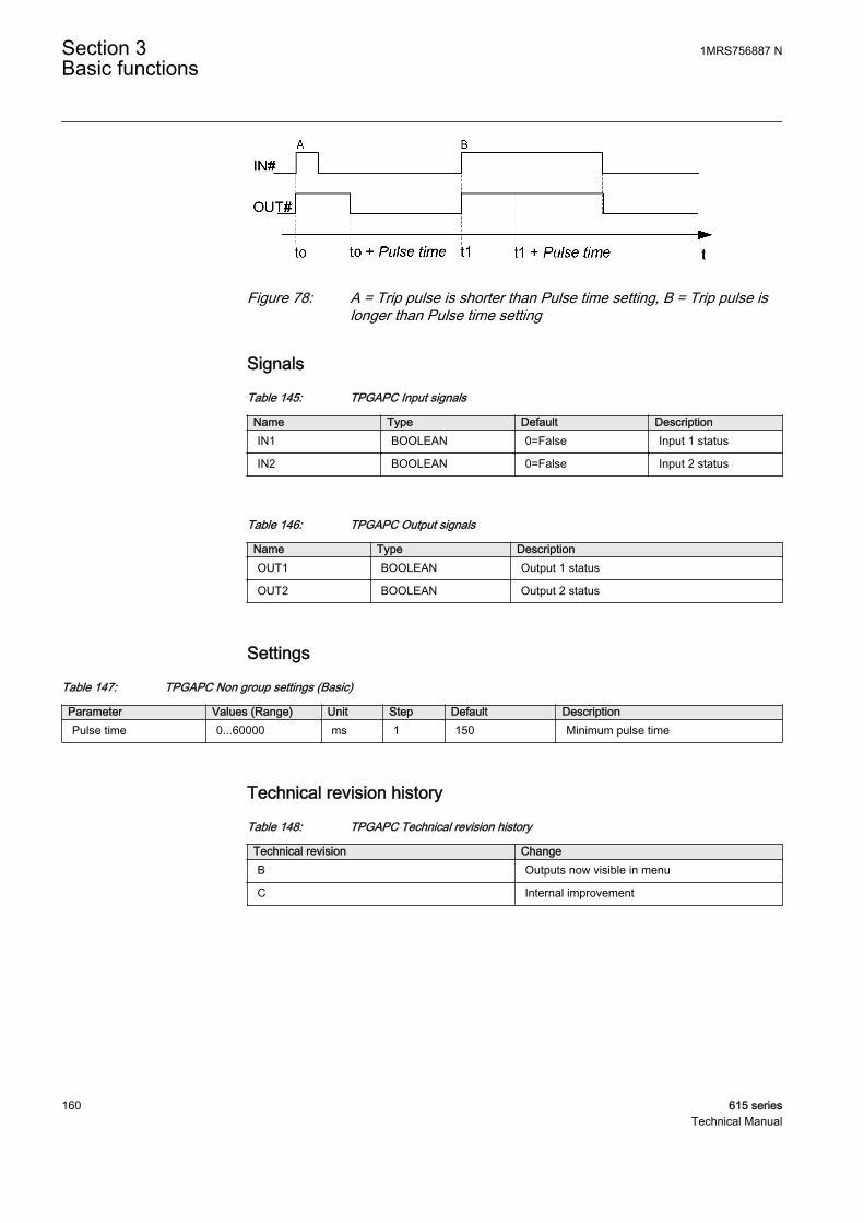
GUID-8196EE39-3529-46DC-A161-B1C40224559F V1 EN
Figure 78: A = Trip pulse is shorter than Pulse time setting, B = Trip pulse islonger than Pulse time setting
Signals
Table 145: TPGAPC Input signals
Name Type Default DescriptionIN1 BOOLEAN 0=False Input 1 status
IN2 BOOLEAN 0=False Input 2 status
Table 146: TPGAPC Output signals
Name Type DescriptionOUT1 BOOLEAN Output 1 status
OUT2 BOOLEAN Output 2 status
Settings
Table 147: TPGAPC Non group settings (Basic)
Parameter Values (Range) Unit Step Default DescriptionPulse time 0...60000 ms 1 150 Minimum pulse time
Technical revision history
Table 148: TPGAPC Technical revision history
Technical revision ChangeB Outputs now visible in menu
C Internal improvement
Section 3 1MRS756887 NBasic functions
160 615 seriesTechnical Manual
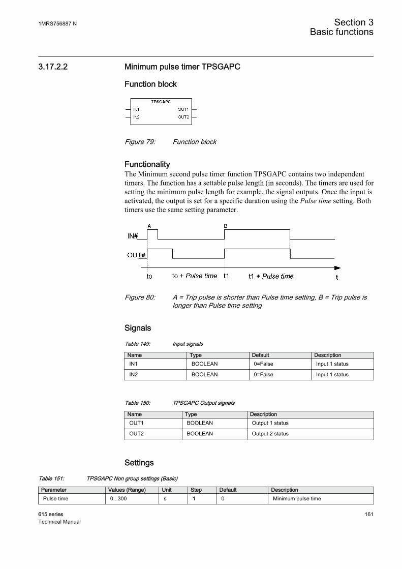
3.17.2.2 Minimum pulse timer TPSGAPC
Function block
GUID-F9AACAF7-2183-4315-BE6F-CD53618009C0 V1 EN
Figure 79: Function block
FunctionalityThe Minimum second pulse timer function TPSGAPC contains two independenttimers. The function has a settable pulse length (in seconds). The timers are used forsetting the minimum pulse length for example, the signal outputs. Once the input isactivated, the output is set for a specific duration using the Pulse time setting. Bothtimers use the same setting parameter.
GUID-8196EE39-3529-46DC-A161-B1C40224559F V1 EN
Figure 80: A = Trip pulse is shorter than Pulse time setting, B = Trip pulse islonger than Pulse time setting
Signals
Table 149: Input signals
Name Type Default DescriptionIN1 BOOLEAN 0=False Input 1 status
IN2 BOOLEAN 0=False Input 1 status
Table 150: TPSGAPC Output signals
Name Type DescriptionOUT1 BOOLEAN Output 1 status
OUT2 BOOLEAN Output 2 status
Settings
Table 151: TPSGAPC Non group settings (Basic)
Parameter Values (Range) Unit Step Default DescriptionPulse time 0...300 s 1 0 Minimum pulse time
1MRS756887 N Section 3Basic functions
615 series 161Technical Manual
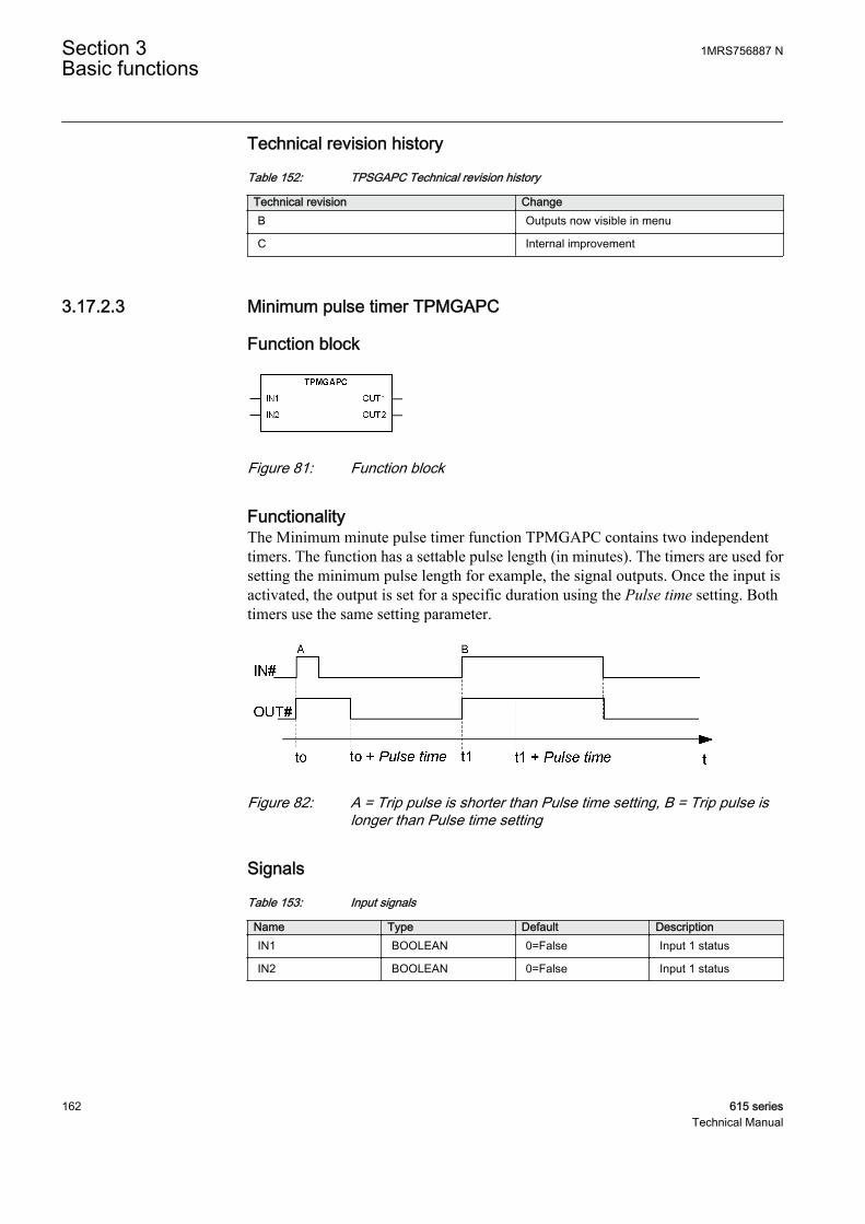
Technical revision history
Table 152: TPSGAPC Technical revision history
Technical revision ChangeB Outputs now visible in menu
C Internal improvement
3.17.2.3 Minimum pulse timer TPMGAPC
Function block
GUID-AB26B298-F7FA-428F-B498-6605DB5B0661 V1 EN
Figure 81: Function block
FunctionalityThe Minimum minute pulse timer function TPMGAPC contains two independenttimers. The function has a settable pulse length (in minutes). The timers are used forsetting the minimum pulse length for example, the signal outputs. Once the input isactivated, the output is set for a specific duration using the Pulse time setting. Bothtimers use the same setting parameter.
GUID-8196EE39-3529-46DC-A161-B1C40224559F V1 EN
Figure 82: A = Trip pulse is shorter than Pulse time setting, B = Trip pulse islonger than Pulse time setting
Signals
Table 153: Input signals
Name Type Default DescriptionIN1 BOOLEAN 0=False Input 1 status
IN2 BOOLEAN 0=False Input 1 status
Section 3 1MRS756887 NBasic functions
162 615 seriesTechnical Manual
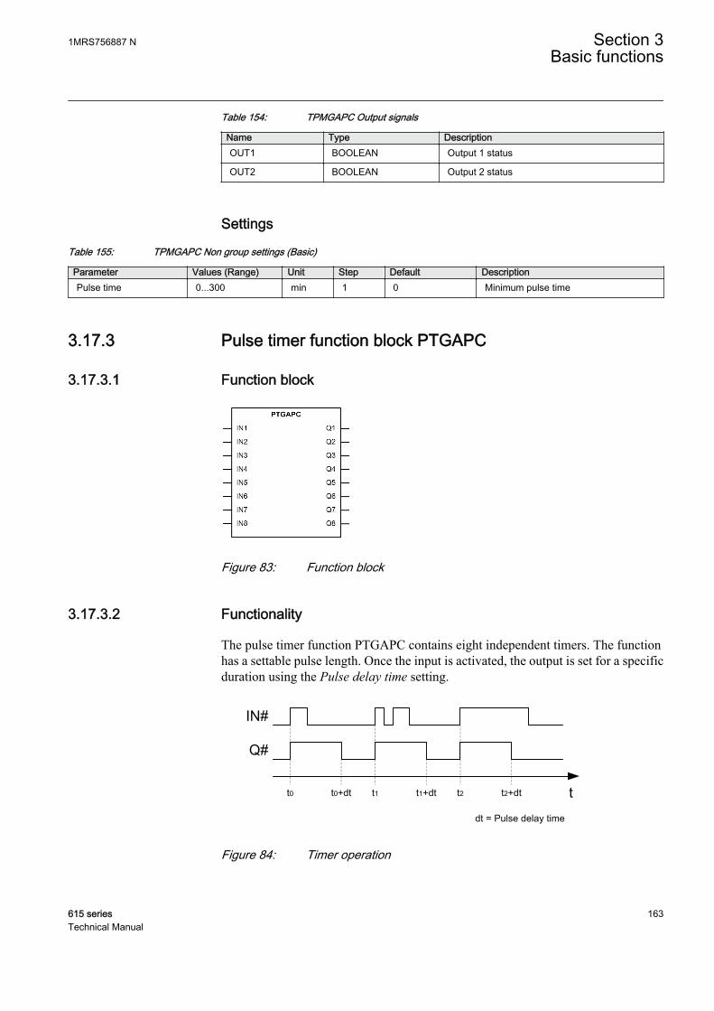
Table 154: TPMGAPC Output signals
Name Type DescriptionOUT1 BOOLEAN Output 1 status
OUT2 BOOLEAN Output 2 status
Settings
Table 155: TPMGAPC Non group settings (Basic)
Parameter Values (Range) Unit Step Default DescriptionPulse time 0...300 min 1 0 Minimum pulse time
3.17.3 Pulse timer function block PTGAPC
3.17.3.1 Function block
GUID-2AA275E8-31D4-4CFE-8BDA-A377213BBA89 V1 EN
Figure 83: Function block
3.17.3.2 Functionality
The pulse timer function PTGAPC contains eight independent timers. The functionhas a settable pulse length. Once the input is activated, the output is set for a specificduration using the Pulse delay time setting.
t0 t0+dt t1 t1+dt t2 t2+dt
dt = Pulse delay timeGUID-08F451EE-5110-41D9-95ED-084D7296FA22 V1 EN
Figure 84: Timer operation
1MRS756887 N Section 3Basic functions
615 series 163Technical Manual

3.17.3.3 Signals
Table 156: PTGAPC Input signals
Name Type Default DescriptionIN1 BOOLEAN 0=False Input 1 status
IN2 BOOLEAN 0=False Input 2 status
IN3 BOOLEAN 0=False Input 3 status
IN4 BOOLEAN 0=False Input 4 status
IN5 BOOLEAN 0=False Input 5 status
IN6 BOOLEAN 0=False Input 6 status
IN7 BOOLEAN 0=False Input 7 status
IN8 BOOLEAN 0=False Input 8 status
Table 157: PTGAPC Output signals
Name Type DescriptionQ1 BOOLEAN Output 1 status
Q2 BOOLEAN Output 2 status
Q3 BOOLEAN Output 3 status
Q4 BOOLEAN Output 4 status
Q5 BOOLEAN Output 5 status
Q6 BOOLEAN Output 6 status
Q7 BOOLEAN Output 7 status
Q8 BOOLEAN Output 8 status
3.17.3.4 Settings
Table 158: PTGAPC Non group settings (Basic)
Parameter Values (Range) Unit Step Default DescriptionPulse time 1 0...3600000 ms 10 0 Pulse time
Pulse time 2 0...3600000 ms 10 0 Pulse time
Pulse time 3 0...3600000 ms 10 0 Pulse time
Pulse time 4 0...3600000 ms 10 0 Pulse time
Pulse time 5 0...3600000 ms 10 0 Pulse time
Pulse time 6 0...3600000 ms 10 0 Pulse time
Pulse time 7 0...3600000 ms 10 0 Pulse time
Pulse time 8 0...3600000 ms 10 0 Pulse time
Section 3 1MRS756887 NBasic functions
164 615 seriesTechnical Manual
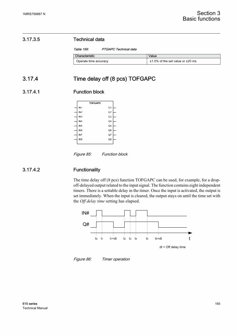
3.17.3.5 Technical data
Table 159: PTGAPC Technical data
Characteristic ValueOperate time accuracy ±1.0% of the set value or ±20 ms
3.17.4 Time delay off (8 pcs) TOFGAPC
3.17.4.1 Function block
GUID-6BFF6180-042F-4526-BB80-D53B2458F376 V1 EN
Figure 85: Function block
3.17.4.2 Functionality
The time delay off (8 pcs) function TOFGAPC can be used, for example, for a drop-off-delayed output related to the input signal. The function contains eight independenttimers. There is a settable delay in the timer. Once the input is activated, the output isset immediately. When the input is cleared, the output stays on until the time set withthe Off delay time setting has elapsed.
t0 t1+dt t2 t3 t5+dt
dt = Off delay time
t1 t4 t5
GUID-D45492E6-5FBC-420C-B1BF-B3A1F65ADF96 V1 EN
Figure 86: Timer operation
1MRS756887 N Section 3Basic functions
615 series 165Technical Manual
3.17.4.3 Signals
Table 160: TOFGAPC Input signals
Name Type Default DescriptionIN1 BOOLEAN 0=False Input 1 status
IN2 BOOLEAN 0=False Input 2 status
IN3 BOOLEAN 0=False Input 3 status
IN4 BOOLEAN 0=False Input 4 status
IN5 BOOLEAN 0=False Input 5 status
IN6 BOOLEAN 0=False Input 6 status
IN7 BOOLEAN 0=False Input 7 status
IN8 BOOLEAN 0=False Input 8 status
Table 161: TOFGAPC Output signals
Name Type DescriptionQ1 BOOLEAN Output 1 status
Q2 BOOLEAN Output 2 status
Q3 BOOLEAN Output 3 status
Q4 BOOLEAN Output 4 status
Q5 BOOLEAN Output 5 status
Q6 BOOLEAN Output 6 status
Q7 BOOLEAN Output 7 status
Q8 BOOLEAN Output 8 status
3.17.4.4 Settings
Table 162: TOFGAPC Non group settings (Basic)
Parameter Values (Range) Unit Step Default DescriptionOff delay time 1 0...3600000 ms 10 0 Off delay time
Off delay time 2 0...3600000 ms 10 0 Off delay time
Off delay time 3 0...3600000 ms 10 0 Off delay time
Off delay time 4 0...3600000 ms 10 0 Off delay time
Off delay time 5 0...3600000 ms 10 0 Off delay time
Off delay time 6 0...3600000 ms 10 0 Off delay time
Off delay time 7 0...3600000 ms 10 0 Off delay time
Off delay time 8 0...3600000 ms 10 0 Off delay time
Section 3 1MRS756887 NBasic functions
166 615 seriesTechnical Manual

3.17.4.5 Technical data
Table 163: TOFGAPC Technical data
Characteristic ValueOperate time accuracy ±1.0% of the set value or ±20 ms
3.17.5 Time delay on (8 pcs) TONGAPC
3.17.5.1 Function block
GUID-B694FC27-E6AB-40FF-B1C7-A7EB608D6866 V1 EN
Figure 87: Function block
3.17.5.2 Functionality
The time delay on (8 pcs) function TONGAPC can be used, for example, for time-delaying the output related to the input signal. TONGAPC contains eight independenttimers. The timer has a settable time delay. Once the input is activated, the output isset after the time set by the On delay time setting has elapsed.
t0 t0+dt t2 t3 t4+dt
dt = On delay time
t1 t4 t5
GUID-B74EE764-8B2E-4FBE-8CE7-779F6B739A11 V1 EN
Figure 88: Timer operation
1MRS756887 N Section 3Basic functions
615 series 167Technical Manual

3.17.5.3 Signals
Table 164: TONGAPC Input signals
Name Type Default DescriptionIN1 BOOLEAN 0=False Input 1
IN2 BOOLEAN 0=False Input 2
IN3 BOOLEAN 0=False Input 3
IN4 BOOLEAN 0=False Input 4
IN5 BOOLEAN 0=False Input 5
IN6 BOOLEAN 0=False Input 6
IN7 BOOLEAN 0=False Input 7
IN8 BOOLEAN 0=False Input 8
Table 165: TONGAPC Output signals
Name Type DescriptionQ1 BOOLEAN Output 1
Q2 BOOLEAN Output 2
Q3 BOOLEAN Output 3
Q4 BOOLEAN Output 4
Q5 BOOLEAN Output 5
Q6 BOOLEAN Output 6
Q7 BOOLEAN Output 7
Q8 BOOLEAN Output 8
3.17.5.4 Settings
Table 166: TONGAPC Non group settings (Basic)
Parameter Values (Range) Unit Step Default DescriptionOn delay time 1 0...3600000 ms 10 0 On delay time
On delay time 2 0...3600000 ms 10 0 On delay time
On delay time 3 0...3600000 ms 10 0 On delay time
On delay time 4 0...3600000 ms 10 0 On delay time
On delay time 5 0...3600000 ms 10 0 On delay time
On delay time 6 0...3600000 ms 10 0 On delay time
On delay time 7 0...3600000 ms 10 0 On delay time
On delay time 8 0...3600000 ms 10 0 On delay time
Section 3 1MRS756887 NBasic functions
168 615 seriesTechnical Manual
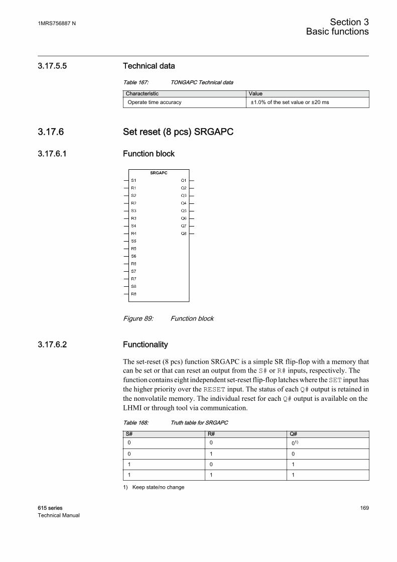
3.17.5.5 Technical data
Table 167: TONGAPC Technical data
Characteristic ValueOperate time accuracy ±1.0% of the set value or ±20 ms
3.17.6 Set reset (8 pcs) SRGAPC
3.17.6.1 Function block
GUID-93136D07-FDC4-4356-95B5-54D3B2FC9B1C V1 EN
Figure 89: Function block
3.17.6.2 Functionality
The set-reset (8 pcs) function SRGAPC is a simple SR flip-flop with a memory thatcan be set or that can reset an output from the S# or R# inputs, respectively. Thefunction contains eight independent set-reset flip-flop latches where the SET input hasthe higher priority over the RESET input. The status of each Q# output is retained inthe nonvolatile memory. The individual reset for each Q# output is available on theLHMI or through tool via communication.
Table 168: Truth table for SRGAPC
S# R# Q#0 0 01)
0 1 0
1 0 1
1 1 1
1) Keep state/no change
1MRS756887 N Section 3Basic functions
615 series 169Technical Manual
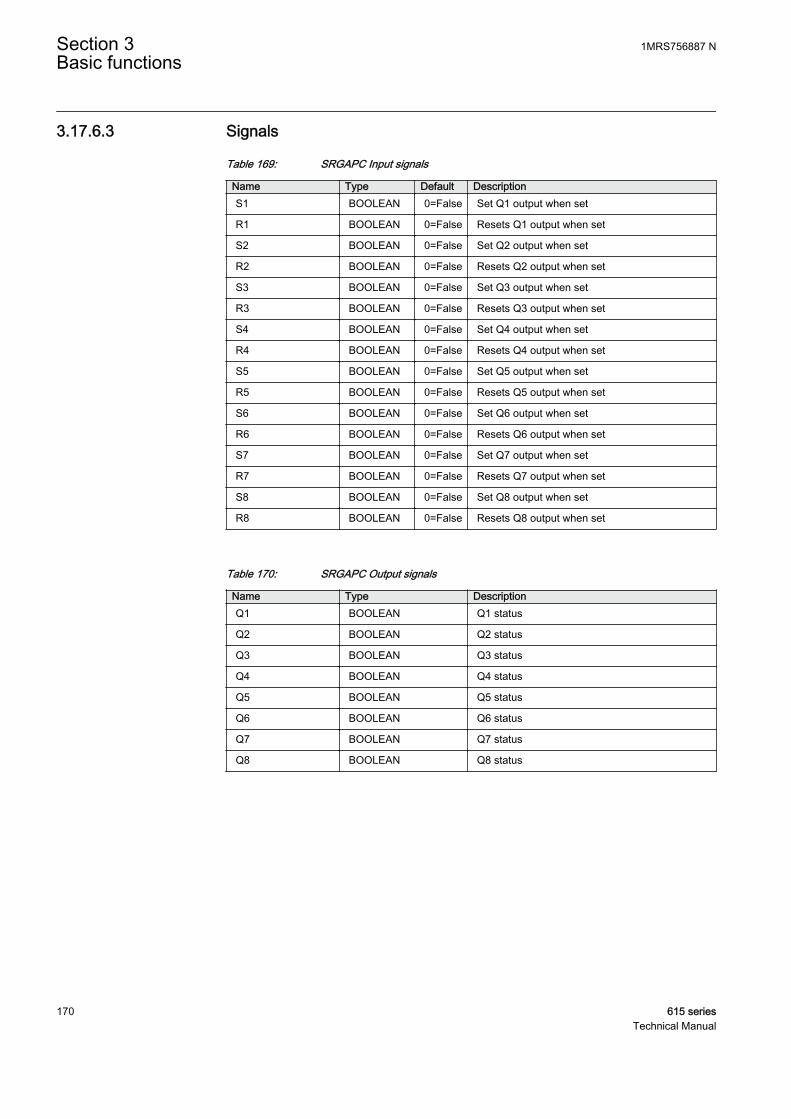
3.17.6.3 Signals
Table 169: SRGAPC Input signals
Name Type Default DescriptionS1 BOOLEAN 0=False Set Q1 output when set
R1 BOOLEAN 0=False Resets Q1 output when set
S2 BOOLEAN 0=False Set Q2 output when set
R2 BOOLEAN 0=False Resets Q2 output when set
S3 BOOLEAN 0=False Set Q3 output when set
R3 BOOLEAN 0=False Resets Q3 output when set
S4 BOOLEAN 0=False Set Q4 output when set
R4 BOOLEAN 0=False Resets Q4 output when set
S5 BOOLEAN 0=False Set Q5 output when set
R5 BOOLEAN 0=False Resets Q5 output when set
S6 BOOLEAN 0=False Set Q6 output when set
R6 BOOLEAN 0=False Resets Q6 output when set
S7 BOOLEAN 0=False Set Q7 output when set
R7 BOOLEAN 0=False Resets Q7 output when set
S8 BOOLEAN 0=False Set Q8 output when set
R8 BOOLEAN 0=False Resets Q8 output when set
Table 170: SRGAPC Output signals
Name Type DescriptionQ1 BOOLEAN Q1 status
Q2 BOOLEAN Q2 status
Q3 BOOLEAN Q3 status
Q4 BOOLEAN Q4 status
Q5 BOOLEAN Q5 status
Q6 BOOLEAN Q6 status
Q7 BOOLEAN Q7 status
Q8 BOOLEAN Q8 status
Section 3 1MRS756887 NBasic functions
170 615 seriesTechnical Manual

3.17.6.4 Settings
Table 171: SRGAPC Non group settings (Basic)
Parameter Values (Range) Unit Step Default DescriptionReset Q1 0=Cancel
1=Reset 0=Cancel Resets Q1 output when set
Reset Q2 0=Cancel1=Reset
0=Cancel Resets Q2 output when set
Reset Q3 0=Cancel1=Reset
0=Cancel Resets Q3 output when set
Reset Q4 0=Cancel1=Reset
0=Cancel Resets Q4 output when set
Reset Q5 0=Cancel1=Reset
0=Cancel Resets Q5 output when set
Reset Q6 0=Cancel1=Reset
0=Cancel Resets Q6 output when set
Reset Q7 0=Cancel1=Reset
0=Cancel Resets Q7 output when set
Reset Q8 0=Cancel1=Reset
0=Cancel Resets Q8 output when set
3.17.7 Move (8 pcs) MVGAPC
3.17.7.1 Function block
GUID-C79D9450-8CB2-49AF-B825-B702EA2CD9F5 V2 EN
Figure 90: Function block
3.17.7.2 Functionality
The move (8 pcs) function MVGAPC is used for user logic bits. Each input state isdirectly copied to the output state. This allows the creating of events from advancedlogic combinations.
1MRS756887 N Section 3Basic functions
615 series 171Technical Manual
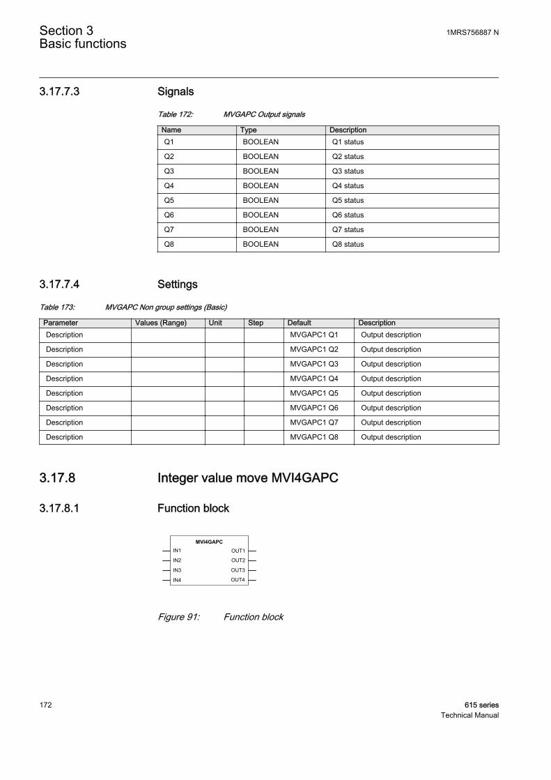
3.17.7.3 Signals
Table 172: MVGAPC Output signals
Name Type DescriptionQ1 BOOLEAN Q1 status
Q2 BOOLEAN Q2 status
Q3 BOOLEAN Q3 status
Q4 BOOLEAN Q4 status
Q5 BOOLEAN Q5 status
Q6 BOOLEAN Q6 status
Q7 BOOLEAN Q7 status
Q8 BOOLEAN Q8 status
3.17.7.4 Settings
Table 173: MVGAPC Non group settings (Basic)
Parameter Values (Range) Unit Step Default DescriptionDescription MVGAPC1 Q1 Output description
Description MVGAPC1 Q2 Output description
Description MVGAPC1 Q3 Output description
Description MVGAPC1 Q4 Output description
Description MVGAPC1 Q5 Output description
Description MVGAPC1 Q6 Output description
Description MVGAPC1 Q7 Output description
Description MVGAPC1 Q8 Output description
3.17.8 Integer value move MVI4GAPC
3.17.8.1 Function block
IN1
IN2 OUT2
IN3
IN4
OUT3
OUT4
OUT1
MVI4GAPC
GUID-9049D1C3-A3FC-4B92-8CDC-9F3D5B916471 V1 EN
Figure 91: Function block
Section 3 1MRS756887 NBasic functions
172 615 seriesTechnical Manual
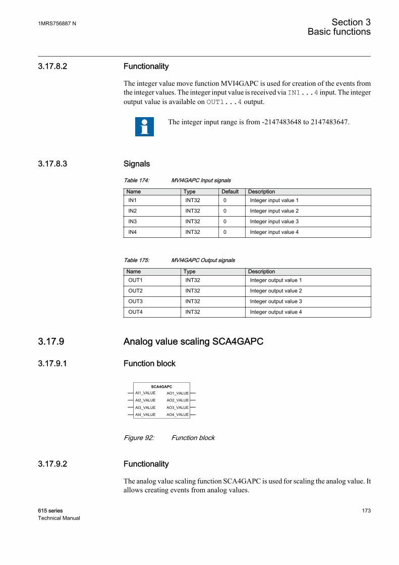
3.17.8.2 Functionality
The integer value move function MVI4GAPC is used for creation of the events fromthe integer values. The integer input value is received via IN1...4 input. The integeroutput value is available on OUT1...4 output.
The integer input range is from -2147483648 to 2147483647.
3.17.8.3 Signals
Table 174: MVI4GAPC Input signals
Name Type Default DescriptionIN1 INT32 0 Integer input value 1
IN2 INT32 0 Integer input value 2
IN3 INT32 0 Integer input value 3
IN4 INT32 0 Integer input value 4
Table 175: MVI4GAPC Output signals
Name Type DescriptionOUT1 INT32 Integer output value 1
OUT2 INT32 Integer output value 2
OUT3 INT32 Integer output value 3
OUT4 INT32 Integer output value 4
3.17.9 Analog value scaling SCA4GAPC
3.17.9.1 Function block
AI1_VALUE
AI2_VALUE AO2_VALUE
AI3_VALUE
AI4_VALUE
AO3_VALUE
AO4_VALUE
AO1_VALUE
SCA4GAPC
GUID-9D830A50-37F1-4478-B458-9C90742ECA54 V1 EN
Figure 92: Function block
3.17.9.2 Functionality
The analog value scaling function SCA4GAPC is used for scaling the analog value. Itallows creating events from analog values.
1MRS756887 N Section 3Basic functions
615 series 173Technical Manual
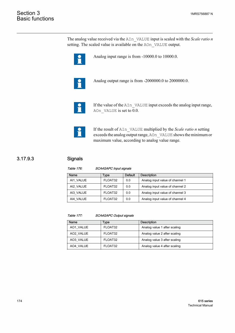
The analog value received via the AIn_VALUE input is scaled with the Scale ratio nsetting. The scaled value is available on the AOn_VALUE output.
Analog input range is from -10000.0 to 10000.0.
Analog output range is from -2000000.0 to 2000000.0.
If the value of the AIn_VALUE input exceeds the analog input range,AOn_VALUE is set to 0.0.
If the result of AIn_VALUE multiplied by the Scale ratio n settingexceeds the analog output range, AOn_VALUE shows the minimum ormaximum value, according to analog value range.
3.17.9.3 Signals
Table 176: SCA4GAPC Input signals
Name Type Default DescriptionAI1_VALUE FLOAT32 0.0 Analog input value of channel 1
AI2_VALUE FLOAT32 0.0 Analog input value of channel 2
AI3_VALUE FLOAT32 0.0 Analog input value of channel 3
AI4_VALUE FLOAT32 0.0 Analog input value of channel 4
Table 177: SCA4GAPC Output signals
Name Type DescriptionAO1_VALUE FLOAT32 Analog value 1 after scaling
AO2_VALUE FLOAT32 Analog value 2 after scaling
AO3_VALUE FLOAT32 Analog value 3 after scaling
AO4_VALUE FLOAT32 Analog value 4 after scaling
Section 3 1MRS756887 NBasic functions
174 615 seriesTechnical Manual
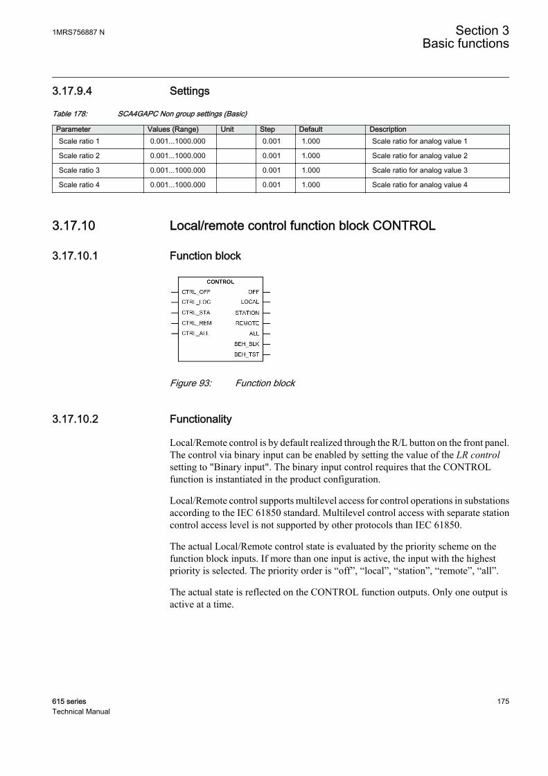
3.17.9.4 Settings
Table 178: SCA4GAPC Non group settings (Basic)
Parameter Values (Range) Unit Step Default DescriptionScale ratio 1 0.001...1000.000 0.001 1.000 Scale ratio for analog value 1
Scale ratio 2 0.001...1000.000 0.001 1.000 Scale ratio for analog value 2
Scale ratio 3 0.001...1000.000 0.001 1.000 Scale ratio for analog value 3
Scale ratio 4 0.001...1000.000 0.001 1.000 Scale ratio for analog value 4
3.17.10 Local/remote control function block CONTROL
3.17.10.1 Function block
GUID-FA386432-3AEF-468D-B25E-D1C5BDA838E3 V3 EN
Figure 93: Function block
3.17.10.2 Functionality
Local/Remote control is by default realized through the R/L button on the front panel.The control via binary input can be enabled by setting the value of the LR controlsetting to "Binary input". The binary input control requires that the CONTROLfunction is instantiated in the product configuration.
Local/Remote control supports multilevel access for control operations in substationsaccording to the IEC 61850 standard. Multilevel control access with separate stationcontrol access level is not supported by other protocols than IEC 61850.
The actual Local/Remote control state is evaluated by the priority scheme on thefunction block inputs. If more than one input is active, the input with the highestpriority is selected. The priority order is “off”, “local”, “station”, “remote”, “all”.
The actual state is reflected on the CONTROL function outputs. Only one output isactive at a time.
1MRS756887 N Section 3Basic functions
615 series 175Technical Manual

Table 179: Truth table for CONTROL
Input OutputCTRL_OFF CTRL_LOC CTRL_STA CTRL_REM CTRL_ALLTRUE N/A N/A N/A N/A OFF = TRUE
FALSE TRUE N/A N/A N/A LOCAL =TRUE
FALSE FALSE TRUE N/A N/A STATION =TRUE
FALSE FALSE FALSE TRUE TRUE REMOTE =TRUE
FALSE FALSE FALSE FALSE TRUE ALL = TRUE
FALSE FALSE FALSE FALSE FALSE OFF = TRUE
3.17.10.3 L/R control access
Four different Local/Remote control access scenarios are possible depending on theselected station authority level: “L,R”, “L,R,L+R”, “L,S,R” and “L, S, S+R, L+S, L+S+R”. If control commands need to be allowed from multiple levels, multilevelaccess can be used. Multilevel access is possible only by using the station authoritylevels “L,R,L+R” and “L, S, S+R, L+S, L+S+R”. Multilevel access status is availablefrom IEC 61850 data object CTRL.LLN0.MltLev.
Control access selection is made with R/L button or CONTROL function block andIEC 61850 data object CTRL.LLN0.LocSta. When writing CTRL.LLN0.LocSta IEC61850 data object, IEC 61850 command originator category station must be used bythe client, and remote IEC 61850 control access must be allowed by the relay stationauthority. CTRL.LLN0.LocSta data object value is retained in the nonvolatilememory. The present control status can be monitored in the HMI or PCM600 viaMonitoring/Control command with the LR state parameter or from the IEC 61850data object CTRL.LLN0. LocKeyHMI.
IEC 61850 command originator category is always set by the IEC 61850 client. Therelay supports station and remote IEC 61850 command originator categories,depending on the selected station authority level.
3.17.10.4 Station authority level “L,R”
Relay's default station authority level is “L,R”. In this scenario only local or remotecontrol access is allowed. Control access with IEC 61850 command originatorcategory station is interpreted as remote access. There is no multilevel access.
Section 3 1MRS756887 NBasic functions
176 615 seriesTechnical Manual
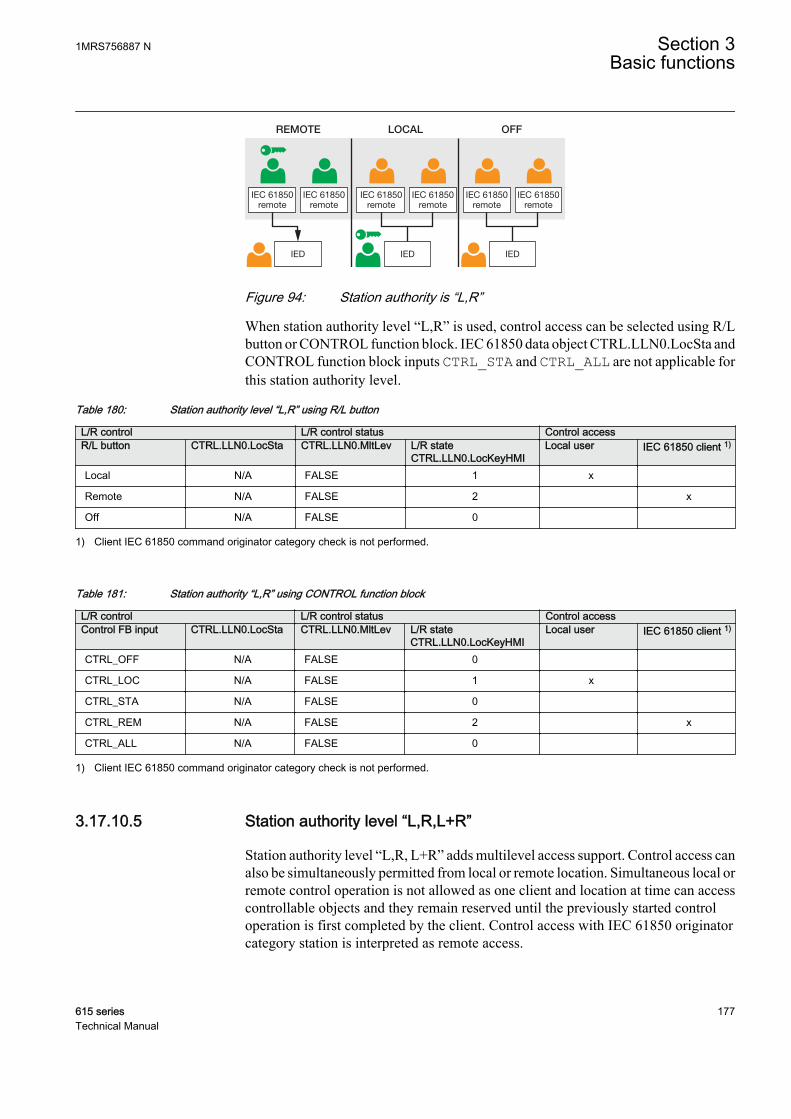
IEC 61850remote
IED
IEC 61850remote
REMOTE LOCAL OFF
IEC 61850remote
IED
IEC 61850remote
IEC 61850remote
IEC 61850remote
IED
GUID-08BACCE4-AF4A-4150-A01A-49FBEE63B438 V1 EN
Figure 94: Station authority is “L,R”
When station authority level “L,R” is used, control access can be selected using R/Lbutton or CONTROL function block. IEC 61850 data object CTRL.LLN0.LocSta andCONTROL function block inputs CTRL_STA and CTRL_ALL are not applicable forthis station authority level.
Table 180: Station authority level “L,R” using R/L button
L/R control L/R control status Control accessR/L button CTRL.LLN0.LocSta CTRL.LLN0.MltLev L/R state
CTRL.LLN0.LocKeyHMILocal user IEC 61850 client 1)
Local N/A FALSE 1 x
Remote N/A FALSE 2 x
Off N/A FALSE 0
1) Client IEC 61850 command originator category check is not performed.
Table 181: Station authority “L,R” using CONTROL function block
L/R control L/R control status Control accessControl FB input CTRL.LLN0.LocSta CTRL.LLN0.MltLev L/R state
CTRL.LLN0.LocKeyHMILocal user IEC 61850 client 1)
CTRL_OFF N/A FALSE 0
CTRL_LOC N/A FALSE 1 x
CTRL_STA N/A FALSE 0
CTRL_REM N/A FALSE 2 x
CTRL_ALL N/A FALSE 0
1) Client IEC 61850 command originator category check is not performed.
3.17.10.5 Station authority level “L,R,L+R”
Station authority level “L,R, L+R” adds multilevel access support. Control access canalso be simultaneously permitted from local or remote location. Simultaneous local orremote control operation is not allowed as one client and location at time can accesscontrollable objects and they remain reserved until the previously started controloperation is first completed by the client. Control access with IEC 61850 originatorcategory station is interpreted as remote access.
1MRS756887 N Section 3Basic functions
615 series 177Technical Manual
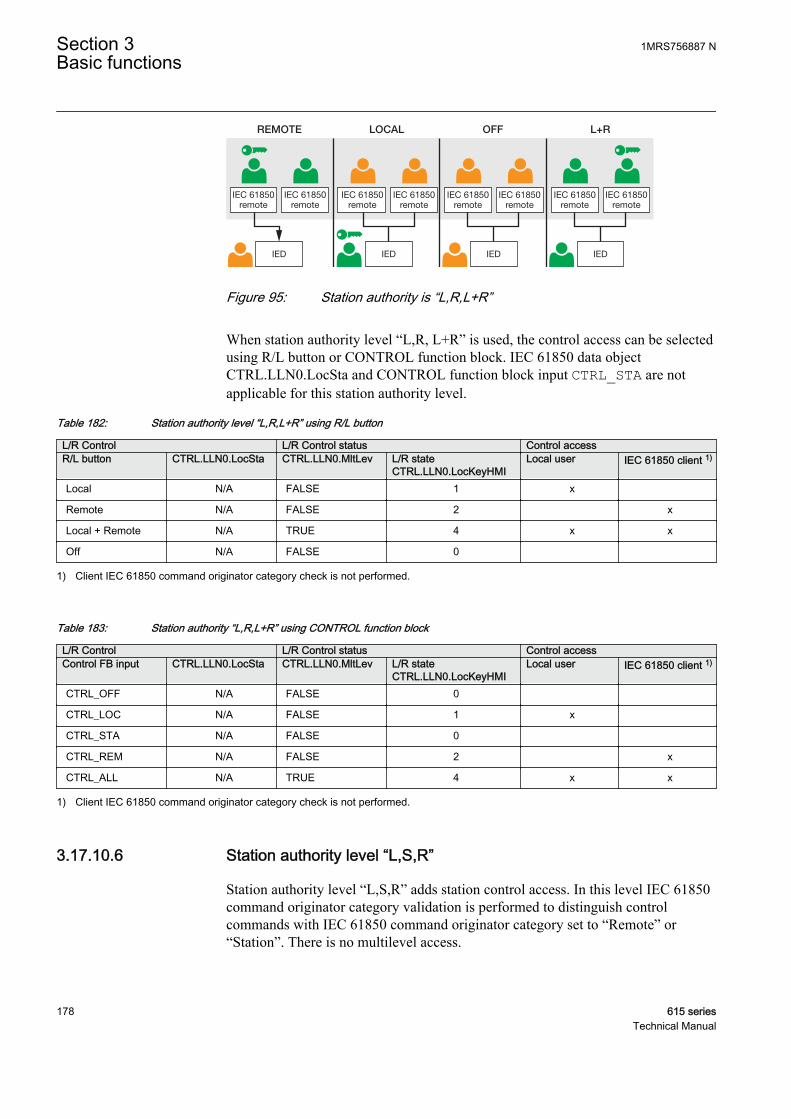
IEC 61850remote
IED
IEC 61850remote
IEC 61850remote
IED
IEC 61850remote
IEC 61850remote
IEC 61850remote
IED
L+R
IEC 61850remote
IEC 61850remote
IED
REMOTE LOCAL OFF
GUID-10D77281-14C3-4066-B641-98A6F8904E39 V1 EN
Figure 95: Station authority is “L,R,L+R”
When station authority level “L,R, L+R” is used, the control access can be selectedusing R/L button or CONTROL function block. IEC 61850 data objectCTRL.LLN0.LocSta and CONTROL function block input CTRL_STA are notapplicable for this station authority level.
Table 182: Station authority level “L,R,L+R” using R/L button
L/R Control L/R Control status Control accessR/L button CTRL.LLN0.LocSta CTRL.LLN0.MltLev L/R state
CTRL.LLN0.LocKeyHMILocal user IEC 61850 client 1)
Local N/A FALSE 1 x
Remote N/A FALSE 2 x
Local + Remote N/A TRUE 4 x x
Off N/A FALSE 0
1) Client IEC 61850 command originator category check is not performed.
Table 183: Station authority “L,R,L+R” using CONTROL function block
L/R Control L/R Control status Control accessControl FB input CTRL.LLN0.LocSta CTRL.LLN0.MltLev L/R state
CTRL.LLN0.LocKeyHMILocal user IEC 61850 client 1)
CTRL_OFF N/A FALSE 0
CTRL_LOC N/A FALSE 1 x
CTRL_STA N/A FALSE 0
CTRL_REM N/A FALSE 2 x
CTRL_ALL N/A TRUE 4 x x
1) Client IEC 61850 command originator category check is not performed.
3.17.10.6 Station authority level “L,S,R”
Station authority level “L,S,R” adds station control access. In this level IEC 61850command originator category validation is performed to distinguish controlcommands with IEC 61850 command originator category set to “Remote” or“Station”. There is no multilevel access.
Section 3 1MRS756887 NBasic functions
178 615 seriesTechnical Manual

IED
IEC 61850remote
IEC 61850station
IEC 61850remote
IEC 61850remote
IEC 61850remote
IED
IEC 61850station
IED
IEC 61850station
IED
IEC 61850station
OFFLOCAL REMOTE STATION
GUID-7BC51FAF-B097-4CD9-AFF4-6D1F3D548C7F V1 EN
Figure 96: Station authority is “L,S,R”
When the station authority level “L,S,R” is used, the control access can be selectedusing R/L button or CONTROL function block. IEC 61850 data objectCTRL.LLN0.LocSta and CONTROL function block input CTRL_STA are applicablefor this station authority level.
Station control access can be reserved by using R/L button or CONTROL functionblock together with IEC 61850 data object CTRL.LLN0.LocSta.
Table 184: Station authority level “L,S,R” using R/L button
L/R Control L/R Control status Control accessR/L button CTRL.LLN0.LocSta 1) CTRL.LLN0.MltLev L/R state
CTRL.LLN0.LocKeyHMILocal user IEC 61850
client 2)IEC 61850client 3)
Local FALSE FALSE 1 x
Remote FALSE FALSE 2 x
Remote TRUE FALSE 3 x
Off FALSE FALSE 0
1) Station client reserves the control operating by writing controllable point LocSta.2) Client IEC 61850 command originator category is remote.3) Client IEC 61850 command originator category is station.
Table 185: Station authority level “L,S,R” using CONTROL function block
L/R Control L/R Control status Control accessControl FB input CTRL.LLN0.LocSta 1) CTRL.LLN0.MltLev L/R state
CTRL.LLN0.LocKeyHMILocal user IEC 61850
client 2)IEC 61850client 3)
CTRL_OFF FALSE FALSE 0
CTRL_LOC FALSE FALSE 1 x
CTRL_STA TRUE FALSE 3 x
Table continues on next page
1MRS756887 N Section 3Basic functions
615 series 179Technical Manual
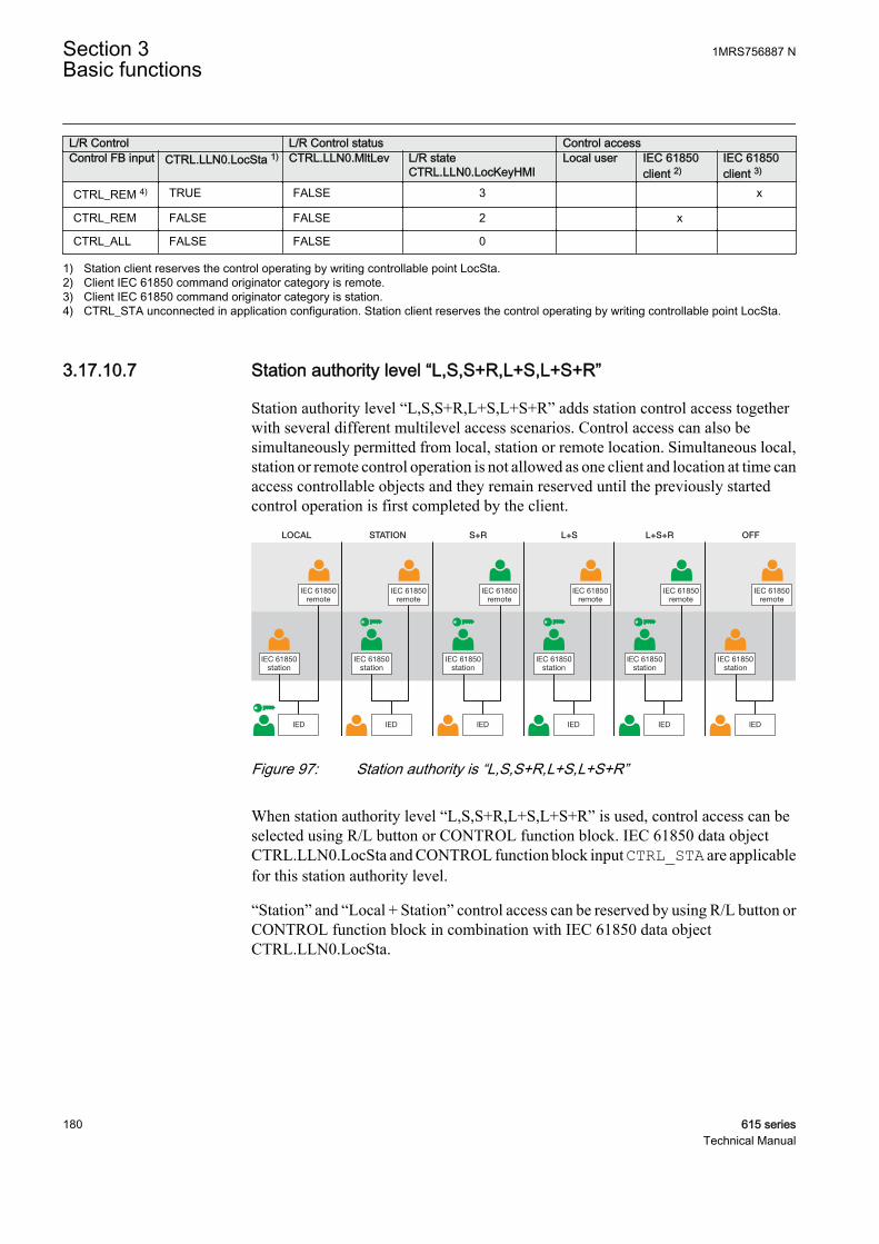
L/R Control L/R Control status Control accessControl FB input CTRL.LLN0.LocSta 1) CTRL.LLN0.MltLev L/R state
CTRL.LLN0.LocKeyHMILocal user IEC 61850
client 2)IEC 61850client 3)
CTRL_REM 4) TRUE FALSE 3 x
CTRL_REM FALSE FALSE 2 x
CTRL_ALL FALSE FALSE 0
1) Station client reserves the control operating by writing controllable point LocSta.2) Client IEC 61850 command originator category is remote.3) Client IEC 61850 command originator category is station.4) CTRL_STA unconnected in application configuration. Station client reserves the control operating by writing controllable point LocSta.
3.17.10.7 Station authority level “L,S,S+R,L+S,L+S+R”
Station authority level “L,S,S+R,L+S,L+S+R” adds station control access togetherwith several different multilevel access scenarios. Control access can also besimultaneously permitted from local, station or remote location. Simultaneous local,station or remote control operation is not allowed as one client and location at time canaccess controllable objects and they remain reserved until the previously startedcontrol operation is first completed by the client.
IED
IEC 61850remote
IEC 61850station
IEC 61850remote
IEC 61850remote
IEC 61850remote
IED
IEC 61850station
IED
IEC 61850station
IED
IEC 61850station
L+SLOCAL STATION S+R
IEC 61850remote
IEC 61850remote
IED
IEC 61850station
IED
IEC 61850station
OFFL+S+R
GUID-3F4E6CD7-A89E-4057-8E25-8846B5387C82 V1 EN
Figure 97: Station authority is “L,S,S+R,L+S,L+S+R”
When station authority level “L,S,S+R,L+S,L+S+R” is used, control access can beselected using R/L button or CONTROL function block. IEC 61850 data objectCTRL.LLN0.LocSta and CONTROL function block input CTRL_STA are applicablefor this station authority level.
“Station” and “Local + Station” control access can be reserved by using R/L button orCONTROL function block in combination with IEC 61850 data objectCTRL.LLN0.LocSta.
Section 3 1MRS756887 NBasic functions
180 615 seriesTechnical Manual
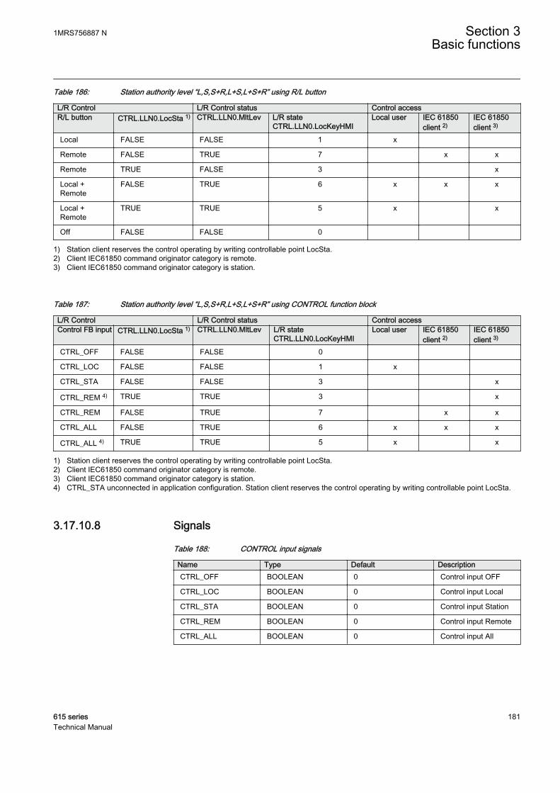
Table 186: Station authority level “L,S,S+R,L+S,L+S+R” using R/L button
L/R Control L/R Control status Control accessR/L button CTRL.LLN0.LocSta 1) CTRL.LLN0.MltLev L/R state
CTRL.LLN0.LocKeyHMILocal user IEC 61850
client 2)IEC 61850client 3)
Local FALSE FALSE 1 x
Remote FALSE TRUE 7 x x
Remote TRUE FALSE 3 x
Local +Remote
FALSE TRUE 6 x x x
Local +Remote
TRUE TRUE 5 x x
Off FALSE FALSE 0
1) Station client reserves the control operating by writing controllable point LocSta.2) Client IEC61850 command originator category is remote.3) Client IEC61850 command originator category is station.
Table 187: Station authority level “L,S,S+R,L+S,L+S+R” using CONTROL function block
L/R Control L/R Control status Control accessControl FB input CTRL.LLN0.LocSta 1) CTRL.LLN0.MltLev L/R state
CTRL.LLN0.LocKeyHMILocal user IEC 61850
client 2)IEC 61850client 3)
CTRL_OFF FALSE FALSE 0
CTRL_LOC FALSE FALSE 1 x
CTRL_STA FALSE FALSE 3 x
CTRL_REM 4) TRUE TRUE 3 x
CTRL_REM FALSE TRUE 7 x x
CTRL_ALL FALSE TRUE 6 x x x
CTRL_ALL 4) TRUE TRUE 5 x x
1) Station client reserves the control operating by writing controllable point LocSta.2) Client IEC61850 command originator category is remote.3) Client IEC61850 command originator category is station.4) CTRL_STA unconnected in application configuration. Station client reserves the control operating by writing controllable point LocSta.
3.17.10.8 Signals
Table 188: CONTROL input signals
Name Type Default DescriptionCTRL_OFF BOOLEAN 0 Control input OFF
CTRL_LOC BOOLEAN 0 Control input Local
CTRL_STA BOOLEAN 0 Control input Station
CTRL_REM BOOLEAN 0 Control input Remote
CTRL_ALL BOOLEAN 0 Control input All
1MRS756887 N Section 3Basic functions
615 series 181Technical Manual

Table 189: CONTROL output signals
Name Type DescriptionOFF BOOLEAN Control output OFF
LOCAL BOOLEAN Control output Local
STATION BOOLEAN Control output Station
REMOTE BOOLEAN Control output Remote
ALL BOOLEAN Control output All
BEH_BLK BOOLEAN Logical device CTRL blockstatus
BEH_TST BOOLEAN Logical device CTRL test status
3.17.10.9 Settings
Table 190: Non group settings
Parameter Values (Range) Unit Step Default DescriptionLR control 1=LR key
2=Binary input 1=LR key LR control through LR key or binary input
Station authority 1=L,R2=L,S,R3=L,R,L+R4=L,S,S+R,L+S,L+S+R
1=L,R Control command originator categoryusage
Control mode 1=On2=Blocked5=Off
1=On Enabling and disabling control
Section 3 1MRS756887 NBasic functions
182 615 seriesTechnical Manual

3.17.10.10 Monitored data
Table 191: Monitored data
Name Type Values (Range) Unit DescriptionCommand response Enum 0=No commands
1=Select open2=Select close3=Operate open4=Operate close5=Direct open6=Direct close7=Cancel8=Positionreached9=Positiontimeout10=Object statusonly11=Object direct12=Object select13=RL localallowed14=RL remoteallowed15=RL off16=Function off17=Functionblocked18=Commandprogress19=Selecttimeout20=Missingauthority21=Close notenabled22=Open notenabled23=Internal fault24=Alreadyclose25=Wrong client26=RL stationallowed27=RL change28=Abortion bytrip
Latest commandresponse
LR state Enum 0=Off1=Local2=Remote3=Station4=L+R5=L+S6=L+S+R7=S+R
LR state monitoring
1MRS756887 N Section 3Basic functions
615 series 183Technical Manual
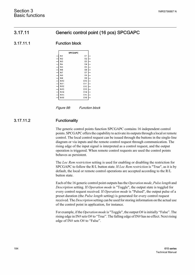
3.17.11 Generic control point (16 pcs) SPCGAPC
3.17.11.1 Function block
GUID-3A7D9472-39BF-4522-83CA-89BFBA1800E6 V1 EN
Figure 98: Function block
3.17.11.2 Functionality
The generic control points function SPCGAPC contains 16 independent controlpoints. SPCGAPC offers the capability to activate its outputs through a local or remotecontrol. The local control request can be issued through the buttons in the single-linediagram or via inputs and the remote control request through communication. Therising edge of the input signal is interpreted as a control request, and the outputoperation is triggered. When remote control requests are used the control pointsbehaves as persistent.
The Loc Rem restriction setting is used for enabling or disabling the restriction forSPCGAPC to follow the R/L button state. If Loc Rem restriction is "True", as it is bydefault, the local or remote control operations are accepted according to the R/Lbutton state.
Each of the 16 generic control point outputs has the Operation mode, Pulse length andDescription setting. If Operation mode is "Toggle", the output state is toggled forevery control request received. If Operation mode is "Pulsed", the output pulse of apreset duration (the Pulse length setting) is generated for every control requestreceived. The Description setting can be used for storing information on the actual useof the control point in application, for instance.
For example, if the Operation mode is "Toggle", the output O# is initially “False”. Therising edge in IN# sets O# to “True”. The falling edge of IN# has no effect. Next risingedge of IN# sets O# to “False”.
Section 3 1MRS756887 NBasic functions
184 615 seriesTechnical Manual

GUID-F0078144-A40B-4A72-915A-0E6665F8DEB1 V1 EN
Figure 99: Operation in "Toggle" mode
The BLOCK input can be used for blocking the functionality of the outputs. Theoperation of the BLOCK input depends on the Operation mode setting. If Operationmode is "Toggle", the output state freezes and cannot be changed while the BLOCKinput is active. If Operation mode is "Pulsed", the activation of the BLOCK input resetsthe outputs to the "False" state and further control requests are ignored while theBLOCK input is active.
From the remote communication point of view SPCGAPC toggledoperation mode is always working as persistent mode. The output O#follows the value written to the input IN#.
3.17.11.3 Signals
Table 192: SPCGAPC Input signals
Name Type Default DescriptionBLOCK BOOLEAN 0=False Block signal for activating the blocking mode
IN1 BOOLEAN 0=False Input of control point 1
IN2 BOOLEAN 0=False Input of control point 2
IN3 BOOLEAN 0=False Input of control point 3
IN4 BOOLEAN 0=False Input of control point 4
IN5 BOOLEAN 0=False Input of control point 5
IN6 BOOLEAN 0=False Input of control point 6
IN7 BOOLEAN 0=False Input of control point 7
IN8 BOOLEAN 0=False Input of control point 8
IN9 BOOLEAN 0=False Input of control point 9
IN10 BOOLEAN 0=False Input of control point 10
IN11 BOOLEAN 0=False Input of control point 11
IN12 BOOLEAN 0=False Input of control point 12
IN13 BOOLEAN 0=False Input of control point 13
IN14 BOOLEAN 0=False Input of control point 14
IN15 BOOLEAN 0=False Input of control point 15
IN16 BOOLEAN 0=False Input of control point 16
1MRS756887 N Section 3Basic functions
615 series 185Technical Manual

Table 193: SPCGAPC Output signals
Name Type DescriptionO1 BOOLEAN Output 1 status
O2 BOOLEAN Output 2 status
O3 BOOLEAN Output 3 status
O4 BOOLEAN Output 4 status
O5 BOOLEAN Output 5 status
O6 BOOLEAN Output 6 status
O7 BOOLEAN Output 7 status
O8 BOOLEAN Output 8 status
O9 BOOLEAN Output 9 status
O10 BOOLEAN Output 10 status
O11 BOOLEAN Output 11 status
O12 BOOLEAN Output 12 status
O13 BOOLEAN Output 13 status
O14 BOOLEAN Output 14 status
O15 BOOLEAN Output 15 status
O16 BOOLEAN Output 16 status
3.17.11.4 Settings
Table 194: SPCGAPC Non group settings (Basic)
Parameter Values (Range) Unit Step Default DescriptionLoc Rem restriction 0=False
1=True 1=True Local remote switch restriction
Operation mode 0=Pulsed1=Toggle/Persistent-1=Off
-1=Off Operation mode for generic control point
Pulse length 10...3600000 ms 10 1000 Pulse length for pulsed operation mode
Description SPCGAPC1Output 1
Generic control point description
Operation mode 0=Pulsed1=Toggle/Persistent-1=Off
-1=Off Operation mode for generic control point
Pulse length 10...3600000 ms 10 1000 Pulse length for pulsed operation mode
Description SPCGAPC1Output 2
Generic control point description
Operation mode 0=Pulsed1=Toggle/Persistent-1=Off
-1=Off Operation mode for generic control point
Pulse length 10...3600000 ms 10 1000 Pulse length for pulsed operation mode
Table continues on next page
Section 3 1MRS756887 NBasic functions
186 615 seriesTechnical Manual
Parameter Values (Range) Unit Step Default DescriptionDescription SPCGAPC1
Output 3Generic control point description
Operation mode 0=Pulsed1=Toggle/Persistent-1=Off
-1=Off Operation mode for generic control point
Pulse length 10...3600000 ms 10 1000 Pulse length for pulsed operation mode
Description SPCGAPC1Output 4
Generic control point description
Operation mode 0=Pulsed1=Toggle/Persistent-1=Off
-1=Off Operation mode for generic control point
Pulse length 10...3600000 ms 10 1000 Pulse length for pulsed operation mode
Description SPCGAPC1Output 5
Generic control point description
Operation mode 0=Pulsed1=Toggle/Persistent-1=Off
-1=Off Operation mode for generic control point
Pulse length 10...3600000 ms 10 1000 Pulse length for pulsed operation mode
Description SPCGAPC1Output 6
Generic control point description
Operation mode 0=Pulsed1=Toggle/Persistent-1=Off
-1=Off Operation mode for generic control point
Pulse length 10...3600000 ms 10 1000 Pulse length for pulsed operation mode
Description SPCGAPC1Output 7
Generic control point description
Operation mode 0=Pulsed1=Toggle/Persistent-1=Off
-1=Off Operation mode for generic control point
Pulse length 10...3600000 ms 10 1000 Pulse length for pulsed operation mode
Description SPCGAPC1Output 8
Generic control point description
Operation mode 0=Pulsed1=Toggle/Persistent-1=Off
-1=Off Operation mode for generic control point
Pulse length 10...3600000 ms 10 1000 Pulse length for pulsed operation mode
Description SPCGAPC1Output 9
Generic control point description
Operation mode 0=Pulsed1=Toggle/Persistent-1=Off
-1=Off Operation mode for generic control point
Pulse length 10...3600000 ms 10 1000 Pulse length for pulsed operation mode
Description SPCGAPC1Output 10
Generic control point description
Table continues on next page
1MRS756887 N Section 3Basic functions
615 series 187Technical Manual

Parameter Values (Range) Unit Step Default DescriptionOperation mode 0=Pulsed
1=Toggle/Persistent-1=Off
-1=Off Operation mode for generic control point
Pulse length 10...3600000 ms 10 1000 Pulse length for pulsed operation mode
Description SPCGAPC1Output 11
Generic control point description
Operation mode 0=Pulsed1=Toggle/Persistent-1=Off
-1=Off Operation mode for generic control point
Pulse length 10...3600000 ms 10 1000 Pulse length for pulsed operation mode
Description SPCGAPC1Output 12
Generic control point description
Operation mode 0=Pulsed1=Toggle/Persistent-1=Off
-1=Off Operation mode for generic control point
Pulse length 10...3600000 ms 10 1000 Pulse length for pulsed operation mode
Description SPCGAPC1Output 13
Generic control point description
Operation mode 0=Pulsed1=Toggle/Persistent-1=Off
-1=Off Operation mode for generic control point
Pulse length 10...3600000 ms 10 1000 Pulse length for pulsed operation mode
Description SPCGAPC1Output 14
Generic control point description
Operation mode 0=Pulsed1=Toggle/Persistent-1=Off
-1=Off Operation mode for generic control point
Pulse length 10...3600000 ms 10 1000 Pulse length for pulsed operation mode
Description SPCGAPC1Output 15
Generic control point description
Operation mode 0=Pulsed1=Toggle/Persistent-1=Off
-1=Off Operation mode for generic control point
Pulse length 10...3600000 ms 10 1000 Pulse length for pulsed operation mode
Description SPCGAPC1Output 16
Generic control point description
3.18 Factory settings restoration
In case of configuration data loss or any other file system error that prevents theprotection relay from working properly, the whole file system can be restored to theoriginal factory state. All default settings and configuration files stored in the factory
Section 3 1MRS756887 NBasic functions
188 615 seriesTechnical Manual

are restored. For further information on restoring factory settings, see the operationmanual.
3.19 Load profile record LDPRLRC
3.19.1 Function block
GUID-FE70FC2E-8582-4450-97F1-B9D699809951 V1 EN
Figure 100: Function block
3.19.2 Functionality
The protection relay is provided with a load profile recorder. The load profile featurestores the historical load data captured at a periodical time interval (demand interval).Up to 12 load quantities can be selected for recording and storing in a nonvolatilememory. The value range for the recorded load quantities is about eight times thenominal value, and values larger than that saturate. The recording time depends on asettable demand interval parameter and the amount of quantities selected. The recordoutput is in the COMTRADE format.
3.19.2.1 Quantities
Selectable quantities are product-dependent.
Table 195: Quantity Description
Quantity Sel x DescriptionDisabled Quantity not selected
IL1 Phase 1 current
IL2 Phase 2 current
IL3 Phase 3 current
Io Neutral/earth/residual current
IL1B Phase 1 current, B side
IL2B Phase 2 current, B side
IL3B Phase 3 current, B side
Io Neutral/earth/residual current, B side
U12 Phase-to-phase 12 voltage
U23 Phase-to-phase 23 voltage
U31 Phase-to-phase 31 voltage
UL1 Phase-to-earth 1 voltage
Table continues on next page
1MRS756887 N Section 3Basic functions
615 series 189Technical Manual
Quantity Sel x DescriptionUL2 Phase-to-earth 2 voltage
UL3 Phase-to-earth 3 voltage
U12B Phase-to-phase 12 voltage, B side
U23B Phase-to-phase 23 voltage, B side
U31B Phase-to-phase 31 voltage, B side
UL1B Phase-to-earth 1 voltage, B side
UL2B Phase-to-earth 2 voltage, B side
UL3B Phase-to-earth 3 voltage, B side
S Apparent power
P Real power
Q Reactive power
PF Power factor
SB Apparent power, B side
PB Real power, B side
QB Reactive power, B side
PFB Power factor, B side
SL1 Apparent power, phase L1
SL2 Apparent power, phase L2
SL3 Apparent power, phase L3
PL1 Real power, phase L1
PL2 Real power, phase L2
PL3 Real power, phase L3
QL1 Reactive power, phase L1
QL2 Reactive power, phase L2
QL3 Reactive power, phase L3
PFL1 Power factor, phase L1
PFL2 Power factor, phase L2
PFL3 Power factor, phase L3
SL1B Apparent power, phase L1, B side
SL2B Apparent power, phase L2, B side
SL3B Apparent power, phase L3, B side
PL1B Real power, phase L1, B side
PL2B Real power, phase L2, B side
PL3B Real power, phase L3, B side
QL1B Reactive power, phase L1, B side
QL2B Reactive power, phase L2, B side
QL3B Reactive power, phase L3, B side
PFL1B Power factor, phase L1, B side
PFL2B Power factor, phase L2, B side
Table continues on next page
Section 3 1MRS756887 NBasic functions
190 615 seriesTechnical Manual
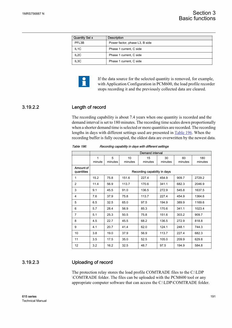
Quantity Sel x DescriptionPFL3B Power factor, phase L3, B side
IL1C Phase 1 current, C side
IL2C Phase 1 current, C side
IL3C Phase 1 current, C side
If the data source for the selected quantity is removed, for example,with Application Configuration in PCM600, the load profile recorderstops recording it and the previously collected data are cleared.
3.19.2.2 Length of record
The recording capability is about 7.4 years when one quantity is recorded and thedemand interval is set to 180 minutes. The recording time scales down proportionallywhen a shorter demand time is selected or more quantities are recorded. The recordinglengths in days with different settings used are presented in Table 196. When therecording buffer is fully occupied, the oldest data are overwritten by the newest data.
Table 196: Recording capability in days with different settings
Demand interval
1
minute5
minutes10
minutes15
minutes30
minutes60
minutes180
minutes
Amount ofquantities Recording capability in days
1 15.2 75.8 151.6 227.4 454.9 909.7 2729.2
2 11.4 56.9 113.7 170.6 341.1 682.3 2046.9
3 9.1 45.5 91.0 136.5 272.9 545.8 1637.5
4 7.6 37.9 75.8 113.7 227.4 454.9 1364.6
5 6.5 32.5 65.0 97.5 194.9 389.9 1169.6
6 5.7 28.4 56.9 85.3 170.6 341.1 1023.4
7 5.1 25.3 50.5 75.8 151.6 303.2 909.7
8 4.5 22.7 45.5 68.2 136.5 272.9 818.8
9 4.1 20.7 41.4 62.0 124.1 248.1 744.3
10 3.8 19.0 37.9 56.9 113.7 227.4 682.3
11 3.5 17.5 35.0 52.5 105.0 209.9 629.8
12 3.2 16.2 32.5 48.7 97.5 194.9 584.8
3.19.2.3 Uploading of record
The protection relay stores the load profile COMTRADE files to the C:\LDP\COMTRADE folder. The files can be uploaded with the PCM600 tool or anyappropriate computer software that can access the C:\LDP\COMTRADE folder.
1MRS756887 N Section 3Basic functions
615 series 191Technical Manual
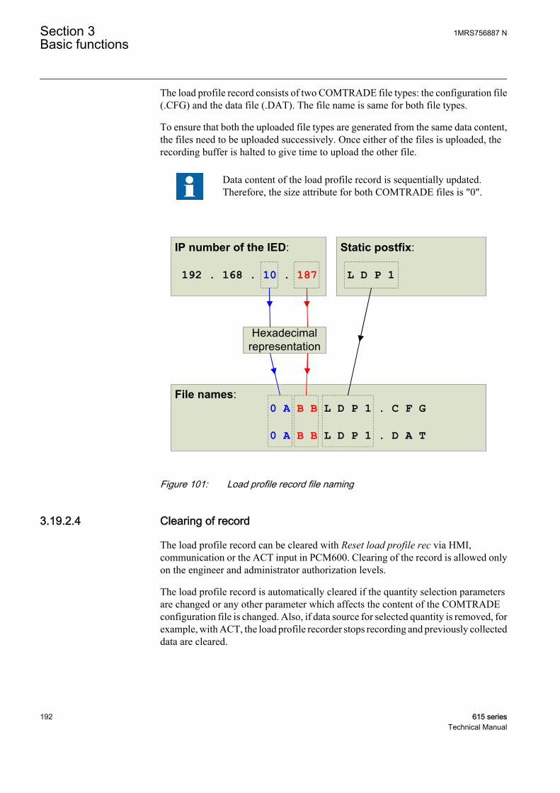
The load profile record consists of two COMTRADE file types: the configuration file(.CFG) and the data file (.DAT). The file name is same for both file types.
To ensure that both the uploaded file types are generated from the same data content,the files need to be uploaded successively. Once either of the files is uploaded, therecording buffer is halted to give time to upload the other file.
Data content of the load profile record is sequentially updated.Therefore, the size attribute for both COMTRADE files is "0".
192 . 168 . 10 . 187 L D P 1
0 A B B L D P 1 . C F G
0 A B B L D P 1 . D A T
GUID-43078009-323D-409C-B84A-5EB914CDEE53 V1 EN
Figure 101: Load profile record file naming
3.19.2.4 Clearing of record
The load profile record can be cleared with Reset load profile rec via HMI,communication or the ACT input in PCM600. Clearing of the record is allowed onlyon the engineer and administrator authorization levels.
The load profile record is automatically cleared if the quantity selection parametersare changed or any other parameter which affects the content of the COMTRADEconfiguration file is changed. Also, if data source for selected quantity is removed, forexample, with ACT, the load profile recorder stops recording and previously collecteddata are cleared.
Section 3 1MRS756887 NBasic functions
192 615 seriesTechnical Manual

3.19.3 Configuration
The load profile record can be configured with the PCM600 tool or any toolsupporting the IEC 61850 standard.
The load profile record can be enabled or disabled with the Operation setting under theConfiguration/Load Profile Record menu.
Each protection relay can be mapped to each of the quantity channels of the loadprofile record. The mapping is done with the Quantity selection setting of thecorresponding quantity channel.
The IP number of the protection relay and the content of the Bay namesetting are both included in the COMTRADE configuration file foridentification purposes.
The memory consumption of load profile record is supervised, and indicated with twosignals MEM_WARN and MEM_ALARM, which could be used to notify the customer thatrecording should be backlogged by reading the recorded data from the protectionrelay. The levels for MEM_WARN and MEM_ALARM are set by two parametersMem.warn level and Mem. Alarm level.
3.19.4 SignalsTable 197: LDPRLRC Output signals
Name Type DescriptionMEM_WARN BOOLEAN Recording memory warning status
MEM_ALARM BOOLEAN Recording memory alarm status
1MRS756887 N Section 3Basic functions
615 series 193Technical Manual

3.19.5 Settings
Section 3 1MRS756887 NBasic functions
194 615 seriesTechnical Manual

Table 198: LDPRLRC Non group settings (Basic)
Parameter Values (Range) Unit Step Default DescriptionOperation 1=on
5=off 1=on Operation Off / On
Quantity Sel 1 0=Disabled1=IL12=IL23=IL34=Io5=IL1B6=IL2B7=IL3B8=IoB9=U1210=U2311=U3112=UL113=UL214=UL315=U12B16=U23B17=U31B18=UL1B19=UL2B20=UL3B21=S22=P23=Q24=PF25=SB26=PB27=QB28=PFB29=SL130=SL231=SL332=PL133=PL234=PL335=QL136=QL237=QL338=PFL139=PFL240=PFL341=SL1B42=SL2B43=SL3B44=PL1B45=PL2B46=PL3B47=QL1B48=QL2B49=QL3B50=PFL1B51=PFL2B52=PFL3B53=IL1C54=IL2C55=IL3C
0=Disabled Select quantity to be recorded
Table continues on next page
1MRS756887 N Section 3Basic functions
615 series 195Technical Manual
Parameter Values (Range) Unit Step Default DescriptionQuantity Sel 2 0=Disabled
1=IL12=IL23=IL34=Io5=IL1B6=IL2B7=IL3B8=IoB9=U1210=U2311=U3112=UL113=UL214=UL315=U12B16=U23B17=U31B18=UL1B19=UL2B20=UL3B21=S22=P23=Q24=PF25=SB26=PB27=QB28=PFB29=SL130=SL231=SL332=PL133=PL234=PL335=QL136=QL237=QL338=PFL139=PFL240=PFL341=SL1B42=SL2B43=SL3B44=PL1B45=PL2B46=PL3B47=QL1B48=QL2B49=QL3B50=PFL1B51=PFL2B52=PFL3B53=IL1C54=IL2C55=IL3C
0=Disabled Select quantity to be recorded
Table continues on next page
Section 3 1MRS756887 NBasic functions
196 615 seriesTechnical Manual

Parameter Values (Range) Unit Step Default DescriptionQuantity Sel 3 0=Disabled
1=IL12=IL23=IL34=Io5=IL1B6=IL2B7=IL3B8=IoB9=U1210=U2311=U3112=UL113=UL214=UL315=U12B16=U23B17=U31B18=UL1B19=UL2B20=UL3B21=S22=P23=Q24=PF25=SB26=PB27=QB28=PFB29=SL130=SL231=SL332=PL133=PL234=PL335=QL136=QL237=QL338=PFL139=PFL240=PFL341=SL1B42=SL2B43=SL3B44=PL1B45=PL2B46=PL3B47=QL1B48=QL2B49=QL3B50=PFL1B51=PFL2B52=PFL3B53=IL1C54=IL2C55=IL3C
0=Disabled Select quantity to be recorded
Table continues on next page
1MRS756887 N Section 3Basic functions
615 series 197Technical Manual

Parameter Values (Range) Unit Step Default DescriptionQuantity Sel 4 0=Disabled
1=IL12=IL23=IL34=Io5=IL1B6=IL2B7=IL3B8=IoB9=U1210=U2311=U3112=UL113=UL214=UL315=U12B16=U23B17=U31B18=UL1B19=UL2B20=UL3B21=S22=P23=Q24=PF25=SB26=PB27=QB28=PFB29=SL130=SL231=SL332=PL133=PL234=PL335=QL136=QL237=QL338=PFL139=PFL240=PFL341=SL1B42=SL2B43=SL3B44=PL1B45=PL2B46=PL3B47=QL1B48=QL2B49=QL3B50=PFL1B51=PFL2B52=PFL3B53=IL1C54=IL2C55=IL3C
0=Disabled Select quantity to be recorded
Table continues on next page
Section 3 1MRS756887 NBasic functions
198 615 seriesTechnical Manual

Parameter Values (Range) Unit Step Default DescriptionQuantity Sel 5 0=Disabled
1=IL12=IL23=IL34=Io5=IL1B6=IL2B7=IL3B8=IoB9=U1210=U2311=U3112=UL113=UL214=UL315=U12B16=U23B17=U31B18=UL1B19=UL2B20=UL3B21=S22=P23=Q24=PF25=SB26=PB27=QB28=PFB29=SL130=SL231=SL332=PL133=PL234=PL335=QL136=QL237=QL338=PFL139=PFL240=PFL341=SL1B42=SL2B43=SL3B44=PL1B45=PL2B46=PL3B47=QL1B48=QL2B49=QL3B50=PFL1B51=PFL2B52=PFL3B53=IL1C54=IL2C55=IL3C
0=Disabled Select quantity to be recorded
Table continues on next page
1MRS756887 N Section 3Basic functions
615 series 199Technical Manual

Parameter Values (Range) Unit Step Default DescriptionQuantity Sel 6 0=Disabled
1=IL12=IL23=IL34=Io5=IL1B6=IL2B7=IL3B8=IoB9=U1210=U2311=U3112=UL113=UL214=UL315=U12B16=U23B17=U31B18=UL1B19=UL2B20=UL3B21=S22=P23=Q24=PF25=SB26=PB27=QB28=PFB29=SL130=SL231=SL332=PL133=PL234=PL335=QL136=QL237=QL338=PFL139=PFL240=PFL341=SL1B42=SL2B43=SL3B44=PL1B45=PL2B46=PL3B47=QL1B48=QL2B49=QL3B50=PFL1B51=PFL2B52=PFL3B53=IL1C54=IL2C55=IL3C
0=Disabled Select quantity to be recorded
Table continues on next page
Section 3 1MRS756887 NBasic functions
200 615 seriesTechnical Manual
Parameter Values (Range) Unit Step Default DescriptionQuantity Sel 7 0=Disabled
1=IL12=IL23=IL34=Io5=IL1B6=IL2B7=IL3B8=IoB9=U1210=U2311=U3112=UL113=UL214=UL315=U12B16=U23B17=U31B18=UL1B19=UL2B20=UL3B21=S22=P23=Q24=PF25=SB26=PB27=QB28=PFB29=SL130=SL231=SL332=PL133=PL234=PL335=QL136=QL237=QL338=PFL139=PFL240=PFL341=SL1B42=SL2B43=SL3B44=PL1B45=PL2B46=PL3B47=QL1B48=QL2B49=QL3B50=PFL1B51=PFL2B52=PFL3B53=IL1C54=IL2C55=IL3C
0=Disabled Select quantity to be recorded
Table continues on next page
1MRS756887 N Section 3Basic functions
615 series 201Technical Manual

Parameter Values (Range) Unit Step Default DescriptionQuantity Sel 8 0=Disabled
1=IL12=IL23=IL34=Io5=IL1B6=IL2B7=IL3B8=IoB9=U1210=U2311=U3112=UL113=UL214=UL315=U12B16=U23B17=U31B18=UL1B19=UL2B20=UL3B21=S22=P23=Q24=PF25=SB26=PB27=QB28=PFB29=SL130=SL231=SL332=PL133=PL234=PL335=QL136=QL237=QL338=PFL139=PFL240=PFL341=SL1B42=SL2B43=SL3B44=PL1B45=PL2B46=PL3B47=QL1B48=QL2B49=QL3B50=PFL1B51=PFL2B52=PFL3B53=IL1C54=IL2C55=IL3C
0=Disabled Select quantity to be recorded
Table continues on next page
Section 3 1MRS756887 NBasic functions
202 615 seriesTechnical Manual

Parameter Values (Range) Unit Step Default DescriptionQuantity Sel 9 0=Disabled
1=IL12=IL23=IL34=Io5=IL1B6=IL2B7=IL3B8=IoB9=U1210=U2311=U3112=UL113=UL214=UL315=U12B16=U23B17=U31B18=UL1B19=UL2B20=UL3B21=S22=P23=Q24=PF25=SB26=PB27=QB28=PFB29=SL130=SL231=SL332=PL133=PL234=PL335=QL136=QL237=QL338=PFL139=PFL240=PFL341=SL1B42=SL2B43=SL3B44=PL1B45=PL2B46=PL3B47=QL1B48=QL2B49=QL3B50=PFL1B51=PFL2B52=PFL3B53=IL1C54=IL2C55=IL3C
0=Disabled Select quantity to be recorded
Table continues on next page
1MRS756887 N Section 3Basic functions
615 series 203Technical Manual

Parameter Values (Range) Unit Step Default DescriptionQuantity Sel 10 0=Disabled
1=IL12=IL23=IL34=Io5=IL1B6=IL2B7=IL3B8=IoB9=U1210=U2311=U3112=UL113=UL214=UL315=U12B16=U23B17=U31B18=UL1B19=UL2B20=UL3B21=S22=P23=Q24=PF25=SB26=PB27=QB28=PFB29=SL130=SL231=SL332=PL133=PL234=PL335=QL136=QL237=QL338=PFL139=PFL240=PFL341=SL1B42=SL2B43=SL3B44=PL1B45=PL2B46=PL3B47=QL1B48=QL2B49=QL3B50=PFL1B51=PFL2B52=PFL3B53=IL1C54=IL2C55=IL3C
0=Disabled Select quantity to be recorded
Table continues on next page
Section 3 1MRS756887 NBasic functions
204 615 seriesTechnical Manual

Parameter Values (Range) Unit Step Default DescriptionQuantity Sel 11 0=Disabled
1=IL12=IL23=IL34=Io5=IL1B6=IL2B7=IL3B8=IoB9=U1210=U2311=U3112=UL113=UL214=UL315=U12B16=U23B17=U31B18=UL1B19=UL2B20=UL3B21=S22=P23=Q24=PF25=SB26=PB27=QB28=PFB29=SL130=SL231=SL332=PL133=PL234=PL335=QL136=QL237=QL338=PFL139=PFL240=PFL341=SL1B42=SL2B43=SL3B44=PL1B45=PL2B46=PL3B47=QL1B48=QL2B49=QL3B50=PFL1B51=PFL2B52=PFL3B53=IL1C54=IL2C55=IL3C
0=Disabled Select quantity to be recorded
Table continues on next page
1MRS756887 N Section 3Basic functions
615 series 205Technical Manual

Parameter Values (Range) Unit Step Default DescriptionQuantity Sel 12 0=Disabled
1=IL12=IL23=IL34=Io5=IL1B6=IL2B7=IL3B8=IoB9=U1210=U2311=U3112=UL113=UL214=UL315=U12B16=U23B17=U31B18=UL1B19=UL2B20=UL3B21=S22=P23=Q24=PF25=SB26=PB27=QB28=PFB29=SL130=SL231=SL332=PL133=PL234=PL335=QL136=QL237=QL338=PFL139=PFL240=PFL341=SL1B42=SL2B43=SL3B44=PL1B45=PL2B46=PL3B47=QL1B48=QL2B49=QL3B50=PFL1B51=PFL2B52=PFL3B53=IL1C54=IL2C55=IL3C
0=Disabled Select quantity to be recorded
Mem. warning level 0...100 % 1 0 Set memory warning level
Mem. alarm level 0...100 % 1 0 Set memory alarm level
Section 3 1MRS756887 NBasic functions
206 615 seriesTechnical Manual
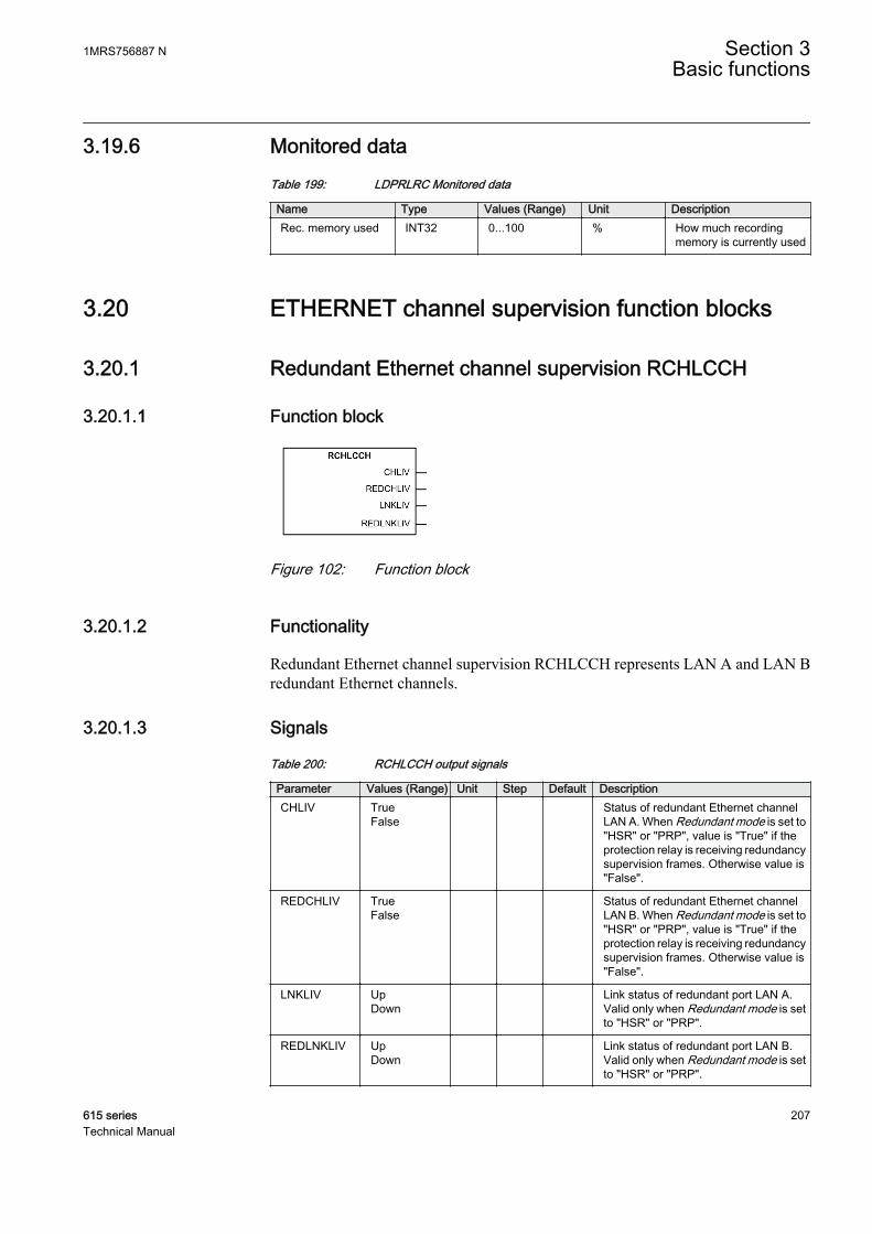
3.19.6 Monitored dataTable 199: LDPRLRC Monitored data
Name Type Values (Range) Unit DescriptionRec. memory used INT32 0...100 % How much recording
memory is currently used
3.20 ETHERNET channel supervision function blocks
3.20.1 Redundant Ethernet channel supervision RCHLCCH
3.20.1.1 Function block
GUID-CD9E923F-7B50-45C0-AE3E-39F576E01906 V1 EN
Figure 102: Function block
3.20.1.2 Functionality
Redundant Ethernet channel supervision RCHLCCH represents LAN A and LAN Bredundant Ethernet channels.
3.20.1.3 Signals
Table 200: RCHLCCH output signals
Parameter Values (Range) Unit Step Default DescriptionCHLIV True
False
Status of redundant Ethernet channelLAN A. When Redundant mode is set to"HSR" or "PRP", value is "True" if theprotection relay is receiving redundancysupervision frames. Otherwise value is"False".
REDCHLIV TrueFalse
Status of redundant Ethernet channelLAN B. When Redundant mode is set to"HSR" or "PRP", value is "True" if theprotection relay is receiving redundancysupervision frames. Otherwise value is"False".
LNKLIV UpDown
Link status of redundant port LAN A.Valid only when Redundant mode is setto "HSR" or "PRP".
REDLNKLIV UpDown
Link status of redundant port LAN B.Valid only when Redundant mode is setto "HSR" or "PRP".
1MRS756887 N Section 3Basic functions
615 series 207Technical Manual
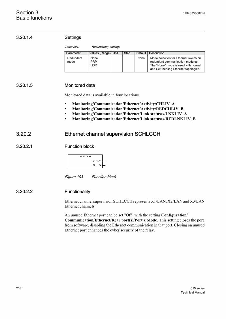
3.20.1.4 Settings
Table 201: Redundancy settings
Parameter Values (Range) Unit Step Default DescriptionRedundantmode
NonePRPHSR
None Mode selection for Ethernet switch onredundant communication modules.The "None" mode is used with normaland Self-healing Ethernet topologies.
3.20.1.5 Monitored data
Monitored data is available in four locations.
• Monitoring/Communication/Ethernet/Activity/CHLIV_A• Monitoring/Communication/Ethernet/Activity/REDCHLIV_B• Monitoring/Communication/Ethernet/Link statuses/LNKLIV_A• Monitoring/Communication/Ethernet/Link statuses/REDLNKLIV_B
3.20.2 Ethernet channel supervision SCHLCCH
3.20.2.1 Function block
GUID-DBA25BB9-6BF5-4C45-A39F-1920113A22F2 V1 EN
Figure 103: Function block
3.20.2.2 Functionality
Ethernet channel supervision SCHLCCH represents X1/LAN, X2/LAN and X3/LANEthernet channels.
An unused Ethernet port can be set "Off" with the setting Configuration/Communication/Ethernet/Rear port(s)/Port x Mode. This setting closes the portfrom software, disabling the Ethernet communication in that port. Closing an unusedEthernet port enhances the cyber security of the relay.
Section 3 1MRS756887 NBasic functions
208 615 seriesTechnical Manual
3.20.2.3 Signals
Table 202: SCHLCCH1 output signals
Parameter Values (Range) Unit Step Default DescriptionCH1LIV True
False Status of Ethernet channel X1/LAN.
Value is "True" if the port is receivingEthernet frames. Valid only whenRedundant mode is set to "None" or portis not one of the redundant ports (LAN Aor LAN B).
LNK1LIV UpDown
Link status of Ethernet port X1/LAN.
Table 203: SCHLCCH2 output signals
Parameter Values (Range) Unit Step Default DescriptionCH2LIV True
False Status of Ethernet channel X2/LAN.
Value is "True" if the port is receivingEthernet frames. Valid only whenRedundant mode is set to "None" or portis not one of the redundant ports (LAN Aor LAN B).
LNK2LIV UpDown
Link status of Ethernet port X2/LAN.
Table 204: SCHLCCH3 output signals
Parameter Values (Range) Unit Step Default DescriptionCH3LIV True
False Status of Ethernet channel X3/LAN.
Value is "True" if the port is receivingEthernet frames. Valid only whenRedundant mode is set to "None" or portis not one of the redundant ports (LAN Aor LAN B).
LNK3LIV UpDown
Link status of Ethernet port X3/LAN.
1MRS756887 N Section 3Basic functions
615 series 209Technical Manual
3.20.2.4 Settings
Table 205: Port mode settings
Parameter Values (Range) Unit Step Default DescriptionPort 1 Mode Off
On
On Mode selection for rear port(s). If port isnot used, it can be set to “Off”. Portcannot be set to “Off” when Redundantmode is “HSR” or “PRP” and port is oneof the redundant ports (LAN A or LAN B)or when port is used for line differentialcommunication.
Port 2 Mode OffOn
On Mode selection for rear port(s). If port isnot used, it can be set to “Off”. Portcannot be set to “Off” when Redundantmode is “HSR” or “PRP” and port is oneof the redundant ports (LAN A or LAN B).
Port 3 Mode OffOn
On Mode selection for rear port(s). If port isnot used, it can be set to “Off”. Portcannot be set to “Off” when Redundantmode is “HSR” or “PRP” and port is oneof the redundant ports (LAN A or LAN B).
3.20.2.5 Monitored data
Monitored data is available in six locations.
• Monitoring/Communication/Ethernet/Activity/CH1LIV• Monitoring/Communication/Ethernet/Activity/CH2LIV• Monitoring/Communication/Ethernet/Activity/CH3LIV• Monitoring/Communication/Ethernet/Link statuses/LNK1LIV• Monitoring/Communication/Ethernet/Link statuses/LNK2LIV• Monitoring/Communication/Ethernet/Link statuses/LNK3LIV
Section 3 1MRS756887 NBasic functions
210 615 seriesTechnical Manual

Section 4 Protection functions
4.1 Three-phase current protection
4.1.1 Three-phase non-directional overcurrent protectionPHxPTOC
4.1.1.1 Identification
Function description IEC 61850identification
IEC 60617identification
ANSI/IEEE C37.2device number
Three-phase non-directionalovercurrent protection, low stage
PHLPTOC 3I> 51P-1
Three-phase non-directionalovercurrent protection, high stage
PHHPTOC 3I>> 51P-2
Three-phase non-directionalovercurrent protection, instantaneousstage
PHIPTOC 3I>>> 50P/51P
4.1.1.2 Function block
A070553 V1 EN
Figure 104: Function block
4.1.1.3 Functionality
The three-phase non-directional overcurrent protection function PHxPTOC is used asone-phase, two-phase or three-phase non-directional overcurrent and short-circuitprotection.
The function starts when the current exceeds the set limit. The operate timecharacteristics for low stage PHLPTOC and high stage PHHPTOC can be selected tobe either definite time (DT) or inverse definite minimum time (IDMT). Theinstantaneous stage PHIPTOC always operates with the DT characteristic.
1MRS756887 N Section 4Protection functions
615 series 211Technical Manual
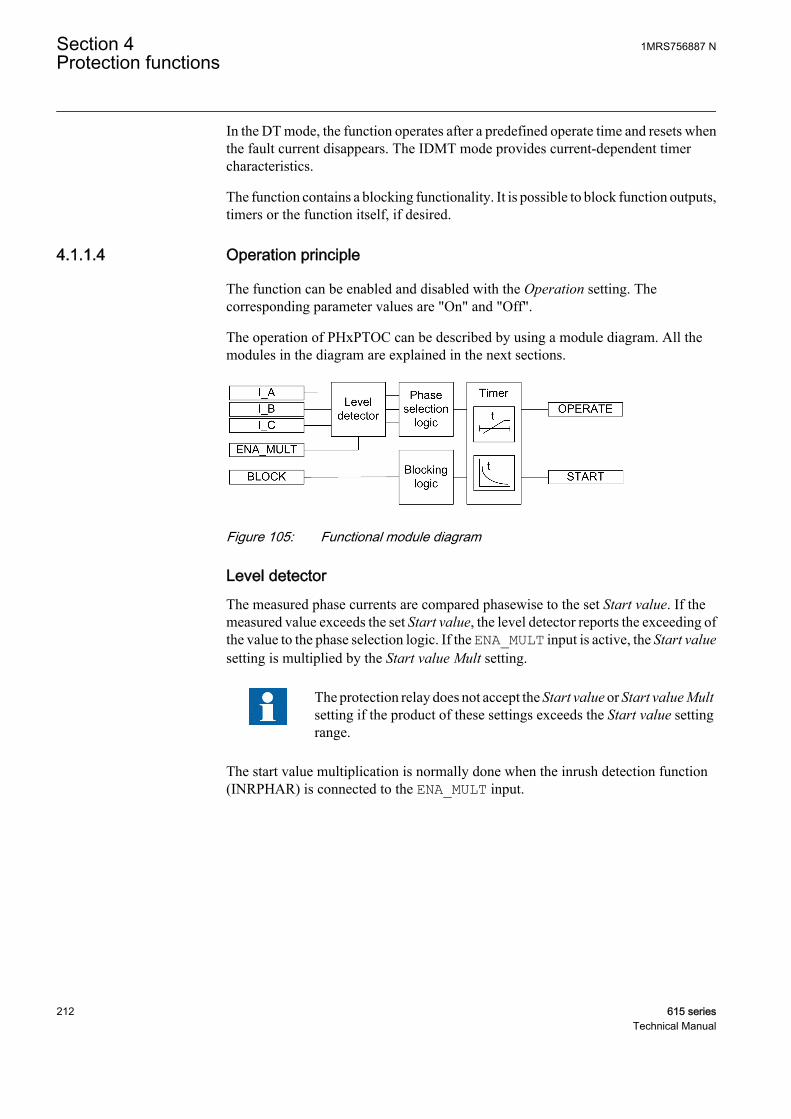
In the DT mode, the function operates after a predefined operate time and resets whenthe fault current disappears. The IDMT mode provides current-dependent timercharacteristics.
The function contains a blocking functionality. It is possible to block function outputs,timers or the function itself, if desired.
4.1.1.4 Operation principle
The function can be enabled and disabled with the Operation setting. Thecorresponding parameter values are "On" and "Off".
The operation of PHxPTOC can be described by using a module diagram. All themodules in the diagram are explained in the next sections.
A070552 V1 EN
Figure 105: Functional module diagram
Level detectorThe measured phase currents are compared phasewise to the set Start value. If themeasured value exceeds the set Start value, the level detector reports the exceeding ofthe value to the phase selection logic. If the ENA_MULT input is active, the Start valuesetting is multiplied by the Start value Mult setting.
The protection relay does not accept the Start value or Start value Multsetting if the product of these settings exceeds the Start value settingrange.
The start value multiplication is normally done when the inrush detection function(INRPHAR) is connected to the ENA_MULT input.
Section 4 1MRS756887 NProtection functions
212 615 seriesTechnical Manual
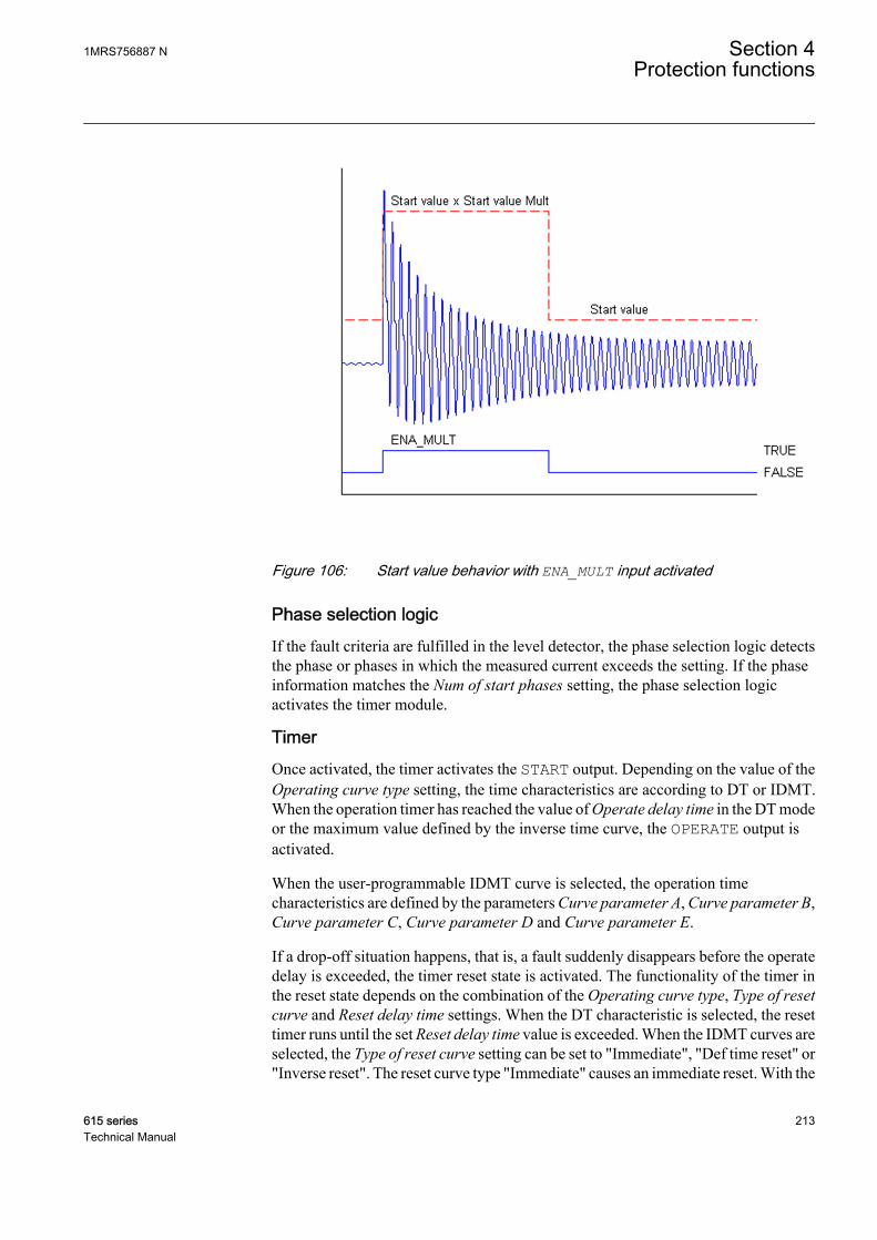
A070554 V1 EN
Figure 106: Start value behavior with ENA_MULT input activated
Phase selection logicIf the fault criteria are fulfilled in the level detector, the phase selection logic detectsthe phase or phases in which the measured current exceeds the setting. If the phaseinformation matches the Num of start phases setting, the phase selection logicactivates the timer module.
TimerOnce activated, the timer activates the START output. Depending on the value of theOperating curve type setting, the time characteristics are according to DT or IDMT.When the operation timer has reached the value of Operate delay time in the DT modeor the maximum value defined by the inverse time curve, the OPERATE output isactivated.
When the user-programmable IDMT curve is selected, the operation timecharacteristics are defined by the parameters Curve parameter A, Curve parameter B,Curve parameter C, Curve parameter D and Curve parameter E.
If a drop-off situation happens, that is, a fault suddenly disappears before the operatedelay is exceeded, the timer reset state is activated. The functionality of the timer inthe reset state depends on the combination of the Operating curve type, Type of resetcurve and Reset delay time settings. When the DT characteristic is selected, the resettimer runs until the set Reset delay time value is exceeded. When the IDMT curves areselected, the Type of reset curve setting can be set to "Immediate", "Def time reset" or"Inverse reset". The reset curve type "Immediate" causes an immediate reset. With the
1MRS756887 N Section 4Protection functions
615 series 213Technical Manual

reset curve type "Def time reset", the reset time depends on the Reset delay timesetting. With the reset curve type "Inverse reset", the reset time depends on the currentduring the drop-off situation. The START output is deactivated when the reset timerhas elapsed.
The "Inverse reset" selection is only supported with ANSI or userprogrammable types of the IDMT operating curves. If anotheroperating curve type is selected, an immediate reset occurs during thedrop-off situation.
The setting Time multiplier is used for scaling the IDMT operate and reset times.
The setting parameter Minimum operate time defines the minimum desired operatetime for IDMT. The setting is applicable only when the IDMT curves are used.
The Minimum operate time setting should be used with great carebecause the operation time is according to the IDMT curve, but alwaysat least the value of the Minimum operate time setting. For moreinformation, see the IDMT curves for overcurrent protection sectionin this manual.
The timer calculates the start duration value START_DUR, which indicates thepercentage ratio of the start situation and the set operating time. The value is availablein the monitored data view.
Blocking logicThere are three operation modes in the blocking function. The operation modes arecontrolled by the BLOCK input and the global setting in Configuration/System/Blocking mode which selects the blocking mode. The BLOCK input can be controlledby a binary input, a horizontal communication input or an internal signal of theprotection relay's program. The influence of the BLOCK signal activation ispreselected with the global setting Blocking mode.
The Blocking mode setting has three blocking methods. In the "Freeze timers" mode,the operation timer is frozen to the prevailing value, but the OPERATE output is notdeactivated when blocking is activated. In the "Block all" mode, the whole function isblocked and the timers are reset. In the "Block OPERATE output" mode, the functionoperates normally but the OPERATE output is not activated.
4.1.1.5 Measurement modes
The function operates on four alternative measurement modes: "RMS", "DFT","Peak-to-Peak" and "P-to-P + backup". Additionally, there is “Wide P-to-P”measurement mode in some products variants. The measurement mode is selectedwith the setting Measurement mode.
Section 4 1MRS756887 NProtection functions
214 615 seriesTechnical Manual
Table 206: Measurement modes supported by PHxPTOC stages
Measurement mode PHLPTOC PHHPTOC PHIPTOCRMS x x
DFT x x
Peak-to-Peak x x
P-to-P + backup x
Wide P-to-P x 1)
1) Available only in REG615 standard configurations C and D
For a detailed description of the measurement modes, see theMeasurement modes section in this manual.
4.1.1.6 Timer characteristics
PHxPTOC supports both DT and IDMT characteristics. The user can select the timercharacteristics with the Operating curve type and Type of reset curve settings. Whenthe DT characteristic is selected, it is only affected by the Operate delay time and Resetdelay time settings.
The protection relay provides 16 IDMT characteristics curves, of which seven complywith the IEEE C37.112 and six with the IEC 60255-3 standard. Two curves follow thespecial characteristics of ABB praxis and are referred to as RI and RD. In addition tothis, a user programmable curve can be used if none of the standard curves areapplicable. The DT characteristics can be chosen by selecting the Operating curvetype values "ANSI Def. Time" or "IEC Def. Time". The functionality is identical inboth cases.
The timer characteristics supported by different stages comply with the list in the IEC61850-7-4 specification, indicate the characteristics supported by different stages:
Table 207: Timer characteristics supported by different stages
Operating curve type PHLPTOC PHHPTOC(1) ANSI Extremely Inverse x x
(2) ANSI Very Inverse x
(3) ANSI Normal Inverse x x
(4) ANSI Moderately Inverse x
(5) ANSI Definite Time x x
(6) Long Time Extremely Inverse x
(7) Long Time Very Inverse x
(8) Long Time Inverse x
(9) IEC Normal Inverse x x
(10) IEC Very Inverse x x
Table continues on next page
1MRS756887 N Section 4Protection functions
615 series 215Technical Manual
Operating curve type PHLPTOC PHHPTOC(11) IEC Inverse x
(12) IEC Extremely Inverse x x
(13) IEC Short Time Inverse x
(14) IEC Long Time Inverse x
(15) IEC Definite Time x x
(17) User programmable x x
(18) RI type x
(19) RD type x
PHIPTOC supports only definite time characteristic.
For a detailed description of timers, see the General function blockfeatures section in this manual.
Table 208: Reset time characteristics supported by different stages
Reset curve type PHLPTOC PHHPTOC Note(1) Immediate x x Available for all operate time curves
(2) Def time reset x x Available for all operate time curves
(3) Inverse reset x x Available only for ANSI and userprogrammable curves
The Type of reset curve setting does not apply to PHIPTOC or whenthe DT operation is selected. The reset is purely defined by the Resetdelay time setting.
4.1.1.7 Application
PHxPTOC is used in several applications in the power system. The applicationsinclude but are not limited to:
• Selective overcurrent and short-circuit protection of feeders in distribution andsubtransmission systems
• Backup overcurrent and short-circuit protection of power transformers andgenerators
• Overcurrent and short-circuit protection of various devices connected to thepower system, for example shunt capacitor banks, shunt reactors and motors
• General backup protection
Section 4 1MRS756887 NProtection functions
216 615 seriesTechnical Manual

PHxPTOC is used for single-phase, two-phase and three-phase non-directionalovercurrent and short-circuit protection. Typically, overcurrent protection is used forclearing two and three-phase short circuits. Therefore, the user can choose how manyphases, at minimum, must have currents above the start level for the function tooperate. When the number of start-phase settings is set to "1 out of 3", the operationof PHxPTOC is enabled with the presence of high current in one-phase.
When the setting is "2 out of 3" or "3 out of 3", single-phase faults arenot detected. The setting "3 out of 3" requires the fault to be present inall three phases.
Many applications require several steps using different current start levels and timedelays. PHxPTOC consists of three protection stages.
• Low PHLPTOC• High PHHPTOC• Instantaneous PHIPTOC
PHLPTOC is used for overcurrent protection. The function contains several types oftime-delay characteristics. PHHPTOC and PHIPTOC are used for fast clearance ofvery high overcurrent situations.
Transformer overcurrent protectionThe purpose of transformer overcurrent protection is to operate as main protection,when differential protection is not used. It can also be used as coarse back-upprotection for differential protection in faults inside the zone of protection, that is,faults occurring in incoming or outgoing feeders, in the region of transformerterminals and tank cover. This means that the magnitude range of the fault current canbe very wide. The range varies from 6xIn to several hundred times In, depending on theimpedance of the transformer and the source impedance of the feeding network. Fromthis point of view, it is clear that the operation must be both very fast and selective,which is usually achieved by using coarse current settings.
The purpose is also to protect the transformer from short circuits occurring outside theprotection zone, that is through-faults. Transformer overcurrent protection alsoprovides protection for the LV-side busbars. In this case the magnitude of the faultcurrent is typically lower than 12xIn depending on the fault location and transformerimpedance. Consequently, the protection must operate as fast as possible taking intoaccount the selectivity requirements, switching-in currents, and the thermal andmechanical withstand of the transformer and outgoing feeders.
Traditionally, overcurrent protection of the transformer has been arranged as shown inFigure 107. The low-set stage PHLPTOC operates time-selectively both intransformer and LV-side busbar faults. The high-set stage PHHPTOC operatesinstantaneously making use of current selectivity only in transformer HV-side faults.If there is a possibility, that the fault current can also be fed from the LV-side up to theHV-side, the transformer must also be equipped with LV-side overcurrent protection.
1MRS756887 N Section 4Protection functions
615 series 217Technical Manual

Inrush current detectors are used in start-up situations to multiply the current startvalue setting in each particular protection relay where the inrush current can occur.The overcurrent and contact based circuit breaker failure protection CCBRBRF isused to confirm the protection scheme in case of circuit breaker malfunction.
A070978 V1 EN
Figure 107: Example of traditional time selective transformer overcurrentprotection
The operating times of the main and backup overcurrent protection of the abovescheme become quite long, this applies especially in the busbar faults and also in thetransformer LV-terminal faults. In order to improve the performance of the abovescheme, a multiple-stage overcurrent protection with reverse blocking is proposed.Figure 108 shows this arrangement.
Transformer and busbar overcurrent protection with reverse blockingprincipleBy implementing a full set of overcurrent protection stages and blocking channelsbetween the protection stages of the incoming feeders, bus-tie and outgoing feeders,it is possible to speed up the operation of overcurrent protection in the busbar andtransformer LV-side faults without impairing the selectivity. Also, the security degreeof busbar protection is increased, because there is now a dedicated, selective and fastbusbar protection functionality which is based on the blockable overcurrent protectionprinciple. The additional time selective stages on the transformer HV and LV-sidesprovide increased security degree of backup protection for the transformer, busbar andalso for the outgoing feeders.
Depending on the overcurrent stage in question, the selectivity of the scheme in Figure108 is based on the operating current, operating time or blockings between successiveovercurrent stages. With blocking channels, the operating time of the protection can
Section 4 1MRS756887 NProtection functions
218 615 seriesTechnical Manual
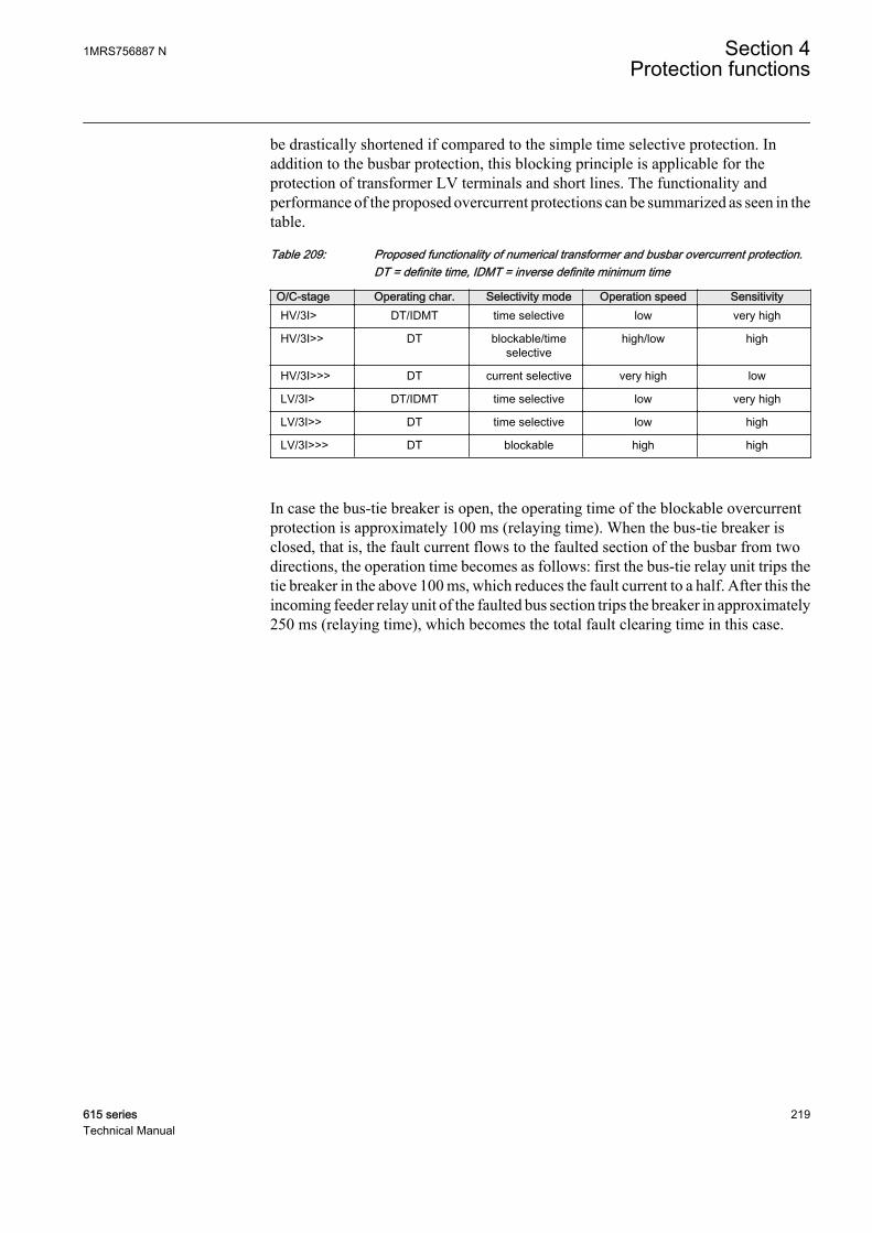
be drastically shortened if compared to the simple time selective protection. Inaddition to the busbar protection, this blocking principle is applicable for theprotection of transformer LV terminals and short lines. The functionality andperformance of the proposed overcurrent protections can be summarized as seen in thetable.
Table 209: Proposed functionality of numerical transformer and busbar overcurrent protection.DT = definite time, IDMT = inverse definite minimum time
O/C-stage Operating char. Selectivity mode Operation speed SensitivityHV/3I> DT/IDMT time selective low very high
HV/3I>> DT blockable/timeselective
high/low high
HV/3I>>> DT current selective very high low
LV/3I> DT/IDMT time selective low very high
LV/3I>> DT time selective low high
LV/3I>>> DT blockable high high
In case the bus-tie breaker is open, the operating time of the blockable overcurrentprotection is approximately 100 ms (relaying time). When the bus-tie breaker isclosed, that is, the fault current flows to the faulted section of the busbar from twodirections, the operation time becomes as follows: first the bus-tie relay unit trips thetie breaker in the above 100 ms, which reduces the fault current to a half. After this theincoming feeder relay unit of the faulted bus section trips the breaker in approximately250 ms (relaying time), which becomes the total fault clearing time in this case.
1MRS756887 N Section 4Protection functions
615 series 219Technical Manual
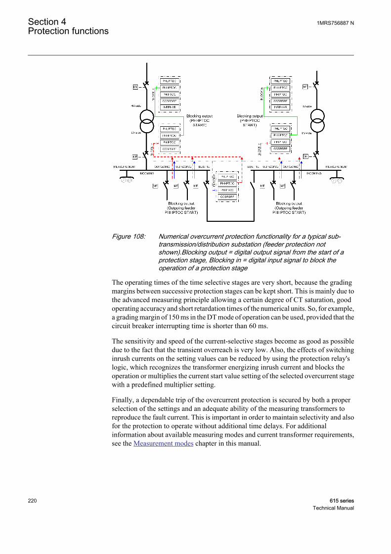
A070980 V2 EN
Figure 108: Numerical overcurrent protection functionality for a typical sub-transmission/distribution substation (feeder protection notshown).Blocking output = digital output signal from the start of aprotection stage, Blocking in = digital input signal to block theoperation of a protection stage
The operating times of the time selective stages are very short, because the gradingmargins between successive protection stages can be kept short. This is mainly due tothe advanced measuring principle allowing a certain degree of CT saturation, goodoperating accuracy and short retardation times of the numerical units. So, for example,a grading margin of 150 ms in the DT mode of operation can be used, provided that thecircuit breaker interrupting time is shorter than 60 ms.
The sensitivity and speed of the current-selective stages become as good as possibledue to the fact that the transient overreach is very low. Also, the effects of switchinginrush currents on the setting values can be reduced by using the protection relay'slogic, which recognizes the transformer energizing inrush current and blocks theoperation or multiplies the current start value setting of the selected overcurrent stagewith a predefined multiplier setting.
Finally, a dependable trip of the overcurrent protection is secured by both a properselection of the settings and an adequate ability of the measuring transformers toreproduce the fault current. This is important in order to maintain selectivity and alsofor the protection to operate without additional time delays. For additionalinformation about available measuring modes and current transformer requirements,see the Measurement modes chapter in this manual.
Section 4 1MRS756887 NProtection functions
220 615 seriesTechnical Manual

Radial outgoing feeder overcurrent protectionThe basic requirements for feeder overcurrent protection are adequate sensitivity andoperation speed taking into account the minimum and maximum fault current levelsalong the protected line, selectivity requirements, inrush currents and the thermal andmechanical withstand of the lines to be protected.
In many cases the above requirements can be best fulfilled by using multiple-stageovercurrent units. Figure 109 shows an example of this. A brief coordination study hasbeen carried out between the incoming and outgoing feeders.
The protection scheme is implemented with three-stage numerical overcurrentprotection, where the low-set stage PHLPTOC operates in IDMT-mode and the twohigher stages PHHPTOC and PHIPTOC in DT-mode. Also the thermal withstand ofthe line types along the feeder and maximum expected inrush currents of the feedersare shown. Faults occurring near the station where the fault current levels are thehighest are cleared rapidly by the instantaneous stage in order to minimize the effectsof severe short circuit faults. The influence of the inrush current is taken intoconsideration by connecting the inrush current detector to the start value multiplyinginput of the instantaneous stage. In this way the start value is multiplied with apredefined setting during the inrush situation and nuisance tripping can be avoided.
1MRS756887 N Section 4Protection functions
615 series 221Technical Manual
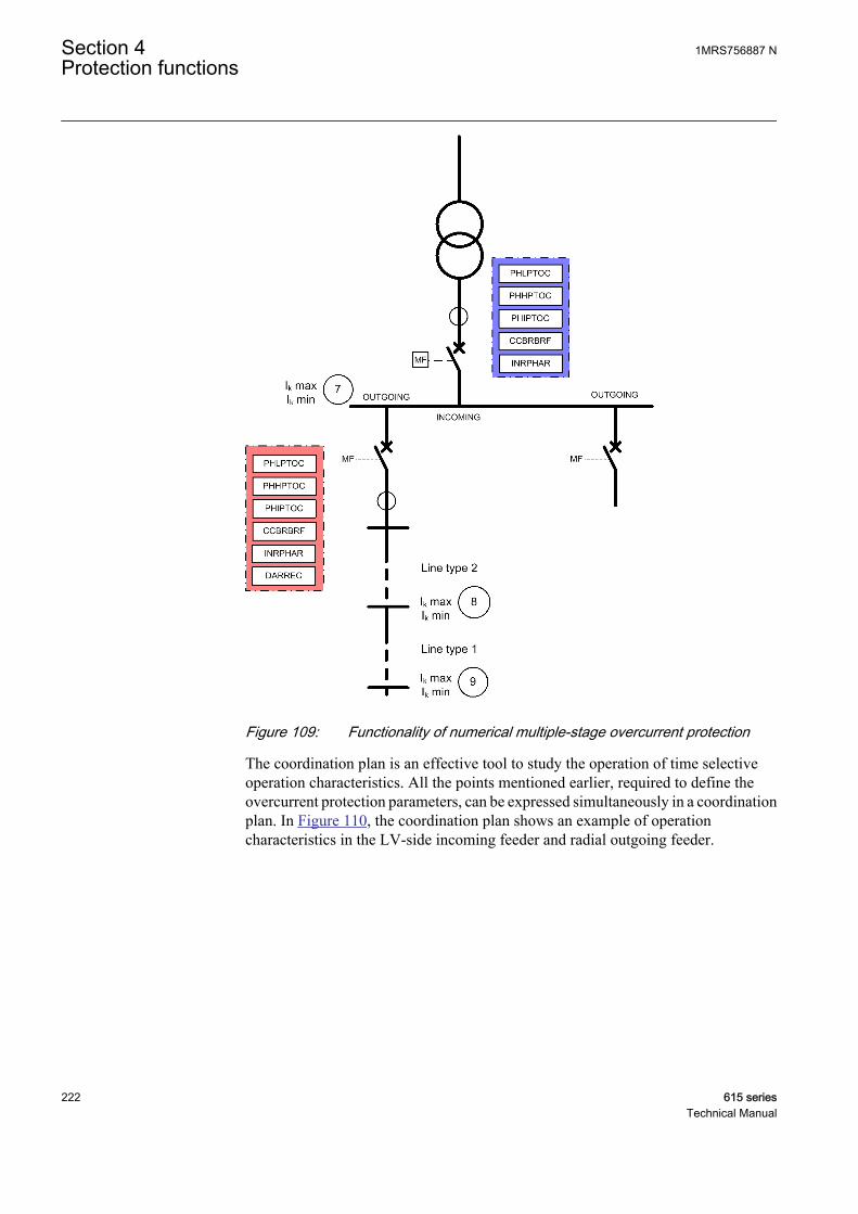
A070982 V1 EN
Figure 109: Functionality of numerical multiple-stage overcurrent protection
The coordination plan is an effective tool to study the operation of time selectiveoperation characteristics. All the points mentioned earlier, required to define theovercurrent protection parameters, can be expressed simultaneously in a coordinationplan. In Figure 110, the coordination plan shows an example of operationcharacteristics in the LV-side incoming feeder and radial outgoing feeder.
Section 4 1MRS756887 NProtection functions
222 615 seriesTechnical Manual
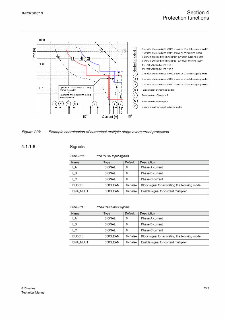
A070984 V2 EN
Figure 110: Example coordination of numerical multiple-stage overcurrent protection
4.1.1.8 Signals
Table 210: PHLPTOC Input signals
Name Type Default DescriptionI_A SIGNAL 0 Phase A current
I_B SIGNAL 0 Phase B current
I_C SIGNAL 0 Phase C current
BLOCK BOOLEAN 0=False Block signal for activating the blocking mode
ENA_MULT BOOLEAN 0=False Enable signal for current multiplier
Table 211: PHHPTOC Input signals
Name Type Default DescriptionI_A SIGNAL 0 Phase A current
I_B SIGNAL 0 Phase B current
I_C SIGNAL 0 Phase C current
BLOCK BOOLEAN 0=False Block signal for activating the blocking mode
ENA_MULT BOOLEAN 0=False Enable signal for current multiplier
1MRS756887 N Section 4Protection functions
615 series 223Technical Manual

Table 212: PHIPTOC Input signals
Name Type Default DescriptionI_A SIGNAL 0 Phase A current
I_B SIGNAL 0 Phase B current
I_C SIGNAL 0 Phase C current
BLOCK BOOLEAN 0=False Block signal for activating the blocking mode
ENA_MULT BOOLEAN 0=False Enable signal for current multiplier
Table 213: PHLPTOC Output signals
Name Type DescriptionOPERATE BOOLEAN Operate
START BOOLEAN Start
Table 214: PHHPTOC Output signals
Name Type DescriptionOPERATE BOOLEAN Operate
START BOOLEAN Start
Table 215: PHIPTOC Output signals
Name Type DescriptionOPERATE BOOLEAN Operate
START BOOLEAN Start
Section 4 1MRS756887 NProtection functions
224 615 seriesTechnical Manual

4.1.1.9 Settings
Table 216: PHLPTOC Group settings (Basic)
Parameter Values (Range) Unit Step Default DescriptionStart value 0.05...5.00 xIn 0.01 0.05 Start value
Start value Mult 0.8...10.0 0.1 1.0 Multiplier for scaling the start value
Time multiplier 0.05...15.00 0.01 1.00 Time multiplier in IEC/ANSI IDMT curves
Operate delay time 40...200000 ms 10 40 Operate delay time
Operating curve type 1=ANSI Ext. inv.2=ANSI Very inv.3=ANSI Norm. inv.4=ANSI Mod. inv.5=ANSI Def. Time6=L.T.E. inv.7=L.T.V. inv.8=L.T. inv.9=IEC Norm. inv.10=IEC Very inv.11=IEC inv.12=IEC Ext. inv.13=IEC S.T. inv.14=IEC L.T. inv.15=IEC Def. Time17=Programmable18=RI type19=RD type
15=IEC Def. Time Selection of time delay curve type
Table 217: PHLPTOC Group settings (Advanced)
Parameter Values (Range) Unit Step Default DescriptionType of reset curve 1=Immediate
2=Def time reset3=Inverse reset
1=Immediate Selection of reset curve type
Table 218: PHLPTOC Non group settings (Basic)
Parameter Values (Range) Unit Step Default DescriptionOperation 1=on
5=off 1=on Operation Off / On
Num of start phases 1=1 out of 32=2 out of 33=3 out of 3
1=1 out of 3 Number of phases required for operateactivation
Curve parameter A 0.0086...120.0000 1 28.2000 Parameter A for customer programmablecurve
Curve parameter B 0.0000...0.7120 1 0.1217 Parameter B for customer programmablecurve
Curve parameter C 0.02...2.00 1 2.00 Parameter C for customer programmablecurve
Curve parameter D 0.46...30.00 1 29.10 Parameter D for customer programmablecurve
Curve parameter E 0.0...1.0 1 1.0 Parameter E for customer programmablecurve
1MRS756887 N Section 4Protection functions
615 series 225Technical Manual
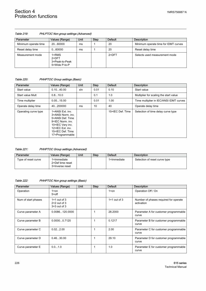
Table 219: PHLPTOC Non group settings (Advanced)
Parameter Values (Range) Unit Step Default DescriptionMinimum operate time 20...60000 ms 1 20 Minimum operate time for IDMT curves
Reset delay time 0...60000 ms 1 20 Reset delay time
Measurement mode 1=RMS2=DFT3=Peak-to-Peak5=Wide P-to-P
2=DFT Selects used measurement mode
Table 220: PHHPTOC Group settings (Basic)
Parameter Values (Range) Unit Step Default DescriptionStart value 0.10...40.00 xIn 0.01 0.10 Start value
Start value Mult 0.8...10.0 0.1 1.0 Multiplier for scaling the start value
Time multiplier 0.05...15.00 0.01 1.00 Time multiplier in IEC/ANSI IDMT curves
Operate delay time 40...200000 ms 10 40 Operate delay time
Operating curve type 1=ANSI Ext. inv.3=ANSI Norm. inv.5=ANSI Def. Time9=IEC Norm. inv.10=IEC Very inv.12=IEC Ext. inv.15=IEC Def. Time17=Programmable
15=IEC Def. Time Selection of time delay curve type
Table 221: PHHPTOC Group settings (Advanced)
Parameter Values (Range) Unit Step Default DescriptionType of reset curve 1=Immediate
2=Def time reset3=Inverse reset
1=Immediate Selection of reset curve type
Table 222: PHHPTOC Non group settings (Basic)
Parameter Values (Range) Unit Step Default DescriptionOperation 1=on
5=off 1=on Operation Off / On
Num of start phases 1=1 out of 32=2 out of 33=3 out of 3
1=1 out of 3 Number of phases required for operateactivation
Curve parameter A 0.0086...120.0000 1 28.2000 Parameter A for customer programmablecurve
Curve parameter B 0.0000...0.7120 1 0.1217 Parameter B for customer programmablecurve
Curve parameter C 0.02...2.00 1 2.00 Parameter C for customer programmablecurve
Curve parameter D 0.46...30.00 1 29.10 Parameter D for customer programmablecurve
Curve parameter E 0.0...1.0 1 1.0 Parameter E for customer programmablecurve
Section 4 1MRS756887 NProtection functions
226 615 seriesTechnical Manual

Table 223: PHHPTOC Non group settings (Advanced)
Parameter Values (Range) Unit Step Default DescriptionMinimum operate time 20...60000 ms 1 20 Minimum operate time for IDMT curves
Reset delay time 0...60000 ms 1 20 Reset delay time
Measurement mode 1=RMS2=DFT3=Peak-to-Peak
2=DFT Selects used measurement mode
Table 224: PHIPTOC Group settings (Basic)
Parameter Values (Range) Unit Step Default DescriptionStart value 1.00...40.00 xIn 0.01 1.00 Start value
Start value Mult 0.8...10.0 0.1 1.0 Multiplier for scaling the start value
Operate delay time 20...200000 ms 10 20 Operate delay time
Table 225: PHIPTOC Non group settings (Basic)
Parameter Values (Range) Unit Step Default DescriptionOperation 1=on
5=off 1=on Operation Off / On
Num of start phases 1=1 out of 32=2 out of 33=3 out of 3
1=1 out of 3 Number of phases required for operateactivation
Table 226: PHIPTOC Non group settings (Advanced)
Parameter Values (Range) Unit Step Default DescriptionReset delay time 0...60000 ms 1 20 Reset delay time
4.1.1.10 Monitored data
Table 227: PHLPTOC Monitored data
Name Type Values (Range) Unit DescriptionSTART_DUR FLOAT32 0.00...100.00 % Ratio of start time /
operate time
PHLPTOC Enum 1=on2=blocked3=test4=test/blocked5=off
Status
1MRS756887 N Section 4Protection functions
615 series 227Technical Manual
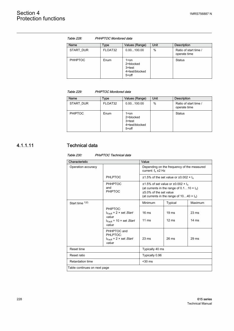
Table 228: PHHPTOC Monitored data
Name Type Values (Range) Unit DescriptionSTART_DUR FLOAT32 0.00...100.00 % Ratio of start time /
operate time
PHHPTOC Enum 1=on2=blocked3=test4=test/blocked5=off
Status
Table 229: PHIPTOC Monitored data
Name Type Values (Range) Unit DescriptionSTART_DUR FLOAT32 0.00...100.00 % Ratio of start time /
operate time
PHIPTOC Enum 1=on2=blocked3=test4=test/blocked5=off
Status
4.1.1.11 Technical data
Table 230: PHxPTOC Technical data
Characteristic ValueOperation accuracy Depending on the frequency of the measured
current: fn ±2 Hz
PHLPTOC ±1.5% of the set value or ±0.002 × In
PHHPTOCandPHIPTOC
±1.5% of set value or ±0.002 × In(at currents in the range of 0.1…10 × In)±5.0% of the set value(at currents in the range of 10…40 × In)
Start time 1)2) Minimum Typical Maximum
PHIPTOC:IFault = 2 × set StartvalueIFault = 10 × set Startvalue
16 ms 11 ms
19 ms 12 ms
23 ms 14 ms
PHHPTOC andPHLPTOC:IFault = 2 × set Startvalue
23 ms
26 ms
29 ms
Reset time Typically 40 ms
Reset ratio Typically 0.96
Retardation time <30 ms
Table continues on next page
Section 4 1MRS756887 NProtection functions
228 615 seriesTechnical Manual

Characteristic ValueOperate time accuracy in definite time mode ±1.0% of the set value or ±20 ms
Operate time accuracy in inverse time mode ±5.0% of the theoretical value or ±20 ms 3)
Suppression of harmonics RMS: No suppressionDFT: -50 dB at f = n × fn, where n = 2, 3, 4, 5,…Peak-to-Peak: No suppressionP-to-P+backup: No suppression
1) Measurement mode = default (depends on stage), current before fault = 0.0 × In, fn = 50 Hz, fault currentin one phase with nominal frequency injected from random phase angle, results based on statisticaldistribution of 1000 measurements
2) Includes the delay of the signal output contact3) Maximum Start value = 2.5 × In, Start value multiples in range of 1.5...20
4.1.1.12 Technical revision history
Table 231: PHIPTOC Technical revision history
Technical revision ChangeB Minimum and default values changed to 40 ms for
the Operate delay time setting
C Minimum and default values changed to 20 ms forthe Operate delay time settingMinimum value changed to 1.00 x In for the Startvalue setting
D Internal improvement
E Internal improvement
Table 232: PHHPTOC Technical revision history
Technical revision ChangeC Measurement mode "P-to-P + backup" replaced
with "Peak-to-Peak"
D Step value changed from 0.05 to 0.01 for the Timemultiplier setting
E Internal improvement
F Internal improvement
Table 233: PHLPTOC Technical revision history
Technical revision ChangeB Minimum and default values changed to 40 ms for
the Operate delay time setting
C Step value changed from 0.05 to 0.01 for the Timemultiplier setting
D Internal improvement
E Internal improvement
1MRS756887 N Section 4Protection functions
615 series 229Technical Manual
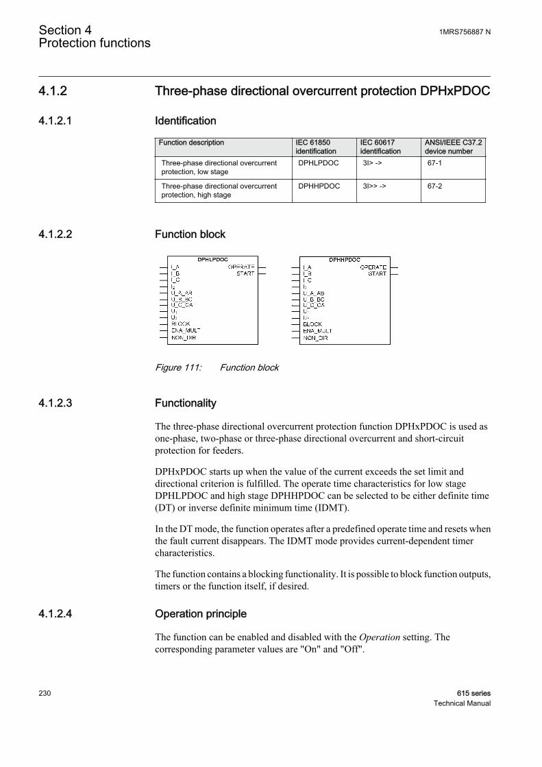
4.1.2 Three-phase directional overcurrent protection DPHxPDOC
4.1.2.1 Identification
Function description IEC 61850identification
IEC 60617identification
ANSI/IEEE C37.2device number
Three-phase directional overcurrentprotection, low stage
DPHLPDOC 3I> -> 67-1
Three-phase directional overcurrentprotection, high stage
DPHHPDOC 3I>> -> 67-2
4.1.2.2 Function block
GUID-9EB77066-518A-4CCC-B973-7EEE31FAE4F1 V3 EN
Figure 111: Function block
4.1.2.3 Functionality
The three-phase directional overcurrent protection function DPHxPDOC is used asone-phase, two-phase or three-phase directional overcurrent and short-circuitprotection for feeders.
DPHxPDOC starts up when the value of the current exceeds the set limit anddirectional criterion is fulfilled. The operate time characteristics for low stageDPHLPDOC and high stage DPHHPDOC can be selected to be either definite time(DT) or inverse definite minimum time (IDMT).
In the DT mode, the function operates after a predefined operate time and resets whenthe fault current disappears. The IDMT mode provides current-dependent timercharacteristics.
The function contains a blocking functionality. It is possible to block function outputs,timers or the function itself, if desired.
4.1.2.4 Operation principle
The function can be enabled and disabled with the Operation setting. Thecorresponding parameter values are "On" and "Off".
Section 4 1MRS756887 NProtection functions
230 615 seriesTechnical Manual
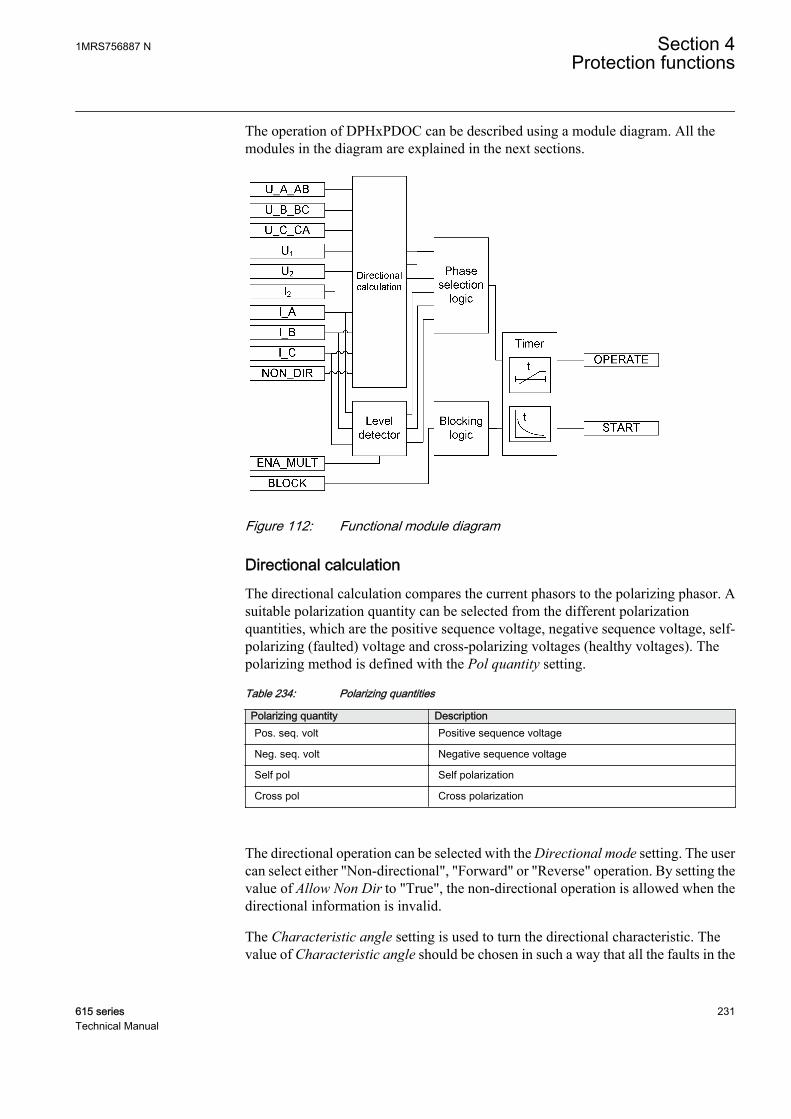
The operation of DPHxPDOC can be described using a module diagram. All themodules in the diagram are explained in the next sections.
GUID-C5892F3E-09D9-462E-A963-023EFC18DDE7 V3 EN
Figure 112: Functional module diagram
Directional calculationThe directional calculation compares the current phasors to the polarizing phasor. Asuitable polarization quantity can be selected from the different polarizationquantities, which are the positive sequence voltage, negative sequence voltage, self-polarizing (faulted) voltage and cross-polarizing voltages (healthy voltages). Thepolarizing method is defined with the Pol quantity setting.
Table 234: Polarizing quantities
Polarizing quantity DescriptionPos. seq. volt Positive sequence voltage
Neg. seq. volt Negative sequence voltage
Self pol Self polarization
Cross pol Cross polarization
The directional operation can be selected with the Directional mode setting. The usercan select either "Non-directional", "Forward" or "Reverse" operation. By setting thevalue of Allow Non Dir to "True", the non-directional operation is allowed when thedirectional information is invalid.
The Characteristic angle setting is used to turn the directional characteristic. Thevalue of Characteristic angle should be chosen in such a way that all the faults in the
1MRS756887 N Section 4Protection functions
615 series 231Technical Manual

operating direction are seen in the operating zone and all the faults in the oppositedirection are seen in the non-operating zone. The value of Characteristic angledepends on the network configuration.
Reliable operation requires both the operating and polarizing quantities to exceedcertain minimum amplitude levels. The minimum amplitude level for the operatingquantity (current) is set with the Min operate current setting. The minimum amplitudelevel for the polarizing quantity (voltage) is set with the Min operate voltage setting.If the amplitude level of the operating quantity or polarizing quantity is below the setlevel, the direction information of the corresponding phase is set to "Unknown".
The polarizing quantity validity can remain valid even if the amplitude of thepolarizing quantity falls below the value of the Min operate voltage setting. In thiscase, the directional information is provided by a special memory function for a timedefined with the Voltage Mem time setting.
DPHxPDOC is provided with a memory function to secure a reliable and correctdirectional protection relay operation in case of a close short circuit or an earth faultcharacterized by an extremely low voltage. At sudden loss of the polarizationquantity, the angle difference is calculated on the basis of a fictive voltage. The fictivevoltage is calculated using the positive phase sequence voltage measured before thefault occurred, assuming that the voltage is not affected by the fault. The memoryfunction enables the function to operate up to a maximum of three seconds after a totalloss of voltage. This time can be set with the Voltage Mem time setting. The voltagememory cannot be used for the "Negative sequence voltage" polarization because it isnot possible to substitute the positive sequence voltage for negative sequence voltagewithout knowing the network unsymmetry level. This is the reason why the fictivevoltage angle and corresponding direction information are frozen immediately for thispolarization mode when the need for a voltage memory arises and these are keptfrozen until the time set with Voltage Mem time elapses.
The value for the Min operate voltage setting should be carefullyselected since the accuracy in low signal levels is strongly affected bythe measuring device accuracy.
When the voltage falls below Min operate voltage at a close fault, the fictive voltageis used to determine the phase angle. The measured voltage is applied again as soonas the voltage rises above Min operate voltage and hysteresis. The fictive voltage isalso discarded if the measured voltage stays below Min operate voltage and hysteresisfor longer than Voltage Mem time or if the fault current disappears while the fictivevoltage is in use. When the voltage is below Min operate voltage and hysteresis andthe fictive voltage is unusable, the fault direction cannot be determined. The fictivevoltage can be unusable for two reasons:
• The fictive voltage is discarded after Voltage Mem time• The phase angle cannot be reliably measured before the fault situation.
Section 4 1MRS756887 NProtection functions
232 615 seriesTechnical Manual
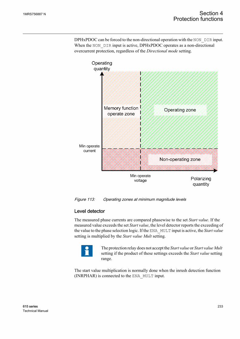
DPHxPDOC can be forced to the non-directional operation with the NON_DIR input.When the NON_DIR input is active, DPHxPDOC operates as a non-directionalovercurrent protection, regardless of the Directional mode setting.
GUID-718D61B4-DAD0-4F43-8108-86F7B44E7E2D V1 EN
Figure 113: Operating zones at minimum magnitude levels
Level detectorThe measured phase currents are compared phasewise to the set Start value. If themeasured value exceeds the set Start value, the level detector reports the exceeding ofthe value to the phase selection logic. If the ENA_MULT input is active, the Start valuesetting is multiplied by the Start value Mult setting.
The protection relay does not accept the Start value or Start value Multsetting if the product of these settings exceeds the Start value settingrange.
The start value multiplication is normally done when the inrush detection function(INRPHAR) is connected to the ENA_MULT input.
1MRS756887 N Section 4Protection functions
615 series 233Technical Manual
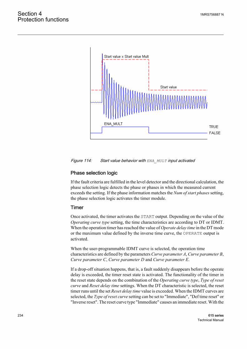
A070554 V1 EN
Figure 114: Start value behavior with ENA_MULT input activated
Phase selection logicIf the fault criteria are fulfilled in the level detector and the directional calculation, thephase selection logic detects the phase or phases in which the measured currentexceeds the setting. If the phase information matches the Num of start phases setting,the phase selection logic activates the timer module.
TimerOnce activated, the timer activates the START output. Depending on the value of theOperating curve type setting, the time characteristics are according to DT or IDMT.When the operation timer has reached the value of Operate delay time in the DT modeor the maximum value defined by the inverse time curve, the OPERATE output isactivated.
When the user-programmable IDMT curve is selected, the operation timecharacteristics are defined by the parameters Curve parameter A, Curve parameter B,Curve parameter C, Curve parameter D and Curve parameter E.
If a drop-off situation happens, that is, a fault suddenly disappears before the operatedelay is exceeded, the timer reset state is activated. The functionality of the timer inthe reset state depends on the combination of the Operating curve type, Type of resetcurve and Reset delay time settings. When the DT characteristic is selected, the resettimer runs until the set Reset delay time value is exceeded. When the IDMT curves areselected, the Type of reset curve setting can be set to "Immediate", "Def time reset" or"Inverse reset". The reset curve type "Immediate" causes an immediate reset. With the
Section 4 1MRS756887 NProtection functions
234 615 seriesTechnical Manual

reset curve type "Def time reset", the reset time depends on the Reset delay timesetting. With the reset curve type "Inverse reset", the reset time depends on the currentduring the drop-off situation. The START output is deactivated when the reset timerhas elapsed.
The "Inverse reset" selection is only supported with ANSI or userprogrammable types of the IDMT operating curves. If anotheroperating curve type is selected, an immediate reset occurs during thedrop-off situation.
The setting Time multiplier is used for scaling the IDMT operate and reset times.
The setting parameter Minimum operate time defines the minimum desired operatetime for IDMT. The setting is applicable only when the IDMT curves are used.
The Minimum operate time setting should be used with great carebecause the operation time is according to the IDMT curve, but alwaysat least the value of the Minimum operate time setting. For moreinformation, see the IDMT curves for overcurrent protection sectionin this manual.
The timer calculates the start duration value START_DUR, which indicates thepercentage ratio of the start situation and the set operating time. The value is availablein the monitored data view.
Blocking logicThere are three operation modes in the blocking function. The operation modes arecontrolled by the BLOCK input and the global setting in Configuration/System/Blocking mode which selects the blocking mode. The BLOCK input can be controlledby a binary input, a horizontal communication input or an internal signal of theprotection relay's program. The influence of the BLOCK signal activation ispreselected with the global setting Blocking mode.
The Blocking mode setting has three blocking methods. In the "Freeze timers" mode,the operation timer is frozen to the prevailing value, but the OPERATE output is notdeactivated when blocking is activated. In the "Block all" mode, the whole function isblocked and the timers are reset. In the "Block OPERATE output" mode, the functionoperates normally but the OPERATE output is not activated.
4.1.2.5 Measurement modes
The function operates on three alternative measurement modes: “RMS”, “DFT” and“Peak-to-Peak” . The measurement mode is selected with the Measurement modesetting.
1MRS756887 N Section 4Protection functions
615 series 235Technical Manual

Table 235: Measurement modes supported by DPHxPDOC stages
Measurement mode DPHLPDOC DPHHPDOCRMS x x
DFT x x
Peak-to-Peak x x
4.1.2.6 Directional overcurrent characteristics
The forward and reverse sectors are defined separately. The forward operation area islimited with the Min forward angle and Max forward angle settings. The reverseoperation area is limited with the Min reverse angle and Max reverse angle settings.
The sector limits are always given as positive degree values.
In the forward operation area, the Max forward angle setting gives thecounterclockwise sector and the Min forward angle setting gives the correspondingclockwise sector, measured from the Characteristic angle setting.
In the backward operation area, the Max reverse angle setting gives thecounterclockwise sector and the Min reverse angle setting gives the correspondingclockwise sector, a measurement from the Characteristic angle setting that has beenrotated 180 degrees.
Relay characteristic angle (RCA) is set positive if the operating current lags thepolarizing quantity and negative if the operating current leads the polarizing quantity.
Section 4 1MRS756887 NProtection functions
236 615 seriesTechnical Manual

GUID-CD0B7D5A-1F1A-47E6-AF2A-F6F898645640 V2 EN
Figure 115: Configurable operating sectors
Table 236: Momentary per phase direction value for monitored data view
Criterion for per phase direction information The value for DIR_A/_B/_CThe ANGLE_X is not in any of the defined sectors,or the direction cannot be defined due too lowamplitude
0 = unknown
The ANGLE_X is in the forward sector 1 = forward
The ANGLE_X is in the reverse sector 2 = backward
(The ANGLE_X is in both forward and reversesectors, that is, when the sectors are overlapping)
3 = both
Table 237: Momentary phase combined direction value for monitored data view
Criterion for phase combined direction information The value for DIRECTIONThe direction information (DIR_X) for all phases isunknown
0 = unknown
The direction information (DIR_X) for at least onephase is forward, none being in reverse
1 = forward
The direction information (DIR_X) for at least onephase is reverse, none being in forward
2 = backward
The direction information (DIR_X) for some phaseis forward and for some phase is reverse
3 = both
1MRS756887 N Section 4Protection functions
615 series 237Technical Manual

FAULT_DIR gives the detected direction of the fault during fault situations, that is,when the START output is active.
Self-polarizing as polarizing methodTable 238: Equations for calculating angle difference for self-polarizing method
Faultedphases
Used faultcurrent
Usedpolarizingvoltage
Angle difference
A IA UA ANGLE A U IA A RCA_ ( ) - ( ) - = ϕ ϕ ϕ
GUID-60308BBA-07F8-4FB4-A9E8-3850325E368C V2 EN
B IB UB ANGLE B U IB B RCA_ ( ) - ( ) - = ϕ ϕ ϕ
GUID-9AF57A77-F9C6-46B7-B056-AC7542EBF449 V2 EN
C IC UC ANGLE C U IC C RCA_ ( ) - ( ) - = ϕ ϕ ϕ
GUID-51FEBD95-672C-440F-A678-DD01ABB2D018 V2 EN
A - B IA - IB UAB ANGLE A U I IAB A B RCA_ ( ) - ( - ) - = ϕ ϕ ϕ
GUID-7DA1116D-86C0-4D7F-AA19-DCF32C530C4C V2 EN
B - C IB - IC UBC ANGLE B U I IBC B C RCA_ ( ) - ( - ) - = ϕ ϕ ϕ
GUID-3E9788CA-D2FC-4FC4-8F9E-1466F3775826 V2 EN
C - A IC - IA UCA ANGLE C U I ICA C A RCA_ ( ) - ( - ) - = ϕ ϕ ϕ
GUID-EFD80F78-4B26-46B6-A5A6-CCA6B7E20C6E V2 EN
In an example case of the phasors in a single-phase earth fault where the faulted phaseis phase A, the angle difference between the polarizing quantity UA and operatingquantity IA is marked as φ. In the self-polarization method, there is no need to rotatethe polarizing quantity.
GUID-C648173C-D8BB-4F37-8634-5D4DC7D366FF V1 EN
Figure 116: Single-phase earth fault, phase A
Section 4 1MRS756887 NProtection functions
238 615 seriesTechnical Manual
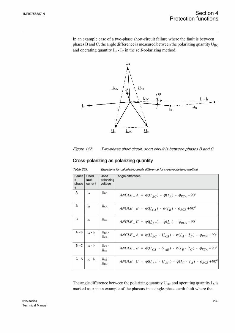
In an example case of a two-phase short-circuit failure where the fault is betweenphases B and C, the angle difference is measured between the polarizing quantity UBCand operating quantity IB - IC in the self-polarizing method.
GUID-65CFEC0E-0367-44FB-A116-057DD29FEB79 V1 EN
Figure 117: Two-phase short circuit, short circuit is between phases B and C
Cross-polarizing as polarizing quantityTable 239: Equations for calculating angle difference for cross-polarizing method
Faultedphases
Usedfaultcurrent
Usedpolarizingvoltage
Angle difference
A IA UBCANGLE A U I
BC A RCA
o_ ( ) - ( ) - = +ϕ ϕ ϕ 90
GUID-4F0D1491-3679-4B1F-99F7-3704BC15EF9D V3 EN
B IB UCAANGLE B U I
CA B RCA
o_ ( ) - ( ) - = +ϕ ϕ ϕ 90
GUID-F5252292-E132-41A7-9F6D-C2A3958EE6AD V3 EN
C IC UABANGLE C U I
AB C RCA
o_ ( ) - ( ) - = +ϕ ϕ ϕ 90
GUID-84D97257-BAEC-4264-9D93-EC2DF853EAE1 V3 EN
A - B IA - IB UBC -UCA
ANGLE A U U I IBC CA A B RCA
o_ ( - ) - ( - ) - = +ϕ ϕ ϕ 90
GUID-AFB15C3F-B9BB-47A2-80E9-796AA1165409 V2 EN
B - C IB - IC UCA -UAB
ANGLE B U U I ICA AB B C RCA
o_ ( - ) - ( - ) - = +ϕ ϕ ϕ 90
GUID-C698D9CA-9139-40F2-9097-007B6B14D053 V2 EN
C - A IC - IA UAB -UBC
ANGLE C U U I IAB BC C A RCA
o_ ( - ) - ( - ) - = +ϕ ϕ ϕ 90
GUID-838ECE7D-8B1C-466F-8166-E8FE16D28AAD V2 EN
The angle difference between the polarizing quantity UBC and operating quantity IA ismarked as φ in an example of the phasors in a single-phase earth fault where the
1MRS756887 N Section 4Protection functions
615 series 239Technical Manual

faulted phase is phase A. The polarizing quantity is rotated with 90 degrees. Thecharacteristic angle is assumed to be ~ 0 degrees.
GUID-6C7D1317-89C4-44BE-A1EB-69BC75863474 V1 EN
Figure 118: Single-phase earth fault, phase A
In an example of the phasors in a two-phase short-circuit failure where the fault isbetween the phases B and C, the angle difference is measured between the polarizingquantity UAB and operating quantity IB - IC marked as φ.
Section 4 1MRS756887 NProtection functions
240 615 seriesTechnical Manual

GUID-C2EC2EF1-8A84-4A32-818C-6D7620EA9969 V1 EN
Figure 119: Two-phase short circuit, short circuit is between phases B and C
The equations are valid when network rotating direction is counter-clockwise, that is, ABC. If the network rotating direction is reversed,180 degrees is added to the calculated angle difference. This is doneautomatically with a system parameter Phase rotation.
Negative sequence voltage as polarizing quantityWhen the negative voltage is used as the polarizing quantity, the angle differencebetween the operating and polarizing quantity is calculated with the same formula forall fault types:
ANGLE X U I RCA_ ( ) ( )= − − −ϕ ϕ ϕ2 2
GUID-470263DD-C1D7-4E59-B011-24D8D35BD52A V3 EN (Equation 5)
1MRS756887 N Section 4Protection functions
615 series 241Technical Manual
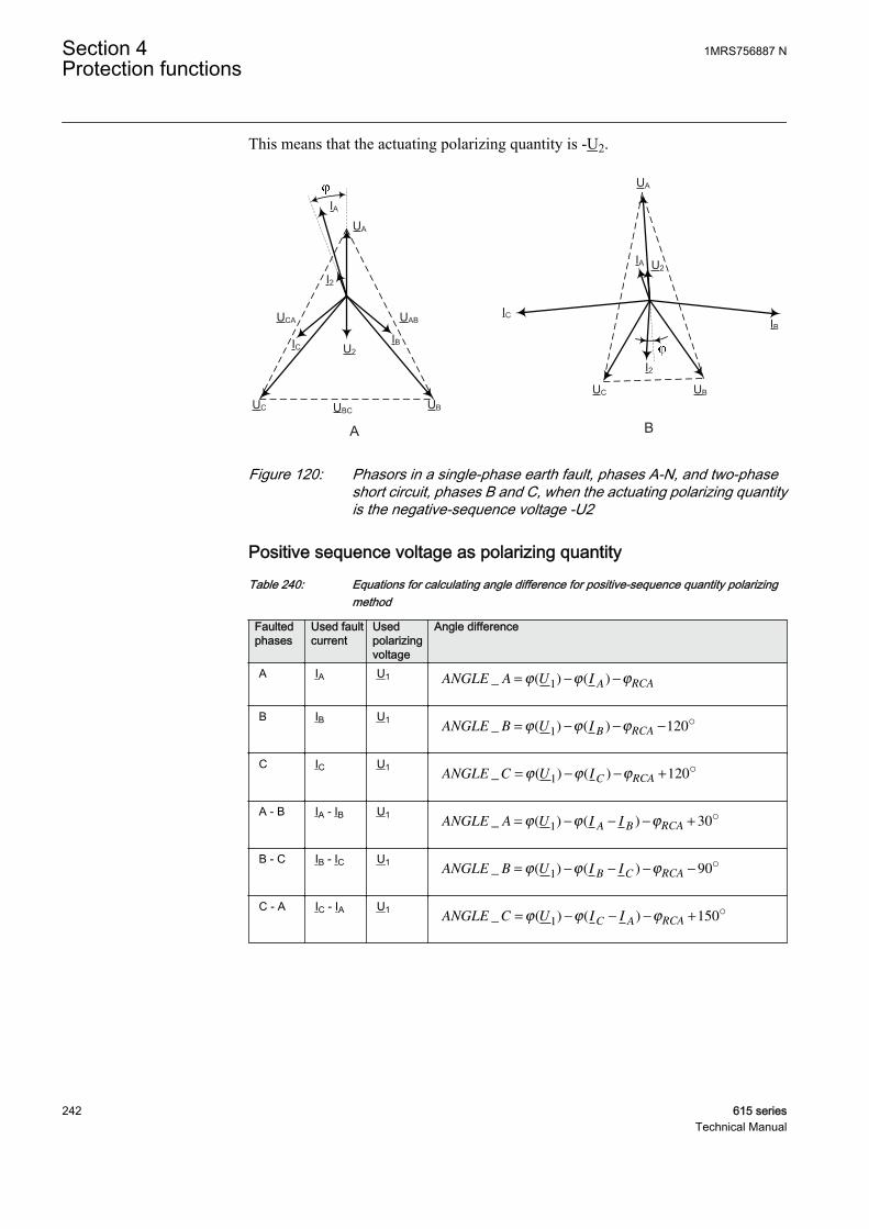
This means that the actuating polarizing quantity is -U2.
UA
UBUC UBC
UABUCA
IA
IBIC U2
I2
UA
UBUC
IA
IBIC
U2
I2
A BGUID-027DD4B9-5844-4C46-BA9C-54784F2300D3 V2 EN
Figure 120: Phasors in a single-phase earth fault, phases A-N, and two-phaseshort circuit, phases B and C, when the actuating polarizing quantityis the negative-sequence voltage -U2
Positive sequence voltage as polarizing quantityTable 240: Equations for calculating angle difference for positive-sequence quantity polarizing
method
Faultedphases
Used faultcurrent
Usedpolarizingvoltage
Angle difference
A IA U1 ANGLE A U IA RCA_ ( ) ( )= − −ϕ ϕ ϕ1
GUID-4C933201-2290-4AA3-97A3-670A40CC4114 V4 EN
B IB U1ANGLE B U I
B RCA_ ( ) ( )= − − −ϕ ϕ ϕ1 120o
GUID-648D061C-6F5F-4372-B120-0F02B42E9809 V4 EN
C IC U1ANGLE C U I
C RCA_ ( ) ( )= − − +ϕ ϕ ϕ1 120o
GUID-355EF014-D8D0-467E-A952-1D1602244C9F V4 EN
A - B IA - IB U1ANGLE A U I I
A B RCA_ ( ) ( )= − − − +ϕ ϕ ϕ1 30o
GUID-B07C3B0A-358E-480F-A059-CC5F3E6839B1 V3 EN
B - C IB - IC U1ANGLE B U I I
B C RCA_ ( ) ( )= − − − −ϕ ϕ ϕ1 90o
GUID-4597F122-99A6-46F6-A38C-81232C985BC9 V3 EN
C - A IC - IA U1ANGLE C U I I
C A RCA_ ( ) ( )= − − − +ϕ ϕ ϕ1 150o
GUID-9892503C-2233-4BC5-8C54-BCF005E20A08 V3 EN
Section 4 1MRS756887 NProtection functions
242 615 seriesTechnical Manual

UA
UBUC
IA
IBIC
UA
UBUC
IA
IBIC
A B
-IC
IB - Ic
-90°
U1
U1
GUID-1937EA60-4285-44A7-8A7D-52D7B66FC5A6 V3 EN
Figure 121: Phasors in a single-phase earth fault, phase A to ground, and a two-phase short circuit, phases B-C, are short-circuited when thepolarizing quantity is the positive-sequence voltage U1
Network rotation directionTypically, the network rotating direction is counter-clockwise and defined as "ABC".If the network rotating direction is reversed, meaning clockwise, that is, "ACB", theequations for calculating the angle difference needs to be changed. The networkrotating direction is defined with a system parameter Phase rotation. The change inthe network rotating direction affects the phase-to-phase voltages polarizationmethod where the calculated angle difference needs to be rotated 180 degrees. Also,when the sequence components are used, which are, the positive sequence voltage ornegative sequence voltage components, the calculation of the components areaffected but the angle difference calculation remains the same. When the phase-to-ground voltages are used as the polarizing method, the network rotating directionchange has no effect on the direction calculation.
The network rotating direction is set in the protection relay using theparameter in the HMI menu Configuration/System/Phase rotation.The default parameter value is "ABC".
1MRS756887 N Section 4Protection functions
615 series 243Technical Manual

UBUC
UA
UCUB
UA
NETWORK ROTATION ABC NETWORK ROTATION ACB
UBC
UABUCA
UBC
UCAUAB
IA
IB
IC
IA
IB
IC
GUID-BF32C1D4-ECB5-4E96-A27A-05C637D32C86 V2 EN
Figure 122: Examples of network rotating direction
4.1.2.7 Application
DPHxPDOC is used as short-circuit protection in three-phase distribution or subtransmission networks operating at 50 or 60 Hz.
In radial networks, phase overcurrent protection relays are often sufficient for theshort circuit protection of lines, transformers and other equipment. The current-timecharacteristic should be chosen according to the common practice in the network. It isrecommended to use the same current-time characteristic for all overcurrentprotection relays in the network. This includes the overcurrent protection oftransformers and other equipment.
The phase overcurrent protection can also be used in closed ring systems as shortcircuit protection. Because the setting of a phase overcurrent protection system inclosed ring networks can be complicated, a large number of fault current calculationsare needed. There are situations with no possibility to have the selectivity with aprotection system based on overcurrent protection relays in a closed ring system.
In some applications, the possibility of obtaining the selectivity can be improvedsignificantly if DPHxPDOC is used. This can also be done in the closed ring networksand radial networks with the generation connected to the remote in the system thusgiving fault current infeed in reverse direction. Directional overcurrent protectionrelays are also used to have a selective protection scheme, for example in case ofparallel distribution lines or power transformers fed by the same single source.In ringconnected supply feeders between substations or feeders with two feeding sources,DPHxPDOC is also used.
Parallel lines or transformersWhen the lines are connected in parallel and if a fault occurs in one of the lines, it ispractical to have DPHxPDOC to detect the direction of the fault. Otherwise, there is
Section 4 1MRS756887 NProtection functions
244 615 seriesTechnical Manual
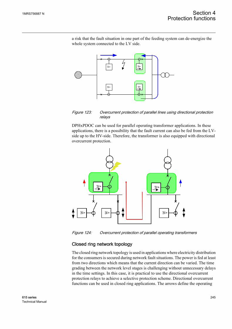
a risk that the fault situation in one part of the feeding system can de-energize thewhole system connected to the LV side.
GUID-1A2BD0AD-B217-46F4-A6B4-6FC6E6256EB3 V2 EN
Figure 123: Overcurrent protection of parallel lines using directional protectionrelays
DPHxPDOC can be used for parallel operating transformer applications. In theseapplications, there is a possibility that the fault current can also be fed from the LV-side up to the HV-side. Therefore, the transformer is also equipped with directionalovercurrent protection.
GUID-74662396-1BAD-4AC2-ADB6-F4A8B3341860 V2 EN
Figure 124: Overcurrent protection of parallel operating transformers
Closed ring network topologyThe closed ring network topology is used in applications where electricity distributionfor the consumers is secured during network fault situations. The power is fed at leastfrom two directions which means that the current direction can be varied. The timegrading between the network level stages is challenging without unnecessary delaysin the time settings. In this case, it is practical to use the directional overcurrentprotection relays to achieve a selective protection scheme. Directional overcurrentfunctions can be used in closed ring applications. The arrows define the operating
1MRS756887 N Section 4Protection functions
615 series 245Technical Manual

direction of the directional functionality. The double arrows define the non-directional functionality where faults can be detected in both directions.
GUID-276A9D62-BD74-4335-8F20-EC1731B58889 V1 EN
Figure 125: Closed ring network topology where feeding lines are protected withdirectional overcurrent protection relays
4.1.2.8 Signals
Table 241: DPHLPDOC Input signals
Name Type Default DescriptionI_A SIGNAL 0 Phase A current
I_B SIGNAL 0 Phase B current
I_C SIGNAL 0 Phase C current
I2 SIGNAL 0 Negative phase sequence current
U_A_AB SIGNAL 0 Phase-to-earth voltage A or phase-to-phasevoltage AB
U_B_BC SIGNAL 0 Phase-to-earth voltage B or phase-to-phasevoltage BC
U_C_CA SIGNAL 0 Phase-to-earth voltage C or phase-to-phasevoltage CA
U1 SIGNAL 0 Positive phase sequence voltage
U2 SIGNAL 0 Negative phase sequence voltage
Table continues on next page
Section 4 1MRS756887 NProtection functions
246 615 seriesTechnical Manual
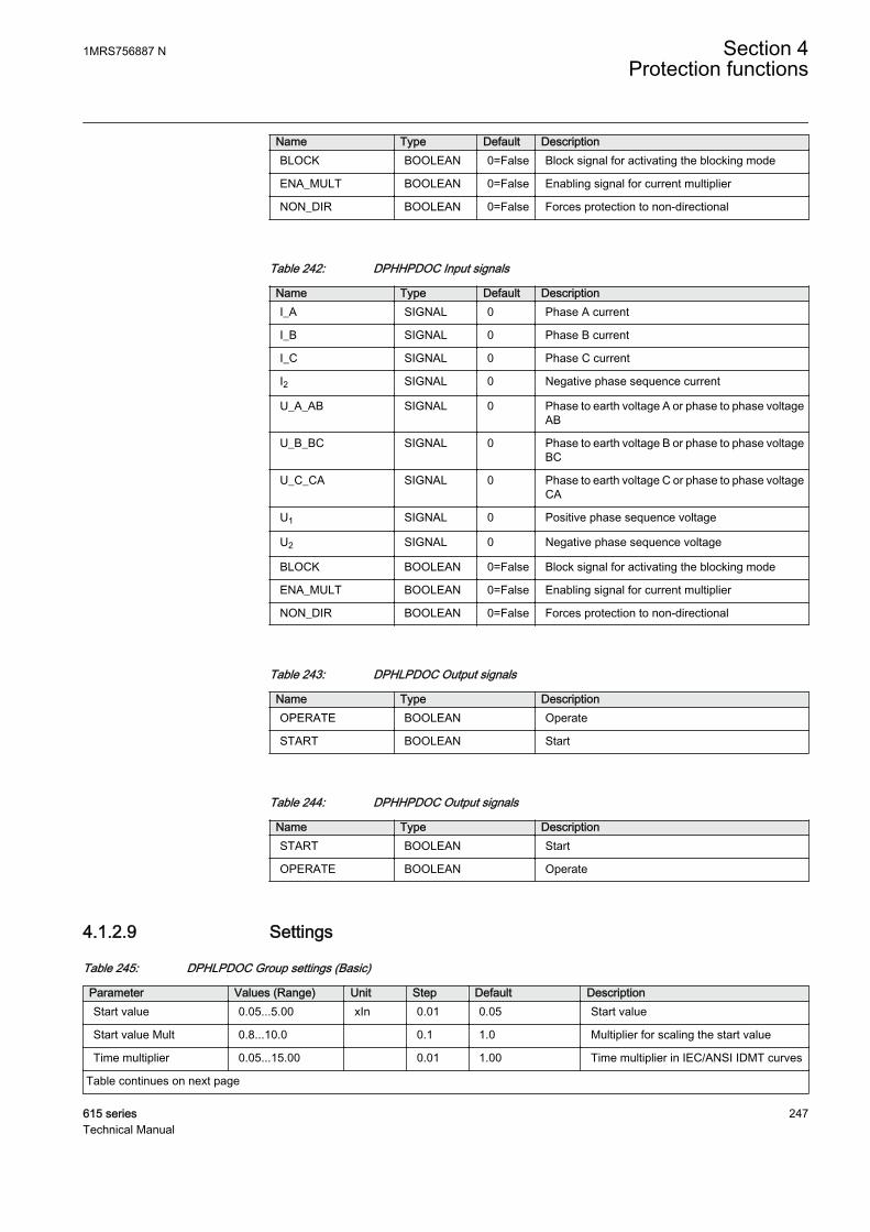
Name Type Default DescriptionBLOCK BOOLEAN 0=False Block signal for activating the blocking mode
ENA_MULT BOOLEAN 0=False Enabling signal for current multiplier
NON_DIR BOOLEAN 0=False Forces protection to non-directional
Table 242: DPHHPDOC Input signals
Name Type Default DescriptionI_A SIGNAL 0 Phase A current
I_B SIGNAL 0 Phase B current
I_C SIGNAL 0 Phase C current
I2 SIGNAL 0 Negative phase sequence current
U_A_AB SIGNAL 0 Phase to earth voltage A or phase to phase voltageAB
U_B_BC SIGNAL 0 Phase to earth voltage B or phase to phase voltageBC
U_C_CA SIGNAL 0 Phase to earth voltage C or phase to phase voltageCA
U1 SIGNAL 0 Positive phase sequence voltage
U2 SIGNAL 0 Negative phase sequence voltage
BLOCK BOOLEAN 0=False Block signal for activating the blocking mode
ENA_MULT BOOLEAN 0=False Enabling signal for current multiplier
NON_DIR BOOLEAN 0=False Forces protection to non-directional
Table 243: DPHLPDOC Output signals
Name Type DescriptionOPERATE BOOLEAN Operate
START BOOLEAN Start
Table 244: DPHHPDOC Output signals
Name Type DescriptionSTART BOOLEAN Start
OPERATE BOOLEAN Operate
4.1.2.9 Settings
Table 245: DPHLPDOC Group settings (Basic)
Parameter Values (Range) Unit Step Default DescriptionStart value 0.05...5.00 xIn 0.01 0.05 Start value
Start value Mult 0.8...10.0 0.1 1.0 Multiplier for scaling the start value
Time multiplier 0.05...15.00 0.01 1.00 Time multiplier in IEC/ANSI IDMT curves
Table continues on next page
1MRS756887 N Section 4Protection functions
615 series 247Technical Manual

Parameter Values (Range) Unit Step Default DescriptionOperate delay time 40...200000 ms 10 40 Operate delay time
Operating curve type 1=ANSI Ext. inv.2=ANSI Very inv.3=ANSI Norm. inv.4=ANSI Mod. inv.5=ANSI Def. Time6=L.T.E. inv.7=L.T.V. inv.8=L.T. inv.9=IEC Norm. inv.10=IEC Very inv.11=IEC inv.12=IEC Ext. inv.13=IEC S.T. inv.14=IEC L.T. inv.15=IEC Def. Time17=Programmable18=RI type19=RD type
15=IEC Def. Time Selection of time delay curve type
Directional mode 1=Non-directional2=Forward3=Reverse
2=Forward Directional mode
Characteristic angle -179...180 deg 1 60 Characteristic angle
Max forward angle 0...90 deg 1 80 Maximum phase angle in forwarddirection
Max reverse angle 0...90 deg 1 80 Maximum phase angle in reversedirection
Min forward angle 0...90 deg 1 80 Minimum phase angle in forward direction
Min reverse angle 0...90 deg 1 80 Minimum phase angle in reverse direction
Table 246: DPHLPDOC Group settings (Advanced)
Parameter Values (Range) Unit Step Default DescriptionType of reset curve 1=Immediate
2=Def time reset3=Inverse reset
1=Immediate Selection of reset curve type
Voltage Mem time 0...3000 ms 1 40 Voltage memory time
Pol quantity 1=Self pol4=Neg. seq. volt.5=Cross pol7=Pos. seq. volt.
5=Cross pol Reference quantity used to determinefault direction
Table 247: DPHLPDOC Non group settings (Basic)
Parameter Values (Range) Unit Step Default DescriptionOperation 1=on
5=off 1=on Operation Off / On
Num of start phases 1=1 out of 32=2 out of 33=3 out of 3
1=1 out of 3 Number of phases required for operateactivation
Curve parameter A 0.0086...120.0000 1 28.2000 Parameter A for customer programmablecurve
Table continues on next page
Section 4 1MRS756887 NProtection functions
248 615 seriesTechnical Manual
Parameter Values (Range) Unit Step Default DescriptionCurve parameter B 0.0000...0.7120 1 0.1217 Parameter B for customer programmable
curve
Curve parameter C 0.02...2.00 1 2.00 Parameter C for customer programmablecurve
Curve parameter D 0.46...30.00 1 29.10 Parameter D for customer programmablecurve
Curve parameter E 0.0...1.0 1 1.0 Parameter E for customer programmablecurve
Table 248: DPHLPDOC Non group settings (Advanced)
Parameter Values (Range) Unit Step Default DescriptionMinimum operate time 20...60000 ms 1 20 Minimum operate time for IDMT curves
Reset delay time 0...60000 ms 1 20 Reset delay time
Measurement mode 1=RMS2=DFT3=Peak-to-Peak
2=DFT Selects used measurement mode
Allow Non Dir 0=False1=True
0=False Allows prot activation as non-dir when dirinfo is invalid
Min operate current 0.01...1.00 xIn 0.01 0.01 Minimum operating current
Min operate voltage 0.01...1.00 xUn 0.01 0.01 Minimum operating voltage
Table 249: DPHHPDOC Group settings (Basic)
Parameter Values (Range) Unit Step Default DescriptionStart value 0.10...40.00 xIn 0.01 0.10 Start value
Start value Mult 0.8...10.0 0.1 1.0 Multiplier for scaling the start value
Directional mode 1=Non-directional2=Forward3=Reverse
2=Forward Directional mode
Time multiplier 0.05...15.00 0.01 1.00 Time multiplier in IEC/ANSI IDMT curves
Operating curve type 1=ANSI Ext. inv.3=ANSI Norm. inv.5=ANSI Def. Time9=IEC Norm. inv.10=IEC Very inv.12=IEC Ext. inv.15=IEC Def. Time17=Programmable
15=IEC Def. Time Selection of time delay curve type
Operate delay time 40...200000 ms 10 40 Operate delay time
Characteristic angle -179...180 deg 1 60 Characteristic angle
Max forward angle 0...90 deg 1 80 Maximum phase angle in forwarddirection
Max reverse angle 0...90 deg 1 80 Maximum phase angle in reversedirection
Min forward angle 0...90 deg 1 80 Minimum phase angle in forward direction
Min reverse angle 0...90 deg 1 80 Minimum phase angle in reverse direction
1MRS756887 N Section 4Protection functions
615 series 249Technical Manual

Table 250: DPHHPDOC Group settings (Advanced)
Parameter Values (Range) Unit Step Default DescriptionType of reset curve 1=Immediate
2=Def time reset3=Inverse reset
1=Immediate Selection of reset curve type
Voltage Mem time 0...3000 ms 1 40 Voltage memory time
Pol quantity 1=Self pol4=Neg. seq. volt.5=Cross pol7=Pos. seq. volt.
5=Cross pol Reference quantity used to determinefault direction
Table 251: DPHHPDOC Non group settings (Basic)
Parameter Values (Range) Unit Step Default DescriptionOperation 1=on
5=off 1=on Operation Off / On
Curve parameter A 0.0086...120.0000 1 28.2000 Parameter A for customer programmablecurve
Curve parameter B 0.0000...0.7120 1 0.1217 Parameter B for customer programmablecurve
Curve parameter C 0.02...2.00 1 2.00 Parameter C for customer programmablecurve
Curve parameter D 0.46...30.00 1 29.10 Parameter D for customer programmablecurve
Curve parameter E 0.0...1.0 1 1.0 Parameter E for customer programmablecurve
Num of start phases 1=1 out of 32=2 out of 33=3 out of 3
1=1 out of 3 Number of phases required for operateactivation
Table 252: DPHHPDOC Non group settings (Advanced)
Parameter Values (Range) Unit Step Default DescriptionReset delay time 0...60000 ms 1 20 Reset delay time
Minimum operate time 20...60000 ms 1 20 Minimum operate time for IDMT curves
Allow Non Dir 0=False1=True
0=False Allows prot activation as non-dir when dirinfo is invalid
Measurement mode 1=RMS2=DFT3=Peak-to-Peak
2=DFT Selects used measurement mode
Min operate current 0.01...1.00 xIn 0.01 0.01 Minimum operating current
Min operate voltage 0.01...1.00 xUn 0.01 0.01 Minimum operating voltage
Section 4 1MRS756887 NProtection functions
250 615 seriesTechnical Manual

4.1.2.10 Monitored data
Table 253: DPHLPDOC Monitored data
Name Type Values (Range) Unit DescriptionSTART_DUR FLOAT32 0.00...100.00 % Ratio of start time /
operate time
FAULT_DIR Enum 0=unknown1=forward2=backward3=both
Detected fault direction
DIRECTION Enum 0=unknown1=forward2=backward3=both
Direction information
DIR_A Enum 0=unknown1=forward2=backward-1=both
Direction phase A
DIR_B Enum 0=unknown1=forward2=backward-1=both
Direction phase B
DIR_C Enum 0=unknown1=forward2=backward-1=both
Direction phase C
ANGLE_A FLOAT32 -180.00...180.00 deg Calculated angledifference, Phase A
ANGLE_B FLOAT32 -180.00...180.00 deg Calculated angledifference, Phase B
ANGLE_C FLOAT32 -180.00...180.00 deg Calculated angledifference, Phase C
VMEM_USED BOOLEAN 0=False1=True
Voltage memory in usestatus
DPHLPDOC Enum 1=on2=blocked3=test4=test/blocked5=off
Status
Table 254: DPHHPDOC Monitored data
Name Type Values (Range) Unit DescriptionSTART_DUR FLOAT32 0.00...100.00 % Ratio of start time /
operate time
FAULT_DIR Enum 0=unknown1=forward2=backward3=both
Detected fault direction
DIRECTION Enum 0=unknown1=forward2=backward3=both
Direction information
Table continues on next page
1MRS756887 N Section 4Protection functions
615 series 251Technical Manual

Name Type Values (Range) Unit DescriptionDIR_A Enum 0=unknown
1=forward2=backward-1=both
Direction phase A
DIR_B Enum 0=unknown1=forward2=backward-1=both
Direction phase B
DIR_C Enum 0=unknown1=forward2=backward-1=both
Direction phase C
ANGLE_A FLOAT32 -180.00...180.00 deg Calculated angledifference, Phase A
ANGLE_B FLOAT32 -180.00...180.00 deg Calculated angledifference, Phase B
ANGLE_C FLOAT32 -180.00...180.00 deg Calculated angledifference, Phase C
VMEM_USED BOOLEAN 0=False1=True
Voltage memory in usestatus
DPHHPDOC Enum 1=on2=blocked3=test4=test/blocked5=off
Status
4.1.2.11 Technical data
Table 255: DPHxPDOC Technical data
Characteristic ValueOperation accuracy Depending on the frequency of the current/voltage
measured: fn ±2 Hz
DPHLPDOC Current:±1.5% of the set value or ±0.002 × InVoltage:±1.5% of the set value or ±0.002 × UnPhase angle: ±2°
DPHHPDOC Current:±1.5% of the set value or ±0.002 × In(at currents in the range of 0.1…10 × In)±5.0% of the set value(at currents in the range of 10…40 × In)Voltage:±1.5% of the set value or ±0.002 × UnPhase angle: ±2°
Start time1)2) Minimum Typical Maximum
IFault = 2.0 × set Startvalue
39 ms 43 ms 47 ms
Reset time Typically 40 ms
Reset ratio Typically 0.96
Table continues on next page
Section 4 1MRS756887 NProtection functions
252 615 seriesTechnical Manual

Characteristic ValueRetardation time <35 ms
Operate time accuracy in definite time mode ±1.0% of the set value or ±20 ms
Operate time accuracy in inverse time mode ±5.0% of the theoretical value or ±20 ms3)
Suppression of harmonics DFT: -50 dB at f = n × fn, where n = 2, 3, 4, 5,…
1) Measurement mode and Pol quantity = default, current before fault = 0.0 × In, voltage before fault = 1.0× Un, fn = 50 Hz, fault current in one phase with nominal frequency injected from random phase angle,results based on statistical distribution of 1000 measurements
2) Includes the delay of the signal output contact3) Maximum Start value = 2.5 × In, Start value multiples in range of 1.5...20
4.1.2.12 Technical revision history
Table 256: DPHHPDOC Technical revision history
Technical revision ChangeB Added a new input NON_DIRC Step value changed from 0.05 to 0.01 for the Time
multiplier setting.
D Monitored data VMEM_USED indicating voltagememory use.
E Internal improvement.
Table 257: DPHLPDOC Technical revision history
Technical revision ChangeB Added a new input NON_DIRC Step value changed from 0.05 to 0.01 for the Time
multiplier setting.
D Monitored data VMEM_USED indicating voltagememory use.
E Internal improvement.
4.1.3 Three-phase voltage-dependent overcurrent protectionPHPVOC
4.1.3.1 Identification
Function description IEC 61850identification
IEC 60617identification
ANSI/IEEE C37.2device number
Three-phase voltage-dependentovercurrent protection
PHPVOC 3I(U)> 51V
1MRS756887 N Section 4Protection functions
615 series 253Technical Manual
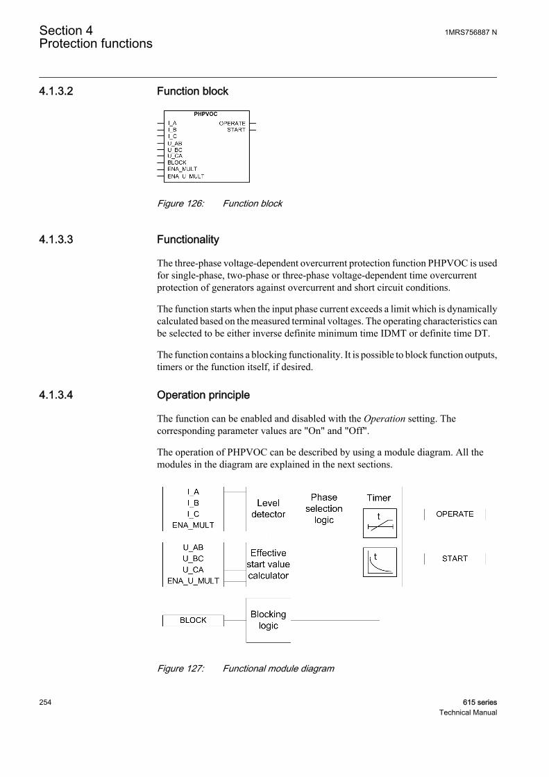
4.1.3.2 Function block
GUID-CC4ABE69-184F-4861-8CAE-38FF1CD44407 V1 EN
Figure 126: Function block
4.1.3.3 Functionality
The three-phase voltage-dependent overcurrent protection function PHPVOC is usedfor single-phase, two-phase or three-phase voltage-dependent time overcurrentprotection of generators against overcurrent and short circuit conditions.
The function starts when the input phase current exceeds a limit which is dynamicallycalculated based on the measured terminal voltages. The operating characteristics canbe selected to be either inverse definite minimum time IDMT or definite time DT.
The function contains a blocking functionality. It is possible to block function outputs,timers or the function itself, if desired.
4.1.3.4 Operation principle
The function can be enabled and disabled with the Operation setting. Thecorresponding parameter values are "On" and "Off".
The operation of PHPVOC can be described by using a module diagram. All themodules in the diagram are explained in the next sections.
GUID-45ECA03E-DA25-43F4-B59A-D8FB56A874AE V1 EN
Figure 127: Functional module diagram
Section 4 1MRS756887 NProtection functions
254 615 seriesTechnical Manual
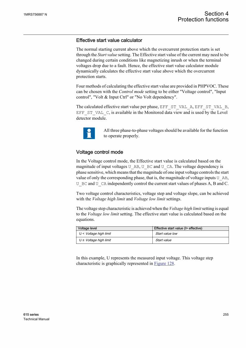
Effective start value calculatorThe normal starting current above which the overcurrent protection starts is setthrough the Start value setting. The Effective start value of the current may need to bechanged during certain conditions like magnetizing inrush or when the terminalvoltages drop due to a fault. Hence, the effective start value calculator moduledynamically calculates the effective start value above which the overcurrentprotection starts.
Four methods of calculating the effective start value are provided in PHPVOC. Thesecan be chosen with the Control mode setting to be either "Voltage control", "Inputcontrol", "Volt & Input Ctrl" or "No Volt dependency".
The calculated effective start value per phase, EFF_ST_VAL_A, EFF_ST_VAL_B,EFF_ST_VAL_C, is available in the Monitored data view and is used by the Leveldetector module.
All three phase-to-phase voltages should be available for the functionto operate properly.
Voltage control modeIn the Voltage control mode, the Effective start value is calculated based on themagnitude of input voltages U_AB, U_BC and U_CA. The voltage dependency isphase sensitive, which means that the magnitude of one input voltage controls the startvalue of only the corresponding phase, that is, the magnitude of voltage inputs U_AB,U_BC and U_CA independently control the current start values of phases A, B and C.
Two voltage control characteristics, voltage step and voltage slope, can be achievedwith the Voltage high limit and Voltage low limit settings.
The voltage step characteristic is achieved when the Voltage high limit setting is equalto the Voltage low limit setting. The effective start value is calculated based on theequations.
Voltage level Effective start value (I> effective)U < Voltage high limit Start value low
U ≥ Voltage high limit Start value
In this example, U represents the measured input voltage. This voltage stepcharacteristic is graphically represented in Figure 128.
1MRS756887 N Section 4Protection functions
615 series 255Technical Manual
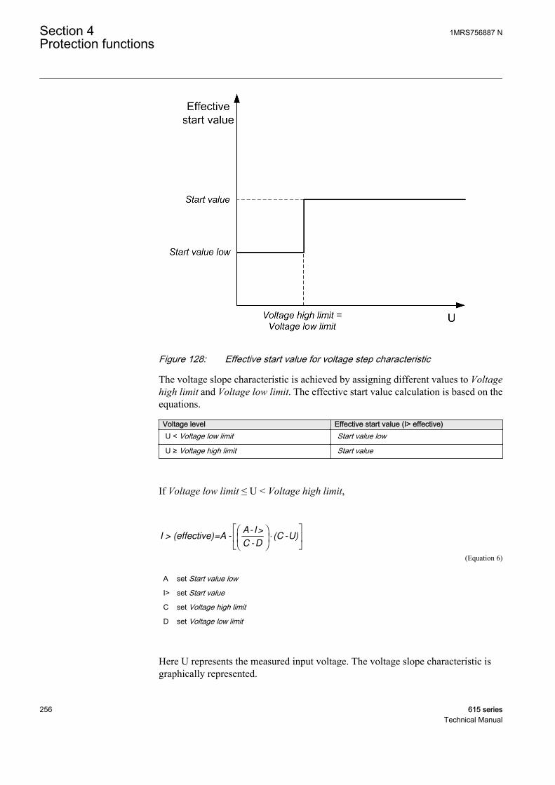
GUID-5D79BE18-92AB-4BDC-8731-D57299D5286A V1 EN
Figure 128: Effective start value for voltage step characteristic
The voltage slope characteristic is achieved by assigning different values to Voltagehigh limit and Voltage low limit. The effective start value calculation is based on theequations.
Voltage level Effective start value (I> effective)U < Voltage low limit Start value low
U ≥ Voltage high limit Start value
If Voltage low limit ≤ U < Voltage high limit,
I > (effective)=A -A- I>
C -D(C -U)
⋅
GUID-ABAAC011-1BC7-4606-AE60-FEC25E6CE155 V1 EN (Equation 6)
A set Start value low
I> set Start value
C set Voltage high limit
D set Voltage low limit
Here U represents the measured input voltage. The voltage slope characteristic isgraphically represented.
Section 4 1MRS756887 NProtection functions
256 615 seriesTechnical Manual
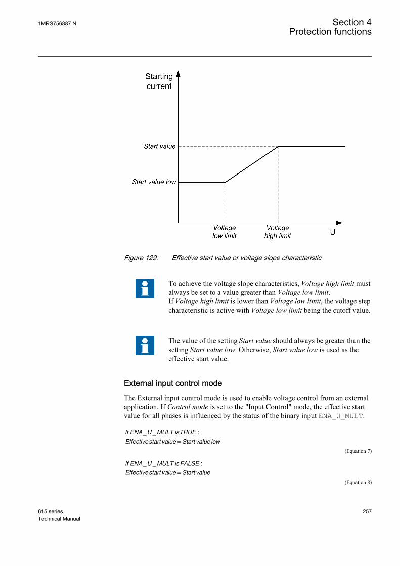
GUID-D9822D90-528D-418D-8422-25F5D2A4637B V1 EN
Figure 129: Effective start value or voltage slope characteristic
To achieve the voltage slope characteristics, Voltage high limit mustalways be set to a value greater than Voltage low limit.If Voltage high limit is lower than Voltage low limit, the voltage stepcharacteristic is active with Voltage low limit being the cutoff value.
The value of the setting Start value should always be greater than thesetting Start value low. Otherwise, Start value low is used as theeffective start value.
External input control modeThe External input control mode is used to enable voltage control from an externalapplication. If Control mode is set to the "Input Control" mode, the effective startvalue for all phases is influenced by the status of the binary input ENA_U_MULT.
If ENA U MULT isTRUE
Effectivestart value Start value low
_ _ :
=
GUID-CDFA5EFC-64BA-4E12-8A08-67356410C452 V1 EN (Equation 7)
If ENA U MULT isFALSE
Effectivestart value Start value
_ _ :
=
GUID-496C64F4-80A6-4CC9-AB67-A1F89B62379C V1 EN (Equation 8)
1MRS756887 N Section 4Protection functions
615 series 257Technical Manual
Voltage and input control modeIf Control mode is set to "Voltage and input Ctrl", both the "Voltage control" and"Input control" modes are used. However, the “Input control” functionality isdominant over the “Voltage control” mode when ENA_U_MULT is active.
No voltage dependency modeWhen Control mode is set to "No Volt dependency", the effective start value has novoltage dependency and the function acts as a normal time overcurrent function witheffective start value being equal to the Start value setting.
Level detectorThe measured phase currents are compared phasewise to the calculated effective startvalue. If the measured value exceeds the calculated effective start value, the Leveldetector reports the exceeding value to the phase selection logic. If the ENA_MULTinput is active, the effective start value is multiplied by the Start value Mult setting.
Do not set the multiplier Start value Mult setting higher thannecessary. If the value is too high, the function may not operate at allduring an inrush followed by a fault, no matter how severe the fault is.
The start value multiplication is normally done when the inrush detection functionINRPHAR is connected to the ENA_MULT input.
Phase selection logicIf the fault criteria are fulfilled in the level detector, the phase selection logic detectsthe phase or phases in which the measured current exceeds the setting. If the phaseinformation matches the Num of start phases setting, the phase selection logicactivates the Timer module.
TimerOnce activated, the Timer module activates the START output.
Depending on the value of the Operating curve type setting, the time characteristicsare according to DT or IDMT. When the operation timer has reached the value ofOperate delay time in the DT mode or the maximum value defined by the inverse timecurve, the OPERATE output is activated.
When the user programmable IDMT curve is selected, the operation timecharacteristics are defined by the settings Curve parameter A, Curve parameter B,Curve parameter C, Curve parameter D and Curve parameter E.
In a drop-off situation, that is, when a fault suddenly disappears before the operatingdelay is exceeded, the timer reset state is activated. The functionality of the Timer inthe reset state depends on the combination of the Operating curve type, Type of resetcurve and Reset delay time settings. When the DT characteristic is selected, the resettimer runs until the set Reset delay time value is exceeded. When the IDMT curves areselected, the Type of reset curve setting can be set to "Immediate", "Def time reset" or
Section 4 1MRS756887 NProtection functions
258 615 seriesTechnical Manual
"Inverse reset". The reset curve type "Immediate" causes an immediate reset. With thereset curve type "Def time reset", the reset time depends on the Reset delay timesetting. With the reset curve type "Inverse reset", the reset time depends on the currentduring the drop-off situation. The START output is deactivated when the reset timerhas elapsed.
The "Inverse reset" selection is only supported with ANSI or userprogrammable types of the IDMT operating curves. If anotheroperating curve type is selected, an immediate reset occurs during thedrop-off situation.
The Time multiplier is used for scaling the IDMT trip and reset times.
The Time multiplier is used for scaling the IDMT trip and reset times.
The Minimum operate time setting defines the minimum desired operating time forIDMT operation. The setting is applicable only when the IDMT curves are used.
Though the Time multiplier and Minimum operate time settings arecommon for different IDMT curves, the operating time essentiallydepends upon the type of IDMT curve chosen.
The Timer calculates the start duration value START_DUR which indicates thepercentage ratio of the start situation and the set operating time. This output isavailable in the Monitored data view.
Blocking logicThere are three operation modes in the blocking function. The operation modes arecontrolled by the BLOCK input and the global setting Configuration/System/Blocking mode which selects the blocking mode. The BLOCK input can be controlledby a binary input, a horizontal communication input or an internal signal of theprotection relay's program. The influence of the BLOCK signal activation ispreselected with the global setting Blocking mode.
The Blocking mode setting has three blocking methods. In the "Freeze timers" mode,the operation timer is frozen to the prevailing value. In the "Block all" mode, the wholefunction is blocked and the timers are reset. In the "Block OPERATE output" mode,the function operates normally but the OPERATE output is not activated.
4.1.3.5 Application
The three-phase voltage-dependent overcurrent protection is used as a backupprotection for the generators and system from damage due to the phase faults whichare not cleared by primary protection and associated breakers.
In case of a short circuit, the sustained fault current of the generator, determined by themachine synchronous reactance, could be below the full-load current. If the generatorexcitation power is fed from the generator terminals, a voltage drop caused by a short
1MRS756887 N Section 4Protection functions
615 series 259Technical Manual
circuit also leads to low fault current. The primary protection, like normal overcurrentprotection, might not detect this kind of fault situation. In some cases, the automaticvoltage regulator AVR can help to maintain high fault currents by controlling thegenerator excitation system. If the AVR is out of service or if there is an internal faultin the operation of AVR, the low fault currents can go unnoticed and therefore avoltage-depended overcurrent protection should be used for backup.
Two voltage control characteristics, voltage step and voltage slope, are available inPHPVOC. The choice is made based on the system conditions and the level ofprotection to be provided.
Voltage step characteristic is applied to generators used in industrial systems. Underclose-up fault conditions when the generator terminal voltages drop below the settablethreshold value, a new start value of the current, well below the normal load current,is selected. The control voltage setting should ensure that PHPVOC does not tripunder the highest loading conditions to which the system can be subjected. Choosingtoo high a value for the control voltage may allow an undesired operation of thefunction during wide-area disturbances. When the terminal voltage of the generator isabove the control voltage value, the normal start value is used. This ensures thatPHPVOC does not operate during normal overloads when the generator terminalvoltages are maintained near the normal levels.
Voltage slope characteristic is often used as an alternative to impedance protection onsmall to medium (5...150 MVA) size generators to provide backup to the differentialprotection. Other applications of the voltage slope characteristic protection exist innetworks to provide better coordination and fault detection than plain overcurrentprotection. The voltage slope method provides an improved sensitivity of overcurrentoperation by making the overcurrent start value proportional to the terminal voltage.The current start value varies correspondingly with the generator terminal voltagesbetween the set voltage high limit and voltage low limit, ensuring the operation ofPHPVOC despite the drop in fault current value.
The operation of PHPVOC should be time-graded with respect to the main protectionscheme to ensure that PHPVOC does not operate before the main protection.
4.1.3.6 Signals
Table 258: PHPVOC Input signals
Name Type Default DescriptionI_A SIGNAL 0 Phase A current
I_B SIGNAL 0 Phase B current
I_C SIGNAL 0 Phase C current
U_AB SIGNAL 0 Phase-to-phase voltage AB
U_BC SIGNAL 0 Phase-to-phase voltage BC
U_CA SIGNAL 0 Phase-to-phase voltage CA
Table continues on next page
Section 4 1MRS756887 NProtection functions
260 615 seriesTechnical Manual
Name Type Default DescriptionBLOCK BOOLEAN 0=False Block signal for activating the blocking mode
ENA_MULT BOOLEAN 0=False Enable signal for current multiplier
ENA_LOW_LIM BOOLEAN 0=False Enable signal for voltage dependent lower startvalue
Table 259: PHPVOC Output signals
Name Type DescriptionOPERATE BOOLEAN Operate
START BOOLEAN Start
4.1.3.7 Settings
Table 260: PHPVOC Group settings (Basic)
Parameter Values (Range) Unit Step Default DescriptionStart value 0.05...5.00 xIn 0.01 0.05 Start value
Start value low 0.05...1.00 xIn 0.01 0.05 Lower start value based on voltage control
Voltage high limit 0.01...1.00 xUn 0.01 1.00 Voltage high limit for voltage control
Voltage low limit 0.01...1.00 xUn 0.01 1.00 Voltage low limit for voltage control
Start value Mult 0.8...10.0 0.1 1.0 Multiplier for scaling the start value
Time multiplier 0.05...15.00 0.01 1.00 Time multiplier in IEC/ANSI IDMT curves
Operating curve type 1=ANSI Ext. inv.2=ANSI Very inv.3=ANSI Norm. inv.4=ANSI Mod. inv.5=ANSI Def. Time6=L.T.E. inv.7=L.T.V. inv.8=L.T. inv.9=IEC Norm. inv.10=IEC Very inv.11=IEC inv.12=IEC Ext. inv.13=IEC S.T. inv.14=IEC L.T. inv.15=IEC Def. Time17=Programmable18=RI type19=RD type
15=IEC Def. Time Selection of time delay curve type
Operate delay time 40...200000 ms 10 40 Operate delay time
Table 261: PHPVOC Group settings (Advanced)
Parameter Values (Range) Unit Step Default DescriptionType of reset curve 1=Immediate
2=Def time reset3=Inverse reset
1=Immediate Selection of reset curve type
1MRS756887 N Section 4Protection functions
615 series 261Technical Manual

Table 262: PHPVOC Non group settings (Basic)
Parameter Values (Range) Unit Step Default DescriptionOperation 1=on
5=off 1=on Operation Off / On
Num of start phases 1=1 out of 32=2 out of 33=3 out of 3
1=1 out of 3 Number of phases required for operateactivation
Curve parameter A 0.0086...120.0000 1 28.2000 Parameter A for customer programmablecurve
Curve parameter B 0.0000...0.7120 1 0.1217 Parameter B for customer programmablecurve
Curve parameter C 0.02...2.00 1 2.00 Parameter C for customer programmablecurve
Curve parameter D 0.46...30.00 1 29.10 Parameter D for customer programmablecurve
Curve parameter E 0.0...1.0 1 1.0 Parameter E for customer programmablecurve
Table 263: PHPVOC Non group settings (Advanced)
Parameter Values (Range) Unit Step Default DescriptionMeasurement mode 1=RMS
2=DFT3=Peak-to-Peak
2=DFT Selects used measurement mode
Control mode 1=Voltage control2=Input control3=Voltage andinput Ctl4=No Voltdependency
1=Voltage control Type of control
Minimum operate time 40...60000 ms 1 40 Minimum operate time for IDMT curves
Reset delay time 0...60000 ms 1 20 Reset delay time
4.1.3.8 Monitored data
Table 264: PHPVOC Monitored data
Name Type Values (Range) Unit DescriptionSTART_DUR FLOAT32 0.00...100.00 % Ratio of start time /
operate time
EFF_ST_VAL_A FLOAT32 0.00...50.00 xIn Effective start value forphase A
EFF_ST_VAL_B FLOAT32 0.00...50.00 xIn Effective start value forphase B
EFF_ST_VAL_C FLOAT32 0.00...50.00 xIn Effective start value forphase C
PHPVOC Enum 1=on2=blocked3=test4=test/blocked5=off
Status
Section 4 1MRS756887 NProtection functions
262 615 seriesTechnical Manual
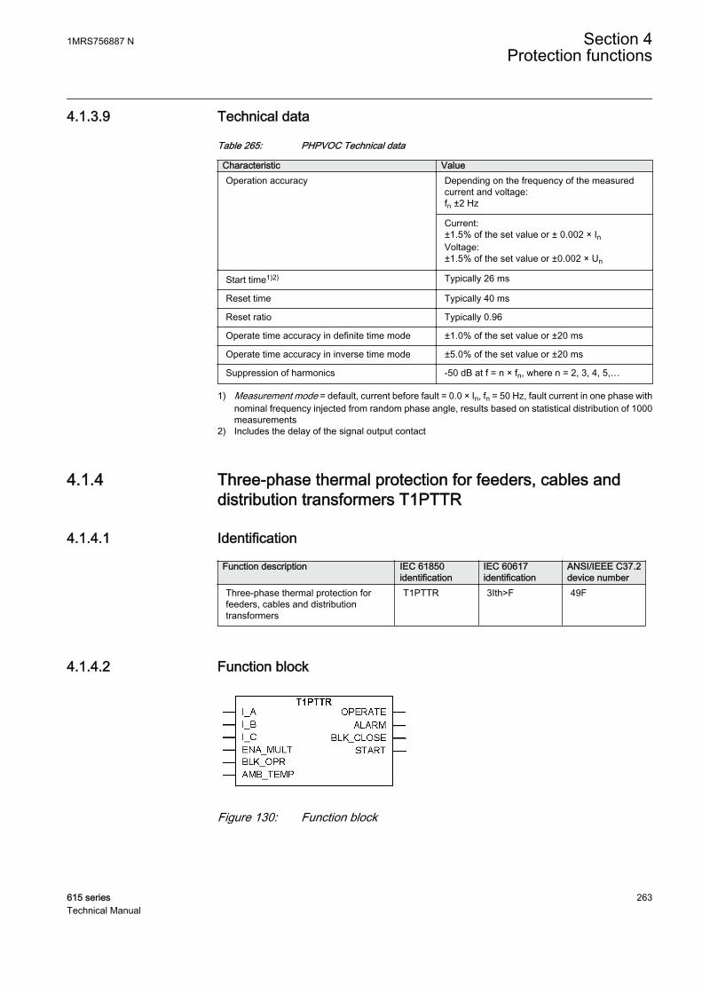
4.1.3.9 Technical data
Table 265: PHPVOC Technical data
Characteristic ValueOperation accuracy Depending on the frequency of the measured
current and voltage:fn ±2 Hz
Current:±1.5% of the set value or ± 0.002 × InVoltage:±1.5% of the set value or ±0.002 × Un
Start time1)2) Typically 26 ms
Reset time Typically 40 ms
Reset ratio Typically 0.96
Operate time accuracy in definite time mode ±1.0% of the set value or ±20 ms
Operate time accuracy in inverse time mode ±5.0% of the set value or ±20 ms
Suppression of harmonics -50 dB at f = n × fn, where n = 2, 3, 4, 5,…
1) Measurement mode = default, current before fault = 0.0 × In, fn = 50 Hz, fault current in one phase withnominal frequency injected from random phase angle, results based on statistical distribution of 1000measurements
2) Includes the delay of the signal output contact
4.1.4 Three-phase thermal protection for feeders, cables anddistribution transformers T1PTTR
4.1.4.1 Identification
Function description IEC 61850identification
IEC 60617identification
ANSI/IEEE C37.2device number
Three-phase thermal protection forfeeders, cables and distributiontransformers
T1PTTR 3Ith>F 49F
4.1.4.2 Function block
A070691 V3 EN
Figure 130: Function block
1MRS756887 N Section 4Protection functions
615 series 263Technical Manual
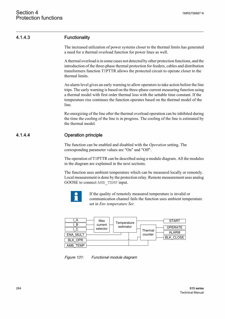
4.1.4.3 Functionality
The increased utilization of power systems closer to the thermal limits has generateda need for a thermal overload function for power lines as well.
A thermal overload is in some cases not detected by other protection functions, and theintroduction of the three-phase thermal protection for feeders, cables and distributiontransformers function T1PTTR allows the protected circuit to operate closer to thethermal limits.
An alarm level gives an early warning to allow operators to take action before the linetrips. The early warning is based on the three-phase current measuring function usinga thermal model with first order thermal loss with the settable time constant. If thetemperature rise continues the function operates based on the thermal model of theline.
Re-energizing of the line after the thermal overload operation can be inhibited duringthe time the cooling of the line is in progress. The cooling of the line is estimated bythe thermal model.
4.1.4.4 Operation principle
The function can be enabled and disabled with the Operation setting. Thecorresponding parameter values are "On" and "Off".
The operation of T1PTTR can be described using a module diagram. All the modulesin the diagram are explained in the next sections.
The function uses ambient temperature which can be measured locally or remotely.Local measurement is done by the protection relay. Remote measurement uses analogGOOSE to connect AMB_TEMP input.
If the quality of remotely measured temperature is invalid orcommunication channel fails the function uses ambient temperatureset in Env temperature Set.
Temperatureestimator
ThermalcounterENA_MULT
ALARMBLK_CLOSE
OPERATE
BLK_OPR
STARTMaxcurrentselector
I_AI_BI_C
AMB_TEMPA070747 V3 EN
Figure 131: Functional module diagram
Section 4 1MRS756887 NProtection functions
264 615 seriesTechnical Manual

Max current selectorThe max current selector of the function continuously checks the highest measuredTRMS phase current value. The selector reports the highest value to the temperatureestimator.
Temperature estimatorThe final temperature rise is calculated from the highest of the three-phase currentsaccording to the expression:
Θ final
ref
ref
I
IT=
⋅
2
A070780 V2 EN (Equation 9)
I the largest phase current
Iref set Current reference
Tref set Temperature rise
The ambient temperature is added to the calculated final temperature rise estimation,and the ambient temperature value used in the calculation is also available in themonitored data as TEMP_AMB in degrees. If the final temperature estimation is largerthan the set Maximum temperature, the START output is activated.
Current reference and Temperature rise setting values are used in the finaltemperature estimation together with the ambient temperature. It is suggested to setthese values to the maximum steady state current allowed for the line or cable underemergency operation for a few hours per years. Current values with the correspondingconductor temperatures are given in cable manuals. These values are given forconditions such as ground temperatures, ambient air temperature, the way of cablelaying and ground thermal resistivity.
Thermal counterThe actual temperature at the actual execution cycle is calculated as:
Θ Θ Θ Θ
∆
n n final n
t
e= + −( ) ⋅ −
− −
−
1 1 1 τ
A070781 V2 EN (Equation 10)
1MRS756887 N Section 4Protection functions
615 series 265Technical Manual

Θn calculated present temperature
Θn-1 calculated temperature at previous time step
Θfinal calculated final temperature with actual current
Δt time step between calculation of actual temperature
t thermal time constant for the protected device (line or cable), set Time constant
The actual temperature of the protected component (line or cable) is calculated byadding the ambient temperature to the calculated temperature, as shown above. Theambient temperature can be given a constant value or it can be measured. Thecalculated component temperature can be monitored as it is exported from thefunction as a real figure.
When the component temperature reaches the set alarm level Alarm value, the outputsignal ALARM is set. When the component temperature reaches the set trip levelMaximum temperature, the OPERATE output is activated. The OPERATE signal pulselength is fixed to 100 ms.
There is also a calculation of the present time to operation with the present current.This calculation is only performed if the final temperature is calculated to be above theoperation temperature:
toperatefinal operate
final n
= − ⋅
−
−
τ lnΘ Θ
Θ Θ
A070782 V2 EN (Equation 11)
Caused by the thermal overload protection function, there can be a lockout toreconnect the tripped circuit after operating. The lockout output BLK_CLOSE isactivated at the same time when the OPERATE output is activated and is not reset untilthe device temperature has cooled down below the set value of the Reclosetemperature setting. The Maximum temperature value must be set at least two degreesabove the set value of Reclose temperature.
The time to lockout release is calculated, that is, the calculation of the cooling time toa set value. The calculated temperature can be reset to its initial value (the Initialtemperature setting) via a control parameter that is located under the clear menu. Thisis useful during testing when secondary injected current has given a calculated falsetemperature level.
tlockout release
final lockout release
final n
_
_ln= − ⋅
−
−
τΘ Θ
Θ Θ
A070783 V3 EN (Equation 12)
Here the final temperature is equal to the set or measured ambient temperature.
Section 4 1MRS756887 NProtection functions
266 615 seriesTechnical Manual
In some applications, the measured current can involve a number of parallel lines. Thisis often used for cable lines where one bay connects several parallel cables. By settingthe Current multiplier parameter to the number of parallel lines (cables), the actualcurrent on one line is used in the protection algorithm. To activate this option, theENA_MULT input must be activated.
The ambient temperature can be measured with the RTD measurement. The measuredtemperature value is then connected, for example, from the AI_VAL3 output of theX130 (RTD) function to the AMB_TEMP input of T1PTTR.
The Env temperature Set setting is used to define the ambient temperature if theambient temperature measurement value is not connected to the AMB_TEMP input.The Env temperature Set setting is also used when the ambient temperaturemeasurement connected to T1PTTR is set to “Not in use” in the X130 (RTD) function.
The temperature calculation is initiated from the value defined with the Initialtemperature setting parameter. This is done in case the protection relay is powered up,the function is turned "Off" and back "On" or reset through the Clear menu. Thetemperature is also stored in the nonvolatile memory and restored in case theprotection relay is restarted.
The thermal time constant of the protected circuit is given in seconds with the Timeconstant setting. Please see cable manufacturers manuals for further details.
T1PTTR thermal model complies with the IEC 60255-149 standard.
4.1.4.5 Application
The lines and cables in the power system are constructed for a certain maximum loadcurrent level. If the current exceeds this level, the losses will be higher than expected.As a consequence, the temperature of the conductors will increase. If the temperatureof the lines and cables reaches too high values, it can cause a risk of damages by, forexample, the following ways:
• The sag of overhead lines can reach an unacceptable value.• If the temperature of conductors, for example aluminium conductors, becomes
too high, the material will be destroyed.• Overheating can damage the insulation on cables which in turn increases the risk
of phase-to-phase or phase-to-earth faults.
In stressed situations in the power system, the lines and cables may be required to beoverloaded for a limited time. This should be done without any risk for the above-mentioned risks.
The thermal overload protection provides information that makes temporaryoverloading of cables and lines possible. The thermal overload protection estimates
1MRS756887 N Section 4Protection functions
615 series 267Technical Manual
the conductor temperature continuously. This estimation is made by using a thermalmodel of the line/cable that is based on the current measurement.
If the temperature of the protected object reaches a set warning level, a signal is givento the operator. This enables actions in the power system to be done before dangeroustemperatures are reached. If the temperature continues to increase to the maximumallowed temperature value, the protection initiates a trip of the protected line.
4.1.4.6 Signals
Table 266: T1PTTR Input signals
Name Type Default DescriptionI_A SIGNAL 0 Phase A current
I_B SIGNAL 0 Phase B current
I_C SIGNAL 0 Phase C current
ENA_MULT BOOLEAN 0=False Enable Current multiplier
BLK_OPR BOOLEAN 0=False Block signal for operate outputs
AMB_TEMP FLOAT32 0 The ambient temperature used in the calculation
Table 267: T1PTTR Output signals
Name Type DescriptionOPERATE BOOLEAN Operate
START BOOLEAN Start
ALARM BOOLEAN Thermal Alarm
BLK_CLOSE BOOLEAN Thermal overload indicator. To inhibite reclose.
4.1.4.7 Settings
Table 268: T1PTTR Group settings (Basic)
Parameter Values (Range) Unit Step Default DescriptionEnv temperature Set -50...100 °C 1 40 Ambient temperature used when no
external temperature measurementavailable
Current reference 0.05...4.00 xIn 0.01 1.00 The load current leading to Temperatureraise temperature
Temperature rise 0.0...200.0 °C 0.1 75.0 End temperature rise above ambient
Time constant 60...60000 s 1 2700 Time constant of the line in seconds.
Maximum temperature 20.0...200.0 °C 0.1 90.0 Temperature level for operate
Alarm value 20.0...150.0 °C 0.1 80.0 Temperature level for start (alarm)
Reclose temperature 20.0...150.0 °C 0.1 70.0 Temperature for reset of block recloseafter operate
Section 4 1MRS756887 NProtection functions
268 615 seriesTechnical Manual
Table 269: T1PTTR Group settings (Advanced)
Parameter Values (Range) Unit Step Default DescriptionCurrent multiplier 1...5 1 1 Current multiplier when function is used
for parallel lines
Table 270: T1PTTR Non group settings (Basic)
Parameter Values (Range) Unit Step Default DescriptionOperation 1=on
5=off 1=on Operation Off / On
Table 271: T1PTTR Non group settings (Advanced)
Parameter Values (Range) Unit Step Default DescriptionInitial temperature -50.0...100.0 °C 0.1 0.0 Temperature raise above ambient
temperature at startup
4.1.4.8 Monitored data
Table 272: T1PTTR Monitored data
Name Type Values (Range) Unit DescriptionTEMP FLOAT32 -100.0...9999.9 °C The calculated
temperature of theprotected object
TEMP_RL FLOAT32 0.00...99.99 The calculatedtemperature of theprotected object relativeto the operate level
T_OPERATE INT32 0...60000 s Estimated time to operate
T_ENA_CLOSE INT32 0...60000 s Estimated time todeactivate BLK_CLOSE
TEMP_AMB FLOAT32 -99...999 °C The ambient temperatureused in the calculation
T1PTTR Enum 1=on2=blocked3=test4=test/blocked5=off
Status
1MRS756887 N Section 4Protection functions
615 series 269Technical Manual
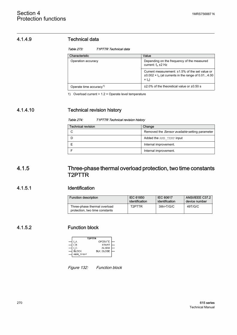
4.1.4.9 Technical data
Table 273: T1PTTR Technical data
Characteristic ValueOperation accuracy Depending on the frequency of the measured
current: fn ±2 Hz
Current measurement: ±1.5% of the set value or±0.002 × In (at currents in the range of 0.01...4.00× In)
Operate time accuracy1) ±2.0% of the theoretical value or ±0.50 s
1) Overload current > 1.2 × Operate level temperature
4.1.4.10 Technical revision history
Table 274: T1PTTR Technical revision history
Technical revision ChangeC Removed the Sensor available setting parameter
D Added the AMB_TEMP input
E Internal improvement.
F Internal improvement.
4.1.5 Three-phase thermal overload protection, two time constantsT2PTTR
4.1.5.1 Identification
Function description IEC 61850identification
IEC 60617identification
ANSI/IEEE C37.2device number
Three-phase thermal overloadprotection, two time constants
T2PTTR 3Ith>T/G/C 49T/G/C
4.1.5.2 Function block
GUID-68AADF30-9DC7-49D5-8C77-14E774C8D1AF V2 EN
Figure 132: Function block
Section 4 1MRS756887 NProtection functions
270 615 seriesTechnical Manual
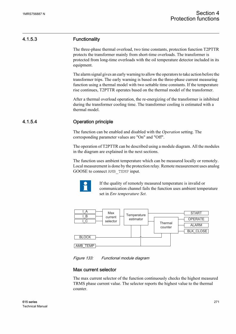
4.1.5.3 Functionality
The three-phase thermal overload, two time constants, protection function T2PTTRprotects the transformer mainly from short-time overloads. The transformer isprotected from long-time overloads with the oil temperature detector included in itsequipment.
The alarm signal gives an early warning to allow the operators to take action before thetransformer trips. The early warning is based on the three-phase current measuringfunction using a thermal model with two settable time constants. If the temperaturerise continues, T2PTTR operates based on the thermal model of the transformer.
After a thermal overload operation, the re-energizing of the transformer is inhibitedduring the transformer cooling time. The transformer cooling is estimated with athermal model.
4.1.5.4 Operation principle
The function can be enabled and disabled with the Operation setting. Thecorresponding parameter values are "On" and "Off".
The operation of T2PTTR can be described using a module diagram. All the modulesin the diagram are explained in the next sections.
The function uses ambient temperature which can be measured locally or remotely.Local measurement is done by the protection relay. Remote measurement uses analogGOOSE to connect AMB_TEMP input.
If the quality of remotely measured temperature is invalid orcommunication channel fails the function uses ambient temperatureset in Env temperature Set.
ALARM
OPERATE
BLK_CLOSE
I_A Max current selector
I_BI_C
BLOCK
Thermal counter
Temperature estimator
START
AMB_TEMPGUID-FF965F1C-6039-4A01-9A4F-B378F8356279 V2 EN
Figure 133: Functional module diagram
Max current selectorThe max current selector of the function continuously checks the highest measuredTRMS phase current value. The selector reports the highest value to the thermalcounter.
1MRS756887 N Section 4Protection functions
615 series 271Technical Manual
Temperature estimatorThe final temperature rise is calculated from the highest of the three-phase currentsaccording to the expression:
Θ final
ref
ref
I
IT=
⋅
2
GUID-06DE6459-E94A-4FC7-8357-CA58988CEE97 V2 EN (Equation 13)
I highest measured phase current
Iref the set value of the Current reference setting
Tref the set value of the Temperature rise setting (temperature rise (°C) with the steady-state current Iref
The ambient temperature value is added to the calculated final temperature riseestimation. If the total value of temperature is higher than the set operate temperaturelevel, the START output is activated.
The Current reference setting is a steady-state current that gives the steady-state endtemperature value Temperature rise. It gives a setting value corresponding to the ratedpower of the transformer.
The Temperature rise setting is used when the value of the reference temperature risecorresponds to the Current reference value. The temperature values with thecorresponding transformer load currents are usually given by transformermanufacturers.
Thermal counterT2PTTR applies the thermal model of two time constants for temperaturemeasurement. The temperature rise in degrees Celsius (°C) is calculated from thehighest of the three-phase currents according to the expression:
∆Θ
∆
=
⋅ −
+ −( ) ⋅
−
pI
IT e p
refref
t
* *
2
11 1τII
IT e
refref
t
⋅
⋅ −
−
2
21
∆
τ
GUID-27A879A9-AF94-4BC3-BAA1-501189F6DE0C V2 EN (Equation 14)
ΔΘ calculated temperature rise (°C) in transformer
I measured phase current with the highest TRMS value
Iref the set value of the Current reference setting (rated current of the protected object)
Tref the set value of the Temperature rise setting (temperature rise setting (°C) with the steady-statecurrent Iref)
p the set value of the Weighting factor p setting (weighting factor for the short time constant)
Δt time step between the calculation of the actual temperature
t1 the set value of the Short time constant setting (the short heating / cooling time constant)
t2 the set value of the Long time constant setting (the long heating / cooling time constant)
Section 4 1MRS756887 NProtection functions
272 615 seriesTechnical Manual
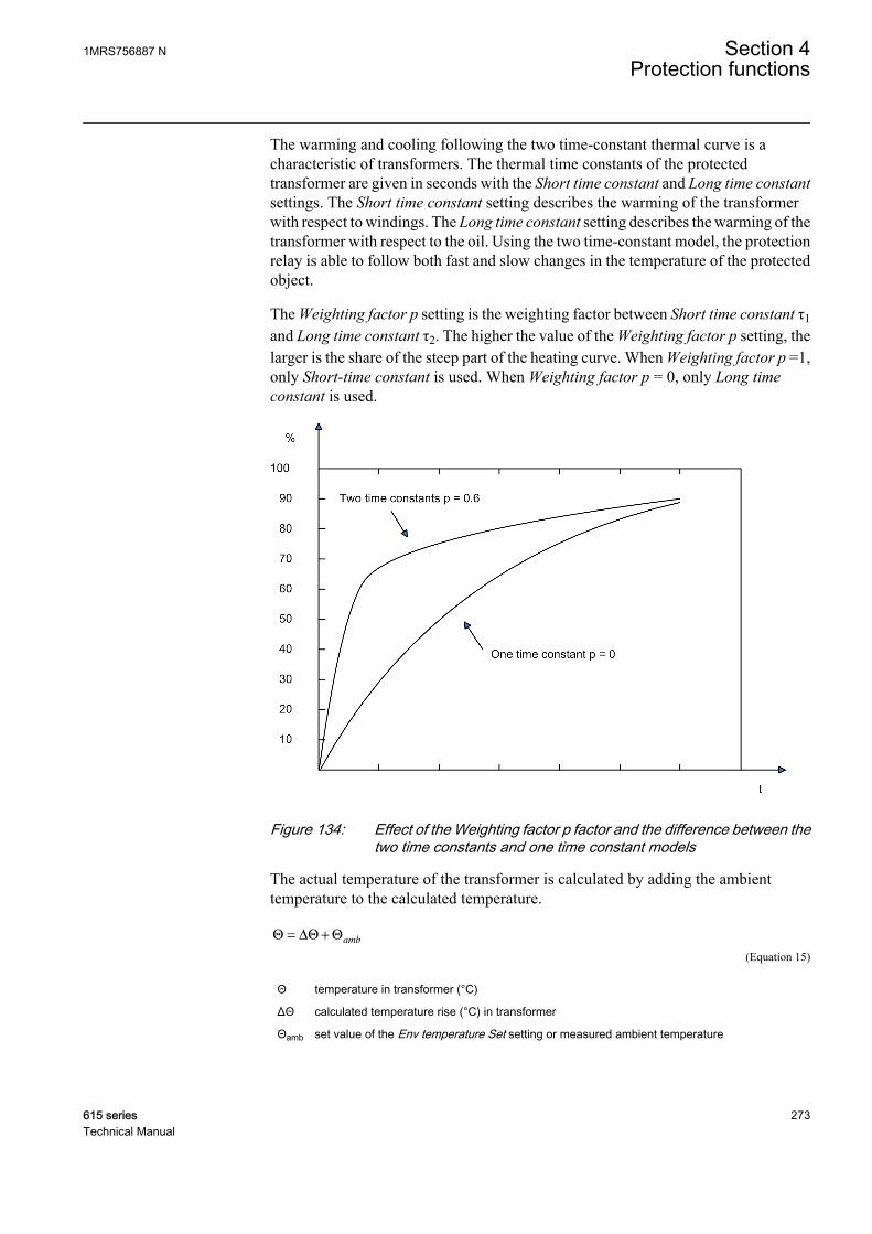
The warming and cooling following the two time-constant thermal curve is acharacteristic of transformers. The thermal time constants of the protectedtransformer are given in seconds with the Short time constant and Long time constantsettings. The Short time constant setting describes the warming of the transformerwith respect to windings. The Long time constant setting describes the warming of thetransformer with respect to the oil. Using the two time-constant model, the protectionrelay is able to follow both fast and slow changes in the temperature of the protectedobject.
The Weighting factor p setting is the weighting factor between Short time constant τ1and Long time constant τ2. The higher the value of the Weighting factor p setting, thelarger is the share of the steep part of the heating curve. When Weighting factor p =1,only Short-time constant is used. When Weighting factor p = 0, only Long timeconstant is used.
GUID-E040FFF4-7FE3-4736-8E5F-D96DB1F1B16B V1 EN
Figure 134: Effect of the Weighting factor p factor and the difference between thetwo time constants and one time constant models
The actual temperature of the transformer is calculated by adding the ambienttemperature to the calculated temperature.
Θ Θ Θ= ∆ +amb
GUID-77E49346-66D2-4CAB-A764-E81D6F382E74 V2 EN (Equation 15)
Θ temperature in transformer (°C)
ΔΘ calculated temperature rise (°C) in transformer
Θamb set value of the Env temperature Set setting or measured ambient temperature
1MRS756887 N Section 4Protection functions
615 series 273Technical Manual
The ambient temperature can be measured with RTD measurement. The measuredtemperature value is connected, for example, from the AI_VAL3 output of the X130(RTD) function to the AMB_TEMP input of T2PTTR.
The Env temperature Set setting is used to define the ambient temperature if theambient temperature measurement value is not connected to the AMB_TEMP input.The Env temperature Set setting is also used when the ambient temperaturemeasurement connected to T2PTTR is set to “Not in use” in the X130 (RTD) function.
The temperature calculation is initiated from the value defined with the Initialtemperature and Max temperature setting parameters. The initial value is a percentageof Max temperature defined by Initial temperature. This is done when the protectionrelay is powered up or the function is turned off and back on or reset through the Clearmenu. The temperature is stored in a nonvolatile memory and restored if the protectionrelay is restarted.
The Max temperature setting defines the maximum temperature of the transformer indegrees Celsius (°C). The value of the Max temperature setting is usually given bytransformer manufacturers. The actual alarm, operating and lockout temperatures forT2PTTR are given as a percentage value of the Max temperature setting.
When the transformer temperature reaches the alarm level defined with the Alarmtemperature setting, the ALARM output signal is set. When the transformertemperature reaches the trip level value defined with the Operate temperature setting,the OPERATE output is activated. The OPERATE output is deactivated when the valueof the measured current falls below 10 percent of the Current Reference value or thecalculated temperature value falls below Operate temperature.
There is also a calculation of the present time to operation with the present current.T_OPERATE is only calculated if the final temperature is calculated to be above theoperation temperature. The value is available in the monitored data view.
After operating, there can be a lockout to reconnect the tripped circuit due to thethermal overload protection function. The BLK_CLOSE lockout output is activatedwhen the device temperature is above the Reclose temperature lockout releasetemperature setting value. The time to lockout release T_ENA_CLOSE is alsocalculated. The value is available in the monitored data view.
4.1.5.5 Application
The transformers in a power system are constructed for a certain maximum loadcurrent level. If the current exceeds this level, the losses are higher than expected. Thisresults in a rise in transformer temperature. If the temperature rise is too high, theequipment is damaged:
• Insulation within the transformer ages faster, which in turn increases the risk ofinternal phase-to-phase or phase-to-earth faults.
• Possible hotspots forming within the transformer degrade the quality of thetransformer oil.
Section 4 1MRS756887 NProtection functions
274 615 seriesTechnical Manual
During stressed situations in power systems, it is required to overload the transformersfor a limited time without any risks. The thermal overload protection providesinformation and makes temporary overloading of transformers possible.
The permissible load level of a power transformer is highly dependent on thetransformer cooling system. The two main principles are:
• ONAN: The air is naturally circulated to the coolers without fans, and the oil isnaturally circulated without pumps.
• OFAF: The coolers have fans to force air for cooling, and pumps to force thecirculation of the transformer oil.
The protection has several parameter sets located in the setting groups, for exampleone for a non-forced cooling and one for a forced cooling situation. Both thepermissive steady-state loading level as well as the thermal time constant areinfluenced by the transformer cooling system. The active setting group can bechanged by a parameter, or through a binary input if the binary input is enabled for it.This feature can be used for transformers where forced cooling is taken out ofoperation or extra cooling is switched on. The parameters can also be changed whena fan or pump fails to operate.
The thermal overload protection continuously estimates the internal heat content, thatis, the temperature of the transformer. This estimation is made by using a thermalmodel of the transformer which is based on the current measurement.
If the heat content of the protected transformer reaches the set alarm level, a signal isgiven to the operator. This enables the action that needs to be taken in the powersystems before the temperature reaches a high value. If the temperature continues torise to the trip value, the protection initiates the trip of the protected transformer.
After the trip, the transformer needs to cool down to a temperature level where thetransformer can be taken into service again. T2PTTR continues to estimate the heatcontent of the transformer during this cooling period using a set cooling time constant.The energizing of the transformer is blocked until the heat content is reduced to the setlevel.
The thermal curve of two time constants is typical for a transformer. The thermal timeconstants of the protected transformer are given in seconds with the Short timeconstant and Long time constant settings. If the manufacturer does not state any othervalue, the Long time constant can be set to 4920 s (82 minutes) for a distributiontransformer and 7260 s (121 minutes) for a supply transformer. The correspondingShort time constants are 306 s (5.1 minutes) and 456 s (7.6 minutes).
If the manufacturer of the power transformer has stated only one, that is, a single timeconstant, it can be converted to two time constants. The single time constant is alsoused by itself if the p-factor Weighting factor p setting is set to zero and the timeconstant value is set to the value of the Long time constant setting. The thermal imagecorresponds to the one time constant model in that case.
1MRS756887 N Section 4Protection functions
615 series 275Technical Manual

Table 275: Conversion table between one and two time constants
Single time constant(min)
Short time constant (min) Long time constant (min) Weighting factor p
10 1.1 17 0.4
15 1.6 25 0.4
20 2.1 33 0.4
25 2.6 41 0.4
30 3.1 49 0.4
35 3.6 58 0.4
40 4.1 60 0.4
45 4.8 75 0.4
50 5.1 82 0.4
55 5.6 90 0.4
60 6.1 98 0.4
65 6.7 107 0.4
70 7.2 115 0.4
75 7.8 124 0.4
The default Max temperature setting is 105°C. This value is chosen since even thoughthe IEC 60076-7 standard recommends 98°C as the maximum allowable temperaturein long-time loading, the standard also states that a transformer can withstand theemergency loading for weeks or even months, which may produce the windingtemperature of 140°C. Therefore, 105°C is a safe maximum temperature value for atransformer if the Max temperature setting value is not given by the transformermanufacturer.
4.1.5.6 Signals
Table 276: T2PTTR Input signals
Name Type Default DescriptionI_A SIGNAL 0 Phase A current
I_B SIGNAL 0 Phase B current
I_C SIGNAL 0 Phase C current
BLOCK BOOLEAN 0=False Block signal for activating the blocking mode
AMB_TEMP FLOAT32 0 The ambient temperature used in the calculation
Table 277: T2PTTR Output signals
Name Type DescriptionOPERATE BOOLEAN Operate
START BOOLEAN Start
ALARM BOOLEAN Thermal Alarm
BLK_CLOSE BOOLEAN Thermal overload indicator. To inhibite reclose.
Section 4 1MRS756887 NProtection functions
276 615 seriesTechnical Manual
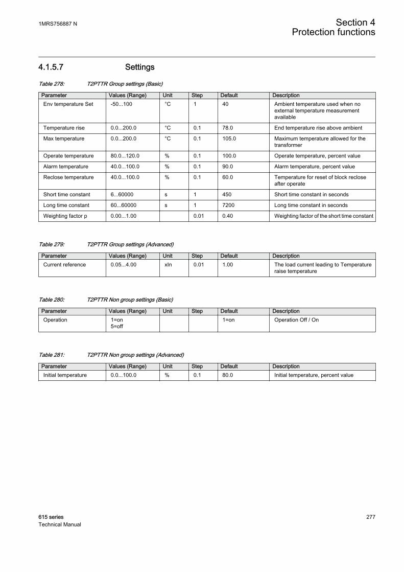
4.1.5.7 Settings
Table 278: T2PTTR Group settings (Basic)
Parameter Values (Range) Unit Step Default DescriptionEnv temperature Set -50...100 °C 1 40 Ambient temperature used when no
external temperature measurementavailable
Temperature rise 0.0...200.0 °C 0.1 78.0 End temperature rise above ambient
Max temperature 0.0...200.0 °C 0.1 105.0 Maximum temperature allowed for thetransformer
Operate temperature 80.0...120.0 % 0.1 100.0 Operate temperature, percent value
Alarm temperature 40.0...100.0 % 0.1 90.0 Alarm temperature, percent value
Reclose temperature 40.0...100.0 % 0.1 60.0 Temperature for reset of block recloseafter operate
Short time constant 6...60000 s 1 450 Short time constant in seconds
Long time constant 60...60000 s 1 7200 Long time constant in seconds
Weighting factor p 0.00...1.00 0.01 0.40 Weighting factor of the short time constant
Table 279: T2PTTR Group settings (Advanced)
Parameter Values (Range) Unit Step Default DescriptionCurrent reference 0.05...4.00 xIn 0.01 1.00 The load current leading to Temperature
raise temperature
Table 280: T2PTTR Non group settings (Basic)
Parameter Values (Range) Unit Step Default DescriptionOperation 1=on
5=off 1=on Operation Off / On
Table 281: T2PTTR Non group settings (Advanced)
Parameter Values (Range) Unit Step Default DescriptionInitial temperature 0.0...100.0 % 0.1 80.0 Initial temperature, percent value
1MRS756887 N Section 4Protection functions
615 series 277Technical Manual
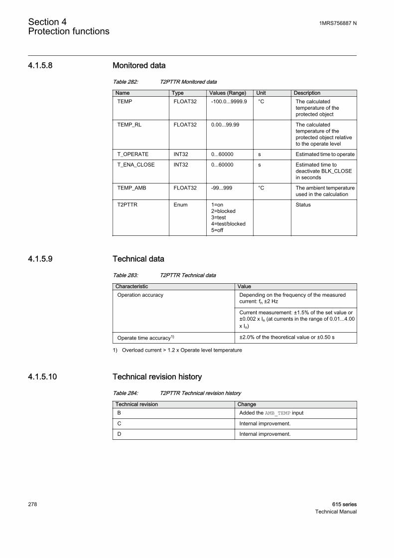
4.1.5.8 Monitored data
Table 282: T2PTTR Monitored data
Name Type Values (Range) Unit DescriptionTEMP FLOAT32 -100.0...9999.9 °C The calculated
temperature of theprotected object
TEMP_RL FLOAT32 0.00...99.99 The calculatedtemperature of theprotected object relativeto the operate level
T_OPERATE INT32 0...60000 s Estimated time to operate
T_ENA_CLOSE INT32 0...60000 s Estimated time todeactivate BLK_CLOSEin seconds
TEMP_AMB FLOAT32 -99...999 °C The ambient temperatureused in the calculation
T2PTTR Enum 1=on2=blocked3=test4=test/blocked5=off
Status
4.1.5.9 Technical data
Table 283: T2PTTR Technical data
Characteristic ValueOperation accuracy Depending on the frequency of the measured
current: fn ±2 Hz
Current measurement: ±1.5% of the set value or±0.002 x In (at currents in the range of 0.01...4.00x In)
Operate time accuracy1) ±2.0% of the theoretical value or ±0.50 s
1) Overload current > 1.2 x Operate level temperature
4.1.5.10 Technical revision history
Table 284: T2PTTR Technical revision history
Technical revision ChangeB Added the AMB_TEMP input
C Internal improvement.
D Internal improvement.
Section 4 1MRS756887 NProtection functions
278 615 seriesTechnical Manual

4.1.6 Motor load jam protection JAMPTOC
4.1.6.1 Identification
Function description IEC 61850identification
IEC 60617identification
ANSI/IEEE C37.2device number
Motor load jam protection JAMPTOC Ist> 51LR
4.1.6.2 Function block
GUID-FA5FAB32-8730-4985-B228-11B92DD9E626 V2 EN
Figure 135: Function block
4.1.6.3 Functionality
The motor load jam protection function JAMPTOC is used for protecting the motor install or mechanical jam situations during the running state.
When the motor is started, a separate function is used for the startup protection, andJAMPTOC is normally blocked during the startup period. When the motor has passedthe starting phase, JAMPTOC monitors the magnitude of phase currents. The functionstarts when the measured current exceeds the breakdown torque level, that is, abovethe set limit. The operation characteristic is definite time.
The function contains a blocking functionality. It is possible to block the functionoutputs.
4.1.6.4 Operation principle
The function can be enabled and disabled with the Operation setting. Thecorresponding parameter values are "On" and "Off".
The operation of JAMPTOC can be described with a module diagram. All the modulesin the diagram are explained in the next sections.
1MRS756887 N Section 4Protection functions
615 series 279Technical Manual
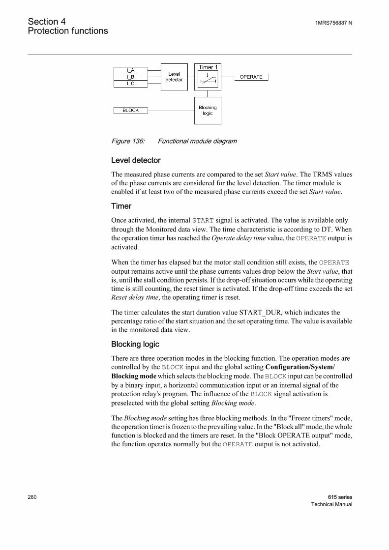
GUID-93025A7F-12BE-4ACD-8BD3-C144CB73F65A V2 EN
Figure 136: Functional module diagram
Level detectorThe measured phase currents are compared to the set Start value. The TRMS valuesof the phase currents are considered for the level detection. The timer module isenabled if at least two of the measured phase currents exceed the set Start value.
TimerOnce activated, the internal START signal is activated. The value is available onlythrough the Monitored data view. The time characteristic is according to DT. Whenthe operation timer has reached the Operate delay time value, the OPERATE output isactivated.
When the timer has elapsed but the motor stall condition still exists, the OPERATEoutput remains active until the phase currents values drop below the Start value, thatis, until the stall condition persists. If the drop-off situation occurs while the operatingtime is still counting, the reset timer is activated. If the drop-off time exceeds the setReset delay time, the operating timer is reset.
The timer calculates the start duration value START_DUR, which indicates thepercentage ratio of the start situation and the set operating time. The value is availablein the monitored data view.
Blocking logicThere are three operation modes in the blocking function. The operation modes arecontrolled by the BLOCK input and the global setting Configuration/System/Blocking mode which selects the blocking mode. The BLOCK input can be controlledby a binary input, a horizontal communication input or an internal signal of theprotection relay's program. The influence of the BLOCK signal activation ispreselected with the global setting Blocking mode.
The Blocking mode setting has three blocking methods. In the "Freeze timers" mode,the operation timer is frozen to the prevailing value. In the "Block all" mode, the wholefunction is blocked and the timers are reset. In the "Block OPERATE output" mode,the function operates normally but the OPERATE output is not activated.
Section 4 1MRS756887 NProtection functions
280 615 seriesTechnical Manual
4.1.6.5 Application
The motor protection during stall is primarily needed to protect the motor fromexcessive temperature rise, as the motor draws large currents during the stall phase.This condition causes a temperature rise in the stator windings. Due to reduced speed,the temperature also rises in the rotor. The rotor temperature rise is more critical whenthe motor stops.
The physical and dielectric insulations of the system deteriorate with age and thedeterioration is accelerated by the temperature increase. Insulation life is related to thetime interval during which the insulation is maintained at a given temperature.
An induction motor stalls when the load torque value exceeds the breakdown torquevalue, causing the speed to decrease to zero or to some stable operating point wellbelow the rated speed. This occurs, for example, when the applied shaft load issuddenly increased and is greater than the producing motor torque due to the bearingfailures. This condition develops a motor current almost equal to the value of thelocked-rotor current.
JAMPTOC is designed to protect the motor in stall or mechanical jam situationsduring the running state. To provide a good and reliable protection for motors in a stallsituation, the temperature effects on the motor have to be kept within the allowedlimits.
4.1.6.6 Signals
Table 285: JAMPTOC Input signals
Name Type Default DescriptionI_A SIGNAL 0 Phase A current
I_B SIGNAL 0 Phase B current
I_C SIGNAL 0 Phase C current
BLOCK BOOLEAN 0=False Block signal for activating the blocking mode
Table 286: JAMPTOC Output signals
Name Type DescriptionOPERATE BOOLEAN Operate
4.1.6.7 Settings
Table 287: JAMPTOC Non group settings (Basic)
Parameter Values (Range) Unit Step Default DescriptionOperation 1=on
5=off 1=on Operation Off / On
Start value 0.10...10.00 xIn 0.01 2.50 Start value
Operate delay time 100...120000 ms 10 2000 Operate delay time
1MRS756887 N Section 4Protection functions
615 series 281Technical Manual

Table 288: JAMPTOC Non group settings (Advanced)
Parameter Values (Range) Unit Step Default DescriptionReset delay time 0...60000 ms 1 100 Reset delay time
4.1.6.8 Monitored data
Table 289: JAMPTOC Monitored data
Name Type Values (Range) Unit DescriptionSTART BOOLEAN 0=False
1=True Start
START_DUR FLOAT32 0.00...100.00 % Ratio of start time /operate time
JAMPTOC Enum 1=on2=blocked3=test4=test/blocked5=off
Status
4.1.6.9 Technical data
Table 290: JAMPTOC Technical data
Characteristic ValueOperation accuracy Depending on the frequency of the measured
current: fn ±2 Hz
±1.5% of the set value or ±0.002 × In
Reset time Typically 40 ms
Reset ratio Typically 0.96
Retardation time <35 ms
Operate time accuracy in definite time mode ±1.0% of the set value or ±20 ms
4.1.6.10 Technical revision history
Table 291: JAMPTOC Technical revision history
Technical revision ChangeB Internal improvement
C Internal improvement
Section 4 1MRS756887 NProtection functions
282 615 seriesTechnical Manual
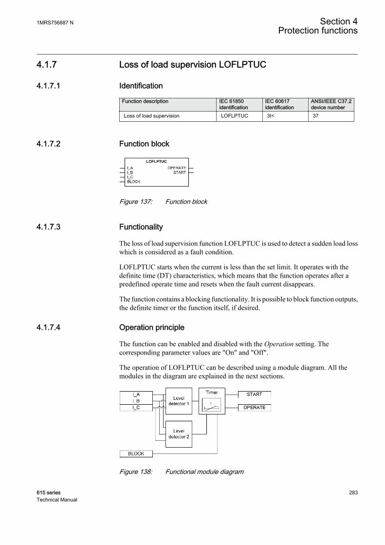
4.1.7 Loss of load supervision LOFLPTUC
4.1.7.1 Identification
Function description IEC 61850identification
IEC 60617identification
ANSI/IEEE C37.2device number
Loss of load supervision LOFLPTUC 3I< 37
4.1.7.2 Function block
GUID-B7774D44-24DB-48B1-888B-D9E3EA741F23 V2 EN
Figure 137: Function block
4.1.7.3 Functionality
The loss of load supervision function LOFLPTUC is used to detect a sudden load losswhich is considered as a fault condition.
LOFLPTUC starts when the current is less than the set limit. It operates with thedefinite time (DT) characteristics, which means that the function operates after apredefined operate time and resets when the fault current disappears.
The function contains a blocking functionality. It is possible to block function outputs,the definite timer or the function itself, if desired.
4.1.7.4 Operation principle
The function can be enabled and disabled with the Operation setting. Thecorresponding parameter values are "On" and "Off".
The operation of LOFLPTUC can be described using a module diagram. All themodules in the diagram are explained in the next sections.
GUID-4A6308B8-47E8-498D-A268-1386EBBBEC8F V1 EN
Figure 138: Functional module diagram
1MRS756887 N Section 4Protection functions
615 series 283Technical Manual
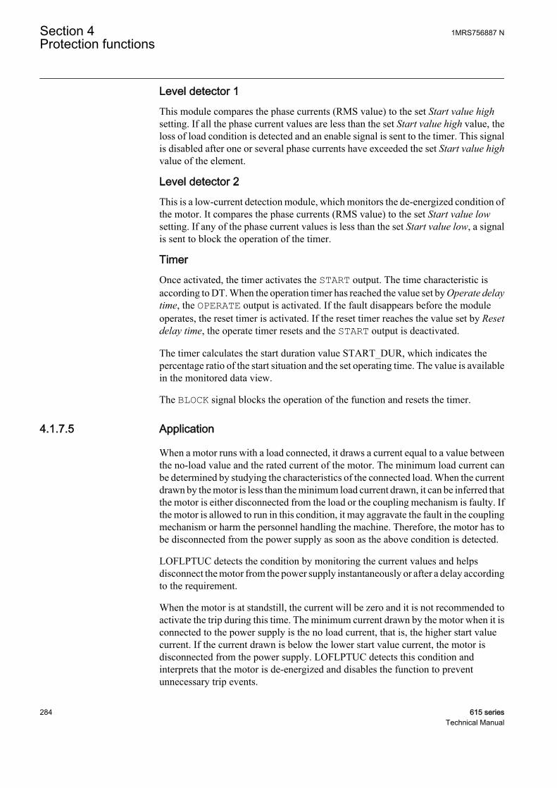
Level detector 1This module compares the phase currents (RMS value) to the set Start value highsetting. If all the phase current values are less than the set Start value high value, theloss of load condition is detected and an enable signal is sent to the timer. This signalis disabled after one or several phase currents have exceeded the set Start value highvalue of the element.
Level detector 2This is a low-current detection module, which monitors the de-energized condition ofthe motor. It compares the phase currents (RMS value) to the set Start value lowsetting. If any of the phase current values is less than the set Start value low, a signalis sent to block the operation of the timer.
TimerOnce activated, the timer activates the START output. The time characteristic isaccording to DT. When the operation timer has reached the value set by Operate delaytime, the OPERATE output is activated. If the fault disappears before the moduleoperates, the reset timer is activated. If the reset timer reaches the value set by Resetdelay time, the operate timer resets and the START output is deactivated.
The timer calculates the start duration value START_DUR, which indicates thepercentage ratio of the start situation and the set operating time. The value is availablein the monitored data view.
The BLOCK signal blocks the operation of the function and resets the timer.
4.1.7.5 Application
When a motor runs with a load connected, it draws a current equal to a value betweenthe no-load value and the rated current of the motor. The minimum load current canbe determined by studying the characteristics of the connected load. When the currentdrawn by the motor is less than the minimum load current drawn, it can be inferred thatthe motor is either disconnected from the load or the coupling mechanism is faulty. Ifthe motor is allowed to run in this condition, it may aggravate the fault in the couplingmechanism or harm the personnel handling the machine. Therefore, the motor has tobe disconnected from the power supply as soon as the above condition is detected.
LOFLPTUC detects the condition by monitoring the current values and helpsdisconnect the motor from the power supply instantaneously or after a delay accordingto the requirement.
When the motor is at standstill, the current will be zero and it is not recommended toactivate the trip during this time. The minimum current drawn by the motor when it isconnected to the power supply is the no load current, that is, the higher start valuecurrent. If the current drawn is below the lower start value current, the motor isdisconnected from the power supply. LOFLPTUC detects this condition andinterprets that the motor is de-energized and disables the function to preventunnecessary trip events.
Section 4 1MRS756887 NProtection functions
284 615 seriesTechnical Manual
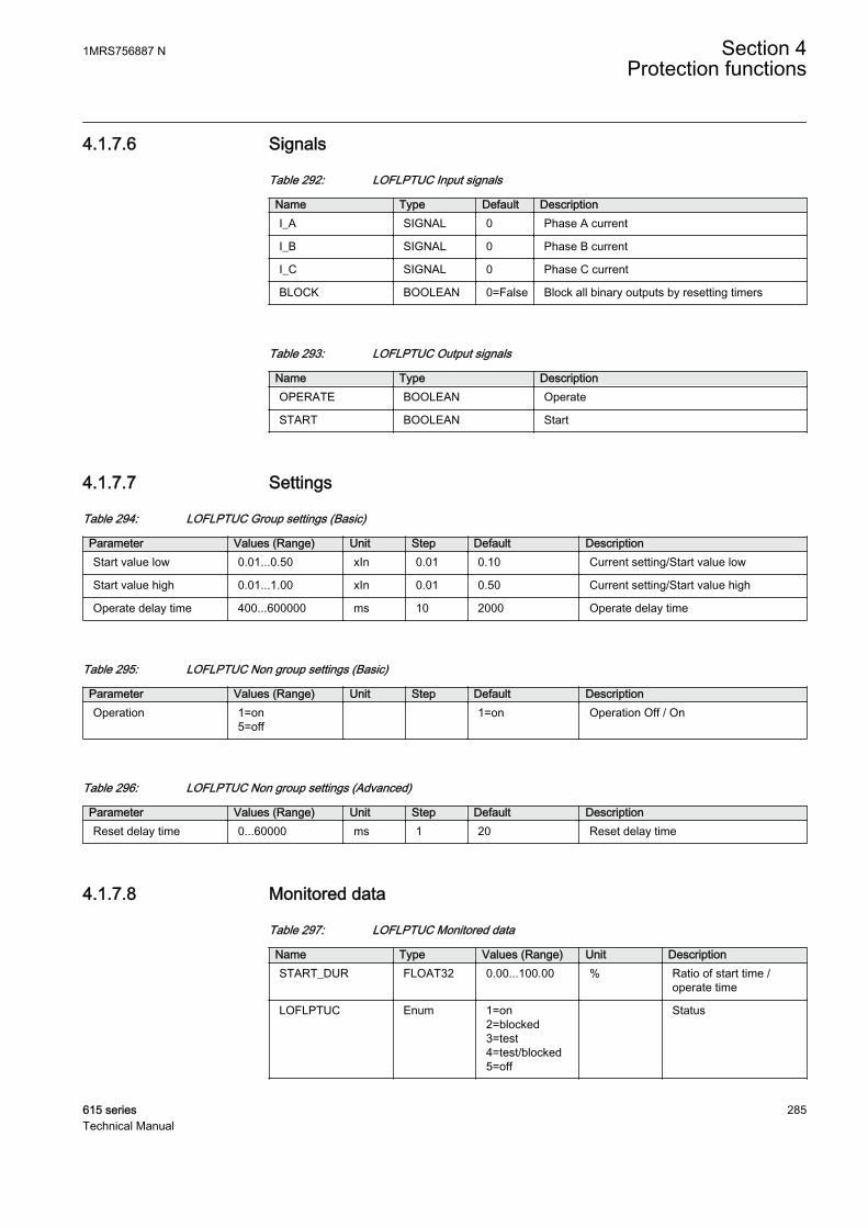
4.1.7.6 Signals
Table 292: LOFLPTUC Input signals
Name Type Default DescriptionI_A SIGNAL 0 Phase A current
I_B SIGNAL 0 Phase B current
I_C SIGNAL 0 Phase C current
BLOCK BOOLEAN 0=False Block all binary outputs by resetting timers
Table 293: LOFLPTUC Output signals
Name Type DescriptionOPERATE BOOLEAN Operate
START BOOLEAN Start
4.1.7.7 Settings
Table 294: LOFLPTUC Group settings (Basic)
Parameter Values (Range) Unit Step Default DescriptionStart value low 0.01...0.50 xIn 0.01 0.10 Current setting/Start value low
Start value high 0.01...1.00 xIn 0.01 0.50 Current setting/Start value high
Operate delay time 400...600000 ms 10 2000 Operate delay time
Table 295: LOFLPTUC Non group settings (Basic)
Parameter Values (Range) Unit Step Default DescriptionOperation 1=on
5=off 1=on Operation Off / On
Table 296: LOFLPTUC Non group settings (Advanced)
Parameter Values (Range) Unit Step Default DescriptionReset delay time 0...60000 ms 1 20 Reset delay time
4.1.7.8 Monitored data
Table 297: LOFLPTUC Monitored data
Name Type Values (Range) Unit DescriptionSTART_DUR FLOAT32 0.00...100.00 % Ratio of start time /
operate time
LOFLPTUC Enum 1=on2=blocked3=test4=test/blocked5=off
Status
1MRS756887 N Section 4Protection functions
615 series 285Technical Manual
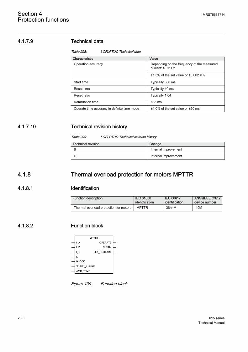
4.1.7.9 Technical data
Table 298: LOFLPTUC Technical data
Characteristic ValueOperation accuracy Depending on the frequency of the measured
current: fn ±2 Hz
±1.5% of the set value or ±0.002 × In
Start time Typically 300 ms
Reset time Typically 40 ms
Reset ratio Typically 1.04
Retardation time <35 ms
Operate time accuracy in definite time mode ±1.0% of the set value or ±20 ms
4.1.7.10 Technical revision history
Table 299: LOFLPTUC Technical revision history
Technical revision ChangeB Internal improvement
C Internal improvement
4.1.8 Thermal overload protection for motors MPTTR
4.1.8.1 Identification
Function description IEC 61850identification
IEC 60617identification
ANSI/IEEE C37.2device number
Thermal overload protection for motors MPTTR 3Ith>M 49M
4.1.8.2 Function block
GUID-1EEED1E9-3A6F-4EF3-BDCC-990E648E2E72 V4 EN
Figure 139: Function block
Section 4 1MRS756887 NProtection functions
286 615 seriesTechnical Manual
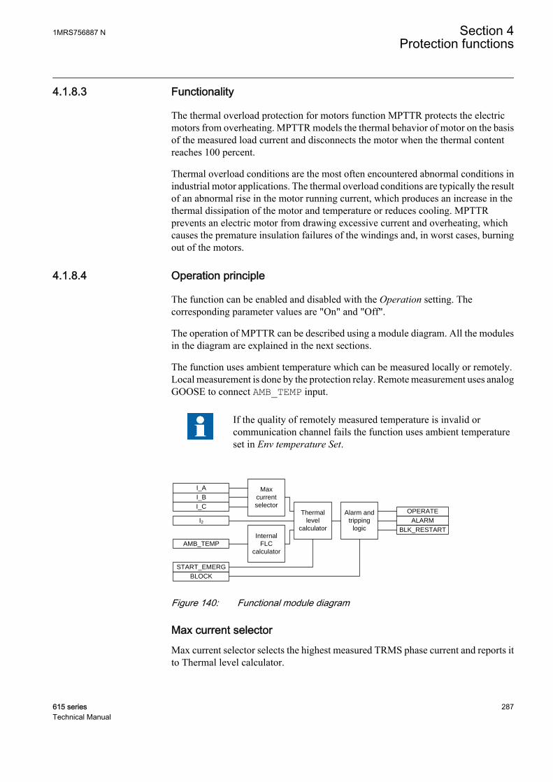
4.1.8.3 Functionality
The thermal overload protection for motors function MPTTR protects the electricmotors from overheating. MPTTR models the thermal behavior of motor on the basisof the measured load current and disconnects the motor when the thermal contentreaches 100 percent.
Thermal overload conditions are the most often encountered abnormal conditions inindustrial motor applications. The thermal overload conditions are typically the resultof an abnormal rise in the motor running current, which produces an increase in thethermal dissipation of the motor and temperature or reduces cooling. MPTTRprevents an electric motor from drawing excessive current and overheating, whichcauses the premature insulation failures of the windings and, in worst cases, burningout of the motors.
4.1.8.4 Operation principle
The function can be enabled and disabled with the Operation setting. Thecorresponding parameter values are "On" and "Off".
The operation of MPTTR can be described using a module diagram. All the modulesin the diagram are explained in the next sections.
The function uses ambient temperature which can be measured locally or remotely.Local measurement is done by the protection relay. Remote measurement uses analogGOOSE to connect AMB_TEMP input.
If the quality of remotely measured temperature is invalid orcommunication channel fails the function uses ambient temperatureset in Env temperature Set.
ALARM
BLK_RESTART
Max
current
selector
I_A
Thermal
level
calculatorInternal
FLC
calculator
Alarm and
tripping
logic
START_EMERG
BLOCK
OPERATE
I_B
I_C
I2
AMB_TEMP
GUID-1E5F2337-DA4E-4F5B-8BEB-27353A6734DC V2 EN
Figure 140: Functional module diagram
Max current selectorMax current selector selects the highest measured TRMS phase current and reports itto Thermal level calculator.
1MRS756887 N Section 4Protection functions
615 series 287Technical Manual
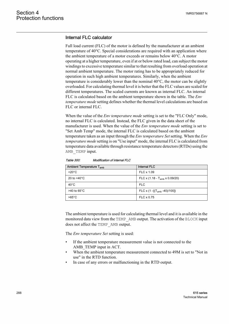
Internal FLC calculatorFull load current (FLC) of the motor is defined by the manufacturer at an ambienttemperature of 40°C. Special considerations are required with an application wherethe ambient temperature of a motor exceeds or remains below 40°C. A motoroperating at a higher temperature, even if at or below rated load, can subject the motorwindings to excessive temperature similar to that resulting from overload operation atnormal ambient temperature. The motor rating has to be appropriately reduced foroperation in such high ambient temperatures. Similarly, when the ambienttemperature is considerably lower than the nominal 40°C, the motor can be slightlyoverloaded. For calculating thermal level it is better that the FLC values are scaled fordifferent temperatures. The scaled currents are known as internal FLC. An internalFLC is calculated based on the ambient temperature shown in the table. The Envtemperature mode setting defines whether the thermal level calculations are based onFLC or internal FLC.
When the value of the Env temperature mode setting is set to the "FLC Only" mode,no internal FLC is calculated. Instead, the FLC given in the data sheet of themanufacturer is used. When the value of the Env temperature mode setting is set to"Set Amb Temp" mode, the internal FLC is calculated based on the ambienttemperature taken as an input through the Env temperature Set setting. When the Envtemperature mode setting is on "Use input" mode, the internal FLC is calculated fromtemperature data available through resistance temperature detectors (RTDs) using theAMB_TEMP input.
Table 300: Modification of internal FLC
Ambient Temperature Tamb Internal FLC<20°C FLC x 1.09
20 to <40°C FLC x (1.18 - Tamb x 0.09/20)
40°C FLC
>40 to 65°C FLC x (1 –[(Tamb -40)/100])
>65°C FLC x 0.75
The ambient temperature is used for calculating thermal level and it is available in themonitored data view from the TEMP_AMB output. The activation of the BLOCK inputdoes not affect the TEMP_AMB output.
The Env temperature Set setting is used:
• If the ambient temperature measurement value is not connected to theAMB_TEMP input in ACT.
• When the ambient temperature measurement connected to 49M is set to "Not inuse" in the RTD function.
• In case of any errors or malfunctioning in the RTD output.
Section 4 1MRS756887 NProtection functions
288 615 seriesTechnical Manual
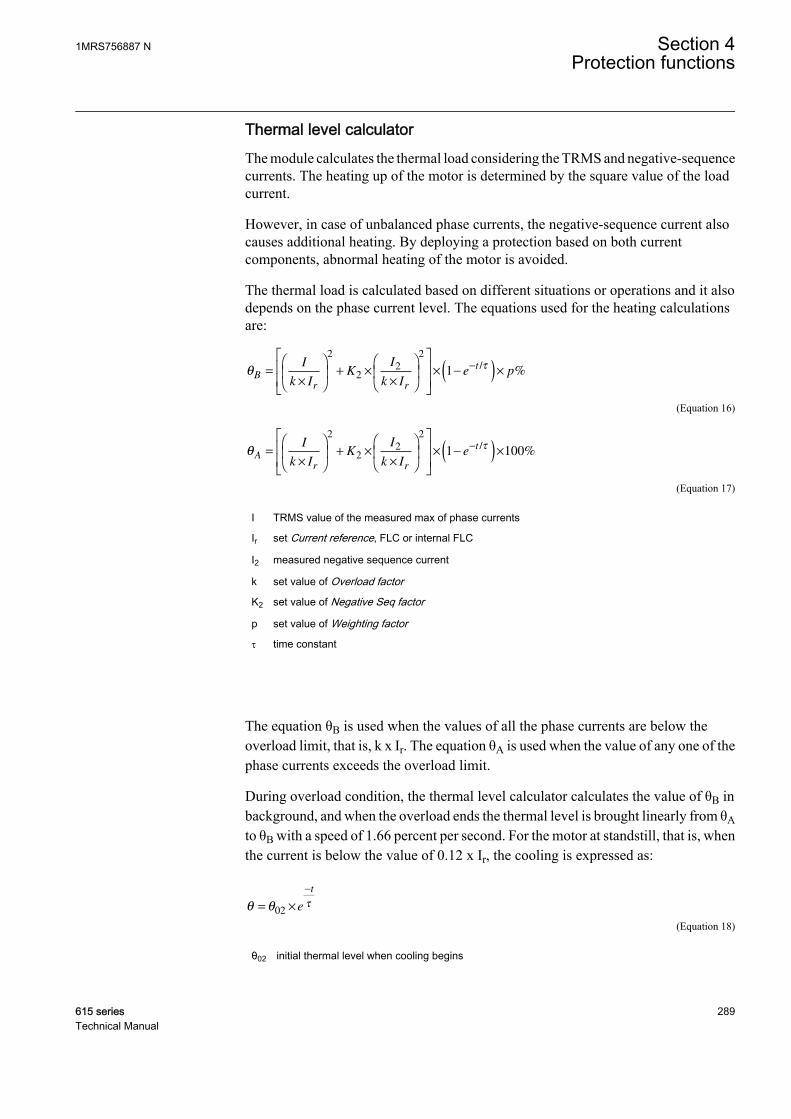
Thermal level calculatorThe module calculates the thermal load considering the TRMS and negative-sequencecurrents. The heating up of the motor is determined by the square value of the loadcurrent.
However, in case of unbalanced phase currents, the negative-sequence current alsocauses additional heating. By deploying a protection based on both currentcomponents, abnormal heating of the motor is avoided.
The thermal load is calculated based on different situations or operations and it alsodepends on the phase current level. The equations used for the heating calculationsare:
θτ
Br r
tI
k IK
I
k Ie p=
×
+ ×
×
× −( )×−
2
22
2
1/
%
GUID-526B455A-67DD-46E7-813D-A64EC619F6D7 V2 EN (Equation 16)
θτ
A
r r
tI
k IK
I
k Ie=
×
+ ×
×
× −( )×−
2
22
2
1 100/
%
GUID-9C893D3E-7CAF-4EA6-B92D-C914288D7CFC V2 EN (Equation 17)
I TRMS value of the measured max of phase currents
Ir set Current reference, FLC or internal FLC
I2 measured negative sequence current
k set value of Overload factor
K2 set value of Negative Seq factor
p set value of Weighting factor
t time constant
The equation θB is used when the values of all the phase currents are below theoverload limit, that is, k x Ir. The equation θA is used when the value of any one of thephase currents exceeds the overload limit.
During overload condition, the thermal level calculator calculates the value of θB inbackground, and when the overload ends the thermal level is brought linearly from θAto θB with a speed of 1.66 percent per second. For the motor at standstill, that is, whenthe current is below the value of 0.12 x Ir, the cooling is expressed as:
θ θ τ= ×
−
02 e
t
GUID-2C640EA9-DF69-42A9-A6A8-3CD20AEC76BD V2 EN (Equation 18)
θ02 initial thermal level when cooling begins
1MRS756887 N Section 4Protection functions
615 series 289Technical Manual

GUID-A19F9DF2-2F04-401F-AE7A-6CE55F88EB1D V2 EN
Figure 141: Thermal behavior
The required overload factor and negative sequence current heating effect factor areset by the values of the Overload factor and Negative Seq factor settings.
In order to accurately calculate the motor thermal condition, different time constantsare used in the above equations. These time constants are employed based on differentmotor running conditions, for example starting, normal or stop, and are set through theTime constant start, Time constant normal and Time constant stop settings. Only onetime constant is valid at a time.
Table 301: Time constant and the respective phase current values
Time constant (tau) in use Phase currentTime constant start Any current whose value is over 2.5 x Ir
Time constant normal Any current whose value is over 0.12 x Ir and allcurrents are below 2.5 x Ir
Time constant stop All the currents whose values are below 0.12 x Ir
The Weighting factor p setting determines the ratio of the thermal increase of the twocurves θA and θB.
The thermal level at the power-up of the protection relay is defined by the Initialthermal Val setting.
The temperature calculation is initiated from the value defined in the Initial thermalVal setting. This is done if the protection relay is powered up or the function is turnedoff and back on or reset through the Clear menu.
The calculated temperature of the protected object relative to the operate level, theTEMP_RL output, is available through the monitored data view. The activation of theBLOCK input does not affect the calculated temperature.
The thermal level at the beginning of the start-up condition of a motor and at the endof the start-up condition is available in the monitored data view at the THERMLEV_ST
Section 4 1MRS756887 NProtection functions
290 615 seriesTechnical Manual
and THERMLEV_END outputs respectively. The activation of the BLOCK input doesnot have any effect on these outputs.
Alarm and tripping logicThe module generates alarm, restart inhibit and tripping signals.
When the thermal level exceeds the set value of the Alarm thermal value setting, theALARM output is activated. Sometimes a condition arises when it becomes necessaryto inhibit the restarting of a motor, for example in case of some extreme startingcondition like long starting time. If the thermal content exceeds the set value of theRestart thermal val setting, the BLK_RESTART output is activated. The time for thenext possible motor start-up is available through the monitored data view from theT_ENARESTART output. The T_ENARESTART output estimates the time for theBLK_RESTART deactivation considering as if the motor is stopped.
When the emergency start signal START_EMERG is set high, the thermal level is setto a value below the thermal restart inhibit level. This allows at least one motor start-up, even though the thermal level has exceeded the restart inhibit level.
When the thermal content reaches 100 percent, the OPERATE output is activated. TheOPERATE output is deactivated when the value of the measured current falls below 12percent of Current reference or the thermal content drops below 100 percent.
The activation of the BLOCK input blocks the ALARM, BLK_RESTART andOPERATE outputs.
1MRS756887 N Section 4Protection functions
615 series 291Technical Manual
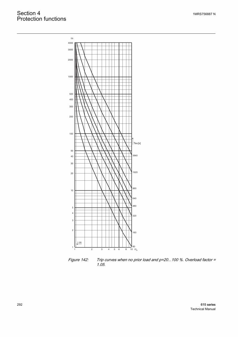
Tau
3840
1920
960
640
480
320
160
80
[s]
GUID-F3D1E6D3-86E9-4C0A-BD43-350003A07292 V1 EN
Figure 142: Trip curves when no prior load and p=20...100 %. Overload factor =1.05.
Section 4 1MRS756887 NProtection functions
292 615 seriesTechnical Manual
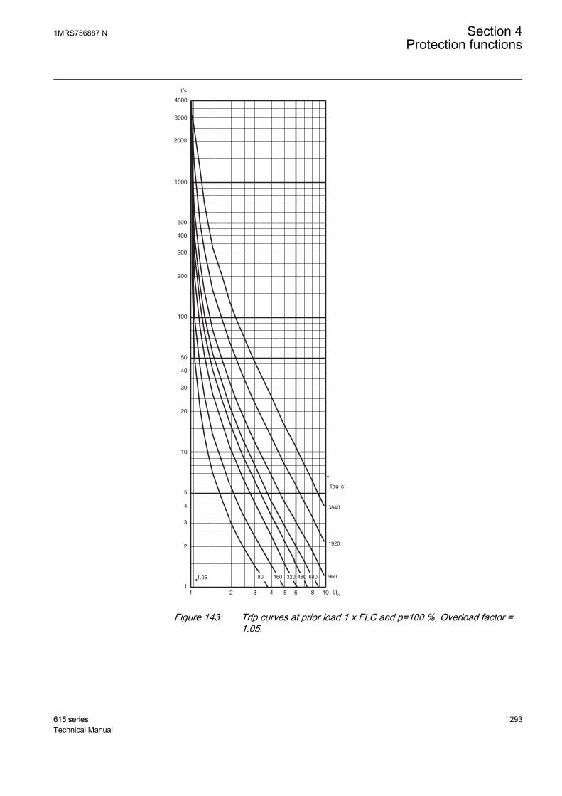
Tau
3840
1920
96080 160 320 480 640
[s]
GUID-44A67C51-E35D-4335-BDBD-5CD0D3F41EF1 V1 EN
Figure 143: Trip curves at prior load 1 x FLC and p=100 %, Overload factor =1.05.
1MRS756887 N Section 4Protection functions
615 series 293Technical Manual
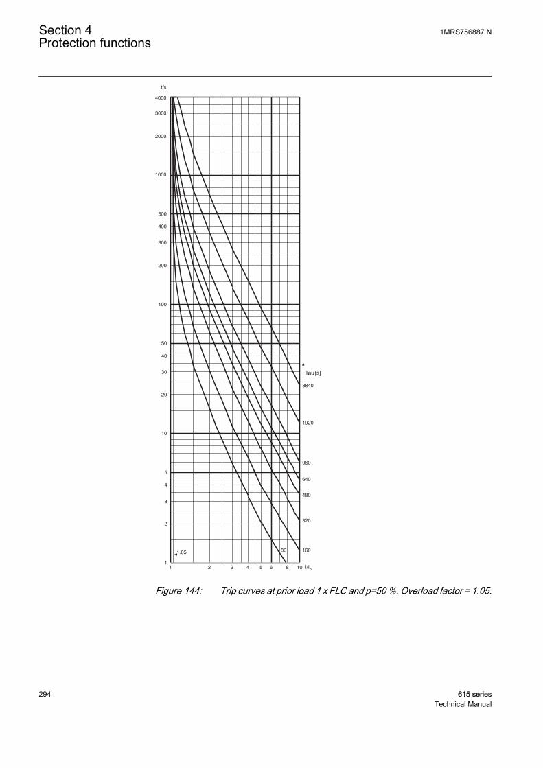
Tau
3840
1920
960
640
480
320
16080
[s]
GUID-5CB18A7C-54FC-4836-9049-0CE926F35ADF V1 EN
Figure 144: Trip curves at prior load 1 x FLC and p=50 %. Overload factor = 1.05.
Section 4 1MRS756887 NProtection functions
294 615 seriesTechnical Manual
4.1.8.5 Application
MPTTR is intended to limit the motor thermal level to predetermined values duringthe abnormal motor operating conditions. This prevents a premature motor insulationfailure.
The abnormal conditions result in overheating and include overload, stalling, failureto start, high ambient temperature, restricted motor ventilation, reduced speedoperation, frequent starting or jogging, high or low line voltage or frequency,mechanical failure of the driven load, improper installation and unbalanced linevoltage or single phasing. The protection of insulation failure by the implementationof current sensing cannot detect some of these conditions, such as restrictedventilation. Similarly, the protection by sensing temperature alone can be inadequatein cases like frequent starting or jogging. The thermal overload protection addressesthese deficiencies to a larger extent by deploying a motor thermal model based on loadcurrent.
The thermal load is calculated using the true RMS phase value and negative sequencevalue of the current. The heating up of the motor is determined by the square value ofthe load current. However, while calculating the thermal level, the rated currentshould be re-rated or de-rated depending on the value of the ambient temperature.Apart from current, the rate at which motor heats up or cools is governed by the timeconstant of the motor.
Setting the weighting factorThere are two thermal curves: one which characterizes the short-time loads and long-time overloads and which is also used for tripping and another which is used formonitoring the thermal condition of the motor. The value of the Weighting factor psetting determines the ratio of the thermal increase of the two curves.
When the Weighting factor p setting is 100 percent, a pure single time constantthermal unit is produced which is used for application with the cables. As presented inFigure 145, the hot curve with the value of Weighting factor p being 100 percent onlyallows an operate time which is about 10 percent of that with no prior load. Forexample, when the set time constant is 640 seconds, the operate time with the priorload 1 x FLC (full Load Current) and overload factor 1.05 is only 2 seconds, even ifthe motor could withstand at least 5 to 6 seconds. To allow the use of the full capacityof the motor, a lower value of Weighting factor p should be used.
Normally, an approximate value of half of the thermal capacity is used when the motoris running at full load. Thus by setting Weighting factor p to 50 percent, the protectionrelay notifies a 45 to 50 percent thermal capacity use at full load.
For direct-on-line started motors with hot spot tendencies, the value of Weightingfactor p is typically set to 50 percent, which will properly distinguish between short-time thermal stress and long-time thermal history. After a short period of thermalstress, for example a motor start-up, the thermal level starts to decrease quite sharply,simulating the leveling out of the hot spots. Consequently, the probability ofsuccessive allowed start-ups increases.
1MRS756887 N Section 4Protection functions
615 series 295Technical Manual
When protecting the objects without hot spot tendencies, for example motors startedwith soft starters, and cables, the value of Weighting factor p is set to 100 percent. Withthe value of Weighting factor p set to 100 percent, the thermal level decreases slowlyafter a heavy load condition. This makes the protection suitable for applications whereno hot spots are expected. Only in special cases where the thermal overload protectionis required to follow the characteristics of the object to be protected more closely andthe thermal capacity of the object is very well known, a value between 50 and 100percent is required.
For motor applications where, for example, two hot starts are allowed instead of threecold starts, the value of the setting Weighting factor p being 40 percent has proven tobe useful. Setting the value of Weighting factor p significantly below 50 percentshould be handled carefully as there is a possibility to overload the protected object asa thermal unit might allow too many hot starts or the thermal history of the motor hasnot been taken into account sufficiently.
Section 4 1MRS756887 NProtection functions
296 615 seriesTechnical Manual
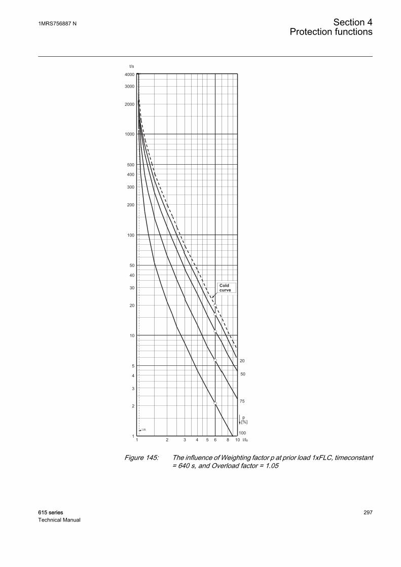
t/s
1000
100
500
200
50
10
20
5
1
2
3
4
30
40
300
400
2000
3000
4000
1 2 3 4 5 106 8 I/Iq
1.05
p[%]
20
50
75
100
x
Cold
curve
GUID-B6F9E655-4FFC-4B06-841A-68DADE785BF2 V1 EN
Figure 145: The influence of Weighting factor p at prior load 1xFLC, timeconstant= 640 s, and Overload factor = 1.05
1MRS756887 N Section 4Protection functions
615 series 297Technical Manual
Setting the overload factorThe value of Overload factor defines the highest permissible continuous load. Therecommended value is 1.05.
Setting the negative sequence factorDuring the unbalance condition, the symmetry of the stator currents is disturbed anda counter-rotating negative sequence component current is set up. An increased statorcurrent causes additional heating in the stator and the negative sequence componentcurrent excessive heating in the rotor. Also mechanical problems like rotor vibrationcan occur.
The most common cause of unbalance for three-phase motors is the loss of phaseresulting in an open fuse, connector or conductor. Often mechanical problems can bemore severe than the heating effects and therefore a separate unbalance protection isused.
Unbalances in other connected loads in the same busbar can also affect the motor. Avoltage unbalance typically produces 5 to 7 times higher current unbalance. Becausethe thermal overload protection is based on the highest TRMS value of the phasecurrent, the additional heating in stator winding is automatically taken into account.For more accurate thermal modeling, the Negative Seq factor setting is used for takingaccount of the rotor heating effect.
Negative Seq factorR
R
R
R
=2
1
GUID-EA5AD510-A3CA-47FB-91F0-75D7272B654E V1 EN (Equation 19)
RR2 Rotor negative sequence resistance
RR1 Rotor positive sequence resistance
A conservative estimate for the setting can be calculated:
Negative Seq factorILR
=
175
2
GUID-13CE37C5-295F-41D4-8159-400FA377C84C V1 EN (Equation 20)
ILR Locked rotor current (multiple of set Rated current). The same as the start-up current at thebeginning of the motor start-up.
For example, if the rated current of a motor is 230 A, start-up current is 5.7 x Ir,
Negative Seq factor = =
175
5 75 4
2.
.
GUID-DF682702-E6B1-4814-8B2E-31C28F3A03DF V1 EN (Equation 21)
Section 4 1MRS756887 NProtection functions
298 615 seriesTechnical Manual

Setting the thermal restart levelThe restart disable level can be calculated as follows:
θi
startup timeof the motor
operate timewhen no prior load= − ×100 10% 00% +
margin
GUID-5B3B714D-8C58-4C5D-910D-A23852BC8B15 V2 EN (Equation 22)
For example, the motor start-up time is 11 seconds, start-up current 6 x rated and Timeconstant start is set for 800 seconds. Using the trip curve with no prior load, theoperation time at 6 x rated current is 25 seconds, one motor start-up uses 11/25 ≈ 45percent of the thermal capacity of the motor. Therefore, the restart disable level mustbe set to below 100 percent - 45 percent = 55 percent, for example to 50 percent (100percent - (45 percent + margin), where margin is 5 percent).
Setting the thermal alarm levelTripping due to high overload is avoided by reducing the load of the motor on a prioralarm.
The value of Alarm thermal value is set to a level which allows the use of the fullthermal capacity of the motor without causing a trip due to a long overload time.Generally, the prior alarm level is set to a value of 80 to 90 percent of the trip level.
4.1.8.6 Signals
Table 302: MPTTR Input signals
Name Type Default DescriptionI_A SIGNAL 0 Phase A current
I_B SIGNAL 0 Phase B current
I_C SIGNAL 0 Phase C current
I2 SIGNAL 0 Negative sequence current
BLOCK BOOLEAN 0=False Block signal for activating the blocking mode
START_EMERG BOOLEAN 0=False Signal for indicating the need for emergency start
AMB_TEMP FLOAT32 0 The ambient temperature used in the calculation
Table 303: MPTTR Output signals
Name Type DescriptionOPERATE BOOLEAN Operate
ALARM BOOLEAN Thermal Alarm
BLK_RESTART BOOLEAN Thermal overload indicator, to inhibit restart
1MRS756887 N Section 4Protection functions
615 series 299Technical Manual
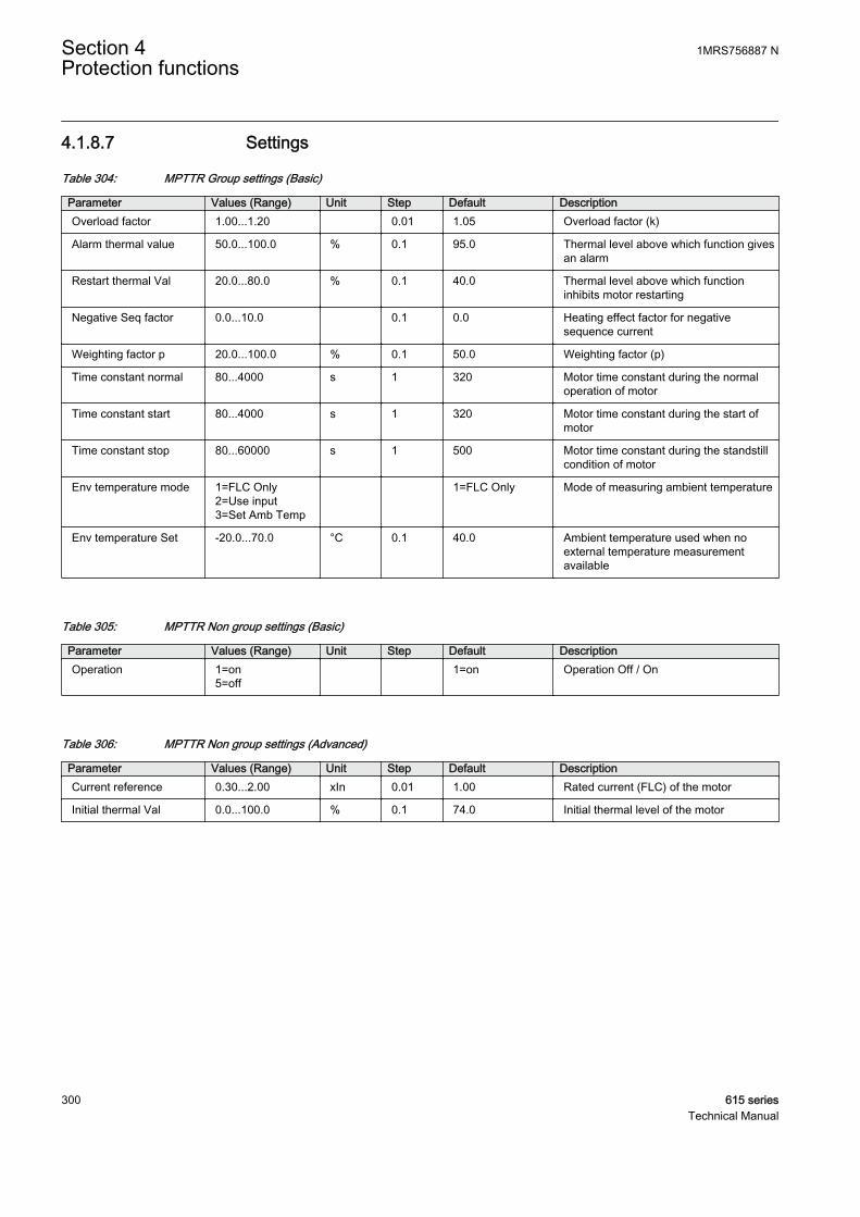
4.1.8.7 Settings
Table 304: MPTTR Group settings (Basic)
Parameter Values (Range) Unit Step Default DescriptionOverload factor 1.00...1.20 0.01 1.05 Overload factor (k)
Alarm thermal value 50.0...100.0 % 0.1 95.0 Thermal level above which function givesan alarm
Restart thermal Val 20.0...80.0 % 0.1 40.0 Thermal level above which functioninhibits motor restarting
Negative Seq factor 0.0...10.0 0.1 0.0 Heating effect factor for negativesequence current
Weighting factor p 20.0...100.0 % 0.1 50.0 Weighting factor (p)
Time constant normal 80...4000 s 1 320 Motor time constant during the normaloperation of motor
Time constant start 80...4000 s 1 320 Motor time constant during the start ofmotor
Time constant stop 80...60000 s 1 500 Motor time constant during the standstillcondition of motor
Env temperature mode 1=FLC Only2=Use input3=Set Amb Temp
1=FLC Only Mode of measuring ambient temperature
Env temperature Set -20.0...70.0 °C 0.1 40.0 Ambient temperature used when noexternal temperature measurementavailable
Table 305: MPTTR Non group settings (Basic)
Parameter Values (Range) Unit Step Default DescriptionOperation 1=on
5=off 1=on Operation Off / On
Table 306: MPTTR Non group settings (Advanced)
Parameter Values (Range) Unit Step Default DescriptionCurrent reference 0.30...2.00 xIn 0.01 1.00 Rated current (FLC) of the motor
Initial thermal Val 0.0...100.0 % 0.1 74.0 Initial thermal level of the motor
Section 4 1MRS756887 NProtection functions
300 615 seriesTechnical Manual
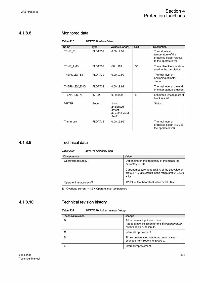
4.1.8.8 Monitored data
Table 307: MPTTR Monitored data
Name Type Values (Range) Unit DescriptionTEMP_RL FLOAT32 0.00...9.99 The calculated
temperature of theprotected object relativeto the operate level
TEMP_AMB FLOAT32 -99...999 °C The ambient temperatureused in the calculation
THERMLEV_ST FLOAT32 0.00...9.99 Thermal level atbeginning of motorstartup
THERMLEV_END FLOAT32 0.00...9.99 Thermal level at the endof motor startup situation
T_ENARESTART INT32 0...99999 s Estimated time to reset ofblock restart
MPTTR Enum 1=on2=blocked3=test4=test/blocked5=off
Status
Therm-Lev FLOAT32 0.00...9.99 Thermal level ofprotected object (1.00 isthe operate level)
4.1.8.9 Technical data
Table 308: MPTTR Technical data
Characteristic ValueOperation accuracy Depending on the frequency of the measured
current: fn ±2 Hz
Current measurement: ±1.5% of the set value or±0.002 × In (at currents in the range of 0.01...4.00× In)
Operate time accuracy1) ±2.0% of the theoretical value or ±0.50 s
1) Overload current > 1.2 × Operate level temperature
4.1.8.10 Technical revision history
Table 309: MPTTR Technical revision history
Technical revision ChangeB Added a new input AMB_TEMP.
Added a new selection for the Env temperaturemode setting "Use input".
C Internal improvement.
D Time constant stop range maximum valuechanged from 8000 s to 60000 s.
E Internal improvement.
1MRS756887 N Section 4Protection functions
615 series 301Technical Manual
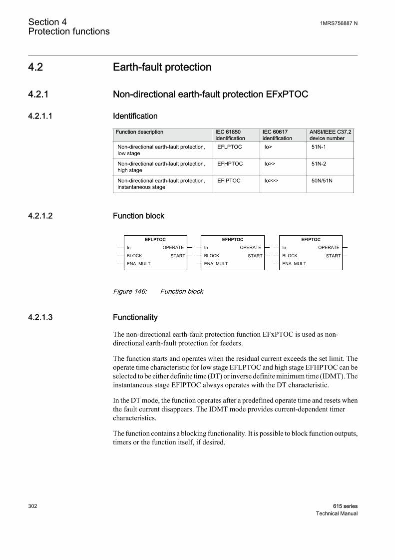
4.2 Earth-fault protection
4.2.1 Non-directional earth-fault protection EFxPTOC
4.2.1.1 Identification
Function description IEC 61850identification
IEC 60617identification
ANSI/IEEE C37.2device number
Non-directional earth-fault protection,low stage
EFLPTOC Io> 51N-1
Non-directional earth-fault protection,high stage
EFHPTOC Io>> 51N-2
Non-directional earth-fault protection,instantaneous stage
EFIPTOC Io>>> 50N/51N
4.2.1.2 Function block
EFLPTOC
Io
BLOCK START
OPERATE
ENA_MULT
EFHPTOC
Io
BLOCK START
OPERATE
ENA_MULT
EFIPTOC
Io
BLOCK START
OPERATE
ENA_MULT
A070432 V2 EN
Figure 146: Function block
4.2.1.3 Functionality
The non-directional earth-fault protection function EFxPTOC is used as non-directional earth-fault protection for feeders.
The function starts and operates when the residual current exceeds the set limit. Theoperate time characteristic for low stage EFLPTOC and high stage EFHPTOC can beselected to be either definite time (DT) or inverse definite minimum time (IDMT). Theinstantaneous stage EFIPTOC always operates with the DT characteristic.
In the DT mode, the function operates after a predefined operate time and resets whenthe fault current disappears. The IDMT mode provides current-dependent timercharacteristics.
The function contains a blocking functionality. It is possible to block function outputs,timers or the function itself, if desired.
Section 4 1MRS756887 NProtection functions
302 615 seriesTechnical Manual
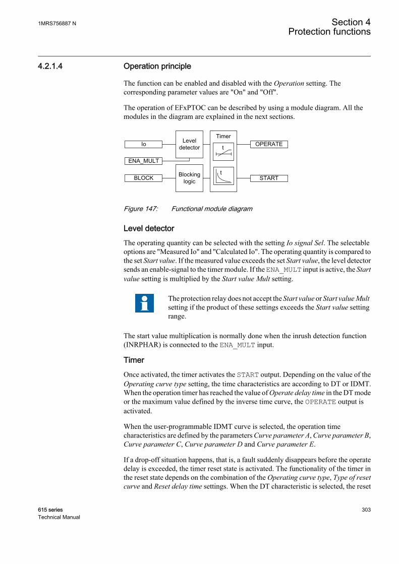
4.2.1.4 Operation principle
The function can be enabled and disabled with the Operation setting. Thecorresponding parameter values are "On" and "Off".
The operation of EFxPTOC can be described by using a module diagram. All themodules in the diagram are explained in the next sections.
A070437 V3 EN
Figure 147: Functional module diagram
Level detectorThe operating quantity can be selected with the setting Io signal Sel. The selectableoptions are "Measured Io" and "Calculated Io". The operating quantity is compared tothe set Start value. If the measured value exceeds the set Start value, the level detectorsends an enable-signal to the timer module. If the ENA_MULT input is active, the Startvalue setting is multiplied by the Start value Mult setting.
The protection relay does not accept the Start value or Start value Multsetting if the product of these settings exceeds the Start value settingrange.
The start value multiplication is normally done when the inrush detection function(INRPHAR) is connected to the ENA_MULT input.
TimerOnce activated, the timer activates the START output. Depending on the value of theOperating curve type setting, the time characteristics are according to DT or IDMT.When the operation timer has reached the value of Operate delay time in the DT modeor the maximum value defined by the inverse time curve, the OPERATE output isactivated.
When the user-programmable IDMT curve is selected, the operation timecharacteristics are defined by the parameters Curve parameter A, Curve parameter B,Curve parameter C, Curve parameter D and Curve parameter E.
If a drop-off situation happens, that is, a fault suddenly disappears before the operatedelay is exceeded, the timer reset state is activated. The functionality of the timer inthe reset state depends on the combination of the Operating curve type, Type of resetcurve and Reset delay time settings. When the DT characteristic is selected, the reset
1MRS756887 N Section 4Protection functions
615 series 303Technical Manual

timer runs until the set Reset delay time value is exceeded. When the IDMT curves areselected, the Type of reset curve setting can be set to "Immediate", "Def time reset" or"Inverse reset". The reset curve type "Immediate" causes an immediate reset. With thereset curve type "Def time reset", the reset time depends on the Reset delay timesetting. With the reset curve type "Inverse reset", the reset time depends on the currentduring the drop-off situation. The START output is deactivated when the reset timerhas elapsed.
The "Inverse reset" selection is only supported with ANSI or userprogrammable types of the IDMT operating curves. If anotheroperating curve type is selected, an immediate reset occurs during thedrop-off situation.
The setting Time multiplier is used for scaling the IDMT operate and reset times.
The setting parameter Minimum operate time defines the minimum desired operatetime for IDMT. The setting is applicable only when the IDMT curves are used.
The Minimum operate time setting should be used with great carebecause the operation time is according to the IDMT curve, but alwaysat least the value of the Minimum operate time setting. For moreinformation, see the IDMT curves for overcurrent protection sectionin this manual.
The timer calculates the start duration value START_DUR, which indicates thepercentage ratio of the start situation and the set operating time. The value is availablein the monitored data view.
Blocking logicThere are three operation modes in the blocking function. The operation modes arecontrolled by the BLOCK input and the global setting in Configuration/System/Blocking mode which selects the blocking mode. The BLOCK input can be controlledby a binary input, a horizontal communication input or an internal signal of theprotection relay's program. The influence of the BLOCK signal activation ispreselected with the global setting Blocking mode.
The Blocking mode setting has three blocking methods. In the "Freeze timers" mode,the operation timer is frozen to the prevailing value, but the OPERATE output is notdeactivated when blocking is activated. In the "Block all" mode, the whole function isblocked and the timers are reset. In the "Block OPERATE output" mode, the functionoperates normally but the OPERATE output is not activated.
4.2.1.5 Measurement modes
The function operates on three alternative measurement modes: "RMS", "DFT" and"Peak-to-Peak". The measurement mode is selected with the Measurement modesetting.
Section 4 1MRS756887 NProtection functions
304 615 seriesTechnical Manual
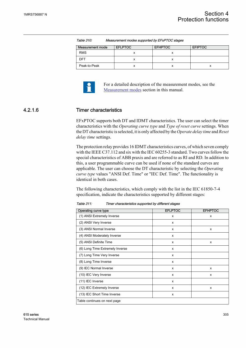
Table 310: Measurement modes supported by EFxPTOC stages
Measurement mode EFLPTOC EFHPTOC EFIPTOCRMS x x
DFT x x
Peak-to-Peak x x x
For a detailed description of the measurement modes, see theMeasurement modes section in this manual.
4.2.1.6 Timer characteristics
EFxPTOC supports both DT and IDMT characteristics. The user can select the timercharacteristics with the Operating curve type and Type of reset curve settings. Whenthe DT characteristic is selected, it is only affected by the Operate delay time and Resetdelay time settings.
The protection relay provides 16 IDMT characteristics curves, of which seven complywith the IEEE C37.112 and six with the IEC 60255-3 standard. Two curves follow thespecial characteristics of ABB praxis and are referred to as RI and RD. In addition tothis, a user programmable curve can be used if none of the standard curves areapplicable. The user can choose the DT characteristic by selecting the Operatingcurve type values "ANSI Def. Time" or "IEC Def. Time". The functionality isidentical in both cases.
The following characteristics, which comply with the list in the IEC 61850-7-4specification, indicate the characteristics supported by different stages:
Table 311: Timer characteristics supported by different stages
Operating curve type EFLPTOC EFHPTOC(1) ANSI Extremely Inverse x x
(2) ANSI Very Inverse x
(3) ANSI Normal Inverse x x
(4) ANSI Moderately Inverse x
(5) ANSI Definite Time x x
(6) Long Time Extremely Inverse x
(7) Long Time Very Inverse x
(8) Long Time Inverse x
(9) IEC Normal Inverse x x
(10) IEC Very Inverse x x
(11) IEC Inverse x
(12) IEC Extremely Inverse x x
(13) IEC Short Time Inverse x
Table continues on next page
1MRS756887 N Section 4Protection functions
615 series 305Technical Manual
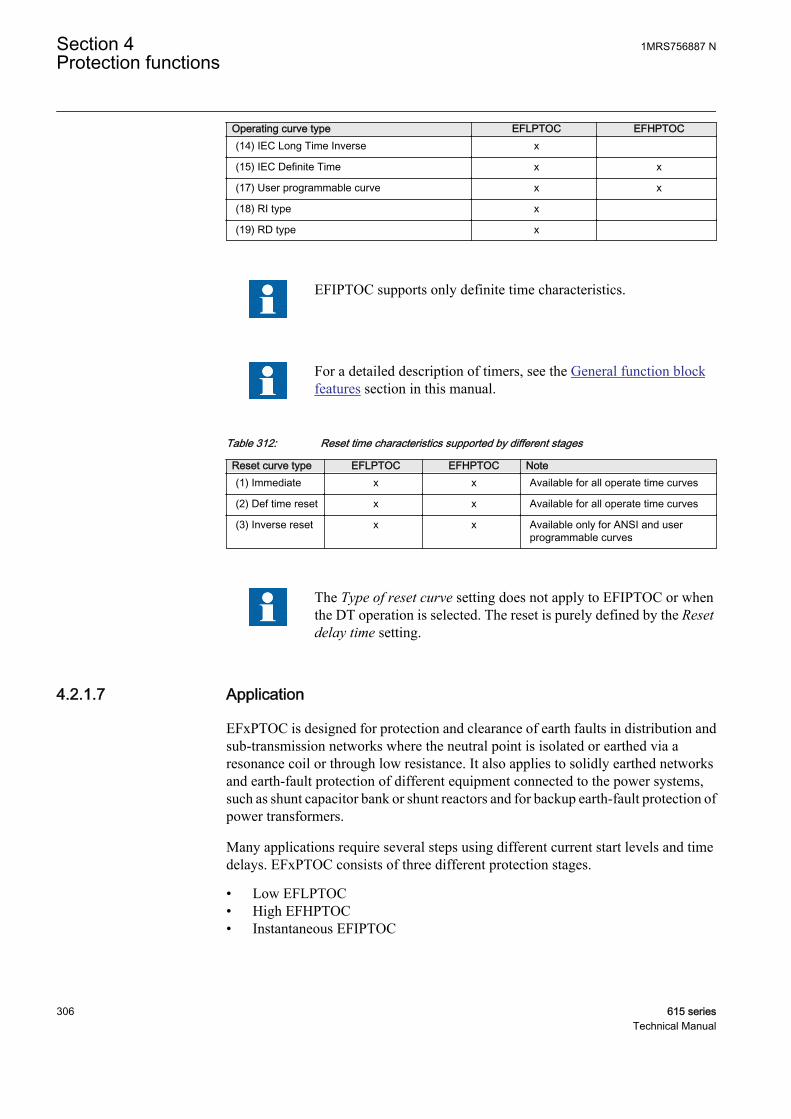
Operating curve type EFLPTOC EFHPTOC(14) IEC Long Time Inverse x
(15) IEC Definite Time x x
(17) User programmable curve x x
(18) RI type x
(19) RD type x
EFIPTOC supports only definite time characteristics.
For a detailed description of timers, see the General function blockfeatures section in this manual.
Table 312: Reset time characteristics supported by different stages
Reset curve type EFLPTOC EFHPTOC Note(1) Immediate x x Available for all operate time curves
(2) Def time reset x x Available for all operate time curves
(3) Inverse reset x x Available only for ANSI and userprogrammable curves
The Type of reset curve setting does not apply to EFIPTOC or whenthe DT operation is selected. The reset is purely defined by the Resetdelay time setting.
4.2.1.7 Application
EFxPTOC is designed for protection and clearance of earth faults in distribution andsub-transmission networks where the neutral point is isolated or earthed via aresonance coil or through low resistance. It also applies to solidly earthed networksand earth-fault protection of different equipment connected to the power systems,such as shunt capacitor bank or shunt reactors and for backup earth-fault protection ofpower transformers.
Many applications require several steps using different current start levels and timedelays. EFxPTOC consists of three different protection stages.
• Low EFLPTOC• High EFHPTOC• Instantaneous EFIPTOC
Section 4 1MRS756887 NProtection functions
306 615 seriesTechnical Manual

EFLPTOC contains several types of time-delay characteristics. EFHPTOC andEFIPTOC are used for fast clearance of serious earth faults.
4.2.1.8 Signals
Table 313: EFLPTOC Input signals
Name Type Default DescriptionIo SIGNAL 0 Residual current
BLOCK BOOLEAN 0=False Block signal for activating the blocking mode
ENA_MULT BOOLEAN 0=False Enable signal for current multiplier
Table 314: EFHPTOC Input signals
Name Type Default DescriptionIo SIGNAL 0 Residual current
BLOCK BOOLEAN 0=False Block signal for activating the blocking mode
ENA_MULT BOOLEAN 0=False Enable signal for current multiplier
Table 315: EFIPTOC Input signals
Name Type Default DescriptionIo SIGNAL 0 Residual current
BLOCK BOOLEAN 0=False Block signal for activating the blocking mode
ENA_MULT BOOLEAN 0=False Enable signal for current multiplier
Table 316: EFLPTOC Output signals
Name Type DescriptionOPERATE BOOLEAN Operate
START BOOLEAN Start
Table 317: EFHPTOC Output signals
Name Type DescriptionOPERATE BOOLEAN Operate
START BOOLEAN Start
Table 318: EFIPTOC Output signals
Name Type DescriptionOPERATE BOOLEAN Operate
START BOOLEAN Start
1MRS756887 N Section 4Protection functions
615 series 307Technical Manual

4.2.1.9 Settings
Table 319: EFLPTOC Group settings (Basic)
Parameter Values (Range) Unit Step Default DescriptionStart value 0.010...5.000 xIn 0.005 0.010 Start value
Start value Mult 0.8...10.0 0.1 1.0 Multiplier for scaling the start value
Time multiplier 0.05...15.00 0.01 1.00 Time multiplier in IEC/ANSI IDMT curves
Operate delay time 40...200000 ms 10 40 Operate delay time
Operating curve type 1=ANSI Ext. inv.2=ANSI Very inv.3=ANSI Norm. inv.4=ANSI Mod. inv.5=ANSI Def. Time6=L.T.E. inv.7=L.T.V. inv.8=L.T. inv.9=IEC Norm. inv.10=IEC Very inv.11=IEC inv.12=IEC Ext. inv.13=IEC S.T. inv.14=IEC L.T. inv.15=IEC Def. Time17=Programmable18=RI type19=RD type
15=IEC Def. Time Selection of time delay curve type
Table 320: EFLPTOC Group settings (Advanced)
Parameter Values (Range) Unit Step Default DescriptionType of reset curve 1=Immediate
2=Def time reset3=Inverse reset
1=Immediate Selection of reset curve type
Table 321: EFLPTOC Non group settings (Basic)
Parameter Values (Range) Unit Step Default DescriptionOperation 1=on
5=off 1=on Operation Off / On
Curve parameter A 0.0086...120.0000 1 28.2000 Parameter A for customer programmablecurve
Curve parameter B 0.0000...0.7120 1 0.1217 Parameter B for customer programmablecurve
Curve parameter C 0.02...2.00 1 2.00 Parameter C for customer programmablecurve
Curve parameter D 0.46...30.00 1 29.10 Parameter D for customer programmablecurve
Curve parameter E 0.0...1.0 1 1.0 Parameter E for customer programmablecurve
Section 4 1MRS756887 NProtection functions
308 615 seriesTechnical Manual
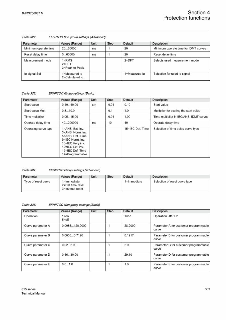
Table 322: EFLPTOC Non group settings (Advanced)
Parameter Values (Range) Unit Step Default DescriptionMinimum operate time 20...60000 ms 1 20 Minimum operate time for IDMT curves
Reset delay time 0...60000 ms 1 20 Reset delay time
Measurement mode 1=RMS2=DFT3=Peak-to-Peak
2=DFT Selects used measurement mode
Io signal Sel 1=Measured Io2=Calculated Io
1=Measured Io Selection for used Io signal
Table 323: EFHPTOC Group settings (Basic)
Parameter Values (Range) Unit Step Default DescriptionStart value 0.10...40.00 xIn 0.01 0.10 Start value
Start value Mult 0.8...10.0 0.1 1.0 Multiplier for scaling the start value
Time multiplier 0.05...15.00 0.01 1.00 Time multiplier in IEC/ANSI IDMT curves
Operate delay time 40...200000 ms 10 40 Operate delay time
Operating curve type 1=ANSI Ext. inv.3=ANSI Norm. inv.5=ANSI Def. Time9=IEC Norm. inv.10=IEC Very inv.12=IEC Ext. inv.15=IEC Def. Time17=Programmable
15=IEC Def. Time Selection of time delay curve type
Table 324: EFHPTOC Group settings (Advanced)
Parameter Values (Range) Unit Step Default DescriptionType of reset curve 1=Immediate
2=Def time reset3=Inverse reset
1=Immediate Selection of reset curve type
Table 325: EFHPTOC Non group settings (Basic)
Parameter Values (Range) Unit Step Default DescriptionOperation 1=on
5=off 1=on Operation Off / On
Curve parameter A 0.0086...120.0000 1 28.2000 Parameter A for customer programmablecurve
Curve parameter B 0.0000...0.7120 1 0.1217 Parameter B for customer programmablecurve
Curve parameter C 0.02...2.00 1 2.00 Parameter C for customer programmablecurve
Curve parameter D 0.46...30.00 1 29.10 Parameter D for customer programmablecurve
Curve parameter E 0.0...1.0 1 1.0 Parameter E for customer programmablecurve
1MRS756887 N Section 4Protection functions
615 series 309Technical Manual

Table 326: EFHPTOC Non group settings (Advanced)
Parameter Values (Range) Unit Step Default DescriptionMinimum operate time 20...60000 ms 1 20 Minimum operate time for IDMT curves
Reset delay time 0...60000 ms 1 20 Reset delay time
Measurement mode 1=RMS2=DFT3=Peak-to-Peak
2=DFT Selects used measurement mode
Io signal Sel 1=Measured Io2=Calculated Io
1=Measured Io Selection for used Io signal
Table 327: EFIPTOC Group settings (Basic)
Parameter Values (Range) Unit Step Default DescriptionStart value 1.00...40.00 xIn 0.01 1.00 Start value
Start value Mult 0.8...10.0 0.1 1.0 Multiplier for scaling the start value
Operate delay time 20...200000 ms 10 20 Operate delay time
Table 328: EFIPTOC Non group settings (Basic)
Parameter Values (Range) Unit Step Default DescriptionOperation 1=on
5=off 1=on Operation Off / On
Table 329: EFIPTOC Non group settings (Advanced)
Parameter Values (Range) Unit Step Default DescriptionReset delay time 0...60000 ms 1 20 Reset delay time
Io signal Sel 1=Measured Io2=Calculated Io
1=Measured Io Selection for used Io signal
4.2.1.10 Monitored data
Table 330: EFLPTOC Monitored data
Name Type Values (Range) Unit DescriptionSTART_DUR FLOAT32 0.00...100.00 % Ratio of start time /
operate time
EFLPTOC Enum 1=on2=blocked3=test4=test/blocked5=off
Status
Section 4 1MRS756887 NProtection functions
310 615 seriesTechnical Manual

Table 331: EFHPTOC Monitored data
Name Type Values (Range) Unit DescriptionSTART_DUR FLOAT32 0.00...100.00 % Ratio of start time /
operate time
EFHPTOC Enum 1=on2=blocked3=test4=test/blocked5=off
Status
Table 332: EFIPTOC Monitored data
Name Type Values (Range) Unit DescriptionSTART_DUR FLOAT32 0.00...100.00 % Ratio of start time /
operate time
EFIPTOC Enum 1=on2=blocked3=test4=test/blocked5=off
Status
4.2.1.11 Technical data
Table 333: EFxPTOC Technical data
Characteristic ValueOperation accuracy Depending on the frequency of the measured
current: fn ±2 Hz
EFLPTOC ±1.5% of the set value or ±0.002 × In
EFHPTOCandEFIPTOC
±1.5% of set value or ±0.002 × In(at currents in the range of 0.1…10 × In)±5.0% of the set value(at currents in the range of 10…40 × In)
Start time 1)2) Minimum Typical Maximum
EFIPTOC:IFault = 2 × set StartvalueIFault = 10 × set Startvalue
16 ms11 ms
19 ms12 ms
23 ms14 ms
EFHPTOC andEFLPTOC:IFault = 2 × set Startvalue
23 ms
26 ms
29 ms
Reset time Typically 40 ms
Reset ratio Typically 0.96
Retardation time <30 ms
Table continues on next page
1MRS756887 N Section 4Protection functions
615 series 311Technical Manual

Characteristic ValueOperate time accuracy in definite time mode ±1.0% of the set value or ±20 ms
Operate time accuracy in inverse time mode ±5.0% of the theoretical value or ±20 ms 3)
Suppression of harmonics RMS: No suppressionDFT: -50 dB at f = n × fn, where n = 2, 3, 4, 5,…Peak-to-Peak: No suppression
1) Measurement mode = default (depends on stage), current before fault = 0.0 × In, fn = 50 Hz, earth-faultcurrent with nominal frequency injected from random phase angle, results based on statisticaldistribution of 1000 measurements
2) Includes the delay of the signal output contact3) Maximum Start value = 2.5 × In, Start value multiples in range of 1.5...20
4.2.1.12 Technical revision history
Table 334: EFIPTOC Technical revision history
Technical revision ChangeB The minimum and default values changed to 40
ms for the Operate delay time setting
C Minimum and default values changed to 20 ms forthe Operate delay time settingMinimum value changed to 1.00 x In for the Startvalue setting
D Added a setting parameter for the "Measured Io"or "Calculated Io" selection
E Internal improvement
F Internal improvement
Table 335: EFHPTOC Technical revision history
Technical revision ChangeB Minimum and default values changed to 40 ms for
the Operate delay time setting
C Added a setting parameter for the "Measured Io"or "Calculated Io" selection
D Step value changed from 0.05 to 0.01 for the Timemultiplier setting
E Internal improvement
F Internal improvement
Table 336: EFLPTOC Technical revision history
Technical revision ChangeB The minimum and default values changed to 40
ms for the Operate delay time setting
C Start value step changed to 0.005
D Added a setting parameter for the "Measured Io"or "Calculated Io" selection
Table continues on next page
Section 4 1MRS756887 NProtection functions
312 615 seriesTechnical Manual
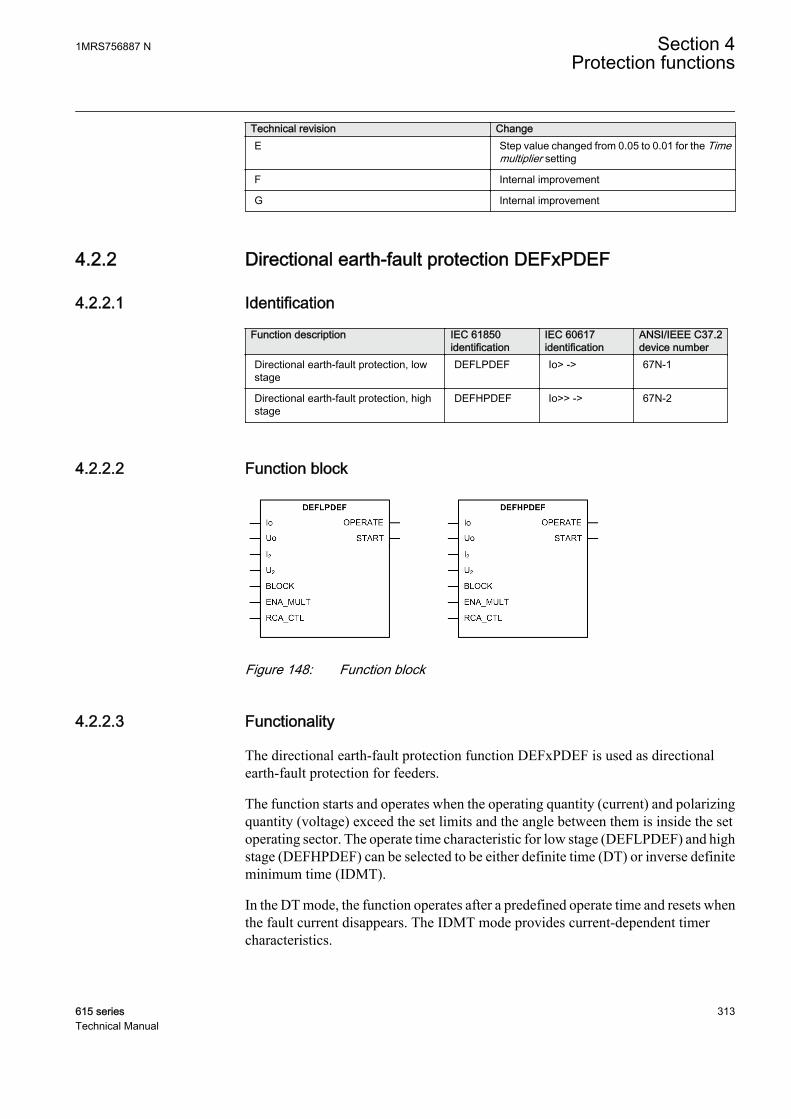
Technical revision ChangeE Step value changed from 0.05 to 0.01 for the Time
multiplier setting
F Internal improvement
G Internal improvement
4.2.2 Directional earth-fault protection DEFxPDEF
4.2.2.1 Identification
Function description IEC 61850identification
IEC 60617identification
ANSI/IEEE C37.2device number
Directional earth-fault protection, lowstage
DEFLPDEF Io> -> 67N-1
Directional earth-fault protection, highstage
DEFHPDEF Io>> -> 67N-2
4.2.2.2 Function block
A070433 V2 EN
Figure 148: Function block
4.2.2.3 Functionality
The directional earth-fault protection function DEFxPDEF is used as directionalearth-fault protection for feeders.
The function starts and operates when the operating quantity (current) and polarizingquantity (voltage) exceed the set limits and the angle between them is inside the setoperating sector. The operate time characteristic for low stage (DEFLPDEF) and highstage (DEFHPDEF) can be selected to be either definite time (DT) or inverse definiteminimum time (IDMT).
In the DT mode, the function operates after a predefined operate time and resets whenthe fault current disappears. The IDMT mode provides current-dependent timercharacteristics.
1MRS756887 N Section 4Protection functions
615 series 313Technical Manual
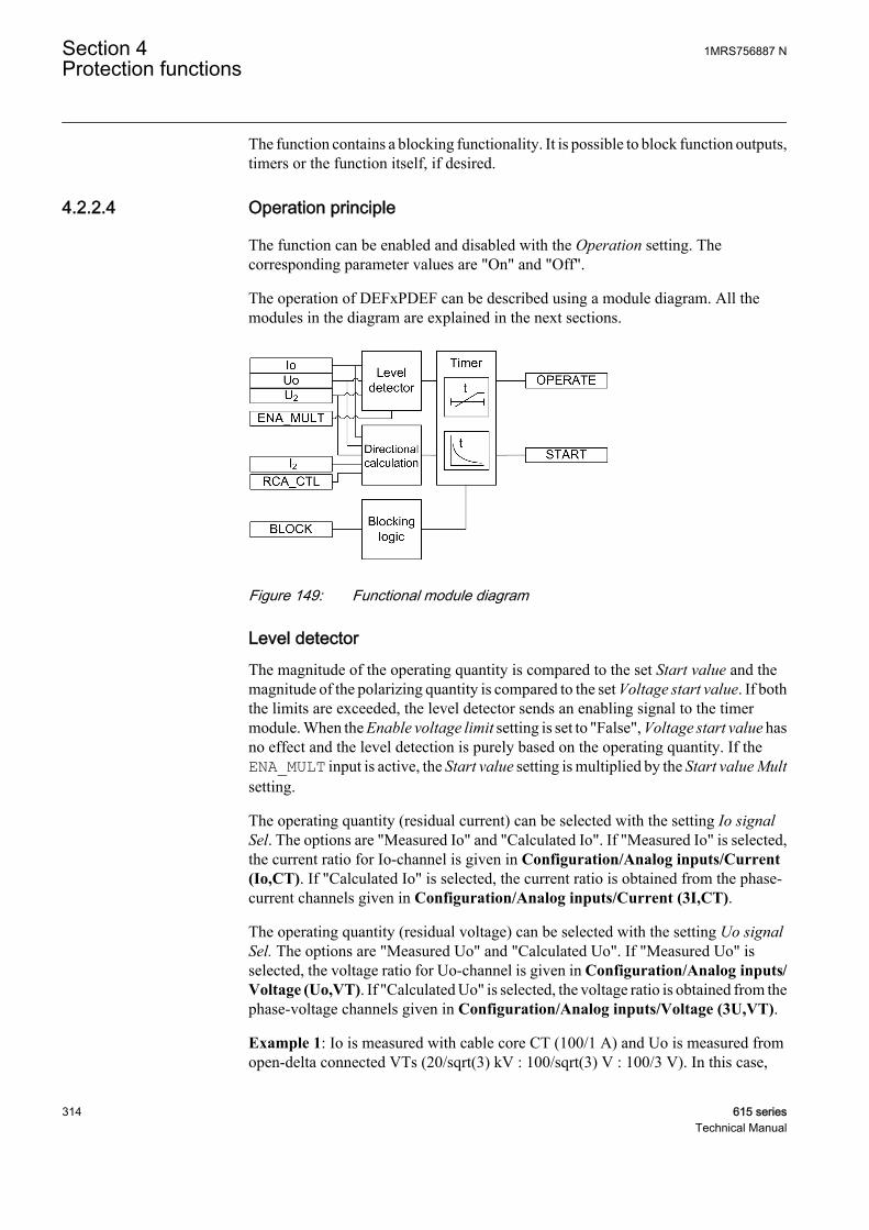
The function contains a blocking functionality. It is possible to block function outputs,timers or the function itself, if desired.
4.2.2.4 Operation principle
The function can be enabled and disabled with the Operation setting. Thecorresponding parameter values are "On" and "Off".
The operation of DEFxPDEF can be described using a module diagram. All themodules in the diagram are explained in the next sections.
A070438 V3 EN
Figure 149: Functional module diagram
Level detectorThe magnitude of the operating quantity is compared to the set Start value and themagnitude of the polarizing quantity is compared to the set Voltage start value. If boththe limits are exceeded, the level detector sends an enabling signal to the timermodule. When the Enable voltage limit setting is set to "False", Voltage start value hasno effect and the level detection is purely based on the operating quantity. If theENA_MULT input is active, the Start value setting is multiplied by the Start value Multsetting.
The operating quantity (residual current) can be selected with the setting Io signalSel. The options are "Measured Io" and "Calculated Io". If "Measured Io" is selected,the current ratio for Io-channel is given in Configuration/Analog inputs/Current(Io,CT). If "Calculated Io" is selected, the current ratio is obtained from the phase-current channels given in Configuration/Analog inputs/Current (3I,CT).
The operating quantity (residual voltage) can be selected with the setting Uo signalSel. The options are "Measured Uo" and "Calculated Uo". If "Measured Uo" isselected, the voltage ratio for Uo-channel is given in Configuration/Analog inputs/Voltage (Uo,VT). If "Calculated Uo" is selected, the voltage ratio is obtained from thephase-voltage channels given in Configuration/Analog inputs/Voltage (3U,VT).
Example 1: Io is measured with cable core CT (100/1 A) and Uo is measured fromopen-delta connected VTs (20/sqrt(3) kV : 100/sqrt(3) V : 100/3 V). In this case,
Section 4 1MRS756887 NProtection functions
314 615 seriesTechnical Manual
"Measured Io" and "Measured Uo" are selected. The nominal values for residualcurrent and residual voltage are obtained from CT and VT ratios entered in Residualcurrent Io: Configuration/Analog inputs/Current (Io,CT): 100 A : 1 A. TheResidual voltage Uo: Configuration/Analog inputs/Voltage (Uo,VT): 11.547 kV :100 V. The Start value of 1.0 × In corresponds to 1.0 * 100 A = 100 A in the primary.The Voltage start value of 1.0 × Un corresponds to 1.0 * 11.547 kV = 11.547 kV in theprimary.
Example 2: Both Io and Uo are calculated from the phase quantities. Phase CT-ratiois 100 : 1 A and phase VT-ratio is 20/sqrt(3) kV : 100/sqrt(3) V. In this case,"Calculated Io" and "Calculated Uo" are selected. The nominal values for residualcurrent and residual voltage are obtained from CT and VT ratios entered in Residualcurrent Io: Configuration/Analog inputs/Current (3I,CT): 100 A : 1 A. Theresidual voltage Uo: Configuration/Analog inputs/Voltage (3U,VT): 20.000 kV :100 V. The Start value of 1.0 × In corresponds to 1.0 * 100 A = 100 A in the primary.The Voltage start value of 1.0 × Un corresponds to 1.0 * 20.000 kV = 20.000 kV in theprimary.
If "Calculated Uo" is selected, the residual voltage nominal value isalways phase-to-phase voltage. Thus, the valid maximum setting forresidual Voltage start value is 0.577 x Un. The calculated Uo requiresthat all the three phase-to-earth voltages are connected to theprotection relay. Uo cannot be calculated from the phase-to-phasevoltages.
If the Enable voltage limit setting is set to "True", the magnitude of thepolarizing quantity is checked even if the Directional mode was set to"Non-directional" or Allow Non Dir to "True". The protection relaydoes not accept the Start value or Start value Mult setting if theproduct of these settings exceeds the Start value setting range.
Typically, the ENA_MULT input is connected to the inrush detection functionINRHPAR. In case of inrush, INRPHAR activates the ENA_MULT input, whichmultiplies Start value by the Start value Mult setting.
Directional calculationThe directional calculation module monitors the angle between the polarizingquantity and operating quantity. Depending on the Pol quantity setting, the polarizingquantity can be the residual voltage (measured or calculated) or the negative sequencevoltage. When the angle is in the operation sector, the module sends the enablingsignal to the timer module.
The minimum signal level which allows the directional operation can be set with theMin operate current and Min operate voltage settings.
If Pol quantity is set to "Zero. seq. volt", the residual current and residual voltage areused for directional calculation.
1MRS756887 N Section 4Protection functions
615 series 315Technical Manual

If Pol quantity is set to "Neg. seq. volt", the negative sequence current and negativesequence voltage are used for directional calculation.
In the phasor diagrams representing the operation of DEFxPDEF, the polarity of thepolarizing quantity (Uo or U2) is reversed, that is, the polarizing quantity in the phasordiagrams is either -Uo or -U2. Reversing is done by switching the polarity of theresidual current measuring channel (see the connection diagram in the applicationmanual). Similarly the polarity of the calculated Io and I2 is also switched.
For defining the operation sector, there are five modes available through theOperation mode setting.
Table 337: Operation modes
Operation mode DescriptionPhase angle The operating sectors for forward and reverse are
defined with the settings Min forward angle, Maxforward angle, Min reverse angle and Max reverseangle.
IoSin The operating sectors are defined as "forward"when |Io| x sin (ANGLE) has a positive value and"reverse" when the value is negative. ANGLE isthe angle difference between -Uo and Io.
IoCos As "IoSin" mode. Only cosine is used forcalculating the operation current.
Phase angle 80 The sector maximum values are frozen to 80degrees respectively. Only Min forward angle andMin reverse angle are settable.
Phase angle 88 The sector maximum values are frozen to 88degrees. Otherwise as "Phase angle 80" mode.
Polarizing quantity selection "Neg. seq. volt." is available only in the"Phase angle" operation mode.
The directional operation can be selected with the Directional mode setting. Thealternatives are "Non-directional", "Forward" and "Reverse" operation. The operationcriterion is selected with the Operation mode setting. By setting Allow Non Dir to"True", non-directional operation is allowed when the directional information isinvalid, that is, when the magnitude of the polarizing quantity is less than the value ofthe Min operate voltage setting.
Typically, the network rotating direction is counter-clockwise and defined as "ABC".If the network rotating direction is reversed, meaning clockwise, that is, "ACB", theequation for calculating the negative sequence voltage component need to be changed.The network rotating direction is defined with a system parameter Phase rotation. Thecalculation of the component is affected but the angle difference calculation remainsthe same. When the residual voltage is used as the polarizing method, the networkrotating direction change has no effect on the direction calculation.
Section 4 1MRS756887 NProtection functions
316 615 seriesTechnical Manual
The network rotating direction is set in the protection relay using theparameter in the HMI menu: Configuration/System/Phase rotation.The default parameter value is "ABC".
If the Enable voltage limit setting is set to "True", the magnitude of thepolarizing quantity is checked even if Directional mode is set to "Non-directional" or Allow Non Dir to "True".
The Characteristic angle setting is used in the "Phase angle" mode to adjust theoperation according to the method of neutral point earthing so that in an isolatednetwork the Characteristic angle (φRCA) = -90° and in a compensated network φRCA= 0°. In addition, the characteristic angle can be changed via the control signalRCA_CTL. RCA_CTL affects the Characteristic angle setting.
The Correction angle setting can be used to improve selectivity due the inaccuraciesin the measurement transformers. The setting decreases the operation sector. Thecorrection can only be used with the "IoCos" or "IoSin" modes.
The polarity of the polarizing quantity can be reversed by setting the Pol reversal to"True", which turns the polarizing quantity by 180 degrees.
For definitions of different directional earth-fault characteristics, seethe Directional earth-fault characteristics section in this manual.
For definitions of different directional earth-fault characteristics,refer to general function block features information.
The directional calculation module calculates several values which are presented inthe monitored data.
1MRS756887 N Section 4Protection functions
615 series 317Technical Manual
Table 338: Monitored data values
Monitored data values DescriptionFAULT_DIR The detected direction of fault during fault
situations, that is, when START output is active.
DIRECTION The momentary operating direction indicationoutput.
ANGLE Also called operating angle, shows the angledifference between the polarizing quantity (Uo,U2) and operating quantity (Io, I2).
ANGLE_RCA The angle difference between the operating angleand Characteristic angle, that is, ANGLE_RCA =ANGLE – Characteristic angle.
I_OPER The current that is used for fault detection. If theOperation mode setting is "Phase angle", "Phaseangle 80" or "Phase angle 88", I_OPER is themeasured or calculated residual current. If theOperation mode setting is "IoSin", I_OPER iscalculated as follows I_OPER = Io x sin(ANGLE).If the Operation mode setting is "IoCos", I_OPERis calculated as follows I_OPER = Io xcos(ANGLE).
Monitored data values are accessible on the LHMI or through tools viacommunications.
TimerOnce activated, the timer activates the START output. Depending on the value of theOperating curve type setting, the time characteristics are according to DT or IDMT.When the operation timer has reached the value of Operate delay time in the DT modeor the maximum value defined by the inverse time curve, the OPERATE output isactivated.
When the user-programmable IDMT curve is selected, the operation timecharacteristics are defined by the parameters Curve parameter A, Curve parameter B,Curve parameter C, Curve parameter D and Curve parameter E.
If a drop-off situation happens, that is, a fault suddenly disappears before the operatedelay is exceeded, the timer reset state is activated. The functionality of the timer inthe reset state depends on the combination of the Operating curve type, Type of resetcurve and Reset delay time settings. When the DT characteristic is selected, the resettimer runs until the set Reset delay time value is exceeded. When the IDMT curves areselected, the Type of reset curve setting can be set to "Immediate", "Def time reset" or"Inverse reset". The reset curve type "Immediate" causes an immediate reset. With thereset curve type "Def time reset", the reset time depends on the Reset delay timesetting. With the reset curve type "Inverse reset", the reset time depends on the currentduring the drop-off situation. The START output is deactivated when the reset timerhas elapsed.
The "Inverse reset" selection is only supported with ANSI or userprogrammable types of the IDMT operating curves. If another
Section 4 1MRS756887 NProtection functions
318 615 seriesTechnical Manual
operating curve type is selected, an immediate reset occurs during thedrop-off situation.
The setting Time multiplier is used for scaling the IDMT operate and reset times.
The setting parameter Minimum operate time defines the minimum desired operatetime for IDMT. The setting is applicable only when the IDMT curves are used.
The Minimum operate time setting should be used with great carebecause the operation time is according to the IDMT curve, but alwaysat least the value of the Minimum operate time setting. For moreinformation, see the IDMT curves for overcurrent protection sectionin this manual.
The timer calculates the start duration value START_DUR, which indicates thepercentage ratio of the start situation and the set operating time. The value is availablein the monitored data view.
Blocking logicThere are three operation modes in the blocking function. The operation modes arecontrolled by the BLOCK input and the global setting in Configuration/System/Blocking mode which selects the blocking mode. The BLOCK input can be controlledby a binary input, a horizontal communication input or an internal signal of theprotection relay's program. The influence of the BLOCK signal activation ispreselected with the global setting Blocking mode
.The Blocking mode setting has three blocking methods. In the "Freeze timers" mode,the operation timer is frozen to the prevailing value, but the OPERATE output is notdeactivated when blocking is activated. In the "Block all" mode, the whole function isblocked and the timers are reset. In the "Block OPERATE output" mode, the functionoperates normally but the OPERATE output is not activated.
4.2.2.5 Directional earth-fault principles
In many cases it is difficult to achieve selective earth-fault protection based on themagnitude of residual current only. To obtain a selective earth-fault protectionscheme, it is necessary to take the phase angle of Io into account. This is done bycomparing the phase angle of the operating and polarizing quantity.
Relay characteristic angleThe Characteristic angle setting, also known as Relay Characteristic Angle (RCA),Relay Base Angle or Maximum Torque Angle (MTA), is used in the "Phase angle"mode to turn the directional characteristic if the expected fault current angle does notcoincide with the polarizing quantity to produce the maximum torque. That is, RCA isthe angle between the maximum torque line and polarizing quantity. If the polarizingquantity is in phase with the maximum torque line, RCA is 0 degrees. The angle is
1MRS756887 N Section 4Protection functions
615 series 319Technical Manual

positive if the operating current lags the polarizing quantity and negative if it leads thepolarizing quantity.
Example 1
The "Phase angle" mode is selected, compensated network (φRCA = 0 deg)
=> Characteristic angle = 0 deg
GUID-829C6CEB-19F0-4730-AC98-C5528C35A297 V2 EN
Figure 150: Definition of the relay characteristic angle, RCA=0 degrees in acompensated network
Example 2
The "Phase angle" mode is selected, solidly earthed network (φRCA = +60 deg)
=> Characteristic angle = +60 deg
Section 4 1MRS756887 NProtection functions
320 615 seriesTechnical Manual

GUID-D72D678C-9C87-4830-BB85-FE00F5EA39C2 V2 EN
Figure 151: Definition of the relay characteristic angle, RCA=+60 degrees in asolidly earthed network
Example 3
The "Phase angle" mode is selected, isolated network (φRCA = -90 deg)
=> Characteristic angle = -90 deg
1MRS756887 N Section 4Protection functions
615 series 321Technical Manual

GUID-67BE307E-576A-44A9-B615-2A3B184A410D V2 EN
Figure 152: Definition of the relay characteristic angle, RCA=–90 degrees in anisolated network
Directional earth-fault protection in an isolated neutral networkIn isolated networks, there is no intentional connection between the system neutralpoint and earth. The only connection is through the phase-to-earth capacitances (C0)of phases and leakage resistances (R0). This means that the residual current is mainlycapacitive and has a phase shift of -90 degrees compared to the polarizing voltage.Consequently, the relay characteristic angle (RCA) should be set to -90 degrees andthe operation criteria to "IoSin" or "Phase angle". The width of the operating sector inthe phase angle criteria can be selected with the settings Min forward angle, Maxforward angle, Min reverse angle or Max reverse angle. Figure 153 illustrates asimplified equivalent circuit for an unearthed network with an earth fault in phase C.
For definitions of different directional earth-fault characteristics, seeDirectional earth-fault principles.
Section 4 1MRS756887 NProtection functions
322 615 seriesTechnical Manual
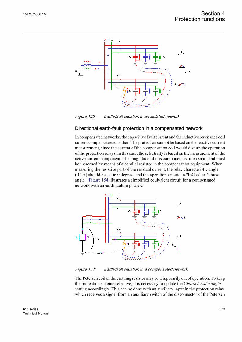
A070441 V1 EN
Figure 153: Earth-fault situation in an isolated network
Directional earth-fault protection in a compensated networkIn compensated networks, the capacitive fault current and the inductive resonance coilcurrent compensate each other. The protection cannot be based on the reactive currentmeasurement, since the current of the compensation coil would disturb the operationof the protection relays. In this case, the selectivity is based on the measurement of theactive current component. The magnitude of this component is often small and mustbe increased by means of a parallel resistor in the compensation equipment. Whenmeasuring the resistive part of the residual current, the relay characteristic angle(RCA) should be set to 0 degrees and the operation criteria to "IoCos" or "Phaseangle". Figure 154 illustrates a simplified equivalent circuit for a compensatednetwork with an earth fault in phase C.
A070444 V2 EN
Figure 154: Earth-fault situation in a compensated network
The Petersen coil or the earthing resistor may be temporarily out of operation. To keepthe protection scheme selective, it is necessary to update the Characteristic anglesetting accordingly. This can be done with an auxiliary input in the protection relaywhich receives a signal from an auxiliary switch of the disconnector of the Petersen
1MRS756887 N Section 4Protection functions
615 series 323Technical Manual
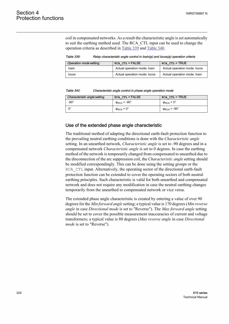
coil in compensated networks. As a result the characteristic angle is set automaticallyto suit the earthing method used. The RCA_CTL input can be used to change theoperation criteria as described in Table 339 and Table 340.
Table 339: Relay characteristic angle control in Iosin(φ) and Iocos(φ) operation criteria
Operation mode setting: RCA_CTL = FALSE RCA_CTL = TRUEIosin Actual operation mode: Iosin Actual operation mode: Iocos
Iocos Actual operation mode: Iocos Actual operation mode: Iosin
Table 340: Characteristic angle control in phase angle operation mode
Characteristic angle setting RCA_CTL = FALSE RCA_CTL = TRUE-90° φRCA = -90° φRCA = 0°
0° φRCA = 0° φRCA = -90°
Use of the extended phase angle characteristicThe traditional method of adapting the directional earth-fault protection function tothe prevailing neutral earthing conditions is done with the Characteristic anglesetting. In an unearthed network, Characteristic angle is set to -90 degrees and in acompensated network Characteristic angle is set to 0 degrees. In case the earthingmethod of the network is temporarily changed from compensated to unearthed due tothe disconnection of the arc suppression coil, the Characteristic angle setting shouldbe modified correspondingly. This can be done using the setting groups or theRCA_CTL input. Alternatively, the operating sector of the directional earth-faultprotection function can be extended to cover the operating sectors of both neutralearthing principles. Such characteristic is valid for both unearthed and compensatednetwork and does not require any modification in case the neutral earthing changestemporarily from the unearthed to compensated network or vice versa.
The extended phase angle characteristic is created by entering a value of over 90degrees for the Min forward angle setting; a typical value is 170 degrees (Min reverseangle in case Directional mode is set to "Reverse"). The Max forward angle settingshould be set to cover the possible measurement inaccuracies of current and voltagetransformers; a typical value is 80 degrees (Max reverse angle in case Directionalmode is set to "Reverse").
Section 4 1MRS756887 NProtection functions
324 615 seriesTechnical Manual
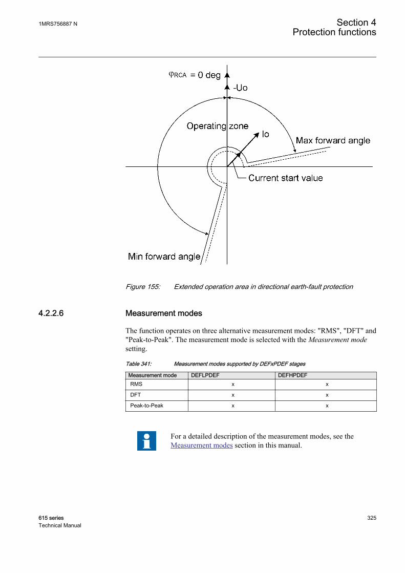
A070443 V3 EN
Figure 155: Extended operation area in directional earth-fault protection
4.2.2.6 Measurement modes
The function operates on three alternative measurement modes: "RMS", "DFT" and"Peak-to-Peak". The measurement mode is selected with the Measurement modesetting.
Table 341: Measurement modes supported by DEFxPDEF stages
Measurement mode DEFLPDEF DEFHPDEFRMS x x
DFT x x
Peak-to-Peak x x
For a detailed description of the measurement modes, see theMeasurement modes section in this manual.
1MRS756887 N Section 4Protection functions
615 series 325Technical Manual
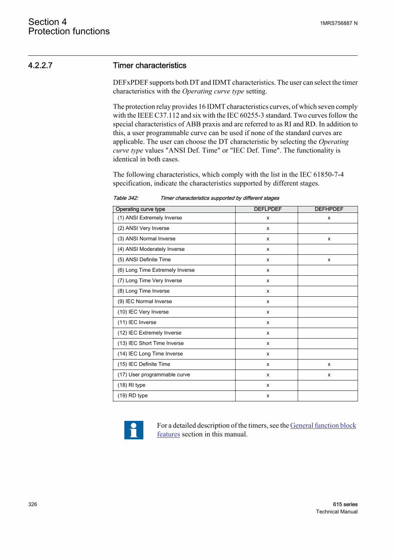
4.2.2.7 Timer characteristics
DEFxPDEF supports both DT and IDMT characteristics. The user can select the timercharacteristics with the Operating curve type setting.
The protection relay provides 16 IDMT characteristics curves, of which seven complywith the IEEE C37.112 and six with the IEC 60255-3 standard. Two curves follow thespecial characteristics of ABB praxis and are referred to as RI and RD. In addition tothis, a user programmable curve can be used if none of the standard curves areapplicable. The user can choose the DT characteristic by selecting the Operatingcurve type values "ANSI Def. Time" or "IEC Def. Time". The functionality isidentical in both cases.
The following characteristics, which comply with the list in the IEC 61850-7-4specification, indicate the characteristics supported by different stages.
Table 342: Timer characteristics supported by different stages
Operating curve type DEFLPDEF DEFHPDEF(1) ANSI Extremely Inverse x x
(2) ANSI Very Inverse x
(3) ANSI Normal Inverse x x
(4) ANSI Moderately Inverse x
(5) ANSI Definite Time x x
(6) Long Time Extremely Inverse x
(7) Long Time Very Inverse x
(8) Long Time Inverse x
(9) IEC Normal Inverse x
(10) IEC Very Inverse x
(11) IEC Inverse x
(12) IEC Extremely Inverse x
(13) IEC Short Time Inverse x
(14) IEC Long Time Inverse x
(15) IEC Definite Time x x
(17) User programmable curve x x
(18) RI type x
(19) RD type x
For a detailed description of the timers, see the General function blockfeatures section in this manual.
Section 4 1MRS756887 NProtection functions
326 615 seriesTechnical Manual

Table 343: Reset time characteristics supported by different stages
Reset curve type DEFLPDEF DEFHPDEF Note(1) Immediate x x Available for all operate time curves
(2) Def time reset x x Available for all operate time curves
(3) Inverse reset x x Available only for ANSI and userprogrammable curves
4.2.2.8 Directional earth-fault characteristics
Phase angle characteristicThe operation criterion phase angle is selected with the Operation mode setting usingthe value "Phase angle".
When the phase angle criterion is used, the function indicates with the DIRECTIONoutput whether the operating quantity is within the forward or reverse operation sectoror within the non-directional sector.
The forward and reverse sectors are defined separately. The forward operation area islimited with the Min forward angle and Max forward angle settings. The reverseoperation area is limited with the Min reverse angle and Max reverse angle settings.
The sector limits are always given as positive degree values.
In the forward operation area, the Max forward angle setting gives the clockwisesector and the Min forward angle setting correspondingly the counterclockwisesector, measured from the Characteristic angle setting.
In the reverse operation area, the Max reverse angle setting gives the clockwise sectorand the Min reverse angle setting correspondingly the counterclockwise sector,measured from the complement of the Characteristic angle setting (180 degrees phaseshift) .
The relay characteristic angle (RCA) is set to positive if the operating current lags thepolarizing quantity. It is set to negative if it leads the polarizing quantity.
1MRS756887 N Section 4Protection functions
615 series 327Technical Manual

GUID-92004AD5-05AA-4306-9574-9ED8D51524B4 V2 EN
Figure 156: Configurable operating sectors in phase angle characteristic
Table 344: Momentary operating direction
Fault direction The value for DIRECTIONAngle between the polarizing and operatingquantity is not in any of the defined sectors.
0 = unknown
Angle between the polarizing and operatingquantity is in the forward sector.
1= forward
Angle between the polarizing and operatingquantity is in the reverse sector.
2 = backward
Angle between the polarizing and operatingquantity is in both the forward and the reversesectors, that is, the sectors are overlapping.
3 = both
If the Allow Non Dir setting is "False", the directional operation (forward, reverse) isnot allowed when the measured polarizing or operating quantities are invalid, that is,their magnitude is below the set minimum values. The minimum values can be definedwith the settings Min operate current and Min operate voltage. In case of lowmagnitudes, the FAULT_DIR and DIRECTION outputs are set to 0 = unknown,except when the Allow non dir setting is "True". In that case, the function is allowed
Section 4 1MRS756887 NProtection functions
328 615 seriesTechnical Manual
to operate in the directional mode as non-directional, since the directional informationis invalid.
Iosin(φ) and Iocos(φ) criteriaA more modern approach to directional protection is the active or reactive currentmeasurement. The operating characteristic of the directional operation depends on theearthing principle of the network. The Iosin(φ) characteristics is used in an isolatednetwork, measuring the reactive component of the fault current caused by the earthcapacitance. The Iocos(φ) characteristics is used in a compensated network,measuring the active component of the fault current.
The operation criteria Iosin(φ) and Iocos(φ) are selected with the Operation modesetting using the values "IoSin" or "IoCos" respectively.
The angle correction setting can be used to improve selectivity. The setting decreasesthe operation sector. The correction can only be used with the Iosin(φ) or Iocos(φ)criterion. The RCA_CTL input is used to change the Io characteristic:
Table 345: Relay characteristic angle control in the IoSin and IoCos operation criteria
Operation mode: RCA_CTL = "False" RCA_CTL = "True"IoSin Actual operation criterion:
Iosin(φ)Actual operation criterion:Iocos(φ)
IoCos Actual operation criterion:Iocos(φ)
Actual operation criterion:Iosin(φ)
When the Iosin(φ) or Iocos(φ) criterion is used, the component indicates a forward- orreverse-type fault through the FAULT_DIR and DIRECTION outputs, in which 1equals a forward fault and 2 equals a reverse fault. Directional operation is not allowed(the Allow non dir setting is "False") when the measured polarizing or operatingquantities are not valid, that is, when their magnitude is below the set minimumvalues. The minimum values can be defined with the Min operate current and Minoperate voltage settings. In case of low magnitude, the FAULT_DIR andDIRECTION outputs are set to 0 = unknown, except when the Allow non dir settingis "True". In that case, the function is allowed to operate in the directional mode asnon-directional, since the directional information is invalid.
The calculated Iosin(φ) or Iocos(φ) current used in direction determination can be readthrough the I_OPER monitored data. The value can be passed directly to a decisiveelement, which provides the final start and operate signals.
The I_OPER monitored data gives an absolute value of the calculatedcurrent.
The following examples show the characteristics of the different operation criteria:
Example 1.
1MRS756887 N Section 4Protection functions
615 series 329Technical Manual

Iosin(φ) criterion selected, forward-type fault
=> FAULT_DIR = 1
GUID-560EFC3C-34BF-4852-BF8C-E3A2A7750275 V2 EN
Figure 157: Operating characteristic Iosin(φ) in forward fault
The operating sector is limited by angle correction, that is, the operating sector is 180degrees - 2*(angle correction).
Example 2.
Iosin(φ) criterion selected, reverse-type fault
=> FAULT_DIR = 2
Section 4 1MRS756887 NProtection functions
330 615 seriesTechnical Manual
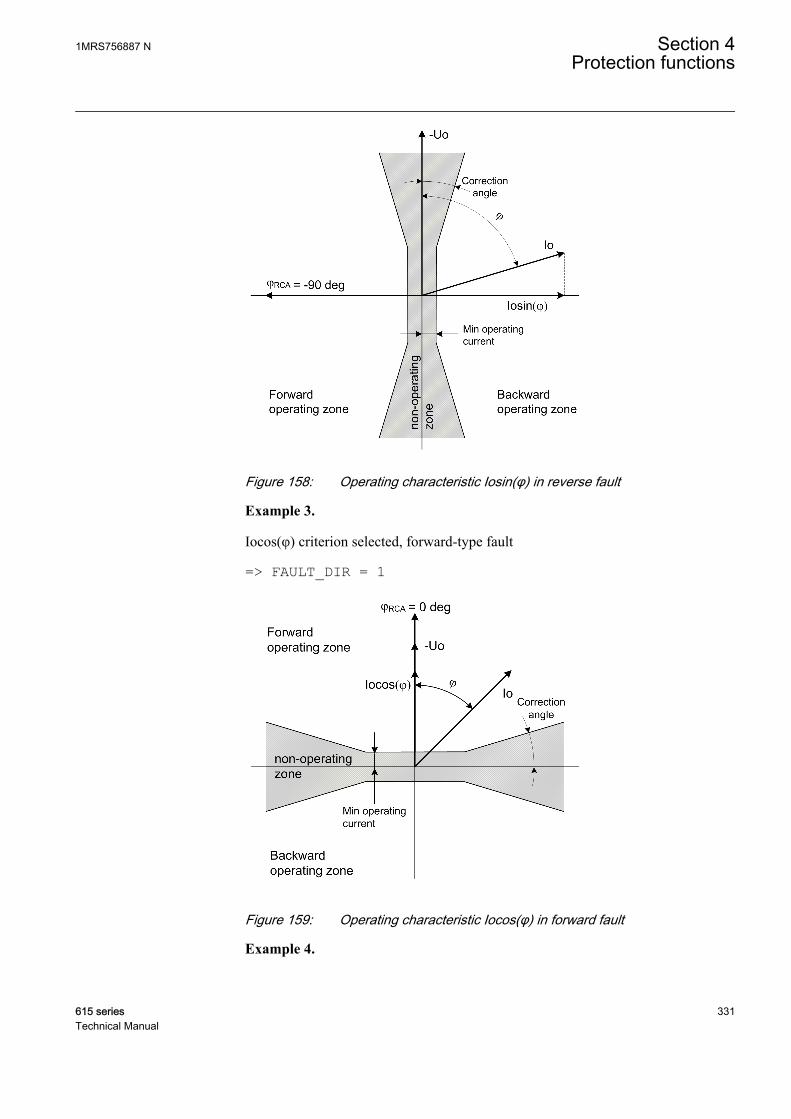
GUID-10A890BE-8C81-45B2-9299-77DD764171E1 V2 EN
Figure 158: Operating characteristic Iosin(φ) in reverse fault
Example 3.
Iocos(φ) criterion selected, forward-type fault
=> FAULT_DIR = 1
GUID-11E40C1F-6245-4532-9199-2E2F1D9B45E4 V2 EN
Figure 159: Operating characteristic Iocos(φ) in forward fault
Example 4.
1MRS756887 N Section 4Protection functions
615 series 331Technical Manual
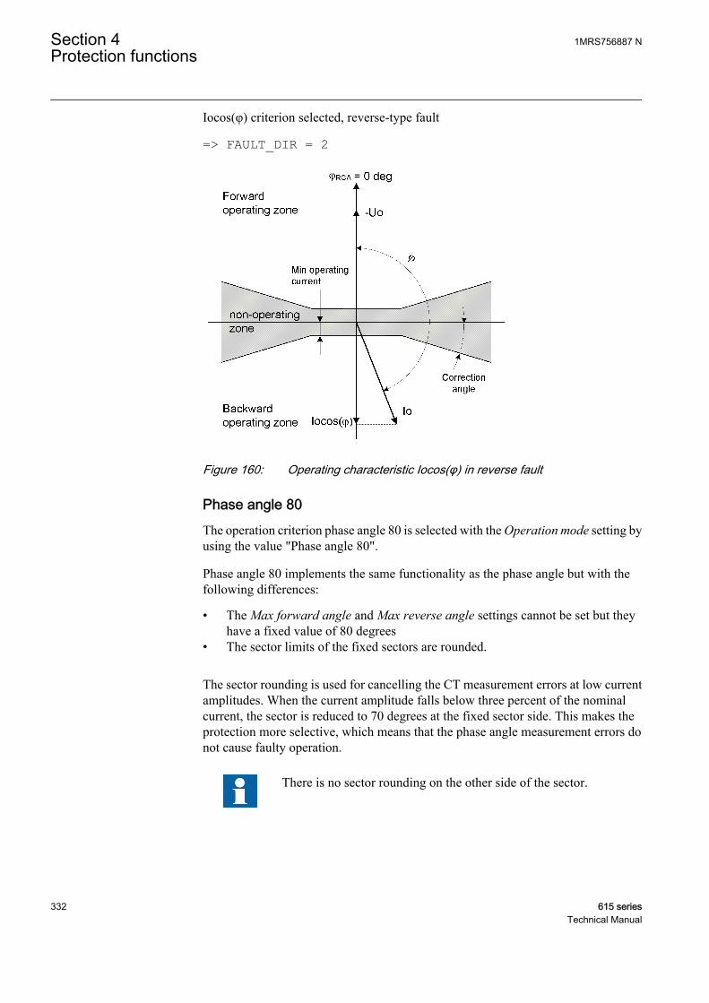
Iocos(φ) criterion selected, reverse-type fault
=> FAULT_DIR = 2
GUID-54ACB854-F11D-4AF2-8BDB-69E5F6C13EF1 V2 EN
Figure 160: Operating characteristic Iocos(φ) in reverse fault
Phase angle 80The operation criterion phase angle 80 is selected with the Operation mode setting byusing the value "Phase angle 80".
Phase angle 80 implements the same functionality as the phase angle but with thefollowing differences:
• The Max forward angle and Max reverse angle settings cannot be set but theyhave a fixed value of 80 degrees
• The sector limits of the fixed sectors are rounded.
The sector rounding is used for cancelling the CT measurement errors at low currentamplitudes. When the current amplitude falls below three percent of the nominalcurrent, the sector is reduced to 70 degrees at the fixed sector side. This makes theprotection more selective, which means that the phase angle measurement errors donot cause faulty operation.
There is no sector rounding on the other side of the sector.
Section 4 1MRS756887 NProtection functions
332 615 seriesTechnical Manual

GUID-EFC9438D-9169-4733-9BE9-6B343F37001A V2 EN
Figure 161: Operating characteristic for phase angle 80
2
3
4
6
7
8
9
10
Io / % of In
0 90453015 7560-90 -45 -30 -15-75 -60
Min forward angle
1
80 deg
70 deg
Operating zone
Non-operating
zone
3% of In
1% of In
GUID-49D23ADF-4DA0-4F7A-8020-757F32928E60 V2 EN
Figure 162: Phase angle 80 amplitude (Directional mode = Forward)
Phase angle 88The operation criterion phase angle 88 is selected with the Operation mode settingusing the value "Phase angle 88".
1MRS756887 N Section 4Protection functions
615 series 333Technical Manual
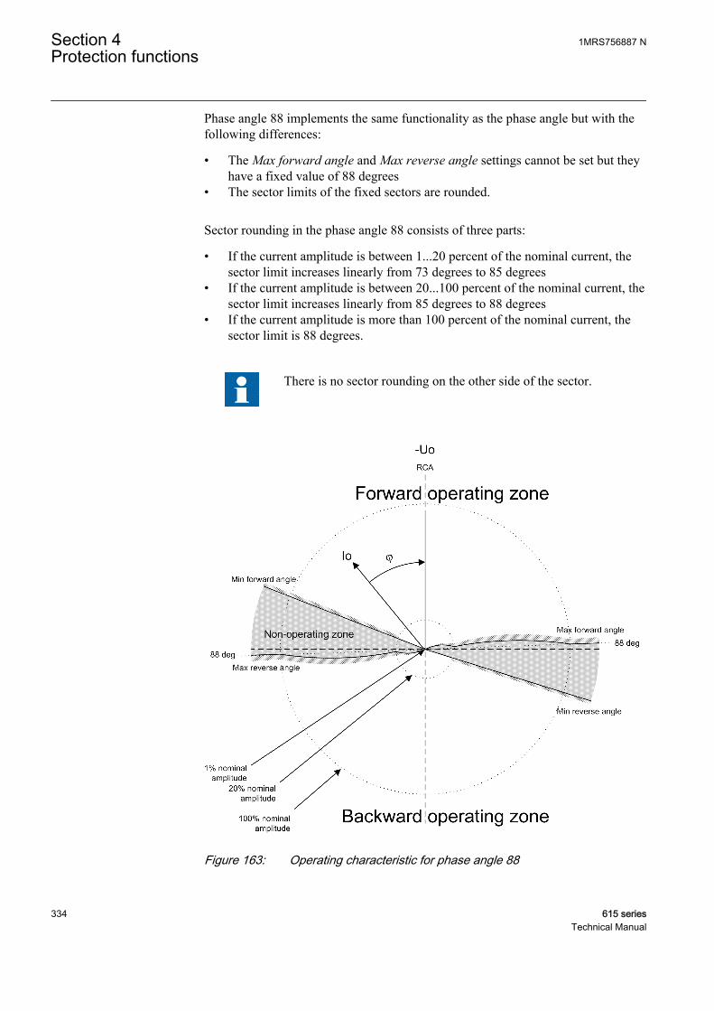
Phase angle 88 implements the same functionality as the phase angle but with thefollowing differences:
• The Max forward angle and Max reverse angle settings cannot be set but theyhave a fixed value of 88 degrees
• The sector limits of the fixed sectors are rounded.
Sector rounding in the phase angle 88 consists of three parts:
• If the current amplitude is between 1...20 percent of the nominal current, thesector limit increases linearly from 73 degrees to 85 degrees
• If the current amplitude is between 20...100 percent of the nominal current, thesector limit increases linearly from 85 degrees to 88 degrees
• If the current amplitude is more than 100 percent of the nominal current, thesector limit is 88 degrees.
There is no sector rounding on the other side of the sector.
GUID-0F0560B7-943E-4CED-A4B8-A561BAE08956 V2 EN
Figure 163: Operating characteristic for phase angle 88
Section 4 1MRS756887 NProtection functions
334 615 seriesTechnical Manual

20
30
40
50
70
80
90
100
Io / % of In
0 90453015 7560-90 -45 -30 -15-75 -60
Min forward angle
10
88 deg
85 deg
73 deg
100% of In
20% of In
1% of In
GUID-F9F1619D-E1B5-4650-A5CB-B62A7F6B0A90 V2 EN
Figure 164: Phase angle 88 amplitude (Directional mode = Forward)
4.2.2.9 Application
The directional earth-fault protection DEFxPDEF is designed for protection andclearance of earth faults and for earth-fault protection of different equipmentconnected to the power systems, such as shunt capacitor banks or shunt reactors, andfor backup earth-fault protection of power transformers.
Many applications require several steps using different current start levels and timedelays. DEFxPDEF consists of two different stages.
• Low DEFLPDEF• High DEFHPDEF
DEFLPDEF contains several types of time delay characteristics. DEFHPDEF is usedfor fast clearance of serious earth faults.
The protection can be based on the phase angle criterion with extended operatingsector. It can also be based on measuring either the reactive part Iosin(φ) or the activepart Iocos(φ) of the residual current. In isolated networks or in networks with highimpedance earthing, the phase-to-earth fault current is significantly smaller than theshort-circuit currents. In addition, the magnitude of the fault current is almostindependent of the fault location in the network.
The function uses the residual current components Iocos(φ) or Iosin(φ) according tothe earthing method, where φ is the angle between the residual current and thereference residual voltage (-Uo). In compensated networks, the phase angle criterionwith extended operating sector can also be used. When the relay characteristic angleRCA is 0 degrees, the negative quadrant of the operation sector can be extended withthe Min forward angle setting. The operation sector can be set between 0 and -180degrees, so that the total operation sector is from +90 to -180 degrees. In other words,the sector can be up to 270 degrees wide. This allows the protection settings to stay the
1MRS756887 N Section 4Protection functions
615 series 335Technical Manual
same when the resonance coil is disconnected from between the neutral point andearth.
System neutral earthing is meant to protect personnel and equipment and to reduceinterference for example in telecommunication systems. The neutral earthing setschallenges for protection systems, especially for earth-fault protection.
In isolated networks, there is no intentional connection between the system neutralpoint and earth. The only connection is through the line-to-earth capacitances (C0) ofphases and leakage resistances (R0). This means that the residual current is mainlycapacitive and has -90 degrees phase shift compared to the residual voltage (-Uo). Thecharacteristic angle is -90 degrees.
In resonance-earthed networks, the capacitive fault current and the inductiveresonance coil current compensate each other. The protection cannot be based on thereactive current measurement, since the current of the compensation coil woulddisturb the operation of the relays. In this case, the selectivity is based on themeasurement of the active current component. This means that the residual current ismainly resistive and has zero phase shift compared to the residual voltage (-Uo) andthe characteristic angle is 0 degrees. Often the magnitude of this component is small,and must be increased by means of a parallel resistor in the compensation equipment.
In networks where the neutral point is earthed through low resistance, thecharacteristic angle is also 0 degrees (for phase angle). Alternatively, Iocos(φ)operation can be used.
In solidly earthed networks, the Characteristic angle is typically set to +60 degrees forthe phase angle. Alternatively, Iosin(φ) operation can be used with a reversalpolarizing quantity. The polarizing quantity can be rotated 180 degrees by setting thePol reversal parameter to "True" or by switching the polarity of the residual voltagemeasurement wires. Although the Iosin(φ) operation can be used in solidly earthednetworks, the phase angle is recommended.
Connection of measuring transformers in directional earth faultapplicationsThe residual current Io can be measured with a core balance current transformer or theresidual connection of the phase current signals. If the neutral of the network is eitherisolated or earthed with high impedance, a core balance current transformer isrecommended to be used in earth-fault protection. To ensure sufficient accuracy ofresidual current measurements and consequently the selectivity of the scheme, thecore balance current transformers should have a transformation ratio of at least 70:1.Lower transformation ratios such as 50:1 or 50:5 are not recommended.
Attention should be paid to make sure the measuring transformers are connectedcorrectly so that DEFxPDEF is able to detect the fault current direction withoutfailure. As directional earth fault uses residual current and residual voltage (-Uo), thepoles of the measuring transformers must match each other and also the fault currentdirection. Also the earthing of the cable sheath must be taken into notice when using
Section 4 1MRS756887 NProtection functions
336 615 seriesTechnical Manual

core balance current transformers. The following figure describes how measuringtransformers can be connected to the protection relay.
A070697 V2 EN
Figure 165: Connection of measuring transformers
4.2.2.10 Signals
Table 346: DEFLPDEF Input signals
Name Type Default DescriptionIo SIGNAL 0 Residual current
Uo SIGNAL 0 Residual voltage
BLOCK BOOLEAN 0=False Block signal for activating the blocking mode
ENA_MULT BOOLEAN 0=False Enable signal for current multiplier
RCA_CTL BOOLEAN 0=False Relay characteristic angle control
Table 347: DEFHPDEF Input signals
Name Type Default DescriptionIo SIGNAL 0 Residual current
Uo SIGNAL 0 Residual voltage
BLOCK BOOLEAN 0=False Block signal for activating the blocking mode
ENA_MULT BOOLEAN 0=False Enable signal for current multiplier
RCA_CTL BOOLEAN 0=False Relay characteristic angle control
1MRS756887 N Section 4Protection functions
615 series 337Technical Manual

Table 348: DEFLPDEF Output signals
Name Type DescriptionOPERATE BOOLEAN Operate
START BOOLEAN Start
Table 349: DEFHPDEF Output signals
Name Type DescriptionOPERATE BOOLEAN Operate
START BOOLEAN Start
4.2.2.11 Settings
Table 350: DEFLPDEF Group settings (Basic)
Parameter Values (Range) Unit Step Default DescriptionStart value 0.010...5.000 xIn 0.005 0.010 Start value
Start value Mult 0.8...10.0 0.1 1.0 Multiplier for scaling the start value
Directional mode 1=Non-directional2=Forward3=Reverse
2=Forward Directional mode
Time multiplier 0.05...15.00 0.01 1.00 Time multiplier in IEC/ANSI IDMT curves
Operating curve type 1=ANSI Ext. inv.2=ANSI Very inv.3=ANSI Norm. inv.4=ANSI Mod. inv.5=ANSI Def. Time6=L.T.E. inv.7=L.T.V. inv.8=L.T. inv.9=IEC Norm. inv.10=IEC Very inv.11=IEC inv.12=IEC Ext. inv.13=IEC S.T. inv.14=IEC L.T. inv.15=IEC Def. Time17=Programmable18=RI type19=RD type
15=IEC Def. Time Selection of time delay curve type
Operate delay time 50...200000 ms 10 50 Operate delay time
Characteristic angle -179...180 deg 1 -90 Characteristic angle
Max forward angle 0...180 deg 1 80 Maximum phase angle in forwarddirection
Max reverse angle 0...180 deg 1 80 Maximum phase angle in reversedirection
Min forward angle 0...180 deg 1 80 Minimum phase angle in forward direction
Min reverse angle 0...180 deg 1 80 Minimum phase angle in reverse direction
Voltage start value 0.010...1.000 xUn 0.001 0.010 Voltage start value
Section 4 1MRS756887 NProtection functions
338 615 seriesTechnical Manual
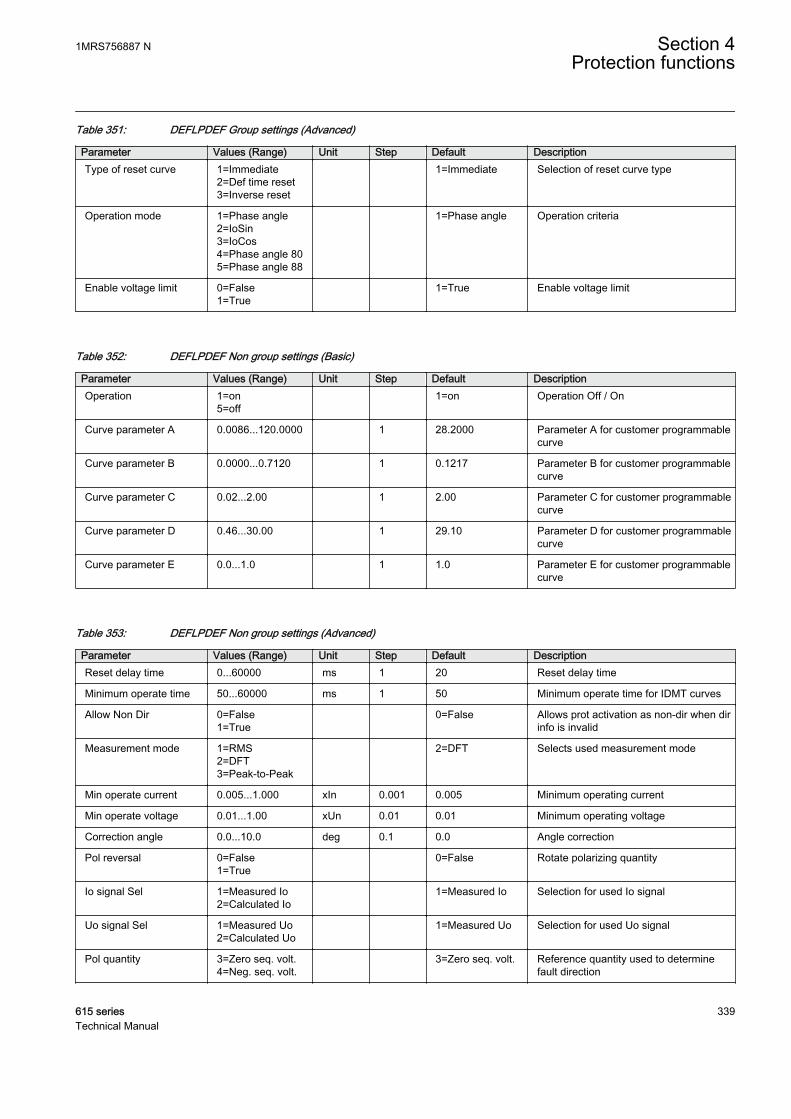
Table 351: DEFLPDEF Group settings (Advanced)
Parameter Values (Range) Unit Step Default DescriptionType of reset curve 1=Immediate
2=Def time reset3=Inverse reset
1=Immediate Selection of reset curve type
Operation mode 1=Phase angle2=IoSin3=IoCos4=Phase angle 805=Phase angle 88
1=Phase angle Operation criteria
Enable voltage limit 0=False1=True
1=True Enable voltage limit
Table 352: DEFLPDEF Non group settings (Basic)
Parameter Values (Range) Unit Step Default DescriptionOperation 1=on
5=off 1=on Operation Off / On
Curve parameter A 0.0086...120.0000 1 28.2000 Parameter A for customer programmablecurve
Curve parameter B 0.0000...0.7120 1 0.1217 Parameter B for customer programmablecurve
Curve parameter C 0.02...2.00 1 2.00 Parameter C for customer programmablecurve
Curve parameter D 0.46...30.00 1 29.10 Parameter D for customer programmablecurve
Curve parameter E 0.0...1.0 1 1.0 Parameter E for customer programmablecurve
Table 353: DEFLPDEF Non group settings (Advanced)
Parameter Values (Range) Unit Step Default DescriptionReset delay time 0...60000 ms 1 20 Reset delay time
Minimum operate time 50...60000 ms 1 50 Minimum operate time for IDMT curves
Allow Non Dir 0=False1=True
0=False Allows prot activation as non-dir when dirinfo is invalid
Measurement mode 1=RMS2=DFT3=Peak-to-Peak
2=DFT Selects used measurement mode
Min operate current 0.005...1.000 xIn 0.001 0.005 Minimum operating current
Min operate voltage 0.01...1.00 xUn 0.01 0.01 Minimum operating voltage
Correction angle 0.0...10.0 deg 0.1 0.0 Angle correction
Pol reversal 0=False1=True
0=False Rotate polarizing quantity
Io signal Sel 1=Measured Io2=Calculated Io
1=Measured Io Selection for used Io signal
Uo signal Sel 1=Measured Uo2=Calculated Uo
1=Measured Uo Selection for used Uo signal
Pol quantity 3=Zero seq. volt.4=Neg. seq. volt.
3=Zero seq. volt. Reference quantity used to determinefault direction
1MRS756887 N Section 4Protection functions
615 series 339Technical Manual

Table 354: DEFHPDEF Group settings (Basic)
Parameter Values (Range) Unit Step Default DescriptionStart value 0.10...40.00 xIn 0.01 0.10 Start value
Start value Mult 0.8...10.0 0.1 1.0 Multiplier for scaling the start value
Directional mode 1=Non-directional2=Forward3=Reverse
2=Forward Directional mode
Time multiplier 0.05...15.00 0.01 1.00 Time multiplier in IEC/ANSI IDMT curves
Operating curve type 1=ANSI Ext. inv.3=ANSI Norm. inv.5=ANSI Def. Time15=IEC Def. Time17=Programmable
15=IEC Def. Time Selection of time delay curve type
Operate delay time 40...200000 ms 10 40 Operate delay time
Characteristic angle -179...180 deg 1 -90 Characteristic angle
Max forward angle 0...180 deg 1 80 Maximum phase angle in forwarddirection
Max reverse angle 0...180 deg 1 80 Maximum phase angle in reversedirection
Min forward angle 0...180 deg 1 80 Minimum phase angle in forward direction
Min reverse angle 0...180 deg 1 80 Minimum phase angle in reverse direction
Voltage start value 0.010...1.000 xUn 0.001 0.010 Voltage start value
Table 355: DEFHPDEF Group settings (Advanced)
Parameter Values (Range) Unit Step Default DescriptionType of reset curve 1=Immediate
2=Def time reset3=Inverse reset
1=Immediate Selection of reset curve type
Operation mode 1=Phase angle2=IoSin3=IoCos4=Phase angle 805=Phase angle 88
1=Phase angle Operation criteria
Enable voltage limit 0=False1=True
1=True Enable voltage limit
Table 356: DEFHPDEF Non group settings (Basic)
Parameter Values (Range) Unit Step Default DescriptionOperation 1=on
5=off 1=on Operation Off / On
Curve parameter A 0.0086...120.0000 1 28.2000 Parameter A for customer programmablecurve
Curve parameter B 0.0000...0.7120 1 0.1217 Parameter B for customer programmablecurve
Table continues on next page
Section 4 1MRS756887 NProtection functions
340 615 seriesTechnical Manual
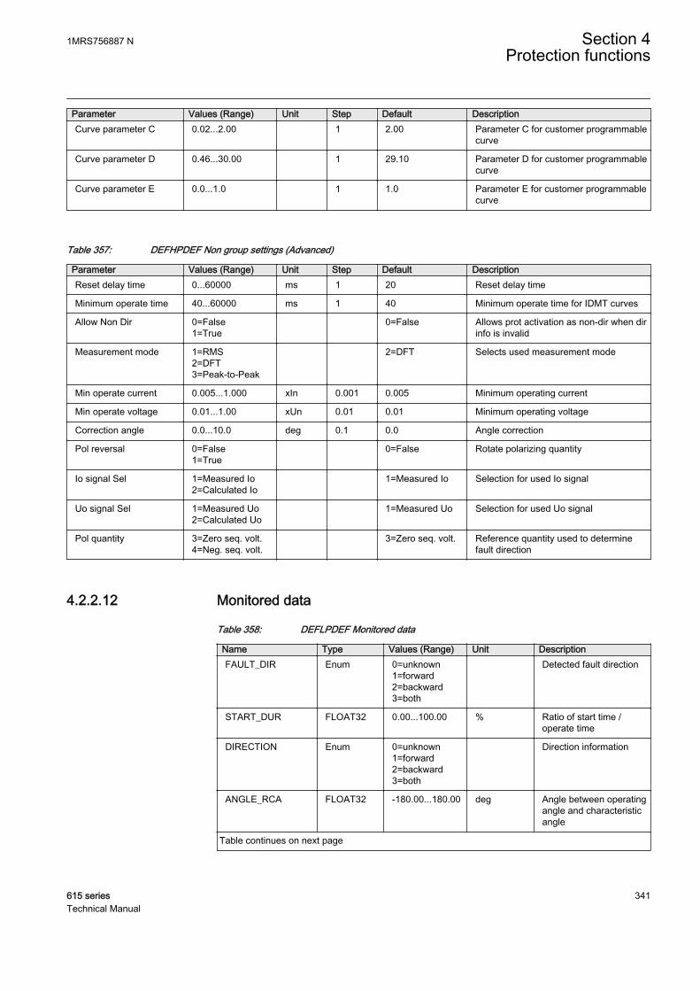
Parameter Values (Range) Unit Step Default DescriptionCurve parameter C 0.02...2.00 1 2.00 Parameter C for customer programmable
curve
Curve parameter D 0.46...30.00 1 29.10 Parameter D for customer programmablecurve
Curve parameter E 0.0...1.0 1 1.0 Parameter E for customer programmablecurve
Table 357: DEFHPDEF Non group settings (Advanced)
Parameter Values (Range) Unit Step Default DescriptionReset delay time 0...60000 ms 1 20 Reset delay time
Minimum operate time 40...60000 ms 1 40 Minimum operate time for IDMT curves
Allow Non Dir 0=False1=True
0=False Allows prot activation as non-dir when dirinfo is invalid
Measurement mode 1=RMS2=DFT3=Peak-to-Peak
2=DFT Selects used measurement mode
Min operate current 0.005...1.000 xIn 0.001 0.005 Minimum operating current
Min operate voltage 0.01...1.00 xUn 0.01 0.01 Minimum operating voltage
Correction angle 0.0...10.0 deg 0.1 0.0 Angle correction
Pol reversal 0=False1=True
0=False Rotate polarizing quantity
Io signal Sel 1=Measured Io2=Calculated Io
1=Measured Io Selection for used Io signal
Uo signal Sel 1=Measured Uo2=Calculated Uo
1=Measured Uo Selection for used Uo signal
Pol quantity 3=Zero seq. volt.4=Neg. seq. volt.
3=Zero seq. volt. Reference quantity used to determinefault direction
4.2.2.12 Monitored data
Table 358: DEFLPDEF Monitored data
Name Type Values (Range) Unit DescriptionFAULT_DIR Enum 0=unknown
1=forward2=backward3=both
Detected fault direction
START_DUR FLOAT32 0.00...100.00 % Ratio of start time /operate time
DIRECTION Enum 0=unknown1=forward2=backward3=both
Direction information
ANGLE_RCA FLOAT32 -180.00...180.00 deg Angle between operatingangle and characteristicangle
Table continues on next page
1MRS756887 N Section 4Protection functions
615 series 341Technical Manual
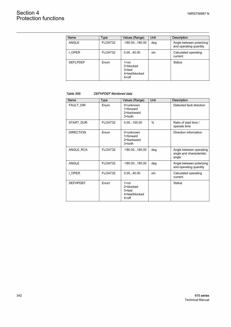
Name Type Values (Range) Unit DescriptionANGLE FLOAT32 -180.00...180.00 deg Angle between polarizing
and operating quantity
I_OPER FLOAT32 0.00...40.00 xIn Calculated operatingcurrent
DEFLPDEF Enum 1=on2=blocked3=test4=test/blocked5=off
Status
Table 359: DEFHPDEF Monitored data
Name Type Values (Range) Unit DescriptionFAULT_DIR Enum 0=unknown
1=forward2=backward3=both
Detected fault direction
START_DUR FLOAT32 0.00...100.00 % Ratio of start time /operate time
DIRECTION Enum 0=unknown1=forward2=backward3=both
Direction information
ANGLE_RCA FLOAT32 -180.00...180.00 deg Angle between operatingangle and characteristicangle
ANGLE FLOAT32 -180.00...180.00 deg Angle between polarizingand operating quantity
I_OPER FLOAT32 0.00...40.00 xIn Calculated operatingcurrent
DEFHPDEF Enum 1=on2=blocked3=test4=test/blocked5=off
Status
Section 4 1MRS756887 NProtection functions
342 615 seriesTechnical Manual
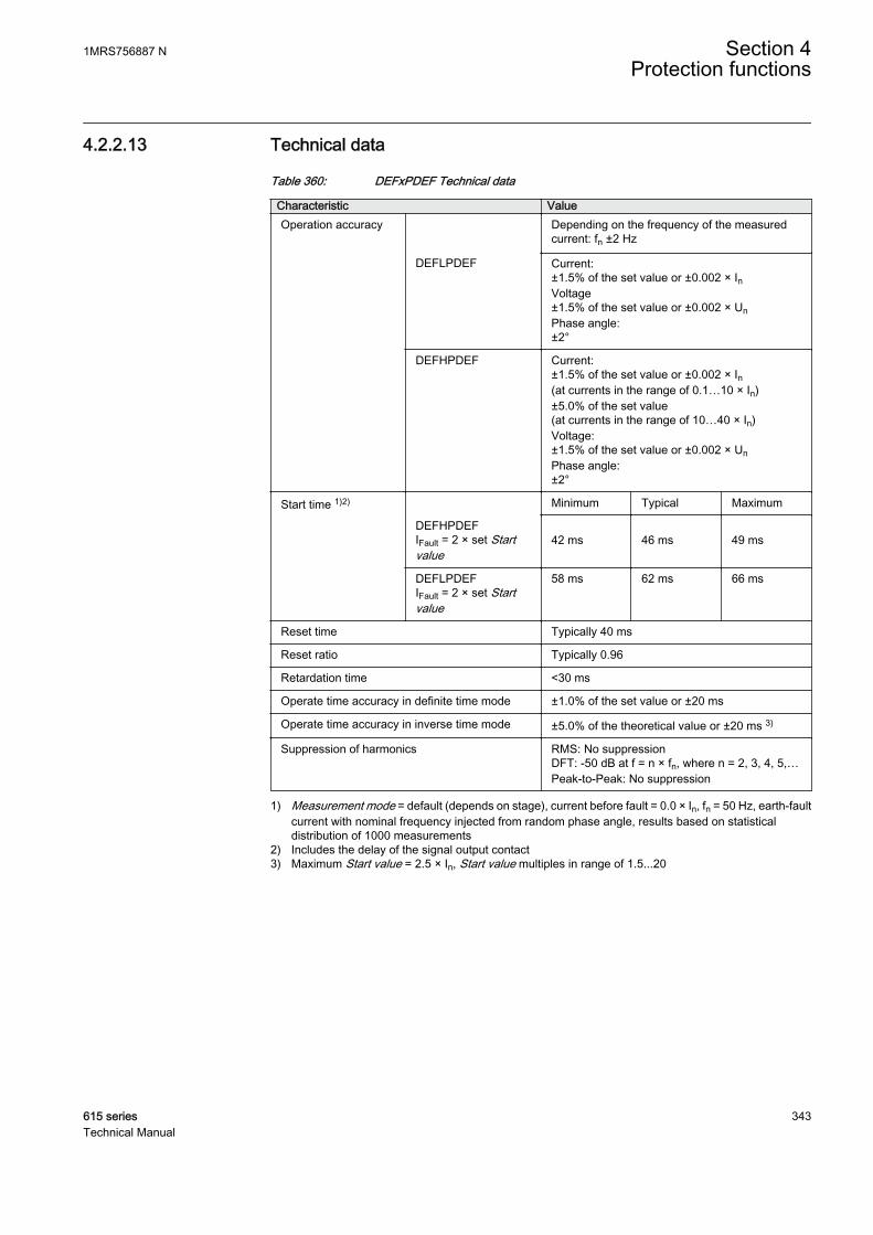
4.2.2.13 Technical data
Table 360: DEFxPDEF Technical data
Characteristic ValueOperation accuracy Depending on the frequency of the measured
current: fn ±2 Hz
DEFLPDEF Current:±1.5% of the set value or ±0.002 × InVoltage±1.5% of the set value or ±0.002 × UnPhase angle:±2°
DEFHPDEF Current:±1.5% of the set value or ±0.002 × In(at currents in the range of 0.1…10 × In)±5.0% of the set value(at currents in the range of 10…40 × In)Voltage:±1.5% of the set value or ±0.002 × UnPhase angle:±2°
Start time 1)2) Minimum Typical Maximum
DEFHPDEFIFault = 2 × set Startvalue
42 ms
46 ms
49 ms
DEFLPDEFIFault = 2 × set Startvalue
58 ms 62 ms 66 ms
Reset time Typically 40 ms
Reset ratio Typically 0.96
Retardation time <30 ms
Operate time accuracy in definite time mode ±1.0% of the set value or ±20 ms
Operate time accuracy in inverse time mode ±5.0% of the theoretical value or ±20 ms 3)
Suppression of harmonics RMS: No suppressionDFT: -50 dB at f = n × fn, where n = 2, 3, 4, 5,…Peak-to-Peak: No suppression
1) Measurement mode = default (depends on stage), current before fault = 0.0 × In, fn = 50 Hz, earth-faultcurrent with nominal frequency injected from random phase angle, results based on statisticaldistribution of 1000 measurements
2) Includes the delay of the signal output contact3) Maximum Start value = 2.5 × In, Start value multiples in range of 1.5...20
1MRS756887 N Section 4Protection functions
615 series 343Technical Manual

4.2.2.14 Technical revision history
Table 361: DEFHPDEF Technical revision history
Technical revision ChangeB Maximum value changed to 180 deg for the Max
forward angle setting
C Added a setting parameter for the "Measured Io"or "Calculated Io" selection and setting parameterfor the "Measured Uo", "Calculated Uo" or "Neg.seq. volt." selection for polarization. Operate delaytime and Minimum operate time changed from 60ms to 40 ms. The sector default setting values arechanged from 88 degrees to 80 degrees.
D Step value changed from 0.05 to 0.01 for the Timemultiplier setting.
E Unit added to calculated operating current output(I_OPER).
F Added setting Pol quantity.
Table 362: DEFLPDEF Technical revision history
Technical revision ChangeB Maximum value changed to 180 deg for the Max
forward angle setting.Start value step changed to 0.005
C Added a setting parameter for the "Measured Io"or "Calculated Io" selection and setting parameterfor the "Measured Uo", "Calculated Uo" or "Neg.seq. volt." selection for polarization. The sectordefault setting values are changed from 88degrees to 80 degrees.
D Step value changed from 0.05 to 0.01 for the Timemultiplier setting.
E Unit added to calculated operating current output(I_OPER).
F Added setting Pol quantity. Minimum value forOperate delay time and Minimum operate timechanged from “60 ms” to “50 ms”. Default value forOperate delay time and Minimum operate timechanged from “60 ms” to “50 ms”.
4.2.3 Transient/intermittent earth-fault protection INTRPTEF
4.2.3.1 Identification
Function description IEC 61850identification
IEC 60617identification
ANSI/IEEE C37.2device number
Transient/intermittent earth-faultprotection
INTRPTEF Io> -> IEF 67NIEF
Section 4 1MRS756887 NProtection functions
344 615 seriesTechnical Manual
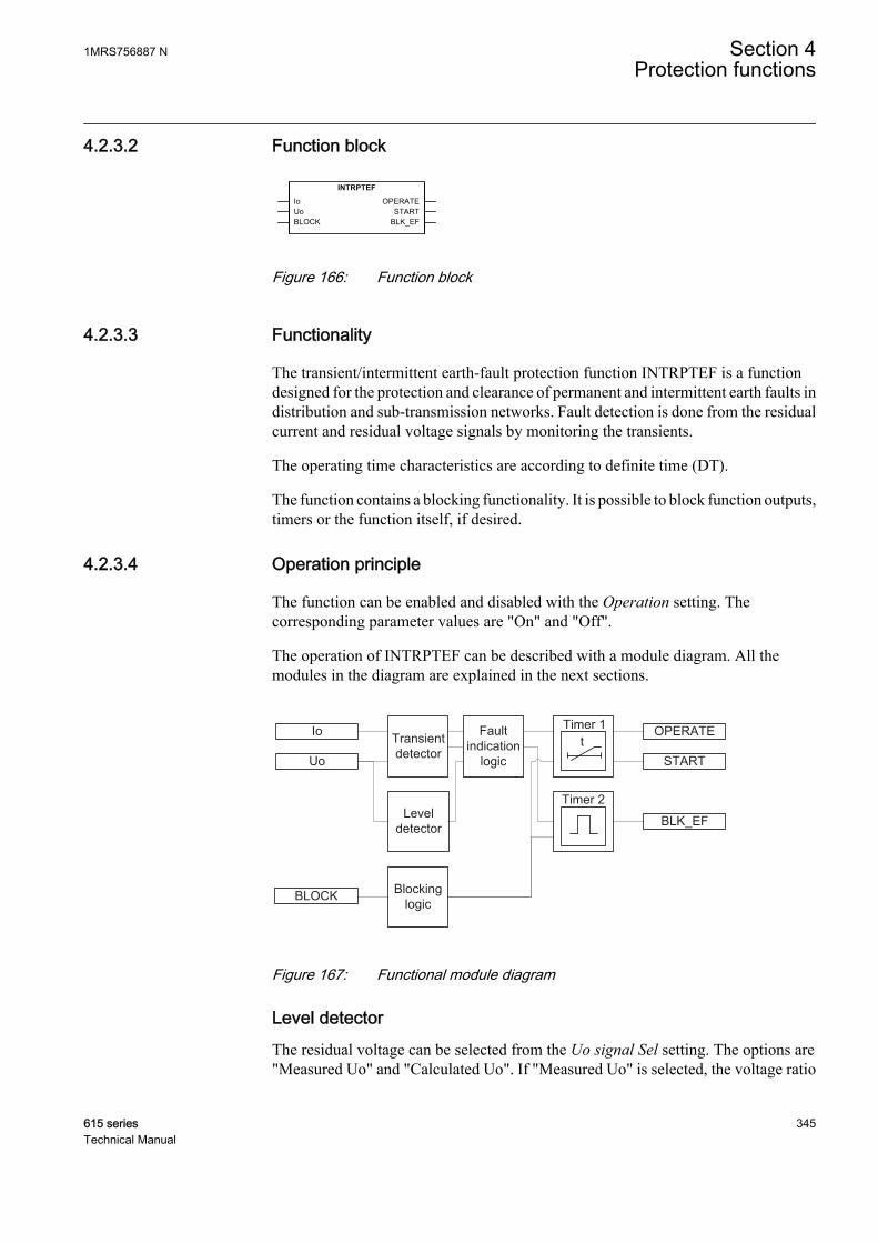
4.2.3.2 Function block
A070663 V2 EN
Figure 166: Function block
4.2.3.3 Functionality
The transient/intermittent earth-fault protection function INTRPTEF is a functiondesigned for the protection and clearance of permanent and intermittent earth faults indistribution and sub-transmission networks. Fault detection is done from the residualcurrent and residual voltage signals by monitoring the transients.
The operating time characteristics are according to definite time (DT).
The function contains a blocking functionality. It is possible to block function outputs,timers or the function itself, if desired.
4.2.3.4 Operation principle
The function can be enabled and disabled with the Operation setting. Thecorresponding parameter values are "On" and "Off".
The operation of INTRPTEF can be described with a module diagram. All themodules in the diagram are explained in the next sections.
BLK_EF
OPERATEIo
Uo
BLOCK
START
Timer 2
tTimer 1
Transient detector
Faultindication
logic
Leveldetector
Blockinglogic
A070661 V4 EN
Figure 167: Functional module diagram
Level detectorThe residual voltage can be selected from the Uo signal Sel setting. The options are"Measured Uo" and "Calculated Uo". If "Measured Uo" is selected, the voltage ratio
1MRS756887 N Section 4Protection functions
615 series 345Technical Manual

for Uo-channel is given in the global setting Configuration/Analog inputs/Voltage(Uo,VT). If "Calculated Uo" is selected, the voltage ratio is obtained from phase-voltage channels given in the global setting Configuration/Analog inputs/Voltage(3U,VT).
Example 1: Uo is measured from open-delta connected VTs (20/sqrt(3) kV : 100/sqrt(3) V : 100/3 V). In this case, "Measured Uo" is selected. The nominal values forresidual voltage is obtained from VT ratios entered in Residual voltage Uo:Configuration/Analog inputs/Voltage (Uo,VT): 11.547 kV :100 V. The residualvoltage start value of 1.0 × Un corresponds to 1.0 × 11.547 kV = 11.547 kV in theprimary.
Example 2: Uo is calculated from phase quantities. The phase VT-ratio is 20/sqrt(3)kV : 100/sqrt(3) V. In this case, "Calculated Uo" is selected. The nominal values forresidual current and residual voltage are obtained from VT ratios entered in Residualvoltage Uo: Configuration/Analog inputs/Voltage (3U,VT): 20.000 kV : 100 V.The residual voltage start value of 1.0 × Un corresponds to 1.0 × 20.000 kV = 20.000kV in the primary.
If "Calculated Uo" is selected, the residual voltage nominal value isalways phase-to-phase voltage. Thus, the valid maximum setting forresidual voltage start value is 0.577 × Un. Calculated Uo requires thatall three phase-to-earth voltages are connected to the protection relay.Uo cannot be calculated from the phase-to-phase voltages.
Transient detectorThe Transient detector module is used for detecting transients in the residual currentand residual voltage signals.
The transient detection is supervised with a settable current threshold. With a specialfiltering technique, the setting Min operate current is based on the fundamentalfrequency current. This setting should be set based on the value of the parallel resistorof the coil, with security margin. For example, if the resistive current of the parallelresistor is 10 A, then a value of 0.7×10 A = 7 A could be used. The same setting is alsoapplicable in case the coil is disconnected and the network becomes unearthed.Generally, a smaller value should be used and it must never exceed the value of theparallel resistor in order to allow operation of the faulted feeder.
Fault indication logicDepending on the set Operation mode, INTRPTEF has two independent modes fordetecting earth faults. The "Transient EF" mode is intended to detect all kinds of earthfaults. The "Intermittent EF" mode is dedicated for detecting intermittent earth faultsin cable networks.
Section 4 1MRS756887 NProtection functions
346 615 seriesTechnical Manual
To satisfy the sensitivity requirements, basic earth-fault protection(based on fundamental frequency phasors) should always be used inparallel with the INTRPTEF function.
The Fault indication logic module determines the direction of the fault. The faultdirection determination is secured by multi-frequency neutral admittancemeasurement and special filtering techniques. This enables fault directiondetermination which is not sensitive to disturbances in measured Io and Uo signals, forexample, switching transients.
When Directional mode setting "Forward" is used, the protection operates when thefault is in the protected feeder. When Directional mode setting "Reverse" is used, theprotection operates when the fault is outside the protected feeder (in the backgroundnetwork). If the direction has no importance, the value "Non-directional" can beselected. The detected fault direction (FAULT_DIR) is available in the monitoreddata view.
In the "Transient EF" mode, when the start transient of the fault is detected and the Uolevel exceeds the set "Voltage start value", Timer 1 is activated. Timer 1 is keptactivated until the Uo level exceeds the set value or in case of a drop-off, the drop-offduration is shorter than the set Reset delay time.
In the "Intermittent EF" mode, when the start transient of the fault is detected and theUo level exceeds the set Voltage start value, the Timer 1 is activated. When a requirednumber of intermittent earth-fault transients set with the Peak counter limit setting aredetected without the function being reset (depends on the drop-off time set with theReset delay time setting), the START output is activated. The Timer 1 is kept activatedas long as transients are occurring during the drop-off time defined by setting Resetdelay time.
Timer 1The time characteristic is according to DT.
In the "Transient EF" mode, the OPERATE output is activated after Operate delay timeif the residual voltage exceeds the set "Voltage start value". The Reset delay time startsto elapse when residual voltage falls below Voltage start value. If there is noOPERATE activation, for example, the fault disappears momentarily, START staysactivated until the the Reset delay time elapses. After OPERATE activation, STARTand OPERATE signals are reset as soon as Uo falls below Voltage start value.
1MRS756887 N Section 4Protection functions
615 series 347Technical Manual

GUID-BE2849D3-015B-4A05-85EF-FD7E8EF29CA3 V1 EN
Figure 168: Example of INTRPTEF operation in ”Transient EF” mode in the faultyfeeder
In the "Intermittent EF" mode the OPERATE output is activated when the followingconditions are fulfilled:
• the number of transients that have been detected exceeds the Peak counter limitsetting
• the timer has reached the time set with the Operate delay time• and one additional transient is detected during the drop-off cycle
The Reset delay time starts to elapse from each detected transient (peak). In case thereis no OPERATE activation, for example, the fault disappears momentarily STARTstays activated until the Reset delay time elapses, that is, reset takes place if timebetween transients is more than Reset delay time. After OPERATE activation, a fixedpulse length of 100 ms for OPERATE is given, whereas START is reset after Resetdelay time elapses
Section 4 1MRS756887 NProtection functions
348 615 seriesTechnical Manual
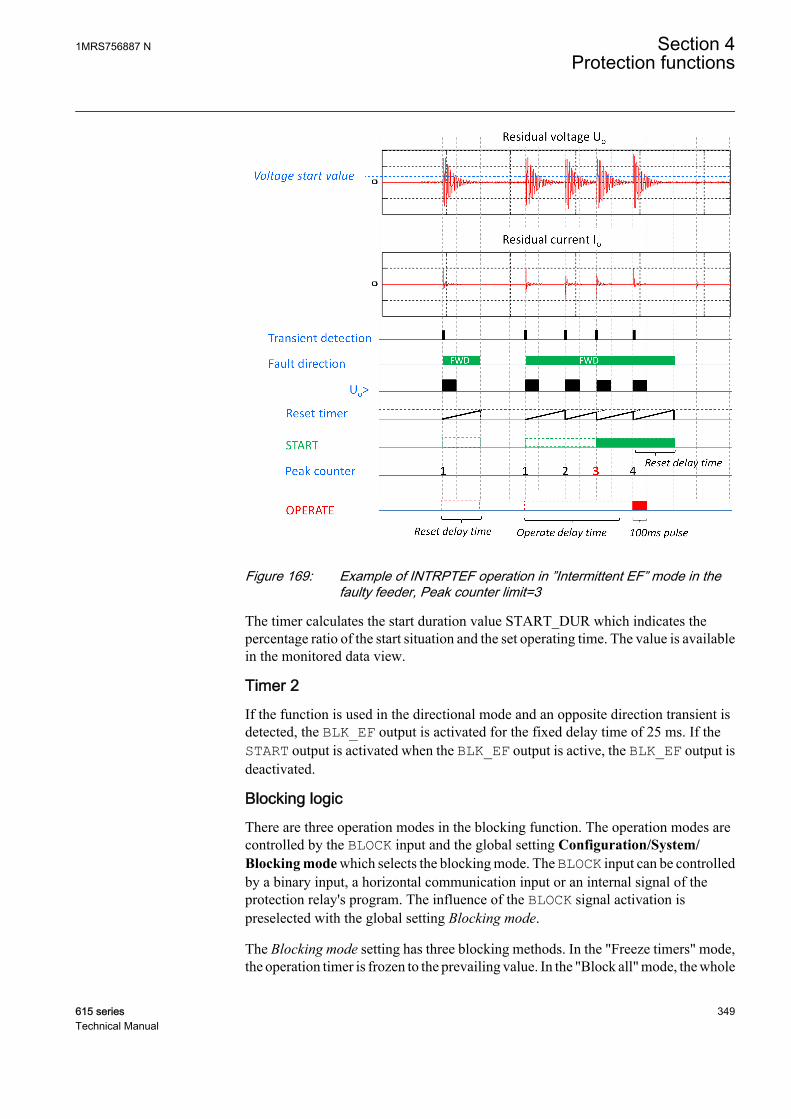
GUID-27C77008-B292-4112-9CF6-4B95EE19B9EC V1 EN
Figure 169: Example of INTRPTEF operation in ”Intermittent EF” mode in thefaulty feeder, Peak counter limit=3
The timer calculates the start duration value START_DUR which indicates thepercentage ratio of the start situation and the set operating time. The value is availablein the monitored data view.
Timer 2If the function is used in the directional mode and an opposite direction transient isdetected, the BLK_EF output is activated for the fixed delay time of 25 ms. If theSTART output is activated when the BLK_EF output is active, the BLK_EF output isdeactivated.
Blocking logicThere are three operation modes in the blocking function. The operation modes arecontrolled by the BLOCK input and the global setting Configuration/System/Blocking mode which selects the blocking mode. The BLOCK input can be controlledby a binary input, a horizontal communication input or an internal signal of theprotection relay's program. The influence of the BLOCK signal activation ispreselected with the global setting Blocking mode.
The Blocking mode setting has three blocking methods. In the "Freeze timers" mode,the operation timer is frozen to the prevailing value. In the "Block all" mode, the whole
1MRS756887 N Section 4Protection functions
615 series 349Technical Manual
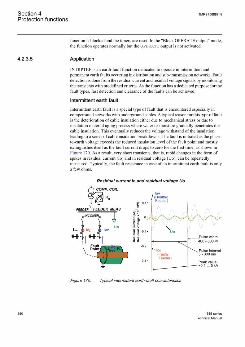
function is blocked and the timers are reset. In the "Block OPERATE output" mode,the function operates normally but the OPERATE output is not activated.
4.2.3.5 Application
INTRPTEF is an earth-fault function dedicated to operate in intermittent andpermanent earth faults occurring in distribution and sub-transmission networks. Faultdetection is done from the residual current and residual voltage signals by monitoringthe transients with predefined criteria. As the function has a dedicated purpose for thefault types, fast detection and clearance of the faults can be achieved.
Intermittent earth faultIntermittent earth fault is a special type of fault that is encountered especially incompensated networks with underground cables. A typical reason for this type of faultis the deterioration of cable insulation either due to mechanical stress or due toinsulation material aging process where water or moisture gradually penetrates thecable insulation. This eventually reduces the voltage withstand of the insulation,leading to a series of cable insulation breakdowns. The fault is initiated as the phase-to-earth voltage exceeds the reduced insulation level of the fault point and mostlyextinguishes itself as the fault current drops to zero for the first time, as shown inFigure 170. As a result, very short transients, that is, rapid changes in the form ofspikes in residual current (Io) and in residual voltage (Uo), can be repeatedlymeasured. Typically, the fault resistance in case of an intermittent earth fault is onlya few ohms.
Residual current Io and residual voltage Uo
FEEDER FEEDER MEAS
Iov
FaultPoint
KRe
-0.3
-0.2
-0.1
Res
idua
l Cur
rent
(kA
)R
esid
ual V
olta
ge x
10
2(k
V)
INCOMER
COMP. COIL
IojUo
KRe
0
0.1
Ioj(FaultyFeeder)
Iov(HealthyFeeder)
UoPulse width400 - 800 s
Pulse interval5 - 300 ms
Peak value~0.1 ... 5 kA
UtresUtres
Ictot
Rf
GUID-415078AD-21B3-4103-9622-712BB88F274A V2 EN
Figure 170: Typical intermittent earth-fault characteristics
Section 4 1MRS756887 NProtection functions
350 615 seriesTechnical Manual
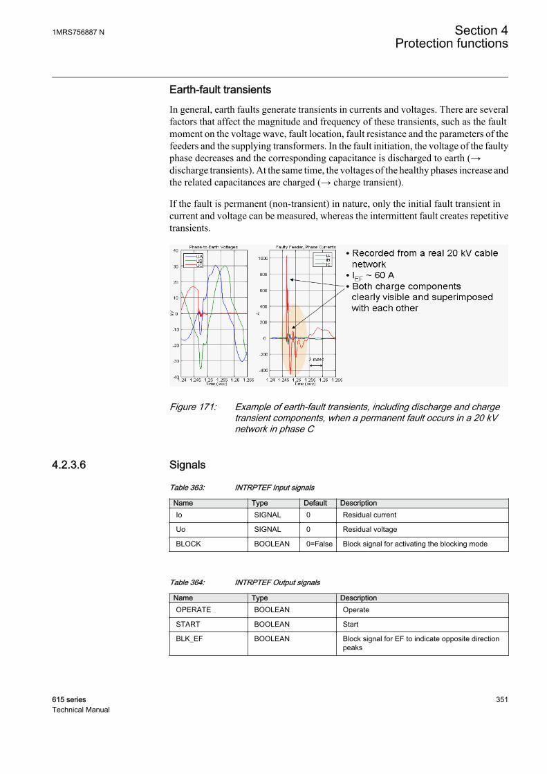
Earth-fault transientsIn general, earth faults generate transients in currents and voltages. There are severalfactors that affect the magnitude and frequency of these transients, such as the faultmoment on the voltage wave, fault location, fault resistance and the parameters of thefeeders and the supplying transformers. In the fault initiation, the voltage of the faultyphase decreases and the corresponding capacitance is discharged to earth (→discharge transients). At the same time, the voltages of the healthy phases increase andthe related capacitances are charged (→ charge transient).
If the fault is permanent (non-transient) in nature, only the initial fault transient incurrent and voltage can be measured, whereas the intermittent fault creates repetitivetransients.
GUID-CC4ADDEA-EE11-4011-B184-F873473EBA9F V1 EN
Figure 171: Example of earth-fault transients, including discharge and chargetransient components, when a permanent fault occurs in a 20 kVnetwork in phase C
4.2.3.6 Signals
Table 363: INTRPTEF Input signals
Name Type Default DescriptionIo SIGNAL 0 Residual current
Uo SIGNAL 0 Residual voltage
BLOCK BOOLEAN 0=False Block signal for activating the blocking mode
Table 364: INTRPTEF Output signals
Name Type DescriptionOPERATE BOOLEAN Operate
START BOOLEAN Start
BLK_EF BOOLEAN Block signal for EF to indicate opposite directionpeaks
1MRS756887 N Section 4Protection functions
615 series 351Technical Manual

4.2.3.7 Settings
Table 365: INTRPTEF Group settings (Basic)
Parameter Values (Range) Unit Step Default DescriptionDirectional mode 1=Non-directional
2=Forward3=Reverse
2=Forward Directional mode
Operate delay time 40...1200000 ms 10 500 Operate delay time
Voltage start value 0.05...0.50 xUn 0.01 0.20 Voltage start value
Table 366: INTRPTEF Non group settings (Basic)
Parameter Values (Range) Unit Step Default DescriptionOperation 1=on
5=off 1=on Operation Off / On
Operation mode 1=Intermittent EF2=Transient EF
1=Intermittent EF Operation criteria
Uo signal Sel 1=Measured Uo2=Calculated Uo
1=Measured Uo Selection for used Uo signal
Table 367: INTRPTEF Non group settings (Advanced)
Parameter Values (Range) Unit Step Default DescriptionReset delay time 40...60000 ms 1 500 Reset delay time
Peak counter limit 2...20 1 2 Min requirement for peak counter beforestart in IEF mode
Min operate current 0.01...1.00 xIn 0.01 0.01 Minimum operating current for transientdetector
4.2.3.8 Monitored data
Table 368: INTRPTEF Monitored data
Name Type Values (Range) Unit DescriptionFAULT_DIR Enum 0=unknown
1=forward2=backward3=both
Detected fault direction
START_DUR FLOAT32 0.00...100.00 % Ratio of start time /operate time
INTRPTEF Enum 1=on2=blocked3=test4=test/blocked5=off
Status
Section 4 1MRS756887 NProtection functions
352 615 seriesTechnical Manual

4.2.3.9 Technical data
Table 369: INTRPTEF Technical data
Characteristic ValueOperation accuracy (Uo criteria with transientprotection)
Depending on the frequency of the measuredcurrent: fn ±2 Hz
±1.5% of the set value or ±0.002 × Uo
Operate time accuracy ±1.0% of the set value or ±20 ms
Suppression of harmonics DFT: -50 dB at f = n × fn, where n = 2, 3, 4, 5
4.2.3.10 Technical revision history
Table 370: INTRPTEF Technical revision history
Technical revision ChangeB Minimum and default values changed to 40 ms for
the Operate delay time setting
C The Minimum operate current setting is added.Correction in IEC 61850 mapping: DO BlkEFrenamed to InhEF. Minimum value changed from0.01 to 0.10 (default changed from 0.01 to 0.20) forthe Voltage start value setting. Minimum valuechanged from 0 ms to 40 ms for the Reset delaytime setting.
D Voltage start value description changed from"Voltage start value for transient EF" to "Voltagestart value" since the start value is effective in bothoperation modes. Added support for calculatedUo. Uo source (measured/calculated) can beselected with "Uo signal Sel". Voltage start valuesetting minimum changed from 0.10 to 0.05.
E Min operate current setting scaling corrected toRMS level from peak level.
4.2.4 Admittance-based earth-fault protection EFPADM
4.2.4.1 Identification
Function description IEC 61850identification
IEC 60617identification
ANSI/IEEE C37.2device number
Admittance-based earth-fault protection EFPADM Yo> -> 21YN
1MRS756887 N Section 4Protection functions
615 series 353Technical Manual

4.2.4.2 Function block
GUID-70A9F388-3588-4550-A291-CB0E74E95F6E V2 EN
Figure 172: Function block
4.2.4.3 Functionality
The admittance-based earth-fault protection function EFPADM provides a selectiveearth-fault protection function for high-resistance earthed, unearthed andcompensated networks. It can be applied for the protection of overhead lines as wellas with underground cables. It can be used as an alternative solution to traditionalresidual current-based earth-fault protection functions, such as the IoCos mode inDEFxPDEF. Main advantages of EFPADM include a versatile applicability, goodsensitivity and easy setting principles.
EFPADM is based on evaluating the neutral admittance of the network, that is, thequotient:
Yo Io Uo= −/
GUID-F8BBC6A4-47BB-4FCB-A2E0-87FD46073AAF V1 EN (Equation 23)
The measured admittance is compared to the admittance characteristic boundaries inthe admittance plane. The supported characteristics include overadmittance,oversusceptance, overconductance or any combination of the three. The directionalityof the oversusceptance and overconductance criteria can be defined as forward,reverse or non-directional, and the boundary lines can be tilted if required by theapplication. This allows the optimization of the shape of the admittance characteristicsfor any given application.
The function supports two calculation algorithms for admittance. The admittancecalculation can be set to include or exclude the prefault zero-sequence values of Io andUo. Furthermore, the calculated admittance is recorded at the time of the trip and it canbe monitored for post-fault analysis purposes.
To ensure the security of the protection, the admittance calculation is supervised by aresidual overvoltage condition which releases the admittance protection during a faultcondition. Alternatively, the release signal can be provided by an external binarysignal.
The function contains a blocking functionality. It is possible to block function outputs,timers or the function itself, if desired.
Section 4 1MRS756887 NProtection functions
354 615 seriesTechnical Manual
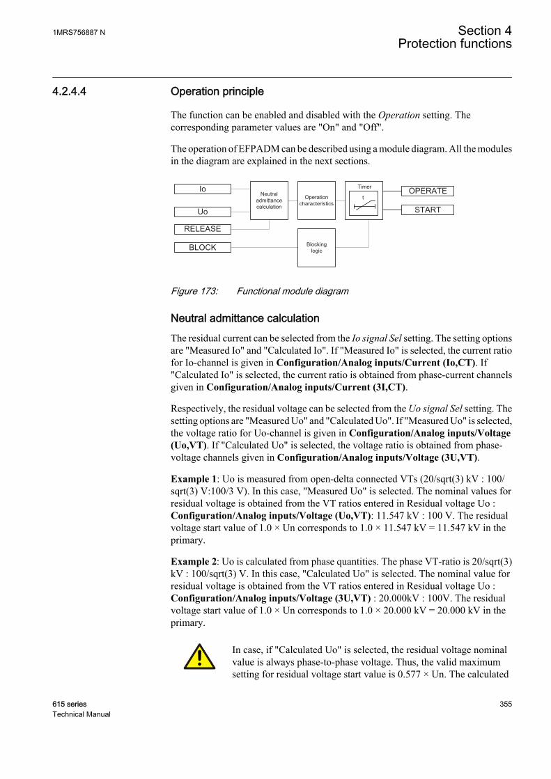
4.2.4.4 Operation principle
The function can be enabled and disabled with the Operation setting. Thecorresponding parameter values are "On" and "Off".
The operation of EFPADM can be described using a module diagram. All the modulesin the diagram are explained in the next sections.
OPERATENeutral admittance calculation
BLOCK
START
Io
Uo
RELEASE
t
Timer
Operation characteristics
Blockinglogic
GUID-BAD34871-A440-433D-8101-022E1E245A0D V1 EN
Figure 173: Functional module diagram
Neutral admittance calculationThe residual current can be selected from the Io signal Sel setting. The setting optionsare "Measured Io" and "Calculated Io". If "Measured Io" is selected, the current ratiofor Io-channel is given in Configuration/Analog inputs/Current (Io,CT). If"Calculated Io" is selected, the current ratio is obtained from phase-current channelsgiven in Configuration/Analog inputs/Current (3I,CT).
Respectively, the residual voltage can be selected from the Uo signal Sel setting. Thesetting options are "Measured Uo" and "Calculated Uo". If "Measured Uo" is selected,the voltage ratio for Uo-channel is given in Configuration/Analog inputs/Voltage(Uo,VT). If "Calculated Uo" is selected, the voltage ratio is obtained from phase-voltage channels given in Configuration/Analog inputs/Voltage (3U,VT).
Example 1: Uo is measured from open-delta connected VTs (20/sqrt(3) kV : 100/sqrt(3) V:100/3 V). In this case, "Measured Uo" is selected. The nominal values forresidual voltage is obtained from the VT ratios entered in Residual voltage Uo :Configuration/Analog inputs/Voltage (Uo,VT): 11.547 kV : 100 V. The residualvoltage start value of 1.0 × Un corresponds to 1.0 × 11.547 kV = 11.547 kV in theprimary.
Example 2: Uo is calculated from phase quantities. The phase VT-ratio is 20/sqrt(3)kV : 100/sqrt(3) V. In this case, "Calculated Uo" is selected. The nominal value forresidual voltage is obtained from the VT ratios entered in Residual voltage Uo :Configuration/Analog inputs/Voltage (3U,VT) : 20.000kV : 100V. The residualvoltage start value of 1.0 × Un corresponds to 1.0 × 20.000 kV = 20.000 kV in theprimary.
In case, if "Calculated Uo" is selected, the residual voltage nominalvalue is always phase-to-phase voltage. Thus, the valid maximumsetting for residual voltage start value is 0.577 × Un. The calculated
1MRS756887 N Section 4Protection functions
615 series 355Technical Manual
Uo requires that all three phase-to-earth voltages are connected to theprotection relay. Uo cannot be calculated from the phase-to-phasevoltages.
When the residual voltage exceeds the set threshold Voltage start value, an earth faultis detected and the neutral admittance calculation is released.
To ensure a sufficient accuracy for the Io and Uo measurements, it is required that theresidual voltage exceeds the value set by Min operate voltage. If the admittancecalculation mode is "Delta", the minimum change in the residual voltage due to a faultmust be 0.01 × Un to enable the operation. Similarly, the residual current must exceedthe value set by Min operate current.
The polarity of the polarizing quantity Uo can be changed, that is,rotated by 180 degrees, by setting the Pol reversal parameter to "True"or by switching the polarity of the residual voltage measurementwires.
As an alternative for the internal residual overvoltage-based start condition, theneutral admittance protection can also be externally released by utilizing theRELEASE input.
When Admittance Clc mode is set to "Delta", the external logic used must be able togive RELEASE in less than 0.1 s from fault initiation. Otherwise the collected pre-fault values are overwritten with fault time values. If it is slower, Admittance Clc modemust be set to “Normal”.
Neutral admittance is calculated as the quotient between the residual current andresidual voltage (polarity reversed) fundamental frequency phasors. The AdmittanceClc mode setting defines the calculation mode.
Admittance Clc mode = "Normal"
YoIo
Uo
fault
fault
=
−
GUID-B1E03EA1-E958-43F3-8A28-2D268138DE36 V1 EN (Equation 24)
Admittance Clc mode = "Delta"
Section 4 1MRS756887 NProtection functions
356 615 seriesTechnical Manual

YoIo Io
Uo Uo
Io
Uo
fault prefault
fault prefault
=
−
− −
=
−( )
∆
∆
GUID-B0611FF1-46FD-4E81-A11D-4721F0AF7BF8 V1 EN (Equation 25)
Yo Calculated neutral admittance [Siemens]
Iofault Residual current during the fault [Amperes]
Uofault Residual voltage during the fault [Volts]
Ioprefault Prefault residual current [Amperes]
Uoprefault Prefault residual voltage [Volts]
ΔIo Change in the residual current due to fault [Amperes]
ΔUo Change in the residual voltage due to fault [Volts]
Traditionally, admittance calculation is done with the calculation mode "Normal",that is, with the current and voltage values directly measured during the fault. As analternative, by selecting the calculation mode "Delta", the prefault zero-sequenceasymmetry of the network can be removed from the admittance calculation.Theoretically, this makes the admittance calculation totally immune to faultresistance, that is, the estimated admittance value is not affected by fault resistance.Utilization of the change in Uo and Io due to a fault in the admittance calculation alsomitigates the effects of the VT and CT measurement errors, thus improving themeasuring accuracy, the sensitivity and the selectivity of the protection.
Calculation mode "Delta" is recommended in case a high sensitivityof the protection is required, if the network has a high degree ofasymmetry during the healthy state or if the residual currentmeasurement is based on sum connection, that is, the Holmgrenconnection.
Neutral admittance calculation produces certain values during forward and reversefaults.
Fault in reverse direction, that is, outside the protected feeder.
Yo YFdtot
= −
GUID-B6E3F720-1F9F-4C11-A5DC-722838E8CCDA V1 EN (Equation 26)
≈ − ⋅jI
U
eFd
ph
GUID-19AA418B-9A0A-4CEE-8772-0CD3F595E63F V1 EN (Equation 27)
YFdtot Sum of the phase-to-earth admittances (YFdA, YFdB, YFdC) of the protected feeder
IeFd Magnitude of the earth-fault current of the protected feeder when the fault resistance iszero ohm
Uph Magnitude of the nominal phase-to-earth voltage of the system
1MRS756887 N Section 4Protection functions
615 series 357Technical Manual
Equation 26 shows that in case of outside faults, the measured admittance equals theadmittance of the protected feeder with a negative sign. The measured admittance isdominantly reactive; the small resistive part of the measured admittance is due to theleakage losses of the feeder. Theoretically, the measured admittance is located in thethird quadrant in the admittance plane close to the im(Yo) axis, see Figure 174.
The result of Equation 26 is valid regardless of the neutral earthingmethod. In compensated networks the compensation degree does notaffect the result. This enables a straightforward setting principle forthe neutral admittance protection: admittance characteristic is set tocover the value Yo = –YFdtot with a suitable margin.
Due to inaccuracies in voltage and current measurement, the smallreal part of the calculated neutral admittance may appear as positive,which brings the measured admittance in the fourth quadrant in theadmittance plane. This should be considered when setting theadmittance characteristic.
Section 4 1MRS756887 NProtection functions
358 615 seriesTechnical Manual
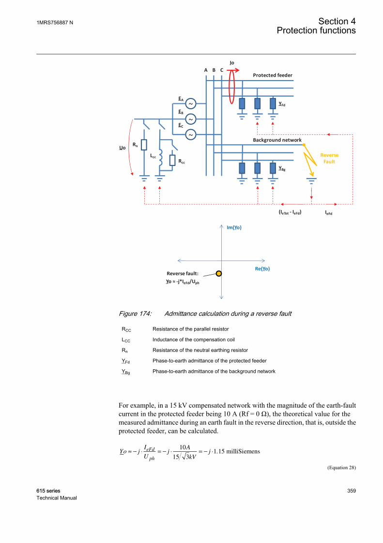
~
~
~
A B C
Uo
EA
EB
EC
Io
Reverse Fault
YFd
LccRcc
YBg
IeFd(IeTot - IeFd)
Rn
Protected feeder
Background network
Im(Yo)
Re(Yo)Reverse fault:
Yo ≈ -j*IeFd/Uph
GUID-B852BF65-9C03-49F2-8FA9-E958EB37FF13 V1 EN
Figure 174: Admittance calculation during a reverse fault
RCC Resistance of the parallel resistor
LCC Inductance of the compensation coil
Rn Resistance of the neutral earthing resistor
YFd Phase-to-earth admittance of the protected feeder
YBg Phase-to-earth admittance of the background network
For example, in a 15 kV compensated network with the magnitude of the earth-faultcurrent in the protected feeder being 10 A (Rf = 0 Ω), the theoretical value for themeasured admittance during an earth fault in the reverse direction, that is, outside theprotected feeder, can be calculated.
Yo jI
Uj
A
kVjeFd
ph
≈ − ⋅ = − ⋅ = − ⋅10
15 31 15. milliSiemens
GUID-E2A45F20-9821-436E-94F1-F0BFCB78A1E3 V1 EN (Equation 28)
1MRS756887 N Section 4Protection functions
615 series 359Technical Manual

The result is valid regardless of the neutral earthing method.
In this case, the resistive part of the measured admittance is due to leakage losses ofthe protected feeder. As they are typically very small, the resistive part is close to zero.Due to inaccuracies in the voltage and current measurement, the small real part of theapparent neutral admittance may appear positive. This should be considered in thesetting of the admittance characteristic.
Fault in the forward direction, that is, inside the protected feeder.
Unearthed network:
Yo Y Bgtot=
GUID-5F1D2145-3C0F-4F8F-9E17-5B88C1822566 V1 EN (Equation 29)
≈ ⋅−
jI I
U
eTot eFd
ph
GUID-0B7C9BA9-B41B-4825-9C1B-F8F36640B693 V1 EN (Equation 30)
Compensated network:
Yo Y YBgtot CC= +
GUID-F3810944-D0E1-4C9A-A99B-8409F4D3CF05 V1 EN (Equation 31)
≈
+ ⋅ ⋅ −( ) −( )I j I K I
U
Rcc eTot eFd
ph
1
GUID-208EA80C-62B6-46E0-8A5B-DC425F0FE122 V1 EN (Equation 32)
High-resistance earthed network:
Yo Y YBgtot Rn= +
GUID-F91DA4E4-F439-4BFA-AA0D-5839B1574946 V1 EN (Equation 33)
≈
+ ⋅ −( )I j I I
U
Rn eTot eFd
ph
GUID-CAA0C492-20CF-406C-80AC-8301375AB454 V1 EN (Equation 34)
YBgtot Sum of the phase-to-earth admittances (YBgA, YBgB, YBgC) of the background network
YCC Admittance of the earthing arrangement (compensation coil and parallel resistor)
IRcc Rated current of the parallel resistor
IeFd Magnitude of the earth-fault current of the protected feeder when the fault resistance is zero ohm
IeTot Magnitude of the uncompensated earth-fault current of the network when Rf is zero ohm
K Compensation degree, K = 1 full resonance, K<1 undercompensated, K>1 overcompensated
IRn Rated current of the neutral earthing resistor
Equation 29 shows that in case of a fault inside the protected feeder in unearthednetworks, the measured admittance equals the admittance of the background network.
Section 4 1MRS756887 NProtection functions
360 615 seriesTechnical Manual
The admittance is dominantly reactive; the small resistive part of the measuredadmittance is due to the leakage losses of the background network. Theoretically, themeasured admittance is located in the first quadrant in the admittance plane, close tothe im(Yo) axis, see Figure 175.
Equation 31 shows that in case of a fault inside the protected feeder in compensatednetworks, the measured admittance equals the admittance of the background networkand the coil including the parallel resistor. Basically, the compensation degreedetermines the imaginary part of the measured admittance and the resistive part is dueto the parallel resistor of the coil and the leakage losses of the background network andthe losses of the coil. Theoretically, the measured admittance is located in the first orfourth quadrant in the admittance plane, depending on the compensation degree, seeFigure 175.
Before the parallel resistor is connected, the resistive part of themeasured admittance is due to the leakage losses of the backgroundnetwork and the losses of the coil. As they are typically small, theresistive part may not be sufficiently large to secure the discriminationof the fault and its direction based on the measured conductance. Thisand the rating and the operation logic of the parallel resistor should beconsidered when setting the admittance characteristic in compensatednetworks.
Equation 33 shows that in case of a fault inside the protected feeder in high-resistanceearthed systems, the measured admittance equals the admittance of the backgroundnetwork and the neutral earthing resistor. Basically, the imaginary part of themeasured admittance is due to the phase-to-earth capacitances of the backgroundnetwork, and the resistive part is due to the neutral earthing resistor and the leakagelosses of the background network. Theoretically, the measured admittance is locatedin the first quadrant in the admittance plane, see Figure 175.
1MRS756887 N Section 4Protection functions
615 series 361Technical Manual

Im(Yo)
Re(Yo)
Forward fault, unearthed network:
Yo ≈ j*(IeTot-IeFd)/Uph
Forward fault, compensated network:
Yo ≈ (Ircc + j*(IeTot*(1-K) - IeFd))/Uph
Under-comp. (K<1)
Resonance (K=1)
Over-comp. (K>1)
Reverse fault:
Yo ≈ -j*IeFd/Uph
Forward fault, high resistance earthed network:
Yo ≈ (IRn+j*(IeTot-IeFd))/Uph
~
~
~
A B C
EA
EB
EC
Io
Forward Fault
LccRcc
IeFdIeTot
(IeTot - IeFd)
Uo Rn
Protected feeder
Background network
YFd
YBg
GUID-5DB19698-38F9-433E-954F-4EBDBA5B63BD V1 EN
Figure 175: Admittance calculation during a forward fault
When the network is fully compensated in compensated networks,theoretically during a forward fault, the imaginary part of themeasured admittance equals the susceptance of the protected feederwith a negative sign. The discrimination between a forward andreverse fault must therefore be based on the real part of the measuredadmittance, that is, conductance. Thus, the best selectivity is achieved
Section 4 1MRS756887 NProtection functions
362 615 seriesTechnical Manual

when the compensated network is operated either in theundercompensated or overcompensated mode.
For example, in a 15 kV compensated network, the magnitude of the earth-faultcurrent of the protected feeder is 10 A (Rf = 0 Ω) and the magnitude of the network is100 A (Rf = 0 Ω). During an earth fault, a 15 A resistor is connected in parallel to thecoil after a 1.0 second delay. Compensation degree is overcompensated, K = 1.1.
During an earth fault in the forward direction, that is, inside the protected feeder, thetheoretical value for the measured admittance after the connection of the parallelresistor can be calculated.
YoI j I K I
U
A j A A
Rcc eTot eFd
ph
≈
+ ⋅ ⋅ −( ) −( )
=
+ ⋅ ⋅ −( ) −( )
1
15 100 1 1 1 10
15
.
kkVj
31 73 2 31≈ − ⋅( ). . milliSiemens
GUID-8763BA04-22DC-4B93-B52D-1E8FD44A68B9 V1 EN (Equation 35)
Before the parallel resistor is connected, the resistive part of the measured admittanceis due to the leakage losses of the background network and the losses of the coil. Asthey are typically small, the resistive part may not be sufficiently large to secure thediscrimination of the fault and its direction based on the measured conductance. Thisand the rating and the operation logic of the parallel resistor should be consideredwhen setting the admittance characteristic.
When a high sensitivity of the protection is required, the residualcurrent should be measured with a cable/ring core CT, that is, theFerranti CT. Also the use of the sensitive Io input should beconsidered. The residual voltage measurement should be done with anopen delta connection of the three single pole-insulated voltagetransformers.
The sign of the admittance characteristic settings should beconsidered based on the location of characteristic boundary in theadmittance plane. All forward-settings are given with positive signand reverse-settings with negative sign.
Operation characteristicAfter the admittance calculation is released, the calculated neutral admittance iscompared to the admittance characteristic boundaries in the admittance plane. If thecalculated neutral admittance Yo moves outside the characteristic, the enabling signalis sent to the timer.
EFPADM supports a wide range of different characteristics to achieve the maximumflexibility and sensitivity in different applications. The basic characteristic shape is
1MRS756887 N Section 4Protection functions
615 series 363Technical Manual

selected with the Operation mode and Directional mode settings. Operation modedefines which operation criterion or criteria are enabled and Directional mode definesif the forward, reverse or non-directional boundary lines for that particular operationmode are activated.
Table 371: Operation criteria
Operation mode DescriptionYo Admittance criterion
Bo Susceptance criterion
Go Conductance criterion
Yo, Go Admittance criterion combined with theconductance criterion
Yo, Bo Admittance criterion combined with thesusceptance criterion
Go, Bo Conductance criterion combined with thesusceptance criterion
Yo, Go, Bo Admittance criterion combined with theconductance and susceptance criterion
The options for the Directional mode setting are "Non-directional", "Forward" and"Reverse".
Figure 176, Figure 177 and Figure 178 illustrate the admittance characteristicssupported by EFPADM and the settings relevant to that particular characteristic. Themost typical characteristics are highlighted and explained in details in the chapterNeutral admittance characteristics. Operation is achieved when the calculated neutraladmittance Yo moves outside the characteristic (the operation area is marked withgray).
The settings defining the admittance characteristics are given inprimary milliSiemens (mS). The conversion equation for theadmittance from secondary to primary is:
Y Yni
nupri
CT
VT
= ⋅sec
GUID-2F4EAEF7-0D92-477F-8D4C-00C7BEDE04CB V1 EN (Equation 36)
niCT CT ratio for the residual current Io
nuVT VT ratio for the residual voltage Uo
Example: Admittance setting in the secondary is 5.00 milliSiemens.The CT ratio is 100/1 A and the VT ratio is 11547/100 V. Theadmittance setting in the primary can be calculated.
Section 4 1MRS756887 NProtection functions
364 615 seriesTechnical Manual
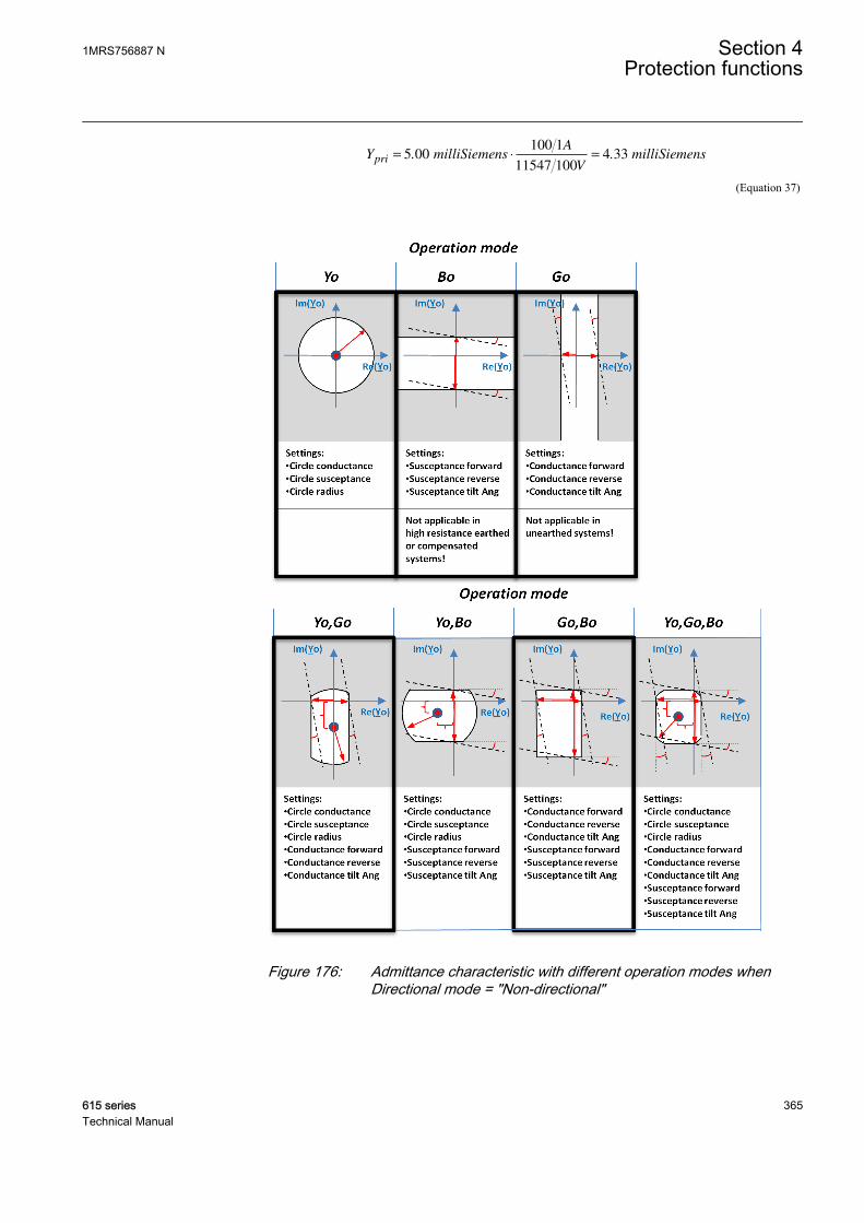
Y milliSiemensA
VmilliSiemenspri = ⋅ =5 00
100 1
11547 1004 33. .
GUID-9CFD2291-9894-4D04-9499-DF38F1F64D59 V1 EN (Equation 37)
GUID-FD8DAB15-CA27-40B0-9A43-FCF0881DB21E V2 EN
Figure 176: Admittance characteristic with different operation modes whenDirectional mode = "Non-directional"
1MRS756887 N Section 4Protection functions
615 series 365Technical Manual
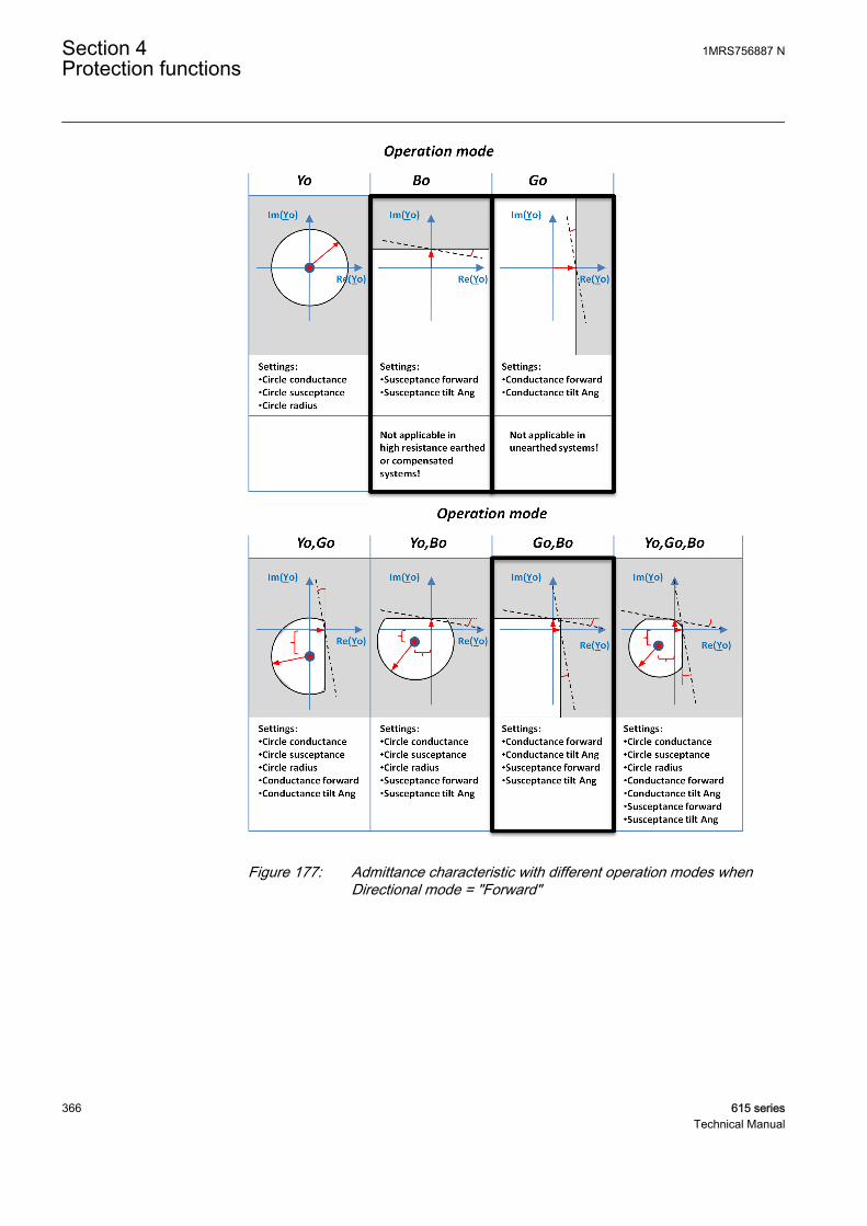
GUID-7EDB14B9-64B4-449C-9290-70A4CC2D588F V2 EN
Figure 177: Admittance characteristic with different operation modes whenDirectional mode = "Forward"
Section 4 1MRS756887 NProtection functions
366 615 seriesTechnical Manual
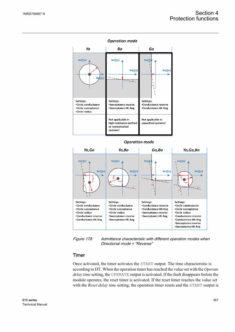
GUID-C847609F-E261-4265-A1D9-3C449F8672A1 V2 EN
Figure 178: Admittance characteristic with different operation modes whenDirectional mode = "Reverse"
TimerOnce activated, the timer activates the START output. The time characteristic isaccording to DT. When the operation timer has reached the value set with the Operatedelay time setting, the OPERATE output is activated. If the fault disappears before themodule operates, the reset timer is activated. If the reset timer reaches the value setwith the Reset delay time setting, the operation timer resets and the START output is
1MRS756887 N Section 4Protection functions
615 series 367Technical Manual

deactivated. The timer calculates the start duration value START_DUR, whichindicates the percentage ratio of the start situation and the set operation time. Thevalue is available in the monitored data view.
Blocking logicThere are three operation modes in the blocking function. The operation modes arecontrolled by the BLOCK input and the global setting in Configuration/System/Blocking mode which selects the blocking mode. The BLOCK input can be controlledby a binary input, a horizontal communication input or an internal signal of theprotection relay's program. The influence of the BLOCK signal activation ispreselected with the global setting Blocking mode.
The Blocking mode setting has three blocking methods. In the "Freeze timers" mode,the operate timer is frozen to the prevailing value, but the OPERATE output is notdeactivated when blocking is activated. In the "Block all" mode, the whole function isblocked and the timers are reset. In the "Block OPERATE output" mode, the functionoperates normally but the OPERATE output is not activated.
4.2.4.5 Neutral admittance characteristics
The applied characteristic should always be set to cover the total admittance of theprotected feeder with a suitable margin. However, more detailed setting valueselection principles depend on the characteristic in question.
The settings defining the admittance characteristics are given inprimary milliSiemens.
The forward and reverse boundary settings should be set so that the forward setting isalways larger than the reverse setting and that there is space between them.
Overadmittance characteristicThe overadmittance criterion is enabled with the setting Operation mode set to "Yo".The characteristic is a circle with the radius defined with the Circle radius setting. Forthe sake of application flexibility, the midpoint of the circle can be moved away fromthe origin with the Circle conductance and Circle susceptance settings. Default valuesfor Circle conductance and Circle susceptance are 0.0 mS, that is, the characteristicis an origin-centered circle.
Operation is achieved when the measured admittance moves outside the circle.
The overadmittance criterion is typically applied in unearthed networks, but it can alsobe used in compensated networks, especially if the circle is set off from the origin.
Section 4 1MRS756887 NProtection functions
368 615 seriesTechnical Manual
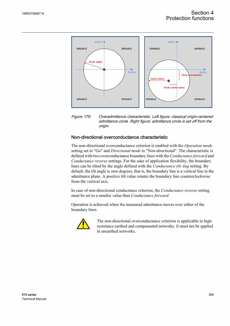
GUID-AD789221-4073-4587-8E82-CD9BBD672AE0 V2 EN
Figure 179: Overadmittance characteristic. Left figure: classical origin-centeredadmittance circle. Right figure: admittance circle is set off from theorigin.
Non-directional overconductance characteristicThe non-directional overconductance criterion is enabled with the Operation modesetting set to "Go" and Directional mode to "Non-directional". The characteristic isdefined with two overconductance boundary lines with the Conductance forward andConductance reverse settings. For the sake of application flexibility, the boundarylines can be tilted by the angle defined with the Conductance tilt Ang setting. Bydefault, the tilt angle is zero degrees, that is, the boundary line is a vertical line in theadmittance plane. A positive tilt value rotates the boundary line counterclockwisefrom the vertical axis.
In case of non-directional conductance criterion, the Conductance reverse settingmust be set to a smaller value than Conductance forward.
Operation is achieved when the measured admittance moves over either of theboundary lines.
The non-directional overconductance criterion is applicable in high-resistance earthed and compensated networks. It must not be appliedin unearthed networks.
1MRS756887 N Section 4Protection functions
615 series 369Technical Manual
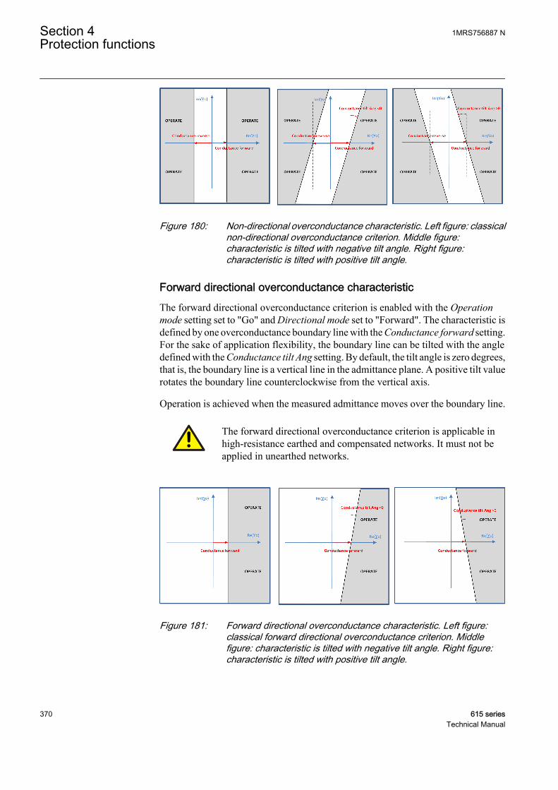
GUID-F5487D41-6B8E-4A7A-ABD3-EBF7254ADC4C V2 EN
Figure 180: Non-directional overconductance characteristic. Left figure: classicalnon-directional overconductance criterion. Middle figure:characteristic is tilted with negative tilt angle. Right figure:characteristic is tilted with positive tilt angle.
Forward directional overconductance characteristicThe forward directional overconductance criterion is enabled with the Operationmode setting set to "Go" and Directional mode set to "Forward". The characteristic isdefined by one overconductance boundary line with the Conductance forward setting.For the sake of application flexibility, the boundary line can be tilted with the angledefined with the Conductance tilt Ang setting. By default, the tilt angle is zero degrees,that is, the boundary line is a vertical line in the admittance plane. A positive tilt valuerotates the boundary line counterclockwise from the vertical axis.
Operation is achieved when the measured admittance moves over the boundary line.
The forward directional overconductance criterion is applicable inhigh-resistance earthed and compensated networks. It must not beapplied in unearthed networks.
GUID-43F312AA-874A-4CE7-ABFE-D76BA70B7A5D V2 EN
Figure 181: Forward directional overconductance characteristic. Left figure:classical forward directional overconductance criterion. Middlefigure: characteristic is tilted with negative tilt angle. Right figure:characteristic is tilted with positive tilt angle.
Section 4 1MRS756887 NProtection functions
370 615 seriesTechnical Manual
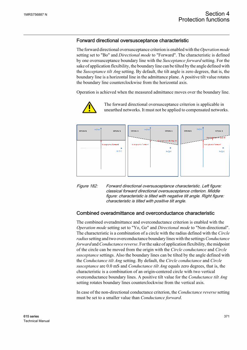
Forward directional oversusceptance characteristicThe forward directional oversusceptance criterion is enabled with the Operation modesetting set to "Bo" and Directional mode to "Forward". The characteristic is definedby one oversusceptance boundary line with the Susceptance forward setting. For thesake of application flexibility, the boundary line can be tilted by the angle defined withthe Susceptance tilt Ang setting. By default, the tilt angle is zero degrees, that is, theboundary line is a horizontal line in the admittance plane. A positive tilt value rotatesthe boundary line counterclockwise from the horizontal axis.
Operation is achieved when the measured admittance moves over the boundary line.
The forward directional oversusceptance criterion is applicable inunearthed networks. It must not be applied to compensated networks.
GUID-43B0F2F9-38CE-4F94-8381-0F20A0668AB1 V2 EN
Figure 182: Forward directional oversusceptance characteristic. Left figure:classical forward directional oversusceptance criterion. Middlefigure: characteristic is tilted with negative tilt angle. Right figure:characteristic is tilted with positive tilt angle.
Combined overadmittance and overconductance characteristicThe combined overadmittance and overconductance criterion is enabled with theOperation mode setting set to "Yo, Go" and Directional mode to "Non-directional".The characteristic is a combination of a circle with the radius defined with the Circleradius setting and two overconductance boundary lines with the settings Conductanceforward and Conductance reverse. For the sake of application flexibility, the midpointof the circle can be moved from the origin with the Circle conductance and Circlesusceptance settings. Also the boundary lines can be tilted by the angle defined withthe Conductance tilt Ang setting. By default, the Circle conductance and Circlesusceptance are 0.0 mS and Conductance tilt Ang equals zero degrees, that is, thecharacteristic is a combination of an origin-centered circle with two verticaloverconductance boundary lines. A positive tilt value for the Conductance tilt Angsetting rotates boundary lines counterclockwise from the vertical axis.
In case of the non-directional conductance criterion, the Conductance reverse settingmust be set to a smaller value than Conductance forward.
1MRS756887 N Section 4Protection functions
615 series 371Technical Manual
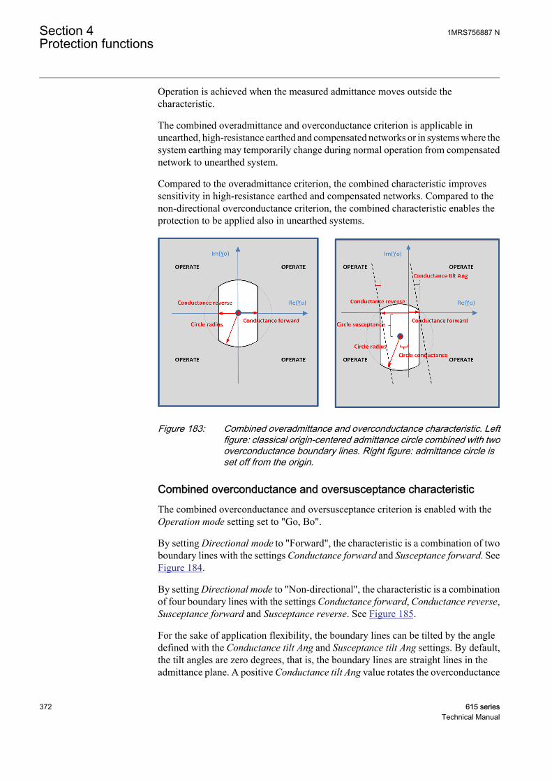
Operation is achieved when the measured admittance moves outside thecharacteristic.
The combined overadmittance and overconductance criterion is applicable inunearthed, high-resistance earthed and compensated networks or in systems where thesystem earthing may temporarily change during normal operation from compensatednetwork to unearthed system.
Compared to the overadmittance criterion, the combined characteristic improvessensitivity in high-resistance earthed and compensated networks. Compared to thenon-directional overconductance criterion, the combined characteristic enables theprotection to be applied also in unearthed systems.
GUID-7AE09721-1428-4392-9142-A6D39FD4C287 V2 EN
Figure 183: Combined overadmittance and overconductance characteristic. Leftfigure: classical origin-centered admittance circle combined with twooverconductance boundary lines. Right figure: admittance circle isset off from the origin.
Combined overconductance and oversusceptance characteristicThe combined overconductance and oversusceptance criterion is enabled with theOperation mode setting set to "Go, Bo".
By setting Directional mode to "Forward", the characteristic is a combination of twoboundary lines with the settings Conductance forward and Susceptance forward. SeeFigure 184.
By setting Directional mode to "Non-directional", the characteristic is a combinationof four boundary lines with the settings Conductance forward, Conductance reverse,Susceptance forward and Susceptance reverse. See Figure 185.
For the sake of application flexibility, the boundary lines can be tilted by the angledefined with the Conductance tilt Ang and Susceptance tilt Ang settings. By default,the tilt angles are zero degrees, that is, the boundary lines are straight lines in theadmittance plane. A positive Conductance tilt Ang value rotates the overconductance
Section 4 1MRS756887 NProtection functions
372 615 seriesTechnical Manual
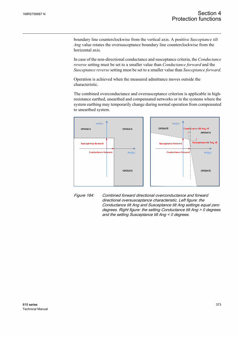
boundary line counterclockwise from the vertical axis. A positive Susceptance tiltAng value rotates the oversusceptance boundary line counterclockwise from thehorizontal axis.
In case of the non-directional conductance and susceptance criteria, the Conductancereverse setting must be set to a smaller value than Conductance forward and theSusceptance reverse setting must be set to a smaller value than Susceptance forward.
Operation is achieved when the measured admittance moves outside thecharacteristic.
The combined overconductance and oversusceptance criterion is applicable in high-resistance earthed, unearthed and compensated networks or in the systems where thesystem earthing may temporarily change during normal operation from compensatedto unearthed system.
GUID-1A21391B-A053-432B-8A44-7D2BF714C52D V2 EN
Figure 184: Combined forward directional overconductance and forwarddirectional oversusceptance characteristic. Left figure: theConductance tilt Ang and Susceptance tilt Ang settings equal zerodegrees. Right figure: the setting Conductance tilt Ang > 0 degreesand the setting Susceptance tilt Ang < 0 degrees.
1MRS756887 N Section 4Protection functions
615 series 373Technical Manual
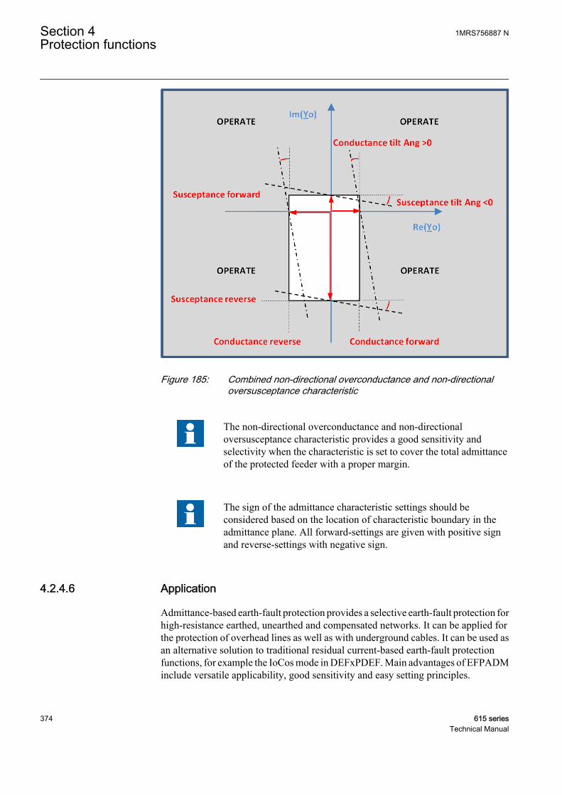
GUID-0A34B498-4FDB-44B3-A539-BAE8F10ABDF0 V2 EN
Figure 185: Combined non-directional overconductance and non-directionaloversusceptance characteristic
The non-directional overconductance and non-directionaloversusceptance characteristic provides a good sensitivity andselectivity when the characteristic is set to cover the total admittanceof the protected feeder with a proper margin.
The sign of the admittance characteristic settings should beconsidered based on the location of characteristic boundary in theadmittance plane. All forward-settings are given with positive signand reverse-settings with negative sign.
4.2.4.6 Application
Admittance-based earth-fault protection provides a selective earth-fault protection forhigh-resistance earthed, unearthed and compensated networks. It can be applied forthe protection of overhead lines as well as with underground cables. It can be used asan alternative solution to traditional residual current-based earth-fault protectionfunctions, for example the IoCos mode in DEFxPDEF. Main advantages of EFPADMinclude versatile applicability, good sensitivity and easy setting principles.
Section 4 1MRS756887 NProtection functions
374 615 seriesTechnical Manual

Residual overvoltage condition is used as a start condition for the admittance-basedearth-fault protection. When the residual voltage exceeds the set threshold Voltagestart value, an earth fault is detected and the neutral admittance calculation is released.In order to guarantee a high security of protection, that is, avoid false starts, theVoltage start value setting must be set above the highest possible value of Uo duringnormal operation with a proper margin. It should consider all possible operationconditions and configuration changes in the network. In unearthed systems, thehealthy-state Uo is typically less than 1%×Uph (Uph = nominal phase-to-earthvoltage). In compensated networks, the healthy-state Uo may reach values even up to30%×Uph if the network includes large parts of overheadlines without a phasetransposition. Generally, the highest Uo is achieved when the compensation coil istuned to the full resonance and when the parallel resistor of the coil is not connected.
The residual overvoltage-based start condition for the admittance protection enablesa multistage protection principle. For example, one instance of EFPADM could beused for alarming to detect faults with a high fault resistance using a relatively lowvalue for the Voltage start value setting. Another instance of EFPADM could then beset to trip with a lower sensitivity by selecting a higher value of the Voltage start valuesetting than in the alarming instance (stage).
To apply the admittance-based earth-fault protection, at least the following networkdata are required:
• System earthing method• Maximum value for Uo during the healthy state• Maximum earth-fault current of the protected feeder when the fault resistance Rf
is zero ohm• Maximum uncompensated earth-fault current of the system (Rf = 0 Ω)• Rated current of the parallel resistor of the coil (active current forcing scheme) in
the case of a compensated neutral network• Rated current of the neutral earthing resistor in the case of a high-resistance
earthed system• Knowledge of the magnitude of Uo as a function of the fault resistance to verify
the sensitivity of the protection in terms of fault resistance
Figure 186 shows the influence of fault resistance on the residual voltage magnitudein unearthed and compensated networks. Such information should be available toverify the correct Voltage start value setting, which helps fulfill the requirements forthe sensitivity of the protection in terms of fault resistance.
1MRS756887 N Section 4Protection functions
615 series 375Technical Manual
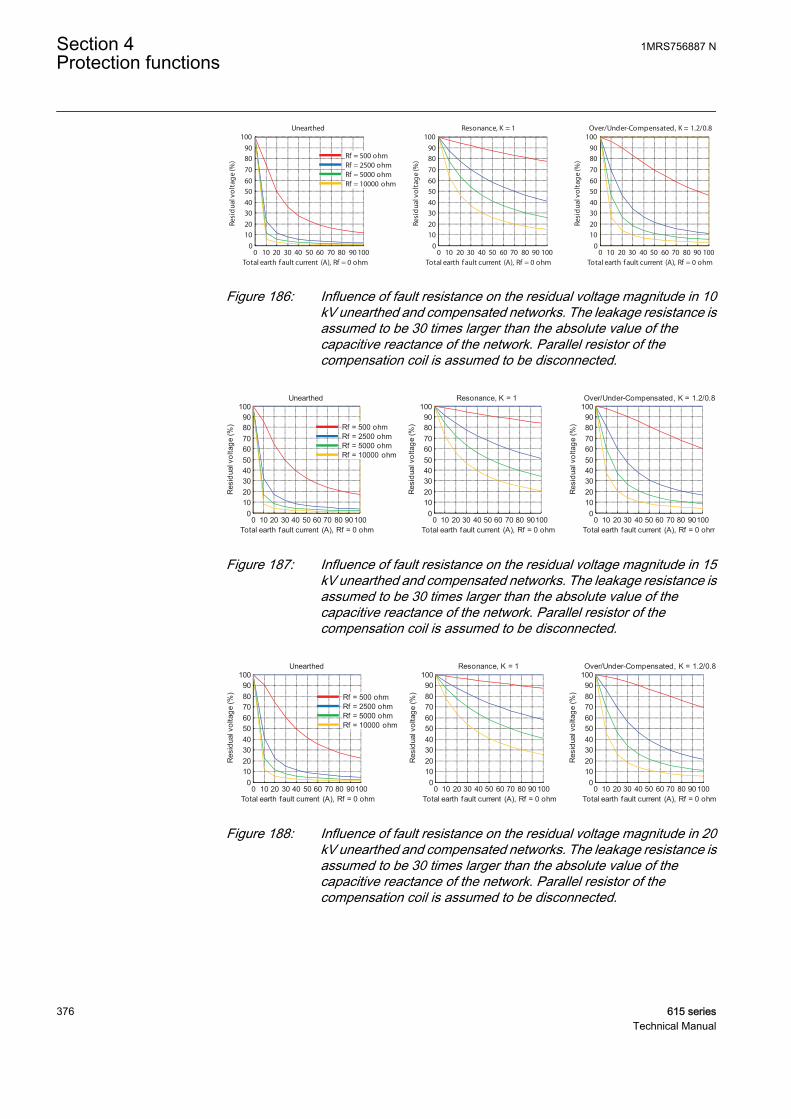
0 10 20 30 40 50 60 70 80 90 1000
102030405060708090
100
Total earth f ault current (A), Rf = 0 ohm
Resi
dua
l vo
ltag
e (%
)
Resonance, K = 1
0 10 20 30 40 50 60 70 80 90 1000
102030405060708090
100
Total earth f ault current (A), Rf = 0 ohm
Resi
dua
l vo
ltag
e (%
)
Over/Under-Compensated, K = 1.2/0.8
0 10 20 30 40 50 60 70 80 90 1000
102030405060708090
100
Total earth fault current (A), Rf = 0 ohm
Resi
dua
l vo
ltag
e (%
)
Unearthed
Rf = 500 ohmRf = 2500 ohmRf = 5000 ohmRf = 10000 ohm
GUID-2F3654EF-9700-4FB7-B73C-85F7ED5D8EEF V1 EN
Figure 186: Influence of fault resistance on the residual voltage magnitude in 10kV unearthed and compensated networks. The leakage resistance isassumed to be 30 times larger than the absolute value of thecapacitive reactance of the network. Parallel resistor of thecompensation coil is assumed to be disconnected.
0 10 20 30 40 50 60 70 80 901000
102030405060708090
100
Total earth fault current (A), Rf = 0 ohm
Res
idua
l vol
tage
(%)
Resonance, K = 1
0 10 20 30 40 50 60 70 80 901000
102030405060708090
100
Total earth fault current (A), Rf = 0 ohm
Res
idua
l vol
tage
(%)
Over/Under-Compensated, K = 1.2/0.8
0 10 20 30 40 50 60 70 80 901000
102030405060708090
100
Total earth fault current (A), Rf = 0 ohm
Res
idua
l vol
tage
(%)
Unearthed
Rf = 500 ohmRf = 2500 ohmRf = 5000 ohmRf = 10000 ohm
GUID-3880FB01-5C89-4E19-A529-805208382BB1 V1 EN
Figure 187: Influence of fault resistance on the residual voltage magnitude in 15kV unearthed and compensated networks. The leakage resistance isassumed to be 30 times larger than the absolute value of thecapacitive reactance of the network. Parallel resistor of thecompensation coil is assumed to be disconnected.
0 10 20 30 40 50 60 70 80 901000
102030405060708090
100
Total earth fault current (A), Rf = 0 ohm
Res
idua
l vol
tage
(%)
Resonance, K = 1
0 10 20 30 40 50 60 70 80 901000
102030405060708090
100
Total earth fault current (A), Rf = 0 ohm
Res
idua
l vol
tage
(%)
Over/Under-Compensated, K = 1.2/0.8
0 10 20 30 40 50 60 70 80 901000
102030405060708090
100
Total earth fault current (A), Rf = 0 ohm
Res
idua
l vol
tage
(%)
Unearthed
Rf = 500 ohmRf = 2500 ohmRf = 5000 ohmRf = 10000 ohm
GUID-6321328D-6C17-4155-A2DF-7E1C47A44D53 V1 EN
Figure 188: Influence of fault resistance on the residual voltage magnitude in 20kV unearthed and compensated networks. The leakage resistance isassumed to be 30 times larger than the absolute value of thecapacitive reactance of the network. Parallel resistor of thecompensation coil is assumed to be disconnected.
Section 4 1MRS756887 NProtection functions
376 615 seriesTechnical Manual
ExampleIn a 15 kV, 50 Hz compensated network, the maximum value for Uo during thehealthy state is 10%×Uph. Maximum earth-fault current of the system is 100 A. Themaximum earth-fault current of the protected feeder is 10 A (Rf = 0 Ω). The appliedactive current forcing scheme uses a 15 A resistor (at 15 kV), which is connected inparallel to the coil during the fault after a 1.0 second delay.
Solution: As a start condition for the admittance-based earth-fault protection, theinternal residual overvoltage condition of EFPADM is used. The Voltage start valuesetting must be set above the maximum healthy-state Uo of 10%×Uph with a suitablemargin.
Voltage start value = 0.15 × Un
According to Figure 187, this selection ensures at least a sensitivity corresponding toa 2000 ohm fault resistance when the compensation degree varies between 80% and120%. The greatest sensitivity is achieved when the compensation degree is close tofull resonance.
An earth-fault current of 10 A can be converted into admittance.
YA
kVjFdtot = ≈ ⋅
10
15 31 15. mS
GUID-3631BAB9-7D65-4591-A3D6-834687D0E03C V2 EN (Equation 38)
A parallel resistor current of 15 A can be converted into admittance.
GA
kVcc = ≈
15
15 31 73. mS
GUID-4B7A18DE-68CB-42B2-BF02-115F0ECC03D9 V2 EN (Equation 39)
According to Equation 26, during an outside fault EFPADM measures the followingadmittance:
Yo Y jFdtot= − ≈ − ⋅1 15. mS
GUID-AD02E209-1740-4930-8E28-AB85637CEF0D V2 EN (Equation 40)
According to Equation 29, during an inside fault EFPADM measures the admittanceafter the connection of the parallel resistor:
Yo Y Y j BBgtot CC= + ≈ + ⋅( )1 73. mS
GUID-28AF4976-1872-48A1-ACC7-7CC3B51CD9D8 V2 EN (Equation 41)
Where the imaginary part of the admittance, B, depends on the tuning of the coil(compensation degree).
The admittance characteristic is selected to be the combined overconductance andoversusceptance characteristic ("Box"-characteristics) with four boundary lines:
Operation mode = "Go, Bo"
1MRS756887 N Section 4Protection functions
615 series 377Technical Manual

Directional mode = "Non-directional"
The admittance characteristic is set to cover the total admittance of the protectedfeeder with a proper margin, see Figure 189. Different setting groups can be used toallow adaptation of protection settings to different feeder and network configurations.
Conductance forward
This setting should be set based on the parallel resistor value of the coil. It must be setto a lower value than the conductance of the parallel resistor, in order to enabledependable operation. The selected value should move the boundary line from originto include some margin for the admittance operation point due to CT/VT-errors, whenfault is located outside the feeder.
Conductance forward: 15 A/(15 kV/sqrt(3)) * 0.2 = +0.35 mS corresponding to 3.0 A(at 15 kV). The selected value provides margin considering also the effect of CT/VT-errors in case of outside faults.
In case of smaller rated value of the parallel resistor, for example, 5 A (at 15 kV), therecommended security margin should be larger, for example 0.7, so that sufficientmargin for CT/VT-errors can be achieved.
Susceptance forward
By default, this setting should be based on the minimum operate current of 1 A.
Susceptance forward: 1 A/(15 kV/sqrt(3)) = +0.1 mS
Susceptance reverse
This setting should be set based on the value of the maximum earth-fault currentproduced by the feeder (considering possible feeder topology changes) with a securitymargin. This ensures that the admittance operating point stays inside the "Box"-characteristics during outside fault. The recommended security margin should not belower than 1.5.
Susceptance reverse: - (10 A * 1.5)/ (15 kV/sqrt(3)) = -1.73 mS
Conductance reverse
This setting is used to complete the non-directional characteristics by closing the"Box"-characteristic. In order to keep the shape of the characteristic reasonable and toallow sufficient margin for the admittance operating point during outside fault, it isrecommended to use the same value as for setting Susceptance reverse.
Conductance reverse = -1.73 mS
Section 4 1MRS756887 NProtection functions
378 615 seriesTechnical Manual
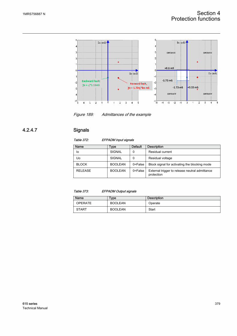
GUID-AE9BB46E-B927-43F6-881A-A96D3410268D V2 EN
Figure 189: Admittances of the example
4.2.4.7 Signals
Table 372: EFPADM Input signals
Name Type Default DescriptionIo SIGNAL 0 Residual current
Uo SIGNAL 0 Residual voltage
BLOCK BOOLEAN 0=False Block signal for activating the blocking mode
RELEASE BOOLEAN 0=False External trigger to release neutral admittanceprotection
Table 373: EFPADM Output signals
Name Type DescriptionOPERATE BOOLEAN Operate
START BOOLEAN Start
1MRS756887 N Section 4Protection functions
615 series 379Technical Manual
4.2.4.8 Settings
Table 374: EFPADM Group settings (Basic)
Parameter Values (Range) Unit Step Default DescriptionVoltage start value 0.01...2.00 xUn 0.01 0.15 Voltage start value
Directional mode 1=Non-directional2=Forward3=Reverse
2=Forward Directional mode
Operation mode 1=Yo2=Go3=Bo4=Yo, Go5=Yo, Bo6=Go, Bo7=Yo, Go, Bo
1=Yo Operation criteria
Operate delay time 60...200000 ms 10 60 Operate delay time
Circle radius 0.05...500.00 mS 0.01 1.00 Admittance circle radius
Circle conductance -500.00...500.00 mS 0.01 0.00 Admittance circle midpoint, conductance
Circle susceptance -500.00...500.00 mS 0.01 0.00 Admittance circle midpoint, susceptance
Conductance forward -500.00...500.00 mS 0.01 1.00 Conductance threshold in forwarddirection
Conductance reverse -500.00...500.00 mS 0.01 -1.00 Conductance threshold in reversedirection
Susceptance forward -500.00...500.00 mS 0.01 1.00 Susceptance threshold in forwarddirection
Susceptance reverse -500.00...500.00 mS 0.01 -1.00 Susceptance threshold in reversedirection
Table 375: EFPADM Group settings (Advanced)
Parameter Values (Range) Unit Step Default DescriptionConductance tilt Ang -30...30 deg 1 0 Tilt angle of conductance boundary line
Susceptance tilt Ang -30...30 deg 1 0 Tilt angle of susceptance boundary line
Table 376: EFPADM Non group settings (Basic)
Parameter Values (Range) Unit Step Default DescriptionOperation 1=on
5=off 1=on Operation Off / On
Table 377: EFPADM Non group settings (Advanced)
Parameter Values (Range) Unit Step Default DescriptionAdmittance Clc mode 1=Normal
2=Delta 1=Normal Admittance calculation mode
Reset delay time 0...60000 ms 1 20 Reset delay time
Pol reversal 0=False1=True
0=False Rotate polarizing quantity
Table continues on next page
Section 4 1MRS756887 NProtection functions
380 615 seriesTechnical Manual
Parameter Values (Range) Unit Step Default DescriptionMin operate current 0.01...1.00 xIn 0.01 0.01 Minimum operating current
Min operate voltage 0.01...1.00 xUn 0.01 0.01 Minimum operating voltage
Io signal Sel 1=Measured Io2=Calculated Io
1=Measured Io Selection for used Io signal
Uo signal Sel 1=Measured Uo2=Calculated Uo
1=Measured Uo Selection for used Uo signal
4.2.4.9 Monitored data
Table 378: EFPADM Monitored data
Name Type Values (Range) Unit DescriptionSTART_DUR FLOAT32 0.00...100.00 % Ratio of start time /
operate time
FAULT_DIR Enum 0=unknown1=forward2=backward3=both
Detected fault direction
COND_RES FLOAT32 -1000.00...1000.00
mS Real part of calculatedneutral admittance
SUS_RES FLOAT32 -1000.00...1000.00
mS Imaginary part ofcalculated neutraladmittance
EFPADM Enum 1=on2=blocked3=test4=test/blocked5=off
Status
4.2.4.10 Technical data
Table 379: EFPADM Technical data
Characteristic Value
Operation accuracy1) At the frequency f = fn
±1.0% or ±0.01 mS(In range of 0.5...100 mS)
Start time2) Minimum Typical Maximum
56 ms 60 ms 64 ms
Reset time 40 ms
Operate time accuracy ±1.0% of the set value of ±20 ms
Suppression of harmonics -50 dB at f = n × fn, where n = 2, 3, 4, 5,…
1) Uo = 1.0 × Un2) Includes the delay of the signal output contact, results based on statistical distribution of 1000
measurements
1MRS756887 N Section 4Protection functions
615 series 381Technical Manual
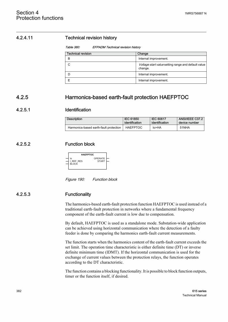
4.2.4.11 Technical revision history
Table 380: EFPADM Technical revision history
Technical revision ChangeB Internal improvement.
C Voltage start value setting range and default valuechange.
D Internal improvement.
E Internal improvement.
4.2.5 Harmonics-based earth-fault protection HAEFPTOC
4.2.5.1 Identification
Description IEC 61850identification
IEC 60617identification
ANSI/IEEE C37.2device number
Harmonics-based earth-fault protection HAEFPTOC Io>HA 51NHA
4.2.5.2 Function block
OPERATE
START
Io
HAEFPTOC
I_REF_RES
BLOCK
GUID-A27B40F5-1E7D-4880-BBC4-3B07B73E9067 V2 EN
Figure 190: Function block
4.2.5.3 Functionality
The harmonics-based earth-fault protection function HAEFPTOC is used instead of atraditional earth-fault protection in networks where a fundamental frequencycomponent of the earth-fault current is low due to compensation.
By default, HAEFPTOC is used as a standalone mode. Substation-wide applicationcan be achieved using horizontal communication where the detection of a faultyfeeder is done by comparing the harmonics earth-fault current measurements.
The function starts when the harmonics content of the earth-fault current exceeds theset limit. The operation time characteristic is either definite time (DT) or inversedefinite minimum time (IDMT). If the horizontal communication is used for theexchange of current values between the protection relays, the function operatesaccording to the DT characteristic.
The function contains a blocking functionality. It is possible to block function outputs,timer or the function itself, if desired.
Section 4 1MRS756887 NProtection functions
382 615 seriesTechnical Manual

4.2.5.4 Operation principle
The function can be enabled and disabled with the Operation setting. Thecorresponding parameter values are "On" and "Off".
The operation of HAEFPTOC can be described using a module diagram. All themodules in the diagram are explained in the next sections.
GUID-DFEDB90A-4ECE-4BAA-9987-87F02BA0798A V3 EN
Figure 191: Functional module diagram
Harmonics calculationThis module feeds the measured residual current to the high-pass filter, where thefrequency range is limited to start from two times the fundamental frequency of thenetwork (for example, in a 50 Hz network the cutoff frequency is 100 Hz), that is,summing the harmonic components of the network from the second harmonic. Theoutput of the filter, later referred to as the harmonics current, is fed to the Leveldetector and Current comparison modules.
The harmonics current I_HARM_RES is available in the monitored data view. Thevalue is also sent over horizontal communication to the other protection relays on theparallel feeders configured in the protection scheme.
1MRS756887 N Section 4Protection functions
615 series 383Technical Manual
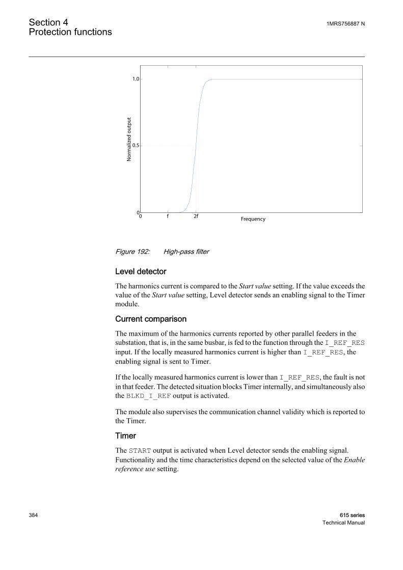
Nor
mal
ized
out
put
0.5
00
1.0
Frequency2ff
GUID-F05BA8C4-AC2B-420C-AE9D-946E815682D5 V1 EN
Figure 192: High-pass filter
Level detectorThe harmonics current is compared to the Start value setting. If the value exceeds thevalue of the Start value setting, Level detector sends an enabling signal to the Timermodule.
Current comparisonThe maximum of the harmonics currents reported by other parallel feeders in thesubstation, that is, in the same busbar, is fed to the function through the I_REF_RESinput. If the locally measured harmonics current is higher than I_REF_RES, theenabling signal is sent to Timer.
If the locally measured harmonics current is lower than I_REF_RES, the fault is notin that feeder. The detected situation blocks Timer internally, and simultaneously alsothe BLKD_I_REF output is activated.
The module also supervises the communication channel validity which is reported tothe Timer.
TimerThe START output is activated when Level detector sends the enabling signal.Functionality and the time characteristics depend on the selected value of the Enablereference use setting.
Section 4 1MRS756887 NProtection functions
384 615 seriesTechnical Manual
Table 381: Values of the Enable reference use setting
Enable reference use FunctionalityStandalone In the standalone mode, depending on the value of the
Operating curve type setting, the time characteristics areaccording to DT or IDMT. When the operation timer hasreached the value of the Operate delay time setting in theDT mode or the value defined by the inverse time curve,the OPERATE output is activated.
Reference use Communicationvalid
When using the horizontal communication, the function isforced to use the DT characteristics. When the operationtimer has reached the value of the Minimum operate timesetting and simultaneously the enabling signal from theCurrent comparison module is active, the OPERATE signalis activated.
Communicationinvalid
Function operates as in the standalone mode.
The Enable reference use setting forces the function to use the DTcharacteristics where the operating time is set with the Minimumoperate time setting.
If the communication for some reason fails, the function switches to use the Operationcurve type setting, and if DT is selected, Operate delay time is used. If the IDMT curveis selected, the time characteristics are according to the selected curve and theMinimum operate time setting is used for restricting too fast an operation time.
In case of a communication failure, the start duration may change substantiallydepending on the user settings.
When the programmable IDMT curve is selected, the operation time characteristicsare defined with the Curve parameter A, Curve parameter B, Curve parameter C,Curve parameter D and Curve parameter E parameters.
If a drop-off situation happens, that is, a fault suddenly disappears before the operationdelay is exceeded, the Timer reset state is activated. The functionality of Timer in thereset state depends on the combination of the Operating curve type, Type of resetcurve and Reset delay time settings. When the DT characteristic is selected, the resettimer runs until the value of the Reset delay time setting is exceeded. When the IDMTcurves are selected, the Type of reset curve setting can be set to "Immediate", "Deftime reset" or "Inverse reset". The reset curve type "Immediate" causes an immediatereset. With the reset curve type "Def time reset", the reset time depends on the Resetdelay time setting. With the reset curve type "Inverse reset", the reset time depends onthe current during the drop-off situation. If the drop-off situation continues, the resettimer is reset and the START output is deactivated.
The "Inverse reset" selection is only supported with ANSI or theprogrammable types of the IDMT operating curves. If anotheroperating curve type is selected, an immediate reset occurs during thedrop-off situation.
1MRS756887 N Section 4Protection functions
615 series 385Technical Manual
The setting Time multiplier is used for scaling the IDMT operation and reset times.
The setting parameter Minimum operate time defines the minimum desired operationtime for IDMT. The setting is applicable only when the IDMT curves are used
The Minimum operate time setting should be used with great carebecause the operation time is according to the IDMT curve but alwaysat least the value of the Minimum operate time setting. Moreinformation can be found in the IDMT curves for overcurrentprotection.
Timer calculates the start duration value START_DUR, which indicates thepercentage ratio of the start situation, and the set operating time, which can be eitheraccording to DT or IDMT. The value is available in the monitored data view.
More information can be found in the General function block features.
Blocking logicThere are three operation modes in the blocking function. The operation modes arecontrolled by the BLOCK input and the global setting in Configuration/System/Blocking mode which selects the blocking mode. The BLOCK input can be controlledby a binary input, a horizontal communication input or an internal signal of theprotection relay's program. The influence of the BLOCK signal activation ispreselected with the global setting Blocking mode.
The Blocking mode setting has three blocking methods. In the "Freeze timers" mode,the operation timer is frozen to the prevailing value, but the OPERATE output is notdeactivated when blocking is activated. In the "Block all" mode, the whole function isblocked and the timers are reset. In the "Block OPERATE output" mode, the functionoperates normally but the OPERATE output is not activated.
4.2.5.5 Application
During an earth fault, HAEFPTOC calculates the maximum current for the currentfeeder. The value is sent over an analog GOOSE to other protection relays of thebusbar in the substation. At the configuration level, all the values received over theanalog GOOSE are compared through the MAX function to find the maximum value.The maximum value is sent back to HAEFPTOC as the I_REF_RES input. Theoperation of HAEFPTOC is allowed in case I_REF_RES is lower than the locallymeasured harmonics current. If I_REF_RES exceeds the locally measuredharmonics current, the operation of HAEFPTOC is blocked.
Section 4 1MRS756887 NProtection functions
386 615 seriesTechnical Manual
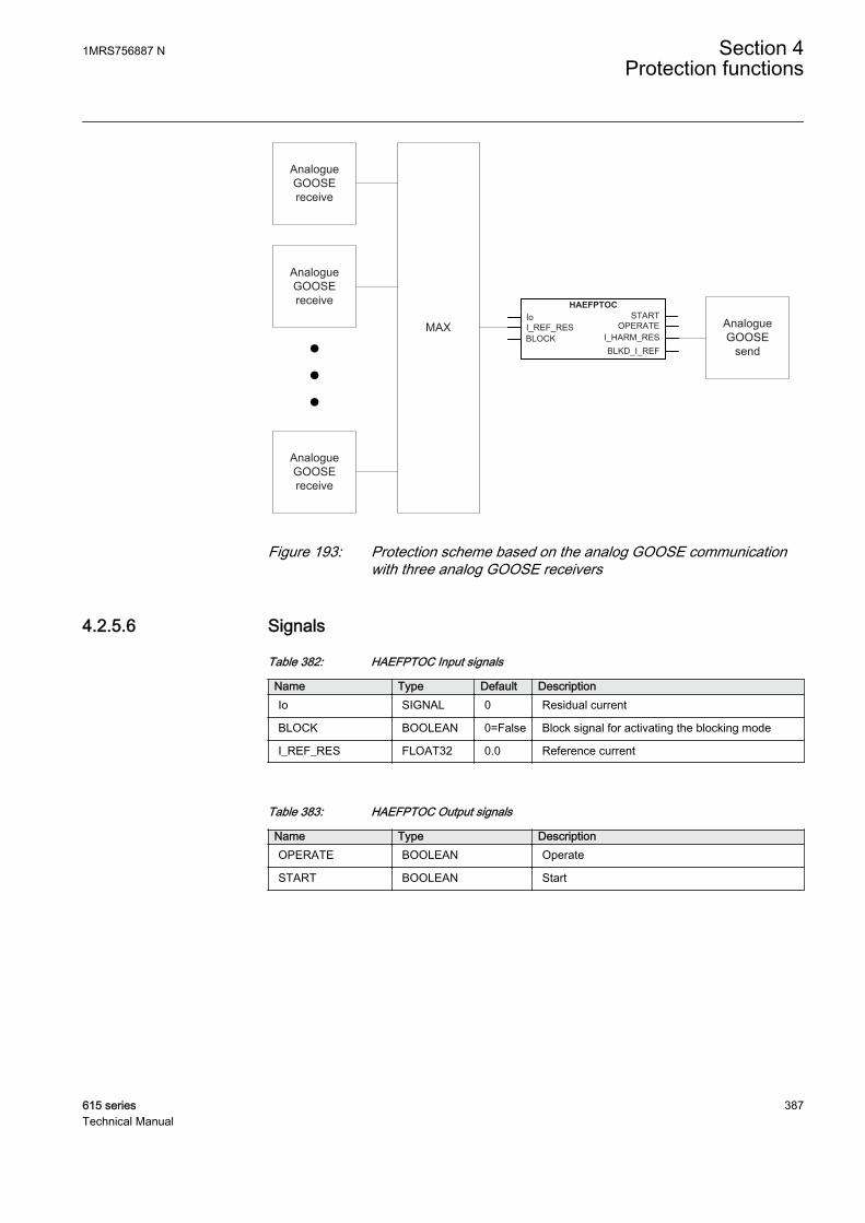
AnalogueGOOSE receive
AnalogueGOOSE receive
AnalogueGOOSE receive
MAX AnalogueGOOSE
send
HAEFPTOC
I_REF_RESBLOCK
STARTOPERATE
Io
I_HARM_RESBLKD_I_REF
GUID-4F4792F0-B311-4EB2-8EC8-56F062592158 V1 EN
Figure 193: Protection scheme based on the analog GOOSE communicationwith three analog GOOSE receivers
4.2.5.6 Signals
Table 382: HAEFPTOC Input signals
Name Type Default DescriptionIo SIGNAL 0 Residual current
BLOCK BOOLEAN 0=False Block signal for activating the blocking mode
I_REF_RES FLOAT32 0.0 Reference current
Table 383: HAEFPTOC Output signals
Name Type DescriptionOPERATE BOOLEAN Operate
START BOOLEAN Start
1MRS756887 N Section 4Protection functions
615 series 387Technical Manual

4.2.5.7 Settings
Table 384: HAEFPTOC Group settings (Basic)
Parameter Values (Range) Unit Step Default DescriptionStart value 0.05...5.00 xIn 0.01 0.10 Start value
Time multiplier 0.05...15.00 0.01 1.00 Time multiplier in IEC/ANSI IDMT curves
Operate delay time 100...200000 ms 10 600 Operate delay time
Operating curve type 1=ANSI Ext. inv.2=ANSI Very inv.3=ANSI Norm. inv.4=ANSI Mod. inv.5=ANSI Def. Time6=L.T.E. inv.7=L.T.V. inv.8=L.T. inv.9=IEC Norm. inv.10=IEC Very inv.11=IEC inv.12=IEC Ext. inv.13=IEC S.T. inv.14=IEC L.T. inv.15=IEC Def. Time17=Programmable18=RI type19=RD type
15=IEC Def. Time Selection of time delay curve type
Table 385: HAEFPTOC Group settings (Advanced)
Parameter Values (Range) Unit Step Default DescriptionMinimum operate time 100...200000 ms 10 500 Minimum operate time for IDMT curves
Type of reset curve 1=Immediate2=Def time reset3=Inverse reset
1=Immediate Selection of reset curve type
Enable reference use 0=False1=True
0=False Enable using current reference from otherIEDs instead of stand-alone
Table 386: HAEFPTOC Non group settings (Basic)
Parameter Values (Range) Unit Step Default DescriptionOperation 1=on
5=off 1=on Operation Off / On
Curve parameter A 0.0086...120.0000 1 28.2000 Parameter A for customer programmablecurve
Curve parameter B 0.0000...0.7120 1 0.1217 Parameter B for customer programmablecurve
Curve parameter C 0.02...2.00 1 2.00 Parameter C for customer programmablecurve
Curve parameter D 0.46...30.00 1 29.10 Parameter D for customer programmablecurve
Curve parameter E 0.0...1.0 1 1.0 Parameter E for customer programmablecurve
Section 4 1MRS756887 NProtection functions
388 615 seriesTechnical Manual

Table 387: HAEFPTOC Non group settings (Advanced)
Parameter Values (Range) Unit Step Default DescriptionReset delay time 0...60000 ms 10 20 Reset delay time
4.2.5.8 Monitored data
Table 388: HAEFPTOC Monitored data
Name Type Values (Range) Unit DescriptionSTART_DUR FLOAT32 0.00...100.00 % Ratio of start time /
operate time
I_HARM_RES FLOAT32 0.0...30000.0 A Calculated harmonicscurrent
BLKD_I_REF BOOLEAN 0=False1=True
Current comparisonstatus indicator
HAEFPTOC Enum 1=on2=blocked3=test4=test/blocked5=off
Status
4.2.5.9 Technical data
Table 389: HAEFPTOC Technical data
Characteristic ValueOperation accuracy Depending on the frequency of the measured
current: fn ±2 Hz
±5% of the set value or ±0.004 × In
Start time 1)2) Typically 77 ms
Reset time Typically 40 ms
Reset ratio Typically 0.96
Operate time accuracy in definite time mode ±1.0% of the set value or ±20 ms
Operate time accuracy in IDMT mode 3) ±5.0% of the set value or ±20 ms
Suppression of harmonics -50 dB at f = fn
-3 dB at f = 13 × fn
1) Fundamental frequency current = 1.0 × In, harmonics current before fault = 0.0 × In, harmonics faultcurrent 2.0 × Start value, results based on statistical distribution of 1000 measurements
2) Includes the delay of the signal output contact3) Maximum Start value = 2.5 × In, Start value multiples in range of 2...20
1MRS756887 N Section 4Protection functions
615 series 389Technical Manual

4.2.5.10 Technical revision history
Table 390: HAEFPTOC Technical revision history
Technical revision ChangeB Internal improvement.
C Internal improvement.
4.2.6 Wattmetric-based earth-fault protection WPWDE
4.2.6.1 Identification
Function description IEC 61850identification
IEC 60617identification
ANSI/IEEE C37.2device number
Wattmetric-based earth-fault protection WPWDE Po> -> 32N
4.2.6.2 Function block
GUID-EDE21448-13FD-44E3-AF7C-CFD47A5C99DC V1 EN
Figure 194: Function block
4.2.6.3 Functionality
The wattmetric-based earth-fault protection function WPWDE can be used to detectearth faults in unearthed networks, compensated networks (Petersen coil-earthednetworks) or networks with a high-impedance earthing. It can be used as an alternativesolution to the traditional residual current-based earth-fault protection functions, forexample, the IoCos mode in the directional earth-fault protection functionDEFxPDEF.
WPWDE measures the earth-fault power 3UoIoCosφ and gives an operating signalwhen the residual current Io, residual voltage Uo and the earth-fault power exceed theset limits and the angle (φ) between the residual current and the residual voltage isinside the set operating sector, that is, forward or backward sector. The operating timecharacteristic can be selected to be either definite time (DT) or a special wattmetric-type inverse definite minimum type (wattmetric type IDMT).
The wattmetric-based earth-fault protection is very sensitive to current transformererrors and it is recommended that a core balance CT is used for measuring the residualcurrent.
The function contains a blocking functionality. It is possible to block function outputs,timers or the function itself, if desired.
Section 4 1MRS756887 NProtection functions
390 615 seriesTechnical Manual

4.2.6.4 Operation principle
The function can be enabled and disabled with the Operation setting. Thecorresponding parameter values are "On" and "Off".
For WPWDE, certain notations and definitions are used.Residual voltage Uo = (UA+UB+UC)/3 = U0, where U0 = zero-sequence voltageResidual current Io = -(IA+IB+IC) = 3×- I0, where I0 = zero-sequencecurrentThe minus sign (-) is needed to match the polarity of calculated andmeasured residual currents.
The operation of WPWDE can be described with a module diagram. All the modulesin the diagram are explained in the next sections.
Directionalcalculation
Leveldetector
Io
Residualpower
calculation
Uo
BLOCK
OPERATE
START
RCA_CTL
t
Timer
t
Blockinglogic
GUID-2E3B73F0-DB0D-4E84-839F-8E12D6528EEC V1 EN
Figure 195: Function module diagram
Directional calculationThe Directional calculation module monitors the angle between the operating quantity(residual current Io) and polarizing quantity (residual voltage Uo). The operatingquantity can be selected with the setting Io signal Sel. The selectable options are“Measured Io” and “Calculated Io”. The polarizing quantity can be selected with thesetting Pol signal Sel. The selectable options are “Measured Uo” and “CalculatedUo”. When the angle between operating quantity and polarizing quantity afterconsidering the Characteristic angle setting is in the operation sector, the modulesends an enabling signal to Level detector. The directional operation is selected withthe Directional mode setting. Either the “Forward” or “Reverse” operation mode canbe selected. The direction of fault is calculated based on the phase angle differencebetween the operating quantity Io and polarizing quantity Uo, and the value (ANGLE)is available in the monitored data view.
In the phasor diagrams representing the operation of WPWDE, the polarity of thepolarizing quantity (residual voltage Uo) is reversed. Reversing is done by switching
1MRS756887 N Section 4Protection functions
615 series 391Technical Manual
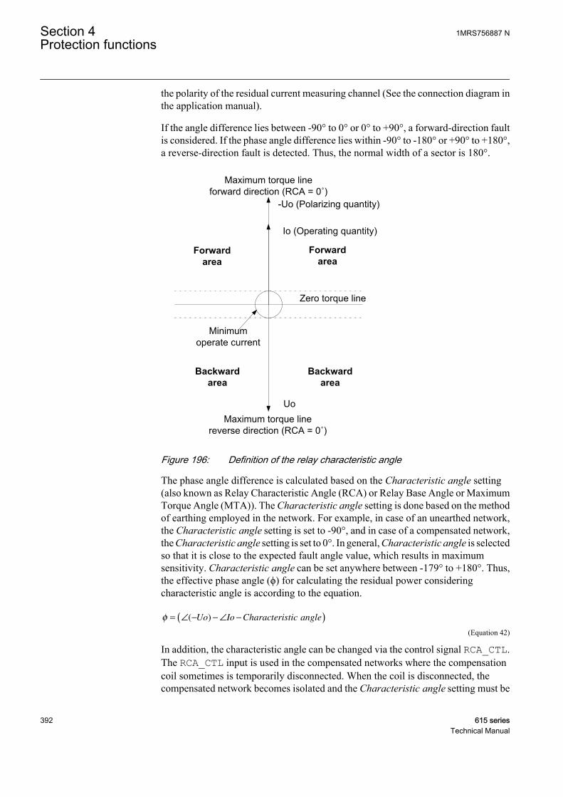
the polarity of the residual current measuring channel (See the connection diagram inthe application manual).
If the angle difference lies between -90° to 0° or 0° to +90°, a forward-direction faultis considered. If the phase angle difference lies within -90° to -180° or +90° to +180°,a reverse-direction fault is detected. Thus, the normal width of a sector is 180°.
GUID-A665FD59-1AD1-40B0-9741-A5DBFD0D0F2E V1 EN
Figure 196: Definition of the relay characteristic angle
The phase angle difference is calculated based on the Characteristic angle setting(also known as Relay Characteristic Angle (RCA) or Relay Base Angle or MaximumTorque Angle (MTA)). The Characteristic angle setting is done based on the methodof earthing employed in the network. For example, in case of an unearthed network,the Characteristic angle setting is set to -90°, and in case of a compensated network,the Characteristic angle setting is set to 0°. In general, Characteristic angle is selectedso that it is close to the expected fault angle value, which results in maximumsensitivity. Characteristic angle can be set anywhere between -179° to +180°. Thus,the effective phase angle (ϕ) for calculating the residual power consideringcharacteristic angle is according to the equation.
φ = ∠ − − ∠ −( )( )Uo Io Characteristic angle
GUID-D538B6BE-5A4E-4D96-850E-A8555FC57C4A V1 EN (Equation 42)
In addition, the characteristic angle can be changed via the control signal RCA_CTL.The RCA_CTL input is used in the compensated networks where the compensationcoil sometimes is temporarily disconnected. When the coil is disconnected, thecompensated network becomes isolated and the Characteristic angle setting must be
Section 4 1MRS756887 NProtection functions
392 615 seriesTechnical Manual
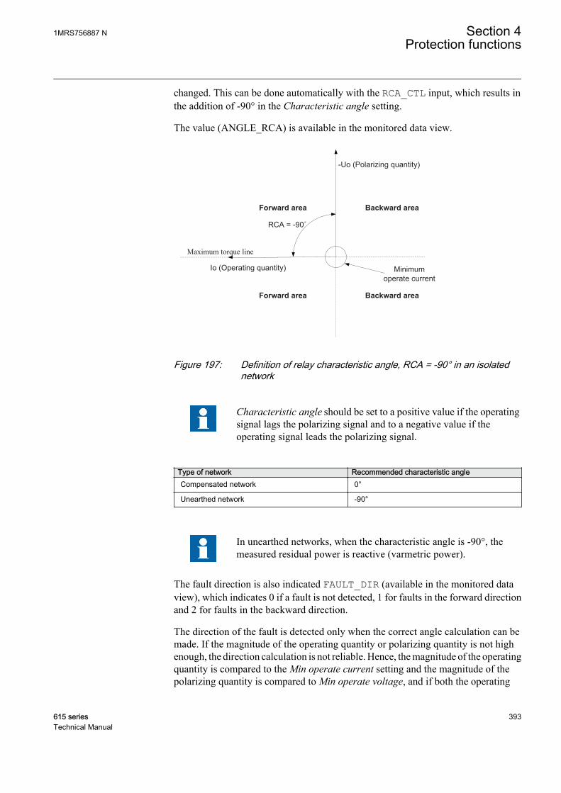
changed. This can be done automatically with the RCA_CTL input, which results inthe addition of -90° in the Characteristic angle setting.
The value (ANGLE_RCA) is available in the monitored data view.
-Uo (Polarizing quantity)
Forward area
Io (Operating quantity)
RCA = -90˚
Maximum torque line
Backward area
Minimumoperate current
Forward area Backward area
GUID-AA58DBE0-CBFC-4820-BA4A-195A11FE273B V1 EN
Figure 197: Definition of relay characteristic angle, RCA = -90° in an isolatednetwork
Characteristic angle should be set to a positive value if the operatingsignal lags the polarizing signal and to a negative value if theoperating signal leads the polarizing signal.
Type of network Recommended characteristic angleCompensated network 0°
Unearthed network -90°
In unearthed networks, when the characteristic angle is -90°, themeasured residual power is reactive (varmetric power).
The fault direction is also indicated FAULT_DIR (available in the monitored dataview), which indicates 0 if a fault is not detected, 1 for faults in the forward directionand 2 for faults in the backward direction.
The direction of the fault is detected only when the correct angle calculation can bemade. If the magnitude of the operating quantity or polarizing quantity is not highenough, the direction calculation is not reliable. Hence, the magnitude of the operatingquantity is compared to the Min operate current setting and the magnitude of thepolarizing quantity is compared to Min operate voltage, and if both the operating
1MRS756887 N Section 4Protection functions
615 series 393Technical Manual

quantity and polarizing quantity are higher than their respective limit, a valid angle iscalculated and the residual power calculation module is enabled.
The Correction angle setting can be used to improve the selectivity when there areinaccuracies due to the measurement transformer. The setting decreases the operationsector. The Correction angle setting should be done carefully as the phase angle errorof the measurement transformer varies with the connected burden as well as with themagnitude of the actual primary current that is being measured. An example of howCorrection angle alters the operating region is as shown:
-Uo (Polarizing quantity)
Backwardarea
Forwardarea
Io (Operating quantity)
Zero torque line
Minimumoperate current
Maximum torque line forward direction (RCA = 0˚)
Correction angleCorrection angle
Forwardarea
Backwardarea
GUID-B420E2F4-8293-4330-A7F3-9A002940F2A4 V1 EN
Figure 198: Definition of correction angle
The polarity of the polarizing quantity can be changed (rotated by180°) by setting Pol reversal to "True" or by switching the polarity ofthe residual voltage measurement wires.
Residual power calculationThe Residual power calculation module calculates the magnitude of residual power3UoIoCosφ. Angle φ is the angle between the operating quantity and polarizingquantity, compensated with a characteristic angle. The angle value is received fromthe Directional calculation module. The Directional calculation module enables theresidual power calculation only if the minimum signal levels for both operatingquantity and polarizing quantity are exceeded. However, if the angle calculation is notvalid, the calculated residual power is zero. Residual power (RES_POWER) iscalculated continuously and it is available in the monitored data view. The power isgiven in relation to nominal power calculated as Pn = Un × In, where Un and In are
Section 4 1MRS756887 NProtection functions
394 615 seriesTechnical Manual
obtained from the entered voltage transformer and current transformer ratios entered,and depend on the Io signal Sel and Uo signal Sel settings.
Level detectorLevel detector compares the magnitudes of the measured operating quantity (residualcurrent Io), polarizing quantity (residual voltage Uo) and calculated residual power tothe set Current start value (×In), Voltage start value (×Un) and Power start value(×Pn) respectively. When all three quantities exceed the limits, Level detector enablesthe Timer module.
When calculating the setting values for Level detector, it must be considered that thenominal values for current, voltage and power depend on whether the residualquantities are measured from a dedicated measurement channel or calculated fromphase quantities, as defined in the Io signal Sel and Uo signal Sel settings.
For residual current Io, if "Measured Io" is selected, the nominal values for primaryand secondary are obtained from the current transformer ratio entered for residualcurrent channel Configuration/Analog inputs/Current (Io, CT). If "Calculated Io"is selected, the nominal values for primary and secondary are obtained from thecurrent transformer ratio entered for phase current channels Configuration/Analoginputs/Current (3I, CT).
For residual voltage Uo, if "Measured Uo" is selected, the nominal values for primaryand secondary are obtained from the voltage transformer ratio entered for residualvoltage channel Configuration/Analog inputs/Voltage (Uo, VT). If "CalculatedUo" is selected, the nominal values for primary and secondary are obtained from thevoltage transformer ratio entered for phase voltage channels Configuration/Analoginputs/Voltage (3U, VT).
Calculated Uo requires that all three phase-to-earth voltages areconnected to the protection relay. Uo cannot be calculated from thephase-to-phase voltages.
As nominal power is the result of the multiplication of the nominal current and thenominal voltage Pn = Un × In, the calculation of the setting value for Power start value(×Pn) depends on whether Io and Uo are measured or calculated from the phasequantities.
Table 391: Measured and calculated Io and Uo
Measured Io Calculated IoMeasured Uo Pn = (Uo, VT) × (Io, CT) Pn = (Uo, VT) × (3I, CT)
Calculated Uo Pn = (3U, VT) × (Io, CT) Pn = (3U, VT) × (3I, CT)
Example 1. Io is measured with cable core CT (100/1A) and Uo is measured fromopen delta-connected VTs (20/sqrt(3) kV:100/sqrt(3) V:100/3 V). In this case,"Measured Io" and "Measured Uo" are selected. The nominal values for residualcurrent and residual voltage are obtained from CT and VT ratios.
1MRS756887 N Section 4Protection functions
615 series 395Technical Manual
Residual current Io: Configuration/Analog inputs/Current (Io, CT): 100 A:1 A
Residual voltage Uo: Configuration/Analog inputs/Current (Uo, VT): 11.547 kV:100 V
Residual Current start value of 1.0 × In corresponds then 1.0 × 100 A = 100 A inprimary
Residual Voltage start value of 1.0 × Un corresponds then 1.0 × 11.547 kV = 11.547kV in primary
Residual Power start value of 1.0 × Pn corresponds then 1.0 × 11.547 kV × 100 A =1154.7kW in primary
Example 2. Both Io and Uo are calculated from phase quantities. Phase CT-ratio is100:1 A and Phase VT-ratio 20/sqrt(3) kV:100/sqrt(3) V. In this case "Calculated Io"and "Calculated Uo" are selected. The nominal values for residual current and residualvoltage are obtained from CT and VT ratios entered in:
Residual current Io: Configuration/Analog inputs/Current (3I, CT): 100 A:1 A
Residual voltage Uo: Configuration/Analog inputs/Current (3U, VT): 20.000 kV:100 V
Residual Current start value of 1.0 × In corresponds then 1.0 × 100 A = 100 A inprimary
Residual Voltage start value of 1.0 × Un corresponds then 1.0 × 20.000 kV = 20.000kV in primary
Residual Power start value of 1.0 × Pn corresponds then 1.0 × 20.000 kV × 100 A =2000kW in primary
If "Calculated Uo" is selected for the Uo signal Sel setting, thenominal value for residual voltage Un is always phase-to-phasevoltage. Thus, the valid maximum setting for residual Voltage startvalue is 0.577 × Un, which corresponds to full phase-to-earth voltagein primary.
TimerOnce activated, Timer activates the START output. Depending on the value of theOperating curve type setting, the time characteristics are according to DT orwattmetric IDMT. When the operation timer has reached the value of Operate delaytime in the DT mode or the maximum value defined by the inverse time curve, theOPERATE output is activated. If a drop-off situation happens, that is, a fault suddenlydisappears before the operating delay is exceeded, the timer reset state is activated.The reset time is identical for both DT or wattmeter IDMT. The reset time depends onthe Reset delay time setting.
Section 4 1MRS756887 NProtection functions
396 615 seriesTechnical Manual

Timer calculates the start duration value START_DUR, which indicates thepercentage ratio of the start situation and the set operation time. The value is availablein the monitored data view.
Blocking logicThere are three operation modes in the blocking function. The operation modes arecontrolled by the BLOCK input and the global setting in Configuration/System/Blocking mode which selects the blocking mode. The BLOCK input can be controlledby a binary input, a horizontal communication input or an internal signal of theprotection relay's program. The influence of the BLOCK signal activation ispreselected with the global setting Blocking mode.
The Blocking mode setting has three blocking methods. In the "Freeze timers" mode,the operation timer is frozen to the prevailing value, but the OPERATE output is notdeactivated when blocking is activated. In the "Block all" mode, the whole function isblocked and the timers are reset. In the "Block OPERATE output" mode, the functionoperates normally but the OPERATE output is not activated.
4.2.6.5 Timer characteristics
In the wattmetric IDMT mode, the OPERATE output is activated based on the timercharacteristics:
t sk P
Pcal
[ ]*
=ref
GUID-FEA556F2-175E-4BDD-BD0F-52E9F5499CA8 V3 EN (Equation 43)
t[s] operation time in seconds
k set value of Time multiplier
Pref set value of Reference power
Pcal calculated residual power
1MRS756887 N Section 4Protection functions
615 series 397Technical Manual
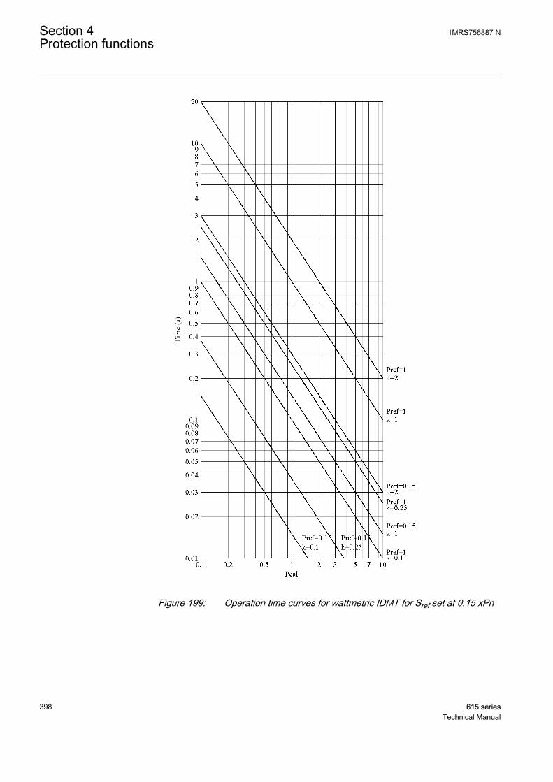
GUID-D2ABEA2C-B0E3-4C60-8E70-404E7C62C5FC V1 EN
Figure 199: Operation time curves for wattmetric IDMT for Sref set at 0.15 xPn
Section 4 1MRS756887 NProtection functions
398 615 seriesTechnical Manual
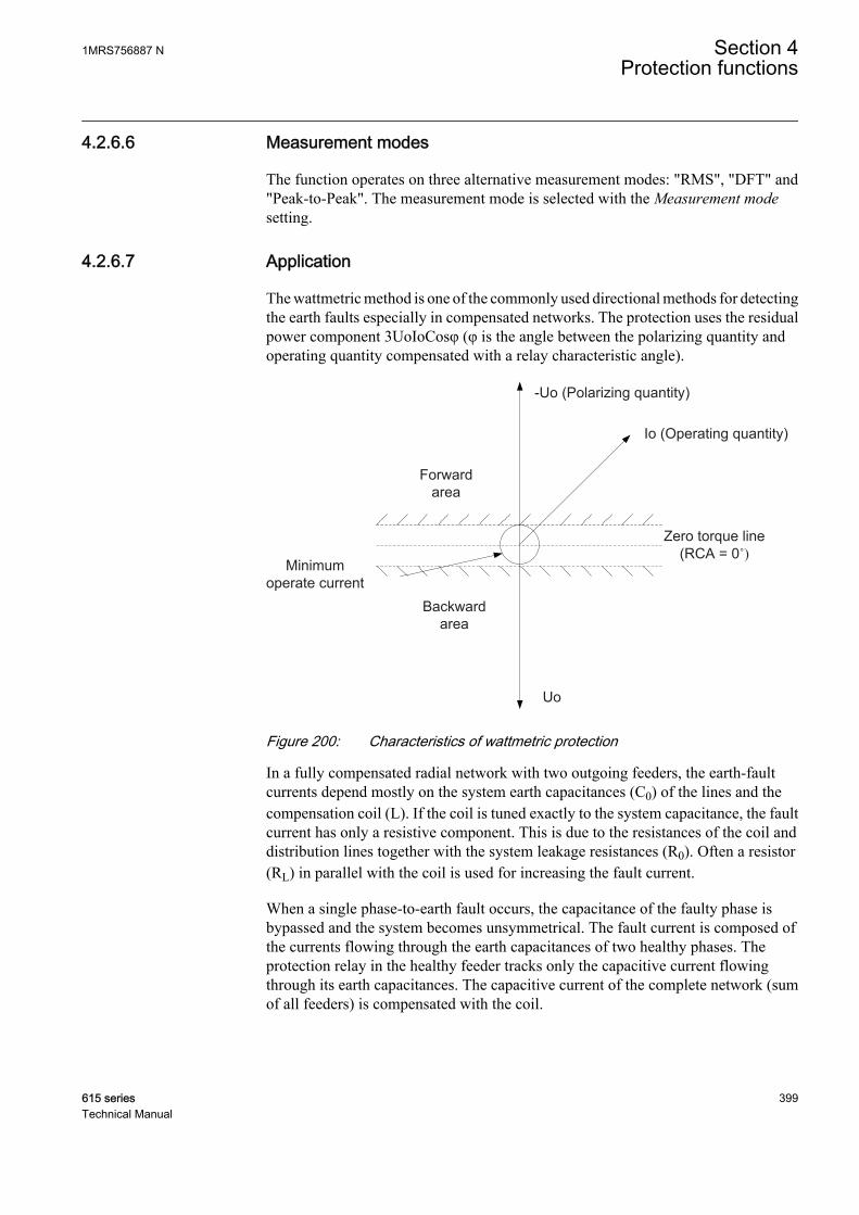
4.2.6.6 Measurement modes
The function operates on three alternative measurement modes: "RMS", "DFT" and"Peak-to-Peak". The measurement mode is selected with the Measurement modesetting.
4.2.6.7 Application
The wattmetric method is one of the commonly used directional methods for detectingthe earth faults especially in compensated networks. The protection uses the residualpower component 3UoIoCosφ (φ is the angle between the polarizing quantity andoperating quantity compensated with a relay characteristic angle).
-Uo (Polarizing quantity)
Uo
Backward area
Forwardarea
Io (Operating quantity)
Zero torque line(RCA = 0˚)
Minimumoperate current
GUID-4E73135C-CEEF-41DE-8091-9849C167C701 V1 EN
Figure 200: Characteristics of wattmetric protection
In a fully compensated radial network with two outgoing feeders, the earth-faultcurrents depend mostly on the system earth capacitances (C0) of the lines and thecompensation coil (L). If the coil is tuned exactly to the system capacitance, the faultcurrent has only a resistive component. This is due to the resistances of the coil anddistribution lines together with the system leakage resistances (R0). Often a resistor(RL) in parallel with the coil is used for increasing the fault current.
When a single phase-to-earth fault occurs, the capacitance of the faulty phase isbypassed and the system becomes unsymmetrical. The fault current is composed ofthe currents flowing through the earth capacitances of two healthy phases. Theprotection relay in the healthy feeder tracks only the capacitive current flowingthrough its earth capacitances. The capacitive current of the complete network (sumof all feeders) is compensated with the coil.
1MRS756887 N Section 4Protection functions
615 series 399Technical Manual
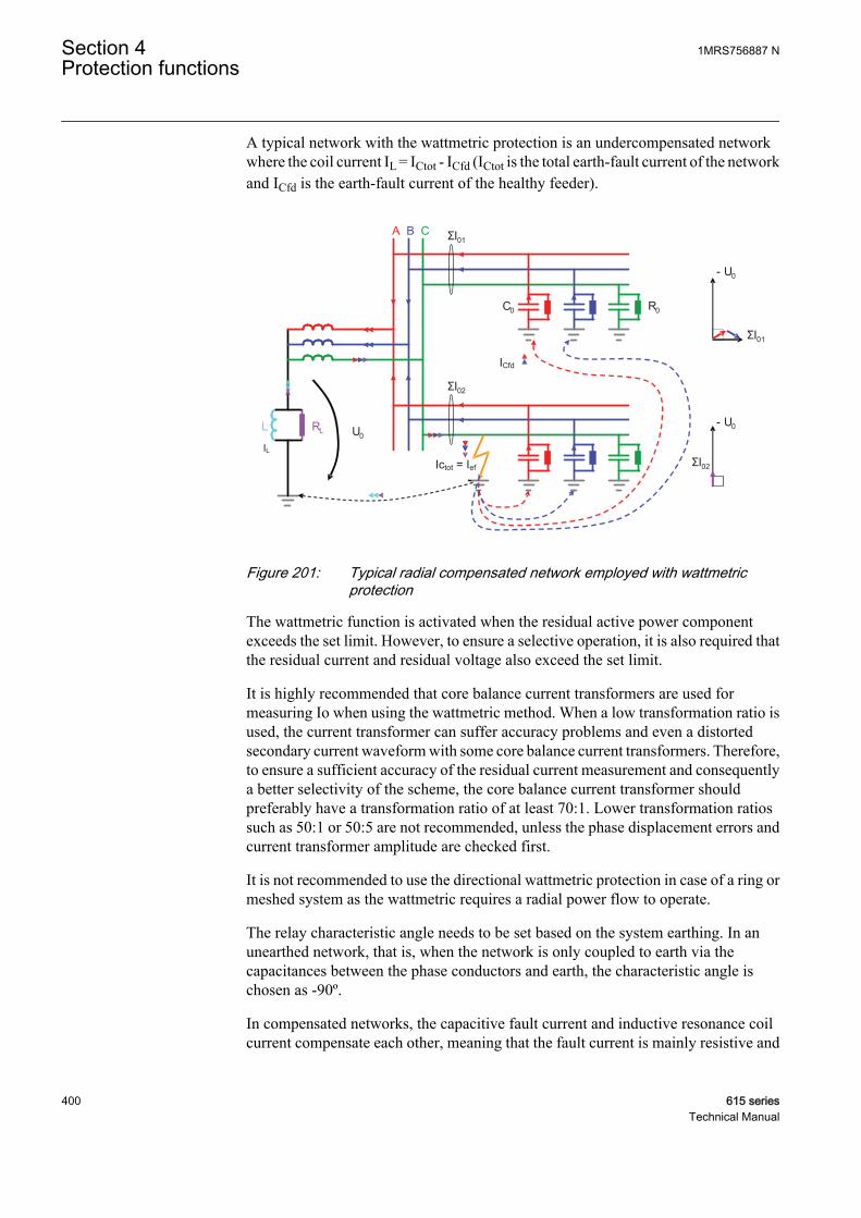
A typical network with the wattmetric protection is an undercompensated networkwhere the coil current IL = ICtot - ICfd (ICtot is the total earth-fault current of the networkand ICfd is the earth-fault current of the healthy feeder).
A B C
U0
C0
ΣI01
ΣI02
- U0
ΣI02
R0
L RL
- U0
ΣI01
IL
ICfd
Ictot = Ief
GUID-A524D89C-35D8-4C07-ABD6-3A6E21AF890E V1 EN
Figure 201: Typical radial compensated network employed with wattmetricprotection
The wattmetric function is activated when the residual active power componentexceeds the set limit. However, to ensure a selective operation, it is also required thatthe residual current and residual voltage also exceed the set limit.
It is highly recommended that core balance current transformers are used formeasuring Io when using the wattmetric method. When a low transformation ratio isused, the current transformer can suffer accuracy problems and even a distortedsecondary current waveform with some core balance current transformers. Therefore,to ensure a sufficient accuracy of the residual current measurement and consequentlya better selectivity of the scheme, the core balance current transformer shouldpreferably have a transformation ratio of at least 70:1. Lower transformation ratiossuch as 50:1 or 50:5 are not recommended, unless the phase displacement errors andcurrent transformer amplitude are checked first.
It is not recommended to use the directional wattmetric protection in case of a ring ormeshed system as the wattmetric requires a radial power flow to operate.
The relay characteristic angle needs to be set based on the system earthing. In anunearthed network, that is, when the network is only coupled to earth via thecapacitances between the phase conductors and earth, the characteristic angle ischosen as -90º.
In compensated networks, the capacitive fault current and inductive resonance coilcurrent compensate each other, meaning that the fault current is mainly resistive and
Section 4 1MRS756887 NProtection functions
400 615 seriesTechnical Manual

has zero phase shift compared to the residual voltage. In such networks, thecharacteristic angle is chosen as 0º. Often the magnitude of an active component issmall and must be increased by means of a parallel resistor in a compensation coil. Innetworks where the neutral point is earthed through a low resistance, the characteristicangle is always 0º.
As the amplitude of the residual current is independent of the fault location, theselectivity of the earth-fault protection is achieved with time coordination.
The use of wattmetric protection gives a possibility to use the dedicated inversedefinite minimum time characteristics. This is applicable in large high-impedanceearthed networks with a large capacitive earth-fault current.
In a network employing a low-impedance earthed system, a medium-size neutral pointresistor is used. Such a resistor gives a resistive earth-fault current component of about200...400 A for an excessive earth fault. In such a system, the directional residualpower protection gives better possibilities for selectivity enabled by the inverse timepower characteristics.
4.2.6.8 Signals
Table 392: WPWDE Input signals
Name Type Default DescriptionIo SIGNAL 0 Residual current
Uo SIGNAL 0 Residual voltage
BLOCK BOOLEAN 0=False Block signal for activating the blocking mode
RCA_CTL BOOLEAN 0=False Relay characteristic angle control
Table 393: WPWDE Output signals
Name Type DescriptionOPERATE BOOLEAN Operate
START BOOLEAN Start
4.2.6.9 Settings
Table 394: WPWDE Group settings (Basic)
Parameter Values (Range) Unit Step Default DescriptionDirectional mode 2=Forward
3=Reverse 2=Forward Directional mode
Current start value 0.010...5.000 xIn 0.001 0.010 Minimum operate residual current fordeciding fault direction
Voltage start value 0.010...1.000 xUn 0.001 0.010 Start value for residual voltage
Power start value 0.003...1.000 xPn 0.001 0.003 Start value for residual active power
Reference power 0.050...1.000 xPn 0.001 0.150 Reference value of residual power forWattmetric IDMT curves
Table continues on next page
1MRS756887 N Section 4Protection functions
615 series 401Technical Manual

Parameter Values (Range) Unit Step Default DescriptionCharacteristic angle -179...180 deg 1 -90 Characteristic angle
Time multiplier 0.05...2.00 0.01 1.00 Time multiplier for Wattmetric IDMTcurves
Operating curve type 5=ANSI Def. Time15=IEC Def. Time20=WattmetricIDMT
15=IEC Def. Time Selection of time delay curve type
Operate delay time 60...200000 ms 10 60 Operate delay time for definite time
Table 395: WPWDE Non group settings (Basic)
Parameter Values (Range) Unit Step Default DescriptionOperation 1=on
5=off 1=on Operation Off / On
Table 396: WPWDE Non group settings (Advanced)
Parameter Values (Range) Unit Step Default DescriptionMeasurement mode 1=RMS
2=DFT3=Peak-to-Peak
2=DFT Selects used current measurement mode
Correction angle 0.0...10.0 deg 0.1 2.0 Angle correction
Min operate current 0.010...1.000 xIn 0.001 0.010 Minimum operating current
Min operate voltage 0.01...1.00 xUn 0.01 0.01 Minimum operating voltage
Reset delay time 0...60000 ms 1 20 Reset delay time
Pol reversal 0=False1=True
0=False Rotate polarizing quantity
Io signal Sel 1=Measured Io2=Calculated Io
1=Measured Io Selection for used Io signal
Uo signal Sel 1=Measured Uo2=Calculated Uo
1=Measured Uo Selection for used polarization signal
4.2.6.10 Monitored data
Table 397: WPWDE Monitored data
Name Type Values (Range) Unit DescriptionFAULT_DIR Enum 0=unknown
1=forward2=backward3=both
Detected fault direction
START_DUR FLOAT32 0.00...100.00 % Ratio of start time /operate time
DIRECTION Enum 0=unknown1=forward2=backward3=both
Direction information
Table continues on next page
Section 4 1MRS756887 NProtection functions
402 615 seriesTechnical Manual
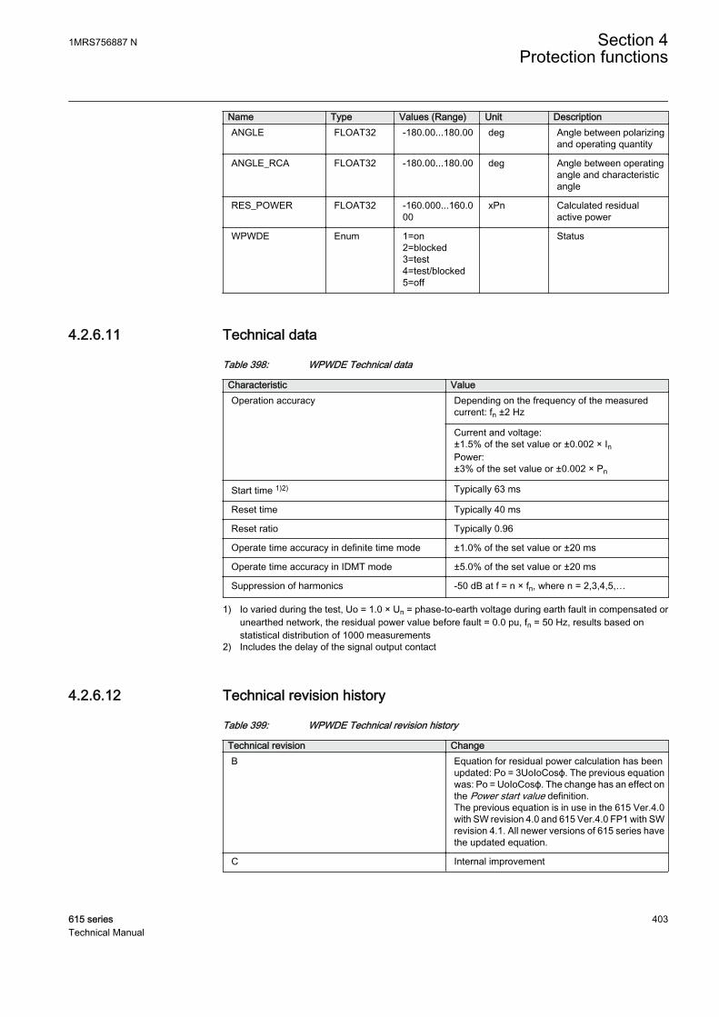
Name Type Values (Range) Unit DescriptionANGLE FLOAT32 -180.00...180.00 deg Angle between polarizing
and operating quantity
ANGLE_RCA FLOAT32 -180.00...180.00 deg Angle between operatingangle and characteristicangle
RES_POWER FLOAT32 -160.000...160.000
xPn Calculated residualactive power
WPWDE Enum 1=on2=blocked3=test4=test/blocked5=off
Status
4.2.6.11 Technical data
Table 398: WPWDE Technical data
Characteristic ValueOperation accuracy Depending on the frequency of the measured
current: fn ±2 Hz
Current and voltage:±1.5% of the set value or ±0.002 × InPower:±3% of the set value or ±0.002 × Pn
Start time 1)2) Typically 63 ms
Reset time Typically 40 ms
Reset ratio Typically 0.96
Operate time accuracy in definite time mode ±1.0% of the set value or ±20 ms
Operate time accuracy in IDMT mode ±5.0% of the set value or ±20 ms
Suppression of harmonics -50 dB at f = n × fn, where n = 2,3,4,5,…
1) Io varied during the test, Uo = 1.0 × Un = phase-to-earth voltage during earth fault in compensated orunearthed network, the residual power value before fault = 0.0 pu, fn = 50 Hz, results based onstatistical distribution of 1000 measurements
2) Includes the delay of the signal output contact
4.2.6.12 Technical revision history
Table 399: WPWDE Technical revision history
Technical revision ChangeB Equation for residual power calculation has been
updated: Po = 3UoIoCosϕ. The previous equationwas: Po = UoIoCosϕ. The change has an effect onthe Power start value definition.The previous equation is in use in the 615 Ver.4.0with SW revision 4.0 and 615 Ver.4.0 FP1 with SWrevision 4.1. All newer versions of 615 series havethe updated equation.
C Internal improvement
1MRS756887 N Section 4Protection functions
615 series 403Technical Manual

4.2.7 Third harmonic based stator earth-fault protectionH3EFPSEF
4.2.7.1 Identification
Function description IEC 61850identification
IEC 60617identification
ANSI/IEEE C37.2device number
Third harmonic-based stator earth-faultprotection
H3EFPSEF dUo>/Uo3H 27/59THD
4.2.7.2 Function block
GUID-2C16B26D-02BC-4208-A0E0-6C9D072A9842 V1 EN
Figure 202: Function block
4.2.7.3 Functionality
The third harmonic-based stator earth-fault protection H3EFPSEF is used to detectstator earth fault at the neutral point and at least up to 15...20% from the neutral pointalong the stator winding. H3EFPSEF compares the third harmonic voltages producedby the generator itself at both neutral and terminal side of the generator for detectingearth fault.
H3EFPSEF provides two alternative protection methods.
• Differential of the third harmonic component measured both at generator neutraland terminal side
• Neutral side third harmonic undervoltage
H3EFPSEF operates with the definite time DT characteristics.
The function contains a blocking functionality. Blocking deactivates all outputs andreset timers.
4.2.7.4 Operation principle
The function can be enabled and disabled with the Operation setting. Thecorresponding parameter values are “On” and “Off”.
The operation of H3EFPSEF can be described using a module diagram. All themodules in the diagram are explained in the next sections.
Section 4 1MRS756887 NProtection functions
404 615 seriesTechnical Manual

GUID-D6ADEBB3-F347-469C-848C-34570FDA10B3 V1 EN
Figure 203: Functional module diagram
3rd harmonic calculation (terminal side)3rd harmonic calculation calculates the magnitude and phase angle of the thirdharmonic voltage at the generator terminal Ū 3H_T. Calculation of the third harmonicvoltage depends on the availability of terminal side voltage and is specified by theVoltage selection setting.
• Voltage selection setting is set to "No voltage" if phase-to-earth voltages are notavailable at the terminal side. Even in a situation where only phase-to-phasevoltages are available, Voltage selection is set to "No Voltage" because phase-to-phase voltages do not contain a third harmonic component. With Voltageselection set to "No Voltage", third harmonic-based earth-fault protection isbased on third harmonic neutral side undervoltage protection.
• Voltage selection setting is set to "Measured Uo" if the terminal side voltage is fedfrom an open delta voltage connection of the voltage transformer. In this case, theterminal side third harmonic voltage Ū3H_T is same as the measured open deltavoltage Ū3H_RES. This is the recommended option for calculating the terminalside third harmonic voltage.
U UH T H RES3 3_ _=
GUID-2B8F8DDD-FCFE-4AE5-B310-37D1C5A99BF9 V1 EN (Equation 44)• Voltage selection setting is set to "Calculated Uo" if all three phase-to-earth
voltages are available. In this case, the terminal side third harmonic voltage iscalculated as a vector average of the third harmonic voltage of all three phases.
U U U UH T H A H B H C3 3 3 3
1
3_ _ _ _(= × + + )
GUID-EADE1C70-5A1A-46C2-8455-3EF71E151988 V1 EN (Equation 45)• If only one phase-to-earth voltage is available, the Voltage selection setting is set
to the respective phase, that is, "Phase A" or "Phase B" or "Phase C" based on theavailable phase. In this case, the magnitude of the terminal side third harmonicvoltage is assumed to be equal to the third harmonic voltage of the phaseavailable.
U U U UH T H A H B H C3 3 3 3_ _ _ _= or or
GUID-29BA3B7C-ABC3-4CA8-9C6D-991C81973C8E V1 EN (Equation 46)
1MRS756887 N Section 4Protection functions
615 series 405Technical Manual
The function is internally blocked if the magnitude of calculated Ū3H_T is lower thanthe set Voltage block value, this also activates the INT_BLKD output.
Differential calculationThe amplitude of the third harmonic differential voltage can be calculated using thefollowing equation.
UD U UH H T H N3 3 3= +_ _
GUID-4582FE8D-145D-49A0-B3A3-7CCD6F623852 V1 EN (Equation 47)
UD3H Magnitude of the third harmonic differential voltage
Ū3H_T Terminal side third harmonic voltage phasor
Ū3H_N Neutral side third harmonic voltage phasor
The magnitude of the third harmonic differential voltage UD_3H and the phase angledifference between the terminal side and neutral side third harmonic voltageU_3HANGL_T_N are available in the Monitored data view.
Bias calculationThe amplitude of the third harmonic bias voltage can be calculated using the followingequation.
UB BetaH3 3H_NU= ×
GUID-5EEF0BE2-0394-43A3-9F38-47F5EEED229E V1 EN (Equation 48)
UB3H Magnitude of the third harmonic bias voltage
Beta Setting to achieve the required degree of security under healthy conditions
Ū3H_N Neutral side third harmonic voltage phasor
The third harmonic bias voltage calculation shown in Equation 48 is valid under alloperating conditions if there is no generator circuit breaker between generator andtransformer. But if the generator circuit breaker is used, it is needed to reduce thesensitivity of the protection when it is open. The use of the generator circuit breakeris defined by Generator CB used setting set to "Yes" and the open position is sensedwhen the binary input GCB_CLOSED available is FALSE.
With the generator breaker in the open position, function desensitizes the protectionby multiplying the value of the Beta setting with the set constant CB open factorsetting.
UB CB open factor Beta3H = × × U H N3 _
GUID-AA791A7D-7F5D-4E44-A7CD-DCE0A4BFCF05 V1 EN (Equation 49)
Section 4 1MRS756887 NProtection functions
406 615 seriesTechnical Manual
Neutral side third harmonic voltage is measured via a voltage transformer between thegenerator neutral point and the earth. The magnitude of the third harmonic biasedvoltage UB_3H is available in the Monitored data view.
Level detectorIn the third harmonic differential method, the Level detector compares the thirdharmonic differential voltage with the third harmonic bias voltage. If the differentialvoltage exceeds the biased voltage, the module sends an enabling signal to start thetimer.
If the terminal voltage is not available, that is, Voltage selection is set to "No voltage"the module compares the neutral side third harmonic voltage U_3H_N to the setVoltage N 3.H Lim.
TimerOnce activated, the Timer activates the START output. The Timer characteristic isaccording to DT. When the operation timer has reached the value set by Operate delaytime, the OPERATE output is activated. If the fault disappears before the moduleoperates, the reset timer is activated. If the reset timer reaches the value set by Resetdelay time, the operation timer resets and the START output is deactivated.
The Timer calculates the start duration START_DUR value, which indicates thepercentage ratio of the start situation and the set operation time. The value is availablein the Monitored data view.
The binary input BLOCK can be used to block the function. The activation of theBLOCK input deactivates all outputs and resets internal timers.
4.2.7.5 Application
Mechanical and thermal stress deteriorates stator winding insulation, which caneventually cause an earth fault between the winding and stator core.
The fault current magnitude in case of stator earth fault depends on the groundingtype. Common practice in most countries is to earth the generator neutral side througha resistor. The resistor is selected such as to limit the maximum earth-fault current inthe range of 5...10 A. The same can be done by connecting a single phase voltagetransformer between the neutral side and earth, and with an equivalent resistor on thesecondary side of the transformer.
In a normal operating condition, that is, when there is no earth fault, the residualvoltage is close to zero with no zero-sequence current flowing in the generator. Whena phase-to-earth fault occurs, the residual voltage increases and the current flowsthrough the neutral. The simplest way to protect the stator winding against an earthfault is by providing residual overvoltage protection (or residual/neutral overcurrentprotection). However, at best these simple schemes can protect only 95% of the statorwinding, leaving 5% of the neutral end unprotected. This is because the voltagegenerated in the faulted winding decreases as the fault point becomes closer to the
1MRS756887 N Section 4Protection functions
615 series 407Technical Manual
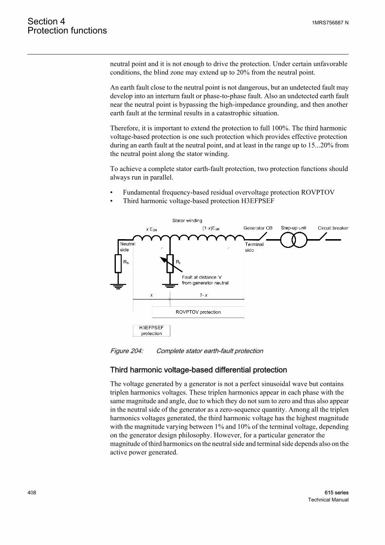
neutral point and it is not enough to drive the protection. Under certain unfavorableconditions, the blind zone may extend up to 20% from the neutral point.
An earth fault close to the neutral point is not dangerous, but an undetected fault maydevelop into an interturn fault or phase-to-phase fault. Also an undetected earth faultnear the neutral point is bypassing the high-impedance grounding, and then anotherearth fault at the terminal results in a catastrophic situation.
Therefore, it is important to extend the protection to full 100%. The third harmonicvoltage-based protection is one such protection which provides effective protectionduring an earth fault at the neutral point, and at least in the range up to 15...20% fromthe neutral point along the stator winding.
To achieve a complete stator earth-fault protection, two protection functions shouldalways run in parallel.
• Fundamental frequency-based residual overvoltage protection ROVPTOV• Third harmonic voltage-based protection H3EFPSEF
GUID-1A4DA0D6-58F5-4F67-B218-3F0A95C6A406 V1 EN
Figure 204: Complete stator earth-fault protection
Third harmonic voltage-based differential protectionThe voltage generated by a generator is not a perfect sinusoidal wave but containstriplen harmonics voltages. These triplen harmonics appear in each phase with thesame magnitude and angle, due to which they do not sum to zero and thus also appearin the neutral side of the generator as a zero-sequence quantity. Among all the triplenharmonics voltages generated, the third harmonic voltage has the highest magnitudewith the magnitude varying between 1% and 10% of the terminal voltage, dependingon the generator design philosophy. However, for a particular generator themagnitude of third harmonics on the neutral side and terminal side depends also on theactive power generated.
Section 4 1MRS756887 NProtection functions
408 615 seriesTechnical Manual
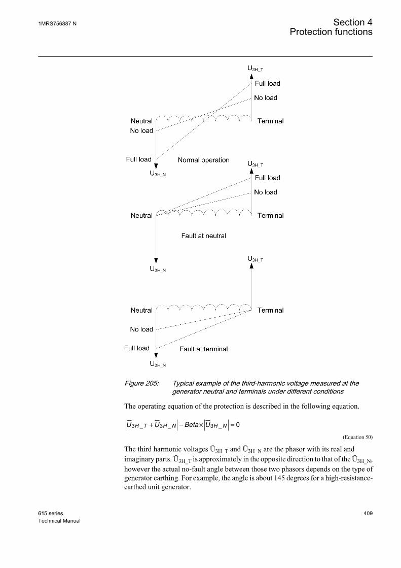
GUID-9CCDBC4D-7464-4ED5-9161-85E89A41946A V1 EN
Figure 205: Typical example of the third-harmonic voltage measured at thegenerator neutral and terminals under different conditions
The operating equation of the protection is described in the following equation.
U U Beta UH T H N H N3 3 3 0_ _ _+ − × =
GUID-1458AEC2-5186-4B4E-B7C2-0D31FF67D072 V1 EN (Equation 50)
The third harmonic voltages Ū3H_T and Ū3H_N are the phasor with its real andimaginary parts. Ū3H_T is approximately in the opposite direction to that of the Ū3H_N,however the actual no-fault angle between those two phasors depends on the type ofgenerator earthing. For example, the angle is about 145 degrees for a high-resistance-earthed unit generator.
1MRS756887 N Section 4Protection functions
615 series 409Technical Manual
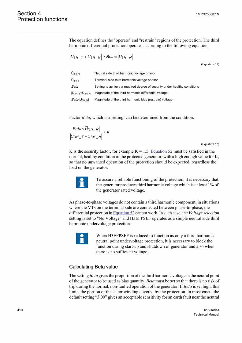
The equation defines the "operate" and "restrain" regions of the protection. The thirdharmonic differential protection operates according to the following equation.
U U Beta UH T H N H N3 3 3_ _ _+ ≥ ×
GUID-4075D1F7-0588-4301-B4A4-C9C22CEB4B38 V1 EN (Equation 51)
Ū3H_N Neutral side third harmonic voltage phasor
Ū3H_T Terminal side third harmonic voltage phasor
Beta Setting to achieve a required degree of security under healthy conditions
|Ū3H_T+Ū3H_N| Magnitude of the third harmonic differential voltage
Beta·|Ū3H_N| Magnitude of the third harmonic bias (restrain) voltage
Factor Beta, which is a setting, can be determined from the condition.
GUID-2AEABFB1-4AC9-480C-B47B-8046B5D79420 V1 EN (Equation 52)
K is the security factor, for example K = 1.5. Equation 52 must be satisfied in thenormal, healthy condition of the protected generator, with a high enough value for K,so that no unwanted operation of the protection should be expected, regardless theload on the generator.
To assure a reliable functioning of the protection, it is necessary thatthe generator produces third harmonic voltage which is at least 1% ofthe generator rated voltage.
As phase-to-phase voltages do not contain a third harmonic component, in situationswhere the VTs on the terminal side are connected between phase-to-phase, thedifferential protection in Equation 52 cannot work. In such case, the Voltage selectionsetting is set to "No Voltage" and H3EFPSEF operates as a simple neutral side thirdharmonic undervoltage protection.
When H3EFPSEF is reduced to function as only a third harmonicneutral point undervoltage protection, it is necessary to block thefunction during start-up and shutdown of generator and also whenthere is no sufficient voltage.
Calculating Beta valueThe setting Beta gives the proportion of the third harmonic voltage in the neutral pointof the generator to be used as bias quantity. Beta must be set so that there is no risk oftrip during the normal, non-faulted operation of the generator. If Beta is set high, thislimits the portion of the stator winding covered by the protection. In most cases, thedefault setting “3.00” gives an acceptable sensitivity for an earth fault near the neutral
Section 4 1MRS756887 NProtection functions
410 615 seriesTechnical Manual

point of the stator winding. However, to assure the best performance, measurementsduring the normal operation of the generator are to be made during commissioning.
1. The value of the Beta setting must be set to “1.00”.2. Loading of the generator is done at 5 to 10 different load points and the third
harmonic differential and bias voltage are measured. Both quantities can beobtained from the Monitored data view of the function.
3. A graph indicating differential and bias voltages as a functions of the load on thegenerator must be plotted.
4. Based on the graph, such value of the Beta setting must be selected that the biasvoltage, even in the worst condition, is at least 30% to 50% higher than thedifferential voltage.
The angle between the third harmonic voltage phasors Ū3H_T and Ū3H_N is 150°, andwith the Beta setting value "1.0", protection guarantees a stability margin of 25%. Thisrequires the value of Beta to be increased so as to increase the stability of protection.The recommended value of the Beta setting is at least “1.2”.
GUID-3166B1C2-6395-4A8E-B5DC-EF10EE915AC2 V1 EN
Figure 206: Typical example of variation of the bias voltage and differentialvoltage with a change in the active generated load (the anglebetween the third harmonic terminal and neutral voltage is 150°)
Calculating CB Open factorOne of the factors, though not major, governing the magnitude of the generated thirdharmonic voltage is the generator terminal capacitance. If there is no generatorbreaker, the capacitive coupling to earth is the same under all operating conditions.
1MRS756887 N Section 4Protection functions
615 series 411Technical Manual
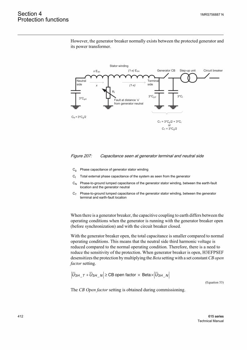
However, the generator breaker normally exists between the protected generator andits power transformer.
Neutral side
x E3H
Rf
(1-x) E3H
3*Cg/2
Step-up unit Generator CB Circuit breaker
Terminal side
Stator winding
3*Cg/2 3*Ct
CT = 3*Cg/2 + 3*Ctor
CT = 3*Cg/2
CN = 3*Cg/2
Fault at distance ‘x’ from generator neutral
x (1-x)
GUID-5A88B023-8F01-46B5-8A6F-CD9AD652E2B4 V1 EN
Figure 207: Capacitance seen at generator terminal and neutral side
Cg Phase capacitance of generator stator winding
Ct Total external phase capacitance of the system as seen from the generator
CN Phase-to-ground lumped capacitance of the generator stator winding, between the earth-faultlocation and the generator neutral
CT Phase-to-ground lumped capacitance of the generator stator winding, between the generatorterminal and earth-fault location
When there is a generator breaker, the capacitive coupling to earth differs between theoperating conditions when the generator is running with the generator breaker open(before synchronization) and with the circuit breaker closed.
With the generator breaker open, the total capacitance is smaller compared to normaloperating conditions. This means that the neutral side third harmonic voltage isreduced compared to the normal operating condition. Therefore, there is a need toreduce the sensitivity of the protection. When generator breaker is open, H3EFPSEFdesensitizes the protection by multiplying the Beta setting with a set constant CB openfactor setting.
U U UH T H N H N3 3 3_ _ _+ ≥ × ×CB open factor Beta
GUID-5C68C60F-34E8-46C4-94CE-077A90BEC1AD V1 EN (Equation 53)
The CB Open factor setting is obtained during commissioning.
Section 4 1MRS756887 NProtection functions
412 615 seriesTechnical Manual
1. For a particular value of Beta the third harmonic neutral voltage is measured withthe generator in the no-load condition and the circuit breaker in the closedposition.
2. With the same condition, the third harmonic neutral voltage with the circuitbreaker in the open position is measured.
3. CB Open factor should be set equal to the ratio of the third harmonic neutralvoltage measured with the circuit breaker in the closed position to that in the open.
4.2.7.6 Signals
Table 400: H3EFPSEF Input signals
Name Type Default DescriptionU_3H_A SIGNAL 0 Third harmonic of phase A voltage
U_3H_B SIGNAL 0 Third harmonic of phase B voltage
U_3H_C SIGNAL 0 Third harmonic of phase C voltage
U_3H_N SIGNAL 0 Third harmonic of neutral voltage
U_3H_RES SIGNAL 0 Third harmonic of residual voltage
BLOCK BOOLEAN 0=False Block signal for activating the blocking mode
GCB_CLOSED BOOLEAN 0=False Generator CB in closed position
Table 401: H3EFPSEF Output signals
Name Type DescriptionOPERATE BOOLEAN Operate
START BOOLEAN Start
INT_BLKD BOOLEAN Protection internally blocked
4.2.7.7 Settings
Table 402: H3EFPSEF Group settings (Basic)
Parameter Values (Range) Unit Step Default DescriptionBeta 0.50...10.00 0.01 3.00 Portion of neutral side 3rd harmonic used
as bias
Voltage N 3.H Lim 0.005...0.200 xUn 0.001 0.010 Start value for 3rd harmonic residualundervoltage protection
Operate delay time 20...300000 ms 10 20 Operate delay time
1MRS756887 N Section 4Protection functions
615 series 413Technical Manual
Table 403: H3EFPSEF Group settings (Advanced)
Parameter Values (Range) Unit Step Default DescriptionVoltage selection 1=No voltage
2=Measured Uo3=Calculated Uo4=Phase A5=Phase B6=Phase C
2=Measured Uo Type of voltage connection available atgenerator terminal
CB open factor 1.00...10.00 0.01 1.00 Multiplication factor for beta when CB is inopen condition
Table 404: H3EFPSEF Non group settings (Basic)
Parameter Values (Range) Unit Step Default DescriptionOperation 1=on
5=off 1=on Operation Off / On
Table 405: H3EFPSEF Non group settings (Advanced)
Parameter Values (Range) Unit Step Default DescriptionVoltage block value 0.010...0.100 xUn 0.001 0.010 Low level blocking for 3rd harmonic
differential protection
Generator CB used 0=No1=Yes
0=No Defines if generator circuit breaker exists
Reset delay time 0...60000 ms 1 20 Reset delay time
4.2.7.8 Monitored data
Table 406: H3EFPSEF Monitored data
Name Type Values (Range) Unit DescriptionSTART_DUR FLOAT32 0.00...100.00 % Ratio of start time /
operate time
UD_3H FLOAT32 0.00...40.00 xUn 3rd harmonic differentialvoltage amplitude
UB_3H FLOAT32 0.00...40.00 xUn 3rd harmonic biasvoltage amplitude
U_3H_T FLOAT32 0.00...40.00 xUn Terminal side 3rdharmonic voltageamplitude
U_3H_N FLOAT32 0.00...40.00 xUn Neutral side 3rdharmonic voltageamplitude
Table continues on next page
Section 4 1MRS756887 NProtection functions
414 615 seriesTechnical Manual

Name Type Values (Range) Unit DescriptionU_3H_N FLOAT32 0.00...40.00 xUn Neutral side 3rd
harmonic voltageamplitude
U_3HANGL_T_N FLOAT32 -180.00...180.00 deg Phase angle between 3rdharmonic terminal andneutral voltage
H3EFPSEF Enum 1=on2=blocked3=test4=test/blocked5=off
Status
4.2.7.9 Technical data
Table 407: H3EFPSEF Technical data
Characteristic ValueOperation accuracy Depending on the frequency of the measured
voltage:fn ±2 Hz
±5% of the set value or ±0.004 × Un
Start time1)2) Typically 35 ms
Reset time Typically 35 ms
Reset ratio Typically 0.96 (differential mode)Typically 1.04 (under voltage mode)
Operate time accuracy ±1.0% of the set value of ±20 ms
1) fn = 50 Hz, results based on statistical distribution of 1000 measurements2) Includes the delay of the signal output contact
4.2.8 Multifrequency admittance-based earth-fault protectionMFADPSDE
4.2.8.1 Identification
Description IEC 61850identification
IEC 60617identification
ANSI/IEEE C37.2device number
Multifrequency admittance-basedearth-fault protection
MFADPSDE Io> ->Y 67YN
1MRS756887 N Section 4Protection functions
615 series 415Technical Manual

4.2.8.2 Function block
GUID-A6EFD856-47F2-462B-8F8D-B64CB0A899AA V1 EN
Figure 208: Function block
4.2.8.3 Functionality
The multifrequency admittance-based earth-fault protection function MFADPSDEprovides selective directional earth-fault protection for high-impedance earthednetworks, that is, for compensated, unearthed and high resistance earthed systems. Itcan be applied for the earth-fault protection of overhead lines and underground cables.
The operation of MFADPSDE is based on multifrequency neutral admittancemeasurement, utilizing cumulative phasor summing technique. This concept providesextremely secure, dependable and selective earth-fault protection also in cases wherethe residual quantities are highly distorted and contain non-fundamental frequencycomponents.
The sensitivity that can be achieved is comparable with traditional fundamentalfrequency based methods such as IoCos/IoSin (DEFxPDEF), Watt/Varmetric(WPWDE) and neutral admittance (EFPADM).
MFADPSDE is capable of detecting faults with dominantly fundamental frequencycontent as well as transient, intermittent and restriking earth faults. MFADPSDE canbe used as an alternative solution to transient or intermittent function INTRPTEF.
MFADPSDE supports fault direction indication both in operate and non-operatedirection, which may be utilized during fault location process. The inbuilt transientdetector can be used to identify restriking or intermittent earth faults, and discriminatethem from permanent or continuous earth faults.
The operation characteristic is defined by a tilted operation sector, which isuniversally valid for unearthed and compensated networks.
The operating time characteristic is according to the definite time (DT).
The function contains a blocking functionality to block function outputs, timers or thefunction itself.
4.2.8.4 Operation principle
The function can be enabled and disabled with the Operation setting. Thecorresponding parameter values are "On" and "Off".
Section 4 1MRS756887 NProtection functions
416 615 seriesTechnical Manual

The operation of MFADPSDE can be described using a module diagram. All themodules in the diagram are explained in the following sections.
GUID-C69174FA-2E03-4582-A479-107B655C136E V1 EN
Figure 209: Functional module diagram
General fault criterionThe General fault criterion (GFC) module monitors the presence of earth fault in thenetwork and it is based on the value of the fundamental frequency zero-sequencevoltage defined as the vector sum of fundamental frequency phase voltage phasorsdivided by three.
U U U UA B C0
1 1 1 13= + +( ) /
GUID-0E55584E-A887-4A4B-B8E0-5CDCEDFCFC55 V1 EN (Equation 54)
When the magnitude of U o
1
exceeds setting Voltage start value, an earth fault isdetected. The GFC module reports the exceeded value to the Fault directiondetermination module and Operation logic. The reporting is referenced as GeneralFault Criterion release.
The setting Voltage start value defines the basic sensitivity of the MFADPSDEfunction. To avoid unselective start or operation, Voltage start value must always beset to a value which exceeds the maximum healthy-state zero-sequence voltage value,taking into consideration of possible network topology changes, compensation coiland parallel resistor switching status and compensation degree variations.
As an alternative for internal residual zero-sequence overvoltage based start-condition, MFADPSDE function can also be externally released by utilizing theRELEASE input. In this case, the external release signal overrides the Voltage startvalue setting and sets the internal limit to minimum value.
1MRS756887 N Section 4Protection functions
615 series 417Technical Manual

Multi-frequency admittance calculationMulti-frequency admittance calculation module calculates neutral admittancesutilizing fundamental frequency and the 2nd, 3rd, 5th, 7th and 9th harmoniccomponents of residual current and zero-sequence voltage. The followingadmittances are calculated, if the magnitude of a particular harmonic in residualcurrent and zero-sequence voltage are measurable by the protection relay.
Fundamental frequency admittance (conductance and susceptance)
YI
U
G j Bo o0
1 0
1
0
1
1 13=
⋅
−
= + ⋅
GUID-565B235E-04DA-4AC2-93A8-FE327A53424F V1 EN (Equation 55)
Y0
1The fundamental frequency neutral admittance phasor.
I0
1The fundamental frequency zero-sequence current phasor
( ( ) / )= + +I I IA B C
1 1 13
U0
1The fundamental frequency zero-sequence voltage phasor
( ( ) / )= + +U U UA B C
1 1 13
Go
1 The fundamental frequency conductance,
Re Y0
1
( )
Bo
1 The fundamental frequency susceptance,
Im Y0
1
( )
Harmonic susceptance
Im ImYI
U
j Bn
n
no
n
0
0
0
3
=
⋅
−
= ⋅
GUID-FEC1F705-F45C-4C56-9A74-AC4EDFC7FC4C V1 EN (Equation 56)
where n = 2, 3, 5, 7 and 9
Yn
0
The nth harmonic frequency neutral admittance phasor.
In
0
The nth harmonic frequency zero-sequence current phasor.
Un
0
The nth harmonic frequency zero-sequence voltage phasor.
Bo
n
The nth harmonic frequency susceptance, Im Y
n
0( )
Section 4 1MRS756887 NProtection functions
418 615 seriesTechnical Manual
For fault direction determination, the fundamental frequency admittance andharmonic susceptances are summed together in phasor format. The result is the sumadmittance phasor defined as below.
Y Y j Y Y G j Bosumn
n
o osum=
+ ⋅ +
= + ⋅
=
∑Re Im0
1
0
1
0
2
91
GUID-6660AD60-0694-4808-8146-A1F053DA5F7C V1 EN (Equation 57)
The polarity of the polarizing quantity (residual voltage) can bechanged (rotated by 180 degrees) by setting the Pol reversalparameter to "True" or by switching the polarity of the residualvoltage measurement wires.
Fault direction determinationIf an earth fault is detected by the GFC module, the fault direction is evaluated based
on the calculated sum admittance phasor Y osum obtained from the Multi-frequencyadmittance calculation module. To obtain dependable and secure fault directiondetermination regardless of the fault type (transient, intermittent, restriking,permanent, high or low ohmic), the fault direction is calculated using a specialfiltering algorithm, Cumulative Phasor Summing (CPS) technique. This filteringmethod is advantageous during transient, intermittent and restriking earth faults withdominantly non-sinusoidal or transient content. It is equally valid during continuous(stable) earth faults.
The concept of CPS is illustrated in Figure 210. It is the result of adding values of themeasured sum admittance phasors together in phasor format in chronological order
during the fault. Using the discrete sum admittance phasors Y osum in different time
instants (t1...t5), the corresponding accumulated sum admittance phasor Y osum CPS_ iscalculated. This phasor is used as directional phasor in determining the direction of thefault.
Y t Y tosum CPS osum_ ( ) ( )1 1
=
GUID-EDC80710-FA5D-4966-AE81-888E8B4D2CD5 V1 EN (Equation 58)
Y t Y t Y tosum CPS osum osum_ ( ) ( ) ( )2 1 2
= +
GUID-696EFC44-7AF4-45A9-A3F4-11C153143D55 V1 EN (Equation 59)
Y t Y t Y t Y tosum CPS osum osum osum_ ( ) ( ) ( ) ( )3 1 2 3
= + +
GUID-A18538B4-EFCD-4844-AEFB-0BB92358582A V1 EN (Equation 60)
Y t Y t Y t Y t Y tosum CPS osum osum osum osum_ ( ) ( ) ( ) ( ) ( )4 1 2 3 4
= + + +
GUID-EBDE2421-0F49-4141-87E2-433DF64503C9 V1 EN (Equation 61)
1MRS756887 N Section 4Protection functions
615 series 419Technical Manual
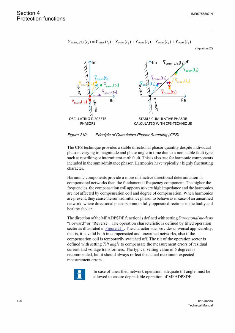
Y t Y t Y t Y t Y t Yosum CPS osum osum osum osum osu_ ( ) ( ) ( ) ( ) ( )5 1 2 3 4
= + + + + mm t( )5
GUID-8E0FAAAB-F656-4FCF-AC71-42C357E77F3E V1 EN (Equation 62)
GUID-69E030E7-F3CF-4872-AF6A-3D12002EA3AC V1 EN
Figure 210: Principle of Cumulative Phasor Summing (CPS)
The CPS technique provides a stable directional phasor quantity despite individualphasors varying in magnitude and phase angle in time due to a non-stable fault typesuch as restriking or intermittent earth fault. This is also true for harmonic componentsincluded in the sum admittance phasor. Harmonics have typically a highly fluctuatingcharacter.
Harmonic components provide a more distinctive directional determination incompensated networks than the fundamental frequency component. The higher thefrequencies, the compensation coil appears as very high impedance and the harmonicsare not affected by compensation coil and degree of compensation. When harmonicsare present, they cause the sum admittance phasor to behave as in case of an unearthednetwork, where directional phasors point in fully opposite directions in the faulty andhealthy feeder.
The direction of the MFADPSDE function is defined with setting Directional mode as“Forward” or “Reverse”. The operation characteristic is defined by tilted operationsector as illustrated in Figure 211. The characteristic provides universal applicability,that is, it is valid both in compensated and unearthed networks, also if thecompensation coil is temporarily switched off. The tilt of the operation sector isdefined with setting Tilt angle to compensate the measurement errors of residualcurrent and voltage transformers. The typical setting value of 5 degrees isrecommended, but it should always reflect the actual maximum expectedmeasurement errors.
In case of unearthed network operation, adequate tilt angle must beallowed to ensure dependable operation of MFADPSDE.
Section 4 1MRS756887 NProtection functions
420 615 seriesTechnical Manual
In Figure 212, phasors 1...4 demonstrate the behavior of the directional phasor indifferent network fault conditions.
• Phasor 1 depicts the direction of accumulated sum admittance phasor in case ofearth fault outside the protected feeder (assuming that the admittance of theprotected feeder is dominantly capacitive). The result is valid regardless of thefault type (low ohmic, high(er) ohmic, permanent, intermittent or restriking). Incase harmonic components are present in the fault quantities, they would turn the
phasor align to the negative Im( )Yo axis.• Phasor 2 depicts the direction of accumulated sum admittance phasor in case of
earth fault inside the protected feeder when the network is unearthed. The resultis also valid in compensated networks when there are harmonic componentspresent in the fault quantities (typically low ohmic permanent or intermittent orrestriking fault). In this case, the result is valid regardless of network’s actualcompensation degree. Harmonics would turn the phasor align to the positive
Im( )Yo axis.• Phasors 3 and 4 depict the direction of accumulated sum admittance phasor in
case of higher-ohmic earth fault in the protected feeder without harmonics in thefault quantities when the network is compensated. As no harmonic componentsare present, the phase angle of the accumulated phasor is determined by thecompensation degree of the network. With high degree of overcompensation, the
phasor turns towards the negative Im( )Yo axis (as phasor 4).
1MRS756887 N Section 4Protection functions
615 series 421Technical Manual
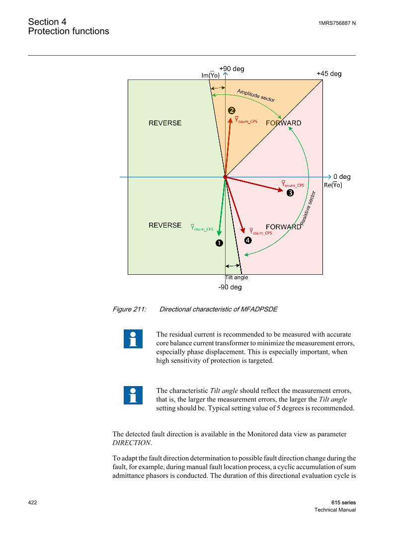
GUID-8E589324-78E1-4E05-8FD9-49607B977DA2 V1 EN
Figure 211: Directional characteristic of MFADPSDE
The residual current is recommended to be measured with accuratecore balance current transformer to minimize the measurement errors,especially phase displacement. This is especially important, whenhigh sensitivity of protection is targeted.
The characteristic Tilt angle should reflect the measurement errors,that is, the larger the measurement errors, the larger the Tilt anglesetting should be. Typical setting value of 5 degrees is recommended.
The detected fault direction is available in the Monitored data view as parameterDIRECTION.
To adapt the fault direction determination to possible fault direction change during thefault, for example, during manual fault location process, a cyclic accumulation of sumadmittance phasors is conducted. The duration of this directional evaluation cycle is
Section 4 1MRS756887 NProtection functions
422 615 seriesTechnical Manual

1.2 · Reset delay time (minimum of 600 ms). If the fault direction based on the cyclicphasor accumulation is opposite to the function direction output for Reset delay timeor 500 ms (minimum of 500 ms), the function is reset and fault direction calculationof MFADPSDE is restarted.
In case the earth-fault protection is alarming, the MFADPSDE includes also a RESETinput, which can be utilized to externally re-trigger the fault direction determination,if re-evaluation of fault direction during a persistent earth fault is required. It is alsorecommended to connect the start signal of non-directional earth-fault protection(EFxPTOC), set to operate in case of a cross-country fault, to RESET input ofMFADPSDE to reset phasor accumulation during a cross-country fault. MFADPSDEis then able to adapt to possible fault direction change more rapidly, if single phaseearth fault still persists in the system after the other faulty feeder has been tripped(cross-country fault has been transformed back to a single phase earth fault).
The direction of the MFADPSDE function is supervised by a settable currentmagnitude threshold. The operate current used in the magnitude supervision ismeasured with a special filtering method, which provides very stable residual currentestimate regardless of the fault type. This stabilized current estimate is the result fromfundamental frequency admittance calculation utilizing the CPS technique. Thestabilized current value is obtained (after conversion) from the correspondingadmittance value by multiplying it with the system nominal phase-to-earth voltagevalue, which is entered as a base value for the residual voltage (Ubaseres). Theequations for calculating the stabilized values of the fundamental frequencyadmittance and the corresponding current are given below.
YI
UY j Y G
o stab
CPS
CPS
o stab o stab ost
1 0
1
0
1
1 13
=⋅
−
=
+ ⋅
=Re Imaab ostab
j B1 1
+ ⋅
GUID-8236D202-E4DB-4185-898D-0FAE1A15431C V1 EN (Equation 63)
Yo stab
1The stabilized fundamental frequency admittance estimate, which is result from fundamentalfrequency admittance calculation utilizing the Cumulative Phasor Summing (CPS) technique.
ICPS0
1The fundamental frequency zero-sequence current phasor calculated utilizing the CumulativePhasor Summing (CPS) technique.
UCPS0
1The fundamental frequency zero-sequence voltage phasor calculated utilizing the CumulativePhasor Summing (CPS) technique.
Gostab
1 The real-part of stabilized fundamental frequency conductance estimate.
Bostab
1 The imaginary part of stabilized fundamental frequency susceptance estimate.
1MRS756887 N Section 4Protection functions
615 series 423Technical Manual

I G j B U I j Io stab ostab ostab baseres oCosstab oSinsta
1 1 1 1= + ⋅ ⋅ = + ⋅( )
bb
1
GUID-5E6BA356-F1BE-42D6-A6A1-308F93255F7E V1 EN (Equation 64)
Io stab
1The stabilized fundamental frequency residual current estimate, which is obtained (afterconversion) from the corresponding admittance value by multiplying it with the systemnominal phase-to-earth voltage value.
Io Cosstab
1The real-part of stabilized fundamental frequency residual current estimate.
Io Sinstab
1The imaginary-part of stabilized fundamental frequency residual current estimate.
The main advantage of the filtering method is that due to the admittance calculation,the resulting current value does not depend on the value of fault resistance, that is, theestimated current magnitude equals the value that would be measured during a solidearth fault (Rf = 0 Ω). Another advantage of the method is that it is capable ofestimating correct current magnitude also during intermittent or restriking faults.
The setting Min operate current defines the minimum operate current.
Setting Operating quantity defines whether the current magnitude supervision isbased on either the “Adaptive” or “Amplitude” methods.
When “Adaptive” is selected, the method adapts the principle of magnitudesupervision automatically to the system earthing condition. In case the phase angle ofaccumulated sum admittance phasor is greater than 45 degrees, the set minimum
operate current threshold is compared to the amplitude of Io stab
1
(see Figure 212). Incase the phase angle of accumulated sum admittance phasor is below 45 degrees, theset minimum operate current threshold is compared to the resistive component of
Io stab
1
. This automatic adaptation of the magnitude supervision enables secure anddependable directional determination in compensated networks, and it is also validwhen the network is unearthed (compensation coil is switched off).
In case operation direction is set to reverse, the resistive and amplitude sectors aremirrored in the operation characteristics.
When “Amplitude” is selected, the set minimum operate current threshold is
compared to the amplitude of Io stab
1
. This selection can be used in unearthed networks.
In compensated networks, setting Operating quantity should be set to“Adaptive”. This enables secure and dependable directionaldetermination on compensated networks and it is also valid whencompensation coil is switched off and network becomes unearthed.
Section 4 1MRS756887 NProtection functions
424 615 seriesTechnical Manual
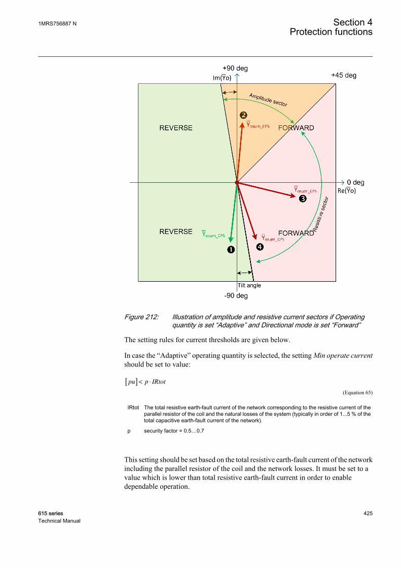
GUID-0A818501-E0BD-402F-BF8B-22BA6B91BBA2 V1 EN
Figure 212: Illustration of amplitude and resistive current sectors if Operatingquantity is set “Adaptive” and Directional mode is set “Forward”
The setting rules for current thresholds are given below.
In case the “Adaptive” operating quantity is selected, the setting Min operate currentshould be set to value:
pu p IRtot[ ] < ⋅
GUID-77CF1715-3730-414C-BC8E-075792F791FB V1 EN (Equation 65)
IRtot The total resistive earth-fault current of the network corresponding to the resistive current of theparallel resistor of the coil and the natural losses of the system (typically in order of 1...5 % of thetotal capacitive earth-fault current of the network).
p security factor = 0.5…0.7
This setting should be set based on the total resistive earth-fault current of the networkincluding the parallel resistor of the coil and the network losses. It must be set to avalue which is lower than total resistive earth-fault current in order to enabledependable operation.
1MRS756887 N Section 4Protection functions
615 series 425Technical Manual

For example, if the resistive current of the parallel resistor is 10 A (at primary voltagelevel), then a value of 0.5 · 10 A = 5 A could be used. The same setting is alsoapplicable in case the coil is disconnected and the network becomes unearthed (as in
this case this setting is compared to the amplitude of Io stab
1
). The selected setting valuemust never exceed the ampere value of the parallel resistor in order to allow operationin the faulty feeder. In case of smaller ampere value of the parallel resistor, forexample 5 A, the recommended security factor should be larger, for example 0.7, sothat sufficient margin for CT and VT errors can be achieved.
In case the “Amplitude” operating quantity is selected, the setting should be selectedbased on the capacitive earth-fault current values produced by the backgroundnetwork in case of a solid earth fault with a security margin.
The main task of the current magnitude supervision module is tosecure the correct directional determination of an earth fault, so thatonly the faulty feeder is disconnected or alarmed. Therefore, thethreshold values should be selected carefully and not set too high asthis can inhibit the disconnection of the faulty feeder.
The residual current should be measured with accurate core balancecurrent transformer to minimize the measurement errors, especiallyphase displacement.
Transient detectorThe Transient detector module is used for detecting transients in the residual currentand zero-sequence voltage signals. Whenever transient is detected, this is indicatedwith the PEAK_IND output. When the number of detected transients equals orexceeds the Peak counter limit setting (without the function being reset, depending onthe drop-off time set with the Reset delay time setting), INTR_EF output is activated.This indicates detection of restriking or intermittent earth fault in the network.Transient detector affects the operation of MFADPSDE (START and OPERATEoutputs) when operation mode is “Intermittent EF”. For other operation modes,(“General EF”, “Alarming EF”), PEAK_IND and INTR_EF outputs can be used formonitoring purposes. The operation of the Transient detector is illustrated in Figure213.
Several factors affect the magnitude and frequency of fault transients,such as the fault inception angle on the voltage wave, fault location,fault resistance and the parameters of the feeders and the supplyingtransformers. If the fault is permanent (non-transient) in nature, theinitial fault transient in current and voltage can be measured, whereasthe intermittent fault creates repetitive transients. The practicalsensitivity of transient detection is limited to approximately few
Section 4 1MRS756887 NProtection functions
426 615 seriesTechnical Manual
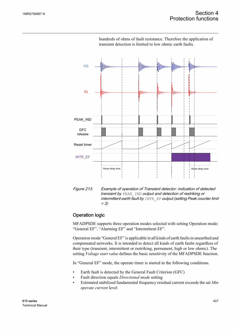
hundreds of ohms of fault resistance. Therefore the application oftransient detection is limited to low ohmic earth faults.
GFC release
INTR_EF
PEAK_IND
Reset timer
Reset delay time
IG
VG
Reset delay time
GUID-A5B0DD30-710A-4E95-82F8-1D2692452239 V2 EN
Figure 213: Example of operation of Transient detector: indication of detectedtransient by PEAK_IND output and detection of restriking orintermittent earth fault by INTR_EF output (setting Peak counter limit= 3)
Operation logicMFADPSDE supports three operation modes selected with setting Operation mode:“General EF”, “Alarming EF” and “Intermittent EF”.
Operation mode “General EF” is applicable in all kinds of earth faults in unearthed andcompensated networks. It is intended to detect all kinds of earth faults regardless oftheir type (transient, intermittent or restriking, permanent, high or low ohmic). Thesetting Voltage start value defines the basic sensitivity of the MFADPSDE function.
In “General EF” mode, the operate timer is started in the following conditions.
• Earth fault is detected by the General Fault Criterion (GFC)• Fault direction equals Directional mode setting• Estimated stabilized fundamental frequency residual current exceeds the set Min
operate current level
1MRS756887 N Section 4Protection functions
615 series 427Technical Manual
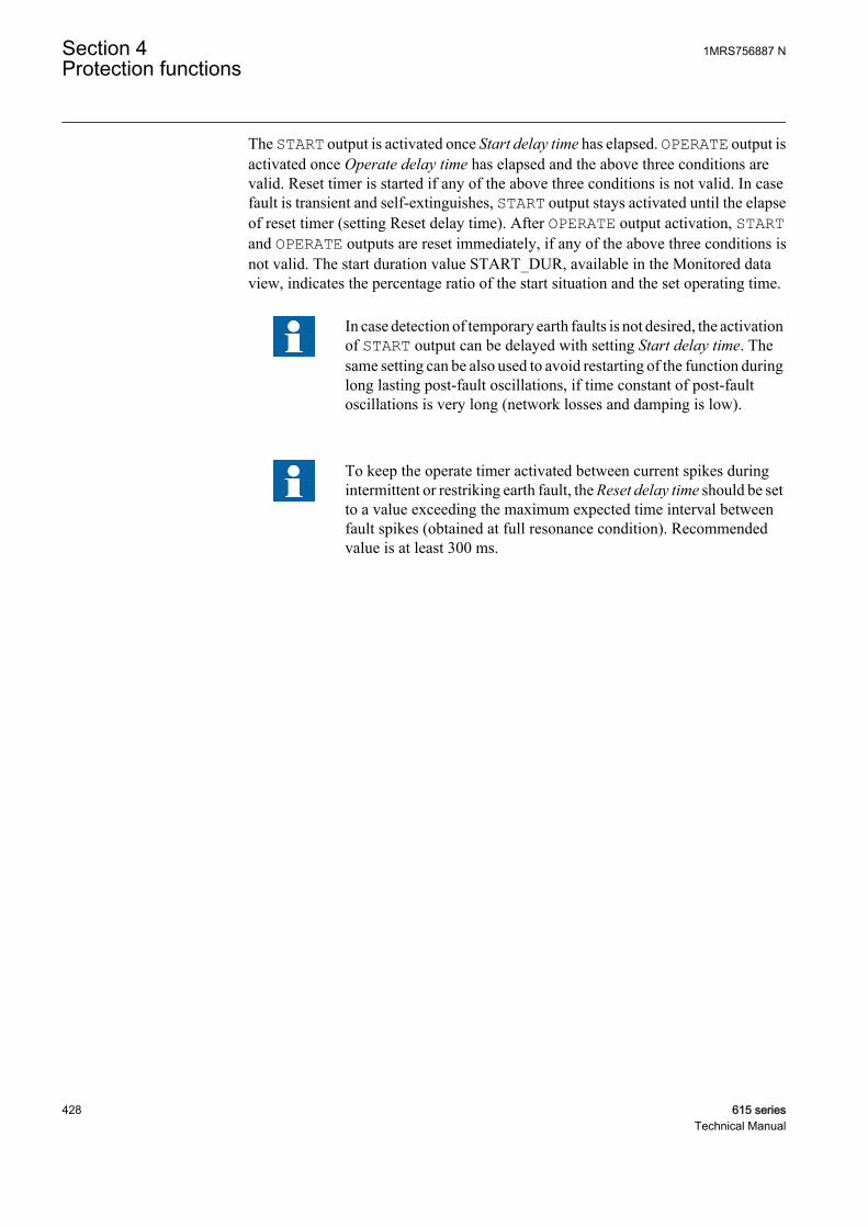
The START output is activated once Start delay time has elapsed. OPERATE output isactivated once Operate delay time has elapsed and the above three conditions arevalid. Reset timer is started if any of the above three conditions is not valid. In casefault is transient and self-extinguishes, START output stays activated until the elapseof reset timer (setting Reset delay time). After OPERATE output activation, STARTand OPERATE outputs are reset immediately, if any of the above three conditions isnot valid. The start duration value START_DUR, available in the Monitored dataview, indicates the percentage ratio of the start situation and the set operating time.
In case detection of temporary earth faults is not desired, the activationof START output can be delayed with setting Start delay time. Thesame setting can be also used to avoid restarting of the function duringlong lasting post-fault oscillations, if time constant of post-faultoscillations is very long (network losses and damping is low).
To keep the operate timer activated between current spikes duringintermittent or restriking earth fault, the Reset delay time should be setto a value exceeding the maximum expected time interval betweenfault spikes (obtained at full resonance condition). Recommendedvalue is at least 300 ms.
Section 4 1MRS756887 NProtection functions
428 615 seriesTechnical Manual
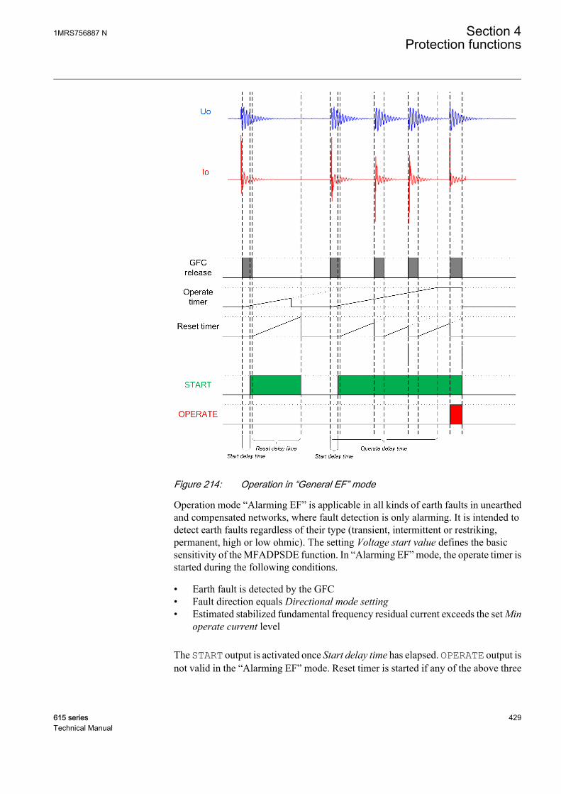
GUID-B8FF033F-EB15-4D81-8C9F-E45A8F1A6FA8 V1 EN
Figure 214: Operation in “General EF” mode
Operation mode “Alarming EF” is applicable in all kinds of earth faults in unearthedand compensated networks, where fault detection is only alarming. It is intended todetect earth faults regardless of their type (transient, intermittent or restriking,permanent, high or low ohmic). The setting Voltage start value defines the basicsensitivity of the MFADPSDE function. In “Alarming EF” mode, the operate timer isstarted during the following conditions.
• Earth fault is detected by the GFC• Fault direction equals Directional mode setting• Estimated stabilized fundamental frequency residual current exceeds the set Min
operate current level
The START output is activated once Start delay time has elapsed. OPERATE output isnot valid in the “Alarming EF” mode. Reset timer is started if any of the above three
1MRS756887 N Section 4Protection functions
615 series 429Technical Manual
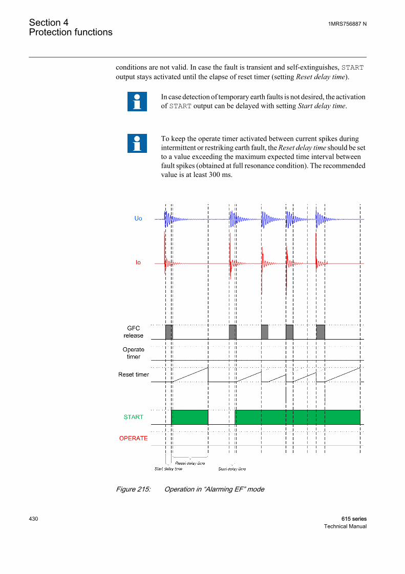
conditions are not valid. In case the fault is transient and self-extinguishes, STARToutput stays activated until the elapse of reset timer (setting Reset delay time).
In case detection of temporary earth faults is not desired, the activationof START output can be delayed with setting Start delay time.
To keep the operate timer activated between current spikes duringintermittent or restriking earth fault, the Reset delay time should be setto a value exceeding the maximum expected time interval betweenfault spikes (obtained at full resonance condition). The recommendedvalue is at least 300 ms.
GUID-24122726-5059-44B7-84AD-617E1801F5A8 V1 EN
Figure 215: Operation in “Alarming EF” mode
Section 4 1MRS756887 NProtection functions
430 615 seriesTechnical Manual

Operation mode “Intermittent EF” is dedicated for detecting restriking or intermittentearth faults. A required number of intermittent earth fault transients set with the Peakcounter limit setting must be detected for operation. Therefore, transient faults orpermanent faults with only initial fault ignition transient are not detected in“Intermittent EF” mode. The application of “Intermittent EF” mode is limited to lowohmic intermittent or restriking earth faults.
In the “Intermittent EF” mode, the operate timer is started when the followingconditions are met.
• Transient is detected by the Transient detector (indicated with PEAK_INDoutput)
• Earth fault is detected by the GFC at time of transient• Fault direction equals Directional mode setting• Estimated stabilized fundamental frequency residual current exceeds the set Min
operate current level
When a required number of intermittent earth-fault transients set with the Peakcounter limit setting are detected without the function being reset (depends on thedrop-off time set with the Reset delay time setting), the START output is activated. TheINTR_EF output is activated to indicate the fault type is intermittent or restrikingearth fault. The operate timer is kept activated as long as transients occur during thedrop-off time defined by setting Reset delay time.
The OPERATE output is activated when Operate delay time has elapsed, requirednumber of transients has been detected, earth fault is detected by the GFC, faultdirection matches the Directional mode setting and estimated stabilized fundamentalfrequency residual current exceeds set Minimum operate current setting.
The Reset delay time starts to elapse from each detected transient. Function is reset iftime between current peaks is more that Reset delay time or if the General FaultCriterion release is reset. After OPERATE output activation, START and OPERATEoutputs are reset immediately at the falling edge of General Fault Criterion release,that is, when zero-sequence voltage falls below Voltage start value. This should beconsidered if “Intermittent EF" mode is applied in case earth faults are only alarmedto avoid repetitive start and operate events.
To keep the operate timer activated between current spikes duringintermittent or restriking earth fault, Reset delay time should be set toa value exceeding the maximum expected time interval between(obtained at full resonance condition). The recommended value is atleast 300 ms.
1MRS756887 N Section 4Protection functions
615 series 431Technical Manual

GUID-FDF97C09-E155-422A-8CBC-CD8B3A19101E V1 EN
Figure 216: Operation in “Intermittent EF” mode, Peak counter limit = 3
Blocking logicThere are three operation modes in the blocking functionality. The operation modesare controlled by the BLOCK input and the global setting Configuration/System/Blocking mode which selects the blocking mode. The BLOCK input can be controlledby a binary input, a horizontal communication input or an internal signal of theprotection relay's program. The influence of the BLOCK signal activation ispreselected with the global setting Blocking mode.
The Blocking mode setting has three blocking methods. In the "Freeze timers" mode,the operation timer is frozen to the prevailing value. In the "Block all" mode, the wholefunction is blocked and the timers are reset. In the "Block OPERATE output" mode,the function operates normally but the OPERATE output is not activated.
Section 4 1MRS756887 NProtection functions
432 615 seriesTechnical Manual
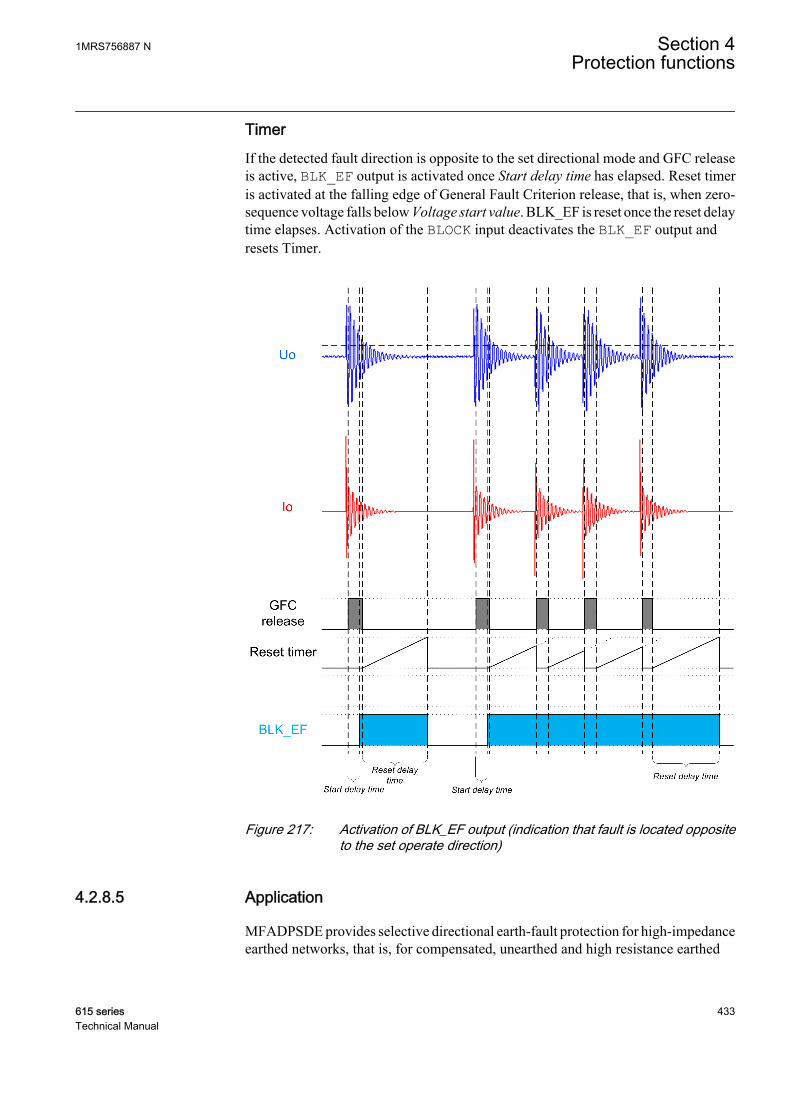
TimerIf the detected fault direction is opposite to the set directional mode and GFC releaseis active, BLK_EF output is activated once Start delay time has elapsed. Reset timeris activated at the falling edge of General Fault Criterion release, that is, when zero-sequence voltage falls below Voltage start value. BLK_EF is reset once the reset delaytime elapses. Activation of the BLOCK input deactivates the BLK_EF output andresets Timer.
GUID-7A52B88C-FBA7-435E-B967-0C7079EF92F6 V1 EN
Figure 217: Activation of BLK_EF output (indication that fault is located oppositeto the set operate direction)
4.2.8.5 Application
MFADPSDE provides selective directional earth-fault protection for high-impedanceearthed networks, that is, for compensated, unearthed and high resistance earthed
1MRS756887 N Section 4Protection functions
615 series 433Technical Manual
systems. It can be applied for the earth-fault protection of overhead lines andunderground cables.
The operation of MFADPSDE is based on multi-frequency neutral admittancemeasurement utilizing cumulative phasor summing technique. This concept providesextremely secure, dependable and selective earth-fault protection also in cases wherethe residual quantities are highly distorted and contain non-fundamental frequencycomponents. MFADPSDE is well-suited for compensated networks wheremeasurement signals may have such characteristics, for example, during intermittentearth faults.
MFADPSDE is capable of operating with both low ohmic and higher ohmic earthfaults, where the sensitivity limit is defined with residual overvoltage condition. Thisallows earth faults with several kilohms of fault resistance to be detected in asymmetrical system. The sensitivity that can be achieved is comparable withtraditional fundamental frequency based methods such as the IoCos/IoSin(DEFxPDEF), Watt/Varmetric (32N) and neutral admittance (21YN).
MFADPSDE is capable of detecting faults with dominantly fundamental frequencycontent as well as transient, intermittent or restriking earth faults. MFADPSDE can beused as an alternative solution to transient or intermittent function INTRPTEF.
MFADPSDE supports Fault direction indication in operate and non-operate directionwhich may be utilized during fault location process. The inbuilt transient detector canbe used to identify restriking or intermittent earth faults, and discriminate them frompermanent or continuous earth faults.
The direction of MFADPSDE can be set as forward or reverse. The operationcharacteristic is defined by a tilted operation sector, which is universally valid both inunearthed and compensated networks. The tilt of the operation sector should beselected based on the measurement errors of the applied residual current and voltagemeasurement transformers.
The operating time characteristic is according to the definite time (DT).
The function contains a blocking functionality to block function outputs, timers or thefunction itself.
MFADPSDE supports both tripping and alarming mode of operation. For alarmingearth-fault protection application, the function contains a dedicated operation mode.
MFADPSDE provides reliability and sensitivity of protection with a single function.This enables simpler implementation of protection schemes as separate fault typededicated earth-fault functions and coordination between them are not necessarilyrequired. Other advantages of MFADPSDE includes versatile applicability, goodselectivity, good sensitivity and easy setting principles.
One instance (stage) of MFADPSDE function is available.
Section 4 1MRS756887 NProtection functions
434 615 seriesTechnical Manual

4.2.8.6 Signals
Table 408: MFADPSDE Input signals
Name Type Default DescriptionIo SIGNAL 0 Residual current
Uo SIGNAL 0 Residual voltage
BLOCK BOOLEAN 0=False Block signal for activating the blocking mode
RELEASE BOOLEAN 0=False External trigger to release neutral admittanceprotection
RESET BOOLEAN 0=False External trigger to reset direction calculation
Table 409: MFADPSDE Output signals
Name Type DescriptionOPERATE BOOLEAN Operate
START BOOLEAN Start
BLK_EF BOOLEAN Block signal for EF to indicate opposite directionpeaks
INTR_EF BOOLEAN Intermittent earth-fault indication
PEAK_IND BOOLEAN Current transient detection indication
4.2.8.7 Settings
Table 410: MFADPSDE Group settings (Basic)
Parameter Values (Range) Unit Step Default DescriptionDirectional mode 2=Forward
3=Reverse 2=Forward Directional mode
Voltage start value 0.01...1.00 xUn 0.01 0.10 Voltage start value
Operate delay time 60...1200000 ms 10 500 Operate delay time
Table 411: MFADPSDE Group settings (Advanced)
Parameter Values (Range) Unit Step Default DescriptionOperating quantity 1=Adaptive
2=Amplitude 1=Adaptive Operating quantity selection
Min operate current 0.005...5.000 xIn 0.001 0.010 Minimum operate current
Tilt angle 2.0...20.0 deg 0.1 5.0 Characteristic tilt angle
Table 412: MFADPSDE Non group settings (Basic)
Parameter Values (Range) Unit Step Default DescriptionOperation 1=on
5=off 1=on Operation Off / On
Operation mode 1=Intermittent EF3=General EF4=Alarming EF
3=General EF Operation criteria
1MRS756887 N Section 4Protection functions
615 series 435Technical Manual

Table 413: MFADPSDE Non group settings (Advanced)
Parameter Values (Range) Unit Step Default DescriptionIo signal Sel 1=Measured Io
2=Calculated Io 1=Measured Io Selection for used Io signal
Uo signal Sel 1=Measured Uo2=Calculated Uo
1=Measured Uo Selection for used Uo signal
Peak counter limit 2...20 1 2 Peak counter limit for restriking EF
Start delay time 30...60000 ms 1 30 Start delay time
Reset delay time 0...60000 ms 1 500 Reset delay time
Pol reversal 0=False1=True
0=False Rotate polarizing quantity
4.2.8.8 Monitored data
Table 414: MFADPSDE Monitored data
Name Type Values (Range) Unit DescriptionSTART_DUR FLOAT32 0.00...100.00 % Ratio of start time /
operate time
FAULT_DIR Enum 0=unknown1=forward2=backward3=both
Detected fault direction
DIRECTION Enum 0=unknown1=forward2=backward3=both
Direction information
ANGLE FLOAT32 -180.00...180.00 deg Angle between polarizingand operating quantity
MFADPSDE Enum 1=on2=blocked3=test4=test/blocked5=off
Status
4.2.8.9 Technical data
Table 415: MFADPSDE Technical data
Characteristic ValueOperation accuracy Depending on the frequency of the measured
voltage:fn ±2 Hz
±1.5% of the set value or ±0.002 × Un
Start time1) Typically 35 ms
Reset time Typically 40 ms
Operate time accuracy ±1.0% of the set value or ±20 ms
1) Includes the delay of the signal output contact, results based on statistical distribution of 1000measurements
Section 4 1MRS756887 NProtection functions
436 615 seriesTechnical Manual
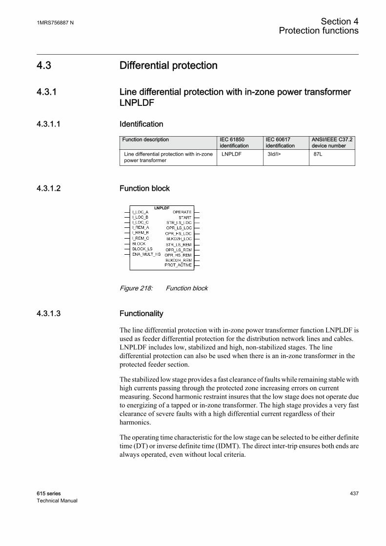
4.3 Differential protection
4.3.1 Line differential protection with in-zone power transformerLNPLDF
4.3.1.1 Identification
Function description IEC 61850identification
IEC 60617identification
ANSI/IEEE C37.2device number
Line differential protection with in-zonepower transformer
LNPLDF 3Id/I> 87L
4.3.1.2 Function block
GUID-F7ECAC0B-14B5-444C-9282-59AC32380576 V3 EN
Figure 218: Function block
4.3.1.3 Functionality
The line differential protection with in-zone power transformer function LNPLDF isused as feeder differential protection for the distribution network lines and cables.LNPLDF includes low, stabilized and high, non-stabilized stages. The linedifferential protection can also be used when there is an in-zone transformer in theprotected feeder section.
The stabilized low stage provides a fast clearance of faults while remaining stable withhigh currents passing through the protected zone increasing errors on currentmeasuring. Second harmonic restraint insures that the low stage does not operate dueto energizing of a tapped or in-zone transformer. The high stage provides a very fastclearance of severe faults with a high differential current regardless of theirharmonics.
The operating time characteristic for the low stage can be selected to be either definitetime (DT) or inverse definite time (IDMT). The direct inter-trip ensures both ends arealways operated, even without local criteria.
1MRS756887 N Section 4Protection functions
615 series 437Technical Manual
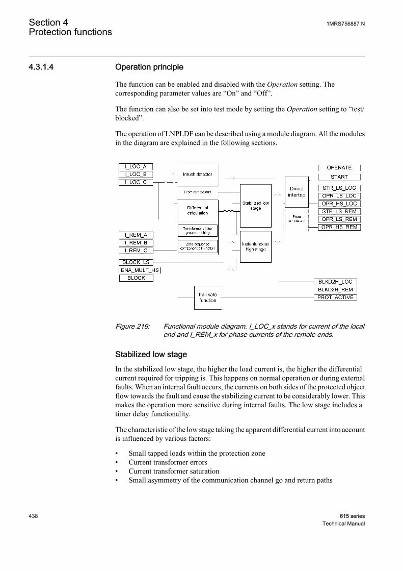
4.3.1.4 Operation principle
The function can be enabled and disabled with the Operation setting. Thecorresponding parameter values are “On” and “Off”.
The function can also be set into test mode by setting the Operation setting to “test/blocked”.
The operation of LNPLDF can be described using a module diagram. All the modulesin the diagram are explained in the following sections.
GUID-44304073-30AC-4EEA-889C-2D9410DC1180 V3 EN
Figure 219: Functional module diagram. I_LOC_x stands for current of the localend and I_REM_x for phase currents of the remote ends.
Stabilized low stageIn the stabilized low stage, the higher the load current is, the higher the differentialcurrent required for tripping is. This happens on normal operation or during externalfaults. When an internal fault occurs, the currents on both sides of the protected objectflow towards the fault and cause the stabilizing current to be considerably lower. Thismakes the operation more sensitive during internal faults. The low stage includes atimer delay functionality.
The characteristic of the low stage taking the apparent differential current into accountis influenced by various factors:
• Small tapped loads within the protection zone• Current transformer errors• Current transformer saturation• Small asymmetry of the communication channel go and return paths
Section 4 1MRS756887 NProtection functions
438 615 seriesTechnical Manual
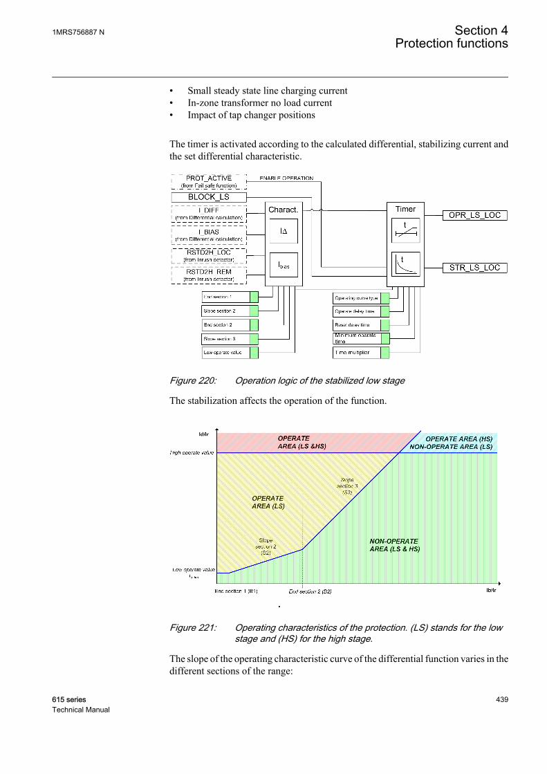
• Small steady state line charging current• In-zone transformer no load current• Impact of tap changer positions
The timer is activated according to the calculated differential, stabilizing current andthe set differential characteristic.
GUID-C5DA7D40-A17A-473F-A73D-6B291716C4A3 V2 EN
Figure 220: Operation logic of the stabilized low stage
The stabilization affects the operation of the function.
GUID-C7A3DFD3-1DDB-47EC-9C9A-B56FA4EDC69B V2 EN
Figure 221: Operating characteristics of the protection. (LS) stands for the lowstage and (HS) for the high stage.
The slope of the operating characteristic curve of the differential function varies in thedifferent sections of the range:
1MRS756887 N Section 4Protection functions
615 series 439Technical Manual
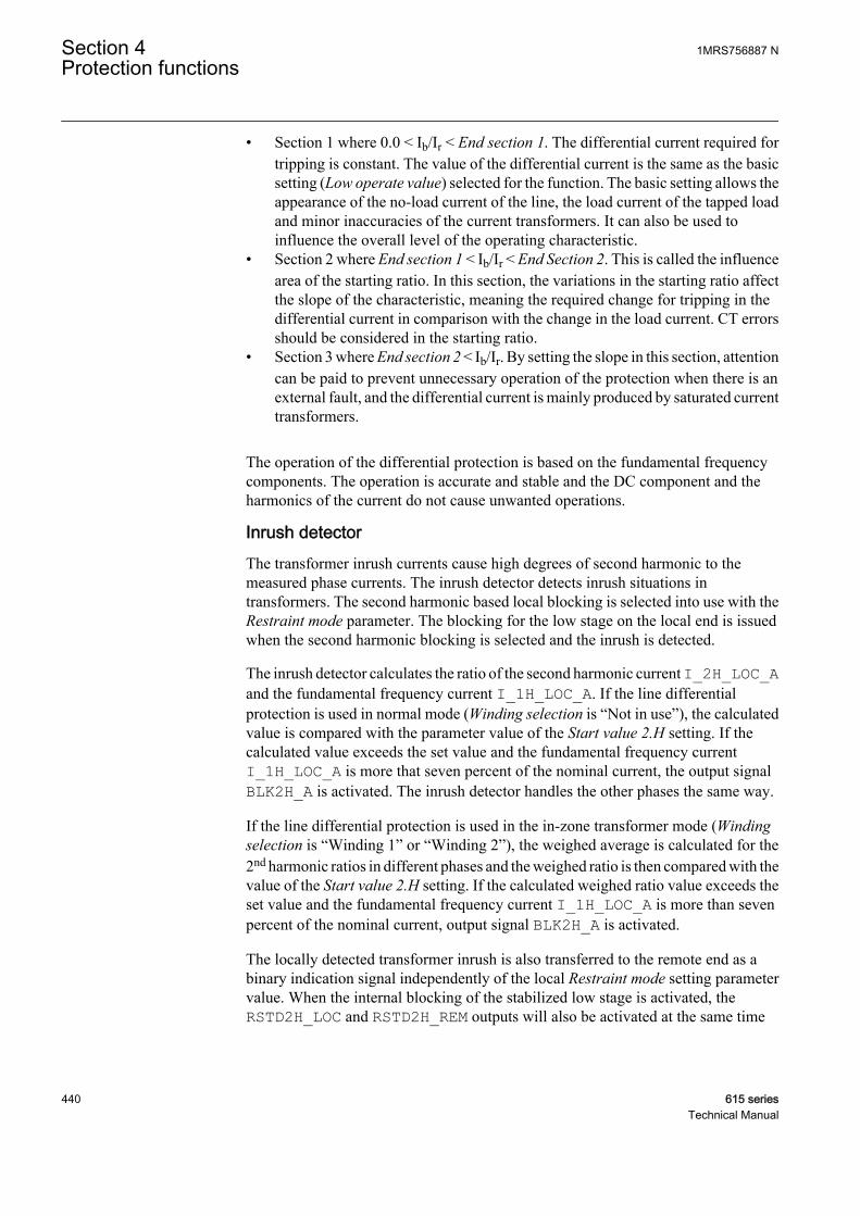
• Section 1 where 0.0 < Ib/Ir < End section 1. The differential current required fortripping is constant. The value of the differential current is the same as the basicsetting (Low operate value) selected for the function. The basic setting allows theappearance of the no-load current of the line, the load current of the tapped loadand minor inaccuracies of the current transformers. It can also be used toinfluence the overall level of the operating characteristic.
• Section 2 where End section 1 < Ib/Ir < End Section 2. This is called the influencearea of the starting ratio. In this section, the variations in the starting ratio affectthe slope of the characteristic, meaning the required change for tripping in thedifferential current in comparison with the change in the load current. CT errorsshould be considered in the starting ratio.
• Section 3 where End section 2 < Ib/Ir. By setting the slope in this section, attentioncan be paid to prevent unnecessary operation of the protection when there is anexternal fault, and the differential current is mainly produced by saturated currenttransformers.
The operation of the differential protection is based on the fundamental frequencycomponents. The operation is accurate and stable and the DC component and theharmonics of the current do not cause unwanted operations.
Inrush detectorThe transformer inrush currents cause high degrees of second harmonic to themeasured phase currents. The inrush detector detects inrush situations intransformers. The second harmonic based local blocking is selected into use with theRestraint mode parameter. The blocking for the low stage on the local end is issuedwhen the second harmonic blocking is selected and the inrush is detected.
The inrush detector calculates the ratio of the second harmonic current I_2H_LOC_Aand the fundamental frequency current I_1H_LOC_A. If the line differentialprotection is used in normal mode (Winding selection is “Not in use”), the calculatedvalue is compared with the parameter value of the Start value 2.H setting. If thecalculated value exceeds the set value and the fundamental frequency currentI_1H_LOC_A is more that seven percent of the nominal current, the output signalBLK2H_A is activated. The inrush detector handles the other phases the same way.
If the line differential protection is used in the in-zone transformer mode (Windingselection is “Winding 1” or “Winding 2”), the weighed average is calculated for the2nd harmonic ratios in different phases and the weighed ratio is then compared with thevalue of the Start value 2.H setting. If the calculated weighed ratio value exceeds theset value and the fundamental frequency current I_1H_LOC_A is more than sevenpercent of the nominal current, output signal BLK2H_A is activated.
The locally detected transformer inrush is also transferred to the remote end as abinary indication signal independently of the local Restraint mode setting parametervalue. When the internal blocking of the stabilized low stage is activated, theRSTD2H_LOC and RSTD2H_REM outputs will also be activated at the same time
Section 4 1MRS756887 NProtection functions
440 615 seriesTechnical Manual

depending on whether the inrush has been detected on local or remote end or on bothends.
GUID-92818F6B-4FB7-4D5C-AF64-36786F31AED8 V3 EN
Figure 222: Inrush current detection logic
Differential calculationThe operating principle is to calculate on both ends differential current from currentsentering and leaving the protection zone by utilizing the digital communicationchannels for data exchange. The differential currents are almost zero on normaloperation. The differential protection is phase segregated and the differential currentsare calculated separately on both ends.
Communication
INC
OM
ING
INC
OM
ING
PROTECTED ZONE
RED 615 RED 615
GUID-E9D80758-16A2-4748-A08C-94C33997E603 V3 EN
Figure 223: Basic protection principle
The differential current I∆ (Id) of the protection relay is obtained on both ends with theformula:
I I Id LOC REM= +
GUID-9C08695B-8241-4B74-AA2A-B64783F9C288 V2 EN (Equation 66)
The stabilizing current Ibias (Ib) of the protection relay is obtained on both ends withthe formula:
1MRS756887 N Section 4Protection functions
615 series 441Technical Manual
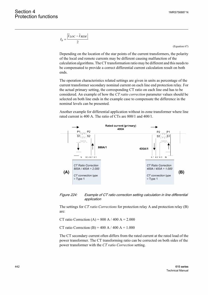
I
I I
b
LOC REM
=
−
2
GUID-6014FAFC-12CB-4DB3-85A9-0EF254D1729D V2 EN (Equation 67)
Depending on the location of the star points of the current transformers, the polarityof the local end remote currents may be different causing malfunction of thecalculation algorithms. The CT transformation ratio may be different and this needs tobe compensated to provide a correct differential current calculation result on bothends.
The operation characteristics related settings are given in units as percentage of thecurrent transformer secondary nominal current on each line end protection relay. Forthe actual primary setting, the corresponding CT ratio on each line end has to beconsidered. An example of how the CT ratio correction parameter values should beselected on both line ends in the example case to compensate the difference in thenominal levels can be presented.
Another example for differential application without in-zone transformer where linerated current is 400 A. The ratio of CTs are 800/1 and 400/1.
GUID-E9087A8C-1F10-45E0-A47C-754C30CB801C V1 EN
Figure 224: Example of CT ratio correction setting calculation in line differentialapplication
The settings for CT ratio Corrections for protection relay A and protection relay (B)are:
CT ratio Correction (A) = 800 A / 400 A = 2.000
CT ratio Correction (B) = 400 A / 400 A = 1.000
The CT secondary current often differs from the rated current at the rated load of thepower transformer. The CT transforming ratio can be corrected on both sides of thepower transformer with the CT ratio Correction setting.
Section 4 1MRS756887 NProtection functions
442 615 seriesTechnical Manual
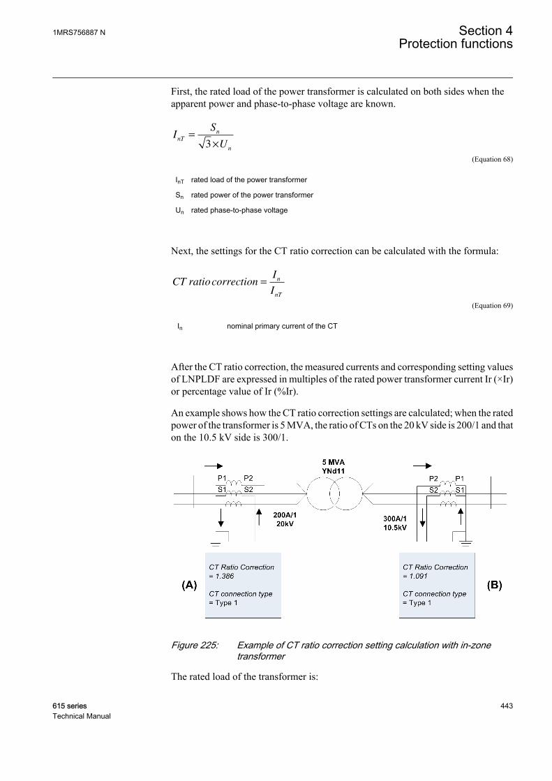
First, the rated load of the power transformer is calculated on both sides when theapparent power and phase-to-phase voltage are known.
IS
UnT
n
n
=
×3
GUID-B2130C43-E82B-4617-9FC4-79AB2F735CD9 V1 EN (Equation 68)
InT rated load of the power transformer
Sn rated power of the power transformer
Un rated phase-to-phase voltage
Next, the settings for the CT ratio correction can be calculated with the formula:
CT ratiocorrectionI
I
n
nT
=
GUID-F950DE9C-6AFB-4DF9-B299-6631693C55C0 V1 EN (Equation 69)
In nominal primary current of the CT
After the CT ratio correction, the measured currents and corresponding setting valuesof LNPLDF are expressed in multiples of the rated power transformer current Ir (×Ir)or percentage value of Ir (%Ir).
An example shows how the CT ratio correction settings are calculated; when the ratedpower of the transformer is 5 MVA, the ratio of CTs on the 20 kV side is 200/1 and thaton the 10.5 kV side is 300/1.
GUID-74289FF5-E90D-4633-9FEE-04DB8E86A3AE V1 EN
Figure 225: Example of CT ratio correction setting calculation with in-zonetransformer
The rated load of the transformer is:
1MRS756887 N Section 4Protection functions
615 series 443Technical Manual
HV side (A): InT_A = 5 MVA / (1.732 × 20 kV) = 144.3 A
LV side (A): InT_B = 5 MVA / (1.732 × 10.5 kV) = 274.9 A
So the settings for CT ratio Corrections at HV (A) and LV (B) side are:
CT ratio Correction (A) = 200 A / 144.3 A = 1.386
CT ratio Correction (B) = 300 A / 274.9 A = 1.091
CT connectionsThe connections of the primary current transformers are designated as “Type 1” and“Type 2”.
• If the positive directions of the winding 1 and winding 2 protection relay currentsare opposite, the CT connection type setting parameter is “Type 1”. Theconnection examples of “Type 1” are as shown in the Figure 226 and Figure 227.
• If the positive directions of the winding 1 and winding 2 protection relay currentsequate, the CT connection type setting parameter is “Type 2”. The connectionexamples of “Type 2” are as shown in the Figure 228 and Figure 229.
• The default value of the CT connection type setting is “Type 1”.
Section 4 1MRS756887 NProtection functions
444 615 seriesTechnical Manual

GUID-CED6A87F-980C-408D-B069-99ACDF1ACE86 V2 EN
Figure 226: Connection example of current transformers of Type 1
1MRS756887 N Section 4Protection functions
615 series 445Technical Manual
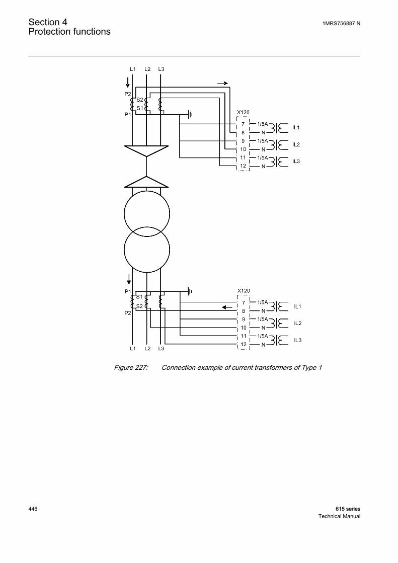
GUID-BFA25E96-B9FC-49F8-A8E2-23F2B5548490 V2 EN
Figure 227: Connection example of current transformers of Type 1
Section 4 1MRS756887 NProtection functions
446 615 seriesTechnical Manual
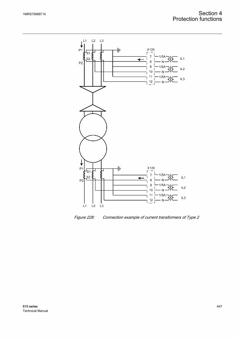
GUID-C49F5640-2FBD-4758-8C8B-7292130648CF V2 EN
Figure 228: Connection example of current transformers of Type 2
1MRS756887 N Section 4Protection functions
615 series 447Technical Manual

GUID-11ABD3BA-877D-411A-A970-3B6D5BA05803 V2 EN
Figure 229: Connection example of current transformers of Type 2
Transformer vector group matchingBefore differential and bias currents can be calculated, the phase difference of thecurrents must be vector group matched based on the transformer connection type. Thevector group of the power transformer is numerically matched on the high voltage andlow voltage sides by means of the Winding selection, Winding 1 type, Winding 2 typeand Clock number settings. Thus no interposing CTs are needed if there is only apower transformer inside the protected zone. The matching is based on phase shiftingand a numerical delta connection in the protection relay. If the neutral of a star-connected power transformer is earthed, any earth-fault in the network is perceived bythe protection relay as a differential current. The elimination of the zero-sequence
Section 4 1MRS756887 NProtection functions
448 615 seriesTechnical Manual
component can be selected for that winding by setting the Zro A eliminationparameter.
Winding selection setting defines the protection relay location respect to thetransformer. If the protection relay is situated at the HV side of the transformer, thenprotection relay location setting is set to “Winding 1” and respectively to “Winding 2”if protection relay is situated at the LV side. If the differential protection relays areused to protect a line without in-zone transformer, then the setting is set to “Not inuse”. In this case vector group matching is ignored.
The matching of the phase difference is based on the phase shifting and the numericaldelta connection inside the protection relay. The Winding 1 type parameter determinesthe connection on winding 1 (“Y”, “YN”, “D”, “Z”, “ZN”). The vector groupmatching can be implemented either on both, winding 1 and winding 2, or only onwinding 1 or winding 2, at intervals of 30° with the Clock number setting. Similarly,the Winding 2 type parameter determines the connections of the phase windings on thelow voltage side (“y”, “yn”, “d”, “z”, “zn”).
When the vector group matching is Yy0 and the CT connection type is according to“Type 2”, the phase angle of the phase currents connected to the protection relay doesnot change. When the vector group matching is Yy6, the phase currents are on one sideturned 180° in the protection relay.
Example 1, vector group matching of an YNd11-connected power transformer onwinding 1, CT connection type according to type 1. The Winding 1 type setting is“YN”, Winding 2 type is “d” and Clock number is “Clk Num 11”. This is compensatedinternally by giving winding 1 internal compensation value +30° and winding 2internal compensation value 0°:
II I
L mHV
L L−
− −
=−
1
1 2
3
GUID-7DD69356-3528-4161-AFD2-7807B133403D V1 EN (Equation 70)
II I
L mHV
L L−
−−
=−
2
2 3
3
GUID-36A1CB86-4BE8-45BD-B9BE-76F417EB0700 V1 EN (Equation 71)
II I
L mHV
L L−
− −
=−
3
3 1
3
GUID-E215125D-50B4-4F0B-95B0-84D5C6519B2E V1 EN (Equation 72)
Example 2, if vector group is Yd11 and CT connection type is according to type 1, thecompensation is a little different. The Winding 1 type setting is “Y”, Winding 2 type is“d” and Clock number is “Clk Num 11”. This is compensated internally by givingwinding 1 internal compensation value 0° and winding 2 internal compensation value-30°:
1MRS756887 N Section 4Protection functions
615 series 449Technical Manual

II I
L mLV
L L−
− −
=−
1
1 3
3
GUID-AFF5341B-32F8-457B-86A2-6A05B950FF29 V1 EN (Equation 73)
II I
L mLV
L L−
− −
=−
2
2 1
3
GUID-FE2E9619-077C-4E9A-99A7-C6DD02A34590 V1 EN (Equation 74)
II I
L mLV
L L−
− −
=−
3
3 2
3
GUID-99D25F61-7857-4410-86E4-E1DC1B3D5F40 V1 EN (Equation 75)
The “Y” side currents stay untouched, while the “d” side currents are compensated tomatch the currents actually flowing in the windings.
In this example there is no neutral current on either side of the transformer (assumingthere are no earthing transformers installed). In the previous example, the matching isdone differently to have the winding 1 neutral current compensated at the same time.
Table 416: LNPLDF vector group matching
Vector group of thetransformer
Winding 1 type Winding 2 type Phase shift Zero sequencecurrent elimination
Yy0 Y y 0 Not needed
YNy0 YN y 0 HV side
YNyn0 YN yn 0 HV & LV side
Yyn0 Y yn 0 LV side
Yy2 Y y 2 Not needed
YNy2 YN y 2 (Automatic)
YNyn2 YN yn 2 (Automatic)
Yyn2 Y yn 2 (Automatic)
Yy4 Y y 4 Not needed
YNy4 YN y 4 (Automatic)
YNyn4 YN yn 4 (Automatic)
Yyn4 Y yn 4 (Automatic)
Yy6 Y y 6 Not needed
YNy6 YN y 6 HV side
YNyn6 YN yn 6 HV & LV side
Yyn6 Y yn 6 LV side
Yy8 Y y 8 Not needed
YNy8 YN y 8 (Automatic)
YNyn8 YN yn 8 (Automatic)
Yyn8 Y yn 8 (Automatic)
Yy10 Y y 10 Not needed
Table continues on next page
Section 4 1MRS756887 NProtection functions
450 615 seriesTechnical Manual
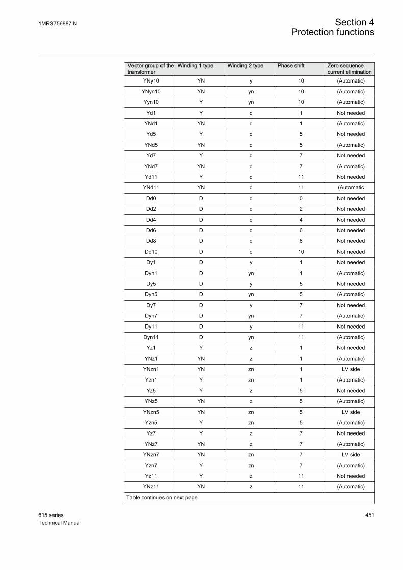
Vector group of thetransformer
Winding 1 type Winding 2 type Phase shift Zero sequencecurrent elimination
YNy10 YN y 10 (Automatic)
YNyn10 YN yn 10 (Automatic)
Yyn10 Y yn 10 (Automatic)
Yd1 Y d 1 Not needed
YNd1 YN d 1 (Automatic)
Yd5 Y d 5 Not needed
YNd5 YN d 5 (Automatic)
Yd7 Y d 7 Not needed
YNd7 YN d 7 (Automatic)
Yd11 Y d 11 Not needed
YNd11 YN d 11 (Automatic
Dd0 D d 0 Not needed
Dd2 D d 2 Not needed
Dd4 D d 4 Not needed
Dd6 D d 6 Not needed
Dd8 D d 8 Not needed
Dd10 D d 10 Not needed
Dy1 D y 1 Not needed
Dyn1 D yn 1 (Automatic)
Dy5 D y 5 Not needed
Dyn5 D yn 5 (Automatic)
Dy7 D y 7 Not needed
Dyn7 D yn 7 (Automatic)
Dy11 D y 11 Not needed
Dyn11 D yn 11 (Automatic)
Yz1 Y z 1 Not needed
YNz1 YN z 1 (Automatic)
YNzn1 YN zn 1 LV side
Yzn1 Y zn 1 (Automatic)
Yz5 Y z 5 Not needed
YNz5 YN z 5 (Automatic)
YNzn5 YN zn 5 LV side
Yzn5 Y zn 5 (Automatic)
Yz7 Y z 7 Not needed
YNz7 YN z 7 (Automatic)
YNzn7 YN zn 7 LV side
Yzn7 Y zn 7 (Automatic)
Yz11 Y z 11 Not needed
YNz11 YN z 11 (Automatic)
Table continues on next page
1MRS756887 N Section 4Protection functions
615 series 451Technical Manual

Vector group of thetransformer
Winding 1 type Winding 2 type Phase shift Zero sequencecurrent elimination
YNzn11 YN zn 11 LV side
Yzn11 Y zn 11 (Automatic)
Zy1 Z y 1 Not needed
Zyn1 Z yn 1 (Automatic)
ZNyn1 ZN yn 1 HV side
ZNy1 ZN y 1 (Automatic)
Zy5 Z y 5 Not needed
Zyn5 Z yn 5 (Automatic)
ZNyn5 ZN yn 5 HV side
ZNy5 ZN y 5 (Automatic)
Zy7 Z y 7 Not needed
Zyn7 Z yn 7 (Automatic)
ZNyn7 ZN yn 7 HV side
ZNy7 ZN y 7 (Automatic)
Zy11 Z y 11 Not needed
Zyn11 Z yn 11 (Automatic)
ZNyn11 ZN yn 11 HV side
ZNy11 ZN y 11 (Automatic)
Dz0 D z 0 Not needed
Dzn0 D zn 0 LV side
Dz2 D z 2 Not needed
Dzn2 D zn 2 (Automatic)
Dz4 D z 4 Not needed
Dzn4 D zn 4 (Automatic)
Dz6 D z 6 Not needed
Dzn6 D zn 6 LV side
Dz8 D z 8 Not needed
Dzn8 D zn 8 (Automatic)
Dz10 D z 10 Not needed
Dzn10 D zn 10 (Automatic)
Zd0 Z d 0 Not needed
ZNd0 ZN d 0 HV side
Zd2 Z d 2 Not needed
ZNd2 ZN d 2 (Automatic)
Zd4 Z d 4 Not needed
ZNd4 ZN d 4 (Automatic)
Zd6 Z d 6 Not needed
ZNd6 ZN d 6 HV side
Zd8 Z d 8 Not needed
Table continues on next page
Section 4 1MRS756887 NProtection functions
452 615 seriesTechnical Manual
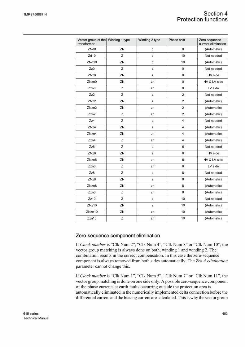
Vector group of thetransformer
Winding 1 type Winding 2 type Phase shift Zero sequencecurrent elimination
ZNd8 ZN d 8 (Automatic)
Zd10 Z d 10 Not needed
ZNd10 ZN d 10 (Automatic)
Zz0 Z z 0 Not needed
ZNz0 ZN z 0 HV side
ZNzn0 ZN zn 0 HV & LV side
Zzn0 Z zn 0 LV side
Zz2 Z z 2 Not needed
ZNz2 ZN z 2 (Automatic)
ZNzn2 ZN zn 2 (Automatic)
Zzn2 Z zn 2 (Automatic)
Zz4 Z z 4 Not needed
ZNz4 ZN z 4 (Automatic)
ZNzn4 ZN zn 4 (Automatic)
Zzn4 Z zn 4 (Automatic)
Zz6 Z z 6 Not needed
ZNz6 ZN z 6 HV side
ZNzn6 ZN zn 6 HV & LV side
Zzn6 Z zn 6 LV side
Zz8 Z z 8 Not needed
ZNz8 ZN z 8 (Automatic)
ZNzn8 ZN zn 8 (Automatic)
Zzn8 Z zn 8 (Automatic)
Zz10 Z z 10 Not needed
ZNz10 ZN z 10 (Automatic)
ZNzn10 ZN zn 10 (Automatic)
Zzn10 Z zn 10 (Automatic)
Zero-sequence component eliminationIf Clock number is “Clk Num 2“, “Clk Num 4”, “Clk Num 8” or “Clk Num 10”, thevector group matching is always done on both, winding 1 and winding 2. Thecombination results in the correct compensation. In this case the zero-sequencecomponent is always removed from both sides automatically. The Zro A eliminationparameter cannot change this.
If Clock number is “Clk Num 1”, “Clk Num 5”, “Clk Num 7” or “Clk Num 11”, thevector group matching is done on one side only. A possible zero-sequence componentof the phase currents at earth faults occurring outside the protection area isautomatically eliminated in the numerically implemented delta connection before thedifferential current and the biasing current are calculated. This is why the vector group
1MRS756887 N Section 4Protection functions
615 series 453Technical Manual

matching is almost always made on the star connected side of the “Ynd” and “Dyn”connected transformers.
If Clock number is “Clk Num 0” or “Clk Num 6”, the zero-sequence component of thephase currents is not eliminated automatically on either side. Therefore, the zero-sequence component on the star connected side that is earthed at its star point has tobe eliminated by using the Zro A elimination parameter.
The same parameter has to be used to eliminate the zero-sequence component if thereis, for example, an earthing transformer on the delta-connected side of the “Ynd”power transformer in the area to be protected. In this case, the vector group matchingis normally made on the side of the star connection. On the side of the deltaconnection, the elimination of the zero-sequence component has to be eliminated byusing the Zro A elimination parameter.
By using the Zro A elimination parameter, the zero-sequence component of the localphase currents is calculated and reduced for each phase current:
I I I I ILOC A LOC A LOC A LOC B LOC C
− − − − −
= − × + +
_ _ _ _ _
1
3
GUID-7C504C11-31C0-47A2-8253-E05020CA1CF7 V1 EN (Equation 76)
I I I I ILOC B LOC B LOC A LOC B LOC C
− − − − −
= − × + +
_ _ _ _ _
1
3
GUID-6FEF478B-7DA1-4012-9F59-43B21AF813E3 V1 EN (Equation 77)
I I I I ILOC C LOC C LOC A LOC B LOC C
− − − − −
= − × + +
_ _ _ _ _
1
3GUID-D5203A0B-D0A0-4147-B1F0-06C2B78B288B V1 EN
Fail safe functionTo prevent malfunction during communication interference, the operation ofLNPLDF is blocked when the protection communication supervision detects severeinterference in the communication channel. The timer reset stage is activated in casethe stabilized stage is started during a communication interruption. The protectioncommunication supervison is connected internally from PCSITPC to LNPLDF(dotted OK line).
Section 4 1MRS756887 NProtection functions
454 615 seriesTechnical Manual
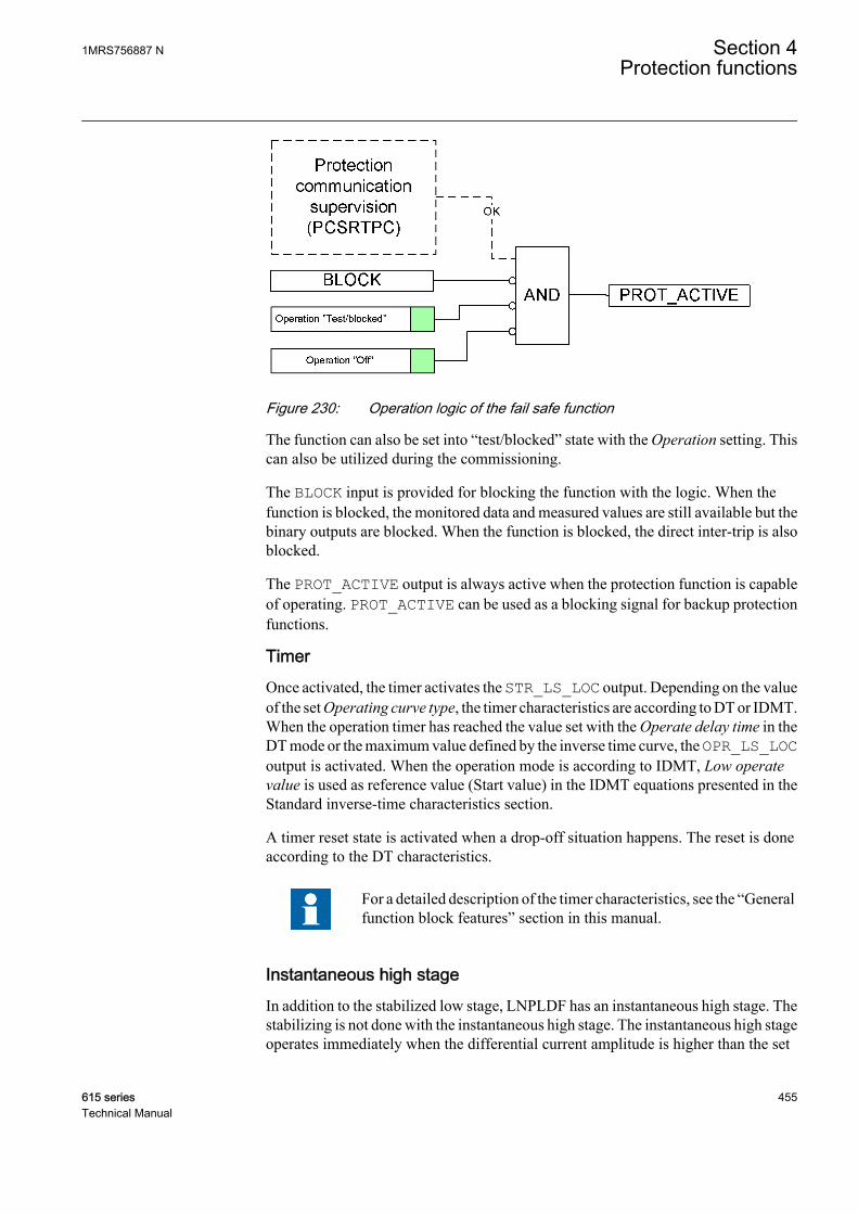
GUID-010E1FF3-D7B0-42C8-9179-09F753D7DFC3 V1 EN
Figure 230: Operation logic of the fail safe function
The function can also be set into “test/blocked” state with the Operation setting. Thiscan also be utilized during the commissioning.
The BLOCK input is provided for blocking the function with the logic. When thefunction is blocked, the monitored data and measured values are still available but thebinary outputs are blocked. When the function is blocked, the direct inter-trip is alsoblocked.
The PROT_ACTIVE output is always active when the protection function is capableof operating. PROT_ACTIVE can be used as a blocking signal for backup protectionfunctions.
TimerOnce activated, the timer activates the STR_LS_LOC output. Depending on the valueof the set Operating curve type, the timer characteristics are according to DT or IDMT.When the operation timer has reached the value set with the Operate delay time in theDT mode or the maximum value defined by the inverse time curve, the OPR_LS_LOCoutput is activated. When the operation mode is according to IDMT, Low operatevalue is used as reference value (Start value) in the IDMT equations presented in theStandard inverse-time characteristics section.
A timer reset state is activated when a drop-off situation happens. The reset is doneaccording to the DT characteristics.
For a detailed description of the timer characteristics, see the “Generalfunction block features” section in this manual.
Instantaneous high stageIn addition to the stabilized low stage, LNPLDF has an instantaneous high stage. Thestabilizing is not done with the instantaneous high stage. The instantaneous high stageoperates immediately when the differential current amplitude is higher than the set
1MRS756887 N Section 4Protection functions
615 series 455Technical Manual

value of the High operate value setting. If the ENA_MULT_HS input is active, theHigh operate value setting is internally multiplied by the High Op value Mult setting.
GUID-99000979-88BE-4A03-9F87-4A9608D91822 V1 EN
Figure 231: Operation logic of instantaneous high stage
Direct inter-tripDirect inter-trip is used to ensure the simultaneous opening of the circuit breakers atboth ends of the protected line when a fault is detected. Both start and operate signalsare sent to the remote end via communication. The direct-intertripping of the linedifferential protection is included into LNPLDF. The OPERATE output combines theoperate signals from both stages, local and remote, so that it can be used for the directinter-trip signal locally.
Section 4 1MRS756887 NProtection functions
456 615 seriesTechnical Manual
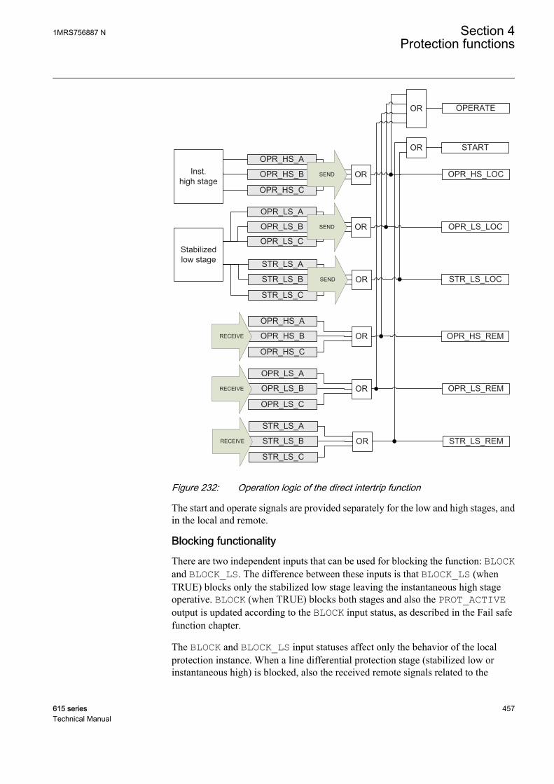
STR_LS_LOC
STR_LS_REM
OPR_LS_LOC
OPR_LS_REM
OPR_HS_LOC
OPR_HS_REM
OPR_LS_A
OPR_LS_B
OPR_LS_CStabilizedlow stage
ORSEND
STR_LS_A
STR_LS_B
STR_LS_C
ORSEND
OPR_HS_A
OPR_HS_B
OPR_HS_C
ORSEND
OPR_LS_A
OPR_LS_B
OPR_LS_C
ORRECEIVE
STR_LS_A
STR_LS_B
STR_LS_C
ORRECEIVE
OPR_HS_A
OPR_HS_B
OPR_HS_C
ORRECEIVE
Inst.high stage
START
OPERATEOR
OR
GUID-002B4F83-260D-4ADA-983E-9CB46DBF1228 V3 EN
Figure 232: Operation logic of the direct intertrip function
The start and operate signals are provided separately for the low and high stages, andin the local and remote.
Blocking functionalityThere are two independent inputs that can be used for blocking the function: BLOCKand BLOCK_LS. The difference between these inputs is that BLOCK_LS (whenTRUE) blocks only the stabilized low stage leaving the instantaneous high stageoperative. BLOCK (when TRUE) blocks both stages and also the PROT_ACTIVEoutput is updated according to the BLOCK input status, as described in the Fail safefunction chapter.
The BLOCK and BLOCK_LS input statuses affect only the behavior of the localprotection instance. When a line differential protection stage (stabilized low orinstantaneous high) is blocked, also the received remote signals related to the
1MRS756887 N Section 4Protection functions
615 series 457Technical Manual
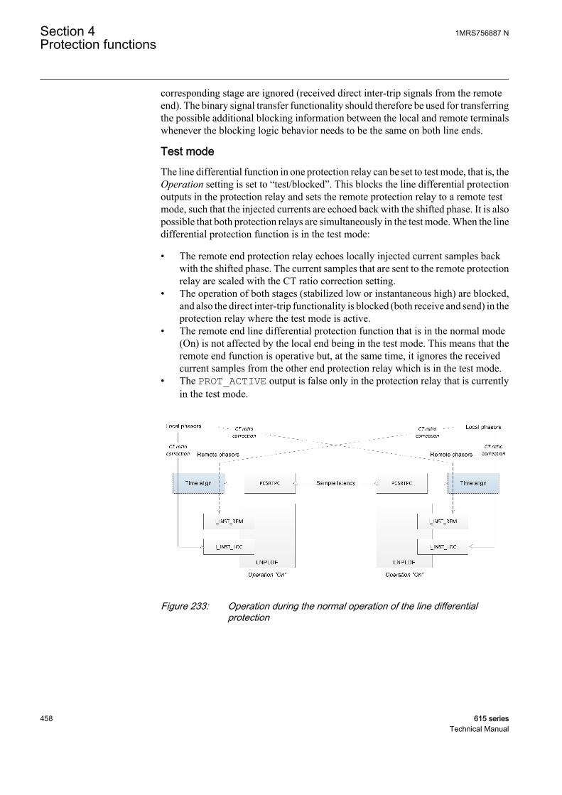
corresponding stage are ignored (received direct inter-trip signals from the remoteend). The binary signal transfer functionality should therefore be used for transferringthe possible additional blocking information between the local and remote terminalswhenever the blocking logic behavior needs to be the same on both line ends.
Test modeThe line differential function in one protection relay can be set to test mode, that is, theOperation setting is set to “test/blocked”. This blocks the line differential protectionoutputs in the protection relay and sets the remote protection relay to a remote testmode, such that the injected currents are echoed back with the shifted phase. It is alsopossible that both protection relays are simultaneously in the test mode. When the linedifferential protection function is in the test mode:
• The remote end protection relay echoes locally injected current samples backwith the shifted phase. The current samples that are sent to the remote protectionrelay are scaled with the CT ratio correction setting.
• The operation of both stages (stabilized low or instantaneous high) are blocked,and also the direct inter-trip functionality is blocked (both receive and send) in theprotection relay where the test mode is active.
• The remote end line differential protection function that is in the normal mode(On) is not affected by the local end being in the test mode. This means that theremote end function is operative but, at the same time, it ignores the receivedcurrent samples from the other end protection relay which is in the test mode.
• The PROT_ACTIVE output is false only in the protection relay that is currentlyin the test mode.
GUID-8E76712C-5DA3-46DA-AC6A-3C05CDBAB5AF V3 EN
Figure 233: Operation during the normal operation of the line differentialprotection
Section 4 1MRS756887 NProtection functions
458 615 seriesTechnical Manual
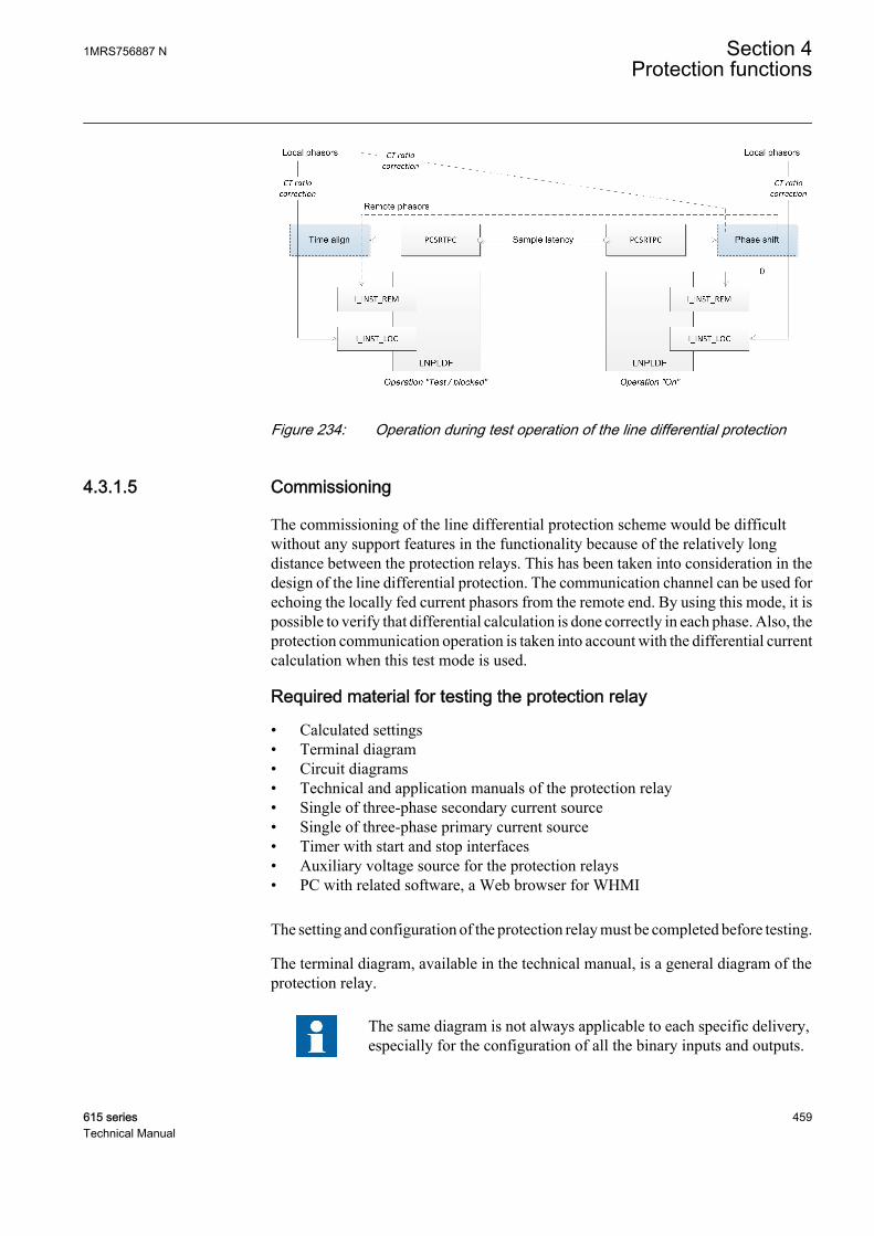
GUID-FC28C85A-6199-4249-8E01-C8693B005D3D V3 EN
Figure 234: Operation during test operation of the line differential protection
4.3.1.5 Commissioning
The commissioning of the line differential protection scheme would be difficultwithout any support features in the functionality because of the relatively longdistance between the protection relays. This has been taken into consideration in thedesign of the line differential protection. The communication channel can be used forechoing the locally fed current phasors from the remote end. By using this mode, it ispossible to verify that differential calculation is done correctly in each phase. Also, theprotection communication operation is taken into account with the differential currentcalculation when this test mode is used.
Required material for testing the protection relay
• Calculated settings• Terminal diagram• Circuit diagrams• Technical and application manuals of the protection relay• Single of three-phase secondary current source• Single of three-phase primary current source• Timer with start and stop interfaces• Auxiliary voltage source for the protection relays• PC with related software, a Web browser for WHMI
The setting and configuration of the protection relay must be completed before testing.
The terminal diagram, available in the technical manual, is a general diagram of theprotection relay.
The same diagram is not always applicable to each specific delivery,especially for the configuration of all the binary inputs and outputs.
1MRS756887 N Section 4Protection functions
615 series 459Technical Manual

Therefore, before testing, check that the available terminal diagramcorresponds to the protection relay.
The circuit diagrams of the application are recommended to be available. These arerequired for checking the terminal block numbers of the current, trip, alarm andpossibly other auxiliary circuits.
The technical and application manuals contain application and functionalitysummaries, function blocks, logic diagrams, input and output signals, settingparameters and technical data sorted per function.
The minimum requirement for a secondary current injection test device is the abilityto work as a one phase current source.
The protection relay should be prepared for the test before testing a particularfunction. The logic diagram of the tested protection function must be considered whileperforming the test. All included functions in the protection relay are tested accordingto the corresponding test instructions in this chapter. The functions can be tested in anyorder according to user preferences. Therefore, the test instructions are presented inalphabetical order. Only the functions that are in use (Operation is set to "On") shouldbe tested.
The response from the test can be viewed in different ways.
• Binary output signals• Monitored data values in the LHMI (logical signals)• A PC with a Web browser for WHMI use (logical signals and phasors)
All used setting groups should be tested.
Checking the external optical and electrical connectionsThe user must check the installation to verify that the protection relay is connected tothe other required parts of the protection system. The protection relay and all theconnected circuits are to be de-energized during the check-up.
Checking CT circuits
Check that the wiring is in strict accordance with the suppliedconnection diagram.
The CTs must be connected in accordance with the terminal diagram provided withthe protection relay, both with regards to phases and polarity. The following tests arerecommended for every primary CT or CT core connected to the protection relay.
• Primary injection test to verify the current ratio of the CT, the correct wiring upto the protection relay and correct phase sequence connection (that is L1, L2, L3.)
• Polarity check to prove that the predicted direction of the secondary current flowis correct for a given direction of the primary current flow. This is an essential test
Section 4 1MRS756887 NProtection functions
460 615 seriesTechnical Manual
for the proper operation of the directional function, protection or measurement inthe protection relay.
• CT secondary loop resistance measurement to confirm that the currenttransformer secondary loop DC resistance is within specification and that thereare no high resistance joints in the CT winding or wiring.
• CT excitation test to ensure that the correct core in the CT is connected to theprotection relay. Normally only a few points along the excitation curve arechecked to ensure that there are no wiring errors in the system, for example, dueto a mistake in connecting the CT's measurement core to the protection relay.
• CT excitation test to ensure that the CT is of the correct accuracy rating and thatthere are no short circuited turns in the CT windings. Manufacturer's designcurves should be available for the CT to compare the actual results.
• Earthing check of the individual CT secondary circuits to verify that each three-phase set of main CTs is properly connected to the station earth and only at oneelectrical point.
• Insulation resistance check.• Phase identification of CT shall be made.
Both the primary and the secondary sides must be disconnected fromthe line and the protection relay when plotting the excitationcharacteristics.
If the CT secondary circuit is opened or its earth connection is missingor removed without the CT primary being de-energized first,dangerous voltages may be produced. This can be lethal and causedamage to the insulation. The re-energizing of the CT primary shouldbe prohibited as long as the CT secondary is open or unearthed.
Checking of the power supplyCheck that the auxiliary supply voltage remains within the permissible input voltagerange under all operating conditions. Check that the polarity is correct beforepowering the protection relay.
Checking binary I/O circuitsAlways check the binary input circuits from the equipment to the protection relayinterface to make sure that all signals are connected correctly. If there is no need to testa particular input, the corresponding wiring can be disconnected from the terminal ofthe protection relay during testing. Check all the connected signals so that both inputvoltage level and polarity are in accordance with the protection relay specifications.However, attention must be paid to the electrical safety instructions.
Always check the binary output circuits from the protection relay to the equipmentinterface to make sure that all signals are connected correctly. If a particular outputneeds to be tested, the corresponding wiring can be disconnected from the terminal ofthe protection relay during testing. Check all the connected signals so that both load
1MRS756887 N Section 4Protection functions
615 series 461Technical Manual

and polarity are in accordance with the protection relay specifications. However,attention must be paid to the electrical safety instructions.
Checking optical connectionsCheck that the Tx and Rx optical connections are correct.
A relay equipped with optical connections requires a minimum depthof 180 mm for plastic fiber cables and 275 mm for glass fiber cables.Check the allowed minimum bending radius from the optical cablemanufacturer.
Applying required settings for the protection relayDownload all calculated settings and measurement transformer parameters in theprotection relay.
Connecting test equipment to the protection relayBefore testing, connect the test equipment according to the protection relay specificconnection diagram.
Pay attention to the correct connection of the input and output current terminals.Check that the input and output logical signals in the logic diagram for the functionunder test are connected to the corresponding binary inputs and outputs of theprotection relay. Select the correct auxiliary voltage source according to the powersupply module of the protection relay. Select the correct auxiliary voltage sourceaccording to the power supply module of the protection relay.
Section 4 1MRS756887 NProtection functions
462 615 seriesTechnical Manual
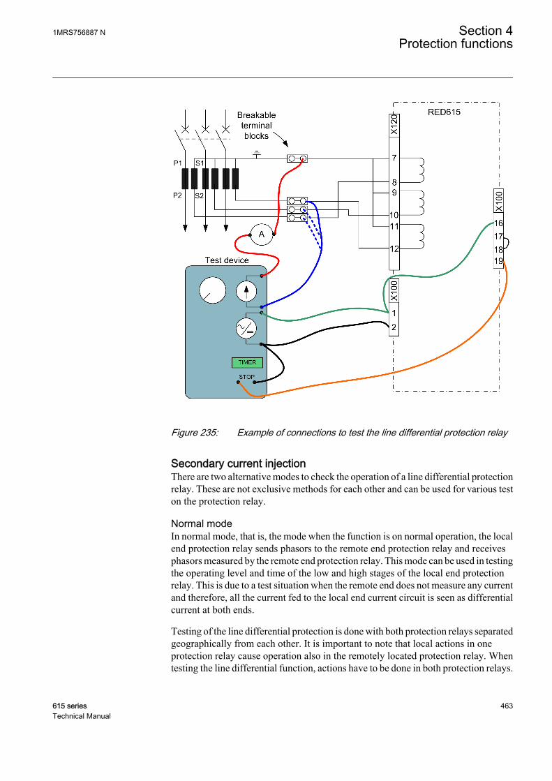
GUID-F1F4E199-8B6A-4066-ACCB-07FE4F887417 V3 EN
Figure 235: Example of connections to test the line differential protection relay
Secondary current injectionThere are two alternative modes to check the operation of a line differential protectionrelay. These are not exclusive methods for each other and can be used for various teston the protection relay.
Normal modeIn normal mode, that is, the mode when the function is on normal operation, the localend protection relay sends phasors to the remote end protection relay and receivesphasors measured by the remote end protection relay. This mode can be used in testingthe operating level and time of the low and high stages of the local end protectionrelay. This is due to a test situation when the remote end does not measure any currentand therefore, all the current fed to the local end current circuit is seen as differentialcurrent at both ends.
Testing of the line differential protection is done with both protection relays separatedgeographically from each other. It is important to note that local actions in oneprotection relay cause operation also in the remotely located protection relay. Whentesting the line differential function, actions have to be done in both protection relays.
1MRS756887 N Section 4Protection functions
615 series 463Technical Manual

Before the test, the trip signal to the circuit breaker shall be blocked, for example bybreaking the trip circuit by opening the terminal block or by using some other suitablemethod.
When injecting current to one phase in the local end protection relay, the current isseen as a differential current at both ends. If a current Iinjected is injected, L1 in phaseL1, the differential and stabilizing currents for phase L1 are:
ID A Iinjected_ =
GUID-B5B84B9B-B26C-421F-B4D0-E301EE4883F3 V3 EN (Equation 78)
IB A Iinjected_ /= 2
GUID-6A1A367B-241B-4831-A1F2-9373AE4D26ED V1 EN (Equation 79)
The operation is equal for phases L2 and L3.
Verifying the settings
1. Block the unwanted trip signals from the protection relay units involved.2. Inject a current in phase L1 and increase the current until the function operates
for phase L1.The injected operate current corresponds to the set Low operate value. Themonitored values for ID_A should be equal to the injected current.
3. Repeat point 2 by current injection in phases L2 and L3.4. Measure the operating time by injecting the single-phase current in phase L1.
The injected current should be four times the operating current. The timemeasurement is stopped by the trip output from the protection relay unit.
5. Disconnect the test equipment and reconnect the current transformers and allother circuits including the trip circuit.
Phasor echoing methodThe line differential function in one protection relay can be set to special test mode,that is, the Operation setting is set to “test/blocked”. When this mode is in use, theremote end protection relay echoes locally injected current phasors back with theshifted phase and settable amplitude. Therefore, the local end line differential functionis also automatically blocked and the remote end line differential function discards thephasors it receives from the protection relay in the test mode.
When the test mode is active, the CT connection type is still used by the linedifferential protection function as in the normal operation mode. The setting can beused for shifting the phase (0 or 180 degrees).
Section 4 1MRS756887 NProtection functions
464 615 seriesTechnical Manual
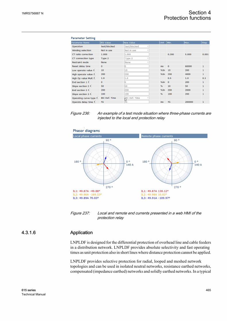
GUID-6F26D761-CB1D-4D86-80AA-CEC95CEBC1A9 V2 EN
Figure 236: An example of a test mode situation where three-phase currents areinjected to the local end protection relay
GUID-21BCDEC5-2A22-4AEE-831E-BC8A72E40A64 V2 EN
Figure 237: Local and remote end currents presented in a web HMI of theprotection relay
4.3.1.6 Application
LNPLDF is designed for the differential protection of overhead line and cable feedersin a distribution network. LNPLDF provides absolute selectivity and fast operatingtimes as unit protection also in short lines where distance protection cannot be applied.
LNPLDF provides selective protection for radial, looped and meshed networktopologies and can be used in isolated neutral networks, resistance earthed networks,compensated (impedance earthed) networks and solidly earthed networks. In a typical
1MRS756887 N Section 4Protection functions
615 series 465Technical Manual

network configuration where the line differential protection scheme is applied, theprotected zone, that is, the line or cable, is fed from two directions.
Communication
INC
OM
ING
INC
OM
ING
PROTECTED ZONE
RED 615 RED 615
GUID-E9D80758-16A2-4748-A08C-94C33997E603 V3 EN
Figure 238: Line protection with phase segregated line differential with in-zonetransformer
LNPLDF can be utilized for various types of network configurations or topologies.Case A shows the protection of a ring-type distribution network. The network is alsoused in the closed ring mode. LNPLDF is used as the main protection for differentsections of the feeder. In case B, the interconnection of two substations is done withparallel lines and each line is protected with the line differential protection. In case C,the connection line to mid scale power generation (typical size around 10...50 MVA)is protected with the line differential function. The protection includes the transformerfrom the protection field. In case D, the connection between two substations and asmall distribution transformer is located at the tapped load. The use of LNPLDF is notlimited to these applications.
Section 4 1MRS756887 NProtection functions
466 615 seriesTechnical Manual
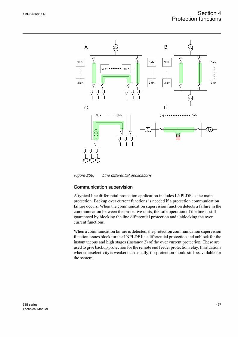
GUID-64A6AADE-275F-43DA-B7D9-2B1340166A4D V2 EN
Figure 239: Line differential applications
Communication supervisionA typical line differential protection application includes LNPLDF as the mainprotection. Backup over current functions is needed if a protection communicationfailure occurs. When the communication supervision function detects a failure in thecommunication between the protective units, the safe operation of the line is stillguaranteed by blocking the line differential protection and unblocking the overcurrent functions.
When a communication failure is detected, the protection communication supervisionfunction issues block for the LNPLDF line differential protection and unblock for theinstantaneous and high stages (instance 2) of the over current protection. These areused to give backup protection for the remote end feeder protection relay. In situationswhere the selectivity is weaker than usually, the protection should still be available forthe system.
1MRS756887 N Section 4Protection functions
615 series 467Technical Manual

PHIPTOC
PHHPTOC(2)
LNPLDF
PCSRTPCBLOCK
UNBLOCK
UNBLOCK
PHHPTOC(1)
PHLPTOC
PHIPTOC
PHHPTOC(2)
LNPLDF
PCSRTPCBLOCK
UNBLOCK
UNBLOCK
PHHPTOC(1)
PHLPTOCPHLPTOC
PHHPTOC(1)
PHIPTOC
RED 615
RED 615
RED 615
GUID-01A2A41E-2813-448D-953F-F9690578DEDE V2 EN
Figure 240: Protection communication supervision detects failures oncommunication
In-zone transformer
20kV300A/11500A/1
PROTECTED ZONE
110kV
Yd1140MW
HVLVL ~
RED 615 RED 615
GUID-52FC4852-C9D1-4DD1-B2D7-62FCE98B7FD7 V2 EN
Figure 241: In-zone transformer example about CT ratio correction calculation
The CT ratio correction calculation starts with the rated load current calculation forHV and LV sides. The rated load current is defined as the rated power of thetransformer divided by the square root of three times the nominal phase-to-phasevoltage at the HV or LV side.
Section 4 1MRS756887 NProtection functions
468 615 seriesTechnical Manual

IS
UnT
n
n
=
×3
GUID-B2130C43-E82B-4617-9FC4-79AB2F735CD9 V1 EN (Equation 80)
The rated load current of the transformer on the HV side is 209.9 A (40 MW / (√3 ×110 kV)) and the rated load current of the transformer on the LV side is 1154.7 A (40MW / (√3 × 20 kV)). This means that the CT ratio corrections for the HV and LV sidesare:
CT ratio correction (HV) = 1.429 (300 A / 209.9 A)
CT ratio correction (LV) = 1.299 (1500 A / 1154.7 A)
Small power transformers in a tapWith a relatively small power transformer in a line tap, the line differential protectioncan be applied without the need of current measurement from the tap. In such cases,the line differential function is time delayed for low differential currents below thehigh set limit and LNPLDF coordinates with the downstream protection relays in therelevant tap. For differential currents above the set limit, the operation isinstantaneous. As a consequence, when the load current of the tap is negligible, thelow resistive line faults are cleared instantaneously at the same time as maximumsensitivity for the high resistive faults are maintained but with a time delayedoperation. The maximum sensitivity for high resistive faults is maintained at the sametime, but with a time delayed operation.
Inst
.
Tim
e de
laye
d
500kVA
33kV
AkV
kVAI L 75.8
333
500
400A/1400A/1 PROTECTED ZONE
%202.01A* 400
75.8I
A
A
A
RED 615 RED 615
GUID-F1B36FF9-7463-4D8D-8EDC-70A09B52CAE9 V2 EN
Figure 242: Influence of the tapped transformer load current to the stabilized lowstage setting
The stabilized stage provides both DT and IDMT characteristics that are used for timeselective protection against faults which are not covered by the instantaneous stage.The impedance of the line is typically an order of magnitude lower than the
1MRS756887 N Section 4Protection functions
615 series 469Technical Manual

transformer impedance providing significantly higher fault currents when the fault islocated on the line.
Z=10%
33kV
AkV
kVAI F 23.96
10.0333
5001.1
400A/1400A/1
500kVA
Inst
.
Tim
e de
laye
d
%2424.01A* 400
23.96I
A
A
A
RED 615 RED 615
GUID-F9600D18-75B9-4EA5-8F9B-656FCB1FC938 V2 EN
Figure 243: Influence of the short circuit current at LV side of the tappedtransformer to the differential current
Detection of the inrush current during transformer start-upWhen the line is energized, the transformer magnetization inrush current is seen asdifferential current by the line differential protection and may cause malfunction ofthe protection if not taken into account. The inrush situation may only be detected onone end but the differential current is always seen on both ends. The inrush currentincludes high order harmonic components which can be detected and used as theblocking criteria for the stabilized stage. The inrush detection information is changedbetween two ends so that fast and safe blocking of the stabilized stage can be issuedon both ends.
Section 4 1MRS756887 NProtection functions
470 615 seriesTechnical Manual

INCO
MIN
G
INRUSH
ID> BLOCKEDID> BLOCKED
BLKD2H_LOC
RED 615RED 615
GUID-0383F2EF-18CC-45A0-A9BC-E04658981495 V3 EN
Figure 244: Blocking of line differential functions during detected transformerstart-up current
If the protection stage is allowed to start during the inrush situation, the time delay canbe selected so that the stabilized stage does not operate in the inrush situation.
4.3.1.7 Signals
Table 417: LNPLDF Input signals
Name Type Default DescriptionI_LOC_A SIGNAL 0 Phase A local current
I_LOC_B SIGNAL 0 Phase B local current
I_LOC_C SIGNAL 0 Phase C local current
I_REM_A SIGNAL 0 Phase A remote current
I_REM_B SIGNAL 0 Phase B remote current
I_REM_C SIGNAL 0 Phase C remote current
BLOCK BOOLEAN 0=False Signal for blocking the function
BLOCK_LS BOOLEAN 0=False Signal for blocking the stab. stage
ENA_MULT_HS BOOLEAN 0=False Enables the high stage multiplier
1MRS756887 N Section 4Protection functions
615 series 471Technical Manual
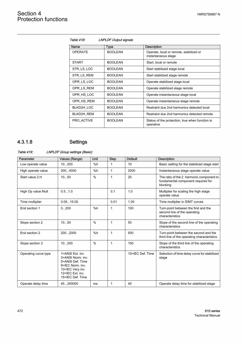
Table 418: LNPLDF Output signals
Name Type DescriptionOPERATE BOOLEAN Operate, local or remote, stabilized or
instantaneous stage
START BOOLEAN Start, local or remote
STR_LS_LOC BOOLEAN Start stabilized stage local
STR_LS_REM BOOLEAN Start stabilized stage remote
OPR_LS_LOC BOOLEAN Operate stabilized stage local
OPR_LS_REM BOOLEAN Operate stabilized stage remote
OPR_HS_LOC BOOLEAN Operate instantaneous stage local
OPR_HS_REM BOOLEAN Operate instantaneous stage remote
BLKD2H_LOC BOOLEAN Restraint due 2nd harmonics detected local
BLKD2H_REM BOOLEAN Restraint due 2nd harmonics detected remote
PRO_ACTIVE BOOLEAN Status of the protection, true when function isoperative
4.3.1.8 Settings
Table 419: LNPLDF Group settings (Basic)
Parameter Values (Range) Unit Step Default DescriptionLow operate value 10...200 %Ir 1 10 Basic setting for the stabilized stage start
High operate value 200...4000 %Ir 1 2000 Instantaneous stage operate value
Start value 2.H 10...50 % 1 20 The ratio of the 2. harmonic component tofundamental component required forblocking
High Op value Mult 0.5...1.0 0.1 1.0 Multiplier for scaling the high stageoperate value
Time multiplier 0.05...15.00 0.01 1.00 Time multiplier in IDMT curves
End section 1 0...200 %Ir 1 100 Turn-point between the first and thesecond line of the operatingcharacteristics
Slope section 2 10...50 % 1 50 Slope of the second line of the operatingcharacteristics
End section 2 200...2000 %Ir 1 500 Turn-point between the second and thethird line of the operating characteristics
Slope section 3 10...200 % 1 150 Slope of the third line of the operatingcharacteristics
Operating curve type 1=ANSI Ext. inv.3=ANSI Norm. inv.5=ANSI Def. Time9=IEC Norm. inv.10=IEC Very inv.12=IEC Ext. inv.15=IEC Def. Time
15=IEC Def. Time Selection of time delay curve for stabilizedstage
Operate delay time 45...200000 ms 1 45 Operate delay time for stabilized stage
Section 4 1MRS756887 NProtection functions
472 615 seriesTechnical Manual
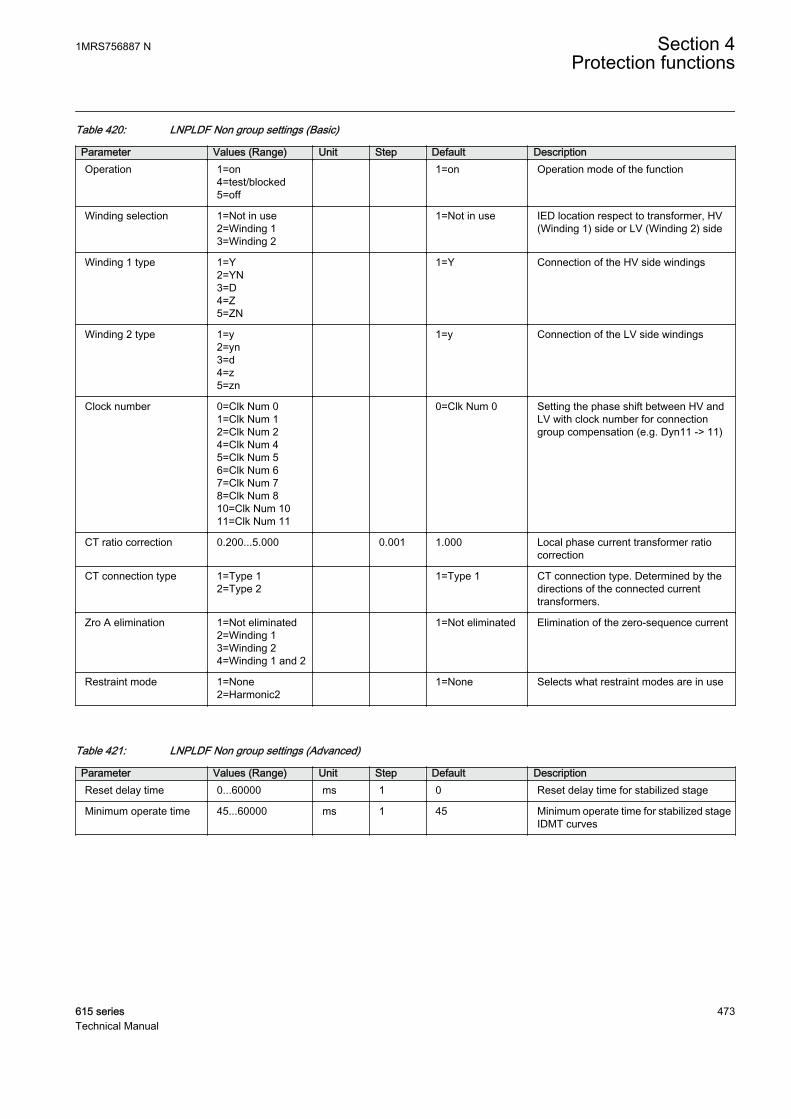
Table 420: LNPLDF Non group settings (Basic)
Parameter Values (Range) Unit Step Default DescriptionOperation 1=on
4=test/blocked5=off
1=on Operation mode of the function
Winding selection 1=Not in use2=Winding 13=Winding 2
1=Not in use IED location respect to transformer, HV(Winding 1) side or LV (Winding 2) side
Winding 1 type 1=Y2=YN3=D4=Z5=ZN
1=Y Connection of the HV side windings
Winding 2 type 1=y2=yn3=d4=z5=zn
1=y Connection of the LV side windings
Clock number 0=Clk Num 01=Clk Num 12=Clk Num 24=Clk Num 45=Clk Num 56=Clk Num 67=Clk Num 78=Clk Num 810=Clk Num 1011=Clk Num 11
0=Clk Num 0 Setting the phase shift between HV andLV with clock number for connectiongroup compensation (e.g. Dyn11 -> 11)
CT ratio correction 0.200...5.000 0.001 1.000 Local phase current transformer ratiocorrection
CT connection type 1=Type 12=Type 2
1=Type 1 CT connection type. Determined by thedirections of the connected currenttransformers.
Zro A elimination 1=Not eliminated2=Winding 13=Winding 24=Winding 1 and 2
1=Not eliminated Elimination of the zero-sequence current
Restraint mode 1=None2=Harmonic2
1=None Selects what restraint modes are in use
Table 421: LNPLDF Non group settings (Advanced)
Parameter Values (Range) Unit Step Default DescriptionReset delay time 0...60000 ms 1 0 Reset delay time for stabilized stage
Minimum operate time 45...60000 ms 1 45 Minimum operate time for stabilized stageIDMT curves
1MRS756887 N Section 4Protection functions
615 series 473Technical Manual
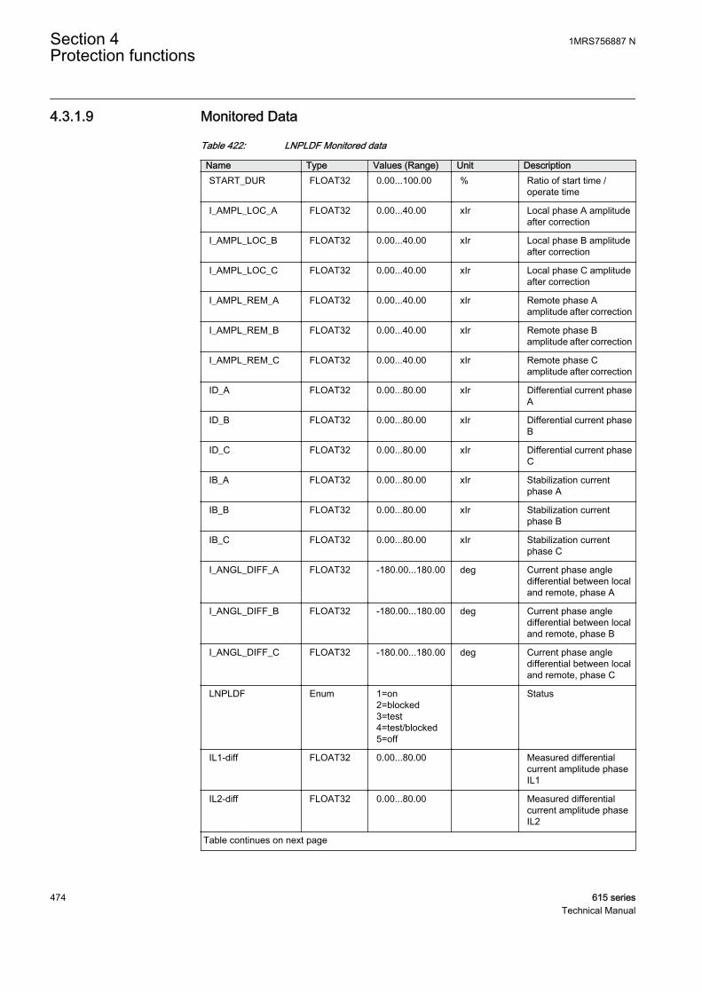
4.3.1.9 Monitored Data
Table 422: LNPLDF Monitored data
Name Type Values (Range) Unit DescriptionSTART_DUR FLOAT32 0.00...100.00 % Ratio of start time /
operate time
I_AMPL_LOC_A FLOAT32 0.00...40.00 xIr Local phase A amplitudeafter correction
I_AMPL_LOC_B FLOAT32 0.00...40.00 xIr Local phase B amplitudeafter correction
I_AMPL_LOC_C FLOAT32 0.00...40.00 xIr Local phase C amplitudeafter correction
I_AMPL_REM_A FLOAT32 0.00...40.00 xIr Remote phase Aamplitude after correction
I_AMPL_REM_B FLOAT32 0.00...40.00 xIr Remote phase Bamplitude after correction
I_AMPL_REM_C FLOAT32 0.00...40.00 xIr Remote phase Camplitude after correction
ID_A FLOAT32 0.00...80.00 xIr Differential current phaseA
ID_B FLOAT32 0.00...80.00 xIr Differential current phaseB
ID_C FLOAT32 0.00...80.00 xIr Differential current phaseC
IB_A FLOAT32 0.00...80.00 xIr Stabilization currentphase A
IB_B FLOAT32 0.00...80.00 xIr Stabilization currentphase B
IB_C FLOAT32 0.00...80.00 xIr Stabilization currentphase C
I_ANGL_DIFF_A FLOAT32 -180.00...180.00 deg Current phase angledifferential between localand remote, phase A
I_ANGL_DIFF_B FLOAT32 -180.00...180.00 deg Current phase angledifferential between localand remote, phase B
I_ANGL_DIFF_C FLOAT32 -180.00...180.00 deg Current phase angledifferential between localand remote, phase C
LNPLDF Enum 1=on2=blocked3=test4=test/blocked5=off
Status
IL1-diff FLOAT32 0.00...80.00 Measured differentialcurrent amplitude phaseIL1
IL2-diff FLOAT32 0.00...80.00 Measured differentialcurrent amplitude phaseIL2
Table continues on next page
Section 4 1MRS756887 NProtection functions
474 615 seriesTechnical Manual
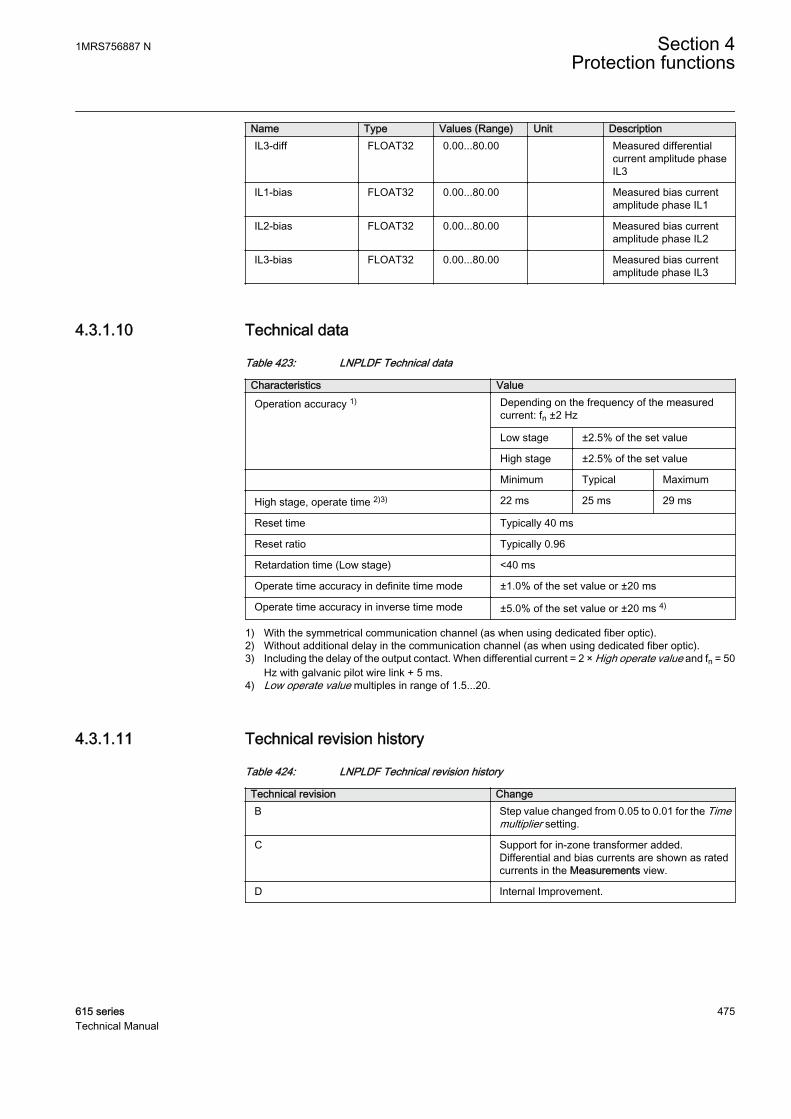
Name Type Values (Range) Unit DescriptionIL3-diff FLOAT32 0.00...80.00 Measured differential
current amplitude phaseIL3
IL1-bias FLOAT32 0.00...80.00 Measured bias currentamplitude phase IL1
IL2-bias FLOAT32 0.00...80.00 Measured bias currentamplitude phase IL2
IL3-bias FLOAT32 0.00...80.00 Measured bias currentamplitude phase IL3
4.3.1.10 Technical data
Table 423: LNPLDF Technical data
Characteristics Value
Operation accuracy 1) Depending on the frequency of the measuredcurrent: fn ±2 Hz
Low stage ±2.5% of the set value
High stage ±2.5% of the set value
Minimum Typical Maximum
High stage, operate time 2)3) 22 ms 25 ms 29 ms
Reset time Typically 40 ms
Reset ratio Typically 0.96
Retardation time (Low stage) <40 ms
Operate time accuracy in definite time mode ±1.0% of the set value or ±20 ms
Operate time accuracy in inverse time mode ±5.0% of the set value or ±20 ms 4)
1) With the symmetrical communication channel (as when using dedicated fiber optic).2) Without additional delay in the communication channel (as when using dedicated fiber optic).3) Including the delay of the output contact. When differential current = 2 × High operate value and fn = 50
Hz with galvanic pilot wire link + 5 ms.4) Low operate value multiples in range of 1.5...20.
4.3.1.11 Technical revision history
Table 424: LNPLDF Technical revision history
Technical revision ChangeB Step value changed from 0.05 to 0.01 for the Time
multiplier setting.
C Support for in-zone transformer added.Differential and bias currents are shown as ratedcurrents in the Measurements view.
D Internal Improvement.
1MRS756887 N Section 4Protection functions
615 series 475Technical Manual

4.3.2 Stabilized and instantaneous differential protection for two-winding transformers TR2PTDF
4.3.2.1 Identification
Function description IEC 61850identification
IEC 60617identification
ANSI/IEEE C37.2device number
Stabilized and instantaneous differentialprotection for two-winding transformers
TR2PTDF 3dI>T 87T
4.3.2.2 Function block
GUID-134E8524-738D-4232-A6BD-4C9BD2A62F8D V2 EN
Figure 245: Function block
4.3.2.3 Functionality
The stabilized and instantaneous differential protection function TR2PTDF isdesigned to protect two-winding transformers and generator-transformer blocks.TR2PTDF includes low biased and high instantaneous stages.
The biased low stage provides a fast clearance of faults while remaining stable withhigh currents passing through the protected zone increasing errors on currentmeasuring. The second harmonic restraint, together with the waveform basedalgorithms, ensures that the low stage does not operate due to the transformer inrushcurrents. The fifth harmonic restraint ensures that the low stage does not operate onapparent differential current caused by a harmless transformer over-excitation.
The instantaneous high stage provides a very fast clearance of severe faults with a highdifferential current regardless of their harmonics.
The setting characteristic can be set more sensitive with the aid of tap changer positioncompensation. The correction of transformation ratio due to the changes in tapposition is done automatically based on the tap changer status information.
4.3.2.4 Operation principle
The function can be enabled and disabled with the Operation setting. Thecorresponding parameter values are "On" and "Off".
Section 4 1MRS756887 NProtection functions
476 615 seriesTechnical Manual

The operation of TR2PTDF can be described by using a module diagram. All themodules in the diagram are explained in the next sections.
GUID-3A506E19-4E77-4866-8EDC-6264823E1090 V2 EN
Figure 246: Functional module diagram
Differential calculationTR2PTDF operates phase-wise on a difference of incoming and outgoing currents.The positive direction of the currents is towards the protected object.
Winding 1(usually HV)
Winding 2(usually LV)
1WI 2WI
GUID-DABAB343-214F-4A86-ADC8-BFD8E64B25A7 V3 EN
Figure 247: Positive direction of the currents
1MRS756887 N Section 4Protection functions
615 series 477Technical Manual
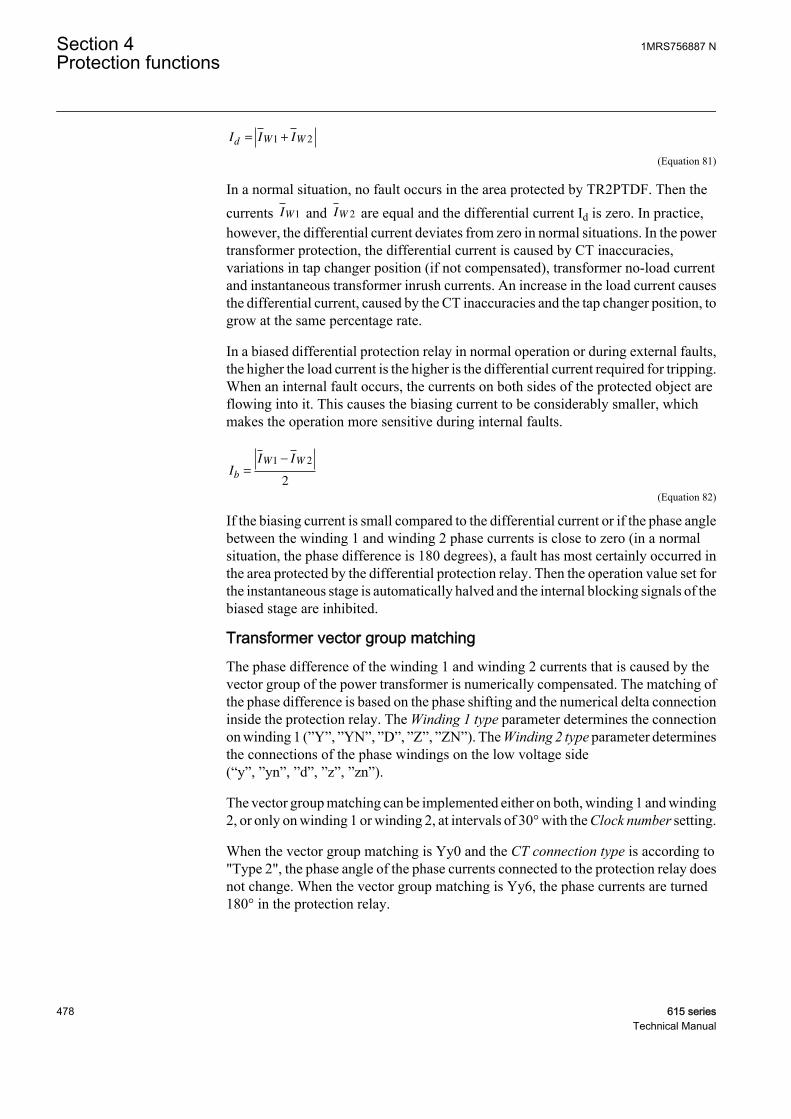
I I Id W W= +1 2
GUID-0B35503B-CA7D-4598-A1E4-59C9AA66012D V2 EN (Equation 81)
In a normal situation, no fault occurs in the area protected by TR2PTDF. Then thecurrents IW1 and IW 2 are equal and the differential current Id is zero. In practice,however, the differential current deviates from zero in normal situations. In the powertransformer protection, the differential current is caused by CT inaccuracies,variations in tap changer position (if not compensated), transformer no-load currentand instantaneous transformer inrush currents. An increase in the load current causesthe differential current, caused by the CT inaccuracies and the tap changer position, togrow at the same percentage rate.
In a biased differential protection relay in normal operation or during external faults,the higher the load current is the higher is the differential current required for tripping.When an internal fault occurs, the currents on both sides of the protected object areflowing into it. This causes the biasing current to be considerably smaller, whichmakes the operation more sensitive during internal faults.
I
I I
b
W W
=
−1 2
2
GUID-1403DDDA-D840-4746-A925-F426AC7A8608 V2 EN (Equation 82)
If the biasing current is small compared to the differential current or if the phase anglebetween the winding 1 and winding 2 phase currents is close to zero (in a normalsituation, the phase difference is 180 degrees), a fault has most certainly occurred inthe area protected by the differential protection relay. Then the operation value set forthe instantaneous stage is automatically halved and the internal blocking signals of thebiased stage are inhibited.
Transformer vector group matchingThe phase difference of the winding 1 and winding 2 currents that is caused by thevector group of the power transformer is numerically compensated. The matching ofthe phase difference is based on the phase shifting and the numerical delta connectioninside the protection relay. The Winding 1 type parameter determines the connectionon winding 1 (”Y”, ”YN”, ”D”, ”Z”, ”ZN”). The Winding 2 type parameter determinesthe connections of the phase windings on the low voltage side(“y”, ”yn”, ”d”, ”z”, ”zn”).
The vector group matching can be implemented either on both, winding 1 and winding2, or only on winding 1 or winding 2, at intervals of 30° with the Clock number setting.
When the vector group matching is Yy0 and the CT connection type is according to"Type 2", the phase angle of the phase currents connected to the protection relay doesnot change. When the vector group matching is Yy6, the phase currents are turned180° in the protection relay.
Section 4 1MRS756887 NProtection functions
478 615 seriesTechnical Manual

Example 1Vector group matching of a Ynd11-connected power transformer on winding 1, CTconnection type according to type 1. The Winding 1 type setting is ”YN”, Winding 2type is “d” and Clock number is “Clk Num 11”. This is compensated internally bygiving winding 1 internal compensation value +30° and winding 2 internalcompensation value 0°:
II I
II I
II I
L mHV
L L
L mHV
L L
L mHV
L L
11 2
22 3
33 1
3
3
3
=
−
=
−
=
−
GUID-633921A4-D973-4BD2-BFDF-E9FF73C3B9E3 V1 EN (Equation 83)
Example 2But if vector group is Yd11 and CT connection type is according to type 1, thecompensation is a little different. The Winding 1 type setting is ”Y”, Winding 2 type is“d” and Clock number is “Clk Num 11”. This is compensated internally by givingwinding 1 internal compensation value 0° and winding 2 internal compensation value-30°;
II I
II I
II I
L mLVL L
L mLVL L
L mLVL L
11 3
22 1
33 2
3
3
3
=−
=−
=−
GUID-41089920-D9BF-4574-96FB-0B1F48019391 V1 EN (Equation 84)
The "Y" side currents stay untouched, while the "d" side currents are compensated tomatch the currents actually flowing in the windings.
In this example there is no neutral current on either side of the transformer (assumingthere are no earthing transformers installed). In the previous example, however, thematching is done differently to have the winding 1 neutral current compensated at thesame time.
Zero-sequence component eliminationIf Clock number is "Clk Num 2", "Clk Num 4", "Clk Num 8" or "Clk Num 10", thevector group matching is always done on both, winding 1 and winding 2. Thecombination results in the correct compensation. In this case the zero-sequencecomponent is always removed from both sides automatically. The Zro A eliminationparameter cannot change this.
If Clock number is "Clk Num 1", "Clk Num 5", "Clk Num 7" or "Clk Num 11", thevector group matching is done on one side only. A possible zero-sequence component
1MRS756887 N Section 4Protection functions
615 series 479Technical Manual
of the phase currents at earth faults occurring outside the protection area is eliminatedin the numerically implemented delta connection before the differential current andthe biasing current are calculated. This is why the vector group matching is almostalways made on the star connected side of the "Ynd" and "Dyn" connectedtransformers.
If Clock number is "Clk Num 0" or "Clk Num 6", the zero-sequence component of thephase currents is not eliminated automatically on either side. Therefore, the zero-sequence component on the star connected side that is earthed at its star point has tobe eliminated by using the Zro A elimination parameter.
The same parameter has to be used to eliminate the zero-sequence component if thereis, for example, an earthing transformer on the delta-connected side of the "Ynd"power transformer in the area to be protected. In this case, the vector group matchingis normally made on the side of the star connection. On the side of the deltaconnection, the elimination of the zero-sequence component has to be separatelyselected.
By using the Zro A elimination parameter, the zero-sequence component of the phasecurrents is calculated and reduced for each phase current:
I I x I I I
I I x I I I
I I
L m L L L L
L m L L L L
L m L
1 1 1 2 3
2 2 1 2 3
3 3
1
3
1
3
= − + +( )
= − + +( )
= −− + +( )1
31 2 3x I I IL L L
GUID-398EDAFF-4A32-4C39-AD75-1F6D19B8FF48 V1 EN (Equation 85)
In many cases with the earthed neutral of a "wye" winding, it ispossible to make the compensation so that a zero-sequencecomponent of the phase currents is automatically eliminated. Forexample, in a case of a "Ynd" transformer, the compensation is madeon the winding 1 side to automatically eliminate the zero-sequencecomponent of the phase currents on that side (and the "d" side does nothave them). In those cases, explicit elimination is not needed.
Compensation of tap changer positionThe position of the tap changer used for voltage control can be compensated and theposition information is provided for the protection function through the tap positionindication function TPOSYLTC.
Typically, the tap changer is located within the high voltage winding, that is, winding1, of the power transformer. The Tapped winding parameter specifies whether the tapchanger is connected to the high voltage side winding or the low voltage side winding.This parameter is also used to enable and disable the automatic adaptation to the tapchanger position. The possible values are "Not in use", "Winding 1" or "Winding 2".
Section 4 1MRS756887 NProtection functions
480 615 seriesTechnical Manual

The Tap nominal parameter tells the number of the tap, which results in the nominalvoltage (and current). When the current tap position deviates from this value, the inputcurrent values on the side where the tap changer resides are scaled to match thecurrents on the other side.
A correct scaling is determined by the number of steps and the direction of thedeviation from the nominal tap and the percentage change in voltage resulting from adeviation of one tap step. The percentage value is set using the Step of tap parameter.
The operating range of the tap changer is defined by the Min winding tap and Maxwinding tap parameters. The Min winding tap parameter tells the tap position numberresulting in the minimum effective number of winding turns on the side of thetransformer where the tap changer is connected. Correspondingly, the Max windingtap parameter tells the tap position number resulting in the maximum effectivenumber of winding turns.
The Min winding tap and Max winding tap parameters help the tap positioncompensation algorithm know in which direction the compensation is being made.This ensures also that if the current tap position information is corrupted for somereason, the automatic tap changer position adaptation does not try to adapt to anyunrealistic position values.
GUID-317C68F8-A517-458A-A5D0-32FCE6C5F547 V1 EN
Figure 248: Simplified presentation of the high voltage and medium voltagewindings with demonstration of the Max winding tap, Min winding tapand Tap nominal parameters
The position value is available through the Monitored data view on LHMI or throughother communication tools in the tap position indication function. When the quality ofthe TAP_POS value is not good, the position information in TAP_POS is not used butthe last value with the good quality information is used instead. In addition, theminimum sensitivity of the biased stage, set by the Low operate value setting, isautomatically desensitized with the total range of the tap position correction. The newacting low operate value is
Desensitized Low operate value = Lowoperatevalue ABS MaxWi+ ( nnding tap Min winding tap Step of tap− ×)
GUID-2E5AD399-D8DD-4F64-A194-7540D55DB8ED V3 EN (Equation 86)
1MRS756887 N Section 4Protection functions
615 series 481Technical Manual
Second harmonic blockingThe transformer magnetizing inrush currents occur when energizing the transformerafter a period of de-energization. The inrush current can be many times the ratedcurrent and the halving time can be up to several seconds. To the differentialprotection, the inrush current represents a differential current, which would cause thedifferential protection to operate almost always when the transformer is connected tothe network. Typically, the inrush current contains a large amount of secondharmonics.
Blocking the operation of the TR2PTDF biased low stage at a magnetizing inrushcurrent is based on the ratio of the amplitudes of the second harmonic digitally filteredfrom the differential current and the fundamental frequency (Id2f /Id1f).
The blocking also prevents unwanted operation at the recovery and sympatheticmagnetizing inrushes. At the recovery inrush, the magnetizing current of thetransformer to be protected increases momentarily when the voltage returns to normalafter the clearance of a fault outside the protected area. The sympathetic inrush iscaused by the energization of another transformer running in parallel with theprotected transformer already connected to the network.
The ratio of the second harmonic to a fundamental component can vary considerablybetween the phases. Especially when the delta compensation is done for a Ynd1connected transformer and the two phases of the inrush currents are otherwise equalbut opposite in phase angle, the subtraction of the phases in a delta compensationresults in a very small second harmonic component.
Some measures have to be taken in order to avoid the false tripping of a phase havingtoo low a ratio of the second harmonic to the fundamental component. One way couldbe to always block all the phases when the second harmonic blocking conditions arefulfilled in at least one phase. The other way is to calculate the weighted ratios of thesecond harmonic to the fundamental component for each phase using the originalratios of the phases. The latter option is used here. The second harmonic ratiosI_2H_RAT_x are given in Monitored data.
The ratio to be used for second harmonic blocking is, therefore, calculated as aweighted average on the basis of the ratios calculated from the differential currents ofthe three phases. The ratio of the concerned phase is of most weight compared to theratios of the other two phases. In this protection relay, if the weighting factors are four,one and one, four is the factor of the phase concerned. The operation of the biasedstage on the concerned phase is blocked if the weighted ratio of that phase is above theset blocking limit Start value 2.H and if blocking is enabled through the Restraintmode parameter.
Using separate blocking for the individual phases and weighted averages calculatedfor the separate phases provides a blocking scheme that is stable at the connectioninrush currents.
Section 4 1MRS756887 NProtection functions
482 615 seriesTechnical Manual

If the peak value of the differential current is very high, that is Ir>12×In, the limit forthe second harmonic blocking is desensitized (in the phase in question) by increasingit proportionally to the peak value of the differential current.
The connection of the power transformer against a fault inside the protected area doesnot delay the operation of the tripping, because in such a situation the blocking basedon the second harmonic of the differential current is prevented by a separate algorithmbased on a different waveform and a different rate of change of the normal inrushcurrent and the inrush current containing the fault current. The algorithm does noteliminate the blocking at inrush currents, unless there is a fault in the protected area.
The feature can also be enabled and disabled with the Harmonic deblock 2.Hparameter.
Fifth harmonic blockingThe inhibition of TR2PTDF operation in the situations of overexcitation is based onthe ratio of the fifth harmonic and the fundamental component of the differentialcurrent (Id5f/Id1f). The ratio is calculated separately for each phase withoutweighting . If the ratio exceeds the setting value of Start value 5.H and if blocking isenabled through the Restraint mode parameter, the operation of the biased stage ofTR2PTDF in the concerned phase is blocked.The fifth harmonic ratios I_5H_RAT_xare given in Monitored data.
At dangerous levels of overvoltage, which can cause damage to the transformer, theblocking can be automatically eliminated. If the ratio of the fifth harmonic and thefundamental component of the differential current exceeds the Stop value 5.Hparameter, the blocking removal is enabled. The enabling and disabling of deblockingfeature is also done through the Harmonic deblock 5.H parameter.
GUID-A97464D1-3085-4F27-B829-11EEC47CA654 V1 EN
Figure 249: The limits and operation of the fifth harmonic blocking when bothblocking and deblocking features are enabled using the Harmonicdeblock 5.H control parameter.
The fifth harmonic blocking has a hysteresis to avoid rapid fluctuation between"TRUE" and "FALSE". The blocking also has a counter, which counts the required
1MRS756887 N Section 4Protection functions
615 series 483Technical Manual

consecutive fulfillments of the condition. When the condition is not fulfilled, thecounter is decreased (if >0).
Also the fifth harmonic deblocking has a hysteresis and a counter which counts therequired consecutive fulfillments of the condition. When the condition is not fulfilled,the counter is decreased (if >0).
Waveform blockingThe biased low stage can always be blocked with waveform blocking. The stage cannot be disabled with the Restraint mode parameter. This algorithm has two parts. Thefirst part is intended for external faults while the second is intended for inrushsituations. The algorithm has criteria for a low current period during inrush where alsothe differential current (not derivative) is checked.
Biased low stageThe current differential protection needs to be biased because the possible appearanceof a differential current can be due to something else than an actual fault in thetransformer (or generator).
In the case of transformer protection, a false differential current can be caused by:
• CT errors• Varying tap changer positions (if not automatically compensated)• Transformer no-load current• Transformer inrush currents• Transformer overexcitation in overvoltage• Underfrequency situations• CT saturation at high currents passing through the transformer
The differential current caused by CT errors or tap changer positions increases at thesame percent ratio as the load current.
In the protection of generators, the false differential current can be caused by variousfactors.
• CT errors• CT saturation at high currents passing through the generator
Section 4 1MRS756887 NProtection functions
484 615 seriesTechnical Manual
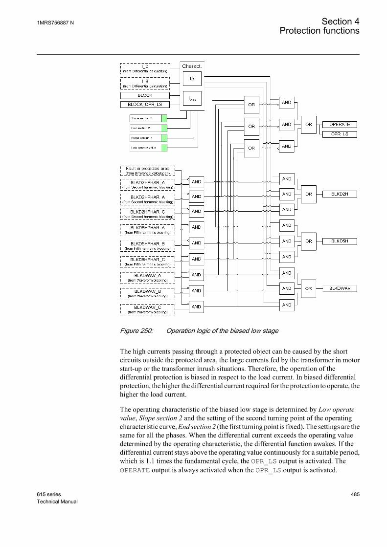
GUID-0E927DF9-5641-4CAE-B808-0B75EA09EA95 V3 EN
Figure 250: Operation logic of the biased low stage
The high currents passing through a protected object can be caused by the shortcircuits outside the protected area, the large currents fed by the transformer in motorstart-up or the transformer inrush situations. Therefore, the operation of thedifferential protection is biased in respect to the load current. In biased differentialprotection, the higher the differential current required for the protection to operate, thehigher the load current.
The operating characteristic of the biased low stage is determined by Low operatevalue, Slope section 2 and the setting of the second turning point of the operatingcharacteristic curve, End section 2 (the first turning point is fixed). The settings are thesame for all the phases. When the differential current exceeds the operating valuedetermined by the operating characteristic, the differential function awakes. If thedifferential current stays above the operating value continuously for a suitable period,which is 1.1 times the fundamental cycle, the OPR_LS output is activated. TheOPERATE output is always activated when the OPR_LS output is activated.
1MRS756887 N Section 4Protection functions
615 series 485Technical Manual
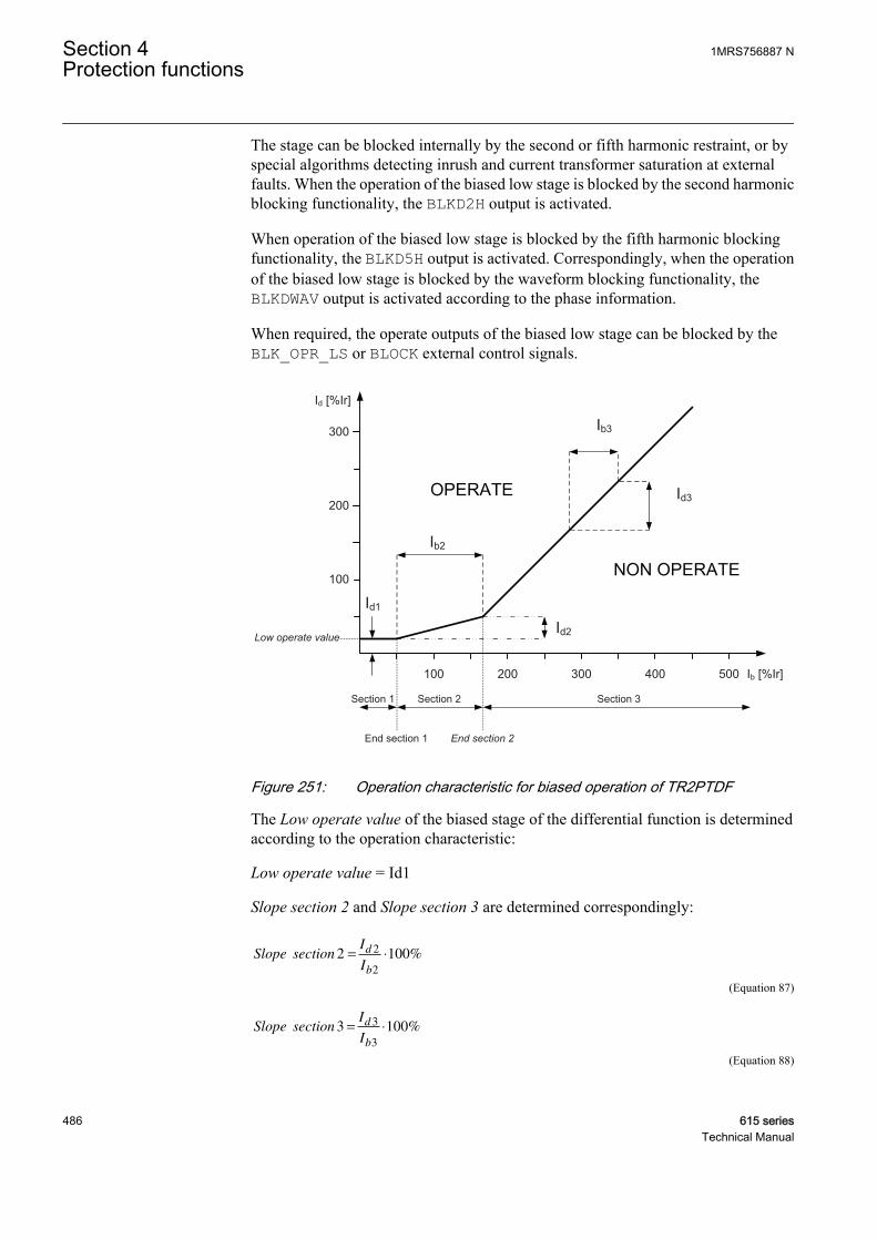
The stage can be blocked internally by the second or fifth harmonic restraint, or byspecial algorithms detecting inrush and current transformer saturation at externalfaults. When the operation of the biased low stage is blocked by the second harmonicblocking functionality, the BLKD2H output is activated.
When operation of the biased low stage is blocked by the fifth harmonic blockingfunctionality, the BLKD5H output is activated. Correspondingly, when the operationof the biased low stage is blocked by the waveform blocking functionality, theBLKDWAV output is activated according to the phase information.
When required, the operate outputs of the biased low stage can be blocked by theBLK_OPR_LS or BLOCK external control signals.
Ib2
Id1
Id2
Ib3
Id3
100
200
300
100 200 300 400 500
End section 2End section 1
Low operate value
Section 1 Section 2 Section 3
Id [%Ir]
Ib [%Ir]
GUID-EAAB6851-B6A9-4A69-B962-1725A4928D54 V3 EN
Figure 251: Operation characteristic for biased operation of TR2PTDF
The Low operate value of the biased stage of the differential function is determinedaccording to the operation characteristic:
Low operate value = Id1
Slope section 2 and Slope section 3 are determined correspondingly:
Slope sectionI
I
d
b
2 1002
2
= ⋅ %
GUID-D1C2CAED-3D58-4405-A79D-17B203A8D3A9 V4 EN (Equation 87)
Slope sectionI
I
d
b
3 1003
3
= ⋅ %
GUID-72224800-6EE1-48E7-9B57-4ABE89DB350C V1 EN (Equation 88)
Section 4 1MRS756887 NProtection functions
486 615 seriesTechnical Manual
The second turning point End section 2 can be set in the range of 100 percent to 500percent.
The slope of the differential function's operating characteristic curve varies in thedifferent sections of the range.
• In section 1, where 0 percent Ir < Ib < End section 1, End section 1 being fixed to50 percent Ir, the differential current required for tripping is constant. The valueof the differential current is the same as the Low operate value selected for thefunction. Low operate value basically allows the no-load current of the powertransformer and small inaccuracies of the current transformers, but it can also beused to influence the overall level of the operating characteristic. At the ratedcurrent, the no-load losses of the power transformer are about 0.2 percent. If thesupply voltage of the power transformer suddenly increases due to operationaldisturbances, the magnetizing current of the transformer increases as well. Ingeneral the magnetic flux density of the transformer is rather high at rated voltageand a rise in voltage by a few percent causes the magnetizing current to increaseby tens of percent. This should be considered in Low operate value
• In section 2, where End section 1 < Ib/In < End section 2, is called the influencearea of Slope section 2. In this section, variations in the starting ratio affect theslope of the characteristic, that is, how big a change in the differential current isrequired for tripping in comparison with the change in the load current. Thestarting ratio should consider CT errors and variations in the transformer tapchanger position (if not compensated). Too high a starting ratio should beavoided, because the sensitivity of the protection for detecting inter-turn faultsdepends basically on the starting ratio.
• In section 3, where Ib/In > End section 2, the slope of the characteristic can be setby Slope section 3 that defines the increase in the differential current to thecorresponding increase in the biasing current.
1MRS756887 N Section 4Protection functions
615 series 487Technical Manual

GUID-739E1789-778D-44BF-BD4A-6BD684BF041D V2 EN
Figure 252: Setting range for biased low stage
If the biasing current is small compared to the differential current of the phase anglebetween the winding 1 and winding 2 phase currents is close to zero (in a normalsituation, the phase difference is 180 degrees), a fault has most likely occurred in thearea protected by TR2PTDF. Then the internal blocking signals of the biased stage areinhibited.
Instantaneous high stageThe instantaneous high stage operation can be enabled and disabled with the Enablehigh set setting. The corresponding parameter values are "TRUE" and "FALSE."
The operation of the instantaneous high stage is not biased. The instantaneous stageoperates and the output OPR_HS is activated when the amplitude of the fundamentalfrequency component of the differential current exceeds the set High operate value orwhen the instantaneous value of the differential current exceeds 2.5 times the value ofHigh operate value. The factor 2.5 (=1.8 × √2) is due to the maximum asymmetricshort circuit current.
If the biasing current is small compared to the differential current or the phase anglebetween the winding 1 and winding 2 phase currents is close to zero (in a normalsituation, the phase difference is 180 degrees), a fault has occurred in the areaprotected by TR2PTDF. Then the operation value set for the instantaneous stage isautomatically halved and the internal blocking signals of the biased stage areinhibited.
Section 4 1MRS756887 NProtection functions
488 615 seriesTechnical Manual
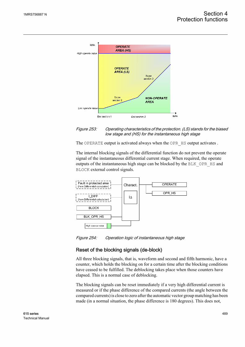
GUID-8B8EC6FC-DF75-4674-808B-7B4C68E9F3E8 V1 EN
Figure 253: Operating characteristics of the protection. (LS) stands for the biasedlow stage and (HS) for the instantaneous high stage
The OPERATE output is activated always when the OPR_HS output activates .
The internal blocking signals of the differential function do not prevent the operatesignal of the instantaneous differential current stage. When required, the operateoutputs of the instantaneous high stage can be blocked by the BLK_OPR_HS andBLOCK external control signals.
GUID-9AACAC66-BF72-430C-AAC7-2E52C3DC4487 V1 EN
Figure 254: Operation logic of instantaneous high stage
Reset of the blocking signals (de-block)All three blocking signals, that is, waveform and second and fifth harmonic, have acounter, which holds the blocking on for a certain time after the blocking conditionshave ceased to be fulfilled. The deblocking takes place when those counters haveelapsed. This is a normal case of deblocking.
The blocking signals can be reset immediately if a very high differential current ismeasured or if the phase difference of the compared currents (the angle between thecompared currents) is close to zero after the automatic vector group matching has beenmade (in a normal situation, the phase difference is 180 degrees). This does not,
1MRS756887 N Section 4Protection functions
615 series 489Technical Manual
however, reset the counters holding the blockings, so the blocking signals may returnwhen these conditions are not valid anymore.
External blocking functionalityTR2PTDF has three inputs for blocking.
• When the BLOCK input is active ("TRUE"), the operation of the function isblocked but measurement output signals are still updated.
• When the BLK_OPR_LS input is active ("TRUE"), TR2PTDF operates normallyexcept that the OPR_LS output is not active or activated in any circumstance.Additionally, the OPERATE output can be activated only by the instantaneoushigh stage (if not blocked as well).
• When the BLK_OPR_HS input is active ("TRUE"), TR2PTDF operates normallyexcept that the OPR_HS output is not active or activated in any circumstance.Additionally, the OPERATE output can be activated only by the biased low stage(if not blocked as well).
4.3.2.5 Application
TR2PTDF is a unit protection function serving as the main protection for transformersin case of winding failure. The protective zone of a differential protection includes thetransformer, the bus-work or the cables between the current transformer and the powertransformer. When bushing current transformers are used for the differentialprotection relay, the protective zone does not include the bus work or cables betweenthe circuit breaker and the power transformer.
In some substations, there is a current differential protection for the busbar. Thebusbar protection includes bus work or cables between the circuit breaker and thepower transformer. Internal electrical faults are very serious and cause immediatedamage. Short circuits and earth faults in windings and terminals are normallydetected by the differential protection. If enough turns are short-circuited, theinterturn faults, which are flashovers between the conductors within the same physicalwinding, are also detected. The interturn faults are the most difficult transformer-winding faults to detect with electrical protections. A small interturn fault including afew turns results in an undetectable amount of current until the fault develops into anearth fault. Therefore, it is important that the differential protection has a high level ofsensitivity and that it is possible to use a sensitive setting without causing unwantedoperations for external faults.
It is important that the faulty transformer is disconnected as fast as possible. AsTR2PTDF is a unit protection function, it can be designed for fast tripping, thusproviding a selective disconnection of the faulty transformer. TR2PTDF should neveroperate to faults outside the protective zone.
TR2PTDF compares the current flowing into the transformer to the current leaving thetransformer. A correct analysis of fault conditions by TR2PTDF must consider thechanges to voltages, currents and phase angles. The traditional transformerdifferential protection functions required auxiliary transformers for the correction of
Section 4 1MRS756887 NProtection functions
490 615 seriesTechnical Manual

the phase shift and turns ratio. The numerical microprocessor based differentialalgorithm implemented in TR2PTDF compensates for both the turns ratio and thephase shift internally in the software.
The differential current should theoretically be zero during normal load or externalfaults if the turns ratio and the phase shift are correctly compensated. However, thereare several different phenomena other than internal faults that cause unwanted andfalse differential currents. The main reasons for unwanted differential currents are:
• Mismatch due to varying tap changer positions• Different characteristics, loads and operating conditions of the current
transformers• Zero sequence currents that only flow on one side of the power transformer• Normal magnetizing currents• Magnetizing inrush currents• Overexcitation magnetizing currents.
TR2PTDF is designed mainly for the protection of two-winding transformers.TR2PTDF can also be utilized for the protection of generator-transformer blocks aswell as short cables and overhead lines. If the distance between the measuring pointsis relatively long in line protection, interposing CTs can be required to reduce theburden of the CTs.
GUID-B326703C-3645-4256-96AD-DA87FC9E9C67 V1 EN
Figure 255: Differential protection of a generator-transformer block and shortcable/line
TR2PTDF can also be used in three-winding transformer applications or two-windingtransformer applications with two output feeders.
On the double-feeder side of the power transformer, the current of the two CTs perphase must be summed by connecting the two CTs of each phase in parallel. Generally
1MRS756887 N Section 4Protection functions
615 series 491Technical Manual
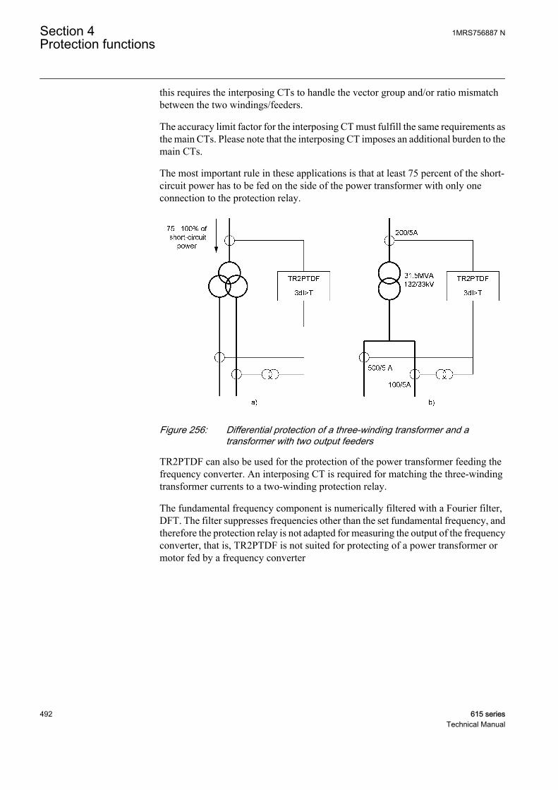
this requires the interposing CTs to handle the vector group and/or ratio mismatchbetween the two windings/feeders.
The accuracy limit factor for the interposing CT must fulfill the same requirements asthe main CTs. Please note that the interposing CT imposes an additional burden to themain CTs.
The most important rule in these applications is that at least 75 percent of the short-circuit power has to be fed on the side of the power transformer with only oneconnection to the protection relay.
GUID-799588E3-C63F-4687-98C5-FF48284676DF V1 EN
Figure 256: Differential protection of a three-winding transformer and atransformer with two output feeders
TR2PTDF can also be used for the protection of the power transformer feeding thefrequency converter. An interposing CT is required for matching the three-windingtransformer currents to a two-winding protection relay.
The fundamental frequency component is numerically filtered with a Fourier filter,DFT. The filter suppresses frequencies other than the set fundamental frequency, andtherefore the protection relay is not adapted for measuring the output of the frequencyconverter, that is, TR2PTDF is not suited for protecting of a power transformer ormotor fed by a frequency converter
Section 4 1MRS756887 NProtection functions
492 615 seriesTechnical Manual

GUID-46FDF23A-7E78-4B17-A888-8501484AB57A V1 EN
Figure 257: Protection of the power transformer feeding the frequency converter
Transforming ratio correction of CTsThe CT secondary currents often differ from the rated current at the rated load of thepower transformer. The CT transforming ratios can be corrected on both sides of thepower transformer with the CT ratio Cor Wnd 1 and CT ration Cor Wnd 2 settings.
First, the rated load of the power transformer must be calculated on both sides whenthe apparent power and phase-to-phase voltage are known.
IS
UnT
n
n
=
×3
GUID-B5467DB8-17EB-4D09-A741-1F5BB23466AA V1 EN (Equation 89)
InT rated load of the power transformer
Sn rated power of the power transformer
Un rated phase-to-phase voltage
Next, the settings for the CT ratio correction can be calculated.
1MRS756887 N Section 4Protection functions
615 series 493Technical Manual
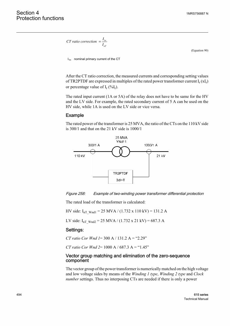
CT ratio correction =
I
I
n
nT
1
GUID-F5F45645-C809-4F99-B783-751C8CC822BF V1 EN (Equation 90)
I1n nominal primary current of the CT
After the CT ratio correction, the measured currents and corresponding setting valuesof TR2PTDF are expressed in multiples of the rated power transformer current Ir (xIr)or percentage value of Ir (%Ir).
The rated input current (1A or 5A) of the relay does not have to be same for the HVand the LV side. For example, the rated secondary current of 5 A can be used on theHV side, while 1A is used on the LV side or vice versa.
ExampleThe rated power of the transformer is 25 MVA, the ratio of the CTs on the 110 kV sideis 300/1 and that on the 21 kV side is 1000/1
GUID-DC9083B2-CB07-4F6B-8C06-52979E5F484A V1 EN
Figure 258: Example of two-winding power transformer differential protection
The rated load of the transformer is calculated:
HV side: InT_Wnd1 = 25 MVA / (1.732 x 110 kV) = 131.2 A
LV side: InT_Wnd2 = 25 MVA / (1.732 x 21 kV) = 687.3 A
Settings:CT ratio Cor Wnd 1= 300 A / 131.2 A = “2.29”
CT ratio Cor Wnd 2= 1000 A / 687.3 A = “1.45”
Vector group matching and elimination of the zero-sequencecomponentThe vector group of the power transformer is numerically matched on the high voltageand low voltage sides by means of the Winding 1 type, Winding 2 type and Clocknumber settings. Thus no interposing CTs are needed if there is only a power
Section 4 1MRS756887 NProtection functions
494 615 seriesTechnical Manual
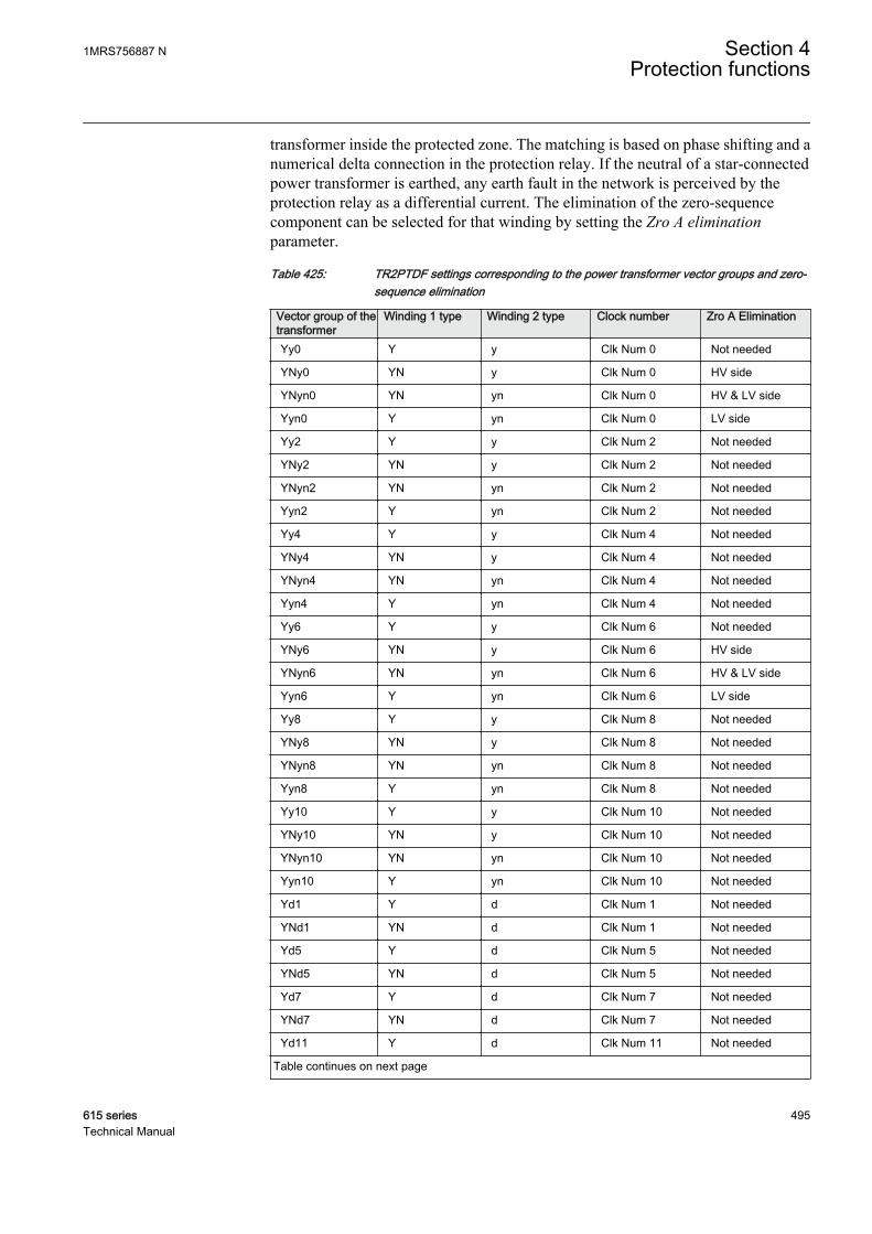
transformer inside the protected zone. The matching is based on phase shifting and anumerical delta connection in the protection relay. If the neutral of a star-connectedpower transformer is earthed, any earth fault in the network is perceived by theprotection relay as a differential current. The elimination of the zero-sequencecomponent can be selected for that winding by setting the Zro A eliminationparameter.
Table 425: TR2PTDF settings corresponding to the power transformer vector groups and zero-sequence elimination
Vector group of thetransformer
Winding 1 type Winding 2 type Clock number Zro A Elimination
Yy0 Y y Clk Num 0 Not needed
YNy0 YN y Clk Num 0 HV side
YNyn0 YN yn Clk Num 0 HV & LV side
Yyn0 Y yn Clk Num 0 LV side
Yy2 Y y Clk Num 2 Not needed
YNy2 YN y Clk Num 2 Not needed
YNyn2 YN yn Clk Num 2 Not needed
Yyn2 Y yn Clk Num 2 Not needed
Yy4 Y y Clk Num 4 Not needed
YNy4 YN y Clk Num 4 Not needed
YNyn4 YN yn Clk Num 4 Not needed
Yyn4 Y yn Clk Num 4 Not needed
Yy6 Y y Clk Num 6 Not needed
YNy6 YN y Clk Num 6 HV side
YNyn6 YN yn Clk Num 6 HV & LV side
Yyn6 Y yn Clk Num 6 LV side
Yy8 Y y Clk Num 8 Not needed
YNy8 YN y Clk Num 8 Not needed
YNyn8 YN yn Clk Num 8 Not needed
Yyn8 Y yn Clk Num 8 Not needed
Yy10 Y y Clk Num 10 Not needed
YNy10 YN y Clk Num 10 Not needed
YNyn10 YN yn Clk Num 10 Not needed
Yyn10 Y yn Clk Num 10 Not needed
Yd1 Y d Clk Num 1 Not needed
YNd1 YN d Clk Num 1 Not needed
Yd5 Y d Clk Num 5 Not needed
YNd5 YN d Clk Num 5 Not needed
Yd7 Y d Clk Num 7 Not needed
YNd7 YN d Clk Num 7 Not needed
Yd11 Y d Clk Num 11 Not needed
Table continues on next page
1MRS756887 N Section 4Protection functions
615 series 495Technical Manual
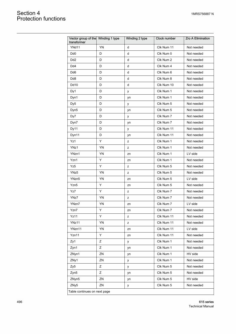
Vector group of thetransformer
Winding 1 type Winding 2 type Clock number Zro A Elimination
YNd11 YN d Clk Num 11 Not needed
Dd0 D d Clk Num 0 Not needed
Dd2 D d Clk Num 2 Not needed
Dd4 D d Clk Num 4 Not needed
Dd6 D d Clk Num 6 Not needed
Dd8 D d Clk Num 8 Not needed
Dd10 D d Clk Num 10 Not needed
Dy1 D y Clk Num 1 Not needed
Dyn1 D yn Clk Num 1 Not needed
Dy5 D y Clk Num 5 Not needed
Dyn5 D yn Clk Num 5 Not needed
Dy7 D y Clk Num 7 Not needed
Dyn7 D yn Clk Num 7 Not needed
Dy11 D y Clk Num 11 Not needed
Dyn11 D yn Clk Num 11 Not needed
Yz1 Y z Clk Num 1 Not needed
YNz1 YN z Clk Num 1 Not needed
YNzn1 YN zn Clk Num 1 LV side
Yzn1 Y zn Clk Num 1 Not needed
Yz5 Y z Clk Num 5 Not needed
YNz5 YN z Clk Num 5 Not needed
YNzn5 YN zn Clk Num 5 LV side
Yzn5 Y zn Clk Num 5 Not needed
Yz7 Y z Clk Num 7 Not needed
YNz7 YN z Clk Num 7 Not needed
YNzn7 YN zn Clk Num 7 LV side
Yzn7 Y zn Clk Num 7 Not needed
Yz11 Y z Clk Num 11 Not needed
YNz11 YN z Clk Num 11 Not needed
YNzn11 YN zn Clk Num 11 LV side
Yzn11 Y zn Clk Num 11 Not needed
Zy1 Z y Clk Num 1 Not needed
Zyn1 Z yn Clk Num 1 Not needed
ZNyn1 ZN yn Clk Num 1 HV side
ZNy1 ZN y Clk Num 1 Not needed
Zy5 Z y Clk Num 5 Not needed
Zyn5 Z yn Clk Num 5 Not needed
ZNyn5 ZN yn Clk Num 5 HV side
ZNy5 ZN y Clk Num 5 Not needed
Table continues on next page
Section 4 1MRS756887 NProtection functions
496 615 seriesTechnical Manual
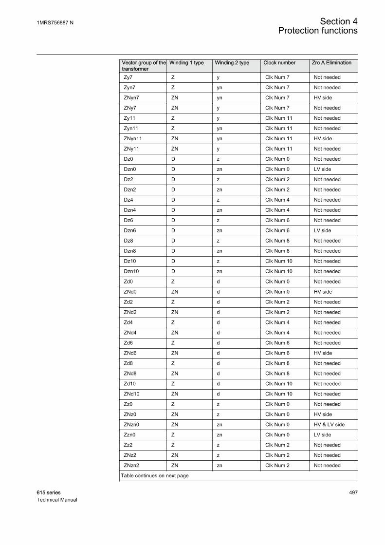
Vector group of thetransformer
Winding 1 type Winding 2 type Clock number Zro A Elimination
Zy7 Z y Clk Num 7 Not needed
Zyn7 Z yn Clk Num 7 Not needed
ZNyn7 ZN yn Clk Num 7 HV side
ZNy7 ZN y Clk Num 7 Not needed
Zy11 Z y Clk Num 11 Not needed
Zyn11 Z yn Clk Num 11 Not needed
ZNyn11 ZN yn Clk Num 11 HV side
ZNy11 ZN y Clk Num 11 Not needed
Dz0 D z Clk Num 0 Not needed
Dzn0 D zn Clk Num 0 LV side
Dz2 D z Clk Num 2 Not needed
Dzn2 D zn Clk Num 2 Not needed
Dz4 D z Clk Num 4 Not needed
Dzn4 D zn Clk Num 4 Not needed
Dz6 D z Clk Num 6 Not needed
Dzn6 D zn Clk Num 6 LV side
Dz8 D z Clk Num 8 Not needed
Dzn8 D zn Clk Num 8 Not needed
Dz10 D z Clk Num 10 Not needed
Dzn10 D zn Clk Num 10 Not needed
Zd0 Z d Clk Num 0 Not needed
ZNd0 ZN d Clk Num 0 HV side
Zd2 Z d Clk Num 2 Not needed
ZNd2 ZN d Clk Num 2 Not needed
Zd4 Z d Clk Num 4 Not needed
ZNd4 ZN d Clk Num 4 Not needed
Zd6 Z d Clk Num 6 Not needed
ZNd6 ZN d Clk Num 6 HV side
Zd8 Z d Clk Num 8 Not needed
ZNd8 ZN d Clk Num 8 Not needed
Zd10 Z d Clk Num 10 Not needed
ZNd10 ZN d Clk Num 10 Not needed
Zz0 Z z Clk Num 0 Not needed
ZNz0 ZN z Clk Num 0 HV side
ZNzn0 ZN zn Clk Num 0 HV & LV side
Zzn0 Z zn Clk Num 0 LV side
Zz2 Z z Clk Num 2 Not needed
ZNz2 ZN z Clk Num 2 Not needed
ZNzn2 ZN zn Clk Num 2 Not needed
Table continues on next page
1MRS756887 N Section 4Protection functions
615 series 497Technical Manual
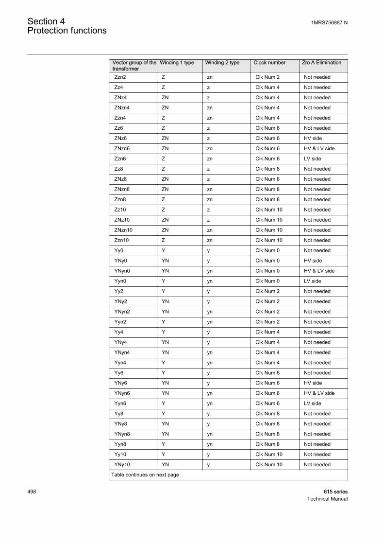
Vector group of thetransformer
Winding 1 type Winding 2 type Clock number Zro A Elimination
Zzn2 Z zn Clk Num 2 Not needed
Zz4 Z z Clk Num 4 Not needed
ZNz4 ZN z Clk Num 4 Not needed
ZNzn4 ZN zn Clk Num 4 Not needed
Zzn4 Z zn Clk Num 4 Not needed
Zz6 Z z Clk Num 6 Not needed
ZNz6 ZN z Clk Num 6 HV side
ZNzn6 ZN zn Clk Num 6 HV & LV side
Zzn6 Z zn Clk Num 6 LV side
Zz8 Z z Clk Num 8 Not needed
ZNz8 ZN z Clk Num 8 Not needed
ZNzn8 ZN zn Clk Num 8 Not needed
Zzn8 Z zn Clk Num 8 Not needed
Zz10 Z z Clk Num 10 Not needed
ZNz10 ZN z Clk Num 10 Not needed
ZNzn10 ZN zn Clk Num 10 Not needed
Zzn10 Z zn Clk Num 10 Not needed
Yy0 Y y Clk Num 0 Not needed
YNy0 YN y Clk Num 0 HV side
YNyn0 YN yn Clk Num 0 HV & LV side
Yyn0 Y yn Clk Num 0 LV side
Yy2 Y y Clk Num 2 Not needed
YNy2 YN y Clk Num 2 Not needed
YNyn2 YN yn Clk Num 2 Not needed
Yyn2 Y yn Clk Num 2 Not needed
Yy4 Y y Clk Num 4 Not needed
YNy4 YN y Clk Num 4 Not needed
YNyn4 YN yn Clk Num 4 Not needed
Yyn4 Y yn Clk Num 4 Not needed
Yy6 Y y Clk Num 6 Not needed
YNy6 YN y Clk Num 6 HV side
YNyn6 YN yn Clk Num 6 HV & LV side
Yyn6 Y yn Clk Num 6 LV side
Yy8 Y y Clk Num 8 Not needed
YNy8 YN y Clk Num 8 Not needed
YNyn8 YN yn Clk Num 8 Not needed
Yyn8 Y yn Clk Num 8 Not needed
Yy10 Y y Clk Num 10 Not needed
YNy10 YN y Clk Num 10 Not needed
Table continues on next page
Section 4 1MRS756887 NProtection functions
498 615 seriesTechnical Manual

Vector group of thetransformer
Winding 1 type Winding 2 type Clock number Zro A Elimination
YNyn10 YN yn Clk Num 10 Not needed
Yyn10 Y yn Clk Num 10 Not needed
Yd1 Y d Clk Num 1 Not needed
YNd1 YN d Clk Num 1 Not needed
Yd5 Y d Clk Num 5 Not needed
YNd5 YN d Clk Num 5 Not needed
Yd7 Y d Clk Num 7 Not needed
YNd7 YN d Clk Num 7 Not needed
Yd11 Y d Clk Num 11 Not needed
YNd11 YN d Clk Num 11 Not needed
Dd0 D d Clk Num 0 Not needed
Dd2 D d Clk Num 2 Not needed
Dd4 D d Clk Num 4 Not needed
Dd6 D d Clk Num 6 Not needed
Dd8 D d Clk Num 8 Not needed
Dd10 D d Clk Num 10 Not needed
Dy1 D y Clk Num 1 Not needed
Dyn1 D yn Clk Num 1 Not needed
Dy5 D y Clk Num 5 Not needed
Dyn5 D yn Clk Num 5 Not needed
Dy7 D y Clk Num 7 Not needed
Dyn7 D yn Clk Num 7 Not needed
Dy11 D y Clk Num 11 Not needed
Dyn11 D yn Clk Num 11 Not needed
Yz1 Y z Clk Num 1 Not needed
YNz1 YN z Clk Num 1 Not needed
YNzn1 YN zn Clk Num 1 LV side
Yzn1 Y zn Clk Num 1 Not needed
Yz5 Y z Clk Num 5 Not needed
YNz5 YN z Clk Num 5 Not needed
YNzn5 YN zn Clk Num 5 LV side
Yzn5 Y zn Clk Num 5 Not needed
Yz7 Y z Clk Num 7 Not needed
YNz7 YN z Clk Num 7 Not needed
YNzn7 YN zn Clk Num 7 LV side
Yzn7 Y zn Clk Num 7 Not needed
Yz11 Y z Clk Num 11 Not needed
YNz11 YN z Clk Num 11 Not needed
YNzn11 YN zn Clk Num 11 LV side
Table continues on next page
1MRS756887 N Section 4Protection functions
615 series 499Technical Manual
Vector group of thetransformer
Winding 1 type Winding 2 type Clock number Zro A Elimination
Yzn11 Y zn Clk Num 11 Not needed
Zy1 Z y Clk Num 1 Not needed
Zyn1 Z yn Clk Num 1 Not needed
ZNyn1 ZN yn Clk Num 1 HV side
ZNy1 ZN y Clk Num 1 Not needed
Zy5 Z y Clk Num 5 Not needed
Zyn5 Z yn Clk Num 5 Not needed
ZNyn5 ZN yn Clk Num 5 HV side
ZNy5 ZN y Clk Num 5 Not needed
Zy7 Z y Clk Num 7 Not needed
Zyn7 Z yn Clk Num 7 Not needed
ZNyn7 ZN yn Clk Num 7 HV side
ZNy7 ZN y Clk Num 7 Not needed
Yy0 Y y Clk Num 0 Not needed
CommissioningThe correct settings, which are CT connection type, Winding 1 type, Winding 2 typeand Clock number, for the connection group compensation can be verified bymonitoring the angle values I_ANGL_A1_B1, I_ANGL_B1_C1,I_ANGL_C1_A1, I_ANGL_A2_B2, I_ANGL_B2_C2, I_ANGL_C2_A2,I_ANGL_A1_A2, I_ANGL_B1_B2 and I_ANGL_C1_C2 while injecting thecurrent into the transformer. These angle values are calculated from the compensatedcurrents. See signal description from Monitored data table.
When a station service transformer is available, it can be used to provide current to thehigh voltage side windings while the low voltage side windings are short-circuited.This way the current can flow in both the high voltage and low voltage windings. Thecommissioning signals can be provided by other means as well. The minimum currentto allow for phase current and angle monitoring is 0.015 Ir.
Section 4 1MRS756887 NProtection functions
500 615 seriesTechnical Manual
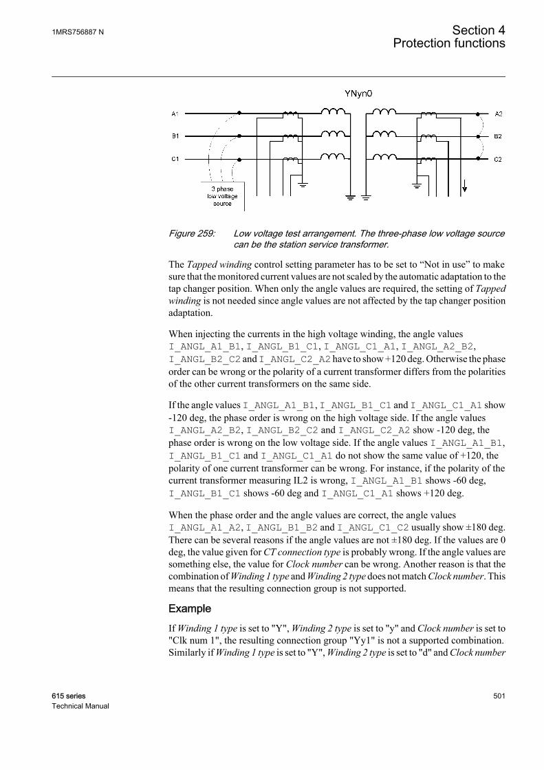
GUID-5ACBF127-85A3-4E5E-A130-9F7206A2DB4C V1 EN
Figure 259: Low voltage test arrangement. The three-phase low voltage sourcecan be the station service transformer.
The Tapped winding control setting parameter has to be set to “Not in use” to makesure that the monitored current values are not scaled by the automatic adaptation to thetap changer position. When only the angle values are required, the setting of Tappedwinding is not needed since angle values are not affected by the tap changer positionadaptation.
When injecting the currents in the high voltage winding, the angle valuesI_ANGL_A1_B1, I_ANGL_B1_C1, I_ANGL_C1_A1, I_ANGL_A2_B2,I_ANGL_B2_C2 and I_ANGL_C2_A2 have to show +120 deg. Otherwise the phaseorder can be wrong or the polarity of a current transformer differs from the polaritiesof the other current transformers on the same side.
If the angle values I_ANGL_A1_B1, I_ANGL_B1_C1 and I_ANGL_C1_A1 show-120 deg, the phase order is wrong on the high voltage side. If the angle valuesI_ANGL_A2_B2, I_ANGL_B2_C2 and I_ANGL_C2_A2 show -120 deg, thephase order is wrong on the low voltage side. If the angle values I_ANGL_A1_B1,I_ANGL_B1_C1 and I_ANGL_C1_A1 do not show the same value of +120, thepolarity of one current transformer can be wrong. For instance, if the polarity of thecurrent transformer measuring IL2 is wrong, I_ANGL_A1_B1 shows -60 deg,I_ANGL_B1_C1 shows -60 deg and I_ANGL_C1_A1 shows +120 deg.
When the phase order and the angle values are correct, the angle valuesI_ANGL_A1_A2, I_ANGL_B1_B2 and I_ANGL_C1_C2 usually show ±180 deg.There can be several reasons if the angle values are not ±180 deg. If the values are 0deg, the value given for CT connection type is probably wrong. If the angle values aresomething else, the value for Clock number can be wrong. Another reason is that thecombination of Winding 1 type and Winding 2 type does not match Clock number. Thismeans that the resulting connection group is not supported.
ExampleIf Winding 1 type is set to "Y", Winding 2 type is set to "y" and Clock number is set to"Clk num 1", the resulting connection group "Yy1" is not a supported combination.Similarly if Winding 1 type is set to "Y", Winding 2 type is set to "d" and Clock number
1MRS756887 N Section 4Protection functions
615 series 501Technical Manual
is set to "Clk num 0", the resulting connection group "Yd0" is not a supportedcombination. All the non-supported combinations of Winding 1 type, Winding 2 typeand Clock number settings result in the default connection group compensation that is"Yy0".
4.3.2.6 CT connections and transformation ratio correction
The connections of the primary current transformers are designated as "Type 1" and"Type 2".
• If the positive directions of the winding 1 and winding 2 protection relay currentsare opposite, the CT connection type setting parameter is "Type 1". Theconnection examples of "Type 1" are as shown in Figure 260 and Figure 261.
• If the positive directions of the winding 1 and winding 2 protection relay currentsequate, the CT connection type setting parameter is "Type 2". The connectionexamples of "Type 2" are as shown in Figure 262 and Figure 263.
• The default value of the CT connection type setting is "Type 1".
Section 4 1MRS756887 NProtection functions
502 615 seriesTechnical Manual

GUID-53F7DCB6-58B8-418C-AB83-805B4B0DCCAE V3 EN
Figure 260: Connection example of current transformers of Type 1
1MRS756887 N Section 4Protection functions
615 series 503Technical Manual
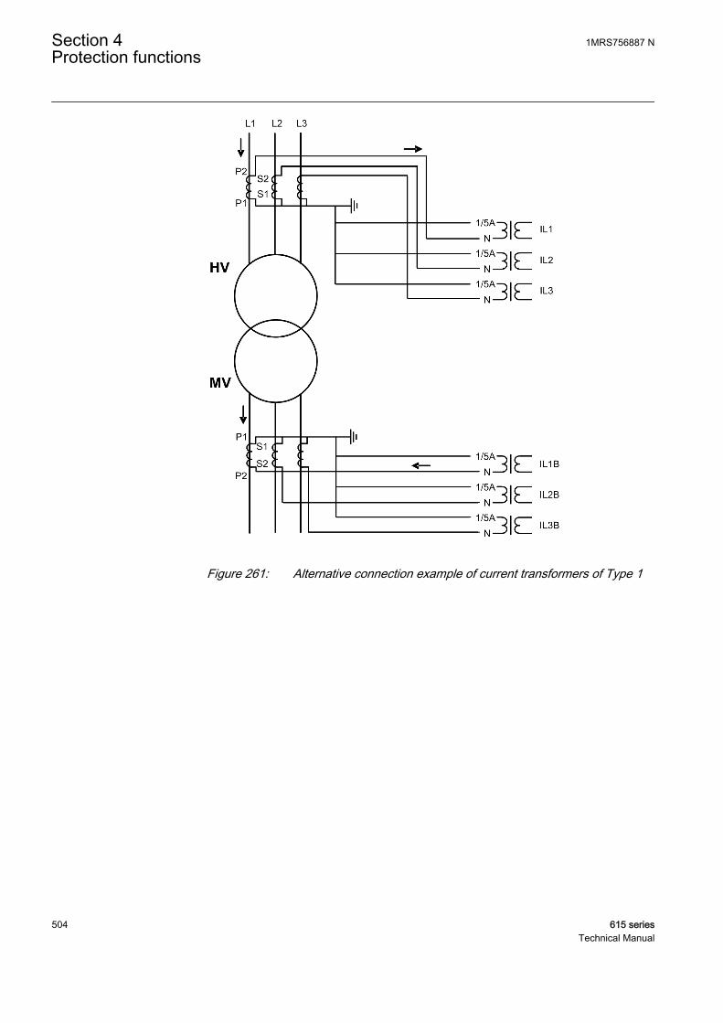
GUID-24C391DC-D767-4848-AE98-FE33C1548DEE V2 EN
Figure 261: Alternative connection example of current transformers of Type 1
Section 4 1MRS756887 NProtection functions
504 615 seriesTechnical Manual

GUID-66D375DD-BF49-43C5-A7B5-BFA2BEAD035C V3 EN
Figure 262: Connection of current transformers of Type 2 and example of thecurrents during an external fault
1MRS756887 N Section 4Protection functions
615 series 505Technical Manual

GUID-5E0D15BA-ADA9-4FE0-A85D-5C6E86D7E32B V2 EN
Figure 263: Alternative connection example of current transformers of Type 2
The CT secondary currents often differ from the rated current at the rated load of thepower transformer. The CT transforming ratios can be corrected on both sides of thepower transformer with the CT ratio Cor Wnd 1 and CT ratio Cor Wnd 2 settings.
4.3.2.7 Signals
Table 426: TR2PTDF Input signals
Name Type Default DescriptionI_A1 SIGNAL 0 Phase A primary current
I_B1 SIGNAL 0 Phase B primary current
I_C1 SIGNAL 0 Phase C primary current
I_A2 SIGNAL 0 Phase A secondary current
I_B2 SIGNAL 0 Phase B secondary current
I_C2 SIGNAL 0 Phase C secondary current
Table continues on next page
Section 4 1MRS756887 NProtection functions
506 615 seriesTechnical Manual
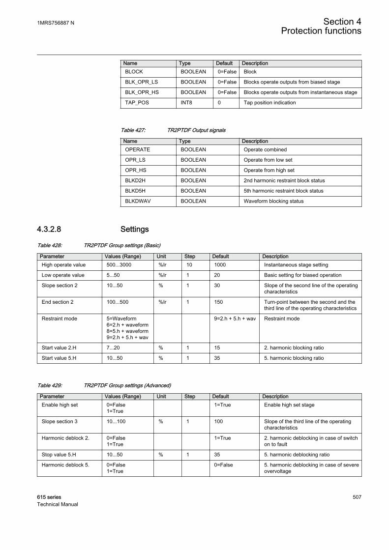
Name Type Default DescriptionBLOCK BOOLEAN 0=False Block
BLK_OPR_LS BOOLEAN 0=False Blocks operate outputs from biased stage
BLK_OPR_HS BOOLEAN 0=False Blocks operate outputs from instantaneous stage
TAP_POS INT8 0 Tap position indication
Table 427: TR2PTDF Output signals
Name Type DescriptionOPERATE BOOLEAN Operate combined
OPR_LS BOOLEAN Operate from low set
OPR_HS BOOLEAN Operate from high set
BLKD2H BOOLEAN 2nd harmonic restraint block status
BLKD5H BOOLEAN 5th harmonic restraint block status
BLKDWAV BOOLEAN Waveform blocking status
4.3.2.8 Settings
Table 428: TR2PTDF Group settings (Basic)
Parameter Values (Range) Unit Step Default DescriptionHigh operate value 500...3000 %Ir 10 1000 Instantaneous stage setting
Low operate value 5...50 %Ir 1 20 Basic setting for biased operation
Slope section 2 10...50 % 1 30 Slope of the second line of the operatingcharacteristics
End section 2 100...500 %Ir 1 150 Turn-point between the second and thethird line of the operating characteristics
Restraint mode 5=Waveform6=2.h + waveform8=5.h + waveform9=2.h + 5.h + wav
9=2.h + 5.h + wav Restraint mode
Start value 2.H 7...20 % 1 15 2. harmonic blocking ratio
Start value 5.H 10...50 % 1 35 5. harmonic blocking ratio
Table 429: TR2PTDF Group settings (Advanced)
Parameter Values (Range) Unit Step Default DescriptionEnable high set 0=False
1=True 1=True Enable high set stage
Slope section 3 10...100 % 1 100 Slope of the third line of the operatingcharacteristics
Harmonic deblock 2. 0=False1=True
1=True 2. harmonic deblocking in case of switchon to fault
Stop value 5.H 10...50 % 1 35 5. harmonic deblocking ratio
Harmonic deblock 5. 0=False1=True
0=False 5. harmonic deblocking in case of severeovervoltage
1MRS756887 N Section 4Protection functions
615 series 507Technical Manual
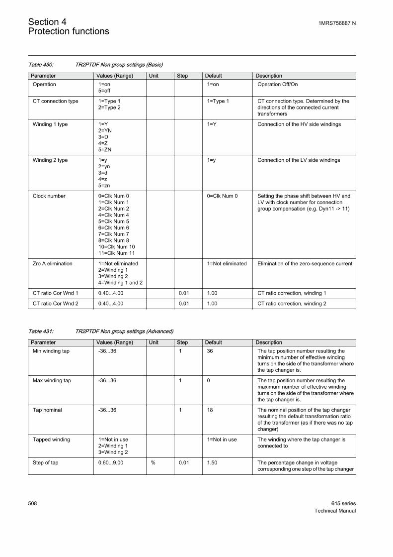
Table 430: TR2PTDF Non group settings (Basic)
Parameter Values (Range) Unit Step Default DescriptionOperation 1=on
5=off 1=on Operation Off/On
CT connection type 1=Type 12=Type 2
1=Type 1 CT connection type. Determined by thedirections of the connected currenttransformers
Winding 1 type 1=Y2=YN3=D4=Z5=ZN
1=Y Connection of the HV side windings
Winding 2 type 1=y2=yn3=d4=z5=zn
1=y Connection of the LV side windings
Clock number 0=Clk Num 01=Clk Num 12=Clk Num 24=Clk Num 45=Clk Num 56=Clk Num 67=Clk Num 78=Clk Num 810=Clk Num 1011=Clk Num 11
0=Clk Num 0 Setting the phase shift between HV andLV with clock number for connectiongroup compensation (e.g. Dyn11 -> 11)
Zro A elimination 1=Not eliminated2=Winding 13=Winding 24=Winding 1 and 2
1=Not eliminated Elimination of the zero-sequence current
CT ratio Cor Wnd 1 0.40...4.00 0.01 1.00 CT ratio correction, winding 1
CT ratio Cor Wnd 2 0.40...4.00 0.01 1.00 CT ratio correction, winding 2
Table 431: TR2PTDF Non group settings (Advanced)
Parameter Values (Range) Unit Step Default DescriptionMin winding tap -36...36 1 36 The tap position number resulting the
minimum number of effective windingturns on the side of the transformer wherethe tap changer is.
Max winding tap -36...36 1 0 The tap position number resulting themaximum number of effective windingturns on the side of the transformer wherethe tap changer is.
Tap nominal -36...36 1 18 The nominal position of the tap changerresulting the default transformation ratioof the transformer (as if there was no tapchanger)
Tapped winding 1=Not in use2=Winding 13=Winding 2
1=Not in use The winding where the tap changer isconnected to
Step of tap 0.60...9.00 % 0.01 1.50 The percentage change in voltagecorresponding one step of the tap changer
Section 4 1MRS756887 NProtection functions
508 615 seriesTechnical Manual

4.3.2.9 Monitored data
Table 432: TR2PTDF Monitored data
Name Type Values (Range) Unit DescriptionOPR_A BOOLEAN 0=False
1=True Operate phase A
OPR_B BOOLEAN 0=False1=True
Operate phase B
OPR_C BOOLEAN 0=False1=True
Operate phase C
BLKD2H_A BOOLEAN 0=False1=True
2nd harmonic restraintblock phase A status
BLKD2H_B BOOLEAN 0=False1=True
2nd harmonic restraintblock phase B status
BLKD2H_C BOOLEAN 0=False1=True
2nd harmonic restraintblock phase C status
BLKD5H_A BOOLEAN 0=False1=True
5th harmonic restraintblock phase A status
BLKD5H_B BOOLEAN 0=False1=True
5th harmonic restraintblock phase B status
BLKD5H_C BOOLEAN 0=False1=True
5th harmonic restraintblock phase C status
BLKDWAV_A BOOLEAN 0=False1=True
Waveform blockingphase A status
BLKDWAV_B BOOLEAN 0=False1=True
Waveform blockingphase B status
BLKDWAV_C BOOLEAN 0=False1=True
Waveform blockingphase C status
BLKD2HPHAR BOOLEAN 0=False1=True
2nd harmonic restraintblocking for PHAR LN,combined
BLKD2HPHAR_A BOOLEAN 0=False1=True
2nd harmonic restraintblocking for PHAR LN,phase A
BLKD2HPHAR_B BOOLEAN 0=False1=True
2nd harmonic restraintblocking for PHAR LN,phase B
BLKD2HPHAR_C BOOLEAN 0=False1=True
2nd harmonic restraintblocking for PHAR LN,phase C
BLKD5HPHAR BOOLEAN 0=False1=True
5th harmonic restraintblocking for PHAR LN,combined
BLKD5HPHAR_A BOOLEAN 0=False1=True
5th harmonic restraintblocking for PHAR LN,phase A
BLKD5HPHAR_B BOOLEAN 0=False1=True
5th harmonic restraintblocking for PHAR LN,phase B
BLKD5HPHAR_C BOOLEAN 0=False1=True
5th harmonic restraintblocking for PHAR LN,phase C
Table continues on next page
1MRS756887 N Section 4Protection functions
615 series 509Technical Manual
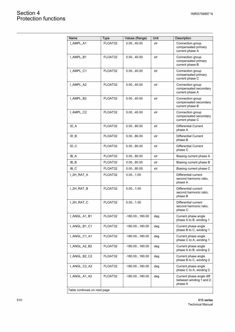
Name Type Values (Range) Unit DescriptionI_AMPL_A1 FLOAT32 0.00...40.00 xIr Connection group
compensated primarycurrent phase A
I_AMPL_B1 FLOAT32 0.00...40.00 xIr Connection groupcompensated primarycurrent phase B
I_AMPL_C1 FLOAT32 0.00...40.00 xIr Connection groupcompensated primarycurrent phase C
I_AMPL_A2 FLOAT32 0.00...40.00 xIr Connection groupcompensated secondarycurrent phase A
I_AMPL_B2 FLOAT32 0.00...40.00 xIr Connection groupcompensated secondarycurrent phase B
I_AMPL_C2 FLOAT32 0.00...40.00 xIr Connection groupcompensated secondarycurrent phase C
ID_A FLOAT32 0.00...80.00 xIr Differential Currentphase A
ID_B FLOAT32 0.00...80.00 xIr Differential Currentphase B
ID_C FLOAT32 0.00...80.00 xIr Differential Currentphase C
IB_A FLOAT32 0.00...80.00 xIr Biasing current phase A
IB_B FLOAT32 0.00...80.00 xIr Biasing current phase B
IB_C FLOAT32 0.00...80.00 xIr Biasing current phase C
I_2H_RAT_A FLOAT32 0.00...1.00 Differential currentsecond harmonic ratio,phase A
I_2H_RAT_B FLOAT32 0.00...1.00 Differential currentsecond harmonic ratio,phase B
I_2H_RAT_C FLOAT32 0.00...1.00 Differential currentsecond harmonic ratio,phase C
I_ANGL_A1_B1 FLOAT32 -180.00...180.00 deg Current phase anglephase A to B, winding 1
I_ANGL_B1_C1 FLOAT32 -180.00...180.00 deg Current phase anglephase B to C, winding 1
I_ANGL_C1_A1 FLOAT32 -180.00...180.00 deg Current phase anglephase C to A, winding 1
I_ANGL_A2_B2 FLOAT32 -180.00...180.00 deg Current phase anglephase A to B, winding 2
I_ANGL_B2_C2 FLOAT32 -180.00...180.00 deg Current phase anglephase B to C, winding 2
I_ANGL_C2_A2 FLOAT32 -180.00...180.00 deg Current phase anglephase C to A, winding 2
I_ANGL_A1_A2 FLOAT32 -180.00...180.00 deg Current phase angle diffbetween winding 1 and 2,phase A
Table continues on next page
Section 4 1MRS756887 NProtection functions
510 615 seriesTechnical Manual
Name Type Values (Range) Unit DescriptionI_ANGL_B1_B2 FLOAT32 -180.00...180.00 deg Current phase angle diff
between winding 1 and 2,phase B
I_ANGL_C1_C2 FLOAT32 -180.00...180.00 deg Current phase angle diffbetween winding 1 and 2,phase C
I_5H_RAT_A FLOAT32 0.00...1.00 Differential current fifthharmonic ratio, phase A
I_5H_RAT_B FLOAT32 0.00...1.00 Differential current fifthharmonic ratio, phase B
I_5H_RAT_C FLOAT32 0.00...1.00 Differential current fifthharmonic ratio, phase C
TR2PTDF Enum 1=on2=blocked3=test4=test/blocked5=off
Status
IL1-diff FLOAT32 0.00...80.00 Measured differentialcurrent amplitude phaseIL1
IL2-diff FLOAT32 0.00...80.00 Measured differentialcurrent amplitude phaseIL2
IL3-diff FLOAT32 0.00...80.00 Measured differentialcurrent amplitude phaseIL3
IL1-bias FLOAT32 0.00...80.00 Measured bias currentamplitude phase IL1
IL2-bias FLOAT32 0.00...80.00 Measured bias currentamplitude phase IL2
IL3-bias FLOAT32 0.00...80.00 Measured bias currentamplitude phase IL3
4.3.2.10 Technical data
Table 433: TR2PTDF Technical data
Characteristic ValueOperation accuracy Depending on the frequency of the measured
current: fn ±2 Hz
±3.0% of the set value or ±0.002 × In
Start time1)2) Minimum Typical Maximum
Low stageHigh stage
36 ms21 ms
41 ms22 ms
46 ms24 ms
Reset time Typically 40 ms
Reset ratio Typically 0.96
Suppression of harmonics DFT: -50 dB at f = n × fn, where n = 2, 3, 4, 5, …
1) Current before fault = 0.0, fn = 50 Hz, results based on statistical distribution of 1000 measurements2) Includes the delay of the output contact. When differential current = 2 × set operate value and fn = 50
Hz.
1MRS756887 N Section 4Protection functions
615 series 511Technical Manual
4.3.2.11 Technical revision history
Table 434: TR2PTDF Technical revision history
Technical revision ChangeB 5th harmonic and waveform blockings taken to
event data set
C Added setting Slope section 3. Added inputTAP_POS
4.3.3 Numerically stabilized low-impedance restricted earth-faultprotection LREFPNDF
4.3.3.1 Identification
Function description IEC 61850identification
IEC 60617identification
ANSI/IEEE C37.2device number
Numerically stabilized low-impedancerestricted earth-fault protection
LREFPNDF dIoLo> 87NL
4.3.3.2 Function block
GUID-A04FED1B-8424-4A84-A327-262E4CC5628F V2 EN
Figure 264: Function block
4.3.3.3 Functionality
The numerically stabilized low-impedance restricted earth-fault protection functionLREFPNDF for a two-winding transformer is based on the numerically stabilizeddifferential current principle. No external stabilizing resistor or non-linear resistor arerequired.
The fundamental components of the currents are used for calculating the residualcurrent of the phase currents, the neutral current, differential currents and stabilizingcurrents. The operating characteristics are according to the definite time.
The function contains a blocking functionality. The neutral current second harmonicis used for blocking during the transformer inrush situation. It is also possible to blockfunction outputs, timers or the function itself, if desired.
Section 4 1MRS756887 NProtection functions
512 615 seriesTechnical Manual
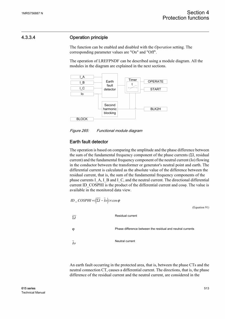
4.3.3.4 Operation principle
The function can be enabled and disabled with the Operation setting. Thecorresponding parameter values are "On" and "Off".
The operation of LREFPNDF can be described using a module diagram. All themodules in the diagram are explained in the next sections.
GUID-079EB39A-B62C-47DF-9B53-9432AB24A9CE V2 EN
Figure 265: Functional module diagram
Earth fault detectorThe operation is based on comparing the amplitude and the phase difference betweenthe sum of the fundamental frequency component of the phase currents (ΣI, residualcurrent) and the fundamental frequency component of the neutral current (Io) flowingin the conductor between the transformer or generator's neutral point and earth. Thedifferential current is calculated as the absolute value of the difference between theresidual current, that is, the sum of the fundamental frequency components of thephase currents I_A, I_B and I_C, and the neutral current. The directional differentialcurrent ID_COSPHI is the product of the differential current and cosφ. The value isavailable in the monitored data view.
ID COSPHI I Io_ ( ) cos= − ×Σ ϕ
GUID-46782962-D465-47D2-8ECE-3FF0B87B324F V3 EN (Equation 91)
ΣIGUID-87E4DEDD-9288-41D9-B608-714CF3CC7A04 V1 EN
Residual current
ϕ
GUID-C4F98C50-7279-4DAA-8C77-5C761572F4B4 V1 EN
Phase difference between the residual and neutral currents
Io
GUID-2D713C98-4F81-4DF4-8193-C47120A65489 V1 EN
Neutral current
An earth fault occurring in the protected area, that is, between the phase CTs and theneutral connection CT, causes a differential current. The directions, that is, the phasedifference of the residual current and the neutral current, are considered in the
1MRS756887 N Section 4Protection functions
615 series 513Technical Manual
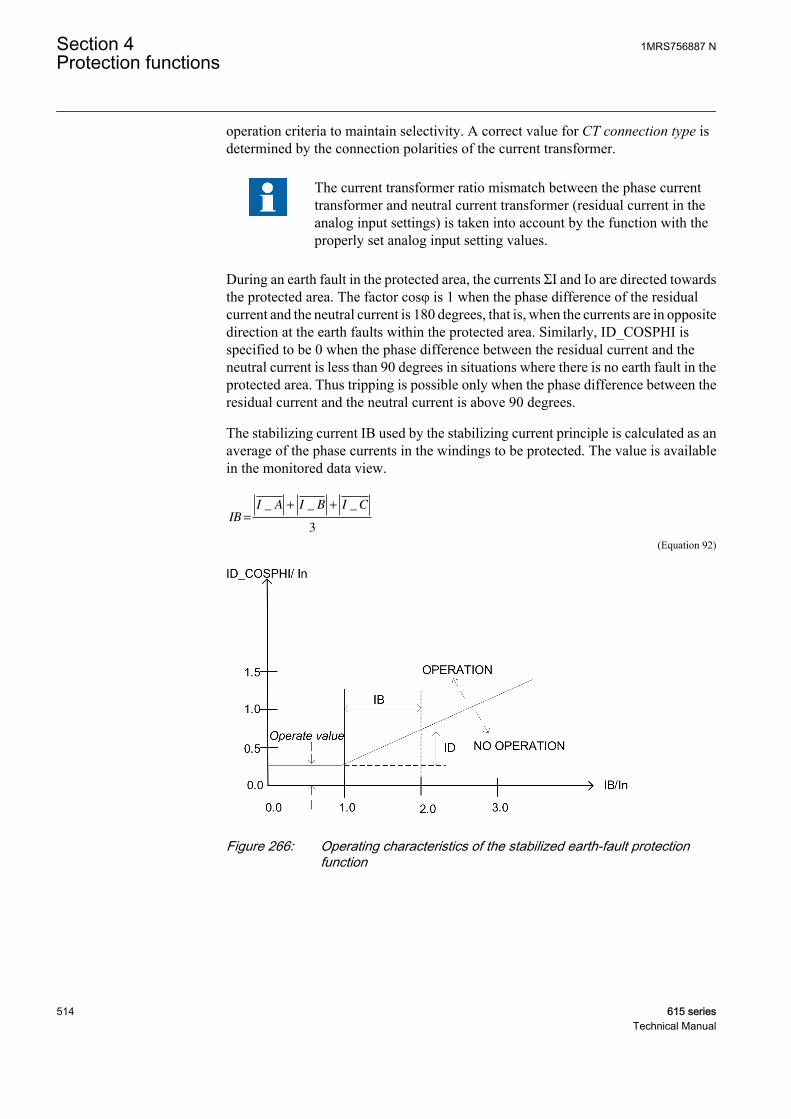
operation criteria to maintain selectivity. A correct value for CT connection type isdetermined by the connection polarities of the current transformer.
The current transformer ratio mismatch between the phase currenttransformer and neutral current transformer (residual current in theanalog input settings) is taken into account by the function with theproperly set analog input setting values.
During an earth fault in the protected area, the currents ΣI and Io are directed towardsthe protected area. The factor cosφ is 1 when the phase difference of the residualcurrent and the neutral current is 180 degrees, that is, when the currents are in oppositedirection at the earth faults within the protected area. Similarly, ID_COSPHI isspecified to be 0 when the phase difference between the residual current and theneutral current is less than 90 degrees in situations where there is no earth fault in theprotected area. Thus tripping is possible only when the phase difference between theresidual current and the neutral current is above 90 degrees.
The stabilizing current IB used by the stabilizing current principle is calculated as anaverage of the phase currents in the windings to be protected. The value is availablein the monitored data view.
IB
I A I B I C
=
+ +_ _ _
3
GUID-E162EE11-DEDF-49BA-B60F-E22ECF1ACAE8 V2 EN (Equation 92)
GUID-9D592151-7598-479B-9285-7FB7C09F0FAB V1 EN
Figure 266: Operating characteristics of the stabilized earth-fault protectionfunction
Section 4 1MRS756887 NProtection functions
514 615 seriesTechnical Manual
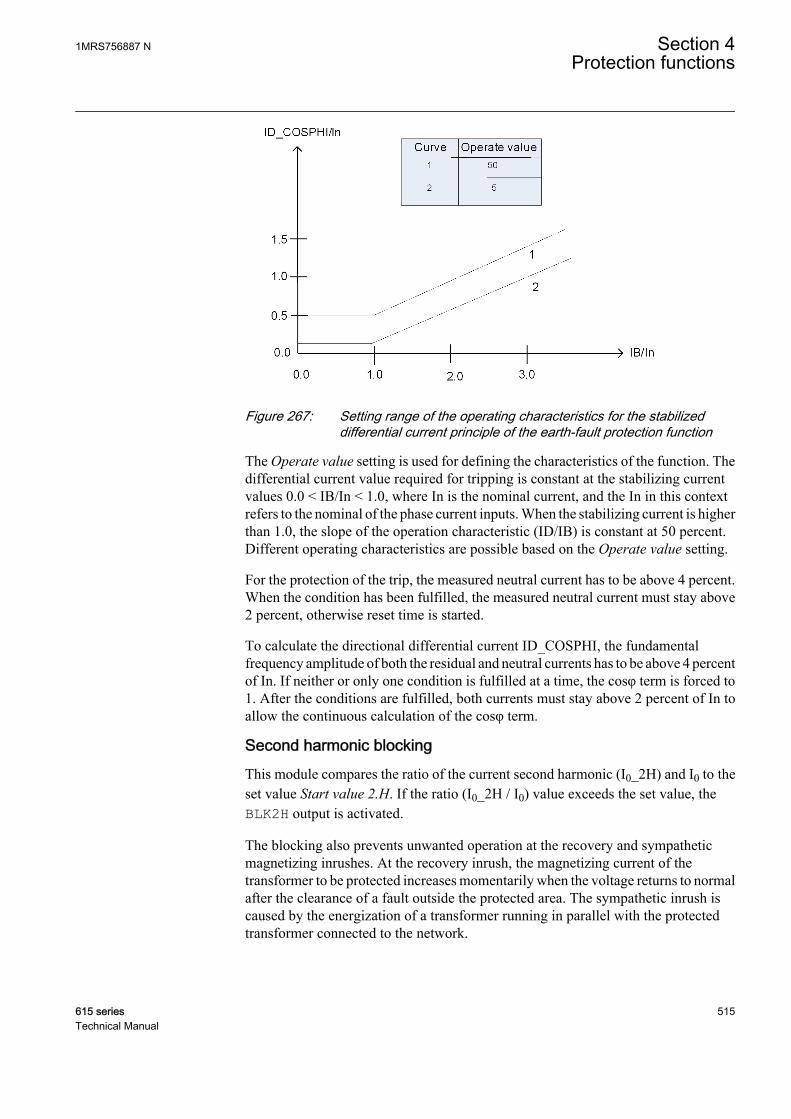
GUID-552423CA-6FE9-4F69-8341-FFE0FF1943D4 V1 EN
Figure 267: Setting range of the operating characteristics for the stabilizeddifferential current principle of the earth-fault protection function
The Operate value setting is used for defining the characteristics of the function. Thedifferential current value required for tripping is constant at the stabilizing currentvalues 0.0 < IB/In < 1.0, where In is the nominal current, and the In in this contextrefers to the nominal of the phase current inputs. When the stabilizing current is higherthan 1.0, the slope of the operation characteristic (ID/IB) is constant at 50 percent.Different operating characteristics are possible based on the Operate value setting.
For the protection of the trip, the measured neutral current has to be above 4 percent.When the condition has been fulfilled, the measured neutral current must stay above2 percent, otherwise reset time is started.
To calculate the directional differential current ID_COSPHI, the fundamentalfrequency amplitude of both the residual and neutral currents has to be above 4 percentof In. If neither or only one condition is fulfilled at a time, the cosφ term is forced to1. After the conditions are fulfilled, both currents must stay above 2 percent of In toallow the continuous calculation of the cosφ term.
Second harmonic blockingThis module compares the ratio of the current second harmonic (I0_2H) and I0 to theset value Start value 2.H. If the ratio (I0_2H / I0) value exceeds the set value, theBLK2H output is activated.
The blocking also prevents unwanted operation at the recovery and sympatheticmagnetizing inrushes. At the recovery inrush, the magnetizing current of thetransformer to be protected increases momentarily when the voltage returns to normalafter the clearance of a fault outside the protected area. The sympathetic inrush iscaused by the energization of a transformer running in parallel with the protectedtransformer connected to the network.
1MRS756887 N Section 4Protection functions
615 series 515Technical Manual
The second harmonic blocking is disabled when Restraint mode is set to "None" andenabled when set to "Harmonic2".
TimerOnce activated, the Timer activates the START output. The time characteristic isaccording to DT. When the operation timer has reached the value set by Minimumoperate time, the OPERATE output is activated. If the fault disappears before themodule operates, the reset timer is activated. If the reset timer reaches the value set byReset delay time, the reset timer resets and the START output is deactivated.
The Timer calculates the start duration value START_DUR which indicates thepercentage ratio of the start situation and the set operate time. The value is availablethrough the Monitored data view.
Blocking logicThere are three operation modes in the blocking function. The operation modes arecontrolled by the BLOCK input and the global setting in Configuration/System/Blocking mode which selects the blocking mode. The BLOCK input can be controlledby a binary input, a horizontal communication input or an internal signal of theprotection relay's program. The influence of the BLOCK signal activation ispreselected with the global setting Blocking mode.
The Blocking mode setting has three blocking methods. In the "Freeze timers" mode,the operate timer is frozen to the prevailing value, but the OPERATE output is notdeactivated when blocking is activated. In the "Block all" mode, the whole function isblocked and the timers are reset. In the "Block OPERATE output" mode, the functionoperates normally but the OPERATE output is not activated. The activation of theoutput of the second harmonic blocking signal BLK2H deactivates the OPERATEoutput.
4.3.3.5 Application
An earth-fault protection using an overcurrent element does not adequately protect thetransformer winding in general and the star-connected winding in particular.
The restricted earth-fault protection is mainly used as a unit protection for thetransformer windings. LREFPNDF is a sensitive protection applied to protect the star-connected winding of a transformer. This protection system remains stable for all thefaults outside the protected zone.
LREFPNDF provides higher sensitivity for the detection of earth faults than theoverall transformer differential protection. This is a high-speed unit protectionscheme applied to the star-connected winding of the transformer. LREFPNDF isnormally applied when the transformer is earthed solidly or through low-impedanceresistor (NER). LREFPNDF can be also applied on the delta side of the transformer ifan earthing transformer (zig-zag transformer) is used there. In LREFPNDF, thedifference of the fundamental component of all three phase currents and the neutral
Section 4 1MRS756887 NProtection functions
516 615 seriesTechnical Manual
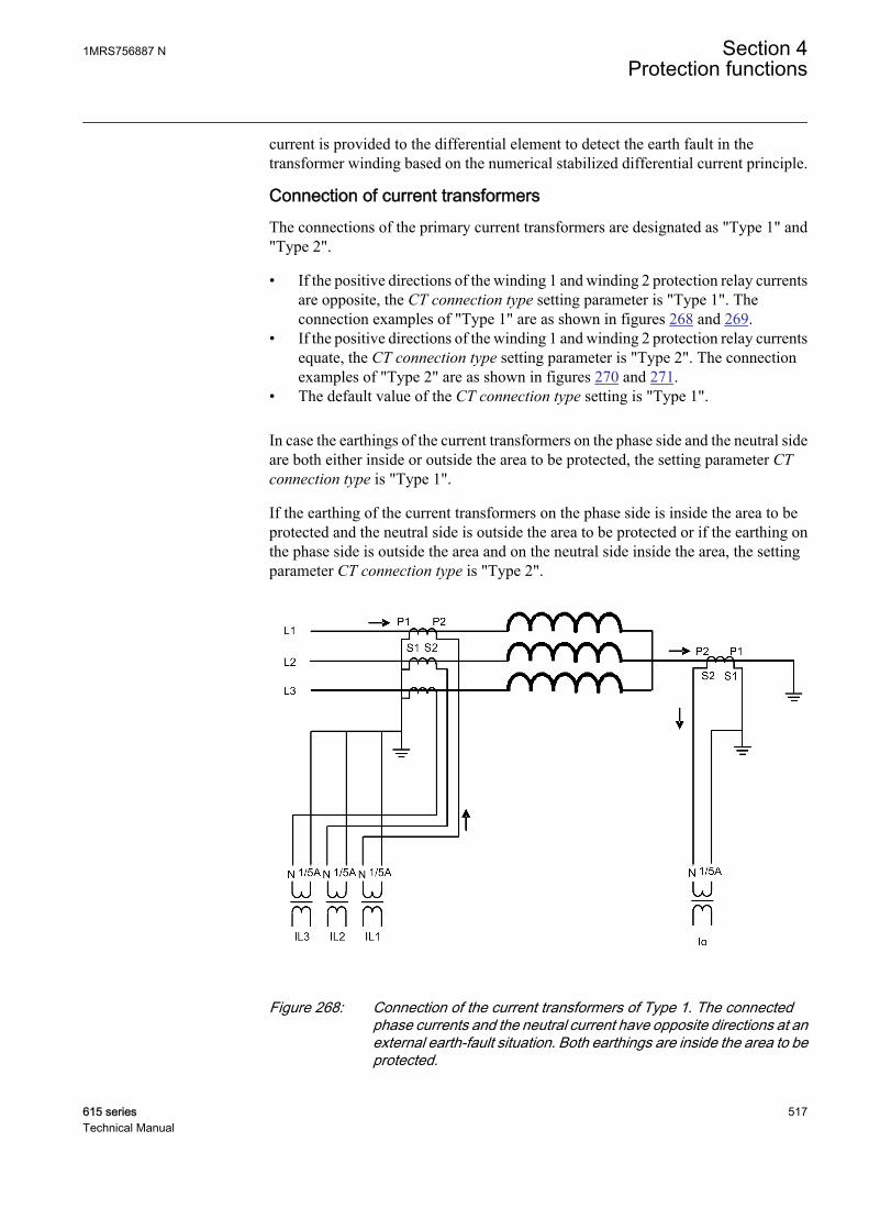
current is provided to the differential element to detect the earth fault in thetransformer winding based on the numerical stabilized differential current principle.
Connection of current transformersThe connections of the primary current transformers are designated as "Type 1" and"Type 2".
• If the positive directions of the winding 1 and winding 2 protection relay currentsare opposite, the CT connection type setting parameter is "Type 1". Theconnection examples of "Type 1" are as shown in figures 268 and 269.
• If the positive directions of the winding 1 and winding 2 protection relay currentsequate, the CT connection type setting parameter is "Type 2". The connectionexamples of "Type 2" are as shown in figures 270 and 271.
• The default value of the CT connection type setting is "Type 1".
In case the earthings of the current transformers on the phase side and the neutral sideare both either inside or outside the area to be protected, the setting parameter CTconnection type is "Type 1".
If the earthing of the current transformers on the phase side is inside the area to beprotected and the neutral side is outside the area to be protected or if the earthing onthe phase side is outside the area and on the neutral side inside the area, the settingparameter CT connection type is "Type 2".
GUID-63BD73B4-7B60-4354-9690-E96C0A8076C7 V2 EN
Figure 268: Connection of the current transformers of Type 1. The connectedphase currents and the neutral current have opposite directions at anexternal earth-fault situation. Both earthings are inside the area to beprotected.
1MRS756887 N Section 4Protection functions
615 series 517Technical Manual

GUID-AF8C4517-178F-4421-8B88-675E30B2C1A1 V1 EN
Figure 269: Connection of the current transformers of Type 1. The connectedphase currents and the neutral current have opposite directions at anexternal earth-fault situation. Both earthings are outside the area tobe protected.
GUID-124047A0-9B33-4D2F-9519-75D98C0A4534 V2 EN
Figure 270: Connection of the current transformers of Type 2. The phase currentsand the neutral current have equal directions at an external earth-fault situation. Phase earthing is inside and neutral earthing is outsidethe area to be protected.
Section 4 1MRS756887 NProtection functions
518 615 seriesTechnical Manual
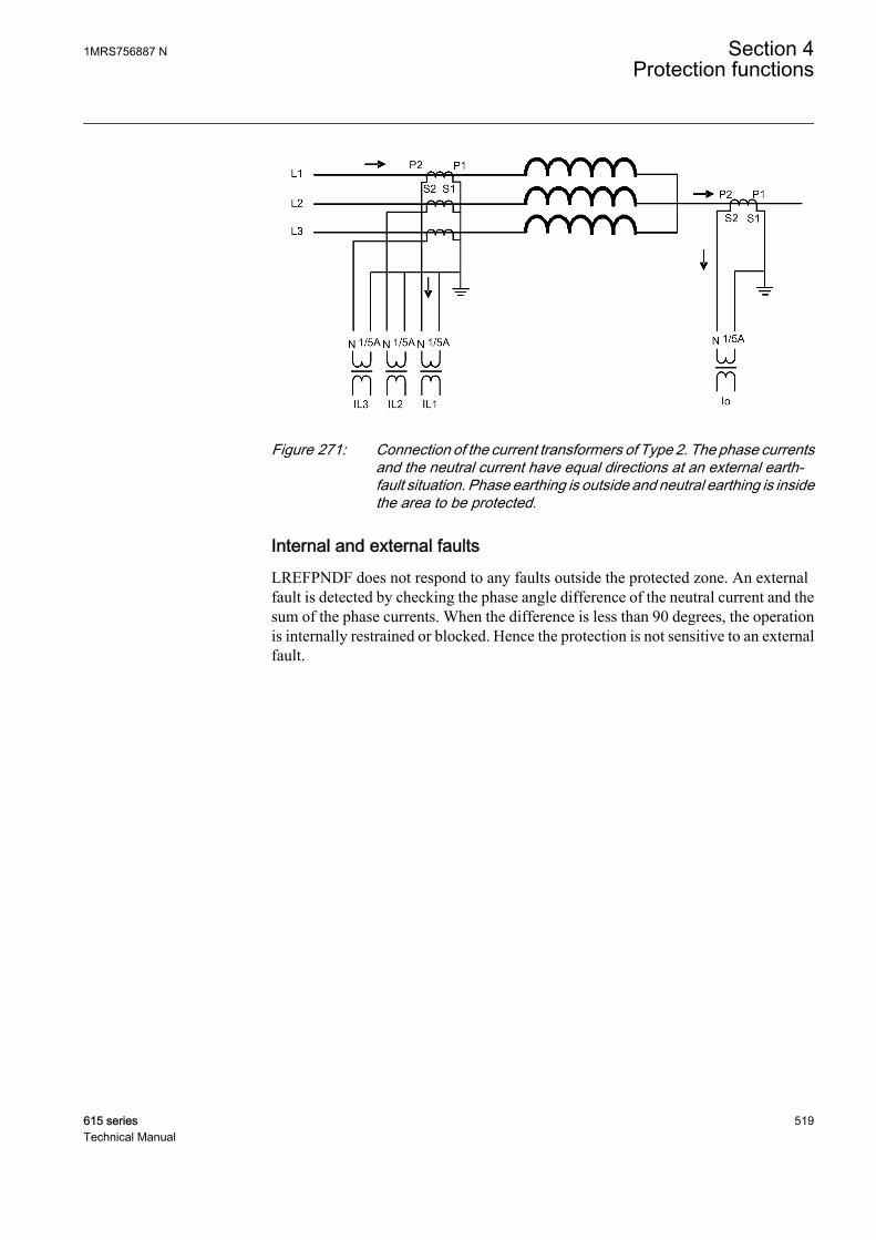
GUID-7F9EBC22-8976-4F9C-8CE8-3BEAA234012A V1 EN
Figure 271: Connection of the current transformers of Type 2. The phase currentsand the neutral current have equal directions at an external earth-fault situation. Phase earthing is outside and neutral earthing is insidethe area to be protected.
Internal and external faultsLREFPNDF does not respond to any faults outside the protected zone. An externalfault is detected by checking the phase angle difference of the neutral current and thesum of the phase currents. When the difference is less than 90 degrees, the operationis internally restrained or blocked. Hence the protection is not sensitive to an externalfault.
1MRS756887 N Section 4Protection functions
615 series 519Technical Manual

A
B
I a = 0
Ib = 0Ib = 0
I c = 0I
Io
zone of protection
C
a
b
c
IN
Izs1
Izs1
Izs1
Io
IN Reference is Neutral Current
Restrain for external fault
Operate for internal fault
For external fault
Uzs
GUID-FAC5E4AD-A4A7-4D39-9EAC-C380EA33CB78 V2 EN
Figure 272: Current flow in all the CTs for an external fault
A
B
C
a
b
c
Ia = 0I
Ib = 0I
c = 0I
UzsIo
zone of protection
Ifault
IN
Io
IN Reference is Neutral Current
Restrain for external fault
Operate for internal fault
For internal fault
source
GUID-D5D712D4-2291-4C49-93DE-363F9F10801C V2 EN
Figure 273: Current flow in all the CTs for an internal fault
Section 4 1MRS756887 NProtection functions
520 615 seriesTechnical Manual

LREFPNDF does not respond to phase-to-phase faults either, as in this case the faultcurrent flows between the two line CTs and so the neutral CT does not experience thisfault current.
Blocking based on the second harmonic of the neutral currentThe transformer magnetizing inrush currents occur when the transformer is energizedafter a period of de-energization. The inrush current can be many times the ratedcurrent, and the halving time can be up to several seconds. For the differentialprotection relay, the inrush current represents the differential current, which causesthe protection relay to operate almost always when the transformer is connected to thenetwork. Typically, the inrush current contains a large amount of second harmonics.
The blocking also prevents unwanted operation at the recovery and sympatheticmagnetizing inrushes. At the recovery inrush, the magnetizing current of thetransformer to be protected increases momentarily when the voltage returns to normalafter the clearance of a fault outside the protected area. The sympathetic inrush iscaused by the energization of a transformer running in parallel with the protectedtransformer already connected to the network.
Blocking the starting of the restricted earth-fault protection at the magnetizing inrushis based on the ratio of the second harmonic and the fundamental frequencyamplitudes of the neutral current Io_2H / Io. Typically, the second harmonic contentof the neutral current at the magnetizing inrush is higher than that of the phasecurrents.
4.3.3.6 Signals
Table 435: LREFPNDF Input signals
Name Type Default DescriptionI_A SIGNAL 0 Phase A current
I_B SIGNAL 0 Phase B current
I_C SIGNAL 0 Phase C current
Io SIGNAL 0 Residual current
BLOCK BOOLEAN 0=False Block signal for activating the blocking mode
Table 436: LREFPNDF Output signals
Name Type DescriptionOPERATE BOOLEAN Operate
START BOOLEAN Start
BLK2H BOOLEAN 2nd harmonic block
1MRS756887 N Section 4Protection functions
615 series 521Technical Manual
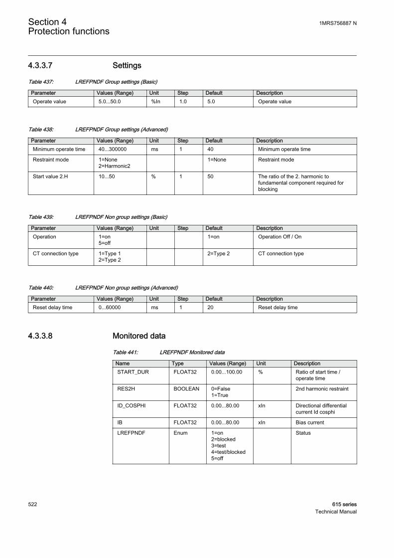
4.3.3.7 Settings
Table 437: LREFPNDF Group settings (Basic)
Parameter Values (Range) Unit Step Default DescriptionOperate value 5.0...50.0 %In 1.0 5.0 Operate value
Table 438: LREFPNDF Group settings (Advanced)
Parameter Values (Range) Unit Step Default DescriptionMinimum operate time 40...300000 ms 1 40 Minimum operate time
Restraint mode 1=None2=Harmonic2
1=None Restraint mode
Start value 2.H 10...50 % 1 50 The ratio of the 2. harmonic tofundamental component required forblocking
Table 439: LREFPNDF Non group settings (Basic)
Parameter Values (Range) Unit Step Default DescriptionOperation 1=on
5=off 1=on Operation Off / On
CT connection type 1=Type 12=Type 2
2=Type 2 CT connection type
Table 440: LREFPNDF Non group settings (Advanced)
Parameter Values (Range) Unit Step Default DescriptionReset delay time 0...60000 ms 1 20 Reset delay time
4.3.3.8 Monitored data
Table 441: LREFPNDF Monitored data
Name Type Values (Range) Unit DescriptionSTART_DUR FLOAT32 0.00...100.00 % Ratio of start time /
operate time
RES2H BOOLEAN 0=False1=True
2nd harmonic restraint
ID_COSPHI FLOAT32 0.00...80.00 xIn Directional differentialcurrent Id cosphi
IB FLOAT32 0.00...80.00 xIn Bias current
LREFPNDF Enum 1=on2=blocked3=test4=test/blocked5=off
Status
Section 4 1MRS756887 NProtection functions
522 615 seriesTechnical Manual

4.3.3.9 Technical data
Table 442: LREFPNDF Technical data
Characteristic ValueOperation accuracy Depending on the frequency of the measured
current: fn ±2 Hz
±2.5% of the set value or ±0.002 x In
Start time1)2) Minimum Typical Maximum
IFault = 2.0 × setOperate value
37 ms 41 ms 45 ms
Reset time Typically 40 ms
Reset ratio Typically 0.96
Retardation time <35 ms
Operate time accuracy in definite time mode ±1.0% of the set value or ±20 ms
Suppression of harmonics DFT: -50 dB at f = n × fn, where n = 2, 3, 4, 5, …
1) Current before fault = 0.0, fn = 50 Hz, results based on statistical distribution of 1000 measurements2) Includes the delay of the signal output contact
4.3.3.10 Technical revision history
Table 443: LREFPNDF Technical revision history
Technical revision ChangeB Unit for setting Start value 2.H changed from %In
to %.
C Internal Improvement.
4.3.4 High-impedance based restricted earth-fault protectionHREFPDIF
4.3.4.1 Identification
Function description IEC 61850identification
IEC 60617identification
ANSI/IEEE C37.2device number
High-impedance based restricted earth-fault protection
HREFPDIF dIoHi> 87NH
4.3.4.2 Function block
GUID-0B400966-B2D9-4027-A2B3-786BA559A4A4 V3 EN
Figure 274: Function block
1MRS756887 N Section 4Protection functions
615 series 523Technical Manual
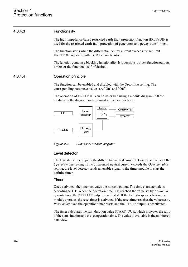
4.3.4.3 Functionality
The high-impedance based restricted earth-fault protection function HREFPDIF isused for the restricted earth-fault protection of generators and power transformers.
The function starts when the differential neutral current exceeds the set limit.HREFPDIF operates with the DT characteristic.
The function contains a blocking functionality. It is possible to block function outputs,timers or the function itself, if desired.
4.3.4.4 Operation principle
The function can be enabled and disabled with the Operation setting. Thecorresponding parameter values are "On" and "Off".
The operation of HREFPDIF can be described using a module diagram. All themodules in the diagram are explained in the next sections.
GUID-75842EE4-C4B8-452A-8FA9-FDE60ED22DD4 V3 EN
Figure 275: Functional module diagram
Level detectorThe level detector compares the differential neutral current IDo to the set value of theOperate value setting. If the differential neutral current exceeds the Operate valuesetting, the level detector sends an enable signal to the timer module to start thedefinite timer.
TimerOnce activated, the timer activates the START output. The time characteristic isaccording to DT. When the operation timer has reached the value set by Minimumoperate time, the OPERATE output is activated. If the fault disappears before themodule operates, the reset timer is activated. If the reset timer reaches the value set byReset delay time, the operation timer resets and the START output is deactivated.
The timer calculates the start duration value START_DUR, which indicates the ratioof the start situation and the set operation time. The value is available in the monitoreddata view.
Section 4 1MRS756887 NProtection functions
524 615 seriesTechnical Manual
Blocking logicThere are three operation modes in the blocking function. The operation modes arecontrolled by the BLOCK input and the global setting Configuration/System/Blocking mode which selects the blocking mode. The BLOCK input can be controlledby a binary input, a horizontal communication input or an internal signal of the IEDprogram. The influence of the BLOCK signal activation is preselected with the globalsetting Blocking mode.
The Blocking mode setting has three blocking methods. In the "Freeze timers" mode,the operation timer is frozen to the prevailing value. In the "Block all" mode, the wholefunction is blocked and the timers are reset. In the "Block OPERATE output" mode,the function operates normally but the OPERATE output is not activated.
4.3.4.5 Application
In solidly earthed systems, the restricted earth-fault protection is always deployed asa complement to the normal transformer differential protection. The advantage of therestricted earth-fault protection is its high sensitivity. Sensitivities of close to 1.0percent can be achieved, whereas normal differential IEDs have their minimumsensitivity in the range of 5 to 10 percent. The level for HREFPDIF is dependent onthe current transformers' magnetizing currents. The restricted earth-fault protection isalso very fast due to the simple measuring principle as it is a unit type of protection.
The differences in measuring principle limit the biased differential IED's possibilityto detect the earth faults. Such faults are then only detected by the restricted earth-faultfunction.
The restricted earth-fault IED is connected across each directly or to low-ohmicearthed transformer winding. If the same CTs are connected to other IEDs, separatecores are to be used.
1MRS756887 N Section 4Protection functions
615 series 525Technical Manual
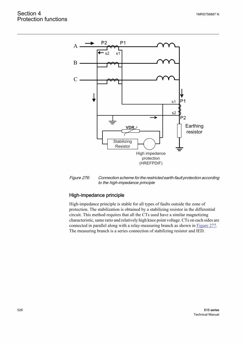
s1s2
s1
s2
VDR
StabilizingResistor
High impedance protection
(HREFPDIF)
GUID-367BDBC9-D2E8-48D3-B98F-623F7CD70D99 V3 EN
Figure 276: Connection scheme for the restricted earth-fault protection accordingto the high-impedance principle
High-impedance principleHigh-impedance principle is stable for all types of faults outside the zone ofprotection. The stabilization is obtained by a stabilizing resistor in the differentialcircuit. This method requires that all the CTs used have a similar magnetizingcharacteristic, same ratio and relatively high knee point voltage. CTs on each sides areconnected in parallel along with a relay-measuring branch as shown in Figure 277.The measuring branch is a series connection of stabilizing resistor and IED.
Section 4 1MRS756887 NProtection functions
526 615 seriesTechnical Manual
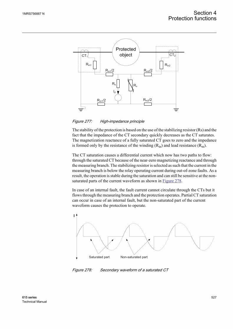
Id
CT1
Rm1/2 Rm2/2
RuRs
Rm1/2 Rm2/2
Rin1 Rin2
CT2
GUID-80DC5CFE-118C-4C5C-A15F-13DCB1708C0E V1 EN
Figure 277: High-impedance principle
The stability of the protection is based on the use of the stabilizing resistor (Rs) and thefact that the impedance of the CT secondary quickly decreases as the CT saturates.The magnetization reactance of a fully saturated CT goes to zero and the impedanceis formed only by the resistance of the winding (Rin) and lead resistance (Rm).
The CT saturation causes a differential current which now has two paths to flow:through the saturated CT because of the near-zero magnetizing reactance and throughthe measuring branch. The stabilizing resistor is selected as such that the current in themeasuring branch is below the relay operating current during out-of-zone faults. As aresult, the operation is stable during the saturation and can still be sensitive at the non-saturated parts of the current waveform as shown in Figure 278.
In case of an internal fault, the fault current cannot circulate through the CTs but itflows through the measuring branch and the protection operates. Partial CT saturationcan occur in case of an internal fault, but the non-saturated part of the currentwaveform causes the protection to operate.
Saturated part Non-saturated part
I
GUID-B4CBEF48-1C9C-410B-997F-440CB10486BD V1 EN
Figure 278: Secondary waveform of a saturated CT
1MRS756887 N Section 4Protection functions
615 series 527Technical Manual
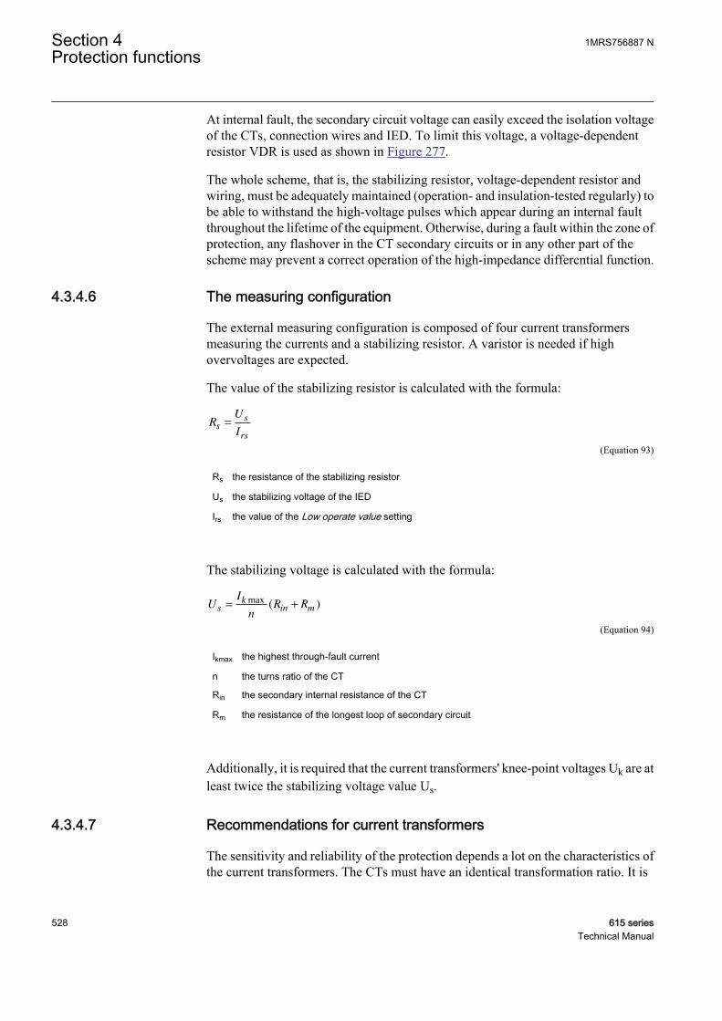
At internal fault, the secondary circuit voltage can easily exceed the isolation voltageof the CTs, connection wires and IED. To limit this voltage, a voltage-dependentresistor VDR is used as shown in Figure 277.
The whole scheme, that is, the stabilizing resistor, voltage-dependent resistor andwiring, must be adequately maintained (operation- and insulation-tested regularly) tobe able to withstand the high-voltage pulses which appear during an internal faultthroughout the lifetime of the equipment. Otherwise, during a fault within the zone ofprotection, any flashover in the CT secondary circuits or in any other part of thescheme may prevent a correct operation of the high-impedance differential function.
4.3.4.6 The measuring configuration
The external measuring configuration is composed of four current transformersmeasuring the currents and a stabilizing resistor. A varistor is needed if highovervoltages are expected.
The value of the stabilizing resistor is calculated with the formula:
RU
Is
s
rs
=
GUID-00FCABE9-93E2-4BDD-83C6-EB1BE7FFE986 V1 EN (Equation 93)
Rs the resistance of the stabilizing resistor
Us the stabilizing voltage of the IED
Irs the value of the Low operate value setting
The stabilizing voltage is calculated with the formula:
UI
nR Rs
kin m= +
max( )
GUID-6A4C58E7-3D26-40C9-A070-0D99BA209B1A V1 EN (Equation 94)
Ikmax the highest through-fault current
n the turns ratio of the CT
Rin the secondary internal resistance of the CT
Rm the resistance of the longest loop of secondary circuit
Additionally, it is required that the current transformers' knee-point voltages Uk are atleast twice the stabilizing voltage value Us.
4.3.4.7 Recommendations for current transformers
The sensitivity and reliability of the protection depends a lot on the characteristics ofthe current transformers. The CTs must have an identical transformation ratio. It is
Section 4 1MRS756887 NProtection functions
528 615 seriesTechnical Manual
recommended that all current transformers have an equal burden and characteristicsand are of same type, preferably from the same manufacturing batch, that is, anidentical construction should be used. If the CT characteristics and burden values arenot equal, calculation for each branch in the scheme should be done separately and theworst-case result is then used.
First, the stabilizing voltage, that is, the voltage appearing across the measuringbranch during the out-of-zone fault, is calculated assuming that one of the parallelconnected CT is fully saturated. The stabilizing voltage can be calculated with theformula
UI
nR Rs
kin m= +
max( )
GUID-6A4C58E7-3D26-40C9-A070-0D99BA209B1A V1 EN (Equation 95)
Ikmax the highest through-fault current in primary amps. The highest earth-fault or short circuit currentduring the out-of-zone fault.
n the turns ratio of the CT
Rin the secondary internal resistance of the CT in ohms
Rm the resistance (maximum of Rin + Rm) of the CT secondary circuit in ohms
The current transformers must be able to force enough current to operate the IEDthrough the differential circuit during a fault condition inside the zone of protection.To ensure this, the knee point voltage Ukn should be at least two times higher than thestabilizing voltage Us.
The required knee point voltage Ukn of the current transformer is calculated using theformula
U Ukn s≥ ×2
GUID-4F7F301A-1573-4736-B740-622605DB0FFB V2 EN (Equation 96)
Ukn the knee point voltage
Us the stabilizing voltage
The factor two is used when no delay in the operating time of the protection in anysituation is acceptable. To prevent the knee point voltage from growing too high, it isadvisable to use current transformers, the secondary winding resistance of which is ofthe same size as the resistance of the measuring loop.
As the impedance of the IED alone is low, a stabilizing resistor is needed. The valueof the stabilizing resistor is calculated with the formula
1MRS756887 N Section 4Protection functions
615 series 529Technical Manual
RU
Is
s
rs
=
GUID-EA4FE2BC-4E93-4093-BD14-F20A4F33AEF2 V1 EN (Equation 97)
Rs the resistance of the stabilizing resistor
Us the stabilizing voltage of the IED
Irs the value of the Operate value setting in secondary amps.
The stabilizing resistor should be capable to dissipate high energy within a very shorttime; therefore, the wire wound-type resistor should be used. Because of the possibleCT inaccuracy, which might cause some current through the stabilizing resistor in anormal load situation, the rated power should be 25 W minimum.
If Ukn is high or the stabilizing voltage is low, a resistor with a higher power rating isneeded. Often resistor manufacturers allow 10 times rated power for 5 seconds. Thusthe power of the resistor can be calculated with the equation
U
R
kn
s
2
10×
GUID-93E59545-7530-408D-8ECF-2D3D9CF76C13 V1 EN (Equation 98)
The actual sensitivity of the protection is affected by the IED setting, the magnetizingcurrents of the parallel connected CTs and the shunting effect of the voltage-dependent resistor (VDR). The value of the primary current Iprim at which the IEDoperates at a certain setting can be calculated with the formula
I n I I m Iprim rs u m= × + + ×( )
GUID-2A742729-7244-4B1C-A4DF-404BDD3A68D9 V1 EN (Equation 99)
Iprim the primary current at which the protection is to start
n the turn ratio of the current transformer
Irs the value of the Operate value setting
Iu the leakage current flowing through the VDR at the Us voltage
m the number of current transformers included in the protection per phase (=4)
Im the magnetizing current per current transformer at the Us voltage
The Ie value given in many catalogs is the excitation current at the knee point voltage.
Assuming Ukn ≈ 2 x Us, the value of Im ≈Ie
2 gives an approximate value for Equation99.
The selection of current transformers can be divided into procedures:
Section 4 1MRS756887 NProtection functions
530 615 seriesTechnical Manual

1. In principle, the highest through-fault should be known. However, when thenecessary data are not available, approximates can be used:• Small power transformers: Ikmax = 16 x In (corresponds to zk = 6% and
infinite grid)• Large power transformers: Ikmax = 12 x In (corresponds to zk = 8% and
infinite grid)• Generators and motors: Ikmax = 6 x In
Where In = rated current and zk = short circuit impedance of the protectedobject
2. The rated primary current I1n of the CT has to be higher than the rated current ofthe machine.The choice of the CT also specifies Rin.
3. The required Ukn is calculated with Equation 96. If the Ukn of the CT is not highenough, another CT has to be chosen. The value of the Ukn is given by themanufacturer in the case of Class X current transformers or it can be estimatedwith Equation 100.
4. The sensitivity Iprim is calculated with Equation 99. If the achieved sensitivity issufficient, the present CT is chosen. If a better sensitivity is needed, a CT with abigger core is chosen.
If other than Class X CTs are used, an estimate for Ukn is calculated with the equation
U F I RS
Ikn n n in
n
n
= × × × +
0 8 2
22
.
GUID-AFA68232-5288-4220-845E-40347B691E29 V2 EN (Equation 100)
Fn the rated accuracy limit factor corresponding to the rated burden Sn
I2n the rated secondary current of the CT
Rin the secondary internal resistance of the CT
Sn the volt-amp rating of the CT
The formulas are based on choosing the CTs according to Equation96, which results an absolutely stable scheme. In some cases, it ispossible to achieve stability with knee point voltages lower than statedin the formulas. The conditions in the network, however, have to beknown well enough to ensure the stability.
1. If Uk ≥ 2 x Us, fast IED operation is secure.2. If Uk ≥ 1.5 x Us and < 2 x Us, IED operation can be slightly
prolonged and should be studied case by case.If Uk < 1.5 x Us, the IED operation is jeopardized. Another CT hasto be chosen.
1MRS756887 N Section 4Protection functions
615 series 531Technical Manual
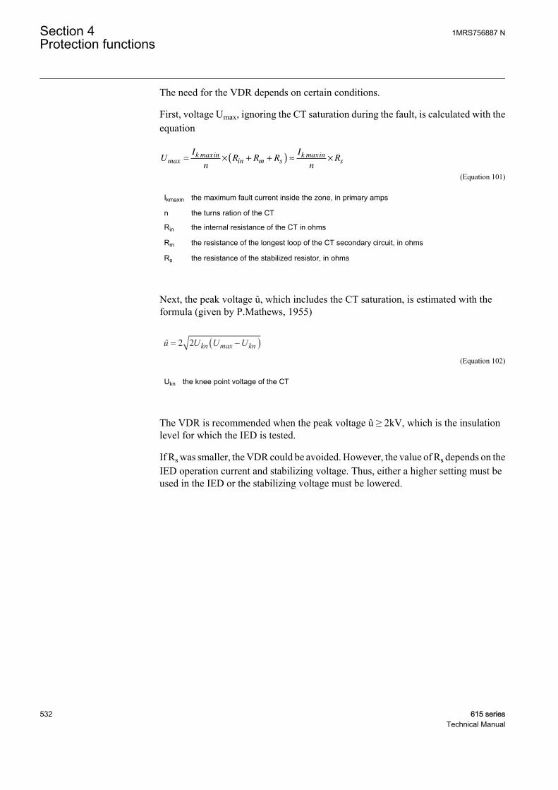
The need for the VDR depends on certain conditions.
First, voltage Umax, ignoring the CT saturation during the fault, is calculated with theequation
UI
nR R R
I
nR
k inin m s
k insmax
max max= × + +( ) ≈ ×
GUID-CB54C30A-C69D-4C59-B9B3-44530319D1CE V1 EN (Equation 101)
Ikmaxin the maximum fault current inside the zone, in primary amps
n the turns ration of the CT
Rin the internal resistance of the CT in ohms
Rm the resistance of the longest loop of the CT secondary circuit, in ohms
Rs the resistance of the stabilized resistor, in ohms
Next, the peak voltage û, which includes the CT saturation, is estimated with theformula (given by P.Mathews, 1955)
û U U Ukn kn= −( )2 2 max
GUID-0FBE4CDF-8A7C-4574-8325-C61E61E0C55C V1 EN (Equation 102)
Ukn the knee point voltage of the CT
The VDR is recommended when the peak voltage û ≥ 2kV, which is the insulationlevel for which the IED is tested.
If Rs was smaller, the VDR could be avoided. However, the value of Rs depends on theIED operation current and stabilizing voltage. Thus, either a higher setting must beused in the IED or the stabilizing voltage must be lowered.
Section 4 1MRS756887 NProtection functions
532 615 seriesTechnical Manual

4.3.4.8 Setting examples
Example 1
n
n2
m
u
s
GUID-AB960DE4-4DD2-4312-9921-0D6E7CD001AA V1 EN
Figure 279: Restricted earth-fault protection of a transformer
The data for the protected power transformer are:
Sn = 20 MVA
U2n = 11 kV
The longest distance of the secondary circuit is 50 m (the whole loop is 100 m) and thearea of the cross section is 10 mm2.
In = Sn / (√3 · Un) = 1050 A
Ikmax = 12 · In = 12600 A
In this example, the CT type is IHBF 12, the core size is 35 percent, the primary currentis 1200 A and the secondary current is 5 A.
Rin = 0.26 Ω (value given by the manufacturer).
Uk = 40 V (value given by the manufacturer).
Ie = 0.055 A (value given by the manufacturer).
Rm = 1.81 Ω/km · 2 · 0.05 km = 0.181 Ω ≈ 0.18 Ω
1MRS756887 N Section 4Protection functions
615 series 533Technical Manual
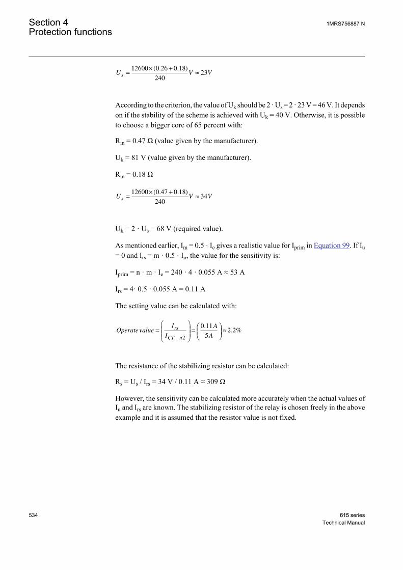
U V Vs =× +
≈12600 0 26 0 18
24023
( . . )
GUID-7AA079B9-4E11-48BD-A474-B7A06BA3976B V1 EN
According to the criterion, the value of Uk should be 2 · Us = 2 · 23 V = 46 V. It dependson if the stability of the scheme is achieved with Uk = 40 V. Otherwise, it is possibleto choose a bigger core of 65 percent with:
Rin = 0.47 Ω (value given by the manufacturer).
Uk = 81 V (value given by the manufacturer).
Rm = 0.18 Ω
U V Vs =× +
≈12600 0 47 0 18
24034
( . . )
GUID-F7AF5A9B-A4F3-4714-94D2-022A54232F0E V1 EN
Uk = 2 · Us = 68 V (required value).
As mentioned earlier, Im = 0.5 · Ie gives a realistic value for Iprim in Equation 99. If Iu= 0 and Irs = m · 0.5 · Io, the value for the sensitivity is:
Iprim = n · m · Ie = 240 · 4 · 0.055 A ≈ 53 A
Irs = 4· 0.5 · 0.055 A = 0.11 A
The setting value can be calculated with:
OperatevalueI
I
A
A
rs
CT n
=
=
≈
_
.. %
2
0 11
52 2
GUID-C03C3B3E-E03F-41F3-B51A-A9AA161BC433 V1 EN
The resistance of the stabilizing resistor can be calculated:
Rs = Us / Irs = 34 V / 0.11 A ≈ 309 Ω
However, the sensitivity can be calculated more accurately when the actual values ofIu and Irs are known. The stabilizing resistor of the relay is chosen freely in the aboveexample and it is assumed that the resistor value is not fixed.
Section 4 1MRS756887 NProtection functions
534 615 seriesTechnical Manual
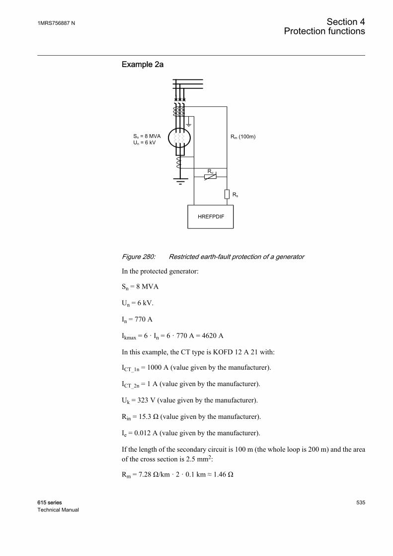
Example 2a
n
n
m
u
s
GUID-787D9DE6-961E-454A-B97A-FAFC6F9701F0 V1 EN
Figure 280: Restricted earth-fault protection of a generator
In the protected generator:
Sn = 8 MVA
Un = 6 kV.
In = 770 A
Ikmax = 6 · In = 6 · 770 A = 4620 A
In this example, the CT type is KOFD 12 A 21 with:
ICT_1n = 1000 A (value given by the manufacturer).
ICT_2n = 1 A (value given by the manufacturer).
Uk = 323 V (value given by the manufacturer).
Rin = 15.3 Ω (value given by the manufacturer).
Ie = 0.012 A (value given by the manufacturer).
If the length of the secondary circuit is 100 m (the whole loop is 200 m) and the areaof the cross section is 2.5 mm2:
Rm = 7.28 Ω/km · 2 · 0.1 km ≈ 1.46 Ω
1MRS756887 N Section 4Protection functions
615 series 535Technical Manual
The required knee-point voltage can be calculated using Equation 96.
Uk = 2 · ( 4620 A / 1000 ) · ( 15.3 + 1.46 ) ≈ 155 V.
The value 155 V is lower than the value 323 V, which means that the value of Uk ishigh enough.
As mentioned earlier, Im = 0.5 · Ie gives a realistic value for Iprim in Equation 99. If Iu= 0 and Irs = m · 0.5 · Ie, the value for the sensitivity is:
Iprim = n · m · Ie = 1000 · 4 · 0.012 A = 48 A ( ≈ 6 % x In).
Irs = 4 · 0.5 · 0.012 A = 0.024 A.
The setting value can be calculated with:
OperatevalueI
I
A
A
rs
CT n
=
=
≈
_
.. %
2
0 024
12 4
GUID-3873DFF7-8FB3-42B1-BF99-CE7D9D141F55 V1 EN
The resistance of the stabilizing resistor can now be calculated:
Rs = Us / Irs = 78 V / (2 · Ie) = 78 V / (2 · 0.012 A) = 3250 Ω.
Example 2bIn this example, Irs = 4 x 12 mA = 48 mA and Iu = 30 mA. This results in the sensitivity:
Iprim = n · ( Irs + Iu + m · Im ) = 1000 · (48 + 30 + 24) mA = 102 A
The setting value can be calculated with:
OperatevalueI
I
A
A
rs
CT n
=
=
≈
_
.. %
2
0 048
14 8
GUID-4373B1E0-46AB-401A-A76A-AD97B850D079 V1 EN
The resistance of the stabilizing resistor is now:
Rs = Us / Irs= 78 V / 48 mA ≈ 1630 Ω
In this example, the relay is of such a type that the stabilizing resistor can be chosenfreely.
4.3.4.9 Signals
Table 444: HREFPDIF Input signals
Name Type Default DescriptionIDo SIGNAL 0 Differential current
BLOCK BOOLEAN 0=False Block signal for activating the blocking mode
Section 4 1MRS756887 NProtection functions
536 615 seriesTechnical Manual

Table 445: HREFPDIF Output signals
Name Type DescriptionOPERATE BOOLEAN Operate
START BOOLEAN Start
4.3.4.10 Settings
Table 446: HREFPDIF Group settings (Basic)
Parameter Values (Range) Unit Step Default DescriptionOperate value 1.0...50.0 %In 0.1 1.0 Low operate value, percentage of the
nominal current
Minimum operate time 40...300000 ms 1 40 Minimum operate time
Table 447: HREFPDIF Non group settings (Basic)
Parameter Values (Range) Unit Step Default DescriptionOperation 1=on
5=off 1=on Operation Off / On
Table 448: HREFPDIF Non group settings (Advanced)
Parameter Values (Range) Unit Step Default DescriptionReset delay time 0...60000 ms 1 20 Reset delay time
4.3.4.11 Monitored data
Table 449: HREFPDIF Monitored data
Name Type Values (Range) Unit DescriptionSTART_DUR FLOAT32 0.00...100.00 % Ratio of start time /
operate time
HREFPDIF Enum 1=on2=blocked3=test4=test/blocked5=off
Status
1MRS756887 N Section 4Protection functions
615 series 537Technical Manual
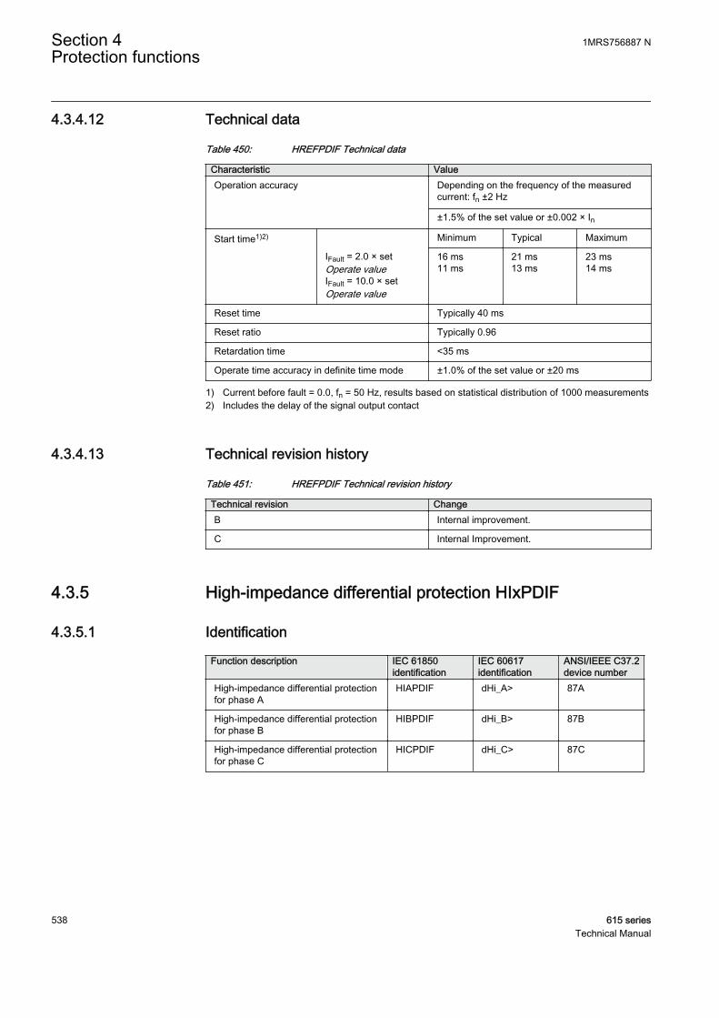
4.3.4.12 Technical data
Table 450: HREFPDIF Technical data
Characteristic ValueOperation accuracy Depending on the frequency of the measured
current: fn ±2 Hz
±1.5% of the set value or ±0.002 × In
Start time1)2) Minimum Typical Maximum
IFault = 2.0 × setOperate valueIFault = 10.0 × setOperate value
16 ms11 ms
21 ms13 ms
23 ms14 ms
Reset time Typically 40 ms
Reset ratio Typically 0.96
Retardation time <35 ms
Operate time accuracy in definite time mode ±1.0% of the set value or ±20 ms
1) Current before fault = 0.0, fn = 50 Hz, results based on statistical distribution of 1000 measurements2) Includes the delay of the signal output contact
4.3.4.13 Technical revision history
Table 451: HREFPDIF Technical revision history
Technical revision ChangeB Internal improvement.
C Internal Improvement.
4.3.5 High-impedance differential protection HIxPDIF
4.3.5.1 Identification
Function description IEC 61850identification
IEC 60617identification
ANSI/IEEE C37.2device number
High-impedance differential protectionfor phase A
HIAPDIF dHi_A> 87A
High-impedance differential protectionfor phase B
HIBPDIF dHi_B> 87B
High-impedance differential protectionfor phase C
HICPDIF dHi_C> 87C
Section 4 1MRS756887 NProtection functions
538 615 seriesTechnical Manual
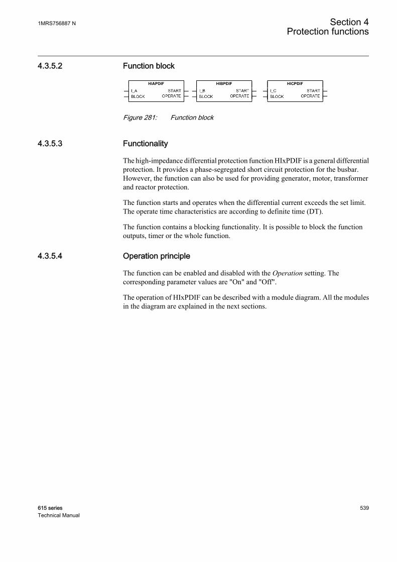
4.3.5.2 Function block
GUID-A8C4ADB7-8892-422F-8B00-873C47A66A3E V1 EN
Figure 281: Function block
4.3.5.3 Functionality
The high-impedance differential protection function HIxPDIF is a general differentialprotection. It provides a phase-segregated short circuit protection for the busbar.However, the function can also be used for providing generator, motor, transformerand reactor protection.
The function starts and operates when the differential current exceeds the set limit.The operate time characteristics are according to definite time (DT).
The function contains a blocking functionality. It is possible to block the functionoutputs, timer or the whole function.
4.3.5.4 Operation principle
The function can be enabled and disabled with the Operation setting. Thecorresponding parameter values are "On" and "Off".
The operation of HIxPDIF can be described with a module diagram. All the modulesin the diagram are explained in the next sections.
1MRS756887 N Section 4Protection functions
615 series 539Technical Manual

GUID-89207322-ADEC-4927-9402-72C112CC7C7C V2 EN
Figure 282: Functional module diagram
The module diagram illustrates all the phases of the function. Functionality for phasesA, B and C is identical.
All three phases have independent settings.
Level detectorThe module compares differential currents I_A calculated by the peak-to-peakmeasurement mode to the set Operate value. The Timer module is activated if thedifferential current exceeds the value of the Operate value setting.
TimerOnce activated, Timer activates the START output. The time characteristic isaccording to DT. When the operation timer reaches the value set by Minimum operatetime, the OPERATE output is activated. If the fault disappears before the moduleoperates, the reset timer is activated. If the reset timer reaches the value set by Resetdelay time, the operation timer resets and the START output is deactivated.
Section 4 1MRS756887 NProtection functions
540 615 seriesTechnical Manual
Timer calculates the start duration START_DUR value, which indicates thepercentage ratio of the start situation and the set operating time. The value is availablein the Monitored data view.
The activation of the BLOCK input resets Timer and deactivates the START andOPERATE outputs.
Blocking logicThere are three operation modes in the blocking functionality. The operation modesare controlled by the BLOCK input and the global setting Configuration/System/Blocking mode which selects the blocking mode. The BLOCK input can be controlledby a binary input, a horizontal communication input or an internal signal of theprotection relay's program. The influence of the BLOCK signal activation ispreselected with the global setting Blocking mode.
The Blocking mode setting has three blocking methods. In the "Freeze timers" mode,the operation timer is frozen to the prevailing value. In the "Block all" mode, the wholefunction is blocked and the timers are reset. In the "Block OPERATE output" mode,the function operates normally but the OPERATE output is not activated.
4.3.5.5 Application
HIxPDIF provides a secure and dependable protection scheme against all types offaults. The high-impedance principle is used for differential protection due to itscapability to manage the through-faults also with the heavy current transformer (CT)saturation.
For current transformer recommendations, see the Requirements formeasurement transformers section in this manual.
High-impedance principleThe phase currents are measured from both the incoming and the outgoing feeder sidesof the busbar. The secondary of the current transformer in each phase is connected inparallel with a protection relay measuring branch. Hence, the relay measures only thedifference of the currents. In an ideal situation, there is a differential current to operatethe relay only if there is a fault between the CTs, that is, inside the protected zone.
If there is a fault outside the zone, a high current, known as the through-fault current,can go through the protected object. This can cause partial saturation in the CTs. Therelay operation is avoided with a stabilizing resistor (Rs) in the protection relaymeasuring branch. Rs increases the impedance of the protection relay; hence the namehigh-impedance differential scheme.
1MRS756887 N Section 4Protection functions
615 series 541Technical Manual

GUID-1AB5D686-3B9C-413F-9D0A-215BFCA224B4 V1 EN
Figure 283: Phase-segregated bus differential protection based on high-impedance principle
CT secondary winding resistances (Rin) and connection wire resistances (Rm/2) arealso shown in Figure 284.
Figure 284 demonstrates a simplified circuit consisting only of one incoming andoutgoing feeder. To keep it simple, the voltage-dependent resistor (Ru) is not included.The wiring resistances are presented as total wiring resistances Rm1 and Rm2.
Rm1 is the maximum wiring resistance concerning all incoming feedersets, whereas Rm2 is the maximum wiring resistance concerning alloutgoing feeder sets.
The lower part of Figure 284 shows the voltage balance when there is no fault in thesystem and no CT saturation.
Section 4 1MRS756887 NProtection functions
542 615 seriesTechnical Manual
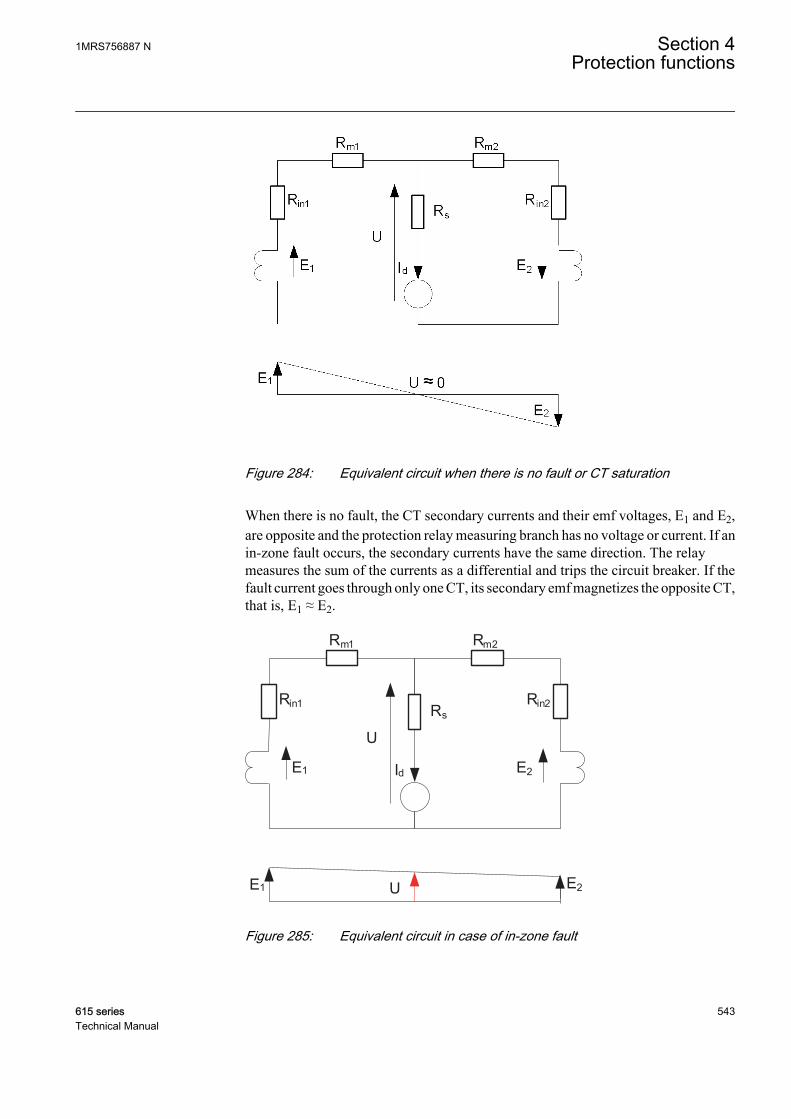
GUID-AE532349-F4F6-4FF9-8A98-0C862162E208 V1 EN
Figure 284: Equivalent circuit when there is no fault or CT saturation
When there is no fault, the CT secondary currents and their emf voltages, E1 and E2,are opposite and the protection relay measuring branch has no voltage or current. If anin-zone fault occurs, the secondary currents have the same direction. The relaymeasures the sum of the currents as a differential and trips the circuit breaker. If thefault current goes through only one CT, its secondary emf magnetizes the opposite CT,that is, E1 ≈ E2.
Id
Rs
Rm1
Rin1 Rin2
Rm2
E1
U
E2
UE1 E2
GUID-CB3CACF7-A2D5-4D76-83B3-44F6AD6D2F9B V1 EN
Figure 285: Equivalent circuit in case of in-zone fault
1MRS756887 N Section 4Protection functions
615 series 543Technical Manual
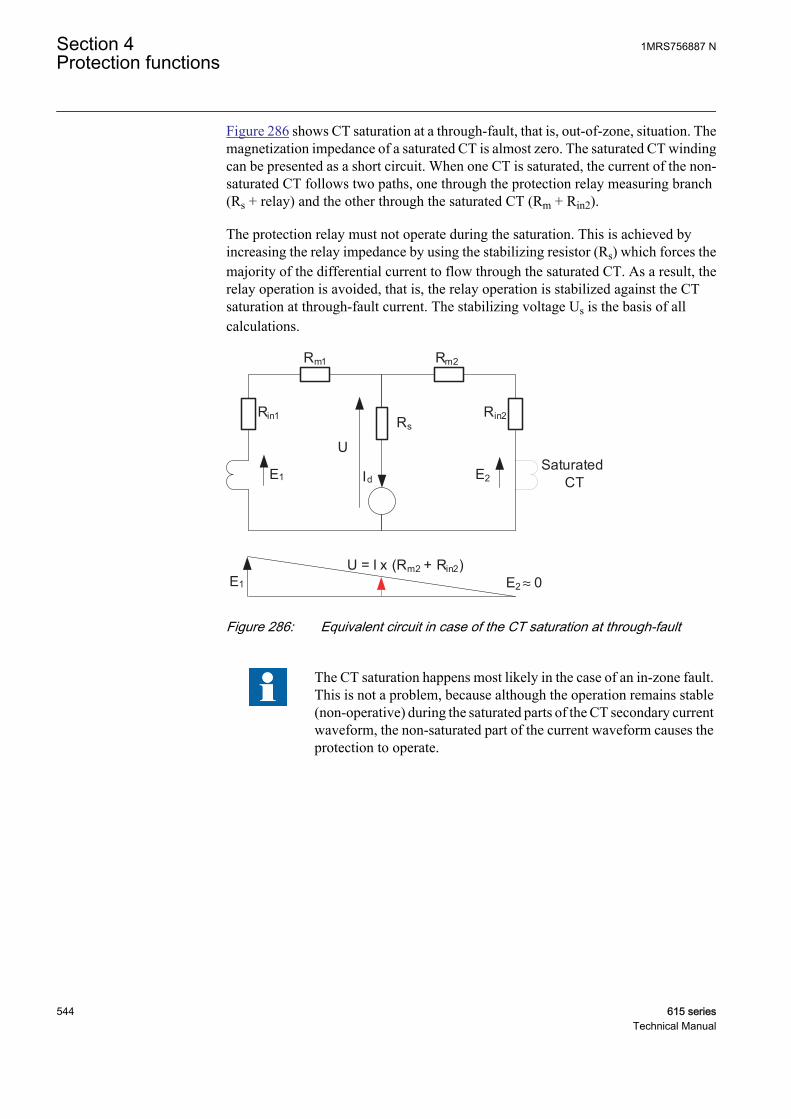
Figure 286 shows CT saturation at a through-fault, that is, out-of-zone, situation. Themagnetization impedance of a saturated CT is almost zero. The saturated CT windingcan be presented as a short circuit. When one CT is saturated, the current of the non-saturated CT follows two paths, one through the protection relay measuring branch(Rs + relay) and the other through the saturated CT (Rm + Rin2).
The protection relay must not operate during the saturation. This is achieved byincreasing the relay impedance by using the stabilizing resistor (Rs) which forces themajority of the differential current to flow through the saturated CT. As a result, therelay operation is avoided, that is, the relay operation is stabilized against the CTsaturation at through-fault current. The stabilizing voltage Us is the basis of allcalculations.
Id
Rs
Rm1
Rin1 Rin2
Rm2
E1
U
E2
U = I x (Rm2 + Rin2)E1 E2 ≈ 0
SaturatedCT
GUID-137DF2DA-9768-4430-8A8E-1986CA9EFD03 V1 EN
Figure 286: Equivalent circuit in case of the CT saturation at through-fault
The CT saturation happens most likely in the case of an in-zone fault.This is not a problem, because although the operation remains stable(non-operative) during the saturated parts of the CT secondary currentwaveform, the non-saturated part of the current waveform causes theprotection to operate.
Section 4 1MRS756887 NProtection functions
544 615 seriesTechnical Manual
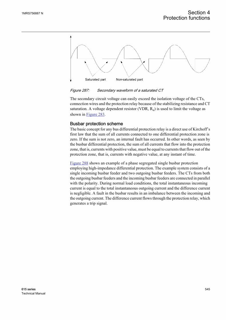
GUID-D8F15382-5E3F-4371-B2AD-936D72941803 V1 EN
Figure 287: Secondary waveform of a saturated CT
The secondary circuit voltage can easily exceed the isolation voltage of the CTs,connection wires and the protection relay because of the stabilizing resistance and CTsaturation. A voltage dependent resistor (VDR, Ru) is used to limit the voltage asshown in Figure 283.
Busbar protection schemeThe basic concept for any bus differential protection relay is a direct use of Kirchoff’sfirst law that the sum of all currents connected to one differential protection zone iszero. If the sum is not zero, an internal fault has occurred. In other words, as seen bythe busbar differential protection, the sum of all currents that flow into the protectionzone, that is, currents with positive value, must be equal to currents that flow out of theprotection zone, that is, currents with negative value, at any instant of time.
Figure 288 shows an example of a phase segregated single busbar protectionemploying high-impedance differential protection. The example system consists of asingle incoming busbar feeder and two outgoing busbar feeders. The CTs from boththe outgoing busbar feeders and the incoming busbar feeders are connected in parallelwith the polarity. During normal load conditions, the total instantaneous incomingcurrent is equal to the total instantaneous outgoing current and the difference currentis negligible. A fault in the busbar results in an imbalance between the incoming andthe outgoing current. The difference current flows through the protection relay, whichgenerates a trip signal.
1MRS756887 N Section 4Protection functions
615 series 545Technical Manual
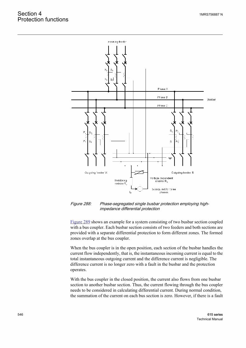
GUID-C5514DFD-9FE8-4BF7-93D8-14186867D0F8 V1 EN
Figure 288: Phase-segregated single busbar protection employing high-impedance differential protection
Figure 289 shows an example for a system consisting of two busbar section coupledwith a bus coupler. Each busbar section consists of two feeders and both sections areprovided with a separate differential protection to form different zones. The formedzones overlap at the bus coupler.
When the bus coupler is in the open position, each section of the busbar handles thecurrent flow independently, that is, the instantaneous incoming current is equal to thetotal instantaneous outgoing current and the difference current is negligible. Thedifference current is no longer zero with a fault in the busbar and the protectionoperates.
With the bus coupler in the closed position, the current also flows from one busbarsection to another busbar section. Thus, the current flowing through the bus couplerneeds to be considered in calculating differential current. During normal condition,the summation of the current on each bus section is zero. However, if there is a fault
Section 4 1MRS756887 NProtection functions
546 615 seriesTechnical Manual

in any busbar section, the difference current is no longer zero and the protectionoperates.
GUID-5F359CB5-4F4F-4803-B5B5-6859F1CB17F5 V1 EN
Figure 289: Differential protection on busbar with bus coupler (Single-phaserepresentation)
4.3.5.6 Example calculations for busbar high-impedance differential protection
The protected object in the example for busbar differential protection is a single-bussystem with two zones of protection.
1MRS756887 N Section 4Protection functions
615 series 547Technical Manual

GUID-A96D78E5-0D17-4CE7-818F-6CB804C7078D V1 EN
Figure 290: Example for busbar differential protection
Bus data:
Un 20 kV
In 2000 A
Ikmax 25 kA
10 feeders per protected zone including bus coupler and incomer.
CT data is assumed to be:
CT 2000/1 A
Rin 15.75 Ω
Ukn 436 V
Ie <7 mA (at Ukn)
Rm 1Ω
Section 4 1MRS756887 NProtection functions
548 615 seriesTechnical Manual
The stabilizing voltage is calculated using the formula:
UA
Vs
= +( ) ≈25000
200015 75 1 209 37. . .Ω Ω
GUID-3911986B-6B0A-4586-BDB7-E7F685E8FF0A V1 EN (Equation 103)
In this case, the requirement for the current transformer knee point voltage is fulfilledbecause Ukn > 2Us.
The magnetizing curve of the CT is assumed to be linear. The magnetizing current atthe stabilizing voltage can be estimated as:
IU
UIm
s
kn
e= ⋅
GUID-C334E82B-9844-4C41-A667-F66B9FF0D860 V2 EN (Equation 104)
IV
VmA mAm = ⋅ ≈
209 37
4367 3 4
..
GUID-F0A8E0D4-C0FE-41CD-A0BA-C0A873F3A402 V2 EN (Equation 105)
To obtain adequate protection stability, the setting current Irs must be at the minimumof the sum of magnetizing currents of all connected CTs.
I mA mArs
= ⋅ ≈10 3 4 34.
GUID-9B9B81AE-DAA9-4D9A-823F-4D239D257E80 V2 EN (Equation 106)
The resistance of the stabilizing resistor is calculated based on Equation 107.
RV
AS
= ≈209 37
0 0346160
.
.Ω
GUID-A240913A-74ED-4A49-8746-182E0F53824F V1 EN (Equation 107)
The calculated value is the maximum value for the stabilizing resistor. If the value isnot available, the next available value below should be selected and the protectionrelay setting current is tuned according to the selected resistor. For example, in thiscase, the resistance value 5900 Ω is used.
IV
mArs
= ≈209 37
590035
.
Ω
GUID-BC97F256-ECDD-432F-B8AE-74AB2769876F V1 EN (Equation 108)
The sensitivity of the protection is obtained as per Equation 109, assuming Iu = 0.
I A A A Aprim
= ⋅ + ⋅ + ≈2000 0 035 10 0 0034 0 140( . . )
GUID-357A9480-16D5-488E-B92C-A6C14FD3708B V2 EN (Equation 109)
The power of the stabilizing resistor is calculated:
PV
W≥ ≈( )436
590032
2
Ω
GUID-28EF2E18-E1A9-4332-B39B-56D3C1141F70 V1 EN (Equation 110)
1MRS756887 N Section 4Protection functions
615 series 549Technical Manual
Based on Equation 111 and Equation 112, the need for voltage-dependent resistor ischecked.
UA
kVmax = + + ≈25000
20005900 15 75 1 00 74 0( . . ) .Ω Ω Ω
GUID-1B91F8BF-62F5-4FE6-A4B4-4FE3AA3DB969 V1 EN (Equation 111)
˘ ( ) .u V V V kV= ⋅ ⋅ ⋅ − ≈2 2 436 74000 436 16 0
GUID-CBD7B53B-1E18-46EA-A6D7-CA3D6D1FDEC2 V2 EN (Equation 112)
The voltage-dependent resistor (one for each phase) is needed in this case as thevoltage during the fault is higher than 2 kV.
The leakage current through the VDR at the stabilizing voltage can be available fromthe VDR manual, assuming that to be approximately 2 mA at stabilizing voltage
Iu A≈0 002.
GUID-5E213E2C-39C4-4BC5-A8B7-514B599B0976 V1 EN (Equation 113)
The sensitivity of the protection can be recalculated taking into account the leakagecurrent through the VDR as per Equation 114.
I A A A Aprim
= ⋅ + ⋅ + ≈2000 0 035 10 0 0034 0 002 142( . . . )
GUID-1C855302-2D84-4B81-8DD8-EC3B1EAE1315 V2 EN (Equation 114)
4.3.5.7 Signals
Table 452: HIAPDIF Input signals
Name Type Default DescriptionI_A SIGNAL 0 Phase A current
BLOCK BOOLEAN 0=False Block signal for activating the blocking mode
Table 453: HIBPDIF Input signals
Name Type Default DescriptionI_B SIGNAL 0 Phase B current
BLOCK BOOLEAN 0=False Block signal for activating the blocking mode
Table 454: HICPDIF Input signals
Name Type Default DescriptionI_C SIGNAL 0 Phase C current
BLOCK BOOLEAN 0=False Block signal for activating the blocking mode
Section 4 1MRS756887 NProtection functions
550 615 seriesTechnical Manual
Table 455: HIAPDIF Output signals
Name Type DescriptionOPERATE BOOLEAN Operate
START BOOLEAN Start
Table 456: HIBPDIF Output signals
Name Type DescriptionOPERATE BOOLEAN Operate
START BOOLEAN Start
Table 457: HICPDIF Output signals
Name Type DescriptionOPERATE BOOLEAN Operate
START BOOLEAN Start
4.3.5.8 Settings
Table 458: HIAPDIF Group settings (Basic)
Parameter Values (Range) Unit Step Default DescriptionOperate value 1.0...200.0 %In 1.0 5.0 Operate value, percentage of the nominal
current
Minimum operate time 20...300000 ms 10 20 Minimum operate time
Table 459: HIAPDIF Non group settings (Basic)
Parameter Values (Range) Unit Step Default DescriptionOperation 1=on
5=off 1=on Operation Off / On
Table 460: HIAPDIF Non group settings (Advanced)
Parameter Values (Range) Unit Step Default DescriptionReset delay time 0...60000 ms 10 20 Reset delay time
Table 461: HIBPDIF Group settings (Basic)
Parameter Values (Range) Unit Step Default DescriptionOperate value 1.0...200.0 %In 1.0 5.0 Operate value, percentage of the nominal
current
Minimum operate time 20...300000 ms 10 20 Minimum operate time
1MRS756887 N Section 4Protection functions
615 series 551Technical Manual

Table 462: HIBPDIF Non group settings (Basic)
Parameter Values (Range) Unit Step Default DescriptionOperation 1=on
5=off 1=on Operation Off / On
Table 463: HIBPDIF Non group settings (Advanced)
Parameter Values (Range) Unit Step Default DescriptionReset delay time 0...60000 ms 10 20 Reset delay time
Table 464: HICPDIF Group settings (Basic)
Parameter Values (Range) Unit Step Default DescriptionOperate value 1.0...200.0 %In 1.0 5.0 Operate value, percentage of the nominal
current
Minimum operate time 20...300000 ms 10 20 Minimum operate time
Table 465: HICPDIF Non group settings (Basic)
Parameter Values (Range) Unit Step Default DescriptionOperation 1=on
5=off 1=on Operation Off / On
Table 466: HICPDIF Non group settings (Advanced)
Parameter Values (Range) Unit Step Default DescriptionReset delay time 0...60000 ms 10 20 Reset delay time
4.3.5.9 Monitored data
Table 467: HIAPDIF Monitored data
Name Type Values (Range) Unit DescriptionSTART_DUR FLOAT32 0.00...100.00 % Ratio of start time /
operate time
HIAPDIF Enum 1=on2=blocked3=test4=test/blocked5=off
Status
Section 4 1MRS756887 NProtection functions
552 615 seriesTechnical Manual

Table 468: HIBPDIF Monitored data
Name Type Values (Range) Unit DescriptionSTART_DUR FLOAT32 0.00...100.00 % Ratio of start time /
operate time
HIBPDIF Enum 1=on2=blocked3=test4=test/blocked5=off
Status
Table 469: HICPDIF Monitored data
Name Type Values (Range) Unit DescriptionSTART_DUR FLOAT32 0.00...100.00 % Ratio of start time /
operate time
HICPDIF Enum 1=on2=blocked3=test4=test/blocked5=off
Status
4.3.5.10 Technical data
Table 470: HIxPDIF Technical data
Characteristic ValueOperation accuracy Depending on the frequency of the current
measured: fn ±2 Hz
±1.5% of the set value or ±0.002 × In
Start time1)2) Minimum Typical Maximum
IFault = 2.0 × set Startvalue
12 ms 16 ms 24 ms
IFault = 10 × set Startvalue
10 ms 12 ms 14 ms
Reset time <40 ms
Reset ratio Typically 0.96
Retardation time <35 ms
Operate time accuracy in definite time mode ±1.0% of the set value or ±20 ms
1) Measurement mode = default (depends on stage), current before fault = 0.0 × In, fn = 50 Hz, fault currentwith nominal frequency injected from random phase angle, results based on statistical distribution of1000 measurements
2) Includes the delay of the signal output contact
4.3.5.11 Technical revision history
Table 471: HIxPDIF Technical revision history
Technical revision ChangeB Function name changed from HIPDIF to HIAPDIF,
HIBPDIF, HICPDIF
1MRS756887 N Section 4Protection functions
615 series 553Technical Manual
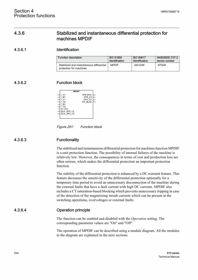
4.3.6 Stabilized and instantaneous differential protection formachines MPDIF
4.3.6.1 Identification
Function description IEC 61850identification
IEC 60617identification
ANSI/IEEE C37.2device number
Stabilized and instantaneous differentialprotection for machines
MPDIF 3dI>G/M 87G/M
4.3.6.2 Function block
GUID-30DCCB1F-FA35-4315-95AC-323B91D1DD46 V1 EN
Figure 291: Function block
4.3.6.3 Functionality
The stabilized and instantaneous differential protection for machines function MPDIFis a unit protection function. The possibility of internal failures of the machine isrelatively low. However, the consequences in terms of cost and production loss areoften serious, which makes the differential protection an important protectionfunction.
The stability of the differential protection is enhanced by a DC restraint feature. Thisfeature decreases the sensitivity of the differential protection optionally for atemporary time period to avoid an unnecessary disconnection of the machine duringthe external faults that have a fault current with high DC currents. MPDIF alsoincludes a CT saturation-based blocking which prevents unnecessary tripping in caseof the detection of the magnetizing inrush currents which can be present at theswitching operations, overvoltages or external faults.
4.3.6.4 Operation principle
The function can be enabled and disabled with the Operation setting. Thecorresponding parameter values are "On" and "Off".
The operation of MPDIF can be described using a module diagram. All the modulesin the diagram are explained in the next sections.
Section 4 1MRS756887 NProtection functions
554 615 seriesTechnical Manual
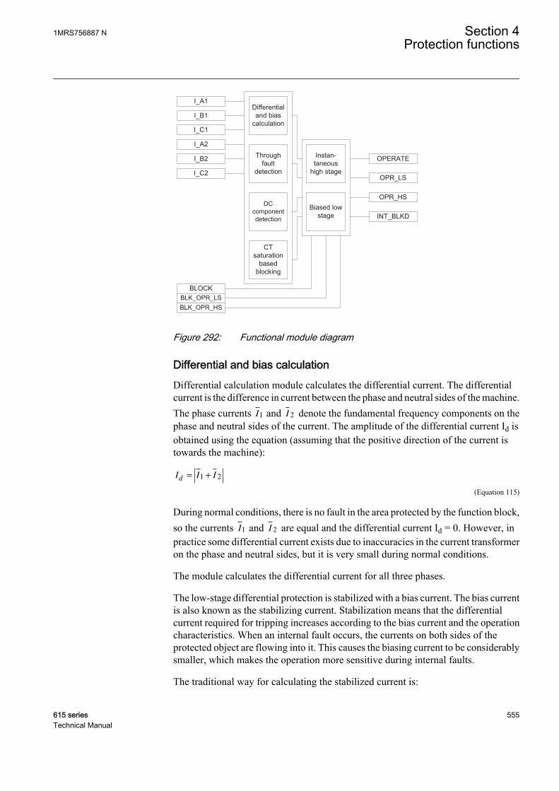
OPR_LS
Through fault
detection
BLK_OPR_LSBLOCK
BLK_OPR_HS
I_A1
I_B1
OPERATE
INT_BLKD
DC component detection
Differential and bias
calculation
OPR_HSBiased low
stage
CT saturation
based blocking
Instan-taneous
high stage
I_C1
I_C2
I_A2
I_B2
GUID-206742C6-5514-41BE-A4F3-2FE0DA9946D5 V1 EN
Figure 292: Functional module diagram
Differential and bias calculationDifferential calculation module calculates the differential current. The differentialcurrent is the difference in current between the phase and neutral sides of the machine.The phase currents I1 and I 2 denote the fundamental frequency components on thephase and neutral sides of the current. The amplitude of the differential current Id isobtained using the equation (assuming that the positive direction of the current istowards the machine):
I I Id = +1 2
GUID-9BC6A743-CA43-407E-8340-7463F15C8128 V1 EN (Equation 115)
During normal conditions, there is no fault in the area protected by the function block,so the currents I1 and I 2 are equal and the differential current Id = 0. However, inpractice some differential current exists due to inaccuracies in the current transformeron the phase and neutral sides, but it is very small during normal conditions.
The module calculates the differential current for all three phases.
The low-stage differential protection is stabilized with a bias current. The bias currentis also known as the stabilizing current. Stabilization means that the differentialcurrent required for tripping increases according to the bias current and the operationcharacteristics. When an internal fault occurs, the currents on both sides of theprotected object are flowing into it. This causes the biasing current to be considerablysmaller, which makes the operation more sensitive during internal faults.
The traditional way for calculating the stabilized current is:
1MRS756887 N Section 4Protection functions
615 series 555Technical Manual
II I
b =−1 2
2
GUID-34FA472E-E419-4A0E-94A3-238D7A3CE5ED V1 EN (Equation 116)
The module calculates the bias current for all three phases.
Through-fault detectionThrough-fault (TF) detection module is for detecting whether the fault is external, thatis, going through, or internal. This information is essential for ensuring the correctoperation of the protection in case of the CT saturation.
• In a through-fault situation, CTs can saturate because of a high fault currentmagnitude. Such AC saturation does not happen immediately when the faultbegins. Thus, the TF module sees the fault as external because the bias current ishigh but the differential current remains low. If the AC saturation then occurs, aCT saturation-based blocking is allowed to work to prevent tripping.
• Normally, the phase angle between the machine neutral and line side CTs is 180degrees. If an internal fault occurs during a through fault, an angle less than 50degrees clearly indicates an internal fault and the TF module overrules, that is,deblocks the presence of any blocking due to CT saturation.
CT saturation-based blockingHigher currents during the motor startup or abnormally high magnetizing currents atan overvoltage (transformer-fed motor) or an external fault may saturate the currenttransformers. The uneven saturation of the star and line side CTs (for example, due toburden differences) may lead to a differential current which can cause a differentialprotection to operate. This module blocks the operation of MPDIF biased low stageinternally in case of the CT saturation. Once the blocking is activated, it is held for acertain time after the blocking conditions have ceased to be fulfilled.
DC component detectionOn detection of a DC component, the function temporarily desensitizes thedifferential protection. The functioning of this module depends on the DC restrainEnable setting. The DC components are continuously extracted from the threeinstantaneous differential currents. The highest DC component of all three is taken asa kind of DC restraint in a sense that the highest effective, temporary sensitivity of theprotection is temporarily decreased as a function of this highest DC offset. Thecalculated DC restraint current is not allowed to decay (from its highest ever measuredvalue) faster than with a time constant of one second. The value of the temporarilyeffective sensitivity limit is limited upwards to the rated current of the machine or 3.3times that of Low operate value, whichever is smaller. The temporary extra limitdecays exponentially from its maximum value with a time constant of one second.
This feature should be used in case of networks where very long time constants areexpected. The temporary sensitivity limit is higher to the set operating characteristics.In other words, the temporary limit has superposed the unchanged operatingcharacteristics and temporarily determines the highest sensitivity of the protection.
Section 4 1MRS756887 NProtection functions
556 615 seriesTechnical Manual
The temporary sensitivity is less than the sensitivity in section 1 of the operatingcharacteristic and is supposed to prevent an unwanted trip during the external faultswith lower currents.
Biased low stageThe current differential protection needs to be biased because of the possibleappearance of a differential current which can be due to something else than an actualfault in the machine. In case of differential protection, a false differential current canbe caused by:
• CT errors• CT saturation at high currents passing through the machine
The differential current caused by CT errors increases at the same percent ratio as theload current.
The high currents passing through the protected object can be caused by the throughfault. Therefore, the operation of the differential protection is biased with respect tothe load current. In the biased differential protection, the higher the differential currentrequired for the protection of operation, the higher the load current.
Based on the conditions checked from the through-fault module, the DC (component)detection module and the CT saturation-based blocking modules, the biased low-stagemodule decides whether the differential current is due to the internal faults or somefalse reason. In case of detection of the TF, DC or CT saturation, the internaldifferential blocking signal is generated, which in turn blocks the operating signal. Incase of internal faults, the operation of the differential protection is affected by the biascurrent.
The Low operate value setting for the stabilized stage of the function block isdetermined with the equation:
Lowoperate value Id= 1
GUID-22A3726A-4B8C-418F-B8C3-D6A5AACD165F V2 EN (Equation 117)
The Slope section 2 and Slope section 3 settings are determined correspondingly:
Slope sectionI
I
d
b
2 1002
2
= ⋅ %
GUID-6707BA3B-6446-4B54-B09B-7D8D1F0DDF32 V1 EN (Equation 118)
Slope sectionI
I
d
b
3 1003
3
= ⋅ %
GUID-ADB22AAC-F1CD-4B6F-B103-E86DBCC8069D V1 EN (Equation 119)
The end of the first section End section 1 can be set at a desired point within the rangeof 0 to 100 percent (or % Ir). Accordingly, the end of the second section End section 2can be set within the range of 100 percent to 300 percent (or % Ir).
1MRS756887 N Section 4Protection functions
615 series 557Technical Manual

The slope of the operating characteristic for the function block varies in different partsof the range.
In section 1, where 0.0 < Ib/In < End section 1, the differential current required fortripping is constant. The value of the differential current is the same as the Low operatevalue setting selected for the function block. The Low operate value setting allows forsmall inaccuracies of the current transformers but it can also be used to influence theoverall level of the operating characteristic.
Section 2, where End section 1 < Ib/In < End section 2, is called the influence area ofthe setting Slope section 2. In this section, variations in End section 2 affect the slopeof the characteristic, that is, how big the change in the differential current required fortripping is in comparison to the change in the load current. The End section 2 settingallows for CT errors.
In section 3, where Ib/In > End section 2, the slope of the characteristic can be set bySlope section 3 that defines the increase in the differential current to the correspondingincrease in the biasing current.
The required differential current for tripping at a certain stabilizing current level canbe calculated using the formulae:
For a stabilizing current lower than End section 1
I I Set Lowoperate valuedoperate r[% ] =
GUID-4FAC8F94-FBB0-47DB-A952-F995889969C6 V2 EN (Equation 120)
For a stabilizing current higher than End section 1 but lower than End section 2
I I Lowoperate value I Ir End section Slopedoperate r b[% ] ( [% ] )= + − ⋅1 ssection 2
GUID-EB0A327A-4079-45A5-87E6-AA30A8D2220C V2 EN (Equation 121)
For higher stabilizing current values exceeding End section 2I I Lowoperate value End section End section Sd operate r[% ] ( )= + − ⋅2 1 llope section I I End section Slope sectionb r2 2 3+ − ⋅( [% ] )
GUID-E9DA330C-84A8-40C2-BCFB-1F7E517395D8 V3 EN (Equation 122)
When the differential current exceeds the operating value determined by the operatingcharacteristics, the OPR_LS output is activated. The OPERATE output is alwaysactivated when the OPR_LS output activates.
The operate signal due to the biased stage can be blocked by the activation of theBLK_OPR_LS or BLOCK input. Also, when the operation of the biased low stage isblocked by the waveform blocking functionality, the INT_BLKD output is activatedaccording to the phase information.
The phase angle difference between the two currents I_A1 and I_A2 is theoretically180 electrical degrees for the external fault and 0 electrical degrees for the internalfault conditions. If the phase angle difference is less than 50 electrical degrees or if thebiasing current drops below 30 percent of the differential current, a fault has most
Section 4 1MRS756887 NProtection functions
558 615 seriesTechnical Manual
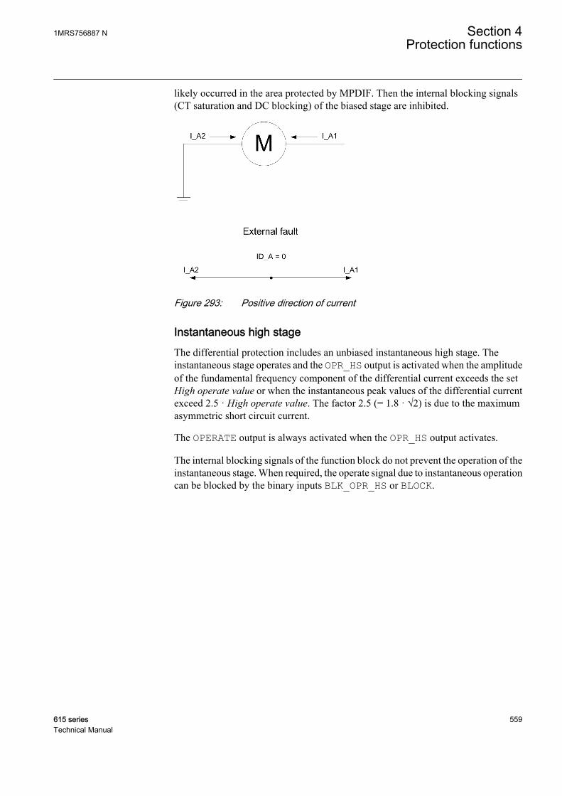
likely occurred in the area protected by MPDIF. Then the internal blocking signals(CT saturation and DC blocking) of the biased stage are inhibited.
GUID-D401D103-BD7C-4096-986F-578925ADB1CC V1 EN
Figure 293: Positive direction of current
Instantaneous high stageThe differential protection includes an unbiased instantaneous high stage. Theinstantaneous stage operates and the OPR_HS output is activated when the amplitudeof the fundamental frequency component of the differential current exceeds the setHigh operate value or when the instantaneous peak values of the differential currentexceed 2.5 · High operate value. The factor 2.5 (= 1.8 · √2) is due to the maximumasymmetric short circuit current.
The OPERATE output is always activated when the OPR_HS output activates.
The internal blocking signals of the function block do not prevent the operation of theinstantaneous stage. When required, the operate signal due to instantaneous operationcan be blocked by the binary inputs BLK_OPR_HS or BLOCK.
1MRS756887 N Section 4Protection functions
615 series 559Technical Manual

GUID-F2067FFD-43A7-478E-8C9F-4E73043141D2 V1 EN
Figure 294: Operating characteristic for the stabilized stage of the generatordifferential protection function
4.3.6.5 Application
The differential protection works on the principle of calculating the differentialcurrent at the two ends of the winding, that is, the current entering the winding iscompared to the current exiting the winding. In case of any internal fault, the currentsentering and exiting the winding are different, which results in a differential current,which is then used as a base for generating the operating signal. Due to this principle,the differential protection does not trip during external faults. However, it should benoted that interturn faults in the same phase are usually not detected unless theydeveloped into some other kind of fault.
The short circuit between the phases of the stator windings normally causes large faultcurrents. The short circuit creates a risk of damages to the insulation, windings andstator core. The large short circuit currents cause large current forces which candamage other components in the machine. The short circuit can also initiate explosionand fire. When a short circuit occurs in a machine, there is a damage that has to berepaired. The severity and the repair time depend on the degree of damage, which ishighly dependent on the fault time. The fast fault clearance of this fault type is ofgreatest importance to limit the damages and the economic loss.
To limit the damages in connection to the stator winding short circuits, the faultclearance time must be as short as possible (instantaneous). The fault current
Section 4 1MRS756887 NProtection functions
560 615 seriesTechnical Manual

contributions from both the external power system (via the machine or the blockcircuit breaker) and from the machine itself must be disconnected as fast as possible.
The DC restraint feature should be used in case of an application with a long DC timeconstant in the fault currents is present. This fault current may be of a lesser magnitude(less than rated current) but is unpleasant and tends to saturate the CT and operate thedifferential protection for external faults. This feature is effective at moderatethrough-currents and ineffective at higher through-currents.
Although the short circuit fault current is normally very large, that is, significantlylarger than the rated current of the machine, it is possible that a short circuit can occurbetween phases close to the neutral point of the machine, causing a relatively smallfault current. The fault current fed from the synchronous machine can also be limiteddue to a low excitation of the synchronous generator. This is normally the case at therun-up of the synchronous machine, before synchronization to the network.Therefore, it is desired that the detection of the machine phase-to-phase short circuitsshall be relatively sensitive, thus detecting the small fault currents.
It is also important that the machine short circuit protection does not trip for externalfaults when a large fault current is fed from the machine. To combine fast faultclearance, sensitivity and selectivity, the machine current differential protection isnormally the best alternative for the phase-to-phase short circuits.
The risk of an unwanted differential protection operation caused by the currenttransformer saturation is a universal differential protection problem. If a bigsynchronous machine is tripped in connection to an external short circuit, it gives anincreased risk of a power system collapse. Besides, there is a production loss for everyunwanted trip of the machine. Therefore, preventing the unwanted disconnection ofmachines has a great economical value.
Recommendations for current transformersThe more important the object to be protected is, the more attention is paid to thecurrent transformers. It is not normally possible to dimension the current transformersso that they repeat the currents with high DC components without saturating when theresidual flux of the current transformer is high. The differential protection functionblock operates reliably even though the current transformers are partially saturated.
The accuracy class recommended for current transformers to be used with thedifferential function block is 5P, in which the limit of the current error at the ratedprimary current is 1 percent and the limit of the phase displacement is 60 minutes. Thelimit of the composite error at the rated accuracy limit primary current is 5 percent.
The approximate value of the actual accuracy limit factor Fa corresponding to theactual CT burden can be calculated on the basis of the rated accuracy limit factor Fn(ALF) at the rated burden, the rated burden Sn, the internal burden Sin and the actualburden Sa of the current transformer.
1MRS756887 N Section 4Protection functions
615 series 561Technical Manual
F FS S
S Sa n
in n
in a
= ×+
+
GUID-8EFD1AED-A804-45DD-963F-D453A6B3D782 V2 EN (Equation 123)
Example 1The rated burden Sn of the current transformer 5P20 is 10 VA, the secondary ratedcurrent 5A, the internal resistance Rin = 0.07 Ω and the rated accuracy limit factor Fncorresponding to the rated burden is 20 (5P20). The internal burden of the currenttransformer is Sin = (5A)² × 0.07 Ω = 1.75 VA. The input impedance of the protectionrelay at a rated current of 5A is < 20 mΩ. If the measurement conductors have aresistance of 0.113 Ω, the actual burden of the current transformer is Sa = (5A)² ×(0.113 + 0.020) Ω = 3.33 VA. Thus, the accuracy limit factor Fa corresponding to theactual burden is about 46.
The CT burden can grow considerably at the rated current 5A. The actual burden of thecurrent transformer decreases at the rated current of 1 A while the repeatabilitysimultaneously improves.
At faults occurring in the protected area, the fault currents can be very high comparedto the rated currents of the current transformers. Due to the instantaneous stage of thedifferential function block, it is sufficient that the current transformers are capable ofrepeating the current required for an instantaneous tripping during the first cycle.
Thus the current transformers usually are able to reproduce the asymmetric faultcurrent without saturating within the next 10 ms after the occurrence of the fault tosecure the operating times of the protection relay comply with the retardation time.
The accuracy limit factors corresponding to the actual burden of the phase currenttransformer to be used in differential protection must fulfill the requirement:
F K Ik T ea r dc
Tm
Tdc> × × × × − +
−
max ( ( ) )ω 1 1
GUID-21C442C8-79F8-411A-829A-1980BC5D1A2E V2 EN (Equation 124)
Ikmax The maximum through-going fault current (in IR) at which the protection is not allowed to operate
Tdc The primary DC time constant related to Ikmax
ω The angular frequency, that is, 2 x π x fn
Tm The time to saturate, that is, the duration of the saturation-free transformation
Kr The remanence factor 1/(1-r), where r is the maximum remanence flux in pu from the saturationflux
The parameter r is the maximum remanence flux density in the CT core in pu from thesaturation flux density. The value of the parameter r depends on the magnetic materialused and also on the construction of the CT. For instance, if the value r = 0.4, theremanence flux density can be 40 percent of the saturation flux density. Themanufacturer of the CT has to be contacted when an accurate value for the parameter
Section 4 1MRS756887 NProtection functions
562 615 seriesTechnical Manual

r is needed. The value r = 0.4 is recommended to be used when an accurate value is notavailable.
The required minimum time-to-saturate Tm in MPDIF is half-fundamental cycleperiod (10 ms when fn = 50 Hz).
Two typical cases are considered for the determination of the sufficient actualaccuracy limit factor Fa:
1. A fault occurring at the substation bus. The protection must be stable at a fault arising during a normal operatingsituation. The reenergizing of the transformer against a bus fault leads to veryhigh fault currents and thermal stress. Therefore, reenergizing is not preferred inthis case. The remanence can be neglected.The maximum through-going fault current Ikmax is typically 6 IR for a motor. Ata short circuit fault close to the supply transformer, the DC time constant Tdc ofthe fault current is almost the same as that of the transformer, the typical valuebeing 100 ms.
Ikmax = 6 IR
Tdc = 100 ms
ω = 100π Hz
Tm = 10 ms
Kr = 1
Equation 124 with these values gives the result:
F K Ik T ea r dc
Tm
Tdc> × × × × − + ≈
−
max ( ( ) )ω 1 1 24
GUID-C510CA46-3857-40D3-B40A-3C237BCE6E79 V2 EN
2. Reenergizing against a fault occurring further down in the network. The protection must be stable also during reenergization against a fault on theline. In this case, the existence of remanence is very probable. It is assumed to be40 percent here.On the other hand, the fault current is now smaller and since the ratio of theresistance and reactance is greater in this location, having a full DC offset is notpossible. Furthermore, the DC time constant (Tdc) of the fault current is nowsmaller, assumed to be 50 ms here.Assuming the maximum fault current is 30 percent lower than in the bus fault anda DC offset 90 percent of the maximum.
Ikmax = 0.7 × 6 = 4.2 (IR)
Tdc = 50 ms
ω = 100π Hz
1MRS756887 N Section 4Protection functions
615 series 563Technical Manual

Tm = 10 ms
Kr = 1/(1-0.4) = 1.6667
Equation 124 with these values gives the result:
F K Ik T ea r dc
Tm
Tdc> × × × × × − + ≈
−
max . ( ( ) )0 9 1 1 24ω
GUID-46A4591B-876D-4E32-A9AB-29F6C1657644 V2 EN
If the actual burden of the current transformer Sa in the accuracy limit factor equationcannot be reduced low enough to provide a sufficient value for Fa, there are twoalternatives to deal with the situation.
1. A current transformer with a higher rated burden Sn can be chosen (which alsomeans a higher rated accurate limit Fn).
2. A current transformer with a higher nominal primary current I1n (but the samerated burden) can be chosen.
Alternative 2 is more cost-effective and therefore often better, although the sensitivityof the scheme is slightly reduced.
Example 2Here the actions according to alternative 2 are taken to improve the actual accuracylimit factor.
FI CT
I MotorFa
R
R
n=
×
GUID-560620F9-50B1-4DA4-AF3F-2B24212080D9 V2 EN (Equation 125)
IRCT rated primary current of the CT, for example, 1500A
IRMotor rated current of the motor under protection, for example, 1000A
Fn rated accuracy limit factor of the CT, for example, 30
Fa actual accuracy limit factor due to oversizing the CT, substituting the values in the equation, Fa= 45
In differential protection it is important that the accuracy limit factors Fa of the phasecurrent transformers at both sides correspond with each other, that is, the burdens ofthe current transformers on both sides are to be as close to each other as possible. Ifhigh inrush or start currents with high DC components pass through the protectedobject when it is connected to the network, special attention is required for theperformance and the burdens of the current transformers and the settings of thefunction block.
Section 4 1MRS756887 NProtection functions
564 615 seriesTechnical Manual
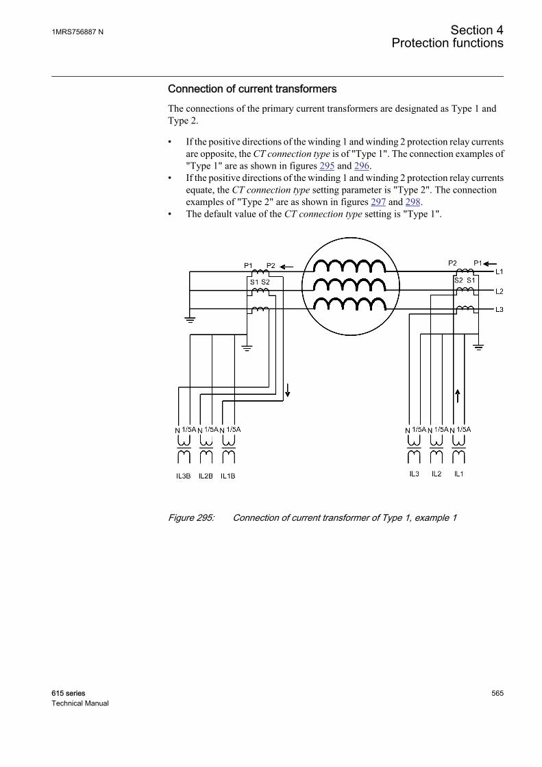
Connection of current transformersThe connections of the primary current transformers are designated as Type 1 andType 2.
• If the positive directions of the winding 1 and winding 2 protection relay currentsare opposite, the CT connection type is of "Type 1". The connection examples of"Type 1" are as shown in figures 295 and 296.
• If the positive directions of the winding 1 and winding 2 protection relay currentsequate, the CT connection type setting parameter is "Type 2". The connectionexamples of "Type 2" are as shown in figures 297 and 298.
• The default value of the CT connection type setting is "Type 1".
GUID-A6716146-6ECD-46A2-B2AC-4408DDDB7BF6 V2 EN
Figure 295: Connection of current transformer of Type 1, example 1
1MRS756887 N Section 4Protection functions
615 series 565Technical Manual

GUID-B3AC7F1B-4714-41B2-9DF9-49BF99BA6123 V1 EN
Figure 296: Connection of current transformer of Type 1, example 2
Section 4 1MRS756887 NProtection functions
566 615 seriesTechnical Manual
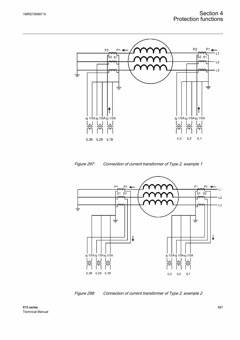
GUID-20C85C2F-B738-4E5A-ACE1-7B30EC9799E2 V2 EN
Figure 297: Connection of current transformer of Type 2, example 1
GUID-045822E0-C4AF-4C36-89C0-670D6AF85919 V1 EN
Figure 298: Connection of current transformer of Type 2, example 2
1MRS756887 N Section 4Protection functions
615 series 567Technical Manual
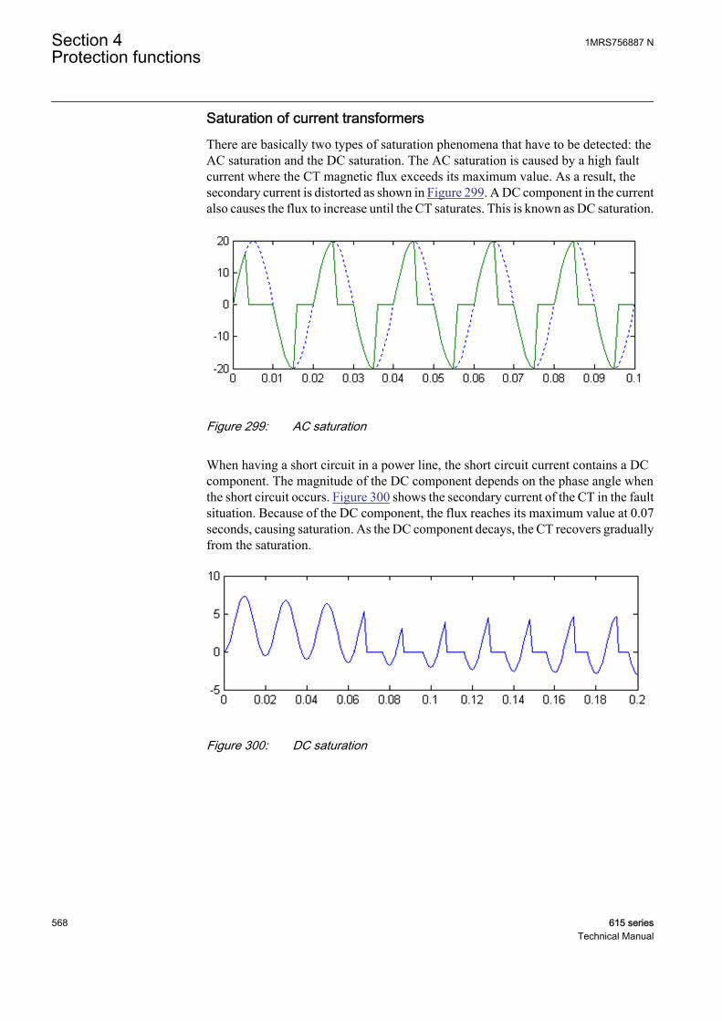
Saturation of current transformersThere are basically two types of saturation phenomena that have to be detected: theAC saturation and the DC saturation. The AC saturation is caused by a high faultcurrent where the CT magnetic flux exceeds its maximum value. As a result, thesecondary current is distorted as shown in Figure 299. A DC component in the currentalso causes the flux to increase until the CT saturates. This is known as DC saturation.
GUID-0A569D8E-6A69-43F1-848B-6AA364E130B7 V1 EN
Figure 299: AC saturation
When having a short circuit in a power line, the short circuit current contains a DCcomponent. The magnitude of the DC component depends on the phase angle whenthe short circuit occurs. Figure 300 shows the secondary current of the CT in the faultsituation. Because of the DC component, the flux reaches its maximum value at 0.07seconds, causing saturation. As the DC component decays, the CT recovers graduallyfrom the saturation.
GUID-505C1447-5FA4-43B7-8AD7-9E2449CC10C3 V1 EN
Figure 300: DC saturation
Section 4 1MRS756887 NProtection functions
568 615 seriesTechnical Manual
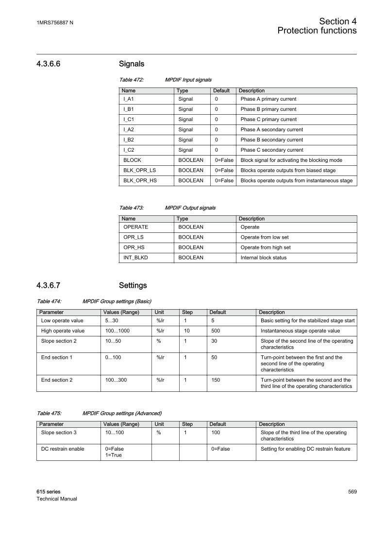
4.3.6.6 Signals
Table 472: MPDIF Input signals
Name Type Default DescriptionI_A1 Signal 0 Phase A primary current
I_B1 Signal 0 Phase B primary current
I_C1 Signal 0 Phase C primary current
I_A2 Signal 0 Phase A secondary current
I_B2 Signal 0 Phase B secondary current
I_C2 Signal 0 Phase C secondary current
BLOCK BOOLEAN 0=False Block signal for activating the blocking mode
BLK_OPR_LS BOOLEAN 0=False Blocks operate outputs from biased stage
BLK_OPR_HS BOOLEAN 0=False Blocks operate outputs from instantaneous stage
Table 473: MPDIF Output signals
Name Type DescriptionOPERATE BOOLEAN Operate
OPR_LS BOOLEAN Operate from low set
OPR_HS BOOLEAN Operate from high set
INT_BLKD BOOLEAN Internal block status
4.3.6.7 Settings
Table 474: MPDIF Group settings (Basic)
Parameter Values (Range) Unit Step Default DescriptionLow operate value 5...30 %Ir 1 5 Basic setting for the stabilized stage start
High operate value 100...1000 %Ir 10 500 Instantaneous stage operate value
Slope section 2 10...50 % 1 30 Slope of the second line of the operatingcharacteristics
End section 1 0...100 %Ir 1 50 Turn-point between the first and thesecond line of the operatingcharacteristics
End section 2 100...300 %Ir 1 150 Turn-point between the second and thethird line of the operating characteristics
Table 475: MPDIF Group settings (Advanced)
Parameter Values (Range) Unit Step Default DescriptionSlope section 3 10...100 % 1 100 Slope of the third line of the operating
characteristics
DC restrain enable 0=False1=True
0=False Setting for enabling DC restrain feature
1MRS756887 N Section 4Protection functions
615 series 569Technical Manual

Table 476: MPDIF Non group settings (Basic)
Parameter Values (Range) Unit Step Default DescriptionOperation 1=on
5=off 1=on Operation Off / On
CT connection type 1=Type 12=Type 2
1=Type 1 CT connection type. Determined by thedirections of the connected currenttransformers
CT ratio Cor Line 0.40...4.00 0.01 1.00 CT ratio correction, line side
CT ratio Cor Neut 0.40...4.00 0.01 1.00 CT ratio correction, neutral side
4.3.6.8 Monitored data
Table 477: MPDIF Monitored data
Name Type Values (Range) Unit DescriptionOPR_A BOOLEAN 0=False
1=True Operate phase A
OPR_B BOOLEAN 0=False1=True
Operate phase B
OPR_C BOOLEAN 0=False1=True
Operate phase C
INT_BLKD_A BOOLEAN 0=False1=True
Internal block statusphase A
INT_BLKD_B BOOLEAN 0=False1=True
Internal block statusphase B
INT_BLKD_C BOOLEAN 0=False1=True
Internal block statusphase C
ID_A FLOAT32 0.00...80.00 xIr Differential current phaseA
ID_B FLOAT32 0.00...80.00 xIr Differential current phaseB
ID_C FLOAT32 0.00...80.00 xIr Differential current phaseC
IB_A FLOAT32 0.00...80.00 xIr Biasing current phase A
IB_B FLOAT32 0.00...80.00 xIr Biasing current phase B
IB_C FLOAT32 0.00...80.00 xIr Biasing current phase C
I_ANGL_A1_B1 FLOAT32 -180.00...180.00 deg Current phase anglephase A to B, line side
I_ANGL_B1_C1 FLOAT32 -180.00...180.00 deg Current phase anglephase B to C, line side
I_ANGL_C1_A1 FLOAT32 -180.00...180.00 deg Current phase anglephase C to A, line side
I_ANGL_A2_B2 FLOAT32 -180.00...180.00 deg Current phase anglephase A to B, neutral side
I_ANGL_B2_C2 FLOAT32 -180.00...180.00 deg Current phase anglephase B to C, neutral side
I_ANGL_C2_A2 FLOAT32 -180.00...180.00 deg Current phase anglephase C to A, neutral side
Table continues on next page
Section 4 1MRS756887 NProtection functions
570 615 seriesTechnical Manual

Name Type Values (Range) Unit DescriptionI_ANGL_A1_A2 FLOAT32 -180.00...180.00 deg Current phase angle diff
between line and neutralside, Phase A
I_ANGL_B1_B2 FLOAT32 -180.00...180.00 deg Current phase angle diffbetween line and neutralside, Phase B
I_ANGL_C1_C2 FLOAT32 -180.00...180.00 deg Current phase angle diffbetween line and neutralside, Phase C
MPDIF Enum 1=on2=blocked3=test4=test/blocked5=off
Status
IL1-diff FLOAT32 0.00...80.00 Measured differentialcurrent amplitude phaseIL1
IL2-diff FLOAT32 0.00...80.00 Measured differentialcurrent amplitude phaseIL2
IL3-diff FLOAT32 0.00...80.00 Measured differentialcurrent amplitude phaseIL3
IL1-bias FLOAT32 0.00...80.00 Measured bias currentamplitude phase IL1
IL2-bias FLOAT32 0.00...80.00 Measured bias currentamplitude phase IL2
IL3-bias FLOAT32 0.00...80.00 Measured bias currentamplitude phase IL3
4.3.6.9 Technical data
Table 478: MPDIF Technical data
Characteristic ValueOperation accuracy Depending on the frequency of the current
measured: fn ±2 Hz
±3% of the set value or ±0.002 x In
Operate time 1)2) Minimum Typical Maximum
Low stage 36 ms 40 ms 42 ms
High stage 18 ms 22 ms 27 ms
Reset time <40 ms
Reset ratio Typically 0.95
Retardation time <20 ms
1) Fn = 50 Hz, results based on statistical distribution of 1000 measurements2) Includes the delay of the power output contact
1MRS756887 N Section 4Protection functions
615 series 571Technical Manual
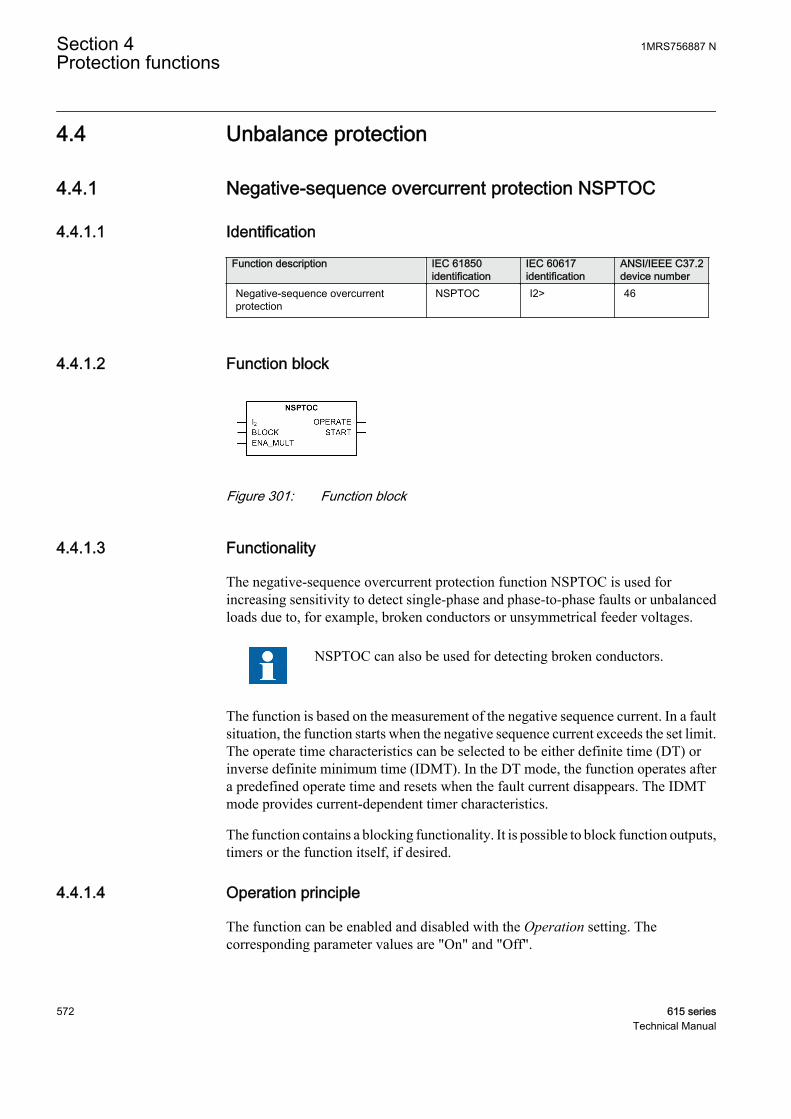
4.4 Unbalance protection
4.4.1 Negative-sequence overcurrent protection NSPTOC
4.4.1.1 Identification
Function description IEC 61850identification
IEC 60617identification
ANSI/IEEE C37.2device number
Negative-sequence overcurrentprotection
NSPTOC I2> 46
4.4.1.2 Function block
A070758 V1 EN
Figure 301: Function block
4.4.1.3 Functionality
The negative-sequence overcurrent protection function NSPTOC is used forincreasing sensitivity to detect single-phase and phase-to-phase faults or unbalancedloads due to, for example, broken conductors or unsymmetrical feeder voltages.
NSPTOC can also be used for detecting broken conductors.
The function is based on the measurement of the negative sequence current. In a faultsituation, the function starts when the negative sequence current exceeds the set limit.The operate time characteristics can be selected to be either definite time (DT) orinverse definite minimum time (IDMT). In the DT mode, the function operates aftera predefined operate time and resets when the fault current disappears. The IDMTmode provides current-dependent timer characteristics.
The function contains a blocking functionality. It is possible to block function outputs,timers or the function itself, if desired.
4.4.1.4 Operation principle
The function can be enabled and disabled with the Operation setting. Thecorresponding parameter values are "On" and "Off".
Section 4 1MRS756887 NProtection functions
572 615 seriesTechnical Manual

The operation of NSPTOC can be described using a module diagram. All the modulesin the diagram are explained in the next sections.
A070660 V1 EN
Figure 302: Functional module diagram
Level detectorThe measured negative-sequence current is compared to the set Start value. If themeasured value exceeds the set Start value, the level detector activates the timermodule. If the ENA_MULT input is active, the set Start value is multiplied by the setStart value Mult.
The protection relay does not accept the Start value or Start value Multsetting if the product of the settings exceeds the Start value settingrange.
TimerOnce activated, the timer activates the START output. Depending on the value of theOperating curve type setting, the time characteristics are according to DT or IDMT.When the operation timer has reached the value of Operate delay time in the DT modeor the maximum value defined by the inverse time curve, the OPERATE output isactivated.
When the user-programmable IDMT curve is selected, the operation timecharacteristics are defined by the parameters Curve parameter A, Curve parameter B,Curve parameter C, Curve parameter D and Curve parameter E.
If a drop-off situation happens, that is, a fault suddenly disappears before the operatedelay is exceeded, the timer reset state is activated. The functionality of the timer inthe reset state depends on the combination of the Operating curve type, Type of resetcurve and Reset delay time settings. When the DT characteristic is selected, the resettimer runs until the set Reset delay time value is exceeded. When the IDMT curves areselected, the Type of reset curve setting can be set to "Immediate", "Def time reset" or"Inverse reset". The reset curve type "Immediate" causes an immediate reset. With thereset curve type "Def time reset", the reset time depends on the Reset delay timesetting. With the reset curve type "Inverse reset", the reset time depends on the currentduring the drop-off situation. The START output is deactivated when the reset timerhas elapsed.
1MRS756887 N Section 4Protection functions
615 series 573Technical Manual
The "Inverse reset" selection is only supported with ANSI or userprogrammable types of the IDMT operating curves. If anotheroperating curve type is selected, an immediate reset occurs during thedrop-off situation.
The setting Time multiplier is used for scaling the IDMT operate and reset times.
The setting parameter Minimum operate time defines the minimum desired operatetime for IDMT. The setting is applicable only when the IDMT curves are used.
The Minimum operate time setting should be used with great carebecause the operation time is according to the IDMT curve, but alwaysat least the value of the Minimum operate time setting. For moreinformation, see the IDMT curves for overcurrent protection sectionin this manual.
The timer calculates the start duration value START_DUR, which indicates thepercentage ratio of the start situation and the set operating time. The value is availablein the monitored data view.
Blocking logicThere are three operation modes in the blocking function. The operation modes arecontrolled by the BLOCK input and the global setting in Configuration/System/Blocking mode which selects the blocking mode. The BLOCK input can be controlledby a binary input, a horizontal communication input or an internal signal of theprotection relay's program. The influence of the BLOCK signal activation ispreselected with the global setting Blocking mode.
The Blocking mode setting has three blocking methods. In the "Freeze timers" mode,the operation timer is frozen to the prevailing value, but the OPERATE output is notdeactivated when blocking is activated. In the "Block all" mode, the whole function isblocked and the timers are reset. In the "Block OPERATE output" mode, the functionoperates normally but the OPERATE output is not activated.
4.4.1.5 Application
Since the negative sequence current quantities are not present during normal, balancedload conditions, the negative sequence overcurrent protection elements can be set forfaster and more sensitive operation than the normal phase-overcurrent protection forfault conditions occurring between two phases. The negative sequence overcurrentprotection also provides a back-up protection functionality for the feeder earth-faultprotection in solid and low resistance earthed networks.
The negative sequence overcurrent protection provides the back-up earth-faultprotection on the high voltage side of a delta-wye connected power transformer forearth faults taking place on the wye-connected low voltage side. If an earth fault
Section 4 1MRS756887 NProtection functions
574 615 seriesTechnical Manual
occurs on the wye-connected side of the power transformer, negative sequence currentquantities appear on the delta-connected side of the power transformer.
The most common application for the negative sequence overcurrent protection isprobably rotating machines, where negative sequence current quantities indicateunbalanced loading conditions (unsymmetrical voltages). Unbalanced loadingnormally causes extensive heating of the machine and can result in severe damageseven over a relatively short time period.
Multiple time curves and time multiplier settings are also available for coordinatingwith other devices in the system.
4.4.1.6 Signals
Table 479: NSPTOC Input signals
Name Type Default DescriptionI2 SIGNAL 0 Negative phase sequence current
BLOCK BOOLEAN 0=False Block signal for activating the blocking mode
ENA_MULT BOOLEAN 0=False Enable signal for current multiplier
Table 480: NSPTOC Output signals
Name Type DescriptionOPERATE BOOLEAN Operate
START BOOLEAN Start
1MRS756887 N Section 4Protection functions
615 series 575Technical Manual
4.4.1.7 Settings
Table 481: NSPTOC Group settings (Basic)
Parameter Values (Range) Unit Step Default DescriptionStart value 0.01...5.00 xIn 0.01 0.30 Start value
Start value Mult 0.8...10.0 0.1 1.0 Multiplier for scaling the start value
Time multiplier 0.05...15.00 0.01 1.00 Time multiplier in IEC/ANSI IDMT curves
Operate delay time 40...200000 ms 10 40 Operate delay time
Operating curve type 1=ANSI Ext. inv.2=ANSI Very inv.3=ANSI Norm. inv.4=ANSI Mod. inv.5=ANSI Def. Time6=L.T.E. inv.7=L.T.V. inv.8=L.T. inv.9=IEC Norm. inv.10=IEC Very inv.11=IEC inv.12=IEC Ext. inv.13=IEC S.T. inv.14=IEC L.T. inv.15=IEC Def. Time17=Programmable18=RI type19=RD type
15=IEC Def. Time Selection of time delay curve type
Table 482: NSPTOC Group settings (Advanced)
Parameter Values (Range) Unit Step Default DescriptionType of reset curve 1=Immediate
2=Def time reset3=Inverse reset
1=Immediate Selection of reset curve type
Table 483: NSPTOC Non group settings (Basic)
Parameter Values (Range) Unit Step Default DescriptionOperation 1=on
5=off 1=on Operation Off / On
Curve parameter A 0.0086...120.0000 1 28.2000 Parameter A for customer programmablecurve
Curve parameter B 0.0000...0.7120 1 0.1217 Parameter B for customer programmablecurve
Curve parameter C 0.02...2.00 1 2.00 Parameter C for customer programmablecurve
Curve parameter D 0.46...30.00 1 29.10 Parameter D for customer programmablecurve
Curve parameter E 0.0...1.0 1 1.0 Parameter E for customer programmablecurve
Section 4 1MRS756887 NProtection functions
576 615 seriesTechnical Manual
Table 484: NSPTOC Non group settings (Advanced)
Parameter Values (Range) Unit Step Default DescriptionMinimum operate time 20...60000 ms 1 20 Minimum operate time for IDMT curves
Reset delay time 0...60000 ms 1 20 Reset delay time
4.4.1.8 Monitored data
Table 485: NSPTOC Monitored data
Name Type Values (Range) Unit DescriptionSTART_DUR FLOAT32 0.00...100.00 % Ratio of start time /
operate time
NSPTOC Enum 1=on2=blocked3=test4=test/blocked5=off
Status
4.4.1.9 Technical data
Table 486: NSPTOC Technical data
Characteristic ValueOperation accuracy Depending on the frequency of the measured
current: fn
±1.5% of the set value or ±0.002 × In
Start time 1)2) Minimum Typical Maximum
IFault = 2 × set StartvalueIFault = 10 × set Startvalue
23 ms15 ms
26 ms18 ms
28 ms20 ms
Reset time Typically 40 ms
Reset ratio Typically 0.96
Retardation time <35 ms
Operate time accuracy in definite time mode ±1.0% of the set value or ±20 ms
Operate time accuracy in inverse time mode ±5.0% of the theoretical value or ±20 ms 3)
Suppression of harmonics DFT: -50 dB at f = n × fn, where n = 2, 3, 4, 5,…
1) Negative sequence current before fault = 0.0, fn = 50 Hz, results based on statistical distribution of 1000measurements
2) Includes the delay of the signal output contact3) Maximum Start value = 2.5 × In, Start value multiples in range of 1.5...20
1MRS756887 N Section 4Protection functions
615 series 577Technical Manual
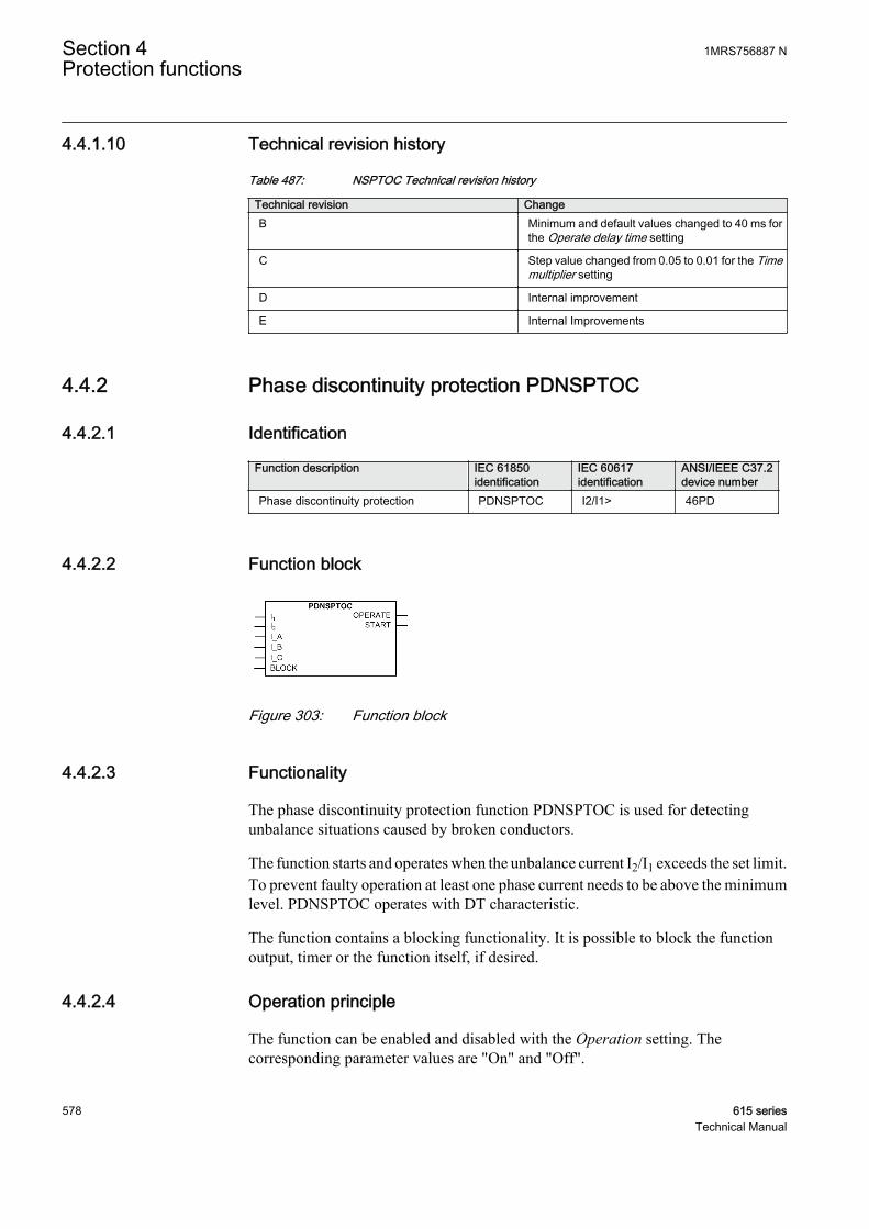
4.4.1.10 Technical revision history
Table 487: NSPTOC Technical revision history
Technical revision ChangeB Minimum and default values changed to 40 ms for
the Operate delay time setting
C Step value changed from 0.05 to 0.01 for the Timemultiplier setting
D Internal improvement
E Internal Improvements
4.4.2 Phase discontinuity protection PDNSPTOC
4.4.2.1 Identification
Function description IEC 61850identification
IEC 60617identification
ANSI/IEEE C37.2device number
Phase discontinuity protection PDNSPTOC I2/I1> 46PD
4.4.2.2 Function block
A070688 V1 EN
Figure 303: Function block
4.4.2.3 Functionality
The phase discontinuity protection function PDNSPTOC is used for detectingunbalance situations caused by broken conductors.
The function starts and operates when the unbalance current I2/I1 exceeds the set limit.To prevent faulty operation at least one phase current needs to be above the minimumlevel. PDNSPTOC operates with DT characteristic.
The function contains a blocking functionality. It is possible to block the functionoutput, timer or the function itself, if desired.
4.4.2.4 Operation principle
The function can be enabled and disabled with the Operation setting. Thecorresponding parameter values are "On" and "Off".
Section 4 1MRS756887 NProtection functions
578 615 seriesTechnical Manual
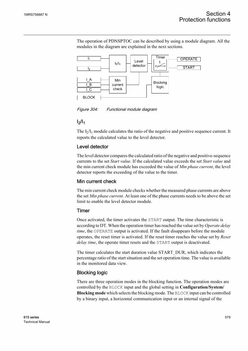
The operation of PDNSPTOC can be described by using a module diagram. All themodules in the diagram are explained in the next sections.
A070687 V2 EN
Figure 304: Functional module diagram
I2/I1The I2/I1 module calculates the ratio of the negative and positive sequence current. Itreports the calculated value to the level detector.
Level detectorThe level detector compares the calculated ratio of the negative and positive-sequencecurrents to the set Start value. If the calculated value exceeds the set Start value andthe min current check module has exceeded the value of Min phase current, the leveldetector reports the exceeding of the value to the timer.
Min current checkThe min current check module checks whether the measured phase currents are abovethe set Min phase current. At least one of the phase currents needs to be above the setlimit to enable the level detector module.
TimerOnce activated, the timer activates the START output. The time characteristic isaccording to DT. When the operation timer has reached the value set by Operate delaytime, the OPERATE output is activated. If the fault disappears before the moduleoperates, the reset timer is activated. If the reset timer reaches the value set by Resetdelay time, the operate timer resets and the START output is deactivated.
The timer calculates the start duration value START_DUR, which indicates thepercentage ratio of the start situation and the set operation time. The value is availablein the monitored data view.
Blocking logicThere are three operation modes in the blocking function. The operation modes arecontrolled by the BLOCK input and the global setting in Configuration/System/Blocking mode which selects the blocking mode. The BLOCK input can be controlledby a binary input, a horizontal communication input or an internal signal of the
1MRS756887 N Section 4Protection functions
615 series 579Technical Manual
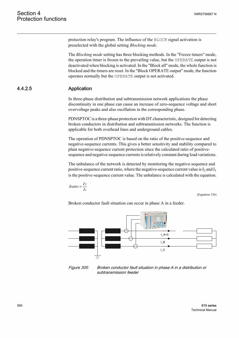
protection relay's program. The influence of the BLOCK signal activation ispreselected with the global setting Blocking mode.
The Blocking mode setting has three blocking methods. In the "Freeze timers" mode,the operation timer is frozen to the prevailing value, but the OPERATE output is notdeactivated when blocking is activated. In the "Block all" mode, the whole function isblocked and the timers are reset. In the "Block OPERATE output" mode, the functionoperates normally but the OPERATE output is not activated.
4.4.2.5 Application
In three-phase distribution and subtransmission network applications the phasediscontinuity in one phase can cause an increase of zero-sequence voltage and shortovervoltage peaks and also oscillation in the corresponding phase.
PDNSPTOC is a three-phase protection with DT characteristic, designed for detectingbroken conductors in distribution and subtransmission networks. The function isapplicable for both overhead lines and underground cables.
The operation of PDNSPTOC is based on the ratio of the positive-sequence andnegative-sequence currents. This gives a better sensitivity and stability compared toplain negative-sequence current protection since the calculated ratio of positive-sequence and negative-sequence currents is relatively constant during load variations.
The unbalance of the network is detected by monitoring the negative-sequence andpositive-sequence current ratio, where the negative-sequence current value is I2 and I1is the positive-sequence current value. The unbalance is calculated with the equation.
IratioI
I=
2
1
A070702 V2 EN (Equation 126)
Broken conductor fault situation can occur in phase A in a feeder.
I_C
I_A=0
I_B
GUID-8B00BC40-DB72-4A9E-8CED-B3BD71C066A1 V1 EN
Figure 305: Broken conductor fault situation in phase A in a distribution orsubtransmission feeder
Section 4 1MRS756887 NProtection functions
580 615 seriesTechnical Manual
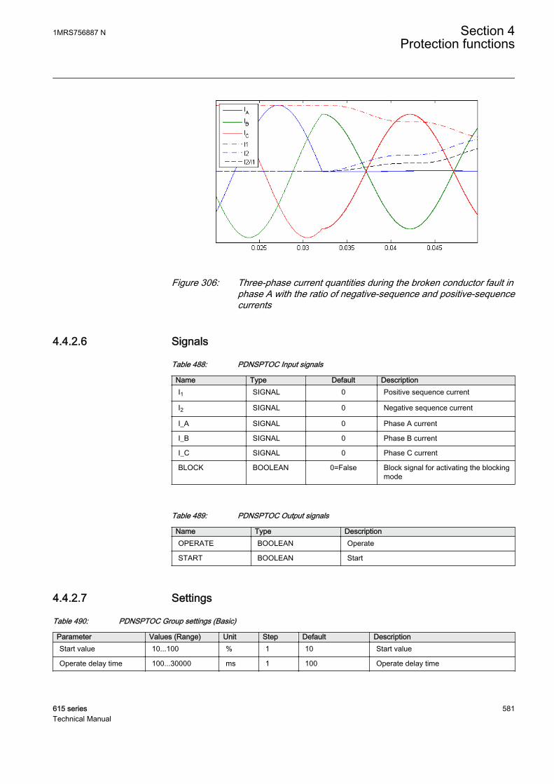
IECA070698 V1 EN
Figure 306: Three-phase current quantities during the broken conductor fault inphase A with the ratio of negative-sequence and positive-sequencecurrents
4.4.2.6 Signals
Table 488: PDNSPTOC Input signals
Name Type Default DescriptionI1 SIGNAL 0 Positive sequence current
I2 SIGNAL 0 Negative sequence current
I_A SIGNAL 0 Phase A current
I_B SIGNAL 0 Phase B current
I_C SIGNAL 0 Phase C current
BLOCK BOOLEAN 0=False Block signal for activating the blockingmode
Table 489: PDNSPTOC Output signals
Name Type DescriptionOPERATE BOOLEAN Operate
START BOOLEAN Start
4.4.2.7 Settings
Table 490: PDNSPTOC Group settings (Basic)
Parameter Values (Range) Unit Step Default DescriptionStart value 10...100 % 1 10 Start value
Operate delay time 100...30000 ms 1 100 Operate delay time
1MRS756887 N Section 4Protection functions
615 series 581Technical Manual

Table 491: PDNSPTOC Non group settings (Basic)
Parameter Values (Range) Unit Step Default DescriptionOperation 1=on
5=off 1=on Operation Off / On
Table 492: PDNSPTOC Non group settings (Advanced)
Parameter Values (Range) Unit Step Default DescriptionReset delay time 0...60000 ms 1 20 Reset delay time
Min phase current 0.05...0.30 xIn 0.01 0.10 Minimum phase current
4.4.2.8 Monitored data
Table 493: PDNSPTOC Monitored data
Name Type Values (Range) Unit DescriptionSTART_DUR FLOAT32 0.00...100.00 % Ratio of start time /
operate time
RATIO_I2_I1 FLOAT32 0.00...999.99 % Measured current ratioI2 / I1
PDNSPTOC Enum 1=on2=blocked3=test4=test/blocked5=off
Status
4.4.2.9 Technical data
Table 494: PDNSPTOC Technical data
Characteristic ValueOperation accuracy Depending on the frequency of the measured
current: fn ±2 Hz
±2% of the set value
Start time <70 ms
Reset time Typically 40 ms
Reset ratio Typically 0.96
Retardation time <35 ms
Operate time accuracy in definite time mode ±1.0% of the set value or ±20 ms
Suppression of harmonics DFT: -50 dB at f = n × fn, where n = 2, 3, 4, 5,…
Section 4 1MRS756887 NProtection functions
582 615 seriesTechnical Manual
4.4.2.10 Technical revision history
Table 495: PDNSPTOC Technical revision history
Technical revision ChangeB Internal improvement
C Internal improvement
D Internal improvement
4.4.3 Phase reversal protection PREVPTOC
4.4.3.1 Identification
Function description IEC 61850identification
IEC 60617identification
ANSI/IEEE C37.2device number
Phase reversal protection PREVPTOC I2>> 46R
4.4.3.2 Function block
GUID-AA794558-EF3A-4E9A-AA39-BCE9FB7253FD V1 EN
Figure 307: Function block
4.4.3.3 Functionality
The phase reversal protection function PREVPTOC is used to detect the reversedconnection of the phases to a three-phase motor by monitoring the negative phasesequence current I2 of the motor.
PREVPTOC starts and operates when I2 exceeds the set limit. PREVPTOC operateson definite time (DT) characteristics. PREVPTOC is based on the calculated I2, andthe function detects too high I2 values during the motor start-up. The excessive I2values are caused by incorrectly connected phases, which in turn makes the motorrotate in the opposite direction.
The function contains a blocking functionality. It is possible to block function outputs,timer or the function itself, if desired.
4.4.3.4 Operation principle
The function can be enabled and disabled with the Operation setting. Thecorresponding parameter values are "On" and "Off".
1MRS756887 N Section 4Protection functions
615 series 583Technical Manual
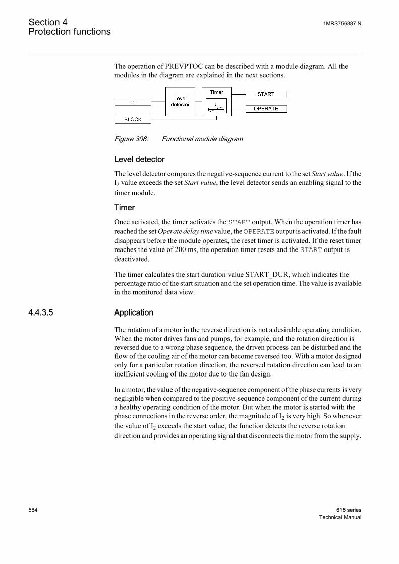
The operation of PREVPTOC can be described with a module diagram. All themodules in the diagram are explained in the next sections.
GUID-F0B4B5EF-8B3C-4967-9818-24DACE686FC8 V1 EN
Figure 308: Functional module diagram
Level detectorThe level detector compares the negative-sequence current to the set Start value. If theI2 value exceeds the set Start value, the level detector sends an enabling signal to thetimer module.
TimerOnce activated, the timer activates the START output. When the operation timer hasreached the set Operate delay time value, the OPERATE output is activated. If the faultdisappears before the module operates, the reset timer is activated. If the reset timerreaches the value of 200 ms, the operation timer resets and the START output isdeactivated.
The timer calculates the start duration value START_DUR, which indicates thepercentage ratio of the start situation and the set operation time. The value is availablein the monitored data view.
4.4.3.5 Application
The rotation of a motor in the reverse direction is not a desirable operating condition.When the motor drives fans and pumps, for example, and the rotation direction isreversed due to a wrong phase sequence, the driven process can be disturbed and theflow of the cooling air of the motor can become reversed too. With a motor designedonly for a particular rotation direction, the reversed rotation direction can lead to aninefficient cooling of the motor due to the fan design.
In a motor, the value of the negative-sequence component of the phase currents is verynegligible when compared to the positive-sequence component of the current duringa healthy operating condition of the motor. But when the motor is started with thephase connections in the reverse order, the magnitude of I2 is very high. So wheneverthe value of I2 exceeds the start value, the function detects the reverse rotationdirection and provides an operating signal that disconnects the motor from the supply.
Section 4 1MRS756887 NProtection functions
584 615 seriesTechnical Manual

4.4.3.6 Signals
Table 496: PREVPTOC Input signals
Name Type Default DescriptionI2 SIGNAL 0 Negative sequence current
BLOCK BOOLEAN 0=False Block signal for activating the blocking mode
Table 497: PREVPTOC Output signals
Name Type DescriptionOPERATE BOOLEAN Operate
START BOOLEAN Start
4.4.3.7 Settings
Table 498: PREVPTOC Group settings (Basic)
Parameter Values (Range) Unit Step Default DescriptionStart value 0.05...1.00 xIn 0.01 0.75 Start value
Operate delay time 100...60000 ms 10 100 Operate delay time
Table 499: PREVPTOC Non group settings (Basic)
Parameter Values (Range) Unit Step Default DescriptionOperation 1=on
5=off 1=on Operation Off / On
4.4.3.8 Monitored data
Table 500: PREVPTOC Monitored data
Name Type Values (Range) Unit DescriptionSTART_DUR FLOAT32 0.00...100.00 % Ratio of start time /
operate time
PREVPTOC Enum 1=on2=blocked3=test4=test/blocked5=off
Status
1MRS756887 N Section 4Protection functions
615 series 585Technical Manual

4.4.3.9 Technical data
Table 501: PREVPTOC Technical data
Characteristic ValueOperation accuracy Depending on the frequency of the measured
current: fn ±2 Hz
±1.5% of the set value or ±0.002 × In
Start time1)2) Minimum Typical Maximum
IFault = 2.0 × set Startvalue
23 ms 25 ms 28 ms
Reset time Typically 40 ms
Reset ratio Typically 0.96
Retardation time <35 ms
Operate time accuracy in definite time mode ±1.0% of the set value or ±20 ms
Suppression of harmonics DFT: -50 dB at f = n × fn, where n = 2, 3, 4, 5,…
1) Negative-sequence current before = 0.0, fn = 50 Hz, results based on statistical distribution of 1000measurements
2) Includes the delay of the signal output contact
4.4.3.10 Technical revision history
Table 502: PREVPTOC Technical revision history46R Technical revision history
Technical revision ChangeB Internal improvement
4.4.4 Negative-sequence overcurrent protection for machinesMNSPTOC
4.4.4.1 Identification
Function description IEC 61850identification
IEC 60617identification
ANSI/IEEE C37.2device number
Negative-sequence overcurrentprotection for machines
MNSPTOC I2>M 46M
4.4.4.2 Function block
GUID-5B6B4705-1EF3-4E12-B1A6-92A5D9D71218 V2 EN
Figure 309: Function block
Section 4 1MRS756887 NProtection functions
586 615 seriesTechnical Manual
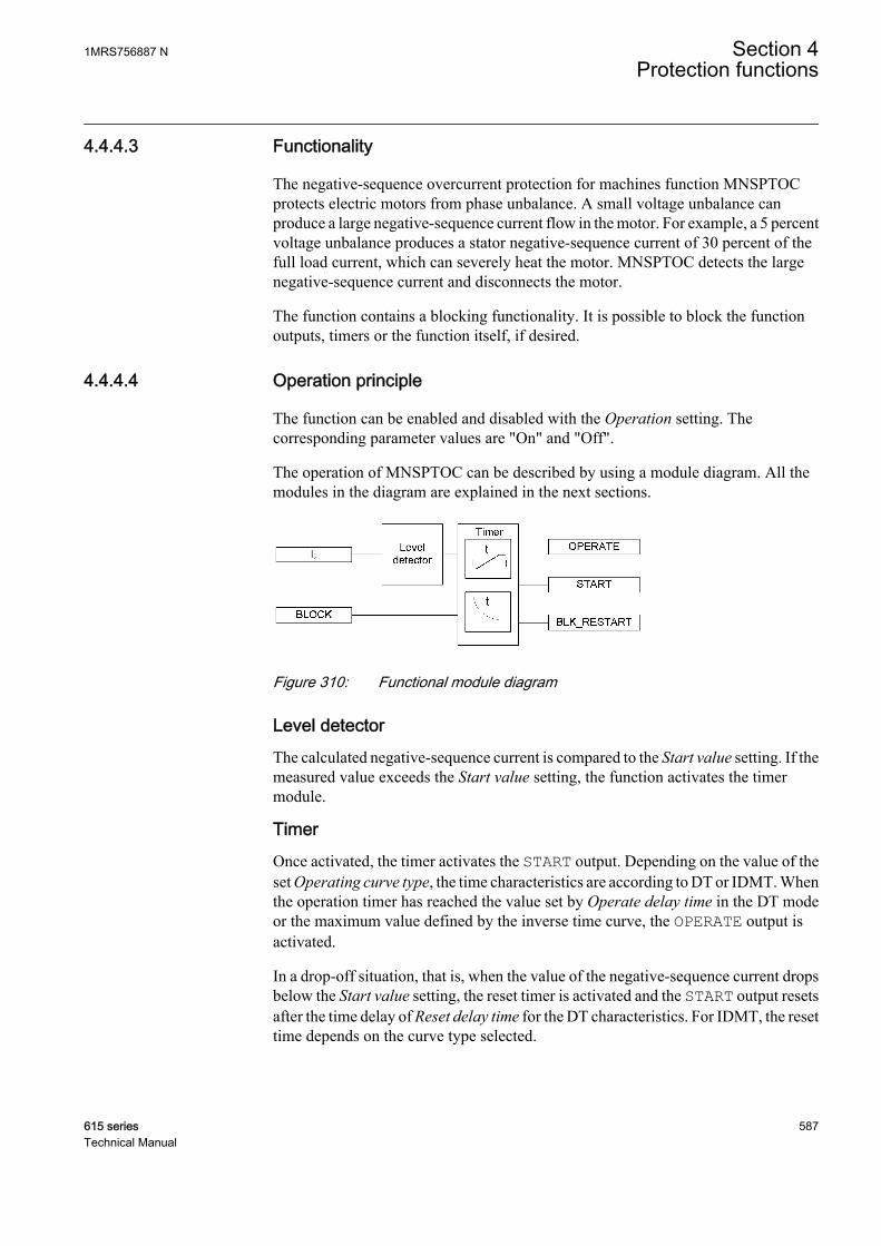
4.4.4.3 Functionality
The negative-sequence overcurrent protection for machines function MNSPTOCprotects electric motors from phase unbalance. A small voltage unbalance canproduce a large negative-sequence current flow in the motor. For example, a 5 percentvoltage unbalance produces a stator negative-sequence current of 30 percent of thefull load current, which can severely heat the motor. MNSPTOC detects the largenegative-sequence current and disconnects the motor.
The function contains a blocking functionality. It is possible to block the functionoutputs, timers or the function itself, if desired.
4.4.4.4 Operation principle
The function can be enabled and disabled with the Operation setting. Thecorresponding parameter values are "On" and "Off".
The operation of MNSPTOC can be described by using a module diagram. All themodules in the diagram are explained in the next sections.
GUID-F890E844-B9C9-4E99-A51F-6EAB19B5239B V1 EN
Figure 310: Functional module diagram
Level detectorThe calculated negative-sequence current is compared to the Start value setting. If themeasured value exceeds the Start value setting, the function activates the timermodule.
TimerOnce activated, the timer activates the START output. Depending on the value of theset Operating curve type, the time characteristics are according to DT or IDMT. Whenthe operation timer has reached the value set by Operate delay time in the DT modeor the maximum value defined by the inverse time curve, the OPERATE output isactivated.
In a drop-off situation, that is, when the value of the negative-sequence current dropsbelow the Start value setting, the reset timer is activated and the START output resetsafter the time delay of Reset delay time for the DT characteristics. For IDMT, the resettime depends on the curve type selected.
1MRS756887 N Section 4Protection functions
615 series 587Technical Manual
For the IDMT curves, it is possible to define minimum and maximum operate timeswith the Minimum operate time and Maximum operate time settings. The Machinetime Mult setting parameter corresponds to the machine constant, equal to the I2
2tconstant of the machine, as stated by the machine manufacturer. In case there is amismatch between the used CT and the protected motor's nominal current values, it ispossible to fit the IDMT curves for the protected motor using the Current referencesetting.
The activation of the OPERATE output activates the BLK_RESTART output. Thedeactivation of the OPERATE output activates the cooling timer. The timer is set to thevalue entered in the Cooling time setting. The BLK_RESTART output is kept activeuntil the cooling timer is exceeded. If the negative-sequence current increases abovethe set value during this period, the OPERATE output is activated immediately.
The T_ENARESTART output indicates the duration for which the BLK_RESTARToutput remains active, that is, it indicates the remaining time of the cooling timer. Thevalue is available in the monitored data view.
The timer calculates the start duration value START_DUR, which indicates thepercentage ratio of the start situation and the set operation time. The value is availablein the monitored data view.
4.4.4.5 Timer characteristics
MNSPTOC supports both DT and IDMT characteristics. The DT timer characteristicscan be selected with "ANSI Def. Time" or "IEC Def. Time" in the Operating curvetype setting. The functionality is identical in both cases. When the DT characteristicsare selected, the functionality is only affected by the Operate delay time and Resetdelay time settings.
The protection relay provides two user-programmable IDMT characteristics curves,"Inv. curve A" and "Inv. curve B".
Current-based inverse definite minimum time curve (IDMT)In inverse-time modes, the operate time depends on the momentary value of thecurrent: the higher the current, the shorter the operate time. The operate timecalculation or integration starts immediately when the current exceeds the set Startvalue and the START output is activated.
The OPERATE output of the component is activated when the cumulative sum of theintegrator calculating the overcurrent situation exceeds the value set by the inversetime mode. The set value depends on the selected curve type and the setting valuesused.
The Minimum operate time and Maximum operate time settings define the minimumoperate time and maximum operate time possible for the IDMT mode. For settingthese parameters, a careful study of the particular IDMT curves is recommended.
Section 4 1MRS756887 NProtection functions
588 615 seriesTechnical Manual
Inv. curve AThe inverse time equation for curve type A is:
t sk
I
Ir
[ ] =
2
2
GUID-D8A4A304-6C63-4BA4-BAEA-E7891504557A V1 EN (Equation 127)
t[s] Operate time in seconds
k Set Machine time Mult
I2 Negative-sequence current
Ir Set Rated current
1MRS756887 N Section 4Protection functions
615 series 589Technical Manual
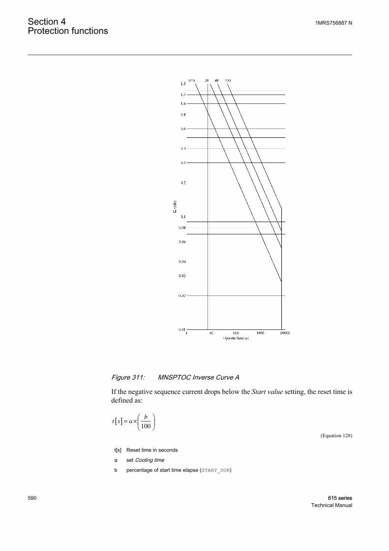
GUID-F0214060-11E8-42F7-B3B9-AF5AC08A1079 V1 EN
Figure 311: MNSPTOC Inverse Curve A
If the negative sequence current drops below the Start value setting, the reset time isdefined as:
t s ab
[ ] = ×
100
GUID-8BE4B6AC-FB61-4D30-B77B-3E599D5BAE81 V1 EN (Equation 128)
t[s] Reset time in seconds
a set Cooling time
b percentage of start time elapse (START_DUR)
Section 4 1MRS756887 NProtection functions
590 615 seriesTechnical Manual
When the reset period is initiated, the time for which START has been active is saved.If the fault reoccurs, that is, the negative-sequence current rises above the set valueduring the reset period, the operate calculations are continued using the saved values.If the reset period elapses without a fault being detected, the operate timer is reset andthe saved values of start time and integration are cleared.
Inv. curve BThe inverse time equation for curve type B is:
t sk
I
I
I
Ir
S
r
[ ] =
−
2
2 2
GUID-805DCB50-71D2-4721-830B-3343E1A5500B V1 EN (Equation 129)
t[s] Operate time in seconds
k Machine time Mult
I2 Negative-sequence current
IS Set Start value
Ir Set Rated current
1MRS756887 N Section 4Protection functions
615 series 591Technical Manual

GUID-C536DD76-70FA-49CF-9D0B-F14CA76873D0 V1 EN
Figure 312: MNSPTOC Inverse Curve B
If the fault disappears, the negative-sequence current drops below the Start valuesetting and the START output is deactivated. The function does not resetinstantaneously. Resetting depends on the equation or the Cooling time setting.
The timer is reset in two ways:
• When the negative sequence current drops below start value the subtraction in thedenominator becomes negative and the cumulative sum starts to decrease. Thedecrease in the sum indicates the cooling of the machine and the cooling speed
Section 4 1MRS756887 NProtection functions
592 615 seriesTechnical Manual
depends on the value of the negative-sequence current. If the sum reaches zerowithout a fault being detected, the accumulation stops and the timer is reset.
• If the reset time set through the Cooling time setting elapses without a fault beingdetected, the timer is reset.
The reset period thus continues for a time equal to the Cooling time setting or until theoperate time decreases to zero, whichever is less.
4.4.4.6 Application
In a three-phase motor, the conditions that can lead to unbalance are single phasing,voltage unbalance from the supply and single-phase fault. The negative sequencecurrent damages the motor during the unbalanced voltage condition, and therefore thenegative sequence current is monitored to check the unbalance condition.
When the voltages supplied to an operating motor become unbalanced, the positive-sequence current remains substantially unchanged, but the negative-sequence currentflows due to the unbalance. For example, if the unbalance is caused by an open circuitin any phase, a negative-sequence current flows and it is equal and opposite to theprevious load current in a healthy phase. The combination of positive and negative-sequence currents produces phase currents approximately 1.7 times the previous loadin each healthy phase and zero current in the open phase.
The negative-sequence currents flow through the stator windings inducing negative-sequence voltage in the rotor windings. This can result in a high rotor current thatdamages the rotor winding. The frequency of the induced current is approximatelytwice the supply frequency. Due to skin effect, the induced current with a frequencydouble the supply frequency encounters high rotor resistance which leads to excessiveheating even with phase currents with value less than the rated current of the motor.
The negative-sequence impedance of induction or a synchronous motor isapproximately equal to the locked rotor impedance, which is approximately one-sixthof the normal motor impedance, considering that the motor has a locked-rotor currentof six times the rated current. Therefore, even a three percent voltage unbalance canlead to 18 percent stator negative sequence current in windings. The severity of this isindicated by a 30-40 percent increase in the motor temperature due to the extra current.
4.4.4.7 Signals
Table 503: MNSPTOC Input signals
Name Type Default DescriptionI2 SIGNAL 0 Negative sequence current
BLOCK BOOLEAN 0=False Block signal for activating the blocking mode
1MRS756887 N Section 4Protection functions
615 series 593Technical Manual

Table 504: MNSPTOC Output signals
Name Type DescriptionOPERATE BOOLEAN Operate
START BOOLEAN Start
BLK_RESTART BOOLEAN Overheated machine reconnection blocking
4.4.4.8 Settings
Table 505: MNSPTOC Group settings (Basic)
Parameter Values (Range) Unit Step Default DescriptionStart value 0.01...0.50 xIn 0.01 0.20 Start value
Operating curve type 5=ANSI Def. Time15=IEC Def. Time17=Inv. Curve A18=Inv. Curve B
15=IEC Def. Time Selection of time delay curve type
Machine time Mult 5.0...100.0 0.1 5.0 Machine related time constant
Operate delay time 100...120000 ms 10 1000 Operate delay time
Table 506: MNSPTOC Non group settings (Basic)
Parameter Values (Range) Unit Step Default DescriptionOperation 1=on
5=off 1=on Operation Off / On
Maximum operate time 500000...7200000 ms 1000 1000000 Max operate time regardless of theinverse characteristic
Minimum operate time 100...120000 ms 1 100 Minimum operate time for IDMT curves
Cooling time 5...7200 s 1 50 Time required to cool the machine
Table 507: MNSPTOC Non group settings (Advanced)
Parameter Values (Range) Unit Step Default DescriptionCurrent reference 0.30...2.00 xIn 0.01 1.00 Rated current (Ir) of the machine (used
only in the IDMT)
Reset delay time 0...60000 ms 1 20 Reset delay time
Section 4 1MRS756887 NProtection functions
594 615 seriesTechnical Manual
4.4.4.9 Monitored data
Table 508: MNSPTOC Monitored data
Name Type Values (Range) Unit DescriptionSTART_DUR FLOAT32 0.00...100.00 % Ratio of start time /
operate time
T_ENARESTART INT32 0...10000 s Estimated time to reset ofblock restart
MNSPTOC Enum 1=on2=blocked3=test4=test/blocked5=off
Status
4.4.4.10 Technical data
Table 509: MNSPTOC Technical data
Characteristic ValueOperation accuracy Depending on the frequency of the measured
current: fn
±1.5% of the set value or ±0.002 × In
Start time1)2) Minimum Typical Maximum
IFault = 2.0 × set Startvalue
23 25 ms 28 ms
Reset time Typically 40 ms
Reset ratio Typically 0.96
Retardation time <35 ms
Operate time accuracy in definite time mode ±1.0% of the set value or ±20 ms
Operate time accuracy in inverse time mode ±5.0% of the theoretical value or ±20 ms3)
Suppression of harmonics DFT: -50 dB at f = n × fn, where n = 2, 3, 4, 5,…
1) Negative-sequence current before = 0.0, fn = 50 Hz, results based on statistical distribution of 1000measurements
2) Includes the delay of the signal output contact3) Start value multiples in range of 1.10...5.00
4.4.4.11 Technical revision history
Table 510: MNSPTOC Technical revision history
Technical revision ChangeB Internal improvement
C Internal improvement
1MRS756887 N Section 4Protection functions
615 series 595Technical Manual
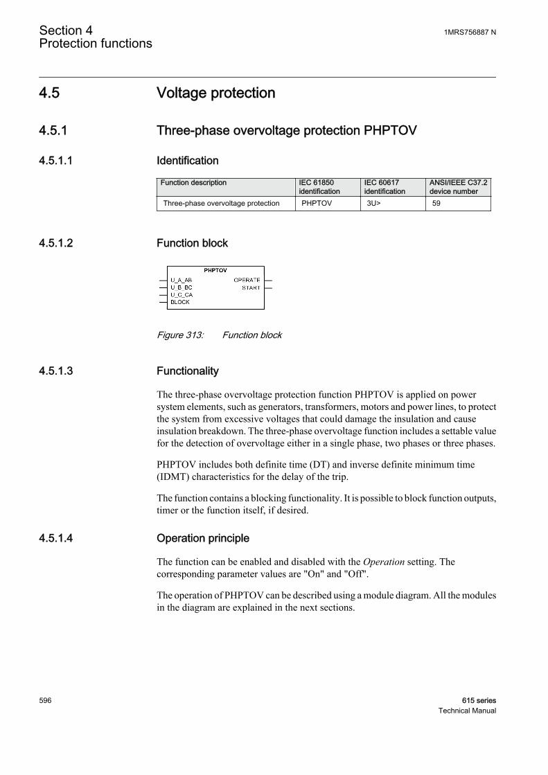
4.5 Voltage protection
4.5.1 Three-phase overvoltage protection PHPTOV
4.5.1.1 Identification
Function description IEC 61850identification
IEC 60617identification
ANSI/IEEE C37.2device number
Three-phase overvoltage protection PHPTOV 3U> 59
4.5.1.2 Function block
GUID-871D07D7-B690-48FD-8EA1-73A7169AE8BD V2 EN
Figure 313: Function block
4.5.1.3 Functionality
The three-phase overvoltage protection function PHPTOV is applied on powersystem elements, such as generators, transformers, motors and power lines, to protectthe system from excessive voltages that could damage the insulation and causeinsulation breakdown. The three-phase overvoltage function includes a settable valuefor the detection of overvoltage either in a single phase, two phases or three phases.
PHPTOV includes both definite time (DT) and inverse definite minimum time(IDMT) characteristics for the delay of the trip.
The function contains a blocking functionality. It is possible to block function outputs,timer or the function itself, if desired.
4.5.1.4 Operation principle
The function can be enabled and disabled with the Operation setting. Thecorresponding parameter values are "On" and "Off".
The operation of PHPTOV can be described using a module diagram. All the modulesin the diagram are explained in the next sections.
Section 4 1MRS756887 NProtection functions
596 615 seriesTechnical Manual
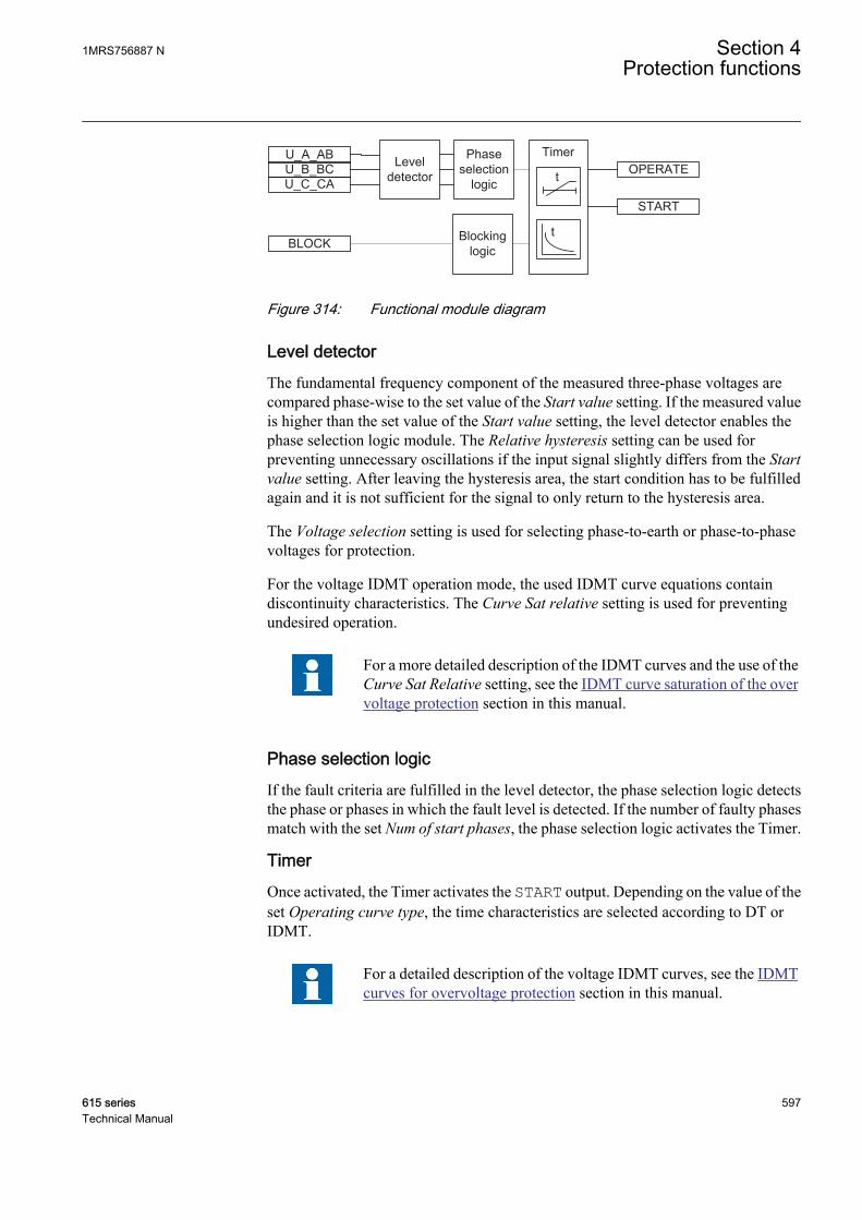
Phaseselection
logic
BLOCK
OPERATE
START
Leveldetector t
Timer
t
U_A_ABU_B_BCU_C_CA
Blockinglogic
GUID-D71B1772-3503-4150-B3FE-6FFD92DE5DB7 V2 EN
Figure 314: Functional module diagram
Level detectorThe fundamental frequency component of the measured three-phase voltages arecompared phase-wise to the set value of the Start value setting. If the measured valueis higher than the set value of the Start value setting, the level detector enables thephase selection logic module. The Relative hysteresis setting can be used forpreventing unnecessary oscillations if the input signal slightly differs from the Startvalue setting. After leaving the hysteresis area, the start condition has to be fulfilledagain and it is not sufficient for the signal to only return to the hysteresis area.
The Voltage selection setting is used for selecting phase-to-earth or phase-to-phasevoltages for protection.
For the voltage IDMT operation mode, the used IDMT curve equations containdiscontinuity characteristics. The Curve Sat relative setting is used for preventingundesired operation.
For a more detailed description of the IDMT curves and the use of theCurve Sat Relative setting, see the IDMT curve saturation of the overvoltage protection section in this manual.
Phase selection logicIf the fault criteria are fulfilled in the level detector, the phase selection logic detectsthe phase or phases in which the fault level is detected. If the number of faulty phasesmatch with the set Num of start phases, the phase selection logic activates the Timer.
TimerOnce activated, the Timer activates the START output. Depending on the value of theset Operating curve type, the time characteristics are selected according to DT orIDMT.
For a detailed description of the voltage IDMT curves, see the IDMTcurves for overvoltage protection section in this manual.
1MRS756887 N Section 4Protection functions
615 series 597Technical Manual
When the operation timer has reached the value set by Operate delay time in the DTmode or the maximum value defined by the IDMT, the OPERATE output is activated.
When the user-programmable IDMT curve is selected, the operate timecharacteristics are defined by the parameters Curve parameter A, Curve parameter B,Curve parameter C, Curve parameter D and Curve parameter E.
If a drop-off situation occurs, that is, a fault suddenly disappears before the operatedelay is exceeded, the reset state is activated. The behavior in the drop-off situationdepends on the selected operate time characteristics. If the DT characteristics areselected, the reset timer runs until the set Reset delay time value is exceeded. If thedrop-off situation exceeds the set Reset delay time, the Timer is reset and the STARToutput is deactivated.
When the IDMT operate time curve is selected, the functionality of the Timer in thedrop-off state depends on the combination of the Type of reset curve, Type of time resetand Reset delay time settings.
Table 511: Reset time functionality when IDMT operation time curve selected
Reset functionality Setting Type ofreset curve
Setting Type of timereset
Setting Reset delaytime
Instantaneousreset
Operation timer is“Resetinstantaneously”when drop-offoccurs
“Immediate” Setting has noeffect
Setting has noeffect
Frozen timer Operation timer isfrozen duringdrop-off
“Def time reset” “Freeze Op timer” Operate timer isreset after the setReset delay timehas elapsed
Linear decrease Operation timervalue linearlydecreases duringthe drop-offsituation
“Def time reset” “Decrease Optimer”
Operate timer isreset after the setReset delay timehas elapsed
Section 4 1MRS756887 NProtection functions
598 615 seriesTechnical Manual

GUID-543D302D-0B91-4692-BAFE-4AB7B8BA08B6 V1 EN
Figure 315: Behavior of different IDMT reset modes. Operate signal is based onsettings Type of reset curve = “Def time reset” and Type of timereset= “Freeze Op timer”. The effect of other reset modes is alsopresented
The Time multiplier setting is used for scaling the IDMT operate times.
The Minimum operate time setting parameter defines the minimum desired operatetime for IDMT. The setting is applicable only when the IDMT curves are used.
The Minimum operate time setting should be used with care becausethe operation time is according to the IDMT curve, but always at leastthe value of the Minimum operate time setting. For more information,
1MRS756887 N Section 4Protection functions
615 series 599Technical Manual
see the IDMT curves for overvoltage protection section in thismanual.
The Timer calculates the start duration value START_DUR, which indicates thepercentage ratio of the start situation and the set operation time. The value is availablein the Monitored data view.
Blocking logicThere are three operation modes in the blocking function. The operation modes arecontrolled by the BLOCK input and the global setting in Configuration/System/Blocking mode which selects the blocking mode. The BLOCK input can be controlledby a binary input, a horizontal communication input or an internal signal of theprotection relay's program. The influence of the BLOCK input signal activation ispreselected with the global Blocking mode setting.
The Blocking mode setting has three blocking methods. In the "Freeze timers" mode,the operation timer is frozen to the prevailing value, but the OPERATE output is notdeactivated when blocking is activated. In the "Block all" mode, the whole function isblocked and the Timers are reset. In the "Block OPERATE output" mode, the functionoperates normally but the OPERATE output is not activated.
The “Freeze timers” mode of blocking has no effect during the inversereset mode.
4.5.1.5 Timer characteristics
The operating curve types supported by PHPTOV are:
Table 512: Timer characteristics supported by IDMT operate curve types
Operating curve type(5) ANSI Def. Time
(15) IEC Def. Time
(17) Inv. Curve A
(18) Inv. Curve B
(19) Inv. Curve C
(20) Programmable
4.5.1.6 Application
Overvoltage in a network occurs either due to the transient surges on the network ordue to prolonged power frequency overvoltages. Surge arresters are used to protect thenetwork against the transient overvoltages, but the relay's protection function is usedto protect against power frequency overvoltages.
Section 4 1MRS756887 NProtection functions
600 615 seriesTechnical Manual

The power frequency overvoltage may occur in the network due to contingencies suchas:
• The defective operation of the automatic voltage regulator when the generator isin isolated operation.
• Operation under manual control with the voltage regulator out of service. Asudden variation of load, in particular the reactive power component, gives rise toa substantial change in voltage because of the inherent large voltage regulation ofa typical alternator.
• Sudden loss of load due to the tripping of outgoing feeders, leaving the generatorisolated or feeding a very small load. This causes a sudden rise in the terminalvoltage due to the trapped field flux and overspeed.
If a load sensitive to overvoltage remains connected, it leads to equipment damage.
It is essential to provide power frequency overvoltage protection, in the form of timedelayed element, either IDMT or DT to prevent equipment damage.
4.5.1.7 Signals
Table 513: PHPTOV Input signals
Name Type Default DescriptionU_A_AB SIGNAL 0 Phase to earth voltage A or phase to phase voltage
AB
U_B_BC SIGNAL 0 Phase to earth voltage B or phase to phase voltageBC
U_C_CA SIGNAL 0 Phase to earth voltage C or phase to phase voltageCA
BLOCK BOOLEAN 0=False Block signal for activating the blocking mode
Table 514: PHPTOV Output signals
Name Type DescriptionOPERATE BOOLEAN Operate
START BOOLEAN Start
1MRS756887 N Section 4Protection functions
615 series 601Technical Manual
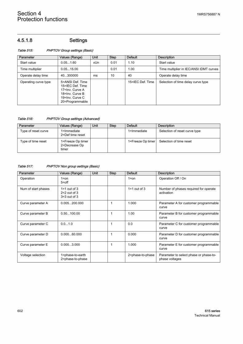
4.5.1.8 Settings
Table 515: PHPTOV Group settings (Basic)
Parameter Values (Range) Unit Step Default DescriptionStart value 0.05...1.60 xUn 0.01 1.10 Start value
Time multiplier 0.05...15.00 0.01 1.00 Time multiplier in IEC/ANSI IDMT curves
Operate delay time 40...300000 ms 10 40 Operate delay time
Operating curve type 5=ANSI Def. Time15=IEC Def. Time17=Inv. Curve A18=Inv. Curve B19=Inv. Curve C20=Programmable
15=IEC Def. Time Selection of time delay curve type
Table 516: PHPTOV Group settings (Advanced)
Parameter Values (Range) Unit Step Default DescriptionType of reset curve 1=Immediate
2=Def time reset 1=Immediate Selection of reset curve type
Type of time reset 1=Freeze Op timer2=Decrease Optimer
1=Freeze Op timer Selection of time reset
Table 517: PHPTOV Non group settings (Basic)
Parameter Values (Range) Unit Step Default DescriptionOperation 1=on
5=off 1=on Operation Off / On
Num of start phases 1=1 out of 32=2 out of 33=3 out of 3
1=1 out of 3 Number of phases required for operateactivation
Curve parameter A 0.005...200.000 1 1.000 Parameter A for customer programmablecurve
Curve parameter B 0.50...100.00 1 1.00 Parameter B for customer programmablecurve
Curve parameter C 0.0...1.0 1 0.0 Parameter C for customer programmablecurve
Curve parameter D 0.000...60.000 1 0.000 Parameter D for customer programmablecurve
Curve parameter E 0.000...3.000 1 1.000 Parameter E for customer programmablecurve
Voltage selection 1=phase-to-earth2=phase-to-phase
2=phase-to-phase Parameter to select phase or phase-to-phase voltages
Section 4 1MRS756887 NProtection functions
602 615 seriesTechnical Manual
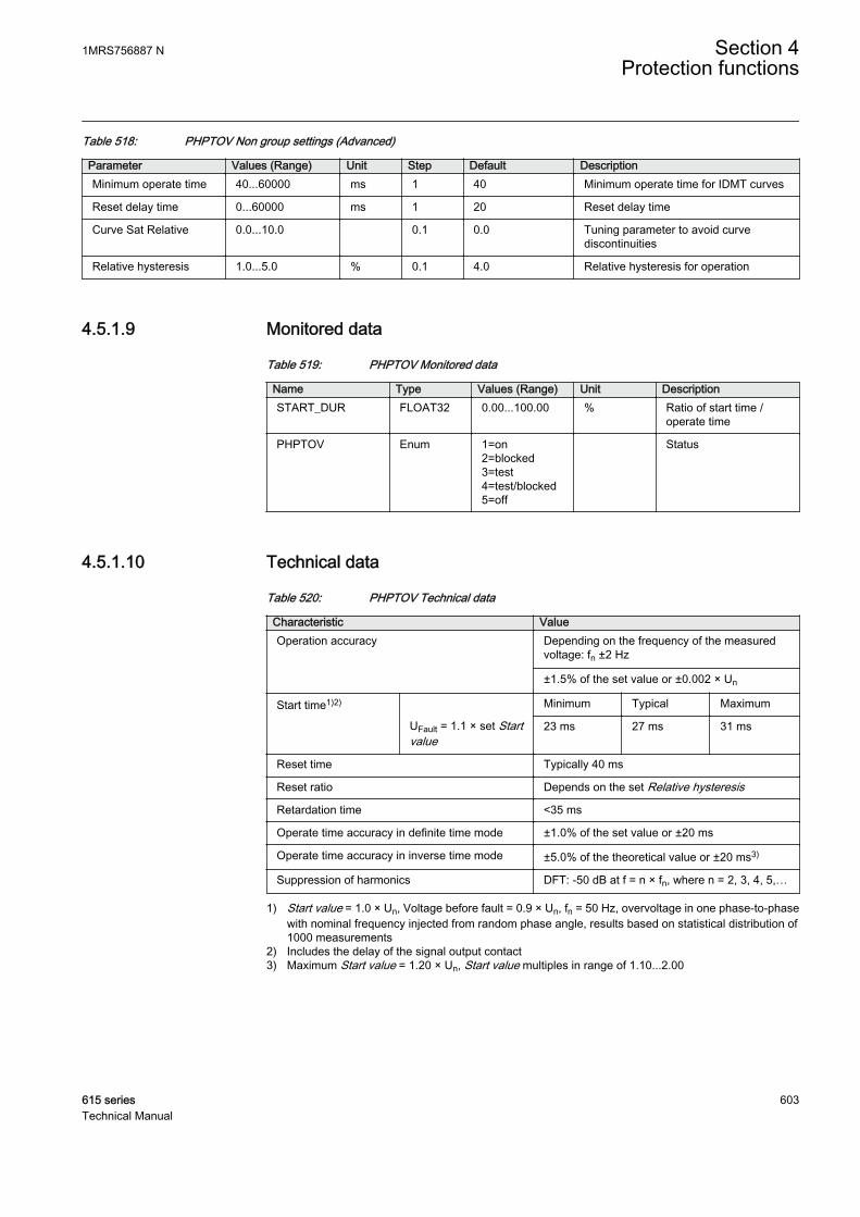
Table 518: PHPTOV Non group settings (Advanced)
Parameter Values (Range) Unit Step Default DescriptionMinimum operate time 40...60000 ms 1 40 Minimum operate time for IDMT curves
Reset delay time 0...60000 ms 1 20 Reset delay time
Curve Sat Relative 0.0...10.0 0.1 0.0 Tuning parameter to avoid curvediscontinuities
Relative hysteresis 1.0...5.0 % 0.1 4.0 Relative hysteresis for operation
4.5.1.9 Monitored data
Table 519: PHPTOV Monitored data
Name Type Values (Range) Unit DescriptionSTART_DUR FLOAT32 0.00...100.00 % Ratio of start time /
operate time
PHPTOV Enum 1=on2=blocked3=test4=test/blocked5=off
Status
4.5.1.10 Technical data
Table 520: PHPTOV Technical data
Characteristic ValueOperation accuracy Depending on the frequency of the measured
voltage: fn ±2 Hz
±1.5% of the set value or ±0.002 × Un
Start time1)2) Minimum Typical Maximum
UFault = 1.1 × set Startvalue
23 ms 27 ms 31 ms
Reset time Typically 40 ms
Reset ratio Depends on the set Relative hysteresis
Retardation time <35 ms
Operate time accuracy in definite time mode ±1.0% of the set value or ±20 ms
Operate time accuracy in inverse time mode ±5.0% of the theoretical value or ±20 ms3)
Suppression of harmonics DFT: -50 dB at f = n × fn, where n = 2, 3, 4, 5,…
1) Start value = 1.0 × Un, Voltage before fault = 0.9 × Un, fn = 50 Hz, overvoltage in one phase-to-phasewith nominal frequency injected from random phase angle, results based on statistical distribution of1000 measurements
2) Includes the delay of the signal output contact3) Maximum Start value = 1.20 × Un, Start value multiples in range of 1.10...2.00
1MRS756887 N Section 4Protection functions
615 series 603Technical Manual
4.5.1.11 Technical revision history
Table 521: PHPTOV Technical revision history
Technical revision ChangeB Step value changed from 0.05 to 0.01 for the Time
multiplier setting.
C Curve Sat relative max range widened from 3.0 to10.0 % and default value changed from 2.0 to0.0 %.
D Added setting Type of time reset.
4.5.2 Three-phase undervoltage protection PHPTUV
4.5.2.1 Identification
Function description IEC 61850identification
IEC 60617identification
ANSI/IEEE C37.2device number
Three-phase undervoltage protection PHPTUV 3U< 27
4.5.2.2 Function block
GUID-B4A78A17-67CA-497C-B2F1-BC4F1DA415B6 V2 EN
Figure 316: Function block
4.5.2.3 Functionality
The three-phase undervoltage protection function PHPTUV is used to disconnectfrom the network devices, for example electric motors, which are damaged whensubjected to service under low voltage conditions. PHPTUV includes a settable valuefor the detection of undervoltage either in a single phase, two phases or three phases.
The function contains a blocking functionality. It is possible to block function outputs,timer or the function itself, if desired.
4.5.2.4 Operation principle
The function can be enabled and disabled with the Operation setting. Thecorresponding parameter values are "On" and "Off".
The operation of PHPTUV can be described using a module diagram. All the modulesin the diagram are explained in the next sections.
Section 4 1MRS756887 NProtection functions
604 615 seriesTechnical Manual

GUID-21DCE3FD-C5A0-471A-AB93-DDAB4AE93116 V1 EN
Figure 317: Functional module diagram
Level detectorThe fundamental frequency component of the measured three phase voltages arecompared phase-wise to the set Start value. If the measured value is lower than the setvalue of the Start value setting, the level detector enables the phase selection logicmodule. The Relative hysteresis setting can be used for preventing unnecessaryoscillations if the input signal slightly varies above or below the Start value setting.After leaving the hysteresis area, the start condition has to be fulfilled again and it isnot sufficient for the signal to only return back to the hysteresis area.
The Voltage selection setting is used for selecting the phase-to-earth or phase-to-phase voltages for protection.
For the voltage IDMT mode of operation, the used IDMT curve equations containdiscontinuity characteristics. The Curve Sat relative setting is used for preventingunwanted operation.
For more detailed description on IDMT curves and usage of Curve SatRelative setting, see the IDMT curves for under voltage protectionsection in this manual.
The level detector contains a low-level blocking functionality for cases where one ofthe measured voltages is below the desired level. This feature is useful whenunnecessary starts and operates are wanted to avoid during, for example, anautoreclose sequence. The low-level blocking is activated by default (Enable blockvalue is set to "True") and the blocking level can be set with the Voltage block valuesetting.
Phase selection logicIf the fault criteria are fulfilled in the level detector, the phase selection logic detectsthe phase or phases in which the fault level is detected. If the number of faulty phasesmatch with the set Num of start phases, the phase selection logic activates the Timer.
1MRS756887 N Section 4Protection functions
615 series 605Technical Manual

TimerOnce activated, the Timer activates the START output. Depending on the value of theset Operating curve type, the time characteristics are selected according to DT orIDMT.
For a detailed description of the voltage IDMT curves, see the IDMTcurves for under voltage protection section in this manual.
When the operation timer has reached the value set by Operate delay time in the DTmode or the maximum value defined by the IDMT, the OPERATE output is activated.
When the user-programmable IDMT curve is selected, the operate timecharacteristics are defined by the parameters Curve parameter A, Curve parameter B,Curve parameter C, Curve parameter D and Curve parameter E.
If a drop-off situation occurs, that is, a fault suddenly disappears before the operatedelay is exceeded, the reset state is activated. The behavior in the drop-off situationdepends on the selected operate time characteristics. If the DT characteristics areselected, the reset timer runs until the set Reset delay time value is exceeded. If thedrop-off situation exceeds the set Reset delay time, the Timer is reset and the STARToutput is deactivated.
When the IDMT operate time curve is selected, the functionality of the Timer in thedrop-off state depends on the combination of the Type of reset curve, Type of time resetand Reset delay time settings.
Table 522: Reset time functionality when IDMT operation time curve selected
Reset functionality Setting Type ofreset curve
Setting Type of timereset
Setting Reset delaytime
Instantaneousreset
Operation timer is“Resetinstantaneously”when drop-offoccurs
“Immediate” Setting has noeffect
Setting has noeffect
Frozen timer Operation timer isfrozen duringdrop-off
“Def time reset” “Freeze Op timer” Operate timer isreset after the setReset delay timehas elapsed
Linear decrease Operation timervalue linearlydecreases duringthe drop-offsituation
“Def time reset” “Decrease Optimer”
Operate timer isreset after the setReset delay timehas elapsed
Section 4 1MRS756887 NProtection functions
606 615 seriesTechnical Manual
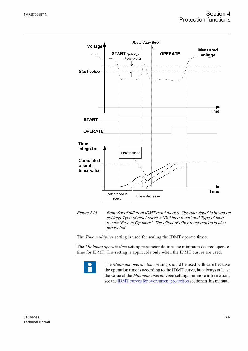
GUID-17E4650D-ADFD-408E-B699-00CBA1E934B8 V1 EN
Figure 318: Behavior of different IDMT reset modes. Operate signal is based onsettings Type of reset curve = “Def time reset” and Type of timereset= “Freeze Op timer”. The effect of other reset modes is alsopresented
The Time multiplier setting is used for scaling the IDMT operate times.
The Minimum operate time setting parameter defines the minimum desired operatetime for IDMT. The setting is applicable only when the IDMT curves are used.
The Minimum operate time setting should be used with care becausethe operation time is according to the IDMT curve, but always at leastthe value of the Minimum operate time setting. For more information,see the IDMT curves for overcurrent protection section in this manual.
1MRS756887 N Section 4Protection functions
615 series 607Technical Manual
The Timer calculates the start duration value START_DUR, which indicates thepercentage ratio of the start situation and the set operation time. The value is availablein the Monitored data view.
Blocking logicThere are three operation modes in the blocking function. The operation modes arecontrolled by the BLOCK input and the global setting in Configuration/System/Blocking mode which selects the blocking mode. The BLOCK input can be controlledby a binary input, a horizontal communication input or an internal signal of theprotection relay's program. The influence of the BLOCK input signal activation ispreselected with the global Blocking mode setting.
The Blocking mode setting has three blocking methods. In the "Freeze timers" mode,the operation timer is frozen to the prevailing value, but the OPERATE output is notdeactivated when blocking is activated. In the "Block all" mode, the whole function isblocked and the Timers are reset. In the "Block OPERATE output" mode, the functionoperates normally but the OPERATE output is not activated.
The “Freeze timers” mode of blocking has no effect during the“Inverse reset” mode.
4.5.2.5 Timer characteristics
The operating curve types supported by PHPTUV are:
Table 523: Supported IDMT operate curve types
Operating curve type(5) ANSI Def. Time
(15) IEC Def. Time
(21) Inv. Curve A
(22) Inv. Curve B
(23) Programmable
4.5.2.6 Application
PHPTUV is applied to power system elements, such as generators, transformers,motors and power lines, to detect low voltage conditions. Low voltage conditions arecaused by abnormal operation or a fault in the power system. PHPTUV can be used incombination with overcurrent protections. Other applications are the detection of ano-voltage condition, for example before the energization of a high voltage line, or anautomatic breaker trip in case of a blackout. PHPTUV is also used to initiate voltagecorrection measures, such as insertion of shunt capacitor banks, to compensate for areactive load and thereby to increase the voltage.
Section 4 1MRS756887 NProtection functions
608 615 seriesTechnical Manual
PHPTUV can be used to disconnect from the network devices, such as electric motors,which are damaged when subjected to service under low voltage conditions.PHPTUV deals with low voltage conditions at power system frequency. Low voltageconditions can be caused by:
• Malfunctioning of a voltage regulator or incorrect settings under manual control(symmetrical voltage decrease)
• Overload (symmetrical voltage decrease)• Short circuits, often as phase-to-earth faults (unsymmetrical voltage increase).
PHPTUV prevents sensitive equipment from running under conditions that couldcause overheating and thus shorten their life time expectancy. In many cases,PHPTUV is a useful function in circuits for local or remote automation processes inthe power system.
4.5.2.7 Signals
Table 524: PHPTUV Input signals
Name Type Default DescriptionU_A_AB SIGNAL 0 Phase to earth voltage A or phase to phase voltage
AB
U_B_BC SIGNAL 0 Phase to earth voltage B or phase to phase voltageBC
U_C_CA SIGNAL 0 Phase to earth voltage C or phase to phase voltageCA
BLOCK BOOLEAN 0=False Block signal for activating the blocking mode
Table 525: PHPTUV Output signals
Name Type DescriptionOPERATE BOOLEAN Operate
START BOOLEAN Start
4.5.2.8 Settings
Table 526: PHPTUV Group settings (Basic)
Parameter Values (Range) Unit Step Default DescriptionStart value 0.05...1.20 xUn 0.01 0.90 Start value
Time multiplier 0.05...15.00 0.01 1.00 Time multiplier in IEC/ANSI IDMT curves
Operate delay time 60...300000 ms 10 60 Operate delay time
Operating curve type 5=ANSI Def. Time15=IEC Def. Time21=Inv. Curve A22=Inv. Curve B23=Programmable
15=IEC Def. Time Selection of time delay curve type
1MRS756887 N Section 4Protection functions
615 series 609Technical Manual
Table 527: PHPTUV Group settings (Advanced)
Parameter Values (Range) Unit Step Default DescriptionType of reset curve 1=Immediate
2=Def time reset 1=Immediate Selection of reset curve type
Type of time reset 1=Freeze Op timer2=Decrease Optimer
1=Freeze Op timer Selection of time reset
Table 528: PHPTUV Non group settings (Basic)
Parameter Values (Range) Unit Step Default DescriptionOperation 1=on
5=off 1=on Operation Off / On
Num of start phases 1=1 out of 32=2 out of 33=3 out of 3
1=1 out of 3 Number of phases required for operateactivation
Curve parameter A 0.005...200.000 1 1.000 Parameter A for customer programmablecurve
Curve parameter B 0.50...100.00 1 1.00 Parameter B for customer programmablecurve
Curve parameter C 0.0...1.0 1 0.0 Parameter C for customer programmablecurve
Curve parameter D 0.000...60.000 1 0.000 Parameter D for customer programmablecurve
Curve parameter E 0.000...3.000 1 1.000 Parameter E for customer programmablecurve
Voltage selection 1=phase-to-earth2=phase-to-phase
2=phase-to-phase Parameter to select phase or phase-to-phase voltages
Table 529: PHPTUV Non group settings (Advanced)
Parameter Values (Range) Unit Step Default DescriptionMinimum operate time 60...60000 ms 1 60 Minimum operate time for IDMT curves
Reset delay time 0...60000 ms 1 20 Reset delay time
Curve Sat Relative 0.0...10.0 0.1 0.0 Tuning parameter to avoid curvediscontinuities
Voltage block value 0.05...1.00 xUn 0.01 0.20 Low level blocking for undervoltage mode
Enable block value 0=False1=True
1=True Enable internal blocking
Relative hysteresis 1.0...5.0 % 0.1 4.0 Relative hysteresis for operation
Section 4 1MRS756887 NProtection functions
610 615 seriesTechnical Manual

4.5.2.9 Monitored data
Table 530: PHPTUV Monitored data
Name Type Values (Range) Unit DescriptionSTART_DUR FLOAT32 0.00...100.00 % Ratio of start time /
operate time
PHPTUV Enum 1=on2=blocked3=test4=test/blocked5=off
Status
4.5.2.10 Technical data
Table 531: PHPTUV Technical data
Characteristic ValueOperation accuracy Depending on the frequency of the voltage
measured: fn ±2 Hz
±1.5% of the set value or ±0.002 × Un
Start time1)2) Minimum Typical Maximum
UFault = 0.9 × set Startvalue
62 ms 66 ms 70 ms
Reset time Typically 40 ms
Reset ratio Depends on the set Relative hysteresis
Retardation time <35 ms
Operate time accuracy in definite time mode ±1.0% of the set value or ±20 ms
Operate time accuracy in inverse time mode ±5.0% of the theoretical value or ±20 ms3)
Suppression of harmonics DFT: -50 dB at f = n × fn, where n = 2, 3, 4, 5,…
1) Start value = 1.0 × Un, Voltage before fault = 1.1 × Un, fn = 50 Hz, undervoltage in one phase-to-phasewith nominal frequency injected from random phase angle, results based on statistical distribution of1000 measurements
2) Includes the delay of the signal output contact3) Minimum Start value = 0.50, Start value multiples in range of 0.90...0.20
4.5.2.11 Technical revision history
Table 532: PHPTUV Technical revision history
Technical revision ChangeB Step value changed from 0.05 to 0.01 for the Time
multiplier setting.
C Curve Sat relative max range widened from 3.0 to10.0 % and default value changed from 2.0 to0.0 %.
D Added setting Type of time reset.
1MRS756887 N Section 4Protection functions
615 series 611Technical Manual
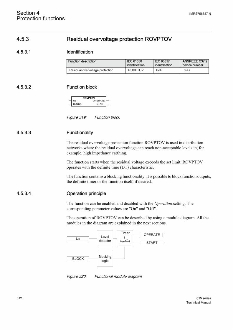
4.5.3 Residual overvoltage protection ROVPTOV
4.5.3.1 Identification
Function description IEC 61850identification
IEC 60617identification
ANSI/IEEE C37.2device number
Residual overvoltage protection ROVPTOV Uo> 59G
4.5.3.2 Function block
A070766 V3 EN
Figure 319: Function block
4.5.3.3 Functionality
The residual overvoltage protection function ROVPTOV is used in distributionnetworks where the residual overvoltage can reach non-acceptable levels in, forexample, high impedance earthing.
The function starts when the residual voltage exceeds the set limit. ROVPTOVoperates with the definite time (DT) characteristic.
The function contains a blocking functionality. It is possible to block function outputs,the definite timer or the function itself, if desired.
4.5.3.4 Operation principle
The function can be enabled and disabled with the Operation setting. Thecorresponding parameter values are "On" and "Off".
The operation of ROVPTOV can be described by using a module diagram. All themodules in the diagram are explained in the next sections.
A070748 V2 EN
Figure 320: Functional module diagram
Section 4 1MRS756887 NProtection functions
612 615 seriesTechnical Manual
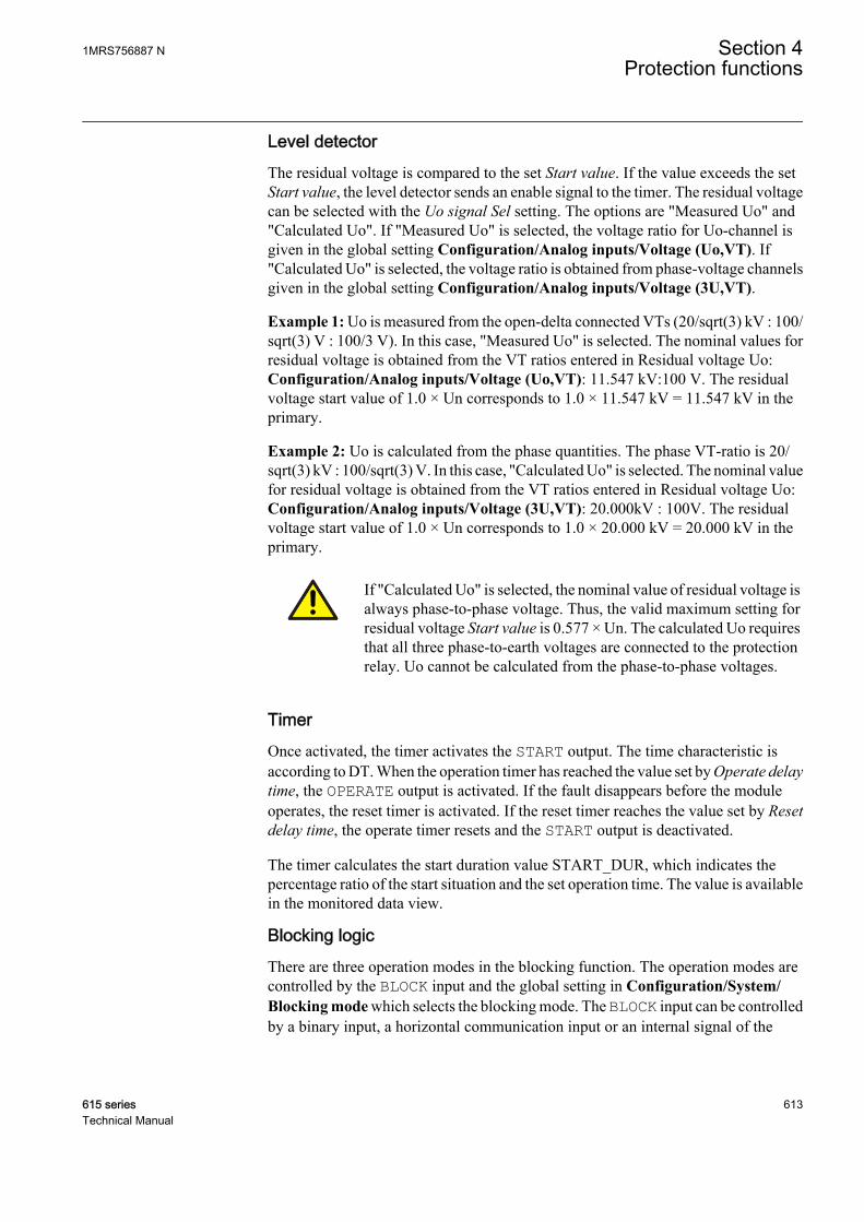
Level detectorThe residual voltage is compared to the set Start value. If the value exceeds the setStart value, the level detector sends an enable signal to the timer. The residual voltagecan be selected with the Uo signal Sel setting. The options are "Measured Uo" and"Calculated Uo". If "Measured Uo" is selected, the voltage ratio for Uo-channel isgiven in the global setting Configuration/Analog inputs/Voltage (Uo,VT). If"Calculated Uo" is selected, the voltage ratio is obtained from phase-voltage channelsgiven in the global setting Configuration/Analog inputs/Voltage (3U,VT).
Example 1: Uo is measured from the open-delta connected VTs (20/sqrt(3) kV : 100/sqrt(3) V : 100/3 V). In this case, "Measured Uo" is selected. The nominal values forresidual voltage is obtained from the VT ratios entered in Residual voltage Uo:Configuration/Analog inputs/Voltage (Uo,VT): 11.547 kV:100 V. The residualvoltage start value of 1.0 × Un corresponds to 1.0 × 11.547 kV = 11.547 kV in theprimary.
Example 2: Uo is calculated from the phase quantities. The phase VT-ratio is 20/sqrt(3) kV : 100/sqrt(3) V. In this case, "Calculated Uo" is selected. The nominal valuefor residual voltage is obtained from the VT ratios entered in Residual voltage Uo:Configuration/Analog inputs/Voltage (3U,VT): 20.000kV : 100V. The residualvoltage start value of 1.0 × Un corresponds to 1.0 × 20.000 kV = 20.000 kV in theprimary.
If "Calculated Uo" is selected, the nominal value of residual voltage isalways phase-to-phase voltage. Thus, the valid maximum setting forresidual voltage Start value is 0.577 × Un. The calculated Uo requiresthat all three phase-to-earth voltages are connected to the protectionrelay. Uo cannot be calculated from the phase-to-phase voltages.
TimerOnce activated, the timer activates the START output. The time characteristic isaccording to DT. When the operation timer has reached the value set by Operate delaytime, the OPERATE output is activated. If the fault disappears before the moduleoperates, the reset timer is activated. If the reset timer reaches the value set by Resetdelay time, the operate timer resets and the START output is deactivated.
The timer calculates the start duration value START_DUR, which indicates thepercentage ratio of the start situation and the set operation time. The value is availablein the monitored data view.
Blocking logicThere are three operation modes in the blocking function. The operation modes arecontrolled by the BLOCK input and the global setting in Configuration/System/Blocking mode which selects the blocking mode. The BLOCK input can be controlledby a binary input, a horizontal communication input or an internal signal of the
1MRS756887 N Section 4Protection functions
615 series 613Technical Manual
protection relay's program. The influence of the BLOCK signal activation ispreselected with the global setting Blocking mode.
The Blocking mode setting has three blocking methods. In the "Freeze timers" mode,the operation timer is frozen to the prevailing value, but the OPERATE output is notdeactivated when blocking is activated. In the "Block all" mode, the whole function isblocked and the timers are reset. In the "Block OPERATE output" mode, the functionoperates normally but the OPERATE output is not activated.
4.5.3.5 Application
ROVPTOV is designed to be used for earth-fault protection in isolated neutral,resistance earthed or reactance earthed systems. In compensated networks, starting ofthe function can be used to control the switching device of the neutral resistor. Thefunction can also be used for the back-up protection of feeders for busbar protectionwhen a more dedicated busbar protection would not be justified.
In compensated and isolated neutral systems, the system neutral voltage, that is, theresidual voltage, increases in case of any fault connected to earth. Depending on thetype of the fault and the fault resistance, the residual voltage reaches different values.The highest residual voltage, equal to the phase-to-earth voltage, is achieved for asingle-phase earth fault. The residual voltage increases approximately the sameamount in the whole system and does not provide any guidance in finding the faultycomponent. Therefore, this function is often used as a backup protection or as a releasesignal for the feeder earth-fault protection.
The protection can also be used for the earth-fault protection of generators and motorsand for the unbalance protection of capacitor banks.
The residual voltage can be calculated internally based on the measurement of thethree-phase voltage. This voltage can also be measured by a single-phase voltagetransformer, located between a transformer star point and earth, or by using an open-delta connection of three single-phase voltage transformers.
4.5.3.6 Signals
Table 533: ROVPTOV Input signals
Name Type Default DescriptionUo SIGNAL 0 Residual voltage
BLOCK BOOLEAN 0=False Block signal for activating the blocking mode
Table 534: ROVPTOV Output signals
Name Type DescriptionOPERATE BOOLEAN Operate
START BOOLEAN Start
Section 4 1MRS756887 NProtection functions
614 615 seriesTechnical Manual

4.5.3.7 Settings
Table 535: ROVPTOV Group settings (Basic)
Parameter Values (Range) Unit Step Default DescriptionStart value 0.010...1.000 xUn 0.001 0.030 Residual overvoltage start value
Operate delay time 40...300000 ms 1 40 Operate delay time
Table 536: ROVPTOV Non group settings (Basic)
Parameter Values (Range) Unit Step Default DescriptionOperation 1=on
5=off 1=on Operation Off / On
Uo signal Sel 1=Measured Uo2=Calculated Uo
1=Measured Uo Selection for used Uo signal
Table 537: ROVPTOV Non group settings (Advanced)
Parameter Values (Range) Unit Step Default DescriptionReset delay time 0...60000 ms 1 20 Reset delay time
4.5.3.8 Monitored data
Table 538: ROVPTOV Monitored data
Name Type Values (Range) Unit DescriptionSTART_DUR FLOAT32 0.00...100.00 % Ratio of start time /
operate time
ROVPTOV Enum 1=on2=blocked3=test4=test/blocked5=off
Status
4.5.3.9 Technical data
Table 539: ROVPTOV Technical data
Characteristic ValueOperation accuracy Depending on the frequency of the measured
voltage: fn ±2 Hz
±1.5% of the set value or ±0.002 × Un
Start time1)2) Minimum Typical Maximum
UFault = 2 × set Startvalue
48 ms 51 ms 54 ms
Reset time Typically 40 ms
Reset ratio Typically 0.96
Table continues on next page
1MRS756887 N Section 4Protection functions
615 series 615Technical Manual
Characteristic ValueRetardation time <35 ms
Operate time accuracy in definite time mode ±1.0% of the set value or ±20 ms
Suppression of harmonics DFT: -50 dB at f = n × fn, where n = 2, 3, 4, 5,…
1) Residual voltage before fault = 0.0 × Un, fn = 50 Hz, residual voltage with nominal frequency injectedfrom random phase angle, results based on statistical distribution of 1000 measurements
2) Includes the delay of the signal output contact
4.5.3.10 Technical revision history
Table 540: ROVPTOV Technical revision history
Technical revision ChangeB Added a setting parameter for the "Measured Uo"
or "Calculated Uo" selection
C Internal improvement
D Internal improvement
4.5.4 Negative-sequence overvoltage protection NSPTOV
4.5.4.1 Identification
Function description IEC 61850identification
IEC 60617identification
ANSI/IEEE C37.2device number
Negative-sequence overvoltageprotection
NSPTOV U2> 47O-
4.5.4.2 Function block
GUID-F94BCCE8-841F-405C-B659-3EF26F959557 V1 EN
Figure 321: Function block
4.5.4.3 Functionality
The negative-sequence overvoltage protection function NSPTOV is used to detectnegative sequence overvoltage conditions. NSPTOV is used for the protection ofmachines.
The function starts when the negative sequence voltage exceeds the set limit.NSPTOV operates with the definite time (DT) characteristics.
The function contains a blocking functionality. It is possible to block function outputs,the definite timer or the function itself, if desired.
Section 4 1MRS756887 NProtection functions
616 615 seriesTechnical Manual
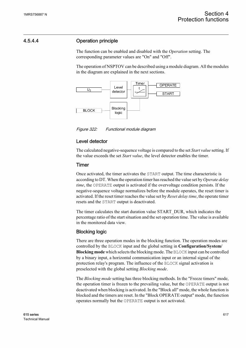
4.5.4.4 Operation principle
The function can be enabled and disabled with the Operation setting. Thecorresponding parameter values are "On" and "Off".
The operation of NSPTOV can be described using a module diagram. All the modulesin the diagram are explained in the next sections.
GUID-0014077D-EEA8-4781-AAC7-AFDBAAF415F4 V1 EN
Figure 322: Functional module diagram
Level detectorThe calculated negative-sequence voltage is compared to the set Start value setting. Ifthe value exceeds the set Start value, the level detector enables the timer.
TimerOnce activated, the timer activates the START output. The time characteristic isaccording to DT. When the operation timer has reached the value set by Operate delaytime, the OPERATE output is activated if the overvoltage condition persists. If thenegative-sequence voltage normalizes before the module operates, the reset timer isactivated. If the reset timer reaches the value set by Reset delay time, the operate timerresets and the START output is deactivated.
The timer calculates the start duration value START_DUR, which indicates thepercentage ratio of the start situation and the set operation time. The value is availablein the monitored data view.
Blocking logicThere are three operation modes in the blocking function. The operation modes arecontrolled by the BLOCK input and the global setting in Configuration/System/Blocking mode which selects the blocking mode. The BLOCK input can be controlledby a binary input, a horizontal communication input or an internal signal of theprotection relay's program. The influence of the BLOCK signal activation ispreselected with the global setting Blocking mode.
The Blocking mode setting has three blocking methods. In the "Freeze timers" mode,the operation timer is frozen to the prevailing value, but the OPERATE output is notdeactivated when blocking is activated. In the "Block all" mode, the whole function isblocked and the timers are reset. In the "Block OPERATE output" mode, the functionoperates normally but the OPERATE output is not activated.
1MRS756887 N Section 4Protection functions
615 series 617Technical Manual
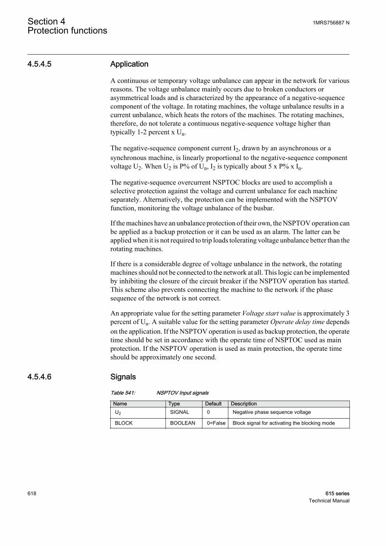
4.5.4.5 Application
A continuous or temporary voltage unbalance can appear in the network for variousreasons. The voltage unbalance mainly occurs due to broken conductors orasymmetrical loads and is characterized by the appearance of a negative-sequencecomponent of the voltage. In rotating machines, the voltage unbalance results in acurrent unbalance, which heats the rotors of the machines. The rotating machines,therefore, do not tolerate a continuous negative-sequence voltage higher thantypically 1-2 percent x Un.
The negative-sequence component current I2, drawn by an asynchronous or asynchronous machine, is linearly proportional to the negative-sequence componentvoltage U2. When U2 is P% of Un, I2 is typically about 5 x P% x In.
The negative-sequence overcurrent NSPTOC blocks are used to accomplish aselective protection against the voltage and current unbalance for each machineseparately. Alternatively, the protection can be implemented with the NSPTOVfunction, monitoring the voltage unbalance of the busbar.
If the machines have an unbalance protection of their own, the NSPTOV operation canbe applied as a backup protection or it can be used as an alarm. The latter can beapplied when it is not required to trip loads tolerating voltage unbalance better than therotating machines.
If there is a considerable degree of voltage unbalance in the network, the rotatingmachines should not be connected to the network at all. This logic can be implementedby inhibiting the closure of the circuit breaker if the NSPTOV operation has started.This scheme also prevents connecting the machine to the network if the phasesequence of the network is not correct.
An appropriate value for the setting parameter Voltage start value is approximately 3percent of Un. A suitable value for the setting parameter Operate delay time dependson the application. If the NSPTOV operation is used as backup protection, the operatetime should be set in accordance with the operate time of NSPTOC used as mainprotection. If the NSPTOV operation is used as main protection, the operate timeshould be approximately one second.
4.5.4.6 Signals
Table 541: NSPTOV Input signals
Name Type Default DescriptionU2 SIGNAL 0 Negative phase sequence voltage
BLOCK BOOLEAN 0=False Block signal for activating the blocking mode
Section 4 1MRS756887 NProtection functions
618 615 seriesTechnical Manual
Table 542: NSPTOV Output signals
Name Type DescriptionOPERATE BOOLEAN Operate
START BOOLEAN Start
4.5.4.7 Settings
Table 543: NSPTOV Group settings (Basic)
Parameter Values (Range) Unit Step Default DescriptionStart value 0.010...1.000 xUn 0.001 0.030 Start value
Operate delay time 40...120000 ms 1 40 Operate delay time
Table 544: NSPTOV Non group settings (Basic)
Parameter Values (Range) Unit Step Default DescriptionOperation 1=on
5=off 1=on Operation Off / On
Table 545: NSPTOV Non group settings (Advanced)
Parameter Values (Range) Unit Step Default DescriptionReset delay time 0...60000 ms 1 20 Reset delay time
4.5.4.8 Monitored data
Table 546: NSPTOV Monitored data
Name Type Values (Range) Unit DescriptionSTART_DUR FLOAT32 0.00...100.00 % Ratio of start time /
operate time
NSPTOV Enum 1=on2=blocked3=test4=test/blocked5=off
Status
1MRS756887 N Section 4Protection functions
615 series 619Technical Manual

4.5.4.9 Technical data
Table 547: NSPTOV Technical data
Characteristic ValueOperation accuracy Depending on the frequency of the voltage
measured: fn
±1.5% of the set value or ±0.002 × Un
Start time1)2) Minimum Typical Maximum
UFault = 1.1 × set StartvalueUFault = 2.0 × set Startvalue
33 ms24 ms
35 ms26 ms
37 ms28 ms
Reset time Typically 40 ms
Reset ratio Typically 0.96
Retardation time <35 ms
Operate time accuracy in definite time mode ±1.0% of the set value or ±20 ms
Suppression of harmonics DFT: -50 dB at f = n × fn, where n = 2, 3, 4, 5,…
1) Negative-sequence voltage before fault = 0.0 × Un, fn = 50 Hz, negative-sequence overvoltage withnominal frequency injected from random phase angle, results based on statistical distribution of 1000measurements
2) Includes the delay of the signal output contact
4.5.4.10 Technical revision history
Table 548: NSPTOV Technical revision history
Technical revision ChangeB Internal change
C Internal improvement.
D Internal improvement.
4.5.5 Positive-sequence undervoltage protection PSPTUV
4.5.5.1 Identification
Function description IEC 61850identification
IEC 60617identification
ANSI/IEEE C37.2device number
Positive-sequence undervoltageprotection
PSPTUV U1< 47U+
Section 4 1MRS756887 NProtection functions
620 615 seriesTechnical Manual
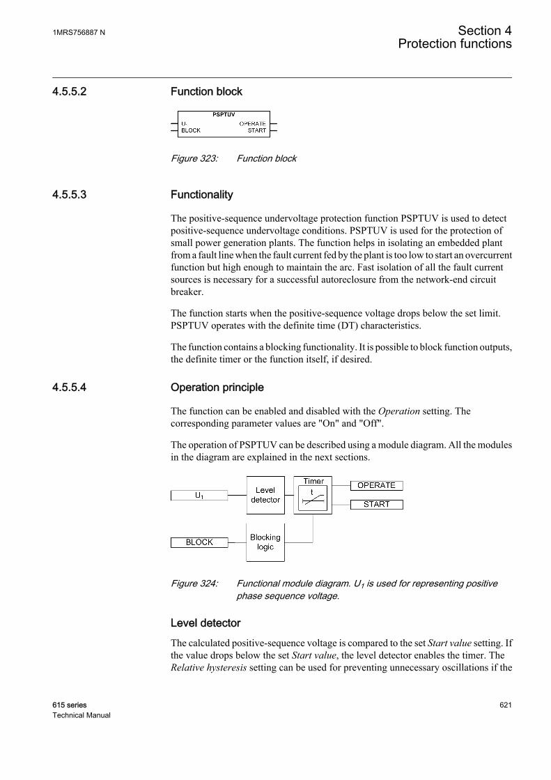
4.5.5.2 Function block
GUID-24EBDE8B-E1FE-47B0-878B-EBEC13A27CAC V1 EN
Figure 323: Function block
4.5.5.3 Functionality
The positive-sequence undervoltage protection function PSPTUV is used to detectpositive-sequence undervoltage conditions. PSPTUV is used for the protection ofsmall power generation plants. The function helps in isolating an embedded plantfrom a fault line when the fault current fed by the plant is too low to start an overcurrentfunction but high enough to maintain the arc. Fast isolation of all the fault currentsources is necessary for a successful autoreclosure from the network-end circuitbreaker.
The function starts when the positive-sequence voltage drops below the set limit.PSPTUV operates with the definite time (DT) characteristics.
The function contains a blocking functionality. It is possible to block function outputs,the definite timer or the function itself, if desired.
4.5.5.4 Operation principle
The function can be enabled and disabled with the Operation setting. Thecorresponding parameter values are "On" and "Off".
The operation of PSPTUV can be described using a module diagram. All the modulesin the diagram are explained in the next sections.
GUID-F1E58B1E-03CB-4A3C-BD1B-F809420397ED V1 EN
Figure 324: Functional module diagram. U1 is used for representing positivephase sequence voltage.
Level detectorThe calculated positive-sequence voltage is compared to the set Start value setting. Ifthe value drops below the set Start value, the level detector enables the timer. TheRelative hysteresis setting can be used for preventing unnecessary oscillations if the
1MRS756887 N Section 4Protection functions
615 series 621Technical Manual
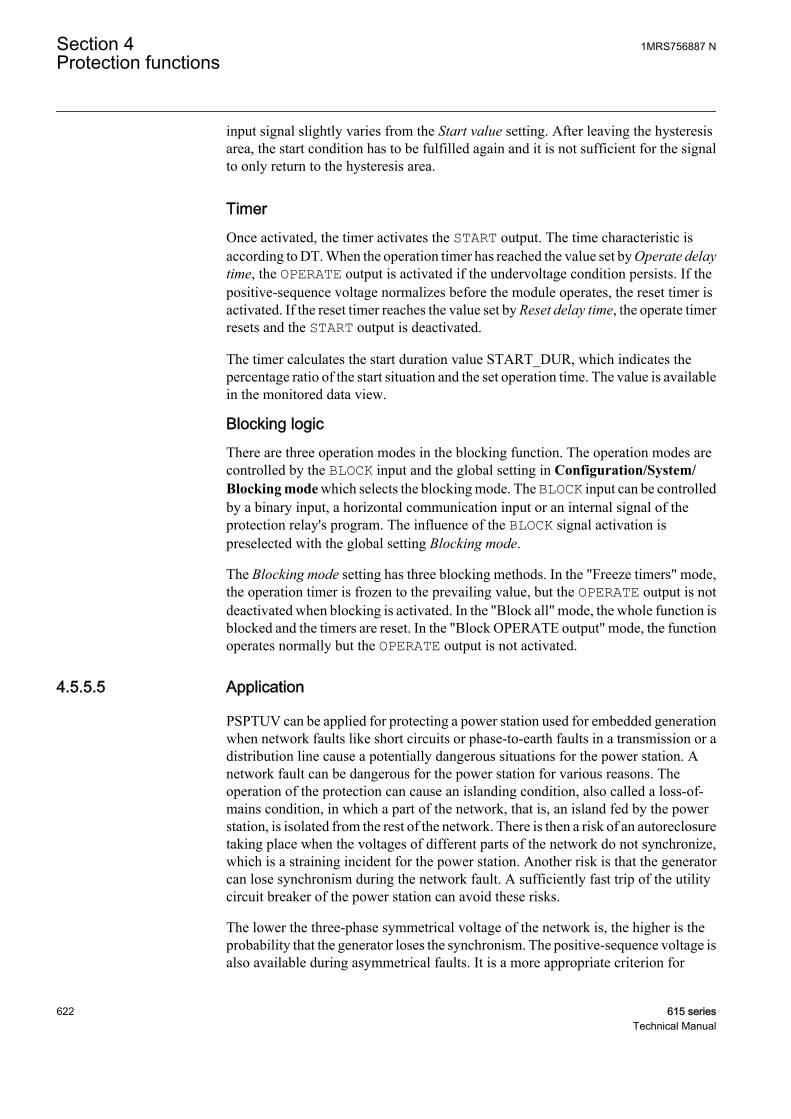
input signal slightly varies from the Start value setting. After leaving the hysteresisarea, the start condition has to be fulfilled again and it is not sufficient for the signalto only return to the hysteresis area.
TimerOnce activated, the timer activates the START output. The time characteristic isaccording to DT. When the operation timer has reached the value set by Operate delaytime, the OPERATE output is activated if the undervoltage condition persists. If thepositive-sequence voltage normalizes before the module operates, the reset timer isactivated. If the reset timer reaches the value set by Reset delay time, the operate timerresets and the START output is deactivated.
The timer calculates the start duration value START_DUR, which indicates thepercentage ratio of the start situation and the set operation time. The value is availablein the monitored data view.
Blocking logicThere are three operation modes in the blocking function. The operation modes arecontrolled by the BLOCK input and the global setting in Configuration/System/Blocking mode which selects the blocking mode. The BLOCK input can be controlledby a binary input, a horizontal communication input or an internal signal of theprotection relay's program. The influence of the BLOCK signal activation ispreselected with the global setting Blocking mode.
The Blocking mode setting has three blocking methods. In the "Freeze timers" mode,the operation timer is frozen to the prevailing value, but the OPERATE output is notdeactivated when blocking is activated. In the "Block all" mode, the whole function isblocked and the timers are reset. In the "Block OPERATE output" mode, the functionoperates normally but the OPERATE output is not activated.
4.5.5.5 Application
PSPTUV can be applied for protecting a power station used for embedded generationwhen network faults like short circuits or phase-to-earth faults in a transmission or adistribution line cause a potentially dangerous situations for the power station. Anetwork fault can be dangerous for the power station for various reasons. Theoperation of the protection can cause an islanding condition, also called a loss-of-mains condition, in which a part of the network, that is, an island fed by the powerstation, is isolated from the rest of the network. There is then a risk of an autoreclosuretaking place when the voltages of different parts of the network do not synchronize,which is a straining incident for the power station. Another risk is that the generatorcan lose synchronism during the network fault. A sufficiently fast trip of the utilitycircuit breaker of the power station can avoid these risks.
The lower the three-phase symmetrical voltage of the network is, the higher is theprobability that the generator loses the synchronism. The positive-sequence voltage isalso available during asymmetrical faults. It is a more appropriate criterion for
Section 4 1MRS756887 NProtection functions
622 615 seriesTechnical Manual
detecting the risk of loss of synchronism than, for example, the lowest phase-to-phasevoltage.
Analyzing the loss of synchronism of a generator is rather complicated and requires amodel of the generator with its prime mover and controllers. The generator can be ableto operate synchronously even if the voltage drops by a few tens of percent for somehundreds of milliseconds. The setting of PSPTUV is thus determined by the need toprotect the power station from the risks of the islanding conditions since that requiresa higher setting value.
The loss of synchronism of a generator means that the generator is unable to operateas a generator with the network frequency but enters into an unstable condition inwhich it operates by turns as a generator and a motor. Such a condition stresses thegenerator thermally and mechanically. This kind of loss of synchronism should not bemixed with the one between an island and the utility network. In the islandingsituation, the condition of the generator itself is normal but the phase angle and thefrequency of the phase-to-phase voltage can be different from the correspondingvoltage in the rest of the network. The island can have a frequency of its own relativelyfast when fed by a small power station with a low inertia.
PSPTUV complements other loss-of-grid protection principles based on thefrequency and voltage operation.
Motor stalling and failure to start can lead to a continuous undervoltage. The positive-sequence undervoltage is used as a backup protection against the motor stallcondition.
4.5.5.6 Signals
Table 549: PSPTUV Input signals
Name Type Default DescriptionU1 SIGNAL 0 Positive phase sequence voltage
BLOCK BOOLEAN 0=False Block signal for activating the blocking mode
Table 550: PSPTUV Output signals
Name Type DescriptionOPERATE BOOLEAN Operate
START BOOLEAN Start
4.5.5.7 Settings
Table 551: PSPTUV Group settings (Basic)
Parameter Values (Range) Unit Step Default DescriptionStart value 0.010...1.200 xUn 0.001 0.500 Start value
Operate delay time 40...120000 ms 10 40 Operate delay time
1MRS756887 N Section 4Protection functions
615 series 623Technical Manual

Table 552: PSPTUV Group settings (Advanced)
Parameter Values (Range) Unit Step Default DescriptionVoltage block value 0.01...1.00 xUn 0.01 0.20 Internal blocking level
Enable block value 0=False1=True
1=True Enable Internal Blocking
Table 553: PSPTUV Non group settings (Basic)
Parameter Values (Range) Unit Step Default DescriptionOperation 1=on
5=off 1=on Operation Off / On
Table 554: PSPTUV Non group settings (Advanced)
Parameter Values (Range) Unit Step Default DescriptionReset delay time 0...60000 ms 1 20 Reset delay time
Relative hysteresis 1.0...5.0 % 0.1 4.0 Relative hysteresis for operation
4.5.5.8 Monitored data
Table 555: PSPTUV Monitored data
Name Type Values (Range) Unit DescriptionSTART_DUR FLOAT32 0.00...100.00 % Ratio of start time /
operate time
PSPTUV Enum 1=on2=blocked3=test4=test/blocked5=off
Status
4.5.5.9 Technical data
Table 556: PSPTUV Technical data
Characteristic ValueOperation accuracy Depending on the frequency of the measured
voltage: fn ±2 Hz
±1.5% of the set value or ±0.002 × Un
Start time1)2) Minimum Typical Maximum
UFault = 0.99 × set StartvalueUFault = 0.9 × set Startvalue
52 ms44 ms
55 ms47 ms
58 ms50 ms
Reset time Typically 40 ms
Reset ratio Depends on the set Relative hysteresis
Table continues on next page
Section 4 1MRS756887 NProtection functions
624 615 seriesTechnical Manual

Characteristic ValueRetardation time <35 ms
Operate time accuracy in definite time mode ±1.0% of the set value or ±20 ms
Suppression of harmonics DFT: -50 dB at f = n × fn, where n = 2, 3, 4, 5,…
1) Start value = 1.0 × Un, positive-sequence voltage before fault = 1.1 × Un, fn = 50 Hz, positive sequenceundervoltage with nominal frequency injected from random phase angle, results based on statisticaldistribution of 1000 measurements
2) Includes the delay of the signal output contact
4.5.5.10 Technical revision history
Table 557: PSPTUV Technical revision history
Technical revision ChangeB -
C Internal improvement
D Internal improvement
4.5.6 Overexcitation protection OEPVPH
4.5.6.1 Identification
Function description IEC 61850identification
IEC 60617identification
ANSI/IEEE C37.2device number
Overexcitation protection OEPVPH U/f> 24
4.5.6.2 Function block
GUID-CCC25550-F3F8-4CF5-8AF3-424CAB1B8D3B V1 EN
Figure 325: Function block
4.5.6.3 Functionality
The overexcitation protection function OEPVPH is used to protect generators andpower transformers against an excessive flux density and saturation of the magneticcore.
1MRS756887 N Section 4Protection functions
615 series 625Technical Manual

The function calculates the U/f ratio (volts/hertz) proportional to the excitation levelof the generator or transformer and compares this value to the setting limit. Thefunction starts when the excitation level exceeds the set limit and operates when theset operating time has elapsed. The operating time characteristic can be selected to beeither definite time (DT) or overexcitation inverse definite minimum time(overexcitation type IDMT).
This function contains a blocking functionality. It is possible to block the functionoutputs, reset timer or the function itself, if desired.
4.5.6.4 Operation principle
The function can be enabled and disabled with the Operation setting. Thecorresponding parameter values are "On" and "Off".
The operation of OEPVPH can be described using a module diagram. All the modulesin the diagram are explained in the next sections.
GUID-154779AA-E81D-451D-A4FA-E1585FD7787F V1 EN
Figure 326: Functional module diagram
U/f calculationThis module calculates the U/f ratio, that is, the excitation level from the internalinduced voltage (E) and frequency. The actual measured voltage (Um) deviates fromthe internal induced voltage (E), a value the equipment has to withstand. This voltagecompensation is based on the load current (IL) and the leakage reactance (Xleak) of theequipment. The leakage reactance of the transformer or generator is set through theLeakage React setting in percentage of the Z base.
The internal induced voltage (E) is calculated from the measured voltage. The settingsVoltage selection and Phase supervision determine which voltages and currents are tobe used. If the Voltage selection setting is set to "phase-to-earth" or "phase-to-phase",the Phase supervision setting is used for determining which phases or phase-to-phasevoltages ("A or AB", "B or BC" and "C or CA") and currents are to be used for thecalculation of the induced voltage.
Section 4 1MRS756887 NProtection functions
626 615 seriesTechnical Manual

Table 558: Voltages and currents used for induced voltage (emf) E calculation
Voltage selectionsetting
Phase supervisionsetting
Calculation of internal induced voltage (emf) E1)
phase-to-earth A or ABE U I j XA A leak= ⋅ + ⋅ ⋅( )3 ( )
GUID-2516665F-F5D8-40D2-8536-D288A31F1D62 V1 EN
phase-to-earth B or BCE U I j XB B leak= ⋅ + ⋅ ⋅( )3 ( )
GUID-6FCBAF6F-45D5-4B78-B982-B08420C06A1F V1 EN
phase-to-earth C or CAE U I j XC C leak= ⋅ + ⋅ ⋅( )3 ( )
GUID-FE8C9442-EB84-4091-8395-E529748CF240 V1 EN
phase-to-phase A or ABE U I I j XAB A B leak= + − ⋅ ⋅( )( ) ( )
GUID-3C5E3177-0063-46B3-B047-FAE94D99A07C V1 EN
phase-to-phase B or BCE U I I j XBC B C leak= + − ⋅ ⋅( )( ) ( )
GUID-829F8472-9601-4E36-A8D3-D9E1965E49CF V1 EN
phase-to-phase C or CAE U I I j XCA C A leak= + − ⋅ ⋅( )( ) ( )
GUID-B949713D-95C3-4BAB-BD07-BB129EAB4444 V1 EN
Pos sequence N/AE U I j X leak= ⋅ + ⋅ ⋅( )3 1 1 ( )
GUID-1B31B8F7-62F0-48D3-BA4F-ACA4AB585C84 V1 EN
1) Voltages, currents and the leakage reactance Xleak in the calculations are given in volts, amps andohms.
If all three phase or phase-to-phase voltages and phase currents are fedto the protection relay, the positive-sequence alternative isrecommended.
If the leakage reactance of the protected equipment is unknown or ifthe measured voltage (Um) is to be used in the excitation levelcalculation, then by setting the leakage reactance value to zero thecalculated induced voltage (E) is equal to the measured voltage.
The calculated U/f ratio is scaled to a value based on the nominal Un/fn ratio. However,the highest allowed continuous voltage (in % Un) can be defined by setting theparameter Voltage Max Cont to change the basis of the voltage. The measured voltageis compared to the new base value to obtain the excitation level.
The excitation level (M) can be calculated:
1MRS756887 N Section 4Protection functions
615 series 627Technical Manual
M
E
f
U
f
Volt Max continuous
m
n
n
=
⋅
100
GUID-123DDA77-3E40-4267-AE9A-99A578104433 V1 EN (Equation 130)
M excitation level (U/f ratio or volts/hertz) in pu
E internal induced voltage (emf)
fm measured frequency
Un nominal phase-to-phase voltage
fn nominal frequency
If the input frequency (fm) is less than 20 percent of the nominal frequency (fn), thecalculation of the excitation level is disabled and forced to zero value. This means thatthe function is blocked from starting and operating during a low-frequency condition.
The calculated excitation level (U/f ratio or volts/hertz) VOLTPERHZ is available inthe Monitored data view.
Level detectorLevel detector compares the calculated excitation level to the Start value setting. If theexcitation level exceeds the set limit, the module sends an enabling signal to startTimer.
TimerOnce activated, Timer activates the START output. Depending on the value of theOperating curve type setting, the time characteristics are according to DT or IDMT.When the operation timer has reached the value set by Operate delay time in the DTmode or the value defined by the inverse time curve, the OPERATE output is activated.
In a drop-off situation, that is, when the excitation level drops below Start value beforethe function operates, the reset timer is activated and the START output resets after thetime delay of Reset delay time for the DT characteristics. For the IDMT curves, thereset operation is as described in the Timer characteristics chapter.
For the IDMT curves, it is possible to define the maximum and minimum operatingtimes via the Minimum operate time and Maximum operate time settings. TheMaximum operate time setting is used to prevent infinite start situations at low degreesof overexcitation. The Time multiplier setting is used for scaling the IDMT operatetimes.
The activation of the OPERATE output activates the BLK_RESTART output.
For the DT characteristics, the deactivation of the OPERATE output activates thecooling timer. The timer is set to the value entered in the Cooling time setting. TheBLK_RESTART and COOL_ACTIVE outputs are kept active until the cooling timer
Section 4 1MRS756887 NProtection functions
628 615 seriesTechnical Manual
is reset. If the excitation increases above the set value during this period, theOPERATE output is activated immediately. For IDMT, the deactivation ofBLK_RESTART and COOL_ACTIVE depends on the curve type selected.
The T_ENARESTART output indicates in seconds the duration for which theBLK_RESTART output still remains active. The value is available in the Monitoreddata view.
Timer calculates the start duration value START_DUR, which indicates thepercentage ratio of the start situation and the set operating time. The value is availablein the Monitored data view.
Blocking logicThere are three operation modes in the blocking functionality. The operation modesare controlled by the BLOCK input and the global setting Configuration/System/Blocking mode which selects the blocking mode. The BLOCK input can be controlledby a binary input, a horizontal communication input or an internal signal of theprotection relay's program. The influence of the BLOCK signal activation ispreselected with the global setting Blocking mode.
The Blocking mode setting has three blocking methods. In the "Freeze timers" mode,the operation timer is frozen to the prevailing value. In the "Block all" mode, the wholefunction is blocked and the timers are reset. In the "Block OPERATE output" mode,the function operates normally but the OPERATE output is not activated.
4.5.6.5 Timer characteristics
OEPVPH supports both DT and IDMT characteristics. The DT timer characteristicscan be selected as "ANSI Def. Time" or "IEC Def. Time" in the Operating curve typesetting. The functionality is identical in both cases. When the DT characteristics areselected, the functionality is only affected by the Operate delay time and Reset delaytime settings.
OEPVPH also supports four overexcitation IDMT characteristic curves: "OvExtIDMT Crv1", "OvExt IDMT Crv2", "OvExt IDMT Crv3" and "OvExt IDMT Crv4".
Overexcitation inverse definite minimum time curve (IDMT)In the inverse time modes, the operate time depends on the momentary value of theexcitation: the higher the excitation level, the shorter the operate time. The operatetime calculation or integration starts immediately when the excitation level exceedsthe set Start value and the START output is activated.
The OPERATE output is activated when the cumulative sum of the integratorcalculating the overexcitation situation exceeds the value set by the inverse timemode. The set value depends on the selected curve type and the setting values used.
1MRS756887 N Section 4Protection functions
615 series 629Technical Manual
The Minimum operate time and Maximum operate time settings define the minimumoperate time and maximum operate time possible for the IDMT mode. For settingthese parameters, a careful study of the particular IDMT curves is recommended.
The operation time of the function block can vary much betweendifferent operating curve types even if other setting parameters for thecurves were not changed.
Once activated, the Timer activates the START output for the IDMT curves. If theexcitation level drops below the Start value setting before the function operates, thereset timer is activated and the START output resets immediately. If START reoccursduring the reset time, the operation calculation is made based on the effects of theperiod when START was previously active. This is intended to allow an operatingcondition to occur in less time to account for the heating effects from the previousactive start period.
When START becomes active, the reset time is based on the following equation.
reset timeSTART DUR
Cooling time=
⋅
_
100
GUID-B24FEFF8-79D1-49EA-BF3B-3C2ECFB1EEA2 V1 EN (Equation 131)
For the IDMT curves, when START is deactivated, the integral value calculatedduring START is continuously decremented by a constant that causes its value tobecome zero when the reset time elapses during the reset period. If a fault reoccurs, theintegration continues from the current integral value and the start time is adjusted, asshown in Figure 327. The start time becomes the value at the time when the faultdropped off minus the amount of reset time that occurred. If the reset period elapseswithout a fault being detected, the saved values of the start time and integration arecleared.
Section 4 1MRS756887 NProtection functions
630 615 seriesTechnical Manual

GUID-9659EC5F-00C6-4791-A705-2D84B1B728B7 V1 EN
Figure 327: An example of a delayed reset in the inverse time characteristics.When the start becomes active during the reset period, the operatetime counter continues from the level corresponding to the drop-off(reset time = 0.50 · Cooling time)
Overexcitation IDMT curves 1, 2 and 3The base equation for the IDMT curves "OvExt IDMT Crv1", "OvExt IDMT Crv2"and "OvExt IDMT Crv3" is:
t s e
ak b M
c( ) = ⋅
+ −
60
100
GUID-FCF33CC8-E4D9-4339-BBAD-593465267F6D V1 EN (Equation 132)
t(s) Operate time in seconds
M Excitation level (U/f ratio or volts/hertz) in pu
k Time multiplier setting
The constant "60" in Equation 132 converts time from minutes toseconds.
Table 559: Parameters a, b and c for different IDMT curves
Operating curve typesetting
a b c
OvExt IDMT Crv1 2.5 115.00 4.886
OvExt IDMT Crv2 2.5 113.50 3.040
OvExt IDMT Crv3 2.5 108.75 2.443
1MRS756887 N Section 4Protection functions
615 series 631Technical Manual
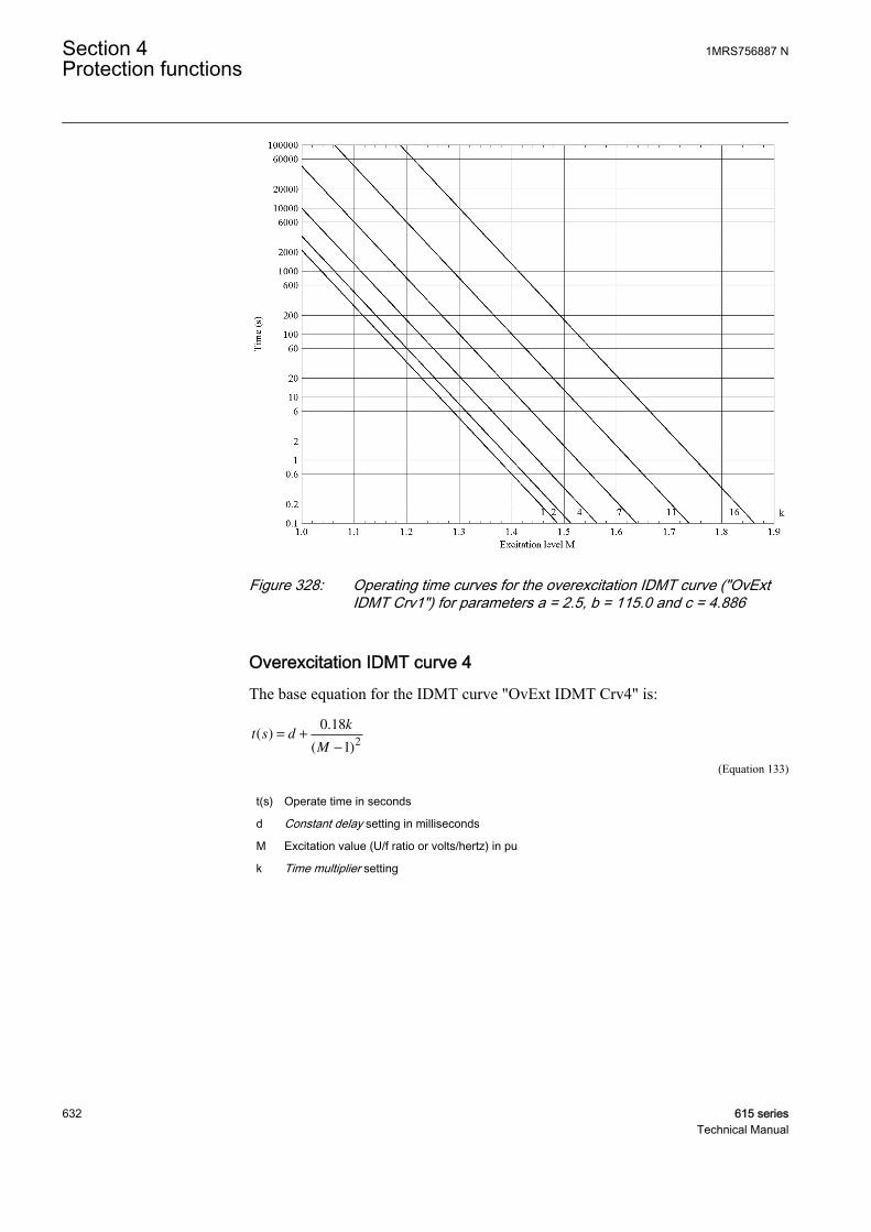
GUID-BD1205DC-1794-4F64-A950-6199C54DB7B1 V1 EN
Figure 328: Operating time curves for the overexcitation IDMT curve ("OvExtIDMT Crv1") for parameters a = 2.5, b = 115.0 and c = 4.886
Overexcitation IDMT curve 4The base equation for the IDMT curve "OvExt IDMT Crv4" is:
t s dk
M
( ).
( )= +
−
0 18
12
GUID-361FE32F-D157-402D-BC70-D568AB809339 V1 EN (Equation 133)
t(s) Operate time in seconds
d Constant delay setting in milliseconds
M Excitation value (U/f ratio or volts/hertz) in pu
k Time multiplier setting
Section 4 1MRS756887 NProtection functions
632 615 seriesTechnical Manual
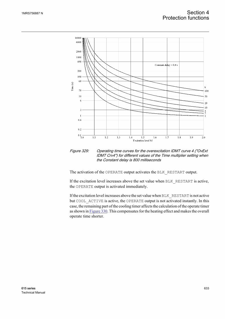
GUID-6FC7624E-7E13-4645-8943-0FDFBAA1D184 V1 EN
Figure 329: Operating time curves for the overexcitation IDMT curve 4 ("OvExtIDMT Crv4") for different values of the Time multiplier setting whenthe Constant delay is 800 milliseconds
The activation of the OPERATE output activates the BLK_RESTART output.
If the excitation level increases above the set value when BLK_RESTART is active,the OPERATE output is activated immediately.
If the excitation level increases above the set value when BLK_RESTART is not activebut COOL_ACTIVE is active, the OPERATE output is not activated instantly. In thiscase, the remaining part of the cooling timer affects the calculation of the operate timeras shown in Figure 330. This compensates for the heating effect and makes the overalloperate time shorter.
1MRS756887 N Section 4Protection functions
615 series 633Technical Manual
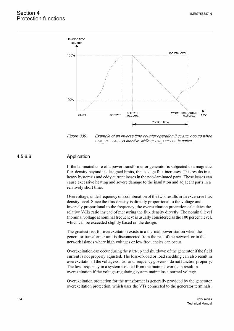
GUID-DC037ABF-2309-4E0A-AB7E-4928C17599AB V1 EN
Figure 330: Example of an inverse time counter operation if START occurs whenBLK_RESTART is inactive while COOL_ACTIVE is active.
4.5.6.6 Application
If the laminated core of a power transformer or generator is subjected to a magneticflux density beyond its designed limits, the leakage flux increases. This results in aheavy hysteresis and eddy current losses in the non-laminated parts. These losses cancause excessive heating and severe damage to the insulation and adjacent parts in arelatively short time.
Overvoltage, underfrequency or a combination of the two, results in an excessive fluxdensity level. Since the flux density is directly proportional to the voltage andinversely proportional to the frequency, the overexcitation protection calculates therelative V/Hz ratio instead of measuring the flux density directly. The nominal level(nominal voltage at nominal frequency) is usually considered as the 100 percent level,which can be exceeded slightly based on the design.
The greatest risk for overexcitation exists in a thermal power station when thegenerator-transformer unit is disconnected from the rest of the network or in thenetwork islands where high voltages or low frequencies can occur.
Overexcitation can occur during the start-up and shutdown of the generator if the fieldcurrent is not properly adjusted. The loss-of-load or load shedding can also result inoverexcitation if the voltage control and frequency governor do not function properly.The low frequency in a system isolated from the main network can result inoverexcitation if the voltage-regulating system maintains a normal voltage.
Overexcitation protection for the transformer is generally provided by the generatoroverexcitation protection, which uses the VTs connected to the generator terminals.
Section 4 1MRS756887 NProtection functions
634 615 seriesTechnical Manual

The curves that define the generator and transformer V/Hz limits must be coordinatedproperly to protect both equipment.
If the generator can be operated with a leading power factor, the high-side voltage ofthe transformer can have a higher pu V/Hz than the generator V/Hz. This needs to beconsidered in a proper overexcitation protection of the transformer. Also,measurement for the voltage must not be taken from any winding where OLTC islocated.
It is assumed that overexcitation is a symmetrical phenomenon caused by events suchas loss-of-load. A high phase-to-earth voltage does not mean overexcitation. Forexample, in an unearthed power system, a single phase-to-earth fault means highvoltages of the healthy two phases to earth but no overexcitation on any winding. Thephase-to-phase voltages remain essentially unchanged. An important voltage to beconsidered for the overexcitation is the voltage between the two ends of each winding.
Example calculations for overexcitation protection
Example 1Nominal values of the machine
Nominal phase-to-phase voltage (Un) 11000 V
Nominal phase current (In) 7455 A
Nominal frequency (fn) 50 Hz
Leakage reactance (Xleak) 20% or 0.2 pu
Measured voltage and load currents of the machine
Phase A-to-phase B voltage (UAB) 11500∠0° V
Phase A current (IA) 5600∠-63.57° A
Phase B current (IB) 5600∠176.42° A
Measured frequency (fm) 49.98 Hz
The setting Voltage Max Cont 100%
The setting Voltage selection phase-to-phase
The setting Phase supervision A or AB
The pu leakage reactance XleakPU is converted to ohms.
X XU
Ileak leakPU
n
n
Ω= ⋅
⋅( )
= ⋅
⋅( )
=
30 2 11000
7455 3. 00 170378. Ohms
GUID-D143EE29-4A67-4B5E-9C1A-87D60F10CFCB V1 EN (Equation 134)
The internal induced voltage E of the machine is calculated.
1MRS756887 N Section 4Protection functions
615 series 635Technical Manual
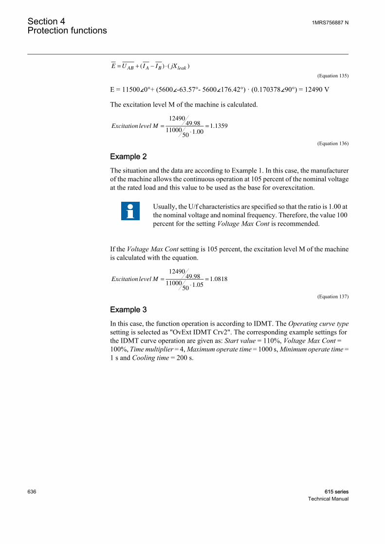
E U I I jXAB A B leak= + − ⋅( ) ( )
GUID-7277AB82-6BAD-4849-A4CC-18C6EEEB4AC5 V1 EN (Equation 135)
E = 11500∠0°+ (5600∠-63.57°- 5600∠176.42°) · (0.170378∠90°) = 12490 V
The excitation level M of the machine is calculated.
Excitation level M =
⋅
=
1249049 98
1100050
1 001 1359.
..
GUID-28DEBF41-9058-4C7B-985F-FA7131DF39A7 V1 EN (Equation 136)
Example 2The situation and the data are according to Example 1. In this case, the manufacturerof the machine allows the continuous operation at 105 percent of the nominal voltageat the rated load and this value to be used as the base for overexcitation.
Usually, the U/f characteristics are specified so that the ratio is 1.00 atthe nominal voltage and nominal frequency. Therefore, the value 100percent for the setting Voltage Max Cont is recommended.
If the Voltage Max Cont setting is 105 percent, the excitation level M of the machineis calculated with the equation.
Excitation level M =
⋅
=
1249049 98
1100050
1 051 0818.
..
GUID-3422B6EB-4564-4EFD-B60A-50CB18850054 V1 EN (Equation 137)
Example 3In this case, the function operation is according to IDMT. The Operating curve typesetting is selected as "OvExt IDMT Crv2". The corresponding example settings forthe IDMT curve operation are given as: Start value = 110%, Voltage Max Cont =100%, Time multiplier = 4, Maximum operate time = 1000 s, Minimum operate time =1 s and Cooling time = 200 s.
Section 4 1MRS756887 NProtection functions
636 615 seriesTechnical Manual
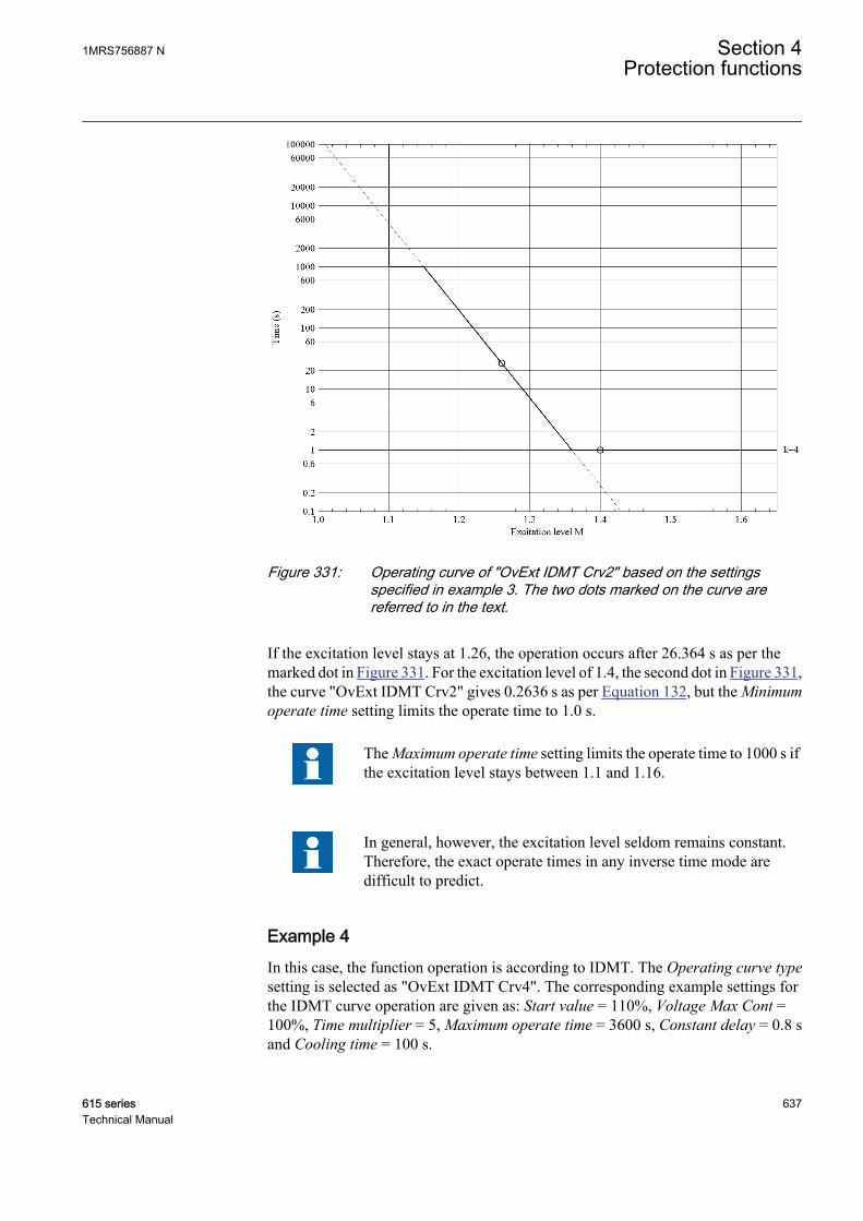
GUID-433F1AF8-DA0B-4FEA-A281-1872487F3B97 V1 EN
Figure 331: Operating curve of "OvExt IDMT Crv2" based on the settingsspecified in example 3. The two dots marked on the curve arereferred to in the text.
If the excitation level stays at 1.26, the operation occurs after 26.364 s as per themarked dot in Figure 331. For the excitation level of 1.4, the second dot in Figure 331,the curve "OvExt IDMT Crv2" gives 0.2636 s as per Equation 132, but the Minimumoperate time setting limits the operate time to 1.0 s.
The Maximum operate time setting limits the operate time to 1000 s ifthe excitation level stays between 1.1 and 1.16.
In general, however, the excitation level seldom remains constant.Therefore, the exact operate times in any inverse time mode aredifficult to predict.
Example 4In this case, the function operation is according to IDMT. The Operating curve typesetting is selected as "OvExt IDMT Crv4". The corresponding example settings forthe IDMT curve operation are given as: Start value = 110%, Voltage Max Cont =100%, Time multiplier = 5, Maximum operate time = 3600 s, Constant delay = 0.8 sand Cooling time = 100 s.
1MRS756887 N Section 4Protection functions
615 series 637Technical Manual
GUID-78B05F4B-3434-4DD5-89F6-17F099444C04 V1 EN
Figure 332: Operating curve of “OvExt IDMT Crv4” based on the specifiedsettings. The two dots marked on the curve are referred to in the text.
If the excitation level stays at 1.25, the operation occurs after 15.20 s. At the excitationlevel of 1.42, the time to operation would be 5.90 s as per the two dots in Figure 332.In this case, the setting Maximum operate time 3600 s does not limit the maximumoperate time because the operate time at Start value = 110% (1.1 pu) is approximately75 s.
4.5.6.7 Signals
Table 560: OEPVPH Input signals
Name Type Default DescriptionI_A SIGNAL 0 Phase A current
I_B SIGNAL 0 Phase B current
I_C SIGNAL 0 Phase C current
I1 SIGNAL 0 Positive-phase sequence current
U_A_AB SIGNAL 0 Phase-to-earth voltage A or phase-to-phasevoltage AB
U_B_BC SIGNAL 0 Phase-to-earth voltage B or phase-to-phasevoltage BC
U_C_CA SIGNAL 0 Phase-to-earth voltage C or phase-to-phasevoltage CA
Table continues on next page
Section 4 1MRS756887 NProtection functions
638 615 seriesTechnical Manual
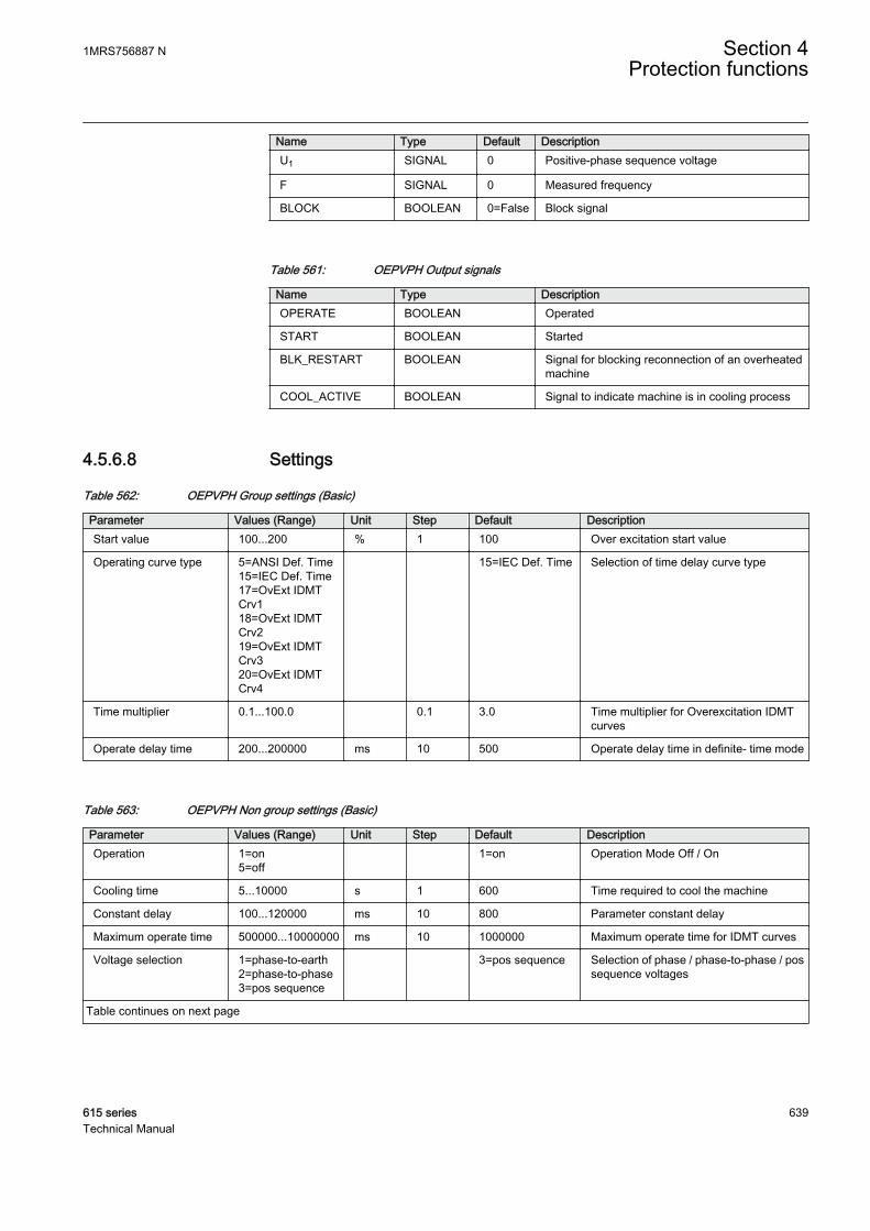
Name Type Default DescriptionU1 SIGNAL 0 Positive-phase sequence voltage
F SIGNAL 0 Measured frequency
BLOCK BOOLEAN 0=False Block signal
Table 561: OEPVPH Output signals
Name Type DescriptionOPERATE BOOLEAN Operated
START BOOLEAN Started
BLK_RESTART BOOLEAN Signal for blocking reconnection of an overheatedmachine
COOL_ACTIVE BOOLEAN Signal to indicate machine is in cooling process
4.5.6.8 Settings
Table 562: OEPVPH Group settings (Basic)
Parameter Values (Range) Unit Step Default DescriptionStart value 100...200 % 1 100 Over excitation start value
Operating curve type 5=ANSI Def. Time15=IEC Def. Time17=OvExt IDMTCrv118=OvExt IDMTCrv219=OvExt IDMTCrv320=OvExt IDMTCrv4
15=IEC Def. Time Selection of time delay curve type
Time multiplier 0.1...100.0 0.1 3.0 Time multiplier for Overexcitation IDMTcurves
Operate delay time 200...200000 ms 10 500 Operate delay time in definite- time mode
Table 563: OEPVPH Non group settings (Basic)
Parameter Values (Range) Unit Step Default DescriptionOperation 1=on
5=off 1=on Operation Mode Off / On
Cooling time 5...10000 s 1 600 Time required to cool the machine
Constant delay 100...120000 ms 10 800 Parameter constant delay
Maximum operate time 500000...10000000 ms 10 1000000 Maximum operate time for IDMT curves
Voltage selection 1=phase-to-earth2=phase-to-phase3=pos sequence
3=pos sequence Selection of phase / phase-to-phase / possequence voltages
Table continues on next page
1MRS756887 N Section 4Protection functions
615 series 639Technical Manual

Parameter Values (Range) Unit Step Default DescriptionPhase selection 1=A or AB
2=B or BC3=C or CA
1=A or AB Parameter for phase selection
Leakage React 0.0...50.0 % 0.1 0.0 Leakage reactance of the machine
Voltage Max Cont 80...160 % 1 110 Maximum allowed continuous operatingvoltage ratio
Table 564: OEPVPH Non group settings (Advanced)
Parameter Values (Range) Unit Step Default DescriptionReset delay time 0...60000 ms 10 100 Resetting time of the operate time counter
in DT mode
Minimum operate time 200...60000 ms 10 200 Minimum operate time for IDMT curves
4.5.6.9 Monitored data
Table 565: OEPVPH Monitored data
Name Type Values (Range) Unit DescriptionSTART_DUR FLOAT32 0.00...100.00 % Ratio of start time /
operate time (in %)
T_ENARESTART INT32 0...10000 s Estimated time to reset ofblock restart
VOLTPERHZ FLOAT32 0.00...10.00 pu Excitation level, i.e U/fratio or Volts/Hertz
OEPVPH Enum 1=on2=blocked3=test4=test/blocked5=off
Status
4.5.6.10 Technical data
Table 566: OEPVPH Technical data
Characteristic ValueOperation accuracy Depending on the frequency of the measured
current: fn ±2 Hz
±3.0% of the set value
Start time 1)2) Frequency change:Typically 200 ms
Voltage change:Typically 40 ms
Reset time Typically 40 ms
Reset ratio Typically 0.96
Table continues on next page
Section 4 1MRS756887 NProtection functions
640 615 seriesTechnical Manual
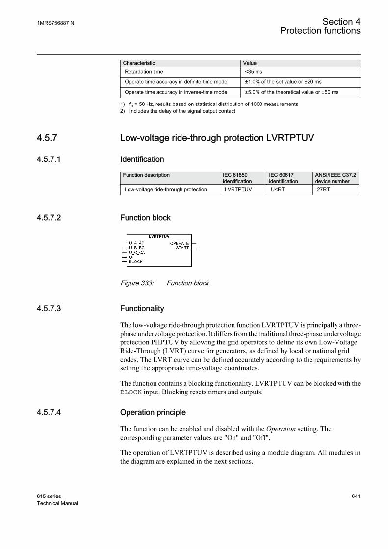
Characteristic ValueRetardation time <35 ms
Operate time accuracy in definite-time mode ±1.0% of the set value or ±20 ms
Operate time accuracy in inverse-time mode ±5.0% of the theoretical value or ±50 ms
1) fn = 50 Hz, results based on statistical distribution of 1000 measurements2) Includes the delay of the signal output contact
4.5.7 Low-voltage ride-through protection LVRTPTUV
4.5.7.1 Identification
Function description IEC 61850identification
IEC 60617identification
ANSI/IEEE C37.2device number
Low-voltage ride-through protection LVRTPTUV U<RT 27RT
4.5.7.2 Function block
GUID-F1220443-D6A1-4BF3-9A50-7552C6F040D5 V1 EN
Figure 333: Function block
4.5.7.3 Functionality
The low-voltage ride-through protection function LVRTPTUV is principally a three-phase undervoltage protection. It differs from the traditional three-phase undervoltageprotection PHPTUV by allowing the grid operators to define its own Low-VoltageRide-Through (LVRT) curve for generators, as defined by local or national gridcodes. The LVRT curve can be defined accurately according to the requirements bysetting the appropriate time-voltage coordinates.
The function contains a blocking functionality. LVRTPTUV can be blocked with theBLOCK input. Blocking resets timers and outputs.
4.5.7.4 Operation principle
The function can be enabled and disabled with the Operation setting. Thecorresponding parameter values are "On" and "Off".
The operation of LVRTPTUV is described using a module diagram. All modules inthe diagram are explained in the next sections.
1MRS756887 N Section 4Protection functions
615 series 641Technical Manual

GUID-722239A2-AF2E-4E0A-A0B1-95AE99F24CF2 V1 EN
Figure 334: Functional module diagram
LVRT curve monitoringLVRT curve monitoring starts with detection of undervoltage. Undervoltagedetection depends on Voltage selection setting. All selectable options are based onfundamental frequency components.
Function uses phase-to-earth voltages when Voltage selection is set to “Highest Ph-to-E” or “Lowest Ph-to-E” and phase-to-phase voltages when Voltage selection is set to“Highest Ph-to-Ph” or “Lowest Ph-to-Ph”.
When the Voltage selection setting is set to “Highest Ph-to-E”, “Lowest Ph-to-E”,“Highest Ph-to-Ph” or “Lowest Ph-to-Ph”, the measured three-phase voltages arecompared phase-wise to the set Voltage start value. If the measured value is lowerthan the set Voltage start value setting in number of phases equal to that set Num ofstart phases, the START output is activated.
The setting options available for Num of start phases are “Exactly 1 of 3”, "Exactly 2of 3", and “Exactly 3 of 3”, which are different from conventional setting optionsavailable in other functions. For example, Num of start phases is set to "Exactly 2 of3", any two voltages should drop below Voltage start value within one cycle networkfor the START output to activate. Even if more than two voltages drop below Voltagestart value, START output is not activated.
When the Voltage selection setting is “Positive Seq”, the positive-sequencecomponent is compared with the set Voltage start value. If it is lower than the setVoltage start value, the START output is activated.
Once START is activated, the function monitors the behavior of the voltage defined byVoltage selection setting with the defined LVRT curve. When defined voltage entersthe operating area, the OPERATE output is activated instantaneously. The pulse lengthof OPERATE is fixed to 100 ms. START also deactivates along with OPERATE.
If a drop-off situation occurs, that is, voltage restores above Voltage start value, beforeOPERATE is activated, the function does not reset until maximum recovery timeunder consideration has elapsed, that is, START output remains active.
LVRT curve is defined using time-voltage settings coordinates. The settings availableare Recovery time 1…Recovery time 10 and Voltage level 1…Voltage level 10. Thenumber of coordinates required to define a LVRT curve is set by Active coordinatesettings.
Section 4 1MRS756887 NProtection functions
642 615 seriesTechnical Manual
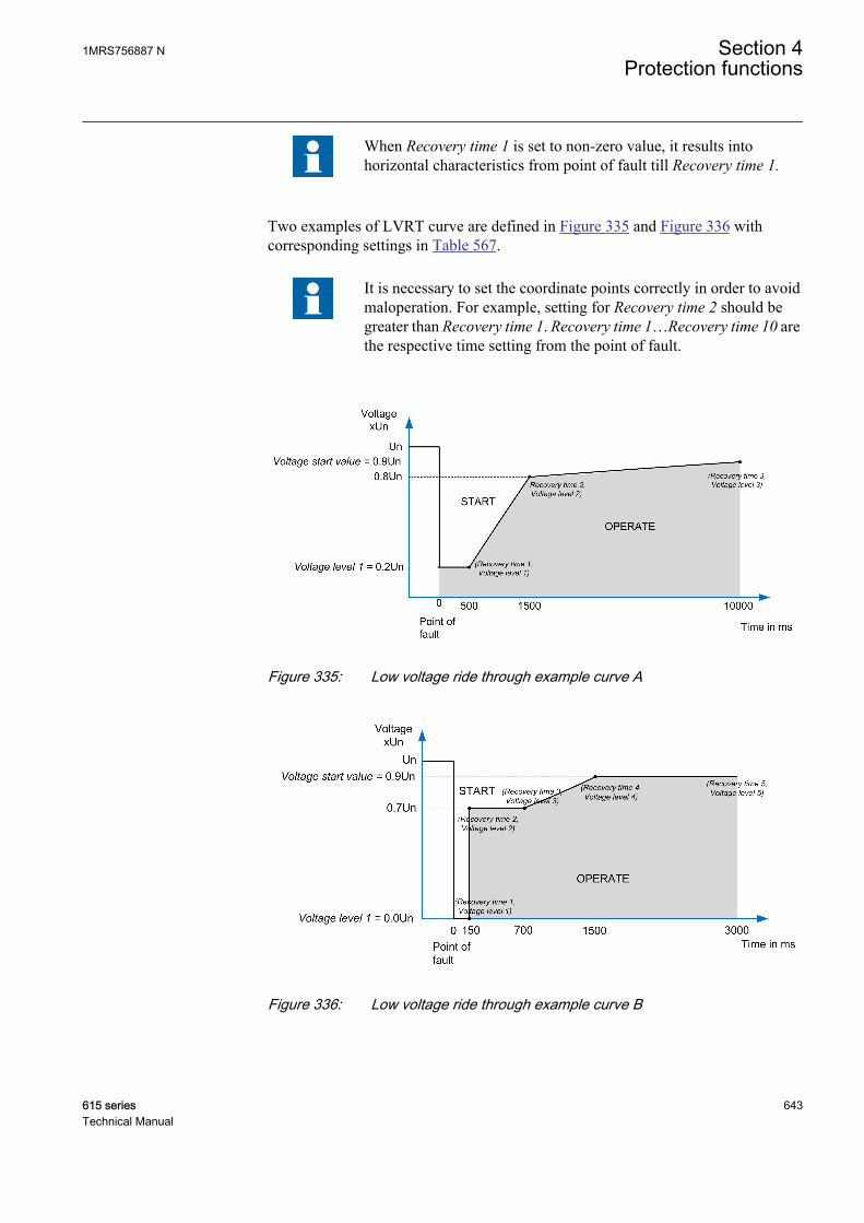
When Recovery time 1 is set to non-zero value, it results intohorizontal characteristics from point of fault till Recovery time 1.
Two examples of LVRT curve are defined in Figure 335 and Figure 336 withcorresponding settings in Table 567.
It is necessary to set the coordinate points correctly in order to avoidmaloperation. For example, setting for Recovery time 2 should begreater than Recovery time 1. Recovery time 1…Recovery time 10 arethe respective time setting from the point of fault.
GUID-BA0DFED4-A2EB-429D-876B-6C5CF633AB38 V1 EN
Figure 335: Low voltage ride through example curve A
GUID-C490F6EB-6DF8-4878-9685-B391651572B7 V1 EN
Figure 336: Low voltage ride through example curve B
1MRS756887 N Section 4Protection functions
615 series 643Technical Manual

Table 567: Settings for example A and B
Settings Curve A Curve BVoltage start value 0.9 · Un 0.9 · Un
Active coordinates 3 5
Voltage level 1 0.2 · Un 0 · Un
Recovery time 1 500 ms 150 ms
Voltage level 2 0.8 · Un 0.7 · Un
Recovery time 2 1000 ms 150 ms
Voltage level 3 0.9 · Un 0.7 · Un
Recovery time 3 10000 ms 700 ms
Voltage level 4 - 0.9 · Un
Recovery time 4 - 1500 ms
Voltage level 5 - 0.9 · Un
Recovery time 5 - 3000 ms
It is necessary that the last active Voltage level X setting is set greaterthan or equal to Voltage start value. Settings are not accepted if the lastactive Voltage level X setting is not set greater than or equal to Voltagestart value.
Figure 337 describes an example of operation of LVRTPTUV protection function setto operate with Num of start phases set to “Exactly 2 of 3” and Voltage selection as“Lowest Ph-to-Ph” voltage.
Section 4 1MRS756887 NProtection functions
644 615 seriesTechnical Manual

GUID-B0166278-6381-4BFF-B859-4A60583007FA V1 EN
Figure 337: Typical example of operation of LVRTPTUV function
Activation of the BLOCK input resets the timers and deactivates the function outputs.
4.5.7.5 Application
Distributed generation, mainly wind and solar farms, are rapidly increasing due toliberalized markets (deregulation) and the global trend to use more renewable sourcesof energy. These farms are directly connected to grids, and due to their large size mayinfluence the behavior of the grid. These farms are now required to comply withstringent grid connection requirement, which was previously mandatory only for highcapacity power plants. These requirements include helping grid in maintaining systemstability, reactive power support, transient recovery and voltage-frequencyregulation. These requirements make it necessary for the wind and solar farms toremain in operation in the event of network disturbances.
Many grid codes now demand that the distributed generation connected to HV gridsmust withstand voltage dips to a certain percentage of nominal voltage (down to 0%in some cases) and for a specific duration. Such requirements are known as Low-Voltage Ride-Through (LVRT) or Fault-Ride-Through (FRT) and are described by avoltage versus time characteristics.
Typical LVRT behavior of a distributed generation can be divided into three areasaccording to the variation in voltage over time.
1MRS756887 N Section 4Protection functions
615 series 645Technical Manual
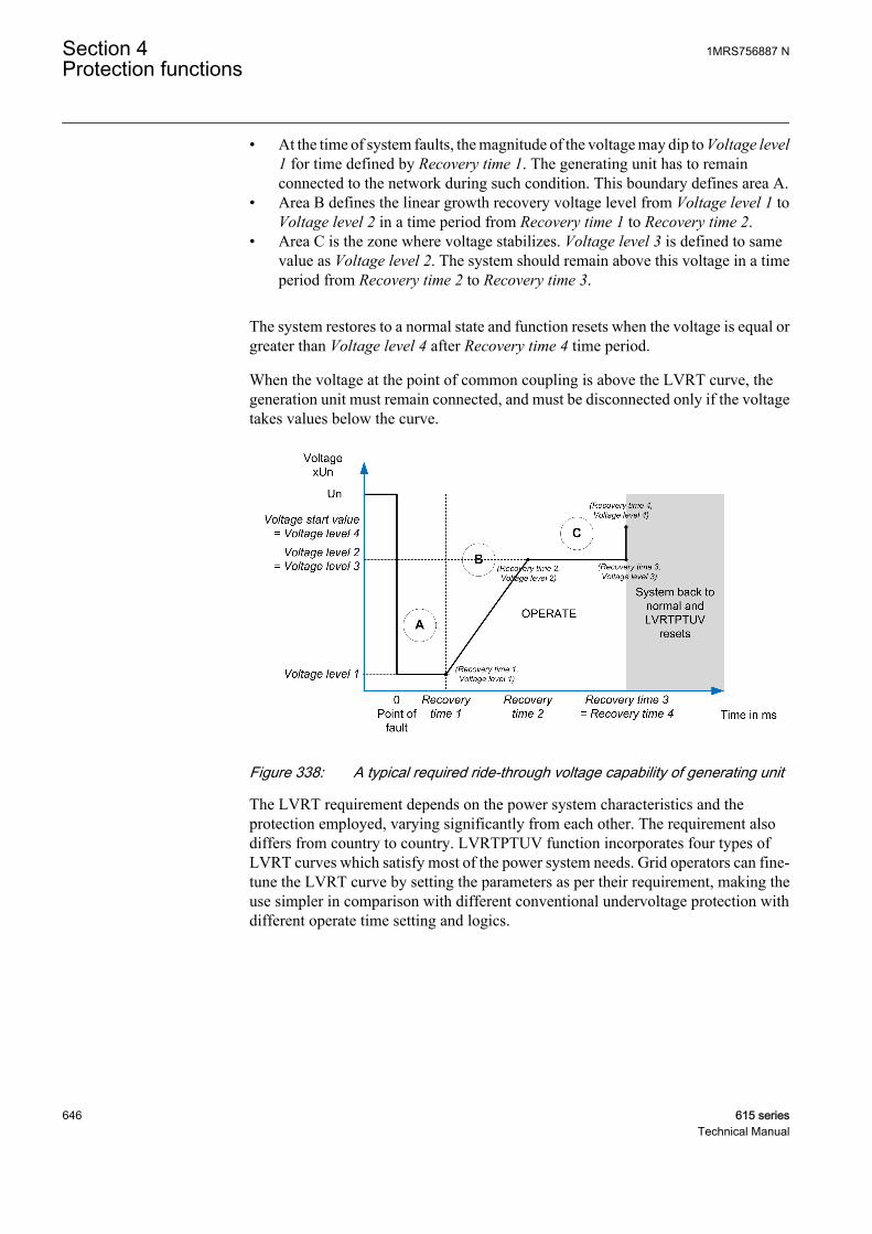
• At the time of system faults, the magnitude of the voltage may dip to Voltage level1 for time defined by Recovery time 1. The generating unit has to remainconnected to the network during such condition. This boundary defines area A.
• Area B defines the linear growth recovery voltage level from Voltage level 1 toVoltage level 2 in a time period from Recovery time 1 to Recovery time 2.
• Area C is the zone where voltage stabilizes. Voltage level 3 is defined to samevalue as Voltage level 2. The system should remain above this voltage in a timeperiod from Recovery time 2 to Recovery time 3.
The system restores to a normal state and function resets when the voltage is equal orgreater than Voltage level 4 after Recovery time 4 time period.
When the voltage at the point of common coupling is above the LVRT curve, thegeneration unit must remain connected, and must be disconnected only if the voltagetakes values below the curve.
GUID-F6602C3F-D3D7-4C0C-B572-96509116A8DE V1 EN
Figure 338: A typical required ride-through voltage capability of generating unit
The LVRT requirement depends on the power system characteristics and theprotection employed, varying significantly from each other. The requirement alsodiffers from country to country. LVRTPTUV function incorporates four types ofLVRT curves which satisfy most of the power system needs. Grid operators can fine-tune the LVRT curve by setting the parameters as per their requirement, making theuse simpler in comparison with different conventional undervoltage protection withdifferent operate time setting and logics.
Section 4 1MRS756887 NProtection functions
646 615 seriesTechnical Manual

4.5.7.6 Signals
Table 568: LVRTPTUV Input signals
Name Type Default DescriptionU_A_AB SIGNAL 0 Phase-to-earth voltage A or phase-to-phase
voltage AB
U_A_BC SIGNAL 0 Phase-to-earth voltage B or phase-to-phasevoltage BC
U_A_CA SIGNAL 0 Phase-to-earth voltage C or phase-to-phasevoltage CA
U1 SIGNAL 0 Positive phase sequence voltage
BLOCK BOOLEAN 0=False Block signal for activating the blocking mode
Table 569: LVRTPTUV Output signals
Name Type DescriptionOPERATE BOOLEAN Operate
START BOOLEAN Start
4.5.7.7 Settings
Table 570: LVRTPTUV Group settings (Basic)
Parameter Values (Range) Unit Step Default DescriptionVoltage start value 0.05...1.20 xUn 0.01 0.90 Voltage value below which function starts
Table 571: LVRTPTUV Non group settings (Basic)
Parameter Values (Range) Unit Step Default DescriptionOperation 1=on
5=off 1=on Operation Off / On
Num of start phases 4=Exactly 1 of 35=Exactly 2 of 36=Exactly 3 of 3
4=Exactly 1 of 3 Number of faulty phases
Voltage selection 1=Highest Ph-to-E2=Lowest Ph-to-E3=Highest Ph-to-Ph4=Lowest Ph-to-Ph5=Positive Seq
4=Lowest Ph-to-Ph
Parameter to select voltage for curvemonitoring
Active coordinates 1...10 1 3 Coordinates used for defining LVRT curve
Voltage level 1 0.00...1.20 xUn 0.01 0.20 1st voltage coordinate for defining LVRTcurve
Voltage level 2 0.00...1.20 xUn 0.01 0.80 2nd voltage coordinate for defining LVRTcurve
Voltage level 3 0.00...1.20 xUn 0.01 0.90 3rd voltage coordinate for defining LVRTcurve
Table continues on next page
1MRS756887 N Section 4Protection functions
615 series 647Technical Manual
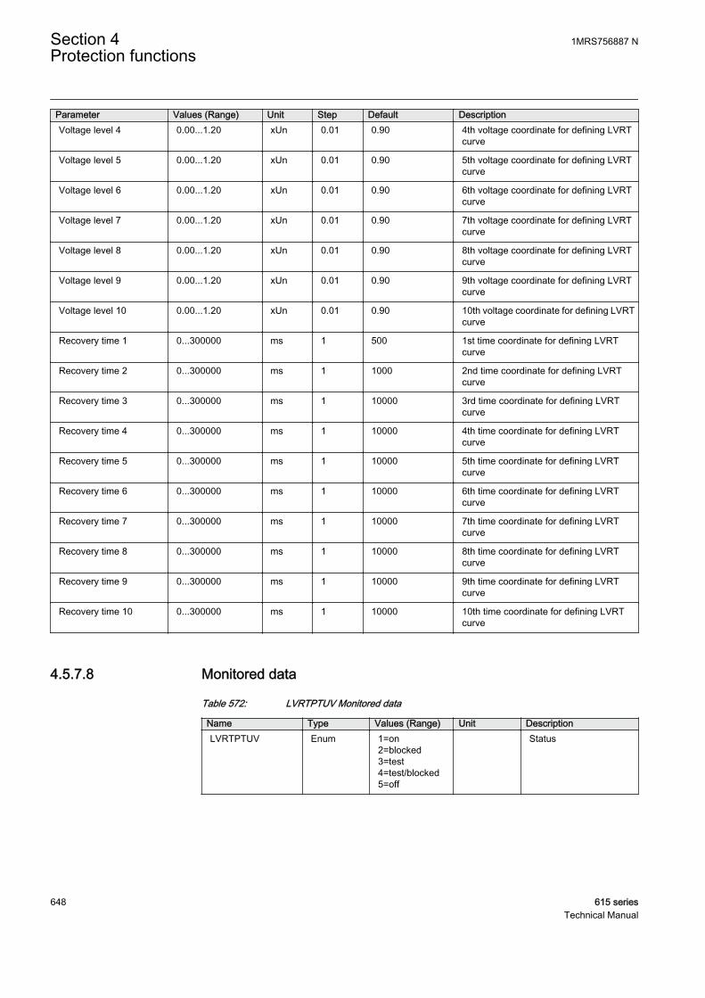
Parameter Values (Range) Unit Step Default DescriptionVoltage level 4 0.00...1.20 xUn 0.01 0.90 4th voltage coordinate for defining LVRT
curve
Voltage level 5 0.00...1.20 xUn 0.01 0.90 5th voltage coordinate for defining LVRTcurve
Voltage level 6 0.00...1.20 xUn 0.01 0.90 6th voltage coordinate for defining LVRTcurve
Voltage level 7 0.00...1.20 xUn 0.01 0.90 7th voltage coordinate for defining LVRTcurve
Voltage level 8 0.00...1.20 xUn 0.01 0.90 8th voltage coordinate for defining LVRTcurve
Voltage level 9 0.00...1.20 xUn 0.01 0.90 9th voltage coordinate for defining LVRTcurve
Voltage level 10 0.00...1.20 xUn 0.01 0.90 10th voltage coordinate for defining LVRTcurve
Recovery time 1 0...300000 ms 1 500 1st time coordinate for defining LVRTcurve
Recovery time 2 0...300000 ms 1 1000 2nd time coordinate for defining LVRTcurve
Recovery time 3 0...300000 ms 1 10000 3rd time coordinate for defining LVRTcurve
Recovery time 4 0...300000 ms 1 10000 4th time coordinate for defining LVRTcurve
Recovery time 5 0...300000 ms 1 10000 5th time coordinate for defining LVRTcurve
Recovery time 6 0...300000 ms 1 10000 6th time coordinate for defining LVRTcurve
Recovery time 7 0...300000 ms 1 10000 7th time coordinate for defining LVRTcurve
Recovery time 8 0...300000 ms 1 10000 8th time coordinate for defining LVRTcurve
Recovery time 9 0...300000 ms 1 10000 9th time coordinate for defining LVRTcurve
Recovery time 10 0...300000 ms 1 10000 10th time coordinate for defining LVRTcurve
4.5.7.8 Monitored data
Table 572: LVRTPTUV Monitored data
Name Type Values (Range) Unit DescriptionLVRTPTUV Enum 1=on
2=blocked3=test4=test/blocked5=off
Status
Section 4 1MRS756887 NProtection functions
648 615 seriesTechnical Manual

4.5.7.9 Technical data
Table 573: LVRTPTUV Technical data
Characteristic ValueOperation accuracy Depending on the frequency of the measured
voltage:fn ±2 Hz
±1.5% of the set value or ±0.002 × Un
Start time1)2) Typically 40 ms
Reset time Based on maximum value of Recovery timesetting
Operate time accuracy ±1.0% of the set value or ±20 ms
Suppression of harmonics DFT: -50 dB at f = n × fn, where n = 2, 3, 4, 5,…
1) Tested for Number of Start phases = 1 out of 3, results based on statistical distribution of 1000measurements
2) Includes the delay of the signal output contact
4.5.8 Voltage vector shift protection VVSPPAM
4.5.8.1 Identification
Function description IEC 61850identification
IEC 60617identification
ANSI/IEEE C37.2device number
Voltage vector shift protection VVSPPAM VS 78V
4.5.8.2 Function block
GUID-3D6DC3BD-5E54-4062-BCB9-4CA8E60B6623 V1 EN
Figure 339: Function block
4.5.8.3 Functionality
The voltage vector shift protection function VVSPPAM, also known as vector surgeor delta phi function, measures continuously the duration of a voltage cycle. At theinstance of islanding, the duration of measured voltage cycle becomes shorter orlonger than the previous one, that is, the measured voltage cycle shifts with time. Thisshifting of voltage is measured in terms of phase angle. VVSPPAM issues aninstantaneous trip when the shift in voltage vector exceeds the set value.
The function can be blocked with BLOCK input. Blocking resets timers and outputs.
1MRS756887 N Section 4Protection functions
615 series 649Technical Manual
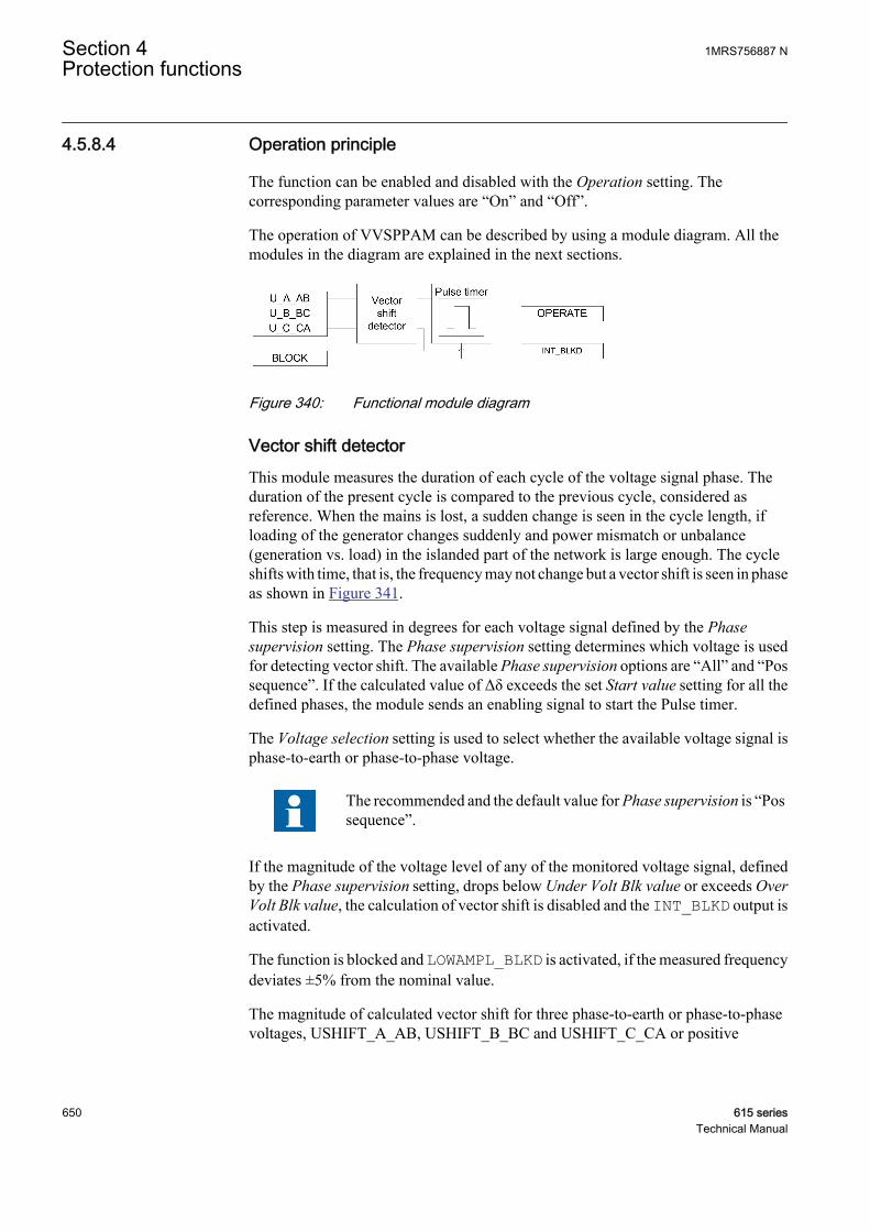
4.5.8.4 Operation principle
The function can be enabled and disabled with the Operation setting. Thecorresponding parameter values are “On” and “Off”.
The operation of VVSPPAM can be described by using a module diagram. All themodules in the diagram are explained in the next sections.
GUID-C286A37F-91A3-49B0-AAF1-FC01E08F59B8 V1 EN
Figure 340: Functional module diagram
Vector shift detectorThis module measures the duration of each cycle of the voltage signal phase. Theduration of the present cycle is compared to the previous cycle, considered asreference. When the mains is lost, a sudden change is seen in the cycle length, ifloading of the generator changes suddenly and power mismatch or unbalance(generation vs. load) in the islanded part of the network is large enough. The cycleshifts with time, that is, the frequency may not change but a vector shift is seen in phaseas shown in Figure 341.
This step is measured in degrees for each voltage signal defined by the Phasesupervision setting. The Phase supervision setting determines which voltage is usedfor detecting vector shift. The available Phase supervision options are “All” and “Possequence”. If the calculated value of Δδ exceeds the set Start value setting for all thedefined phases, the module sends an enabling signal to start the Pulse timer.
The Voltage selection setting is used to select whether the available voltage signal isphase-to-earth or phase-to-phase voltage.
The recommended and the default value for Phase supervision is “Possequence”.
If the magnitude of the voltage level of any of the monitored voltage signal, definedby the Phase supervision setting, drops below Under Volt Blk value or exceeds OverVolt Blk value, the calculation of vector shift is disabled and the INT_BLKD output isactivated.
The function is blocked and LOWAMPL_BLKD is activated, if the measured frequencydeviates ±5% from the nominal value.
The magnitude of calculated vector shift for three phase-to-earth or phase-to-phasevoltages, USHIFT_A_AB, USHIFT_B_BC and USHIFT_C_CA or positive
Section 4 1MRS756887 NProtection functions
650 615 seriesTechnical Manual

sequence voltage U1SHIFT, which resulted in the activation of last OPERATE output,are available in the Monitored data view.
The activation of BLOCK input deactivates the INT_BLKD output.
GUID-174B2AC6-B830-4A0D-B072-80FFF3EBF159 V1 EN
Figure 341: Vector shift during Loss of Mains
Pulse timerOnce the Pulse timer is activated, it activates the OPERATE output. The pulse lengthof OPERATE is fixed to 100 ms.
The activation of the BLOCK input deactivates the OPERATE binary output and resetsthe timer.
4.5.8.5 Application
Use of distributed generation (DG) units is increasing due to liberalized markets(deregulation) and the global trend to use more renewable sources of energy. Theygenerate power in the range of 10 kW...10 MW and most of them are interconnectedto the distribution network. They can supply power into the network as well as to thelocal loads. It is not common to connect generators directly to the distributionnetworks and thus the distributed generation can cause some challenges for theprotection of distribution networks. From the protection point of view, one of the mostchallenging issue is islanding.
Islanding is defined as a condition in which a distributed generation unit continues tosupply power to a certain part of the distribution network when power from the largerutility main grid is no longer available after the opening of a circuit-breaker. Islandingis also referred as Loss of Mains (LOM) or Loss of Grid (LOG). When LOM occurs,neither the voltage or the frequency is controlled by the utility supply. Thesedistributed generators are not equipped with voltage and frequency control; therefore,the voltage magnitude of an islanded network may not be kept within the desired limitswhich causes undefined voltage magnitudes during islanding situations andfrequency instability. Uncontrolled frequency represents a high risk for drives and
1MRS756887 N Section 4Protection functions
615 series 651Technical Manual
other machines. Islanding can occur as a consequence of a fault in the network, due tocircuit breaker maloperation or due to circuit breaker opening during maintenance. Ifthe distributed generator continues its operation after the utility supply isdisconnected, faults do not clear under certain conditions as the arc is charged by thedistributed generators. Moreover, the distributed generators are incompatible with thecurrent reclosing practices. During the reclosing sequence dead time, the generators inthe network tend to drift out of synchronism with the grid and reconnecting themwithout synchronizing may damage the generators introducing high currents andvoltages in the neighboring network.
To avoid these technical challenges, protection is needed to disconnect the distributedgeneration once it is electrically isolated from the main grid supply. Varioustechniques are used for detecting Loss of Mains. However, the present functionfocuses on voltage vector shift.
The vector shift detection guarantees fast and reliable detection of mains failure inalmost all operational conditions when a distributed generation unit is running inparallel with the mains supply, but in certain cases this may fail.
If the active and reactive power generated by the distributed generation units is nearlybalanced (for example, if the power mismatch or unbalance is less than 5...10%) withthe active and reactive power consumed by loads, a large enough voltage phase shiftmay not occur which can be detected by the vector shift algorithm. This means that thevector shift algorithm has a small non-detection-zone (NDZ) which is also dependenton the type of generators, loads, network and start or operate value of the vector shiftalgorithm. Other network events like capacitor switching, switching of very largeloads in weak network or connection of parallel transformer at HV/MV substation, inwhich the voltage magnitude is not changed considerably (unlike in faults) canpotentially cause maloperation of vector shift algorithm, if very sensitive settings areused.
The vector shift detection also protects synchronous generators from damaging due toislanding or loss-of-mains. To detect loss-of-mains with vector shift function, thegenerator should aim to export or import at least 5...10% of the generated power to thegrid, in order to guarantee detectable change in loading after islanding or loss-of-mains.
Multicriteria Loss of MainsApart from vector shift, there are other passive techniques which are used fordetecting Loss of Mains. Some of these passive techniques are over/under voltage,over/under frequency, rate of change of frequency, voltage unbalance, rate of changeof power and so on. These passive methods use voltage and frequency to identify Lossof Mains. The performance of these methods depends on the power mismatch betweenlocal generation and load. The advantage of all these methods is that, they are simpleand cost effective, but each method has a non detectable zone. To overcome thisproblem, it is recommended to combine different criteria for detecting Loss of Mains.
Two or more protection functions run in parallel to detect Loss of Mains. When allcriteria are fulfilled to indicate Loss of Mains, an alarm or a trip can be generated.
Section 4 1MRS756887 NProtection functions
652 615 seriesTechnical Manual
Vector shift and rate of change of frequency are two parallel criteria typically used fordetection of Loss of Mains.
Chosen protection criteria can be included in the Application Configuration tool tocreate multicriteria loss of mains alarm or trip.
4.5.8.6 Signals
Table 574: VVSPPAM Input signals
Name Type Default DescriptionU_A_AB SIGNAL 0 Phase-to-earth voltage A or phase-to-phase
voltage AB
U_B_BC SIGNAL 0 Phase-to-earth voltage B or phase-to-phasevoltage BC
U_C_CA SIGNAL 0 Phase-to-earth voltage C or phase-to-phasevoltage CA
BLOCK BOOLEAN 0=False Block signal for activating the blocking mode
Table 575: VVSPPAM Output signals
Name Type DescriptionOPERATE BOOLEAN Operate
INT_BLKD BOOLEAN Protection function internally blocked
4.5.8.7 Settings
Table 576: VVSPPAM Group settings (Basic)
Parameter Values (Range) Unit Step Default DescriptionStart value 2.0...30.0 deg 0.1 6.0 Start value for vector shift
Table 577: VVSPPAM Group settings (Advanced)
Parameter Values (Range) Unit Step Default DescriptionOver Volt Blk value 0.40...1.50 xUn 0.01 1.20 Voltage above which function will be
internally blocked
Under Volt Blk value 0.15...1.00 xUn 0.01 0.80 Voltage below which function will beinternally blocked
Table 578: VVSPPAM Non group settings (Basic)
Parameter Values (Range) Unit Step Default DescriptionOperation 1=on
5=off 1=on Operation Off / On
1MRS756887 N Section 4Protection functions
615 series 653Technical Manual
Table 579: VVSPPAM Non group settings (Advanced)
Parameter Values (Range) Unit Step Default DescriptionPhase supervision 7=Ph A + B + C
8=Pos sequence 8=Pos sequence Monitored voltage phase
4.5.8.8 Monitored data
Table 580: VVSPPAM Monitored data
Name Type Values (Range) Unit DescriptionVEC_SHT_A_AB FLOAT32 -180.00...180.00 deg Vector shift for phase to
earth voltage A or phaseto phase voltage AB
VEC_SHT_B_BC FLOAT32 -180.00...180.00 deg Vector shift for phase toearth voltage B or phaseto phase voltage BC
VEC_SHT_C_CA FLOAT32 -180.00...180.00 deg Vector shift for phase toearth voltage C or phaseto phase voltage CA
VEC_SHT_U1 FLOAT32 -180.00...180.00 deg Vector shift for positivesequence voltage
VVSPPAM Enum 1=on2=blocked3=test4=test/blocked5=off
Status
4.5.8.9 Technical data
Table 581: VVSPPAM Technical data
Characteristic ValueOperation accuracy Depending on the frequency of the measured
voltage:fn ±1 Hz
±1°
Operate time1)2) Typically 53 ms
1) fn = 50 Hz, results based on statistical distribution of 1000 measurements2) Includes the delay of the signal output contact
Section 4 1MRS756887 NProtection functions
654 615 seriesTechnical Manual
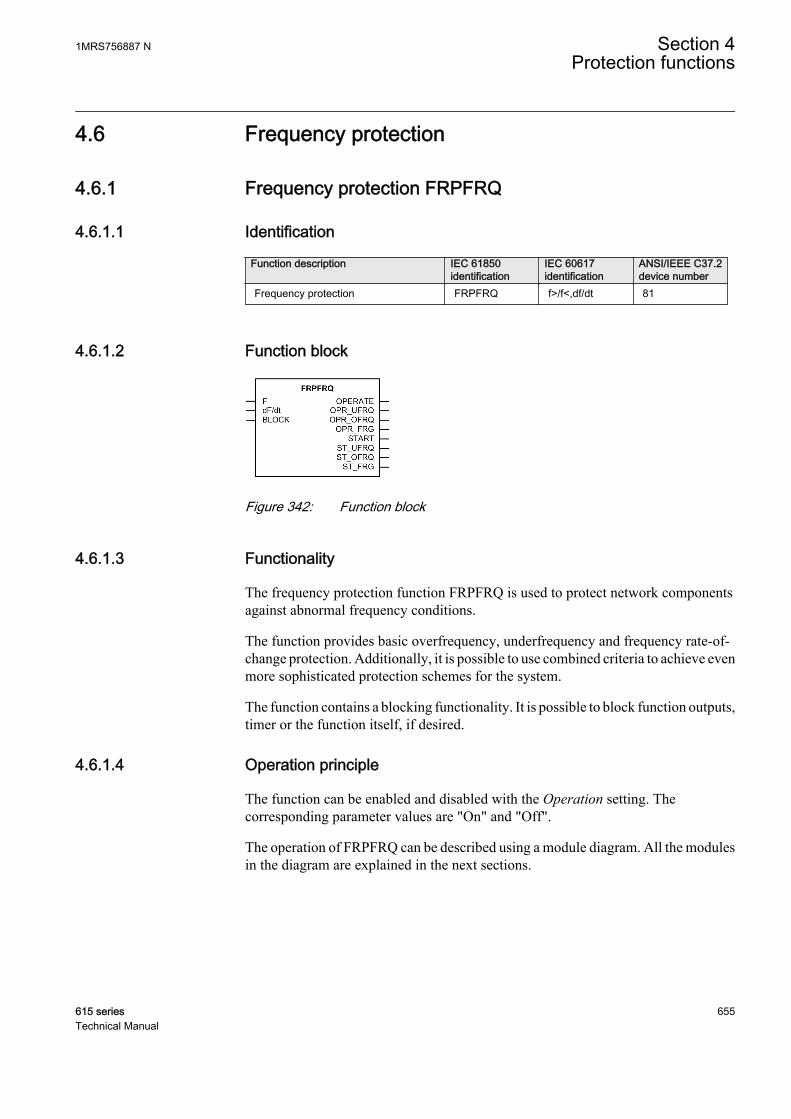
4.6 Frequency protection
4.6.1 Frequency protection FRPFRQ
4.6.1.1 Identification
Function description IEC 61850identification
IEC 60617identification
ANSI/IEEE C37.2device number
Frequency protection FRPFRQ f>/f<,df/dt 81
4.6.1.2 Function block
GUID-744529D8-E976-4AFD-AA77-85D6ED2C3B70 V1 EN
Figure 342: Function block
4.6.1.3 Functionality
The frequency protection function FRPFRQ is used to protect network componentsagainst abnormal frequency conditions.
The function provides basic overfrequency, underfrequency and frequency rate-of-change protection. Additionally, it is possible to use combined criteria to achieve evenmore sophisticated protection schemes for the system.
The function contains a blocking functionality. It is possible to block function outputs,timer or the function itself, if desired.
4.6.1.4 Operation principle
The function can be enabled and disabled with the Operation setting. Thecorresponding parameter values are "On" and "Off".
The operation of FRPFRQ can be described using a module diagram. All the modulesin the diagram are explained in the next sections.
1MRS756887 N Section 4Protection functions
615 series 655Technical Manual
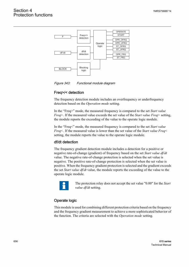
F
BLOCK
Operate logic
Freq>/<detection
df/dtdetection
Blockinglogic
START
ST_FRG
ST_UFRQST_OFRQ
OPERATE
OPR_FRG
OPR_UFRQOPR_OFRQ
dF/dt
GUID-76692C3F-8B09-4C69-B598-0288CB946300 V1 EN
Figure 343: Functional module diagram
Freq>/< detectionThe frequency detection module includes an overfrequency or underfrequencydetection based on the Operation mode setting.
In the “Freq>” mode, the measured frequency is compared to the set Start valueFreq>. If the measured value exceeds the set value of the Start value Freq> setting,the module reports the exceeding of the value to the operate logic module.
In the “Freq<” mode, the measured frequency is compared to the set Start valueFreq<. If the measured value is lower than the set value of the Start value Freq<setting, the module reports the value to the operate logic module.
df/dt detectionThe frequency gradient detection module includes a detection for a positive ornegative rate-of-change (gradient) of frequency based on the set Start value df/dtvalue. The negative rate-of-change protection is selected when the set value isnegative. The positive rate-of-change protection is selected when the set value ispositive. When the frequency gradient protection is selected and the gradient exceedsthe set Start value df/dt value, the module reports the exceeding of the value to theoperate logic module.
The protection relay does not accept the set value "0.00" for the Startvalue df/dt setting.
Operate logicThis module is used for combining different protection criteria based on the frequencyand the frequency gradient measurement to achieve a more sophisticated behavior ofthe function. The criteria are selected with the Operation mode setting.
Section 4 1MRS756887 NProtection functions
656 615 seriesTechnical Manual
Table 582: Operation modes for operation logic
Operation mode DescriptionFreq< The function operates independently as the underfrequency
("Freq<") protection function. When the measured frequency isbelow the set value of the Start value Freq< setting, the moduleactivates the START and STR_UFRQ outputs. The time characteristicis according to DT. When the operation timer has reached the valueset by the Operate Tm Freq setting, the OPERATE and OPR_UFRQoutputs are activated. If the frequency restores before the moduleoperates, the reset timer is activated. If the timer reaches the valueset by the Reset delay Tm Freq setting, the operate timer resets andthe START and STR_UFRQ outputs are deactivated.
Freq> The function operates independently as the overfrequency("Freq>") protection function. When the measured frequencyexceeds the set value of the Start value Freq> setting, the moduleactivates the START and STR_OFRQ outputs. The time characteristicis according to DT. When the operation timer has reached the valueset by the Operate Tm Freq setting, the OPERATE and OPR_OFRQoutputs are activated. If the frequency restores before the moduleoperates, the reset timer is activated. If the timer reaches the valueset by the Reset delay Tm Freq setting, the operate timer resets andthe START and STR_OFRQ outputs are deactivated.
df/dt The function operates independently as the frequency gradient ("df/dt"), rate-of-change, protection function. When the frequencygradient exceeds the set value of the Start value df/dt setting, themodule activates the START and STR_FRG outputs. The timecharacteristic is according to DT. When the operation timer hasreached the value set by the Operate Tm df/dt setting, the OPERATEand OPR_FRG outputs are activated. If the frequency gradientrestores before the module operates, the reset timer is activated. Ifthe timer reaches the value set by the Reset delay Tm df/dt setting,the operate timer resets and the START and STR_FRG outputs aredeactivated.
Freq< + df/dt A consecutive operation is enabled between the protectionmethods. When the measured frequency is below the set value ofthe Start value Freq< setting, the frequency gradient protection isenabled. After the frequency has dropped below the set value, thefrequency gradient is compared to the set value of the Start value df/dt setting. When the frequency gradient exceeds the set value, themodule activates the START and STR_FRG outputs. The timecharacteristic is according to DT. When the operation timer hasreached the value set by the Operate Tm df/dt setting, the OPERATEand OPR_FRG outputs are activated. If the frequency gradientrestores before the module operates, the reset timer is activated. Ifthe timer reaches the value set by the Reset delay Tm df/dt setting,the operate timer resets and the START and STR_FRG outputs aredeactivated. The OPR_UFRQ output is not active when this operationmode is used.
Table continues on next page
1MRS756887 N Section 4Protection functions
615 series 657Technical Manual
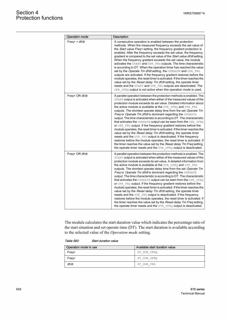
Operation mode DescriptionFreq> + df/dt A consecutive operation is enabled between the protection
methods. When the measured frequency exceeds the set value ofthe Start value Freq> setting, the frequency gradient protection isenabled. After the frequency exceeds the set value, the frequencygradient is compared to the set value of the Start value df/dt setting.When the frequency gradient exceeds the set value, the moduleactivates the START and STR_FRG outputs. The time characteristicis according to DT. When the operation timer has reached the valueset by the Operate Tm df/dt setting, the OPERATE and OPR_FRGoutputs are activated. If the frequency gradient restores before themodule operates, the reset timer is activated. If the timer reaches thevalue set by the Reset delay Tm df/dt setting, the operate timerresets and the START and STR_FRG outputs are deactivated. TheOPR_OFRQ output is not active when this operation mode is used.
Freq< OR df/dt A parallel operation between the protection methods is enabled. TheSTART output is activated when either of the measured values of theprotection module exceeds its set value. Detailed information aboutthe active module is available at the STR_UFRQ and STR_FRGoutputs. The shortest operate delay time from the set Operate TmFreq or Operate Tm df/dt is dominant regarding the OPERATEoutput. The time characteristic is according to DT. The characteristicthat activates the OPERATE output can be seen from the OPR_UFRQor OPR_FRG output. If the frequency gradient restores before themodule operates, the reset timer is activated. If the timer reaches thevalue set by the Reset delay Tm df/dt setting, the operate timerresets and the STR_FRG output is deactivated. If the frequencyrestores before the module operates, the reset timer is activated. Ifthe timer reaches the value set by the Reset delay Tm Freq setting,the operate timer resets and the STR_UFRQ output is deactivated.
Freq> OR df/dt A parallel operation between the protection methods is enabled. TheSTART output is activated when either of the measured values of theprotection module exceeds its set value. A detailed information fromthe active module is available at the STR_OFRQ and STR_FRGoutputs. The shortest operate delay time from the set Operate TmFreq or Operate Tm df/dt is dominant regarding the OPERATEoutput. The time characteristic is according to DT. The characteristicthat activates the OPERATE output can be seen from the OPR_OFRQor OPR_FRG output. If the frequency gradient restores before themodule operates, the reset timer is activated. If the timer reaches thevalue set by the Reset delay Tm df/dt setting, the operate timerresets and the STR_FRG output is deactivated. If the frequencyrestores before the module operates, the reset timer is activated. Ifthe timer reaches the value set by the Reset delay Tm Freq setting,the operate timer resets and the STR_UFRQ output is deactivated.
The module calculates the start duration value which indicates the percentage ratio ofthe start situation and set operate time (DT). The start duration is available accordingto the selected value of the Operation mode setting.
Table 583: Start duration value
Operation mode in use Available start duration valueFreq< ST_DUR_UFRQFreq> ST_DUR_OFRQdf/dt ST_DUR_FRG
Section 4 1MRS756887 NProtection functions
658 615 seriesTechnical Manual
The combined start duration START_DUR indicates the maximum percentage ratio ofthe active protection modes. The values are available via the Monitored data view.
Blocking logicThere are three operation modes in the blocking function. The operation modes arecontrolled by the BLOCK input and the global setting in Configuration/System/Blocking mode which selects the blocking mode. The BLOCK input can be controlledby a binary input, a horizontal communication input or an internal signal of theprotection relay's program. The influence of the BLOCK signal activation ispreselected with the global setting Blocking mode.
The Blocking mode setting has three blocking methods. In the "Freeze timers" mode,the operation timer is frozen to the prevailing value, but the OPERATE output is notdeactivated when blocking is activated. In the "Block all" mode, the whole function isblocked and the timers are reset. In the "Block OPERATE output" mode, the functionoperates normally but the OPERATE output is not activated.
4.6.1.5 Application
The frequency protection function uses the positive phase-sequence voltage tomeasure the frequency reliably and accurately.
The system frequency stability is one of the main principles in the distribution andtransmission network maintenance. To protect all frequency-sensitive electricalapparatus in the network, the departure from the allowed band for a safe operationshould be inhibited.
The overfrequency protection is applicable in all situations where high levels of thefundamental frequency of a power system voltage must be reliably detected. The highfundamental frequency in a power system indicates an unbalance between productionand consumption. In this case, the available generation is too large compared to thepower demanded by the load connected to the power grid. This can occur due to asudden loss of a significant amount of load or due to failures in the turbine governorsystem. If the situation continues and escalates, the power system loses its stability.
The underfrequency is applicable in all situations where a reliable detection of a lowfundamental power system voltage frequency is needed. The low fundamentalfrequency in a power system indicates that the generated power is too low to meet thedemands of the load connected to the power grid.
The underfrequency can occur as a result of the overload of generators operating in anisolated system. It can also occur as a result of a serious fault in the power system dueto the deficit of generation when compared to the load. This can happen due to a faultin the grid system on the transmission lines that link two parts of the system. As aresult, the system splits into two with one part having the excess load and the other partthe corresponding deficit.
The frequency gradient is applicable in all the situations where the change of thefundamental power system voltage frequency should be detected reliably. The
1MRS756887 N Section 4Protection functions
615 series 659Technical Manual

frequency gradient can be used for both increasing and decreasing the frequencies.This function provides an output signal suitable for load shedding, generatorshedding, generator boosting, set point change in sub-transmission DC systems andgas turbine startup. The frequency gradient is often used in combination with a lowfrequency signal, especially in smaller power systems where the loss of a largegenerator requires quick remedial actions to secure the power system integrity. In suchsituations, the load shedding actions are required at a rather high frequency level.However, in combination with a large negative frequency gradient, theunderfrequency protection can be used at a high setting.
4.6.1.6 Signals
Table 584: FRPFRQ Input signals
Name Type Default DescriptionF SIGNAL 0 Measured frequency
dF/dt SIGNAL 0 Rate of change of frequency
BLOCK BOOLEAN 0=False Block signal for activating the blocking mode
Table 585: FRPFRQ Output signals
Name Type DescriptionOPERATE BOOLEAN Operate
OPR_OFRQ BOOLEAN Operate signal for overfrequency
OPR_UFRQ BOOLEAN Operate signal for underfrequency
OPR_FRG BOOLEAN Operate signal for frequency gradient
START BOOLEAN Start
ST_OFRQ BOOLEAN Start signal for overfrequency
ST_UFRQ BOOLEAN Start signal for underfrequency
ST_FRG BOOLEAN Start signal for frequency gradient
4.6.1.7 Settings
Table 586: FRPFRQ Group settings (Basic)
Parameter Values (Range) Unit Step Default DescriptionOperation mode 1=Freq<
2=Freq>3=df/dt4=Freq< + df/dt5=Freq> + df/dt6=Freq< OR df/dt7=Freq> OR df/dt
1=Freq< Frequency protection operation modeselection
Start value Freq> 0.9000...1.2000 xFn 0.0001 1.0500 Frequency start value overfrequency
Start value Freq< 0.8000...1.1000 xFn 0.0001 0.9500 Frequency start value underfrequency
Table continues on next page
Section 4 1MRS756887 NProtection functions
660 615 seriesTechnical Manual

Parameter Values (Range) Unit Step Default DescriptionStart value df/dt -0.2000...0.2000 xFn /s 0.0025 0.0100 Frequency start value rate of change
Operate Tm Freq 80...200000 ms 10 200 Operate delay time for frequency
Operate Tm df/dt 120...200000 ms 10 400 Operate delay time for frequency rate ofchange
Table 587: FRPFRQ Non group settings (Basic)
Parameter Values (Range) Unit Step Default DescriptionOperation 1=on
5=off 1=on Operation Off / On
Table 588: FRPFRQ Non group settings (Advanced)
Parameter Values (Range) Unit Step Default DescriptionReset delay Tm Freq 0...60000 ms 1 0 Reset delay time for frequency
Reset delay Tm df/dt 0...60000 ms 1 0 Reset delay time for rate of change
4.6.1.8 Monitored data
Table 589: FRPFRQ Monitored data
Name Type Values (Range) Unit DescriptionSTART_DUR FLOAT32 0.00...100.00 % Start duration
ST_DUR_OFRQ FLOAT32 0.00...100.00 % Start duration
ST_DUR_UFRQ FLOAT32 0.00...100.00 % Start duration
ST_DUR_FRG FLOAT32 0.00...100.00 % Start duration
FRPFRQ Enum 1=on2=blocked3=test4=test/blocked5=off
Status
4.6.1.9 Technical data
Table 590: FRPFRQ Technical data
Characteristic ValueOperation accuracy f>/f< ±5 mHz
df/dt ±50 mHz/s (in range |df/dt| <5 Hz/s)±2.0% of the set value (in range 5 Hz/s < |df/dt| <15 Hz/s)
Start time f>/f< <80 ms
df/dt <120 ms
Reset time <150 ms
Operate time accuracy ±1.0% of the set value or ±30 ms
1MRS756887 N Section 4Protection functions
615 series 661Technical Manual
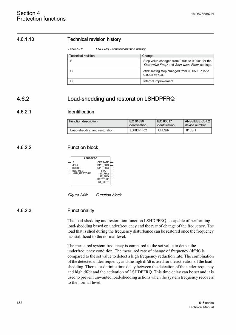
4.6.1.10 Technical revision history
Table 591: FRPFRQ Technical revision history
Technical revision ChangeB Step value changed from 0.001 to 0.0001 for the
Start value Freq> and Start value Freq< settings.
C df/dt setting step changed from 0.005 ×Fn /s to0.0025 ×Fn /s.
D Internal improvement.
4.6.2 Load-shedding and restoration LSHDPFRQ
4.6.2.1 Identification
Function description IEC 61850identification
IEC 60617identification
ANSI/IEEE C37.2device number
Load-shedding and restoration LSHDPFRQ UFLS/R 81LSH
4.6.2.2 Function block
GUID-1B46D13E-4F26-4CFA-9655-E979E0E05D67 V2 EN
Figure 344: Function block
4.6.2.3 Functionality
The load-shedding and restoration function LSHDPFRQ is capable of performingload-shedding based on underfrequency and the rate of change of the frequency. Theload that is shed during the frequency disturbance can be restored once the frequencyhas stabilized to the normal level.
The measured system frequency is compared to the set value to detect theunderfrequency condition. The measured rate of change of frequency (df/dt) iscompared to the set value to detect a high frequency reduction rate. The combinationof the detected underfrequency and the high df/dt is used for the activation of the load-shedding. There is a definite time delay between the detection of the underfrequencyand high df/dt and the activation of LSHDPFRQ. This time delay can be set and it isused to prevent unwanted load-shedding actions when the system frequency recoversto the normal level.
Section 4 1MRS756887 NProtection functions
662 615 seriesTechnical Manual
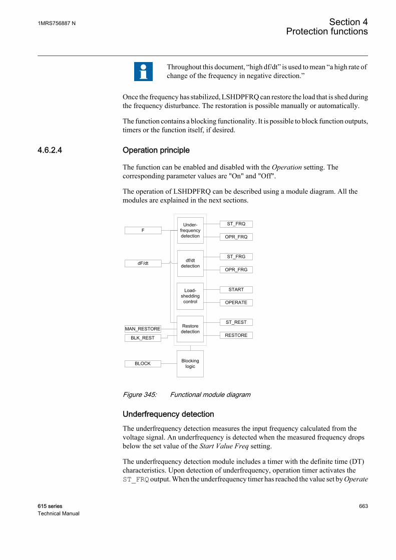
Throughout this document, “high df/dt” is used to mean “a high rate ofchange of the frequency in negative direction.”
Once the frequency has stabilized, LSHDPFRQ can restore the load that is shed duringthe frequency disturbance. The restoration is possible manually or automatically.
The function contains a blocking functionality. It is possible to block function outputs,timers or the function itself, if desired.
4.6.2.4 Operation principle
The function can be enabled and disabled with the Operation setting. Thecorresponding parameter values are "On" and "Off".
The operation of LSHDPFRQ can be described using a module diagram. All themodules are explained in the next sections.
GUID-17F7A604-487F-4D45-8150-AE041BB939B1 V2 EN
Figure 345: Functional module diagram
Underfrequency detectionThe underfrequency detection measures the input frequency calculated from thevoltage signal. An underfrequency is detected when the measured frequency dropsbelow the set value of the Start Value Freq setting.
The underfrequency detection module includes a timer with the definite time (DT)characteristics. Upon detection of underfrequency, operation timer activates theST_FRQ output. When the underfrequency timer has reached the value set by Operate
1MRS756887 N Section 4Protection functions
615 series 663Technical Manual
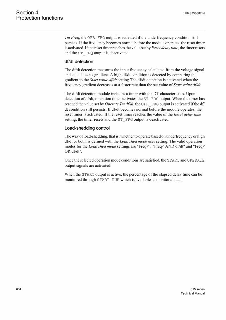
Tm Freq, the OPR_FRQ output is activated if the underfrequency condition stillpersists. If the frequency becomes normal before the module operates, the reset timeris activated. If the reset timer reaches the value set by Reset delay time, the timer resetsand the ST_FRQ output is deactivated.
df/dt detectionThe df/dt detection measures the input frequency calculated from the voltage signaland calculates its gradient. A high df/dt condition is detected by comparing thegradient to the Start value df/dt setting.The df/dt detection is activated when thefrequency gradient decreases at a faster rate than the set value of Start value df/dt.
The df/dt detection module includes a timer with the DT characteristics. Upondetection of df/dt, operation timer activates the ST_FRG output. When the timer hasreached the value set by Operate Tm df/dt, the OPR_FRG output is activated if the df/dt condition still persists. If df/dt becomes normal before the module operates, thereset timer is activated. If the reset timer reaches the value of the Reset delay timesetting, the timer resets and the ST_FRG output is deactivated.
Load-shedding controlThe way of load-shedding, that is, whether to operate based on underfrequency or highdf/dt or both, is defined with the Load shed mode user setting. The valid operationmodes for the Load shed mode settings are "Freq<", "Freq< AND df/dt" and "Freq<OR df/dt".
Once the selected operation mode conditions are satisfied, the START and OPERATEoutput signals are activated.
When the START output is active, the percentage of the elapsed delay time can bemonitored through START_DUR which is available as monitored data.
Section 4 1MRS756887 NProtection functions
664 615 seriesTechnical Manual
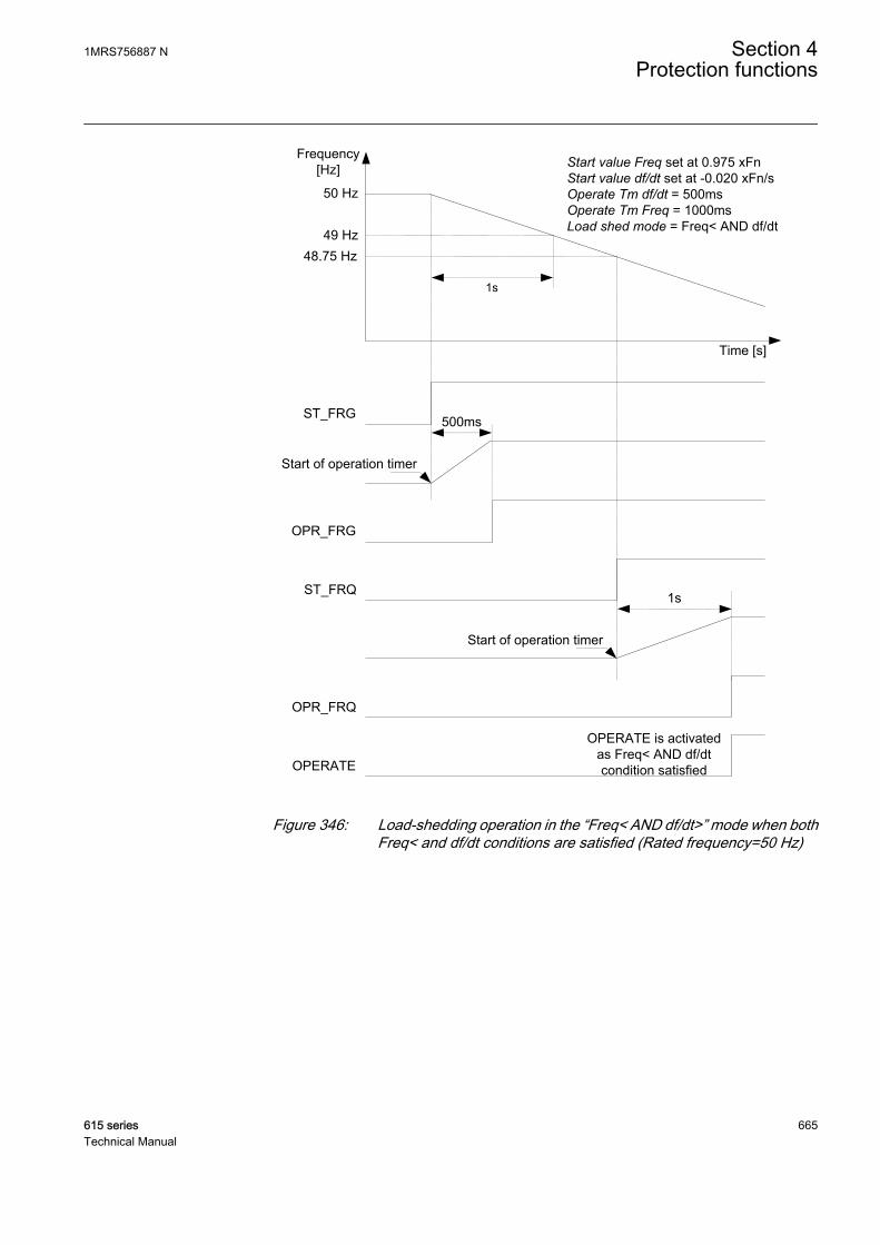
50 Hz
Start value Freq set at 0.975 xFnStart value df/dt set at -0.020 xFn/sOperate Tm df/dt = 500msOperate Tm Freq = 1000msLoad shed mode = Freq< AND df/dt 49 Hz
ST_FRG
OPR_FRG
500ms
1s
OPERATE is activated as Freq< AND df/dt condition satisfiedOPERATE
48.75 Hz
Start of operation timer
ST_FRQ
OPR_FRQ
Start of operation timer
1s
Time [s]
Frequency[Hz]
GUID-143A36EB-FCC9-4E87-B615-7743A3D75A15 V2 EN
Figure 346: Load-shedding operation in the “Freq< AND df/dt>” mode when bothFreq< and df/dt conditions are satisfied (Rated frequency=50 Hz)
1MRS756887 N Section 4Protection functions
615 series 665Technical Manual
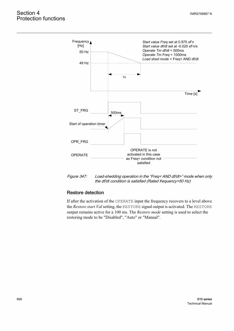
50 Hz
Start value Freq set at 0.975 xFnStart value df/dt set at -0.020 xFn/sOperate Tm df/dt = 500msOperate Tm Freq = 1000msLoad shed mode = Freq< AND df/dt
49 Hz
ST_FRG
OPR_FRG
500ms
1s
OPERATE is not activated in this case
as Freq< condition not satisfied
OPERATE
Start of operation timer
Time [s]
Frequency[Hz]
GUID-DB333B09-D987-4A62-ABAE-7B70ACA275EB V2 EN
Figure 347: Load-shedding operation in the “Freq< AND df/dt>” mode when onlythe df/dt condition is satisfied (Rated frequency=50 Hz)
Restore detectionIf after the activation of the OPERATE input the frequency recovers to a level abovethe Restore start Val setting, the RESTORE signal output is activated. The RESTOREoutput remains active for a 100 ms. The Restore mode setting is used to select therestoring mode to be "Disabled", "Auto" or "Manual".
Section 4 1MRS756887 NProtection functions
666 615 seriesTechnical Manual

Restoring mode DescriptionDisabled Load restoration is disabled.
Auto In the “Auto” mode, input frequency is continuously compared to the Restorestart Val setting. The restore detection module includes a timer with the DTcharacteristics. Upon detection of restoring, the operation timer activates theST_REST output. When the timer has reached the value of the Restore delaytime setting, the RESTORE output is activated if the restoring condition stillpersists. If the frequency drops below the Restore start Val before theRESTORE output is activated, the reset timer is activated. If the reset timerreaches the value of the Reset delay time setting, the timer resets and theST_REST start output is deactivated.
Manual In the “Manual” mode, a manual restoration is possible through theMAN_RESTORE input or via communication. The ST_REST output is activated ifthe MAN_RESTORE command is available and the frequency has exceeded theRestore start Val setting. The manual restoration includes a timer with the DTcharacteristics. When the timer has reached the set value of the Restore delaytime setting, the RESTORE output is activated if the restoring condition stillpersists. If the frequency drops below the Restore start Val setting before theRESTORE output is activated, the reset timer is activated. If the reset timerreaches the value of the Reset delay time setting, the timer resets and theST_REST start output is deactivated.
A condition can arise where the restoring operation needs to be canceled. Activatingthe BLK_REST input for the "Auto" or "Manual" modes cancels the restoringoperation. In the "Manual" restoring mode, the cancellation happens even ifMAN_RESTORE is present.
Once the RESTORE output command is cancelled, the reactivation of RESTORE ispossible only after the reactivation of the OPERATE output, that is, when the nextload-shedding operation is detected.
Blocking logicThere are three operation modes in the blocking function. The operation modes arecontrolled by the BLOCK input and the global setting in Configuration/System/Blocking mode that selects the blocking mode. The BLOCK input can be controlledwith a binary input, a horizontal communication input or an internal signal of theprotection relay's program. The influence of the BLOCK input signal activation ispreselected with the Blocking mode global setting.
The Blocking mode setting has three blocking methods. In the "Freeze timers" mode,the operate timer is frozen to the prevailing value, but the OPERATE output is notdeactivated when blocking is activated. In the "Block all" mode, the whole function isblocked and the timers are reset. In the "Block OPERATE output" mode, the functionoperates normally but the OPERATE, OPR_FRQ and OPR_FRG outputs are notactivated.
4.6.2.5 Application
An AC power system operates at a defined rated frequency. The nominal frequency inmost systems in the world is 50 Hz or 60 Hz. The system operation is such that theoperating frequency remains approximately at the nominal frequency value by a small
1MRS756887 N Section 4Protection functions
615 series 667Technical Manual

margin. The safe margin of operation is usually less than ±0.5 Hz. The systemfrequency stability is one of the main concerns in the transmission and distributionnetwork operation and control. To protect the frequency-sensitive electricalequipment in the network, departure from the allowed band for safe operation shouldbe inhibited.
Any increase in the connected load requires an increase in the real power generationto maintain the system frequency. Frequency variations form whenever there aresystem conditions that result in an unbalance between the generation and load. Therate of change of the frequency represents the magnitude of the difference between theload and generation. A reduction in frequency and a negative rate of change of thefrequency are observed when the load is greater than the generation, and an increasein the frequency along with a positive rate of change of the frequency are observed ifthe generation is greater than the load. The rate of change of the frequency is used fora faster decision of load-shedding. In an underfrequency situation, the load-sheddingtrips out the unimportant loads to stabilize the network. Thus, loads are normallyprioritized so that the less important loads are shed before the important loads.
During the operation of some of the protective schemes or other system emergencies,the power system is divided into small islands. There is always a load - generationimbalance in such islands that leads to a deviation in the operating frequency from thenominal frequency. This off-nominal frequency operation is harmful to power systemcomponents like turbines and motors. Therefore, such situation must be preventedfrom continuing. The frequency-based load-shedding scheme should be applied torestore the operation of the system to normal frequency. This is achieved by quicklycreating the load - generation balance by disconnecting the load.
As the formation of the system islands is not always predefined, several load-sheddingrelays are required to be deployed at various places near the load centers. A quickshedding of a large amount of load from one place can cause a significant disturbancein the system. The load-shedding scheme can be made most effective if the sheddingof load feeders is distributed and discrete, that is, the loads are shed at variouslocations and in distinct steps until the system frequency reaches the acceptable limits.
Due to the action of load-shedding schemes, the system recovers from the disturbanceand the operating frequency value recovers towards the nominal frequency. The loadthat was shed during the disturbance can be restored. The load-restoring operationshould be done stepwise in such a way that it does not lead the system back to theemergency condition. This is done through an operator intervention or in case ofremote location through an automatic load restoration function. The load restorationfunction also detects the system frequency and restores the load if the systemfrequency remains above the value of the set restoration frequency for a predefinedduration.
Section 4 1MRS756887 NProtection functions
668 615 seriesTechnical Manual
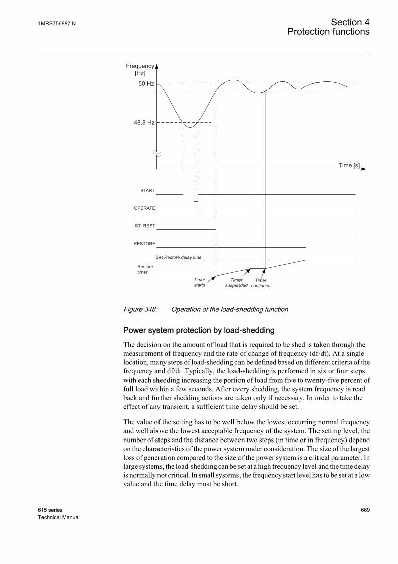
ST_REST
50 Hz
Frequency [Hz]
48.8 Hz
START
OPERATE
Time [s]
RESTORE
Set Restore delay time
Restoretimer
Timer starts
Timer continues
Timer suspended
GUID-8694ACBB-CC73-46E6-A9C9-5DE27F6FC7AF V3 EN
Figure 348: Operation of the load-shedding function
Power system protection by load-sheddingThe decision on the amount of load that is required to be shed is taken through themeasurement of frequency and the rate of change of frequency (df/dt). At a singlelocation, many steps of load-shedding can be defined based on different criteria of thefrequency and df/dt. Typically, the load-shedding is performed in six or four stepswith each shedding increasing the portion of load from five to twenty-five percent offull load within a few seconds. After every shedding, the system frequency is readback and further shedding actions are taken only if necessary. In order to take theeffect of any transient, a sufficient time delay should be set.
The value of the setting has to be well below the lowest occurring normal frequencyand well above the lowest acceptable frequency of the system. The setting level, thenumber of steps and the distance between two steps (in time or in frequency) dependon the characteristics of the power system under consideration. The size of the largestloss of generation compared to the size of the power system is a critical parameter. Inlarge systems, the load-shedding can be set at a high frequency level and the time delayis normally not critical. In small systems, the frequency start level has to be set at a lowvalue and the time delay must be short.
1MRS756887 N Section 4Protection functions
615 series 669Technical Manual
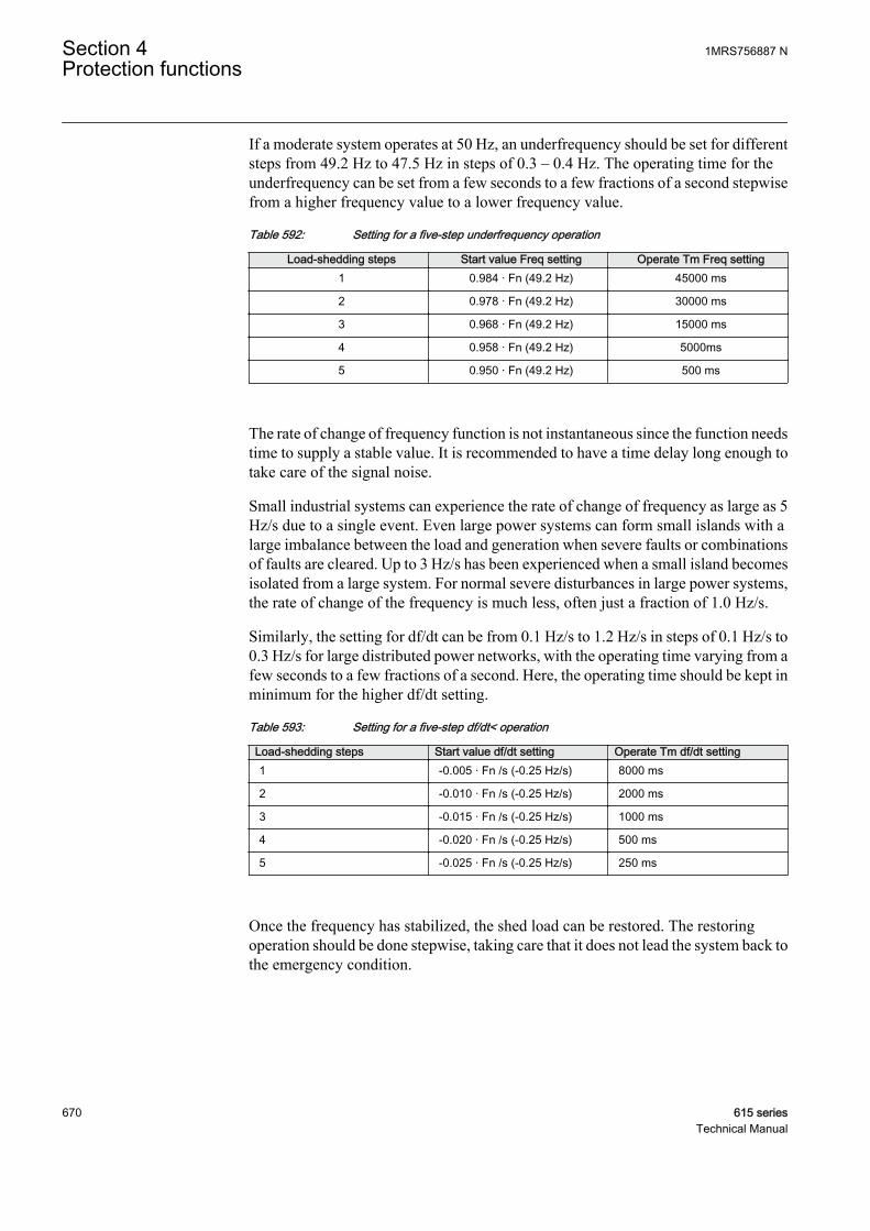
If a moderate system operates at 50 Hz, an underfrequency should be set for differentsteps from 49.2 Hz to 47.5 Hz in steps of 0.3 – 0.4 Hz. The operating time for theunderfrequency can be set from a few seconds to a few fractions of a second stepwisefrom a higher frequency value to a lower frequency value.
Table 592: Setting for a five-step underfrequency operation
Load-shedding steps Start value Freq setting Operate Tm Freq setting1 0.984 · Fn (49.2 Hz) 45000 ms
2 0.978 · Fn (49.2 Hz) 30000 ms
3 0.968 · Fn (49.2 Hz) 15000 ms
4 0.958 · Fn (49.2 Hz) 5000ms
5 0.950 · Fn (49.2 Hz) 500 ms
The rate of change of frequency function is not instantaneous since the function needstime to supply a stable value. It is recommended to have a time delay long enough totake care of the signal noise.
Small industrial systems can experience the rate of change of frequency as large as 5Hz/s due to a single event. Even large power systems can form small islands with alarge imbalance between the load and generation when severe faults or combinationsof faults are cleared. Up to 3 Hz/s has been experienced when a small island becomesisolated from a large system. For normal severe disturbances in large power systems,the rate of change of the frequency is much less, often just a fraction of 1.0 Hz/s.
Similarly, the setting for df/dt can be from 0.1 Hz/s to 1.2 Hz/s in steps of 0.1 Hz/s to0.3 Hz/s for large distributed power networks, with the operating time varying from afew seconds to a few fractions of a second. Here, the operating time should be kept inminimum for the higher df/dt setting.
Table 593: Setting for a five-step df/dt< operation
Load-shedding steps Start value df/dt setting Operate Tm df/dt setting1 -0.005 · Fn /s (-0.25 Hz/s) 8000 ms
2 -0.010 · Fn /s (-0.25 Hz/s) 2000 ms
3 -0.015 · Fn /s (-0.25 Hz/s) 1000 ms
4 -0.020 · Fn /s (-0.25 Hz/s) 500 ms
5 -0.025 · Fn /s (-0.25 Hz/s) 250 ms
Once the frequency has stabilized, the shed load can be restored. The restoringoperation should be done stepwise, taking care that it does not lead the system back tothe emergency condition.
Section 4 1MRS756887 NProtection functions
670 615 seriesTechnical Manual
Table 594: Setting for a five-step restoring operation
Load-shedding steps Restoring start Val setting Restore delay time setting1 0.990 · Fn (49.5 Hz) 200000 ms
2 0.990 · Fn (49.5 Hz) 160000 ms
3 0.990 · Fn (49.5 Hz) 100000 ms
4 0.990 · Fn (49.5 Hz) 50000 ms
5 0.990 · Fn (49.5 Hz) 10000 ms
4.6.2.6 Signals
Table 595: LSHDPFRQ Input signals
Name Type Default DescriptionF SIGNAL 0 Measured frequency
dF/dt SIGNAL 0 Rate of change of frequency
BLOCK BOOLEAN 0=False Block signal for activating the blocking mode
BLK_REST BOOLEAN 0=False Block restore
MAN_RESTORE BOOLEAN 0=False Manual restore signal
Table 596: LSHDPFRQ Output signals
Name Type DescriptionOPERATE BOOLEAN Operation of load shedding
OPR_FRQ BOOLEAN Operate signal for under frequency
OPR_FRG BOOLEAN Operate signal for high df/dt
START BOOLEAN Start
ST_FRQ BOOLEAN Pick-Up signal for under frequency detection
ST_FRG BOOLEAN Pick-Up signal for high df/dt detection
RESTORE BOOLEAN Restore signal for load restoring purposes
ST_REST BOOLEAN Restore frequency attained and restore timerstarted
4.6.2.7 Settings
Table 597: LSHDPFRQ Group settings (Basic)
Parameter Values (Range) Unit Step Default DescriptionLoad shed mode 1=Freq<
6=Freq< OR df/dt8=Freq< AND df/dt
1=Freq< Set the operation mode for load sheddingfunction
Restore mode 1=Disabled2=Auto3=Manual
1=Disabled Mode of operation of restore functionality
Start value Freq 0.800...1.200 xFn 0.001 0.975 Frequency setting/start value
Table continues on next page
1MRS756887 N Section 4Protection functions
615 series 671Technical Manual

Parameter Values (Range) Unit Step Default DescriptionStart value df/dt -0.200...-0.005 xFn /s 0.005 -0.010 Setting of frequency gradient for df/dt
detection
Operate Tm Freq 80...200000 ms 10 200 Time delay to operate for under frequencystage
Operate Tm df/dt 120...200000 ms 10 200 Time delay to operate for df/dt stage
Restore start Val 0.800...1.200 xFn 0.001 0.998 Restore frequency setting value
Restore delay time 80...200000 ms 10 300 Time delay to restore
Table 598: LSHDPFRQ Non group settings (Basic)
Parameter Values (Range) Unit Step Default DescriptionOperation 1=on
5=off 1=on Operation Off / On
Table 599: LSHDPFRQ Non group settings (Advanced)
Parameter Values (Range) Unit Step Default DescriptionReset delay time 0...60000 ms 1 50 Time delay after which the definite timers
will reset
4.6.2.8 Monitored data
Table 600: LSHDPFRQ Monitored data
Name Type Values (Range) Unit DescriptionSTART_DUR FLOAT32 0.00...100.00 % Start duration
LSHDPFRQ Enum 1=on2=blocked3=test4=test/blocked5=off
Status
4.6.2.9 Technical data
Table 601: LSHDPFRQ Technical data
Characteristic ValueOperation accuracy f< ±5 mHz
df/dt ±100 mHz/s (in range |df/dt| < 5 Hz/s)± 2.0% of the set value (in range 5 Hz/s < |df/dt| <15 Hz/s)
Start time f< <80 ms
df/dt <120 ms
Reset time <150 ms
Operate time accuracy ±1.0% of the set value or ±30 ms
Section 4 1MRS756887 NProtection functions
672 615 seriesTechnical Manual

4.6.2.10 Technical revision history
Table 602: LSHDPFRQ Technical revision history
Technical revision ChangeB Internal improvement.
C Internal improvement.
4.7 Impedance protection
4.7.1 Out of step OOSRPSB
4.7.1.1 Identification
Function description IEC 61850identification
IEC 60617identification
ANSI/IEEE C37.2device number
Out-of-step protection OOSRPSB OOS 78
4.7.1.2 Function block
GUID-E240274D-693A-41B4-81E6-3E774228ECC0 V1 EN
Figure 349: Function block
4.7.1.3 Functionality
The out-of-step protection function OOSRPSB detects out of step conditions bymonitoring impedance.
The protection uses two impedance measurement elements known as inner and outerblinders on mho characteristics with a timer. The function calculates the impedance.If the measured impedance stays between inner and outer blinder for a predeterminedtime and moves farther inside the inner blinder, then an out of step condition isindicated. Operate is generated if out of step is indicated and impedance moves out ofmho characteristics. The mho characteristic can be divided into two zones so separatetrips can be generated based on the zone. Operating can also be selected to occur whenthe impedance is on the way into the zone or for when the impedance is on the way outof the zone.
The function contains a blocking functionality. It is possible to block function outputs,the definite timer or the function itself, if desired.
1MRS756887 N Section 4Protection functions
615 series 673Technical Manual
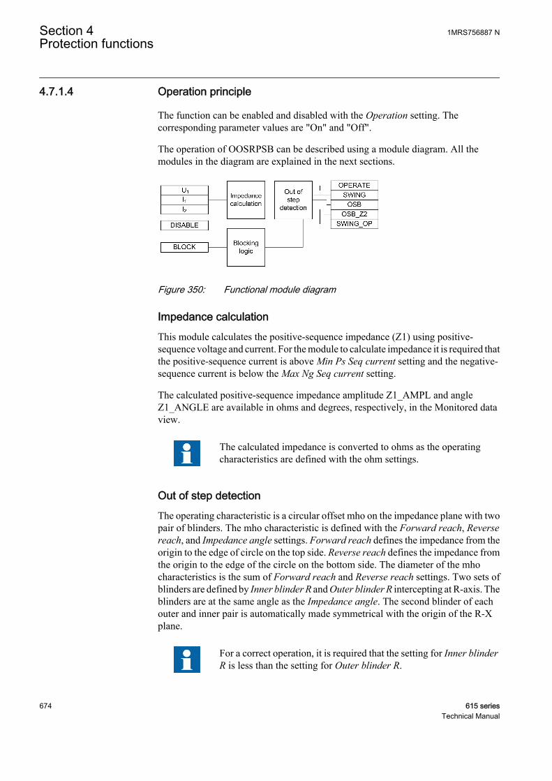
4.7.1.4 Operation principle
The function can be enabled and disabled with the Operation setting. Thecorresponding parameter values are "On" and "Off".
The operation of OOSRPSB can be described using a module diagram. All themodules in the diagram are explained in the next sections.
GUID-0836FFC5-FD02-4EB6-BB30-CE0FB3AFDAE7 V1 EN
Figure 350: Functional module diagram
Impedance calculationThis module calculates the positive-sequence impedance (Z1) using positive-sequence voltage and current. For the module to calculate impedance it is required thatthe positive-sequence current is above Min Ps Seq current setting and the negative-sequence current is below the Max Ng Seq current setting.
The calculated positive-sequence impedance amplitude Z1_AMPL and angleZ1_ANGLE are available in ohms and degrees, respectively, in the Monitored dataview.
The calculated impedance is converted to ohms as the operatingcharacteristics are defined with the ohm settings.
Out of step detectionThe operating characteristic is a circular offset mho on the impedance plane with twopair of blinders. The mho characteristic is defined with the Forward reach, Reversereach, and Impedance angle settings. Forward reach defines the impedance from theorigin to the edge of circle on the top side. Reverse reach defines the impedance fromthe origin to the edge of the circle on the bottom side. The diameter of the mhocharacteristics is the sum of Forward reach and Reverse reach settings. Two sets ofblinders are defined by Inner blinder R and Outer blinder R intercepting at R-axis. Theblinders are at the same angle as the Impedance angle. The second blinder of eachouter and inner pair is automatically made symmetrical with the origin of the R-Xplane.
For a correct operation, it is required that the setting for Inner blinderR is less than the setting for Outer blinder R.
Section 4 1MRS756887 NProtection functions
674 615 seriesTechnical Manual

The circular mho characteristic can be further divided into two zones by setting Zone2 enable to “Yes”. The boundary between zones is set using the setting Zone 1 reach.The lower portion of the circle, Zone 1, is separated from the upper portion, Zone 2,by a line, perpendicular to the blinders, located at a set percentage of the Forwardreach setting from the origin.
GUID-3C167F6E-E0BF-4AC6-B059-7FBFE5AAD307 V1 EN
Figure 351: Operating region for out of step with double blinder
An impedance is only considered to be within the mho circle if it isalso between the inner blinders.
A third zone, Zone 3, can be enabled by setting Zone 3 enable to “Yes”. Zone 3 isdefined to include the area outside of the circular mho characteristic but inside the areathat is bound with the magnitude of the minimum positive-sequence current definedby setting Min Ps Seq.Figure shows the three zones. Settings that determine the shapeof the zones should be coordinated with the settings for any distance protectionfunctions. The zones and their respective slip counters are applicable only for Way outoperations when the Oos operation mode setting option is “Way out” or “Adaptive”.
1MRS756887 N Section 4Protection functions
615 series 675Technical Manual
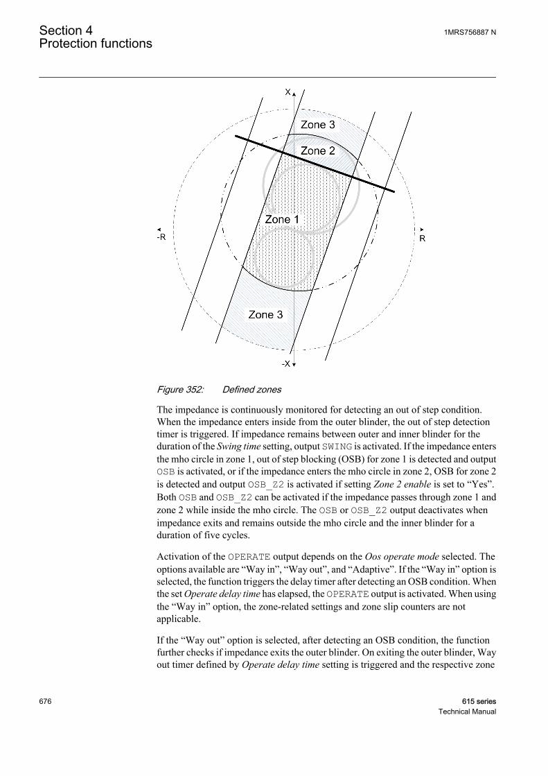
GUID-94CC2B30-D7CC-4CB0-AB7C-C6261C641D37 V1 EN
Figure 352: Defined zones
The impedance is continuously monitored for detecting an out of step condition.When the impedance enters inside from the outer blinder, the out of step detectiontimer is triggered. If impedance remains between outer and inner blinder for theduration of the Swing time setting, output SWING is activated. If the impedance entersthe mho circle in zone 1, out of step blocking (OSB) for zone 1 is detected and outputOSB is activated, or if the impedance enters the mho circle in zone 2, OSB for zone 2is detected and output OSB_Z2 is activated if setting Zone 2 enable is set to “Yes”.Both OSB and OSB_Z2 can be activated if the impedance passes through zone 1 andzone 2 while inside the mho circle. The OSB or OSB_Z2 output deactivates whenimpedance exits and remains outside the mho circle and the inner blinder for aduration of five cycles.
Activation of the OPERATE output depends on the Oos operate mode selected. Theoptions available are “Way in”, “Way out”, and “Adaptive”. If the “Way in” option isselected, the function triggers the delay timer after detecting an OSB condition. Whenthe set Operate delay time has elapsed, the OPERATE output is activated. When usingthe “Way in” option, the zone-related settings and zone slip counters are notapplicable.
If the “Way out” option is selected, after detecting an OSB condition, the functionfurther checks if impedance exits the outer blinder. On exiting the outer blinder, Wayout timer defined by Operate delay time setting is triggered and the respective zone
Section 4 1MRS756887 NProtection functions
676 615 seriesTechnical Manual
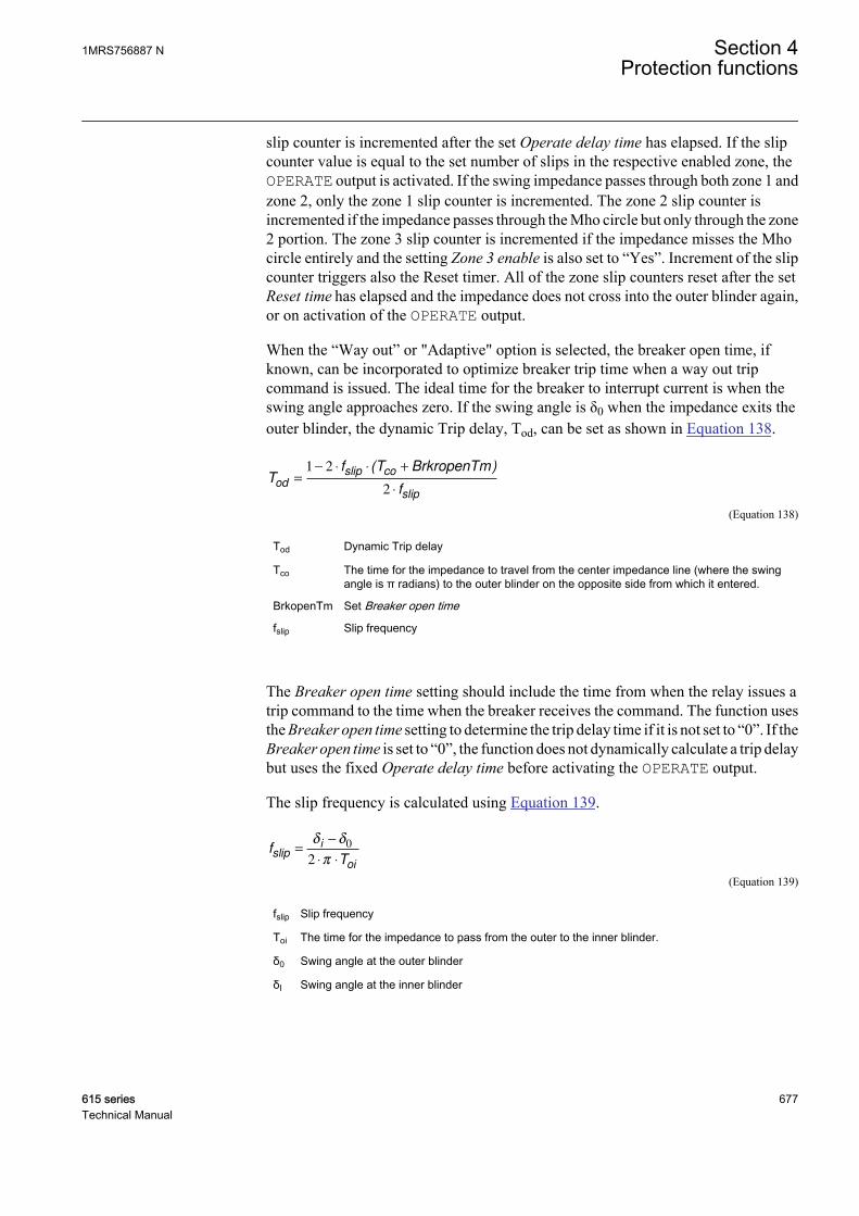
slip counter is incremented after the set Operate delay time has elapsed. If the slipcounter value is equal to the set number of slips in the respective enabled zone, theOPERATE output is activated. If the swing impedance passes through both zone 1 andzone 2, only the zone 1 slip counter is incremented. The zone 2 slip counter isincremented if the impedance passes through the Mho circle but only through the zone2 portion. The zone 3 slip counter is incremented if the impedance misses the Mhocircle entirely and the setting Zone 3 enable is also set to “Yes”. Increment of the slipcounter triggers also the Reset timer. All of the zone slip counters reset after the setReset time has elapsed and the impedance does not cross into the outer blinder again,or on activation of the OPERATE output.
When the “Way out” or "Adaptive" option is selected, the breaker open time, ifknown, can be incorporated to optimize breaker trip time when a way out tripcommand is issued. The ideal time for the breaker to interrupt current is when theswing angle approaches zero. If the swing angle is δ0 when the impedance exits theouter blinder, the dynamic Trip delay, Tod, can be set as shown in Equation 138.
Tf T BrkropenTm
fod
slip co
slip
=
− ⋅ ⋅ +
⋅
1 2
2
( )
GUID-43B1AF3E-06F3-44C6-AA3F-AD0F8EF18FE6 V1 EN (Equation 138)
Tod Dynamic Trip delay
Tco The time for the impedance to travel from the center impedance line (where the swingangle is π radians) to the outer blinder on the opposite side from which it entered.
BrkopenTm Set Breaker open time
fslip Slip frequency
The Breaker open time setting should include the time from when the relay issues atrip command to the time when the breaker receives the command. The function usesthe Breaker open time setting to determine the trip delay time if it is not set to “0”. If theBreaker open time is set to “0”, the function does not dynamically calculate a trip delaybut uses the fixed Operate delay time before activating the OPERATE output.
The slip frequency is calculated using Equation 139.
fT
slipi
oi
=
−
⋅ ⋅
δ δ
π
0
2
GUID-F94B7BCA-473F-42E1-95D5-EF5DF2DCC7C6 V1 EN (Equation 139)
fslip Slip frequency
Toi The time for the impedance to pass from the outer to the inner blinder.
δ0 Swing angle at the outer blinder
δI Swing angle at the inner blinder
1MRS756887 N Section 4Protection functions
615 series 677Technical Manual
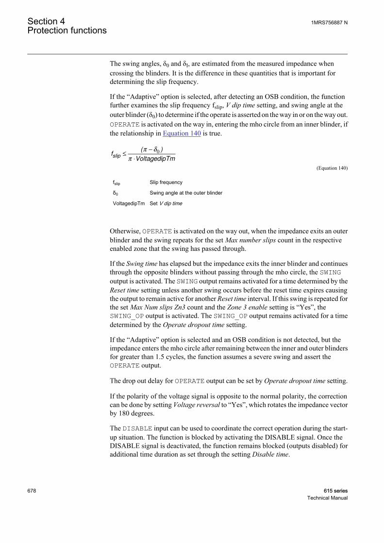
The swing angles, δ0 and δI, are estimated from the measured impedance whencrossing the blinders. It is the difference in these quantities that is important fordetermining the slip frequency.
If the “Adaptive” option is selected, after detecting an OSB condition, the functionfurther examines the slip frequency fslip, V dip time setting, and swing angle at theouter blinder (δ0) to determine if the operate is asserted on the way in or on the way out.OPERATE is activated on the way in, entering the mho circle from an inner blinder, ifthe relationship in Equation 140 is true.
fVoltagedipTm
slip ≤
−
⋅
( )π δ
π
0
GUID-4FEE5C5D-B60F-42E5-AFED-0EBE46145537 V1 EN (Equation 140)
fslip Slip frequency
δ0 Swing angle at the outer blinder
VoltagedipTm Set V dip time
Otherwise, OPERATE is activated on the way out, when the impedance exits an outerblinder and the swing repeats for the set Max number slips count in the respectiveenabled zone that the swing has passed through.
If the Swing time has elapsed but the impedance exits the inner blinder and continuesthrough the opposite blinders without passing through the mho circle, the SWINGoutput is activated. The SWING output remains activated for a time determined by theReset time setting unless another swing occurs before the reset time expires causingthe output to remain active for another Reset time interval. If this swing is repeated forthe set Max Num slips Zn3 count and the Zone 3 enable setting is “Yes”, theSWING_OP output is activated. The SWING_OP output remains activated for a timedetermined by the Operate dropout time setting.
If the “Adaptive” option is selected and an OSB condition is not detected, but theimpedance enters the mho circle after remaining between the inner and outer blindersfor greater than 1.5 cycles, the function assumes a severe swing and assert theOPERATE output.
The drop out delay for OPERATE output can be set by Operate dropout time setting.
If the polarity of the voltage signal is opposite to the normal polarity, the correctioncan be done by setting Voltage reversal to “Yes”, which rotates the impedance vectorby 180 degrees.
The DISABLE input can be used to coordinate the correct operation during the start-up situation. The function is blocked by activating the DISABLE signal. Once theDISABLE signal is deactivated, the function remains blocked (outputs disabled) foradditional time duration as set through the setting Disable time.
Section 4 1MRS756887 NProtection functions
678 615 seriesTechnical Manual
Blocking logicThere are three operation modes in the blocking function. The operation modes arecontrolled by the BLOCK input and the global setting in Configuration/System/Blocking mode which selects the blocking mode. The BLOCK input can be controlledby a binary input, a horizontal communication input or an internal signal of theprotection relay's program. The influence of the BLOCK signal activation ispreselected with the global setting Blocking mode.
The Blocking mode setting has three blocking methods. In the “Freeze timers” mode,the operation timer is frozen to the prevailing value, but the OPERATE output is notdeactivated when blocking is activated. In the “Block all” mode, the whole functionis blocked and the timers are reset. In the “Block OPERATE output” mode, thefunction operates normally but the OPERATE output is not activated.
4.7.1.5 Application
Out of step protection functions detect stable power swings and out of step conditionsbased on the fact that the voltage/current variation during a power swing is slowcompared to the step change during a fault. Both faults and power swings may causethe measured impedance to enter into the operating characteristic of a distance relayelement. The apparent impedance moves from the pre-fault value to a fault value in avery short time, a few milliseconds, during a fault condition. However, the rate ofchange of the impedance is much slower during a power swing or out of step conditionthan during a fault depending on the slip frequency of the out of step. The impedancemeasurement should not be used by itself to distinguish between a fault condition andan out of step condition from a phase fault. The fundamental method fordiscriminating between faults and power swings is to track the rate of change of themeasured impedance.
The function measures the rate of change of the impedance using two impedancemeasurement elements known as blinders together with a timing device. If themeasured impedance stays between the blinders for a predetermined time, thefunction declares a power swing condition and asserts an output that can be used toblock the distance protection. However, if the impedance passes the inner blinder andexits on the other side of the mho characteristics (that is, the resistive component ofimpedance has opposite sign as at the time of point of entry) an out of step operate isissued by the function.Figure 353 gives an example of out of step detection.
1MRS756887 N Section 4Protection functions
615 series 679Technical Manual
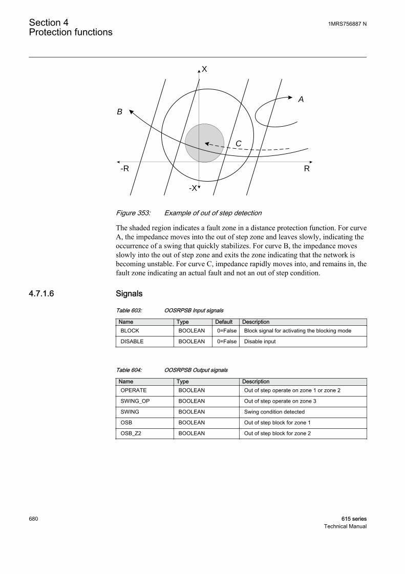
X
-X
-R R
A
B
C
GUID-87E27B8C-02D6-4970-AF78-55E6ACB630F0 V1 EN
Figure 353: Example of out of step detection
The shaded region indicates a fault zone in a distance protection function. For curveA, the impedance moves into the out of step zone and leaves slowly, indicating theoccurrence of a swing that quickly stabilizes. For curve B, the impedance movesslowly into the out of step zone and exits the zone indicating that the network isbecoming unstable. For curve C, impedance rapidly moves into, and remains in, thefault zone indicating an actual fault and not an out of step condition.
4.7.1.6 Signals
Table 603: OOSRPSB Input signals
Name Type Default DescriptionBLOCK BOOLEAN 0=False Block signal for activating the blocking mode
DISABLE BOOLEAN 0=False Disable input
Table 604: OOSRPSB Output signals
Name Type DescriptionOPERATE BOOLEAN Out of step operate on zone 1 or zone 2
SWING_OP BOOLEAN Out of step operate on zone 3
SWING BOOLEAN Swing condition detected
OSB BOOLEAN Out of step block for zone 1
OSB_Z2 BOOLEAN Out of step block for zone 2
Section 4 1MRS756887 NProtection functions
680 615 seriesTechnical Manual
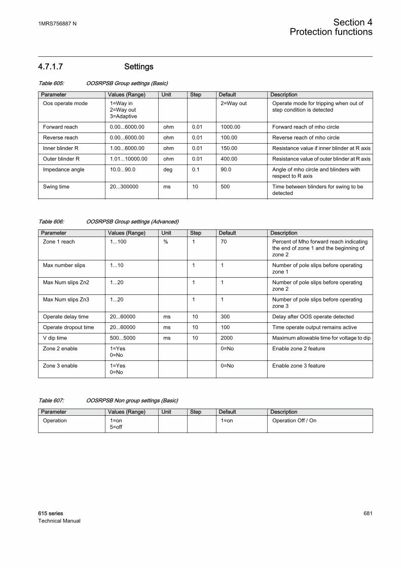
4.7.1.7 Settings
Table 605: OOSRPSB Group settings (Basic)
Parameter Values (Range) Unit Step Default DescriptionOos operate mode 1=Way in
2=Way out3=Adaptive
2=Way out Operate mode for tripping when out ofstep condition is detected
Forward reach 0.00...6000.00 ohm 0.01 1000.00 Forward reach of mho circle
Reverse reach 0.00...6000.00 ohm 0.01 100.00 Reverse reach of mho circle
Inner blinder R 1.00...6000.00 ohm 0.01 150.00 Resistance value if inner blinder at R axis
Outer blinder R 1.01...10000.00 ohm 0.01 400.00 Resistance value of outer blinder at R axis
Impedance angle 10.0...90.0 deg 0.1 90.0 Angle of mho circle and blinders withrespect to R axis
Swing time 20...300000 ms 10 500 Time between blinders for swing to bedetected
Table 606: OOSRPSB Group settings (Advanced)
Parameter Values (Range) Unit Step Default DescriptionZone 1 reach 1...100 % 1 70 Percent of Mho forward reach indicating
the end of zone 1 and the beginning ofzone 2
Max number slips 1...10 1 1 Number of pole slips before operatingzone 1
Max Num slips Zn2 1...20 1 1 Number of pole slips before operatingzone 2
Max Num slips Zn3 1...20 1 1 Number of pole slips before operatingzone 3
Operate delay time 20...60000 ms 10 300 Delay after OOS operate detected
Operate dropout time 20...60000 ms 10 100 Time operate output remains active
V dip time 500...5000 ms 10 2000 Maximum allowable time for voltage to dip
Zone 2 enable 1=Yes0=No
0=No Enable zone 2 feature
Zone 3 enable 1=Yes0=No
0=No Enable zone 3 feature
Table 607: OOSRPSB Non group settings (Basic)
Parameter Values (Range) Unit Step Default DescriptionOperation 1=on
5=off 1=on Operation Off / On
1MRS756887 N Section 4Protection functions
615 series 681Technical Manual
Table 608: OOSRPSB Non group settings (Advanced)
Parameter Values (Range) Unit Step Default DescriptionMin Ps Seq current 0.01...10.00 xIn 0.01 0.10 Minimum positive sequence current for
operation
Max Ng Seq current 0.01...10.00 xIn 0.01 0.20 Maximum negative sequence current foroperation
Breaker open time 0...300 ms 1 30 Opening time of the breaker
Disable time 20...60000 ms 10 5000 Additional time function is disabled afterremoval of DISABLE input
Reset time 20...60000 ms 10 5000 Time to reset OOS condition and counters
Voltage reversal 0=No1=Yes
0=No Rotate voltage signals by 180 degrees
4.7.1.8 Monitored data
Table 609: OOSRPSB Monitored data
Name Type Values (Range) Unit DescriptionZ1_AMPL FLOAT32 0.00...99999.00 ohm Positive sequence
impedance amplitude
Z1_ANGLE FLOAT32 -180...180 deg Positive sequenceimpedance phase angle
OOSRPSB Enum 1=on2=blocked3=test4=test/blocked5=off
Status
4.7.1.9 Technical data
Table 610: OOSRPSB Technical data
Characteristic ValueImpedance reach Depending on the frequency of the measured
current and voltage: fn ±2 Hz
±3.0% of the reach value or ±0.2% of Un/(√3 × In)
Reset time ±1.0% of the set value or ±40 ms
Operate time accuracy ±1.0% of the set value or ±20 ms
Suppression of harmonics DFT: -50 dB at f = n × fn, where n = 2, 3, 4, 5...
4.7.2 Three-phase underexcitation protection UEXPDIS
4.7.2.1 Identification
Function description IEC 61850identification
IEC 60617identification
ANSI/IEEE C37.2device number
Three-phase underexcitation protection UEXPDIS X< 40
Section 4 1MRS756887 NProtection functions
682 615 seriesTechnical Manual

4.7.2.2 Function block
GUID-1D165D41-1EE8-4AF4-A3F5-E688F97850DB V1 EN
Figure 354: Function block
4.7.2.3 Functionality
The three-phase underexcitation protection function UEXPDIS is used to protect thesynchronous machine against the underexcitation or loss of excitation condition.
The protection is based on the offset-mho circular characteristics on the impedanceplane. The function calculates the apparent impedance from the machine terminalvoltages and currents. If the impedance vector enters the offset-mho circle, thefunction gives the operating signal after a set definite time. The operating timecharacteristics are according to definite time (DT).
This function contains a blocking functionality. It is possible to block the functionoutputs, timer or the function itself, if desired.
4.7.2.4 Operation principle
The function can be enabled and disabled with the Operation setting. Thecorresponding parameter values are "On" and "Off".
The operation of UEXPDIS can be described using a module diagram. All themodules in the diagram are explained in the next sections.
1MRS756887 N Section 4Protection functions
615 series 683Technical Manual
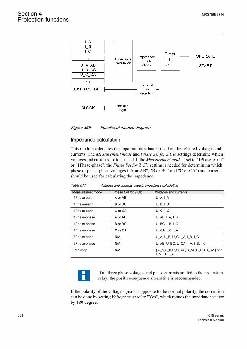
GUID-8AD2B23E-F625-4B01-BD82-EA15FF35989A V1 EN
Figure 355: Functional module diagram
Impedance calculationThis module calculates the apparent impedance based on the selected voltages andcurrents. The Measurement mode and Phase Sel for Z Clc settings determine whichvoltages and currents are to be used. If the Measurement mode is set to "1Phase-earth"or "1Phase-phase", the Phase Sel for Z Clc setting is needed for determining whichphase or phase-phase voltages ("A or AB", "B or BC" and "C or CA") and currentsshould be used for calculating the impedance.
Table 611: Voltages and currents used in impedance calculation
Measurement mode Phase Sel for Z Clc Voltages and currents1Phase-earth A or AB U_A, I_A
1Phase-earth B or BC U_B, I_B
1Phase-earth C or CA U_C, I_C
1Phase-phase A or AB U_AB, I_A, I_B
1Phase-phase B or BC U_BC, I_B, I_C
1Phase-phase C or CA U_CA, I_C, I_A
3Phase-earth N/A U_A, U_B, U_C, I_A, I_B, I_C
3Phase-phase N/A U_AB, U_BC, U_CA, I_A, I_B, I_C
Pos seqn N/A U_A,U_B,U_C or U_AB,U_BC,U_CA andI_A, I_B, I_C
If all three phase voltages and phase currents are fed to the protectionrelay, the positive-sequence alternative is recommended.
If the polarity of the voltage signals is opposite to the normal polarity, the correctioncan be done by setting Voltage reversal to "Yes", which rotates the impedance vectorby 180 degrees.
Section 4 1MRS756887 NProtection functions
684 615 seriesTechnical Manual
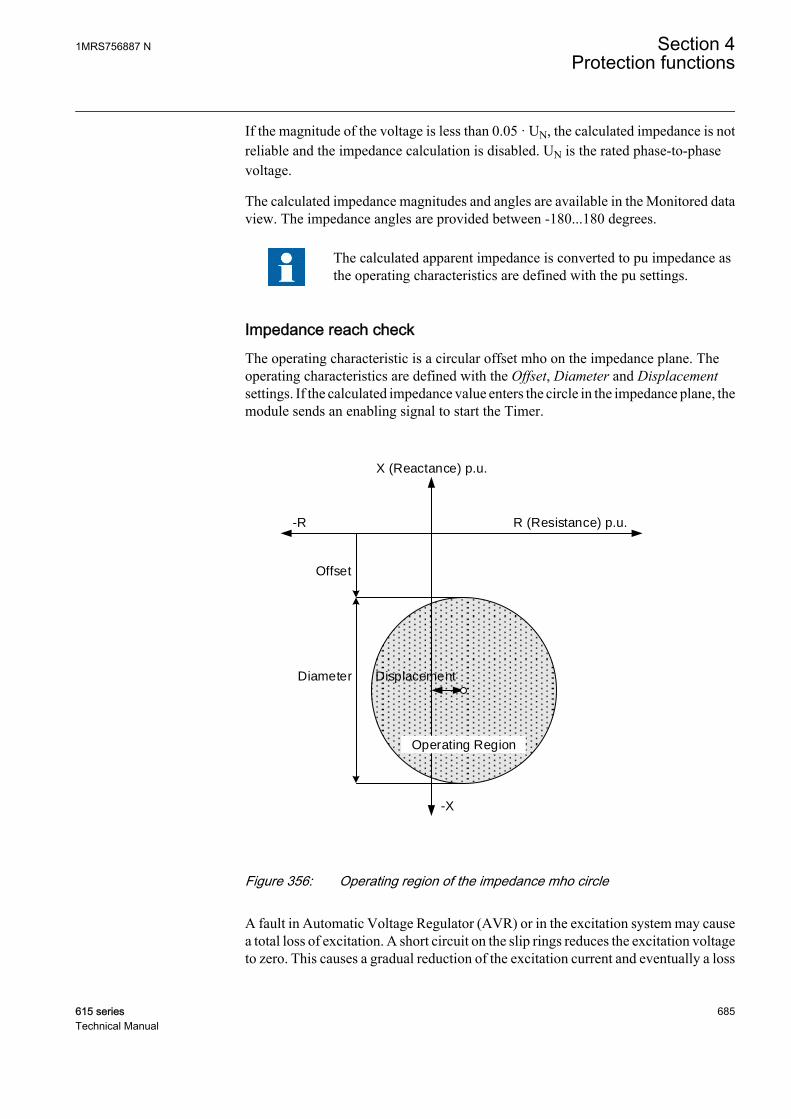
If the magnitude of the voltage is less than 0.05 · UN, the calculated impedance is notreliable and the impedance calculation is disabled. UN is the rated phase-to-phasevoltage.
The calculated impedance magnitudes and angles are available in the Monitored dataview. The impedance angles are provided between -180...180 degrees.
The calculated apparent impedance is converted to pu impedance asthe operating characteristics are defined with the pu settings.
Impedance reach checkThe operating characteristic is a circular offset mho on the impedance plane. Theoperating characteristics are defined with the Offset, Diameter and Displacementsettings. If the calculated impedance value enters the circle in the impedance plane, themodule sends an enabling signal to start the Timer.
Offset
DisplacementDiameter
X (Reactance) p.u.
R (Resistance) p.u.-R
-X
Operating Region
GUID-A023B281-CA68-4A0C-8E90-9075DF588504 V2 EN
Figure 356: Operating region of the impedance mho circle
A fault in Automatic Voltage Regulator (AVR) or in the excitation system may causea total loss of excitation. A short circuit on the slip rings reduces the excitation voltageto zero. This causes a gradual reduction of the excitation current and eventually a loss
1MRS756887 N Section 4Protection functions
615 series 685Technical Manual

of excitation. An open circuit in the field circuit also causes a loss of excitation. Theseare typical examples which cause underexcitation in synchronous machines. Thismodule detects the underexcitation condition for the above cases when the calculatedimpedance enters the operating characteristics.
External loss detectionThe module checks the status information of the excitation system. It is activatedwhen the External Los Det Ena setting is set to "Enable". The total loss of excitationcurrent or a failure in the excitation system is indicated by connecting the externalbinary signal to the EXT_LOS_DET input. The Timer is enabled immediately whenthe EXT_LOS_DET input is activated.
TimerOnce activated, the Timer activates the START output. The time characteristic isaccording to DT. When the duration of the underexcitation exceeds the set definiteOperate delay time, the OPERATE output is activated. If the impedance locus movesout of the offset-mho operating characteristics before the module operates, the resettimer is activated. If the reset timer reaches the value set by Reset delay time, theoperating timer resets and the START output is deactivated.
The Timer calculates the start duration value START_DUR, which indicates thepercentage ratio of the pickup situation and the set operating time (DT). The value isavailable in the Monitored data view.
Blocking logicThere are three operation modes in the blocking functionality. The operation modesare controlled by the BLOCK input and the global setting Configuration/System/Blocking mode which selects the blocking mode. The BLOCK input can be controlledby a binary input, a horizontal communication input or an internal signal of theprotection relay's program. The influence of the BLOCK signal activation ispreselected with the global setting Blocking mode.
The Blocking mode setting has three blocking methods. In the "Freeze timers" mode,the operate timer is frozen to the prevailing value. In the "Block all" mode, the wholefunction is blocked and the timers are reset. In the "Block OPERATE output" mode,the function operates normally but the OPERATE output is not activated.
4.7.2.5 Application
There are limits for the underexcitation of a synchronous machine. A reduction of theexcitation current weakens the coupling between the rotor and the external powersystem. The machine may lose the synchronism and start to operate like an inductionmachine, which increases the consumption of the reactive power. Even if the machinedoes not lose synchronism, it is not recommended to operate in this state. Theunderexcitation causes excessive heating in the end region of the stator winding. Thiscan damage the insulation of the stator winding and even the iron core.
Section 4 1MRS756887 NProtection functions
686 615 seriesTechnical Manual
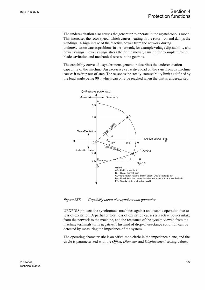
The underexcitation also causes the generator to operate in the asynchronous mode.This increases the rotor speed, which causes heating in the rotor iron and damps thewindings. A high intake of the reactive power from the network duringunderexcitation causes problems in the network, for example voltage dip, stability andpower swings. Power swings stress the prime mover, causing for example turbineblade cavitation and mechanical stress in the gearbox.
The capability curve of a synchronous generator describes the underexcitationcapability of the machine. An excessive capacitive load on the synchronous machinecauses it to drop out-of-step. The reason is the steady-state stability limit as defined bythe load angle being 90°, which can only be reached when the unit is underexcited.
Q (Reactive power) p.u.
P (Active power) p.u.
A
B
C
D
FE
0.0 0.8
0.6
0.5
0.3
1.0
0.9
GeneratorMotor
Over-Excitation
Under-Excitation
H
Xe=0.2
Xs=0.0
37o
18o
Where,AB= Field current limitBC= Stator current limitCD= End region heating limit of stator. Due to leakage fluxBH= Possible active power limit due to turbine output power limitationEF= Steady -state limit without AVR
GUID-FD5EDD69-0D03-4A97-A1AB-46C755F531A5 V2 EN
Figure 357: Capability curve of a synchronous generator
UEXPDIS protects the synchronous machines against an unstable operation due toloss of excitation. A partial or total loss of excitation causes a reactive power intakefrom the network to the machine, and the reactance of the system viewed from themachine terminals turns negative. This kind of drop-of-reactance condition can bedetected by measuring the impedance of the system.
The operating characteristic is an offset-mho circle in the impedance plane, and thecircle is parameterized with the Offset, Diameter and Displacement setting values.
1MRS756887 N Section 4Protection functions
615 series 687Technical Manual

Table 612: Parameters of the circle
Setting values DescriptionOffset Distance of the top of the circle from the R-axis. This is usually set equal to - xd’/2,
where xd’ is the transient reactance of the machine. The sign of the setting valuedetermines the top of the circle regarding the R-axis. If the sign is negative, thecircle lies below the R-axis.
Diameter Normally set equal to the machine's synchronous reactance xd, which determinesthe size of the impedance circle.
Displacement Displacement of the center of the circle from the reactance axis or the R-coordinateof the center. The setting can be used to adjust the sensitivity of the underexcitationprotection. If the sign of the setting is positive, the circle is shifted to the right, thatis, closer to the normal operating point. Respectively, if the sign is negative, thecircle is shifted to the left and thus moves away from the normal operating point.
The setting parameters of the off-set mho circle are to be given in pu values. The baseimpedance (ZN) in ohms is:
ZU
SN
N
N
=
2
GUID-FDF8D989-6F91-4AE9-8A3C-31769808FF71 V1 EN (Equation 141)
UN rated (phase-to-phase) voltage in kV
SN rated power of the protected machine in MVA
The corresponding calculation to convert ohms to pu values is:
XX
Zpu
ohm
N
=
GUID-8F02750E-98A4-4AD9-82C6-0632CCE84F01 V1 EN (Equation 142)
Xpu pu value
Xohm reactance in ohms
ZN base impedance
Example of impedance locus in underexcitationIn an example of a typical impedance locus, once the impedance locus enters the relayoperation characteristics, the relay operates after a settable definite time.
Section 4 1MRS756887 NProtection functions
688 615 seriesTechnical Manual
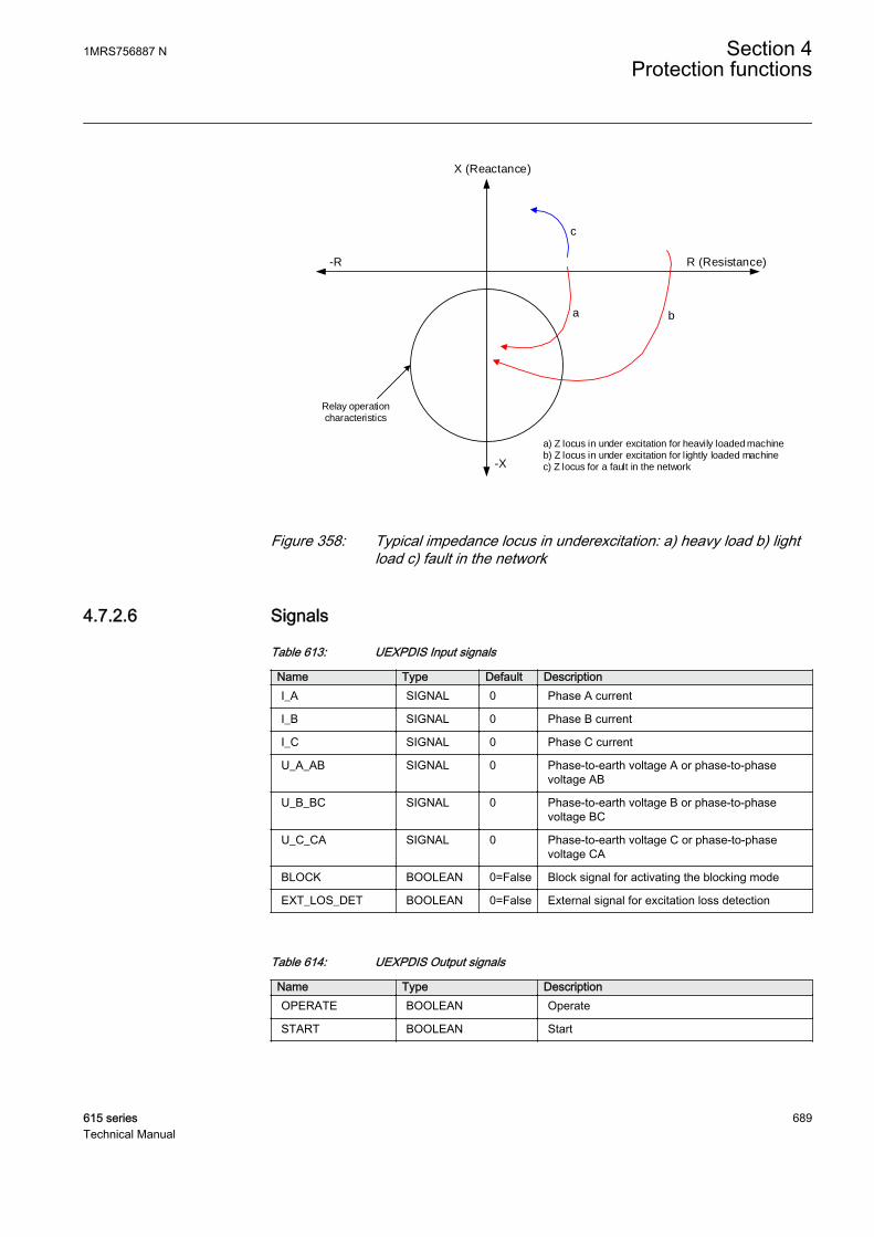
a) Z locus in under excitation for heavily loaded machineb) Z locus in under excitation for lightly loaded machinec) Z locus for a fault in the network
X (Reactance)
R (Resistance)
-X
Relay operation characteristics
-R
a b
c
GUID-C7940DC8-04A8-4FED-B089-DAA9B21D50DB V2 EN
Figure 358: Typical impedance locus in underexcitation: a) heavy load b) lightload c) fault in the network
4.7.2.6 Signals
Table 613: UEXPDIS Input signals
Name Type Default DescriptionI_A SIGNAL 0 Phase A current
I_B SIGNAL 0 Phase B current
I_C SIGNAL 0 Phase C current
U_A_AB SIGNAL 0 Phase-to-earth voltage A or phase-to-phasevoltage AB
U_B_BC SIGNAL 0 Phase-to-earth voltage B or phase-to-phasevoltage BC
U_C_CA SIGNAL 0 Phase-to-earth voltage C or phase-to-phasevoltage CA
BLOCK BOOLEAN 0=False Block signal for activating the blocking mode
EXT_LOS_DET BOOLEAN 0=False External signal for excitation loss detection
Table 614: UEXPDIS Output signals
Name Type DescriptionOPERATE BOOLEAN Operate
START BOOLEAN Start
1MRS756887 N Section 4Protection functions
615 series 689Technical Manual

4.7.2.7 Settings
Table 615: UEXPDIS Group settings (Basic)
Parameter Values (Range) Unit Step Default DescriptionDiameter 1...6000 %Zn 1 200 Diameter of the Mho diagram
Offset -1000...1000 %Zn 1 -10 Offset of top of the impedance circle fromthe R-axis
Displacement -1000...1000 %Zn 1 0 Displacement of impedance circle centrefrom the X-axis
Operate delay time 60...200000 ms 10 5000 Operate delay time
Table 616: UEXPDIS Non group settings (Basic)
Parameter Values (Range) Unit Step Default DescriptionOperation 1=on
5=off 1=on Operation Off / On
External Los Det Ena 0=Disable1=Enable
1=Enable Enable external excitation loss detection
Voltage reversal 0=No1=Yes
0=No Rotate voltage signals by 180 degrees
Impedance Meas mode 1=1Phase-to-earth2=1Phase-to-phase3=3Phase-to-earth4=3Phase-to-phase5=Pos sequence
5=Pos sequence Select voltage and currents forimpedance calculation
Phase Sel for Z Clc 1=A or AB2=B or BC3=C or CA
1=A or AB Voltage phase selection
Table 617: UEXPDIS Non group settings (Advanced)
Parameter Values (Range) Unit Step Default DescriptionReset delay time 0...60000 ms 10 3000 Reset delay time
4.7.2.8 Monitored data
Table 618: UEXPDIS Monitored data
Name Type Values (Range) Unit DescriptionSTART_DUR FLOAT32 0.00...100.00 % Ratio of start time /
operate time (in %)
Z_AMPL_A FLOAT32 0.00...200.00 xZn Impedance amplitudephase A
Z_ANGLE_A FLOAT32 -180.00...180.00 deg Impedance angle phaseA
Z_AMPL_B FLOAT32 0.00...200.00 xZn Impedance amplitudephase B
Table continues on next page
Section 4 1MRS756887 NProtection functions
690 615 seriesTechnical Manual
Name Type Values (Range) Unit DescriptionZ_ANGLE_B FLOAT32 -180.00...180.00 deg Impedance angle phase
B
Z_AMPL_C FLOAT32 0.00...200.00 xZn Impedance amplitudephase C
Z_ANGLE_C FLOAT32 -180.00...180.00 deg Impedance angle phaseC
Z_AMPL_AB FLOAT32 0.00...200.00 xZn Phase-to-phase A-Bimpedance amplitude
Z_ANGLE_AB FLOAT32 -180.00...180.00 deg Phase-to-phase A-Bimpedance phase angle
Z_AMPL_BC FLOAT32 0.00...200.00 xZn Phase-to-phase B-Cimpedance amplitude
Z_ANGLE_BC FLOAT32 -180.00...180.00 deg Phase-to-phase B-Cimpedance phase angle
Z_AMPL_CA FLOAT32 0.00...200.00 xZn Phase-to-phase C-Aimpedance amplitude
Z_ANGLE_CA FLOAT32 -180.00...180.00 deg Phase-to-phase C-Aimpedance phase angle
Z1_AMPL FLOAT32 0.00...200.00 xZn Positive sequenceimpedance amplitude
Z1_ANGLE FLOAT32 -180.00...180.00 deg Positive sequenceimpedance phase angle
UEXPDIS Enum 1=on2=blocked3=test4=test/blocked5=off
Status
4.7.2.9 Technical data
Table 619: UEXPDIS Technical data
Characteristic ValueOperation accuracy Depending on the frequency of the measured
current and voltage:f = fn ± 2 Hz
±3.0% of the set value or ±0.2% Zb
Start time1)2) Typically 45 ms
Reset time Typically 30 ms
Reset ratio Typically 1.04
Retardation time Total retardation time when the impedancereturns from the operating circle <40 ms
Operate time accuracy ±1.0% of the set value or ±20 ms
Suppression of harmonics -50 dB at f = n × fn, where n = 2, 3, 4, 5,…
1) fn= 50Hz, results based on statistical distribution of 1000 measurements2) Includes the delay of the signal output contact
1MRS756887 N Section 4Protection functions
615 series 691Technical Manual

4.7.3 Three-phase underimpedance protection UZPDIS
4.7.3.1 Identification
Function description IEC 61850identification
IEC 60617identification
ANSI/IEEE C37.2device number
Three-phase underimpedanceprotection
UZPDIS Z<G 21G
4.7.3.2 Function block
GUID-0CE355B5-23B5-4BF0-B368-DD4AECEB5B01 V1 EN
Figure 359: Function block
4.7.3.3 Functionality
The three-phase underimpedance protection UZPDIS is generally applied as a backupprotection for generators and transformers against short circuit faults.
The protection is based on the origin-centric circular characteristics on the impedanceplane. The function calculates the impedance value from the voltage and currentphasors. If the impedance vector enters the origin-centric circle, the function producesthe operating signal after a set delay. The operating time characteristics are accordingto definite time (DT).
This function contains a blocking functionality. It is possible to block the functionoutputs, reset timer or the function itself, if desired.
4.7.3.4 Operation principle
The function can be enabled and disabled with the Operation setting. Thecorresponding parameter values are "On" and "Off".
The operation of UZPDIS can be described with a module diagram. All the modulesin the diagram are explained in the next sections.
Section 4 1MRS756887 NProtection functions
692 615 seriesTechnical Manual
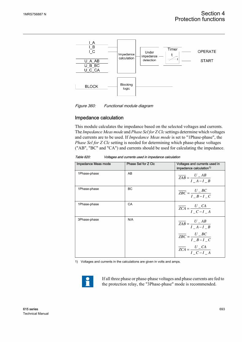
GUID-AC85EE54-CEDC-4978-98F1-27CFBAED83D1 V1 EN
Figure 360: Functional module diagram
Impedance calculationThis module calculates the impedance based on the selected voltages and currents.The Impedance Meas mode and Phase Sel for Z Clc settings determine which voltagesand currents are to be used. If Impedance Meas mode is set to "1Phase-phase", thePhase Sel for Z Clc setting is needed for determining which phase-phase voltages("AB", "BC" and "CA") and currents should be used for calculating the impedance.
Table 620: Voltages and currents used in impedance calculation
Impedance Meas mode Phase Sel for Z Clc Voltages and currents used inimpedance calculation1)
1Phase-phase ABZAB
U AB
I A I B=
−
_
_ _
1Phase-phase BCZBC
U BC
I B I C=
−
_
_ _
1Phase-phase CAZCA
U CA
I C I A=
−
_
_ _
3Phase-phase N/AZAB
U AB
I A I B=
−
_
_ _
ZBCU BC
I B I C=
−
_
_ _
ZCAU CA
I C I A=
−
_
_ _
1) Voltages and currents in the calculations are given in volts and amps.
If all three phase or phase-phase voltages and phase currents are fed tothe protection relay, the "3Phase-phase" mode is recommended.
1MRS756887 N Section 4Protection functions
615 series 693Technical Manual

The current measurement of the function is based on two alternative measurementmodes, "DFT" and "Peak-To-Peak". The measurement mode is selected using theMeasurement mode setting.
If the current magnitude is below 0.02 · IN, where IN is the nominal phase current, theimpedance value is not evaluated and the maximum impedance value (99.999 pu) isshown in the Monitored data view.
The calculated impedances are converted to a pu impedance as theoperating characteristics are defined using the Polar reach setting in%Zb.
The calculated phase-phase impedance amplitudes ZAB_AMPL, ZBC_AMPL andZCA_AMPL are available as pu values in the Monitored data view.
Underimpedance detectionThe operating characteristic is an origin-centric circle on the impedance plane. Theorigin-centric circular characteristic is defined using the Polar reach setting. If thecalculated impedance value enters the circle in the impedance plane, the module sendsan enabling signal to start the Timer.
GUID-87BF61EC-937C-4C2C-928E-984CA26D23DE V1 EN
Figure 361: Origin-centric circular operating characteristics
Section 4 1MRS756887 NProtection functions
694 615 seriesTechnical Manual

More than one impedance value is available when Impedance Measmode is set to "3Phase-phase", and the function considers the lowestimpedance value for starting and operating.
TimerOnce activated, the Timer activates START output. The time characteristic isaccording to DT. When the duration of the underimpedance condition exceeds the setdefinite Operate delay time, the OPERATE output is activated. If the impedance locusmoves out of circular operating characteristics before the module operates, the resettimer is activated. If the reset timer reaches the value set by Reset delay time, theoperating timer resets and the START output is deactivated.
The Timer calculates the start duration value START_DUR, which indicates thepercentage ratio of the start situation and the set operating time (DT). The value isavailable in the Monitored data view.
Blocking logicThere are three operation modes in the blocking functionality. The operation modesare controlled by the BLOCK input and the global setting Configuration/System/Blocking mode which selects the blocking mode. The BLOCK input can be controlledby a binary input, a horizontal communication input or an internal signal of theprotection relay's program. The influence of the BLOCK signal activation ispreselected with the global setting Blocking mode.
The Blocking mode setting has three blocking methods. In the "Freeze timers" mode,the operate timer is frozen to the prevailing value. In the "Block all" mode, the wholefunction is blocked and the timers are reset. In the "Block OPERATE output" mode,the function operates normally but the OPERATE output is not activated.
4.7.3.5 Application
The three-phase underimpedance protection is used as a backup protection againstshort circuit faults at the generator terminals or on the high-voltage side of a step-uptransformer. This function can be used either instead of the definite time voltage-dependent overcurrent protection or to obtain a limited protection zone and theoptimum operating time instead of the non-directional overcurrent protection.
Comparison between overcurrent and underimpedance protectionPhase current for three-phase short circuit is shown in Figure 362. In this case, with anordinary over current relay having the current setting as 1.2 · In, the time setting shouldbe less than 0.2 seconds, since with a higher value the short-circuit current decaysbelow the set value and the relay drops off. The current setting can also be reduced to1.1 · In, although this provides no substantial rise in the time setting. In somesituations, either of the above current settings is appropriate, but if longer trippingtimes are required to maintain the time selectivity, the underimpedance protection isneeded.
1MRS756887 N Section 4Protection functions
615 series 695Technical Manual

GUID-E7269B2F-83FE-4385-8374-8F8C06D4CC0B V1 EN
Figure 362: Short circuit current waveform, fault occurs at time 0 seconds(Current setting limit is multiplied by the square root of 2)
The phase voltage in a three-phase short circuit when a fault occurs at time = 0 s isshown in Figure 363. The voltage drop caused by a three-phase fault provides moretime for determining the fault by means of an underimpedance protection.
Section 4 1MRS756887 NProtection functions
696 615 seriesTechnical Manual
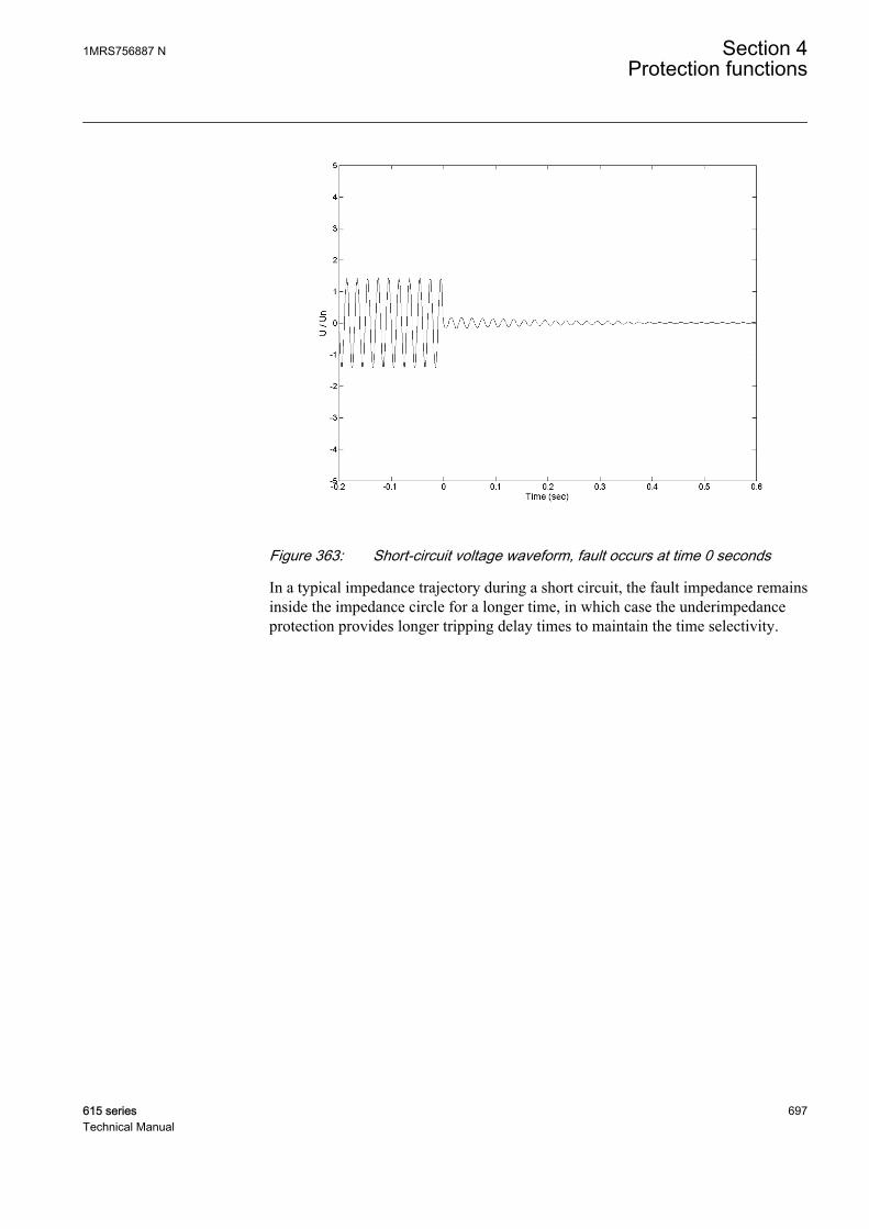
GUID-81098928-2DEE-4297-9EEB-97F42C4B893C V1 EN
Figure 363: Short-circuit voltage waveform, fault occurs at time 0 seconds
In a typical impedance trajectory during a short circuit, the fault impedance remainsinside the impedance circle for a longer time, in which case the underimpedanceprotection provides longer tripping delay times to maintain the time selectivity.
1MRS756887 N Section 4Protection functions
615 series 697Technical Manual

GUID-3AE8053A-348E-4651-A1E5-F384230AF1CF V1 EN
Figure 364: Typical impedance trajectory during a short circuit
Underimpedance protection for transformersThe underimpedance function is used as a short circuit protection instead of theovercurrent protection. It is also used as a backup to the differential protection oftransformers.
The voltage and current phasors are measured with the VTs and CTs connected on theHV side of the transformer.
The phase and current shifts due to transformer D/Y connections andother factors complicate the settings for the faults in the secondarywinding (as seen from the protection relay), and detailed calculationsare necessary for a good coverage.
The Polar reach setting is set to a value equal to 150 percent of the transformer shortcircuit impedance. The setting also provides a backup protection for the busbar andfeeder faults on the HV side.
Underimpedance protection for generatorsThe underimpedance protection is set to protect the zone between the generatorwindings and the generator side windings of the step-up transformer. The function
Section 4 1MRS756887 NProtection functions
698 615 seriesTechnical Manual
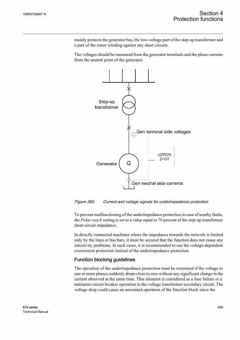
mainly protects the generator bus, the low-voltage part of the step-up transformer anda part of the stator winding against any short circuits.
The voltages should be measured from the generator terminals and the phase currentsfrom the neutral point of the generator.
GUID-E1B90616-E865-49E2-9366-616B0112CA85 V1 EN
Figure 365: Current and voltage signals for underimpedance protection
To prevent malfunctioning of the underimpedance protection in case of nearby faults,the Polar reach setting is set to a value equal to 70 percent of the step-up transformershort circuit impedance.
In directly connected machines where the impedance towards the network is limitedonly by the lines or bus bars, it must be secured that the function does not cause anyselectivity problems. In such cases, it is recommended to use the voltage-dependentovercurrent protection instead of the underimpedance protection.
Function blocking guidelinesThe operation of the underimpedance protection must be restrained if the voltage inone or more phases suddenly drops close to zero without any significant change in thecurrent observed at the same time. This situation is considered as a fuse failure or aminiature circuit breaker operation in the voltage transformer secondary circuit. Thevoltage drop could cause an unwanted operation of the function block since the
1MRS756887 N Section 4Protection functions
615 series 699Technical Manual

calculated impedance could fall below the set operating limit even if there is no actualfault in the primary system.
The blocking operation is provided by an external function block, the fuse failuresupervision SEQSPVC, whose output is connected to the BLOCK input of UZPDIS.
4.7.3.6 Signals
Table 621: UZPDIS Input signals
Name Type Default DescriptionI_A SIGNAL 0 Phase A current
I_B SIGNAL 0 Phase B current
I_C SIGNAL 0 Phase C current
U_A_AB SIGNAL 0 Phase-to-earth voltage A or phase-to-phasevoltage AB
U_B_BC SIGNAL 0 Phase-to-earth voltage B or phase-to-phasevoltage BC
U_C_CA SIGNAL 0 Phase-to-earth voltage C or phase-to-phasevoltage CA
BLOCK BOOLEAN 0=False Block signal for activating the blocking mode
Table 622: UZPDIS Output signals
Name Type DescriptionOPERATE BOOLEAN Operate
START BOOLEAN Start
4.7.3.7 Settings
Table 623: UZPDIS Group settings (Basic)
Parameter Values (Range) Unit Step Default DescriptionPercentage reach 1...6000 %Zn 1 7 Radius of the origin centric circle
Operate delay time 40...200000 ms 10 200 Operate delay time
Section 4 1MRS756887 NProtection functions
700 615 seriesTechnical Manual
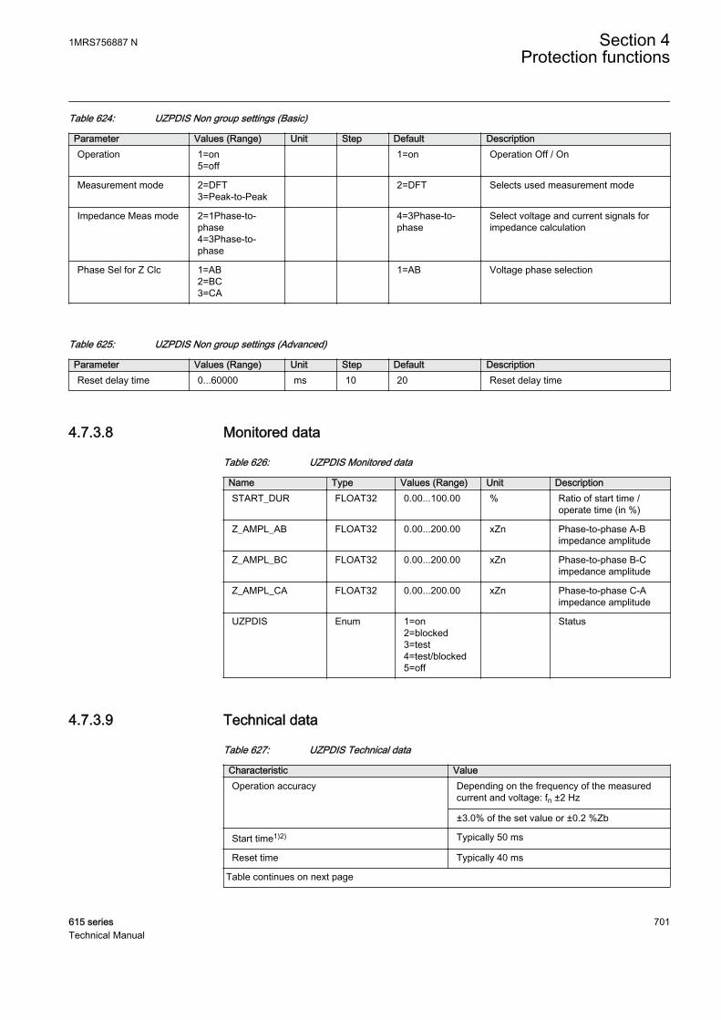
Table 624: UZPDIS Non group settings (Basic)
Parameter Values (Range) Unit Step Default DescriptionOperation 1=on
5=off 1=on Operation Off / On
Measurement mode 2=DFT3=Peak-to-Peak
2=DFT Selects used measurement mode
Impedance Meas mode 2=1Phase-to-phase4=3Phase-to-phase
4=3Phase-to-phase
Select voltage and current signals forimpedance calculation
Phase Sel for Z Clc 1=AB2=BC3=CA
1=AB Voltage phase selection
Table 625: UZPDIS Non group settings (Advanced)
Parameter Values (Range) Unit Step Default DescriptionReset delay time 0...60000 ms 10 20 Reset delay time
4.7.3.8 Monitored data
Table 626: UZPDIS Monitored data
Name Type Values (Range) Unit DescriptionSTART_DUR FLOAT32 0.00...100.00 % Ratio of start time /
operate time (in %)
Z_AMPL_AB FLOAT32 0.00...200.00 xZn Phase-to-phase A-Bimpedance amplitude
Z_AMPL_BC FLOAT32 0.00...200.00 xZn Phase-to-phase B-Cimpedance amplitude
Z_AMPL_CA FLOAT32 0.00...200.00 xZn Phase-to-phase C-Aimpedance amplitude
UZPDIS Enum 1=on2=blocked3=test4=test/blocked5=off
Status
4.7.3.9 Technical data
Table 627: UZPDIS Technical data
Characteristic ValueOperation accuracy Depending on the frequency of the measured
current and voltage: fn ±2 Hz
±3.0% of the set value or ±0.2 %Zb
Start time1)2) Typically 50 ms
Reset time Typically 40 ms
Table continues on next page
1MRS756887 N Section 4Protection functions
615 series 701Technical Manual

Characteristic ValueReset ratio Typically 1.04
Retardation time <40 ms
Operate time accuracy ±1.0% of the set value or ±20 ms
1) fn = 50 Hz, results based on statistical distribution of 1000 measurements2) Includes the delay of the signal output contact
4.8 Power protection
4.8.1 Underpower protection DUPPDPR
4.8.1.1 Identification
Function description IEC 61850identification
IEC 60617identification
ANSI/IEEE C37.2device number
Underpower protection DUPPDPR P< 32U
4.8.1.2 Function block
GUID-4EC3361A-FD8E-4925-B133-7E9C402DA564 V1 EN
Figure 366: Function block
4.8.1.3 Functionality
The underpower protection function DUPPDPR is used for protecting generators andprime movers against the effects of very low power outputs or reverse powercondition.
The function operates when the measured active power falls below the set value. Theoperating characteristics are according to definite time DT.
This function contains a blocking functionality. It is possible to block the functionoutputs, timer or the function itself, if desired.
Section 4 1MRS756887 NProtection functions
702 615 seriesTechnical Manual
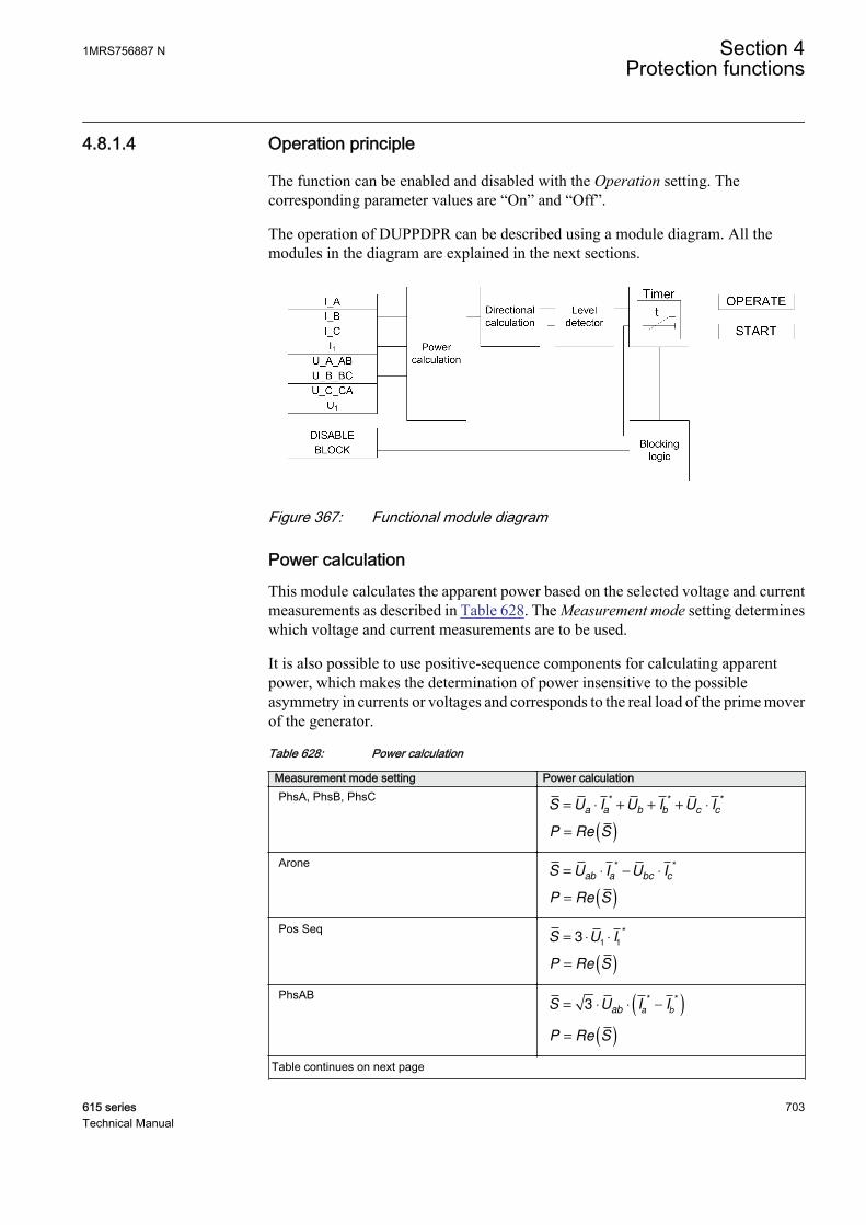
4.8.1.4 Operation principle
The function can be enabled and disabled with the Operation setting. Thecorresponding parameter values are “On” and “Off”.
The operation of DUPPDPR can be described using a module diagram. All themodules in the diagram are explained in the next sections.
GUID-9F4E5EA7-0B5E-4523-A25E-FC9A008A7374 V1 EN
Figure 367: Functional module diagram
Power calculationThis module calculates the apparent power based on the selected voltage and currentmeasurements as described in Table 628. The Measurement mode setting determineswhich voltage and current measurements are to be used.
It is also possible to use positive-sequence components for calculating apparentpower, which makes the determination of power insensitive to the possibleasymmetry in currents or voltages and corresponds to the real load of the prime moverof the generator.
Table 628: Power calculation
Measurement mode setting Power calculationPhsA, PhsB, PhsC
S U I U I U Ia a b b c c
= ⋅ + + + ⋅* * *
P S= ( )Re
AroneS U I U I
ab a bc c= ⋅ − ⋅
* *
P S= ( )Re
Pos SeqS U I= ⋅ ⋅3
1 1
*
P S= ( )Re
PhsABS U I I
ab a b= ⋅ ⋅ −( )3
* *
P S= ( )Re
Table continues on next page
1MRS756887 N Section 4Protection functions
615 series 703Technical Manual

Measurement mode setting Power calculationPhsBC
S U I Ibc b c
= ⋅ ⋅ −( )3* *
P S= ( )Re
PhsCAS U I I
ca c a= ⋅ ⋅ −( )3
* *
P S= ( )Re
PhsAS U I
a a= ⋅ ⋅3
*
P S= ( )Re
PhsBS U I
b b= ⋅ ⋅3
*
P S= ( )Re
PhsCS U I
c c= ⋅ ⋅3
*
P S= ( )Re
If all three phase voltages and phase currents are fed to the protectionrelay, the positive-sequence alternative is recommended (default).
Depending on the set Measurement mode, the power calculation calculates activepower, reactive power and apparent power values from the available set ofmeasurements. The calculated powers S, P, Q and the power factor angle, PF_ANGL,are available in the Monitored data.
Directional calculationThe Directional calculation determines the direction of the measured power. Themeasured power is considered to be in the forward direction if the active power ispositive, else it is considered to be in the reverse direction.
If the polarity of the measured power is opposite to normal, the correction can be doneby setting Pol reversal to "True", which rotates the apparent power by 180 degrees.
Level detectorThe Level detector compares the calculated value of the active power with a set Startvalue. If the calculated value of the active power falls below Start value in the forwarddirection or if the measured power is in the reverse direction, the Level detectorenables the Timer module.
Section 4 1MRS756887 NProtection functions
704 615 seriesTechnical Manual
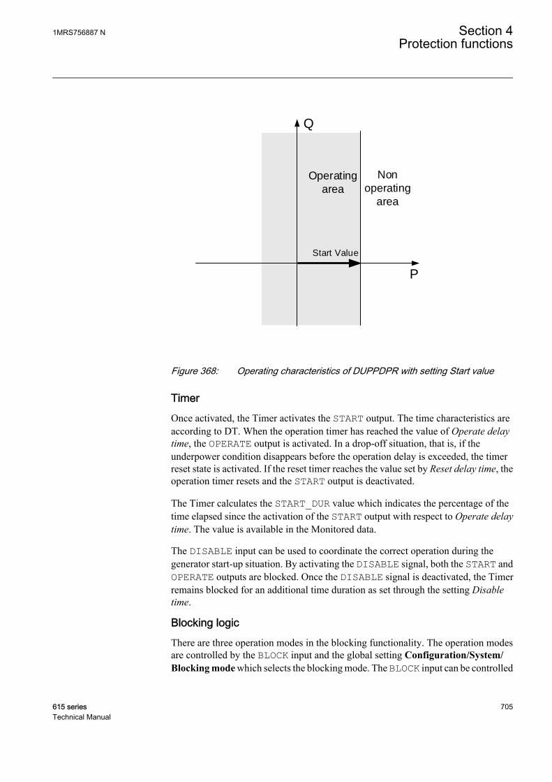
P
Q
Non
operating
area
Operating
area
Start Value
GUID-D4104D30-04BC-4FE5-978A-1401F1D5301F V2 EN
Figure 368: Operating characteristics of DUPPDPR with setting Start value
TimerOnce activated, the Timer activates the START output. The time characteristics areaccording to DT. When the operation timer has reached the value of Operate delaytime, the OPERATE output is activated. In a drop-off situation, that is, if theunderpower condition disappears before the operation delay is exceeded, the timerreset state is activated. If the reset timer reaches the value set by Reset delay time, theoperation timer resets and the START output is deactivated.
The Timer calculates the START_DUR value which indicates the percentage of thetime elapsed since the activation of the START output with respect to Operate delaytime. The value is available in the Monitored data.
The DISABLE input can be used to coordinate the correct operation during thegenerator start-up situation. By activating the DISABLE signal, both the START andOPERATE outputs are blocked. Once the DISABLE signal is deactivated, the Timerremains blocked for an additional time duration as set through the setting Disabletime.
Blocking logicThere are three operation modes in the blocking functionality. The operation modesare controlled by the BLOCK input and the global setting Configuration/System/Blocking mode which selects the blocking mode. The BLOCK input can be controlled
1MRS756887 N Section 4Protection functions
615 series 705Technical Manual
by a binary input, a horizontal communication input or an internal signal of theprotection relay's program. The influence of the BLOCK signal activation ispreselected with the global setting Blocking mode.
The Blocking mode setting has three blocking methods. In the "Freeze timers" mode,the operation timer is frozen to the prevailing value. In the "Block all" mode, the wholefunction is blocked and the timers are reset. In the "Block OPERATE output" mode,the function operates normally but the OPERATE output is not activated.
4.8.1.5 Application
The task of a generator in a power plant is to convert mechanical energy into electricalenergy. Sometimes the mechanical power from the prime mover may decrease somuch that it does not cover the internal losses. The task of an underpower protectionis to protect the generator from very low power output conditions.
Steam turbines become easily overheated if the steam flow becomes too low or if thesteam ceases to flow through the turbine. Hydro turbine of the Kaplan type may bedamaged due to the fact that the turbine blade surfs on the water and sets up axialpressure on the bearing. Diesel engines may be damaged due to insufficientlubrication.
If the generator size is very large, it is uneconomical to continue running it with lowgenerated power. In the reverse power condition, large generators draw a considerableamount of power from the rest of the system to feed their internal losses. Hence, it isdesirable to disconnect the generator in such situations.
In case of the parallel-connected generators, for example, the load of one generatormay be so low that it is better to disconnect it and let the remaining generators feed thenetwork.
Where a low value of power setting is required, for example less than2%, the correction parameters should be used to compensate for themeasuring errors. The manufacturer of the measuring devices is to becontacted for information on the measuring errors.If the measuring errors are not compensated for, the underpowersetting should not be lower than the sum of the current-measuring andvoltage-measuring errors.For example, if the error of the current-measuring device is 2% andthat of the voltage-measuring device is 1%, the minimum setting is (2+ 1)% = 3%.
Section 4 1MRS756887 NProtection functions
706 615 seriesTechnical Manual
4.8.1.6 Signals
Table 629: DUPPDPR Input signals
Name Type Default DescriptionI_A SIGNAL 0 Phase A current
I_B SIGNAL 0 Phase B current
I_C SIGNAL 0 Phase C current
I1 SIGNAL 0 Positive sequence current
U_A_AB SIGNAL 0 Phase-to-earth voltage A or phase-to-phasevoltage AB
U_B_BC SIGNAL 0 Phase-to-earth voltage B or phase-to-phasevoltage BC
U_C_CA SIGNAL 0 Phase-to-earth voltage C or phase-to-phasevoltage CA
U1 SIGNAL 0 Positive phase sequence voltage
DISABLE BOOLEAN 0=False Signal to block the function during generatorstartup
BLOCK BOOLEAN 0=False Block signal for activating the blocking mode
Table 630: DUPPDPR Output signals
Name Type DescriptionOPERATE BOOLEAN Operate
START BOOLEAN Start
4.8.1.7 Settings
Table 631: DUPPDPR Group settings (Basic)
Parameter Values (Range) Unit Step Default DescriptionStart value 0.01...2.00 xSn 0.01 0.10 Start value
Operate delay time 40...300000 ms 10 40 Operate delay time
Table 632: DUPPDPR Non group settings (Basic)
Parameter Values (Range) Unit Step Default DescriptionOperation 1=on
5=off 1=on Operation On/Off
1MRS756887 N Section 4Protection functions
615 series 707Technical Manual

Table 633: DUPPDPR Non group settings (Advanced)
Parameter Values (Range) Unit Step Default DescriptionMeasurement mode 1=PhsA, PhsB,
PhsC2=Arone3=Pos Seq4=PhsAB5=PhsBC6=PhsCA7=PhsA8=PhsB9=PhsC
3=Pos Seq Selection of power calculation method
Reset delay time 0...60000 ms 10 20 Reset delay time
Pol reversal 0=False1=True
0=False Reverse the definition of the powerdirection
Disable time 0...60000 ms 1000 0 Additional wait time after CB closing
4.8.1.8 Monitored data
Table 634: DUPPDPR Monitored data
Name Type Values (Range) Unit DescriptionSTART_DUR FLOAT32 0.00...100.00 % Ratio of start time /
operate time
P FLOAT32 -160.000...160.000
xSn Active power
Q FLOAT32 -160.000...160.000
xSn Reactive power
S FLOAT32 0.000...160.000 xSn Apparent power
PF_ANGLE FLOAT32 -180.00...180.00 deg Power factor angle
DUPPDPR Enum 1=on2=blocked3=test4=test/blocked5=off
Status
4.8.1.9 Technical data
Table 635: DUPPDPR Technical data
Characteristic Value
Operation accuracy 1) Depending on the frequency of the measuredcurrent and voltage:fn ±2 Hz
Power measurement accuracy ±3% of the setvalue or ±0.002 × SnPhase angle: ±2°
Start time2)3) Typically 45 ms
Reset time Typically 30 ms
Table continues on next page
Section 4 1MRS756887 NProtection functions
708 615 seriesTechnical Manual
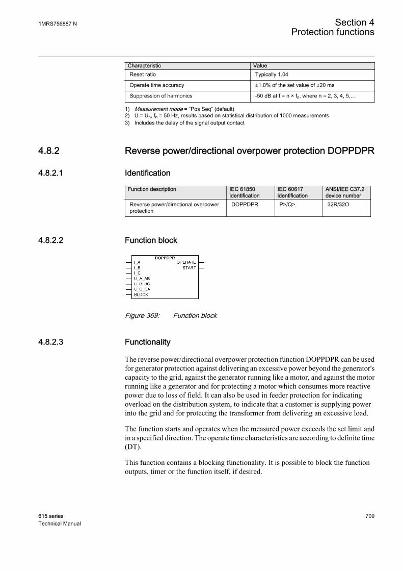
Characteristic ValueReset ratio Typically 1.04
Operate time accuracy ±1.0% of the set value of ±20 ms
Suppression of harmonics -50 dB at f = n × fn, where n = 2, 3, 4, 5,…
1) Measurement mode = “Pos Seq” (default)2) U = Un, fn = 50 Hz, results based on statistical distribution of 1000 measurements3) Includes the delay of the signal output contact
4.8.2 Reverse power/directional overpower protection DOPPDPR
4.8.2.1 Identification
Function description IEC 61850identification
IEC 60617identification
ANSI/IEE C37.2device number
Reverse power/directional overpowerprotection
DOPPDPR P>/Q> 32R/32O
4.8.2.2 Function block
GUID-484CA24D-EA36-4DE4-BE86-6B73C09AD4BB V1 EN
Figure 369: Function block
4.8.2.3 Functionality
The reverse power/directional overpower protection function DOPPDPR can be usedfor generator protection against delivering an excessive power beyond the generator'scapacity to the grid, against the generator running like a motor, and against the motorrunning like a generator and for protecting a motor which consumes more reactivepower due to loss of field. It can also be used in feeder protection for indicatingoverload on the distribution system, to indicate that a customer is supplying powerinto the grid and for protecting the transformer from delivering an excessive load.
The function starts and operates when the measured power exceeds the set limit andin a specified direction. The operate time characteristics are according to definite time(DT).
This function contains a blocking functionality. It is possible to block the functionoutputs, timer or the function itself, if desired.
1MRS756887 N Section 4Protection functions
615 series 709Technical Manual
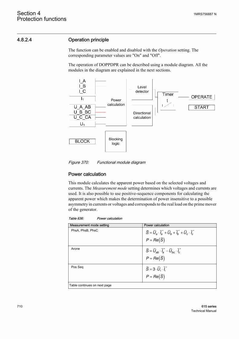
4.8.2.4 Operation principle
The function can be enabled and disabled with the Operation setting. Thecorresponding parameter values are "On" and "Off".
The operation of DOPPDPR can be described using a module diagram. All themodules in the diagram are explained in the next sections.
GUID-5088472A-9E14-4BF4-BDC4-3C03D661224E V1 EN
Figure 370: Functional module diagram
Power calculationThis module calculates the apparent power based on the selected voltages andcurrents. The Measurement mode setting determines which voltages and currents areused. It is also possible to use positive-sequence components for calculating theapparent power which makes the determination of power insensitive to a possibleasymmetry in currents or voltages and corresponds to the real load on the prime moverof the generator.
Table 636: Power calculation
Measurement mode setting Power calculationPhsA, PhsB, PhsC
S U I U I U Ia a b b c c
= ⋅ + + + ⋅* * *
P S= ( )Re
AroneS U I U I
ab a bc c= ⋅ − ⋅
* *
P S= ( )Re
Pos SeqS U I= ⋅ ⋅3
1 1
*
P S= ( )Re
Table continues on next page
Section 4 1MRS756887 NProtection functions
710 615 seriesTechnical Manual
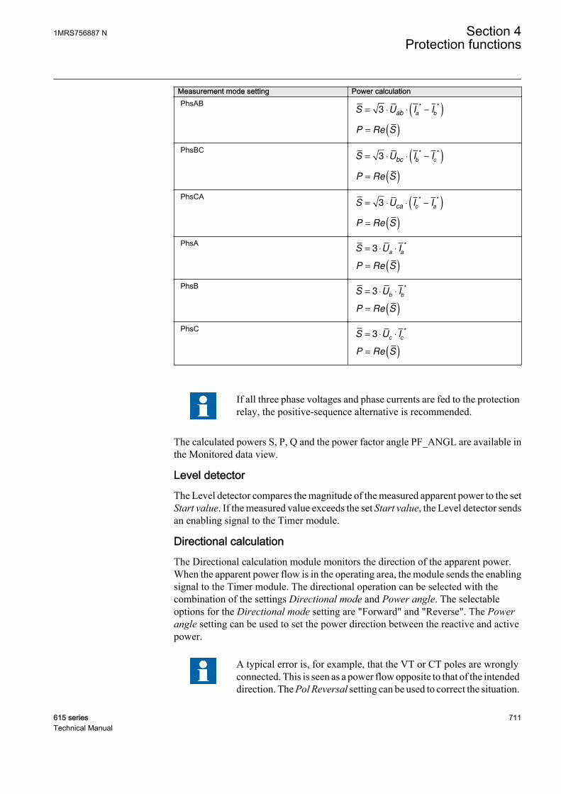
Measurement mode setting Power calculationPhsAB
S U I Iab a b
= ⋅ ⋅ −( )3* *
P S= ( )Re
PhsBCS U I I
bc b c= ⋅ ⋅ −( )3
* *
P S= ( )Re
PhsCAS U I I
ca c a= ⋅ ⋅ −( )3
* *
P S= ( )Re
PhsAS U I
a a= ⋅ ⋅3
*
P S= ( )Re
PhsBS U I
b b= ⋅ ⋅3
*
P S= ( )Re
PhsCS U I
c c= ⋅ ⋅3
*
P S= ( )Re
If all three phase voltages and phase currents are fed to the protectionrelay, the positive-sequence alternative is recommended.
The calculated powers S, P, Q and the power factor angle PF_ANGL are available inthe Monitored data view.
Level detectorThe Level detector compares the magnitude of the measured apparent power to the setStart value. If the measured value exceeds the set Start value, the Level detector sendsan enabling signal to the Timer module.
Directional calculationThe Directional calculation module monitors the direction of the apparent power.When the apparent power flow is in the operating area, the module sends the enablingsignal to the Timer module. The directional operation can be selected with thecombination of the settings Directional mode and Power angle. The selectableoptions for the Directional mode setting are "Forward" and "Reverse". The Powerangle setting can be used to set the power direction between the reactive and activepower.
A typical error is, for example, that the VT or CT poles are wronglyconnected. This is seen as a power flow opposite to that of the intendeddirection. The Pol Reversal setting can be used to correct the situation.
1MRS756887 N Section 4Protection functions
615 series 711Technical Manual

By setting the value to "True", the measured apparent power is turned180 degrees.
Non operating
areaOperating
area
P
Q
Start value
GUID-6D7F4DBD-73FF-40C4-87B6-22BDC54A41E2 V2 EN
Figure 371: Operating characteristics with the Start Value setting, the Powerangle setting being 0 and Directional mode "Forward"
Start value
Non operating
area
Operating
area
P
Q
GUID-27F1C899-F8E0-43F6-8326-8F7DCD5E9007 V2 EN
Figure 372: Operating characteristics with the Start Value setting, Power angle(α) being +45 and Directional mode "Forward"
Section 4 1MRS756887 NProtection functions
712 615 seriesTechnical Manual
TimerOnce activated, the Timer activates the START output. The time characteristics areaccording to DT. When the operation timer has reached the value of Operate delaytime, the OPERATE output is activated. If a drop-off situation happens, that is, thevalue of power drops below Start value before the operate delay is exceeded, the timerreset state is activated. If the reset timer reaches the value set by Reset delay time, theoperate timer resets and the START output is deactivated.
The Timer calculates the start duration value START_DUR, which indicates thepercentage ratio of the start situation and the set operating time (DT). The value isavailable in the Monitored data view.
Blocking logicThere are three operation modes in the blocking function. The operation modes arecontrolled by the BLOCK input and the global setting Configuration/System/Blocking mode, which selects the blocking mode. The BLOCK input can be controlledby a binary input, a horizontal communication input or an internal signal of theprotection relay's program. The influence of the BLOCK signal activation ispreselected with the global setting Blocking mode.
The Blocking mode setting has three blocking methods. In the "Freeze timers" mode,the operate timer is frozen to the prevailing value. In the "Block all" mode, the wholefunction is blocked and the timers are reset. In the "Block OPERATE output" mode,the function operates normally but the OPERATE output is not activated.
4.8.2.5 Application
DOPPDPR is used to provide protection against an excessive power flow in the setoperating direction. The main application is the protection of generators and turbines.It can also be used in feeder protection applications, for example, the ring network.
DOPPDPR in the forward direction can be used to protect the generators or motorsfrom delivering or consuming excess power. For example, the generator overpowerprotection can be used to shed a noncritical feeder load or to start parallel generators.A synchronous motor may start consuming more reactive power in case of loss ofexcitation, in which case the forward overpower protection is used to detect suchcondition.
The DOPPDPR function has many applications when used as reverse powerprotection. A generator in a power plant converts mechanical energy to electricalenergy. Sometimes the mechanical power from a prime mover may decrease to a limitthat it does not cover the internal losses. The synchronous generator becomes asynchronous motor and starts importing power from the system. The effect of agenerator acting as a motor implies no risk to the machine but can cause damage to theprime mover. The extent of the damage depends on the type of the prime mover.
Steam turbines become overheated easily if the steam flow drops too low or if thesteam ceases to flow through the turbine. The break of a main steam pipe, damage to
1MRS756887 N Section 4Protection functions
615 series 713Technical Manual
one or more blades in the steam turbine or an inadvertent closing of the main stopvalves are typical causes for the low steam flow. The steam turbines of turbogenerators can be protected during a low steam flow with the overpower protectionoperating in reverse direction. Hydroturbines tolerate reverse power much better thansteam turbines do. There is a risk that the turbine runner moves axially and touchesstationary parts. They are not always strong enough to withstand the associatedstresses.
A hydroturbine that rotates in water with the closed wicket gates draws about 10% ofthe rated power from the rest of the power system if the intake is blocked due to ice,snow, branches or leaves. A complete blockage of the intake may cause cavitations.If there is only air in the hydroturbine, the power demand drops to about 3%. The riskof damages to the hydroturbines can justify the reverse operation of the overpowerprotection in unattended plants.
Whenever a low value of the reverse power setting is required, anunderpower protection should also be used in conjunction withDOPPDPR. The limit depends on the CT and VT accuracy.
Diesel engines should have overpower protection in reverse direction. The generatortakes about 15% or more of its rated power from the system. A stiff engine may require25% of the rated power to motor it. A well run engine may need no more than 5%. Itis necessary to obtain information from the engine manufacturer and to measure thereverse power during commissioning.
Reverse overpower can also act as an alternative for an under excitation protection incase of small generators. If the field excitation is reduced, the generator may startimporting the reactive power, making the generator run as an asynchronous generator.A synchronous generator is not designed to work asynchronously and may becomedamaged due to heating in the damper windings or heating in the rotor due to slipfrequency current.
When operated in reverse power direction, DOPPDPR can be used as an alarm if thepower flowing from the industry is feeding the grid, which may not be desired as perthe rules and regulations of the utility owning the grid.
Section 4 1MRS756887 NProtection functions
714 615 seriesTechnical Manual
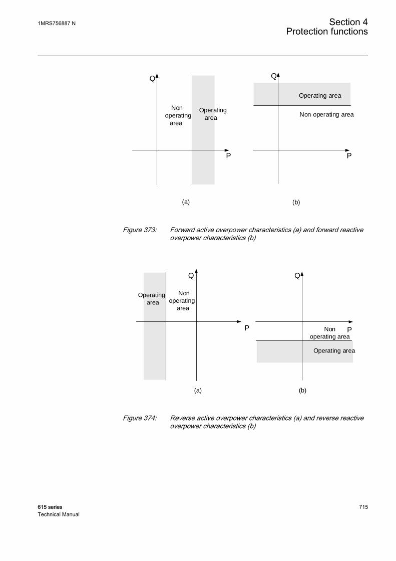
P
Non
operating
area
Operating
area
P
Non operating area
Operating area
Q Q
(a) (b)
GUID-69E16240-232F-4B20-B2C0-7CD73E5376C1 V2 EN
Figure 373: Forward active overpower characteristics (a) and forward reactiveoverpower characteristics (b)
P
Q
Non
operating
area
Operating
area
P
Q
Operating area
Non
operating area
(a) (b)
GUID-37C694E9-74A9-4E39-A529-86B6A7FFAA6F V2 EN
Figure 374: Reverse active overpower characteristics (a) and reverse reactiveoverpower characteristics (b)
1MRS756887 N Section 4Protection functions
615 series 715Technical Manual

4.8.2.6 Signals
Table 637: DOPPDPR Input signals
Name Type Default DescriptionI_A SIGNAL 0 Phase A current
I_B SIGNAL 0 Phase B current
I_C SIGNAL 0 Phase C current
U_A_AB SIGNAL 0 Phase-to-earth voltage A or phase-to-phasevoltage AB
U_A_BC SIGNAL 0 Phase-to-earth voltage B or phase-to-phasevoltage BC
U_A_CA SIGNAL 0 Phase-to-earth voltage C or phase-to-phasevoltage CA
BLOCK BOOLEAN 0=False Block signal for activating the blocking mode
Table 638: DOPPDPR Output signals
Name Type DescriptionOPERATE BOOLEAN Operate
START BOOLEAN Start
4.8.2.7 Settings
Table 639: DOPPDPR Group settings (Basic)
Parameter Values (Range) Unit Step Default DescriptionStart value 0.01...2.00 xSn 0.01 1.00 Start value
Operate delay time 40...300000 ms 10 40 Operate delay time
Directional mode 2=Forward3=Reverse
2=Forward Directional mode
Power angle -90...90 deg 1 0 Adjustable angle for power
Table 640: DOPPDPR Non group settings (Basic)
Parameter Values (Range) Unit Step Default DescriptionOperation 1=on
5=off 1=on Operation On/Off
Measurement mode 1=PhsA, PhsB,PhsC2=Arone3=Pos Seq4=PhsAB5=PhsBC6=PhsCA7=PhsA8=PhsB9=PhsC
3=Pos Seq Selection of power calculation method
Section 4 1MRS756887 NProtection functions
716 615 seriesTechnical Manual
Table 641: DOPPDPR Non group settings (Advanced)
Parameter Values (Range) Unit Step Default DescriptionReset delay time 0...60000 ms 10 20 Reset delay time
Pol reversal 0=False1=True
0=False Reverse the definition of the powerdirection
4.8.2.8 Monitored data
Table 642: DOPPDPR Monitored data
Name Type Values (Range) Unit DescriptionSTART_DUR FLOAT32 0.00...100.00 % Ratio of start time /
operate time
P FLOAT32 -160.000...160.000
xSn Active power
Q FLOAT32 -160.000...160.000
xSn Reactive power
S FLOAT32 0.000...160.000 xSn Apparent power
PF_ANGLE FLOAT32 -180.00...180.00 deg Power factor angle
DOPPDPR Enum 1=on2=blocked3=test4=test/blocked5=off
Status
4.8.2.9 Technical data
Table 643: DOPPDPR Technical data
Characteristic Value
Operation accuracy 1)
Depending on the frequency of the measuredcurrent and voltage:f = fn ±2 Hz
Power measurement accuracy ±3% of the setvalue or ±0.002 × SnPhase angle: ±2°
Start time2)3) Typically 45 ms
Reset time Typically 30 ms
Reset ratio Typically 0.94
Operate time accuracy ±1.0% of the set value of ±20 ms
Suppression of harmonics -50 dB at f = n × fn, where n = 2, 3, 4, 5,…
1) Measurement mode = “Pos Seq” (default)2) U = Un, fn = 50 Hz, results based on statistical distribution of 1000 measurements3) Includes the delay of the signal output contact
1MRS756887 N Section 4Protection functions
615 series 717Technical Manual
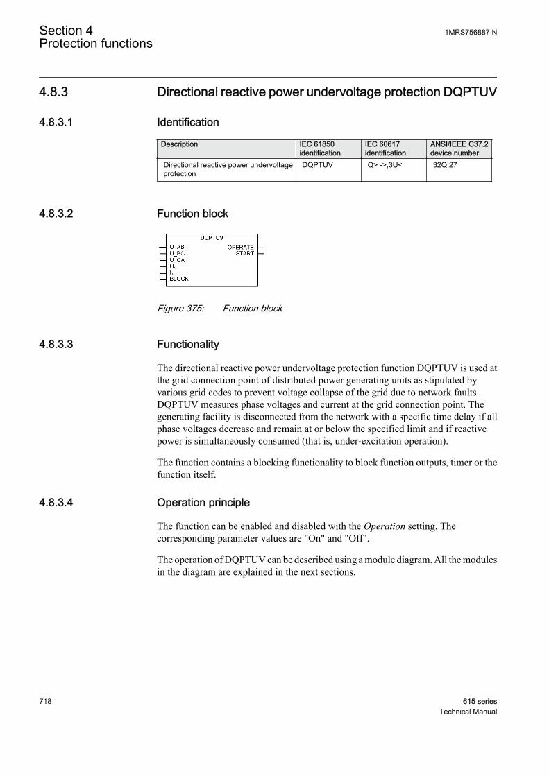
4.8.3 Directional reactive power undervoltage protection DQPTUV
4.8.3.1 Identification
Description IEC 61850identification
IEC 60617identification
ANSI/IEEE C37.2device number
Directional reactive power undervoltageprotection
DQPTUV Q> ->,3U< 32Q,27
4.8.3.2 Function block
GUID-C043067F-F0F7-4168-BBB5-14442B2CE163 V1 EN
Figure 375: Function block
4.8.3.3 Functionality
The directional reactive power undervoltage protection function DQPTUV is used atthe grid connection point of distributed power generating units as stipulated byvarious grid codes to prevent voltage collapse of the grid due to network faults.DQPTUV measures phase voltages and current at the grid connection point. Thegenerating facility is disconnected from the network with a specific time delay if allphase voltages decrease and remain at or below the specified limit and if reactivepower is simultaneously consumed (that is, under-excitation operation).
The function contains a blocking functionality to block function outputs, timer or thefunction itself.
4.8.3.4 Operation principle
The function can be enabled and disabled with the Operation setting. Thecorresponding parameter values are "On" and "Off".
The operation of DQPTUV can be described using a module diagram. All the modulesin the diagram are explained in the next sections.
Section 4 1MRS756887 NProtection functions
718 615 seriesTechnical Manual
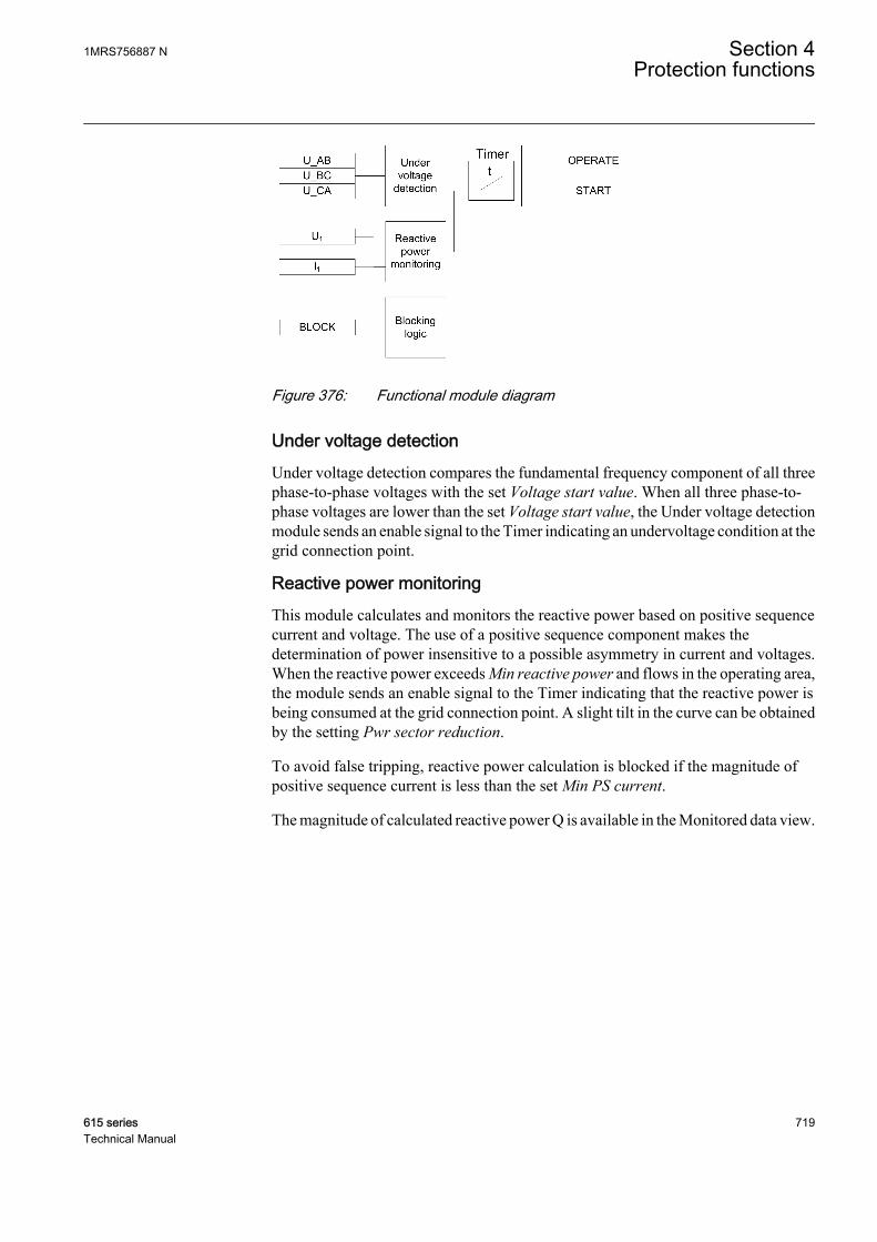
GUID-C488DC7F-2257-47E0-B352-09D29D49AFC3 V1 EN
Figure 376: Functional module diagram
Under voltage detectionUnder voltage detection compares the fundamental frequency component of all threephase-to-phase voltages with the set Voltage start value. When all three phase-to-phase voltages are lower than the set Voltage start value, the Under voltage detectionmodule sends an enable signal to the Timer indicating an undervoltage condition at thegrid connection point.
Reactive power monitoringThis module calculates and monitors the reactive power based on positive sequencecurrent and voltage. The use of a positive sequence component makes thedetermination of power insensitive to a possible asymmetry in current and voltages.When the reactive power exceeds Min reactive power and flows in the operating area,the module sends an enable signal to the Timer indicating that the reactive power isbeing consumed at the grid connection point. A slight tilt in the curve can be obtainedby the setting Pwr sector reduction.
To avoid false tripping, reactive power calculation is blocked if the magnitude ofpositive sequence current is less than the set Min PS current.
The magnitude of calculated reactive power Q is available in the Monitored data view.
1MRS756887 N Section 4Protection functions
615 series 719Technical Manual
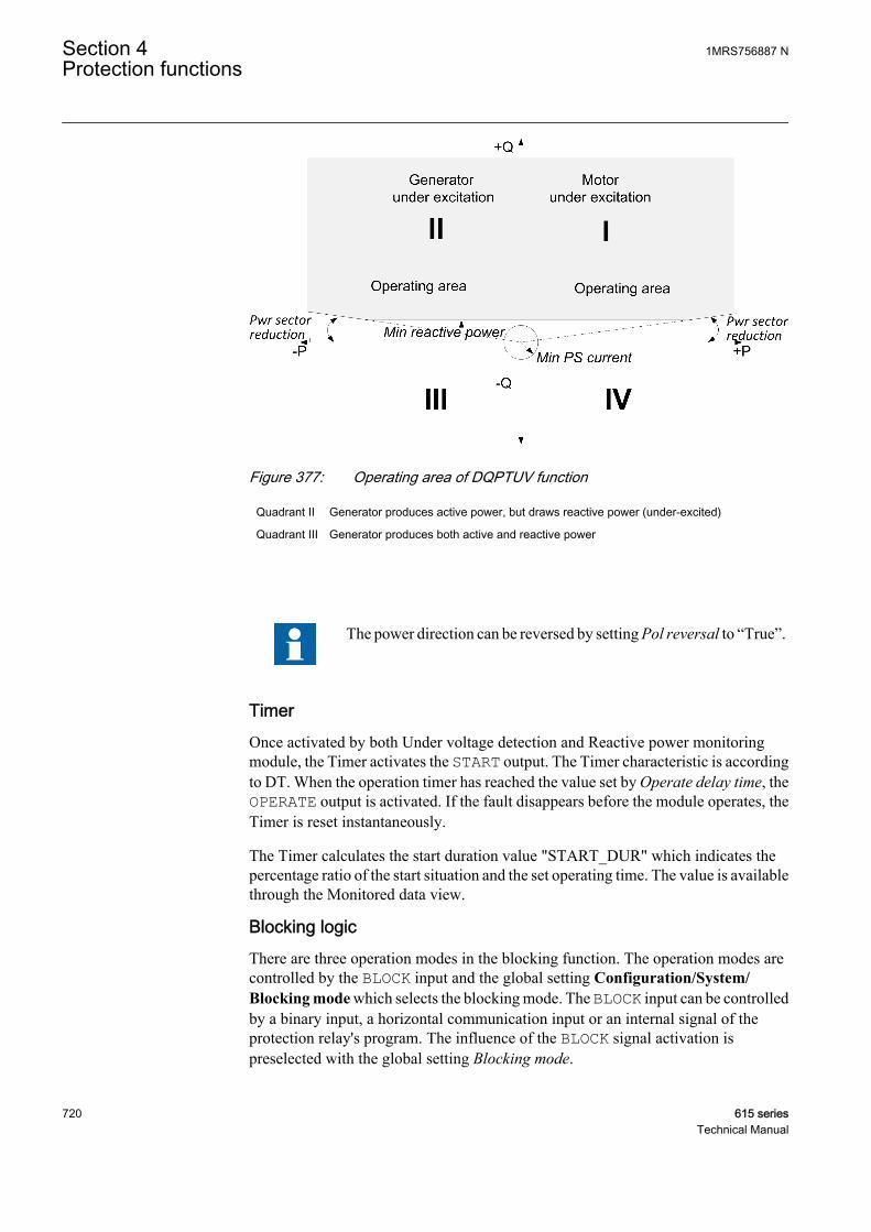
GUID-9C7C3D36-0158-47B5-902B-E4F22830C03E V1 EN
Figure 377: Operating area of DQPTUV function
Quadrant II Generator produces active power, but draws reactive power (under-excited)
Quadrant III Generator produces both active and reactive power
The power direction can be reversed by setting Pol reversal to “True”.
TimerOnce activated by both Under voltage detection and Reactive power monitoringmodule, the Timer activates the START output. The Timer characteristic is accordingto DT. When the operation timer has reached the value set by Operate delay time, theOPERATE output is activated. If the fault disappears before the module operates, theTimer is reset instantaneously.
The Timer calculates the start duration value "START_DUR" which indicates thepercentage ratio of the start situation and the set operating time. The value is availablethrough the Monitored data view.
Blocking logicThere are three operation modes in the blocking function. The operation modes arecontrolled by the BLOCK input and the global setting Configuration/System/Blocking mode which selects the blocking mode. The BLOCK input can be controlledby a binary input, a horizontal communication input or an internal signal of theprotection relay's program. The influence of the BLOCK signal activation ispreselected with the global setting Blocking mode.
Section 4 1MRS756887 NProtection functions
720 615 seriesTechnical Manual

The Blocking mode setting has three blocking methods. In the "Freeze timers" mode,the operation timer is frozen to the prevailing value. In the "Block all" mode, the wholefunction is blocked and the timers are reset. In the "Block OPERATE output" mode,the function operates normally but the OPERATE output is not activated.
4.8.3.5 Application
Use of distributed power generating units (PGU) is rapidly increasing due toliberalized markets (deregulation) and the global trend to use more renewable sourcesof energy. As the capacity of these generating units increase, they are connecteddirectly to medium voltage networks. Until recent years it had been a practice by gridoperators to disconnect the distributed power generator from the network in case offault in the network.
If there is a considerable loss in the power generation, it may affect the system’s abilityto recover. To ensure power system stability, various grid codes have revised theirrequirements and therefore require that the distributed PGUs have to make acontribution to network support. In case of network faults, the distributed powergenerator should not be immediately disconnected from the network. Instead, as amatter of principle, generating plants connected to the medium-voltage network mustbe capable of participating in steady-state voltage control and dynamic networksupport. However, if the generators stay connected, it must be ensured that they do nottake reactive power from the network because this may lead to collapse of the grid.DQPTUV is used for detecting such situations, that is, simultaneous undervoltage andreactive power (under excited generators) and trip the generators.
The protection function DQPTUV is developed considering various grid codes. Forexample, in the BDEW Technical Guideline “Generating Plants Connected to theMedium-Voltage Network” (June 2008 issue, Germany), it is stated that if all threephase-to-phase voltages at the grid connection point decrease and remain at and belowa value of 85% of the rated and if reactive power is simultaneously consumed at thegrid connection point (under-excited operation), the generating facility must bedisconnected from the network with a time delay of 0.5 s.
1MRS756887 N Section 4Protection functions
615 series 721Technical Manual

G G GG G
U12
3U
3I
Io
G
Common point of coupling distributed power generationinto the utility network
REG615
Std. conf.
ANSI IEC
25
27RT
32Q, 27
32R/32O
47O-/59
47U+/27
50L/50NL
60
78V
81
SYNC
U<RT
Q>→, 3U<
P>/Q>
U2>/3U>
U1</3U<
ARC
FUSEF
VS
f</f>, df/dt
A
GUID-FC594C90-D99A-4D1B-89FE-089A640794E4 V1 EN
Figure 378: Application example of wind power plant as distributed powergeneration coupled into the utility network
4.8.3.6 Signals
Table 644: DQPTUV Input signals
Name Type Default DescriptionU_AB SIGNAL 0 Phase-to-phase voltage AB
U_BC SIGNAL 0 Phase-to-phase voltage BC
U_CA SIGNAL 0 Phase-to-phase voltage CA
Table continues on next page
Section 4 1MRS756887 NProtection functions
722 615 seriesTechnical Manual
Name Type Default DescriptionU1 SIGNAL 0 Positive phase sequence voltage
I1 SIGNAL 0 Positive sequence current
BLOCK BOOLEAN 0=False Block signal for activating the blocking mode
Table 645: DQPTUV Output signals
Name Type DescriptionOPERATE BOOLEAN Operate
START BOOLEAN Start
4.8.3.7 Settings
Table 646: DQPTUV Group settings (Basic)
Parameter Values (Range) Unit Step Default DescriptionVoltage start value 0.20...1.20 xUn 0.01 0.85 Start value for under voltage detection
Operate delay time 100...300000 ms 10 500 Operate delay time
Table 647: DQPTUV Non group settings (Basic)
Parameter Values (Range) Unit Step Default DescriptionOperation 1=on
5=off 1=on Operation On/Off
Table 648: DQPTUV Non group settings (Advanced)
Parameter Values (Range) Unit Step Default DescriptionMin reactive power 0.01...0.50 xSn 0.01 0.05 Minimum reactive power needed for
function to operate
Min Ps Seq current 0.02...0.20 xIn 0.01 0.05 Minimum positive sequence current
Pwr sector reduction 0...10 deg 1 3 Power sector reduction
Pol reversal 0=False1=True
0=False Reverse the definition of the positivereactive power direction
1MRS756887 N Section 4Protection functions
615 series 723Technical Manual
4.8.3.8 Monitored data
Table 649: DQPTUV Monitored data
Name Type Values (Range) Unit DescriptionSTART_DUR FLOAT32 0.00...100.00 % Ratio of start time /
operate time
Q FLOAT32 -160.000...160.000
xSn Reactive power
DQPTUV Enum 1=on2=blocked3=test4=test/blocked5=off
Status
4.8.3.9 Technical data
Table 650: DQPTUV Technical data
Characteristic ValueOperation accuracy Depending on the frequency of the measured
current and voltage:fn ±2 HzReactive power range |PF| <0.71
Power:±3.0% or ±0.002 × QnVoltage:±1.5% of the set value or ±0.002 × Un
Start time1)2) Typically 46 ms
Reset time <50 ms
Reset ratio Typically 0.96
Operate time accuracy ±1.0% of the set value or ±20 ms
Suppression of harmonics DFT: -50 dB at f = n × fn, where n = 2, 3, 4, 5,…
1) Start value = 0.05 × Sn, reactive power before fault = 0.8 × Start value, reactive power overshoot 2times, results based on statistical distribution of 1000 measurements
2) Includes the delay of the signal output contact
4.9 Arc protection ARCSARC
4.9.1 IdentificationFunction description IEC 61850
identificationIEC 60617identification
ANSI/IEEE C37.2device number
Arc protection ARCSARC ARC 50L/50NL
Section 4 1MRS756887 NProtection functions
724 615 seriesTechnical Manual

4.9.2 Function block
A070686 V3 EN
Figure 379: Function block
4.9.3 Functionality
The arc protection function ARCSARC detects arc situations in air insulated metal-clad switchgears caused by, for example, human errors during maintenance orinsulation breakdown during operation.
The function detects light from an arc either locally or via a remote light signal. Thefunction also monitors phase and residual currents to be able to make accuratedecisions on ongoing arcing situations.
The function contains a blocking functionality. Blocking deactivates all outputs andresets timers.
4.9.4 Operation principle
The function can be enabled and disabled with the Operation setting. Thecorresponding parameter values are "On" and "Off".
The operation of ARCSARC can be described by using a module diagram. All themodules in the diagram are explained in the next sections.
OPERATE
Leveldetector
1
I_AI_BI_C
BLOCK
Leveldetector
2Io
FLT_ARCREM_FLT_ARC
ARC_FLT_DET
Operation mode
selector t
Dropoff
OPR_MODE
t
Dropoff
A070746 V4 EN
Figure 380: Functional module diagram
1MRS756887 N Section 4Protection functions
615 series 725Technical Manual
Level detector 1The measured phase currents are compared phasewise to the set Phase start value. Ifthe measured value exceeds the set Phase start value, the level detector reports theexceeding of the value to the operation mode selector.
Level detector 2The measured residual currents are compared to the set Ground start value. If themeasured value exceeds the set Ground start value, the level detector reports theexceeding of the value to the operation mode selector.
Operation mode selectorDepending on the Operation mode setting, the operation mode selector makes surethat all required criteria are fulfilled for a reliable decision of an arc fault situation. Theuser can select either "Light+current", "Light only" or "BI controlled" operationmode. The operation is based on both current and light information in “Light+current”mode, on light information only in “Light only” mode or on remotely controlledinformation in “BI controlled” mode. When the "BI controlled" mode is in use and theOPR_MODE input is activated, the operation of the function is based on lightinformation only. When the OPR_MODE input is deactivated, the operation of thefunction is based on both light and current information. When the required criteria aremet, the drop-off timer is activated.
Drop-off timerOnce activated, the drop-off timer remains active until the input is deactivated or atleast during the drop-off time. The BLOCK signal can be used to block the OPERATEsignal or the light signal output ARC_FLT_DET.
4.9.5 Application
The arc protection can be realized as a stand-alone function in a single relay or as astation-wide arc protection, including several protection relays. If realized as astation-wide arc protection, different tripping schemes can be selected for theoperation of the circuit breakers of the incoming and outgoing feeders. Consequently,the relays in the station can, for example, be set to trip the circuit breaker of either theincoming or the outgoing feeder, depending on the fault location in the switchgear. Formaximum safety, the relays can be set to always trip both the circuit breaker of theincoming feeder and that of the outgoing feeder.
The arc protection consists of:
• Optional arc light detection hardware with automatic backlight compensation forlens type sensors
• Light signal output ARC_FLT_DET for routing indication of locally detectedlight signal to another relay
• Protection stage with phase- and earth-fault current measurement.
Section 4 1MRS756887 NProtection functions
726 615 seriesTechnical Manual
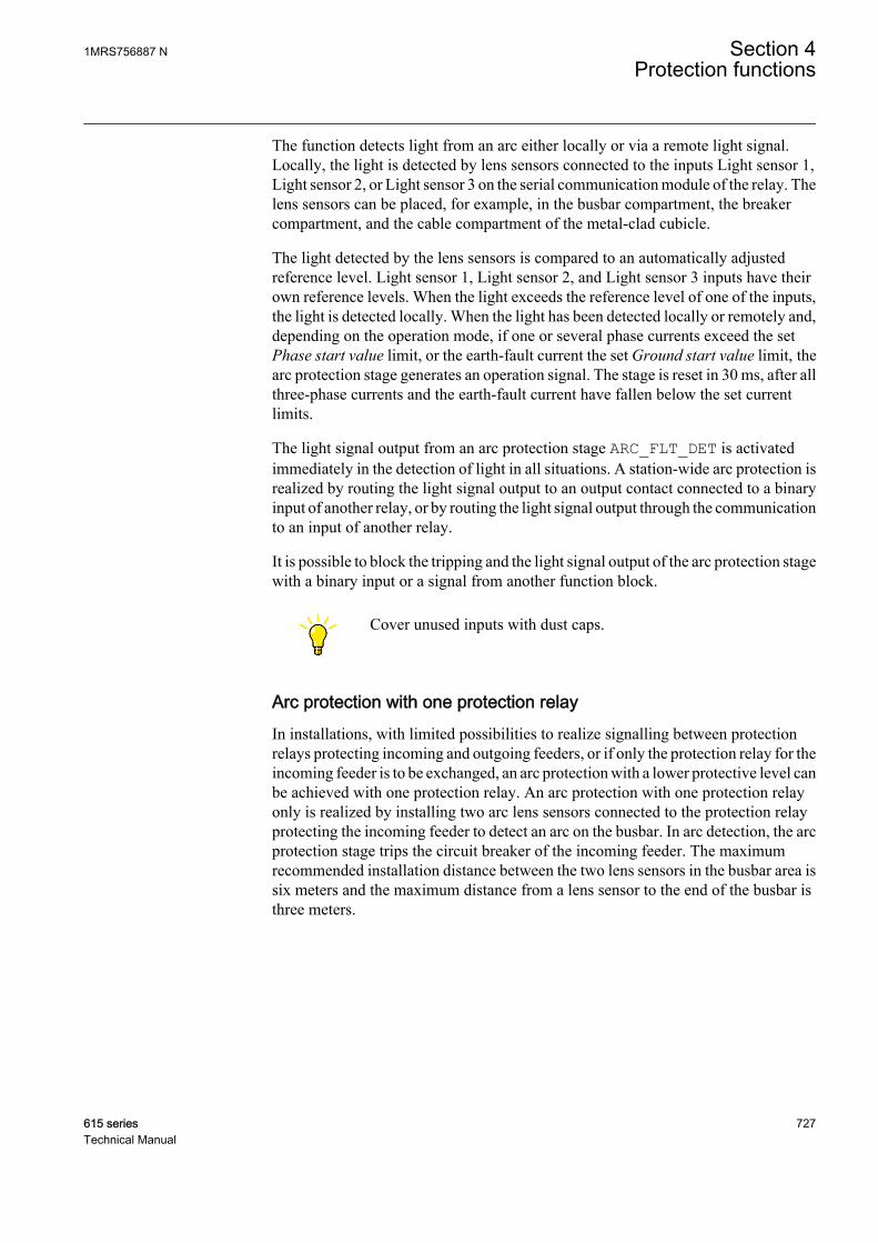
The function detects light from an arc either locally or via a remote light signal.Locally, the light is detected by lens sensors connected to the inputs Light sensor 1,Light sensor 2, or Light sensor 3 on the serial communication module of the relay. Thelens sensors can be placed, for example, in the busbar compartment, the breakercompartment, and the cable compartment of the metal-clad cubicle.
The light detected by the lens sensors is compared to an automatically adjustedreference level. Light sensor 1, Light sensor 2, and Light sensor 3 inputs have theirown reference levels. When the light exceeds the reference level of one of the inputs,the light is detected locally. When the light has been detected locally or remotely and,depending on the operation mode, if one or several phase currents exceed the setPhase start value limit, or the earth-fault current the set Ground start value limit, thearc protection stage generates an operation signal. The stage is reset in 30 ms, after allthree-phase currents and the earth-fault current have fallen below the set currentlimits.
The light signal output from an arc protection stage ARC_FLT_DET is activatedimmediately in the detection of light in all situations. A station-wide arc protection isrealized by routing the light signal output to an output contact connected to a binaryinput of another relay, or by routing the light signal output through the communicationto an input of another relay.
It is possible to block the tripping and the light signal output of the arc protection stagewith a binary input or a signal from another function block.
Cover unused inputs with dust caps.
Arc protection with one protection relayIn installations, with limited possibilities to realize signalling between protectionrelays protecting incoming and outgoing feeders, or if only the protection relay for theincoming feeder is to be exchanged, an arc protection with a lower protective level canbe achieved with one protection relay. An arc protection with one protection relayonly is realized by installing two arc lens sensors connected to the protection relayprotecting the incoming feeder to detect an arc on the busbar. In arc detection, the arcprotection stage trips the circuit breaker of the incoming feeder. The maximumrecommended installation distance between the two lens sensors in the busbar area issix meters and the maximum distance from a lens sensor to the end of the busbar isthree meters.
1MRS756887 N Section 4Protection functions
615 series 727Technical Manual
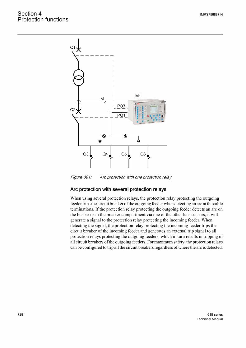
A040362 V2 EN
Figure 381: Arc protection with one protection relay
Arc protection with several protection relaysWhen using several protection relays, the protection relay protecting the outgoingfeeder trips the circuit breaker of the outgoing feeder when detecting an arc at the cableterminations. If the protection relay protecting the outgoing feeder detects an arc onthe busbar or in the breaker compartment via one of the other lens sensors, it willgenerate a signal to the protection relay protecting the incoming feeder. Whendetecting the signal, the protection relay protecting the incoming feeder trips thecircuit breaker of the incoming feeder and generates an external trip signal to allprotection relays protecting the outgoing feeders, which in turn results in tripping ofall circuit breakers of the outgoing feeders. For maximum safety, the protection relayscan be configured to trip all the circuit breakers regardless of where the arc is detected.
Section 4 1MRS756887 NProtection functions
728 615 seriesTechnical Manual
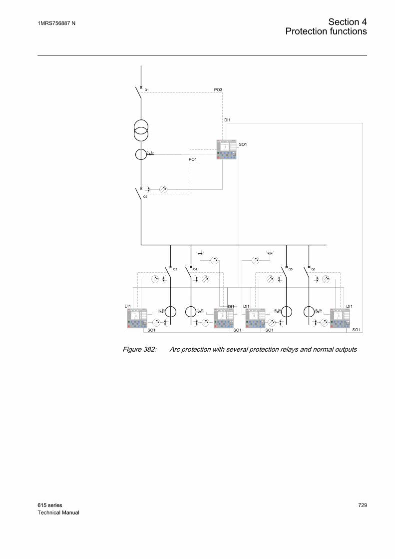
Q1
Q2
M1
Q3 Q4 Q5 Q6
PO3
PO1
3I, Io
S1 S2 S3 S4
DI1
SO1SO1SO1
DI1 DI1 DI13I, Io3I, Io 3I, Io3I, Io
DI1
SO1
SO1
REF 615 REF 615 REF 615REF 615 REF 615
REF 615
A040363 V4 EN
Figure 382: Arc protection with several protection relays and normal outputs
1MRS756887 N Section 4Protection functions
615 series 729Technical Manual

Q1
Q2
M1
Q3 Q4 Q5 Q6
3I, Io
S1 S2 S3 S4
3I, Io3I, Io 3I, Io3I, Io
Ethernet switch
Binary horisontalGOOSE connection
HSO1
HSO2
REF 615 REF 615 REF 615 REF 615
REF 615
GUID-ADDBDA34-D5C7-47E9-B2B6-B44F3D3921B3 V1 EN
Figure 383: Arc protection with several protection relays and high-speed outputsand GOOSE
Arc protection with several protection relays and a separate arcprotection systemWhen realizing an arc protection with both protection relays and a separate arcprotection system, the cable terminations of the outgoing feeders are protected byprotection relays using one lens sensor for each protection relay. The busbar and theincoming feeder are protected by the sensor loop of the separate arc protection system.With arc detection at the cable terminations, an protection relay trips the circuitbreaker of the outgoing feeder. However, when detecting an arc on the busbar, theseparate arc protection system trips the circuit breaker of the incoming feeder andgenerates an external trip signal to all protection relays protecting the outgoingfeeders, which in turn results in tripping of all circuit breakers of the outgoing feeders.
Section 4 1MRS756887 NProtection functions
730 615 seriesTechnical Manual
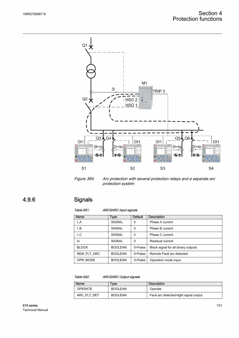
A040364 V2 EN
Figure 384: Arc protection with several protection relays and a separate arcprotection system
4.9.6 SignalsTable 651: ARCSARC Input signals
Name Type Default DescriptionI_A SIGNAL 0 Phase A current
I_B SIGNAL 0 Phase B current
I_C SIGNAL 0 Phase C current
Io SIGNAL 0 Residual current
BLOCK BOOLEAN 0=False Block signal for all binary outputs
REM_FLT_ARC BOOLEAN 0=False Remote Fault arc detected
OPR_MODE BOOLEAN 0=False Operation mode input
Table 652: ARCSARC Output signals
Name Type DescriptionOPERATE BOOLEAN Operate
ARC_FLT_DET BOOLEAN Fault arc detected=light signal output
1MRS756887 N Section 4Protection functions
615 series 731Technical Manual

4.9.7 SettingsTable 653: ARCSARC Group settings (Basic)
Parameter Values (Range) Unit Step Default DescriptionPhase start value 0.50...40.00 xIn 0.01 2.50 Operating phase current
Ground start value 0.05...8.00 xIn 0.01 0.20 Operating residual current
Operation mode 1=Light+current2=Light only3=BI controlled
1=Light+current Operation mode
Table 654: ARCSARC Non group settings (Basic)
Parameter Values (Range) Unit Step Default DescriptionOperation 1=on
5=off 1=on Operation Off / On
4.9.8 Monitored dataTable 655: ARCSARC Monitored data
Name Type Values (Range) Unit DescriptionARCSARC Enum 1=on
2=blocked3=test4=test/blocked5=off
Status
4.9.9 Technical dataTable 656: ARCSARC Technical data
Characteristic ValueOperation accuracy ±3% of the set value or ±0.01 × In
Operate time Minimum Typical Maximum
Operation mode ="Light+current"1)2)
9 ms3)
4 ms4)12 ms3)
6 ms4)15 ms 3)
9 ms4)
Operation mode ="Light only"2)
9 ms3)
4 ms4)10 ms3)
6 ms4)12 ms3)
7 ms4)
Reset time Typically 40 ms
Reset ratio Typically 0.96
1) Phase start value = 1.0 × In, current before fault = 2.0 × set Phase start value, fn = 50 Hz, fault withnominal frequency, results based on statistical distribution of 200 measurements
2) Includes the delay of the heavy-duty output contact3) Normal power output4) High-speed output
Section 4 1MRS756887 NProtection functions
732 615 seriesTechnical Manual

4.9.10 Technical revision historyTable 657: ARCSARC Technical revision history
Technical revision ChangeB Internal Improvement.
4.10 Motor start-up supervision STTPMSU
4.10.1 IdentificationFunction description IEC 61850
identificationIEC 60617identification
ANSI/IEEE C37.2device number
Motor start-up supervision STTPMSU Is2t n< 49,66,48,51LR
4.10.2 Function block
GUID-A37CF63B-5273-423B-9DC3-AACADB668AEE V2 EN
Figure 385: Function block
4.10.3 Functionality
The motor start-up supervision function STTPMSU is designed for protection againstexcessive starting time and locked rotor conditions of the motor during starting. Forthe good and reliable operation of the motor, the thermal stress during the motorstarting is maintained within the allowed limits.
The starting of the motor is supervised by monitoring the TRMS magnitude of all thephase currents or by monitoring the status of the circuit breaker connected to themotor.
During the start-up period of the motor, STTPMSU calculates the integral of the I²tvalue. If the calculated value exceeds the set value, the operate signal is activated.
STTPMSU has the provision to check the locked rotor condition of the motor using thespeed switch, which means checking if the rotor is able to rotate or not. This featureoperates after a predefined operating time.
1MRS756887 N Section 4Protection functions
615 series 733Technical Manual
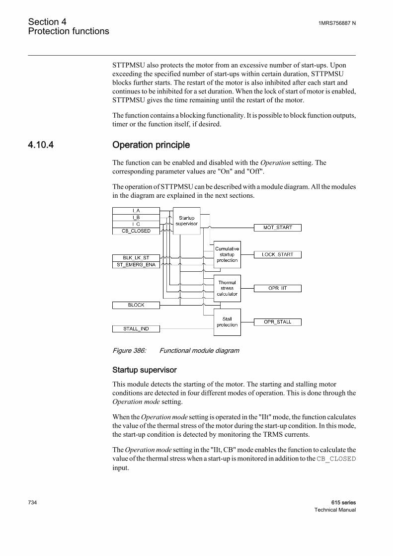
STTPMSU also protects the motor from an excessive number of start-ups. Uponexceeding the specified number of start-ups within certain duration, STTPMSUblocks further starts. The restart of the motor is also inhibited after each start andcontinues to be inhibited for a set duration. When the lock of start of motor is enabled,STTPMSU gives the time remaining until the restart of the motor.
The function contains a blocking functionality. It is possible to block function outputs,timer or the function itself, if desired.
4.10.4 Operation principle
The function can be enabled and disabled with the Operation setting. Thecorresponding parameter values are "On" and "Off".
The operation of STTPMSU can be described with a module diagram. All the modulesin the diagram are explained in the next sections.
GUID-35DD1223-14B2-48BF-ADF4-4A1DF6930314 V1 EN
Figure 386: Functional module diagram
Startup supervisorThis module detects the starting of the motor. The starting and stalling motorconditions are detected in four different modes of operation. This is done through theOperation mode setting.
When the Operation mode setting is operated in the "IIt" mode, the function calculatesthe value of the thermal stress of the motor during the start-up condition. In this mode,the start-up condition is detected by monitoring the TRMS currents.
The Operation mode setting in the "IIt, CB" mode enables the function to calculate thevalue of the thermal stress when a start-up is monitored in addition to the CB_CLOSEDinput.
Section 4 1MRS756887 NProtection functions
734 615 seriesTechnical Manual
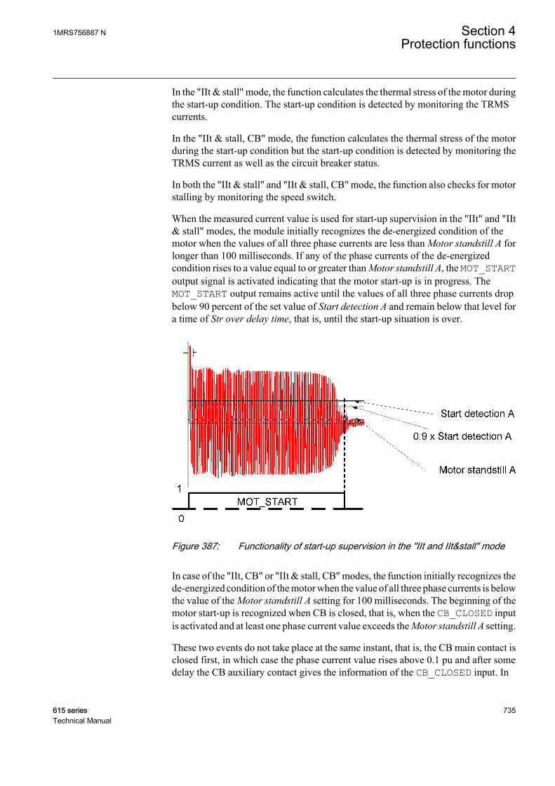
In the "IIt & stall" mode, the function calculates the thermal stress of the motor duringthe start-up condition. The start-up condition is detected by monitoring the TRMScurrents.
In the "IIt & stall, CB" mode, the function calculates the thermal stress of the motorduring the start-up condition but the start-up condition is detected by monitoring theTRMS current as well as the circuit breaker status.
In both the "IIt & stall" and "IIt & stall, CB" mode, the function also checks for motorstalling by monitoring the speed switch.
When the measured current value is used for start-up supervision in the "IIt" and "IIt& stall" modes, the module initially recognizes the de-energized condition of themotor when the values of all three phase currents are less than Motor standstill A forlonger than 100 milliseconds. If any of the phase currents of the de-energizedcondition rises to a value equal to or greater than Motor standstill A, the MOT_STARToutput signal is activated indicating that the motor start-up is in progress. TheMOT_START output remains active until the values of all three phase currents dropbelow 90 percent of the set value of Start detection A and remain below that level fora time of Str over delay time, that is, until the start-up situation is over.
GUID-4475BDFB-57AE-4BFD-9EE7-AE7672F7206E V2 EN
Figure 387: Functionality of start-up supervision in the "IIt and IIt&stall" mode
In case of the "IIt, CB" or "IIt & stall, CB" modes, the function initially recognizes thede-energized condition of the motor when the value of all three phase currents is belowthe value of the Motor standstill A setting for 100 milliseconds. The beginning of themotor start-up is recognized when CB is closed, that is, when the CB_CLOSED inputis activated and at least one phase current value exceeds the Motor standstill A setting.
These two events do not take place at the same instant, that is, the CB main contact isclosed first, in which case the phase current value rises above 0.1 pu and after somedelay the CB auxiliary contact gives the information of the CB_CLOSED input. In
1MRS756887 N Section 4Protection functions
615 series 735Technical Manual

some cases, the CB_CLOSED input can be active but the value of current may not begreater than the value of the Motor standstill A setting. To allow both possibilities, atime slot of 200 milliseconds is provided for current and the CB_CLOSED input. Ifboth events occur during this time, the motor start-up is recognized.
The motor start-up ends either within the value of the Str over delay time setting fromthe beginning of the start-up or the opening of CB or when the CB_CLOSED input isdeactivated. The operation of the MOT_START output signal in this operation modeis as illustrated in Figure 388.
This CB mode can be used in soft-started or slip ring motors for protection against alarge starting current, that is, a problem in starting and so on.
GUID-DDAD7B3F-28BE-4573-BE79-FBB488A22ECA V1 EN
GUID-1470A4DB-310F-46BC-B775-843EAB8BA836 V1 EN
Figure 388: Functionality of start-up supervision in the "IIt, CB" mode and the "IItand stall, CB" mode
Section 4 1MRS756887 NProtection functions
736 615 seriesTechnical Manual
The Str over delay time setting has different purposes in different modes of operation.
• In the “IIt” or “IIt & stall” modes, the aim of this setting is to check for thecompletion of the motor start-up period. The purpose of this time delay setting isto allow for short interruptions in the current without changing the state of theMOT_START output. In this mode of operation, the value of the setting is in therange of around 100 milliseconds.
• In the “IIt, CB” or “IIt & stall, CB” modes, the purpose of this setting is to checkfor the life of the protection scheme after the CB_CLOSED input has beenactivated. Based on the values of the phase currents, the completion of the start-up period cannot be judged. So in this mode of operation, the value of the timedelay setting can even be as high as within the range of seconds, for examplearound 30 seconds.
The activation of the BLOCK input signal deactivates the MOT_START output.
Thermal stress calculatorBecause of the high current surges during the start-up period, a thermal stress isimposed on the rotor. With less air circulation in the ventilation of the rotor before itreaches its full speed, the situation becomes even worse. Consequently, a long start-up causes a rapid heating of the rotor.
This module calculates the thermal stress developed in the motor during start-up. Theheat developed during the starting can be calculated with the equation.
W R i t dts s
t
= ( )∫2
0
GUID-7A92209F-7451-415B-8C3D-276A6ED4A44B V1 EN (Equation 143)
Rs combined rotor and stator resistance
is starting current of the motor
t starting time of the motor
This equation is normally represented as the integral of I²t. It is a commonly usedmethod in protective protection relays to protect the motor from thermal stress duringstarting. The advantage of this method over the traditional definite time overcurrentprotection is that when the motor is started with a reduced voltage as in the star-deltastarting method, the starting current is lower. This allows more starting time for themotor since the module is monitoring the integral of I²t.
The module calculates the accumulated heat continuously and compares it to thelimiting value obtained from the product of the square of the values of the Motor start-up A and Motor start-up time settings. When the calculated value of the thermal stressexceeds this limit, the OPR_IIT output is activated.
1MRS756887 N Section 4Protection functions
615 series 737Technical Manual
The module also measures the time START_TIME required by the motor to attain therated speed and the relative thermal stress IIT_RL. The values are available in theMonitored data view.
The activation of the BLOCK input signal resets the thermal stress calculator anddeactivates the OPR_IIT output.
Stall protectionThis module is activated only when the selected Operation mode setting value is "IIt& stall" or "IIt & stall, CB".
The start-up current is specific to each motor and depends on the start-up method used,such as direct online, autotransformer and rotor resistance insertion. The start-up timeis dependent on the load connected to the motor.
Based on the motor characteristics supplied by the manufacturer, this module isrequired if the stalling time is shorter than or too close to the starting time. In suchcases, a speed switch must be used to indicate whether a motor is accelerating duringstart-up or not.
At motor standstill, the STALL_IND input is active. It indicates that the rotor is notrotating. When the motor is started, at certain revolution the deactivation of theSTALL_IND by the speed switch indicates that the rotor is rotating. If the input is notdeactivated within Lock rotor time, the OPR_STALL output is activated.
The module calculates the duration of the motor in stalling condition, the STALL_RLoutput indicating the percent ratio of the start situation and the set value of Lock rotortime. The value is available in the Monitored data view.
The activation of the BLOCK input signal resets the operation time and deactivates theOPR_STALL output.
Cumulative start-up protectionThis module protects the motor from an excessive number of start-ups.
Whenever the motor is started, the latest value of START_TIME is added to theexisting value of T_ST_CNT and the updated cumulative start-up time is available atT_ST_CNT. If the value of T_ST_CNT is greater than the value of Cumulative timeLim, the LOCK_START output is activated and lockout condition for the restart ofmotor is enabled during the time the output is active. The LOCK_START outputremains high until the T_ST_CNT value reduces to a value less than the value ofCumulative time Lim. The start time counter reduces at the rate of the value of CounterRed rate.
The LOCK_START output becomes activated at the start of MOT_START. The outputremains active for a period of Restart inhibit time.
Section 4 1MRS756887 NProtection functions
738 615 seriesTechnical Manual

GUID-200BC4CB-8B33-4616-B014-AFCC99ED9224 V2 EN
Figure 389: Time delay for cumulative start
This module also protects the motor from consecutive start-ups. When theLOCK_START output is active, T_RST_ENA shows the possible time for next restart.The value of T_RST_ENA is calculated by the difference of Restart inhibit time andthe elapsed time from the instant LOCK_START is enabled.
When the ST_EMERG_ENA emergency start is set high, the value of the cumulativestart-up time counter is set to Cumulative time Lim - 60s · Emg start Red rate. Thisdisables LOCK_START and in turn makes the restart of the motor possible.
This module also calculates the total number of start-ups occurred, START_CNT. Thevalue can be reset from the Clear menu.
The old Number of motor start-ups occurred counter value (START_CNT) can betaken into use by writing the value to the Ini start up counter parameter and resettingthe value via the Clear menu from WHMI or LHMI.
The calculated values of T_RST_ENA, T_ST_CNT and START_CNT are available inthe Monitored data view.
The activation of the BLK_LK_ST input signal deactivates the LOCK_START output.The activation of the BLOCK input signal resets the cumulative start-up countermodule.
4.10.5 Application
When a motor is started, it draws a current well in excess of the motor's full-load ratingthroughout the period it takes for the motor to run up to the rated speed. The motorstarting current decreases as the motor speed increases and the value of currentremains close to the rotor-locked value for most of the acceleration period.
1MRS756887 N Section 4Protection functions
615 series 739Technical Manual

The full-voltage starting or the direct-on-line starting method is used out of the manymethods used for starting the induction motor. If there is either an electrical ormechanical constraint, this starting method is not suitable. The full-voltage startingproduces the highest starting torque. A high starting torque is generally required tostart a high-inertia load to limit the acceleration time. In this method, full voltage isapplied to the motor when the switch is in the "On" position. This method of startingresults in a large initial current surge, which is typically four to eight times that of thefull-load current drawn by the motor. If a star-delta starter is used, the value of the linecurrent will only be about one-third of the direct-on-line starting current.
GUID-F4C17D13-48CA-480A-BBE5-DFD7D6316DB8 V1 EN
Figure 390: Typical motor starting and capability curves
The start-up supervision of a motor is an important function because of the higherthermal stress developed during starting. During the start-up, the current surgeimposes a thermal strain on the rotor. This is exaggerated as the air flow for coolingis less because the fans do not rotate in their full speed. Moreover, the difference ofspeed between the rotating magnetic field and the rotor during the start-up timeinduces a high magnitude of slip current in the rotor at frequencies higher than whenthe motor is at full speed. The skin effect is stronger at higher frequencies and all thesefactors increase the losses and the generated heat. This is worse when the rotor islocked.
The starting current for slip-ring motors is less than the full load current and thereforeit is advisable to use the circuit breaker in the closed position to indicate the startingfor such type of motors.
The starting times vary depending on motor design and load torque characteristics.The time taken may vary from less than two seconds to more than 60 seconds. Thestarting time is determined for each application.
Section 4 1MRS756887 NProtection functions
740 615 seriesTechnical Manual
When the permissible stall time is less than the starting time of the motor, the stallingprotection is used and the value of the time delay setting should be set slightly less thanthe permissible stall time. The speed switch on the motor shaft must be used fordetecting whether the motor begins to accelerate or not. However, if the safe stall timeis longer than the start-up time of the motor, the speed switch is not required.
The failure of a motor to accelerate or to reach its full nominal speed in an acceptabletime when the stator is energized is caused by several types of abnormal conditions,including a mechanical failure of the motor or load bearings, low supply voltage, opencircuit in one phase of a three-phase voltage supply or too high starting voltage. Allthese abnormal conditions result in overheating.
Repeated starts increase the temperature to a high value in the stator or rotor windings,or both, unless enough time is allowed for the heat to dissipate. To ensure a safeoperation it is necessary to provide a fixed-time interval between starts or limit thenumber of starts within a period of time. This is why the motor manufacturers haverestrictions on how many starts are allowed in a defined time interval. This functiondoes not allow starting of the motor if the number of starts exceeds the set level in theregister that calculates them. This insures that the thermal effects on the motor forconsecutive starts stay within permissible levels.
For example, the motor manufacturer may state that three starts at the maximum areallowed within 4 hours and the start-up situation time is 60 seconds. By initiating threesuccessive starts we reach the situation as illustrated. As a result, the value of theregister adds up to a total of 180 seconds. Right after the third start has been initiated,the output lock of start of motor is activated and the fourth start will not be allowed,provided the time limit has been set to 121 seconds.
Furthermore, a maximum of three starts in 4 hours means that the value of the registershould reach the set start time counter limit within 4 hours to allow a new start.Accordingly, the start time counter reduction should be 60 seconds in 4 hours andshould thus be set to 60 s / 4 h = 15 s / h.
1MRS756887 N Section 4Protection functions
615 series 741Technical Manual

GUID-6E9B7247-9009-4302-A79B-B326009ECC7A V2 EN
Figure 391: Typical motor-starting and capability curves
Setting of Cumulative time Lim
Cumulative time Lim is calculated by
t n t marginsi∑ = − × +( )1
GUID-0214B677-48D0-4DD4-BD1E-67BA9FD3C345 V1 EN (Equation 144)
n specified maximum allowed number of motor start-ups
t start-up time of the motor (in seconds)
margin safety margin (~10...20 percent)
Setting of Counter Red rate
Counter Red rate is calculated by
∆ tt
ts
reset
∑ =
GUID-E7C44256-0F67-4D70-9B54-1C5042A151AF V1 EN (Equation 145)
t specified start time of the motor in seconds
treset duration during which the maximum number of motor start-ups stated by the manufacturer can bemade; time in hours
Section 4 1MRS756887 NProtection functions
742 615 seriesTechnical Manual
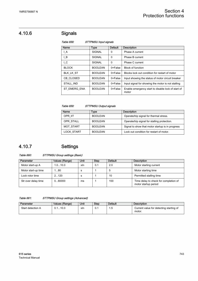
4.10.6 SignalsTable 658: STTPMSU Input signals
Name Type Default DescriptionI_A SIGNAL 0 Phase A current
I_B SIGNAL 0 Phase B current
I_C SIGNAL 0 Phase C current
BLOCK BOOLEAN 0=False Block of function
BLK_LK_ST BOOLEAN 0=False Blocks lock out condition for restart of motor
CB_CLOSED BOOLEAN 0=False Input showing the status of motor circuit breaker
STALL_IND BOOLEAN 0=False Input signal for showing the motor is not stalling
ST_EMERG_ENA BOOLEAN 0=False Enable emergency start to disable lock of start ofmotor
Table 659: STTPMSU Output signals
Name Type DescriptionOPR_IIT BOOLEAN Operate/trip signal for thermal stress.
OPR_STALL BOOLEAN Operate/trip signal for stalling protection.
MOT_START BOOLEAN Signal to show that motor startup is in progress
LOCK_START BOOLEAN Lock out condition for restart of motor.
4.10.7 SettingsTable 660: STTPMSU Group settings (Basic)
Parameter Values (Range) Unit Step Default DescriptionMotor start-up A 1.0...10.0 xIn 0.1 2.0 Motor starting current
Motor start-up time 1...80 s 1 5 Motor starting time
Lock rotor time 2...120 s 1 10 Permitted stalling time
Str over delay time 0...60000 ms 1 100 Time delay to check for completion ofmotor startup period
Table 661: STTPMSU Group settings (Advanced)
Parameter Values (Range) Unit Step Default DescriptionStart detection A 0.1...10.0 xIn 0.1 1.5 Current value for detecting starting of
motor.
1MRS756887 N Section 4Protection functions
615 series 743Technical Manual
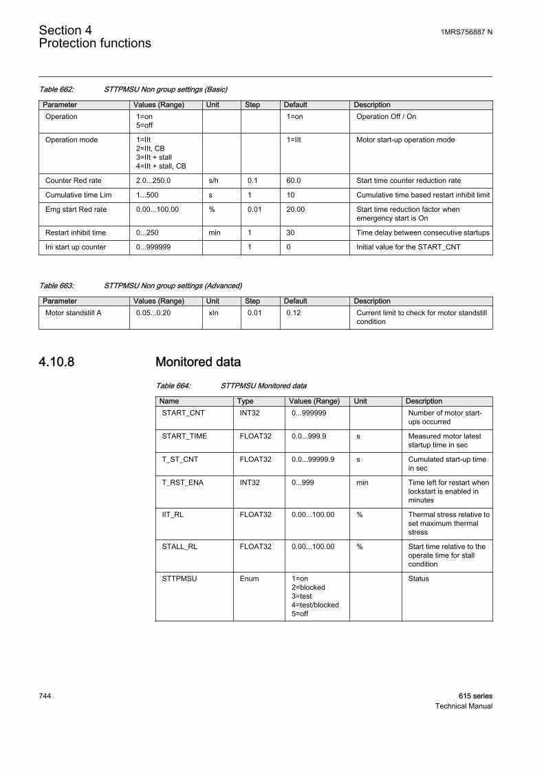
Table 662: STTPMSU Non group settings (Basic)
Parameter Values (Range) Unit Step Default DescriptionOperation 1=on
5=off 1=on Operation Off / On
Operation mode 1=IIt2=IIt, CB3=IIt + stall4=IIt + stall, CB
1=IIt Motor start-up operation mode
Counter Red rate 2.0...250.0 s/h 0.1 60.0 Start time counter reduction rate
Cumulative time Lim 1...500 s 1 10 Cumulative time based restart inhibit limit
Emg start Red rate 0.00...100.00 % 0.01 20.00 Start time reduction factor whenemergency start is On
Restart inhibit time 0...250 min 1 30 Time delay between consecutive startups
Ini start up counter 0...999999 1 0 Initial value for the START_CNT
Table 663: STTPMSU Non group settings (Advanced)
Parameter Values (Range) Unit Step Default DescriptionMotor standstill A 0.05...0.20 xIn 0.01 0.12 Current limit to check for motor standstill
condition
4.10.8 Monitored dataTable 664: STTPMSU Monitored data
Name Type Values (Range) Unit DescriptionSTART_CNT INT32 0...999999 Number of motor start-
ups occurred
START_TIME FLOAT32 0.0...999.9 s Measured motor lateststartup time in sec
T_ST_CNT FLOAT32 0.0...99999.9 s Cumulated start-up timein sec
T_RST_ENA INT32 0...999 min Time left for restart whenlockstart is enabled inminutes
IIT_RL FLOAT32 0.00...100.00 % Thermal stress relative toset maximum thermalstress
STALL_RL FLOAT32 0.00...100.00 % Start time relative to theoperate time for stallcondition
STTPMSU Enum 1=on2=blocked3=test4=test/blocked5=off
Status
Section 4 1MRS756887 NProtection functions
744 615 seriesTechnical Manual
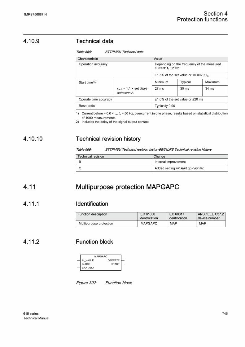
4.10.9 Technical dataTable 665: STTPMSU Technical data
Characteristic ValueOperation accuracy Depending on the frequency of the measured
current: fn ±2 Hz
±1.5% of the set value or ±0.002 × In
Start time1)2) Minimum Typical Maximum
Fault = 1.1 × set Startdetection A
27 ms 30 ms 34 ms
Operate time accuracy ±1.0% of the set value or ±20 ms
Reset ratio Typically 0.90
1) Current before = 0.0 × In, fn = 50 Hz, overcurrent in one phase, results based on statistical distributionof 1000 measurements
2) Includes the delay of the signal output contact
4.10.10 Technical revision historyTable 666: STTPMSU Technical revision history66/51LRS Technical revision history
Technical revision ChangeB Internal improvement
C Added setting Ini start up counter.
4.11 Multipurpose protection MAPGAPC
4.11.1 IdentificationFunction description IEC 61850
identificationIEC 60617identification
ANSI/IEEE C37.2device number
Multipurpose protection MAPGAPC MAP MAP
4.11.2 Function block
GUID-A842A2C8-0188-4E01-8490-D00F7D1D8719 V2 EN
Figure 392: Function block
1MRS756887 N Section 4Protection functions
615 series 745Technical Manual

4.11.3 Functionality
The multipurpose protection function MAPGAPC is used as a general protection withmany possible application areas as it has flexible measuring and setting facilities. Thefunction can be used as an under- or overprotection with a settable absolute hysteresislimit. The function operates with the definite time (DT) characteristics.
The function contains a blocking functionality. It is possible to block function outputs,the definite timer or the function itself, if desired.
4.11.4 Operation principle
The function can be enabled and disabled with the Operation setting. Thecorresponding parameter values are "On" and "Off".
The operation of MAPGAPC can be described using a module diagram. All themodules in the diagram are explained in the next sections.
AI_VALUE OPERATELeveldetector
BlockinglogicBLOCK
START
Timer
ENA_ADDt
GUID-50AA4A14-7379-43EB-8FA0-6C20C12097AC V1 EN
Figure 393: Functional module diagram
Level detectorThe level detector compares AI_VALUE to the Start value setting. The Operationmode setting defines the direction of the level detector.
Table 667: Operation mode types
Operation Mode Description"Under" If the input signal AI_VALUE is lower than the set
value of the "Start value" setting, the level detectorenables the timer module.
"Over" If the input signal AI_VALUE exceeds the setvalue of the Start value setting, the level detectorenables the timer module.
The Absolute hysteresis setting can be used for preventing unnecessary oscillations ifthe input signal is slightly above or below the Start value setting. After leaving thehysteresis area, the start condition has to be fulfilled again and it is not sufficient forthe signal to only return to the hysteresis area. If the ENA_ADD input is activated, thethreshold value of the internal comparator is the sum of the Start value Add and Start
Section 4 1MRS756887 NProtection functions
746 615 seriesTechnical Manual

value settings. The resulting threshold value for the comparator can be increased ordecreased depending on the sign and value of the Start value Add setting.
TimerOnce activated, the timer activates the START output. The time characteristic isaccording to DT. When the operation timer has reached the value set by Operate delaytime, the OPERATE output is activated. If the starting condition disappears before themodule operates, the reset timer is activated. If the reset timer reaches the value set byReset delay time, the operation timer resets and the START output is deactivated.
The timer calculates the start duration value START_DUR, which indicates thepercentage ratio of the start situation and the set operation time. The value is availablein the monitored data view.
Blocking logicThere are three operation modes in the blocking function. The operation modes arecontrolled by the BLOCK input and the global setting in Configuration/System/Blocking mode which selects the blocking mode. The BLOCK input can be controlledby a binary input, a horizontal communication input or an internal signal of theprotection relay's program. The influence of the BLOCK signal activation ispreselected with the global setting Blocking mode.
The Blocking mode setting has three blocking methods. In the "Freeze timers" mode,the operation timer is frozen to the prevailing value, but the OPERATE output is notdeactivated when blocking is activated. In the "Block all" mode, the whole function isblocked and the timers are reset. In the "Block OPERATE output" mode, the functionoperates normally but the OPERATE output is not activated.
4.11.5 Application
The function block can be used for any general analog signal protection, eitherunderprotection or overprotection. The setting range is wide, allowing variousprotection schemes for the function. Thus, the absolute hysteresis can be set to a valuethat suits the application.
The temperature protection using the RTD sensors can be done using the functionblock. The measured temperature can be fed from the RTD sensor to the function inputthat detects too high temperatures in the motor bearings or windings, for example.When the ENA_ADD input is enabled, the threshold value of the internal comparatoris the sum of the Start value Add and Start value settings. This allows a temporalincrease or decrease of the level detector depending on the sign and value of the Startvalue Add setting, for example, when the emergency start is activated. If, for example,Start value is 100, Start value Add is 20 and the ENA_ADD input is active, the inputsignal needs to rise above 120 before MAPGAPC operates.
1MRS756887 N Section 4Protection functions
615 series 747Technical Manual

4.11.6 SignalsTable 668: MAPGAPC Input signals
Name Type Default DescriptionAI_VALUE FLOAT32 0.0 Analogue input value
BLOCK BOOLEAN 0=False Block signal for activating the blocking mode
ENA_ADD BOOLEAN 0=False Enable start added
Table 669: MAPGAPC Output signals
Name Type DescriptionOPERATE BOOLEAN Operate
START BOOLEAN Start
4.11.7 SettingsTable 670: MAPGAPC Group settings (Basic)
Parameter Values (Range) Unit Step Default DescriptionStart value -10000.0...10000.0 0.1 0.0 Start value
Start value Add -100.0...100.0 0.1 0.0 Start value Add
Operate delay time 0...200000 ms 100 0 Operate delay time
Table 671: MAPGAPC Non group settings (Basic)
Parameter Values (Range) Unit Step Default DescriptionOperation 1=on
5=off 1=on Operation Off / On
Operation mode 1=Over2=Under
1=Over Operation mode
Table 672: MAPGAPC Non group settings (Advanced)
Parameter Values (Range) Unit Step Default DescriptionReset delay time 0...60000 ms 100 0 Reset delay time
Absolute hysteresis 0.01...100.00 0.01 0.10 Absolute hysteresis for operation
Table 673: MAPGAPC Group settings (Basic)
Parameter Values (Range) Unit Step Default DescriptionStart value -10000.0...10000.0 0.1 0.0 Start value
Start value Add -100.0...100.0 0.1 0.0 Start value Add
Operate delay time 0...200000 ms 100 0 Operate delay time
Section 4 1MRS756887 NProtection functions
748 615 seriesTechnical Manual

Table 674: MAPGAPC Non group settings (Basic)
Parameter Values (Range) Unit Step Default DescriptionOperation 1=on
5=off 1=on Operation Off / On
Operation mode 1=Over2=Under
1=Over Operation mode
Table 675: MAPGAPC Non group settings (Advanced)
Parameter Values (Range) Unit Step Default DescriptionReset delay time 0...60000 ms 100 0 Reset delay time
Absolute hysteresis 0.01...100.00 0.01 0.10 Absolute hysteresis for operation
4.11.8 Monitored dataTable 676: MAPGAPC Monitored data
Name Type Values (Range) Unit DescriptionSTART_DUR FLOAT32 0.00...100.00 % Ratio of start time /
operate time
MAPGAPC Enum 1=on2=blocked3=test4=test/blocked5=off
Status
4.11.9 Technical dataTable 677: MAPGAPC Technical data
Characteristic ValueOperation accuracy ±1.0% of the set value or ±20 ms
4.11.10 Technical revision historyTable 678: MAPGAPC Technical revision history
Technical revision ChangeB Internal improvement.
C Internal improvement.
1MRS756887 N Section 4Protection functions
615 series 749Technical Manual

4.12 Capacitor bank protection
4.12.1 Three-phase overload protection for shunt capacitor banksCOLPTOC
4.12.1.1 Identification
Function description IEC 61850identification
IEC 60617identification
ANSI/IEEE C37.2device number
Three-phase overload protection forshunt capacitor banks
COLPTOC 3I> 3I< 51C/37
4.12.1.2 Function block
GUID-14122FFE-3DD4-4813-A8BE-56A5A7387C1E V1 EN
Figure 394: Function block symbol
4.12.1.3 Functionality
The three-phase overload protection for shunt capacitor banks function COLPTOCprovides single-phase, two-phase and three-phase protection against overloadscaused by harmonic currents and overvoltages in shunt capacitor banks. The operationof overload and alarm is based on the peak value of the integrated current which isproportional to the voltage across the capacitor.
The overload function operates with IDMT characteristic and an alarm functionoperates with DT characteristic.
COLPTOC provides undercurrent protection to detect disconnection of the capacitor.COLPTOC has breaker reclosing inhibit feature to enable complete capacitordischarging before breaker reclosing after it has operated.
COLPTOC contains blocking functionality. It is possible to block the functionoutputs, timers or the function itself, if desired.
4.12.1.4 Operation principle
The function can be enabled and disabled with the Operation setting. Thecorresponding parameter values are “On” and “Off”.
Section 4 1MRS756887 NProtection functions
750 615 seriesTechnical Manual

The operation of COLPTOC can be described using a module diagram. All themodules in the diagram are explained in the next sections.
GUID-23E40C9B-871B-447A-8302-AE1329868AA9 V1 EN
Figure 395: Functional module diagram
Peak integrated current calculatorThe peak integrated current calculator calculates peak value of integrated current(I_PEAK_INT_A, I_PEAK_INT_B and I_PEAK_INT_C) which is proportionalto the voltage over capacitor. The I_PEAK_INT_A, I_PEAK_INT_B andI_PEAK_INT_C values are available in monitored data view. The frequencyresponse of the peak integrated current calculator can be seen in Figure 396.
GUID-81EC4C3E-7E8C-4BDF-9AE3-D4133690CD04 V1 EN
Figure 396: Frequency response of the peak integrated current calculator
1MRS756887 N Section 4Protection functions
615 series 751Technical Manual

Operate level detectorThe Operate level detector compares I_PEAK_INT_x value to Start value overload.If the phase or phases in which I_PEAK_INT_x exceeds the setting matches the Numof start phases setting, the Operate level detector module activates the Timer 1module.
Timer 1Once activated, the Timer 1 module activates the ST_OVLOD output. The operationtime depends on the overload level and Time multiplier. The operation time understandard characteristics is based on ANSI/IEEE 37.99 and IEC 60871-1recommendations.
Table 679: Standard Curve characteristics for IDMT Curve
Overload value IED operate time(s) with k = 1 Standard1.10 43200 IEC60871-1
1.15 1800 IEC60871-1
1.20 300 IEC60871-1
1.30 60 ANSI/IEEE37.99,IEC60871-1
1.40 15 ANSI/IEEE37.99
1.70 1 ANSI/IEEE37.99
2.20 0.120 ANSI/IEEE37.99
Operate time is based on maximum value of I_PEAK_INT_A, I_PEAK_INT_B andI_PEAK_INT_C. From maximum value calculated , operate time between any twoconsecutive points in the standard table is based on logarithmic interpolation.
The operate time can be scaled using the Time multiplier setting. The OPR_OVLODoutput is activated if the overload situation lasts long enough to exceed the operationtime.
The operate time for the operation overload stage is limited between0.1 s to 43200 s (12 hours) if Time multiplier is used.
Section 4 1MRS756887 NProtection functions
752 615 seriesTechnical Manual

GUID-17CFB7BD-8839-467B-92F8-750624D737CE V1 EN
Figure 397: Inverse-time characteristic curves for overload stage
If the integrated current exceeds 1.1 times the setting Start value overload for a shortperiod but does not operate as the current decreases within Start value overload, theoutput ST_OVLOD is kept active but the operation timer is frozen. However, if theintegrated current exceeds 1.1 times the Start value overload setting value again, theoperation timer continue from the freezing point. Thus, the operation timer iscumulative. If the integrated current exceeds 1.1 times the setting Start value overload
1MRS756887 N Section 4Protection functions
615 series 753Technical Manual

only once and remains within the Start value overload area for 24 hours, the operationtimer and the output ST_OVLOD are reset.
GUID-21B1AE66-D9B1-4F10-9678-45DC0366784A V1 EN
Figure 398: The behavior of the IDMT timer and the output ST_OVLOD
The ST_DUR_OVLOD output indicates the percentage ratio of the start situation andthe operation time in the Timer 1 module and is available in the monitored data view.
The Timer 1 module is internally blocked for one second after thecapacitor bank is connected by detecting the rising edge of theCB_CLOSED signal. The CB_CLOSED signal is True when the CBposition is closed.
Alarm level detectorThe Alarm level detector compares I_PEAK_INT_x value to Alarm start value. Ifthe phase or phases in which I_PEAK_INT_x exceeds the setting matches the Numof start phases setting, the Alarm level detector module activates the Timer 2 module.
The Num of start phases setting is a common setting for both Operatelevel detector and Alarm level detector.
Section 4 1MRS756887 NProtection functions
754 615 seriesTechnical Manual

Timer 2The Timer 2 characteristics are according to Definite Time (DT) .When the operationtimer has reached the value of Alarm delay time, the ALARM output is activated.
If a drop-off situation happens, the timer is reset.
The Timer 2 module is internally blocked for one second after thecapacitor bank is connected by detecting the rising edge of theCB_CLOSED signal. The CB_CLOSED signal is True when the CBposition is closed.
Under current detectorThe Under current detector module can be enabled by setting Enable under current to“Enable” and disabled by setting it to “Disable”. The Under current detector moduleis also disabled when CB_CLOSED is FALSE, that is, when circuit breaker is open.
The fundamental frequency component of phase currents is compared to the settingStart value Un Cur. If all the three-phase currents are below the setting Start value UnCur, the Under current detector module enables the Timer 3 module.
Timer 3Once activated, the Timer 3 module activates the ST_UN_I output. The operation isbased on DT characteristics. When the operation timer has reached the value of UnCur delay time, the OPR_UN_I output is activated.
If the undercurrent situation disappears, the operation timer is reset. TheST_DUR_UN_I output indicates the percentage ratio of the undercurrent startsituation and the set operation time in the Timer 3 module and is available in themonitored data view.
The OPR_UN_I output is of pulse type and remains TRUE for 150 ms. After that,ST_DUR_UN_I and OPR_UN_I are deactivated and ST_DUR_UN_I is reset.
If the circuit breaker closed status signal is not detected, the constantvalue TRUE has to be connected to CB_CLOSED input to enable theundercurrent detector.
If the circuit breaker status signal is not connected to CB_CLOSEDinput, the OPR_UN_I output is activated even if the circuit breaker isopen and undercurrent is detected.
1MRS756887 N Section 4Protection functions
615 series 755Technical Manual

Inhibit recloseWhen the output OPR_UN_I becomes active or when the CB_CLOSED state changesfrom TRUE to FALSE, that is, when circuit breaker opens, the reclosing inhibitionmodule activates output BLK_CLOSE.
If Enable under current is set to “Disable”, the reclosing inhibitionoperation is based purely on the CB_CLOSED input.
The behavior of the BLK_CLOSE output depends on Reclose inhibit mode. If Recloseinhibit mode is set to “Lockout”, the BLK_CLOSE output needs to be reset manuallyfrom the clearing menu parameter COLPTOC inhibit recl. If Reclose inhibit mode isset to “Non-latched”, the BLK_CLOSE output resets after the set Reclose inhibit timehas elapsed.
Blocking logicThere are three operation modes in the blocking function. The operation modes arecontrolled by the BLOCK input and the global setting Configuration/System/Blocking mode which selects the blocking mode. The BLOCK input can be controlledby a binary input, a horizontal communication input or an internal signal of the IEDprogram. The influence of the BLOCK signal activation is preselected with the globalsetting Blocking mode.
The Blocking mode setting has three blocking methods. In the “Freeze timers” mode,the operation timer is frozen to the prevailing value. In the “Block all” mode, thewhole function is blocked and the timers are reset. In the “Block OPERATE output”mode, COLPTOC is executed normally but the OPR_OVLOD and OPR_UN_I outputsare not allowed to activate.
The BLOCK input does not block the BLK_CLOSE signal.
4.12.1.5 Application
The application area for three-phase overload protection function of shunt capacitorbank is the protection of power capacitor banks intended for reactive powercompensation and filtering of the harmonics. Shunt capacitor banks provide a low-impedance path to harmonic currents and hence attract harmonic currents flowing inthe system. Increased harmonic currents result in excessive voltage stress across thecapacitor bank. According to the standards, a high-voltage capacitor shall be able towithstand 10% overload. Loading beyond that can cause damage to the capacitor bankand in turn to the system. Hence, COLPTOC is specially designed for the protectionagainst overloads produced by harmonic currents and overvoltage.
Undercurrent protection is used to disconnect the capacitor bank from the rest of thepower system when the voltage at the capacitor bank terminals is too low for too long
Section 4 1MRS756887 NProtection functions
756 615 seriesTechnical Manual
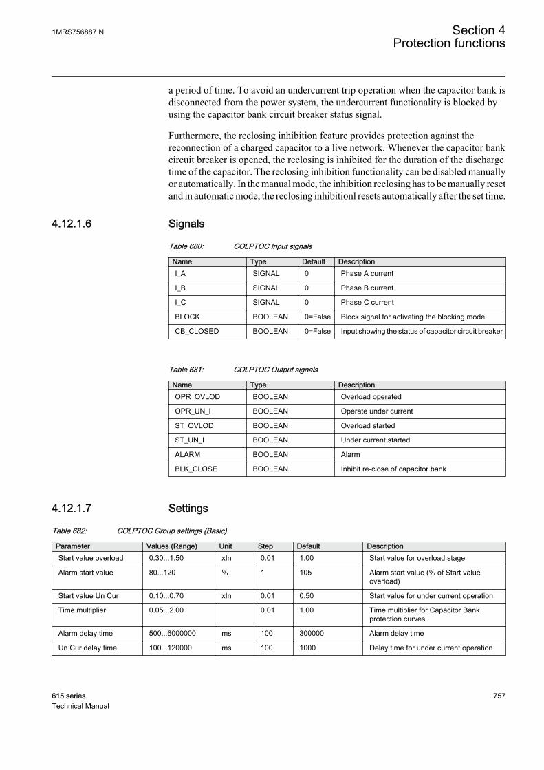
a period of time. To avoid an undercurrent trip operation when the capacitor bank isdisconnected from the power system, the undercurrent functionality is blocked byusing the capacitor bank circuit breaker status signal.
Furthermore, the reclosing inhibition feature provides protection against thereconnection of a charged capacitor to a live network. Whenever the capacitor bankcircuit breaker is opened, the reclosing is inhibited for the duration of the dischargetime of the capacitor. The reclosing inhibition functionality can be disabled manuallyor automatically. In the manual mode, the inhibition reclosing has to be manually resetand in automatic mode, the reclosing inhibitionl resets automatically after the set time.
4.12.1.6 Signals
Table 680: COLPTOC Input signals
Name Type Default DescriptionI_A SIGNAL 0 Phase A current
I_B SIGNAL 0 Phase B current
I_C SIGNAL 0 Phase C current
BLOCK BOOLEAN 0=False Block signal for activating the blocking mode
CB_CLOSED BOOLEAN 0=False Input showing the status of capacitor circuit breaker
Table 681: COLPTOC Output signals
Name Type DescriptionOPR_OVLOD BOOLEAN Overload operated
OPR_UN_I BOOLEAN Operate under current
ST_OVLOD BOOLEAN Overload started
ST_UN_I BOOLEAN Under current started
ALARM BOOLEAN Alarm
BLK_CLOSE BOOLEAN Inhibit re-close of capacitor bank
4.12.1.7 Settings
Table 682: COLPTOC Group settings (Basic)
Parameter Values (Range) Unit Step Default DescriptionStart value overload 0.30...1.50 xIn 0.01 1.00 Start value for overload stage
Alarm start value 80...120 % 1 105 Alarm start value (% of Start valueoverload)
Start value Un Cur 0.10...0.70 xIn 0.01 0.50 Start value for under current operation
Time multiplier 0.05...2.00 0.01 1.00 Time multiplier for Capacitor Bankprotection curves
Alarm delay time 500...6000000 ms 100 300000 Alarm delay time
Un Cur delay time 100...120000 ms 100 1000 Delay time for under current operation
1MRS756887 N Section 4Protection functions
615 series 757Technical Manual
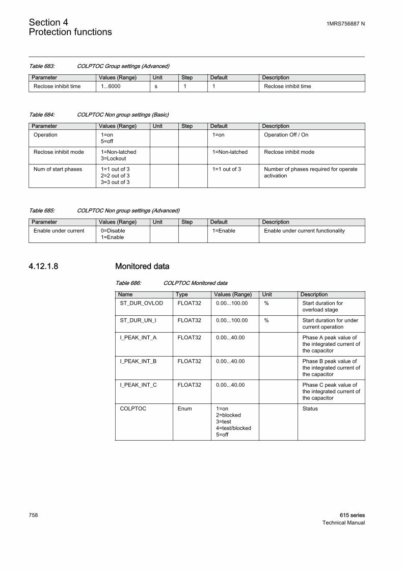
Table 683: COLPTOC Group settings (Advanced)
Parameter Values (Range) Unit Step Default DescriptionReclose inhibit time 1...6000 s 1 1 Reclose inhibit time
Table 684: COLPTOC Non group settings (Basic)
Parameter Values (Range) Unit Step Default DescriptionOperation 1=on
5=off 1=on Operation Off / On
Reclose inhibit mode 1=Non-latched3=Lockout
1=Non-latched Reclose inhibit mode
Num of start phases 1=1 out of 32=2 out of 33=3 out of 3
1=1 out of 3 Number of phases required for operateactivation
Table 685: COLPTOC Non group settings (Advanced)
Parameter Values (Range) Unit Step Default DescriptionEnable under current 0=Disable
1=Enable 1=Enable Enable under current functionality
4.12.1.8 Monitored data
Table 686: COLPTOC Monitored data
Name Type Values (Range) Unit DescriptionST_DUR_OVLOD FLOAT32 0.00...100.00 % Start duration for
overload stage
ST_DUR_UN_I FLOAT32 0.00...100.00 % Start duration for undercurrent operation
I_PEAK_INT_A FLOAT32 0.00...40.00 Phase A peak value ofthe integrated current ofthe capacitor
I_PEAK_INT_B FLOAT32 0.00...40.00 Phase B peak value ofthe integrated current ofthe capacitor
I_PEAK_INT_C FLOAT32 0.00...40.00 Phase C peak value ofthe integrated current ofthe capacitor
COLPTOC Enum 1=on2=blocked3=test4=test/blocked5=off
Status
Section 4 1MRS756887 NProtection functions
758 615 seriesTechnical Manual
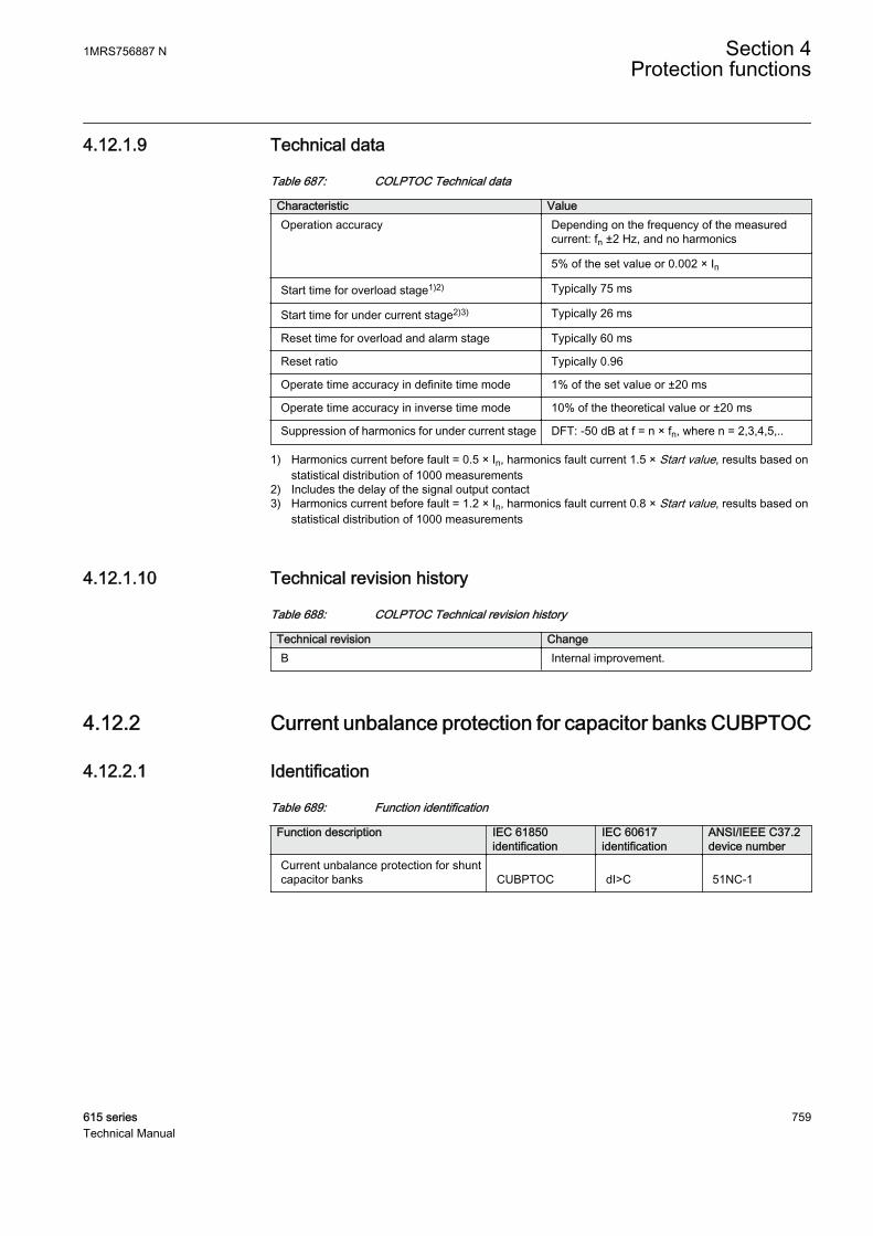
4.12.1.9 Technical data
Table 687: COLPTOC Technical data
Characteristic ValueOperation accuracy Depending on the frequency of the measured
current: fn ±2 Hz, and no harmonics
5% of the set value or 0.002 × In
Start time for overload stage1)2) Typically 75 ms
Start time for under current stage2)3) Typically 26 ms
Reset time for overload and alarm stage Typically 60 ms
Reset ratio Typically 0.96
Operate time accuracy in definite time mode 1% of the set value or ±20 ms
Operate time accuracy in inverse time mode 10% of the theoretical value or ±20 ms
Suppression of harmonics for under current stage DFT: -50 dB at f = n × fn, where n = 2,3,4,5,..
1) Harmonics current before fault = 0.5 × In, harmonics fault current 1.5 × Start value, results based onstatistical distribution of 1000 measurements
2) Includes the delay of the signal output contact3) Harmonics current before fault = 1.2 × In, harmonics fault current 0.8 × Start value, results based on
statistical distribution of 1000 measurements
4.12.1.10 Technical revision history
Table 688: COLPTOC Technical revision history
Technical revision ChangeB Internal improvement.
4.12.2 Current unbalance protection for capacitor banks CUBPTOC
4.12.2.1 Identification
Table 689: Function identification
Function description IEC 61850identification
IEC 60617identification
ANSI/IEEE C37.2device number
Current unbalance protection for shuntcapacitor banks CUBPTOC dI>C 51NC-1
1MRS756887 N Section 4Protection functions
615 series 759Technical Manual
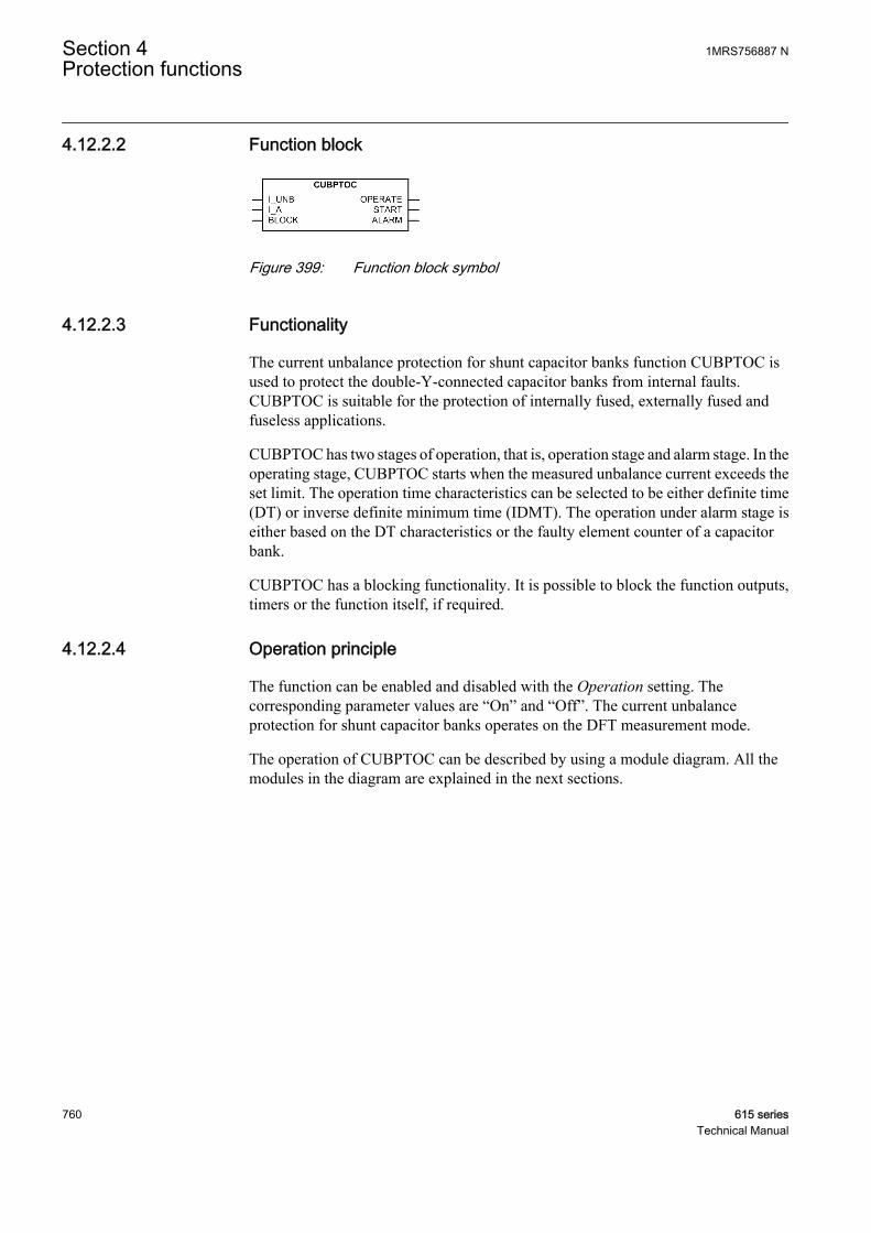
4.12.2.2 Function block
GUID-6447040F-55DC-4FA5-9111-0941695F8544 V1 EN
Figure 399: Function block symbol
4.12.2.3 Functionality
The current unbalance protection for shunt capacitor banks function CUBPTOC isused to protect the double-Y-connected capacitor banks from internal faults.CUBPTOC is suitable for the protection of internally fused, externally fused andfuseless applications.
CUBPTOC has two stages of operation, that is, operation stage and alarm stage. In theoperating stage, CUBPTOC starts when the measured unbalance current exceeds theset limit. The operation time characteristics can be selected to be either definite time(DT) or inverse definite minimum time (IDMT). The operation under alarm stage iseither based on the DT characteristics or the faulty element counter of a capacitorbank.
CUBPTOC has a blocking functionality. It is possible to block the function outputs,timers or the function itself, if required.
4.12.2.4 Operation principle
The function can be enabled and disabled with the Operation setting. Thecorresponding parameter values are “On” and “Off”. The current unbalanceprotection for shunt capacitor banks operates on the DFT measurement mode.
The operation of CUBPTOC can be described by using a module diagram. All themodules in the diagram are explained in the next sections.
Section 4 1MRS756887 NProtection functions
760 615 seriesTechnical Manual

GUID-C448B20B-4253-4F41-BB8A-ADA6A8E59CE3 V1 EN
Figure 400: Functional module diagram
Natural unbalance CompensationA standard double-Y-connected shunt capacitor bank configuration is shown inFigure 401. The fundamental frequency component of an unbalance current ismeasured on the common neutral connecting the two balanced parts of a shuntcapacitor bank, that is, between star point 1 and star point 2.
GUID-B90CC18A-3603-4485-8ED0-43C37A035522 V1 EN
Figure 401: Double-Y-connected capacitor bank
The phase angle of the measured fundamental frequency component of the unbalancecurrent I_UNB is synchronized by using the phase current I_A as a reference.
∠ = ∠ − ∠I I UNB I Aunb
_ _
GUID-CB8F2C7C-9CAC-47D7-A33F-C6369E34EC7B V1 EN (Equation 146)
1MRS756887 N Section 4Protection functions
615 series 761Technical Manual
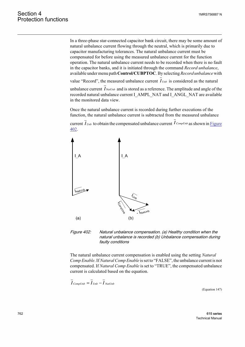
In a three-phase star-connected capacitor bank circuit, there may be some amount ofnatural unbalance current flowing through the neutral, which is primarily due tocapacitor manufacturing tolerances. The natural unbalance current must becompensated for before using the measured unbalance current for the functionoperation. The natural unbalance current needs to be recorded when there is no faultin the capacitor banks, and it is initiated through the command Record unbalance,available under menu path Control/CUBPTOC. By selecting Record unbalance with
value “Record”, the measured unbalance current IUnb is considered as the natural
unbalance current INatUnb and is stored as a reference. The amplitude and angle of therecorded natural unbalance current I_AMPL_NAT and I_ANGL_NAT are availablein the monitored data view.
Once the natural unbalance current is recorded during further executions of thefunction, the natural unbalance current is subtracted from the measured unbalance
current IUnb to obtain the compensated unbalance current I CompUnb as shown in Figure402.
GUID-32346323-2B5B-4EF7-A4AF-95B03646D57A V1 EN
Figure 402: Natural unbalance compensation. (a) Healthy condition when thenatural unbalance is recorded (b) Unbalance compensation duringfaulty conditions
The natural unbalance current compensation is enabled using the setting NaturalComp Enable. If Natural Comp Enable is set to “FALSE”, the unbalance current is notcompensated. If Natural Comp Enable is set to “TRUE”, the compensated unbalancecurrent is calculated based on the equation.
I I ICompUnb Unb NatUnb= −
GUID-675D6F00-06CD-45DE-BAFC-2CF87587F474 V1 EN (Equation 147)
Section 4 1MRS756887 NProtection functions
762 615 seriesTechnical Manual
The amplitude I_AMPL_COMP and the angle I_ANGL_COMP of the compensated
unbalance current I CompUnb are available in the monitored data view.
Level detector 1The calculated compensated unbalance current I_AMPL_COMP is compared to theset Start value. If I_AMPL_COMP exceeds the set Start value, the Level detector 1sends an enabling signal to the Timer 1 module.
Timer 1Once activated, the Timer 1 module activates the START output. Depending on thevalue of the Operating curve type setting, the time characteristics are according to DTor IDMT. When the operation timer has reached the value of Operate delay time in theDT mode or the maximum value defined by the inverse time curve, the OPERATEoutput is activated. When the user-programmable IDMT curve is selected, theoperation time characteristics are defined by the parameters Curve parameter A,Curve parameter B, Curve parameter C and Curve parameter E.
In a drop-off situation, that is when a fault suddenly disappears before the operatedelay is exceeded, the Timer 1 reset state is activated. The functionality of the Timer1 in the reset state depends on the combination of the Operating curve type and Resetdelay time settings. When the DT characteristic is selected, the reset timer runs untilthe set Reset delay time value is exceeded. When the IDMT curves are selected, animmediate reset occurs. The START output is deactivated when the reset timer haselapsed.
The setting Time multiplier is used for scaling the IDMT operation and reset times.
The setting parameter Minimum operate time defines the minimum desired operationtime for IDMT. The setting is applicable only when the IDMT curves are used.
The Minimum operate time setting should be used with great carebecause the operation time is according to the IDMT curve but alwaysat least the value of the Minimum operate time setting.
The Timer 1 module calculates the start duration value START_DUR, whichindicates the percentile ratio of the start situation and the set operation time. The valueis available in the monitored data view.
In a typical double-Y-connected configuration (Figure 401), there are two branches inevery phase and hence six individual counters COUNT_BR1_A, COUNT_BR2_A,COUNT_BR1_B, COUNT_BR2_B, COUNT_BR1_C and COUNT_BR2_C aremaintained. Based on the phase angle of the compensated unbalance currentI_ANGL_COMP, the phase and the branch of the element failure location is detected.However, the element failure location also depends on the type of capacitor banks, thatis, whether internal or external fuses are used. The setting Fuse location is used to setthe capacitor bank type as “External” or “Internal”.
1MRS756887 N Section 4Protection functions
615 series 763Technical Manual

For an external fuse capacitor bank, the element failure location and correspondingcounters to be incremented are determined based on the phase angle of thecompensated unbalance current.
Table 690: Element failure location and counters to be incremented for external fuse case
Phase angle of the compensatedunbalance current (degrees)
Phase and branch of the elementfailure
Counters to be incremented
-15...+15 Phase-A branch 1 COUNT_BR1_A
-15...-45 Phase-A branch 1Phase-C branch 2
COUNT_BR1_ACOUNT_BR2_C
-45...-75 Phase-C branch 2 COUNT_BR2_C
-75...-105 Phase-B branch 1Phase-C branch 2
COUNT_BR1_BCOUNT_BR2_C
-105...-135 Phase-B branch 1 COUNT_BR1_B
-135...-165 Phase-B branch 1Phase-A branch 2
COUNT_BR1_BCOUNT_BR2_A
-165...-180 Phase-A branch 2 COUNT_BR2_A
+165...+180 Phase-A branch2 COUNT_BR2_A
+135...+165 Phase-C branch 1Phase-A branch 2
COUNT_BR1_CCOUNT_BR2_A
+105...+135 Phase-C branch 1 COUNT_BR1_C
+75...+105 Phase-C branch1Phase-B branch2
COUNT_BR1_CCOUNT_BR2_B
+45...+75 Phase-B branch2 COUNT_BR2_B
+15...+45 Phase-A branch1Phase-B branch2
COUNT_BR1_ACOUNT_BR2_B
If the capacitor bank is fuseless, then the setting Fuse location shouldbe set to “External” and Table 690 can be used to determine theelement failure location.
If the compensated unbalance current I_AMPL_COMP is greater than three times theset Alarm value, it is considered to be a case of blown external fuse. For the internalfuse and blown fuse cases, the element failure location and corresponding counters tobe incremented are determined based on the phase angle of the compensatedunbalance current.
Table 691: Element failure location and counters to be incremented for internal fuse and blownfuse case
Phase angle of the compensatedunbalance current (degrees)
Phase and branch of the elementfailure
Counters to be incremented
-15...+15 Phase-A branch 2 COUNT_BR2_A
-15... -45 Phase-A branch 2Phase-C branch 1
COUNT_BR2_ACOUNT_BR1_C
-45...-75 Phase-C branch 1 COUNT_BR1_C
Table continues on next page
Section 4 1MRS756887 NProtection functions
764 615 seriesTechnical Manual
Phase angle of the compensatedunbalance current (degrees)
Phase and branch of the elementfailure
Counters to be incremented
-75...-105 Phase-B branch 2Phase-C branch 1
COUNT_BR2_BCOUNT_BR1_C
-105...-135 Phase-B branch 2 COUNT_BR2_B
-135...-165 Phase-B branch 2Phase-A branch 1
COUNT_BR2_BCOUNT_BR1_A
-165...-180 Phase-A branch 1 COUNT_BR1_A
+165...+180 Phase-A branch 1 COUNT_BR1_A
+135...+165 Phase-C branch 2Phase-A branch 1
COUNT_BR2_CCOUNT_BR1_A
+105...+135 Phase-C branch 2 COUNT_BR2_C
+75...+105 Phase-C branch 2Phase-B branch 1
COUNT_BR2_CCOUNT_BR1_B
+45...+75 Phase-B branch 1 COUNT_BR1_B
+15...+45 Phase-A branch 2Phase-B branch 1
COUNT_BR2_ACOUNT_BR1_B
After Alarm delay time has elapsed, the corresponding counter value is incrementedbased on the magnitude of the unbalance current. If I_AMPL_COMP is less than 1.5times the set Alarm value, the counter is incremented by one. Furthermore, ifI_AMPL_COMP is between 1.5 and 2.5 times the set Alarm value, the counter isincremented by two and so on.
Normally, the setting Alarm value is about 0.1 percent lower than thevalue of the unbalance current which is caused by one faulty element.This setting value has to be chosen carefully because a slightly lowervalue may lead to a situation where the counters show more failuresthan the actual. Too high setting leads to a situation where a fault is notdetected.
The counter values COUNT_BR1_A, COUNT_BR2_A, COUNT_BR1_B,COUNT_BR2_B, COUNT_BR1_C and COUNT_BR2_C are available in themonitoring data view. The total number of element failures in double-Y-connectedcapacitor banks, FAIL_COUNT, is available in the monitored data view.
The ALARM output is activated, when the value of FAIL_COUNT exceeds the settingElement failure limit.
The counter values can be reset via CUBPTOC counters which is located under theClear menu.
Level detector 2The calculated compensated unbalance current I_AMPL_COMP is compared to theset Alarm start value. If the I_AMPL_COMP exceeds the set Alarm value the Leveldetector 2 sends enabling signal to the Alarm control module.
1MRS756887 N Section 4Protection functions
615 series 765Technical Manual

Alarm controlDepending on the Alarm mode setting, the alarm stage operation is according to“Normal mode” or “Element counter mode”.
In the “Normal mode” the time characteristic is according to DT. When the alarmtimer has reached the value set by Alarm delay time, the ALARM output is activated. Ifthe fault disappears before the alarm activates, the alarm timer is reset immediately.
The “Element counter mode” is used to detect faulty elements of the capacitor bankand count the number of element failures in each branch and line. On activation, thismodule increments the corresponding element failure counters after the set Alarmdelay time has elapsed.
Blocking logicThere are three operation modes in the blocking function. The operation modes arecontrolled by the BLOCK input and the global setting Configuration/System/Blocking mode, which selects the blocking mode. The BLOCK input can be controlledby a binary input, a horizontal communication input or an internal signal of the IEDprogram. The influence of the BLOCK signal activation is preselected with the globalsetting Blocking mode.
The Blocking mode setting has three blocking methods. In the "Freeze timers" mode,the operation timer is frozen to the prevailing value. In the "Block all" mode, the wholefunction is blocked and the timers are reset. In the "Block OPERATE output" mode,CUBPTOC operates normally but the OPERATE output is not activated.
4.12.2.5 Application
CUBPTOC is designed for the protection against internal faults in double-Y-connected capacitor banks. This unbalance protection detects an asymmetry in thecapacitor bank caused by blown fuses or short circuits across bushings or betweencapacitor units and the racks in which they are mounted.
Normally, the capacitor units are designed to withstand 110 percent of the nominalvoltage continuously. When an element inside a capacitor bank fails, the remaininghealthier elements experience an increase in voltage across them. If the voltageexceeds the 110 percent value of the nominal voltage, it can lead to a failure of thehealthier elements of the bank and in turn fail the entire capacitor bank. Since thecapacitor unbalance current is directly proportional to the element failures, unbalanceprotection is an effective way of detecting capacitor element failures. The currentunbalance protection function is usually used with the three-phase capacitor bankoverload protection function to increase the sensitivity of protection for capacitorbanks.
Due to the two-stage (operation and alarm stage) unbalance protection and the naturalunbalance compensation facility, the protection of capacitor banks with internal fusescan be implemented with a very high degree of sensitivity. Furthermore, CUBPTOC
Section 4 1MRS756887 NProtection functions
766 615 seriesTechnical Manual
provides a sophisticated method of detecting the number of faulty elements in eachphase by calculating the differential unbalance current.
The unbalance protection function can be used for internally fused, externally fusedand fuseless shunt capacitor banks. Since a fuseless capacitor bank lacks theindividual capacitor unit fuses, current unbalance protection becomes even morecritical for fuseless applications.
When an individual element fails, it causes unbalance current. With an increasingnumber of element failures, the unbalance current increases and CUBPTOC gives analarm. The alarm level is normally set to 50 percent of the maximum permitted level.The capacitor bank needs to be taken out of service to replace the faulty units. If thisis not done, the capacitor bank is tripped when the maximum allowed unbalancecurrent level is exceeded.
If two simultaneous faults occur in the same phase but in differentbranches, there is no change in the unbalance current and CUBPTOCdoes not detect this type of faults.
If two simultaneous faults occur in the same branch but in differentphases, it may cause a phase angle equal to a situation where there isonly one fault in the branch. Therefore, the element failure countersshow only one fault instead of two.
1MRS756887 N Section 4Protection functions
615 series 767Technical Manual
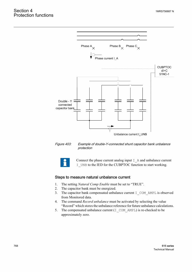
GUID-D7B7D142-7CF4-4DFB-B8E5-876F6C3579C7 V1 EN
Figure 403: Example of double-Y-connected shunt capacitor bank unbalanceprotection
Connect the phase current analog input I_A and unbalance currentI_UNB to the IED for the CUBPTOC function to start working.
Steps to measure natural unbalance current1. The setting Natural Comp Enable must be set to “TRUE”.2. The capacitor bank must be energized.3. The capacitor bank compensated unbalance current I_COM_AMPL is observed
from Monitored data.4. The command Record unbalance must be activated by selecting the value
“Record” which stores the unbalance reference for future unbalance calculations.5. The compensated unbalance current (I_COM_AMPL) is re-checked to be
approximately zero.
Section 4 1MRS756887 NProtection functions
768 615 seriesTechnical Manual
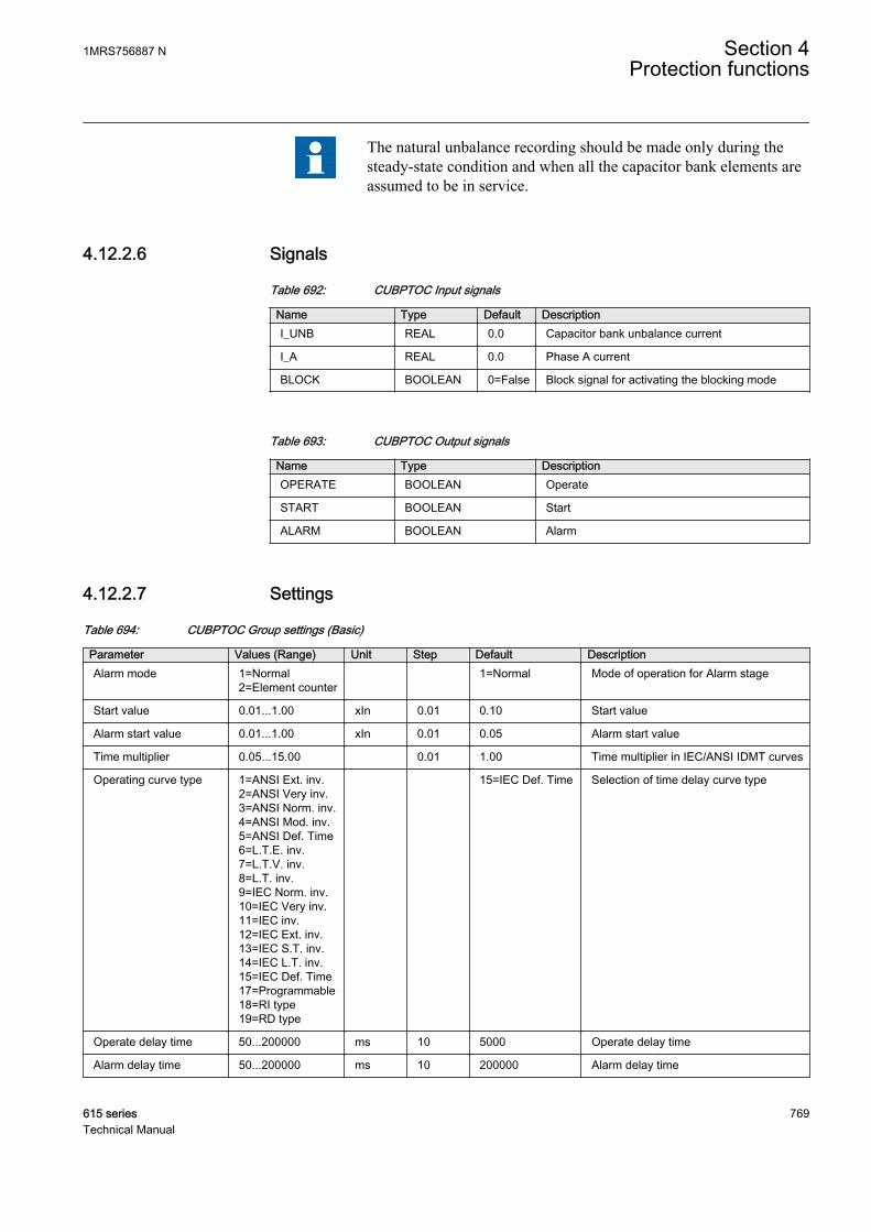
The natural unbalance recording should be made only during thesteady-state condition and when all the capacitor bank elements areassumed to be in service.
4.12.2.6 Signals
Table 692: CUBPTOC Input signals
Name Type Default DescriptionI_UNB REAL 0.0 Capacitor bank unbalance current
I_A REAL 0.0 Phase A current
BLOCK BOOLEAN 0=False Block signal for activating the blocking mode
Table 693: CUBPTOC Output signals
Name Type DescriptionOPERATE BOOLEAN Operate
START BOOLEAN Start
ALARM BOOLEAN Alarm
4.12.2.7 Settings
Table 694: CUBPTOC Group settings (Basic)
Parameter Values (Range) Unit Step Default DescriptionAlarm mode 1=Normal
2=Element counter 1=Normal Mode of operation for Alarm stage
Start value 0.01...1.00 xIn 0.01 0.10 Start value
Alarm start value 0.01...1.00 xIn 0.01 0.05 Alarm start value
Time multiplier 0.05...15.00 0.01 1.00 Time multiplier in IEC/ANSI IDMT curves
Operating curve type 1=ANSI Ext. inv.2=ANSI Very inv.3=ANSI Norm. inv.4=ANSI Mod. inv.5=ANSI Def. Time6=L.T.E. inv.7=L.T.V. inv.8=L.T. inv.9=IEC Norm. inv.10=IEC Very inv.11=IEC inv.12=IEC Ext. inv.13=IEC S.T. inv.14=IEC L.T. inv.15=IEC Def. Time17=Programmable18=RI type19=RD type
15=IEC Def. Time Selection of time delay curve type
Operate delay time 50...200000 ms 10 5000 Operate delay time
Alarm delay time 50...200000 ms 10 200000 Alarm delay time
1MRS756887 N Section 4Protection functions
615 series 769Technical Manual

Table 695: CUBPTOC Group settings (Advanced)
Parameter Values (Range) Unit Step Default DescriptionFuse location 1=Internal
2=External 1=Internal Location of capacitor fuse
Element fail limit 1...100 1 3 Element failure limit above which alarm isactive
Natural Comp enable 0=False1=True
0=False Enable natural unbalance compensation
Table 696: CUBPTOC Non group settings (Basic)
Parameter Values (Range) Unit Step Default DescriptionOperation 1=on
5=off 1=on Operation Off / On
Curve parameter A 0.00860...120.00000
1 28.20000 Parameter A for customer programmablecurve
Curve parameter B 0.00000...0.71200 1 0.12170 Parameter B for customer programmablecurve
Curve parameter C 0.02...2.00 1 2.00 Parameter C for customer programmablecurve
Curve parameter E 0.0...1.0 1 1.0 Parameter E for customer programmablecurve
Table 697: CUBPTOC Non group settings (Advanced)
Parameter Values (Range) Unit Step Default DescriptionReset delay time 0...60000 ms 1 20 Reset delay time
Minimum operate time 20...60000 ms 1 20 Minimum operate time for IDMT curves
4.12.2.8 Monitored data
Table 698: CUBPTOC Monitored data
Name Type Values (Range) Unit DescriptionSTART_DUR FLOAT32 0.00...100.00 % Ratio of start time /
operate time
I_NAT_AMPL FLOAT32 0.00...5.00 xIn Recorded naturalunbalance currentamplitude
I_NAT_ANGL FLOAT32 -179.00...179.00 deg Recorded naturalunbalance current angle
I_COM_AMPL FLOAT32 0.00...5.00 xIn Compensated unbalancecurrent amplitude
I_COM_ANGL FLOAT32 -179.00...179.00 deg Compensated unbalancecurrent angle
COUNT_BR1_A INT32 0...2147483647 Number of elementfailures in branch1phase-A
Table continues on next page
Section 4 1MRS756887 NProtection functions
770 615 seriesTechnical Manual

Name Type Values (Range) Unit DescriptionCOUNT_BR2_A INT32 0...2147483647 Number of element
failures in branch2phase-A
COUNT_BR1_B INT32 0...2147483647 Number of elementfailures in branch1phase-B
COUNT_BR2_B INT32 0...2147483647 Number of elementfailures in branch2phase-B
COUNT_BR1_C INT32 0...2147483647 Number of elementfailures in branch1phase-C
COUNT_BR2_C INT32 0...2147483647 Number of elementfailures in branch2phase-C
FAIL_COUNT INT32 0...2147483647 Total number of elementfailures
CUBPTOC Enum 1=on2=blocked3=test4=test/blocked5=off
Status
I-unb FLOAT32 0.00...5.00 xIn Measured neutralunbalance currentamplitude
4.12.2.9 Technical data
Table 699: CUBPTOC Technical data
Characteristic ValueOperation accuracy Depending on the frequency of the measured
current: fn ±2 Hz
1.5% of the set value or 0.002 × In
Start time1)2) Typically 26 ms
Reset time Typically 40 ms
Reset ratio Typically 0.96
Operate time accuracy in definite time mode 1% of the theoretical value or ±20 ms
Operate time accuracy in inverse definiteminimum time mode
5% of the theoretical value or ±20 ms
Suppression of harmonics DFT: -50 dB at f = n × fn, where n = 2,3,4,5,..
1) Fundamental frequency current = 1.0 × In, current before fault = 0.0 × In, fault current = 2.0 × Startvalue, results based on statistical distribution of 1000 measurements
2) Includes the delay of the signal output contact
1MRS756887 N Section 4Protection functions
615 series 771Technical Manual

4.12.2.10 Technical revision history
Table 700: CUBPTOC Technical revision history
Technical revision ChangeB Selection name for Recorded unbalance changed.
4.12.3 Three-phase current unbalance protection for shuntcapacitor banks HCUBPTOC
4.12.3.1 Identification
Function description IEC 61850identification
IEC 60617identification
ANSI/IEEE C37.2device number
Three-phase current unbalanceprotection for shunt capacitor banks
HCUBPTOC 3dI>C 51NC-2
4.12.3.2 Function block
GUID-B2D864D6-0F7A-4C23-9A78-C0499E3BD3AE V1 EN
Figure 404: Function block symbol
4.12.3.3 Functionality
The three-phase current unbalance protection function for shunt capacitor banksHCUBPTOC is used to protect the H-bridge capacitor banks against internal faults.HCUBPTOC is suitable for protection of internally fused, externally fused and fuse-less capacitor bank applications.
HCUBPTOC has two stages of operation, the operation stage and alarm stage. In theoperation stage, HCUBPTOC starts when the measured unbalance current exceedsthe set limit. The operating time characteristics can be selected to be either definitetime (DT) or inverse definite minimum time (IDMT). In the alarm stage, the alarmstarts when the measured unbalance current exceeds the set alarm limit. The alarmtime characteristics are based on DT.
HCUBPTOC contains blocking functionality. It is possible to block the functionoutputs, timers or the function itself, if desired.
Section 4 1MRS756887 NProtection functions
772 615 seriesTechnical Manual

4.12.3.4 Operation principle
The function can be enabled and disabled with the Operation setting. Thecorresponding parameter values are “On” and “Off”.
The three-phase current unbalance protection for shunt capacitor banks operates onthe DFT measurement mode. The operation of HCUBPTOC can be described byusing a module diagram. All the modules in the diagram are explained in the nextsections.
GUID-0B0CF77E-8F7F-455F-BDF7-BE5B68A18F48 V1 EN
Figure 405: Function module diagram
Natural unbalance compensationIn the three-phase H-bridge-connected shunt capacitor bank configuration, theunbalance currents I_UNB_A, I_UNB_B and I_UNB_C are measured at thecommon points of the H-bridge.
Branch 1
Branch 3
Branch 2
Branch 4
I_UNB_A I_UNB_B I_UNB_C
GUID-38C780C9-4BBD-4896-9FB7-7449A2F9273C V1 EN
Figure 406: H-Bridge-connected capacitor bank
1MRS756887 N Section 4Protection functions
615 series 773Technical Manual
The phase angles of three-phase measured unbalance currents are synchronized usingthe phase current I_A as reference. The phase-A unbalance current phase angle can becalculated with the equation.
∠ =∠ −∠I I_UNB_A I_AUnb_A
GUID-A53BB793-53F0-4AA6-B417-7C0B4052A7B0 V1 EN (Equation 148)
A three-phase H-bridge-connected capacitor bank circuit may have some amount ofnatural unbalance current flowing through the common points of H-bridge, whichmay primarily be due to capacitor manufacturing tolerances. Therefore, the naturalunbalance current must be compensated for before using the measured unbalancecurrent for function operation.
The natural unbalance current needs to be recorded when there is no fault in thecapacitor banks, and it is initiated through the command Record unbalance availableunder menu path Control/HCUBPTOC. The natural unbalance currents are recordedfor all the phases at the same time by setting command Record unbalance to “Recordall phases” or each natural unbalance current can be recorded separately for individualphases by setting command Record unbalance to “Record phase A” or “Record phaseB” or “Record phase C”. By selecting Record unbalance with value “Record”, the
measured three-phase unbalance currents ( I I IUnb_A Unb_B Unb_C
, , , ) are considered thenatural unbalance currents for each phase respectively and stored as a reference. Theamplitude and angle of the phasewise-recorded natural unbalance currentsI_NAT_AMPL_A, I_NAT_ANGL_A, I_NAT_AMPL_B, I_NAT_ANGL_B,I_NAT_AMPL_C and I_NAT_ANGL_C are available in the monitored data view.
Once a natural unbalance current is recorded, the phasewise natural unbalance current
is subtracted from the corresponding phase-measured unbalance current ( IUnb )
during further executions of the function to obtain the compensated unbalance current
( ICompUnb ) .
Section 4 1MRS756887 NProtection functions
774 615 seriesTechnical Manual
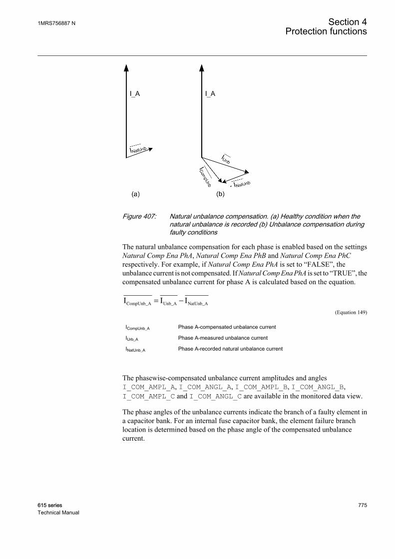
GUID-5E967F3C-8ED9-4C42-A8C0-81E6264350C6 V1 EN
Figure 407: Natural unbalance compensation. (a) Healthy condition when thenatural unbalance is recorded (b) Unbalance compensation duringfaulty conditions
The natural unbalance compensation for each phase is enabled based on the settingsNatural Comp Ena PhA, Natural Comp Ena PhB and Natural Comp Ena PhCrespectively. For example, if Natural Comp Ena PhA is set to “FALSE”, theunbalance current is not compensated. If Natural Comp Ena PhA is set to “TRUE”, thecompensated unbalance current for phase A is calculated based on the equation.
I I ICompUnb_A Unb_A NatUnb_A
= −
GUID-86A0D979-EA77-4AD8-B8D3-2D77578125F8 V1 EN (Equation 149)
ICompUnb_A Phase A-compensated unbalance current
IUrb_A Phase A-measured unbalance current
INatUnb_A Phase A-recorded natural unbalance current
The phasewise-compensated unbalance current amplitudes and anglesI_COM_AMPL_A, I_COM_ANGL_A, I_COM_AMPL_B, I_COM_ANGL_B,I_COM_AMPL_C and I_COM_ANGL_C are available in the monitored data view.
The phase angles of the unbalance currents indicate the branch of a faulty element ina capacitor bank. For an internal fuse capacitor bank, the element failure branchlocation is determined based on the phase angle of the compensated unbalancecurrent.
1MRS756887 N Section 4Protection functions
615 series 775Technical Manual
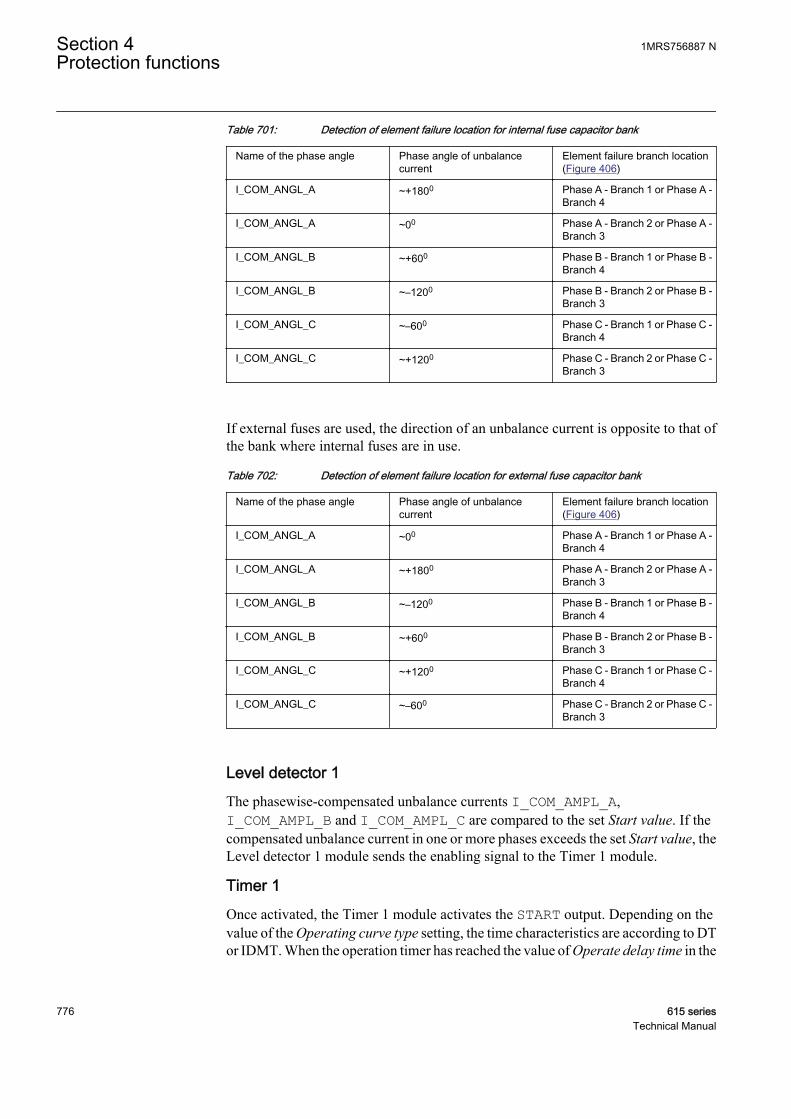
Table 701: Detection of element failure location for internal fuse capacitor bank
Name of the phase angle Phase angle of unbalancecurrent
Element failure branch location(Figure 406)
I_COM_ANGL_A ~+1800 Phase A - Branch 1 or Phase A -Branch 4
I_COM_ANGL_A ~00 Phase A - Branch 2 or Phase A -Branch 3
I_COM_ANGL_B ~+600 Phase B - Branch 1 or Phase B -Branch 4
I_COM_ANGL_B ~–1200 Phase B - Branch 2 or Phase B -Branch 3
I_COM_ANGL_C ~–600 Phase C - Branch 1 or Phase C -Branch 4
I_COM_ANGL_C ~+1200 Phase C - Branch 2 or Phase C -Branch 3
If external fuses are used, the direction of an unbalance current is opposite to that ofthe bank where internal fuses are in use.
Table 702: Detection of element failure location for external fuse capacitor bank
Name of the phase angle Phase angle of unbalancecurrent
Element failure branch location(Figure 406)
I_COM_ANGL_A ~00 Phase A - Branch 1 or Phase A -Branch 4
I_COM_ANGL_A ~+1800 Phase A - Branch 2 or Phase A -Branch 3
I_COM_ANGL_B ~–1200 Phase B - Branch 1 or Phase B -Branch 4
I_COM_ANGL_B ~+600 Phase B - Branch 2 or Phase B -Branch 3
I_COM_ANGL_C ~+1200 Phase C - Branch 1 or Phase C -Branch 4
I_COM_ANGL_C ~–600 Phase C - Branch 2 or Phase C -Branch 3
Level detector 1The phasewise-compensated unbalance currents I_COM_AMPL_A,I_COM_AMPL_B and I_COM_AMPL_C are compared to the set Start value. If thecompensated unbalance current in one or more phases exceeds the set Start value, theLevel detector 1 module sends the enabling signal to the Timer 1 module.
Timer 1Once activated, the Timer 1 module activates the START output. Depending on thevalue of the Operating curve type setting, the time characteristics are according to DTor IDMT. When the operation timer has reached the value of Operate delay time in the
Section 4 1MRS756887 NProtection functions
776 615 seriesTechnical Manual

DT mode or the maximum value defined by the inverse time curve, the OPERATEoutput is activated.
When the user-programmable IDMT curve is selected, the operation timecharacteristics are defined by the parameters Curve parameter A, Curve parameter B,Curve parameter C and Curve parameter E.
In a drop-off situation, that is, when a fault suddenly disappears before the operationdelay is exceeded, the Timer 1 reset state is activated. The functionality of Timer 1 inthe reset state depends on the combination of the Operating curve type and Reset delaytime settings. When the DT characteristic is selected, the reset timer runs until the setReset delay time value is exceeded. When the IDMT curves are selected, an immediatereset occurs. The START output is deactivated when the reset timer has elapsed.
The setting Time multiplier is used for scaling the IDMT operation times.
The setting parameter Minimum operate time defines the minimum desired operationtime for IDMT. The setting is applicable only when the IDMT curves are used.
The Minimum operate time setting should be used with great carebecause the operation time is according to the IDMT curve, but alwaysat least the value of the Minimum operate time setting.
Timer 1 calculates the start duration value START_DUR, which indicates thepercentage ratio of the start situation and the set operation time. The value is availablein the monitored data view.
Level detector 2The phasewise-compensated unbalance currents I_COM_AMPL_A,I_COM_AMPL_B and I_COM_AMPL_C are compared to the set Alarm start value. Ifthe compensated unbalance current in one or more phases exceeds the set Alarm startvalue, the Level detector 2 module sends the enabling signal to the Timer 2 module.
Timer 2Once activated, the timer activates the alarm timer. The timer characteristic isaccording to DT. When the alarm timer has reached the value set by Alarm delaytime, the ALARM output is activated.
If the fault disappears before the alarm activates, the alarm timer is reset immediately.
Blocking logicThere are three operation modes in the blocking function. The operation modes arecontrolled by the BLOCK input and the global setting Configuration/System/Blocking mode which selects the blocking mode. The BLOCK input can be controlledby a binary input, a horizontal communication input or an internal signal of the IEDprogram. The influence of the BLOCK signal activation is preselected with the globalsetting Blocking mode.
1MRS756887 N Section 4Protection functions
615 series 777Technical Manual
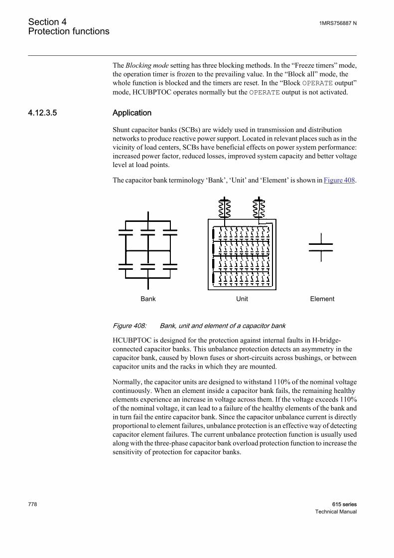
The Blocking mode setting has three blocking methods. In the “Freeze timers” mode,the operation timer is frozen to the prevailing value. In the “Block all” mode, thewhole function is blocked and the timers are reset. In the “Block OPERATE output”mode, HCUBPTOC operates normally but the OPERATE output is not activated.
4.12.3.5 Application
Shunt capacitor banks (SCBs) are widely used in transmission and distributionnetworks to produce reactive power support. Located in relevant places such as in thevicinity of load centers, SCBs have beneficial effects on power system performance:increased power factor, reduced losses, improved system capacity and better voltagelevel at load points.
The capacitor bank terminology ‘Bank’, ‘Unit’ and ‘Element’ is shown in Figure 408.
Bank Unit Element
GUID-A95A599A-328F-4480-A84B-1A8F4A98DA54 V1 EN
Figure 408: Bank, unit and element of a capacitor bank
HCUBPTOC is designed for the protection against internal faults in H-bridge-connected capacitor banks. This unbalance protection detects an asymmetry in thecapacitor bank, caused by blown fuses or short-circuits across bushings, or betweencapacitor units and the racks in which they are mounted.
Normally, the capacitor units are designed to withstand 110% of the nominal voltagecontinuously. When an element inside a capacitor bank fails, the remaining healthyelements experience an increase in voltage across them. If the voltage exceeds 110%of the nominal voltage, it can lead to a failure of the healthy elements of the bank andin turn fail the entire capacitor bank. Since the capacitor unbalance current is directlyproportional to element failures, unbalance protection is an effective way of detectingcapacitor element failures. The current unbalance protection function is usually usedalong with the three-phase capacitor bank overload protection function to increase thesensitivity of protection for capacitor banks.
Section 4 1MRS756887 NProtection functions
778 615 seriesTechnical Manual
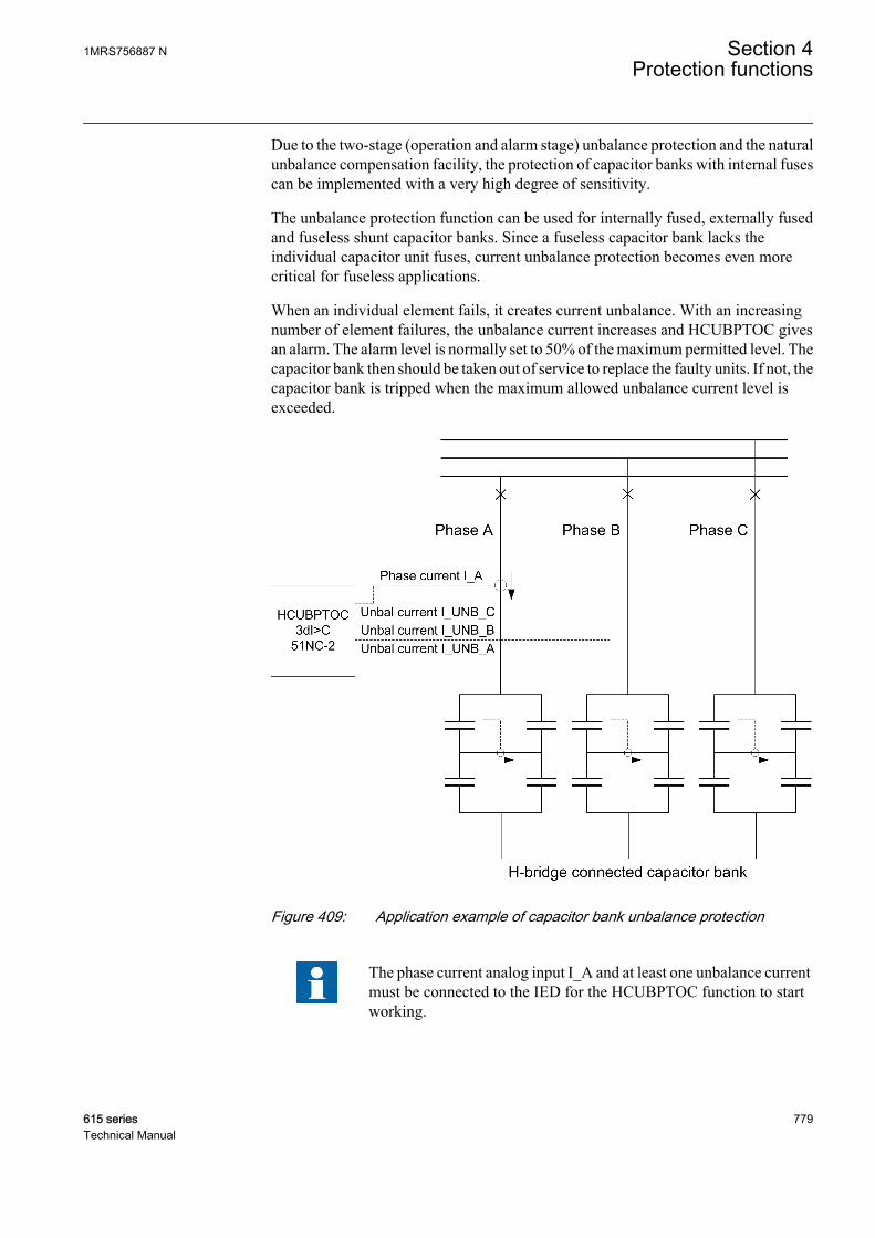
Due to the two-stage (operation and alarm stage) unbalance protection and the naturalunbalance compensation facility, the protection of capacitor banks with internal fusescan be implemented with a very high degree of sensitivity.
The unbalance protection function can be used for internally fused, externally fusedand fuseless shunt capacitor banks. Since a fuseless capacitor bank lacks theindividual capacitor unit fuses, current unbalance protection becomes even morecritical for fuseless applications.
When an individual element fails, it creates current unbalance. With an increasingnumber of element failures, the unbalance current increases and HCUBPTOC givesan alarm. The alarm level is normally set to 50% of the maximum permitted level. Thecapacitor bank then should be taken out of service to replace the faulty units. If not, thecapacitor bank is tripped when the maximum allowed unbalance current level isexceeded.
GUID-B7066385-DD0A-4357-93EC-8077BD145CBF V1 EN
Figure 409: Application example of capacitor bank unbalance protection
The phase current analog input I_A and at least one unbalance currentmust be connected to the IED for the HCUBPTOC function to startworking.
1MRS756887 N Section 4Protection functions
615 series 779Technical Manual

Steps to measure natural unbalance current1. The setting Natural Comp Enable must be set to “TRUE”.2. The capacitor bank must be energized.3. The capacitor bank compensated unbalance current I_COM_AMPL is observed
from Monitored data.4. The command Record unbalance must be activated by selecting the value
“Record” which stores the unbalance reference for future unbalance calculations.5. The compensated unbalance current (I_COM_AMPL) is re-checked to be
approximately zero.
The natural unbalance recording should be made only during thesteady-state condition and when all the capacitor bank elements areassumed to be in service.
4.12.3.6 Signals
Table 703: HCUBPTOC Input signals
Name Type Default DescriptionI_UNB_A REAL 0.0 Capacitor bank unbalance current phase A
I_UNB_B REAL 0.0 Capacitor bank unbalance current phase B
I_UNB_C REAL 0.0 Capacitor bank unbalance current phase C
I_A REAL 0.0 Phase A current
BLOCK BOOLEAN 0=False Block signal for activating the blocking mode
Table 704: HCUBPTOC Output signals
Name Type DescriptionOPERATE BOOLEAN Operate
START BOOLEAN Start
ALARM BOOLEAN Alarm
4.12.3.7 Settings
Table 705: HCUBPTOC Group settings (Basic)
Parameter Values (Range) Unit Step Default DescriptionStart value 0.01...1.00 xIn 0.01 0.10 Start value
Alarm start value 0.01...1.00 xIn 0.01 0.05 Alarm start value
Time multiplier 0.05...15.00 0.01 1.00 Time multiplier in IEC/ANSI IDMT curves
Table continues on next page
Section 4 1MRS756887 NProtection functions
780 615 seriesTechnical Manual
Parameter Values (Range) Unit Step Default DescriptionOperating curve type 1=ANSI Ext. inv.
2=ANSI Very inv.3=ANSI Norm. inv.4=ANSI Mod. inv.5=ANSI Def. Time6=L.T.E. inv.7=L.T.V. inv.8=L.T. inv.9=IEC Norm. inv.10=IEC Very inv.11=IEC inv.12=IEC Ext. inv.13=IEC S.T. inv.14=IEC L.T. inv.15=IEC Def. Time17=Programmable18=RI type19=RD type
15=IEC Def. Time Selection of time delay curve type
Operate delay time 40...200000 ms 10 5000 Operate delay time
Alarm delay time 40...200000 ms 10 200000 Alarm delay time
Table 706: HCUBPTOC Group settings (Advanced)
Parameter Values (Range) Unit Step Default DescriptionNatural Comp Ena PhA 0=False
1=True 0=False Enable natural unbalance compensation
PhA
Natural Comp Ena PhB 0=False1=True
0=False Enable natural unbalance compensationPhB
Natural Comp Ena PhC 0=False1=True
0=False Enable natural unbalance compensationPhC
Table 707: HCUBPTOC Non group settings (Basic)
Parameter Values (Range) Unit Step Default DescriptionOperation 1=on
5=off 1=on Operation Off / On
Curve parameter A 0.00860...120.00000
1 28.20000 Parameter A for customer programmablecurve
Curve parameter B 0.00000...0.71200 1 0.12170 Parameter B for customer programmablecurve
Curve parameter C 0.02...2.00 1 2.00 Parameter C for customer programmablecurve
Curve parameter E 0.0...1.0 1 1.0 Parameter E for customer programmablecurve
Table 708: HCUBPTOC Non group settings (Advanced)
Parameter Values (Range) Unit Step Default DescriptionReset delay time 0...60000 ms 1 20 Reset delay time
Minimum operate time 20...60000 ms 1 20 Minimum operate time for IDMT curves
1MRS756887 N Section 4Protection functions
615 series 781Technical Manual
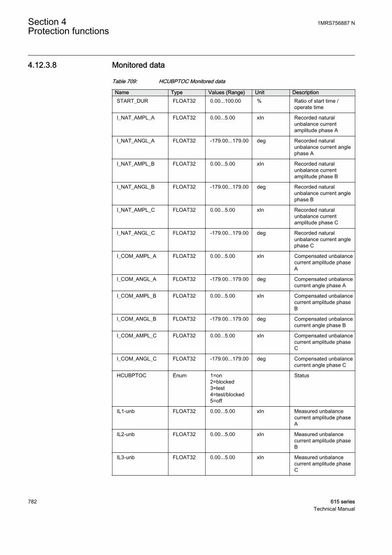
4.12.3.8 Monitored data
Table 709: HCUBPTOC Monitored data
Name Type Values (Range) Unit DescriptionSTART_DUR FLOAT32 0.00...100.00 % Ratio of start time /
operate time
I_NAT_AMPL_A FLOAT32 0.00...5.00 xIn Recorded naturalunbalance currentamplitude phase A
I_NAT_ANGL_A FLOAT32 -179.00...179.00 deg Recorded naturalunbalance current anglephase A
I_NAT_AMPL_B FLOAT32 0.00...5.00 xIn Recorded naturalunbalance currentamplitude phase B
I_NAT_ANGL_B FLOAT32 -179.00...179.00 deg Recorded naturalunbalance current anglephase B
I_NAT_AMPL_C FLOAT32 0.00...5.00 xIn Recorded naturalunbalance currentamplitude phase C
I_NAT_ANGL_C FLOAT32 -179.00...179.00 deg Recorded naturalunbalance current anglephase C
I_COM_AMPL_A FLOAT32 0.00...5.00 xIn Compensated unbalancecurrent amplitude phaseA
I_COM_ANGL_A FLOAT32 -179.00...179.00 deg Compensated unbalancecurrent angle phase A
I_COM_AMPL_B FLOAT32 0.00...5.00 xIn Compensated unbalancecurrent amplitude phaseB
I_COM_ANGL_B FLOAT32 -179.00...179.00 deg Compensated unbalancecurrent angle phase B
I_COM_AMPL_C FLOAT32 0.00...5.00 xIn Compensated unbalancecurrent amplitude phaseC
I_COM_ANGL_C FLOAT32 -179.00...179.00 deg Compensated unbalancecurrent angle phase C
HCUBPTOC Enum 1=on2=blocked3=test4=test/blocked5=off
Status
IL1-unb FLOAT32 0.00...5.00 xIn Measured unbalancecurrent amplitude phaseA
IL2-unb FLOAT32 0.00...5.00 xIn Measured unbalancecurrent amplitude phaseB
IL3-unb FLOAT32 0.00...5.00 xIn Measured unbalancecurrent amplitude phaseC
Section 4 1MRS756887 NProtection functions
782 615 seriesTechnical Manual
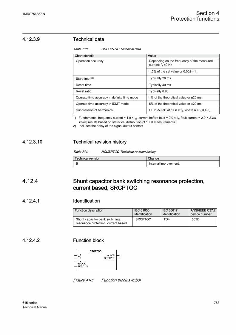
4.12.3.9 Technical data
Table 710: HCUBPTOC Technical data
Characteristic ValueOperation accuracy Depending on the frequency of the measured
current: fn ±2 Hz
1.5% of the set value or 0.002 × In
Start time1)2) Typically 26 ms
Reset time Typically 40 ms
Reset ratio Typically 0.96
Operate time accuracy in definite time mode 1% of the theoretical value or ±20 ms
Operate time accuracy in IDMT mode 5% of the theoretical value or ±20 ms
Suppression of harmonics DFT: -50 dB at f = n × fn, where n = 2,3,4,5,..
1) Fundamental frequency current = 1.0 × In, current before fault = 0.0 × In, fault current = 2.0 × Startvalue, results based on statistical distribution of 1000 measurements
2) Includes the delay of the signal output contact
4.12.3.10 Technical revision history
Table 711: HCUBPTOC Technical revision history
Technical revision ChangeB Internal improvement.
4.12.4 Shunt capacitor bank switching resonance protection,current based, SRCPTOC
4.12.4.1 Identification
Function description IEC 61850identification
IEC 60617identification
ANSI/IEEE C37.2device number
Shunt capacitor bank switchingresonance protection, current based
SRCPTOC TD> 55TD
4.12.4.2 Function block
GUID-170BD62B-0F80-4DC6-AB28-219DEDD10E5C V1 EN
Figure 410: Function block symbol
1MRS756887 N Section 4Protection functions
615 series 783Technical Manual

4.12.4.3 Functionality
The shunt capacitor bank switching resonance protection, current based, functionSRCPTOC is used for detecting three-phase resonance caused by capacitor switchingor topology changes in the network. The operating characteristic is a definite time(DT).
SRCPTOC contains a blocking functionality. It is possible to block function outputs,timers or the function itself, if desired.
4.12.4.4 Operation principle
The function can be enabled and disabled with the Operation setting. Thecorresponding parameter values are “On” and “Off”.
The operation of SRCPTOC can be described by using a module diagram. All themodules in the diagram are explained in the next sections.
GUID-9D427F91-9B97-4C4B-A2FA-A0772C149B38 V1 EN
Figure 411: Functional module diagram
Resonance current calculationThis module calculates the resonance current per phase set as per setting Tuningharmonic Num. The resonance current for phase A is calculated with the equation.
I RESO A I I I IRMS A A DC A K A
_ __ _ _ _
= − − −2
1
2 2 2
GUID-283368A5-9696-4E39-8E99-7973D45B7230 V1 EN (Equation 150)
IRMS_A RMS value of current in phase A (contains up to 11th harmonic)
IDC_A DC-component in phase A current
I_A Fundamental component in phase A current
IK_A Kth harmonic component in phase A current, K is defined by setting Tuning harmonicNum
I_RESO_A Calculated resonance current for phase A
Section 4 1MRS756887 NProtection functions
784 615 seriesTechnical Manual
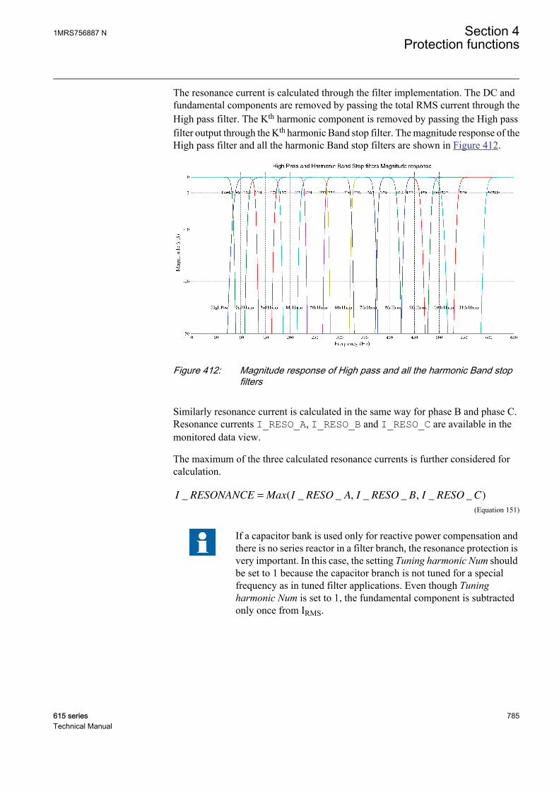
The resonance current is calculated through the filter implementation. The DC andfundamental components are removed by passing the total RMS current through theHigh pass filter. The Kth harmonic component is removed by passing the High passfilter output through the Kth harmonic Band stop filter. The magnitude response of theHigh pass filter and all the harmonic Band stop filters are shown in Figure 412.
GUID-8F2E7A59-BA62-4D8B-A97D-F00933BE291A V1 EN
Figure 412: Magnitude response of High pass and all the harmonic Band stopfilters
Similarly resonance current is calculated in the same way for phase B and phase C.Resonance currents I_RESO_A, I_RESO_B and I_RESO_C are available in themonitored data view.
The maximum of the three calculated resonance currents is further considered forcalculation.
I RESONANCE Max I RESO A I RESO B I RESO C_ ( _ _ _ _ _ _= , , )
GUID-DBF6D7C6-0BD4-4302-9A59-E57909928AB2 V1 EN (Equation 151)
If a capacitor bank is used only for reactive power compensation andthere is no series reactor in a filter branch, the resonance protection isvery important. In this case, the setting Tuning harmonic Num shouldbe set to 1 because the capacitor branch is not tuned for a specialfrequency as in tuned filter applications. Even though Tuningharmonic Num is set to 1, the fundamental component is subtractedonly once from IRMS.
1MRS756887 N Section 4Protection functions
615 series 785Technical Manual
Level detector 1The maximum calculated resonance current is compared to the set Alarm start value.If the calculated I_RESONANCE exceeds the set Alarm start value, the module sendsthe enabling signal to the Timer 1 module.
Level detector 2The maximum calculated resonance current is compared to the set Start value. If thecalculated I_RESONANCE exceeds the set Start value, this module sends the enablingsignal to the Timer 2 module.
Timer 1Once activated, the timer activates the alarm timer. The timer characteristic isaccording to DT. When the alarm timer has reached the value set by Alarm delaytime, the ALARM output is activated.
If the fault disappears before the alarm activates, the alarm timer is reset immediately.
Timer 2Once activated, the timer activates the operation timer. The timer characteristic isaccording to DT. When the operation timer has reached the value set by Operate delaytime, the OPERATE output is activated.
If the fault disappears before the operate activates, the operation timer is resetimmediately.
If the input RESO_IN becomes active, the OPERATE output is activated immediately.If the resonance protection at a higher-order filter branch has already operated, thefunction in lower-order filter branches can be tripped immediately using this feature.
Blocking logicThere are three operation modes in the blocking function. The operation modes arecontrolled by the BLOCK input and the global setting Configuration/System/Blocking mode which selects the blocking mode. The BLOCK input can be controlledby a binary input, a horizontal communication input or an internal signal of the IEDprogram. The influence of the BLOCK signal activation is preselected with the globalsetting Blocking mode.
The Blocking mode setting has three blocking methods. In the “Freeze timers” mode,the operation timer is frozen to the prevailing value. In the “Block all” mode, thewhole function is blocked and the timers are reset. In the “Block OPERATE output”mode, SRCPTOC operates normally but the OPERATE output is not activated.
4.12.4.5 Application
Switched shunt capacitor banks are widely used by utilities and customers inindustrial distribution systems to provide voltage support and to improve the powerfactor of a load. Capacitor steps may be switched in and out of circuits routinely as the
Section 4 1MRS756887 NProtection functions
786 615 seriesTechnical Manual
demand for capacitive VAR compensation of a load fluctuates. Normally, automaticpower factor controllers are employed which automatically switch on or off thecapacitors of the capacitor bank, depending upon the prevalent reactive powerrequirement in the system.
One potential problem for the application of automatic power factor controllers is thatit may cause harmonic resonance under certain system conditions. Capacitorswitching changes the parameters of the system, which may cause the resonancefrequency of the circuit to be equal to one of the frequencies of the harmonic sourcesprevalent in the system. Harmonic resonance, when it occurs, may result in severevoltage and current distortions, which increases losses and causes overheating of otherequipment in the circuit.
A traditional way of solving the problem is to conduct a detailed system study for eachindividual installation and use the results to properly size the capacitors and determinethe right operating range of capacitors to avoid harmonic resonance with other systemcomponents. However, this method is not economical but more time-consuming.
The capacitor switching-resonance protection function can be used as a solution to theabove mentioned problem. The basis for the harmonic resonance protection is thedetection of a current harmonic resonance condition caused by capacitor switching. Aprolonged increase of the harmonic distortion level after a switching operation is aclear indication of such condition. When a resonant condition caused by capacitorswitching occurs in a circuit, SRCPTOC detunes the circuit by taking the reverseaction, that is, switching the capacitor bank off if switching it on causes resonance. Ifthe resonance situation has been detected and SRCPTOC has switched off a capacitorbank, power factor controller should not try to switch on the capacitor bank until theswitching resonance function reset.
The capacitor switching-resonance protection function can also be used to protectharmonic filters. In harmonic filter bank applications, the SRCPTOC function can betuned to harmonic frequency for which the harmonic filter is designed to ensure thatthe function does not include thr tuned harmonic frequency current into thecalculation of the resonance current. If there is more than one harmonic filter bankinvolved, each SRCPTOC tunes to the harmonic frequency of its corresponding filterbank. The interlinking between the functions can be done in such a way that ifresonance occurs in a higher harmonic frequency filter bank, all the lower harmonicfrequency filter banks can be tripped immediately by activating the function inputRESO_IN.
The settings Alarm start value and Start value determine the portion of the totalharmonic current (excluding the harmonic defined by the setting Tuning harmonicNum) in relation to the CT nominal value required for SRCPTOC to give alarm andoperate respectively.
For power factor correction application
• Tuning harmonic Num must be set to 1.• Alarm start value and Start value must be set according to the standard IEEE519
-1992.
1MRS756887 N Section 4Protection functions
615 series 787Technical Manual
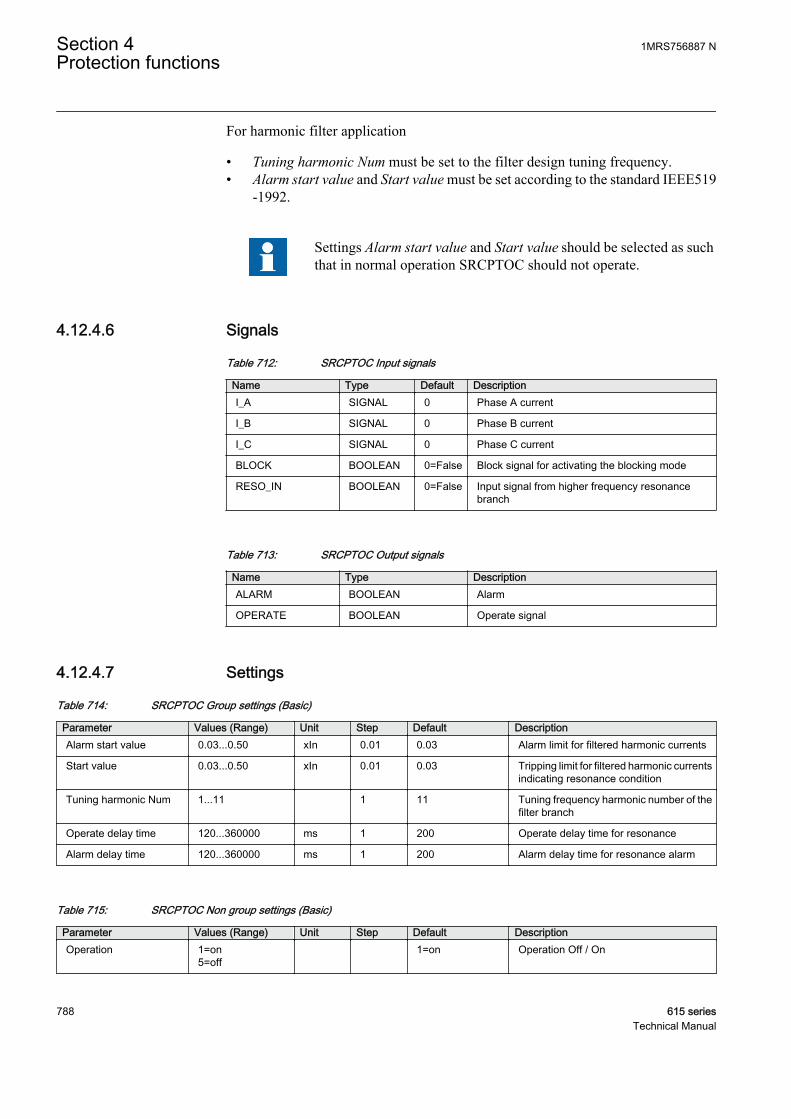
For harmonic filter application
• Tuning harmonic Num must be set to the filter design tuning frequency.• Alarm start value and Start value must be set according to the standard IEEE519
-1992.
Settings Alarm start value and Start value should be selected as suchthat in normal operation SRCPTOC should not operate.
4.12.4.6 Signals
Table 712: SRCPTOC Input signals
Name Type Default DescriptionI_A SIGNAL 0 Phase A current
I_B SIGNAL 0 Phase B current
I_C SIGNAL 0 Phase C current
BLOCK BOOLEAN 0=False Block signal for activating the blocking mode
RESO_IN BOOLEAN 0=False Input signal from higher frequency resonancebranch
Table 713: SRCPTOC Output signals
Name Type DescriptionALARM BOOLEAN Alarm
OPERATE BOOLEAN Operate signal
4.12.4.7 Settings
Table 714: SRCPTOC Group settings (Basic)
Parameter Values (Range) Unit Step Default DescriptionAlarm start value 0.03...0.50 xIn 0.01 0.03 Alarm limit for filtered harmonic currents
Start value 0.03...0.50 xIn 0.01 0.03 Tripping limit for filtered harmonic currentsindicating resonance condition
Tuning harmonic Num 1...11 1 11 Tuning frequency harmonic number of thefilter branch
Operate delay time 120...360000 ms 1 200 Operate delay time for resonance
Alarm delay time 120...360000 ms 1 200 Alarm delay time for resonance alarm
Table 715: SRCPTOC Non group settings (Basic)
Parameter Values (Range) Unit Step Default DescriptionOperation 1=on
5=off 1=on Operation Off / On
Section 4 1MRS756887 NProtection functions
788 615 seriesTechnical Manual
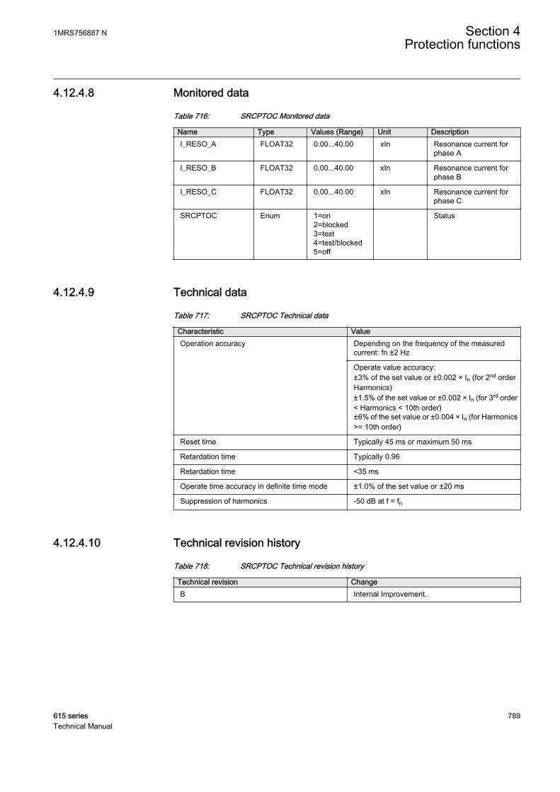
4.12.4.8 Monitored data
Table 716: SRCPTOC Monitored data
Name Type Values (Range) Unit DescriptionI_RESO_A FLOAT32 0.00...40.00 xIn Resonance current for
phase A
I_RESO_B FLOAT32 0.00...40.00 xIn Resonance current forphase B
I_RESO_C FLOAT32 0.00...40.00 xIn Resonance current forphase C
SRCPTOC Enum 1=on2=blocked3=test4=test/blocked5=off
Status
4.12.4.9 Technical data
Table 717: SRCPTOC Technical data
Characteristic ValueOperation accuracy Depending on the frequency of the measured
current: fn ±2 Hz
Operate value accuracy:±3% of the set value or ±0.002 × In (for 2nd orderHarmonics)±1.5% of the set value or ±0.002 × In (for 3rd order< Harmonics < 10th order)±6% of the set value or ±0.004 × In (for Harmonics>= 10th order)
Reset time Typically 45 ms or maximum 50 ms
Retardation time Typically 0.96
Retardation time <35 ms
Operate time accuracy in definite time mode ±1.0% of the set value or ±20 ms
Suppression of harmonics -50 dB at f = fn
4.12.4.10 Technical revision history
Table 718: SRCPTOC Technical revision history
Technical revision ChangeB Internal Improvement.
1MRS756887 N Section 4Protection functions
615 series 789Technical Manual

790

Section 5 Protection related functions
5.1 Three-phase inrush detector INRPHAR
5.1.1 IdentificationFunction description IEC 61850
identificationIEC 60617identification
ANSI/IEEE C37.2device number
Three-phase inrush detector INRPHAR 3I2f> 68
5.1.2 Function block
A070377 V1 EN
Figure 413: Function block
5.1.3 Functionality
The three-phase inrush detector function INRPHAR is used to coordinate transformerinrush situations in distribution networks.
Transformer inrush detection is based on the following principle: the output signalBLK2H is activated once the numerically derived ratio of second harmonic currentI_2H and the fundamental frequency current I_1H exceeds the set value.
The operate time characteristic for the function is of definite time (DT) type.
The function contains a blocking functionality. Blocking deactivates all outputs andresets timers.
5.1.4 Operation principle
The function can be enabled and disabled with the Operation setting. Thecorresponding parameter values are "On" and "Off".
1MRS756887 N Section 5Protection related functions
615 series 791Technical Manual
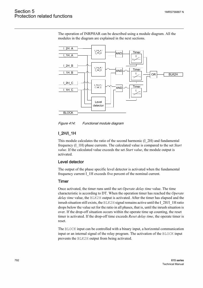
The operation of INRPHAR can be described using a module diagram. All themodules in the diagram are explained in the next sections.
A070694 V2 EN
Figure 414: Functional module diagram
I_2H/I_1HThis module calculates the ratio of the second harmonic (I_2H) and fundamentalfrequency (I_1H) phase currents. The calculated value is compared to the set Startvalue. If the calculated value exceeds the set Start value, the module output isactivated.
Level detectorThe output of the phase specific level detector is activated when the fundamentalfrequency current I_1H exceeds five percent of the nominal current.
TimerOnce activated, the timer runs until the set Operate delay time value. The timecharacteristic is according to DT. When the operation timer has reached the Operatedelay time value, the BLK2H output is activated. After the timer has elapsed and theinrush situation still exists, the BLK2H signal remains active until the I_2H/I_1H ratiodrops below the value set for the ratio in all phases, that is, until the inrush situation isover. If the drop-off situation occurs within the operate time up counting, the resettimer is activated. If the drop-off time exceeds Reset delay time, the operate timer isreset.
The BLOCK input can be controlled with a binary input, a horizontal communicationinput or an internal signal of the relay program. The activation of the BLOCK inputprevents the BLK2H output from being activated.
Section 5 1MRS756887 NProtection related functions
792 615 seriesTechnical Manual
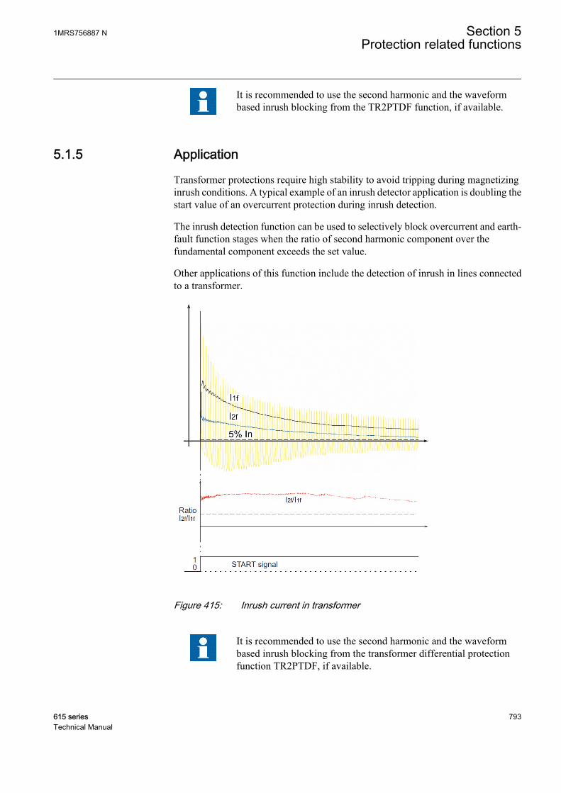
It is recommended to use the second harmonic and the waveformbased inrush blocking from the TR2PTDF function, if available.
5.1.5 Application
Transformer protections require high stability to avoid tripping during magnetizinginrush conditions. A typical example of an inrush detector application is doubling thestart value of an overcurrent protection during inrush detection.
The inrush detection function can be used to selectively block overcurrent and earth-fault function stages when the ratio of second harmonic component over thefundamental component exceeds the set value.
Other applications of this function include the detection of inrush in lines connectedto a transformer.
A070695 V4 EN
Figure 415: Inrush current in transformer
It is recommended to use the second harmonic and the waveformbased inrush blocking from the transformer differential protectionfunction TR2PTDF, if available.
1MRS756887 N Section 5Protection related functions
615 series 793Technical Manual
5.1.6 SignalsTable 719: INRPHAR Input signals
Name Type Default DescriptionI_2H_A SIGNAL 0 Second harmonic phase A current
I_1H_A SIGNAL 0 Fundamental frequency phase A current
I_2H_B SIGNAL 0 Second harmonic phase B current
I_1H_B SIGNAL 0 Fundamental frequency phase B current
I_2H_C SIGNAL 0 Second harmonic phase C current
I_1H_C SIGNAL 0 Fundamental frequency phase C current
BLOCK BOOLEAN 0=False Block input status
Table 720: INRPHAR Output signals
Name Type DescriptionBLK2H BOOLEAN Second harmonic based block
5.1.7 SettingsTable 721: INRPHAR Group settings (Basic)
Parameter Values (Range) Unit Step Default DescriptionStart value 5...100 % 1 20 Ratio of the 2. to the 1. harmonic leading
to restraint
Operate delay time 20...60000 ms 1 20 Operate delay time
Table 722: INRPHAR Non group settings (Basic)
Parameter Values (Range) Unit Step Default DescriptionOperation 1=on
5=off 1=on Operation Off / On
Table 723: INRPHAR Non group settings (Advanced)
Parameter Values (Range) Unit Step Default DescriptionReset delay time 0...60000 ms 1 20 Reset delay time
5.1.8 Monitored dataTable 724: INRPHAR Monitored data
Name Type Values (Range) Unit DescriptionINRPHAR Enum 1=on
2=blocked3=test4=test/blocked5=off
Status
Section 5 1MRS756887 NProtection related functions
794 615 seriesTechnical Manual

5.1.9 Technical dataTable 725: INRPHAR Technical data
Characteristic ValueOperation accuracy At the frequency f = fn
Current measurement:±1.5% of the set value or ±0.002 × InRatio I2f/I1f measurement:±5.0% of the set value
Reset time +35 ms / -0 ms
Reset ratio Typically 0.96
Operate time accuracy +35 ms / -0 ms
5.1.10 Technical revision historyTable 726: INRPHAR Technical revision history
Technical revision ChangeB Internal improvement
C Internal improvement
5.2 Circuit breaker failure protection CCBRBRF
5.2.1 IdentificationFunction description IEC 61850
identificationIEC 60617identification
ANSI/IEEE C37.2device number
Circuit breaker failure protection CCBRBRF 3I>/Io>BF 51BF/51NBF
5.2.2 Function block
A070436 V4 EN
Figure 416: Function block
1MRS756887 N Section 5Protection related functions
615 series 795Technical Manual
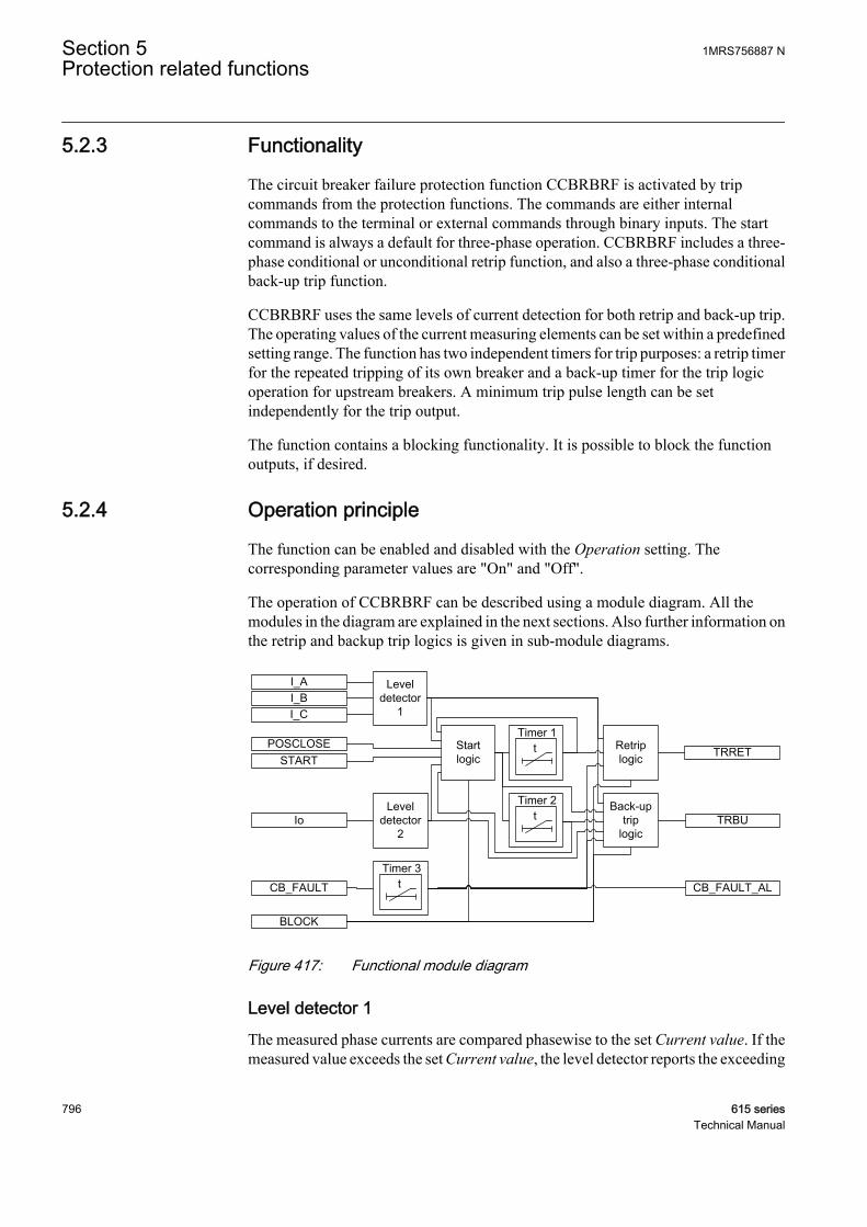
5.2.3 Functionality
The circuit breaker failure protection function CCBRBRF is activated by tripcommands from the protection functions. The commands are either internalcommands to the terminal or external commands through binary inputs. The startcommand is always a default for three-phase operation. CCBRBRF includes a three-phase conditional or unconditional retrip function, and also a three-phase conditionalback-up trip function.
CCBRBRF uses the same levels of current detection for both retrip and back-up trip.The operating values of the current measuring elements can be set within a predefinedsetting range. The function has two independent timers for trip purposes: a retrip timerfor the repeated tripping of its own breaker and a back-up timer for the trip logicoperation for upstream breakers. A minimum trip pulse length can be setindependently for the trip output.
The function contains a blocking functionality. It is possible to block the functionoutputs, if desired.
5.2.4 Operation principle
The function can be enabled and disabled with the Operation setting. Thecorresponding parameter values are "On" and "Off".
The operation of CCBRBRF can be described using a module diagram. All themodules in the diagram are explained in the next sections. Also further information onthe retrip and backup trip logics is given in sub-module diagrams.
TRRET
BLOCK
CB_FAULT
TRBUBack-up
triplogic
POSCLOSESTART
Io
Retriplogic
Leveldetector
2
Leveldetector
1
I_AI_BI_C
tTimer 2
tTimer 3
CB_FAULT_AL
Start logic
tTimer 1
A070445 V3 EN
Figure 417: Functional module diagram
Level detector 1The measured phase currents are compared phasewise to the set Current value. If themeasured value exceeds the set Current value, the level detector reports the exceeding
Section 5 1MRS756887 NProtection related functions
796 615 seriesTechnical Manual
of the value to the start, retrip and backup trip logics. The parameter should be set lowenough so that breaker failure situations with small fault current or high load currentcan be detected. The setting can be chosen in accordance with the most sensitiveprotection function to start the breaker failure protection.
Level detector 2The measured residual current is compared to the set Current value Res. If themeasured value exceeds the set Current value Res, the level detector reports theexceeding of the value to the start and backup trip logics. In high-impedance earthedsystems, the residual current at phase-to-earth faults is normally much smaller than theshort circuit currents. To detect a breaker failure at single-phase earth faults in thesesystems, it is necessary to measure the residual current separately. In effectivelyearthed systems, also the setting of the earth-fault current protection can be chosen ata relatively low current level. The current setting should be chosen in accordance withthe setting of the sensitive earth-fault protection.
Start logicThe start logic is used to manage the starting of the timer 1 and timer 2. It also resetsthe function after the circuit breaker failure is handled. On the rising edge of theSTART input, the enabling signal is send to the timer 1 and timer 2.
Function resetting is prevented during the next 150 ms. The 150 ms time elapse isprovided to prevent malfunctioning due to oscillation in the starting signal.
In case the setting Start latching mode is set to "Level sensitive", the CCBRBRF isreset immediately after the START signal is deactivated. The recommended settingvalue is "Rising edge".
The resetting of the function depends on the CB failure mode setting.
• If CB failure mode is set to "Current", the resetting logic further depends on theCB failure trip mode setting.• If CB failure trip mode is set to "1 out of 3", the resetting logic requires that
the values of all the phase currents drop below the Current value setting.• If CB failure trip mode is set to "1 out of 4", the resetting logic requires that
the values of the phase currents and the residual current drops below theCurrent value and Current value Res setting respectively.
• If CB failure trip mode is set to "2 out of 4", the resetting logic requires thatthe values of all the phase currents and the residual current drop below theCurrent value and Current value Res setting.
• If CB failure mode is set to the "Breaker status" mode, the resetting logic requiresthat the circuit breaker is in the open condition.
• If the CB failure mode setting is set to "Both", the resetting logic requires that thecircuit breaker is in the open condition and the values of the phase currents and theresidual current drops below the Current value and Current value Res settingrespectively.
The activation of the BLOCK input resets the function.
1MRS756887 N Section 5Protection related functions
615 series 797Technical Manual
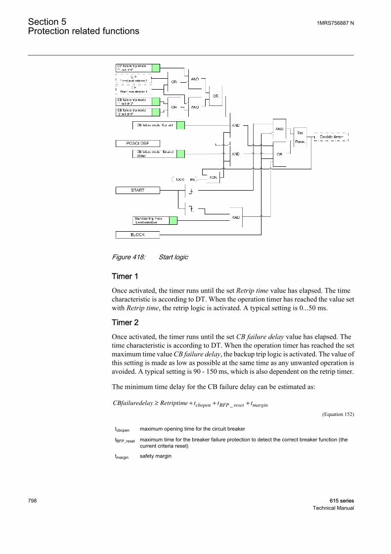
GUID-61D73737-798D-4BA3-9CF2-56D57719B03D V4 EN
Figure 418: Start logic
Timer 1Once activated, the timer runs until the set Retrip time value has elapsed. The timecharacteristic is according to DT. When the operation timer has reached the value setwith Retrip time, the retrip logic is activated. A typical setting is 0...50 ms.
Timer 2Once activated, the timer runs until the set CB failure delay value has elapsed. Thetime characteristic is according to DT. When the operation timer has reached the setmaximum time value CB failure delay, the backup trip logic is activated. The value ofthis setting is made as low as possible at the same time as any unwanted operation isavoided. A typical setting is 90 - 150 ms, which is also dependent on the retrip timer.
The minimum time delay for the CB failure delay can be estimated as:
CBfailuredelay Retriptime t t tcbopen BFP reset margin≥ + + +_
A070693 V3 EN (Equation 152)
tcbopen maximum opening time for the circuit breaker
tBFP_reset maximum time for the breaker failure protection to detect the correct breaker function (thecurrent criteria reset)
tmargin safety margin
Section 5 1MRS756887 NProtection related functions
798 615 seriesTechnical Manual

It is often required that the total fault clearance time is less than the given critical time.This time often depends on the ability to maintain transient stability in case of a faultclose to a power plant.
GUID-1A2C47ED-0DCF-4225-9294-2AEC97C14D5E V1 EN
Figure 419: Timeline of the breaker failure protection
Timer 3This module is activated by the CB_FAULT signal. Once activated, the timer runsuntil the set CB fault delay value has elapsed. The time characteristic is according toDT. When the operation timer has reached the maximum time value CB fault delay,the CB_FAULT_AL output is activated. After the set time, an alarm is given so that thecircuit breaker can be repaired. A typical value is 5 s.
Retrip logicThe retrip logic provides the TRRET output, which can be used to give a retrip signalfor the main circuit breaker. Timer 1 activates the retrip logic. The operation of theretrip logic depends on the CB fail retrip mode setting.
• The retrip logic is inactive if the CB fail retrip mode setting is set to "Off".• If CB fail retrip mode is set to the "Current check" mode, the activation of the
retrip output TRRET depends on the CB failure mode setting.
• If CB failure mode is set to the "Current" mode, TRRET is activated whenthe value of any phase current exceeds the Current value setting. TheTRRET output remains active for the time set with the Trip pulse timesetting or until all phase current values drop below the Current valuesetting, whichever is longer.
• If CB failure mode is set to the "Breaker status" mode, TRRET is activatedif the circuit breaker is in the closed position. The TRRET output remains
1MRS756887 N Section 5Protection related functions
615 series 799Technical Manual
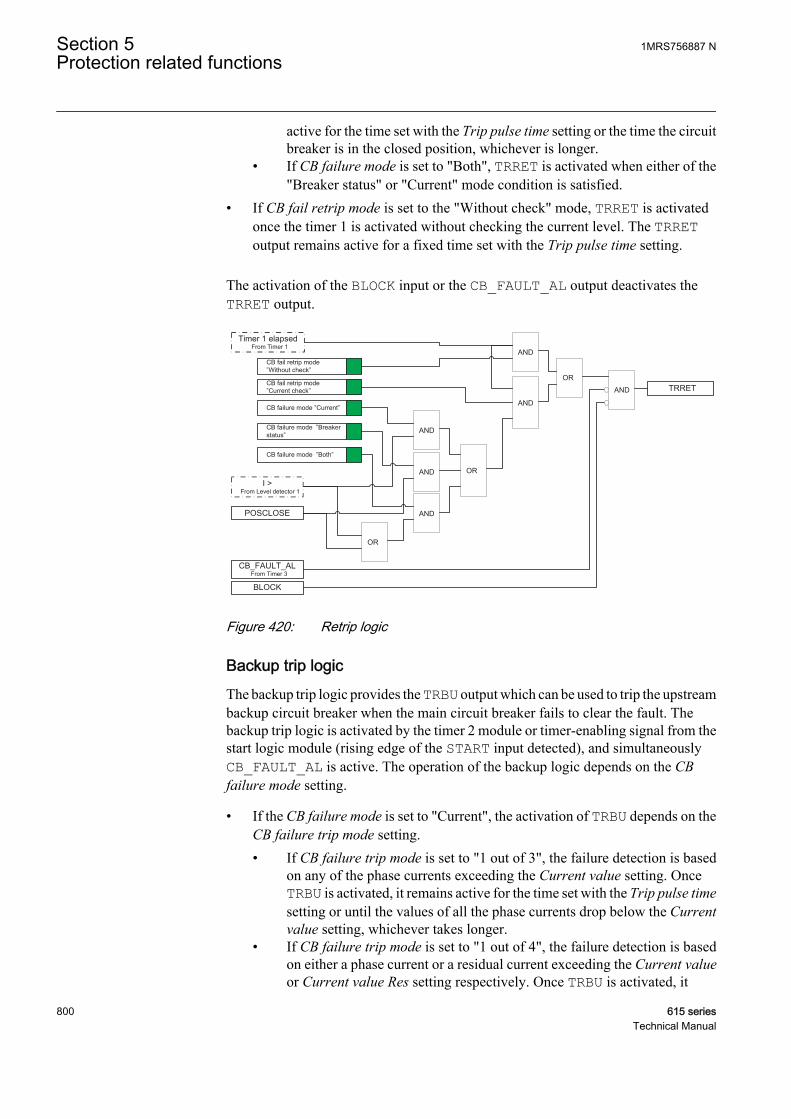
active for the time set with the Trip pulse time setting or the time the circuitbreaker is in the closed position, whichever is longer.
• If CB failure mode is set to "Both", TRRET is activated when either of the"Breaker status" or "Current" mode condition is satisfied.
• If CB fail retrip mode is set to the "Without check" mode, TRRET is activatedonce the timer 1 is activated without checking the current level. The TRREToutput remains active for a fixed time set with the Trip pulse time setting.
The activation of the BLOCK input or the CB_FAULT_AL output deactivates theTRRET output.
POSCLOSE
I >From Level detector 1
Timer 1 elapsedFrom Timer 1
OR
AND
AND
CB fail retrip mode ”Without check”
CB fail retrip mode ”Current check”
CB failure mode ”Current”
CB failure mode ”Breaker status”
CB failure mode ”Both”
AND
AND
AND
OR
OR
AND TRRET
BLOCK
CB_FAULT_ALFrom Timer 3
GUID-BD64DEDB-758C-4F53-8287-336E43C750F2 V2 EN
Figure 420: Retrip logic
Backup trip logicThe backup trip logic provides the TRBU output which can be used to trip the upstreambackup circuit breaker when the main circuit breaker fails to clear the fault. Thebackup trip logic is activated by the timer 2 module or timer-enabling signal from thestart logic module (rising edge of the START input detected), and simultaneouslyCB_FAULT_AL is active. The operation of the backup logic depends on the CBfailure mode setting.
• If the CB failure mode is set to "Current", the activation of TRBU depends on theCB failure trip mode setting.• If CB failure trip mode is set to "1 out of 3", the failure detection is based
on any of the phase currents exceeding the Current value setting. OnceTRBU is activated, it remains active for the time set with the Trip pulse timesetting or until the values of all the phase currents drop below the Currentvalue setting, whichever takes longer.
• If CB failure trip mode is set to "1 out of 4", the failure detection is basedon either a phase current or a residual current exceeding the Current valueor Current value Res setting respectively. Once TRBU is activated, it
Section 5 1MRS756887 NProtection related functions
800 615 seriesTechnical Manual
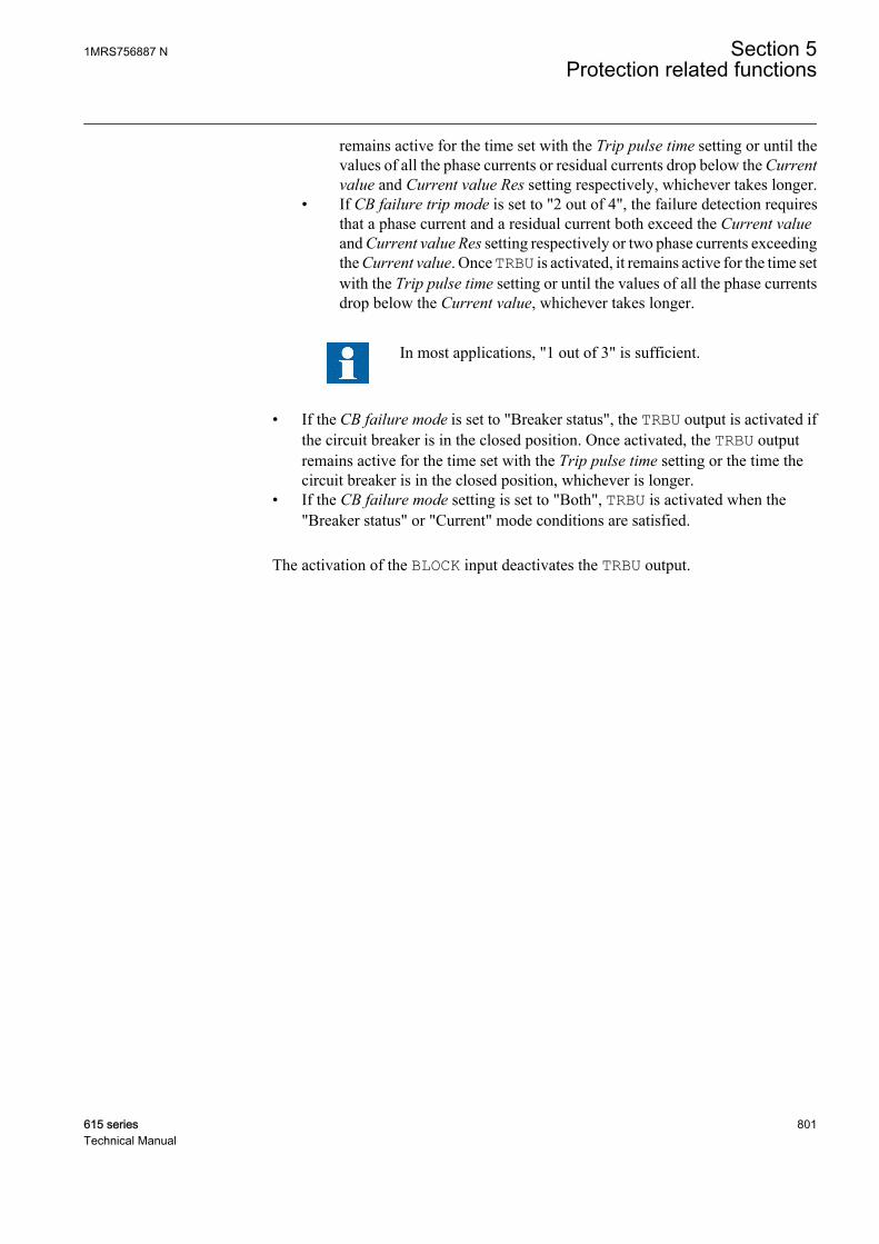
remains active for the time set with the Trip pulse time setting or until thevalues of all the phase currents or residual currents drop below the Currentvalue and Current value Res setting respectively, whichever takes longer.
• If CB failure trip mode is set to "2 out of 4", the failure detection requiresthat a phase current and a residual current both exceed the Current valueand Current value Res setting respectively or two phase currents exceedingthe Current value. Once TRBU is activated, it remains active for the time setwith the Trip pulse time setting or until the values of all the phase currentsdrop below the Current value, whichever takes longer.
In most applications, "1 out of 3" is sufficient.
• If the CB failure mode is set to "Breaker status", the TRBU output is activated ifthe circuit breaker is in the closed position. Once activated, the TRBU outputremains active for the time set with the Trip pulse time setting or the time thecircuit breaker is in the closed position, whichever is longer.
• If the CB failure mode setting is set to "Both", TRBU is activated when the"Breaker status" or "Current" mode conditions are satisfied.
The activation of the BLOCK input deactivates the TRBU output.
1MRS756887 N Section 5Protection related functions
615 series 801Technical Manual
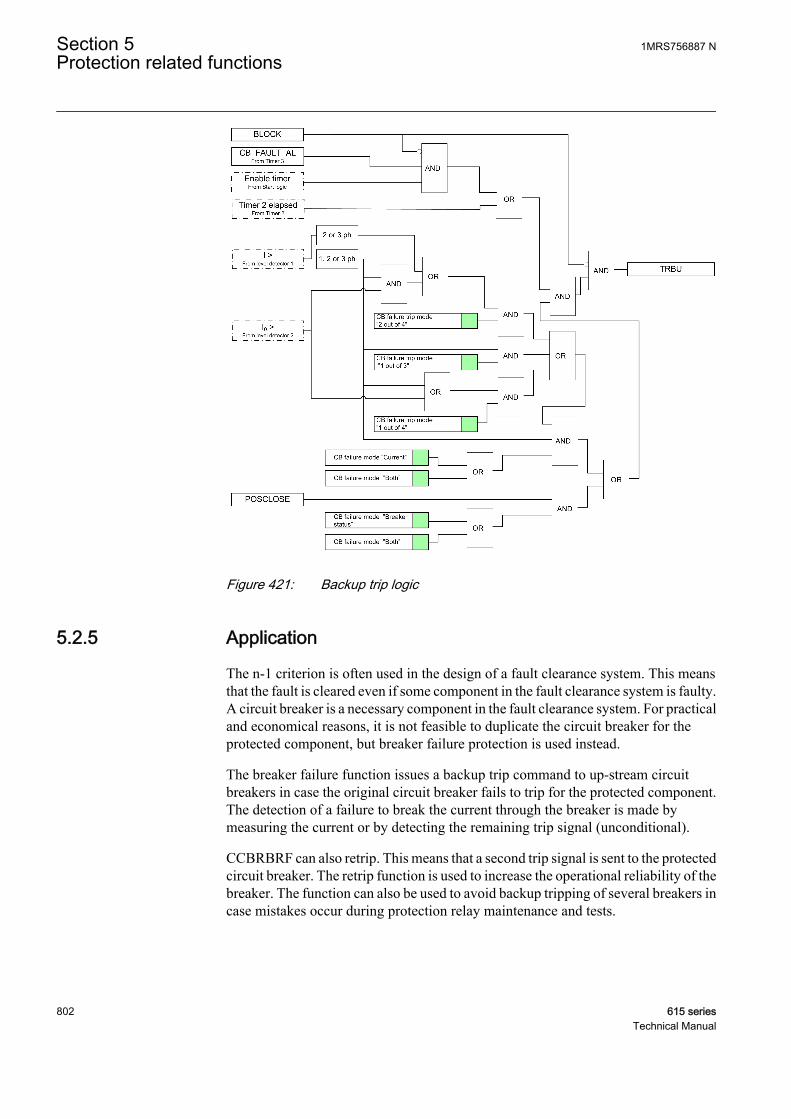
GUID-30BB8C04-689A-4FA5-85C4-1DF5E3ECE179 V4 EN
Figure 421: Backup trip logic
5.2.5 Application
The n-1 criterion is often used in the design of a fault clearance system. This meansthat the fault is cleared even if some component in the fault clearance system is faulty.A circuit breaker is a necessary component in the fault clearance system. For practicaland economical reasons, it is not feasible to duplicate the circuit breaker for theprotected component, but breaker failure protection is used instead.
The breaker failure function issues a backup trip command to up-stream circuitbreakers in case the original circuit breaker fails to trip for the protected component.The detection of a failure to break the current through the breaker is made bymeasuring the current or by detecting the remaining trip signal (unconditional).
CCBRBRF can also retrip. This means that a second trip signal is sent to the protectedcircuit breaker. The retrip function is used to increase the operational reliability of thebreaker. The function can also be used to avoid backup tripping of several breakers incase mistakes occur during protection relay maintenance and tests.
Section 5 1MRS756887 NProtection related functions
802 615 seriesTechnical Manual
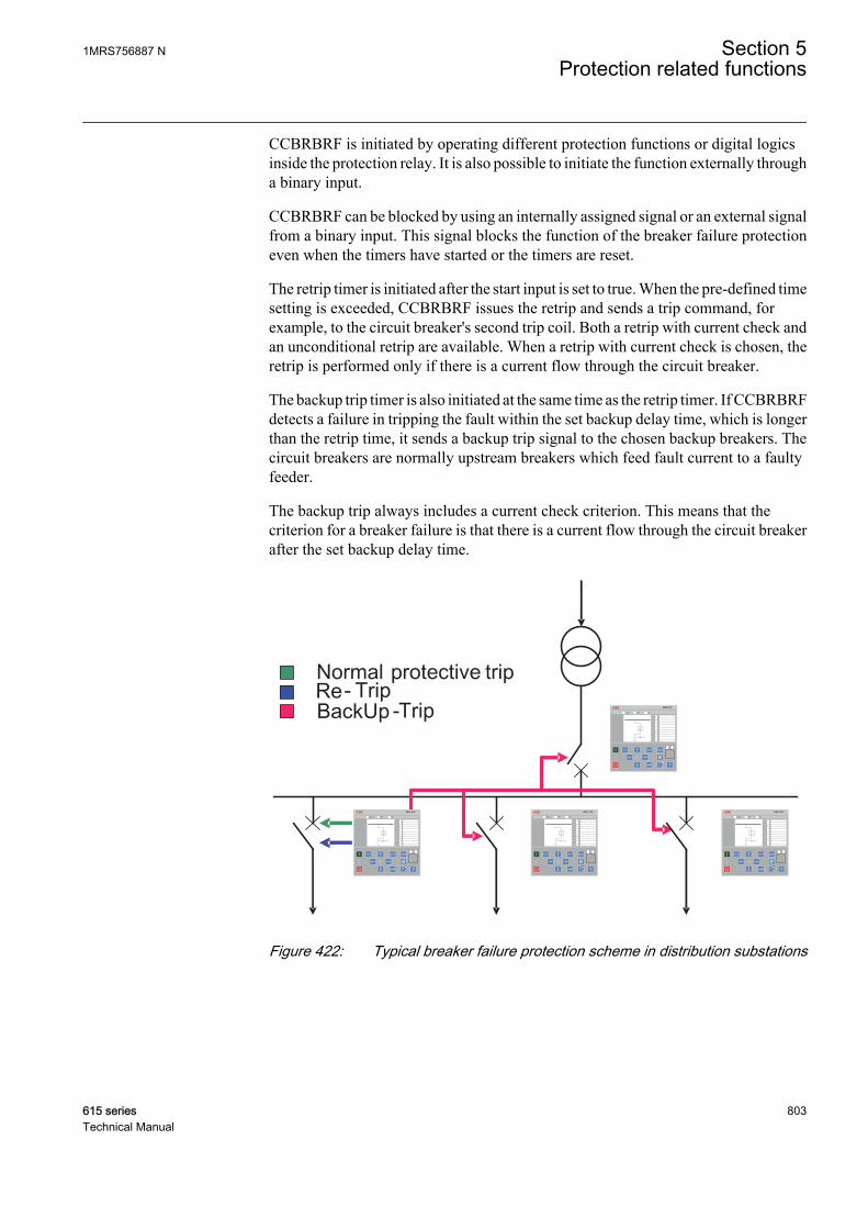
CCBRBRF is initiated by operating different protection functions or digital logicsinside the protection relay. It is also possible to initiate the function externally througha binary input.
CCBRBRF can be blocked by using an internally assigned signal or an external signalfrom a binary input. This signal blocks the function of the breaker failure protectioneven when the timers have started or the timers are reset.
The retrip timer is initiated after the start input is set to true. When the pre-defined timesetting is exceeded, CCBRBRF issues the retrip and sends a trip command, forexample, to the circuit breaker's second trip coil. Both a retrip with current check andan unconditional retrip are available. When a retrip with current check is chosen, theretrip is performed only if there is a current flow through the circuit breaker.
The backup trip timer is also initiated at the same time as the retrip timer. If CCBRBRFdetects a failure in tripping the fault within the set backup delay time, which is longerthan the retrip time, it sends a backup trip signal to the chosen backup breakers. Thecircuit breakers are normally upstream breakers which feed fault current to a faultyfeeder.
The backup trip always includes a current check criterion. This means that thecriterion for a breaker failure is that there is a current flow through the circuit breakerafter the set backup delay time.
REF 615
REF 615
REF 615 REF 615
A070696 V3 EN
Figure 422: Typical breaker failure protection scheme in distribution substations
1MRS756887 N Section 5Protection related functions
615 series 803Technical Manual
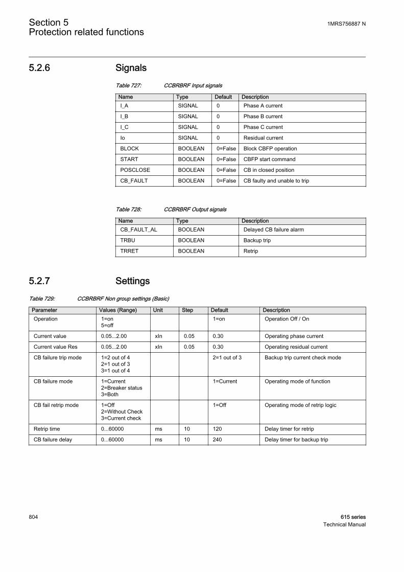
5.2.6 SignalsTable 727: CCBRBRF Input signals
Name Type Default DescriptionI_A SIGNAL 0 Phase A current
I_B SIGNAL 0 Phase B current
I_C SIGNAL 0 Phase C current
Io SIGNAL 0 Residual current
BLOCK BOOLEAN 0=False Block CBFP operation
START BOOLEAN 0=False CBFP start command
POSCLOSE BOOLEAN 0=False CB in closed position
CB_FAULT BOOLEAN 0=False CB faulty and unable to trip
Table 728: CCBRBRF Output signals
Name Type DescriptionCB_FAULT_AL BOOLEAN Delayed CB failure alarm
TRBU BOOLEAN Backup trip
TRRET BOOLEAN Retrip
5.2.7 SettingsTable 729: CCBRBRF Non group settings (Basic)
Parameter Values (Range) Unit Step Default DescriptionOperation 1=on
5=off 1=on Operation Off / On
Current value 0.05...2.00 xIn 0.05 0.30 Operating phase current
Current value Res 0.05...2.00 xIn 0.05 0.30 Operating residual current
CB failure trip mode 1=2 out of 42=1 out of 33=1 out of 4
2=1 out of 3 Backup trip current check mode
CB failure mode 1=Current2=Breaker status3=Both
1=Current Operating mode of function
CB fail retrip mode 1=Off2=Without Check3=Current check
1=Off Operating mode of retrip logic
Retrip time 0...60000 ms 10 120 Delay timer for retrip
CB failure delay 0...60000 ms 10 240 Delay timer for backup trip
Section 5 1MRS756887 NProtection related functions
804 615 seriesTechnical Manual

Table 730: CCBRBRF Non group settings (Advanced)
Parameter Values (Range) Unit Step Default DescriptionCB fault delay 0...60000 ms 10 5000 Circuit breaker faulty delay
Measurement mode 2=DFT3=Peak-to-Peak
3=Peak-to-Peak Phase current measurement mode offunction
Trip pulse time 0...60000 ms 10 200 Pulse length of retrip and backup tripoutputs
Start latching mode 1=Rising edge2=Level sensitive
1=Rising edge Start reset delayed or immediately
5.2.8 Monitored dataTable 731: CCBRBRF Monitored data
Name Type Values (Range) Unit DescriptionCCBRBRF Enum 1=on
2=blocked3=test4=test/blocked5=off
Status
5.2.9 Technical dataTable 732: CCBRBRF Technical data
Characteristic ValueOperation accuracy Depending on the frequency of the measured
current: fn ±2 Hz
±1.5% of the set value or ±0.002 × In
Operate time accuracy ±1.0% of the set value or ±20 ms
Reset time Typically 40 ms
Retardation time <20 ms
5.2.10 Technical revision historyTable 733: CCBRBRF Technical revision history
Technical revision ChangeB Default trip pulse time changed to 150 ms
C Added new setting parameter Start latching mode.Maximum value changed to 2.00 xIn for theCurrent value setting.
D Internal improvement.
E Maximum value for Current value and Currentvalue Res changed from “1.00 x In” to “2.00 x In”.
1MRS756887 N Section 5Protection related functions
615 series 805Technical Manual
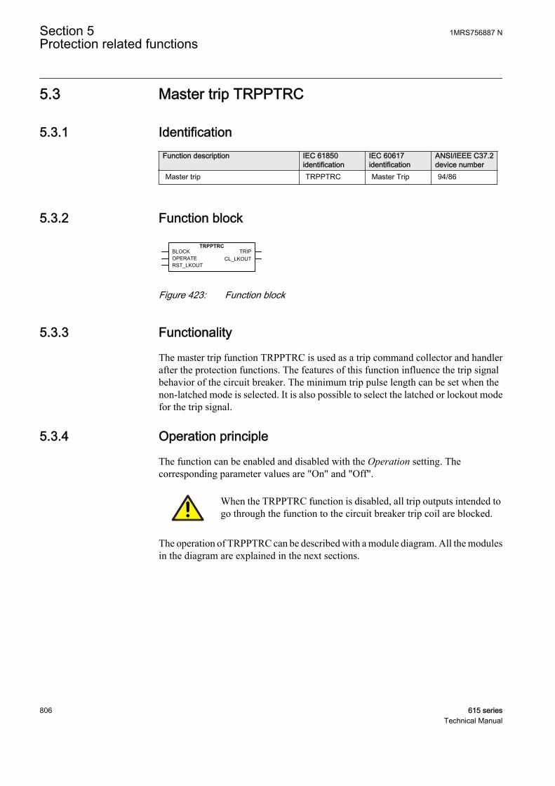
5.3 Master trip TRPPTRC
5.3.1 IdentificationFunction description IEC 61850
identificationIEC 60617identification
ANSI/IEEE C37.2device number
Master trip TRPPTRC Master Trip 94/86
5.3.2 Function block
A071286 V2 EN
Figure 423: Function block
5.3.3 Functionality
The master trip function TRPPTRC is used as a trip command collector and handlerafter the protection functions. The features of this function influence the trip signalbehavior of the circuit breaker. The minimum trip pulse length can be set when thenon-latched mode is selected. It is also possible to select the latched or lockout modefor the trip signal.
5.3.4 Operation principle
The function can be enabled and disabled with the Operation setting. Thecorresponding parameter values are "On" and "Off".
When the TRPPTRC function is disabled, all trip outputs intended togo through the function to the circuit breaker trip coil are blocked.
The operation of TRPPTRC can be described with a module diagram. All the modulesin the diagram are explained in the next sections.
Section 5 1MRS756887 NProtection related functions
806 615 seriesTechnical Manual

A070882 V4 EN
Figure 424: Functional module diagram
TimerThe duration of the TRIP output signal from TRPPTRC can be adjusted with the Trippulse time setting when the "Non-latched" operation mode is used. The pulse lengthshould be long enough to secure the opening of the breaker. For three-pole tripping,TRPPTRC has a single input OPERATE, through which all trip output signals arerouted from the protection functions within the protection relay, or from externalprotection functions via one or more of the protection relay's binary inputs. Thefunction has a single trip output TRIP for connecting the function to one or more ofthe protection relay's binary outputs, and also to other functions within the protectionrelay requiring this signal.
The BLOCK input blocks the TRIP output and resets the timer.
Lockout logicTRPPTRC is provided with possibilities to activate a lockout. When activated, thelockout can be manually reset after checking the primary fault by activating theRST_LKOUT input or from the LHMI clear menu parameter. When using the"Latched" mode, the resetting of the TRIP output can be done similarly as when usingthe "Lockout" mode. It is also possible to reset the "Latched" mode remotely througha separate communication parameter.
The minimum pulse trip function is not active when using the"Lockout" or "Latched" modes but only when the "Non-latched"mode is selected.
The CL_LKOUT and TRIP outputs can be blocked with the BLOCK input.
Table 734: Operation modes for the TRPPTRC trip output
Mode OperationNon-latched The Trip pulse length parameter gives the
minimum pulse length for TRIPLatched TRIP is latched ; both local and remote clearing is
possible.
Lockout TRIP is locked and can be cleared only locally viamenu or the RST_LKOUT input.
1MRS756887 N Section 5Protection related functions
615 series 807Technical Manual
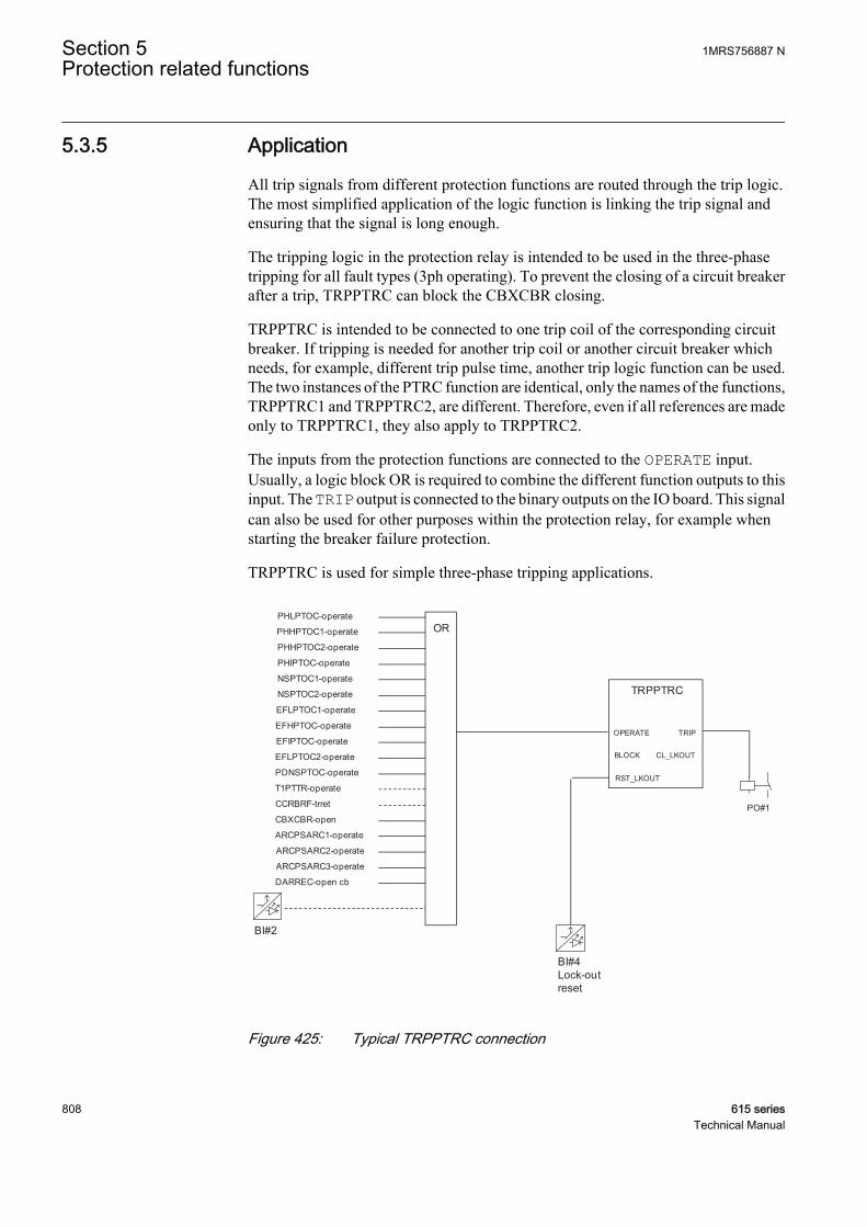
5.3.5 Application
All trip signals from different protection functions are routed through the trip logic.The most simplified application of the logic function is linking the trip signal andensuring that the signal is long enough.
The tripping logic in the protection relay is intended to be used in the three-phasetripping for all fault types (3ph operating). To prevent the closing of a circuit breakerafter a trip, TRPPTRC can block the CBXCBR closing.
TRPPTRC is intended to be connected to one trip coil of the corresponding circuitbreaker. If tripping is needed for another trip coil or another circuit breaker whichneeds, for example, different trip pulse time, another trip logic function can be used.The two instances of the PTRC function are identical, only the names of the functions,TRPPTRC1 and TRPPTRC2, are different. Therefore, even if all references are madeonly to TRPPTRC1, they also apply to TRPPTRC2.
The inputs from the protection functions are connected to the OPERATE input.Usually, a logic block OR is required to combine the different function outputs to thisinput. The TRIP output is connected to the binary outputs on the IO board. This signalcan also be used for other purposes within the protection relay, for example whenstarting the breaker failure protection.
TRPPTRC is used for simple three-phase tripping applications.
BI#4Lock-outreset
OR
PO#1
BI#2
TRPPTRC
OPERATE
RST_LKOUT
TRIP
CCRBRF-trret
T1PTTR-operate
CBXCBR-open
PHLPTOC-operate
PHHPTOC1-operate
PHHPTOC2-operate
PHIPTOC-operate
NSPTOC1-operate
NSPTOC2-operate
EFLPTOC1-operate
EFHPTOC-operate
EFIPTOC-operate
PDNSPTOC-operate
EFLPTOC2-operate
ARCPSARC1-operate
ARCPSARC2-operate
ARCPSARC3-operate
DARREC-open cb
BLOCK CL_LKOUT
A070881 V2 EN
Figure 425: Typical TRPPTRC connection
Section 5 1MRS756887 NProtection related functions
808 615 seriesTechnical Manual

5.3.6 SignalsTable 735: TRPPTRC Input signals
Name Type Default DescriptionBLOCK BOOLEAN 0=False Block of function
OPERATE BOOLEAN 0=False Operate
RST_LKOUT BOOLEAN 0=False Input for resetting the circuit breaker lockoutfunction
Table 736: TRPPTRC Output signals
Name Type DescriptionTRIP BOOLEAN General trip output signal
CL_LKOUT BOOLEAN Circuit breaker lockout output (set until reset)
5.3.7 SettingsTable 737: TRPPTRC Non group settings (Basic)
Parameter Values (Range) Unit Step Default DescriptionOperation 1=on
5=off 1=on Operation Off / On
Trip pulse time 20...60000 ms 1 250 Minimum duration of trip output signal
Trip output mode 1=Non-latched2=Latched3=Lockout
1=Non-latched Select the operation mode for trip output
5.3.8 Monitored dataTable 738: TRPPTRC Monitored data
Name Type Values (Range) Unit DescriptionTRPPTRC Enum 1=on
2=blocked3=test4=test/blocked5=off
Status
1MRS756887 N Section 5Protection related functions
615 series 809Technical Manual
5.3.9 Technical revision historyTable 739: TRPPTRC Technical revision history
Technical revision ChangeB -
C -
D Internal improvement.
E Setting Trip output mode default setting ischanged to "Latched".
F Internal improvement.
5.4 High-impedance fault detection PHIZ
5.4.1 IdentificationFunction description IEC 61850
identificationIEC 60617identification
ANSI/IEEE C37.2device number
High-impedance fault detection PHIZ HIF HIZ
5.4.2 Function block
GUID-30E489A2-8D06-4940-95F8-E346313791A5 V1 EN
Figure 426: Function block
5.4.3 Functionality
A small percentage of earth faults have a very large impedance. They are comparableto load impedance and consequently have very little fault current. These high-impedance faults do not pose imminent danger to power system equipment. However,they are a substantial threat to humans and properties; people can touch or get close toconductors carrying large amounts of energy.
ABB has developed a patented technology (US Patent 7,069,116 B2 June 27, 2006,US Patent 7,085,659 B2 August 1, 2006) to detect a high-impedance fault.
The high-impedance fault detection function PHIZ also contains a blockingfunctionality. It is possible to block function outputs, if desired.
Section 5 1MRS756887 NProtection related functions
810 615 seriesTechnical Manual
PHIZ is limited to be used in 60 Hz electrical networks with efficientlygrounded or isolated neutral.
5.4.4 Operation principle
The function can be enabled and disabled with the Operation setting. Thecorresponding parameter values are "On" and "Off".
PHIZ uses a multi-algorithm approach. Each algorithm uses various features of earthcurrents to detect a high-impedance fault.
Although the PHIZ algorithm is very sophisticated, the setting required to operate thefunction is simple. The Security Level setting, with the setting range of 1 to 10, is setto strike a balance between the extremes of security and dependability which togetherconstitute the reliability of any system. The setting value “10” is more secure than “1”.
The higher the Security Level setting, the lower the probability of false detection, butthe system might miss out some genuine fault. On the other hand, a lower settingwould make the system operate more dependably for high-impedance faults in theline, but the operation is more likely for other transients in the system. There are eventsin electrical networks which can cause similar current waveforms like high-impedance faults. These events could then be detected by the PHIZ algorithm causingunnecessary detections. Normally, electrical network operator does not know theexistence of these events well and those can also be happening very randomly. Theeffect is also always dependent on event location compared to protection relaymeasurement location. All these facts make the PHIZ algorithm operation in certainelectrical networks quite hard to measure and forecast beforehand. There is not anydirect formula which can calculate the exact right setting based on known electricalnetwork parameters.
It is hence recommended to set the value midway to “5” initially. Based on experienceand confidence gained in a particular application, the setting can be moved either side.In many cases, it would be a good practice to use PHIZ as an indicative function duringa piloting phase, until enough experience has been gathered and a suitable settingfound.
1MRS756887 N Section 5Protection related functions
615 series 811Technical Manual

Transformer Feeder
Bus
Ct Breaker
GUID-1911BE79-9816-42E3-87FF-A16F7A130A8E V1 EN
Figure 427: Electrical power system equipped with PHIZ
Power system signals are acquired, filtered and then processed by individual high-impedance fault detection algorithm. The results of these individual algorithms arefurther processed by a decision logic to provide the detection decision. The decisionlogic can be modified depending on the application requirement.
GUID-8A2A7CA8-E82C-4327-8961-D89B095A3FE6 V1 EN
Figure 428: Block diagram of PHIZ
PHIZ is based on algorithms that use earth current signatures which are considerednon-stationary, temporally volatile and of various burst duration. All harmonic andnon-harmonic components within the available data window can play a vital role inthe high-impedance fault detection. A major challenge is to develop a data model thatacknowledges that high-impedance faults could take place at any time within theobservation window of the signal and could be delayed randomly and attenuatedsubstantially. The model is motivated by extensive research, actual experimentalobservations in the laboratory, field testing and what traditionally represents anaccurate depiction of a non-stationary signal with a time-dependent spectrum.
Section 5 1MRS756887 NProtection related functions
812 615 seriesTechnical Manual

GUID-61D297F5-783F-4CF2-BD16-18CE537C9E95-ANSI V1 EN
Figure 429: Validation of PHIZ ongravel
GUID-B9AC5923-6A67-431B-A785-171FD132E1A6-ANSI V1 EN
Figure 430: Validation of PHIZ onconcrete
GUID-988539D2-9893-4B16-8CF6-C32E17991628-ANSI V1 EN
Figure 431: Validation of PHIZ onsand
GUID-9F87C93B-BF44-4488-BD97-209FC90B592A-ANSI V1 EN
Figure 432: Validation of PHIZ ongrass
5.4.5 Application
PHIZ is used to detect a downed conductor dropping to a very resistive ground,causing an earth fault which is very difficult to detect by a conventional protectionrelay functionality. PHIZ is then targeted to be used with overhead lines. PHIZ islimited to be used in 60 Hz electrical networks with efficiently grounded or isolatedneutral.
Electric power lines experience faults for many reasons. In most cases, electricalfaults manifest in mechanical damage, which must be repaired before returning theline to service.
Most of the electrical network faults are earth faults. Conventional protection systemsbased on overcurrent, impedance or other principles are suitable for detectingrelatively low-impedance faults which have a relatively large fault current.
However, a small percentage of the earth faults have a very large impedance. They arecomparable to load impedance and consequently have very little fault current. These
1MRS756887 N Section 5Protection related functions
615 series 813Technical Manual
high-impedance faults do not pose imminent danger to power system equipment.However, they are a considerable threat to people and property. The IEEE PowerSystem Relay Committee working group on High Impedance Fault DetectionTechnology defines High Impedance Faults as those that 'do not produce enough faultcurrent to be detectable by conventional overcurrent relays or fuses.
PHIZ always needs sensitive Io measurement.
High-impedance fault (PHIZ) detection requires a different approach than that forconventional low-impedance faults. Reliable detection of PHIZ provides safety tohumans and animals. PHIZ detection can also prevent fire and minimize propertydamage. ABB has developed innovative technology for high-impedance faultdetection with over ten years of research resulting in many successful field tests.
5.4.6 SignalsTable 740: PHIZ Input signals
Name Type Default DescriptionIo SIGNAL 0 Earth current measured using SEF CT
BLOCK BOOLEAN 0=False Block signal for activating the blocking mode
CB_CLOSED BOOLEAN 0=False Circuit Breaker Closed input
CB_OPEN BOOLEAN 0=False Circuit Breaker Open input
Table 741: PHIZ Output signals
Name Type DescriptionOPERATE BOOLEAN Operate
5.4.7 SettingsTable 742: PHIZ Group settings (Basic)
Parameter Values (Range) Unit Step Default DescriptionSecurity Level 1...10 1 5 Security Level
Table 743: PHIZ Non group settings (Basic)
Parameter Values (Range) Unit Step Default DescriptionOperation 1=on
5=off 1=on Operation Off / On
System type 1=Grounded2=Ungrounded
1=Grounded System Type
Section 5 1MRS756887 NProtection related functions
814 615 seriesTechnical Manual

5.4.8 Monitored dataTable 744: PHIZ Monitored data
Name Type Values (Range) Unit DescriptionPosition Dbpos 0=intermediate
1=open2=closed3=faulty
Position
PHIZ Enum 1=on2=blocked3=test4=test/blocked5=off
Status
5.4.9 Technical revision historyTable 745: PHIZ Technical revision history
Technical revision ChangeB Internal improvement
C Added inputs for Circuit Breaker Closed andCircuit Breaker Open
5.5 Binary signal transfer BSTGGIO
5.5.1 IdentificationFunction description IEC 61850
identificationIEC 60617identification
ANSI/IEEE C37.2device number
Binary signal transfer BSTGGIO BST BST
5.5.2 Function block
GUID-6D70959C-EC59-4C72-85E5-9BE89ED39DBB V1 EN
Figure 433: Function block
1MRS756887 N Section 5Protection related functions
615 series 815Technical Manual
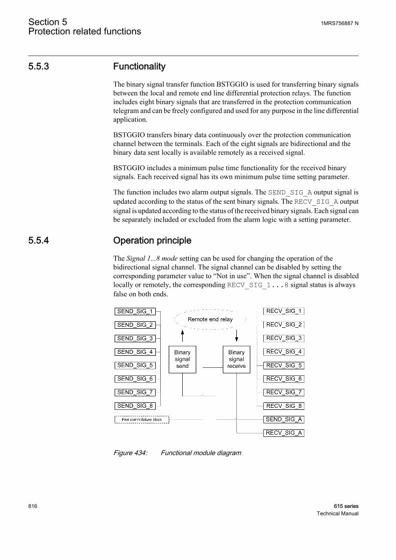
5.5.3 Functionality
The binary signal transfer function BSTGGIO is used for transferring binary signalsbetween the local and remote end line differential protection relays. The functionincludes eight binary signals that are transferred in the protection communicationtelegram and can be freely configured and used for any purpose in the line differentialapplication.
BSTGGIO transfers binary data continuously over the protection communicationchannel between the terminals. Each of the eight signals are bidirectional and thebinary data sent locally is available remotely as a received signal.
BSTGGIO includes a minimum pulse time functionality for the received binarysignals. Each received signal has its own minimum pulse time setting parameter.
The function includes two alarm output signals. The SEND_SIG_A output signal isupdated according to the status of the sent binary signals. The RECV_SIG_A outputsignal is updated according to the status of the received binary signals. Each signal canbe separately included or excluded from the alarm logic with a setting parameter.
5.5.4 Operation principle
The Signal 1...8 mode setting can be used for changing the operation of thebidirectional signal channel. The signal channel can be disabled by setting thecorresponding parameter value to “Not in use”. When the signal channel is disabledlocally or remotely, the corresponding RECV_SIG_1...8 signal status is alwaysfalse on both ends.
GUID-54526C83-99FA-478B-877A-394234289F91 V1 EN
Figure 434: Functional module diagram
Section 5 1MRS756887 NProtection related functions
816 615 seriesTechnical Manual

Binary signal sendThe status of the inputs is continuously sent in the line differential protectiontelegrams. SEND_SIG_A can be used for alarming based on the status ofSEND_SIG_1...8. By selecting the signal mode as "In use, alarm sel.", the sendingstatus of the corresponding signal affects also the activation criteria ofSEND_SIG_A. Further, in case more than one signal channels are selected into thealarm logic, the activation criteria can be defined according to "Any of selected" (OR)or "All of selected" (AND).
Binary signal receiveThe function receives continuous binary data within the protection telegrams from theremote end protection relay. This received binary data status is then available as theRECV_SIG_1...8 outputs on the local end protection relay. RECV_SIG_A can beused for alarming based on the status of RECV_SIG_1...8. By selecting the signalmode as "In use, alarm sel.", the received status of the corresponding signal affects theactivation criteria of RECV_SIG_A. Further, in case more than one signal channelsare selected into the alarm logic, the activation criteria can be defined according to"Any of selected" (OR) or "All of selected" (AND). Each signal has also the Pulse time1...8 setting that defines the minimum pulse length for RECV_SIG_1...8. Also, incase the protection communication supervision detects a failure in thecommunication, the RECV_SIG_1...8 outputs are not set to false sooner than theminimum pulse length defined is first ensured for each signal.
5.5.5 Application
Among with the analog data, the binary data can also be exchanged with the linedifferential protection relays. The usage of the binary data is application specific andcan vary in each separate case. The demands for the speed of the binary signals varydepending on the usage of the data. When the binary data is used as blocking signalsfor the line differential protection, the transfer response is extremely high. Binarysignal interchange can be used in applications such as:
• Remote position indications• Inter-tripping of the circuit breakers on both line ends• Blocking of the line differential protection during transformer inrush or current
circuit supervision failure• Protection schemes; blocking or permissive• Remote alarming.
The figure shows the overall chain to transfer binary data in an example application.The position indication of the local circuit breaker is connected to the protectionrelay’s input interface and is then available for the protection relay configuration. Thecircuit breaker position indication is connected to the first input of BSTGGIO whichis used to send information to the remote end via communication. In the remote end,this information is handled as a remote circuit breaker open position and it is availablefrom the first output of BSTGGIO. This way the information can be exchanged.
1MRS756887 N Section 5Protection related functions
615 series 817Technical Manual
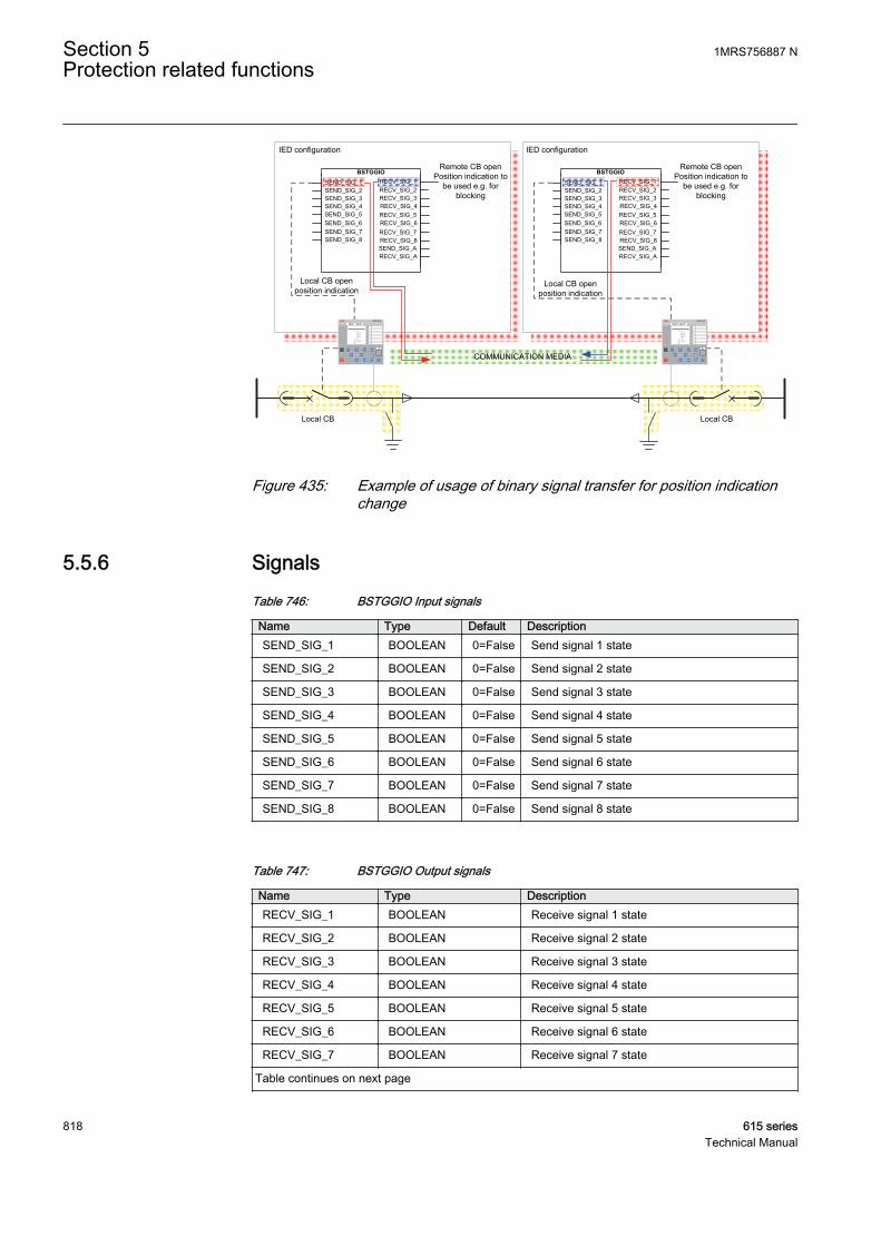
BSTGGIO
SEND_SIG_3
SEND_SIG_7SEND_SIG_8
RECV_SIG_1RECV_SIG_2RECV_SIG_3
SEND_SIG_2SEND_SIG_1
RECV_SIG_4
SEND_SIG_6SEND_SIG_5SEND_SIG_4
RECV_SIG_5RECV_SIG_6RECV_SIG_7RECV_SIG_8SEND_SIG_ARECV_SIG_A
BSTGGIO
SEND_SIG_3
SEND_SIG_7SEND_SIG_8
RECV_SIG_1RECV_SIG_2RECV_SIG_3
SEND_SIG_2SEND_SIG_1
RECV_SIG_4
SEND_SIG_6SEND_SIG_5SEND_SIG_4
RECV_SIG_5RECV_SIG_6RECV_SIG_7RECV_SIG_8SEND_SIG_ARECV_SIG_A
Remote CB openPosition indication to
be used e.g. for blocking
IED configuration IED configuration
COMMUNICATION MEDIA
Local CB Local CB
Local CB open position indication
Local CB open position indication
Remote CB openPosition indication to
be used e.g. for blocking
RED 615 RED 615
GUID-85FE5892-DDA5-4ED9-9412-A3A48E364EFC V2 EN
Figure 435: Example of usage of binary signal transfer for position indicationchange
5.5.6 SignalsTable 746: BSTGGIO Input signals
Name Type Default DescriptionSEND_SIG_1 BOOLEAN 0=False Send signal 1 state
SEND_SIG_2 BOOLEAN 0=False Send signal 2 state
SEND_SIG_3 BOOLEAN 0=False Send signal 3 state
SEND_SIG_4 BOOLEAN 0=False Send signal 4 state
SEND_SIG_5 BOOLEAN 0=False Send signal 5 state
SEND_SIG_6 BOOLEAN 0=False Send signal 6 state
SEND_SIG_7 BOOLEAN 0=False Send signal 7 state
SEND_SIG_8 BOOLEAN 0=False Send signal 8 state
Table 747: BSTGGIO Output signals
Name Type DescriptionRECV_SIG_1 BOOLEAN Receive signal 1 state
RECV_SIG_2 BOOLEAN Receive signal 2 state
RECV_SIG_3 BOOLEAN Receive signal 3 state
RECV_SIG_4 BOOLEAN Receive signal 4 state
RECV_SIG_5 BOOLEAN Receive signal 5 state
RECV_SIG_6 BOOLEAN Receive signal 6 state
RECV_SIG_7 BOOLEAN Receive signal 7 state
Table continues on next page
Section 5 1MRS756887 NProtection related functions
818 615 seriesTechnical Manual

Name Type DescriptionRECV_SIG_8 BOOLEAN Receive signal 8 state
SEND_SIG_A BOOLEAN Binary signal transfer sending alarm state
RECV_SIG_A BOOLEAN Binary signal transfer receive alarm state
5.5.7 SettingsTable 748: BSTGGIO Group settings (Basic)
Parameter Values (Range) Unit Step Default DescriptionSignal 1 mode 1=In use
2=In use, alarm sel.3=Not in use
2=In use, alarmsel.
Operation mode for signal 1
Signal 2 mode 1=In use2=In use, alarm sel.3=Not in use
2=In use, alarmsel.
Operation mode for signal 2
Signal 3 mode 1=In use2=In use, alarm sel.3=Not in use
1=In use Operation mode for signal 3
Signal 4 mode 1=In use2=In use, alarm sel.3=Not in use
1=In use Operation mode for signal 4
Signal 5 mode 1=In use2=In use, alarm sel.3=Not in use
1=In use Operation mode for signal 5
Signal 6 mode 1=In use2=In use, alarm sel.3=Not in use
1=In use Operation mode for signal 6
Signal 7 mode 1=In use2=In use, alarm sel.3=Not in use
1=In use Operation mode for signal 7
Signal 8 mode 1=In use2=In use, alarm sel.3=Not in use
1=In use Operation mode for signal 8
Pulse time 1 0...60000 ms 1 0 Minimum pulse time for received signal 1
Pulse time 2 0...60000 ms 1 0 Minimum pulse time for received signal 2
Pulse time 3 0...60000 ms 1 0 Minimum pulse time for received signal 3
Pulse time 4 0...60000 ms 1 0 Minimum pulse time for received signal 4
Pulse time 5 0...60000 ms 1 0 Minimum pulse time for received signal 6
Pulse time 6 0...60000 ms 1 0 Minimum pulse time for received signal 6
Pulse time 7 0...60000 ms 1 0 Minimum pulse time for received signal 7
Pulse time 8 0...60000 ms 1 0 Minimum pulse time for received signal 8
Table 749: BSTGGIO Non group settings (Basic)
Parameter Values (Range) Unit Step Default DescriptionAlarm mode 1=Any of selected
2=All of selected 1=Any of selected Selects the used alarm logic mode for
activating SEND_SIG_A andRECV_SIG_A
1MRS756887 N Section 5Protection related functions
615 series 819Technical Manual
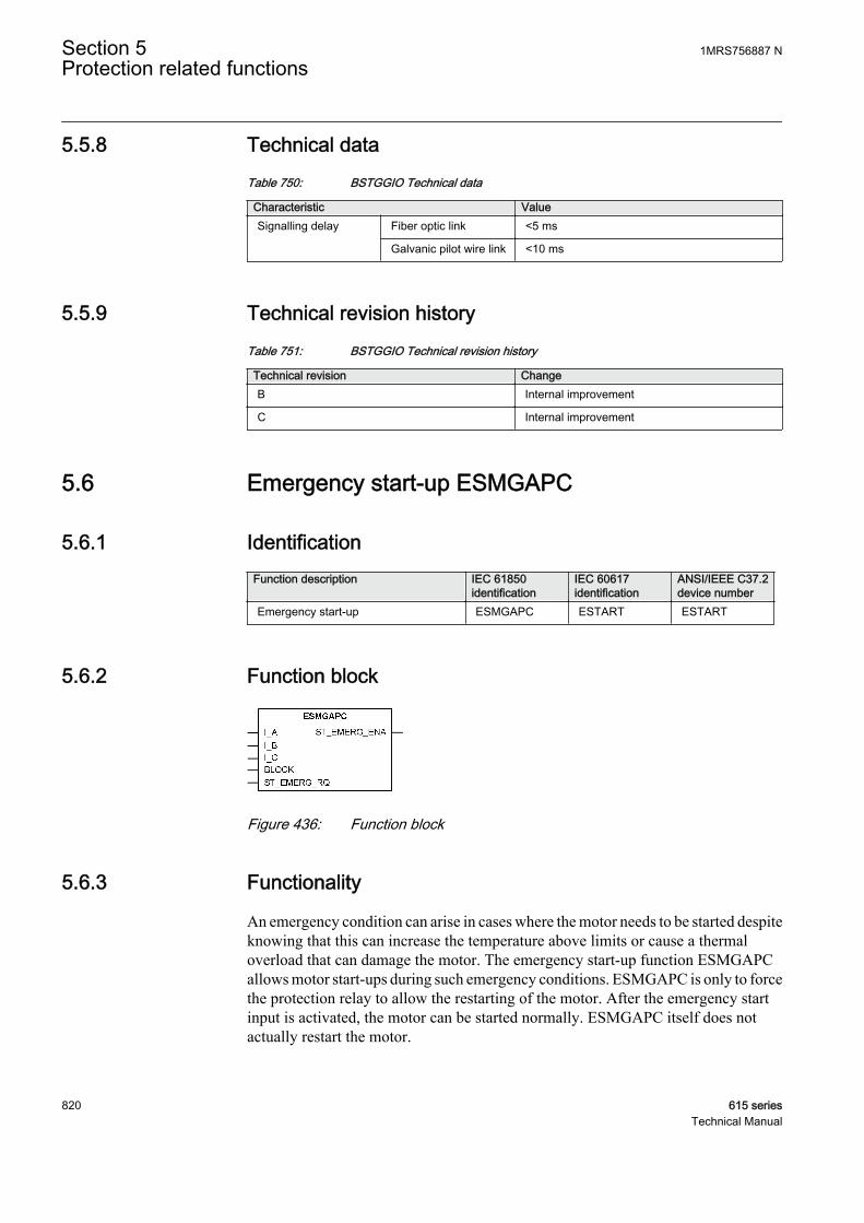
5.5.8 Technical dataTable 750: BSTGGIO Technical data
Characteristic ValueSignalling delay Fiber optic link <5 ms
Galvanic pilot wire link <10 ms
5.5.9 Technical revision historyTable 751: BSTGGIO Technical revision history
Technical revision ChangeB Internal improvement
C Internal improvement
5.6 Emergency start-up ESMGAPC
5.6.1 IdentificationFunction description IEC 61850
identificationIEC 60617identification
ANSI/IEEE C37.2device number
Emergency start-up ESMGAPC ESTART ESTART
5.6.2 Function block
GUID-3AF99427-2061-47E1-B3AB-FD1C9BF98E76 V1 EN
Figure 436: Function block
5.6.3 Functionality
An emergency condition can arise in cases where the motor needs to be started despiteknowing that this can increase the temperature above limits or cause a thermaloverload that can damage the motor. The emergency start-up function ESMGAPCallows motor start-ups during such emergency conditions. ESMGAPC is only to forcethe protection relay to allow the restarting of the motor. After the emergency startinput is activated, the motor can be started normally. ESMGAPC itself does notactually restart the motor.
Section 5 1MRS756887 NProtection related functions
820 615 seriesTechnical Manual
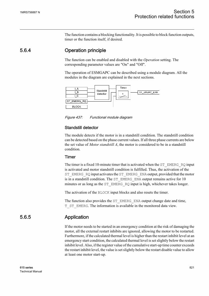
The function contains a blocking functionality. It is possible to block function outputs,timer or the function itself, if desired.
5.6.4 Operation principle
The function can be enabled and disabled with the Operation setting. Thecorresponding parameter values are "On" and "Off".
The operation of ESMGAPC can be described using a module diagram. All themodules in the diagram are explained in the next sections.
GUID-18128621-4A78-45D0-A788-9116B5213449 V1 EN
Figure 437: Functional module diagram
Standstill detectorThe module detects if the motor is in a standstill condition. The standstill conditioncan be detected based on the phase current values. If all three phase currents are belowthe set value of Motor standstill A, the motor is considered to be in a standstillcondition.
TimerThe timer is a fixed 10-minute timer that is activated when the ST_EMERG_RQ inputis activated and motor standstill condition is fulfilled. Thus, the activation of theST_EMERG_RQ input activates the ST_EMERG_ENA output, provided that the motoris in a standstill condition. The ST_EMERG_ENA output remains active for 10minutes or as long as the ST_EMERG_RQ input is high, whichever takes longer.
The activation of the BLOCK input blocks and also resets the timer.
The function also provides the ST_EMERG_ENA output change date and time,T_ST_EMERG. The information is available in the monitored data view.
5.6.5 Application
If the motor needs to be started in an emergency condition at the risk of damaging themotor, all the external restart inhibits are ignored, allowing the motor to be restarted.Furthermore, if the calculated thermal level is higher than the restart inhibit level at anemergency start condition, the calculated thermal level is set slightly below the restartinhibit level. Also, if the register value of the cumulative start-up time counter exceedsthe restart inhibit level, the value is set slightly below the restart disable value to allowat least one motor start-up.
1MRS756887 N Section 5Protection related functions
615 series 821Technical Manual
The activation of the ST_EMERG_RQ digital input allows to perform emergency start.The protection relay is forced to a state which allows the restart of motor, and theoperator can now restart the motor. A new emergency start cannot be made until the10 minute time-out has passed or until the emergency start is released, whichevertakes longer.
The last change of the emergency start output signal is recorded.
5.6.6 SignalsTable 752: ESMGAPC Input signals
Name Type Default DescriptionI_A SIGNAL 0 Phase A current
I_B SIGNAL 0 Phase B current
I_C SIGNAL 0 Phase C current
BLOCK BOOLEAN 0=False Block signal for activating the blocking mode
ST_EMERG_RQ BOOLEAN 0=False Emergency start input
Table 753: ESMGAPC Output signals
Name Type DescriptionST_EMERG_ENA BOOLEAN Emergency start
5.6.7 SettingsTable 754: ESMGAPC Group settings (Advanced)
Parameter Values (Range) Unit Step Default DescriptionMotor standstill A 0.05...0.20 xIn 0.01 0.12 Current limit to check for motor standstill
condition
Table 755: ESMGAPC Non group settings (Basic)
Parameter Values (Range) Unit Step Default DescriptionOperation 1=on
5=off 1=on Operation Off / On
Section 5 1MRS756887 NProtection related functions
822 615 seriesTechnical Manual

5.6.8 Monitored dataTable 756: ESMGAPC Monitored data
Name Type Values (Range) Unit DescriptionT_ST_EMERG Timestamp Emergency start
activation timestamp
ESMGAPC Enum 1=on2=blocked3=test4=test/blocked5=off
Status
5.6.9 Technical dataTable 757: ESMGAPC Technical data
Characteristic ValueOperation accuracy At the frequency f = fn
±1.5% of the set value or ±0.002 × Un
5.6.10 Technical revision historyTable 758: ESMGAPC Technical revision history
Technical revision ChangeB Internal improvement
C Internal improvement
5.7 Fault locator SCEFRFLO
5.7.1 IdentificationFunction description IEC 61850
identificationIEC 60617identification
ANSI/IEEE C37.2device number
Fault locator SCEFRFLO FLOC 21FL
1MRS756887 N Section 5Protection related functions
615 series 823Technical Manual
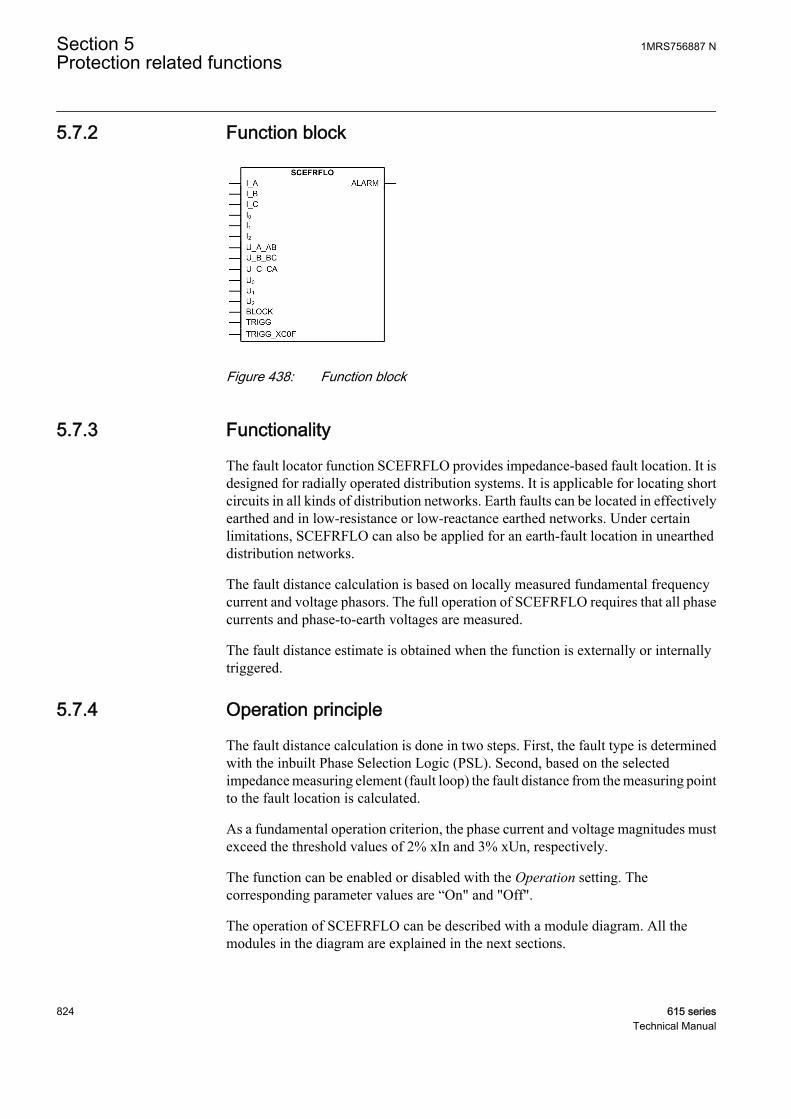
5.7.2 Function block
GUID-AB1F9A6B-6092-4224-8FCB-F1C5552FF823 V1 EN
Figure 438: Function block
5.7.3 Functionality
The fault locator function SCEFRFLO provides impedance-based fault location. It isdesigned for radially operated distribution systems. It is applicable for locating shortcircuits in all kinds of distribution networks. Earth faults can be located in effectivelyearthed and in low-resistance or low-reactance earthed networks. Under certainlimitations, SCEFRFLO can also be applied for an earth-fault location in uneartheddistribution networks.
The fault distance calculation is based on locally measured fundamental frequencycurrent and voltage phasors. The full operation of SCEFRFLO requires that all phasecurrents and phase-to-earth voltages are measured.
The fault distance estimate is obtained when the function is externally or internallytriggered.
5.7.4 Operation principle
The fault distance calculation is done in two steps. First, the fault type is determinedwith the inbuilt Phase Selection Logic (PSL). Second, based on the selectedimpedance measuring element (fault loop) the fault distance from the measuring pointto the fault location is calculated.
As a fundamental operation criterion, the phase current and voltage magnitudes mustexceed the threshold values of 2% xIn and 3% xUn, respectively.
The function can be enabled or disabled with the Operation setting. Thecorresponding parameter values are “On" and "Off".
The operation of SCEFRFLO can be described with a module diagram. All themodules in the diagram are explained in the next sections.
Section 5 1MRS756887 NProtection related functions
824 615 seriesTechnical Manual
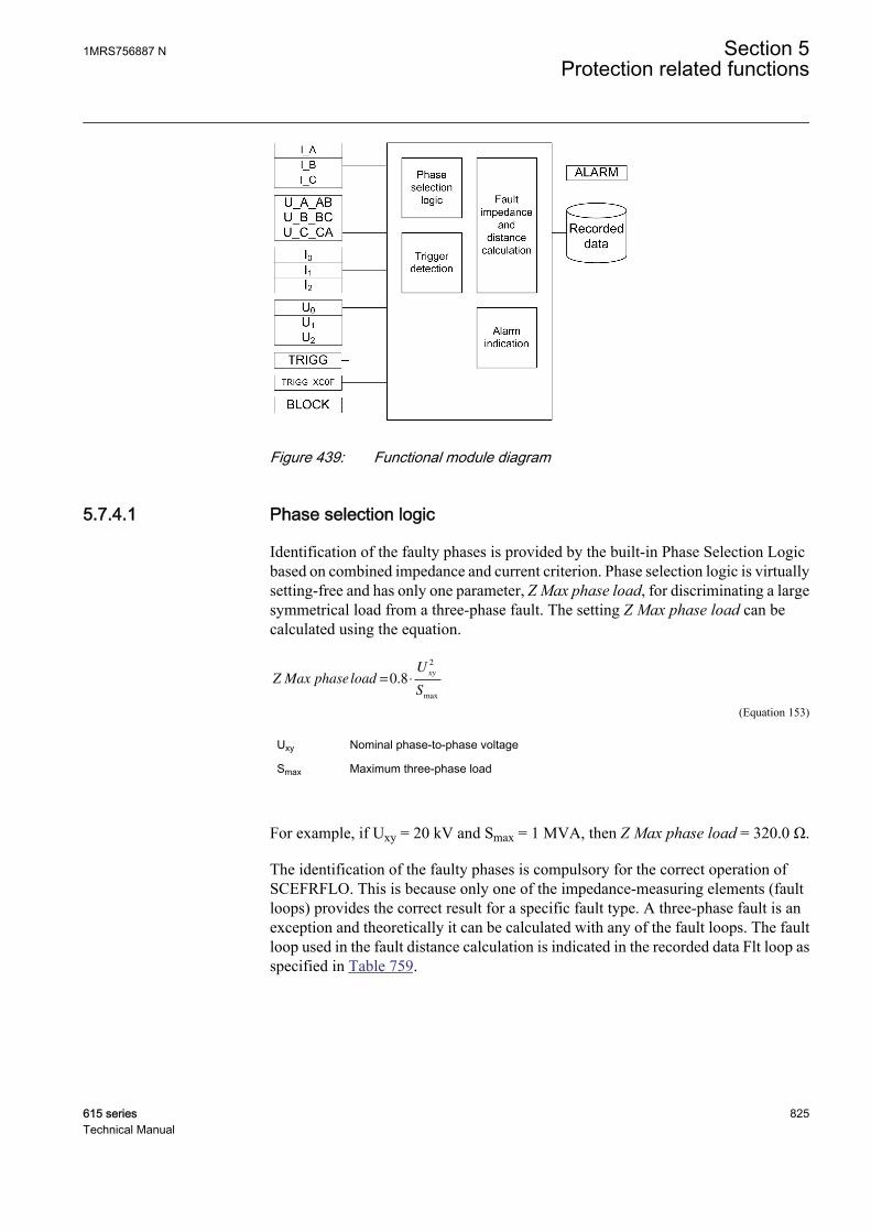
GUID-FB1818E0-0F8D-4CBA-A55F-FC927CDA11C6 V2 EN
Figure 439: Functional module diagram
5.7.4.1 Phase selection logic
Identification of the faulty phases is provided by the built-in Phase Selection Logicbased on combined impedance and current criterion. Phase selection logic is virtuallysetting-free and has only one parameter, Z Max phase load, for discriminating a largesymmetrical load from a three-phase fault. The setting Z Max phase load can becalculated using the equation.
Z Max phaseloadU
S
xy= ⋅0 8
2
.
max
GUID-9FFE90C4-0734-46B5-9D17-5A7FA6F723E6 V1 EN (Equation 153)
Uxy Nominal phase-to-phase voltage
Smax Maximum three-phase load
For example, if Uxy = 20 kV and Smax = 1 MVA, then Z Max phase load = 320.0 Ω.
The identification of the faulty phases is compulsory for the correct operation ofSCEFRFLO. This is because only one of the impedance-measuring elements (faultloops) provides the correct result for a specific fault type. A three-phase fault is anexception and theoretically it can be calculated with any of the fault loops. The faultloop used in the fault distance calculation is indicated in the recorded data Flt loop asspecified in Table 759.
1MRS756887 N Section 5Protection related functions
615 series 825Technical Manual
Table 759: Fault types and corresponding fault loops
Fault type Description Flt loop- No fault No fault
A-E Phase A-to-earth fault AG Fault
B-E Phase B-to-earth fault BG Fault
C-E Phase C-to-earth fault CG Fault
A-B Phase A-to-B short circuit fault AB Fault
B-C Phase B-to-C short circuit fault BC Fault
C-A Phase C-to-A short circuit fault AC Fault
A-B-C-(E) Three-phase short circuit ABC Fault
In case of two-phase-to-earth faults (A-B-E, B-C-E or C-A-E), the selected fault loopdepends on the location of the individual earth faults. When the faults are located at thesame feeder, the corresponding phase-to-phase loop (either “AB Fault” or “BC Fault”or “CA Fault”) is used for calculation. When the faults are located at different feeders,the phase-to-earth loop (either “AG Fault” or “BG Fault” or “CG Fault”)corresponding to the faulty phase at the protected feeder is used for calculation.
5.7.4.2 Fault impedance and distance calculation
As soon as a fault condition is recognized by the phase selection logic, the faultdistance calculation is started with one of the seven impedance-measuring elements,that is, the fault loops. SCEFRFLO employs independent algorithms for each faulttype to achieve optimal performance.
The inherent result from the fault distance calculation is the ohmic fault loopimpedance value.
Table 760: The calculated impedance values available in the recorded data
Impedance valule DescriptionFlt phase reactance Estimated positive sequence reactance from the substation to the fault
location in primary ohms.
Flt point resistance Fault resistance value in the fault spot in primary ohms. The composition ofthis term depends on the fault loop as described in the following subsections.
Flt loop resistance The total fault loop resistance from the substation to the fault location inprimary ohms. Fault point resistance is included in this value. Thecomposition of this term is different for short-circuit and earth-fault loops asdescribed in the following subsections.
Flt loop reactance The total fault loop reactance from the substation to the fault location inprimary ohms. The composition of this term is different for short-circuit andearth-faults loops as described in the following subsections.
These impedance values can be utilized as such or they can be further processed insystem level fault location applications, such as distribution management system(DMS).
Section 5 1MRS756887 NProtection related functions
826 615 seriesTechnical Manual

Fault loops “AG Fault” or “BG Fault” or “CG Fault”Fault loops “AG Fault”, “BG Fault” or “CG Fault” are used for single-phase-to-earthfaults. When the individual earth faults are located at different feeders, they are alsoapplied in the case of two-phase-to-earth fault. In this case, the phase-to-earth loop(either “AG Fault” or “BG Fault” or “CG Fault”) corresponding to the faulty phase atthe protected feeder, is used for calculation. Figure 440 shows the phase-to-earth faultloop model. The following impedances are measured and stored in the recorded dataof SCEFRFLO.
Flt point resistance Rfault=
GUID-2503378E-4AC5-4E9F-9D77-2E7C71592C37 V3 EN (Equation 154)
Flt loop resistance R R RN fault= + +1
GUID-4DF67AFC-67E4-4BCB-958E-CC9E4872E252 V3 EN (Equation 155)
Flt loop reactance X XN= +1
GUID-B4E21936-B993-4A8A-9C4A-7425F8AC4670 V3 EN (Equation 156)
Flt phase reactance X=1
GUID-56EC16DD-7F6A-4DE5-935E-4302196DE21A V3 EN (Equation 157)
R1 Estimated positive-sequence resistance from the substation to the fault location
X1 Estimated positive-sequence reactance from the substation to the fault location
R0 Estimated zero-sequence resistance from the substation to the fault location
X0 Estimated zero-sequence reactance from the substation to the fault location
RN Estimated the earth return path resistance (= (R0 – R1)/3) from the substation tothe fault location
XN Estimated is the earth return path reactance (= (X0 – X1)/3) from the substation tothe fault
Rfault Estimated fault resistance at the fault location
The recorded data Flt phase reactance provides the estimated positive-sequencereactance from the substation to the fault location.
1MRS756887 N Section 5Protection related functions
615 series 827Technical Manual
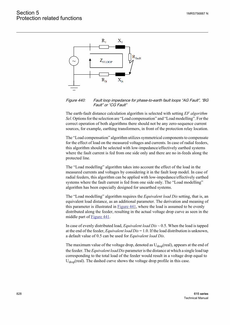
GUID-B455F553-4F09-442D-9297-4262002D5D07 V2 EN
Figure 440: Fault loop impedance for phase-to-earth fault loops “AG Fault”, “BGFault” or “CG Fault”
The earth-fault distance calculation algorithm is selected with setting EF algorithmSel. Options for the selection are “Load compensation” and “Load modelling”. For thecorrect operation of both algorithms there should not be any zero-sequence currentsources, for example, earthing transformers, in front of the protection relay location.
The “Load compensation” algorithm utilizes symmetrical components to compensatefor the effect of load on the measured voltages and currents. In case of radial feeders,this algorithm should be selected with low-impedance/effectively earthed systemswhere the fault current is fed from one side only and there are no in-feeds along theprotected line.
The “Load modelling” algorithm takes into account the effect of the load in themeasured currents and voltages by considering it in the fault loop model. In case ofradial feeders, this algorithm can be applied with low-impedance/effectively earthedsystems where the fault current is fed from one side only. The “Load modelling”algorithm has been especially designed for unearthed systems.
The “Load modelling” algorithm requires the Equivalent load Dis setting, that is, anequivalent load distance, as an additional parameter. The derivation and meaning ofthis parameter is illustrated in Figure 441, where the load is assumed to be evenlydistributed along the feeder, resulting in the actual voltage drop curve as seen in themiddle part of Figure 441.
In case of evenly distributed load, Equivalent load Dis ~ 0.5. When the load is tappedat the end of the feeder, Equivalent load Dis = 1.0. If the load distribution is unknown,a default value of 0.5 can be used for Equivalent load Dis.
The maximum value of the voltage drop, denoted as Udrop(real), appears at the end ofthe feeder. The Equivalent load Dis parameter is the distance at which a single load tapcorresponding to the total load of the feeder would result in a voltage drop equal toUdrop(real). The dashed curve shows the voltage drop profile in this case.
Section 5 1MRS756887 NProtection related functions
828 615 seriesTechnical Manual
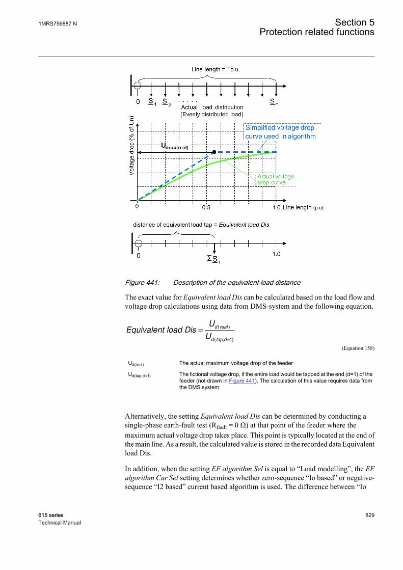
GUID-134928BF-ACE3-42C9-A70F-985A1913FB75 V3 EN
Figure 441: Description of the equivalent load distance
The exact value for Equivalent load Dis can be calculated based on the load flow andvoltage drop calculations using data from DMS-system and the following equation.
Equivalent load DisU
U
d real
d tap d
=
=
( )
( , )1
GUID-E447E8AC-65F7-4586-B853-C297347303FF V2 EN (Equation 158)
Ud(real) The actual maximum voltage drop of the feeder
Ud(tap,d=1) The fictional voltage drop, if the entire load would be tapped at the end (d=1) of thefeeder (not drawn in Figure 441). The calculation of this value requires data fromthe DMS system.
Alternatively, the setting Equivalent load Dis can be determined by conducting asingle-phase earth-fault test (Rfault = 0 Ω) at that point of the feeder where themaximum actual voltage drop takes place. This point is typically located at the end ofthe main line. As a result, the calculated value is stored in the recorded data Equivalentload Dis.
In addition, when the setting EF algorithm Sel is equal to “Load modelling”, the EFalgorithm Cur Sel setting determines whether zero-sequence “Io based” or negative-sequence “I2 based” current based algorithm is used. The difference between “Io
1MRS756887 N Section 5Protection related functions
615 series 829Technical Manual

based” and “I2 based” methods is that “I2 based” does not require the Ph capacitiveReact and Ph leakage Ris settings. In case of “Io based”, these settings are needed tocompensate for the influence of the line-charging capacitances of the protected feeder.This improves the accuracy of the fault location estimate when fault resistance isinvolved in the fault.
Under certain restrictions, the “Load modelling” algorithm can also be applied tounearthed networks. In this case the EF algorithm Cur Sel setting should be set to “Iobased” and thus Ph capacitive React and Ph leakage Ris settings must be determined.
The prerequisite for the operation of SCEFRFLO in earth faults in unearthed networksis that the earth-fault current of the network corresponding to a solid fault exceeds thepre-fault load current; that is the Equation 159 is valid.
Flt to Lod Cur ratioI
I
ef Rfault
Load
= ≥=( )0
1
GUID-CABC3779-DAB9-4785-8451-DCCC8EAA034F V3 EN (Equation 159)
This ratio is estimated by SCEFRFLO and stored in the recorded data Flt to Lod Curratio together with the fault distance estimate.
In case of unearthed network, sufficient fault current magnitude resulting in Flt to LodCur ratio >1 can be achieved, for example, with proper switching operations in thebackground network, if possible, which increase the fault current. If the faulty feederis re-energized after the switching operation, a new estimate for the fault distance canbe obtained. Fault resistance decreases the fault location accuracy and the resistanceshould not be too high, the maximum is a few hundred ohms. Also low value of Flt toLod Cur ratio causes inaccuracy and affects the quality of fault distance estimate.Considered inaccuracies affecting the calculated fault distance estimate are reportedin the recorded result quality indicator value Flt Dist quality in Table 761.
Fault loops “AB Fault”, “BC Fault” or “CA Fault”Fault loops “AB Fault”, “BC Fault” or “CA Fault” are used for phase-to-phase shortcircuit faults as well as in the case of a two-phase-to-earth fault if the individual earthfaults are located at the same feeder. Figure 442 shows the phase-to-phase fault loopmodel. The following impedances are measured and stored in the recorded data ofSCEFRFLO.
Flt point resistanceRfault
=
2
GUID-F8007C95-5C0B-4FBA-B724-0BC45E64841F V3 EN (Equation 160)
Flt loop resistance RRfault
= +1
2
GUID-CB02F4ED-8E75-4C30-BB25-3F4984D75FC8 V3 EN (Equation 161)
Flt loop reactance Flt phase reactance X= =1
GUID-049B892B-9031-4361-843B-7102E6A4DA17 V3 EN (Equation 162)
Section 5 1MRS756887 NProtection related functions
830 615 seriesTechnical Manual

GUID-9CBC31C7-4DF6-4555-9029-4188CCC5533C V2 EN
Figure 442: Fault loop impedance for phase-to-phase fault loops (either “ABFault”, “BC Fault” or “CA Fault”)
The fault distance calculation algorithm for the phase-to-phase fault loops is definedby using settings Load Com PP loops and Enable simple model. Options for theselection are "Disabled" or "Enabled".
Load compensation can be enabled or disabled with setting Load Com PP loops. Theload compensation should be disabled only if the ratio between the fault current andload current is large or when the value of the fault distance estimate for the short circuitfault is required from each shot of an autoreclosing sequence.
The fault distance calculation is most accurate when calculated with the fault loopmodel. This model requires positive sequence impedances of the protected feeder tobe given as settings. If these settings are not available, valid impedance values can becalculated also without the fault loop model with setting Enable simple model =“TRUE”. However, valid distance estimate, that is, the conversion of measuredimpedance (‘’electrical fault distance’’) into a physical fault distance requiresaccurate positive sequence impedance settings.
Fault loop “ABC Fault”Fault loop “ABC Fault” is used exclusively for the three-phase short circuit fault.Figure 443 shows the three-phase fault loop model. The following impedances aremeasured and stored in the recorded data of SCEFRFLO.
Flt point resistance Rfault=
GUID-2503378E-4AC5-4E9F-9D77-2E7C71592C37 V3 EN (Equation 163)
Flt loop resistance R Rfault= +1
GUID-F9E2B211-9C30-4A81-ABD4-525CC10AB7A8 V2 EN (Equation 164)
Flt loop reactance Flt phase reactance X= =1
GUID-049B892B-9031-4361-843B-7102E6A4DA17 V3 EN (Equation 165)
1MRS756887 N Section 5Protection related functions
615 series 831Technical Manual
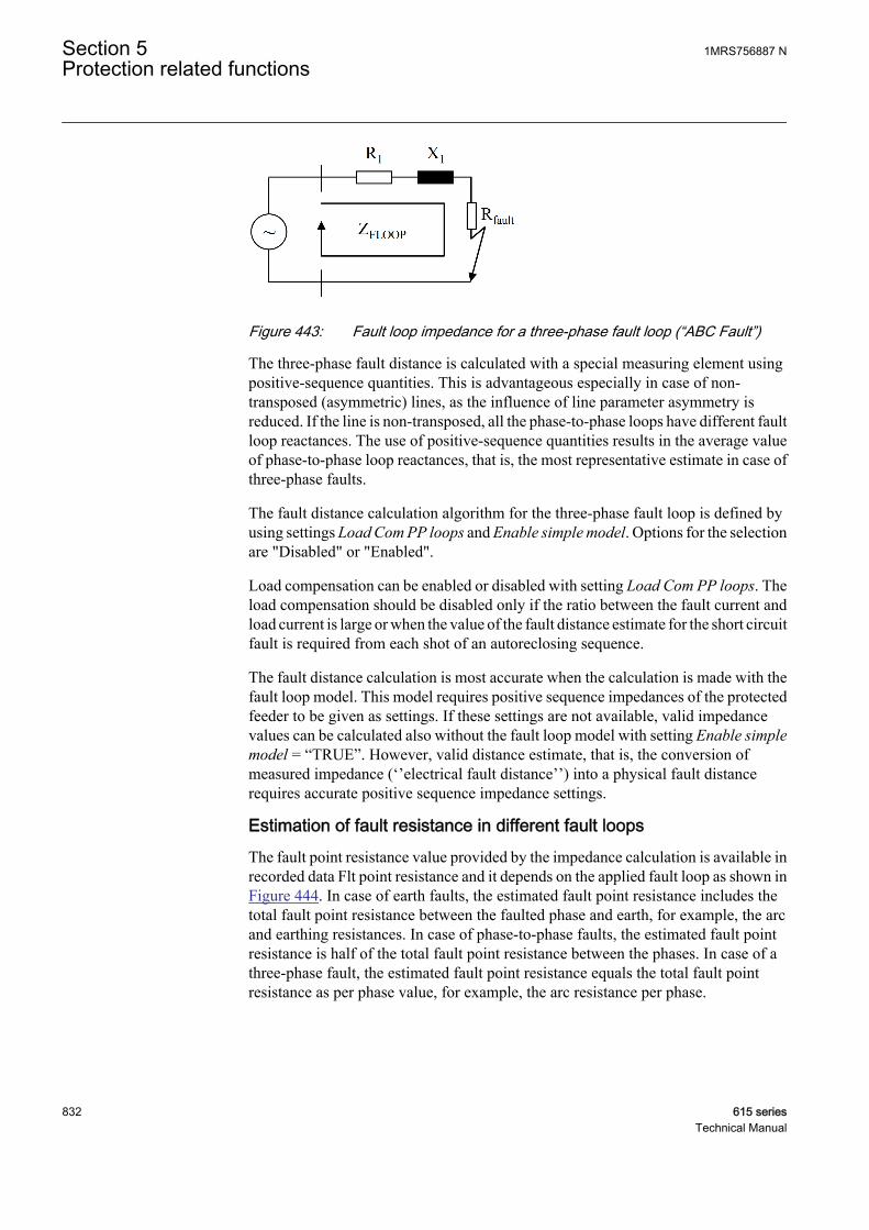
GUID-359785B9-1D24-4751-B018-2225F04D7A2F V2 EN
Figure 443: Fault loop impedance for a three-phase fault loop (“ABC Fault”)
The three-phase fault distance is calculated with a special measuring element usingpositive-sequence quantities. This is advantageous especially in case of non-transposed (asymmetric) lines, as the influence of line parameter asymmetry isreduced. If the line is non-transposed, all the phase-to-phase loops have different faultloop reactances. The use of positive-sequence quantities results in the average valueof phase-to-phase loop reactances, that is, the most representative estimate in case ofthree-phase faults.
The fault distance calculation algorithm for the three-phase fault loop is defined byusing settings Load Com PP loops and Enable simple model. Options for the selectionare "Disabled" or "Enabled".
Load compensation can be enabled or disabled with setting Load Com PP loops. Theload compensation should be disabled only if the ratio between the fault current andload current is large or when the value of the fault distance estimate for the short circuitfault is required from each shot of an autoreclosing sequence.
The fault distance calculation is most accurate when the calculation is made with thefault loop model. This model requires positive sequence impedances of the protectedfeeder to be given as settings. If these settings are not available, valid impedancevalues can be calculated also without the fault loop model with setting Enable simplemodel = “TRUE”. However, valid distance estimate, that is, the conversion ofmeasured impedance (‘’electrical fault distance’’) into a physical fault distancerequires accurate positive sequence impedance settings.
Estimation of fault resistance in different fault loopsThe fault point resistance value provided by the impedance calculation is available inrecorded data Flt point resistance and it depends on the applied fault loop as shown inFigure 444. In case of earth faults, the estimated fault point resistance includes thetotal fault point resistance between the faulted phase and earth, for example, the arcand earthing resistances. In case of phase-to-phase faults, the estimated fault pointresistance is half of the total fault point resistance between the phases. In case of athree-phase fault, the estimated fault point resistance equals the total fault pointresistance as per phase value, for example, the arc resistance per phase.
Section 5 1MRS756887 NProtection related functions
832 615 seriesTechnical Manual
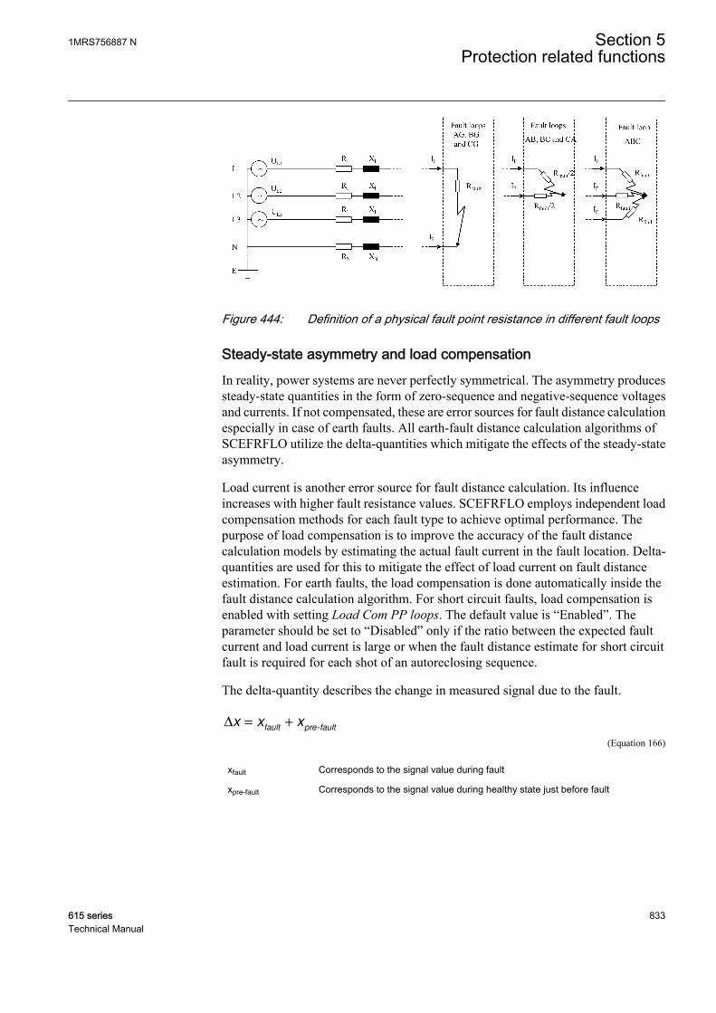
GUID-8C1D00A2-1DFC-4904-B2D5-1CF7A88E9C4D V2 EN
Figure 444: Definition of a physical fault point resistance in different fault loops
Steady-state asymmetry and load compensationIn reality, power systems are never perfectly symmetrical. The asymmetry producessteady-state quantities in the form of zero-sequence and negative-sequence voltagesand currents. If not compensated, these are error sources for fault distance calculationespecially in case of earth faults. All earth-fault distance calculation algorithms ofSCEFRFLO utilize the delta-quantities which mitigate the effects of the steady-stateasymmetry.
Load current is another error source for fault distance calculation. Its influenceincreases with higher fault resistance values. SCEFRFLO employs independent loadcompensation methods for each fault type to achieve optimal performance. Thepurpose of load compensation is to improve the accuracy of the fault distancecalculation models by estimating the actual fault current in the fault location. Delta-quantities are used for this to mitigate the effect of load current on fault distanceestimation. For earth faults, the load compensation is done automatically inside thefault distance calculation algorithm. For short circuit faults, load compensation isenabled with setting Load Com PP loops. The default value is “Enabled”. Theparameter should be set to “Disabled” only if the ratio between the expected faultcurrent and load current is large or when the fault distance estimate for short circuitfault is required for each shot of an autoreclosing sequence.
The delta-quantity describes the change in measured signal due to the fault.
∆ = +x x xfault pre fault-
GUID-2F67A337-58A8-40F4-B752-678A8D89083E V1 EN (Equation 166)
xfault Corresponds to the signal value during fault
xpre-fault Corresponds to the signal value during healthy state just before fault
1MRS756887 N Section 5Protection related functions
615 series 833Technical Manual
Result quality indicatorThe quality of the estimated fault distance is judged and reported in recorded data asthe Flt Dist quality together with the fault distance estimate. The Flt Dist quality is abit vector indicating detected sources of inaccuracy in the fault distance estimate. Incase Flt Dist quality equals 1, the result is not affected by error sources. This resultsin good quality for fault distance estimate. If factors affecting negatively to faultdistance estimation are detected, the Flt Dist quality is according to Table 761. In thiscase estimated fault distance, Flt distance value is given in HMI in parenthesis.
Table 761: Fault distance quality indicator Flt Dist quality
Value Corresponding inaccuracy description2 Estimation stability criterion has not been reached
4 Fault point resistance exceeds 500 Ω
8 Fault point resistance exceeds 5 × Xloop1)
16 Fault point resistance exceeds 20 × Xloop1)
32 Flt to Lod Cur ratio is below 1.00
64 Fault distance estimate outside tolerances (<-0.1pu or >1.1 pu)
128 Distance estimate calculation is not done due totoo low magnitudes of I or U
256 Distance estimate calculation cannot beperformed (for example avoiding internal divisionby zero)
1) Xloop is the total loop reactance according to settings
For example, if fault point resistance exceeds 500 Ω and Flt to Lod Cur ratio is below1.0, Flt Dist quality is “36”. As another example, if no error sources are found, butstability criterion is not met, the value of Flt Dist quality is “2”.
Impedance settingsThe fault distance calculation in SCEFRFLO is based on the fault loop impedancemodeling. The fault loop is parametrized with the impedance settings and these can beset at maximum for three line sections (A, B and C). Each section is enabled byentering a section length, which differs from zero to settings Line Len section A, LineLen section B or Line Len section C in the order section A-> section B-> section C.
The earth-fault loops require both positive-sequence and zero-sequence impedances,for example, R1 line section A and X1 line section A, R0 line section A and X0 linesection A. For the short circuit loops, only positive-sequence impedances are needed.Even these can be omitted in the short circuit loops, if the setting Enable simple modelequals "TRUE".
If the impedance settings are in use, it is important that the settings closely match theimpedances of used conductor types. The impedance settings are given in primaryohms [ohm/pu] and the line section lengths in per unit [pu]. Thus, impedances can be
Section 5 1MRS756887 NProtection related functions
834 615 seriesTechnical Manual
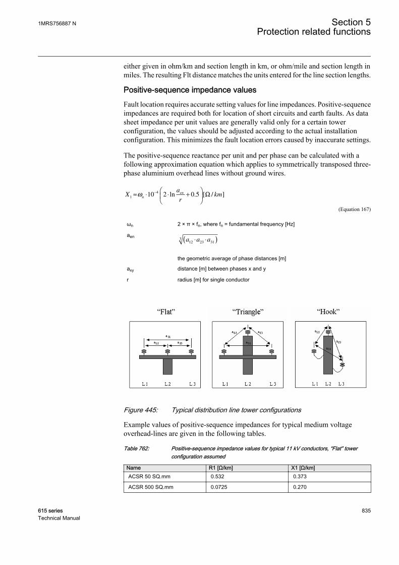
either given in ohm/km and section length in km, or ohm/mile and section length inmiles. The resulting Flt distance matches the units entered for the line section lengths.
Positive-sequence impedance valuesFault location requires accurate setting values for line impedances. Positive-sequenceimpedances are required both for location of short circuits and earth faults. As datasheet impedance per unit values are generally valid only for a certain towerconfiguration, the values should be adjusted according to the actual installationconfiguration. This minimizes the fault location errors caused by inaccurate settings.
The positive-sequence reactance per unit and per phase can be calculated with afollowing approximation equation which applies to symmetrically transposed three-phase aluminium overhead lines without ground wires.
Xa
rkm
n
en
1
410 2 0 5≈ ⋅ ⋅ +
−
ω ln . [ / ]Ω
GUID-B7F3697A-7C8E-4BF6-A63C-7BFD307DD128 V2 EN (Equation 167)
ωn 2 × π × fn, where fn = fundamental frequency [Hz]
aena a a
12 23 313 ⋅ ⋅( )
GUID-DA850ABF-239A-4AB5-B63B-F0B54557CF2E V2 EN
the geometric average of phase distances [m]
axy distance [m] between phases x and y
r radius [m] for single conductor
GUID-40949A85-D97F-4639-9D61-3CAE997D28D3 V2 EN
Figure 445: Typical distribution line tower configurations
Example values of positive-sequence impedances for typical medium voltageoverhead-lines are given in the following tables.
Table 762: Positive-sequence impedance values for typical 11 kV conductors, “Flat” towerconfiguration assumed
Name R1 [Ω/km] X1 [Ω/km]ACSR 50 SQ.mm 0.532 0.373
ACSR 500 SQ.mm 0.0725 0.270
1MRS756887 N Section 5Protection related functions
615 series 835Technical Manual
Table 763: Positive-sequence impedance values for typical 10/20 kV conductors, “Flat” towerconfiguration assumed
Name R1 [Ω/km] X1 [Ω/km]Al/Fe 36/6 Sparrow 0.915 0.383
Al/Fe 54/9 Raven 0.578 0.368
Al/Fe 85/14 Pigeon 0.364 0.354
Al/Fe 93/39 Imatra 0.335 0.344
Al/Fe 108/23 Vaasa 0.287 0.344
Al/Fe 305/39 Duck 0.103 0.314
Table 764: Positive-sequence impedance values for typical 33 kV conductors, “Flat” towerconfiguration assumed
Name R1 [Ω/km] X1 [Ω/km]ACSR 50 sq.mm 0.529 0.444
ACSR 100 sq.mm 0.394 0.434
ACSR 500 sq.mm 0.0548 0.346
Zero-sequence impedance valuesLocation of earth faults requires both positive-sequence and zero-sequenceimpedances. For short circuit faults, zero-sequence impedances are not required.
The positive-sequence impedance per unit values for the lines are typically known orcan easily be obtained from data sheets. The zero-sequence values are generally not aseasy to obtain as they depend on the actual installation conditions and configurations.Sufficient accuracy can, however, be obtained with rather simple calculations usingthe following equations, which apply per phase for symmetrically transposed three-phase aluminium overhead lines without ground wires.
R Hz R km0
50 1 0 14804[ ] . [ / ]≈ + Ω
GUID-087D1F51-4C8C-4CF4-ACE5-9F43AF0DD3FC V1 EN (Equation 168)
R Hz R km0
60 1 0 17765[ ] . [ / ]≈ + Ω
GUID-C33EC003-0DA2-4FFC-9496-586D7342DAF6 V1 EN (Equation 169)
Xw
rkm
n
en
0
42 10 3 0 25≈ ⋅ ⋅ ⋅ +
−
ω ln . [ / ]Ω
GUID-6850481D-094B-4FA0-9E73-39DCC6C49BCC V2 EN (Equation 170)
R1 conductor AC resistance [Ω/km]
Section 5 1MRS756887 NProtection related functions
836 615 seriesTechnical Manual

W658
ρearth
nf
GUID-2FE803A9-203E-44ED-8153-4F5903233736 V1 EN
the equivalent depth [m] of the earth return path
ρearth earth resistivity [Ωm]
renr a a a⋅ ⋅ ⋅
12
2
23
2
31
233
GUID-F7698D7C-ADCC-4555-A3C7-05DAEB3FBA70 V2 EN
the equivalent radius [m] for conductor bundle
r radius [m] for single conductor
axy distance [m] between phases x and y
Ph leakage Ris and Ph capacitive React settingsThe Ph leakage Ris and Ph capacitive React settings are used for improving faultdistance estimation accuracy for earth faults. They are critical for an accurate faultlocation in unearthed networks. In other types of networks they are less critical. ThePh leakage Ris setting represents the leakage losses of the protected feeder in terms ofresistance per phase. The Ph capacitive React setting represents the total phase-to-earth capacitive reactance of the protected feeder per phase. Based on experience, aproper estimate for Ph leakage Ris should be about 20…40 × Ph capacitive React.
GUID-4FEEEF83-D0D7-49A8-90F6-453E28AE27B2 V2 EN
Figure 446: Equivalent diagram of the protected feeder. RL0F = Ph leakage Ris.
The determination of the Ph capacitive React setting can be based either on networkdata or measurement.
If the total phase-to-earth capacitance (including all branches) per phase C0F of theprotected feeder is known, the setting value can be calculated.
Ph capacitive ReactC
n F
=
⋅( )
1
0ω
GUID-3D723613-A007-47ED-B8D7-F9D55C5FBF38 V2 EN (Equation 171)
1MRS756887 N Section 5Protection related functions
615 series 837Technical Manual
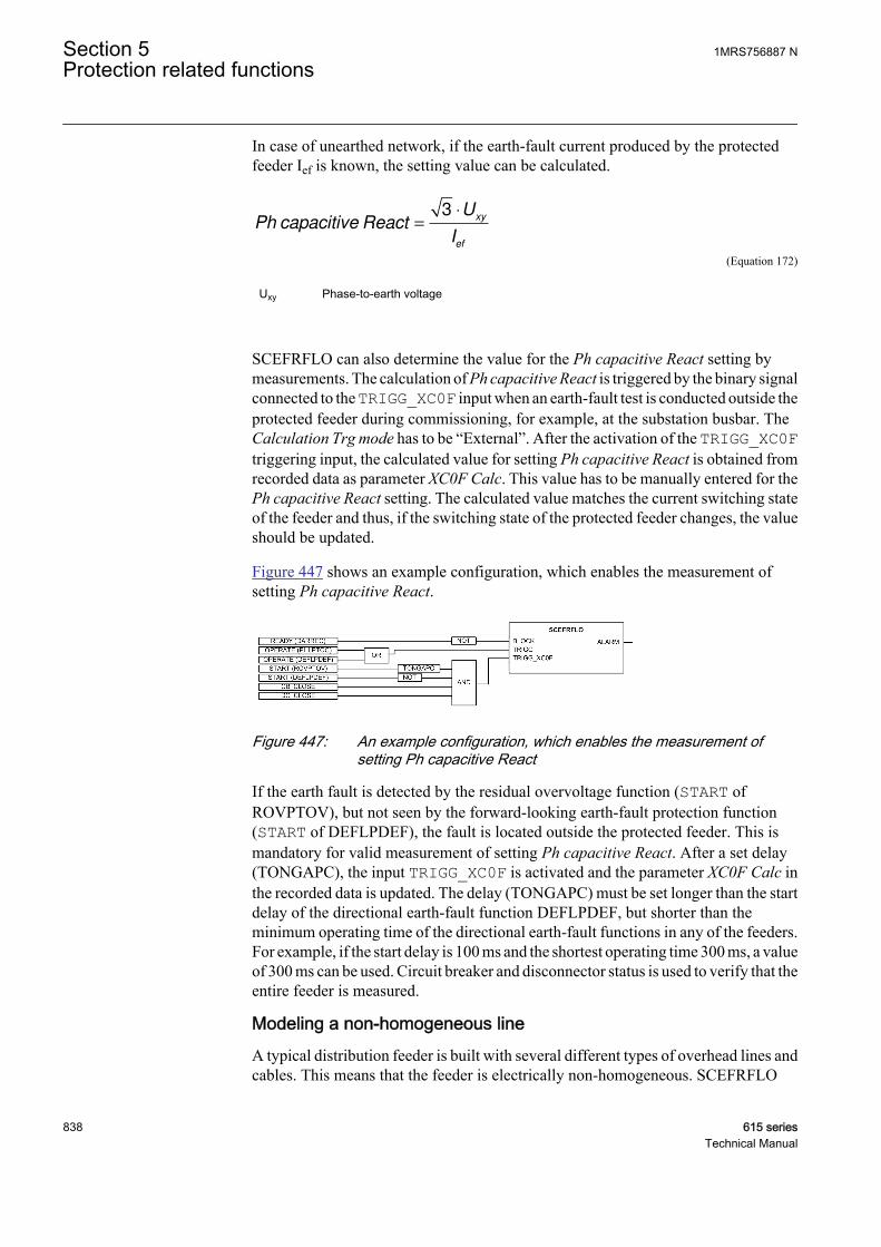
In case of unearthed network, if the earth-fault current produced by the protectedfeeder Ief is known, the setting value can be calculated.
Ph capacitive ReactU
I
xy
ef
=
⋅3
GUID-60CC60C2-2547-404D-ABEB-74D112142F48 V3 EN (Equation 172)
Uxy Phase-to-earth voltage
SCEFRFLO can also determine the value for the Ph capacitive React setting bymeasurements. The calculation of Ph capacitive React is triggered by the binary signalconnected to the TRIGG_XC0F input when an earth-fault test is conducted outside theprotected feeder during commissioning, for example, at the substation busbar. TheCalculation Trg mode has to be “External”. After the activation of the TRIGG_XC0Ftriggering input, the calculated value for setting Ph capacitive React is obtained fromrecorded data as parameter XC0F Calc. This value has to be manually entered for thePh capacitive React setting. The calculated value matches the current switching stateof the feeder and thus, if the switching state of the protected feeder changes, the valueshould be updated.
Figure 447 shows an example configuration, which enables the measurement ofsetting Ph capacitive React.
GUID-DB04812D-DFF9-4E3F-9CC3-486322E70420 V1 EN
Figure 447: An example configuration, which enables the measurement ofsetting Ph capacitive React
If the earth fault is detected by the residual overvoltage function (START ofROVPTOV), but not seen by the forward-looking earth-fault protection function(START of DEFLPDEF), the fault is located outside the protected feeder. This ismandatory for valid measurement of setting Ph capacitive React. After a set delay(TONGAPC), the input TRIGG_XC0F is activated and the parameter XC0F Calc inthe recorded data is updated. The delay (TONGAPC) must be set longer than the startdelay of the directional earth-fault function DEFLPDEF, but shorter than theminimum operating time of the directional earth-fault functions in any of the feeders.For example, if the start delay is 100 ms and the shortest operating time 300 ms, a valueof 300 ms can be used. Circuit breaker and disconnector status is used to verify that theentire feeder is measured.
Modeling a non-homogeneous lineA typical distribution feeder is built with several different types of overhead lines andcables. This means that the feeder is electrically non-homogeneous. SCEFRFLO
Section 5 1MRS756887 NProtection related functions
838 615 seriesTechnical Manual

allows the modeling of the line impedance variation in protection relay with three linesections with independent impedance settings. This improves the accuracy of physicalfault distance conversion done in the protection relay, especially in cases where theline impedance non-homogeneity is severe. Each section is enabled by entering asection length, which differs from zero, to settings Line Len section A, Line Lensection B or Line Len section C in the order section A-> section B-> section C.
Impedance model with one line section is enabled by setting Line Len section A todiffer from zero. In this case the impedance settings R1 line section A, X1 line sectionA, R0 line section A and X0 line section A are used for the fault distance calculation andfor conversion from reactance to physical fault distance. This option should be usedonly in the case of a homogeneous line, that is, when the protected feeder consists ofonly one conductor type.
Impedance model with two line sections is enabled by setting both Line Len section Aand Line Len section B to differ from zero. In this case the impedance settings R1 linesection A, X1 line section A, R0 line section A, X0 line section A, R1 line section B, X1line section B, R0 line section B and X0 line section B are used for the fault distancecalculation and for conversion from reactance to physical fault distance. This optionshould be used in the case of a non-homogeneous line when the protected feederconsists of two types of conductors.
Impedance model with three line sections is enabled by setting Line Len section A,Line Len section B and Line Len section C all differ from zero. In this case theimpedance settings R1 line section A, X1 line section A, R0 line section A, X0 linesection A, R1 line section B, X1 line section B, R0 line section B, X0 line section B, R1line section C, X1 line section C, R0 line section C and X0 line section C are used forthe fault distance calculation and for conversion from reactance to physical faultdistance. This option should be used in the case of a non-homogeneous line when theprotected feeder consists of more than two types of conductors.
The effect of line impedance non-homogeneity in the conversion of fault loopreactance into physical fault distance is demonstrated in example shown in Figure 448with 10 kilometer long feeder with three line types. The total line impedance for the10 km line is R1 = 6.602 Ω (0.660 Ω/km) and X1 = 3.405 Ω (0.341 Ω/km), consistingof the following sections and impedance values.
• 4 km of PAS 150 (R1 = 0.236 Ω/km, X1 = 0.276 Ω/km)• 3 km of Al/Fe 54/9 Raven (R1 = 0.536 Ω/km, X1 = 0.369 Ω/km)• 3 km of Al/Fe 21/4 Swan (R1 = 1.350 Ω/km, X1 = 0.398 Ω/km)
The non-homogeneity of feeder impedance can be illustrated by drawing the protectedfeeder in RX-diagram (in the impedance plane), as shown in Figure 448.
1MRS756887 N Section 5Protection related functions
615 series 839Technical Manual
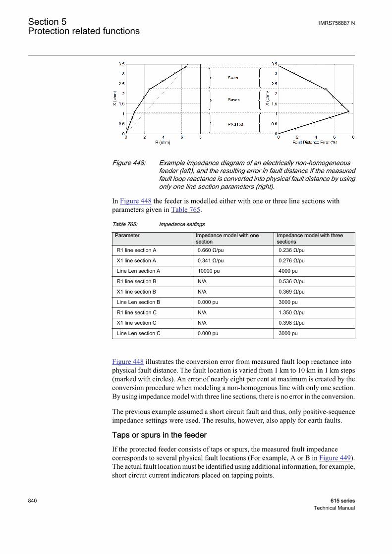
GUID-AEA0E874-C871-4C90-82ED-3AFE41D28145 V2 EN
Figure 448: Example impedance diagram of an electrically non-homogeneousfeeder (left), and the resulting error in fault distance if the measuredfault loop reactance is converted into physical fault distance by usingonly one line section parameters (right).
In Figure 448 the feeder is modelled either with one or three line sections withparameters given in Table 765.
Table 765: Impedance settings
Parameter Impedance model with onesection
Impedance model with threesections
R1 line section A 0.660 Ω/pu 0.236 Ω/pu
X1 line section A 0.341 Ω/pu 0.276 Ω/pu
Line Len section A 10000 pu 4000 pu
R1 line section B N/A 0.536 Ω/pu
X1 line section B N/A 0.369 Ω/pu
Line Len section B 0.000 pu 3000 pu
R1 line section C N/A 1.350 Ω/pu
X1 line section C N/A 0.398 Ω/pu
Line Len section C 0.000 pu 3000 pu
Figure 448 illustrates the conversion error from measured fault loop reactance intophysical fault distance. The fault location is varied from 1 km to 10 km in 1 km steps(marked with circles). An error of nearly eight per cent at maximum is created by theconversion procedure when modeling a non-homogenous line with only one section.By using impedance model with three line sections, there is no error in the conversion.
The previous example assumed a short circuit fault and thus, only positive-sequenceimpedance settings were used. The results, however, also apply for earth faults.
Taps or spurs in the feederIf the protected feeder consists of taps or spurs, the measured fault impedancecorresponds to several physical fault locations (For example, A or B in Figure 449).The actual fault location must be identified using additional information, for example,short circuit current indicators placed on tapping points.
Section 5 1MRS756887 NProtection related functions
840 615 seriesTechnical Manual

GUID-312EE60E-1CB9-4334-83BD-39DF3FC5815E V3 EN
Figure 449: Fault on a distribution line with spurs
5.7.4.3 Trigger detection
The fault distance estimate is obtained when SCEFRFLO is triggered. The triggeringmethod is defined with setting Calculation Trg mode. The options for selection are:“External” or “Internal”, where the default value is “External”. The TRIGG_OUTevent indicates fault distance value recording moment. The fault distance estimate, Fltdistance, together with the timestamp of actual triggering are saved in the recordeddata of SCEFRFLO.
• In case of external triggering, an external trigger signal should be connected to theTRIGG input. The triggering signal is typically a trip signal from a protectivefunction. At triggering moment the fault distance is stored into recorded data. Itis important that triggering is timed suitably to provide sufficient distanceestimation calculation time before tripping of the feeder circuit breaker.
• In case of internal triggering, the TRIGG input is not used for triggering. Instead,the trigger signal is created internally so that the estimation is started when phaseselection logic detects a fault and the estimate is triggered when its value hasstabilized sufficiently. This is judged by maximum variation in fault distanceestimate and defined with setting Distance estimate Va (in the same unit as thefault distance estimate). When successive estimates during one fundamentalcycle are within “final value ± Distance estimate Va”, the fault distance estimate(mean of successive estimates) is recorded. In case stabilization criterion has notbeen fulfilled, the fault distance estimate is given just before the phase currentsare interrupted. The phase selection logic is a non-directional function, and thusinternal triggering should not be used when directionality is required.
Generally, SCEFRFLO requires a minimum of two fundamental cycles of measuringtime after the fault occurrence. Figure 450 illustrates typical behavior of fault distanceestimate of SCEFRFLO as a function of time.
1MRS756887 N Section 5Protection related functions
615 series 841Technical Manual
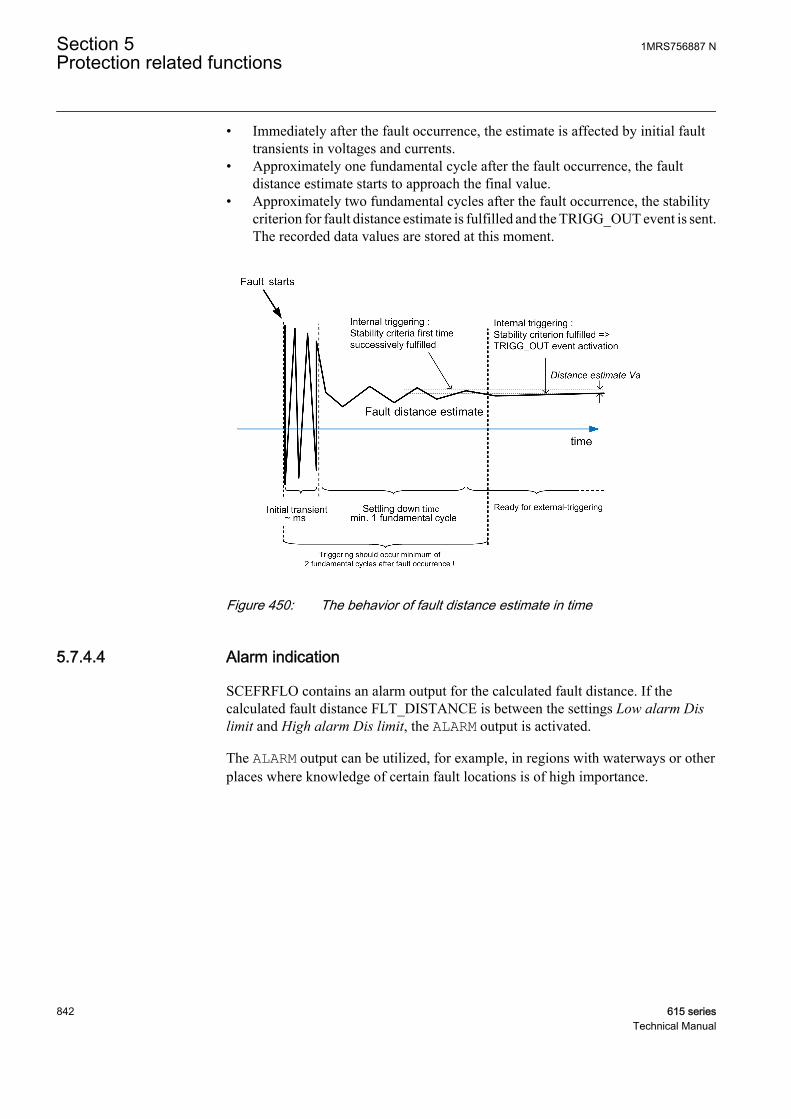
• Immediately after the fault occurrence, the estimate is affected by initial faulttransients in voltages and currents.
• Approximately one fundamental cycle after the fault occurrence, the faultdistance estimate starts to approach the final value.
• Approximately two fundamental cycles after the fault occurrence, the stabilitycriterion for fault distance estimate is fulfilled and the TRIGG_OUT event is sent.The recorded data values are stored at this moment.
GUID-2C1E2C55-B61A-4200-BC8E-0F6FC9036A56 V3 EN
Figure 450: The behavior of fault distance estimate in time
5.7.4.4 Alarm indication
SCEFRFLO contains an alarm output for the calculated fault distance. If thecalculated fault distance FLT_DISTANCE is between the settings Low alarm Dislimit and High alarm Dis limit, the ALARM output is activated.
The ALARM output can be utilized, for example, in regions with waterways or otherplaces where knowledge of certain fault locations is of high importance.
Section 5 1MRS756887 NProtection related functions
842 615 seriesTechnical Manual
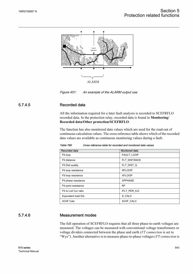
GUID-59F4E262-44C8-4EF3-A352-E6358C84C791 V2 EN
Figure 451: An example of the ALARM output use
5.7.4.5 Recorded data
All the information required for a later fault analysis is recorded to SCEFRFLOrecorded data. In the protection relay, recorded data is found in Monitoring/Recorded data/Other protection/SCEFRFLO.
The function has also monitored data values which are used for the read-out ofcontinuous calculation values. The cross reference table shows which of the recordeddata values are available as continuous monitoring values during a fault.
Table 766: Cross reference table for recorded and monitored data values
Recorded data Monitored dataFlt loop FAULT_LOOP
Flt distance FLT_DISTANCE
Flt Dist quality FLT_DIST_Q
Flt loop resistance RFLOOP
Flt loop reactance XFLOOP
Flt phase reactance XFPHASE
Flt point resistance RF
Flt to Lod Cur ratio IFLT_PER_ILD
Equivalent load Dis S_CALC
XC0F Calc XC0F_CALC
5.7.4.6 Measurement modes
The full operation of SCEFRFLO requires that all three phase-to-earth voltages aremeasured. The voltages can be measured with conventional voltage transformers orvoltage dividers connected between the phase and earth (VT connection is set to“Wye”). Another alternative is to measure phase-to-phase voltages (VT connection is
1MRS756887 N Section 5Protection related functions
615 series 843Technical Manual
set to “Delta”) and residual voltage (Uo). Both alternatives are covered by setting theconfiguration parameter Phase voltage Meas to "Accurate".
When the Phase voltage Meas setting is set to "Ph-to-ph without Uo" and only phase-to-phase voltages are available (but not Uo), only short-circuit measuring loops (faultloops “AB Fault”, “BC Fault” or “CA Fault” or “ABC Fault”) can be measuredaccurately. In this case, the earth-fault loops (fault loops either “AG Fault”, “BGFault” or “CG Fault”) cannot provide correct fault distance estimates and thetriggering of the function in case of earth fault is automatically disabled.
5.7.5 Application
The main objective of the feeder terminals is a fast, selective and reliable operation infaults inside the protected feeder. In addition, information on the distance to the faultpoint is very important for those involved in operation and maintenance. Reliableinformation on the fault location greatly decreases the downtime of the protectedfeeders and increases the total availability of a power system.
SCEFRFLO provides impedance-based fault location. It is designed for radiallyoperated distribution systems and is applicable for locating short circuits in all kindsof distribution networks. Earth faults can be located in effectively earthed and lowresistance/low-reactance earthed networks. Under certain limitations, SCEFRFLOcan also be applied for earth-fault location in unearthed distribution networks.
Configuration exampleA typical configuration example for SCEFRFLO triggering is illustrated in Figure 447where external triggering is applied, that is, Calculation Trg mode is set to “External”.The OPERATE signal from non-directional overcurrent function PHLPTOC is used toprovide an indication of a short circuit fault. The OPERATE signal from the directionalearth-fault function DEFLPDEF is used to provide an indication of an earth fault at theprotected feeder.
SCEFRFLO with the autoreclosing functionWhen SCEFRFLO is used with the autoreclosing sequence, the distance estimatefrom the first trip is typically the most accurate one. The fault distance estimates fromsuccessive trips are possible but accuracy can be decreased due to inaccurate loadcompensation. During the dead time of an autoreclosing sequence, the load conditionof the feeder is uncertain.
The triggering of SCEFRFLO can also be inhibited during the autoreclosingsequence. This is achieved by connecting the inverted READY signal from theautoreclosing function DARREC, which indicates that the autoreclosing sequence isin progress, to the BLOCK input of SCEFRFLO. Blocking of the SCEFRFLOtriggering is suggested during the autoreclosing sequence when the loadcompensation or steady-state asymmetry elimination is based on the delta quantities.This applies to the short circuit faults when Load Com PP loops is set to “Enabled” or,for earth faults, when EF algorithm Sel is set to “Load compensation” or “Loadmodelling”.
Section 5 1MRS756887 NProtection related functions
844 615 seriesTechnical Manual
5.7.6 SignalsTable 767: SCEFRFLO Input signals
Name Type Default DescriptionI_A SIGNAL 0 Phase A current
I_B SIGNAL 0 Phase B current
I_C SIGNAL 0 Phase C current
Io SIGNAL 0 Residual current
I1 SIGNAL 0 Positive sequence current
I2 SIGNAL 0 Negative sequence current
U_A_AB SIGNAL 0 Phase to earth voltage A or phase to phase voltageAB
U_B_BC SIGNAL 0 Phase to earth voltage B or phase to phase voltageBC
U_C_CA SIGNAL 0 Phase to earth voltage C or phase to phase voltageCA
Uo SIGNAL 0 Residual voltage
U1 SIGNAL 0 Positive phase sequence voltage
U2 SIGNAL 0 Negative phase sequence voltage
BLOCK BOOLEAN 0=False Block signal for activating the blocking mode
TRIGG BOOLEAN 0=False Distance calculation triggering signal
TRIGG_XC0F BOOLEAN 0=False XC0F calculation triggering signal
Table 768: SCEFRFLO Output signals
Name Type DescriptionALARM BOOLEAN Fault location alarm signal
5.7.7 SettingsTable 769: SCEFRFLO Group settings (Basic)
Parameter Values (Range) Unit Step Default DescriptionZ Max phase load 1.0...10000.0 ohm 0.1 80.0 Impedance per phase of max. load,
overcurr./under-imp., PSL
Ph leakage Ris 20...1000000 ohm 1 210000 Line PhE leakage resistance in primaryohms
Ph capacitive React 10...1000000 ohm 1 7000 Line PhE capacitive reactance in primaryohms
R1 line section A 0.000...1000.000 ohm / pu 0.001 1.000 Positive sequence line resistance, linesection A
X1 line section A 0.000...1000.000 ohm / pu 0.001 1.000 Positive sequence line reactance, linesection A
Table continues on next page
1MRS756887 N Section 5Protection related functions
615 series 845Technical Manual
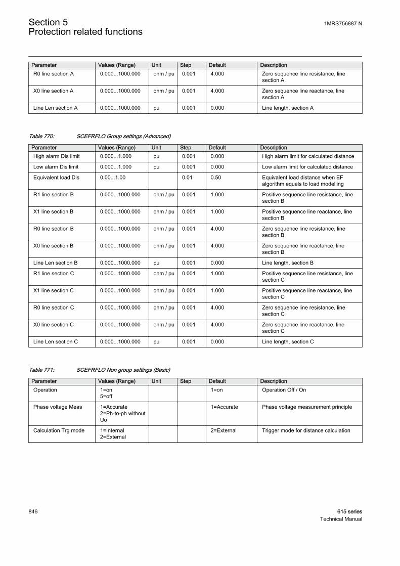
Parameter Values (Range) Unit Step Default DescriptionR0 line section A 0.000...1000.000 ohm / pu 0.001 4.000 Zero sequence line resistance, line
section A
X0 line section A 0.000...1000.000 ohm / pu 0.001 4.000 Zero sequence line reactance, linesection A
Line Len section A 0.000...1000.000 pu 0.001 0.000 Line length, section A
Table 770: SCEFRFLO Group settings (Advanced)
Parameter Values (Range) Unit Step Default DescriptionHigh alarm Dis limit 0.000...1.000 pu 0.001 0.000 High alarm limit for calculated distance
Low alarm Dis limit 0.000...1.000 pu 0.001 0.000 Low alarm limit for calculated distance
Equivalent load Dis 0.00...1.00 0.01 0.50 Equivalent load distance when EFalgorithm equals to load modelling
R1 line section B 0.000...1000.000 ohm / pu 0.001 1.000 Positive sequence line resistance, linesection B
X1 line section B 0.000...1000.000 ohm / pu 0.001 1.000 Positive sequence line reactance, linesection B
R0 line section B 0.000...1000.000 ohm / pu 0.001 4.000 Zero sequence line resistance, linesection B
X0 line section B 0.000...1000.000 ohm / pu 0.001 4.000 Zero sequence line reactance, linesection B
Line Len section B 0.000...1000.000 pu 0.001 0.000 Line length, section B
R1 line section C 0.000...1000.000 ohm / pu 0.001 1.000 Positive sequence line resistance, linesection C
X1 line section C 0.000...1000.000 ohm / pu 0.001 1.000 Positive sequence line reactance, linesection C
R0 line section C 0.000...1000.000 ohm / pu 0.001 4.000 Zero sequence line resistance, linesection C
X0 line section C 0.000...1000.000 ohm / pu 0.001 4.000 Zero sequence line reactance, linesection C
Line Len section C 0.000...1000.000 pu 0.001 0.000 Line length, section C
Table 771: SCEFRFLO Non group settings (Basic)
Parameter Values (Range) Unit Step Default DescriptionOperation 1=on
5=off 1=on Operation Off / On
Phase voltage Meas 1=Accurate2=Ph-to-ph withoutUo
1=Accurate Phase voltage measurement principle
Calculation Trg mode 1=Internal2=External
2=External Trigger mode for distance calculation
Section 5 1MRS756887 NProtection related functions
846 615 seriesTechnical Manual

Table 772: SCEFRFLO Non group settings (Advanced)
Parameter Values (Range) Unit Step Default DescriptionEF algorithm Sel 1=Load
compensation2=Load modelling
1=Loadcompensation
Selection for PhE-loop calculationalgorithm
EF algorithm Cur Sel 1=Io based2=I2 based
1=Io based Selection for earth-fault current model
Load Com PP loops 0=Disabled1=Enabled
1=Enabled Enable load compensation for PP/3P-loops
Enable simple model 0=Disabled1=Enabled
0=Disabled Enable calc. without impedance settingsfor PP/3P-loops
Distance estimate Va 0.001...0.300 0.001 0.015 Allowed variation of short circuit distanceestimate
5.7.8 Monitored dataTable 773: SCEFRFLO Monitored data
Name Type Values (Range) Unit DescriptionRF FLOAT32 0.0...1000000.0 ohm Fault point resistance in
primary ohms
FAULT_LOOP Enum 1=AG Fault2=BG Fault3=CG Fault4=AB Fault5=BC Fault6=CA Fault7=ABC Fault-5=No fault
Fault impedance loop
FLT_DISTANCE FLOAT32 0.00...3000.00 pu Fault distance in unitsselected by the user
FLT_DIST_Q INT32 0...511 Fault distance quality
RFLOOP FLOAT32 0.0...1000000.0 ohm Fault loop resistance inprimary ohms
XFLOOP FLOAT32 0.0...1000000.0 ohm Fault loop reactance inprimary ohms
XFPHASE FLOAT32 0.0...1000000.0 ohm Positive sequence faultreactance in primaryohms
IFLT_PER_ILD FLOAT32 0.00...60000.00 Fault to load current ratio
S_CALC FLOAT32 0.00...1.00 Estimated equivalentload distance
XC0F_CALC FLOAT32 0.0...1000000.0 ohm Estimated PhEcapacitive reactance ofline
SCEFRFLO Enum 1=on2=blocked3=test4=test/blocked5=off
Status
Triggering time Timestamp Estimate triggering time
Table continues on next page
1MRS756887 N Section 5Protection related functions
615 series 847Technical Manual
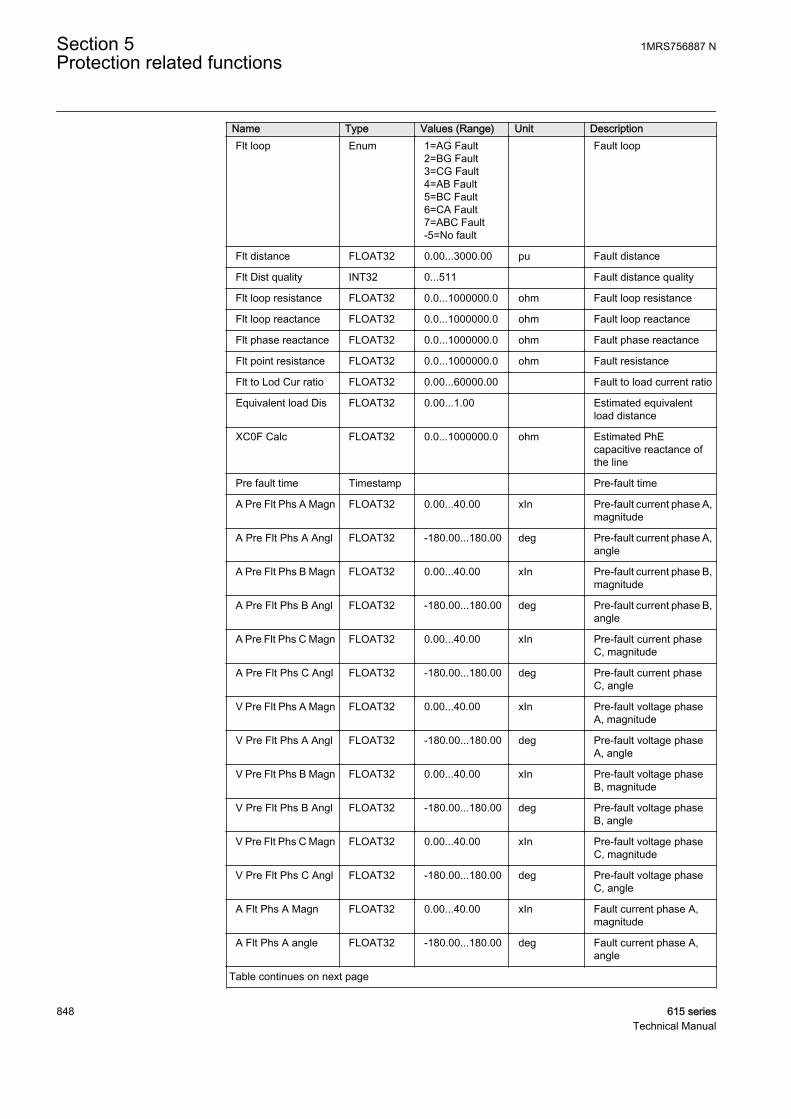
Name Type Values (Range) Unit DescriptionFlt loop Enum 1=AG Fault
2=BG Fault3=CG Fault4=AB Fault5=BC Fault6=CA Fault7=ABC Fault-5=No fault
Fault loop
Flt distance FLOAT32 0.00...3000.00 pu Fault distance
Flt Dist quality INT32 0...511 Fault distance quality
Flt loop resistance FLOAT32 0.0...1000000.0 ohm Fault loop resistance
Flt loop reactance FLOAT32 0.0...1000000.0 ohm Fault loop reactance
Flt phase reactance FLOAT32 0.0...1000000.0 ohm Fault phase reactance
Flt point resistance FLOAT32 0.0...1000000.0 ohm Fault resistance
Flt to Lod Cur ratio FLOAT32 0.00...60000.00 Fault to load current ratio
Equivalent load Dis FLOAT32 0.00...1.00 Estimated equivalentload distance
XC0F Calc FLOAT32 0.0...1000000.0 ohm Estimated PhEcapacitive reactance ofthe line
Pre fault time Timestamp Pre-fault time
A Pre Flt Phs A Magn FLOAT32 0.00...40.00 xIn Pre-fault current phase A,magnitude
A Pre Flt Phs A Angl FLOAT32 -180.00...180.00 deg Pre-fault current phase A,angle
A Pre Flt Phs B Magn FLOAT32 0.00...40.00 xIn Pre-fault current phase B,magnitude
A Pre Flt Phs B Angl FLOAT32 -180.00...180.00 deg Pre-fault current phase B,angle
A Pre Flt Phs C Magn FLOAT32 0.00...40.00 xIn Pre-fault current phaseC, magnitude
A Pre Flt Phs C Angl FLOAT32 -180.00...180.00 deg Pre-fault current phaseC, angle
V Pre Flt Phs A Magn FLOAT32 0.00...40.00 xIn Pre-fault voltage phaseA, magnitude
V Pre Flt Phs A Angl FLOAT32 -180.00...180.00 deg Pre-fault voltage phaseA, angle
V Pre Flt Phs B Magn FLOAT32 0.00...40.00 xIn Pre-fault voltage phaseB, magnitude
V Pre Flt Phs B Angl FLOAT32 -180.00...180.00 deg Pre-fault voltage phaseB, angle
V Pre Flt Phs C Magn FLOAT32 0.00...40.00 xIn Pre-fault voltage phaseC, magnitude
V Pre Flt Phs C Angl FLOAT32 -180.00...180.00 deg Pre-fault voltage phaseC, angle
A Flt Phs A Magn FLOAT32 0.00...40.00 xIn Fault current phase A,magnitude
A Flt Phs A angle FLOAT32 -180.00...180.00 deg Fault current phase A,angle
Table continues on next page
Section 5 1MRS756887 NProtection related functions
848 615 seriesTechnical Manual
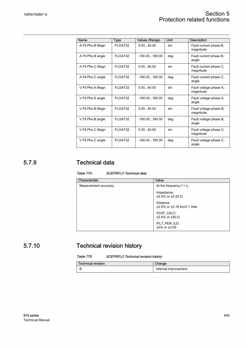
Name Type Values (Range) Unit DescriptionA Flt Phs B Magn FLOAT32 0.00...40.00 xIn Fault current phase B,
magnitude
A Flt Phs B angle FLOAT32 -180.00...180.00 deg Fault current phase B,angle
A Flt Phs C Magn FLOAT32 0.00...40.00 xIn Fault current phase C,magnitude
A Flt Phs C angle FLOAT32 -180.00...180.00 deg Fault current phase C,angle
V Flt Phs A Magn FLOAT32 0.00...40.00 xIn Fault voltage phase A,magnitude
V Flt Phs A angle FLOAT32 -180.00...180.00 deg Fault voltage phase A,angle
V Flt Phs B Magn FLOAT32 0.00...40.00 xIn Fault voltage phase B,magnitude
V Flt Phs B angle FLOAT32 -180.00...180.00 deg Fault voltage phase B,angle
V Flt Phs C Magn FLOAT32 0.00...40.00 xIn Fault voltage phase C,magnitude
V Flt Phs C angle FLOAT32 -180.00...180.00 deg Fault voltage phase C,angle
5.7.9 Technical dataTable 774: SCEFRFLO Technical data
Characteristic ValueMeasurement accuracy At the frequency f = fn
Impedance:±2.5% or ±0.25 Ω
Distance:±2.5% or ±0.16 km/0.1 mile
XC0F_CALC:±2.5% or ±50 Ω
IFLT_PER_ILD:±5% or ±0.05
5.7.10 Technical revision historyTable 775: SCEFRFLO Technical revision history
Technical revision ChangeB Internal improvement.
1MRS756887 N Section 5Protection related functions
615 series 849Technical Manual

5.8 Switch onto fault CBPSOF
5.8.1 IdentificationFunction description IEC 61850
identificationIEC 60617identification
ANSI/IEEE C37.2device number
Switch onto fault CBPSOF SOTF SOTF
5.8.2 Function block
GUID-5F45AD47-0FF7-47EC-B360-7F0F5F97E7F8 V1 EN
Figure 452: Function block
5.8.3 Functionality
The switch onto fault function CBPSOF provides an instantaneous trip or a timedelayed trip when closing the breaker while a fault exists.
CBPSOF is activated when the CB_CL_CMD circuit breaker closing command is sethigh. The function has START and START_DLYD inputs for immediate or delayedstart operation respectively.
The function contains a blocking functionality. It is possible to block function outputsand the reset timers, if desired.
5.8.4 Operation principle
The function can be enabled and disabled with the Operation setting. Thecorresponding parameter values are "On" and "Off".
The operation of CBPSOF can be described by using a module diagram. All themodules in the diagram are explained in the next sections.
Section 5 1MRS756887 NProtection related functions
850 615 seriesTechnical Manual

GUID-A786834F-1BA2-4DD6-8457-D38BCBC4ABF8 V2 EN
Figure 453: Functional module diagram
TriggerThis module is used for detecting possible fault immediately after closing the circuitbreaker. An external protection function for example, PHxPTOC or EFxPTOC is usedfor fault indication. The START and START_DLYD inputs are available for feedingthe detected fault.
• START input is used when it is required to enable SOTF control immediatelyafter protection function indicates a fault.
• START_DLYD input is used when time delayed SOTF control enabling isneeded. In this case, the delay can be set with a Operate delay time setting.
SOTF controlThe SOTF control is activated when CB_CL_CMD circuit breaker closing commandinput is activated. The module is kept active until the set SOTF reset time is exceededafter the CB_CL_CMD is deactivated. The OPERATE output is activated when a faultindication signal is received from the Trigger module while the SOTF control is stillactive.
5.8.5 Application
The CB_CL_CMD input activates CBPSOF. In the standard configuration, the breakerclose command should be connected to this input. The SOTF reset time settingparameter is used for keeping CBPSOF active for a certain time after the CB closecommand is executed.
The overcurrent high and instantaneous signals, for example, the PHIPTOC STARTsignal is connected to the function START input. When the SOTF control module isactive and the START input is activated, the function operates instantaneously withoutany delays.
The overcurrent low stage signals, for example, PHLPTOC START signal isconnected to the function START_DLYD input. The setting parameter Operate delaytime is used to delay the operation in case of inrush situation.
1MRS756887 N Section 5Protection related functions
615 series 851Technical Manual

5.8.6 SignalsTable 776: CBPSOF Input signals
Name Type Default DescriptionSTART BOOLEAN 0=False Start from function to be accelerated by SOTF
START_DLYD BOOLEAN 0=False Start from function to be accelerated with delay bySOTF
CB_CL_CMD BOOLEAN 0=False External enabling of SOTF by CB close command
BLOCK BOOLEAN 0=False Block of function
Table 777: CBPSOF Output signals
Name Type DescriptionOPERATE BOOLEAN Operate
5.8.7 SettingsTable 778: CBPSOF Group settings (Basic)
Parameter Values (Range) Unit Step Default DescriptionOperate delay time 0...60000 ms 1 0 Time delay for start input
Table 779: CBPSOF Group settings (Advanced)
Parameter Values (Range) Unit Step Default DescriptionSOTF reset time 0...60000 ms 1 1000 SOTF detection period after initialization
Table 780: CBPSOF Non group settings (Basic)
Parameter Values (Range) Unit Step Default DescriptionOperation 1=on
5=off 1=on Operation Off / On
5.8.8 Monitored dataTable 781: CBPSOF Monitored data
Name Type Values (Range) Unit DescriptionCBPSOF Enum 1=on
2=blocked3=test4=test/blocked5=off
Status
Section 5 1MRS756887 NProtection related functions
852 615 seriesTechnical Manual

5.8.9 Technical dataTable 782: CBPSOF Technical data
Characteristic ValueOperate time accuracy ±1.0% of the set value or ±20 ms
1MRS756887 N Section 5Protection related functions
615 series 853Technical Manual

854

Section 6 Supervision functions
6.1 Trip circuit supervision TCSSCBR
6.1.1 IdentificationFunction description IEC 61850
identificationIEC 60617identification
ANSI/IEEE C37.2device number
Trip circuit supervision TCSSCBR TCS TCM
6.1.2 Function block
A070788 V1 EN
Figure 454: Function block
6.1.3 Functionality
The trip circuit supervision function TCSSCBR is designed to supervise the controlcircuit of the circuit breaker. The invalidity of a control circuit is detected by using adedicated output contact that contains the supervision functionality. The failure of acircuit is reported to the corresponding function block in the relay configuration.
The function starts and operates when TCSSCBR detects a trip circuit failure. Theoperating time characteristic for the function is DT. The function operates after apredefined operating time and resets when the fault disappears.
The function contains a blocking functionality. Blocking deactivates the ALARMoutput and resets the timer.
6.1.4 Operation principle
The function can be enabled and disabled with the Operation setting. Thecorresponding parameter values are "On" and "Off".
The operation of TCSSCBR can be described by using a module diagram. All themodules in the diagram are explained in the next sections.
1MRS756887 N Section 6Supervision functions
615 series 855Technical Manual

A070785 V2 EN
Figure 455: Functional module diagram
TCS statusThis module receives the trip circuit status from the hardware. A detected failure in thetrip circuit activates the timer.
TimerOnce activated, the timer runs until the set value of Operate delay time has elapsed.The time characteristic is according to DT. When the operation timer has reached themaximum time value, the ALARM output is activated. If a drop-off situation occursduring the operate time up counting, the fixed 0.5 s reset timer is activated. After thattime, the operation timer is reset.
The BLOCK input can be controlled with a binary input, a horizontal communicationinput or an internal signal of the relay program. The activation of the BLOCK inputprevents the ALARM output to be activated.
6.1.5 Application
TCSSCBR detects faults in the electrical control circuit of the circuit breaker. Thefunction can supervise both open and closed coil circuits. This supervision isnecessary to find out the vitality of the control circuits continuously.
Figure 456 shows an application of the trip circuit supervision function use. The bestsolution is to connect an external Rext shunt resistor in parallel with the circuit breakerinternal contact. Although the circuit breaker internal contact is open, TCS can see thetrip circuit through Rext. The Rext resistor should have such a resistance that the currentthrough the resistance remains small, that is, it does not harm or overload the circuitbreaker's trip coil.
Section 6 1MRS756887 NSupervision functions
856 615 seriesTechnical Manual
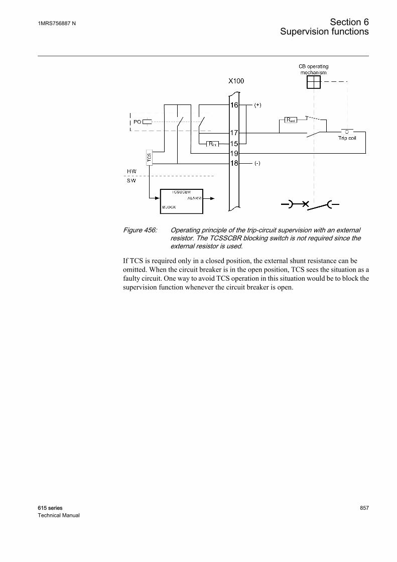
A051097 V6 EN
Figure 456: Operating principle of the trip-circuit supervision with an externalresistor. The TCSSCBR blocking switch is not required since theexternal resistor is used.
If TCS is required only in a closed position, the external shunt resistance can beomitted. When the circuit breaker is in the open position, TCS sees the situation as afaulty circuit. One way to avoid TCS operation in this situation would be to block thesupervision function whenever the circuit breaker is open.
1MRS756887 N Section 6Supervision functions
615 series 857Technical Manual
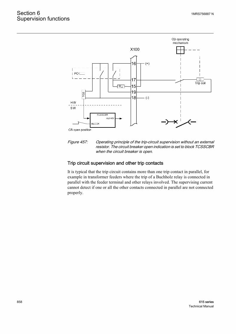
A051906 V4 EN
Figure 457: Operating principle of the trip-circuit supervision without an externalresistor. The circuit breaker open indication is set to block TCSSCBRwhen the circuit breaker is open.
Trip circuit supervision and other trip contactsIt is typical that the trip circuit contains more than one trip contact in parallel, forexample in transformer feeders where the trip of a Buchholz relay is connected inparallel with the feeder terminal and other relays involved. The supervising currentcannot detect if one or all the other contacts connected in parallel are not connectedproperly.
Section 6 1MRS756887 NSupervision functions
858 615 seriesTechnical Manual

A070968 V5 EN
Figure 458: Constant test current flow in parallel trip contacts and trip circuitsupervision
In case of parallel trip contacts, the recommended way to do the wiring is that the TCStest current flows through all wires and joints.
1MRS756887 N Section 6Supervision functions
615 series 859Technical Manual
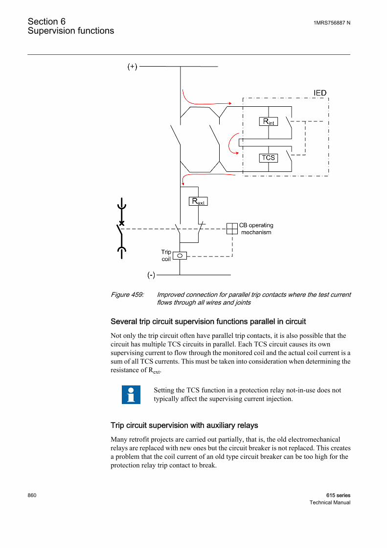
A070970 V3 EN
Figure 459: Improved connection for parallel trip contacts where the test currentflows through all wires and joints
Several trip circuit supervision functions parallel in circuitNot only the trip circuit often have parallel trip contacts, it is also possible that thecircuit has multiple TCS circuits in parallel. Each TCS circuit causes its ownsupervising current to flow through the monitored coil and the actual coil current is asum of all TCS currents. This must be taken into consideration when determining theresistance of Rext.
Setting the TCS function in a protection relay not-in-use does nottypically affect the supervising current injection.
Trip circuit supervision with auxiliary relaysMany retrofit projects are carried out partially, that is, the old electromechanicalrelays are replaced with new ones but the circuit breaker is not replaced. This createsa problem that the coil current of an old type circuit breaker can be too high for theprotection relay trip contact to break.
Section 6 1MRS756887 NSupervision functions
860 615 seriesTechnical Manual
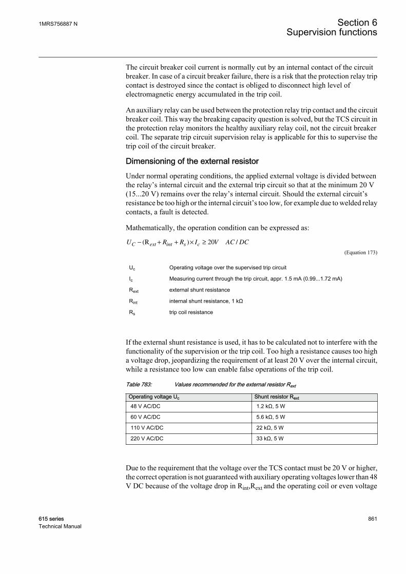
The circuit breaker coil current is normally cut by an internal contact of the circuitbreaker. In case of a circuit breaker failure, there is a risk that the protection relay tripcontact is destroyed since the contact is obliged to disconnect high level ofelectromagnetic energy accumulated in the trip coil.
An auxiliary relay can be used between the protection relay trip contact and the circuitbreaker coil. This way the breaking capacity question is solved, but the TCS circuit inthe protection relay monitors the healthy auxiliary relay coil, not the circuit breakercoil. The separate trip circuit supervision relay is applicable for this to supervise thetrip coil of the circuit breaker.
Dimensioning of the external resistorUnder normal operating conditions, the applied external voltage is divided betweenthe relay’s internal circuit and the external trip circuit so that at the minimum 20 V(15...20 V) remains over the relay’s internal circuit. Should the external circuit’sresistance be too high or the internal circuit’s too low, for example due to welded relaycontacts, a fault is detected.
Mathematically, the operation condition can be expressed as:
U R R I V AC DCC ext int s c− + + × ≥(R ) /20
A070986 V2 EN (Equation 173)
Uc Operating voltage over the supervised trip circuit
Ic Measuring current through the trip circuit, appr. 1.5 mA (0.99...1.72 mA)
Rext external shunt resistance
Rint internal shunt resistance, 1 kΩ
Rs trip coil resistance
If the external shunt resistance is used, it has to be calculated not to interfere with thefunctionality of the supervision or the trip coil. Too high a resistance causes too higha voltage drop, jeopardizing the requirement of at least 20 V over the internal circuit,while a resistance too low can enable false operations of the trip coil.
Table 783: Values recommended for the external resistor Rext
Operating voltage Uc Shunt resistor Rext
48 V AC/DC 1.2 kΩ, 5 W
60 V AC/DC 5.6 kΩ, 5 W
110 V AC/DC 22 kΩ, 5 W
220 V AC/DC 33 kΩ, 5 W
Due to the requirement that the voltage over the TCS contact must be 20 V or higher,the correct operation is not guaranteed with auxiliary operating voltages lower than 48V DC because of the voltage drop in Rint,Rext and the operating coil or even voltage
1MRS756887 N Section 6Supervision functions
615 series 861Technical Manual
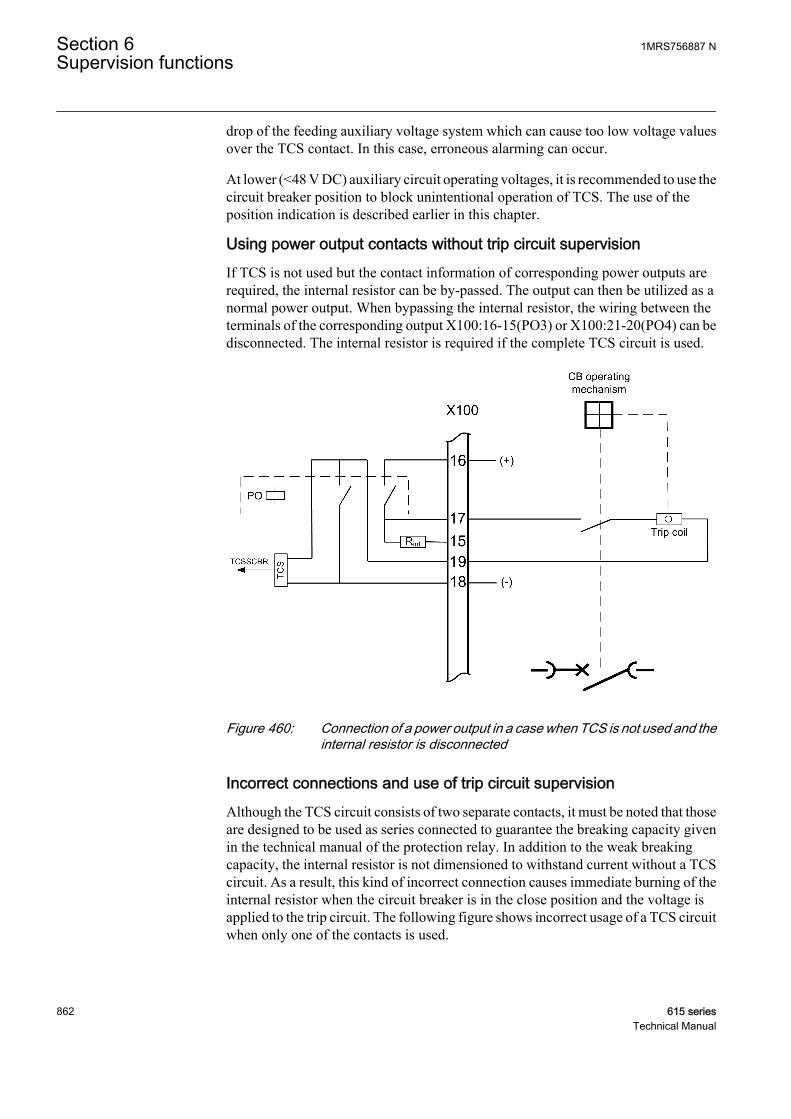
drop of the feeding auxiliary voltage system which can cause too low voltage valuesover the TCS contact. In this case, erroneous alarming can occur.
At lower (<48 V DC) auxiliary circuit operating voltages, it is recommended to use thecircuit breaker position to block unintentional operation of TCS. The use of theposition indication is described earlier in this chapter.
Using power output contacts without trip circuit supervisionIf TCS is not used but the contact information of corresponding power outputs arerequired, the internal resistor can be by-passed. The output can then be utilized as anormal power output. When bypassing the internal resistor, the wiring between theterminals of the corresponding output X100:16-15(PO3) or X100:21-20(PO4) can bedisconnected. The internal resistor is required if the complete TCS circuit is used.
GUID-0560DE53-903C-4D81-BAFD-175B9251872D V3 EN
Figure 460: Connection of a power output in a case when TCS is not used and theinternal resistor is disconnected
Incorrect connections and use of trip circuit supervisionAlthough the TCS circuit consists of two separate contacts, it must be noted that thoseare designed to be used as series connected to guarantee the breaking capacity givenin the technical manual of the protection relay. In addition to the weak breakingcapacity, the internal resistor is not dimensioned to withstand current without a TCScircuit. As a result, this kind of incorrect connection causes immediate burning of theinternal resistor when the circuit breaker is in the close position and the voltage isapplied to the trip circuit. The following figure shows incorrect usage of a TCS circuitwhen only one of the contacts is used.
Section 6 1MRS756887 NSupervision functions
862 615 seriesTechnical Manual

A070972 V4 EN
Figure 461: Incorrect connection of trip-circuit supervision
A connection of three protection relays with a double pole trip circuit is shown in thefollowing figure. Only the protection relay R3 has an internal TCS circuit. In order totest the operation of the protection relay R2, but not to trip the circuit breaker, theupper trip contact of the protection relay R2 is disconnected, as shown in the figure,while the lower contact is still connected. When the protection relay R2 operates, thecoil current starts to flow through the internal resistor of the protection relay R3 andthe resistor burns immediately. As proven with the previous examples, both tripcontacts must operate together. Attention should also be paid for correct usage of thetrip-circuit supervision while, for example, testing the protection relay.
1MRS756887 N Section 6Supervision functions
615 series 863Technical Manual

A070974 V5 EN
Figure 462: Incorrect testing of protection relays
6.1.6 SignalsTable 784: TCSSCBR Input signals
Name Type Default DescriptionBLOCK BOOLEAN 0=False Block input status
Table 785: TCSSCBR Output signals
Name Type DescriptionALARM BOOLEAN Alarm output
6.1.7 SettingsTable 786: TCSSCBR Non group settings (Basic)
Parameter Values (Range) Unit Step Default DescriptionOperation 1=on
5=off 1=on Operation Off / On
Operate delay time 20...300000 ms 1 3000 Operate delay time
Section 6 1MRS756887 NSupervision functions
864 615 seriesTechnical Manual
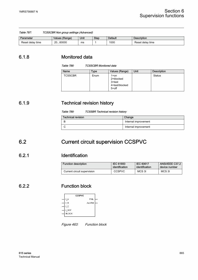
Table 787: TCSSCBR Non group settings (Advanced)
Parameter Values (Range) Unit Step Default DescriptionReset delay time 20...60000 ms 1 1000 Reset delay time
6.1.8 Monitored dataTable 788: TCSSCBR Monitored data
Name Type Values (Range) Unit DescriptionTCSSCBR Enum 1=on
2=blocked3=test4=test/blocked5=off
Status
6.1.9 Technical revision historyTable 789: TCSSBR Technical revision history
Technical revision ChangeB Internal improvement
C Internal improvement
6.2 Current circuit supervision CCSPVC
6.2.1 IdentificationFunction description IEC 61850
identificationIEC 60617identification
ANSI/IEEE C37.2device number
Current circuit supervision CCSPVC MCS 3I MCS 3I
6.2.2 Function block
GUID-7695BECB-3520-4932-9429-9A552171C0CA V2 EN
Figure 463: Function block
1MRS756887 N Section 6Supervision functions
615 series 865Technical Manual

6.2.3 Functionality
The current circuit supervision function CCSPVC is used for monitoring currenttransformer secondary circuits.
CCSPVC calculates internally the sum of phase currents (I_A, I_B and I_C) andcompares the sum against the measured single reference current (I_REF).Thereference current must originate from other three-phase CT cores than the phasecurrents (I_A, I_B and I_C) and it is to be externally summated, that is, outside theprotection relay.
CCSPVC detects a fault in the measurement circuit and issues an alarm or blocks theprotection functions to avoid unwanted tripping.
It must be remembered that the blocking of protection functions at an occurring openCT circuit means that the situation remains unchanged and extremely high voltagesstress the secondary circuit.
6.2.4 Operation principle
The function can be enabled and disabled with the Operation setting. Thecorresponding parameter values are "On" and "Off".
The operation of CCSPVC can be described with a module diagram. All the modulesin the diagram are explained in the next sections.
GUID-A4F2DBEE-938F-4961-9DAD-977151DDBA13 V1 EN
Figure 464: Functional module diagram
Differential current monitoringDifferential current monitoring supervises the difference between the summed phasecurrents I_A, I_B and I_C and the reference current I_REF.
The current operating characteristics can be selected with the Start value setting.When the highest phase current is less than 1.0 × In, the differential current limit isdefined with Start value. When the highest phase current is more than 1.0 × In, thedifferential current limit is calculated with the equation.
MAX I A I B I C Start value( _ , _ , _ )×
GUID-A0C500CA-4A1A-44AA-AC14-4540676DD8CB V3 EN (Equation 174)
The differential current is limited to 1.0 × In.
Section 6 1MRS756887 NSupervision functions
866 615 seriesTechnical Manual
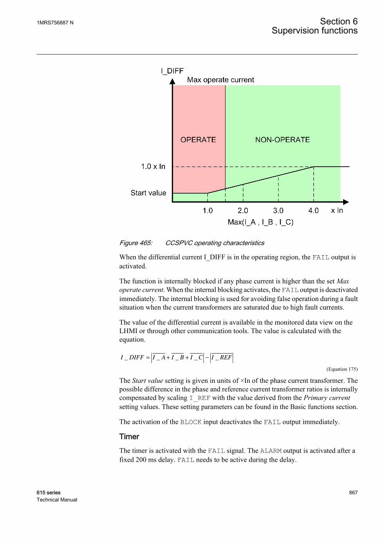
GUID-DC279F84-19B8-4FCB-A79A-2461C047F1B2 V1 EN
Figure 465: CCSPVC operating characteristics
When the differential current I_DIFF is in the operating region, the FAIL output isactivated.
The function is internally blocked if any phase current is higher than the set Maxoperate current. When the internal blocking activates, the FAIL output is deactivatedimmediately. The internal blocking is used for avoiding false operation during a faultsituation when the current transformers are saturated due to high fault currents.
The value of the differential current is available in the monitored data view on theLHMI or through other communication tools. The value is calculated with theequation.
I DIFF I A I B I C I REF_ _ _ _ _= + + −
GUID-9CC931FA-0637-4FF8-85D4-6F461BD996A9 V2 EN (Equation 175)
The Start value setting is given in units of ×In of the phase current transformer. Thepossible difference in the phase and reference current transformer ratios is internallycompensated by scaling I_REF with the value derived from the Primary currentsetting values. These setting parameters can be found in the Basic functions section.
The activation of the BLOCK input deactivates the FAIL output immediately.
TimerThe timer is activated with the FAIL signal. The ALARM output is activated after afixed 200 ms delay. FAIL needs to be active during the delay.
1MRS756887 N Section 6Supervision functions
615 series 867Technical Manual
When the internal blocking is activated, the FAIL output is deactivated immediatelyimmediately. However, the ALARM output is deactivated immediately after a fixeddelay of three seconds.
The function resets when the differential current is below the start value and thehighest phase current is more than 5 percent of the nominal current (0.05 × In).
If the current falls to zero when the FAIL or ALARM outputs are active, thedeactivation of these outputs is prevented.
The activation of the BLOCK input deactivates the ALARM output.
6.2.5 Application
Open or short-circuited current transformer cores can cause unwanted operation inmany protection functions such as differential, earth-fault current and negative-sequence current functions. When currents from two independent three-phase sets ofCTs or CT cores measuring the same primary currents are available, reliable currentcircuit supervision can be arranged by comparing the currents from the two sets. Whenan error in any CT circuit is detected, the protection functions concerned can beblocked and an alarm given.
In case of high currents, the unequal transient saturation of CT cores with a differentremanence or saturation factor can result in differences in the secondary currents fromthe two CT cores. An unwanted blocking of protection functions during the transientstage must then be avoided.
The supervision function must be sensitive and have a short operation time to preventunwanted tripping from fast-acting, sensitive numerical protections in case of faultyCT secondary circuits.
Open CT circuits create extremely high voltages in the circuits, whichmay damage the insulation and cause further problems. This must betaken into consideration especially when the protection functions areblocked.
When the reference current is not connected to the protection relay,the function should be turned off. Otherwise, the FAIL output isactivated when unbalance occurs in the phase currents even if therewas nothing wrong with the measurement circuit.
Reference current measured with core-balanced current transformerCCSPVC compares the sum of phase currents to the current measured with the core-balanced CT.
Section 6 1MRS756887 NSupervision functions
868 615 seriesTechnical Manual
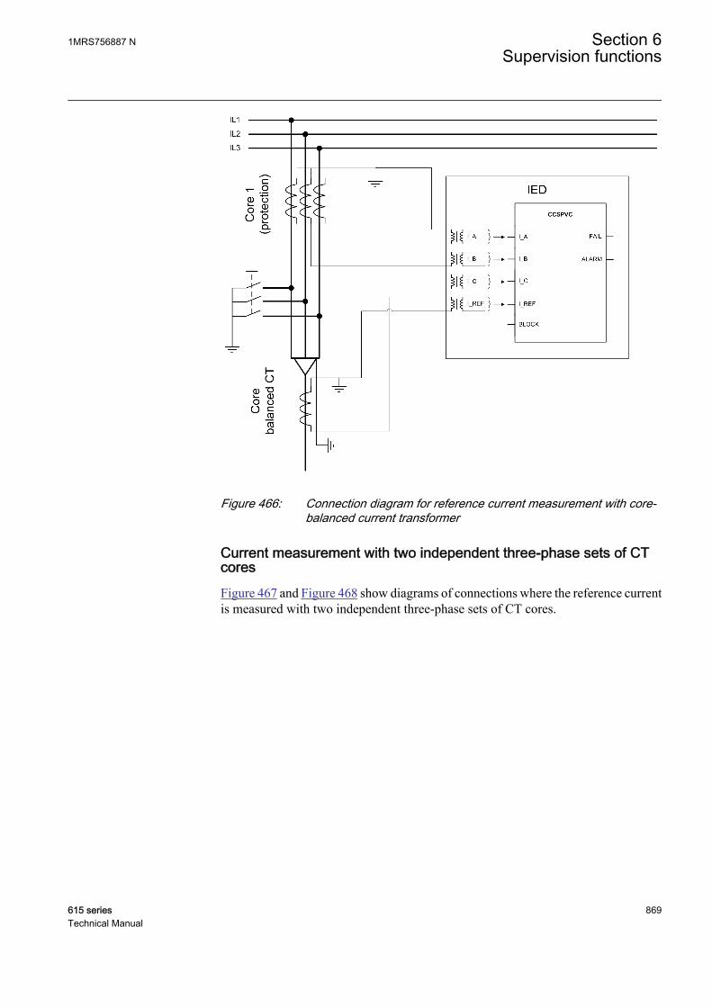
GUID-88FC46C8-8D14-45DE-9E36-E517EA3886AA V2 EN
Figure 466: Connection diagram for reference current measurement with core-balanced current transformer
Current measurement with two independent three-phase sets of CTcoresFigure 467 and Figure 468 show diagrams of connections where the reference currentis measured with two independent three-phase sets of CT cores.
1MRS756887 N Section 6Supervision functions
615 series 869Technical Manual

GUID-8DC3B17A-13FE-4E38-85C6-A228BC03206B V2 EN
Figure 467: Connection diagram for current circuit supervision with two sets ofthree-phase current transformer protection cores
When using the measurement core for reference currentmeasurement, it should be noted that the saturation level of themeasurement core is much lower than with the protection core. Thisshould be taken into account when setting the current circuitsupervision function.
Section 6 1MRS756887 NSupervision functions
870 615 seriesTechnical Manual

GUID-C5A6BB27-36F9-4652-A5E4-E3D32CFEA77B V2 EN
Figure 468: Connection diagram for current circuit supervision with two sets ofthree-phase current transformer cores (protection andmeasurement)
Example of incorrect connectionThe currents must be measured with two independent cores, that is, the phase currentsmust be measured with a different core than the reference current. A connectiondiagram shows an example of a case where the phase currents and the referencecurrents are measured from the same core.
1MRS756887 N Section 6Supervision functions
615 series 871Technical Manual

GUID-BBF3E23F-7CE4-43A3-8986-5AACA0433235 V2 EN
Figure 469: Example of incorrect reference current connection
6.2.6 SignalsTable 790: CCSPVC Input signals
Name Type Default DescriptionI_A SIGNAL 0 Phase A current
I_B SIGNAL 0 Phase B current
I_C SIGNAL 0 Phase C current
I_REF SIGNAL 0 Reference current
BLOCK BOOLEAN 0=False Block signal for all binary outputs
Table 791: CCSPVC Output signals
Name Type DescriptionFAIL BOOLEAN Fail output
ALARM BOOLEAN Alarm output
Section 6 1MRS756887 NSupervision functions
872 615 seriesTechnical Manual

6.2.7 SettingsTable 792: CCSPVC Non group settings (Basic)
Parameter Values (Range) Unit Step Default DescriptionOperation 1=on
5=off 1=on Operation On / Off
Start value 0.05...0.20 xIn 0.01 0.05 Minimum operate current differential level
Table 793: CCSPVC Non group settings (Advanced)
Parameter Values (Range) Unit Step Default DescriptionMax operate current 1.00...5.00 xIn 0.01 1.50 Block of the function at high phase current
6.2.8 Monitored dataTable 794: CCSPVC Monitored data
Name Type Values (Range) Unit DescriptionIDIFF FLOAT32 0.00...40.00 xIn Differential current
CCSPVC Enum 1=on2=blocked3=test4=test/blocked5=off
Status
6.2.9 Technical dataTable 795: CCSPVC Technical data
Characteristic Value
Operate time 1) <30 ms
1) Including the delay of the output contact
6.2.10 Technical revision historyTable 796: CCSPVC Technical revision history
Technical revision ChangeB Internal improvement
C Internal improvement
D Internal improvement
1MRS756887 N Section 6Supervision functions
615 series 873Technical Manual

6.3 Current transformer supervision for high-impedanceprotection scheme HZCCxSPVC
6.3.1 IdentificationFunction description IEC 61850
identificationIEC 60617identification
ANSI/IEEE C37.2device number
Current transformer supervision forhigh-impedance protection scheme forphase A
HZCCASPVC MCS I_A MCS I_A
Current transformer supervision forhigh-impedance protection scheme forphase B
HZCCBSPVC MCS I_B MCS I_B
Current transformer supervision forhigh-impedance protection scheme forphase C
HZCCCSPVC MCS I_C MCS I_C
6.3.2 Function block
GUID-BDB9139A-3F45-479F-9DCA-6C4AAAF33504 V1 EN
Figure 470: Function block
6.3.3 Functionality
The current transformer supervision for high-impedance protection scheme functionHZCCxSPVC is a dedicated phase-segregated supervision function to be used alongwith the high-impedance differential protection for detecting the broken CTsecondary wires. The differential current is taken as an input for the protection relay.During normal CT condition, the value of the differential current is zero. However,when the CT is broken, the secondary differential current starts flowing and it is usedfor generating alarms.
To avoid faulty operation, HZCCxSPVC should have a sensitive setting, compared tothe high-impedance differential protection. The function is likely to start underthrough-fault conditions. However, by incorporating a high time delay (3 s or more),the downstream protection clears the fault before an alarm is generated.
HZCCxSPVC generates an alarm when the differential current exceeds the set limit.The function operates within the DT characteristic.
The function contains a blocking functionality. It is possible to block the functionoutput, Timer or the whole function.
Section 6 1MRS756887 NSupervision functions
874 615 seriesTechnical Manual
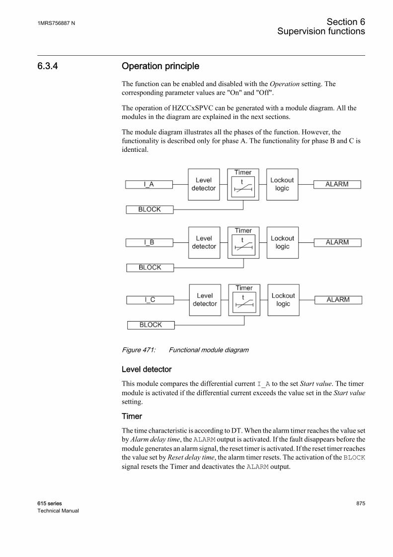
6.3.4 Operation principle
The function can be enabled and disabled with the Operation setting. Thecorresponding parameter values are "On" and "Off".
The operation of HZCCxSPVC can be generated with a module diagram. All themodules in the diagram are explained in the next sections.
The module diagram illustrates all the phases of the function. However, thefunctionality is described only for phase A. The functionality for phase B and C isidentical.
GUID-8C5661F6-12FC-4733-886C-01F793DF2FBF V1 EN
Figure 471: Functional module diagram
Level detectorThis module compares the differential current I_A to the set Start value. The timermodule is activated if the differential current exceeds the value set in the Start valuesetting.
TimerThe time characteristic is according to DT. When the alarm timer reaches the value setby Alarm delay time, the ALARM output is activated. If the fault disappears before themodule generates an alarm signal, the reset timer is activated. If the reset timer reachesthe value set by Reset delay time, the alarm timer resets. The activation of the BLOCKsignal resets the Timer and deactivates the ALARM output.
1MRS756887 N Section 6Supervision functions
615 series 875Technical Manual
Lockout logicHZCCxSPVC is provided with the possibility to activate a lockout for the ALARMoutput depending on the Alarm output mode setting. In the "Lockout" mode, theALARM must be reset manually from the LHMI Clear menu after checking the CTsecondary circuit. In the "Non-latched" mode, the ALARM output functions normally,that is, it resets as soon as the fault is cleared.
6.3.5 Measuring modes
The function operates on two alternative measurement modes, DFT and Peak-to-Peak. The measurement mode is selected using the Measurement mode setting.
6.3.6 Application
HZCCxSPVC is a dedicated phase-segregated supervision function to be used alongwith the high-impedance differential protection for detecting the broken CTsecondary wires. The operation principle of HZCCxSPVC is similar to the high-impedance differential protection function HIxPDIF. However, the current setting ofHZCCxSPVC is set to be much more sensitive than HIxPDIF and it operates with ahigher time delay. A typical example of the HZCCxSPVC Start value setting is 0.1 puwith an Alarm delay time of 3 s or more.
As the current setting of HZCCxSPVC is more sensitive than the actual differentialstage, it can start internally under the through-fault conditions; however, a sufficienttime delay prevents false alarm. If the bus wire is broken, differential current arisesdepending on the load of the feeder with the broken bus wire.
Section 6 1MRS756887 NSupervision functions
876 615 seriesTechnical Manual
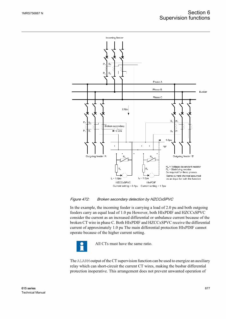
GUID-FB4ECBAC-1408-4EE6-9F8E-F8F903C84A90 V1 EN
Figure 472: Broken secondary detection by HZCCxSPVC
In the example, the incoming feeder is carrying a load of 2.0 pu and both outgoingfeeders carry an equal load of 1.0 pu However, both HIxPDIF and HZCCxSPVCconsider the current as an increased differential or unbalance current because of thebroken CT wire in phase C. Both HIxPDIF and HZCCxSPVC receive the differentialcurrent of approximately 1.0 pu The main differential protection HIxPDIF cannotoperate because of the higher current setting.
All CTs must have the same ratio.
The ALARM output of the CT supervision function can be used to energize an auxiliaryrelay which can short-circuit the current CT wires, making the busbar differentialprotection inoperative. This arrangement does not prevent unwanted operation of
1MRS756887 N Section 6Supervision functions
615 series 877Technical Manual
HIxPDIF if the start setting is below the rated load. For example, if the start setting forHIxPDIF in the example is set as 0.8 pu HIxPDIF operates before HZCCxSPVC.
6.3.7 SignalsTable 797: HZCCASPVC Input signals
Name Type Default DescriptionI_A SIGNAL 0 Phase A current
BLOCK BOOLEAN 0=False Block signal for activating blocking mode
Table 798: HZCCBSPVC Input signals
Name Type Default DescriptionI_B SIGNAL 0 Phase B current
BLOCK BOOLEAN 0=False Block signal for activating blocking mode
Table 799: HZCCCSPVC Input signals
Name Type Default DescriptionI_C SIGNAL 0 Phase C current
BLOCK BOOLEAN 0=False Block signal for activating blocking mode
Table 800: HZCCASPVC Output signals
Name Type DescriptionALARM BOOLEAN Alarm output
Table 801: HZCCBSPVC Output signals
Name Type DescriptionALARM BOOLEAN Alarm output
Table 802: HZCCCSPVC Output signals
Name Type DescriptionALARM BOOLEAN Alarm output
Section 6 1MRS756887 NSupervision functions
878 615 seriesTechnical Manual
6.3.8 SettingsTable 803: HZCCASPVC Non group settings (Basic)
Parameter Values (Range) Unit Step Default DescriptionOperation 1=on
5=off 1=on Operation Off / On
Start value 1.0...100.0 %In 0.1 10.0 Start value, percentage of the nominalcurrent
Alarm delay time 100...300000 ms 10 3000 Alarm delay time
Alarm output mode 1=Non-latched3=Lockout
3=Lockout Select the operation mode for alarmoutput
Table 804: HZCCASPVC Non group settings (Advanced)
Parameter Values (Range) Unit Step Default DescriptionReset delay time 0...60000 ms 10 20 Reset delay time
Measurement mode 2=DFT3=Peak-to-Peak
2=DFT Selects used measurement mode
Table 805: HZCCBSPVC Non group settings (Basic)
Parameter Values (Range) Unit Step Default DescriptionOperation 1=on
5=off 1=on Operation Off / On
Start value 1.0...100.0 %In 0.1 10.0 Start value, percentage of the nominalcurrent
Alarm delay time 100...300000 ms 10 3000 Alarm delay time
Alarm output mode 1=Non-latched3=Lockout
3=Lockout Select the operation mode for alarmoutput
Table 806: HZCCBSPVC Non group settings (Advanced)
Parameter Values (Range) Unit Step Default DescriptionReset delay time 0...60000 ms 10 20 Reset delay time
Measurement mode 2=DFT3=Peak-to-Peak
2=DFT Selects used measurement mode
Table 807: HZCCCSPVC Non group settings (Basic)
Parameter Values (Range) Unit Step Default DescriptionOperation 1=on
5=off 1=on Operation Off / On
Start value 1.0...100.0 %In 0.1 10.0 Start value, percentage of the nominalcurrent
Alarm delay time 100...300000 ms 10 3000 Alarm delay time
Alarm output mode 1=Non-latched3=Lockout
3=Lockout Select the operation mode for alarmoutput
1MRS756887 N Section 6Supervision functions
615 series 879Technical Manual

Table 808: HZCCCSPVC Non group settings (Advanced)
Parameter Values (Range) Unit Step Default DescriptionReset delay time 0...60000 ms 10 20 Reset delay time
Measurement mode 2=DFT3=Peak-to-Peak
2=DFT Selects used measurement mode
6.3.9 Monitored dataTable 809: HZCCASPVC Monitored data
Name Type Values (Range) Unit DescriptionHZCCASPVC Enum 1=on
2=blocked3=test4=test/blocked5=off
Status
Table 810: HZCCBSPVC Monitored data
Name Type Values (Range) Unit DescriptionHZCCBSPVC Enum 1=on
2=blocked3=test4=test/blocked5=off
Status
Table 811: HZCCCSPVC Monitored data
Name Type Values (Range) Unit DescriptionHZCCCSPVC Enum 1=on
2=blocked3=test4=test/blocked5=off
Status
6.3.10 Technical dataTable 812: HZCCxSPVC Technical data
Characteristic ValueOperation accuracy Depending on the frequency of the current
measured: fn ±2 Hz
±1.5% of the set value or ±0.002 × In
Reset time <40 ms
Reset ratio Typically 0.96
Retardation time <35 ms
Operate time accuracy in definite time mode ±1.0% of the set value or ±20 ms
Section 6 1MRS756887 NSupervision functions
880 615 seriesTechnical Manual
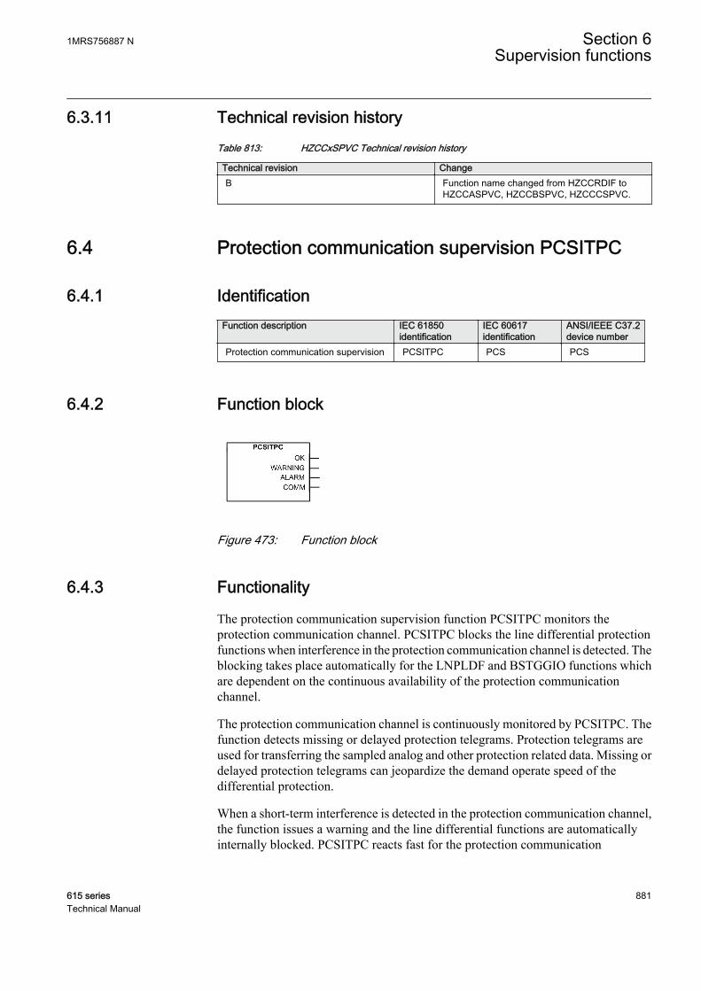
6.3.11 Technical revision historyTable 813: HZCCxSPVC Technical revision history
Technical revision ChangeB Function name changed from HZCCRDIF to
HZCCASPVC, HZCCBSPVC, HZCCCSPVC.
6.4 Protection communication supervision PCSITPC
6.4.1 IdentificationFunction description IEC 61850
identificationIEC 60617identification
ANSI/IEEE C37.2device number
Protection communication supervision PCSITPC PCS PCS
6.4.2 Function block
GUID-8732CEA2-358D-441A-B5BB-B2DC9E36E4A4 V2 EN
Figure 473: Function block
6.4.3 Functionality
The protection communication supervision function PCSITPC monitors theprotection communication channel. PCSITPC blocks the line differential protectionfunctions when interference in the protection communication channel is detected. Theblocking takes place automatically for the LNPLDF and BSTGGIO functions whichare dependent on the continuous availability of the protection communicationchannel.
The protection communication channel is continuously monitored by PCSITPC. Thefunction detects missing or delayed protection telegrams. Protection telegrams areused for transferring the sampled analog and other protection related data. Missing ordelayed protection telegrams can jeopardize the demand operate speed of thedifferential protection.
When a short-term interference is detected in the protection communication channel,the function issues a warning and the line differential functions are automaticallyinternally blocked. PCSITPC reacts fast for the protection communication
1MRS756887 N Section 6Supervision functions
615 series 881Technical Manual
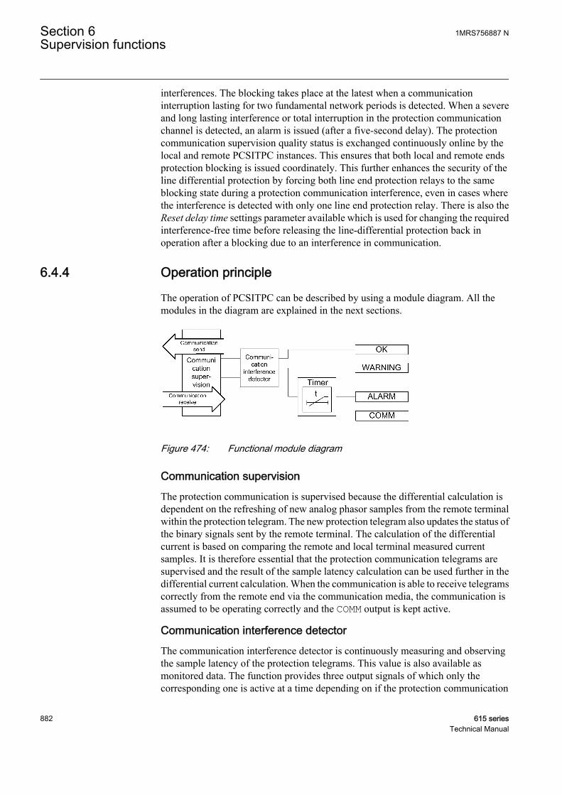
interferences. The blocking takes place at the latest when a communicationinterruption lasting for two fundamental network periods is detected. When a severeand long lasting interference or total interruption in the protection communicationchannel is detected, an alarm is issued (after a five-second delay). The protectioncommunication supervision quality status is exchanged continuously online by thelocal and remote PCSITPC instances. This ensures that both local and remote endsprotection blocking is issued coordinately. This further enhances the security of theline differential protection by forcing both line end protection relays to the sameblocking state during a protection communication interference, even in cases wherethe interference is detected with only one line end protection relay. There is also theReset delay time settings parameter available which is used for changing the requiredinterference-free time before releasing the line-differential protection back inoperation after a blocking due to an interference in communication.
6.4.4 Operation principle
The operation of PCSITPC can be described by using a module diagram. All themodules in the diagram are explained in the next sections.
GUID-FE089DD8-D0A0-4D3B-9287-48B11ADBAC25 V1 EN
Figure 474: Functional module diagram
Communication supervisionThe protection communication is supervised because the differential calculation isdependent on the refreshing of new analog phasor samples from the remote terminalwithin the protection telegram. The new protection telegram also updates the status ofthe binary signals sent by the remote terminal. The calculation of the differentialcurrent is based on comparing the remote and local terminal measured currentsamples. It is therefore essential that the protection communication telegrams aresupervised and the result of the sample latency calculation can be used further in thedifferential current calculation. When the communication is able to receive telegramscorrectly from the remote end via the communication media, the communication isassumed to be operating correctly and the COMM output is kept active.
Communication interference detectorThe communication interference detector is continuously measuring and observingthe sample latency of the protection telegrams. This value is also available asmonitored data. The function provides three output signals of which only thecorresponding one is active at a time depending on if the protection communication
Section 6 1MRS756887 NSupervision functions
882 615 seriesTechnical Manual
supervision is in OK, WARNING or ALARM. The OK state indicates the correctoperation of the protection. The WARNING state indicates that the protection isinternally blocked due to detected interference. The WARNING state is switched toALARM if the interference lasts for a longer period. The protection communicationsupervision can sometimes be in the WAITING state. This state indicates that theterminal is waiting for the communication to start or restart from the remote endterminal.
TimerOnce activated with the WARNING signal, the timer has a constant time delay value offive seconds. If the communication failure exists after the delay, the ALARM output isactivated.
6.4.5 Application
Communication principleAnalog samples, trip, start and user programmable signals are transferred in eachprotection telegram and the exchange of these protection telegrams is done eight timesper power system cycle (every 2.5 ms when Fn = 50 Hz).
Master-Master communication arrangement is used in the two-terminal linedifferential solution. Current samples are sent from both line ends and the protectionalgorithms are also executed on both line ends. The direct-intertrip, however, ensuresthat both ends are always operated simultaneously.
Time synchronizationIn numerical line differential protection, the current samples from the protectionswhich are located geographically apart from each other must be time coordinated sothat the current samples from both ends of the protected line can be compared withoutintroducing irrelevant errors. The time coordination requires an extremely highaccuracy.
As an example, an inaccuracy of 0.1 ms in a 50 Hz system gives a maximum amplitudeerror of approximately around 3 percent. An inaccuracy of 1 ms gives a maximumamplitude error of approximately 31 percent. The corresponding figures for a 60 Hzsystem are 4 and 38 percent respectively.
In the protection relay, the time coordination is done with an echo method. Theprotection relays create their own time reference between each other so that the systemclocks do not need to synchronize.
The figure shows that in the time synchronization the transmission time to send amessage from station B to station A, T1→T2, and the time to receive a message fromA to B, T4→T5, are measured. The station A protection relay delay from the samplingto the start of send, T3→T4, and the local delay from receive to the station B protectionrelay sampling T5→T6 time, are also measured for the station B protection relay, and
1MRS756887 N Section 6Supervision functions
615 series 883Technical Manual
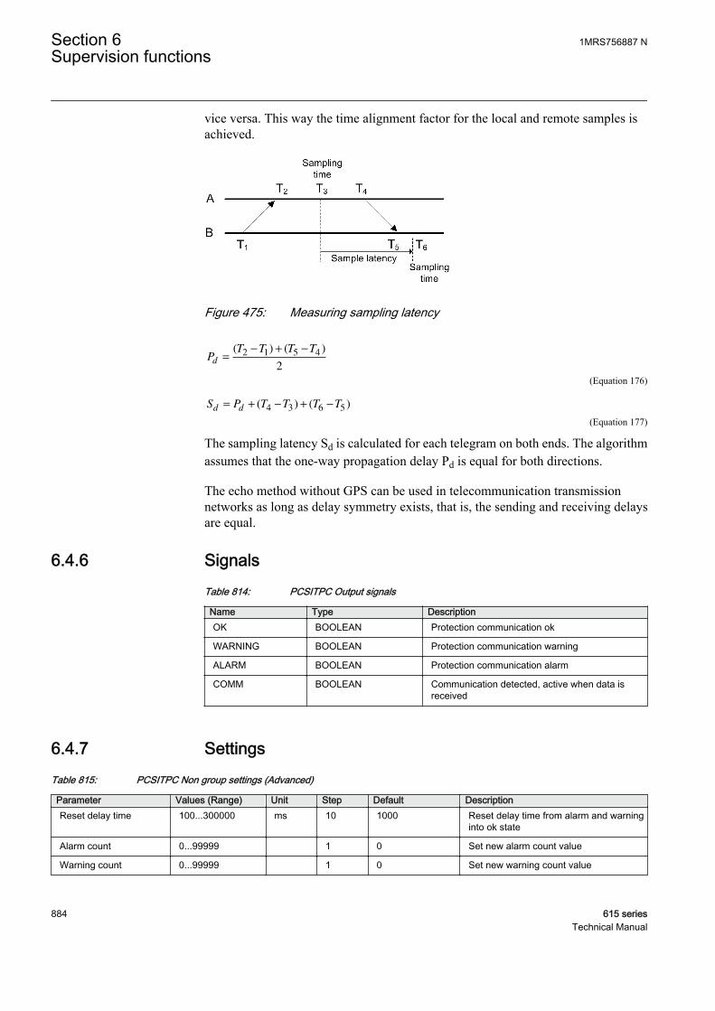
vice versa. This way the time alignment factor for the local and remote samples isachieved.
GUID-2DDF64E2-D635-4783-854A-A62E5EFB7186 V1 EN
Figure 475: Measuring sampling latency
PT T T T
d =
− + −( ) ( )2 1 5 4
2
GUID-0CB3B365-7081-43D4-90F5-91A8082522FE V2 EN (Equation 176)
S P T T T Td d= + − + −( ) ( )4 3 6 5
GUID-2940B36E-3A6C-44E4-BD39-1B117E168829 V2 EN (Equation 177)
The sampling latency Sd is calculated for each telegram on both ends. The algorithmassumes that the one-way propagation delay Pd is equal for both directions.
The echo method without GPS can be used in telecommunication transmissionnetworks as long as delay symmetry exists, that is, the sending and receiving delaysare equal.
6.4.6 SignalsTable 814: PCSITPC Output signals
Name Type DescriptionOK BOOLEAN Protection communication ok
WARNING BOOLEAN Protection communication warning
ALARM BOOLEAN Protection communication alarm
COMM BOOLEAN Communication detected, active when data isreceived
6.4.7 SettingsTable 815: PCSITPC Non group settings (Advanced)
Parameter Values (Range) Unit Step Default DescriptionReset delay time 100...300000 ms 10 1000 Reset delay time from alarm and warning
into ok state
Alarm count 0...99999 1 0 Set new alarm count value
Warning count 0...99999 1 0 Set new warning count value
Section 6 1MRS756887 NSupervision functions
884 615 seriesTechnical Manual
6.4.8 Monitored dataTable 816: PCSITPC Monitored data
Name Type Values (Range) Unit DescriptionHEALTH Enum 1=Ok
2=Warning3=Alarm-2=Waiting
Communication linkhealth
ALARM_CNT INT32 0...99999 Number of alarmsdetected
WARN_CNT INT32 0...99999 Number of warningsdetected
SMPL_LATENCY FLOAT32 0.000...99.999 ms Measured samplelatency
PROPAGTN_DLY FLOAT32 0.000...99.999 ms Measured propagationdelay
RND_TRIP_DLY FLOAT32 0.000...99.999 ms Measured round tripdelay
T_ALARM_CNT Timestamp Time when alarm countwas last changed
T_WARN_CNT Timestamp Time when warning countwas last changed
6.4.9 Technical revision historyTable 817: PCSITPC Technical revision history
Technical revision ChangeB Changes and additions to the monitored data
C Internal improvement
D Internal improvement
E Function name changed from PCSRTCP to PCSITPC
6.5 Fuse failure supervision SEQSPVC
6.5.1 IdentificationFunction description IEC 61850
identificationIEC 60617identification
ANSI/IEEE C37.2device number
Fuse failure supervision SEQSPVC FUSEF 60
1MRS756887 N Section 6Supervision functions
615 series 885Technical Manual
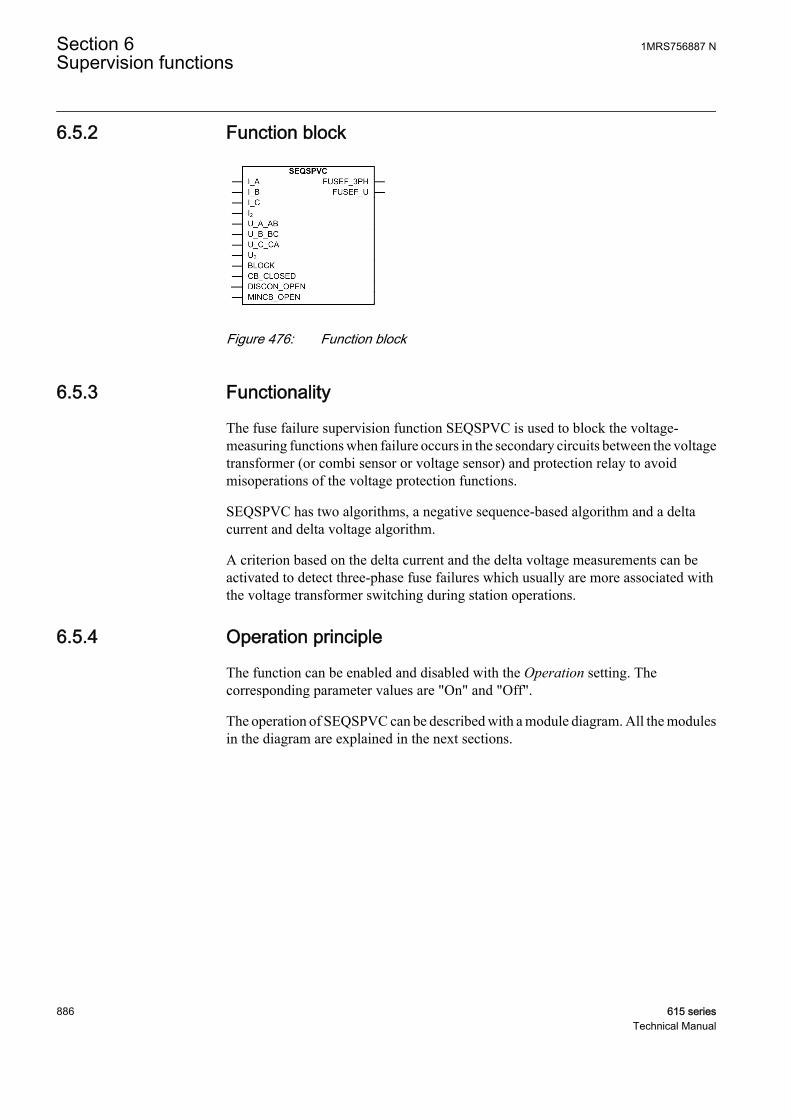
6.5.2 Function block
GUID-1843AD62-0328-4BBF-B8D6-EF28945855D8 V1 EN
Figure 476: Function block
6.5.3 Functionality
The fuse failure supervision function SEQSPVC is used to block the voltage-measuring functions when failure occurs in the secondary circuits between the voltagetransformer (or combi sensor or voltage sensor) and protection relay to avoidmisoperations of the voltage protection functions.
SEQSPVC has two algorithms, a negative sequence-based algorithm and a deltacurrent and delta voltage algorithm.
A criterion based on the delta current and the delta voltage measurements can beactivated to detect three-phase fuse failures which usually are more associated withthe voltage transformer switching during station operations.
6.5.4 Operation principle
The function can be enabled and disabled with the Operation setting. Thecorresponding parameter values are "On" and "Off".
The operation of SEQSPVC can be described with a module diagram. All the modulesin the diagram are explained in the next sections.
Section 6 1MRS756887 NSupervision functions
886 615 seriesTechnical Manual
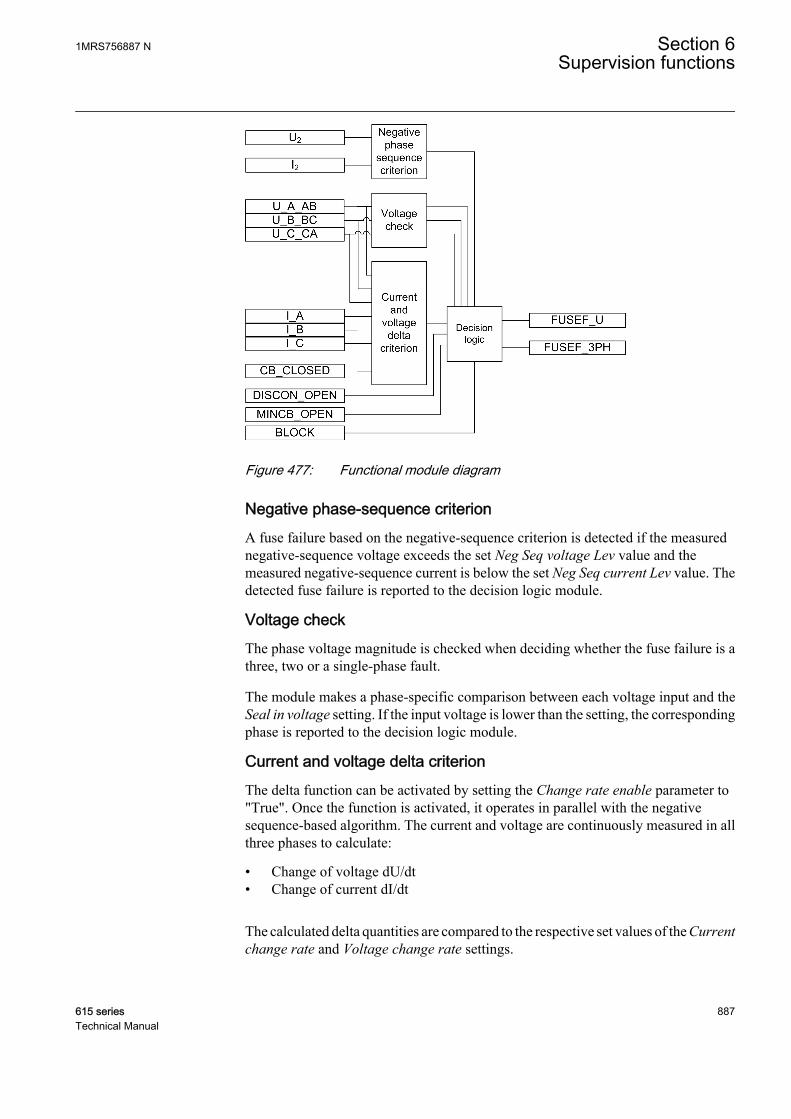
GUID-27E5A90A-6DCB-4545-A33A-F37C02F27A28 V1 EN
Figure 477: Functional module diagram
Negative phase-sequence criterionA fuse failure based on the negative-sequence criterion is detected if the measurednegative-sequence voltage exceeds the set Neg Seq voltage Lev value and themeasured negative-sequence current is below the set Neg Seq current Lev value. Thedetected fuse failure is reported to the decision logic module.
Voltage checkThe phase voltage magnitude is checked when deciding whether the fuse failure is athree, two or a single-phase fault.
The module makes a phase-specific comparison between each voltage input and theSeal in voltage setting. If the input voltage is lower than the setting, the correspondingphase is reported to the decision logic module.
Current and voltage delta criterionThe delta function can be activated by setting the Change rate enable parameter to"True". Once the function is activated, it operates in parallel with the negativesequence-based algorithm. The current and voltage are continuously measured in allthree phases to calculate:
• Change of voltage dU/dt• Change of current dI/dt
The calculated delta quantities are compared to the respective set values of the Currentchange rate and Voltage change rate settings.
1MRS756887 N Section 6Supervision functions
615 series 887Technical Manual
The delta current and delta voltage algorithms detect a fuse failure if there is asufficient negative change in the voltage amplitude without a sufficient change in thecurrent amplitude in each phase separately. This is performed when the circuit breakeris closed. Information about the circuit breaker position is connected to theCB_CLOSED input.
There are two conditions for activating the current and voltage delta function.
• The magnitude of dU/dt exceeds the corresponding value of the Voltage changerate setting and magnitude of dI/dt is below the value of the Current change ratesetting in any phase at the same time due to the closure of the circuit breaker(CB_CLOSED = TRUE).
• The magnitude of dU/dt exceeds the value of the Voltage change rate setting andthe magnitude of dI/dt is below the Current change rate setting in any phase at thesame time and the magnitude of the phase current in the same phase exceeds theMin Op current delta setting.
The first condition requires the delta criterion to be fulfilled in any phase at the sametime as the circuit breaker is closed. Opening the circuit breaker at one end andenergizing the line from the other end onto a fault could lead to an improper operationof SEQSPVC with an open breaker. If this is considered to be an importantdisadvantage, the CB_CLOSED input is to be connected to FALSE. In this way onlythe second criterion can activate the delta function.
The second condition requires the delta criterion to be fulfilled in one phase togetherwith a high current for the same phase. The measured phase current is used to reducethe risk of a false fuse failure detection. If the current on the protected line is low, avoltage drop in the system (not caused by the fuse failure) is not followed by a currentchange and a false fuse failure can occur. To prevent this, the minimum phase currentcriterion is checked.
The fuse failure detection is active until the voltages return above the Min Op voltagedelta setting. If a voltage in a phase is below the Min Op voltage delta setting, a newfuse failure detection for that phase is not possible until the voltage returns above thesetting value.
Decision logic
If voltages are Wye-connected, it is recommended to scale the defaultvalues of voltage-based settings with 1/sqrt(3) because the defaultsetting values apply for Delta-connected settings.
The fuse failure detection outputs FUSEF_U and FUSEF_3PH are controlledaccording to the detection criteria or external signals.
Section 6 1MRS756887 NSupervision functions
888 615 seriesTechnical Manual

Table 818: Fuse failure output control
Fuse failure detection criterion Conditions and function responseNegative-sequence criterion If a fuse failure is detected based on the negative
sequence criterion, the FUSEF_U output isactivated.
If the fuse failure detection is active for more thanfive seconds and at the same time all the phasevoltage values are below the set value of the Sealin voltage setting with Enable seal in turned to"True", the function activates the FUSE_3PHoutput signal.
The FUSEF_U output signal is also activated if allthe phase voltages are above the Seal in voltagesetting for more than 60 seconds and at the sametime the negative sequence voltage is above NegSeq voltage Lev for more than 5 seconds, all thephase currents are below the Current dead Lin Valsetting and the circuit breaker is closed, thatis,CB_CLOSED is TRUE.
Current and voltage delta function criterion If the current and voltage delta criterion detects afuse failure condition, but all the voltages are notbelow the Seal in voltage setting, only theFUSEF_U output is activated.
If the fuse failure detection is active for more thanfive seconds and at the same time all the phasevoltage values are below the set value of the Sealin voltage setting with Enable seal in turned to"True", the function activates the FUSE_3PHoutput signal.
External fuse failure detection The MINCB_OPEN input signal is supposed to beconnected through a protection relay binary inputto the N.C. auxiliary contact of the miniature circuitbreaker protecting the VT secondary circuit.TheMINCB_OPEN signal sets the FUSEF_U outputsignal to block all the voltage-related functionswhen MCB is in the open state.
The DISCON_OPEN input signal is supposed to beconnected through a protection relay binary inputto the N.C. auxiliary contact of the linedisconnector.The DISCON_OPEN signal sets theFUSEF_U output signal to block the voltage-related functions when the line disconnector is inthe open state.
It is recommended to always set Enable seal in to "True". This securesthat the blocked protection functions remain blocked until normalvoltage conditions are restored if the fuse failure has been active for 5seconds, that is, the fuse failure outputs are deactivated when thenormal voltage conditions are restored.
The activation of the BLOCK input deactivates both FUSEF_U and FUSEF_3PHoutputs.
1MRS756887 N Section 6Supervision functions
615 series 889Technical Manual
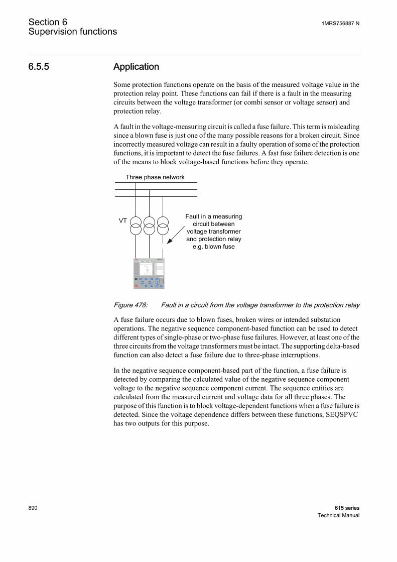
6.5.5 Application
Some protection functions operate on the basis of the measured voltage value in theprotection relay point. These functions can fail if there is a fault in the measuringcircuits between the voltage transformer (or combi sensor or voltage sensor) andprotection relay.
A fault in the voltage-measuring circuit is called a fuse failure. This term is misleadingsince a blown fuse is just one of the many possible reasons for a broken circuit. Sinceincorrectly measured voltage can result in a faulty operation of some of the protectionfunctions, it is important to detect the fuse failures. A fast fuse failure detection is oneof the means to block voltage-based functions before they operate.
Three phase network
VTFault in a measuring
circuit between voltage transformer and protection relay
e.g. blown fuse
REF 615
GUID-FA649B6A-B51E-47E2-8E37-EBA9CDEB2BF5 V2 EN
Figure 478: Fault in a circuit from the voltage transformer to the protection relay
A fuse failure occurs due to blown fuses, broken wires or intended substationoperations. The negative sequence component-based function can be used to detectdifferent types of single-phase or two-phase fuse failures. However, at least one of thethree circuits from the voltage transformers must be intact. The supporting delta-basedfunction can also detect a fuse failure due to three-phase interruptions.
In the negative sequence component-based part of the function, a fuse failure isdetected by comparing the calculated value of the negative sequence componentvoltage to the negative sequence component current. The sequence entities arecalculated from the measured current and voltage data for all three phases. Thepurpose of this function is to block voltage-dependent functions when a fuse failure isdetected. Since the voltage dependence differs between these functions, SEQSPVChas two outputs for this purpose.
Section 6 1MRS756887 NSupervision functions
890 615 seriesTechnical Manual
6.5.6 SignalsTable 819: SEQSPVC Input signals
Name Type Default DescriptionI_A SIGNAL 0 Phase A current
I_B SIGNAL 0 Phase B current
I_C SIGNAL 0 Phase C current
I2 SIGNAL 0 Negative sequence current
U_A_AB SIGNAL 0 Phase A voltage
U_B_BC SIGNAL 0 Phase B voltage
U_C_CA SIGNAL 0 Phase C voltage
U2 SIGNAL 0 Negative phase sequence voltage
BLOCK BOOLEAN 0=False Block of function
CB_CLOSED BOOLEAN 0=False Active when circuit breaker is closed
DISCON_OPEN BOOLEAN 0=False Active when line disconnector is open
MINCB_OPEN BOOLEAN 0=False Active when external MCB opens protected voltagecircuit
Table 820: SEQSPVC Output signals
Name Type DescriptionFUSEF_3PH BOOLEAN Three-phase start of function
FUSEF_U BOOLEAN General start of function
6.5.7 SettingsTable 821: SEQSPVC Non group settings (Basic)
Parameter Values (Range) Unit Step Default DescriptionOperation 1=on
5=off 1=on Operation Off / On
Table 822: SEQSPVC Non group settings (Advanced)
Parameter Values (Range) Unit Step Default DescriptionNeg Seq current Lev 0.03...0.20 xIn 0.01 0.03 Operate level of neg seq undercurrent
element
Neg Seq voltage Lev 0.03...0.20 xUn 0.01 0.10 Operate level of neg seq overvoltageelement
Current change rate 0.01...0.50 xIn 0.01 0.15 Operate level of change in phase current
Voltage change rate 0.25...0.90 xUn 0.01 0.40 Operate level of change in phase voltage
Change rate enable 0=False1=True
0=False Enabling operation of change basedfunction
Table continues on next page
1MRS756887 N Section 6Supervision functions
615 series 891Technical Manual

Parameter Values (Range) Unit Step Default DescriptionMin Op voltage delta 0.01...1.00 xUn 0.01 0.50 Minimum operate level of phase voltage
for delta calculation
Min Op current delta 0.01...1.00 xIn 0.01 0.10 Minimum operate level of phase currentfor delta calculation
Seal in voltage 0.01...1.00 xUn 0.01 0.50 Operate level of seal-in phase voltage
Enable seal in 0=False1=True
0=False Enabling seal in functionality
Current dead Lin Val 0.05...1.00 xIn 0.01 0.05 Operate level for open phase currentdetection
6.5.8 Monitored dataTable 823: SEQSPVC Monitored data
Name Type Values (Range) Unit DescriptionSEQSPVC Enum 1=on
2=blocked3=test4=test/blocked5=off
Status
6.5.9 Technical dataTable 824: SEQSPVC Technical data
Characteristic Value
Operate time1) NPS function UFault = 1.1 × set NegSeq voltage Lev
<33 ms
UFault = 5.0 × set NegSeq voltage Lev
<18 ms
Delta function ΔU = 1.1 × set Voltagechange rate
<30 ms
ΔU = 2.0 × set Voltagechange rate
<24 ms
1) Includes the delay of the signal output contact, fn = 50 Hz, fault voltage with nominal frequency injectedfrom random phase angle, results based on statistical distribution of 1000 measurements
6.5.10 Technical revision historyTable 825: SEQSPVC Technical revision history
Technical revision ChangeB Internal improvement
C Internal improvement
D Function name changed from SEQRFUF toSEQSPVC
Section 6 1MRS756887 NSupervision functions
892 615 seriesTechnical Manual
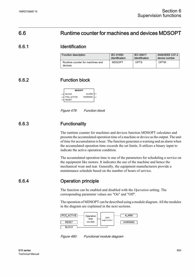
6.6 Runtime counter for machines and devices MDSOPT
6.6.1 IdentificationFunction description IEC 61850
identificationIEC 60617identification
ANSI/IEEE C37.2device number
Runtime counter for machines anddevices
MDSOPT OPTS OPTM
6.6.2 Function block
GUID-C20AF735-FF25-411B-9EA6-11D595484613 V3 EN
Figure 479: Function block
6.6.3 Functionality
The runtime counter for machines and devices function MDSOPT calculates andpresents the accumulated operation time of a machine or device as the output. The unitof time for accumulation is hour. The function generates a warning and an alarm whenthe accumulated operation time exceeds the set limits. It utilizes a binary input toindicate the active operation condition.
The accumulated operation time is one of the parameters for scheduling a service onthe equipment like motors. It indicates the use of the machine and hence themechanical wear and tear. Generally, the equipment manufacturers provide amaintenance schedule based on the number of hours of service.
6.6.4 Operation principle
The function can be enabled and disabled with the Operation setting. Thecorresponding parameter values are "On" and "Off".
The operation of MDSOPT can be described using a module diagram. All the modulesin the diagram are explained in the next sections.
GUID-6BE6D1E3-F3FB-45D9-8D6F-A44752C1477C V1 EN
Figure 480: Functional module diagram
1MRS756887 N Section 6Supervision functions
615 series 893Technical Manual

Operation time counterThis module counts the operation time. When POS_ACTIVE is active, the count iscontinuously added to the time duration until it is deactivated. At any time theOPR_TIME output is the total duration for which POS_ACTIVE is active. The unit oftime duration count for OPR_TIME is hour. The value is available through theMonitored data view.
The OPR_TIME output is a continuously increasing value and it is stored in a non-volatile memory. When POS_ACTIVE is active, the OPR_TIME count startsincreasing from the previous value. The count of OPR_TIME saturates at the finalvalue of 299999, that is, no further increment is possible. The activation of RESET canreset the count to the Initial value setting.
Limit SupervisionThis module compares the motor run-time count to the set values of Warning valueand Alarm value to generate the WARNING and ALARM outputs respectively when thecounts exceed the levels.
The activation of the WARNING and ALARM outputs depends on the Operating timemode setting. Both WARNING and ALARM occur immediately after the conditions aremet if Operating time mode is set to “Immediate”. If Operating time mode is set to“Timed Warn”, WARNING is activated within the next 24 hours at the time of the dayset using the Operating time hour setting. If Operating time mode is set to “TimedWarn Alm”, the WARNING and ALARM outputs are activated at the time of day setusing Operating time hour.
The Operating time hour setting is used to set the hour of day inCoordinated Universal Time (UTC). The setting has to be adjustedaccording to the local time and local daylight-saving time.
The function contains a blocking functionality. Activation of the BLOCK input blocksboth WARNING and ALARM.
6.6.5 Application
The machine operating time since commissioning indicates the use of the machine.For example, the mechanical wear and lubrication requirement for the shaft bearing ofthe motors depend on the use hours.
If some motor is used for long duration runs, it might require frequent servicing, whilefor a motor that is not used regularly the maintenance and service are scheduled lessfrequently. The accumulated operating time of a motor together with the appropriatesettings for warning can be utilized to trigger the condition based maintenance of themotor.
The operating time counter combined with the subsequent reset of the operating-timecount can be used to monitor the motor's run time for a single run.
Section 6 1MRS756887 NSupervision functions
894 615 seriesTechnical Manual
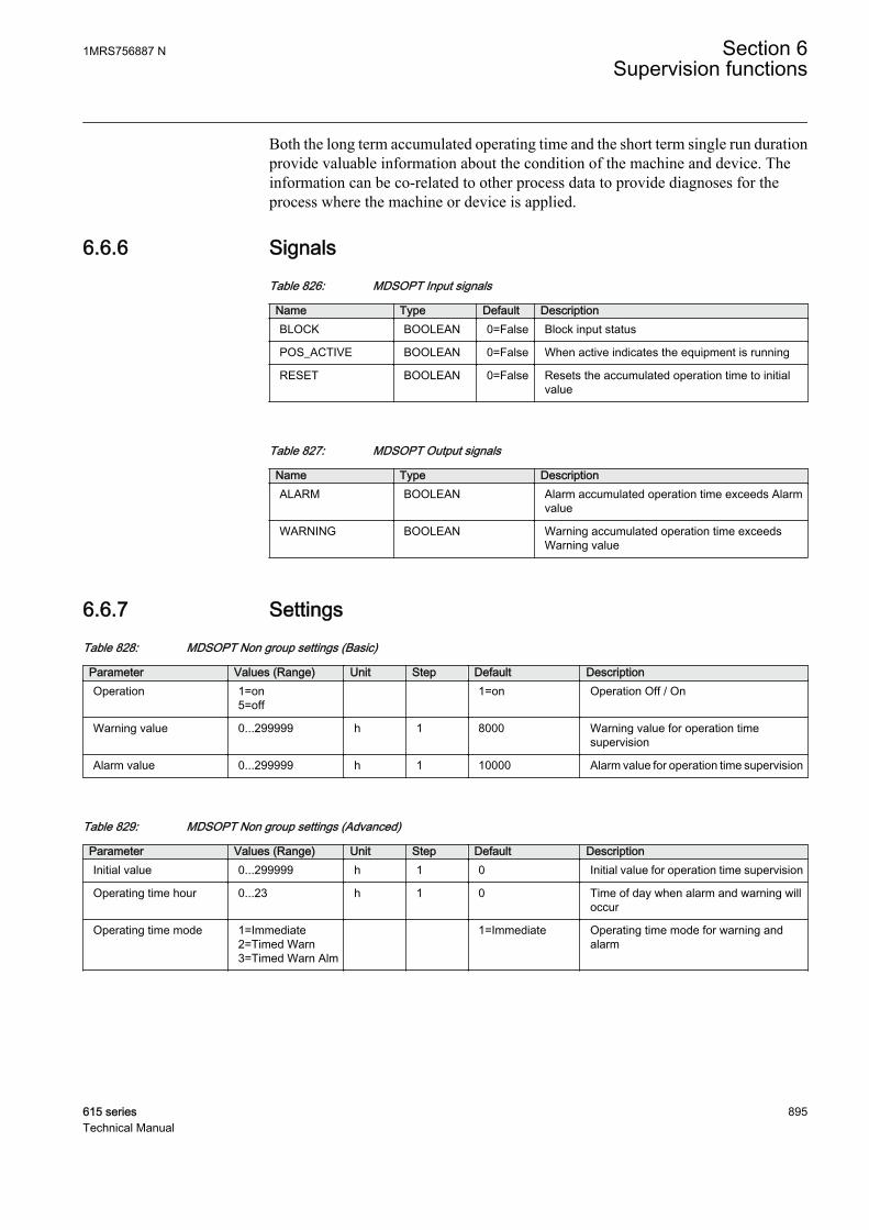
Both the long term accumulated operating time and the short term single run durationprovide valuable information about the condition of the machine and device. Theinformation can be co-related to other process data to provide diagnoses for theprocess where the machine or device is applied.
6.6.6 SignalsTable 826: MDSOPT Input signals
Name Type Default DescriptionBLOCK BOOLEAN 0=False Block input status
POS_ACTIVE BOOLEAN 0=False When active indicates the equipment is running
RESET BOOLEAN 0=False Resets the accumulated operation time to initialvalue
Table 827: MDSOPT Output signals
Name Type DescriptionALARM BOOLEAN Alarm accumulated operation time exceeds Alarm
value
WARNING BOOLEAN Warning accumulated operation time exceedsWarning value
6.6.7 SettingsTable 828: MDSOPT Non group settings (Basic)
Parameter Values (Range) Unit Step Default DescriptionOperation 1=on
5=off 1=on Operation Off / On
Warning value 0...299999 h 1 8000 Warning value for operation timesupervision
Alarm value 0...299999 h 1 10000 Alarm value for operation time supervision
Table 829: MDSOPT Non group settings (Advanced)
Parameter Values (Range) Unit Step Default DescriptionInitial value 0...299999 h 1 0 Initial value for operation time supervision
Operating time hour 0...23 h 1 0 Time of day when alarm and warning willoccur
Operating time mode 1=Immediate2=Timed Warn3=Timed Warn Alm
1=Immediate Operating time mode for warning andalarm
1MRS756887 N Section 6Supervision functions
615 series 895Technical Manual

6.6.8 Monitored dataTable 830: MDSOPT Monitored data
Name Type Values (Range) Unit DescriptionMDSOPT Enum 1=on
2=blocked3=test4=test/blocked5=off
Status
OPR_TIME INT32 0...299999 h Total operation time inhours
6.6.9 Technical dataTable 831: MDSOPT Technical data
Description Value
Motor runtime measurement accuracy1) ±0.5%
1) Of the reading, for a stand-alone relay, without time synchronization
6.6.10 Technical revision historyTable 832: MDSOPT Technical revision history
Technical revision ChangeB Internal improvement.
C Internal improvement.
D Internal improvement.
Section 6 1MRS756887 NSupervision functions
896 615 seriesTechnical Manual
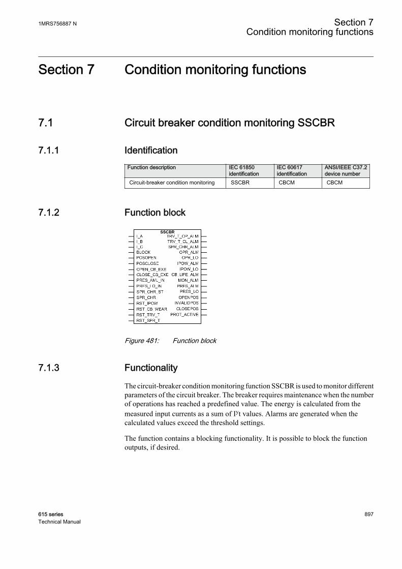
Section 7 Condition monitoring functions
7.1 Circuit breaker condition monitoring SSCBR
7.1.1 IdentificationFunction description IEC 61850
identificationIEC 60617identification
ANSI/IEEE C37.2device number
Circuit-breaker condition monitoring SSCBR CBCM CBCM
7.1.2 Function block
A070795 V3 EN
Figure 481: Function block
7.1.3 Functionality
The circuit-breaker condition monitoring function SSCBR is used to monitor differentparameters of the circuit breaker. The breaker requires maintenance when the numberof operations has reached a predefined value. The energy is calculated from themeasured input currents as a sum of Iyt values. Alarms are generated when thecalculated values exceed the threshold settings.
The function contains a blocking functionality. It is possible to block the functionoutputs, if desired.
1MRS756887 N Section 7Condition monitoring functions
615 series 897Technical Manual

7.1.4 Operation principle
The circuit breaker condition monitoring function includes different metering andmonitoring sub-functions. The functions can be enabled and disabled with theOperation setting. The corresponding parameter values are “On” and “Off”. Theoperation counters are cleared when Operation is set to “Off”.
The operation of SSCBR can be described with a module diagram. All the modules inthe diagram are explained in the next sections.
A071103 V4 EN
Figure 482: Functional module diagram
Section 7 1MRS756887 NCondition monitoring functions
898 615 seriesTechnical Manual
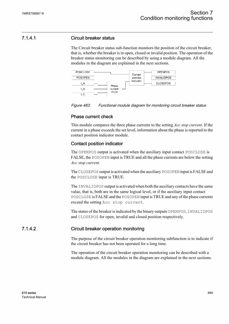
7.1.4.1 Circuit breaker status
The Circuit breaker status sub-function monitors the position of the circuit breaker,that is, whether the breaker is in open, closed or invalid position. The operation of thebreaker status monitoring can be described by using a module diagram. All themodules in the diagram are explained in the next sections.
A071104 V3 EN
Figure 483: Functional module diagram for monitoring circuit breaker status
Phase current checkThis module compares the three phase currents to the setting Acc stop current. If thecurrent in a phase exceeds the set level, information about the phase is reported to thecontact position indicator module.
Contact position indicatorThe OPENPOS output is activated when the auxiliary input contact POSCLOSE isFALSE, the POSOPEN input is TRUE and all the phase currents are below the settingAcc stop current.
The CLOSEPOS output is activated when the auxiliary POSOPEN input is FALSE andthe POSCLOSE input is TRUE.
The INVALIDPOS output is activated when both the auxiliary contacts have the samevalue, that is, both are in the same logical level, or if the auxiliary input contactPOSCLOSE is FALSE and the POSOPEN input is TRUE and any of the phase currentsexceed the setting Acc stop current.
The status of the breaker is indicated by the binary outputs OPENPOS, INVALIDPOSand CLOSEPOS for open, invalid and closed position respectively.
7.1.4.2 Circuit breaker operation monitoring
The purpose of the circuit breaker operation monitoring subfunction is to indicate ifthe circuit breaker has not been operated for a long time.
The operation of the circuit breaker operation monitoring can be described with amodule diagram. All the modules in the diagram are explained in the next sections.
1MRS756887 N Section 7Condition monitoring functions
615 series 899Technical Manual
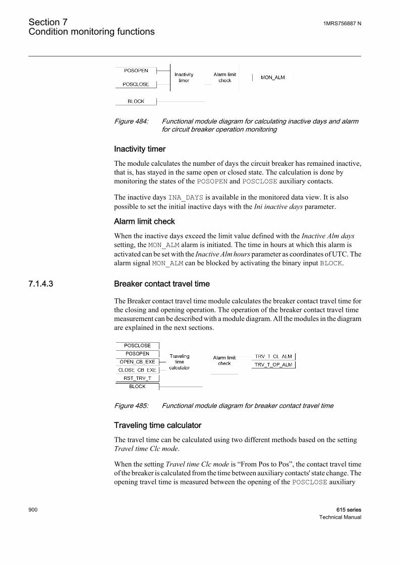
A071105 V2 EN
Figure 484: Functional module diagram for calculating inactive days and alarmfor circuit breaker operation monitoring
Inactivity timerThe module calculates the number of days the circuit breaker has remained inactive,that is, has stayed in the same open or closed state. The calculation is done bymonitoring the states of the POSOPEN and POSCLOSE auxiliary contacts.
The inactive days INA_DAYS is available in the monitored data view. It is alsopossible to set the initial inactive days with the Ini inactive days parameter.
Alarm limit checkWhen the inactive days exceed the limit value defined with the Inactive Alm dayssetting, the MON_ALM alarm is initiated. The time in hours at which this alarm isactivated can be set with the Inactive Alm hours parameter as coordinates of UTC. Thealarm signal MON_ALM can be blocked by activating the binary input BLOCK.
7.1.4.3 Breaker contact travel time
The Breaker contact travel time module calculates the breaker contact travel time forthe closing and opening operation. The operation of the breaker contact travel timemeasurement can be described with a module diagram. All the modules in the diagramare explained in the next sections.
A071106 V4 EN
Figure 485: Functional module diagram for breaker contact travel time
Traveling time calculatorThe travel time can be calculated using two different methods based on the settingTravel time Clc mode.
When the setting Travel time Clc mode is “From Pos to Pos”, the contact travel timeof the breaker is calculated from the time between auxiliary contacts' state change. Theopening travel time is measured between the opening of the POSCLOSE auxiliary
Section 7 1MRS756887 NCondition monitoring functions
900 615 seriesTechnical Manual

contact and the closing of the POSOPEN auxiliary contact. The travel time is alsomeasured between the opening of the POSOPEN auxiliary contact and the closing ofthe POSCLOSE auxiliary contact.
A071107 V1 EN
Figure 486: Travel time calculation when Travel time Clc mode is “From Pos toPos”
There is a time difference t1 between the start of the main contact opening and theopening of the POSCLOSE auxiliary contact. Similarly, there is a time gap t2 betweenthe time when the POSOPEN auxiliary contact opens and the main contact iscompletely open. To incorporate the time t1 + t2, a correction factor needs to be addedwith topen to get the actual opening time. This factor is added with the Opening timeCor (= t1 + t2) setting. The closing time is calculated by adding the value set with theClosing time Cor (t3 + t4) setting to the measured closing time.
When the setting Travel time Clc mode is “From Cmd to Pos”, the contact travel timeof the breaker is calculated from the time between the circuit breaker opening orclosing command and the auxiliary contacts’ state change. The opening travel time ismeasured between the rising edge of the OPEN_CB_EXE command and thePOSOPEN auxiliary contact. The closing travel time is measured between the risingedge of the CLOSE_CB_EXEC command and the POSCLOSE auxiliary contact.
1MRS756887 N Section 7Condition monitoring functions
615 series 901Technical Manual
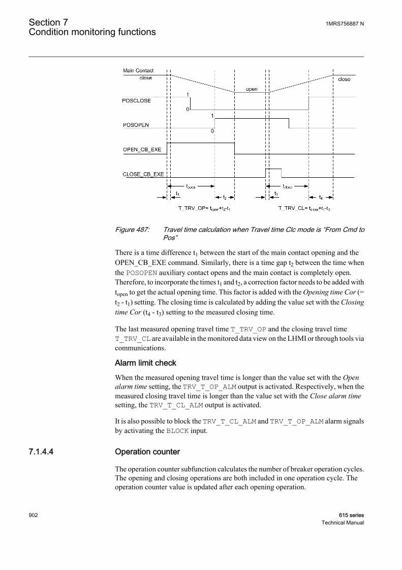
GUID-A8C2EB5B-F105-4BF7-B1EC-77D4B8238531 V1 EN
Figure 487: Travel time calculation when Travel time Clc mode is “From Cmd toPos”
There is a time difference t1 between the start of the main contact opening and theOPEN_CB_EXE command. Similarly, there is a time gap t2 between the time whenthe POSOPEN auxiliary contact opens and the main contact is completely open.Therefore, to incorporate the times t1 and t2, a correction factor needs to be added withtopen to get the actual opening time. This factor is added with the Opening time Cor (=t2 - t1) setting. The closing time is calculated by adding the value set with the Closingtime Cor (t4 - t3) setting to the measured closing time.
The last measured opening travel time T_TRV_OP and the closing travel timeT_TRV_CL are available in the monitored data view on the LHMI or through tools viacommunications.
Alarm limit checkWhen the measured opening travel time is longer than the value set with the Openalarm time setting, the TRV_T_OP_ALM output is activated. Respectively, when themeasured closing travel time is longer than the value set with the Close alarm timesetting, the TRV_T_CL_ALM output is activated.
It is also possible to block the TRV_T_CL_ALM and TRV_T_OP_ALM alarm signalsby activating the BLOCK input.
7.1.4.4 Operation counter
The operation counter subfunction calculates the number of breaker operation cycles.The opening and closing operations are both included in one operation cycle. Theoperation counter value is updated after each opening operation.
Section 7 1MRS756887 NCondition monitoring functions
902 615 seriesTechnical Manual

The operation of the subfunction can be described with a module diagram. All themodules in the diagram are explained in the next sections.
A071108 V2 EN
Figure 488: Functional module diagram for counting circuit breaker operations
Operation counterThe operation counter counts the number of operations based on the state change ofthe binary auxiliary contacts inputs POSCLOSE and POSOPEN.
The number of operations NO_OPR is available in the monitored data view on theLHMI or through tools via communications. The old circuit breaker operation countervalue can be taken into use by writing the value to the Counter initial Val parameterand by setting the parameter Initial CB Rmn life in the clear menu from WHMI orLHMI.
Alarm limit checkThe OPR_ALM operation alarm is generated when the number of operations exceedsthe value set with the Alarm Op number threshold setting. However, if the number ofoperations increases further and exceeds the limit value set with the Lockout Opnumber setting, the OPR_LO output is activated.
The binary outputs OPR_LO and OPR_ALM are deactivated when the BLOCK input isactivated.
7.1.4.5 Accumulation of Iyt
Accumulation of the Iyt module calculates the accumulated energy.
The operation of the module can be described with a module diagram. All the modulesin the diagram are explained in the next sections.
1MRS756887 N Section 7Condition monitoring functions
615 series 903Technical Manual

A071109 V2 EN
Figure 489: Functional module diagram for calculating accumulative energy andalarm
Accumulated energy calculator
This module calculates the accumulated energy Iyt [(kA)ys]. The factor y is set withthe Current exponent setting.
The calculation is initiated with the POSCLOSE input opening events. It ends whenthe RMS current becomes lower than the Acc stop current setting value.
A071110 V1 EN
Figure 490: Significance of the Difference Cor time setting
The Difference Cor time setting is used instead of the auxiliary contact to accumulatethe energy from the time the main contact opens. If the setting is positive, thecalculation of energy starts after the auxiliary contact has opened and when the delayis equal to the value set with the Difference Cor time setting. When the setting isnegative, the calculation starts in advance by the correction time before the auxiliarycontact opens.
The accumulated energy outputs IPOW_A (_B, _C) are available in the monitoreddata view on the LHMI or through tools via communications. The values can be resetby setting the parameter Initial CB Rmn life setting to true in the clear menu fromWHMI or LHMI.
Alarm limit checkThe IPOW_ALM alarm is activated when the accumulated energy exceeds the valueset with the Alm Acc currents Pwr threshold setting. However, when the energy
Section 7 1MRS756887 NCondition monitoring functions
904 615 seriesTechnical Manual

exceeds the limit value set with the LO Acc currents Pwr threshold setting, theIPOW_LO output is activated.
The IPOW_ALM and IPOW_LO outputs can be blocked by activating the binary inputBLOCK.
7.1.4.6 Remaining life of circuit breaker
Every time the breaker operates, the life of the circuit breaker reduces due to wearing.The wearing in the breaker depends on the tripping current, and the remaining life ofthe breaker is estimated from the circuit breaker trip curve provided by themanufacturer. The remaining life is decremented at least with one when the circuitbreaker is opened.
The operation of the remaining life of the circuit breaker subfunction can be describedwith a module diagram. All the modules in the diagram are explained in the nextsections.
A071111 V2 EN
Figure 491: Functional module diagram for estimating the life of the circuitbreaker
Circuit breaker life estimatorThe circuit breaker life estimator module calculates the remaining life of the circuitbreaker. If the tripping current is less than the rated operating current set with theRated Op current setting, the remaining operation of the breaker reduces by oneoperation. If the tripping current is more than the rated fault current set with the Ratedfault current setting, the possible operations are zero. The remaining life of thetripping current in between these two values is calculated based on the trip curve givenby the manufacturer. The Op number rated and Op number fault parameters set thenumber of operations the breaker can perform at the rated current and at the rated faultcurrent, respectively.
The remaining life is calculated separately for all three phases and it is available as amonitored data value CB_LIFE_A (_B,_C). The values can be cleared by settingthe parameter CB wear values in the clear menu from WHMI or LHMI.
Clearing CB wear values also resets the operation counter.
1MRS756887 N Section 7Condition monitoring functions
615 series 905Technical Manual

Alarm limit checkWhen the remaining life of any phase drops below the Life alarm level thresholdsetting, the corresponding circuit breaker life alarm CB_LIFE_ALM is activated.
It is possible to deactivate the CB_LIFE_ALM alarm signal by activating the binaryinput BLOCK. The old circuit breaker operation counter value can be taken into use bywriting the value to the Initial CB Rmn life parameter and resetting the value via theclear menu from WHMI or LHMI.
7.1.4.7 Circuit breaker spring-charged indication
The circuit breaker spring-charged indication subfunction calculates the springcharging time.
The operation of the subfunction can be described with a module diagram. All themodules in the diagram are explained in the next sections.
A071112 V3 EN
Figure 492: Functional module diagram for circuit breaker spring-chargedindication and alarm
Spring charge time measurementTwo binary inputs, SPR_CHR_ST and SPR_CHR, indicate spring charging startedand spring charged, respectively. The spring-charging time is calculated from thedifference of these two signal timings.
The spring charging time T_SPR_CHR is available in the monitored data view on theLHMI or through tools via communications.
Alarm limit checkIf the time taken by the spring to charge is more than the value set with the Springcharge time setting, the subfunction generates the SPR_CHR_ALM alarm.
It is possible to block the SPR_CHR_ALM alarm signal by activating the BLOCKbinary input.
7.1.4.8 Gas pressure supervision
The gas pressure supervision subfunction monitors the gas pressure inside the arcchamber.
Section 7 1MRS756887 NCondition monitoring functions
906 615 seriesTechnical Manual
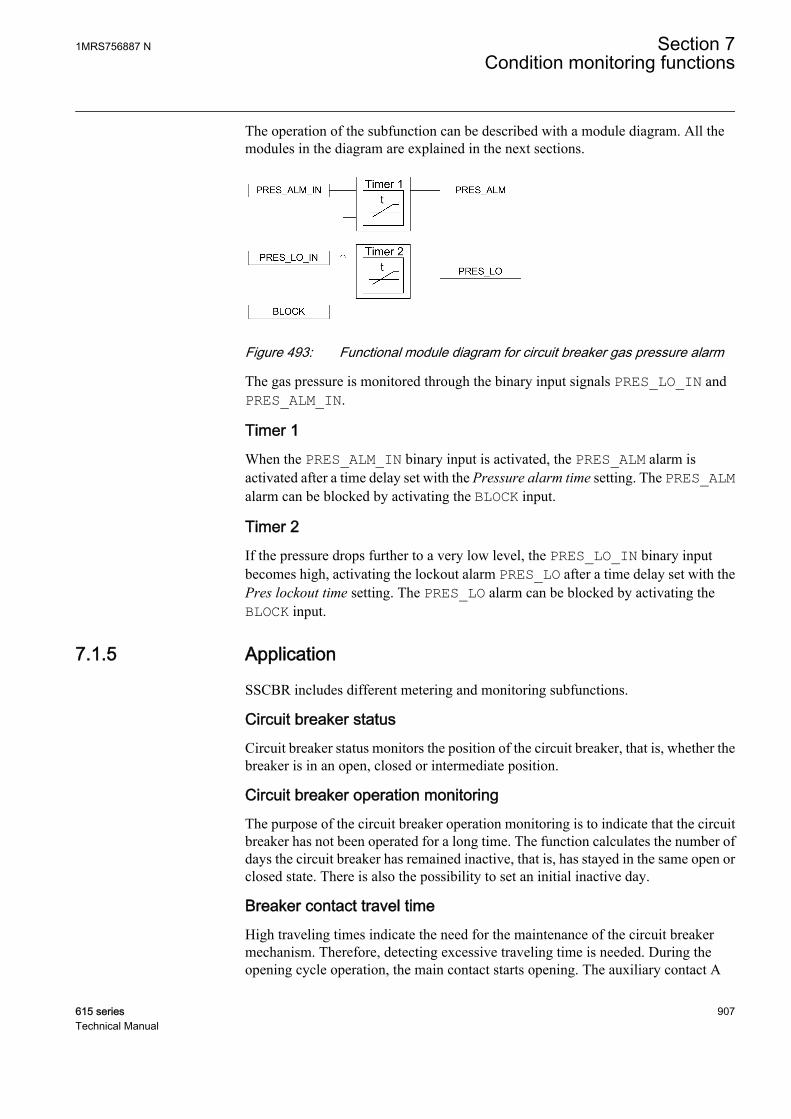
The operation of the subfunction can be described with a module diagram. All themodules in the diagram are explained in the next sections.
A071113 V2 EN
Figure 493: Functional module diagram for circuit breaker gas pressure alarm
The gas pressure is monitored through the binary input signals PRES_LO_IN andPRES_ALM_IN.
Timer 1When the PRES_ALM_IN binary input is activated, the PRES_ALM alarm isactivated after a time delay set with the Pressure alarm time setting. The PRES_ALMalarm can be blocked by activating the BLOCK input.
Timer 2If the pressure drops further to a very low level, the PRES_LO_IN binary inputbecomes high, activating the lockout alarm PRES_LO after a time delay set with thePres lockout time setting. The PRES_LO alarm can be blocked by activating theBLOCK input.
7.1.5 Application
SSCBR includes different metering and monitoring subfunctions.
Circuit breaker statusCircuit breaker status monitors the position of the circuit breaker, that is, whether thebreaker is in an open, closed or intermediate position.
Circuit breaker operation monitoringThe purpose of the circuit breaker operation monitoring is to indicate that the circuitbreaker has not been operated for a long time. The function calculates the number ofdays the circuit breaker has remained inactive, that is, has stayed in the same open orclosed state. There is also the possibility to set an initial inactive day.
Breaker contact travel timeHigh traveling times indicate the need for the maintenance of the circuit breakermechanism. Therefore, detecting excessive traveling time is needed. During theopening cycle operation, the main contact starts opening. The auxiliary contact A
1MRS756887 N Section 7Condition monitoring functions
615 series 907Technical Manual

opens, the auxiliary contact B closes and the main contact reaches its opening position.During the closing cycle, the first main contact starts closing. The auxiliary contact Bopens, the auxiliary contact A closes and the main contact reaches its closed position.The travel times are calculated based on the state changes of the auxiliary contacts andthe adding correction factor to consider the time difference of the main contact's andthe auxiliary contact's position change.
Operation counterRoutine maintenance of the breaker, such as lubricating breaker mechanism, isgenerally based on a number of operations. A suitable threshold setting to raise analarm when the number of operation cycle exceeds the set limit helps preventivemaintenance. This can also be used to indicate the requirement for oil sampling fordielectric testing in case of an oil circuit breaker.
The change of state can be detected from the binary input of the auxiliary contact.There is a possibility to set an initial value for the counter which can be used toinitialize this functionality after a period of operation or in case of refurbished primaryequipment.
Accumulation of Iyt
Accumulation of Iyt calculates the accumulated energy ΣIyt, where the factor y isknown as the current exponent. The factor y depends on the type of the circuit breaker.For oil circuit breakers, the factor y is normally 2. In case of a high-voltage system, thefactor y can be 1.4...1.5.
Remaining life of the breakerEvery time the breaker operates, the life of the circuit breaker reduces due to wearing.The wearing in the breaker depends on the tripping current, and the remaining life ofthe breaker is estimated from the circuit breaker trip curve provided by themanufacturer.
Example for estimating the remaining life of a circuit breaker
Section 7 1MRS756887 NCondition monitoring functions
908 615 seriesTechnical Manual
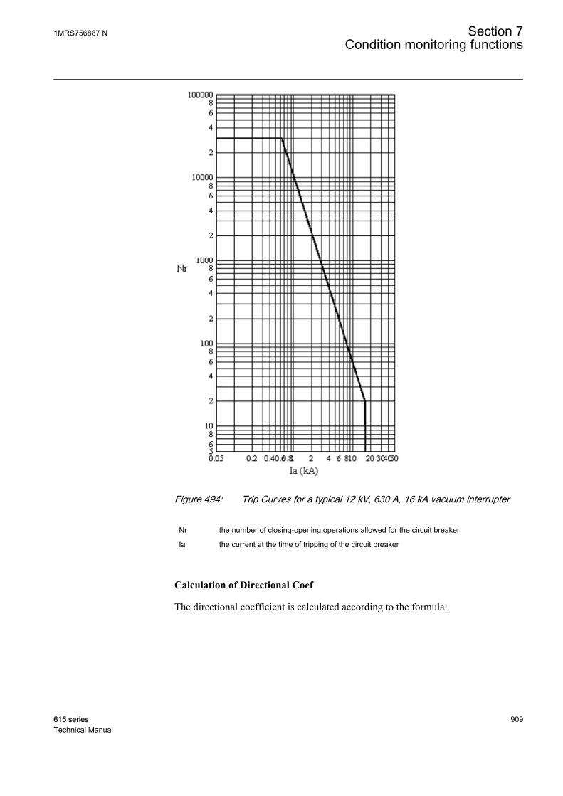
A071114 V3 EN
Figure 494: Trip Curves for a typical 12 kV, 630 A, 16 kA vacuum interrupter
Nr the number of closing-opening operations allowed for the circuit breaker
Ia the current at the time of tripping of the circuit breaker
Calculation of Directional Coef
The directional coefficient is calculated according to the formula:
1MRS756887 N Section 7Condition monitoring functions
615 series 909Technical Manual

Directional Coef
B
A
I
I
f
r
=
= −
log
log
.2 2609
A070794 V2 EN (Equation 178)
Ir Rated operating current = 630 A
If Rated fault current = 16 kA
A Op number rated = 30000
B Op number fault = 20
Calculation for estimating the remaining life
Figure 494 shows that there are 30,000 possible operations at the rated operatingcurrent of 630 A and 20 operations at the rated fault current 16 kA. Therefore, if thetripping current is 10 kA, one operation at 10 kA is equivalent to 30,000/60=500operations at the rated current. It is also assumed that prior to this tripping, theremaining life of the circuit breaker is 15,000 operations. Therefore, after oneoperation of 10 kA, the remaining life of the circuit breaker is 15,000-500=14,500 atthe rated operating current.
Remaining life reduction =
−
I
Ir
Directional Coef
GUID-5AA23DAD-AAF0-4D03-844F-216C80F80789 V1 EN (Equation 179)
Spring-charged indicationFor normal operation of the circuit breaker, the circuit breaker spring should becharged within a specified time. Therefore, detecting long spring-charging timeindicates that it is time for the circuit breaker maintenance. The last value of thespring-charging time can be used as a service value.
Gas pressure supervisionThe gas pressure supervision monitors the gas pressure inside the arc chamber. Whenthe pressure becomes too low compared to the required value, the circuit breakeroperations are locked. A binary input is available based on the pressure levels in thefunction, and alarms are generated based on these inputs.
7.1.6 SignalsTable 833: SSCBR Input signals
Name Type Default DescriptionI_A SIGNAL 0 Phase A current
I_B SIGNAL 0 Phase B current
I_C SIGNAL 0 Phase C current
Table continues on next page
Section 7 1MRS756887 NCondition monitoring functions
910 615 seriesTechnical Manual

Name Type Default DescriptionBLOCK BOOLEAN 0=False Block input status
POSOPEN BOOLEAN 0=False Signal for open position of apparatus from I/O
POSCLOSE BOOLEAN 0=False Signal for close position of apparatus from I/O
OPEN_CB_EXE BOOLEAN 0=False Signal for open command to coil
CLOSE_CB_EXE BOOLEAN 0=False Signal for close command to coil
PRES_ALM_IN BOOLEAN 0=False Binary pressure alarm input
PRES_LO_IN BOOLEAN 0=False Binary pressure input for lockout indication
SPR_CHR_ST BOOLEAN 0=False CB spring charging started input
SPR_CHR BOOLEAN 0=False CB spring charged input
RST_IPOW BOOLEAN 0=False Reset accumulation energy
RST_CB_WEAR BOOLEAN 0=False Reset input for CB remaining life and operationcounter
RST_TRV_T BOOLEAN 0=False Reset input for CB closing and opening travel times
RST_SPR_T BOOLEAN 0=False Reset input for the charging time of the CB spring
Table 834: SSCBR Output signals
Name Type DescriptionTRV_T_OP_ALM BOOLEAN CB open travel time exceeded set value
TRV_T_CL_ALM BOOLEAN CB close travel time exceeded set value
SPR_CHR_ALM BOOLEAN Spring charging time has crossed the set value
OPR_ALM BOOLEAN Number of CB operations exceeds alarm limit
OPR_LO BOOLEAN Number of CB operations exceeds lockout limit
IPOW_ALM BOOLEAN Accumulated currents power (Iyt),exceeded alarmlimit
IPOW_LO BOOLEAN Accumulated currents power (Iyt),exceededlockout limit
CB_LIFE_ALM BOOLEAN Remaining life of CB exceeded alarm limit
MON_ALM BOOLEAN CB 'not operated for long time' alarm
PRES_ALM BOOLEAN Pressure below alarm level
PRES_LO BOOLEAN Pressure below lockout level
OPENPOS BOOLEAN CB is in open position
INVALIDPOS BOOLEAN CB is in invalid position (not positively open orclosed)
CLOSEPOS BOOLEAN CB is in closed position
1MRS756887 N Section 7Condition monitoring functions
615 series 911Technical Manual

7.1.7 SettingsTable 835: SSCBR Non group settings (Basic)
Parameter Values (Range) Unit Step Default DescriptionOperation 1=on
5=off 1=on Operation Off / On
Acc stop current 5.00...500.00 A 0.01 10.00 RMS current setting below which engyacm stops
Open alarm time 0...200 ms 1 40 Alarm level setting for open travel time inms
Close alarm time 0...200 ms 1 40 Alarm level Setting for close travel time inms
Spring charge time 0...60000 ms 10 15000 Setting of alarm for spring charging time ofCB in ms
Alarm Op number 0...99999 1 200 Alarm limit for number of operations
Lockout Op number 0...99999 1 300 Lock out limit for number of operations
Current exponent 0.00...2.00 0.01 2.00 Current exponent setting for energycalculation
Difference Cor time -10...10 ms 1 5 Corr. factor for time dif in aux. and maincontacts open time
Alm Acc currents Pwr 0.00...20000.00 0.01 2500.00 Setting of alarm level for accumulatedcurrents power
LO Acc currents Pwr 0.00...20000.00 0.01 2500.00 Lockout limit setting for accumulatedcurrents power
Directional Coef -3.00...-0.50 0.01 -1.50 Directional coefficient for CB lifecalculation
Initial CB Rmn life 0...99999 1 5000 Initial value for the CB remaining life
Rated Op current 100.00...5000.00 A 0.01 1000.00 Rated operating current of the breaker
Rated fault current 500.00...75000.00 A 0.01 5000.00 Rated fault current of the breaker
Op number rated 1...99999 1 10000 Number of operations possible at ratedcurrent
Op number fault 1...10000 1 1000 Number of operations possible at ratedfault current
Inactive Alm days 0...9999 1 2000 Alarm limit value of the inactive dayscounter
Travel time Clc mode 1=From Cmd toPos2=From Pos to Pos
2=From Pos to Pos Travel time calculation mode selection
Table 836: SSCBR Non group settings (Advanced)
Parameter Values (Range) Unit Step Default DescriptionOpening time Cor -100...100 ms 1 10 Correction factor for open travel time in ms
Closing time Cor -100...100 ms 1 10 Correction factor for CB close travel timein ms
Counter initial Val 0...99999 1 0 The operation numbers counterinitialization value
Ini Acc currents Pwr 0.00...20000.00 0.01 0.00 Initial value for accumulation energy (Iyt)
Table continues on next page
Section 7 1MRS756887 NCondition monitoring functions
912 615 seriesTechnical Manual
Parameter Values (Range) Unit Step Default DescriptionLife alarm level 0...99999 1 500 Alarm level for CB remaining life
Pressure alarm time 0...60000 ms 1 10 Time delay for gas pressure alarm in ms
Pres lockout time 0...60000 ms 10 10 Time delay for gas pressure lockout in ms
Ini inactive days 0...9999 1 0 Initial value of the inactive days counter
Inactive Alm hours 0...23 h 1 0 Alarm time of the inactive days counter inhours
7.1.8 Monitored dataTable 837: SSCBR Monitored data
Name Type Values (Range) Unit DescriptionT_TRV_OP FLOAT32 0...60000 ms Travel time of the CB
during opening operation
T_TRV_CL FLOAT32 0...60000 ms Travel time of the CBduring closing operation
T_SPR_CHR FLOAT32 0.00...99.99 s The charging time of theCB spring
NO_OPR INT32 0...99999 Number of CB operationcycle
INA_DAYS INT32 0...9999 The number of days CBhas been inactive
CB_LIFE_A INT32 -99999...99999 CB Remaining life phaseA
CB_LIFE_B INT32 -99999...99999 CB Remaining life phaseB
CB_LIFE_C INT32 -99999...99999 CB Remaining life phaseC
IPOW_A FLOAT32 0.000...30000.000
Accumulated currentspower (Iyt), phase A
IPOW_B FLOAT32 0.000...30000.000
Accumulated currentspower (Iyt), phase B
IPOW_C FLOAT32 0.000...30000.000
Accumulated currentspower (Iyt), phase C
SSCBR Enum 1=on2=blocked3=test4=test/blocked5=off
Status
1MRS756887 N Section 7Condition monitoring functions
615 series 913Technical Manual
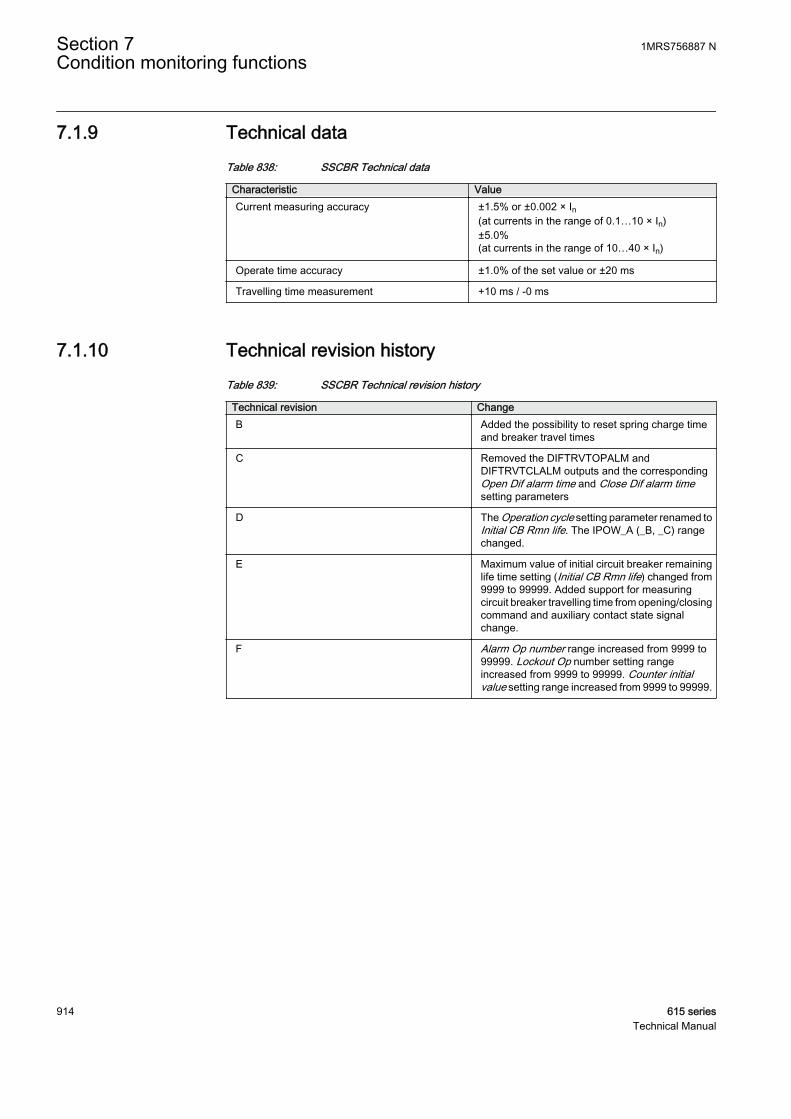
7.1.9 Technical dataTable 838: SSCBR Technical data
Characteristic ValueCurrent measuring accuracy ±1.5% or ±0.002 × In
(at currents in the range of 0.1…10 × In)±5.0%(at currents in the range of 10…40 × In)
Operate time accuracy ±1.0% of the set value or ±20 ms
Travelling time measurement +10 ms / -0 ms
7.1.10 Technical revision historyTable 839: SSCBR Technical revision history
Technical revision ChangeB Added the possibility to reset spring charge time
and breaker travel times
C Removed the DIFTRVTOPALM andDIFTRVTCLALM outputs and the correspondingOpen Dif alarm time and Close Dif alarm timesetting parameters
D The Operation cycle setting parameter renamed toInitial CB Rmn life. The IPOW_A (_B, _C) rangechanged.
E Maximum value of initial circuit breaker remaininglife time setting (Initial CB Rmn life) changed from9999 to 99999. Added support for measuringcircuit breaker travelling time from opening/closingcommand and auxiliary contact state signalchange.
F Alarm Op number range increased from 9999 to99999. Lockout Op number setting rangeincreased from 9999 to 99999. Counter initialvalue setting range increased from 9999 to 99999.
Section 7 1MRS756887 NCondition monitoring functions
914 615 seriesTechnical Manual
Section 8 Measurement functions
8.1 Basic measurements
8.1.1 Functions
The three-phase current measurement function CMMXU is used for monitoring andmetering the phase currents of the power system.
The three-phase voltage measurement function VMMXU is used for monitoring andmetering the phase-to-phase voltages of the power system. The phase-to-earthvoltages are also available in VMMXU.
The residual current measurement function RESCMMXU is used for monitoring andmetering the residual current of the power system.
The residual voltage measurement function RESVMMXU is used for monitoring andmetering the residual voltage of the power system.
The sequence current measurement CSMSQI is used for monitoring and metering thephase sequence currents.
The sequence voltage measurement VSMSQI is used for monitoring and metering thephase sequence voltages.
The frequency measurement FMMXU is used for monitoring and metering the powersystem frequency.
The three-phase power and energy measurement PEMMXU is used for monitoringand metering active power (P), reactive power (Q), apparent power (S) and powerfactor (PF) and for calculating the accumulated energy separately as forward active,reversed active, forward reactive and reversed reactive. PEMMXU calculates thesequantities using the fundamental frequency phasors, that is, the DFT values of themeasured phase current and phase voltage signals.
The information of the measured quantity is available for the operator both locally inLHMI or WHMI and remotely to a network control center with communication.
If the measured data in LHMI or WHMI is within parentheses, thereare some problems to express the data.
1MRS756887 N Section 8Measurement functions
615 series 915Technical Manual

8.1.2 Measurement functionality
The functions can be enabled or disabled with the Operation setting. Thecorresponding parameter values are "On" and "Off".
Some of the measurement functions operate on two alternative measurement modes:"DFT" and "RMS". The measurement mode is selected with the X Measurement modesetting. Depending on the measuring function if the measurement mode cannot beselected, the measuring mode is "DFT".
Demand value calculationThe demand values are calculated separately for each measurement function and perphase when applicable. The available measurement modes are "Linear" and"Logarithmic". The "Logarithmic" measurement mode is only effective for phasecurrent and residual current demand value calculations. The demand value calculationmode is selected with the setting parameter Configuration/Measurements/Ademand Av mode. The time interval for all demand value calculations is selectedwith the setting parameter Configuration/Measurements/Demand interval.
If the Demand interval setting is set to "15 minutes", for example, the demand valuesare updated every quarter of an hour. The demand time interval is synchronized to thereal-time clock of the protection relay. When the demand time interval or calculationmode is changed, it initializes the demand value calculation. For the very first demandvalue calculation interval, the values are stated as invalid until the first refresh isavailable.
The "Linear" calculation mode uses the periodic sliding average calculation of themeasured signal over the demand time interval. A new demand value is obtained oncein a minute, indicating the analog signal demand over the demand time intervalproceeding the update time. The actual rolling demand values are stored in thememory until the value is updated at the end of the next time interval.
The "Logarithmic" calculation mode uses the periodic calculation using a log10function over the demand time interval to replicate thermal demand ammeters. Thelogarithmic demand calculates a snapshot of the analog signal every 1/15 x demandtime interval.
Each measurement function has its own recorded data values. In protection relay,these are found in Monitoring/Recorded data/Measurements. In the technicalmanual these are listed in the monitored data section of each measurement function.These values are periodically updated with the maximum and minimum demandvalues. The time stamps are provided for both values.
Reset of Recorded data initializes a present demand value to the minimum andmaximum demand values.
Value reportingThe measurement functions are capable of reporting new values for network controlcenter (SCADA system) based on various functions.
Section 8 1MRS756887 NMeasurement functions
916 615 seriesTechnical Manual
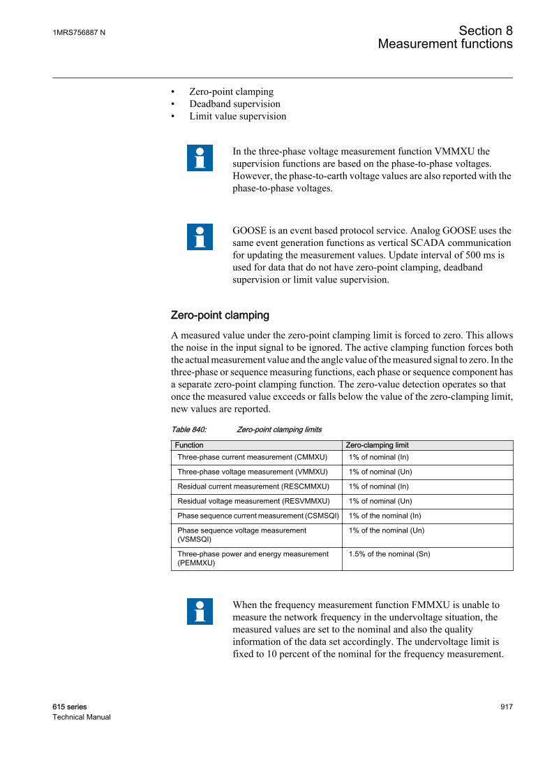
• Zero-point clamping• Deadband supervision• Limit value supervision
In the three-phase voltage measurement function VMMXU thesupervision functions are based on the phase-to-phase voltages.However, the phase-to-earth voltage values are also reported with thephase-to-phase voltages.
GOOSE is an event based protocol service. Analog GOOSE uses thesame event generation functions as vertical SCADA communicationfor updating the measurement values. Update interval of 500 ms isused for data that do not have zero-point clamping, deadbandsupervision or limit value supervision.
Zero-point clampingA measured value under the zero-point clamping limit is forced to zero. This allowsthe noise in the input signal to be ignored. The active clamping function forces boththe actual measurement value and the angle value of the measured signal to zero. In thethree-phase or sequence measuring functions, each phase or sequence component hasa separate zero-point clamping function. The zero-value detection operates so thatonce the measured value exceeds or falls below the value of the zero-clamping limit,new values are reported.
Table 840: Zero-point clamping limits
Function Zero-clamping limitThree-phase current measurement (CMMXU) 1% of nominal (In)
Three-phase voltage measurement (VMMXU) 1% of nominal (Un)
Residual current measurement (RESCMMXU) 1% of nominal (In)
Residual voltage measurement (RESVMMXU) 1% of nominal (Un)
Phase sequence current measurement (CSMSQI) 1% of the nominal (In)
Phase sequence voltage measurement(VSMSQI)
1% of the nominal (Un)
Three-phase power and energy measurement(PEMMXU)
1.5% of the nominal (Sn)
When the frequency measurement function FMMXU is unable tomeasure the network frequency in the undervoltage situation, themeasured values are set to the nominal and also the qualityinformation of the data set accordingly. The undervoltage limit isfixed to 10 percent of the nominal for the frequency measurement.
1MRS756887 N Section 8Measurement functions
615 series 917Technical Manual

Limit value supervisionThe limit value supervision function indicates whether the measured value ofX_INST exceeds or falls below the set limits. The measured value has thecorresponding range information X_RANGE and has a value in the range of 0 to 4:
• 0: "normal"• 1: "high"• 2: "low"• 3: "high-high"• 4: "low-low"
The range information changes and the new values are reported.
GUID-AAAA7367-377C-4743-A2D0-8DD4941C585D V1 EN
Figure 495: Presentation of operating limits
The range information can also be decoded into boolean output signals on some of themeasuring functions and the number of phases required to exceed or undershoot thelimit before activating the outputs and can be set with the Num of phases setting in thethree-phase measurement functions CMMXU and VMMXU. The limit supervisionboolean alarm and warning outputs can be blocked.
Table 841: Settings for limit value supervision
Function Settings for limit value supervisionThree-phase current measurement(CMMXU)
High limit A high limit
Low limit A low limit
High-high limit A high high limit
Low-low limit A low low limit
Table continues on next page
Section 8 1MRS756887 NMeasurement functions
918 615 seriesTechnical Manual
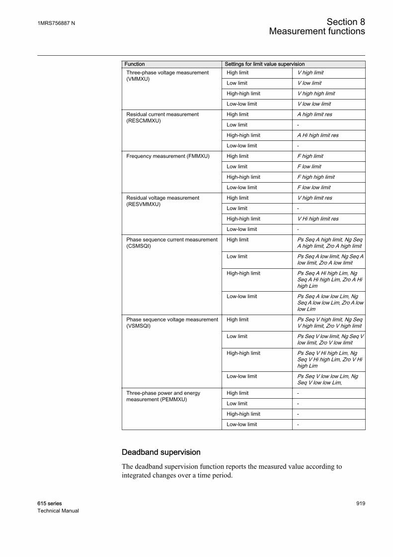
Function Settings for limit value supervisionThree-phase voltage measurement(VMMXU)
High limit V high limit
Low limit V low limit
High-high limit V high high limit
Low-low limit V low low limit
Residual current measurement(RESCMMXU)
High limit A high limit res
Low limit -
High-high limit A Hi high limit res
Low-low limit -
Frequency measurement (FMMXU) High limit F high limit
Low limit F low limit
High-high limit F high high limit
Low-low limit F low low limit
Residual voltage measurement(RESVMMXU)
High limit V high limit res
Low limit -
High-high limit V Hi high limit res
Low-low limit -
Phase sequence current measurement(CSMSQI)
High limit Ps Seq A high limit, Ng SeqA high limit, Zro A high limit
Low limit Ps Seq A low limit, Ng Seq Alow limit, Zro A low limit
High-high limit Ps Seq A Hi high Lim, NgSeq A Hi high Lim, Zro A Hihigh Lim
Low-low limit Ps Seq A low low Lim, NgSeq A low low Lim, Zro A lowlow Lim
Phase sequence voltage measurement(VSMSQI)
High limit Ps Seq V high limit, Ng SeqV high limit, Zro V high limit
Low limit Ps Seq V low limit, Ng Seq Vlow limit, Zro V low limit
High-high limit Ps Seq V Hi high Lim, NgSeq V Hi high Lim, Zro V Hihigh Lim
Low-low limit Ps Seq V low low Lim, NgSeq V low low Lim,
Three-phase power and energymeasurement (PEMMXU)
High limit -
Low limit -
High-high limit -
Low-low limit -
Deadband supervisionThe deadband supervision function reports the measured value according tointegrated changes over a time period.
1MRS756887 N Section 8Measurement functions
615 series 919Technical Manual
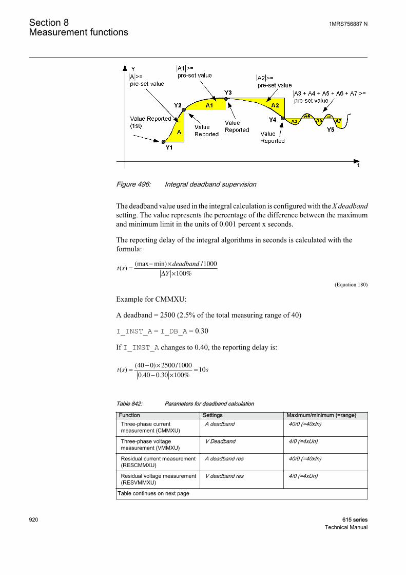
GUID-63CA9A0F-24D8-4BA8-A667-88632DF53284 V1 EN
Figure 496: Integral deadband supervision
The deadband value used in the integral calculation is configured with the X deadbandsetting. The value represents the percentage of the difference between the maximumand minimum limit in the units of 0.001 percent x seconds.
The reporting delay of the integral algorithms in seconds is calculated with theformula:
t sdeadband
Y( )
(max min) /
%=
− ×
×
1000
100∆
GUID-5381484E-E205-4548-A846-D3519578384B V1 EN (Equation 180)
Example for CMMXU:
A deadband = 2500 (2.5% of the total measuring range of 40)
I_INST_A = I_DB_A = 0.30
If I_INST_A changes to 0.40, the reporting delay is:
t s s( )( ) /
. . %=
− ×
− ×
=40 0 2500 1000
0 40 0 30 10010
GUID-D1C387B1-4F2E-4A28-AFEA-431687DDF9FE V1 EN
Table 842: Parameters for deadband calculation
Function Settings Maximum/minimum (=range)Three-phase currentmeasurement (CMMXU)
A deadband 40/0 (=40xIn)
Three-phase voltagemeasurement (VMMXU)
V Deadband 4/0 (=4xUn)
Residual current measurement(RESCMMXU)
A deadband res 40/0 (=40xIn)
Residual voltage measurement(RESVMMXU)
V deadband res 4/0 (=4xUn)
Table continues on next page
Section 8 1MRS756887 NMeasurement functions
920 615 seriesTechnical Manual

Function Settings Maximum/minimum (=range)Frequency measurement(FMMXU)
F deadband 75/35 (=40 Hz)1)
Phase sequence currentmeasurement (CSMSQI)
Ps Seq A deadband, Ng Seq Adeadband, Zro A deadband
40/0 (=40xIn)
Phase sequence voltagemeasurement (VSMSQI)
Ps Seq V deadband, Ng Seq Vdeadband, Zro V deadband
4/0 (=4xUn)
Three-phase power and energymeasurement (PEMMXU)
-
1) The value provided is for REF615, RET615 and REM615 in 50 Hz network. The value for 60 Hz networkis 90/36 (=54 Hz). For REG615 the values are 75/10 (=65 Hz) in 50 Hz network and 90/12 (=78 Hz) in60 Hz network.
In the three-phase power and energy measurement functionPEMMXU, the deadband supervision is done separately for apparentpower S, with the preset value of fixed 10 percent of the Sn, and thepower factor PF, with the preset values fixed at 0.10. . All the powermeasurement-related values P, Q, S and PF are reportedsimultaneously when either one of the S or PF values exceeds thepreset limit.
Power and energy calculationThe three-phase power is calculated from the phase-to-earth voltages and phase-to-earth currents. The power measurement function is capable of calculating a complexpower based on the fundamental frequency component phasors (DFT).
S = ⋅ + ⋅ + ⋅(U I U I U IA A B B C C* * *
)
GUID-8BF2FBFE-B33B-4B49-86AA-C1B326BBBAC1 V1 EN (Equation 181)
Once the complex apparent power is calculated, P, Q, S and PF are calculated with theequations:
P S= Re( )
GUID-92B45FA5-0B6B-47DC-9ADB-69E7EB30D53A V3 EN (Equation 182)
Q S= Im( )
GUID-CA5C1D5D-3AD9-468C-86A1-835525F8BE27 V2 EN (Equation 183)
S S P Q= = +2 2
GUID-B3999831-E376-4DAF-BF36-BA6F761230A9 V2 EN (Equation 184)
CosP
Sϕ =
GUID-D729F661-94F9-48B1-8FA0-06E84A6F014C V2 EN (Equation 185)
Depending on the unit multiplier selected with Power unit Mult, the calculated powervalues are presented in units of kVA/kW/kVAr or in units of MVA/MW/MVAr.
1MRS756887 N Section 8Measurement functions
615 series 921Technical Manual
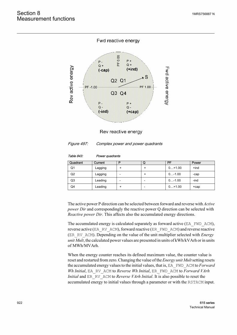
GUID-9947B4F2-CD26-4F85-BF57-EAF1593AAE1B V1 EN
Figure 497: Complex power and power quadrants
Table 843: Power quadrants
Quadrant Current P Q PF PowerQ1 Lagging + + 0…+1.00 +ind
Q2 Lagging - + 0…-1.00 -cap
Q3 Leading - - 0…-1.00 -ind
Q4 Leading + - 0…+1.00 +cap
The active power P direction can be selected between forward and reverse with Activepower Dir and correspondingly the reactive power Q direction can be selected withReactive power Dir. This affects also the accumulated energy directions.
The accumulated energy is calculated separately as forward active (EA_FWD_ACM),reverse active (EA_RV_ACM), forward reactive (ER_FWD_ACM) and reverse reactive(ER_RV_ACM). Depending on the value of the unit multiplier selected with Energyunit Mult, the calculated power values are presented in units of kWh/kVArh or in unitsof MWh/MVArh.
When the energy counter reaches its defined maximum value, the counter value isreset and restarted from zero. Changing the value of the Energy unit Mult setting resetsthe accumulated energy values to the initial values, that is, EA_FWD_ACM to ForwardWh Initial, EA_RV_ACM to Reverse Wh Initial, ER_FWD_ACM to Forward VArhInitial and ER_RV_ACM to Reverse VArh Initial. It is also possible to reset theaccumulated energy to initial values through a parameter or with the RSTACM input.
Section 8 1MRS756887 NMeasurement functions
922 615 seriesTechnical Manual
Sequence componentsThe phase-sequence components are calculated using the phase currents and phasevoltages. More information on calculating the phase-sequence components can befound in Calculated measurements in this manual.
8.1.3 Measurement function applications
The measurement functions are used for power system measurement, supervision andreporting to LHMI, a monitoring tool within PCM600, or to the station level, forexample, with IEC 61850. The possibility to continuously monitor the measuredvalues of active power, reactive power, currents, voltages, power factors and so on, isvital for efficient production, transmission, and distribution of electrical energy. Itprovides a fast and easy overview of the present status of the power system to thesystem operator. Additionally, it can be used during testing and commissioning ofprotection relays to verify the proper operation and connection of instrumenttransformers, that is, the current transformers (CTs) and voltage transformers (VTs).The proper operation of the protection relay analog measurement chain can be verifiedduring normal service by a periodic comparison of the measured value from theprotection relay to other independent meters.
When the zero signal is measured, the noise in the input signal can still produce smallmeasurement values. The zero point clamping function can be used to ignore the noisein the input signal and, hence, prevent the noise to be shown in the user display. Thezero clamping is done for the measured analog signals and angle values.
The demand values are used to neglect sudden changes in the measured analog signalswhen monitoring long time values for the input signal. The demand values are linearaverage values of the measured signal over a settable demand interval. The demandvalues are calculated for the measured analog three-phase current signals.
The limit supervision indicates, if the measured signal exceeds or goes below the setlimits. Depending on the measured signal type, up to two high limits and up to two lowlimits can be set for the limit supervision.
The deadband supervision reports a new measurement value if the input signal hasgone out of the deadband state. The deadband supervision can be used in valuereporting between the measurement point and operation control. When the deadbandsupervision is properly configured, it helps in keeping the communication load inminimum and yet measurement values are reported frequently enough.
8.1.4 Three-phase current measurement CMMXU
8.1.4.1 Identification
Function description IEC 61850identification
IEC 60617identification
ANSI/IEEE C37.2device number
Three-phase current measurement CMMXU 3I 3I
1MRS756887 N Section 8Measurement functions
615 series 923Technical Manual
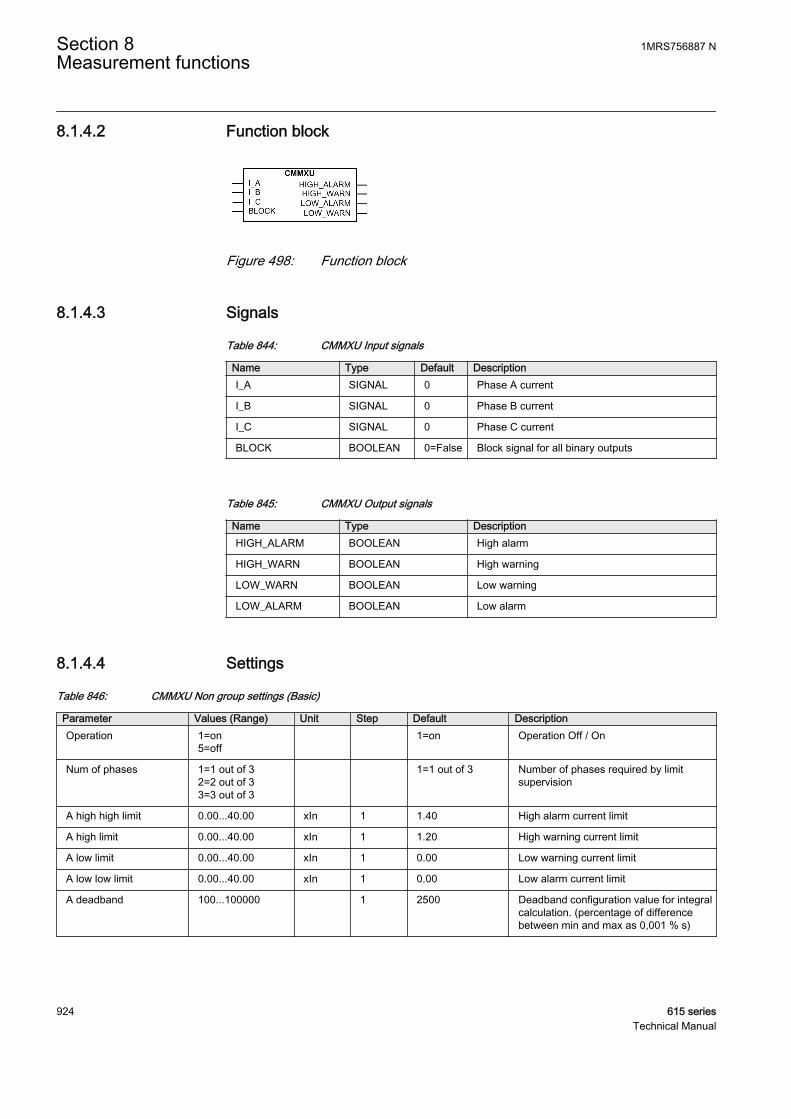
8.1.4.2 Function block
A070777 V2 EN
Figure 498: Function block
8.1.4.3 Signals
Table 844: CMMXU Input signals
Name Type Default DescriptionI_A SIGNAL 0 Phase A current
I_B SIGNAL 0 Phase B current
I_C SIGNAL 0 Phase C current
BLOCK BOOLEAN 0=False Block signal for all binary outputs
Table 845: CMMXU Output signals
Name Type DescriptionHIGH_ALARM BOOLEAN High alarm
HIGH_WARN BOOLEAN High warning
LOW_WARN BOOLEAN Low warning
LOW_ALARM BOOLEAN Low alarm
8.1.4.4 Settings
Table 846: CMMXU Non group settings (Basic)
Parameter Values (Range) Unit Step Default DescriptionOperation 1=on
5=off 1=on Operation Off / On
Num of phases 1=1 out of 32=2 out of 33=3 out of 3
1=1 out of 3 Number of phases required by limitsupervision
A high high limit 0.00...40.00 xIn 1 1.40 High alarm current limit
A high limit 0.00...40.00 xIn 1 1.20 High warning current limit
A low limit 0.00...40.00 xIn 1 0.00 Low warning current limit
A low low limit 0.00...40.00 xIn 1 0.00 Low alarm current limit
A deadband 100...100000 1 2500 Deadband configuration value for integralcalculation. (percentage of differencebetween min and max as 0,001 % s)
Section 8 1MRS756887 NMeasurement functions
924 615 seriesTechnical Manual

Table 847: CMMXU Non group settings (Advanced)
Parameter Values (Range) Unit Step Default DescriptionMeasurement mode 1=RMS
2=DFT 2=DFT Selects used measurement mode
8.1.4.5 Monitored data
Table 848: CMMXU Monitored data
Name Type Values (Range) Unit DescriptionIL1-A FLOAT32 0.00...40.00 xIn Measured current
amplitude phase A
IL2-A FLOAT32 0.00...40.00 xIn Measured currentamplitude phase B
IL3-A FLOAT32 0.00...40.00 xIn Measured currentamplitude phase C
Max demand IL1 FLOAT32 0.00...40.00 xIn Maximum demand forPhase A
Max demand IL2 FLOAT32 0.00...40.00 xIn Maximum demand forPhase B
Max demand IL3 FLOAT32 0.00...40.00 xIn Maximum demand forPhase C
Min demand IL1 FLOAT32 0.00...40.00 xIn Minimum demand forPhase A
Min demand IL2 FLOAT32 0.00...40.00 xIn Minimum demand forPhase B
Min demand IL3 FLOAT32 0.00...40.00 xIn Minimum demand forPhase C
Time max demandIL1
Timestamp Time of maximumdemand phase A
Time max demandIL2
Timestamp Time of maximumdemand phase B
Time max demandIL3
Timestamp Time of maximumdemand phase C
Time min demandIL1
Timestamp Time of minimumdemand phase A
Time min demandIL2
Timestamp Time of minimumdemand phase B
Time min demandIL3
Timestamp Time of minimumdemand phase C
BLOCK BOOLEAN 0=False1=True
Block signal for all binaryoutputs
HIGH_ALARM BOOLEAN 0=False1=True
High alarm
HIGH_WARN BOOLEAN 0=False1=True
High warning
LOW_WARN BOOLEAN 0=False1=True
Low warning
Table continues on next page
1MRS756887 N Section 8Measurement functions
615 series 925Technical Manual
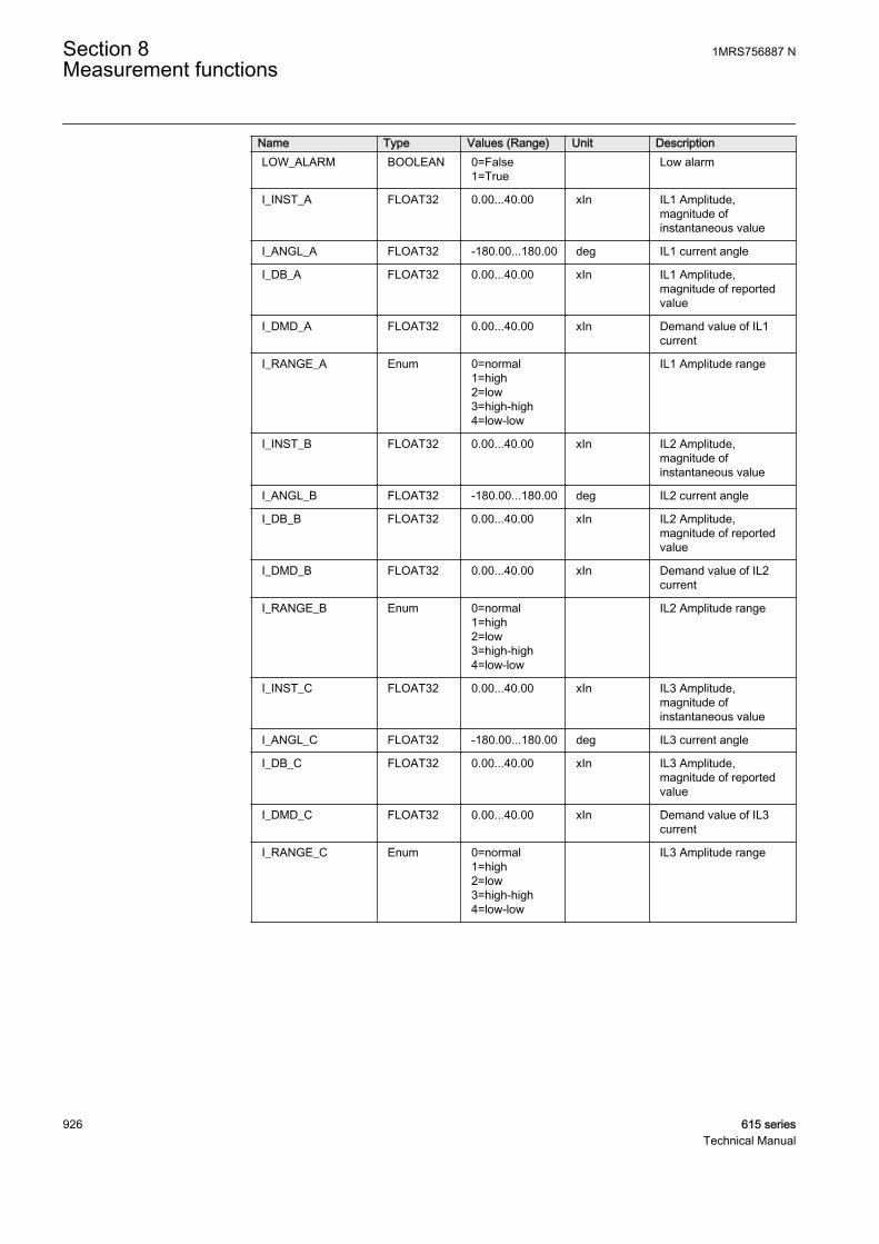
Name Type Values (Range) Unit DescriptionLOW_ALARM BOOLEAN 0=False
1=True Low alarm
I_INST_A FLOAT32 0.00...40.00 xIn IL1 Amplitude,magnitude ofinstantaneous value
I_ANGL_A FLOAT32 -180.00...180.00 deg IL1 current angle
I_DB_A FLOAT32 0.00...40.00 xIn IL1 Amplitude,magnitude of reportedvalue
I_DMD_A FLOAT32 0.00...40.00 xIn Demand value of IL1current
I_RANGE_A Enum 0=normal1=high2=low3=high-high4=low-low
IL1 Amplitude range
I_INST_B FLOAT32 0.00...40.00 xIn IL2 Amplitude,magnitude ofinstantaneous value
I_ANGL_B FLOAT32 -180.00...180.00 deg IL2 current angle
I_DB_B FLOAT32 0.00...40.00 xIn IL2 Amplitude,magnitude of reportedvalue
I_DMD_B FLOAT32 0.00...40.00 xIn Demand value of IL2current
I_RANGE_B Enum 0=normal1=high2=low3=high-high4=low-low
IL2 Amplitude range
I_INST_C FLOAT32 0.00...40.00 xIn IL3 Amplitude,magnitude ofinstantaneous value
I_ANGL_C FLOAT32 -180.00...180.00 deg IL3 current angle
I_DB_C FLOAT32 0.00...40.00 xIn IL3 Amplitude,magnitude of reportedvalue
I_DMD_C FLOAT32 0.00...40.00 xIn Demand value of IL3current
I_RANGE_C Enum 0=normal1=high2=low3=high-high4=low-low
IL3 Amplitude range
Section 8 1MRS756887 NMeasurement functions
926 615 seriesTechnical Manual
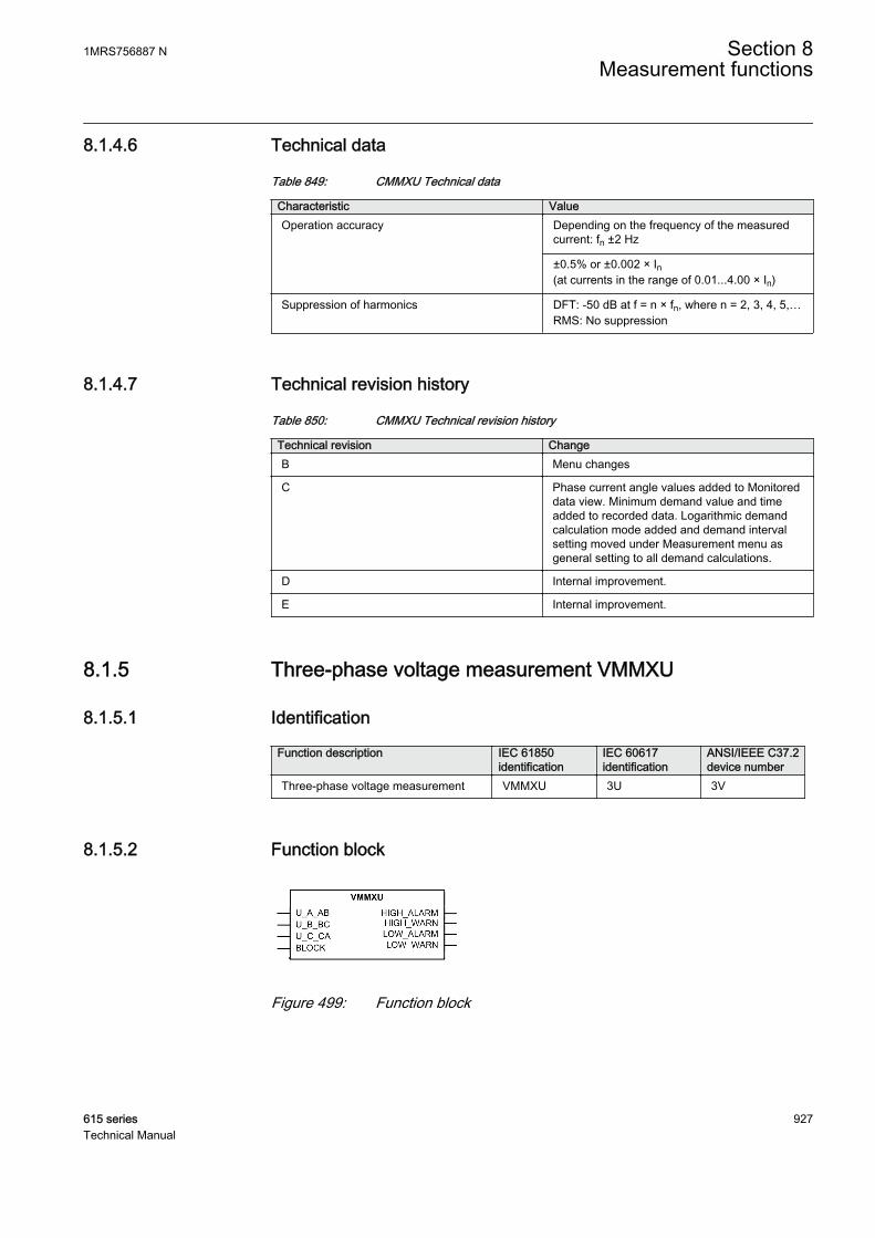
8.1.4.6 Technical data
Table 849: CMMXU Technical data
Characteristic ValueOperation accuracy Depending on the frequency of the measured
current: fn ±2 Hz
±0.5% or ±0.002 × In(at currents in the range of 0.01...4.00 × In)
Suppression of harmonics DFT: -50 dB at f = n × fn, where n = 2, 3, 4, 5,…RMS: No suppression
8.1.4.7 Technical revision history
Table 850: CMMXU Technical revision history
Technical revision ChangeB Menu changes
C Phase current angle values added to Monitoreddata view. Minimum demand value and timeadded to recorded data. Logarithmic demandcalculation mode added and demand intervalsetting moved under Measurement menu asgeneral setting to all demand calculations.
D Internal improvement.
E Internal improvement.
8.1.5 Three-phase voltage measurement VMMXU
8.1.5.1 Identification
Function description IEC 61850identification
IEC 60617identification
ANSI/IEEE C37.2device number
Three-phase voltage measurement VMMXU 3U 3V
8.1.5.2 Function block
GUID-5B741292-7FA6-4DEA-8D16-B530FD16A0FE V1 EN
Figure 499: Function block
1MRS756887 N Section 8Measurement functions
615 series 927Technical Manual
8.1.5.3 Signals
Table 851: VMMXU Input signals
Name Type Default DescriptionU_A_AB SIGNAL 0 Phase to earth voltage A or phase to phase voltage
AB
U_B_BC SIGNAL 0 Phase to earth voltage B or phase to phase voltageBC
U_C_CA SIGNAL 0 Phase to earth voltage C or phase to phase voltageCA
BLOCK BOOLEAN 0=False Block signal for all binary outputs
Table 852: VMMXU Output signals
Name Type DescriptionHIGH_ALARM BOOLEAN High alarm
HIGH_WARN BOOLEAN High warning
LOW_WARN BOOLEAN Low warning
LOW_ALARM BOOLEAN Low alarm
8.1.5.4 Settings
Table 853: VMMXU Non group settings (Basic)
Parameter Values (Range) Unit Step Default DescriptionOperation 1=on
5=off 1=on Operation Off / On
Num of phases 1=1 out of 32=2 out of 33=3 out of 3
1=1 out of 3 Number of phases required by limitsupervision
V high high limit 0.00...4.00 xUn 1 1.40 High alarm voltage limit
V high limit 0.00...4.00 xUn 1 1.20 High warning voltage limit
V low limit 0.00...4.00 xUn 1 0.00 Low warning voltage limit
V low low limit 0.00...4.00 xUn 1 0.00 Low alarm voltage limit
V deadband 100...100000 1 10000 Deadband configuration value for integralcalculation. (percentage of differencebetween min and max as 0,001 % s)
Table 854: VMMXU Non group settings (Advanced)
Parameter Values (Range) Unit Step Default DescriptionMeasurement mode 1=RMS
2=DFT 2=DFT Selects used measurement mode
Section 8 1MRS756887 NMeasurement functions
928 615 seriesTechnical Manual

8.1.5.5 Monitored data
Table 855: VMMXU Monitored data
Name Type Values (Range) Unit DescriptionU12-kV FLOAT32 0.00...4.00 xUn Measured phase to
phase voltage amplitudephase AB
U23-kV FLOAT32 0.00...4.00 xUn Measured phase tophase voltage amplitudephase BC
U31-kV FLOAT32 0.00...4.00 xUn Measured phase tophase voltage amplitudephase CA
BLOCK BOOLEAN 0=False1=True
Block signal for all binaryoutputs
HIGH_ALARM BOOLEAN 0=False1=True
High alarm
HIGH_WARN BOOLEAN 0=False1=True
High warning
LOW_WARN BOOLEAN 0=False1=True
Low warning
LOW_ALARM BOOLEAN 0=False1=True
Low alarm
U_INST_AB FLOAT32 0.00...4.00 xUn U12 Amplitude,magnitude ofinstantaneous value
U_ANGL_AB FLOAT32 -180.00...180.00 deg U12 angle
U_DB_AB FLOAT32 0.00...4.00 xUn U12 Amplitude,magnitude of reportedvalue
U_DMD_AB FLOAT32 0.00...4.00 xUn Demand value of U12voltage
U_RANGE_AB Enum 0=normal1=high2=low3=high-high4=low-low
U12 Amplitude range
U_INST_BC FLOAT32 0.00...4.00 xUn U23 Amplitude,magnitude ofinstantaneous value
U_ANGL_BC FLOAT32 -180.00...180.00 deg U23 angle
U_DB_BC FLOAT32 0.00...4.00 xUn U23 Amplitude,magnitude of reportedvalue
U_DMD_BC FLOAT32 0.00...4.00 xUn Demand value of U23voltage
U_RANGE_BC Enum 0=normal1=high2=low3=high-high4=low-low
U23 Amplitude range
Table continues on next page
1MRS756887 N Section 8Measurement functions
615 series 929Technical Manual

Name Type Values (Range) Unit DescriptionU_INST_CA FLOAT32 0.00...4.00 xUn U31 Amplitude,
magnitude ofinstantaneous value
U_ANGL_CA FLOAT32 -180.00...180.00 deg U31 angle
U_DB_CA FLOAT32 0.00...4.00 xUn U31 Amplitude,magnitude of reportedvalue
U_DMD_CA FLOAT32 0.00...4.00 xUn Demand value of U31voltage
U_RANGE_CA Enum 0=normal1=high2=low3=high-high4=low-low
U31 Amplitude range
U_INST_A FLOAT32 0.00...5.00 xUn UL1 Amplitude,magnitude ofinstantaneous value
U_ANGL_A FLOAT32 -180.00...180.00 deg UL1 angle
U_DMD_A FLOAT32 0.00...5.00 xUn Demand value of UL1voltage
U_INST_B FLOAT32 0.00...5.00 xUn UL2 Amplitude,magnitude ofinstantaneous value
U_ANGL_B FLOAT32 -180.00...180.00 deg UL2 angle
U_DMD_B FLOAT32 0.00...5.00 xUn Demand value of UL2voltage
U_INST_C FLOAT32 0.00...5.00 xUn UL3 Amplitude,magnitude ofinstantaneous value
U_ANGL_C FLOAT32 -180.00...180.00 deg UL3 angle
U_DMD_C FLOAT32 0.00...5.00 xUn Demand value of UL3voltage
8.1.5.6 Technical data
Table 856: VMMXU Technical data
Characteristic ValueOperation accuracy Depending on the frequency of the voltage
measured: fn ±2 HzAt voltages in range 0.01…1.15 × Un
±0.5% or ±0.002 × Un
Suppression of harmonics DFT: -50 dB at f = n × fn, where n = 2, 3, 4, 5,…RMS: No suppression
Section 8 1MRS756887 NMeasurement functions
930 615 seriesTechnical Manual
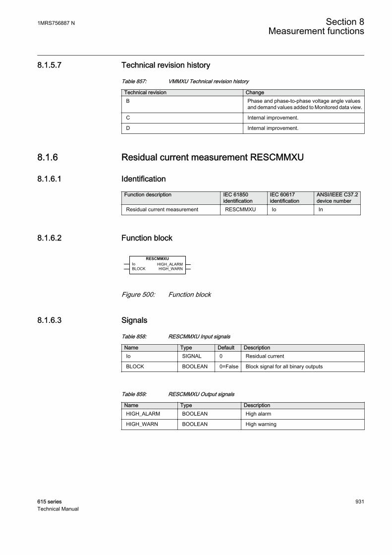
8.1.5.7 Technical revision history
Table 857: VMMXU Technical revision history
Technical revision ChangeB Phase and phase-to-phase voltage angle values
and demand values added to Monitored data view.
C Internal improvement.
D Internal improvement.
8.1.6 Residual current measurement RESCMMXU
8.1.6.1 Identification
Function description IEC 61850identification
IEC 60617identification
ANSI/IEEE C37.2device number
Residual current measurement RESCMMXU Io In
8.1.6.2 Function block
A070778 V2 EN
Figure 500: Function block
8.1.6.3 Signals
Table 858: RESCMMXU Input signals
Name Type Default DescriptionIo SIGNAL 0 Residual current
BLOCK BOOLEAN 0=False Block signal for all binary outputs
Table 859: RESCMMXU Output signals
Name Type DescriptionHIGH_ALARM BOOLEAN High alarm
HIGH_WARN BOOLEAN High warning
1MRS756887 N Section 8Measurement functions
615 series 931Technical Manual
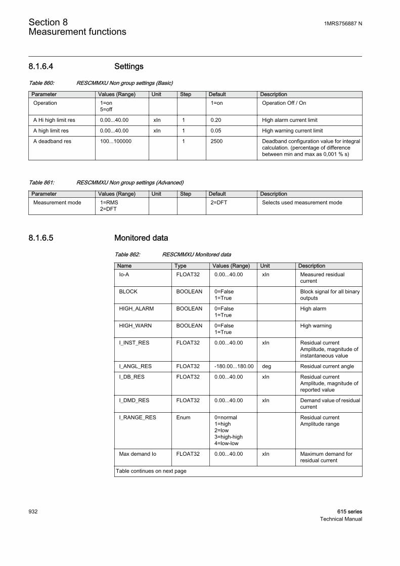
8.1.6.4 Settings
Table 860: RESCMMXU Non group settings (Basic)
Parameter Values (Range) Unit Step Default DescriptionOperation 1=on
5=off 1=on Operation Off / On
A Hi high limit res 0.00...40.00 xIn 1 0.20 High alarm current limit
A high limit res 0.00...40.00 xIn 1 0.05 High warning current limit
A deadband res 100...100000 1 2500 Deadband configuration value for integralcalculation. (percentage of differencebetween min and max as 0,001 % s)
Table 861: RESCMMXU Non group settings (Advanced)
Parameter Values (Range) Unit Step Default DescriptionMeasurement mode 1=RMS
2=DFT 2=DFT Selects used measurement mode
8.1.6.5 Monitored data
Table 862: RESCMMXU Monitored data
Name Type Values (Range) Unit DescriptionIo-A FLOAT32 0.00...40.00 xIn Measured residual
current
BLOCK BOOLEAN 0=False1=True
Block signal for all binaryoutputs
HIGH_ALARM BOOLEAN 0=False1=True
High alarm
HIGH_WARN BOOLEAN 0=False1=True
High warning
I_INST_RES FLOAT32 0.00...40.00 xIn Residual currentAmplitude, magnitude ofinstantaneous value
I_ANGL_RES FLOAT32 -180.00...180.00 deg Residual current angle
I_DB_RES FLOAT32 0.00...40.00 xIn Residual currentAmplitude, magnitude ofreported value
I_DMD_RES FLOAT32 0.00...40.00 xIn Demand value of residualcurrent
I_RANGE_RES Enum 0=normal1=high2=low3=high-high4=low-low
Residual currentAmplitude range
Max demand Io FLOAT32 0.00...40.00 xIn Maximum demand forresidual current
Table continues on next page
Section 8 1MRS756887 NMeasurement functions
932 615 seriesTechnical Manual
Name Type Values (Range) Unit DescriptionMin demand Io FLOAT32 0.00...40.00 xIn Minimum demand for
residual current
Time max demand Io Timestamp Time of maximumdemand residual current
Time min demand Io Timestamp Time of minimumdemand residual current
8.1.6.6 Technical data
Table 863: RESCMMXU Technical data
Characteristic ValueOperation accuracy At the frequency f = fn
±0.5% or ±0.002 × In(at currents in the range of 0.01...4.00 × In)
Suppression of harmonics DFT: -50 dB at f = n × fn, where n = 2, 3, 4, 5,…RMS: No suppression
8.1.6.7 Technical revision history
Table 864: RESCMMXU Technical revision history
Technical revision ChangeB -
C Residual current angle and demand value addedto Monitored data view. Recorded data added forminimum and maximum values with timestamps.
D Monitored data Min demand Io maximum valuerange (RESCMSTA2.MinAmps.maxVal.f ) iscorrected to 40.00.
E Internal improvement
8.1.7 Residual voltage measurement RESVMMXU
8.1.7.1 Identification
Function description IEC 61850identification
IEC 60617identification
ANSI/IEEE C37.2device number
Residual voltage measurement RESVMMXU Uo Vn
1MRS756887 N Section 8Measurement functions
615 series 933Technical Manual
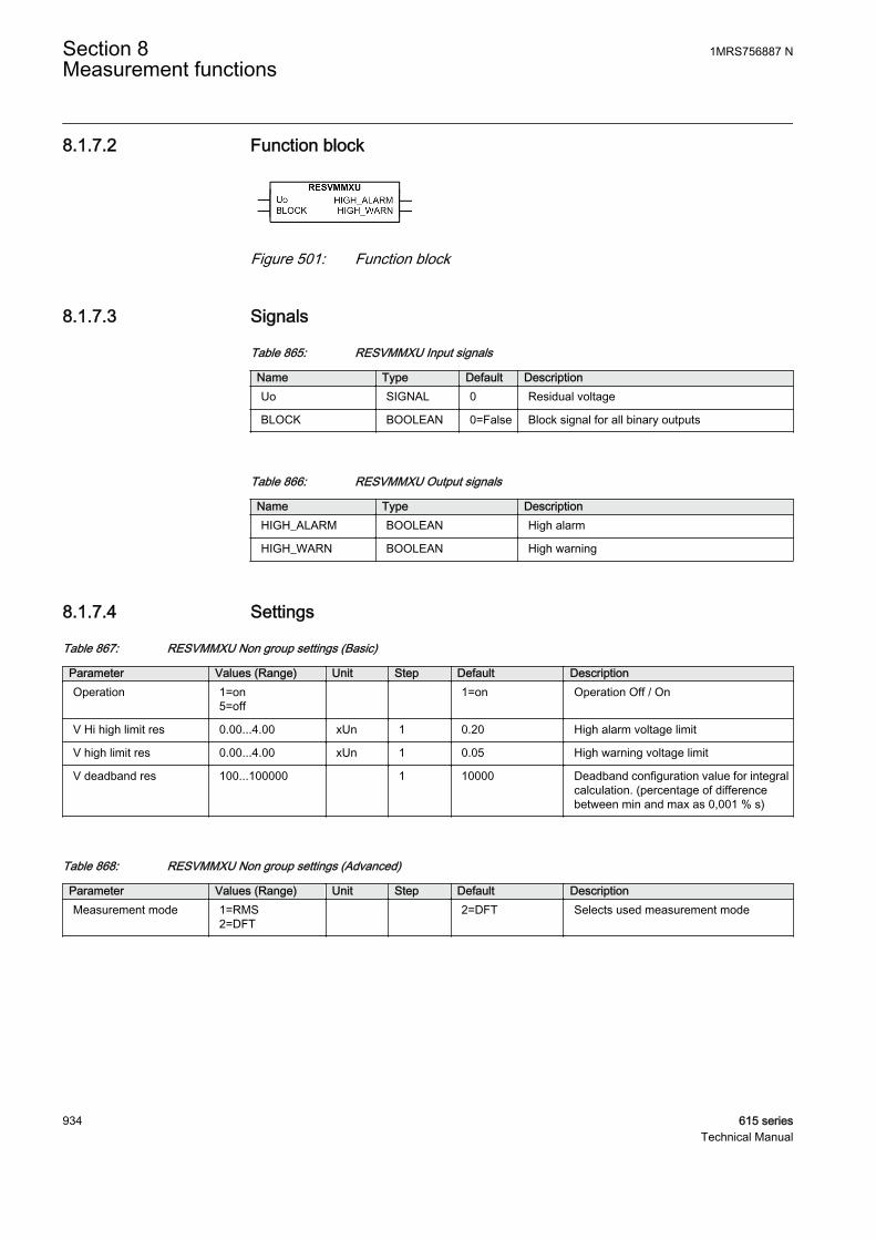
8.1.7.2 Function block
A070779 V2 EN
Figure 501: Function block
8.1.7.3 Signals
Table 865: RESVMMXU Input signals
Name Type Default DescriptionUo SIGNAL 0 Residual voltage
BLOCK BOOLEAN 0=False Block signal for all binary outputs
Table 866: RESVMMXU Output signals
Name Type DescriptionHIGH_ALARM BOOLEAN High alarm
HIGH_WARN BOOLEAN High warning
8.1.7.4 Settings
Table 867: RESVMMXU Non group settings (Basic)
Parameter Values (Range) Unit Step Default DescriptionOperation 1=on
5=off 1=on Operation Off / On
V Hi high limit res 0.00...4.00 xUn 1 0.20 High alarm voltage limit
V high limit res 0.00...4.00 xUn 1 0.05 High warning voltage limit
V deadband res 100...100000 1 10000 Deadband configuration value for integralcalculation. (percentage of differencebetween min and max as 0,001 % s)
Table 868: RESVMMXU Non group settings (Advanced)
Parameter Values (Range) Unit Step Default DescriptionMeasurement mode 1=RMS
2=DFT 2=DFT Selects used measurement mode
Section 8 1MRS756887 NMeasurement functions
934 615 seriesTechnical Manual
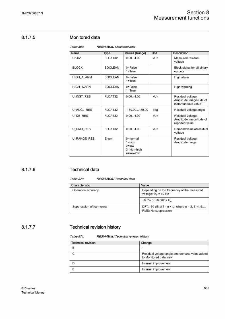
8.1.7.5 Monitored data
Table 869: RESVMMXU Monitored data
Name Type Values (Range) Unit DescriptionUo-kV FLOAT32 0.00...4.00 xUn Measured residual
voltage
BLOCK BOOLEAN 0=False1=True
Block signal for all binaryoutputs
HIGH_ALARM BOOLEAN 0=False1=True
High alarm
HIGH_WARN BOOLEAN 0=False1=True
High warning
U_INST_RES FLOAT32 0.00...4.00 xUn Residual voltageAmplitude, magnitude ofinstantaneous value
U_ANGL_RES FLOAT32 -180.00...180.00 deg Residual voltage angle
U_DB_RES FLOAT32 0.00...4.00 xUn Residual voltageAmplitude, magnitude ofreported value
U_DMD_RES FLOAT32 0.00...4.00 xUn Demand value of residualvoltage
U_RANGE_RES Enum 0=normal1=high2=low3=high-high4=low-low
Residual voltageAmplitude range
8.1.7.6 Technical data
Table 870: RESVMMXU Technical data
Characteristic ValueOperation accuracy Depending on the frequency of the measured
voltage: f/fn = ±2 Hz
±0.5% or ±0.002 × Un
Suppression of harmonics DFT: -50 dB at f = n × fn, where n = 2, 3, 4, 5,…RMS: No suppression
8.1.7.7 Technical revision history
Table 871: RESVMMXU Technical revision history
Technical revision ChangeB -
C Residual voltage angle and demand value addedto Monitored data view
D Internal improvement
E Internal improvement
1MRS756887 N Section 8Measurement functions
615 series 935Technical Manual

8.1.8 Frequency measurement FMMXU
8.1.8.1 Identification
Function description IEC 61850identification
IEC 60617identification
ANSI/IEEE C37.2device number
Frequency measurement FMMXU f f
8.1.8.2 Function block
GUID-5CCF8F8C-E1F4-421B-8BE9-C0620F7446A7 V2 EN
Figure 502: Function block
8.1.8.3 Functionality
The frequency measurement range is 35...75 Hz. The measured frequencies outsidethe measurement range are considered to be out of range and the minimum andmaximum values are then shown in parentheses.
When Frequency adaptivity is enabled, the measurement range is extended to 10...75Hz in a 50 Hz network and 12...90 Hz in a 60 Hz network. The measured frequenciesoutside 35...75 Hz are shown in parentheses.
When the frequencies cannot be measured, for example, due to too low voltageamplitude, the default value for frequency measurement can be selected with the Deffrequency Sel setting parameter. In the “Nominal” mode the frequency is set to 50 Hz(or 60 Hz) and in “Zero” mode the frequency is set to zero and shown in parentheses.
8.1.8.4 Signals
Table 872: FMMXU Input signals
Name Type Default DescriptionF SIGNAL - Measured system frequency
8.1.8.5 Settings
Table 873: FMMXU Non group settings (Basic)
Parameter Values (Range) Unit Step Default DescriptionOperation 1=on
5=off 1=on Operation Off / On
F high high limit 35.00...75.00 Hz 1 60.00 High alarm frequency limit
F high limit 35.00...75.00 Hz 1 55.00 High warning frequency limit
Table continues on next page
Section 8 1MRS756887 NMeasurement functions
936 615 seriesTechnical Manual

Parameter Values (Range) Unit Step Default DescriptionF low limit 35.00...75.00 Hz 1 45.00 Low warning frequency limit
F low low limit 35.00...75.00 Hz 1 40.00 Low alarm frequency limit
F deadband 100...100000 1 1000 Deadband configuration value for integralcalculation (percentage of differencebetween min and max as 0,001 % s)
Table 874: FMMXU Non group settings (Advanced)
Parameter Values (Range) Unit Step Default DescriptionDef frequency Sel 1=Nominal
2=Zero 1=Nominal Default frequency selection
8.1.8.6 Monitored data
Table 875: FMMXU Monitored data
Name Type Values (Range) Unit Descriptionf-Hz FLOAT32 35.00...75.00 Hz Measured frequency
F_INST FLOAT32 35.00...75.00 Hz Frequency,instantaneous value
F_DB FLOAT32 35.00...75.00 Hz Frequency, reportedvalue
F_RANGE Enum 0=normal1=high2=low3=high-high4=low-low
Measured frequencyrange
8.1.8.7 Technical data
Table 876: FMMXU Technical data
Characteristic ValueOperation accuracy ±5 mHz
(in measurement range 35...75 Hz)
8.1.8.8 Technical revision history
Table 877: FMMXU Technical revision history
Technical revision ChangeB Added new setting Def frequency Sel. Frequency
measurement range lowered from 35 Hz to 10 Hz.
1MRS756887 N Section 8Measurement functions
615 series 937Technical Manual
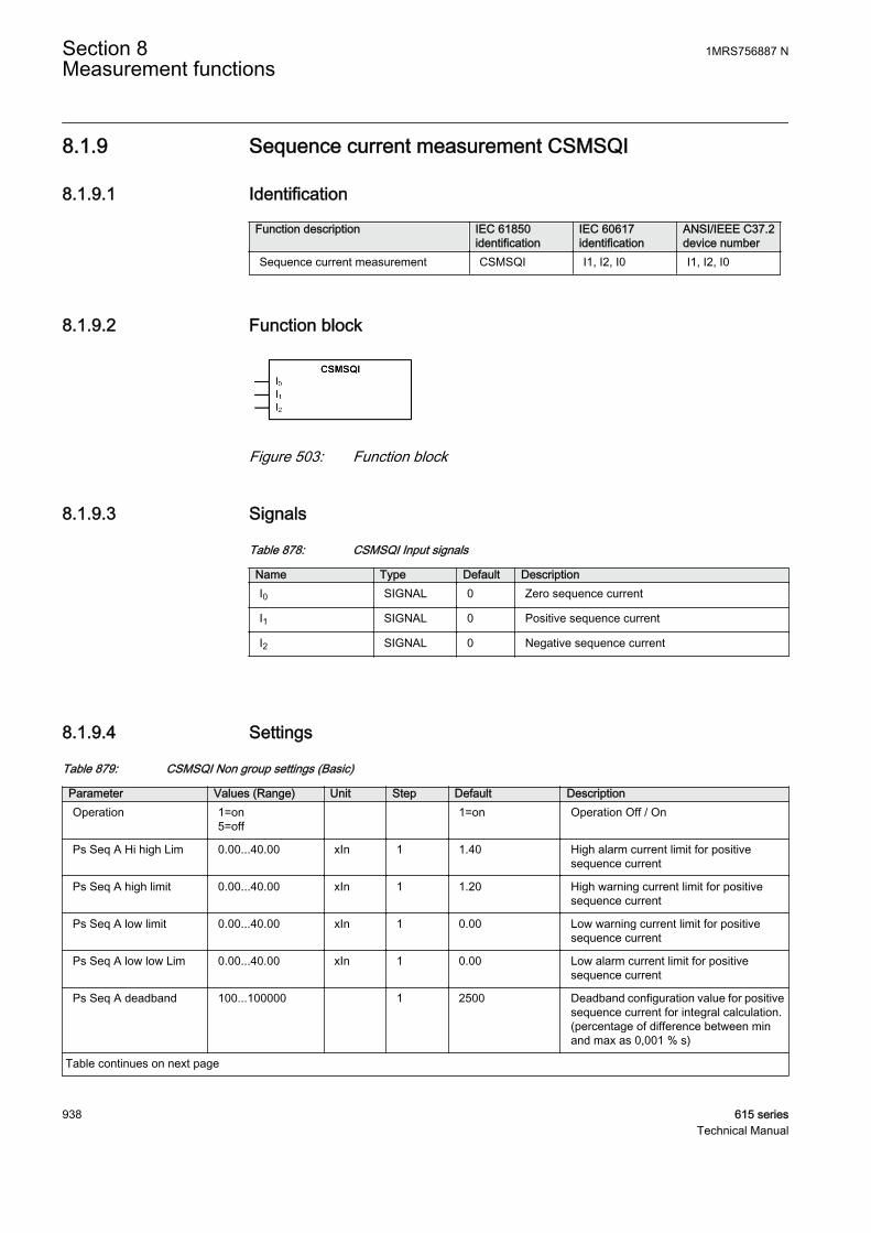
8.1.9 Sequence current measurement CSMSQI
8.1.9.1 Identification
Function description IEC 61850identification
IEC 60617identification
ANSI/IEEE C37.2device number
Sequence current measurement CSMSQI I1, I2, I0 I1, I2, I0
8.1.9.2 Function block
A070784 V2 EN
Figure 503: Function block
8.1.9.3 Signals
Table 878: CSMSQI Input signals
Name Type Default DescriptionI0 SIGNAL 0 Zero sequence current
I1 SIGNAL 0 Positive sequence current
I2 SIGNAL 0 Negative sequence current
8.1.9.4 Settings
Table 879: CSMSQI Non group settings (Basic)
Parameter Values (Range) Unit Step Default DescriptionOperation 1=on
5=off 1=on Operation Off / On
Ps Seq A Hi high Lim 0.00...40.00 xIn 1 1.40 High alarm current limit for positivesequence current
Ps Seq A high limit 0.00...40.00 xIn 1 1.20 High warning current limit for positivesequence current
Ps Seq A low limit 0.00...40.00 xIn 1 0.00 Low warning current limit for positivesequence current
Ps Seq A low low Lim 0.00...40.00 xIn 1 0.00 Low alarm current limit for positivesequence current
Ps Seq A deadband 100...100000 1 2500 Deadband configuration value for positivesequence current for integral calculation.(percentage of difference between minand max as 0,001 % s)
Table continues on next page
Section 8 1MRS756887 NMeasurement functions
938 615 seriesTechnical Manual
Parameter Values (Range) Unit Step Default DescriptionNg Seq A Hi high Lim 0.00...40.00 xIn 1 0.20 High alarm current limit for negative
sequence current
Ng Seq A High limit 0.00...40.00 xIn 1 0.05 High warning current limit for negativesequence current
Ng Seq A low limit 0.00...40.00 xIn 1 0.00 Low warning current limit for negativesequence current
Ng Seq A low low Lim 0.00...40.00 xIn 1 0.00 Low alarm current limit for negativesequence current
Ng Seq A deadband 100...100000 1 2500 Deadband configuration value fornegative sequence current for integralcalculation. (percentage of differencebetween min and max as 0,001 % s)
Zro A Hi high Lim 0.00...40.00 xIn 1 0.20 High alarm current limit for zero sequencecurrent
Zro A High limit 0.00...40.00 xIn 1 0.05 High warning current limit for zerosequence current
Zro A low limit 0.00...40.00 xIn 1 0.00 Low warning current limit for zerosequence current
Zro A low low Lim 0.00...40.00 xIn 1 0.00 Low alarm current limit for zero sequencecurrent
Zro A deadband 100...100000 1 2500 Deadband configuration value for zerosequence current for integral calculation.(percentage of difference between minand max as 0,001 % s)
8.1.9.5 Monitored data
Table 880: CSMSQI Monitored data
Name Type Values (Range) Unit DescriptionNgSeq-A FLOAT32 0.00...40.00 xIn Measured negative
sequence current
PsSeq-A FLOAT32 0.00...40.00 xIn Measured positivesequence current
ZroSeq-A FLOAT32 0.00...40.00 xIn Measured zero sequencecurrent
I2_INST FLOAT32 0.00...40.00 xIn Negative sequencecurrent amplitude,instantaneous value
I2_ANGL FLOAT32 -180.00...180.00 deg Negative sequencecurrent angle
I2_DB FLOAT32 0.00...40.00 xIn Negative sequencecurrent amplitude,reported value
I2_RANGE Enum 0=normal1=high2=low3=high-high4=low-low
Negative sequencecurrent amplitude range
Table continues on next page
1MRS756887 N Section 8Measurement functions
615 series 939Technical Manual
Name Type Values (Range) Unit DescriptionI1_INST FLOAT32 0.00...40.00 xIn Positive sequence
current amplitude,instantaneous value
I1_ANGL FLOAT32 -180.00...180.00 deg Positive sequencecurrent angle
I1_DB FLOAT32 0.00...40.00 xIn Positive sequencecurrent amplitude,reported value
I1_RANGE Enum 0=normal1=high2=low3=high-high4=low-low
Positive sequencecurrent amplitude range
I0_INST FLOAT32 0.00...40.00 xIn Zero sequence currentamplitude, instantaneousvalue
I0_ANGL FLOAT32 -180.00...180.00 deg Zero sequence currentangle
I0_DB FLOAT32 0.00...40.00 xIn Zero sequence currentamplitude, reported value
I0_RANGE Enum 0=normal1=high2=low3=high-high4=low-low
Zero sequence currentamplitude range
8.1.9.6 Technical data
Table 881: CSMSQI Technical data
Characteristic ValueOperation accuracy Depending on the frequency of the measured
current: f/fn = ±2 Hz
±1.0% or ±0.002 × Inat currents in the range of 0.01...4.00 × In
Suppression of harmonics DFT: -50 dB at f = n × fn, where n = 2, 3, 4, 5,…
8.1.9.7 Technical revision history
Table 882: CSMSQI Technical revision history
Technical revision ChangeA -
B Sequence current angle values added to theMonitored data view.
C Internal improvement.
Section 8 1MRS756887 NMeasurement functions
940 615 seriesTechnical Manual
8.1.10 Sequence voltage measurement VSMSQI
8.1.10.1 Identification
Function description IEC 61850identification
IEC 60617identification
ANSI/IEEE C37.2device number
Sequence voltage measurement VSMSQI U1, U2, U0 V1, V2, V0
8.1.10.2 Function block
GUID-63393283-E2C1-406A-9E70-847662D83CFC V2 EN
Figure 504: Function block
8.1.10.3 Signals
Table 883: VSMSQI Input signals
Name Type Default DescriptionU0 SIGNAL 0 Zero sequence voltage
U1 SIGNAL 0 Positive phase sequence voltage
U2 SIGNAL 0 Negative phase sequence voltage
8.1.10.4 Settings
Table 884: VSMSQI Non group settings (Basic)
Parameter Values (Range) Unit Step Default DescriptionOperation 1=on
5=off 1=on Operation Off / On
Ps Seq V Hi high Lim 0.00...4.00 xUn 1 1.40 High alarm voltage limit for positivesequence voltage
Ps Seq V high limit 0.00...4.00 xUn 1 1.20 High warning voltage limit for positivesequence voltage
Ps Seq V low limit 0.00...4.00 xUn 1 0.00 Low warning voltage limit for positivesequence voltage
Ps Seq V low low Lim 0.00...4.00 xUn 1 0.00 Low alarm voltage limit for positivesequence voltage
Ps Seq V deadband 100...100000 1 10000 Deadband configuration value for positivesequence voltage for integral calculation.(percentage of difference between minand max as 0,001 % s)
Table continues on next page
1MRS756887 N Section 8Measurement functions
615 series 941Technical Manual
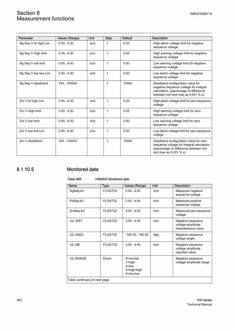
Parameter Values (Range) Unit Step Default DescriptionNg Seq V Hi high Lim 0.00...4.00 xUn 1 0.20 High alarm voltage limit for negative
sequence voltage
Ng Seq V High limit 0.00...4.00 xUn 1 0.05 High warning voltage limit for negativesequence voltage
Ng Seq V low limit 0.00...4.00 xUn 1 0.00 Low warning voltage limit for negativesequence voltage
Ng Seq V low low Lim 0.00...4.00 xUn 1 0.00 Low alarm voltage limit for negativesequence voltage
Ng Seq V deadband 100...100000 1 10000 Deadband configuration value fornegative sequence voltage for integralcalculation. (percentage of differencebetween min and max as 0,001 % s)
Zro V Hi high Lim 0.00...4.00 xUn 1 0.20 High alarm voltage limit for zero sequencevoltage
Zro V High limit 0.00...4.00 xUn 1 0.05 High warning voltage limit for zerosequence voltage
Zro V low limit 0.00...4.00 xUn 1 0.00 Low warning voltage limit for zerosequence voltage
Zro V low low Lim 0.00...4.00 xUn 1 0.00 Low alarm voltage limit for zero sequencevoltage
Zro V deadband 100...100000 1 10000 Deadband configuration value for zerosequence voltage for integral calculation.(percentage of difference between minand max as 0,001 % s)
8.1.10.5 Monitored data
Table 885: VSMSQI Monitored data
Name Type Values (Range) Unit DescriptionNgSeq-kV FLOAT32 0.00...4.00 xUn Measured negative
sequence voltage
PsSeq-kV FLOAT32 0.00...4.00 xUn Measured positivesequence voltage
ZroSeq-kV FLOAT32 0.00...4.00 xUn Measured zero sequencevoltage
U2_INST FLOAT32 0.00...4.00 xUn Negative sequencevoltage amplitude,instantaneous value
U2_ANGL FLOAT32 -180.00...180.00 deg Negative sequencevoltage angle
U2_DB FLOAT32 0.00...4.00 xUn Negative sequencevoltage amplitude,reported value
U2_RANGE Enum 0=normal1=high2=low3=high-high4=low-low
Negative sequencevoltage amplitude range
Table continues on next page
Section 8 1MRS756887 NMeasurement functions
942 615 seriesTechnical Manual
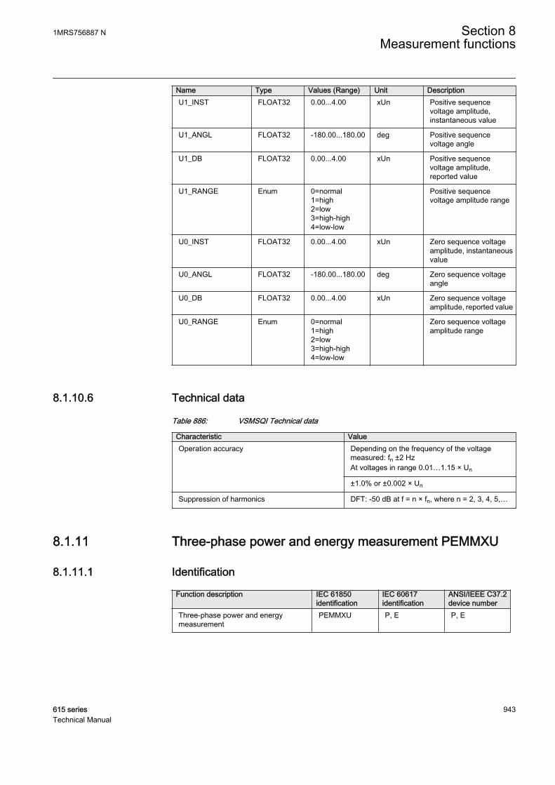
Name Type Values (Range) Unit DescriptionU1_INST FLOAT32 0.00...4.00 xUn Positive sequence
voltage amplitude,instantaneous value
U1_ANGL FLOAT32 -180.00...180.00 deg Positive sequencevoltage angle
U1_DB FLOAT32 0.00...4.00 xUn Positive sequencevoltage amplitude,reported value
U1_RANGE Enum 0=normal1=high2=low3=high-high4=low-low
Positive sequencevoltage amplitude range
U0_INST FLOAT32 0.00...4.00 xUn Zero sequence voltageamplitude, instantaneousvalue
U0_ANGL FLOAT32 -180.00...180.00 deg Zero sequence voltageangle
U0_DB FLOAT32 0.00...4.00 xUn Zero sequence voltageamplitude, reported value
U0_RANGE Enum 0=normal1=high2=low3=high-high4=low-low
Zero sequence voltageamplitude range
8.1.10.6 Technical data
Table 886: VSMSQI Technical data
Characteristic ValueOperation accuracy Depending on the frequency of the voltage
measured: fn ±2 HzAt voltages in range 0.01…1.15 × Un
±1.0% or ±0.002 × Un
Suppression of harmonics DFT: -50 dB at f = n × fn, where n = 2, 3, 4, 5,…
8.1.11 Three-phase power and energy measurement PEMMXU
8.1.11.1 Identification
Function description IEC 61850identification
IEC 60617identification
ANSI/IEEE C37.2device number
Three-phase power and energymeasurement
PEMMXU P, E P, E
1MRS756887 N Section 8Measurement functions
615 series 943Technical Manual
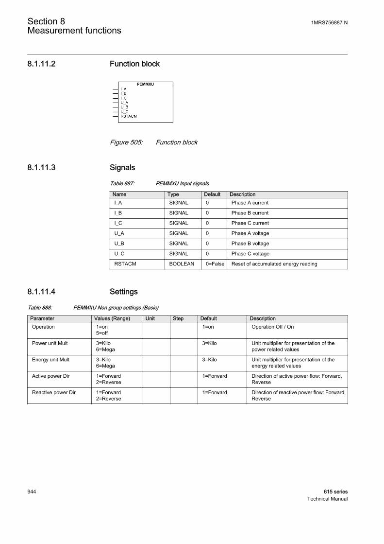
8.1.11.2 Function block
GUID-E38A24DA-85CE-4246-9C3F-DFC6FDAEA302 V1 EN
Figure 505: Function block
8.1.11.3 Signals
Table 887: PEMMXU Input signals
Name Type Default DescriptionI_A SIGNAL 0 Phase A current
I_B SIGNAL 0 Phase B current
I_C SIGNAL 0 Phase C current
U_A SIGNAL 0 Phase A voltage
U_B SIGNAL 0 Phase B voltage
U_C SIGNAL 0 Phase C voltage
RSTACM BOOLEAN 0=False Reset of accumulated energy reading
8.1.11.4 Settings
Table 888: PEMMXU Non group settings (Basic)
Parameter Values (Range) Unit Step Default DescriptionOperation 1=on
5=off 1=on Operation Off / On
Power unit Mult 3=Kilo6=Mega
3=Kilo Unit multiplier for presentation of thepower related values
Energy unit Mult 3=Kilo6=Mega
3=Kilo Unit multiplier for presentation of theenergy related values
Active power Dir 1=Forward2=Reverse
1=Forward Direction of active power flow: Forward,Reverse
Reactive power Dir 1=Forward2=Reverse
1=Forward Direction of reactive power flow: Forward,Reverse
Section 8 1MRS756887 NMeasurement functions
944 615 seriesTechnical Manual

Table 889: PEMMXU Non group settings (Advanced)
Parameter Values (Range) Unit Step Default DescriptionForward Wh Initial 0...999999999 1 0 Preset Initial value for forward active
energy
Reverse Wh Initial 0...999999999 1 0 Preset Initial value for reverse activeenergy
Forward VArh Initial 0...999999999 1 0 Preset Initial value for forward reactiveenergy
Reverse VArh Initial 0...999999999 1 0 Preset Initial value for reverse reactiveenergy
8.1.11.5 Monitored data
Table 890: PEMMXU Monitored data
Name Type Values (Range) Unit DescriptionS-kVA FLOAT32 -999999.9...9999
99.9kVA Total Apparent Power
P-kW FLOAT32 -999999.9...999999.9
kW Total Active Power
Q-kVAr FLOAT32 -999999.9...999999.9
kVAr Total Reactive Power
PF FLOAT32 -1.00...1.00 Average Power factor
RSTACM BOOLEAN 0=False1=True
Reset of accumulatedenergy reading
S_INST FLOAT32 -999999.9...999999.9
kVA Apparent power,magnitude ofinstantaneous value
S_DB FLOAT32 -999999.9...999999.9
kVA Apparent power,magnitude of reportedvalue
S_DMD FLOAT32 -999999.9...999999.9
kVA Demand value ofapparent power
P_INST FLOAT32 -999999.9...999999.9
kW Active power, magnitudeof instantaneous value
P_DB FLOAT32 -999999.9...999999.9
kW Active power, magnitudeof reported value
P_DMD FLOAT32 -999999.9...999999.9
kW Demand value of activepower
Q_INST FLOAT32 -999999.9...999999.9
kVAr Reactive power,magnitude ofinstantaneous value
Q_DB FLOAT32 -999999.9...999999.9
kVAr Reactive power,magnitude of reportedvalue
Q_DMD FLOAT32 -999999.9...999999.9
kVAr Demand value of reactivepower
PF_INST FLOAT32 -1.00...1.00 Power factor, magnitudeof instantaneous value
Table continues on next page
1MRS756887 N Section 8Measurement functions
615 series 945Technical Manual
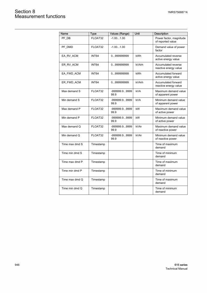
Name Type Values (Range) Unit DescriptionPF_DB FLOAT32 -1.00...1.00 Power factor, magnitude
of reported value
PF_DMD FLOAT32 -1.00...1.00 Demand value of powerfactor
EA_RV_ACM INT64 0...999999999 kWh Accumulated reverseactive energy value
ER_RV_ACM INT64 0...999999999 kVArh Accumulated reversereactive energy value
EA_FWD_ACM INT64 0...999999999 kWh Accumulated forwardactive energy value
ER_FWD_ACM INT64 0...999999999 kVArh Accumulated forwardreactive energy value
Max demand S FLOAT32 -999999.9...999999.9
kVA Maximum demand valueof apparent power
Min demand S FLOAT32 -999999.9...999999.9
kVA Minimum demand valueof apparent power
Max demand P FLOAT32 -999999.9...999999.9
kW Maximum demand valueof active power
Min demand P FLOAT32 -999999.9...999999.9
kW Minimum demand valueof active power
Max demand Q FLOAT32 -999999.9...999999.9
kVAr Maximum demand valueof reactive power
Min demand Q FLOAT32 -999999.9...999999.9
kVAr Minimum demand valueof reactive power
Time max dmd S Timestamp Time of maximumdemand
Time min dmd S Timestamp Time of minimumdemand
Time max dmd P Timestamp Time of maximumdemand
Time min dmd P Timestamp Time of minimumdemand
Time max dmd Q Timestamp Time of maximumdemand
Time min dmd Q Timestamp Time of minimumdemand
Section 8 1MRS756887 NMeasurement functions
946 615 seriesTechnical Manual
8.1.11.6 Technical data
Table 891: PEMMXU Technical data
Characteristic ValueOperation accuracy At all three currents in range 0.10…1.20 × In
At all three voltages in range 0.50…1.15 × UnAt the frequency fn ±1 Hz
±1.5% for apparent power S±1.5% for active power P and active energy1)
±1.5% for reactive power Q and reactive energy2)
±0.015 for power factor
Suppression of harmonics DFT: -50 dB at f = n × fn, where n = 2, 3, 4, 5,…
1) |PF| >0.5 which equals |cosφ| >0.52) |PF| <0.86 which equals |sinφ| >0.5
8.1.11.7 Technical revision history
Table 892: PEMMXU Technical revision history
Technical revision ChangeB Demand values added to Monitored data.
Recorded data added to store minimum andmaximum demand values with timestamps.
C Internal improvement.
D Internal improvement.
8.2 Disturbance recorder RDRE
8.2.1 IdentificationFunction description IEC 61850
identificationIEC 60617identification
ANSI/IEEE C37.2device number
Disturbance recorder RDRE DR DFR
8.2.2 Functionality
The relay is provided with a disturbance recorder featuring up to 12 analog and 64binary signal channels.The analog channels can be set to record either the waveformor the trend of the currents and voltages measured.
The analog channels can be set to trigger the recording function when the measuredvalue falls below or exceeds the set values. The binary signal channels can be set tostart a recording either on the rising or the falling edge of the binary signal or on both.
By default, the binary channels are set to record external or internal relay signals, forexample, the start or trip signals of the relay stages, or external blocking or control
1MRS756887 N Section 8Measurement functions
615 series 947Technical Manual

signals. Binary relay signals, such as protection start and trip signals, or an externalrelay control signal via a binary input, can be set to trigger the recording. Recordedinformation is stored in a nonvolatile memory and can be uploaded for subsequentfault analysis.
8.2.2.1 Recorded analog inputs
The user can map any analog signal type of the protection relay to each analog channelof the disturbance recorder by setting the Channel selection parameter of thecorresponding analog channel. In addition, the user can enable or disable each analogchannel of the disturbance recorder by setting the Operation parameter of thecorresponding analog channel to "on" or "off".
All analog channels of the disturbance recorder that are enabled and have a validsignal type mapped are included in the recording.
8.2.2.2 Triggering alternatives
The recording can be triggered by any or several of the following alternatives:
• Triggering according to the state change of any or several of the binary channelsof the disturbance recorder. The user can set the level sensitivity with the Leveltrigger mode parameter of the corresponding binary channel.
• Triggering on limit violations of the analog channels of the disturbance recorder(high and low limit)
• Manual triggering via the Trig recording parameter (LHMI or communication)• Periodic triggering.
Regardless of the triggering type, each recording generates the Recording started andRecording made events. The Recording made event indicates that the recording hasbeen stored to the non-volatile memory. In addition, every analog channel and binarychannel of the disturbance recorder has its own Channel triggered parameter. Manualtrigger has the Manual triggering parameter and periodic trigger has the Periodictriggering parameter.
Triggering by binary channelsInput signals for the binary channels of the disturbance recorder can be formed fromany of the digital signals that can be dynamically mapped. A change in the status of amonitored signal triggers the recorder according to the configuration and settings.Triggering on the rising edge of a digital input signal means that the recordingsequence starts when the input signal is activated. Correspondingly, triggering on thefalling edge means that the recording sequence starts when the active input signalresets. It is also possible to trigger from both edges. In addition, if preferred, themonitored signal can be non-triggering. The trigger setting can be set individually foreach binary channel of the disturbance recorder with the Level trigger mode parameterof the corresponding binary channel.
Section 8 1MRS756887 NMeasurement functions
948 615 seriesTechnical Manual
Triggering by analog channelsThe trigger level can be set for triggering in a limit violation situation. The user can setthe limit values with the High trigger level and Low trigger level parameters of thecorresponding analog channel. Both high level and low level violation triggering canbe active simultaneously for the same analog channel. If the duration of the limitviolation condition exceeds the filter time of approximately 50 ms, the recordertriggers. In case of a low level limit violation, if the measured value falls belowapproximately 0.05 during the filter time, the situation is considered to be a circuit-breaker operation and therefore, the recorder does not trigger. This is useful especiallyin undervoltage situations. The filter time of approximately 50 ms is common to all theanalog channel triggers of the disturbance recorder. The value used for triggering isthe calculated peak-to-peak value. Either high or low analog channel trigger can bedisabled by setting the corresponding trigger level parameter to zero.
Manual triggeringThe recorder can be triggered manually via the LHMI or via communication by settingthe Trig recording parameter to TRUE.
Periodic triggeringPeriodic triggering means that the recorder automatically makes a recording at certaintime intervals. The user can adjust the interval with the Periodic trig time parameter.If the value of the parameter is changed, the new setting takes effect when the nextperiodic triggering occurs. Setting the parameter to zero disables the triggeringalternative and the setting becomes valid immediately. If a new non-zero setting needsto be valid immediately, the user should first set the Periodic trig time parameter tozero and then to the new value. The user can monitor the time remaining to the nexttriggering with the Time to trigger monitored data which counts downwards.
8.2.2.3 Length of recordings
The user can define the length of a recording with the Record length parameter. Thelength is given as the number of fundamental cycles.
According to the memory available and the number of analog channels used, thedisturbance recorder automatically calculates the remaining amount of recordingsthat fit into the available recording memory. The user can see this information with theRem. amount of rec monitored data. The fixed memory size allocated for therecorder can fit in two recordings that are ten seconds long. The recordings containdata from all analog and binary channels of the disturbance recorder, at the sample rateof 32 samples per fundamental cycle.
The user can view the number of recordings currently in memory with the Numberof recordings monitored data. The currently used memory space can be viewedwith the Rec. memory used monitored data. It is shown as a percentage value.
1MRS756887 N Section 8Measurement functions
615 series 949Technical Manual
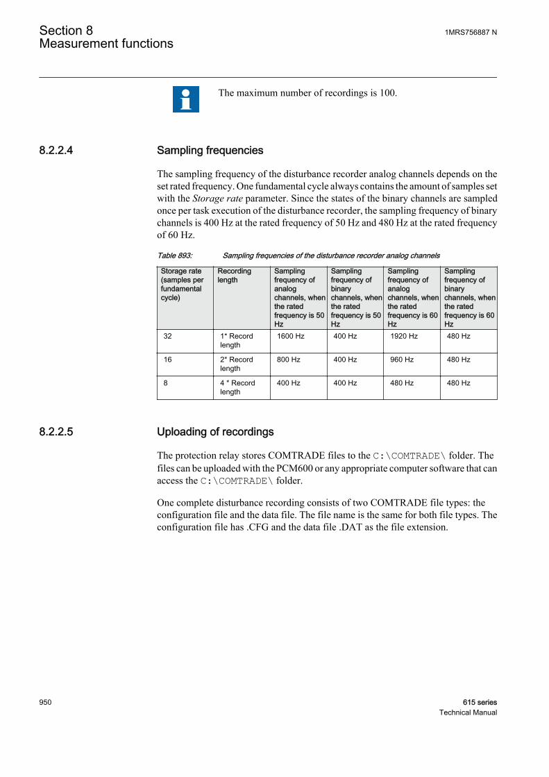
The maximum number of recordings is 100.
8.2.2.4 Sampling frequencies
The sampling frequency of the disturbance recorder analog channels depends on theset rated frequency. One fundamental cycle always contains the amount of samples setwith the Storage rate parameter. Since the states of the binary channels are sampledonce per task execution of the disturbance recorder, the sampling frequency of binarychannels is 400 Hz at the rated frequency of 50 Hz and 480 Hz at the rated frequencyof 60 Hz.
Table 893: Sampling frequencies of the disturbance recorder analog channels
Storage rate(samples perfundamentalcycle)
Recordinglength
Samplingfrequency ofanalogchannels, whenthe ratedfrequency is 50Hz
Samplingfrequency ofbinarychannels, whenthe ratedfrequency is 50Hz
Samplingfrequency ofanalogchannels, whenthe ratedfrequency is 60Hz
Samplingfrequency ofbinarychannels, whenthe ratedfrequency is 60Hz
32 1* Recordlength
1600 Hz 400 Hz 1920 Hz 480 Hz
16 2* Recordlength
800 Hz 400 Hz 960 Hz 480 Hz
8 4 * Recordlength
400 Hz 400 Hz 480 Hz 480 Hz
8.2.2.5 Uploading of recordings
The protection relay stores COMTRADE files to the C:\COMTRADE\ folder. Thefiles can be uploaded with the PCM600 or any appropriate computer software that canaccess the C:\COMTRADE\ folder.
One complete disturbance recording consists of two COMTRADE file types: theconfiguration file and the data file. The file name is the same for both file types. Theconfiguration file has .CFG and the data file .DAT as the file extension.
Section 8 1MRS756887 NMeasurement functions
950 615 seriesTechnical Manual
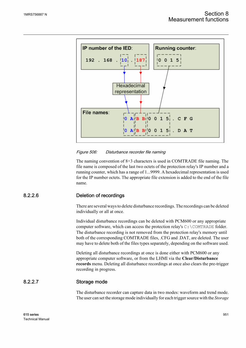
A070835 V1 EN
Figure 506: Disturbance recorder file naming
The naming convention of 8+3 characters is used in COMTRADE file naming. Thefile name is composed of the last two octets of the protection relay's IP number and arunning counter, which has a range of 1...9999. A hexadecimal representation is usedfor the IP number octets. The appropriate file extension is added to the end of the filename.
8.2.2.6 Deletion of recordings
There are several ways to delete disturbance recordings. The recordings can be deletedindividually or all at once.
Individual disturbance recordings can be deleted with PCM600 or any appropriatecomputer software, which can access the protection relay's C:\COMTRADE folder.The disturbance recording is not removed from the protection relay's memory untilboth of the corresponding COMTRADE files, .CFG and .DAT, are deleted. The usermay have to delete both of the files types separately, depending on the software used.
Deleting all disturbance recordings at once is done either with PCM600 or anyappropriate computer software, or from the LHMI via the Clear/Disturbancerecords menu. Deleting all disturbance recordings at once also clears the pre-triggerrecording in progress.
8.2.2.7 Storage mode
The disturbance recorder can capture data in two modes: waveform and trend mode.The user can set the storage mode individually for each trigger source with the Storage
1MRS756887 N Section 8Measurement functions
615 series 951Technical Manual
mode parameter of the corresponding analog channel or binary channel, the Stor.mode manual parameter for manual trigger and the Stor. mode periodic parameter forperiodic trigger.
In the waveform mode, the samples are captured according to the Storage rate andPre-trg length parameters.
In the trend mode, one value is recorded for each enabled analog channel, once perfundamental cycle. The recorded values are RMS values, which are scaled to peaklevel. The binary channels of the disturbance recorder are also recorded once perfundamental cycle in the trend mode.
Only post-trigger data is captured in trend mode.
The trend mode enables recording times of 32 * Record length.
8.2.2.8 Pre-trigger and post-trigger data
The waveforms of the disturbance recorder analog channels and the states of thedisturbance recorder binary channels are constantly recorded into the history memoryof the recorder. The user can adjust the percentage of the data duration preceding thetriggering, that is, the so-called pre-trigger time, with the Pre-trg length parameter.The duration of the data following the triggering, that is, the so-called post-triggertime, is the difference between the recording length and the pre-trigger time.Changing the pre-trigger time resets the history data and the current recording undercollection.
8.2.2.9 Operation modes
Disturbance recorder has two operation modes: saturation and overwrite mode. Theuser can change the operation mode of the disturbance recorder with the Operationmode parameter.
Saturation modeIn saturation mode, the captured recordings cannot be overwritten with newrecordings. Capturing the data is stopped when the recording memory is full, that is,when the maximum number of recordings is reached. In this case, the event is sent viathe state change (TRUE) of the Memory full parameter. When there is memoryavailable again, another event is generated via the state change (FALSE) of theMemory full parameter.
Overwrite modeWhen the operation mode is "Overwrite" and the recording memory is full, the oldestrecording is overwritten with the pre-trigger data collected for the next recording.Each time a recording is overwritten, the event is generated via the state change of theOverwrite of rec. parameter. The overwrite mode is recommended, if it is more
Section 8 1MRS756887 NMeasurement functions
952 615 seriesTechnical Manual
important to have the latest recordings in the memory. The saturation mode ispreferred, when the oldest recordings are more important.
New triggerings are blocked in both the saturation and the overwrite mode until theprevious recording is completed. On the other hand, a new triggering can be acceptedbefore all pre-trigger samples are collected for the new recording. In such a case, therecording is as much shorter as there were pre-trigger samples lacking.
8.2.2.10 Exclusion mode
Exclusion mode is on, when the value set with the Exclusion time parameter is higherthan zero. During the exclusion mode, new triggerings are ignored if the triggeringreason is the same as in the previous recording. The Exclusion time parameter controlshow long the exclusion of triggerings of same type is active after a triggering. Theexclusion mode only applies to the analog and binary channel triggerings, not toperiodic and manual triggerings.
When the value set with the Exclusion time parameter is zero, the exclusion mode isdisabled and there are no restrictions on the triggering types of the successiverecordings.
The exclusion time setting is global for all inputs, but there is an individual counter foreach analog and binary channel of the disturbance recorder, counting the remainingexclusion time. The user can monitor the remaining exclusion time with the Exclusiontime rem parameter (only visible via communication, IEC 61850 data ExclTmRmn)of the corresponding analog or binary channel. The Exclusion time rem parametercounts downwards.
8.2.3 Configuration
The disturbance recorder can be configured with PCM600 or any tool supporting theIEC 61850 standard.
The disturbance recorder can be enabled or disabled with the Operation parameterunder the Configuration/Disturbance recorder/General menu.
One analog signal type of the protection relay can be mapped to each of the analogchannels of the disturbance recorder. The mapping is done with the Channel selectionparameter of the corresponding analog channel. The name of the analog channel isuser-configurable. It can be modified by writing the new name to the Channel id textparameter of the corresponding analog channel.
Any external or internal digital signal of the protection relay which can bedynamically mapped can be connected to the binary channels of the disturbancerecorder. These signals can be, for example, the start and trip signals from protectionfunction blocks or the external binary inputs of the protection relay.The connection ismade with dynamic mapping to the binary channel of the disturbance recorder using,for example, SMT of PCM600. It is also possible to connect several digital signals toone binary channel of the disturbance recorder. In that case, the signals can be
1MRS756887 N Section 8Measurement functions
615 series 953Technical Manual
combined with logical functions, for example AND and OR. The name of the binarychannel can be configured and modified by writing the new name to the Channel idtext parameter of the corresponding binary channel.
Note that the Channel id text parameter is used in COMTRADE configuration files asa channel identifier.
The recording always contains all binary channels of the disturbance recorder. If oneof the binary channels is disabled, the recorded state of the channel is continuouslyFALSE and the state changes of the corresponding channel are not recorded. Thecorresponding channel name for disabled binary channels in the COMTRADEconfiguration file is Unused BI.
To enable or disable an analog or a binary channel of the disturbance recorder, theOperation parameter of the corresponding analog or binary channel is set to "on" or"off".
The states of manual triggering and periodic triggering are not included in therecording, but they create a state change to the Periodic triggering and Manualtriggering status parameters, which in turn create events.
The TRIGGERED output can be used to control the indication LEDs of the protectionrelay. The TRIGGERED output is TRUE due to the triggering of the disturbancerecorder, until all the data for the corresponding recording has been recorded.
The IP number of the protection relay and the content of the Bay nameparameter are both included in the COMTRADE configuration file foridentification purposes.
8.2.4 Application
The disturbance recorder is used for post-fault analysis and for verifying the correctoperation of protection relays and circuit breakers. It can record both analog andbinary signal information. The analog inputs are recorded as instantaneous values andconverted to primary peak value units when the protection relay converts therecordings to the COMTRADE format.
COMTRADE is the general standard format used in storingdisturbance recordings.
The binary channels are sampled once per task execution of the disturbance recorder.The task execution interval for the disturbance recorder is the same as for theprotection functions. During the COMTRADE conversion, the digital status valuesare repeated so that the sampling frequencies of the analog and binary channelscorrespond to each other. This is required by the COMTRADE standard.
Section 8 1MRS756887 NMeasurement functions
954 615 seriesTechnical Manual

The disturbance recorder follows the 1999 version of theCOMTRADE standard and uses the binary data file format.
8.2.5 SettingsTable 894: RDRE Non-group general settings
Parameter Values (Range) Unit Step Default DescriptionOperation 1=on
5=off 1 1=on Disturbance
recorder on/off
Record length 10...500 fundamentalcycles
1 50 Size of therecording infundamentalcycles
Pre-trg length 0...100 % 1 50 Length of therecordingpreceding thetriggering
Operationmode
1=Saturation2=Overwrite
1 1 Operationmode of therecorder
Exclusion time 0...1 000 000 ms 1 0 The timeduring whichtriggerings ofsame type areignored
Storage rate 32, 16, 8 samples perfundamentalcycle
32 Storage rateof thewaveformrecording
Periodic trigtime
0...604 800 s 10 0 Time betweenperiodictriggerings
Stor. modeperiodic
0=Waveform1=Trend /cycle
1 0 Storage modefor periodictriggering
Stor. modemanual
0=Waveform1=Trend /cycle
1 0 Storage modefor manualtriggering
1MRS756887 N Section 8Measurement functions
615 series 955Technical Manual
Table 895: RDRE Non-group channel settings
Parameter Values (Range) Unit Step Default DescriptionOperation 1=on
5=off 1 1=on Analog
channel isenabled ordisabled
Channelselection
0=Disabled1=Io2=IL13=IL24=IL35=IoB6=IL1B7=IL2B8=IL3B9=Uo10=U111=U212=U313=UoB14=U1B15=U2B16=U3B17=CIo18=SI11)
19=SI21)
20=SU021=SU11)
22=SU21)
23=CIoB24=SI1B1)
25=SI2B1)
26=SUoB27=SU1B1)
28=SU2B1)
29=U1230=U2331=U3132=UL133=UL234=UL335=U12B36=U23B37=U31B38=UL1B39=UL2B40=UL3B
0 0=Disabled Select thesignal to berecorded bythis channel.Applicablevalues for thisparameter areproductvariantdependent.Every productvariantincludes onlythe values thatare applicableto thatparticularvariant
Channel idtext
0 to 64characters,alphanumeric
DR analogchannel X
Identificationtext for theanalogchannel usedin theCOMTRADEformat
Table continues on next page
Section 8 1MRS756887 NMeasurement functions
956 615 seriesTechnical Manual

Parameter Values (Range) Unit Step Default DescriptionHigh triggerlevel
0.00...60.00 pu 0.01 10.00 High triggerlevel for theanalogchannel
Low triggerlevel
0.00...2.00 pu 0.01 0.00 Low triggerlevel for theanalogchannel
Storage mode 0=Waveform1=Trend /cycle
1 0 Storage modefor the analogchannel
1) Recordable values are available only in trend mode. In waveform mode, samples for this signal type areconstant zeroes. However, these signal types can be used to trigger the recorder on limit violations ofthe corresponding analog channel.
Table 896: RDRE Non-group binary channel settings
Parameter Values (Range) Unit Step Default DescriptionOperation 1=on
5=off 1 5=off Binary
channel isenabled ordisabled
Level triggermode
1=Positive orRising2=Negative orFalling3=Both4=Leveltrigger off
1 1=Rising Level triggermode for thebinarychannel
Storage mode 0=Waveform1=Trend /cycle
1 0 Storage modefor the binarychannel
Channel idtext
0 to 64characters,alphanumeric
DR binarychannel X
Identificationtext for theanalogchannel usedin theCOMTRADEformat
Table 897: RDRE Control data
Parameter Values (Range) Unit Step Default DescriptionTrig recording 0=Cancel
1=Trig Trigger the
disturbancerecording
Clearrecordings
0=Cancel1=Clear
Clear allrecordingscurrently inmemory
1MRS756887 N Section 8Measurement functions
615 series 957Technical Manual

8.2.6 Monitored dataTable 898: RDRE Monitored data
Parameter Values (Range) Unit Step Default DescriptionNumber ofrecordings
0...100 Number ofrecordingscurrently inmemory
Rem. amountof rec.
0...100 Remainingamount ofrecordingsthat fit into theavailablerecordingmemory, whencurrentsettings areused
Rec. memoryused
0...100 % Storage modefor the binarychannel
Time totrigger
0...604 800 s Timeremaining tothe nextperiodictriggering
8.2.7 Technical revision historyTable 899: RDRE Technical revision history
Technical revision ChangeB ChNum changed to EChNum (RADR's)
RADR9...12 added (Analog channels 9...12)RBDR33...64 added (Binary channels 33...64)
C New channels added to parameter ChannelselectionSelection names for Trig Recording and ClearRecordings updated
D Symbols in the Channel selection setting areupdated
E New channels IL1C, IL2C and IL3C added toChannel selection parameter
F Internal improvement
G Internal improvement
Section 8 1MRS756887 NMeasurement functions
958 615 seriesTechnical Manual

8.3 Tap changer position indicator TPOSYLTC
8.3.1 IdentificationFunction description IEC 61850
identificationIEC 60617identification
ANSI/IEEE C37.2device number
Tap changer position indication TPOSYLTC TPOSM 84M
8.3.2 Function block
GUID-D31468A2-778A-4FF6-A9DE-3508934B6789 V1 EN
Figure 507: Function block
8.3.3 Functionality
The tap changer position indication function TPOSYLTC is used for transformer tapposition supervision. The binary inputs can be used for converting a binary-coded tapchanger position to a tap position status indication. The X130 (RTD) card, availableas an option, provides the RTD sensor information to be used and the versatile analoginputs enabling the tap position supervision through mA.
There are three user-selectable conversion modes available for the 7-bit binary inputswhere MSB is used as the SIGN bit: the natural binary-coded boolean input to thesigned integer output, binary coded decimal BCD input to the signed integer outputand binary reflected GRAY coded input to the signed integer output.
8.3.4 Operation principle
The function can be enabled and disabled with the Operation setting. Thecorresponding parameter values are "On" and "Off". When the function is disabled,the tap position quality information is changed accordingly. When the tap positioninformation is not available, it is recommended to disable this function with theOperation setting.
The operation of TPOSYLTC can be described using a module diagram. All themodules in the diagram are explained in the next sections.
1MRS756887 N Section 8Measurement functions
615 series 959Technical Manual

GUID-D3B3C7DB-1E8C-4189-9554-77C8B5ACD17D V1 EN
Figure 508: Functional module diagram
Tap position decoderWhen there is a wired connection to the TAP_POS input connector, the correspondingtap changer position is decoded from the mA or RTD input. When there is no wiredconnection to the TAP_POS connector, the binary inputs are expected to be used forthe tap changer position information. The tap changer position value and quality areinternally shared to other functions. The value is available in the Monitored data viewor as a TAP_POS output signal.
The function has three alternative user selectable operation modes: "NAT2INT","BCD2INT" and "GRAY2INT". The operation mode is selected with the Operationmode setting. Each operation mode can be used to convert a maximum of 6–bit codedinput to an 8–bit signed short integer output. For less than 6–bit input, for example 19positions with 5 bits when the BCD coding is used, the rest of the bits can be set toFALSE (0).
The operation mode "NAT2INT" is selected when the natural binary coding is usedfor showing the position of the transformer tap changer. The basic principle of thenatural binary coding is to calculate the sum of the bits set to TRUE (1). The LSB hasthe factor 1. Each following bit has the previous factor multiplied by 2. This is alsocalled dual coding.
The operation mode "BCD2INT" is selected when the binary-coded decimal codingis used for showing the position of the transformer tap changer. The basic principlewith the binary-coded decimal coding is to calculate the sum of the bits set to TRUE(1). The four bits nibble (BI3...BI0) have a typical factor to the natural binary coding.The sum of the values should not be more than 9. If the nibble sum is greater than 9,the tap position output validity is regarded as bad.
The operation mode “GRAY2INT” is selected when the binary-reflected Gray codingis used for showing the position of the transformer tap changer. The basic principle ofthe Gray coding is that only one actual bit changes value with consecutive positions.This function is based on the common binary-reflected Gray code which is used withsome tap changers. Changing the bit closest to the right side bit gives a new pattern.
Section 8 1MRS756887 NMeasurement functions
960 615 seriesTechnical Manual
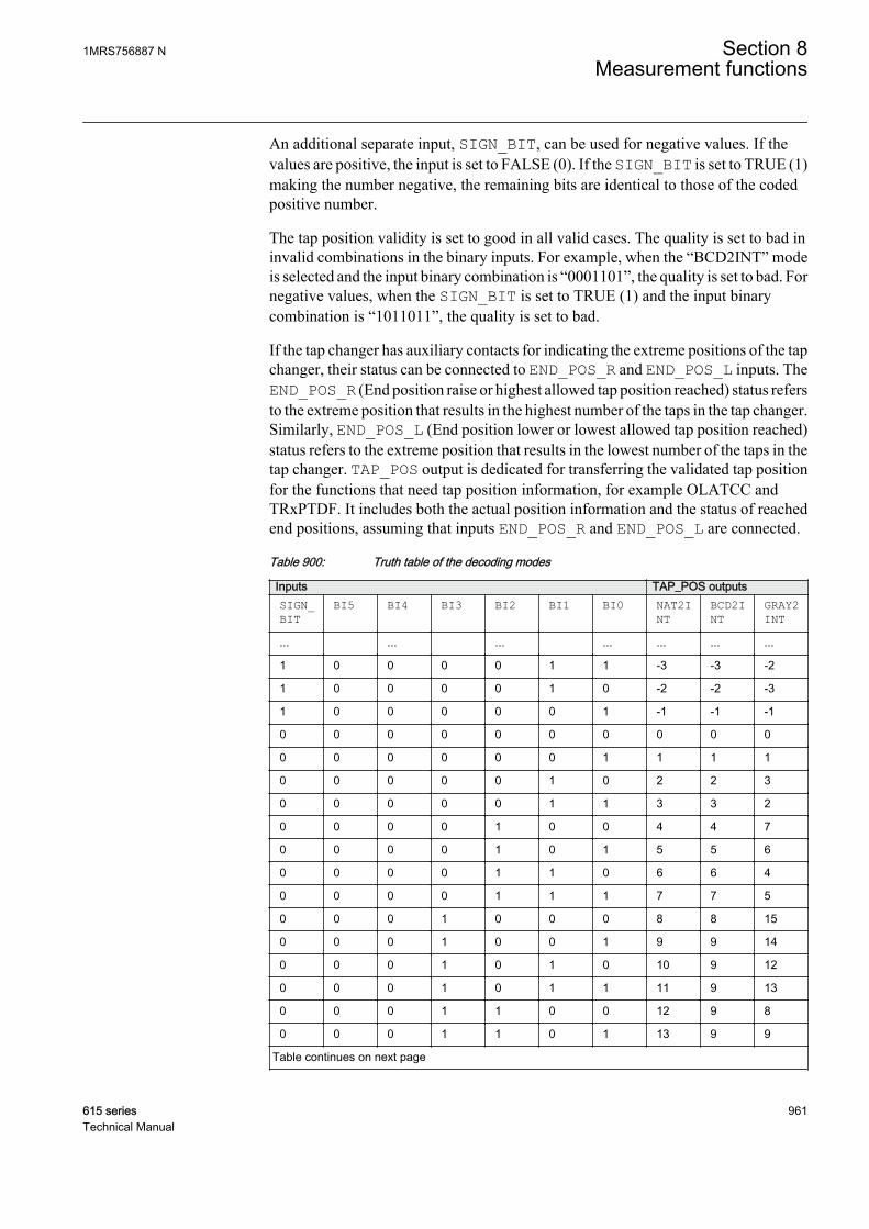
An additional separate input, SIGN_BIT, can be used for negative values. If thevalues are positive, the input is set to FALSE (0). If the SIGN_BIT is set to TRUE (1)making the number negative, the remaining bits are identical to those of the codedpositive number.
The tap position validity is set to good in all valid cases. The quality is set to bad ininvalid combinations in the binary inputs. For example, when the “BCD2INT” modeis selected and the input binary combination is “0001101”, the quality is set to bad. Fornegative values, when the SIGN_BIT is set to TRUE (1) and the input binarycombination is “1011011”, the quality is set to bad.
If the tap changer has auxiliary contacts for indicating the extreme positions of the tapchanger, their status can be connected to END_POS_R and END_POS_L inputs. TheEND_POS_R (End position raise or highest allowed tap position reached) status refersto the extreme position that results in the highest number of the taps in the tap changer.Similarly, END_POS_L (End position lower or lowest allowed tap position reached)status refers to the extreme position that results in the lowest number of the taps in thetap changer. TAP_POS output is dedicated for transferring the validated tap positionfor the functions that need tap position information, for example OLATCC andTRxPTDF. It includes both the actual position information and the status of reachedend positions, assuming that inputs END_POS_R and END_POS_L are connected.
Table 900: Truth table of the decoding modes
Inputs TAP_POS outputsSIGN_BIT
BI5 BI4 BI3 BI2 BI1 BI0 NAT2INT
BCD2INT
GRAY2INT
... ... ... ... ... ... ...
1 0 0 0 0 1 1 -3 -3 -2
1 0 0 0 0 1 0 -2 -2 -3
1 0 0 0 0 0 1 -1 -1 -1
0 0 0 0 0 0 0 0 0 0
0 0 0 0 0 0 1 1 1 1
0 0 0 0 0 1 0 2 2 3
0 0 0 0 0 1 1 3 3 2
0 0 0 0 1 0 0 4 4 7
0 0 0 0 1 0 1 5 5 6
0 0 0 0 1 1 0 6 6 4
0 0 0 0 1 1 1 7 7 5
0 0 0 1 0 0 0 8 8 15
0 0 0 1 0 0 1 9 9 14
0 0 0 1 0 1 0 10 9 12
0 0 0 1 0 1 1 11 9 13
0 0 0 1 1 0 0 12 9 8
0 0 0 1 1 0 1 13 9 9
Table continues on next page
1MRS756887 N Section 8Measurement functions
615 series 961Technical Manual

Inputs TAP_POS outputs0 0 0 1 1 1 0 14 9 11
0 0 0 1 1 1 1 15 9 10
0 0 1 0 0 0 0 16 10 31
0 0 1 0 0 0 1 17 11 30
0 0 1 0 0 1 0 18 12 28
0 0 1 0 0 1 1 19 13 29
0 0 1 0 1 0 0 20 14 24
0 0 1 0 1 0 1 21 15 25
0 0 1 0 1 1 0 22 16 27
0 0 1 0 1 1 1 23 17 26
0 0 1 1 0 0 0 24 18 16
0 0 1 1 0 0 1 25 19 17
0 0 1 1 0 1 0 26 19 19
0 0 1 1 0 1 1 27 19 18
0 0 1 1 1 0 0 28 19 23
0 0 1 1 1 0 1 29 19 22
0 0 1 1 1 1 0 30 19 20
0 0 1 1 1 1 1 31 19 21
0 1 0 0 0 0 0 32 20 63
0 1 0 0 0 0 1 33 21 62
0 1 0 0 0 1 0 34 22 60
0 1 0 0 0 1 1 35 23 61
0 1 0 0 1 0 0 36 24 56
... ... ... ... ... ... ...
8.3.5 Application
TPOSYLTC provides tap position information for other functions as a signed integervalue that can be fed to the tap position input.
The position information of the tap changer can be coded in various methods for manyapplications, for example, the differential protection algorithms. In this function, thebinary inputs in the transformer terminal connector are used as inputs to the function.The coding method can be chosen by setting the mode parameter. The availablecoding methods are BCD, Gray and Natural binary coding. Since the number of binaryinputs are limited to seven, the coding functions are limited to seven bits including thesign bit and thus the six bits are used in the coding functions. The position limits forthe tap positions at BCD, Gray and Natural binary coding are ±39, ±63 and ±63respectively.
In this example, the transformer tap changer position indication is wired as a mAsignal from the corresponding measuring transducer. The position indication is
Section 8 1MRS756887 NMeasurement functions
962 615 seriesTechnical Manual

connected to input 1 (AI_VAL1) of the X130 (RTD) card. The tap changer operatingrange from the minimum to maximum turns of the tap and a corresponding mA signalfor the tap position are set in XRGGIO130. Since the values of the XRGGIO130outputs are floating point numbers, the float to integer (T_F32_INT8) conversion isneeded before the tap position information can be fed to TPOSYLTC. When there isa wired connection to the TAP_POS connector, the validated tap changer position ispresented in the TAP_POS output that is connected to other functions, for example,OLATCC1. When there is no wired connection to the TAP_POS connector, the binaryinputs are expected to be used for the tap changer position information.
GUID-37AF8128-34E7-4614-88D8-6DBC5C3A8DC1 V1 EN
Figure 509: RTD/analog input configuration example
8.3.6 SignalsTable 901: TPOSYLTC Input signals
Name Type Default DescriptionBI0 BOOLEAN 0=False Binary input 1
BI1 BOOLEAN 0=False Binary input 2
BI2 BOOLEAN 0=False Binary input 3
BI3 BOOLEAN 0=False Binary input 4
BI4 BOOLEAN 0=False Binary input 5
BI5 BOOLEAN 0=False Binary input 6
SIGN_BIT BOOLEAN 0=False Binary input sign bit
END_POS_R BOOLEAN 0=False End position raise or highest allowed tap positionreached
END_POS_L BOOLEAN 0=False End position lower or lowest allowed tap positionreached
TAP_POS INT8 0 Tap position indication
Table 902: TPOSYLTC Output signals
Name Type DescriptionTAP_POS INT8 Tap position indication
1MRS756887 N Section 8Measurement functions
615 series 963Technical Manual
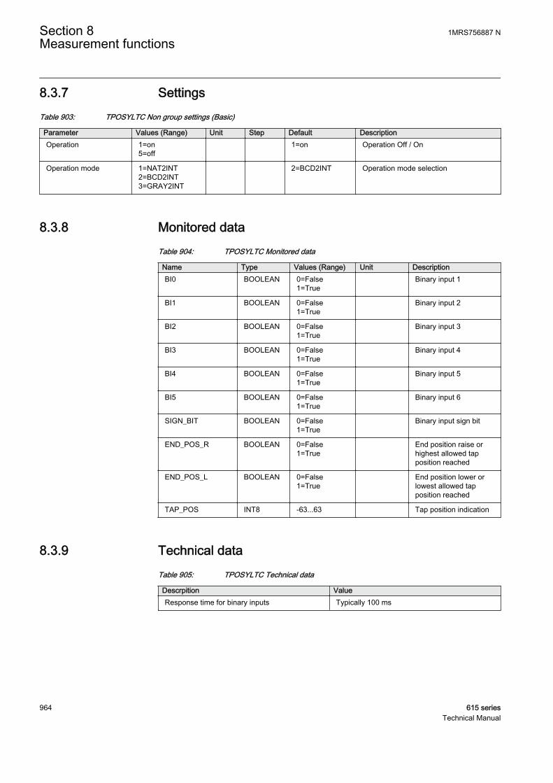
8.3.7 SettingsTable 903: TPOSYLTC Non group settings (Basic)
Parameter Values (Range) Unit Step Default DescriptionOperation 1=on
5=off 1=on Operation Off / On
Operation mode 1=NAT2INT2=BCD2INT3=GRAY2INT
2=BCD2INT Operation mode selection
8.3.8 Monitored dataTable 904: TPOSYLTC Monitored data
Name Type Values (Range) Unit DescriptionBI0 BOOLEAN 0=False
1=True Binary input 1
BI1 BOOLEAN 0=False1=True
Binary input 2
BI2 BOOLEAN 0=False1=True
Binary input 3
BI3 BOOLEAN 0=False1=True
Binary input 4
BI4 BOOLEAN 0=False1=True
Binary input 5
BI5 BOOLEAN 0=False1=True
Binary input 6
SIGN_BIT BOOLEAN 0=False1=True
Binary input sign bit
END_POS_R BOOLEAN 0=False1=True
End position raise orhighest allowed tapposition reached
END_POS_L BOOLEAN 0=False1=True
End position lower orlowest allowed tapposition reached
TAP_POS INT8 -63...63 Tap position indication
8.3.9 Technical dataTable 905: TPOSYLTC Technical data
Descrpition ValueResponse time for binary inputs Typically 100 ms
Section 8 1MRS756887 NMeasurement functions
964 615 seriesTechnical Manual

8.3.10 Technical revision historyTable 906: TPOSYLTC Technical revision history
Technical revision ChangeB Added new input TAP_POSC Internal improvement
D Added new inputs END_TPOS_R andEND_TPOS_LAdded a new output TAP_POS
1MRS756887 N Section 8Measurement functions
615 series 965Technical Manual

966
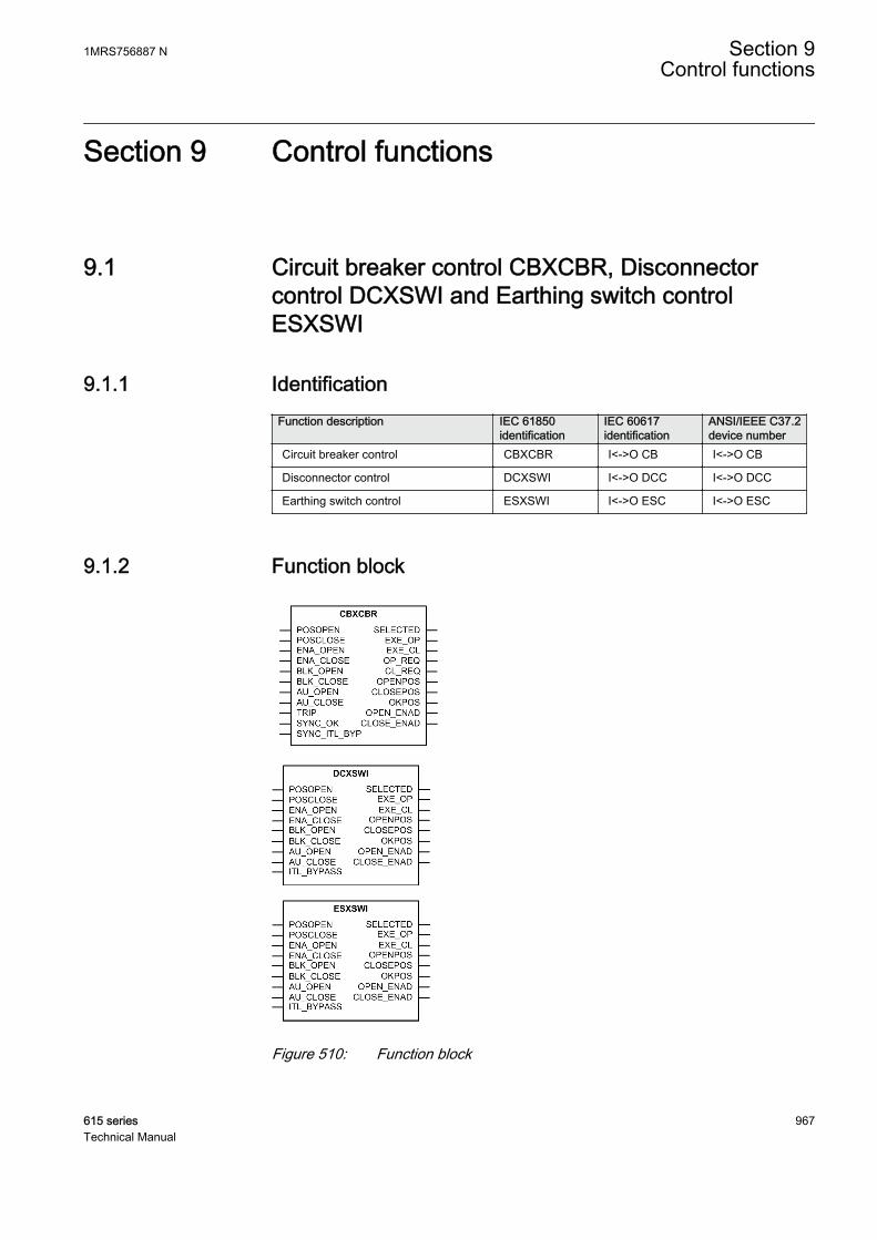
Section 9 Control functions
9.1 Circuit breaker control CBXCBR, Disconnectorcontrol DCXSWI and Earthing switch controlESXSWI
9.1.1 IdentificationFunction description IEC 61850
identificationIEC 60617identification
ANSI/IEEE C37.2device number
Circuit breaker control CBXCBR I<->O CB I<->O CB
Disconnector control DCXSWI I<->O DCC I<->O DCC
Earthing switch control ESXSWI I<->O ESC I<->O ESC
9.1.2 Function block
A071284 V4 EN
GUID-87017F8B-A03A-409C-8707-E721A1B0DE3E V1 EN
GUID-91FB6354-B7B0-46B4-9975-BE2769B97902 V1 EN
Figure 510: Function block
1MRS756887 N Section 9Control functions
615 series 967Technical Manual
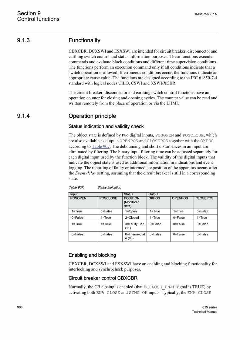
9.1.3 Functionality
CBXCBR, DCXSWI and ESXSWI are intended for circuit breaker, disconnector andearthing switch control and status information purposes. These functions executecommands and evaluate block conditions and different time supervision conditions.The functions perform an execution command only if all conditions indicate that aswitch operation is allowed. If erroneous conditions occur, the functions indicate anappropriate cause value. The functions are designed according to the IEC 61850-7-4standard with logical nodes CILO, CSWI and XSWI/XCBR.
The circuit breaker, disconnector and earthing switch control functions have anoperation counter for closing and opening cycles. The counter value can be read andwritten remotely from the place of operation or via the LHMI.
9.1.4 Operation principle
Status indication and validity checkThe object state is defined by two digital inputs, POSOPEN and POSCLOSE, whichare also available as outputs OPENPOS and CLOSEPOS together with the OKPOSaccording to Table 907. The debouncing and short disturbances in an input areeliminated by filtering. The binary input filtering time can be adjusted separately foreach digital input used by the function block. The validity of the digital inputs thatindicate the object state is used as additional information in indications and eventlogging. The reporting of faulty or intermediate position of the apparatus occurs afterthe Event delay setting, assuming that the circuit breaker is still in a correspondingstate.
Table 907: Status indication
Input Status OutputPOSOPEN POSCLOSE POSITION
(Monitoreddata)
OKPOS OPENPOS CLOSEPOS
1=True 0=False 1=Open 1=True 1=True 0=False
0=False 1=True 2=Closed 1=True 0=False 1=True
1=True 1=True 3=Faulty/Bad(11)
0=False 0=False 0=False
0=False 0=False 0=Intermediate (00)
0=False 0=False 0=False
Enabling and blockingCBXCBR, DCXSWI and ESXSWI have an enabling and blocking functionality forinterlocking and synchrocheck purposes.
Circuit breaker control CBXCBRNormally, the CB closing is enabled (that is, CLOSE_ENAD signal is TRUE) byactivating both ENA_CLOSE and SYNC_OK inputs. Typically, the ENA_CLOSE
Section 9 1MRS756887 NControl functions
968 615 seriesTechnical Manual
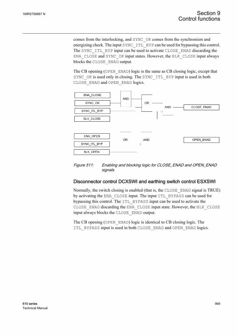
comes from the interlocking, and SYNC_OK comes from the synchronism andenergizing check. The input SYNC_ITL_BYP can be used for bypassing this control.The SYNC_ITL_BYP input can be used to activate CLOSE_ENAD discarding theENA_CLOSE and SYNC_OK input states. However, the BLK_CLOSE input alwaysblocks the CLOSE_ENAD output.
The CB opening (OPEN_ENAD) logic is the same as CB closing logic, except thatSYNC_OK is used only in closing. The SYNC_ITL_BYP input is used in bothCLOSE_ENAD and OPEN_ENAD logics.
GUID-AC1D16A3-6BED-4FD4-A5BE-E4079BE5FBB9 V1 EN
Figure 511: Enabling and blocking logic for CLOSE_ENAD and OPEN_ENADsignals
Disconnector control DCXSWI and earthing switch control ESXSWINormally, the switch closing is enabled (that is, the CLOSE_ENAD signal is TRUE)by activating the ENA_CLOSE input. The input ITL_BYPASS can be used forbypassing this control. The ITL_BYPASS input can be used to activate theCLOSE_ENAD discarding the ENA_CLOSE input state. However, the BLK_CLOSEinput always blocks the CLOSE_ENAD output.
The CB opening (OPEN_ENAD) logic is identical to CB closing logic. TheITL_BYPASS input is used in both CLOSE_ENAD and OPEN_ENAD logics.
1MRS756887 N Section 9Control functions
615 series 969Technical Manual

GUID-5C49E128-422F-4991-A7FE-6FB61B72CFD9 V1 EN
Figure 512: Enabling and blocking logic for CLOSE_ENAD and OPEN_ENADsignals
Opening and closing operationsThe opening and closing operations are available via communication, binary inputs orLHMI commands. As a prerequisite for control commands, there are enabling andblocking functionalities for both opening and closing commands (CLOSE_ENAD andOPEN_ENAD signals). If the control command is executed against the blocking or ifthe enabling of the corresponding command is not valid, CBXCBR, DCXSWI andESXSWI generate an error message.
When close command is given from communication, via LHMI or activating theAU_CLOSE input, it is carried out (the EXE_CL output) only if CLOSE_ENAD isTRUE.
If the SECRSYN function is used in “Command” mode, the CL_REQ output can beused in CBXCBR. Initially, the SYNC_OK input is FALSE. When the close commandgiven, it activates the CL_REQ output, which should be routed to SECRSYN. Theclose command is then processed only after SYNC_OK is received from SECRSYN.
When using SECRSYN in the “Command” mode, the CBXCBRsetting Operation timeout should be set longer than SECRSYNsetting Maximum Syn time.
Section 9 1MRS756887 NControl functions
970 615 seriesTechnical Manual
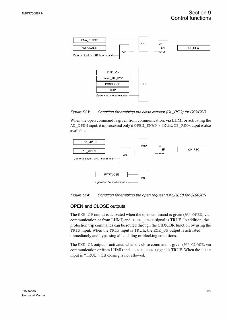
GUID-36839B06-10FE-46FA-8289-5AA1EBBCD0FA V1 EN
Figure 513: Condition for enabling the close request (CL_REQ) for CBXCBR
When the open command is given from communication, via LHMI or activating theAU_OPEN input, it is processed only if OPEN_ENAD is TRUE. OP_REQ output is alsoavailable.
GUID-0683760A-9832-4A01-8E87-6E3A7E6FDFC3 V1 EN
Figure 514: Condition for enabling the open request (OP_REQ) for CBXCBR
OPEN and CLOSE outputsThe EXE_OP output is activated when the open command is given (AU_OPEN, viacommunication or from LHMI) and OPEN_ENAD signal is TRUE. In addition, theprotection trip commands can be routed through the CBXCBR function by using theTRIP input. When the TRIP input is TRUE, the EXE_OP output is activatedimmediately and bypassing all enabling or blocking conditions.
The EXE_CL output is activated when the close command is given (AU_CLOSE, viacommunication or from LHMI) and CLOSE_ENAD signal is TRUE. When the TRIPinput is “TRUE”, CB closing is not allowed.
1MRS756887 N Section 9Control functions
615 series 971Technical Manual

GUID-B85B9772-2F20-4BC3-A3AE-90989F4817E2 V1 EN
Figure 515: OPEN and CLOSE outputs logic for CBXCBR
Opening and closing pulse widthsThe pulse width type can be defined with the Adaptive pulse setting. The functionprovides two modes to characterize the opening and closing pulse widths. When theAdaptive pulse is set to “TRUE”, it causes a variable pulse width, which means that theoutput pulse is deactivated when the object state shows that the apparatus has enteredthe correct state. If apparatus fails to enter the correct state, the output pulse isdeactivated after the set Operation timeout setting, and an error message is displayed.When the Adaptive pulse is set to “FALSE”, the functions always use the maximumpulse width, defined by the user-configurable Pulse length setting. The Pulse lengthsetting is the same for both the opening and closing commands. When the apparatusalready is in the right position, the maximum pulse length is given.
The Pulse length setting does not affect the length of the trip pulse.
Control methodsThe command execution mode can be set with the Control model setting. Thealternatives for command execution are direct control and secured object control,which can be used to secure controlling.
The secured object control SBO is an important feature of the communicationprotocols that support horizontal communication, because the command reservationand interlocking signals can be transferred with a bus. All secured control operationsrequire two-step commands: a selection step and an execution step. The secured objectcontrol is responsible for the several tasks.
Section 9 1MRS756887 NControl functions
972 615 seriesTechnical Manual
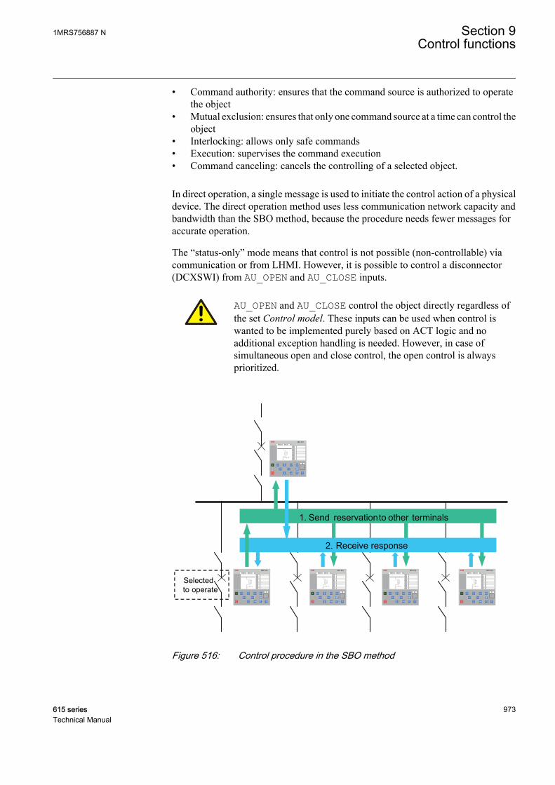
• Command authority: ensures that the command source is authorized to operatethe object
• Mutual exclusion: ensures that only one command source at a time can control theobject
• Interlocking: allows only safe commands• Execution: supervises the command execution• Command canceling: cancels the controlling of a selected object.
In direct operation, a single message is used to initiate the control action of a physicaldevice. The direct operation method uses less communication network capacity andbandwidth than the SBO method, because the procedure needs fewer messages foraccurate operation.
The “status-only” mode means that control is not possible (non-controllable) viacommunication or from LHMI. However, it is possible to control a disconnector(DCXSWI) from AU_OPEN and AU_CLOSE inputs.
AU_OPEN and AU_CLOSE control the object directly regardless ofthe set Control model. These inputs can be used when control iswanted to be implemented purely based on ACT logic and noadditional exception handling is needed. However, in case ofsimultaneous open and close control, the open control is alwaysprioritized.
1. Send reservationto other terminals
2. Receive response
Selectedto operate
REF 615 REF 615 REF 615 REF 615
REF 615
A070878 V3 EN
Figure 516: Control procedure in the SBO method
1MRS756887 N Section 9Control functions
615 series 973Technical Manual

Local/Remote operationsThe local/remote selection affects CBXCBR, DCXSWI and ESXSWI.
• Local: the opening and closing via communication is disabled.• Remote: the opening and closing via LHMI is disabled.• AU_OPEN and AU_CLOSE inputs function regardless of the local/remote
selection.
9.1.5 Application
In the field of distribution and sub-transmission automation, reliable control andstatus indication of primary switching components both locally and remotely is in asignificant role. They are needed especially in modern remotely controlledsubstations.
Control and status indication facilities are implemented in the same package withCBXCBR, DCXSWI and ESXSWI. When primary components are controlled in theenergizing phase, for example, the correct execution sequence of the controlcommands must be ensured. This can be achieved, for example, with interlockingbased on the status indication of the related primary components. The interlocking onsubstation level can be applied using the IEC 61850 GOOSE messages betweenfeeders.
Control and interlocking via GOOSE messages
REF 615 REF 615 REF 615
REF 615
A070879 V3 EN
Figure 517: Status indication-based interlocking via the GOOSE messaging
Section 9 1MRS756887 NControl functions
974 615 seriesTechnical Manual
9.1.6 SignalsTable 908: CBXCBR Input signals
Name Type Default DescriptionPOSOPEN BOOLEAN 0=False Signal for open position of apparatus from I/O1)
POSCLOSE BOOLEAN 0=False Signal for close position of apparatus from I/O1)
ENA_OPEN BOOLEAN 1=True Enables opening
ENA_CLOSE BOOLEAN 1=True Enables closing
BLK_OPEN BOOLEAN 0=False Blocks opening
BLK_CLOSE BOOLEAN 0=False Blocks closing
AU_OPEN BOOLEAN 0=False Auxiliary open1)2)
AU_CLOSE BOOLEAN 0=False Auxiliary close1)2)
TRIP BOOLEAN 0=False Trip signal
SYNC_OK BOOLEAN 1=True Synchronism-check OK
SYNC_ITL_BYP BOOLEAN 0=False Discards ENA_OPEN and ENA_CLOSEinterlocking when TRUE
1) Not available for monitoring2) Always direct operation
Table 909: DCXSWI Input signals
Name Type Default DescriptionPOSOPEN BOOLEAN 0=False Apparatus open position
POSCLOSE BOOLEAN 0=False Apparatus closed position
ENA_OPEN BOOLEAN 1=True Enables opening
ENA_CLOSE BOOLEAN 1=True Enables closing
BLK_OPEN BOOLEAN 0=False Blocks opening
BLK_CLOSE BOOLEAN 0=False Blocks closing
AU_OPEN BOOLEAN 0=False Executes the command for open direction1)2)
AU_CLOSE BOOLEAN 0=False Executes the command for close direction1)2)
ITL_BYPASS BOOLEAN 0=False Discards ENA_OPEN and ENA_CLOSEinterlocking when TRUE
1) Not available for monitoring2) Always direct operation
Table 910: ESXSWI Input signals
Name Type Default DescriptionPOSOPEN BOOLEAN 0=False Apparatus open position
POSCLOSE BOOLEAN 0=False Apparatus closed position
ENA_OPEN BOOLEAN 1=True Enables opening
ENA_CLOSE BOOLEAN 1=True Enables closing
BLK_OPEN BOOLEAN 0=False Blocks opening
Table continues on next page
1MRS756887 N Section 9Control functions
615 series 975Technical Manual
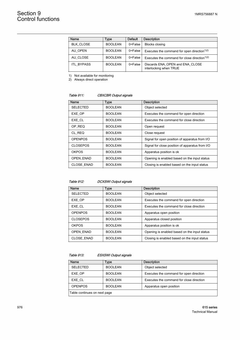
Name Type Default DescriptionBLK_CLOSE BOOLEAN 0=False Blocks closing
AU_OPEN BOOLEAN 0=False Executes the command for open direction1)2)
AU_CLOSE BOOLEAN 0=False Executes the command for close direction1)2)
ITL_BYPASS BOOLEAN 0=False Discards ENA_OPEN and ENA_CLOSEinterlocking when TRUE
1) Not available for monitoring2) Always direct operation
Table 911: CBXCBR Output signals
Name Type DescriptionSELECTED BOOLEAN Object selected
EXE_OP BOOLEAN Executes the command for open direction
EXE_CL BOOLEAN Executes the command for close direction
OP_REQ BOOLEAN Open request
CL_REQ BOOLEAN Close request
OPENPOS BOOLEAN Signal for open position of apparatus from I/O
CLOSEPOS BOOLEAN Signal for close position of apparatus from I/O
OKPOS BOOLEAN Apparatus position is ok
OPEN_ENAD BOOLEAN Opening is enabled based on the input status
CLOSE_ENAD BOOLEAN Closing is enabled based on the input status
Table 912: DCXSWI Output signals
Name Type DescriptionSELECTED BOOLEAN Object selected
EXE_OP BOOLEAN Executes the command for open direction
EXE_CL BOOLEAN Executes the command for close direction
OPENPOS BOOLEAN Apparatus open position
CLOSEPOS BOOLEAN Apparatus closed position
OKPOS BOOLEAN Apparatus position is ok
OPEN_ENAD BOOLEAN Opening is enabled based on the input status
CLOSE_ENAD BOOLEAN Closing is enabled based on the input status
Table 913: ESXSWI Output signals
Name Type DescriptionSELECTED BOOLEAN Object selected
EXE_OP BOOLEAN Executes the command for open direction
EXE_CL BOOLEAN Executes the command for close direction
OPENPOS BOOLEAN Apparatus open position
Table continues on next page
Section 9 1MRS756887 NControl functions
976 615 seriesTechnical Manual
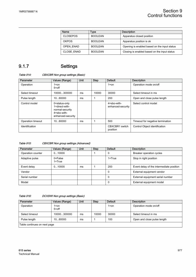
Name Type DescriptionCLOSEPOS BOOLEAN Apparatus closed position
OKPOS BOOLEAN Apparatus position is ok
OPEN_ENAD BOOLEAN Opening is enabled based on the input status
CLOSE_ENAD BOOLEAN Closing is enabled based on the input status
9.1.7 SettingsTable 914: CBXCBR Non group settings (Basic)
Parameter Values (Range) Unit Step Default DescriptionOperation 1=on
5=off 1=on Operation mode on/off
Select timeout 10000...300000 ms 10000 30000 Select timeout in ms
Pulse length 10...60000 ms 1 200 Open and close pulse length
Control model 0=status-only1=direct-with-normal-security4=sbo-with-enhanced-security
4=sbo-with-enhanced-security
Select control model
Operation timeout 10...60000 ms 1 500 Timeout for negative termination
Identification CBXCBR1 switchposition
Control Object identification
Table 915: CBXCBR Non group settings (Advanced)
Parameter Values (Range) Unit Step Default DescriptionOperation counter 0...10000 1 0 Breaker operation cycles
Adaptive pulse 0=False1=True
1=True Stop in right position
Event delay 0...10000 ms 1 200 Event delay of the intermediate position
Vendor 0 External equipment vendor
Serial number 0 External equipment serial number
Model 0 External equipment model
Table 916: DCXSWI Non group settings (Basic)
Parameter Values (Range) Unit Step Default DescriptionOperation 1=on
5=off 1=on Operation mode on/off
Select timeout 10000...300000 ms 10000 30000 Select timeout in ms
Pulse length 10...60000 ms 1 100 Open and close pulse length
Table continues on next page
1MRS756887 N Section 9Control functions
615 series 977Technical Manual
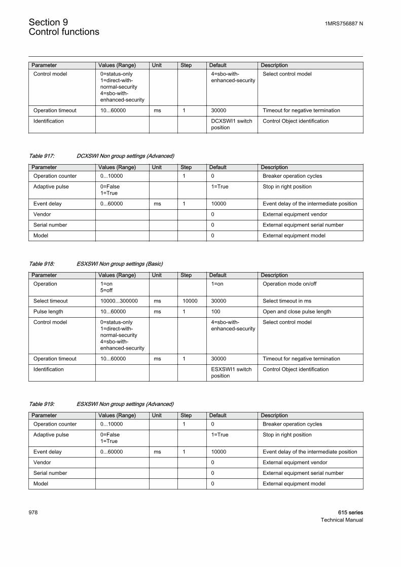
Parameter Values (Range) Unit Step Default DescriptionControl model 0=status-only
1=direct-with-normal-security4=sbo-with-enhanced-security
4=sbo-with-enhanced-security
Select control model
Operation timeout 10...60000 ms 1 30000 Timeout for negative termination
Identification DCXSWI1 switchposition
Control Object identification
Table 917: DCXSWI Non group settings (Advanced)
Parameter Values (Range) Unit Step Default DescriptionOperation counter 0...10000 1 0 Breaker operation cycles
Adaptive pulse 0=False1=True
1=True Stop in right position
Event delay 0...60000 ms 1 10000 Event delay of the intermediate position
Vendor 0 External equipment vendor
Serial number 0 External equipment serial number
Model 0 External equipment model
Table 918: ESXSWI Non group settings (Basic)
Parameter Values (Range) Unit Step Default DescriptionOperation 1=on
5=off 1=on Operation mode on/off
Select timeout 10000...300000 ms 10000 30000 Select timeout in ms
Pulse length 10...60000 ms 1 100 Open and close pulse length
Control model 0=status-only1=direct-with-normal-security4=sbo-with-enhanced-security
4=sbo-with-enhanced-security
Select control model
Operation timeout 10...60000 ms 1 30000 Timeout for negative termination
Identification ESXSWI1 switchposition
Control Object identification
Table 919: ESXSWI Non group settings (Advanced)
Parameter Values (Range) Unit Step Default DescriptionOperation counter 0...10000 1 0 Breaker operation cycles
Adaptive pulse 0=False1=True
1=True Stop in right position
Event delay 0...60000 ms 1 10000 Event delay of the intermediate position
Vendor 0 External equipment vendor
Serial number 0 External equipment serial number
Model 0 External equipment model
Section 9 1MRS756887 NControl functions
978 615 seriesTechnical Manual

9.1.8 Monitored dataTable 920: CBXCBR Monitored data
Name Type Values (Range) Unit DescriptionPOSITION Dbpos 0=intermediate
1=open2=closed3=faulty
Apparatus positionindication
Table 921: DCXSWI Monitored data
Name Type Values (Range) Unit DescriptionPOSITION Dbpos 0=intermediate
1=open2=closed3=faulty
Apparatus positionindication
Table 922: ESXSWI Monitored data
Name Type Values (Range) Unit DescriptionPOSITION Dbpos 0=intermediate
1=open2=closed3=faulty
Apparatus positionindication
9.1.9 Technical revision historyTable 923: CBXCBR Technical revision history
Technical revision ChangeB Interlocking bypass input (ITL_BYPASS) and
opening enabled (OPEN_ENAD)/closing enabled(CLOSE_ENAD) outputs added. ITL_BYPASSbypasses the ENA_OPEN and ENA_CLOSE states.
C Internal improvement.
D Added inputs TRIP and SYNC_OK. Renamed inputITL_BYPASS to SYNC_ITL_BYP. Added outputsCL_REQ and OP_REQ. Outputs OPENPOS andCLOSEPOS are forced to “FALSE” in case status isFaulty (11).
Table 924: DCXSWI Technical revision history
Technical revision ChangeB Maximum and default values changed to 60 s and
10 s respectively for Event delay settings. Defaultvalue changed to 30 s for Operation timeoutsetting.
C Outputs OPENPOS and CLOSEPOS are forced to“FALSE” in case status is Faulty (11).
1MRS756887 N Section 9Control functions
615 series 979Technical Manual

Table 925: ESXSWI Technical revision history
Technical revision ChangeB Maximum and default values changed to 60 s and
10 s respectively for Event delay settings. Defaultvalue changed to 30 s for Operation timeoutsetting.
C Outputs OPENPOS and CLOSEPOS are forced to“FALSE” in case status is Faulty (11).
9.2 Disconnector position indicator DCSXSWI andearthing switch indication ESSXSWI
9.2.1 IdentificationFunction description IEC 61850
identificationIEC 60617identification
ANSI/IEEE C37.2device number
Disconnector position indication DCSXSWI I<->O DC I<->O DC
Earthing switch indication ESSXSWI I<->O ES I<->O ES
9.2.2 Function block
A071280 V2 EN
Figure 518: Function block
A071282 V2 EN
Figure 519: Function block
9.2.3 Functionality
The functions DCSXSWI and ESSXSWI indicate remotely and locally the open,close and undefined states of the disconnector and earthing switch. The functionalityof both is identical, but each one is allocated for a specific purpose visible in thefunction names. For example, the status indication of disconnectors or circuit breakertruck can be monitored with the DCSXSWI function.
The functions are designed according to the IEC 61850-7-4 standard with the logicalnode XSWI.
Section 9 1MRS756887 NControl functions
980 615 seriesTechnical Manual
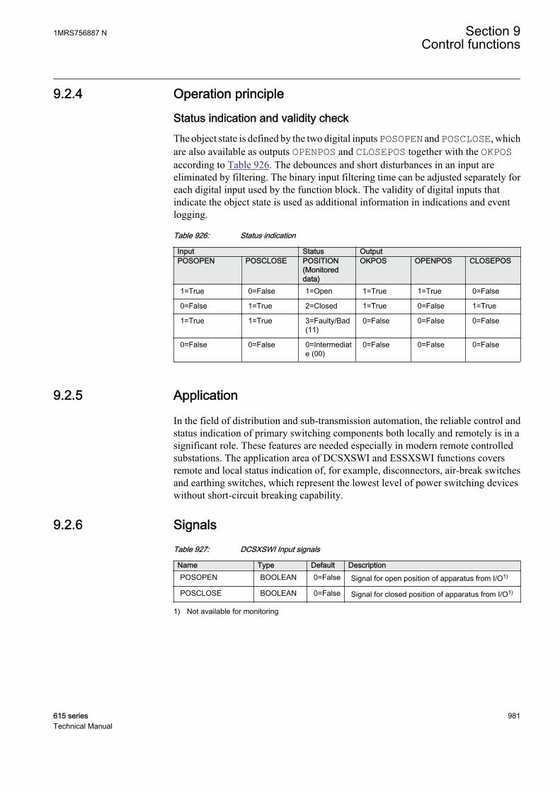
9.2.4 Operation principle
Status indication and validity checkThe object state is defined by the two digital inputs POSOPEN and POSCLOSE, whichare also available as outputs OPENPOS and CLOSEPOS together with the OKPOSaccording to Table 926. The debounces and short disturbances in an input areeliminated by filtering. The binary input filtering time can be adjusted separately foreach digital input used by the function block. The validity of digital inputs thatindicate the object state is used as additional information in indications and eventlogging.
Table 926: Status indication
Input Status OutputPOSOPEN POSCLOSE POSITION
(Monitoreddata)
OKPOS OPENPOS CLOSEPOS
1=True 0=False 1=Open 1=True 1=True 0=False
0=False 1=True 2=Closed 1=True 0=False 1=True
1=True 1=True 3=Faulty/Bad(11)
0=False 0=False 0=False
0=False 0=False 0=Intermediate (00)
0=False 0=False 0=False
9.2.5 Application
In the field of distribution and sub-transmission automation, the reliable control andstatus indication of primary switching components both locally and remotely is in asignificant role. These features are needed especially in modern remote controlledsubstations. The application area of DCSXSWI and ESSXSWI functions coversremote and local status indication of, for example, disconnectors, air-break switchesand earthing switches, which represent the lowest level of power switching deviceswithout short-circuit breaking capability.
9.2.6 SignalsTable 927: DCSXSWI Input signals
Name Type Default DescriptionPOSOPEN BOOLEAN 0=False Signal for open position of apparatus from I/O1)
POSCLOSE BOOLEAN 0=False Signal for closed position of apparatus from I/O1)
1) Not available for monitoring
1MRS756887 N Section 9Control functions
615 series 981Technical Manual

Table 928: ESSXSWI Input signals
Name Type Default DescriptionPOSOPEN BOOLEAN 0=False Signal for open position of apparatus from I/O1)
POSCLOSE BOOLEAN 0=False Signal for closed position of apparatus from I/O1)
1) Not available for monitoring
Table 929: DCSXSWI Output signals
Name Type DescriptionOPENPOS BOOLEAN Apparatus open position
CLOSEPOS BOOLEAN Apparatus closed position
OKPOS BOOLEAN Apparatus position is ok
Table 930: ESSXSWI Output signals
Name Type DescriptionOPENPOS BOOLEAN Apparatus open position
CLOSEPOS BOOLEAN Apparatus closed position
OKPOS BOOLEAN Apparatus position is ok
9.2.7 SettingsTable 931: DCSXSWI Non group settings (Basic)
Parameter Values (Range) Unit Step Default DescriptionIdentification DCSXSWI1 switch
positionControl Object identification
Table 932: DCSXSWI Non group settings (Advanced)
Parameter Values (Range) Unit Step Default DescriptionEvent delay 0...60000 ms 1 30000 Event delay of the intermediate position
Vendor 0 External equipment vendor
Serial number 0 External equipment serial number
Model 0 External equipment model
Table 933: ESSXSWI Non group settings (Basic)
Parameter Values (Range) Unit Step Default DescriptionIdentification ESSXSWI1 switch
positionControl Object identification
Section 9 1MRS756887 NControl functions
982 615 seriesTechnical Manual

Table 934: ESSXSWI Non group settings (Advanced)
Parameter Values (Range) Unit Step Default DescriptionEvent delay 0...60000 ms 1 30000 Event delay of the intermediate position
Vendor 0 External equipment vendor
Serial number 0 External equipment serial number
Model 0 External equipment model
9.2.8 Monitored dataTable 935: DCSXSWI Monitored data
Name Type Values (Range) Unit DescriptionPOSITION Dbpos 0=intermediate
1=open2=closed3=faulty
Apparatus positionindication
Table 936: ESSXSWI Monitored data
Name Type Values (Range) Unit DescriptionPOSITION Dbpos 0=intermediate
1=open2=closed3=faulty
Apparatus positionindication
9.2.9 Technical revision historyTable 937: DCSXSWI Technical revision history
Technical revision ChangeB Maximum and default values changed to 60 s and
30 s respectively for Event delay settings.
C Outputs OPENPOS and CLOSEPOS are forced to“FALSE” in case status is Faulty (11).
Table 938: ESSXSWI Technical revision history
Technical revision ChangeB Maximum and default values changed to 60 s and
30 s respectively for Event delay settings.
C Outputs OPENPOS and CLOSEPOS are forced to“FALSE” in case status is Faulty (11).
1MRS756887 N Section 9Control functions
615 series 983Technical Manual

9.3 Synchronism and energizing check SECRSYN
9.3.1 IdentificationFunction description IEC 61850
identificationIEC 60617identification
ANSI/IEEE C37.2device number
Synchronism and energizing check SECRSYN SYNC 25
9.3.2 Function block
GUID-9270E059-ED17-4355-90F0-3345E1743464 V2 EN
Figure 520: Function block
9.3.3 Functionality
The synchronism and energizing check function SECRSYN checks the conditionacross the circuit breaker from separate power system parts and gives the permissionto close the circuit breaker. SECRSYN includes the functionality of synchrocheck andenergizing check.
Asynchronous operation mode is provided for asynchronously running systems. Themain purpose of the asynchronous operation mode is to provide a controlled closingof circuit breakers when two asynchronous systems are connected.
The synchrocheck operation mode checks that the voltages on both sides of the circuitbreaker are perfectly synchronized. It is used to perform a controlled reconnection oftwo systems which are divided after islanding and it is also used to perform acontrolled reconnection of the system after reclosing.
The energizing check function checks that at least one side is dead to ensure thatclosing can be done safely.
The function contains a blocking functionality. It is possible to block function outputsand timers if desired.
Section 9 1MRS756887 NControl functions
984 615 seriesTechnical Manual
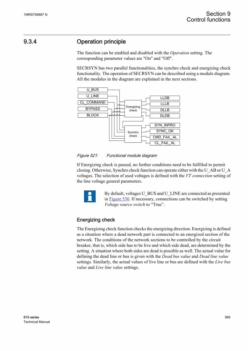
9.3.4 Operation principle
The function can be enabled and disabled with the Operation setting. Thecorresponding parameter values are "On" and "Off".
SECRSYN has two parallel functionalities, the synchro check and energizing checkfunctionality. The operation of SECRSYN can be described using a module diagram.All the modules in the diagram are explained in the next sections.
Energizing check
Synchro check
GUID-FE07029C-C6C1-4BA7-9F8E-CACE86D0A9BD V2 EN
Figure 521: Functional module diagram
If Energizing check is passed, no further conditions need to be fulfilled to permitclosing. Otherwise, Synchro check function can operate either with the U_AB or U_Avoltages. The selection of used voltages is defined with the VT connection setting ofthe line voltage general parameters.
By default, voltages U_BUS and U_LINE are connected as presentedin Figure 530. If necessary, connections can be switched by settingVoltage source switch to “True”.
Energizing checkThe Energizing check function checks the energizing direction. Energizing is definedas a situation where a dead network part is connected to an energized section of thenetwork. The conditions of the network sections to be controlled by the circuitbreaker, that is, which side has to be live and which side dead, are determined by thesetting. A situation where both sides are dead is possible as well. The actual value fordefining the dead line or bus is given with the Dead bus value and Dead line valuesettings. Similarly, the actual values of live line or bus are defined with the Live busvalue and Live line value settings.
1MRS756887 N Section 9Control functions
615 series 985Technical Manual
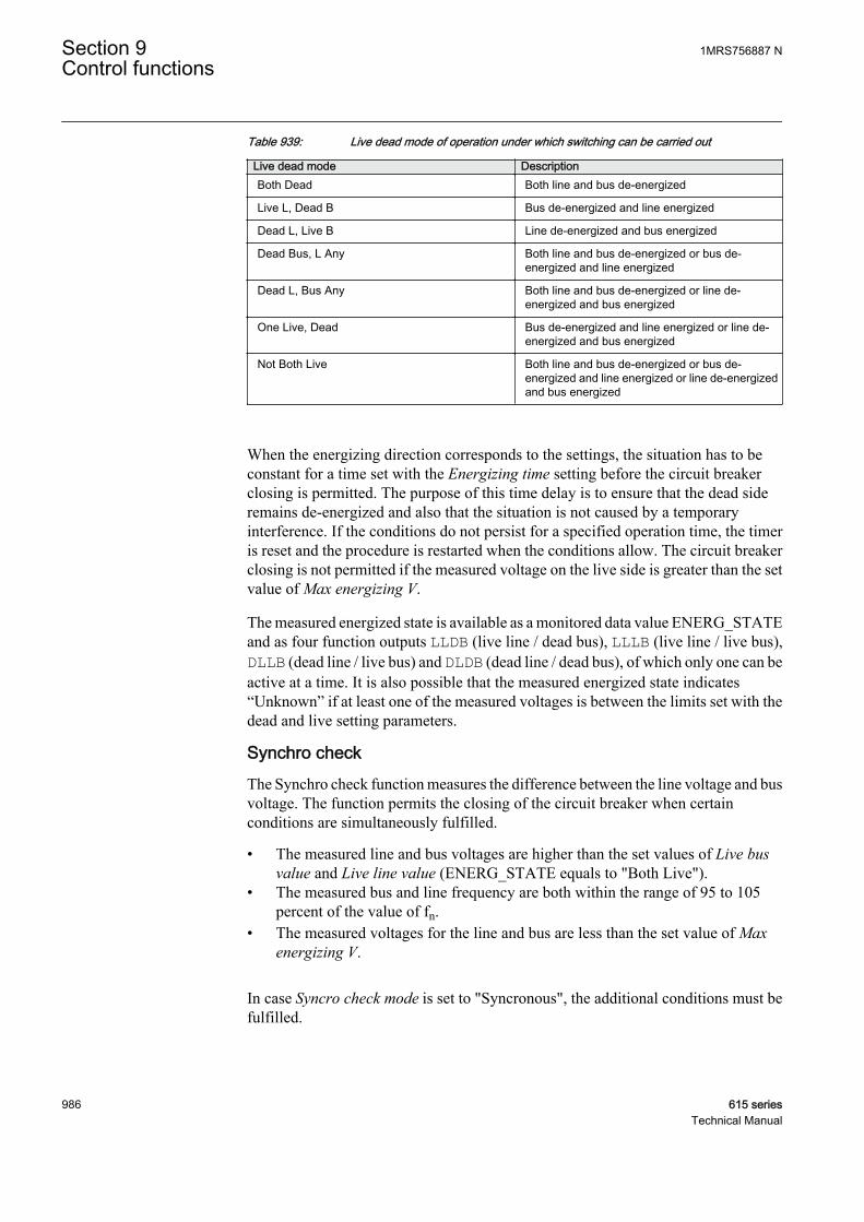
Table 939: Live dead mode of operation under which switching can be carried out
Live dead mode DescriptionBoth Dead Both line and bus de-energized
Live L, Dead B Bus de-energized and line energized
Dead L, Live B Line de-energized and bus energized
Dead Bus, L Any Both line and bus de-energized or bus de-energized and line energized
Dead L, Bus Any Both line and bus de-energized or line de-energized and bus energized
One Live, Dead Bus de-energized and line energized or line de-energized and bus energized
Not Both Live Both line and bus de-energized or bus de-energized and line energized or line de-energizedand bus energized
When the energizing direction corresponds to the settings, the situation has to beconstant for a time set with the Energizing time setting before the circuit breakerclosing is permitted. The purpose of this time delay is to ensure that the dead sideremains de-energized and also that the situation is not caused by a temporaryinterference. If the conditions do not persist for a specified operation time, the timeris reset and the procedure is restarted when the conditions allow. The circuit breakerclosing is not permitted if the measured voltage on the live side is greater than the setvalue of Max energizing V.
The measured energized state is available as a monitored data value ENERG_STATEand as four function outputs LLDB (live line / dead bus), LLLB (live line / live bus),DLLB (dead line / live bus) and DLDB (dead line / dead bus), of which only one can beactive at a time. It is also possible that the measured energized state indicates“Unknown” if at least one of the measured voltages is between the limits set with thedead and live setting parameters.
Synchro checkThe Synchro check function measures the difference between the line voltage and busvoltage. The function permits the closing of the circuit breaker when certainconditions are simultaneously fulfilled.
• The measured line and bus voltages are higher than the set values of Live busvalue and Live line value (ENERG_STATE equals to "Both Live").
• The measured bus and line frequency are both within the range of 95 to 105percent of the value of fn.
• The measured voltages for the line and bus are less than the set value of Maxenergizing V.
In case Syncro check mode is set to "Syncronous", the additional conditions must befulfilled.
Section 9 1MRS756887 NControl functions
986 615 seriesTechnical Manual

• In the synchronous mode, the closing is attempted so that the phase difference atclosing is close to zero.
• The synchronous mode is only possible when the frequency slip is below 0.1percent of the value of fn.
• The voltage difference must not exceed the 1 percent of the value of Un.
In case Syncro check mode is set to “Asyncronous”, the additional conditions must befulfilled.
• The measured difference of the voltages is less than the set value of Differencevoltage.
• The measured difference of the phase angles is less than the set value ofDifference angle.
• The measured difference in frequency is less than the set value of Frequencydifference.
• The estimated breaker closing angle is decided to be less than the set value ofDifference angle.
Dead line or bus value
Live line or bus value
Difference angle
U_Bus
U_LineDifference voltage
fU_Bus fU_Line
Frequency[Hz]
f = abs(fU_Bus - fU_Line)
Rated frequency
Frequency deviation
= U_Bus - U_Line Difference frequency
GUID-191F6C44-7A67-4277-8AD1-9711B535F1E1 V2 EN
Figure 522: Conditions to be fulfilled when detecting synchronism betweensystems
When the frequency, phase angle and voltage conditions are fulfilled, the duration ofthe synchronism conditions is checked so as to ensure that they are still met when thecondition is determined on the basis of the measured frequency and phase difference.Depending on the circuit breaker and the closing system, the delay from the momentthe closing signal is given until the circuit breaker finally closes is about 50...250 ms.The selected Closing time of CB informs the function how long the conditions have topersist. The Synchro check function compensates for the measured slip frequency andthe circuit breaker closing delay. The phase angle advance is calculated continuouslywith the formula.
1MRS756887 N Section 9Control functions
615 series 987Technical Manual

Closing angle = ∠ − ∠( )° + −( )× +( )× °( )U U f f T TBus Line Bus line CB PL 360
GUID-48292FC2-C00C-4166-BCAD-FFC77D7F196B V1 EN (Equation 186)
∠ UBus Measured bus voltage phase angle
∠ULine Measured line voltage phase angle
fBus Measured bus frequency
fline Measured line frequency
TCB Total circuit breaker closing delay, including the delay of the protection relay output contactsdefined with the Closing time of CB setting parameter value
The closing angle is the estimated angle difference after the breaker closing delay.
The Minimum Syn time setting time can be set, if required, to demand the minimumtime within which conditions must be simultaneously fulfilled before the SYNC_OKoutput is activated.
The measured voltage, frequency and phase angle difference values between the twosides of the circuit breaker are available as monitored data values U_DIFF_MEAS,FR_DIFF_MEAS and PH_DIFF_MEAS. Also, the indications of the conditions thatare not fulfilled and thus preventing the breaker closing permission are available asmonitored data values U_DIFF_SYNC, PH_DIF_SYNC and FR_DIFF_SYNC.These monitored data values are updated only when the Synchro check is enabled withthe Synchro check mode setting and the measured ENERG_STATE is "Both Live".
Continuous modeThe continuous mode is activated by setting the parameter Control mode to"Continuous". In the continuous control mode, Synchro check is continuouslychecking the synchronism. When synchronism is detected (according to the settings),the SYNC_OK output is set to TRUE (logic '1') and it stays TRUE as long as theconditions are fulfilled. The command input is ignored in the continuous controlmode. The mode is used for situations where Synchro check only gives the permissionto the control block that executes the CB closing.
SECRSYN CBXCBR I
Closing permission
Closing command
GUID-A9132EDC-BFAB-47CF-BB9D-FDE87EDE5FA5 V2 EN
Figure 523: A simplified block diagram of the Synchro check function in thecontinuous mode operation
Section 9 1MRS756887 NControl functions
988 615 seriesTechnical Manual
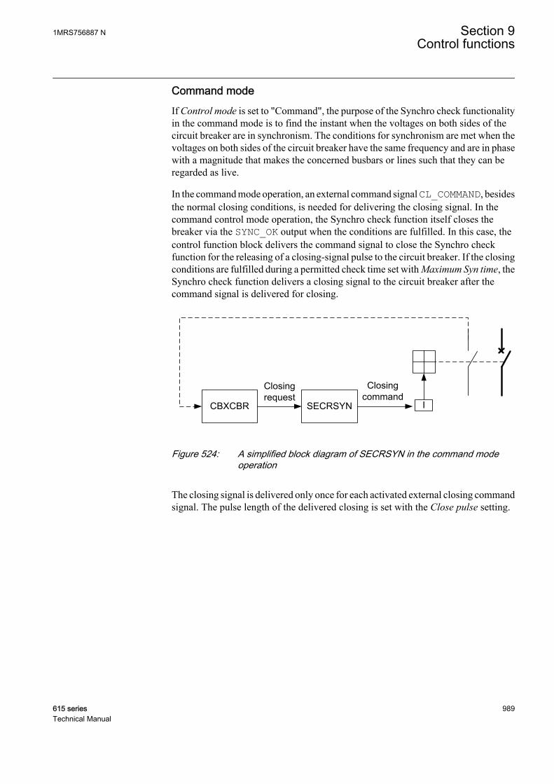
Command modeIf Control mode is set to "Command", the purpose of the Synchro check functionalityin the command mode is to find the instant when the voltages on both sides of thecircuit breaker are in synchronism. The conditions for synchronism are met when thevoltages on both sides of the circuit breaker have the same frequency and are in phasewith a magnitude that makes the concerned busbars or lines such that they can beregarded as live.
In the command mode operation, an external command signal CL_COMMAND, besidesthe normal closing conditions, is needed for delivering the closing signal. In thecommand control mode operation, the Synchro check function itself closes thebreaker via the SYNC_OK output when the conditions are fulfilled. In this case, thecontrol function block delivers the command signal to close the Synchro checkfunction for the releasing of a closing-signal pulse to the circuit breaker. If the closingconditions are fulfilled during a permitted check time set with Maximum Syn time, theSynchro check function delivers a closing signal to the circuit breaker after thecommand signal is delivered for closing.
SECRSYNCBXCBR I
Closing request
Closing command
GUID-820585ED-8AED-45B1-8FC2-2CEE7727A65C V2 EN
Figure 524: A simplified block diagram of SECRSYN in the command modeoperation
The closing signal is delivered only once for each activated external closing commandsignal. The pulse length of the delivered closing is set with the Close pulse setting.
1MRS756887 N Section 9Control functions
615 series 989Technical Manual
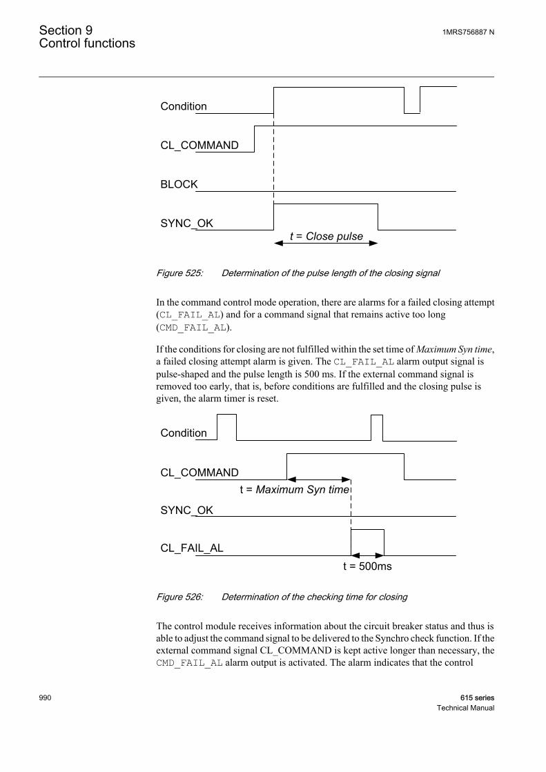
t = Close pulse
GUID-0D9A1A7F-58D1-4081-B974-A3CE10DEC5AF V2 EN
Figure 525: Determination of the pulse length of the closing signal
In the command control mode operation, there are alarms for a failed closing attempt(CL_FAIL_AL) and for a command signal that remains active too long(CMD_FAIL_AL).
If the conditions for closing are not fulfilled within the set time of Maximum Syn time,a failed closing attempt alarm is given. The CL_FAIL_AL alarm output signal ispulse-shaped and the pulse length is 500 ms. If the external command signal isremoved too early, that is, before conditions are fulfilled and the closing pulse isgiven, the alarm timer is reset.
Maximum Syn time
GUID-FA8ADA22-6A90-4637-AA1C-714B1D0DD2CF V2 EN
Figure 526: Determination of the checking time for closing
The control module receives information about the circuit breaker status and thus isable to adjust the command signal to be delivered to the Synchro check function. If theexternal command signal CL_COMMAND is kept active longer than necessary, theCMD_FAIL_AL alarm output is activated. The alarm indicates that the control
Section 9 1MRS756887 NControl functions
990 615 seriesTechnical Manual
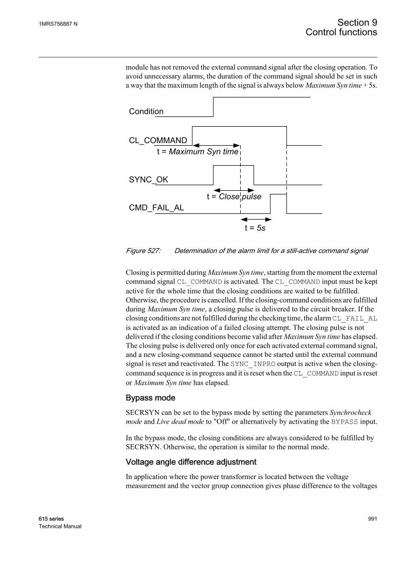
module has not removed the external command signal after the closing operation. Toavoid unnecessary alarms, the duration of the command signal should be set in sucha way that the maximum length of the signal is always below Maximum Syn time + 5s.
Close pulse
Maximum Syn time
5sGUID-4DF3366D-33B9-48B5-8EB4-692D98016753 V2 EN
Figure 527: Determination of the alarm limit for a still-active command signal
Closing is permitted during Maximum Syn time, starting from the moment the externalcommand signal CL_COMMAND is activated. The CL_COMMAND input must be keptactive for the whole time that the closing conditions are waited to be fulfilled.Otherwise, the procedure is cancelled. If the closing-command conditions are fulfilledduring Maximum Syn time, a closing pulse is delivered to the circuit breaker. If theclosing conditions are not fulfilled during the checking time, the alarm CL_FAIL_ALis activated as an indication of a failed closing attempt. The closing pulse is notdelivered if the closing conditions become valid after Maximum Syn time has elapsed.The closing pulse is delivered only once for each activated external command signal,and a new closing-command sequence cannot be started until the external commandsignal is reset and reactivated. The SYNC_INPRO output is active when the closing-command sequence is in progress and it is reset when the CL_COMMAND input is resetor Maximum Syn time has elapsed.
Bypass modeSECRSYN can be set to the bypass mode by setting the parameters Synchrocheckmode and Live dead mode to "Off" or alternatively by activating the BYPASS input.
In the bypass mode, the closing conditions are always considered to be fulfilled bySECRSYN. Otherwise, the operation is similar to the normal mode.
Voltage angle difference adjustmentIn application where the power transformer is located between the voltagemeasurement and the vector group connection gives phase difference to the voltages
1MRS756887 N Section 9Control functions
615 series 991Technical Manual
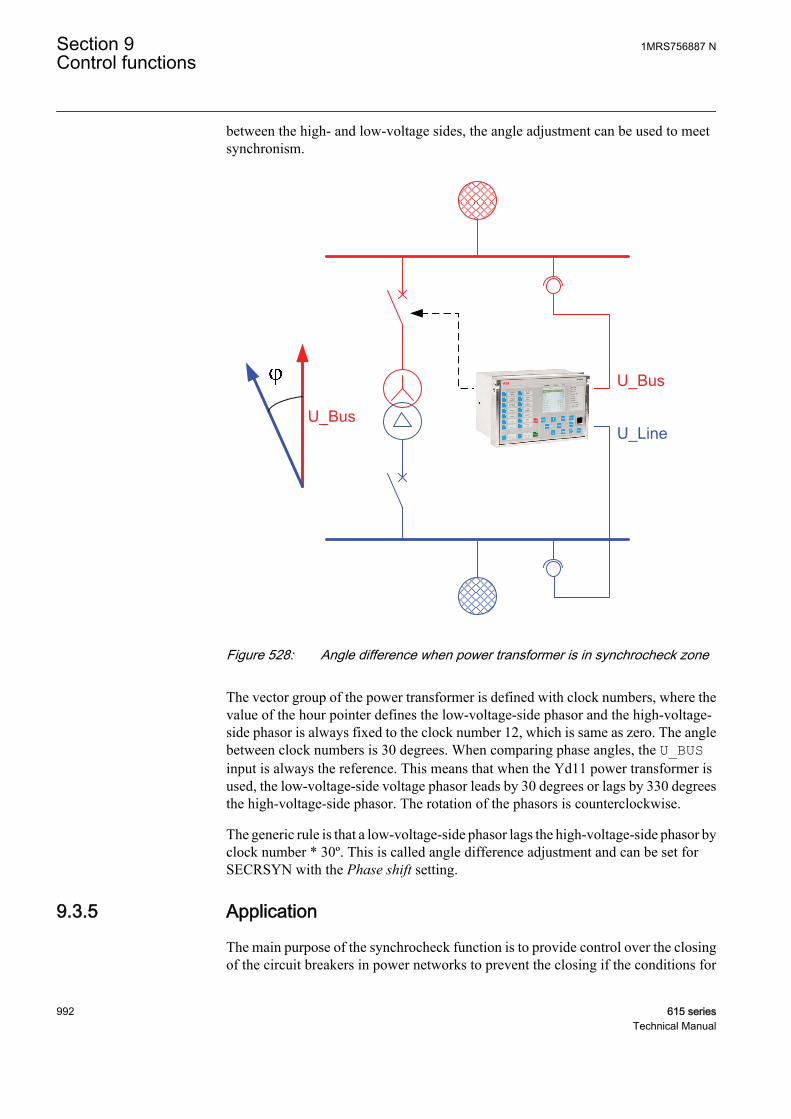
between the high- and low-voltage sides, the angle adjustment can be used to meetsynchronism.
GUID-AD453DCE-B54E-4A95-AC05-5A153E08AEBE V1 EN
Figure 528: Angle difference when power transformer is in synchrocheck zone
The vector group of the power transformer is defined with clock numbers, where thevalue of the hour pointer defines the low-voltage-side phasor and the high-voltage-side phasor is always fixed to the clock number 12, which is same as zero. The anglebetween clock numbers is 30 degrees. When comparing phase angles, the U_BUSinput is always the reference. This means that when the Yd11 power transformer isused, the low-voltage-side voltage phasor leads by 30 degrees or lags by 330 degreesthe high-voltage-side phasor. The rotation of the phasors is counterclockwise.
The generic rule is that a low-voltage-side phasor lags the high-voltage-side phasor byclock number * 30º. This is called angle difference adjustment and can be set forSECRSYN with the Phase shift setting.
9.3.5 Application
The main purpose of the synchrocheck function is to provide control over the closingof the circuit breakers in power networks to prevent the closing if the conditions for
Section 9 1MRS756887 NControl functions
992 615 seriesTechnical Manual
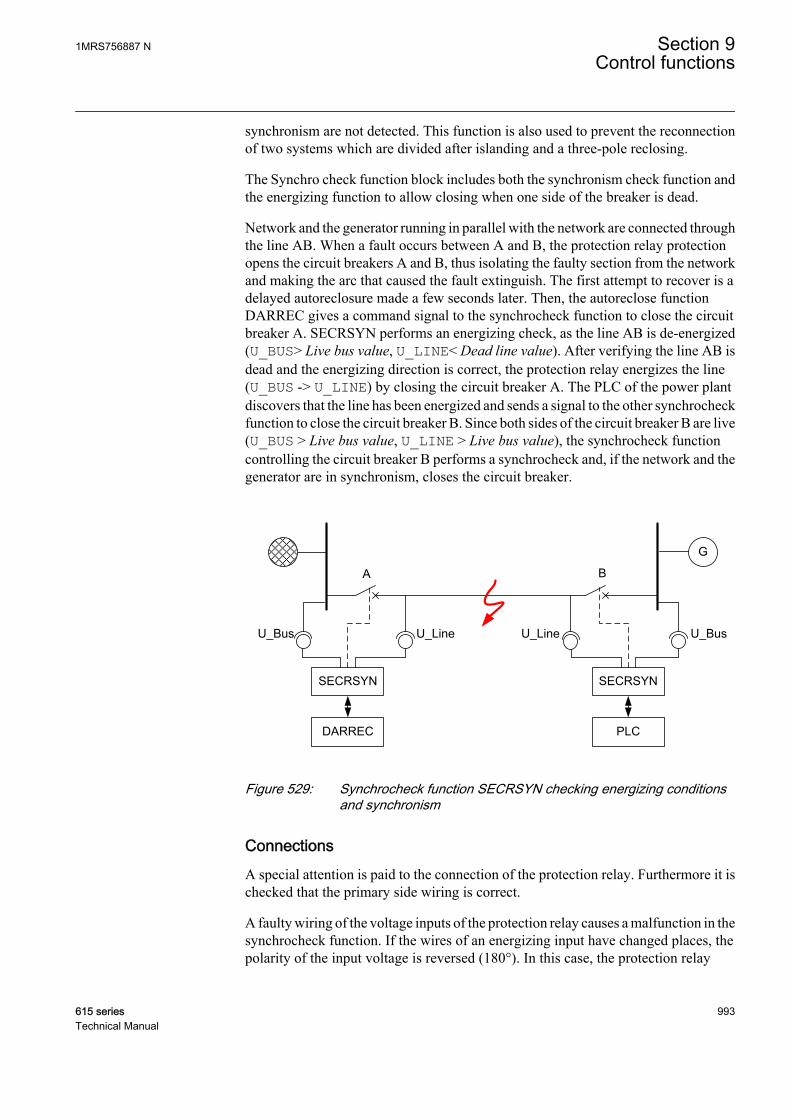
synchronism are not detected. This function is also used to prevent the reconnectionof two systems which are divided after islanding and a three-pole reclosing.
The Synchro check function block includes both the synchronism check function andthe energizing function to allow closing when one side of the breaker is dead.
Network and the generator running in parallel with the network are connected throughthe line AB. When a fault occurs between A and B, the protection relay protectionopens the circuit breakers A and B, thus isolating the faulty section from the networkand making the arc that caused the fault extinguish. The first attempt to recover is adelayed autoreclosure made a few seconds later. Then, the autoreclose functionDARREC gives a command signal to the synchrocheck function to close the circuitbreaker A. SECRSYN performs an energizing check, as the line AB is de-energized(U_BUS> Live bus value, U_LINE< Dead line value). After verifying the line AB isdead and the energizing direction is correct, the protection relay energizes the line(U_BUS -> U_LINE) by closing the circuit breaker A. The PLC of the power plantdiscovers that the line has been energized and sends a signal to the other synchrocheckfunction to close the circuit breaker B. Since both sides of the circuit breaker B are live(U_BUS > Live bus value, U_LINE > Live bus value), the synchrocheck functioncontrolling the circuit breaker B performs a synchrocheck and, if the network and thegenerator are in synchronism, closes the circuit breaker.
G
SECRSYN
DARREC
SECRSYN
PLC
A B
U_Bus U_BusU_Line U_Line
GUID-27A9936F-0276-47A1-B646-48E336FDA95C V2 EN
Figure 529: Synchrocheck function SECRSYN checking energizing conditionsand synchronism
ConnectionsA special attention is paid to the connection of the protection relay. Furthermore it ischecked that the primary side wiring is correct.
A faulty wiring of the voltage inputs of the protection relay causes a malfunction in thesynchrocheck function. If the wires of an energizing input have changed places, thepolarity of the input voltage is reversed (180°). In this case, the protection relay
1MRS756887 N Section 9Control functions
615 series 993Technical Manual
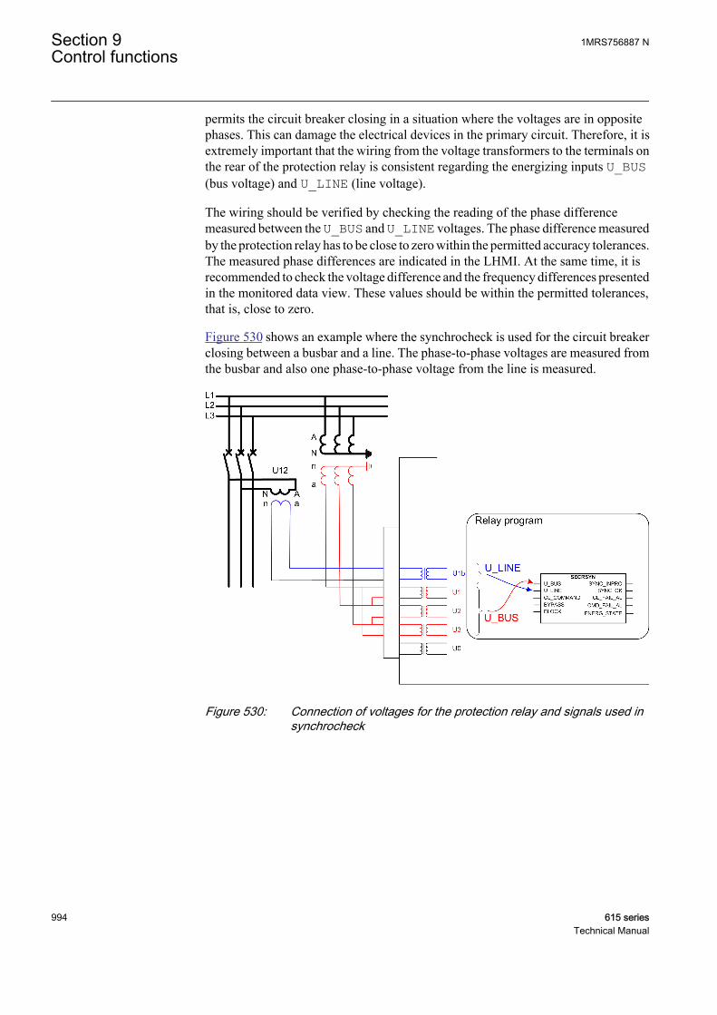
permits the circuit breaker closing in a situation where the voltages are in oppositephases. This can damage the electrical devices in the primary circuit. Therefore, it isextremely important that the wiring from the voltage transformers to the terminals onthe rear of the protection relay is consistent regarding the energizing inputs U_BUS(bus voltage) and U_LINE (line voltage).
The wiring should be verified by checking the reading of the phase differencemeasured between the U_BUS and U_LINE voltages. The phase difference measuredby the protection relay has to be close to zero within the permitted accuracy tolerances.The measured phase differences are indicated in the LHMI. At the same time, it isrecommended to check the voltage difference and the frequency differences presentedin the monitored data view. These values should be within the permitted tolerances,that is, close to zero.
Figure 530 shows an example where the synchrocheck is used for the circuit breakerclosing between a busbar and a line. The phase-to-phase voltages are measured fromthe busbar and also one phase-to-phase voltage from the line is measured.
GUID-DE29AFFC-9769-459B-B52C-4C11DC37A583 V3 EN
Figure 530: Connection of voltages for the protection relay and signals used insynchrocheck
Section 9 1MRS756887 NControl functions
994 615 seriesTechnical Manual
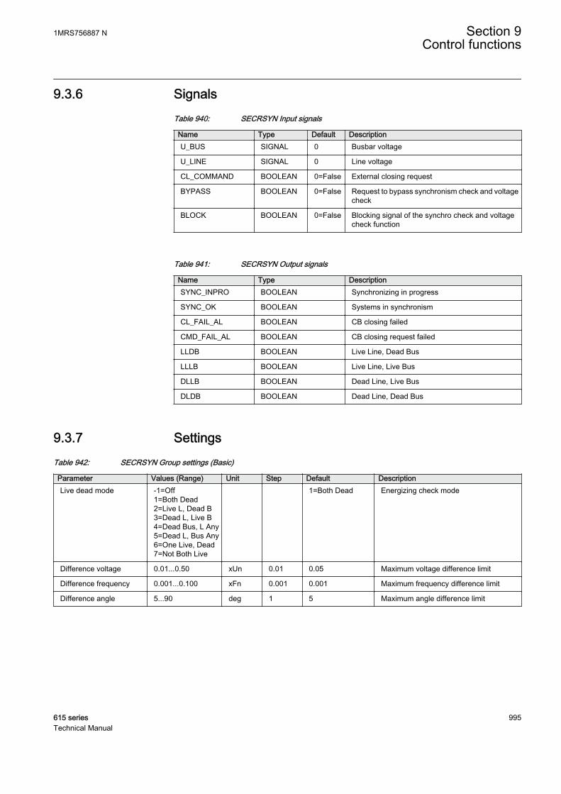
9.3.6 SignalsTable 940: SECRSYN Input signals
Name Type Default DescriptionU_BUS SIGNAL 0 Busbar voltage
U_LINE SIGNAL 0 Line voltage
CL_COMMAND BOOLEAN 0=False External closing request
BYPASS BOOLEAN 0=False Request to bypass synchronism check and voltagecheck
BLOCK BOOLEAN 0=False Blocking signal of the synchro check and voltagecheck function
Table 941: SECRSYN Output signals
Name Type DescriptionSYNC_INPRO BOOLEAN Synchronizing in progress
SYNC_OK BOOLEAN Systems in synchronism
CL_FAIL_AL BOOLEAN CB closing failed
CMD_FAIL_AL BOOLEAN CB closing request failed
LLDB BOOLEAN Live Line, Dead Bus
LLLB BOOLEAN Live Line, Live Bus
DLLB BOOLEAN Dead Line, Live Bus
DLDB BOOLEAN Dead Line, Dead Bus
9.3.7 SettingsTable 942: SECRSYN Group settings (Basic)
Parameter Values (Range) Unit Step Default DescriptionLive dead mode -1=Off
1=Both Dead2=Live L, Dead B3=Dead L, Live B4=Dead Bus, L Any5=Dead L, Bus Any6=One Live, Dead7=Not Both Live
1=Both Dead Energizing check mode
Difference voltage 0.01...0.50 xUn 0.01 0.05 Maximum voltage difference limit
Difference frequency 0.001...0.100 xFn 0.001 0.001 Maximum frequency difference limit
Difference angle 5...90 deg 1 5 Maximum angle difference limit
1MRS756887 N Section 9Control functions
615 series 995Technical Manual
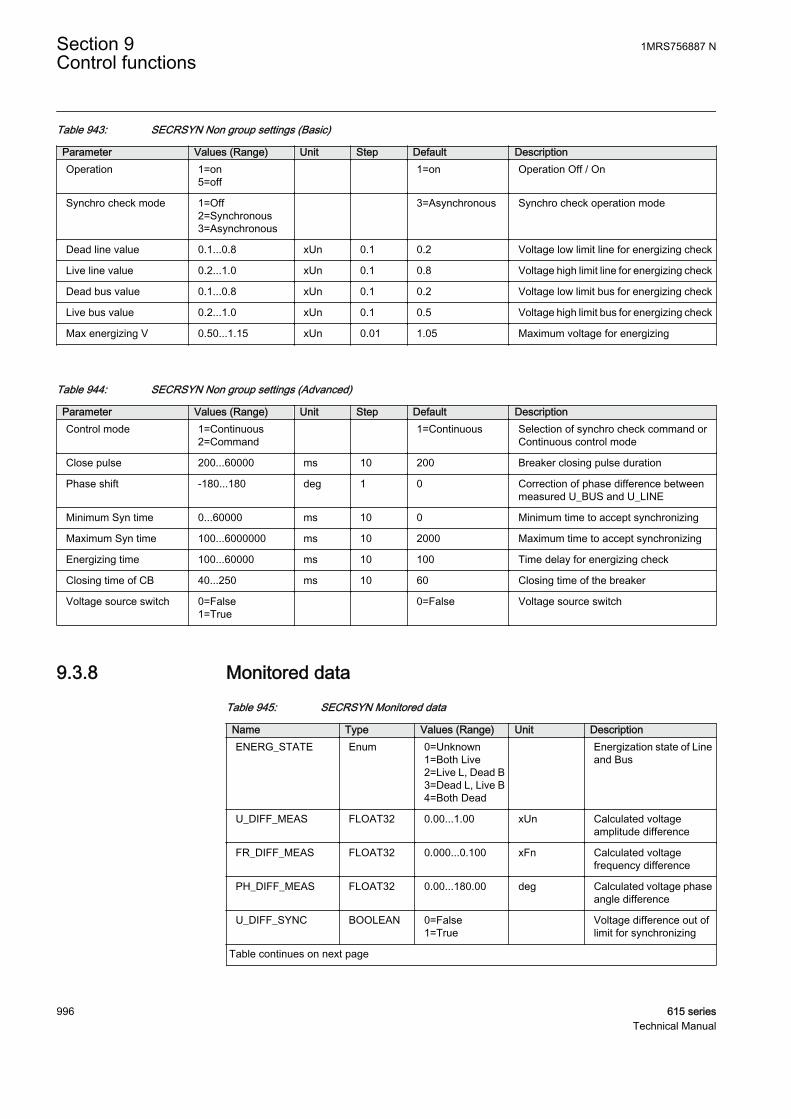
Table 943: SECRSYN Non group settings (Basic)
Parameter Values (Range) Unit Step Default DescriptionOperation 1=on
5=off 1=on Operation Off / On
Synchro check mode 1=Off2=Synchronous3=Asynchronous
3=Asynchronous Synchro check operation mode
Dead line value 0.1...0.8 xUn 0.1 0.2 Voltage low limit line for energizing check
Live line value 0.2...1.0 xUn 0.1 0.8 Voltage high limit line for energizing check
Dead bus value 0.1...0.8 xUn 0.1 0.2 Voltage low limit bus for energizing check
Live bus value 0.2...1.0 xUn 0.1 0.5 Voltage high limit bus for energizing check
Max energizing V 0.50...1.15 xUn 0.01 1.05 Maximum voltage for energizing
Table 944: SECRSYN Non group settings (Advanced)
Parameter Values (Range) Unit Step Default DescriptionControl mode 1=Continuous
2=Command 1=Continuous Selection of synchro check command or
Continuous control mode
Close pulse 200...60000 ms 10 200 Breaker closing pulse duration
Phase shift -180...180 deg 1 0 Correction of phase difference betweenmeasured U_BUS and U_LINE
Minimum Syn time 0...60000 ms 10 0 Minimum time to accept synchronizing
Maximum Syn time 100...6000000 ms 10 2000 Maximum time to accept synchronizing
Energizing time 100...60000 ms 10 100 Time delay for energizing check
Closing time of CB 40...250 ms 10 60 Closing time of the breaker
Voltage source switch 0=False1=True
0=False Voltage source switch
9.3.8 Monitored dataTable 945: SECRSYN Monitored data
Name Type Values (Range) Unit DescriptionENERG_STATE Enum 0=Unknown
1=Both Live2=Live L, Dead B3=Dead L, Live B4=Both Dead
Energization state of Lineand Bus
U_DIFF_MEAS FLOAT32 0.00...1.00 xUn Calculated voltageamplitude difference
FR_DIFF_MEAS FLOAT32 0.000...0.100 xFn Calculated voltagefrequency difference
PH_DIFF_MEAS FLOAT32 0.00...180.00 deg Calculated voltage phaseangle difference
U_DIFF_SYNC BOOLEAN 0=False1=True
Voltage difference out oflimit for synchronizing
Table continues on next page
Section 9 1MRS756887 NControl functions
996 615 seriesTechnical Manual
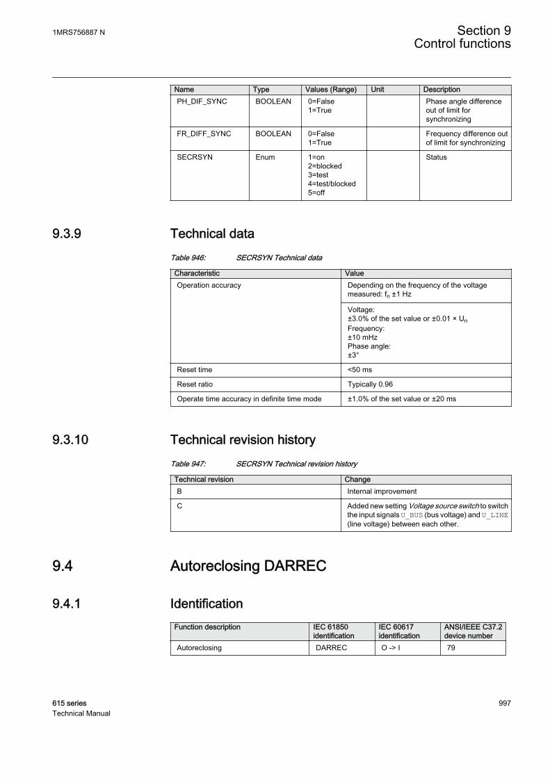
Name Type Values (Range) Unit DescriptionPH_DIF_SYNC BOOLEAN 0=False
1=True Phase angle difference
out of limit forsynchronizing
FR_DIFF_SYNC BOOLEAN 0=False1=True
Frequency difference outof limit for synchronizing
SECRSYN Enum 1=on2=blocked3=test4=test/blocked5=off
Status
9.3.9 Technical dataTable 946: SECRSYN Technical data
Characteristic ValueOperation accuracy Depending on the frequency of the voltage
measured: fn ±1 Hz
Voltage:±3.0% of the set value or ±0.01 × UnFrequency:±10 mHzPhase angle:±3°
Reset time <50 ms
Reset ratio Typically 0.96
Operate time accuracy in definite time mode ±1.0% of the set value or ±20 ms
9.3.10 Technical revision historyTable 947: SECRSYN Technical revision history
Technical revision ChangeB Internal improvement
C Added new setting Voltage source switch to switchthe input signals U_BUS (bus voltage) and U_LINE(line voltage) between each other.
9.4 Autoreclosing DARREC
9.4.1 IdentificationFunction description IEC 61850
identificationIEC 60617identification
ANSI/IEEE C37.2device number
Autoreclosing DARREC O -> I 79
1MRS756887 N Section 9Control functions
615 series 997Technical Manual
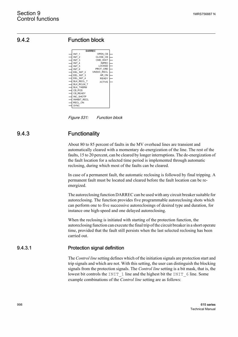
9.4.2 Function block
A070836 V4 EN
Figure 531: Function block
9.4.3 Functionality
About 80 to 85 percent of faults in the MV overhead lines are transient andautomatically cleared with a momentary de-energization of the line. The rest of thefaults, 15 to 20 percent, can be cleared by longer interruptions. The de-energization ofthe fault location for a selected time period is implemented through automaticreclosing, during which most of the faults can be cleared.
In case of a permanent fault, the automatic reclosing is followed by final tripping. Apermanent fault must be located and cleared before the fault location can be re-energized.
The autoreclosing function DARREC can be used with any circuit breaker suitable forautoreclosing. The function provides five programmable autoreclosing shots whichcan perform one to five successive autoreclosings of desired type and duration, forinstance one high-speed and one delayed autoreclosing.
When the reclosing is initiated with starting of the protection function, theautoreclosing function can execute the final trip of the circuit breaker in a short operatetime, provided that the fault still persists when the last selected reclosing has beencarried out.
9.4.3.1 Protection signal definition
The Control line setting defines which of the initiation signals are protection start andtrip signals and which are not. With this setting, the user can distinguish the blockingsignals from the protection signals. The Control line setting is a bit mask, that is, thelowest bit controls the INIT_1 line and the highest bit the INIT_6 line. Someexample combinations of the Control line setting are as follows:
Section 9 1MRS756887 NControl functions
998 615 seriesTechnical Manual
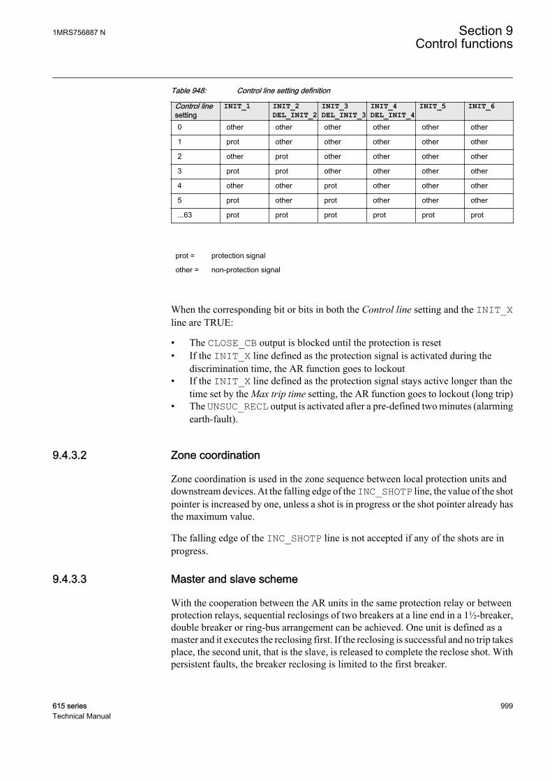
Table 948: Control line setting definition
Control linesetting
INIT_1 INIT_2DEL_INIT_2
INIT_3DEL_INIT_3
INIT_4DEL_INIT_4
INIT_5 INIT_6
0 other other other other other other
1 prot other other other other other
2 other prot other other other other
3 prot prot other other other other
4 other other prot other other other
5 prot other prot other other other
...63 prot prot prot prot prot prot
prot = protection signal
other = non-protection signal
When the corresponding bit or bits in both the Control line setting and the INIT_Xline are TRUE:
• The CLOSE_CB output is blocked until the protection is reset• If the INIT_X line defined as the protection signal is activated during the
discrimination time, the AR function goes to lockout• If the INIT_X line defined as the protection signal stays active longer than the
time set by the Max trip time setting, the AR function goes to lockout (long trip)• The UNSUC_RECL output is activated after a pre-defined two minutes (alarming
earth-fault).
9.4.3.2 Zone coordination
Zone coordination is used in the zone sequence between local protection units anddownstream devices. At the falling edge of the INC_SHOTP line, the value of the shotpointer is increased by one, unless a shot is in progress or the shot pointer already hasthe maximum value.
The falling edge of the INC_SHOTP line is not accepted if any of the shots are inprogress.
9.4.3.3 Master and slave scheme
With the cooperation between the AR units in the same protection relay or betweenprotection relays, sequential reclosings of two breakers at a line end in a 1½-breaker,double breaker or ring-bus arrangement can be achieved. One unit is defined as amaster and it executes the reclosing first. If the reclosing is successful and no trip takesplace, the second unit, that is the slave, is released to complete the reclose shot. Withpersistent faults, the breaker reclosing is limited to the first breaker.
1MRS756887 N Section 9Control functions
615 series 999Technical Manual
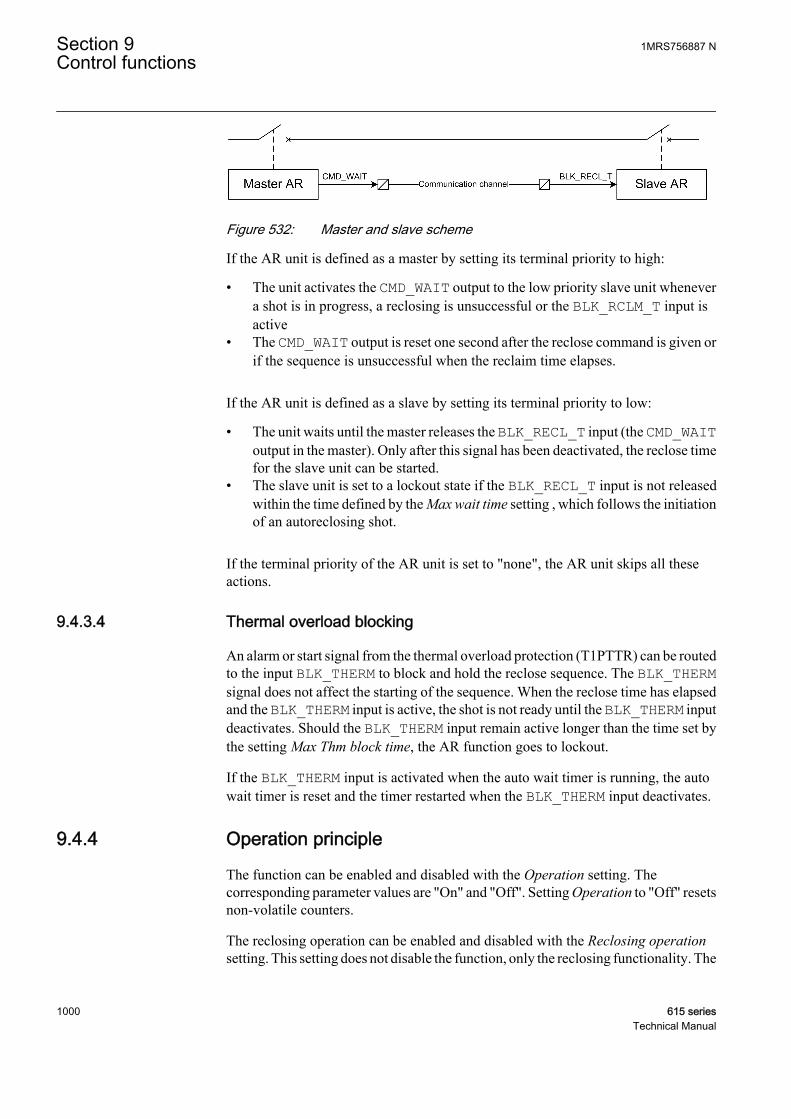
A070877 V1 EN
Figure 532: Master and slave scheme
If the AR unit is defined as a master by setting its terminal priority to high:
• The unit activates the CMD_WAIT output to the low priority slave unit whenevera shot is in progress, a reclosing is unsuccessful or the BLK_RCLM_T input isactive
• The CMD_WAIT output is reset one second after the reclose command is given orif the sequence is unsuccessful when the reclaim time elapses.
If the AR unit is defined as a slave by setting its terminal priority to low:
• The unit waits until the master releases the BLK_RECL_T input (the CMD_WAIToutput in the master). Only after this signal has been deactivated, the reclose timefor the slave unit can be started.
• The slave unit is set to a lockout state if the BLK_RECL_T input is not releasedwithin the time defined by the Max wait time setting , which follows the initiationof an autoreclosing shot.
If the terminal priority of the AR unit is set to "none", the AR unit skips all theseactions.
9.4.3.4 Thermal overload blocking
An alarm or start signal from the thermal overload protection (T1PTTR) can be routedto the input BLK_THERM to block and hold the reclose sequence. The BLK_THERMsignal does not affect the starting of the sequence. When the reclose time has elapsedand the BLK_THERM input is active, the shot is not ready until the BLK_THERM inputdeactivates. Should the BLK_THERM input remain active longer than the time set bythe setting Max Thm block time, the AR function goes to lockout.
If the BLK_THERM input is activated when the auto wait timer is running, the autowait timer is reset and the timer restarted when the BLK_THERM input deactivates.
9.4.4 Operation principle
The function can be enabled and disabled with the Operation setting. Thecorresponding parameter values are "On" and "Off". Setting Operation to "Off" resetsnon-volatile counters.
The reclosing operation can be enabled and disabled with the Reclosing operationsetting. This setting does not disable the function, only the reclosing functionality. The
Section 9 1MRS756887 NControl functions
1000 615 seriesTechnical Manual
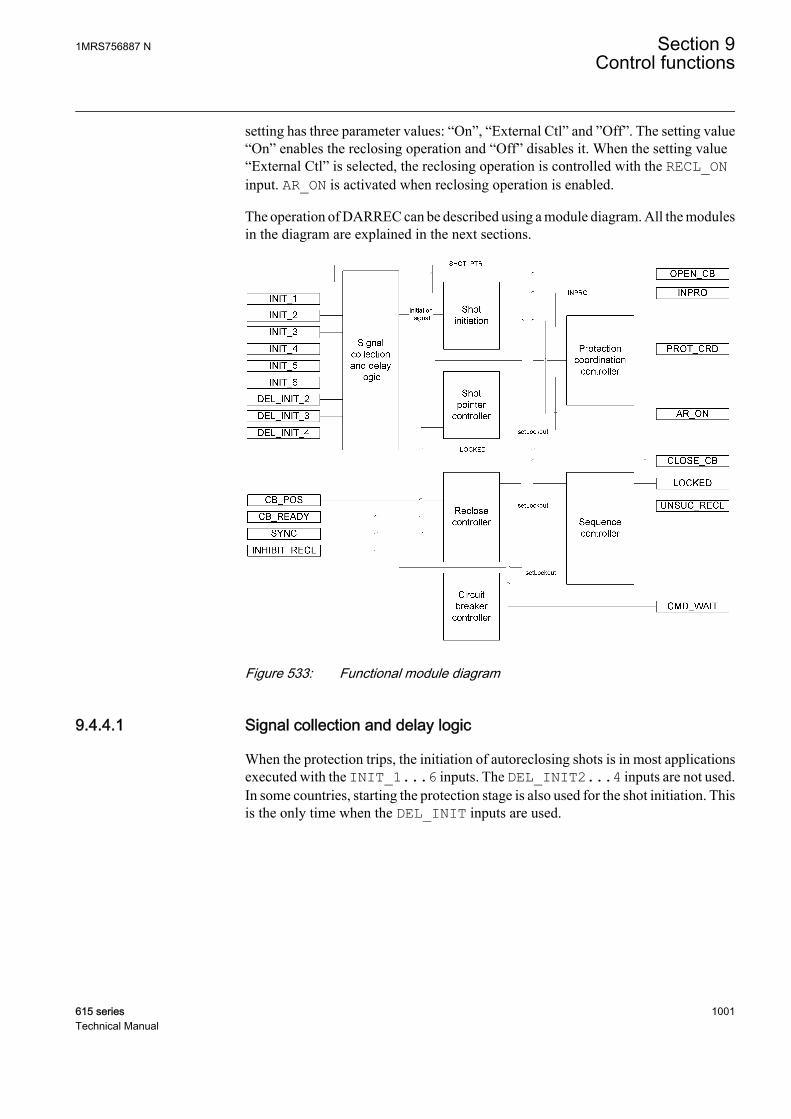
setting has three parameter values: “On”, “External Ctl” and ”Off”. The setting value“On” enables the reclosing operation and “Off” disables it. When the setting value“External Ctl” is selected, the reclosing operation is controlled with the RECL_ONinput. AR_ON is activated when reclosing operation is enabled.
The operation of DARREC can be described using a module diagram. All the modulesin the diagram are explained in the next sections.
A070864 V3 EN
Figure 533: Functional module diagram
9.4.4.1 Signal collection and delay logic
When the protection trips, the initiation of autoreclosing shots is in most applicationsexecuted with the INIT_1...6 inputs. The DEL_INIT2...4 inputs are not used.In some countries, starting the protection stage is also used for the shot initiation. Thisis the only time when the DEL_INIT inputs are used.
1MRS756887 N Section 9Control functions
615 series 1001Technical Manual
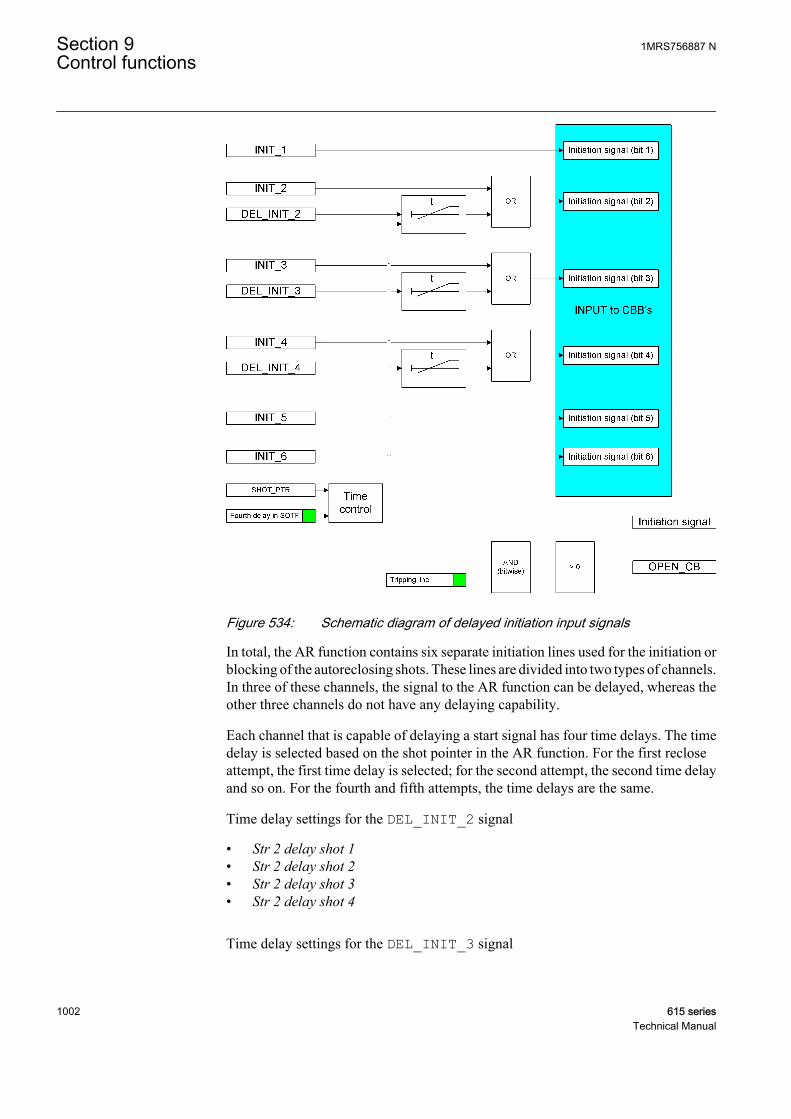
A070865 V2 EN
Figure 534: Schematic diagram of delayed initiation input signals
In total, the AR function contains six separate initiation lines used for the initiation orblocking of the autoreclosing shots. These lines are divided into two types of channels.In three of these channels, the signal to the AR function can be delayed, whereas theother three channels do not have any delaying capability.
Each channel that is capable of delaying a start signal has four time delays. The timedelay is selected based on the shot pointer in the AR function. For the first recloseattempt, the first time delay is selected; for the second attempt, the second time delayand so on. For the fourth and fifth attempts, the time delays are the same.
Time delay settings for the DEL_INIT_2 signal
• Str 2 delay shot 1• Str 2 delay shot 2• Str 2 delay shot 3• Str 2 delay shot 4
Time delay settings for the DEL_INIT_3 signal
Section 9 1MRS756887 NControl functions
1002 615 seriesTechnical Manual
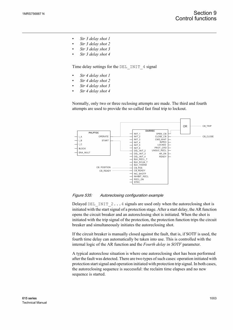
• Str 3 delay shot 1• Str 3 delay shot 2• Str 3 delay shot 3• Str 3 delay shot 4
Time delay settings for the DEL_INIT_4 signal
• Str 4 delay shot 1• Str 4 delay shot 2• Str 4 delay shot 3• Str 4 delay shot 4
Normally, only two or three reclosing attempts are made. The third and fourthattempts are used to provide the so-called fast final trip to lockout.
OR CB_TRIP
CB_POSITIONCB_READY
CB_CLOSE
PHLPTOC
I_A
I_B START
OPERATE
I_C
BLOCK
ENA_MULT
DARRECOPEN _CB
CLOSE_CBCMD_WAIT
INPROLOCKED
PROT _CRDUNSUC_RECL
DEL_INIT_4DEL_INIT_3DEL_INIT_2INIT_6INIT_5INIT_4INIT_3INIT_2INIT_1
SYNC
INC_SHOTPCB_READYCB_POS
RECL_ONINHIBIT_RECL
BLK_RCLM_TBLK_RECL_T
BLK_THERM
AR_ONREADY
A070866 V3 EN
Figure 535: Autoreclosing configuration example
Delayed DEL_INIT_2...4 signals are used only when the autoreclosing shot isinitiated with the start signal of a protection stage. After a start delay, the AR functionopens the circuit breaker and an autoreclosing shot is initiated. When the shot isinitiated with the trip signal of the protection, the protection function trips the circuitbreaker and simultaneously initiates the autoreclosing shot.
If the circuit breaker is manually closed against the fault, that is, if SOTF is used, thefourth time delay can automatically be taken into use. This is controlled with theinternal logic of the AR function and the Fourth delay in SOTF parameter.
A typical autoreclose situation is where one autoreclosing shot has been performedafter the fault was detected. There are two types of such cases: operation initiated withprotection start signal and operation initiated with protection trip signal. In both cases,the autoreclosing sequence is successful: the reclaim time elapses and no newsequence is started.
1MRS756887 N Section 9Control functions
615 series 1003Technical Manual
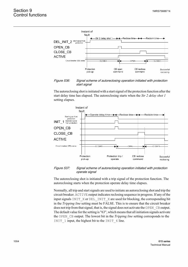
A070867 V1 EN
Figure 536: Signal scheme of autoreclosing operation initiated with protectionstart signal
The autoreclosing shot is initiated with a start signal of the protection function after thestart delay time has elapsed. The autoreclosing starts when the Str 2 delay shot 1setting elapses.
A070868 V1 EN
Figure 537: Signal scheme of autoreclosing operation initiated with protectionoperate signal
The autoreclosing shot is initiated with a trip signal of the protection function. Theautoreclosing starts when the protection operate delay time elapses.
Normally, all trip and start signals are used to initiate an autoreclosing shot and trip thecircuit breaker. ACTIVE output indicates reclosing sequence in progress. If any of theinput signals INIT_X or DEL_INIT_X are used for blocking, the corresponding bitin the Tripping line setting must be FALSE. This is to ensure that the circuit breakerdoes not trip from that signal, that is, the signal does not activate the OPEN_CB output.The default value for the setting is "63", which means that all initiation signals activatethe OPEN_CB output. The lowest bit in the Tripping line setting corresponds to theINIT_1 input, the highest bit to the INIT_6 line.
Section 9 1MRS756887 NControl functions
1004 615 seriesTechnical Manual

9.4.4.2 Shot initiation
A070869 V1 EN
Figure 538: Example of an autoreclosing program with a reclose scheme matrix
In the AR function, each shot can be programmed to locate anywhere in the reclosescheme matrix. The shots are like building blocks used to design the reclose program.The building blocks are called CBBs. All blocks are alike and have settings which givethe attempt number (columns in the matrix), the initiation or blocking signals (rows inthe matrix) and the reclose time of the shot.
The settings related to CBB configuration are:
• First...Seventh reclose time• Init signals CBB1…CBB7• Blk signals CBB1…CBB7• Shot number CBB1…CBB7
The reclose time defines the open and dead times, that is, the time between theOPEN_CB and the CLOSE_CB commands. The Init signals CBBx setting defines theinitiation signals. The Blk signals CBBx setting defines the blocking signals that arerelated to the CBB (rows in the matrix). The Shot number CBB1…CBB7 settingdefines which shot is related to the CBB (columns in the matrix). For example, CBB1settings are:
1MRS756887 N Section 9Control functions
615 series 1005Technical Manual
• First reclose time = 1.0s• Init signals CBB1 = 7 (three lowest bits: 111000 = 7)• Blk signals CBB1 = 16 (the fifth bit: 000010 = 16)• Shot number CBB1 = 1
CBB2 settings are:
• Second reclose time = 10s• Init signals CBB2 = 6 (the second and third bits: 011000 = 6)• Blk signals CBB2 = 16 (the fifth bit: 000010 = 16)• Shot number CBB2 = 2
CBB3 settings are:
• Third reclose time = 30s• Init signals CBB3 = 4 (the third bit: 001000 = 4)• Blk signals CBB3 = 16 (the fifth bit: 000010 = 16)• Shot number CBB3 = 3
CBB4 settings are:
• Fourth reclose time = 0.5s• Init signals CBB4 = 8 (the fourth bit: 000100 = 8)• Blk signals CBB4 = 0 (no blocking signals related to this CBB)• Shot number CBB4 = 1
If a shot is initiated from the INIT_1 line, only one shot is allowed before lockout.If a shot is initiated from the INIT_3 line, three shots are allowed before lockout.
A sequence initiation from the INIT_4 line leads to a lockout after two shots. In asituation where the initiation is made from both the INIT_3 and INIT_4 lines, athird shot is allowed, that is, CBB3 is allowed to start. This is called conditionallockout. If the initiation is made from the INIT_2 and INIT_3 lines, an immediatelockout occurs.
The INIT_5 line is used for blocking purposes. If the INIT_5 line is active duringa sequence start, the reclose attempt is blocked and the AR function goes to lockout.
If more than one CBBs are started with the shot pointer, the CBB withthe smallest individual number is always selected. For example, if theINIT_2 and INIT_4 lines are active for the second shot, that is, theshot pointer is 2, CBB2 is started instead of CBB5.
Even if the initiation signals are not received from the protection functions, the ARfunction can be set to continue from the second to the fifth reclose shot. The ARfunction can, for example, be requested to automatically continue with the sequencewhen the circuit breaker fails to close when requested. In such a case, the AR function
Section 9 1MRS756887 NControl functions
1006 615 seriesTechnical Manual
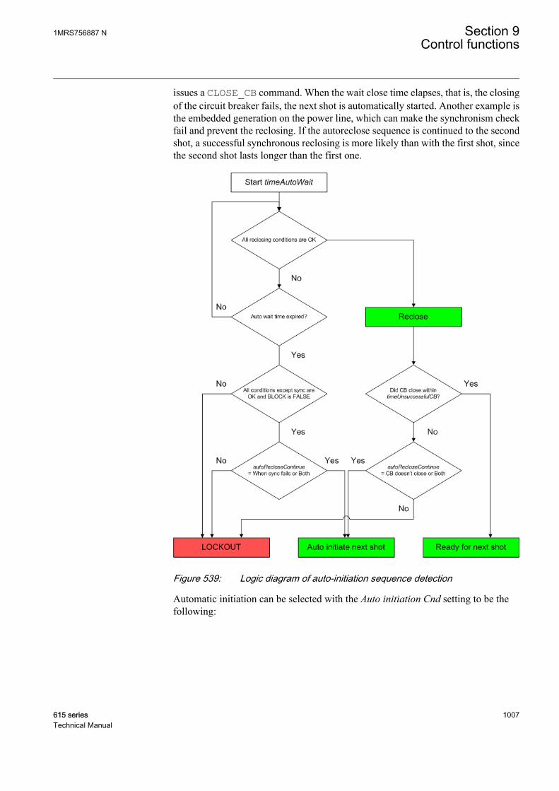
issues a CLOSE_CB command. When the wait close time elapses, that is, the closingof the circuit breaker fails, the next shot is automatically started. Another example isthe embedded generation on the power line, which can make the synchronism checkfail and prevent the reclosing. If the autoreclose sequence is continued to the secondshot, a successful synchronous reclosing is more likely than with the first shot, sincethe second shot lasts longer than the first one.
A070870 V1 EN
Figure 539: Logic diagram of auto-initiation sequence detection
Automatic initiation can be selected with the Auto initiation Cnd setting to be thefollowing:
1MRS756887 N Section 9Control functions
615 series 1007Technical Manual
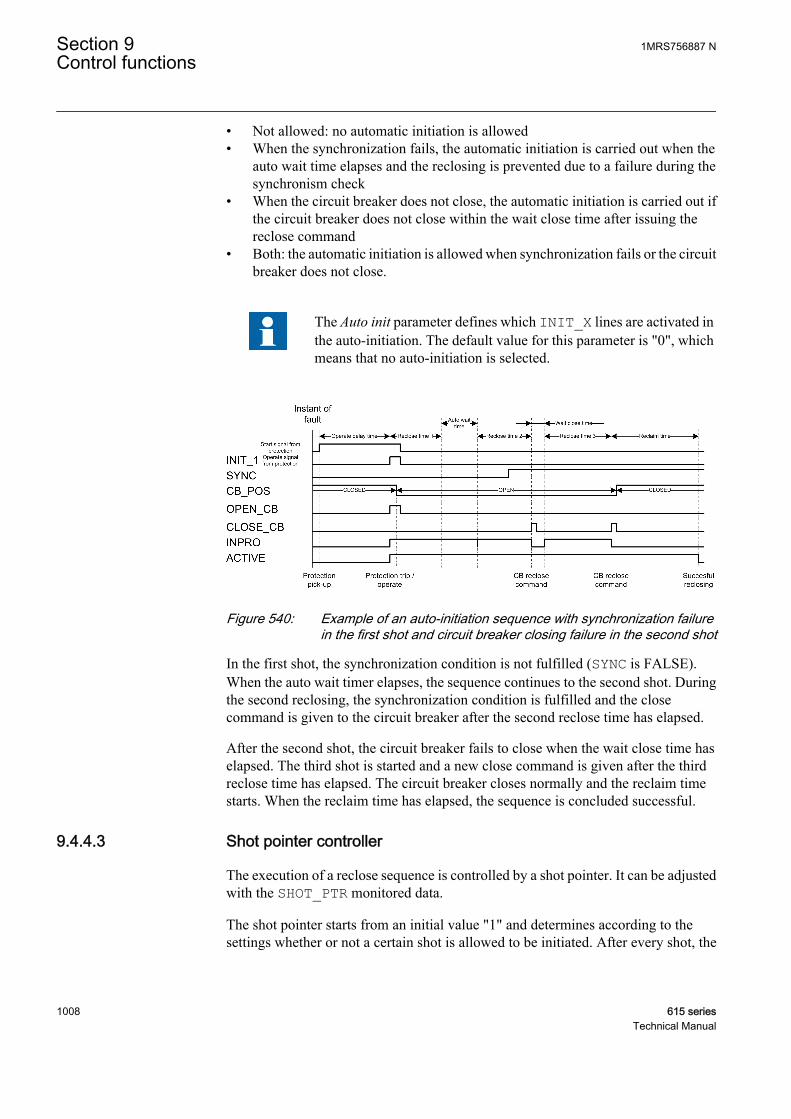
• Not allowed: no automatic initiation is allowed• When the synchronization fails, the automatic initiation is carried out when the
auto wait time elapses and the reclosing is prevented due to a failure during thesynchronism check
• When the circuit breaker does not close, the automatic initiation is carried out ifthe circuit breaker does not close within the wait close time after issuing thereclose command
• Both: the automatic initiation is allowed when synchronization fails or the circuitbreaker does not close.
The Auto init parameter defines which INIT_X lines are activated inthe auto-initiation. The default value for this parameter is "0", whichmeans that no auto-initiation is selected.
A070871 V1 EN
Figure 540: Example of an auto-initiation sequence with synchronization failurein the first shot and circuit breaker closing failure in the second shot
In the first shot, the synchronization condition is not fulfilled (SYNC is FALSE).When the auto wait timer elapses, the sequence continues to the second shot. Duringthe second reclosing, the synchronization condition is fulfilled and the closecommand is given to the circuit breaker after the second reclose time has elapsed.
After the second shot, the circuit breaker fails to close when the wait close time haselapsed. The third shot is started and a new close command is given after the thirdreclose time has elapsed. The circuit breaker closes normally and the reclaim timestarts. When the reclaim time has elapsed, the sequence is concluded successful.
9.4.4.3 Shot pointer controller
The execution of a reclose sequence is controlled by a shot pointer. It can be adjustedwith the SHOT_PTR monitored data.
The shot pointer starts from an initial value "1" and determines according to thesettings whether or not a certain shot is allowed to be initiated. After every shot, the
Section 9 1MRS756887 NControl functions
1008 615 seriesTechnical Manual

shot pointer value increases. This is carried out until a successful reclosing or lockouttakes place after a complete shot sequence containing a total of five shots.
A070872 V1 EN
Figure 541: Shot pointer function
Every time the shot pointer increases, the reclaim time starts. When the reclaim timeends, the shot pointer sets to its initial value, unless no new shot is initiated. The shotpointer increases when the reclose time elapses or at the falling edge of theINC_SHOTP signal.
When SHOT_PTR has the value six, the AR function is in a so called pre-lockout state.If a new initiation occurs during the pre-lockout state, the AR function goes to lockout.Therefore, a new sequence initiation during the pre-lockout state is not possible.
The AR function goes to the pre-lockout state in the following cases:
• During SOTF• When the AR function is active, it stays in a pre-lockout state for the time defined
by the reclaim time• When all five shots have been executed• When the frequent operation counter limit is reached. A new sequence initiation
forces the AR function to lockout.
9.4.4.4 Reclose controller
The reclose controller calculates the reclose, discrimination and reclaim times. Thereclose time is started when the INPRO signal is activated, that is, when the sequencestarts and the activated CBB defines the reclose time.
When the reclose time has elapsed, the CLOSE_CB output is not activated until thefollowing conditions are fulfilled:
1MRS756887 N Section 9Control functions
615 series 1009Technical Manual

• The SYNC input must be TRUE if the particular CBB requires information aboutthe synchronism
• All AR initiation inputs that are defined protection lines (using the Control linesetting) are inactive
• The circuit breaker is open• The circuit breaker is ready for the close command, that is, the CB_READY input
is TRUE. This is indicated by active READY output.
If at least one of the conditions is not fulfilled within the time set with the Auto waittime parameter, the autoreclose sequence is locked.
The synchronism requirement for the CBBs can be defined with the Synchronisationset setting, which is a bit mask. The lowest bit in the Synchronisation set setting isrelated to CBB1 and the highest bit to CBB7. For example, if the setting is set to "1",only CBB1 requires synchronism. If the setting is it set to "7", CBB1, CBB2 andCBB3 require the SYNC input to be TRUE before the reclosing command can begiven.
A070873 V1 EN
Figure 542: Initiation during discrimination time - AR function goes to lockout
The discrimination time starts when the close command CLOSE_CB has been given.If a start input is activated before the discrimination time has elapsed, the AR functiongoes to lockout. The default value for each discrimination time is zero. Thediscrimination time can be adjusted with the Dsr time shot 1…4 parameter.
Section 9 1MRS756887 NControl functions
1010 615 seriesTechnical Manual
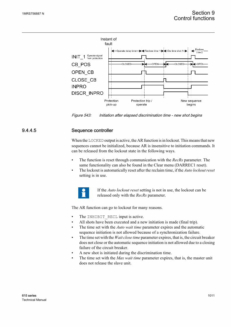
A070874 V1 EN
Figure 543: Initiation after elapsed discrimination time - new shot begins
9.4.4.5 Sequence controller
When the LOCKED output is active, the AR function is in lockout. This means that newsequences cannot be initialized, because AR is insensitive to initiation commands. Itcan be released from the lockout state in the following ways.
• The function is reset through communication with the RecRs parameter. Thesame functionality can also be found in the Clear menu (DARREC1 reset).
• The lockout is automatically reset after the reclaim time, if the Auto lockout resetsetting is in use.
If the Auto lockout reset setting is not in use, the lockout can bereleased only with the RecRs parameter.
The AR function can go to lockout for many reasons.
• The INHIBIT_RECL input is active.• All shots have been executed and a new initiation is made (final trip).• The time set with the Auto wait time parameter expires and the automatic
sequence initiation is not allowed because of a synchronization failure.• The time set with the Wait close time parameter expires, that is, the circuit breaker
does not close or the automatic sequence initiation is not allowed due to a closingfailure of the circuit breaker.
• A new shot is initiated during the discrimination time.• The time set with the Max wait time parameter expires, that is, the master unit
does not release the slave unit.
1MRS756887 N Section 9Control functions
615 series 1011Technical Manual
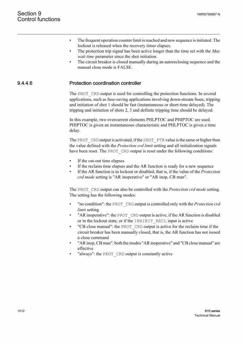
• The frequent operation counter limit is reached and new sequence is initiated. Thelockout is released when the recovery timer elapses.
• The protection trip signal has been active longer than the time set with the Maxwait time parameter since the shot initiation.
• The circuit breaker is closed manually during an autoreclosing sequence and themanual close mode is FALSE.
9.4.4.6 Protection coordination controller
The PROT_CRD output is used for controlling the protection functions. In severalapplications, such as fuse-saving applications involving down-stream fuses, trippingand initiation of shot 1 should be fast (instantaneous or short-time delayed). Thetripping and initiation of shots 2, 3 and definite tripping time should be delayed.
In this example, two overcurrent elements PHLPTOC and PHIPTOC are used.PHIPTOC is given an instantaneous characteristic and PHLPTOC is given a timedelay.
The PROT_CRD output is activated, if the SHOT_PTR value is the same or higher thanthe value defined with the Protection crd limit setting and all initialization signalshave been reset. The PROT_CRD output is reset under the following conditions:
• If the cut-out time elapses• If the reclaim time elapses and the AR function is ready for a new sequence• If the AR function is in lockout or disabled, that is, if the value of the Protection
crd mode setting is "AR inoperative" or "AR inop, CB man".
The PROT_CRD output can also be controlled with the Protection crd mode setting.The setting has the following modes:
• "no condition": the PROT_CRD output is controlled only with the Protection crdlimit setting
• "AR inoperative": the PROT_CRD output is active, if the AR function is disabledor in the lockout state, or if the INHIBIT_RECL input is active
• "CB close manual": the PROT_CRD output is active for the reclaim time if thecircuit breaker has been manually closed, that is, the AR function has not issueda close command
• "AR inop, CB man": both the modes "AR inoperative" and "CB close manual" areeffective
• "always": the PROT_CRD output is constantly active
Section 9 1MRS756887 NControl functions
1012 615 seriesTechnical Manual
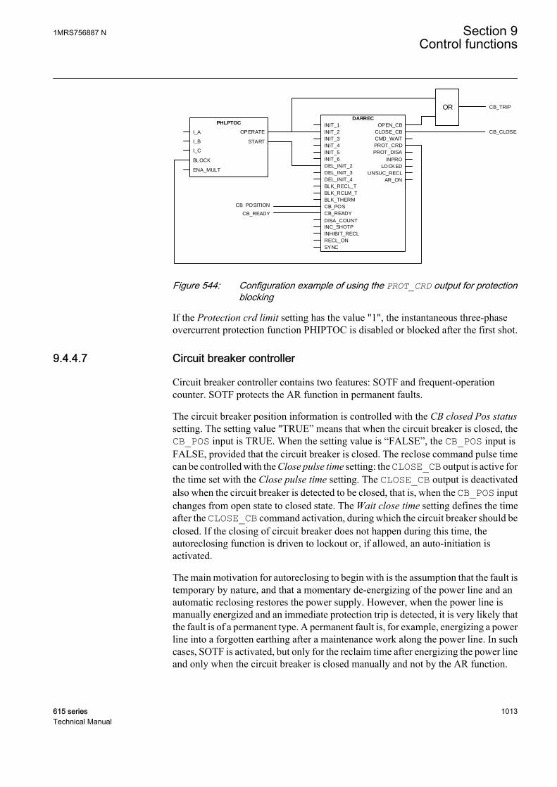
OR CB_TRIP
CB_POSITION
CB_READY
CB_CLOSE
DARREC
OPEN_CB
CLOSE_CB
CMD_WAIT
PROT_CRD
INPRO
LOCKED
UNSUC_RECL
PROT_DISA
DEL_INIT_4
DEL_INIT_3
DEL_INIT_2
INIT_6
INIT_5
INIT_4
INIT_3
INIT_2
INIT_1
SYNC
INC_SHOTP
CB_READY
CB_POS
RECL_ON
INHIBIT_RECL
BLK_RCLM_T
BLK_RECL_T
BLK_THERM
DISA_COUNT
AR_ON
PHLPTOC
I_A
I_B START
OPERATE
I_C
BLOCK
ENA_MULT
A070875 V3 EN
Figure 544: Configuration example of using the PROT_CRD output for protectionblocking
If the Protection crd limit setting has the value "1", the instantaneous three-phaseovercurrent protection function PHIPTOC is disabled or blocked after the first shot.
9.4.4.7 Circuit breaker controller
Circuit breaker controller contains two features: SOTF and frequent-operationcounter. SOTF protects the AR function in permanent faults.
The circuit breaker position information is controlled with the CB closed Pos statussetting. The setting value "TRUE” means that when the circuit breaker is closed, theCB_POS input is TRUE. When the setting value is “FALSE”, the CB_POS input isFALSE, provided that the circuit breaker is closed. The reclose command pulse timecan be controlled with the Close pulse time setting: the CLOSE_CB output is active forthe time set with the Close pulse time setting. The CLOSE_CB output is deactivatedalso when the circuit breaker is detected to be closed, that is, when the CB_POS inputchanges from open state to closed state. The Wait close time setting defines the timeafter the CLOSE_CB command activation, during which the circuit breaker should beclosed. If the closing of circuit breaker does not happen during this time, theautoreclosing function is driven to lockout or, if allowed, an auto-initiation isactivated.
The main motivation for autoreclosing to begin with is the assumption that the fault istemporary by nature, and that a momentary de-energizing of the power line and anautomatic reclosing restores the power supply. However, when the power line ismanually energized and an immediate protection trip is detected, it is very likely thatthe fault is of a permanent type. A permanent fault is, for example, energizing a powerline into a forgotten earthing after a maintenance work along the power line. In suchcases, SOTF is activated, but only for the reclaim time after energizing the power lineand only when the circuit breaker is closed manually and not by the AR function.
1MRS756887 N Section 9Control functions
615 series 1013Technical Manual
SOTF disables any initiation of an autoreclosing shot. The energizing of the powerline is detected from the CB_POS information.
SOTF is activated when the AR function is enabled or when the AR function is startedand the SOTF should remain active for the reclaim time.
When SOTF is detected, the parameter SOTF is active.
If the Manual close mode setting is set to FALSE and the circuitbreaker has been manually closed during an autoreclosing shot, theAR unit goes to an immediate lockout.
If the Manual close mode setting is set to TRUE and the circuit breakerhas been manually closed during an autoreclosing shot (the INPRO isactive), the shot is considered as completed.
When SOTF starts, reclaim time is restarted, provided that it isrunning.
The frequent-operation counter is intended for blocking the autoreclosing function incases where the fault causes repetitive autoreclosing sequences during a short periodof time. For instance, if a tree causes a short circuit and, as a result, there areautoreclosing shots within a few minutes interval during a stormy night. These typesof faults can easily damage the circuit breaker if the AR function is not locked by afrequent-operation counter.
The frequent-operation counter has three settings:
• Frq Op counter limit• Frq Op counter time• Frq Op recovery time
The Frq Op counter limit setting defines the number of reclose attempts that areallowed during the time defined with the Frq Op counter time setting. If the set valueis reached within a pre-defined period defined with the Frq Op counter time setting,the AR function goes to lockout when a new shot begins, provided that the counter isstill above the set limit. The lockout is released after the recovery time has elapsed.The recovery time can be defined with the Frq Op recovery time setting .
If the circuit breaker is manually closed during the recovery time, the reclaim time isactivated after the recovery timer has elapsed.
Section 9 1MRS756887 NControl functions
1014 615 seriesTechnical Manual

9.4.5 Counters
The AR function contains six counters. Their values are stored in a semi-retainmemory. The counters are increased at the rising edge of the reclosing command. Thecounters count the following situations.
• COUNTER: counts every reclosing command activation• CNT_SHOT1: counts reclosing commands that are executed from shot 1• CNT_SHOT2: counts reclosing commands that are executed from shot 2• CNT_SHOT3: counts reclosing commands that are executed from shot 3• CNT_SHOT4: counts reclosing commands that are executed from shot 4• CNT_SHOT5: counts reclosing commands that are executed from shot 5
The counters are disabled through communication with the DsaCnt parameter. Whenthe counters are disabled, the values are not updated.
The counters are reset through communication with the CntRs parameter.The samefunctionality can also be found in the clear menu (DARREC1 counters).
9.4.6 Application
Modern electric power systems can deliver energy to users very reliably. However,different kind of faults can occur. Protection relays play an important role in detectingfailures or abnormalities in the system. They detect faults and give commands forcorresponding circuit breakers to isolate the defective element before excessivedamage or a possible power system collapse occurs. A fast isolation also limits thedisturbances caused for the healthy parts of the power system.
The faults can be transient, semi-transient or permanent. For example, a permanentfault in power cables means that there is a physical damage in the fault location thatmust first be located and repaired before the network voltage can be restored.
In overhead lines, the insulating material between phase conductors is air. Themajority of the faults are flash-over arcing faults caused by lightning, for example.Only a short interruption is needed for extinguishing the arc. These faults are transientby nature.
A semi-transient fault can be caused for example by a bird or a tree branch falling onthe overhead line. The fault disappears on its own if the fault current burns the branchor the wind blows it away.
Transient and semi-transient faults can be cleared by momentarily de-energizing thepower line. Using the autoreclose function minimizes interruptions in the powersystem service and brings the power back on-line quickly and effortlessly.
The basic idea of the autoreclose function is simple. In overhead lines, where thepossibility of self-clearing faults is high, the autoreclose function tries to restore thepower by reclosing the breaker. This is a method to get the power system back intonormal operation by removing the transient or semi-transient faults. Several trials, that
1MRS756887 N Section 9Control functions
615 series 1015Technical Manual
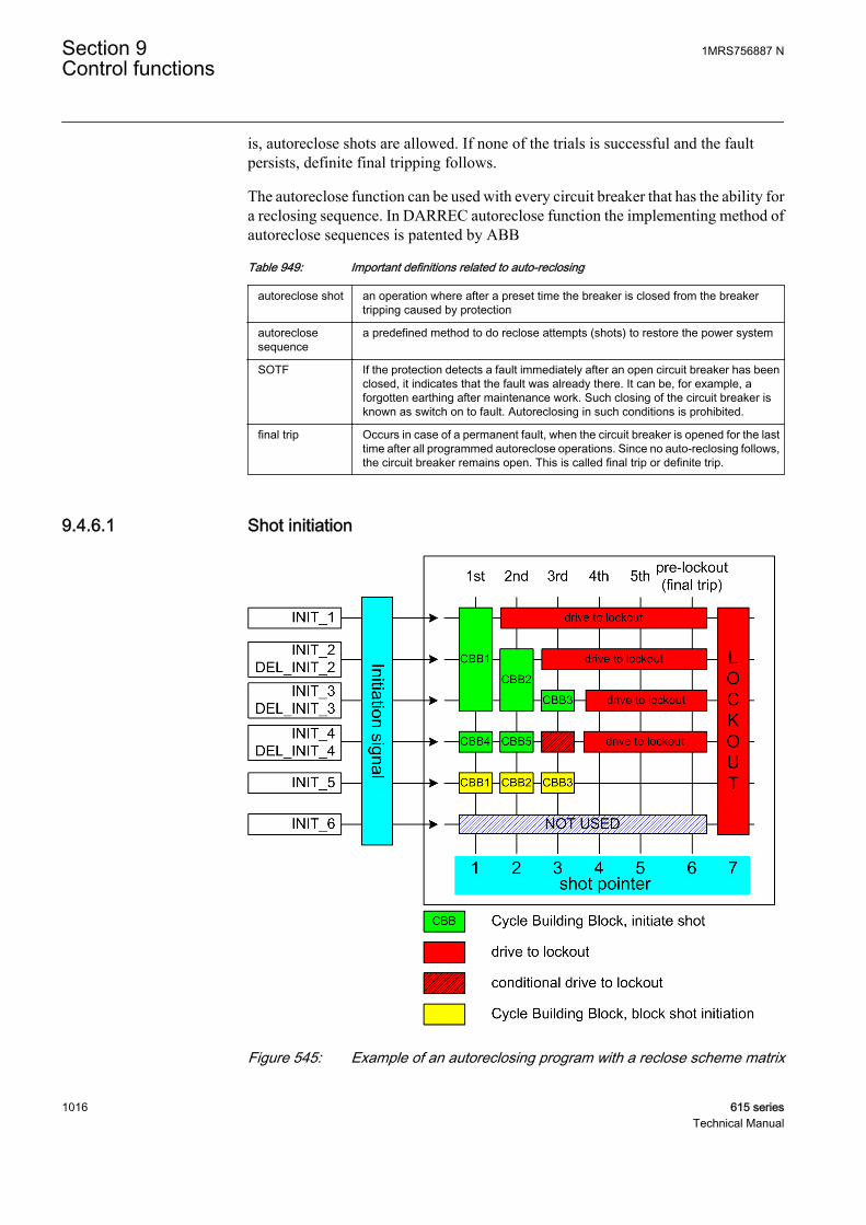
is, autoreclose shots are allowed. If none of the trials is successful and the faultpersists, definite final tripping follows.
The autoreclose function can be used with every circuit breaker that has the ability fora reclosing sequence. In DARREC autoreclose function the implementing method ofautoreclose sequences is patented by ABB
Table 949: Important definitions related to auto-reclosing
autoreclose shot an operation where after a preset time the breaker is closed from the breakertripping caused by protection
autoreclosesequence
a predefined method to do reclose attempts (shots) to restore the power system
SOTF If the protection detects a fault immediately after an open circuit breaker has beenclosed, it indicates that the fault was already there. It can be, for example, aforgotten earthing after maintenance work. Such closing of the circuit breaker isknown as switch on to fault. Autoreclosing in such conditions is prohibited.
final trip Occurs in case of a permanent fault, when the circuit breaker is opened for the lasttime after all programmed autoreclose operations. Since no auto-reclosing follows,the circuit breaker remains open. This is called final trip or definite trip.
9.4.6.1 Shot initiation
A070869 V1 EN
Figure 545: Example of an autoreclosing program with a reclose scheme matrix
Section 9 1MRS756887 NControl functions
1016 615 seriesTechnical Manual

In the AR function, each shot can be programmed to locate anywhere in the reclosescheme matrix. The shots are like building blocks used to design the reclose program.The building blocks are called CBBs. All blocks are alike and have settings which givethe attempt number (columns in the matrix), the initiation or blocking signals (rows inthe matrix) and the reclose time of the shot.
The settings related to CBB configuration are:
• First...Seventh reclose time• Init signals CBB1…CBB7• Blk signals CBB1…CBB7• Shot number CBB1…CBB7
The reclose time defines the open and dead times, that is, the time between theOPEN_CB and the CLOSE_CB commands. The Init signals CBBx setting defines theinitiation signals. The Blk signals CBBx setting defines the blocking signals that arerelated to the CBB (rows in the matrix). The Shot number CBB1…CBB7 settingdefines which shot is related to the CBB (columns in the matrix). For example, CBB1settings are:
• First reclose time = 1.0s• Init signals CBB1 = 7 (three lowest bits: 111000 = 7)• Blk signals CBB1 = 16 (the fifth bit: 000010 = 16)• Shot number CBB1 = 1
CBB2 settings are:
• Second reclose time = 10s• Init signals CBB2 = 6 (the second and third bits: 011000 = 6)• Blk signals CBB2 = 16 (the fifth bit: 000010 = 16)• Shot number CBB2 = 2
CBB3 settings are:
• Third reclose time = 30s• Init signals CBB3 = 4 (the third bit: 001000 = 4)• Blk signals CBB3 = 16 (the fifth bit: 000010 = 16)• Shot number CBB3 = 3
CBB4 settings are:
• Fourth reclose time = 0.5s• Init signals CBB4 = 8 (the fourth bit: 000100 = 8)• Blk signals CBB4 = 0 (no blocking signals related to this CBB)• Shot number CBB4 = 1
If a shot is initiated from the INIT_1 line, only one shot is allowed before lockout.If a shot is initiated from the INIT_3 line, three shots are allowed before lockout.
1MRS756887 N Section 9Control functions
615 series 1017Technical Manual
A sequence initiation from the INIT_4 line leads to a lockout after two shots. In asituation where the initiation is made from both the INIT_3 and INIT_4 lines, athird shot is allowed, that is, CBB3 is allowed to start. This is called conditionallockout. If the initiation is made from the INIT_2 and INIT_3 lines, an immediatelockout occurs.
The INIT_5 line is used for blocking purposes. If the INIT_5 line is active duringa sequence start, the reclose attempt is blocked and the AR function goes to lockout.
If more than one CBBs are started with the shot pointer, the CBB withthe smallest individual number is always selected. For example, if theINIT_2 and INIT_4 lines are active for the second shot, that is, theshot pointer is 2, CBB2 is started instead of CBB5.
Even if the initiation signals are not received from the protection functions, the ARfunction can be set to continue from the second to the fifth reclose shot. The ARfunction can, for example, be requested to automatically continue with the sequencewhen the circuit breaker fails to close when requested. In such a case, the AR functionissues a CLOSE_CB command. When the wait close time elapses, that is, the closingof the circuit breaker fails, the next shot is automatically started. Another example isthe embedded generation on the power line, which can make the synchronism checkfail and prevent the reclosing. If the autoreclose sequence is continued to the secondshot, a successful synchronous reclosing is more likely than with the first shot, sincethe second shot lasts longer than the first one.
Section 9 1MRS756887 NControl functions
1018 615 seriesTechnical Manual
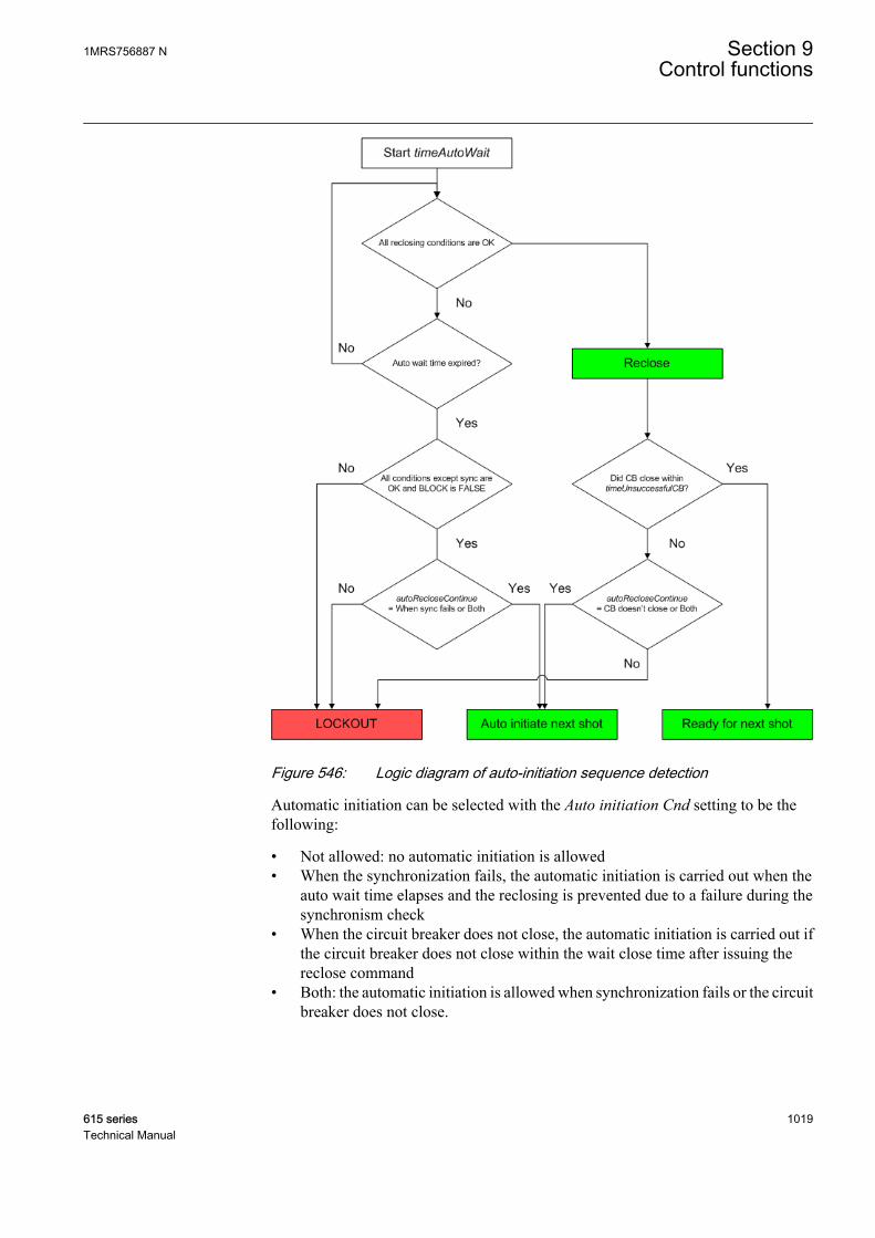
A070870 V1 EN
Figure 546: Logic diagram of auto-initiation sequence detection
Automatic initiation can be selected with the Auto initiation Cnd setting to be thefollowing:
• Not allowed: no automatic initiation is allowed• When the synchronization fails, the automatic initiation is carried out when the
auto wait time elapses and the reclosing is prevented due to a failure during thesynchronism check
• When the circuit breaker does not close, the automatic initiation is carried out ifthe circuit breaker does not close within the wait close time after issuing thereclose command
• Both: the automatic initiation is allowed when synchronization fails or the circuitbreaker does not close.
1MRS756887 N Section 9Control functions
615 series 1019Technical Manual

The Auto init parameter defines which INIT_X lines are activated inthe auto-initiation. The default value for this parameter is "0", whichmeans that no auto-initiation is selected.
A070871 V1 EN
Figure 547: Example of an auto-initiation sequence with synchronization failurein the first shot and circuit breaker closing failure in the second shot
In the first shot, the synchronization condition is not fulfilled (SYNC is FALSE).When the auto wait timer elapses, the sequence continues to the second shot. Duringthe second reclosing, the synchronization condition is fulfilled and the closecommand is given to the circuit breaker after the second reclose time has elapsed.
After the second shot, the circuit breaker fails to close when the wait close time haselapsed. The third shot is started and a new close command is given after the thirdreclose time has elapsed. The circuit breaker closes normally and the reclaim timestarts. When the reclaim time has elapsed, the sequence is concluded successful.
9.4.6.2 Sequence
The auto reclose sequence is implemented by using CBBs. The highest possibleamount of CBBs is seven. If the user wants to have, for example, a sequence of threeshots, only the first three CBBs are needed. Using building blocks instead of fixedshots gives enhanced flexibility, allowing multiple and adaptive sequences.
Each CBB is identical. The Shot number CBB_ setting defines at which point in theauto-reclose sequence the CBB should be performed, that is, whether the particularCBB is going to be the first, second, third, fourth or fifth shot.
During the initiation of a CBB, the conditions of initiation and blocking are checked.This is done for all CBBs simultaneously. Each CBB that fulfils the initiationconditions requests an execution.
The function also keeps track of shots already performed, that is, at which point theauto-reclose sequence is from shot 1 to lockout. For example, if shots 1 and 2 havealready been performed, only shots 3 to 5 are allowed.
Additionally, the Enable shot jump setting gives two possibilities:
Section 9 1MRS756887 NControl functions
1020 615 seriesTechnical Manual

• Only such CBBs that are set for the next shot in the sequence can be accepted forexecution. For example, if the next shot in the sequence should be shot 2, a requestfrom CBB set for shot 3 is rejected.
• Any CBB that is set for the next shot or any of the following shots can be acceptedfor execution. For example, if the next shot in the sequence should be shot 2, alsoCBBs that are set for shots 3, 4 and 5 are accepted. In other words, shot 2 can beignored.
In case there are multiple CBBs allowed for execution, the CBB with the smallestnumber is chosen. For example, if CBB2 and CBB4 request an execution, CBB2 isallowed to execute the shot.
The auto-reclose function can perform up to five auto-reclose shots or cycles.
9.4.6.3 Configuration examples
OR CB_TRIP
Circuit breaker position information from binary inputConditions to verify if circuit breaker is ready to be reclosed
CB_CLOSE
PHLPTOC
I_A
I_B START
OPERATE
I_C
BLOCK
ENA_MULT
PHHPTOC
I_A
I_B START
OPERATE
I_C
BLOCK
ENA_MULT
EFLPTOC
Io
BLOCK START
OPERATE
ENA_MULT
DARRECOPEN _CB
CLOSE _CBCMD_WAIT
INPROLOCKED
PROT_CRDUNSUC_RECL
DEL_INIT _4DEL_INIT _3DEL_INIT _2INIT _6INIT _5INIT _4INIT _3INIT _2INIT _1
SYNC
INC_SHOTPCB_READYCB_POS
RECL_ONINHIBIT _RECL
BLK _RCLM_TBLK _RECL_T
BLK _THERM
AR_ONREADY
A070886 V4 EN
Figure 548: Example connection between protection and autoreclosing functionsin protection relay configuration
It is possible to create several sequences for a configuration.
Autoreclose sequences for overcurrent and non-directional earth-fault protectionapplications where high speed and delayed autoreclosings are needed can be asfollows:
1MRS756887 N Section 9Control functions
615 series 1021Technical Manual
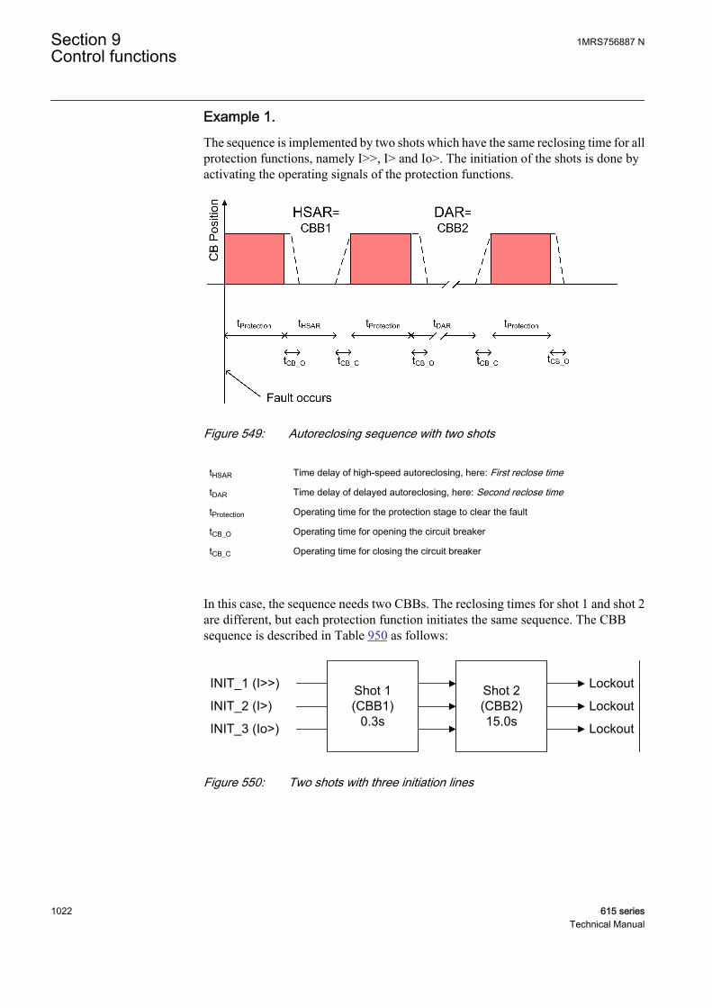
Example 1.The sequence is implemented by two shots which have the same reclosing time for allprotection functions, namely I>>, I> and Io>. The initiation of the shots is done byactivating the operating signals of the protection functions.
A070887 V1 EN
Figure 549: Autoreclosing sequence with two shots
tHSAR Time delay of high-speed autoreclosing, here: First reclose time
tDAR Time delay of delayed autoreclosing, here: Second reclose time
tProtection Operating time for the protection stage to clear the fault
tCB_O Operating time for opening the circuit breaker
tCB_C Operating time for closing the circuit breaker
In this case, the sequence needs two CBBs. The reclosing times for shot 1 and shot 2are different, but each protection function initiates the same sequence. The CBBsequence is described in Table 950 as follows:
Shot 1(CBB1)
0.3s
Shot 2(CBB2)15.0s
INIT_1 (I>>)
INIT_2 (I>)
INIT_3 (Io>)
Lockout
Lockout
Lockout
A071270 V2 EN
Figure 550: Two shots with three initiation lines
Section 9 1MRS756887 NControl functions
1022 615 seriesTechnical Manual
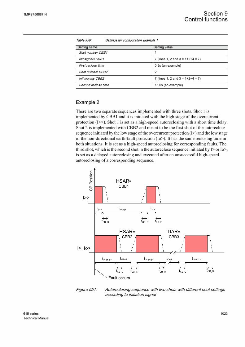
Table 950: Settings for configuration example 1
Setting name Setting valueShot number CBB1 1
Init signals CBB1 7 (lines 1, 2 and 3 = 1+2+4 = 7)
First reclose time 0.3s (an example)
Shot number CBB2 2
Init signals CBB2 7 (lines 1, 2 and 3 = 1+2+4 = 7)
Second reclose time 15.0s (an example)
Example 2There are two separate sequences implemented with three shots. Shot 1 isimplemented by CBB1 and it is initiated with the high stage of the overcurrentprotection (I>>). Shot 1 is set as a high-speed autoreclosing with a short time delay.Shot 2 is implemented with CBB2 and meant to be the first shot of the autoreclosesequence initiated by the low stage of the overcurrent protection (I>) and the low stageof the non-directional earth-fault protection (Io>). It has the same reclosing time inboth situations. It is set as a high-speed autoreclosing for corresponding faults. Thethird shot, which is the second shot in the autoreclose sequence initiated by I> or Io>,is set as a delayed autoreclosing and executed after an unsuccessful high-speedautoreclosing of a corresponding sequence.
A071272 V1 EN
Figure 551: Autoreclosing sequence with two shots with different shot settingsaccording to initiation signal
1MRS756887 N Section 9Control functions
615 series 1023Technical Manual
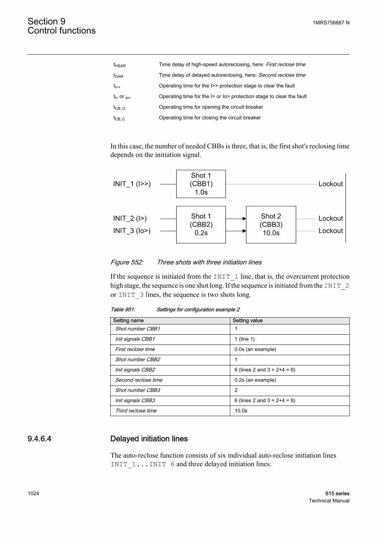
tHSAR Time delay of high-speed autoreclosing, here: First reclose time
tDAR Time delay of delayed autoreclosing, here: Second reclose time
tl>> Operating time for the I>> protection stage to clear the fault
tl> or lo> Operating time for the I> or Io> protection stage to clear the fault
tCB_O Operating time for opening the circuit breaker
tCB_C Operating time for closing the circuit breaker
In this case, the number of needed CBBs is three, that is, the first shot's reclosing timedepends on the initiation signal.
INIT_1 (I>>)
INIT_2 (I>)
INIT_3 (Io>)
Shot 1(CBB1)
1.0s
Shot 1(CBB2)
0.2s
Shot 2(CBB3)10.0s
Lockout
Lockout
Lockout
A071274 V2 EN
Figure 552: Three shots with three initiation lines
If the sequence is initiated from the INIT_1 line, that is, the overcurrent protectionhigh stage, the sequence is one shot long. If the sequence is initiated from the INIT_2or INIT_3 lines, the sequence is two shots long.
Table 951: Settings for configuration example 2
Setting name Setting valueShot number CBB1 1
Init signals CBB1 1 (line 1)
First reclose time 0.0s (an example)
Shot number CBB2 1
Init signals CBB2 6 (lines 2 and 3 = 2+4 = 6)
Second reclose time 0.2s (an example)
Shot number CBB3 2
Init signals CBB3 6 (lines 2 and 3 = 2+4 = 6)
Third reclose time 10.0s
9.4.6.4 Delayed initiation lines
The auto-reclose function consists of six individual auto-reclose initiation linesINIT_1...INIT 6 and three delayed initiation lines:
Section 9 1MRS756887 NControl functions
1024 615 seriesTechnical Manual
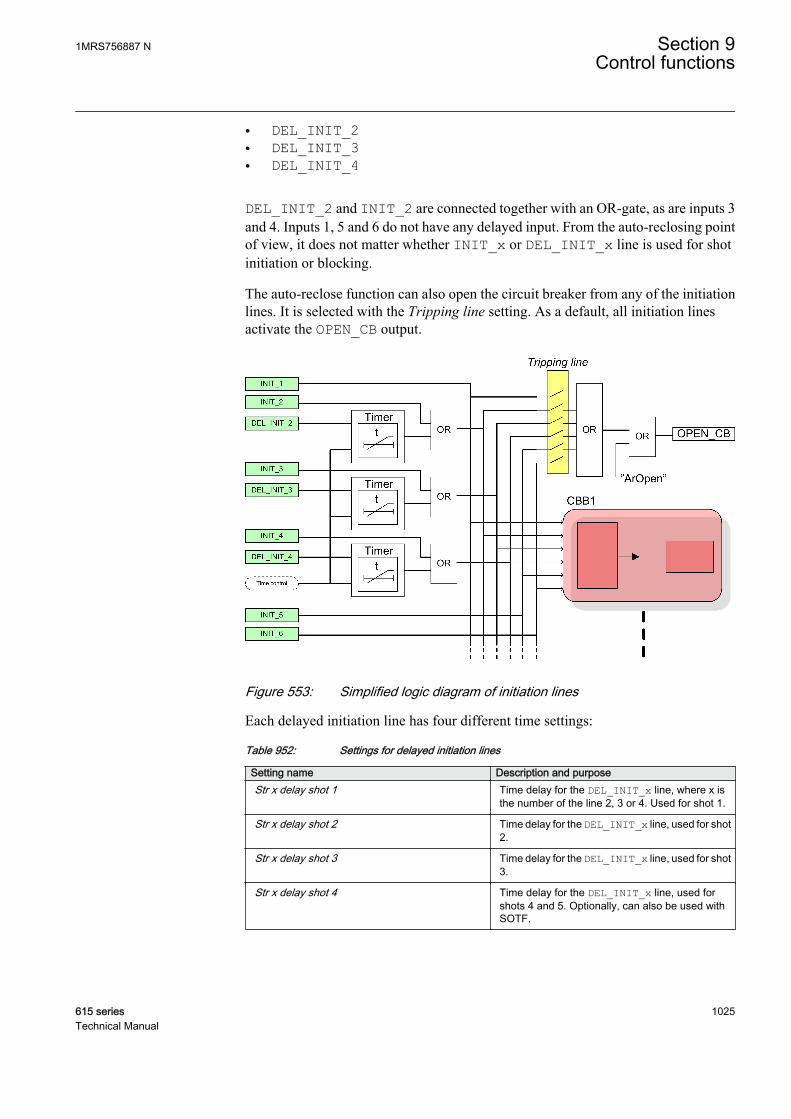
• DEL_INIT_2• DEL_INIT_3• DEL_INIT_4
DEL_INIT_2 and INIT_2 are connected together with an OR-gate, as are inputs 3and 4. Inputs 1, 5 and 6 do not have any delayed input. From the auto-reclosing pointof view, it does not matter whether INIT_x or DEL_INIT_x line is used for shotinitiation or blocking.
The auto-reclose function can also open the circuit breaker from any of the initiationlines. It is selected with the Tripping line setting. As a default, all initiation linesactivate the OPEN_CB output.
A070276 V1 EN
Figure 553: Simplified logic diagram of initiation lines
Each delayed initiation line has four different time settings:
Table 952: Settings for delayed initiation lines
Setting name Description and purposeStr x delay shot 1 Time delay for the DEL_INIT_x line, where x is
the number of the line 2, 3 or 4. Used for shot 1.
Str x delay shot 2 Time delay for the DEL_INIT_x line, used for shot2.
Str x delay shot 3 Time delay for the DEL_INIT_x line, used for shot3.
Str x delay shot 4 Time delay for the DEL_INIT_x line, used forshots 4 and 5. Optionally, can also be used withSOTF.
1MRS756887 N Section 9Control functions
615 series 1025Technical Manual
9.4.6.5 Shot initiation from protection start signal
In it simplest, all auto-reclose shots are initiated by protection trips. As a result, all triptimes in the sequence are the same. This is why using protection trips may not be theoptimal solution. Using protection start signals instead of protection trips for initiatingshots shortens the trip times.
Example 1When a two-shot-sequence is used, the start information from the protection functionis routed to the DEL_INIT 2 input and the operate information to the INIT_2 input.The following conditions have to apply:
• protection operate time = 0.5s• Str 2 delay shot 1 = 0.05s• Str 2 delay shot 2 = 60s• Str 2 delay shot 3 = 60s
Operation in a permanent fault:
1. Protection starts and activates the DEL_INIT 2 input.2. After 0.05 seconds, the first autoreclose shot is initiated. The function opens the
circuit breaker: the OPEN_CB output activates. The total trip time is theprotection start delay + 0.05 seconds + the time it takes to open the circuit breaker.
3. After the first shot, the circuit breaker is reclosed and the protection starts again.4. Because the delay of the second shot is 60 seconds, the protection is faster and
trips after the set operation time, activating the INIT 2 input. The second shotis initiated.
5. After the second shot, the circuit breaker is reclosed and the protection startsagain.
6. Because the delay of the second shot is 60 seconds, the protection is faster andtrips after the set operation time. No further shots are programmed after the finaltrip. The function is in lockout and the sequence is considered unsuccessful.
Example 2The delays can be used also for fast final trip. The conditions are the same as inExample 1, with the exception of Str 2 delay shot 3 = 0.10 seconds.
The operation in a permanent fault is the same as in Example 1, except that after thesecond shot when the protection starts again, Str 2 delay shot 3 elapses before theprotection operate time and the final trip follows. The total trip time is the protectionstart delay + 0.10 seconds + the time it takes to open the circuit breaker.
9.4.6.6 Fast trip in Switch on to fault
The Str _ delay shot 4 parameter delays can also be used to achieve a fast andaccelerated trip with SOTF. This is done by setting the Fourth delay in SOTF
Section 9 1MRS756887 NControl functions
1026 615 seriesTechnical Manual
parameter to "1" and connecting the protection start information to the correspondingDEL_INIT_ input.
When the function detects a closing of the circuit breaker, that is, any other closingexcept the reclosing done by the function itself, it always prohibits shot initiation forthe time set with the Reclaim time parameter. Furthermore, if the Fourth delay inSOTF parameter is "1", the Str _ delay shot 4 parameter delays are also activated.
Example 1The protection operation time is 0.5 seconds, the Fourth delay in SOTF parameter isset to "1" and the Str 2 delay shot 4 parameter is 0.05 seconds. The protection startsignal is connected to the DEL_INIT_2 input.
If the protection starts after the circuit breaker closes, the fast trip follows after the set0.05 seconds. The total trip time is the protection start delay + 0.05 seconds + the timeit takes to open the circuit breaker.
9.4.7 SignalsTable 953: DARREC Input signals
Name Type Default DescriptionINIT_1 BOOLEAN 0=False AR initialization / blocking signal 1
INIT_2 BOOLEAN 0=False AR initialization / blocking signal 2
INIT_3 BOOLEAN 0=False AR initialization / blocking signal 3
INIT_4 BOOLEAN 0=False AR initialization / blocking signal 4
INIT_5 BOOLEAN 0=False AR initialization / blocking signal 5
INIT_6 BOOLEAN 0=False AR initialization / blocking signal 6
DEL_INIT_2 BOOLEAN 0=False Delayed AR initialization / blocking signal 2
DEL_INIT_3 BOOLEAN 0=False Delayed AR initialization / blocking signal 3
DEL_INIT_4 BOOLEAN 0=False Delayed AR initialization / blocking signal 4
BLK_RECL_T BOOLEAN 0=False Blocks and resets reclose time
BLK_RCLM_T BOOLEAN 0=False Blocks and resets reclaim time
BLK_THERM BOOLEAN 0=False Blocks and holds the reclose shot from the thermaloverload
CB_POS BOOLEAN 0=False Circuit breaker position input
CB_READY BOOLEAN 1=True Circuit breaker status signal
INC_SHOTP BOOLEAN 0=False A zone sequence coordination signal
INHIBIT_RECL BOOLEAN 0=False Interrupts and inhibits reclosing sequence
RECL_ON BOOLEAN 0=False Level sensitive signal for allowing (high) / notallowing (low) reclosing
SYNC BOOLEAN 0=False Synchronizing check fulfilled
1MRS756887 N Section 9Control functions
615 series 1027Technical Manual
Table 954: DARREC Output signals
Name Type DescriptionOPEN_CB BOOLEAN Open command for circuit breaker
CLOSE_CB BOOLEAN Close (reclose) command for circuit breaker
CMD_WAIT BOOLEAN Wait for master command
INPRO BOOLEAN Reclosing shot in progress, activated during deadtime
LOCKED BOOLEAN Signal indicating that AR is locked out
PROT_CRD BOOLEAN A signal for coordination between the AR and theprotection
UNSUC_RECL BOOLEAN Indicates an unsuccessful reclosing sequence
AR_ON BOOLEAN Autoreclosing allowed
READY BOOLEAN Indicates that the AR is ready for a new sequence,i.e. the CB_READY input equals TRUE
ACTIVE BOOLEAN Reclosing sequence is in progress
9.4.8 SettingsTable 955: DARREC Non group settings (Basic)
Parameter Values (Range) Unit Step Default DescriptionOperation 1=on
5=off 1=on Operation Off/On
Reclosing operation 1=Off2=External Ctl3=On
1=Off Reclosing operation (Off, External Ctl /On)
Close pulse time 10...10000 ms 10 200 CB close pulse time
Reclaim time 100...1800000 ms 100 10000 Reclaim time
Terminal priority 1=None2=Low (follower)3=High (master)
1=None Terminal priority
Synchronisation set 0...127 1 0 Selection for synchronizing requirementfor reclosing
Auto initiation cnd 1=Not allowed2=When sync fails3=CB doesn't close4=Both
2=When sync fails Auto initiation condition
Tripping line 0...63 1 0 Tripping line, defines INIT inputs whichcause OPEN_CB activation
Fourth delay in SOTF 0=False1=True
0=False Sets 4th delay into use for all DEL_INITsignals during SOTF
First reclose time 0...300000 ms 10 5000 Dead time for CBB1
Second reclose time 0...300000 ms 10 5000 Dead time for CBB2
Third reclose time 0...300000 ms 10 5000 Dead time for CBB3
Fourth reclose time 0...300000 ms 10 5000 Dead time for CBB4
Fifth reclose time 0...300000 ms 10 5000 Dead time for CBB5
Table continues on next page
Section 9 1MRS756887 NControl functions
1028 615 seriesTechnical Manual
Parameter Values (Range) Unit Step Default DescriptionSixth reclose time 0...300000 ms 10 5000 Dead time for CBB6
Seventh reclose time 0...300000 ms 10 5000 Dead time for CBB7
Init signals CBB1 0...63 1 0 Initiation lines for CBB1
Init signals CBB2 0...63 1 0 Initiation lines for CBB2
Init signals CBB3 0...63 1 0 Initiation lines for CBB3
Init signals CBB4 0...63 1 0 Initiation lines for CBB4
Init signals CBB5 0...63 1 0 Initiation lines for CBB5
Init signals CBB6 0...63 1 0 Initiation lines for CBB6
Init signals CBB7 0...63 1 0 Initiation lines for CBB7
Shot number CBB1 0...5 1 0 Shot number for CBB1
Shot number CBB2 0...5 1 0 Shot number for CBB2
Shot number CBB3 0...5 1 0 Shot number for CBB3
Shot number CBB4 0...5 1 0 Shot number for CBB4
Shot number CBB5 0...5 1 0 Shot number for CBB5
Shot number CBB6 0...5 1 0 Shot number for CBB6
Shot number CBB7 0...5 1 0 Shot number for CBB7
Frq Op counter limit 0...250 1 0 Frequent operation counter lockout limit
Frq Op counter time 1...250 min 1 1 Frequent operation counter time
Frq Op recovery time 1...250 min 1 1 Frequent operation counter recovery time
Auto init 0...63 1 0 Defines INIT lines that are activated atauto initiation
Table 956: DARREC Non group settings (Advanced)
Parameter Values (Range) Unit Step Default DescriptionManual close mode 0=False
1=True 0=False Manual close mode
Wait close time 50...10000 ms 50 250 Allowed CB closing time after reclosecommand
Max wait time 100...1800000 ms 100 10000 Maximum wait time for BLK_RECL_Trelease
Max trip time 100...10000 ms 100 10000 Maximum wait time for deactivation ofprotection signals
Max Thm block time 100...1800000 ms 100 10000 Maximum wait time for thermal blockingsignal deactivation
Cut-out time 0...1800000 ms 100 10000 Cutout time for protection coordination
Dsr time shot 1 0...10000 ms 100 0 Discrimination time for first reclosing
Dsr time shot 2 0...10000 ms 100 0 Discrimination time for second reclosing
Dsr time shot 3 0...10000 ms 100 0 Discrimination time for third reclosing
Dsr time shot 4 0...10000 ms 100 0 Discrimination time for fourth reclosing
Auto wait time 0...60000 ms 10 2000 Wait time for reclosing condition fullfilling
Auto lockout reset 0=False1=True
1=True Automatic lockout reset
Table continues on next page
1MRS756887 N Section 9Control functions
615 series 1029Technical Manual

Parameter Values (Range) Unit Step Default DescriptionProtection crd limit 1...5 1 1 Protection coordination shot limit
Protection crd mode 1=No condition2=AR inoperative3=CB close manual4=AR inop, CB man5=Always
4=AR inop, CBman
Protection coordination mode
Control line 0...63 1 63 Control line, defines INIT inputs which areprotection signals
Enable shot jump 0=False1=True
1=True Enable shot jumping
CB closed Pos status 0=False1=True
0=False Circuit breaker closed position status
Blk signals CBB1 0...63 1 0 Blocking lines for CBB1
Blk signals CBB2 0...63 1 0 Blocking lines for CBB2
Blk signals CBB3 0...63 1 0 Blocking lines for CBB3
Blk signals CBB4 0...63 1 0 Blocking lines for CBB4
Blk signals CBB5 0...63 1 0 Blocking lines for CBB5
Blk signals CBB6 0...63 1 0 Blocking lines for CBB6
Blk signals CBB7 0...63 1 0 Blocking lines for CBB7
Str 2 delay shot 1 0...300000 ms 10 0 Delay time for start2, 1st reclose
Str 2 delay shot 2 0...300000 ms 10 0 Delay time for start2 2nd reclose
Str 2 delay shot 3 0...300000 ms 10 0 Delay time for start2 3rd reclose
Str 2 delay shot 4 0...300000 ms 10 0 Delay time for start2, 4th reclose
Str 3 delay shot 1 0...300000 ms 10 0 Delay time for start3, 1st reclose
Str 3 delay shot 2 0...300000 ms 10 0 Delay time for start3 2nd reclose
Str 3 delay shot 3 0...300000 ms 10 0 Delay time for start3 3rd reclose
Str 3 delay shot 4 0...300000 ms 10 0 Delay time for start3, 4th reclose
Str 4 delay shot 1 0...300000 ms 10 0 Delay time for start4, 1st reclose
Str 4 delay shot 2 0...300000 ms 10 0 Delay time for start4 2nd reclose
Str 4 delay shot 3 0...300000 ms 10 0 Delay time for start4 3rd reclose
Str 4 delay shot 4 0...300000 ms 10 0 Delay time for start4, 4th reclose
9.4.9 Monitored dataTable 957: DARREC Monitored data
Name Type Values (Range) Unit DescriptionDISA_COUNT BOOLEAN 0=False
1=True Signal for counter
disabling
FRQ_OPR_CNT INT32 0...2147483647 Frequent operationcounter
FRQ_OPR_AL BOOLEAN 0=False1=True
Frequent operationcounter alarm
Table continues on next page
Section 9 1MRS756887 NControl functions
1030 615 seriesTechnical Manual
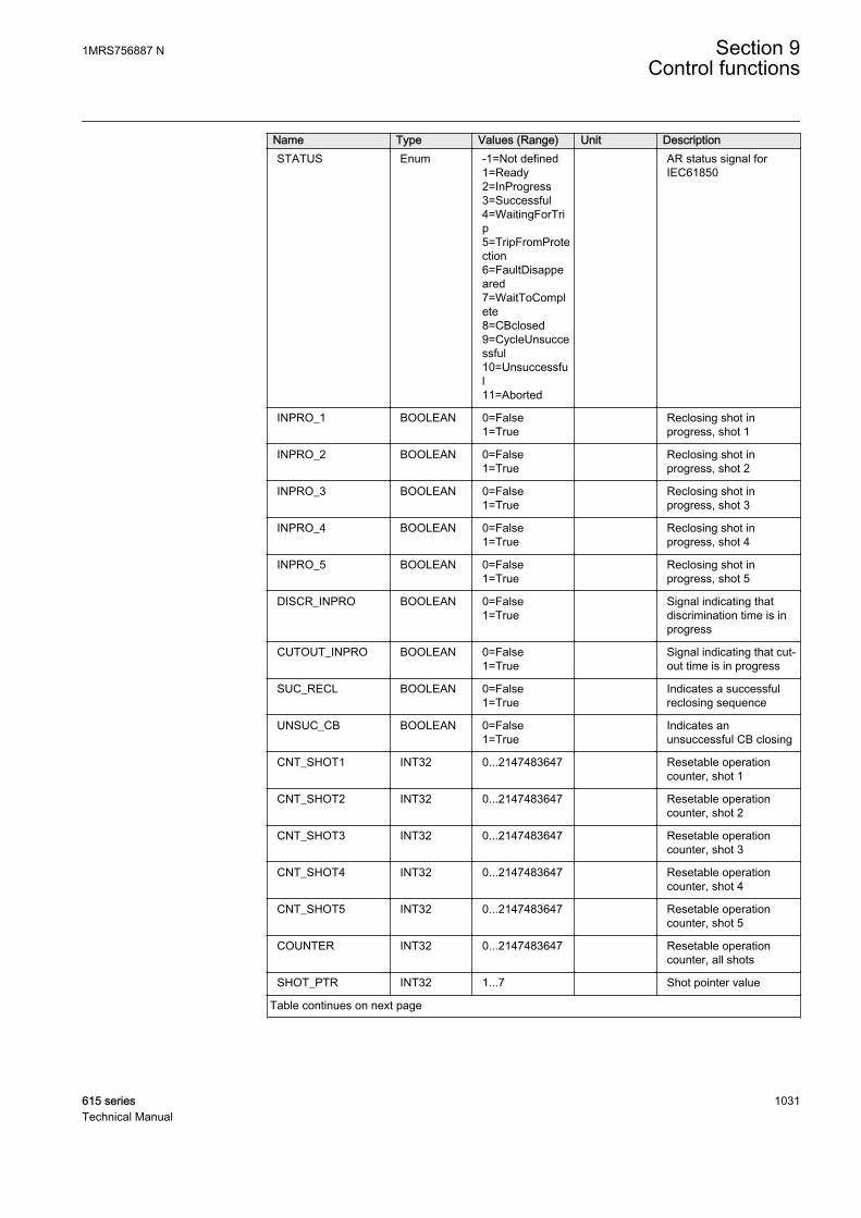
Name Type Values (Range) Unit DescriptionSTATUS Enum -1=Not defined
1=Ready2=InProgress3=Successful4=WaitingForTrip5=TripFromProtection6=FaultDisappeared7=WaitToComplete8=CBclosed9=CycleUnsuccessful10=Unsuccessful11=Aborted
AR status signal forIEC61850
INPRO_1 BOOLEAN 0=False1=True
Reclosing shot inprogress, shot 1
INPRO_2 BOOLEAN 0=False1=True
Reclosing shot inprogress, shot 2
INPRO_3 BOOLEAN 0=False1=True
Reclosing shot inprogress, shot 3
INPRO_4 BOOLEAN 0=False1=True
Reclosing shot inprogress, shot 4
INPRO_5 BOOLEAN 0=False1=True
Reclosing shot inprogress, shot 5
DISCR_INPRO BOOLEAN 0=False1=True
Signal indicating thatdiscrimination time is inprogress
CUTOUT_INPRO BOOLEAN 0=False1=True
Signal indicating that cut-out time is in progress
SUC_RECL BOOLEAN 0=False1=True
Indicates a successfulreclosing sequence
UNSUC_CB BOOLEAN 0=False1=True
Indicates anunsuccessful CB closing
CNT_SHOT1 INT32 0...2147483647 Resetable operationcounter, shot 1
CNT_SHOT2 INT32 0...2147483647 Resetable operationcounter, shot 2
CNT_SHOT3 INT32 0...2147483647 Resetable operationcounter, shot 3
CNT_SHOT4 INT32 0...2147483647 Resetable operationcounter, shot 4
CNT_SHOT5 INT32 0...2147483647 Resetable operationcounter, shot 5
COUNTER INT32 0...2147483647 Resetable operationcounter, all shots
SHOT_PTR INT32 1...7 Shot pointer value
Table continues on next page
1MRS756887 N Section 9Control functions
615 series 1031Technical Manual
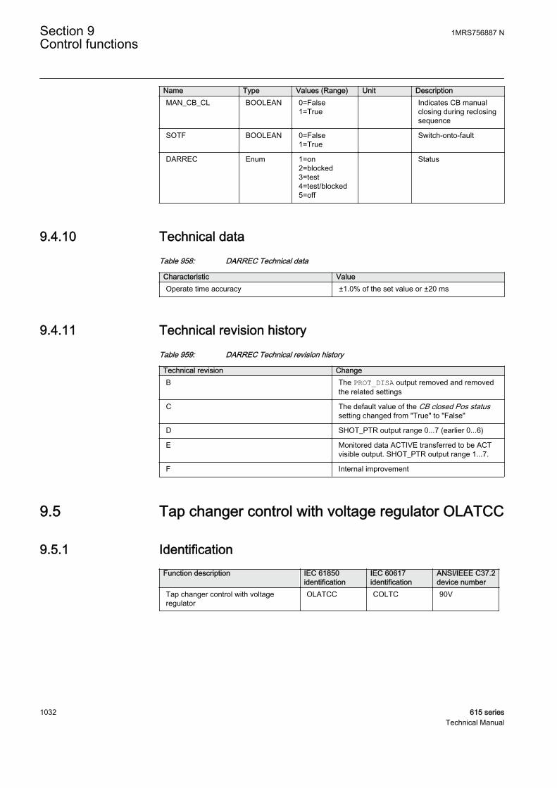
Name Type Values (Range) Unit DescriptionMAN_CB_CL BOOLEAN 0=False
1=True Indicates CB manual
closing during reclosingsequence
SOTF BOOLEAN 0=False1=True
Switch-onto-fault
DARREC Enum 1=on2=blocked3=test4=test/blocked5=off
Status
9.4.10 Technical dataTable 958: DARREC Technical data
Characteristic ValueOperate time accuracy ±1.0% of the set value or ±20 ms
9.4.11 Technical revision historyTable 959: DARREC Technical revision history
Technical revision ChangeB The PROT_DISA output removed and removed
the related settings
C The default value of the CB closed Pos statussetting changed from "True" to "False"
D SHOT_PTR output range 0...7 (earlier 0...6)
E Monitored data ACTIVE transferred to be ACTvisible output. SHOT_PTR output range 1...7.
F Internal improvement
9.5 Tap changer control with voltage regulator OLATCC
9.5.1 IdentificationFunction description IEC 61850
identificationIEC 60617identification
ANSI/IEEE C37.2device number
Tap changer control with voltageregulator
OLATCC COLTC 90V
Section 9 1MRS756887 NControl functions
1032 615 seriesTechnical Manual

9.5.2 Function block
GUID-3E242704-6B28-412D-9719-D5E4297CAD80 V1 EN
Figure 554: Function block
9.5.3 Functionality
The tap changer control with voltage regulator function OLATCC (on-load tapchanger controller) is designed for regulating the voltage of power transformers withon-load tap changers in distribution substations. OLATCC provides a manual orautomatic voltage control of the power transformer by using the raising or loweringsignals to the on-load tap changer.
The automatic voltage regulation can be used in single or parallel transformerapplications. Parallel operation can be based on Master/Follower (M/F), NegativeReactance Principle (NRP) or Minimizing Circulating Current (MCC).
OLATCC includes the line drop compensation (LDC) functionality, and the loaddecrease is possible with a dynamic voltage reduction.
Either definite time characteristic (DT) or inverse time characteristic (IDMT) isselectable for delays between the raising and lowering operations.
The function contains a blocking functionality. It is possible to block the voltagecontrol operations with an external signal or with the supervision functionality of thefunction.
9.5.4 Operation principle
The function can be enabled and disabled with the Operation setting. Thecorresponding parameter values are "On" and "Off".
The operation of OLATCC can be described using a module diagram. All the modulesin the diagram are explained in the next sections.
1MRS756887 N Section 9Control functions
615 series 1033Technical Manual
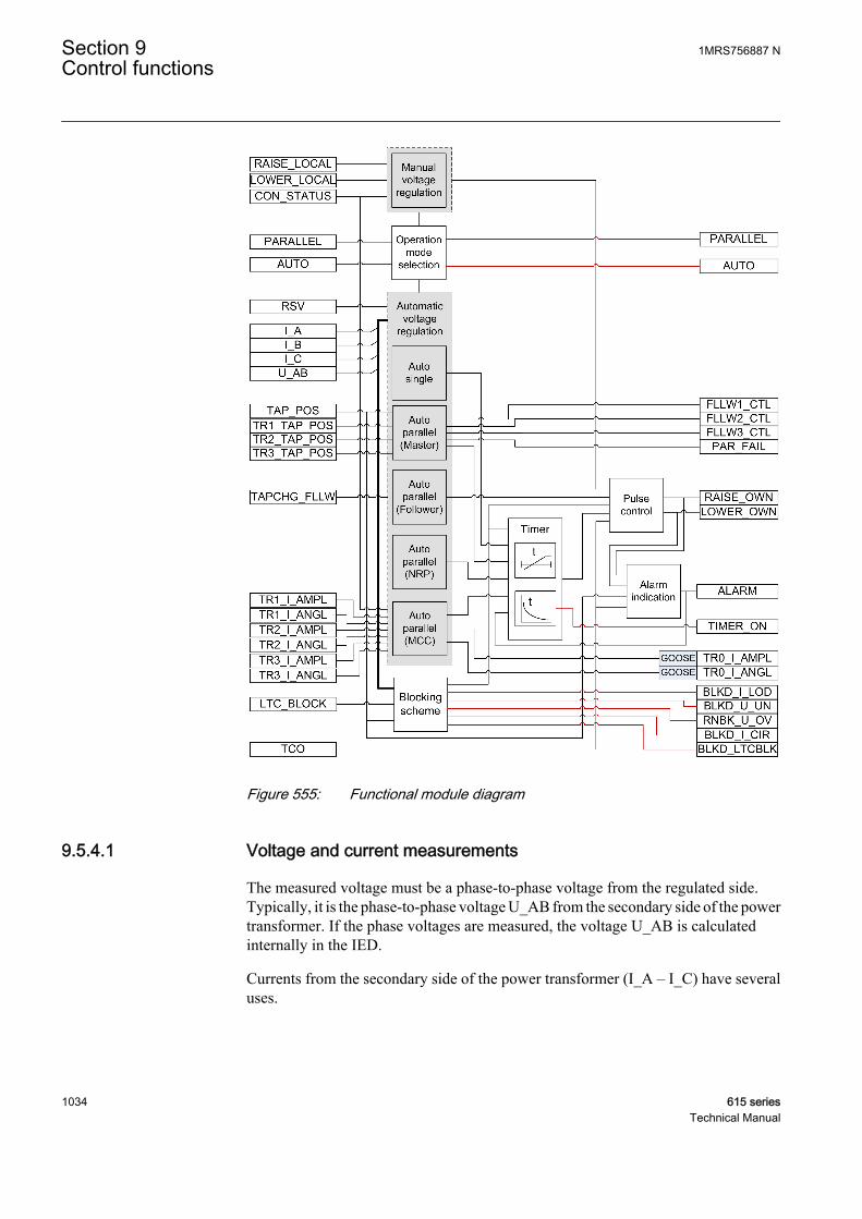
GUID-3C9D9747-FF06-4BC9-99B1-65DCA3DD20EE V1 EN
Figure 555: Functional module diagram
9.5.4.1 Voltage and current measurements
The measured voltage must be a phase-to-phase voltage from the regulated side.Typically, it is the phase-to-phase voltage U_AB from the secondary side of the powertransformer. If the phase voltages are measured, the voltage U_AB is calculatedinternally in the IED.
Currents from the secondary side of the power transformer (I_A – I_C) have severaluses.
Section 9 1MRS756887 NControl functions
1034 615 seriesTechnical Manual

• The highest phase current value is used for overcurrent blocking.• The currents from the secondary side of the power transformer are used for line
drop compensation (average of the connected inputs).• The currents from the secondary side of the power transformer are used for
calculating the circulating current in the Negative Reactance Principle (NRP) andMinimizing Circulating Current (MCC) operation modes.
Both voltage U_AB and the phase currents from the secondary side (I_x, where x isA, B or C) are always measured using the value of the filtered fundamental frequencycomponent (DFT). Hence, the harmonics are always suppressed. Moreover, themeasured voltage value is continuously average-filtered with the eight-value-longsliding window where the resulting filtering delay is not compensated. The phase-compensated voltage U_A is always used in calculations, although it is not connected.Um is the averaged value used for control and its magnitude can be read from themonitored data U_MEAS.
Similarly, the magnitude of the phase current of the own transformer, I_x, and thephase angle difference between the internally phase-compensated voltage U_A andphase current I_x are also average-filtered by the same length-fixed window. Thephase angle value can be read from the monitored data ANGL_UA_IA. Thesecurrents and phase angle differences are used solely on circulating currentcalculations.
The angle difference is used in Equation 189, Equation 190 andEquation 192.
There are minimum limits for the voltage and current magnitudes, resulting in themagnitude and phase angle difference values diverging from zero. The voltagemagnitude must exceed three percent of Un and the current I_A must exceed twopercent of In.
9.5.4.2 Tap changer position inputs
The position value of the tap changer can be brought to OLATCC as a resistance value,a mA signal or as a binary-coded signal. More information on how the resistancevalue, the mA signal or a binary-coded interface are implemented can be found inTPOSYLTC in the technical manual of the IED.
The indicated tap changer position of the own transformer is internally connected tothe TAP_POS input, and the tap changer positions of the parallel transformers are fedto the other TRx_TAP_POS inputs. This also defines the connection identity so thatfollower 1 is connected to TR1_TAP_POS, follower 2 is connected toTR2_TAP_POS and follower 3 is connected to TR3_TAP_POS. The owntransformer position can be read from the monitored data TAP_POS. The follower tapchanger positions can also be read from the input data TRx_TAP_POS, where x is avalue between 1 and 3.
1MRS756887 N Section 9Control functions
615 series 1035Technical Manual

The tap changer position value is given in parentheses. For example, (0) indicates thatthere is no tap changer position connected or the tap changer position value quality isbad. Typically, if no tap changer position is connected, all the TPOSYLTC binaryinputs are FALSE by default and the value shown is (0). A value other than zeroindicates bad quality. A bad-quality tap changer position is dealt by OLATCC likeunconnected tap position information.
9.5.4.3 Operation mode selection
OLATCC has the Operation mode and Auto parallel mode settings for selecting thedesired operation mode. The Operation mode setting can have any of the followingvalues: "Manual", "Auto single", "Auto parallel", "Input control" and “Command”. Ifthe Operation mode setting is set to "Input control", the acting operation mode isdetermined by the inputs PARALLEL and AUTO. When the Operation mode setting isset to "Command", the acting operation mode is determined by the IEC 61850command data points Auto and ParOp. The PARALLEL input and ParOp define if thetransformer (voltage regulator) is in the parallel or single mode. The AUTO inputdefines the operation status in the single mode. PARALLEL and AUTO Monitoreddata represent acting "Parallel or single operation" and "Auto/Manual indication"respectively.
Table 960: Acting operation mode determined by the operation mode inputs and commandsignals
PARALLEL AUTO Operation Mode0 0 Manual
0 1 Auto single
1 0 or 1 Auto parallel
Furthermore, if Operation mode has been set to "Auto parallel", the second settingparameter Auto parallel mode defines the parallel mode and the alternatives are "Automaster", "Auto follower", "MCC" or "NRP".
The acting operation mode can be read from the monitored data OPR_MODE_STS.
Command ExclusionAn acting operation mode change using two inputs (PARALLEL and AUTO) andsetting group change (either with the input or via menu) is needed when the actingoperation mode must be changed automatically, that is, there is a logic which drivesthese two inputs and setting group change based on the status information from thecircuit breakers.
The common Local/Remote (L/R) exclusion concerns the manual raising andlowering commands of OLATCC, that is, it internally proves the exclusionmechanism to prevent the remote commands (from SCADA) when the IED is in localmode.
Section 9 1MRS756887 NControl functions
1036 615 seriesTechnical Manual
9.5.4.4 Manual voltage regulation
The manual raising and lowering commands can be given either via the configurationinputs LOWER_LOCAL and RAISE_LOCAL, via the HMI of the IED or via remotecommands. The acting operation mode of OLATCC must be set to "Manual" and theLocal/Remote control LR state monitored data of the IED has to be "Local" to executethe control commands manually from HMI or via configuration inputs. AlthoughOLATCC is set to "Manual" but the LR state is set to "OFF" or "Remote", no manualcontrol commands can be given.
For remote commands, the acting operation mode of the OLATCC function must alsobe set to "Manual" and the LR state monitored data has to be "Remote".
The manual raising or lowering commands can be given locally either via the Manualcontrol parameter ("Cancel"/"Lower"/"Raise") located in the HMI menu Control/OLATCC1 or via the configuration inputs LOWER_LOCAL or RAISE_LOCAL.
A raising command is given by selecting the enumeration value "Raise" and thelowering command is given by selecting the enumeration value "Lower". An acceptedmanual raising/lowering command activates the corresponding output RAISE_OWNor LOWER_OWN to control the voltage of the own transformer.
Voltage control vs. tap changer moving directionOLATCC has the control settings Lower block tap and Raise block tap. The Lowerblock tap and Raise block tap settings should give the tap changer position that resultsin the lowest and highest controlled voltage value (usually at the LV side of thetransformer). The setting of both Raise block tap value higher than Lower block tapvalue and Lower block tap value higher than Raise block tap value is allowed.
When the value of Raise block tap exceeds the Lower block tap value, the raise controlactivates the RAISE_OWN output. This results in raising the tap changer position, andthe measured voltage rises. Furthermore, the RAISE_OWN output value is TRUE. Ifthe own tap changer position is connected (that is, the own tap changer's quality isgood), the tap changer alarm is activated if the tap changer does not move upwards inthe Cmd error delay time setting after the pulse activation, resulting thatALARM_REAS in the monitored data contains a command error value. The Cmderror delay time setting default value is 20 seconds.
The lowering control works in a similar way, as shown in Figure 556. In the outputdata, the LOWER_OWN output value is TRUE. An alarm is generated if the tap changerdoes not move upwards in Cmd error delay time after the pulse activation, assumingthat the own tap changer position is connected.
In the second case, the parameters are set so that the value of Lower block tap exceedsthe value of Raise block tap. The raising control activates the RAISE_OWN output.The result should be that the tap changer lowers its position and the measured voltagerises. Furthermore, the RAISE_OWN output value is TRUE in the output data. If theown tap changer position is connected, the tap changer alarm is activated if the tap
1MRS756887 N Section 9Control functions
615 series 1037Technical Manual
changer does not move downwards in Cmd error delay time after the pulse activation,resulting that ALARM_REAS in the monitored data contains a command error value.
9.5.4.5 Automatic voltage regulation of single transformer
OLATCC is intended to control the power transformers with a motor-driven on-loadtap changer. The function is designed to regulate the voltage at the secondary side ofthe power transformer. The control method is based on a step-by-step principle, whichmeans that one control pulse at a time is issued to the tap changer mechanism to moveit exactly one position upwards or downwards. However, when intermediate steps arenot indicated for the tap changer, it does not cause alarm if more than one step changeis met.
The purpose of the regulator is to maintain a stable secondary voltage of the powertransformer. The basis for this operation is the Band center voltage setting. Byincreasing or decreasing various compensation factors, the regulator calculates acontrol voltage from the band center voltage as shown in Equation 187. Hence, thecontrol voltage is the desired transformer secondary voltage to be maintained by theregulator. The control voltage is compared to the measured voltage and the differencebetween the two forms the regulating process error.
Since the tap changer changes the voltage in steps, a certain error has to be allowed.The error, called Band width voltage, is also set by the user. A recommended settingfor Band width voltage should be close to twice the step voltage of the transformerΔUstep and never below it as a minimum. For example, Band width voltage is twice thevalue of ΔUstep in Figure 556.
If the measured voltage fluctuates within the control voltage ± half the Band widthvoltage setting, the regulator is inactive. If the measured voltage is outside the half-bandwidth voltage limits, an adjustable delay T1 (Control delay time 1 ) starts, asshown in Figure 556, where the lowering function is an example. The delay T1remains active as long as the measured voltage is outside the hysteresis limits of halfthe value of Band width voltage. The factory setting for the hysteresis is 10 percent ofthe set Band width voltage.
Section 9 1MRS756887 NControl functions
1038 615 seriesTechnical Manual

Bandwidth
voltage
U
ΔUstep
t
bandwidth limithysteresis limitUm, measured voltageUp, control voltage
T1 s
tart
T1 re
set
T1 s
tart
Low
er
T1
GUID-65BA0EC4-8E96-41E1-B273-3519DF5C25E1 V2 EN
Figure 556: Voltage-regulating function. A control pulse to lower the voltage isissued after the elapsed T1.
If the measured voltage is outside the hysteresis when the delay counter T1 reaches itssetting value, the raising or lowering output relay is activated. This activates eitheroutput pulse RAISE_OWN or LOWER_OWN, and the motor drive of the tap changeroperates. The status of these outputs can be read from the output data RAISE_OWN orLOWER_OWN.
If the measured voltage falls or rises within the hysteresis limits during the operatingtime, the delay counter is reset.
The pulse length can be defined with the LTC pulse time setting. The default value is1.5 seconds.
A short delay same as the typical tap changer operating time is active before the startof the next operating timer is possible. For OLATCC, the delay is set to 6 seconds. Ifone tap changer operation is not enough to regulate the transformer voltage within thehysteresis limits, a second adjustable delay T2 (Control delay time 2), usually with ashorter time setting than T1, starts. This delay is used for the control commands withinthe same sequence until the recovery of voltage occurs. The delays T1 and T2 can beselected either with definite or inverse time characteristics. In the inverse time modeoperation, the operating time depends on the difference between the control voltageand the measured voltage as shown in Equation 194. The bigger the difference in thevoltage, the shorter the operating time. More information on the inverse timeoperation can be found in the OLATCC timer characteristics chapter.
Regulation equationThe simple regulating principle is often complemented by additional features to takethe voltage drop of lines into account (line drop compensation), coordinate theregulation of parallel transformers and change the voltage level according to theloading state of the network. The control voltage Up is calculated according to theequation
1MRS756887 N Section 9Control functions
615 series 1039Technical Manual

U U U U Up s z ci rsv= + + −
GUID-86D55536-6EF1-43CB-BA21-EF57280DEBB4 V1 EN (Equation 187)
Up Control voltage
Us Set voltage level Band center voltage
Uz Line drop compensation term
Uci Circulating current compensation term
Ursv Voltage reduction parameter
Up can be directly read in the monitored data U_CTL.
The circulating current compensation term is calculated only in the parallel actingoperation modes "NRP" and "MCC".
Line Drop Compensation (LDC)The line drop compensation feature is used to compensate the voltage drop along a lineor network fed by the transformer. The compensation setting parameters can becalculated theoretically if the resistance and reactance of the line are known ormeasured practically from the line drop.
ILXLRL
UB UL
Load
GUID-552C931B-4A1A-4361-8068-0A151CB99F30 V2 EN
Figure 557: Equivalent electrical circuit for calculating the LDC term
The compensation parameters Line drop V Ris (Ur) and Line drop V React (Ux), arepercentage values of Un according to the equations.
Line drop V Ris UI R
U
Line dro
rCT n
VT n
= [ ] =
⋅ ⋅
⋅ [ ]%_
_
3100
1
1
%Un
pp V React UI X
UUx
CT n
VT nn= [ ] =
⋅ ⋅
⋅ [ ]% %_
_
3100
1
1
GUID-B79F4E6B-B70E-4D85-BD8C-7877BD52A334 V2 EN (Equation 188)
ICT_n1 Nominal primary current of the CT
UVT_n1 Nominal primary voltage of the VT (phase-to-phase voltage)
R Resistance of the line, Ω/phase
X Reactance of the line, Ω/phase
The general LDC equation can be calculated.
Section 9 1MRS756887 NControl functions
1040 615 seriesTechnical Manual
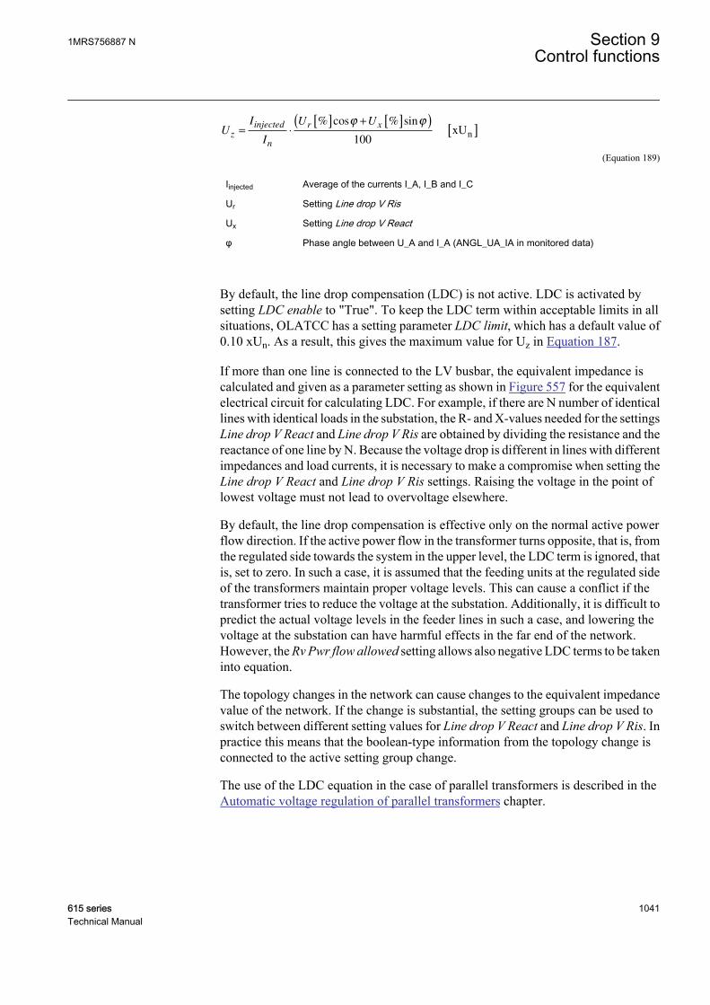
UI
I
U Uz
injected
n
r x= ⋅
[ ] + [ ]( )[ ]
% cos % sinϕ ϕ
100 xUn
GUID-B004A188-862D-4015-868D-8654F8F5D214 V2 EN (Equation 189)
Iinjected Average of the currents I_A, I_B and I_C
Ur Setting Line drop V Ris
Ux Setting Line drop V React
φ Phase angle between U_A and I_A (ANGL_UA_IA in monitored data)
By default, the line drop compensation (LDC) is not active. LDC is activated bysetting LDC enable to "True". To keep the LDC term within acceptable limits in allsituations, OLATCC has a setting parameter LDC limit, which has a default value of0.10 xUn. As a result, this gives the maximum value for Uz in Equation 187.
If more than one line is connected to the LV busbar, the equivalent impedance iscalculated and given as a parameter setting as shown in Figure 557 for the equivalentelectrical circuit for calculating LDC. For example, if there are N number of identicallines with identical loads in the substation, the R- and X-values needed for the settingsLine drop V React and Line drop V Ris are obtained by dividing the resistance and thereactance of one line by N. Because the voltage drop is different in lines with differentimpedances and load currents, it is necessary to make a compromise when setting theLine drop V React and Line drop V Ris settings. Raising the voltage in the point oflowest voltage must not lead to overvoltage elsewhere.
By default, the line drop compensation is effective only on the normal active powerflow direction. If the active power flow in the transformer turns opposite, that is, fromthe regulated side towards the system in the upper level, the LDC term is ignored, thatis, set to zero. In such a case, it is assumed that the feeding units at the regulated sideof the transformers maintain proper voltage levels. This can cause a conflict if thetransformer tries to reduce the voltage at the substation. Additionally, it is difficult topredict the actual voltage levels in the feeder lines in such a case, and lowering thevoltage at the substation can have harmful effects in the far end of the network.However, the Rv Pwr flow allowed setting allows also negative LDC terms to be takeninto equation.
The topology changes in the network can cause changes to the equivalent impedancevalue of the network. If the change is substantial, the setting groups can be used toswitch between different setting values for Line drop V React and Line drop V Ris. Inpractice this means that the boolean-type information from the topology change isconnected to the active setting group change.
The use of the LDC equation in the case of parallel transformers is described in theAutomatic voltage regulation of parallel transformers chapter.
1MRS756887 N Section 9Control functions
615 series 1041Technical Manual

Reduce Set Voltage (RSV) inputThe system frequency decreases when the active power production in the network issmaller than its consumption. Either the power supply has to be increased or someloads have to be shed to restore the power balance.
The simplest way to decrease the load is to reduce the voltage level by giving a lowerband center voltage value to the regulators. For this purpose, OLATCC has the settinggroup parameter Band reduction. The RSV input activation results in reduction. If thisinput is set to TRUE, a set target voltage value is decreased by Band reduction. If morethan one RSV reduction steps are desired, the setting group change has to be usedwhere different Band reduction values are supported. The decreased value is kept asa target value as long as the RSV input is TRUE.
Because the decrease of frequency indicates a need to reduce the load, it is practicalto connect the start signal of an underfrequency function block to the RSV digitalinput.
It depends on the load characteristics how much the load is reduced as the voltagedrops. For instance, purely resistive loads are proportional to the square of the voltage,whereas motor drives based on frequency controllers may draw constant powerdespite small voltage changes.
The status of the RSV input can be read from the RSV input data.
9.5.4.6 Automatic voltage regulation of parallel transformers
It is likely that a circulating current between transformers occurs if two or moretransformers with slightly different ratios are energized in parallel. This is due to theunbalanced short circuit impedances of the parallel transformers. To avoid suchcurrents, the tap changers of the transformers should be adjusted to achieveequilibrium. If the transformers are assumed identical, the tap (voltage) steps and tappositions should also match. In this case, the Master/Follower principle can be used.However, unequally rated transformers with different tap steps can be connected inparallel and these configurations can also be managed by the tap changer controlfunction. For these configurations, the Minimizing Circulating Current (MCC) orNegative Reactance Principle (NRP) should be used. The MCC and NRP principlesare also suitable for identical transformers.
The circulating current, which is almost purely inductive, is defined as negative if itflows towards the transformer. Uci in Equation 187 is positive and the control voltageUp rises as a result to the RAISE_OWN output signal activation if the circulatingcurrent level is sufficient (Equation 190 and Equation 192) and the other parametersremain the same. As a result, the voltage rise should diminish the circulating current.
LDC equation and parallel connectionThe additional challenge in the parallel connection regarding the line dropcompensation is to know the total current which flows through the paralleltransformers.
Section 9 1MRS756887 NControl functions
1042 615 seriesTechnical Manual

In the Master/Follower mode, it is easier to know the total current than in other parallelmodes since the transformers are assumed to have identical ratings, that is, the totalcurrent (Iinjected in Equation 189) is obtained by multiplying the measured load current(the average of the secondary currents I_A, I_B and I_C of the connected owntransformer) with the number of parallel transformers. OLATCC can internallyconclude the number of parallel transformers from the connected tap changer positioninputs. However, if there is no connected position information from the other paralleltransformers, the correct number of the parallel transformers, excluding the owntransformer, needs to be set with the Parallel trafos setting.
In the MCC mode, the horizontal communication transfers the information from themeasured load currents between the regulators so that the total current needed in theline drop compensation can be summed accurately. Here, Iinjected is defined to be thephasor sum of all the parallel power transformer secondary-side currents. The currentsfrom other transformers must be fed via the TRx_I_AMPL and TRx_I_ANGL inputs.
In the NRP mode, the parallel transformers have different ratings and there is nocommunication between the regulators. Therefore, when setting Line drop V Reactand Line drop V Ris, the ICT_n1 used in the equation should be the sum of the ratedcurrents of all the transformers operating in parallel. Here, Iinjected is also defined as theaverage of the connected secondary currents (I_A, I_B and I_C). The calculated linedrop compensation value can be read from the monitored data LDC.
Master/Follower principle M/FThe Master/Follower (M/F) operation principle is suitable for power transformerswith identical ratings and step voltages. One voltage regulator (master) measures andcontrols and the other regulators (followers) follow the master, that is, all the tapchangers connected in parallel are synchronized. This parallel operation is obtained byconnecting the FLLWx_CTL output of the master to the corresponding inputTAPCHG_FLLW of the followers via a horizontal GOOSE communication.
The values for the FLLWx_CTL command are 1=Lower follower x and 2=Raisefollower x. Consequently, the values for the TAPCHG_FLLW command are 1=Lowerand 2=Raise.
If several regulators are to act as masters (one at a time), their outputs also have to berouted to the inputs of other regulators. To start the parallel operation, the masterregulator is set to the "Auto master" mode and the followers to the "Auto follower"mode. To implement this setting, a group changing has to be planned.
To keep all the tap changers in the same position, the master needs to know the tappositions of the followers. This way, the circulating current is kept at its minimum.The position values of the followers can be brought to the master either via thehorizontal GOOSE communication or TPOSYLTC.
If it is not possible to use horizontal communication between the IEDs and the positioninformation cannot be wired from the parallel transformers, the M/F principle can stillbe used to regulate two or an unlimited number of transformers in parallel. Since themaster cannot detect the tap positions of parallel transformers, it just activates the
1MRS756887 N Section 9Control functions
615 series 1043Technical Manual
lowering and raising outputs for all the followers when it controls its own tap changer.This is called blind control. In this case, a number of parallel transformers areregulated as one unit. The tap position inputs 1…3(TR1_TAP_POS..TR3_TAP_POS) must be left unconnected for the master to knowthat the tap positions of the followers are unknown. The time delay betweensuccessive commands can be set by the Follower delay time setting. The default valueis six seconds.
When a disconnected transformer is taken into use and the tap position is unknown,the follower should be manually controlled to the same position as the master. Thiscan also take place in the master/follower mode. First, the master gives a controlcommand to its own transformer, that is, it is echoed to the followers (the follower tappositions have to be connected). Thereafter, successive control commands to thefollowers take place until the master and followers have the same tap positions.
Out-of-step functionThe out-of-step function is usually used in the M/F modes only. The out-of-stepfunction means that the master is able to detect the position values of the followers andcontrol them to the same position as the master is. In this case, the master assumes thatthe followers also have either Raise block tap higher than Lower block tap or Lowerblock tap higher than Raise block tap because this defines what is the given commandpulse for a follower. If the master has Raise block tap higher than Lower block tap andthe follower has Lower block tap higher than Raise block tap, the correspondingTAPCHG_FLLW included control signals should be connected crosswise. Thisrequires an extra logic where dual-point command bits have to be converted, that is,0=>0, [01]=1=>[10]=2 and [10]=2=>[01]=1.
M/F is the only parallel mode which has an out-of-step functionality. In the MCC andNRP operation modes, the circulating current is minimized, which most probablymeans different tap positions in the parallel transformers. Moreover, these modesallow different ratings and step voltages for the parallel transformers. Therefore, it isreasonable to apply the out-of-step function only to the M/F operation mode.
The out-of-step function is triggered when the master detects a difference of at leastone step between the tap changer positions in the follower and in the master. Themaster then sends special raising or lowering commands to the diverged follower. Iftwo consecutive commands fail to change the position of the follower to the rightdirection, the master activates the PAR_FAIL output, that is, PAR_FAIL is set toTRUE, and stops the special recovery efforts. However, every time the mastercontrols its own tap changer later, it always sends a controlling pulse to the divergedfollower too. Furthermore, if the master notices a correct position change after a sentpulse, it restarts the attempt to drive the follower to the same position and deactivatesthe PAR_FAIL output, that is, PAR_FAIL is set to FALSE. However, if there still arediverged followers, the reset is not indicated. It is indicated only when no divergedfollowers exist. Monitoring, and hence the indication of a paralleling failure, is notpossible in blind control. The followers with a parallel failure can be read from themonitored data FAIL_FLLW. For example, if only follower 3 is in the parallel failurestate, FAIL_FLLW has the value "Follower 3". If both followers 1 and 2 are in the
Section 9 1MRS756887 NControl functions
1044 615 seriesTechnical Manual

parallel failure state, FAIL_FLLW has the value "Followers 1+2". By default, whenno failed followers exist, the value is "No failed followers".
Negative Reactance Principle NRPThis parallel control scheme is suitable for power transformers with different ratingsand step voltages. Since no communication between the regulators is needed, thisprinciple can be applied even when the parallel transformers are located at differentsubstations. To start the parallel operation, the acting operation mode has to be set to"NRP" for all the regulators of the connection. The acting operation mode can bechanged via function block inputs or by setting either locally or remotely.
When applying this principle, each regulator has a phase angle setting φLoad (settingparameter Load phase angle) towards which it tries to regulate the current. The settingvalue is chosen according to the expected power factor of the load (positive settingvalue equals inductive load). When the actual phase angle of the load current is thesame as the setting and the transformers and their tap changer positions are identical,the currents of the two or more transformers are in the same phase as the total loadcurrent. If the tap changer positions are different, the circulating current flows and thecurrents of different transformers either lag or lead the load current. Figure 558 showsthat the circulating current is the reactive component which separates the measuredcurrent vector from the expected angle value.
ILOAD x sin(φLOAD)
ITR1 x sin(φ1)
φLOAD
φ1
U_A
Ici = circulatingcurrent
ILOAD
ITR1
ILOAD = ITR1 x cos(φ1)/cos(φLOAD)
GUID-2B71B160-FB76-4BE0-952F-75F42220401F V2 EN
Figure 558: The expected phase angle of the load supplied by the transformersoperating in parallel is entered as a setting value φLoad
The regulators calculate the circulating current with the equation
1MRS756887 N Section 9Control functions
615 series 1045Technical Manual
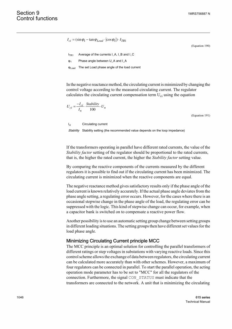
I Ici Load TR= − ⋅ ⋅(sin tan cos )ϕ ϕ ϕ1 1 1
GUID-823FAEEA-589B-4C8E-81CD-E5FECF28BF06 V2 EN (Equation 190)
ITR1 Average of the currents I_A, I_B and I_C
φ1 Phase angle between U_A and I_A
φLoad The set Load phase angle of the load current
In the negative reactance method, the circulating current is minimized by changing thecontrol voltage according to the measured circulating current. The regulatorcalculates the circulating current compensation term Uci using the equation
UI
I
StabilityUci
ci
nn=
−⋅ ⋅
100
GUID-2A7864D3-D59F-47F9-84FD-B3F2C15178EB V2 EN (Equation 191)
Ici Circulating current
Stability Stability setting (the recommended value depends on the loop impedance)
If the transformers operating in parallel have different rated currents, the value of theStability factor setting of the regulator should be proportional to the rated currents,that is, the higher the rated current, the higher the Stability factor setting value.
By comparing the reactive components of the currents measured by the differentregulators it is possible to find out if the circulating current has been minimized. Thecirculating current is minimized when the reactive components are equal.
The negative reactance method gives satisfactory results only if the phase angle of theload current is known relatively accurately. If the actual phase angle deviates from thephase angle setting, a regulating error occurs. However, for the cases where there is anoccasional stepwise change in the phase angle of the load, the regulating error can besuppressed with the logic. This kind of stepwise change can occur, for example, whena capacitor bank is switched on to compensate a reactive power flow.
Another possibility is to use an automatic setting group change between setting groupsin different loading situations. The setting groups then have different set values for theload phase angle.
Minimizing Circulating Current principle MCCThe MCC principle is an optimal solution for controlling the parallel transformers ofdifferent ratings or step voltages in substations with varying reactive loads. Since thiscontrol scheme allows the exchange of data between regulators, the circulating currentcan be calculated more accurately than with other schemes. However, a maximum offour regulators can be connected in parallel. To start the parallel operation, the actingoperation mode parameter has to be set to "MCC" for all the regulators of theconnection. Furthermore, the signal CON_STATUS must indicate that thetransformers are connected to the network. A unit that is minimizing the circulating
Section 9 1MRS756887 NControl functions
1046 615 seriesTechnical Manual
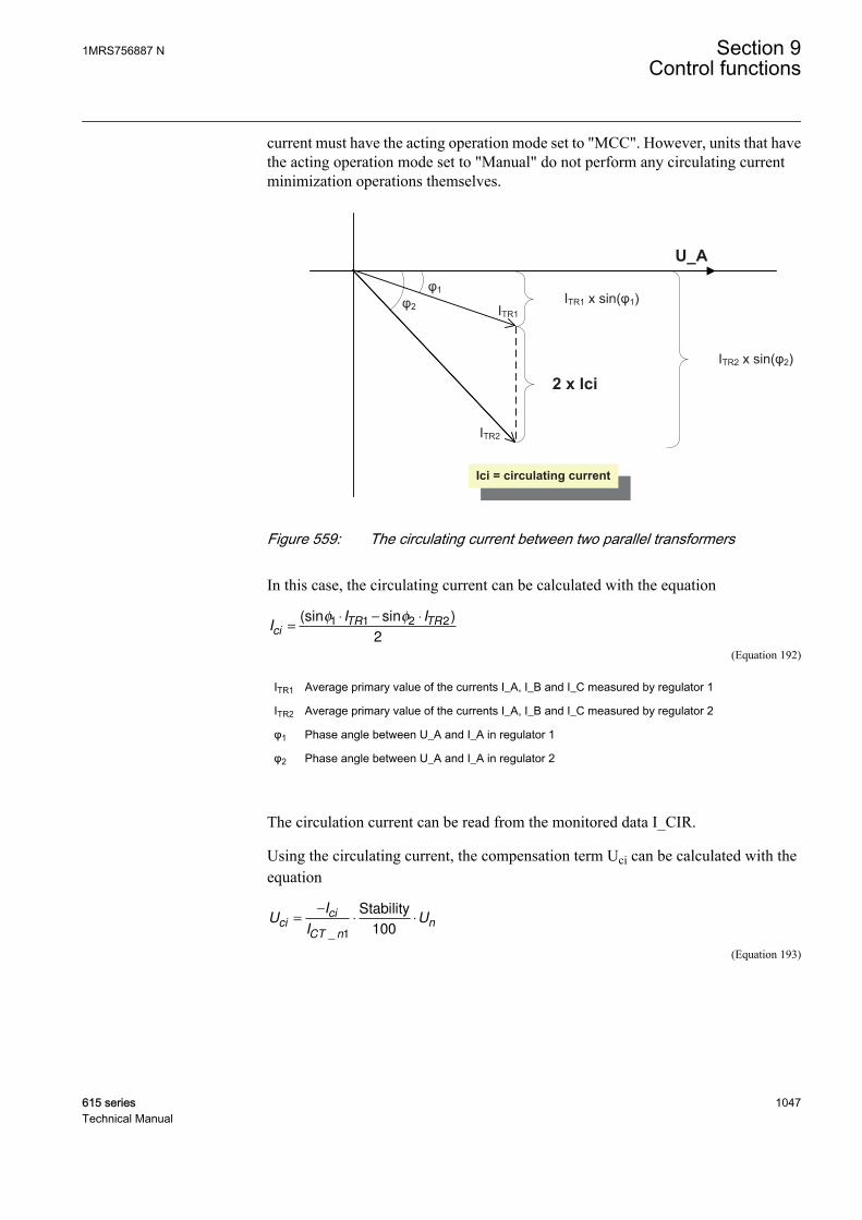
current must have the acting operation mode set to "MCC". However, units that havethe acting operation mode set to "Manual" do not perform any circulating currentminimization operations themselves.
2 x Ici
ITR1 x sin(φ1)
ITR2 x sin(φ2)
φ1
φ2
U_A
Ici = circulating current
ITR1
ITR2
GUID-F73692B0-629D-4C0A-BFAB-648B0A832E42 V2 EN
Figure 559: The circulating current between two parallel transformers
In this case, the circulating current can be calculated with the equation
II I
ciTR TR
=⋅ − ⋅(sin sin )φ φ1 1 2 2
2
GUID-5898550F-0095-4173-91ED-4D5AFFC7B58D V3 EN (Equation 192)
ITR1 Average primary value of the currents I_A, I_B and I_C measured by regulator 1
ITR2 Average primary value of the currents I_A, I_B and I_C measured by regulator 2
φ1 Phase angle between U_A and I_A in regulator 1
φ2 Phase angle between U_A and I_A in regulator 2
The circulation current can be read from the monitored data I_CIR.
Using the circulating current, the compensation term Uci can be calculated with theequation
UI
IUci
ci
CT n
n=
−
⋅ ⋅
_ 1 100
Stability
GUID-173A1FA0-8C07-4BA8-AAEB-62F95E10396C V3 EN (Equation 193)
1MRS756887 N Section 9Control functions
615 series 1047Technical Manual
Ici Circulating current, primary value
ICT_n1 Nominal primary current of the CT
Stability factor Stability setting (the recommended value depends on the loop impedance)
Using the circulating current, a compensation term Uci can be calculated usingEquation 191. The value of Uci, which can be positive or negative, is considered byadding it to the Band center voltage Us (Equation 187). According to Figure 559 andEquation 192, the phasor information from the other IEDs is needed.
Parallel unit detection and the MCC modeThe network connection status information is essential for the MCC operation mode.The status FALSE needs to be connected to the CON_STATUS input to ensure aproper operation of the MCC calculation if the transformer is disconnected butOLATCC remains in the MCC mode. This way the disconnected transformer isexcluded from the circulating current calculations.
The CON_STATUS input is used to identify if a certain transformer controller is ableto send the current information to other transformer controllers for circulating currentminimization purposes. As a result, this input has effect only in the MCC or Manualacting operation modes. In these modes, if CON_STATUS is TRUE, the informationtransmission is started. The circulating current information receiving is allowed onlyin the MCC acting operation mode when CON_STATUS is TRUE. PAR_UNIT_MCCcan be seen in the monitored data view.
Communication and the MCC modeThe phasor information from the other parallel IEDs is needed for the circular currentcalculation. Therefore, horizontal GOOSE communication is needed between IEDswhen the MCC principle is used.
The transferred current phasor contains the primary value of the measured current.The received current phasor information can be read from the input dataTRx_I_AMPL and TRx_I_ANGL for the magnitude and angle respectively. Thevalue "x" gives the connected parallel transformer number, a value between 1 and 3.
The sent phasor information always represents the difference between the voltagephasor U_A and I_A. This information regarding the current phasor can be read fromthe output data TR0_I_AMPL and TR0_I_ANGL. The allowed acting operationmodes for sending data are MCC or Manual, both with the input CON_STATUSactivated. The communication can be seen to be active when the sent and receivedphasor magnitude is not clamped to zero. The communication phasor magnitudefound to be zero results either from a rejected acting operation mode or too low signalmagnitudes (see Voltage and current measurements chapter). Active CON_STATUSindicates that the corresponding transformer is connected to network and its current
Section 9 1MRS756887 NControl functions
1048 615 seriesTechnical Manual
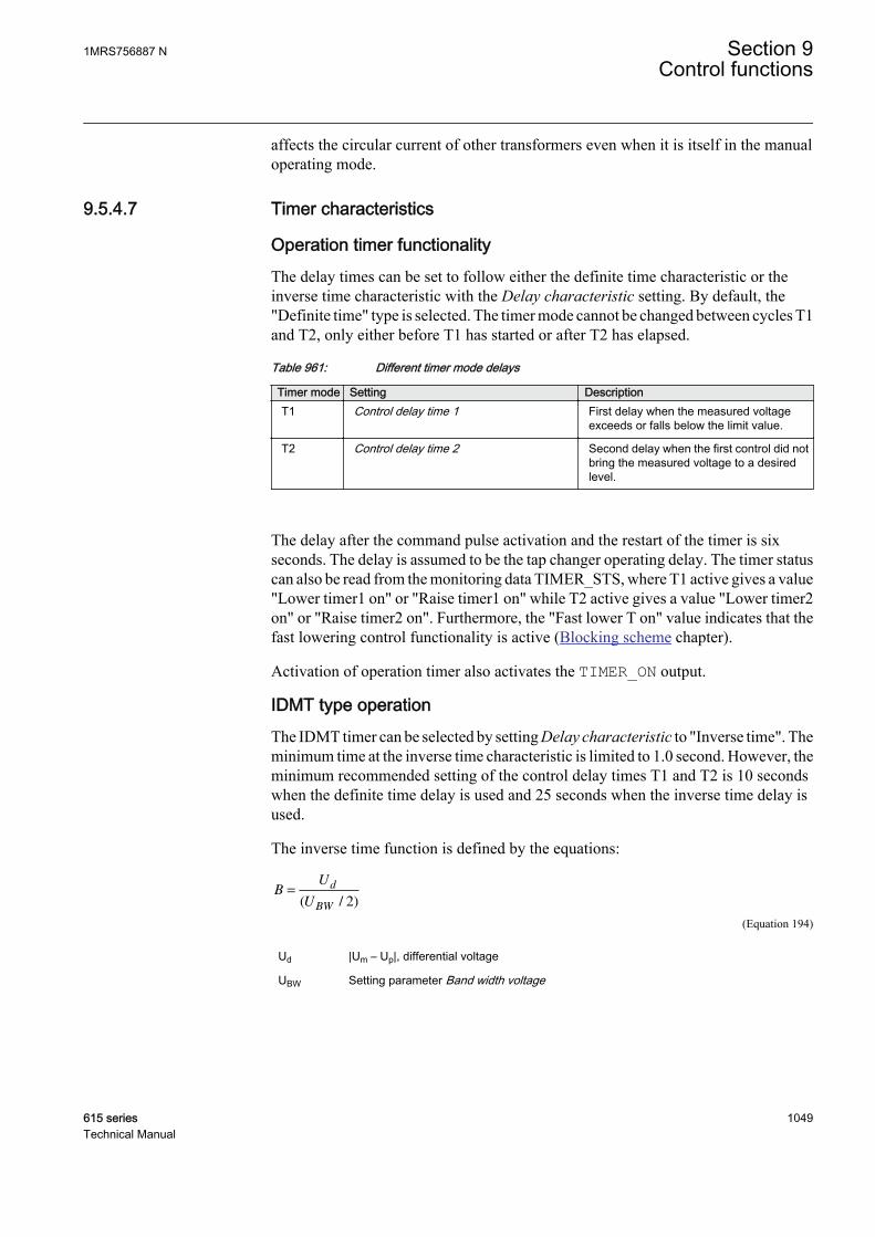
affects the circular current of other transformers even when it is itself in the manualoperating mode.
9.5.4.7 Timer characteristics
Operation timer functionalityThe delay times can be set to follow either the definite time characteristic or theinverse time characteristic with the Delay characteristic setting. By default, the"Definite time" type is selected. The timer mode cannot be changed between cycles T1and T2, only either before T1 has started or after T2 has elapsed.
Table 961: Different timer mode delays
Timer mode Setting DescriptionT1 Control delay time 1 First delay when the measured voltage
exceeds or falls below the limit value.
T2 Control delay time 2 Second delay when the first control did notbring the measured voltage to a desiredlevel.
The delay after the command pulse activation and the restart of the timer is sixseconds. The delay is assumed to be the tap changer operating delay. The timer statuscan also be read from the monitoring data TIMER_STS, where T1 active gives a value"Lower timer1 on" or "Raise timer1 on" while T2 active gives a value "Lower timer2on" or "Raise timer2 on". Furthermore, the "Fast lower T on" value indicates that thefast lowering control functionality is active (Blocking scheme chapter).
Activation of operation timer also activates the TIMER_ON output.
IDMT type operationThe IDMT timer can be selected by setting Delay characteristic to "Inverse time". Theminimum time at the inverse time characteristic is limited to 1.0 second. However, theminimum recommended setting of the control delay times T1 and T2 is 10 secondswhen the definite time delay is used and 25 seconds when the inverse time delay isused.
The inverse time function is defined by the equations:
BU
U
d
BW
=
( / )2
GUID-59DE8DA1-7C1D-41A2-98A8-48A91D061FFD V1 EN (Equation 194)
Ud |Um – Up|, differential voltage
UBW Setting parameter Band width voltage
1MRS756887 N Section 9Control functions
615 series 1049Technical Manual
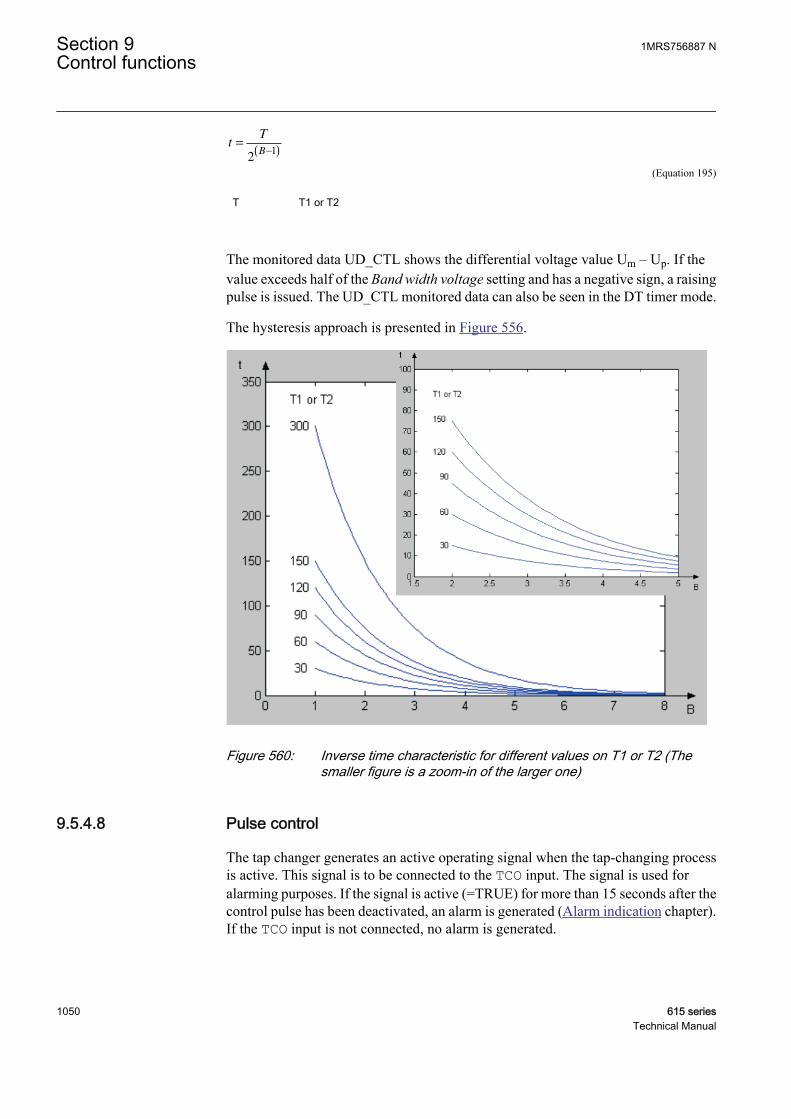
tT
B=
−( )2
1
GUID-18A433AA-B4A7-4DA8-94B2-4FDF12A23FD1 V1 EN (Equation 195)
T T1 or T2
The monitored data UD_CTL shows the differential voltage value Um – Up. If thevalue exceeds half of the Band width voltage setting and has a negative sign, a raisingpulse is issued. The UD_CTL monitored data can also be seen in the DT timer mode.
The hysteresis approach is presented in Figure 556.
GUID-6AA3C028-E7DD-4C87-A91C-4B8B1D43CBBA V2 EN
Figure 560: Inverse time characteristic for different values on T1 or T2 (Thesmaller figure is a zoom-in of the larger one)
9.5.4.8 Pulse control
The tap changer generates an active operating signal when the tap-changing processis active. This signal is to be connected to the TCO input. The signal is used foralarming purposes. If the signal is active (=TRUE) for more than 15 seconds after thecontrol pulse has been deactivated, an alarm is generated (Alarm indication chapter).If the TCO input is not connected, no alarm is generated.
Section 9 1MRS756887 NControl functions
1050 615 seriesTechnical Manual

The control operation is disabled when the TCO input signal is active, unless no tapchanger stuck is detected (Alarm indication chapter). Thus, it is not possible for thecontroller to send new pulses to the tap changer when it is already operating. This isbecause the tap changers are typically immune to new pulses when they are operating.Furthermore, because the pulses are omitted, the tap changer pulse counter of thecontroller is not incremented either.
The commands are not tolerated during an active pulse. Therefore the command pulselength (setting LTC pulse time) has to be carefully selected, although an active TCOinput is used internally to prevent new commands from reaching the tap changer.
To be more certain that no new pulses are to be sent when the tap changer is inoperation, the tap changer operating signal can also be connected to the LTC_BLOCKinput. In this case, the external blocking is achieved when an automatic pulse is sentto the operating tap changer. The external LTC_BLOCK has by default no effect whenthe acting operation mode is set to "Manual".
The status of the TCO input can be read from the TCO input data.
9.5.4.9 Blocking scheme
The operation of the voltage regulator can be blocked for several reasons. The purposeof blocking is to prevent the tap changer from operating under conditions that candamage the tap changer or exceed other power system-related limits. TheBLK_STATUS monitored data does not imply actual blocking but reveals if thecoming command pulse is issued or not. The blocking itself happens when thecorresponding bit in the signal BLK_STATUS is active and the command pulse isstarted due to a timer elapse or a local command. This is to avoid unnecessary eventsending.
The BLK_STATUS monitored data is also packed. It contains information about theblocking status as bit-coded output. The block status output does not indicate theactual blocking but indicates if the coming command is successful. The actualblocking is indicated by studying the corresponding monitored data (BLK_I_LOD,BLK_U_UN, RNBK_U_OV, BLK_LTCBLOCK, BLK_I_CIR, BLK_RAISE andBLK_LOWER) values. Table 962 illustrates the meaning of different monitored datavalues. For example, the block status value 9 indicates that there are conditionalcirculating current and load current blockings (8 + 1 = 9) indicated. By default, thestatus is “0”.
Table 962: Bit-coded block status and the meaning of different bits
Bit Active value Blocking reason6 (msb) 64 Lowest position reached
5 32 Highest position reached
4 16 External LTC_BLOCK
3 8 High circuit current
Table continues on next page
1MRS756887 N Section 9Control functions
615 series 1051Technical Manual
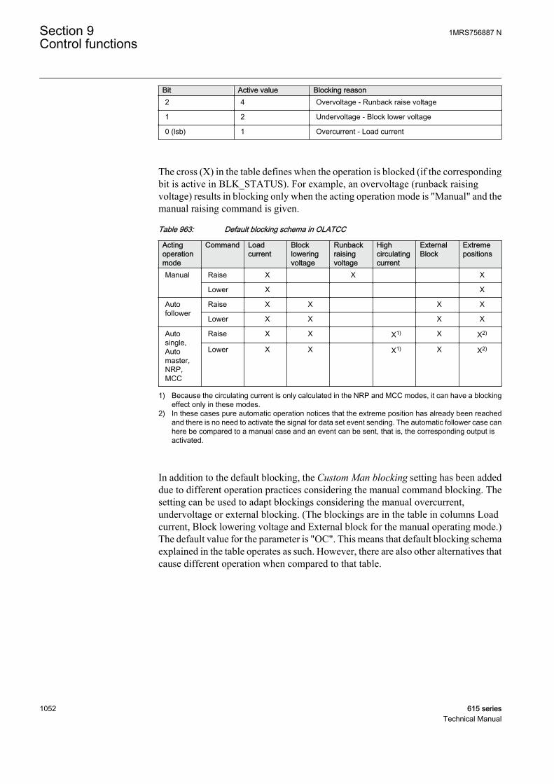
Bit Active value Blocking reason2 4 Overvoltage - Runback raise voltage
1 2 Undervoltage - Block lower voltage
0 (lsb) 1 Overcurrent - Load current
The cross (X) in the table defines when the operation is blocked (if the correspondingbit is active in BLK_STATUS). For example, an overvoltage (runback raisingvoltage) results in blocking only when the acting operation mode is "Manual" and themanual raising command is given.
Table 963: Default blocking schema in OLATCC
Actingoperationmode
Command Loadcurrent
Blockloweringvoltage
Runbackraisingvoltage
Highcirculatingcurrent
ExternalBlock
Extremepositions
Manual Raise X X X
Lower X X
Autofollower
Raise X X X X
Lower X X X X
Autosingle,Automaster,NRP,MCC
Raise X X X1) X X2)
Lower X X X1) X X2)
1) Because the circulating current is only calculated in the NRP and MCC modes, it can have a blockingeffect only in these modes.
2) In these cases pure automatic operation notices that the extreme position has already been reachedand there is no need to activate the signal for data set event sending. The automatic follower case canhere be compared to a manual case and an event can be sent, that is, the corresponding output isactivated.
In addition to the default blocking, the Custom Man blocking setting has been addeddue to different operation practices considering the manual command blocking. Thesetting can be used to adapt blockings considering the manual overcurrent,undervoltage or external blocking. (The blockings are in the table in columns Loadcurrent, Block lowering voltage and External block for the manual operating mode.)The default value for the parameter is "OC". This means that default blocking schemaexplained in the table operates as such. However, there are also other alternatives thatcause different operation when compared to that table.
Section 9 1MRS756887 NControl functions
1052 615 seriesTechnical Manual

Table 964: Customized manual blocking schema
Manualblockingtype
Enumeration Description
1 Custom disabled No load current, blocking of lower (under) voltage or externalblocking have effect in the manual.
2 OC Load current blocking has an effect in the manual operation mode
3 UV Block lowering (under) voltage blocking has an effect in the manualoperation mode
4 OC, UV Conditions 2 and 3 together: Load current and block lowering(under) voltage blocking have effect in the manual operation mode
5 EXT External blocking has an effect in the manual operation mode
6 OC, EXT Conditions 2 and 5 together: Load current and external blockinghave effect in the manual operation mode
7 UV, EXT Conditions 3 and 5 together: Block lowering (under) voltage andexternal blocking have effect in the manual operation mode
8 OC, UV, EXT All conditions 2, 3 and 5 together: Load current and block lowering(under) voltage and external blocking have effect in the manualoperation mode
If the Custom Man blocking setting is "Custom disabled", the blocking schemaregarding the acting operation mode "Manual" is as given in Table 965. Otheroperation modes follow the default schema.
Table 965: Blocking schema for selection "Custom disabled"
Actingoperationmode
Command Loadcurrent
Blockloweringvoltage
Runbackraisingvoltage
Highcirculatingcurrent
ExternalBlock
Extremepositions
Manual Raise X X
Lower X
Table 966: Blocking schema for selection "OC, UV, EXT"
Actingoperationmode
Command Loadcurrent
Blockloweringvoltage
Runbackraisingvoltage
Highcirculatingcurrent
ExternalBlock
Extremepositions
Manual Raise X X X X X
Lower X X X X
Table 967: Blocking schema for selection “UV, EXT”
Actingoperationmode
Command Loadcurrent
Blockloweringvoltage
Runbackraisingvoltage
Highcirculatingcurrent
ExternalBlock
Extremepositions
Manual Raise X X X X
Lower X X X
1MRS756887 N Section 9Control functions
615 series 1053Technical Manual
Load currentThe load current blocking is mainly used for preventing the tap changer fromoperating in an overcurrent situation. For example, if the current is not high enough toactivate the protective IED of the substation, it can still be fatal for the diverter switchof the tap changer. This operation can be adjusted with the setting parameter Loadcurrent limit. The maximum of measurements from the secondary-side current phasesis used for blocking. By default, both the automatic operation and the manualoperation are blocked (Table 963) when the set limit is exceeded.
The blocking status can be read from the monitored data BLKD_I_LOD.
Block lowering voltageThe block lowering voltage feature blocks both raising and lowering voltagecommands if the measured voltage is too low to be corrected by operating the tapchanger. Such a situation can occur due to a faulty measuring circuit, an earth fault oran overcurrent situation. By default, only the automatic (also automatic follower)operation is blocked when the undervoltage condition is met (Table 963). Thisoperation can be adjusted with the setting parameter Block lower voltage.
The blocking status can be read from the monitored data BLKD_U_UN.
However, there is no minimum limit for the undervoltage blocking. The blocking isallowed even if the measured voltage is not connected or it has temporarily a very lowvalue. There is a minimum limit for the phase angle calculation based on the voltagephasor magnitude.
Runback raising voltageThe manual raising command is blocked if the overvoltage limit is exceeded (Table963). However, in the automatic operation mode, the overvoltage situation triggersthe fast lowering feature. More information can be found in the Manual voltageregulation chapter. This operation can be adjusted with the setting parameter Runbackraise V.
The blocking status can be read from the monitored data RNBK_U_OV.
High Circulating CurrentThe circulating current value is calculated in the operation modes Negative ReactancePrinciple (NRP) and Minimizing Circulating Current (MCC). Only the automaticoperation in these modes is blocked when the high circulating current is measured(Table 963). This operation can be adjusted with the setting parameter Cir currentlimit.
The blocking status can be read from the monitored data BLKD_I_CIR.
LTC_BLOCK – external block inputWith the PCM600 tool configuration possibilities, a desired blocking condition can bebuilt by connecting an outcome to this input. The blocking status can be read from themonitored data BLKD_LTCBLK. When activated, this input blocks only the
Section 9 1MRS756887 NControl functions
1054 615 seriesTechnical Manual
automatic operation of the regulator by default (Table 963). For the fully automaticmodes, the signal activation resets the timer, and the monitored data BLKD_LTCBLKis not activated.
Extreme positionsThis blocking function supervises the extreme positions of the tap changer. Theseextreme positions can be adjusted with the setting parameters Raise block tap andLower block tap. When the tap changer reaches one of these two positions, thecommands in the corresponding direction are blocked (Table 963). It depends on thecomparison between the Raise block tap and Lower block tap settings, which directionis blocked (Voltage control vs. tap changer moving direction section). This blockingaffects both the automatic and manual operation modes.
However, as shown in Table 963, no blocking indication is to be generated in the fullyautomatic modes. Here "Auto follower" is not a fully automatic mode. Theunconnected position information does not cause the total block of OLATCC, only theextreme position blocking is not working.
The blocking status can be seen in the generated events.
Fast lowering controlOLATCC provides the fast lowering control in the automatic operation modes. Whenthe set Runback raise V is exceeded, the regulator gives fast lowering control pulsesuntil the voltage drops below the specified limit. This fast lowering control can be seenwith the monitoring data TIMER_STS, where the value "Fast lower T on" indicatesthis functionality to be active.
To allow the fast lowering operation, Runback raise V has to be setalways to a value higher than the control voltage (U_CTL) plus half ofBand width voltage.
Typically, the blockings are reset when the corresponding limit with the hysteresis isundershoot or exceeded. Although blocking is reset after undershooting the above-mentioned limit, the fast lowering control operation continues until the measuredvoltage signal difference undershoots half the Band width voltage hysteresis limit(Figure 556). As a result, normal automatic mode operation is not possible before thishappens.
Fast lowering control causes successive LOWER_OWN pulses to be activated. The timebetween consecutive pulse starts is the pulse length plus 1.5 seconds.
• There is no tap changer operating delay (otherwise six seconds) taken intoaccount in this cycle (meaning that some command pulses are ineffective due totap changer operation, as described in the Pulse control chapter)
• Timer mode set by Delay characteristic has no effect here (always the DT timer-type operation). Because the minimum pulse length (the LTC pulse time setting)is 0.5 seconds, the shortest interval between successive pulses can be twoseconds.
1MRS756887 N Section 9Control functions
615 series 1055Technical Manual
In the automatic follower mode, the fast lowering is not triggered. In this way, theawkward dispersion of position values in different units can be avoided. The masteralways decides on the fast lowering on behalf of the follower units. Moreover, masterand follower should measure an equal voltage level and have similar setting values forthe overvoltage blocking limit.
9.5.4.10 Alarm indication
Tap Changer MonitoringOLATCC supervises the operation of the tap changer and alarms if the alarmcondition is detected. An alarm activation means that the ALARM output is activatedand the alarm reason can be read from the monitored data ALARM_REAS. Alarmsare in use by default but they can be set not to be in use by setting Alarms enabled to"False". Three different alarm conditions and their combinations can be detected byOLATCC.
Command errorOLATCC supervises the tap changer position information of the own transformerwhen a control pulse is given. If the correct position change (direction depends on thecomparison of the settings Raise block tap and Lower block tap) is not seen byOLATCC in Cmd error delay time after the pulse start, the alarm is issued.
If the position information is not connected, no alarm is generated. The alarm is resetwhen the correct change in position value is detected after a given pulse or if a newcommand pulse is given.
The monitored data ALARM_REAS is set during an alarm. This means that if thealarm reason is active, ALARM_REAS has the value "Cmd error".
TCO signal failsIf the tap changer operating signal TCO stays active for more than 15 seconds after theoutput pulse deactivation, OLATCC concludes this as an abnormal condition andassumes that the tap changer is stuck. The alarm is reset when the TCO input signaldeactivates. The monitored data ALARM_REAS is set during the alarm. This meansthat only if alarm reason is active, ALARM_REAS has the value "TCO error".
If the TCO input signal is not connected (indicated by bad quality), this type of alarmis not possible.
Regulator pumpingIt is possible that faulty settings cause the regulator to give control pulses toofrequently. For example, too low a setting for the Band width voltage (Figure 556) canresult in a pumping condition where the regulator has problems to bring the regulatedvoltage to a desired level. To detect this, OLATCC has a setting Max operations in1h, which defines the allowed number of lowering and raising commands during aone-hour sliding time window. The detection is active both in the manual andautomatic operation modes. The alarm is reset after the counted number of the
Section 9 1MRS756887 NControl functions
1056 615 seriesTechnical Manual
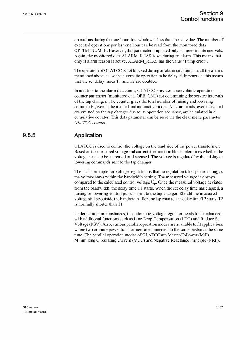
operations during the one-hour time window is less than the set value. The number ofexecuted operations per last one hour can be read from the monitored dataOP_TM_NUM_H. However, this parameter is updated only in three-minute intervals.Again, the monitored data ALARM_REAS is set during an alarm. This means thatonly if alarm reason is active, ALARM_REAS has the value "Pump error".
The operation of OLATCC is not blocked during an alarm situation, but all the alarmsmentioned above cause the automatic operation to be delayed. In practice, this meansthat the set delay times T1 and T2 are doubled.
In addition to the alarm detections, OLATCC provides a nonvolatile operationcounter parameter (monitored data OPR_CNT) for determining the service intervalsof the tap changer. The counter gives the total number of raising and loweringcommands given in the manual and automatic modes. All commands, even those thatare omitted by the tap changer due to its operation sequence, are calculated in acumulative counter. This data parameter can be reset via the clear menu parameterOLATCC counter.
9.5.5 Application
OLATCC is used to control the voltage on the load side of the power transformer.Based on the measured voltage and current, the function block determines whether thevoltage needs to be increased or decreased. The voltage is regulated by the raising orlowering commands sent to the tap changer.
The basic principle for voltage regulation is that no regulation takes place as long asthe voltage stays within the bandwidth setting. The measured voltage is alwayscompared to the calculated control voltage Up. Once the measured voltage deviatesfrom the bandwidth, the delay time T1 starts. When the set delay time has elapsed, araising or lowering control pulse is sent to the tap changer. Should the measuredvoltage still be outside the bandwidth after one tap change, the delay time T2 starts. T2is normally shorter than T1.
Under certain circumstances, the automatic voltage regulator needs to be enhancedwith additional functions such as Line Drop Compensation (LDC) and Reduce SetVoltage (RSV). Also, various parallel operation modes are available to fit applicationswhere two or more power transformers are connected to the same busbar at the sametime. The parallel operation modes of OLATCC are Master/Follower (M/F),Minimizing Circulating Current (MCC) and Negative Reactance Principle (NRP).
1MRS756887 N Section 9Control functions
615 series 1057Technical Manual

Configuration example for the Manual and Auto single modes
M
U12b
IL1b, IL2b, IL3b
VT_
CT_
IED
TCO LOWER RAISE
+ +-
+
TAP_POS
Tap position indication (e.g. mA -signal)
-
+Auto /
Manual
-
+Lower
-
+Raise
AUTO RAISE_LOCALLOWER_LOCAL
GUID-88A1D370-2203-48CA-9843-76C309B4049D V4 EN
Figure 561: Basic connection diagram for the voltage regulator
GUID-E5F2C693-2E5C-46B4-8E4D-FDBE8F0DDE12 V1 EN
Figure 562: Configuration example for the Manual and Auto single modes
The configuration example uses an mA signal to indicate the current tap position of thelocal transformer. To take that position information to OLATCC, the measured mAsignal is first scaled with the X130 (RTD) function. The scaled value is then convertedto integer value with T_F32_INT8 function. That integer value is connected to theTAP_POS input of the TPOSYLTC function. The tap position value is automaticallytransferred from TPOSYLTC to OLATCC without a configuration connection.
Section 9 1MRS756887 NControl functions
1058 615 seriesTechnical Manual
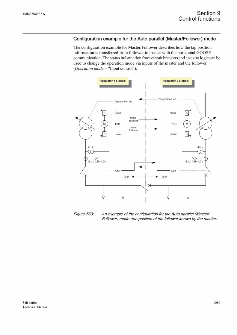
Configuration example for the Auto parallel (Master/Follower) modeThe configuration example for Master/Follower describes how the tap positioninformation is transferred from follower to master with the horizontal GOOSEcommunication. The status information from circuit breakers and an extra logic can beused to change the operation mode via inputs of the master and the follower(Operation mode = "Input control").
M
U12b
IL1b, IL2b, IL3b
TCO
Tap position ind.
Raise
Lower
M
U12b
IL1b, IL2b, IL3b
TCO
Tap position ind.
Raise
Lower
Regulator 1 signals Regulator 2 signals
CB1 CB3
CB2CB2
Lowerfollower
Raisefollower
GUID-0B2CBB09-9B4C-498A-BB1C-3A3689513BDF V2 EN
Figure 563: An example of the configuration for the Auto parallel (Master/Follower) mode (the position of the follower known by the master)
1MRS756887 N Section 9Control functions
615 series 1059Technical Manual
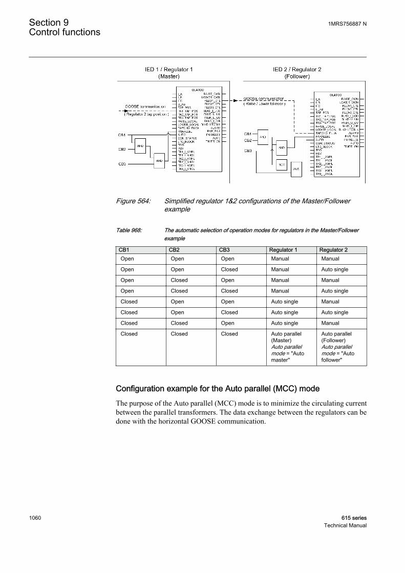
GUID-0AA52200-4426-4E2A-8173-37709E4F9CEA V1 EN
Figure 564: Simplified regulator 1&2 configurations of the Master/Followerexample
Table 968: The automatic selection of operation modes for regulators in the Master/Followerexample
CB1 CB2 CB3 Regulator 1 Regulator 2Open Open Open Manual Manual
Open Open Closed Manual Auto single
Open Closed Open Manual Manual
Open Closed Closed Manual Auto single
Closed Open Open Auto single Manual
Closed Open Closed Auto single Auto single
Closed Closed Open Auto single Manual
Closed Closed Closed Auto parallel(Master)Auto parallelmode = "Automaster''
Auto parallel(Follower)Auto parallelmode = "Autofollower"
Configuration example for the Auto parallel (MCC) modeThe purpose of the Auto parallel (MCC) mode is to minimize the circulating currentbetween the parallel transformers. The data exchange between the regulators can bedone with the horizontal GOOSE communication.
Section 9 1MRS756887 NControl functions
1060 615 seriesTechnical Manual
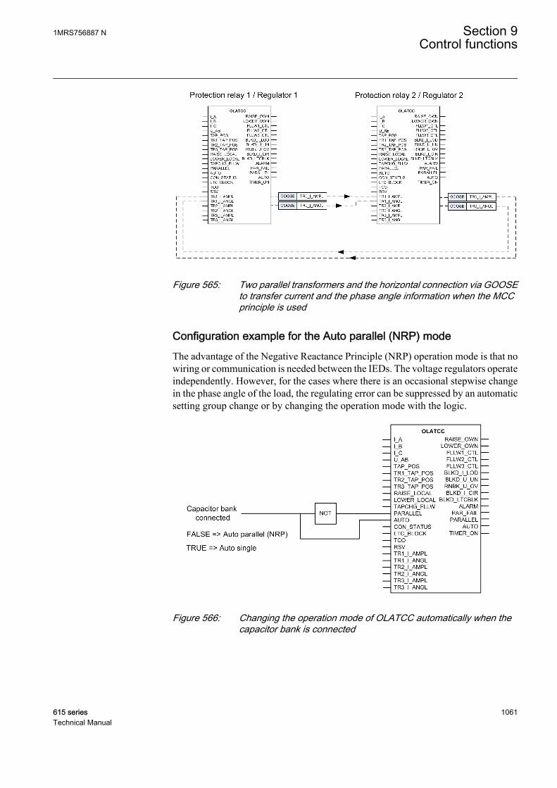
GUID-3A91DA4B-0362-42FF-820B-518DC8B6A785 V1 EN
Figure 565: Two parallel transformers and the horizontal connection via GOOSEto transfer current and the phase angle information when the MCCprinciple is used
Configuration example for the Auto parallel (NRP) modeThe advantage of the Negative Reactance Principle (NRP) operation mode is that nowiring or communication is needed between the IEDs. The voltage regulators operateindependently. However, for the cases where there is an occasional stepwise changein the phase angle of the load, the regulating error can be suppressed by an automaticsetting group change or by changing the operation mode with the logic.
GUID-E3536CF1-4185-40F9-9080-316A081F66D9 V1 EN
Figure 566: Changing the operation mode of OLATCC automatically when thecapacitor bank is connected
1MRS756887 N Section 9Control functions
615 series 1061Technical Manual

Comparison summary between parallel operation modesThe parallel operation modes are needed because if the parallel regulators operatedindependently, at some point the transformers would become out of step with eachother.
The circulating current would increase and the line drop compensation would thusincrease for the transformer giving the highest voltage. Correspondingly, theincreasing circulating current would cause the transformer giving the lowest voltageto decrease the voltage due to a decreased line drop compensation effect. In otherwords, the two transformers would run apart.
However, it is case-specific which parallel operation mode is the most suitable.
Section 9 1MRS756887 NControl functions
1062 615 seriesTechnical Manual
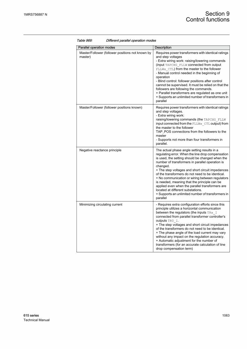
Table 969: Different parallel operation modes
Parallel operation modes DescriptionMaster/Follower (follower positions not known bymaster)
Requires power transformers with identical ratingsand step voltages- Extra wiring work: raising/lowering commands(input TAPCHG_FLLW connected from outputFLLWx_CTL) from the master to the follower- Manual control needed in the beginning ofoperation- Blind control: follower positions after controlcannot be supervised. It must be relied on that thefollowers are following the commands.+ Parallel transformers are regulated as one unit+ Supports an unlimited number of transformers inparallel
Master/Follower (follower positions known) Requires power transformers with identical ratingsand step voltages.- Extra wiring work:raising/lowering commands (the TAPCHG_FLLWinput connected from the FLLWx_CTL output) fromthe master to the followerTAP_POS connections from the followers to themaster- Supports not more than four transformers inparallel.
Negative reactance principle The actual phase angle setting results in aregulating error. When the line drop compensationis used, the setting should be changed when thenumber of transformers in parallel operation ischanged.+ The step voltages and short circuit impedancesof the transformers do not need to be identical.+ No communication or wiring between regulatorsis needed, meaning that the principle can beapplied even when the parallel transformers arelocated at different substations.+ Supports an unlimited number of transformers inparallel
Minimizing circulating current - Requires extra configuration efforts since thisprinciple utilizes a horizontal communicationbetween the regulators (the inputs TRx_Iconnected from parallel transformer controller'soutputs TR0_I.+ The step voltages and short circuit impedancesof the transformers do not need to be identical.+ The phase angle of the load current may varywithout any impact on the regulation accuracy.+ Automatic adjustment for the number oftransformers (for an accurate calculation of linedrop compensation term)
1MRS756887 N Section 9Control functions
615 series 1063Technical Manual
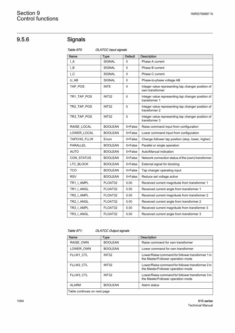
9.5.6 SignalsTable 970: OLATCC Input signals
Name Type Default DescriptionI_A SIGNAL 0 Phase A current
I_B SIGNAL 0 Phase B current
I_C SIGNAL 0 Phase C current
U_AB SIGNAL 0 Phase-to-phase voltage AB
TAP_POS INT8 0 Integer value representing tap changer position ofown transformer
TR1_TAP_POS INT32 0 Integer value representing tap changer position oftransformer 1
TR2_TAP_POS INT32 0 Integer value representing tap changer position oftransformer 2
TR3_TAP_POS INT32 0 Integer value representing tap changer position oftransformer 3
RAISE_LOCAL BOOLEAN 0=False Raise command input from configuration
LOWER_LOCAL BOOLEAN 0=False Lower command input from configuration
TAPCHG_FLLW Enum 0=False Change follower tap position (stop, lower, higher)
PARALLEL BOOLEAN 0=False Parallel or single operation
AUTO BOOLEAN 0=False Auto/Manual indication
CON_STATUS BOOLEAN 0=False Network connection status of the (own) transformer
LTC_BLOCK BOOLEAN 0=False External signal for blocking
TCO BOOLEAN 0=False Tap changer operating input
RSV BOOLEAN 0=False Reduce set voltage active
TR1_I_AMPL FLOAT32 0.00 Received current magnitude from transformer 1
TR1_I_ANGL FLOAT32 0.00 Received current angle from transformer 1
TR2_I_AMPL FLOAT32 0.00 Received current magnitude from transformer 2
TR2_I_ANGL FLOAT32 0.00 Received current angle from transformer 2
TR3_I_AMPL FLOAT32 0.00 Received current magnitude from transformer 3
TR3_I_ANGL FLOAT32 0.00 Received current angle from transformer 3
Table 971: OLATCC Output signals
Name Type DescriptionRAISE_OWN BOOLEAN Raise command for own transformer
LOWER_OWN BOOLEAN Lower command for own transformer
FLLW1_CTL INT32 Lower/Raise command for follower transformer 1 inthe Master/Follower operation mode
FLLW2_CTL INT32 Lower/Raise command for follower transformer 2 inthe Master/Follower operation mode
FLLW3_CTL INT32 Lower/Raise command for follower transformer 3 inthe Master/Follower operation mode
ALARM BOOLEAN Alarm status
Table continues on next page
Section 9 1MRS756887 NControl functions
1064 615 seriesTechnical Manual
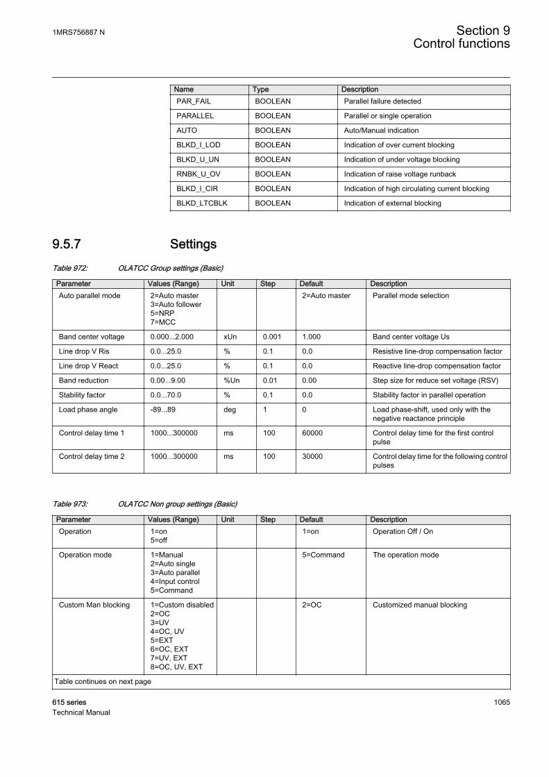
Name Type DescriptionPAR_FAIL BOOLEAN Parallel failure detected
PARALLEL BOOLEAN Parallel or single operation
AUTO BOOLEAN Auto/Manual indication
BLKD_I_LOD BOOLEAN Indication of over current blocking
BLKD_U_UN BOOLEAN Indication of under voltage blocking
RNBK_U_OV BOOLEAN Indication of raise voltage runback
BLKD_I_CIR BOOLEAN Indication of high circulating current blocking
BLKD_LTCBLK BOOLEAN Indication of external blocking
9.5.7 SettingsTable 972: OLATCC Group settings (Basic)
Parameter Values (Range) Unit Step Default DescriptionAuto parallel mode 2=Auto master
3=Auto follower5=NRP7=MCC
2=Auto master Parallel mode selection
Band center voltage 0.000...2.000 xUn 0.001 1.000 Band center voltage Us
Line drop V Ris 0.0...25.0 % 0.1 0.0 Resistive line-drop compensation factor
Line drop V React 0.0...25.0 % 0.1 0.0 Reactive line-drop compensation factor
Band reduction 0.00...9.00 %Un 0.01 0.00 Step size for reduce set voltage (RSV)
Stability factor 0.0...70.0 % 0.1 0.0 Stability factor in parallel operation
Load phase angle -89...89 deg 1 0 Load phase-shift, used only with thenegative reactance principle
Control delay time 1 1000...300000 ms 100 60000 Control delay time for the first controlpulse
Control delay time 2 1000...300000 ms 100 30000 Control delay time for the following controlpulses
Table 973: OLATCC Non group settings (Basic)
Parameter Values (Range) Unit Step Default DescriptionOperation 1=on
5=off 1=on Operation Off / On
Operation mode 1=Manual2=Auto single3=Auto parallel4=Input control5=Command
5=Command The operation mode
Custom Man blocking 1=Custom disabled2=OC3=UV4=OC, UV5=EXT6=OC, EXT7=UV, EXT8=OC, UV, EXT
2=OC Customized manual blocking
Table continues on next page
1MRS756887 N Section 9Control functions
615 series 1065Technical Manual
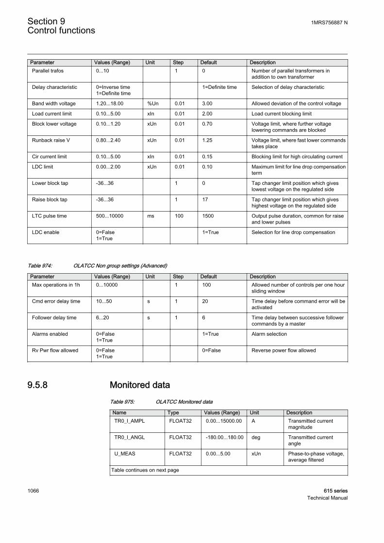
Parameter Values (Range) Unit Step Default DescriptionParallel trafos 0...10 1 0 Number of parallel transformers in
addition to own transformer
Delay characteristic 0=Inverse time1=Definite time
1=Definite time Selection of delay characteristic
Band width voltage 1.20...18.00 %Un 0.01 3.00 Allowed deviation of the control voltage
Load current limit 0.10...5.00 xIn 0.01 2.00 Load current blocking limit
Block lower voltage 0.10...1.20 xUn 0.01 0.70 Voltage limit, where further voltagelowering commands are blocked
Runback raise V 0.80...2.40 xUn 0.01 1.25 Voltage limit, where fast lower commandstakes place
Cir current limit 0.10...5.00 xIn 0.01 0.15 Blocking limit for high circulating current
LDC limit 0.00...2.00 xUn 0.01 0.10 Maximum limit for line drop compensationterm
Lower block tap -36...36 1 0 Tap changer limit position which giveslowest voltage on the regulated side
Raise block tap -36...36 1 17 Tap changer limit position which giveshighest voltage on the regulated side
LTC pulse time 500...10000 ms 100 1500 Output pulse duration, common for raiseand lower pulses
LDC enable 0=False1=True
1=True Selection for line drop compensation
Table 974: OLATCC Non group settings (Advanced)
Parameter Values (Range) Unit Step Default DescriptionMax operations in 1h 0...10000 1 100 Allowed number of controls per one hour
sliding window
Cmd error delay time 10...50 s 1 20 Time delay before command error will beactivated
Follower delay time 6...20 s 1 6 Time delay between successive followercommands by a master
Alarms enabled 0=False1=True
1=True Alarm selection
Rv Pwr flow allowed 0=False1=True
0=False Reverse power flow allowed
9.5.8 Monitored dataTable 975: OLATCC Monitored data
Name Type Values (Range) Unit DescriptionTR0_I_AMPL FLOAT32 0.00...15000.00 A Transmitted current
magnitude
TR0_I_ANGL FLOAT32 -180.00...180.00 deg Transmitted currentangle
U_MEAS FLOAT32 0.00...5.00 xUn Phase-to-phase voltage,average filtered
Table continues on next page
Section 9 1MRS756887 NControl functions
1066 615 seriesTechnical Manual

Name Type Values (Range) Unit DescriptionANGL_UA_IA FLOAT32 -180...180 deg Measured angle value
between phase A voltageand current
TIMER_STS Enum 0=Timer off1=Lower timer1on2=Raise timer1on3=Lower timer2on4=Raise timer2on5=Fast lower Ton
Timer T1, T2 or fast lowertimer active
OPR_MODE_STS Enum 0=Not in use1=Manual2=Auto single3=Auto master4=Auto follower5=MCC6=NRP
The acting operationmode of the functionblock
U_CTL FLOAT32 0.000...3.000 xUn Control voltage, Up,target voltage level
UD_CTL FLOAT32 -2.000...2.000 xUn Voltage differencebetween Measuredvoltage - Control Voltage:Um - Up
I_CIR FLOAT32 -10.00...10.00 xIn Calculated circulatingcurrent - calculated inoperation modes NRPand MCC
LDC FLOAT32 -2.00...2.00 xUn Calculated line dropcompensation
BLK_STATUS INT32 0...127 Bit-coded output showingthe blocking status for thenext operation
ALARM_REAS Enum 0=No alarm1=Cmd error2=TCO error3=Cmd + TCOerr4=Pump error5=Pump + cmderr6=Pump + TCOerr7=Pmp+TCO+cmd err
Status and reason foralarm
OP_TM_NUM_H INT32 0...2147483647 Number of controls forown tap changer duringlast hour
Table continues on next page
1MRS756887 N Section 9Control functions
615 series 1067Technical Manual

Name Type Values (Range) Unit DescriptionFAIL_FLLW Enum 0=No failed
followers1=Follower 12=Follower 23=Followers 1+24=Follower 35=Followers 1+36=Followers 2+37=Followers1+2+3
Failed followers
PAR_UNIT_MCC Enum 0=No parall units1=Trafo 12=Trafo 23=Trafos 1 and 24=Trafo 35=Trafos 1 and 36=Trafos 2 and 37=Trafos 1+2+3
Parallel units included inMCC calculation
OPR_CNT INT32 0...2147483647 Total number of raise andlower commands given inthe manual andautomatic modes
OLATCC Enum 1=on2=blocked3=test4=test/blocked5=off
Status
9.5.9 Technical dataTable 976: OLATCC Technical data
Characteristic Value
Operation accuracy1) Depending on the frequency of the measuredcurrent: fn ±2 Hz
Differential voltage Ud = ±0.5% of the measuredvalue or ±0.005 × Un (in measured voltages <2.0 ×Un)Operation value = ±1.5% of the Ud for Us = 1.0 ×Un
Operate time accuracy in definite time mode2) +4.0%/-0% of the set value
Operate time accuracy in inverse time mode2) +8.5%/-0% of the set value(at theoretical B in range of 1.1…5.0)Also note fixed minimum operate time (IDMT) 1 s.
Reset ratio for control operationReset ratio for analogue based blockings (exceptrun back raise voltage blocking)
Typically 0.80 (1.20)Typically 0.96 (1.04)
1) Default setting values used2) Voltage before deviation = set Band center voltage
Section 9 1MRS756887 NControl functions
1068 615 seriesTechnical Manual

9.5.10 Technical revision historyTable 977: OLATTC Technical revision history
Technicalrevision
Change
B Added new output TIMER_ON (new 61850 data for that). ACT interface changes byinterchanging already existing data between monitored data and output interface.Operation mode default to be changed to 4=Input control (previously it was Manual).
C Internal improvement.
D Added input TAP_POS. Added command mode for Operation mode setting.
1MRS756887 N Section 9Control functions
615 series 1069Technical Manual

1070

Section 10 Power quality measurement functions
10.1 Current total demand distortion CMHAI
10.1.1 IdentificationFunction description IEC 61850
identificationIEC 60617identification
ANSI/IEEE C37.2device number
Current total demand distortion CMHAI PQM3I PQM3I
10.1.2 Function block
GUID-62495CAB-20DF-4BBA-9D5C-ECDE1D2AAB52 V1 EN
Figure 567: Function block
10.1.3 Functionality
The current total demand distortion function CMHAI is used for monitoring thecurrent total demand distortion TDD.
10.1.4 Operation principle
The function can be enabled and disabled with the Operation setting. Thecorresponding parameter values are "On" and "Off".
The operation of CMHAI can be described with a module diagram. All the modulesin the diagram are explained in the next sections.
BLOCK
ALARMDistortion measure-
ment
I_A
I_B
I_C
Demand calculation
GUID-E5EC5FFE-7679-445B-B327-A8B1759D90C4 V1 EN
Figure 568: Functional module diagram
1MRS756887 N Section 10Power quality measurement functions
615 series 1071Technical Manual

Distortion measurementThe distortion measurement module measures harmonics up to the 11th harmonic.The total demand distortion TDD is calculated from the measured harmoniccomponents with the formula
TDD
I
I
kk
N
demand
==
∑2
2
max_
GUID-9F532219-6991-4F61-8DB6-0D6A0AA9AC29 V1 EN (Equation 196)
Ik kth harmonic component
Imax_demand The maximum demand current measured by CMMXU
If CMMXU is not available in the configuration or the measured maximum demandcurrent is less than the Initial Dmd current setting, Initial Dmd current is used forImax_demand.
Demand calculationThe demand value for TDD is calculated separately for each phase. If any of thecalculated total demand distortion values is above the set alarm limit TDD alarmlimit, the ALARM output is activated.
The demand calculation window is set with the Demand interval setting. It has sevenwindow lengths from "1 minute" to "180 minutes". The window type can be set withthe Demand window setting. The available options are "Sliding" and "Non-sliding".
The activation of the BLOCK input blocks the ALARM output.
10.1.5 Application
In standards, the power quality is defined through the characteristics of the supplyvoltage. Transients, short-duration and long-duration voltage variations, unbalanceand waveform distortions are the key characteristics describing power quality. Powerquality is, however, a customer-driven issue. It could be said that any power problemconcerning voltage or current that results in a failure or misoperation of customerequipment is a power quality problem.
Harmonic distortion in a power system is caused by nonlinear devices. Electronicpower converter loads constitute the most important class of nonlinear loads in apower system. The switch mode power supplies in a number of single-phaseelectronic equipment, such as personal computers, printers and copiers, have a veryhigh third-harmonic content in the current. Three-phase electronic power converters,that is, dc/ac drives, however, do not generate third-harmonic currents. Still, they canbe significant sources of harmonics.
Power quality monitoring is an essential service that utilities can provide for theirindustrial and key customers. Not only can a monitoring system provide information
Section 10 1MRS756887 NPower quality measurement functions
1072 615 seriesTechnical Manual
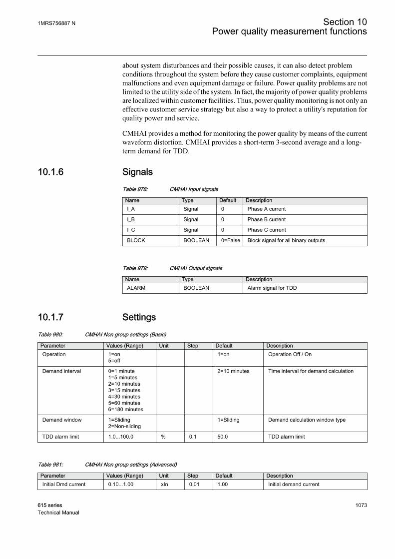
about system disturbances and their possible causes, it can also detect problemconditions throughout the system before they cause customer complaints, equipmentmalfunctions and even equipment damage or failure. Power quality problems are notlimited to the utility side of the system. In fact, the majority of power quality problemsare localized within customer facilities. Thus, power quality monitoring is not only aneffective customer service strategy but also a way to protect a utility's reputation forquality power and service.
CMHAI provides a method for monitoring the power quality by means of the currentwaveform distortion. CMHAI provides a short-term 3-second average and a long-term demand for TDD.
10.1.6 SignalsTable 978: CMHAI Input signals
Name Type Default DescriptionI_A Signal 0 Phase A current
I_B Signal 0 Phase B current
I_C Signal 0 Phase C current
BLOCK BOOLEAN 0=False Block signal for all binary outputs
Table 979: CMHAI Output signals
Name Type DescriptionALARM BOOLEAN Alarm signal for TDD
10.1.7 SettingsTable 980: CMHAI Non group settings (Basic)
Parameter Values (Range) Unit Step Default DescriptionOperation 1=on
5=off 1=on Operation Off / On
Demand interval 0=1 minute1=5 minutes2=10 minutes3=15 minutes4=30 minutes5=60 minutes6=180 minutes
2=10 minutes Time interval for demand calculation
Demand window 1=Sliding2=Non-sliding
1=Sliding Demand calculation window type
TDD alarm limit 1.0...100.0 % 0.1 50.0 TDD alarm limit
Table 981: CMHAI Non group settings (Advanced)
Parameter Values (Range) Unit Step Default DescriptionInitial Dmd current 0.10...1.00 xIn 0.01 1.00 Initial demand current
1MRS756887 N Section 10Power quality measurement functions
615 series 1073Technical Manual
10.1.8 Monitored dataTable 982: CMHAI Monitored data
Name Type Values (Range) Unit DescriptionMax demand TDDIL1
FLOAT32 0.00...500.00 % Maximum demand TDDfor phase A
Max demand TDDIL2
FLOAT32 0.00...500.00 % Maximum demand TDDfor phase B
Max demand TDDIL3
FLOAT32 0.00...500.00 % Maximum demand TDDfor phase C
Time max dmd TDDIL1
Timestamp Time of maximumdemand TDD phase A
Time max dmd TDDIL2
Timestamp Time of maximumdemand TDD phase B
Time max dmd TDDIL3
Timestamp Time of maximumdemand TDD phase C
3SMHTDD_A FLOAT32 0.00...500.00 % 3 second mean value ofTDD for phase A
DMD_TDD_A FLOAT32 0.00...500.00 % Demand value for TDDfor phase A
3SMHTDD_B FLOAT32 0.00...500.00 % 3 second mean value ofTDD for phase B
DMD_TDD_B FLOAT32 0.00...500.00 % Demand value for TDDfor phase B
3SMHTDD_C FLOAT32 0.00...500.00 % 3 second mean value ofTDD for phase C
DMD_TDD_C FLOAT32 0.00...500.00 % Demand value for TDDfor phase C
10.1.9 Technical revision historyTable 983: CMHAI Technical revision history
Technical revision ChangeB Internal improvement.
C Internal improvement.
D Internal improvement.
10.2 Voltage total harmonic distortion VMHAI
10.2.1 IdentificationFunction description IEC 61850
identificationIEC 60617identification
ANSI/IEEE C37.2device number
Voltage total harmonic distortion VMHAI PQM3U PQM3V
Section 10 1MRS756887 NPower quality measurement functions
1074 615 seriesTechnical Manual

10.2.2 Function block
GUID-CF203BDC-8C9A-442C-8D31-1AD55110469C V1 EN
Figure 569: Function block
10.2.3 Functionality
The voltage total harmonic distortion function VMHAI is used for monitoring thevoltage total harmonic distortion THD.
10.2.4 Operation principle
The function can be enabled and disabled with the Operation setting. Thecorresponding parameter values are "On" and "Off".
The operation of VMHAI can be described with a module diagram. All the modulesin the diagram are explained in the next sections.
Distortion measure-
ment
Demand calculation
BLOCK
ALARM
U_A_AB
U_B_BC
U_C_CA
GUID-615D1A8A-621A-4AFA-ABB0-C681208AE62C V1 EN
Figure 570: Functional module diagram
Distortion measurementThe distortion measurement module measures harmonics up to the 11th harmonic.The total harmonic distortion THD for voltage is calculated from the measuredharmonic components with the formula
THD
U
U
kk
N
==
∑2
2
1
GUID-83A22E8C-5F4D-4332-A832-4E48B35550EF V1 EN (Equation 197)
Uk kth harmonic component
U1 the voltage fundamental component amplitude
1MRS756887 N Section 10Power quality measurement functions
615 series 1075Technical Manual

Demand calculationThe demand value for THD is calculated separately for each phase. If any of thecalculated demand THD values is above the set alarm limit THD alarm limit, theALARM output is activated.
The demand calculation window is set with the Demand interval setting. It has sevenwindow lengths from "1 minute" to "180 minutes". The window type can be set withthe Demand window setting. The available options are "Sliding" and "Non-sliding".
The activation of the BLOCK input blocks the ALARM output.
10.2.5 Application
VMHAI provides a method for monitoring the power quality by means of the voltagewaveform distortion. VMHAI provides a short-term three-second average and long-term demand for THD.
10.2.6 SignalsTable 984: VMHAI Input signals
Name Type Default DescriptionU_A_AB SIGNAL 0 Phase-to-earth voltage A or phase-to-phase
voltage AB
U_B_BC SIGNAL 0 Phase-to-earth voltage B or phase-to-phasevoltage BC
U_C_CA SIGNAL 0 Phase-to-earth voltage C or phase-to-phasevoltage CA
BLOCK BOOLEAN 0=False Block signal for all binary outputs
Table 985: VMHAI Output signals
Name Type DescriptionALARM BOOLEAN Alarm signal for THD
Section 10 1MRS756887 NPower quality measurement functions
1076 615 seriesTechnical Manual
10.2.7 SettingsTable 986: VMHAI Non group settings (Basic)
Parameter Values (Range) Unit Step Default DescriptionOperation 1=on
5=off 1=on Operation Off / On
Demand interval 0=1 minute1=5 minutes2=10 minutes3=15 minutes4=30 minutes5=60 minutes6=180 minutes
2=10 minutes Time interval for demand calculation
Demand window 1=Sliding2=Non-sliding
1=Sliding Demand calculation window type
THD alarm limit 1.0...100.0 % 0.1 50.0 THD alarm limit
10.2.8 Monitored dataTable 987: VMHAI Monitored data
Name Type Values (Range) Unit DescriptionMax demand THDUL1
FLOAT32 0.00...500.00 % Maximum demand THDfor phase A
Max demand THDUL2
FLOAT32 0.00...500.00 % Maximum demand THDfor phase B
Max demand THDUL3
FLOAT32 0.00...500.00 % Maximum demand THDfor phase C
Time max dmd THDUL1
Timestamp Time of maximumdemand THD phase A
Time max dmd THDUL2
Timestamp Time of maximumdemand THD phase B
Time max dmd THDUL3
Timestamp Time of maximumdemand THD phase C
3SMHTHD_A FLOAT32 0.00...500.00 % 3 second mean value ofTHD for phase A
DMD_THD_A FLOAT32 0.00...500.00 % Demand value for THDfor phase A
3SMHTHD_B FLOAT32 0.00...500.00 % 3 second mean value ofTHD for phase B
DMD_THD_B FLOAT32 0.00...500.00 % Demand value for THDfor phase B
3SMHTHD_C FLOAT32 0.00...500.00 % 3 second mean value ofTHD for phase C
DMD_THD_C FLOAT32 0.00...500.00 % Demand value for THDfor phase C
1MRS756887 N Section 10Power quality measurement functions
615 series 1077Technical Manual

10.2.9 Technical revision historyTable 988: VMHAI Technical revision history
Technical revision ChangeB Internal improvement.
C Internal improvement.
10.3 Voltage variation PHQVVR
10.3.1 IdentificationFunction description IEC 61850
identificationIEC 60617identification
ANSI/IEEE C37.2device number
Voltage variation PHQVVR PQMU PQMV
10.3.2 Function block
GUID-9AA7CE99-C11C-4312-89B4-1C015476A165 V1 EN
Figure 571: Function block
10.3.3 Functionality
The voltage variation function PHQVVR is used for measuring the short-durationvoltage variations in distribution networks.
Power quality in the voltage waveform is evaluated by measuring voltage swells, dipsand interruptions. PHQVVR includes single-phase and three-phase voltage variationmodes.
Typically, short-duration voltage variations are defined to last more than half of thenominal frequency period and less than one minute. The maximum magnitude (in thecase of a voltage swell) or depth (in the case of a voltage dip or interruption) and theduration of the variation can be obtained by measuring the RMS value of the voltagefor each phase. International standard 61000-4-30 defines the voltage variation to beimplemented using the RMS value of the voltage. IEEE standard 1159-1995 providesrecommendations for monitoring the electric power quality of the single-phase andpolyphase ac power systems.
Section 10 1MRS756887 NPower quality measurement functions
1078 615 seriesTechnical Manual
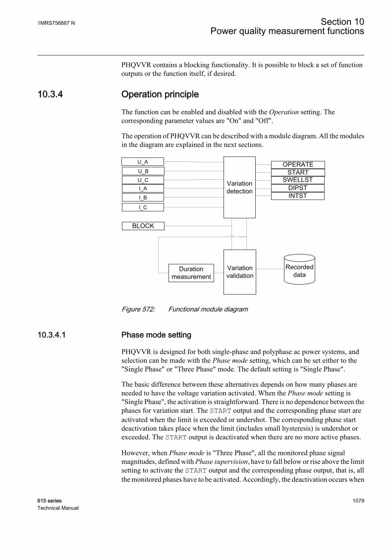
PHQVVR contains a blocking functionality. It is possible to block a set of functionoutputs or the function itself, if desired.
10.3.4 Operation principle
The function can be enabled and disabled with the Operation setting. Thecorresponding parameter values are "On" and "Off".
The operation of PHQVVR can be described with a module diagram. All the modulesin the diagram are explained in the next sections.
U_A
U_BU_CI_A
I_B
I_C
GUID-91ED3E3D-F014-49EE-B4B0-DAD2509DD013 V1 EN
Figure 572: Functional module diagram
10.3.4.1 Phase mode setting
PHQVVR is designed for both single-phase and polyphase ac power systems, andselection can be made with the Phase mode setting, which can be set either to the"Single Phase" or "Three Phase" mode. The default setting is "Single Phase".
The basic difference between these alternatives depends on how many phases areneeded to have the voltage variation activated. When the Phase mode setting is"Single Phase", the activation is straightforward. There is no dependence between thephases for variation start. The START output and the corresponding phase start areactivated when the limit is exceeded or undershot. The corresponding phase startdeactivation takes place when the limit (includes small hysteresis) is undershot orexceeded. The START output is deactivated when there are no more active phases.
However, when Phase mode is "Three Phase", all the monitored phase signalmagnitudes, defined with Phase supervision, have to fall below or rise above the limitsetting to activate the START output and the corresponding phase output, that is, allthe monitored phases have to be activated. Accordingly, the deactivation occurs when
1MRS756887 N Section 10Power quality measurement functions
615 series 1079Technical Manual

the activation requirement is not fulfilled, that is, one or more monitored phase signalmagnitudes return beyond their limits. Phases do not need to be activated by the samevariation type to activate the START output. Another consequence is that if only oneor two phases are monitored, it is sufficient that these monitored phases activate theSTART output.
10.3.4.2 Variation detection
The module compares the measured voltage against the limit settings. If there is apermanent undervoltage or overvoltage, the Reference voltage setting can be set tothis voltage level to avoid the undesired voltage dip or swell indications. This isaccomplished by converting the variation limits with the Reference voltage setting inthe variation detection module, that is, when there is a voltage different from thenominal voltage, the Reference voltage setting is set to this voltage.
The Variation enable setting is used for enabling or disabling the variation types. Bydefault, the setting value is "Swell+dip+Int" and all the alternative variation types areindicated. For example, for setting "Swell+dip", the interruption detection is notactive and only swell or dip events are indicated.
In a case where Phase mode is "Single Phase" and the dip functionality is available,the output DIPST is activated when the measured TRMS value drops below theVoltage dip set 3 setting in one phase and also remains above the Voltage Int setsetting. If the voltage drops below the Voltage Int set setting, the output INTST isactivated. INTST is deactivated when the voltage value rises above the settingVoltage Int set. When the same measured TRMS magnitude rises above the settingVoltage swell set 3, the SWELLST output is activated.
There are three setting value limits for dip (Voltage dip set 1..3) and swell activation(Voltage swell set 1..3) and one setting value limit for interruption.
If Phase mode is "Three Phase", the DIPST and INTST outputs areactivated when the voltage levels of all monitored phases, definedwith the parameter Phase supervision, drop below the Voltage Int setsetting value. An example for the detection principle of voltageinterruption for "Three Phase" when Phase supervision is "Ph A + B+ C", and also the corresponding start signals when Phase mode is"Single Phase", are as shown in the example for the detection of athree-phase interruption.
Section 10 1MRS756887 NPower quality measurement functions
1080 615 seriesTechnical Manual
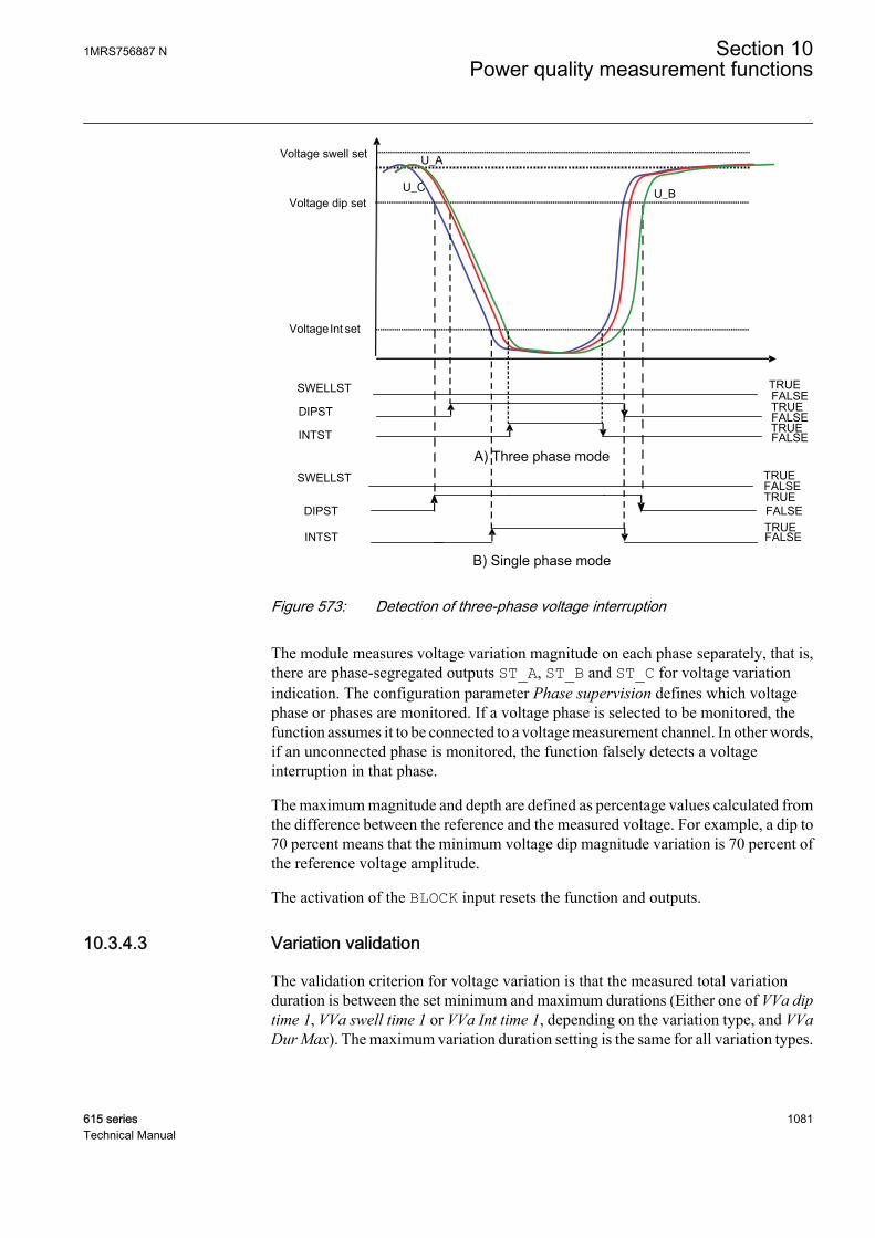
U_A
U_C U_B
DIPST
INTST
SWELLST
Voltage Int set
Voltage dip set
Voltage swell set
FALSETRUE FALSETRUE
FALSETRUE
DIPST
INTST
SWELLST
FALSETRUE FALSETRUE
FALSETRUE
A) Three phase mode
B) Single phase modeGUID-F44C8E6E-9354-44E4-9B2E-600D66B76C1A V1 EN
Figure 573: Detection of three-phase voltage interruption
The module measures voltage variation magnitude on each phase separately, that is,there are phase-segregated outputs ST_A, ST_B and ST_C for voltage variationindication. The configuration parameter Phase supervision defines which voltagephase or phases are monitored. If a voltage phase is selected to be monitored, thefunction assumes it to be connected to a voltage measurement channel. In other words,if an unconnected phase is monitored, the function falsely detects a voltageinterruption in that phase.
The maximum magnitude and depth are defined as percentage values calculated fromthe difference between the reference and the measured voltage. For example, a dip to70 percent means that the minimum voltage dip magnitude variation is 70 percent ofthe reference voltage amplitude.
The activation of the BLOCK input resets the function and outputs.
10.3.4.3 Variation validation
The validation criterion for voltage variation is that the measured total variationduration is between the set minimum and maximum durations (Either one of VVa diptime 1, VVa swell time 1 or VVa Int time 1, depending on the variation type, and VVaDur Max). The maximum variation duration setting is the same for all variation types.
1MRS756887 N Section 10Power quality measurement functions
615 series 1081Technical Manual
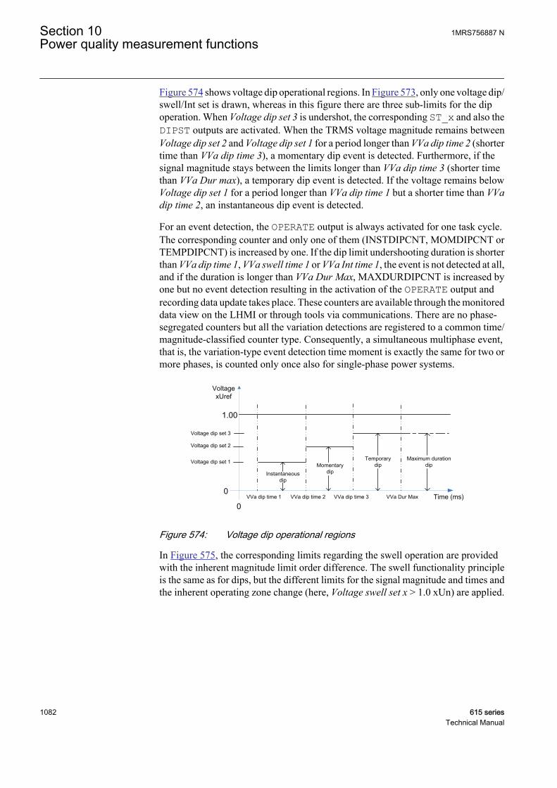
Figure 574 shows voltage dip operational regions. In Figure 573, only one voltage dip/swell/Int set is drawn, whereas in this figure there are three sub-limits for the dipoperation. When Voltage dip set 3 is undershot, the corresponding ST_x and also theDIPST outputs are activated. When the TRMS voltage magnitude remains betweenVoltage dip set 2 and Voltage dip set 1 for a period longer than VVa dip time 2 (shortertime than VVa dip time 3), a momentary dip event is detected. Furthermore, if thesignal magnitude stays between the limits longer than VVa dip time 3 (shorter timethan VVa Dur max), a temporary dip event is detected. If the voltage remains belowVoltage dip set 1 for a period longer than VVa dip time 1 but a shorter time than VVadip time 2, an instantaneous dip event is detected.
For an event detection, the OPERATE output is always activated for one task cycle.The corresponding counter and only one of them (INSTDIPCNT, MOMDIPCNT orTEMPDIPCNT) is increased by one. If the dip limit undershooting duration is shorterthan VVa dip time 1, VVa swell time 1 or VVa Int time 1, the event is not detected at all,and if the duration is longer than VVa Dur Max, MAXDURDIPCNT is increased byone but no event detection resulting in the activation of the OPERATE output andrecording data update takes place. These counters are available through the monitoreddata view on the LHMI or through tools via communications. There are no phase-segregated counters but all the variation detections are registered to a common time/magnitude-classified counter type. Consequently, a simultaneous multiphase event,that is, the variation-type event detection time moment is exactly the same for two ormore phases, is counted only once also for single-phase power systems.
Voltage dip set 1
Voltage dip set 2
Voltage dip set 3
VoltagexUref
Time (ms)0
0VVa Dur MaxVVa dip time 3VVa dip time 1 VVa dip time 2
1.00
Instantaneousdip
TemporarydipMomentary
dip
Maximum durationdip
GUID-0D3F6D81-F905-4D8D-A579-836EF7BB6773 V1 EN
Figure 574: Voltage dip operational regions
In Figure 575, the corresponding limits regarding the swell operation are providedwith the inherent magnitude limit order difference. The swell functionality principleis the same as for dips, but the different limits for the signal magnitude and times andthe inherent operating zone change (here, Voltage swell set x > 1.0 xUn) are applied.
Section 10 1MRS756887 NPower quality measurement functions
1082 615 seriesTechnical Manual

Voltage swell set 3
Voltage swell set 2
Voltage swell set 1
VoltagexUref
Time (ms)0
0VVa Dur MaxVVa swell time 3VVa swell time 1 VVa swell time 2
1.40Instantaneous
swellTemporary
swell
Momentaryswell Maximum duration
swell
1.00
GUID-7F23358A-5B42-4F5B-8F12-B157208C8945 V1 EN
Figure 575: Voltage swell operational regions
For interruption, as shown in Figure 576, there is only one magnitude limit but fourduration limits for interruption classification. Now the event and counter type dependsonly on variation duration time.
Voltage Int set
VoltagexUref
Time (ms)0
0VVa Dur MaxVVa Int time 3VVa Int time 1 VVa Int time 2
1.00
Momentaryinterruption
Sustainedinterruption
Temporaryinterruption
Maximum durationinterruption
GUID-AA022CA2-4CBF-49A1-B710-AB602F8C8343 V1 EN
Figure 576: Interruption operating regions
Generally, no event detection is done if both the magnitude and duration requirementsare not fulfilled. For example, the dip event does not indicate if the TRMS voltagemagnitude remains between Voltage dip set 3 and Voltage dip set 2 for a period shorterthan VVa dip time 3 before rising back above Voltage dip set 3.
The event indication ends and possible detection is done when the TRMS voltagereturns above (for dip and interruption) or below (for swell) the activation-startinglimit. For example, after an instantaneous dip, the event indication when the voltagemagnitude exceeds Voltage dip set 1 is not detected (and recorded) immediately butonly if no longer dip indication for the same dip variation takes place and maximumduration time for dip variation does not exceed before the signal magnitude risesabove Voltage dip set 3. There is a small hysteresis for all these limits to avoid theoscillation of the output activation. No drop-off approach is applied here due to thehysteresis.
1MRS756887 N Section 10Power quality measurement functions
615 series 1083Technical Manual
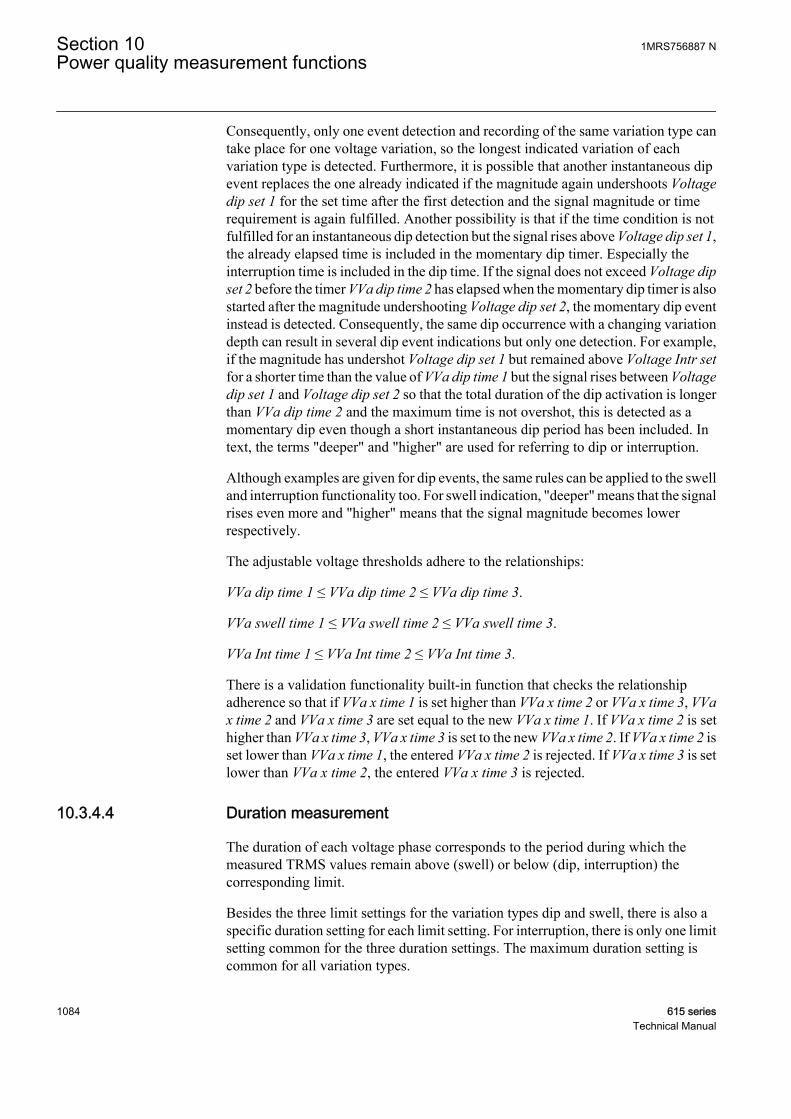
Consequently, only one event detection and recording of the same variation type cantake place for one voltage variation, so the longest indicated variation of eachvariation type is detected. Furthermore, it is possible that another instantaneous dipevent replaces the one already indicated if the magnitude again undershoots Voltagedip set 1 for the set time after the first detection and the signal magnitude or timerequirement is again fulfilled. Another possibility is that if the time condition is notfulfilled for an instantaneous dip detection but the signal rises above Voltage dip set 1,the already elapsed time is included in the momentary dip timer. Especially theinterruption time is included in the dip time. If the signal does not exceed Voltage dipset 2 before the timer VVa dip time 2 has elapsed when the momentary dip timer is alsostarted after the magnitude undershooting Voltage dip set 2, the momentary dip eventinstead is detected. Consequently, the same dip occurrence with a changing variationdepth can result in several dip event indications but only one detection. For example,if the magnitude has undershot Voltage dip set 1 but remained above Voltage Intr setfor a shorter time than the value of VVa dip time 1 but the signal rises between Voltagedip set 1 and Voltage dip set 2 so that the total duration of the dip activation is longerthan VVa dip time 2 and the maximum time is not overshot, this is detected as amomentary dip even though a short instantaneous dip period has been included. Intext, the terms "deeper" and "higher" are used for referring to dip or interruption.
Although examples are given for dip events, the same rules can be applied to the swelland interruption functionality too. For swell indication, "deeper" means that the signalrises even more and "higher" means that the signal magnitude becomes lowerrespectively.
The adjustable voltage thresholds adhere to the relationships:
VVa dip time 1 ≤ VVa dip time 2 ≤ VVa dip time 3.
VVa swell time 1 ≤ VVa swell time 2 ≤ VVa swell time 3.
VVa Int time 1 ≤ VVa Int time 2 ≤ VVa Int time 3.
There is a validation functionality built-in function that checks the relationshipadherence so that if VVa x time 1 is set higher than VVa x time 2 or VVa x time 3, VVax time 2 and VVa x time 3 are set equal to the new VVa x time 1. If VVa x time 2 is sethigher than VVa x time 3, VVa x time 3 is set to the new VVa x time 2. If VVa x time 2 isset lower than VVa x time 1, the entered VVa x time 2 is rejected. If VVa x time 3 is setlower than VVa x time 2, the entered VVa x time 3 is rejected.
10.3.4.4 Duration measurement
The duration of each voltage phase corresponds to the period during which themeasured TRMS values remain above (swell) or below (dip, interruption) thecorresponding limit.
Besides the three limit settings for the variation types dip and swell, there is also aspecific duration setting for each limit setting. For interruption, there is only one limitsetting common for the three duration settings. The maximum duration setting iscommon for all variation types.
Section 10 1MRS756887 NPower quality measurement functions
1084 615 seriesTechnical Manual
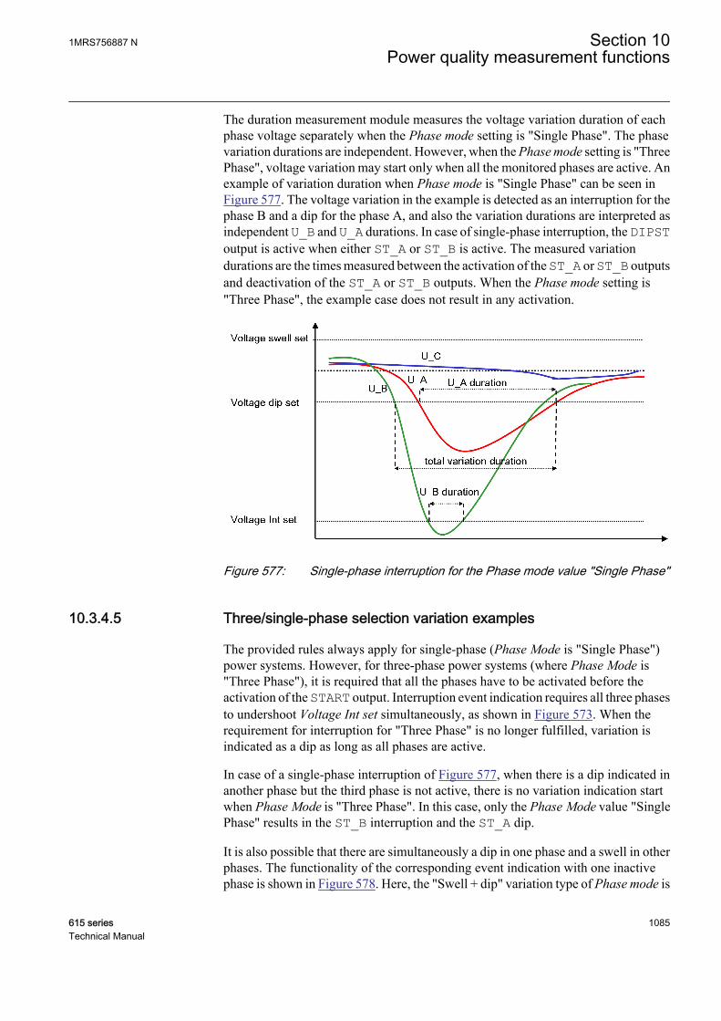
The duration measurement module measures the voltage variation duration of eachphase voltage separately when the Phase mode setting is "Single Phase". The phasevariation durations are independent. However, when the Phase mode setting is "ThreePhase", voltage variation may start only when all the monitored phases are active. Anexample of variation duration when Phase mode is "Single Phase" can be seen inFigure 577. The voltage variation in the example is detected as an interruption for thephase B and a dip for the phase A, and also the variation durations are interpreted asindependent U_B and U_A durations. In case of single-phase interruption, the DIPSToutput is active when either ST_A or ST_B is active. The measured variationdurations are the times measured between the activation of the ST_A or ST_B outputsand deactivation of the ST_A or ST_B outputs. When the Phase mode setting is"Three Phase", the example case does not result in any activation.
GUID-22014C0F-9FE2-4528-80BA-AEE2CD9813B8 V1 EN
Figure 577: Single-phase interruption for the Phase mode value "Single Phase"
10.3.4.5 Three/single-phase selection variation examples
The provided rules always apply for single-phase (Phase Mode is "Single Phase")power systems. However, for three-phase power systems (where Phase Mode is"Three Phase"), it is required that all the phases have to be activated before theactivation of the START output. Interruption event indication requires all three phasesto undershoot Voltage Int set simultaneously, as shown in Figure 573. When therequirement for interruption for "Three Phase" is no longer fulfilled, variation isindicated as a dip as long as all phases are active.
In case of a single-phase interruption of Figure 577, when there is a dip indicated inanother phase but the third phase is not active, there is no variation indication startwhen Phase Mode is "Three Phase". In this case, only the Phase Mode value "SinglePhase" results in the ST_B interruption and the ST_A dip.
It is also possible that there are simultaneously a dip in one phase and a swell in otherphases. The functionality of the corresponding event indication with one inactivephase is shown in Figure 578. Here, the "Swell + dip" variation type of Phase mode is
1MRS756887 N Section 10Power quality measurement functions
615 series 1085Technical Manual
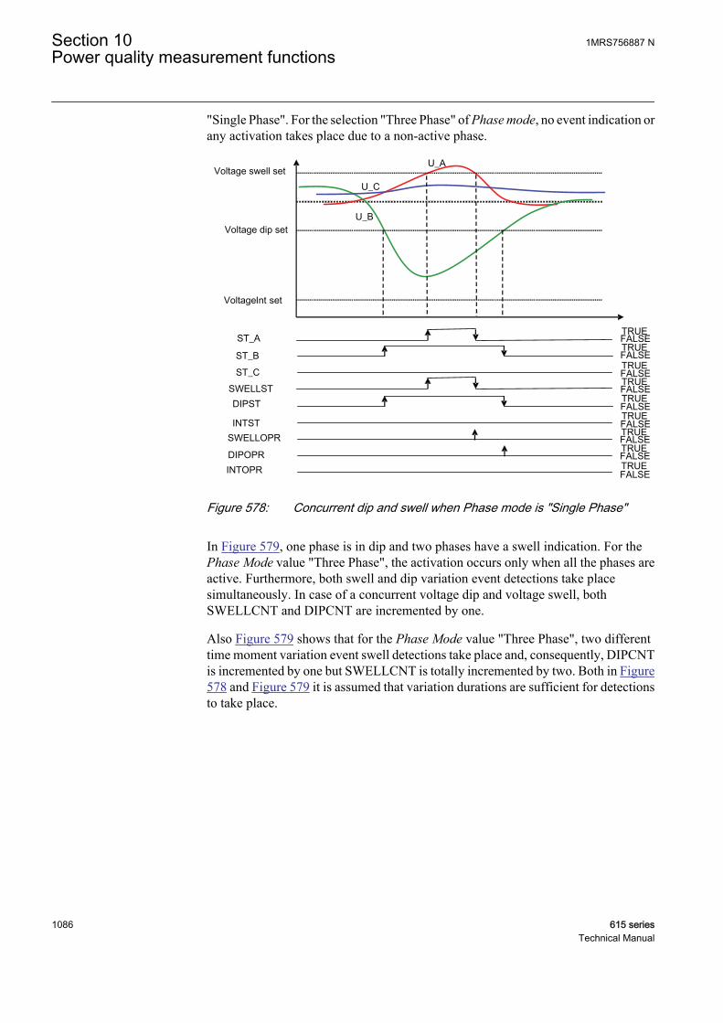
"Single Phase". For the selection "Three Phase" of Phase mode, no event indication orany activation takes place due to a non-active phase.
U_A
U_C
U_B
ST_BST_C
ST_A
DIPST
INTST
SWELLST
SWELLOPR
INTOPRDIPOPR
Voltage Int set
Voltage dip set
Voltage swell set
FALSETRUE FALSETRUE
FALSETRUE
FALSETRUE FALSETRUE
FALSETRUE
FALSETRUE FALSETRUE
FALSETRUE
GUID-0657A163-7D42-4543-8EC8-3DF84E2F0BF5 V1 EN
Figure 578: Concurrent dip and swell when Phase mode is "Single Phase"
In Figure 579, one phase is in dip and two phases have a swell indication. For thePhase Mode value "Three Phase", the activation occurs only when all the phases areactive. Furthermore, both swell and dip variation event detections take placesimultaneously. In case of a concurrent voltage dip and voltage swell, bothSWELLCNT and DIPCNT are incremented by one.
Also Figure 579 shows that for the Phase Mode value "Three Phase", two differenttime moment variation event swell detections take place and, consequently, DIPCNTis incremented by one but SWELLCNT is totally incremented by two. Both in Figure578 and Figure 579 it is assumed that variation durations are sufficient for detectionsto take place.
Section 10 1MRS756887 NPower quality measurement functions
1086 615 seriesTechnical Manual
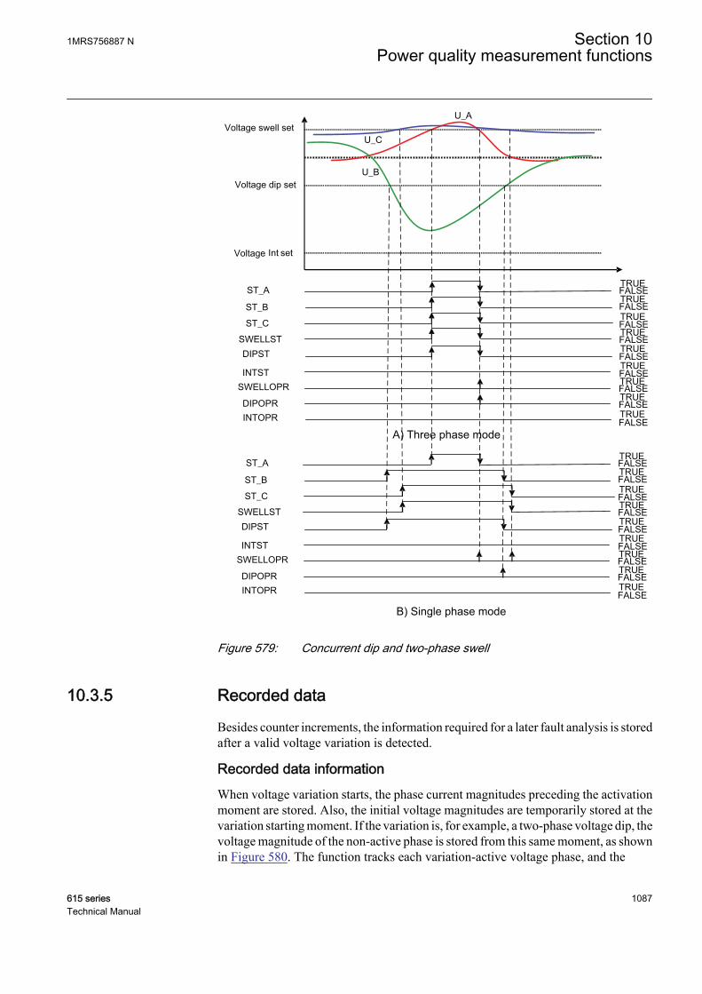
U_A
U_C
U_B
ST_BST_C
ST_A
DIPST
INTST
SWELLST
SWELLOPR
INTOPRDIPOPR
Voltage Int set
Voltage dip set
Voltage swell set
FALSETRUE FALSETRUE
FALSETRUE
FALSETRUE FALSETRUE
FALSETRUE
FALSETRUE FALSETRUE
FALSETRUE
ST_BST_C
ST_A
DIPST
INTST
SWELLST
SWELLOPR
INTOPRDIPOPR
FALSETRUE FALSETRUE
FALSETRUE
FALSETRUE FALSETRUE
FALSETRUE
FALSETRUE FALSETRUE
FALSETRUE
A) Three phase mode
B) Single phase modeGUID-1C0C906B-EC91-4C59-9291-B5002830E590 V1 EN
Figure 579: Concurrent dip and two-phase swell
10.3.5 Recorded data
Besides counter increments, the information required for a later fault analysis is storedafter a valid voltage variation is detected.
Recorded data informationWhen voltage variation starts, the phase current magnitudes preceding the activationmoment are stored. Also, the initial voltage magnitudes are temporarily stored at thevariation starting moment. If the variation is, for example, a two-phase voltage dip, thevoltage magnitude of the non-active phase is stored from this same moment, as shownin Figure 580. The function tracks each variation-active voltage phase, and the
1MRS756887 N Section 10Power quality measurement functions
615 series 1087Technical Manual

minimum or maximum magnitude corresponding to swell or dip/interruption duringvariation is temporarily stored. If the minimum or maximum is found in tracking anda new magnitude is stored, also the inactive phase voltages are stored at the samemoment, that is, the inactive phases are not magnitude-tracked. The time instant (timestamp) at which the minimum or maximum magnitude is measured is also temporarilystored for each voltage phase where variation is active. Finally, variation detectiontriggers the recorded data update when the variation activation ends and the maximumduration time is not exceeded.
The data objects to be recorded for PHQVVR are given in Table 989. There are totallythree data banks, and the information given in the table refers to one data bank content.
The three sets of recorded data available are saved in data banks 1-3. The data bank 1holds always the most recent recorded data, and the older data sets are moved to thenext banks (1→2 and 2→3) when a valid voltage variation is detected. When all threebanks have data and a new variation is detected, the newest data are placed into bank1 and the data in bank 3 are overwritten by the data from bank 2.
Figure 580 shows a valid recorded voltage interruption and two dips for the Phasemode value "Single Phase". The first dip event duration is based on the U_A duration,while the second dip is based on the time difference between the dip stop and starttimes. The first detected event is an interruption based on the U_B duration given inFigure 580. It is shown also with dotted arrows how voltage time stamps are takenbefore the final time stamp for recording, which is shown as a solid arrow. Here, theU_B timestamp is not taken when the U_A activation starts.
U_A
U_C
U_BU_A duration
U_B duration
U_B amplitude & timestamp
U_A amplitude & timestamp
U_C amplitude & timestamp
Voltage dip set
Voltage swell set
Dip
star
t
Dip
stop
Voltage Int set
GUID-7A859344-8960-4CF3-B637-E2DE6D3BDA85 V1 EN
Figure 580: Valid recorded voltage interruption and two dips
Section 10 1MRS756887 NPower quality measurement functions
1088 615 seriesTechnical Manual

Table 989: PHQVVR recording data bank parameters
Parameter description Parameter nameEvent detection triggering time stamp Time
Variation type Variation type
Variation magnitude Ph A Variation Ph A
Variation magnitude Ph A time stamp (maximum/minimum magnitude measuring time momentduring variation)
Var Ph A rec time
Variation magnitude Ph B Variation Ph B
Variation magnitude Ph B time stamp (maximum/minimum magnitude measuring time momentduring variation)
Var Ph B rec time
Variation magnitude Ph C Variation Ph C
Variation magnitude Ph C time stamp (maximum/minimum magnitude measuring time momentduring variation)
Var Ph C rec time
Variation duration Ph A Variation Dur Ph A
Variation Ph A start time stamp (phase A variationstart time moment)
Var Dur Ph A time
Variation duration Ph B Variation Dur Ph B
Variation Ph B start time stamp (phase B variationstart time moment)
Var Dur Ph B time
Variation duration Ph C Variation Dur Ph C
Variation Ph C start time stamp (phase C variationstart time moment)
Var Dur Ph C time
Current magnitude Ph A preceding variation Var current Ph A
Current magnitude Ph B preceding variation Var current Ph B
Current magnitude Ph C preceding variation Var current Ph C
Table 990: Enumeration values for the recorded data parameters
Setting name Enum name ValueVariation type Swell 1
Variation type Dip 2
Variation type Swell + dip 3
Variation type Interruption 4
Variation type Swell + Int 5
Variation type Dip + Int 6
Variation type Swell+dip+Int 7
10.3.6 Application
Voltage variations are the most typical power quality variations on the public electricnetwork. Typically, short-duration voltage variations are defined to last more than
1MRS756887 N Section 10Power quality measurement functions
615 series 1089Technical Manual

half of the nominal frequency period and less than one minute (European Standard EN50160 and IEEE Std 1159-1995).
These short-duration voltage variations are almost always caused by a fault condition.Depending on where the fault is located, it can cause either a temporary voltage rise(swell) or voltage drop (dip). A special case of voltage drop is the complete loss ofvoltage (interruption).
PHQVVR is used for measuring short-duration voltage variations in distributionnetworks. The power quality is evaluated in the voltage waveform by measuring thevoltage swells, dips and interruptions.
U_B
interruption
dip
swell
duration
max duration
magnitude
Voltage Int set
Voltage dip set
Voltage swell set
V Var Dur point 1 V Var Dur point 2
min duration
GUID-EF7957CE-E6EF-483E-A879-ABD003AC1AF9 V1 EN
Figure 581: Duration and voltage magnitude limits for swell, dip and interruptionmeasurement
Voltage dips disturb the sensitive equipment such as computers connected to thepower system and may result in the failure of the equipment. Voltage dips are typicallycaused by faults occurring in the power distribution system. Typical reasons for thefaults are lightning strikes and tree contacts. In addition to fault situations, theswitching of heavy loads and starting of large motors also cause dips.
Voltage swells cause extra stress for the network components and the devicesconnected to the power system. Voltage swells are typically caused by the earth faultsthat occur in the power distribution system.
Voltage interruptions are typically associated with the switchgear operation related tothe occurrence and termination of short circuits. The operation of a circuit breakerdisconnects a part of the system from the source of energy. In the case of overheadnetworks, automatic reclosing sequences are often applied to the circuit breakers that
Section 10 1MRS756887 NPower quality measurement functions
1090 615 seriesTechnical Manual
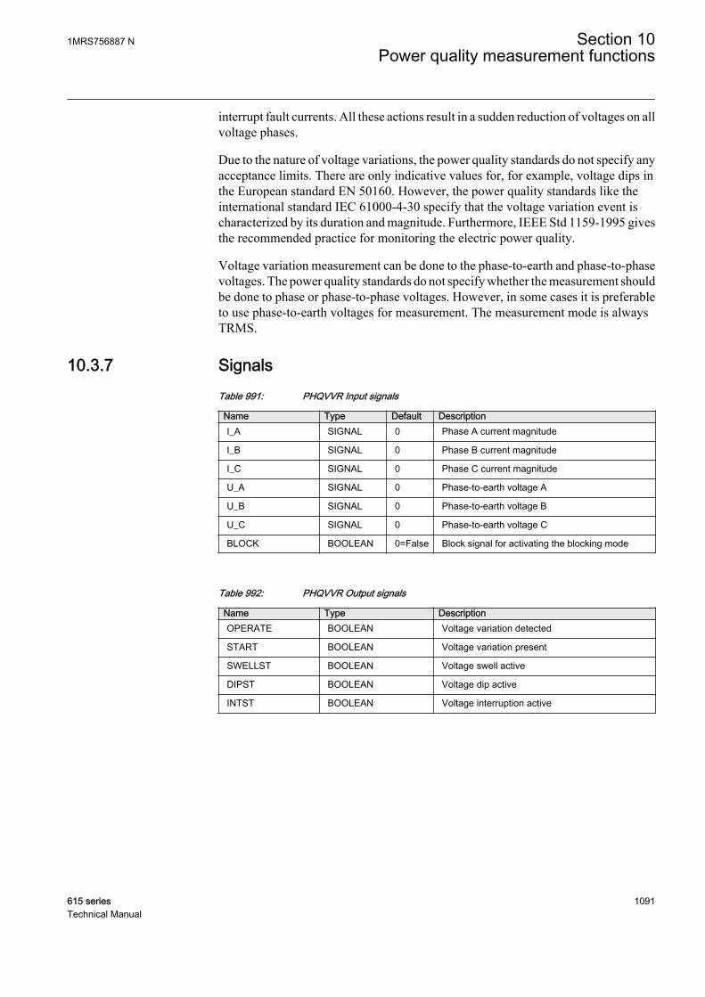
interrupt fault currents. All these actions result in a sudden reduction of voltages on allvoltage phases.
Due to the nature of voltage variations, the power quality standards do not specify anyacceptance limits. There are only indicative values for, for example, voltage dips inthe European standard EN 50160. However, the power quality standards like theinternational standard IEC 61000-4-30 specify that the voltage variation event ischaracterized by its duration and magnitude. Furthermore, IEEE Std 1159-1995 givesthe recommended practice for monitoring the electric power quality.
Voltage variation measurement can be done to the phase-to-earth and phase-to-phasevoltages. The power quality standards do not specify whether the measurement shouldbe done to phase or phase-to-phase voltages. However, in some cases it is preferableto use phase-to-earth voltages for measurement. The measurement mode is alwaysTRMS.
10.3.7 SignalsTable 991: PHQVVR Input signals
Name Type Default DescriptionI_A SIGNAL 0 Phase A current magnitude
I_B SIGNAL 0 Phase B current magnitude
I_C SIGNAL 0 Phase C current magnitude
U_A SIGNAL 0 Phase-to-earth voltage A
U_B SIGNAL 0 Phase-to-earth voltage B
U_C SIGNAL 0 Phase-to-earth voltage C
BLOCK BOOLEAN 0=False Block signal for activating the blocking mode
Table 992: PHQVVR Output signals
Name Type DescriptionOPERATE BOOLEAN Voltage variation detected
START BOOLEAN Voltage variation present
SWELLST BOOLEAN Voltage swell active
DIPST BOOLEAN Voltage dip active
INTST BOOLEAN Voltage interruption active
1MRS756887 N Section 10Power quality measurement functions
615 series 1091Technical Manual

10.3.8 SettingsTable 993: PHQVVR Group settings (Basic)
Parameter Values (Range) Unit Step Default DescriptionReference voltage 10.0...200.0 %Un 0.1 57.7 Reference supply voltage in %
Voltage dip set 1 10.0...100.0 % 0.1 80.0 Dip limit 1 in % of reference voltage
VVa dip time 1 0.5...54.0 cycles 0.1 3.0 Voltage variation dip duration 1
Voltage dip set 2 10.0...100.0 % 0.1 80.0 Dip limit 2 in % of reference voltage
VVa dip time 2 10.0...180.0 cycles 0.1 30.0 Voltage variation dip duration 2
Voltage dip set 3 10.0...100.0 % 0.1 80.0 Dip limit 3 in % of reference voltage
VVa dip time 3 2000...60000 ms 10 3000 Voltage variation dip duration 3
Voltage swell set 1 100.0...140.0 % 0.1 120.0 Swell limit 1 in % of reference voltage
VVa swell time 1 0.5...54.0 cycles 0.1 0.5 Voltage variation swell duration 1
Voltage swell set 2 100.0...140.0 % 0.1 120.0 Swell limit 2 in % of reference voltage
VVa swell time 2 10.0...80.0 cycles 0.1 10.0 Voltage variation swell duration 2
Voltage swell set 3 100.0...140.0 % 0.1 120.0 Swell limit 3 in % of reference voltage
VVa swell time 3 2000...60000 ms 10 2000 Voltage variation swell duration 3
Voltage Int set 0.0...100.0 % 0.1 10.0 Interruption limit in % of reference voltage
VVa Int time 1 0.5...30.0 cycles 0.1 3.0 Voltage variation Int duration 1
VVa Int time 2 10.0...180.0 cycles 0.1 30.0 Voltage variation Int duration 2
VVa Int time 3 2000...60000 ms 10 3000 Voltage variation interruption duration 3
VVa Dur Max 100...3600000 ms 100 60000 Maximum voltage variation duration
Table 994: PHQVVR Non group settings (Basic)
Parameter Values (Range) Unit Step Default DescriptionOperation 1=on
5=off 1=on Operation Off / On
Variation enable 1=Swell2=Dip3=Swell + dip4=Interruption5=Swell + Int6=Dip + Int7=Swell+dip+Int
7=Swell+dip+Int Enable variation type
Table 995: PHQVVR Non group settings (Advanced)
Parameter Values (Range) Unit Step Default DescriptionPhase supervision 1=Ph A
2=Ph B3=Ph A + B4=Ph C5=Ph A + C6=Ph B + C7=Ph A + B + C
7=Ph A + B + C Monitored voltage phase
Phase mode 1=Three Phase2=Single Phase
2=Single Phase Three/Single phase mode
Section 10 1MRS756887 NPower quality measurement functions
1092 615 seriesTechnical Manual

10.3.9 Monitored dataTable 996: PHQVVR Monitored data
Name Type Values (Range) Unit DescriptionST_A BOOLEAN 0=False
1=True Start Phase A (Voltage
Variation Event inprogress)
ST_B BOOLEAN 0=False1=True
Start Phase B (VoltageVariation Event inprogress)
ST_C BOOLEAN 0=False1=True
Start Phase C (VoltageVariation Event inprogress)
INSTSWELLCNT INT32 0...2147483647 Instantaneous swelloperation counter
MOMSWELLCNT INT32 0...2147483647 Momentary swelloperation counter
TEMPSWELLCNT INT32 0...2147483647 Temporary swelloperation counter
MAXDURSWELLCNT
INT32 0...2147483647 Maximum duration swelloperation counter
INSTDIPCNT INT32 0...2147483647 Instantaneous dipoperation counter
MOMDIPCNT INT32 0...2147483647 Momentary dip operationcounter
TEMPDIPCNT INT32 0...2147483647 Temporary dip operationcounter
MAXDURDIPCNT INT32 0...2147483647 Maximum duration dipoperation counter
MOMINTCNT INT32 0...2147483647 Momentary interruptionoperation counter
TEMPINTCNT INT32 0...2147483647 Temporary interruptionoperation counter
SUSTINTCNT INT32 0...2147483647 Sustained interruptionoperation counter
MAXDURINTCNT INT32 0...2147483647 Maximum durationinterruption operationcounter
PHQVVR Enum 1=on2=blocked3=test4=test/blocked5=off
Status
Time Timestamp Time
Variation type Enum 0=No variation1=Swell2=Dip3=Swell + dip4=Interruption5=Swell + Int6=Dip + Int7=Swell+dip+Int
Variation type
Table continues on next page
1MRS756887 N Section 10Power quality measurement functions
615 series 1093Technical Manual

Name Type Values (Range) Unit DescriptionVariation Ph A FLOAT32 0.00...5.00 xUn Variation magnitude
Phase A
Var Ph A rec time Timestamp Variation magnitudePhase A time stamp
Variation Ph B FLOAT32 0.00...5.00 xUn Variation magnitudePhase B
Var Ph B rec time Timestamp Variation magnitudePhase B time stamp
Variation Ph C FLOAT32 0.00...5.00 xUn Variation magnitudePhase C
Var Ph C rec time Timestamp Variation magnitudePhase C time stamp
Variation Dur Ph A FLOAT32 0.000...3600.000 s Variation duration PhaseA
Var Dur Ph A time Timestamp Variation Ph A start timestamp
Variation Dur Ph B FLOAT32 0.000...3600.000 s Variation duration PhaseB
Var Dur Ph B time Timestamp Variation Ph B start timestamp
Variation Dur Ph C FLOAT32 0.000...3600.000 s Variation duration PhaseC
Var Dur Ph C time Timestamp Variation Ph C start timestamp
Var current Ph A FLOAT32 0.00...60.00 xIn Current magnitudePhase A precedingvariation
Var current Ph B FLOAT32 0.00...60.00 xIn Current magnitudePhase B precedingvariation
Var current Ph C FLOAT32 0.00...60.00 xIn Current magnitudePhase C precedingvariation
Time Timestamp Time
Variation type Enum 0=No variation1=Swell2=Dip3=Swell + dip4=Interruption5=Swell + Int6=Dip + Int7=Swell+dip+Int
Variation type
Variation Ph A FLOAT32 0.00...5.00 xUn Variation magnitudePhase A
Var Ph A rec time Timestamp Variation magnitudePhase A time stamp
Variation Ph B FLOAT32 0.00...5.00 xUn Variation magnitudePhase B
Var Ph B rec time Timestamp Variation magnitudePhase B time stamp
Table continues on next page
Section 10 1MRS756887 NPower quality measurement functions
1094 615 seriesTechnical Manual
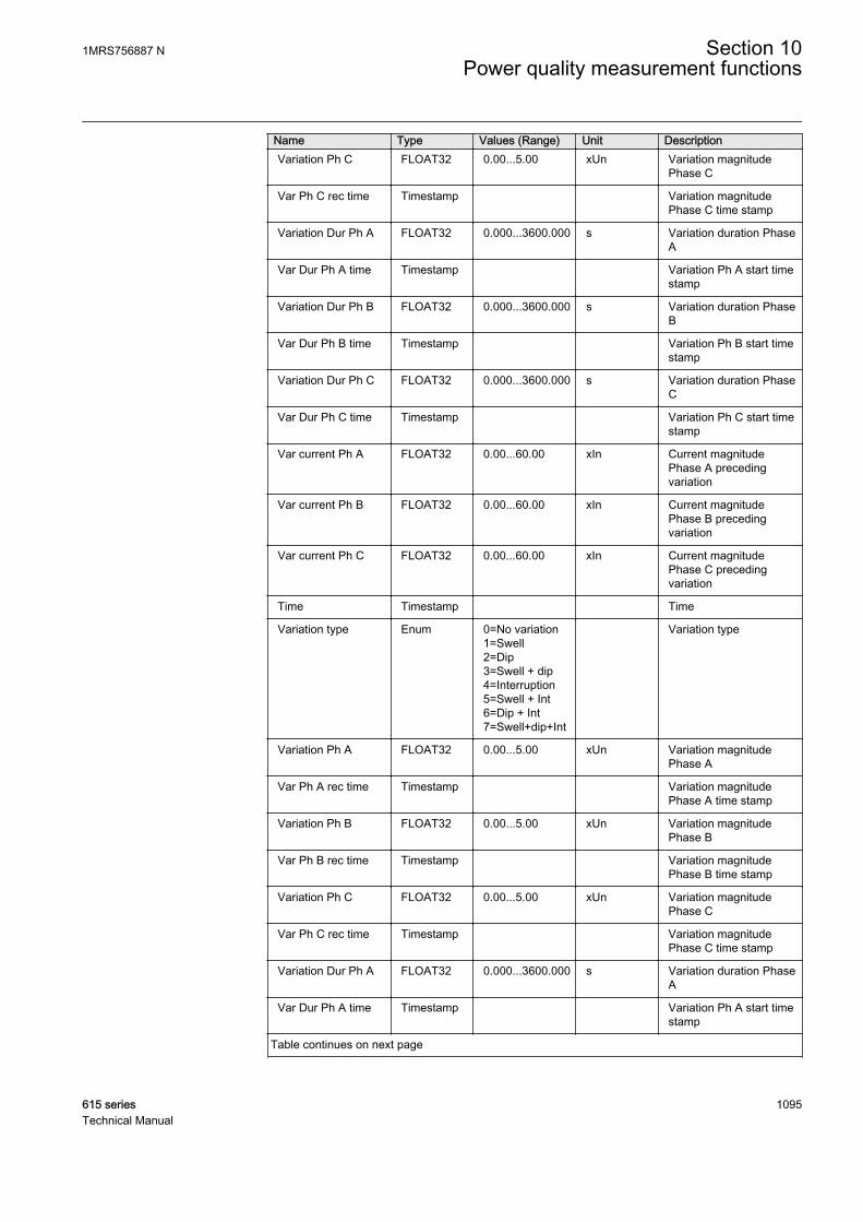
Name Type Values (Range) Unit DescriptionVariation Ph C FLOAT32 0.00...5.00 xUn Variation magnitude
Phase C
Var Ph C rec time Timestamp Variation magnitudePhase C time stamp
Variation Dur Ph A FLOAT32 0.000...3600.000 s Variation duration PhaseA
Var Dur Ph A time Timestamp Variation Ph A start timestamp
Variation Dur Ph B FLOAT32 0.000...3600.000 s Variation duration PhaseB
Var Dur Ph B time Timestamp Variation Ph B start timestamp
Variation Dur Ph C FLOAT32 0.000...3600.000 s Variation duration PhaseC
Var Dur Ph C time Timestamp Variation Ph C start timestamp
Var current Ph A FLOAT32 0.00...60.00 xIn Current magnitudePhase A precedingvariation
Var current Ph B FLOAT32 0.00...60.00 xIn Current magnitudePhase B precedingvariation
Var current Ph C FLOAT32 0.00...60.00 xIn Current magnitudePhase C precedingvariation
Time Timestamp Time
Variation type Enum 0=No variation1=Swell2=Dip3=Swell + dip4=Interruption5=Swell + Int6=Dip + Int7=Swell+dip+Int
Variation type
Variation Ph A FLOAT32 0.00...5.00 xUn Variation magnitudePhase A
Var Ph A rec time Timestamp Variation magnitudePhase A time stamp
Variation Ph B FLOAT32 0.00...5.00 xUn Variation magnitudePhase B
Var Ph B rec time Timestamp Variation magnitudePhase B time stamp
Variation Ph C FLOAT32 0.00...5.00 xUn Variation magnitudePhase C
Var Ph C rec time Timestamp Variation magnitudePhase C time stamp
Variation Dur Ph A FLOAT32 0.000...3600.000 s Variation duration PhaseA
Var Dur Ph A time Timestamp Variation Ph A start timestamp
Table continues on next page
1MRS756887 N Section 10Power quality measurement functions
615 series 1095Technical Manual

Name Type Values (Range) Unit DescriptionVariation Dur Ph B FLOAT32 0.000...3600.000 s Variation duration Phase
B
Var Dur Ph B time Timestamp Variation Ph B start timestamp
Variation Dur Ph C FLOAT32 0.000...3600.000 s Variation duration PhaseC
Var Dur Ph C time Timestamp Variation Ph C start timestamp
Var current Ph A FLOAT32 0.00...60.00 xIn Current magnitudePhase A precedingvariation
Var current Ph B FLOAT32 0.00...60.00 xIn Current magnitudePhase B precedingvariation
Var current Ph C FLOAT32 0.00...60.00 xIn Current magnitudePhase C precedingvariation
10.3.10 Technical dataTable 997: PHQVVR Technical data
Characteristic ValueOperation accuracy ±1.5% of the set value or ±0.2% of reference
voltage
Reset ratio Typically 0.96 (Swell), 1.04 (Dip, Interruption)
10.3.11 Technical revision historyTable 998: PHQVVR Technical revision history
Technical revision ChangeB Internal improvement
C Internal improvement
D Internal improvement
10.4 Voltage unbalance VSQVUB
10.4.1 IdentificationFunction description IEC 61850
identificationIEC 60617identification
ANSI/IEEE C37.2device number
Voltage unbalance VSQVUB PQUUB PQVUB
Section 10 1MRS756887 NPower quality measurement functions
1096 615 seriesTechnical Manual
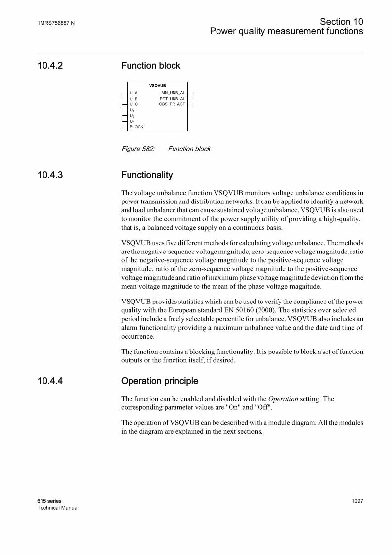
10.4.2 Function block
GUID-568233FA-CCCC-4D0F-998A-52F9F12AC0F9 V2 EN
Figure 582: Function block
10.4.3 Functionality
The voltage unbalance function VSQVUB monitors voltage unbalance conditions inpower transmission and distribution networks. It can be applied to identify a networkand load unbalance that can cause sustained voltage unbalance. VSQVUB is also usedto monitor the commitment of the power supply utility of providing a high-quality,that is, a balanced voltage supply on a continuous basis.
VSQVUB uses five different methods for calculating voltage unbalance. The methodsare the negative-sequence voltage magnitude, zero-sequence voltage magnitude, ratioof the negative-sequence voltage magnitude to the positive-sequence voltagemagnitude, ratio of the zero-sequence voltage magnitude to the positive-sequencevoltage magnitude and ratio of maximum phase voltage magnitude deviation from themean voltage magnitude to the mean of the phase voltage magnitude.
VSQVUB provides statistics which can be used to verify the compliance of the powerquality with the European standard EN 50160 (2000). The statistics over selectedperiod include a freely selectable percentile for unbalance. VSQVUB also includes analarm functionality providing a maximum unbalance value and the date and time ofoccurrence.
The function contains a blocking functionality. It is possible to block a set of functionoutputs or the function itself, if desired.
10.4.4 Operation principle
The function can be enabled and disabled with the Operation setting. Thecorresponding parameter values are "On" and "Off".
The operation of VSQVUB can be described with a module diagram. All the modulesin the diagram are explained in the next sections.
1MRS756887 N Section 10Power quality measurement functions
615 series 1097Technical Manual
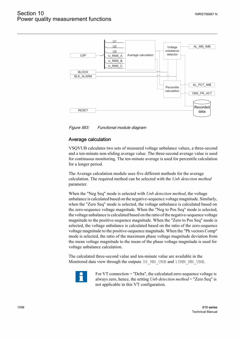
U3P
BLOCK
Average calculation
Voltageunbalancedetector
AL_MN_IMB
AL_PCT_IMB
OBS_PR_ACT
Percentilecalculation
U_RMS_A
U_RMS_B
U_RMS_C
U1
U2
U0
RESET
BLK_ALARM
GUID-6D371A54-607F-4073-A604-F8C86B1EDB43 V1 EN
Figure 583: Functional module diagram
Average calculationVSQVUB calculates two sets of measured voltage unbalance values, a three-secondand a ten-minute non-sliding average value. The three-second average value is usedfor continuous monitoring. The ten-minute average is used for percentile calculationfor a longer period.
The Average calculation module uses five different methods for the averagecalculation. The required method can be selected with the Unb detection methodparameter.
When the "Neg Seq" mode is selected with Unb detection method, the voltageunbalance is calculated based on the negative-sequence voltage magnitude. Similarly,when the "Zero Seq" mode is selected, the voltage unbalance is calculated based onthe zero-sequence voltage magnitude. When the "Neg to Pos Seq" mode is selected,the voltage unbalance is calculated based on the ratio of the negative-sequence voltagemagnitude to the positive-sequence magnitude. When the "Zero to Pos Seq" mode isselected, the voltage unbalance is calculated based on the ratio of the zero-sequencevoltage magnitude to the positive-sequence magnitude. When the "Ph vectors Comp"mode is selected, the ratio of the maximum phase voltage magnitude deviation fromthe mean voltage magnitude to the mean of the phase voltage magnitude is used forvoltage unbalance calculation.
The calculated three-second value and ten-minute value are available in theMonitored data view through the outputs 3S_MN_UNB and 10MN_MN_UNB.
For VT connection = "Delta", the calculated zero-sequence voltage isalways zero, hence, the setting Unb detection method = "Zero Seq" isnot applicable in this VT configuration.
Section 10 1MRS756887 NPower quality measurement functions
1098 615 seriesTechnical Manual
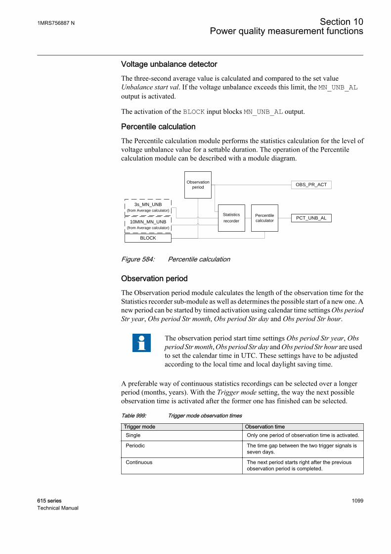
Voltage unbalance detectorThe three-second average value is calculated and compared to the set valueUnbalance start val. If the voltage unbalance exceeds this limit, the MN_UNB_ALoutput is activated.
The activation of the BLOCK input blocks MN_UNB_AL output.
Percentile calculationThe Percentile calculation module performs the statistics calculation for the level ofvoltage unbalance value for a settable duration. The operation of the Percentilecalculation module can be described with a module diagram.
Observation
period
Statistics
recorder
Percentile
calculatorPCT_UNB_AL
OBS_PR_ACT
BLOCK
10MIN_MN_UNB
(from Average calculator)
3s_MN_UNB
(from Average calculator)
GUID-0190AF77-2DCC-4015-8142-EA6FE5FA2228 V2 EN
Figure 584: Percentile calculation
Observation periodThe Observation period module calculates the length of the observation time for theStatistics recorder sub-module as well as determines the possible start of a new one. Anew period can be started by timed activation using calendar time settings Obs periodStr year, Obs period Str month, Obs period Str day and Obs period Str hour.
The observation period start time settings Obs period Str year, Obsperiod Str month, Obs period Str day and Obs period Str hour are usedto set the calendar time in UTC. These settings have to be adjustedaccording to the local time and local daylight saving time.
A preferable way of continuous statistics recordings can be selected over a longerperiod (months, years). With the Trigger mode setting, the way the next possibleobservation time is activated after the former one has finished can be selected.
Table 999: Trigger mode observation times
Trigger mode Observation timeSingle Only one period of observation time is activated.
Periodic The time gap between the two trigger signals isseven days.
Continuous The next period starts right after the previousobservation period is completed.
1MRS756887 N Section 10Power quality measurement functions
615 series 1099Technical Manual

The length of the period is determined by the settings Obs period selection and UserDef Obs period. The OBS_PR_ACT output is an indication signal which exhibitsrising edge (TRUE) when the observation period starts and falling edge (FALSE)when the observation period ends.
If the Percentile unbalance, Trigger mode or Obs period duration settings changewhen OBS_PR_ACT is active, OBS_PR_ACT deactivates immediately.
Trigger mode - Single
Trigger mode - Continuous
Obs period selection – 4 (7 days)
Trigger mode - Continuous
Trigger mode - Periodic
TIme
TIme
TIme
TIme
7 days
OBS_PR_ACT
Obs period selection – 4 (7 days)
Obs period selection – 3 (1 day)
Obs period selection – 3 (1 day)
GUID-A70EC355-E810-4A4A-8368-97B7AEF9F65B V1 EN
Figure 585: Periods for statistics recorder with different trigger modes and periodsettings
The BLOCK input blocks the OBS_PR_ACT output, which then disables themaximum value calculation of the Statistics recorder module. If the trigger mode is
Section 10 1MRS756887 NPower quality measurement functions
1100 615 seriesTechnical Manual

selected "Periodic" or "Continuous" and the blocking is deactivated before the nextobservation period is due to start, the scheduled period starts normally.
Statistics recorderThe Statistics recorder module provides readily calculated three-second or ten-minutevalues of the selected phase to the percentile calculator module based on the length ofthe active observation period. If the observation period is less than one day, the three-second average values are used. If the observation period is one day or longer, the ten-minute average values are used.
The maximum three-second or ten-minute mean voltage unbalance is recorded duringthe active observation period. The observation period start time PR_STR_TIME,observation period end time PR_END_TIME, maximum voltage unbalance valueduring observation period active, MAX_UNB_VAL and time of occurrenceMAX_UNB_TIME are available through the Monitored data view. These outputs areupdated once OBS_PR_ACT deactivates.
Percentile calculatorThe purpose of the Percentile calculator module is to find the voltage unbalance levelso that during the observation time 95 percent (default value of the Percentileunbalance setting) of all the measured voltage unbalance amplitudes are less than orequal to the calculated percentile.
The computed output value PCT_UNB_VAL, below which the percentile of the valueslies, is available in the Monitored data view. The PCT_UNB_VAL output value isupdated at the end of the observation period.
If the output PCT_UNB_VAL is higher than the defined setting Unbalance start val atthe end of the observation period, an alarm output PCT_UNB_AL is activated. ThePCT_UNB_AL output remains active for the whole period before the next periodcompletes.
The BLOCK input blocks the output PCT_UNB_VAL.
Recorded dataThe information required for a later fault analysis is stored when the Recorded datamodule is triggered. This happens when a voltage unbalance is detected by theVoltage unbalance detector module.
Three sets of recorded data are available in total. The sets are saved in data banks 1...3.The data bank 1 holds the most recent recorded data. Older data are moved to thesubsequent banks (1 to 2 and 2 to 3) when a voltage unbalance is detected. When allthree banks have data and a new variation is detected, the latest data set is placed intobank 1 and the data in bank 3 is overwritten by the data from bank 2.
The recorded data can be reset with the RESET binary input signal by navigating to theHMI reset (Main menu/Clear/Reset recorded data/VSQVUBx) or through toolsvia communications.
1MRS756887 N Section 10Power quality measurement functions
615 series 1101Technical Manual

When a voltage unbalance is detected in the system, VSQVUB responds with theMN_UNB_AL alarm signal. During the alarm situation, VSQVUB stores themaximum magnitude and the time of occurrence and the duration of alarmMN_UNB_AL. The recorded data is stored when MN_UNB_AL is deactivated.
Table 1000: Recorded data
Parameter DescriptionAlarm high mean Dur Time duration for alarm high mean unbalance
Max unbalance Volt Maximum three-second voltage
Time Max Unb Volt Time stamp of voltage unbalance
10.4.5 Application
Voltage unbalance is one of the basic power quality parameters.
Ideally, in a three-phase or multiphase power system, the frequency and voltagemagnitude of all the phases are equal and the phase displacement between any twoconsecutive phases is also equal. This is called a balanced source. Apart from thebalanced source, usually the power system network and loads are also balanced,implying that network impedance and load impedance in each phase are equal. Insome cases, the condition of a balance network and load is not met completely, whichleads to a current and voltage unbalance in the system. Providing unbalanced supplyvoltage has a detrimental effect on load operation. For example, a small magnitude ofa negative-sequence voltage applied to an induction motor results in a significantheating of the motor.
A balanced supply, balanced network and balanced load lead to a better power quality.When one of these conditions is disturbed, the power quality is deteriorated.VSQVUB monitors voltage unbalance conditions in power transmission anddistribution networks. VSQVUB calculates two sets of measured values, a three-second and a ten-minute non-sliding average value. The three-second average valueis used for continuous monitoring while the ten-minute average value is used forpercentile calculation for a longer period of time. It can be applied to identify thenetwork and load unbalance that may cause sustained voltage unbalance. A single-phase or phase-to-phase fault in the network or load side can create voltage unbalancebut, as faults are usually isolated in a short period of time, the voltage unbalance is nota sustained one. Therefore, the voltage unbalance may not be covered by VSQVUB.
Another major application is the long-term power quality monitoring. This can beused to confirm a compliance to the standard power supply quality norms. Thefunction provides a voltage unbalance level which corresponds to the 95th percentileof the ten minutes' average values of voltage unbalance recorded over a period of upto one week. It means that for 95 percent of time during the observation period thevoltage unbalance was less than or equal to the calculated percentile. An alarm can beobtained if this value exceeds the value that can be set.
The function uses five different methods for calculating voltage unbalance.
Section 10 1MRS756887 NPower quality measurement functions
1102 615 seriesTechnical Manual
• Negative-sequence voltage magnitude• Zero-sequence voltage magnitude• Ratio of negative-sequence to positive-sequence voltage magnitude• Ratio of zero-sequence to positive-sequence voltage magnitude• Ratio of maximum phase voltage magnitude deviation from the mean voltage
magnitude to the mean of phase voltage magnitude.
Usually, the ratio of the negative-sequence voltage magnitude to the positive-sequence voltage magnitude is selected for monitoring the voltage unbalance.However, other methods may also be used if required.
10.4.6 SignalsTable 1001: VSQVUB Input signals
Name Type Default DescriptionU_A SIGNAL 0 Phase A voltage
U_B SIGNAL 0 Phase B voltage
U_C SIGNAL 0 Phase C voltage
U1 SIGNAL 0 Positive phase sequence voltage
U2 SIGNAL 0 Negative phase sequence voltage
U0 SIGNAL 0 Zero sequence voltage
BLOCK BOOLEAN 0=False Block all outputs except measured values
Table 1002: VSQVUB Output signals
Name Type DescriptionMN_UNB_AL BOOLEAN Alarm active when 3 sec voltage unbalance
exceeds the limit
PCT_UNB_AL BOOLEAN Alarm active when percentile unbalance exceedsthe limit
OBS_PR_ACT BOOLEAN Observation period is active
10.4.7 SettingsTable 1003: VSQVUB Non group settings (Basic)
Parameter Values (Range) Unit Step Default DescriptionOperation 1=on
5=off 1=on Operation On/Off
Unb detection method 1=Neg Seq2=Zero Seq3=Neg to Pos Seq4=Zero to Pos Seq5=Ph vectors Comp
3=Neg to Pos Seq Set the operation mode for voltageunbalance calculation
Unbalance start Val 1...100 % 1 1 Voltage unbalance start value
Table continues on next page
1MRS756887 N Section 10Power quality measurement functions
615 series 1103Technical Manual
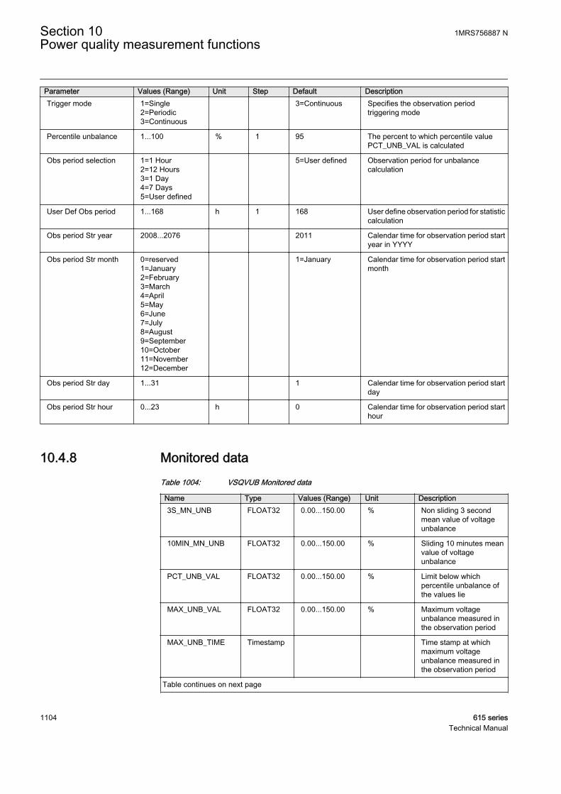
Parameter Values (Range) Unit Step Default DescriptionTrigger mode 1=Single
2=Periodic3=Continuous
3=Continuous Specifies the observation periodtriggering mode
Percentile unbalance 1...100 % 1 95 The percent to which percentile valuePCT_UNB_VAL is calculated
Obs period selection 1=1 Hour2=12 Hours3=1 Day4=7 Days5=User defined
5=User defined Observation period for unbalancecalculation
User Def Obs period 1...168 h 1 168 User define observation period for statisticcalculation
Obs period Str year 2008...2076 2011 Calendar time for observation period startyear in YYYY
Obs period Str month 0=reserved1=January2=February3=March4=April5=May6=June7=July8=August9=September10=October11=November12=December
1=January Calendar time for observation period startmonth
Obs period Str day 1...31 1 Calendar time for observation period startday
Obs period Str hour 0...23 h 0 Calendar time for observation period starthour
10.4.8 Monitored dataTable 1004: VSQVUB Monitored data
Name Type Values (Range) Unit Description3S_MN_UNB FLOAT32 0.00...150.00 % Non sliding 3 second
mean value of voltageunbalance
10MIN_MN_UNB FLOAT32 0.00...150.00 % Sliding 10 minutes meanvalue of voltageunbalance
PCT_UNB_VAL FLOAT32 0.00...150.00 % Limit below whichpercentile unbalance ofthe values lie
MAX_UNB_VAL FLOAT32 0.00...150.00 % Maximum voltageunbalance measured inthe observation period
MAX_UNB_TIME Timestamp Time stamp at whichmaximum voltageunbalance measured inthe observation period
Table continues on next page
Section 10 1MRS756887 NPower quality measurement functions
1104 615 seriesTechnical Manual
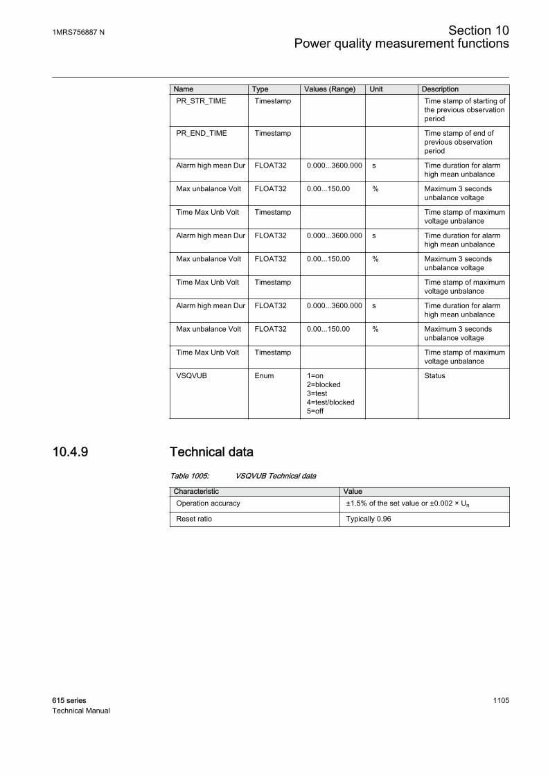
Name Type Values (Range) Unit DescriptionPR_STR_TIME Timestamp Time stamp of starting of
the previous observationperiod
PR_END_TIME Timestamp Time stamp of end ofprevious observationperiod
Alarm high mean Dur FLOAT32 0.000...3600.000 s Time duration for alarmhigh mean unbalance
Max unbalance Volt FLOAT32 0.00...150.00 % Maximum 3 secondsunbalance voltage
Time Max Unb Volt Timestamp Time stamp of maximumvoltage unbalance
Alarm high mean Dur FLOAT32 0.000...3600.000 s Time duration for alarmhigh mean unbalance
Max unbalance Volt FLOAT32 0.00...150.00 % Maximum 3 secondsunbalance voltage
Time Max Unb Volt Timestamp Time stamp of maximumvoltage unbalance
Alarm high mean Dur FLOAT32 0.000...3600.000 s Time duration for alarmhigh mean unbalance
Max unbalance Volt FLOAT32 0.00...150.00 % Maximum 3 secondsunbalance voltage
Time Max Unb Volt Timestamp Time stamp of maximumvoltage unbalance
VSQVUB Enum 1=on2=blocked3=test4=test/blocked5=off
Status
10.4.9 Technical dataTable 1005: VSQVUB Technical data
Characteristic ValueOperation accuracy ±1.5% of the set value or ±0.002 × Un
Reset ratio Typically 0.96
1MRS756887 N Section 10Power quality measurement functions
615 series 1105Technical Manual

1106
Section 11 General function block features
11.1 Definite time characteristics
11.1.1 Definite time operation
The DT mode is enabled when the Operating curve type setting is selected either as"ANSI Def. Time" or "IEC Def. Time". In the DT mode, the OPERATE output of thefunction is activated when the time calculation exceeds the set Operate delay time.
The user can determine the reset in the DT mode with the Reset delay time setting,which provides the delayed reset property when needed.
The Type of reset curve setting has no effect on the reset method whenthe DT mode is selected, but the reset is determined solely with theReset delay time setting.
The purpose of the delayed reset is to enable fast clearance of intermittent faults, forexample self-sealing insulation faults, and severe faults which may produce highasymmetrical fault currents that partially saturate the current transformers. It is typicalfor an intermittent fault that the fault current contains so called drop-off periods,during which the fault current falls below the set start current, including hysteresis.Without the delayed reset function, the operate timer would reset when the currentdrops off. In the same way, an apparent drop-off period of the secondary current of thesaturated current transformer can also reset the operate timer.
1MRS756887 N Section 11General function block features
615 series 1107Technical Manual
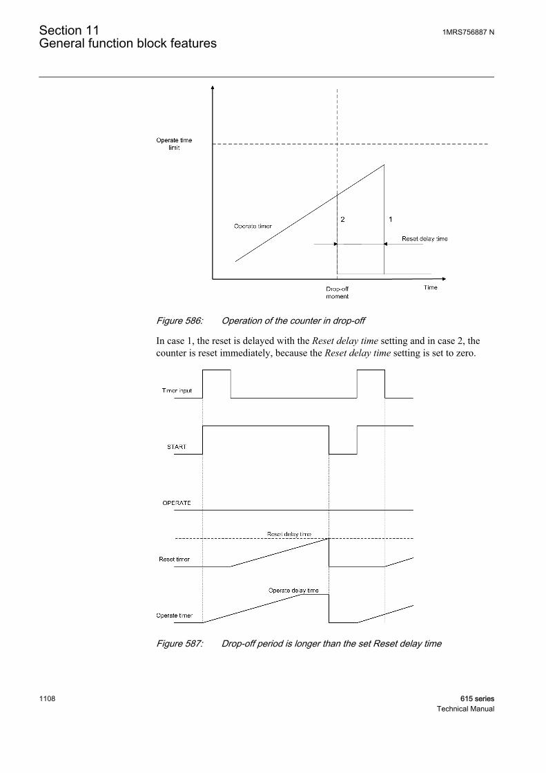
A060764 V1 EN
Figure 586: Operation of the counter in drop-off
In case 1, the reset is delayed with the Reset delay time setting and in case 2, thecounter is reset immediately, because the Reset delay time setting is set to zero.
A070421 V1 EN
Figure 587: Drop-off period is longer than the set Reset delay time
Section 11 1MRS756887 NGeneral function block features
1108 615 seriesTechnical Manual

When the drop-off period is longer than the set Reset delay time, as described in Figure587, the input signal for the definite timer (here: timer input) is active, provided thatthe current is above the set Start value. The input signal is inactive when the currentis below the set Start value and the set hysteresis region. The timer input rises whena fault current is detected. The definite timer activates the START output and theoperate timer starts elapsing. The reset (drop-off) timer starts when the timer inputfalls, that is, the fault disappears. When the reset (drop-off) timer elapses, the operatetimer is reset. Since this happens before another start occurs, the OPERATE output isnot activated.
A070420 V1 EN
Figure 588: Drop-off period is shorter than the set Reset delay time
When the drop-off period is shorter than the set Reset delay time, as described inFigure 588, the input signal for the definite timer (here: timer input) is active, providedthat the current is above the set Start value. The input signal is inactive when thecurrent is below the set Start value and the set hysteresis region. The timer input riseswhen a fault current is detected. The definite timer activates the START output and theoperate timer starts elapsing. The Reset (drop-off) timer starts when the timer inputfalls, that is, the fault disappears. Another fault situation occurs before the reset (drop-off) timer has elapsed. This causes the activation of the OPERATE output, since theoperate timer already has elapsed.
1MRS756887 N Section 11General function block features
615 series 1109Technical Manual
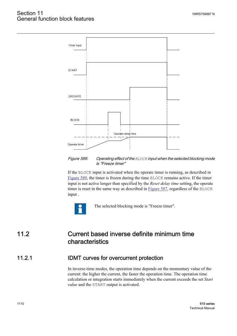
A070422 V1 EN
Figure 589: Operating effect of the BLOCK input when the selected blocking modeis "Freeze timer"
If the BLOCK input is activated when the operate timer is running, as described inFigure 589, the timer is frozen during the time BLOCK remains active. If the timerinput is not active longer than specified by the Reset delay time setting, the operatetimer is reset in the same way as described in Figure 587, regardless of the BLOCKinput .
The selected blocking mode is "Freeze timer".
11.2 Current based inverse definite minimum timecharacteristics
11.2.1 IDMT curves for overcurrent protection
In inverse-time modes, the operation time depends on the momentary value of thecurrent: the higher the current, the faster the operation time. The operation timecalculation or integration starts immediately when the current exceeds the set Startvalue and the START output is activated.
Section 11 1MRS756887 NGeneral function block features
1110 615 seriesTechnical Manual
The OPERATE output of the component is activated when the cumulative sum of theintegrator calculating the overcurrent situation exceeds the value set by the inverse-time mode. The set value depends on the selected curve type and the setting valuesused. The curve scaling is determined with the Time multiplier setting.
There are two methods to level out the inverse-time characteristic.
• The Minimum operate time setting defines the minimum operating time for theIDMT curve, that is, the operation time is always at least the Minimum operatetime setting.
• Alternatively, the IDMT Sat point is used for giving the leveling-out point as amultiple of the Start value setting. (Global setting: Configuration/System/IDMT Sat point). The default parameter value is 50. This setting affects only theovercurrent and earth-fault IDMT timers.
IDMT operation time at currents over 50 x In is not guaranteed.
1MRS756887 N Section 11General function block features
615 series 1111Technical Manual

GUID-20353F8B-2112-41CB-8F68-B51F8ACA775E V1 EN
Figure 590: Operation time curve based on the IDMT characteristic leveled outwith the Minimum operate time setting is set to 1000 milliseconds (theIDMT Sat point setting is set to maximum).
Section 11 1MRS756887 NGeneral function block features
1112 615 seriesTechnical Manual

GUID-87A96860-4268-4AD1-ABA1-3227D3BB36D5 V1 EN
Figure 591: Operation time curve based on the IDMT characteristic leveled outwith IDMT Sat point setting value “11” (the Minimum operate timesetting is set to minimum).
1MRS756887 N Section 11General function block features
615 series 1113Technical Manual
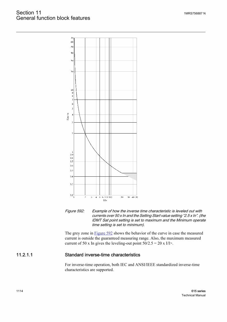
GUID-9BFD6DC5-08B5-4755-A899-DF5ED26E75F6 V1 EN
Figure 592: Example of how the inverse time characteristic is leveled out withcurrents over 50 x In and the Setting Start value setting “2.5 x In”. (theIDMT Sat point setting is set to maximum and the Minimum operatetime setting is set to minimum).
The grey zone in Figure 592 shows the behavior of the curve in case the measuredcurrent is outside the guaranteed measuring range. Also, the maximum measuredcurrent of 50 x In gives the leveling-out point 50/2.5 = 20 x I/I>.
11.2.1.1 Standard inverse-time characteristics
For inverse-time operation, both IEC and ANSI/IEEE standardized inverse-timecharacteristics are supported.
Section 11 1MRS756887 NGeneral function block features
1114 615 seriesTechnical Manual

The operate times for the ANSI and IEC IDMT curves are defined with thecoefficients A, B and C.
The values of the coefficients can be calculated according to the formula:
t sA
I
I
B kc
[ ] =
>
−
+
⋅
1
A060821 V2 EN (Equation 198)
t[s] Operate time in seconds
I measured current
I> set Start value
k set Time multiplier
Table 1006: Curve parameters for ANSI and IEC IDMT curves
Curve name A B C(1) ANSI ExtremelyInverse
28.2 0.1217 2.0
(2) ANSI Very Inverse 19.61 0.491 2.0
(3) ANSI NormalInverse
0.0086 0.0185 0.02
(4) ANSI ModeratelyInverse
0.0515 0.1140 0.02
(6) Long TimeExtremely Inverse
64.07 0.250 2.0
(7) Long Time VeryInverse
28.55 0.712 2.0
(8) Long Time Inverse 0.086 0.185 0.02
(9) IEC Normal Inverse 0.14 0.0 0.02
(10) IEC Very Inverse 13.5 0.0 1.0
(11) IEC Inverse 0.14 0.0 0.02
(12) IEC ExtremelyInverse
80.0 0.0 2.0
(13) IEC Short TimeInverse
0.05 0.0 0.04
(14) IEC Long TimeInverse
120 0.0 1.0
1MRS756887 N Section 11General function block features
615 series 1115Technical Manual
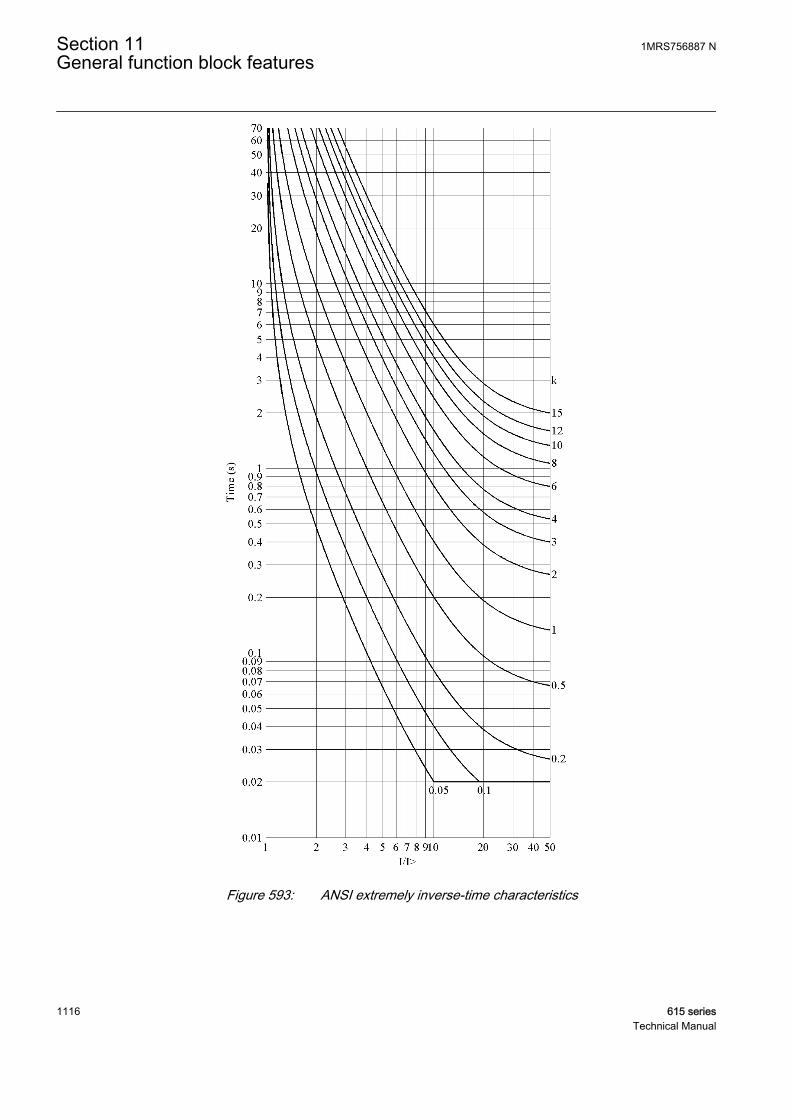
A070750 V2 EN
Figure 593: ANSI extremely inverse-time characteristics
Section 11 1MRS756887 NGeneral function block features
1116 615 seriesTechnical Manual

A070751 V2 EN
Figure 594: ANSI very inverse-time characteristics
1MRS756887 N Section 11General function block features
615 series 1117Technical Manual

A070752 V2 EN
Figure 595: ANSI normal inverse-time characteristics
Section 11 1MRS756887 NGeneral function block features
1118 615 seriesTechnical Manual

A070753 V2 EN
Figure 596: ANSI moderately inverse-time characteristics
1MRS756887 N Section 11General function block features
615 series 1119Technical Manual
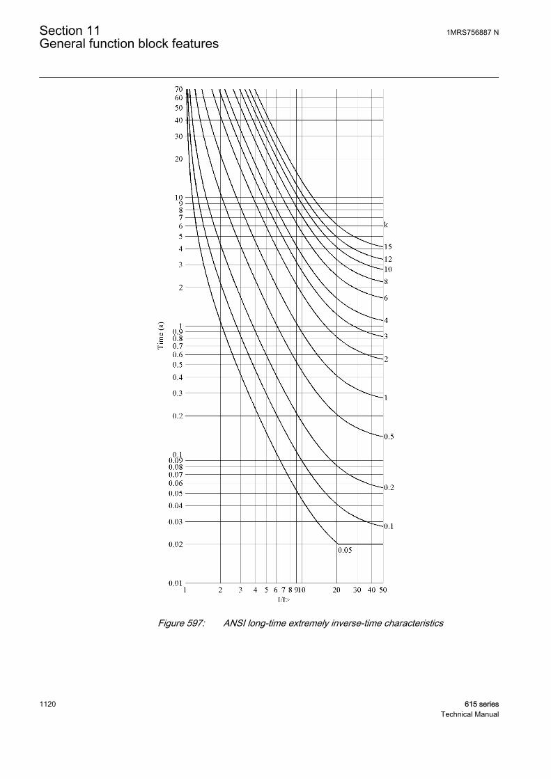
A070817 V2 EN
Figure 597: ANSI long-time extremely inverse-time characteristics
Section 11 1MRS756887 NGeneral function block features
1120 615 seriesTechnical Manual
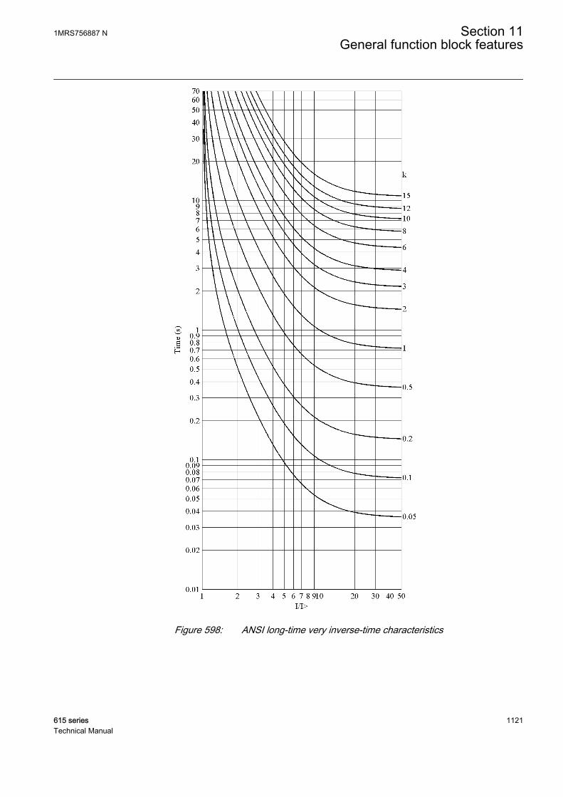
A070818 V2 EN
Figure 598: ANSI long-time very inverse-time characteristics
1MRS756887 N Section 11General function block features
615 series 1121Technical Manual
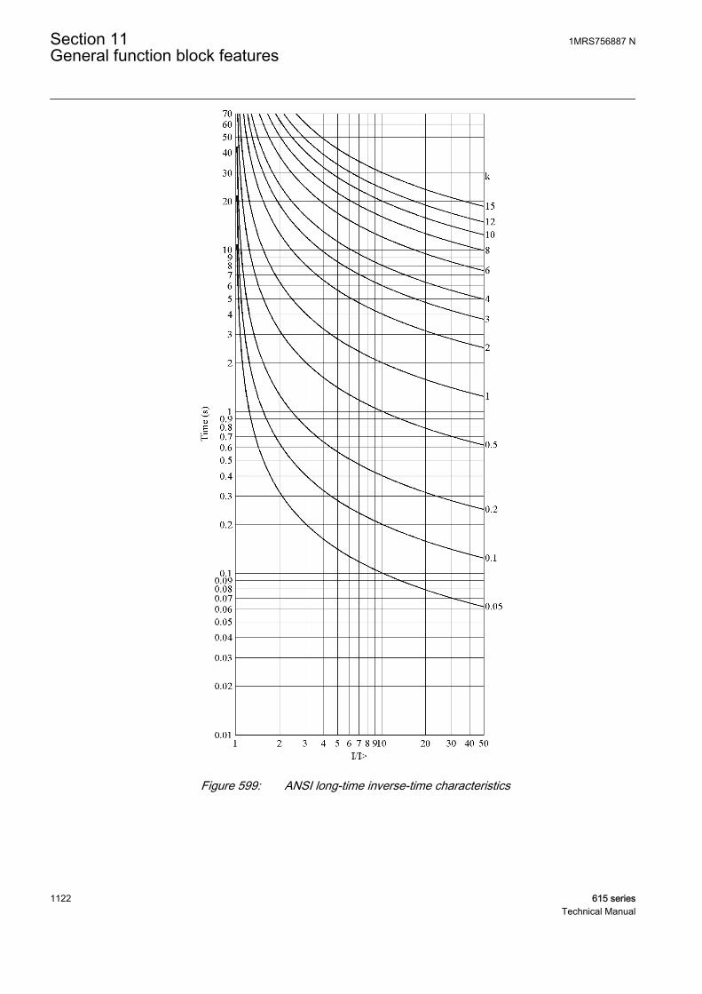
A070819 V2 EN
Figure 599: ANSI long-time inverse-time characteristics
Section 11 1MRS756887 NGeneral function block features
1122 615 seriesTechnical Manual
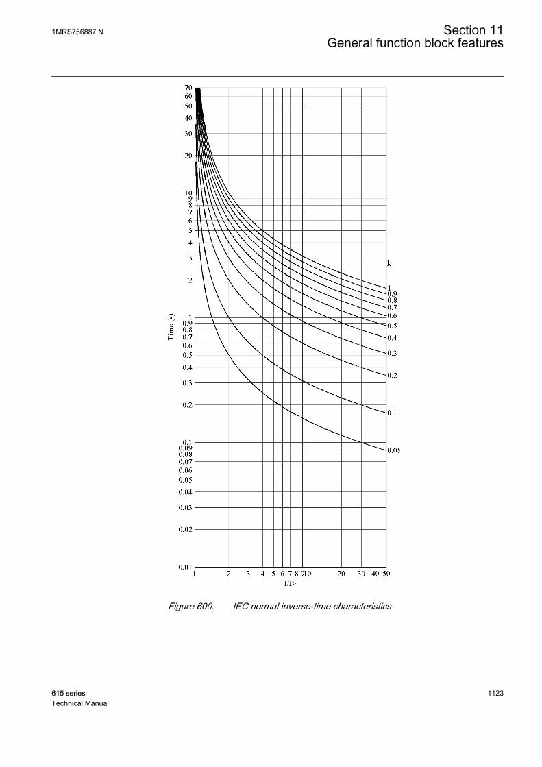
A070820 V2 EN
Figure 600: IEC normal inverse-time characteristics
1MRS756887 N Section 11General function block features
615 series 1123Technical Manual
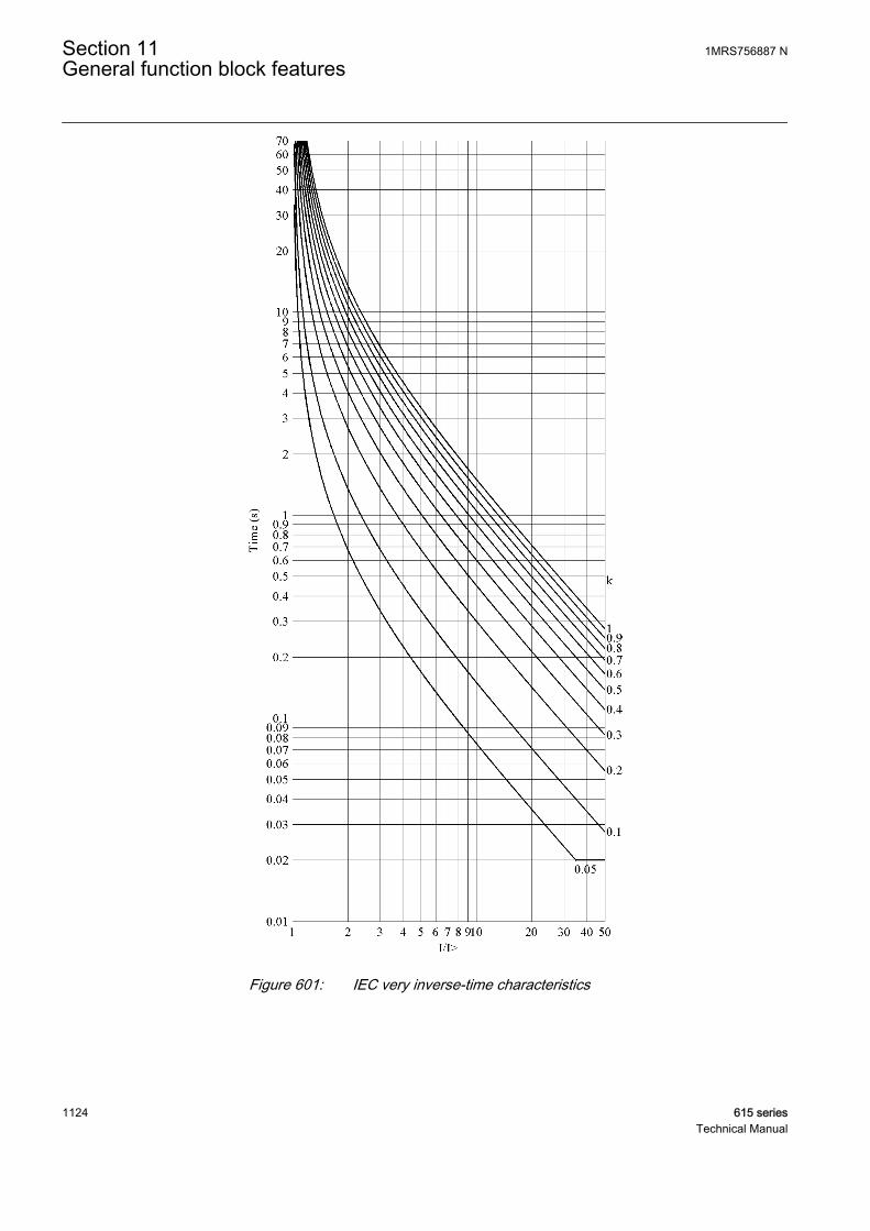
A070821 V2 EN
Figure 601: IEC very inverse-time characteristics
Section 11 1MRS756887 NGeneral function block features
1124 615 seriesTechnical Manual
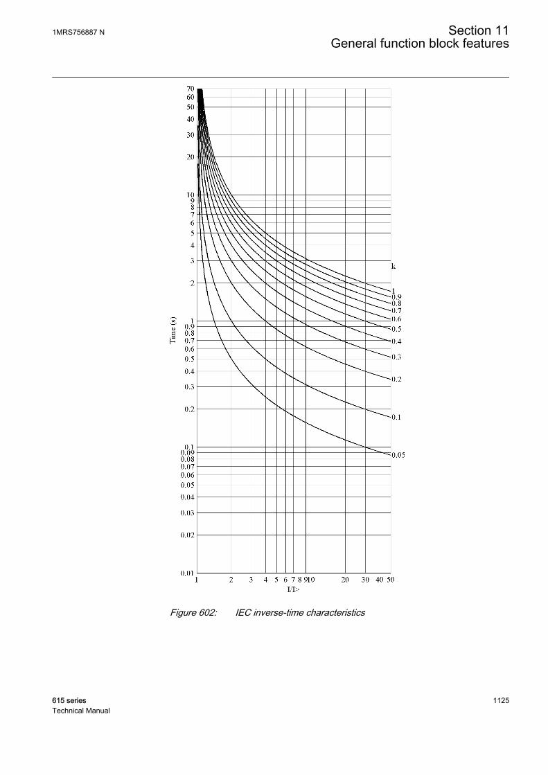
A070822 V2 EN
Figure 602: IEC inverse-time characteristics
1MRS756887 N Section 11General function block features
615 series 1125Technical Manual

A070823 V2 EN
Figure 603: IEC extremely inverse-time characteristics
Section 11 1MRS756887 NGeneral function block features
1126 615 seriesTechnical Manual

A070824 V2 EN
Figure 604: IEC short-time inverse-time characteristics
1MRS756887 N Section 11General function block features
615 series 1127Technical Manual
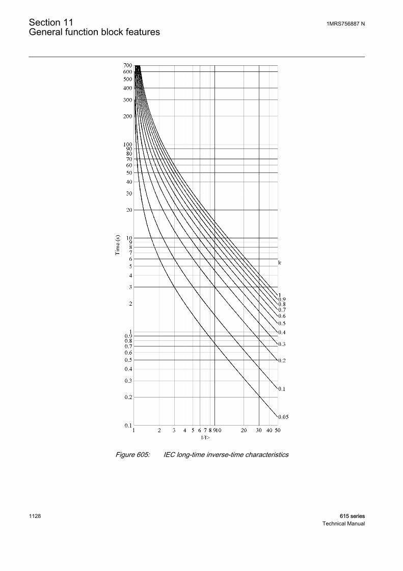
A070825 V2 EN
Figure 605: IEC long-time inverse-time characteristics
Section 11 1MRS756887 NGeneral function block features
1128 615 seriesTechnical Manual

11.2.1.2 User-programmable inverse-time characteristics
The user can define curves by entering parameters into the following standardformula:
t sA
I
IE
B kc
[ ] =
>
−
+
⋅
A060641 V3 EN (Equation 199)
t[s] Operate time (in seconds)
A set Curve parameter A
B set Curve parameter B
C set Curve parameter C
E set Curve parameter E
I Measured current
I> set Start value
k set Time multiplier
11.2.1.3 RI and RD-type inverse-time characteristics
The RI-type simulates the behavior of electromechanical relays. The RD-type is anearth-fault specific characteristic.
The RI-type is calculated using the formula
t sk
I
I
[ ]
. .
=
− ×>
0 339 0 236
A060642 V2 EN (Equation 200)
The RD-type is calculated using the formula
t sI
k I[ ] . .= − ×
× >
5 8 1 35 In
A060643 V2 EN (Equation 201)
1MRS756887 N Section 11General function block features
615 series 1129Technical Manual

t[s] Operate time (in seconds)
k set Time multiplier
I Measured current
I> set Start value
Section 11 1MRS756887 NGeneral function block features
1130 615 seriesTechnical Manual
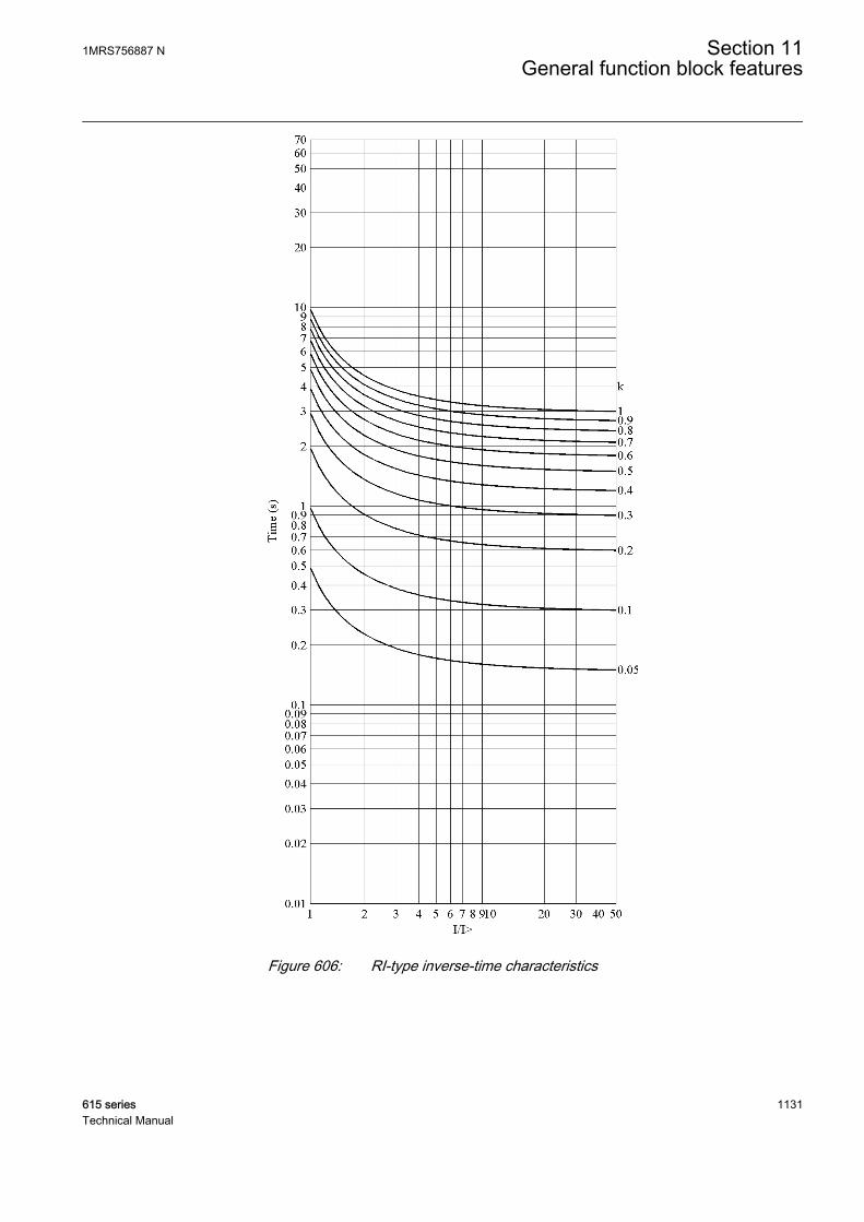
A070826 V2 EN
Figure 606: RI-type inverse-time characteristics
1MRS756887 N Section 11General function block features
615 series 1131Technical Manual
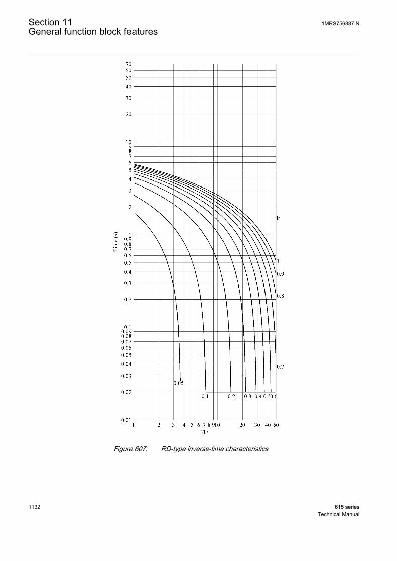
A070827 V2 EN
Figure 607: RD-type inverse-time characteristics
Section 11 1MRS756887 NGeneral function block features
1132 615 seriesTechnical Manual

11.2.2 Reset in inverse-time modes
The user can select the reset characteristics by using the Type of reset curve setting.
Table 1007: Values for reset mode
Setting name Possible valuesType of reset curve 1=Immediate
2=Def time reset3=Inverse reset
Immediate resetIf the Type of reset curve setting in a drop-off case is selected as "Immediate", theinverse timer resets immediately.
Definite time resetThe definite type of reset in the inverse-time mode can be achieved by setting the Typeof reset curve parameter to “Def time reset”. As a result, the operate inverse-timecounter is frozen for the time determined with the Reset delay time setting after thecurrent drops below the set Start value, including hysteresis.The integral sum of theinverse-time counter is reset, if another start does not occur during the reset delay.
If the Type of reset curve setting is selected as “Def time reset”, thecurrent level has no influence on the reset characteristic.
Inverse reset
Inverse reset curves are available only for ANSI and user-programmable curves. If you use other curve types, immediate resetoccurs.
Standard delayed inverse reset
The reset characteristic required in ANSI (IEEE) inverse-time modes is provided bysetting the Type of reset curve parameter to “Inverse reset”. In this mode, the timedelay for reset is given with the following formula using the coefficient D, which hasits values defined in the table below.
t sD
I
I
k[ ] =
>
−
⋅2
1
A060817 V3 EN (Equation 202)
1MRS756887 N Section 11General function block features
615 series 1133Technical Manual
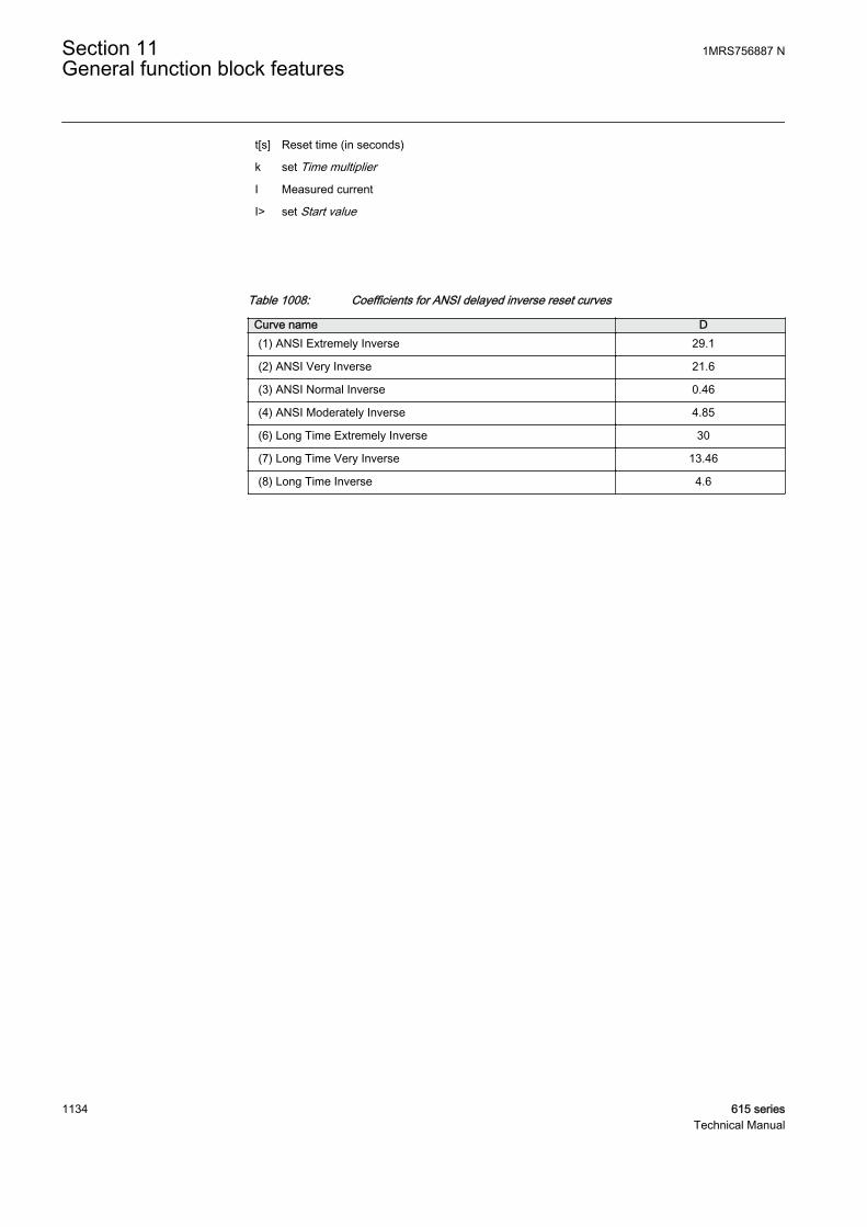
t[s] Reset time (in seconds)
k set Time multiplier
I Measured current
I> set Start value
Table 1008: Coefficients for ANSI delayed inverse reset curves
Curve name D(1) ANSI Extremely Inverse 29.1
(2) ANSI Very Inverse 21.6
(3) ANSI Normal Inverse 0.46
(4) ANSI Moderately Inverse 4.85
(6) Long Time Extremely Inverse 30
(7) Long Time Very Inverse 13.46
(8) Long Time Inverse 4.6
Section 11 1MRS756887 NGeneral function block features
1134 615 seriesTechnical Manual
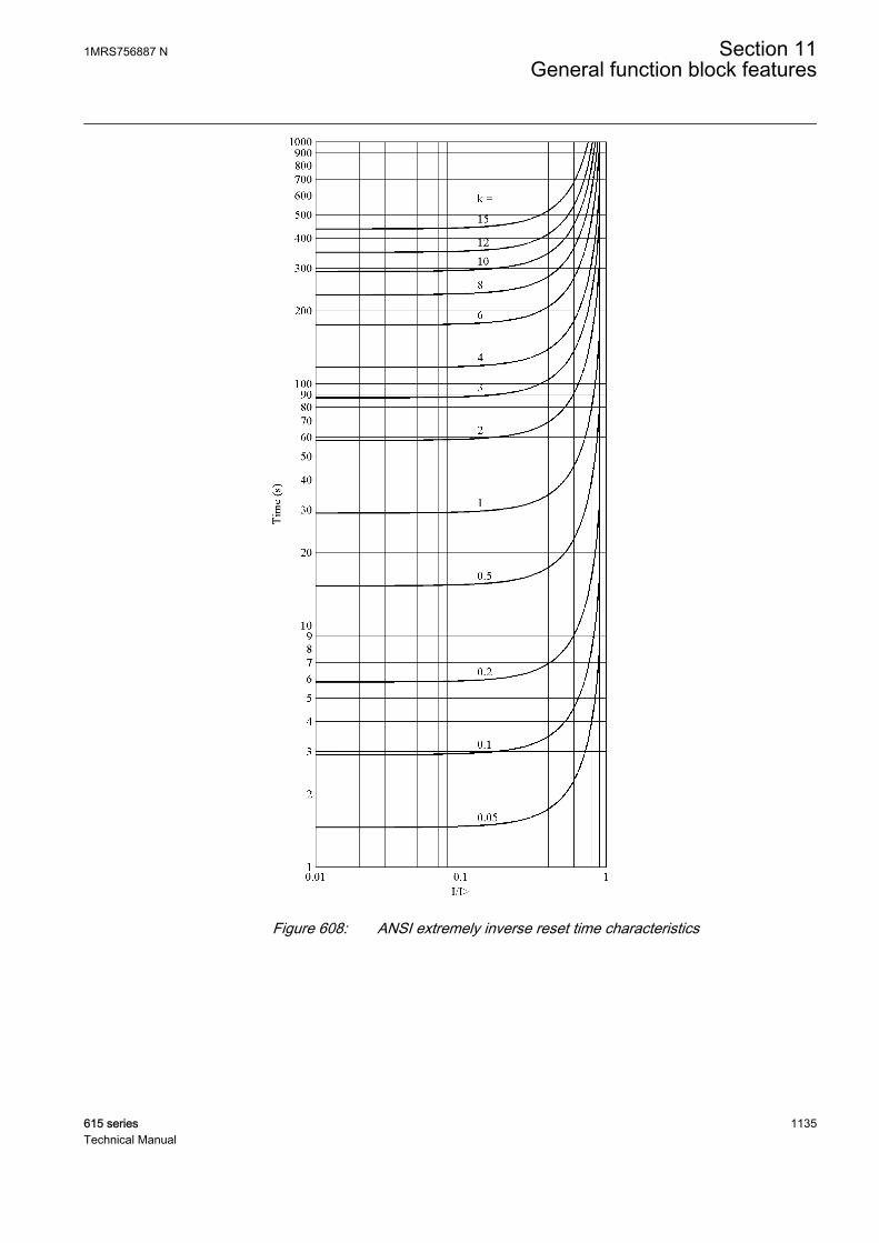
A070828 V1 EN
Figure 608: ANSI extremely inverse reset time characteristics
1MRS756887 N Section 11General function block features
615 series 1135Technical Manual

A070829 V1 EN
Figure 609: ANSI very inverse reset time characteristics
Section 11 1MRS756887 NGeneral function block features
1136 615 seriesTechnical Manual

A070830 V1 EN
Figure 610: ANSI normal inverse reset time characteristics
1MRS756887 N Section 11General function block features
615 series 1137Technical Manual

A070831 V1 EN
Figure 611: ANSI moderately inverse reset time characteristics
Section 11 1MRS756887 NGeneral function block features
1138 615 seriesTechnical Manual
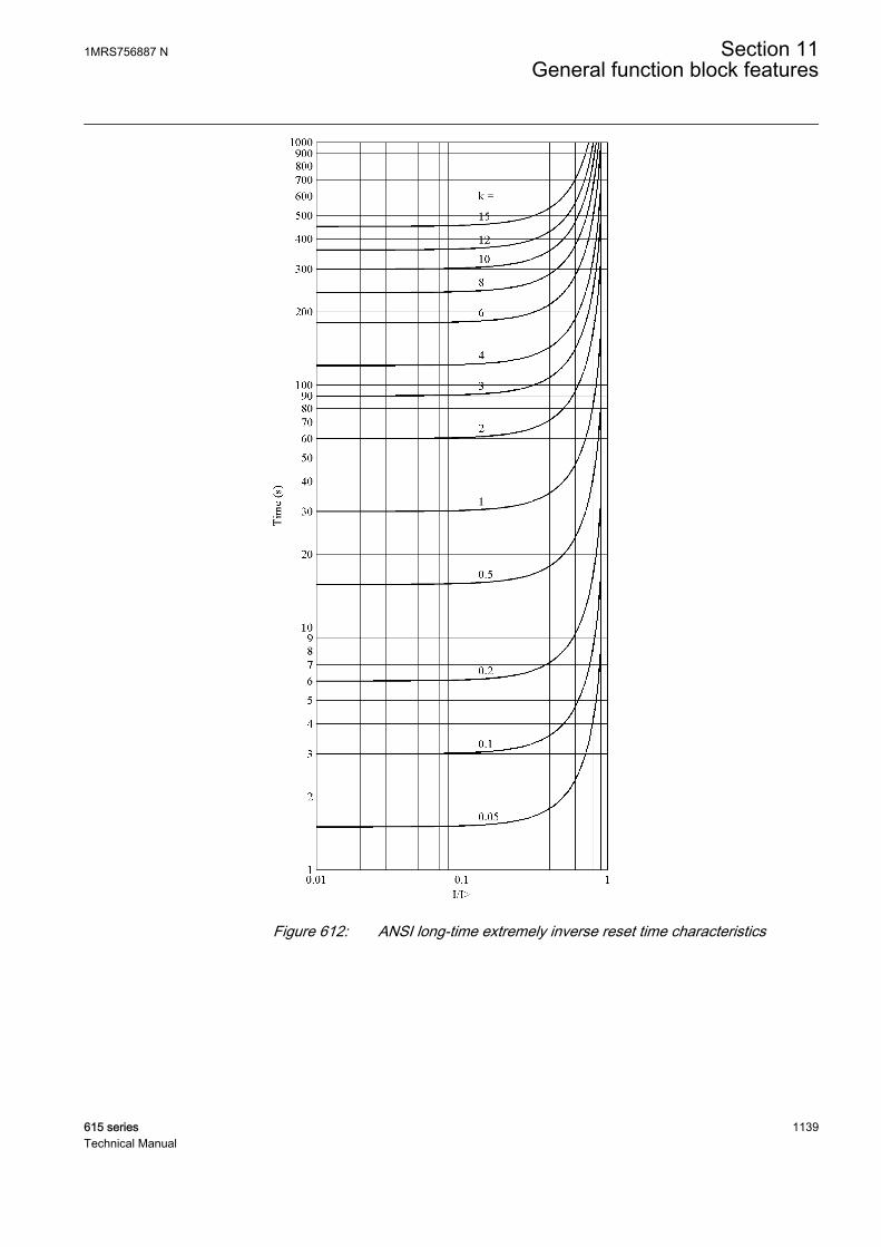
A070832 V1 EN
Figure 612: ANSI long-time extremely inverse reset time characteristics
1MRS756887 N Section 11General function block features
615 series 1139Technical Manual
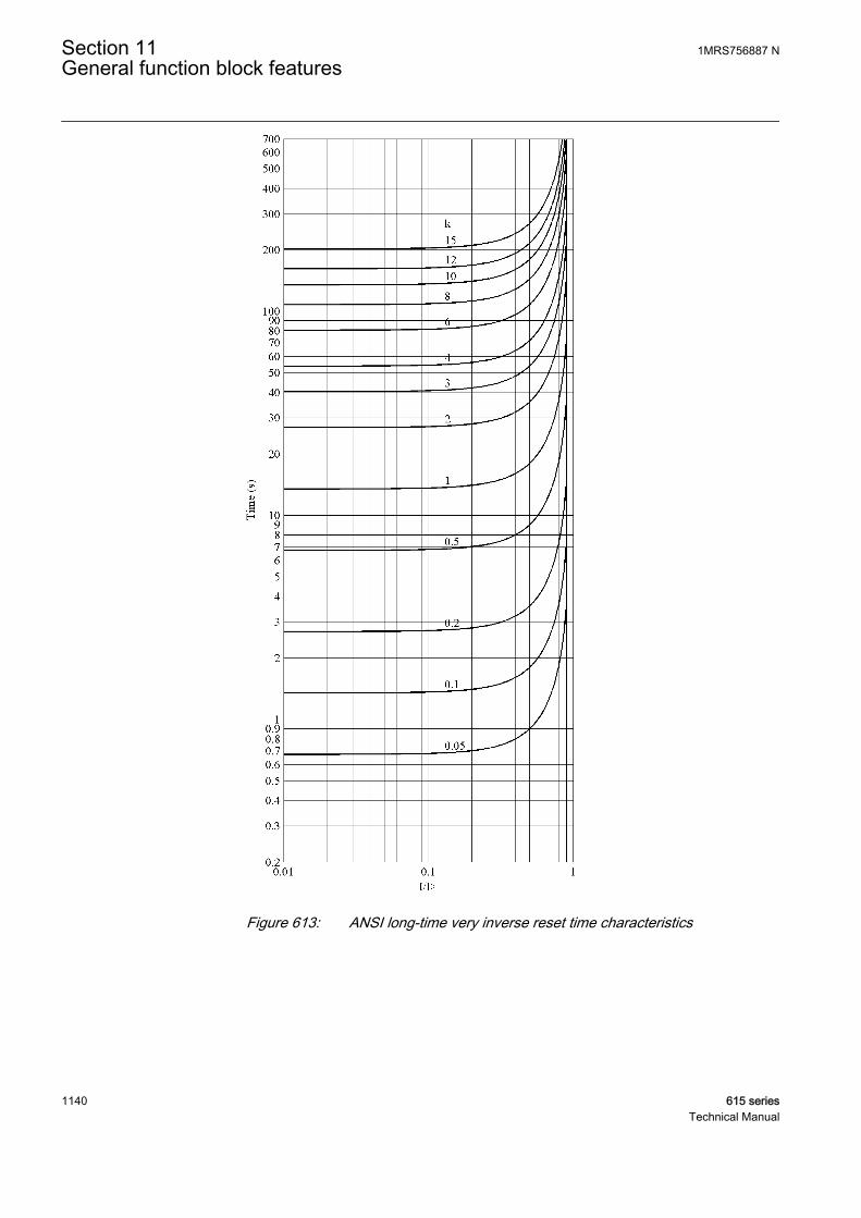
A070833 V1 EN
Figure 613: ANSI long-time very inverse reset time characteristics
Section 11 1MRS756887 NGeneral function block features
1140 615 seriesTechnical Manual
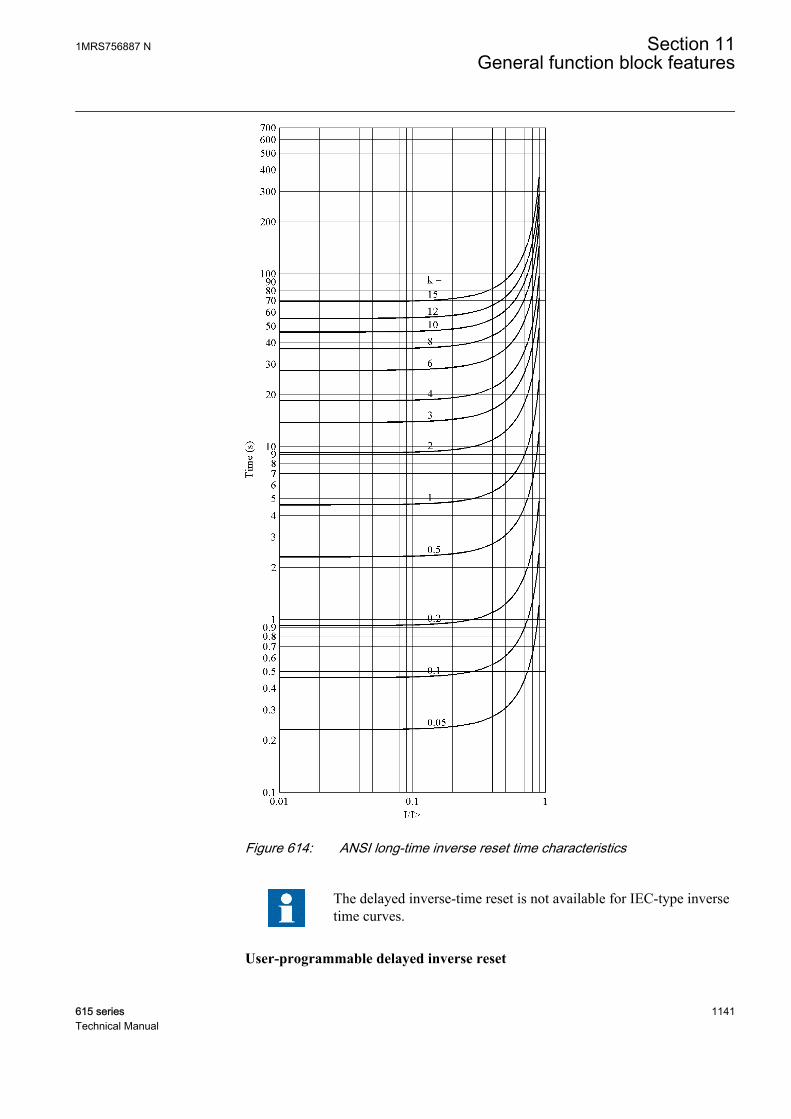
A070834 V1 EN
Figure 614: ANSI long-time inverse reset time characteristics
The delayed inverse-time reset is not available for IEC-type inversetime curves.
User-programmable delayed inverse reset
1MRS756887 N Section 11General function block features
615 series 1141Technical Manual

The user can define the delayed inverse reset time characteristics with the followingformula using the set Curve parameter D.
t sD
I
I
k[ ] =
>
−
⋅2
1
A060817 V3 EN (Equation 203)
t[s] Reset time (in seconds)
k set Time multiplier
D set Curve parameter D
I Measured current
I> set Start value
11.2.3 Inverse-timer freezing
When the BLOCK input is active, the internal value of the time counter is frozen at thevalue of the moment just before the freezing. Freezing of the counter value is chosenwhen the user does not wish the counter value to count upwards or to be reset. Thismay be the case, for example, when the inverse-time function of a protection relayneeds to be blocked to enable the definite-time operation of another protection relayfor selectivity reasons, especially if different relaying techniques (old and modernrelays) are applied.
The selected blocking mode is "Freeze timer".
The activation of the BLOCK input also lengthens the minimum delayvalue of the timer.
Activating the BLOCK input alone does not affect the operation of the START output.It still becomes active when the current exceeds the set Start value, and inactive whenthe current falls below the set Start value and the set Reset delay time has expired.
Section 11 1MRS756887 NGeneral function block features
1142 615 seriesTechnical Manual
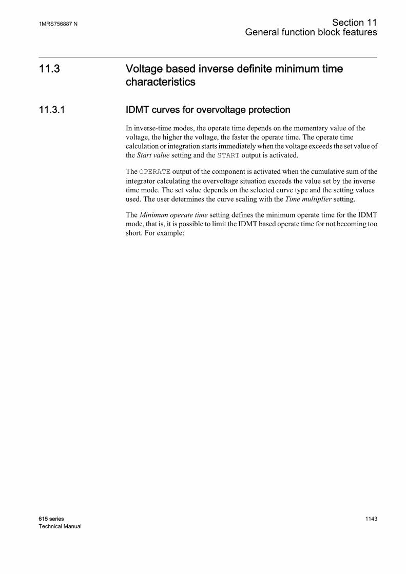
11.3 Voltage based inverse definite minimum timecharacteristics
11.3.1 IDMT curves for overvoltage protection
In inverse-time modes, the operate time depends on the momentary value of thevoltage, the higher the voltage, the faster the operate time. The operate timecalculation or integration starts immediately when the voltage exceeds the set value ofthe Start value setting and the START output is activated.
The OPERATE output of the component is activated when the cumulative sum of theintegrator calculating the overvoltage situation exceeds the value set by the inversetime mode. The set value depends on the selected curve type and the setting valuesused. The user determines the curve scaling with the Time multiplier setting.
The Minimum operate time setting defines the minimum operate time for the IDMTmode, that is, it is possible to limit the IDMT based operate time for not becoming tooshort. For example:
1MRS756887 N Section 11General function block features
615 series 1143Technical Manual
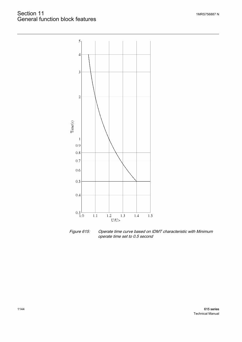
GUID-BCFE3F56-BFA8-4BCC-8215-30C089C80EAD V1 EN
Figure 615: Operate time curve based on IDMT characteristic with Minimumoperate time set to 0.5 second
Section 11 1MRS756887 NGeneral function block features
1144 615 seriesTechnical Manual

GUID-90BAEB05-E8FB-4F8A-8F07-E110DD63FCCF V1 EN
Figure 616: Operate time curve based on IDMT characteristic with Minimumoperate time set to 1 second
11.3.1.1 Standard inverse-time characteristics for overvoltage protection
The operate times for the standard overvoltage IDMT curves are defined with thecoefficients A, B, C, D and E.
The inverse operate time can be calculated with the formula:
1MRS756887 N Section 11General function block features
615 series 1145Technical Manual

t sk A
BU U
UC
DE
=
⋅
×− >
>
−
+
GUID-6E9DC0FE-7457-4317-9480-8CCC6D63AB35 V2 EN (Equation 204)
t [s] operate time in seconds
U measured voltage
U> the set value of Start value
k the set value of Time multiplier
Table 1009: Curve coefficients for the standard overvoltage IDMT curves
Curve name A B C D E(17) Inverse Curve A 1 1 0 0 1
(18) Inverse Curve B 480 32 0.5 0.035 2
(19) Inverse Curve C 480 32 0.5 0.035 3
Section 11 1MRS756887 NGeneral function block features
1146 615 seriesTechnical Manual
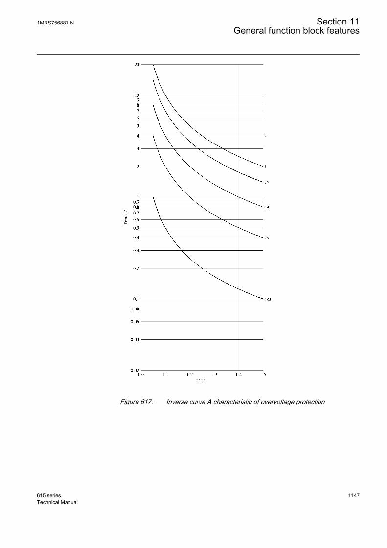
GUID-ACF4044C-052E-4CBD-8247-C6ABE3796FA6 V1 EN
Figure 617: Inverse curve A characteristic of overvoltage protection
1MRS756887 N Section 11General function block features
615 series 1147Technical Manual
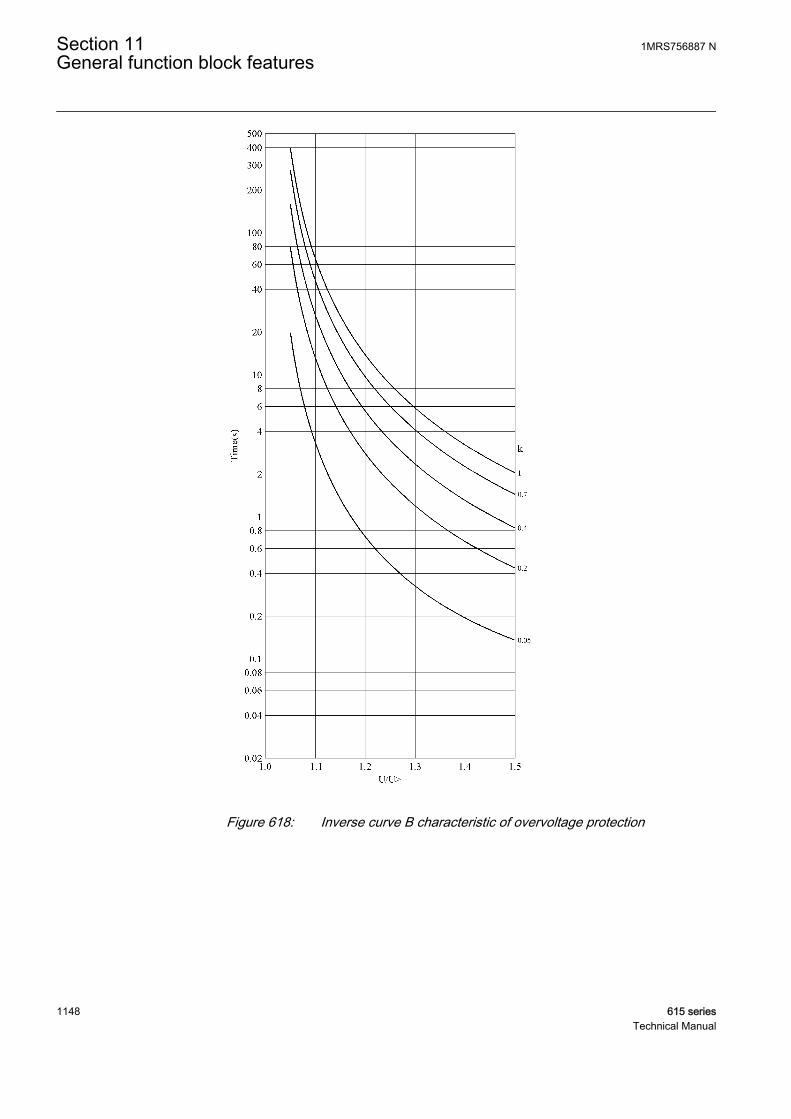
GUID-F5E0E1C2-48C8-4DC7-A84B-174544C09142 V1 EN
Figure 618: Inverse curve B characteristic of overvoltage protection
Section 11 1MRS756887 NGeneral function block features
1148 615 seriesTechnical Manual
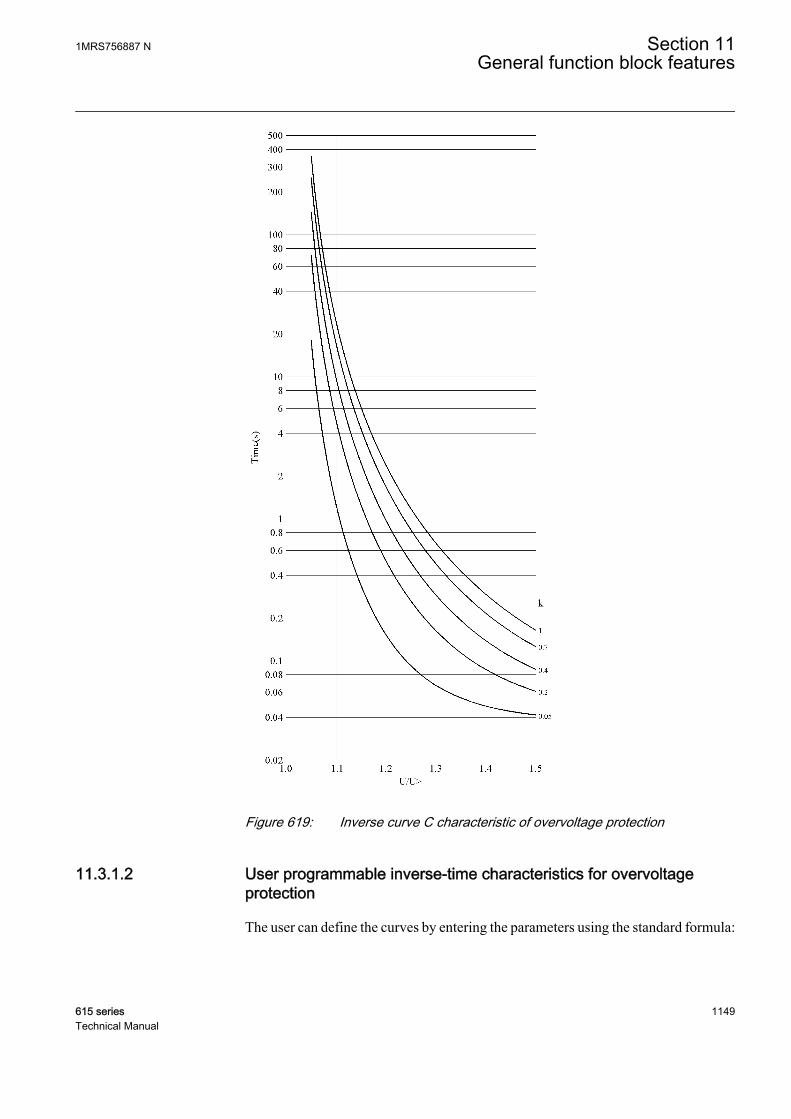
GUID-A9898DB7-90A3-47F2-AEF9-45FF148CB679 V1 EN
Figure 619: Inverse curve C characteristic of overvoltage protection
11.3.1.2 User programmable inverse-time characteristics for overvoltageprotection
The user can define the curves by entering the parameters using the standard formula:
1MRS756887 N Section 11General function block features
615 series 1149Technical Manual
t sk A
BU U
UC
DE
=
⋅
×− >
>
−
+
GUID-6E9DC0FE-7457-4317-9480-8CCC6D63AB35 V2 EN (Equation 205)
t[s] operate time in seconds
A the set value of Curve parameter A
B the set value of Curve parameter B
C the set value of Curve parameter C
D the set value of Curve parameter D
E the set value of Curve parameter E
U measured voltage
U> the set value of Start value
k the set value of Time multiplier
11.3.1.3 IDMT curve saturation of overvoltage protection
For the overvoltage IDMT mode of operation, the integration of the operate time doesnot start until the voltage exceeds the value of Start value. To cope with discontinuitycharacteristics of the curve, a specific parameter for saturating the equation to a fixedvalue is created. The Curve Sat Relative setting is the parameter and it is given inpercents compared to Start value. For example, due to the curve equation B and C, thecharacteristics equation output is saturated in such a way that when the input voltagesare in the range of Start value to Curve Sat Relative in percent over Start value, theequation uses Start value * (1.0 + Curve Sat Relative / 100 ) for the measured voltage.Although, the curve A has no discontinuities when the ratio U/U> exceeds the unity,Curve Sat Relative is also set for it. The Curve Sat Relative setting for curves A, B andC is 2.0 percent. However, it should be noted that the user must carefully calculate thecurve characteristics concerning the discontinuities in the curve when theprogrammable curve equation is used. Thus, the Curve Sat Relative parameter givesanother degree of freedom to move the inverse curve on the voltage ratio axis and iteffectively sets the maximum operate time for the IDMT curve because for the voltageratio values affecting by this setting, the operation time is fixed, that is, the definitetime, depending on the parameters but no longer the voltage.
11.3.2 IDMT curves for undervoltage protection
In the inverse-time modes, the operate time depends on the momentary value of thevoltage, the lower the voltage, the faster the operate time. The operate time calculationor integration starts immediately when the voltage goes below the set value of the Startvalue setting and the START output is activated.
The OPERATE output of the component is activated when the cumulative sum of theintegrator calculating the undervoltage situation exceeds the value set by the inverse-
Section 11 1MRS756887 NGeneral function block features
1150 615 seriesTechnical Manual
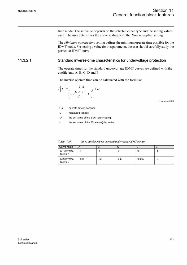
time mode. The set value depends on the selected curve type and the setting valuesused. The user determines the curve scaling with the Time multiplier setting.
The Minimum operate time setting defines the minimum operate time possible for theIDMT mode. For setting a value for this parameter, the user should carefully study theparticular IDMT curve.
11.3.2.1 Standard inverse-time characteristics for undervoltage protection
The operate times for the standard undervoltage IDMT curves are defined with thecoefficients A, B, C, D and E.
The inverse operate time can be calculated with the formula:
t sk A
BU U
UC
DE
=
⋅
×< −
<
−
+
GUID-4A433D56-D7FB-412E-B1AB-7FD43051EE79 V2 EN (Equation 206)
t [s] operate time in seconds
U measured voltage
U< the set value of the Start value setting
k the set value of the Time multiplier setting
Table 1010: Curve coefficients for standard undervoltage IDMT curves
Curve name A B C D E(21) InverseCurve A
1 1 0 0 1
(22) InverseCurve B
480 32 0.5 0.055 2
1MRS756887 N Section 11General function block features
615 series 1151Technical Manual
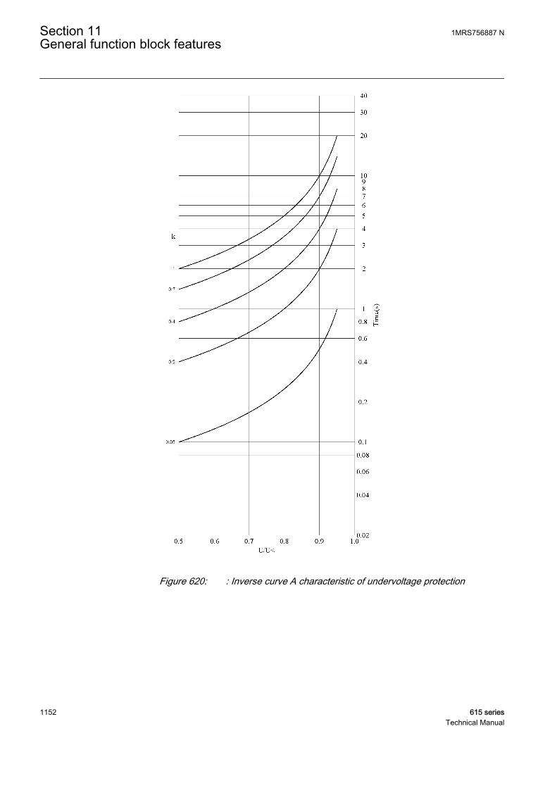
GUID-35F40C3B-B483-40E6-9767-69C1536E3CBC V1 EN
Figure 620: : Inverse curve A characteristic of undervoltage protection
Section 11 1MRS756887 NGeneral function block features
1152 615 seriesTechnical Manual

GUID-B55D0F5F-9265-4D9A-A7C0-E274AA3A6BB1 V1 EN
Figure 621: Inverse curve B characteristic of undervoltage protection
11.3.2.2 User-programmable inverse-time characteristics for undervoltageprotection
The user can define curves by entering parameters into the standard formula:
1MRS756887 N Section 11General function block features
615 series 1153Technical Manual
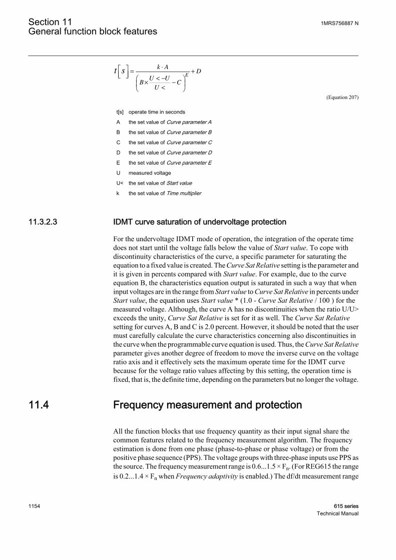
t sk A
BU U
UC
DE
=
⋅
×< −
<
−
+
GUID-4A433D56-D7FB-412E-B1AB-7FD43051EE79 V2 EN (Equation 207)
t[s] operate time in seconds
A the set value of Curve parameter A
B the set value of Curve parameter B
C the set value of Curve parameter C
D the set value of Curve parameter D
E the set value of Curve parameter E
U measured voltage
U< the set value of Start value
k the set value of Time multiplier
11.3.2.3 IDMT curve saturation of undervoltage protection
For the undervoltage IDMT mode of operation, the integration of the operate timedoes not start until the voltage falls below the value of Start value. To cope withdiscontinuity characteristics of the curve, a specific parameter for saturating theequation to a fixed value is created. The Curve Sat Relative setting is the parameter andit is given in percents compared with Start value. For example, due to the curveequation B, the characteristics equation output is saturated in such a way that wheninput voltages are in the range from Start value to Curve Sat Relative in percents underStart value, the equation uses Start value * (1.0 - Curve Sat Relative / 100 ) for themeasured voltage. Although, the curve A has no discontinuities when the ratio U/U>exceeds the unity, Curve Sat Relative is set for it as well. The Curve Sat Relativesetting for curves A, B and C is 2.0 percent. However, it should be noted that the usermust carefully calculate the curve characteristics concerning also discontinuities inthe curve when the programmable curve equation is used. Thus, the Curve Sat Relativeparameter gives another degree of freedom to move the inverse curve on the voltageratio axis and it effectively sets the maximum operate time for the IDMT curvebecause for the voltage ratio values affecting by this setting, the operation time isfixed, that is, the definite time, depending on the parameters but no longer the voltage.
11.4 Frequency measurement and protection
All the function blocks that use frequency quantity as their input signal share thecommon features related to the frequency measurement algorithm. The frequencyestimation is done from one phase (phase-to-phase or phase voltage) or from thepositive phase sequence (PPS). The voltage groups with three-phase inputs use PPS asthe source. The frequency measurement range is 0.6...1.5 × Fn. (For REG615 the rangeis 0.2...1.4 × Fn when Frequency adaptivity is enabled.) The df/dt measurement range
Section 11 1MRS756887 NGeneral function block features
1154 615 seriesTechnical Manual
always starts from 0.6 × Fn. When the frequency exceeds these limits, it is regarded asout of range and a minimum or maximum value is held as the measured valuerespectively with appropriate quality information. The frequency estimation requires160 ms to stabilize after a bad quality signal. Therefore, a delay of 160 ms is added tothe transition from the bad quality. The bad quality of the signal can be due torestrictions like:
• The source voltage is below 0.02 × Un at Fn.• The source voltage waveform is discontinuous.• The source voltage frequency rate of change exceeds 15 Hz/s (including stepwise
frequency changes).
When the bad signal quality is obtained, the nominal or zero (depending on the Deffrequency Sel setting) frequency value is shown with appropriate quality informationin the measurement view. The frequency protection functions are blocked when thequality is bad, thus the timers and the function outputs are reset. When the frequencyis out of the function block’s setting range but within the measurement range, theprotection blocks are running. However, the OPERATE outputs are blocked until thefrequency restores to a valid range.
11.5 Frequency adaptivity and generator start-upprotection
Frequency adaptivity enables sensitive and selective protection during the start-upand shutdown phase of the generator when low frequency and low voltage amplitudeexist at the same time. Sensitive protection is necessary because, for example, the faultcurrent level in generator internal fault during start-up or shutdown (when fieldexcitation is not present) may not exceed even the nominal current level. Frequencyadaptivity, available only in REG615, can be enabled by setting Frequencyadaptivity. When selected, the operation range of the relay measurements is extendedto 0.2...1.5 xFn (10...75 Hz when Rated frequency = 50 Hz or 12...90 Hz when Ratedfrequency = 60 Hz).
The frequency adaptivity uses the positive-sequence voltage in the frequency trackingand adapts the DFT, RMS, peak-to-peak and peak measurement accuracies of thecurrent and voltage inputs by using the tracked frequency in the operation range of0.2...1.5 xFn. Frequency adaptation starts when the generator terminal positive-sequence voltage level exceeds 0.04 xUn (minimum level). As the Synchronism andenergizing check (SECRSYN) bus voltage U12b voltage input always expects Ratedfrequency, the frequency adaptivity does not apply for this input.
If the generator terminal positive-sequence voltage is below the minimum level, therelay is not able to maintain frequency adaptation. The non-adaptive situation isindicated by function PROTECTION output FRQ_ADP_FAIL. The trackedfrequency is retained for 3 seconds until the FRQ_ADP_FAIL output is activated and
1MRS756887 N Section 11General function block features
615 series 1155Technical Manual
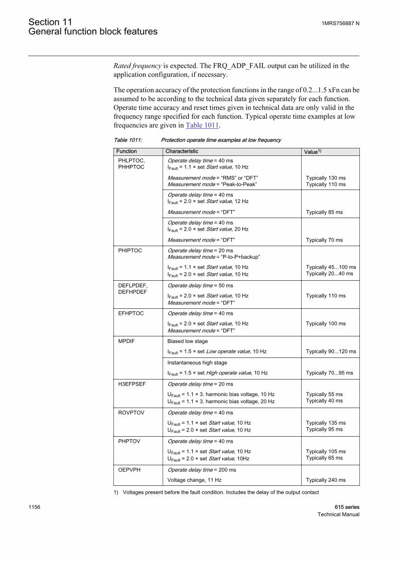
Rated frequency is expected. The FRQ_ADP_FAIL output can be utilized in theapplication configuration, if necessary.
The operation accuracy of the protection functions in the range of 0.2...1.5 xFn can beassumed to be according to the technical data given separately for each function.Operate time accuracy and reset times given in technical data are only valid in thefrequency range specified for each function. Typical operate time examples at lowfrequencies are given in Table 1011.
Table 1011: Protection operate time examples at low frequency
Function Characteristic Value1)
PHLPTOC,PHHPTOC
Operate delay time = 40 msIFault = 1.1 × set Start value, 10 Hz
Measurement mode = “RMS” or “DFT”Measurement mode = “Peak-to-Peak”
Typically 130 msTypically 110 ms
Operate delay time = 40 msIFault = 2.0 × set Start value, 12 Hz
Measurement mode = “DFT” Typically 85 ms
Operate delay time = 40 msIFault = 2.0 × set Start value, 20 Hz
Measurement mode = “DFT” Typically 70 ms
PHIPTOC Operate delay time = 20 msMeasurement mode = “P-to-P+backup”
IFault = 1.1 × set Start value, 10 HzIFault = 2.0 × set Start value, 10 Hz
Typically 45...100 msTypically 20...40 ms
DEFLPDEF,DEFHPDEF
Operate delay time = 50 ms
IFault = 2.0 × set Start value, 10 HzMeasurement mode = “DFT”
Typically 110 ms
EFHPTOC Operate delay time = 40 ms
IFault = 2.0 × set Start value, 10 HzMeasurement mode = “DFT”
Typically 100 ms
MPDIF Biased low stage
IFault = 1.5 × set Low operate value, 10 Hz Typically 90...120 ms
Instantaneous high stage
IFault = 1.5 × set High operate value, 10 Hz Typically 70...95 ms
H3EFPSEF Operate delay time = 20 ms
UFault = 1.1 × 3. harmonic bias voltage, 10 HzUFault = 1.1 × 3. harmonic bias voltage, 20 Hz
Typically 55 msTypically 40 ms
ROVPTOV Operate delay time = 40 ms
UFault = 1.1 × set Start value, 10 HzUFault = 2.0 × set Start value, 10 Hz
Typically 135 msTypically 95 ms
PHPTOV Operate delay time = 40 ms
UFault = 1.1 × set Start value, 10 HzUFault = 2.0 × set Start value, 10Hz
Typically 105 msTypically 65 ms
OEPVPH Operate delay time = 200 ms
Voltage change, 11 Hz Typically 240 ms
1) Voltages present before the fault condition. Includes the delay of the output contact
Section 11 1MRS756887 NGeneral function block features
1156 615 seriesTechnical Manual
Frequency adaptivity depends on the availability of voltages. The generator start-upprotection can be also extended by using wide peak-to-peak measurement mode(operational from 2 Hz upward) with designated start-up overcurrent protectionfunction (PHLPTOC). Before the generator is connected with the rest of the networkby closing the circuit breaker, the designated start-up overcurrent function should beeither blocked or its start value increased, as the Start value setting is typically lowerthan the nominal current.
11.6 Measurement modes
In many current or voltage dependent function blocks, there are various alternativemeasuring principles.
• RMS• DFT which is a numerically calculated fundamental component of the signal• Peak-to-peak• Peak-to-peak with peak backup• Wide peak-to-peak (REG615 standard configurations C and D)
Consequently, the measurement mode can be selected according to the application.
In extreme cases, for example with high overcurrent or harmonic content, themeasurement modes function in a slightly different way. The operation accuracy isdefined with the frequency range of f/fn=0.95...1.05. In peak-to-peak and RMSmeasurement modes, the harmonics of the phase currents are not suppressed, whereasin the fundamental frequency measurement the suppression of harmonics is at least-50 dB at the frequency range of f= n x fn, where n = 2, 3, 4, 5,...
RMSThe RMS measurement principle is selected with the Measurement mode settingusing the value "RMS". RMS consists of both AC and DC components. The ACcomponent is the effective mean value of the positive and negative peak values. RMSis used in applications where the effect of the DC component must be taken intoaccount.
RMS is calculated according to the formula:
In
IRMS i
i
n
=
=
∑1 2
1
A070883 V3 EN (Equation 208)
n The number of samples in a calculation cycle
Ii The current sample value
1MRS756887 N Section 11General function block features
615 series 1157Technical Manual

DFTThe DFT measurement principle is selected with the Measurement mode setting usingthe value "DFT". In the DFT mode, the fundamental frequency component of themeasured signal is numerically calculated from the samples. In some applications, forexample, it can be difficult to accomplish sufficiently sensitive settings and accurateoperation of the low stage, which may be due to a considerable amount of harmonicson the primary side currents. In such a case, the operation can be based solely on thefundamental frequency component of the current. In addition, the DFT mode hasslightly higher CT requirements than the peak-to-peak mode, if used with high andinstantaneous stages.
Peak-to-peakThe peak-to-peak measurement principle is selected with the Measurement modesetting using the value "Peak-to-Peak". It is the fastest measurement mode, in whichthe measurement quantity is made by calculating the average from the positive andnegative peak values. The DC component is not included. The retardation time isshort. The damping of the harmonics is quite low and practically determined by thecharacteristics of the anti-aliasing filter of the protection relay inputs. Consequently,this mode is usually used in conjunction with high and instantaneous stages, where thesuppression of harmonics is not so important. In addition, the peak-to-peak modeallows considerable CT saturation without impairing the performance of theoperation.
Peak-to-peak with peak backupThe peak-to-peak with peak backup measurement principle is selected with theMeasurement mode setting using the value "P-to-P+backup". It is similar to the peak-to-peak mode, with the exception that it has been enhanced with the peak backup. Inthe peak-to-peak with peak backup mode, the function starts with two conditions: thepeak-to-peak value is above the set start current or the peak value is above two timesthe set Start value. The peak backup is enabled only when the function is used in theDT mode in high and instantaneous stages for faster operation.
Wide peak-to-peakThe wide peak-to-peak measurement mode is available only in the three-phaseovercurrent protection function PHLPTOC in REG615 standard configurations C andD. The wide peak-to-peak measurement principle is available in products where it isnecessary for overcurrent protection to operate already starting from as low frequencyas 2 Hz during the generator start-up or shutdown phase. The wide peak-to-peakmeasurement principle is selected with the Measurement mode setting "Wide P-to-P".
The measurement mode calculates the average from the positive and negative peakvalues over the 500 ms wide measurement window, independently of the Frequencyadaptivity setting value. Retardation and reset times are longer due to the length of themeasurement window. The frequency of the fault current affects the operate time. Thedamping of the harmonics is quite low and practically determined by thecharacteristics of the anti-aliasing filter of the protection relay current inputs.
Section 11 1MRS756887 NGeneral function block features
1158 615 seriesTechnical Manual
When using measurement mode “Wide P-to-P”, the protection relayaccepts only Operate delay time setting value 800 ms or longer andOperating curve type 5=”ANSI Def. Time” or 15=”IEC Def. Time”.
Operation accuracy in the frequency range 2...85 Hz is ±1.5% or ±0.003 × In. Operatetime accuracy in definite time mode is ±1.0% of the set value or ±60 ms when IFault =2 × set Start value and the fault current frequency is 10...85 Hz.
11.7 Calculated measurements
Calculated residual current and voltageThe residual current is calculated from the phase currents according to equation:
Io I I IA B C= − + +( )
GUID-B9280304-8AC0-40A5-8140-2F00C1F36A9E V1 EN (Equation 209)
The residual voltage is calculated from the phase-to-earth voltages when the VTconnection is selected as “Wye” with the equation:
Uo U U UA B C= + +( ) / 3
GUID-03909E83-8AA3-42FF-B088-F216BBB16839 V1 EN (Equation 210)
Sequence componentsThe phase-sequence current components are calculated from the phase currentsaccording to:
I I I IA B C0 3= + +( ) /
GUID-2319C34C-8CC3-400C-8409-7E68ACA4F435 V2 EN (Equation 211)
I I a I a IA B C12
3= + ⋅ + ⋅( ) /
GUID-02E717A9-A58F-41B3-8813-EB8CDB78CBF1 V2 EN (Equation 212)
I I a I a IA B C22
3= + ⋅ + ⋅( ) /
GUID-80F92D60-0425-4F1F-9B18-DB2DEF4C2407 V2 EN (Equation 213)
The phase-sequence voltage components are calculated from the phase-to-earthvoltages when VT connection is selected as “Wye” with the equations:
U U U UA B C0 3= + +( ) /
GUID-49CFB460-5B74-43A6-A72C-AAD3AF795716 V2 EN (Equation 214)
U U a U a UA B C12
3= + ⋅ + ⋅( ) /
GUID-7A6B6AAD-8DDC-4663-A72F-A3715BF3E56A V2 EN (Equation 215)
U U a U a UA B C22
3= + ⋅ + ⋅( ) /
GUID-6FAAFCC1-AF25-4A0A-8D9B-FC2FD0BCFB21 V1 EN (Equation 216)
1MRS756887 N Section 11General function block features
615 series 1159Technical Manual

When VT connection is selected as “Delta”, the positive and negative phase sequencevoltage components are calculated from the phase-to-phase voltages according to theequations:
U U a UAB BC12
3= − ⋅( ) /
GUID-70796339-C68A-4D4B-8C10-A966BD7F090C V2 EN (Equation 217)
U U a UAB BC2 3= − ⋅( ) /
GUID-C132C6CA-B5F9-4DC1-94AF-FF22D2F0F12A V2 EN (Equation 218)
The phase-to-earth voltages are calculated from the phase-to-phase voltages when VTconnection is selected as "Delta" according to the equations.
U U U UA AB CA= + −( )0 3/
GUID-8581E9AC-389C-40C2-8952-3C076E74BDEC V1 EN (Equation 219)
U U U UB BC AB= + −( )0 / 3
GUID-9EB6302C-2DB8-482F-AAC3-BB3857C6F100 V1 EN (Equation 220)
U U U UC CA BC= + −( )0 / 3
GUID-67B3ACF2-D8F5-4829-B97C-7E2F3158BF8E V1 EN (Equation 221)
If the U 0 channel is not valid, it is assumed to be zero.
The phase-to-phase voltages are calculated from the phase-to-earth voltages when VTconnection is selected as "Wye" according to the equations.
U U UAB A B= −
GUID-674F05D1-414A-4F76-B196-88441B7820B8 V1 EN (Equation 222)
U U UBC B C= −
GUID-9BA93C77-427D-4044-BD68-FEE4A3A2433E V1 EN (Equation 223)
U U UCA C A= −
GUID-DDD0C1F0-6934-4FB4-9F79-702440125979 V1 EN (Equation 224)
Section 11 1MRS756887 NGeneral function block features
1160 615 seriesTechnical Manual
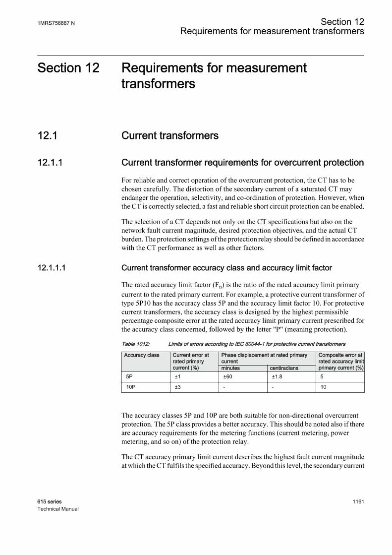
Section 12 Requirements for measurementtransformers
12.1 Current transformers
12.1.1 Current transformer requirements for overcurrent protection
For reliable and correct operation of the overcurrent protection, the CT has to bechosen carefully. The distortion of the secondary current of a saturated CT mayendanger the operation, selectivity, and co-ordination of protection. However, whenthe CT is correctly selected, a fast and reliable short circuit protection can be enabled.
The selection of a CT depends not only on the CT specifications but also on thenetwork fault current magnitude, desired protection objectives, and the actual CTburden. The protection settings of the protection relay should be defined in accordancewith the CT performance as well as other factors.
12.1.1.1 Current transformer accuracy class and accuracy limit factor
The rated accuracy limit factor (Fn) is the ratio of the rated accuracy limit primarycurrent to the rated primary current. For example, a protective current transformer oftype 5P10 has the accuracy class 5P and the accuracy limit factor 10. For protectivecurrent transformers, the accuracy class is designed by the highest permissiblepercentage composite error at the rated accuracy limit primary current prescribed forthe accuracy class concerned, followed by the letter "P" (meaning protection).
Table 1012: Limits of errors according to IEC 60044-1 for protective current transformers
Accuracy class Current error atrated primarycurrent (%)
Phase displacement at rated primarycurrent
Composite error atrated accuracy limitprimary current (%)minutes centiradians
5P ±1 ±60 ±1.8 5
10P ±3 - - 10
The accuracy classes 5P and 10P are both suitable for non-directional overcurrentprotection. The 5P class provides a better accuracy. This should be noted also if thereare accuracy requirements for the metering functions (current metering, powermetering, and so on) of the protection relay.
The CT accuracy primary limit current describes the highest fault current magnitudeat which the CT fulfils the specified accuracy. Beyond this level, the secondary current
1MRS756887 N Section 12Requirements for measurement transformers
615 series 1161Technical Manual
of the CT is distorted and it might have severe effects on the performance of theprotection relay.
In practise, the actual accuracy limit factor (Fa) differs from the rated accuracy limitfactor (Fn) and is proportional to the ratio of the rated CT burden and the actual CTburden.
The actual accuracy limit factor is calculated using the formula:
F FS S
S Sa n
in n
in
≈ ×
+
+
A071141 V1 EN
Fn the accuracy limit factor with the nominal external burden Sn
Sin the internal secondary burden of the CT
S the actual external burden
12.1.1.2 Non-directional overcurrent protection
The current transformer selectionNon-directional overcurrent protection does not set high requirements on the accuracyclass or on the actual accuracy limit factor (Fa) of the CTs. It is, however,recommended to select a CT with Fa of at least 20.
The nominal primary current I1n should be chosen in such a way that the thermal anddynamic strength of the current measuring input of the protection relay is notexceeded. This is always fulfilled when
I1n > Ikmax / 100,
Ikmax is the highest fault current.
The saturation of the CT protects the measuring circuit and the current input of theprotection relay. For that reason, in practice, even a few times smaller nominalprimary current can be used than given by the formula.
Recommended start current settingsIf Ikmin is the lowest primary current at which the highest set overcurrent stage is tooperate, the start current should be set using the formula:
Current start value < 0.7 × (Ikmin / I1n)
I1n is the nominal primary current of the CT.
The factor 0.7 takes into account the protection relay inaccuracy, current transformererrors, and imperfections of the short circuit calculations.
Section 12 1MRS756887 NRequirements for measurement transformers
1162 615 seriesTechnical Manual

The adequate performance of the CT should be checked when the setting of the highset stage overcurrent protection is defined. The operate time delay caused by the CTsaturation is typically small enough when the overcurrent setting is noticeably lowerthan Fa.
When defining the setting values for the low set stages, the saturation of the CT doesnot need to be taken into account and the start current setting is simply according to theformula.
Delay in operation caused by saturation of current transformersThe saturation of CT may cause a delayed protection relay operation. To ensure thetime selectivity, the delay must be taken into account when setting the operate timesof successive protection relays.
With definite time mode of operation, the saturation of CT may cause a delay that isas long as the time constant of the DC component of the fault current, when the currentis only slightly higher than the starting current. This depends on the accuracy limitfactor of the CT, on the remanence flux of the core of the CT, and on the operate timesetting.
With inverse time mode of operation, the delay should always be considered as beingas long as the time constant of the DC component.
With inverse time mode of operation and when the high-set stages are not used, the ACcomponent of the fault current should not saturate the CT less than 20 times thestarting current. Otherwise, the inverse operation time can be further prolonged.Therefore, the accuracy limit factor Fa should be chosen using the formula:
Fa > 20 × Current start value / I1n
The Current start value is the primary start current setting of the protection relay.
12.1.1.3 Example for non-directional overcurrent protection
The following figure describes a typical medium voltage feeder. The protection isimplemented as three-stage definite time non-directional overcurrent protection.
1MRS756887 N Section 12Requirements for measurement transformers
615 series 1163Technical Manual
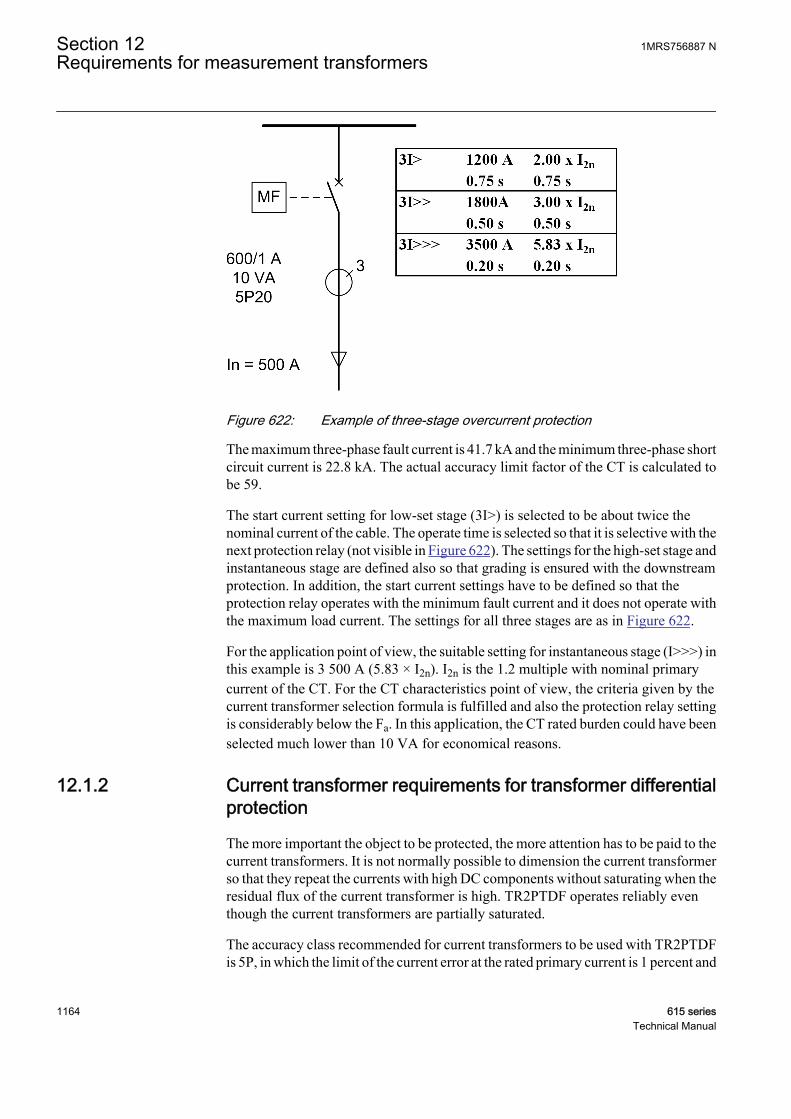
A071142 V1 EN
Figure 622: Example of three-stage overcurrent protection
The maximum three-phase fault current is 41.7 kA and the minimum three-phase shortcircuit current is 22.8 kA. The actual accuracy limit factor of the CT is calculated tobe 59.
The start current setting for low-set stage (3I>) is selected to be about twice thenominal current of the cable. The operate time is selected so that it is selective with thenext protection relay (not visible in Figure 622). The settings for the high-set stage andinstantaneous stage are defined also so that grading is ensured with the downstreamprotection. In addition, the start current settings have to be defined so that theprotection relay operates with the minimum fault current and it does not operate withthe maximum load current. The settings for all three stages are as in Figure 622.
For the application point of view, the suitable setting for instantaneous stage (I>>>) inthis example is 3 500 A (5.83 × I2n). I2n is the 1.2 multiple with nominal primarycurrent of the CT. For the CT characteristics point of view, the criteria given by thecurrent transformer selection formula is fulfilled and also the protection relay settingis considerably below the Fa. In this application, the CT rated burden could have beenselected much lower than 10 VA for economical reasons.
12.1.2 Current transformer requirements for transformer differentialprotection
The more important the object to be protected, the more attention has to be paid to thecurrent transformers. It is not normally possible to dimension the current transformerso that they repeat the currents with high DC components without saturating when theresidual flux of the current transformer is high. TR2PTDF operates reliably eventhough the current transformers are partially saturated.
The accuracy class recommended for current transformers to be used with TR2PTDFis 5P, in which the limit of the current error at the rated primary current is 1 percent and
Section 12 1MRS756887 NRequirements for measurement transformers
1164 615 seriesTechnical Manual
the limit of the phase displacement is 60 minutes. The limit of the composite error atthe rated accuracy limit primary current is 5 percent.
The approximate value of the accuracy limit factor Fa corresponding to the actualcurrent transformer burden can be calculated on the basis of the rated accuracy limitfactor Fn at the rated burden, the rated burden Sn, the internal burden Sinand the actualburden Sa of the current transformer.
F FS S
S Sa n
in n
in a
= ×
+
+
GUID-26DEE538-9E1A-49A2-9C97-F69BD44591C9 V2 EN (Equation 225)
Fa The approximate value of the accuracy limit factor (ALF) corresponding to the actual CT burden
Fn The rated accuracy limit factor at the rated burden of the current transformer
Sn The rated burden of the current transformer
Sin The internal burden of the current transformer
Sa The actual burden of the current transformer
Example 1The rated burden Sn of the current transformer 5P20 is 10 VA, the secondary ratedcurrent is 5A, the internal resistance Rin= 0.07 Ω and the accuracy limit factor Fncorresponding to the rated burden is 20 (5P20). Thus the internal burden of the currenttransformer is Sin= (5A)2 * 0.07 Ω = 1.75 VA. The input impedance of the protectionrelay at a rated current of 5A is < 20 mΩ. If the measurement conductors have aresistance of 0.113 Ω, the actual burden of the current transformer is Sa=(5A)2 *(0.113 + 0.020) Ω = 3.33 VA. Thus the accuracy limit factor Fa corresponding to theactual burden is approximately 46.
The CT burden can grow considerably at the rated current 5A. The actual burden of thecurrent transformer decreases at the rated current of 1A while the repeatabilitysimultaneously improves.
At faults occurring in the protected area, the currents may be very high compared tothe rated currents of the current transformers. Due to the instantaneous stage of thedifferential function block, it is sufficient that the current transformers are capable ofrepeating the current required for instantaneous tripping during the first cycle.
Thus the current transformers usually are able to reproduce the asymmetric faultcurrent without saturating within the next 10 ms after the occurrence of the fault tosecure that the operate times of the protection relay comply with the retardation time.
The accuracy limit factors corresponding to the actual burden of the phase currenttransformer to be used in differential protection fulfill the requirement.
1MRS756887 N Section 12Requirements for measurement transformers
615 series 1165Technical Manual

F K Ik T ea r dc
T Tm dc> × × × × − +−
max/
( ( ) )ω 1 1
GUID-DA861DAD-C40E-4A82-8973-BBAFD15279C0 V1 EN (Equation 226)
Ikmax The maximum through-going fault current (in Ir) at which the protection is not allowed to operate
Tdc The primary DC time constant related to Ikmax
ω The angular frequency, that is, 2*π*fn
Tm The time-to-saturate, that is, the duration of the saturation free transformation
Kr The remanence factor 1/(1-r), where r is the maximum remanence flux in p.u. from saturation flux
The accuracy limit factors corresponding to the actual burden of the phase currenttransformer is used in differential protection.
The parameter r is the maximum remanence flux density in the CT core in p.u. fromsaturation flux density. The value of the parameter r depends on the magnetic materialused and on the construction of the CT. For instance, if the value of r = 0.4, theremanence flux density can be 40 percent of the saturation flux density. Themanufacturer of the CT has to be contacted when an accurate value for the parameter ris needed. The value r = 0.4 is recommended to be used when an accurate value is notavailable.
The required minimum time-to-saturate Tm in TR2PTDF is half fundamental cycleperiod (10 ms when fn = 50Hz).
Two typical cases are considered for the determination of the sufficient accuracy limitfactor (Fa):
1. A fault occurring at the substation bus:The protection must be stable at a fault arising during a normal operatingsituation. Re-energizing the transformer against a bus fault leads to very highfault currents and thermal stress and therefore re-energizing is not preferred inthis case. Thus, the remanence can be neglected.The maximum through-going fault current Ikmax is typically 10 Ir for a substationmain transformer. At a short circuit fault close to the supply transformer, the DCtime constant (Tdc) of the fault current is almost the same as that of thetransformer, the typical value being 100 ms.
Ikmax 10 Ir
Tdc 100 ms
ω 100π Hz
Tm 10 ms
Kr 1
When the values are substituted in Equation 226, the result is:
Section 12 1MRS756887 NRequirements for measurement transformers
1166 615 seriesTechnical Manual
Fa > × × × × − + ≈−
K Ik T er dc
T Tm dcmax
/( ( ) )ω 1 1 40
GUID-7F1019C5-C819-440B-871B-5CFD1AF88956 V1 EN
2. Re-energizing against a fault occurring further down in the network:The protection must be stable also during re-energization against a fault on theline. In this case, the existence of remanence is very probable. It is assumed to be40 percent here.On the other hand, the fault current is now smaller and since the ratio of theresistance and reactance is greater in this location, having a full DC offset is notpossible. Furthermore, the DC time constant (Tdc) of the fault current is nowsmaller, assumed to be 50 ms here.Assuming a maximum fault current being 30 percent lower than in the bus faultand a DC offset 90 percent of the maximum.
Ikmax 0.7* 10 = 7 (Ir)
Tdc 50 ms
ω 100π Hz
Tm 10 ms
Kr 1/(1-0.4) = 1.6667
When the values are substituted in the equation, the result is:
Fa > × × × × × − + ≈−
K Ik T er dc
T Tm dcmax
/. ( ( ) )0 9 1 1 40ω
GUID-9B859B2D-AC40-4278-8A99-3475442D7C67 V1 EN
If the actual burden of the current transformer (Sa) in Equation 225 cannot bereduced low enough to provide a sufficient value for Fa, there are two alternativesto deal with the situation:• a CT with a higher rated burden Sn can be chosen (which also means a
higher rated accuracy limit Fn)• a CT with a higher nominal primary current I1n (but the same rated burden)
can be chosen
Example 2Assuming that the actions according to alternative two above are taken in order toimprove the actual accuracy limit factor:
FIrCT
IrTRFa n= ×
GUID-31A3C436-4E17-40AE-A4EA-D2BD6B72034E V2 EN (Equation 227)
IrTR 1000 A (rated secondary side current of the power transformer)
IrCT 1500 A (rated primary current of the CT on the transformer secondary side)
Fn 30 (rated accuracy limit factor of the CT)
1MRS756887 N Section 12Requirements for measurement transformers
615 series 1167Technical Manual

Fa (IrCT / IrTR) * Fn (actual accuracy limit factor due to oversizing the CT) = (1500/1000) * 30 = 45
In TR2PTDF, it is important that the accuracy limit factors Fa of the phase currenttransformers at both sides correspond with each other, that is, the burdens of thecurrent transformers on both sides are to be as equal as possible. If high inrush or startcurrents with high DC components pass through the protected object when it isconnected to the network, special attention is required for the performance and theburdens of the current transformers and for the settings of the function block.
Section 12 1MRS756887 NRequirements for measurement transformers
1168 615 seriesTechnical Manual

Section 13 Protection relay's physical connections
13.1 Module slot numbering
1 2 3 4 5
GUID-87FBCD58-52E4-44D3-9BF2-81BEB7377034 V1 EN
Figure 623: Module slot numbering
1 X000
2 X100
3 X110
4 X120
5 X130
1MRS756887 N Section 13Protection relay's physical connections
615 series 1169Technical Manual

13.2 Protective earth connections
7
6
7
8
24
23
22
21
20
19
18
17
16
15
14
13
12
11
10
9
5
4
3
2
1
8
6
23
1
2
3
4
5
9
10
11
12
13
14
15
16
17
18
19
20
21
22
24
A070772 V1 EN
Figure 624: The protective earth screw is located between connectors X100 andX110
The earth lead must be at least 6.0 mm2 and as short as possible.
13.3 Binary and analog connections
All binary and analog connections are described in the productspecific application manuals.
13.4 Communication connections
The front communication connection is an RJ-45 type connector used mainly forconfiguration and setting.
For RED615, the rear communication module is mandatory due to the connectionneeded for the line-differential protection communication. If station communicationis needed for REF615, REG615, REM615, RET615, REU615 or REV615, an
Section 13 1MRS756887 NProtection relay's physical connections
1170 615 seriesTechnical Manual
optional rear communication module is required. Several optional communicationconnections are available.
• Galvanic RJ-45 Ethernet connection• Optical LC Ethernet connection• ST-type glass fiber serial connection• EIA-485 serial connection• EIA-232 serial connection
Never touch the end face of an optical fiber connector.
Always install dust caps on unplugged fiber connectors.
If contaminated, clean optical connectors only with fiber-opticcleaning products.
13.4.1 Ethernet RJ-45 front connection
The protection relay is provided with an RJ-45 connector on the LHMI. The connectoris intended for configuration and setting purposes. The interface on the PC side has tobe configured in a way that it obtains the IP address automatically. There is a DHCPserver inside protection relay for the front interface only.
The events and setting values and all input data such as memorized values anddisturbance records can be read via the front communication port.
Only one of the possible clients can be used for parametrization at a time.
• PCM600• LHMI• WHMI
The default IP address of the protection relay through this port is 192.168.0.254.
The front port supports TCP/IP protocol. A standard Ethernet CAT 5 crossover cableis used with the front port.
The speed of the front connector interface is limited to 10 Mbps.
1MRS756887 N Section 13Protection relay's physical connections
615 series 1171Technical Manual

13.4.2 Ethernet rear connections
The Ethernet station bus communication module is provided with either galvanicRJ-45 connection or optical multimode LC type connection, depending on the productvariant and the selected communication interface option. A shielded twisted-paircable CAT 5e is used with the RJ-45 connector and an optical multi-mode cable (≤2km) with the LC type connector.
In addition, communication modules with multiple Ethernet connectors enable theforwarding of Ethernet traffic. These variants include an internal Ethernet switch thathandles the Ethernet traffic between an protection relay and a station bus. In this case,the used network can be a ring or daisy-chain type of network topology. In loop typetopology, a self-healing Ethernet loop is closed by a managed switch supporting rapidspanning tree protocol. In daisy-chain type of topology, the network is bus type and itis either without switches, where the station bus starts from the station client, or witha switch to connect some devices and the protection relays of this product series to thesame network.Internal Ethernet switch MAC table size is 512 entries. All Ethernetports share this one common MAC table.
Communication modules including Ethernet connectors X1, X2, and X3 can utilizethe third port for connecting any other device (for example, an SNTP server, that isvisible for the whole local subnet) to a station bus. In RED615, the first Ethernet portX16 is dedicated to the line differential communication and it cannot be used forstation bus communication.
The protection relay's default IP address through rear Ethernet port is 192.168.2.10with the TCP/IP protocol. The data transfer rate is 10 or 100 Mbps full duplex.
13.4.3 EIA-232 serial rear connection
The EIA-232 connection follows the TIA/EIA-232 standard and is intended to be usedwith a point-to-point connection. The connection supports hardware flow control(RTS, CTS, DTR, DSR), full-duplex and half-duplex communication.
13.4.4 EIA-485 serial rear connection
The EIA-485 communication module follows the TIA/EIA-485 standard and isintended to be used in a daisy-chain bus wiring scheme with 2-wire half-duplex or 4-wire full-duplex, multi-point communication.
The maximum number of devices (nodes) connected to the bus wherethe protection relay is used is 32, and the maximum length of the busis 1200 meters.
Section 13 1MRS756887 NProtection relay's physical connections
1172 615 seriesTechnical Manual

13.4.5 Line differential protection communication connection
The dedicated line differential protection communication link uses either a singlemode or a multimode connection with an LC type connector. The line differentialcommunication connector (X16/LD) is always the topmost in the communicationmodule. Line differential communication cards COM0008 and COM0036 areprovided with multimode optical LC connector. Line differential communicationcards COM0010 and COM0035 are provided with single mode optical LC connector.
The port cannot be used with any other Ethernet communication network. Theinterface speed is 100 Mbps.
Use direct link. Switches, hubs or routers are not allowed between theprotection relays.
If galvanic pilot wire is used as protection communication link, the pilot wire modemRPW600 is required. The protection communication link always requires twomodems in a protection scheme, thus delivered in pairs of master (RPW600M) andfollower (RPW600F) units. A single-mode fiber optic cable with dual LC typeconnectors is used to connect RED615 with RPW600 modem. The recommendedminimum length for this cable is 3 m.
Communication port X16/LD of RED615 is used both for direct fiberoptic link and connection with the pilot wire modem.
The RPW600 modem has a built-in 5 kVAC (RMS, 1 min) levelinsulation against earth potential in the pilot wire connection.
13.4.6 Optical ST serial rear connection
Serial communication can be used optionally through an optical connection either inloop or star topology. The connection idle state is light on or light off.
Using ST loop mode requires an ST serial converter that supportsdetecting and removing of duplicate request after transmission troughfull circle.
13.4.7 Communication interfaces and protocols
The communication protocols supported depend on the optional rear communicationmodule.
1MRS756887 N Section 13Protection relay's physical connections
615 series 1173Technical Manual
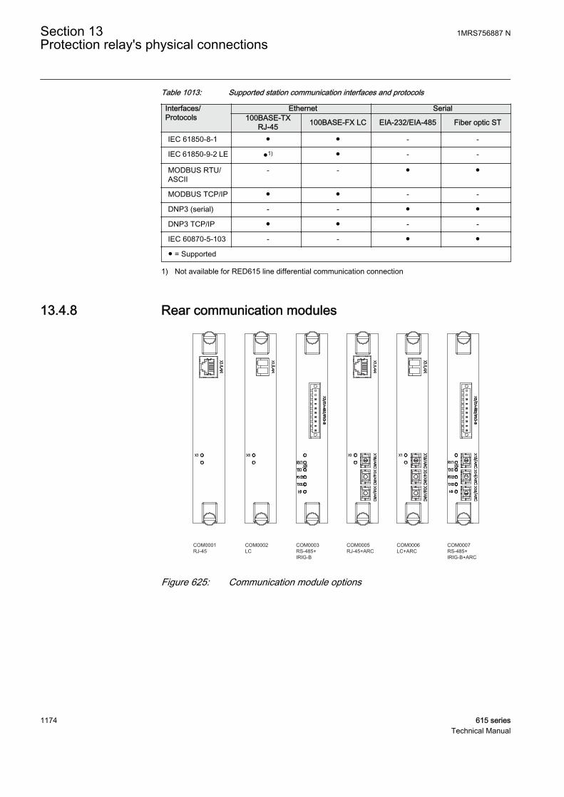
Table 1013: Supported station communication interfaces and protocols
Interfaces/Protocols
Ethernet Serial100BASE-TX
RJ-45 100BASE-FX LC EIA-232/EIA-485 Fiber optic ST
IEC 61850-8-1 - -
IEC 61850-9-2 LE 1) - -
MODBUS RTU/ASCII
- -
MODBUS TCP/IP - -
DNP3 (serial) - -
DNP3 TCP/IP - -
IEC 60870-5-103 - -
= Supported
1) Not available for RED615 line differential communication connection
13.4.8 Rear communication modules
COM0001RJ-45
COM0002LC
COM0003RS-485+IRIG-B
COM0005RJ-45+ARC
COM0006LC+ARC
COM0007RS-485+IRIG-B+ARC
GUID-9942EA65-7B6F-4987-BD1A-9A88B0B222D6 V3 EN
Figure 625: Communication module options
Section 13 1MRS756887 NProtection relay's physical connections
1174 615 seriesTechnical Manual

COM0008LC+2xRJ-45+RS485+ST+IRIG-B
COM0010LC+2xRJ-45+RS485+ST+IRIG-B
COM0011RJ-45+RS485+IRIG-B
COM0012LC+RS485+IRIG-B
COM0013RJ-45+RS485+IRIG-B+ARC
COM0014LC+RS485+IRIG-B+ARC
COM0023RJ-45+RS232/485+RS485+ST+IRIG-B
GUID-07821EE0-53E5-44A8-82BF-1C1D652DD21E V2 EN
Figure 626: Communication module options
1MRS756887 N Section 13Protection relay's physical connections
615 series 1175Technical Manual
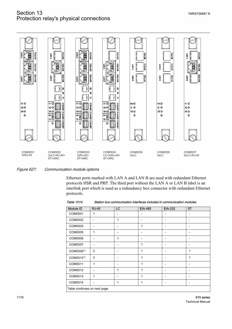
COM00313xRJ-45
COM00322xLC+RJ-45+ST+ARC
COM00333xRJ-45+ST+ARC
COM0034LC+2xRJ-45+ST+ARC
COM00372xLC+RJ-45
COM00353xLC
COM00363xLC
GUID-AF5B9B14-A1F1-4EED-96AD-DA0665226860 V4 EN
Figure 627: Communication module options
Ethernet ports marked with LAN A and LAN B are used with redundant Ethernetprotocols HSR and PRP. The third port without the LAN A or LAN B label is aninterlink port which is used as a redundancy box connector with redundant Ethernetprotocols.
Table 1014: Station bus communication interfaces included in communication modules
Module ID RJ-45 LC EIA-485 EIA-232 STCOM0001 1 - - - -
COM0002 - 1 - - -
COM0003 - - 1 - -
COM0005 1 - - - -
COM0006 - 1 - - -
COM0007 - - 1 - -
COM00081) 2 - 1 - 1
COM00101) 2 - 1 - 1
COM0011 1 - 1 - -
COM0012 - 1 1 - -
COM0013 1 - 1 - -
COM0014 - 1 1 - -
Table continues on next page
Section 13 1MRS756887 NProtection relay's physical connections
1176 615 seriesTechnical Manual

Module ID RJ-45 LC EIA-485 EIA-232 STCOM0023 1 - 1 1 1
COM0031 3 - - - -
COM0032 1 2 - - 1
COM0033 3 - - - 1
COM0034 2 1 - - 1
COM00351) - 3 - - -
COM00361) - 3 - - -
COM0037 1 2 - - -
1) Available only for RED615
Table 1015: LED descriptions for COM0001-COM0014
LED Connector Description1)
X1 X1 X1/LAN link status and activity (RJ-45 and LC)
RX1 X5 COM2 2-wire/4-wire receive activity
TX1 X5 COM2 2-wire/4-wire transmit activity
RX2 X5 COM1 2-wire receive activity
TX2 X5 COM1 2-wire transmit activity
I-B X5 IRIG-B signal activity
1) Depending on the COM module and jumper configuration
Table 1016: LED descriptions for COM0008 and COM0010
LED Connector Description1)
X16 X16 X16/LD link status and activity
X1 X1 X1/LAN link status and activity
X2 X2 X2/LAN link status and activity
RX X5 COM1 2-wire receive activity/COM2 4-wire receive activity
TX X5 COM1 2-wire transmit activity/COM2 4-wire transmit activity
RX X5/X12 COM2 2-wire receive activity/COM2 4-wire receive activity
TX X5/X12 COM2 2-wire transmit activity/COM2 4-wire transmit activity
I-B X5 IRIG-B signal activity
1) Depending on the jumper configuration
Table 1017: LED descriptions for COM0023
LED Connector Description1)
FX X12 Not used by COM0023
X1 X1 LAN Link status and activity (RJ-45 and LC)
FL X12 Not used by COM0023
Table continues on next page
1MRS756887 N Section 13Protection relay's physical connections
615 series 1177Technical Manual
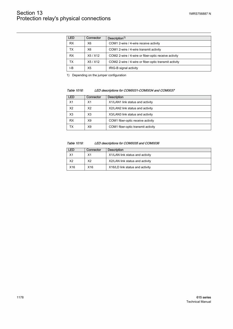
LED Connector Description1)
RX X6 COM1 2-wire / 4-wire receive activity
TX X6 COM1 2-wire / 4-wire transmit activity
RX X5 / X12 COM2 2-wire / 4-wire or fiber-optic receive activity
TX X5 / X12 COM2 2-wire / 4-wire or fiber-optic transmit activity
I-B X5 IRIG-B signal activity
1) Depending on the jumper configuration
Table 1018: LED descriptions for COM0031-COM0034 and COM0037
LED Connector DescriptionX1 X1 X1/LAN1 link status and activity
X2 X2 X2/LAN2 link status and activity
X3 X3 X3/LAN3 link status and activity
RX X9 COM1 fiber-optic receive activity
TX X9 COM1 fiber-optic transmit activity
Table 1019: LED descriptions for COM0035 and COM0036
LED Connector DescriptionX1 X1 X1/LAN link status and activity
X2 X2 X2/LAN link status and activity
X16 X16 X16/LD link status and activity
Section 13 1MRS756887 NProtection relay's physical connections
1178 615 seriesTechnical Manual

13.4.8.1 COM0001-COM0014 jumper locations and connections
X4X6X5
X8X9
X7
1 2 3
A070893 V3 EN
Figure 628: Jumper connectors on communication module
Table 1020: 2-wire EIA-485 jumper connectors
Group Jumper connection Description NotesX4 1-2 A+ bias enabled COM2
2-wire connection2-3 A+ bias disabled
X5 1-2 B- bias enabled
2-3 B- bias disabled
X6 1-2 Bus terminationenabled
2-3 Bus terminationdisabled
Table continues on next page
1MRS756887 N Section 13Protection relay's physical connections
615 series 1179Technical Manual

Group Jumper connection Description NotesX7 1-2 B- bias enabled COM1
2-wire connection2-3 B- bias disabled
X8 1-2 A+ bias enabled
2-3 A+ bias disabled
X9 1-2 Bus terminationenabled
2-3 Bus terminationdisabled
The bus is to be biased at one end to ensure fail-safe operation, which can be doneusing the pull-up and pull-down resistors on the communication module. In 4-wireconnection the pull-up and pull-down resistors are selected by setting jumpers X4, X5,X7 and X8 to enabled position. The bus termination is selected by setting jumpers X6and X9 to enabled position.
The jumpers have been set to no termination and no biasing as default.
Table 1021: 4-wire EIA-485 jumper connectors for COM2
Group Jumper connection Description Notes
X41-2 A+ bias enabled
COM24-wire TX channel
2-3 A+ bias disabled 1)
X51-2 B- bias enabled
2-3 B- bias disabled1)
X6
1-2 Bus terminationenabled
2-3 Bus terminationdisabled1)
X71-2 B- bias enabled
COM24-wire RX channel
2-3 B- bias disabled1)
X81-2 A+ bias enabled
2-3 A+ bias disabled1)
X9
1-2 Bus terminationenabled
2-3 Bus terminationdisabled1)
1) Default setting
It is recommended to enable biasing only at one end of the bus.
Section 13 1MRS756887 NProtection relay's physical connections
1180 615 seriesTechnical Manual
It is recommended to enable termination at each end of the bus.
It is recommended to ground the signal directly to earth from one nodeusing a GND pin and through capacitor from other nodes using aGNDC pin.
Signal grounding should be used with all devices in RS-485 bushaving an isolated communication port. Grounding ensures thatdifferent RS-485 nodes have the same signal reference ground.Without grounding the differential RS-485 signal might besuperimposed between different nodes with respect to the node's localground. For signal grounding it is recommended to connect to AGNDpin in RS-485 connector an additional ground wire which runs insidethe shielded serial cable.
The optional communication modules include support for EIA-485 serialcommunication (X5 connector). Depending on the configuration, the communicationmodules can host either two 2-wire ports or one 4-wire port.
The two 2-wire ports are called COM1 and COM2. Alternatively, if there is only one4-wire port configured, the port is called COM2. The fiber optic ST connection usesthe COM1 port.
Table 1022: EIA-485 connections for COM0001-COM0014
Pin 2-wire mode 4-wire mode10 COM1 A/+ COM2 Rx/+
9 B/- Rx/-
8 COM2 A/+ Tx/+
7 B/- Tx/-
6 AGND (isolated ground)
5 IRIG-B +
4 IRIG-B -
3 -
2 GNDC (case via capacitor)
1 GND (case)
1MRS756887 N Section 13Protection relay's physical connections
615 series 1181Technical Manual

13.4.8.2 COM0023 jumper locations and connections
The optional communication module supports EIA-232/EIA-485 serialcommunication (X6 connector), EIA-485 serial communication (X5 connector) andoptical ST serial communication (X12 connector).
Two independent communication ports are supported. The two 2-wire ports are calledCOM1 and COM2. Alternatively, if only one 4-wire port is configured, the port iscalled COM2. The fiber optic ST connection uses the COM1 port.
Table 1023: Configuration options of the two independent communication ports
COM1 connector X6 COM2 connector X5 or X12EIA-232 Optical ST (X12)
EIA-485 2-wire EIA-485 2-wire (X5)
EIA-485 4-wire EIA-485 4-wire (X5)
Section 13 1MRS756887 NProtection relay's physical connections
1182 615 seriesTechnical Manual
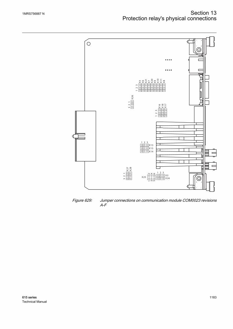
6
X2
6
X8
X1
1
X1
9
X9
X5
X7
X2
1
X6
X2
0
1
2
3
1
2
3
X1
7
X1
8
X1
6
X15
X14
X13
1 2 3
X24
1 2 3
X3X25
12
3 5
4
3
2
1
X2
7
X2
83
2
1
GUID-D4044F6B-2DA8-4C14-A491-4772BA108292 V1 EN
Figure 629: Jumper connections on communication module COM0023 revisionsA-F
1MRS756887 N Section 13Protection relay's physical connections
615 series 1183Technical Manual
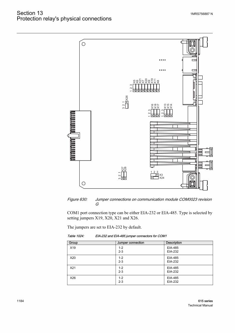
1 2
3
1 2
3
X24X3
X5
1 2
3
1 2 3
X6
X21 X7
X20 X9
X19
X11
X8
X16 X18
X27
X13
X26
3 2
1
X14X15
X28
X17
3 2
1
GUID-1E542C3A-F6E9-4F94-BEFD-EA3FEEC65FC8 V1 EN
Figure 630: Jumper connections on communication module COM0023 revisionG
COM1 port connection type can be either EIA-232 or EIA-485. Type is selected bysetting jumpers X19, X20, X21 and X26.
The jumpers are set to EIA-232 by default.
Table 1024: EIA-232 and EIA-485 jumper connectors for COM1
Group Jumper connection DescriptionX19 1-2
2-3EIA-485EIA-232
X20 1-22-3
EIA-485EIA-232
X21 1-22-3
EIA-485EIA-232
X26 1-22-3
EIA-485EIA-232
Section 13 1MRS756887 NProtection relay's physical connections
1184 615 seriesTechnical Manual

To ensure fail-safe operation, the bus is to be biased at one end using the pull-up andpull-down resistors on the communication module. In the 4-wire connection, the pull-up and pull-down resistors are selected by setting jumpers X5, X6, X8 and X9 toenabled position. The bus termination is selected by setting jumpers X7 and X11 toenabled position.
The jumpers have been set to no termination and no biasing as default.
Table 1025: 2-wire EIA-485 jumper connectors for COM1
Group Jumper connection Description NotesX5 1-2
2-3A+ bias enabledA+ bias disabled1)
COM1Rear connector X62-wire connection
X6 1-22-3
B- bias enabledB- bias disabled1)
X7 1-22-3
Bus terminationenabledBus terminationdisabled1)
1) Default setting
Table 1026: 4–wire EIA-485 jumper connectors for COM1
Group Jumper connection Description NotesX5 1-2
2-3A+ bias enabledA+ bias disabled1)
COM1Rear connector X64-wire TX channel
X6 1-22-3
B- bias enabledB- bias disabled1)
X7 1-22-3
Bus terminationenabledBus terminationdisabled1)
X9 1-22-3
A+ bias enabledA+ bias disabled1)
4-wire RX channel
X8 1-22-3
B- bias enabledB- bias disabled1)
X11 1-22-3
Bus terminationenabledBus terminationdisabled1)
1) Default setting
COM2 port connection can be either EIA-485 or optical ST. Connection type isselected by setting jumpers X27 and X28.
Table 1027: COM2 serial connection X5 EIA-485/ X12 Optical ST
Group Jumper connection DescriptionX27 1-2
2-3EIA-485Optical ST
X28 1-22-3
EIA-485Optical ST
1MRS756887 N Section 13Protection relay's physical connections
615 series 1185Technical Manual
Table 1028: 2-wire EIA-485 jumper connectors for COM2
Group Jumper connection DescriptionX13 1-2
2-3A+ bias enabledA+ bias disabled
X14 1-22-3
B- bias enabledB- bias disabled
X15 1-22-3
Bus termination enabledBus termination disabled
Table 1029: 4-wire EIA-485 jumper connectors for COM2
Group Jumper connection Description NotesX13 1-2
2-3A+ bias enabledA+ bias disabled
COM24-wire TX channel
X14 1-22-3
B- bias enabledB- bias disabled
X15 1-22-3
Bus terminationenabledBus terminationdisabled
X16 1-22-3
Bus terminationenabledBus terminationdisabled
4-wire RX channelX17 1-22-3
A+ bias enabledA+ bias disabled
X18 1-22-3
B- bias enabledB- bias disabled
Table 1030: X12 Optical ST connection
Group Jumper connection DescriptionX3 1-2
2-3Star topologyLoop topology
X24 1-22-3
Idle state = Light onIdle state = Light off
Table 1031: EIA-232 connections for COM0023 (X6)
Pin EIA-2321 DCD
2 RxD
3 TxD
4 DTR
5 AGND
6 -
7 RTS
8 CTS
Section 13 1MRS756887 NProtection relay's physical connections
1186 615 seriesTechnical Manual
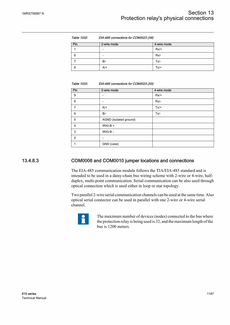
Table 1032: EIA-485 connections for COM0023 (X6)
Pin 2-wire mode 4-wire mode1 - Rx/+
6 - Rx/-
7 B/- Tx/-
8 A/+ Tx/+
Table 1033: EIA-485 connections for COM0023 (X5)
Pin 2-wire mode 4-wire mode9 - Rx/+
8 - Rx/-
7 A/+ Tx/+
6 B/- Tx/-
5 AGND (isolated ground)
4 IRIG-B +
3 IRIG-B -
2 -
1 GND (case)
13.4.8.3 COM0008 and COM0010 jumper locations and connections
The EIA-485 communication module follows the TIA/EIA-485 standard and isintended to be used in a daisy-chain bus wiring scheme with 2-wire or 4-wire, half-duplex, multi-point communication. Serial communication can be also used throughoptical connection which is used either in loop or star topology.
Two parallel 2-wire serial communication channels can be used at the same time. Alsooptical serial connector can be used in parallel with one 2-wire or 4-wire serialchannel.
The maximum number of devices (nodes) connected to the bus wherethe protection relay is being used is 32, and the maximum length of thebus is 1200 meters.
1MRS756887 N Section 13Protection relay's physical connections
615 series 1187Technical Manual
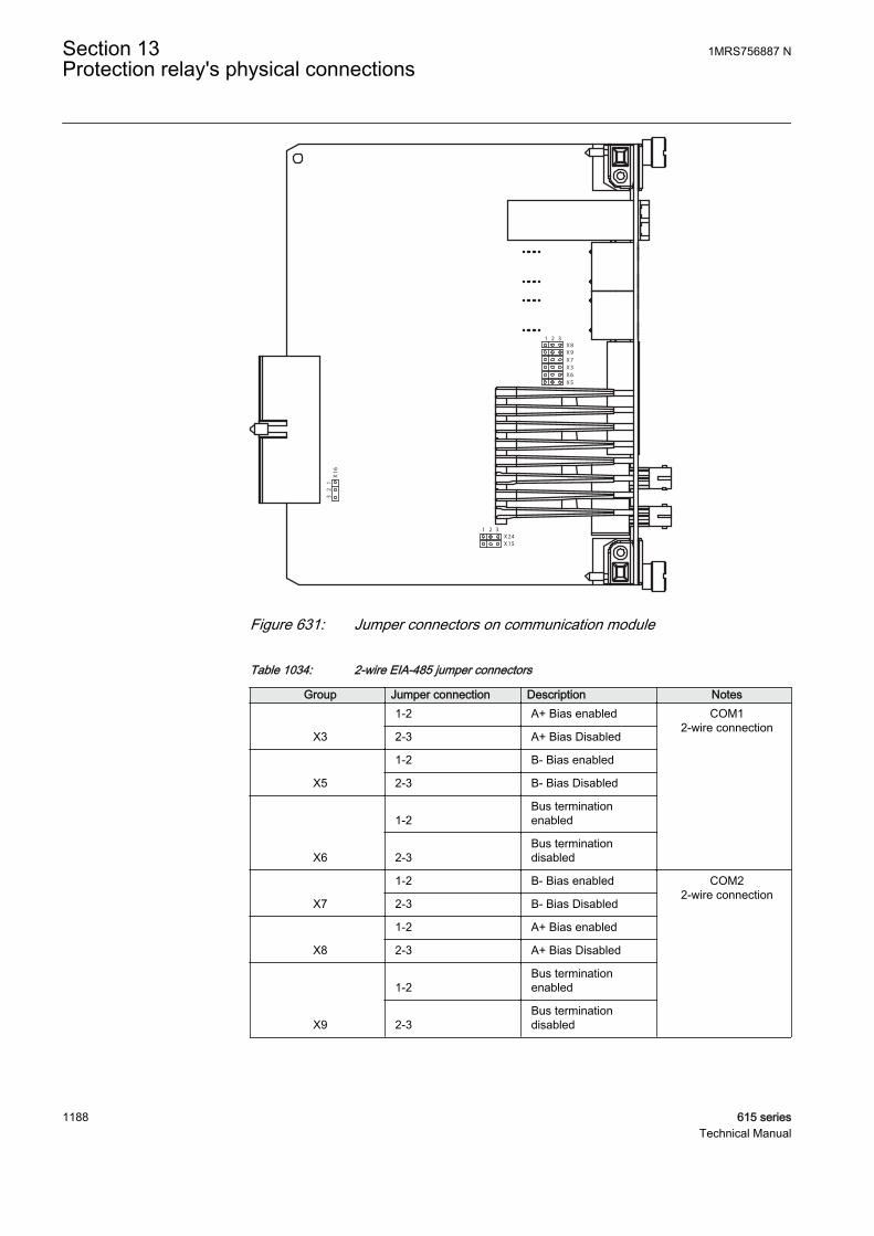
X8
X9
X7
X3
X6
X5
X15
X24
1 2 3
X1
6
3
2
1
1 2 3
GUID-FDC31D60-8F9F-4D2A-A1A2-F0E57553C06B V1 EN
Figure 631: Jumper connectors on communication module
Table 1034: 2-wire EIA-485 jumper connectors
Group Jumper connection Description Notes
X3
1-2 A+ Bias enabled COM12-wire connection
2-3 A+ Bias Disabled
X5
1-2 B- Bias enabled
2-3 B- Bias Disabled
X6
1-2Bus terminationenabled
2-3Bus terminationdisabled
X7
1-2 B- Bias enabled COM22-wire connection
2-3 B- Bias Disabled
X8
1-2 A+ Bias enabled
2-3 A+ Bias Disabled
X9
1-2Bus terminationenabled
2-3Bus terminationdisabled
Section 13 1MRS756887 NProtection relay's physical connections
1188 615 seriesTechnical Manual
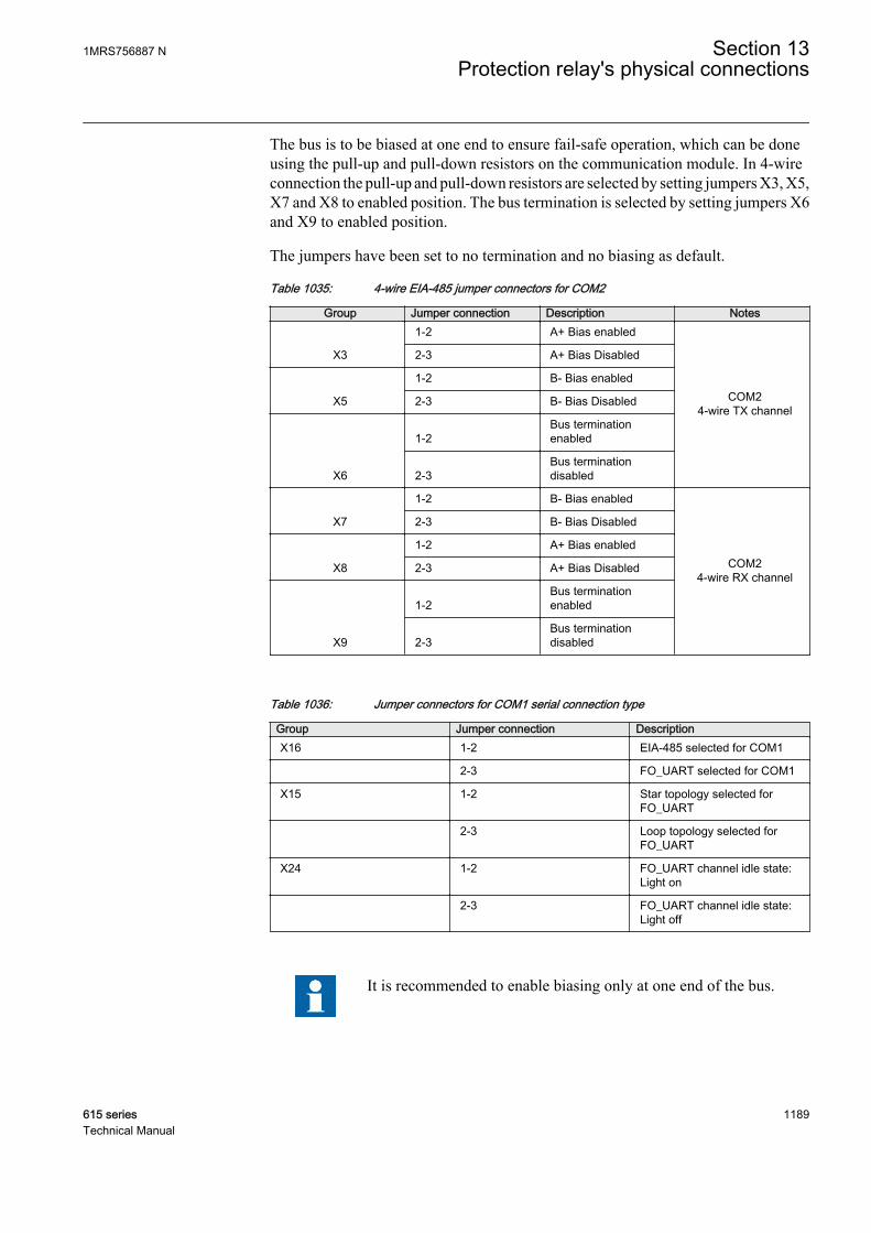
The bus is to be biased at one end to ensure fail-safe operation, which can be doneusing the pull-up and pull-down resistors on the communication module. In 4-wireconnection the pull-up and pull-down resistors are selected by setting jumpers X3, X5,X7 and X8 to enabled position. The bus termination is selected by setting jumpers X6and X9 to enabled position.
The jumpers have been set to no termination and no biasing as default.
Table 1035: 4-wire EIA-485 jumper connectors for COM2
Group Jumper connection Description Notes
X3
1-2 A+ Bias enabled
COM24-wire TX channel
2-3 A+ Bias Disabled
X5
1-2 B- Bias enabled
2-3 B- Bias Disabled
X6
1-2Bus terminationenabled
2-3Bus terminationdisabled
X7
1-2 B- Bias enabled
COM24-wire RX channel
2-3 B- Bias Disabled
X8
1-2 A+ Bias enabled
2-3 A+ Bias Disabled
X9
1-2Bus terminationenabled
2-3Bus terminationdisabled
Table 1036: Jumper connectors for COM1 serial connection type
Group Jumper connection DescriptionX16 1-2 EIA-485 selected for COM1
2-3 FO_UART selected for COM1
X15 1-2 Star topology selected forFO_UART
2-3 Loop topology selected forFO_UART
X24 1-2 FO_UART channel idle state:Light on
2-3 FO_UART channel idle state:Light off
It is recommended to enable biasing only at one end of the bus.
1MRS756887 N Section 13Protection relay's physical connections
615 series 1189Technical Manual
Termination is enabled at each end of the bus
It is recommended to ground the signal directly to earth from one nodeand through capacitor from other nodes.
The optional communication modules include support for EIA-485 serialcommunication (X5 connector). Depending on the configuration the communicationmodules can host either two 2-wire ports or one 4-wire port.
The two 2-wire ports are called as COM1 and COM2. Alternatively, if there is onlyone 4-wire port configured, the port is called COM2. The fiber optic ST connectionuses the COM1 port.
Table 1037: EIA-485 connections for COM0008 and COM0010
Pin 2-wire mode 4-wire mode9 COM1 A/+ COM2 Rx/+
8 B/- Rx/-
7 COM2 A/+ Tx/+
6 B/- Tx/-
5 AGND (isolated ground)
4 IRIG-B +
3 IRIG-B -
2 GNDC (case via capasitor)
1 GND (case)
13.4.8.4 COM0032-COM0034 jumper locations and connections
The optional communication modules include support for optical ST serialcommunication (X9 connector). The fiber optic ST connection uses the COM1 port.
Section 13 1MRS756887 NProtection relay's physical connections
1190 615 seriesTechnical Manual

X15 X24321
321
GUID-CA481BBF-C1C9-451D-BC18-19EC49B8A3A3 V2 EN
Figure 632: Jumper connections on communication module COM0032
1MRS756887 N Section 13Protection relay's physical connections
615 series 1191Technical Manual
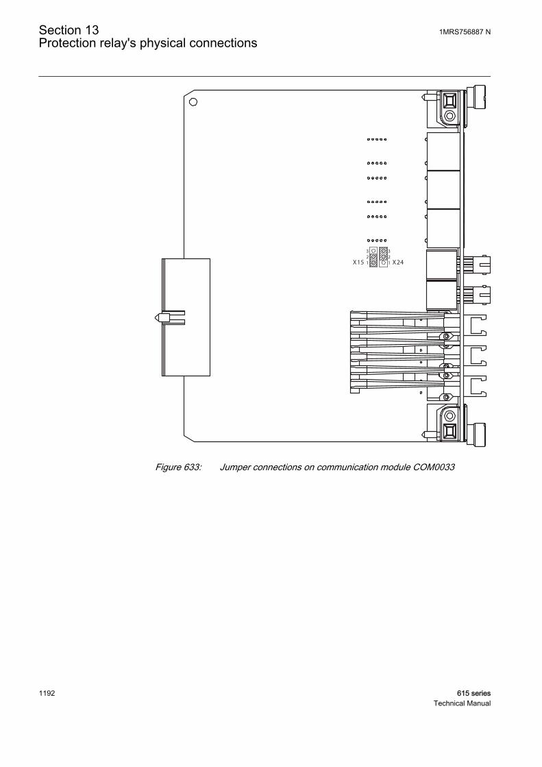
1X15
3
X2412
32
GUID-4CAF22E5-1491-44EF-BFC7-45017DED68F4 V2 EN
Figure 633: Jumper connections on communication module COM0033
Section 13 1MRS756887 NProtection relay's physical connections
1192 615 seriesTechnical Manual
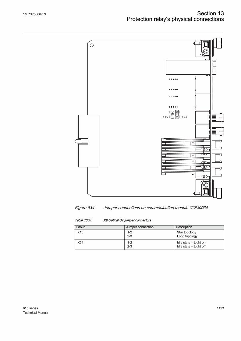
3
1 X2421
32
X15
GUID-E54674FD-2E7F-4742-90AB-505772A0CFF4 V2 EN
Figure 634: Jumper connections on communication module COM0034
Table 1038: X9 Optical ST jumper connectors
Group Jumper connection DescriptionX15 1-2
2-3Star topologyLoop topology
X24 1-22-3
Idle state = Light onIdle state = Light off
1MRS756887 N Section 13Protection relay's physical connections
615 series 1193Technical Manual

1194

Section 14 Technical data
Table 1039: Dimensions
Description Value Width Frame 177 mm
Case 164 mm
Height Frame 177 mm (4U)
Case 160 mm
Depth 201 mm (153 + 48 mm)
Weight Complete protection relay 4.1 kg
Plug-in unit only 2.1 kg
Table 1040: Power supply
Description Type 1 Type 2Nominal auxiliary voltage Un 100, 110, 120, 220, 240 V AC,
50 and 60 Hz24, 30, 48, 60 V DC
48, 60, 110, 125, 220, 250 V DC
Maximum interruption time inthe auxiliary DC voltage withoutresetting the relay
50 ms at Un
Auxiliary voltage variation 38...110% of Un (38...264 V AC) 50...120% of Un (12...72 V DC)
80...120% of Un (38.4...300 VDC)
Start-up threshold 19.2 V DC (24 V DC × 80%)
Burden of auxiliary voltagesupply under quiescent (Pq)/operating condition
DC <13.0 W (nominal)/<18.0 W(max.)AC <16.0 W (nominal)/<21.0 W(max.)
DC <13.0 W (nominal)/<18.0 W(max.)
Ripple in the DC auxiliaryvoltage
Max 15% of the DC value (at frequency of 100 Hz)
Fuse type T4A/250 V
1MRS756887 N Section 14Technical data
615 series 1195Technical Manual

Table 1041: Energizing inputs
Description ValueRated frequency 50/60 Hz
Current inputs Rated current, In 0.2/1 A1)2) 1/5 A3)
Thermal withstandcapability:
• Continuously 4 A 20 A
• For 1 s 100 A 500 A
Dynamic currentwithstand:
• Half-wave value 250 A 1250 A
Input impedance <100 mΩ <20 mΩ
Voltage inputs Rated voltage 60...210 V AC
Voltage withstand:
• Continuous 240 V AC
• For 10 s 360 V AC
Burden at rated voltage <0.05 VA
1) Ordering option for residual current input2) Not available for RET615 and REU6153) Residual current and/or phase current
Table 1042: Energizing inputs (sensors)
Description ValueCurrent sensor input Rated current voltage (in
secondary side)75 mV...9000 mV1)
Continuous voltagewithstand
125 V
Input impedance at 50/60Hz
2...3 MΩ2)
Voltage sensor input Rated voltage 6 kV...30 kV3)
Continuous voltagewithstand
50 V
Input impedance at 50/60Hz
3 MΩ
1) Equals the current range of 40...4000 A with a 80 A, 3 mV/Hz Rogowski2) Depending on the used nominal current (hardware gain)3) This range is covered (up to 2*rated) with sensor division ratio of 10 000:1
Section 14 1MRS756887 NTechnical data
1196 615 seriesTechnical Manual
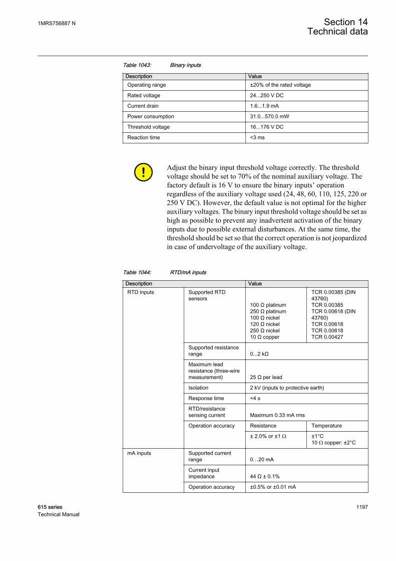
Table 1043: Binary inputs
Description ValueOperating range ±20% of the rated voltage
Rated voltage 24...250 V DC
Current drain 1.6...1.9 mA
Power consumption 31.0...570.0 mW
Threshold voltage 16...176 V DC
Reaction time <3 ms
Adjust the binary input threshold voltage correctly. The thresholdvoltage should be set to 70% of the nominal auxiliary voltage. Thefactory default is 16 V to ensure the binary inputs’ operationregardless of the auxiliary voltage used (24, 48, 60, 110, 125, 220 or250 V DC). However, the default value is not optimal for the higherauxiliary voltages. The binary input threshold voltage should be set ashigh as possible to prevent any inadvertent activation of the binaryinputs due to possible external disturbances. At the same time, thethreshold should be set so that the correct operation is not jeopardizedin case of undervoltage of the auxiliary voltage.
Table 1044: RTD/mA inputs
Description ValueRTD inputs Supported RTD
sensors100 Ω platinum250 Ω platinum100 Ω nickel120 Ω nickel250 Ω nickel10 Ω copper
TCR 0.00385 (DIN43760)TCR 0.00385TCR 0.00618 (DIN43760)TCR 0.00618TCR 0.00618TCR 0.00427
Supported resistancerange 0...2 kΩ
Maximum leadresistance (three-wiremeasurement) 25 Ω per lead
Isolation 2 kV (inputs to protective earth)
Response time <4 s
RTD/resistancesensing current Maximum 0.33 mA rms
Operation accuracy Resistance Temperature
± 2.0% or ±1 Ω ±1°C10 Ω copper: ±2°C
mA inputs Supported currentrange 0…20 mA
Current inputimpedance 44 Ω ± 0.1%
Operation accuracy ±0.5% or ±0.01 mA
1MRS756887 N Section 14Technical data
615 series 1197Technical Manual
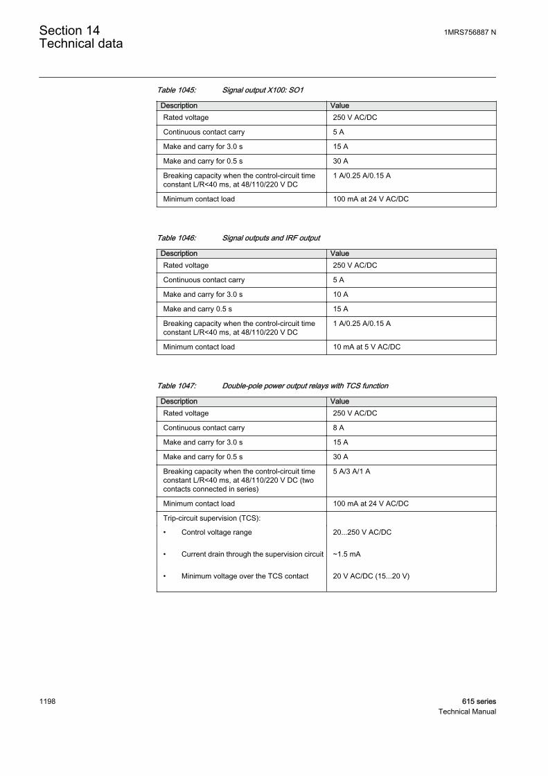
Table 1045: Signal output X100: SO1
Description ValueRated voltage 250 V AC/DC
Continuous contact carry 5 A
Make and carry for 3.0 s 15 A
Make and carry for 0.5 s 30 A
Breaking capacity when the control-circuit timeconstant L/R<40 ms, at 48/110/220 V DC
1 A/0.25 A/0.15 A
Minimum contact load 100 mA at 24 V AC/DC
Table 1046: Signal outputs and IRF output
Description ValueRated voltage 250 V AC/DC
Continuous contact carry 5 A
Make and carry for 3.0 s 10 A
Make and carry 0.5 s 15 A
Breaking capacity when the control-circuit timeconstant L/R<40 ms, at 48/110/220 V DC
1 A/0.25 A/0.15 A
Minimum contact load 10 mA at 5 V AC/DC
Table 1047: Double-pole power output relays with TCS function
Description ValueRated voltage 250 V AC/DC
Continuous contact carry 8 A
Make and carry for 3.0 s 15 A
Make and carry for 0.5 s 30 A
Breaking capacity when the control-circuit timeconstant L/R<40 ms, at 48/110/220 V DC (twocontacts connected in series)
5 A/3 A/1 A
Minimum contact load 100 mA at 24 V AC/DC
Trip-circuit supervision (TCS):
• Control voltage range 20...250 V AC/DC
• Current drain through the supervision circuit ~1.5 mA
• Minimum voltage over the TCS contact 20 V AC/DC (15...20 V)
Section 14 1MRS756887 NTechnical data
1198 615 seriesTechnical Manual

Table 1048: Single-pole power output relays
Description ValueRated voltage 250 V AC/DC
Continuous contact carry 8 A
Make and carry for 3.0 s 15 A
Make and carry for 0.5 s 30 A
Breaking capacity when the control-circuit timeconstant L/R<40 ms, at 48/110/220 V DC
5 A/3 A/1 A
Minimum contact load 100 mA at 24 V AC/DC
Table 1049: High-speed output HSO with BIO0007
Description ValueRated voltage 250 V AC/DC
Continuous contact carry 6 A
Make and carry for 3.0 s 15 A
Make and carry for 0.5 s 30 A
Breaking capacity when the control-circuit timeconstant L/R <40 ms, at 48/110/220 V DC
5 A/3 A/1 A
Operate time <1 ms
Reset <20 ms, resistive load
Table 1050: Ethernet interfaces
Ethernet interface Protocol Cable Data transfer rateFront TCP/IP
protocolStandard Ethernet CAT 5 cable with RJ-45connector
10 MBits/s
Rear TCP/IPprotocol
Shielded twisted pair CAT 5e cable withRJ-45 connector or fiber optic cable with LCconnector
100 MBits/s
Table 1051: Serial rear interface
Type Counter connectorSerial port (X5) 10-pin counter connector Weidmüller BL
3.5/10/180F AU OR BEDRor9-pin counter connector Weidmüller BL3.5/9/180F AU OR BEDR1)
Serial port (X16) 9-pin D-sub connector DE-9
Serial port (X12) Optical ST-connector
1) Depending on the optional communication module
1MRS756887 N Section 14Technical data
615 series 1199Technical Manual

Table 1052: Fiber optic communication link
Connector Fiber type Wave length Typical max.length1)
Permitted path attenuation2)
LC MM 62.5/125 or50/125 μm glassfiber core
1300 nm 2 km <8 dB
ST MM 62.5/125 or50/125 μm glassfiber core
820...900 nm 1 km <11 dB
1) Maximum length depends on the cable attenuation and quality, the amount of splices and connectorsin the path.
2) Maximum allowed attenuation caused by connectors and cable together
Table 1053: Fiber optic protection communication link available in RED615
Connector Fibre type Wave length Typical max.length1)
Permitted path attenuation2)
LC MM 62.5/125 or50/125 μm
1300 nm 2 km <8 dB
LC SM 9/125 μm3) 1300 nm 20 km <8 dB
1) Maximum length depends on the cable attenuation and quality, the amount of splices and connectorsin the path.
2) Maximum allowed attenuation caused by connectors and cable altogether3) Use single-mode fiber with recommended minimum length of 3 m to connect RED615 to the pilot wire
modem RPW600.
Table 1054: IRIG-B
Description ValueIRIG time code format B004, B0051)
Isolation 500V 1 min
Modulation Unmodulated
Logic level 5 V TTL
Current consumption <4 mA
Power consumption <20 mW
1) According to the 200-04 IRIG standard
Table 1055: Lens sensor and optical fiber for arc protection
Description ValueFiber optic cable including lens 1.5 m, 3.0 m or 5.0 m
Normal service temperature range of the lens -40...+100°C
Maximum service temperature range of the lens,max 1 h
+140°C
Minimum permissible bending radius of theconnection fiber
100 mm
Section 14 1MRS756887 NTechnical data
1200 615 seriesTechnical Manual
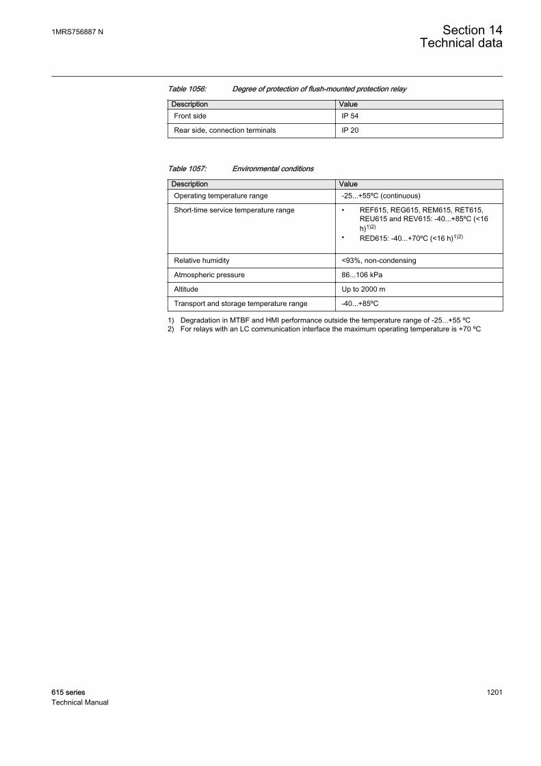
Table 1056: Degree of protection of flush-mounted protection relay
Description ValueFront side IP 54
Rear side, connection terminals IP 20
Table 1057: Environmental conditions
Description ValueOperating temperature range -25...+55ºC (continuous)
Short-time service temperature range • REF615, REG615, REM615, RET615,REU615 and REV615: -40...+85ºC (<16h)1)2)
• RED615: -40...+70ºC (<16 h)1)2)
Relative humidity <93%, non-condensing
Atmospheric pressure 86...106 kPa
Altitude Up to 2000 m
Transport and storage temperature range -40...+85ºC
1) Degradation in MTBF and HMI performance outside the temperature range of -25...+55 ºC2) For relays with an LC communication interface the maximum operating temperature is +70 ºC
1MRS756887 N Section 14Technical data
615 series 1201Technical Manual

1202

Section 15 Protection relay and functionality tests
Table 1058: Electromagnetic compatibility tests
Description Type test value Reference1 MHz/100 kHz burstdisturbance test
IEC 61000-4-18IEC 60255-26, class IIIIEEE C37.90.1-2002
• Common mode 2.5 kV
• Differential mode 2.5 kV
3 MHz, 10 MHz and 30 MHzburst disturbance test
IEC 61000-4-18IEC 60255-26, class III
• Common mode 2.5 kV
Electrostatic discharge test IEC 61000-4-2IEC 60255-26IEEE C37.90.3-2001
• Contact discharge 8 kV
• Air discharge 15 kV
Radio frequency interferencetest
10 V (rms)f = 150 kHz...80 MHz
IEC 61000-4-6IEC 60255-26, class III
10 V/m (rms)f = 80...2700 MHz
IEC 61000-4-3IEC 60255-26, class III
10 V/mf = 900 MHz
ENV 50204IEC 60255-26, class III
20 V/m (rms)f = 80...1000 MHz
IEEE C37.90.2-2004
Fast transient disturbance test IEC 61000-4-4IEC 60255-26IEEE C37.90.1-2002
• All ports 4 kV
Surge immunity test IEC 61000-4-5IEC 60255-26
• Communication 1 kV, line-to-earth
• Other ports 4 kV, line-to-earth2 kV, line-to-line
Power frequency (50 Hz)magnetic field immunity test
IEC 61000-4-8
• Continuous• 1...3 s 300 A/m
1000 A/m
Table continues on next page
1MRS756887 N Section 15Protection relay and functionality tests
615 series 1203Technical Manual
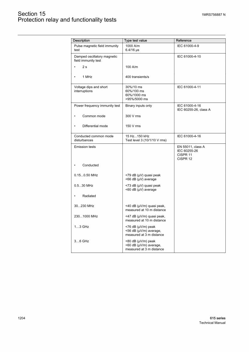
Description Type test value ReferencePulse magnetic field immunitytest
1000 A/m6.4/16 µs
IEC 61000-4-9
Damped oscillatory magneticfield immunity test
IEC 61000-4-10
• 2 s 100 A/m
• 1 MHz 400 transients/s
Voltage dips and shortinterruptions
30%/10 ms60%/100 ms60%/1000 ms>95%/5000 ms
IEC 61000-4-11
Power frequency immunity test Binary inputs only IEC 61000-4-16IEC 60255-26, class A
• Common mode 300 V rms
• Differential mode 150 V rms
Conducted common modedisturbances
15 Hz...150 kHzTest level 3 (10/1/10 V rms)
IEC 61000-4-16
Emission tests EN 55011, class AIEC 60255-26CISPR 11CISPR 12
• Conducted
0.15...0.50 MHz <79 dB (µV) quasi peak<66 dB (µV) average
0.5...30 MHz <73 dB (µV) quasi peak<60 dB (µV) average
• Radiated
30...230 MHz <40 dB (µV/m) quasi peak,measured at 10 m distance
230...1000 MHz <47 dB (µV/m) quasi peak,measured at 10 m distance
1…3 GHz <76 dB (µV/m) peak<56 dB (µV/m) average,measured at 3 m distance
3…6 GHz <80 dB (µV/m) peak<60 dB (µV/m) average,measured at 3 m distance
Section 15 1MRS756887 NProtection relay and functionality tests
1204 615 seriesTechnical Manual

Table 1059: Insulation tests
Description Type test value ReferenceDielectric tests 2 kV, 50 Hz, 1 min
500 V, 50 Hz, 1 min,communication
IEC 60255-27
Impulse voltage test 5 kV, 1.2/50 μs, 0.5 J1 kV, 1.2/50 μs, 0.5 J,communication
IEC 60255-27
Insulation resistancemeasurements
>100 MΩ, 500 V DC IEC 60255-27
Protective bonding resistance <0.1 Ω, 4 A, 60 s IEC 60255-27
Table 1060: Mechanical tests
Description Requirement ReferenceVibration tests (sinusoidal) Class 2 IEC 60068-2-6 (test Fc)
IEC 60255-21-1
Shock and bump test Class 2 IEC 60068-2-27 (test Ea shock)IEC 60068-2-29 (test Eb bump)IEC 60255-21-2
Seismic test Class 2 IEC 60255-21-3
Table 1061: Environmental tests
Description Type test value ReferenceDry heat test • 96 h at +55ºC
• 16 h at +85ºC1)2)IEC 60068-2-2
Dry cold test • 96 h at -25ºC• 16 h at -40ºC
IEC 60068-2-1
Damp heat test • 6 cycles (12 h + 12 h) at+25°C…+55°C, humidity>93%
IEC 60068-2-30
Change of temperature test • 5 cycles (3 h + 3 h)at -25°C...+55°C
IEC60068-2-14
Storage test • 96 h at -40ºC• 96 h at +85ºC
IEC 60068-2-1IEC 60068-2-2
1) For relays with an LC communication interface the maximum operating temperature is +70oC2) For RED615 +70oC, 16 h
Table 1062: Product safety
Description ReferenceLV directive 2006/95/EC
Standard EN 60255-27 (2013)EN 60255-1 (2009)
1MRS756887 N Section 15Protection relay and functionality tests
615 series 1205Technical Manual

Table 1063: EMC compliance
Description ReferenceEMC directive 2004/108/EC
Standard EN 60255-26 (2013)
Section 15 1MRS756887 NProtection relay and functionality tests
1206 615 seriesTechnical Manual

Section 16 Applicable standards and regulations
EN 60255-1
EN 60255-26
EN 60255-27
EMC council directive 2004/108/EC
EU directive 2002/96/EC/175
IEC 60255
Low-voltage directive 2006/95/EC
IEC 61850
1MRS756887 N Section 16Applicable standards and regulations
615 series 1207Technical Manual

1208
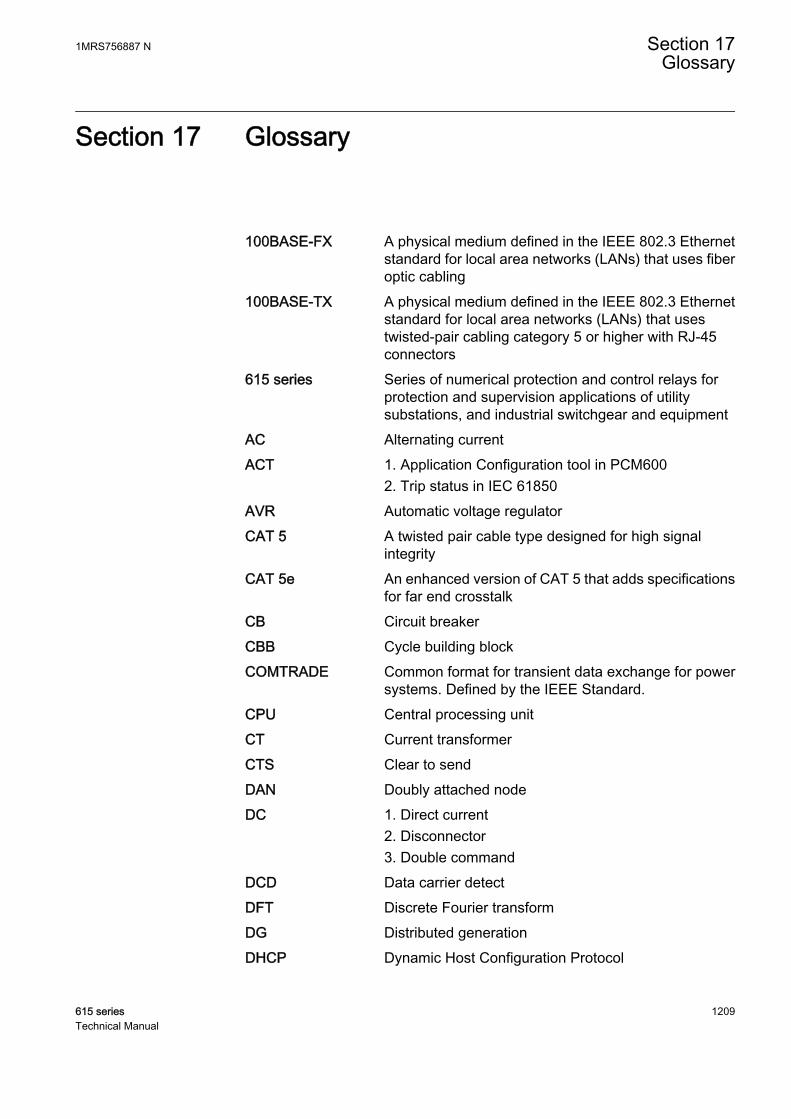
Section 17 Glossary
100BASE-FX A physical medium defined in the IEEE 802.3 Ethernetstandard for local area networks (LANs) that uses fiberoptic cabling
100BASE-TX A physical medium defined in the IEEE 802.3 Ethernetstandard for local area networks (LANs) that usestwisted-pair cabling category 5 or higher with RJ-45connectors
615 series Series of numerical protection and control relays forprotection and supervision applications of utilitysubstations, and industrial switchgear and equipment
AC Alternating currentACT 1. Application Configuration tool in PCM600
2. Trip status in IEC 61850AVR Automatic voltage regulatorCAT 5 A twisted pair cable type designed for high signal
integrityCAT 5e An enhanced version of CAT 5 that adds specifications
for far end crosstalkCB Circuit breakerCBB Cycle building blockCOMTRADE Common format for transient data exchange for power
systems. Defined by the IEEE Standard.CPU Central processing unitCT Current transformerCTS Clear to sendDAN Doubly attached nodeDC 1. Direct current
2. Disconnector3. Double command
DCD Data carrier detectDFT Discrete Fourier transformDG Distributed generationDHCP Dynamic Host Configuration Protocol
1MRS756887 N Section 17Glossary
615 series 1209Technical Manual

DNP3 A distributed network protocol originally developed byWestronic. The DNP3 Users Group has the ownershipof the protocol and assumes responsibility for itsevolution.
DPC Double-point controlDSR Data set readyDT Definite timeDTR Data terminal readyEEPROM Electrically erasable programmable read-only memoryEIA-232 Serial communication standard according to
Electronics Industries AssociationEIA-485 Serial communication standard according to
Electronics Industries AssociationEMC Electromagnetic compatibilityEthernet A standard for connecting a family of frame-based
computer networking technologies into a LANFIFO First in, first outFLC Full load currentFPGA Field-programmable gate arrayFTP File transfer protocolFTPS FTP SecureGFC General fault criteriaGOOSE Generic Object-Oriented Substation EventGPS Global Positioning SystemHMI Human-machine interfaceHSO High-speed outputHSR High-availability seamless redundancyHTTPS Hypertext Transfer Protocol SecureHV High voltageHW HardwareIDMT Inverse definite minimum timeIEC International Electrotechnical CommissionIEC 60870-5-103 1. Communication standard for protective equipment
2. A serial master/slave protocol for point-to-pointcommunication
IEC 61850 International standard for substation communicationand modeling
Section 17 1MRS756887 NGlossary
1210 615 seriesTechnical Manual

IEC 61850-8-1 A communication protocol based on the IEC 61850standard series
IEC 61850-9-2 A communication protocol based on the IEC 61850standard series
IEC 61850-9-2 LE Lite Edition of IEC 61850-9-2 offering process businterface
IED Intelligent electronic deviceIEEE 1686 Standard for Substation Intelligent Electronic Devices'
(IEDs') Cyber Security CapabilitiesIP Internet protocolIP address A set of four numbers between 0 and 255, separated by
periods. Each server connected to the Internet isassigned a unique IP address that specifies the locationfor the TCP/IP protocol.
IRF 1. Internal fault2. Internal relay fault
IRIG-B Inter-Range Instrumentation Group's time code formatB
LAN Local area networkLC Connector type for glass fiber cable, IEC 61754-20LCD Liquid crystal displayLDC Line drop compensationLE Light EditionLED Light-emitting diodeLHMI Local human-machine interfaceLOG Loss of gridLOM Loss of mainsLV Low voltageMAC Media access controlMCB Miniature circuit breakerMM 1. Multimode
2. Multimode optical fiberMMS 1. Manufacturing message specification
2. Metering management systemModbus A serial communication protocol developed by the
Modicon company in 1979. Originally used forcommunication in PLCs and RTU devices.
MV Medium voltage
1MRS756887 N Section 17Glossary
615 series 1211Technical Manual

NC Normally closedOSB Out of step blockingP2P peer-to-peerPC 1. Personal computer
2. PolycarbonatePCM600 Protection and Control IED ManagerPeak-to-peak 1. The amplitude of a waveform between its maximum
positive value and its maximum negative value2. A measurement principle where the measurementquantity is made by calculating the average from thepositive and negative peak values without including theDC component. The peak-to-peak mode allowsconsiderable CT saturation without impairing theperformance of the operation.
Peak-to-peak withpeak backup
A measurement principle similar to the peak-to-peakmode but with the function starting on two conditions:the peak-to-peak value is above the set start current orthe peak value is above two times the set start value
PGU Power generating unitPLC Programmable logic controllerPPS Pulse per secondPRP Parallel redundancy protocolPTP Precision Time ProtocolRAM Random access memoryRCA Also known as MTA or base angle. Characteristic
angle.RED615 Line differential protection and control relayREF615 Feeder protection and control relayREM615 Motor protection and control relayRET615 Transformer protection and control relayREU615 Voltage protection and control relayREV615 Capacitor bank protection and control relayRJ-45 Galvanic connector typeRMS Root-mean-square (value)ROM Read-only memoryRSTP Rapid spanning tree protocolRTC Real-time clockRTD Resistance temperature detector
Section 17 1MRS756887 NGlossary
1212 615 seriesTechnical Manual
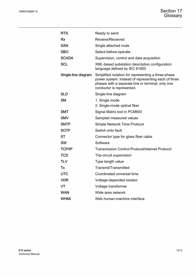
RTS Ready to sendRx Receive/ReceivedSAN Single attached nodeSBO Select-before-operateSCADA Supervision, control and data acquisitionSCL XML-based substation description configuration
language defined by IEC 61850Single-line diagram Simplified notation for representing a three-phase
power system. Instead of representing each of threephases with a separate line or terminal, only oneconductor is represented.
SLD Single-line diagramSM 1. Single mode
2. Single-mode optical fiberSMT Signal Matrix tool in PCM600SMV Sampled measured valuesSNTP Simple Network Time ProtocolSOTF Switch onto faultST Connector type for glass fiber cableSW SoftwareTCP/IP Transmission Control Protocol/Internet ProtocolTCS Trip-circuit supervisionTLV Type length valueTx Transmit/TransmittedUTC Coordinated universal timeVDR Voltage-depended resistorVT Voltage transformerWAN Wide area networkWHMI Web human-machine interface
1MRS756887 N Section 17Glossary
615 series 1213Technical Manual

1214

1215

ABB Distribution SolutionsDistribution AutomationP.O. Box 699FI-65101 VAASA, FinlandPhone +358 10 22 11
ABB Distribution AutomationManeja WorksVadodara-390013, IndiaPhone +91 265 2604386Fax +91 265 2638922
www.abb.com/mediumvoltagewww.abb.com/relionwww.abb.com/substationautomation
—
© Copyright 2018 ABB. All rights reserved. 1MR
S75
6887
N