How To Order MagWave - ABB
32
-
Upload
khangminh22 -
Category
Documents
-
view
0 -
download
0
Transcript of How To Order MagWave - ABB


For the latest version of this configuration guide, visit abb.com/level.

|
How To Order MagWave
To request a quotation for a MagWave Dual Chamber Level System:
1. Complete the Quotation Request Form on pages 27 and 28 or 2. Use this Configuration Guide to Select a Model Number and provide additional information
such as process pressure, temperature, and specific gravity. Submit Request to ABB via e-mail to [email protected] or via fax to +1.225.673.2525.
How to Order: Page Step 1: /a/ Select Chamber Style ............................................................................................................................. 4 Step 2: /b/ Select Secondary Chamber Size .......................................................................................................... 9 Step 3: /c/ Select Chamber Material ........................................................................................................................ 9 Step 4: /d/ Select Chamber Configuration .............................................................................................................. 10 Step 5: /e/ Select Connection Size & Rating .......................................................................................................... 14 Step 6: /f/ Select Indicator Type ............................................................................................................................. 16 Step 7: /g/ Select Indicator Ruler............................................................................................................................. 16 Step 8: /h/ Select Options ........................................................................................................................................ 17 Step 9: /i/j Select Center to Center / Measuring Length ........................................................................................ 18
MW05 Dual Chamber Level System
Model Number Format
MW05 a / b / c / d / e / f / g / h / i / j
Example: MW0501/A/SS6/W2FEFEB2/WR21/S1G/B/X/48”
CHAMBER STYLE
SECONDARY CHAMBER SIZE
CHAMBER MATERIAL
CHAMBER CONFIGURATION
CONNECTION SIZE & RATING
INDICATOR TYPE
INDICATOR RULER
OPTIONS
CENTER TO CENTER / FACE TO FACE
MEASURING LENGTH (Optional)

Model Number Selection: Step 1 MW05
a/ Select Chamber Style
MW0502
MW0503 MW0504
MW0505 MW0506
Secondary Chamber
Connection Location
Cap Left Side
MLG Chamber Connections
Top Side Bottom
Flange Flanges Flange
Secondary Chamber
Connection Location
Cap Left Side
MLG Chamber Connections
Top Side Bottom
Flange Flanges Flange
Secondary Chamber
Connection Location
Cap Left Side
MLG Chamber Connections
Top Side Bottom
Flange None Flange
Secondary Chamber
Connection Location
Flange Left Side
MLG Chamber Connections
Top Side Bottom
Cap Flanges Flange
Secondary Chamber
Connection Location
Flange Left Side
MLG Chamber Connections
Top Side Bottom
Flange Flanges Flange
All dimensions in the drawings below are based on a 2” MLG chamber with 2” process connections, a 1.5” Secondary Chamber, and 150 lb flanges.
Many chamber styles feature the same MLG connection configuration with different Secondary Chamber connections and locations. The chamber style selected shall be changed to accommodate the appropriate GWR transmitter.
Secondary Chambers with cap connections require Code “P” for Step 10-/j of the GWR model selection. Secondary Chambers with flange connections require Code “FL” or “WP” for Step 10-/j of the GWR model selection.
Actual MLG Chamber connections will be determined by Step 4 pages 10 thru 13. For chamber styles which do not appear in the following selections use code MW05XX.
Secondary Chamber
Connection Location
Cap Left Side
MLG Chamber Connections
Top Side Bottom
Cap Flanges Flange
MW0501 Standard

|
Model Number Selection: Step 1 MW05
MW0509 MW0510
MW0511 MW0512
Secondary Chamber
Connection Location
Cap Left Side
MLG Chamber Connections
Top Side Bottom
Cap 3 Flanges Flange
Secondary Chamber
Connection Location
Cap Left Side
MLG Chamber Connections
Top Side Bottom
Flange 3 Flanges Flange
Secondary Chamber
Connection Location
Flange Left Side
MLG Chamber Connections
Top Side Bottom
Flange 3 Flanges Flange
Secondary Chamber
Connection Location
Flange Left Side
MLG Chamber Connections
Top Side Bottom
Cap 3 Flanges Flange
a/ Select Chamber Style
MW0507 MW0508
Secondary Chamber
Connection Location
Flange Left Side
MLG Chamber Connections
Top Side Bottom
Flange None Flange
Secondary Chamber
Connection Location
Flange Left Side
MLG Chamber Connections
Top Side Bottom
Flange None Flange
All dimensions in the drawings below are based on a 2” MLG chamber with 2” process connections, a 1.5” Secondary Chamber, and 150 lb flanges.
Many chamber styles feature the same MLG connection configuration with different Secondary Chamber connections and locations. The chamber style selected shall be changed to accommodate the appropriate GWR transmitter.
Secondary Chambers with cap connections require Code “P” for Step 10-/j of the GWR model selection. Secondary Chambers with flange connections require Code “FL” or “WP” for Step 10-/j of the GWR model selection.
Actual MLG Chamber connections will be determined by Step 4 pages 10 thru 13. For chamber styles which do not appear in the following selections use code MW05XX.

MW0518
Secondary Chamber
Connection Location
Flange Right Side
MLG Chamber Connections
Top Side Bottom
Flange Flanges Flange
MW0517
Secondary Chamber
Connection Location
Flange Right Side
MLG Chamber Connections
Top Side Bottom
Cap Flanges Flange
Model Number Selection: Step 1 MW05
a/ Select Chamber Style
MW0516
Secondary Chamber
Connection Location
Cap Right Side
MLG Chamber Connections
Top Side Bottom
Flange Flanges Flange
MW0515
Secondary Chamber
Connection Location
Cap Right Side
MLG Chamber Connections
Top Side Bottom
Flange None Flange
MW0514
Secondary Chamber
Connection Location
Cap Right Side
MLG Chamber Connections
Top Side Bottom
Flange Flanges Flange
MW0513
Secondary Chamber
Connection Location
Cap Right Side
MLG Chamber Connections
Top Side Bottom
Cap Flanges Flange
All dimensions in the drawings below are based on a 2” MLG chamber with 2” process connections, a 1.5” secondary chamber, and 150 lb flanges.
Many chamber styles feature the same MLG connection configuration with different Secondary Chamber connections and locations. The chamber style selected shall be changed to accommodate the appropriate GWR transmitter.
Secondary Chambers with cap connections require Code “P” for Step 10-/j of the GWR model selection. Secondary Chambers with flange connections require Code “FL” or “WP” for Step 10-/j of the GWR model selection.
Actual MLG Chamber connections will be determined by Step 4 pages 10 thru 13. For chamber styles which do not appear in the following selections use code MW05XX.

|
MW0524
Secondary Chamber
Connection Location
Flange Right Side
MLG Chamber Connections
Top Side Bottom
Flange 3 Flanges Flange
MW0523
Secondary Chamber
Connection Location
Cap Right Side
MLG Chamber Connections
Top Side Bottom
Flange 3 Flanges Flange
MW0522
Secondary Chamber
Connection Location
Flange Right Side
MLG Chamber Connections
Top Side Bottom
Cap 3 Flanges Flange
MW0521
Secondary Chamber
Connection Location
Cap Right Side
MLG Chamber Connections
Top Side Bottom
Cap 3 Flanges Flange
MW0520
Secondary Chamber
Connection Location
Flange Right Side
MLG Chamber Connections
Top Side Bottom
Flange None Flange
MW0519
Secondary Chamber
Connection Location
Flange Right Side
MLG Chamber Connections
Top Side Bottom
Flange None Flange
Model Number Selection: Step 1 MW05
a/ Select Chamber Style
All dimensions in the drawings below are based on a 2” MLG chamber with 2” process connections, a 1.5” secondary chamber, and 150 lb flanges.
Many chamber styles feature the same MLG connection configuration with different Secondary Chamber connections and locations. The chamber style selected shall be changed to accommodate the appropriate GWR transmitter.
Secondary Chambers with cap connections require Code “P” for Step 10-/j of the GWR model selection. Secondary Chambers with flange connections require Code “FL” or “WP” for Step 10-/j of the GWR model selection.
Actual MLG Chamber connections will be determined by Step 4 pages 10 thru 13. For chamber styles which do not appear in the following selections use code MW05XX.

Model Number Selection: Step 1 MW05
Additional Dimensional Information
The MagWave footprint dimensions will vary depending on the chamber configuration, flange size, flange rating and Guided Wave Radar coupler type. The table below provides the basic footprint dimensions for each configuration using a 2 inch float chamber with 2 inch ANSI process connections, a 1-1/2 inch Secondary Chamber with a C1 radar coupler type. Consult the Factory regarding DIN and other flange types.
Width
Depth
MagWave Chamber
Style
FLANGE RATINGS
150# 300# 600# 900# / 1500#
Width Depth Width Depth Width Depth Width Depth
MW0501 10 1/8" 7 1/2" 10 3/8" 8 1/16" 10 3/8" 8 3/16" 11 3/8" 10 5/16"
MW0502 11 3/8" 7 1/2" 11 7/8" 8 1/16" 11 7/8" 8 3/16" 13 7/8" 10 5/16"
MW0503 11 3/8" 6 11/16" 11 7/8" 7 3/8" 11 7/8" 7 1/4" 13 7/8" 9 3/8"
MW0504 11 3/8" 6 11/16" 11 7/8" 7 3/8" 11 7/8" 7 1/4" 13 7/8" 9 3/8"
MW0505 11 3/8" 7 1/2" 11 7/8" 8 1/16" 11 7/8" 8 3/16" 13 7/8" 10 5/16"
MW0506 12 15/16" 7 1/2" 14" 8 1/16" 14" 8 3/16" 16 7/16" 10 5/16"
MW0507 12 15/16" 6 11/16" 14" 7 1/4" 14" 7 1/4" 16 7/16" 9 3/8"
MW0508 12 15/16" 6 11/16" 14" 7 1/4" 14" 7 1/4" 16 7/16" 9 3/8"
MW0509 10 1/8" 7 1/2" 10 3/8" 8 1/16" 10 3/8" 8 3/16" 11 3/8" 10 5/16"
MW0510 11 3/8" 7 1/2" 11 7/8" 8 1/16" 11 7/8" 8 3/16" 13 7/8" 10 5/16"
MW0511 11 3/8" 7 1/2" 11 7/8" 8 1/16" 11 7/8" 8 3/16" 13 7/8" 10 5/16"
MW0512 12 15/16" 7 1/2" 14" 8 1/16" 14" 8 3/16" 16 7/16" 10 5/16"
MW0513 7 1/16" 7 1/2" 7 5/16" 8 1/16" 7 5/16" 8 3/16" 11 3/8" 10 5/16"
MW0514 8 3/8" 7 1/2" 8 7/8" 8 1/16" 8 7/8" 8 3/16" 10 7/8" 10 5/16"
MW0515 11 3/8" 6 11/16" 11 7/8" 7 3/8" 11 7/8" 7 1/4" 13 7/8" 9 3/8"
MW0516 10 1/8" 7 1/2" 10 1/2" 8 1/16" 10 1/2" 8 3/16" 12" 10 5/16"
MW0517 9 11/16" 7 1/2" 11 1/16" 8 1/16" 11 1/16" 8 3/16" 12 15/16" 10 5/16"
MW0518 11 1/2" 7 1/2" 13 1/8" 8 1/16" 13 1/8" 8 3/16" 16" 10 5/16"
MW0519 12 15/16" 6 11/16" 14" 7 1/4" 14" 7 1/4" 16 7/16" 9 3/8"
MW0520 12 15/16" 6 11/16" 14" 7 1/4" 14" 7 1/4" 16 7/16" 9 3/8"
MW0521 7 1/16" 7 1/2" 7 5/16" 8 1/16" 7 5/16" 8 3/16" 11 3/8" 10 5/16"
MW0522 9 11/16" 7 1/2" 11 1/16" 8 1/16" 11 1/16" 8 3/16" 12 15/16" 10 5/16"
MW0523 8 3/8" 7 1/2" 8 7/8" 8 1/16" 8 7/8" 8 3/16" 10 7/8" 10 5/16"
MW0524 11 1/2" 7 1/2" 13 1/8" 8 1/16" 13 1/8" 8 3/16" 16" 10 5/16"
CUSTOM CONSULT FACTORY
U GWR transmitters equipped with the H6 high temperature extension option (GWR Step 7- /g page 23) will increase the “U” dimensions from the previous pages by 6 inches. GWR transmitters equipped with the C8 or C9 coupler option (GWR Step 4 - /d page 21) will increase the “U” dimensions from the previous pages by 20 inches.
Additional Dimensional Information

|
b/ Select Secondary Chamber Size
MW05 Model Number Selection: Step 2
The MagWave system features two individual, close coupled chambers with extruded connections between the chambers and to the process connections. The Magnetic Level Gauge chamber size and wall thickness will be determined by the specific gravity and pressure specifications of the process. The Secondary Chamber has a standard size of 1-1/2 inch pipe to allow the best performance of the Guided Wave Radar, however, an alternate size may be selected form the option codes below.
For example, “/A” would be entered for a 1-1/2 inch chamber.
Code Part 1
Secondary Chamber Size
A (Std) 1-1/2 inch
B 2 inch
C 2-1/2 inch
D 3 inch
E 4 inch
Notes: 1. If necessary, the size of the Secondary Chamber will be changed to accommodate the process pressure. 2. MagWave Systems may have an AT100 Magnetostrictive Transmitter installed in the Secondary
Chamber. The Secondary Chamber size will be determined by the process pressure and size of the float used. The minimum Secondary Chamber size for an AT100 is 2 inch.
Code Description Code Description
SS1 321 SS TI Titanium (Grade 2)
SS4 304 / 304L SS A20 Alloy 20
SS6 316 / 316L SS IN600 Incoloy 600
SS7 317 / 317L SS IN625 Incoloy 625
SS9 904L SS IN800 Incoloy 800
HSC Hastelloy C-276 IN825 Incoloy 825
HSB Hastelloy B-3 ALU Aluminum
TN4 Teflon “S” Coated 304/304L SS (Float Chamber Only) 1
TN42 Teflon “S” Coated 304/304L SS (Both Chambers) 1,2
TN6 Teflon “S” Coated 316/316L SS (Float Chamber Only) 1
TN62 Teflon “S” Coated 316/316L SS (Both Chambers) 1,2
Notes: 1: To minimize friction for optimal float travel - max. temp = 425°F. Maximum chamber length 18ft. 2: Secondary Chamber requires a flanged connection.
c/ Select Chamber Material
Choose a material type from the list below that will be compatible with the process fluid and specifications. The Magnetic Level Gauge and Secondary Chamber will be constructed of this material. Chamber materials must be non-magnetic. If specified flanges or process connections may be made of Carbon Steel (CST) or Duplex Stainless Steel (DUP).
Model Number Selection: Step 3

d/ Select Chamber Configuration Option Codes
Model Number Selection: Step 4 MW05
Notes: 1: When a Weld Neck Flange (F0) or a Fixed Flange (G), (SW) option is a process connection on either end of the chamber as shown
in the configuration tables these will be provided with a float stop bar or disk and spring to keep the float confined in the chamber. 2: 1/2” FNPT Standard; Optional FN7 (3/4”) or FN1 (1”). Specify after option “D”. 3: 1/2” SW Standard; Optional SW7 (3/4”). Specify after option “D”. 4: “E” Suffix implies connection to chamber via Extruded Outlet. Extruded outlet can be utilized as follows FLANGES & NIPPLES COUPLING SIZES Stainless Steel: Sch. 10 chambers with 1”, 1-1/2” & 2” connections 3/4”, 1”, 1-1/4” Sch. 40 chambers with 1”, 1-1/2” & 2” connections6 1-1/4” Alloy20: Sch. 10 chambers with 1-1/2” & 2” connections 1-1/4” Hastelloy: Sch. 10 chambers with 1-1/2” & 2” connections 1-1/4” 5: 1/2” plug Standard; see Table 2 (Page 14) for additional sizes. 6: Cannot extrude SCH 40 seamless pipe. 7: Select B9, D9, T9 or W9 when flange connections are smaller than the chamber size at either the top and / or bottom of MW05. 8: Minimum Schedule 40 Chamber.
Description of Option Codes
B0 Blind Flange with Float Stop Spring and Mating Slip-On Flange G1 Slip-On Flange with Weld-o-let and Pipe Nipple 8
B1 B0 with FNPT 2 ; 1/2” FNPT standard G3E Slip-on Flange with Concentric Reducer
4,6
B2 B0 with Plug 5 ; 1/2” Standard L Stub End with Loose (Lap Joint) Flange
B3 B0 with Socket Weld Coupling LE Stub End with Loose (Lap Joint) Flange 4,6
B4 B0 with FNPT Coupling L4 Stub End with Loose (Lap Joint) Flange and Butt Weld Tee
B5 B0 with Nipple, for Socket Welding (Flat end) N0E Branch Nipple for Socket Weld (Flat end) 4,6
B6 B0 with Nipple, for Butt Welding (37.5° Beveled end) N0 Branch Nipple for Socket Weld (Flat end)
B7 B0 with Nipple, MNPT N2E Branch Nipple for Butt Welding (37.5° Beveled end) 4,6
B9 B0 with Reducing Spool Piece and Flange 7 N2 Branch Nipple for Butt Welding (37.5° Beveled end)
B10 B0 with Socket Weld Bore 3 ; 1/2” SW standard N3E MNPT Branch Nipple
4,6
C0 FNPT Coupling N3 MNPT Branch Nipple
C0E FNPT Coupling 4,6
N6 Weld-o-let 8
C0L Thread-o-let 8 S0 Screwed Pipe Cap with Float Stop Spring
8
C1 Socket Weld Coupling S1 S0 with FNPT 2 ; 1/2” FNPT Standard
8
C1L Sock-o-let 8 S2 S0 with Plug
8
C2 C0 with plug SW Socket Weld Flange 1
D0 Blind Flange with Float Stop Spring and Mating Weld Neck Flange
SWE Socket Weld Flange 4,6
T0 Butt Welded Dome Pipe Cap
D1 D0 with FNPT 2 ; 1/2” FNPT standard T2 T0 with FNPT Coupling and Plug
D2 D0 with Plug 5 ; 1/2” standard T3 T0 with Socket Weld Coupling
D3 D0 with Socket Weld Coupling T4 T0 with FNPT Coupling
D4 D0 with FNPT Coupling T5 T0 with Nipple, for Socket Welding (Flat end)
D5 D0 with Nipple, for Socket Welding (Flat end) T6 T0 with Nipple, for Butt Welding (37.5° Beveled end)
D6 D0 with Nipple, for Butt Welding (37.5° Beveled end) T7 T0 with Nipple, MNPT
D7 D0 with Nipple, MNPT T9 T0 with Nipple and Flange 7
D9 D0 with Reducing Spool and Flange 7 W0 Welded Flat Pipe Cap with Float Stop Spring
D10 D0 with Socket Weld Bore 3 ; 1/2” SW Standard W1 W0 with FNPT
2 ; 1/2” FNPT standard
FE Weld Neck Flange 4,6 W2 W0 with Plug
5 ; 1/2” Standard
F0 Weld Neck Flange 1 W3 W0 with Socket Weld Coupling
F0E FE with pipe between chamber and Weld Neck Flange 4,6 W4 W0 with FNPT Coupling
F1 Weld Neck Flange with Weld-o-let 8 W5 W0 with Nipple, for Socket Welding (Flat end)
F2 Weld Neck Flange with Weld-o-let and Concentric Reducer 8 W6 W0 with Nipple, for Butt Welding (37.5° Beveled end)
F3E Weld Neck Flange with Concentric Reducer 4,6 W7 W0 with Nipple, MNPT
F3 Weld Neck Flange with Concentric Reducer W9 W0 with Nipple and Flange 7
GE Slip-On Flange 4,6 W10 W0 with Socket Weld Bore
3 ; 1/2” SW Standard
G Slip-On Flange 1 X No Connection

|
Model Number Selection: Step 4 MW05
Option Code Detail Top Connections
B0 B1 B2 B3 B4 B5 B6
B7 B9 B10 D0 D1 D2 D3
D4 D5 D6 D7 D9 D10 F0
T0 T2 T3
T4 T5 T6 T7
W10
W9
OR
G S0 S1 S2
W1
W7 W6 W5 W4 W2 W3
W0 T9
OR
d/ Select Chamber Configuration
The Chamber Style selected in Step 1 determines the basic orientation of the MagWave level system. This Step will specify the actual process and end connections of the Primary MagWave chamber. To begin selecting the Chamber Configuration select the top connection code from the chart below. Example: /W2--------------/
If the Chamber Style does not match the Chamber Configuration, the Chamber Style which closely matches the Chamber Configuration will be used.

C0L
G G1
Model Number Selection: Step 4 MW05
d/ Select Chamber Configuration
Continue selecting the Chamber Configuration by selecting the Primary Chamber side (process) connections from the chart below. Example: /W2FEFE------/ For Chamber Styles with more than 2 side connections, enter the code for each connection or enter the code with a multiplier: Example: /W2FEFEFE----/ or /W23FE------/
If the Chamber Style does not match the Chamber Configuration, the Chamber Style which closely matches the Chamber Configuration will be used.
L
NO
C1L
N0E
N2E N3 N3E
X
N6 SW
SWE
N2
LE G3E
C0 C1 C2 FE
F0 F1 F2 F3 F3E GE
C0E
F0E
L4
Option Code Detail Side Connections

|
Model Number Selection: Step 4 MW05
d/ Select Chamber Configuration
To complete the Chamber Configuration code, select the code for the bottom connection form the chart below. Example: /W2FEFEB2/
If the Chamber Style does not match the Chamber Configuration, the Chamber Style which closely matches the Chamber Configuration will be used.
Option Code Detail Bottom Connections
B0 B1 B2 B3 B4 B5 B6
D0 D1 B9 B7 D2 D3
D4 D5 D6 D7 D9 D10 F0
G S0 S1 S2 T0 T2 T3
T4
W2
T5 T6 T7 T9 W0 W1
OR
W10
W3 W4 W5 W6 W7 W9
OR
B10

Flanged Connections
TYPE
Lap Joint
Slip-On Socket Weld
Weld Neck
Size Pressure
Rating Raised Face
RTJ Tongue &
Groove Male /
Female Raised Face
Raised Face
RTJ Tongue &
Groove Male /
Female
1/2”
150# 300# 600# 1500#
L51 L53 L56 L515
SR51 SR53 SR56 SR515
SJ51 SJ53 SJ56 SJ515
ST51 ST53 ST56 ST515
SM51 SM53 SM56 SM515
SWR51 SWR53 SWR56 SWR515
WR51 WR53 WR56 WR515
WJ51 WJ53 WJ56 WJ515
WT51 WT53 WT56 WT515
WM51 WM53 WM56 WM515
3/4”
150# 300# 600# 1500#
L71 L73 L76 L715
SR71 SR73 SR76 SR715
SJ71 SJ73 SJ76 SJ715
ST71 ST73 ST76 ST715
SM71 SM73 SM76 SM715
SWR71 SWR73 SWR76 SWR715
WR71 WR73 WR76 WR715
WJ71 WJ73 WJ76 WJ715
WT71 WT73 WT76 WT715
WM71 WM73 WM76 WM715
1”
150# 300# 600# 1500#
L11 L13 L16 L115
SR11 SR13 SR16 SR115
SJ11 SJ13 SJ16 SJ115
ST11 ST13 ST16 ST115
SM11 SM13 SM16 SM115
SWR11 SWR13 SWR16 SWR115
WR11 WR13 WR16 WR115
WJ11 WJ13 WJ16 WJ115
WT11 WT13 WT16 WT115
WM11 WM13 WM16 WM115
1-1/2”
150# 300# 600# 1500#
L151 L153 L156 L1515
SR151 SR153 SR156 SR1515
SJ151 SJ153 SJ156 SJ1515
ST151 ST153 ST156 ST1515
SM151 SM153 SM156 SM1515
SWR151 SWR153 SWR156 SWR1515
WR151 WR153 WR156 WR1515
WJ151 WJ153 WJ156 WJ1515
WT151 WT153 WT156 WT1515
WM151 WM153 WM156 WM1515
2”
150# 300# 600# 1500#
L21 L23 L26 L215
SR21 SR23 SR26 SR215
SJ21 SJ23 SJ26 SJ215
ST21 ST23 ST26 ST215
SM21 SM23 SM26 SM215
SWR21 SWR23 SWR26 SWR215
WR21 WR23 WR26 WR215
WJ21 WJ23 WJ26 WJ215
WT21 WT23 WT26 WT215
WM21 WM23 WM26 WM215
2-1/2”
150# 300# 600# 1500#
L251 L253 L256 L2515
SR251 SR253 SR256 SR2515
SJ251 SJ253 SJ256 SJ2515
ST251 ST253 ST256 ST2515
SM251 SM253 SM256 SM2515
SWR251 SWR253 SWR256 SWR2515
WR251 WR253 WR256 WR2515
WJ251 WJ253 WJ256 WJ2515
WT251 WT253 WT256 WT2515
WM251 WM253 WM256 WM2515
3”
150# 300# 600# 900# 1500#
L31 L33 L36 L39 L315
SR31 SR33 SR36 SR39 SR315
SJ31 SJ33 SJ36 SJ39 SJ315
ST31 ST33 ST36 ST39 ST315
SM31 SM33 SM36 SM39 SM315
SWR31 SWR33 SWR36 SWR39 SWR315
WR31 WR33 WR36 WR39 WR315
WJ31 WJ33 WJ36 WJ39 WJ315
WT31 WT33 WT36 WT39 WT315
WM31 WM33 WM36 WM39 WM315
4” 150# 300#
L41 L43
SR41 SR43
SJ41 SJ43
ST41 ST43
SM41 SM43
SWR41 SWR43
WR41 WR43
WJ41 WJ43
WT41 WT43
WM41 WM43
Notes: 1: Extruded Outlets are full bore up to a maximum of 2” See note 4 on page 10. 2: 1/2” to 2 1/2” flanges use 1500# if 900# is specified. 3: Flanges are standard ANSI. Other flanges, such as DIN, are also available. 4: For flange material different from Chamber material enter code from Step 3 - c/, then flange code (CST-SR21).
Nipples (Sch. 40 Std) Plugs (1/2” Std) Threaded Couplings Screw-On Caps
1/2” Sch. 40 Sch. 80
Sch. 160
N54 N58 N51
1/2” 3/4” 1” 2” 3” 4” 6”
P5 P7 P1 P2 P3 P4 P6
1/2” 3/4” 1”
3000# 3000# 3000#
C53 C73 C13
2” 2-1/2”
3” 4”
3000# 3000# 3000# 3000#
S23 S253 S33 S43
3/4” Sch. 40 Sch. 80
Sch. 160
N74 N78 N71
Socket Weld Couplings
1/2” 3/4” 1”
3000# 3000# 3000#
SC53 SC73 SC13
1” Sch. 40 Sch. 80
Sch. 160
N14 N18 N11
1.5” Sch. 40 Sch. 80
Sch. 160
N154 N158 N151
Sock-o-lets Thread-o-lets
1/2” 3/4” 1”
1-1/2” 2”
3000# 3000# 3000# 3000# 3000#
S05 S07 S10 S15 S20
1/2” 3/4” 1”
1-1/2” 2”
3000# 3000# 3000# 3000# 3000#
T053 T073 T103 T153 T203
1/2” 3/4” 1”
1-1/2” 2”
6000# 6000# 6000# 6000# 6000#
T056 T076 T106 T156 T206
Model Number Selection: Step 5 MW05
e/ Select Connection Size & Rating

|
CLASS 150 FLANGE PRESSURE RATINGS (PSI) PER ASME B16.5-2003
Process Temperature
A105 C. STEEL
A182 304 SS
A182 316 SS
A182 304L SS 316L SS
B462 ALLOY 20
B564 625
C276
-20 to 100 ºF 285 275 275 230 290 290
200 ºF 260 230 235 195 260 260
300 ºF 230 205 215 175 230 230
400 ºF 200 190 195 160 200 200
500 ºF 170 170 170 150 170 170
600 ºF 140 140 140 140 140 140
650 ºF 125 125 125 125 125 125
700 ºF 110 110 110 110 110 110
750 ºF 95 95 95 95 95 95
800 ºF 80 80 80 80 80 80
850 ºF 65 65 65 65 65
900 ºF 50 50 50 50
950 ºF 35 35 35 35
1000 ºF 20 20 20 20
CLASS 300 FLANGE PRESSURE RATINGS (PSI) PER ASME B16.5-2003
Process Temperature
A105 C. STEEL
A182 304 SS
A182 316 SS
A182 304L SS 316L SS
B462 ALLOY
20
B564 625
C276
-20 to 100 ºF 740 720 720 600 750 750
200 ºF 680 600 620 510 740 750
300 ºF 655 540 560 455 710 730
400 ºF 635 495 515 420 680 700
500 ºF 605 465 480 395 655 665
600 ºF 570 440 450 370 605 605
650 ºF 550 430 440 365 590 590
700 ºF 530 420 435 360 570 570
750 ºF 505 415 425 355 530 530
800 ºF 410 405 420 345 510 510
850 ºF 320 395 420 340 485
900 ºF 230 390 415 450
950 ºF 135 380 385 385
1000 ºF 85 355 365 365
CLASS 600 FLANGE PRESSURE RATINGS (PSI) PER ASME B16.5-2003
Process Temperature
A105 C. STEEL
A182 304 SS
A182 316 SS
A182 304L SS 316L SS
B462 ALLOY
20
B564 625
C276
-20 to 100 ºF 1480 1440 1440 1200 1500 1500
200 ºF 1360 1200 1240 1020 1485 1500
300 ºF 1310 1075 1120 910 1420 1455
400 ºF 1265 995 1025 840 1365 1395
500 ºF 1205 930 955 785 1310 1330
600 ºF 1135 885 900 745 1210 1210
650 ºF 1100 865 885 730 1175 1175
700 ºF 1060 845 870 720 1135 1135
750 ºF 1015 825 855 705 1065 1065
800 ºF 825 810 845 690 1015 1015
850 ºF 640 790 835 675 975
900 ºF 460 780 830 900
950 ºF 275 765 775 775
1000 ºF 170 710 725 725
Model Number Selection: Step 5 MW05
e/ Select Connection Size & Rating

Model Number Selection: Step 6 MW05
/f Select Indicator Type
Code Description
S1P Fluorescent Shuttle w/ Permanently Sealed Lexan Tube (200ºF/93ºC max) 1
S1G Fluorescent Shuttle w/ Hermetically Sealed Glass Tube (350ºF/176ºC max) 1
S2G High Temp (Red) Shuttle w/ Hermetically Sealed Glass Tube (1000ºF/538ºC max) 1
M1P Yellow/Black MBG w/ Permanently Sealed Lexan Tube (200ºF/93ºC max) 2
M2P Red/White MBG w/ Permanently Sealed Lexan Tube (200ºF/93ºC max) 2
M1G Yellow/Black MBG w/ Hermetically Sealed Glass Tube (650ºF/343ºC max) 3,6
M2G Red/White MBG w/ Hermetically Sealed Glass Tube (650ºF/343ºC max) 3,6
CM1A Yellow/Black MBG w/ Lexan Frost Extension for -100ºF/-73ºC min (2" thick insulation) 4,5
CM2A Red/White MBG w/ Lexan Frost Extension for -100ºF/-73ºC min (2" thick insulation) 4,5
X None
Notes: 1: Not available when a transmitter is used for total & interface level combined. 2: Add “H” to the indicator type to include insulation pad behind the indicator and raise maximum temperature to (300°F / 149 °C) 3: Add “HS” to the indicator type to include insulation pad and TempKoat™ behind the indicator and raise maximum temperature
to (1000°F / 538°C) 4: Cryogenic unit indicator types are not field accessible. 5: Minimum process temperature limited by the Guided Wave Radar to –60°F/-51°C 6: MagWave maximum process temperature limited by the Guided Wave Radar to 800°F/ 427°C
Model Number Selection: Step 7
/g Select Indicator Ruler
Code Description
N No indicator housing or scale (must select “X” for Indicator Type)
A No scale
B SS scale marked in ft / inches w/ 1/2" divisions (from 0 to 48 ft. standard 3)
C SS scale marked in meters/centimeters w/ 1 cm divisions 1
D SS scale marked in running inches w/ 1/2" divisions 2
E SS scale marked in running inches w/ 1/8" divisions 2
F Custom SS scale (%, gallons, liters, etc.)
G Custom plastic scale (%, gallons, liters, etc.) 200ºF (93ºC) max with no insulation
H Dual scale; specify types
Notes: 1: Standard rulers begin with 0 cm but can be specified from –100 cm to 10 meters. 2: Standard rulers begin with 0 inches but can be specified from: 1/2” divisions: -48” to 216” 1/8” divisions: -48” to 144” 3: Custom rulers available (Consult Factory - Choose /F or /G).

|
Model Number Selection: Step 8 MW05
/h Select Options
Code Description
X None
IH1 High Temp. Insulation; Chamber Only; 1/2" thick; 250°F max (121°C)
IH1D High Temp. Insulation; Chamber & Vent / Drain Flanges; 1/2" thick; 250°F max (121°C)
IH2 High Temp. Insulation; Chamber Only; 1" thick; 500°F max (260°C)
IH2D High Temp. Insulation; Chamber & Vent / Drain Flanges; 1" thick; 500°F max (260°C)
IH3 High Temp. Insulation; Chamber Only; 2" thick; 900°F max 1,5
(482°C)
IH3D High Temp. Insulation; Chamber & Vent / Drain Flanges; 2" thick; 900°F max 1,5
(482°C)
IL1 Cryogenic Insulation; 2" thick; single layer; -100°F minimum 4 (-73°C)
TT1 Steam Trace Tubing
ET1xx Electric Tracing; Class I, Div. 2, Gp BCD; 221°F max (105°C); fixed setpoint control 2,3
ET2x Electric Tracing; Class I, Div. 2, Gp BCD; 400°F max (204°C); adjustable setpoint control 2
ET3x Electric Tracing; Class I, Div. 1, Gp CD; 800°F max (427°C); adjustable setpoint control 2
IV Isolation (to process) Valves (Specify valve manufacturer & model)
DV Drain Valves (Specify valve manufacturer & model)
VV Vent Valves (Specify valve manufacturer & model)
RD Switch Mount Rod
G Gussets on process connections
GR Oversized chamber with guide rods for flashing
S Special (Consult factory and provide description)
Notes: 1. Insulation is 1” thick when a level transmitter and / or level switch is used regardless of maximum temperature 2. Specify power supply 1) 110, 2) 220, 3) 277 & 4) 440 VAC) (ex. ET21= ET2 for 110VAC) 3. Specify setpoint A) 35°, B) 45°, C) 60°, D) 90° or E) 185°F (1.7°, 7.2°, 15.6°, 32.2°, or 85°C) (ex. ET11A = ET1 for
110VAC with a setpoint at 35°F) 4. Minimum process temperature limited by the Guided Wave Radar to –60°F (-51°C) 5. Maximum process temperature limited by the Guided Wave Radar to 800°F (427°C), 635°F (335°C) for steam service. 6. Requires 6 inch (150mm) centers between chambers.

Model Number Selection: Step 9
/i/j Select Center to Center / Measuring Length
Enter the Center to Center dimension of the process connections in inches or mm. This will also be the Measuring Length (ML) of the MW05 and the Guided Wave Radar Transmitter. MW0501/A/SS6/W2FEFEB2/WR21/S1G/B/X/48” Maximum Center to Center length 40 ft / 12.2 m. If a Measuring Length other than the Center to Center dimension is required, enter the Measuring Length as the next entry of the model number (/j.) MW0501/A/SS6/W2FEFEB2/WR21/S1G/B/X/48”/36”
C-C or ML
MW05
B
ML
A
FACE
TO
FACE
B
ML
A
FACE
TO
FACE
Face to Face = A + B + ML
For MagWave Configurations with Top and Bottom process connections, enter the Face-to-Face dimension followed by the Measuring Length. MW0507/A/SS6/GXXG/SR21/S1G/B/X/48”/29.5” Typical “A” dimension = 12 inches Typical “B” dimension = 6.5 inches If the Measuring length is uncertain enter “ML” for the last entry. MW0507/A/SS6/GXXG/SR21/S1G/B/X/48”/ML

|
How To Order Guided Wave Radar
MT5000 Guided Wave Radar Level Transmitter
Model Number Format
a / b / c / d / e / f / g / h / i / j / k
MT5000 x / x / x / x / x / x / x / x / x / x / x
COUPLER AND PROBE MATERIAL
TRANSMITTER CONFIGURATION
TRANSMITTER HOUSING
PROCESS CONNECTION / WAVEGUIDE COUPLER
PROBE TYPE
PROBE ATTACHMENT
PROCESS TEMPERATURE OPTIONS
ELECTRONIC MODULE
APPROVALS
PROCESS CONNECTION
INSERTION LENGTH
How to Order: Step 1: /a/ Select Coupler and Probe Material
Step 2: /b/ Select Transmitter Configuration Step 3: /c/ Select Transmitter Housing Step 4: /d/ Select Process Connection / Waveguide Coupler Step 5: /e/ Select Probe Type Step 6: /f/ Select Probe Attachment Step 7: /g/ Select Process Temperature Options Step 8: /h/ Select Electronic Module Step 9: /i/ Select Approvals Step 10: /j/ Select Process Connection Step 11: /k/ Select Insertion Length
Page
20
20
20
21
22
22
23
23
24
24
24
The MagWave system features the MT5000 Guided Wave Radar transmitter installed in the Secondary Chamber. Use the following pages to select the model number for the MT5000.
Consult the Factory regarding other transmitter options.
Example: MT5000/S6/LW/A/C1V/P11/H0/CW09-S6/M7A/FM/P/48”

Guided Wave Radar
Model Number Selection: Step 2
/b Select Transmitter Configuration
Code Description
L Local Transmitter (Std)
LW Local Transmitter with Window Cover (Std)
R Remote Mounted Electronics with 5 ft. Cable (Dielectric > 35)
RW Remote Mounted Electronics with Window Cover and 5 ft. Cable (Dielectric > 35)
Model Number Selection: Step 3
/c Select Transmitter Housing
Code Description
A Dual Compartment Aluminum Housing (Std)
S Dual Compartment 316L Stainless Steel Housing
/a Select Coupler and Probe Material
Code Description
S6 316L Stainless Steel (Std)
HC Hastelloy C-276 (Rigid Probes Only, P43 probe HSC-270)
HB Hastelloy B3 (Rigid Probes Only)
MO Monel
TI Titanium (Rigid Probes Only)
Model Number Selection: Step 1
|
Model Number Selection: Step 4
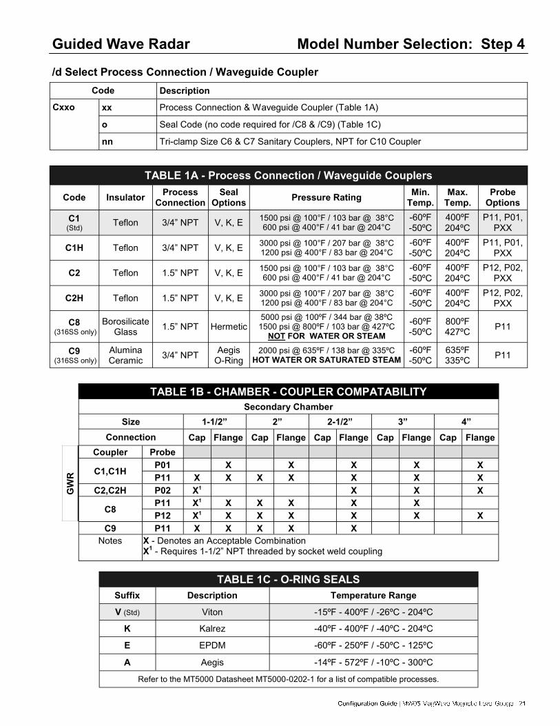
/d Select Process Connection / Waveguide Coupler
Description Code
Cxxo xx Process Connection & Waveguide Coupler (Table 1A)
o Seal Code (no code required for /C8 & /C9) (Table 1C)
nn Tri-clamp Size C6 & C7 Sanitary Couplers, NPT for C10 Coupler
TABLE 1A - Process Connection / Waveguide Couplers
Code Insulator Process
Connection
Seal Options
Pressure Rating Min.
Temp. Max.
Temp. Probe
Options
C1 (Std)
Teflon 3/4” NPT
V, K, E 1500 psi @ 100°F / 103 bar @ 38°C 600 psi @ 400°F / 41 bar @ 204°C
-60ºF -50ºC
400ºF 204ºC
P11, P01, PXX
C1H Teflon 3/4” NPT V, K, E 3000 psi @ 100°F / 207 bar @ 38°C 1200 psi @ 400°F / 83 bar @ 204°C
-60ºF -50ºC
400ºF 204ºC
P11, P01, PXX
C2 Teflon 1.5” NPT V, K, E 1500 psi @ 100°F / 103 bar @ 38°C 600 psi @ 400°F / 41 bar @ 204°C
-60ºF -50ºC
400ºF 204ºC
P12, P02, PXX
C2H Teflon 1.5” NPT V, K, E 3000 psi @ 100°F / 207 bar @ 38°C 1200 psi @ 400°F / 83 bar @ 204°C
-60ºF -50ºC
400ºF 204ºC
P12, P02, PXX
C8 (316SS only)
Borosilicate Glass
1.5” NPT Hermetic 5000 psi @ 100ºF / 344 bar @ 38ºC
1500 psi @ 800ºF / 103 bar @ 427ºC NOT FOR WATER OR STEAM
-60ºF -50ºC
800ºF 427ºC
P11
C9 (316SS only)
Alumina Ceramic
3/4” NPT Aegis
O-Ring 2000 psi @ 635ºF / 138 bar @ 335ºC
HOT WATER OR SATURATED STEAM -60ºF -50ºC
635ºF 335ºC
P11
Guided Wave Radar
TABLE 1C - O-RING SEALS
Suffix Description Temperature Range
V (Std) Viton -15ºF - 400ºF / -26ºC - 204ºC
K Kalrez -40ºF - 400ºF / -40ºC - 204ºC
E EPDM -60ºF - 250ºF / -50ºC - 125ºC
A Aegis -14ºF - 572ºF / -10ºC - 300ºC
Refer to the MT5000 Datasheet MT5000-0202-1 for a list of compatible processes.
TABLE 1B - CHAMBER - COUPLER COMPATABILITY
Secondary Chamber
Size 1-1/2” 2” 2-1/2” 3” 4”
Connection Cap Flange Cap Flange Cap Flange Cap Flange Cap Flange
Coupler Probe
C1,C1H P01 X X X X X
P11 X X X X X X X
C2,C2H P02 X1 X X X
P11 X1 X X X X X C8
P12 X1 X X X X X X
C9 P11 X X X X X
Notes X - Denotes an Acceptable Combination X
1 - Requires 1-1/2” NPT threaded by socket weld coupling
GW
R

Guided Wave Radar
Model Number Selection: Step 6 /f Select Probe Attachment
Code Description
X None
CDyyz-ww Clamp On Centering Disk (Solid Rod Probes) from Table 3. Note: Rigid probes installed in stilling wells or external chambers require centering disk.
CWyyz-ww Clamp On Centering Weight (Cable Probes) from Table 3. Note: Cable probes require a centering weight or end fitting to stabilize bottom of cable
E Eyelet (Cable Probes)
Model Number Selection: Step 5
/e Select Probe Type
Table 2 - PROBE DESCRIPTIONS
Code O.D. Description
Max Length
Probe Materials
Secondary Chamber Connection
Cap Flange
P01 0.25” Rigid N/A 5ft/1.52m S6, HC, HB,MO, TI
P11 (Std) 0.19” Cable C1,C9 =7 ft/2.13m
C2,C8 = 50ft/15.24m1 50ft/15.24m
1 S6, MO
P02 0.50” Rigid 1.5” - 2” chamber = 5ft/1.52m
2.5” - 4” chamber = 10ft/3.05m S6, HC, HB,MO, TI
Custom
PXX Consult Factory
Note: 1: Requires spacers at 5 ft maximum intervals for lengths exceeding 7 ft.
Table 3 - CENTERING DISKS AND WEIGHTS
Secondary Chamber
Probe Type
P01 P11 P02
Size Conn. Cap Flange Cap Flange Cap Flange
1-1/2”
10
CD15B-%
CW09D-% (Std) CD15C-%
40
80
2”
10
CD20B-%
CW09D-% 40 CD15B-%
80
2-1/2”
10
CD20B-% CW19F-% CD20C-% 40
80
3”
10
CD28B-% CW29F-%
CD28B-% 40
80 CW19F-%
4”
10
CD38B-% CW29F-% CD38B-% 40
80
% - Denotes material type. Use code from Step 1 - /a.
Refer to Centering Disc and Weight Chart CDW-0202-1 for detailed descriptions

|
/h Select Electronic Module
Code Description
X None
M7A One Level, Graphic Display, 4-20 mA Output, HART Add Suffix “M” for MODBUS (not Intrinsically Safe) Add Suffix “F” for Foundation Fieldbus
Model Number Selection: Step 8
Model Number Selection: Step 7
/g Select Process Temperature Options
Code Description
H0 32 - 250ºF / 0 - 121ºC
H6
C1 through C7 and C10 couplers: Above 250ºF / 121ºC or below 32ºF / 0ºC; Electronics enclosure is ex-tended 6” above process connection. C8 and C9 couplers: Above 500ºF / 260ºC; Extends electronics en-closure an additional 6 inches above process connection. Refer to Table 1A for maximum and minimum process temperatures.
Guided Wave Radar
In order to properly detect the level of interface between two liquids using the MT5100, the following rules must be adhered to: 1. One of the following probe and mounting configurations must be used:
a. Single rigid rod or flexible cable mounted in a stilling well, external chamber, or existing displacer.* b. Dual rigid rod, dual flexible cable or Tri-Tape c. Coaxial probe mounted into tank, external chamber, or displacer
* This is the preferred mounting configuration to reduce the chance of fouling. 2. Emulsion layers will affect the detection of an interface level. An emulsion layer may negate an interface
level indication completely. The MT5100 will read an interface level in the presence of a 2 inch emul-sion.
3. The minimum upper fluid thickness must be 4 inches when emulsion is present, and 0 inches with a clean interface.
4. The upper fluid dielectric constant must be greater than 1.6 and less than 5. 5. The interface level indication is a calculated value based partially upon the dielectric of the upper fluid.
The upper fluid dielectric must remain constant for consistency / accuracy in the interface level indica-tion.
6. The lower fluid dielectric constant must not be less than 15. 7. If the application is a flooded condition (sensor completely submerged in process), it must remain com-
pletely flooded. 8. In a non-flooded condition, the upper fluid must not be allowed to enter the upper un-measurable zone.
The upper un-measurable zone is typically located within the mounting nozzle of the vessel. If the required interface application does not fall within the above mentioned parameters, please consult the factory for an alternate technology, such as a Magnetostrictive, or RF Capacitance.
Table 4 - Guidelines for Interface Level Measurement
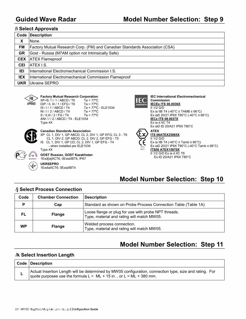
Guided Wave Radar Model Number Selection: Step 9
/i Select Approvals
Code Description
X None
FM Factory Mutual Research Corp. (FM) and Canadian Standards Association (CSA)
GR Gost - Russia (M7AM option not Intrinsically Safe)
CEX ATEX Flameproof
CEI ATEX I.S.
IEI International Electromechanical Commission I.S.
IEX International Electromechanical Commission Flameproof
UKR Ukraine SEPRO
/j Select Process Connection
Code Chamber Connection Description
P Cap Standard as shown on Probe Process Connection Table (Table 1A)
FL Loose flange or plug for use with probe NPT threads. Type, material and rating will match MW05.
Flange
WP Welded process connection. Type, material and rating will match MW05.
Flange
Model Number Selection: Step 10
/k Select Insertion Length
Code Description
L Actual Insertion Length will be determined by MW05 configuration, connection type, size and rating. For quote purposes use the formula L = ML + 15 in. , or L = ML + 380 mm.
Model Number Selection: Step 11
Factory Mutual Research Corporation XP-IS / I / 1 / ABCD / T6 Ta = 77ºC DIP / II, III / 1 / EFG / T6 Ta = 77ºC IS / I / 1 / ABCD / T4 Ta = 77ºC - ELE1034 NI / I / 2 / ABCD / T4 Ta = 77ºC S / II,III / 2 / FG / T4 Ta = 77ºC ANI / I / 2 / ABCD / T4 - ELE1034 Type 4X
IEC International Electromechanical Commission IECEx ITS 08.0036X II 1/2 G/D Ex ia IIB T4 (-40°C ≤ TAMB ≤ 66°C) Ex iaD 20/21 IP6X T80°C (-40°C ≤ 66°C) IECx ITS 08.0037X Ex ia d IIC T4 Ex iaD tD 20/A21 IP6X T80°C
Canadian Standards Association XP CL 1, DIV 1, GP ABCD; CL 2, DIV 1, GP EFG; CL 3 - T6 CL 1, DIV 2, GP ABCD; CL 2, DIV 2, GP EFG - T5 IS CL 1, DIV 1, GP CD; CL 2, DIV 1, GP EFG - T4 - when installed per ELE1034 Type 4X
ATEX ITS 08ATEX25865X II 1/2 G/D Ex ia IIB T4 (-40°C ≤ Tamb ≤ 66°C) Ex iaD 20/21 IP6X T80°C (-40°C Tamb ≤ 66°C) ITS08 ATEX15870X II 1/2 G/D Ex ia d IIC T6
Ex tD 20/A21 IP6X T80°C GOST Russian, GOST Kazakhstan 1Exd[ia]IICT6, 0ExiaIIBT6, IP67
UKRSEPRO 1ExdiaIICT6; 0ExiaIIBT4
0575
0871

|
Switch & Transmitter Accessories MW05
Other Transmitter and Switch Accessories:
Magnetostrictive Level Transmitters
AT100 Refer to AT100-0202-1 Data Sheet for Ordering Information
AT200 Refer to AT200-0202-1 Data Sheet for Ordering Information
AT500 Refer to AT500-0202-1 Data Sheet for Ordering Information
AT600 Refer to AT600-0202-1 Data Sheet for Ordering Information
Capacitance Level Transmitter
A38 Refer to A38-0202-1 Data Sheet for Ordering Information
Magnetic Level Gauge Switches
MS30 Refer to MS30-0202-1 Data Sheet for Ordering Information
MS40 Refer to MS40-0202-1 Data Sheet for Ordering Information
MS41 Refer to MS41-0202-1 Data Sheet for Ordering Information
PS35 Refer to PS35-0202-1 Data Sheet for Ordering Information
PS45 Refer to PS45-0202-1 Data Sheet for Ordering Information
Vibrating Level Switch
RS80 Refer to RS80-0202-1 Data Sheet for Ordering Information
RS85 Refer to RS85-0202-1 Data Sheet for Ordering Information
Thermal Dispersion Switch
TX Refer to TX-0202-1 Data Sheet for Ordering Information
Capacitance Switch
KCAP400 Refer to KCAP400-0202-1 Data Sheet for Ordering Information
All Data Sheets are available on the ABB website at www.abb.com/level
FM
FM
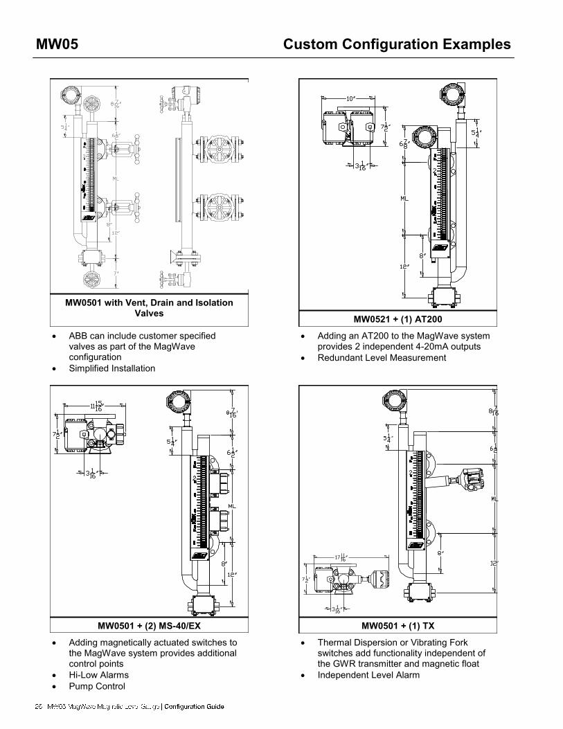
MW05 Custom Configuration Examples
ABB can include customer specified valves as part of the MagWave configuration
Simplified Installation
MW0501 with Vent, Drain and Isolation Valves
Adding an AT200 to the MagWave system provides 2 independent 4-20mA outputs
Redundant Level Measurement
MW0521 + (1) AT200
Adding magnetically actuated switches to the MagWave system provides additional control points
Hi-Low Alarms
Pump Control
MW0501 + (2) MS-40/EX
Thermal Dispersion or Vibrating Fork switches add functionality independent of the GWR transmitter and magnetic float
Independent Level Alarm
MW0501 + (1) TX

|
QUOTATION REQUEST - MW05-Dual Chamber
Tel: (1) 225-673-6100 / 800-735-5835 E-mail: [email protected] Fax: (1) 225-673-2525
Rep. Firm: Contact:
Phone #: Fax #:
E-mail:
Customer: Contact:
Phone #: Fax:
Chamber Style (Circle one or provide sketch.)
MLG Chamber & Float Details: Chamber Material Float Material Flange Material Process Connection Type: Size Rating Center to Center/Measuring Length Vent/Drain Type & Size
Indicator Details: Shuttle Yellow/Black MBG Red/White MBG Scale: Ft/In M/cm Running In. (1/2” Div.) Running In. (1/8” Div.) Custom Special Requirements
Process Conditions: Qty: MW05 Application for (circle one): Total Level Interface Level
1 Total & Interface
1
Operating Sp. Gravity: Min. Sp. Gravity: Second Specific Gravity (Interface): Fluid(s): (If Water: Steam Service? Y / N ) Operating Temp Max Temp Operating Press Max Press Dielectric Constant: Upper Fluid Lower Fluid Note 1: Both fluids must meet specific dielectric requirements for interface measurement. Refer to page 23 Table 4.
MW0501 MW0502 MW0505 MW0506

A C
B
Guided Wave Radar Details Housing: Aluminum Connection: Threaded Probe: Cable SS Welded Rigid Rod Window: Yes No Communication: None Approval: FM/CSA HART ATEX I.S Honeywell DE ATEX Flameproof Foundation Fieldbus Gost Russia IEC I.S. IEC Flameproof Ukraine SEPRO Other Transmitter: AT100 A38 Details:
Second Chamber Details: Chamber Size: 1-1/2” (Std) Orientation:(optional) 2” 2 - 1/2” 3” 4”
For Office Use Only
Additional Notes or Comments:
Quote Number: Completed By: Date: MW05 P/N: Transmitter Part Number:
Option #1: $ ea. Option #3: $ ea. Option #2: $ ea. Option #4: $ ea.
Additional Accessories if Required (circle all that apply):
Chamber Insulation
Electric Heat
Tracing
Steam Trace Tubing
Vent, Drain,
Or Isolation Valves
Special Process
Connection (Specify)
Magnetic Particle Traps
Switches (Specify)
Transmitter AT200 or other
(CF)
Secondary Chamber (A) B C
Indicator A (B) C Switch(es) A B (C)

|
This page intentionally left blank.

This page intentionally left blank.

|
This page intentionally left blank.