Transformer bushing, type GSBK - ABB
72
1ZSC000563-AAB EN, REV. 6, 2019-09-12 Transformer bushing, type GSBK Installation and maintenance guide
-
Upload
khangminh22 -
Category
Documents
-
view
0 -
download
0
Transcript of Transformer bushing, type GSBK - ABB

1ZSC000563-AAB EN, REV. 6, 2019-09-12
Transformer bushing, type GSBKInstallation and maintenance guide

The information contained in this document may be subject to change without prior warning and should not be consideredas binding on ABB AB’s behalf. ABB AB accepts no liability for any errors that may appear in this document. ABB AB isnot liable for any damage resulting from the incorrect interpretation of this document. This document, or parts thereof, maynot be reproduced or copied without ABB AB’s consent. It may not be distributed to others, or used by unauthorizedparties. Any breaches to the above will be penalized with the support of applicable laws.

Installation and maintenance guide1ZSC000563-AAB EN, REV. 6, 2019-09-12
3
Contents1 Safety 5
1.1 Levels of safety risks ................................................................................................................................................................... 51.2 Hazardous working situations ..................................................................................................................................................... 61.3 Safety precautions....................................................................................................................................................................... 6
2 Product description 72.1 Design ......................................................................................................................................................................................... 72.2 Transformer testing ..................................................................................................................................................................... 102.3 Technical specifications............................................................................................................................................................... 11
2.3.1 General specifications ............................................................................................................................................... 112.3.2 Mechanical loading.................................................................................................................................................... 12
3 Delivery 153.1 Incoming inspection..................................................................................................................................................................... 153.2 Transportation ............................................................................................................................................................................. 153.3 Storage........................................................................................................................................................................................ 153.4 Lifting........................................................................................................................................................................................... 16
3.4.1 Lifting the transport box............................................................................................................................................. 163.4.2 Lifting the bushing out of the transport box ............................................................................................................... 17
4 Installation 194.1 Tools ............................................................................................................................................................................................ 194.2 Consumables .............................................................................................................................................................................. 194.3 Installation with fixed bottom contact........................................................................................................................................... 20
4.3.1 Installation of lifting tools ........................................................................................................................................... 204.3.2 Installation with fixed bottom contact......................................................................................................................... 22
4.4 Preparations with draw rod.......................................................................................................................................................... 274.4.1 Removal of the outer terminal ................................................................................................................................... 274.4.2 Removal of the lower draw rod with bottom contact from the bushing ..................................................................... 284.4.3 Installation of the large bottom contact in the transformer ........................................................................................ 304.4.4 Lifting the bushing for installation on the transformer................................................................................................ 32
4.5 Installation with draw rod............................................................................................................................................................. 334.5.1 Installation of the bushing on the transformer ........................................................................................................... 334.5.2 Manual tightening of the draw-rod nut....................................................................................................................... 364.5.3 Hydraulic tightening of the draw-rod nut.................................................................................................................... 38
4.6 Oil-filling....................................................................................................................................................................................... 394.7 Installation of the outer terminal .................................................................................................................................................. 404.8 Grounding of the bushing flange ................................................................................................................................................. 44
5 Commissioning 475.1 Waiting time before energization ................................................................................................................................................. 475.2 Recommended tests before energization.................................................................................................................................... 47
5.2.1 Overview ................................................................................................................................................................... 475.2.2 Tightness test between transformer and bushing flange........................................................................................... 475.2.3 Measurement of capacitance and dissipation factor ................................................................................................. 485.2.4 Measurement of through-resistance.......................................................................................................................... 51

4 Installation and maintenance guide1ZSC000563-AAB EN, REV. 6, 2019-09-12
6 Maintenance 536.1 Recommended maintenance ...................................................................................................................................................... 53
7 Re-packing 557.1 Removal of the bushing from the transformer, fixed bottom contact ...........................................................................................557.2 Removal of the bushing from the transformer, draw rod .............................................................................................................567.3 Re-packing of the bushing........................................................................................................................................................... 60
8 Spare parts 638.1 Summary ..................................................................................................................................................................................... 638.2 Spare parts .................................................................................................................................................................................. 638.3 Special tools ................................................................................................................................................................................ 64
9 Disposal and environmental information 679.1 Overview ..................................................................................................................................................................................... 679.2 Disposal and recycling ................................................................................................................................................................ 67
10 Reference 6910.1 Summary ..................................................................................................................................................................................... 69

Installation and maintenance guide1ZSC000563-AAB EN, REV. 6, 2019-09-12
5
1 Safety
1.1 Levels of safety risks
Throughout the manual, various types of safety risks are indicated. The most serious level on this scaleprovides a warning about serious personal injury or possible death, or major damage to a product, if theinstructions are not observed.
Symbols and their meanings
The following describes the symbols that appear in the manual, along with their meaning.
DANGER!The yellow, filled warning triangle warns that an accident will occur if the instructions are notcomplied with and that it will result in serious personal injury or death and/or major damage to theproduct.
It is used, for example, to warn of such dangers as: contact with high voltage, explosion or firerisk, risk for toxic gases, risk of crushing, impacts, falls from high places, etc.
CAUTION!The round warning symbol warns that an accident could occur if the instructions are not observed,and that this could result in personal injury and/or damage to the product.
It is also used to warn of risks that entail burns, eye or skin injuries, impaired hearing, crushing orslipping injuries, tripping, impacts, falls from high places, etc.
In addition, it is used to warn of functional requirements when assembling or removing equipmentwhere there is a risk of damage to the product or downtime.
NOTE!The comment symbol identifies important information and conditions. Also used to indicate anydanger that could lead to property damage.
TorqueThe torque symbol indicates tightening torque.
6 Installation and maintenance guide1ZSC000563-AAB EN, REV. 6, 2019-09-12
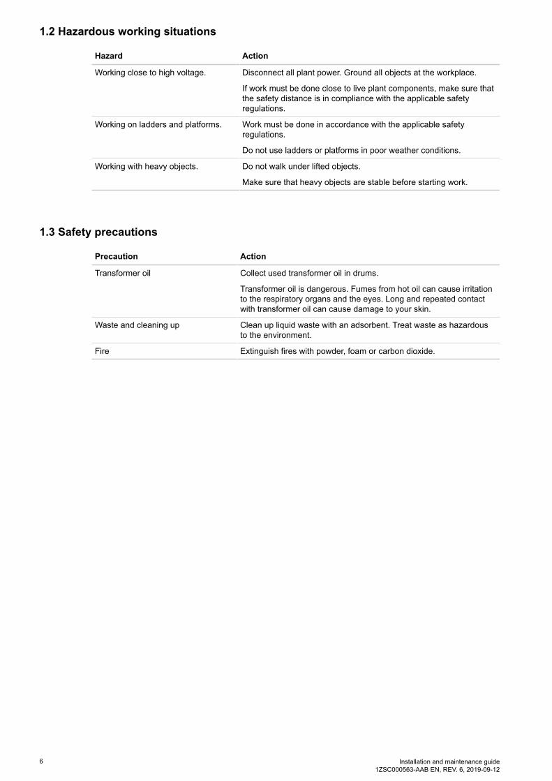
1.2 Hazardous working situations
Hazard Action
Working close to high voltage. Disconnect all plant power. Ground all objects at the workplace.
If work must be done close to live plant components, make sure thatthe safety distance is in compliance with the applicable safetyregulations.
Working on ladders and platforms. Work must be done in accordance with the applicable safetyregulations.
Do not use ladders or platforms in poor weather conditions.
Working with heavy objects. Do not walk under lifted objects.
Make sure that heavy objects are stable before starting work.
1.3 Safety precautions
Precaution Action
Transformer oil Collect used transformer oil in drums.
Transformer oil is dangerous. Fumes from hot oil can cause irritationto the respiratory organs and the eyes. Long and repeated contactwith transformer oil can cause damage to your skin.
Waste and cleaning up Clean up liquid waste with an adsorbent. Treat waste as hazardousto the environment.
Fire Extinguish fires with powder, foam or carbon dioxide.

Installation and maintenance guide1ZSC000563-AAB EN, REV. 6, 2019-09-12
7
2 Product description
2.1 Design
Overview
The GSBK type is a transformer bushing. It is made for immersed oil to SF6 service. The bushing is of thedry, gas-free type, with a resin impregnated paper RIP condenser core as the primary insulation. Bushings ofthis design can be installed at any angle from vertical to horizontal.
General schematics
G005122
1 Outer terminal
2 RIP condenser core
3 Mounting flange
4 RIP condenser core
5 End shield
6 Test/voltage tap

8 Installation and maintenance guide1ZSC000563-AAB EN, REV. 6, 2019-09-12
Terminal system
The bushing can be configured with one of two terminal systems: the fixed bottom contact system, or thedraw-rod system.
G005101
1 Draw rod
2 Fixed bottom contact

Installation and maintenance guide1ZSC000563-AAB EN, REV. 6, 2019-09-12
9
Test tap
The bushing has a test tap that is connected to the outermost conductive layer of the condenser core. The testtap is used to measure the bushing insulation by capacitance and dissipation factor. The cover connects theoutermost conductive layer to ground, and must always be installed when the bushing is energized.
The maximum one minute test voltage for this test tap is 2 kVrms. The test tap can be used as a power source,if it is connected to an external capacitance. The operating voltage is limited to 600 V.
CAUTION!Do not energize the bushing without a test adapter or the cover installed. The bushing is groundedthrough the cover to prevent damage to the bushing.
G000388
1 Stud
2 Cover
3 Grounding spring
4 O-ring

10 Installation and maintenance guide1ZSC000563-AAB EN, REV. 6, 2019-09-12
Voltage tap
The voltage tap is available as an option, instead of the test tap.
The bushing has a voltage tap that is connected to the second outermost conductive layer of the condensercore. The voltage tap is used to measure the bushing insulation by capacitance and dissipation factor. Thecover connects the outermost conductive layer to ground, and must always be installed when the bushing isenergized.
The maximum one minute test voltage for this voltage tap is 20 kVrms. The voltage tap can be used as apower source, if it is connected to an external capacitance. The operating voltage is limited to 6 kV.
CAUTION!Do not energize the bushing without a test adapter or the cover installed. The cover connects theoutermost conductive layer to ground and will prevent damage to the bushing.
G000388
1 Stud
2 Cover
3 Grounding spring
4 O-ring
2.2 Transformer testing
To simplify the transformer testing, several alternatives are available instead of using the GIS-system.
• The GSBK bushing can be used as an oil-to-oil bushing.• The GSBK bushing can be replaced by an oil-to-air bushing, in the combinations listed in the table.
Type Alternative bushing Note
GSBK 245 GSB 245 or GOE(2) 1175-850 -
GSBK 362 GSB 362 or GOE(2) 1175-850 GOE(2) 1175-850 has an oil-sidethat is 110 mm shorter than GSBK362.
GSBK 420 GSB 420 or GOE(2) 1425-1050 -
GSBK 550 GSB 550 -
NOTE!The GSBK draw-rod system is not compatible with the GOE draw-rod system.

Installation and maintenance guide1ZSC000563-AAB EN, REV. 6, 2019-09-12
11
2.3 Technical specifications
2.3.1 General specifications
Refer to the table for the standard technical specifications of the bushing. For conditions exceeding thespecifications, please contact ABB.
Application: Transformers
Classification: Tranformer bushing
• Resin impregnated paper, capacitance graded, oilimmersed.
• Temperature class E (120 °C) according to IEC 60137.
Ambient temperature limits: -40 °C to +40 °C.
Immersion medium on switchgear side: SF6 gas.
• Maximum daily mean temperature: +75 °C.• Maximum pressure: 850 kPa (abs).• Minimum pressure: 350 kPa (abs).
Immersion medium: Transformer oil.
• Maximum daily mean oil temperature: +90 °C.• Maximum temporary oil temperature, at normal load:
+100 °C.• Maximum temporary oil temperature, at short time
overload: +115 °C.
Oil-level in transformer: Not lower than 30 mm from the bushing flange.
Maximum pressure of medium: pg 100 kPa (pg = relative to ambient pressure).
Angle of installation: From horizontal to vertical.
Test tap: According to IEEE potential tap type A. Ur = max 600 V.
Voltage tap: According to IEEE potential tap type A. Ur = 6 kV.
Capacitance C2 of test tap: <5000 pF
Arcing horns: N/A
Conductor: Center-tube conductor.
Markings: Conforming to IEC/IEEE.

12 Installation and maintenance guide1ZSC000563-AAB EN, REV. 6, 2019-09-12
List of bushings applicable to this installation guide
Type Article number
Test tap 2 kV Voltage tap 6 kV
GSBK 170 1ZSC900170-AAA 1ZSC900170-ABA
1ZSC900170-AAB 1ZSC900170-ABB
1ZSC900170-ACA 1ZSC900170-ADA
1ZSC900170-ACB 1ZSC900170-ADB
GSBK 245 1ZSC900245-AAA 1ZSC900245-ABA
1ZSC900245-AAB 1ZSC900245-ABB
1ZSC900245-ACA 1ZSC900245-ADA
1ZSC900245-ACB 1ZSC900245-ADB
GSBK 362 1ZSC900362-AAA 1ZSC900362-ABA
1ZSC900362-AAB 1ZSC900362-ABB
1ZSC900362-ACA 1ZSC900362-ADA
1ZSC900362-ACB 1ZSC900362-ADB
GSBK 420 1ZSC900420-AAA 1ZSC900420-ABA
1ZSC900420-AAB 1ZSC900420-ABB
1ZSC900420-ACA 1ZSC900420-ADA
1ZSC900420-ACB 1ZSC900420-ADB
GSBK 550 1ZSC900550-AAA 1ZSC900550-ABA
1ZSC900550-AAB 1ZSC900550-ABB
1ZSC900550-ACA 1ZSC900550-ADA
1ZSC900550-ACB 1ZSC900550-ADB
2.3.2 Mechanical loading
Maximum permitted static load on the outer terminal
The load must be applied at the midpoint (2) of the outer terminal. The total cantilever load must beperpendicular to the bushing axis. The bushing can be installed in all positions from horizontal to vertical.
NOTE!The loads described in this section are static loads, for dynamic loads such as earthquakes andextreme wheather conditions, please contact your ABB sales representative.

Installation and maintenance guide1ZSC000563-AAB EN, REV. 6, 2019-09-12
13
Load on the outer terminal
G006302
1 Cantilever load
2 Outer terminal
Type Maximum cantilever load on the outer terminal:
Type test load, 1 minute (kN) Maximum service load (kN)
GSBK 170 4 2
GSBK 245 4 2
GSBK 362 4 2
GSBK 420 4 2
GSBK 550 4 2

14 Installation and maintenance guide1ZSC000563-AAB EN, REV. 6, 2019-09-12
Load on the bushing flange
G006509
1 Bending moment
2 Compressive or tensile load
3 Shearing load
4 Bushing flange
Type Maximum bending moment on thebushing flange:
Maximum load on the bushing flange inservice:
Test load (kNm) In operation (kNm) Shearing load (kN) Compressive ortensile load (kN)
GSBK 170 20 10 10 50
GSBK 245 40 20 14 70
GSBK 362 80 40 20 10
GSBK 420 80 40 20 10
GSBK 550 80 40 20 10
GIS pressure
The limit SF6 gas pressures for the GIS side of the bushing.
Type Type test pressure 1minute MPaabs
Routine test pressure 1minute MPaabs
Maximum servicepressure MPaabs
GSBK 170 2.55 1.25 0.85
GSBK 245 2.55 1.25 0.85
GSBK 362 2.55 1.25 0.85
GSBK 420 2.55 1.25 0.85
GSBK 550 2.55 1.25 0.85

Installation and maintenance guide1ZSC000563-AAB EN, REV. 6, 2019-09-12
15
3 Delivery
3.1 Incoming inspection
• Make sure that all items have been delivered, refer to the packing list.• Carefully inspect the bushings for shipping damage.
3.2 Transportation
• The bushing must be transported in the transport box.• Make sure that the bushing is wrapped in the original (or equivalent) moisture proof wrapping.
If the drying agent inside the wrapping has been exposed to the atmosphere, replace it.• The bushing must be transported in the horizontal position.• Carefully inspect the bushing for damage after transportation.
3.3 Storage
Short term storage, less than 6 months
• Make sure that the bushing is wrapped in the original (or equivalent) moisture-proof wrapping.If the drying agent inside the wrapping has been exposed to the atmosphere, replace it.
• The bushing can be stored outdoors, if it is in the transport box.Keep the transport box protected from water, when the bushing is stored outdoors.
• Keep the bushing dry, clean and protected against mechanical damage.• The bushing can be stored in both the vertical, and horizontal positions.

16 Installation and maintenance guide1ZSC000563-AAB EN, REV. 6, 2019-09-12
Long term storage, more than 6 months
• Use transport containers on both sides of the bushing, they have to be ordered separately.Put drying agent in both transport containers.
• The bushing can be stored outdoors, if it is in the transport box.Keep the transport box protected from water, when the bushing is stored outdoors.
• Keep the bushing dry, clean and protected against mechanical damage.• The bushing can be stored in both the vertical, and horizontal positions.
The bushing is delivered from ABB in a transport box, and the bushing is held in place by support blocks andfiberboard in the box.
G006274
3.4 Lifting
3.4.1 Lifting the transport box
Overview
G004736
1 Center of gravity
2 Soft lifting slings

Installation and maintenance guide1ZSC000563-AAB EN, REV. 6, 2019-09-12
17
Procedure
1. Make sure that the crane and the soft lifting slings are approved for the total weight of the transportbox and bushing. Refer to the weight in the packing list.
2. Attach soft lifting slings (2).
3. Make sure that the angle of the soft lifting sling is not more than 20°.
4. Carefully lift the transport box.
5. Set down the transport box on a flat surface.
End of instruction
3.4.2 Lifting the bushing out of the transport box
Overview
G005083
Procedure
1. Make sure that the crane is approved for lifting the weight of the bushing. Refer to the weight on therating plate.
2. Open the transport box.
NOTE!The cover is attached with bolts.
18 Installation and maintenance guide1ZSC000563-AAB EN, REV. 6, 2019-09-12
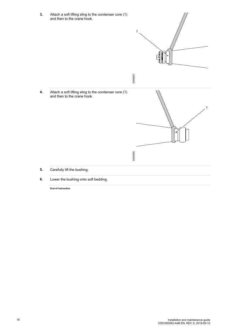
3. Attach a soft lifting sling to the condenser core (1)and then to the crane hook.
G006857
4. Attach a soft lifting sling to the condenser core (1)and then to the crane hook.
G005085
5. Carefully lift the bushing.
6. Lower the bushing onto soft bedding.
End of instruction

Installation and maintenance guide1ZSC000563-AAB EN, REV. 6, 2019-09-12
19
4 Installation
4.1 Tools
Tool Part number Note
Lifting tool 9ADA338 -
Soft bedding - E.g. rubber mat or wood board
Soft lifting slings - -
Pull-through cord 9760 669-A With M8 terminal.
For assembly and disassembly of thedraw rod.
Torque wrench key for hex socketscrews, 10 mm (M12), torque20 to 40 Nm.
- -
Wrench for hex socket screws 30 mm oradjustable wrench for 30 mm boltsor larger.
- For the test tap cover.
Shackles - To fit Ø 25 mm holes, for connection ofthe soft lifting slings to the bushingflange.
Hydraulic jack 2769 897-A For removal, and installation of thebottom contact. Draw-rod system.
Box spanner 9760 669-B For removal, and installation of thebottom contact. Draw-rod system.
Tackle - For installation of the bushing at aspecific angle.
4.2 Consumables
Item Brand ABB partnumber
Note
Oil based Vaseline Fuchs 1171 5011-102 For treatment of contact surfases. Doesnot react with transformer oil.
Mobilgrease 28 MOBIL 1171 4014-407 Lubricates and protects metals againstcorrosion. Protects rubber. Does notreact with transformer oil.
Molykote 1000 Dow Corning 1171 2016-618 For the sealing and lubrication of thecontact on the outer terminal.

20 Installation and maintenance guide1ZSC000563-AAB EN, REV. 6, 2019-09-12
4.3 Installation with fixed bottom contact
4.3.1 Installation of lifting tools
Overview
G005086
1 Soft bedding, i.e. rubber mat or woodboard
2 Lifting eye
Procedure
1. Install the lifting eyes (1) in the top end andintermediate flange.
G005089

Installation and maintenance guide1ZSC000563-AAB EN, REV. 6, 2019-09-12
21
2. Attach soft lifting slings (8) from the lifting eye tothe crane hook.
G005137
3. For installation at a specific angle: attach softlifting slings with a schackle (9) from theintermediate flange to the crane hook.
G005105
End of instruction
22 Installation and maintenance guide1ZSC000563-AAB EN, REV. 6, 2019-09-12
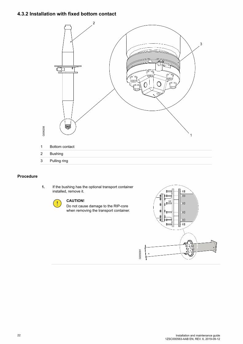
4.3.2 Installation with fixed bottom contact
G006208
1 Bottom contact
2 Bushing
3 Pulling ring
Procedure
1. If the bushing has the optional transport containerinstalled, remove it.
CAUTION!Do not cause damage to the RIP-corewhen removing the transport container.
G005091

Installation and maintenance guide1ZSC000563-AAB EN, REV. 6, 2019-09-12
23
2. Make sure that there is a distance of 7 ±0.5 mmbetween the pressing ring (17) and the pullingring (3).
G006215
3. Make sure with a torque wrench that the the sixbolts are tightened with a torque of 40 Nm.
G006214
Torque40 Nm
4. Make sure that the gasket is installed in the turretflange.
NOTE!The gasket is supplied by thetransformer manufacturer.
G006865

24 Installation and maintenance guide1ZSC000563-AAB EN, REV. 6, 2019-09-12
5. Lower the bushing onto the transformer.
G005106
6. When installing the bushing at the transformerfactory:
1. Make sure that the bushing is installed in thecorrect orientation.
2. Make permanent markings (16) on thebushing flange and the transformer turret.
G005107
7. Install the bolts and washers. Tighten the bolts ina crosswise sequence.
• When installing the bushing at site, makesure that the marking (16) on the bushingflange lines up with the marking on thetransformer turret.
G005108
TorqueRefer to the transformer manufacturersdocumentation.

Installation and maintenance guide1ZSC000563-AAB EN, REV. 6, 2019-09-12
25
8. Remove the lifting eyes (1).
G005089
9. Put the winding cables through the end-shield.
G004325
10. Install the winding cables to the bottom contact.
CAUTION!Make sure that there is no tension inthe winding cables. Tension in thewinding cables will cause damage tothe bottom contact.
G006212
Torque68 ± 6 Nm

26 Installation and maintenance guide1ZSC000563-AAB EN, REV. 6, 2019-09-12
11. Install the end shield:
1. Push the end shield carefully against thepressing ring (17).
2. Turn the end shield approximately 20°, to itslocked position.
G006213
12. If the transformer will be oil-filled with theatmospheric process:
1. Remove the hex screws (6).2. Put the blades of two screwdrivers in the
recesses (19) in the outer terminal (5), andcarefully push them down to lift the outerterminal (5) straight up.
CAUTION!Do not cause damage to the shield(18).
G006307
13. The bushing is ready for oil-filling of the transformer, refer to Oil-filling, page 39.
End of instruction

Installation and maintenance guide1ZSC000563-AAB EN, REV. 6, 2019-09-12
27
4.4 Preparations with draw rod
4.4.1 Removal of the outer terminal
Procedure
1. If the bushing has the optional transport containerinstalled, remove it.
CAUTION!Do not cause damage to the RIP-corewhen removing the transport container.
G005091
2. Remove the hex screws (6).G005126
3. Put the blades of two screwdrivers in the recesses(19) in the outer terminal (5), and carefully pushthem down to lift the outer terminal (5) straight up.
CAUTION!Do not cause damage to theshield (18).
G006307

28 Installation and maintenance guide1ZSC000563-AAB EN, REV. 6, 2019-09-12
4. Install the lifting eye (1).
G005127
End of instruction
4.4.2 Removal of the lower draw rod with bottom contact from the bushing
Overview
The bottom contact is usually installed in the bushing when it is delivered from ABB, the first step at thetransformer factory is thus to remove it.
G005090
1 Upper draw rod
2 Lower draw rod with bottom contact
3 Bottom contact
4 Bushing

Installation and maintenance guide1ZSC000563-AAB EN, REV. 6, 2019-09-12
29
Procedure
1. If the bushing has the optional transport containerinstalled, remove it.
CAUTION!Do not cause damage to the RIP-corewhen removing the transport container.
G006350
2. Put the pull-through cord (12) through thebox-spanner (13).
NOTE!The terminal on the pull-through cord(12) has M8 threads.
G004924
3. Apply Vaseline to the threads on the pull-throughcord (12), then connect it to the upper draw rod.
NOTE!Or use a lubricant with equal propertiesto Vaseline.
G005092

30 Installation and maintenance guide1ZSC000563-AAB EN, REV. 6, 2019-09-12
4. Remove the M16 nut (10) and washer (11), on thedraw rod with the box spanner.
CAUTION!Do not remove the compensationdevice.
NOTE!Keep the draw-rod nut (10) and washer(11), they will be used again.
G005093
5. Pull down the draw rod from the bottom end of thebushing, and disassemble it at the lower joint (8).
CAUTION!Do not disassemble the joint (7), thisincreases the risk of incorrectassembly.
The joint (7) is locked with highstrenght tread-locking fluid grade 42.
G005094
6. Carefully clean the bottom end of the bushing, and the inside of the center hole. Look for damage.
End of instruction
4.4.3 Installation of the large bottom contact in the transformer
Overview
G006201
1 Bottom contact

Installation and maintenance guide1ZSC000563-AAB EN, REV. 6, 2019-09-12
31
Procedure
1. Remove the transformer cover (13) from thetransformer turret (11).
G004927
2. Install the winding cables to the bottom contact.
CAUTION!Make sure that there is no tension inthe winding cables. Tension in thewinding cables will cause damage tothe bottom contact.
G004929
Torque68 ±6 Nm
3. Install the end shield:
1. Push the end shield carefully against thepressing ring (17), until the springs are fullycompressed.
2. Turn the end shield approximately 20°, to itslocked position.
G006202
End of instruction

32 Installation and maintenance guide1ZSC000563-AAB EN, REV. 6, 2019-09-12
4.4.4 Lifting the bushing for installation on the transformer
Procedure
1. Make sure that the crane can lift the bushing. Refer to the net weight in the packing list.
2. Align the crane hook with the lifting tool on the bushing.
3. Attach soft lifting slings (8) to the lifting tool and tothe crane hook.
CAUTION!Put soft bedding (2) under the bottomcontact. The bottom contact is made ofsoft metal, and contact with the floorcan cause damage.
G005137
4. For installation of the bushing at a specific angle:
1. Attach soft lifting slings with a shackle (9) onthe flange and to the crane hook.
G005105
5. Carefully lift the bushing from the floor.
CAUTION!Make sure that the bushing does not rotate.
6. Adjust the shackle (9) until the bushing flange has the same angle as the transformer flange.
7. Lift the bushing to a position above the transformer.
CAUTION!Make sure that the bushing does not rotate.

Installation and maintenance guide1ZSC000563-AAB EN, REV. 6, 2019-09-12
33
8. Align the bushing with the hole in the transformerturret.
G004562
End of instruction
4.5 Installation with draw rod
4.5.1 Installation of the bushing on the transformer
Overview
G006866
1 Draw-rod
12 Pull-through cord

34 Installation and maintenance guide1ZSC000563-AAB EN, REV. 6, 2019-09-12
Procedure
1. Connect the upper draw-rod (1) to the lowerdraw-rod (4).
G004932
2. Hold the pull-through cord (12) in tension, whilelowering the bushing onto the transformer.
CAUTION!Do not damage the stud bolts. There isa risk of metal falling into thetransformer.
NOTE!Plastic sleeves put on two or three ofthe stud bolts will help to guide theflange, and will prevent damage to thestud bolts.
G005100
3. When installing the bushing at the transformerfactory:
1. Make sure that the bushing is installed in thecorrect orientation.
2. Make permanent markings (16) on thebushing flange and the transformer turret.
G005107

Installation and maintenance guide1ZSC000563-AAB EN, REV. 6, 2019-09-12
35
4. Install the bolts and washers. Tighten the bolts ina crosswise sequence.
• When installing the bushing at site, makesure that the marking (16) on the bushingflange lines up with the marking on thetransformer turret.
G005108
TorqueRefer to the transformer manufacturersdocumentation.
5. Install the draw-rod nut (10):
1. Apply a generous quantity of Molykote to thenut (10), and the threads of the draw rod.
2. Install the washer (11) and nut (10) on thedraw rod, tighten with your fingers.
3. Remove excess Molykote with a rag.
CAUTION!If the nut (10) is not lubricated correctly,it will not be tighten to the correcttorque. This can cause the bushing tofail.
G005109
6. Tighten the draw-rod nut (10).
G005093
Torque10 Nm
7. Remove the pull-through cord (12).

36 Installation and maintenance guide1ZSC000563-AAB EN, REV. 6, 2019-09-12
8. Remove the lifting eyes (1).
G005089
9. Tighten the draw-rod nut, refer to Hydraulic tightening of the draw-rod nut, page 38, or Manualtightening of the draw-rod nut, page 36.
End of instruction
4.5.2 Manual tightening of the draw-rod nut
Overview
This procedure requires the draw-rod nut, washer and threads of the draw rod to be correctly lubricated. Thedraw rod will not get the correct tension if the fasteners are not correctly lubricated, this can cause thebushing to fail.
Procedure
1. Make sure that the draw-rod nut, and threads of the draw rod are correctly lubricaded, and that thedraw-rod nut is tightened to 10 Nm.
2. Measure the distance (a).
NOTE!The bushing is delivered with aninformation sheet that specifies themeasurement (b-a). These values aremeasured when the bushing ismanufactured, and are unique to everyunit.
G005110

Installation and maintenance guide1ZSC000563-AAB EN, REV. 6, 2019-09-12
37
3. Turn the nut clockwise until you get the the correctextension (b).
Distance (b) = (a) + extension, refer to the table.
CAUTION!Make sure that you do not overtightenthe nut. Use a torque wrench set to140 Nm.
NOTE!One turn of the nut corresponds to a2 mm extension of the draw rod.
Type Extension
CT 300 mm CT 600 mm
GSBK 170 24.0 mm 24.5 mm
GSBK 245 24.5 mm 25.0 mm
GSBK 362 25.0 mm 25.5 mm
GSBK 420 25.0 mm 25.5 mm
GSBK 550 25.5 mm 26.0 mm
G005111
4. Make sure with a torque wrench that the nut is tightened with a torque of more than 70 Nm and lessthan 140 Nm.
5. Continue with Installation of the outer terminal, page 40.
End of instruction

38 Installation and maintenance guide1ZSC000563-AAB EN, REV. 6, 2019-09-12
4.5.3 Hydraulic tightening of the draw-rod nut
Overview
G006278
8 Hydraulic jack
10 Draw-rod nut
Procedure
1. Install the hydraulic jack (8).
2. Pull the draw rod with a force according to the table.
Type Force
CT 300 mm CT 600 mm
GSBK 170 39.5 kN 39.5 kN
GSBK 245 39.1 kN 39.3 kN
GSBK 362 39.1 kN 39.3 kN
GSBK 420 39.0 kN 39.2 kN
GSBK 550 39.4 kN 39.5 kN
3. Tighten the nut on the draw rod with your hand.
4. Remove the hydraulic jack (8).
End of instruction

Installation and maintenance guide1ZSC000563-AAB EN, REV. 6, 2019-09-12
39
4.6 Oil-filling
Overview
Start this procedure when the transformer oil has reached the bottom of the bushing.
• This procedure is NOT applicable if the transformer is oil-filled with the vacuum process.
The purpose of this procedure is to remove as much air as possible from the center tube of the bushing.Because air is soluble in transformer oil, air will go into the transformer oil and will cause its performance todeteriorate. The amount of air that can be removed depends on the bushings position in relation to thetransformers oil-conservator.
G006346
Oil spillage
Oil spillages that are not removed can be misstaken for oil-leakage at a later time, it is thus important toremove them.
Procedure
1. Make sure that the transformer oil-level is lessthan 30 mm from the flange.
G005099

40 Installation and maintenance guide1ZSC000563-AAB EN, REV. 6, 2019-09-12
2. Wait until the oil-level (h) in the center-tube hasrisen to the same height as the oil-level in thetransformers oil-conservator.
• If the top of the bushing is lower than thetransformers oil-conservator, wait until oilflows out from top of the bushing.
NOTE!Air is soluble in transformer oil, thus asmuch as possible must be releasedfrom the bushing center-tube.
G005102
3. Install the outer terminal, refer to Installation of the outer terminal, page 40.
End of instruction
4.7 Installation of the outer terminal
Procedure
1. Carefully clean the contact and gasket surfaceswith a soft cloth, and then apply Mobilgrease 28.
CAUTION!Do not use a wire brush on aluminiumsurfaces, or silver coated surfaces. Awire brush can make scratches in thesurfaces.
G006273

Installation and maintenance guide1ZSC000563-AAB EN, REV. 6, 2019-09-12
41
2. Carefully clean the contact and gasket surfaceswith a soft cloth, and then apply Mobilgrease 28 tothe contact surfaces and the O-rings (3).
CAUTION!Do not use a wire brush on aluminiumouter terminals. A wire brush can makescratches in the silver coating.
NOTE!Or use a lubricant with equal propertiesto Mobilgrease 28.
NOTE!When the outer terminal (5) is installedat site for grid operation, replace theused O-rings (3) with new O-rings.New O-rings are supplied with thebushing.
G005098
3. Put the O-rings (3) on the outer terminal (5).
CAUTION!Make sure that the guide-ring (7) is inposition.
G006366
4. Put the outer terminal (5) on the bushing.
G005125

42 Installation and maintenance guide1ZSC000563-AAB EN, REV. 6, 2019-09-12
5. Apply Mobilgrease 28 to the M10 hex screws (6).
NOTE!Or use Molykote 1000 as analternative.
G005126
6. Install the M10 hex screws (6).
7. Tighten the M10 hex screws (6) in a crosswisesequence.
CAUTION!Make sure that the outer terminalmoves straight down. Turn each bolt alittle, and then the next bolt, until allbolts can be tightened to the correcttorque.
G005114
Torque40 ±4 Nm
8. Make sure that there is a distance of 2-3 mmbetween the outer terminal (5) and the pullingring (8).
NOTE!The current is conducted through thecenter-tube conductor and the outerterminal, thus it is important that thereis good contact between the matingsurfaces (9).
G006377

Installation and maintenance guide1ZSC000563-AAB EN, REV. 6, 2019-09-12
43
9. Prepare the contact surface of the outer terminalfor the external connection. Refer to thedocumentation from the supplier of the externalconnection.
G005128
10. Install the external connections. Refer to the documentation from the supplier of the externalconnection.
End of instruction

44 Installation and maintenance guide1ZSC000563-AAB EN, REV. 6, 2019-09-12
4.8 Grounding of the bushing flange
Overview
The bushing flange must be grounded to the transformer tank. This prevents electrical discharge between thebushing flange and the transformer tank under normal service conditions.
There are two alternatives.
DANGER!Make sure that the grounding is correct. An unsatisfactory grounding can cause damage toequipment, or death to personnel.
Procedure with a cone point set screw
1. Apply a large quantity of Mobilgrease 28 to thecone point set screw (13).
CAUTION!The quality of the cone point set screwis important, stainless steel of A4-80quality is recommended.
NOTE!Or use a lubricant similar toMobilgrease 28.
G005115
2. Install the cone point set screw (13).
NOTE!The cone point of the set screwpenetrates the paint. This makes anelectrical connection between thebushing and the keeping them at thesame potential.
TorqueM12: 40 Nm
End of instruction

Installation and maintenance guide1ZSC000563-AAB EN, REV. 6, 2019-09-12
45
Procedure with a flexible cable
1. Clean the contact surfaces.
G006856
2. Put a flexible cable (14) between the groundinghole in the bushing flange and a grounding pointon the transformer.
G005116
3. Apply a large quantity of Mobilgrease 28 to the bolt (13).
CAUTION!The quality of the bolt is important, stainless steel of A4-80 quality is recommended.
NOTE!Or use a lubricant similar to Mobilgrease 28.
4. Install the bolt (13). TorqueM12: 40 Nm
5. Connect the other end of the flexible cable (14) to the transformer.
NOTE!This makes an electrical connection between the bushing and keeping them at the samepotential.
End of instruction

46 Installation and maintenance guide1ZSC000563-AAB EN, REV. 6, 2019-09-12

Installation and maintenance guide1ZSC000563-AAB EN, REV. 6, 2019-09-12
47
5 Commissioning
5.1 Waiting time before energization
Waiting times after oil-filling of the transformer
Some waiting time is necessary after the transformer has been oil-filled, before the bushing is energized. Thereason for this is that air bubbles stick to the bushings surface when the transformer is filled with oil, andflashovers and partial discharges can form in the bubbles. Thus, it is important to let the necessary waitingtime pass, to make sure that all the air bubbles have risen to the surface of the oil before the bushing isenergized. Refer to the table.
The transformer is oil-filled with Necessary waiting time
The vacuum process No waiting time is necessary, air bubbles does notform in vacuum. Refer to the transformermanuafacturers instructions.
Gas-saturated transformer oil After the oil-filling process has been completed, waitfor 24 hours before energizing the transformer.
De-gassed transformer oil After the oil-filling process has been completed, waitfor 6 hours before energizing the transformer.
A reduced oil-level After the oil-level has been restored, wait 24 hoursbefore energizing the transformer.
5.2 Recommended tests before energization
5.2.1 Overview
The tests should be done to check the insulation, sealing and current path of the bushing.
NOTE!The tests should be done after installation, but before connecting the outer terminal of the bushingto the power circuit.
5.2.2 Tightness test between transformer and bushing flange
Many different methods can be used, and we thus refer to the instructions given by the company responsiblefor field erection.
For example, the tightness of the seal between the transformer and the bushing flange can be examined whenthe transformer is oil-filled, with chalk or paper strips.

48 Installation and maintenance guide1ZSC000563-AAB EN, REV. 6, 2019-09-12
5.2.3 Measurement of capacitance and dissipation factor
Overview
After installation of the bushing, it is recommended to measure the capacitance values for future reference,such as repairs, service etc. This can be done on an installed bushing because it has an insulated test/voltagetap. Refer to 2750 515-142, “Bushing diagnostics and conditioning”.
• C1 is the capacitance between the test/voltage tap and the outer terminal.
• C2 is the capacitance between the test/voltage tap and ground.
NOTE!The transport container must be removed before measuring the capacitance and dissipation factor(tan δ).
Nominal capacitance
The capacitance (C2) depends on the transformer, and it is not possible to give a nominal value that is validfor all service conditions. Thus, it is important to measure and record the capacitance (C2) for futurereference, such as repairs, service etc.
Type Space for CT = 300 mm Space for CT = 600 mm
C1 C1
GSBK 170 496 656
GSBK 245 500 622
GSBK 362 405 494
GSBK 420 346 424
GSBK 550 286 353

Installation and maintenance guide1ZSC000563-AAB EN, REV. 6, 2019-09-12
49
Dissipation factor, tan δ
The dissipation factor varies with the temperature of the bushing core, and thus the measured dissipationfactor must be multiplied with the correction factor given below.
Bushing core temperature °C Correction factor to 20 °C (IEC)
0-2 0.76
3-7 0.81
8-12 0.87
13-17 0.93
18-22 1.00
23-27 1.07
28-32 1.14
33-37 1.21
38-42 1.27
43-47 1.33
48-52 1.37
53-57 1.41
58-62 1.73
63-67 1.43
68-72 1.42
73-77 1.39
78-82 1.35
83-87 1.29
Procedure
1. De-energize the transformer.
2. Disconnect the external connections from the outer terminal of the bushing.
3. Remove the cover (2).
G005117

50 Installation and maintenance guide1ZSC000563-AAB EN, REV. 6, 2019-09-12
4. Connect the measuring equipment.
1. Connect the low voltage cable to the stud (1).2. Connect the high voltage cable to the
outer terminal.3. Connect the ground cable to the bushing
flange (3).
G005118
5. Measure the capacitance (C1) between the outer terminal and the stud (1).
• Record the capacitance (C1) for future reference.
NOTE!Refer to the table for the nominal capacitance (C1), Nominal capacitance, page 48.
6. Measure the capacitance (C2) between the stud (1) and the flange.
• Record the capacitance (C2) for future reference.
7. Measure the dissipation factor:
1. Start the measurements with a low sensitivity setting on the measuring bridge.2. Gradually increased the sensitivity setting on the measuring bridge to the highest possible.3. Calculate the dissipation factor with the correction factor, refer to Dissipation factor, tan δ,
page 49.
NOTE!In some cases, external interference can make it difficult to set the measuring bridgeto zero.
8. Install the cover (2).
CAUTION!The voltage tap is not self-grounding!
The bushing can be destroyed if the voltage tap is not grounded. Because the capacitance(C2) is usually relatively small, the voltage tap must never be open-circuited when applyinga voltage to the bushing. It must always be grounded or connected to an externalimpedance.
CAUTION!Do not energize the bushing without the cover or a test adapter installed. The coverconnects the outermost conductive foil to ground and will prevent damage to the bushing.
CAUTION!Make sure that the cover is correctly installed with the O-ring in place, when the bushing isnot in use. The purpose is to prevent dust and water from entering the tap.
Installation and maintenance guide1ZSC000563-AAB EN, REV. 6, 2019-09-12
51
9. Connect the outer terminal of the bushing to the external connections.
End of instruction
5.2.4 Measurement of through-resistance
Overview
The method to use for measuring the through-resistance depends on the design of the transformer. In general,a current is applied from bushing to bushing. The voltage drop from the outer terminal to outer terminal ismeasured. The resistance is calculated with Ohm's law, R=U÷I.(R: total circuit resistance, U: measured voltage drop, I: through-current).
The total through-resistance is the sum of the transformer winding, lead resistance, the bushing conductor,and contact resistance. The additional resistance from the bushing conductor should not be more than150 μΩ. Because the through-resistance of the HV winding of a typical power transformer is in the order of0.1 to 1 Ω, this is a very rough method that can only be used to detect very large faults in the current path,such as open circuits.
Small faults in the current path can only be detected by making sensitive measurements across eachconnection point, or by measuring the temperature increase during operation with an infrared sensitivecamera (thermovision).
The through-resistance of an installed bushing can only be measured from the outer terminal of one bushing,to the outer terminal of the other bushing on the same transformer winding. The through-resistance willinclude the resistance of both bushings, all connections and the transformer winding.
Procedure
1. Record the temperature of the transformer winding.
NOTE!The resistance of metals depends on their temperature. Because the transformer windingusually dominates the total resistance, the average winding temperature at the time ofmeasurement must be recorded.
2. Measure the through-resistance from outer terminal to outer terminal.
3. Calculate the measured resistance to the reference temperature. Then compare the calculatedresistance to the reference resistance.
A difference of less than 2% is acceptable.
NOTE!The transformer manufacturer gives the reference temperature for through-resistancemeasurements.
4. If the calculated difference of resistance is more than 2% from the reference resistance:
1. Make sure that the external connections have low resistance, and make sure that the outerterminal and the internal connections are correctly installed.
2. Measure the through-resistance again.
5. If the calculated difference of resistance again is more than 2%:
• Wait 24 hours and do steps 1 through 5 again.
End of instruction

52 Installation and maintenance guide1ZSC000563-AAB EN, REV. 6, 2019-09-12

Installation and maintenance guide1ZSC000563-AAB EN, REV. 6, 2019-09-12
53
6 Maintenance
6.1 Recommended maintenance
General
The bushings are maintenance free, no regular maintenance is necessary.
DANGER!Risk of electrocution!
Do not go near the bushing while it is energized, or ungrounded. High voltages can kill you.
Make sure that the bushing is de-energized, and grounded before you do work on it.
Measurement of capacitance and dissipation factor
Please refer to Measurement of capacitance and dissipation factor, page 48.
Thermovision (infrared camera) check for local overheating on connectors
At the maximum rated current, the bushing outer terminal normally operates at a temperature of about+35 °C to +45 °C above the ambient temperature. Significantly higher temperatures can be a sign of badconnections, especially at lower current loading.
Checking of oil leakage
Make a visual inspection for oil leakage during regular station supervision.
After repairs
ABB recommends that the capacitance is measured after repairs have been done, after maintenance ofconnected equipment, or after work near the bushing is completed.
It is important to compare the capacitance before energization with the capacitance that was measured atcommisioning. A change in capacitance gives indication of a fault. Refer to Measurement of capacitance anddissipation factor, page 48.

54 Installation and maintenance guide1ZSC000563-AAB EN, REV. 6, 2019-09-12

Installation and maintenance guide1ZSC000563-AAB EN, REV. 6, 2019-09-12
55
7 Re-packing
7.1 Removal of the bushing from the transformer, fixed bottom contact
Procedure
1. Install the lifting tool, refer to Installation of lifting tools, page 20.
2. Remove the end shield:
1. Push the end shield carefully against thepressing ring (17).
2. Turn the end shield approximately 20°, andlower it.
G006348
3. Remove the winding cables from the bottomcontact.
G006212

56 Installation and maintenance guide1ZSC000563-AAB EN, REV. 6, 2019-09-12
4. Remove the bolts and washers.
G005108
5. Carefully lift the bushing from the transformer.
CAUTION!Do not cause damage to the stud bolts, there is a risk of metal falling into the transformer.
6. Install the transport cover (13) on the transformerturret (11).
G004559
7. Lower the bushing to the floor.
CAUTION!Make sure that there is soft bedding, or support blocks on the floor.
End of instruction
7.2 Removal of the bushing from the transformer, draw rod
Procedure
1. Install the lifting tool, refer to Installation of lifting tools, page 20.

Installation and maintenance guide1ZSC000563-AAB EN, REV. 6, 2019-09-12
57
2. Put the pull-through cord (12) through thebox-spanner (13).
NOTE!The terminal on the pull-through cord(12) has M8 threads.
G004924
3. Apply Vaseline to the thread on the pull-throughcord (12), then connect it to the draw rod.
NOTE!Or use a lubricant with equal propertiesto Vaseline.
G005119
4. Remove the M16 nut (10) on the draw rod withthe box spanner (13).
G005093

58 Installation and maintenance guide1ZSC000563-AAB EN, REV. 6, 2019-09-12
5. Remove the bolts and washers.
G005108
6. Hold the pull-through cord (12) in tension, whilelifting the bushing from the transformer.
CAUTION!Do not damage the stud bolts, there isa risk of metal falling into thetransformer.
G005100
7. Disassemble the draw rod at the lower joint (8).
Use the key grip on the lower draw rod.
DANGER!Make sure that the upper draw roddoes not fall down when the lowerjoint (8) is disassembled.
CAUTION!Do not disassemble the joint (7), thisincreases the risk of incorrectassembly.
The joint (7) is locked withtread-locking fluid grade 42. G
005094

Installation and maintenance guide1ZSC000563-AAB EN, REV. 6, 2019-09-12
59
8. Pull up the draw rod, and install the washer (11)and nut (10).
CAUTION!Make sure that the centering ring (28)is in position, it is necessary for thecorrect installation of the draw rod.
G005109
9. Remove the pull-through cord.
10. Lower the bushing to the floor.
CAUTION!Make sure that there is soft bedding, or support blocks on the floor.
11. Install the lower draw rod (4) in the transportcover (13).
G005120
12. Install the transport cover (13) on the transformerturret (11).
G004927
End of instruction

60 Installation and maintenance guide1ZSC000563-AAB EN, REV. 6, 2019-09-12
7.3 Re-packing of the bushing
Overview
G005083
Procedure
1. For storage <6 months: wrap the bushing in the original protective wrapping, and replace the dryingagent.
2. For storage >6 months: install the transportcontainer (1):
1. Replace the drying agent in the transportcontainer (1).
2. Install the gasket (2).3. Carefully put the transport container on the
bushing, and install the bolts.
CAUTION!Make sure that the transport containerdoes not cause damage to thecondenser core.
NOTE!The transport container has to beordered separately.
G005121
Torque50 Nm
3. Lift the bushing. Refer to Lifting the bushing out of the transport box, page 17.
Installation and maintenance guide1ZSC000563-AAB EN, REV. 6, 2019-09-12
61
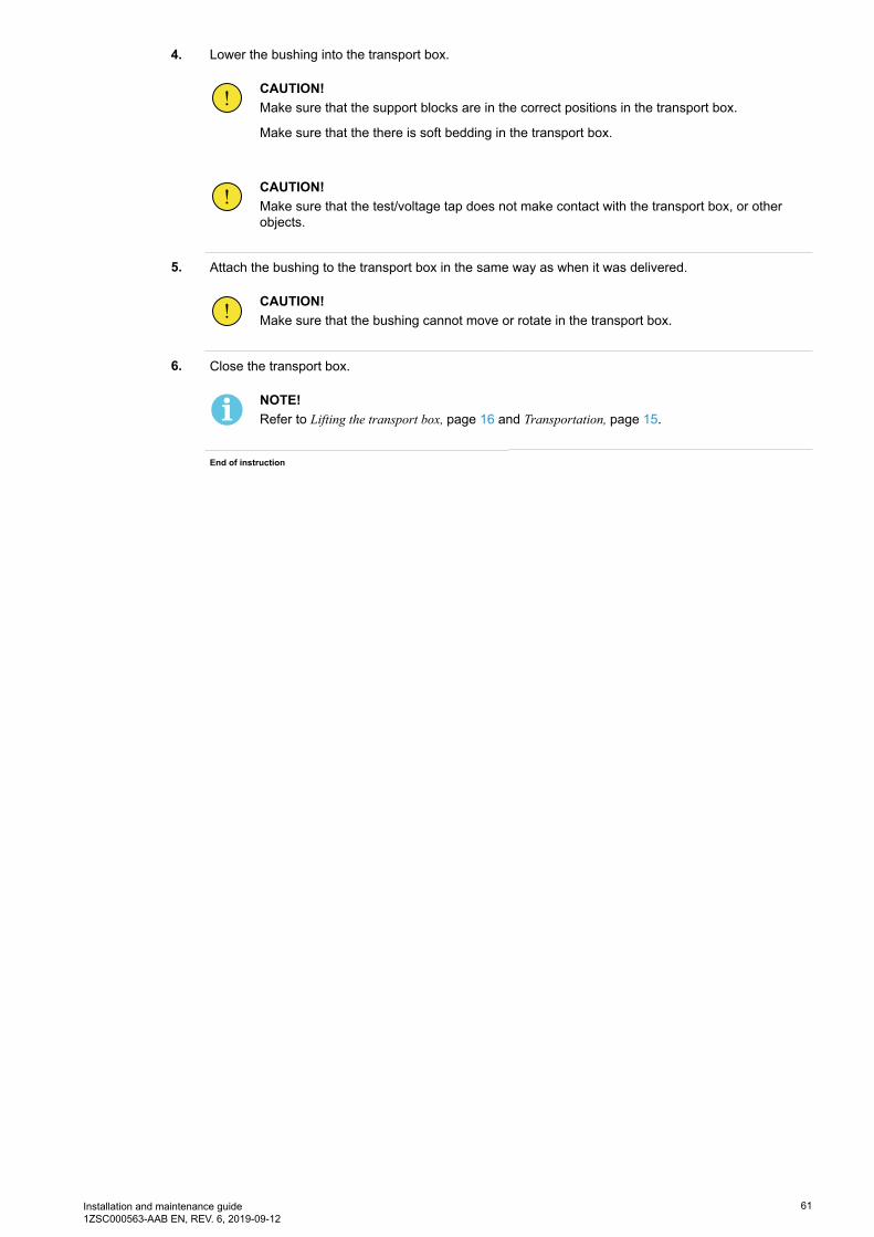
4. Lower the bushing into the transport box.
CAUTION!Make sure that the support blocks are in the correct positions in the transport box.
Make sure that the there is soft bedding in the transport box.
CAUTION!Make sure that the test/voltage tap does not make contact with the transport box, or otherobjects.
5. Attach the bushing to the transport box in the same way as when it was delivered.
CAUTION!Make sure that the bushing cannot move or rotate in the transport box.
6. Close the transport box.
NOTE!Refer to Lifting the transport box, page 16 and Transportation, page 15.
End of instruction

62 Installation and maintenance guide1ZSC000563-AAB EN, REV. 6, 2019-09-12

Installation and maintenance guide1ZSC000563-AAB EN, REV. 6, 2019-09-12
63
8 Spare parts
8.1 Summary
If the bushing is damaged, we recommend that it is returned to ABB for repairs and re-testing. Some partsthat are damaged or lost during transportation or installation can be ordered from ABB.
8.2 Spare parts
Cover
For the test/voltage tap.
Position Part Article number Note
1 Cover 1ZSC00442-CAK -
2 O-ring 2769 522-M -
G006194

64 Installation and maintenance guide1ZSC000563-AAB EN, REV. 6, 2019-09-12
8.3 Special tools
Lifting tool
Part Article number Note
Lifiting eye 9ADA338 2 pcs.
G005096
Pull-through cord
Part Article number Note
Pull-through cord 9760 669-A With M8-terminal.
G006198

Installation and maintenance guide1ZSC000563-AAB EN, REV. 6, 2019-09-12
65
Hydraulic jack
Part Article number Note
Hydraulic jack 2769 897-A For removal, and installation of thebottom contact. Draw-rod system.
G006275
Box-spanner
Part Article number Note
Box-spanner 9760 669-B -
G006276

66 Installation and maintenance guide1ZSC000563-AAB EN, REV. 6, 2019-09-12

Installation and maintenance guide1ZSC000563-AAB EN, REV. 6, 2019-09-12
67
9 Disposal and environmental information
9.1 Overview
This chapter specifies the materials used in the bushing. Comply with local environmental regulations ondisposal of this product, the materials used are specified for this purpose.
9.2 Disposal and recycling
ABB strives to minimize the product's impact on the environment throughout its entire life cycle. Technicaland product development focuses on environmental aspects. The ecocycle approach is striven for, andconsideration is taken to the materials' environmental impact and recycling alternatives. The manufacturingprocesses are selected to be as safe for the environment as possible.
Disposal of worn-out equipment
Worn-out equipment must be disposed of in an environmentally sound manner.
Much of the material, or the energy content in the material, can be recycled if it is sorted and cleaned. Thequantity of material that can be recycled varies depending on the technical resources and capabilities in eachcountry. Non-recyclable components should be sent to an approved environmental waste treatment plant fordestruction or disposal.
The bushing has these parts and materials
• The conductor is made of low-alloy aluminum or copper.• The outer terminal is made of silver plated aluminum, the pulling ring and bolts are made from stainless
steel.• The bottom contact is made of copper. The pulling ring and bolts are made of stainless steel.• The bushing flange, outdoor housing, tap cover, and end-shield are made of aluminum. The fixed corona
shield is made of aluminum.• The test/voltage tap body is made of epoxy with a core of brass, cover of aluminum, cable and contacts
of brass.• The voltage tap option is filled with 200 cc of silicone gel.• O-rings are made of rubber.• The condenser core is made of paper, 1 % aluminum foil (by weight), 2 g of carbon and 1 g of lead. It
also has small quantities of rubber bonded cork, rubber seals, braided copper wire (tinned), braidedcopper strap, silver glue and lead.
Gas
The SF6 gas must be removed before disposal of the bushing. All handling of SF6 gas must be done with careand according to the applicable regulations, to make sure that gas does not leak into the environment. Usedgas can be:
• Regenerated on-site, and reused in other equipment.• Sent to the gas supplier for regeneration.• Sent for destruction at a special waste treatment plant.

68 Installation and maintenance guide1ZSC000563-AAB EN, REV. 6, 2019-09-12
If the bushing is filled with mixed gas, the SF6 gas can be separated from the mixture for regeneration. As analternative, the gas mixture can be sent for destruction without being separated. Upon request, ABB canprovide a quote for final disposal of used gas in connection with the disposal of a bushing.
DANGER!SF6 gas must be recycled and not released into the atmosphere.
Porcelain
After cleaning, the porcelain can be sent for disposal or used for other purposes, such as for use asfilling material.
Electronics
Electronics equipment should be sent to an approved recycling plant, or sorted into different componentmaterials for correct processing.
Metals
Metals should be sorted according to type and surface coating, and sent to an approved recycling plant. Afterthe removal of paint or other surface coatings, clean metal can usually be melted down and used in newproducts. Many metal components of iron, steel and aluminum are large and easy to identify, e.g. supportstructures. ABB strives to reduce the use of precious metals and the release of environmentally hazardousmetals.
The recycling of precious metals is particularly important. Metals such as copper and silver are expensive,and are only present in small quantities in the earth's crust. Copper is primarily used in current conductors,contacts and cables. Some contacts are silver plated. Fumes from some metals can cause environmentaldamage, this applies to zinc and nickel, which are used sparingly as surface coatings.
Plastics
The different types of plastic should be separated and sent to an approved environmental waste treatmentplant or recycling plant. The energy content in thermoplastics and thermosetting plastics can often berecovered through combustion at a plant built for the purpose. Thermoplastics can usually be melted downand reused without significant loss of quality. Composites can be fractioned and used as filling materials inother materials, or be disposed of.
Oils and greases
Before disposal of the bushing, oil, grease and similar products must be removed and sent to an approvedenvironmental waste treatment plant or recycling plant. By utilizing gravimetric forces, oil waste can beseparated into oil, water and a range of contaminants. In many cases, the oil can then be reused. As analternative, the energy content in oil can be recovered through combustion at a plant designed forthe purpose.
Rubber
Send rubber to an approved environmental waste treatment plant, either for disposal or reuse fordifferent purposes.
Rubber is used in seals and gaskets.
Other materials
Sort other materials and send them to an approved environmental waste treatment plant.

Installation and maintenance guide1ZSC000563-AAB EN, REV. 6, 2019-09-12
69
10 Reference
10.1 Summary
• Markings: Conforming to IEC/IEEE.• Bushing diagnostics and conditioning, 2750 515-142.• The quality of the SF6 gas must comply with standard IEC 60376.


ABB AB, ComponentsSE-771 80 Ludvika, Sweden
www.abb.com/transformercomponents
© Copyright 2019 ABB, All rights reserved.Specifications subject to change without notice. 1ZSC000563-AABEN,REV.6,2019-09-12