UniGear Digital - ABB Group
118
— DISTRIBUTION SOLUTIONS UniGear Family UniGear Digital Engineering Guide
-
Upload
khangminh22 -
Category
Documents
-
view
0 -
download
0
Transcript of UniGear Digital - ABB Group

— DISTRIBUTION SOLUTIO NS
UniGear Family
UniGear Digital
Engineering Guide


— DISTRIBUTION SOLUTIO NS
UniGear Family
UniGear Digital
Engineering Guide

NOTICE This document contains information about one or more ABB products and may include a description of or
a reference to one or more standards that may be generally relevant to the ABB products. The presence of any
such description of a standard or reference to a standard is not a representation that all the ABB products ref-
erenced in this document support all the features of the described or referenced standard. To determine the
specific features supported by ABB product, the reader should consult the product specifications for the ABB
product.
ABB may have one or more patents or pending patent applications protecting the intellectual property in
the ABB products described in this document.
The information in this document is subject to change without notice and should not be construed as a com-
mitment by ABB. ABB assumes no responsibility for any errors that may appear in this document.
Products described or referenced in this document are designed to be connected and to communicate infor-
mation and data through network interfaces, which should be connected to a secure network. It is the sole re-
sponsibility of the system/product owner to provide and continuously ensure a secure connection between the
product and the system network and/or any other networks that may be connected.
The system/product owners must establish and maintain appropriate measures, including, but not limited to,
the installation of firewalls, application of authentication measures, encryption of data, installation of antivirus
programs, and so on, to protect these products, the network, its system, and interfaces against security
breaches, unauthorized access, interference, intrusion, leakage, and/or theft of data or information.
ABB performs functionality testing on the products and updates that we release. However, system/product
owners are ultimately responsible for ensuring that any product updates or other major system updates (to
include but not limited to code changes, configuration file changes, third-party software updates or patches,
hardware change out, and so on) are compatible with the security measures implemented. The system/ prod-
uct owners must verify that the system and associated products function as expected in the environment in
which they are deployed.
In no event shall ABB be liable for direct, indirect, special, incidental or consequential damages of any nature or
kind arising from the use of this document, nor shall ABB be liable for incidental or consequential damages
arising from use of any software or hardware described in this document.
This document and parts thereof must not be reproduced or copied without written permission from ABB, and
the contents thereof must not be imparted to a third party nor used for any unauthorized purpose.
The software or hardware described in this document is furnished under a license and may be used, copied, or
disclosed only in accordance with the terms of such license. This product meets the requirements specified in
EMC Directive 2014/30/EU and in Low Voltage Directive 2014/35/EU.
TRADEMARKS All rights to copyrights, registered trademarks, and trademarks reside with their respective owners.
Copyright © 2020 ABB.
All rights reserved.
Release: June 2020
Document Number: 1VLG500007
Revision: F

TABLE OF CONTENTS
I
Table of Contents
1 Introduction ................................................................................................................................ 1 1.1 This manual ................................................................................................................................... 1 1.2 Intended users .............................................................................................................................. 1
2 UniGear Digital ............................................................................................................................ 2 2.1 Sensors ........................................................................................................................................... 3
2.1.1 Current sensors ......................................................................................................... 4 2.1.2 Voltage sensors .......................................................................................................... 7
2.2 Protection relays ........................................................................................................................ 11 2.3 IEC 61850 .....................................................................................................................................22 2.4 Switchgear type overview ....................................................................................................... 24
3 Engineering ............................................................................................................................... 27 3.1 Sensors ......................................................................................................................................... 27
3.1.1 Current sensors ........................................................................................................ 27 3.1.2 Voltage sensors ....................................................................................................... 32
3.2 Documentation ......................................................................................................................... 34 3.3 Station bus (GOOSE)................................................................................................................ 36 3.4 Process bus (SMV) .................................................................................................................... 43 3.5 Ethernet ...................................................................................................................................... 54
3.5.1 Requirements ........................................................................................................... 54 3.5.2 Technology ............................................................................................................... 55 3.5.3 Topologies ................................................................................................................ 62 3.5.4 Ethernet traffic estimation ................................................................................... 68 3.5.5 Naming convention to identify protection relays ............................................ 69 3.5.6 IP address allocation .............................................................................................. 69 3.5.7 Time synchronization ............................................................................................. 70 3.5.8 Traffic segregation ................................................................................................. 73 3.5.9 Protection relays ..................................................................................................... 75 3.5.10 Managed Ethernet switches ................................................................................. 78 3.5.11 Satellite controlled clock ........................................................................................ 91
3.6 Statistical energy meters ........................................................................................................ 96 3.6.1 ESM-ET statistical energy meter ......................................................................... 96

LIST OF FIGURES
I I I
List of Figures
Figure 1: UniGear Digital and its key components ................................................................................. 2 Figure 2: Current sensor KECA 80 C104 / KECA 80 C165 ..................................................................... 4 Figure 3: Current sensor KECA 80 C184 / KECA 80 C216 ......................................................................5 Figure 4: Current sensor KECA 250 B1 ..................................................................................................... 6 Figure 5: Voltage sensor KEVA 17.5 B20 .................................................................................................... 7 Figure 6: Voltage sensor KEVA 24 B20 ..................................................................................................... 8 Figure 7: Coupler adapter AR5 utilized with Relion® 615, 620 and 640 series protection
relays ............................................................................................................................................................... 9 Figure 8: Connector pins assignment of a current sensor plug ....................................................... 10 Figure 9: Connector pins assignment of a voltage sensor plug ....................................................... 10 Figure 10: Functionality overview of REF615 standard configuration G ......................................... 12 Figure 11: Functionality overview of REF615 standard configuration L .......................................... 13 Figure 12: Functionality overview of REM615 standard configuration D ........................................ 14 Figure 13: Functionality overview of RED615 standard configuration E ......................................... 15 Figure 14: Functionality overview of REF620 standard configuration B ......................................... 16 Figure 15: Functionality overview of REM620 standard configuration B ........................................ 17 Figure 16: Protection and control REX640 ............................................................................................. 18 Figure 17: Overview of RIO600 connection ............................................................................................ 19 Figure 18: RIO600 communicating analog signals for the panel meters ........................................ 19 Figure 19: ESSAILEC RJ45 test block ...................................................................................................... 20 Figure 20: Low Voltage Compartment door with ESSAILEC RJ45 test blocks ............................. 20 Figure 21: The testing (only one phase is shown) ............................................................................... 20 Figure 22: ESM-ET connectivity to I/U sensors .................................................................................... 21 Figure 23: Examples of ESM and ENMI assembly ................................................................................. 21 Figure 24: Switchgear with sensor measurement ...............................................................................22 Figure 25: Switchgear with sensor measurement and process bus application of voltage
sharing and synchrocheck .........................................................................................................................23 Figure 26: UniGear ZS1 Digital (17.5 kV, 4 000 A, 50 kA) ..................................................................... 24 Figure 27: UniGear ZS1 Digital (24 kV, 3 150 A, 31.5 kA) ...................................................................... 25 Figure 28: UniGear 550 Digital (12 kV, 1 250 A, 31.5 kA) ...................................................................... 25 Figure 29: UniGear 500R Digital (17.5 kV, 2 000 A, 31.5 kA) ............................................................... 26 Figure 30: UniGear MCC Digital (12 kV, 400 A, 50 kA) ......................................................................... 26 Figure 31: Example of a current sensor label ......................................................................................... 27 Figure 32: Example of setting the correction factors for the current sensors in PCM600 ......... 27 Figure 33: Single line diagram ................................................................................................................. 28 Figure 34: Example of setting values for current sensor in PCM600 ............................................. 29 Figure 35: Example of parameter setting for PHIPTOC1 Start value in PCM600 ......................... 29 Figure 36: Current sensor with unique physical polarity ................................................................... 30 Figure 37: Polarity setting for current sensors in incoming feeder ................................................. 31 Figure 38: Example of polarity setting for current sensor in PCM600 ............................................ 31 Figure 39: Example of a voltage sensor label ....................................................................................... 32 Figure 40: Example of setting the correction factors for the voltage sensors in PCM600 ....... 32 Figure 41: Single line diagram .................................................................................................................. 33 Figure 42: Example of setting values for Voltage sensor in PCM600 ............................................. 33 Figure 43: Example of a Network Overview Diagram ......................................................................... 34 Figure 44: Example of a logic diagram for interconnection between panels ............................... 34 Figure 45: Example of a Sampled measured value diagram ............................................................. 35 Figure 46: Creating a new GOOSE data set and its entries ............................................................... 37 Figure 47: GOOSE control block properties .......................................................................................... 38 Figure 48: GOOSE control block editor (1- receiver #1, 2- receiver #2, 3 – sender)....................... 39 Figure 49: Selecting Show IED Capabilities Tab .................................................................................. 39

LIST OF FIGURES
IV
Figure 50: Editing 615 series capabilities ............................................................................................. 40 Figure 51: Creating a new GOOSE data set and its entries ............................................................... 40 Figure 52: Naming a GOOSE control block ............................................................................................ 41 Figure 53: GCB client ................................................................................................................................... 41 Figure 54: Adding a GOOSERCV function block in the Application Configuration Tool............. 42 Figure 55: Creating GOOSERCV block connection to a new variable ............................................. 42 Figure 56: Signal Matrix ............................................................................................................................ 42 Figure 57: Example of Process bus application of voltage sharing and synchro-check ............. 43 Figure 58: Example of Process bus application of voltage sharing redundancy and synchro
check .............................................................................................................................................................. 43 Figure 59: Example of Process bus application of voltage sharing (Double busbar system) and
synchro check .............................................................................................................................................. 44 Figure 60: Example of Process bus application of voltage sharing redundancy (Double busbar
system) and synchro check ...................................................................................................................... 44 Figure 61: Example of VMSWI voltage switch function block implementation in the Application
Configuration Tool ..................................................................................................................................... 44 Figure 62: Adding a SMSENDER block in the Application Configuration Tool .............................. 45 Figure 63: Adding a ULTVTR1 block in the Application Configuration Tool .................................. 45 Figure 64: Time parameter setting dialog in PCM600 ....................................................................... 46 Figure 65: Configuring the SMV senders and receivers ..................................................................... 47 Figure 66: Changing the Sampled Measured Value Control Block attributes............................... 48 Figure 67: Selecting Show IED Capabilities Tab .................................................................................. 49 Figure 68: Editing 615 series capabilities ............................................................................................. 50 Figure 69: Sampled value control block ................................................................................................. 50 Figure 70: Connecting the SMV senders and receivers ...................................................................... 50 Figure 71: Receiving all phase voltages and residual voltage using SMV ........................................ 51 Figure 72: Receiving line voltage for synchrocheck functionality using SMV ................................ 51 Figure 73: Application Configuration tool logic examples for the SMV fail save operation ...... 52 Figure 74: SMV Max delay setting in PCM600 ...................................................................................... 53 Figure 75: FTP patch cable terminated with RJ-45 connectors ....................................................... 55 Figure 76: Fiber optic patch cable terminated with LC connectors ................................................ 55 Figure 77: LC connectors ........................................................................................................................... 56 Figure 78: Communication module with single Ethernet connector (615 and 620 series) ........ 56 Figure 79: Communication modules with multiple Ethernet connectors (615 and 620 series) 57 Figure 80: Communication modules with multiple Ethernet connectors (640 series) .............. 57 Figure 81: Example of Managed Ethernet Switches from AFS family ............................................. 59 Figure 82: 1 - Fast Ethernet fiber optic SFP module, 2 - Gigabit Ethernet fiber optic SFP
module .......................................................................................................................................................... 59 Figure 83: Installed SFP module in managed Ethernet switch AFS677 .......................................... 59 Figure 84: Example of satellite-controlled clock from Tekron with optional accessories ......... 60 Figure 85: Example of satellite-controlled clock from Meinberg ...................................................... 61 Figure 86: Low Voltage Compartment of UniGear panel ................................................................... 61 Figure 87: RSTP ring redundant structure ............................................................................................ 62 Figure 88: MRP / E-MRP ring redundant structure ............................................................................. 63 Figure 89: Single network using RSTP / E-MRP ................................................................................... 63 Figure 90: PRP networks using RSTP / E-MRP ..................................................................................... 64 Figure 91: HSR network ............................................................................................................................. 65 Figure 92: HSR network with redboxes ................................................................................................. 65 Figure 93: Combined PRP and HSR networks ...................................................................................... 66 Figure 94: Example of an allocation of device IP addresses ............................................................. 70 Figure 95: Example of IEEE 1588-time synchronization via the Ethernet network ..................... 70 Figure 96: IEEE 1588 Time synchronization scheme for HSR-PRP networks ................................. 72 Figure 97: IEEE 1588 Time synchronization scheme for PRP networks ........................................... 72 Figure 98: Example of traffic segregation via building virtual LANs .............................................. 73
LIST OF FIGURES
V
Figure 99: Virtual LANs allocation in PRP-RSTP networks................................................................. 73 Figure 100: Virtual LANs allocation in HSR-PRP networks .................................................................74 Figure 101: Communication parameter setting dialog ...................................................................... 75 Figure 102: Adding RCHLCCH and SCHLCCH blocks in the Application Configuration Tool ..... 76 Figure 103: Status of Ethernet rear port displayed via ITT SA Explorer (on top and on bottom)
......................................................................................................................................................................... 77 Figure 104: AFS switch screen ................................................................................................................. 78 Figure 105: Login window ......................................................................................................................... 78 Figure 106: Network parameters dialog ................................................................................................ 79 Figure 107: Port Configuration dialog .................................................................................................... 79 Figure 108: Load / Save dialog ................................................................................................................ 80 Figure 109: PTP Global dialog ................................................................................................................... 81 Figure 110: PTP Version 2 (Transparent Clock) Global dialog ............................................................ 81 Figure 111: PTP Version 2 (Transparent Clock) Port dialog ............................................................... 82 Figure 112: Switching Global dialog in AFS67x (on top) and AFS66x (on bottom) ...................... 83 Figure 113: VLAN Global dialog in AFS67x ............................................................................................. 84 Figure 114: VLAN Static dialog ................................................................................................................. 84 Figure 115: VLAN Port dialog .................................................................................................................... 85 Figure 116: Spanning Tree Global dialog ............................................................................................... 86 Figure 117: Spanning Tree Ports dialog.................................................................................................. 86 Figure 118: E-MRP Ring Redundancy dialog .......................................................................................... 87 Figure 119: Example of AFS660 Front view ........................................................................................... 88 Figure 120: Switching Global dialog ....................................................................................................... 88 Figure 121: PRP Configuration dialog ..................................................................................................... 89 Figure 122: HSR Configuration dialog .................................................................................................... 90 Figure 123: IEC61850-MMS Configuration dialog ................................................................................ 90 Figure 124: Tekron clock configuration Tool .......................................................................................... 91 Figure 125: Basic setting dialog .............................................................................................................. 92 Figure 126: PTP setting dialog ................................................................................................................. 92 Figure 127: Port Configuration dialog .................................................................................................... 93 Figure 128: PTP setting dialog ................................................................................................................. 93 Figure 129: PTP Global settings dialog .................................................................................................. 94 Figure 130: PTP Network settings dialog .............................................................................................. 95 Figure 131: Network configuration dialog ............................................................................................. 96 Figure 132: Measurements configuration dialog ................................................................................. 97 Figure 133: Clock configuration dialog .................................................................................................. 98 Figure 134: Example of setting the correction factors for the current and the voltage sensors
in ESM Test tool .......................................................................................................................................... 99


LIST OF TABLES
VII
List of Tables
Table 1: Sensor product portfolio for UniGear Digital .......................................................................... 3 Table 2: Protection relay key functionality overview for UniGear Digital ........................................ 11 Table 3: Overview of UniGear Digital in UniGear switchgear family ............................................... 24 Table 4: Maximum current Start and protection setting values ...................................................... 30 Table 5: Topology-dependent SMV max delay setting ....................................................................... 53 Table 6: Recommended Managed Ethernet switches overview for UniGear Digital ................... 58 Table 7: Comparison of network topologies ........................................................................................ 67 Table 8: C37.238 Power Profile key parameters .................................................................................... 71


INTRODUCTION THIS MANUAL
1VLG500007 F 1
1 Introduction
1.1 This manual
The engineering guide provides information for the UniGear Digital solution by providing
details about its main components. This guide focuses especially on the IEC 61850 digital
communication and it can be used as a technical reference during the engineering phase.
1.2 Intended users
This manual is intended for to be used by design, protection relay, test and service engineers.
The protection relay engineer needs to have a thorough knowledge of protection systems,
protection equipment, protection functions, configured functional logic in the Protection
relays and their IEC 61850 engineering. The test and service engineers are expected to be
familiar with handling of the electronic equipment.

2 1VLG500007 F
2 UniGear Digital UniGear Digital is a new solution implemented to the traditional UniGear switchgear. It is
accomplished by using state-of-the-art, well-proven components: current and voltage
sensors, Relion® protection relays and IEC 61850 digital communication.
The design of the current sensors is very compact, and it is optimized for the use in UniGear.
Each panel can accommodate two sets of current sensors. The voltage sensors are very
compact as well. They are integrated as part of support insulators housed in the cable
compartment or directly in the busbar compartment.
The current and voltage sensors are very accurate (accuracy class 0.5), however revenue
metering might require higher accuracy classes or separate instrument current and voltage
transformer. Such transformers can optionally be added to sensor-equipped panels.
Capacitive voltage detection is enabled by capacitive dividers that are either integrated into
the support insulators or into the conventional current transformers, which is used case by
case.
Fast horizontal GOOSE communication for inter-panel (bay-to-bay) signals exchange is
a mandatory part of this solution, while the Process bus is optional.
Figure 1: UniGear Digital and its key components

UNIGEAR DIGITAL SENSORS
1VLG500007 F 3
2.1 Sensors
Sensors, for current and voltage measurement, are important part of UniGear Digital. Each
switchgear type offering UniGear Digital solution uses sensors as shown in the table below.
Table 1: Sensor product portfolio for UniGear Digital
Measure-
ment
type
Sensor
type
Maximum
app.
parame-
ter
Panel
width
[mm]
UniGear
ZS1
Digital
up to 17.5
kV
UniGear
ZS1
Digital
up to
24 kV
UniGear
550
Digital
UniGear
500R
Digital
UniGear
MCC
Digital
Current
KECA 80
C104 Up to
1 250 A 650 Yes No No No No
KECA 80
C165 Up to
4 000 A
800 /
1000 Yes No No No No
KECA 80
C184 Up to
1 250 A 800 No Yes No No No
KECA 80
C216
Up to
3 150 A 1000 No Yes No No No
KECA 250
B1
Up to
2 000 A No No Yes Yes Yes
Voltage
KEVA 17.5
B20
Up to
17.5 kV Yes No Yes Yes Yes
KEVA 24
B20 Up to
24 kV No Yes No No No

4 1VLG500007 F
2.1.1 Current sensors
Current measurement in KECA sensors is based on the Rogowski coil principle.
KECA 80 C104 / KECA 80 C165
For dynamic current measurement (protection purposes) the ABB sensors KECA 80 C104, and
KECA 80 C165, fulfil requirements of protection class 5P up to an impressive value reaching
the rated short-time thermal current Ith (31.5 kA or 50 kA). With KECA 80 C104 and KECA 80
C165 sensors, measuring class 0.5 is reached for continuous current measurement in the
extended accuracy ranges from 5 % of the rated primary current Ipr not only up to 120 % of Ipr
(as being common for conventional current transformers), but even up to the rated continu-
ous thermal current Icth (1 250 A or 4 000 A). That provides the possibility to designate the
corresponding accuracy class as 5P400 and 5P630, proving excellent linearity and accuracy
measurements.
Figure 2: Current sensor KECA 80 C104 / KECA 80 C165
Technical parameters
– Continuous thermal current 1 250 / 4 000 A
– Rated primary current 80 A / 150 mV at 50 Hz or 80 A / 180 mV at 60 Hz
– Accuracy class 0.5 / 5P400; 5P630

UNIGEAR DIGITAL SENSORS
1VLG500007 F 5
KECA 80 C184 / KECA 80 C216
For dynamic current measurement (protection purposes) the ABB sensors KECA 80 C184, and
KECA 80 C216, fulfil requirements of protection class 5P up to an impressive value reaching
the rated short-time thermal current Ith (31.5 kA). With KECA 80 C184 and KECA 80 C216
sensors, measuring class 0.5 is reached for continuous current measurement in the extended
accuracy range from 5 % of the rated primary current Ipr not only up to 120 % of Ipr (as being
common for conventional current transformers), but even up to the rated continuous thermal
current Icth (1 250 A or 3 150 A). That provides the possibility to designate the corresponding
accuracy class as 5P400, proving excellent linearity and accuracy measurements.
Figure 3: Current sensor KECA 80 C184 / KECA 80 C216
Technical parameters
– Continuous thermal current 1 250 / 3 150 A
– Rated primary current 80 A / 150 mV at 50 Hz or 80 A / 180 mV at 60 Hz
– Accuracy class 0.5 / 5P400

6 1VLG500007 F
KECA 250 B1
For dynamic current measurement (protection purposes) the ABB sensors KECA 250 B1, fulfil
requirements of protection class 5P up to an impressive value reaching the rated short-time
thermal current Ith (31.5 kA). With KECA 250 B1 sensors, measuring class 0.5 is reached for
continuous current measurement in the extended accuracy range from 5 % of the rated
primary current Ipr not only up to 120 % of Ipr (as being common for conventional current
transformers), but even up to the rated continuous thermal current Icth (2 000 A). That
provides the possibility to designate the corresponding accuracy class as 5P125, proving
excellent linearity and accuracy measurements.
Figure 4: Current sensor KECA 250 B1
Technical parameters
– Continuous thermal current 2 000 A
– Rated primary current 250 A / 150 mV at 50 Hz or 250 A / 180 mV at 60 Hz
– Accuracy class 0.5 / 5P125

UNIGEAR DIGITAL SENSORS
1VLG500007 F 7
2.1.2 Voltage sensors
Voltage measurement in the KEVA sensor is based on the resistive divider principle. Voltage
sensors are designed to be compact and shaped as support insulators. They can be installed
in the switchgear´s cable compartment or directly in the busbar compartment.
KEVA 17.5 B20
KEVA B sensor can be used in all applications up to the voltage level 17.5 kV. The sensor fulfils
requirements of accuracy class 0.5 for measurement purposes and accuracy class 3P for
protection purposes.
Figure 5: Voltage sensor KEVA 17.5 B20
Technical parameters
– Rated primary voltage 15 / 3 kV
– Rated power frequency withstand voltage 38 (42) kV
– Rated lightning impulse withstand voltage 95 kV
– Transformation ratio 10 000: 1
– Accuracy class 0.5 / 3P

8 1VLG500007 F
KEVA 24 B20
KEVA B sensor can be used in all applications up to the voltage level 24 kV. The sensor fulfils
requirements of accuracy class 0.5 for measurement purposes and accuracy class 3P for
protection purposes.
Figure 6: Voltage sensor KEVA 24 B20
Technical parameters
– Rated primary voltage 22 / 3 kV
– Rated power frequency withstand voltage 50 kV
– Rated lightning impulse withstand voltage 125 kV
– Transformation ratio 10 000: 1
– Accuracy class 0.5 / 3P

UNIGEAR DIGITAL SENSORS
1VLG500007 F 9
Sensor accessories
Sensors are connected to protection relay via cable with RJ-45 connector. In case both
current and voltage sensors are connected to a protection relay, a coupler adapter AR5 is
used. The coupler adapter AR5 is three phases adapter. Protection relays used in
UniGear Digital have combined sensor inputs. Each current and voltage sensor has separate
cable with one RJ-45 connector. The cable is a separable part of each sensor and it can be re-
placed by cable of the same length because of the guaranteed accuracy and performance of
the sensor. The cable is to be connected directly (or via the coupler adapter AR5 if needed) to
the protection relay. The coupler adapter AR5 is used to combine two RJ-45 connectors from
current and voltage sensors into a combined sensor input for each phase on a protection
relay.
Figure 7: Coupler adapter AR5 utilized with Relion® 615, 620 and 640 series protection
relays

10 1VLG500007 F
Current sensor wires are connected according to the following assignment:
PIN 4 – S1, PIN 5 – S2, other PINs remain unused.
Figure 8: Connector pins assignment of a current sensor plug
Voltage sensor wires are connected according to the following assignment: PIN 7 – a,
PIN 8 - , other PINs remain unused.
Figure 9: Connector pins assignment of a voltage sensor plug

UNIGEAR DIGITAL PROTECTION RELAYS
1VLG500007 F 11
2.2 Protection relays
UniGear Digital is supported by the following types of protection relays, shown in table
below.
Table 2: Protection relay key functionality overview for UniGear Digital
Relion® Product
type
Standard
configuration
I/U sensor
input
Arc
protection
IEC 61850-
9-2LE
Synchro-check
/ Synchronizer
615 series
REF615
G Yes Yes Yes Yes* / No
L Yes Yes Yes Yes* / No
REM615 D Yes Yes Yes No / No
RED615 E Yes No Yes Yes* / No
620 series REF620 B Yes Yes Yes Yes* / No
REM620 B Yes Yes Yes Yes* / No
640 series REX640 Yes Yes Yes Yes / Yes
* Only available with IEC 61850-9-2LE
The above-mentioned protection relays support IEC 61850 Ed.2 and Ed.1 communication with
GOOSE messaging (performance class P1 / 1A) and 9-2LE stream (sample rate 4 kHz in case
of 50 Hz, 80 samples per cycle, 1 ASDU per frame). The IEC 61850-9-2LE interface is sup-
ported by the Relion® 615, 620 and 640 series, including the PRP1 / HSR redundancy (RED615
only via fiber optic interfaces). The 615, 620 and 640 series work as a redundancy box
(Redbox) between the HSR / PRP1 networks and single attached devices or networks not
aware of PRP1 / HSR.
The 615, 620 and 640 series support the IEEE 1588 (PTPv2) and Power profile as defined in
IEEE C37.238 standard to reach the required timing accuracy over an Ethernet network. The
615, 620 and 640 series work as an ordinary clock (capable of acting as either a Master or a
Slave clock). There is no need to design a substation with two Grandmaster clocks to reach
redundancy because the 615, 620 and 640 series can work as Master clock. For more details
see 615, 620 and 640 series manuals.

12 1VLG500007 F
Feeder protection and control REF615
The REF615 is a dedicated feeder protection relay perfectly aligned for protection, control,
measurement and supervision of utilities and industrial power distribution systems including
radial, looped and meshed networks, and involving a potential distributed power generation.
The REF615 can send (1 instance) and / or receive (1 instance) voltage over
the IEC 61850-9-2LE and to synchrocheck with IEC 61850-9-2 LE.
Figure 10: Functionality overview of REF615 standard configuration G

UNIGEAR DIGITAL PROTECTION RELAYS
1VLG500007 F 13
Figure 11: Functionality overview of REF615 standard configuration L
14 1VLG500007 F
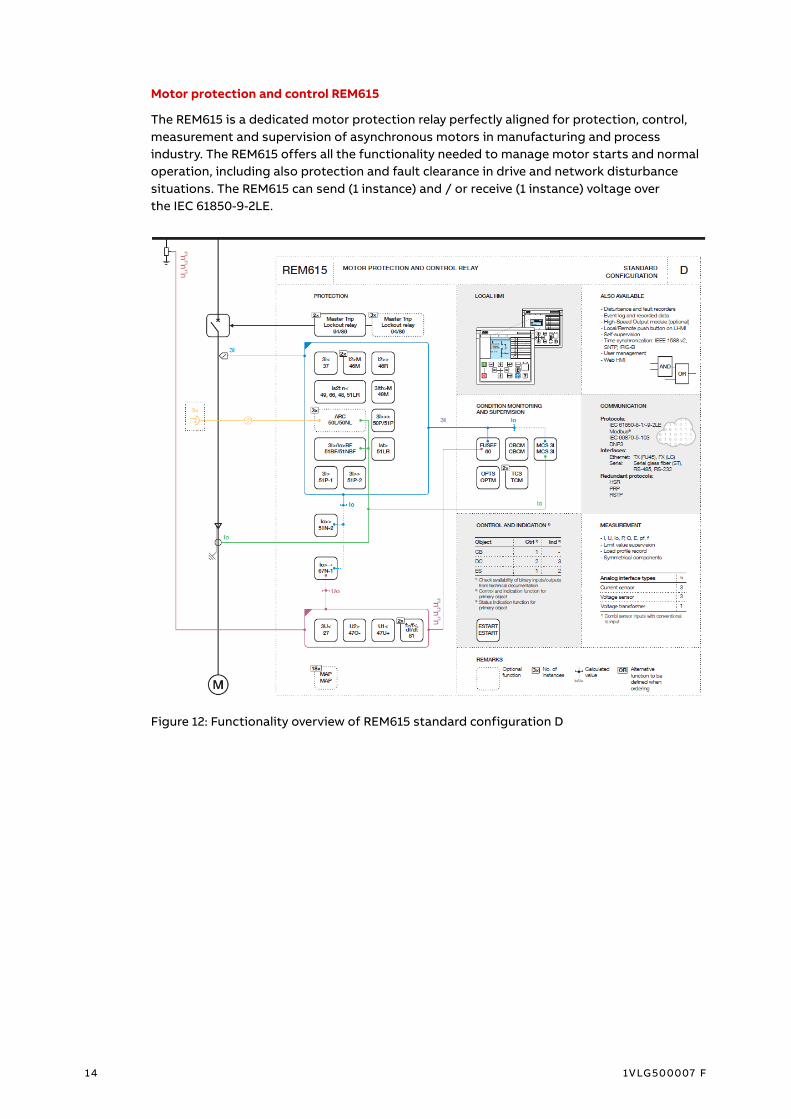
Motor protection and control REM615
The REM615 is a dedicated motor protection relay perfectly aligned for protection, control,
measurement and supervision of asynchronous motors in manufacturing and process
industry. The REM615 offers all the functionality needed to manage motor starts and normal
operation, including also protection and fault clearance in drive and network disturbance
situations. The REM615 can send (1 instance) and / or receive (1 instance) voltage over
the IEC 61850-9-2LE.
Figure 12: Functionality overview of REM615 standard configuration D

UNIGEAR DIGITAL PROTECTION RELAYS
1VLG500007 F 15
Line differential protection and control RED615
RED615 is a phase-segregated, two-end, line differential protection and control relay. With
in-zone transformer support, perfectly harmonized for utility and industrial power distribu-
tion networks. The RED615 relays communicate between substations over a fiber optic link or
a galvanic pilot wire connection. Protection of ring-type and meshed distribution networks
generally requires unit protection solutions, also applied in radial networks containing
distributed power generation. With relation to UniGear Digital this protection relay is used
for more dedicated applications only. The RED615 can send (1 instance) and / or receive
(1 instance) voltage over the IEC 61850-9-2LE and to synchrocheck with IEC 61850-9-2 LE.
Figure 13: Functionality overview of RED615 standard configuration E

16 1VLG500007 F
Feeder protection and control REF620
The REF620 is a dedicated feeder management relay perfectly aligned for the protection, con-
trol, measurement and supervision of utility and industrial power distribution systems, in-
cluding radial, looped and meshed networks, with or without distributed power generation.
REF620 can also be used to protect feeders including motors or capacitor banks. Addition-
ally, REF620 offers functionality for interconnection protection used with distributed genera-
tion like wind or solar power connection to utility grid. The REF620 can send (1 instance) and
/ or receive (1 instance) voltage over the IEC 61850-9-2LE and to synchrocheck with
IEC 61850-9-2 LE.
Figure 14: Functionality overview of REF620 standard configuration B

UNIGEAR DIGITAL PROTECTION RELAYS
1VLG500007 F 17
Motor protection and control REM620
The REM620 is a dedicated motor management relay perfectly aligned for the protection,
control, measurement and supervision of medium-sized and large asynchronous and syn-
chronous motors requiring also differential protection in the manufacturing and process
industry. The REF620 can send (1 instance) and / or receive (1 instance) voltage over
the IEC 61850-9-2LE and to synchrocheck with IEC 61850-9-2 LE.
Figure 15: Functionality overview of REM620 standard configuration B

18 1VLG500007 F
Protection and control REX640
REX640 is a powerful all-in-one protection and control relay for use in advanced power distri-
butions and generation applications with unmatched flexibility available during the complete
life cycle of the device. The modular design of both hardware and software elements facili-
tates the coverage of any comprehensive protection application requirement that may arise
during the complete life cycle of the relay and substation.
One full IEC 61850-9-2 LE stream containing both voltages and currents can be sent. Receiv-
ing of up to four Sampled Measured Value (SMV) streams is supported with a total of maxi-
mum 16 channels. The channels are freely configurable with the possibility to engineer SMV
stream redundancy using the voltage and current switch functions with either another SMV
stream or local measurements.
Figure 16: Protection and control REX640

UNIGEAR DIGITAL PROTECTION RELAYS
1VLG500007 F 19
Remote IO unit RIO600
The remote inputs / outputs unit RIO600 is designed to expand the digital and analog
inputs / outputs of ABB’s Relion® protection relays and to provide inputs / outputs for the
ABB ZEE600 using the IEC 61850 Ed.2 communication. The RIO600 communicates with the
protection relays over the Ethernet cable via fast horizontal GOOSE communication.
Figure 17: Overview of RIO600 connection
The RIO600 AOM4 analog output module has four mA outputs providing mA output signal in
range 0–20 mA. These outputs can be used for connection to the analog / digital panel me-
ters. Operation accuracy of mA output is 0.1 % or 0.2 mA. There is an option to use a selector
switch to display more than one phase on one panel meter.
Figure 18: RIO600 communicating analog signals for the panel meters

20 1VLG500007 F
TE Connectivity’s ESSAILEC RJ45 test block
The test block is used for efficient testing of protection and control relay with sensor inputs
during regular maintenance. The test block is flush mounting type on the low voltage com-
partment door and its vertical layout is recommended. The testing of protection and control
relay’s sensor inputs is possible without opening the low voltage compartment door. One
test block is intended for one phase and it consists of a socket, a lid and a plug.
Figure 19: ESSAILEC RJ45 test block
Figure 20: Low Voltage Compartment door with ESSAILEC RJ45 test blocks
The socket is covered during Normal operation by the lid. For testing, the lid is removed and
replaced by the test plug.
Figure 21: The testing (only one phase is shown)
ESSAILEC Trip or Polarity range test block
A test block allows the testing without circuit breaker tripping.

UNIGEAR DIGITAL PROTECTION RELAYS
1VLG500007 F 21
Statistical Energy meter
ESM-ET statistical energy meter (Order code: ESM-ET97-220-A2E2-05S) is manufactured by
EnergoService (https://enip2.ru/en/). The meter is compatible and has been tested with
ABB’s current and voltage sensors. New sets of dedicated I/U sensors are required. The en-
ergy meter can be used for current measurement up to 4 200 A and voltage measurement up
to 40 kV. The amplitude correction and the phase error correction factors of the current and
voltage sensors must be entered in the energy meter. ESM-ET counts four-quadrant active
and reactive energy, it uses its built-in memory to store power demands and energy readings
by time of use tariffs. ENMI-5 and 7 display panels connected with single patch cord serves as
a Human Machine Interface (HMI) for the energy meter. The display panel can be mounted
separately or attached to the back of the meter.
Figure 22: ESM-ET connectivity to I/U sensors
Figure 23: Examples of ESM and ENMI assembly
22 1VLG500007 F
2.3 IEC 61850
The IEC 61850 standard was released in 2004 as a global international standard representing
the architecture for communication networks and systems for power utility automation. It is
updated with new version, Edition 2, which extends to new application areas in transmission
and distribution power systems and defines a new functionality to Edition 1 functionality. IEC
61850 Edition 2 adds new functionality which is not supported by the Edition 1. Therefore, it
is recommended to always use the same standard version in all devices and not to mix differ-
ent versions in the same project.
The IEC 61850 standard defines the Ethernet technology for substation automation commu-
nication. It also includes the related system requirements and the data model of the protec-
tion and control functions. The standardized data modelling of substation functions includ-
ing the communication interfaces pave the way to openness and interoperability of devices.
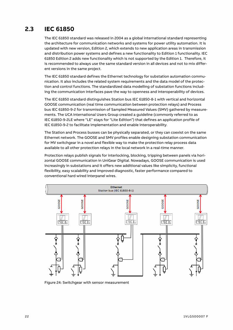
The IEC 61850 standard distinguishes Station bus IEC 61850-8-1 with vertical and horizontal
GOOSE communication (real time communication between protection relays) and Process
bus IEC 61850-9-2 for transmission of Sampled Measured Values (SMV) gathered by measure-
ments. The UCA International Users Group created a guideline (commonly referred to as
IEC 61850-9-2LE where “LE” stays for “Lite Edition”) that defines an application profile of
IEC 61850-9-2 to facilitate implementation and enable interoperability.
The Station and Process busses can be physically separated, or they can coexist on the same
Ethernet network. The GOOSE and SMV profiles enable designing substation communication
for MV switchgear in a novel and flexible way to make the protection relay process data
available to all other protection relays in the local network in a real-time manner.
Protection relays publish signals for interlocking, blocking, tripping between panels via hori-
zontal GOOSE communication in UniGear Digital. Nowadays, GOOSE communication is used
increasingly in substations and it offers new additional values like simplicity, functional
flexibility, easy scalability and improved diagnostic, faster performance compared to
conventional hard wired interpanel wires.
Figure 24: Switchgear with sensor measurement

UNIGEAR DIGITAL IEC 61850
1VLG500007 F 23
Process interfaces to MV apparatus (for example voltage sensors) are on the process level.
Besides the conventional signal wiring between the process interface and protection relays,
IEC 61850 introduces a concept where process signals can be exchanged in process bus, un-
der IEC 61850-9-2. In MV switchgear application the station and the process bus can be com-
bined to one common bus. When using conventional voltage instrument transformers (VTs)
in MV switchgear they are usually located in the incoming feeders on the cable side and the
busbar voltage is measured in any of the outgoing feeders or in dedicated metering panel.
The sharing of the busbar voltage is done by interconnection wires between busbar VTs and
protection relays in all outgoing feeders. Usage of sensors and IEC 61850-9-2 has significant
effect on the design of the switchgear. The signal from the voltage sensor measuring the
busbar voltage in one of the protection relays is digitized into sampled values stream shared
over Ethernet network. The interconnection wiring in switchgear becomes simplified as less
regular galvanic signal wires are needed. Transmitting voltage signal over process bus enable
also higher error detection because the signal transmission is supervised.
Figure 25: Switchgear with sensor measurement and process bus application of voltage
sharing and synchrocheck

24 1VLG500007 F
2.4 Switchgear type overview
UniGear Digital is available for the following switchgear types:
– UniGear ZS1
– UniGear 550
– UniGear 500R
– UniGear MCC
Table 3: Overview of UniGear Digital in UniGear switchgear family
Switch-
gear type
Busbar
arrangement
UniGear
Digital
Voltage
level
Rated feeder
current
Rated short-
circuit
current
UniGear
ZS1
Single
busbar Yes
Up to
24 kV
Up to
4 000 A
Up to
63 kA / 1 s
(50 kA / 3 s)
Double
busbar
Yes
(Up to 17.5 kV)
Up to
24 kV
Up to
4 000 A
Up to
31.5 kA / 3 s
Back to back No Up to
24 kV
Up to
4 000 A
Up to
50 kA / 3 s
UniGear
550
Single
busbar Yes
Up to
12 kV
Up to
1 250 A
Up to
31.5 kA / 3 s
UniGear
500R (IEC)
Single
busbar Yes
Up to
17.5 kV
Up to
2 000 A
Up to
31.5 kA / 3 s
UniGear
MCC
Single
busbar Yes
Up to
12 kV
Up to
400 A
Up to
50 kA / 3 s
Figure 26: UniGear ZS1 Digital (17.5 kV, 4 000 A, 50 kA)

UNIGEAR DIGITAL SWITCHGEAR T YPE OVERVIEW
1VLG500007 F 25
Figure 27: UniGear ZS1 Digital (24 kV, 3 150 A, 31.5 kA)
Figure 28: UniGear 550 Digital (12 kV, 1 250 A, 31.5 kA)

26 1VLG500007 F
Figure 29: UniGear 500R Digital (17.5 kV, 2 000 A, 31.5 kA)
Figure 30: UniGear MCC Digital (12 kV, 400 A, 50 kA)

ENGINEERING SENSORS
1VLG500007 F 27
3 Engineering
3.1 Sensors
3.1.1 Current sensors
Correction factors
The amplitude and phase error of a current sensor is, in practice, constant and independent
on the primary current. This means it is an inherent and constant property of each sensor and
it is not considered to be unpredictable and bound to influences. Hence, it can be easily recti-
fied in the protection relay by using appropriate correction factors, specified separately for
every sensor. Values of correction factors for the amplitude and phase error of a current
sensor are entered on the sensor label and as well as in the sensor´s routine test report.
To achieve the required accuracy classes, it is recommended to use both correction factors
(Cfs), that is, the amplitude correction factor (aI) and the phase error correction factor (pI) of
the current sensor.
Figure 31: Example of a current sensor label
Due to linear characteristics of the sensor measurement error caused by manufacturing
tolerances can be compensated for by using correction factors entered in the protection
relay. The correction factors are entered via parameter setting in PCM600 (IED Configuration
/ Configuration / Analog inputs / Current (3I, CT))
Figure 32: Example of setting the correction factors for the current sensors in PCM600

28 1VLG500007 F
Primary current
Setting example
In this example, an 80 A / 0.150 V at 50 Hz sensor is used and the application has a 1 000 A
nominal current (In).
Figure 33: Single line diagram
When defining another primary value for the sensor, also the nominal voltage should be rede-
fined to maintain the same transformation ratio. However, the setting in the protection relay
(Rated Secondary Value) is not in V but in mV / Hz, which makes the same setting value valid
for both 50 Hz and 60 Hz nominal frequency.
𝑅𝑆𝑉 = 𝐼𝑛 𝐼𝑝𝑟⁄ × 𝐾𝑟
𝑓𝑛
RSV Rated secondary value in mV / Hz
In Application nominal current
Ipr Sensor-rated nominal current
Kr Sensor-rated voltage at the rated current in mV
fn Network nominal frequency
In this example, the value is as calculated using the equation.
𝑅𝑆𝑉 = 1000 𝐴 80 𝐴⁄ × 150 𝑚𝑉
50 𝐻𝑧 = 37.5
𝑚𝑉
𝐻𝑧

ENGINEERING SENSORS
1VLG500007 F 29
Primary, Nominal current and Rated secondary values are entered via parameter setting in
PCM600 (IED Configuration / Configuration / Analog inputs / Current (3I, CT))
Figure 34: Example of setting values for current sensor in PCM600
Unless otherwise specified, the Nominal Current setting should always be the same as the
Primary Current setting which is a reference value for protection functions.
Each setting parameter of current protection functions is divided by application nominal cur-
rent In.
Threshold for PHIPTOC1 Start value tripping at 2 000 A is:
InTRIP
In =
2 000 A
1 000 A = 2
Figure 35: Example of parameter setting for PHIPTOC1 Start value in PCM600

30 1VLG500007 F
Maximum current Start and protection setting values
If the ratio of the application nominal current In and sensor-rated primary current Ipr becomes
higher, and the rated secondary value needs to be set higher than 46.875 mV / Hz, the high-
est value that the relay can measure before the current sensor input is saturated is smaller
than the maximum setting value of the current protection.
Table 4: Maximum current Start and protection setting values
Application Nominal current
(In)
Rated Secondary Value with
80 A / 0.150 V at 50 Hz
Maximum current Start and
protection setting values
... 1 250 A 1.000 … 46.875 mV / Hz 40 x In
1 250 … 2 500 A 46.875 … 93.750 mV / Hz 20 x In
2 500 … 4 000 A 93.750 … 150.000 mV / Hz 12.5 x In
Priority
Each current sensor has unique physical polarity defined by sensor hardware.
Figure 36: Current sensor with unique physical polarity

ENGINEERING SENSORS
1VLG500007 F 31
Figure 37: Polarity setting for current sensors in incoming feeder
Sensor polarity is changed via parameter setting in PCM600 (IED Configuration /
Configuration / Analog inputs / Current (3I, CT))
Figure 38: Example of polarity setting for current sensor in PCM600

32 1VLG500007 F
3.1.2 Voltage sensors
Correction factors
The amplitude and phase error of a voltage sensor is, in practice, constant and independent
on the primary voltage. This means it is an inherent and constant property of each sensor
and it is not considered to be unpredictable and bound to influences. Hence, it can be easily
rectified in the protection relay by using appropriate correction factors, specified separately
for every sensor. Values of correction factors for the amplitude and phase error of a voltage
sensor are entered on the sensor label and as well as in the sensor´s routine test report. To
achieve the required accuracy classes, it is recommended to use both correction factors
(Cfs), that is, the amplitude correction factor (aU) and the phase error correction factor (pU)
of the voltage sensor.
Figure 39: Example of a voltage sensor label
Due to linear characteristics of the sensor measurement error caused by manufacturing tol-
erances can be compensated for by using correction factors entered in the protection relay.
The correction factors are entered via parameter setting in PCM600 (IED Configuration /
Configuration / Analog inputs / Voltage (3U, VT))
Figure 40: Example of setting the correction factors for the voltage sensors in PCM600
Amplitude correction factors of sensors also affect the scaling of SMV frames. Thus, it is
enough to configure these correction factors in the sender only. On the other hand, phase
error correction factors affect only the phasor of fundamental frequency and need to be set
both in the SMV senders and the receivers.

ENGINEERING SENSORS
1VLG500007 F 33
Other parameters
The voltage sensor is based on the resistive divider principle. Therefore, the voltage is linear
throughout the whole measuring range. The output signal is a voltage, directly proportional
to the primary voltage. For the voltage sensor all parameters are readable directly from its
rating plate and conversions are not needed.
In this example the system phase-to-phase voltage rating is 10 kV.
Figure 41: Single line diagram
Primary voltage parameter is set to 10 kV. For protection relays with sensor measurement
support the Voltage input type is always set to “CVD sensor” and it cannot be changed. The
same applies for the VT connection parameter which is always set to “WYE” type. The divi-
sion ratio is 10 000: 1. Thus, the Division ratio parameter is set to “10 000”. The primary
voltage is proportionally divided by this division ratio.
Figure 42: Example of setting values for Voltage sensor in PCM600

34 1VLG500007 F
3.2 Documentation
Network overview diagram
The diagram provides an overview of the substation network (interconnections between the
protection relay and Ethernet switch, network architectures, and device location – Panel No.
…)
Figure 43: Example of a Network Overview Diagram
Logic diagrams for interconnection between panels
The GOOSE Logic diagrams show the principle of the application used and are project
oriented.
Figure 44: Example of a logic diagram for interconnection between panels

ENGINEERING DOCUMENTATION
1VLG500007 F 35
Sampled measured value diagram
The diagram gives overview about measurement sharing when using the IEC 61850-9-2LE
(Process Bus).
Figure 45: Example of a Sampled measured value diagram

36 1VLG500007 F
3.3 Station bus (GOOSE)
Protection and control relay manager (PCM600)
The protection relay configuration process is carried out via a protection relay configuration
tool. The PCM600 provides versatile functionalities for the entire lifecycle of all Relion®
protection and control relay applications, on all voltage levels. The IEC 61850 configuration
tool of PCM600 makes it possible to view or engineer a data set and dataflow configuration
for a vertical, GOOSE and SMV IEC 61850 communication. The IEC 61850 configuration tool
is recommended to be used for simple applications.
– PCM600 v.2.5 or later / IEC 61850 Configuration / GOOSE Communication
Always use the latest version of PCM600 and the latest relevant connectivity package for pro-
tection relays.
Integrated Engineering Tool (IET600)
The IET600 is a System Configuration Tool which contains various modules to complete
the system engineering of an IEC 61850 based substation, including:
– Configuration of the substation topology
– Configuration of the communication network
– Configuration of the IEC 61850 dataflow (Data sets, Control blocks)
– Engineering of typical bays for efficient engineering
– Import and export of IEC-61850-SCL data for exchange with other tools
– Export of project data for documentation
The IET600 tool is recommended for use in advanced applications. Always use the latest
version of IET600 and the latest relevant connectivity package for protection relays.
Detailed information on the specific protection relay and its network configuration can be
found in the Technical Manual or in the IEC 61850 Engineering Guide of dedicated protection
relay.

ENGINEERING STATION BUS (GOOSE)
1VLG500007 F 37
Configuration procedure in PCM600
A maximum of allowed GOOSE control blocks, data sets and data attributes of the protection
relay must not be exceeded. To minimize the message-handling load in receiving and sending
protection relays, it is recommended to limit data attributes amount to 20 per data set.
Only three simple steps are needed to get GOOSE engineered in PCM600.
Step 1 / 3
Creating a GOOSE data set and its entries with the IEC 61850 Configuration tool
If quality data attributes are added to the data set, they must be located after the status
value of the corresponding data object.
Figure 46: Creating a new GOOSE data set and its entries
A maximum of 20 data attributes can be added to a single GOOSE data set. If a data set has
quality attributes, the attributes must be located after the status value of the same data
object.

38 1VLG500007 F
Step 2 / 3
Configuring a GOOSE control block with the IEC 61850 Configuration tool
Figure 47: GOOSE control block properties
The data set defines what protection relay data is used in GOOSE service and sent to local
Ethernet subnetwork in a GOOSE message. The GOOSE control block links the data set and
its attributes to actual data.
GOOSE Control Block Attributes
– APPID – unique GoID in network
• Reserved value is ranging from 0x0000 to 0x3FFF (Ed.1)
– MAC address
• Unique Multicast address per GoCB is recommended
• The allowed multicast address ranges from 01-0C-CD-01-00-00 to 01-0C-CD-01-01-FF
– GOOSE Control block name
– Data set definition
– VLAN ID
• The default value is 0x000; it should be configured to > 0
• Recommended values (as per IEC 61850-90-4) are ranging from 0x3E8 (1 000) to 0x5E7
(1 511)
– VLAN priority
• The default value is 4 as per IEC 61850-8-1 (value range 0 …7)
– Tmin [ms]
• Maximum response time to data change
– Tmax [ms]
• Heartbeat cycle time in (the default value is 10 000 ms)
– ConfRev
• Its value increases when referenced data set becomes modified

ENGINEERING STATION BUS (GOOSE)
1VLG500007 F 39
Step 3 / 3
Configuring GOOSE receivers with the IEC 61850 Configuration tool
Figure 48: GOOSE control block editor (1- receiver #1, 2- receiver #2, 3 – sender)
Configuration procedure in IET600
Step 1 / 6
After the common configuration items have been completed, the SCD file has been exported
from PCM600 and the SCD file has been imported to IET600.
Step 2 / 6
In the Options dialog box in IET600, click Show IED Capabilities Tab.
Figure 49: Selecting Show IED Capabilities Tab

40 1VLG500007 F
In the IED Capabilities tab, check the Override for Client Service for Client Service Conf Da-
taset Modify box to adjust the IED615 / IED620 option to support GOOSE dataset modifica-
tion.
Figure 50: Editing 615 series capabilities
Step 3 / 6
Creating a GOOSE data set and its entries with the IET600
If quality data attributes are added to the data set, they must be located after the status
value of the corresponding data object.
Figure 51: Creating a new GOOSE data set and its entries

ENGINEERING STATION BUS (GOOSE)
1VLG500007 F 41
Step 4 / 6
Configuring a GOOSE control block with the IET600
Figure 52: Naming a GOOSE control block
Step 5 / 6
Configuring GOOSE receivers with the IET600
Figure 53: GCB client
Step 6 / 6
Save and export the SCD file and import it to PCM600

42 1VLG500007 F
Connecting GOOSE sender data to a protection relay application in PCM600
Step 1 / 3
Adding GOOSERCV function block with Application Configuration Tool. Give the GOOSERCV
block application-specific user-defined names to distinguish between different blocks when
making GOOSE connections in the Signal Matrix tool.
Figure 54: Adding a GOOSERCV function block in the Application Configuration Tool
Step 2 / 3
Creating GOOSERCV block connection into the application
Figure 55: Creating GOOSERCV block connection to a new variable
Step 3 / 3
Mapping of GOOSE sender data into the corresponding GOOSERCV function block in Signal
Matrix
Figure 56: Signal Matrix

ENGINEERING PROCESS BUS (SMV )
1VLG500007 F 43
3.4 Process bus (SMV)
Supported applications
Power measurement, directional protections, voltage-based protections and synchro-check
work when voltage is shared over the Process bus.
640 series support redundant SMV streams by using the voltage (VMSWI) and current
(CMSWI) function blocks. Automatic switching to the backup SMV stream can be configured
in Application Configuration using SMV quality and / or other logic.
Figure 57: Example of Process bus application of voltage sharing and synchro-check
Figure 58: Example of Process bus application of voltage sharing redundancy and synchro
check

4 4 1VLG500007 F
Figure 59: Example of Process bus application of voltage sharing (Double busbar system) and
synchro check
Figure 60: Example of Process bus application of voltage sharing redundancy (Double busbar
system) and synchro check
Figure 61: Example of VMSWI voltage switch function block implementation in the Application
Configuration Tool

ENGINEERING PROCESS BUS (SMV )
1VLG500007 F 45
SMV Engineering tools
– PCM600 v.2.6 or later / IEC 61850 Configuration / Process bus Communication
– IET600 v.5.2 or later
Always use the latest version of tools and the latest relevant connectivity package for protec-
tion relays.
Detailed information on the specific protection relay and its network configuration can be
found in Technical Manual of dedicated protection relay or in the IEC 61850 Engineering
Guide, ABB Oy, Distribution Automation.
Configuration procedure in PCM600
Only four simple steps are needed to get Process Bus engineered in PCM600.
Step 1 / 4
Activation of transmission of Sampled Measured Value needs to have the SMVSENDER func-
tion block added to the Application Configuration Tool (ACT) in a voltage sender protection
relay. By adding the SMVSENDER function block new data set is automatically added to the
protection relay configuration and a control block for SMV is created.
Figure 62: Adding a SMSENDER block in the Application Configuration Tool
Supervision of Sampled Measured Value receiving status needs to have the ULTVTR1 function
block added to the ACT in all voltage receiver protection relays.
Figure 63: Adding a ULTVTR1 block in the Application Configuration Tool

46 1VLG500007 F
Step 2 / 4
Since the SMV needs to obtain accurate time synchronization the synchronization method is
to correspond to IEEE 1588, with the PTP priority to be set to correct values. Lower value
means highest priority. Identical time synchronization method is to be used in all SMV
sending and receiving protection relays.
Figure 64: Time parameter setting dialog in PCM600
IED Configuration / Configuration / Time / Parameter Setting / Synchronization
– Synch source = IEEE 1588
– PTP domain ID = 0, only clocks with the same domain are synchronized
– PTP priority 1 = 127...128, the clock with the lowest priority 1 becomes reference clock
(Grandmaster)
– PTP priority 2 = 128...255, if all the relevant values for selecting the reference clock for mul-
tiple devices are the same, the clock with the lowest priority 2 is selected as the reference
clock
– PTP announce mode: Power Profile
It is recommended to set Priority 1 and Priority 2 to be equal to 128 for all protection relays,
except the voltage sender protection relays (Priority 1 = 127, Priority 2 = 128...255 to be differ-
ent for each protection relay). Voltage sender protection relay provides the synchronization
of network time in case Grandmaster clock is not available.

ENGINEERING PROCESS BUS (SMV )
1VLG500007 F 47
Step 3 / 4
The connection between SMV sender and receiver is handled using the IEC 61850 Configura-
tion tool. Protection relay can receive voltage only from one another relay via IEC 61850-9-2LE.
Figure 65: Configuring the SMV senders and receivers

48 1VLG500007 F
Step 4 / 4
Setting the Sampled Measured Value Control Block attributes
Figure 66: Changing the Sampled Measured Value Control Block attributes

ENGINEERING PROCESS BUS (SMV )
1VLG500007 F 49
Sampled Measured Value Control Block Attributes
– App ID – unique SvID in network
• It shall always be 0x4000 based on 9-2LE
• Reserved value range is from 0x4000 to 0x7FFF (if no APPID is configured, the default
value shall be 0x4000 based on IEC 61850-9-2)
– MAC address
• Unique Multicast address per Control Block is recommended
• The allowed multicast address range is from 01-0C-CD-04-00-00 to 01-0C-CD-04-01-
FF
– VLAN ID
• The default value is 0x000, should be configured > 0
• Recommended value range (as per IEC 61850-90-4) is from 0xBB8 (3 000) to 0xDB7
(3 511)
– VLAN priority
• The default value is 4 as per IEC 61850-9-2 (value range 0 …7)
– Config Revision
• It increases in case of modification of attributes
• Recommended value is 1
– Data Set Definition
– Control block name (Sampled value ID)
If configuration is updated in a manner that affects the Config Revision value of Sampled
Measured Value Control Block, update all SMV sender and receiver protection relays using the
PCM600 tool.
Configuration procedure in IET600
Step 1 / 5
After the common configuration items have been completed, the SCD file has been exported
from PCM600 and the SCD file has been imported to IET600, the SMV sender and receiver
connections can be handled using the IET600 tool.
Step 2 / 5
In the Options dialog box in IET600, click Show IED Capabilities Tab.
Figure 67: Selecting Show IED Capabilities Tab

50 1VLG500007 F
In the IED Capabilities tab, check the Override for Client Service SampledValues box to adjust
the IED615 / IED620 option to support sampled values services.
Figure 68: Editing 615 series capabilities
Step 3 / 5
Configuring sampled value control block in the IET600
Figure 69: Sampled value control block
Step 4 / 5
Connecting the SMV senders and receivers in the IET600
Figure 70: Connecting the SMV senders and receivers
Step 5 / 5
Save and export the SCD file and import it to PCM600

ENGINEERING PROCESS BUS (SMV )
1VLG500007 F 51
Application configuration of the SMV receiver
TVTR function blocks are used in receiver application to perform the supervision for the sam-
pled values and to connect the received analog voltage inputs to the application. When
SMVRCV is connected to the TVTR inputs, the connected TVTR does not physically measure
its analog inputs if they are available in the protection relay. SMVRCV function block outputs
need to be connected according to the SMV application requirements, typically all three
analog phase voltages connected either to ULTVTR1 or alternatively only a single analog
phase voltage UL1 connected to the ULTVTR2 input. RESTVTR1 input is typically connected
only in case there is measured neutral voltage needed and then available from the sender.
Figure 71: Receiving all phase voltages and residual voltage using SMV
Synchrocheck function requires and uses only single analog phase voltage (UL1) connected to
ULTVTR2.
Figure 72: Receiving line voltage for synchrocheck functionality using SMV

52 1VLG500007 F
The ALARM output of UL1TVTR1 function block should be connected to ensure failsafe opera-
tion in all circumstances. The WARNING output is always internally active whenever the
ALARM output is active. The WARNING in the receiver is activated if the synchronization
accuracy of the sender or the receiver is less than 4 μs. The output is held on for 10 s after the
synchronization accuracy returns within limits. The ALARM in the receiver is activated if the
synchronization accuracy of the sender or the receiver is unknown, less than 100 ms or more
than one consecutive frame is lost. The output is held on for 10 s after the synchronization
accuracy returns within limits.
Figure 73: Application Configuration tool logic examples for the SMV fail save operation

ENGINEERING PROCESS BUS (SMV )
1VLG500007 F 53
SMV delay
The SMV Max Delay parameter, found via menu path Configuration / System, defines how
long the receiver waits for the SMV frames before activating the ALARM output. This setting
also delays the local measurements of the receiver to keep them correctly time aligned. The
SMV Max Delay values include sampling, processing and network delay.
Figure 74: SMV Max delay setting in PCM600
ALARM activates when two or more consecutive SMV frames are lost or late. A single loss of
frame is corrected with a zero-order hold scheme, the effect on protection is considered neg-
ligible in this case and it does not activate the WARNING or ALARM outputs.
Table 5: Topology-dependent SMV max delay setting
Number
of hops
in
network
Internal
App.delay
[μs]
[50Hz]
Internal
switch
delay [μs]
Store and
forward
latency
[μs]
Queue
latency
[μs] 1)
Additional
tolerance
[μs] 2)
Theoretical
max delay
[μs]
Recommended
max delay
setting [μs]
2 1 746 20 24 240 80 2 112 3 150
5 1 746 50 60 600 200 2 656 3 150
10 1 746 100 120 1 200 250 3 416 3 150
15 1 746 150 180 1 800 300 4 176 3 150
20 1 746 200 240 2 400 350 4 936 4 400
25 1 746 250 300 3 000 400 5 696 5 650
30 1 746 300 360 3 600 450 6 456 5 650
1) Queue latency calculated when the port has started to send a full-sized frame (1500
bytes) before the SMV frame and the switch has been configured to prioritize SMV
2) Additional tolerance in case of long wires or disturbance in network
Default max delay setting (3 150 µs) can be set for most of the communication topologies.
Special attention must be focused on HSR topology when number of hops in network should
be calculated for the worst situation (HSR ring is open).

54 1VLG500007 F
3.5 Ethernet
3.5.1 Requirements
Electro Magnetic Immunity (EMI)
The IEC 61850-3 standard outlines the EMI immunity requirements for communication equip-
ment installed in substations. EMI phenomena include inductive load switching, lightning
strikes, electrostatic discharges from human contact, radio frequency interference due to
personnel using portable radio handsets, ground potential rise resulting from high current
fault conditions within the substation and a variety of other events commonly encountered in
the substation.
Environmental Robustness
Both the IEC 61850-3 standard and the IEEE P1613 standard define the atmospheric environ-
mental requirements for network communication devices such as the Ethernet switches in
substations. Devices connected to the substation network must be specifically toughened
for the substation environment.
Real-Time Operation
Modern managed Ethernet switches offer advanced Layer 2 and Layer 3 features that are crit-
ical for real-time control and substation automation. These include:
– IEEE 802.3x Full-Duplex operation on all ports, which ensures that no collisions occur and
thereby makes Ethernet much more deterministic. There are absolutely zero collisions in
connections that both support IEEE 802.3x Full-Duplex operation.
– IEEE 802.1p Priority Queuing, which allows frames to be tagged with different priority lev-
els to ensure that real-time critical traffic always makes it through the network even dur-
ing periods of high congestion.
– IEEE 802.1Q VLAN which allows the segregation and grouping of protection relays into vir-
tual LANs to isolate real-time protection relays from data collection or less critical protec-
tion relays.
– IEEE 802.1w Rapid Spanning Tree Protocol, which allows the creation of fault tolerant ring
network architectures that will reconfigure in milliseconds as opposed to tens of seconds,
as was the case for the original Spanning Tree Protocol 802.1D.
It is important to note that the above features are based on standards, thereby ensuring
interoperability amongst different vendors.

ENGINEERING ETHERNET
1VLG500007 F 55
3.5.2 Technology
Metal cabling
Metal cabling consists of four twisted pairs terminated with RJ-45 (not ruggedized) connect-
ors. The cabling should be shielded CAT6 S / FTP or better. In general, metal cabling is sus-
ceptible to electromagnetic interference, therefore should be only used inside the panels /
switchgear.
Figure 75: FTP patch cable terminated with RJ-45 connectors
Fiber Optic
The ABB standard for fiber optic in substations is the multi-mode fiber cable 50 / 125 µm,
1 300 nm. Multi-mode communication links are generally the most common due to the low
cost of fiber cabling and transceivers. When forming a multi-mode link, multi-mode transceiv-
ers must be used as well as multi-mode cabling. Multi-mode fiber cable 50 / 125 µm embod-
ies a core size of 50 µm in diameter and a cladding size of 125 µm. 62.5 / 125 µm cabling is
generally the most popular one. The name “Multi-mode” comes from the fact that the light
used to transmit the data travels multiple paths within the core.
Patch cords
A patch cord or patch cable is an electrical or optical cable used to connect (“patch-in”) one
device to another one for signal routing. The patch cord is terminated by connectors on both
ends. Interconnections between protection relays and the Ethernet switch and between
Ethernet switches inside the substation are made with the help of patch cables. Patch cables
should be duplex; they have two fiber optics, one used for data transmission and the other
for data reception.
Figure 76: Fiber optic patch cable terminated with LC connectors

56 1VLG500007 F
Fiber Optics Connector
Relion® protection relays are equipped with Small Form Factor connectors, type LC. The inno-
vative LC design offers a form factor one-half the size of current industry standards.
Figure 77: LC connectors
Ethernet rear connections of protection relays
The Ethernet communication module is provided with either galvanic RJ-45 connection or op-
tical multimode LC type connection, depending on the product variant and the selected com-
munication interface option.
Figure 78: Communication module with single Ethernet connector (615 and 620 series)
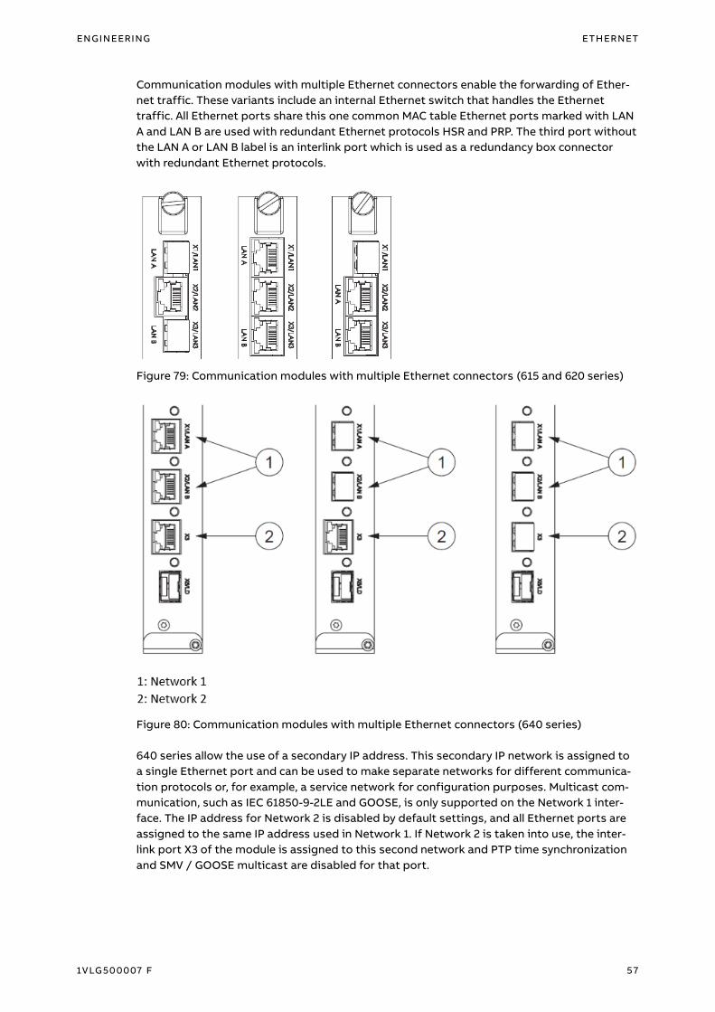
ENGINEERING ETHERNET
1VLG500007 F 57
Communication modules with multiple Ethernet connectors enable the forwarding of Ether-
net traffic. These variants include an internal Ethernet switch that handles the Ethernet
traffic. All Ethernet ports share this one common MAC table Ethernet ports marked with LAN
A and LAN B are used with redundant Ethernet protocols HSR and PRP. The third port without
the LAN A or LAN B label is an interlink port which is used as a redundancy box connector
with redundant Ethernet protocols.
Figure 79: Communication modules with multiple Ethernet connectors (615 and 620 series)
Figure 80: Communication modules with multiple Ethernet connectors (640 series)
640 series allow the use of a secondary IP address. This secondary IP network is assigned to
a single Ethernet port and can be used to make separate networks for different communica-
tion protocols or, for example, a service network for configuration purposes. Multicast com-
munication, such as IEC 61850-9-2LE and GOOSE, is only supported on the Network 1 inter-
face. The IP address for Network 2 is disabled by default settings, and all Ethernet ports are
assigned to the same IP address used in Network 1. If Network 2 is taken into use, the inter-
link port X3 of the module is assigned to this second network and PTP time synchronization
and SMV / GOOSE multicast are disabled for that port.

58 1VLG500007 F
Managed Ethernet switches
A switch is an Ethernet device that filters and forwards data packets between the LAN seg-
ments. The switches operate on the data link layer and occasionally the network layer.
Packets that arrive on a port are analysed for errors and only forwarded onto the port that
has a connection to the destination device.
The AFS family offers many features which are required in the utility environments, including
fast protection schemes, redundant power supply and alarm contacts, and enables the step-
wise introduction of Smart grid applications. Recommended types of managed Ethernet
switches are shown in table below.
Table 6: Recommended Managed Ethernet switches overview for UniGear Digital
Type Manufacturer Assembly Number
of ports
HSR
Redbox
PRP
Redbox
RSTP SNTP PTPv2 Station
bus
Process
bus
AFS670 ABB 19' up to 24 No No Yes Yes No Yes No
AFS675 ABB 19' up to 28 No No Yes Yes No Yes No
AFS677 ABB 19' 16 No No Yes Yes Yes Yes Yes
AFS660B ABB DIN Rail 8 No No Yes Yes No Yes No
AFS665B ABB DIN Rail 10 No No Yes Yes No Yes No
AFS660C ABB DIN Rail 6 Yes Yes Yes Yes Yes Yes Yes
AFS660S ABB DIN Rail 6 Yes Yes Yes Yes Yes Yes Yes
AFS665S ABB DIN Rail 11 Yes Yes Yes Yes Yes Yes Yes
RSG2100 Siemens 19' up to 19 No No Yes Yes No Yes No
RST2228 Siemens 19' Up to 28 No No Yes Yes Yes Yes Yes
RSG2300 Siemens 19' up to 32 No No Yes Yes No Yes No
RS900 Siemens DIN Rail up to 9 No No Yes Yes No Yes No
RS900G Siemens DIN Rail 10 No No Yes Yes No Yes No
RS950G Siemens DIN Rail 3 Yes Yes Yes Yes Yes Yes Yes
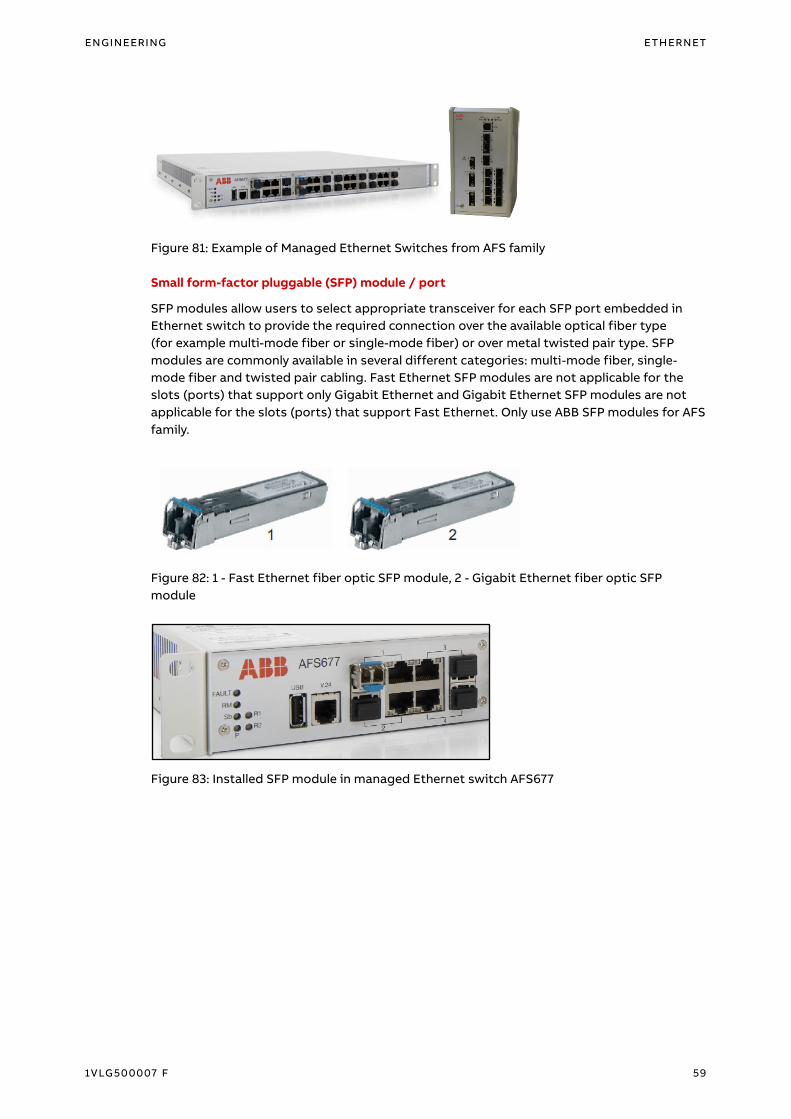
ENGINEERING ETHERNET
1VLG500007 F 59
Figure 81: Example of Managed Ethernet Switches from AFS family
Small form-factor pluggable (SFP) module / port
SFP modules allow users to select appropriate transceiver for each SFP port embedded in
Ethernet switch to provide the required connection over the available optical fiber type
(for example multi-mode fiber or single-mode fiber) or over metal twisted pair type. SFP
modules are commonly available in several different categories: multi-mode fiber, single-
mode fiber and twisted pair cabling. Fast Ethernet SFP modules are not applicable for the
slots (ports) that support only Gigabit Ethernet and Gigabit Ethernet SFP modules are not
applicable for the slots (ports) that support Fast Ethernet. Only use ABB SFP modules for AFS
family.
Figure 82: 1 - Fast Ethernet fiber optic SFP module, 2 - Gigabit Ethernet fiber optic SFP
module
Figure 83: Installed SFP module in managed Ethernet switch AFS677

60 1VLG500007 F
Satellite reference clock
It synchronizes all connected devices using its reference time source. Optional accessories
usually are antenna, antenna cable, antenna mount and lightning protection kit.
Recommended type of a compact substation clock, TTM 01-G manufactured by TEKRON, sup-
ports accurate GPS (USA) / GLONASS (Russian) clock with sub-microsecond timing that is
used to synchronize protection relays. Key features are:
– Synchronization of IEEE 1588-2008 (PTPv2) compatible clients via IEEE C37.238-2011 Power
Profile
– Synchronization of NTP and SNTP compatible clients
– 1x RJ-45 or 1x multi-mode fiber optic interface
Parallel Redundancy Protocol support for ultimate reliability is available in a fully customiza-
ble satellite reference clock NTS 03-G+ manufactured by TEKRON too.
Refer to www.tekron.com for additional information.
Figure 84: Example of satellite-controlled clock from Tekron with optional accessories

ENGINEERING ETHERNET
1VLG500007 F 61
Other recommended type of substation clock is LANTIME M400 manufactured by Meinberg.
It supports GPS / GLONASS clock and synchronization of IEEE 1588-2008 (PTPv2) compatible
clients via IEEE C37.238-2011 Power Profile, two-step clock. Refer to www.meinberg.de for
additional information.
Figure 85: Example of satellite-controlled clock from Meinberg
Layout
The communication devices are usually mounted inside the low voltage compartment of the
panel. Therefore, the panels are ready for connection. The main benefits of this solution are:
– Cubicles are ready for connection
– Saving space in substation building
– Shorter communication links
– Cheaper solution
Protection relays are connected to the Ethernet network in compliance with the Network
Overview Diagrams. It is recommended to wire communication link from Ethernet switch to
protection relays and keep minimal allowed bend radius especially for fiber optic patch cords.
Figure 86: Low Voltage Compartment of UniGear panel

62 1VLG500007 F
3.5.3 Topologies
SINGLE network using Rapid Spanning Tree Protocol (RSTP) / Fast Media Redundancy
Protocol (E-MRP)
The single network topology is the most common one, protection relays are connected to
managed Ethernet switch via single connection. The managed Ethernet switches form a
physical loop (ring).
RSTP ring offer redundancy mechanism against link between switches failures, but not
against protection relay link or switch failure. Rapid Spanning Tree protocol always blocks
one path to avoid duplicates. Moreover, the RSTP ring cannot guarantee a zero or near-zero
frame loss upon network failure occurrence. It is supported by AFS and RUGGEDCOM family.
Figure 87: RSTP ring redundant structure

ENGINEERING ETHERNET
1VLG500007 F 63
Media Redundancy Protocol (MRP) is a ring redundancy protocol defined in IEC 62439-2
standard. One of the Ethernet switches in the ring acts as a Ring Manager. There is exactly
one ring manger in the ring. With the help of the ring manager function, the two ends of a
backbone in a line structure can be closed to a redundant ring. The Ring Manager keeps the
redundant line open if the line structure is intact. If a segment fails, the ring manager imme-
diately closes the redundant line, and line structure is intact again. E-MRP is fast MRP with
decreased recovery time (Ring < 10 switches: < 10 ms recovery time, Ring < 100 switches: < 40
ms). It is supported by AFS family.
MRP provides shorter switching times than RSTP, it is limited to ring topology and it covers
much bigger networks in comparison to RSTP. Coupling RSTP, MRP and E-MRP networks is
possible.
Figure 88: MRP / E-MRP ring redundant structure
Figure 89: Single network using RSTP / E-MRP

64 1VLG500007 F
Network Redundancy
IEC 61850 standard specifies network redundancy that improves the system availability for
substation communication. It is based on two complementary protocols defined in the IEC
62439-3 standard: Parallel Redundancy Protocol and High Availability Seamless Redundancy
protocol. Both protocols can overcome failure of a link or switch with zero-switchover time. In
both protocols, each node has two identical Ethernet ports for one network connection. They
rely on the duplication of all transmitted information and provide zero-switchover time if
links or switches fail, thus fulfilling all the stringent real-time requirements of substation au-
tomation. The choice between these two protocols depends on the application and the re-
quired functionality.
Parallel Redundancy Protocol (PRP) networks using Rapid Spanning Tree Protocol (RSTP) /
Fast Media Redundancy Protocol (E-MRP)
In PRP, each node is attached to two independent networks operated in parallel. The net-
works are completely separated to ensure failure independence and can have different topol-
ogies. Both networks operate in parallel, thus providing zero-time recovery and continuous
checking of redundancy to avoid failures. The PRP1 redundancy is supported by Relion® 615
(RED615 only via fiber optic interfaces), 620 and 640 series. SCADA system can be connected
to PRP networks via Redbox or directly if PRP redundancy is supported by SCADA.
Figure 90: PRP networks using RSTP / E-MRP
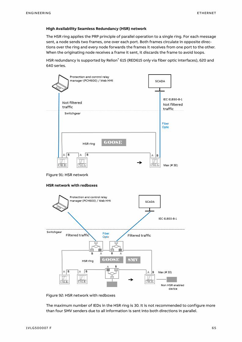
ENGINEERING ETHERNET
1VLG500007 F 65
High Availability Seamless Redundancy (HSR) network
The HSR ring applies the PRP principle of parallel operation to a single ring. For each message
sent, a node sends two frames, one over each port. Both frames circulate in opposite direc-
tions over the ring and every node forwards the frames it receives from one port to the other.
When the originating node receives a frame it sent, it discards the frame to avoid loops.
HSR redundancy is supported by Relion® 615 (RED615 only via fiber optic interfaces), 620 and
640 series.
Figure 91: HSR network
HSR network with redboxes
Figure 92: HSR network with redboxes
The maximum number of IEDs in the HSR ring is 30. It is not recommended to configure more
than four SMV senders due to all information is sent into both directions in parallel.

66 1VLG500007 F
Combined Parallel Redundancy Protocol (PRP) and High Availability Seamless Redundancy
(HSR) networks
Combining PRP and HSR networks can be overcome some drawback of pure PRP or HSR net-
work. PRP and HSR protocols have been developed to work interoperable, because HSR ring
applies the PRP principle of parallel operation to a single ring. PRP networks and HSR rings
are coupled through PRP / HSR redboxes. Two redboxes should be used per one ring to be
redundant and have access to both PRP networks. If one Redbox fails, the seamless redun-
dancy is still available through the other. The redboxes divide HSR ring in two parts of equal
size minimizing the maximum number of hops.
Figure 93: Combined PRP and HSR networks

ENGINEERING ETHERNET
1VLG500007 F 67
Comparison of network topologies
Comparison of network topologies is shown in table below.
Table 7: Comparison of network topologies
SINGLE network
+ RSTP
PRP networks HSR network
ARCHITECTURE
Supported topologies Any topology: tree, star,
ring, mashed
Any topology: tree, star,
ring, mashed
Limited: rings, rings of
rings
Connecting single port
protection relays
Yes Yes, directly to one net-
work
No, only via Redbox
Number of devices No limitations, due to
flexible topology
No limitations, due to
flexible topology
Max 30 per ring
Network independent of
protection relays
Yes Yes No
INTEROPERABILITY
Interoperability
with non-redundant
protection relays
Yes Yes No, only via Redbox
Compatible with
standard Ethernet Com-
ponents
Yes Yes No, HSR support is
needed
PERFORMANCE
Recovery time 10…500 ms 0 ms 0 ms
Network bandwidth Full bandwidth Full bandwidth Half bandwidth
Latency No latency in protection
relay
No latency in protection
relay
Latency in each protec-
tion relay
AVAILABILITY
Failure of a switch / ac-
tive network component
Connected protection re-
lays are lost
No impact One protection relay is
lost
Failure of 2 or more
protection relays
No impact to
communication
No impact to
communication
Communication between
relays interruption

68 1VLG500007 F
SINGLE network
+ RSTP
PRP networks HSR network
Data loss Yes No No
ECONOMICS
Equipment costs
Medium, Ethernet
switches
High, double amount of
Ethernet switches, pro-
tection relay with more
interfaces
Medium, Redbox, protec-
tion relay with more in-
terfaces
Communication Links
Medium, links between
protection relays and
Ethernet switches
High, double links be-
tween protection relays
and Ethernet switches
Low, only links between
protection relays
Space requirements Medium, Ethernet
switches
High, Ethernet switches Low, less devices
ENGINEERING
Effort Less More Less
3.5.4 Ethernet traffic estimation
MMS 0.01 Mb/s per a single protection relay
GOOSE 0.1 Mb/s in burst conditions per a single protection relay (2 data sets)
SMV 5 Mb/s per a source protection relay
Fast Ethernet = 100 Mb/s
The bandwidth of the HSR ring is half of the Fast Ethernet, because each message is sent in
parallel into either direction.
For instance, estimated Ethernet traffic volume for a substation consisting of two sections
(20x GOOSE sender, 2x SMV sender) is: 20 x 0.01 + 20 x 0.1 + 2 x 5 = 12.2 Mb/s
Knowledge of data flows and traffic patterns allows for detecting bottlenecks and planning
the network segmentation and segregation of traffic.

ENGINEERING ETHERNET
1VLG500007 F 69
3.5.5 Naming convention to identify protection relays
The protection relay name must be unique within the planned network. A default name is
applied if it is not specified by the client and it is based on the reference designation system
of IEC 61346
– Substation 3 characters
– Voltage Level 1 character
• B > 420kV
• C < 380, 420> kV
• D < 220, 380) kV
• E < 110, 220) kV
• F < 60, 110) kV
• G < 45, 60) kV
• H < 30, 45) kV
• J < 20, 30) kV
• K < 10, 20) kV
• L < 6, 10) kV
• M < 1, 6) kV
• N < 1 kV
– Voltage Level Index 1 character
– Bay 3 characters, 1st char. = letter, 2nd-3rd char. = digits
– Protection Relay 2 characters
For example, SubstationVoltagelevelVoltagelevelindexBayProtectionRelay SUBJ1J01A1
3.5.6 IP address allocation
The IP address is a number that identifies a network device. Each device connected to a net-
work must have a unique address. The default IP address range for a substation is: 172.16.X.X -
172.30.X.X. The IP addresses and IP masks are a specific feature of each device. In case of
device failure, the replacement device receives the same IP address. The IP address should be
structured in a way to reflect the physical plant layout according to IEC 61850-90-4.
– 172.NET.BAY.DEVICE
Subnet mask 255.255.0.0 (Class B)
– NET
• 16 - 30 16 = the highest voltage level,
17 = the second highest voltage level …
– BAY
• 0 Station level (PC, ZEE600, Satellites reference clock ...)
• 1-169 Bays
• 170 - 179 Virtual bays (substitution of actual devices by simulation or calculation)
• 201 - 250 Station Level Ethernet Switches
– DEVICE
• 0 Bay Level Ethernet Switch
• 1- … Protection relays
Note: PRP redundancy +100
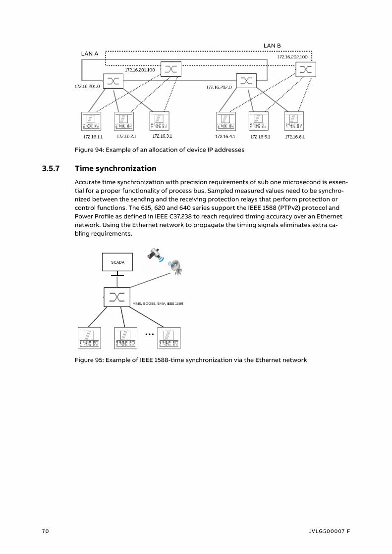
70 1VLG500007 F
Figure 94: Example of an allocation of device IP addresses
3.5.7 Time synchronization
Accurate time synchronization with precision requirements of sub one microsecond is essen-
tial for a proper functionality of process bus. Sampled measured values need to be synchro-
nized between the sending and the receiving protection relays that perform protection or
control functions. The 615, 620 and 640 series support the IEEE 1588 (PTPv2) protocol and
Power Profile as defined in IEEE C37.238 to reach required timing accuracy over an Ethernet
network. Using the Ethernet network to propagate the timing signals eliminates extra ca-
bling requirements.
Figure 95: Example of IEEE 1588-time synchronization via the Ethernet network

ENGINEERING ETHERNET
1VLG500007 F 71
Using the Best Master Clock (BMC) algorithm devices in the network with the most accurate
time are determined, which are to be used as a reference time source (Grandmaster). Subse-
quently the participating devices synchronize themselves with this reference time source.
The BMC algorithm run continuously to quickly adjust for changes in network configuration.
IEEE 1588 networked protocol supports multiple master clock, which improves redundancy
and reliability of substation time synchronization system.
PTP clock types
– Grandmaster clock is synchronized with an external source as satellites (satellites refer-
ence clocks)
– Ordinary clock can act as either a Master or a Slave clock (protection relay). In most net-
work implementations the clocks remain in the Slave state and only become Master when
the Grandmaster fails.
– Transparent clock corrects the time information before forwarding it without synchroniz-
ing itself (Managed Ethernet switch)
The PTP Clocks can be either one-step or two-step ones; their mixing should be avoided.
Two-step clock sends Sync message (contains the approximate time) and follow-up message
(contains more precise value of when Sync message left the clock). One-step clock does not
send Follow-up message, instead the Sync message carries a precise time stamp. The One-
step mode reduces network traffic and is preferable.
System settings for the 3rd party devices
To be capable of supporting the IEEE 1588-2008 (PTPv2) version of the standard
Preferably of 1588 type according to the Power profile, either via power profile parameters or
by individually setting the parameters according to the Power Profile, with implementation in
line with the one-step mode.
Table 8: C37.238 Power Profile key parameters
Parameter Value
Path delay Peer to peer
VLAN 1 recommended
Ethertype 0x88f7
Announce period 1 s
Sync period 1 s
Pdelay period 1 s

72 1VLG500007 F
Time synchronization schemes
Preferred schemes for HSR-PRP and PRP networks
The PRP redundancy protocol foresees that the grandmaster clock is doubly attached to both
LANs. An ordinary clock therefore receives the Sync (Follow-Up) and Announce messages
from each LAN independently. The ordinary clock treats each side as a different clock, but it
does not apply the Best Master Clock algorithm since both have the same identity. Locating
two grandmaster clocks, one in each LAN also possible, in that case the doubly attached
ordinary clocks execute the Best Master Clock algorithm to select the clock they are synchro-
nized to. However, singly attached nodes do not benefit from redundancy.
Figure 96: IEEE 1588 Time synchronization scheme for HSR-PRP networks
Figure 97: IEEE 1588 Time synchronization scheme for PRP networks

ENGINEERING ETHERNET
1VLG500007 F 73
3.5.8 Traffic segregation
SMV messages causing high traffic should be filtered out so that they do not reach network
devices which do not subscribe to SMV messages. This is done in managed Ethernet switch
configuration which must be configured to perform the filtering operation. Traffic over
Ethernet network is grouped into several virtual LANs.
– VLAN ID = 1 (MMS, IEEE 1588, SNMP, …). It exists as default and its usage
throughout LAN yields the same behaviour as if there were no
VLANs (VLAN ID = 0)
– VLAN ID = 1 000 – 1 511 (GOOSE messages). It is grouped based on substation,
application, …
– VLAN ID = 3 000 – 3 511 (SMV stream). It is grouped based on sender and associated
receivers.
Figure 98: Example of traffic segregation via building virtual LANs
Figure 99: Virtual LANs allocation in PRP-RSTP networks
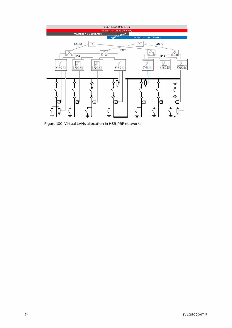
74 1VLG500007 F
Figure 100: Virtual LANs allocation in HSR-PRP networks

ENGINEERING ETHERNET
1VLG500007 F 75
3.5.9 Protection relays
Ethernet rear ports and redundancy settings
IED configuration / Configuration / Communication / Ethernet / Communication: 0
– IP address = IP number
– Subnet mask = Subnet mask
– Switch mode = HSR / PRP / Normal
Figure 101: Communication parameter setting dialog
Ethernet rear ports supervision
RCHLCCH or / and SCHLCCH are used for supervision. RCHLCCH block supervises redundant
channels and SCHLCCH block supervises status of Ethernet ports.
RCHLCCH outputs signals
– CHLIV Status of redundant Ethernet channel LAN A. When redundant mode is set to
HSR or PRP mode, value is True if the protection relay is receiving redundancy
supervision frames. Otherwise value is False.
– REDCHLIV Status of redundant Ethernet channel LAN B. When redundant mode is set to
HSR or PRP mode, value is True if the protection relay is receiving
redundancy supervision frames. Otherwise value is False.
– LNKLIV Link status of redundant port LAN A
– REDLNKLIV Link status of redundant port LAN B

76 1VLG500007 F
SCHLCCH outputs signals
– CH1LIV Status of Ethernet channel X1 / LAN1. Value is True if the port is receiving
Ethernet frames. Valid only when redundant mode is set to None or port is
not one of the redundant ports (LAN A or LAN B)
– LNK1LIV Link status of Ethernet port X1 / LAN1
– CH2LIV Status of Ethernet channel X2 / LAN2. Value is True if the port is receiving
Ethernet frames. Valid only when redundant mode is set to None or port is
not one of the redundant ports (LAN A or LAN B)
– LNK2LIV Link status of Ethernet port X2 / LAN2
– CH3LIV Status of Ethernet channel X3 / LAN3. Value is True if the port is receiving
Ethernet frames. Valid only when redundant mode is set to None or port is
not one of the redundant ports (LAN A or LAN B)
– LNK3LIV Link status of Ethernet port X3 / LAN3
Figure 102: Adding RCHLCCH and SCHLCCH blocks in the Application Configuration Tool

ENGINEERING ETHERNET
1VLG500007 F 7 7
Figure 103: Status of Ethernet rear port displayed via ITT SA Explorer (on top and on bottom)

78 1VLG500007 F
3.5.10 Managed Ethernet switches
AFS Family
After connecting a notebook with the AFS Finder SW tool to any Switch Port except HSR dedi-
cated ports, the following dialogue screen appears. AFS Finder automatically searches the
network for those devices, which support the AFS finder protocol. The next dialogue, opened
by double clicking on the respective switch in AFS finder, defines the IP address and netmask.
Figure 104: AFS switch screen
The user-friendly Web-based interface offers the possibility of operating the device from any
location in the network via a standard browser such as Mozilla Firefox or Microsoft Internet
Explorer. Being a universal access tool, the Web browser uses an applet which communicates
with the device via the Simple Network Management Protocol (SNMP). The Web-based inter-
face allows the device to be graphically configured and it uses Java. Java must be enabled in
the security settings of the Web browser.
Login
Default User name to configure the AFS67x family is admin and the password is admin.
Default User name to configure the AFS66x family is admin and password is abbadmin.
Figure 105: Login window
Notes on saving the Configuration profile
– To copy changed settings to the volatile memory (RAM), click the Set button
– To refresh the display in the dialogs, click the Reload button
– To keep the changed settings even after restarting the device, click the Save button in
Basic Settings / Load / Save dialog

ENGINEERING ETHERNET
1VLG500007 F 79
3.5.10.1 Basic Settings <Mandatory>
Basic Setting / Network
Mode / Local = enabled
VLAN / ID = 1
Local
– IP address = IP number
– Netmask = Netmask
AFS Finder Protocol / Operation = ON
Figure 106: Network parameters dialog
Basic Setting / Port configuration
Port on = enabled
Automatic Configuration
– Enabled, Gigabits ports and TX (RJ-45) ports to protection relay supporting
auto negotiation function
– Disabled, fiber optic ports
Manual Configuration = Fixed speed to protection relay should be set
Manual cable crossing = enabled on one ring port, when automatic configuration is disabled
Flow control = disabled
Figure 107: Port Configuration dialog
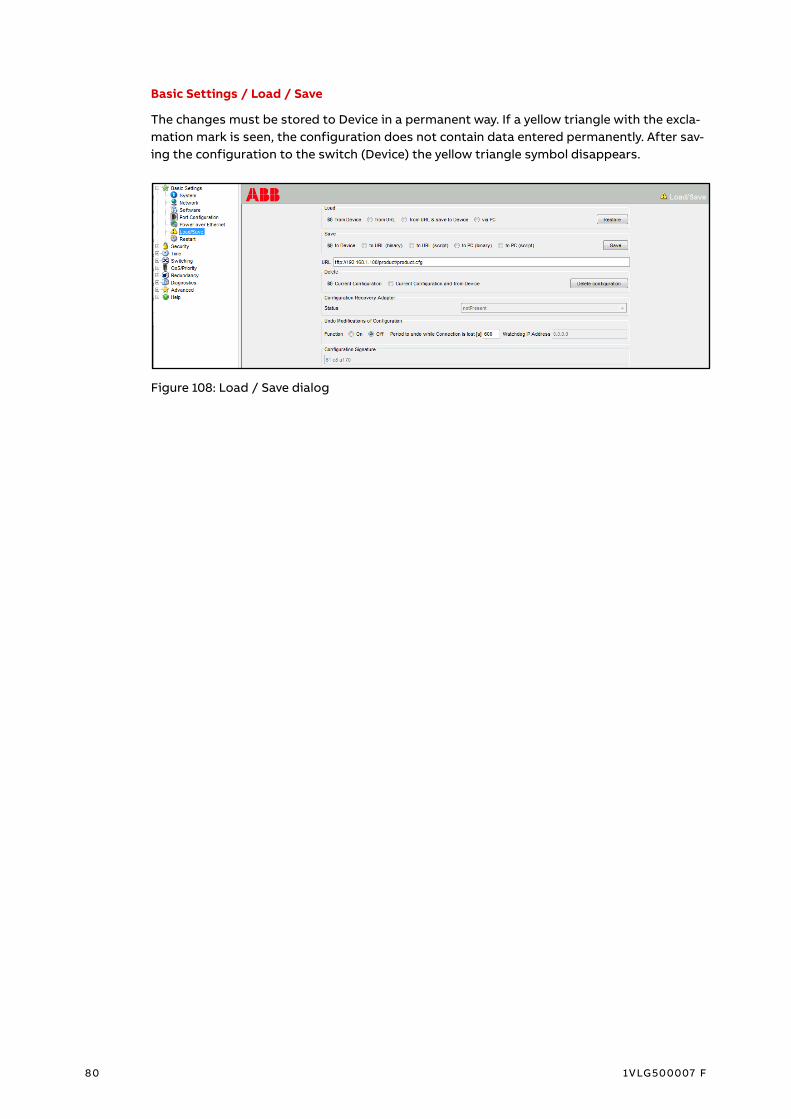
80 1VLG500007 F
Basic Settings / Load / Save
The changes must be stored to Device in a permanent way. If a yellow triangle with the excla-
mation mark is seen, the configuration does not contain data entered permanently. After sav-
ing the configuration to the switch (Device) the yellow triangle symbol disappears.
Figure 108: Load / Save dialog

ENGINEERING ETHERNET
1VLG500007 F 81
3.5.10.2 Time Settings <Mandatory>
Time / PTP / Global
PTPv2 must be configured in case SMV (IEC 61850-9-2LE) is used.
Operation IEEE 1588 / PTP = ON
Configuration IEEE 1588 / PTP / PTP Version-Mode
– V2-transparent-clock; used only to correct and forward PTP messages. The device cannot
become a PTPv2 master.
Figure 109: PTP Global dialog
Time / PTP / Version 2(TC) / Global
Profile Presets / Profile = Power - Defaults
Operation IEEE 1588 / PTPv2 TC
– Delay mechanism = P2P (Peer to Peer)
– Primary Domain = 0
– Network protocol = IEEE 802.3
– Syntonize = enabled to synchronize also local time
– Power TLV Check = enabled
– VLAN = 1
Figure 110: PTP Version 2 (Transparent Clock) Global dialog

82 1VLG500007 F
Time / PTP / Version 2(TC) / Port
PTP Enable = enabled on all ports
Figure 111: PTP Version 2 (Transparent Clock) Port dialog

ENGINEERING ETHERNET
1VLG500007 F 83
3.5.10.3 Switching Settings <Mandatory>
The traffic segregation is essential especially for process bus to reduce data traffic and to let
it go only where needed (for example GOOSE, SMV shared between protection relays should
be not sent to the control system; GOOSE, SMV should be sent only where required). Traffic
filtering in managed Ethernet switches can be done via logical separation of the data traffic
to several VLANs or via multicast MAC address filtering for ports.
Switching / Global
Global setting should be kept as default.
Configuration
– Activate Flow Control = disabled
– Address Learning = enabled; it is disabled only to observe data at all ports (disable direct
packet distribution)
– Frame size = 1 522, 1 552 is intended for double VLAN tagging
Figure 112: Switching Global dialog in AFS67x (on top) and AFS66x (on bottom)

84 1VLG500007 F
Switching / VLAN / Global
Configuration
– VLAN 0 Transparent Mode / VLAN Unaware Mode = disabled
– GVRP active = disabled (enabled to synchronize VLAN information between Ethernet
switches)
Learning / Mode / Independent VLAN = enabled
Figure 113: VLAN Global dialog in AFS67x
Switching / VLAN / Static
This item is used to configure outgoing packets (Egress filtering) from the switch. New VLAN
ID Entries as per the protection relays engineering must be created.
VLAN ID
– GOOSE ranging from 1 000 to 1 511
– SMV ranging from 3 000 to 3 511
Name = for information purpose on the switch only
Untagged ports = U (The port transmits data without the VLAN tag), all ports in VLAN ID 1
except ring, PRP, HSR ports. It is possible to connect engineering tools, Internet Explorer or
other features via this untagged VLAN
Tagged ports = T (The port transmits data with the VLAN tag), all ports in the VLAN IDs > 1
(ring, PRP, HSR, GOOSE and SMV receiver)
Default setting = - (The port is not member of the VLAN and does not transmit data packets
of the VLAN)
Figure 114: VLAN Static dialog

ENGINEERING ETHERNET
1VLG500007 F 85
Switching / VLAN / Port
Ingress Filtering = enabled on all ports. The port evaluates the received VLAN tags and
transmits messages relevant to VLANs configured for this port; other messages are
discarded.
GVRP = disabled on all ports, (VLANs are manually created and administered)
Figure 115: VLAN Port dialog

86 1VLG500007 F
3.5.10.4 Redundancy Settings RSTP <Conditional>
Redundancy / Spanning Tree / Global
Operation = ON
Protocol version = RSTP
Protocol Configuration / Information
– Priority
• 4 096 for Root (Master) Switch
• 8 192 for Backup Root Switch
• 32 768 for all Bay (Slave) Switches
– Hello Time = 2 s
– Forward Delay = 15 s
– Max Age = 20 s
– MRP Compatibility = disabled; enabled if MRP ring ID is used together with RSTP
Figure 116: Spanning Tree Global dialog
Redundancy / Spanning Tree / Port
STP active = enabled for all ports
AdminEdge Port = enabled for all ports except the ring ones
AutoEdge Port = enabled for all ports
Figure 117: Spanning Tree Ports dialog

ENGINEERING ETHERNET
1VLG500007 F 87
3.5.10.5 Redundancy Settings E-MRP <Conditional>
E-MRP ring is supported only by AFS family. Spanning Tree Operation is off (Redundancy /
Spanning Tree / Global / Operation) or STP protocol is disabled on all ports used for E-MRP
(Redundancy / Spanning Tree / Port) before configuring the E-MRP.
Redundancy / Ring Redundancy
Version = E-MRP (not all switches support E-MRP; use same version for all switches)
Ring Port 1 & 2 = Ring Ports used for E-MRP
Ring Manager / Mode = enabled in one switch (Ring Manager)
Ring Manager / Mode = disabled in in all ring switches except of switch (Ring Manager)
Operation = ON
VLAN / VLAN ID = 1
Switches / Number = the number of switches in the ring
Figure 118: E-MRP Ring Redundancy dialog

88 1VLG500007 F
3.5.10.6 Redundancy Settings PRP and HSR < Conditional>
Supported by AFS66x. The PRP and HSR networks are always connected to AFS66x via ports
1/1 and 1/2, marked as port 1A and port 2B. Both ports support fiber optic connection (SFP
slot) or twisted-pair connection (RJ-45 socket). PRP function replaces interfaces 1/1 and 1/2
with interface prp/1 and HSR function replaces interfaces 1/1 and 1/2 with interface hsr/1,
that is why it is recommended to initialize configuration process of the Ethernet switch with
redundancy settings if it is applicable.
Figure 119: Example of AFS660 Front view
Switching / Global
Configuration / VLAN Unaware mode = disabled (another name for the VLAN 0 transparent
mode). When VLAN Unaware mode is enabled, the device transmits data packets to all
learned ports without evaluating or changing the VLAN tagging in the data packet. The prior-
ity information remains unchanged.
Figure 120: Switching Global dialog

ENGINEERING ETHERNET
1VLG500007 F 89
L2-Redundancy / PRP / Configuration
MRP and STP protocol cannot operate on the same ports as PRP
– STP protocol is disabled on ports used for PRP (Redundancy / Spanning Tree / Port (both
tabs))
– PRP ports are different from MRP or MRP operation is completely disabled
Operation = ON
Ports A, B = ON, other devices not providing support to PRP are connected to other ports.
Figure 121: PRP Configuration dialog
L2-Redundancy / HSR / Configuration
MRP and STP protocol cannot operate on the same ports as HSR
– STP protocol is disabled on ports used for HSR (Redundancy / Spanning Tree / Port (both
tabs))
– HSR ports are different from MRP or E-MRP operation is completely disabled
Operation = ON
Ports A, B = ON, other devices not providing support to HSR are connected to other ports.
HSR parameter
– HSR mode = modeu (host operates as a proxy for destination device, it forwards unicast
traffic around the ring and forwards it to destination address, when the frames return to
the source node it discards the unicast message) / modeh (host operates as a proxy for
destination device, it removes unicast traffic from the ring and forwards it to destination
address)
– Switching node Type = hsrredboxsan (to connect non HSR device to HSR ring) /
hsrredboxprpa (to connect HSR ring to PRP LAN A) / hsredboxprpb (to connect HSR ring
to PRP LAN B)
– Redbox Identity = Id1a / Id1b, specifies the tags for PRP LAN traffic

90 1VLG500007 F
Figure 122: HSR Configuration dialog
3.5.10.7 Advanced Settings <Optional>
Advanced / Industrial Protocols / IEC61850-MMS
Operation = ON to make information related to the Ethernet switch available on
the IEC 61850 network.
Figure 123: IEC61850-MMS Configuration dialog

ENGINEERING ETHERNET
1VLG500007 F 91
3.5.11 Satellite controlled clock
3.5.11.1 Tekron
After connecting a notebook with the Tekron clock configuration tool software (available
from www.tekron.com) to Ethernet port of Tekron device, the following dialogue screen
appears. Tekron clock configuration tool automatically discover connected unit supposing
(Discover button).
Figure 124: Tekron clock configuration Tool
Configuration procedure is initiated by Configure button after selecting of unit from the list.
Default login is: User Name - admin, Password - Password. The procedure can be blocked by
Windows firewall settings.
Network / Basic Settings
Advanced Options = enabled
IPv4
– Method / Static = enabled
– IP address = IP number
– Netmask = Netmask
– Gateway = IP number
VLAN
– Enable = enabled
– ID = 1
– Priority = 4
– Tagged traffic / PTP = enabled
Ethernet
– Link Settings = 100 Mb/s + Full duplex

92 1VLG500007 F
Figure 125: Basic setting dialog
Network / PTP Settings
Enable = enabled
Operating mode = Two-Step
Profiles = C37.238
Grandmaster Priority #1 = 120 (128 default setting)
Figure 126: PTP setting dialog

ENGINEERING ETHERNET
1VLG500007 F 93
Ethernet switch - Basic settings / Port configuration
Ethernet switch port, where TEKRON clock is connected, must have Automatic Configuration
disabled and 100 Mbit/s FDX mode.
Figure 127: Port Configuration dialog
3.5.11.2 Meinberg
The LANTIME M400 timeserver can be configured via several user interfaces (for example
local display, web interface).
Web interface
For first time installation enter IP address, netmask for Ethernet connection LAN0 of
LANTIME via local HMI and then connect to the web interface by entering IP address of the
LANTIME into the address field of a web browser. Default User name to configure device is
root and password is timeserver.
PTP Settings
Figure 128: PTP setting dialog

94 1VLG500007 F
PTP Setting / Interface 01 / Global
Select Profile = Power
Priority1 = 120 (128 default setting)
Other setting is default
Figure 129: PTP Global settings dialog

ENGINEERING ETHERNET
1VLG500007 F 95
PTP Setting / Interface 01 / Network
Enable DHCP-Client = Static
TCP/IP Address = IP number
Netmask = Netmask
Gateway = IP number
Other setting is default
Figure 130: PTP Network settings dialog

96 1VLG500007 F
3.6 Statistical energy meters
3.6.1 ESM-ET statistical energy meter
The statistical energy meter configuration process is carried out via EsConfigurator and
ESM Test tools.
3.6.1.1 EsConfigurator tool
Network
IP address = IP number
Subnet mask = Netmask
Default gateway = IP address
Figure 131: Network configuration dialog

ENGINEERING STATISTICAL ENERGY METERS
1VLG500007 F 97
Measurements / Transformation ratios and measurement units
current = 426.667
voltage = 346.620
Calculate automatically = enabled
Figure 132: Measurements configuration dialog

98 1VLG500007 F
Clock
Synchronization
– Source = NTP
SNTP synchronization
– Server 1 = IP address
Figure 133: Clock configuration dialog
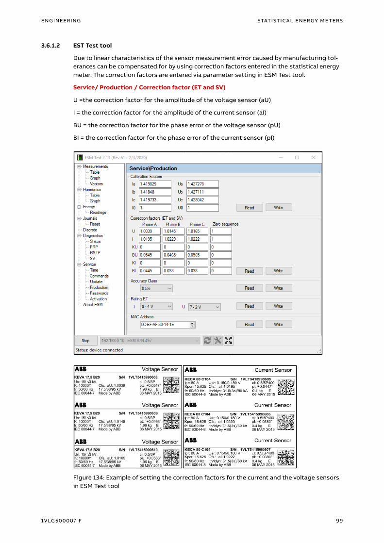
ENGINEERING STATISTICAL ENERGY METERS
1VLG500007 F 99
3.6.1.2 EST Test tool
Due to linear characteristics of the sensor measurement error caused by manufacturing tol-
erances can be compensated for by using correction factors entered in the statistical energy
meter. The correction factors are entered via parameter setting in ESM Test tool.
Service/ Production / Correction factor (ET and SV)
U =the correction factor for the amplitude of the voltage sensor (aU)
I = the correction factor for the amplitude of the current sensor (aI)
BU = the correction factor for the phase error of the voltage sensor (pU)
BI = the correction factor for the phase error of the current sensor (pI)
Figure 134: Example of setting the correction factors for the current and the voltage sensors
in ESM Test tool

100 1VLG500007 F
Glossary 615 series Relion® 615 series protection and control relays
620 series Relion® 620 series protection and control relays
640 series Relion® 640 series protection and control relays
ACT Application Configuration Tool
AFS Family ABB FOX Switch family for utility applications
APPID Application Identifier in GOOSE and SMV messages
ASDU Application Service Data Unit
BC Boundary clock
BMC Best Master Clock algorithm
Control Block It defines HOW and WHEN data is sent to WHOM
CT Current Transformer
Data set It defines WHAT data is sent
EMI Electro Magnetic Immunity
Ethernet A standard for connecting a family of frame-based computer
networking technologies into a LAN
E-MRP Fast Media Redundancy Protocol with decreased recovery
time
FDX Full Duplex
FTP Foiled Twisted pairs
GOOSE Generic Object-Oriented Substation Event
GLONASS Global Navigation Satellite System
GoID GOOSE message identifier
GPS Global Positioning System
GVRP Generic VLAN Registration Protocol
HMI Human Machine Interface
HSR High Availability Seamless Redundancy
HW Hardware
ID Identifier
IGMP Internet Group Management Protocol
IEC International Electrotechnical Commission
IEC 61850 International standard for communication networks and
systems for power utility automation
IEC 61850-8-1 Station bus (MMS + GOOSE)
IEC 61850-9-2 Process bus
IEC 61439 International standard for High availability automation
networks
IED Intelligent Electronic Device

ENGINEERING STATISTICAL ENERGY METERS
1VLG500007 F 101
IEEE Institute of Electrical and Electronics Engineers. The IEEE
standard groups defined the PTP and Power profile
IEEE 1588 Standard for Precision Clock Synchronization Protocol for
Networked Measurement and Control Systems
IET600 Integrated Engineering Toolbox
IP Internet Protocol
ITT Integrated Testing Toolbox for efficient testing and commis-
sioning of IEC 61850 based Substation Automation Systems
I/O Input / Output
I/U Current / Voltage
KECA Indoor Current Sensor
KEVA Indoor Voltage Sensor
LAN Local Area Network
LC Type of connector for glass fiber cable
LE Light Edition (Lite Edition)
MAC Media Access Control
Mbps Megabit per second
MMS Manufacturing Message Specification
MRP Media Redundancy Protocol (according IEC 62439)
MV Medium voltage
NTP Network Time Protocol
PC Personal computer
PCM600 Protection and control relay Manager
PPS Pulses per second
PRP Parallel Redundancy Protocol
PTPv2 Precision Time Protocol Version 2
REF615 Feeder protection and control relay
REF620 Feeder protection and control relay
Redbox Redundancy box connects non-PRP / non-HSR devices to high
availability IEC 62439 networks
RED615 Line differential protection and control relay
REM615 Motor protection and control relay
REM620 Motor protection and control relay
REX640 Protection and control REX640
RJ-45 Galvanic connector type
RSTP Rapid spanning tree protocol
SA Substation Automation
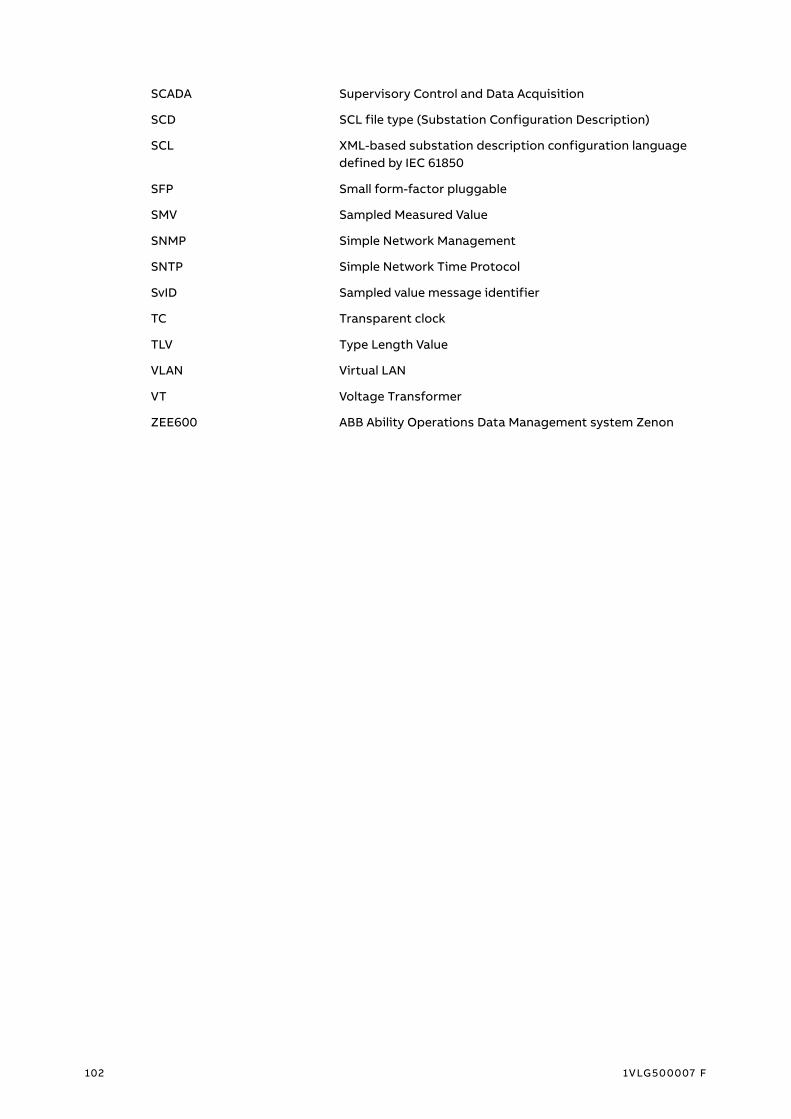
102 1VLG500007 F
SCADA Supervisory Control and Data Acquisition
SCD SCL file type (Substation Configuration Description)
SCL XML-based substation description configuration language
defined by IEC 61850
SFP Small form-factor pluggable
SMV Sampled Measured Value
SNMP Simple Network Management
SNTP Simple Network Time Protocol
SvID Sampled value message identifier
TC Transparent clock
TLV Type Length Value
VLAN Virtual LAN
VT Voltage Transformer
ZEE600 ABB Ability Operations Data Management system Zenon

Revision History
Rev. Page Change Description Date / Initial
A All Initial release 2014
B All New switchgear types for UniGear Digital (UniGear ZS1 24kV, UniGear
550, UniGear 500R, UniGear MCC)
3D models of switchgear panels
Extended sensor product portfolio for UniGear Digital
Engineering of sensors including setting examples
Updated recommended network topologies (HSR networks with
redboxes, HSR-PRP networks)
Updated recommended time synchronization schemes (HSR-PRP net-
works)
HSR and IEEE1588 v2 support in AFS 66x
2015-01-16
C All 615 series 5.0 FP1 (new functionality: for example, IEC 61850 Edition 2
support, synchro check function with IEC 61850-9-2LE, RED615 sup-
ports HSR, PRP and IEC61850-9-2LE)
Connecting GOOSE sender data to a protection relay application in
PCM600
Application configuration of the SMV receiver
Protection relay Ethernet rear ports setting and supervision
Updated engineering of current sensors (RSV up to 150 mV / Hz)
Small form-factor pluggable module / port
Recommended Satellite controlled clocks and their engineering
Updated recommended network topologies (Fast Media redundancy
protocol)
2015-12-01
D All Ethernet technology extended about Ethernet rear connections of
protection relays
620 series 2.0 FP1 (new functionality: for example, IEC 61850 Edition 2
support, synchro check function with IEC 61850-9-2LE, REM620 sup-
ports sensor inputs)
Testing section has moved to UniGear Digital Commissioning and
testing Guide
Updated figures with UniGear ZS1 Digital (17.5 kV, 4 000 A, 50 kA) –
a new post insulator support
Automatic port configuration in Ethernet switch for connected protec-
tion relays via metal cabling
Ethernet channel supervision function blocks (RCHLCCH and
SCHLCCH)
Coupler adapter AR5 – three phases adapter
ESSAILEC® test block
Removal of SNTP-> IEEE1588 Time synchronization scheme (It is not
optimal solution for UniGear Digital)
2017-01-02

2 1VLG500007 F
E All Satellite reference clock with PRP support
Removal of Coupler adapter AR4
SMV Max delay parameter
UniGear 500R – tested voltage level up to 17.5kV
Protection and control REX640
Updated recommended Managed Ethernet switches
Supported Process bus application extended about voltage sharing
redundancy
2019-02-26
F All Statistical Energy meter ESM-ET
UniGear Digital (UniGear ZS1 Double busbar system up to 17.5 kV,
UniGear ZS1 63 kA)
2020-06-17


—
Visit us
www.abb.com/mediumvoltage
Do
cu
me
nt
Nu
mb
er:
1V
LG
50
00
07
Re
v. F