–– SureWave SFC™ User Manual - ABB Group
77
© Copyright 2021 ABB, All rights reserved. — SureWave SFC User Manual –– STATIC FREQUENCY CONVERTER SureWave SFC™ User Manual
-
Upload
khangminh22 -
Category
Documents
-
view
4 -
download
0
Transcript of –– SureWave SFC™ User Manual - ABB Group

© Copyright 2021 ABB, All rights reserved. — Sure
Wav
e SF
CU
ser
Man
ual
––STATIC FREQUENCY CONVERTER
SureWave SFC™User Manual

ABO U T T HIS DOC UME NT
2/78
––
ABB’s SureWave is the new generation of Static Frequency Converter (SFC) allows the connection of 60 Hz powered equip-ment to a 50 Hz supply network and 50 Hz powered equipment to a 60 Hz supply network.
Additionally, the SureWave SFC can sta-bilize the frequency and the voltage to allow the correct operation of sensitive equipment when the supply is not suffi-ciently regulated.
The SureWave’s high efficiency also con-tributes to sustainability, potentially represents a carbon emissions reduction of 351 tons over a typical 15-years lifespan

ABO U T T HIS DOC UME NT
3/78
––1 About this document
––Document information
1.1.1 Copyright notice
The information in this manual is subject to change without notice. This manual and parts thereof must not be reproduced or copied, or disclosed to third parties, nor used for any unau-thorized purpose without written permission from ABB Ltd.
The hardware and software described in this manual are provided under a license and may be used, copied, or disclosed only in accordance with the terms of such license
1.1.2 Document identification
Ownership: ABB Ltd., Power Conditioning ProductsDocument Number: 2UCD400000E001Issue Date: 2021.10Revision: Rev. A
1.1.3 Contact information
Address: ABB Ltd. Napier 4110, 111, Main North Road. New ZealandWeb: https://new.abb.com/power-converters-inverters/grid-interconnections/indus-trial/pcs120-sfc
1.1.4 Equipment covered by the manual
This manual covers the standard SureWave SFC product and provides general information regard-ing:
General functions of the SFC
Operation
Component enclosures
Graphical Display Module (GDM)
Control and adjustments
This manual does not claim to cover all variations and details of the SureWave SFC, nor to con-sider all eventualities that may arise during the operation of the product.
Installation, commissioning, and maintenance of the product are covered elsewhere. If the SureWave SFC is adapted to specific customer needs or applications, and handling, installation,

ABO U T T HIS DOC UME NT
4/78
and operation of the product are affected by these modifications, the extra information required to cover these adaptions will be supplied in extra documentation.
If information is required beyond the instructions in this manual, please refer the matter to ABB
1.1.5 Target groups and required qualifications
The product presented in this manual is part of an industrial environment where voltages are pre-sent that contain a potential hazard of electric shock and/or burn. For this reason, only personnel who have a thorough knowledge of the SFC and the industrial environment and have obtained the required qualification may handle, install, operate, or maintain the product.
The manual addresses personnel who are responsible for operation and maintenance of the SureWave SFC. The personnel must carry out the listed tasks in a manner that does not cause physical harm or danger, and that ensures the safe and reliable functioning of the product.
“Commissioning of the SureWave SFC must only be performed by qualified and certified ABB personnel.”
Handling
The personnel must be skilled and experienced in unpacking and transporting heavy equipment.
Mechanical installation
The personnel must be qualified to prepare the installation site according to the site and equip-ment requirements and to perform the installation accordingly.
Electrical installation
The personnel must have a sound knowledge of the relevant electrical codes and specifications covering low voltage equipment, be experienced with electrical wiring principles, and know the electrical symbols typically used in wiring diagrams.
Operation
The personnel include all persons who operate the SureWave SFC from the HMI. Those people must know the functions of the GDM, be adequately trained for the SFC, and understand its oper-ation process.
Maintenance
The personnel include all persons who:
• are qualified to carry out preventive and corrective maintenance on SureWave SFC as de-scribed in this manual.
• are thoroughly familiar with the product.• have a sound knowledge of the relevant electrical codes and specifications covering low
voltage equipment.• are able to assess the hazards associated with the energy sources of the SureWave SFC
system and act correspondingly.• know the safe shutdown procedures for the SureWave SFC system

ABO U T T HIS DOC UME NT
5/78
1.1.6 Responsibilities of the user
It is the responsibility of those in charge of the SureWave SFC to ensure that each person involved in the installation, operation or maintenance of the product has received the appropriate training and has thoroughly read and clearly understood the instructions in this manual and the relevant safety instructions
1.1.7 Intended use of equipment
Those in charge of the SureWave SFC must ensure that the product is only used as specified in the contractual documents, operated under the conditions stipulated in the technical specifica-tions and on the rating plate of the product, and serviced in the intervals as specified by ABB.
Use outside the scope of the specifications, and unauthorized modifications and constructional changes of the SureWave SFC will render the warranty void
Intended equipment use also implies that only spare parts recommended and approved by ABB may be used.
1.1.8 Quality certificates and applicable Standards
The following certificates and conformity declarations are available from ABB:
– ISO 9001 certificates stating that ABB Ltd in Napier has implemented and maintains a man-agement system that fulfils the requirements of the normative standards.
– EC conformity declaration.
– Individual IEC
Standard number Standard name
IEC60146-1 Semiconductor converters – General requirements
IEC60146-2 Semiconductor converters – Self commutated semiconductor converters
IEC61000-6-2 EMC generic standards - Immunity standard for industrial environments
IEC6100-6-4 EMC generic standards - Emission standard for industrial environments
IEC/EN60947-1 Low voltage switchgear and control gear -General rules
IEC/EN60947-2 Low voltage switchgear and control gear -Circuit breakers
IEC62477-1 Safety requirements for power electronic converter systems and equipment - General
WEEE Waste electrical and electronic equipment directive
Table 1-1: Summary of applicable standards

ABO U T T HIS DOC UME NT
6/78
1.1.9 Items covered by delivery
Delivery of a SureWave SFC comprises the following items:
250 kVA to 750 kVA:
1 enclosure, identified as PE120-U1
This carries the universal controller (main), graphical display module (GDM) and power electron-ics building blocks (PEBBs) to make a complete static frequency converter.
Input and output circuit breakers are NOT supplied with these models and must be sourced sepa-rately.
1 MVA to 1.5 MVA
4 enclosures, as follows:
1. Input enclosure (Term. Enclosure-UAx) complete with circuit breaker
2. PE120-U1 enclosure (main), carrying the universal controller, GDM and PEBBs.
3. PE120-U2 enclosure (hub), carrying PEBBs, and universal controller.
4. Output enclosure (Term. Enclosure-UAx) complete with circuit breaker
1.75 MVA to 2.25 MVA:
5 enclosures, as follows:
1. Input enclosure (Term. Enclosure-UAx) complete with circuit breaker
2. PE120-U1 enclosure (main), carrying the universal controller (main), GDM and PEBBs.
3. PE120-U2 enclosure (hub), carrying PEBBs, and universal controller.
4. PE120-U3 enclosure (hub), carrying PEBBs, and universal controller.
5. Output enclosure (Term. Enclosure-UAx) complete with circuit breaker
1.1.10 Identifying the delivery
The SFC and accessories are identified by the type code printed on the rating label. The label is located on the back of the PE120-1 enclosure door.
The Label provides information on the SureWave SFC rated voltage, frequency, rated current and auxiliary power supply.

ABO U T T HIS DOC UME NT
7/78
––Abbreviations & Terms
The following table lists terms and abbreviations user should be familiar with when using this manual. Some of the terms and abbreviations used in the manual are unique to ABB and might differ from the common use.
Abbreviation/Term Meaning
SFC Static Frequency Converter
LV Low Voltage.Voltage level up to 1000 Vac or 1500 Vdc.
LV PSU 24 Vdc internal power supply for fans and electronics
MV Medium Voltage.Voltage level between 1 kVac and 35 kVac.
PCS120 Power Conversion System 120.The PCS120 is the product platform for the ABB power conditioning products.
PEBB Power Electronic Building Block.
PE120-U<n> Platform Enclosure 120.PE120 is the enclosure that contains several PEBB. The PE120 could be main controller or hub.
MC Main Controller. UC120main controller located in the PE120-U1 enclosure.
HUB HUB controllers are located in PE120-U2 and PE120-U3 cabinets re-spectively. The main function is to transfer the information to the main controller.
GDM Graphical Display Module.Has the local Human Machine Interface (HMI) and it is located in the PE120-U1 enclosure.
HMI Human Machine Interface
CB Circuit Breaker
PE Chassis Protective Earth.
PE-I Inverter Earth.
PCC Point of Common Coupling. The PCC is the point in the electrical power supply system where the responsibility of the utility changes to the industrial customer. The utility is responsible for providing clean voltage and current with respect to harmonic distortion up to the PCC. The industrial customer is responsible not to distort voltage and current by its electrical systems.
Line voltage RMS line to line voltage of the main power supply of the input.
PCB Printed Circuit Board.

ABO U T T HIS DOC UME NT
8/78
Abbreviation/Term Meaning
EMC Electromagnetic Compatibility.All measures to suppress electromagnetic disturbances caused by different electrical equipment in the same electromagnetic environ-ment, and to strengthen the immunity of the equipment to such disturbances.
RTD Resistance Temperature Detector. The RTD is a temperature sensor where the change in electrical re-sistance is used to measure the temperature.
Table 1-2: Summary of abbreviations
––Trademarks
Names that are believed to be trademarks of other companies and organizations are designated as such. The absence or presence of such a designation should however not be regarded as an offence of the legal status of any trademark. The following registrations and trademarks are used in this manual:
Abbreviation/Term Meaning
Modbus™ Registered trademark of Schneider Electric USA, Inc
SureWave Registered trademark of ABB Ltd
Table 1-3: Trademarks
––Related documentation
Document type Document title Document Number
Drawings 250 kVA to 750kVA Layout drawings 2UCD42000E102
Drawings 1 MVA kVA to 1.5 MVA Layout drawings 2UCD42000E101
Drawings 1.75 MVA to 2.25 MVA Layout drawings 2UCD42000E103
Specifications PCS120 SFC Technical Specifications 2UCD420000E002
Installation PCS120 SFC Installation Manual 2UCD420000E003
Service Service Manual 2UCD420000E400
Health & Safety Health and Safety Risk Assessment 2UCD400000E601
Table 1-4: Summary of related documentation

9/78 SUREWAVE SFC USER MANUAL
––2 Introduction
Thank you for selecting ABB as your preferred supplier of frequency conversion equipment andcongratulations on your choice of the SureWave SFC to support your installation.
ABB’s SureWave SFC is the latest Static Frequency Converter developed with ABB’s years of ex-perience with market trends and knowledge in the field.
The new generation of Static Frequency Converters allows connection of 60 Hz powered equip-ment to a 50 Hz supply network and 50 Hz powered equipment to a 60 Hz supply network.
Please carefully read this User Manual, which contains all the necessary information and de-scribes all you need to know about the use of the SFC. The User Manual describes the functionof the SFC, its operation, system components, the meaning of the system events related to theuser interface and provides procedures for starting and stopping the equipment.
Please refer to the Installation Manual, for details on how to prepare the installation site, weight,dimensions, and procedures for moving, installing, and connecting the SFC.
While every care has been taken to ensure the completeness and accuracy of this manual, ABBassumes no responsibility or liability for any losses or damages resulting from the use of the in-formation contained in this document.
Thank you for choosing ABB

10/78 SUREWAVE SFC USER MANUAL
––Contents1 About this document .........................................................................................................................3
Document information ..................................................................................................................... 3Abbreviations & Terms ......................................................................................................................7Trademarks ......................................................................................................................................... 8Related documentation.................................................................................................................... 8
2 Introduction ........................................................................................................................................9
3 Safety ................................................................................................................................................ 12Safety notices ................................................................................................................................... 14General safety information ............................................................................................................15Possible residual risks .....................................................................................................................16
4 Cyber security .................................................................................................................................. 17Deployment guidelines ................................................................................................................... 17
5 Product description .........................................................................................................................18Single line diagram .......................................................................................................................... 18Operating principle ..........................................................................................................................19User interface ................................................................................................................................... 20Major SFC components ...................................................................................................................21Cooling system ................................................................................................................................ 24
6 Selecting transformer configuration .............................................................................................26Industrial application...................................................................................................................... 26Shore to ship (Converter on shore side)..................................................................................... 26On-board shore power ................................................................................................................... 27Specifying transformer .................................................................................................................. 28Sizing Transformers ........................................................................................................................ 28
7 Model definition ...............................................................................................................................29Platform code ................................................................................................................................... 29SureWave product code ................................................................................................................. 29Power rating ..................................................................................................................................... 29Input cable routing & CB ................................................................................................................ 30Output cable routing & CB .............................................................................................................31Ingress protection ............................................................................................................................31Input voltage..................................................................................................................................... 32Input frequency ................................................................................................................................ 32Output voltage ................................................................................................................................. 32
Output frequency ........................................................................................................................ 33Operation ...................................................................................................................................... 33Input termination side ...............................................................................................................34RFI configuration ......................................................................................................................... 34External LV PSU feed ................................................................................................................... 35
8 Technical specifications ..................................................................................................................36250 kVA to 2.25 MVA range specifications ................................................................................. 36Dimensional data............................................................................................................................. 37Circuit breaker specifications....................................................................................................... 38
9 Technical specifications ................................................................................................................. 40

11/78 SUREWAVE SFC USER MANUAL
Power connections to SFC.............................................................................................................40I/O interfaces ................................................................................................................................... 41Auxiliary AC power supply for LV PSU .........................................................................................48
10 User Interface .................................................................................................................................50Graphic Display Module (GDM) ................................................................................................50Navigation buttons ......................................................................................................................51
11 Operation of the SFC .....................................................................................................................66Machine state flow diagram .....................................................................................................66System start .................................................................................................................................68Operation modes ........................................................................................................................68VSI vs virtual generator .............................................................................................................. 69SureWave SFC performance ...................................................................................................... 70Remote AC bus Synchronization ...............................................................................................71System EPO ................................................................................................................................... 74Hard fault ...................................................................................................................................... 74
12 Maintenance schedule ...................................................................................................................75

12/78 SUREWAVE SFC USER MANUAL
––3 Safety
AR
! خطر كهربائيجهد: تحذيرالتشغيلتعليماتراجع .
الجهاز هذاالعملقبلبتأمينهاوقمالكهرباءافصلالكهربائيةالتقنيةبمجالدرايةعشخصخاللمنإالالتركيبعدميجب! تنبيه .
BG
Предупреждение: Опасно напрежение!Вижте инструкциите за работа.Изключете и блокирайте захранването преди да работите с устройството.Внимание! Да се монтира само от експерт електротехник.
CS
Varování: Nebezpečné napětí!Viz návod k obsluze.Před zahájením prací na tomto zařízení odpojte a uzamkněte napájení.Pozor! Toto zařízení smí instalovat pouze osoba s elektrotechnickouodborností.
DA
Advarsel: Farlig elektrisk spænding!Se betjeningsvejledningen.Frakobl enheden, og afbryd strømforsyningen, før du arbejder med denne enhed.Giv agt! Installation må kun foretages af personer med elektrotekniskekspertise.
DE
Warnung: Gefährliche Spannung!Siehe Bedienungsanleitung.Vor dem Arbeiten Gerät ausschalten und von der Spannungsversorgung trennen.Achtung! Installation nur durch elektrotechnische Fachkraft.
EL
Προειδοποίηση: Επικίνδυνη τάση!Ανατρέξτε στις οδηγίες λειτουργίας.Αποσυνδέστε και απομονώστε την παροχή ισχύος προτού ξε κινήσετε τις εργασίες σε αυτήν τη συσκευή.Προσοχή! Η εγκατάσταση πρέπει να γίνεται μόνο από αδειούχο ηλεκτρολόγο εγκαταστάτη.
EN
Warning: Hazardous voltage!Refer to installation instructions.Disconnect and lock out power before working on this device.Attention! Installation by person with electrotechnical expertise only.
ES
Advertencia: ¡Tensión peligrosa!Consulte las instrucciones de funcionamiento.Antes de trabajar con este dispositivo, desconecte y bloquee la corriente.¡Atención! La instalación debe ser realizada únicamente por un técnicoelectricista.
ET
Hoiatus: Elektrilöögi oht!Lisateavet vaadake kasutusjuhendist.Enne selle seadmega töötamist ühendage lahti ja lukustage toide.Tähelepanu! Seadet tohib paigaldada ainult elektrotehnilise kogemusega isik.
FI
Varoitus: Vaarallinen jännite!Katso käyttöohje.Katkaise virta ja estä virran kytkeminen lukituksella ennen töiden aloittamista.Huomio! Asennuksen saa suorittaa vain henkilö, jolla on kokemusta sähkötekniikasta.
FR
Avertissement: Tension dangereuse!Consultez les consignes d’utilisation.Débranchez et verrouillez l’alimentation électrique avant d’entreprendre des travaux sur cet appareil.Attention! L’installation doit être effectuée uniquement par une personne ayant une expertise en élec-trotechnique.
HR Upozorenje: Opasan napon!

13/78 SUREWAVE SFC USER MANUAL
Pogledajte upute za uporabu.Odspojite i isključite struju prije rada na ovom uređaju.Pažnja! Ugradnja je dopuštena samo osobama stručnim u području elektrotehnike.
HU
Figyelmeztetés: Veszélyes feszültség!Lásd a használati utasítást.Válassza le és zárja ki az áramellátást, mielőtt a berendezésen dolgozni kezd.Figyelem! Az üzembe helyezést csak elektrotechnikai szakértelemmel rendelkező személy végezheti el.
IT
Attenzione: Tensione pericolosa!Fare riferimento alle istruzioni per l’uso.Prima di intervenire su questo dispositivo, scollegare e isolare tutte le fonti di alimentazione.Attenzione! L’installazione deve essere eseguita esclusivamente da un installatore qualificato.
LT
Įspėjimas: Pavojinga įtampa!Žr. naudojimo instrukcijas.Atjunkite ir laikinai užblokuokite maitinimą prieš dirbdami su šiuo įrenginiu.Dėmesio! Įrengti gali tik asmuo, turintis elektrotechniko patirties.
LV
Brīdinājums: Bīstams spriegums!Skatiet darba norādījumus.Pirms sākat darbu ar šo ierīci, atvienojiet un bloķējiet strāvas padevi.Uzmanību! Uzstādīšanu drīkst veikt tikai persona ar zināšanām par elektrotehniku.
NL
Waarschuwing: Gevaarlijke spanning!Raadpleeg de bedieningsinstructies.Koppel dit apparaat los van de stroomvoorziening voordat u werkzaamheden uitvoert.Let op! Installatie mag alleen worden uitgevoerd door een monteur met elektrotechnische expertise.
NO
Advarsel: Farlig spenning!Se i bruksanvisningen.Koble fra og steng av strømmen før du arbeider på denne enheten.Forsiktig! Montering skal kun utføres av kvalifiserte personer med elektrokompetanse.
PL
Ostrzeżenie: Niebezpieczne napięcie!Patrz: instrukcja obsługi.Przed rozpoczęciem wykonywania pracy z tym urządzeniem odłącz i zablokuj zasilanie.Uwaga! Montaż może wykonywać wyłącznie osoba posiadająca doświadczenie elektrotechniczne.
PT
Aviso: Tensão perigosa!Consulte as instruções de operação.Desconecte e desligue a energia elétrica antes de trabalhar nesse dispositivo.Atenção! A instalação deve ser feita apenas por uma pessoa com especialidade eletrotécnica.
RO
Avertisment: Tensiune electrică periculoasă!Consultați instrucțiunile de utilizare.Deconectați și închideți sursa de energie înainte de a lucra cu acestdispozitiv.Atenție! Instalare
RU
Внимание: Опасное электрическое напряжение!Обратитесь к инструкциям по эксплуатации.Отключите питание и обесточьте устройство перед началом работ.Внимание! Установка должна выполняться только специалистом по электротехническим работам.
SK
Výstraha: Nebezpečné napätie!Pozrite si návod na použitie.Pred začatím prác na tomto zariadení odpojte a zablokujte napájanie.Pozor! Inštaláciu smie vykonávať len osoba s odbornými znalosťami v oblasti elektrotechniky.
SL
Opozorilo: Nevarna napetost!Glejte navodila za uporabo.Pred delom na tej napravi izklopite in zaklenite električno napajanje.Pozor! Namestitev sme izvesti samo elektrotehnični strokovnjak.
SV
Varning: Livsfarlig spänning!Se i bruksanvisningen.Frånkoppla och blockera anläggning eller en anläggningsdel innan arbeite utförs.Obs! Får endast installeras av behörig elektriker.
TR Uyarı: Tehlikeli gerilim!

14/78 SUREWAVE SFC USER MANUAL
Çalışma talimatlarına bakın.Bu cihaz üzerinde çalışmadan önce elektriği kesin ve kilitleyin.Dikkat! Yalnızca elektroteknik uzmanlığa sahip kişiler tarafından kurulabilir.
ZH
警告:高压危险!
请参见操作手册
操作本设备前请断开并锁定电源。
注意!安装仅限专业电工人员。
Table 3-1: Safety instructions
Safety instructions are used to highlight a potential hazard when working on the equipment. Safety instructions must be strictly followed! Non-compliance can jeopardize the safety of per-sonnel, the equipment, and the environment.
This manual contains important information regarding the operation of the ABB SureWave SFC and provides technical and operational guidance for operators. The following safety instructions are to be observed.
––Safety notices
Sign Meaning
DANGERThis manual provides information for the safe operation of the SureWave SFC. It does NOT provide installation, commissioning or service information. For such information, refer to the appropriate manual.
CAUTION – Trained operatorsAll operations on the SureWave SFC must only be carried out by a trained opera-tor familiar with the contents of this manual. Hazardous conditions could arise from incorrect adjustment.
DANGER – Hazardous voltagesAn Operator must not open doors or panels marked as containing hazardous voltages. Many parts in this product, including printed circuit boards operate at lethal high voltages. Stored energy components such as batteries and capaci-tors can hold this voltage even after the opening of isolation switches. DO NOT TOUCH components or connections that may have voltage present.
DANGER – Stored chargeStored charge is present after the device is switched off. When the SFC is pow-ered down, lethal voltages will remain in the energy storage elements and the complete SureWave SFC should be considered live. To remove this hazard, en-ergy storage will need to be isolated and locked off, and filter capacitors dis-charged. This may only be done by trained technical personnel while following the stipulated isolation, grounding, and lockout procedures.
DANGER – Protective coversNormal operation of this product requires all protective covers to be in place and all doors secured closed.

15/78 SUREWAVE SFC USER MANUAL
DANGER – Personal Protective EquipmentEnsure safety glasses and other appropriate PPE are worn while working if any part of the unit could be energized. Observe site requirements for PPE while operating this equipment.
DANGER – Arc flashArc flash is a dangerous phenomenon associated with operation at low volt-ages. It may be caused by switchgear failure, insulation breakdown or foreign object intrusion. It may result in severe burns, severe eye injury, blindness or death. To minimize the risk, keep all doors closed and covers in place while op-erating the equipment. Observe any arc flash protection boundaries that may be in place around the SFC enclosures.
DANGER – Potential material hazard of batteries and capacitorsIf a capacitor is damaged electrically or physically, the resulting debris could represent a material hazard. Refer to the appropriate Material Safety Data Sheet for information on safe handling and disposal.
Table 3-2: Safety notices
Safety labels are attached to the enclosures to alert personnel of potential hazards when work-ing on the equipment. The instructions on the safety labels must always be followed, and the la-bels must be kept in a perfectly legible condition.
––General safety information
3.2.1 Operator duties
The scope of work for an operator of the SureWave SFC is to control and monitor the SFC from the GDM, digital I/O and or MODBUS interface, or from a remote web page. An operator is not normally authorized to undertake any maintenance, service, or repair work.
The operator may be authorized to provide assistance to a maintenance, service or repair tech-nician, by performing his or her duties under the direction of a service team. If so, the operator must be wearing PPE to the same level as those of the service team.
3.2.2 Before energization
Before the SFC is energized, inspect to make sure:
any maintenance work being done on the SFC has been completed and signed off, and all tools and equipment are removed.
All covers on the SFC enclosures are securely fastened, and all doors are closed, locked, and/or bolted.

16/78 SUREWAVE SFC USER MANUAL
––Possible residual risks
The following risks can arise from a SureWave SFC system and pose a hazard to people. These risks must therefore be considered by the system integrator and/or the plant owner when assessing the risks of the machinery.
The SFC is a high energy power conversion machine. Components may be dislodged or dam-aged during transport, or when being installed, commissioned, operated or serviced, due to, for example:
• Damage during transport,• Incorrectly assembled or installed equipment, • Wrongly connected cables, • External influence on, or damage to the equipment, • Wrong parameter settings, • Operation of the equipment outside the scope of the specifications,• Software errors,• Faulty hardware.
Hazardous touch voltages can be present on SureWave SFC system components caused by, for example:
• Operation of the equipment outside the scope of the specifications, • External influence on, or damage to the equipment, • Induced voltages by external equipment,• Condensation on equipment components or pollution, • Faulty hardware,• The used of inappropriate tools during servicing,
For all of the above reasons, always operate with all side and rear panels in place and all doors shut and latched

17/78 SUREWAVE SFC USER MANUAL
––4 Cyber securityOverview This product is designed to be connected to and to communicate information and data via net-work interface.
It is customer's sole responsibility to provide and continuously ensure a secure connection be-tween the product and customer network or any other network (as the case may be). Customer shall establish and maintain any appropriate measures (such as but not limited to the installa-tion of firewalls, application of authentication measures, encryption of data, installation of anti-virus programs, etc.) to protect the product, the network, its system and the interface against any kind of security breaches, unauthorized access, interference, intrusion, leakage and/or theft of data or information.
ABB and its affiliates are not liable for damages and/or losses related to such security breaches, any unauthorized access, interference, intrusion, leakage and/or theft of data or information.
––Deployment guidelines
The recommended Cyber Security deployment for the SureWave SFC is for it to be only used in a trusted network with restricted access. The user is responsible for creating a defense-in-depth protection by allocating firewall solutions to each network.
For secure remote access, use a VPN connection – the SureWave SFC is not approved by ABB for direct Internet connection. The user of the product should be aware that the unsecure nature of the Modbus TCP protocol exposes the communication between the product and the control sys-tem. Authentication and integrity of transmitted information is not provided by the proto-col. This enables certain types of attacks, such as man-in-the-middle attacks, eavesdropping attacks and replay attacks for instance. The main security is provided through monitoring the cyber se-curity, topology (asset management) and correct operation of the data networks using the cyber security monitoring modules and features of the firewalls and managed switches

18/78 SUREWAVE SFC USER MANUAL
––5 Product descriptionOverview
The ABB SureWave SFC is a high-performance high-efficiency static frequency converter system that provides a stable three-phase power supply with fixed voltage and frequency. The supply source is likely to be of different voltage and frequency to that required by the load.
A typical application of a frequency converter is the supply of electrical power to a ship when it is in harbor. The ship will be able to be supplied with electrical power without running any on-board generators. This has major benefits in reduction of noise and pollution, reduction in run-ning time of shipboard generators, and overall energy savings.
The SureWave SFC uses ABB’s new generation PCS120 power modules to convert the incoming utility to DC, then convert this DC back to 3-phase AC for supplying the load at the required fre-quency and voltage. The PCS120 power modules are compact and efficient, which contribute to the overall SureWave SFC being a compact powerful converter system with a fast-dynamic re-sponse to load changes and a high overload margin.
The SureWave SFC installation may be stand alone, operating the load without any parallel con-nected generating capacity. Or it may be connected in parallel with an existing generator bus, where it may be started to seamlessly take over the load from the generator(s). Alternatively, it may be connected in parallel to one or more SureWave SFC. Each of these possibilities is best catered for by selecting one of several operating modes.
––Single line diagram
PEBBs
Input 50/60 Hz
SureWave SFC
UCControllerGDM
Output IsolationTransformer
Output50/60 Hz
Figure 5-1: SureWave SFC SLD

19/78 SUREWAVE SFC USER MANUAL
––Operating principle
Refer to Figure 5-1: SureWave SFC SLD. The SureWave SFC employs Power Electronics Building Blocks (PEBBs) in sets of two. The PEBB connected to the incoming utility is configured as an active rectifier, which converts the incoming AC to DC. The PEBB connected to the load func-tions as an inverter, to provide the load with clean power at the required voltage and frequency.
The PEBB pairs are then paralleled to give the required output rating, up to a maximum of 2.25MVA at 480Vac output. More than one SureWave SFC may be connected in parallel if the to-tal required rating exceeds 2.25MVA.
The output of the SureWave SFC is at a fixed frequency and voltage, to suit the load require-ments. Thanks to the double conversion architecture, the output voltage is tolerant to signifi-cant voltage distortion and transients from incoming voltage.
5.2.1 Generator mode
In generator mode (VGen) the SFC emulates the behavior of a real rotary generator and thus in-teracts with the power system in the same way as a traditional synchronous machine. This be-havior is achieved purely through power electronic control and there are no large spinning masses.
In this mode the SFC can be configured to run as a standalone power source with tight tolerance voltage and frequency regulation (Isochronous) for a fixed application or as a power source run-ning in parallel with other generators with voltage and frequency droop enabled.
In generator mode the bump less load transfer to and from another generator or generators.
The system can also synchronize to an external bus to connect another node to the output of the SureWave SFC.
PEBBs
SureWave SFC
UCControllerGDM
Output IsolationTransformer
V/F
Figure 5-2: SureWave in Generator mode

20/78 SUREWAVE SFC USER MANUAL
5.2.2 Power flow control mode
In power flow control mode (Fix Power), when in parallel with another source the SFC has the ability to provide fixed P and Q power flow on the output. This is used when interfacing genera-tors to a grid where power flow to and from the grid must be controlled.
Setpoints for both real power (P) and reactive power (Q) can be set.
PEBBs
SureWave SFC
UCControllerGDM
Output IsolationTransformer
P/Q
Figure 5-3: SureWave in Fix Power
––User interface
The primary user interface is via a door mounted touch screen Graphical Display Module (GDM). The display is a 10” resistive touchscreen with a user-friendly intuitive interface.
The integrated navigation screen gives easy accessibility to any information on the SureWave SFC, it shows the system status and provides access to the operating parameters and event his-tory. The mimic diagram gives the users a clear view of the status of the system.
Figure 5-4: SureWave HMI

21/78 SUREWAVE SFC USER MANUAL
––Major SFC components
This section introduces the main components of the SureWave SFC.
Figure 5-5: SureWave product overview
- Platform Enclosure (PE120-U1)
o Subcomponents:
SureWave Power Electronic Building Blocks (PEBBs)Main controller (MC)Graphic Display Module (GDM)
- Platform Enclosure (PE120-U2, U3)
o Subcomponents:
SureWave Power Electronic Building Blocks (PEBBs)Hub controller (hub)
- AC Termination Enclosure (Term. Enclosure-UAx)
o Subcomponents:
AC input and output cable termination3-phase AC circuit breaker (ACB)

22/78 SUREWAVE SFC USER MANUAL
5.4.1 PE120 enclosures
Each PE120 can house up to six PEBBs and the enclosures are designated PE120-U1, PE120-U2and PE120-3 (model dependent). Below the PEBBs in each cabinet, there is a control tray carry-ing the enclosure controller and associated circuits.
The PE120-U1 (main) is the enclosure that houses the Graphical Display Module (GDM) and theMain Controller (MC) of the SFC. The other two enclosures (PE120-U2 & PE120-U3) have HUB con-trollers to transfer the information between the main controller and their PEBBs.
The auxiliary supply in the control tray at the bottom of each PE120 enclosure may be externallyfeed from an independent 3-phase AC source. Generally, the auxiliary supply is feed from the in-put AC power terminals.
Figure 5-6: PE120 enclosure
5.4.1.1 SureWave SFC power electronic building blocks
The SureWave SFC can contain up to eighteen PEBBs. The Power Electronic Building Blocks arehigh efficiency three-level bi-directional power electronics IGBT-based converters.
Each PEBB is rated at 250 kVA and includes a sine filter. The PEBBs are plug-in modules with au-tomatic smart firmware management and controlled via 2 x fiber optic cables (Tx, Rx) and auxil-iary power provided by a 24 Vdc connection.
The power connections are at the back of the modules and are connected to busbars at the rearof the PE120 enclosures.

23/78 SUREWAVE SFC USER MANUAL
At the top-left front side of each PEBB, there are two LEDs. That indicates if 24 Vdc power supplyis present, and the second one describes three main different states (Green = PEBB Ok, Yellow =Starting and Red.= Fault).
Figure 5-7: PEBBs
5.4.1.2 Graphic display module
The GDM is located in the PE120-U1 (main) enclosure. This user interface of the SureWave SFC isconnected to the main controller. Through the GDM, it is possible to operate and monitor theSFC, read/edit its parameters, and reset faults.
Figure 5-8: GDM
5.4.2 Termination enclosure (Term. Enclosure-UAx)
The termination enclosures have the AC termination bars where the input and output of the SFCis connected. The enclosure is designed to accommodate up to twelve terminal lugs (of eachphase) with six M16 stud holes.
Note, termination enclosures are only present for > 750 kVA models.

24/78 SUREWAVE SFC USER MANUAL
Figure 5-9: Termination enclosure
––Cooling system
Figure 5-10: Air flow direction

25/78 SUREWAVE SFC USER MANUAL
The air enters the SureWave SFC enclosures through the louvre panels at the front and exitsthrough the air outlet at the top.
The air intakes, including the louvers and filters, must be maintained and unobstructed whenthe SureWave SFC is operating. Figure 5-10: Air flow direction illustrate the air intake (blue ar-rows) and air out (red arrows). Please refer to the General Arrangement drawings for more infor-mation about the minimum recommended clearances for operation and maintenance purposes.
5.5.1 PE120 Enclosure air flow diagram
The enclosure airflow is managed as shown in Figure 5-11: Enclosure air flow diagram, where theair gets drawn from the enclosure front through the PEBBs fans and routed to the back and thenupwards to the top exhaust.
Figure 5-11: Enclosure air flow diagram.

26/78 SUREWAVE SFC USER MANUAL
––6 Selecting transformer configuration
––Industrial application
When the incoming supply voltage is between 380 Vac and 480 Vac from a TN power network, using an output transformer will give the most flexible output configuration. This will enable the customer to utilize either 3 wire or 4 wire output and give a choice of flexible earthing options.
An additional input transformer may be required if voltage matching is required, this must be Delta – Star with a solidly grounded star point to create a TN network supply. This is the best and recommended configuration for the SureWave SFC.
SureWave SFC
Output IsolationTransformer
DNY11
TN input380-480 V50/60Hz
Figure 6-1: Industrial application example.
––Shore to ship (Converter on shore side)
When supplying power to berthed vessels, it is recommended that the SFC has an output trans-former. The transformer will not only provide voltage matching and isolation of the common mode voltages generated by the converter, but also very importantly galvanic isolation for the ship from the shore earth. The isolation is required to eliminate earth currents that cause gal-vanic corrosion.

27/78 SUREWAVE SFC USER MANUAL
SureWave SFC
Output IsolationTransformerDelta-Delta
TN input380-480 V50/60Hz
Figure 6-2: Shore to ship typical configuration.
––On-board shore power
When the SureWave is installed on board to provide power conversion from the shore supply, a transformer must be provisioned on the input side of the frequency converter. The transformer will not only provide voltage matching and isolation of the common mode voltages generated by the converter, but also very importantly galvanic isolation from the shore earth. Galvanic iso-lation from the shore earth is required to eliminate the earth currents that cause galvanic corro-sion between the ship’s hull and other metal objects. An additional transformer may be required on the output if voltage matching, or a neutral point is required.
Note: unless a static balancer is employed on the output, in this configuration the SFC is not ref-erenced to ground, therefore an earth leakage monitoring device will be required to trip the con-verter offline if earth faults are detected.
SureWave SFC
Figure 6-3: On board typical configuration.

28/78 SUREWAVE SFC USER MANUAL
––Specifying transformer
The SureWave SFC requires a TN network. The most common and recommended transformer configuration is using an output transformer with DYN11 vector group, and the SFC with input RFI grounded. This gives the SFC a solid ground reference where no additional earth fault detec-tion is required, and also allows single phase loads to utilize the converted power.
In general, there is nothing special about the SureWave SFC transformers, except for an EMC screen (shielding); any quality transformer manufacturer will be able to provide a suitable solu-tion. Please see ABB document 2UCD030000E003 for more detailed information.
––Sizing Transformers
When specifying a transformer, the engineering application team must be aware and take in to account the required power output of the SureWave SFC. If an input transformer is being used allowance must be made for the converter losses which will be around 4%. If both an input and output transformer is employed, allowance must also be made for the additional losses of the additional transformer.
If using an output transformer allowance must be made for internal transformer losses. Also, be aware the rated power is rated at the SureWave SFC output terminals, not after transformer losses.

29/78 SUREWAVE SFC USER MANUAL
––7 Model definitionProduct type code
The product type code defines the characteristics and features of the SureWave SFC. The type code is unique for each model of SureWave SFC and specifies all the parameters needed to order the product. Figure 7-1: SureWave product type code outlines the structure of the type code
PCS120 – 42 – 225 B1 B1 42 / 44 6 46 5 P : RH F N1 2 3 4 5 6 7 8 9 10 11 12 13 14
Figure 7-1: SureWave product type code
1 Platform code 6 Ingress protection 11 Operation
2 SureWave product code 7 Input voltage 12 Input termination side
3 Power rating 8 Input frequency 13 RFI configuration
4 Input cable routing & CB 9 Output voltage 14 External LV PSU feed
5 Output cable routing & CB 10 Output frequency
––Platform code
The SureWave SFC is part of the family of the high-efficiency power converters PCS120. The plat-form comprises different products for specific applications.
––SureWave product code
Each product in the power conditioning portfolio has its own unique identifier. “42” designates the SureWave SFC static frequency converter product.
––Power rating
Indicates the full load continuous power output rating of the converter. The code number repre-sents the kVA output rating ÷10. For example, the type code indicated in Figure 7-1: SureWave

30/78 SUREWAVE SFC USER MANUAL
product type code represents a 2.25 MVA rated unit. Be aware that this rating can only be achieved with input and output voltages at (480 Vac).
Output rating Code
250 kVA 025
500 kVA 050
750 kVA 075
1000 kVA 100
1250 kVA 125
1500 kVA 150
1750 kVA 175
2000 kVA 200
2250 kVA 225
Table 7-1: SureWave SFC power rating type code
––Input cable routing & CB
The SureWave SFC is available with provision for top or bottom cable routing for the input termi-nation. Models between 250 kVA and 750 kVA only provides bottom cable routing.
Note, termination enclosures are only available for > 750 kVA models.
For protection reasons, it is necessary to supply the SFC through a suitably rated low voltage circuit breaker. Models between 1 MVA and 2.25 MVA have circuit breaker installed by default from the factory.

31/78 SUREWAVE SFC USER MANUAL
Cable routing & circuit breaker Code
Top entry, circuit breaker present T1
Top entry, no circuit breaker T0
Bottom entry, circuit breaker present B1
Bottom entry, no circuit breaker B0
Table 7-2: SureWave SFC input routing cable & CB type code
––Output cable routing & CB
The SureWave SFC is available with provision for top or bottom cable routing for the output ter-mination. Models between 250 kVA and 750 kVA are only bottom cable routing.
Note, termination enclosures are only available for > 750 kVA models.
Cable routing & circuit breaker Code
Top entry, circuit breaker present T1
Top entry, no circuit breaker T0
Bottom entry, circuit breaker present B1
Bottom entry, no circuit breaker B0
Table 7-3: SureWave SFC output routing cable & CB type code
––Ingress protection
IP21 models provide protection against touch and fingers greater than 12mm diameter. Addi-tionally, protects against vertically falling drops of water.
IP42 models protect against tools and small wires greater than 1mm diameter, and against wa-ter spray at an angle less than 15 degrees from vertical.
Ingress protection Code
IP21 21
IP42 42
Table 7-4: SureWave SFC ingress protection type code

32/78 SUREWAVE SFC USER MANUAL
––Input voltage
The SureWave SFC covers a wide range of low voltage input levels. The voltage is referred to as the line-
to-line RMS voltage. This value may be set through different sources by an operator with the cor-rect log-in credentials.
Note, input voltage values lower than 380 V will need external 3-phase Ac supply the low voltage internal power supplies.
Input voltage Code
380 V 38
400 V 40
420 V 42
440 V 44
460 V` 46
480 V 48
Table 7-5: SureWave SFC input voltage type code
––Input frequency
The nominal supply input frequency to the SureWave SFC may be set through different sources by an operator with the correct log-in credentials.
Input frequency Code
50 Hz 5
60 Hz 6
Table 7-6: SureWave SFC input frequency type code
––Output voltage
The SureWave SFC covers a wide range of low voltage output levels. The voltage is referred to as the line-
to-line RMS voltage. This value may be set through different sources by an operator with the cor-rect log-in credentials.

33/78 SUREWAVE SFC USER MANUAL
Output voltage Code
340 V 34
360 V 36
380 V 38
400 V 40
420 V 42
440 V 44
460 V` 46
480 V 48
Table 7-7: SureWave SFC output voltage type code
––Output frequency
The nominal output frequency of the SureWave SFC may be set through different sources by an operator with the correct log-in credentials.
Output frequency Code
50 Hz 5
60 Hz 6
Table 7-8: SureWave SFC output frequency type code
––Operation
The SureWave SFC can be set to operate standalone or to share the load with other power sources e.g., a diesel generator or another SFC.
Operation Code
Parallel (sharing) P
Standalone S
Table 7-9: SureWave SFC operation type code

34/78 SUREWAVE SFC USER MANUAL
–– Input termination side
It is possible to order the SureWave SFC with the input termination enclosure on the left or the right side (when viewed from front). This selection is made to best suit the layout of the installa-tion location.
Note, termination enclosures are only available for > 750 kVA models.
Input termination side Code
Left side LH
Right side RS
Table 7-10: SureWave SFC input termination side type code
–– RFI configuration
To adequately suppress radio frequency interference, the SureWave SFC must be RFI referenced to ground in one end, either input or output side. The recommended standard option for the SureWave is to be fed from a TN network supply using an output transformer and having RFI ground reference on the input side (rectifiers), which means the output side (inverters) is RFI floating. This will also ensure a clean (common-mode noise filtered) 3-phase voltage supply to the auxiliary supply.
As an option, the SureWave SFC’s incoming supply can be from a network supply different to TN if required e.g., IT network using an input transformer, in this configuration the output side of the SFC (inverters) needs to be RFI grounded, and the auxiliary supply needs to be externally feed from a 3-phase supply clean of common-mode noise.
Note, for nonstandard use of the SureWave SFC in IT networks earth fault detection device is re-quired.
RFI configuration Code
Output side (inverter) is RFI floating, input side (rectifier) RFI grounded
F
Output side (inverter) is RFI grounded, input side (rectifier) RFI floating
E
Table 7-11: SureWave SFC RFI configuration type code

35/78 SUREWAVE SFC USER MANUAL
––External LV PSU feed
The 3-phase feed to the 24 Vdc power supplies (LV PSU) are normally fed internally by the input supply for each cabinet as the expected incoming network supply is TN using output trans-former (output side RFI floating).
In cases where the input side is not RFI grounded (e.g., no output isolation transformer), the supply will have to be externally fed from 3-phase supply clean of common-mode noise, as per LV PSU specifications.
External LV PSU feed Code
Yes Y
No N
Table 7-12: SureWave SFC external LV PSU feed type code

36/78 SUREWAVE SFC USER MANUAL
––8 Technical specificationsGeneral product data
General
AC voltage 380 – 480 V line-line
AC frequency range 50 – 60 Hz
Efficiency 96% (typical @ 100% load)
THDi at the input terminals < 3% (at rated load)
THDv at the output terminals < 2.5% (linear load)
Overload capability 250% for 2 seconds
Graphic Display Module (GDM) Functional, high res., resistive 10” display
Acoustic noise < 80 dBA @ 1 m
Cooling exhaust Top hat
Input termination cabinet (only > 750 kVA) Left or right
Cable entry (only for > 750 kVA) Top or bottom
Communication MODBUS TCP/IP, Ethernet
Table 8-1: SureWave SFC technical specifications summary
––250 kVA to 2.25 MVA range specifications
1 PE120 2 PE120 3 PE120
Module pairs (PEBBs) 1 2 3 4 5 6 7 8 9
Termination Cabinet No No No Yes Yes Yes Yes Yes Yes
I/O Breaker N/A N/A N/AE4.2 2000
E4.2 2000
E4.2 2000
E4.2 3200
E4.2 3200
E4.2 3200
Breaker rating current [A] N/A N/A N/A 2000 2000 2000 3200 3200 3200
Nominal output current [A] 300 600 900 1200 1500 1800 2100 2400 2700
Nominal output power [kVA] 250 500 750 1000 1250 1500 1750 2000 2250
Max output power [kW] 225 450 675 900 1125 1350 1575 1800 2025
Table 8-2: SureWave SFC complete range specifications

37/78 SUREWAVE SFC USER MANUAL
––Dimensional data
8.2.1 250 kVA to 750 kVA range
Dim (W x D x H) 830 x 899 x 2292 mm
Weight 1010 kg (fully populated)
Floor loading 1353 kg/m²
Table 8-3: SureWave 250 kVA to 750 kVA range
Refer to 2UCD42000E102_B for more detail
8.2.2 1.0 MVA to 1.5 MVA range
Dimensions (W x D x H) 3230 x 898 x 2295 mm
Weight 3300 kg (bottom entry fully populated)
Floor loading 1136 kg/m²
Table 8-4: SureWave 1.0 MVA to 1.5 MVA range
Refer to 2UCD42000E101_B for more detail

38/78 SUREWAVE SFC USER MANUAL
8.2.3 1.75 MVA to 2.25 MVA
Dimensions (W x D x H) 4030 x 899 x 2295 mm
Weight 4400 kg (bottom entry fully populated)
Floor loading 1214 kg/m²
Table 8-5: SureWave 1.75 MVA to 2.25 MVA
Refer to 2UCD42000E103_A for more detail
Note, for more information about the SureWave SFC technical specifications, please refer to 2UCD420000E002_a SureWave SFC Technical Data Sheet
––Circuit breaker specifications
8.3.1 Input circuit protection
The SureWave SFC models < 1 MVA (single enclosure) relies upon upstream protection for cur-rent overload and short circuit protection. Upstream protection should be provided by a circuit breaker between the incoming supply and the SFC as per product specifications, please refer to 2UCD420000E002_a SureWave SFC Technical Data Sheet.
Rectifier modules (PEBBs) do not draw large inrush currents, nor do they consume current be-yond about 250%. Therefore, upstream protection can be set quite closely. Fast, close protec-tion should be applied. “Fast” protection refers to clearing times (always without delay / as fast as possible - for MCCBs typically 8 - 40ms). “Close” means setting the detection current to levels not much larger than the capability of the rectifier – typically 300%.

39/78 SUREWAVE SFC USER MANUAL
8.3.2 Output circuit protection
The SureWave SFC models < 1 MVA (single enclosure) relies upon downstream protection for cur-rent overload and short circuit protection when high fault capacities are present on both ends ofthe SFC. Downstream protection should be provided by a circuit breaker between the incomingsupply and the SFC as per product specifications, please refer to 2UCD420000E002_a SureWaveSFC Technical Data Sheet.
Inverter modules (PEBBs) do not draw large inrush currents, nor do they consume current be-yond about 250%. Therefore, downstream protection can be set quite closely. Fast, close protec-tion should be applied. “Fast” protection refers to clearing times (always without delay / as fastas possible - for MCCBs typically 8 - 40ms). “Close” means setting the detection current to levelsnot much larger than the capability of the rectifier – typically 300%.

40/78 SUREWAVE SFC USER MANUAL
––9 Technical specificationsOverview
The following sections provide a general overview of the power and control connections. For de-tailed description, cable sizes, recommended torque, and information about installation require-ments, please refer to the Installation Manual and project-specific documents.
––Power connections to SFC
9.1.1 Single enclosure (250 kVA to 750 kVA)
Single enclosure models (PCS120-42-025xxxxxx, PCS120-42-050xxxxx, and PCS120-42-075xxxxxx) do not have circuit breakers or termination enclosures fitted. It is the responsibility of the customer or system integrator to supply and install these circuit breakers. Power wiring is made directly between these circuit breakers and the SureWave SFC input and output busbars.
Figure 9-1: Single enclosure power cables connection
9.1.2 Multiple enclosures (1 MVA to 2.25 MVA)
Multiple enclosure models (PCS120-42-100xxxxxx, PCS120-42-125xxxxxx, PCS120-42- 150xxxxxx, PCS120-42-175xxxxxx, PCS120-42-200xxxxxx, PCS120-42-225xxxxxx) have input and output cir-cuit breakers and power termination enclosures supplied by the factory for termination of the power cables.

41/78 SUREWAVE SFC USER MANUAL
By default, the input circuit breaker and termination enclosure are located on the left side (front view), and the output circuit breaker and termination enclosure are located on the right side of the plinth. These can be specified as reverse at the time of ordering.
Additionally, for models fitted with termination enclosure, the power cable routing could be from the top or the bottom of the termination enclosure. Single enclosure solution only provides bottom routing.
Figure 9-2: Multiple enclosures power cables connection
––I/O interfaces
Multiple digital I/O and analogue I/O are available on the MC (main controller) for monitoring and control of the system.
The ethernet connection for remote webpage and MODBUS is provided for in the MC gear tray. This is routed to the main controller via the graphic display module (GDM), which provided the cyber security.
12 3
4
5
Figure 9-3: Universal controller – User interfaces

42/78 SUREWAVE SFC USER MANUAL
1 Digital inputs
2 Digital outputs
3 Analogue inputs
4 Analogue outputs
5 External voltage sync
9.2.1 Digital inputs
A number of digital inputs are provided for customer interface. The inputs are active high, withactivation voltage being 24Vdc (supplied). These are summarized in Table 9-1: Summary of con-trol inputs
Figure 9-4: User digital inputs
Terminal no. Name Description
P287-A-1 Hard stop(EPO)
When system is running & this input goes low (opens),emergency trip is activated.
P287-A-5
(Internal)
Inhibit start(Door switch)
When system is not running, & this input is off, system is in-hibited from starting. When system is running & this inputgoes low (opens), an emergency trip is activated.
P287-B-2 Customer DI-A Configurable to be used as a warning or a trip, e.g. a trans-former thermal warning or trip.
P287-B-3 Customer DI-B Configurable to be used as a warning or a trip, e.g. a trans-former thermal warning or trip.
P287-C-1 Start Starts the system if not current faults are present

43/78 SUREWAVE SFC USER MANUAL
P287-C-2 Stop
(Controlled)
Stops the system when running, when droop enabled, thesystem is first unloaded, when standalone the system willramp down the output voltage prior to stopping.
P287-C-3 Reset Rising edge will cause application & PEBB reset.Faults will not necessarily be cleared.
P287-C-4 Droop enable When this input goes high (closes), system will transferfrom isochronous to Vdroop, Fdroop mode for parallel opera-tion.If fix power input is high, Droop enable input is overridden.
P287-C-5 Fix power Applicable only in Virtual Generator mode.When enabled (high), output power and VARs are sourcedbased on Pset and Qset.
P287-C-6 Load enable Applicable only in Virtual Generator mode, used to bump-lessly load or unload the SFC. When enabled (High) the loadis ramped to the SFC at a fixed rate, when disabled (Low)the load is offloaded to the other sources.
P287-C-7 Synchronize Used to synchronize system to another AC bus.
P287-C-8 NA NA
Table 9-1: Summary of control inputs
9.2.2 Digital outputs
A number of digital outputs are provided, to provide status signals for the customer. Note thatthese outputs are electronic, rated at 24V 1A each. For remote signaling, suitable relays willneed to be fitted and their coils wired to the respective digital outputs.
Table 9-2 summarizes these digital outputs.
Figure 9-5: User digital outputs

44/78 SUREWAVE SFC USER MANUAL
Terminal no. Name Description
P286-A-1 Ready High signal indicates that system is initialized, ready forcommands
P286-A-2 Running High signal indicates system is in final running state, onload and ramps complete,Signal is low during start-up, shutdown or stopped states
P286-A-3 Warning High signal indicates a system warning is active.System will continue to run but investigation is needed.
P286-A-4 Fault High signal indicates system in fault or trip, or emergencystop issued. System can only be restarted if fault no longerpresent and reset is issued to clear the trip.
P286-B-1 Overload High signal indicates system is supplying more than over-load current set point. If this overload persists, the systemwill eventually trip after configurable trip time.
P286-B-2 Synchronized High signal indicates output power terminals are synchro-nized to external bus.
P286-B-3 Loaded Only relevant in virtual generator mode. When set high, loadramp is at 100%, when low, load % is 0 or not yet reached100%
P286-B-3 Reserved
Table 9-2: Summary of status outputs
9.2.3 Analogue inputs
Four analogue inputs are provided, to enable customer input of setpoints. Depending on theoutput mode selected by the operator, one or more of these setpoints may be used to controlthe operation of the SFC. Alternatively, fixed setpoints as entered into the GDM may be used.The source for each setpoint may be individually configured from the GDM.
Table 9-3 summarizes these analogue inputs. Two inputs are for +/-10V and the other two arefor 0-20mA or 4-20mA.
Figure 9-6: User analogue inputs

45/78 SUREWAVE SFC USER MANUAL
Terminal no. Name Description Notes
P288-V1 Vset (default) Can be configured to control theExternal output voltage setpoint
+/-10V
P288-V2 Fset (default) Can be configured to control theExternal output frequency setpoint
+/-10V
P288-I1 Vset (default) Can be configured to control theExternal output voltage setpoint
0-20mA or 4-20mA
P288-I2 Fset (default) Can be configured to control theExternal output frequency setpoint
0-20mA or 4-20mA
Table 9-3: Summary of analogue inputs
9.2.4 Analogue outputs
Two analogue outputs are provided, to enable customer monitoring of various running parame-ters in the SFC. Table 9-4 summarizes these analogue outputs. Each analogue output may beconfigured as 0-20mA or 4-20mA or 0-10Vdc
Figure 9-7: User analogue outputs
Terminal no. Name Description
P289-1 % of rated power Output indicates output power delivered as % of itsrating
P289-2 % of rated current Output indicates output current delivered as % of itsrating
Table 9-4: Summary of analogue outputs
9.2.5 External voltage sync
A DB9 male connector is provided to enable the SFC output voltage synchronization with an ex-ternal AC bus. Measurements are taken through a external voltage sense board.

46/78 SUREWAVE SFC USER MANUAL
Figure 9-8: User DB9 external voltage sensing for sync
9.2.5.1 External voltage sense board
The external voltage sense board work without external circuitry and it is rated for 900 Vrms
9.2.6 Ethernet port
An ethernet port connection is provided for Modbus TCP and web interfaces can be physicallyaccessed. The connection point is located on the bottom of the Main Enclosure’s gear tray viathe ethernet coupler “XF2” see Figure 9-9: User ethernet interface
Figure 9-9: User ethernet interface

47/78 SUREWAVE SFC USER MANUAL
9.2.7 Webpage interface
A web server of the SureWave SFC is also accessible form the Local Area Network. The webpageinterface can be accessed from any device with a web browser by entering the SureWave SFC’s IPaddress into the address bar of the browser. The IP address can be obtained from the right-hand display column on the GDM dashboard page.
Note: There cannot be two devices with the same IP within the same network.
System status and events are accessible from the webpage interface. Start/Stop/Reset, settingof parameters and control are also available to those with the correct log-in credentials.
Figure 9-10: Remote webpage interface
9.2.7.1 List of user accounts
The SureWave SFC includes an ABB Service account which is accessible via Secure Shell (SSH). Noother accounts are enabled for SSH access. Operator parameter setting to temporarily allowABB access for Service actions.
SSH is disabled by default, however it can be enabled from the GDM through an Operator pa-rameter setting to temporarily allow ABB access for Service actions.
Username Interface Password access Enable by default
pcs120admin SSH No No

48/78 SUREWAVE SFC USER MANUAL
9.2.7.2 Ports and services
Modbus TCP (read-only registers) on port 502. This port is disabled by default. Enable this MODBUS TCP from the GDM services menu.
Remote web interface for status/logs on port 443. This port is enabled by default.
SSH interface for ABB Service on port 22. This port is disabled by default.
9.2.8 Modbus TCP
Ethernet standards support different physical media and topologies. Modbus TCP is a variant of the Modbus communication which uses Modbus messages over TCP connection in an IP net-work.
The SureWave SFC provides information including input/output voltages/frequencies/currents, and system status through the Modbus TCP communication port.
For a detailed description of Modbus registers, addresses and ranges, refer to SureWave SFC Modbus TCP Register Map (2UCD4200000E005)
––Auxiliary AC power supply for LV PSU
The SureWave SFC’s LV PSU can be externally feed if required from a 3-phase, 3-wire AC voltage (380 V to 480 V). The terminal locations are depending on the SFC model.
9.3.1 250 kVA to 750 kVA models
For SureWave SFC models between 250 kVA and 750 kVA the 3-phase terminals location is on the peripheral tray, in the bottom right corner of the PE120-U1 enclosure (when view from the front).
Figure 9-11: Peripheral tray for LV PSU external AC feeding (< 750 kVA)

49/78 SUREWAVE SFC USER MANUAL
9.3.2 1 MVA to 2.25 MVA models
For SureWave SFC models between 1 MVA and 2.25 MVA the 3-phase terminals location is on theleft-hand termination enclosure, next the PE120-U1 (main).
Figure 9-12: Terminal connection for external AC feeding (> 750 kVA models)

50/78 SUREWAVE SFC USER MANUAL
––10 User InterfaceOverview
––Graphic Display Module (GDM)
The primary user interface for configuration of the SureWave SFC is via the Graphic Display Mod-ule (GDM) which is mounted on the door of the PE120-U1 enclosure. The HMI contained in it al-lows local control of the SureWave SFC showing the system status, providing access to the oper-ating parameters, and event history.
The HMI has different screens and menus. The user can switch between them using the naviga-tion buttons appearing on the left side of the GDM screen. On the right side of the GDM screen, the user can view product's main information (product number, access level, language, etc.) and the current system status bar. The Start/Stop and Reset buttons are also placed at the bottom righthand corner of the GDM screen.
The navigation buttons are always observable on the left side of the GDM screen. While the product information, control buttons and the status bar are always visible on the right side of the screen and on all pages.
1
2
3
4
Figure 10-1: GDM screen

51/78 SUREWAVE SFC USER MANUAL
1 Navigation buttons
2 Product information
3 System status bar
4 Start/Stop and Reset buttons
To avoid an unintentional operation, after pressing the Start/Stop button, the GDM will show a confirmation window in the middle of the screen and the message "You are going to Start/Stop the SFC block. Please, confirm".
The user can confirm the operation by pressing "START/STOP” on the confirmation window or by pressing "Dismiss" to close the window and return to the previous screen with no changes on the SFC state. Please refer to 11 Operation of the SFC for more information about the system Start/Stop.
Figure 10-2: GDM – SFC stop confirmation screen
––Navigation buttons
The navigation buttons provide all different main pages available in the SureWave SFC’s HMI. These provide to the user a friendly and intuitive way to control and monitor the SureWave SFC.

52/78 SUREWAVE SFC USER MANUAL
Icon Description
Main - Dashboard
Active Events
Event Log
Product Information
Service
Settings
User
Table 10-1: Navigation buttons
10.2.1 Main Page
Refer to Figure 10-3: SureWave – Main page. This shows the dashboard screen, displaying therunning state of the SFC. The screen can be divided into three different functional columns, asfollows:
Figure 10-3: SureWave – Main page
10.2.1.1 Column 1- Input.
Shows the line-to-line voltage (Vrms) of the incoming three-phase power supply
Input line currents (A)
Input frequency (Hz)
Active (% of the power base) and reactive power (% of the power base).

53/78 SUREWAVE SFC USER MANUAL
The input voltages are represented by vertical bars at the input and output columns, and a hori-zontal line across the bars indicates the 100% mark (normalized to the nominal value of the volt-age).
10.2.1.2 Colum 2 – Key parameters
Operation mode
Start mode
V/F references (Vrms/Hz) or P and Q references (%)
V/F droop (% of the base/% of the base)
Availability (%)
10.2.1.3 Column 3 – Diagram
Shows a single-line diagram indicating the present operating status of the SFC and indi-cates the power flow path (direction of power flow is not shown). See Chapter 11 Opera-tion of the SFC for more detail.
The power flow in the SureWave SFC system can be summarized into two main states, Runningand Stopped. The thick blue lines will indicate the energized sections.
For applications where the SFC is energized at both ends, the main difference between Runningand Stopped states is the energization of the DC bus link between the inverter and the rectifier.
System states SLD
Stopped
Table 10-2: SFC power flow stopped state

54/78 SUREWAVE SFC USER MANUAL
System states SLD
Running
Table 10-3: SFC power flow running state
10.2.1.4 Column 4- Output.
Shows the line-to-line voltage (Vrms) of the outgoing three-phase power supply
Output line currents (A)
Output frequency (Hz)
Active (% of the power base) and reactive power (% of the power base).
The output voltages are represented by vertical bars at the input and output columns, and a hor-izontal line across the bars indicates the 100% mark (normalized to the nominal value of thevoltage).
10.2.1.5 Column – 5 External measurements
Shows external three-phase line-to-line voltage (Vrms) and frequency (Hz) measure-ments of the AC external bus to synchronize with.

55/78 SUREWAVE SFC USER MANUAL
PEBBs
SureWave SFC
MainControllerGDM
Output IsolationTransformer
3
3
3
3
External VoltageSense Board
AC Bus
Output CB
Generator CB
Figure 10-4: Example of an external measuring point
10.2.2 Active events page
This page shows a list of the system messages for currently active events like warnings andfaults. When clicking on an active event on the left-hand side of the window, a description of thewarning or fault is displayed in the events detail field.
Figure 10-5: SureWave – Active events page
Description of all the icons found in the active events page is shown in Table 10-4: SureWave SFCactive events icons

56/78 SUREWAVE SFC USER MANUAL
Icon Description/Function
Indicates the number of active events (can be seen from any page)
Indicates an active fault
Indicates a warning
Indicates the total number of active events
Move to the next active events page
Return to the previous active events page
Return to the first page (latest event)
Table 10-4: SureWave SFC active events icons
10.2.2.1 List of warnings
ID Event Description Recommended Action
6 Customer WarningA
WARNING: Input A of two dedi-cated inputs trip/warning in-puts is configured as a Warn-ing. Typically used fortransformer monitoring. Thisevent has occurred.
Check the source of the warningand take action accordingly. Inthe case of a transformer over-heat, shut the system down orreduce the load. Check inter-cabinet wiring. Check TX PTCconnections are intact.
7 Customer WarningB
WARNING: Input B of two dedi-cated inputs trip/warning in-puts is configured as a Warn-ing. Typically used fortransformer monitoring. Thisevent has occurred.
Check the source of the warningand take action accordingly. Inthe case of a transformer over-heat, shut the system down orreduce the load. Check inter-cabinet wiring. Check TX PTCconnections are intact.
8 Chamber Hot WARNING: One of the PE120sbus bar thermal switches hasopened.
Check overload status, PEBB fanoperation or exhaust obstruc-tion.
9 Buffers Not Good WARNING: Power supply buff-ers problem. Auxiliary powersupply failure likely. SFC willsoon stop.
Assess cause of power failure.
11 PSUs Not Good WARNING OR TRIP: One ormore of the auxiliary PSU out-put voltage < 90%, or output inoverload. If one fails, fanspeed will be reduced. If bothfail, SFC will trip.
If SFC still running with reducedcooling, organize PSU Replace-ment.System can continue running fora time although hotter.If both have failed replace one ormore of the PSUs as soon aspossible.
37 Output NegativeSequence
WARNING: Output grid PLL hasdetected output grid is nega-tive sequence.
Check for correct output gridphase sequence. Correct if nec-essary.

57/78 SUREWAVE SFC USER MANUAL
39 Uref Sat max WARNING: Output Voltage ref-erence exceeds the upper limitthreshold.
Check set point parameter iswithin bounds
40 Uref Sat min WARNING: Output Voltage ref-erence set below the lowerlimit threshold.
Check set point parameter iswithin bounds
41 Freq ref Sat max WARNING: Output Frequencyreference exceeds the upperlimit threshold.
Check set point parameter iswithin bounds
42 Freq ref Sat min WARNING: Output Frequencyreference set below the lowerlimit threshold.
Check set point parameter iswithin bounds
43 Vgen Q Sat max WARNING: Virtual Generator Qloop output has been limitedto Sat Max threshold.
AVR has wound up to its upperlimit. If in Fixed power, checkQset set point maximum param-eter is within bounds.
44 Vgen Q Sat min WARNING: Virtual Generator Qloop output has been limitedto Sat Min threshold.
AVR has wound down to itslower limit. If in Fixed power,check Qset set point minimumparameter is within bounds.
45 Vgen P Sat max WARNING: Virtual Generator Ploop output has been limitedto Sat Max threshold.
Governor has wound up to itsupper limit. If in Fixed power,check Pset set point maximumparameter is within bounds.
46 Vgen P Sat min WARNING: Virtual Generator Ploop output has been limitedto Sat Min threshold.
Governor has wound down to itslower limit. If in Fixed power,check Pset set point minimumparameter is within bounds.
47 Vgen Vlim Sat max WARNING: Virtual Generatoroutput voltage has been lim-ited to Sat Max threshold.
Voltage control has wound up toits upper limit. If in Fixed power,check Vlim set point maximumparameter is within bounds.
48 Vgen Vlim Sat min WARNING: Virtual Generatoroutput voltage has been lim-ited to Sat Min threshold.
Voltage control has wounddown to its lower limit. If inFixed power, check Vlim setpoint minimum parameter iswithin bounds.
52 Thermal OverloadWarning
WARNING: Internal tempera-ture has been measured ashigher than warning limit.
Check SFC fans and filters, andrepair / clean as necessary.Check SFC load and reduce ifnecessary. Check cooling fans,filters, and repair / clean if nec-essary.Check ambient air temperature.Check for cooling air recircula-tion.
54 External Neg Se-quence
WARNING: Negative Sequencedetected on External bus.
Check phase rotations of outputconnections and Vsense meas-urements
Table 10-5: SureWave SFC active events icons
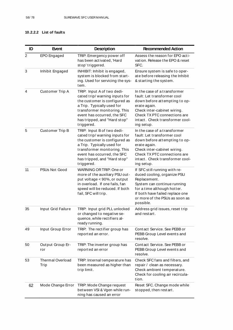
58/78 SUREWAVE SFC USER MANUAL
10.2.2.2 List of faults
ID Event Description Recommended Action2 EPO Engaged TRIP: Emergency power off
has been activated, 'Hardstop' triggered.
Assess the reason for EPO acti-vation. Release the EPO & resetSFC.
3 Inhibit Engaged INHIBIT: Inhibit is engaged,system is blocked from start-ing. Used for servicing the sys-tem.
Ensure system is safe to oper-ate before releasing the Inhibit& starting the system.
4 Customer Trip A TRIP: Input A of two dedi-cated trip/warning inputs forthe customer is configured asa Trip. Typically used fortransformer monitoring. Thisevent has occurred, the SFChas tripped, and "Hard stop"triggered.
In the case of a transformerfault: Let transformer cooldown before attempting to op-erate again.Check inter-cabinet wiring.Check TX PTC connections areintact. Check transformer cool-ing setup.
5 Customer Trip B TRIP: Input B of two dedi-cated trip/warning inputs forthe customer is configured asa Trip. Typically used fortransformer monitoring. Thisevent has occurred, the SFChas tripped, and "Hard stop"triggered.
In the case of a transformerfault: Let transformer cooldown before attempting to op-erate again.Check inter-cabinet wiring.Check TX PTC connections areintact. Check transformer cool-ing setup.
11 PSUs Not Good WARNING OR TRIP: One ormore of the auxiliary PSU out-put voltage < 90%, or outputin overload. If one fails, fanspeed will be reduced. If bothfail, SFC will trip.
If SFC still running with re-duced cooling, organize PSUReplacement.System can continue runningfor a time although hotter.If both have failed replace oneor more of the PSUs as soon aspossible.
35 Input Grid Failure TRIP: Input grid PLL unlockedor changed to negative se-quence, while rectifiers al-ready running.
Address grid issues, reset tripand restart.
49 Input Group Error TRIP: The rectifier group hasreported an error.
Contact Service. See PEBB orPEBB Group Level events andresolve.
50 Output Group Er-ror
TRIP: The inverter group hasreported an error
Contact Service. See PEBB orPEBB Group Level events andresolve.
53 Thermal OverloadTrip
TRIP: Internal temperature hasbeen measured as higher thantrip limit.
Check SFC fans and filters, andrepair / clean as necessary.Check ambient temperature.Check for cooling air recircula-tion.
62 Mode Change Error TRIP: Mode Change requestbetween VSI & Vgen while run-ning has caused an error
Reset SFC. Change mode whilestopped, then restart.

59/78 SUREWAVE SFC USER MANUAL
63 Max output volt-age exceeded
TRIP: Output voltage has ex-ceeded maximum level limit.
Contact ABB Service.
64 Min output voltageexceeded
TRIP: Output voltage has fallenbelow minimum level limit.
Contact ABB Service.
65 Max output freqexceeded
TRIP: Output frequency hasexceeded maximum level limit.
Contact ABB Service.
66 Min output freq ex-ceeded
TRIP: Output frequency hasfallen below minimum levellimit.
Contact ABB Service.
Table 10-6: SureWave SFC active events icons
10.2.3 Event Log
This page shows a list of the system messages for system events including origin, code, type,timestamp and basic description. The events are classified as information, warnings, or faults.Up to ten events are displayed on each page.
Figure 10-6: Event log page
Table 10-7: Event Log page icons, describes the function of each icon that may appear on theevents Log page.

60/78 SUREWAVE SFC USER MANUAL
Icon Description
Indicates the number of new unacknowledged events (can be seenfrom any page)
Indicates an fault
Indicates a warning
Move to the next active events page
Return to the previous active events page
Return to the first page (latest event)
Acknowledge all events
Update events list
Table 10-7: Event Log page icons
10.2.4Product information page
This page includes all the software version for the different system components. Also, for accesslevel higher than the default one “Any User” the option of “Service Log” is enable.
Figure 10-7: Product information page
10.2.5 Service page
This page is available for service trained authorized personnel that need special access require-ments. The main service page includes several sub-pages such as test and calibration pages.

61/78 SUREWAVE SFC USER MANUAL
Figure 10-8: Service page
10.2.6 Settings page
The Settings page gives access to SureWave SFC system parameters based on the user log-inand their accessibility level. The parameters are organized into different groups, and each onehas specific access rights.
Figure 10-9: Settings page

62/78 SUREWAVE SFC USER MANUAL
10.2.6.1 List of parameters
Parameter Parameter Name Access
0 Dashboard w
3 Active Events w
4 Event Log w
7 Information w
73 Service Log w
74 Firmware Versions w
8 Service w
80 Restricted - Login as 'service' required to enable all available func-tions
r
9 Settings w
90 General w
900 Customer Name w
901 Customer Tag Name w
902 Site Name w
903 Unit ID r
904 Product Name r
905 Model Name r
906 Serial Number r
907 Main Controller Reboot w
908 PEBBs Reboot w
91 Graphical Display w
910 Display w
9100 Color Theme w
9101 GDM Reboot w
9102 Screen Saver Time w
911 Access w
9110 Remote Access w
9111 SSH Port w
9113 Change Operator Password w
9114 Service Access w
912 Network Settings w
913 Network Status w
9130 Actual DHCP active r
9131 Actual IP Address r

63/78 SUREWAVE SFC USER MANUAL
9132 Actual IP Mask r
9133 Actual IP Gateway r
9134 MAC Address r
9135 Ethernet Status r
9136 Actual DNS 1 r
9137 Actual DNS 2 r
92 Nominal Settings w
920 Input Nominal RMS Voltage r
921 Output Nominal RMS Voltage r
922 Output Nominal Freq Sel r
93 Input Settings w
930 Auto-Restart on Grid Drop w
931 Reactive Current r
94 Output Settings w
940 Run Mode Sel r
941 Start Coupling w
942 Inductance Compensation r
943 Resistance Compensation r
944 Voltage Ref Ramp Rate r
945 Voltage Trip Maximum r
946 Voltage Trip Minimum r
947 Frequency Ref Ramp Rate r
948 Frequency Trip Maximum r
949 Frequency Trip Minimum r
94A Droop Settings w
94A0 Voltage Droop (Params Source) w
94A1 Frequency Droop (Params Source) w
94B Virtual Generator w
94B0 Inertia J w
94B1 Synthetic Impedance L (VGen Mode Only) r
94B2 Synthetic Impedance R (VGen Mode Only) r
94B3 Virtual Generator lower P Limit w
94B4 Virtual Generator upper P Limit w
94B5 Virtual Generator lower Q Limit w
94B6 Virtual Generator upper Q Limit w
95 System Config w
950 Breaker A Enable w

64/78 SUREWAVE SFC USER MANUAL
951 Breaker B Enable w
952 Cust DI A Severity w
953 Cust DI B Severity w
96 Commands (Params) w
960 Droop Enable (Params Source) w
961 Load Enable (Params Source) w
962 Fix Power Enable (Params Source) w
97 References (Params) w
970 Output Voltage (Params Source) w
971 Output Frequency (Params Source) w
972 Fix P ref (Params Source) w
973 Fix Q ref (Params Source) w
98 CMD/Ref Sources w
980 Output Voltage Source r
981 Output Frequency Source r
982 Droop Source r
983 Droop Enable Source r
984 Load Enable Source r
985 Fix Power Enable Source r
986 Fix P ref Source r
987 Fix Q ref Source r
99 PEBB Group Configs w
990 Input Minimum Capacity r
991 Input RFI Mode r
992 Input Fan speed r
993 Output Minimum Capacity r
994 Output RFI Mode r
995 Output Fan Speed r
996 Input PEBB Bitmap r
997 Output PEBB Bitmap r
Table 10-8: SureWave SFC list of parameters

65/78 SUREWAVE SFC USER MANUAL
10.2.7 User log in page
The SureWave SFC has three levels of user roles available from the touch screen:
Any User (default)
Operator
Service
Factory
To log in, access the pin code entry screen from the main dashboard login icon.
Select the user role to access the virtual keyboard. This will appear as in Figure 10-10: User Log-in page. Then, enter the password. If no user is logged in, the SFC will remain at a reduced ac-cessibility level of “Any User”.
Logging in prevents the unauthorized changing of parameters and/or the up-loading of firm-ware. The end-user must log in as operator to enable the SSH (Se-cure Shell) port and to enablethe service log-in.
It is recommended that the end-user changes the Operator password from the factory defaultto improve security.
Warning: Store the password in a safe place, as ABB cannot reset the password on-site. A lostpassword will necessitate the returning of the GDM to the factory.
Figure 10-10: User Log-in page

66/78 SUREWAVE SFC USER MANUAL
––11 Operation of the SFCSafety
The SFC must be only operated by trained and authorized personnel, i.e., personnel who are fa-miliar with the operation of the SureWave SFC and the hazards involved.
––Machine state flow diagram
While the SureWave SFC system is operational, it has two basic modes of operation Isochronous and droop mode. This section explains the SureWave SFC machine different states transitioning between modes of operation and the logic driving the control of transitioning from one state to another.
Figure 11-1: SureWave SFC state flow diagram

67/78 SUREWAVE SFC USER MANUAL
11.1.1 System states
11.1.1.1 Stopped
Idle - Ready for start command.
Inhibited - System inhibit is activated, all start commands are blocked, used for Service.
Tripped - System has been tripped, this state is latched, a reset command can attempt to un-latch it, if the fault is not still present.
11.1.1.2 Not stopped
Wait input grid - Assesses the input AC feed for voltage frequency and stability prior to startingthe rectifiers.
Wait rectifier run -Waits for rectifiers to pre-charge, boost DC bus prior to starting inverters.
Live Bus detect (If Auto start or Coupled start selected) - Determines whether output bus issuitable for a couple start or if ‘auto start’ is selected determines whether to black start or tocouple start.
Black start
Start inverters - Starts the output inverters with 0 volts as the output setpoint.
Ramp-up - Ramps the voltage up from 0 to the set point and a rate defined in the inter-nal parameters.
Coupled start
Output PLL lock - Assesses output AC bus for suitable voltage, magnitude and stabilityprior to synching.
Sync voltage - Synchronizes internal voltage reference to the output bus.
Sync frequency - Synchronizes internal frequency reference to the output bus.
Sync phase - Synchronizes internal phase reference to the output bus.
Start inverters - Starts inverters a couples with references following the output bus.
RampRef - Transitions the voltage and frequency references to selected referencesources and set points.
Running
VF Isochronous - Output is set to stiff voltage and frequency
VF Droop - Output is set to V and F droop to share with a parallel source.
PQ Set - Fixed P and Q output, only can be used in VGen mode
External Sync - While the output is running, the output voltage, frequency and phase areadjusted to match the external measurements. During this transition the droop sharingis disabled, load enable is forced. When sync command is released the output will transi-tion back to the selected output mode.

68/78 SUREWAVE SFC USER MANUAL
11.1.1.3 Stopping
Stop unload - When configured to share with droop or running fixed P and Q then the system will first unload the SFC and hand load off to other generators, prior to stopping the inverters
Stop ramp 0 - If stopping in from and Isochronous mode, the system will ramp the output volt-age down to 0 prior to stopping the inverters.
Stop Inverters - Disconnects and stops the inverters
Stop rectifiers - Disconnects and stops the rectifiers
–– System start
To start the SureWave SFC the incoming supply needs to be present and the rectifiers AC termi-nals to be energized. Hence, the user has to check the system state e.g., confirming input volt-age is at required levels through the GDM.
Once the input voltage is within nominal conditions and no faults are present, the system can be started via three sources:
GDM – Via “Dashboard” page, the SFC can be started with the press of one button.
Digital I/O – the SFC can be started after the “Start” digital signals is received.
Modbus TCP – The SFC can be started after the “Start” command is received.
–– Operation modes
The SureWave SFC may have its output frequency and voltage controlled independently in a number of different ways, depending on the application.
Stand-alone applications without any other generation equipment connected to the load. This typically require the output frequency and voltage to be fixed.
Applications with a generator connected in parallel with the SureWave. This typically re-quire the SFC to control its real power output by adjusting its output frequency. This enables seamless handover of load between generator and the SureWave SFC.
Applications with more than one SureWave SFC in parallel to cover larger loads. Gener-ally, the load sharing is successfully achieved by applying droop to the SureWave SFC output voltage.
11.3.1 Stand-alone (VSI) operation mode
11.3.1.1 VSI-V/F
This mode is typically used when the SFC either stands alone or is the largest unit on a grid. In this mode, the voltage and frequency are regulated very tightly in reaction to load changes.

69/78 SUREWAVE SFC USER MANUAL
11.3.1.2 VSI-V/F droop enable
Additionally, the SureWave can operate in parallel and share the load with other energy sources by enabling the frequency and voltage droops.
Note, when droop enable the frequency and the voltage will change depending on the load.
This is not a recommended operation. VGen with droop is the recommended mode of operation when running is parallel with other systems.
11.3.2 Virtual generator (VGen) operation mode
The ABB virtual generator mode is a unique operating mode for a power electronic converter whereby the converter emulates the behavior of a rotary generator and thus interacts with the power system in the same way as a traditional synchronous machine. This behavior is achieved purely through power electronic control and there are no large spinning masses.
When set to virtual generator mode, the SureWave SFC ca be operated in two control modes:
11.3.2.1 VGen-V/F
When operated in virtual generator V/F mode, the SFC run as a standalone power source by tightly controlling its own voltage and frequency. In this setting the SureWave supports the local loads with minimal disturbance.
In this mode, physical inertia is modeled in the SureWave SFC control system providing a damp-ing response to the grid frequency via the energy provided by the incoming supply.
Note, the modelled inertia artificially limits the speed of the SFC, thus this mode is not recom-mended for applications where fast control is required.
11.3.2.2 VGen-V/F droop
The recommended mode when in parallel with other energy sources.
Note, when droop enable the frequency and the voltage will change and depending on the load.
11.3.2.3 VGen fix power (P/Q)
When operated in VGen fix power, the SFC has the ability to control power flow on the output . This is typically used when interfacing generators to a grid where power flow to and from the grid must be controlled. The SureWave SFC operates with setpoints for both real power (P) and reactive power (Q).
Note, switching between V/F and fix power control modes can be done while the system is run-ning, which is particularly interesting for micro-grid applications.
–– VSI vs virtual generator
VSI mode is the simplest mode and can provide ‘stiff’ voltage and frequency. This has the fastest transient response. Although it can be used with droop it is not recommended.
Virtual generator mode is the most powerful when it comes to load sharing. It can be tuned to emulate the transient behavior of almost any type and size of generator. This allows even load

70/78 SUREWAVE SFC USER MANUAL
distribution during load steps. It also enables bump less loading or unloading of the SFC, so that parallel generators are not exposed to large load steps.
It also enables fixed real power and Var sourcing for advanced uses.
–– SureWave SFC performance
11.5.1 Step load capability
The step load capability of a power converter or generator is a measure of how much load can be applied to the converter or generator, without output voltage or frequency deviating from specification.
The step load capability of a generator is typically between 10% and 75% of its capacity, de-pending on the generator and type of prime mover. In contrast, the step load capacity of the SureWave SFC is 100% of its capacity.
Thus, depending on the parametrization of the SureWave SFC, if it is used in parallel with one or more generators, the step load capability of the overall system is substantially improved. Imme-diately on load application, the SureWave SFC typically will take on all the additional load, and then the load increase is gradually passed over to the generator(s).
11.5.2 Load rejection capability
A load rejection is a decrease in load. Load rejection capability is a measure of how much load can be removed from the output of a converter or generator while still providing output voltage and frequency within specifications.
The load rejection capability of a generator set is very dependent on its prime mover. Typical figures may be:
Steam turbine: 10 to 30% of its present loading.
Gas reciprocating: 50 to 100% of its present loading.
Diesel reciprocating: 90 to 100% of its present loading.
The SureWave SFC has a load rejection capability in excess of its present loading – that is, the SFC output power can briefly go negative by regenerating power into the source grid.
Thus, if the SureWave SFC is used in parallel with one or more energy sources, it can assist in handling load rejection by absorbing any energy transients and dissipating them by regenerat-ing back into the grid. This can prevent the generator(s) from going into “reverse power” and tripping off. The decrease in load is then passed over to the other generator(s).
Note, for load rejection capability of the SureWave SFC, the real power (P) limits need to be con-sidered.
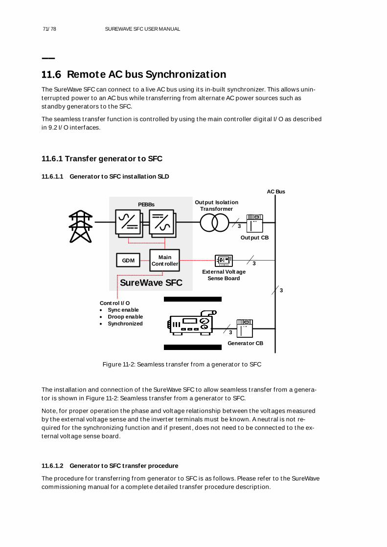
71/78 SUREWAVE SFC USER MANUAL
–– Remote AC bus Synchronization
The SureWave SFC can connect to a live AC bus using its in-built synchronizer. This allows unin-terrupted power to an AC bus while transferring from alternate AC power sources such as standby generators to the SFC.
The seamless transfer function is controlled by using the main controller digital I/O as described in 9.2 I/O interfaces.
11.6.1 Transfer generator to SFC
11.6.1.1 Generator to SFC installation SLD
PEBBs
SureWave SFC
MainControllerGDM
Output IsolationTransformer
3
3
3
3
External VoltageSense Board
Control I/O Sync enable Droop enable Synchronized
AC Bus
Output CB
Generator CB
Figure 11-2: Seamless transfer from a generator to SFC
The installation and connection of the SureWave SFC to allow seamless transfer from a genera-tor is shown in Figure 11-2: Seamless transfer from a generator to SFC.
Note, for proper operation the phase and voltage relationship between the voltages measured by the external voltage sense and the inverter terminals must be known. A neutral is not re-quired for the synchronizing function and if present, does not need to be connected to the ex-ternal voltage sense board.
11.6.1.2 Generator to SFC transfer procedure
The procedure for transferring from generator to SFC is as follows. Please refer to the SureWave commissioning manual for a complete detailed transfer procedure description.

72/78 SUREWAVE SFC USER MANUAL
Step Description
1 With the output CB open, start the SureWave SFC
2 Enable V/F droops to allow the SFC to parallel with the generator
3 Command the SureWave SFC to synchronize to the reference as measured on the exter-nal voltage sense board.
5 Once the SFC is synchronized, the output CB can now be closed connecting the SFC tothe AC bus.
6 Remove the synchronize commandThe SFC is now in parallel with the generator.
7 Once the generator is offline, disable the V/F droops. The AC bus is now being suppliedfrom the SFC.
Table 11-1: Generator to SFC transfer procedure
11.6.1.3 Parallel operation with generator
If a long-term parallel operation and load sharing with a generator is required, ensure the gener-ator has the identical voltage and frequency setpoints, as well as equal droop characteristic set-tings for both voltage and frequency. Follow the steps above until step 6. The SFC and generatorwill now be sharing the load.
The load may be transferred from either machine by setting the unload command on the SFC orunloading the Generator.
11.6.2 Transfer SFC to generator
Typically, generators will have their own synchronizer, which will perform the synchronization tothe SFC supplied AC bus. If a generator is unstable when connected to the AC bus supplied bythe SFC, enabling V/F droops on the SureWave SFC might help with stability.
11.6.2.1 SFC to generator installation SLD
The installation and connection of the SureWave SFC to allow seamless transfer from the SFC togenerator is shown in Figure 11-3: Seamless transfer from the SFC to generator. In this scenariothe external voltage sensing must be moved to sense the generator output voltage that is to bebrought online. This could be done with a change-over relay to allow both connections to the ex-ternal voltage sensing board.
Note, for proper operation the phase and voltage relationship between the voltages measuredby the external voltage sense and the inverter terminals must be known. A neutral is not re-quired for the synchronizing function and if present, does not need to be connected to the ex-ternal voltage sense board.

73/78 SUREWAVE SFC USER MANUAL
PEBBs
SureWave SFC
MainControllerGDM
Output IsolationTransformer
3
3
3
External VoltageSense Board
Control I/O Sync enable Droop enable Synchronized
AC Bus
Output CB
Generator CB
3
Figure 11-3: Seamless transfer from the SFC to generator
11.6.2.2 SFC to generator transfer procedure
The procedure for transferring from generator to SFC is as follows. Please refer to the SureWavecommissioning manual for a complete detailed transfer procedure description.
Step Description
1 With the generator contactor open, start the generator.
2 Once the generator output is stable and ready for loading, enable SureWave V/F droopsto allow the SFC to parallel with the generator when the generator is online.
3 Command the SureWave SFC to synchronize to the reference as measured on the exter-nal voltage sense board.
4 Once the SFC is synchronized, the generator CB can now be closed connecting the gen-erator to the AC bus.
6 Once the generator is online the SFC can be off loaded and switched off. The AC bus isnow being supplied from the generator.
Table 11-2: SFC to generator transfer procedure
11.6.2.3 Parallel operation with generator
If a long-term parallel operation and load sharing with a generator is required, ensure the gener-ator has the identical voltage and frequency setpoints, as well as equal droop characteristic set-tings for both voltage and frequency. Follow the steps above until step 6. The SFC and generatorwill now be sharing the load.

74/78 SUREWAVE SFC USER MANUAL
The load may be transferred from either machine by setting the unload command on the SFC or unloading the Generator.
11.6.3 External voltage sense board calibration
If the SFC has an output transformer, the transformers’ output voltage and the voltage phase angle will be different to inverter output (transformer input). When the external voltage sense board is used for remote synchronization, these differences will need to be trimmed out. Please refer to the SureWave commissioning manual for a complete detailed transfer procedure de-scription.
–– System EPO
The system Emergency Power Off (EPO) is a digital input linked to the site EPO and use to in-hibit the SureWave SFC operation in case of emergency shut down. For larger systems > 750kVA the emergency inhibit action will not open the CBs located inside the termination enclosures.
–– Hard fault
Hard faults are extremely rare situations where multiple failures occur at the same time, and the system is not capable of keeping the correct operation any longer. In the case of hard fault the SureWave will stop operation and report accordingly. For larger systems > 750kVA a hard fault scenario will not open the CBs located inside the termination enclosures.

75/78 SUREWAVE SFC USER MANUAL
––12 Maintenance scheduleOverview
The recommended intervals for maintenance and component replacement are based on the nor-mal operating conditions of the SureWave SFC. The SFC should be checked at least annually byqualified personnel whose recommendations should be followed. Depending on the actual con-ditions of the SureWave SFC, maintenance work can be carried out before or after the recom-mended interval.
Item Years from start up
1 2 3 4 5 6 7 8 9 10 11 12 13 14
Power supply - - - - - - I I I R - - - -
PSU buffer - - - - - - I I I R - - - -
Busbar contact grease - - - - - R - - - I I R - -
PEBB fan - - I I I R I I I I I R I I
PEBB air filter kit - - I I I R I I I I I R I I
PEBB AC caps - - - - - - I I I R - - - -
Enclosure air filter kit I I R I I R I I R I I R I I
Input/output breakers*
Table 12-1: SFC to generator transfer procedure
Key:
I = Inspection (visual inspection, corrective measures, repair and/or replacement of componentif needed).
R = Replacement of component.
- = No action
* Refer to ABB library document 1SDH001000R0002

Additional informationWe reserve the right to make technicalchanges or modify the contents of this doc-ument without prior notice. With regard topurchase orders, the agreed particulars shallprevail. ABB AG does not accept any respon-sibility whatsoever for potential errors orpossible lack of information in this docu-ment.
We reserve all rights in this document and inthe subject matter and illustrations con-tained therein. Any reproduction, disclosureto third parties or utilization of its contents– in whole or in parts – is forbidden withoutprior written consent of ABB AG.
2UC
D42
00
00
E00
1
http
s://
to.a
bb/R
H91
iGe3
—ABB Ltd111 Main North Road4110, Napier
New Zealand