Documentation eibPort - ABB
177
Documentation eibPort Version 3.0
-
Upload
khangminh22 -
Category
Documents
-
view
1 -
download
0
Transcript of Documentation eibPort - ABB

Documentation eibPort
Version 3.0

eibPort version. 3


Table of contents documentation eibPort
2 eibPort version. 3
Documentation eibPort Table of contents
eibPort Version 3 3
TABLE OF CONTENTS
1 Introduction................................................................................................................................... 10
1.1 Function Survey ......................................................................................................................... 10 1.2 General information about the present manual ...................................................................... 11 1.3 Scope of delivery / Interfaces ................................................................................................... 11 1.4 Prerequisites / Environment ...................................................................................................... 11 1.5 Updates / Version history .......................................................................................................... 12
2 Initial operation and installation .................................................................................................... 13
2.1 Safety instructions...................................................................................................................... 13 2.2 Device Overview ........................................................................................................................ 14 2.3 Installation.................................................................................................................................. 14 2.4 Initial operation ......................................................................................................................... 15
2.4.1 Java settings / Preparations at the Client PC ....................................................................... 15 2.4.2 Communicate with eibPort................................................................................................... 17
Default IP Address / Discovery Tool .......................................................................................... 17 2.4.3 Passwords .............................................................................................................................. 17 2.4.4 Starting behaviour................................................................................................................. 18 2.4.5 Basic settings ......................................................................................................................... 18
3 Visualisation................................................................................................................................... 19
3.1 Java Visualisation ....................................................................................................................... 20 3.1.1 VisuToolBar ............................................................................................................................ 20 3.1.2 Important Hints ..................................................................................................................... 21
3.2 Ajax Visualisation ....................................................................................................................... 22 3.2.1 Requirements: ....................................................................................................................... 22 3.2.2 Important notes .................................................................................................................... 22
Use hardware acceleration / CSS 3 animations ....................................................................... 23 3.3 Home Information Center ......................................................................................................... 24
3.3.1 Support Terminals ................................................................................................................. 24 3.3.2 Call ......................................................................................................................................... 24 3.3.3 Important notes .................................................................................................................... 25
3.4 Autologin / Log Remember....................................................................................................... 25 3.4.1 Autologin for Java Visualization ............................................................................................ 25 3.4.2 Remember login for The Ajax Visualization.......................................................................... 26 3.4.3 „Remember ME“ Login for the HIC Visualization ................................................................. 26
4 eibPort editor ................................................................................................................................ 27
4.1 Things to know before getting started ..................................................................................... 28 Authentifizierung ....................................................................................................................... 28 Group addresses, virtual and real .............................................................................................. 28 Communications objects........................................................................................................... 28 Syntax general ........................................................................................................................... 28 ETS 4........................................................................................................................................... 28
4.2 Editor .......................................................................................................................................... 29 4.2.1 Menu bar of editor ................................................................................................................ 29
4.2.1.1 File ................................................................................................................................ 30 Localisation ................................................................................................................................ 30 Address-levels............................................................................................................................. 30 eibPort time ............................................................................................................................... 30 Reset client settings................................................................................................................... 31 Erasing history table .................................................................................................................. 31 Erasing state-table ..................................................................................................................... 31
4.2.1.2 Window ........................................................................................................................ 31 4.2.1.3 Extras ............................................................................................................................ 32
ESF Upload & data maintenance ............................................................................................... 32 EnOcean Configuration ............................................................................................................. 34
Table of contents documentation eibPort
4 eibPort version. 3
Image transfer............................................................................................................................ 34 Free-Components - Transfer ...................................................................................................... 35 Themes ....................................................................................................................................... 35 Export Group Details.................................................................................................................. 36 History & state-table .................................................................................................................. 36
4.2.1.1 Help .............................................................................................................................. 37 4.3 Close the Editor ......................................................................................................................... 38
4.3.1 Creating Backup .................................................................................................................... 38 4.3.2 Create Statistics..................................................................................................................... 39
5 Visualisation editor ........................................................................................................................ 40
5.1 Menu bar of visualization editor ............................................................................................... 40 Save/ Reload .............................................................................................................................. 40 Visualisation / security settings / room allocation plan(Control R) ......................................... 41 New project / new page ........................................................................................................... 41 Raster / catch / color ................................................................................................................ 41 Arrange items / align horizontally / align vertically ................................................................. 41 Visualisation live mode .............................................................................................................. 41
5.2 Window layout ........................................................................................................................... 42 5.2.1 Structure ................................................................................................................................ 42 5.2.2 Elements ................................................................................................................................ 42 5.2.3 Parameter window ................................................................................................................ 43 5.2.4 Working surface .................................................................................................................... 43
5.3 Information for operating.......................................................................................................... 44 Release windows........................................................................................................................ 44 To scale elements ...................................................................................................................... 44 Copy, paste, delete.................................................................................................................... 44 Drag & Drop ............................................................................................................................... 44
5.4 Projects and pages..................................................................................................................... 45 5.4.1 Projects .................................................................................................................................. 45 5.4.2 Master pages ......................................................................................................................... 46 5.4.3 Flip / dialogue pages ............................................................................................................ 47 5.4.4 Pages...................................................................................................................................... 48 5.4.5 Ajax support........................................................................................................................... 49
5.5 Elements..................................................................................................................................... 50 5.5.1 Themes / exchangeable elements ....................................................................................... 50 5.5.2 General Element Parameter .................................................................................................. 50
5.6 Visualisation Elements ............................................................................................................... 53 5.6.1 Embedded page (flip) ........................................................................................................... 53 5.6.2 Web Container ...................................................................................................................... 54 5.6.3 Shape element ...................................................................................................................... 55 5.6.4 Sequence push button .......................................................................................................... 56 5.6.5 Blinds and status indicator .................................................................................................... 57 5.6.6 Window contact .................................................................................................................... 57 5.6.7 RTR display ............................................................................................................................. 58 5.6.8 Colour selection .................................................................................................................... 58 5.6.9 Top consumer ....................................................................................................................... 59 5.6.10 Room ..................................................................................................................................... 60 5.6.11 Image..................................................................................................................................... 60 5.6.12 EIS 1 Objects / Switch, Button and Luminaire ..................................................................... 62 5.6.13 Blinds ..................................................................................................................................... 63 5.6.14 EIS 14 pushbutton................................................................................................................. 63 5.6.15 Bit bar .................................................................................................................................... 63 5.6.16 Static and dynamic text ........................................................................................................ 64 5.6.17 EIS 15 Text............................................................................................................................. 64 5.6.18 EIS 15 display ........................................................................................................................ 65 5.6.19 Temperature switch .............................................................................................................. 65 5.6.20 Temperature display ............................................................................................................. 66 5.6.21 Date/ time display ................................................................................................................ 67 5.6.22 Analogue Clock ..................................................................................................................... 68

Documentation eibPort Table of contents
eibPort Version 3 5
5.6.23 Slider ...................................................................................................................................... 68 5.6.24 Dimmer.................................................................................................................................. 69 5.6.25 Value display.......................................................................................................................... 69 5.6.26 Telegram Time ...................................................................................................................... 71 5.6.27 Bus Monitor ........................................................................................................................... 72 5.6.28 Job Editor ............................................................................................................................... 73 5.6.29 Logic display .......................................................................................................................... 73 5.6.30 Failure indicator .................................................................................................................... 74 5.6.31 Page Link................................................................................................................................ 75 5.6.32 RSS Feed ................................................................................................................................ 75 5.6.33 Camera .................................................................................................................................. 76 5.6.34 Graph ..................................................................................................................................... 78
Functionality within the visualization ....................................................................................... 80 Ajax functionality within the visualization ................................................................................ 80 Information about the recording table (ringbuffer) ................................................................. 81
5.7 Security Settings - user administration for the visualisation ..................................................... 82 5.8 Room Allocation Plan (Control R) .............................................................................................. 83
6 Jobeditor ....................................................................................................................................... 84
6.1 General hints about the job editor ........................................................................................... 85 6.2 Jobs............................................................................................................................................. 86
6.2.1 Logic ...................................................................................................................................... 86 6.2.2 Staircase lighting function .................................................................................................... 86 6.2.3 Delay unit .............................................................................................................................. 87 6.2.4 Light scene ............................................................................................................................ 87 6.2.5 Hysteresis unit ....................................................................................................................... 87 6.2.6 Logic threshold unit .............................................................................................................. 89 6.2.7 Comparator ........................................................................................................................... 90 6.2.8 Mathematics.......................................................................................................................... 92 6.2.9 Counter.................................................................................................................................. 98 6.2.10 Integrator .............................................................................................................................. 99
Example.................................................................................................................................... 100 6.2.11 Timers (Weekly timer und year-timer) ................................................................................ 101 6.2.12 Astro Timer .......................................................................................................................... 102
Astro Timer simple ................................................................................................................... 103 Astro Timer (complex) ............................................................................................................. 104
6.2.13 Sending/receiving date and time....................................................................................... 108 6.2.14 Send eMail ........................................................................................................................... 108
SMS Sending............................................................................................................................. 109 6.2.15 Linking facilities ................................................................................................................... 110 6.2.16 UDP-sender .......................................................................................................................... 111 6.2.17 Squeeze Center receiver (SlimServer receiver) .................................................................. 112 6.2.18 IRTrans receiver ................................................................................................................... 113 6.2.19 xPL remote. Basic receiver .................................................................................................. 115 6.2.20 xPL-sender............................................................................................................................ 117 6.2.21 Wake On LAN....................................................................................................................... 118 6.2.22 EIS 15-Multiplexer ............................................................................................................... 119 6.2.23 SB-Control............................................................................................................................ 120 6.2.24 HTTP- Request...................................................................................................................... 126
Example.................................................................................................................................... 130
7 Home Information Center (HIC)...................................................................................................133
7.1 Layout of the Home Information Center (HIC) – Editor .......................................................... 133 7.2 Available element types .......................................................................................................... 135 7.3 HIC User Authentication .......................................................................................................... 136
8 Sonos UPnP ..................................................................................................................................137
8.1 Sonos Configuration ................................................................................................................ 137 General..................................................................................................................................... 137 UPnP devices ............................................................................................................................ 137

Table of contents documentation eibPort
6 eibPort version. 3
Radio ........................................................................................................................................ 139 Sonos Desktop Controller ........................................................................................................ 140
9 System .........................................................................................................................................141
9.1 Configuration-tool (ConfigTool) .............................................................................................. 142 9.1.1 Layout .................................................................................................................................. 142 9.1.2 Configuration ...................................................................................................................... 143
9.1.2.1 General ....................................................................................................................... 143 Physical address ....................................................................................................................... 143
9.1.2.2 Extended EIB (yabus) / settings ................................................................................. 144 TCP port „bmx“ ....................................................................................................................... 144 UDP-Port „bmx“ ....................................................................................................................... 144 TCP-Port „http“ ........................................................................................................................ 144 TCP Port „Websockets“ ........................................................................................................... 145 TCP-Port „ssh“ .......................................................................................................................... 145 KNXnet/IP Tunneling ............................................................................................................... 146
9.1.2.3 Network settings ........................................................................................................ 147 Time server............................................................................................................................... 147
9.1.2.4 EIB- telegram record filter.......................................................................................... 148 9.1.2.5 E-Mail .......................................................................................................................... 148
9.1.3 Startpage ............................................................................................................................. 150 9.1.4 Database.............................................................................................................................. 151
9.1.4.1 Tabletypes .................................................................................................................. 151 9.1.5 Licence upload .................................................................................................................... 153 9.1.6 Backup/ restore................................................................................................................... 153
Backup...................................................................................................................................... 154 Restore ..................................................................................................................................... 154
9.1.7 eibPort control .................................................................................................................... 155 9.1.8 User administration ............................................................................................................. 155
9.1.8.1 Add user ..................................................................................................................... 155 9.1.8.2 Assinging user privileges ............................................................................................ 155
10 Object structure / Address space ................................................................................................158
10.1 eibPort Address space:............................................................................................................. 158 10.2 General syntax ......................................................................................................................... 158
11 ETS ...............................................................................................................................................159
KNXnet/IP................................................................................................................................. 159 KNXnet/IP Tunneling ............................................................................................................... 160 Eibport use as a programming Interface ................................................................................ 161 Export group address out of ETS ............................................................................................. 161 Group address structure in ets 4 ............................................................................................. 162
12 Public IP-Addresses / DynDNS ......................................................................................................163
12.1 Example: DynDNS Account application .................................................................................. 163
13 Change the language ..................................................................................................................165
14 Disclaimer....................................................................................................................................166
15 Appendix .....................................................................................................................................167

eibPort Version 3 7
Documentation eibPort List of figures
LIST OF FIGURES
Figure 1: Device Overview ........................................................................................................................ 14 Figure 2: Java update................................................................................................................................. 15 Figure 3: Disable temporary internet files .............................................................................................. 16 Figure 4: Increase java heap space .......................................................................................................... 16 Figure 5: Home - Waiting for Application Server ................................................................................... 18 Figure 6: ConfigTool - Configuration ....................................................................................................... 18 Figure 7: eibPort - Home - visualization .................................................................................................. 19 Figure 8: Visu - in a external window....................................................................................................... 20 Figure 9: Java-visualisation - Visu Tool Bar .............................................................................................. 20 Figure 10: Apple iPad with Ajax visualisation (Control L) ..................................................................... 22 Figure 11: Ajax visualization - Context Menu ......................................................................................... 23 Figure 12: HIC with iPhone (Control S).................................................................................................... 24 Figure 13: eibPort Home - HIC start ....................................................................................................... 24 Figure 14: visualization Log out ............................................................................................................... 26 Figure 15: eibPort - Startpage - editor .................................................................................................... 27 Figure 16: Editor window - all editors ..................................................................................................... 29 Figure 17: Editor - window menu item ................................................................................................... 29 Figure 18: Editor - menu item .................................................................................................................. 30 Figure 19: Editor - dialoque of localization ............................................................................................ 30 Figure 20: Editor - setting clock time ...................................................................................................... 30 Figure 21: Editor - menu item ‚Window’ ................................................................................................ 31 Figure 23: Editor - ESF Upload & Data maintenance ............................................................................. 32 Figure 22: Editor - menu - item ‘Extras’ ................................................................................................... 32 Figure 24: Maintaining ESF data .............................................................................................................. 33 Figure 25: Editor - Image transfer ............................................................................................................ 34 Figure 26: Editor - Image transfer ............................................................................................................ 34 Figure 27: Editor - Component Upload ................................................................................................... 35 Figure 28: Load Theme.............................................................................................................................. 35 Figure 29: Export of group adresses ........................................................................................................ 36 Figure 30: Editor - state table................................................................................................................... 36 Figure 31: Editor - help > info................................................................................................................... 37 Figure 32: Editor - security dialogue ....................................................................................................... 38 Figure 33: eibPort Statistics ..................................................................................................................... 39 Figure 34: Editor - editor for visualisation .............................................................................................. 40 Figure 35: Editor - VisuEditor menu bar ................................................................................................. 40 Figure 36: Visualisation - editor - strukture context menue................................................................. 42 Figure 37: Visualisation editor - element window ................................................................................. 42 Figure 38: Visualisation - editor - parameter window ........................................................................... 43 Figure 39: Visualisation editor - work surface ........................................................................................ 43 Figure 40: Editor - Release of windows ................................................................................................... 44 Figure 41: Visualisation Editor - Project parameters ............................................................................. 45 Figure 42: Visualisation editor - parameter of master page ................................................................ 46 Figure 43: Visualisation editor - Flip / dialogue page parameter........................................................ 47 Figure 44: Element - Embedded Page ..................................................................................................... 48 Figure 45: Visualisation editor - page parameter .................................................................................. 48 Figure 46: Visualisation editor - tooltipp ajax support ......................................................................... 49 Figure 47: Visualisation editor - general parameter of elements ........................................................ 50 Figure 48: setting global element behaviour......................................................................................... 51 Figure 49: Address allocation with ESF File ............................................................................................ 51 Figure 50: Modify font style...................................................................................................................... 52 Figure 51: Visualisation editor - Flip / Dialogue page out of distribution project. ........................... 53 Figure 52: Visualisation editor - embedded page(flip) in distribution project ................................. 54 Figure 53: Web Container - parameter ................................................................................................... 54 Figure 54: Shape Element - Shape type................................................................................................... 55 Figure 55: Shape Element - Add action ................................................................................................... 55 Figure 56: Shape Element - Actions ......................................................................................................... 55 Figure 57: Sequence Button - specific parameters................................................................................ 56

8 eibPort version. 3
List of figures documentation eibPort
Figure 58: Sequence Button - edit functions.......................................................................................... 56 Figure 59: Jalousie and Status indicator - Parameters .......................................................................... 57 Figure 60: Window contact - parameters ............................................................................................... 57 Figure 61: RTR-Display - specific parameters.......................................................................................... 58 Figure 62: Colour selection - specific parameters ................................................................................. 58 Figure 63: Top Consumer - specific parameters .................................................................................... 59 Figure 64: Top Comsumer - editing consumers ..................................................................................... 59 Figure 65: Visualisation Element Room Allocation Plan (Control R).................................................... 60 Figure 66: Image Element Parameter ..................................................................................................... 60 Figure 67: Example Cover Display............................................................................................................ 61 Figure 68: Jalousie - parameters .............................................................................................................. 63 Figure 69: Bitbar - parameters ................................................................................................................. 63 Figure 70: Static Text, Object style configuration................................................................................. 64 Figure 71: Enter font style ........................................................................................................................ 64 Figure 72: Dynamic Text - Parameters .................................................................................................... 64 Figure 73: EIS 15 Text - Paramters ........................................................................................................... 64 Figure 74: EIS 15 Display - Parameters .................................................................................................... 65 Figure 75: Temp. Switch- Parameters...................................................................................................... 65 Figure 76: Date / Time display - Parameters .......................................................................................... 67 Figure 77: Analogue Clock - Parameters ................................................................................................. 68 Figure 78: Slider - Parameters .................................................................................................................. 68 Figure 79: Dimmer - Parameters .............................................................................................................. 69 Figure 80: Value Display - Parameters..................................................................................................... 69 Figure 81: Telegram Time- Parameters ................................................................................................... 71 Figure 82: Bus Monitor - Parameters ....................................................................................................... 72 Figure 83: Bus Monitor - embedded in Visualisation............................................................................. 72 Figure 84: Job Editor element .................................................................................................................. 73 Figure 85: Logic display - Parameters...................................................................................................... 73 Figure 86: Failure Indicator - Parameters ............................................................................................... 74 Figure 87: Page Link - Parameters ........................................................................................................... 75 Figure 88: RSS Feed - Parameters............................................................................................................. 75 Figure 89: Kamera Element - Parameter ................................................................................................. 76 Figure 90: Camera view - Copy URL ......................................................................................................... 77 Figure 91: Graph - Parameters ................................................................................................................. 78 Figure 92: Zoomed graph with curve information ................................................................................ 80 Figure 93: ConfigTool - EIB record filter.................................................................................................. 81 Figure 94: Altering between user management and visu-editor......................................................... 82 Figure 95: Editor - Create/Delete User Account .................................................................................... 82 Figure 96: Editor – user management..................................................................................................... 82 Figure 97: Job editor.................................................................................................................................. 84 Figure 98: Job editor - job symbol bar..................................................................................................... 84 Figure 99: Job editor – creating reports ................................................................................................. 84 Figure 100: Job Editor - Job Verwaltung ................................................................................................. 85 Figure 101: Job Editor - ESF Dialog .......................................................................................................... 85 Figure 102: Diagram threshold switch.................................................................................................... 89 Figure 103: Job Editor - Job mask mathematics..................................................................................... 93 Figure 104: Job Editor – Counter job mask ............................................................................................ 98 Figure 105: Job Editor – Cofinguration example Integrator .............................................................. 100 Figure 106: Visualisation Editor – Configuration example Top Consumers ..................................... 101 Figure 107: Astro clock - add new job................................................................................................... 102 Figure 108: Astro Timer - Global settings ............................................................................................. 103 Figure 109: Astro Timer - Configuration Astro Timer Simple ............................................................. 103 Figure 110: Astro Timer (complex) - Define Point in Time.................................................................. 105 Figure 111: Astro Timer (complex) – Output configuration ............................................................... 106 Figure 112: Job Editor - IRTrans Job – example for additional using ................................................. 115 Figure 113: Job Editor - SB-Control ........................................................................................................ 121 Figure 114: Job Editor - HTTP Request .................................................................................................. 126 Figure 115: Job Editor - HTTP Request Sending Values....................................................................... 128 Figure 116: Example response interpreting "Google Weather API" ................................................. 132 Figure 117: HIC sight of editor............................................................................................................... 133
eibPort Version 3 9
Documentation eibPort List of figures
Figure 118: HIC editor – control menue ............................................................................................... 134 Figure 119: HIC editor - Elemente Overview ........................................................................................ 134 Figure 120: HIC editor – Sight of visualisation ..................................................................................... 134 Figure 121: HIC editor – Parameterization window............................................................................ 134 Figure 122: HIC Authentication ............................................................................................................. 136 Figure 123: Sonos general configuration ............................................................................................. 137 Figure 124: Sonos configuration UPnP devices.................................................................................... 137 Figure 125: Sonos configuration UPnP devices.................................................................................... 139 Figure 126: Sonos Desktop Controller .................................................................................................. 140 Figure 127: start page - system.............................................................................................................. 141 Figure 128: ConfigTool - overview ......................................................................................................... 142 Figure 129: ConfigTool - Menüleiste ..................................................................................................... 142 Figure 130: ConfigTool - tab bar ............................................................................................................ 143 Figure 131: ConfigTool - save ................................................................................................................. 143 Figure 132: ConfigTool - configuration - general................................................................................. 143 Figure 133: ConfigTool - configuration ................................................................................................. 144 Figure 134: ConfigTool - Konfiguration - Netzwerkeinstellungen ..................................................... 147 Figure 135: ConfigTool - Configuration - Email .................................................................................... 148 Figure 136: ConfigTool - Database connection ................................................................................... 151 Figure 137: ConfigTool - Database connection- Generate SQL statement ...................................... 152 Figure 138: ConfigTool - Licence upload .............................................................................................. 153 Figure 139: ConfigTool - Save / restore ................................................................................................ 153 Figure 140: ConfigTool - user administration ...................................................................................... 155 Figure 141: ConfigTool - user administration - edit user .................................................................... 155 Figure 142: ConfigTool - Assigning user privileges.............................................................................. 156 Figure 143: ETS - KNXnet/IP Routing..................................................................................................... 159 Figure 144: ETS - KNXnet/IP Routing..................................................................................................... 159 Figure 145: KNXnet/IP Tunneling .......................................................................................................... 160 figure 146: ETS - KNXnet/IP Tunneling.................................................................................................. 160 Figure 147: ETS - ESF file export ............................................................................................................. 161 Figure 148: ETS 4 - ESF Export ................................................................................................................ 162 Figure 149: DynDNS application ............................................................................................................ 163 Figure 150: DynDNS Router settings ..................................................................................................... 164 Figure 151: Java Control Panel - change of language ......................................................................... 165 Figure 152: Java Runtime settings - change of language ................................................................... 165

Introduction Documentation eibPort
10 eibPort version. 3
1 INTRODUCTION
Product: eibPort Application: Gateway Type: REG (DIN Rail mounted) Order No.: 10104, 11104, 10504
eibPort is a device for DIN rail mounting with a eletric power consumption of less than 5W. The integrated software is based on Java; this serves for a platform independent operation. Actually eibPort serves as a gateway between Ethernet LAN and both „KNX“ and „EnOcean“.
All required software and software/ hardware settings are already stored in the eibPort. No additional software is needed for operation. The only required features are an up to date browser and Java installation.
Using sundry technologies and open standards a visualization can be displayed and operated on nearly any terminal equipment. As eibPort device is connected to LAN it may be operated from anywhere.
Moreover eibPort provides a huge number of services which can be configured individually. So the bus system obtains an enourmous additional value and expensive individual systems can be saved.
1.1 FUNCTION SURVEY
By using the JAVA Runtime Engine (version 1.5 and higher), you do not require any special software for configuration the eibPort. Any standard-internet browser allows to regulate and configurate your eibPort. Following services and applications are available:
Integrated multiple browser remote visualization (incl. Editor), licencecost free 36 predefined elements in a library, free positionable icons and texts Using of your own images (jpg, png, gif, animated gif) Transparency switches as well as creating of free editable (own) buttons possible Creating of your own Button libraries (so called ‘Themes’) Pageelements for ‘sliding’ Dialog pages for failure notices (always on top) User management Remote implementing of EIB-facilities over iETS (over LAN/Internet) Remote control over LAN/WLAN/Internet Integration of IP-network cams Timers (Yearly timer, weekly timer, special day timer, delayer) Scences and logical functions (Links, comparator, threshold, hysteresis) Sending out failure notcices, measurements or states by email (SMS) Facility coupling (over LAN / Internet) Email dispatch, email to sms Controlling of multimedia applications Integration of the xPL-protocol (Logitech Squeezebox Server) Connection to the Microsoft Media Center Edition (MCE) Sending and receiving infrared signals (IRTrans, Squeezebox) Databaseconnection (MySQL); logging into MySQL database NTP time server Astro timer Sending out ASCII text or binary values (UDP-Sender) KNXnet/IP protocol connection (‘routing’ and ‘tunneling’, no programming) EIB-data server (CGI-interface) OPC-server (mit NETxEIB Open OPC) Sending text via EIS 15 Displaying RSS Feeds HTTP Request

Documentation eibPort Introduction
eibPort Version 3 11
Mathematic module with functions, predefined constants and creating of your own variables Integral function over the time (for the calculation of consumption) Counter with several functions Room allocation plan module; forward planning of room functions (additional licence cost) Controlling via PDA, iPhone/iPod, Nokia Handy S60 by the so called HIC. Ajax interface for the visualization on mobile devices like iPad, webpads etc. Data assumption out of the ETS possible (ESF file). ESF data merging Integrated bus monitor No datapoint limitation 128 bit encryption for the transmitting of configuration data No software for implementation necessary
1.2 GENERAL INFORMATION ABOUT THE PRESENT MANUAL
Please note that all information and images published in this manual are without liability. The software descibed in this manual is developed persistently for the purpose of our customers, so the content in the manual may differ from the actual status.
Information about the actual eibPort Firmware and also the manual („Montageanleitung“) you may find here: www.bab-tec.de.
1.3 SCOPE OF DELIVERY / INTERFACES
eibPort is delivered in a white box with including:
1x eibPort 1x KNX bus clamp 1x CD 1x card
A power supply is not part of the bundle!
Beneath the 10-30V power connector the eibPort provides foll. interfaces:
1x RJ 45: Ethernet 100Mbit/s Full Duplex 1x KNX: Twisted Pair
Optional: PowerNet: BuschJaeger net coupler (allover width is 10TE! then) EnOcean: TCM300 Transceiver + magnetic base antenna with 2,50m cable
1.4 PREREQUISITES / ENVIRONMENT
Environment Voltage : 10- 30V Power consumption: <= 5 W Climate persistent: acc to EN 50090-2-2 Ambient temperature: 0 - 35°C Rel. humidity (not condensing): 5% - 80%

Introduction Documentation eibPort
12 eibPort version. 3
Power supply Please care for sufficient performance when selecting the power supply. eibPort needs 300mA at 12 V during the boot phase!
KNX To establish optimum operating conditions and performance the eibPort should be connected to the KNX bus system. It is of prior importance that the device is supplied with bus voltage; real devices on the bus system are not needed.
Ethernet For programming the eibPort it is necessary to access via LAN. This can be done both using an existing LAN network or via direct connection.
EnOcean An existing EnOcean radio system is not part of the operation prerequisites
prerequisites of the Client PC In order to use eibPort a PC with network adapter is necessary. An uptodate browse ras well as an actual Java environment should be part of the operating system.
1.5 UPDATES / VERSION HISTORY
In general each eibPort firmware can be updated. In this case you should also care for the used Hardware version. There are 4 different versions available up to now:
Hardware Version 1.0 > up to firmware version 0.3.17
Hardware Version 2.0 Hardware Version 2.1
> up to firmware version 0.7.8 > since version 0.8.0
Hardware Version 3.0 > since version 1.0.1
The software update is for free but can be executed within one hardware variant. If the software update of a newer hardware should be used the hardware hast o be updated too. This is not just a simple update but an Upgrade; this will be charged and the device has to be sent in to b.a.b- technologie gmbh.
The software update for hardware versions 1.0 und 2.0 can only be done by ABB erfolgen. The device hast o be sent in to ABB or the access via internet has to be enabled. Detailed information you’ll get at bab-tec Support ([email protected]).
The software update for hardware versions 2.1 and hardware version 3 can be done by the customer himself by using an additional software tool. This update tool and the according firmware image can be ordered at the hotline or at [email protected] . Detailed information you get in an additional document describing the update process.

eibPort Version 3 13
Documentation eibPort Initial operation and installation
2 INITIAL OPERATION AND INSTALLATION
For initial operation of the device actually valid security information has to be paid attention to. Moreover for initial operation beneath power supply and KNX connector a PC with network adapter and a patch or cross-over cable is necessary. Please have a look at the updated information in this manual.
2.1 SAFETY INSTRUCTIONS
Working on low-voltage systems and on the EIB is only allowed to trained and qualified personnel. Installation and connection oft the bus mains, the 10-30v mains as well as the integrated units, have to be performed in accordance with current DIN VDE guidelines as well as the EIB-manual.
This component is intended to be installed for application in distribution boards resp. control panels and can be used for installation in
Indoor applications, Dry rooms, Low-voltage distributors, Mini-boxes
Doing so, you have to respect the environment-requirements, compliant with the protection class and permitted operating temperature of the EIB-unit.
The line with integrated choke cannot be used as the operating voltage of 10-30 V DC.
Safety and regulatory compliance standards: DIN EN 55024 Einrichtungen der Informationstechnik (equipments of information technology) DIN EN 60950 Sicherheit von Einrichtungen der Informationstechnik. (safety of information
technology) DIN EN 50090-2-2 Elektrische Systemtechnik für Heim und Gebäude (electrical systems for
home and buildings)
CE- qualification according to: EMV- Richtlinie (Wohn- und Zweckbau) (EMV-guideline, residential- and functional building) EN 50081-1 EN 50082-2 EN 50090-2-2
! Note - Functional security! In case of special requirements regarding risks to life or property (functional safety), appropriate additional measures have to be taken. These measures must have the necessary independence from the operation of the eibPort and always have to be available.
Measures to reduce risk you can take from the Tables "Functional safety" of the "Building Control Handbook, Fundamentals" from ZVEH / ZVEI.

14 eibPort version. 3
Initial operation and installation Documentation eibPort
2.2 DEVICE OVERVIEW
The below image shows eibPort variant 10503 with EnOcean interface. This interface is optional. In case of this the SMAsocket and antenna are missing. Moreover eibPort device is available with a PowerNet bus coupler. Please note that the overall width is increasing to 10 TE then. The twisted pair KNX connection is out of function too.
Figure 1: Device Overview
(1) Power supply 10-30 V DC (2) Signal LEDs (3) RJ45-socket for Ethernet LAN (4) Programming button (5) Programming-LED (6) Bus clamp EIB (7) Optional: SMA Socket (8) Optional: Magnetic base antenna incl 2,50m cable and SMA plug
2.3 INSTALLATION
When mounting the device and during the initial operation please take care and note the following information to prevent any risk.
Attention! Device may be destroyed in case of wrong use. Operations under voltage may cause residual voltage. Before connecting the device please disconnect the installation environment from voltage.
Please pay attention to the polarity of the supply voltage. If this is reversed, the unit must be returned because a fuse blows.
Plugging the device Snap the device onto the top-hat rail acc to 60715
Connect the bus wire with the bus clamp (image 1, (6)) a or:

eibPort Version 3 15
Documentation eibPort Initial operation and installation
Connect the PowerNet net coupler with the electric power wire Connect the power supply according to the marking with the spring clips (image 1, (1))
The device warms up during operation. Take care about the maximum operation temperature and for sufficient thermal discharge.
The unthrottled output of an EIB- power supply may be used as power supply.
If existing: Screw the SMA plug on the SMA connector to tighten it. Plug in the network cable (LAN) into the RJ 45- connector (image 1(3)).
When all connections are made correctly the device may be supplied with power. Please wait until the device has booted completely before checking the correct installation. The boot phase takes about 2 minutes. Have a look at signal LEDs (image 1 (2)). If everything is done correctly 3 LEDs are flashing
Power LED = green
EIB LED = LAN LED
green (eventually blinking) = green (eventually blinking)
If EIB and LAN LEDs are not flashing one or both connections are not correct. Please check the bus voltage and the LAN cable/ connection. If the power LED is flashing orange instead of green the boot operation didn’t work. Try again. If the Power LED doesn’t turn to green even after several trials the device is defective.
2.4 INITIAL OPERATION
When the device is booted up proper (depending on LEDs) it can be put into operation. The initial operation takes place solely over the network
2.4.1 JAVA SETTINGS / PREPARATIONS AT THE CLIENT PC
The Client PC which serves for operating and programming the eibPort needs an uptodate browser and an actual Java Installation. The used operating system is out of scope. For optimum performance at programming please note the following hints:
Check the used Java version First check the used Java version. The required information you find under Windows: „Start“ > „Control panel“ > „Java“. If you’re using an older version goto „Updates“ > „Update now“ and update your system. If Java is not installed yet you may download it for free from http://www.java.com/de/download/
Delete or deactivate temporary files If the actual Java Version is installed please close all browser
Figure 2: Java update
windows (really all incl. Download popups etc) and go to the Java Control Panel via „Start“ > „Control Panel“ > „Java“. Under the first Tab „General“ you’ll find „settings“ for „temporary Internet files“. Delete the check mark from „save temporary files on computer“ and delete these files using the Delete button.
16 eibPort version. 3
Initial operation and installation Documentation eibPort
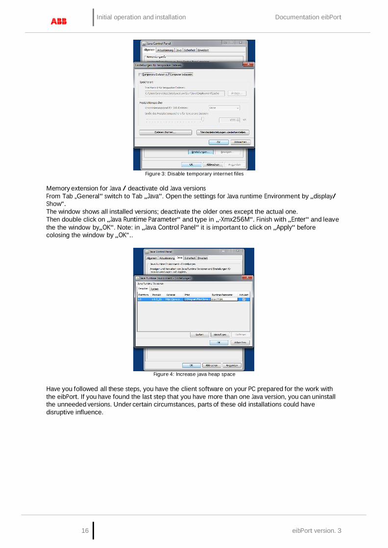
Figure 3: Disable temporary internet files
Memory extension for Java / deactivate old Java versions From Tab „General“ switch to Tab „Java“. Open the settings for Java runtime Environment by „display/ Show“. The window shows all installed versions; deactivate the older ones except the actual one. Then double click on „Java Runtime Parameter“ and type in „-Xmx256M“. Finish with „Enter“ and leave the the window by„OK“. Note: in „Java Control Panel“ it is important to click on „Apply“ before colosing the window by „OK“..
Figure 4: Increase java heap space
Have you followed all these steps, you have the client software on your PC prepared for the work with the eibPort. If you have found the last step that you have more than one Java version, you can uninstall the unneeded versions. Under certain circumstances, parts of these old installations could have disruptive influence.
eibPort Version 3 17
Documentation eibPort Initial operation and installation
2.4.2 COMMUNICATE WITH EIBPORT
The eibPort has bootet without problems and all Client PC software and settings are done as described. To start the communication now a LAN connection between eibPort and the PC has to be built up. This may be realized directly using a crossover cable or on the other hand a connection via switch/ Hub. Open the browser and type in the eibPort’s IP- Address. The home page of the eibPort comes up.
DEFAULT IP ADDRESS / DISCOVERY TOOL
The eibPort is delivered with factory- made settings. So the default address(es) should be typed in. Actually there are two different ones (depending on firmware version) used:
Up to firmware Version 0.10.2 => 192.168.1.1 From firmware Version 0.11.1 => 192.168.1.222
If the eibPort can not be reached from both it will have been in use before already and the IP Address was changed. To set the device in operation nervertheless the „Discovery tool“ will help you to find the device in the network. This tool will be delivered with the installation CD or alternatively can be downloaded from ABB (http://www.bab-tec.de/deutsch/service/download/).
Note: Devices with hardware version 1 are not displayed in the discovery tool. The discovery tool serves for reading out address information even if the device is outside the network range. If the device is located within the same IP address range it is displayed in green otherwise in yellow. If the eibPort is outside the PC’s IP range the IP Address has to be changed. So the PC and eibPort just differ within the last three digits.
Open eibPort startpage If the settings of the IP address have been executed successfully the homepage of eibPort can be accessed. Therefore please enter the IP address in your browser’s address line and confirm with „Enter“. On the homepage you’ll find several menu items: Visualization Editor System
To get access to Editor and/ or System a password is needed and additionally for menu item System the eibPort character string (sticked on the inset card).
2.4.3 PASSWORDS
Access to “System” and “Editor” is protected by username and passwort. The access data can be edit over “System”. In delivery status the following access data is valid:
Area:
Username
Password:
Editor: admin eibPort
System:
admin
eibPort
To change a password, the new password has to be entered twice.

18 eibPort version. 3
Initial operation and installation Documentation eibPort
2.4.4 STARTING BEHAVIOUR
Since the hardware version 3 the eibPort starts with a different behavior. The unit will start in two phases: First by a green power LED is indicated that the operating system has booted properly and the page can be accessed. So also the "Editor" and "system" can be called and another service ("Application Server"), has to be started in the unit. The successful execution is displayed by a bright green LED BMX can be read.
If an attempt is made to access the editor or the system during the starting phase of the second service an information window opens and displays the status of the start of the Application Server.
Figure 5: Home - Waiting for Application Server
2.4.5 BASIC SETTINGS
In order to put the device into operation it may happen that some basic settings have to be adjusted. These settings have to be made under System; in special cases the device hast o be rebooted after saving the settings.
Figure 6: ConfigTool - Configuration
IP-Address / Default Gateway / DNS Server The IP-Addresse setting can be accessed via „System“ > „Configuration“ > „Network settings“. Moreover Default Gateway and DNS Server can be adjusted here.
Physical address for KNX The physical address will not be programmed using but also via „System“ > „cCnfiguration“ > „General“.
Place of mounting The settings for the place of mounting of the eibPort are important regarding time zone and positioning (Astro clock). These setting will be made under „System“ >„Configuration“ > „General“ too.
Port Settings The communication ports can be adjusted under „System“ > „Configuration“ > „Advanced EIB (yabus) settings“.
eibPort Version 3 19
Documentation eibPort Visualisation
3 VISUALISATION
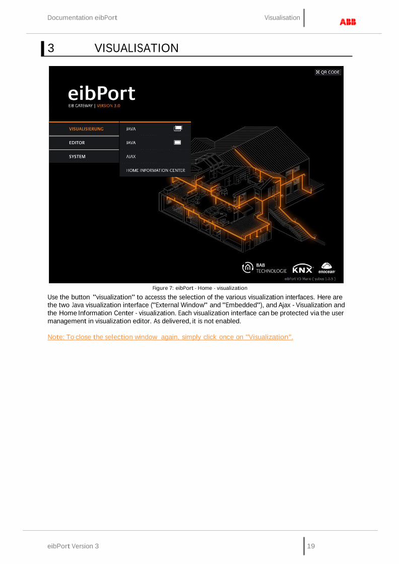
Figure 7: eibPort - Home - visualization
Use the button "visualization" to accesss the selection of the various visualization interfaces. Here are the two Java visualization interface ("External Window" and "Embedded"), and Ajax - Visualization and the Home Information Center - visualization. Each visualization interface can be protected via the user management in visualization editor. As delivered, it is not enabled.
Note: To close the selection window again, simply click once on "Visualization".
Visualisation Documentation eibPort
20 eibPort version. 3
3.1 JAVA VISUALISATION
Java visualisation can be called up in two different modes:
- External window: Visualisation will be opened up in a separate window. - Embedded: Visualisation will be opened up in a just been used browser window.
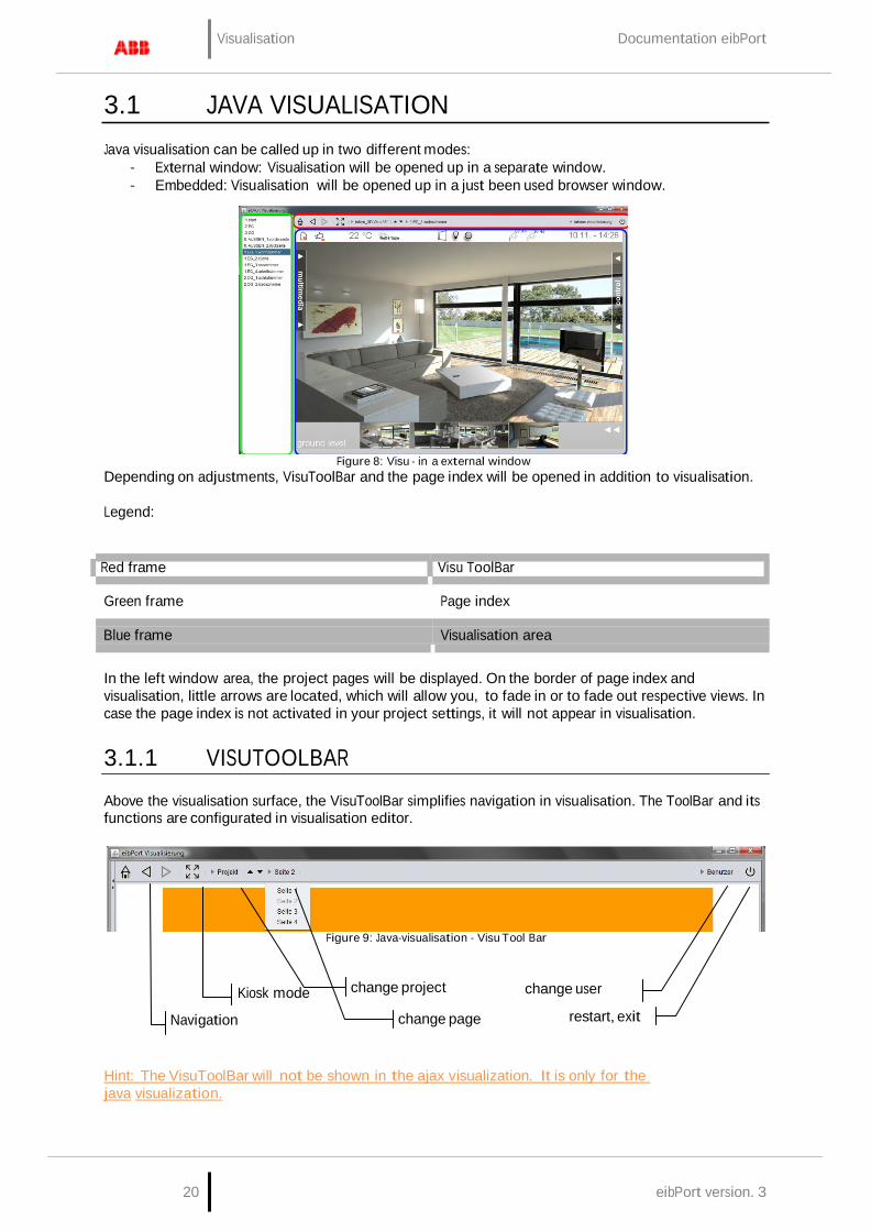
Figure 8: Visu - in a external window Depending on adjustments, VisuToolBar and the page index will be opened in addition to visualisation.
Legend:
Red frame Visu ToolBar
Green frame Page index
Blue frame
Visualisation area In the left window area, the project pages will be displayed. On the border of page index and visualisation, little arrows are located, which will allow you, to fade in or to fade out respective views. In case the page index is not activated in your project settings, it will not appear in visualisation.
3.1.1 VISUTOOLBAR
Above the visualisation surface, the VisuToolBar simplifies navigation in visualisation. The ToolBar and its functions are configurated in visualisation editor.
Figure 9: Java-visualisation - Visu Tool Bar
Kiosk mode change project change user
Navigation
change page restart, exit
Hint: The VisuToolBar will not be shown in the ajax visualization. It is only for the java visualization.

Documentation eibPort Visualisation
eibPort Version 3 21
Navigation Navigation enables to browse project pages and, with help of the house-symbol, jumping back to the frontpage of your project.
Kiosk Pressing this button, kiosk mode can be activated while using visualisation, but settings for ToolBar and page index will be preserved.
Change of project If several projects are created, you can switch between them.
Paging All pages of the project are shown on the screen. Change happens while using the arrows or using the overview of pages. Overview appears by key-click on the page-name.
Change of user If user administration has been activated, you can change between several user, without restarting visualisation.User names are displayed, if you click on the actual user.
Restart; exit Pressing this button, visualisation will be closed or the application restarts. Restarting the visualisation surface requires a new authentification by user.
3.1.2 IMPORTANT HINTS
Authentication The visualization should be protected from unauthorized access with appropriate measures. These are the "Security Settings" you can achieve visualization editor. On request, it will also control which users can see which pages visualization.
BMX-protokol For visualisation you need, among others, a port for BMX-protocol. In case this port is not activated, for example by access over internet (port forwarding), working with the visualisation surface is not possible. By default, BMX-Port is fixed with number 1735, which can potentially be changed over ConfigTool (System > Configuration > Advanced EIB (yabus) setting ).
JAVA Cache By activating JAVA Cache while configurating visualisation or other parts of eibPort, it can happen, that after a while visualisation does not operate correctly anymore. Java cache goes back to temporary files, which have actuality no more. Clear this cache und start up the browser again. (see „adjusting JAVA“ >„settings of temporary internet files”).
Time stamps If clocktime adjustment of the eibPort is not correct, actual telegrams und current states are saved with an uncorrect time stamp in the state table. In this case, the visualisation for analysis gets uncorrect reference periods, which leads to invalid status displays. Please erase the state table and restart the eibPort (see chapter „File“ in “eibPort Editor”).
Visualisation Documentation eibPort
22 eibPort version. 3
3.2 AJAX VISUALISATION
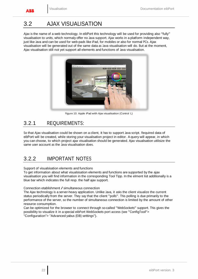
Ajax is the name of a web technology. In eibPort this technology will be used for providing also “fully” visualisation to units, which normaly offer no Java support. Ajax works in a platform independent way, just like Java and can be used for web-pads like iPad, for mobiles or also for normal PCs. Ajax visualisation will be generated out of the same data as Java visualisation will do. But at the moment, Ajax visualisation still not yet support all elements and functions of Java visualisation.
Figure 10: Apple iPad with Ajax visualisation (Control L)
3.2.1 REQUIREMENTS:
So that Ajax visualisation could be shown on a client, it has to support Java script. Required data of eibPort will be created, while storing your visualisation project in editor. A query will appear, in which you can choose, to which project ajax visualisation should be generated. Ajax visualisation utilisize the same user account as the Java visualisation does.
3.2.2 IMPORTANT NOTES
Support of visualsisation elements and functions To get information about what visualsisation elements and functions are supported by the ajax visualisation you will find information in the corresponding Tool Tipp. In the elment list additionally is a blue bar which indicates the full resp. the half ajax support.
Connection etablishment / simultaneous connection The Ajax technology is a server-heavy application. Unlike Java, it asks the client visualize the current status periodically from the server. They say that the client "polls". This polling is due primarily to the performance of the server, so the number of simultaneous connection is limited by the amount of other resource consumption. Can be optimized for the browser to connect through so-called "WebSockets" support. This gives the possibility to visualize it in a special eibPort WebSockets port access (see "ConfigTool"> "Configuration"> "Advanced yabus (EIB) settings").

Documentation eibPort Visualisation
eibPort Version 3 23
USE HARDWARE ACCELERATION / CSS 3 ANIMATIONS
The Mobile Safari browser on Apple devices like the iPad and iPhone uses simple animation, no hardware acceleration. Therefore, it may be committed by the slide effects to a jerky presentation. To circumvent this supports the visualization Ajax CSS 3 transformations. This animation will be displayed more smoothly, since use is made in this case the hardware acceleration. The activation is automatic once the Ajax visualization detects an appropriate browser. The use of CSS 3, however, can cause some browsers or other devices to ensure that the operation is not optimal expires. In order to disable CSS 3 in this case, a context menu that is at the start of visualization during the first 10 seconds in the lower right area of visualization. This menu can also logout from the visualization can be initiated.
Figure 11: Ajax visualization - Context Menu
Visualisation Documentation eibPort
24 eibPort version. 3
3.3 HOME INFORMATION CENTER
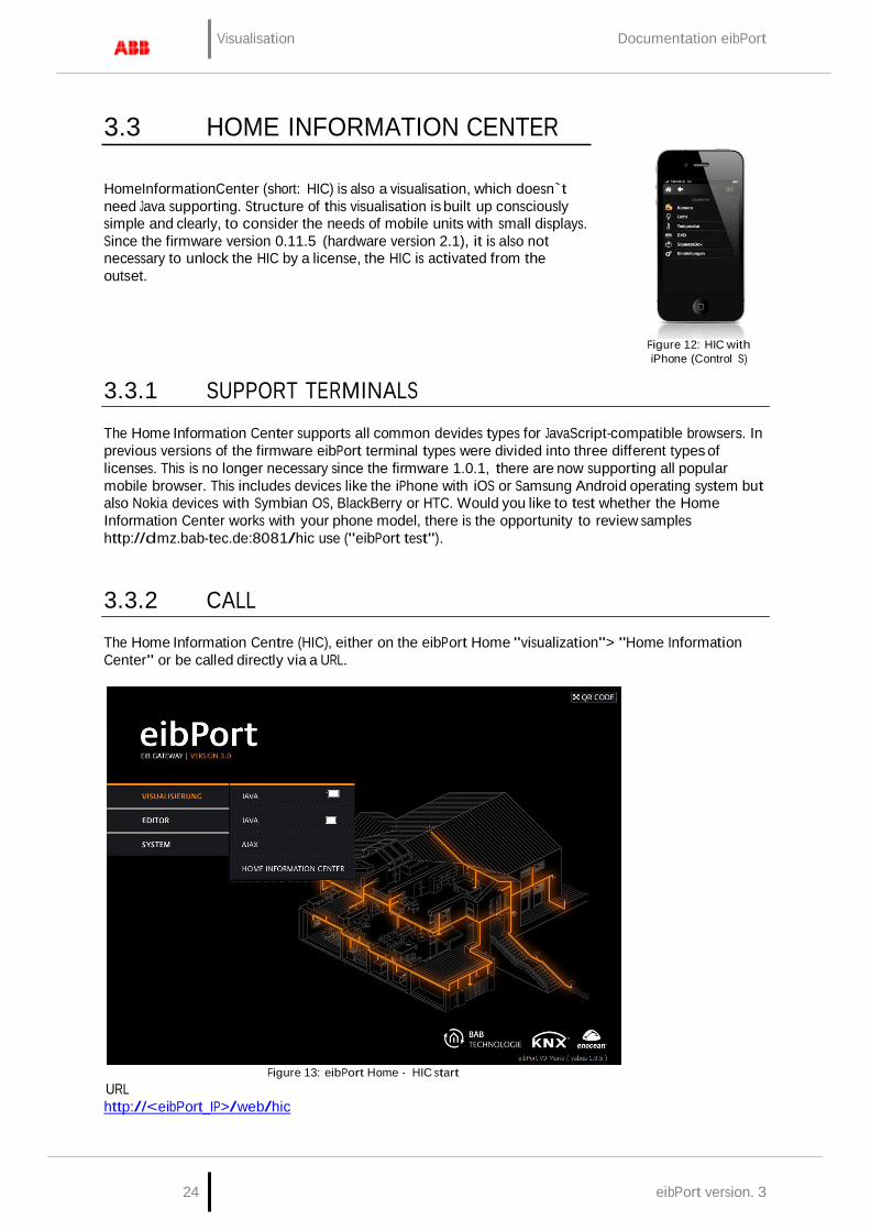
HomeInformationCenter (short: HIC) is also a visualisation, which doesn`t need Java supporting. Structure of this visualisation is built up consciously simple and clearly, to consider the needs of mobile units with small displays. Since the firmware version 0.11.5 (hardware version 2.1), it is also not necessary to unlock the HIC by a license, the HIC is activated from the outset.
3.3.1 SUPPORT TERMINALS
Figure 12: HIC with iPhone (Control S)
The Home Information Center supports all common devides types for JavaScript-compatible browsers. In previous versions of the firmware eibPort terminal types were divided into three different types of licenses. This is no longer necessary since the firmware 1.0.1, there are now supporting all popular mobile browser. This includes devices like the iPhone with iOS or Samsung Android operating system but also Nokia devices with Symbian OS, BlackBerry or HTC. Would you like to test whether the Home Information Center works with your phone model, there is the opportunity to review samples http://dmz.bab-tec.de:8081/hic use ("eibPort test").
3.3.2 CALL
The Home Information Centre (HIC), either on the eibPort Home "visualization"> "Home Information Center" or be called directly via a URL.
URL Figure 13: eibPort Home - HIC start
http://<eibPort_IP>/web/hic

Documentation eibPort Visualisation
eibPort Version 3 25
After the call, you get to the user login. Authentication is configured in Visualsierungseditor in the security settings.
3.3.3 IMPORTANT NOTES
Authentification User authentication for the Home Information Center is administered in the security settings of the visualization editor. In the User Details can be accessed individually switched to the HIC for each user. For more information, see "HIC". It is strongly recommended to establish authentication!
Concurrent Connections In general, the number is unlimited. The actual number of connections depends on the message load on the KNX system and the number of parallel tasks to be performed the eibPort. The more tasks and messages must be treated simultaneously eibPort, the fewer resources remain for the designs of individual tasks such as communication with the visualization left.
3.4 AUTOLOGIN / LOG REMEMBER
In order to enter the user does not always have his access, there is the possibility of so-called "auto login" or "Remember Login" to use functions. Here, the application data when the visualization is transmitted to or stored on the client computer.
3.4.1 AUTOLOGIN FOR JAVA VISUALIZATION
The user data parameters can be passed in the URL. For example, a bookmark is saved with the URL, which can itself be directly connected to the visualization. The following syntax must be adhered to:
http:// <eibPort_IP> / bmxjava2 / <Type the Startseite>? <username> & <Password> & <Autologin>
For "eibPort_IP" Either enter the IP address or host name.
"Type of Home", the following parameters are entered: visu.php visualization open in a separate window visuPlain.php visualization open in the browser window (See also chapter "System"> "Home")
For "User Name": The parameter must be added with user name = user name here. The user name must be entered exactly as it is laid down in the user management.
For "Password": The password is passed using password = password. The password is in plain text (!) Registered as such it has been defined in the user management.
For "Auto Login": Can be either 'true' or 'false' value thus obtained. The parameter is passed with autologin = true / false. In the "auto login" is an optional parameter. Autologin = true means that no additional demand will be logged. Autologin = false means that the fields of the login dialog with the specified username / password is indeed completed, but must be confirmed to the login still. So at this point there is still a possibility with a different account to register. Here is the default value of "true".
The parameters are separated by "&" (ampersand "and") from each other, and with a "?" (Question mark) of the URL.
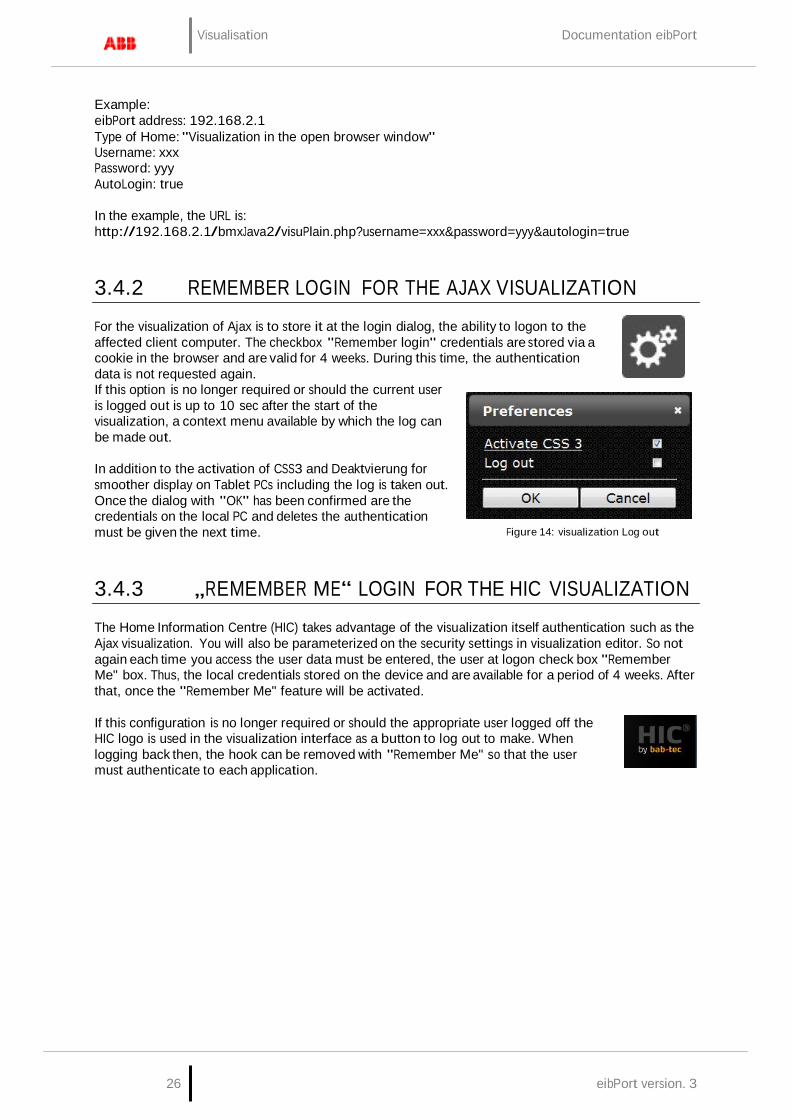
Visualisation Documentation eibPort
26 eibPort version. 3
Example: eibPort address: 192.168.2.1 Type of Home: "Visualization in the open browser window" Username: xxx Password: yyy AutoLogin: true
In the example, the URL is: http://192.168.2.1/bmxJava2/visuPlain.php?username=xxx&password=yyy&autologin=true
3.4.2 REMEMBER LOGIN FOR THE AJAX VISUALIZATION
For the visualization of Ajax is to store it at the login dialog, the ability to logon to the affected client computer. The checkbox "Remember login" credentials are stored via a cookie in the browser and are valid for 4 weeks. During this time, the authentication data is not requested again. If this option is no longer required or should the current user is logged out is up to 10 sec after the start of the visualization, a context menu available by which the log can be made out.
In addition to the activation of CSS3 and Deaktvierung for smoother display on Tablet PCs including the log is taken out. Once the dialog with "OK" has been confirmed are the credentials on the local PC and deletes the authentication must be given the next time.
Figure 14: visualization Log out
3.4.3 „REMEMBER ME“ LOGIN FOR THE HIC VISUALIZATION
The Home Information Centre (HIC) takes advantage of the visualization itself authentication such as the Ajax visualization. You will also be parameterized on the security settings in visualization editor. So not again each time you access the user data must be entered, the user at logon check box "Remember Me" box. Thus, the local credentials stored on the device and are available for a period of 4 weeks. After that, once the "Remember Me" feature will be activated.
If this configuration is no longer required or should the appropriate user logged off the HIC logo is used in the visualization interface as a button to log out to make. When logging back then, the hook can be removed with "Remember Me" so that the user must authenticate to each application.

eibPort Version 3 27
Documentation eibPort eibPort editor
4 EIBPORT EDITOR
Figure 15: eibPort - Startpage - editor
With help of the Editor the eibPort will be programmed and visualisation will be created. Editor contains the following applications:
Visualisation editor This editor helps you to create the graphical user interface for controlling the EIB/KNX-system. A visualisation are saved as a „project“, containing several pages. Various projects are possible. In theory, you can create as much pages and projects as you will, limited only by the size of loaded pictures on eibPort and by the performance of the client PC.
Job editor Job editor configures the services of the eibPort. An overview of all job types you will find in the corresponding chapter. Consumption of storage space of thes jobfiles is unsignificant. By configuration of the services, you have to consider the maximal bus- and cpu load.
HomeInformationCenter (HIC) Here you configure the „HomeInformationCenter“ (HIC) visualisation. The HIC is a visualization that is designed specifically for the needs of mobile devices like smartphones and cell phones.

28 eibPort version. 3
eibPort editor Documentation eibPort
4.1 THINGS TO KNOW BEFORE GETTING STARTED
AUTHENTIFIZIERUNG
Authentication when the "editor" and "system" is controlled by the so-called "User Administration" in the configuration tool (aka "ConfigTool"), which you reach by clicking on the "System". So from the beginning of the eibPort is protected against unauthorized access will be immediately asked when you first registered with the default user data (BN = "admin" and PW = "eibPort") after a new password. The user login is always done, and can not be switched off for safety reasons. The user application for the visualization is the visualization editor under "security settings" and managed (see chapter "Security settings for the visualization").
GROUP ADDRESSES, VIRTUAL AND REAL
eibPort offers a range for virtual group addresses, which extends from 16/0/0 to 31/7/255. eibPort doesn`t send these adresses on the bus. They are for combining the jobs with each other or with the elements of visualisation. Besides the effect saving address space with it, another circumstance should be regarded: If real group addresses are used to run a job, although there exists no real KNX/EIB-subscriber, substantial delays in program sequence could appear. In the KNX-bus system every subscriber awaits an „ACK“ (Acknowledge) on every telegram. In case this doesn´t happpen, telegrams will be send several times. A very “telegram expensive” job like SB-Control then can cause a significant slow down while sending out the repeat telegrams (vain waiting on an “ACK””). Therefore you should not use real group addresses, if there exists no real bus subscriber.
COMMUNICATIONS OBJECTS
eibPort emulates the structure of communication objects of EIB/KNX. That means, every object can refer up to 5 group addresses. In this way, placing of a group address, for example an actuator channel, can be simulated directly. In this case, eibPort gets information at any time about the real state of the actuator (not the state of group address) and complex working with acknowledge-ments remains undone.This procedure simplifies creation of logical links, because every input object could connected to a gate of up to 5 group addresses. In ESF dialoque, you can refer all of the 5 group-addresses, and these addresses automatically are registered in a correct syntax to a chosen object field. Output object, by contrast, allows filling in only one address information.
SYNTAX GENERAL
After entering the first group address, additional addresses must be placed in brackets and have to separate with commas.
For example: 2/12 (2/13,2/14,2/15,2/16)
ETS 4
Note: Restricted compability with ETS4! In ETS4 please just use the group address structure as known from ETS 2/3. The use with the extended group address range resp the free group address structure is not posssible!
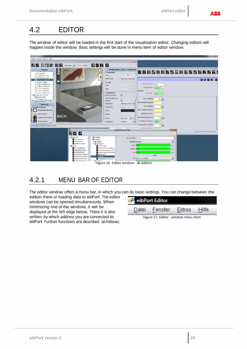
eibPort Version 3 29
Documentation eibPort eibPort editor
4.2 EDITOR
The window of editor will be loaded in the first start of the visualisation editor. Changing editors will happen inside the window. Basic settings will be done in menu item of editor window.
Figure 16: Editor window - all editors
4.2.1 MENU BAR OF EDITOR
The editor window offers a menu bar, in which you can do basic settings. You can change between the editors there or loading data to eibPort. The editor windows can be opened simultaneously. When minimizing one of the windows, it will be displayed at the left edge below. There it is also written by which address you are connected to eibPort. Further functions are described as follows:
Figure 17: Editor - window menu item
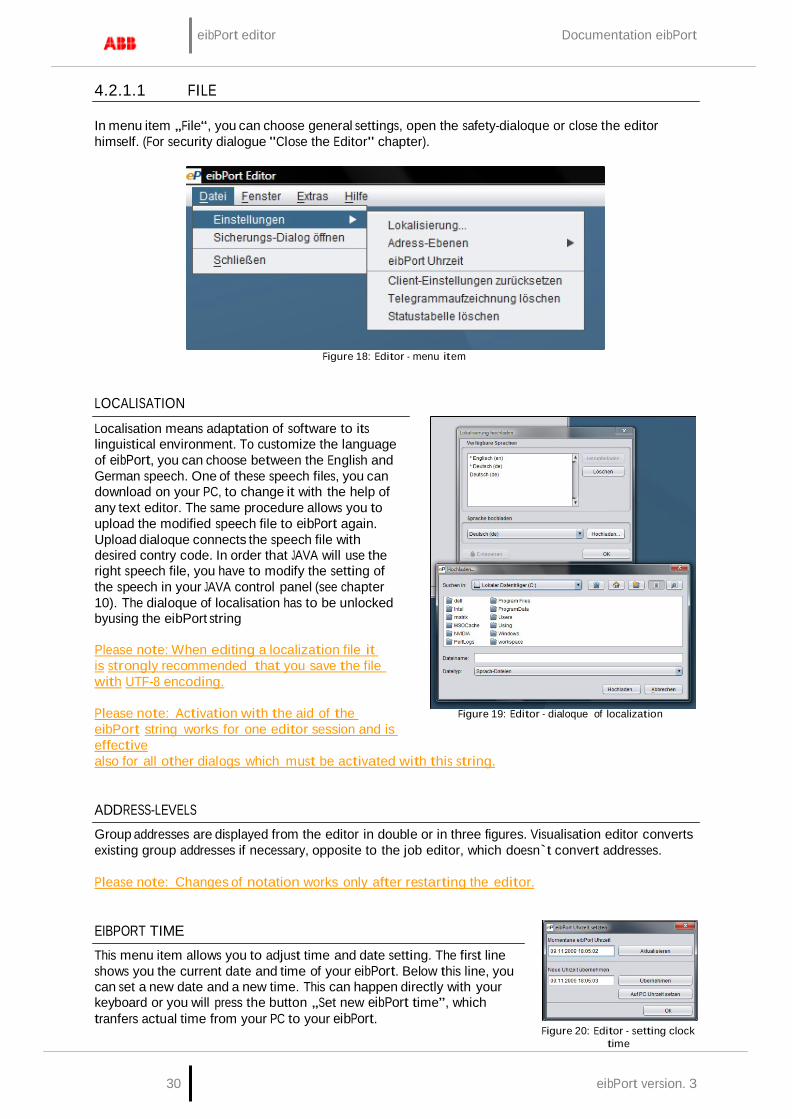
eibPort editor Documentation eibPort
30 eibPort version. 3
4.2.1.1 FILE
In menu item „File“, you can choose general settings, open the safety-dialoque or close the editor himself. (For security dialogue "Close the Editor" chapter).
Figure 18: Editor - menu item
LOCALISATION
Localisation means adaptation of software to its linguistical environment. To customize the language of eibPort, you can choose between the English and German speech. One of these speech files, you can download on your PC, to change it with the help of any text editor. The same procedure allows you to upload the modified speech file to eibPort again. Upload dialoque connects the speech file with desired contry code. In order that JAVA will use the right speech file, you have to modify the setting of the speech in your JAVA control panel (see chapter 10). The dialoque of localisation has to be unlocked byusing the eibPort string
Please note: When editing a localization file it is strongly recommended that you save the file with UTF-8 encoding.
Please note: Activation with the aid of the eibPort string works for one editor session and is effective
Figure 19: Editor - dialoque of localization
also for all other dialogs which must be activated with this string.
ADDRESS-LEVELS
Group addresses are displayed from the editor in double or in three figures. Visualisation editor converts existing group addresses if necessary, opposite to the job editor, which doesn`t convert addresses.
Please note: Changes of notation works only after restarting the editor.
EIBPORT TIME
This menu item allows you to adjust time and date setting. The first line shows you the current date and time of your eibPort. Below this line, you can set a new date and a new time. This can happen directly with your keyboard or you will press the button „Set new eibPort time”, which tranfers actual time from your PC to your eibPort.
Figure 20: Editor - setting clock
time
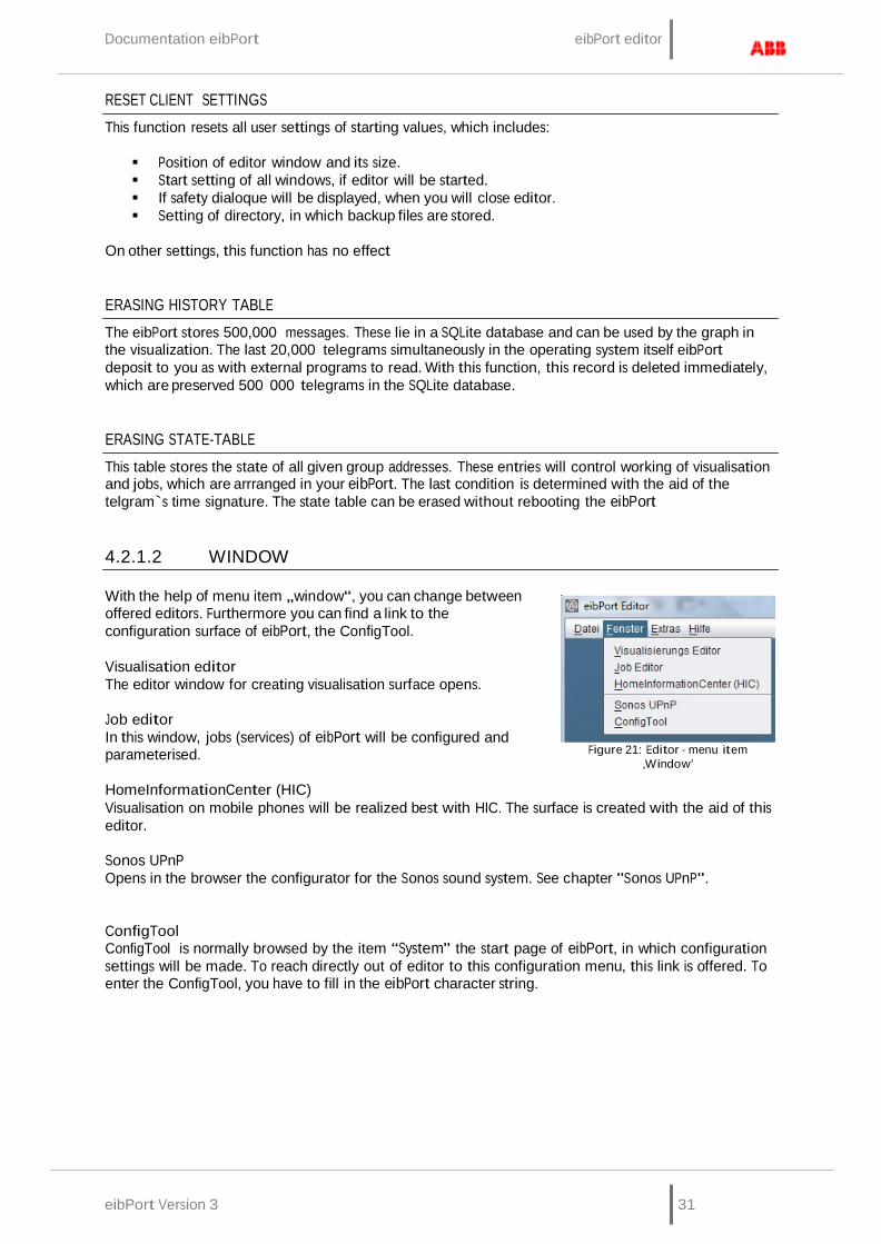
Documentation eibPort eibPort editor
eibPort Version 3 31
RESET CLIENT SETTINGS
This function resets all user settings of starting values, which includes:
Position of editor window and its size. Start setting of all windows, if editor will be started. If safety dialoque will be displayed, when you will close editor. Setting of directory, in which backup files are stored.
On other settings, this function has no effect
ERASING HISTORY TABLE
The eibPort stores 500,000 messages. These lie in a SQLite database and can be used by the graph in the visualization. The last 20,000 telegrams simultaneously in the operating system itself eibPort deposit to you as with external programs to read. With this function, this record is deleted immediately, which are preserved 500 000 telegrams in the SQLite database.
ERASING STATE-TABLE
This table stores the state of all given group addresses. These entries will control working of visualisation and jobs, which are arrranged in your eibPort. The last condition is determined with the aid of the telgram`s time signature. The state table can be erased without rebooting the eibPort
4.2.1.2 WINDOW
With the help of menu item „window“, you can change between offered editors. Furthermore you can find a link to the configuration surface of eibPort, the ConfigTool.
Visualisation editor The editor window for creating visualisation surface opens.
Job editor In this window, jobs (services) of eibPort will be configured and parameterised.
HomeInformationCenter (HIC)
Figure 21: Editor - menu item ‚Window’
Visualisation on mobile phones will be realized best with HIC. The surface is created with the aid of this editor.
Sonos UPnP Opens in the browser the configurator for the Sonos sound system. See chapter "Sonos UPnP".
ConfigTool ConfigTool is normally browsed by the item “System” the start page of eibPort, in which configuration settings will be made. To reach directly out of editor to this configuration menu, this link is offered. To enter the ConfigTool, you have to fill in the eibPort character string.
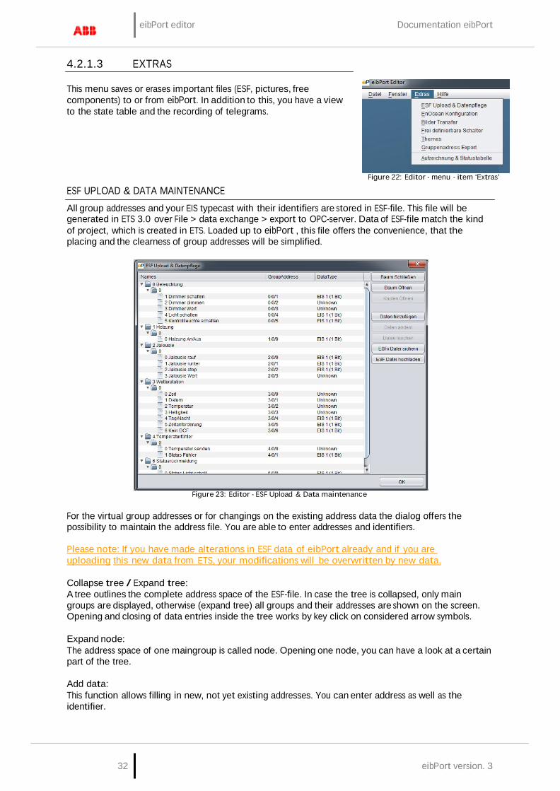
eibPort editor Documentation eibPort
32 eibPort version. 3
4.2.1.3 EXTRAS
This menu saves or erases important files (ESF, pictures, free components) to or from eibPort. In addition to this, you have a view to the state table and the recording of telegrams.
ESF UPLOAD & DATA MAINTENANCE Figure 22: Editor - menu - item ‘Extras’
All group addresses and your EIS typecast with their identifiers are stored in ESF-file. This file will be generated in ETS 3.0 over File > data exchange > export to OPC-server. Data of ESF-file match the kind of project, which is created in ETS. Loaded up to eibPort , this file offers the convenience, that the placing and the clearness of group addresses will be simplified.
Figure 23: Editor - ESF Upload & Data maintenance
For the virtual group addresses or for changings on the existing address data the dialog offers the possibility to maintain the address file. You are able to enter addresses and identifiers.
Please note: If you have made alterations in ESF data of eibPort already and if you are uploading this new data from ETS, your modifications will be overwritten by new data.
Collapse tree / Expand tree: A tree outlines the complete address space of the ESF-file. In case the tree is collapsed, only main groups are displayed, otherwise (expand tree) all groups and their addresses are shown on the screen. Opening and closing of data entries inside the tree works by key click on considered arrow symbols.
Expand node: The address space of one maingroup is called node. Opening one node, you can have a look at a certain part of the tree.
Add data: This function allows filling in new, not yet existing addresses. You can enter address as well as the identifier.
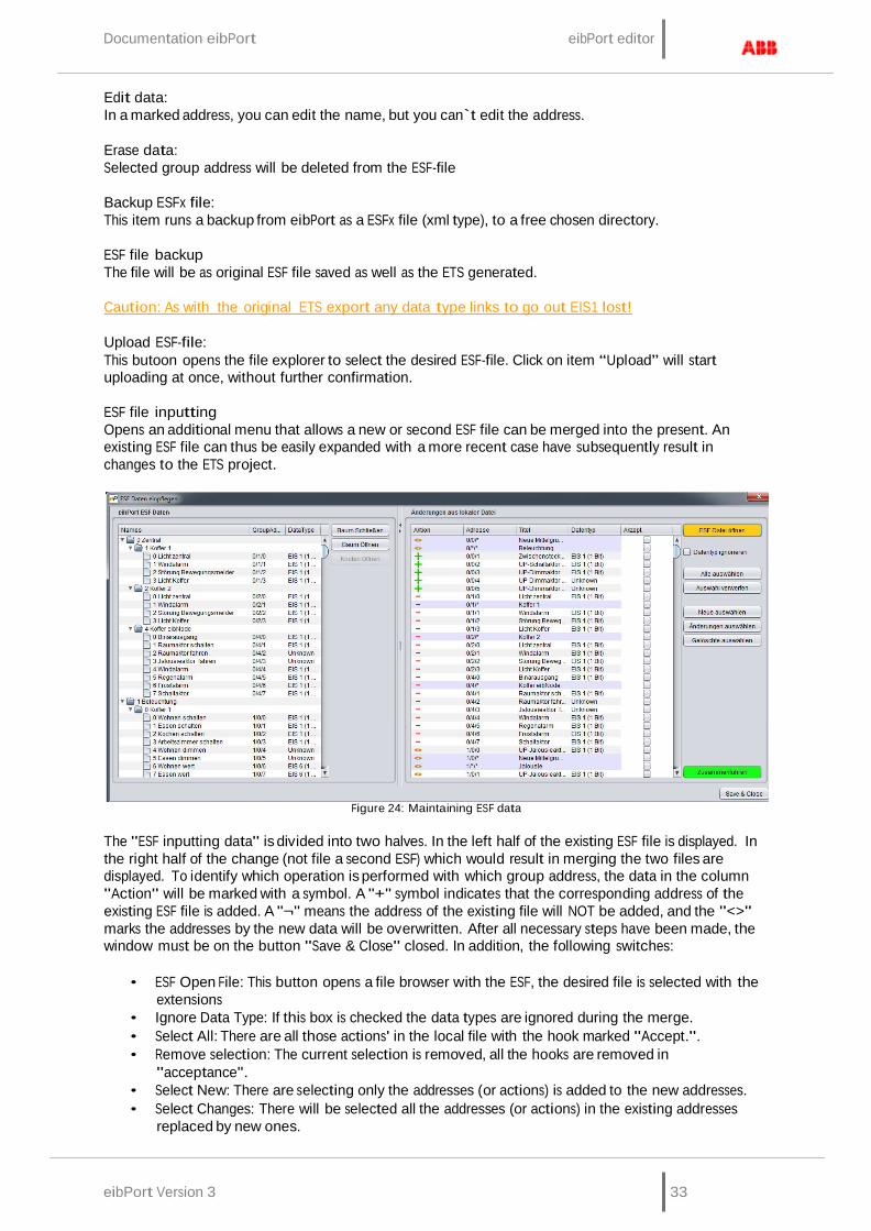
Documentation eibPort eibPort editor
eibPort Version 3 33
Edit data: In a marked address, you can edit the name, but you can`t edit the address.
Erase data: Selected group address will be deleted from the ESF-file
Backup ESFx file: This item runs a backup from eibPort as a ESFx file (xml type), to a free chosen directory.
ESF file backup The file will be as original ESF file saved as well as the ETS generated.
Caution: As with the original ETS export any data type links to go out EIS1 lost!
Upload ESF-file: This butoon opens the file explorer to select the desired ESF-file. Click on item “Upload” will start uploading at once, without further confirmation.
ESF file inputting Opens an additional menu that allows a new or second ESF file can be merged into the present. An existing ESF file can thus be easily expanded with a more recent case have subsequently result in changes to the ETS project.
Figure 24: Maintaining ESF data
The "ESF inputting data" is divided into two halves. In the left half of the existing ESF file is displayed. In the right half of the change (not file a second ESF) which would result in merging the two files are displayed. To identify which operation is performed with which group address, the data in the column "Action" will be marked with a symbol. A "+" symbol indicates that the corresponding address of the existing ESF file is added. A "¬" means the address of the existing file will NOT be added, and the "<>" marks the addresses by the new data will be overwritten. After all necessary steps have been made, the window must be on the button "Save & Close" closed. In addition, the following switches:
• ESF Open File: This button opens a file browser with the ESF, the desired file is selected with the
extensions • Ignore Data Type: If this box is checked the data types are ignored during the merge. • Select All: There are all those actions' in the local file with the hook marked "Accept.". • Remove selection: The current selection is removed, all the hooks are removed in
"acceptance". • Select New: There are selecting only the addresses (or actions) is added to the new addresses. • Select Changes: There will be selected all the addresses (or actions) in the existing addresses
replaced by new ones.
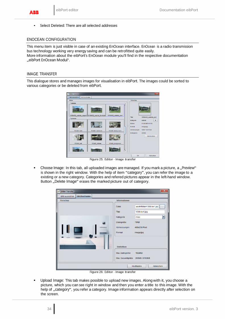
eibPort editor Documentation eibPort
34 eibPort version. 3
• Select Deleted: There are all selected addresses
ENOCEAN CONFIGURATION
This menu item is just visible in case of an existing EnOcean interface. EnOcean is a radio transmission bus technology working very energy saving and can be retrofitted quite easily. More information about the eibPort’s EnOcean module you’ll find in the respective documentation „eibPort EnOcean Modul“.
IMAGE TRANSFER
This dialogue stores and manages images for visualisation in eibPort. The images could be sorted to various categories or be deleted from eibPort.
Figure 25: Editor - Image transfer
Choose Image: In this tab, all uploaded images are managed. If you mark a picture, a „Preview“ is shown in the right window. With the help of item “category”, you can refer the image to a existing or a new category. Categories and refered pictures appear in the left-hand window. Button „Delete Image“ erases the marked picture out of category.
Figure 26: Editor - Image transfer
Upload Image: This tab makes possible to upload new images. Along with it, you choose a picture, which you can see right in window and then you enter a title to this image. With the help of „category“, you refer a category. Image information appears directly after selection on the screen.
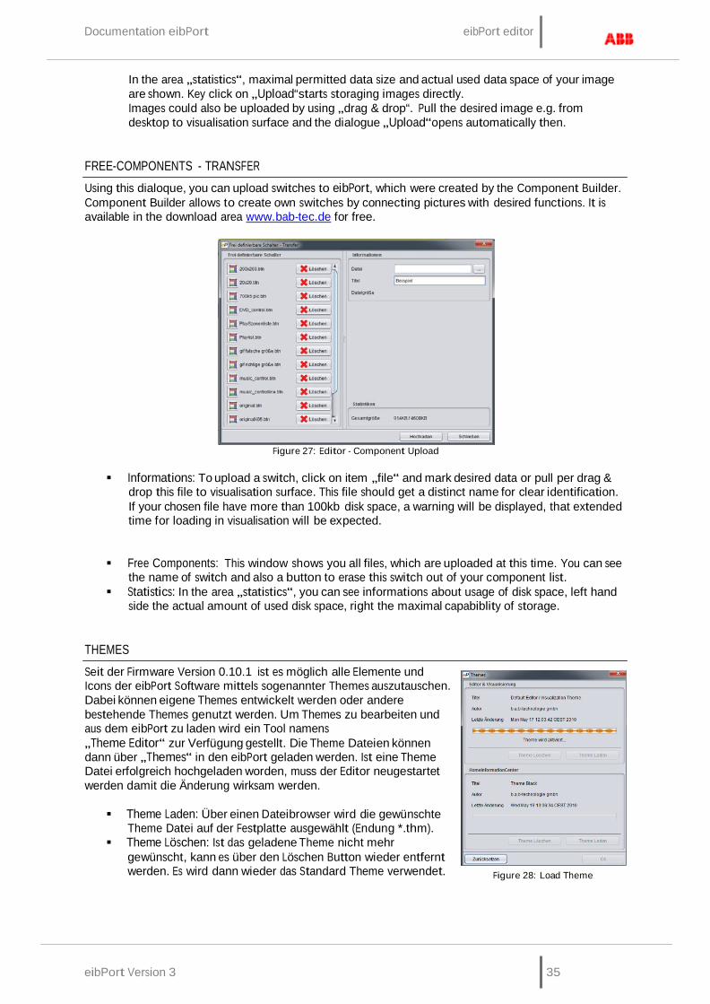
Documentation eibPort eibPort editor
eibPort Version 3 35
In the area „statistics“, maximal permitted data size and actual used data space of your image are shown. Key click on „Upload“starts storaging images directly. Images could also be uploaded by using „drag & drop“. Pull the desired image e.g. from desktop to visualisation surface and the dialogue „Upload“opens automatically then.
FREE-COMPONENTS - TRANSFER
Using this dialoque, you can upload switches to eibPort, which were created by the Component Builder. Component Builder allows to create own switches by connecting pictures with desired functions. It is available in the download area www.bab-tec.de for free.
Figure 27: Editor - Component Upload
Informations: To upload a switch, click on item „file“ and mark desired data or pull per drag & drop this file to visualisation surface. This file should get a distinct name for clear identification. If your chosen file have more than 100kb disk space, a warning will be displayed, that extended time for loading in visualisation will be expected.
Free Components: This window shows you all files, which are uploaded at this time. You can see the name of switch and also a button to erase this switch out of your component list.
Statistics: In the area „statistics“, you can see informations about usage of disk space, left hand side the actual amount of used disk space, right the maximal capabiblity of storage.
THEMES
Seit der Firmware Version 0.10.1 ist es möglich alle Elemente und Icons der eibPort Software mittels sogenannter Themes auszutauschen. Dabei können eigene Themes entwickelt werden oder andere bestehende Themes genutzt werden. Um Themes zu bearbeiten und aus dem eibPort zu laden wird ein Tool namens „Theme Editor“ zur Verfügung gestellt. Die Theme Dateien können dann über „Themes“ in den eibPort geladen werden. Ist eine Theme Datei erfolgreich hochgeladen worden, muss der Editor neugestartet werden damit die Änderung wirksam werden.
Theme Laden: Über einen Dateibrowser wird die gewünschte
Theme Datei auf der Festplatte ausgewählt (Endung *.thm). Theme Löschen: Ist das geladene Theme nicht mehr
gewünscht, kann es über den Löschen Button wieder entfernt werden. Es wird dann wieder das Standard Theme verwendet.
Figure 28: Load Theme
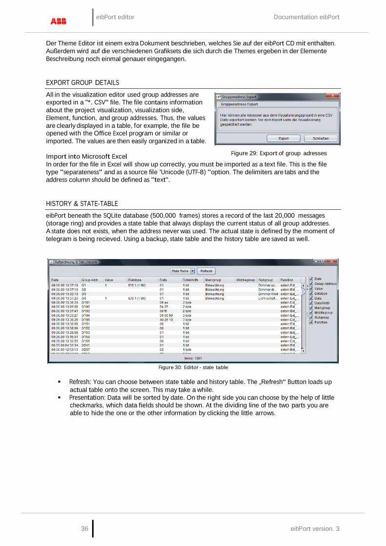
eibPort editor Documentation eibPort
36 eibPort version. 3
Der Theme Editor ist einem extra Dokument beschrieben, welches Sie auf der eibPort CD mit enthalten. Außerdem wird auf die verschiedenen Grafiksets die sich durch die Themes ergeben in der Elemente Beschreibung noch einmal genauer eingegangen.
EXPORT GROUP DETAILS
All in the visualization editor used group addresses are exported in a "*. CSV" file. The file contains information about the project visualization, visualization side, Element, function, and group addresses. Thus, the values are clearly displayed in a table, for example, the file be opened with the Office Excel program or similar or imported. The values are then easily organized in a table.
Import into Microsoft Excel
Figure 29: Export of group adresses
In order for the file in Excel will show up correctly, you must be imported as a text file. This is the file type "separateness" and as a source file 'Unicode (UTF-8) "option. The delimiters are tabs and the address column should be defined as "text".
HISTORY & STATE-TABLE
eibPort beneath the SQLite database (500,000 frames) stores a record of the last 20,000 messages (storage ring) and provides a state table that always displays the current status of all group addresses. A state does not exists, when the address never was used. The actual state is defined by the moment of telegram is being recieved. Using a backup, state table and the history table are saved as well.
Figure 30: Editor - state table
Refresh: You can choose between state table and history table. The „Refresh“ Button loads up
actual table onto the screen. This may take a while. Presentation: Data will be sorted by date. On the right side you can choose by the help of little
checkmarks, which data fields should be shown. At the dividing line of the two parts you are able to hide the one or the other information by clicking the little arrows.
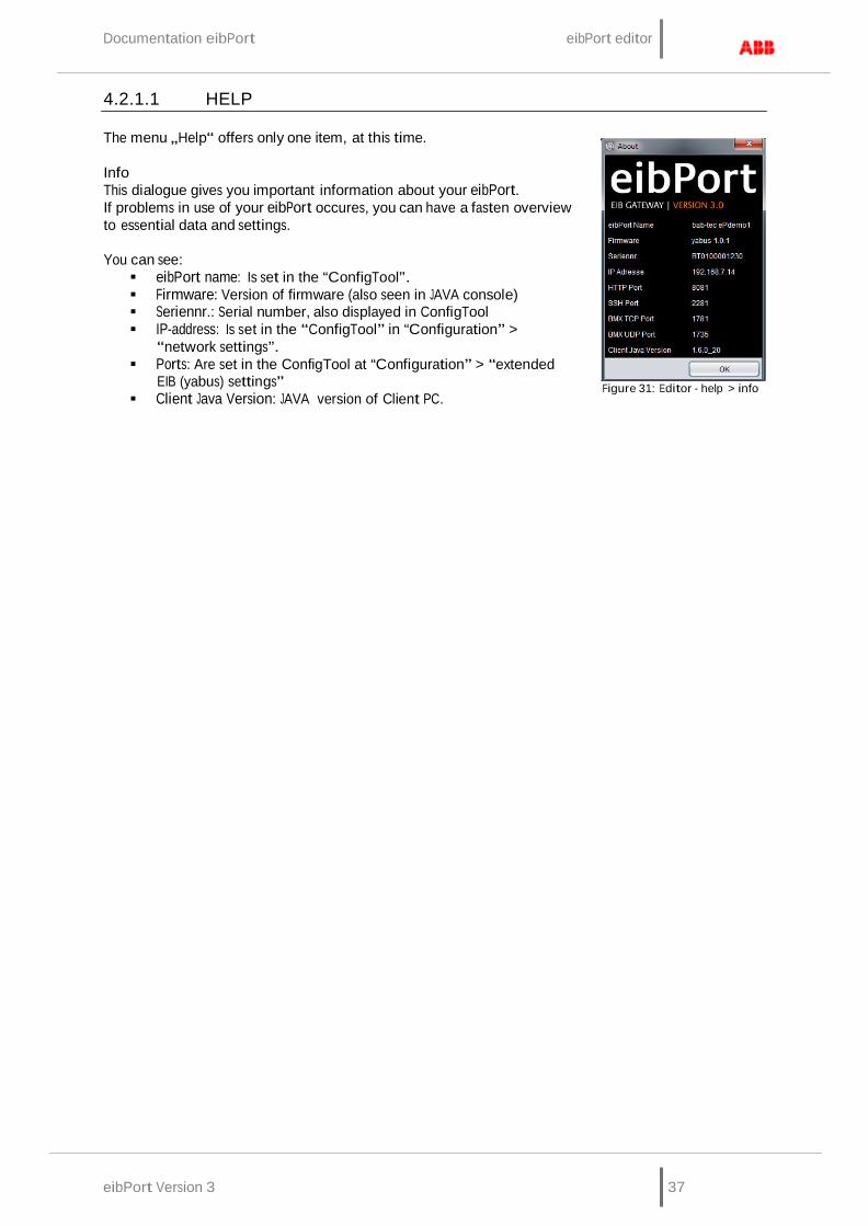
Documentation eibPort eibPort editor
eibPort Version 3 37
4.2.1.1 HELP
The menu „Help“ offers only one item, at this time.
Info This dialogue gives you important information about your eibPort. If problems in use of your eibPort occures, you can have a fasten overview to essential data and settings.
You can see: eibPort name: Is set in the “ConfigTool”. Firmware: Version of firmware (also seen in JAVA console) Seriennr.: Serial number, also displayed in ConfigTool IP-address: Is set in the “ConfigTool” in “Configuration” >
“network settings”. Ports: Are set in the ConfigTool at “Configuration” > “extended
EIB (yabus) settings” Client Java Version: JAVA version of Client PC.
Figure 31: Editor - help > info
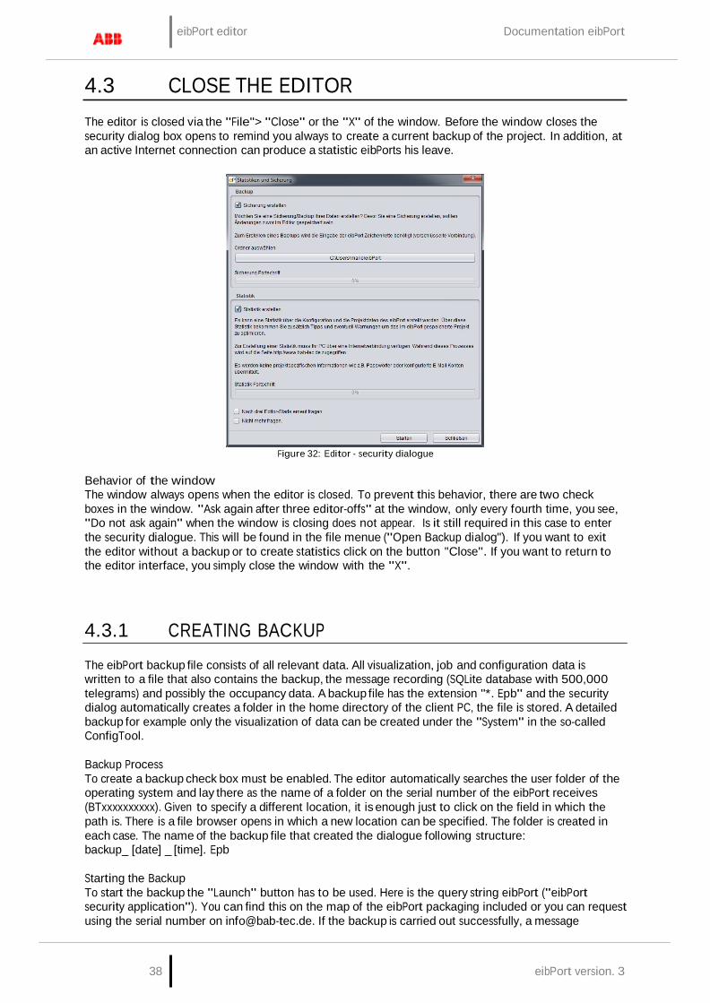
eibPort editor Documentation eibPort
38 eibPort version. 3
4.3 CLOSE THE EDITOR
The editor is closed via the "File"> "Close" or the "X" of the window. Before the window closes the security dialog box opens to remind you always to create a current backup of the project. In addition, at an active Internet connection can produce a statistic eibPorts his leave.
Figure 32: Editor - security dialogue
Behavior of the window The window always opens when the editor is closed. To prevent this behavior, there are two check boxes in the window. "Ask again after three editor-offs" at the window, only every fourth time, you see, "Do not ask again" when the window is closing does not appear. Is it still required in this case to enter the security dialogue. This will be found in the file menue ("Open Backup dialog"). If you want to exit the editor without a backup or to create statistics click on the button "Close". If you want to return to the editor interface, you simply close the window with the "X".
4.3.1 CREATING BACKUP
The eibPort backup file consists of all relevant data. All visualization, job and configuration data is written to a file that also contains the backup, the message recording (SQLite database with 500,000 telegrams) and possibly the occupancy data. A backup file has the extension "*. Epb" and the security dialog automatically creates a folder in the home directory of the client PC, the file is stored. A detailed backup for example only the visualization of data can be created under the "System" in the so-called ConfigTool.
Backup Process To create a backup check box must be enabled. The editor automatically searches the user folder of the operating system and lay there as the name of a folder on the serial number of the eibPort receives (BTxxxxxxxxxx). Given to specify a different location, it is enough just to click on the field in which the path is. There is a file browser opens in which a new location can be specified. The folder is created in each case. The name of the backup file that created the dialogue following structure: backup_ [date] _ [time]. Epb
Starting the Backup To start the backup the "Launch" button has to be used. Here is the query string eibPort ("eibPort security application"). You can find this on the map of the eibPort packaging included or you can request using the serial number on [email protected]. If the backup is carried out successfully, a message

Documentation eibPort eibPort editor
eibPort Version 3 39
appears displaying "successful backup" on the screen. If you have selected "create statistics" at the same time the statistics are created after the backup too.
4.3.2 CREATE STATISTICS
The statistics of eibPort provide useful information about the project and the eibPort itself. Following information is included:
• Information about the client computer (the
"Operating System", "Java") • eibPort system information ("System") • Montageorteinstellung ("Location") • average processor utilization ("CPU load") • Memory usage ("Memory") • network settings ("Network") Port settings ("port") Enabled Services ("Services") Number of editor-users ("system
administration") configuration data ("Configuration") Number of entries in the address state table
("address state table") Internal communications statistics ("Statistics") The type and number of jobs ("Jobs") Statistics of the visualization project ("Visualization") Resolution of visualization pages ("Page resolution") Number and type of visualization objects ("objects") information on HIC project ("Home Information Center")
Figure 33: eibPort Statistics
Information about the availability calendar module ("Room Allocation Plan") Information on the ESF data ("Data ESF") number and memory usage of the images ("Images") number and memory consumption of the Free Component ("Components")
In order to compile statistics for the client PC from which the eibPort is operated an Internet connection is necessary. The data are collected from the web server on www.bab-tec.de and displayed graphically. Personal data such as passwords or e-mail account settings are a matter of course not read or transmitted. The backup is created on the button "Start". You will be automatically forwarded to a corresponding Web page that contains all of the above information.
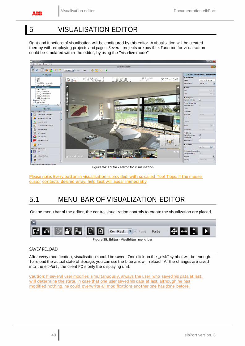
Visualisation editor Documentation eibPort
40 eibPort version. 3
5 VISUALISATION EDITOR
Sight and functions of visualisation will be configured by this editor. A visualisation will be created thereby with employing projects and pages. Several projects are possible. Function for visualisation could be simulated within the editor, by using the “visu-live-mode”
Figure 34: Editor - editor for visualisation
Please note: Every button in visualisation is provided with so called Tool Tipps. If the mouse cursor contacts desired array, help text will apear immediatly
5.1 MENU BAR OF VISUALIZATION EDITOR
On the menu bar of the editor, the central visualization controls to create the visualization are placed.
Figure 35: Editor - VisuEditor menu bar
SAVE/ RELOAD
After every modification, visualisation should be saved. One click on the „disk“-symbol will be enough. To reload the actual state of storage, you can use the blue arrow „ reload“ All the changes are saved into the eibPort , the client PC is only the displaying unit.
Caution: If several user modifies simultanuously, always the user who saved his data at last, will determine the state. In case that one user saved his data at last, although he has modified nothing, he could overwrite all modifications another one has done before.

Documentation eibPort Visualisation editor
eibPort Version 3 41
VISUALISATION / SECURITY SETTINGS / ROOM ALLOCATION PLAN(CONTROL R)
With the help of these three buttons, you can switch your sight. As a standard feature VisuEditor starts with the sight “visualisation”. “Security settings“ allows you to determine users and their user rights. To configure the room allocation plan its editor is reached by clicking on the according button.
NEW PROJECT / NEW PAGE
A new project or a new page will be created. A visualization consists of at least one project and one side.
RASTER / CATCH / COLOR
The working surface of visualisation can be overlayed by a raster. This makes it easier to position your elements. In the proper visualization, raster is not be displayed on screen. The size of raster is described in pixel-size, in addition to that, you can set colour to raster. The button „catch“ automatically aligns objects of visualisation along the raster.
ARRANGE ITEMS / ALIGN HORIZONTALLY / ALIGN VERTICALLY
With this function, marked objects are arranged with uniform distance from another, acccording to their destinations. Every button contains a menu, which allows you to place the marked group of objects to various positions.
VISUALISATION LIVE MODE
If you activate Live-Mode, editor simulates visualisation. In this moment jobs, which are connected to elements of visualisation, will also be executed and displayed the states of visualization correctly.
Please note: While Visu Live Mode is running, all telegrams will be sent onto the KNX-Bus. Acting in the visu could cause circuitry then. But change of page based on a malfunction message or the event camara doesn’t work
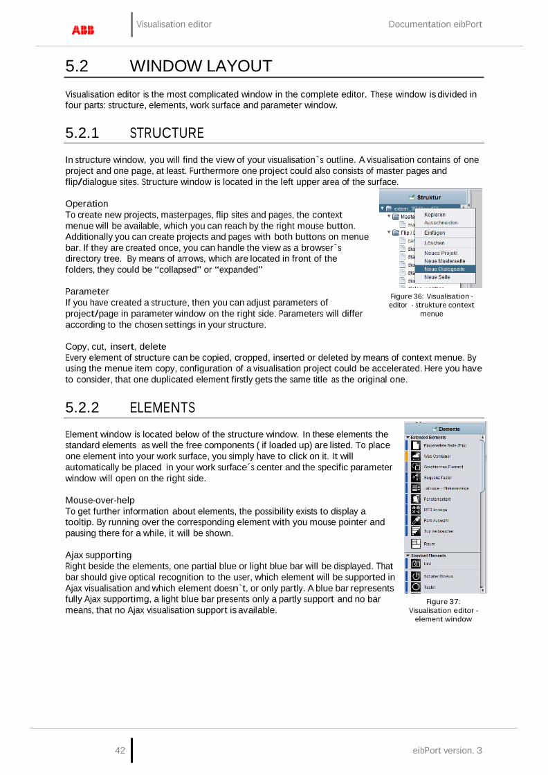
Visualisation editor Documentation eibPort
42 eibPort version. 3
5.2 WINDOW LAYOUT
Visualisation editor is the most complicated window in the complete editor. These window is divided in four parts: structure, elements, work surface and parameter window.
5.2.1 STRUCTURE
In structure window, you will find the view of your visualisation`s outline. A visualisation contains of one project and one page, at least. Furthermore one project could also consists of master pages and flip/dialogue sites. Structure window is located in the left upper area of the surface.
Operation To create new projects, masterpages, flip sites and pages, the context menue will be available, which you can reach by the right mouse button. Additionally you can create projects and pages with both buttons on menue bar. If they are created once, you can handle the view as a browser`s directory tree. By means of arrows, which are located in front of the folders, they could be “collapsed” or “expanded”
Parameter If you have created a structure, then you can adjust parameters of project/page in parameter window on the right side. Parameters will differ according to the chosen settings in your structure.
Figure 36: Visualisation - editor - strukture context
menue
Copy, cut, insert, delete Every element of structure can be copied, cropped, inserted or deleted by means of context menue. By using the menue item copy, configuration of a visualisation project could be accelerated. Here you have to consider, that one duplicated element firstly gets the same title as the original one.
5.2.2 ELEMENTS
Element window is located below of the structure window. In these elements the standard elements as well the free components ( if loaded up) are listed. To place one element into your work surface, you simply have to click on it. It will automatically be placed in your work surface´s center and the specific parameter window will open on the right side.
Mouse-over-help To get further information about elements, the possibility exists to display a tooltip. By running over the corresponding element with you mouse pointer and pausing there for a while, it will be shown.
Ajax supporting Right beside the elements, one partial blue or light blue bar will be displayed. That bar should give optical recognition to the user, which element will be supported in Ajax visualisation and which element doesn`t, or only partly. A blue bar represents fully Ajax supportimg, a light blue bar presents only a partly support and no bar means, that no Ajax visualisation support is available.
Figure 37: Visualisation editor -
element window
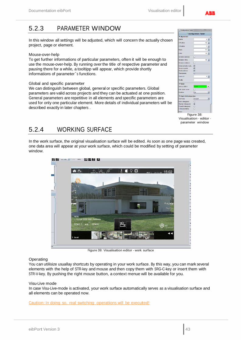
Documentation eibPort Visualisation editor
eibPort Version 3 43
5.2.3 PARAMETER WINDOW
In this window all settings will be adjusted, which will concern the actually chosen project, page or element.
Mouse-over-help To get further informations of particular parameters, often it will be enough to use the mouse-over-help. By running over the title of respective parameter and pausing there for a while, a tooltipp will appear, which provide shortly informations of parameter`s functions.
Global and specific parameter We can distinguish between global, general or specific parameters. Global parameters are valid across projects and they can be actuated at one position. General parameters are repetitive in all elements and specific parameters are used for only one particular element. More details of individual parameters will be described exactly in later chapters .
5.2.4 WORKING SURFACE
Figure 38:
Visualisation - editor - parameter window
In the work surface, the original visualisation surface will be edited. As soon as one page was created, one data area will appear at your work surface, which could be modified by setting of parameter window.
Figure 39: Visualisation editor - work surface
Operating You can utilisize usuallay shortcuts by operating in your work surface. By this way, you can mark several elements with the help of STR-key and mouse and then copy them with SRG-C-key or insert them with STR-V-key. By pushing the right mouse button, a context menue will be available for you.
Visu-Live mode In case Visu-Live-mode is activated, your work surface automatically serves as a visualisation surface and all elements can be operated now.
Caution: In doing so, real switching operations will be executed!

Visualisation editor Documentation eibPort
44 eibPort version. 3
Frame: The area outside of original visualisation surface is called frame. This frame will be displayed, if screen resolution of client will be higher than the screen resolution of visualisation project. The colour of frame can also be adapted to the background colour of the actual page. Additionally it will be possible to set parameters of visualisation surface`s horizontal and vertical orientation. (project parameters).
5.3 INFORMATION FOR OPERATING
Visualisation always consists of a project and at least of one page. Several projects can be created, e.g. for various buildings. Starting or using visualisation, you can change between your created projects. If user administration is activated, users only could work with projects, to which they got permissions.
RELEASE WINDOWS
On the left and on the right side of visualation surface, you see windows of elements and of parametrization. These windows can disturb your work with visualisation, according as which size and which resolution you have adjusted and maybe they will cover your visualisation surface. Therefore it is possible to “exempt” these windows out of the visualisation editor. You can exempt a window by doing a key click on the blue headline. After that, it becomes a window on the taskbar of your operation system and it can freely be positioned. To incorporate the window again, you have to click to the headline once more..
Figure 40: Editor - Release of windows
TO SCALE ELEMENTS
All elements of visualisation are free to scale. To scale one object, it will be reduced or extended with the aid of applicable marking points on it. Another way is, to mark this object and to change the size in the parametrization window on the right. In case in Parameterize window check mark „keep aspect ratio“ is set, it is not possible to scale element partially. With the flag “Prevent deformation” content of element will be scaled without distortion or not. Option “Smooth drawing” will cause, that element will burred by scaling, to avoid pixelated appearance. Elements, which contain text additional to symbols, you will find function „auto scale“, which provide for adapting of font size to size of element
COPY, PASTE, DELETE
You be able to copy elements of visualisation by containing their parameters. Use the right mouse button and click on one element ( in visualisation) and choose “copy”, “paste” or “delete” Alternatively you can use the key sequences „ SRTG-C” (for copy) and “STRG-V” (for paste) and for deleting the key „DEL“ .
DRAG & DROP
To place rapidly pictures of free components (switches from your component builder) on your visualization surface, you can also pull them per drag & drop from another window to the editor window. “Releasing” this file will automatically start a corresponding dialogue for uploading this file. All required informations are already filled in, you only have to push the „upload“ button. After uploading, your file will be placed in the selected visualisation window.

Documentation eibPort Visualisation editor
eibPort Version 3 45
5.4 PROJECTS AND PAGES
The structure of one visualisation project will be assembled roughly by so called „projects“ and „pages“. At this place particular parameters will be described, which will be determined by projects and pages. Many of parameters carries global characters, which specify generally performance and appearance.
5.4.1 PROJECTS
In parameter window of a project, general project settings are determined. This window willl appear, when you choose your requested project out of the project structure.
General Name: Name of your project. Start page: Starting the visualisation project, the selected page will be
displayed. Show page index: An index of pages will be displayed on the margin of
visualisation, in case of activated entry. With the help of this index, you can call up directly your visualisation pages.
Kiosk-mode: In this entry activated, visualisation starts in full-screen mode. This mode will be used esspecially in case visualisation is not allowed to be closed. (official hours)
Show disconnects : The activated entry here displays connection problems between client and eibPort ( red bar at the bottom of the visualisation window)
Color filter: Using this filter, you can change colour of element diagrams. The background of the elements will not be influenced in this way. Preview shows the appearance of the icons (in actuated and not actuated status). You can select between three defaults colour filters.
Page fade time (ms): You can configure a “page change change-over” mode. This parameter specifies duration of change using the measure of milliseconds.
Smart fade effect: The change-over effect will be performed more gently. Possibly effects of flicker will be avoided hereby. Furthermore change–over appears softly, if you are using slow acting computers.
To start page: After the specified number of minutes without any user interaction to visualize changes from any page in the project back to the defined home page.
Please note: During working of change-over, switching operation will not be possible.
Figure 41: Visualisation
Editor - Project parameters
Optimize memory usage: Using this option, only elements of the actual visualisation sheet are called up. This implicates a minor consumption of memory, but time for loading will be extended a little.
Object style configuration These settings define the style of the elements used within the project; the settings obtain fort he whole project. Each element an individual style can be assigned to via Element Attributes:
Theme background: The Theme background is set within the Theme Editor and can optionally
be set to global. So the style will be uniform for the whole project. Manually: Select this option in case of manual definition of the object “background”. Rounded edges: here the radius of the edges can be set (unit = px) Background: Three different options are available for the elements:
„Gradient“, „Background Colour“ and „No Background“.
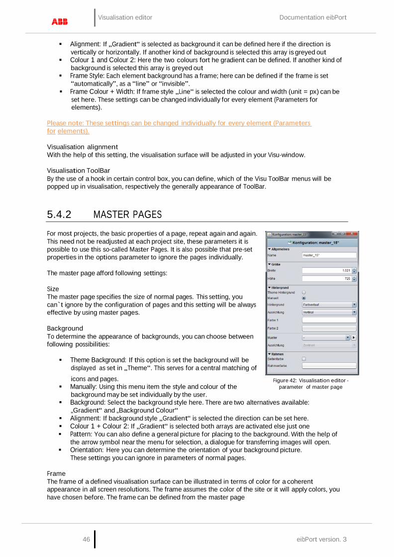
Visualisation editor Documentation eibPort
46 eibPort version. 3
Alignment: If „Gradient“ is selected as background it can be defined here if the direction is
vertically or horizontally. If another kind of background is selected this array is greyed out Colour 1 and Colour 2: Here the two colours fort he gradient can be defined. If another kind of
background is selected this array is greyed out Frame Style: Each element background has a frame; here can be defined if the frame is set
“automatically”, as a “line” or “invisible”. Frame Colour + Width: If frame style „Line“ is selected the colour and width (unit = px) can be
set here. These settings can be changed individually for every element (Parameters for elements).
Please note: These settings can be changed individually for every element (Parameters for elements).
Visualisation alignment With the help of this setting, the visualisation surface will be adjusted in your Visu-window.
Visualisation ToolBar By the use of a hook in certain control box, you can define, which of the Visu ToolBar menus will be popped up in visualisation, respectively the generally appearance of ToolBar.
5.4.2 MASTER PAGES
For most projects, the basic properties of a page, repeat again and again. This need not be readjusted at each project site, these parameters it is possible to use this so-called Master Pages. It is also possible that pre-set properties in the options parameter to ignore the pages individually.
The master page afford following settings:
Size The master page specifies the size of normal pages. This setting, you can`t ignore by the configuration of pages and this setting will be always effective by using master pages.
Background To determine the appearance of backgrounds, you can choose between following possibilities:
Theme Background: If this option is set the background will be
displayed as set in „Theme“. This serves for a central matching of icons and pages.
Manually: Using this menu item the style and colour of the background may be set individually by the user.
Figure 42: Visualisation editor - parameter of master page
Background: Select the background style here. There are two alternatives available: „Gradient“ and „Background Colour“
Alignment: If background style „Gradient“ is selected the direction can be set here. Colour 1 + Colour 2: If „Gradient“ is selected both arrays are activated else just one Pattern: You can also define a general picture for placing to the background. With the help of
the arrow symbol near the menu for selection, a dialogue for transferring images will open. Orientation: Here you can determine the orientation of your background picture.
These settings you can ignore in parameters of normal pages.
Frame The frame of a defined visualisation surface can be illustrated in terms of color for a coherent appearance in all screen resolutions. The frame assumes the color of the site or it will apply colors, you have chosen before. The frame can be defined from the master page
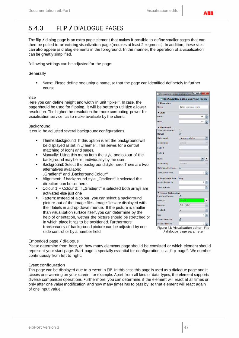
Documentation eibPort Visualisation editor
eibPort Version 3 47
5.4.3 FLIP / DIALOGUE PAGES
The flip / dialog page is an extra page element that makes it possible to define smaller pages that can then be pulled to an existing visualization page (requires at least 2 segments). In addition, these sites can also appear as dialog elements in the foreground. In this manner, the operation of a visualization can be greatly simplified.
Following settings can be adjusted for the page:
Generally
Name: Please define one unique name, so that the page can identified definetely in further
course.
Size Here you can define height and width in unit “pixel”. In case, the page should be used for flipping, it will be better to utilisize a lower resolution. The higher the resolution the more computing power for visualisation service has to make available by the client.
Background It could be adjusted several background configurations.
Theme Background: If this option is set the background will
be displayed as set in „Theme“. This serves for a central matching of icons and pages.
Manually: Using this menu item the style and colour of the background may be set individually by the user.
Background: Select the background style here. There are two alternatives available: „Gradient“ and „Background Colour“
Alignment: If background style „Gradient“ is selected the direction can be set here.
Colour 1 + Colour 2: If „Gradient“ is selected both arrays are activated else just one
Pattern: Instead of a colour, you can select a background picture out of the image files. Image files are displayed with their labels in a drop-down menue. If the picture is smaller than visualisation surface itself, you can determine by the help of orientation, wether the picture should be stretched or in which place it has to be positioned. Furthermore transparancy of background picture can be adjusted by one slide control or by a number field
Figure 43: Visualisation editor - Flip
/ dialogue page parameter
Embedded page / dialogue Please determine from here, on how many elements page should be consisted or which element should represent your start page. Start page is specially essential for configuration as a „flip page“. We number continuously from left to right.
Event configuration This page can be displayed due to a event in EIB. In this case this page is used as a dialogue page and it causes one warning on your screen, for example. Apart from all kind of data types, the element supports diverse comparison operations. Furthermore, you can determine, if the element will react at all times or only after one value modification and how many times has to pass by, so that element will react again of one input value.
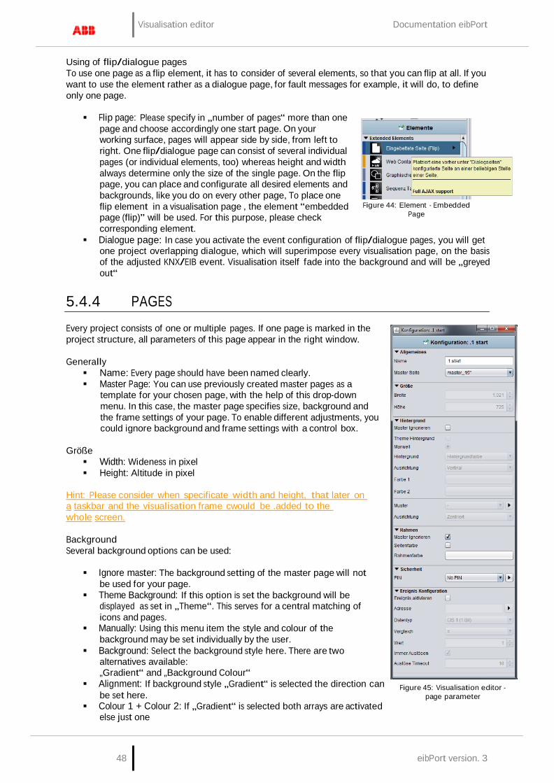
Visualisation editor Documentation eibPort
48 eibPort version. 3
Using of flip/dialogue pages To use one page as a flip element, it has to consider of several elements, so that you can flip at all. If you want to use the element rather as a dialogue page, for fault messages for example, it will do, to define only one page.
Flip page: Please specify in „number of pages“ more than one
page and choose accordingly one start page. On your working surface, pages will appear side by side, from left to right. One flip/dialogue page can consist of several individual pages (or individual elements, too) whereas height and width always determine only the size of the single page. On the flip page, you can place and configurate all desired elements and backgrounds, like you do on every other page, To place one flip element in a visualisation page , the element “embedded page (flip)” will be used. For this purpose, please check corresponding element.
Figure 44: Element - Embedded
Page
Dialogue page: In case you activate the event configuration of flip/dialogue pages, you will get one project overlapping dialogue, which will superimpose every visualisation page, on the basis of the adjusted KNX/EIB event. Visualisation itself fade into the background and will be „greyed out“
5.4.4 PAGES
Every project consists of one or multiple pages. If one page is marked in the project structure, all parameters of this page appear in the right window.
Generally Name: Every page should have been named clearly. Master Page: You can use previously created master pages as a
template for your chosen page, with the help of this drop-down menu. In this case, the master page specifies size, background and the frame settings of your page. To enable different adjustments, you could ignore background and frame settings with a control box.
Größe Width: Wideness in pixel Height: Altitude in pixel
Hint: Please consider when specificate width and height, that later on a taskbar and the visualisation frame cwould be .added to the whole screen.
Background Several background options can be used:
Ignore master: The background setting of the master page will not
be used for your page. Theme Background: If this option is set the background will be
displayed as set in „Theme“. This serves for a central matching of icons and pages.
Manually: Using this menu item the style and colour of the background may be set individually by the user.
Background: Select the background style here. There are two alternatives available: „Gradient“ and „Background Colour“
Alignment: If background style „Gradient“ is selected the direction can be set here.
Colour 1 + Colour 2: If „Gradient“ is selected both arrays are activated else just one
Figure 45: Visualisation editor - page parameter

Documentation eibPort Visualisation editor
eibPort Version 3 49
Pattern: As a background pattern, one picture out of the uploded picture pool will be diplayed.
With the aid of the arrow button, dialogue „Uploading images“ opens up. In addition to that, you can specify the alignment.
Frame A frame makes sure, that the VISU-surface will be displayed all over your screen, no matter how, which resolution is adjusted. In case, that among the visualisation-clients one screen offers a higher resolution as the visulisation surface, the frame will be shown additionally. The colour of your frame can be set individually beside the colour of the page. The frame can also be determined by the master page.
Security Each page can be locked with a PIN-code. The menu, which allows you to create and organize the PIN- code, is been opened up with the help from the symbol right beside of PIN selection array. You can create a new PIN with the “+” – symbol. Your PIN-code should get a unique name. As a PIN, numerals from 0 to 9 in a random length can be chosen. The setting of decline for a PIN-code decides how long the user can work without a recent password request. In case the user remains working on the page and the PIN-code looses validity, a new code entry will be required, not until user opens the page again. By using the “-“ symbol, a PIN-code will be erased. Options for PIN-code features, your can also change in the menu item “user settings”.
Trigger Configuration Activate trigger: The regarding page will be displayed on screen by releasing a telegram.
Reversal of a page can only take place within one project. Address: Here the group address for event releasing has to be filled in. Possible variations of EIS-
types are : EIS 1, EIS 5, EIS 6, EIS 9, EIS 10, EIS 11, EIS 14. Comparison: Incoming group addresses can be proofed by comparison. Only a correct proof
result will cause a change of page. Possible operation of comparison are: similar, less than, greater than, less or equal, greater or equal and dissimilar. If the setting is “*” a comparison will not take place, the page will be initiate after any value of receipt.
Retrigger always: If this function has been activated, every accurate result of comparison starts a change of page, in case of non activated function the change of page happens only after alteration of comparison results.
Retrigger timeout: The setting of time in seconds during a new release will not cause a reaction.
5.4.5 AJAX SUPPORT
In what form visualisation elements and global parameters also are effective for Ajax visualisation, we can find out quickly and simply by means of tooltips. Visualisation elements will get one optical marking (a blue bar). Ajax support of the elements will be constantly developed and alters from firmware to firmware.
Color coding: Blue bar = Full Ajax support Light blue bars = Partial support Orange bars = No Java support No bars = Only supports Java
Figure 46: Visualisation editor - tooltipp ajax support
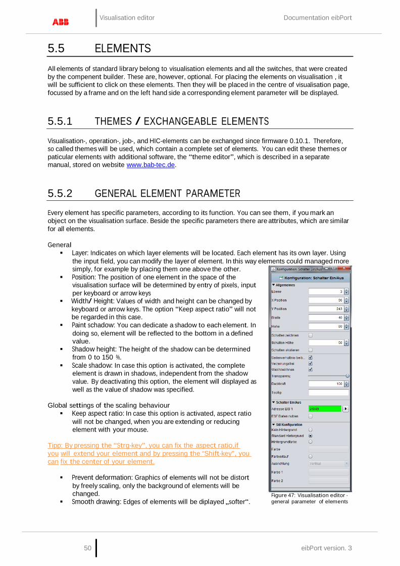
Visualisation editor Documentation eibPort
50 eibPort version. 3
5.5 ELEMENTS
All elements of standard library belong to visualisation elements and all the switches, that were created by the compenent builder. These are, however, optional. For placing the elements on visualisation , it will be sufficient to click on these elements. Then they will be placed in the centre of visualisation page, focussed by a frame and on the left hand side a corresponding element parameter will be displayed.
5.5.1 THEMES / EXCHANGEABLE ELEMENTS
Visualisation-, operation-, job-, and HIC-elements can be exchanged since firmware 0.10.1. Therefore, so called themes will be used, which contain a complete set of elements. You can edit these themes or paticular elements with additional software, the “theme editor”, which is described in a separate manual, stored on website www.bab-tec.de.
5.5.2 GENERAL ELEMENT PARAMETER
Every element has specific parameters, according to its function. You can see them, if you mark an object on the visualisation surface. Beside the specific parameters there are attributes, which are similar for all elements.
General Layer: Indicates on which layer elements will be located. Each element has its own layer. Using
the input field, you can modify the layer of element. In this way elements could managed more simply, for example by placing them one above the other.
Position: The position of one element in the space of the visualisation surface will be determined by entry of pixels, input per keyboard or arrow keys
Width/ Height: Values of width and height can be changed by keyboard or arrow keys. The option “Keep aspect ratio” will not be regarded in this case.
Paint schadow: You can dedicate a shadow to each element. In doing so, element will be reflected to the bottom in a defined value.
Shadow height: The height of the shadow can be determined from 0 to 150 %.
Scale shadow: In case this option is activated, the complete element is drawn in shadows, independent from the shadow value. By deactivating this option, the element will displayed as well as the value of shadow was specified.
Global settings of the scaling behaviour Keep aspect ratio: In case this option is activated, aspect ratio
will not be changed, when you are extending or reducing element with your mouse.
Tipp: By pressing the “Strg-key”, you can fix the aspect ratio,if you will extend your element and by pressing the “Shift-key”, you can fix the center of your element.
Prevent deformation: Graphics of elements will not be distort
by freely scaling, only the background of elements will be changed.
Smooth drawing: Edges of elements will be diplayed „softer“.
Figure 47: Visualisation editor - general parameter of elements
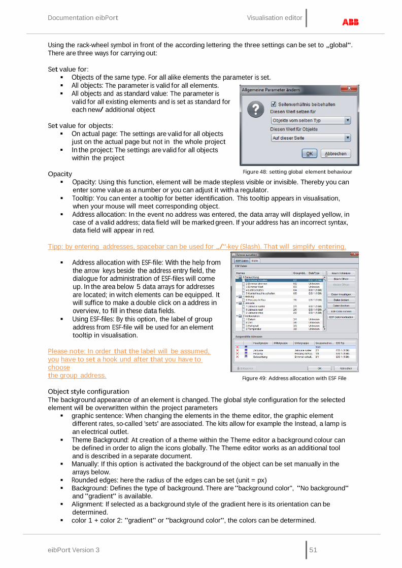
Documentation eibPort Visualisation editor
eibPort Version 3 51
Using the rack-wheel symbol in front of the according lettering the three settings can be set to „global“. There are three ways for carrying out:
Set value for: Objects of the same type. For all alike elements the parameter is set. All objects: The parameter is valid for all elements. All objects and as standard value: The parameter is
valid for all existing elements and is set as standard for each new/ additional object
Set value for objects: On actual page: The settings are valid for all objects
just on the actual page but not in the whole project In the project: The settings are valid for all objects
within the project
Opacity
Figure 48: setting global element behaviour
Opacity: Using this function, element will be made stepless visible or invisible. Thereby you can enter some value as a number or you can adjust it with a regulator.
Tooltip: You can enter a tooltip for better identification. This tooltip appears in visualisation, when your mouse will meet corresponding object.
Address allocation: In the event no address was entered, the data array will displayed yellow, in case of a valid address; data field will be marked green. If your address has an incorrect syntax, data field will appear in red.
Tipp: by entering addresses, spacebar can be used for „/“-key (Slash). That will simplify entering.
Address allocation with ESF-file: With the help from
the arrow keys beside the address entry field, the dialogue for administration of ESF-files will come up. In the area below 5 data arrays for addresses are located; in witch elements can be equipped. It will suffice to make a double click on a address in overview, to fill in these data fields.
Using ESF-files: By this option, the label of group address from ESF-file will be used for an element tooltip in visualisation.
Please note: In order that the label will be assumed, you have to set a hook und after that you have to choose the group address.
Object style configuration
Figure 49: Address allocation with ESF File
The background appearance of an element is changed. The global style configuration for the selected element will be overwritten within the project parameters graphic sentence: When changing the elements in the theme editor, the graphic element
different rates, so-called 'sets' are associated. The kits allow for example the Instead, a lamp is an electrical outlet.
Theme Background: At creation of a theme within the Theme editor a background colour can be defined in order to align the icons globally. The Theme editor works as an additional tool and is described in a separate document.
Manually: If this option is activated the background of the object can be set manually in the arrays below.
Rounded edges: here the radius of the edges can be set (unit = px) Background: Defines the type of background. There are "background color", "No background"
and "gradient" is available. Alignment: If selected as a background style of the gradient here is its orientation can be
determined. color 1 + color 2: "gradient" or "background color", the colors can be determined.
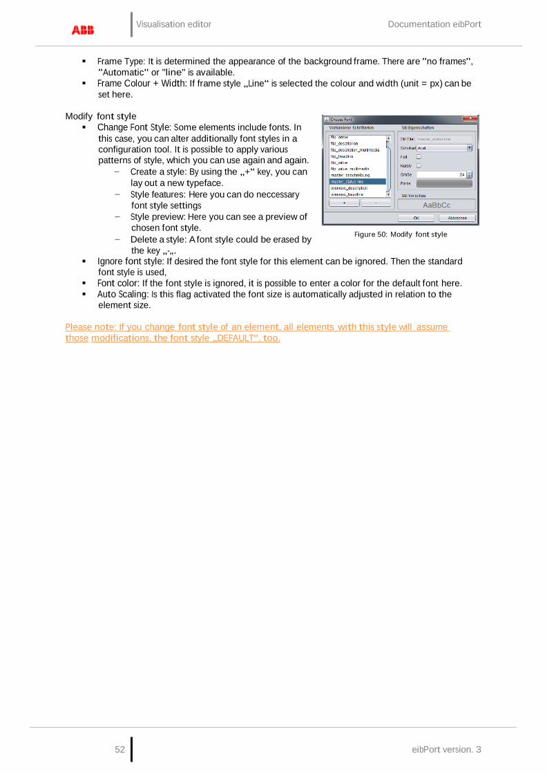
Visualisation editor Documentation eibPort
52 eibPort version. 3
Frame Type: It is determined the appearance of the background frame. There are "no frames",
"Automatic" or "line" is available. Frame Colour + Width: If frame style „Line“ is selected the colour and width (unit = px) can be
set here.
Modify font style Change Font Style: Some elements include fonts. In
this case, you can alter additionally font styles in a configuration tool. It is possible to apply various patterns of style, which you can use again and again.
− Create a style: By using the „+“ key, you can lay out a new typeface.
− Style features: Here you can do neccessary font style settings
− Style preview: Here you can see a preview of chosen font style.
− Delete a style: A font style could be erased by the key „-„.
Figure 50: Modify font style
Ignore font style: If desired the font style for this element can be ignored. Then the standard font style is used,
Font color: If the font style is ignored, it is possible to enter a color for the default font here. Auto Scaling: Is this flag activated the font size is automatically adjusted in relation to the
element size.
Please note: If you change font style of an element, all elements with this style will assume those modifications, the font style „DEFAULT“, too.
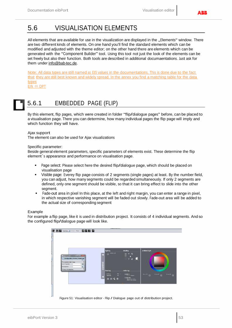
Documentation eibPort Visualisation editor
eibPort Version 3 53
5.6 VISUALISATION ELEMENTS
All elements that are available for use in the visualization are displayed in the „Elements“ window. There are two different kinds of elements. On one hand you’ll find the standard elements which can be modified and adjusted with the theme editor; on the other hand there are elements which can be generated with the “Component Builder” tool. Using this tool not just the look of the elements can be set freely but also their function. Both tools are described in additional documaentations. Just ask for them under [email protected].
Note: All data types are still named as EIS values in the documentations. This is done due to the fact that they are still best known and widely spread. In the annex you find a matching table for the data types EIN DPT
5.6.1 EMBEDDED PAGE (FLIP) By this element, flip pages, which were created in folder “flip/dialogue pages” before, can be placed to a visualisation page. There you can determine, how many individual pages the flip page will imply and which function they will have.
Ajax support The element can also be used for Ajax visualizations
Specific parameter: Beside general element parameters, specific parameters of elements exist. These determine the flip element`s appearance and performance on visualisation page.
Page select: Please select here the desired flip/dialogue page, which should be placed on
visualisation page Visible page: Everey flip page consists of 2 segments (single pages) at least. By the number field,
you can adjust, how many segments could be regarded simultaneously. If only 2 segments are defined, only one segment should be visible, so that it can bring effect to slide into the other segment.
Fade-out area in pixel In this place, at the left and right margin, you can enter a range in pixel, in which respective vanishing segment will be faded out slowly. Fade-out area will be added to the actual size of corresponding segment
Example For example a flip page, like it is used in distribution project. It consists of 4 individual segments. And so the configured flip/dialogue page will look like.
Figure 51: Visualisation editor - Flip / Dialogue page out of distribution project.
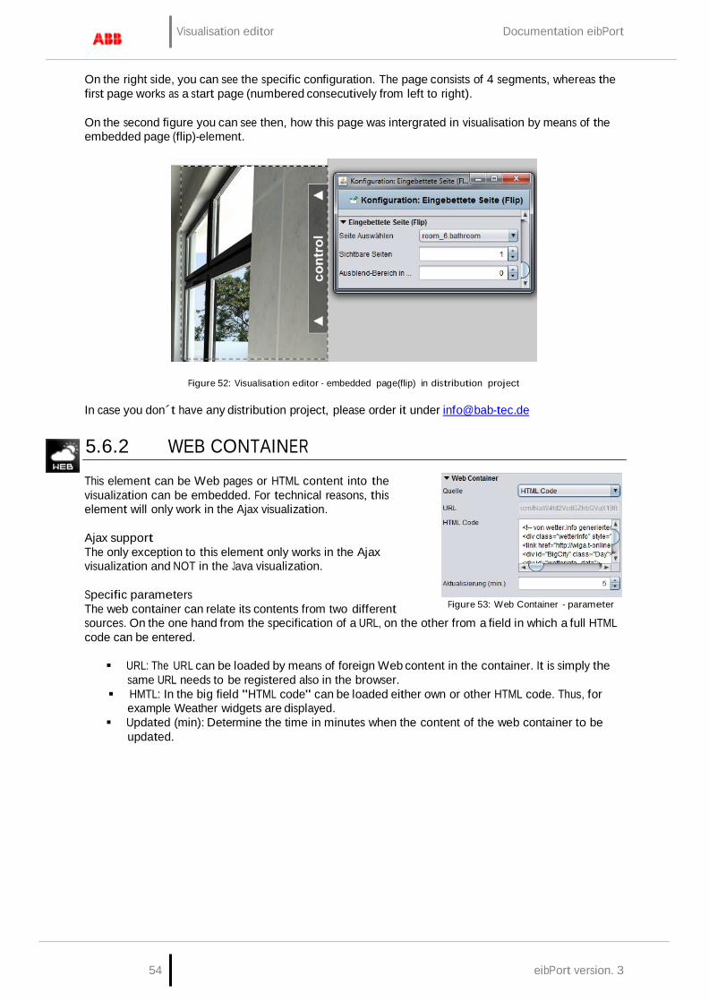
Visualisation editor Documentation eibPort
54 eibPort version. 3
On the right side, you can see the specific configuration. The page consists of 4 segments, whereas the first page works as a start page (numbered consecutively from left to right).
On the second figure you can see then, how this page was intergrated in visualisation by means of the embedded page (flip)-element.
Figure 52: Visualisation editor - embedded page(flip) in distribution project
In case you don´t have any distribution project, please order it under [email protected]
5.6.2 WEB CONTAINER
This element can be Web pages or HTML content into the visualization can be embedded. For technical reasons, this element will only work in the Ajax visualization.
Ajax support The only exception to this element only works in the Ajax visualization and NOT in the Java visualization.
Specific parameters The web container can relate its contents from two different
Figure 53: Web Container - parameter
sources. On the one hand from the specification of a URL, on the other from a field in which a full HTML code can be entered.
URL: The URL can be loaded by means of foreign Web content in the container. It is simply the
same URL needs to be registered also in the browser. HMTL: In the big field "HTML code" can be loaded either own or other HTML code. Thus, for
example Weather widgets are displayed. Updated (min): Determine the time in minutes when the content of the web container to be
updated.
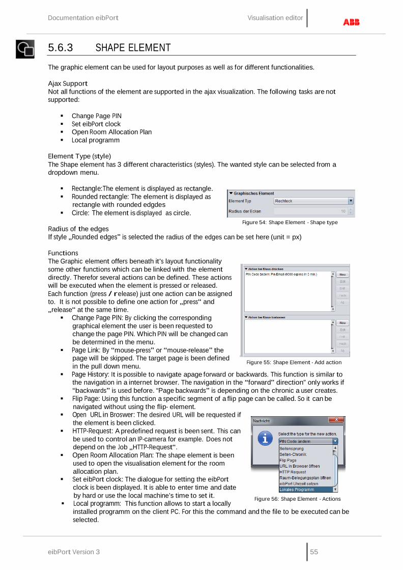
Documentation eibPort Visualisation editor
eibPort Version 3 55
5.6.3 SHAPE ELEMENT
The graphic element can be used for layout purposes as well as for different functionalities.
Ajax Support Not all functions of the element are supported in the ajax visualization. The following tasks are not supported:
Change Page PIN Set eibPort clock Open Room Allocation Plan Local programm
Element Type (style) The Shape element has 3 different characteristics (styles). The wanted style can be selected from a dropdown menu.
Rectangle:The element is displayed as rectangle. Rounded rectangle: The element is displayed as
rectangle with rounded edgdes Circle: The element is displayed as circle.
Radius of the edges
Figure 54: Shape Element - Shape type
If style „Rounded edges” is selected the radius of the edges can be set here (unit = px)
Functions The Graphic element offers beneath it’s layout functionality some other functions which can be linked with the element directly. Therefor several actions can be defined. These actions will be executed when the element is pressed or released. Each function (press / release) just one action can be assigned to. It is not possible to define one action for „press“ and „release“ at the same time. Change Page PIN: By clicking the corresponding
graphical element the user is been requested to change the page PIN. Which PIN will be changed can be determined in the menu.
Page Link: By “mouse-press” or “mouse-release” the page will be skipped. The target page is been defined in the pull down menu.
Figure 55: Shape Element - Add action
Page History: It is possible to navigate apage forward or backwards. This function is similar to the navigation in a internet browser. The navigation in the “forward” direction” only works if “backwards” is used before. “Page backwards” is depending on the chronic a user creates.
Flip Page: Using this function a specific segment of a flip page can be called. So it can be navigated without using the flip- element.
Open URL in Broswer: The desired URL will be requested if the element is been clicked.
HTTP-Request: A predefined request is been sent. This can be used to control an IP-camera for example. Does not depend on the Job „HTTP-Request“.
Open Room Allocation Plan: The shape element is been used to open the visualisation element for the room allocation plan.
Set eibPort clock: The dialogue for setting the eibPort clock is been displayed. It is able to enter time and date by hard or use the local machine’s time to set it.
Local programm: This function allows to start a locally
Figure 56: Shape Element - Actions
installed programm on the client PC. For this the command and the file to be executed can be selected.
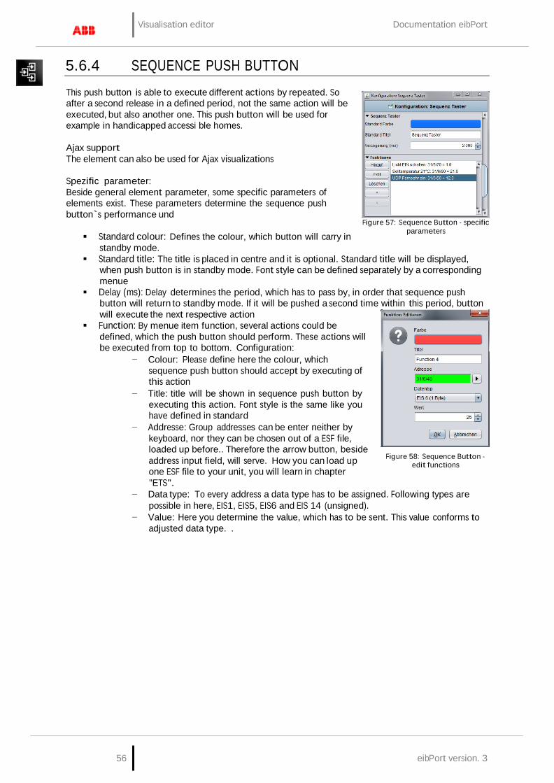
Visualisation editor Documentation eibPort
56 eibPort version. 3
5.6.4 SEQUENCE PUSH BUTTON
This push button is able to execute different actions by repeated. So after a second release in a defined period, not the same action will be executed, but also another one. This push button will be used for example in handicapped accessi ble homes.
Ajax support The element can also be used for Ajax visualizations
Spezific parameter: Beside general element parameter, some specific parameters of elements exist. These parameters determine the sequence push button`s performance und
Standard colour: Defines the colour, which button will carry in
standby mode.
Figure 57: Sequence Button - specific
parameters
Standard title: The title is placed in centre and it is optional. Standard title will be displayed, when push button is in standby mode. Font style can be defined separately by a corresponding menue
Delay (ms): Delay determines the period, which has to pass by, in order that sequence push button will return to standby mode. If it will be pushed a second time within this period, button will execute the next respective action
Function: By menue item function, several actions could be defined, which the push button should perform. These actions will be executed from top to bottom. Configuration:
− Colour: Please define here the colour, which sequence push button should accept by executing of this action
− Title: title will be shown in sequence push button by executing this action. Font style is the same like you have defined in standard
− Addresse: Group addresses can be enter neither by keyboard, nor they can be chosen out of a ESF file, loaded up before.. Therefore the arrow button, beside address input field, will serve. How you can load up one ESF file to your unit, you will learn in chapter ”ETS”.
Figure 58: Sequence Button - edit functions
− Data type: To every address a data type has to be assigned. Following types are possible in here, EIS1, EIS5, EIS6 and EIS 14 (unsigned).
− Value: Here you determine the value, which has to be sent. This value conforms to adjusted data type. .
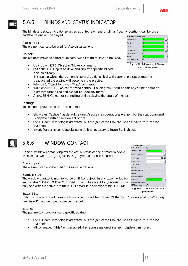
Documentation eibPort Visualisation editor
eibPort Version 3 57
5.6.5 BLINDS AND STATUS INDICATOR
The blinds and status indicator serves as a control element for blinds. Specific positions can be driven and the tilt angle is displayed.
Ajax support The element can also be used for Ajax visualizations
Objects The element provides different objects. Not all of them have to be used.
Up / Down: EIS 1 Object as ‘Move‘ command. Position: EIS 6 Object to drive and display a specific blind’s
postion directly
Figure 59: Jalousie and Status
indicator - Parameters
The scaling within the element is controlled dynamically. If parameter „aspect ratio“ is deactivated the scaling will become more precise.
Ribs: EIS 1 Object for blinds “Step“ command. Wind control: EIS 1 object for wind control. If a telegram is sent on this object the operation
elements turn to red and cannot be used any more. Angle: EIS 6 Object for controlling and displaying the angle of the ribs.
Settings The element provides some more options:
Show Step: “active “ as default setting. Assigns if an operational element for the step command
is displayed within the element or not. Use ESF data: if this flag is activated ESF data (out of the ETS) are used as tooltip resp. mouse-
over-help. Invert: For use in some special controls it is necessary to invert EIS 1 objects
5.6.6 WINDOW CONTACT
Element window contact displays the actual status of one or more windows. Therefore as well EIS 1 (1Bit) as EIS 14 (1 Byte) object can be used.
Ajax support The element can also be used for Ajax visualizations
Status EIS 14 The window contact is monitored by an EIS14 object. In this case a value for each status “Open“, “Closed“, “Tilted” is set. The object for „Broken“ is the only one which is active in “Status EIS 1“ even if in selection “Status EIS 14”.
Status EIS 1
Figure 60: Window contact -
parameters
If this status is activated there are three objects each for “Open“,“Tilted“and “breakage of glass“. Using the „Invert“ flag the objects can be inverted.
Settings The parameters serve for more specific settings:
Use ESF data: if this flag is activated ESF data (out of the ETS) are used as tooltip resp. mouse-
over-help. Mirror Image: If this flag is enabled, the representation of the item displayed mirrored.

Visualisation editor Documentation eibPort
58 eibPort version. 3
5.6.7 RTR DISPLAY
RTR display serves for room temperature control. In this process, switch offers the functions standby / comfort / night reduction and frost protection. This element can be operated with EIS 1 or EIS 14. .
Ajax support The element can also be used for Ajax visualizations
Specific parameter Beside general element parameters, some specific parameters of elements exist. These parameter define, which data type and which address RTR-display will use
Typ EIS 14 / EIS 1: G Fundamental RTR-display can be operated with EIS 14 or EIS 1 values.
Depending on which data type is chosen, one or the other display will be activated.
Status Adresse: If EIS 14 as data type is chosen, address data has to be entered here. This could happen either by hand nor by the dialogue for address input, which offers the access to data of ETS (see also: upload ESF-file)
Value Standby/comfort/night reductiong/frost protection: for every status, you have to enter necessary EIS14 values in the corresponding input fields. .
Adr. Standby/comfort: If EIS 1 is defined for data type, so it will be switched between standby and comfort by this communication object
Adr. Night reduction: By the help of this address, it will be switched to night reduction.
Adr. Frost protection By the help of this address, it will be switched to frost protection.
Figure 61: RTR-Display - specific parameters
5.6.8 COLOUR SELECTION Colour selection circle serves for combination of colours out of RGB colour space. Thereby it will be possible to control LED coloured light by visualisation, with the help of so called „DMX-dimmer“. Necessary values will be sent from eibPort by EIS 14 telegrams.
Ajax support The element can also be used for Ajax visualizations
Specific parameter Beside general element parameters, some specific parameters of elements exist. These parameters determine, to which groupaddresses necessary values will be sent.
EIS 14 red/green/blue: Here communication objects of EIS 14
values of red, green and blue will be entered. Addresses can be filled in either by keyboard, nor by entering in the address dialogue, where you can also find data from ETS, in case they were imported before. (see chapter ETS
EIS 1 sending complete: to this group address a EIS confirmation telegram weill be sent, if entering of colour was completed.
Figure 62: Colour selection - specific parameters

Documentation eibPort Visualisation editor
eibPort Version 3 59
5.6.9 TOP CONSUMER
Top consumer is an element of display, which compares 4 incoming values and which list them automatically according to their amount. Thereby values will be compared by means of a horizontal bar graph. So that display is suited excellently for making visible the top consumer in a building for one view. To measure this consumption, KNX-actuators with current value detection will be applied ideally. These will deliver momentary electricity (ampere), which will convert by the integrated job to energy consumption (for example watt-hours) umgerechnet wird.
Ajax support The element can also be used for Ajax visualizations
Specific parameter Beside general element parameters, some specific parameters of elements exist. These parameters define which unit the top consumer will display and how many consumers will be reflected.
Bar colour: Determines the colour of the bar, which displays the
amount of consumption Value format: To influence the value`s format, you can place
following inputs here: Integer and fractional digits are controlled by characters „0“ and „#“. “0” stands for a forcing digit, that means, even if there is no value, character „0“ will be displayed. All characters, which are marked with “#”, will be optional, that means, that if there is a “0” or no value, this character will not be displayed. For example:
− Value should be 0,2. In case of value format 0.0, value 0.2 will be displayed. But if you enter #.#, only digit ,2 will be shown, because there is no value (=0) on the first digit.
Figure 63: Top Consumer - specific
parameters
Data source: At present unique selectable option “Momentary (EIB)”. That implies that information about consumption will be extract out of current EIB telegrams.
Consumer: By this menue, particular consumer will be allocated to the element. Therefore you will find the buttons „Append“, „Edit“ and „Delete“ on the side. With arrow keys, the sequence can be changed. With the help The button „Append“ opens another menue:
− Title: The title will eb shown also in corresponding element. The name should be unique.
− Address: Input address of consumption data.This address can´t be entered by keyboard, but it has to be chosen out of one ESF file.ESF-dialogue will open by pushing the arrow key near the address entry.
− Data type: The element supports folowing EIS types: EIS 5, EIS 6, EIS 9, EIS 10 (s + u), EIS 11 (s + u), and EIS 14 (s + u).
Figure 64: Top Comsumer - editing consumers
− Factor und Offset: Value will be multiplied with Factor and be added with Offset.
Please note: For integrate job`s configuration please read more in chapter „JobEditor“

Visualisation editor Documentation eibPort
60 eibPort version. 3
5.6.10 ROOM
This element serves for accessing the room allocation plan module. So f.i. a caretaker is enabled to operate the occupancy out of the visualization. Detailled explanations and documentation of the occupancy plan module you may order here: [email protected]
Ajax Support This element is not displayed in the ajax visualization. Currently it has no ajax support.
Select room Different rooms being generated in the occupancy plan module can be selected here out of a dropdown menu. Element „room“ is named with the title of the room and its assigned colour.
Figure 65: Visualisation
Element Room Allocation Plan (Control R)
Checkbox The checkboxes serve for configuration of the visualization element. According information can be found in the occupancy plan module.
Display active profile: Displays the actually active profile of the room Display active status: Displays the actually active status of the room Display exits: All exits and their status are displayed Change status: An additional button „Set State“ appears on the element. Using this button the
user can change (via dropdown menu) the status of the room for a defined period. Display calendar: An additional button „Open Calendar“ appears on the element. Using the
button the user is enabled to access the configuration module („Profile“, „calender“ and „generated data“). The access level is set in the occupancy plan module. (=> please refer to the respective documentation).
5.6.11 IMAGE
Element “Image“ allows to place any graphic on the visualization surface. Not just graphics from the eibPort’s buffer but even from other sources (server etc) can be uploaded. Moreover the display mode (yes / no) can be linked with an event.
Ajax support The element can also be used for Ajax visualizations
Image from internal memory Via dialogue “Image“ all graphics being loaded into the eibPort can be selected. Dialogue „Graphic Transfer“ serves for uploading graphics into the device. The dialogue can be called via „Extras“ > „Image transfer“, or alternatively using the arrows beside the drop down menu “Image“. Graphic files also can be drawn by drag and drop directly onto the visualization surface and are also available in the dropdown list.
Adopt size: If the Image’s size was changed this button resizes it to
the original gauge
Figure 66: Image Element Parameter
External image This element provides graphics being located on the client PC or on any server. So it is possible to display an actual cover graphic while playing the music.
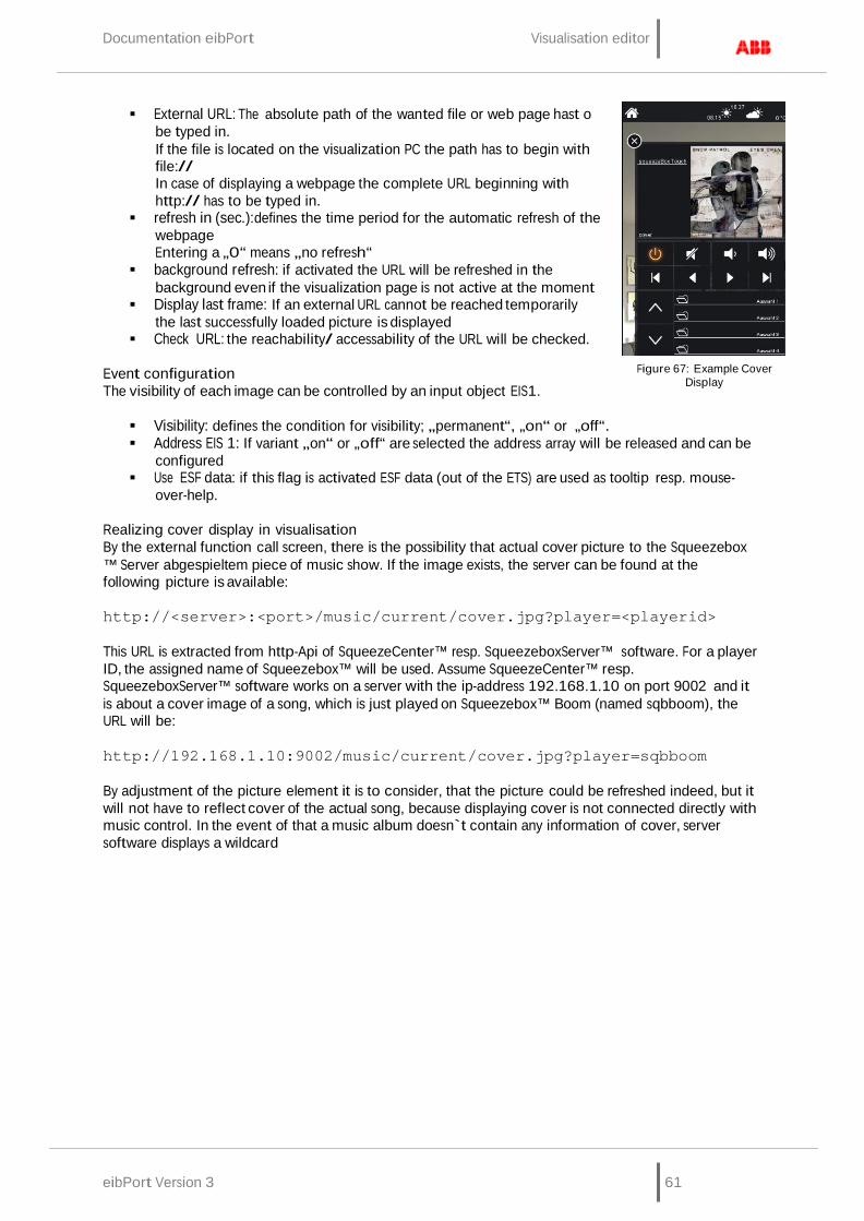
Documentation eibPort Visualisation editor
eibPort Version 3 61
External URL: The absolute path of the wanted file or web page hast o be typed in. If the file is located on the visualization PC the path has to begin with file:// In case of displaying a webpage the complete URL beginning with http:// has to be typed in.
refresh in (sec.):defines the time period for the automatic refresh of the webpage Entering a „0“ means „no refresh“
background refresh: if activated the URL will be refreshed in the background even if the visualization page is not active at the moment
Display last frame: If an external URL cannot be reached temporarily the last successfully loaded picture is displayed
Check URL: the reachability/ accessability of the URL will be checked.
Event configuration The visibility of each image can be controlled by an input object EIS1.
Figure 67: Example Cover Display
Visibility: defines the condition for visibility; „permanent“, „on“ or „off“. Address EIS 1: If variant „on“ or „off“ are selected the address array will be released and can be
configured Use ESF data: if this flag is activated ESF data (out of the ETS) are used as tooltip resp. mouse-
over-help.
Realizing cover display in visualisation By the external function call screen, there is the possibility that actual cover picture to the Squeezebox ™ Server abgespieltem piece of music show. If the image exists, the server can be found at the following picture is available:
http://<server>:<port>/music/current/cover.jpg?player=<playerid>
This URL is extracted from http-Api of SqueezeCenter™ resp. SqueezeboxServer™ software. For a player ID, the assigned name of Squeezebox™ will be used. Assume SqueezeCenter™ resp. SqueezeboxServer™ software works on a server with the ip-address 192.168.1.10 on port 9002 and it is about a cover image of a song, which is just played on Squeezebox™ Boom (named sqbboom), the URL will be:
http://192.168.1.10:9002/music/current/cover.jpg?player=sqbboom
By adjustment of the picture element it is to consider, that the picture could be refreshed indeed, but it will not have to reflect cover of the actual song, because displaying cover is not connected directly with music control. In the event of that a music album doesn`t contain any information of cover, server software displays a wildcard

Visualisation editor Documentation eibPort
62 eibPort version. 3
5.6.12 EIS 1 OBJECTS / SWITCH, BUTTON AND LUMINAIRE
The Standard library provides three standard elements for data type EIS 1. These elements only can display 1 Bit values. Using the theme Editor it is possible to insert additional style sets for button and luminaire.
Ajax support The elements can also be used for Ajax visualizations.
Switch On / OFF Element switch toggles an EIS 1 object. The switch’s style cannot be modified.
Button Button contains different functions within one element. Moreover it is possible to use different style sets via the “Theme editor”.
Toggle (On/OFF): each trigger on the element sends out an ON or OFF signal. Button (ON/OFF): each trigger on the element sends an ON signal and after this returns with an
OFF signal into its original status. Button (OFF/ON): each trigger on the element sends an OFF signal and after this returns with an
ON signal into its original status. ON: each trigger on the element sends out an ON signal. OFF: each trigger on the element sends out an OFF signal.
Luminaire The luminaire displays the status of EIS1 objects. This element cannot be operated, but it is possible to use different style sets via the “Theme editor”.
Style set Button and luminaire have different style sets which can be extended individually using the „theme Editor“. Basically both style sets provide:
Power Jack: The element shows a power jack. In case of being used for the button
it can be operated as switch, if used as luminaire it just displays Corona: The element pictures a corona. The element is suitable for being placed on
“real” lamps (without background)
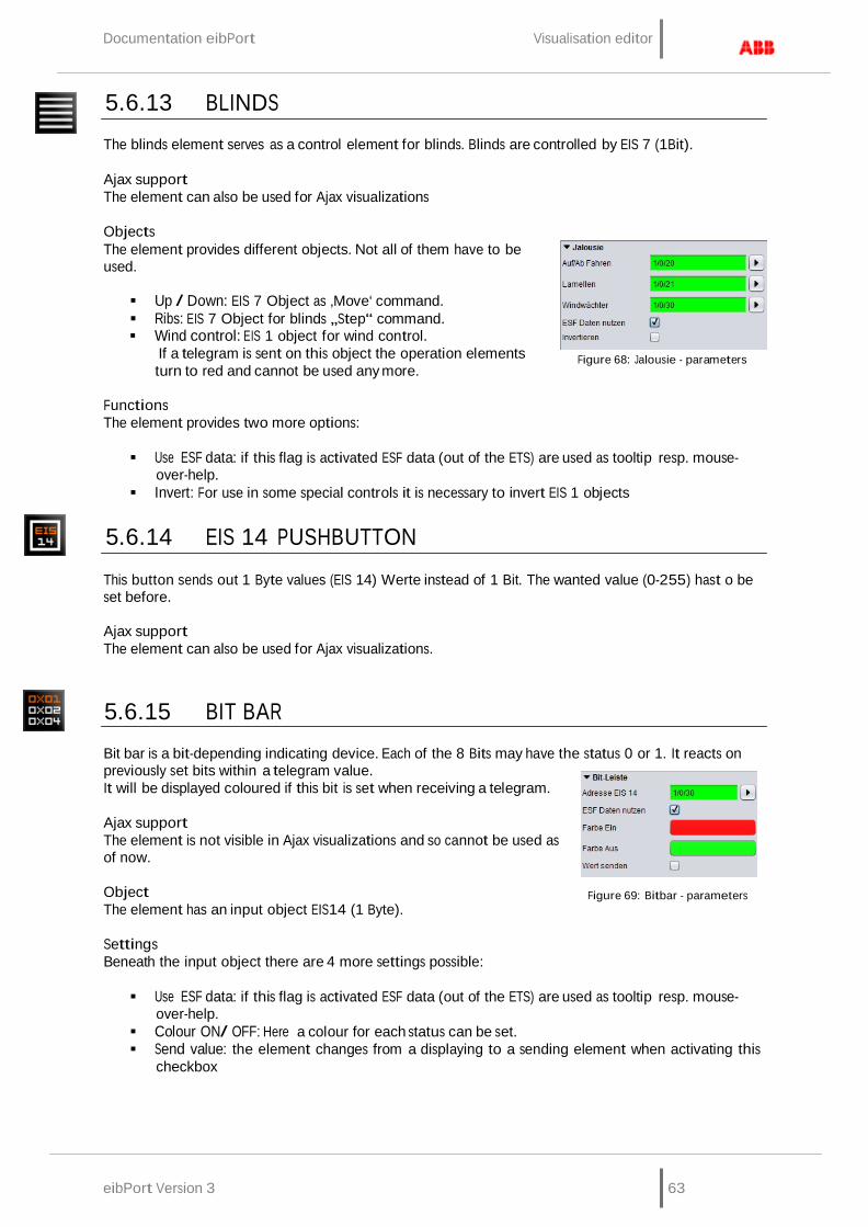
Documentation eibPort Visualisation editor
eibPort Version 3 63
5.6.13 BLINDS
The blinds element serves as a control element for blinds. Blinds are controlled by EIS 7 (1Bit).
Ajax support The element can also be used for Ajax visualizations
Objects The element provides different objects. Not all of them have to be used.
Up / Down: EIS 7 Object as ‚Move‘ command. Ribs: EIS 7 Object for blinds „Step“ command. Wind control: EIS 1 object for wind control.
If a telegram is sent on this object the operation elements turn to red and cannot be used any more.
Functions The element provides two more options:
Figure 68: Jalousie - parameters
Use ESF data: if this flag is activated ESF data (out of the ETS) are used as tooltip resp. mouse-
over-help. Invert: For use in some special controls it is necessary to invert EIS 1 objects
5.6.14 EIS 14 PUSHBUTTON
This button sends out 1 Byte values (EIS 14) Werte instead of 1 Bit. The wanted value (0-255) hast o be set before.
Ajax support The element can also be used for Ajax visualizations.
5.6.15 BIT BAR
Bit bar is a bit-depending indicating device. Each of the 8 Bits may have the status 0 or 1. It reacts on previously set bits within a telegram value. It will be displayed coloured if this bit is set when receiving a telegram.
Ajax support The element is not visible in Ajax visualizations and so cannot be used as of now.
Object The element has an input object EIS14 (1 Byte).
Settings Beneath the input object there are 4 more settings possible:
Figure 69: Bitbar - parameters
Use ESF data: if this flag is activated ESF data (out of the ETS) are used as tooltip resp. mouse-
over-help. Colour ON/ OFF: Here a colour for each status can be set. Send value: the element changes from a displaying to a sending element when activating this
checkbox
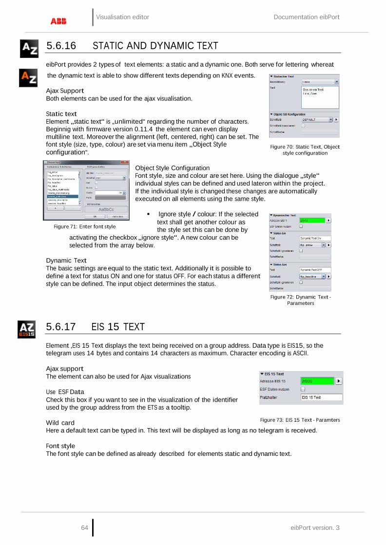
Visualisation editor Documentation eibPort
64 eibPort version. 3
5.6.16 STATIC AND DYNAMIC TEXT
eibPort provides 2 types of text elements: a static and a dynamic one. Both serve for lettering whereat
the dynamic text is able to show different texts depending on KNX events.
Ajax Support Both elements can be used for the ajax visualisation.
Static text Element „static text“ is „unlimited“ regarding the number of characters. Beginnig with firmware version 0.11.4 the element can even display multiline text. Moreover the alignment (left, centered, right) can be set. The font style (size, type, colour) are set via menu item „Object Style configuration“.
Figure 70: Static Text, Object
style configuration
Figure 71: Enter font style
Object Style Configuration Font style, size and colour are set here. Using the dialogue „style“ individual styles can be defined and used lateron within the project. If the individual style is changed these changes are automatically executed on all elements using the same style. Ignore style / colour: If the selected
text shall get another colour as the style set this can be done by
activating the checkbox „ignore style“. A new colour can be selected from the array below.
Dynamic Text The basic settings are equal to the static text. Additionally it is possible to define a text for status ON and one for status OFF. For each status a different style can be defined. The input object determines the status.
5.6.17 EIS 15 TEXT
Figure 72: Dynamic Text -
Parameters
Element ‚EIS 15 Text displays the text being received on a group address. Data type is EIS15, so the telegram uses 14 bytes and contains 14 characters as maximum. Character encoding is ASCII.
Ajax support The element can also be used for Ajax visualizations
Use ESF Data Check this box if you want to see in the visualization of the identifier used by the group address from the ETS as a tooltip.
Wild card
Figure 73: EIS 15 Text - Paramters
Here a default text can be typed in. This text will be displayed as long as no telegram is received.
Font style The font style can be defined as already described for elements static and dynamic text.

Documentation eibPort Visualisation editor
eibPort Version 3 65
5.6.18 EIS 15 DISPLAY
Based on the‚EIS 15 Text‘ -element the EIS 15 display offers some more possibilities of use. So several messages can be buffered and messages can be sent. The element background can be customized.
Ajax support The element can also be used for Ajax visualization.
Use ESF Data Check this box if you want to see in the visualization of the identifier used by the group address from the ETS as a tooltip.
Wild card Here a default text can be typed in. This text will be displayed as long as no telegram is received.
Recording If this option is selected the element records incoming telegramms. The number of recordings is set by the input line „recording length“. Default setting is „10“.
Figure 74: EIS 15 Display -
Parameters
Input active If the checkbox is activated the elment is able to send EIS 15 text messages. Therefore the element has to be activated by mouseclick. An input box opens and the text can be typed in.
Object Style Configuration Not just the text itself but also background can be designed individually. Possible opportunities are depending on global element settings (compare chapter „general element parameters“)
5.6.19 TEMPERATURE SWITCH
The temperature switch serves for changing temperature values. The user is enabled to increase or decrease the values in predefined steps. By defining a background or using a graphics set the switch can be designed individually.
Ajax support The element can also be used for Ajax visualization.
Use ESF Data Check this box if you want to see in the visualization of the identifier used by the group address from the ETS as a tooltip.
Data type Possible data types are EIS 5 or DPT 6.010 (2 byte values). The wanted data type can be selected from a dropdown menu.
Step width
Figure 75: Temp. Switch- Parameters
Here it is defined by which value the default/ last value will be changed. Because the values are floating point values, also decimal places can be used. The default setting for the increment is 0.5
Min. / Max. value These two values define the range between minimum and maximum temperature. Even negative values are possible.
Object Style Configuration Not just the text itself but also background can be designed individually. Possible opportunities are depending on global element settings (compare chapter „general element parameters“)

Visualisation editor Documentation eibPort
66 eibPort version. 3
5.6.20 TEMPERATURE DISPLAY
The temperature display shows the scheduled value and the actual temperature. For changing the scheduled value the element can be linked with the temperature switch. Background and font style can be set individually.
Ajax support The element can also be used for Ajax visualizations
Use ESF Data if this flag is activated ESF data (out of the ETS) are used as tooltip
Input objects Both input objects have data type EIS 5. According to the KNX object structure several addresses can be joined to one object (=> chapter Object structure).
Text The text being displayed within the element can be edited in these two arrays. For instance instead of „actual temperature“ it can be edited to „temperature“.
Object Style Configuration Not just the text itself but also background can be designed individually. Possible opportunities are depending on global element settings (compare chapter „general element parameters“)
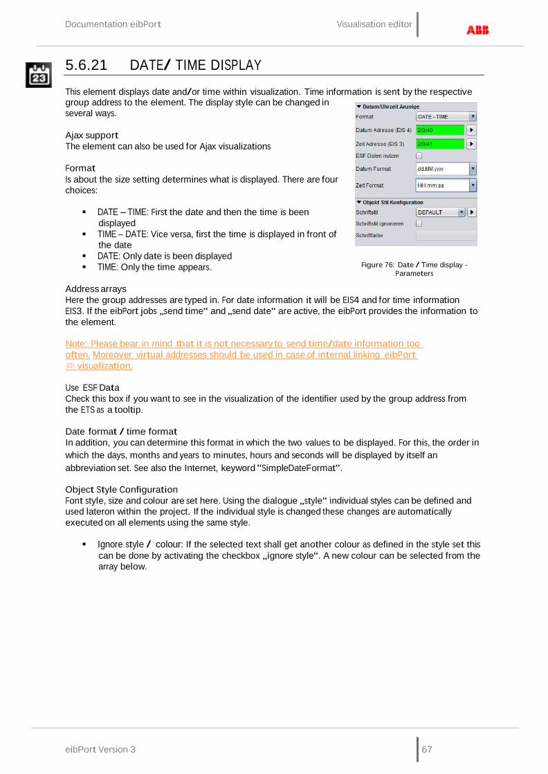
Documentation eibPort Visualisation editor
eibPort Version 3 67
5.6.21 DATE/ TIME DISPLAY
This element displays date and/or time within visualization. Time information is sent by the respective group address to the element. The display style can be changed in several ways.
Ajax support The element can also be used for Ajax visualizations
Format Is about the size setting determines what is displayed. There are four choices:
DATE – TIME: First the date and then the time is been
displayed TIME – DATE: Vice versa, first the time is displayed in front of
the date DATE: Only date is been displayed TIME: Only the time appears.
Address arrays
Figure 76: Date / Time display - Parameters
Here the group addresses are typed in. For date information it will be EIS4 and for time information EIS3. If the eibPort jobs „send time“ and „send date“ are active, the eibPort provides the information to the element.
Note: Please bear in mind that it is not necessary to send time/date information too often. Moreover virtual addresses should be used in case of internal linking eibPort visualization.
Use ESF Data Check this box if you want to see in the visualization of the identifier used by the group address from the ETS as a tooltip.
Date format / time format In addition, you can determine this format in which the two values to be displayed. For this, the order in which the days, months and years to minutes, hours and seconds will be displayed by itself an abbreviation set. See also the Internet, keyword "SimpleDateFormat".
Object Style Configuration Font style, size and colour are set here. Using the dialogue „style“ individual styles can be defined and used lateron within the project. If the individual style is changed these changes are automatically executed on all elements using the same style.
Ignore style / colour: If the selected text shall get another colour as defined in the style set this
can be done by activating the checkbox „ignore style“. A new colour can be selected from the array below.
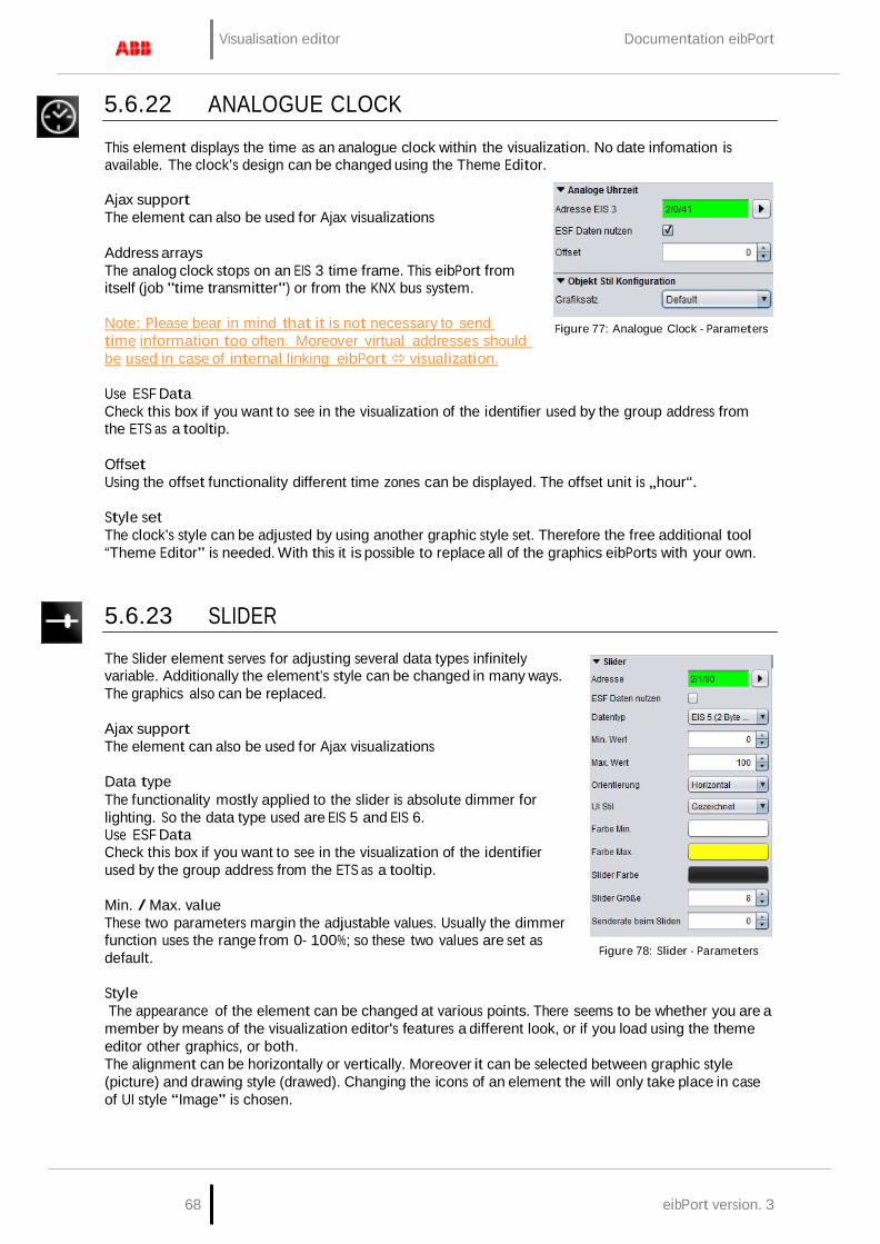
Visualisation editor Documentation eibPort
68 eibPort version. 3
5.6.22 ANALOGUE CLOCK
This element displays the time as an analogue clock within the visualization. No date infomation is available. The clock’s design can be changed using the Theme Editor.
Ajax support The element can also be used for Ajax visualizations
Address arrays The analog clock stops on an EIS 3 time frame. This eibPort from itself (job "time transmitter") or from the KNX bus system.
Note: Please bear in mind that it is not necessary to send time information too often. Moreover virtual addresses should be used in case of internal linking eibPort visualization.
Figure 77: Analogue Clock - Parameters
Use ESF Data Check this box if you want to see in the visualization of the identifier used by the group address from the ETS as a tooltip.
Offset Using the offset functionality different time zones can be displayed. The offset unit is „hour“.
Style set The clock’s style can be adjusted by using another graphic style set. Therefore the free additional tool “Theme Editor” is needed. With this it is possible to replace all of the graphics eibPorts with your own.
5.6.23 SLIDER
The Slider element serves for adjusting several data types infinitely variable. Additionally the element’s style can be changed in many ways. The graphics also can be replaced.
Ajax support The element can also be used for Ajax visualizations
Data type The functionality mostly applied to the slider is absolute dimmer for lighting. So the data type used are EIS 5 and EIS 6. Use ESF Data Check this box if you want to see in the visualization of the identifier used by the group address from the ETS as a tooltip.
Min. / Max. value These two parameters margin the adjustable values. Usually the dimmer function uses the range from 0- 100%; so these two values are set as default.
Figure 78: Slider - Parameters
Style The appearance of the element can be changed at various points. There seems to be whether you are a member by means of the visualization editor's features a different look, or if you load using the theme editor other graphics, or both. The alignment can be horizontally or vertically. Moreover it can be selected between graphic style (picture) and drawing style (drawed). Changing the icons of an element the will only take place in case of UI style “Image” is chosen.
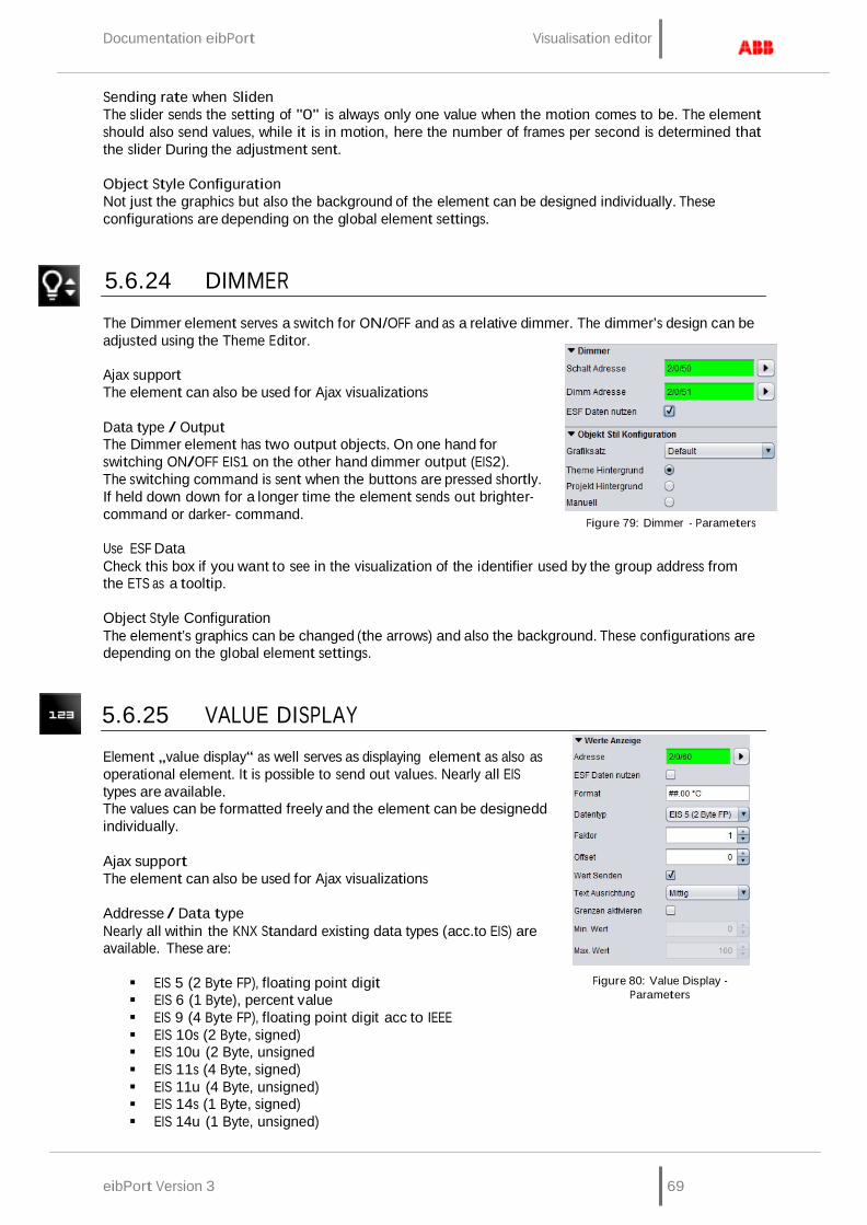
Documentation eibPort Visualisation editor
eibPort Version 3 69
Sending rate when Sliden The slider sends the setting of "0" is always only one value when the motion comes to be. The element should also send values, while it is in motion, here the number of frames per second is determined that the slider During the adjustment sent.
Object Style Configuration Not just the graphics but also the background of the element can be designed individually. These configurations are depending on the global element settings.
5.6.24 DIMMER
The Dimmer element serves a switch for ON/OFF and as a relative dimmer. The dimmer’s design can be adjusted using the Theme Editor.
Ajax support The element can also be used for Ajax visualizations
Data type / Output The Dimmer element has two output objects. On one hand for switching ON/OFF EIS1 on the other hand dimmer output (EIS2). The switching command is sent when the buttons are pressed shortly. If held down down for a longer time the element sends out brighter- command or darker- command.
Use ESF Data
Figure 79: Dimmer - Parameters
Check this box if you want to see in the visualization of the identifier used by the group address from the ETS as a tooltip.
Object Style Configuration The element’s graphics can be changed (the arrows) and also the background. These configurations are depending on the global element settings.
5.6.25 VALUE DISPLAY
Element „value display“ as well serves as displaying element as also as operational element. It is possible to send out values. Nearly all EIS types are available. The values can be formatted freely and the element can be designedd individually.
Ajax support The element can also be used for Ajax visualizations
Addresse / Data type Nearly all within the KNX Standard existing data types (acc.to EIS) are available. These are:
EIS 5 (2 Byte FP), floating point digit EIS 6 (1 Byte), percent value EIS 9 (4 Byte FP), floating point digit acc to IEEE EIS 10s (2 Byte, signed) EIS 10u (2 Byte, unsigned EIS 11s (4 Byte, signed) EIS 11u (4 Byte, unsigned) EIS 14s (1 Byte, signed) EIS 14u (1 Byte, unsigned)
Figure 80: Value Display - Parameters

Visualisation editor Documentation eibPort
70 eibPort version. 3
DPT 29 (8 Byte signed) DPT 6.010 (1 Byte signed)
Use ESF Data Check this box if you want to see in the visualization of the identifier used by the group address from the ETS as a tooltip.
Format Here the received value can be formatted as wanted. Additionally a unit can be added. Therefore the following parameters have to be used:
# = optional 0 = obliging
So if a „0“ is set this digit is displayed whether if the input value is existing or not. If a „#“ is set the digit is only displayed when an input value is existing.
Example The input value it 23,4 (degrees). The value display shall show 2 digits behind the comma and the unit symbol. The settings have to look like this: ##.00 °C So the value display element shows 23,40 °C .
Factor / Offset The value can be multiplied with a factor and an offset can be added. Incoming values can be converted in the desired format/ unit.
Send value The element can be used as operational element. In this case the labelling „Edit“ occurs on the element. The user is enabled to interfere into operation.
Text alignment Sets the position on which the value is displayed; the „edit“ labelling remains on the original position.
Activate limits This limits the value range the user can send out. An example for use is shifting temperatures.
Object Style Configuration Not just the text itself but also background can be designed individually. Possible opportunities are depending on global element settings (compare chapter „general element parameters“)

Documentation eibPort Visualisation editor
eibPort Version 3 71
5.6.26 TELEGRAM TIME
The element shows the last time stamp of the telegramm(s) an address object has received. Fach telegram received or leaving the eibPort the last time stamp is buffered in the internal address table. The time stamp element scans the address table and returns the result.
Ajax support The element can also be used for Ajax visualizations
Address / Address object The address object listens according to the defined object structure within the eibPort to up to 5 group addresses independent from the data type format.
Use ESF Data Check this box if you want to see in the visualization of the identifier used by the group address from the ETS as a tooltip.
Format The displayed format for date and time can be set here. The definition follows the „Simpledateformat“ providing three different versions; additionally an individual format can be typed in.
Figure 81: Telegram Time-
Parameters
Object Style Configuration Font, size and colour are set in this menu. Using the dialogue „Font“ own font styles can be defined and used in the project. If the individual style is changed these changes are automatically executed on all elements using the same style (compare chapter „general element parameters“).
Ignore style / colour: If the selected text shall get another colour as defined in the style set this can be done by activating the checkbox „ignore style“. A new colour can be selected from the array below.

Visualisation editor Documentation eibPort
72 eibPort version. 3
5.6.27 BUS MONITOR
The Bus Monitor shows the actual telegramm traffic within the KNX installation. The element can be embedded into the visualization or alternatively be opened in an external window. The content can be adjusted individually and by using operational elements the content can be changed and / or buffered while the visualization is running.
Ajax support The element can not be used for Ajax visualizations because it cannot be displayed there.
External Window If this option is activated the bus monitor will be opened in a window of ist own. If it is deactivated the depiction within the editor changes and the element has to be positioned and scaled accordingly. The element, thereby changing their appearance.
Note: Deactivate the option „maintain aspect ratio“ in order to adjust the window to ist environment.
Display operational elements If this option is activated several operational elements are displayed on the visualization surface.
Figure 82: Bus Monitor - Parameters
Column: by using this button columns can be added or removed. Export: The actually displayed telegrams can be downloaded to the local PC (as csv- file). Filter: By using the filter specific group addresses can be selected and displayed. Break: Recording is suspended. Void: The recordings of the Bus Monitor are deleted and recording starts again.
Address Filter A specific address filter can already be entered during parametrization, then the bus monitor just displays the input address.
Columns Using the checkboxes the wanted columns can be activated. Columns „Bus Repeats“, „Bus Priority“, „Bus routing counter“ and „System ID“ are deactivated as default setting.
Object Style Configuration Furthermore the graphic and the background appearance of the element can be changed. Possible opportunities are depending on global element settings (compare chapter „general element parameters“).
Figure 83: Bus Monitor - embedded in Visualisation

Documentation eibPort Visualisation editor
eibPort Version 3 73
5.6.28 JOB EDITOR
This element enables the user to access and edit several jobs. So f.i. the user may configure the settings of autotimers or change the outputs of a light scene. In order to do this the user gets a limited access to the job mask.
Ajax support The element can not be used for Ajax visualizations because it cannot be displayed there.
Job The dropdown menu provides all actually available jobs. The possible job types are:
Annual timer Weekly timer Light scene
The job name being selected in the Job Editor will be displayed as labelling within the visualization element.
Tooltip This text array defines the labelling being displayed in case of mouseover.
Figure 84: Job Editor element
Integrated Editor If this checkbox is activated the limited job mask will not be opened in a new (external) window but will embedded into the visualization page. Especially for client PCs with a visualization running in the foreground permanently this is an important feature.
Object Style Configuration Not just the text itself but also background can be designed individually. Possible opportunities are depending on global element settings (compare chapter „general element parameters“)
5.6.29 LOGIC DISPLAY
This element displays the actual status of logics. The element shows just the status of the output or the status of all affected group addresses (input, release). Style and functionality can be set arbitrarily.
Ajax support The element cannot be used for Ajax visualizations because it cannot be displayed there.
Colour ON / OFF These colour arrays define the status colour for staus ON and OFF. The settings are valid for input and output.
Send value
Figure 85: Logic display - Parameters
Similar to the value display element the logics display element can be adapted to an operational element. The user is enabled to click onto the logics‘ colour arrays to trigger a telegram for the wanted group address.
External Window If this function is activated on the visualization surface just a one-line element is displayed. This element shows the status of the output by a colour array. When clicking on the lement an external window opens and displays a complete overview (input, output, parameter….) for the logics element.

Visualisation editor Documentation eibPort
74 eibPort version. 3
5.6.30 FAILURE INDICATOR
This element displays alarm messages by receiving an EIS1 telegram. The alarm messages can be acknowledged, the status colour can be changed and modalities in case of malfunctions / alarms can be defined.
Ajax support The element cannot be used for Ajax visualizations because it cannot be displayed there.
Address / Address object - Fault The address object listens according to the defined object structure within the eibPort to up to 5 group addresses independent from the data type format.
Address / Address object - Acknowledge Just if this object a group address is assigned to the alarm messages can be acknowledged out of the visualization.
Text Defines the text being displayed.
Colour „OK“ / „Failure“ / „Acknowledge“ / „not Acknowledged“ For each status a colour can be assigned
Figure 86: Failure Indicator - Parameters
Jump to page If the checkbox is activated the affected page is put into the foreground by the visualization in case of an alarm
Focus on window If the checkbox in activated the visualization program is put into the foreground. This functionality is depending on the operation system and browser used on the client PC.
Focus trigger Defines the trigger for focussing the visualization window:
ON: receiving any ON telegram Rising edge: just if the object’s value changes from „0“ to „1“ the focus becomes active.
Show Text If this option is deactivated the element will be displayed without any text infomation but just by colour indicationt.
Disturbance invert If this option is enabled, the fault is not set at "1" instead of "0".
Confirmable If activated the element can be acknowledged by the user out of the visualization; else this can be done just by the object itself.
Observe time stamp Compares the time stamps of acknowledge objects and alarm objects in order to check in case of visualization’s restart if the alarm was already acknowledged. Especially if more than one visualization client is used this function very useful.
Beep Enabled If activated the visualization sends out an alert signal via PC speakers.
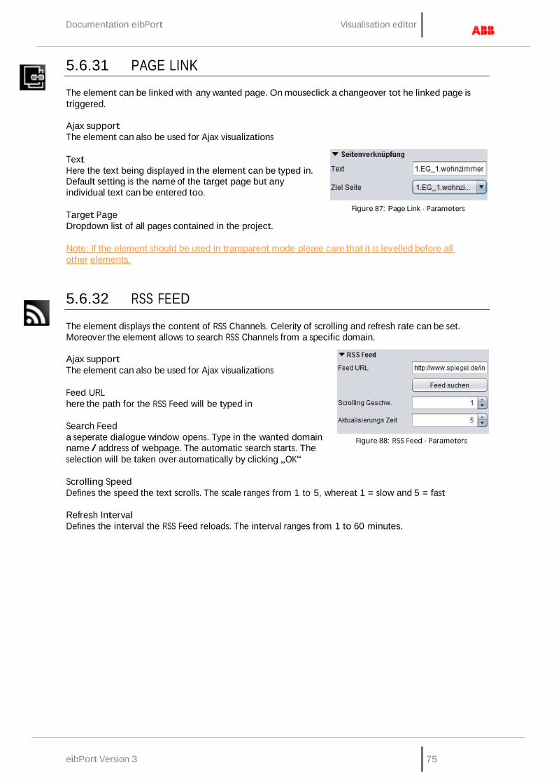
Documentation eibPort Visualisation editor
eibPort Version 3 75
5.6.31 PAGE LINK
The element can be linked with any wanted page. On mouseclick a changeover tot he linked page is triggered.
Ajax support The element can also be used for Ajax visualizations
Text Here the text being displayed in the element can be typed in. Default setting is the name of the target page but any individual text can be entered too.
Target Page Dropdown list of all pages contained in the project.
Figure 87: Page Link - Parameters
Note: If the element should be used in transparent mode please care that it is levelled before all other elements.
5.6.32 RSS FEED
The element displays the content of RSS Channels. Celerity of scrolling and refresh rate can be set. Moreover the element allows to search RSS Channels from a specific domain.
Ajax support The element can also be used for Ajax visualizations
Feed URL here the path for the RSS Feed will be typed in
Search Feed a seperate dialogue window opens. Type in the wanted domain name / address of webpage. The automatic search starts. The selection will be taken over automatically by clicking „OK“
Figure 88: RSS Feed - Parameters
Scrolling Speed Defines the speed the text scrolls. The scale ranges from 1 to 5, whereat 1 = slow and 5 = fast
Refresh Interval Defines the interval the RSS Feed reloads. The interval ranges from 1 to 60 minutes.
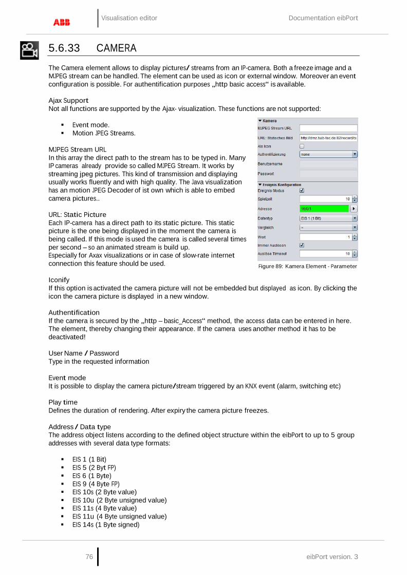
Visualisation editor Documentation eibPort
76 eibPort version. 3
5.6.33 CAMERA
The Camera element allows to display pictures/ streams from an IP-camera. Both a freeze image and a MJPEG stream can be handled. The element can be used as icon or external window. Moreover an event configuration is possible. For authentification purposes „http basic access“ is available.
Ajax Support Not all functions are supported by the Ajax- visualization. These functions are not supported:
Event mode. Motion JPEG Streams.
MJPEG Stream URL In this array the direct path to the stream has to be typed in. Many IP cameras already provide so called MJPEG Stream. It works by streaming jpeg pictures. This kind of transmission and displaying usually works fluently and with high quality. The Java visualization has an motion JPEG Decoder of ist own which is able to embed camera pictures..
URL: Static Picture Each IP-camera has a direct path to its static picture. This static picture is the one being displayed in the moment the camera is being called. If this mode is used the camera is called several times per second – so an animated stream is build up. Especially for Axax visualizations or in case of slow-rate internet connection this feature should be used.
Figure 89: Kamera Element - Parameter
Iconify If this option is activated the camera picture will not be embedded but displayed as icon. By clicking the icon the camera picture is displayed in a new window.
Authentification If the camera is secured by the „http – basic_Access“ method, the access data can be entered in here. The element, thereby changing their appearance. If the camera uses another method it has to be deactivated!
User Name / Password Type in the requested information
Event mode It is possible to display the camera picture/stream triggered by an KNX event (alarm, switching etc)
Play time Defines the duration of rendering. After expiry the camera picture freezes.
Address / Data type The address object listens according to the defined object structure within the eibPort to up to 5 group addresses with several data type formats:
EIS 1 (1 Bit) EIS 5 (2 Byt FP) EIS 6 (1 Byte) EIS 9 (4 Byte FP) EIS 10s (2 Byte value) EIS 10u (2 Byte unsigned value) EIS 11s (4 Byte value) EIS 11u (4 Byte unsigned value) EIS 14s (1 Byte signed)

Documentation eibPort Visualisation editor
eibPort Version 3 77
EIS 14u (1 Byte unsigned)
Comparison / Value The value of the object input is routed automatically to a comparator and is compared with a fixed value. The following comparative operators are available:
At each alteration „*“ Equal to „=“ Less than „<“ larger than„>“ less than or equal „<=“ larger than or equal „>= Unequal to „<>“
Retrigger always If activated the event is triggered by each result sent out
Figure 90: Camera view - Copy URL
by the comparator. If deactivated just in case of changes an event is triggered.
Retrigger Timeout Defines the time range (unit = sec) after which the trigger is available again
How to find out the correct URLs Due to the fact that there are existing different camera types and manufacturers there are also different syntaxes for the correct URL. Usually it works like this to find out the correct URL:
Set the camera to the wanted modulation (MJPEG or static picture). Switch to the „Live View“ view on the camera’s configuration page and right- click onto the
picture. Select „copy file location“ and insert the address in a new browser window. Now you should see just the camera stream without menue bar or another elements.
If this doesn’t work please refer to the camera’s manual or the manufacturers webpage.

Visualisation editor Documentation eibPort
78 eibPort version. 3
5.6.34 GRAPH
Element Graph displays the progression of values in a certain time range (like a line recorder). Example of use are temperatures, counters, power consumption etc. The telegrams are provided by the ringbuffer of the eibPort which stores the last 20000 telegrams. Special settings are:
Ajax support This item appears in the Ajax visualization. The graph provides some additional functions there in the Java visualization can not be used. The relevant features are identified in the parameter window with a "*" (asterisk).
Refresh on Start The Graph element is actualized when the visualization starts.
Grid colour / Axes Colour Here the colours are defined.
Axis Format This text array sets the displayed value format of the y- axis. The number of decimals is set. The following syntax is used: „0“ means enforced value; the digit is displayed even if now
value is available. „#“ means optional valuel; the digit is displayed just if a value
is available. The number of digits is limited by the settings. „.“ = Comma If units or other characters should be displayeed they have to
be put into tickmarks (’).
Example: A value of „21,2“ shall be displayed. If the format is set to „00.00“, „21,20“ will be displayed. If the format is set to „0.##“, „21,2“ will be displayed. F.i. a percent sign is added like this: „0.##’%’“.
Axis Limit
Figure 91: Graph - Parameters
If activates the axis is limited within a specific range. Settings can be made in the arrays below.
Graph data by time / by count Values displayed by the graph will be filtered by time or by count. The time period is set in hours.
Note: Please have in mind that the graph elment is only able to display values if it finds any data in the recording table. If the data is a group address as appropriate by a broken clock eibPort with a time stamp well before the present, the data will not be shown in the graph (or graph must be scrolled back up to that date)!
Auto Refresh If the visualization has started once the graph automatically updates the data displayed within this interval. This means that the elements gets new data from the eibPort recording table and recalculates the measuring points.

Documentation eibPort Visualisation editor
eibPort Version 3 79
Time domain Determines the time frame that the graph is based. Selections are: 1 hours 3 hours 6 hours 12 hours 1 days 2 days 1 weeks
Fixed time period When activated, the time range will always be displayed from beginning to end. If the option is disabled, the time range we always back-calculated from the present time.
First / follow-up time Be taken into account determines the number of minutes in the data and before and after the beginning or end of the time domain. If for example The time range is set on a particular day, considered in this way, values that were active just before or after 0:00 clock. Otherwise, the graph would assume at this point, no value ("0") and misrepresent.
The "leaves" (also available in Java) With this option the user can visualize in each case by the set time range browse forward or back, is always set in case there are any data at this time.
Calculation There are two different types possible:
Total: the value is displayed as absolute value by time. In case of meter readings the graph
would increase continously Difference: The difference between two values is displayed by time. The frequency between the
measurings can be set by „interval“ (Unit = min). The smaller the time gap the more exact the curve will be.
Data type Several EIS formats are supported:
EIS 1 (1 Bit) EIS 5 (2 Byte FP) EIS 6 (1 Byte) EIS 9 (4 Byte FP) EIS 10s (2 Byte Value) EIS 10u (2 Byte unsigned Value) EIS 11s (4 Byte Value) EIS 11u (4 Byte unsigned Value) EIS 14s (1 Byte Value) EIS 14u (1 Byte unsigned Value) DPT 29 (8 Byte signed Value)
The appendix provides an overview of types of EIS in conjunction with DTP data types.
Descprition Enter a legend for the curve. The text is displayed below the graph in the selected color curve.
Factor / Offset Using factor and offset, the input value to be formatted as desired. The value is multiplied by a factor and added to the offset.

Visualisation editor Documentation eibPort
80 eibPort version. 3
Color Defines the colour of the curve and the labelling.
Curve type (only possible for the AJAX visualization) When the curve type is determined which form of a diagram is displayed. The following is available:
line: There is a line drawn diagram area: It creates a surface plot in the area below the line marked accordingly.
Levels draw (only possible for the AJAX visualization) When activated, there will be dawn no curves there were drawn Levels. This is for example Interest in the presentation of an EIS values.
Points draw (only possible for the AJAX visualization) On the line of the graph, when activated, the different measuring points are plotted.
FUNCTIONALITY WITHIN THE VISUALIZATION
Within the visualization the element provides some more functions. These functions can becalled by right-button mouseclick.
update: updates the value Export as graphic…: Opens the file browser for saving the graph as file (*.png). Export as CSV…: Opens the file browser for saving the graph as csv file
AJAX FUNCTIONALITY WITHIN THE VISUALIZATION
In contrast to the graph in the Java Visualsierung has the graph at Ajax a zoom function and curve information.
Zoom Function The mouse is inside the graph element can be in and zoomed out again with the mouse wheel in the graph. Can also hold down the mouse button to select one area to be marked on the graph, which is then enlarged. With a double click anywhere in the field of graph unmagnified view is restored.
Figure 92: Zoomed graph with curve information
Curve information If you use the mouse pointer moves along the curve recording, useful information related to the measurement point are shown: curve name, time / date and the measured value.
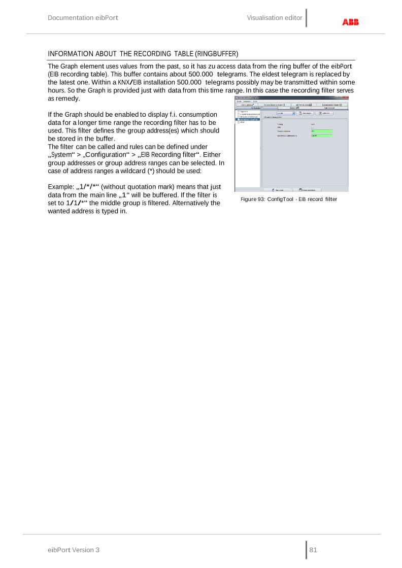
Documentation eibPort Visualisation editor
eibPort Version 3 81
INFORMATION ABOUT THE RECORDING TABLE (RINGBUFFER)
The Graph element uses values from the past, so it has zu access data from the ring buffer of the eibPort (EIB recording table). This buffer contains about 500.000 telegrams. The eldest telegram is replaced by the latest one. Within a KNX/EIB installation 500.000 telegrams possibly may be transmitted within some hours. So the Graph is provided just with data from this time range. In this case the recording filter serves as remedy.
If the Graph should be enabled to display f.i. consumption data for a longer time range the recording filter has to be used. This filter defines the group address(es) which should be stored in the buffer. The filter can be called and rules can be defined under „System“ > „Configuration“ > „EIB Recording filter“. Either group addresses or group address ranges can be selected. In case of address ranges a wildcard (*) should be used:
Example: „1/*/*“ (without quotation mark) means that just data from the main line „1“ will be buffered. If the filter is set to 1/1/*“ the middle group is filtered. Alternatively the wanted address is typed in.
Figure 93: ConfigTool - EIB record filter
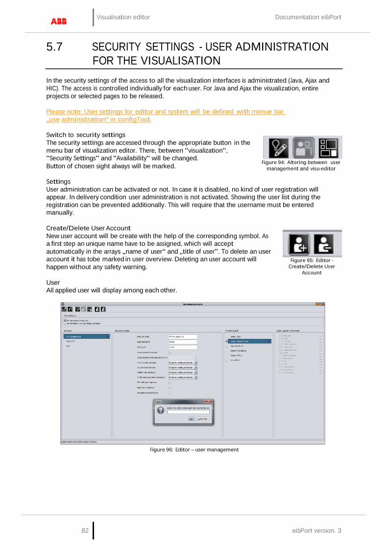
Visualisation editor Documentation eibPort
82 eibPort version. 3
5.7 SECURITY SETTINGS - USER ADMINISTRATION
FOR THE VISUALISATION
In the security settings of the access to all the visualization interfaces is administrated (Java, Ajax and HIC). The access is controlled individually for each user. For Java and Ajax the visualization, entire projects or selected pages to be released.
Please note: User settings for editor and system will be defined with menue bar „use administration“ in configTool.
Switch to security settings The security settings are accessed through the appropriate button in the menu bar of visualization editor. There, between "visualization", "Security Settings" and "Availability" will be changed. Button of chosen sight always will be marked.
Figure 94: Altering between user
management and visu-editor
Settings User administration can be activated or not. In case it is disabled, no kind of user registration will appear. In delivery condition user administration is not activated. Showing the user list during the registration can be prevented additionally. This will require that the username must be entered manually.
Create/Delete User Account New user account will be create with the help of the corresponding symbol. As a first step an unique name have to be assigned, which will accept automatically in the arrays „name of user“ and „title of user”. To delete an user account it has tobe marked in user overview. Deleting an user account will happen without any safety warning.
User All applied user will display among each other.
Figure 95: Editor - Create/Delete User
Account
Figure 96: Editor – user management

Documentation eibPort Visualisation editor
eibPort Version 3 83
Userdetails Each user account will be allocated general settings:
User Title: Title will be shown in selection menue. User will be identified with it by starting
visualisation. Username: The name of user will be requested by log-in. In case list of user is activated during
log in, name of user will be transferred to dialogue from register, after selecting title. Password: With the aid of this password, user has to identify himself. Auto-Logout: After finishing adjusted period of time, user will be asked for a new identification,
if this function is activated. Project Settings Parameters Every user you can assign individual settings, according to project
parameters „Visu-Toolbar“, Kiosk mode“, „Index of pages“ and “Connection problems”. Administration can assign individual settings (yes/no) to user, or those settings of the project (using project settings). Preferences „yes/no“ overwrite project settings.
Bypass PIN challange: If this box is activated, user will not be asked for his PIN. Hide User: This user will not be displayed in the list of user. Home Information Center: The user data is requested in the case, when logging on to the HIC
visualization. The HIC visualization is achieved via the "Home Information Center Editor" from the menu "Window" parameter.
Project Access All defined projects are displayed. A complete project will be attached to a user, if you mark corresponding control box. In case several projects are connected with one user, a selection of the projects will be displayed after log in.
Page Access & Startpage Attaching only individual project pages to a user, you can mark desired project in column. All pages of a project can be attached separately, by marking the corresponding control box. Behind the page name, hompage will be chosen, which the user should achieve. If pages of several projects will be involved, user will get a selection of projects as well after log in.
Saving settings Created user settings will be stored by a click on button „Storing“ in menu bar (symbol of diskette)
5.8 ROOM ALLOCATION PLAN (CONTROL R)
The room allocation plan module is able to control functions (light, shadowing, heating) of several rooms of a plant, based on calender and group settings. This modul is an extension of eibPort and has to be unlocked by a licence. If this licence is not uploaded, the necessary switching telegrams will not be created (“Generated Data”). Configuration and operating of the room allocation plan are discribed in a seperate document, which can be demanded at [email protected].
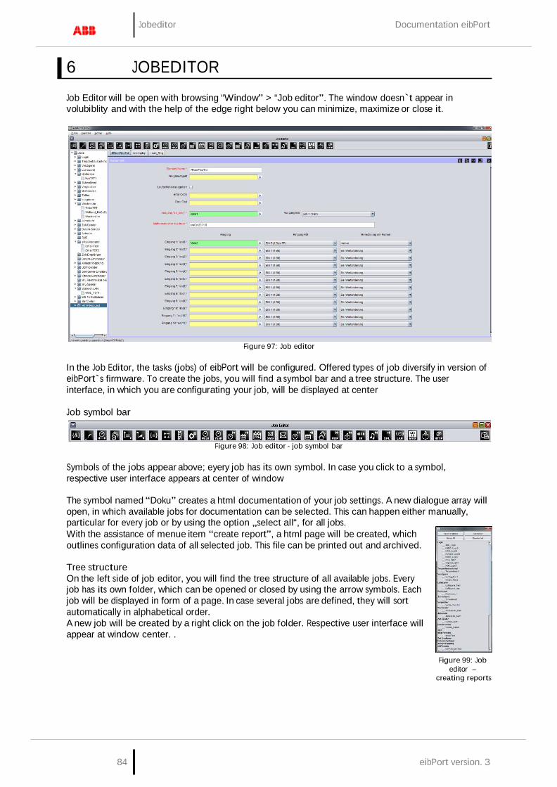
84 eibPort version. 3
Jobeditor Documentation eibPort
6 JOBEDITOR
Job Editor will be open with browsing “Window” > “Job editor”. The window doesn`t appear in volubiblity and with the help of the edge right below you can minimize, maximize or close it.
Figure 97: Job editor
In the Job Editor, the tasks (jobs) of eibPort will be configured. Offered types of job diversify in version of eibPort`s firmware. To create the jobs, you will find a symbol bar and a tree structure. The user interface, in which you are configurating your job, will be displayed at center
Job symbol bar
Figure 98: Job editor - job symbol bar
Symbols of the jobs appear above; eyery job has its own symbol. In case you click to a symbol, respective user interface appears at center of window
The symbol named “Doku” creates a html documentation of your job settings. A new dialogue array will open, in which available jobs for documentation can be selected. This can happen either manually, particular for every job or by using the option „select all“, for all jobs. With the assistance of menue item “create report”, a html page will be created, which outlines configuration data of all selected job. This file can be printed out and archived.
Tree structure On the left side of job editor, you will find the tree structure of all available jobs. Every job has its own folder, which can be opened or closed by using the arrow symbols. Each job will be displayed in form of a page. In case several jobs are defined, they will sort automatically in alphabetical order. A new job will be created by a right click on the job folder. Respective user interface will appear at window center. .
Figure 99: Job editor –
creating reports

eibPort Version 3 85
Documentation eibPort Jobeditor
Saving, copying and deleting jobs A Job will be managed by the job window. In the right edge above of every job input mask, you can find symbols for deleting, copying, saving or closing of jobs. Copying a job happens without duplicating the job name. By clicking on “Delete Job”, selected job will be deleted without any previous security query.
Figure 100: Job Editor - Job Verwaltung
6.1 GENERAL HINTS ABOUT THE JOB EDITOR
Tabs In case several job masks are loaded up in one window, they will be displayed above by tabs. A job, which is not stored, carries no description. You can call up any desired number of jobs.
Parameter Every job interface has specific parameters. All red marked parameters have to fill out stringently. In case that doesn`t happen, the specific job cannot be stored, because it will not work then. Every job contains one gate object, which will enable you to block one job or release it again. A gate object always been defined EIS1, one for release, zero for no release. In case one address was filled in, which wasn`t assigned before, the job remains locked, as long as group address will get one value. In case, this group address had one value before, so state of gate object correlates with that value.
Allocating group addresses Group addresses will be filled in directly by input field or by using a schedule of addresses. Doing input directly, you can use space bar for creating symbol “/”. Addresstable is a matrix, in which you can choose your desired address. Open up dialogue gives you the opportunity, to load up one out of ETS exported ESF file and to use it for address selection. In this way, project data out of the ETS will made available and a mixed up of addresses will be avoided. How to export ESF files and how to load it up in eibPort, will be described in chapter “ETS”.
Virtual group addresses eibPort not only controls address space of the main groups from 0 to 15, but also address space from 16 to 31, which are called
Figure 101: Job Editor - ESF Dialog
virtual group addresses. This kind of addresses allows you for example to connect jobs at each other, without consuming addresses from real address space. Virtual addresses will not be sent to EIB/KNX.
Communication objects eibPort emulates the structure of communication objects from EIB/KNX. That means that you can dedicate every object up to 5 group addresses. For example with that you can simulate directly placing of an actuator`s group addresses. So eibPort will be informed at any moment about the actual status of the actuator (not group address) and extravagantly working with feed back can be remained undone. This procedure simplifies creating of logical links, because to every Inputobject of the gate will be assigned up to 5 group addresses. In dialogue of ESF, you can assign all five group addresses in this case and they will automatically entered in chosen object fields, using correct syntax. Outputs, however, only allows to enter one address.
General syntax After the first group address, all of following addresses have to be enclosed in brackets and to be separated with commas. For example: 2/12(2/13,2/14,2/15,2/16)
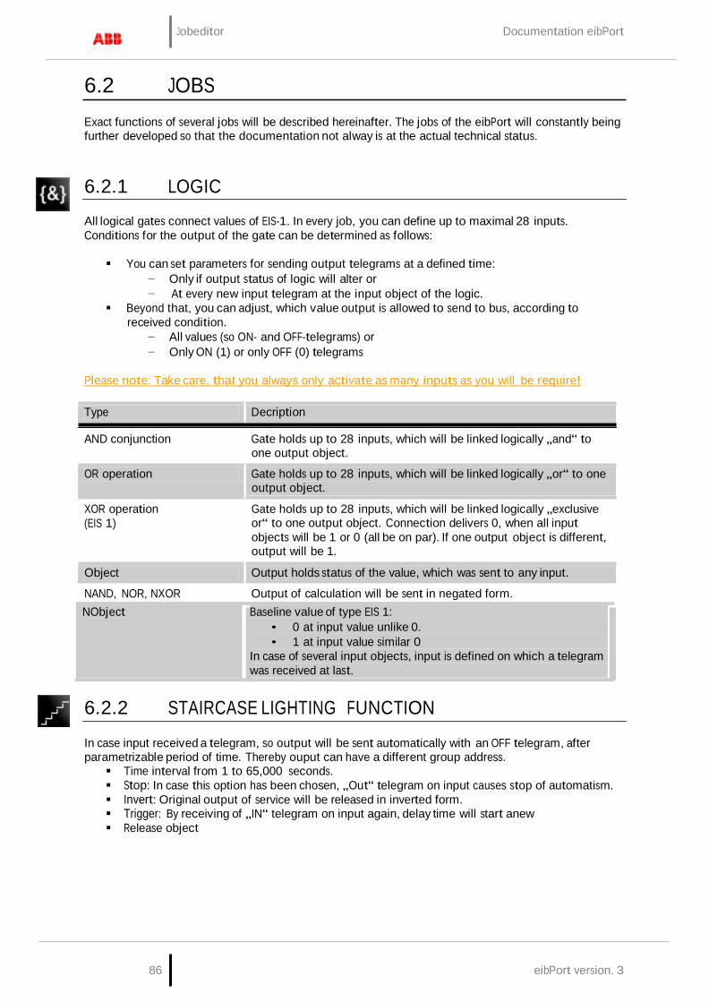
86 eibPort version. 3
Jobeditor Documentation eibPort
6.2 JOBS
Exact functions of several jobs will be described hereinafter. The jobs of the eibPort will constantly being further developed so that the documentation not alway is at the actual technical status.
6.2.1 LOGIC
All logical gates connect values of EIS-1. In every job, you can define up to maximal 28 inputs. Conditions for the output of the gate can be determined as follows:
You can set parameters for sending output telegrams at a defined time:
− Only if output status of logic will alter or − At every new input telegram at the input object of the logic.
Beyond that, you can adjust, which value output is allowed to send to bus, according to received condition.
− All values (so ON- and OFF-telegrams) or − Only ON (1) or only OFF (0) telegrams
Please note: Take care, that you always only activate as many inputs as you will be require!
Type Decription
AND conjunction Gate holds up to 28 inputs, which will be linked logically „and“ to
one output object.
OR operation Gate holds up to 28 inputs, which will be linked logically „or“ to one output object.
XOR operation (EIS 1)
Gate holds up to 28 inputs, which will be linked logically „exclusive or“ to one output object. Connection delivers 0, when all input objects will be 1 or 0 (all be on par). If one output object is different, output will be 1.
Object Output holds status of the value, which was sent to any input.
NAND, NOR, NXOR Output of calculation will be sent in negated form. NObject Baseline value of type EIS 1:
• 0 at input value unlike 0. • 1 at input value similar 0
In case of several input objects, input is defined on which a telegram was received at last.
6.2.2 STAIRCASE LIGHTING FUNCTION
In case input received a telegram, so output will be sent automatically with an OFF telegram, after parametrizable period of time. Thereby ouput can have a different group address. Time interval from 1 to 65,000 seconds. Stop: In case this option has been chosen, „Out“ telegram on input causes stop of automatism. Invert: Original output of service will be released in inverted form. Trigger: By receiving of „IN“ telegram on input again, delay time will start anew Release object
eibPort Version 3 87
Documentation eibPort Jobeditor
6.2.3 DELAY UNIT
A gate which has one input and one output object. Output will be sent delayed. Input object starts timer. Form: EIS 1: Delay interval from 1 to 65,000 seconds. Delay-Type: Defines which telegrams will be sent retarded. On input all telegrams will be
retarded standardly for x seconds. When requested service will reproduce only „ON“ or „OUT“ telegrams delayed in time.
Important: In this case output will be activated without any delay, if the input has the particular other value. Gate object
6.2.4 LIGHT SCENE
You can combine up to 28 EIB-members in a group. To each member can be assigned a individual value, which it has to send. Light scene will be activated by a starting object. For every start object, you have to define the starting value (0 or 1). That means, that for every group address two different light scenes will be available. By using gate object execution can be locked or activated (timer e.g). Group address to Start: Light scene will be started by EIS 1 telegram. Lightscene-Start: Determines which value of EIS 1 telegram activates light scene. Group address for Saving: This object stores actual states of light scene subscriber. In case value
of a member will be altered and have been stored, light scene will work with the so changed value. Storing could happen by one „IN“ or „OUT“ telegram.
Stoppable: Light scene can be stopped by a telegram to input. Telegam may not meet start conditions.
Delay (s): Delay time can be adjust in seconds. Delay times shorter than 1 second can`t be adjusted, for security reasons. ( Overload of bus)
EIS-Type: Output adresses can be type of EIS 1, EIS 5, EIS 6, EIS 9, EIS 10, EIS 11 and EIS 14.
Please note: Light scene only should have as many outputs as used.
6.2.5 HYSTERESIS UNIT
Element Hysteresis is a comparator with two thresholds. The two thresholds were called as one upper threshold and one lower threshold. If input receives a value, this value will be compared with the thresholds and result will be send in form of a binary value (0 or 1) EIS 1. Depending on the last calculated state, the new state will be calculated according to following definition:
If last result of calculation is 0, the output object will alter to 1, in case the received input value will exceed upper threshold. If the last result of calculation is 1, the output object will alter to 0, in case received input value will fall below lower threshold. Input value could only be received by the input object. Upper and lower threshold can be described by a constant or by an object.
Calculation of hysteresis switch will start, if input object or object of threshold will receive one telegram. Parameterized type of EIB defines how hysteresis switch will calculate the value.
If entering in type of EIS „nothingness“, so the“constant“ will be used for the value.
If you parameterize EIS type 1, 2, 3, 4, 6, 8, 10 or 11, so value of object will be determined over factor and offset, that implies that received object value of EIB will be multiplied by the factor. Value of offset will be added. Result of this calculation is the object value, which will be used for calculation of hysteresis switch. After computation by min/max value, calculated object value will be forced to a valid array of the threshold switch in this way. That means that min/max value formed a limitation of variable thresholds, which will be sent with the help of related object value.

88 eibPort version. 3
Jobeditor Documentation eibPort
In case object value falls below min value, so object value will be the min value. In case object value will rise above max value, so object value will be the max value. Plausibility check will not be performed by calculation of the gate.
With the help of so obtained values for input, lower and upper threshold, actual state of output will be calculated.
By calculation two cases were differentiated: Output state 0 or 1.
If state 0 was output status, before activating telegram will be received, the input value has to
be above the upper threshold, as to obtain 1 for the new output value.
If state 1 was output status, the input value has to be under lower threshold, as to obtain 0 for the new output value.
In case the calculation forces, a change of state at the jobs’ output a telegram will be send out. If there was no change of state at the a telegram will be sent out only when the parameter “send only changes“ is not set.
If parameter “send only changes” has been activated, so a telegram will be send out from output, only when calculation will cause a change of state on output. In case this flag is not activated, so a telegram will be sending out after every recalculation.

eibPort Version 3 89
Documentation eibPort Jobeditor
6.2.6 LOGIC THRESHOLD UNIT
For threshold switch there are two important switching events (see diagram):
Figure 102: Diagram threshold switch
First switch event: Switchpoint 1 (Schaltpunkt 1): Here upper threshold will be exceeded. By crossing upper threshold, timer „dead time“ starts. If this timer ends and the input condition „ crossing upper threshold“ will be fulfiled furthermore the output value, which was parameterized in culumn “upper threshold”, will be sent on the bues. Connected EIB group address will be entered in output parameter window. Output value can be EIS 1, 5, 6 or 14. “Dead time” prevents, that threshold switch sends constantly output value to KNX/EIB, in case input value varying by upper (lower) threshold.
After output value was sent toKNX/ EIB, timer “repeat time” will be started. After ending this timer the input conditions “crossing upper threshold” are furthermore fulfilled the output value will be sent toKNX/EIB once again. This program loop will be executed as long as input condition „crossing upper threshold“ will not be complied anymore. That is the case from switchpoint 1.1. (see diagram).
In case input value is located between upper or lower threshold, the job doesn`t send anything to KNX/EIB.
Second switch event: Fall below lower threshold. By deceeding of lower threshold, again the“dead time” timer starts. If this timer ends and the input conditions “falling below lower threshold” are still fulfilled the output value, which was parameterized in column “lower threshold”, will be sent to KNX/EIB. Output value can be EIS 1, 5 or 6.
After output value was sent to KNX/EIB the timer “repeat time” will be started. If this timer ends and the input conditions “crossing upper threshold” furthermore are fulfilled the output value will be sent toKNX/EIB once again. This program loop will be executed as long as input condition „crossing upper threshold“ will not be complied anymore.
Please note: In case for „dead time“ no value was entered, sending to bus will start at once. If for “ time replay” no value was entered, switch sends result only once.

Jobeditor Documentation eibPort
90 eibPort version. 3
6.2.7 COMPARATOR
This job compares the value of an input object with the value of another or with the worth of a static value. Result will be evaluated by „true“ or „false“. Output can be parameterized independent from input.
Input 1 und 2 Both inputs will be compared with another according to adjusted comparison operations. Depending on result, output will be send either „true“ or „false“. Input objects get following parameters:
Group address The group addresses of the input object.
EIS Format Here you can choose the EIS type of input object. Following EIS types were supported by comperator:
EIS 1 (switching, 1Bit) EIS 2 (dimming, 1,4,8 Bit) EIS 3 (time, 3 Byte) EIS 4 (date, 3 Byte) EIS 5 (floating point, 16Bit) EIS 6 (percent 0-100%, 1 Byte) EIS 8 (priority, 2 Bit) EIS 9 (floating point, 32 Bit) EIS 10 (counter, 16 Bit) EIS 11 (counter, 32 Bit) EIS 14 (counter, 8 Bit) EIS 15 (text, 14 Byte)
Static If that input is activated instead of the group address value, the value of the bordering entry field will be used for comparison operations.
Factor and offset You can format the value of group address with help of these both parameters. The value will be multiplied by factor, offset will be added.
Operation Following comparison operation are available:
„=“ similar „<>“ dissimilar „>“ greater than „<“ smaller than „>=“ greater or equal „<=“ smaller than or equal
Every receiving of a telegram to input object causes comparison operation once again.
Output („FALSE“ or „TRUE“) According to which result of comparison operation, respective output will be send. Output could have following parameters:
Group address To every output a group address will be dedicated. Both outputs can have the same address.

Documentation eibPort Jobeditor
eibPort Version 3 91
EIS value If output is marked as static, following EIS types are available
EIS 1 (switching, 1Bit) EIS 2 (dimming, 1,4,8 Bit) EIS 3 (time, 3 Byte) EIS 4 (date, 3 Byte) EIS 5 (floating point, 16Bit) EIS 6 (percentt 0-100%, 1 Byte) EIS 8 (priority, 2 Bit) EIS 9 (floating point, 32 Bit) EIS 10 (counter, 16 Bit) EIS 11 (counter, 32 Bit) EIS 14 (Zähler, 8 Bit) EIS 15 (text, 14 Byte)
Static For the output value, the value of bordering entry field will be used. Value has to match adjusted EIS typing.
Non-Static output Output carries no fixed value. For output one of the following values are used: Activating telegramm (Input 1 or 2) Last telegram from input 1 Last telegram from input 2
In case on input is static, no on input object received telegram could be sent to output.
Volatile Group address value cannot be overwritten by external telegrams (directly from KNX/EIB).
Changes Output will be sent to bus, only if the output value changes. In case this entry is not activated, output value will be sent out after every new operation again and again. Changes only refers to the value of the respective output object. If output object remains static, no modifications of output value can happen. This setting is only practical by using a dynamic output.

Jobeditor Documentation eibPort
92 eibPort version. 3
6.2.8 MATHEMATICS
Since the firmware version 0.10.1 the eibPort contains a mathematics job. This one is not only offering all usual mathematical operations but beyond that also a lot of mathematical functions. At the end of this description you will find some examples for this.
EIS Formats The math job supports the following datatypes at the input- and output-object. EIS 1 (1 Bit) EIS 5 (2 Byte FP) EIS 6 (1 Byte) EIS 9 (4 Byte FP) EIS 10s (2 Byte Value) EIS 11s (4 Byte Value) EIS 14u (1 Byte unsigned) EIS 15 (14Byte Text)
Beside that the jobs disposes a gate object as well as an EIS 14 output for an error code and an EIS 15 text output for an error text. They are given out when the flag “Runtime Errors” is activated.
Required fields All red titled entry arrays are required informations, without them the job cannot be saved.
Runtime error issue If this flag is enabled, error codes and error messages via EIS 14 EIS issued by telegram 15. The addresses to be entered into the fields below. An overview of error codes is at the end of the job description.
Exit / access to the initial value The value of the output object can use the variables "eo_out ()" is also used for the calculation. The operation can never be "eo_out ()" is triggered.
Inputs Each mathematics job contains 12 input objects. This could correspond to the above mentioned datatypes. Also can be determined when a telegram abutting the selected input to calculate the formula. To enter a groupaddress either the keyboard or the ESF-Dialogue can be used. For the ESF Dialogue the arrow button next to the address entry array is been pressed. You will reach the overview of the data which will be uploaded into the eibPort before (also see chapter ETS).
Note: All values are generally calculated unsigned within the math job. If values are displayed with a sign, this is only a matter merely of the display element.
Calculation of the formula The selection in the dropdown menu determines when the calculation of the formula is triggered in the mathematical expression: Always: The calculation will be triggered when any input is detected at the input object. Never: The calculation is that input never initiated. Of course, the value of the input object in
the execution of the operation is considered. If the value is changed: Only if changing the input value against the previous value, initiated a
calculation.

Documentation eibPort Jobeditor
eibPort Version 3 93
Figure 103: Job Editor - Job mask mathematics
Access onto the input in the mathematicalexpression In order to use the input objects for the mathematical expression the following syntax applies: The inputs 1-12 own the index numbers 0-11. By entering “eo(number of index)” the respective value of theinput objects is been fetched for
the mathematical expression. For the input 1 so is entered “eo(0)”. If the other way round the index number of an object should be issued (and eventually continue
to use) on which at last a telegram was incoming, it can be done by entering “eoi()”.
Mathematically Expression In this array the required mathematically expression will be put together. Doing this the usual mathematical rules applies. In order to output the result it is to considered that the value of the result is not exceeding the range of the datatype set in the output object. The following operations are available:
Note: Internally, the math module can work with floating point numbers or texts.
Mathematical operations Symbol Description
+ Addition (resp. stringing together ) - Subtraction * Multiplication / Division (real numbers) % Modulo (Rest of an integer division) & „AND“- operation bit by bit | „OR“ – operation bit by bit ^ Raise to higher power

Jobeditor Documentation eibPort
94 eibPort version. 3
Symbol Description = Allocation '(' und ')' Paranthesis for changing the operator process ?: If-Then-Else Operator ( Variable = requirement ? Value is true : Value is false)
Logical (boolean) operations
Symbol Description || Logical OR && Logical AND > Comparison operation "Greater than" >= Comparison operation " Greater than or equal" < Comparison operation "Less-than“ <= Comparison operation "Less or equal“ == Comparison operation "Equal“
Other operations
Built in Functions Symbol Description
sqrt(x) Square root calculation
sin(x) Sinus calculation
cos(x) Cosinus calculation
tan(x) Tangens calculation
max(x,...) Maximum determination of a (finite) amount of values
min(x,...) Minimum determination of a (finite) amount of values
rad(x) Conversion from degrees into radian (arc calculation)
asin(x) Calculation of arc sine
acos(x) Calculation of arc cosine
atan(x) Calculation of arc tangent
ceil(x) Calculation oft he smallest integer value which is not smaller than the argument ("round off").
floor(x) Calculation oft he largest integer value which is not larger than the argument ("rounded down").
abs(x) Calculation of an absolute value of an argument
exp(x) Calculation of the exponential function oft he base „e“ (Berechnung der Exponentialfunktion zur Basis 'e' (Eulersche constant)
log10(x) Logarithm tot he base 10
pow(x,y) Exponential function calculating x^y
time() Is giving out the system time since the beginning of the epoch (00:00:00 UTC, January 1, 1970)
srand(x) Is setting the (pseudo) random generator to definated start value.
rand() Is giving out the next random number.
eo_sum(x,...) Adding the EIB-objects with this numbers according to the arguments.

Documentation eibPort Jobeditor
eibPort Version 3 95
Kind Notation Integer numbers 42 Hexadecimal numbers 0x12ab Real numbers 1.23 Exponential numbers 1.23e3 für 1.23 * 10^3 oder 1023.0 Text "text"
int(x) Is cutting of the real number and is only given back the integer. modf(x) Is giving back the the decimal part of a real number (the digits after the decimal
point).) round(x) Is giving out a correct rounded integer of an real arguments. eoiga() Returns the group address that triggered the calculation (not format!) eo_ga(idx, idx_ga) Returns the group address of an object unformatted. idx specifies the index
number of the input idx_ga the index number of the group address in the Object. Both start at "0" to include (from left to right).
ga_str(ga, fmt) Returns the wanted group address (ga = index number) as a string (EIS 15) to the output. Using "fmt", 2 - or 3-digit notation can be determined.
str_ga(str) Outputs a desired group address as an integer. 2 - or 3-digit notation does not matter.
version() Returns the version number of the math module back. We have the "18" = Version 1.2 (0x12) and "17" = Version 1.1 (0x11).
Datatypes and Strings:
Predefined constants: Symbol Description
M_PI The constant pi (3.14.....).
M_E Euler’s constant (base of the natural logarithm)
M_LOG2E Logarithm to the base 2 from 'e'
M_LOG10E Logarithm to the base 10 from 'e'
M_LN2 Natural Log. from 2
M_LN10 Natural Log. from 10
M_PI_2 Pi divided by 2 ("Pi-Half")
M_PI_4 Pi divided by 4 ("Pi-Quarter")
M_1_PI Reciprocal value from Pi (1 divided by Pi)
M_2_PI 2 times 1 divided by Pi
M_2_SQRTPI 2 times 1 divided by squareroot of Pi
M_SQRT2 Squareroot of 2
M_SQRT1_2 Reciprocal value of squareroot 2 (resp. Squareroot of 1/2)
Self defined variables and multiple expressions after another: “a=10” allocates the variable “a” the value 10. “a=1; b=2; a+b” allocates the values 1 resp. 2 to the variables “a” and “b” and is giving out the result “3”.
Jobeditor Documentation eibPort
96 eibPort version. 3
Variable Description override_addr If the value of this variable is equal to "0", is the true starting address is
discarded, and instead interpreted the value of this variable as a starting address (1-digit notation).
override_eis If the value of this variable equal to "0", the actual data type is overridden by this configuration. We do not make adjustment of the value.
override_skip_send If the value of this variable equal to "0", the transmission will be aborted. The current calculation leads to no result.
override_keep_data If the value of this variable equal to "0" is not the calculated output value, but uses the input value of the calculation has been initiated.
Important: That way defined variables only have a limited validity within one calculation of one expression!
Reservierte Variablen
Examples: Here some examples so that the using of the several functions and operations becomes a little bit clearer:
„eo(1) + 100“ -> Is giving out the EIB-object with the number one (hereafter EO_1) added by
100. Of course every time important is paying attention to the possible range of the EIB output object!
„eo(3)*eo(4)“ -> Multiplies EO_3 and EO_4. If there are EIB-objects which are not provided with a groupaddress, a failure is beeing noticed.
„100 / eo(1)“ -> Divides 100 by EO_1. Attention: If a null is being sent on the input 1 the calculation is giving out a runtime error! (“Division by null”).
„sqrt(eo(0)^2+eo(1)^2)“ -> Is calculating the length of the hypothenuse in a right angled triangle, if on EO_0 und EO_1 the length of the cathetus is beings sent („Pythagorean theorem“).
„eoi()“ -> Is giving out a 2 if something is received on the EIB-object with the number two. „eo(eoi())“ -> Is giving back the receiving value. „eo(eoi())^2“ -> Is calculating the square for every tranceived telegram value. „rand()“ -> Is giving out the random value. „rand() & 0xff“ -> Limits this value on a range from 0 to maximum 255. So the result must be
presentable in EIS 14. „srand(time())“ -> Ist giving out nothing (resp. null), but is initializing the random generator
with a pseudo-random start value. „eo(0)+eo(2)+eo(3)+eo(1)+eo(5)+eo(6)+eo(4)“ -> Is calculating the sum of multiple EIB-
objects. „eo_sum(0,1,2,3,4,5,6)“ ->Like above, but plenty more „runtime-friendlier“ and more insight. „"foo" + "bar"“ -> Is giving out the result „foobar“. This only works if the output is switched to
EIS 15 datatype.

Documentation eibPort Jobeditor
eibPort Version 3 97
Error Codes and Error text Number(Error Codes EIS 14)
Meaning resp. EIS 15 text output
0 No Error
42 Syntax error
43 General runtime error (e.g.: division by null or tan(PI/2))
1 Missing right bracket
2 Missing left bracket (with embedded function)
3 Missing right bracket (found expression instead)
4 Unknown variable
5 Unknown keyword
6 Error in String expression: String contains no mathematical operator.
7 Division by null
8 String cannot be exponentiated
9 Error in String expression: String cannot be arranged with operator.
10 Missing right bracket or comma at function call.
11 Missing comma
12 Missing argument
50 Error in EO-function: Wrong number of arguments
51 Error in EO-function: Wrong index
52 Error in EO-function: EO is empty
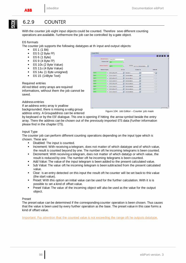
Jobeditor Documentation eibPort
98 eibPort version. 3
6.2.9 COUNTER
With the counter job eight input objects could be counted. Therefore seve different counting operations are available. Furthermore the job can be controlled by a gate object.
EIS formats The counter job supports the following datatypes at th input and output objects: EIS 1 (1 Bit) EIS 5 (2 Byte FP) EIS 6 (1 Byte) EIS 9 (4 Byte FP) EIS 10s (2 Byte Value) EIS 11s (4 Byte Value) EIS 14u (1 Byte unsigned) EIS 15 (14Byte Text)
Required entries All red titled entry arrays are required informations, without them the job cannot be saved.
Address entries If an address entry array is yeallow backgrounded, there is missing a valig group address entry. A Groupaddress can be entered
Figure 104: Job Editor – Counter job mask
by keyboard or by the ESF dialogue. This one is opening if hitting the arrow symbol beside the entry array. There the address can be chosen out of the previously imported ETS data (Further information please find in the chapter ETS).
Input Type The counter job can perform different counting operations depending on the input type which is chosen. These are: Disabled: The input is counted. Increment: With receiving a telegram, does not matter of which datatype and of which value,
the result is counted beyond by one. The number oft he incoming telegrams is been counted. Decrement: With receiving a telegram, does not matter of which datatyp or which value, the
result is reduced by one. The number oft he incoming telegrams is been counted. Add Value: The value of the input telegram is been added to the present calculated value. Sub Value: The value oft he incoming telegram is been subtracted from the present calculated
value. Clear: Is an entry detected on this input the result oft he counter will be set back to this value
(the start value). Preset: With this option an initial value can be used for the further calculation. With it is is
possible to set a kind of offset value. Preset Value: The value of the incoming object will also be used as the value for the output
object.
Preset The preset value can be determined if the corresponding counter operation is been chosen. Thus causes that the value is been used by every further operation as the base. The preset value in this case forms a kind of offset value.
Important: Pay attention that the counted value is not exceeding the range oft he outputs datatype.

Documentation eibPort Jobeditor
eibPort Version 3 99
6.2.10 INTEGRATOR
This job is excuting the mathematical function of integrating. With it the area calculating among a graph is ment (definite integral). The function hereby is the the input value over the time. Thereby the job is especially made for calculating the power consumption out of the current values giving out by actuators with current detection. Afterwards this description you will also find an example about this.
EIS-Formats The integrator job supports the following EIS Formats at the input and output object:
Input
− EIS 1 (1 Bit) − EIS 5 (2 Byte FP) − EIS 6 (1 Byte) − EIS 9 (4 Byte FP) − EIS 10s (2 Byte Value) − EIS 11s (4 Byte Value) − EIS 14u (1 Byte unsigned)
Output − EIS 5 (2 Byte FP) − EIS 6 (1 Byte) − EIS 9 (4 Byte FP) − EIS 10s (2 Byte Value) − EIS 11s (4 Byte Value) − EIS 14u (1 Byte unsigned) In addition the job is offering the feature that the output can send the result also EIS 15 formatted. In this case there is the possibility to influence place right and left of decimal point by control characters. The following syntax applies with the control characters: − Open control character - '% − Closing control character - 'f' − Optional place- '#' − Forced place - '2' (example) Example: There should be displayed a number with 2 places left of decimal point and minimum 3 places right of the decimal point: %2.###f
Required entries All red titled entry arrays are required informations, without them the job cannot be saved.
Address entries If an address entry array is yeallow backgrounded, there is missing a valig group address entry. A Groupaddress can be entered by keyboard or by the ESF dialogue. This one is opening if hitting the arrow symbol beside the entry array. There the address can be chosen out of the previously imported ETS data (Further information please find in the chapter ETS).
Interval (s) Because the integrator underlies a function over the time here is the possibility to define the interval of the x- axis. At the same time the interval is determining how often the result is given out.
Important: During calculation the integrator depends on a constant, which corresponds to the Input value that is active within the interval!
Clear on Timeout Is this flag activated and there is no further telegram detected during the timeout interval set in the input settings, the output of the job will be resetted.
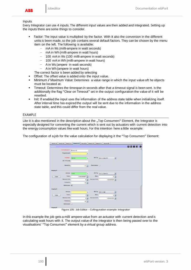
Jobeditor Documentation eibPort
100 eibPort version. 3
Inputs Every Integrator can use 4 inputs. The different input values are then added and integrated. Setting up the inputs there are some things to consider.
Factor: The input value is multiplied by the factor. With it also the conversion in the different
units is been made, so the job contains several default factors. They can be chosen by the menu item on the left. The following is available:
− mA in Ws (milli-ampere in watt seconds) − mA in Wh (milli-ampere in watt hours) − 100 mA in Ws (100 milli-ampere in watt seconds) − 100 mA in Wh (milli-ampere in watt hours) − A in Ws (ampere in watt seconds) − A in Wh (ampere in watt hours)
The correct factor is been added by selecting Offset: The offset value is added onto the input value. Minimum / Maximum Value: Determines a value range in which the input value oft he objects
must be located at. Timeout: Determines the timespan in seconds after that a timeout signal is been sent. Is the
additionally the flag “Clear on Timeout” set in the output configuration the value of it will be resetted.
Init: If enabled the input uses the information of the address state table when initializing itself. After interval time has expired the output will be sent due to the information in the address state table, and this could differ from the real value.
EXAMPLE
Like it is also mentioned in the description about the „Top Consumers“ Element, the Integrator is especially designed for converting the current which is sent out by actuators with current detection into the energy consumption values like watt hours. For this intention here a little example:
The configuration of a job for the value calculation for displaying it the “Top Consumers” Element:
Figure 105: Job Editor – Cofinguration example Integrator
In this example the job gets a milli ampere value from an actuator with current detection and is calculating watt hours with it. The output value of the integrator is then being passed over to the visualisations’ “Top Consumers” element by a virtual group address.

Documentation eibPort Jobeditor
eibPort Version 3 101
Configuration of the „Top Consumer“ Element: Konfiguration des „Top Verbraucher“ Elements
Figure 106: Visualisation Editor – Configuration example Top Consumers
The virtual group address is then being linked to a consumer in the visualization element. Beside the correct datatype and value format here must not considered anything else.
6.2.11 TIMERS (WEEKLY TIMER UND YEAR-TIMER)
eibPort contains a Weak- and a Year-Timer:
Week Timer A 24-hour profil will be allocated to the subsrcibers. Beneath to the 7 days of week, you can parameterize additionally 3 special days. By a clicking the timeline, switch-on time will be entered, a double-click detemines the desactivating point; three times of click will erase this point. Releasing of the weekly timer will be controlled by a connection to the year timer. In annual clock switching points are inactiv, week modus and special days 1 to 3 were seated. Therewith the year timer decides on which days of month which configuration of week clock will take place. “W” for weekdays Monday to Sunday, S1 to S1 for the special days and “non-active” for no function at all.
Year Timer Output type: Link to week timer (non EIS): Week clock, which is connected by a respective group address, will be controlled. On timeline of months you can configurate which mode of week clock will be activated, “W” for normal week days, “S1 to S3” for the special days or “disable” for no function at all. First you choose the modus, after that, you place it on the month time line. Output type Enable group address (EIS1): Annual clock is not being connected with a week clock. It activates or deactivates one or several subscribers by itself. For configuration state of “ON“ or „OFF“ will be chosen and will be placed as desired on the month time line. Clock will always switch at 0:00 clock on respective day.
Parameter Detect leaps in time: In similar circumstances it will be possible, that a switching point will be skipped (by a new clocktime of a NTP server, for example). That will engender, that determined switches will not be performed. These kinds of leaps in time could be controlled optionally, so that a function will be ensured anyhow.
Overwrite: In case control box is activated, no local operation is possible. Telegram value is determined exclusively by the timer.

Jobeditor Documentation eibPort
102 eibPort version. 3
Initiate: If control box is activated, clock sends, after a phase of initialisation (e.g.: restart of eibPort, modification of the job parameters), the actual telegram value. If this function is not activated, telegram value will be sent only to the defined switching points.
Please note: Annual clock always switches at 0:00 o’clock. Modifications, for example on a special day, will become operative only at next day
6.2.12 ASTRO TIMER
The astro timer determines the different points in time that a defined sun position has. That way it is possible to move e.g. a blind every time at the same brightness resp. darkness doesn’t matter if it is winter or summer. For the calculation a correct position and time information is been needed.
Figure 107: Astro clock - add new job
The astro clock job is offering a normal and for more experienced user a more sophisticated entry form. As output datatypes there are EIS 1, EIS 5, EIS 6, EIS 14 and EIS 15 available.
Stages of Twilight During the transitions from night to day and from day to night people talk about twilight in general. It is a result of light reflection in the atmosphere and is longer in summer an in the winter shorter. In order to have better definability the sunrise- resp. sunset is separated into different twilight stages.
Geometric Twilight
Defines the stage on which the sun is passing the horizon in the geometrical point of view. The sun is at 0 degrees, it is nearly daytime luminous.
Civil Twilight Is the center of the sun lying about -0.83 degrees below the horizon the civil twilight is beginning according to the definition. About this twilight stage it is spoken as long as -6 degrees are reached. For the reason that the light will be bent by the atmosphere it is as bright as to read the newspaper outside.
Nautical Twilight During this stage the light is shining fewer, and the brightest stars are eventually visible. Talking about this stage, the sun is between 6 and 12 degrees under the horizon.
Astronomical Twilight The sun is more than 12 degrees beyond the horizon. It is such dark that nearly all stars are apparent. The range for the astronomical twilight is lying between 12 and 18 degrees.
Night In astronomical point of view it is night when the center of the sun is less than 18 degrees of the horizon. During that stage it is completly dark and all stars are visible.
Unit of measurement for the solar altitude The solar altitude is specified in arc minutes. Thereby 60 arc minutes complies to one degree.
1 degree = 60 arc minutes
The numerical values behind the twilight designations in the selection of twilight stages are showing off the limits of the twilight stages.
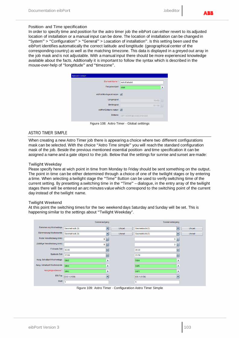
Documentation eibPort Jobeditor
eibPort Version 3 103
Position- and Time specification In order to specify time and position for the astro timer job the eibPort can either revert to its adjusted location of installation or a manual input can be done. The location of installation can be changed in “System” > “Configuration” > “General” > Loacation of installation”. Is this setting been used the eibPort identifies automatically the correct latitude and longtitude (geographical center of the corresponding country) as well as the matching timezone. This data is displayed in a greyed out array in the job mask and is not adjustable. With a manual input there should be more experienced knowledge available about the facts. Addtionally it is important to follow the syntax which is described in the mouse-over-help of “longtitude” and “timezone”.
Figure 108: Astro Timer - Global settings
ASTRO TIMER SIMPLE
When creating a new Astro Timer job there is appearing a choice where two different configurations mask can be selected. With the choice “Astro Time simple” you will reach the standard configuration mask of the job. Beside the previous mentioned essential position- and time specification it can be assigned a name and a gate object to the job. Below that the settings for sunrise and sunset are made:
Twilight Weekday Please specify here at wich point in time from Monday to Friday should be sent something on the output. The point in time can be either determined through a choice of one of the twilight stages or by entering a time. When selecting a twilight stage the “Time” Button can be used to verify switching time of the current setting. By presetting a switching time in the “Time” – dialogue, in the entry array of the twilight stages there will be entered an arc minutes value which correspond to the switching point of the current day instead of the twilight name.
Twilight Weekend At this point the switching times for the two weekend days Saturday and Sunday will be set. This is happening similar to the settings about “Twilight Weekday”.
Figure 109: Astro Timer - Configuration Astro Timer Simple

Jobeditor Documentation eibPort
104 eibPort version. 3
Fixed Offset (min) Specifies the time span in minutes that the switching time should be suspended forward or backwards. If the switching should happen earlier a negative value is to be entered and if the switching should happen later a positive value must be set.
Random Offset (min) With this offset the really circuit time will be suspended for a random value later. In which period of time the random offset happens, can be set here in minutes. By this setting a presence simulation can be realised.
Earliest Time This time intended from whicht point the output is allowed to be send earliest. This is to avoid switching time earlier than a certain point in time. For instance: Never earlier than 7 o’clock in the morning or 8’clock in the evening.
Latest Time Over this time it is able to avoid switching time later than a certain point. For instance: Never later than 8 o’clock in the morning and 10 o’clock in the evening.
Output time weekdays For each weekday the identified switching times will be sent out on this EIS 3 output object. It will be sent at 0 o’clock at the beginning of the day. The arrow symbol near the address input array allows to display an address matrix, or if happens before, to choose an address out of the ESF file of the ETS (please see “export ESF file out of the ETS”).
Output time weekend For each day on the weekend the identified switching times will be sent out on this EIS 3 output object. It will be sent at 0 o’clock at the beginning of the day. The arrow symbol near the address input array allows to display an address matrix, or if happens before, to choose an address out of the ESF file of the ETS (please see “export ESF file out of the ETS”).
Output address Mandatory field. On this output address the defined output will be sent at the determined time. The EIS type and the output value will be set in the arrays below it. The arrow symbol near the address input array allows to display an address matrix, or if happens before, to choose an address out of the ESF file of the ETS (please see “export ESF file out of the ETS”).
EIS Type Determine the EIS type of the output. EIS 1, EIS 5, EIS 6, EIS 14 and EIS 15 are available.
Value Determines the value of the telegram. The value must correspond to the configured EIS type.
ASTRO TIMER (COMPLEX)
The astro timer complex offers compared to the “astro timer simple” more enhanced features and a trigger object. To realise a simple astro timer function please use the job mask “astro timer simple”. Beside the above already mentioned and essential position and time information the job can be allocated a name and a gate object as ever. In addition there is the ability to enter an EIS 14 trigger object.
Trigger input Over the trigger input it is able to trigger three special points in time which are configured later in the job mask. Also a linkage with the year-timer can be established over this object. The arrow symbol near the address input array allows to display an address matrix, or if happens before, to choose an address out of the ESF file of the ETS (please see “export ESF file out of the ETS”).
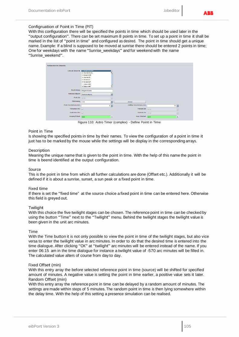
Documentation eibPort Jobeditor
eibPort Version 3 105
Configruation of Point in Time (PIT) With this configuration there will be specified the points in time which should be used later in the “output configuration”. There can be set maximum 8 points in time. To set up a point in time it shall be marked in the list of “point in time” and configured as desired. The point in time should get a unique name. Example: If a blind is supposed to be moved at sunrise there should be entered 2 points in time; One for weekdays with the name “Sunrise_weekdays” and for weekend with the name “Sunrise_weekend”.
Figure 110: Astro Timer (complex) - Define Point in Time
Point in Time Is showing the specified points in time by their names. To view the configuration of a point in time it just has to be marked by the mouse while the settings will be display in the corresponding arrays.
Description Meaning the unique name that is given to the point in time. With the help of this name the point in time is beend identified at the output configuration.
Source This is the point in time from which all further calculations are done (Offset etc.). Additionally it will be defined if it is about a sunrise, sunset, a sun peak or a fixed point in time.
Fixed time If there is set the “fixed time” at the source choice a fixed point in time can be entered here. Otherwise this field is greyed out.
Twilight With this choice the five twilight stages can be chosen. The reference point in time can be checked by using the button “Time” next to the “Twilight” menu. Behind the twilight stages the twilight value is been given in the unit arc minutes.
Time With the Time button it is not only possible to view the point in time of the twilight stages, but also vice versa to enter the twilight value in arc minutes. In order to do that the desired time is entered into the time dialogue. After clicking “OK” at “twilight” arc minutes will be entered instead of the name. If you enter 06:15 am in the time dialogue for instance a twilight value of -570 arc minutes will be filled in. The calculated value alters of course from day to day.
Fixed Offset (min) With this entry array the before selected reference point in time (source) will be shifted for specified amount of minutes. A negative value is setting the point in time earlier, a positive value sets it later. Random Offset (min) With this entry array the reference point in time can be delayed by a random amount of minutes. The settings are made within steps of 5 minutes. The random point in time is then lying somewhere within the delay time. With the help of this setting a presence simulation can be realised.
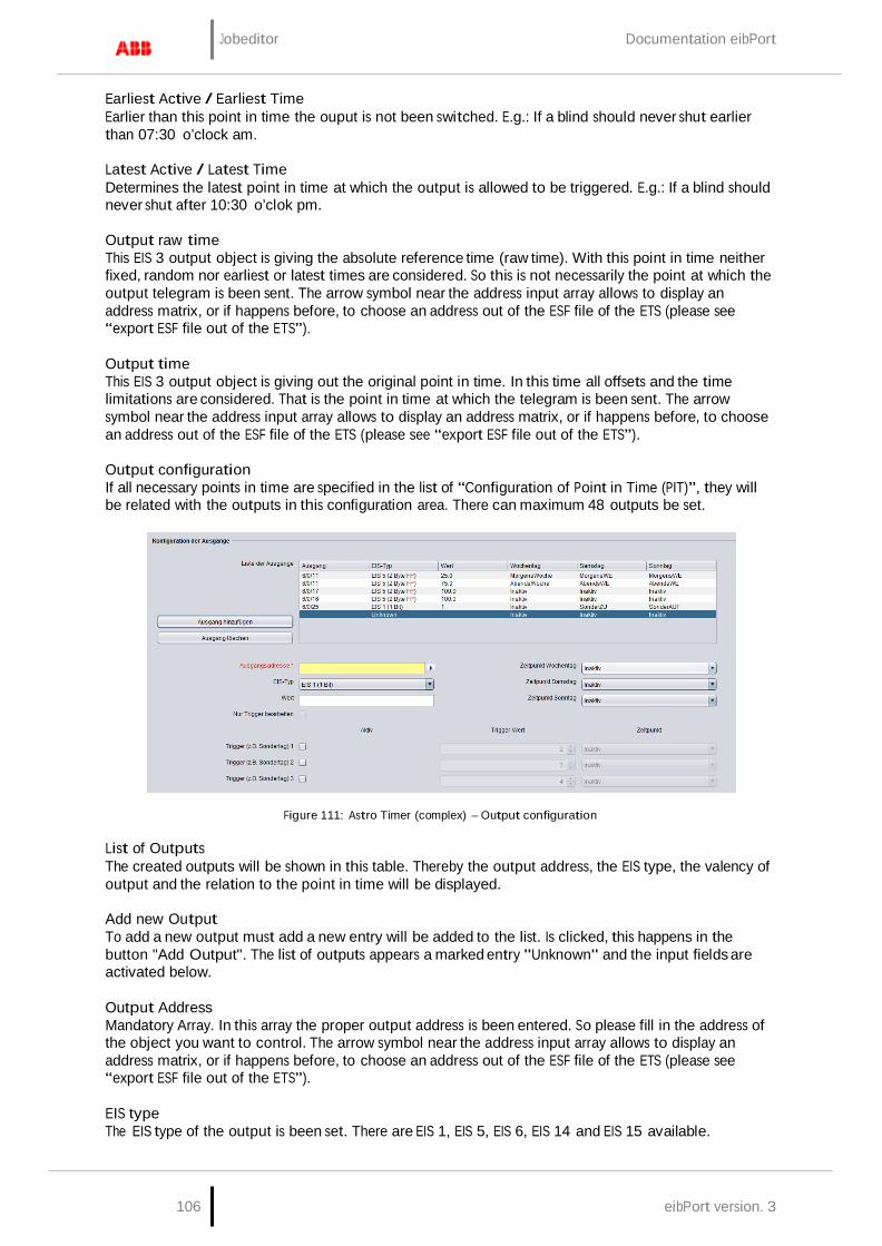
Jobeditor Documentation eibPort
106 eibPort version. 3
Earliest Active / Earliest Time Earlier than this point in time the ouput is not been switched. E.g.: If a blind should never shut earlier than 07:30 o’clock am.
Latest Active / Latest Time Determines the latest point in time at which the output is allowed to be triggered. E.g.: If a blind should never shut after 10:30 o’clok pm.
Output raw time This EIS 3 output object is giving the absolute reference time (raw time). With this point in time neither fixed, random nor earliest or latest times are considered. So this is not necessarily the point at which the output telegram is been sent. The arrow symbol near the address input array allows to display an address matrix, or if happens before, to choose an address out of the ESF file of the ETS (please see “export ESF file out of the ETS”).
Output time This EIS 3 output object is giving out the original point in time. In this time all offsets and the time limitations are considered. That is the point in time at which the telegram is been sent. The arrow symbol near the address input array allows to display an address matrix, or if happens before, to choose an address out of the ESF file of the ETS (please see “export ESF file out of the ETS”).
Output configuration If all necessary points in time are specified in the list of “Configuration of Point in Time (PIT)”, they will be related with the outputs in this configuration area. There can maximum 48 outputs be set.
Figure 111: Astro Timer (complex) – Output configuration
List of Outputs The created outputs will be shown in this table. Thereby the output address, the EIS type, the valency of output and the relation to the point in time will be displayed.
Add new Output To add a new output must add a new entry will be added to the list. Is clicked, this happens in the button "Add Output". The list of outputs appears a marked entry "Unknown" and the input fields are activated below.
Output Address Mandatory Array. In this array the proper output address is been entered. So please fill in the address of the object you want to control. The arrow symbol near the address input array allows to display an address matrix, or if happens before, to choose an address out of the ESF file of the ETS (please see “export ESF file out of the ETS”).
EIS type The EIS type of the output is been set. There are EIS 1, EIS 5, EIS 6, EIS 14 and EIS 15 available.

Documentation eibPort Jobeditor
eibPort Version 3 107
Value It is determining the value of the telegram. The value must correspond to the preset EIS type.
PIT Weekday (PIT = Point in Time) Within the output address it is specified which object /device is been controlled. The PIT choice appoints when the control is happening. In the menu the list of the before configured points in time is available. If the PIT is set to “inactive” there will be nothing executed. Example: Should the blind at sunrise weekdays use the configured point im time “Sunrise_Weekday”, it must be chosen in this menu.
PIT Saturday / Sunday With this both menus it is possible to specify the points in time for the weekend. Is it proposed that on weekend the same point in time as on weekdays should be valid, it would be easily related to the “weekdays-point in time”. If there should be other point in time used on the weekend, they have to be configured first in the list of point in time.
Note: Save the outputs To save a configured output there must be clicked on “Add new output” again or an already defined output must be chosen in the list.
Remove selected output To remove a selected output this one must be marked in the list (blue color).
Trigger Configuration To use the trigger function resp. the linkage to the Year Timer a trigger address must be filled into the the input object of the job. The triggers will not appear in the “List of outputs” overview, but will only be visible if the corresponding entry in the list is been marked.
Linkage with the Year-Timer In order to realise a connection to the Year-Timer the trigger object of the Astro Timer must be related to the output of Year-Timer. The Year-Timer provides provides the possibility to set the special days 1 to 3 on a calendar timeline (please see Job “Year-Timer”). It then initiates with the EIS 14 values 2 – 4 the complying trigger configuration of the Astro Timer. In the astro timer the trigger values are accordingly presetted.
Note: For each Astro Timer can be set maximum three trigger objects. If are more special points in time are required there must be created multiple Astro-Timers.
Trigger (e.g. Special day 1, 2, 3) With this checkbox the trigger is enabled. The trigger is listening on the trigger address entered in the job mask.
Trigger-Value In this entry array the EIS 14 value must be set from which the trigger should be forced to work with (0- 255). For the linkage with the Year-Timer the following values are valid:
Disabled = 0 Week mode = 1 S1 = 2 (S= Special day) S2 = 3 S3 = 4
PIT (Trigger) Like the normal output configuration every trigger has to be assigned a point in time. It is selected in the menu “PIT” and accesses to same the same list which is configured in the “Configuration of Point in Time (PIT)”.
Just use triggers With the help of this checkbox it is determined if an output is only controlled by the triggers or if the trigger and the normal weekday/weekend configuration should run parallel. If this option is activated the point in time choice for weekdays and Saturday/Sunday will be disabled.

Jobeditor Documentation eibPort
108 eibPort version. 3
6.2.13 SENDING/RECEIVING DATE AND TIME
Receiving To set its internal system clock eibPort is able to receive time telegrams (EIS3) and date telegrams (EIS4) over KNX/EIB. In case the variance of eibPort system clock is oversized, it will be corrected. Gate objects can be assigned. By telegrams of time, it will be possible to consider additionally the date; by telegrams of date, it can be considered additionally the time. Tolerable variance will be displayed in seconds, before system clock will be corrected.
Hint:Alternatively internal clock could be sychronised by NTP-time server. Connection data of NTP-time server will be entered in ConfigTool under menu item „Network settings“. Query of time takes place automatically. In doing so, connection to internet has to be ensured.
Sending eibPort is able to send telegrams of time (EIS3) and telegrams of date(EIS4). Releasing objects can be assigned. Time space between sending of two telegrams (pause of telegram) is displayed in seconds.
6.2.14 SEND EMAIL
With a telegram you are able to dispatching emails from eibPort to several recipients simultaneously.
Input Group Addresses This object (EIS1) starts the job, the email dispatch. Exactly conditions, for example shoulder ON, you can determine by using the menu ”Send condition”.
Value Group Address With control characters you are able to outline the value of this object in the continuous text of the email. Exactly use of control characters see in Appendix. You are able to calibrate your value with factor and offset.
Send condition The dispatch of an email can be started with different conditions. Following choices can be done: „Change of shoulder“, „OFF“, Shoulder OFF“, „ON“, „Shoulder ON“, “ON or OFF” and “Shoulder ON or OFF”.
eMail – Provider This menue allows you to choose the email provider for sending your mail. A Mail provider you can set in System > Configuration > email. In doing so, the provider entries are listened from 00 to 99, whereas the provider „00“ and „01“ are presetted.
Type This menue allows you to set the kind of sending for the corresponding addresses. In case you have chosen “not used” for this setting, the addressee will be disregarded.
Note: The "From Setting" (sender) is checked by some mail servers in order to prevent spam messages. There is no valid address, the e-mail is not sent. The "From Settings" can be made even if the e-mail provider settings under "System". There is also the possibility that "all by setting" to enforce, so that even when different entry in the job the right mask "from" - is used for address.
“Real” Name / eMail – Address Name and email address have to be entered in this menu. If no name and no email address will be filled in at “sender”, eibPort will use the address out of the configuration data of the email provider (from the ConfigTool).
Subject This text will appear in the subject heading.

Documentation eibPort Jobeditor
eibPort Version 3 109
Text Here you can enter your actually text of your email. To fill in values, control characters have to be entered. (see Appendix)
Hints about the settings in the ConfigTool To dispatch emails without any problems, you have to determine your email provider in the configuration tool. (System > configuration > email). You can add your provider with the help of the menue bar „Append“, in which you have to fill in the settings according to the intentions of your provider. Consecutive numbering of the entries will be done automatically. The address or name of sender, you will enter in the configuration data, are used for the default setting of your job. This default setting will be applied, in case no name of sender or no sender address is entered there. (Settings for email provider, witch will be not required any more, can be erased by using menue bar „Remove”).
Advice: Furthermore you have to enter the DNS server of your email provider. This setting you can fill in under “Configuration > network settings”.
SMS SENDING
If you want to send SMS, you can achieve with the e-mail job. It sends an e-mail eibPort to the respective mobile service provider, which in turn converts the e-mail to SMS. Ask to be sent from the mobile service provider at the e-mail address must be.

Jobeditor Documentation eibPort
110 eibPort version. 3
6.2.15 LINKING FACILITIES
eibPort can be used for facility coupling. With facility linking a connection of two or more physically separated EIB-equipments by ethernet is meant. Overlapping physical addresses dont`t play a part in doing so. Overlapping group adresses will be prevented by using of virtual group addresses (chapter 10 unterhalb).
Installation of hardware The eibPorts will be connected over Ethernet (LAN).
Parametrization Parametrization of facility linking will be done by the integrated job editor – job “Linking facilities”. All parameters always be parameterised out of the sight of local EIB-installation in direction to aimed EIB- equipment. Should the EIB installation 1 be connected with one EIB installation 2 and reverted, so you have
to configure always the service “Linking facilities” in both eibPorts.
Gate group address The gate group address (format EIS1) to enable (value 1) or disable (value 0) the job. In case no entry happened here the service will always be active.
Hostname / IP-address Hostname or IP-address from the destination eibPort of the facility linking. (As soon as DNS of eibPort will be supported, name of destination eibPort could be entered here).
Get Host by name instantly enabled: by starting the eibPort resolution of name happens immediately. disabled: Name resolution only takes place by activating the job.
Always get host by name enabled: Every start of the job will cause the name resolving again (only useful by dynamic
resolution). disabled: Hostname will only resolute by the first start of the service.
Allow loop backs enabled: Permits loopbacks via LAN disabled: Loopbacks via LAN will be suppressed.
Connection type Direct (LAN): Equipment linkage via Ethernet.
Target system-ID Unique EIB-installation ID (0-255) (no entry: target system ID = 0)
Rules for Linking facilities For quick entering the rules of facility linking, wildcards will be used. For a wildcard the symbol “*” is applied. According to its position (before or behind of “/”), wildcard “*” represents the EIB maingroup or the subgroup.
Rule Relevance
*/* -> */* All main- and subgroups of EIB installation 1 will be connected one-on-one to EIB installation 2. Attention: This function only is allowed to be used in eqipment linkage via ethernet!
6/* -> 6/* All group addresses of main group 6 of EIB installation 1 will be connected one-
on-one to main group 6 of EIB installation 2.

Documentation eibPort Jobeditor
eibPort Version 3 111
7/* -> 17/* All group addresses of main group 7 of EIB installation 1 will be connected to
virtaul main group 17 of EIB installation 2. No EIB address overlap in installation 2 is possible!
*/1 -> */1 Addresses 0/1; 1/1; 2/1...32/1 will be connected one-on-one to EIB
installation 2.
Virtual group addresses Virtual group addresses are the main groups 16 – 32. They only be available in eibPort and cannot be used for parameterization of equipments with the help of ETS. In case of facility linking, virtual group addresses will be employed to prevent address overlapping. If for example a light scene will be started out of installation 1 into installation 2, the light scene in installation 2 gets a virtual group address (for example 17/1). In the eibPort of installation 1 following rule will be parameterised: 2/3 -> 17/1. The real group address in installation 1 (for example allocated to a pushbutton) will be translated in the virtual group address of installation 2 (light scene).
6.2.16 UDP-SENDER
According to its input object, this job sends UDP-datagrams to LAN subscribers. For example to IR-trans devices.
Input group address Value of input object determines which of max. 8 UDP datagrams will be sent by receiving. If EIS 1 (1 bit) or EIS 14 (8 bit) is used will be automatically interpreted, see „input/trigger value“.
Value object The value object is used to transmit a portion of the data can change dynamically. The telegram value of the object is entered instead of a control character in the transmit data. Which control characters must be used for what type of data is in the chapter "control characters" described in the Appendix. The data type and factor / offset can be set right next to the field value object.
Hostname/IP-address Address, to which UDP datagrams are sent, it can either be entered a IP address or a DNS address. By using of a DNS address, you have to consider, that elimination of name is warrented. .
Get host by name instantly active: by starting the eibPort resolution of name happens immediately. inactive: Name resolution only takes place by activating the job.
Port number In this data field portnumber of recipient will be entered. It has to be ensured, that sender and recipient are able to cummunicate on the same port.
Note: Please check the port settings of the receiver. If necessary a forwarding by router has to be enabled. IR-Trans LAN always uses Port 21000. This setting cannot be changed!.
Command mode Here you can choose the command mode. In mode “ASCII” data will be sent in ASCII code. In case of entry “disabled” corresponding line will not be handled. In command mode “HEX” transmit data have to be annotated hexadecimal. Wildcard In case the entry is active, value of trigger will not be considered. Datagram will be sent after every received value in input object.
Trigger value (EIS1 or EIS14) By different values of trigger you can control, which line, and therewith which UDP telegram, will be handled.

Jobeditor Documentation eibPort
112 eibPort version. 3
For example: In case input object of type EIS 14 with value 147 will be received, eibPort sends UDP datagrams with „input/triggervalue“ 147. Range of values of input/trigger value is 0 –255 (EIS 14)
Data to send In this data field data/commands for sending will be entered. If command mode ASCII is chosen, data have to be entered accordingly, in command mode HEX hexdecimal data will be required. Which date have to be entered, depends on function of target system.
Syntax for sending data of the IR-Trans Within the IR-Trans a new remote control called „squeeze“ together with the corresponding commands is applied. Aim is to control a Squeezebox device. The name of the On/Off command is „power”. So the following syntax for sending data has to be used:
„snd squeeze,power“
The basic syntax is „snd <remotecontrol name>,<remotecontrol name>“. It is important that there is no blank before and after the comma between name and command.
6.2.17 SQUEEZE CENTER RECEIVER (SLIMSERVER RECEIVER) This job translates sent title informations from SqueezeCenter™ to KNX/EIB. The informations can be showed in visualisation or on EIB displays. For this job you have to install and to activated those in appendix 9 x PL requirements described services.
Job Name Unique name on which job will be recognized later on.
Gate group address Job can be controlled by a gate object.
xPL wildcard ? If this setting is activated, xPL telegrams of all Squeezebox™ equipments in network will be analysed. Setting of xPL instance will be canceled in this case.
xPL- instance xPL- instance determines, which Squeezebox™ is used for data source. This segmentation enables evaluation title information of only one Squeezebox™ , even if there are several Squeezebox™ in network. Name of instance can be taken from xPL-Hal manager under xPL device. Instance matches the name of Squeezebox™, for example LIVING ROOM. Please note by naming, that a length of 15 digits do not be exceeded. Name of Squeezebox™ equipment can be assigned in Squeeze-Center™ (settings>player)
Outputs The output object on which one of the informations (artist, album, title) will be sent on. Value of object is type EIS 15
Modus/ display Text can be displayed in a most different manner. Between following outline versions could be chosen: Left-aligned Right-aligned From character “start” From character “start” (maximised) From word „start“ From word „start“ (maximised) Left – rolling (character oriented) Right - rolling (character oriented) Left - rolling (wordwise) Right - rolling (wordwise)
Documentation eibPort Jobeditor
eibPort Version 3 113
“back and forth“ rolling (character oriented) “back and forth“ rolling (wordwise)
Speed With help of this setting, you can determine speed of „rolling“. Between following speed you can differentiate: Still (no rolling) Very quickly Quickly Normal Slow Very slow
„Start“ character/word Determine from which word outline should be started.
6.2.18 IRTRANS RECEIVER
This job enables a connection to IRTrans and activates events in KNX/EIB by IR-remote control. eibPort receives along with it, from IRTrans sent UDP-datagrams and will sent out EIB telegrams, according to its defined configuration. For this application, IRTrans with ethernet port and database will be essential.
Please note: Lay out of remote controls and learning of IR-commands take place by use of IRTrans- software. Therby you assign remote control and command names, which have to be known by configuration of that job.
Job Name Unique name, on which job will be identified.
Gate group address Job can be managed with help of a gate group address.
Port Port number, on which comunication should be taken place. Therefore IRTrans uses port 21001. Port number can be changed in web interface of IRTrans.
IRTrans wildcard? By activated entry, UDP telegrams of all in LAN located IRTrans modules will be processed. By inactivated entry, exclusive those UDP datagrams will be recognized, which names are indicated.
Please note: For this job it is necessary, that in configuration pages of IRTrans, under menue item “IR relay configuration”, both data arrays “UDP broadcast target” and “UDP broadcast port” will be filled in. As standard, UDP port “21001” should be adjusted and as broadcast address “255.255.255.255”.
If the IRTrans receiver is not yet flashed with commends it sends out binary data of an IR command on port 21000. To check this the program „Wireshark“ can be used. Therefore type in the capture filter „host <IRTrans-IP>“ under „options“.
If there one unicast address of eibPort will be entered, instead of broadcast address as above, then only finally saved IRTrans receiver job will be accepted and will process data packets!
IRTrans name Here you will enter the name of IRTrans, on which should be „listened“. In case entry „wildcard“ is active, the name will be ignored and it will be listened on all IRTrans modules Name of the unit will be assigned by IRTrans software. Please use only alpha-numeric characters for naming.

Jobeditor Documentation eibPort
114 eibPort version. 3
“RC“-wildcard? In one IRTrans several remote controls can be assigned. In case this job has to process all remote controls, this entry must be activated. Otherwise remote control will be used, which name is entered.
“RC“ name Name of remote control on which should be listened exclusively. If entry “RC-wildcard” is active, name will be ignored and it will be listened on all remote controls. “RC” will be assigned over web interface of IRTrans.
Entry # If the send mode EIS 14 is chosen the entry-number will be sent on the corresponding group address in. The EIS 14 value can be used then to trigger a other job.
Outputs On this group address a telegram will be sent after receiving the corresponding command
Send mode The send mode determines what will be sent to chosen group address. Following transmit modes be on hand: EIS 1 toggle EIS 1 ON EIS 1 OFF EIS 14 with entry No. as a value EIS 15 keycode will be sent on bus as a text.
Key code Here you will enter by IRTrans-software assigned name of learned command.
Attention: Lay out of remote controls and learning of commands for IRTrans, take place with the help of IRTrans-sofware. Innovations and modifications will be accepted only after uploading (flashing) of database to IRTrans.
Port settings of IRTrans should be controlled, which is possible in web interface of the device. The web interface will be browsed by just entering the ip-address in the browser. All the other settings could be managed too, by this interface. Please check the settings „IR relay configuration“ and enter following parameter right there: UDP Port 21001
Broadcast address UDP relaying
255.255.255.255 activated
Tip: To avoid confusion and to enlarge flexibility, it can be recommended by using of several IRTrans modules, to flash all of them with the same database. That includes the advantage, that in every IRTrans, all adjusted remote controls with its commands are available. Partially inconvient learning of commands has to be ensured in this way once only. Modifications and assignments could take place quickly and easily in job editor.
Additional scenarios for using With the help of UDP Datagramms from other computers this job also can be used to trigger group addresses on KNX/EIB. Therefore is no IRTrans necessary. Furthermore additional scenarios of using, in connection with IRTrans, are described in the chapter “Applications”. To control the job from other computer, following command has to be sent to eibPort:
<name of remote control>,<name of command> 0d 0a
Hex-values "0d" und "0a" stand at that for „retrun“ and „line feed“ and are closing up the command. Using the example of following screen shot, it has to be sent to port 10003 of eibPort also „test,five 0d 0a“ for the group address 1/4 “test, zero 0d 0a” activate group address 1/5. After every command it will be switched.

Documentation eibPort Jobeditor
eibPort Version 3 115
Figure 112: Job Editor - IRTrans Job – example for additional using
6.2.19 XPL REMOTE. BASIC RECEIVER
By this job, Squeezebox™ unit can be used also as IR-interface. If a Squeezebox™ will be managed by remote control, it deposes xPL telegrams. This job makes is possible to interpret these telegrams and to create actions in bus out of this. Precondition for this is, that scheme remote.basic will be supported.
Example for application: By a second remote control you can switch light. Squeezebox™ works hereby as an IR-receiver.
Job name The unique name which identifies the job without any doubt.
Gate group address Job can be controlled by a gate group address.
xPL wildcard? By activating this entry, xPL telegrams of all xPL devices and applications will be processed. In case you will only listen to one device, so you have to inactivate this entry and the complete name ( xPL-vendor/- device/-instance) has to be assigned.
xPL-vendor/device/instance These values serve as unique addressing of xPL-equipment, they can taken from xPL-Hal manager under xPL device. See appendix xPL-requirements.
zone wildcard? By activating this entry, all xPL-diagrams out of all zones will be processed. By inactivating this entry, xPL- diagrams will be regarded exclusively of this zone, which name is assigned.
”remote” zone [Instance name] According to the device or application, zone name is assigned firmly or it can be modified freely. Zone of SqueezeCenter™ is named „slimserver“.
device wildcard? By activating this entry, all xPL-telegrams of all in LAN working xPL-devices will be processed. By inactivating this entry, only xPL-telegrams of that device will be processed, which name is assigned.
”remote” device This name can be chosen freely by using most of all units. Which names will be assigned and where they will be entered, depends on type of device and application. Please read the instruction manual of manufacturer therefore. SqueezeCenter™ terminal name is similar to xPL-instance.
Tip for xPL-settings: The easiest way of changing xPL-settings, is to use monitor of XPL Hal manager. There you can see all xPL-datagrams in the network and you can deduce particular parameters (see appendix “xPL-requirements”)

Jobeditor Documentation eibPort
116 eibPort version. 3
Power status Here it will be differenced, in which state unit should be situated, that xPL-telegrams will be processed along.
on: xPL-datagram only will be processed, when unit is active. off: xPL-datagram only will be processed, when unit is inactive. SqueezeCenter™ will send only
the key „dead“, in spite of using all buttons of inactivated remote control! don’t care: Das xPL-Datagram will be processed, independent from status.
Entry- Nr. If the send mode EIS 14 is chosen the entry-number will be sent on the corresponding group address in. The EIS 14 value can be used then to trigger another job.
Outputs Entered group address will be sent after receiving respective command.
Send mode Send mode determines, what will be sent to selected group address. Following sending modes could be chosen:
EIS 1 toggle EIS 1 ON EIS 1 OFF EIS 14: with entry – No. as a value. EIS 15: key code will be sent to group address. In case key code „RE: +“ will be entered, all
received key codes will be transmit to the group address.
Key code Here entered key code depends on the xPl unit. Please look up in documentation/manual of xPL unit or use the monitor of xPL-Hal manager for observing. There you can see several xPL-datagrams in plain text.
Key code also can be visualised in bus monitor or on dispays. Therefore you select sending mode EIS 15 and for the key code „RE:.+“ (RE doubledot dot plus). Now all received keycodes will be transmitted to selected group address as text and can visualise in bus monitor or on displays.

Documentation eibPort Jobeditor
eibPort Version 3 117
6.2.20 XPL-SENDER
Dependent on EIB telegrams, this job controls xPL-devices and applications by xPL. In this way stereo equipments can be controlled by EIB-push button sensors, for example.
Input group address Input object determines which out of max. 16 commands will be processed. EIS types EIS 1 (1 bit) and EIS 14 (8 bit) will be interpreted automatically see “input/trigger value”
Gate group address Job can be controlled by a gate group address.
Value group address In case text will be sent to one or several xPL user, you can attach a value out of KNX/EIB-world to the text, for example a temperature value. For value object almost all EIS types are available:
EIS 1 EIS 2 EIS 3 EIS 4 EIS 5 EIS 6 EIS 8 EIS 9 EIS 10 EIS 11 EIS 14 EIS 15
Moreover you can calibrate every value object by factor and offset.
Service-type Service type determines what kind of xPL datagram will be sent out. Three kind of types are available, “command”, “status” and “trigger”. The Entry “command” almost always is useful, because most xPL commands, which started from eibPort, shall be processed. In state of “inactive” line will not be recommended by processing.
Wildcard By activating this entry, eibPort sends this command on every incoming value. The list of commands will be executed completely top down.
Input/Trigger value This value determines on which input value the commando should react. Therefore on input has to be received an EIS 1 or an EIS 14 value.
For example: In case input object of type EIS 14 with value 147 will be received, eibPort will send a command, which will carry „input/trigger value“ 147. Range of values of input-/trigger value is 0 – 255. If the input receives an EIS 1 telegram with the value 0 or 1, the command with the trigger value 0 or 1 would be executed.
xPL-wildcard? In case this entry is active, this command will be sent to all xPL-devices in LAN. In this way, for example, all Squeezebox™ devices can reproduce one alarm sound.
xPL-vendor/device/instance These settings are for the unique addressing of a device, for which the xPL-datagram is specified. A valid address is containing „xPL-vendor“, xPL-device“ and „xPL-instance“. [vendor]-[device].[instance]

Jobeditor Documentation eibPort
118 eibPort version. 3
Therewith for Squeezebox™ appears following address: „slimdev-slimserv.instance“
Please note that Squeezebox™ naming should not exceed a length of 15 digits. Squeezebox™ Name can be entered with the help of SqueezeCenter™ (settings > player)
xPL- Schema The xPL scheme indicates kind/class of device and sets the connected commands. One device can support several schemes, as may be necessary. SqueezeCenter™ supports beside the scheme “audio.slimserv“ for level control, also the scheme “remote.basic” and “OSD.basic”. With scheme “OSD.basic” you are able to control the display of a connected SqueezeBox™. It will be possible to write text on that display.
xPL-command Here you determine actual „command“, which should be sent. Commands are connected with selected schemes. Most of commands don`t need additional parameters; therewith entry of „additional data” is dropped.
Additional data This array allows entering additional text parameters, which will be necessary for some xPL-commands. For example that is the case when the scheme/command „audio.slimserv / play list“ is used. For this purpose, you have to enter the name of playlist, which you want to start.
Several commands are marked with „(value)“. In this commands you are able to fill in value objects with the help of control characters(%f). Using of control character is described exactly in Appendix “Control characters”.
Selecting “OSD.basic” for xPL scheme and“writing” as xPL command, so here entered text will be shown on display of the Squeezebox™.
6.2.21 WAKE ON LAN By the help of the „Wake on LAN“ job it is possible to put up to 8 PCs or other clients into operation modus.
Job name Unique name, which identifies the job without any doubt.
Gate group address Job can be controlled by a gate group address.
Active Select which entries should be active.
Wildcard In case this flag is set the corresponding line will be performed, independent from input value. It is important only, that something was received at the input.
MAC-address MAC-address of the device, whichshould be accosted. The MAC-address is the so called physical address of network adapter. This address is unique and cannot be changed.
Transfer-Type UDP-Broadcast: By this setting, packets of data will be provided with IP address
255.255.255.255. This address carries no determination and will be sent to all subscribers. Broadcast addresses will not be transfered by router.

Documentation eibPort Jobeditor
eibPort Version 3 119
UDP-Unicast: Using this setting, it will be possible to enter an IP address. With the help of the IP-
address the network in which corresponding devices are situated, can be identified. Unicast is an end to end connection.
Broadcast IP This data array will be unlocked when the option „UDP-unicast“ is activated. In case you want to use WOL over Internet, you are able to enter the WAN address from the network, in which the desired subscriber is situated. Therefore the corresponding router has to support transferring of „magicPackets“ or „directed Broadcasting“
UDP Port As may be necassary, port has to be adapted, if WOL over internet has to be done. Standard is port 40000.
6.2.22 EIS 15-MULTIPLEXER Job „EIS15 multiplexer“ sends predefined text on the basis of EIS 14 input values.
Input group address Input object of the service. Format: EIS 14
Activate Activating, inactivating of corresponding output.
Wildcard In case check mark is set, command will be sent by every input value.
Trigger Command will be transmitted, if enterd value will be received.
Overwrite In case check mark will be set, text can be the object can be overwritten by another input.
Text This text will be sent. EIS 15 can outline 14 characters maximal.
EIS 15 output On this group address the text will be transmitted.

Jobeditor Documentation eibPort
120 eibPort version. 3
6.2.23 SB-CONTROL
SB-Control stands for “Squeezebox™-Control”. This Job is the further development of the xPL-Interface of eibPort. With it the control of SqueezeCenter™ and the connected Squeezebox™ devices is easier and faster to establish. Beyond that it cannot only send data but also receive xPL Datagrams to transcribe in the EIB/KNX.
With SB-Control you can remote control the Logitech Squeezebox™ devices and the central music server SqueezeCenter™. This is working with EIB/KNX switch sensors, room control panels, EIB/KNX panels or the eibPort visualisation. It is possible to switch the Squeezebox™ devices on and off, to mute them, to steer the volume or to navigate and choose the playlist titles. Information about the playlist, the titles, the status or the volume e.g. be placed on the text display of a KNX push button or a touch panel display elements in or on the eibPort visualization for display.
Requirements for the control of Squeezebox™ devices with eibPort: SqueezeCenter™ server software must be installed on a PC (Informations about supported OS
please see www.logitechsqueezebox.com). ExPL-Plugin for SqueezeCenter™. xPL-Hub installed on the PC (xPL Hub is not available for all operating systems, please see
www.xplmonkey.com). The network settings of the device where the SqueezeCenter™ is running on must contain a
default gateway address. If there is normally not set any, an unused dummy address must be used.
One or more Squeezebox™ devices connected to the SqueezeCenter™. (The instance names must be different!).
A gateway address must be written in the eibPort network settings (ConfigTool). Is no gateway available an unused dummy address must be filled in (192.168.1.254 for example).
Playlist must be created in the SqueezeCenter™.
Specific characteristics NAS drive Most NAS drives are using a special build Linux firmware. In fact the installation of the SqueezeCenter™ Software will work with it, but to copy the ExPL Plugin onto the drive special rights of hidden folders are required. This could only be solved by having founded Linux skills. Further the xPL Hub, an important instrument to realize controlling by the EIB/KNX World, is not that easy to install. It must be customized specially for the hardware of the NAS drive. For this reason the company ABB offers NAS drives of the manufacturer Synology, which will be supplied with a special installation package. There are all necessary components installed then. Please turn enquiries [email protected].
Advices:
• Before setting up the SB-Control job, please read the documentation of the SqueezeCenter™ software and your Squeezebox™ devices.
• Activate the xPL-Settings in the SqueezeCenter™ Software. Therefore browse the software with http://<sever_IP>:9000/ and go to Server settings>plugins.
• For this function the service xPL-Hub must be installed on all participating PCs in the network. See Appendant 9: xPL Requirements for further information.
• Before starting the SqueezeCenter™ software the xPL-Hub must be started. • Remember to create a Playlist in the SqueezeCenter™ before continuing with installation • Please be sure that the communication on UDP port 3865 (xPL) not at all involved
devices blocked by a firewall.
Installation of ExPL Plugin: Download the ExPL-Plugin from the download area of www.bab-tec.de, or take it from the bab-
tec CD. Copy the ExPL directories in the SqueezeCenter™ folder ‘Plugins’. Restart the SqueezeCenter™ (reboot the pc) and verify that ExPL plugin is started.
(Settings>Plugins)
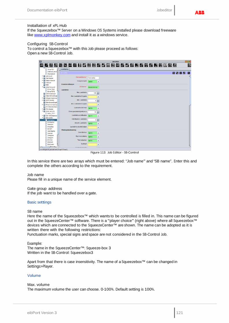
Documentation eibPort Jobeditor
eibPort Version 3 121
Installation of xPL-Hub If the Squeezebox™ Server on a Windows OS Systems installed please download freeware like www.xplmonkey.com and install it as a windows service.
Configuring SB-Control To control a Squeezebox™ with this Job please proceed as follows: Open a new SB-Control Job.
Figure 113: Job Editor - SB-Control
In this service there are two arrays which must be entered: “Job name” and “SB name”. Enter this and complete the others according to the requirement.
Job name Please fill in a unique name of the service element.
Gate group address If the job want to be handled over a gate.
Basic settings
SB name Here the name of the Squeezebox™ which wants to be controlled is filled in. This name can be figured out in the SqueezeCenter™ software. There is a “player choice” (right above) where all Squeezebox™ devices which are connected to the SqueezeCenter™ are shown. The name can be adopted as it is written there with the following restrictions: Punctuation marks, special signs and space are not considered in the SB-Control Job.
Example: The name in the SqueezeCenter™: Squeeze-box 3 Written in the SB-Control: Squeezebox3
Apart from that there is case insensitivity. The name of a Squeezebox™ can be changed in Settings>Player.
Volume
Max. volume The maximum volume the user can choose. 0-100%. Default setting is 100%.

Jobeditor Documentation eibPort
122 eibPort version. 3
Max. volume in Provide the option to build a dynamic volume control. Does the transmitted value under-run the proper “max volume” value, this value is valid. Does it overrun it, the static “max volume” value is valid furthermore. The value has to be EIS 6 (0-100%).
Example: After 10 o’clock p.m. the volume will be reduced from 100% to 70%.
Min. volume It sets the minimum volume between 0 and 100% which the user is able to choose. Default setting is 0%.
Min. volume in Provide the option to build a dynamic volume control. Does the transmitted value overrun the real “min volume” value, this value is valid. Does it under-run it, the static “min volume” value is valid furthermore. The value has to be EIS 6 (0-100%).
Example: By sending out a datagram it can be avoided that the minimal Volume not can be reduced lower than 30%.
Volume dim up/down With this object the volume can be changed in the minimal and maximum limits, EIS 2 (dim). The adjusting speed can be set separately. (Dim by holding switch sensor pressed).
Dim width Set the dim width in seconds. The higher the value the faster is the adjusting (always according to the volume scale of the end device).
Volume step up/down With this object the volume can be changed in the minimal and maximum limits according to the step width which is set. (EIS 1: 0=lower; 1=higher). (Step by typing the switch sensor).
Step width Defines the step width for „Volume step up/down“, (according to the volume scale of the end device).
Current output volume With this group address the current chosen volume is send out as EIS 6 value (0-100%).
Setpoint volume This group address sets an absolute volume. It will only be assumed if it is in the limits of “min volume” and “max volume”. EIS 6 (0-100%).
Track control
Zone on/off This object switches a music zone on or off. In this case a “zone” is the Squeezebox™ which is controlled by this job. (EIS 1: 0=OFF; 1=ON).
Mute/unmute This is the mute object. Mute means the player stops playing a title. Unmute means it continues playing. (EIS 1: 0=UNMUTE; 1=MUTE).
Track next/prev With this object it is switched between the titles forward and backwards. (EIS 1: 0=PREVIOUS; 1=NEXT).
Seek This is the seeking object. Seeking works like fast-forward and rewind. (EIS 2 value, dim).
Seek width Here it is defined how much units it jumps while seeking. The unit corresponds to the end device. If the seek width is set very high, the device forwards faster than if it is set lower.
Documentation eibPort Jobeditor
eibPort Version 3 123
Playlist next/prev This is the object for switching the playlists. The next and previous playlist will be started directly. (EIS 1 Value: 0=PREVIUOS; 1=NEXT).
Display Settings
Display message This object gives out the status information of the Squeezebox™ on a one-row-display in an EIB/KNX switch sensor for example. (EIS 15 value).
Text bypass input Through this object it is possible to overwrite the status information by another EIB/KNX component for a moment, because if this object is used normally no other devices have the chance to send their information onto the display. (EIS 15 value).
Reset textdisplay With this object the display message will be reset into the normal state. (EIS 1: 0=NO FUNCTION; 1=RESET).
Reset invert Is this flag activated, the EIS 1 value of „Reset text display“ -object is inverted. (0=RESET; 1=NO FUNCTION).
Reset on zone With this flag the Display message is reset by the „zone off“ signal.
Reset on mute With this flag the display message is reset by switch on mute.
Display „No playlist“ This flag activates the display message „No playlist“, when no such information is found.
Display "No title" This flag activates the display message „No title“, when no such information is found.
Timeout playlist Means the time in seconds after which the text display switches from the chosen playlist back to the standard display. Normally this is the name of the actual played title. (All other text displays which matches not with the other timeout rules, are affected by this parameter as well).
Timeout mute/zone Means the time after that the text displays is reset having sent the zone on/off or the mute signal (in seconds).
Timeout volume Declares how long the settled volume is shown in the display before the display is switch to standard (in seconds).
Additional Text displays
Current playlist Giving out the current playlist name (EIS 15 value).
PL select line 1,2,3,4 This is the group address for printing out the first/second/third/fourth position of the playlists choice. The position of the playlists is changed by the command “PL scroll up/down”. It is one EIS 14 value for each position. It could be used less then four lines, too.

Jobeditor Documentation eibPort
124 eibPort version. 3
Current title With this group address the actual title is sent as text on the bus, EIS 15 value. Information can only be provided when SqueezeCenter™ can find it in the music data.
Current album With this group address the current album title is given out, EIS 15 value. Information can only be provided when SqueezeCenter™ is able to find it in the music data.
Current artist This group address shows the name of the current artist in a text display, EIS 15 value. Information can only be provided when SqueezeCenter™ is able to find it in the music data.
Playlisten selection
PL scroll up/down The Playlists in the “PL select line” are scrolled with this command. The Playlist are switching through the PL select line 1 to 4. With one datagram a whole page will be switched. (EIS 1: 0=DOWN; 1=UP).
PL selection With this object a playlist can be directly chose out of the playlist selection. (The value 0 to 3 is for the selection of the lines 1 to 4!), EIS 14 value.
Command Settings
Command code With this object it is possible to send command code directly over EIB/KNX to the SqueezeCenter™. The following commands are available (1Byte, EIS 14):
EIS 14 Value Function
1 Synchronize the current volume
2
Refreshes the playlist entrys. If the playlists in the SqueezeCenter™ are changed, with this command the modification is transferred into the eibPort.
21 Next playlist
22
Previous playlist
23 Next title
24
Previous title
25 Reducing volume with dim width speed, stop with 27.
26
Increase the volume with dim width speed, stop with 27.
27 Stops volume modification.
28
One step volume reducing.
29 One step volume increasing.
30
Zone off

Documentation eibPort Jobeditor
eibPort Version 3 125
31 Zone on
32
Play (Mute off)
33 Pause (Mute on)
34
Re-transmit display content
35 Starts fast-forward until stop with 37.
36 Starts rewind until stop with 37.
37 Stopping fast-forward/rewind.
38
Reset text display.
39 Forward with one step.
40
Rewind with one step.
61 Shows the current version number of the SB- control job.
62
Shows the current title.
63 Shows the current playlist.
64
Shows the current volume.
65 Shows the status of the zone.
66
Shows the status of play/pause.
Shows information: SB-control version, ExPL-Plugin version, current playlist source, current volume, 67 minimum volume, maximum volume, zone status, mute status.
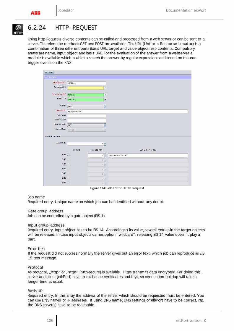
Jobeditor Documentation eibPort
126 eibPort version. 3
6.2.24 HTTP- REQUEST
Using http-Requests diverse contents can be called and processed from a web server or can be sent to a server. Therefore the methods GET and POST are available. The URL (Uniform Resource Locator) is a combination of three different parts (basis URL, target and value object resp contents. Compulsory arrays are name, input object and basis URL. For the evaluation of the answer from a webserver a module is available which is able to search the answer by regular expressions and based on this can trigger events on the KNX.
Figure 114: Job Editor - HTTP Request
Job name Required entry. Unique name on which job can be identified without any doubt.
Gate group address Job can be controlled by a gate object (EIS 1)
Input group address Required entry. Input object has to be EIS 14. According to its value, several entries in the target objects will be released. In case input objects carries option “wildcard”, releasing EIS 14 value doesn`t play a part.
Error text If the request did not success normally the server gives out an error text, which job can reproduce as EIS 15 text message.
Protocol As protocol, „http“ or „https“ (http-secure) is available. Https transmits data encrypted. For doing this, server and client (eibPort) have to exchange certificates and keys, so connection buildup will take a longer time as usual.
Basis-URL Required entry. In this array the address of the server which should be requested must be entered. You can use DNS names or IP addresses. If using DNS name, DNS settings of eibPort have to be correct, rsp. the DNS server(s) have to be reachable.

Documentation eibPort Jobeditor
eibPort Version 3 127
Tip: DNS request will take relatively long time sometimes. To speed preforming of the job, IP address of the server can be enterd. Then a DNS request will be unnecessary.
Hint: If IP address of a DynDNS account varies, maybe IP will differ for a moment from the address, which eibPort has stored in his internal DNS schedule. In this case, request will have the incorrect address.
Auth name und Auth password If necessary, username and password for http authentication can be entered. In case protocoll “http” is activated, http basic authentication will be used. Thereby user data and password will be transmitted in uncoded form. „https” uses the same account, certainly transmit of authentication data will be encrypted.
Request Type A HTTP-Request can be executed in two different ways. It may be selected between method „GET“ and „POST“ .
GET = is the most common method. By means of URLs ( more exactly URI) some arguments
(values, commands) can be tranmitted to a server in order to control this server. Moreover a file (f.i. an answer) can be requested from the server.
POST = is used for sending contents (unlimited) to server. So f.i. formular data can be sent which trigger the server to apply new data or to change existing data. The transmission is done (alike the GET method) by URL(URI).
Note: If method „POST“ ist selected the URL may not be completed under „target“ but in array „Basis URL“. The input array for the target definition is available (mx 256 characters) for „POST“ – data.
Content Type If under „Request Type“ method „POST“ is selected the selection for content type will be released. The combo box defines the encoding of the data being sent via „POST“ method to the server. This array serves to inform the server about the type of data expected. Several data types can be selected:
text/plain: Content of the „Post-Data“ is marked as plain text text/xml: Content is marked as xml- file text/html: Content is marked as HTML- file. application/x-www-form-urlencoded: The server is told that the text is URL encoded.
Special characters will be replaced by according character strings. More information about this can be found in the web by searching „URL Encoding“.
Note: Some servers require a dedicated data type within the content. Due to this all data packets with differed content type information will be rejected even if the content complies with the required content type.
Request: URL Targets
Number of targets You can allocate to every basic URL several targets. In the targets the variable part of the the URL could be entered, which alters during the different requests. Maximal 8 targets can be filled in.
Wildcard If this option is activated, corresponding target will be released by any incoming EIS 14 trigger value.
Hint: One job can only containt one wildcard entry.
Trigger value Determine the EIS 14 value which should trigger the target. EIS 14 has a range from 0-255.
URL

Jobeditor Documentation eibPort
128 eibPort version. 3
Basic URL will be completed with that data array. To transmit the value objects, which are entered in the following part, the variables „\0“ to „\9“ have to be used. The “backslash” will anounce one value object and following digit will determine value object 1-10. “0” will be value object 1 and “9” will be value object 10.
Hint: Between basic URL and URL completion, the necessary separation with „/“ (slash) will not be entered automatically. Slash has to be set by user, neither at the end of basic URL or at start of URL completion.
Send values
Value objects Up to 10 value objects can be set. Each of them may contain these EIS types:
EIS 1 (1 Bit) EIS 5 (2 Byte FP) EIS 6 (1 Byte) EIS 9 (4 Byte FP) EIS 10s (2 Byte value) EIS 11s (4 Byte value) EIS 14u (1 Byte unsigned) EIS 15 (14 Byte Text)
Figure 115: Job Editor - HTTP Request Sending Values
Address Please enter the group address which handed over the value object.
EIS Type Depending on what EIS Type is chosen the format entry array behind changed.
Format According to the EIS Type,the format entry array will be set. The format entry array serves the possibility to give the value object the right formatting. In this way for EIS 1 instead of “1” or “0”, “ON” or “OFF” can be used.
EIS 1: Entering text for „1“ and „0“ is available. EIS 5 and EIS 9: Factor and offset can be adjusted. Value will be muliplied by “factor” and
added by “offset”. EIS 6: Will be interpreted as percentage value from 0% to 100%. Percent sign will not be
tranmitted and has to be enterd in URL completion if necessary (by “%%”). EIS 10, EIS 11 and EIS 14: Will be directly passed as text values in URL completion. EIS 15: Also these values will passed directly as text values. In this way fully free completions out
of EIB/KNX can be realized. EIS 15 allows maximal 14 digits.

Documentation eibPort Jobeditor
eibPort Version 3 129
Insert Spaces: If a space is inserted after a value object, it must be "%% 20" is entered.
Answer response
Up from Firmware Version 0.11.5 the HTTP Request Job provides the possibility to interpret the response from the web server. For this the content of the response file can be searched by regular terms and so the wanted values can be filtered out. The result of the filters can be sent out on up to 4 outputs to a KNX address.
Groups In order to allocate values to the 4 outputs groups have to be defined within the regular expression. Per group one output is used. The sequence proceeds from the left to the right resp according to the syntax of the regular expression. A group is set by ():
Expression(Group1=output1)expression(Group2=output2)… etc.
Regular Expression Due to the complexity of this subject it would burst this documentation. For more information please refer to the diverse documentation in the internet. There functionality and use of regualr expressions are described comprehensively . To give an example for use it will be described lateron.
Flags (Checkboxes above the expression) These flags serve for changing the behaviour of regular expressions. In more complex expressions this will help f.i. for search in severall lines. These flags are available:
Case Insensitive: Dot All: The expression "." Considered by all the characters. He would not see otherwise line
endings. In another context, "Single Line" called. Multiline: has to be used if the expression is not valid just for one line but spread over many
lines Extended: By setting this flag the expression is also valid for „extended characters. So even
commented out strings can be searched. Ungreedy: Basically a regular expression tries to provide a maximum number of hits. In some
cases this can be obstructive; setting the flag causes a break after the first hit. If by ". *?" Resolved in the expression itself.
Outputs As already described above the outputs are operated by groups within the regular expression. A maximum of 4 outputs is allowed. For each address array the access to the ESF data is possible using the arrow.
EIS Types These EIS types can be used for the outputs. For EIS 1 and EIS 5 special settings are valid.
EIS 1 (1 Bit) EIS 5 (2 Byte FP) EIS 6 (1 Byte) EIS 9 (4 Byte FP) EIS 10s (2 Byte value) EIS 11s (4 Byte value) EIS 14u (1 Byte unsigned) EIS 15 (14 Byte Text)
EIS 1 (Mode) If this data type is selected two modes can be used.
Read value: In this mode the value being detected by the expression will be read and sent.

Jobeditor Documentation eibPort
130 eibPort version. 3
Match Pattern: informs if the expression has led to a result. In case of “yes” it will be sent out a
“1”, else a “0”.
EIS 15 (output: format) If data type EIS 15 is selected, the output can be formatted by control characters. These are the possible ones:
„%f“ = floating point value „%d“ = decimal value „%s“ = text value
Data / Length For data types EIS 1 to EIS 14u the data format and eventually the length has to be set. This is due to the fact that the data may be returning from the server in different formats.
ASCII - Unsigned long decimal The content consists of ASCII characters a 'long' data type,
unsigned decimal coded ASCII - Signed long decimal Signed decimal ASCII - Unsigned long hex unsigned hexadecimal ASCII - Signed long hex Signed hexadecimal ASCII - Unsigned long octal Octal unsigned ASCII - Signed long octal Octal signed ASCII - Floating Point floating point number Binary - Unsigned integer little endian (whole) number with little endian byte order, and without
a sign Binary - Unsigned integer big endian With big-endian byte order Binary - Signed integer little endian Little endian signed Binary - Signed integer big endian Big endian signed Binary - Floating Point little endian floating point with little-endian Binary - Floating Point big endian floating point number with a big-endian
Moreover for all binary data the data length has to be set. The data length can be between 1 and 8 byte.
EXAMPLE
The use of regular expressions for the evaluation of an answer will be described in the following example. Requesting the Google weather data server („Google Weather API“) the eibPort receives a XML-file as answer. The answer is filtered by the expression and the remaining values are sent via output channel to the visualization. For the request these settings are made:
Protocol: http:// Basis-URL: www.google.de Request Type: GET GET-URL / Post Data: /ig/api?weather=Dortmund
Note: It is important to secure the correct language for the answer. If f.i. google.com is used the answer will be in English language.
Typing the name of the wanted city behind ‚weather=‘ provides the weather data. Theoretically it would be possibel to change these settings by sending an according value object. If the URL of this request is pasted into a browser the answer is displayed as xml- file in the browser window. In this example the actual weather conditions, the actual temperature in °C, the actual humidity and the expected top temperature for tomorrow should be provided. In a first step all expressions are generated separately in a second step they will be joined.

Documentation eibPort Jobeditor
eibPort Version 3 131
Note: The created expressions can be tested and controlled with several tools. One of them can be found online here: http://dev.radsoftware.com.au/downloads/Rad.RegexDesigner.Setup.1.4.exe. It should be noted that the flags sometimes have a different meaning (eg Dot All = single line).
Actual weather conditions: The actual weather data are located in section „<current_conditions>“. Hereafter the specification „<condition data=“ follows. This is repeated in the specifications „<forecast conditions>“ three times. To avoid, that the expression is valid for all „condition data=“ a string „<current_conditions>“ has to be prefixed:
<current_conditions>.*?<condition data="([a-zA-ZäÄöÖüÜ\s]+)"
Between „<current_conditions>“ and the underlying expression a „.*?“ has to be put and the flag „DotAll“ has to be activated.
This is the first group and so output 1 is defined as EIS 15 Text.
Actual temperature in degree centigrade The output of the actual temperature is positioned after the string„<temp_c data=“.This string only appears once in the whole text. So the expression looks like this:
temp_c data="([\-\+]?[0-9]+)
No further flag has to be activated. The output format is set to EIS 5, the data configuration is „ASCII – Unsigned long decimal“.
Actual humidity The output of the actual humidity is positioned after the string„< Feuchtigkeit” This string also only appears once in the whole text. So the expression looks like this:
Feuchtigkeit: ([0-9]+)
No further flag has to be activated. The output format is set to EIS 6, the data configuration is „ASCII – Unsigned long decimal“.
Expected top temperature for the next day(s) The forecast data for the coming up days are located under „<forecast_conditions>“. There the expression „high data=“ can be found. This one provides the top temperature for the wanted day. This expression exists four times (for the next 4 days); in our example just the first entry in string „high data=“. is relevant.
high data="([\-\+]?[0-9]+)
All flags are deactivated. The expressions returns the first entry of overall 4 hits. No further flag has to be activated. The output format is set to EIS 5, the data configuration is „ASCII – Unsigned long decimal“.
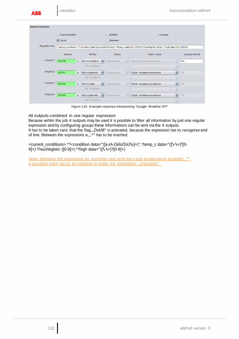
Jobeditor Documentation eibPort
132 eibPort version. 3
Figure 116: Example response interpreting "Google Weather API"
All outputs combined in one regular expression Because wihtin the job 4 outputs may be used it is possible to filter all information by just one regular expression and by configuring groups these informations can be sent via the 4 outputs. It has to be taken care, that the flag „DotAll“ is activated, because the expression has to recognize end of line. Between the expressions a „.*“ has to be inserted.
<current_conditions>.*?<condition data="([a-zA-ZäÄöÖüÜ\s]+)".*temp_c data="([\-\+]?[0- 9]+).*Feuchtigkeit: ([0-9]+).*?high data="([\-\+]?[0-9]+)
Note: Between the expression for humidity and next day’s top temperature beneath „*“ a question mark has to be inserted to make the expression „ungreedy“ .

eibPort Version 3 133
Documentation eibPort Home Information Center (HIC)
7 HOME INFORMATION CENTER (HIC)
HomeInformationCenter offers visualisation for mobile devices or for TVs. User interface is oriented especially for devices like mobiles (iPhone/iPod, Nokia, HTC, Blackberry). HIC visualisation is able to display and switch values of EIS 1, EIS 5, EIS 6 and EIS 14. Camera images, control of blinds and music controlling are contributed as well.
Call It is called with the URL: http:// <eibPort_IP> / web / hic / index.php or by the eibPort Home. By default, the user authentication for the HIC enabled and can be configured in the security settings in visualization editor. It is strongly recommended to use the authentication.
License Since the firmware version 0.11.5, no license is required to unlock the HIC for use! The HIC can be used immediately after setup.
7.1 LAYOUT OF THE HOME INFORMATION CENTER (HIC) – EDITOR
Figure 117: HIC sight of editor
With help of the editor, visualisation will be adjusted. Therfore three different columns are available, in which you can execute each and every step. Control menue is located above.

134 eibPort version. 3
Home Information Center (HIC) Documentation eibPort
Control menue With three symbols at the head of window, the HIC editor will be controlled. There you will find a button for “saving”, a symbol for „reload“ and a symbol for “new element” which allows you to add a new element into the project.
Left column – element overview
Figure 118: HIC editor – control menue
In the element overview first all required elements will be added. Every element will be created automatically in a category folder. For example, element “EIS 14 value” will be stored to folder “Value”.. In this column, all required elements are sorted by its category and can be configured over parametrization window (right column). To delete an element or the complete folder, please use the context menue.
Middle column – sight of visualisation The middle column correspond to the sight of the visualisation. The here performed arrangement will be seen later on in the display of your mobile. The user is able to create folders by him and distribute elements at his will. You can create a folder by context menue (right click to column). Elements, which are parametrized in left column before, will be drawn simply by “drag and drop” to desired folder. Display arrangement of can happen, according to floors and rooms and/or to functions, for example.
Figure 119: HIC editor - Elemente Overview
Right column – parametrization window In the right column the parameters of the elements will be entered. The parameters will be displayed, when an element is chosen in
left or middle column. By parametrization it makes no different, in which column elements will be marked.
Address assignments Address assignments in HIC editor happens conveniently over ESF dialoque, like it does in
Figure 120: HIC editor – Sight
of visualisation
Figure 121: HIC editor – Parameterization window
other editors. The dialogue will open by clicking on the arrow symbol near the data entry field for the addresses. An overview will be displayed, which contains all addresses of loaded up ESF files and/or a address matrix. You can allocate an address to an object by a double click. To every input object you can assign maximal 5 addresses. Addresses for feedback will be entered in brackets, separated with comma, behind the used address.

eibPort Version 3 135
Documentation eibPort Home Information Center (HIC)
7.2 AVAILABLE ELEMENT TYPES
EIS 1 on/off If “is control?” is activated ON/OFF will be sent, in case it is disabled this element can be used as a simple status indication.
EIS 5 temperature Displays the current and setpoint temperature in EIS 5 format. Is controlling activated, you will be able to set the setpoint temperature by “+/-“ in a defined step width. In case “operating” is inactivated, element is just an indicator.
EIS 5 value floating point Represent EIS 5 values. Maximum and minimum value can be adjusted, step width also. Element can work as a control or as an indicator (“is control?”).
EIS 6 value 0-100% Represent EIS 6 values. The values 0 – 255 will be converted to 0 – 100 %. Additional maximum and minimum values as well as step width can be adjusted for operation. Element can work as a control or as an indicator (“is control?”).
EIS14 value 0-255 Represent EIS 14 values (0-255). You can specify minimum or maximum value. Step width for adjustment can be defined. Element can work as a control or as an indicator (“is control?”).
Camera with controlling This element shows pictures from a camera. Therefore the URL to the fixed frame of the camera must be entered. When open the the element in HIC, it will be requested several times in a second, so that a moving pictures will appear. The syntax of the URL behind the camera address will depend on the camera manufacturer.
The entry arrays below the camera URL are for the controlling of the camera by http requests, in case of camera is supporting this. Thereby the camera is told by an URL which position it has to take. The user then has the possibility to control his camera by hitting the image in his mobile on the four cardinal points.
This function is only available together with the job “HTTP-Requests”. This job has to be created before ind Job editor and must be parameterized correctly (for hints please see into the description of the http request). After that the “http-request address” of the camera element can be connected with the job. Please consider to set the EIS 14 values correctly.
Please note: For retrieval the picture from off site, also the camera image has to be reached from outside. Normally therefore a port will be fowarded to the camera. As address of camera, external address of router (fixed IP or dyndns) with corresponding port will be entered
Jalousie Element for controlling shutters or window shades. Some shutter actuators require inverting of telegrams.
MediaControl Control element for a network music player connected to the system. eibPort offers the possibilty to controll the Squeezebox™ devices. Element offers functions like “play/stop”, “back/forward” and “volume up/volume down”. Furthermore informations of album, title and artist will be displayed.
Please note: Controlling by HIC only can be realized, if one job (xPL-sender and receiver, or SB- Control) will be applied in job editor before. Element “media control” uses comunication objects of this job. Therefore a perfect function of jobs is absolutely necessary.
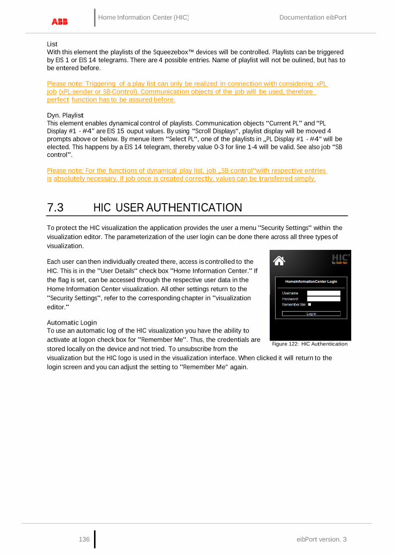
136 eibPort version. 3
Home Information Center (HIC) Documentation eibPort
List With this element the playlists of the Squeezebox™ devices will be controlled. Playlists can be triggered by EIS 1 or EIS 14 telegrams. There are 4 possible entries. Name of playlist will not be oulined, but has to be entered before.
Please note: Triggering of a play list can only be realized in connection with considering xPL job (xPL-sender or SB-Control). Communication objects of the job will be used, therefore perfect function has to be assured before.
Dyn. Playlist This element enables dynamical control of playlists. Communication objects “Current PL” and “PL Display #1 - #4” are EIS 15 ouput values. By using “Scroll Displays“, playlist display will be moved 4 prompts above or below. By menue item “Select PL“, one of the playlists in „PL Display #1 - #4“ will be elected. This happens by a EIS 14 telegram, thereby value 0-3 for line 1-4 will be valid. See also job “SB control”.
Please note: For the functions of dynamical play list, job „SB control“with respective entries is absolutely necessary. If job once is created correctly, values can be transferred simply.
7.3 HIC USER AUTHENTICATION
To protect the HIC visualization the application provides the user a menu "Security Settings" within the visualization editor. The parameterization of the user login can be done there across all three types of visualization.
Each user can then individually created there, access is controlled to the HIC. This is in the "User Details" check box "Home Information Center." If the flag is set, can be accessed through the respective user data in the Home Information Center visualization. All other settings return to the "Security Settings", refer to the corresponding chapter in "visualization editor."
Automatic Login To use an automatic log of the HIC visualization you have the ability to activate at logon check box for "Remember Me". Thus, the credentials are stored locally on the device and not tried. To unsubscribe from the
Figure 122: HIC Authentication
visualization but the HIC logo is used in the visualization interface. When clicked it will return to the login screen and you can adjust the setting to "Remember Me" again.
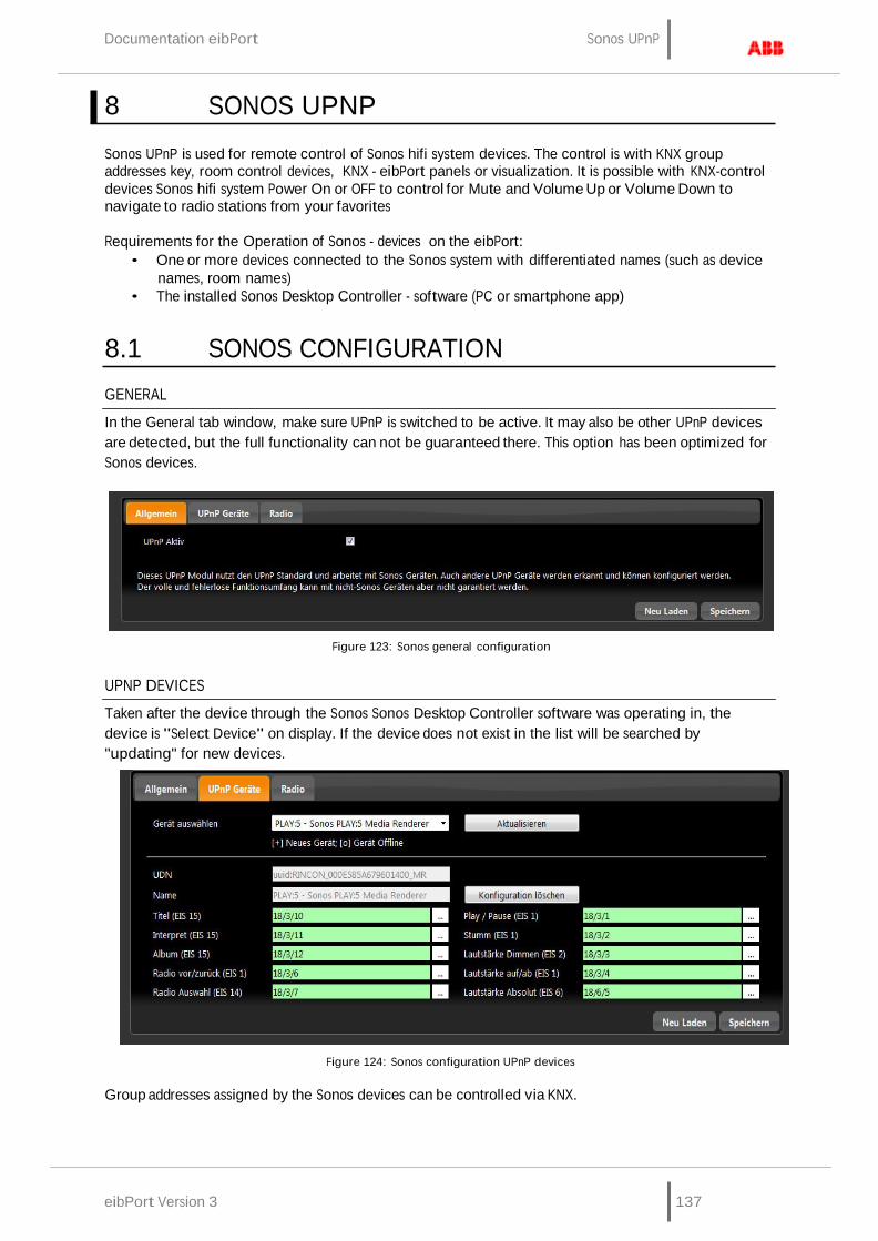
eibPort Version 3 137
Documentation eibPort Sonos UPnP
8 SONOS UPNP
Sonos UPnP is used for remote control of Sonos hifi system devices. The control is with KNX group addresses key, room control devices, KNX - eibPort panels or visualization. It is possible with KNX-control devices Sonos hifi system Power On or OFF to control for Mute and Volume Up or Volume Down to navigate to radio stations from your favorites
Requirements for the Operation of Sonos - devices on the eibPort:
• One or more devices connected to the Sonos system with differentiated names (such as device names, room names)
• The installed Sonos Desktop Controller - software (PC or smartphone app)
8.1 SONOS CONFIGURATION
GENERAL
In the General tab window, make sure UPnP is switched to be active. It may also be other UPnP devices are detected, but the full functionality can not be guaranteed there. This option has been optimized for Sonos devices.
Figure 123: Sonos general configuration
UPNP DEVICES
Taken after the device through the Sonos Sonos Desktop Controller software was operating in, the device is "Select Device" on display. If the device does not exist in the list will be searched by "updating" for new devices.
Figure 124: Sonos configuration UPnP devices
Group addresses assigned by the Sonos devices can be controlled via KNX.

138 eibPort version. 3
Sonos UPnP Documentation eibPort
Title (EIS 15) About this group address the current title of the radio station will be sent as a text output on the bus, 15 of the EIS. Information can only be made available when this is present.
Artist (EIS 15) Group address to the text output of the current artist. (EIS 15 value). Information can only be made available when this is present.
Album (EIS 15) This group will address the current issue album title. (EIS 15 value). Information can only be made available when this is present.
Radio front / back (EIS 1) The object for switching radio stations forward / back. (EIS 1: 0 = BACK, 1 = ON).
Radio selection (EIS 14) Group address for selection of favorite radio stations that have been created and managed under the radio (see radio). The list of radio stations beginning with 0, the position of favorites can be connected to a EIS14 button. By specifying the value in EIS14 button can be called the favorite desired (eg 2 for 1Live). ICE CREAM 14 Value.
Play / Pause (EIS 1) With this object, turn the Sonos playback devices on or off. (EIS 1: 0 = OFF 1 = ON)
Mute (EIS 1) The group addresses for the mute (Mute). Muting the effect that the song is stopped, and again on Mute OFF continues (EIS 1: 0 = OFF MUTE, AN 1 = mute).
Volume dim (ICE 2) With this object, the volume can be adjusted continuously, (dim) EIS 2.
Volume up / down (EIS 1) About this object is in the volume gradually increased or decreased, (EIS 1: 0 = quiet, 1 = up).
Absolute volume (EIS 6) This group address, it is possible to set an absolute volume. EIS6 value (0-100%).
Save After editing the objects care must be taken to "save", because otherwise all will be deleted.
Delete Configuration By "clear configuration" stated the group addresses are removed.
Reload "Reload" reloads the current configuration eibPort.
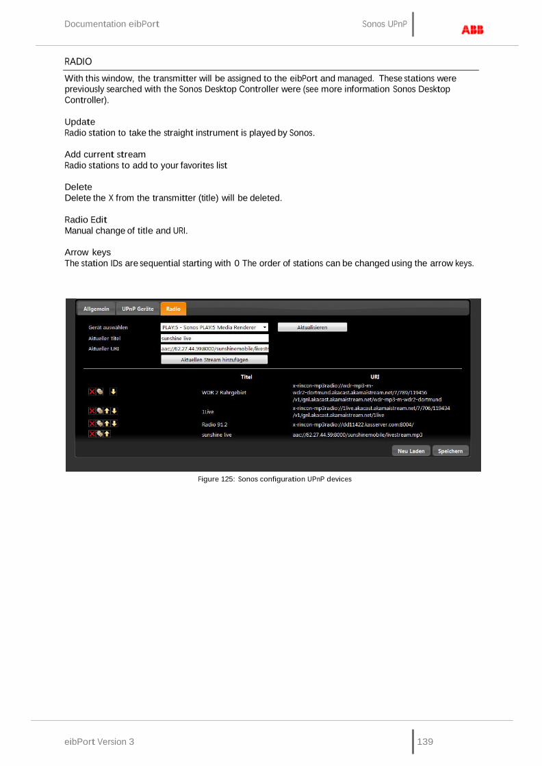
eibPort Version 3 139
Documentation eibPort Sonos UPnP
RADIO
With this window, the transmitter will be assigned to the eibPort and managed. These stations were previously searched with the Sonos Desktop Controller were (see more information Sonos Desktop Controller).
Update Radio station to take the straight instrument is played by Sonos.
Add current stream Radio stations to add to your favorites list
Delete Delete the X from the transmitter (title) will be deleted.
Radio Edit Manual change of title and URI.
Arrow keys The station IDs are sequential starting with 0 The order of stations can be changed using the arrow keys.
Figure 125: Sonos configuration UPnP devices
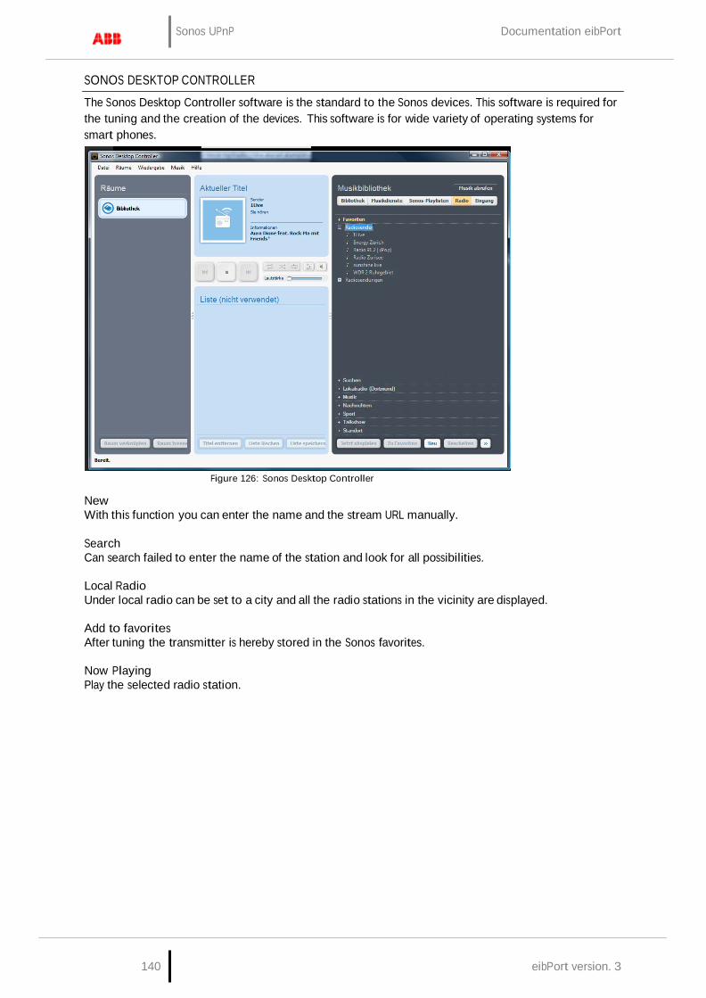
Sonos UPnP Documentation eibPort
140 eibPort version. 3
SONOS DESKTOP CONTROLLER
The Sonos Desktop Controller software is the standard to the Sonos devices. This software is required for the tuning and the creation of the devices. This software is for wide variety of operating systems for smart phones.
Figure 126: Sonos Desktop Controller
New With this function you can enter the name and the stream URL manually.
Search Can search failed to enter the name of the station and look for all possibilities.
Local Radio Under local radio can be set to a city and all the radio stations in the vicinity are displayed.
Add to favorites After tuning the transmitter is hereby stored in the Sonos favorites.
Now Playing Play the selected radio station.
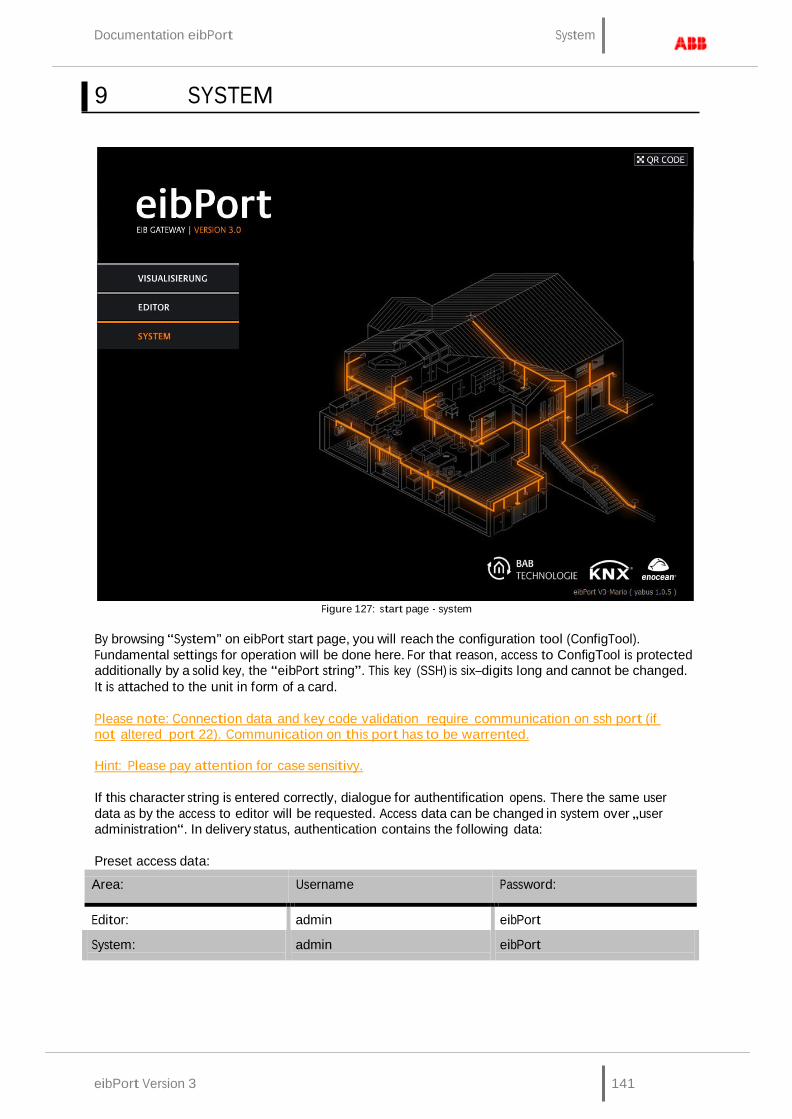
eibPort Version 3 141
Documentation eibPort System
9 SYSTEM
Figure 127: start page - system
By browsing “System” on eibPort start page, you will reach the configuration tool (ConfigTool). Fundamental settings for operation will be done here. For that reason, access to ConfigTool is protected additionally by a solid key, the “eibPort string”. This key (SSH) is six–digits long and cannot be changed. It is attached to the unit in form of a card.
Please note: Connection data and key code validation require communication on ssh port (if not altered port 22). Communication on this port has to be warrented.
Hint: Please pay attention for case sensitivy.
If this character string is entered correctly, dialogue for authentification opens. There the same user data as by the access to editor will be requested. Access data can be changed in system over „user administration“. In delivery status, authentication contains the following data:
Preset access data:
Area:
Username
Password:
Editor: admin eibPort
System:
admin
eibPort
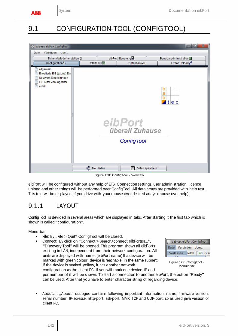
142 eibPort version. 3
System Documentation eibPort
9.1 CONFIGURATION-TOOL (CONFIGTOOL)
Figure 128: ConfigTool - overview
eibPort will be configured without any help of ETS. Connection settings, user administration, licence upload and other things will be performed over ConfigTool. All data arrays are provided with help text. This text wil be displayed, if you drive with your mouse over desired arrays (mouse over help).
9.1.1 LAYOUT
ConfigTool is devided in several areas which are displayed in tabs. After starting it the first tab which is shown is called “configuration”.
Menu bar File: By „File > Quit“ ConfigTool will be closed. Connect: By click on “Connect > Search/connect eibPort(s)...“,
“Discovery Tool” will be opened. This program shows all eibPorts existing in LAN, independent from their network configuration. All units are displayed with name. (eibPort name) If a device will be marked with green colour, device is reachable in the same subnet; if the device is marked yellow, it has another network configuration as the client PC. If you will mark one device, IP and
Figure 129: ConfigTool - Menüleiste
portnumber of it will be shown. To start a connection to another eibPort, the button “Ready” can be used. After that you have to enter character string of regarding device.
About…: „About“ dialogue contains following important information: name, firmware version, serial number, IP-adresse, http-port, ssh-port, MMX TCP and UDP-port, so as used java version of client PC.
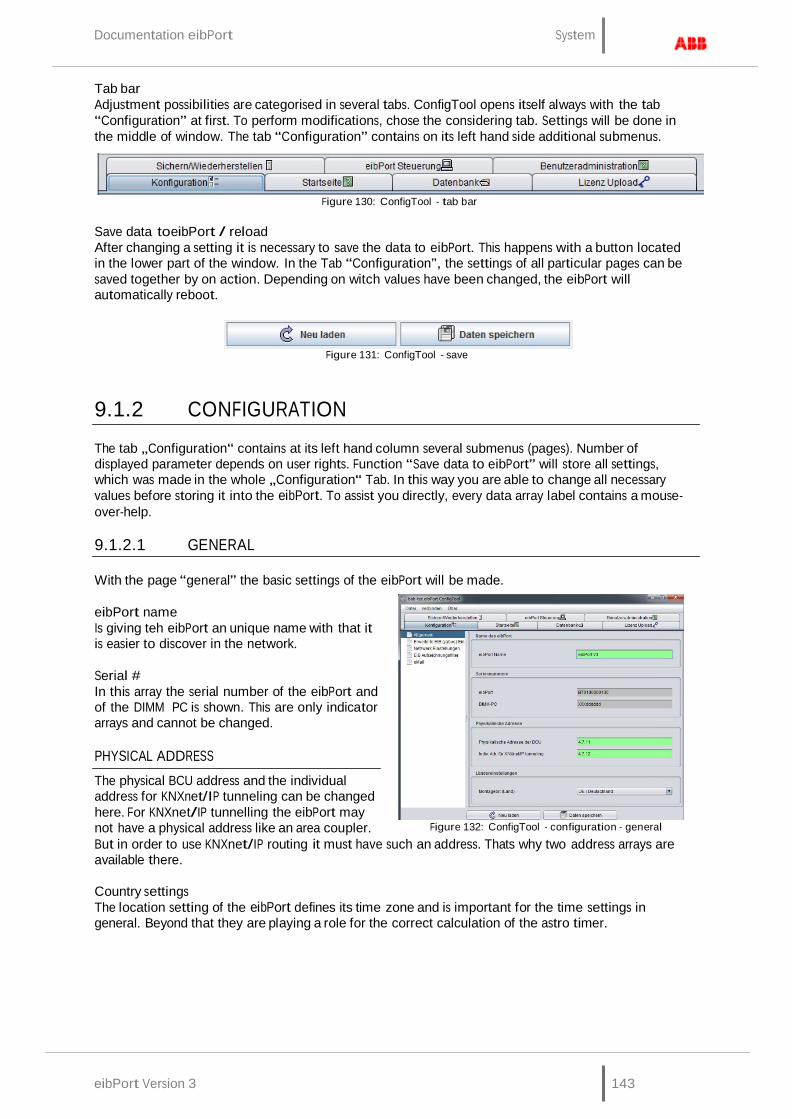
eibPort Version 3 143
Documentation eibPort System
Tab bar Adjustment possibilities are categorised in several tabs. ConfigTool opens itself always with the tab “Configuration” at first. To perform modifications, chose the considering tab. Settings will be done in the middle of window. The tab “Configuration” contains on its left hand side additional submenus.
Figure 130: ConfigTool - tab bar
Save data toeibPort / reload After changing a setting it is necessary to save the data to eibPort. This happens with a button located in the lower part of the window. In the Tab “Configuration”, the settings of all particular pages can be saved together by on action. Depending on witch values have been changed, the eibPort will automatically reboot.
Figure 131: ConfigTool - save
9.1.2 CONFIGURATION
The tab „Configuration“ contains at its left hand column several submenus (pages). Number of displayed parameter depends on user rights. Function “Save data to eibPort” will store all settings, which was made in the whole „Configuration“ Tab. In this way you are able to change all necessary values before storing it into the eibPort. To assist you directly, every data array label contains a mouse- over-help.
9.1.2.1 GENERAL
With the page “general” the basic settings of the eibPort will be made.
eibPort name Is giving teh eibPort an unique name with that it is easier to discover in the network.
Serial # In this array the serial number of the eibPort and of the DIMM PC is shown. This are only indicator arrays and cannot be changed.
PHYSICAL ADDRESS
The physical BCU address and the individual address for KNXnet/IP tunneling can be changed here. For KNXnet/IP tunnelling the eibPort may not have a physical address like an area coupler.
Figure 132: ConfigTool - configuration - general
But in order to use KNXnet/IP routing it must have such an address. Thats why two address arrays are available there.
Country settings The location setting of the eibPort defines its time zone and is important for the time settings in general. Beyond that they are playing a role for the correct calculation of the astro timer.
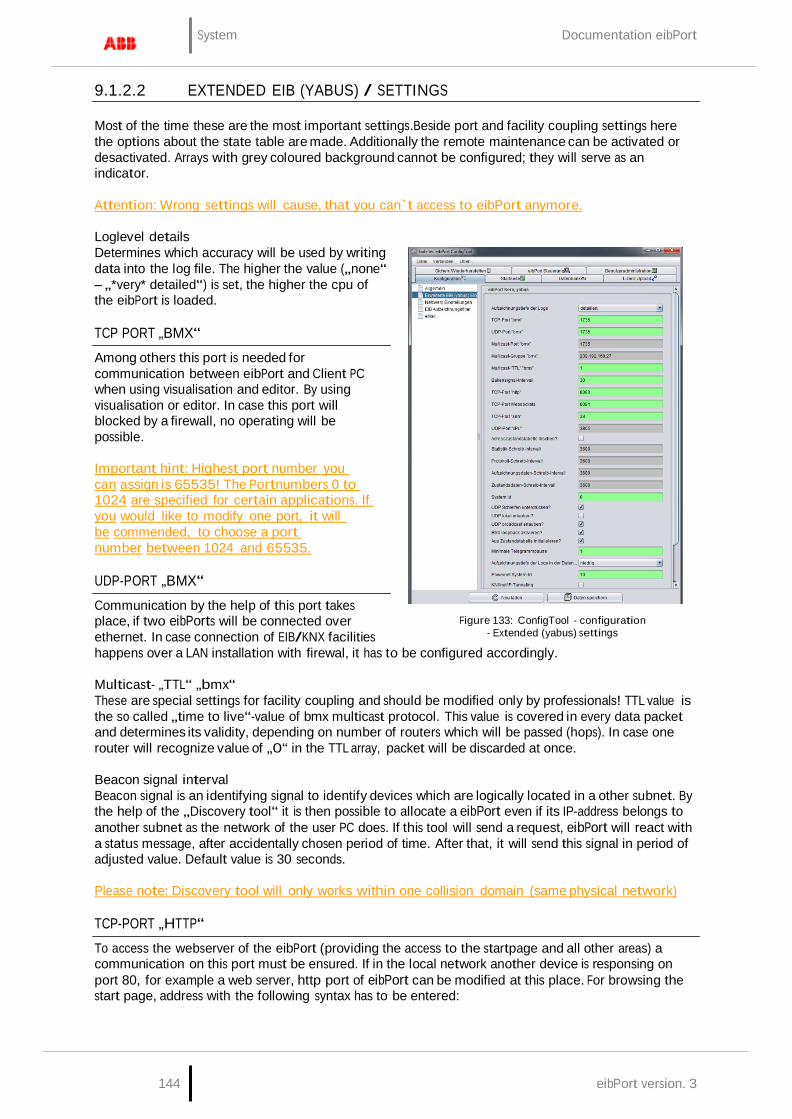
144 eibPort version. 3
System Documentation eibPort
9.1.2.2 EXTENDED EIB (YABUS) / SETTINGS
Most of the time these are the most important settings.Beside port and facility coupling settings here the options about the state table are made. Additionally the remote maintenance can be activated or desactivated. Arrays with grey coloured background cannot be configured; they will serve as an indicator.
Attention: Wrong settings will cause, that you can`t access to eibPort anymore.
Loglevel details Determines which accuracy will be used by writing data into the log file. The higher the value („none“ – „*very* detailed“) is set, the higher the cpu of the eibPort is loaded.
TCP PORT „BMX“
Among others this port is needed for communication between eibPort and Client PC when using visualisation and editor. By using visualisation or editor. In case this port will blocked by a firewall, no operating will be possible.
Important hint: Highest port number you can assign is 65535! The Portnumbers 0 to 1024 are specified for certain applications. If you would like to modify one port, it will be commended, to choose a port number between 1024 and 65535.
UDP-PORT „BMX“
Communication by the help of this port takes place, if two eibPorts will be connected over ethernet. In case connection of EIB/KNX facilities
Figure 133: ConfigTool - configuration - Extended (yabus) settings
happens over a LAN installation with firewal, it has to be configured accordingly.
Multicast- „TTL“ „bmx“ These are special settings for facility coupling and should be modified only by professionals! TTL value is the so called „time to live“-value of bmx multicast protocol. This value is covered in every data packet and determines its validity, depending on number of routers which will be passed (hops). In case one router will recognize value of „0“ in the TTL array, packet will be discarded at once.
Beacon signal interval Beacon signal is an identifying signal to identify devices which are logically located in a other subnet. By the help of the „Discovery tool“ it is then possible to allocate a eibPort even if its IP-address belongs to another subnet as the network of the user PC does. If this tool will send a request, eibPort will react with a status message, after accidentally chosen period of time. After that, it will send this signal in period of adjusted value. Default value is 30 seconds.
Please note: Discovery tool will only works within one collision domain (same physical network)
TCP-PORT „HTTP“
To access the webserver of the eibPort (providing the access to the startpage and all other areas) a communication on this port must be ensured. If in the local network another device is responsing on port 80, for example a web server, http port of eibPort can be modified at this place. For browsing the start page, address with the following syntax has to be entered:

eibPort Version 3 145
Documentation eibPort System
http://<eibPort_IP>:<Portnummer>
Example with port number 8080: 192.168.2.1:8080
Hint: Please note: After saving modifications of port number, unit will be restarted (duration ca. 2 minutes)
TCP PORT „WEBSOCKETS“
WebSockets is a web technology that can be used for the visualization of Ajax. Thus, the communication between client and server is visualization (eibPort) instead of better performance. The technique can be used only if the browser supports WebSockets technology. If the network is already a device that communicates over this port, the port can be adjusted here.
TCP-PORT „SSH“
This port is necessary for communication while updating, data transfer and while accessing to the “System“. By default this port is adjusted on number 22, which can be changed as well. In case commnunication takes place over firewalls, you have to configure these firewalls accordingly.
Delete address state table If this option is activated the address state table will be not loaded the next time the eibPort is rebooted. The address state table is written new after a 15 minutes cycle and would overwrite the old (still existing) one. The address state table then has the values which was actual in the last 15 minutes. But is the eibPort rebooted during this time and this option is disabled again, the old state is restored again.
Hint: Since the firmware version 0.9.x it is able to delete the address state table with an option in the Editor.
System ID System ID acts as a unique identification in case, several devices should work together in facility coupling. Therewith only these devices are able to communicate, which are using the same System ID.
UDP loop prevention? Prevent the creating of UDP-loops in case of facility coupling over UDP-bmx protocol (linkage by job “linking facilities”). By a failure configuration it can happen, that UDP datagrams will run in a loop through the network. This effect can be restricted by this option.
Allow UDP locally? In case this option will be placed, eibPort will process also those UDP-telegrams, which it will depose for the purposes of facility coupling.
Allow UDP broadcast? Several services of eibPort produce in their function UDP-unicast connections. (UDP-sender, linking facilities). If desired also a „point to multipoint connection“ can be established. Therefore you have the broadcast address has to be entered into the job entry array and this option has to be activated.
Activate BMX loopback? If this option is activated, a switching will be outlined as conducted at once in visualisation, independent from the actual status. In case option is inactivated, feed back of actuator will be awaited. Option is activated in delivery condition.
Initialize from address state table? By restarting the eibPort, the state of the communication objects will be determined according to the actual state table. In case of gate objects there is not waited until a new telegram arrives but the current state is read out of the state table. In this way the jobs will start dependable. Option is activated as default.
Please note: If status table will be used for initialisation, you have to regard, that telegrams will get the right time stamp. If that is not the case, (and time stamp is older than existíng time

146 eibPort version. 3
System Documentation eibPort
stamp) existing status will not be overwritten, so that wrong values will be displayed resp. be interpreted.
Minimum telegram delay? Determines the minimal timespan which has to lay between two telegrams generated from the lightscene job. This value cannot be set lower than “1”. This acts as for prevention of exorbitant bus load.
Loglevel database details? eibPort can also write logs to an external database. Here it will be defined, how detailed the log recordings into the database will be. If recording will be very detailed, a lot of computing power will be necessary.
KNXNET/IP TUNNELING
About this flag KNXnet / IP tunneling is enabled or disabled in the device. KNXnet / IP tunneling can program or to be used for communication with other devices.
URL information for Discovery The dropdown menu will determine what information a potential for discovery, so the track by other services on the network sends. This information is sent via multicast to the network. It can be determined are whether sending the LAN address, WAN address (if in the bottom field, then fill in as appropriate), or both addresses.
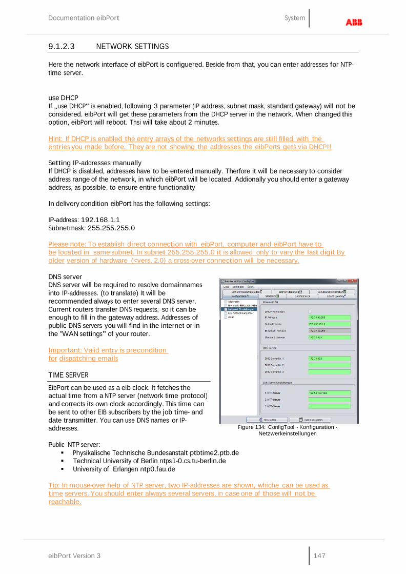
eibPort Version 3 147
Documentation eibPort System
9.1.2.3 NETWORK SETTINGS
Here the network interface of eibPort is configuered. Beside from that, you can enter addresses for NTP- time server.
use DHCP If „use DHCP“ is enabled, following 3 parameter (IP address, subnet mask, standard gateway) will not be considered. eibPort will get these parameters from the DHCP server in the network. When changed this option, eibPort will reboot. Thsi will take about 2 minutes.
Hint: If DHCP is enabled the entry arrays of the networks settings are still filled with the entries you made before. They are not showing the addresses the eibPorts gets via DHCP!!
Setting IP-addresses manually If DHCP is disabled, addresses have to be entered manually. Therfore it will be necessary to consider address range of the network, in which eibPort will be located. Addionally you should enter a gateway address, as possible, to ensure entire functionality
In delivery condition eibPort has the following settings:
IP-address: 192.168.1.1 Subnetmask: 255.255.255.0
Please note: To establish direct connection with eibPort, computer and eibPort have to be located in same subnet. In subnet 255.255.255.0 it is allowed only to vary the last digit By older version of hardware (<vers. 2.0) a cross-over connection will be necessary.
DNS server DNS server will be required to resolve domainnames into IP-addresses. (to translate) It will be recommended always to enter several DNS server. Current routers transfer DNS requests, so it can be enough to fill in the gateway address. Addresses of public DNS servers you will find in the internet or in the ”WAN settings” of your router.
Important: Valid entry is precondition for dispatching emails
TIME SERVER
EibPort can be used as a eib clock. It fetches the actual time from a NTP server (network time protocol) and corrects its own clock accordingly. This time can be sent to other EIB subscribers by the job time- and date transmitter. You can use DNS names or IP- addresses.
Public NTP server:
Figure 134: ConfigTool - Konfiguration -
Netzwerkeinstellungen
Physikalische Technische Bundesanstalt ptbtime2.ptb.de Technical University of Berlin ntps1-0.cs.tu-berlin.de University of Erlangen ntp0.fau.de
Tip: In mouse-over help of NTP server, two IP-addresses are shown, whiche can be used as time servers. You should enter always several servers, in case one of those will not be reachable.
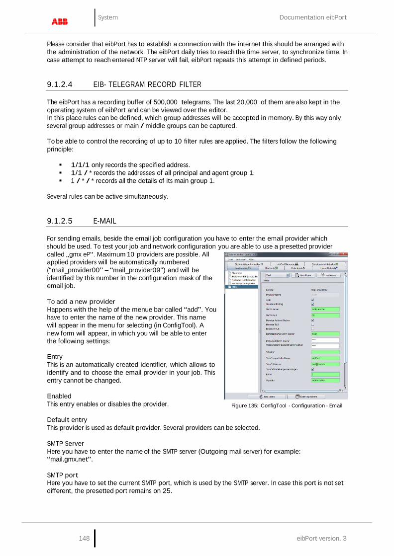
148 eibPort version. 3
System Documentation eibPort
Please consider that eibPort has to establish a connection with the internet this should be arranged with the administration of the network. The eibPort daily tries to reach the time server, to synchronize time. In case attempt to reach entered NTP server will fail, eibPort repeats this attempt in defined periods.
9.1.2.4 EIB- TELEGRAM RECORD FILTER
The eibPort has a recording buffer of 500,000 telegrams. The last 20,000 of them are also kept in the operating system of eibPort and can be viewed over the editor. In this place rules can be defined, which group addresses will be accepted in memory. By this way only several group addresses or main / middle groups can be captured.
To be able to control the recording of up to 10 filter rules are applied. The filters follow the following principle:
1/1/1 only records the specified address. 1/1 / * records the addresses of all principal and agent group 1. 1 / * / * records all the details of its main group 1.
Several rules can be active simultaneously.
9.1.2.5 E-MAIL
For sending emails, beside the email job configuration you have to enter the email provider which should be used. To test your job and network configuration you are able to use a presetted provider called „gmx eP“. Maximum 10 providers are possible. All applied providers will be automatically numbered (“mail_provider00” – “mail_provider09”) and will be identified by this number in the configuration mask of the email job.
To add a new provider Happens with the help of the menue bar called “add”. You have to enter the name of the new provider. This name will appear in the menu for selecting (in ConfigTool). A new form will appear, in which you will be able to enter the following settings:
Entry This is an automatically created identifier, which allows to identify and to choose the email provider in your job. This entry cannot be changed.
Enabled This entry enables or disables the provider.
Figure 135: ConfigTool - Configuration - Email
Default entry This provider is used as default provider. Several providers can be selected.
SMTP Server Here you have to enter the name of the SMTP server (Outgoing mail server) for example: “mail.gmx.net”.
SMTP port Here you have to set the current SMTP port, which is used by the SMTP server. In case this port is not set different, the presetted port remains on 25.

eibPort Version 3 149
Documentation eibPort System
Use authentication According to the SMTP server, an authentification will be necessary. In this case this entry has to be activated.
Using TLS (Transport Layer Security) You have to activate this entry, if the connection to the SMTP sever should be encoded. Is there no possibility to establish a TLS connection an unencrypted connection will be tried to create.
Require TLS This setting has to be activated when the SMTP server requires an encoded connection. In the case this entry is enabled, but no TLS-connection is possible, the connecting will be interrupted. An unencrypted link is not tried to establish.
User name SMTP-Server With this username (name of email account) the eibPort logs on to the SMTP server (Outgoing mail server).
Password SMTP Server Here the password for the user authentication is entered. To avoid typing errors the password has to be repeated.
“Realm“ The “Realm” entry can be necessary at some providers. It will be used for authentication, to allocate a defined area for the user. Please ask your provider or your administrator for more details.
“From:“ real name Using this name your email will be dispatched, if no other name will be entered in the configuration mask of the email job.
“From:“ address Using this email address your email will be dispatched, if no other address will be entered in the configuration mask of the email job.
Organization and Default signature These informations are for optional use und will be integrated in your mail.
Notice: For testing the network configuration, you can send emails in cooperation with the already applied provider. In case you are not sure about your provider settings you can also check your settings with the help of well known email clients, like Outlook or Thunderbird. You only need to apply an email account in there, which contains the same settings like it is in the eibPort. Doing so, you have to consider that eibPort settings are only matches the outgoing (SMTP) settings.
Notice: Connection to an email server only works with valid DNS Server entries. If it is not possible for eibPort to resolve the domain names, the email job will not start and cause problems. The information about valid DNS entries regarding to your email provider you get at the provider itself or in the internet.
The email provider can be used after saving the settings.
System Documentation eibPort
150 eibPort version. 3
9.1.3 STARTPAGE
The startpage is the page, which will be displayed if the address of eibPort is entered in the browsers’ address bar. In this tab you have the possibility to determine which behaviour takes place in this case. To use your own background image, you are able upload it into eibPort by function in field at the bottom.
Please note: The option to upload a background image is only be valid for background of startpage, not for background of visualisation.
Following choices are available for start page:
Show default page Well known start page with menu items visualisation, editor, system, webstart will appear (delivery condition).
Open visualisation in an extra window By browsing the eibPort address, visualisation will be opened in a new window. This makes sure, that user will be guided directly to visualisation; user doesn`t have the possibility to call up „editor“ or „system“.
Open visualisation in the browser window Visualisation will be opened directly, as described above, certainly not in one seperate window, but in the same browser window.
Please note: Standard start page is directly reachable under http://<eibPort_IP>/bmxJava2/default.html, independently from here fixed settings
Show userdefined page The uploaded image will be used as the startpage. Visualisation doesn’t start immediately, contrary to the other options, but will be called up by “start” button placed on the backgrund image. In delivery condition picture of a hotel plant is situated on this place.
Autologin If the start page setting changes at the same time enabled user management (for visualization), it is necessary for direct access to the visualization, to give the user data in the URL call. Otherwise, first the username and password is required. The information can be found in the "visualization"> "Auto Login".
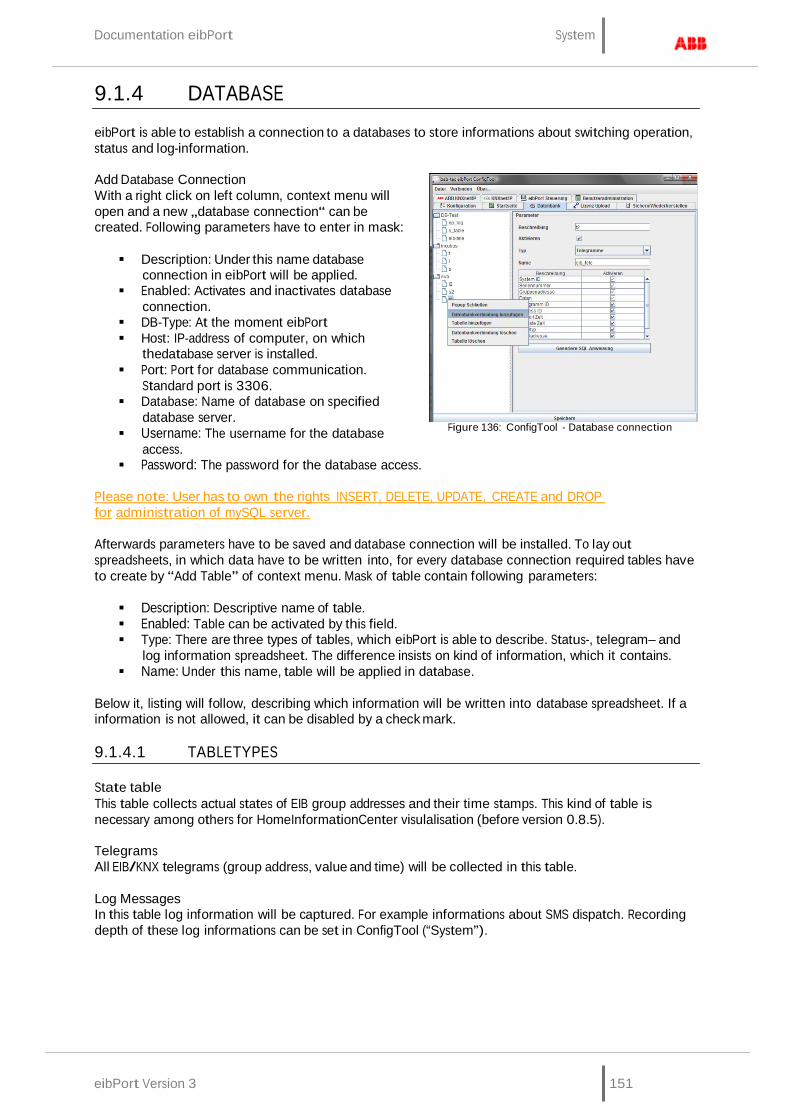
Documentation eibPort System
eibPort Version 3 151
9.1.4 DATABASE
eibPort is able to establish a connection to a databases to store informations about switching operation, status and log-information.
Add Database Connection With a right click on left column, context menu will open and a new „database connection“ can be created. Following parameters have to enter in mask:
Description: Under this name database
connection in eibPort will be applied. Enabled: Activates and inactivates database
connection. DB-Type: At the moment eibPort Host: IP-address of computer, on which
thedatabase server is installed. Port: Port for database communication.
Standard port is 3306. Database: Name of database on specified
database server. Username: The username for the database
access. Password: The password for the database access.
Figure 136: ConfigTool - Database connection
Please note: User has to own the rights INSERT, DELETE, UPDATE, CREATE and DROP for administration of mySQL server.
Afterwards parameters have to be saved and database connection will be installed. To lay out spreadsheets, in which data have to be written into, for every database connection required tables have to create by “Add Table” of context menu. Mask of table contain following parameters:
Description: Descriptive name of table. Enabled: Table can be activated by this field. Type: There are three types of tables, which eibPort is able to describe. Status-, telegram– and
log information spreadsheet. The difference insists on kind of information, which it contains. Name: Under this name, table will be applied in database.
Below it, listing will follow, describing which information will be written into database spreadsheet. If a information is not allowed, it can be disabled by a check mark.
9.1.4.1 TABLETYPES
State table This table collects actual states of EIB group addresses and their time stamps. This kind of table is necessary among others for HomeInformationCenter visulalisation (before version 0.8.5).
Telegrams All EIB/KNX telegrams (group address, value and time) will be collected in this table.
Log Messages In this table log information will be captured. For example informations about SMS dispatch. Recording depth of these log informations can be set in ConfigTool (“System”).
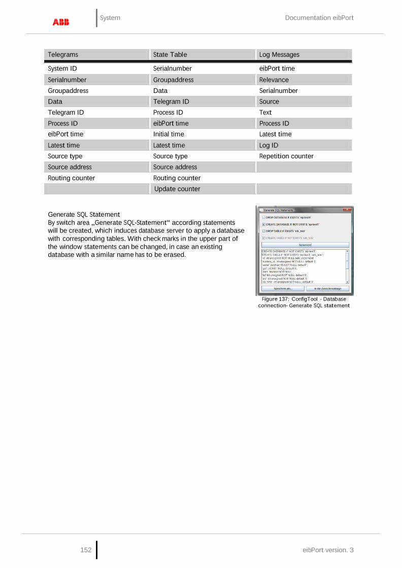
System Documentation eibPort
152 eibPort version. 3
Telegrams State Table Log Messages
System ID Serialnumber eibPort time
Serialnumber Groupaddress Relevance Groupaddress Data Serialnumber Data Telegram ID Source Telegram ID Process ID Text Process ID eibPort time Process ID eibPort time Initial time Latest time Latest time Latest time Log ID Source type Source type Repetition counter Source address Source address Routing counter Routing counter
Update counter
Generate SQL Statement By switch area „Generate SQL-Statement“ according statements will be created, which induces database server to apply a database with corresponding tables. With check marks in the upper part of the window statements can be changed, in case an existing database with a similar name has to be erased.
Figure 137: ConfigTool - Database connection- Generate SQL statement
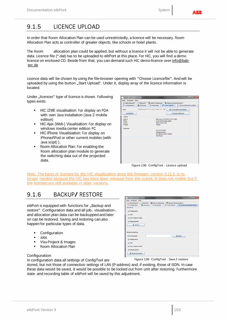
Documentation eibPort System
eibPort Version 3 153
9.1.5 LICENCE UPLOAD
In order that Room Allocation Plan can be used unrestrictedly, a licence will be necessary. Room Allocation Plan acts as controller of greater objects, like schools or hotel plants.
The Room allocation plan could be applied, but without a licence it will not be able to generate data. Licence file (*.dat) has to be uploaded to eibPort at this place. For HIC, you will find a demo licence on enclosed CD. Beside from that, you can demand such HIC demo-licence over info@bab- tec.de
Licence data will be chosen by using the file-browser opening with “Choose Licencefile“. And will be uploaded by using the button „Start Upload“. Under it, display array of the licence information is located.
Under „licences“ type of licence is shown. Following types exists:
HIC J2ME visualisation: For display on PDA
with own Java installation (Java 2 mobile edition)
HIC Ajax (Web-) Visualisation: For display on windows media center edition PC
HIC iPhone Visualisiation: For display on iPhone/iPod or other current mobiles (with Java scipt) ).
Room Allocation Plan: For enabling the Room allocation plan module to generate the switching data out of the projected data.
Figure 138: ConfigTool - Licence upload
Note: The types of licenses for the HIC visualization since the firmware version 0.11.5 is no longer needed because the HIC has since been released from the outset. It does not matter but if the licenses are still available in older versions.
9.1.6 BACKUP/ RESTORE
eibPort is equipped with functions for „Backup and restore”. Configuration data and all job-, visualisation-, and allocation plan data can be backupped and later on can be restored. Saving and restoring can also happen for particular types of data.
Configuration Jobs Visu-Project & Images Room Allocation Plan
Configuration In configuration data all settings of ConfigTool are
Figure 139: ConfigTool - Save / restore
stored, but not those of connection settings of LAN (IP-address) and, if existing, those of ISDN. In case these data would be saved, it would be possible to be locked out from unit after restoring. Furthermore state- and recording table of eibPort will be saved by this adjustment.

System Documentation eibPort
154 eibPort version. 3
Jobs Job data contains only services, which will be set up in job editor. Job data will not claim much storage space, so that data saving will proceed as quickly as possible. Saved jobs will be written automatically in available folder.
Attention: Already existing jobs will be overwritten by restore.
Visu-Project & pictures In these data all created visualisation projects will be saved. To these data belongs images and free components (switches from component bulder), which are uploaded into eibPort.
Room Allocation Plan Contains all data of created room allocation plan projects. It stores the built plan and the generated data from that. eibPort could only generate data out of the created plan, if it has a valid licence for that. One room allocation plan project can also be saved and restored solitary. A detailed documentation about room allocation plan can be demanded under [email protected]
Telegrammhistorie The eibPort has an internal table record for 500,000 telegrams. Based on these message history graphs are drawn in the visualization. Thus, the same data after a restore provide, you can be backed up. The backup is not done, can be used in the target device, the existing data in the visualization and the display is faulty.
BACKUP
Saving of eibPort project can happen in the Editor or in the ConfigTool (“System”). Saving dialoque in Editor names the back-up files automatically with serial number and date. In this place always be located a complete back-up. In ConfigTool it can be distinguished, as desired, which data should be saved. Beyond that you have to choose the file name by yourself. File ending of back-up file is “.*epb“ (eibPort backup)
Please note: Back-up of a project should be performed after every modification, so you can restore last actual status in an emergency.
RESTORE
If desired restore file has been chosen, four check marks will display, which data the backup file contains. Is it, for example, a backup file of configuration, check marks on „jobs“, „Visu-project & pictures“ and „Room Allocation Plan“ are not set. With a backup file, which saved more than one type of data, it can be defined by check mark, which part of backup file will be restored. So it is possible to restore only job data out of a complete backup file.
Compability Different eibPort versions are created in this manner, that a downwards compability is get. That means that projects which are created with older versions, can be uploaded to newly versionswithout any problems.
Exception: Units of hardware version 1. Project data of this version ( up to firmware 0.3.17) can not be loaded in newly units.
Important: Projects, which are created by newly versions can not loaded up in older versions!

Documentation eibPort System
eibPort Version 3 155
9.1.7 EIBPORT CONTROL
LED test: Test of signal-LEDs.
BCU Reset: Restart of BCU (Bus Coupling Unit).
Warmstart: Restart of internal applications.
Coldstart: Completely restart (equivalent to disconnect from power supply)
9.1.8 USER ADMINISTRATION
User administartion of ConfigTool is idependent from the user management for the visualization (Visualisation Editor). Here you are able to administrate user access to Editor and ConfigTool (“System”). To manage access to visualisation und its projects, the user management in the Editor has to be activated.
In menu you can find a table of applied user. In delivery condition only user “administrator” is entered. In the first column real name and in the second column user name will be shown. Last column shows, if user is visible or not. This column serves only for information. If user should be visible in selection menu of account or not, can be defined in the user settings.
9.1.8.1 ADD USER
Figure 140: ConfigTool - user administration
One new user will be applied by button „Add user“. At first name of user has to be defined. This is the name, which will be requested later on by registration process. After confirming with “OK”, user will appear in the list. As the real name automatically “User” will be entered. Account “user” will be numbered serially self acting. Every user will be applied initially without any rights.
9.1.8.2 ASSINGING USER PRIVILEGES
New applied users own no rights. To apply these or to modify rights of an existing account, you have to open the context menu by a right click to user name. This menu offers the possibility to edit user or to erase user. By selecting “edit”, a new dialoque will appear, in which specific settings of a user can be made.
User Label of user, not the account name.
Figure 141: ConfigTool - user administration - edit user
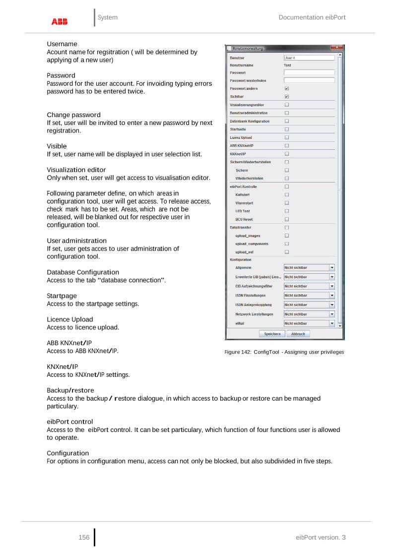
System Documentation eibPort
156 eibPort version. 3
Username Acount name for regsitration ( will be determined by applying of a new user)
Password Password for the user account. For invoiding typing errors password has to be entered twice.
Change password If set, user will be invited to enter a new password by next registration.
Visible If set, user name will be displayed in user selection list.
Visualization editor Only when set, user will get access to visualisation editor.
Following parameter define, on which areas in configuration tool, user will get access. To release access, check mark has to be set. Areas, which are not be released, will be blanked out for respective user in configuration tool.
User administration If set, user gets acces to user administration of configuration tool.
Database Configuration Access to the tab “database connection”.
Startpage Access to the startpage settings.
Licence Upload Access to licence upload.
ABB KNXnet/IP Access to ABB KNXnet/IP.
KNXnet/IP Access to KNXnet/IP settings.
Figure 142: ConfigTool - Assigning user privileges
Backup/restore Access to the backup / restore dialogue, in which access to backup or restore can be managed particulary.
eibPort control Access to the eibPort control. It can be set particulary, which function of four functions user is allowed to operate.
Configuration For options in configuration menu, access can not only be blocked, but also subdivided in five steps.

Documentation eibPort System
eibPort Version 3 157
Invisibler: Parameter categorie is blinded out. Level 1: Commissioning; only parameter will be shown, which will be necessary for start-up. Level 2: Standard Level 3: Extended access Level 4: Complet access to all parameters.
By mouse-over help (to pause awhile pointer of mouse to selected step) will be displayed, which settings in which level would be activated. Detail “false” means inhibition of settings, “true” means, that setting can be modified.
After modifiying the settings, you have to save them.
To delete a user A user will be erased with the help of the context menu (right click on user name in user overview).

158 eibPort version. 3
Object structure / Address space Documentation eibPort
10 OBJECT STRUCTURE / ADDRESS SPACE
eibPort emulates structure of comunications objects of EIB. That means, to every object can be allocated up to five group addresses. Therefor placing of group address, for example of an actor channel, can be emulated directly. In this way eibPort will be informed in every time about real state of actor (not group address) and expensive working with feedback can remain undone. This procedure simplifies creating of logical connections, because to every input object of gatter can allocated up to five group addresses.
10.1 EIBPORT ADDRESS SPACE:
eibPort supports 32 maingroups (in 2- oder 3-digits spelling). There are divided as follows:
0–15 real EIB-Address space Real address space will be sent from eibPort to EIB.
16–31 virtual EIB-Addres space Virtual address space will be used by eibPort in network and intra eibPort.
Based on this address division, real EIB–bus load can be reduced. One in network bound on centrical visualisation can directly activate or inactivate, for example a timer, without to burden EIB.
10.2 GENERAL SYNTAX
After first group address, following addresses have to set in brackets, separated by comma.
Example: 2/12(2/13,2/14,2/15,2/16)
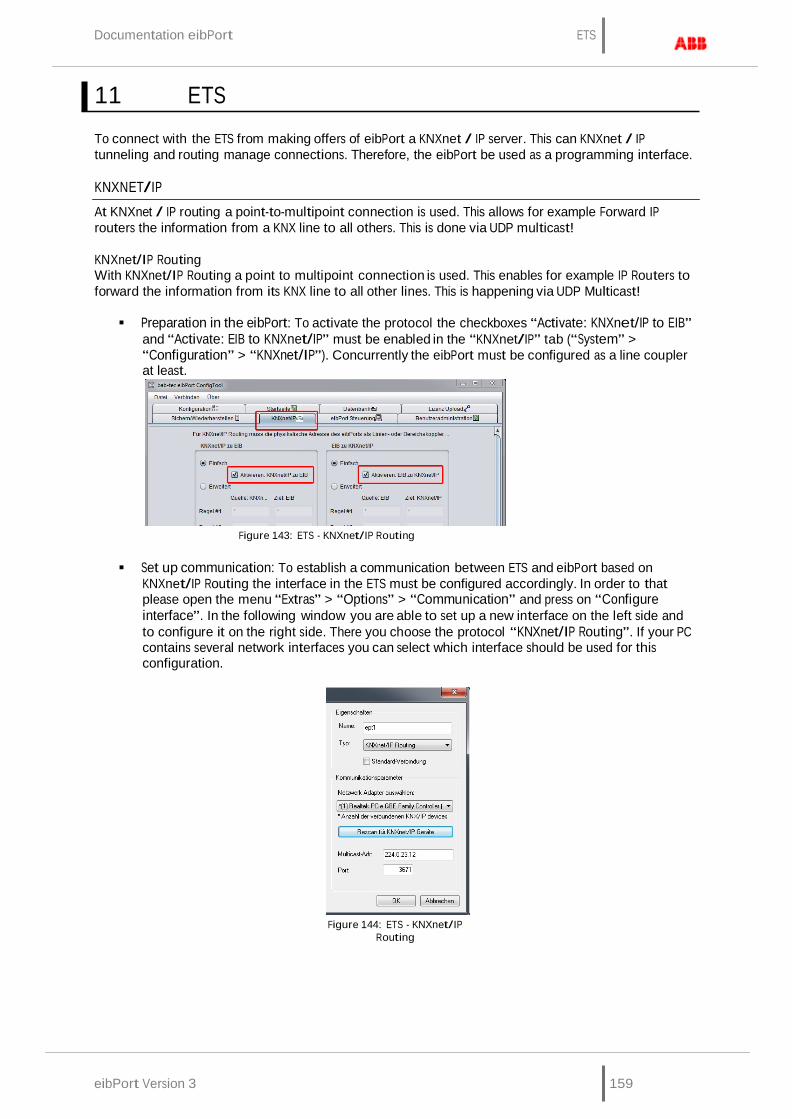
eibPort Version 3 159
Documentation eibPort ETS
11 ETS
To connect with the ETS from making offers of eibPort a KNXnet / IP server. This can KNXnet / IP tunneling and routing manage connections. Therefore, the eibPort be used as a programming interface.
KNXNET/IP
At KNXnet / IP routing a point-to-multipoint connection is used. This allows for example Forward IP routers the information from a KNX line to all others. This is done via UDP multicast!
KNXnet/IP Routing With KNXnet/IP Routing a point to multipoint connection is used. This enables for example IP Routers to forward the information from its KNX line to all other lines. This is happening via UDP Multicast!
Preparation in the eibPort: To activate the protocol the checkboxes “Activate: KNXnet/IP to EIB”
and “Activate: EIB to KNXnet/IP” must be enabled in the “KNXnet/IP” tab (“System” > “Configuration” > “KNXnet/IP”). Concurrently the eibPort must be configured as a line coupler at least.
Figure 143: ETS - KNXnet/IP Routing
Set up communication: To establish a communication between ETS and eibPort based on
KNXnet/IP Routing the interface in the ETS must be configured accordingly. In order to that please open the menu “Extras” > “Options” > “Communication” and press on “Configure interface”. In the following window you are able to set up a new interface on the left side and to configure it on the right side. There you choose the protocol “KNXnet/IP Routing”. If your PC contains several network interfaces you can select which interface should be used for this configuration.
Figure 144: ETS - KNXnet/IP
Routing

ETS Documentation eibPort
160 eibPort version. 3
KNXNET/IP TUNNELING
With KNXnet/IP Tunneling is used differently from “Routing” a point to point connection. Thereby the KNX Protokoll is been tunneled over an IP connection. Communcation subscriber are always a server and a client.
• Preparation in the eibPort: To enable the protocol there is a checkbox at the bottom of the
menu “advanced EIB (yabus) settings”. Further the eibPort has to have a subscriber address in the physical address settings. He must not be configured as Area- or line coupler. For this purpose there is an additional configuration array you will find in “Configuration” > “General” that is called “individual Address for KNXnet/IP Tunneling” where a deviating physical address can be entered in case of using KNXnet/IP Routing at the same time.
Figure 145: KNXnet/IP Tunneling
• Set up communication: To establish a communication between ETS and eibPort based on
KNXnet/IP Tunneling the interface in the ETS must be configured accordingly. In order to do that please open the menu “Extras” > “Options” > “Communication” and press on “Configure interface”. In the following window you can set up a new interface on the left side and configure it on the right side. There you choose the protocol “KNXnet/IP”. You get the opportunity to search the network after KNXnet/IP enabled devices, or type in the address of the desired device by yourself. A diagnostic assistant helps you with filtering the network traffic.
figure 146: ETS - KNXnet/IP
Tunneling

Documentation eibPort ETS
eibPort Version 3 161
EIBPORT USE AS A PROGRAMMING INTERFACE
To use the eibPort as a programming interface the "KNXnet / IP tunneling" protocol should be used. Tunneling is connection-oriented and can therefore be used both locally as well as via an Internet connection. Theoretically, a programming operation is also a KNXnet / IP routing connection is possible, but generally not recommended.
eibPort settings Select eibPort in "System"> "Configuration"> "Advanced Bank (yabus) Settings," select "KNXnet / IP tunneling." You may need to adapt to the "indiv Addr for KNXnet / IP tunneling "to make as to the description of" tunneling "section.
ETS settings Select the protocol here "KNXnet / IP" and searching for the appropriate dropdown menu eibPort and select from. The underlying fields fill up after, from automatically, via the "Diagnostic Assitent" the connection may be checked.
Are all the settings made you should be able in the ETS on the bus and group monitors to see and telegrams to send, and to program participants KNX.
Programming via the Internet For a connection over the Internet requires a valid eibPort the "default gateway" in its network settings. In addition, the router must be in place before the firewall or NAT rules accordingly. The communication between eibPort and ETS applies to the UDP port 3671 instead! Manually enter in the ET, the IP address in the box provided, since an automatic search for the devices for the drop-down list does not work via the Internet. Moreover, there must be activated with a remote connection to the mandatory "NAT mode".
Insert the eibPort into the ETS There is no ETS application for eibPort, because it will be programmed via the web front end. To reserve the physical address in the project and possibly filter tables can be created correctly, is a dummy application / device inserted into the project.
EXPORT GROUP ADDRESS OUT OF ETS
There is no ETS application for eibPort, because it will be programmed by its web-frontend. Therwith physical address will be reserved in project and if necessary, table of filter will be created correctly, one dummy-application has to inserted to the project.
Export group address out of ETS 3 To export group address out of ETS3, you have to proceed as follows:
Should group addresses will be transferred out of visualising project to eibPort, group addresses have to be expored by the help of OPC-export of OPC client in an ESF file. Therby all group addresses, which will be connected in project, will be written in ESF file.
Figure 147: ETS - ESF file export

ETS Documentation eibPort
162 eibPort version. 3
Export group address out of ETS4 To export group address out of ETS3, you have to proceed as follows: Please select in menu file-> data exchange (for example OPC). Dialoque „ export other data formats“ will appear. There you select second option “export to OPC-server” and define one storage place. Result of exporting is one *.esf file.
Figure 148: ETS 4 - ESF Export
In editor ESF file can uploaded to eibPort by “ESF upload & maintenance“. There it is also possible to modify settings if necessary.
GROUP ADDRESS STRUCTURE IN ETS 4
Note: Restricted compability with ETS4! In ETS4 please just use the group address structure as known from ETS 2/3. The use with the extended group address range resp the free group address structure is not posssible!
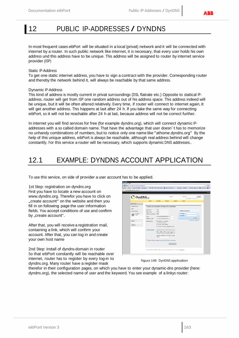
eibPort Version 3 163
Documentation eibPort Public IP-Addresses / DynDNS
12 PUBLIC IP-ADDRESSES / DYNDNS
In most frequent cases eibPort will be situated in a local (privat) network and it will be connected with internet by a router. In such public network like internet, it is necessary, that every user holds his own address und this address have to be unique. This address will be assigned to router by internet service provider (ISP)
Static IP-Address To get one static internet address, you have to sign a contract with the provider. Corresponding router and thereby the network behind it, will always be reachable by that same address.
Dynamic IP-Address This kind of address is mostly current in privat surroundings (DSL flatrate etc.) Opposite to statical IP- address, router will get from ISP one random address out of his address space. This address indeed will be unique, but it will be often altered relatively. Every time, if router will connect to internet again, it will get another address. This happens at last after 24 h. If you take the same way for connecting eibPort, so it will not be reachable after 24 h at last, because address will not be correct further.
In internet you will find services for free (for example dyndns.org), which will connect dynamic IP- addresses with a so called domain name. That have the advantage that user doesn´t has to memorize no unhandy combinations of numbers, but to notice only one name like “athome.dyndns.org” By the help of this unique address, eibPort is always be reachable, although real address behind will change constantly. For this service a router will be necessary, which supports dynamic DNS addresses..
12.1 EXAMPLE: DYNDNS ACCOUNT APPLICATION
To use this service, on side of provider a user account has to be applied.
1st Step: registration on dyndns.org First you have to locate a new account on www.dyndns.org. Therefor you have to click on „create account“ on the website and then you fill in on following page the user information fields. You accept conditions of use and confirm by „create account“.
After that, you will receive a registration mail, containing a link, which will confirm your account. After that, you can log in and create your own host name
2nd Step: Install of dyndns-domain in router So that eibPort constantly will be reachable over internet, router has to register by every log-in to dyndns.org. Many router have a register mask
Figure 149: DynDNS application
therefor in their configuration pages, on which you have to enter your dynamic-dns provider (here: dyndns.org), the selected name of user and the keyword. You see example of a linkys router:

164 eibPort version. 3
Public IP-Addresses / DynDNS Documentation eibPort
After storage of new settings, router will register by every log-in to dyndns.org. and will be assigned to selected domain name, according to the from internet provider received IP-address. This can be tested by “ping” instruction from windows. Concerning this you fill in “ping>selected domain>” and confirm it with “enter” . In case router will reply to this instruction, assigning of IP-address and name of domain is successful.
Figure 150: DynDNS Router settings

eibPort Version 3 165
Documentation eibPort Change the language
13 CHANGE THE LANGUAGE
Because all components of eibPort are so called Java-applets, you have to change language not in eibPort, but in Java VM. TJava will load up corresponding language files (if available) out of unit and displays desired speech. By “localisation function“ in editor, the language file can downloaded, modified and uploaded again.
Dialogue can also be seen in the localization language files that are already included in the editor. When you upload the revised language is intended file on a menu in the dialogue which language localization file contains the new. After that, the language will only be set in the Java VM. The default language setting of the Java machine depend on the language of the operating system on which it is installed.
Language setting of Java VM will be changed as follows:
In Windows on start -> settings -> systemcontrol Double click on java symbol Change to tab Java
Figure 151: Java Control Panel - change
of language
Under Java-Applet run time settings click on „display“ – Window Java runtime settings will open.
To enter desired language according to following syntax:
German -Duser.language=de English -Duser.language=en Swedish -Duser.language=se France -Duser.language=fr Spain -Duser.language=es Netherlands -Duser.language=nl Italian -Duser.language=it
Figure 152: Java Runtime settings - change of language
In case on client PC will be installed several Java versions, desired parameter has to enter in all runtime parameters. Should windows will use an older Java for one function, so language will also be set.
Control field closing with “ok” . Important: To close all browser windows, to restert browser completely.
After restart of browser and call up of eibPort, desired language will be displayed.

166 eibPort version. 3
Disclaimer Documentation eibPort
14 DISCLAIMER
1. Although bab-technologie gmbH always ensures with necessary accuracy, that information and content will be correct and on actual state of technology, information could contain technical inaccuracies and/or literal mistakes. bab-technology gmbH gives no guarantee or warrenties with regard to accuracy and correctness of information. bab-technology gmbH can not assume any liability and responsibility for mistakes or omissions in the content of technical documentations ( especially data sheets, documentation, assembly instructions, manuals etc.)
2. All informations, which can be extracted from technical documentation, will be granted – as far as permitted by law – without any explicit, conclusive or tacit responsibility of defects or warrenty. Informations contain no agreement of quality, describe no commercial quality and constitute no assurance of properties or no assurance with regard to applicability for a particular purpose.
3. Because our products will be developed and actualised constantly, informations of this documentation could diviate and no longer be adequate to current status. We are attempted to provide current innovations and modifications in our website. All used product designations of this manual are registered trademarks of respective companies.
4. Manufacturer can not assume responsibility for results of unit programming/parametrization; these will lie within responsibility of commisioning engineer.
5. bab-technologie gmbh gives no guarantee and will not be responsible for lost data or pictures, which are stored to a product (including returned products). Reasons for lost doesn`t play a part in this case. bab-technology gmbH assumes no warrenty , that products of bab-technology gmbH always will work faultlessly. Products of bab-technolgy gmbh must not be used in life sustaining systems or be used in other applications, in which malfunction could cause injuries or will lead to death.
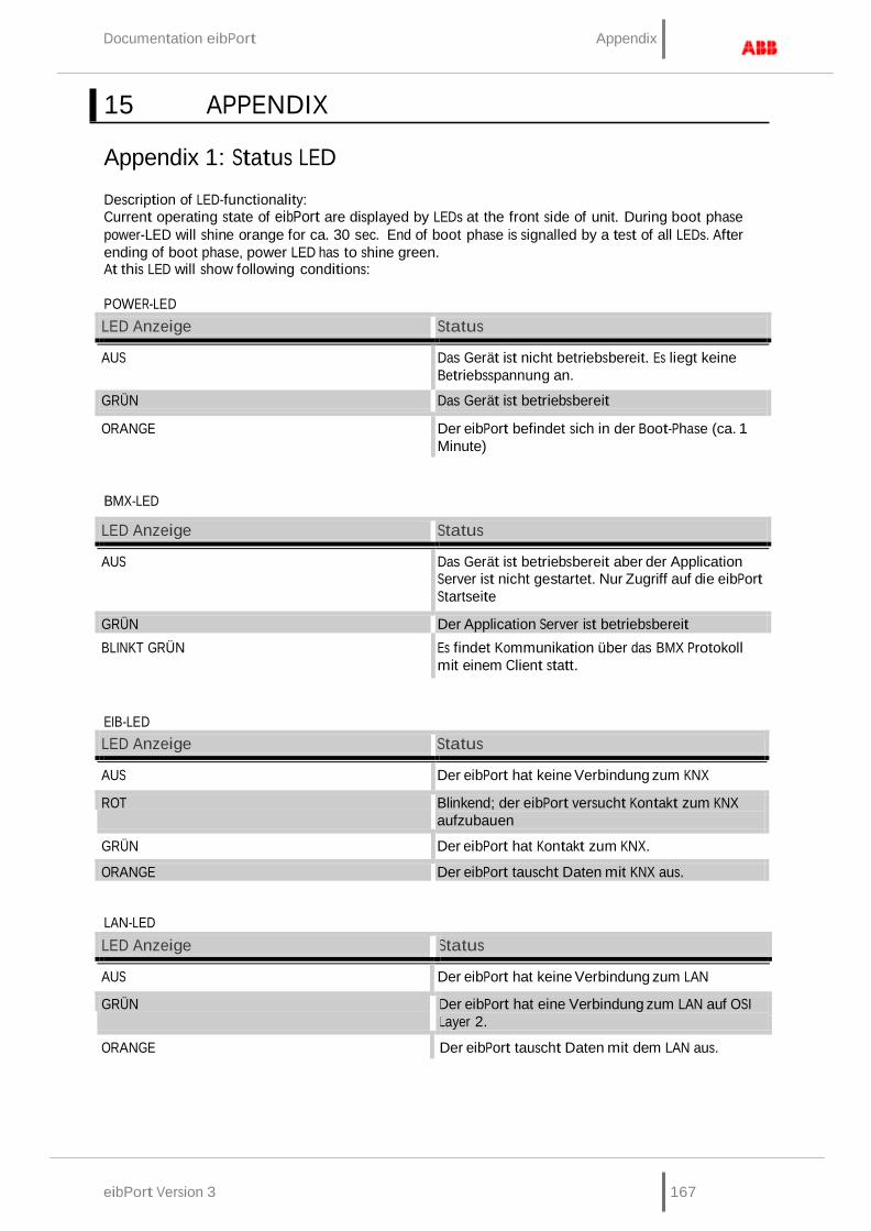
eibPort Version 3 167
Documentation eibPort Appendix
LED Anzeige Status AUS Der eibPort hat keine Verbindung zum LAN GRÜN Der eibPort hat eine Verbindung zum LAN auf OSI
Layer 2. ORANGE
15 APPENDIX
Appendix 1: Status LED
Description of LED-functionality: Current operating state of eibPort are displayed by LEDs at the front side of unit. During boot phase power-LED will shine orange for ca. 30 sec. End of boot phase is signalled by a test of all LEDs. After ending of boot phase, power LED has to shine green. At this LED will show following conditions:
POWER-LED LED Anzeige Status AUS Das Gerät ist nicht betriebsbereit. Es liegt keine
Betriebsspannung an. GRÜN Das Gerät ist betriebsbereit ORANGE Der eibPort befindet sich in der Boot-Phase (ca. 1
Minute)
BMX-LED
LED Anzeige Status AUS Das Gerät ist betriebsbereit aber der Application
Server ist nicht gestartet. Nur Zugriff auf die eibPort Startseite
GRÜN Der Application Server ist betriebsbereit BLINKT GRÜN Es findet Kommunikation über das BMX Protokoll
mit einem Client statt.
EIB-LED LED Anzeige Status AUS Der eibPort hat keine Verbindung zum KNX ROT Blinkend; der eibPort versucht Kontakt zum KNX
aufzubauen GRÜN Der eibPort hat Kontakt zum KNX. ORANGE Der eibPort tauscht Daten mit KNX aus.
LAN-LED
Der eibPort tauscht Daten mit dem LAN aus.

168 eibPort version. 3
Appendix Documentation eibPort
Appendix 2: Control characters for value objects
In some jobs of the eibPort it is able to assigns value objects. Therefore it is necessary fill in control characters into the continous text depending on the chosen EIS Value. At first the the EIS Value has to be parameterized. Values are placed between replacement characters “%” (always without quotes) and “f” ( to end the replacement characters string) within the text. With all numeric values the following format should be used:
%[Amount of integer digits.Amount of decimal digits]f
These replacement characters can be placed anywhere in the text.
Example: A floating point digit should be displayed with 5 integer digits and 2 decimal digits. Text entries:
“ ... Text %5.2f Text ...”
Should the prefix be shown in the text, the following entries has to be done. Text entries:
“ ... Text -5.2f Text…”
Should be displayed the appropriate amount of digits correctly in the text the following entries has to be done:
“... Text %.1f Text…”
If a percent sign should be displayed in the text, the sign has to be entered twice:
“The tank is filled up %.1f%%.” Or (without decimal places): „The tank is filled up %.0f%%.“
The following text is then be displayed:
“The tank is filled up 82.3%.”
Is a EIS 3 or EIS 54 type value chosen, a “%s” must be entered into the continous text.

eibPort Version 3 169
Documentation eibPort Appendix
Appendix 3: Technical data
Operating voltage : 10- 30V Power consumption: <= 5 W Bus voltage: over EIB
Important : Throttled EIB bus voltage must not be used for operating voltage!
eibPort ownes for data buffering a gold-cap condensor, which will guarantee buffering of internal clock by breakdown of operating voltage for nearly ½ hour. Data remain stored in flash steady. t.
Climatic resistance: according EN 50090-2-2 Ambient temperature: 0 - 35°C Storage temperature: -20 - +70°C Re. humidity (non condensing): 5% - 80%
Mechanical data Measures: Rail mounted device (width 8 TE á 18 mm) Housing: Plastic Weight: ca. 0,4 kg Assembling: Hat rail mounting after EN 50022-35x7,5 Protection class: IP20 (EN 60529)
Other device properties: Operating system: Embedded Linux Processor: Vortex 86DX@600Mhz Cooling: passive, fanless Ethernet: Fast Ethernet IEEE 802.3u 100Base-T KNX: via KNX bus clamp o. Powernet KNX: screw clamp on network coupler additional EnOcean: antenna with SMA Anschluss (Only KNX)
Software: integrated Browser visualisation;
integrated commissioning software; KNX/IP-Server
Memory: 256 Mbyte SD-RAM / 4Gbyte Flash (Micro SD-Card)
EIB-Data points Management of complete KNX group addresses
EIB-Memory History memory (500.000 Telegrams)

Appendix Documentation eibPort
170 eibPort version. 3
Appendix 4: camera
By eibPort, pictures of network cameras will be displayed directly in visualisation or in a seperated windows. With the function event camera, automatically will be changed to visualisation page, rsp. window of camera pictures will be placed in forefront, by triggering through respective group address.
To integrate camera Every network-enabled camera can be integrated in visualisation. To dipllay camera picture in its own window, camera element “ as icon” has to be inserted. In data field “URL” you have to enter the complete network path to the camera, with prefixed HTTP: (for example: http://192.168.1.2/record/curent.jpg) b
To display directly camera pictures as a picture in visualisation, option „as icon“ must not be activated. . In data field “URL” you have to enter the complete network path to the camera, with prefixed HTTP: (for example: http://192.168.1.2/record/curent.jpg)
Please note: How you call up picture memory of camera, depends on manufacturer and model of your camera. Please read operation manual of your nertwork camera or please get informed on website of manufacturer. .
MJPEG-camera To integrate MJPEG-streams in visualisation, option „MJPEG-camera“ has to be activated and path to MJPEG stream of camera has to be connnected.
Event camera To desplay camera pictures automatically in separat window, after triggerinmg by respective group address, option „as icon“ has to be activated. Um das Kamerabild bei Auslösung durch die entsprechende Gruppenadresse automatisch in einem eigenen Fenster erscheinen zu lassen, muss die Option „als Icon“. . In data field “URL” you have to enter the complete network path to the camera, with prefixed HTTP: (for example: http://192.168.1.2/record/curent.jpg)
Please note: For this picture function, camera has to possess its own cache, in which pictures will be stored as JPEG files. Path of picture cache depends on manufacturer of camera. Therefore please read operation manual of your camera. In case, path should not be known, you can find for download a helpful program under http://www.go1984.de in download area. This program will know most of current IP-camera models
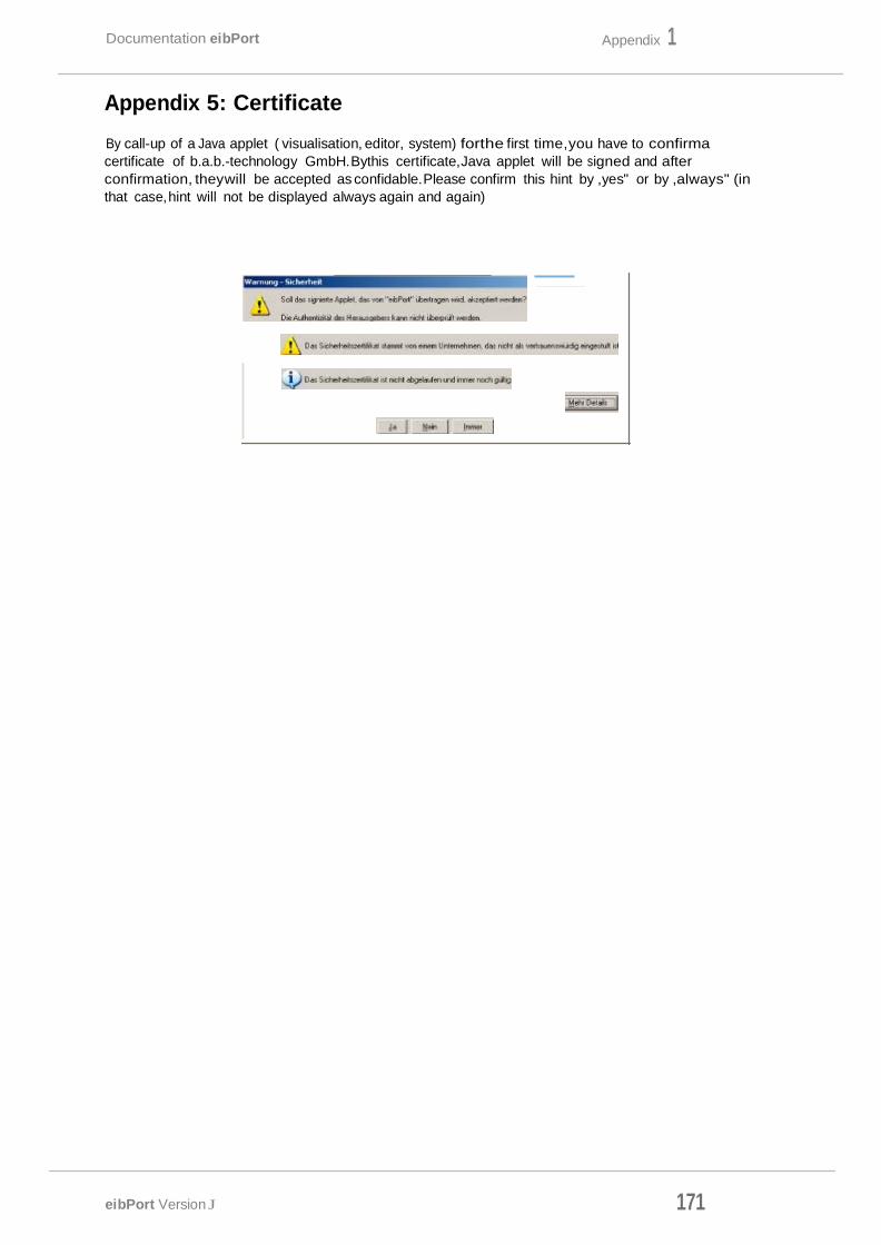
171 eibPort Version J
Appendix 1 Documentation eibPort
Appendix 5: Certificate
By call-up of a Java applet ( visualisation, editor, system) forthe first time,you have to confirma certificate of b.a.b.-technology GmbH.Bythis certificate,Java applet will be signed and after confirmation, theywill be accepted as confidable.Please confirm this hint by ,yes" or by ,always" (in that case, hint will not be displayed always again and again)
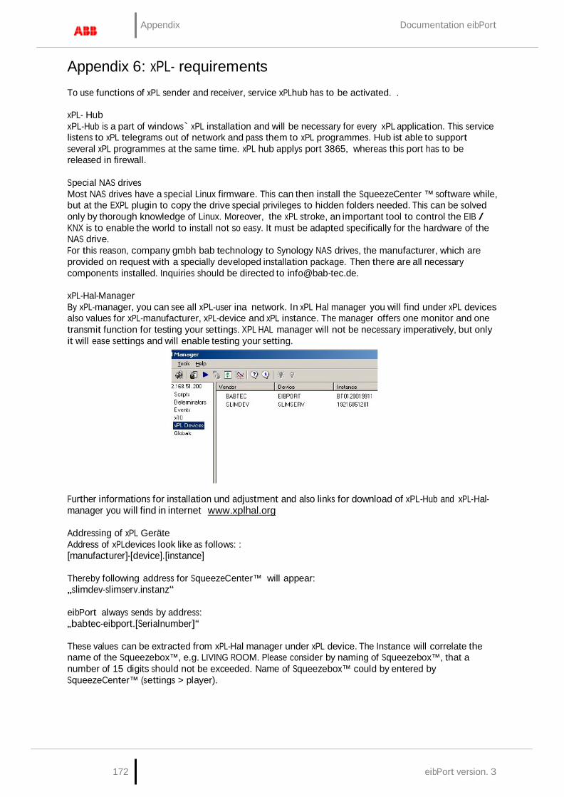
172 eibPort version. 3
Appendix Documentation eibPort
Appendix 6: xPL- requirements To use functions of xPL sender and receiver, service xPLhub has to be activated. .
xPL- Hub xPL-Hub is a part of windows` xPL installation and will be necessary for every xPL application. This service listens to xPL telegrams out of network and pass them to xPL programmes. Hub ist able to support several xPL programmes at the same time. xPL hub applys port 3865, whereas this port has to be released in firewall.
Special NAS drives Most NAS drives have a special Linux firmware. This can then install the SqueezeCenter ™ software while, but at the EXPL plugin to copy the drive special privileges to hidden folders needed. This can be solved only by thorough knowledge of Linux. Moreover, the xPL stroke, an important tool to control the EIB / KNX is to enable the world to install not so easy. It must be adapted specifically for the hardware of the NAS drive. For this reason, company gmbh bab technology to Synology NAS drives, the manufacturer, which are provided on request with a specially developed installation package. Then there are all necessary components installed. Inquiries should be directed to [email protected].
xPL-Hal-Manager By xPL-manager, you can see all xPL-user ina network. In xPL Hal manager you will find under xPL devices also values for xPL-manufacturer, xPL-device and xPL instance. The manager offers one monitor and one transmit function for testing your settings. XPL HAL manager will not be necessary imperatively, but only it will ease settings and will enable testing your setting.
Further informations for installation und adjustment and also links for download of xPL-Hub and xPL-Hal- manager you will find in internet www.xplhal.org
Addressing of xPL Geräte Address of xPLdevices look like as follows: : [manufacturer]-[device].[instance]
Thereby following address for SqueezeCenter™ will appear: „slimdev-slimserv.instanz“
eibPort always sends by address: „babtec-eibport.[Serialnumber]“
These values can be extracted from xPL-Hal manager under xPL device. The Instance will correlate the name of the Squeezebox™, e.g. LIVING ROOM. Please consider by naming of Squeezebox™, that a number of 15 digits should not be exceeded. Name of Squeezebox™ could by entered by SqueezeCenter™ (settings > player).
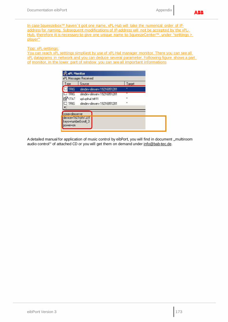
Documentation eibPort Appendix
eibPort Version 3 173
In case Squeezebox™ haven`t got one name, xPL-Hub will take the numerical order of IP-address for naming. Subsequent modifications of IP-address will not be accepted by the xPL- Hub, therefore it is necessary to give one unique name to SqueezeCenter™, under “settings > player”
Tipp: xPL-settings: You can reach xPL settings simpliest by use of xPL-Hal manager monitor. There you can see all xPL datagrams in network and you can deduce several parameter. Following figure shows a part of monitor, in the lower part of window you can see all important informations
A detailed manual for application of music control by eibPort, you will find in document „multiroom audio control“ of attached CD or you will get them on demand under [email protected].
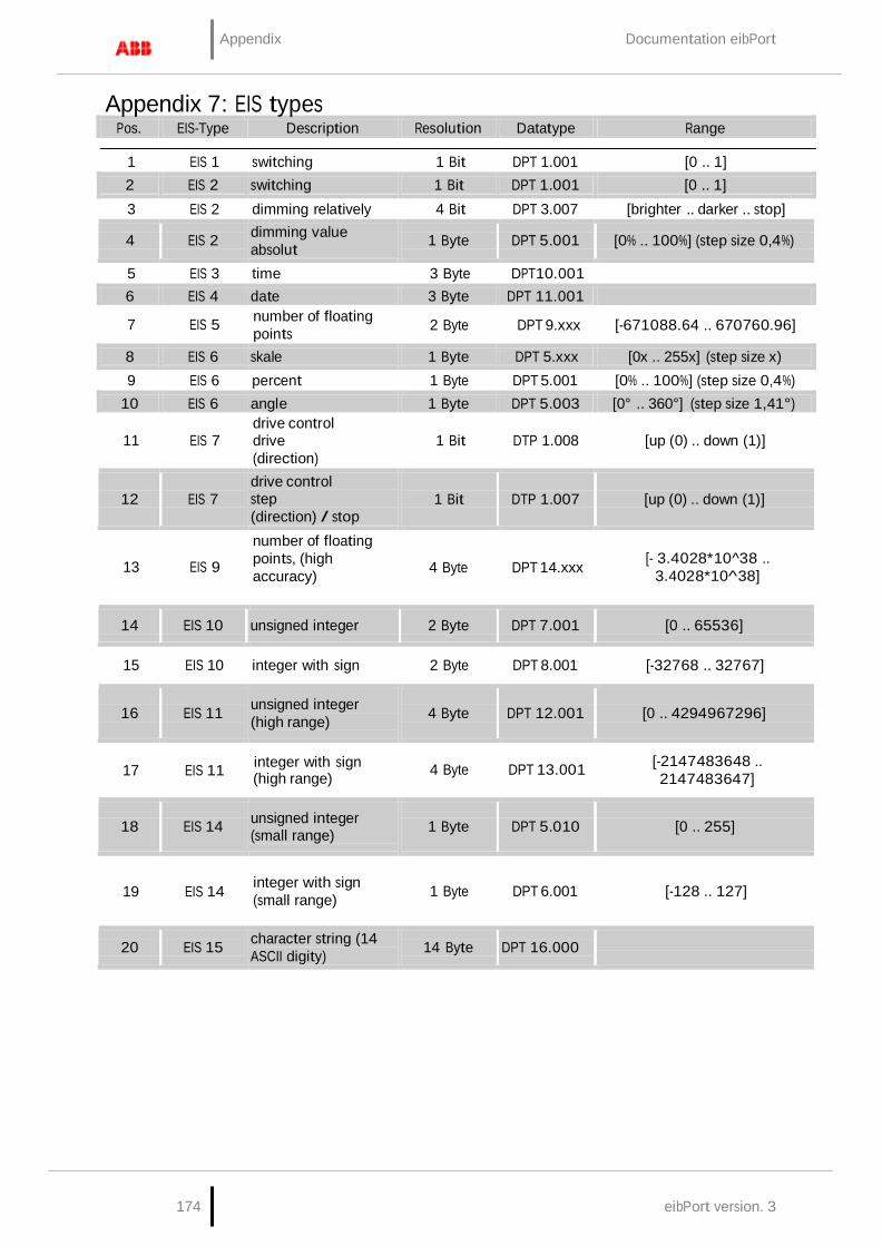
Appendix Documentation eibPort
174 eibPort version. 3
Pos. EIS-Type Description Resolution Datatype Range
7 EIS 5
17 EIS 11
19 EIS 14
Appendix 7: EIS types
1 EIS 1 switching 1 Bit DPT 1.001 [0 .. 1]
2 EIS 2 switching 1 Bit DPT 1.001 [0 .. 1] 3 EIS 2 dimming relatively 4 Bit DPT 3.007 [brighter .. darker .. stop]
4
EIS 2 dimming value absolut
1 Byte
DPT 5.001
[0% .. 100%] (step size 0,4%)
5 EIS 3 time 3 Byte DPT10.001
6 EIS 4 date 3 Byte DPT 11.001 number of floating points 2 Byte DPT 9.xxx [-671088.64 .. 670760.96]
8 EIS 6 skale 1 Byte DPT 5.xxx [0x .. 255x] (step size x) 9 EIS 6 percent 1 Byte DPT 5.001 [0% .. 100%] (step size 0,4%)
10 EIS 6 angle 1 Byte DPT 5.003 [0° .. 360°] (step size 1,41°)
11 EIS 7 drive control drive (direction)
1 Bit DTP 1.008 [up (0) .. down (1)]
12
EIS 7
drive control step (direction) / stop
1 Bit
DTP 1.007
[up (0) .. down (1)]
13 EIS 9
number of floating points, (high accuracy) 4 Byte DPT 14.xxx
[- 3.4028*10^38 ..
3.4028*10^38]
14
EIS 10
unsigned integer
2 Byte
DPT 7.001
[0 .. 65536]
15 EIS 10 integer with sign 2 Byte DPT 8.001 [-32768 .. 32767]
16
EIS 11 unsigned integer
(high range)
4 Byte
DPT 12.001
[0 .. 4294967296]
integer with sign (high range) 4 Byte DPT 13.001
[-2147483648 .. 2147483647]
18
EIS 14 unsigned integer
(small range)
1 Byte
DPT 5.010
[0 .. 255]
integer with sign (small range) 1 Byte DPT 6.001 [-128 .. 127]
20
EIS 15 character string (14 ASCII digity)
14 Byte
DPT 16.000

Documentation eibPort Appendix
eibPort Version 3 175
Pos.
Datatype
Description
Resolution EIS Type
Range
11 DPT 6.001
17 DPT 12.001
4 Byte EIS 9
Appendix 8: DTP (data point type)
1 DPT 1.001 switching 1 Bit EIS 1 [0 .. 1]
2 DPT 1.001 switching 1 Bit EIS 2 [0 .. 1]
3 DTP 1.007 drive control step (direction) / stop
1 Bit EIS 7 [up (0) .. down (1)]
4 DTP 1.008 drive control
(direction) 1 Bit
EIS 7 [up (0) .. down (1)]
5 DPT 3.007 dimming relative 4 Bit EIS 2 [brighter .. darker .. stop]
6 DPT 5.xxx scale 1 Byte EIS 6 [0x .. 255x] (step size x)
7 DPT 5.001 dimming value absolut 1 Byte EIS 2 [0% .. 100%] (step size 0,4%)
8 DPT 5.001 percent 1 Byte EIS 6 [0% .. 100%] (step size 0,4%) 9 DPT 5.003 angle 1 Byte EIS 6 [0° .. 360°] (step size 1,41°)
10
DPT 5.010 unsigned integer (low range)
1 Byte
EIS 14
[0 .. 255]
integer with sign (low range) 1 Byte EIS 14 [-128 .. 127]
12 DPT 7.001 unsigned integer 2 Byte EIS 10 [0 .. 65536] 13 DPT 8.001 integer with sign 2 Byte EIS 10 [-32768 .. 32767]
14 DPT 9.xxx number of floating points 2 Byte EIS 5 [-671088.64 .. 670760.96] 15 DPT 10.001 time 3 Byte EIS 3
16 DPT 11.001 date 3 Byte EIS 4 unsigned integer (high range) 4 Byte EIS 11 [0 .. 4294967296]
18
DPT 13.001 integer with sign (high range)
4 Byte
EIS 11 [-2147483648 .. 2147483647]
19 DPT 14.xxx number of floating points (high accurarcy)
[-3.4028*10^38 .. 3.4028*10^38]
20
DPT 16.000 Character string (14 ASCII digits)
14 Byte
EIS 15