Brown Boveri Review - ABB
56
Brown Boveri Review January 1974, Volume 61 Baden/Switzerland 1 59 367.C BROWN BOVERI
-
Upload
khangminh22 -
Category
Documents
-
view
0 -
download
0
Transcript of Brown Boveri Review - ABB

Brown Boveri Review
January 1974, Volume 61 Baden/Switzerland
1 59 367.C BROWN BOVERI
Brown Boveri Review
January 1974, Volume 61 Baden/Switzerland p. 1-60
The Brown Boveri Review appears monthly No article or illustration may be reproduced without the express permission of the publisher
Published by BBC Brown, Boveri & Company, Limited, CH-5401 Baden/Switzerland Printed by Buchdruckerei Effingerhof AG, Brugg Obtainable direct from the publisher
Cover: Blast furnace blower driven by a steam turbine at the Port Kembla plant of Australian Iron and Steel Pty. Ltd. The steam turbine is rated 29 500 kW at 3500 rev/min, live steam 420 bar at 454 °C, cooling water temperature 21 °C
Contents Page
G. A. Burkhard:
Steam Turbines for Industry 4
D. Huhle: Combined-Cycle Plants for Generating Economical Medium-Load Power 9 A. Spechtenhauser:
High-Power Turbines for Compressor Drives 17
P. Magajna: Automatic System Decoupling for Industrial Plants 28 F. Peneder, H. Butz and M. Fiorentzis: Protection of Industrial Generators and Industrial Networks
Taking the Excitation System into Account 36
F. Peneder and H. Butz: Exciter Systems for Three-Phase Generators in Industrial and Medium-Size Power Stations 41 W. Andres: Automation of Industrial Turbines 51
Brown Boveri Rev. 1-74

Steam Turbines for Industry
G. A. Burkhard
The steam turbine in an industrial context where it forms an integral pari of the machinery needed to carry out a pro-duction process, has to meet Jar more complicated require-ments than when it is used solely for generating electricity in a power Station. Apart from mechanieal energy, often over a wide ränge of speeds, there is a de man dfor electricity, hoth in isolated operation and when running in parallel with the supply network, heat energy in a form suitable for the process in question, and utilization of the waste heat for heating purpose in order to improve cost effectiveness. Only by carefully matching the steam turbine to the particular circumstances of the process involved can the best possible Solution be found. This requires close Cooperation between the turbine manufacturer and users in the various industries.
trical power generated. In most cases there is no State of equilibrium in this respect which, in isolated operation, i.e. with no link to a large electricity supply network, leads to the following measures. In the event of small and short-lived deviations from this equilibrium condition, the electrical Output can be increased by venting off excess back-pressure steam, or the Output for heating can be raised by diverting live steam through a bypass into the back-pressure network. Both kinds of operation incur losses and are thus uneconomical. For efficient isolated duty the turbine in most cases needs a condensing section which, when necessary, can use low-pressure steam to increase the output of electricity. The live steam conditions and throughput capacity of the individual turbine sections of an extraction/condensing machine have to be chosen so that under any operating conditions the turbine can meet the demand for heating energy and electricity, and at the same time generate as many kilowatt-hours as possible per year in back-pressure operation, in order to keep the heat transfer to the water circulating in the condenser as low as possible. Some branches of industry require such a large proportion of electricity that a straightforward condensing turbine or reheat turbine is used. Additional back-pressure or extraction/back-pressure turbosets are often installed to provide steam for the industrial process or for heating purposes. If suitable public electricity networks are available, for general economic reasons the aim should be to operate industrial back-pressure turbosets in parallel with the public system. The same reasoning leads to district heating
Introduction
Steam turbines employing back-pressure techniques are widely used in industrial applications. They expand the high-pressure steam supplied from a steam generator down to the value needed for the industrial process or for heating purposes. The energy drop between the two steam conditions is converted into mechanical energy, and usually into electricity by means of generators. In cases where more than one pressure level is required the ex-traction turbine may be used. This is equipped with bleed-points at the appropriate pressure stages. The exhaust steam conditions are always defined by the pressure, which can be controlled easily and accurately. The degree of superheat or wetness of the steam at the turbine exhaust is dependent on the live steam conditions, back-pressure and efficiency of the turbine; it is difficult to vary, and then only within narrow limits. In many cases, therefore, the process steam needs to be conditioned either by sub-sequent superheating or cooling. With all turbine working on the back-pressure principle there is a fixed relationship between the required flow rate of process or heating steam and the mechanical or elec-
Table I: Major industries having their own heat and power supply
Industry Number of turbines delivered [%]
Pulp and paper 17 Cane sugar 11-5 District heating 9-7 Salts and soda 9-5 Chemicals (basic materials) 9-5 Petrochemicals etc. 9 Beet sugar 8-5 Textiles 7-1 Aluminium 5-1 Steel, copper, nickel 3-3 Food 3-2 Motor cars 3 Others 3-6
4 Brown Boveri Rev. 1-74

Fig. 1 - Turbosets in a beet sugar factory Location: Jedula, Spain Output per turboset: 4 MW Live steam: 30 bar, 400 °C Process steam: 3-8 bar
Fig. 2 - Compressor with drive turbine in a chemical works
Location: Grangemouth, Great Britain Turbine rating: 2-5 M W at 7600 rev/min Live steam: 39 bar, 370°C
and generating power plants in industrial areas where the heat requirement of the individual factories is relatively small, and also in residential and business districts [1],
Applications and Design Variations
In addition to producing process steam and electricity, steam turbines are often employed to drive pumps, blow-ers and compressors. Again, both back-pressure or con-densing machines can be used. Which kind of turbine is best suited to a given production process depends not only on the technical requirements,
but also to a large degree on local conditions. In coun-tries without extensive power supply systems it is common for the plants to operate independently. Fuel costs also play a major role in the design of a plant. If cheap primary energy is available, minimum capital outlay and simple operation are rated higher than a particularly high effi-ciency. The most important branches of industry having their own supplies of heat and power are summarized in Table I. The smallest turbines specifkally tailored to a particular industry are sometimes known, slightly disparagingly, as 'sugar turbines'. These are back-pressure machines with ratings of 2 to 4 MW for the cane sugar industry.
BROWN BOVERI 157054.
BROWN BOVERI 157081.1
Brown Boveri Rev. 1-74

MAX muTC» NYTTie Last. soo
BROWN BOVERI
Fig. 3 - Turbosets for process steam in a paper miII and for public power supply Location: Karskär, Sweden Rating of largest turbine: 125 M W Live steam: 71 bar, 485°C Process s team: 5 bar and 13 bar
Their rating corresponds to the heat and power require-ment of a cane sugar factory, the production capacity of which is determined by the amount of cane that can be obtained economically from the neighbourhood of the factory. The residue of the sugar cane, bagasse, is often used as fuel. The fuel costs in this case is not a major factor in calcu-lating the economics, and the efficiency of the turbine is
therefore not very important. On the other hand, it must be simple and rugged and, during the months of the sugar campaign, absolutely reliable. Owing to the short period of operation each year there is no question of purchasing standby units. The live steam conditions are generally low, about 10 to 25 bar at 250 to 300°C, and process steam is drawn from the turbine exhaust branch at some 2 to 3 bar. Extensive standardization of the live steam and back-pressure con-ditions seem possible, and this would have a beneficial effect on production costs. Factories producing beet sugar are less restricted as re-gards size and generally use turbines with higher steam rates and Outputs (Fig. 1). They are commonly located in countries with a highly developed agriculture, or in indus-trialized countries. The fuel in most instances is expensive and it is therefore worth obtaining turbines with higher live steam data and better efficiency. Here too, the back pressure is on average about 3 bar. In terms of rating and live steam conditions, similar turbines are to be found in factories processing a variety of salts, such as common salt, soda, potash, etc. These machines, however, are of much more varied and complex design. In addition to low-pressure process steam at about 1 to 3 bar, needed here too for boilers and evapo-rator plant, higher pressure steam at 6 to 12 bar, or more, is also required. Under these circumstances extraction/ back-pressure turbines are used. Back-pressure turbines for driving compressors are also frequently used in in-dustries of this kind (Fig. 2). The chemical industry is among the most important users of back-pressure, extraction/back-pressure and also ex-traction/condensing turbines, with ratings up to 50 MW and more. Very high live steam conditions are here the general rule, for instance 170 bar at 535 °C with extraction at 10 to 12 bar and back-pressure steam at 1-3 to 4 bar. The wide variety of processes in the fields of petrochemi-cals etc., has led to special-purpose steam turbines adapted to suit the particular Service conditions. Live and process steam data spanning a broad ränge do not lend themselves to stereotyped turbine designs. High ratings with high efficiencies are required in the pulp and paper industry. While pulp factories and the smaller
Fig. 4 - Turbosets in an alumina works
Location: Gove, Northern Australia Rating per turboset: 35 MW Live steam: 89 bar, 520°C Process steam: 5 bar
ssis.
BROWN BOVERI 162266.1
6 Brown Boveri Rev. 1-74

3 T3 C
03 U >> C 1> u <u
<D o
oa c £ o j-I m
-o <u — <U •o D c i— 3
c o <u t>0
J D
3 es H
<u n .5 ° 1» (X ' S p. £ o U
3 &
C 1) o (h l>
- &0 O . S
C/D u g S & 2 -o c o
l- T3 — C o o X w
o & c P o o
s ja x ™ W x> u (L) CS
u & O
<u O TD </> C O " 3 « <u
<D I s 3 u « c3 §3 cq
o Cd &
i - X Oh yj i> 60 e CS
3 5 i -
<u 6
c <U
CS •O
U OH £_• -a e o
£ es <u <u £ > u
J S £ ,
00 o -S 0 0 'S Di 's
c
#o es CJ n <
o
m m i l I o
i ©
so I l o
—< in
o o o o o m o o o o T—< i n m r^l r - m F-H
t i 1 | ? t
m — in I N N
o
i o
2 I I l m <N
o o o o
C") O ^ * m o O +•> in <N -st
cn
m O xr
o m O
in O oo
<N O oo
O tM
m Ös
in 2 os
o O <N 2 ?
O m
m m m o m O in o in o o O o
OS 'S" m TT r - CN O so ON TT m r-( i i1 ? t o l i 1 J
OO in i— OO i n OO r- in m <N ös i n m TT OS
so o o i n o in O O o O O O O o O Q * Q Q 1 -*—' 1 * '
m cn in m i n i n i n in <N i n SO <N -H sö (N — — Ö ö —
in in
in m — O ot 2 £ S - <s n
o m i n i n m o i n i n o i n i n o i n i n O o i n i n oo i n i n o 0 4 OS m ( N ( N 0 0 CO m r - m oo m o r - 0 4 m r o o
i n i n i n i n m Tt- i n i n i n i n m m m i n m m o o O o O O o O o o O O o o o O o o o o O O
— J +-• -t-i ^ -*-» —»
o o o o o o o o o o o o m m o o o i n o o o o f > oo m 0 0 r a m o m o r - Q r o <N 5 o i—i SO - o
<N (N <N <N m m i n m <N TT i n Tl- m (N m <N m •<t
o m o <N m m <N <N m o
SO i n oo m m i n m i n o o i—i t-H o i n O oo <N r—4 m SO i n I—H m r- — so oo o — .—i 00 so so o cn i—i —H — -
o o o o o o O O o o SO o o o
o o O o O o o
o i n 00 o 4-t o m i n m o
o o so o m oo i n
i n
CN SO <N so o
1—1 sö r-H m m i—i 00 so m m — r—l — m (N
m
m m so
i n o m
<N i n
0 0 o i n o r - i n m
OO SO
O o o O o f n o O o — O l
O o 0 o o SO
o o o O O q s i n o o Tt- SO oo
•—i <N '—1 m 'S- 'S"
o m r o O 1—1 O r - O
Q <N
c o
CS
CS T3 <3 s 1/5 <" g l « s C/3 —» .£5
Cfl 03 <-< 22 <» « S « — £ s u cj U 05 $ U
B <D cj O i-u PL,
£ X) .3 5 S 03 t- "3 n I) E •q ft 3 3 es Dh & <
cS u t-l O
a •• c '-S CS & S «j Dhj: g 9 «ri u • u
CS o 3 <D O CS I « p 1> CS X °
Ü O Ü • ^ - ' S R 3 Ph H PH CO D £ O .ä «r D
Brown Boveri Rev. 1-74

162339.1 BROWN BOVERI
Fig. 5 - The world's largest compressor turbine during assembly Location: Skikdu, Algeria Rating: 90 MW at 3600 rev/min Live steam: 68 bar, 450 °C
board and paper mills employ relatively small back-pres-sure machines with modest steam conditions, especially in countries overseas, the big pulp and paper works in the North often need extraction/back-pressure and extrac-tion/condensing turbines with ratings of up to 50 MW, or more. In hardly any other industry is the emphasis on efficiency so great as in the large paper mills of certain countries possessing little fuel (Fig. 3). Process steam for the pulp boilers and for heating the drying drums of the paper machines is extracted at 2-5 to 5 and 10 to 14 bar, respectively. Alumina plants in the aluminium industry have a heavy demand for heat. The total power rating of the back-pressure turbines installed in a large works can be more than 100 MW. To increase reliability and make operation more flexible this capacity is divided between a number of units (Fig. 4). In the production of iron and steel, condensing turbines with ratings from 25 to 60 MW are used to drive blast furnace blowers. Waste gas resulting from the process is employed as the source of primary energy, and so does not figure very prominently in the cost calculation. The biggest turbines at present for driving compressors, with ratings up to 90 MW at the coupling, are in service in plant for liquefying natural gas (LNG) (Fig. 5). Units with capacities of 120 to 180 MW are ready to go into production [2], Mainly extraction/condensing turbines with ratings of up to 50 MW and often impressive live steam conditions are found in the motor car industry. Heating steam is drawn off at 2-5 to 3-5 bar.
Finally, mention must be made of steam turbines for public district heating plant. In many cases their basic designs are similar to industrial turbines. Stations supply-ing only heat are usually equipped with back-pressure or extraction/back-pressure machines. Depending on the flow temperature chosen for the hot water, the steam pressure at the turbine exhaust is generally about 1-5, 4 or 12 bar. Refuse incineration plants operate with very low live steam data and ratings up to perhaps 25 MW, while oil-fired district heating stations work with live steam up to 110 bar at 520 °C and turboset unit ratings of 60 MW and more. In countries where electricity is generated predominantly by thermal means the power stations feeding the public grid often contain large extraction/condensing sets with terminal ratings up to 285 MW and heat Outputs of up to 280 Gcal/h for district heating the neighbouring towns. Table I illustrates the widely varied applications and designs of about 500 turbines ordered from the Brown Boveri Group and their licencees in recent years for indus-trial use.
Outlook
The made-to-measure approach adopted previously in the industrial steam turbine sector was expensive. Manu-facture at reasonable cost demands the production of types or, if possible, series of identical, or at least similar machines. An adaptable ränge of Standard models enables us to offer industrial steam turbines to cover the majority of applications without involving special designs. When a new production facility is planned, early contact between the process engineer and the manufacturer of the thermal plant leads in almost every case to lower cost. The engineer will possibly adapt his process to the machines already on the market, or give the turbine manufacturer an opportunity to modify his product ränge in good time to meet a future market need.
Bibliography
[1] R. Hohl: District heating for Switzerland. Brown Bo-veri Rev. 60 1973 (6) 252-264.
[2] A. Spechtenhauser: High-power turbines for compres-sor drives. Brown Boveri Rev. 61 1974 (1) 17-27.
8 Brown Boveri Rev. 1-74

Combined-Cycle Plants for Generating Economical Medium-Load Power
D. Huhle
As a result of the large increase in energy consumption over the past two decades, turbine generator units in the 400 to 1300 MW size ränge have become economic in the indus-trialized countries. With such large units, and in particular for those operating in nuclear power plants, it is advisable, for economic and operational reasons, to maintain a constant load close to the maximum over as many operating hours as possible. In other words these turbosets are installed, in the majority of cases, as base-load plants. The annual and daily load swings which the electric supply Utilities have to meet amount, in the majority of distri-bution systems, to about 50% of the maximum peak demand. In densely populated areas where the majority, or even all plants are thermal, the medium and peak-load requirements are still met by older conventional units. These are often not entirely suited to the required mode of operation with daily or even more frequent start-ups and shutdowns, and in addition they often have very high heat rates and thus inflate the average generation costs. There is therefore a need for specially designed medium-load power plants which will operate between 3000 and 4000 hours per annum and which should meet the following requirements:
Rapid, scheduled start-up and shutdown capability using a suitable automation system.
- Simple, reliable and rugged design. - Low costs per installed kilowatt. - Low heat rate. - Insignificant pollution of the environment. This is of
particular importance when the medium-load power plant is situated close to consumer and housing areas in order to relieve the transmission lines.
These requirements are almost ideally met by a combined cycle plant similar to that currently being built by Brown Boveri in Cooperation with a Dutch client1. The following is a brief description of this plant and shows one of the methods used by Brown Boveri in building com-bined cycle plants.
Introduction
The improved fuel qualities of light oil and natural gas have contributed to the increase in the availability of gas turbines. New blade materials together with blade cooling and rotor cooling techniques used by BST2 permit gas turbines to be built today with Outputs of about 80 MW. As a result of this development many supply companies are using gas turbines to meet their peak load require-ments. In the past, it was argued that since gas turbines are only in operation for a few hours each day, their contribution to the total energy production is small and thus the low efficiency of approximately 28% can be accepted. With ever increasing gas turbine Outputs and fuel costs this argument has lost much of its validity in the evaluation
2 BST Brown Boveri-Sulzer Turbomachinery Ltd.
Fig. 1 - Heat flow diagram of the combined cycle medium-load power plant
Qn = Quantity of fuel ß i i ! = Gas turbine Output QN2 = Steam turbine Output Qvi = Condensation losses Qy2 = Exhaust gas losses Qv3 = Boiler losses Qv , = Compressor losses Q v ä = Gas turbine losses Qv s = Generator and cooling oil losses gas turbine set <2 \ 7 = Generator and cooling oil losses at steam turbine set
Provinciale Noordbrabantsche Electriciteits Maatschappij (PNEM)
ß N 1 = 28 ,4%
^>ßN2 = 16%
Brown Boveri Rev. 1-74

of new medium and peak-load plants. 1t is a well-known fact that using the gas turbine in a gas-steam cycle allows a much greater utilization of the heat derived from the fuel. By feeding the hot gas turbine exhaust with tem-peratures of approximately 495 °C to a heat recovery boiler and thereby generating steam for a steam turbine, an overall efficiency of between approximately 40% and 44% can be obtained on medium-sized plants (Fig. 1). The combined cycle thus has efficiencies comparable to those of large steam turbine plants, and can contribute its share to efficient energy production and justify the use of high quality sulphur-free natural gas or expensive sulphur-free light oil.
Opt imum Loading of a Medium-Load Power Plant
The load diagram in Fig. 2, which can be considered to be typical for an industrial country, shows that the minimum night demand lies between 55% and 60% of the maximum day load demand during all seasons, disregarding ex-ceptionally cold winter days. Assuming that 70% of the maximum winter peak load can be supplied by base-load plants, i.e. large fossil and nu-clear units with low generation costs, and assuming also that a further 15% load can be met with medium-load plants of the type described in this article, these two plant types will meet the load demand from May to September. The diagram for these two months shows an almost Opti-mum load distribution between the base and medium-load plants. The medium-load power plants should be brought into service as soon as the base-load units approach their maximum capability and they should be taken out of service as soon as the large base-load plants are able to supply the system demand on their own. The medium-load power plants are continuously operated at füll load when-ever they are in service; the base-load plants are respon-sible for maintaining the frequency. With this type of load distribution the base-load plants can be controlled at an Output of not lower than 70 to 75% of their maximum rating, even for minimum power demand periods during the night. As can be seen from the diagram for July, the base-load units have sufficient capacity in the summer to meet the maximum daily demand, and overnight they must be run
To Fig. 3 •
Steam
Working cycle of gas turbine (air/exhaust) Condensate
= Impulse lines = Fuel — — = Cooling water
1 = Compressor 2 Combustion Chamber 3 = Gas turbine 4 Generator for gas turbine 5 L.P. boiler feed pumps 6 L.P. economizer 7 = L.P. evaporator 8 L.P. superheater 9 H.P. economizer
10 H.P. evaporator 11 = H.P. superheater 12 = L.P. boiler drum 13 = L.P. boiler circulation pumps 14 = H.P. boiler feed pumps 15 = H.P. steam drum 16 = H.P. boiler circulation pumps 17 Steam turbine 18 Generator for steam turbine 19 Condenser 20 = Turbine bypass 21 = Make-up water pipe 22 Condensate pump 23 = Gland steam condenser 24 Deaerator and feedwater tank
down to almost half load. 1t is therefore more economical to maintain a reduced number of base-load plants in operation and cover the missing capacity during the day with medium-load power plants. During the winter months the combined capacity of the base and medium-load plants is no longer sufficient to meet the power requirements, and older, less efficient units in the system must also be brought into service. A Computer programme is available for calculating the most economic loading of power plants in a system [ 1 ] and we make the appropriate calculations for our clients.
Choice of Cycle
A detailed consideration of the above mentioned require-ments together with an Optimum choice of the free Para-meters and the decision to have no supplementary firing of the heat recovery boiler led to a plant whose cycle
Fig. 2 - Typical daily seasonal load curves with theoretical loading Pro-gramme of the combined cycle medium-load power plant
a : January 1972 b: March 1972 c: July 1972 d : September 1972
100 N %
80
60
40
20
0
\ t ~ 71 \
100 N%
80
60
40
20
j \ J VN \\ \ \ j \
e: Maximum load curve on a day in December with loading Programme of the various plant types
A Base load from nuclear and large power plants B Base load from older plant C = Medium-load turbine plant
4 8 12 16 h 24 0 4 8 12 16 h 24
100 N %
80
60
40
20
r s
r 0 4 8 12 16 h 24 12 16 h 24 0 4 8 12 16 h 24
10 Brown Boveri Rev. 1-74

Fig. 3 - Circuit diagram of the combined cycle medium-Ioad power plant at present under con-struction at Geertruidenberg for PNEM
The data printed in the diagram refer to the design and guarantee point.
Brown Boveri Rev. 1-74

20
ol -15 -12 -6 0 6 12 18 °C 24
t 160954-1
Fig. 4 - Load Variation of the gas and steam turbine units as a function of gas turbine air inlet temperature
diagram is shown in Fig. 3. This plant has the following features:
- Sulphur-free natural gas was chosen as the main fuel. The higher cost per unit of heat of natural gas is offset by cooling the turbine exhaust gas to a lower temperature in the heat recovery boiler. The final feedwater temperature is 50°C at the design point. This leads to a small steam extraction at a bleed point where the pressure is low. Natural gas operation also gives a higher gas turbine blade life and causes less pollution. - A two-stage, mixed-pressure system was chosen for the steam cycle. This enables the gas turbine exhaust to be cooled down in the heat recovery boiler to a Stack tem-perature of 108 °C which contributes greatly to obtaining a high plant efficiency. - Should a shortage or break in the natural gas supply occur, high-grade, low-sulphur light oil can be used as a Substitute fuel. Changeover from gas to light oil is auto-matic. The deaerator pressure in such a case is raised, increasing the final feedwater temperature to 120°C - The start-up and loading of the gas turbine is dependent only on the relevant gas turbine characteristics and is controlled by the automatic start-up equipment. Since there is no mechanical connection between the gas and steam turbines, the gas turbine can be started and rapidly brought up to füll load irrespective of the momentary temperatures or other conditions of the steam turbine. The steam generated in the heat recovery boiler during start-up is passed through the turbine bypass. On a cold start this is continued until a certain temperature and pressure has been reached in the inlet steam pipework, and on a warm start until the inlet live steam temperature matches the temperature in the h.p. turbine casing. Only
then does the start-up and loading of the steam turbine and the gradual changeover from bypass to füll load operation take place. - The mean gas turbine inlet temperature is constant. The Output of the gas turbine unit varies with changes in the ambient air temperature (Fig. 4). At the same time the exhaust heat quantity from the gas turbine to the heat recovery boiler changes and therefore the quantity of steam generated also changes. The steam turbine control valves are normally in the fully open position. The pressure level in the steam cycle and the steam turbine output adjust automatically to the generated steam flow. In other words, the turbine runs with variable pressure operation. - Supplementary firing of the boiler was purposely not provided in spite of the fact that a higher total plant output and also lower installation costs per kW could be achieved. These advantages are counteracted by:
- inferior efficiency, - longer start-up time, - slightly greater pollution per generated kilowatt-hour.
- To obtain a simple plant concept and a good overall efficiency the steam turbine cycle has only a single-stage feedheater. This allows the turbine condensate to be preheated, before entering the heat recovery boiler, to such a temperature that with natural gas or light oil the Stack gas temperature is above the dew point. This pre-vents corrosion on the last tube rows of the l.p. econo-mizer. Multi-stage feed-heating would bring about a slight efficiency improvement when the unit is fired with light oil. With natural gas operation, which should be considered as normal, this is not the case.
Principal Plant Components
The more important components of the plant can be seen in the cycle diagram (Fig. 3):
- the gas turbine unit, - the heat recovery boiler with accessories and - the steam turbine group with condensing plant, turbine
bypass, and other accessories.
The type 13D gas turbine (Fig. 5) is the largest built up to the present by Brown Boveri-Sulzer Turbomachinery Ltd., and is manufactured by their subsidiary BST GmbH, Mannheim. The compressor and turbine are contained within the same casing. The welded turbine rotor is built up from a number of discs, a design that has been used successfully for many years by Brown Boveri on both gas and steam turbines. The mean gas inlet temperature of approximately 945 °C is mastered by the choice of ma-terials and suitable rotor and blade cooling. The output of the gas turbine with atmospheric exhaust is 77-5 MW at an air temperature of 15°C and an atmos-pheric pressure of 1013-15 mbar. When the suction and exhaust pressure losses in the gas and air ducts, filter and silencer and also the pressure loss in the heat recovery boiler are taken into account the output is reduced by about 2 MW. The 10-5 kV gas turbine generator has an output of 110 MVA at 50 Hz. It has a static excitation system and is also used as starting motor for the gas turbine.
12 Brown Boveri Rev. 1-74

The heat recovery boiler is designed for an exhaust flow of 1321 t/h at a temperature of 485°C (Fig. 3). The gas turbine exhaust still contains about 70 % of the fuel's initial energy. The combined cycle derives its advantages from the utilization of this exhaust heat. A maximum energy recovery is achieved using a two-stage mixed-pressure system with relatively low steam conditions. Figure 6 shows the heat transfer through the boiler. The boiler output steam conditions are 31-5 bar/400°C at the h.p. section and 4-4 bar/170°C at the l.p. section. With these operating conditions a short boiler start-up time can be achieved. There is a delay of only about two minutes between a change in the exhaust gas production of the gas turbine and the corresponding production of steam at the heat recovery boiler. The steam turbine generating set comprises a two-stage mixed-pressure turbine, type DZF m 52 (Fig. 7) and a generator with a rated output at the terminals of 42-5 MW. Two operating conditions
- start-up and shutdown once or several times daily and - short start-up times and high Ioading rates
impose very high demands on the turbine design. The welded rotor design used by Brown Boveri on all large turbines contributes greatly to meeting these demands. Two of the advantages of welded rotors for applications requiring such operational flexibility are:
- As a result of its relatively small mass the rotor follows temperature changes more quickly than a solid forged rotor. Heat transfer takes place through the welded metal discs without setting up internal axial stresses and, with the design chosen, there is a two-dimensional instead of a three-dimensional stress pattern. - The ability to rapidly follow temperature variations considerably reduces the thermal stresses that occur at the rotor surface during the frequent start-ups and shut-downs.
The severe operating conditions are also accommodated by the thermo-elastic support of the blade carrier and the temperature detector in the turbine casing whose signal is incorporated in the automated start-up and Ioading system. To meet the requirements of future anti-pollution laws only a small temperature increase in the circulating water is permitted. At design point a rise of 6-3 deg. C should not be exceeded. This leads to relatively large cooling water flows but, on the other hand, gives a better condenser vacuum. The condenser is of the two-section single-pass type. The output of the 10-5 kV air-cooled steam turbine gener-ator is 52-5 MVA at 50 Hz. 1t has a brushless excitation system of type WBT and a twin-channel AVR type Unitrol K 16008 suitable for automatic and manual operation [2].
Fig. 5 - Cross-section of the 75-5 MW BST gas turbine type 13 D
Brown Boveri Rev. 1-74 13

S ' G
\ \ ' D
\ \ \ \ V
\
NN I
I 0 20 40 60 80 100 (G cal/h) 140
M- Q 160 956 ' I
Fig. 6 - Variation of the exhaust and steam temperatures in various sections of the heat recovery boiler
Q = Heat transfer
Design data of the combined cycle plant at present under construction at Geertruidenberg for PNEM
Gas turbine plant
Barometric pressure 1013-15 mbar Air intake temperature 15°C Intake pressure loss 50 mm w.g. Exhaust pressure loss 290 mm w.g. Cooling water temperature 12°C Output at generator terminals 75-5 MW Efficiency 28-40% Exhaust flow 367 kg/s Exhaust temperature 485 °C Fuel Natural gas
Heat recovery boiler
Automat ion
The plant is fully automated, i.e. the start-up and shut-down of the complete plant can each be carried out from one single command. The most important parts of the plant such as the gas turbine, the heat recovery boiler and the steam turbine are independent functional groups within the overall automatic control system. The coordi-nation during start-up and shutdown is carried out by the master Controller (Fig. 8), which is built up according to the 'Decontic' modular system. The functional groups are either built up as logic blocks or are designed on the sequential control principle. In the first case the functional group is immediately switched in when the 'on' order from the automation system is given, provided the appropriate interlock conditions have been met. In the second case the drives are switched in according to a programmed sequence. The latter alter-native is preferred for the more complex functional groups such as for example turbine start-up [4], The decentralized layout gives a neatly arranged plant where maintenance is relatively simple. If a fault occurs, in spite of the high quality of the elements, this can be easily localized with the help of the normal display. Safety circuits are built into the modules to prevent spu-rious signals in the case of a fault (loss of voltage, module defect, earth fault). The experience obtained from more
14
Exhaust flow 367 kg/s Exhaust temperature 485°C Flue gas temperature 108°C Pressure loss (without silencer) 240 mm w.g. Steam conditions at boiler outlet:
- H.P. steam 31-5 bar/400 °C - Quantity 147-6 t/h - L.P. steam 4-4 bar/170°C - Quantity 30-5 t/h
Feedwater 178-1 t/h Feedwater temperature 50°C
Steam turbine plant
Steam conditions at turbine inlet:
- H.P. steam 29-7 bar/395 °C - Quantity 147-6 t/h - L.P. steam from boiler 4-2 bar/165 °C - Quantity 30-5 t/h
Exhaust pressure 0-034 bar Cooling water temperature 12°C Feedwater 178-1 t/h Feedwater temperature 50 °C Output at generator terminals 42-5 MW
Brown Boveri Rev. 1-74

Fig. 7 - Cross-section of the 42-5 MW two-stage mixed-pressure turbine A type D Z F m 52
160 9571
than 50 plants proves that faults in the electronic section are very rare. For reasons of safety the electronic system is fed from a 24 V battery which is continuously recharged from the mains supply.
Environmental Considerations
As shown in the Table the output of the steam turbine is more than 56% of the gas turbine Output. The NOx emission of the combined cycle plant is thus 64% less than that of a pure gas turbine plant having the same output. From the point of view of thermal pollution a comparison between the combined cycle plant and a pure steam tur-bine plant having the same output and the same operating conditions shows that the combined plant discharges between 50% and 60% less heat to the surroundings. If environmental regulations in the country where the plant is installed allow the use of sulphur bearing fuel, a steam turbine plant will be more economical than the combined cycle plant in spite of the 30% higher steam turbine heat rate. In the majority of countries where
medium-load plants are required, more and more anti-pollution laws are being passed forbidding the use of high sulphur bearing fuels even for steam power plants. Thus, even in those countries having no relatively cheap indigenous natural gas the fuel cost comparison makes the combined cycle plant an increasingly interesting pro-position. On this topic we refer to the coal gasification studies currently being carried out in the USA to find a
Fig. 8 - Diagram of the master control system a — Unit automation b Gas turbine plant automation c = Steam turbine plant automation d — Boiler automation
160 958 -I
Brown Boveri Rev. 1-74

method of Converting some of this country's immense coal reserves into clean, pollution-free gas. This clean gas should be burned only in plants with the lowest specific heat rates, in other words, in suitable combined cycle plants. Finally it must be pointed out that by using the same components, combined cycle plants of the same concept can be made for Outputs up to 240 MW. Two gas turbines of type 13D, two heat recovery boilers and a single-cylinder, two-flow steam turbine are necessary for this design.
Bibliography
[1] G. Oplatka: Economic problems in the design of steam power stations. Brown Boveri Rev. 59 1972 (1) 36-41.
[2] F. Peneder, H. Butz: Exciter systems for three-phase generators in industrial and medium-size power stations. Brown Boveri Rev. 61 1974 (1) 41-50.
[3] F. Motz: Decontic®, a decentralized control system for the automation of power stations. Brown Boveri Rev. 55 1968 (1/2) 25-31.
[4] W. Andres: Automation of industrial turbines. Brown Boveri Rev. 61 1974 (1) 51-57.
16 Brown Boveri Rev. 74

High-Power Turbines for Compressor Drives
A. Speehtenhauser
Turbines for large compressor drives, which are required for the economical production of steel or for liquefaction of natural gas, do not present the manufacturers of industrial and large steam turbines with any exceptiona! problems. Proved components as well as modern methods and tecli-nology form the basis for the safe and reliable Operation of these turbines.
Steam or gas turbines are the preferred driving machines for blast furnace blowers and natural gas liquefaction plants. Of the two, the steam turbine enjoys first place due to the advantages mentioned above. The significance of turbo-machines in industrial processes (LNG, metal-lurgical and chemical processes, etc.) has grown contin-ually during the past few years. Today, outages of these machines can cause losses which are comparable with those resulting from outages of large power plants. In order to fulfil all the demands set by the process as well as those regarding operational safety, the application of advanced technology in the building of these machines is indispensable. After brief consideration of the require-ments which these machines have to fulfil, the following will deal with the corresponding technical solutions.
Introduction
Today, the application of compressors and pumps to numerous industrial processes is unavoidable. The ever increasing size of the plants and the associated increase in the size of units led to a definite preference for the steam turbine, especially for compressor drives. The steam tur-bine can be optimally adapted to any power and speed requirements set by the compressor. High efficiency over a wide speed ränge combined with simplicity of control, ideally suits the steam turbine for direct drives. Figure I shows the increase in unit size of industrial and Utility turbines over the past few years: the unit ratings of utility as well as industrial turbines have increased con-siderably during the past few years. Especially the Outputs of compressor turbines have outgrown the field of normal industrial turbines. At the moment there are machines in operation with unit Outputs up to 80 MW and units of 120 to 180 MW are at the project planning stage. Next to these Outputs, required for liquefaction of natural gas (LNG), drives for blast furnace blowers come second with a remarkable increase in unit rating. Today, units with 20 to 40 MW per blower are being installed and pro-jects with ratings up to 70 MW are being planned. Manufacturers of large turbo-generators are prepared for this sort of increase in rating. They already have proved components at hand and are rieh in experience which has definite advantages for operators: excellent reliability, high efficiency and the best economy, based on the ad-vanced State of development of large turbines. The general and worldwide interest in opening up new sources of energy which are, primarily, least offensive to the environment led to the use of natural gas [1], This gas is first liquefied to make transport economical. In each liquefaction plant there are several compressor groups.
Fig. I - Increase in the unit Output P of power plant and industrial turbines since 1958
a = Plants with reheat, including nuclear b Plants without reheat c = Industrial plants
— - —
a
• /
b / /
c
1955 1960 1965 1970 1975
Brown Boveri Rev. 1-74

160 961-1
Fig. 2 - Characteristic working curves of compressor units
a Blast furnace blowers b = L N G applications « = Speed (rev/min) P Output (MW)
Limited amounts of cooling water can affect the transition to air-cooled condensers so that, in future, exhaust pres-sures above 0-1 bar can be expected.
Efficiency Blast furnace and LNG compressor units have different efficiency requirements. In general the LNG plant is designed for füll load operation and the plant efficiency is infiuenced only to a very small degree by the turbine efficiency. This is also valid for plants which have a certain control capability in order to compensate for fiuc-tuations in the delivery rates of the liquefied gas. On the other hand, operators of blast furnaces place higher demands on efficiency, and this over a greater part-load ränge.
Operation Only a few of the more important operational require-ments are briefly mentioned. With compressor drives all starts and speed changes take place under load. Turbines in blast furnace applications usually must be able to operate at atmospheric pressure (atmospheric exhaust operation when the cooling water supply fails). LNG plants often require that the turbine can run backwards without causing problems. This could occur due to failure of the intercept valve in the gas circuit when the turbine is tripped.
Requirements
Output/speed characteristic The main requirement placed by compressors on the driving turbine is a definite relationship between speed and Output. With increasing unit rating i.e. increasing size, the speed decreases and vice versa. Fig. 2 shows typical working curves of compressor groups for blast furnace and LNG application [2], For concrete examples there are two possibilities which depend on the design of the com-pressor; a variable speed over the whole load ränge or, if the compressor is equipped with adjustable blades, a wide constant speed ränge above a certain load.
Steam Conditions The requirements of live steam conditions of 45 to 70 bar and 455 to 490°C are, for reasons of operational safety, relatively conservative. Individual cases, especially in blast furnace applications, exhibit conditions below (30 bar/330°C) or above (90 bar/535°C) those mentioned. On the other hand, the exhaust pressures are not so uni-form due to the different locations of the installations. There is a noticeable tendency towards higher pressures.
Fulfilling the Requirements
General
Years of experience and thousands of hours of operation of large steam turbines are at hand to assist in fulfilling the requirements. Together with the modern calculation methods which are common today, they lead to the appli-cation of the correct elements while taking into consider-ation economical aspects. The condensing steam turbine is the only practica! choice for compressor drives in steel mills and natural gas lique-faction plants because it offers the largest enthalpy drop and also because these plants do not require process steam at a certain pressure, as is the case in the chemical in-dustry. Feedwater heating, together with the application of small-er turbines for auxiliary drives, results in extremely eco-nomical utilization of the available primary energy. If all the requirements regarding the output/speed char-acteristic are to be satisfied, the condensing turbine re-quires a standardized series of last stage blades. The proved types of last stage blades used in large turbines find appli-cation here for the higher Outputs. Experiments carried
18 Brown Boveri Rev. 1-74

out in actual plants have shown that the stresses due to higher exhaust pressures are acceptable. For financial reasons, only single-cylinder turbines can be considered. In their simplest form these are Single flow machines. In certain cases, in response to special customer requirements, or for high-speed applications, it may be necessary to divide the low pressure blading and make two flows. The design of compressor turbines conforms to the power requirements and the service conditions. Figure 3 shows several usual configurations. Arrangements 3a and 3 b are suitable for medium Outputs. A control stage with nozzle group governing at the steam inlet fulfils the require-ment for high part-load efficiencies. The arrangement shown in Fig. 3c offers definite advantages for higher Out-puts. Simplifications are possible if throttle governing will suffice and if the control stage with its superior part load efficiencies can be excluded. Figure 4 shows an efficiency comparison between turbines with nozzle governing and those without a control stage.
Design
Before going into detail on the design aspects, reference is made to the two essential principles which apply to the design of turbines for large compressor drives:
- the use of proved components to achieve a high degree of reliability,
- consideration of the special service requirements.
A 60 MW turbine for a blast furnace blower is used as an example in the following to describe certain design details. Figure 5 shows a section through the turbine which cor-responds to version 3 a. The choice of the reaction stage design results in the following advantages:
- higher efficiency, - the 'drum' rotor used is not composed of vibrating discs, - relatively large axial clearances between the fixed and
moving blades reduce the even further the already low exciting forces which cause blade vibrations (nozzle excitation).
Casings The high-pressure casing of cast steel and the low-pres-sure casing of welded plate construction are connected by a vertical flanged joint (Fig. 5). This design is encoun-tered more frequently in the higher output ranges, but cast iron low-pressure casings are still very common (Fig. 6). The valve groups mounted on both sides of the front end of the casing each contain one main stop valve and 2 or 3 control valves.
Fig. 3 - Design concepts of single-cylinder condensing turbines a: Single-flow design b: Double-flow, low-pressure blading c: Double-flow, two-stage
\ s
N s
•
- y
b
/ / / /
/
_ — - c
^ —
' d
0,4 0,5 0,6 0,7 0,8 0,9 1,0 P 1 6 0 9 6 3 1
''max Fig. 4 - Relative efficiencies of an 80 MW turbine for various operating modes
a -- Nozzle group control, Single control stage without throttling effect b = Nozzle group control, double control stage without throttling effect c = Sliding pressure d = Throttle governing P = Output rjth Thermal efficiency
Inlet Section After leaving the control valves the steam is piped to four or five nozzle boxes welded to the casing. It then passes through nozzle segments, which are keyed to the nozzle boxes, into the high-pressure section. This design repre-sents the most economical Solution for the above live steam conditions and exhibits the following advantages:
- design flexibility - defined stress conditions - favourable starting times
Brown Boveri Rev. 1-74

Fig. 5 - Section through a 60 MW turbine
The high-pressure casing is of cast steel, welded assembly.
Brown Boveri Rev. 1-74

Brown Boveri Rev. 1-74

162375.1 BROWN BOVERI
Fig. 7 - Low-pressure blading of an 80 MW turbine designed for variable speed operation between 80 and 100% of the maximum rated speed
Rotor Monobloc rotors are used for the smaller size ranges provided that the high material quality Standards are maintained during heat treatment. Rotors for larger sizes are composed of individual forged discs which are welded together according to the Brown Boveri method [3, 4], This technique achieves the following:
- The individual parts are relatively small and can be easily forged, heat treated and tested, especially in the regions of highest stress.
- The random positioning of the discs helps to cancel any variations in the material structure. Stress relieving runs are superfluous.
- Short starting and load change times, due to smaller masses.
- Rejected discs can be replaced more quickly than whole rotors.
The welding takes place in two steps. The pre-machined forgings are stacked and aligned vertically and after in-ductive pre-heating the root weld is made using the Argon-arc process. After all the root welds are complete, the rotor is placed horizontally in a special welding lathe and the welds are filled up by the submerged arc process. Following welding the rotor is subjected to extensive testing, heat treatment, machining on lathes and miliers, is bladed, the labyrinth sealing strips are caulked in and
22 Brown Boveri Rev. 1-74

Fig. 8 - Model of the Skikda IV LNG com-pressor unit, output 80/88 MW
finally the completed rotor is balanced and subjected to a 20% overspeed test.
Blading A compressor turbine contains three different types of blading: the control stage, the following reaction stages and the end stage.
Control Stage The control stage is of the impulse type. Generally the blades are attached to the rotor by means of hammer head roots which have been specially developed for these stresses. The blades for higher Outputs and correspondingly higher live steam conditions are welded to the rotor, as is com-
mon practice for all large power plant turbines. The blades of the control stage are subjected to higher stresses due to the partial arc admission which requires that special attention be given to the Vibration analysis. This point is discussed in more detail below.
Reaction Stages The blades of the reaction stages correspond to the Brown Boveri Standard profile which has proved itself in the largest of power plant turbines. A cost analysis should be made in each individual case to determine whether and to what extent the blades of these stages are to be fitted with shrouds. Short blades without shrouds are made of drawn material whereas longer blades and all blades with shrouds are milled from solid stock.
BROWN BOVERI 161655.1
Brown Boveri Rev. 1-74

End Stages The forged end stage blades are generally tapered and twisted. Depending on the stresses involved they are at-tached to the rotor with rhomboid or fir-tree roots. The tips of blades without shrouds are sharpened. This results in a good sealing effect while allowing smaller clearances between the blade tip and casing. Slight rubbing between these blades and the casing does not cause any Problems. Figure 7 shows the low-pressure blading of an existing 80 MW turbine for a natural gas liquefaction plant.
Bearings All bearings are generously dimensioned and exhibit favourable stability characteristics. The thrust bearing is very important for safe operation as it must absorb the axial thrust of the turbine and, with rigid couplings, that of the compressor as well. Rieh experience in the design of these bearings ensures maxi-mum reliability.
Labyrinth Seals The balance piston, which serves to partially equalize the axial thrust, and all sealing points between rotor and casing are fitted with labyrinth seals. Sealing strips caulked into the rotor and spring-backed counter pieces in the casing provide the required sealing effect. A model of the Skikda IV compressor unit is shown in Fig. 8. Such models are used to facilitate the design and also because their unequalled clearness assists in obtaining an optimum arrangement of the individual components.
Special Aspects
In the following, a few questions are considered which have always been of primary interest to the operators of compressor units and which are actually of great im-portance for the reliability of compressor turbines.
Couplings The coupling between the turbine and compressor rotors deserves special attention. Basically there are two possible
arrangements: rigid friction couplings or flexible gear-type couplings. While the gear-type coupling is predominantly favoured by the American market, the rigid coupling is definitely preferred in Europe, especially for larger units. The Table gives a comparison of the main features.
Strength and Vibration of Blades Careful design of the blading with regard to strength and Vibration is the deciding factor for safe operation of a steam turbine. In this respect the calculation of the static blade stresses presents no problems. Blade damage is predominantly caused by dynamic stresses. Years of experience with theoretical and experimentally proven methods has resulted in the fact that today practically no blade failures can be attributed to inade-quate dimensioning. Recognition of the dangerous re-sonances and their avoidance, correct choice of material and favourable design practices, together with superior manufacturing methods are prerequisites for safe oper-ation.
Control Stage The moving blades of the control stage are unfavourably stressed due to the partial arc admission by the individual nozzle groups. Safe operation of blades subjected to partial arc admission is possible only if the blades are suitably packaged to-gether in groups. Dangerous exciting frequencies can be determined by Fourier analysis and a further calculation gives the most favourable number of blades for each group so that the principal exciting forces are mutually cancelled [5], The blades are formed into groups by welding the shrouds together.
Reaction Stages Today, the calculation of natural frequencies in short and long blades is no problem, especially since the calculation methods have been calibrated and perfected through experimentation in the laboratories and plants. Although it is well known that it is impossible to design completely resonance-free blading [6], the dangerous
A comparison of the main features of gear type and rigid couplings
Gear type coupling Rigid coupling
Power transmission line contact friction Installation meticulous normal Lubrication very clean oil required, problems above not required
certain peripheral speeds Wear possible if not assembled correctly none Number of thrust bearings separate thrust bearings for turbine and compressor only one thrust
bearing (turbine) Thrust bearing loading influenced by the friction coefficient defined Thrust balance not possible possible Transmission of differential expansions no yes Mutual influence on critical speed slight normal
24 Brown Boveri Rev. 1-74

Fig. 9 - Section through a 150 MW turbine for LNG plants
Brown Boveri Rev. 1-74

resonances can be recognized. Short blades are excited by the preceding row (nozzle excitation) and the lower multiples of the rotor rotational frequency are responsible for the critical excitation of longer blades. The funda-mental for a favourable Vibration tuning are known so that reliable blading for variable speeds can be designed.
Vibration Measurements Many specifications for compressor drive turbines require that natural frequency measurements be made before delivery on the moving blades mounted in the rotor. The following can be said about this requirement:
- Frequency measurements with the rotor stationary give no direct indication of the safety of the blading which can be expected in operation. Knowledge of the natural fre-quencies at operating speed is necessary to judge the oper-ational safety of the blading. - Our knowledge in this connection is based on many years of experience, on Computer programmes which have been tested and calibrated through numerous experiments, as well as on the excellent operating records of blading which has been designed according to our basic principles. - We have adequate documentation at our disposal to ensure correct and accurate blading straight from the initial design stages.
Rotor Dynamics Dynamic problems of rotors: critical speeds, Vibration amplitudes, bearing instability, etc., have always pre-dominated the interest of operators of compressor units. Without doubt, larger compressor units will cause the emphasis to be shifted to other principles than those which were common for the smaller high-speed turbines.
'Rigid' Rotors Small rotors are run sub-critically, i.e. their maximum operating speeds lie below the critical speeds with theo-retically rigid bearings. This is not feasible for the realiza-tion of larger rotors which are consequently designed for above critical operation, i.e. the critical speed lies at about 60% of rated speed. This applies equally well to compressors and turbines. The mass ratios as well as the elasticities of the oil film, bearings and foundation must be considered for deter-mining the critical speeds. To consider the rotor alone would represent an over simplification of the problem.
'Elastic' Rotors An elastic rotor which is operated above its critical speed has several definite advantages over rigid rotors:
- it is self-stabilizing, - careful balancing in the ränge of the critical speed
results in particularly smooth operation, - smaller gland diameters help reduce losses, - rotors operating at above critical speeds for the types
of turbines discussed here have been in successfull operation for years.
Questions on Vibration have been discussed in [2],
Differential Expansions Normally the fixed point of the turbine casing relative to the foundation is near the exhaust section. The fixed point between the casing and rotor is at the thrust bearing which is mounted in the front bearing pedestal as can be seen in Fig. 5. During installation this bearing is provided with an axial clearance of 0-15 to 0-2 mm. Differential expansion occurs between the various casing and rotor sections due to their different heating rates and temperatures. These differential expansions must be con-sidered for the blading design. If there is a rigid coupling between the turbine and compressor, these expansions are transmitted to the compressor where they also must be considered. The values of differential expansion for small and medium-sized units are relatively modest (max. 2 mm) and the turbine can be designed with a normal arrangement. However, if minimum differential expansion is required of the driving turbine shown in Fig. 8, the thrust bearing will be placed in the bearing pedestal between the turbine and compressor which thus forms the fixed point for all the differential expansions (Fig. 6).
Erosion When steam reaches the Saturation point during expansion, drops of condensate form and impinge on the leading edges of the moving blades. Previously it was thought that the effects of erosion were de-pendent only on the wetness of the steam and the peri-pheral speed of the corresponding blade sections. How-ever, new knowledge on the subject has shown that the danger to blades can be drastically reduced through appropriate design measures [7], Naturally all of these measures are also applied to turbines for compressor drives.
Future Developments
In line with the projects mentioned at the beginning of this article, an increase in the unit size of turbine drives for blast furnace blowers and LNG plants can be expected in the immediate future.
26 Brown Boveri Rev. 1-74

Fig. 9 shows the design of a fully developed turbine of the 150 MW class with a Single flow arrangement of the first stages at the steam inlet. It has no control stage. The inlet valves which are located on each side of the turbine oper-ate in parallel. The experience gained through the manufacture of large steam turbines has a sustained effect on the development of turbines for compressor drives: the chosen concept is applied to medium and peak load units with Outputs in the 200 to 300 MW ränge and the types of last stage blades provided have proved themselves in operation for more than 10 years. Another interesting development is the possible combina-tion of a steam and a gas turbine on one shaft for driving a large compressor. The thermal energy in the exhaust from the gas turbine is used for producing steam in a heat recovery boiler. Very high overall thermal efficiencies can be achieved with this method [8].
Bibliography
[1] J. P. Naegeli: Erdgasverflüssigung. Neue Zürcher Zei-tung 194 Mittagausgabe Nr. 10 (8. 1. 1973).
[2] J.P. Naegeli, A. Spechtenhauser, W.Aieher: Turbo-machinery in base load natural gas liquefaction plants. Paper IGU/A 23-73 of 12th World Gas Conference.
[3] W. Dien: Welded turbine shafts. Brown Boveri Rev. 60 1973 (9) 427-430.
[4] A. Hohn: Rotors for large steam turbines. Brown Boveri Rev. 60 1973 (9) 404-416.
[5] W. Traupel: Thermische Turbomaschinen, Vol. 2, 2nd edition. Springer, Berlin/Heidelberg/New York 1968.
[6] R. Ehrich: Schwingungsverhalten der Endstufenschau-feln von Verdichterantriebsturbinen. Brennstoff-Wärme-Kraft 23 1971 (8) 351-355.
[7] E. Somm: A means of estimating the erosion hazard in low-pressure steam turbines. Brown Boveri Rev. 58 1971 (10) 458-472.
[8] H. Pfenninger: Combined steam and gas turbine power stations. Brown Boveri Rev. 60 1973 (9) 389-397.
Brown Boveri Rev. 1-74

Automatic System Decoupling for Industria! Plants
P. Magajna
Industriell plants operating on an interconnected basis with other networks often require quick-acting decoupling equip-ment. Outlying faults which can endanger reliable Operation must be located as soon as possible. The external supply must therefore be divided up at suitable points to ensure power supply in isolated duty for at least the more important plant components. A correct plant concept and decoupling equipment matched to the conditions assist in avoiding serious damage where an uninterrupted power supply is essential.
The following contribution describes arrangements suit-able for industrial plant with medium to large backpres-sure turbine sets. A new compact Standard arrangement with solid-state protection relays is introduced. It has integrated components for changing over from back-pressure to speed control, has frequency stages for load shedding and an automatic synchronizing unit which, if there is a fault in parallel operation, can instigate the necessary switching manceuvres and, once the fault has been cleared, can automatically change back to inter-connected operation.
Plant Concept — Undisturbed Parallel Operation
In normal parallel operation with a separate network at least part of the required electric power is drawn from the system's own generator. The necessary pressure in the steam system of the plant is kept constant by the back-pressure Controller. The excess steam is available for producing electrical energy which, depending on operating conditions, is either drawn from the separate network or fed back into it. With regard to ensuring a secure plant supply it would be necessary to set the level of power pro-duced so high that the total power requirement of the plant is covered at all times, even after disconnection from the separate network due to an outlying fault. As a result the plant would be continuously feeding a consider-able amount of energy into the external network because, not only would the normal loading have to be taken into account, but also the power requirement for starting the
motors. An arrangement of this nature is often econo-mically not feasible as the power Utilities are not interested in a power infeed from industrial networks and even find them, in many cases, to be a disturbing influence. Only in rare cases is isolated operation of the complete plant required. Plant components which can withstand a brief interruption in supply without suffering damage are not disconnected from the separate supply in the event of a short-term supply interruption. Other consumers which are suseep-tible to damage in the event of a fault or whose continuous operation is essential and are normally fed with electrical energy from the plant generator are connected to the isolated networks. However, it is not always possible to divide the consumers into essential and non-essential categories and connect them to secure and 'higher risk' busbars. It is often difficult to clearly define the two groups because the significance of the individual consumers is not always the same with respect to time and also the Output of the turboset can vary widely according to the available quantity of steam. It is therefore possible to overload the generator after decoupling from the separate network and consequently only planned load shedding of the circuits connected to the secure busbar can safeguard the plant against total voltage collapse. Obviously, no essential plant components can be included in the load shedding programme. For example, the power supply to the boiler house and to the hot water plant must on no account be interrupted as the turboset could no longer be kept in operation. If, in the event of a fault, there is not sufficient energy available for emergency operation, the generator breaker must be operated instead of the coupling circuit-breaker. The decision for this step can be made by a power com-parison relay which compares the power drawn from the separate network with that supplied by the plant itself. Under normal operating conditions the industrial network /shown in Fig. 1 is coupled to a separate network through the line switch B. The plant power source comprises a generator G driven by a backpressure turbine T. Through breaker D the generator feeds direct to the secure busbar S II to which the important consumers Vu V2 etc. and Wu W2 etc. are connected, of which Vu V2 etc. are essential. The other consumers, i.e. Uu U2 etc. are con-nected to busbar SI. The two busbars are coupled through breaker C.
In parallel operation the electrical energy flows through line L. Breaker A is part of the first substation. A branch in the feeder leads to a further consumer such as the supply network of a small township. Düring normal interconnected operation energy can flow in both directions through breakers B and C, depending on the operating condition of the plant. The speed of the generator is determined by the frequency of the external network.
28 Brown Boveri Rev. 1-74

Faulty Parallel Operation Decoupling
Criteria for
Parallel operation becomes faulty when the voltage or frequency drops so far below the tolerable limits that the proper functioning of consumer plant is endangered. The cause for this may lie either in the external network or in the plant itself. Faults within the plant must be selectively located in the shortest possible time before the generator or even the external network are interrupted due to over-load. It is therefore essential to provide reliable selective protection for the individual plant components. If the fault is external, the power outflow from the plant network may reach unacceptable proportions. The extent, i.e. partial or complete, to which it becomes necessary to isolate the consumers from the system depends on the type and duration of the fault, the sensitivity of the various consumers to drops in voltage or frequency and the level of generation of the internal network at the time of the fault. The most common form of external fault is the short-term energy interruption originating from lightning strokes, earth faults and short circuits. Each interruption invariably results in some fromof surge phenomenadueto motor loads when the voltage is recovered The current necessary for this may be a multiple of the füll load current and in certain circumstances may decay to the rated value only after several seconds The critical voltage limit for an industrial plant is at 60 to 70 % of the rated voltage. The pull-out torque then drops below the rated torque of the motors and the speed drops to critical values within a fraction of a second. Synchronous motors drop irretriev-ably out of step and induction motors run up to normal speed when the voltage is recovered but consume a great deal of current. This can cause overloading of the feeder transformer or the generator. The decoupling equipment must therefore intervene in all voltage drops below 70% originating from the separate supply network and intro-duce isolated operation within 0-2 to 0-5 seconds at the latest. Even more rapid response is required if short-term three-phase interruptions are to be expected on the line between the factory and the first power Station. The industrial network will fall out of step after about 0-3 seconds. The secure generator bus must be disconnected before the system voltage is recovered to avoid serious damage, particularly at the turboset. In addition to the voltage, the drop in frequency can also indicate the imminent danger. If the external supply should fail, i.e. due to breaker A in Fig. 1 opening, the industrial network remains connected to the town network FS. It is possible for the voltage regulator of the generator to maintain füll voltage for a certain period. However, as the power is insufficient the frequency will drop. In this case it is always an indication of an external fault, and
therefore represents a criterion for disconnection by means of breaker C. The criteria for disconnecting the plant depend on the following factors:
- dependence of the consumers on an uninterrupted power supply,
- electrical energy produced by the industrial plant, - power requirement of individual plant components and - configuration of the external and internal network.
Fig. 1 - Example of industrial plant in parallel operation with an external network
A = B = C D E F, FL, FS = 1 =
L G T = SI S II
£/I, U2, U 3 . . Wi, W2... VX, V 2 . . .
Breaker in intermediate Station Line breaker Coupling circuit-breaker Generator breaker Decoupling equipment External network Industrial network Line Generator Turbine 'Higher risk' busbar Secure busbar . = Consumers of secondary importance
= Important consumers = Essential consumers
FL ,
FS
F A
SI
6 6 6 4 U1 Vi -C3D-
S II
V, V-,
- V *>7
wx w2
Brown Boveri Rev. 1-74
Sil
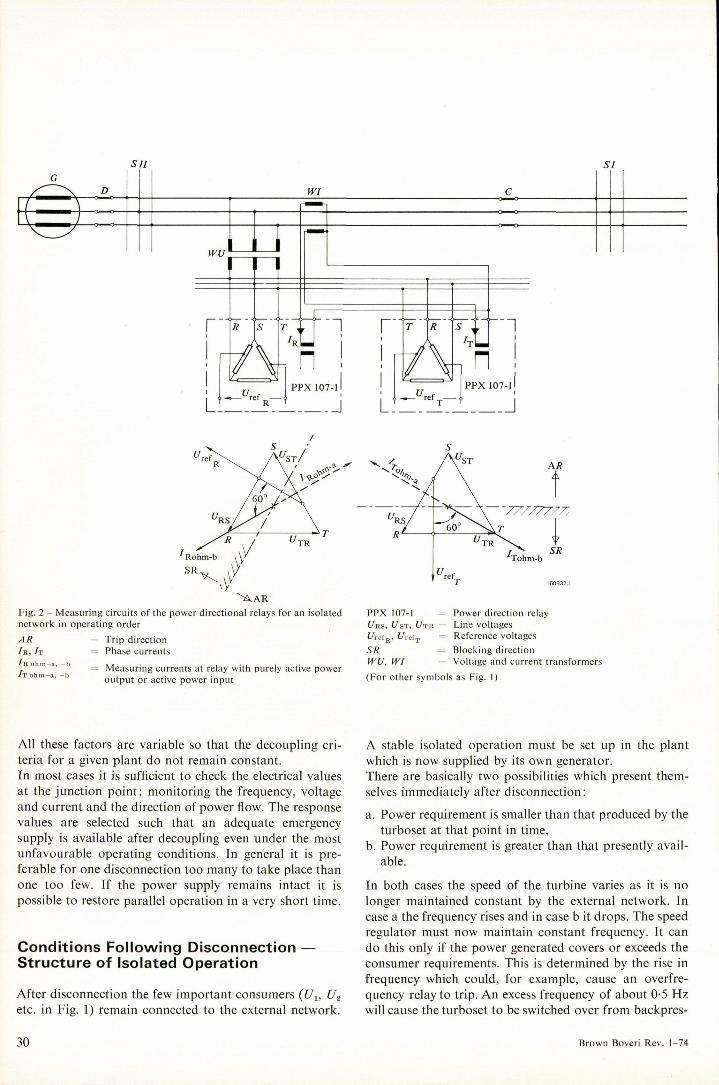
^AAR Fig. 2 - Measuring circuits of the power directional relays for an isolated network in operating Order
A R = Trip direction In, IT Phase currents
In ohm a, b Measuring currents at relay with purely active power JT ohm-a, -b . .
Output or active power input
PPX 107-1 Power direction relay Urs, Ust, 1 / tr = Line voltages f/retB, f refT Reference voltages SR = Blocking direction WU, W1 = Voltage and current transformers
(For other symbols as Fig. 1)
All these factors are variable so that the decoupling cri-teria for a given plant do not remain constant. In most cases it is sufficient to check the electrical values at the junction point; monitoring the frequency, voltage and current and the direction of power flow. The response values are selected such that an adequate emergency supply is available after decoupling even under the most unfavourable operating conditions. In general it is pre-ferable for one disconnection too many to take place than one too few. If the power supply remains intact it is possible to restore parallel operation in a very short time.
Conditions Following Disconnection — Structure of Isolated Operation
After disconnection the few important consumers (Ux, J/2 etc. in Fig. 1) remain connected to the external network.
A stable isolated operation must be set up in the plant which is now supplied by its own generator. There are basically two possibilities which present them-selves immediately after disconnection:
a. Power requirement is smaller than that produced by the turboset at that point in time,
b. Power requirement is greater than that presently avail-able.
In both cases the speed of the turbine varies as it is no longer maintained constant by the external network. In case a the frequency rises and in case b it drops. The speed regulator must now maintain constant frequency. It can do this only if the power generated Covers or exceeds the consumer requirements. This is determined by the rise in frequency which could, for example, cause an overfre-quency relay to trip. An excess frequency of about 0-5 Hz will cause the turboset to be switched over from backpres-
30 Brown Boveri Rev. 1-74

Fig. 3 - Measured values with a two-phase short circuit before and after the coupling circuit-breaker
R, S, T = Triangle of measured volt-ages in healthy Operation
/?', S', 7" Voltage triangle when a short circuit between phases R and T (with arcing resistor and isolated network)
= Direction of reference volt-ages under short-circuit conditions
a = Range in which the measur-ing current can be with an external fault
b Range of measuring current with a short circuit on the generator side of the cou-pling breaker C
(Other symbols as Fig. I and 2)
sure to speed control. In case b sufficient load must first be shed until the frequency which has risen to 50-5 Hz shows a positive energy balance. A graded underfrequency protection system ensures step-by-step load reduction at the generator according to a preset Programme until excess power is generated and the speed regulator can take over control of the turbine. The prerequisites for automatic load reduction of this nature are reliable frequency relays which are independent of voltage and have a high reset ratio, are quick-acting and whose response can be set in fine steps. In actual fact the decision as to whether and how much load must be shed to regain stable Operation is made at the instant of disconnection. A quantitative comparison of the energy produced and flowing through the coupling circuit-breaker at that instant determines the amount of load to be shed. However, the equipment required for continuous load comparison to determine Optimum load removal from the generator when disconnecting from the external network is rather expensive and its use can be justified only if simpler equipment does not offer sufficient secu-rity. Load shedding simultaneously with disconnection is al-
ways an advantage where division of the consumers to secure and non-secure buses cannot be carried out, or can be achieved only to a limited extent, so that there is always an energy deficit after disconnection. This also applies where not all of the several generators in a plant are in operation and the corresponding consumers cannot all be switched over to the network side of the coupling circuit-breaker.
Synchronizing and System Connect ion
Once the external fault has been cleared the complete plant can be reconnected to the external network. This is best accomplished automatically; when the network con-ditions necessary for return to healthy parallel operation are restored a trip signal is issued to the synchronizing unit and voltage, frequency and phase angle of the isolated system are matched to the values of the external network. The coupling breaker carries out the function of a syn-chronizing switch. Once parallel connection has been successfully carried out the turboset is switched over to backpressure control and normal operation is restored.
Brown Boveri Rev. 1-74

Sl
A t —
wi
wu
<n>
PPX 107-1 (2x) Y
ISX 149 —v
Sil
V ©
USX 123-1
Fig. 4 - Circuit diagrams of decoupling equip-ment
FCX 103 = Frequency relays with stages a, b, c and d
ISX 149 = Overcurrent relay PPX 107-1 = Power direction relay USX 123-1 = Undervoltage relay HK = Auxiliary contacts of generator
breaker R = Backpressure regulator
(Other symbols as Fig. 1)
Selection of Protection Relays — Concept of Decoupling Equipment1
In order to locate the fault the first Step is to decide which direction the power is flowing at the coupling breaker. This can be derived from the phase angle between current and voltage. This angle is variable and depends on the type of fault, the impedances of the supply source and the fault loop. It may be assumed, however, that the short-circuit impedance is primarily inductive. In the interests of better selectivity it has been shown that directional relays with predominant reactive current response are to advan-tage. The response ränge must be selected such that no erroneous decisions can be made, for any short circuits in either isolated or earthed systems. In addition to this
1 B. Grob: Protection for complete installations. Brown Boveri Rev. 58 1971 (9) 384-388.
the d.c. components which often occur in the event of short circuits and also the harmonics must be taken into consideration. Many conventional directional relays fulfil these conditions but are suitable only if they respond rapidly and reliably to even small voltages (short circuits near the point of measurements). The solid-state power directional relay type PPX 107-1 is particularly suitable and has the following features:
- Phase comparator measuring system; the following values are evaluated: phase angles, positive and negative half-waves, the result being rapid decision (approx. 15 ms at 50 Hz).
- Directional response up to 0-01 % of rated voltage is ensured.
- Measuring angle of Standard model relay is 60°. - The relay is of single-phase design, i.e. two relays must
be fitted in isolated networks or networks with arc
32 Brown Boveri Rev. 1-74

Fig. 5 - Fron t view (a) and rear view (b) of the Standard model decoupling equipment type IPX 3 installed in Standard rack
The top rack contains the power units, signalling and check equipment, the middle two racks contain protection relays and the bottom rack contains the tripping and auxiliary contactors and terminals.
suppression coils and three relays must be fitted in solidly earthed systems.
- Integrated circuits provide high reliability.
The measuring system of this relay is shown in Fig. 2. The phase comparator compares the phase displacement of a phase current with that of a reference voltage. This is derived from a bridge connection at the input circuit of the relay and is normally displaced by 30° to the phase-to-phase voltage opposite the measuring current. The oper-ating point between the blocking and tripping directions is when the direction of the current lies perpendicular to the reference voltage. The conditions during a two-phase short circuit between phases R and Tin an isolated network are shown in Fig. 3. The arc resistance is also taken into account. The voltage triangle reduced by the short circuit i.e. R', S', T provides the reference voltages UreT OR and Uret OT- Depending on
the impedance of the short-circuit loop the short-circuit currents relative to the impedance of the supply source may lie in one of two shaded areas (a for a short circuit in the external network, b for a fault on the generator side). It can be seen that both relays clearly move to the blocking or forward directions. The direction of power flow alone cannot be used as a trip criterion because both directions of flow can occur in normal parallel operation. The trip command is given only if the current in the external net-work exceeds the maximum operating current at the junc-tion point. Three-phase electronic overcurrent relays type ISX 149 having the following features are suitable for detecting overcurrents:
- independently ajustable measuring units for each of the three phases,
- separate response contacts for each phase,
Brown Boveri Rev. 1-74

Fig. 6 - Enlarged decoupling equipment installed in a cabinet
The power units are in the top rack, the protection relays for decoupling are in the third rack, the fourth rack contains the indicating equipment and check facilities, the frequency relays for 12 load shedding stages and the time relays are in rack 5-9 and the synchronizing equipment is in rack 11.
- one contact for time delay and one for instantaneous response and
- response values and times infinitely variable over a wide ränge.
Both directional relays and overcurrent relays are equipped with I A and 5 A inputs. The choice of undervoltage relay is also important. It is required that all three line voltages are monitored, often with extremely short response times. For this purpose the three-phase voltage relay type USX 123-1 is recommended on the basis of its excellent Performance in solid-state line protection. Its features include:
three independent measuring systems, - short response times infinitely variable between 20 and
200 ms and - internal response signals can be acknowledged exter-
nally.
A high-performance frequency relay which is largely in-dependent of voltage and has a short response time is required for monitoring the frequency It must be precisely adjustable in fine stages and the solid-state relay type FCX 103 fulfils these requirements; its features include
- high accuracy, - wide setting ränge (31-1 to 65 Hz in stages of 0-1 Hz),
unaffected by voltage fluctuations in the ränge 1-2 to 0-6 X rated voltage,
- trip block at voltages below 0-6 X rated voltage, - its facility for extension up to 4 independently adjustable
trip stages, and - its use for under or overfrequency protection.
With a relay of this type it is always possible to identify a dangerous frequency fluctuation within the necessary time period, instigate decoupling and control load shedding in isolated operation. A supplementary overfrequency stage issues the changeover command from backpressure to speed control. The concept of the decoupling system is shown in simpli-fied form as a single-phase diagram in Fig. 4. The contacts of the individual protection relays are interlinked in such a manner that tripping occurs at a given overcurrent or undervoltage only if the appropriate directional relay has tripped. The latter is instigated by the overcurrent relay. Tripping occurs direct through the frequency relay be-cause frequency collapse can be traced only to faults in the external network. It is recommended that an auxiliary contact of the gener-ator breaker is connected in series with the trip circuit of the frequency relay. Under no circumstances should dis-connection occur if the plant is supplied from the external network alone. Parallel connection often causes short-term power fluctua-tions. To avoid erroneous tripping the response Channel
34 Brown Boveri Rev. 1-74

remains blocked for several seconds after the coupling circuit-breaker has closed (At in Fig. 4). In this particular example the second stage (b) of the fre-quency relay responds to the overfrequency in isolated operation and causes the backpressure regulator (R) to be shut down. Two further frequency stages of the same relay cause the load to be removed from the generator by shedding consumers Wx and W2.
Design Features — Standard Model
All relays are modular and designed to plug-in to Standard racks. The equipment for the system described above, including power supply units, check facilities, and tripping contactors can be installed in four Standard racks. This is illustrated in Fig. 5 which shows a Standard arrange-ment with the supply, check and indicating equipment in the top rack, the protection relays in the middle two racks and the tripping and auxiliary contactor terminals in the bottom rack. The equipment is supplied ready-wired and checked; only the measuring, indicating and tripping circuits need to be connected on site.
Conclusion
All the solid-state relay modules required for system dis-connection equipment have been proved in practice in industrial networks. The experience gained has enabled a combination of relays to be standardized to a large degree and they can satisfy the majority of requirements. The system disconnection equipment described here offers optimum reliability for uninterrupted power supply from a system generator which would normally operate in parallel with the supply network.
Alternative Arrangements
The Standard arrangement can be augmented by additional protection and measuring equipment to suit particular applications. The racks are then installed either in hinged frames or in a cabinet (Fig. 6). Alternatively they can be installed in a frame for fixed installation in a switch bay. The supplementary equipment includes:
- automatic synchronizing rack, - additional frequency relays for load shedding, - earth-fault relays, - differential relays for the infeed transformer.
There are certain advantages to be gained in using a complete protection cabinet for complex plant. It enables power units, check and indicating equipment to be used in common for various solid-state protection relays such as for generator protection, plant protection, and distance protection.
Brown Boveri Rev. 1-74

Protection of Industrial Generators and Industrial Networks Taking the Excitation System into Account
F. Peneder, H. ßutz and M. Fiorentzis
Thyristor excitation for industrial power stations can be fed from the terminals without a current dependent support circuit if a suitable protection concept is applied for both network and generator. The protection system must be capable of quickly isolating any faults that occur.
Introduction
The tasks of protection equipment for industrial generators and industrial networks are to rapidly locate and isolate faults in the generator or in the network before other damage can occur. The use of suitable excitation systems in conjunction with purpose-built protection equipment in the industrial network ensures a reliable power supply. Rapid and selective isolation of faulty consumers by means of suitable switphgear plays an important role. The object of the protection equipment in an industrial power Station and its network is to protect the generator and the network. In certain cases both protection systems interact.
Criteria for the Design of Protection Equipment
In addition to the Output of the turboset the configuration of the industrial supply network is a significant factor in planning an industrial power Station project. The excita-tion system for the industrial generator must also be adapted to the requirements of the internal network. There are two possibilities to be considered: the solid-state excitation system fed from the terminals and the excitation system with an a.c. exciter with rotating rectifier built onto the turboset. Both systems have electronic voltage regulators [1], Depending on the specific conditions either an auxiliary generator is built onto the turboset for supplying power
to the voltage regulator or the power is supplied direct from the generator terminals. In the case of excitation equipment fed from the terminals a short-circuit current greater than the rated current and lasting longer than 1 s can be maintained only if a support circuit is provided. This supplies a supplementary excitation which is de-pendent lipon the generator current. Industrial networks primarily supply induction machines which require very rapid disconnection in the event of a short circuit. The transient phenomena at the main bus system alone are significant for the investigation and determination of the protection system. An example is used in the following to describe a protec-tion concept and an excitation system fed from the ter-minals such as is generally suitable for industrial plant. An industrial power Station with various loads as shown in Fig. I is selected for the following investigation. Two generators with unit-connected transformers supply bus system Sj which is connected to the external network through a coupling transformer. The total Output of the generators is 75 MVA and the coupling transformer is rated 100 MVA. Induction motors connected to the busbars, either direct or indirect through an additional transformer, can fully load both generators. A simple protection concept demands rapid control res-ponse of the excitation. In this case both generators have excitation systems fed from the terminals with additional excitation support circuits. The peak excitation of 1-6 to 1-8 times the rated excitation voltage is thus available extremely rapidly even in the event of a short circuit. Network stability, the transient response of the machines and the layout of the protection system are recorded by Computer programme in response to simulated short circuits at the junction points. Short circuits are simulated at the busbars Sx, S2 and S3 under various load condi-tions. To study the most extreme conditions the external network is immediately interrupted by means of the coupling circuit-breaker in the event of a fault. A short circuit of more than 0-2 seconds at busbar St will cause both generators, which are preloaded with 75% of their rated Output, to drop out of step with the network. If the two generators are differently loaded in a ratio of about 3:4a short circuit of this nature will even cause them to drop out of step with each other. The induction motors with a total rating of 30 MW con-nected to each of the busbars S1 and 5., will drop below the stalling torque speed after 0-2 seconds. The conse-quent reactive load demand reduces the terminal voltage at Sj to about 80 % of the rated voltage and at S2 to about 33 % of the rated voltage so that a restart becomes impos-sible in spite of peak excitation at the synchronous gener-ators. The induction machines can be restarted only after load shedding or reduction of the motor Output to a fifth of the generator rating, in this case 15 MW.
36 Brown Boveri Rev. 1-74

Fig. I - Configuration of investigated network
G,, G 2 = Generators h to / 1 5 Overcurrent/time relays Mh to Ma = Induction motors N = Network 5 j to S 3 Busbars 7 \ to Tt = Transformers Xa Reactance Z 3 to Z 4 = Impedance relays
Similar conditions apply for short circuits at busbars S 2 and S3 in respect of the induction motors connected to the system. Here again the consumption must be reduced. However, if the coupling circuit-breaker to the external system remains closed the induction motors can be re-started after the fault at busbar has been cleared. The investigations clearly show that any fault on the bus-bars must be interrupted within 0-2 seconds if there is to be no risk of complete breakdown of the internal network. Very short interruption times of this nature require neither a support circuit for the excitation equipment fed from the terminals nor separately fed control electronics. The selec-
tivity of the protection equipment is maintained during the voltage drop due to the short circuit. The electronics fed from the terminals still operate per-fectly at only 30% of the rated generator voltage. If the recovered generator voltage after the fault has been cleared is below this 30% limit it becomes necessary to provide an independent supply for the control electronics of the voltage regulator to build up the excitation. In order to determine the most economical excitation system and arrive at an Optimum design of the protection system it is therefore essential to know the limiting inter-ruption times of short circuits for control electronic
Brown Boveri Rev. 1-74

Fig. 2 - Short-circuit current /K and terminal voltage UG of a generator with excitation fed from the terminals in relation to the short-circuit duration TK (network reactance XT = 0 1 2 p.u.)
Uok Terminal voltage before short circuit is interrupted UGO Transient recovery voltage at terminals after Interruption of
short circuit
systems fed either from the terminals or with separate supply. To this end we select a short-circuit interruption time Tk and a given short-circuit reactance Xt and derive a curve of short-circuit current It and terminal voltage Ug with respect to time. The necessary supply for the control electronics is determined by the short-circuit voltage Ugk and the transient recovery voltage UgO at the instant of interruption. The diagram in Fig. 2 shows the curve of terminal voltage Ug and short-circuit current 1k for a specific case where a generator is suddenly short-circuited by reactance Xt; the generator having rated preloading and at load shed-ding after a short-circuit duration of Tk- Attention is drawn to the envelope of the transient recovery voltage UGO. Similar curves were determined for various reactances and also with the electronics fed from the terminals. This results in a response of the excitation equipment with thyristors fed from the terminals in relation to the network reactance due to the short circuit as shown in Fig. 3 a, b, c and d. Large short-circuit interruption times Tk and small net-work reactances Xt result in duty points below the limiting
Fig. 3 - Short-circuit current /K and terminal voltage UG of a generator in relation to the total network reactance XT to the location of the short circuit and the corresponding short-circuit duration TK
a : Generator short-circuit current IK immediately prior to interruption of short circuit by electronic protection system with separate power supply
b: Generator terminal voltage UGK immediately prior to interruption of short circuit by electronic protection equipment with separate power supply
a —- XT [p.u.]
38
c: No-load terminal voltage of a generator UGO immediately after inter-ruption of short circuit by electronic equipment with separate supply
d: No-load terminal voltage of generator Uco immediately after inter-ruption of short circuit by electronic equipment supplied from the terminals I Limiting characteristic curve for control electronics supplied
from terminals Lower ränge: control electronics with separate supply Upper ränge: control electronics with supply from terminals
II = Limiting characteristic curve for recovery of excitation
c —~XT [p.u.]
— XT [p.u.]
Brown Boveri Rev. 1-74

characteristics I and II and require a separate supply for the control electronics. For the case of close-up faults it is essential to aim at the minimum fault duration time by means of a suitable protection concept. As the subsidiary busbars are generally connected to the main busbars through high reactances (transformers with relatively low ratings) faults at these points have very little effect on the function of the excita-tion equipment fed from the terminals. Calculations have shown that with a short-circuit impedance greater than 0-5 p.u. the short-circuit duration can also be set higher than 0-2 seconds without taking the excitation equipment into account.
Generator Protection
The individual components of the protection equipment for unit-connected turbogenerators are shown in Fig. 4. With excitation equipment fed from the terminals the overcurrent protection I is augmented by an undervoltage relay 2 which instigates generator disconnection after a time lag. This combination provides the back-up protec-
tion for the busbars beyond the unit-connected trans-former. The Stator overload protection 7 operates on the principle of a thermal replica. The Standard unit can be matched to the thermal time constant of the machine. The overvoltage protection 4 has an instantaneous and a time delay stage combined in one unit. The generator and unit differential protection systems 5 and 6 have stabilized percentage differential relays. The unit differential protection system 6 has intermediate current transformers for matching. The Standard arrangement of the Stator earth-fault pro-tection system 7 has a protection ränge covering 95% of the generator winding length. This can be extended to 100% and remains unaffected by earth faults on the high-voltage side of the unit-connected transformer. The rotor earth-fault protection system 8 indicates earth faults at the rotor windings. The load unbalance protection system 9 protects the gener-ator against excessive load unbalance. This has two stages: the first (3 to 15 % rated current) is for indication purposes, the second (15 to 40% rated current) causes a trip. Because of the cost of the protected object (turbine) the inverse power protection system 10 is duplicated and
Kl. 5 P 2 0 V
5
' A D I X 1 1 1
Ell (C 6 0 V A /
4 VA
Kl. 5P 20
Kl. 5P 20
Kl. 5P 2 0 ,
F-30 VA Kl. 5 P 2 0 T + 7 ^
R,
Q 60 VA
Fig. 4 - Electronic protection equipment for unit-connected industrial generator
1 2 3 4 5 6 7 8 9
10 11 12 13
Overcurrent protection Undercurrent protection Stator overload protection Overcurrent protection Differential protection for generator Unit differential protection Stator earth-fault protection Rotor earth-fault protection Load unbalance protection Inverse power protection Protection against loss of excitation Inter-turn fault protection Frequency protection
13
U > USX 115 E 37
U < USX 123 E 38
FCX 102 E 42
10 10 3
P PPX 105 E 211
P PPX 105 E 212
Th TTX 103 E 17
4 VA Kl. 5P2i
+ - I WX 135 E 19
l 12
UBX 114 E 35
i> 1SX 148 E 142 h> IPX 132
E 18
II
+ - ZPX 103 E 24
OD 60 VA I i i UBX 117 E 311 OD K U UBX 117 E 311
Brown Boveri Rev. 1-74

monitors two phases. Relay 11 which provides protection against the generator dropping out of step is equipped with a time integrator. The inter-turn fault protection system 12 monitors the windings of the individual phases and signals faults in the insulation level between the windings. The two-stage frequency protection system 13 gives an alarm at -3 % of rated frequency and issues a trip signal at -5% of rated frequency. For medium-sized turbogenerator sets Brown Boveri use primarily the standardized electronic generator protection systems. The series GSX 3 and GSX 4 ranges of equipment simplify project planning work and guarantee perfect functioning, and delivery times are short. All functional, signalling and trip circuits are contained in a hinged frame. The trip programme can be fixed at a matrix to suit the requirements of the industrial power Station. The protection relays are in the form of plug-in units. The conceptenables each generator protection system to be produced as a compact, ready-wired and tested unit which occupies far less space than the mechanical systems with individually arranged relays. On site it is necessary only to connect the leads for supply voltage and measuring and tripping circuits.
Protection Equipment for an Industrial Ne twork
It is the task of this protection system to selectively locate and instigate the corresponding interruption in the event of any faults which cause the generator voltage to drop below 0-5 p.u. within 0-2 seconds. The following con-siderations are illustrated by Fig. 1 and the worst possible condition of an open coupling circuit-breaker is assumed. The voltage of the industrial network is thus not supported by an external network in the event of an internal fault. Although this case is very rare today, because modern industrial networks are equipped with decoupling equip-ment [2] the protection equipment must nevertheless be designed to cover this case. Any faults on busbar Sx must be interrupted as quickly as possible. The interruption command is issued either by the busbar protection system or the back-up protection system for the generators. A distinction must be made between two types of fault: either the induction motor is connected direct to the feeder or further busbars S2 or S3 are coupled to the feeder through a transformer and additional induc-tion motors are connected to these buses. In the first case an overcurrent relay with a linear charac-teristic which ensures interruption of any fault in the motor feeder within the basic time of 0-2 seconds is sufficient. The relay setting is determined by the short-circuit current and the motor starting current.
In the second case the feeders of busbars S2 and S3 must also be fitted with overcurrent relays set for 0-2 seconds. The power infeeds to busbars S2 and S3 must be protected by overcurrent relays with time gradings of up to 0-6 s. The time of 0-6 s is permissible because the voltage decay at the generator terminals due to faults beyond trans-formers T3 or Tt is rarely below the 0-5 p.u. limit. If the values are below 0-5 p.u. relay 10 must be set to a maximum of 0-2 seconds and at the same time must be blocked by the starting contacts of relays 7, 8 and 9. In the case of faults on the power infeed leads to transformers T3 and Tt and, to a certain degree also at the transformer itself, it is to be expected that the voltage decay at the generator terminals will be rapid. The time setting of 0-2 seconds must not be exceeded. Overcurrent relays at this point lead to time graduations of at least 1 0 s and are therefore not suitable. Consequently, minimum impedance relays must be used. These have a non-directional circular characteristic and must be set such that they do not res-pond to faults beyond transformers T3 and Tt. The un-protected zone on the secondary side of the transformers T3 and Tt is covered by overcurrent relays in series with the minimum impedance relays. The time grading of the overcurrent relays is 1 -0 s.
An industrial power Station protected in this manner ensures reliable power supply through selective fault inter-ruption within the permissible time. The protection equip-ment has demonstrated its functional and operational reliability in many plants already supplied and, thanks to the components used, is largely maintenance-free and its response accuracy remains unaffected by time.
Bibliography
[1] F. Peneder, H. Butz: Exciter systems for three-phase generators in industrial and medium-size power stations. Brown Boveri Rev. 61 1974 (1) 41-50.
[2] P. Magajna: Automatic system decoupling for indus-trial plants. Brown Boveri Rev. 61 1974 (1) 28-35.
40 Brown Boveri Rev. 1-74

Exciter Systems for Three-Phase Generators in Industrial and Medium-Size Power Stations
F. Peneder and H. Butz
Fully developed excitation and voltage regulation systems for turbogenerators are readily available. Depending on generator requirements, either brushless or solid-state ihy-ristor exciter systems are used. The features and applications of these are described.
Introduction
Over the years a great many methods of exciting and Con-trolling industrial generators have been devised in answer to the wide variety of problems presented by different kinds of application. In effect, an appropriate system was developed, offered and delivered for each particular case. High utilization factors, low short-circuit ratios of 0-4 to 0-6 and insistence on dependable, low-maintenance gener-ators led to the exciter systems used today. These systems are the subject of this article.
Present-Day Exciter Systems
In accordance with the requirements to be met by the generator, whether in the context of control or for reasons of maintenance, two exciter systems have been developed and standardized: brushless excitation and purely solid-state excitation from the generator terminals. Brown Boveri employ the brushless system in conjunction with an electronic voltage regulator for industrial gener-ators which feed networks with normal conditions, espe-cially where local circumstances require excitation systems that have no sliprings. The solid-state system, comprising a thyristorized power control element and an electronic voltage regulator, is used to deal with complex control tasks, or in cases where emphasis is laid on very fast response. Difficult network conditions include:
- long connecting lines to the centre of the distribution net
- sudden, high reactive power demand on starting three-phase motors
- wide voltage variations - wide frequency variations
Technical control problems arise predominantly, though not exclusively, when conditions in the network are ab-normal. Without an exciter machine the voltage of a synchronous machine can be maintained better and optimized to a greater degree, because one time constant is eliminated.
Fig. 1 - Rotor of a 10 MVA industrial generator with rectifier ring and exciter armature on the non-driving shaft end
Brown Boveri Rev. 1-74
136848.1 BROWN BOVERI

Brushless Excitation Systems
Brushless excitation has almost completely ousted the d.c. exciter machine for generators with ratings from about 2 MVA to 100 MVA. Continuous, maintenance-free operation without the risk of sparking is of great im-portance for many industrial power stations, refuse in-cineration plant and district heating stations. The essential components of a brushless exciter system are the a.c. exciter machine with its rectifier bridge and the electronic regulator. Power for the voltage regulator can be provided by a permanent-magnet generator or via a transformer from the generator terminal.
The A.C. Exciter Machine with Diode Rectifier on the Rotor
The quality of Brown Boveri exciter machines today is in many respects due to the technical possibilities presented in recent years by high-performance Silicon diodes. Two types of exciter machines are available to match the generator ratings and their different excitation require-ments. The brushless turboexciter type WFT is used for turbo-generators up to 20 MVA. This is a salient-pole synchro-nous generator with a three-phase winding in the rotor and a d.c. exciter winding in the Stator. It is mounted overhung on the generator, i.e. it has no bearing of its own, and is naturally ventilated (Fig. 1 and 2).
Fig. 4 Brushless exciter type WBT, viewed from the non-driving end
BROWN BOVERI 137090.1
Fig. 2 - The complete brushless exciter type W F T of Fig. 1 shown on the test bed
Fig. 3 - Brushless exciter type WBT, viewed from the driving end
BROWN BOVERI BROWN BOVERI
42 Brown Boveri Rev. 1-74
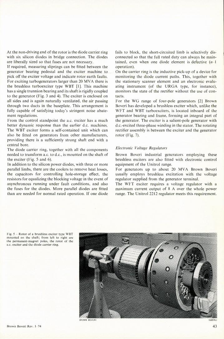
At the non-driving end of the rotor is the diode carrier ring with six Silicon diodes in bridge connection. The diodes are liberally sized so that fuses are not necessary. Jf required, measuring sliprings can be fitted between the generator bearing pedestal and the exciter machine to pick off the exciter voltage and indicate rotor earth faults. For exciting turbogenerators larger than 20 MVA there is the brushless turboexciter type WBT [1]. This machine has a Single trunnion bearing and its shaft is rigidly coupled to the generator (Fig. 3 and 4). The exciter is enclosed on all sides and is again naturally ventilated, the air passing through two ducts in the baseplate. This arrangement is fully capable of satisfying today's stringent noise abate-ment regulations. From the control Standpoint the a.c. exciter has a much better dynamic response than the earlier d.c. machines. The WBT exciter forms a self-contained unit which can also be fitted on generators from other manufacturers, providing there is a sufficiently strong shaft end with a central bore. The diode carrier ring, together with all the components needed to transform a.c. to d.c., is mounted on the shaft of the exciter (Fig. 5 and 6). In addition to the Silicon power diodes, with three or more parallel limbs, there are the coolers to remove heat losses, the capacitors for Controlling hole-storage elfect, the resistors for equalizing the blocking voltage in the event of asynchronous running under fault conditions, and also the fuses for the diodes. More parallel diodes are fitted than are needed for normal rated operation. If one diode
fails to block, the short-circuited limb is selectively dis-connected so that the füll rated duty can always be main-tained, even when one diode element is defective («-1 operation). On the carrier ring is the inductive pick-up of a device for monitoring the diode current paths. This, together with the stationary Scanner element and an electronic evalu-ating instrument (of the URGA type, for instance), monitors the State of the rectifier without the use of con-tacts. For the WG ränge of four-pole generators [2] Brown Boveri has developed a brushless exciter which, unlike the WFT and WBT turboexciters, is located inboard of the generator bearing and frame, forming an integral part of the generator. The exciter is a salient-pole generator with d.c.-excited three-phase winding in the Stator. The rotating rectifier assembly is between the exciter and the generator rotor (Fig. 7).
Electronic Voltage Regulators Brown Boveri industrial generators employing these brushless exciters are also fitted with electronic control equipment of the Unitrol ränge. For generators up to about 20 MVA Brown Boveri usually employs brushless excitation with the voltage regulator supplied from the generator terminal. The WFT exciter requires a voltage regulator with a maximum current Output of 8 A over the whole power ränge. The Unitrol 2212 regulator meets this requirement.
Fig. 5 - Rotor of a brushless exciter type WBT mounted on the shaft; from left to right are the permanent-magnet poles, the rotor of the a.c. exciter and the diode carrier ring.
BROWN BOVERI
Brown Boveri Rev. 1-74

1 + _ u V
r I i n 1 1 1 1 i 2
w
+ -
- L
Fig. 6 - Circuit diagram of brushless exciter type WBT
1 = A.C. main exciter 2 = Permanent-magnet pilot exciter 3 = Rotating rectifier 4 = Silicon diode 5 = RC network 6 = Fuse 7 - Field connections 8 = Measuring sliprings 9 = Rotating part
10 = Magnet cores for monitoring diodes
Fig. 7 - Rotor of a brushless generator type W G 630 for 3360 kVA, 6 kV, 50 Hz
BROWN BOVERI 143289.1
4 4 Brown Boveri Rev. 1-74

Fig. 8 - Excitation circuit of a brushless exciter system with power supply from generator termi-n a l and compounding
«2 De-excitation switch
/«/, = Instrument transformers / s Current transformer ki Compound transformer m1 Generator m2 A.C. exciter m 4 Power transformer «I Rotating rectifier «2 Compound rectifier r 2 De-excitation resistor " l Voltage regulator, auto «2 Voltage regulator, manual K-Ol
Fig. 9 - Excitation circuit of a brushless exciter system with power supply from a Permanent-magnet generator
«2 = De-excitation switch /1./2 = Instrument transformers h = Current transformer m1 = Generator in 2 = A.C. exciter "h = Permanent-magnet generator "1 = Rotating rectifier H = De-excitation resistor «1 = Voltage regulator, auto «2 = Voltage regulator, manual «-Ol
In answer to many customer requests a regulator system incorporating redundancy has also been developed for industrial installations. Many systems of this kind have been supplied under the name of Unitrol K 14001, and have performed very well in service. Two Unitrol 2212 Controllers are fitted in a Standard cubicle, one for auto-matic operation u1 and the other for manual w2 (Fig. 8). This version is termed a dual-channel AVR system [3]. If the automatic Channel fails, protective relays switch over to the manual Channel.
Operating Principle (see Fig. 8). Under normal operating conditions, i.e. in the automatic mode, voltage regulator u1 is on. Generator voltage and current are measured by means of the two instrument
transformers f^ and / 2 . The final control element, a thy-ristor bridge contained in the Unitrol regulator, receives its power from the generator terminals via a special matching transformer m t . The voltage regulator supplies more or less excitation to the stationary field poles of the a.c. exciter, depending on the amount of deviation from a chosen set point. The exciter functions as a classical amplifying machine and generates the necessary power in the rotating armature winding. The diode rectifier nx, also rotating, performs the conversion to d.c. for exciting the rotor. When the regulator is fed from the generator terminals an important addition, especially in industrial networks, is a back-up excitation system depending on stator current. Without this there would be no guarantee of supply for excitation in the event of a system fault. The aim of
Brown Boveri Rev. 1-74

Fig. 10 - Unitrol K 18008 dual-channel voltage regulator
compounding is to maintain excitation if a short circuit occurs in the industrial network, and hence also a certain sustained generator short-circuit current, which allows selective disconnection of the affected load. The Compound connection is formed by Compound transformer k j (a current choke, for example) and rectifier « 2 . The Com-pound transformer kt is so designed that it creates an additional voltage proportional to the generator current via rectifier n 2 . In the event of a short circuit, Saturation of the Compound transformer has the effect of limiting the additional excitation to the required value. This ar-rangement is also known as series compounding because the additional excitation voltage is in series with the regulator output voltage. For generators having ratings above 20 MVA Brown Boveri employs brushless excitation with power obtained from a pilot exciter with permanent magnet poles. In this
Fig. 11 - Basic circuit of a thyristorized shunt-type exciter system
ÖJ = Circuit-breaker a 2 De-excitation switch / , , / , , / 3 , / 4 Instrument transformers m j - Generator m 2 , m 3 , m 1 Power transformers «! = Controlled rectifier «, - Voltage regulator rl De-excitation r2 Starting exciter
configuration, shown in Fig. 9, the type WBT brushless exciter is used together with the integrated permanent-pole generator m3 as the auxiliary exciter. The permanent-pole generator is a three-phase generator excited through rotating permanent-magnet poles. It feeds the field winding of the main exciter m2 via the final control element of the voltage regulator. In this way the excitation system can be made completely independent of the distri-bution network. The permanent magnets of the generator are so designed that their Performance and reliability are in no way affected by short circuits and dismantling. For the ränge between 20 and 80 MVA there is the Unitrol K 16008 voltage regulator. This is a dual-channel version comprising two Unitrol 3313 regulators (Fig. 10). Com-pounding is not needed here because the permanent-pole generator supplies an almost constant supply voltage to
46 Brown Boveri Rev. 1-74

Fig. 12
»h «2 /„/*,/4 'l "l I II III IV
Block diagram of a thyristorized exciter system Generator De-excitation switch Instrument transformers
= De-excitation Thyristor control element Measured-value transducer for voltage regulator Amplifier for voltage regulator Grid control set Pulse Output stage
V Amplifier for rotor current limitation VI Delay unit, integrator VII = Amplifier for angle regulation VIII Amplifier for inductive Stator current regulation IX Amplifier for capacitive Stator current regulation X Measured-value Converter for motor current regulation XI Measured-value Converter for angle regulation XII Measured-value Converter for Stator current regulation XIII Discriminator for inductive or capacitive stator current
limitation
the regulator, irrespective of external events at the gener-ator terminals. Each combination of voltage regulators can also be fitted with a limit-value Controller Unitrol K 3001 for limiting the control ränge of the regulator. The set limits are matched to the power chart of the synchronous machine (rotor angle, stator and rotor current) [4], Limiting Controllers are used in the case of generators running in parallel with the main network or with other generators. Working in conjunction with the voltage regulator, these allow Optimum utilization ot the gener-ator and improve the security of parallel operation. The Unitrol 1040 Controller can also be fitted. Depending on the connection, this either regulates the power factor of the generator or the power factor at the point of trans-fer. When voltage is constant, the power factor of the generator is held more or less constant at 0-8 by the current
droop for parallel operation. In the event of voltage fluctuations, however, variations in reactive current occur which incur higher costs when drawn from the network, and when sent out into the network can impose an unwel-come load on the generator. Operating industrial generators therefore generally re-quires means of tie-line power factor control at the point of attachment to the supply network. Additional facilities of this kind necessitate limiters for the generator. In the case of existing industrial networks, on the other hand, the power factor is often compensated with rotating machines or static means. A newly added turboset must not influence the existing facilities for Controlling power factor in the industrial net. For this reason p.f. control at the generator is often specified.
Brown Boveri Rev. 1-74

BROWN BOVERI 147308.1
Fig. 13 - Unitrol 8305 thyristor unit for 500 A
Sol id-State Excitation System
Solid-state excitation gear equipped with thyristors is generally used by Brown Boveri for medium to large turbo-generators and for hydro generators. The thyris-torized final control element for exciting the generators then receives its power direct from the generator terminal via a transformer. This method of excitation is also becoming increasingly populär for smaller generating sets, partly owing to the free choice of location and the reduced length of the set, and partly because of the fast correcting action in response to faults in the network supplied. A solid-state exciter system comprises the power trans-former, the thyristor control element, the electronic regu-lator and the de-excitation unit (Fig. 11). With excitation systems using rotating machines the power needed to excite the rotor is obtained mechanically by way of the shaft. With a solid-state system, on the other hand, the necessary electrical power is taken direct from the terminals of the generator. The dimensions of a solid-state system are determined solely by the power to be produced. Any control system must be capable of achieving more than its nominal Performance for a short time. This extra capability is stated in terms of ceiling voltage and ceiling current. With thyristor excitation the ceiling voltage can be chosen at will, it is generally between 1.6 and 2 times the rated exciter voltage. The electronic measuring, regulating and firing devices for the thyristors give an extremely short voltage response time of only some 10 milliseconds. The functioning of a voltage regulator with a thyristor control element can be simply described with reference to Fig. 12. The actual value, provided by transformers fx and / 2 , is rectified in a Converter I and reduced to the
Fig. 14 - Unitrol K 27001 thyristor exciter cubicle with de-exciter cubicle
BROWN BOVERI 155424.1
48 Brown Boveri Rev. 1-74

comparison level of the regulator. The deviation from set point U0 is amplified in PID Controller II and fed to a device for firing the thyristors. This consists of a grid control set III and a number of pulse output stages IV. In this way, the d.c. excitation voltage supplied from the rectifier bridge can be varied between 0 and 100%. For fast de-excitation when the generator load is removed, the thyristor control element connected direct to the exciter winding is operated briefly in the inverter mode. The Out-put voltage from the three-phase bridge then becomes negative. Because there is no change in the direction of flow in the field, energy is withdrawn from the field and the rapid decrease in flux has the effect of greatly reducing the response time. Brown Boveri thyristor exciter systems include the follow-ing limit control devices as Standard equipment:
- Maximum rotor current limitation V with measured-value Converter X and delay unit VI
- Rotor angle limitation VII with measured-value Con-verter XI
- Inductive Stator current limitation VIII and delay unit VI
- Capacitive Stator current limitation IX with measured-value Converter XII and discriminator XIII
These facilities allow the machine to be loaded to the limit of its Performance. The power supply equipment for the control electronics ensure a secure supply within the ränge of 30 to 130% of the rated voltage. On starting, an auxiliary supply is needed for a short time to excite the generator up to 30% of rated voltage. The power required for this is very small and is drawn from the Station battery (approx. 10% of the no-load exciter power for about 4 s). Above this value the regulator system takes over the supply, and the starting circuit is disconnected. A de-excitation device protects the generator and the entire solid-state exciter system. In the event of a fault the field is quickly suppressed by means of a special switch and a non-linear resistance. Fully wired excitation equipment mounted in Standard cubicles is available for small and medium-size generators. A particular equipment configuration is chosen to suit the generator application and the way it is operated, and also to provide the required redundancy, both in the elec-tronics and in the power stage. A characteristic feature of thyristor excitation is maximum continuous current. This is the value that the power stage can produce for an unlimited time. A three-phase bridge, with six thyristors and the asso-ciated pulse output stage, forms a self-contained unit. Up to four bridges can be connected in parallel. The mechanical arrangement is illustrated in Fig. 13. The hinged frames contain the control electronics and are easily accessible from both sides (Fig. 14). The Thysert system is used for high generator ratings. In this case the Controller power stage and the electronics are mounted in separate cubicles (Fig. 15 and 16). The pulse stages are contained in the hinged frame. The heat generated in the thyristors is small compared with the power handled by the thyristor output stage, and is removed by heat sinks with forced (fan) circulation and dissipated to the surroundings. When planning the installa-tion as a whole, therefore, attention must be paid to
Fig. 15 - Unitrol K 17005 voltage regulator cubicle for a high-capacity thyristor exciter system
facilities for cooling the space in which the exciter equip-ment is located. The output of the thyristor control units is determined by the number of bridges used (each bridge has six thyristors). Units with the following data have been standardized:
No. of Max. Rated Ceiling Heat loss thyristors continuous exciter voltage approx.
current current up to max.
A A V kW
6 500 300 900 1 12 900 600 900 2 18 1350 900 900 3 24 1800 1200 900 4 more over over over than 36 2000 1500 1500 5
BROWN BOVERI
Brown Boveri Rev. 1-74

BROWN BOVERI 139762.1
With thyristor exciter systems fed from the terminals, the generator current can, if necessary, be assisted by a Compound connection. The equipment needed for this, a three-phase current choke and an uncontrolled rectifier, depends on the Stator current to be maintained in case of a short circuit. Solid-state excitation provides industrial installations with a system involving minimum maintenance together with optimum reliability and quality of control. This is made possible by non-wearing electronic com-ponents with almost negligibly small time constants. Response times are determined only by the time constant of the generator and the chosen ceiling voltage. Up-to-date exciter systems supplied by Brown Boveri are in service in many industrial plants and power stations.
Bibliography
[1] W. Merhof: Brushless excitation of synchronous machines by rotating semiconductors. Brown Boveri Rev. 54 1967 (9) 539-553.
[2] 1. Kovacevic, T. van Stiphout: Synchronous machines for 250 to 11 200 kVA. Brown Boveri Rev. 59 1972 (12) 571-576.
[3] T. Sidler: Dual control Channels - a progressive con-cept for regulating the voltage of synchronous generators. Brown Boveri Rev. 58 1971 (11) 527-537.
[4] W. Haller: Excitation limit Controllers for synchro-nous generators. Brown Boveri Rev. 57 1970 (2) 60-65.
Fig. 16 - Thysert thyristorized control unit for high capacities, with 42 plug-in thyristor assemblies
50 Brown Boveri Rev. 1-74

Automation of Industrial Turbines
W. Andres
A survey ofthe present level of automation of industrial and power Station turbines is followed by a discussion of the reasons for automating and the structure of today's most common systems. The Decontic modular electronic control system which is suited for solving the numerous control functions is described. Finally, an industrial turbine is used as an example for illustrating the structure of an automatic system.
b. The availability and safety of the turbine is increased as the possibility of operator mistakes and their effects are limited. If disturbances occur the turbine is brought to a safe operating condition by the automatic system. With-out an automatic system the operators are often unable to interpret the vast amount of information and instigate the necessary control manipulations in time.
c. Shorter start-up times are achieved without exceeding any of the permissible limits.
Introduction
As a supplier of turbines Brown Boveri have been working on automation systems for gas turbines, steam turbines and power stations since 1963. Until now approximately 60 units ranging from 20 to 1300 MW, with either füll or partial automatic features, have been commissioned. The experience gained has proved the suitability of the applied systems. The majority of automated plants contain steam turbines with Outputs of more than 100 MW. However, a certain reluctance could be observed in the automation of industrial turbines, mostly because the cost of füll auto-mation in relation to the cost of the plant is higher in the case of industrial turbines than for high-power turbines. This attitude has changed to a certain extent in recent years as a result of more economical arrangements using partial automation matched to the process itself and its control. Some advantages of a process automation are:
a. Operating staff is reduced. Remote controlled industrial processes, supervised by only one operator, will certainly be no exception in the near future.
Structure of the automat ic control system
Of all the different automation systems the one based on the decentralized control hierarchy has proved to be the best suited [1] (Fig. 1). The individual drive control level contains the control and supervision of the various auxiliaries. Manual control and the specific protection interlocks of each drive are also included. The functional group level, which contains a logic programme, coordinates and controls one or more drives which operate interdependently. The control system can be either logic or sequential. Economic considerations decide which type of control is to be applied. The fixed-wired logic is used for simple functional groups, whereas sequential control is more economic for complex and chronologically staggered control functions. The func-tional group level is also provided with a manual control facility. The process control level is the highest level in the control Organization. During normal operation, the process is always controlled from this level. The process control can be either logic or sequential. The design of an automation system is a step by step iter-ative process. Electromechanical, pneumatic or electronic
Fig. 1 - Decentralized control level Organization
F G Function group A to K = Drives
160 935*1
Brown Boveri Rev. 1-74
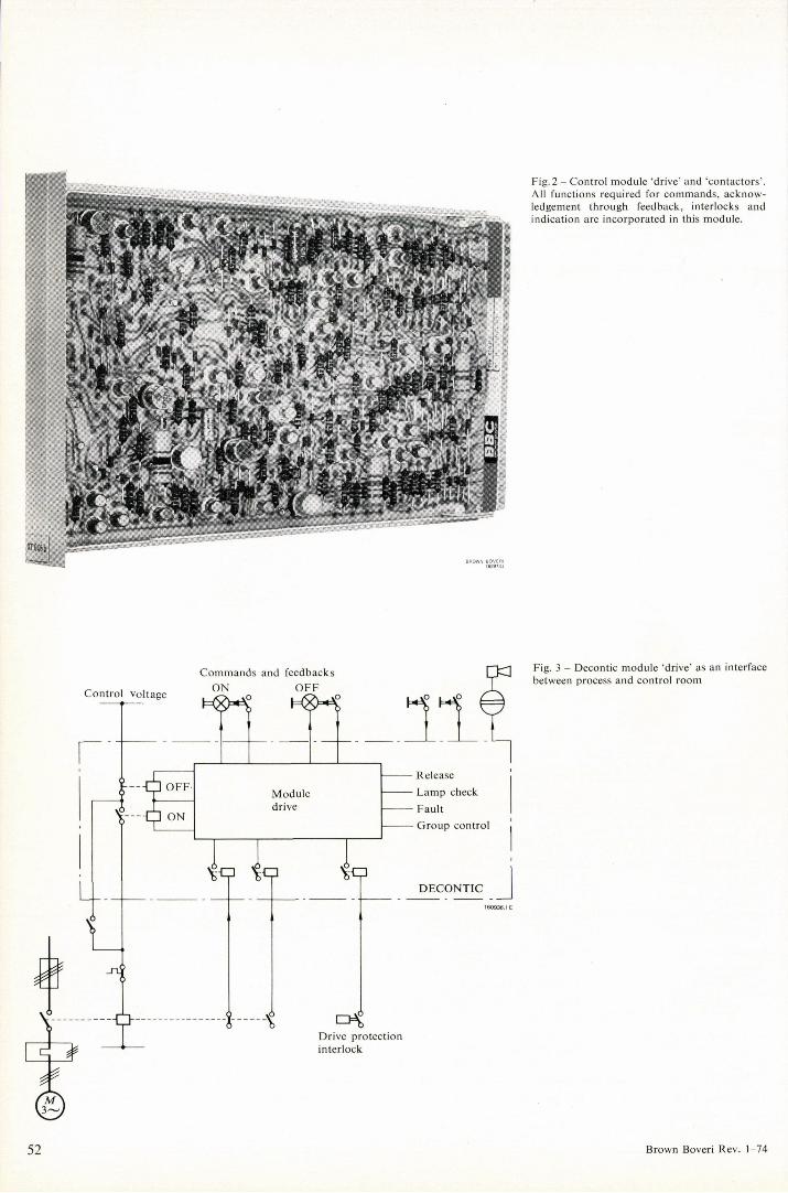
Fig. 2 - Control module 'drive' and 'contactors ' . All functions required for commands, acknow-ledgement through feedback, interlocks and indication are incorporated in this module.
Fig. 3 - Decontic module 'drive' as an interface between process and control room
52 Brown Boveri Rev. 1-74

control systems can be used in combination. The optimum concept is derived by taking into account the features of the process, the control systems to be used and the operational requirements.
'Decontic' system Brown Boveri developed the 'Decontic' system for solv-ing the above tasks. This is a flexible modular electronic control system which is suitable for power plant control as well as for other process control duties. The systematic design makes the planning of the electrical equipment simple and uncomplicated. Extensive use of electronic components practically eliminates maintenance.
The Decontic system contains 12 types of sub-assemblies with various logic functions. These are assembled to form a sub-rack and are wired and tested according to a logic Programme which results in a compact functional unit, Fig. 4. Sequential control is primarily applied to complex func-tional groups and process control levels, e.g. start-up and shut-down programmes for turbines, boilers, and burner controls, etc. The command sequence is defined by a Programme containing the sequence of actions which take the process criteria into consideration. One step must be completed before the next can be initiated. The size of
Individuell Drive Control Level At this level essentially three control modules are applied: 'drive', 'valve' and 'solenoid valve'. These contain the majority of the logic interlocks which are necessary for control of the different drives (Fig. 2). Motor contactors, circuit-breakers or other mechanically latched relays are controlled by the 'drive' control module. The commands are latched electrically or mechanically in the switchgear. The control module 'valve' is used for intermittent drives with operating periods in the region of 1 to 2 seconds. The command is stored in the control module until the desired position is reached. Solenoid valves, depending on type, may use either of the two above mentioned modules. In certain cases, however, it may be practical to use a special module for solenoid valves. This module is similar to the one for 'drives' except that it will störe the order internally. The plant criteria are continuously supervised. The con-trol voltage supply is taken from a plant d.c. source (48, 110, 220 V). The transformation of the binary plant feedbacks to the electronic voltage is accomplished through reed relays, see Fig. 3. These relays also act as filters against disturbances in the criteria circuits. Coupling relays with power con-tacts are used for command Outputs, which makes for simplified planning of the control voltage circuits. Each control module contains a signalling system with 2 to 3 Outputs for direct connection to indicating lamps in the control room. This indication gives clear information on the drive condition as well as fault indication of the drive. The signalling system also provides a signal for the alarm system in case of drive faults. All this information enables the operator to locate the faulty drive immediately.
Functional Group and Process Control Level Various logic elements are required for the functions at this level, especially for the logic controls.
Fig. 4 - Sub-rack and sub-assemblies for Decontic control system
Upper : Logic funetion sub-assemblies Lower: Sub-rack with sub-assemblies forming a compact
functional unit
BROWN BOVERI 156341.1
Brown Boveri Rev. 1-74

aovEi
Fig. 5 - Diode matrix for programming the criteria in relation to the process control Programme
such a sequence programme can vary from a minimum up to that of a power plant process control programme con-taining up to 30 steps and 2 to 4 different programmes. Two programmes containing 15 to 30 steps are normally sufficient for start-up and shut-down of steam turbines. The Decontic system is provided with certain special modules for sequential control. Sub-assemblies are also used here as for the logic control systems. Changes in the Programme must be carried out during the project plan-ning stage. Even during commissioning programme changes may occur. The Decontic sequential control was therefore designed with a diode matrix, Fig. 5, for all criteria, time and step-functions. A change in programme can be carried out quickly and simply by removing or adding diodes. Of all the information contained in the logic or sequential programme, only that information is indicated which requires action by the operator or which denotes a fault already corrected by the programme. It is very important that few but significant criteria are selected. In most cases signal lamps are used for indication. Figure 6 shows the circuit arrangement of a Decontic sequence control sys-tem.
Fig. 6 - Block diagram of a Decontic sequence control
Criteria
Sensors 1
Process
C
H ?ntrol units D X i bwitchgear
Transducers
V Sim.
Release matrix
D E C O N T I C Sequential control unit
Lamp amplifiers
Criteria matrix
Time monitor
Step logic
Outpu t logic
Commands
fr
Control panel
Step display -<gMg>-
Indicator lamps
-A ©
A
A
A
A
Release
Run up
Run down
Stop
Lamp check
54 Brown Boveri Rev. 1-74

Power Supply The rated supply for the Decontic system is 24 V d.c. with a tolerance of -20 to +25%. A power supply comprising storage battery and charging unit is recommended.
Programming
The programming involves four main steps:
1. Determination of the drive interlocks 2. Grouping the drives according to function 3. Establishing the Programme for functional group con-
trol 4. Building up a coordinating programme for the process
Extensive knowledge on various aspects of the process is necessary to obtain an optimum arrangement; forexample:
- thermodynamics, physics and chemistry to understand the process requirements
- mechanical and electrical engineering to ensure correct application of specific conditions to the various drives
- control and regulation engineering - protection - electronics
Brown Boveri have many years' experience in automation of thermal processes, which ensures well adapted and thoroughly coordinated arrangements. The equipment supplied by Brown Boveri takes operation and supervision philosophy into account and is easily adapted to meet special customer requirements.
Example
The automation of a 7 MW turbine with condensing plant is briefly described in the following. The block circuit diagram, Fig. 7, shows the relation be-tween control, regulation and protection. The unit control system for the turbine consists of two programmes, run-up and shut-down, and contains a total of 11 steps. The con-trol and monitoring panel can be seen in Fig. 8. The functional group level has been split into 6 groups, i.e. lubricating oil, barring gear, turbine drains, main and
Fig. 7 - Block diagram of a turbine automation system showing its relation to protection and control functions
C O N T R O L P R O T E C T I O N
Process control
Group control
Drive control
Plant
Brown Boveri Rev. 1-74

CRITE RIOS PRIM4RI0S s ECCIOL i E SCALO N RE TRGCE s o CRITE :RIOS iggSBkf
SECU NDARI OS
0
mnm *m
mm» mm. mm *am U I
STTTT mm i
1 mjm mmmm
mmm. I MCMSTE
U I M *
tumr 43*m
im: mm* ™ OTASW
wmatot mmmkt «ST* 1 9 @ mm*. U T W U U
*umm <ttm.
jmKKä* •JSSS? L @ Jmm ASÜFC rmm 4tm*
m um mm
m M M
0
«*M8» F»
3 O
ISSSFC«
mm. 1 4 t
. 4 * mm CMSK
m mm UTLILNU
0
«<*««* SC 5 © m msm. ^ S Ü F
smm 0 *rm mmm. mmm J mmm. wir • M M U M « »•PHsm* *«AM» tum* mmm nst «L
mm R ISm «FCNUS
«48 ; FR» MCM&«
*m*t Tmm >«*C omm mmm. «m « mmm mmm mm : *_JM T.W» HUM mumm m um mm mm
7nrm tprnw. mmm mm» «
mm* mim
mm*6* 19 mmm «MMHMM
&MM «Eft» W M M 1
7 U M
m iMMn
• «
mmm M M
« K M ,
» « M C jm.im m HOHEM 0 CM«* 8
tm mmmm
» M M
mmm HU. MIM ^sr I tt TTI.MM
M M M M M
s
CONTR GL DE RETRI 3CES0 )
«mm 1 [ Z T n» TS
. rnmom mmt
L —
( M M M mm na mm
T T M.«
«MMM
T U MMM
mmm |*srsasr| T T fisa
M.«
«MMM
T U MMM
mmm
R 1 1
Fig. 8 - Control and display panel for a process control system for automatic start-up and shut-down of a turbine
start-up air ejectors, and condensate pumps. The indivi-dual drive control level is used to control 22 drives. Some of these drives are controlled directly from the process control level. The turbine run-up impulses are generated by an elec-tronic unit, the pulse frequency is dependent of the thermal condition of the turbine. The pulses are led via a thyristor output stage to the turbine operating device. Synchronizing is initiated by the process control and is carried out automatically by the Synchrotact electronic control unit. The control is then transferred to the turbine Controller for further operation.
Bibliography
[1] G. Eifert, D. Engelhard, W. Hinz, H.-P. Stöckler: Be-griffsbestimmungen für die Steuerungstechnik in Wärme-kraftwerken. Elektrizitätswirtschaft 70 1971 (24) 691-695.
[2] F. Motz: Decontic®, a decentralized control system for the automation of power stations. Brown Boveri Rev. 55 1968 (1/2) 25-31.
56 Brown Boveri Rev. 1-74

BBC BROWN BOVERI
BBC Brown, Boveri & Company, Ltd. Baden/Switzerland