Ventilación para un Aceptable Calidad del Aire Interior - ANSI ...
Upload
khangminh22Category
view
0download
0
—RELION® PROTECTION AND CONTROL
615 series ANSIIEC 61850 Engineering Guide


Document ID: 1MAC053584-RGIssued: 2019-06-07
Revision: BProduct version: 5.0 FP1
© Copyright 2019 ABB. All rights reserved

Copyright
This document and parts thereof must not be reproduced or copied without writtenpermission from ABB, and the contents thereof must not be imparted to a third party, norused for any unauthorized purpose.
The software or hardware described in this document is furnished under a license and maybe used, copied, or disclosed only in accordance with the terms of such license.
TrademarksABB and Relion are registered trademarks of the ABB Group. All other brand or productnames mentioned in this document may be trademarks or registered trademarks of theirrespective holders.
WarrantyPlease inquire about the terms of warranty from your nearest ABB representative.
www.abb.com/mediumvoltage
www.abb.com/substationautomation

Disclaimer
The data, examples and diagrams in this manual are included solely for the concept orproduct description and are not to be deemed as a statement of guaranteed properties. Allpersons responsible for applying the equipment addressed in this manual must satisfythemselves that each intended application is suitable and acceptable, including that anyapplicable safety or other operational requirements are complied with. In particular, anyrisks in applications where a system failure and/or product failure would create a risk forharm to property or persons (including but not limited to personal injuries or death) shallbe the sole responsibility of the person or entity applying the equipment, and those soresponsible are hereby requested to ensure that all measures are taken to exclude ormitigate such risks.
This product has been designed to be connected and communicate data and informationvia a network interface which should be connected to a secure network. It is the soleresponsibility of the person or entity responsible for network administration to ensure asecure connection to the network and to take the necessary measures (such as, but notlimited to, installation of firewalls, application of authentication measures, encryption ofdata, installation of anti virus programs, etc.) to protect the product and the network, itssystem and interface included, against any kind of security breaches, unauthorized access,interference, intrusion, leakage and/or theft of data or information. ABB is not liable forany such damages and/or losses.
This document has been carefully checked by ABB but deviations cannot be completelyruled out. In case any errors are detected, the reader is kindly requested to notify themanufacturer. Other than under explicit contractual commitments, in no event shall ABBbe responsible or liable for any loss or damage resulting from the use of this manual or theapplication of the equipment.

Conformity
This product complies with the directive of the Council of the European Communities onthe approximation of the laws of the Member States relating to electromagneticcompatibility (EMC Directive 2014/30/EU) and concerning electrical equipment for usewithin specified voltage limits (Low-voltage directive 2014/35/EU). This conformity isthe result of tests conducted by ABB in accordance with the product standards EN 50263and EN 60255-26 for the EMC directive, and with the product standards EN 60255-1 andEN 60255-27 for the low voltage directive. The product is designed in accordance with theinternational standards of the IEC 60255 series and ANSI C37.90. This product complieswith the UL 508 certification.

Safety information
Dangerous voltages can occur on the connectors, even though theauxiliary voltage has been disconnected.
Non-observance can result in death, personal injury or substantialproperty damage.
Only a competent electrician is allowed to carry out the electricalinstallation.
National and local electrical safety regulations must always be followed.
The frame of the protection relay has to be carefully grounded.
When the plug-in unit has been detached from the case, do not touch theinside of the case. The relay case internals may contain high voltagepotential and touching these may cause personal injury.
The protection relay contains components which are sensitive toelectrostatic discharge. Unnecessary touching of electronic componentsmust therefore be avoided.
Whenever changes are made in the protection relay, measures should betaken to avoid inadvertent tripping.


Table of contents
Section 1 Introduction............................................................................5This manual.............................................................................................. 5Intended audience.................................................................................... 5Product documentation.............................................................................6
Product documentation set..................................................................6Document revision history................................................................... 6Related documentation........................................................................7
Symbols and conventions.........................................................................7Symbols...............................................................................................7Document conventions........................................................................ 7
Section 2 IEC 61850 overview.............................................................. 9
Section 3 PCM600 tool........................................................................13Connectivity packages............................................................................14PCM600 and relay connectivity package version................................... 14
Section 4 615 series data model......................................................... 17Product series implementation .............................................................. 17Information model...................................................................................17Vertical and horizontal communication................................................... 19
Predefined vertical communication data sets.................................... 20Predefined horizontal communication data set..................................22Vertical communication diagnostic counters..................................... 22
Parameter setting and digital fault recorder............................................23
Section 5 GOOSE............................................................................... 25Horizontal communication...................................................................... 25
Configuring horizontal communication.............................................. 25GOOSE publishing properties................................................................ 26Configuring GOOSE with the IEC 61850 Configuration tool...................27
Defining IEDs and starting the IEC 61850 Configuration tool............27Configuring a GOOSE publisher with the IEC 61850Configuration tool.............................................................................. 28
Creating a GOOSE data set with the IEC 61850 Configurationtool................................................................................................28
Table of contents
615 series ANSI 1Engineering Guide

Configuring a GOOSE control block with the IEC 61850Configuration tool......................................................................... 33
Configuring a GOOSE subscriber with the IEC 61850Configuration tool.............................................................................. 38
Configuring GOOSE inputs with the IEC 61850 Configurationtool................................................................................................38
Configuring GOOSE with IET600........................................................... 39Defining devices and exporting the SCD file for IET600................... 41Creating an empty project with IET600............................................. 42Importing the SCD file into IET600.................................................... 43Configuring a GOOSE publisher with IET600................................... 44
Creating a GOOSE data set with IET600..................................... 44Configuring a GOOSE control block with IET600.........................48
Configuring a GOOSE subscriber with IET600................................. 51Configuring GOOSE inputs with IET600...................................... 51
Finalizing GOOSE configuration with IET600....................................52Exporting the SCL file...................................................................52Importing the SCL file................................................................... 53
Connecting GOOSE inputs to a relay application...................................55Received GOOSE message handling.................................................... 57GOOSE supervision............................................................................... 58
Background sending..........................................................................58Default value handling....................................................................... 59Alarm supervision in application........................................................ 59Diagnostic counters........................................................................... 60
Forcing of GOOSE signals .................................................................... 63Testing of one device........................................................................ 63Testing of many devices in a system ................................................64
Section 6 Process bus and IEEE 1588 time synchronization..............67Sampled measured values and IEEE 1588 v2 time synchronization..... 67System building...................................................................................... 67
High-availability seamless redundancy HSR.....................................67Parallel redundancy protocol PRP.....................................................69Performance optimization..................................................................70Requirements for third party devices.................................................70
SMV system configuration...................................................................... 71Configuring SMV with the IEC 61850 Configuration tool...................73Configuring SMV with IET600........................................................... 74
Bay level configuration............................................................................77Application configuration of the SMV receiver...................................77
Table of contents
2 615 series ANSIEngineering Guide

SMV control block .............................................................................79Angle and amplitude corrections....................................................... 80SMV delay......................................................................................... 81IEEE 1588 v2 parameters and status information............................. 82Power profile parameters.................................................................. 86Quality bits in SMV frames................................................................ 86
Engineering verification.......................................................................... 87
Section 7 Engineering of event reporting with PCM600......................91Managing IEC 61850 clients with the IEC 61850 Configuration tool...... 91
Adding new IEC 61850 clients for the IEC 61850 Configuration tool 91IEC 61850 Configuration tool user interface...........................................94Creating data sets with the IEC 61850 Configuration tool...................... 96
Defining data set entries with the IEC 61850 Configuration tool....... 98Creating report control blocks with the IEC 61850 Configuration tool.. 100Configuring RCB clients with the IEC 61850 Configuration tool........... 103Substation section configuration in the IEC 61850 Configuration tool..104
Section 8 Engineering of event reporting with IET600...................... 107Managing IEC 61850 clients with IET600.............................................107
Adding new IEC 61850 clients for IET600.......................................107Attaching IEC 61850 clients to a bus with IET600...........................110
IET600 user interface........................................................................... 110Setting visibility of columns in grid editors....................................... 112
Substation section configuration in IET600.......................................... 113Creating data sets with IET600.............................................................114Creating report control blocks with IET600...........................................116RCB client configuration with IET600................................................... 117
Configuring RCB clients semi-automatically....................................118
Section 9 Glossary............................................................................ 121
Table of contents
615 series ANSI 3Engineering Guide

4

Section 1 Introduction
1.1 This manual
The engineering guide provides information for IEC 61850 engineering of the protectionrelays with PCM600 and IET600. The guide can be used as a technical reference duringthe engineering phase, installation and commissioning phase, and during normal service.For more details on tool usage, see the PCM600 documentation.
1.2 Intended audience
This manual addresses the system engineers and installation and commissioningpersonnel.
The system engineer must have a thorough knowledge of protection systems, protectionequipment, protection functions and the configured functional logic in the protectionrelays. The installation and commissioning personnel must have basic knowledge of howto handle the electronic equipment.
1MAC053584-RG B Section 1Introduction
615 series ANSI 5Engineering Guide

1.3 Product documentation
1.3.1 Product documentation set
Pla
nnin
g &
pu
rcha
se
Eng
inee
ring
Inst
alla
tion
Com
mis
sion
ing
Ope
ratio
n
Mai
nten
ance
Dec
omm
issi
onin
g,
dein
stal
latio
n &
dis
posa
l
Quick start guideQuick installation guideBrochureProduct guideOperation manualInstallation manualConnection diagramEngineering manualTechnical manualApplication manualCommunication protocol manualIEC 61850 engineering guidePoint list manualCyber security deployment guideline
GUID-12DC16B2-2DC1-48DF-8734-0C8B7116124C V2 EN
Figure 1: The intended use of documents during the product life cycle
Product series- and product-specific manuals can be downloaded from theABB Web site http://www.abb.com/relion.
1.3.2 Document revision historyDocument revision/date Product series version HistoryA/2018-02-26 5.0 FP1 First release
B/2019-06-07 5.0 FP1 Content updated
Download the latest documents from the ABB Web sitehttp://www.abb.com/substationautomation.
Section 1 1MAC053584-RG BIntroduction
6 615 series ANSIEngineering Guide
1.3.3 Related documentation
Product series- and product-specific manuals can be downloaded from the ABB Web sitehttp://www.abb.com/substationautomation.
1.4 Symbols and conventions
1.4.1 Symbols
The caution icon indicates important information or warning related to theconcept discussed in the text. It might indicate the presence of a hazardwhich could result in corruption of software or damage to equipment orproperty.
The information icon alerts the reader of important facts and conditions.
The tip icon indicates advice on, for example, how to design your projector how to use a certain function.
Although warning hazards are related to personal injury, it is necessary to understand thatunder certain operational conditions, operation of damaged equipment may result indegraded process performance leading to personal injury or death. Therefore, complyfully with all warning and caution notices.
1.4.2 Document conventions
A particular convention may not be used in this manual.
• Abbreviations and acronyms are spelled out in the glossary. The glossary alsocontains definitions of important terms.
• Push button navigation in the LHMI menu structure is presented by using the pushbutton icons.To navigate between the options, use and .
• Menu paths are presented in bold.Select Main menu/Settings.
• LHMI messages are shown in Courier font.To save the changes in nonvolatile memory, select Yes and press .
• Parameter names are shown in italics.
1MAC053584-RG B Section 1Introduction
615 series ANSI 7Engineering Guide

The function can be enabled and disabled with the Operation setting.• Parameter values are indicated with quotation marks.
The corresponding parameter values are "Enabled" and "Disabled".• Input/output messages and monitored data names are shown in Courier font.
When the function picks up, the PICKUP output is set to TRUE.• Dimensions are provided both in inches and mm. If it is not specifically mentioned,
the dimension is in mm.• This document assumes that the parameter setting visibility is "Advanced".
Section 1 1MAC053584-RG BIntroduction
8 615 series ANSIEngineering Guide

Section 2 IEC 61850 overview
The international IEC 61850 standard defines a framework for substationcommunications networks and systems. The standard consists of several parts rangingfrom the requirements on substation automation systems to the details of a communicationprotocol. Its main goal is interoperability; the ability for IEDs from one or differentmanufacturers to exchange information and use the information for their own functions.
IEC 61850 standard for communication networks and systems in substations has been outsince 2005 and used successfully in ABB products. IEC 61850 standard is updated witha new version, Edition 2. Edition 2 extends to new application areas in transmission anddistribution power systems and also defines a new functionality to Edition 1 functionality.This product series supports both versions of IEC 61850, Edition 1 and Edition 2.
A major difference between the other communication protocols applied in substationautomation and IEC 61850 is that the latter is not only a communication protocol, but awhole framework for specifying, engineering and operating substation automationsystems. The communication part covers the connection between the IEDs and thesubstation clients, for example, SCADA and gateways.
GUID-43179FBC-BDC7-4062-95BC-81A0F886F785 V1 EN
Figure 2: Structure and parts of the IEC 61850 standard
1MAC053584-RG B Section 2IEC 61850 overview
615 series ANSI 9Engineering Guide

The IEC 61850 standard specifies an expandable object-oriented data model and wide setof protocol services for substation automation (standard parts 7-x). The standard does notspecify any protection or control functions, but specifies how the functions expose theirinformation to a communication network.
The standard supports free allocation of functions to devices. With efficientcommunication facilities, the functions can be located anywhere in the system, that is, aninterlocking function can reside in the IED or on the station level. Additionally, thestandard is open for different system implementations, that is, different integration levelsand allocation of functions to different devices is supported.
The standard also defines an XML description language for substation automationsystems. The language facilitates efficient integration of devices into systems in anautomated fashion. Additionally the standard supports a comprehensive and consistentsystem definition and engineering, which makes not only the devices, but also their toolsand systems interoperable (standard part 6).
The standard uses Ethernet and TCP/IP for communication. Since Ethernet and TCP/IPare widely accepted and used, the application of these technologies provide a broad rangeof features from mainstream communication.However, IEC 61850 is also open forpossible new communication concepts in the future.Communication profiles in IEC61850 can be divided to vertical and horizontal. The vertical profile uses MMS over TCP/IP and vertical communication Layer 2 Ethernet multicast messages. The standardseparates the functionality represented by the data model and the related communicationservices from the communication implementation thus being open for possible newcommunication concepts in the future.
Section 2 1MAC053584-RG BIEC 61850 overview
10 615 series ANSIEngineering Guide

Data model (objects, sevices)
Client server
communication GOOSESampled
values
Mapping
Real-time
communication
MMS
TCP
IP
Ethernet link layer
Ethernet physical layer with priority tagging (100 Mbit/s)
1
2
3
GUID-A9FD9579-37AD-4B03-935E-BF39D48B7211 V1 EN
Figure 3: Communication stacks and mapping used in IEC 61850
1 Abstract communication services interface (ACSI)
2 Stack interface
3 ISO/OSI stack
1MAC053584-RG B Section 2IEC 61850 overview
615 series ANSI 11Engineering Guide

12

Section 3 PCM600 tool
Protection and Control IED Manager PCM600 offers all the necessary functionality towork throughout all stages of the protection relay life cycle.
• Planning• Engineering• Commissioning• Operation and disturbance handling• Functional analysis
The whole substation configuration can be controlled and different tasks and functionscan be performed with the individual tool components. PCM600 can operate with manydifferent topologies, depending on the customer needs.
PCM600 is used to conduct complete engineering and configuration activities needed forthe bay level protection relays.
Connectivity Packages are separate software packages that provide type and versioninformation to PCM600. Further Connectivity Packages assist the tool withcommunications.
PCM600 uses IEC 61850 over Ethernet to communicate with bay devices. Thiscommunication allows PCM600 to configure and monitor the devices. In addition to IEC61850 the devices have optional communications protocols and hardware to connect tostation engineering tools. PCM600 provides the ability to export the configuration of thedevices or an entire substation in a standard file format which enables station engineeringin separate IEC 61850 System Configuration tools.
A PC with PCM600 can be connected to any 615 series protection relay within a stationby using the Ethernet connection. The connection can also be used for service andmaintenance purposes. In addition, the connection is used to handle digital fault recordsfrom the protection relays.
The modern-day protection relays are designed using the concept of the IEC 61850standard. This is primarily in regards to how functions within the protection relay aremodelled and how the protection relay is represented in the substation. See the IEC 61850parameter list for the list of logical nodes available in the protection relay and observe howthey follow the structure and rules as defined in part 7 of the standard.
The engineering of the used communication protocols is a separate task and an addition tothe engineering of protection and control functions.
1MAC053584-RG B Section 3PCM600 tool
615 series ANSI 13Engineering Guide
PCM600 can be used for different purposes throughout the protection relay life cycle. Aset of special tools is available for different applications.
The applications can be organized into groups.
• Relay engineering• Communication engineering• Record management• Device monitoring and diagnostic
For more information, see the PCM600 documentation.
3.1 Connectivity packages
A connectivity package is a software component that consists of executable code and datawhich enables system tools to communicate with a protection relay. Connectivitypackages are used to create configuration structures in PCM600. The latest PCM600 andconnectivity packages are backward compatible with older protection relay versions.
A connectivity package includes all the data which is used to describe the protection relay.For example, it contains a list of the existing parameters, data format used, units, settingrange, access rights and visibility of the parameters. In addition, it contains code whichallows software packages that use the connectivity package to properly communicate withthe protection relay. It also supports localization of text even when it is read from theprotection relay in a standard format such as COMTRADE.
Update Manager is a tool that helps in defining the right connectivity package versions fordifferent system products and tools. Update Manager is included with the products thatuse connectivity packages.
3.2 PCM600 and relay connectivity package version
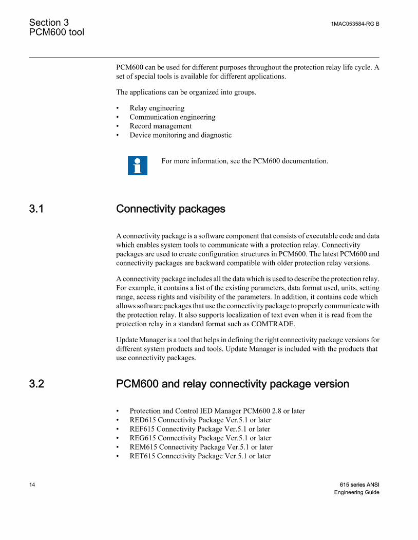
• Protection and Control IED Manager PCM600 2.8 or later• RED615 Connectivity Package Ver.5.1 or later• REF615 Connectivity Package Ver.5.1 or later• REG615 Connectivity Package Ver.5.1 or later• REM615 Connectivity Package Ver.5.1 or later• RET615 Connectivity Package Ver.5.1 or later
Section 3 1MAC053584-RG BPCM600 tool
14 615 series ANSIEngineering Guide

Download connectivity packages from the ABB Web sitehttp://www.abb.com/substationautomation or directly with UpdateManager in PCM600.
1MAC053584-RG B Section 3PCM600 tool
615 series ANSI 15Engineering Guide

16

Section 4 615 series data model
4.1 Product series implementation
The protection relays have been fully designed according to IEC 61850. This means thatthe functionality of the protection relay is represented in a data model in accordance withthe standard and the protection relays support a wide range of the services provided by thestandard.
• Process data: monitoring of statuses and measurements• Application data: protection activation, tripping, fault recordings• Digital fault recorder files• Control commands• Protection settings• Settings and setting groups• Configuration data• Diagnostics and self-supervision• Fast horizontal communication between devices• Time synchronization• File transfer
If the protection relay is ordered with no Ethernet communication interface, the front porton the device still works according to IEC 61850. All settings and configurations arechanged with IEC 61850 services using PCM600 via the front Ethernet port of the LHMI.Without the rear Ethernet option, station communication is not available.
4.2 Information model
The protection relay is fully modelled according to the IEC 61850 standard. The datamodel can include up to four logical devices where different logical nodes, representingprotection and control functionality, are located. Depending on the selected functionalityin the protection relay, different configurations have different set of logical devices andlogical nodes. Data models also include full modelling and functionality of setting, settinggroups and configuration according to the IEC 61850 concept.
The protection relays are modelled in IEC 61850 using three logical devices.
1MAC053584-RG B Section 4615 series data model
615 series ANSI 17Engineering Guide

• Control logical device, CTRL• Disturbance recorder logical device, DR• Protection logical device, LD0
All generic functionality, such as modelling of physical inputs and outputs as well as thealarming LED functionality, resides under logical device LD0.
Different configurations have different data models.
During system engineering in the system configuration tool, do not deleteor rename logical devices, logical nodes, data objects or data attributes inthe IEC 61850 data model.
GUID-42167015-6E8C-4707-8E3C-5CCB30BE2BF4 V1 EN
Figure 4: Example of an IEC 61850 data model of a protection relay
Section 4 1MAC053584-RG B615 series data model
18 615 series ANSIEngineering Guide

In the IEC 61850 standard, communication services are configured through a number ofdata structures including data sets, report control blocks, GOOSE control blocks andsetting group control blocks. As these data structures pertain to the entire logical device,the standard indicates that they are to be modeled under LLN0, which is a special logicalnode that describes the common functionality of the logical device. All these datastructures are located in logical device LD0 logical node LLN0.
The full data model can be exported from PCM600 in the form of a SCL file, which isdefined in part 6 of the standard.
4.3 Vertical and horizontal communication
The protection relays are capable of vertical communication between the protection relayand monitoring and control systems (clients) such as PCM600 or MicroSCADA. Eachprotection relay can communicate to five separate clients to receive events, read or writedata (an active PCM600 connection is considered to be a client). The protection relay canreport data in either buffered or unbuffered mode and execute direct or select-before-operate control sequences according to the control commands sent by the client.
The protection relays are also capable of horizontal or peer-to-peer communication. Theycan be programmed to publish (send) information to and subscribe (receive) informationfrom other devices according to IEC 61850-8-1 and IEC 61850-9-2 LE.
IEC 61850 standard Edition 2 increased several identification string lengths which affectcommunication engineering and interoperability. The table lists identification lengthvalues to be considered especially with third party tools. ABB tools generally check thelength values.
Table 1: Identification lengths in IEC 61850 versions
Object Edition 1 length Edition 2 length DescriptionIED name 28 (32-4) 60 (64-4) Excluding the longest LD name length of 4
characters
Report controlblock name
14 30 Without a two digit RCB instance number
Data set name 32 32
RptID 65 129 Report Identifier
GoID 65 129 GOOSE Identifier
MSVID 65 65 Multicast Sampled Value Identifier (length asin 61850-9-2 LE)
1MAC053584-RG B Section 4615 series data model
615 series ANSI 19Engineering Guide

Table 2: Number of control block data sets and size of data sets
Control Block Maximum data sets Maximum length DescriptionGoCB 4 80 data attributes The protection relays allow a maximum of four
GOOSE control blocks, which effectively limitsthe protection relay to four data sets forGOOSE. The sending GOOSE data sets canhave a maximum total of 80 data attributes. Tominimize the message-handling load in thereceiving and sending protection relays, it isrecommended to limit data attribute amount to20 per data set.
RCB 10 Edition 1: 256data attributesEdition 2: 80 dataobjects
The IEC 61850 configuration tool (IET600 orPCM600) allows a maximum of 10 data setsfor the report control blocks.
SVCB 1 16 data attributes Some protection relay variants allow onesampled value control block. The sendingsampled value data set has a fixed set of 16data attributes as defined in IEC 61850-9-2LE.
4.3.1 Predefined vertical communication data sets
In vertical communications, the protection relay can generate events that areautomatically reported to any listening clients. These communications are configured viaa series of predefined data sets and corresponding report control blocks. The data sets areused to configure what data is sent and the report control block is used to configure whendata is sent.
The relay connectivity package includes predefined data sets and control blocks forvertical MMS event reporting. These data sets are used in predefined reporting controlblocks for five clients. The selected data in the data sets is suitable to most of the differentapplications and the selected default data automatically considers the used protectionrelay type and options.
The data sets and report control blocks can be modified using IET600, however, thisshould only be done by individuals that are extremely familiar with both the protectionrelays and IEC 61850. Inappropriate modifications can result in misoperation of theprotection relay.
• StatIed – generic status information of IEDs• StatIo – inputs, outputs, LEDs• StatUrg – measurement limit supervision, control feedback• StatNrml – protection pickup and trip signals, autoreclosing status• StatDR – digital fault recorder status• MeasReg – registered measurement values at faults• MeasFlt – measurements
Section 4 1MAC053584-RG B615 series data model
20 615 series ANSIEngineering Guide

When function blocks are added to or removed from a relay configuration also the defaultdata sets and the content of data sets are automatically modified to follow the IED datamodel. If all data does not fit into one data set, two data sets with suffixes "A" and "B" arecreated.
The protection relays support both buffered and unbuffered event reporting. In thepredefined configuration all report control blocks are configured to use bufferedreporting. The benefit of buffered reporting is that it buffers events during communicationbreaks and thus no events are lost. Further, a single data set can only be used by one reportcontrol block and the same data set entry cannot be used in different event reporting datasets.
The default values for the data sets and control blocks are suitable for most applications.The protection relay allows free renaming and editing of report control blocks and datasets. Only users who have an in-depth understanding of the protection relay and IEC61850 should modify the default configuration. Description of data in default data sets isavailable in the parameter list.
Vertical communication protocols, such as Modbus, rely on the data setsfor event generation. Modification of the default configuration have animpact on vertical communication.
The protection relay allows free renaming and editing of report control blocks and datasets. However, it is mandatory to keep certain signals in data sets for the protection relays,as removing signals from data sets affects also the available events in the local HMI. Dataobjects PhyHealth, PhyHealth1and PhyHealth2 from logical node LD0.LPHD1 giveindications of the internal relay or system configuration faults and these must be availablein some of the IEC 61850 data sets.
Data sets define also the status events which are available in the LHMIevent list.
It is not recommended to mix seldom updated status data (FC=ST) andfrequently updated measurement data (FC=MX) in the same data set tominimize the bandwidth consumption in the network and to avoidunnecessary publishing of unchanged status data.
It is not recommended to mix status (FC=ST) and measurement (FC=MX)data to the same data set due to the protection relay's internal eventhandling.
1MAC053584-RG B Section 4615 series data model
615 series ANSI 21Engineering Guide

A 615 series protection relay can have at maximum 14 configured datasets and 10 report control blocks for event handling. The maximum lengthfor a data set is 256 data attributes. The amount of data attributes within adata object varies, however, a 615 series protection relay can have 1500data attributes in data sets in total.
The protection relay does not support defining data on data attribute levelfor data sets used for vertical reporting. Only data object level is allowed.
When new data sets are added for MMS communication, the clientsreceiving this information need to be selected.
4.3.2 Predefined horizontal communication data set
In horizontal communication the user normally has to engineer IEC 61850-8-1 GOOSEdata sets. When IEC 61850-9-2 is used, the connectivity package automatically creates adata set including data as defined in 9-2 LE: four currents and four voltages with qualityattributes.
It is not allowed to engineer or modify the predefined 9-2 LE data set. Together with the9-2 LE data sets the connectivity package also creates a default sampled measurementvalue control block. The SVCB configuration needs to be finalized in the tool beforeconnecting the sent 9-2 data to the receiver IEDs.
4.3.3 Vertical communication diagnostic counters
The IEC 61850 data model of the IEDs includes a logical node LD0.MMSLPRT1 for IEC61850 vertical communication diagnostic. The counters are available via the HMI orPCM600 path Monitoring/Communication/MMSLPRT1.
Table 3: Diagnostic data objects
Data object Description Diagnostic informationSucConnCnt Successful connections Number of succeeded client connection attempts
FailConnCnt Failed connections Number of failed client connection attempts
ConcCnt Concludes Number of session concludes
TxAbtCnt Sent aborts Number of association aborts sent by server
RxAbtCnt Received aborts Number of received association aborts by server
TxRejCnt Sent rejects Number of sent rejects by server
Table continues on next page
Section 4 1MAC053584-RG B615 series data model
22 615 series ANSIEngineering Guide

Data object Description Diagnostic informationRxRqCnt Received request Number of received client requests
FailRqCnt Failed requests Number of failed client requests
SucReadCnt Reads Number of variable reads
FailReadCnt Failed reads Number of failed variable reads
SucWrCnt Writes Number of succeeded variable writes
FailWrCnt Failed writes Number of failed variable writes
InfRepCnt Reports Number of sent reports
ActConnCnt Active connections Number of active client connections
It is possible to reset the vertical diagnostics counters via Monitoring/Communication/MMSLPRT1/Reset counters and via the IEC 61850 communication by writing TRUE tothe RsCnt.Oper.ctlVal attribute under MMSLPRT1.
GOOSE communication has its own diagnostic counters. See the Diagnostic counterschapter in this manual for information on diagnostic counters used in GOOSEcommunication.
4.4 Parameter setting and digital fault recorder
The relay's protection function settings and parameters can be set and the active settinggroups changed by a IEC 61850 client using the standard IEC 61850 services. Thedisturbance recorder and load profile files in COMTRADE format are retrieved from the\COMTRADE\ and \LPD\COMTRADE\ directories by using PCM600 or any otherclient supporting IEC 61850 file transfer service or FTP.
When setting the parameter Configuration/Communication/MMSLPRT1/Unit modeto “Primary”, the values sent over IEC 61850 are scaled according to the CT and VTsettings.When setting the parameter Configuration/Communication/MMSGGIO1/Unit mode to “Primary”, the values sent over IEC 61850 are scaled according to the CTand VT settings.Restart the protection relay after changing the parameter. This feature isneeded if the SCADA system or substation gateway does not handle scaling from nominalvalues.
Digital fault recorder files in COMTRADE format are also retrieved by using the IEC61850 compatible services from the \COMTRADE\ directory.
1MAC053584-RG B Section 4615 series data model
615 series ANSI 23Engineering Guide

24

Section 5 GOOSE
5.1 Horizontal communication
GOOSE is used in substation automation for fast horizontal communication between theprotection relays. GOOSE can be used for direct data exchange, for example, ofinterlocking and blocking information between protection relays. According to the IEC61850-8-1 standard, GOOSE uses a publisher/subscriber profile in which information isshared from one device to one or several devices by using Ethernet multicast messages. Amessage is an image of a sent IEC 61850 data set that is defined in the configuration.
IET600 is used to configure the vertical and horizontal communication properties of theprotection relays.
The protection relay can send any type of status or measurement data in the GOOSEmessages from its IEC 61850 data model. The status data response time, that is, the timeit takes for the application to handle a received GOOSE message and to send theconcerned data back to the network, is below 3 ms. The response time fulfils the tightestType 1A, Class P2/3 requirements of the standard.
When the protection relay is configured to send measurements, the analog, integer orcounter type data should be placed in its own data set to minimize the bandwidthconsumption in the network and to avoid unnecessary publishing of unchanged statusdata. The triggering of analog data sending is controlled by deadband handling, zero-pointclamping and limit supervision.
The horizontal communication configuration consists of the protection relays' GOOSEcontrol block, data set and GOOSE input configuration. The result of the configurationwork is a system configuration which is used for the protection relays. The used files in theworkflow are IEC 61850 standard format SCL files.
5.1.1 Configuring horizontal communication
Configure GOOSE by using the IEC 61850 Configuration tool in PCM600 or by using theseparate IET600 tool. PCM600 interacts with IET600 by importing and exporting SCLfiles.
1MAC053584-RG B Section 5GOOSE
615 series ANSI 25Engineering Guide

5.2 GOOSE publishing properties
GOOSE data is transmitted at regular intervals in 802.1Q multicast frames over the LAN.Peer devices can determine the state of the communications by listening for thetransmissions. When the data values change, the data is transmitted at an increasedfrequency to ensure the timeliness of its reception. The transmission then gradually tapersoff to the original frequency with the new data.
In GOOSE, data sending is based on data sets and GOOSE control blocks. The data setdefines what device data is used in GOOSE service and sent to local Ethernet subnetworkin a GOOSE message. The GOOSE control block links the data set and its attributes toactual data.
Table 4: GOOSE control block attributes
GoCB attribute DescriptionMulticast address A multicast addressing scheme is used when sending GOOSE messages. A
multicast address can be shared by several sending devices, or it can bedevice specific. To keep the multicast message filtering of the devicesworking it is recommended to use unique multicast addresses.
Ethernet frame-specificinformation (802.1 Q tagginginfo: APPID, priority andVLAN id)
APPID is a GoCB-specific integer value identifying the sender GoCB and itsdata. The APPID must be unique for the GoCB in the system. The prioritycan be used according to the local network priority scheme, but normally thedefault value is sufficient. The VLAN group can be used when configuring theEthernet network topology Virtual LANs for routing and filtering multicastmessages. Configuration is done in managed Ethernet switches.
GoCB name The name of the GoCB structure seen from the IEC 61850/MMS client.Some devices use this as a unique data reference.
GoID A GOOSE control block specific string. The default value is the GoCB pathin the 61850 namespace if nothing is set. It is recommended to always set aunique value in tool.Check the GOOSE Control block GoID name according to the systemrequirements of the receiving device. Although the protection relays useMAC address and APPID for receiving packet detection, some devicesrequire additionally that the GOOSE control block GoID is named explicitly.
Data set definition Data sent in GOOSE messages to the network.
ConfRev ConfRev increases when the referenced data set is modified. Both theGOOSE sender and the receiver must have the same ConfRev value. Thisensures that the both devices have the same configuration level in thesubstation configuration. ConfRev usage is done automatically by tools. Ifthe latest system configuration is not downloaded to all required devices, theconfiguration revision may differ between the receiver and sender and dataexchange does not work.
Section 5 1MAC053584-RG BGOOSE
26 615 series ANSIEngineering Guide

5.3 Configuring GOOSE with the IEC 61850 Configurationtool
See detailed descriptions of the steps in corresponding chapters.
1. Add devices to a PCM600 project.2. Engineer the GOOSE connections between the devices.
2.1. Define the published GOOSE data and control blocks.2.2. Define the subscribing IEDs for the GOOSE data.
3. Engineer the IED applications with GOOSE inputs.
5.3.1 Defining IEDs and starting the IEC 61850 Configuration tool
Use PCM600 to define the substation and the IEDs. Before starting the systemengineering, configure the IED settings and logic in PCM600.
For more information, see PCM600 documentation.
1. Create a PCM600 project with all the needed IEDs.
If the substation includes third party IEDs requiring configuring forhorizontal GOOSE communication, instantiate a generic IEC 61850IED under the substation in the plant structure and import the SCLfiles (ICD/CID) holding the information on those IEDs. The thirdparty IEDs have separate tools for creating the ICD/CID/SCD file.
2. Start the IEC 61850 Configuration tool.
1MAC053584-RG B Section 5GOOSE
615 series ANSI 27Engineering Guide

GUID-B9B41288-BB3A-491F-BA7E-C9DF36A2908F V1 EN
Figure 5: Starting IEC 61850 Configuration
5.3.2 Configuring a GOOSE publisher with the IEC 61850Configuration tool
To control the GOOSE data publishing, such as addressing, every publisher IED musthave at least one data set for GOOSE data and one GOOSE control block.
1. Group the data to a data set sent to IEC 61850 station bus.2. Define the GOOSE control block.
The IED can send single binary, double binary, integer and floating pointdata values with a quality attribute. A quality attribute is used at thereceiver side to check data validity.
5.3.2.1 Creating a GOOSE data set with the IEC 61850 Configuration tool
The sending data set is defined with the GOOSE control block. With the IEDs of thisproduct series, the sending GOOSE data set can have a maximum of 20 data attributes tominimize the message-handling load in the receiving and sending IEDs.
Section 5 1MAC053584-RG BGOOSE
28 615 series ANSIEngineering Guide

All data sets must be configured under the logical node LLN0 and must be provided withnames unique within the IED. The IEDs allow a maximum of four GOOSE control blocks,which effectively limits the IED to four data sets for GOOSE, as there is a one-to-onecorrespondence between the GOOSE control blocks and GOOSE data sets. Typically, itis sufficient to define a single data set and control block for an application. However, it isrecommended to use a separate data set and corresponding control block for analogvalues.
1. Select the target IED in the Plant Structure view.2. Select GOOSE Communication in the drop-down box on the toolbar.
GUID-4BC10E72-1660-464C-9E00-DF40146342F8 V1 EN
Figure 6: Selecting GOOSE communication
3. Select the Data Sets tab.4. To add a new data set, right-click the area containing the data set names and select
New.
1MAC053584-RG B Section 5GOOSE
615 series ANSI 29Engineering Guide

GUID-E0D859A1-1B0B-4F80-A926-6CF2945C05EA V1 EN
Figure 7: Creating a new data set
5. Define the LN where the data set is to be placed (accept preselected “LD0/LLN0”)and give the data set a unique name.
Section 5 1MAC053584-RG BGOOSE
30 615 series ANSIEngineering Guide

GUID-67590F2E-34BC-48FC-8779-E425A5B4DBAF V1 EN
Figure 8: Naming the data set
A maximum of 80 data attributes can be added to IED's GOOSE data sets.Recommendation is to divide attribute amount to 20 per GOOSE data set, for maximumperformance in sender/receiver. After creating the GOOSE data sets, define the data setentries (data attributes or data objects) for the data sets.
After creating the GOOSE data sets, define the data set entries (data attributes or dataobjects) for the data sets.
If quality data attributes are added to a data set, they must be located afterthe status value of the corresponding data object.
The received GOOSE data set can contain signals on the data attribute or data object level.Data object level GOOSE entries can only be received of the following CDC types: SPS,SPC, ACD, ACT, DPS, DPC, INC, INS, ENC and ENS. Other CDC types can beconnected to application only when dataset is defined in attribute level.
1MAC053584-RG B Section 5GOOSE
615 series ANSI 31Engineering Guide

Defining GOOSE data set entries with the IEC 61850 Configuration tool
1. Select the Data Sets tab.2. Right-click a data set and select Details to add data attributes.
GUID-E8418EA9-A61D-4656-A31E-2192FAF5400A V1 EN
Figure 9: Opening Details
3. In the Data Set Entry window, select the data attribute or data object present in thedata set.• Click Append selected to add the data to the end of the data set. To add a data
object level entry, select it from the FC section. To add a data attribute levelentry, select it from the DA section
• Click Insert selected to add the data above the selected row in the data setentries list.
• To remove a data from the data set, select the data in the data set entries paneand click Remove selected.
A maximum of 80 data attributes can be added total to IED's GOOSE data sets.Recommendation is to divide attribute amount to 20 per GOOSE data se, for maximumperformance in sender/receiver.
Section 5 1MAC053584-RG BGOOSE
32 615 series ANSIEngineering Guide

GUID-77B169D9-6A48-4686-90D0-15468FF79A67 V1 EN
Figure 10: Adding data set entries
If a data set has quality attributes, the attributes must be located after thestatus value of the same data object.
The data attribute entries are single data, such as stVal and q. Data setentries can be also defined on the data object level. Data object levelGOOSE entries can only be received of the following CDC types: SPS,SPC, ACD, ACT, DPS, DPC, INC, INS, ENC and ENS. Product versionsprior to Ver.5.0 FP1 do not support the data object level GOOSE entries.This limitation must be considered when configuring the whole systemconsisting of different product versions.
After defining the data entries for the data sets, configure the GOOSE control blockproperties.
5.3.2.2 Configuring a GOOSE control block with the IEC 61850 Configuration tool
1. Select the IED in the Plant Structure view.2. Select the GOOSE Controls tab in the tool pane.3. To add a new GOOSE control block, right-click the area containing the existing
GOOSE control blocks and select New.
1MAC053584-RG B Section 5GOOSE
615 series ANSI 33Engineering Guide

GUID-F97EA615-D339-4B9A-8EC2-4B44D0FB21D9 V1 EN
Figure 11: Creating a new GOOSE control block
4. Browse to LLN0 under LD0 to define where the GOOSE control block is to beplaced.
5. Give a unique name to the GOOSE control block.
Section 5 1MAC053584-RG BGOOSE
34 615 series ANSIEngineering Guide

GUID-7CDEC4B8-6227-4B4D-948D-746E72C0C169 V1 EN
Figure 12: Naming a GOOSE control block
6. In the Data set drop-down list, select the previously created data set to link with theGCB.
GUID-DC485CA5-04BE-4047-8047-67D38F72D956 V1 EN
Figure 13: Data set drop-down list
1MAC053584-RG B Section 5GOOSE
615 series ANSI 35Engineering Guide

Data set entries in a data set linked to the GCB can be modified fromthe GOOSE control block tab by selecting Data Set details in theshortcut menu.
7. Edit the properties and addresses of the created GOOSE control block.Edit at least MAC Address and APP ID.
GUID-EA2CBAC9-B42A-4AA2-8245-34D50ED28B8F V1 EN
Figure 14: GOOSE control block properties
Section 5 1MAC053584-RG BGOOSE
36 615 series ANSIEngineering Guide

Table 5: GOOSE control block properties
GoCB property DescriptionGoCB name GOOSE control block name. The maximum length is 28 characters.
Application (AppID) A unique GOOSE Identification string for each GoCB in the system.Recommendation is to define a device-specific value and not to use thedefault empty value. The maximum length is 64 characters.
t(min) (ms) Indicates the maximum response time in milliseconds to data change.This time can be used by the receiver to discard messages that are tooold. In principle, t(min) can vary depending on the data type, but for theIEDs, the value is always “10 ms” for sent data.
t(max) (ms) Indicates the background "heartbeat" cycle time in milliseconds; thedefault value is “10 000 ms”. If there are no data changes, the IED stillresends the message with the heartbeat cycle to enable the receiver todetect communication losses, that is, the communication is supervised.
Configuration Revision Contains an integer value that is sent in every GOOSE message. Theinteger indicates the amount of changes in the data set. The receiverchecks the message for configuration mismatches. “ConfigurationRevision” cannot be manually edited in IET600.
MAC Address Multicast MAC address to which the specific GOOSE data is sent. Thereceiving IED filters the frames and starts to process them if a specificmulticast address is defined in the configuration. It is recommended tohave one unique multicast address per GoCB. The address range forGOOSE Multicast addresses is 01-0C-CD-01-00-00...01-0C-CD-01-01-FF
App ID Unique HEX value application identifier for sending the GoCB within thesystem. It identifies the purpose of this particular data set. The valuerange is 0000...3FFF.
VLAN-ID Used if the Ethernet switches in a station bus support VLAN. If staticVLAN identifiers are defined, it also affects the switch port configuration.Value “000” indicates a non-configured VLAN and switches do not filterthese messages on a port basis. This is recommended if there is noneed to split the logical network. The VLAN identifier is a 3-characterHEX value with range 000...FFF. Recommended values are 2...1001.
VLAN Priority Used in networks supporting VLANs. The priority is used with networkswitches. The default value for GOOSE is “4” and the value range is0...7.
With the IEDs of this product series, only t(max) is configurable, nott(min).
The multicast MAC address is usually unique, and APP-ID must beunique.
1MAC053584-RG B Section 5GOOSE
615 series ANSI 37Engineering Guide

5.3.3 Configuring a GOOSE subscriber with the IEC 61850Configuration tool
The IED application can receive and use single binary, double binary, integer and floatingpoint values with attached quality information. A quality attribute is received andprocessed automatically.
5.3.3.1 Configuring GOOSE inputs with the IEC 61850 Configuration tool
1. Select the IED node from the plant structure in the Project Explorer window.2. Click the GOOSE Controls tab in the tool pane.
The rows of the GCB client editor show GCBs, the so-called senders, and thecolumns show the IEDs available as the GOOSE clients, the so-called receivers.All IEDs that are configured in the plant structure automatically appear in the clientscolumn.
3. To add or remove clients for a GOOSE control block, click the check-box in the gridcorresponding to the IEDs.When adding or removing clients, the input sections of the corresponding IEDs areupdated.
Section 5 1MAC053584-RG BGOOSE
38 615 series ANSIEngineering Guide

1
2
3
GUID-3436301A-3118-45F2-8F29-DE83E192B977 V1 EN
Figure 15: GCB client editor showing the senders and receivers
1 Subscriber 1
2 Subscriber 2
3 Publisher
In the Data Sets tab and the GOOSE Controls tab, the Clients columnshows all the configured IEDs. For the IED without data sets and GCBs,however, there is no check box in the grid matrix since the IED publishesthe GOOSE control block to the network.
In the Data Sets tab, the clients are mapped automatically to thecorresponding data sets based on the configuration done in the GOOSEControls pane and vice-versa.
5.4 Configuring GOOSE with IET600
See detailed descriptions of the steps in corresponding chapters.
1MAC053584-RG B Section 5GOOSE
615 series ANSI 39Engineering Guide

1. Add devices to a PCM600 project.2. Export the SCD file.3. Import the SCD file to IET600.4. Engineer the GOOSE connections between the devices.
4.1. Define the published GOOSE data and control blocks.4.2. Define the subscribing IEDs for the GOOSE data.
5. Export the SCD file back to PCM600.6. In PCM600, engineer the IED applications with GOOSE inputs.
Before any configuration, create backups of the PCM600 andIET600 projects. For example, once an SCD file is imported intoPCM600, the changes cannot be undone except by restoring thebackup.
PCM600SCDfile
SCD file
ICDfile
CreateABB
devices IET600
Configure GOOSEpublisher and
subscriber
PCM600
ConfigureGOOSE inputs
Third partydevice
Third partydevice
Configure
Export Import
Import
Import
Export
Export
GUID-69164641-F2BE-4FC3-BEFC-EA6F4BC9AAF1 V2 EN
Figure 16: Horizontal communication configuration process
Section 5 1MAC053584-RG BGOOSE
40 615 series ANSIEngineering Guide

5.4.1 Defining devices and exporting the SCD file for IET600
Use PCM600 to define the substation and the devices. Before starting the systemengineering, configure the device in PCM600.
For more information, see the PCM600 documentation.
1. Create a PCM600 project with all the needed devices.2. To export the SCD file, click the Plant Structure tab, right-click the substation node
in the submenu and select Export.The file includes the whole substation configuration in SCL format for other tools.
GUID-8510D9CE-3772-4EDA-89B2-DE811B1D7096 V2 EN
Figure 17: Exporting an SCD file from PCM600
3. Define the export options.A dialog box with several options opens. Unlike other ABB tools such as COM600Sor MicroSCADA product configuration tools, IET600 does not use the privatesections. Select all the check boxes but clear Export As SCL Template.
1MAC053584-RG B Section 5GOOSE
615 series ANSI 41Engineering Guide
GUID-220A10FD-5961-4ED6-9698-FCCC5E0EF6A8 V3 EN
Figure 18: Export options for an SCL file
4. Click Export.
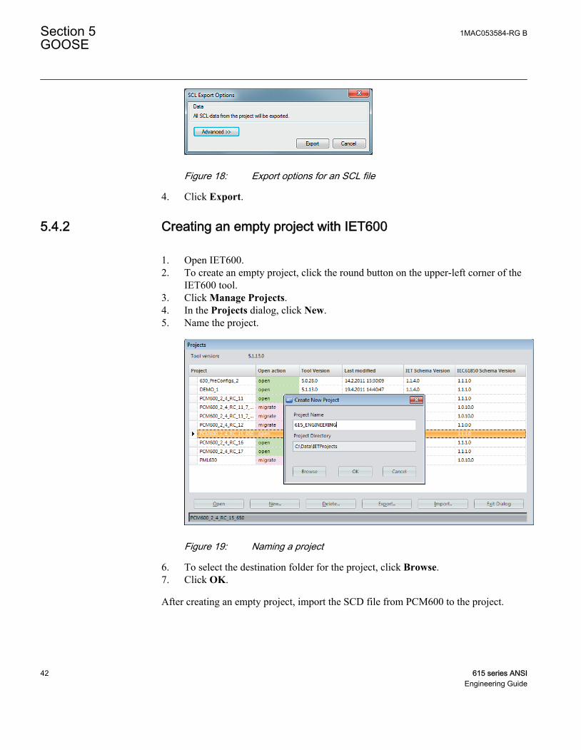
5.4.2 Creating an empty project with IET600
1. Open IET600.2. To create an empty project, click the round button on the upper-left corner of the
IET600 tool.3. Click Manage Projects.4. In the Projects dialog, click New.5. Name the project.
GUID-1B4325E3-7D15-4C92-A094-4128A5ECFC04 V2 EN
Figure 19: Naming a project
6. To select the destination folder for the project, click Browse.7. Click OK.
After creating an empty project, import the SCD file from PCM600 to the project.
Section 5 1MAC053584-RG BGOOSE
42 615 series ANSIEngineering Guide

5.4.3 Importing the SCD file into IET600
1. Import the SCD file from PCM600 to the empty project.• Click Import SCL File on the shortcut menu of the project object• Click Import button
GUID-C9CA5E07-9CE1-452C-8553-EF259BA0E999 V2 EN
Figure 20: Importing an SCL file
2. Locate the SCL file and click Open.
If the substation includes third-party devices which need to be configuredfor horizontal GOOSE communication, the SCL files holding theinformation from those devices must be imported as well. The third-partydevices have separate tools for creating the ICD/CID/SCD file.
1MAC053584-RG B Section 5GOOSE
615 series ANSI 43Engineering Guide

SCD files can be imported to a project only once. If a new device needs tobe later added to the configuration, it must be first created using theCreate New IED function after which the Update IED function can beused to import the related CID or ICD file. Another alternative is to createa new project in IET600 and import the whole SCD file from PCM600.The existing IEC 61850 configuration including GOOSE remains if thechanges made in IET600 have been already imported to PCM600.
5.4.4 Configuring a GOOSE publisher with IET600
To control the GOOSE data publishing, such as addressing, every publisher device musthave at least one data set for GOOSE data and one GOOSE control block.
1. Group the data to a data set sent to IEC 61850 station bus.2. Define the GOOSE control block.
The protection relay can send single binary, double binary, integer andfloating point data values with a quality attribute. A quality attribute isused at the receiver side to check data validity.
5.4.4.1 Creating a GOOSE data set with IET600
The sending data set used by the GOOSE control block must be defined. With theprotection relays of this product series, the sending device can have a maximum of 80 dataattributes in GOOSE data sets. To minimize the message-handling load in receiving andsending protection relays, the recommendation is to divide data attributes to a maximumof 20 per data set.
All data sets must be configured under the logical node LLN0 and must be provided withnames unique within the device. The protection relays allow a maximum of four GOOSEcontrol blocks, which effectively limits the protection relay to four data sets for GOOSEas there is a one-to-one correspondence between the GOOSE control blocks and GOOSEdata sets. Typically it is sufficient to define a single data set and control block for anapplication. However, it is recommended to use a separate data set and correspondingcontrol block for analog values.
1. Select the IEDs tab in the navigation pane.2. Click the IED node.3. Click the Datasets tab in the editor pane.
Section 5 1MAC053584-RG BGOOSE
44 615 series ANSIEngineering Guide

GUID-D5AA23C7-F93C-449A-98A2-8E628E4B141E V2 EN
Figure 21: Creating a data set in IET600
4. To add a new data set, right-click the area containing the data set names and selectInsert new row the shortcut menu.
5. Define the LN where the data set is to be placed (accept preselected “LD0/LLN0”)and give the data set a unique name.
1MAC053584-RG B Section 5GOOSE
615 series ANSI 45Engineering Guide

GUID-277CF35A-9D31-45E7-8FFC-8A6461D4B553 V1 EN
Figure 22: Naming a data set in IET600
After creating the GOOSE data sets, define the data attributes for the data sets.
If quality data attributes are added to a data set, they must be located afterthe status value of the corresponding data object.
The received GOOSE data set can contain signals on the data attribute or data object level.Data object level GOOSE entries can only be received of the following CDC types: SPS,SPC, ACD, ACT, DPS, DPC, INC, INS, ENC and ENS. Other CDC types can beconnected to application only when dataset is defined in attribute level.
Defining data entries with IET600
1. Select the Datasets tab on the editor pane.2. Select a GOOSE data set.3. Using the selection lists below the data set grid, select a data attribute or data object
to be used.• Click Append >> to add the data attribute to the end of the data set.• Click Insert > to add the data attribute above the selected row in the data set
entries list.
Section 5 1MAC053584-RG BGOOSE
46 615 series ANSIEngineering Guide

A maximum of 80 data attributes can be added in total to the IED's GOOSE data sets.Recommendation is to divide the attribute amount to 20 per GOOSE data set formaximum performance in sender/receiver.
GUID-78399F79-C437-49E6-8D4E-44860A235BEF V2 EN
Figure 23: Adding data set entries
The possible amount of attributes that can be added to a data set andthe amount of already added attributes are shown above the data setentries list. However, since IET600 cannot make a differencebetween the maximum data attribute count of a data set for verticalreporting and a GOOSE data set, too high a maximum value isshown for a GOOSE data set.
If a data set has quality attributes, the attributes must be located afterthe status value of the same data object.
The data set entries must be single data attributes, such as stVal andq.
After installation of the connectivity package documentation add-on, a full list of the available signals with descriptions and IEC61850 names is available in PCM600 under the Documentation
1MAC053584-RG B Section 5GOOSE
615 series ANSI 47Engineering Guide
menu of the IED node. The document name in PCM600 is ParameterList.
After defining the data entries for the data sets, configure the GOOSE control blockproperties.
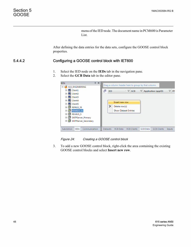
5.4.4.2 Configuring a GOOSE control block with IET600
1. Select the IED node on the IEDs tab in the navigation pane.2. Select the GCB Data tab in the editor pane.
GUID-99FF4DC6-FAC8-495F-9D2A-CC5ED3AC8A0B V1 EN
Figure 24: Creating a GOOSE control block
3. To add a new GOOSE control block, right-click the area containing the existingGOOSE control blocks and select Insert new row.
Section 5 1MAC053584-RG BGOOSE
48 615 series ANSIEngineering Guide

GUID-C7F23F7B-F486-4163-A4E9-41B454D36254 V1 EN
Figure 25: Naming a GOOSE control block
4. Browse to LLN0 under LD0 to define where the GOOSE control block is to beplaced.
5. Give a unique name to the GOOSE control block.6. In the Attached Dataset drop-down list, select the previously created data set.
After creating the GOOSE control block, edit its properties and addresses. Edit atleast MAC Address and APP-ID.
GUID-BFBAAD7C-DE54-48E9-A160-2F178DFC3F24 V1 EN
Figure 26: GOOSE control block properties
To set the visibility of the GoCB columns, click the upper-left iconof the table and select or clear the check boxes in the Field Chooserdialog.
1MAC053584-RG B Section 5GOOSE
615 series ANSI 49Engineering Guide

GUID-63BBBAFE-B1F2-448B-89B9-E5CD12C5E988 V1 EN
Figure 27: Field Chooser dialog
Table 6: Selected GOOSE control block properties
GoCB property DescriptionGCB GOOSE control block name
Application (appID) A unique GoID for each GoCB in the system. Recommendation is todefine a device-specific value and not to use the default empty value.
t(min) (ms) Indicates the maximum response time in milliseconds to data change.This time can be used by the receiver to discard messages that aretoo old. In principle, t(min) can vary depending on the data type, butfor the protection relays, the value is always “10 ms” for sent data.
t(max) (ms) Indicates the background "heartbeat" cycle time in milliseconds; thedefault value is “10 000 ms”. If there are no data changes, theprotection relay still resends the message with the heartbeat cycle toenable the receiver to detect communication losses, that is, thecommunication is supervised.
Conf.Rev. Contains an integer value that is sent in every GOOSE message. Theinteger indicates the amount of changes in the data set. The receiverchecks the message for configuration mismatches. “ConfigurationRevision” cannot be edited manually in IET600.
MAC Address Multicast MAC address to which the specific GOOSE data is sent. Thereceiving device filters the frames and starts to process them if aspecific multicast address is defined in the configuration. It isrecommended to have one unique multicast address per GoCB. Theaddress range for GOOSE Multicast addresses is 01-0C-CD-01-00-00...01-0C-CD-01-01-FF.
Table continues on next page
Section 5 1MAC053584-RG BGOOSE
50 615 series ANSIEngineering Guide

GoCB property DescriptionAPP-ID Unique HEX value application identifier for sending the GoCB within
the system. It identifies the purpose of this particular data set. Thevalue range is 0000...3FFF.
VLAN-ID Used if the Ethernet switches in a station bus support VLAN. If staticVLAN identifiers are defined, it also affects the switch portconfiguration. Value “000” indicates a non-configured VLAN andswitches do not filter these messages on a port basis. This is therecommended if there is no need to split the logical network. TheVLAN identifier is a 3-character HEX value with range 000...FFF.
VLAN Priority Used in networks supporting VLANs. The priority is used with networkswitches. The default value for GOOSE is “4” and the value range is0...7.
With the protection relays of this product series, only t(max) isconfigurable, not t(min).
Conf.Rev. cannot be manually edited. IET600 updates it automatically tothe next multiple of 100 when the configuration changes.
The multicast MAC address is usually unique, and APP-ID must beunique.
5.4.5 Configuring a GOOSE subscriber with IET600
The relay application can receive and use single binary, double binary, integer andfloating point values with attached quality information. A quality attribute is received andprocessed automatically.
5.4.5.1 Configuring GOOSE inputs with IET600
1. Select the root node on the IEDs tab in the navigation pane.2. Click the GCB Clients tab in the editor pane.
The rows of the GCB client editor show GoCBs, that is, “senders”, and the columnsshow the devices available as GOOSE clients, that is, “receivers”. If the client deviceis not on the same subnetwork as the GoCB sender, it cannot be configured as aclient.
1MAC053584-RG B Section 5GOOSE
615 series ANSI 51Engineering Guide

GUID-73A71281-0361-4CBC-821C-134054F263B0 V1 EN
Figure 28: GCB client editor
3. To add or to delete clients, double-click the cell.Upon adding or removing clients, the corresponding input sections are updated.
GUID-8E44EA71-0843-46AA-A9A7-5ADB65299CEC V1 EN
Figure 29: GOOSE inputs
5.4.6 Finalizing GOOSE configuration with IET600
5.4.6.1 Exporting the SCL file
1. Export the SCL file in one of the alternative ways.• Click Export SCD File on the shortcut menu of the project object• Click Export button.
Section 5 1MAC053584-RG BGOOSE
52 615 series ANSIEngineering Guide

GUID-52150B11-1100-4D0F-83F4-6E44BECEC7BF V2 EN
Figure 30: Exporting an SCD file
2. Select the file destination and click Save.It is recommended to leave the SCD file exported from PCM600 as a backup.
5.4.6.2 Importing the SCL file
1. Open PCM600 and ensure the original project is open.2. Switch off the engineering mode.
1MAC053584-RG B Section 5GOOSE
615 series ANSI 53Engineering Guide

GUID-653B6F22-8ACA-43D5-B227-2044A8BDD637 V1 EN
Figure 31: Switching off the engineering mode
3. Go to the Project Explorer view and select the Plant Structure tab.4. Right-click the project and select Import.
GUID-B23D0214-E0ED-4DC2-9006-505851DE3412 V2 EN
Figure 32: Importing an SCD file to PCM600
5. Open the SCL file exported from IET600.6. In the SCL Import Options dialog box under IED Types, select Don't import IEDs
of unknown type if the GOOSE configuration does not include third-party devices.
Section 5 1MAC053584-RG BGOOSE
54 615 series ANSIEngineering Guide

GUID-5F360E11-43BC-4853-AC45-DDAFEC6B387C V2 EN
Figure 33: SCL import options in PCM600
7. Click Import.
For more information, see the PCM600 documentation.
5.5 Connecting GOOSE inputs to a relay application
1. In PCM600, open Project Explorer and select the Plant Structure tab.2. Add the GOOSERCV function block with the Application Configuration tool.
The GOOSERCV function block can only be added with theApplication Configuration tool.
Give the GOOSERCV block application-specific user-definednames to distinguish between different blocks when makingGOOSE connections in the Signal Matrix tool.
1MAC053584-RG B Section 5GOOSE
615 series ANSI 55Engineering Guide

GUID-6AE0900F-7D20-4333-A221-15EC54104841 V2 EN
Figure 34: Adding the GOOSERCV function block
3. Create the connection into the application.3.1. Create the connection.3.2. Click Calculate execution order.3.3. Click Validate configuration.3.4. Save the connection to the application.
4. To open the Signal Matrix tool, right-click the protection relay, and select SignalMatrix.
5. To map the input points to the receiving input data, click the cell.To expand the source field, drag the edge of the field to expand it until the wholeGOOSE source address is visible.
6. In Signal Matrix in the GOOSE sheet, map the GOOSE publisher data into thecorresponding GOOSERCV function block.The columns in the GOOSE sheet represent publisher data and the rows represent thepossible subscriber input point.
GUID-82E5907B-82B8-488F-BD00-C2B4B7852FDF V2 EN
Figure 35: GOOSE sheet in Signal Matrix
The GOOSE receiver block output VALID defines the validity forthe received data. The value is based on the received quality attribute
Section 5 1MAC053584-RG BGOOSE
56 615 series ANSIEngineering Guide

value or communication status. This validity information can beused in the application to build the validity logic in addition to theGOOSE default supervision information.
During the protection relay start-up phase, the protection relay keepsthe value of the output VALID as “1” until the communication isactivated. After the communication is activated, the value of theoutput VALID is updated by the value received via thecommunication.
If the data type does not match with the GOOSERCV functionblock, the attribute cell is red.
In Signal Matrix, the received GOOSE data can be directly connected to the relayapplication. The GOOSE inputs are shown on the Binary or Analog Inputs sheetsand they can be connected to the application receiver function blocks. The columnsrepresent publisher data and the rows represent the possible subscriber input points.If the data type, for example timestamp, is not supported by the relay application, theattribute column is red. The quality attribute is automatically incorporated in theapplication with the status value, and it is not seen in Signal Matrix.
7. Save the changes made in Signal Matrix.8. Write to the IED.
5.6 Received GOOSE message handling
A GOOSE frame is not accepted if the Needs Commission bit is set. When the protectionrelay uses IEC 61850 Edition 2, data with the Test quality bit set is accepted only if thereceiving device is also in the test mode. When the relay uses IEC 61850 Edition 1, theTest field in GOOSE message is also used. For more information about GOOSE qualityhandling, see the corresponding flowcharts. A frame with the Test bit set is only acceptedif the receiving device is also in the test mode.
When the protection relay uses IEC 61850 Edition 2, a GOOSE frame isnot accepted if the Simulation bit is set.
When the protection relay uses IEC 61850 Edition 2, the Test quality bit is active in thesender if the relay is set to test mode. When the relay uses IEC 61850 Edition 1, the Testfield in GOOSE message is also set when in test mode.
1MAC053584-RG B Section 5GOOSE
615 series ANSI 57Engineering Guide

When the GOOSE sender is in test mode and the GOOSE receiver is not, in Edition 1 modethe GOOSE receiver freezes to its previous valid state, and in Edition 2 mode the datavalue is defaulted and the quality set to invalid.
The Test bit is active in the sender if the protection relay is set to test mode.
See the technical manual for more information on the test mode.
The GOOSE frame is also not accepted if ConfRev deviates from the one in theconfiguration. These error situations can be observed in the GSELPRT1 diagnosticcounters.
The default GOOSE input value is “0” for all the data types. The functionality is analogousto physically wired galvanic Normally Open (NO) contacts where the disconnected signalgives value “0” of FALSE to relay application. The application must be designed towithstand the default value. This value is used when the subscribed GOOSE data is notvalid, or it is not received from the network and the peer device is considered to be in atime-out state.
If a peer device sends the data including the quality attribute, the receiver device inputobject is not updated according to the received status value if the data quality is bad,questionable or blocked. The default value is also used in this case.
5.7 GOOSE supervision
5.7.1 Background sending
To ensure reliability and availability of the application, the GOOSE communication mustbe supervised. Design the application so that it can handle communication losses, forexample, when a peer device is not available or there are communication time-outs.
If there are no GOOSE-related data changes, the protection relay resends the last GOOSEmessage with a heartbeat cycle to enable the receiver to detect communication losses. Theheartbeat cycle is defined by modifying the MaxTime property on GOOSE control block.
Every GOOSE frame has a TAL field which shows how long the frame is valid until thenext heartbeat frame. Other devices may have their own TAL values. Nevertheless, all theTAL values under 1000 ms are rounded up to 1000 ms on the receiving side.
If no frames are received during 2xTAL, that is, if at least two consecutive frames are lost,then the receiver considers the whole data set as invalid. The quality attribute for the entiredata set is set to "bad" and the values are set to their default values. This is an important
Section 5 1MAC053584-RG BGOOSE
58 615 series ANSIEngineering Guide

consideration when designing the application as the default values need to be "fail-safe"values. For example, the protection relay should use an enabled signal for interlocking anda blocking-type signal for protection.
5.7.2 Default value handling
The information is of point-to-point type which means that there is only one signalconnected to the function block input.
The default value of the GOOSE receiver blocks output (OUT) is FALSE (0) in case thereis a communication error. This handling is applicable for all signal types (binary, integer,enum and floating point). In addition to the default value handling, value output signalautomatically carries validity information to the application function blocks. Validityinformation can be used in application by adding the quality function blocks.
In communication disturbance cases, GOOSE receiver blocks use default values.Application function blocks using these signals have their own handling for propagatedquality information and fail-safe functionality, especially when receiving analog type ofdata. Exact fail-safe functionality must be checked from the function block description inthe technical manual.
If one relay application function block input receives several signals from severalprotection relays, the input value is calculated in OR or AND operation (configured in theApplication Configuration tool) from several inputs. In this case, one default signal istreated as logical FALSE (0), but the other signals can keep the function block input valueactive. It works similarly as the traditional galvanic signal wires connected betweenprotection relays. The advantage in the GOOSE-based signalling is that the applicationalways detects faulty connections, which is not the case with the Normally Open (NO)type of physically wired galvanic contacts.
In all cases, however, a separate alarm event is always generated by the GSELPRT1.Almdata object for IEC 61850 event clients.
GSELPRT1.Alm can also be used on the application side as an input in the Signal MatrixTool's Binary Outputs sheet (signal GSELPRT ALARM).For example, it is possible tochange the setting group in case one or several protection relays are disconnected from thenetwork.
5.7.3 Alarm supervision in application
In a communication time-out situation, all the peer devices receive information about theproblem. The system does not tolerate single failures or non-existing devices, forexample, in service situations. Take this into account when designing an application.
1MAC053584-RG B Section 5GOOSE
615 series ANSI 59Engineering Guide

Disable GOOSE sending by writing “false” from IEC 61850 clients to theGoEna attribute under the GOOSE control block. Use this featurecarefully, and for test purposes only.
5.7.4 Diagnostic counters
The IEC 61850 data model of the protection relays includes a logical nodeLD0.GSELPRT1 for the GOOSE communication diagnostic. The counters are alsoavailable via the HMI or PCM600 path Monitoring/I/O Status/Communication/GSELPRT1/Monitoring.
It is possible to reset the GOOSE communication diagnostics counters via Monitoring/I/O Status/Communication/GSELPRT1/Monitoring/Reset counters and via the IEC61850 communication by writing TRUE to the RsCnt.Oper.ctlVal attribute underGSELPRT1.
Table 7: Diagnostics data objects
Data object Description Diagnostics informationFrRxCnt Received messages When increasing, the protection relay is receiving GOOSE
messages.
FrTxCnt Transmitted messages When increasing, the protection relay is sending GOOSEmessages.
RxStCnt Received state changes Received GOOSE messages with a new stNum value
RxSeqCnt Received sequencenumber
Received GOOSE retransmissions or heartbeat cyclemessages with a new sequence number
RxTestCnt Received frames with testbit
Received GOOSE frames with the test flag on
StWrnCnt State errors Number of notified state number jumps
SeqWrnCnt Sequence errors Number of notified sequence number jumps
RxTmOutCnt
Receiver time-outs Number of notified peer device time-outs
ConfErrCnt Received ConfRevmismatches
When increasing, there is a mismatch between the receivedGOOSE frame information and the used GOOSE configuration.
NdsComCnt Received frames withNeeds Commissioning
One peer device Indicates that its configuration is not valid orup-to-date.
DSErrCnt Errors in received dataset
Received data are syntactically wrong, or there are less data inreceived data set than expected.
Alm Receiver alarm Alarm signal value connected to the event and application logic.It is active when one peer device is in time-out.
GOOSE Alarm is activated in the receiver device in certain situations.
Section 5 1MAC053584-RG BGOOSE
60 615 series ANSIEngineering Guide

• Time-out• Configuration revision mismatch• Error in the received data set• The Needs Commissioning bit is active in the received message
1MAC053584-RG B Section 5GOOSE
615 series ANSI 61Engineering Guide

Wait for GOOSE Message
GOOSE Multicast MAC Address and APPID Match?
GOOSE Message Received
Needs Commissioning
?
GOOSE Receiver Timeout
Target Data Value Is Defaulted and Quality Set
To Invalid. Alarm Is Set To TRUE
No Frames Received During 2xTAL
TRUE
Configuration Revision
Mismatch?
FALSE
TRUE
Reset Receiver Timer
Message Out of Order or Dataset Mismatch?
FALSE
TRUE
Same State Number As Previous Message?
Receiver Timeout Counter +1
Needs Commissioning
Counter +1
Configuration Revision Mismatch Counter +1
Dataset Error Counter +1
FALSE
FALSE
State or Sequence Number Not As
Expected?
State or Sequence Number Error Counter
+1
Frame Test or Simulation field
Set?
Target Data Value and Quality Are Updated
Accordingly
FALSE
Device In Test Mode?
TRUE
TRUE
TRUE
Test Diagnostic Counter +1
FALSE
Amount of data entries same as in
previous msg?
TRUE
FALSE
Dataset Error Counter +1
FALSE TRUE
IEC 61850 Edition 2?
FALSE
TRUE
TRUE
TRUE
GUID-739488C5-3B0A-4126-A430-7E0FF1FBE505 V1 EN
Figure 36: Receiving GOOSE data in the protection relays
Section 5 1MAC053584-RG BGOOSE
62 615 series ANSIEngineering Guide

Status or measurand value has been
received.
Value is followed by quality attribute?
Proceed to next data entry
Target data value is defaulted and quality set
to invalid.Quality is bad?
FALSE
TRUE
Bad quality=INVALID | RESERVED |QUESTIONABLE | OVERFLOW | OUT-OF-RANGE | BAD-REFERENCE | OSCILLATORY | FAILURE | INCONSISTENT | INACCURATE
TRUE
Old data?Operator blocked?
Operator blocked?
TRUE
FALSE
FALSE
Target data value is defaulted and quality is
set according to q attribute.
FALSE
Target data value is updated and quality is set according to q attribute.
TRUE
TRUE
FALSE
Target data value is updated.
Test bit enabled?Receiver in test mode?
FALSE
TRUETRUE
TRUE
TRUE
IEC 61850 Edition 2?
TRUE
FALSEFALSE
GUID-5A73778C-01C5-49BF-9379-34F604E2343B V1 EN
Figure 37: Receiving GOOSE data with quality in the protection relays
5.8 Forcing of GOOSE signals
Application Configuration tool in PCM600 is used for configuring the IED.
5.8.1 Testing of one device
Configuration logic testing is done for individual configurations. GOOSE signals can beforced using the Signal Monitoring tool.
1MAC053584-RG B Section 5GOOSE
615 series ANSI 63Engineering Guide

GOOSERCV_BIN
Force value
Device under testGUID-DCF6F60C-42CC-42A1-AFEE-511CF4C61E73 V1 EN
Figure 38: Testing of one device
The device must be in test mode.
5.8.2 Testing of many devices in a system
Any status data can be sent through GOOSE communication. Horizontal communicationcan be tested by forcing the outputs of the sender device and observing the results in thereceiving device.
Section 5 1MAC053584-RG BGOOSE
64 615 series ANSIEngineering Guide

GOOSERCV_BIN
Tests
Protection function
System under test
Function testsCurrent protection
PHPTUC1 [3I<(1),37(1)]Reset
Activate START
Deactive START
Activate OPERATE
Deactive OPERATE
GUID-237BC2F7-FB5A-4306-9B49-6EDD6679DD30 V1 EN
Figure 39: Testing of many devices
Both devices must be in test mode.
1MAC053584-RG B Section 5GOOSE
615 series ANSI 65Engineering Guide

66

Section 6 Process bus and IEEE 1588 timesynchronization
6.1 Sampled measured values and IEEE 1588 v2 timesynchronization
The IED supports IEC 61850 process bus with sampled values of analog neutral and phasevoltages. Thus, the galvanic interpanel wiring used for sharing the busbar voltage valuecan be replaced with Ethernet communication. Sending of sampled values of analogneutral and phase currents is supported in addition to the voltages. The neutral voltage isderived from the phase voltages when there is no physical neutral voltage input availablein the IED. The measured values are transferred as sampled values using the IEC61850-9-2 LE protocol. Sampled values are intended for sharing neutral and phasevoltages to other IEDs with phase voltage based functions and 9-2 support. IEDs withprocess bus based applications use IEEE 1588 v2 Precision Time Protocol (PTP)according to IEEE C37.238-2011 Power Profile for high accuracy time synchronization.
Configure IEC 61850-9-2 LE with the IEC 61850 Configuration tool inPCM600 or with the separate IET600 tool. PCM600 interacts withIET600 by importing and exporting SCL files.
6.2 System building
Redundant Ethernet topologies (HSR/PRP) are recommended to be used in the sampledmeasured values applications and with GOOSE to ensure the highest availability.
6.2.1 High-availability seamless redundancy HSR
HSR topology presented here is a reference system for process bus usage with switchessupporting HSR and IEEE 1588 v2. This topology includes an HSR ring with theprotection relays of this product series where IEEE 1588 v2 clock masters are connectedto the ring utilizing Ethernet switches. Ethernet switches filter out IEC 61850-9-2 LEtraffic from the IEEE 1588 v2 clock masters. HSR ring is presented with light blue linesand normal Ethernet connections with dark blue.
1MAC053584-RG B Section 6Process bus and IEEE 1588 time synchronization
615 series ANSI 67Engineering Guide

Each connected node in the HSR ring must support HSR protocol to ensure smoothredundancy. Otherwise Ethernet communication is disturbed and might not work. Singleattached nodes can be connected to a HSR ring with a separate redundancy box (RedBox).
Use correct Ethernet connectors in the IED with HSR. IEDs with HSRsupport have three Ethernet connectors and redundant Ethernet ports aremarked as LAN A and LAN B. The third Ethernet port without any LANA or LAN B marking is an interlink port which is used as a redundancybox connector. However, RED615 with HSR/PRP support does notimplement an interlink port.
IEC 61850 HSR
SMV traffi
c
Backup 1588master clock
Managed HSREthernet switch
PrimaryIEEE 1588 v2 master clock
SecondaryIEEE 1588 v2 master clock(optional)
Managed HSREthernet switch
GUID-7C56BC1F-F1B2-4E74-AB8E-05001A88D53D V6 EN
Figure 40: Recommended HSR reference topology with SMV and IEEE 1588 v2
The maximum number of IEDs supported in the HSR ring is 30. This is tokeep the ring delay as small as possible for horizontal applications.
The IED interlink port does not support IEEE 1588 v2 slave devices.
Section 6 1MAC053584-RG BProcess bus and IEEE 1588 time synchronization
68 615 series ANSIEngineering Guide

HSR bandwidth is 50 Mbit/s as all messages are doubled for bothdirections of the ring.
6.2.2 Parallel redundancy protocol PRP
PRP topology presented here is a reference system for process bus usage with properswitches supporting IEEE 1588 v2. This topology includes duplicated star networkswhich are in PRP called LAN A and LAN B. IEEE 1588 v2 clock masters are connectedto the network utilizing Ethernet switches. Ethernet switches filter out IEC 61850-9-2 LEtraffic from the IEEE 1588 v2 clock masters. PRP LAN A is presented with dark blue linesand LAN B with light blue.
It is important in PRP not to connect LAN A and LAN B anywhere else than to end devicessupporting PRP. Otherwise Ethernet communication is disturbed and might not work. Alldevices connected to both LAN A and LAN B must support the PRP protocol. Singleattached nodes can be connected directly to LAN A or LAN B in which case there is noredundancy for this node or with a separate redundancy box (RedBox).
Use the correct Ethernet connectors in the IED with PRP. IEDs with PRPsupport have three Ethernet connectors and redundant Ethernet ports aremarked as LAN A and LAN B. The third Ethernet port without any LANA or LAN B marking is an interlink port which is used as a redundancybox connector. However, RED615 with HSR/PRP support does notimplement an interlink port.
Do not mix different PRP LANs. Ensure that the LAN A port is alwaysconnected to LAN A only and the LAN B port is connected to LAN B.
The IED interlink port does not support IEEE 1588 v2 slave devices.
1MAC053584-RG B Section 6Process bus and IEEE 1588 time synchronization
615 series ANSI 69Engineering Guide

Managed
Ethernet switch
IEC 61850
PRPManaged
Ethernet switch
Primary
IEEE 1588 v2
master clock
Secondary
IEEE 1588 v2
master clock
(optional)
Backup
IEEE 1588 v2
master clock
SMV
tra
ffic
GUID-424C4FFA-A4A6-463D-BFFE-3117E5AE55C8 V3 EN
Figure 41: Recommended PRP reference topology with SMV and IEEE 1588 v2
6.2.3 Performance optimization
• The SMV messages should be filtered out from the local subnetwork part not usingthese, because they cause high traffic in the network. Otherwise they reach also thosenetwork devices that do not subscribe the SMV messages. Managed Ethernetswitches can be configured to perform the filtering operation.
• IEEE 1588 v2 network devices complying with Power Profile are highlyrecommended to simplify the settings and to ensure compatibility. Power Profile andHSR standard recommend implementation according to the one-step mode.
• It is recommended to use IEEE 1588 v2 devices with the same clock mode (one-stepor two-step) within one network. Ethernet switches performing one-step to two-stepconversions should be avoided due to additional inaccuracy.
• One SMV publisher generates around 5 Mbit/s traffic to the network. This is about5% of bandwidth in PRP and 10% in HSR when the bandwidth of the used networkis 100 Mb/s.
6.2.4 Requirements for third party devices
System and setting requirements
Section 6 1MAC053584-RG BProcess bus and IEEE 1588 time synchronization
70 615 series ANSIEngineering Guide

• Support for the IEEE 1588 v2 time synchronization• Preferably IEEE 1588 v2 according to the Power Profile and implementation
according to the one-step mode• All network devices between the IEEE 1588 v2 clock master and the IED must
support IEEE 1588 v2
Ethernet switch requirements
• Support for the IEEE 1588 v2 transparent-clock operation mode to enable accuratetime synchronization in the system
• Preferably managed switch capabilities for SMV filtering and VLAN to restrict theflow of SMV only to devices using it
IEEE 1588 v2 master clock requirements
• Support for IEEE 1588 v2 Grand Master operation mode• Clock accuracy of ±1 µs or better to enable accurate enough sampled measured values
6.3 SMV system configuration
The SMVSENDER function block must be added to the ACT configuration of the SMVsender IED to activate SMV sending. By doing this the sampled value control block andthe related data set are automatically added to the IED configuration. SVCB and the dataset are defined by 9-2 LE in which the data set consists of four currents and four voltageswith quality attributes. IED sends the residual voltage as a calculated value when there isno physical neutral voltage input available in the IED. IEC 61850-9-2 LE defines a samplerate of 4000 samples per second in 50 Hz system.
GUID-EE462273-04EB-493C-938C-FCEC15C8960E V2 EN
Figure 42: Adding an SMVSENDER block in the Application Configuration tool
1MAC053584-RG B Section 6Process bus and IEEE 1588 time synchronization
615 series ANSI 71Engineering Guide

The SMV receiver cannot be configured to transfer received samplevalues from 9-2 LE to a second receiver.
The default data set for SMV sending is fixed and should not be modified.
If SMVSENDER is used in RED615, the SMVSENDER function blockshould also be added to the configuration of the other RED615.SMVSENDER can be disabled, if it is not used in the second RED615.The SMV Max Delay parameter must be in same position at both ends.
Due to the high time accuracy requirement of SMV the used time synchronization methodmust be IEEE 1588 v2. PTP priorities of IEDs and other IEEE 1588 v2 devices in thenetwork need to be configured properly (smaller value means highest priority) for bestmaster clock algorithm in 1588. External accurate master clocks must be set with highestpriority and if the IED is selected as backup, master clock priorities should be setaccordingly in all IEDs.
Some network routers can block 1588 traffic. Check that all devices using1588 time synchronization utilize the same master clock.
GUID-B096F89D-7B48-42B4-8E69-082FC9868AC3 V3 EN
Figure 43: Time synchronization source
SMV data set and SVCB should not be manually added or removed with other tools.
Section 6 1MAC053584-RG BProcess bus and IEEE 1588 time synchronization
72 615 series ANSIEngineering Guide

6.3.1 Configuring SMV with the IEC 61850 Configuration tool
The connection between SMV sender and receiver is handled using the IEC 61850Configuration tool.
1. Start the IEC 61850 Configuration tool.2. Select Process Bus Communication in the drop-down box on the toolbar.
GUID-0461A422-40DA-4429-B9FA-95CAF5B126EF V1 EN
Figure 44: Selecting Process Bus Communication
The SMV sender and the possible SMV receiver IEDs become visible.3. Edit the properties and addresses of the sampled value control block.
GUID-FD2F543A-9D6A-46D7-91F1-D2CDF9B5FABB V3 EN
Figure 45: Changing the VLAN ID
Some switches do not support multicast filtering with VLAN value“0” because it means “no VLAN” and VLAN 1 has special purposeas management VLAN for switches. Recommended value forVLAN is 2...1001.
1MAC053584-RG B Section 6Process bus and IEEE 1588 time synchronization
615 series ANSI 73Engineering Guide

Use a unique multicast address for each SVCB. The address rangefor sampled values multicast addresses is 01-0C-CD-04-00-00...01-0C-CD-04-FF-FF.
4. Connect the SMV sender to the receivers.5. In PCM600, select Write to IED.
GUID-B022C6A1-F19D-4CAB-B12F-5A4744359A6C V3 EN
Figure 46: Configuring the SMV sender and receivers
If the configuration is updated in a manner that affects the Conf.Rev valueof SVCB, configurations of both SMV sender and all receivers must berewritten from PCM600.
6.3.2 Configuring SMV with IET600
After the common configuration items have been completed, the SCD file has beenexported from PCM600 and the SCD file has been imported to IET600, the SMV senderand receiver connections can be handled using the IET600 tool Ver.5.3.21 or later.
1. In the Options dialog box in IET600, click Show IED Capabilities Tab.
Section 6 1MAC053584-RG BProcess bus and IEEE 1588 time synchronization
74 615 series ANSIEngineering Guide

GUID-28E4A3A2-8985-4C0D-B091-57B5031843B5 V1 EN
Figure 47: Selecting Show IED Capabilities Tab
2. In the IED Capabilities tab, check the Override for Client ServiceSampledValues box to adjust the IED615 option to support sampled valuesservices.
GUID-5D55765D-E23A-4376-869E-331F4293422B V1 EN
Figure 48: Editing the IED capabilities
3. Edit the properties and addresses of the sampled value control block.
1MAC053584-RG B Section 6Process bus and IEEE 1588 time synchronization
615 series ANSI 75Engineering Guide

GUID-F5503ED3-E477-43A5-96D5-5DE1FAE6415E V2 EN
Figure 49: Sampled value control block
Some switches do not support multicast filtering with VLAN value“0” because it means “no VLAN” and VLAN 1 has special purposeas management VLAN for switches. Recommended value forVLAN is 2...1001.
Use a unique multicast address for each SVCB. The address rangefor sampled values multicast addresses is 01-0CCD-04-00-00...01-0C-CD-04-FF-FF.
4. Connect the SMV sender and receivers.
GUID-4B27A48C-345A-44A8-A6FB-2FF498AB7307 V2 EN
Figure 50: Connecting the SMV sender and receivers in IET600
5. Save and export the SCD file and import it to PCM600.6. In PCM600, select Write to IED.
If the configuration is updated in a manner that affects the Conf.Rev valueof SVCB, configurations of both SMV sender and all receivers must berewritten from PCM600.
Section 6 1MAC053584-RG BProcess bus and IEEE 1588 time synchronization
76 615 series ANSIEngineering Guide

6.4 Bay level configuration
6.4.1 Application configuration of the SMV receiver
The SMV receiver application configuration is done with the Application Configurationtool in PCM600. TVTR function blocks are used in receiver application to perform thesupervision for the sampled values and to connect the received analog voltage inputs to theapplication. When SMVRCV is connected to the TVTR inputs, the connected TVTR doesnot physically measure its analog inputs if they are available in the IED. SMVRCVfunction block outputs need to be connected according to the SMV applicationrequirements, typically all three analog phase voltages connected either to ULTVTR1 oralternatively only a single analog phase voltage UL1 connected to the ULTVTR2 input.The VT connection analog input setting parameter for phase voltages must be selectedaccordingly and depending of the inputs connected either as "Wye" or "UL1".RESTVTR1 input is typically connected only in case there is measured neutral voltageneeded and then available from the sender.
SMVRCV
O:146|T:2,5|I:1
UL1UL2UL3Uo
ULTVTR1
O:147|T:2,5|I:1
UL1UL2UL3MINCB_OPEN
ALARMWARNING
RESTVTR1
O:148|T:2,5|I:1
Uo ALARMWARNING
ULTVTR1_ALARMULTVTR1_WARNING
RESTVTR1_ALARMRESTVTR1_WARNING
GUID-B526E64B-2782-48C5-98EA-5F00375D01D9 V1 EN
Figure 51: Receiving all phase voltages and residual voltage using SMV
Synchrocheck function requires and uses only single analog phase voltage (UL1)connected to ULTVTR2.
SMVRCV
O:146|T:2,5|I:1
UL1UL2UL3Uo
ULTVTR2
O:147|T:2,5|I:2
UL1MINCB_OPEN
ALARMWARNING
ULTVTR2_ALARMULTVTR2_WARNING
GUID-47BC90E8-6B3F-4096-AC1D-381C8E1F7A28 V2 EN
Figure 52: Receiving line voltage for synchrocheck functionality using SMV
If only one phase (UL1) is connected between SMVRCV and ULTVTR2,then VT connection parameter of the ULTVTR2 function block needs tobe set to “UL1” in the Parameter Setting tool in PCM600 before writingthe configuration to the IED.
1MAC053584-RG B Section 6Process bus and IEEE 1588 time synchronization
615 series ANSI 77Engineering Guide

ALARM and WARNING outputs are active during the configurationwriting. If VT connection type is set incorrectly, ULTVTR ALARM andWARNING outputs are always active. In case of unsupportedconfiguration, SMV error is indicated.
The WARNING output of TxTR should be connected in the SMV applications to performthe necessary actions in case the SMV angle information is out of the accuracy range.Depending on the protection function operation principle, inaccurate angle information isalso seen in the related protection function operation inaccuracy.
Additionally, the ALARM output of TxTR should be connected to ensure fail-safeoperation in all circumstances. The WARNING output is always internally active wheneverthe ALARM output is active.
WARNING and ALARM information is internally propagated for the measurementfunctions. Thus, measurement functions are able to update the measured value qualityinformation accordingly without any additional connections.
Voltage protection blocked in caseSMV voltages unavailable/unreliable
Directional protection changed to non-directionalscheme in case:- SMV voltages unavailable/unreliable. OR- SMV angle information inaccurate
GUID-2E245F6E-18DB-4F43-9615-82C368DC97DD V3 EN
Figure 53: Application Configuration tool logic example for the SMV applications
The receiver activates the TxTR WARNING and ALARM outputs if any of the quality bits,except for the derived bit, is activated. When the receiver is in the test mode, it acceptsSMV frames with test bit without activating the TxTR WARNING and ALARM outputs.
The TxTR WARNING in the receiver is activated if the synchronization accuracy of thesender or the receiver is worse than 4 µs. The output is held on for 10 seconds after thesynchronization accuracy returns within limits.
The TxTR ALARM in the receiver is activated if the synchronization accuracy of the senderor the receiver is unknown, worse than 100 ms or two or more consecutive frames are lost.The output is held on for 10 seconds after the synchronization accuracy returns withinlimits.
Section 6 1MAC053584-RG BProcess bus and IEEE 1588 time synchronization
78 615 series ANSIEngineering Guide

Quality of received SMV is available as outputs in SMV measuement function block andnot propagated directly to protection function blocks along with the SMV measurementvalues. To handle situations where SMV is not available, its quality is not good or thereis an issue with time synchronization, the WARNING and ALARM outputs of SMVmeasurement function blocks must be connected to application, for example to blockdirectional protection.
6.4.2 SMV control blockTable 8: Sampled value control block attributes
SVCB attribute DescriptionSvID A sampled value control block specific string. The
default value is <IedName>MU01.
Multicast address A multicast addressing scheme is used whensending sampled values messages. A multicastaddress can be shared by several sending devicesor it can be IED specific. To keep the multicastmessage filtering of the devices working, it isrecommended to use a unique multicast addresses.
SVCB name The name of the SVCB structure seen by the IEC61850/MMS client.
Data set Data sent in sampled values messages to thenetwork.
ConfRev ConfRev increases when the referenced data set ismodified. Both the sampled values sender and thereceiver must have the same ConfRev value. Thisensures that both IEDs have the same configurationlevel in the substation configuration. ConfRev usageis done automatically by the tools. If the latest systemconfiguration is not downloaded into all requiredIEDs, the configuration revision may differ betweenthe receiver and sender.
MAC Address Multicast MAC address to which the specificsampled values data is sent. The receiving IED filtersthe frames and starts to process them if a specificmulticast address is defined in the configuration. It isrecommended to have one unique multicast addressper SVCB. The address range for sampled valuesMulticast addresses is 01-0C-CD-04-00-00...01-0C-CD-04-01-FF.
App ID Unique HEX value application identifier for sendingthe SVCB within the system. It identifies the purposeof this particular data set. Value range for sampledvalues is 0x4000 to 0x7FFF.
Table continues on next page
1MAC053584-RG B Section 6Process bus and IEEE 1588 time synchronization
615 series ANSI 79Engineering Guide

SVCB attribute DescriptionVLAN-ID Used if the Ethernet switches in a station bus support
VLAN. If static VLAN identifiers are defined, it alsoaffects the switch port configuration. Value “000”indicates a non-configured VLAN and switches donot filter these messages on a port basis. This isrecommended if there is no need to split the logicalnetwork. The VLAN identifier is a 3-character HEXvalue with range 000...FFF. Recommended valuesare 2...1001.
VLAN Priority Used in networks supporting VLANs. The priority isused with network switches. The default value forsampled values is “4” and the value range is 0...7.
Sample Rate Amount of samples per period.
NoAsdu Number of ASDUs, which are concatenated into oneAPDU.
IncludeRefreshTime If selected SV buffer contains the attribute “RefrTm”.
IncludeSampleRate If selected SV buffer contains the attribute“SmpRate”.
Modify only MAC address, VLAN ID and sampled value ID to keep the9-2 LE compliancy. Leave the others as default.
6.4.3 Angle and amplitude corrections
The TxTR instrument transformer amplitude correction factors also affect the scaling inSMV frames. Thus, it is sufficient to configure these correction factors in the sender only.The angle correction factors on the other hand affect only the fundamental frequencyphasor and they need to be set in both the SMV sender and the receiver analog inputconfiguration.
Section 6 1MAC053584-RG BProcess bus and IEEE 1588 time synchronization
80 615 series ANSIEngineering Guide

GUID-E448DEBF-E032-4967-A73C-7D8D2D9B815D V1 EN
Figure 54: Amplitude and angle correction
6.4.4 SMV delay
The SMV Max Delay parameter, found via menu path Configuration/System, defineshow long the receiver waits for the SMV frames before activating the TxTR ALARMoutput. This setting also delays the local measurements of the receiver to keep themcorrectly time aligned. The SMV Max Delay values include sampling, processing andnetwork delay.
GUID-46F004DE-2AF9-4CBE-9A9F-1A87B3F5E7FA V1 EN
Figure 55: SMV Max Delay
TxTR ALARM activates when two or more consecutive SMV frames are lost or late. Asingle loss of frame is corrected with a zero-order hold scheme, the affect on protection isconsidered negligible in this case and it does not activate the TxTR WARNING or ALARMoutputs.
1MAC053584-RG B Section 6Process bus and IEEE 1588 time synchronization
615 series ANSI 81Engineering Guide

Table 9: Topology-dependent SMV max delay setting
Number ofhops innetwork
Internalapplicationdelay (µs)(50Hz)
Internalswitch delay(µs)
Store andforwardlatency (µs)
Queuelatency(µs)1)
Additionaltolerance(µs)2)
Theoreticalmax delay(µs)
Recommended maxdelaysetting (µs)
2 1746 20 24 240 80 2112 3150
5 1746 50 60 600 200 2656 3150
10 1746 100 120 1200 250 3416 3150
15 1746 150 180 1800 300 4176 3150
20 1746 200 240 2400 350 4936 4400
25 1746 250 300 3000 400 5696 5650
30 1746 300 360 3600 450 6456 5650
1) Queue latency calculated when the port has started to send a full-sized frame (1500 bytes) before the SMVframe and the switch has been configured to prioritize SMV
2) Additional tolerance in case of long wires or disturbance in network
Table 10: Protection delays and network margins
SMV Max Delay setting 50 Hz (ms) Ethernet network margin 50 Hz(ms)1)
Protection delay 50 Hz (ms)
1.90 0.25 1.25
3.15 1.5 2.5
4.40 2.75 3.75
5.65 3 5
6.90 4.25 6.25
1) Average values, variation is ±0.1 ms
6.4.5 IEEE 1588 v2 parameters and status information
TimeThe time parameters are found via menu path Configuration/Time..
Table 11: Time parameters
Parameter Value RangeSynch source IEEE 1588
PTP Domain ID 0 0...255
PTP priority 11) 128 0...255
PTP priority 21) 128 0...255
1) Smaller value has higher priority
Section 6 1MAC053584-RG BProcess bus and IEEE 1588 time synchronization
82 615 series ANSIEngineering Guide

In IEEE 1588 v2, the PTP domain is a logical grouping of clocks that synchronize to eachother using the protocol but that are not necessarily synchronized to clocks in anotherdomain.
PTP priority 1 and PTP priority 2 are used in the execution of the best master clockalgorithm in which lower values take precedence. Priority 1 is the first one used to decidethe clock master.
Best master clock algorithmThe best master clock algorithm compares data describing two clocks to determine whichdata describes the better clock. This algorithm is used to determine which of the describedclocks in several announce messages received by the local clock port is the best clock. Itis also used to determine whether a newly discovered clock is better than the local clock.
The comparison algorithm is based on pair-wise comparisons of attributes with thefollowing precedence.
• Priority 1• Clock class• Clock accuracy• Clock stability• Priority 2• Clock identity: A tie-breaker based on unique identifiers
Transition between the “IEEE 1588 master” and the “IEEE 1588 slave” modes causes ashort period of 1...3 s during which the SMV sender sets smpSynch in the SMV frame to"0: less than 4 µs synch accuracy" mode. This activates the TxTR WARNING output in theSMV receiver for a period of 11...33 s. The duration depends on the time offset betweenthe previous and the new IEEE 1588 v2 master. The TxTR ALARM output activates in theSMV receiver if transfer is made to a IEEE 1588 v2 master that has 100 ms or more offsetcompared to the previous master. The ALARM output stays on for a period of 11...33 s.
Time synchronization monitoring valuesThe time synchronization monitoring values are found via menu path Monitoring/IEDstatus/Time synchronization.
Table 12: Time synchronization monitoring values
Description ValueSync source IEEE 1588 master
IEEE 1588 slave
Sync status Up
Down
Sync accuracy 0...26 bits
1MAC053584-RG B Section 6Process bus and IEEE 1588 time synchronization
615 series ANSI 83Engineering Guide

Sync accuracy indicates the synchronization accuracy in number of fractional bits. Syncaccuracy can be calculated from the number of bits according to a formula.
Synch accuracy bits_ =−2 seconds
GUID-58685882-9968-4558-AFCC-45F63F2FE02D V1 EN (Equation 1)
Table 13: Synch accuracy values and corresponding accuracies
Bits Accuracy21 0.5 µs
20 1 µs
19 2 µs
18 4 µs
17 8 µs
11 0.5 ms
10 1 ms
9 2 ms
8 4 ms
7 8 ms
1 0.5 s
0 1 s
The time synchronization accuracy is rounded to the next worse accuracy,for example, if the accuracy is 2..3 ms, it is shown as 8 bits (4 ms).
IEEE 1588 v2 monitoring valuesThe IEEE 1588 v2 monitoring values are found via menu path Monitoring/IED status/Time synchronization/IEEE 1588.
Section 6 1MAC053584-RG BProcess bus and IEEE 1588 time synchronization
84 615 series ANSIEngineering Guide

Table 14: IEEE 1588 v2 monitoring values
Description ValueGrandmaster Identity
Grandmaster time src Atomic clock
GPS
Terrestrial radio
PTP
NTP
Hand set
Other
Internal oscil.
Grandmaster accuracy
Within a domain, grandmaster is the clock that is the ultimate source of time for clocksynchronization using the PTP protocol.
Grandmaster identity indicates the identity of the master clock.
Grandmaster time src indicates the source of time used by the grandmaster clock.
Grandmaster accuracy indicates the accuracy of the grandmaster clock.
SMV accuracy monitoring valuesThe SMV accuracy monitoring values are found via menu path Monitoring/IEDstatus/SMV accuracy.
Table 15: SMV accuracy monitoring values
Description ValueSMV synch accuracy No sync
Local clock
Global clock
Local synch accuracy
Max Dev Sync Acc
SMV synch accuracy value ”No sync” indicates that the SMV is either not in use or it doesnot use IEEE 1588 v2. The clock synchronization is locally synchronized to thegrandmaster clock with parameter value “Local clock” and to the GPS clock withparameter value “Global clock”.
Local synch accuracy indicates the time synchronization accuracy in microseconds.
1MAC053584-RG B Section 6Process bus and IEEE 1588 time synchronization
615 series ANSI 85Engineering Guide

Max Dev Sync Acc indicates the maximum clock deviation in situation where clockaccuracy was over 4 µs.
6.4.6 Power profile parameters
The IEDs' IEEE 1588 v2 time synchronization complies with the IEEE C37.238-2011Power Profile.
For best interoperability, third party devices in the same IEEE 1588 v2 time domainnetwork must be set according to Power Profile either via the power profile parameter orby individually setting the parameters according to Power Profile.
Table 16: IEEE C37.238-2011 Power Profile key parameters
Parameter Value1)
Delay Mechanism P2P
VLAN priority mandatory (default=4)
Ethertype 0x88f7
Announce period 1 s
Sync period 1 s
Pdelay period 1 s
PTP mode transparent
1) Some devices use the standard notation format 2x[s] of IEEE 1588 v2 intervals. The values in this table arein [s] format.
6.4.7 Quality bits in SMV framesTable 17: Explanation of quality bits
Quality bit DescriptionsmpSynch Synchronization accuracy for all channels in the
SMV frame.0: less than 4 µs synchronization accuracy1: within 4 µs synchronization accuracy
test bit The sender IED is in test mode.
invalid 01 & bad reference The sender time synchronization is uninitialized(accuracy unknown).
The sender has time accuracy less than 100 ms.
invalid 01 The channel is not available.
questionable 11 & inaccurate The accuracy of the measurement value isinaccurate or not supported.
derived The channel is derived from other channels, forexample, calculated residual voltage.
Section 6 1MAC053584-RG BProcess bus and IEEE 1588 time synchronization
86 615 series ANSIEngineering Guide

6.5 Engineering verification
This chapter gives a checklist of items to check and confirm during the engineering phase.The complete test specification depends on the network topology and used systemcomponents.
Check the configuration and settings with real system load and topology.
In the Measurement view of the SMV receiver, the voltage values inbrackets indicate an invalid or a questionable measurement.
Table 18: SMV sender
Item Description CheckedMissing sender Disable the SMV sender via Configuration/Communication/
Ethernet/SMVSENDER and verify the expected handling inreceivers. In the SMV receivers's Measurement view, the voltagevalues should be in brackets indicating invalid or questionablemeasurement. If The SMVSENDER is disabled from the LHMI, itcan only be enabled from the LHMI. Thus, in this situation aconfiguration write from PCM600 does not enable theSMVSENDER.
Internal fault test Force internal fault in the sender via Tests/IED test and check thatthe receiving devices behave as expected.
SMV receiver monitored data is available in three locations.
• Monitoring/I/O status/Analog inputs• Monitoring/IED status/SMV traffic• Monitoring/IED status/SMV accuracy
1MAC053584-RG B Section 6Process bus and IEEE 1588 time synchronization
615 series ANSI 87Engineering Guide

Table 19: SMV receiver
Item Description CheckedWARNING WARNING (Monitoring/I/O status/Analog inputs/Voltage(3U,VT))
works as specified in the Application Configuration tool. Necessaryspecial handling considered in the Application Configuration toollogics. WARNING is active when the IED starts.
ALARM ALARM (Monitoring/I/O status/Analog inputs/Voltage(3U,VT))works as specified in the Application Configuration tool. Necessaryspecial handling considered in the Application Configuration toollogics. ALARM is active when the IED starts.
Max delay The maximum delay (Monitoring/IED status/SMV traffic) must be inall conditions smaller than the SMV Max Delay parameter(Configuration/System). Larger values indicate configurationproblems in the network or the need to change the SMV Max Delay.
Average delay The average delay (Monitoring/IED status/SMV traffic) variation issmall in different network traffic setups. A large variation mayindicate configuration problems in the network.
Measurement In the SMV receivers' Measurement view, the voltage values shouldbe without brackets indicating good status. Brackets indicatequestionable or invalid values. The SMV traffic delay(Monitoring/IED status/SMV traffic) value should be lower than thevalue of SMV Max delay (Max 6.48ms).
Table 20: Time synchronization
Item Description CheckedTime quality Observe the grandmaster accuracy (Monitoring/IED status/Time
synchronization/IEEE 1588). The accuracy decreases slowly if theGPS antenna is removed. The IED GNRLLTMS1 WARNING signalis activated if the accuracy is not within the specified limits.
Missing clock Disable the clock master and check that one IED takes the clockmaster role.
PTP priority 1 Compare priorities against the grandmaster's priority. The clockmaster should have smaller value (bigger priority).
PTP priority 2 Same as above, but PTP priority 2 handles the selection when PTPpriority 1 is the same. Can be used to set priorities to the IEDs insituation when the clock master fails.
SMV Synch accuracy The global clock is seen when the clock master is present.
Local synch accuracy According to 9-2 LE the synchronization accuracy needs to bebetter than 4 μs which is the defined supervision limit. 1)
Max Dev synchAccuracy
According to 9-2 LE the synchronization accuracy needs to bebetter than 4 μs which is the defined supervision limit. 1)
Grandmaster Check the grandmaster monitoring from the master configurationvia the LHMI path Monitoring/IED status/Time synchronization/IEEE 1588. Check that all IEDs are synchronized to same PTPmaster.
1) 4 μs corresponds to approximately 0.07 degrees in 50 Hz systems
Section 6 1MAC053584-RG BProcess bus and IEEE 1588 time synchronization
88 615 series ANSIEngineering Guide

Table 21: Network
Item Description CheckedMax HSR loop size Maximum supported HSR loop size is 30. Consider applying
different topology in case a larger system is needed.
Interlink port IEEE 1588 v2 slave devices are not allowed in the interlink port.
Redundancy Check the maximum delays in different network setups.
1MAC053584-RG B Section 6Process bus and IEEE 1588 time synchronization
615 series ANSI 89Engineering Guide

90
Section 7 Engineering of event reporting with PCM600
7.1 Managing IEC 61850 clients with the IEC 61850Configuration tool
The default IED SCL contains five default client definitions, “Client1”...”Client5”, whichare used by all the RCBs. PCM600 does not show these clients in the plant structure, butthe IEC 61850 Configuration tool shows the clients in the client-server communication.
MicroSCADA and COM600S clients can use the client definitions directly. If otherclients need to be added to the project, import the ICD file describing the client data modelto PCM600.
7.1.1 Adding new IEC 61850 clients for the IEC 61850 Configurationtool
Adding a new IEC 61850 client to a PCM600 project is a two-step operation. First, a newgeneric IEC 61850 IED object must be created under the plant structure and the relevantclient ICD or CID file must be imported to the generic IEC 61850 IED.
1. Right-click a bay node in the project plant structure, point to New, then point toGeneric IEC61850 IEC and select IEC61850 IED.
1MAC053584-RG B Section 7Engineering of event reporting with PCM600
615 series ANSI 91Engineering Guide

GUID-578C9247-EC0A-4129-8190-187C927AA41C V1 EN
Figure 56: Creating a generic IEC 61850 IED
2. Rename the IED object as “Client_G”.3. Right-click the IED and then select Import.
GUID-2A885669-9F01-491E-8227-4F9B744B7D29 V1 EN
Figure 57: Selecting Import on the shortcut menu
Section 7 1MAC053584-RG BEngineering of event reporting with PCM600
92 615 series ANSIEngineering Guide

4. Select a valid Client SCL file (ICD or CID) and click Open in the file selectiondialog box.
5. Select Ignore PCM Object Type and then click Import in the SCL ImportOptions dialog box.
GUID-D6C8D4FB-0E38-499D-95D8-2D21099F974F V1 EN
Figure 58: Defining SCL import options
6. Start the IEC61850 Configuration tool and select Client-Server communication asengineering mode.
The newly added client should be present in the Clients column along with other clientsin both the Data Set tab and the Report Controls tab.
1MAC053584-RG B Section 7Engineering of event reporting with PCM600
615 series ANSI 93Engineering Guide

7.2 IEC 61850 Configuration tool user interface
1
9
8
6
7
10
2 4 53
GUID-50A943F9-2590-45D6-ADE7-E188F0652205 V1 EN
Figure 59: IEC 61850 Configuration tool user interface
1 Engineering mode selection
2 Switch engineering mode on and off
3 Switch IEC 61850 IED naming on and off
4 Create new object
5 Selection details
6 Receiving access points
7 Mapping grid
8 Data to send/receive
9 Engineering type selection
10 Object properties
1. Engineering mode selectionThe communication mode can be selected from the drop-down list on the toolbar.Three modes are available: “GOOSE Communication”, “Client-ServerCommunication” and “Process Bus Communication”.
2. Switching engineering mode on and off
Section 7 1MAC053584-RG BEngineering of event reporting with PCM600
94 615 series ANSIEngineering Guide

The button switches between engineering and view mode. The configuration can beedited only in the engineering mode.
GUID-3D82B39F-D86C-4E99-9AB7-DC3105E6DFE6 V1 EN
Figure 60: Engineering mode selection button
When the engineering mode is enabled, SCD files from external IEC61850 engineering tools cannot be imported into PCM600.
3. Switching IEC 61850 IED naming on and offThe button switches between IEC 61850 and PCM600 IED naming.
4. Create new object.The button opens a window to create a new object. The type of object depends on thecurrently selected engineering type.
5. Selection detailsThe button opens the Editor window for the data currently selected in the mappinggrid. The same editor can also be opened by double-clicking the data.
6. Receiving access pointsAll IEDs that have access points capable of receiving the kind of data according to thecurrently selected engineering type and engineering mode are displayed as columnsin the mapping grid. A check mark in a column means that the access point isreceiving the data.
7. Mapping gridMapping grid consists of check boxes for configuring what data is sent to or receivedby an access point. A check mark in the grid means that the data on the row is sent tothe receiver in the column.
8. Data to send/receiveThe data available for sending/receiving in the selected engineering mode and type isdisplayed as rows in the mapping grid. The data is context-sensitive, with the currentselection in the PCM600 plant structure. A check mark in the row means that the datais sent to or received by an access point. Double-click a data to open the data editor.
9. Engineering type selectionEach engineering mode has several engineering types. Engineering type means thetype of data to configure. The types can be selected by clicking the tab page on thebottom of the tool window. The available engineering types depend on the selectedengineering mode.
1MAC053584-RG B Section 7Engineering of event reporting with PCM600
615 series ANSI 95Engineering Guide

• Data sets: Create, delete, modify or send data sets• GOOSE controls: Create, delete, modify or send GOOSE controls• Sampled value controls: Create, delete, modify or send GOOSE controls• Report controls: Create, delete, modify or send report controls• Inputs: View inputs (external references)
10. Object propertiesThe Object Properties window displays the properties of the currently selected data.Different data properties are edited in this window.
7.3 Creating data sets with the IEC 61850 Configurationtool
1. Select Plant Structure in the Project Explorer window.2. Right-click the IED node.3. Select Client-Server Communication in the drop-down box on the toolbar.
GUID-FF5A846C-7D78-4D14-940D-39D1EFF4B724 V1 EN
Figure 61: Selecting Client-Server Communication
4. Select the Data Sets tab.5. Right-click the area containing the data set names and select New to add a new data
set.
Section 7 1MAC053584-RG BEngineering of event reporting with PCM600
96 615 series ANSIEngineering Guide

GUID-E4AC9DB7-64D2-44EF-9213-0BC663AA261D V1 EN
Figure 62: Creating a new data set
6. In the Create New Data Set dialog box, define the LN where to place the data set(accept preselected “LD0/LLN0”) and give the data set a unique name.
1MAC053584-RG B Section 7Engineering of event reporting with PCM600
615 series ANSI 97Engineering Guide

GUID-086B1F34-0EBC-4ABC-A1B7-D1F3E565FA09 V1 EN
Figure 63: Naming the data set
After creating the GOOSE data sets, define the data set entries (data attributes or dataobjects) for the data sets.
7.3.1 Defining data set entries with the IEC 61850 Configuration tool
1. Select the Data Sets tab.2. Right-click a data set and select Details to add data attributes.
Section 7 1MAC053584-RG BEngineering of event reporting with PCM600
98 615 series ANSIEngineering Guide

GUID-1FD4F887-92C6-4235-ADE4-22A3F0BEEC98 V1 EN
Figure 64: Adding data attributes
3. In the data set entry window, select the data attribute to be contained in the data set.• Click Append selected to add the data attribute to the end of the data set.• Click Insert selected to add the data attribute above the selected row in the
data set entries list.• To remove a data attribute from the data set, select the data attribute in the data
set entries pane and click Removed selected.
Reporting datasets can include status and measurement type of data. Also configurationand setting values can be added to datasets in case required.
Data set entries for vertical reporting are selected using the data objectlevel, and entries for GOOSE using the data attribute or data object level.
The default data set for SMV sending is fixed and may not be modified.
1MAC053584-RG B Section 7Engineering of event reporting with PCM600
615 series ANSI 99Engineering Guide

7.4 Creating report control blocks with the IEC 61850Configuration tool
1. Select the IED node in Plant Structure in Project Explorer.2. Click the Report Controls tab.3. Right-click the area containing the existing report control blocks and select New to
add a new report control block.
GUID-3A592C33-907C-4DD6-8750-90371540419D V1 EN
Figure 65: Adding a new report control block
4. Browse to LLN0 under LD0 to define where to place the report control block.5. Give a unique name to the report control block.6. In the drop-down list, select the previously created data set to link with the GCB.
Section 7 1MAC053584-RG BEngineering of event reporting with PCM600
100 615 series ANSIEngineering Guide

GUID-2B418960-26D6-43B5-9D9C-328D733A1ADF V1 EN
Figure 66: Data set drop-down list
7. Edit the properties and options of the created report control block.
1MAC053584-RG B Section 7Engineering of event reporting with PCM600
615 series ANSI 101Engineering Guide

GUID-B847B5C7-D06E-465C-8EC8-BCC080310D76 V1 EN
Figure 67: Report control block properties
Section 7 1MAC053584-RG BEngineering of event reporting with PCM600
102 615 series ANSIEngineering Guide

Data set entries in a data set linked to the GCB can be modified from theGCB Control Block tab by selecting the Data Set Details in the shortcutmenu.
7.5 Configuring RCB clients with the IEC 61850Configuration tool
Add and configure the IEDs before configuring the RCB client. The potential clients andtheir communication configuration should be known for a successful RCB clientconfiguration.
The RCB name is limited to 14 characters or 30 charactecters (withouttwo-digit index number) depending on which IEC 61850 version is in use.
1. In the Plant Structure, click the IED node which is RCB server.2. Click Report Controls tab.
The rows of the Report Controls window show RCBs configured for the IED.The columns of the Report Controls window show the RCB clients configured inthe PCM600.
3. To add or remove clients for a report control block, click the check-box in the grid,corresponding to the client and RCB.Five clients at the maximum can be connected to a RCB.
1MAC053584-RG B Section 7Engineering of event reporting with PCM600
615 series ANSI 103Engineering Guide

1 2
GUID-CAF20776-F778-435C-A24B-788CDC78D098 V1 EN
Figure 68: RCB clients
1 RCBs configured for the IED
2 RCB clients
The clients are added or removed automatically to the corresponding datasets in the Data Sets tab. Date sets are based on the configuration done inthe Reports Controls tab and vice-versa.
7.6 Substation section configuration in the IEC 61850Configuration tool
The substation topology consists of the substation, voltage level and bay nodes. The baynodes include also the conducting (primary) equipment, which corresponds to theswitches, that is, the circuit breakers, disconnectors, and earth switch, of the configuredIED. In addition to the substation topology configuration, logical nodes of the IEDs are
Section 7 1MAC053584-RG BEngineering of event reporting with PCM600
104 615 series ANSIEngineering Guide

mapped to proper objects, for example, to support the automatic bay configuration viaSCL files in the SCADA system.
At the moment, the IEC 61850 Configuration tool does not support engineering of thesubstation section. Instead, for example, IET600 can be used for engineering, if needed.
1MAC053584-RG B Section 7Engineering of event reporting with PCM600
615 series ANSI 105Engineering Guide

106

Section 8 Engineering of event reporting with IET600
8.1 Managing IEC 61850 clients with IET600
When the relay configurations are changed using IET600, some preparations are requiredwhen a project is started and the protection relay's data model is imported to the tool forthe first time.
• The default IED SCL export from PCM600 contains five default client definitions,“Client1”...”Client5”, which are used by all the RCBs.MicroSCADA and COM600Sclients can use the client definitions directly. If other clients need to be added to theIET600 project, import the ICD file describing the client data model to the project andattach the file to the same IEC 61850 subnetwork in the Communication tab.
• Create the bus connections for the IEC 61850 clients.
8.1.1 Adding new IEC 61850 clients for IET600
Adding a new IEC 61850 client to an IET600 project is a two-step operation. The clientmust be first created using the Create New IED function, after which the Update IEDfunction can be used to import the related ICD or CID file.
1. To create an IED, click the IEDs tab in the navigation pane.2. Click the root node in the IED tree.3. Right-click the node and click Create New IED.
1MAC053584-RG B Section 8Engineering of event reporting with IET600
615 series ANSI 107Engineering Guide

GUID-F2A01D1F-B5FB-4C38-8DFD-FD9ECEB16595 V1 EN
Figure 69: Creating a new IED
4. Type the name of the client IED as it is in the file to be imported. Click OK.
GUID-53409B1B-FF9C-4D65-8486-3D1A45AAE3A4 V1 EN
Figure 70: Naming the new IED
5. Right-click the created IED and click Update IED.
Section 8 1MAC053584-RG BEngineering of event reporting with IET600
108 615 series ANSIEngineering Guide
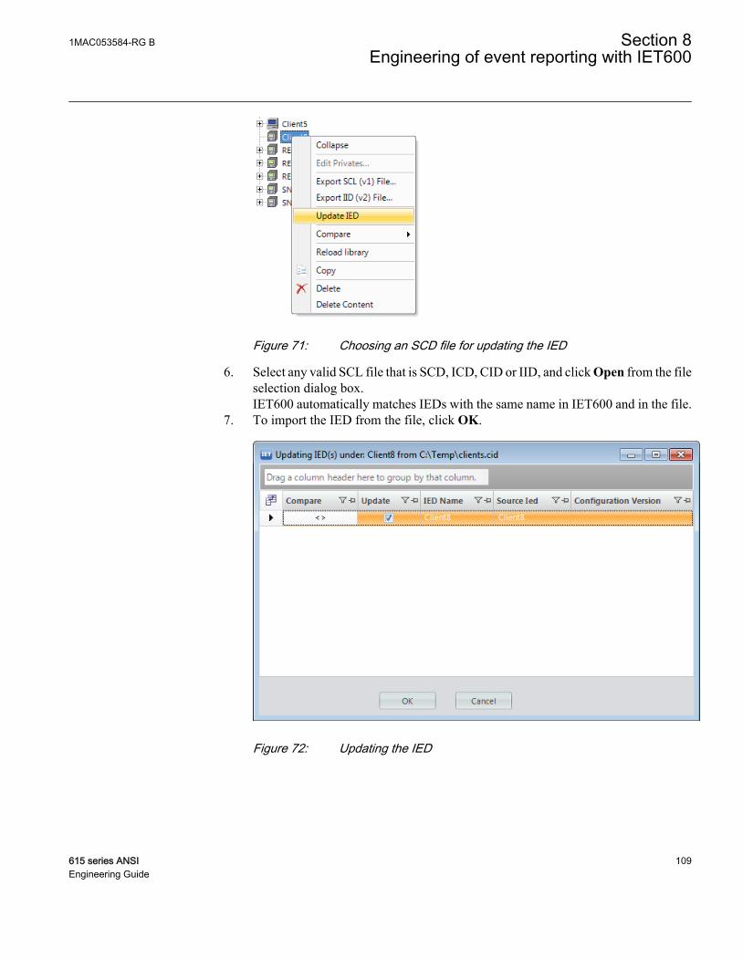
GUID-C973BC98-2389-40BF-A5BF-81DDC9A2A797 V1 EN
Figure 71: Choosing an SCD file for updating the IED
6. Select any valid SCL file that is SCD, ICD, CID or IID, and click Open from the fileselection dialog box.IET600 automatically matches IEDs with the same name in IET600 and in the file.
7. To import the IED from the file, click OK.
GUID-A86207E8-AE9F-4F84-AEA4-8007F35F3960 V1 EN
Figure 72: Updating the IED
1MAC053584-RG B Section 8Engineering of event reporting with IET600
615 series ANSI 109Engineering Guide

The procedure used in configuring IEC 61850 clients can be used to createor update any IED, also several IEDs at the same time.
8.1.2 Attaching IEC 61850 clients to a bus with IET600
1. Click the Communication tab in the navigation pane.2. Click the Subnetworks tab in the editor pane.3. In the Subnetworks grid, select the bus from the Subnetwork list to attach the IEC
61850 client to the bus.An alternative way is to drag the client in the Communication tab to the correctsubnetwork.
GUID-3A9A6F46-5311-44D0-B948-55529DCDC779 V1 EN
Figure 73: Defining bus connection properties for IEC 61850 clients
4. Repeat the steps to attach all five default clients in the project to the bus.
By default, the IEDs' bus connections are ready-made when the configuration work isstarted and need not to be set separately. After the client bus connections are created, theevent clients appear in the RCB Clients tab.
8.2 IET600 user interface
IET600 user interface is divided into sections, that is, panes for navigating and displayingthe project data.
Section 8 1MAC053584-RG BEngineering of event reporting with IET600
110 615 series ANSIEngineering Guide

1 2 3 4 5
GUID-E7E65190-A0C8-46DB-BBC1-212DC10BC3E1 V1 EN
Figure 74: IET600 user interface
1 Menu on the top of the user interface
2 Navigation pane for context-oriented navigation and filtering the various editors
3 Properties pane for detailed properties of the selected element in the navigation pane
4 Editors for detailed design and engineering of the substation, IEDs and IEC 61850 communication
5 Logging and messaging (output) pane
The navigation pane provides context-oriented navigation of the editors. It has three tabs,which correspond to three different context views.
• Substation – Full substation topology and primary equipment nodes• IEDs – IED nodes and corresponding functionality• Communication – Subnetworks and connected IED access points
The editor pane is the main working area of the IET600 user interface. It is organized tovarious tabs for detailed substation design and engineering. The visible tabs depend on thenode type selected in the navigation pane.
1MAC053584-RG B Section 8Engineering of event reporting with IET600
615 series ANSI 111Engineering Guide

Available editor tabs depend on the selected node type, not on the selectednavigation tab. Choose any available context view to do the neededengineering tasks.
Choose upper or lower level in the structure to see the data of single, manyor all IEDs at the same time in the editor pane.
8.2.1 Setting visibility of columns in grid editors
Most editors are implemented as tables. These grid editors provide features like settingcolumn visibility, filtering, sorting, automatic data filling, copying and pasting, findingand replacing and exporting to Excel.
Most tables include columns which are hidden by default.
GUID-7939B95E-2BEA-4781-BBBB-B38F9876B364 V1 EN
Figure 75: Setting column visibility in a grid editor
1. To set the visibility of the columns, click the upper-left icon of the table.2. Select or clear the check boxes from the Field Chooser dialog box.
Section 8 1MAC053584-RG BEngineering of event reporting with IET600
112 615 series ANSIEngineering Guide

8.3 Substation section configuration in IET600
Substation topology consists of the substation, voltage level and bay nodes. Bay nodesinclude also the conducting (primary) equipment, which corresponds to the switches, thatis, the circuit breakers, disconnectors, earth switch, of the configured protection relay.Substation topology is initially built by importing the SCD file from PCM600.
The SLD editor is a graphical editor for the configuration of the substation section inIET600. It provides tools to draw the primary equipment and the interconnection betweenthe equipment in the bay.
GUID-3C46EAA0-33DC-407C-8C45-BDE89FD86648 V1 EN
Figure 76: SLD Editor
SLD in the protection relay is configured using the Graphical DisplayEditor of PCM600, not in IET600
1MAC053584-RG B Section 8Engineering of event reporting with IET600
615 series ANSI 113Engineering Guide

In addition to the substation topology configuration, logical nodes of IEDs need to bemapped to proper objects, for example, to support the automatic bay configuration viaSCL files in the SCADA system. Logical nodes are mapped with the LN Mapping Editor.
GUID-216E641B-6B75-42AB-A106-E5CFA720D149 V3 EN
Figure 77: LN Mapping Editor
8.4 Creating data sets with IET600
Data sets are created or modified using the Dataset editor, which consists of three parts.
• Grid for existing data sets (data set creating, deleting and renaming)• Selection lists for adding new entries to a selected data set• List of data set entries for selected data set (viewing, deleting)
Section 8 1MAC053584-RG BEngineering of event reporting with IET600
114 615 series ANSIEngineering Guide

1 2 3
GUID-10C7EBD1-A0B1-4AEC-9EA0-3F2FF895B82D V2 EN
Figure 78: Data set editor
1 Grid
2 Selection lists
3 List of data entries
1. Select an IED node in the IEDs navigation pane.2. Click the Datasets tab in the editor pane.3. Right-click the area containing data set names and select Insert new row.4. Define the LN where the data set is to be placed (preselected LD0/LLN0 is
recommended) and the name for the new data set.5. Click Append>> to add data items to the end of the data set or click Insert> to add
data items above the selected row in the data set entries list.
Reporting datasets can include status and measurement type of data. Also configurationand setting values can be added to datasets in case required.
Above the data set entries list is shown how many attributes it is possibleto add to the data set and how many are already added.
1MAC053584-RG B Section 8Engineering of event reporting with IET600
615 series ANSI 115Engineering Guide

Select a proper FC (functional constraint) value for the data attributes tobe added to a data set. If none is selected, that is “(all)” is shown on the list,it is not possible to add attributes to the data set.
Data set entries for vertical reporting are selected using the data objectlevel, and entries for GOOSE using the data attribute or data object level.
8.5 Creating report control blocks with IET600
Configuration properties, such as the attached data set and the buffering and triggeringoptions of the RCBs are are defined in the RCB editor. A predefined RCB configurationof a preconfigured IED is a proposed default configuration which can be adaptedaccording to the requirements.
1. Click an IED node in the IEDs navigation pane.2. Click the RCB Data tab in the editor pane.3. Right-click the area containing RCB names and select Insert new row.4. Define the LN where the RCB is to be placed (preselected LD0/LLN0 is
recommended) and the name for the new RCB.Use the field chooser to show or hide the properties. For example, the SeqNum,Entry ID and Reason Code options (set by default in the IED) are hidden by default.
GUID-7BB47172-901A-4FC6-90D4-C80CA7EAE797 V1 EN
Figure 79: RCB editor
Section 8 1MAC053584-RG BEngineering of event reporting with IET600
116 615 series ANSIEngineering Guide

Conf.Rev cannot be manually edited. IET600 updates it automatically tothe next multiple of 100 when the configuration changes.
Deleting an RCB does not totally remove it from IET600. Instead, itsstatus is set to “Deleted” and it is not exported to SCL files. Removing adata set automatically puts the related RCB to the “Deleted” state.
An RCB cannot be renamed. To rename an RCB, delete it and create a newRCB with a new name.
The RCB name is limited to 14 characters or 30 charactecters (withouttwo-digit index number) depending on which IEC 61850 version is in use.
8.6 RCB client configuration with IET600
To succeed with an RCB client configuration, the potential clients and theircommunication configuration should be known. Therefore, the IEDs must be added andconfigured to the subnetwork before configuring the RCB client.
The rows of the RCB client editor show IEDs and RCBs and the columns show theavailable client IEDs.
If a client IED is not on the same subnetwork as a server IED or RCB, itcannot be configured as a client.
1MAC053584-RG B Section 8Engineering of event reporting with IET600
615 series ANSI 117Engineering Guide

GUID-A8E7BA15-36B7-48F5-B269-BDB18F422E09 V1 EN
Figure 80: RCB client editor
Different keys can be used when editing the cells.
• PLUS SIGN (+), asterisk (*) or X to add an additional client to the existing ones• Numbers to change the client sequence or add clients• MINUS SIGN (-), SPACEBAR or DELETE to delete existing clients• Double-clicking with the mouse to add or delete clients
RCB client editor supports both manual and semi-automatic client configuration.
8.6.1 Configuring RCB clients semi-automatically
On the right in the RCB client editor there are option buttons to choose whether to showIEDs (for defining default clients) or RCBs or both together.
There are also buttons to allow semi-automatic configuration of default clients and RCBclients.
Section 8 1MAC053584-RG BEngineering of event reporting with IET600
118 615 series ANSIEngineering Guide

GUID-EB4EE24C-111F-45E7-BFC4-FF6A1DB93F3F V1 EN
Figure 81: Semi-automatic configuring of RCB clients
1. Configure the default clients which are used by the rule-based RCB generation toautomatically configure RCB clients.Use buttons on the RCB client editor.• Clear All removes all default clients• Configure Empty fills out only default clients for those IEDs that have no
clients configured yet• Configure All deletes all existing default clients and fills them out afterwards
2. Configure the RCBs clients.The default clients must be configured before configuring RCB clients otherwise theautomatic RCB client configuration does not work. Use buttons on the RCB clienteditor.• Clear All removes all RCB clients• Configure Empty copies the default client configuration of this IED to its
RCBs (only for those RCBs that have no clients configured yet)• Configure All deletes the existing RCB clients and copies the default client
configuration of this IED to its RCBs
IET600 updates the Enabled Clients configuration value of the RCBsautomatically based on the configuration made in the RCB client editor.In addition, IET600 always reserves one extra engineering client. Forexample, when configuring three RCB clients, the Enabled Clients valueof that RCB is “4”.
1MAC053584-RG B Section 8Engineering of event reporting with IET600
615 series ANSI 119Engineering Guide

120
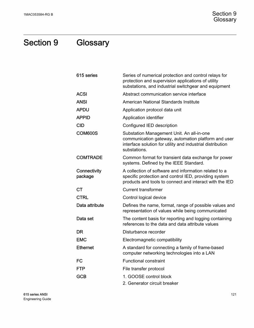
Section 9 Glossary
615 series Series of numerical protection and control relays forprotection and supervision applications of utilitysubstations, and industrial switchgear and equipment
ACSI Abstract communication service interfaceANSI American National Standards InstituteAPDU Application protocol data unitAPPID Application identifierCID Configured IED descriptionCOM600S Substation Management Unit. An all-in-one
communication gateway, automation platform and userinterface solution for utility and industrial distributionsubstations.
COMTRADE Common format for transient data exchange for powersystems. Defined by the IEEE Standard.
Connectivitypackage
A collection of software and information related to aspecific protection and control IED, providing systemproducts and tools to connect and interact with the IED
CT Current transformerCTRL Control logical deviceData attribute Defines the name, format, range of possible values and
representation of values while being communicatedData set The content basis for reporting and logging containing
references to the data and data attribute valuesDR Disturbance recorderEMC Electromagnetic compatibilityEthernet A standard for connecting a family of frame-based
computer networking technologies into a LANFC Functional constraintFTP File transfer protocolGCB 1. GOOSE control block
2. Generator circuit breaker
1MAC053584-RG B Section 9Glossary
615 series ANSI 121Engineering Guide
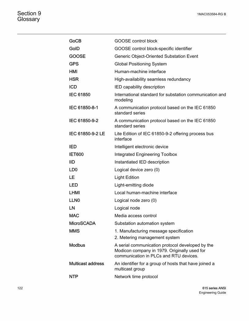
GoCB GOOSE control blockGoID GOOSE control block-specific identifierGOOSE Generic Object-Oriented Substation EventGPS Global Positioning SystemHMI Human-machine interfaceHSR High-availability seamless redundancyICD IED capability descriptionIEC 61850 International standard for substation communication and
modelingIEC 61850-8-1 A communication protocol based on the IEC 61850
standard seriesIEC 61850-9-2 A communication protocol based on the IEC 61850
standard seriesIEC 61850-9-2 LE Lite Edition of IEC 61850-9-2 offering process bus
interfaceIED Intelligent electronic deviceIET600 Integrated Engineering ToolboxIID Instantiated IED descriptionLD0 Logical device zero (0)LE Light EditionLED Light-emitting diodeLHMI Local human-machine interfaceLLN0 Logical node zero (0)LN Logical nodeMAC Media access controlMicroSCADA Substation automation systemMMS 1. Manufacturing message specification
2. Metering management systemModbus A serial communication protocol developed by the
Modicon company in 1979. Originally used forcommunication in PLCs and RTU devices.
Multicast address An identifier for a group of hosts that have joined amulticast group
NTP Network time protocol
Section 9 1MAC053584-RG BGlossary
122 615 series ANSIEngineering Guide

P2P peer-to-peerPCM600 Protection and Control IED ManagerPRP Parallel redundancy protocolPTP Precision Time ProtocolRCB Report control blockSCADA Supervision, control and data acquisitionSCD Substation configuration descriptionSCL XML-based substation description configuration
language defined by IEC 61850SMV Sampled measured valuesST Connector type for glass fiber cableSVCB Sampled value control blockTAL Time allowed to liveTCP/IP Transmission Control Protocol/Internet ProtocolUL Underwriters LaboratoriesVLAN Virtual LANVT Voltage transformerXML Extensible markup language
1MAC053584-RG B Section 9Glossary
615 series ANSI 123Engineering Guide

ABB Distribution SolutionsDistribution AutomationP.O. Box 699FI-65101 VAASA, FinlandPhone +358 10 22 11
ABB Inc.655 Century PointLake Mary, FL 32746, USAPhone +1-800-222 1946
www.abb.com/mediumvoltagewww.abb.com/relionwww.abb.com/substationautomation
—
© Copyright 2019 ABB. All rights reserved. 1MA
C0
5358
4-R
G B
Copyright © 2022 FDOKUMEN