REF615 ANSI Application Manual - ABB
220
— RELION® 615 SERIES Feeder Protection and Control REF615 ANSI Application Manual
-
Upload
khangminh22 -
Category
Documents
-
view
1 -
download
0
Transcript of REF615 ANSI Application Manual - ABB

—RELION® 615 SERIES
Feeder Protection and ControlREF615 ANSIApplication Manual


Document ID: 1MAC109016-MBIssued: 2019-06-07
Revision: CProduct version: 5.0 FP1
© Copyright 2019 ABB. All rights reserved

Copyright
This document and parts thereof must not be reproduced or copied without writtenpermission from ABB, and the contents thereof must not be imparted to a third party, norused for any unauthorized purpose.
The software or hardware described in this document is furnished under a license and maybe used, copied, or disclosed only in accordance with the terms of such license.
TrademarksABB and Relion are registered trademarks of the ABB Group. All other brand or productnames mentioned in this document may be trademarks or registered trademarks of theirrespective holders.
WarrantyPlease inquire about the terms of warranty from your nearest ABB representative.
www.abb.com/mediumvoltage
www.abb.com/substationautomation

Disclaimer
The data, examples and diagrams in this manual are included solely for the concept orproduct description and are not to be deemed as a statement of guaranteed properties. Allpersons responsible for applying the equipment addressed in this manual must satisfythemselves that each intended application is suitable and acceptable, including that anyapplicable safety or other operational requirements are complied with. In particular, anyrisks in applications where a system failure and/or product failure would create a risk forharm to property or persons (including but not limited to personal injuries or death) shallbe the sole responsibility of the person or entity applying the equipment, and those soresponsible are hereby requested to ensure that all measures are taken to exclude ormitigate such risks.
This product has been designed to be connected and communicate data and informationvia a network interface which should be connected to a secure network. It is the soleresponsibility of the person or entity responsible for network administration to ensure asecure connection to the network and to take the necessary measures (such as, but notlimited to, installation of firewalls, application of authentication measures, encryption ofdata, installation of anti virus programs, etc.) to protect the product and the network, itssystem and interface included, against any kind of security breaches, unauthorized access,interference, intrusion, leakage and/or theft of data or information. ABB is not liable forany such damages and/or losses.
This document has been carefully checked by ABB but deviations cannot be completelyruled out. In case any errors are detected, the reader is kindly requested to notify themanufacturer. Other than under explicit contractual commitments, in no event shall ABBbe responsible or liable for any loss or damage resulting from the use of this manual or theapplication of the equipment.

Conformity
This product complies with the directive of the Council of the European Communities onthe approximation of the laws of the Member States relating to electromagneticcompatibility (EMC Directive 2014/30/EU) and concerning electrical equipment for usewithin specified voltage limits (Low-voltage directive 2014/35/EU). This conformity isthe result of tests conducted by ABB in accordance with the product standards EN 50263and EN 60255-26 for the EMC directive, and with the product standards EN 60255-1 andEN 60255-27 for the low voltage directive. The product is designed in accordance with theinternational standards of the IEC 60255 series and ANSI C37.90. This product complieswith the UL 508 certification.

Table of contents
Section 1 Introduction............................................................................5This manual.............................................................................................. 5Intended audience.................................................................................... 5Product documentation.............................................................................6
Product documentation set..................................................................6Document revision history................................................................... 6Related documentation........................................................................7
Symbols and conventions.........................................................................7Symbols...............................................................................................7Document conventions........................................................................ 8Functions, codes and symbols............................................................ 8
Section 2 REF615 overview................................................................ 15Overview.................................................................................................15
Product version history...................................................................... 16PCM600 and relay connectivity package version..............................17
Operation functionality............................................................................17Optional features............................................................................... 17
Physical hardware.................................................................................. 18Local HMI................................................................................................21
Display...............................................................................................22LEDs..................................................................................................23Keypad.............................................................................................. 23
Web HMI.................................................................................................24Authorization...........................................................................................25Communication.......................................................................................26
Self-healing Ethernet ring.................................................................. 27Ethernet redundancy......................................................................... 28
Section 3 REF615 standard configurations.........................................31Standard configurations .........................................................................31
Addition of control functions for primary devices and the use ofbinary inputs and outputs.................................................................. 35
Connection diagrams..............................................................................37Standard configuration D........................................................................42
Applications....................................................................................... 42
Table of contents
REF615 ANSI 1Application Manual

Functions........................................................................................... 42Default I/O connections................................................................ 43Default disturbance recorder settings...........................................44
Functional diagrams.......................................................................... 47Functional diagrams for protection............................................... 47Functional diagrams for disturbance recorder.............................. 56Functional diagrams for condition monitoring...............................57Functional diagrams for control and interlocking.......................... 59Functional diagrams for measurement functions..........................61Functional diagrams for I/O and alarm LEDs............................... 62Functional diagrams for other functions....................................... 65Functional diagrams for other timer logics....................................65Functional diagrams for communication.......................................66
Standard configuration F........................................................................ 67Applications....................................................................................... 67Functions........................................................................................... 67
Default I/O connections................................................................ 68Default disturbance recorder settings...........................................70
Functional diagrams.......................................................................... 72Functional diagrams for protection............................................... 73Functional diagrams for disturbance recorder.............................. 87Functional diagrams for condition monitoring...............................88Functional diagrams for control and interlocking.......................... 90Functional diagrams for measurement functions..........................92Functional diagrams for I/O and alarm LEDs............................... 94Functional diagrams for other functions....................................... 97Functional diagrams for other timer logics....................................97Functional diagrams for communication.......................................99
Standard configuration L.........................................................................99Applications....................................................................................... 99Functions......................................................................................... 100
Default I/O connections.............................................................. 100Default disturbance recorder settings.........................................102
Functional diagrams........................................................................ 104Functional diagrams for protection............................................. 105Functional diagrams for disturbance recorder............................ 121Functional diagrams for condition monitoring.............................122Functional diagrams for control and interlocking........................ 124Functional diagrams for measurement functions........................127Functional diagrams for I/O and alarm LEDs............................. 129
Table of contents
2 REF615 ANSIApplication Manual

Functional diagrams for other functions..................................... 131Functional diagrams for other timer logics..................................131Functional diagrams for communication.....................................132
Standard configuration N......................................................................133Applications..................................................................................... 133Functions......................................................................................... 133
Default I/O connections.............................................................. 134Default disturbance recorder settings.........................................136
Functional diagrams........................................................................ 138Functional diagrams for protection............................................. 139Functional diagrams for disturbance recorder............................ 153Functional diagrams for condition monitoring.............................153Functional diagrams for control and interlocking........................ 156Functional diagrams for measurement functions........................158Functional diagrams for I/O and alarm LEDs............................. 160Functional diagrams for other functions..................................... 163Functional diagrams for other timer logics..................................163Functional diagrams for communication.....................................164
Standard configuration P...................................................................... 165Applications..................................................................................... 165Functions......................................................................................... 165
Default I/O connections.............................................................. 166Default disturbance recorder settings.........................................168
Functional diagrams........................................................................ 170Functional diagrams for protection............................................. 171Functional diagrams for disturbance recorder............................ 182Functional diagrams for condition monitoring.............................183Functional diagrams for control and interlocking........................ 186Functional diagrams for measurement functions........................188Functional diagrams for I/O and alarm LEDs............................. 190Functional diagrams for other timer logics..................................195Functional diagrams for communication.....................................196
Section 4 Requirements for measurement transformers...................197Current transformers.............................................................................197
Current transformer requirements for overcurrent protection.......... 197Current transformer accuracy class and accuracy limit factor....197Non-directional overcurrent protection....................................... 198Example for non-directional overcurrent protection....................199
Section 5 Protection relay's physical connections.............................201
Table of contents
REF615 ANSI 3Application Manual

Inputs....................................................................................................201Energizing inputs............................................................................. 201
Phase currents........................................................................... 201Ground current........................................................................... 201Phase voltages...........................................................................201Ground voltage...........................................................................202Sensor inputs..............................................................................202
Auxiliary supply voltage input.......................................................... 202Binary inputs....................................................................................203Optional light sensor inputs............................................................. 205RTD/mA inputs................................................................................ 206
Outputs................................................................................................. 207Outputs for tripping and controlling..................................................207Outputs for signalling.......................................................................208IRF...................................................................................................209
Section 6 Glossary............................................................................ 211
Table of contents
4 REF615 ANSIApplication Manual
Section 1 Introduction
1.1 This manual
The application manual contains application descriptions and setting guidelines sorted perfunction. The manual can be used to find out when and for what purpose a typicalprotection function can be used. The manual can also be used when calculating settings.
1.2 Intended audience
This manual addresses the protection and control engineer responsible for planning, pre-engineering and engineering.
The protection and control engineer must be experienced in electrical power engineeringand have knowledge of related technology, such as protection schemes and principles.
1MAC109016-MB C Section 1Introduction
REF615 ANSI 5Application Manual

1.3 Product documentation
1.3.1 Product documentation set
Pla
nnin
g &
pu
rcha
se
Eng
inee
ring
Inst
alla
tion
Com
mis
sion
ing
Ope
ratio
n
Mai
nten
ance
Dec
omm
issi
onin
g,
dein
stal
latio
n &
dis
posa
l
Quick start guideQuick installation guideBrochureProduct guideOperation manualInstallation manualConnection diagramEngineering manualTechnical manualApplication manualCommunication protocol manualIEC 61850 engineering guidePoint list manualCyber security deployment guideline
GUID-12DC16B2-2DC1-48DF-8734-0C8B7116124C V2 EN
Figure 1: The intended use of documents during the product life cycle
Product series- and product-specific manuals can be downloaded from theABB Web site http://www.abb.com/relion.
1.3.2 Document revision historyDocument revision/date Product version HistoryA/2018-02-26 5.0 FP1 First release
B/2019-05-08 5.0 FP1 Content updated
C/2019-06-07 5.0 FP1 Content updated
Section 1 1MAC109016-MB CIntroduction
6 REF615 ANSIApplication Manual

Download the latest documents from the ABB Web sitehttp://www.abb.com/substationautomation.
1.3.3 Related documentationName of the document Document IDModbus Communication Protocol Manual 1MAC057386-MB
DNP3 Communication Protocol Manual 1MAC052479-MB
IEC 61850 Engineering Guide 1MAC053584-RG
Engineering Manual 1MAC108982-MB
Installation Manual 1MAC051065-MB
Operation Manual 1MAC054853-MB
Technical Manual 1MAC059074-MB
Cyber Security Deployment Guideline 1MAC052704-HT
1.4 Symbols and conventions
1.4.1 Symbols
The electrical warning icon indicates the presence of a hazard which couldresult in electrical shock.
The warning icon indicates the presence of a hazard which could result inpersonal injury.
The caution icon indicates important information or warning related to theconcept discussed in the text. It might indicate the presence of a hazardwhich could result in corruption of software or damage to equipment orproperty.
The information icon alerts the reader of important facts and conditions.
1MAC109016-MB C Section 1Introduction
REF615 ANSI 7Application Manual

The tip icon indicates advice on, for example, how to design your projector how to use a certain function.
Although warning hazards are related to personal injury, it is necessary to understand thatunder certain operational conditions, operation of damaged equipment may result indegraded process performance leading to personal injury or death. Therefore, complyfully with all warning and caution notices.
1.4.2 Document conventions
A particular convention may not be used in this manual.
• Abbreviations and acronyms are spelled out in the glossary. The glossary alsocontains definitions of important terms.
• Push button navigation in the LHMI menu structure is presented by using the pushbutton icons.To navigate between the options, use and .
• Menu paths are presented in bold.Select Main menu/Settings.
• LHMI messages are shown in Courier font.To save the changes in nonvolatile memory, select Yes and press .
• Parameter names are shown in italics.The function can be enabled and disabled with the Operation setting.
• Parameter values are indicated with quotation marks.The corresponding parameter values are "Enabled" and "Disabled".
• Input/output messages and monitored data names are shown in Courier font.When the function picks up, the PICKUP output is set to TRUE.
• Dimensions are provided both in inches and mm. If it is not specifically mentioned,the dimension is in mm.
• This document assumes that the parameter setting visibility is "Advanced".
1.4.3 Functions, codes and symbolsTable 1: Functions included in the relay
Function IEC 61850 IEC 60617 ANSI/C37.2-2008Protection
Three-phase non-directional overcurrentprotection, low stage
PHLPTOC1 3I> (1) 51P-1
PHLPTOC2 3I> (2) 51P-2
Three-phase non-directional overcurrentprotection, high stage
PHHPTOC1 3I>> (1) 50P-1
PHHPTOC2 3I>> (2) 50P-2
Table continues on next page
Section 1 1MAC109016-MB CIntroduction
8 REF615 ANSIApplication Manual
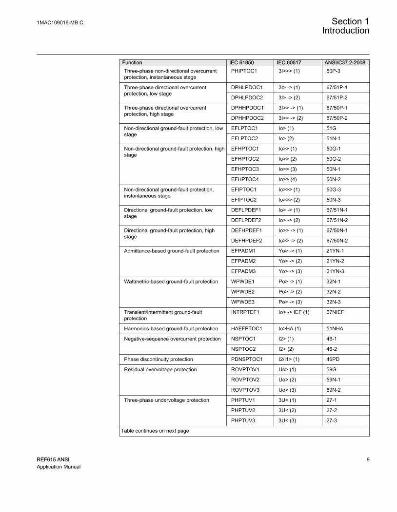
Function IEC 61850 IEC 60617 ANSI/C37.2-2008Three-phase non-directional overcurrentprotection, instantaneous stage
PHIPTOC1 3I>>> (1) 50P-3
Three-phase directional overcurrentprotection, low stage
DPHLPDOC1 3I> -> (1) 67/51P-1
DPHLPDOC2 3I> -> (2) 67/51P-2
Three-phase directional overcurrentprotection, high stage
DPHHPDOC1 3I>> -> (1) 67/50P-1
DPHHPDOC2 3I>> -> (2) 67/50P-2
Non-directional ground-fault protection, lowstage
EFLPTOC1 Io> (1) 51G
EFLPTOC2 Io> (2) 51N-1
Non-directional ground-fault protection, highstage
EFHPTOC1 Io>> (1) 50G-1
EFHPTOC2 Io>> (2) 50G-2
EFHPTOC3 Io>> (3) 50N-1
EFHPTOC4 Io>> (4) 50N-2
Non-directional ground-fault protection,instantaneous stage
EFIPTOC1 Io>>> (1) 50G-3
EFIPTOC2 Io>>> (2) 50N-3
Directional ground-fault protection, lowstage
DEFLPDEF1 Io> -> (1) 67/51N-1
DEFLPDEF2 Io> -> (2) 67/51N-2
Directional ground-fault protection, highstage
DEFHPDEF1 Io>> -> (1) 67/50N-1
DEFHPDEF2 Io>> -> (2) 67/50N-2
Admittance-based ground-fault protection EFPADM1 Yo> -> (1) 21YN-1
EFPADM2 Yo> -> (2) 21YN-2
EFPADM3 Yo> -> (3) 21YN-3
Wattmetric-based ground-fault protection WPWDE1 Po> -> (1) 32N-1
WPWDE2 Po> -> (2) 32N-2
WPWDE3 Po> -> (3) 32N-3
Transient/intermittent ground-faultprotection
INTRPTEF1 Io> -> IEF (1) 67NIEF
Harmonics-based ground-fault protection HAEFPTOC1 Io>HA (1) 51NHA
Negative-sequence overcurrent protection NSPTOC1 I2> (1) 46-1
NSPTOC2 I2> (2) 46-2
Phase discontinuity protection PDNSPTOC1 I2/I1> (1) 46PD
Residual overvoltage protection ROVPTOV1 Uo> (1) 59G
ROVPTOV2 Uo> (2) 59N-1
ROVPTOV3 Uo> (3) 59N-2
Three-phase undervoltage protection PHPTUV1 3U< (1) 27-1
PHPTUV2 3U< (2) 27-2
PHPTUV3 3U< (3) 27-3
Table continues on next page
1MAC109016-MB C Section 1Introduction
REF615 ANSI 9Application Manual

Function IEC 61850 IEC 60617 ANSI/C37.2-2008Three-phase overvoltage protection PHPTOV1 3U> (1) 59-1
PHPTOV2 3U> (2) 59-2
PHPTOV3 3U> (3) 59-3
Positive-sequence undervoltage protection PSPTUV1 U1< (1) 47U-1
PSPTUV2 U1< (2) 47U-2
Negative-sequence overvoltage protection NSPTOV1 U2> (1) 47-1
NSPTOV2 U2> (2) 47-2
Three-phase remnant undervoltageprotection
MSVPR1 3U< (1) 27R-1
MSVPR2 3U< (2) 27R-2
Frequency protection FRPFRQ1 f>/f<,df/dt (1) 81-1
FRPFRQ2 f>/f<,df/dt (2) 81-2
FRPFRQ3 f>/f<,df/dt (3) 81-3
FRPFRQ4 f>/f<,df/dt (4) 81-4
FRPFRQ5 f>/f<,df/dt (5) 81-5
FRPFRQ6 f>/f<,df/dt (6) 81-6
Three-phase thermal protection for feeders,cables and distribution transformers
T1PTTR1 3Ith>F (1) 49F-1
High-impedance differential protection forphase A
HIAPDIF1 dHi_A>(1) 87A
High-impedance differential protection forphase B
HIBPDIF1 dHi_B>(1) 87B
High-impedance differential protection forphase C
HICPDIF1 dHi_C>(1) 87C
Circuit breaker failure protection CCBRBRF1 3I>/Io>BF (1) 50BF-1
CCBRBRF2 3I>/Io>BF (2) 50BF-2
Three-phase inrush detector INRPHAR1 3I2f> (1) INR-1
Switch onto fault CBPSOF1 SOTF (1) SOTF-1
Master trip TRPPTRC1 Master Trip (1) 86/94-1
TRPPTRC2 Master Trip (2) 86/94-2
TRPPTRC3 Master Trip (3) 86/94-3
TRPPTRC4 Master Trip (4) 86/94-4
TRPPTRC5 Master Trip (5) 86/94-5
Arc protection ARCSARC1 ARC (1) AFD-1
ARCSARC2 ARC (2) AFD-2
ARCSARC3 ARC (3) AFD-3
Table continues on next page
Section 1 1MAC109016-MB CIntroduction
10 REF615 ANSIApplication Manual
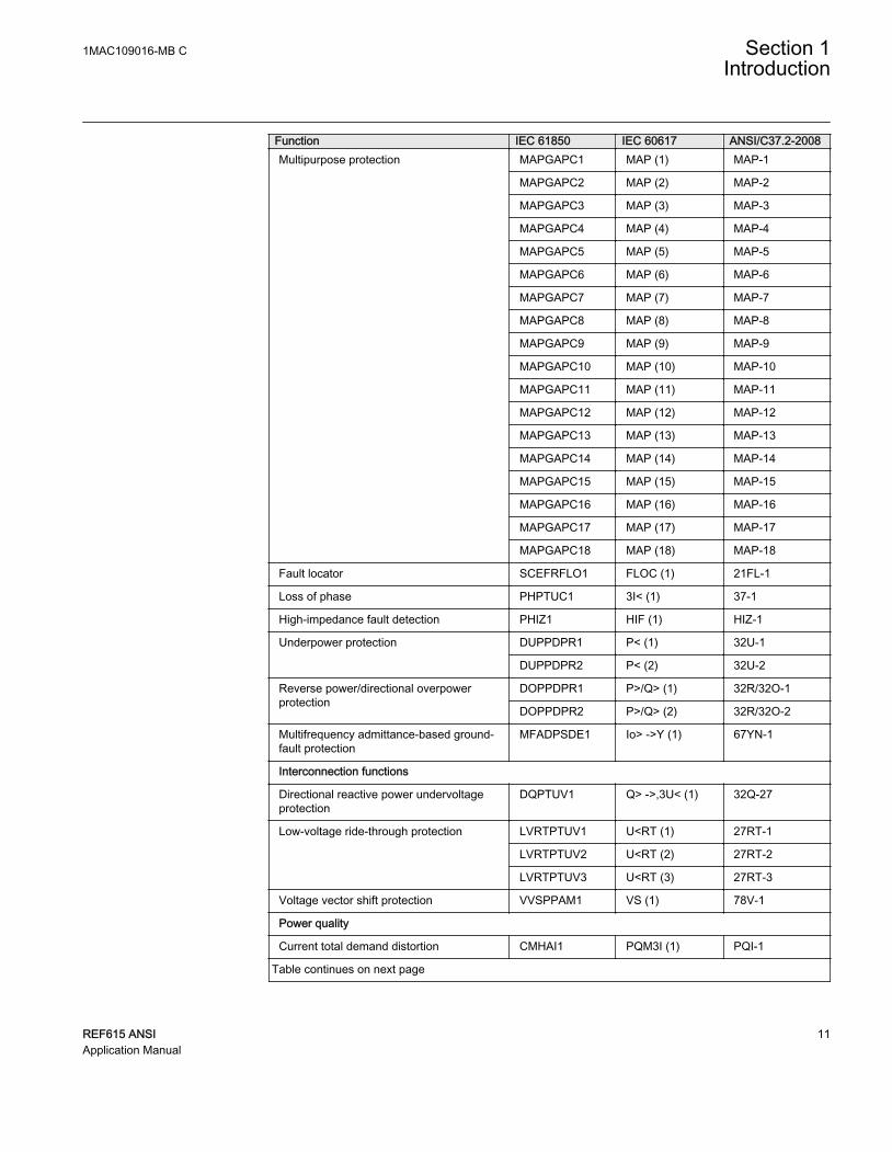
Function IEC 61850 IEC 60617 ANSI/C37.2-2008Multipurpose protection MAPGAPC1 MAP (1) MAP-1
MAPGAPC2 MAP (2) MAP-2
MAPGAPC3 MAP (3) MAP-3
MAPGAPC4 MAP (4) MAP-4
MAPGAPC5 MAP (5) MAP-5
MAPGAPC6 MAP (6) MAP-6
MAPGAPC7 MAP (7) MAP-7
MAPGAPC8 MAP (8) MAP-8
MAPGAPC9 MAP (9) MAP-9
MAPGAPC10 MAP (10) MAP-10
MAPGAPC11 MAP (11) MAP-11
MAPGAPC12 MAP (12) MAP-12
MAPGAPC13 MAP (13) MAP-13
MAPGAPC14 MAP (14) MAP-14
MAPGAPC15 MAP (15) MAP-15
MAPGAPC16 MAP (16) MAP-16
MAPGAPC17 MAP (17) MAP-17
MAPGAPC18 MAP (18) MAP-18
Fault locator SCEFRFLO1 FLOC (1) 21FL-1
Loss of phase PHPTUC1 3I< (1) 37-1
High-impedance fault detection PHIZ1 HIF (1) HIZ-1
Underpower protection DUPPDPR1 P< (1) 32U-1
DUPPDPR2 P< (2) 32U-2
Reverse power/directional overpowerprotection
DOPPDPR1 P>/Q> (1) 32R/32O-1
DOPPDPR2 P>/Q> (2) 32R/32O-2
Multifrequency admittance-based ground-fault protection
MFADPSDE1 Io> ->Y (1) 67YN-1
Interconnection functions
Directional reactive power undervoltageprotection
DQPTUV1 Q> ->,3U< (1) 32Q-27
Low-voltage ride-through protection LVRTPTUV1 U<RT (1) 27RT-1
LVRTPTUV2 U<RT (2) 27RT-2
LVRTPTUV3 U<RT (3) 27RT-3
Voltage vector shift protection VVSPPAM1 VS (1) 78V-1
Power quality
Current total demand distortion CMHAI1 PQM3I (1) PQI-1
Table continues on next page
1MAC109016-MB C Section 1Introduction
REF615 ANSI 11Application Manual

Function IEC 61850 IEC 60617 ANSI/C37.2-2008Voltage total harmonic distortion VMHAI1 PQM3U (1) PQVPH-1
VMHAI2 PQM3U(B) PQVPH-2
Voltage variation PHQVVR1 PQMU (1) PQSS-1
PHQVVR2 PQ 3U<>(B) PQSS-2
Voltage unbalance VSQVUB1 PQUUB (1) PQVUB-1
Control
Circuit-breaker control CBXCBR1 I <-> O CB (1) 52-1
CBXCBR2 I <-> O CB (2) 52-2
Disconnector control DCXSWI1 I <-> O DCC (1) 29DS-1
DCXSWI2 I <-> O DCC (2) 29DS-2
Grounding switch control ESXSWI1 I <-> O ESC (1) 29GS-1
Disconnector position indication DCSXSWI1 I <-> O DC (1) 52-TOC
DCSXSWI2 I <-> O DC (2) 29DS-1
DCSXSWI3 I <-> O DC (3) 29DS-2
Grounding switch indication ESSXSWI1 I <-> O ES (1) 29GS-1
ESSXSWI2 I <-> O ES (2) 29GS-2
Autoreclosing DARREC1 O -> I (1) 79
Synchronism and energizing check SECRSYN1 SYNC (1) 25
Condition monitoring
Circuit-breaker condition monitoring SSCBR1 CBCM (1) 52CM-1
SSCBR2 CBCM (2) 52CM-2
Trip circuit supervision TCSSCBR1 TCS (1) TCM-1
TCSSCBR2 TCS (2) TCM-2
Current circuit supervision CCSPVC1 MCS 3I (1) CCM
Current transformer supervision for high-impedance protection scheme for phase A
HZCCASPVC1 MCS I_A(1) MCS-A
Current transformer supervision for high-impedance protection scheme for phase B
HZCCBSPVC1 MCS I_B(1) MCS-B
Current transformer supervision for high-impedance protection scheme for phase C
HZCCCSPVC1 MCS I_C(1) MCS-C
Fuse failure supervision SEQSPVC1 FUSEF (1) 60-1
SEQSPVC2 FUSEF (2) 60-2
Runtime counter for machines and devices MDSOPT1 OPTS (1) OPTM-1
Measurement
Load profile record LDPRLRC1 LOADPROF (1) LoadProf
Three-phase current measurement CMMXU1 3I (1) IA, IB, IC
Sequence current measurement CSMSQI1 I1, I2, I0 (1) I1, I2, I0
Table continues on next page
Section 1 1MAC109016-MB CIntroduction
12 REF615 ANSIApplication Manual

Function IEC 61850 IEC 60617 ANSI/C37.2-2008Residual current measurement RESCMMXU1 Io (1) IG
Three-phase voltage measurement VMMXU1 3U (1) VA, VB, VC
VMMXU2 3U (2) VA, VB, VC (2)
Residual voltage measurement RESVMMXU1 Uo (1) VG
Sequence voltage measurement VSMSQI1 U1, U2, U0 (1) V1, V2, V0
VSMSQI2 U1, U2, U0(B) V1, V2, V0 (2)
Single-phase power and energymeasurement
SPEMMXU1 SP, SE SP, SE-1
Three-phase power and energymeasurement
PEMMXU1 P, E (1) P, E-1
RTD/mA measurement XRGGIO130 X130 (RTD) (1) X130 (RTD) (1)
Frequency measurement FMMXU1 f (1) f
IEC 61850-9-2 LE sampled value sending SMVSENDER SMVSENDER SMVSENDER
IEC 61850-9-2 LE sampled value receiving(voltage sharing)
SMVRECEIVER SMVRECEIVER SMVRECEIVER
Other
Minimum pulse timer TPGAPC1 TP (1) 62TP-1
TPGAPC2 TP (2) 62TP-2
TPGAPC3 TP (3) 62TP-3
TPGAPC4 TP (4) 62TP-4
Minimum pulse timer (second resolution) TPSGAPC1 TPS (1) 62TPS-1
Minimum pulse timer (minute resolution) TPMGAPC1 TPM (1) 62TPM-1
Pulse timer PTGAPC1 PT (1) 62PT-1
PTGAPC2 PT (2) 62PT-2
Time delay off TOFGAPC1 TOF (1) 62TOF-1
TOFGAPC2 TOF (2) 62TOF-2
TOFGAPC3 TOF (3) 62TOF-3
TOFGAPC4 TOF (4) 62TOF-4
Time delay on TONGAPC1 TON (1) 62TON-1
TONGAPC2 TON (2) 62TON-2
TONGAPC3 TON (3) 62TON-3
TONGAPC4 TON (4) 62TON-4
Set-reset SRGAPC1 SR (1) SR-1
SRGAPC2 SR (2) SR-2
SRGAPC3 SR (3) SR-3
SRGAPC4 SR (4) SR-4
Table continues on next page
1MAC109016-MB C Section 1Introduction
REF615 ANSI 13Application Manual

Function IEC 61850 IEC 60617 ANSI/C37.2-2008Move MVGAPC1 MV (1) MV-1
MVGAPC2 MV (2) MV-2
Generic control point SPCGAPC1 SPC (1) SPC-1
SPCGAPC2 SPC (2) SPC-2
Analog value scaling SCA4GAPC1 SCA4 (1) SCA4-1
SCA4GAPC2 SCA4 (2) SCA4-2
SCA4GAPC3 SCA4 (3) SCA4-3
SCA4GAPC4 SCA4 (4) SCA4-4
Integer value move MVI4GAPC1 MVI4 (1) MVI4-1
Generic up-down counters UDFCNT1 UDCNT (1) CTR-1
UDFCNT2 UDCNT (2) CTR-2
UDFCNT3 UDCNT (3) CTR-3
UDFCNT4 UDCNT (4) CTR-4
Section 1 1MAC109016-MB CIntroduction
14 REF615 ANSIApplication Manual

Section 2 REF615 overview
2.1 Overview
REF615 is a dedicated feeder protection and control relay designed for the protection,control, measurement and supervision of utility substations and industrial power systemsincluding radial, looped and meshed distribution networks with or without distributedpower generation. REF615 is a member of ABB’s Relion® product family and part of its615 protection and control product series. The 615 series relays are characterized by theircompactness and withdrawable-unit design.
Re-engineered from the ground up, the 615 series has been designed to unleash the fullpotential of the IEC 61850 standard for communication and interoperability betweensubstation automation devices.
The relay provides main protection for overhead lines and cable feeders in distributionnetworks. The relay is also used as back-up protection in applications, where anindependent and redundant protection system is required.
Depending on the chosen standard configuration, the relay is adapted for the protection ofoverhead line and cable feeders in isolated neutral, resistance grounded, compensated andsolidly grounded networks. Once the standard configuration relay has been given theapplication-specific settings, it can directly be put into service.
The 615 series relays support a range of communication protocols including IEC 61850with Edition 2 support, process bus according to IEC 61850-9-2 LE, Modbus® andDNP3.
1MAC109016-MB C Section 2REF615 overview
REF615 ANSI 15Application Manual

2.1.1 Product version historyProduct version Product history1.0.1 Product released
1.1 • Circuit breaker condition monitoring• Replaced EFIPTOC3 with EFLPTOC3• New communication modules COMB11A, COMB12A, COMB13A and
COMB14A• IRIG-B• CB interlocking functionality enhanced• TCS functionality in HW enhanced• Non-volatile memory added• Serial communications
2.0 • Support for DNP3 serial or TCP/IP• Voltage measurement and protection• Power and energy measurement• Disturbance recorder upload via WHMI• Fuse failure supervision
4.0 • User programming through Application Configuration• Frequency measurement protection• Load shedding and restoration• Single phase power and energy measurement• Load profile recorder
4.2 • New configurations to tailor for high-impedance current differential and dualbreaker autotransfer application
• High impedance current differential function• Generic up-down counters• Remnant voltage protection function• Support for HSR/PRP protocol support for a limited configurations
5.0 FP1 • New layout in Application Configuration for all configurations• Support for IEC 61850-9-2 LE• IEEE 1588 v2 time synchronization• Fault locator• High-speed binary outputs• Optional RTD inputs• Profibus adapter support• Support for multiple SLD pages• Import/export of settings via WHMI• Setting usability improvements• HMI event filtering tool• IEC 61850 Edition 2• Currents sending support with IEC 61850-9-2 LE• Support for synchronism and energizing check with IEC 61850-9-2 LE• Software closable Ethernet ports• Report summary via WHMI• Multifrequency admittance-based ground-fault protection• High-impedance differential protection• Voltage unbalance power quality option• Interconnection protection option• Reverse power/directional overpower• Switch onto fault• Additional timer, set-reset and analog value scaling functions
Section 2 1MAC109016-MB CREF615 overview
16 REF615 ANSIApplication Manual

2.1.2 PCM600 and relay connectivity package version
• Protection and Control IED Manager PCM600 2.8 or later• REF615 Connectivity Package Ver.5.1 or later
• Parameter Setting• Signal Monitoring• Event Viewer• Disturbance Handling• Application Configuration• Signal Matrix• Graphical Display Editor• Communication Management• IED User Management• IED Compare• Firmware Update• Fault Record tool• Load Record Profile• Lifecycle Traceability• Configuration Wizard• AR Sequence Visualizer• Label Printing• IEC 61850 Configuration• IED Configuration Migration
Download connectivity packages from the ABB Web sitehttp://www.abb.com/substationautomation or directly with UpdateManager in PCM600.
2.2 Operation functionality
2.2.1 Optional features
• Arc protection• Autoreclosing• Modbus TCP/IP or RTU/ASCII• DNP3 TCP/IP or serial• Admittance-based ground-fault protectiont (configurations F, L and N only)• Wattmetric-based ground-fault protection (configurations F, L and N only)• Harmonics-based ground-fault protection (configurations F, L and N only)• Interconnection protection (configurations L and N only)
1MAC109016-MB C Section 2REF615 overview
REF615 ANSI 17Application Manual

• Power quality functions (configurations L and N only)• Fault locator (configurations L and N only)• RTD/mA measurement (configurations F and N only)• IEC 61850-9-2 LE (configurations F, L and N only)• IEEE 1588 v2 time synchronization
2.3 Physical hardware
The protection relay consists of two main parts: plug-in unit and case. The contentdepends on the ordered functionality.
Table 2: Plug-in unit and case
Main unit Slot ID Content DetailsPlug-in unit - HMI Large (10 lines, 20 characters) with SLD
X100 Auxiliary power/BOmodule
48...250 V DC/100...240 V AC or 24...60 V DC2 normally-open PO contacts1 change-over SO contact1 normally-open SO contact2 double-pole PO contacts with TCS1 dedicated internal fault output contact
X110 Optional BIO module Only with configurations D, F, L, N and P:8 binary inputs4 SO contacts
Only with configurations D, F, L, N and P:8 binary inputs3 high-speed SO contacts
X120 AI/BI module Only with configurations D, F, N and P:3 phase current inputs (1/5 A)1 residual current input (1/5 A)3 binary inputs
Only with configurations D, F and N:3 phase current inputs (1/5 A)1 residual current input (0.2/1 A)1)
3 binary inputs
Table continues on next page
Section 2 1MAC109016-MB CREF615 overview
18 REF615 ANSIApplication Manual

Main unit Slot ID Content DetailsCase X130 Optional RTD/mA
moduleOptional for configuration D:2 generic mA inputs6 RTD sensor inputs
Optional AI/BImodule
Only with configurations F and N:3 phase voltage inputs (60...210 V)1 residual voltage input (60...210 V)4 binary inputsAdditionally with configuration N:1 reference voltage input for SECRSYN1 (60...210 V)
Optional AI/RTD/mAmodule
Only with configurations F and N:3 phase voltage inputs (60...210 V)1 residual voltage input (60...210 V)1 generic mA input2 RTD sensor inputsAdditionally with configuration N:1 reference voltage input for SECRSYN1 (60...210 V)
Optional BIO module Optional for configuration D:6 binary inputs3 SO contacts
AI/BI module Only with configuration P:6 phase voltage inputs (60...210 V)3 binary inputs
Sensor input module Only with configuration L:3 combi sensor inputs (three-phase current and voltage)1 residual current input (0.2/1 A)1)
X000 Optionalcommunicationmodule
See the technical manual for details about different types ofcommunication modules.
1) The 0.2/1 A input is normally used in applications requiring sensitive earth-fault protection and featuringcore-balance current transformers.
The rated input levels are selected in the software of the protection relay for phase currentand ground current. The binary input thresholds 18...176 V DC are selected by adjustingthe protection relay's parameter settings.
The optional BIO module can be added in the protection relay to allstandard configurations.
The connection diagrams of different hardware modules are presented in this manual.
See the installation manual for more information about the case and theplug-in unit.
1MAC109016-MB C Section 2REF615 overview
REF615 ANSI 19Application Manual

Table 3: Input/output overview
Std. conf. Order code digit Analog channels Binary channels 5-6 7-8 CT VT Combi
sensorBI BO RTD mA
D AC/AD AF 4 - - 18 4 PO+ 9 SO
- -
FB 4 - - 18 4 PO+ 5 SO+ 3HSO
- -
AC/ADFC/FD
AD 4 - - 12 4 PO+ 6 SO
6 2
FE 4 - - 12 4 PO+ 2 SO+ 3HSO
F AE/AF AG 4 5 - 16 4 PO+ 6 SO
- -
FC 4 5 - 16 4 PO+ 2 SO+ 3HSO
- -
FE/FF AG 4 5 - 12 4 PO +6SO
2 1
FC 4 5 - 12 4 PO+ 2 SO+ 3HSO
2 1
L DA AH 1 - 3 8 4 PO+ 6 SO
- -
FD 1 - 3 8 4 PO+ 2 SO+ 3HSO
- -
Table continues on next page
Section 2 1MAC109016-MB CREF615 overview
20 REF615 ANSIApplication Manual

Std. conf. Order code digit Analog channels Binary channels 5-6 7-8 CT VT Combi
sensorBI BO RTD mA
N AE/AF AG 4 5 - 16 4 PO+ 6 SO
- -
FC 4 5 - 16 4 PO+ 2 SO+ 3HSO
- -
FE/FF AG 4 5 - 12 4 PO+ 6 SO
2 1
FC 4 5 - 12 4 PO+ 2 SO+ 3HSO
2 1
P AK AK 4 6 - 15 4 PO+ 6 SO
- -
FH 4 6 - 15 4 PO+ 2 SO+ 3HSO
- -
2.4 Local HMI
The LHMI is used for setting, monitoring and controlling the protection relay. The LHMIcomprises the display, buttons, LED indicators and communication port.
1MAC109016-MB C Section 2REF615 overview
REF615 ANSI 21Application Manual

A070704-ANSI V3 EN
Figure 2: Example of the LHMI
2.4.1 Display
The LHMI includes a graphical display that supports one character size. The character sizedepends on the selected language. The amount of characters and rows fitting the viewdepends on the character size.
Table 4: Large display
Character size1) Rows in the view Characters per row
Small, mono-spaced (6 × 12 pixels) 10 20
1) Depending on the selected language
The display view is divided into four basic areas.
Section 2 1MAC109016-MB CREF615 overview
22 REF615 ANSIApplication Manual

1 2
3 4
A070705-ANSI V3 EN
Figure 3: Display layout
1 Header
2 Icon
3 Content
4 Scroll bar (displayed when needed)
2.4.2 LEDs
The LHMI includes three protection indicators above the display: Normal, Pickup andTrip.
There are 11 matrix programmable LEDs on front of the LHMI. The LEDs can beconfigured with PCM600 and the operation mode can be selected with the LHMI, WHMIor PCM600.
There are two additional LEDs which are embedded into the control buttons and .They represent the status of breaker 1 (CBXCBR1).
2.4.3 Keypad
The LHMI keypad contains push buttons which are used to navigate in different views ormenus. Using the push buttons, open or close commands can be given to objects in theprimary circuit, for example, a circuit breaker, a contactor or a disconnector. The pushbuttons are also used to acknowledge alarms, reset indications, provide help and switchbetween local and remote control mode.
1MAC109016-MB C Section 2REF615 overview
REF615 ANSI 23Application Manual

A071176-ANSI V1 EN
Figure 4: LHMI keypad with object control, navigation and command push buttonsand RJ-45 communication port
2.5 Web HMI
The WHMI allows secure access to the protection relay via a Web browser. The supportedWeb browser versions are Internet Explorer 9.0, 10.0 and 11.0. When the SecureCommunication parameter in the protection relay is activated, the Web server is forced totake a secured (HTTPS) connection to WHMI using TLS encryption.The WHMI isverified with Internet Explorer 11.0.
WHMI is disabled by default.WHMI is enabled by default.
WHMI offers several functions.
• Programmable LEDs and event lists• System supervision• Parameter settings• Measurement display• DFR records• Fault records• Load profile record• Phasor diagram• Single-line diagram• Importing/Exporting parameters• Report summary
The menu tree structure on the WHMI is almost identical to the one on the LHMI.
Section 2 1MAC109016-MB CREF615 overview
24 REF615 ANSIApplication Manual

A070754 V6 EN
Figure 5: Example view of the WHMI
The WHMI can be accessed locally and remotely.
• Locally by connecting the laptop to the protection relay via the front communicationport.
• Remotely over LAN/WAN.
2.6 Authorization
Four user categories have been predefined for the LHMI and the WHMI, each withdifferent rights and default passwords.
The default passwords in the protection relay delivered from the factory can be changedwith Administrator user rights.
User authorization is disabled by default for LHMI but WHMI alwaysuses authorization.
1MAC109016-MB C Section 2REF615 overview
REF615 ANSI 25Application Manual

Table 5: Predefined user categories
Username User rightsVIEWER Read only access
OPERATOR • Selecting remote or local state with (only locally)• Changing setting groups• Controlling• Clearing indications
ENGINEER • Changing settings• Clearing event list• Clearing DFRs and load profile record• Changing system settings such as IP address, serial baud rate or
DFR settings• Setting the protection relay to test mode• Selecting language
ADMINISTRATOR • All listed above• Changing password• Factory default activation
For user authorization for PCM600, see PCM600 documentation.
2.7 Communication
The protection relay supports a range of communication protocols including IEC 61850,IEC 61850-9-2 LE, Modbus® and DNP3. Operational information and controls areavailable through these protocols. However, some communication functionality, forexample, horizontal communication between the protection relays, is only enabled by theIEC 61850 communication protocol.
The protection relay utilizes Ethernet communication extensively for different purposes.The exact services depend on the ordered product variant and enabled functionality.HSR/PRP is available in 615 series Ver.5.0 FP1 ANSI.
HSR/PRP availability depends on the product ordering information. Seethe Rear communication modules chapter for information on HSR/PRPsupported COM cards.
Section 2 1MAC109016-MB CREF615 overview
26 REF615 ANSIApplication Manual

Table 6: TCP and UDP ports used for different services
Service PortFile Transfer Protocol (FTP and FTPS) 20, 21
IEC 61850 102
Web Server HTTP 80
Web Server HTTPS 443
Simple Network Time Protocol (SNTP) 123
Modbus TCP 502
DNP TCP 20000
The IEC 61850 communication implementation supports all monitoring and controlfunctions. Additionally, parameter setting and DFR records can be accessed using the IEC61850 protocol. Oscillographic files are available to any Ethernet-based application in thestandard COMTRADE format. The protection relay can send and receive binary signalsfrom other devices (so-called horizontal communication) using the IEC 61850-8-1GOOSE profile, where the highest performance class with a total transmission time of 3ms is supported. Furthermore, the protection relay supports sending and receiving ofanalog values using GOOSE messaging. The protection relay meets the GOOSEperformance requirements for tripping applications in distribution substations, as definedby the IEC 61850 standard. The protection relay can simultaneously report events to fivedifferent clients on the station bus.
The protection relay can support five simultaneous clients. If PCM600 reserves one clientconnection, only four client connections are left, for example, for IEC 61850 and Modbus.
All communication connectors, except for the front port connector, are placed onintegrated optional communication modules. The protection relay can be connected toEthernet-based communication systems via the RJ-45 connector (100Base-TX) or thefiber optic LC connector (100Base-FX). An optional serial interface is available forRS-232/RS-485 communication.
2.7.1 Self-healing Ethernet ring
For the correct operation of self-healing loop topology, it is essential that the externalswitches in the network support the RSTP protocol and that it is enabled in the switches.Otherwise, connecting the loop topology can cause problems to the network. Theprotection relay itself does not support link-down detection or RSTP. The ring recoveryprocess is based on the aging of the MAC addresses, and the link-up/link-down events cancause temporary breaks in communication. For a better performance of the self-healingloop, it is recommended that the external switch furthest from the protection relay loop isassigned as the root switch (bridge priority = 0) and the bridge priority increases towardsthe protection relay loop. The end links of the protection relay loop can be attached to the
1MAC109016-MB C Section 2REF615 overview
REF615 ANSI 27Application Manual

same external switch or to two adjacent external switches. A self-healing Ethernet ringrequires a communication module with at least two Ethernet interfaces for all protectionrelays.
GUID-AB81C355-EF5D-4658-8AE0-01DC076E519C-ANSI V1 EN
Figure 6: Self-healing Ethernet ring solution
The Ethernet ring solution supports the connection of up to 30 protectionrelays. If more than 30 protection relays are to be connected, it isrecommended that the network is split into several rings with no more than30 protection relays per ring. Each protection relay has a 50-μs store-and-forward delay, and to fulfil the performance requirements for fasthorizontal communication, the ring size is limited to 30 protection relays.
2.7.2 Ethernet redundancy
IEC 61850 specifies a network redundancy scheme that improves the system availabilityfor substation communication. It is based on two complementary protocols defined in theIEC 62439-3:2012 standard: parallel redundancy protocol PRP and high-availabilityseamless redundancy HSR protocol. Both protocols rely on the duplication of alltransmitted information via two Ethernet ports for one logical network connection.Therefore, both are able to overcome the failure of a link or switch with a zero-switchover
Section 2 1MAC109016-MB CREF615 overview
28 REF615 ANSIApplication Manual

time, thus fulfilling the stringent real-time requirements for the substation automationhorizontal communication and time synchronization.
PRP specifies that each device is connected in parallel to two local area networks. HSRapplies the PRP principle to rings and to the rings of rings to achieve cost-effectiveredundancy. Thus, each device incorporates a switch element that forwards frames fromport to port. The HSR/PRP option is available for all 615 series protection relays.However, RED615 supports this option only over fiber optics.
IEC 62439-3:2012 cancels and replaces the first edition published in2010. These standard versions are also referred to as IEC 62439-3 Edition1 and IEC 62439-3 Edition 2. The protection relay supports IEC62439-3:2012 and it is not compatible with IEC 62439-3:2010.
PRPEach PRP node, called a double attached node with PRP (DAN), is attached to twoindependent LANs operated in parallel. These parallel networks in PRP are called LANA and LAN B. The networks are completely separated to ensure failure independence, andthey can have different topologies. Both networks operate in parallel, thus providing zero-time recovery and continuous checking of redundancy to avoid communication failures.Non-PRP nodes, called single attached nodes (SANs), are either attached to one networkonly (and can therefore communicate only with DANs and SANs attached to the samenetwork), or are attached through a redundancy box, a device that behaves like a DAN.
Ethernet switchIEC 61850 PRPEthernet switch
SCADACOM600
GUID-334D26B1-C3BD-47B6-BD9D-2301190A5E9D V3 EN
Figure 7: PRP solution
1MAC109016-MB C Section 2REF615 overview
REF615 ANSI 29Application Manual
In case a laptop or a PC workstation is connected as a non-PRP node to one of the PRPnetworks, LAN A or LAN B, it is recommended to use a redundancy box device or anEthernet switch with similar functionality between the PRP network and SAN to removeadditional PRP information from the Ethernet frames. In some cases, default PCworkstation adapters are not able to handle the maximum-length Ethernet frames with thePRP trailer.
There are different alternative ways to connect a laptop or a workstation as SAN to a PRPnetwork.
• Via an external redundancy box (RedBox) or a switch capable of connecting to PRPand normal networks
• By connecting the node directly to LAN A or LAN B as SAN• By connecting the node to the protection relay's interlink port
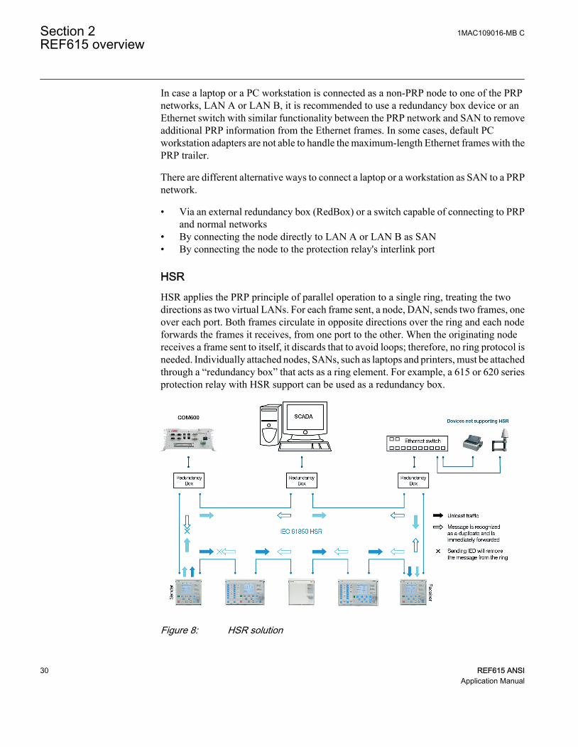
HSRHSR applies the PRP principle of parallel operation to a single ring, treating the twodirections as two virtual LANs. For each frame sent, a node, DAN, sends two frames, oneover each port. Both frames circulate in opposite directions over the ring and each nodeforwards the frames it receives, from one port to the other. When the originating nodereceives a frame sent to itself, it discards that to avoid loops; therefore, no ring protocol isneeded. Individually attached nodes, SANs, such as laptops and printers, must be attachedthrough a “redundancy box” that acts as a ring element. For example, a 615 or 620 seriesprotection relay with HSR support can be used as a redundancy box.
GUID-207430A7-3AEC-42B2-BC4D-3083B3225990 V3 EN
Figure 8: HSR solution
Section 2 1MAC109016-MB CREF615 overview
30 REF615 ANSIApplication Manual

Section 3 REF615 standard configurations
3.1 Standard configurations
REF615 is available with two alternative standard configurations. The standard signalconfiguration can be altered by means of the signal matrix or the graphical applicationfunctionality of the Protection and Control IED Manager PCM600. Further, theapplication configuration functionality of PCM600 supports the creation of multi-layerlogic functions using various logical elements, including timers and flip-flops. Bycombining protection functions with logic function blocks, the relay configuration can beadapted to user-specific application requirements.
The relay is delivered from the factory with default connections described in thefunctional diagrams for binary inputs, binary outputs, function-to-function connectionsand alarm LEDs. Some of the supported functions in REF615 must be added with theApplication Configuration tool to be available in the Signal Matrix tool and in the relay.The positive measuring direction of directional protection functions is towards theoutgoing feeder.
Table 7: Standard configurations
Description Std. conf.Non-directional overcurrent and ground-fault protection and circuit-breaker conditionmonitoring (RTD option) D
Directional overcurrent and ground-fault protection, voltage-based protection andmeasurements, and circuit-breaker condition monitoring (RTD option) F
Directional and non-directional overcurrent and ground-fault protection with multifrequencyneutral admittance, voltage, frequency and power based protection and measurements, andcircuit-breaker condition monitoring (sensor inputs, optional power quality, fault locator,interconnection protection and synchro-check with IEC 61850-9-2 LE)
L
Directional and non-directional overcurrent and ground-fault protection with multifrequencyneutral admittance, voltage, frequency and power based protection and measurements,high-impedance differential protection, synchro-check and circuit-breaker conditionmonitoring (optional power quality, fault locator and interconnection protection)
N
Non-directional phase and ground overcurrent, voltage and power directional protection andpower system metering for two tie breakers P
1MAC109016-MB C Section 3REF615 standard configurations
REF615 ANSI 31Application Manual
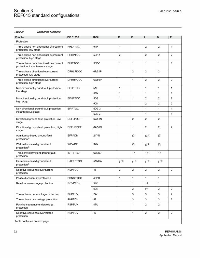
Table 8: Supported functions
Function IEC 61850 ANSI D F L N PProtection
Three-phase non-directional overcurrentprotection, low stage
PHLPTOC 51P 1 2 2 1
Three-phase non-directional overcurrentprotection, high stage
PHHPTOC 50P-1 2 2 2 2
Three-phase non-directional overcurrentprotection, instantaneous stage
PHIPTOC 50P-3 1 1 1 1 1
Three-phase directional overcurrentprotection, low stage
DPHLPDOC 67/51P 2 2 2
Three-phase directional overcurrentprotection, high stage
DPHHPDOC 67/50P 1 2 2 2
Non-directional ground-fault protection,low stage
EFLPTOC 51G 1 1 1 1
51N 1 1 1 1
Non-directional ground-fault protection,high stage
EFHPTOC 50G 1 1 2 2 2
50N 2 2 2
Non-directional ground-fault protection,instantaneous stage
EFIPTOC 50G-3 1 1 1 1
50N-3 1 1 1
Directional ground-fault protection, lowstage
DEFLPDEF 67/51N 2 2 2
Directional ground-fault protection, highstage
DEFHPDEF 67/50N 1 2 2 2
Admittance-based ground-faultprotection1)
EFPADM 21YN (3) (3)2) (3)
Wattmetric-based ground-faultprotection1)
WPWDE 32N (3) (3)2) (3)
Transient/intermittent ground-faultprotection
INTRPTEF 67NIEF 13) 12)3) 13)
Harmonics-based ground-faultprotection1)
HAEFPTOC 51NHA (1)3) (1)3) (1)3) (1)3)
Negative-sequence overcurrentprotection
NSPTOC 46 2 2 2 2 2
Phase discontinuity protection PDNSPTOC 46PD 1 1 1 1
Residual overvoltage protection ROVPTOV 59G 1 12) 1
59N 2 22) 2 2
Three-phase undervoltage protection PHPTUV 27-1 3 3 3 2
Three-phase overvoltage protection PHPTOV 59 3 3 3 2
Positive-sequence undervoltageprotection
PSPTUV 47U 1 2 2
Negative-sequence overvoltageprotection
NSPTOV 47 1 2 2 2
Table continues on next page
Section 3 1MAC109016-MB CREF615 standard configurations
32 REF615 ANSIApplication Manual

Function IEC 61850 ANSI D F L N PThree-phase remnant undervoltageprotection (source 1)
MSVPR 27R (1)4) 1 2
Frequency protection FRPFRQ 81 6 6
Three-phase thermal protection forfeeders, cables and distributiontransformers
T1PTTR 49F 1 1 1 1
High-impedance differential protection forphase A
HIAPDIF 87A 1
High-impedance differential protection forphase B
HIBPDIF 87B 1
High-impedance differential protection forphase C
HICPDIF 87C 1
Circuit breaker failure protection CCBRBRF 50BF 1 1 1 1 2
Three-phase inrush detector INRPHAR INR 1 1 1 1 1
Switch onto fault CBPSOF SOTF 1 1 1 1
Master trip TRPPTRC 86/94 2(3)5)
2(3)5)
2(3)5)
2(3)5)
2(3)5)
Arc protection ARCSARC AFD (3) (3) (3) (3) (3)
Multipurpose protection MAPGAPC MAP 18 18 18 18 18
Fault locator SCEFRFLO 21FL (1) (1) (1)
Loss of phase PHPTUC 37 1
High-impedance fault detection PHIZ HIZ 1 1 1
Underpower protection DUPPDPR 32U 2 2
Reverse power/directional overpowerprotection
DOPPDPR 32R/32O 2 2
Multifrequency admittance-based ground-fault protection
MFADPSDE 67YN 1 1
Interconnection functions
Directional reactive power undervoltageprotection
DQPTUV 32Q-27 (1) (1)
Low-voltage ride-through protection LVRTPTUV 27RT (3) (3)
Voltage vector shift protection VVSPPAM 78V (1) (1)
Power quality
Current total demand distortion CMHAI PQI (1)6) (1)6) (1)6)
Voltage total harmonic distortion VMHAI PQVPH (1)6) (1)6) (2)6)
Voltage variation PHQVVR PQSS (1)6) (1)6) (2)6)
Voltage unbalance VSQVUB PQVUB (1)6) (1)6) (1)6)
Control
Circuit-breaker control CBXCBR 52 1 1 1 1 2
Disconnector control DCXSWI 29DS 2 2 2 2 2
Table continues on next page
1MAC109016-MB C Section 3REF615 standard configurations
REF615 ANSI 33Application Manual

Function IEC 61850 ANSI D F L N PGrounding switch control ESXSWI 29GS 1 1 1 1 1
Disconnector position indication DCSXSWI 52-TOC 1 1 1 1 1
29DS 2 2 2 2 2
Grounding switch indication ESSXSWI 29GS 2 2 2 2 2
Autoreclosing DARREC 79 (1) (1) (1) (1) (1)
Synchronism and energizing check SECRSYN 25 (1)4) 1 1
Condition monitoring
Circuit-breaker condition monitoring SSCBR 52CM 1 1 1 1 2
Trip circuit supervision TCSSCBR TCM 2 2 2 2 2
Current circuit supervision CCSPVC CCM 1 1 1 1
Current transformer supervision for high-impedance protection scheme for phase A
HZCCASPVC MCS-A 1
Current transformer supervision for high-impedance protection scheme for phase B
HZCCBSPVC MCS-B 1
Current transformer supervision for high-impedance protection scheme for phase C
HZCCCSPVC MCS-C 1
Fuse failure supervision SEQSPVC 60 1 1 1 2
Runtime counter for machines anddevices
MDSOPT OPTM 1 1 1 1 1
Measurement
Load profile record LDPRLRC LoadProf 1 1 1 1 1
Three-phase current measurement CMMXU IA, IB, IC 1 1 1 1 1
Sequence current measurement CSMSQI I1, I2, I0 1 1 1 1 1
Residual current measurement RESCMMXU IG 1 1 1 1 1
Three-phase voltage measurement VMMXU VA, VB, VC 1 1(1)4)
2 2
Residual voltage measurement RESVMMXU VG 1 1
Sequence voltage measurement VSMSQI V1, V2, V0 1 1 1 2
Single-phase power and energymeasurement
SPEMMXU SP, SE 1 1 1 1
Three-phase power and energymeasurement
PEMMXU P, E 1 1 1 1
RTD/mA measurement XRGGIO130 X130 (RTD) (1) (1) (1)
Frequency measurement FMMXU f 1 1 1 1
IEC 61850-9-2 LE sampled valuesending7)
SMVSENDER SMVSENDER (1) (1) (1) (1)
IEC 61850-9-2 LE sampled valuereceiving (voltage sharing)7)
SMVRECEIVER SMVRECEIVER (1) (1) (1) (1)
Other
Table continues on next page
Section 3 1MAC109016-MB CREF615 standard configurations
34 REF615 ANSIApplication Manual
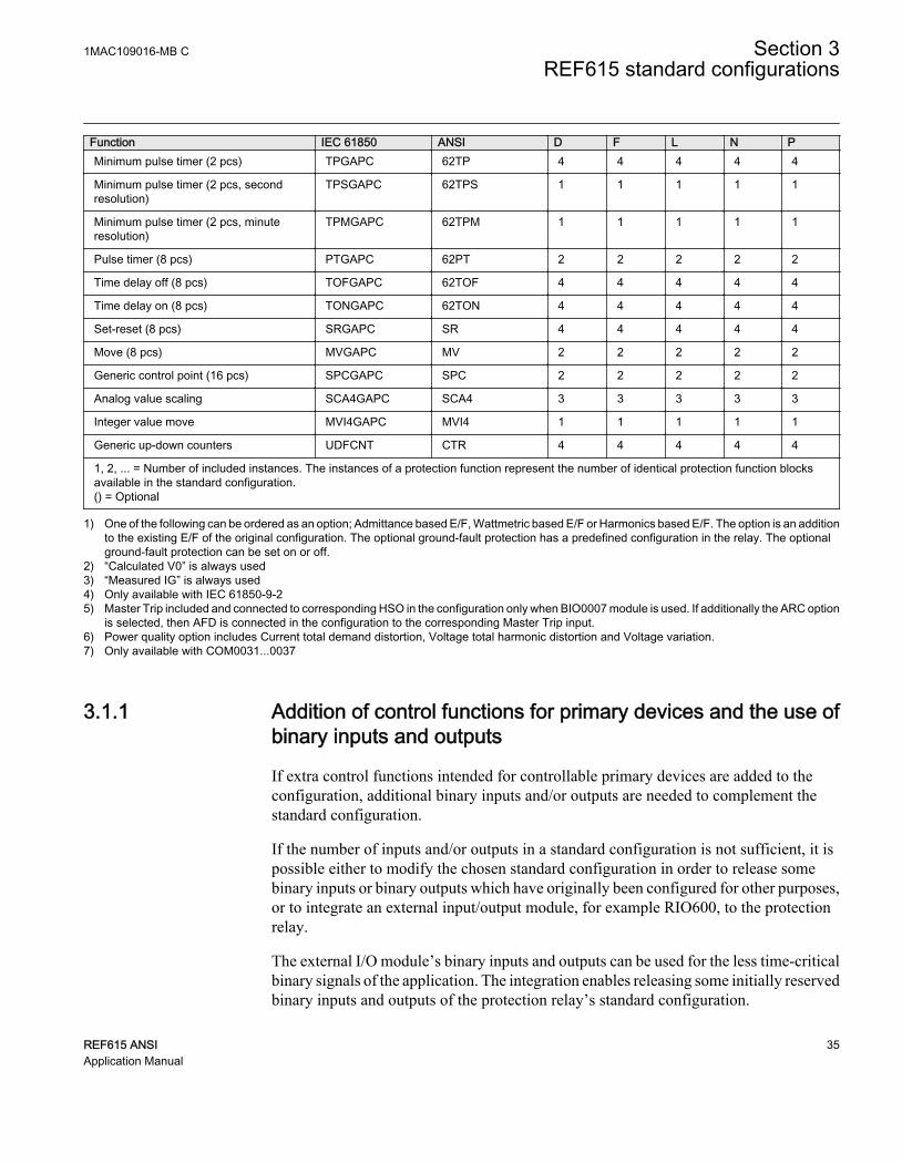
Function IEC 61850 ANSI D F L N PMinimum pulse timer (2 pcs) TPGAPC 62TP 4 4 4 4 4
Minimum pulse timer (2 pcs, secondresolution)
TPSGAPC 62TPS 1 1 1 1 1
Minimum pulse timer (2 pcs, minuteresolution)
TPMGAPC 62TPM 1 1 1 1 1
Pulse timer (8 pcs) PTGAPC 62PT 2 2 2 2 2
Time delay off (8 pcs) TOFGAPC 62TOF 4 4 4 4 4
Time delay on (8 pcs) TONGAPC 62TON 4 4 4 4 4
Set-reset (8 pcs) SRGAPC SR 4 4 4 4 4
Move (8 pcs) MVGAPC MV 2 2 2 2 2
Generic control point (16 pcs) SPCGAPC SPC 2 2 2 2 2
Analog value scaling SCA4GAPC SCA4 3 3 3 3 3
Integer value move MVI4GAPC MVI4 1 1 1 1 1
Generic up-down counters UDFCNT CTR 4 4 4 4 4
1, 2, ... = Number of included instances. The instances of a protection function represent the number of identical protection function blocksavailable in the standard configuration.() = Optional
1) One of the following can be ordered as an option; Admittance based E/F, Wattmetric based E/F or Harmonics based E/F. The option is an additionto the existing E/F of the original configuration. The optional ground-fault protection has a predefined configuration in the relay. The optionalground-fault protection can be set on or off.
2) “Calculated V0” is always used3) “Measured IG” is always used4) Only available with IEC 61850-9-25) Master Trip included and connected to corresponding HSO in the configuration only when BIO0007 module is used. If additionally the ARC option
is selected, then AFD is connected in the configuration to the corresponding Master Trip input.6) Power quality option includes Current total demand distortion, Voltage total harmonic distortion and Voltage variation.7) Only available with COM0031...0037
3.1.1 Addition of control functions for primary devices and the use ofbinary inputs and outputs
If extra control functions intended for controllable primary devices are added to theconfiguration, additional binary inputs and/or outputs are needed to complement thestandard configuration.
If the number of inputs and/or outputs in a standard configuration is not sufficient, it ispossible either to modify the chosen standard configuration in order to release somebinary inputs or binary outputs which have originally been configured for other purposes,or to integrate an external input/output module, for example RIO600, to the protectionrelay.
The external I/O module’s binary inputs and outputs can be used for the less time-criticalbinary signals of the application. The integration enables releasing some initially reservedbinary inputs and outputs of the protection relay’s standard configuration.
1MAC109016-MB C Section 3REF615 standard configurations
REF615 ANSI 35Application Manual

The suitability of the protection relay’s binary outputs which have been selected forprimary device control should be carefully verified, for example make and carry andbreaking capacity. If the requirements for the primary device control circuit are not met,using external auxiliary relays should be considered.
Section 3 1MAC109016-MB CREF615 standard configurations
36 REF615 ANSIApplication Manual

3.2 Connection diagrams
REF615
X13Light sensor input 1 1)
X14Light sensor input 2 1)
X15Light sensor input 3 1)
16
17
1918
X100
67
8910
111213
15
14
2
1
3
45
22
212324
SO2
TCM-2
PO4
SO1
TCM-1
PO3
PO2
PO1
IRF
+
-Uaux
20
X13012
3
45
6BI 4
BI 3
BI 2
BI 1
BI 6
BI 58
9
7
X130
12
10
11
15
13
14
18
16
17
SO3
SO2
SO1
1) 4)
1) 4)
ABC
S1
S2
P1
P2
X110
34
56
7
89
10BI 6
BI 5
BI 4
BI 3
BI 2
BI 8
BI 712
13
11
BI 112
X110
16
14
15
19
17
18
22
20
21
SO3
SO2
SO1
23SO4
24
PositiveCurrentDirection
2)
1) Optional2) The IED features an automatic short-circuit mechanism in the CT connector when plug-in unit is detached3) REF615 conf D: BIO0005 module (8BI+4BO) Alternative module BIO0007 (8BI+3HSO)4) REF615 conf D: BIO0006 module (6BI+3BO) Alternative module RTD0001 (6RTD+2mA)
X120
12
3
4
567
89
1011
1213
14IG
IA
IB
BI 4
BI 3
BI 2
BI 1
IC
1/5A
N1/5A
N1/5A
N1/5A
N
3)
3)
52
GUID-882B62DB-9C90-43CB-9D49-8D3EB6BF9B65 V1 EN
Figure 9: Connection diagram for the D configuration
1MAC109016-MB C Section 3REF615 standard configurations
REF615 ANSI 37Application Manual

REF615
X13Light sensor input 1 1)
X14Light sensor input 2 1)
X15Light sensor input 3 1)
16
17
1918
X100
67
89
10
111213
15
14
2
1
3
45
22
212324
SO2
TCM-2
PO4
SO1
TCM-1
PO3
PO2
PO1
IRF
+
-Uaux
20
ABC
S1
S2
P1
P2
P2
P1 S1
S2
da dn
X110
34
56
7
89
10BI 6
BI 5
BI 4
BI 3
BI 2
BI 8
BI 712
13
11
BI 112
X110
16
14
15
19
17
18
22
20
21
SO3
SO2
SO1
23SO4
24
a
nN
A
PositiveCurrentDirection
1) Optional2) The IED features an automatic short-circuit mechanism in the CT connector when plug-in unit is detached3) BIO0005 module (8BI+4BO) Alternative module BIO0007 (8BI+3HSO)4) AIM0006 module (5U+4BI) Alternative module AIM0003 (5U+2RTD+1mA)
2)
X120
12
3
4
567
89
1011
12
14IG
IA
IB
BI 4
BI 3
BI 2
BI 1
IC
1/5A
N1/5A
N1/5A
N1/5A
N
X13012
34
56
BI 4
BI 3
BI 2
BI 1
87
9101112
not in use
1314
VA
1516
VB
1718
VC
VGN
N
N
N
60 -
N
210V
60 -210V
60 -210V
60 -210V
60 -210V
4)
3)
3)
52
GUID-BCE3AC29-6587-4561-9FA5-D6A69B043809 V1 EN
Figure 10: Connection diagram for the F configuration
Section 3 1MAC109016-MB CREF615 standard configurations
38 REF615 ANSIApplication Manual
16
17
1918
X100
67
8910
111213
15
14
2
1
3
45
22
212324
SO2
TCM-2
PO4
SO1
TCM-1
PO3
PO2
PO1
IRF
+
-Uaux
20X110
34
56
7
89
10BI 6
BI 5
BI 4
BI 3
BI 2
BI 8
BI 712
13
11
BI 112
X110
16
14
15
19
17
18
22
20
21
SO3
SO2
SO1
23SO4
24
X130
12
X131
45
IA
78
VA
X132
45
IB
78
VB
X133
45
IC
78
VC
IG0,2/1A
N
X13Light sensor input 1 1)
X14Light sensor input 2 1)
X15Light sensor input 3 1)
1) Optional2) BIO0005 module (8BI+4BO) Alternative module BIO0007 (8BI+3HSO)
P2
P1 S1
S2
PositiveCurrentDirection
A
B
C
2)
2)
52
Current Sensor
Voltage Sensor
REF615
GUID-37A72CAC-69AC-45E2-B892-88A2D38CAD31 V1 EN
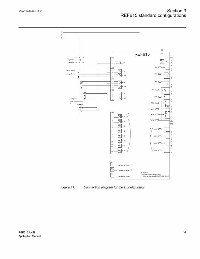
Figure 11: Connection diagram for the L configuration
1MAC109016-MB C Section 3REF615 standard configurations
REF615 ANSI 39Application Manual

REF615
X13Light sensor input 1 1)
X14Light sensor input 2 1)
X15Light sensor input 3 1)
16
17
1918
X100
67
89
10
111213
15
14
2
1
3
45
22
212324
SO2
TCM-2
PO4
SO1
TCM-1
PO3
PO2
PO1
IRF
+
-Uaux
20
ABC
S1
S2
P1
P2
P2
P1 S1
S2
da dn
X110
34
56
7
89
10BI 6
BI 5
BI 4
BI 3
BI 2
BI 8
BI 712
13
11
BI 112
X110
16
14
15
19
17
18
22
20
21
SO3
SO2
SO1
23SO4
24
a
nN
A
PositiveCurrentDirection
1) Optional2) The IED features an automatic short-circuit mechanism in the CT connector when plug-in unit is detached3) BIO0005 module (8BI+4BO) Alternative module BIO0007 (8BI+3HSO)4) AIM0006 module (5U+4BI) Alternative module AIM0003 (5U+2RTD+1mA)
2)
X120
12
3
4
567
89
1011
12
14IG
IA
IB
BI 4
BI 3
BI 2
BI 1
IC
1/5A
N1/5A
N1/5A
N1/5A
N
X13012
34
56
BI 4
BI 3
BI 2
BI 1
87
9101112
V12B
1314
VA
1516
VB
1718
VC
VGN
N
N
N
60 -
N
210V
60 -210V
60 -210V
60 -210V
60 -210V
3)
3)
4)
52
GUID-2EE7CD9D-D35A-4C6A-99E3-E86A9B561C1B V1 EN
Figure 12: Connection diagram for the N configuration
Section 3 1MAC109016-MB CREF615 standard configurations
40 REF615 ANSIApplication Manual
SO2
TCM-2
PO4
SO1
TCM-1
PO3
IG
IA
BI 4
BI 3
BI 2
BI 1
REF615
PO2
PO1
IRF
+
-Vaux
16
151918
10
111213
14
22
23
24
17
21
20
X100
67
89
10
21
3
45
X12012
3
4
567
89
1011
1213
14
IB
IC
1)
ABC
X130123
9
4
56
10
78
1112131415161718
BI 1
BI 2
BI 3
VC(2)
VB(2)
VA(2)
VC(1)
VA(1)
VB(1)
X110
16
14
15
19
17
18
22
20
21
SO3
SO2
24
23SO4
2)
X11012
43 2)
56
7
8910
1213
11
BI 1
BI 2
BI 3
BI 4
BI 5
BI 6
BI 7
BI 8
SO1
X110
2)
BI 1
BI 2
BI 3
BI 4
BI 5
BI 6
BI 7
BI 8
X11015
16
HSO3
HSO2
HSO1
2) 19
2023
24
Light Sensor Input 1
X13
Light Sensor Input 2
X14
Light Sensor Input 3
X15
2)
AlternativeModule
52
52
52
A B C
abc
P1
P2
S1
S2
(1)
(2)
A
Nn
a
a
nN
A
2
3
5
6
7
10
8
1
4
9
1) The IED features an automatic short-circuitmechanism in the CT connector whenplug-in unit is detached.
2) Order selectable. Optional.
GUID-5167A0C4-C9C3-40A1-A827-72E92310EEFA V2 EN
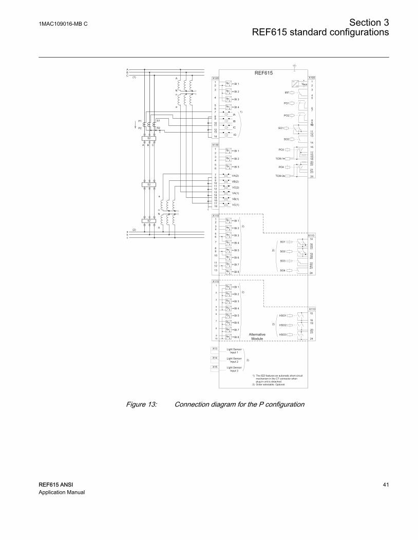
Figure 13: Connection diagram for the P configuration
1MAC109016-MB C Section 3REF615 standard configurations
REF615 ANSI 41Application Manual

3.3 Standard configuration D
3.3.1 Applications
The standard configuration for non-directional overcurrent and non-directional ground-fault protection is mainly intended for cable and overhead-line feeder applications indirectly or resistance grounded distribution networks.
The protection relay with a standard configuration is delivered from the factory withdefault settings and parameters. The end-user flexibility for incoming, outgoing andinternal signal designation within the protection relay enables this configuration to befurther adapted to different primary circuit layouts and the related functionality needs bymodifying the internal functionality using PCM600.
3.3.2 Functions
3
792
51P-1 50P-1 50P-3
46PD49F-1
51G
REF615 V5.0 FP-1 ANSI Func Appl D
1 Available with Harmonic-based earth-fault option2 Available with Reclosing option3 Available with Arc Flash Detection(AFD) option4 Available with RTD option
3
52
AFD-33
AFD-13
AFD-23
51N-1
50P-2
46-2
46-1
50G-3
50BF-1
50NBF-1
51NHA1
LoadProf.
50G-1
INR-1
HIZ-1
384
GUID-D0C1421A-5B6D-4FD1-A187-1ADC8D5B061D V1 EN
Figure 14: Functionality overview for standard configuration D
Section 3 1MAC109016-MB CREF615 standard configurations
42 REF615 ANSIApplication Manual

3.3.2.1 Default I/O connections
Table 9: Default connections for analog inputs
Analog input Description Connector pinsIA Phase A current X120:7-8
IB Phase B current X120:9-10
IC Phase C current X120:11-12
IG Residual current IG X120:13-14
Table 10: Default connections for binary inputs
Binary input Description Connector pinsBIO0005 BIO0007
X110-BI1 - X110:1-2 X110:1,5
X110-BI2 Autoreclose external pickup command X110:3-4 X110:2,5
X110-BI3 - X110:5-6 X110:3,5
X110-BI4 - X110:7-6 X110:4-5
X110-BI5 - X110:8-9 X110:6,10
X110-BI6 - X110:10-9 X110:7,10
X110-BI7 - X110:11-12 X110:8,10
X110-BI8 - X110:13-12 X110:9-10
X120-BI1 Blocking of overcurrent instantaneous stage X120:1-2
X120-BI2 Circuit breaker closed position indication X120:3-2
X120-BI3 Circuit breaker open position indication X120:4-2
X120-BI4 Lock-out reset X120:5-6
X130-BI1 - X130:1-2
X130-BI2 - X130:3-2
X130-BI3 - X130:4-5
X130-BI4 - X130:6-5
X130-BI5 - X130:7-8
X130-BI6 - X130:9-8
Table 11: Default connections for binary outputs
Binary output Description Connector pinsX100-PO1 Close circuit breaker X100:6-7
X100-PO2 Circuit breaker failure protection trip to upstream breaker X100:8-9
X100-SO1 General pickup indication X100:10-11,(12)
X100-SO2 General trip indication X100:13-14
Table continues on next page
1MAC109016-MB C Section 3REF615 standard configurations
REF615 ANSI 43Application Manual

Binary output Description Connector pinsX100-PO3 Open circuit breaker/trip coil 1 X100:15-19
X100-PO4 Open circuit breaker/trip coil 2 X100:20-24
X110-SO1 Upstream overcurrent blocking X110:14-16
X110-SO2 Overcurrent trip alarm X110:17-19
X110-SO3 Ground-fault trip alarm X110:20-22
X110-SO4 - X110:23-24
X110-HSO1 Arc protection instance 1 trip activated X110:15-16
X110-HSO1 Arc protection instance 2 trip activated X110:19-20
X110-HSO1 Arc protection instance 3 trip activated X110:23-24
X130-SO1 - X130:10-12
X130-SO2 - X130:13-15
X130-SO3 - X130:16-18
Table 12: Default connections for LEDs
LED Default usage ID Label description1 Non-directional overcurrent trip LED_Overcurrent_1 Overcurrent
2 Non-directional ground-faulttrip
LED_EarthFault_1 Ground-fault
3 Sensitive ground-fault trip LED_SensitiveEarthFault_1 Sensitive ground-fault
4 Negative sequence overcurrentor phase discontinuity trip
LED_PhaseUnbalance_1 Phase unbalance
5 Thermal overload alarm LED_ThermalOverload_1 Thermal overload
6 Breaker failure trip LED_BreakerFailure_1 Breaker failure
7 Disturbance recorder triggered LED_DisturbRecTriggered_1 Disturb. rec. triggered
8 Circuit breaker conditionmonitoring alarm
LED_CBConditionMonitoring_1
CB condition monitoring
9 Trip circuit supervision alarm LED_TripCircuitFailure_1 Trip circuit failure
10 Arc flash detection LED_ArcDetected_1 Arc detected
11 Autoreclose in progress LED_AutorecloseInProgress_1 Autoreclose shot in progr.
3.3.2.2 Default disturbance recorder settings
Table 13: Default disturbance recorder analog channels
Channel Description1 IL1
2 IL2
3 IL3
Table continues on next page
Section 3 1MAC109016-MB CREF615 standard configurations
44 REF615 ANSIApplication Manual

Channel Description4 Io
5 -
6 -
7 -
8 -
9 -
10 -
11 -
12 -
Table 14: Default disturbance recorder binary channels
Channel ID text Level trigger mode1 PHLPTOC1 - pickup Positive or Rising
2 PHHPTOC1 - pickup Positive or Rising
3 PHHPTOC2 - pickup Positive or Rising
4 PHIPTOC1 - pickup Positive or Rising
5 NSPTOC1 - pickup Positive or Rising
6 NSPTOC2 - pickup Positive or Rising
7 EFLPTOC1 - pickup Positive or Rising
8 EFHPTOC1 - pickup Positive or Rising
9 EFIPTOC1 - pickup Positive or Rising
10 EFLPTOC2 - pickup Positive or Rising
11 - -
12 PDNSPTOC1 - pickup Positive or Rising
13 T1PTTR1 - pickup Positive or Rising
14 CCBRBRF1 - trret Level trigger off
15 CCBRBRF1 - trbu Level trigger off
16 PHxPTOC - trip Level trigger off
17 NSPTOC - trip Level trigger off
18 EFxPTOC - trip Level trigger off
19 X110BI2 - ext pickup AutoReclose Level trigger off
20 EFL2PTOC - trip Level trigger off
21 PDNSPTOC1 - trip Level trigger off
22 INRPHAR1 - blk2h Level trigger off
23 T1PTTR1 - trip Level trigger off
24 ARCSARC - ARC flt det Level trigger off
Table continues on next page
1MAC109016-MB C Section 3REF615 standard configurations
REF615 ANSI 45Application Manual

Channel ID text Level trigger mode25 ARCSARC1 - trip Positive or Rising
26 ARCSARC2 - trip Positive or Rising
27 ARCSARC3 - trip Positive or Rising
28 DARREC1 - inpro Level trigger off
29 DARREC1 - close CB Level trigger off
30 DARREC1 - unsuc recl Level trigger off
31 X120BI1 - ext OC blocking Level trigger off
32 X120BI2 - CB closed Level trigger off
33 X120BI3 - CB open Level trigger off
34
35
36 - -
37 - -
38 - -
39 - -
40 - -
41 - -
42 - -
43 - -
44 - -
45 - -
46 - -
47 - -
48 - -
49 - -
50 - -
51 - -
52 - -
53 - -
54 - -
55 - -
56 - -
57 - -
58 - -
59 - -
60 - -
Table continues on next page
Section 3 1MAC109016-MB CREF615 standard configurations
46 REF615 ANSIApplication Manual

Channel ID text Level trigger mode61 - -
62 - -
63 - -
64 - -
3.3.3 Functional diagrams
The functional diagrams describe the default input, output, alarm LED and function-to-function connections. The default connections can be viewed and changed with PCM600according to the application requirements.
The analog channels have fixed connections to the different function blocks inside theprotection relay’s standard configuration. However, the 12 analog channels available forthe disturbance recorder function are freely selectable as a part of the disturbancerecorder’s parameter settings.
The phase currents to the protection relay are fed from a current transformer. The residualcurrent to the protection relay is fed from either residually connected CTs, an external corebalance CT, neutral CT or calculated internally.
The signal marked with IA, IB and IC represents the three phase currents. The signal IGrepresents the measured ground current.
The protection relay offers six different setting groups which can be set based onindividual needs. Each group can be activated or deactivated using the setting groupsettings available in the protection relay.
Depending on the communication protocol the required function block needs to beinstantiated in the configuration.
3.3.3.1 Functional diagrams for protection
The functional diagrams describe the relay's protection functionality in detail andaccording to the factory set default connections.
Four overcurrent stages are offered for overcurrent and short-circuit protection. The non-directional instantaneous stage PHIPTOC1_50P-3 can be blocked by energizing thebinary input X120:BI1.
1MAC109016-MB C Section 3REF615 standard configurations
REF615 ANSI 47Application Manual

PHIPTOC1
O:13|T:2.5|I:1
BLOCKENA_MULT
TRIPPICKUP
PHLPTOC1
O:23|T:5|I:1
BLOCKENA_MULT
TRIPPICKUP
PHHPTOC1
O:12|T:5|I:1
BLOCKENA_MULT
TRIPPICKUP
PHHPTOC2
O:11|T:5|I:2
BLOCKENA_MULT
TRIPPICKUP
OR6
O:90|T:2.5|I:27
B1B2B3B4B5B6
O
PHIPTOC1_50P-3_TRIP
PHIPTOC1_50P-3_TRIP
PHLPTOC1_51P-1_TRIP
PHLPTOC1_51P-1_TRIP
PHHPTOC1_50P-1_TRIP
PHHPTOC1_50P-1_TRIP
PHHPTOC2_50P-2_TRIP
PHHPTOC2_50P-2_TRIP
PHLPTOC1_51P-1_PICKUP
PHHPTOC1_50P-1_PICKUP
PHHPTOC2_50P-2_PICKUP
PHIPTOC1_50P-3_PICKUPX120_BI1_EXT_OC_BLOCKING
PHxPTOC_TRIP
GUID-9F58DD49-59D6-4CAF-8BF4-D572E064D069 V1 EN
Figure 15: Overcurrent protection functions
The upstream blocking from the pickup of the second high stage of three-phase non-directional overcurrent protection PHHPTOC2_50P-2 is connected to the binary outputX110:SO1. This output can be used for sending a blocking signal to the relevantovercurrent protection stage of the relay at the infeeding bay.
OR6
O:98|T:2.5|I:29
B1B2B3B4B5B6
O UPSTEAM_OC_BLOCKINGPHHPTOC2_50P-2_PICKUP
GUID-E4F23744-DC73-4048-9654-867A21960BA5 V1 EN
Figure 16: Upstream blocking logic
The output BLK2H of three-phase inrush detector INRPHAR1_INR-1 enables eitherblocking the function or multiplying the active settings for any of the availableovercurrent or ground-fault function blocks.
Section 3 1MAC109016-MB CREF615 standard configurations
48 REF615 ANSIApplication Manual

INRPHAR1
O:69|T:2.5|I:1BLOCK BLK2H INRPHAR1_INR-1_BLK2H
GUID-5FAEFBEC-C27F-450F-8031-9B51ECEBEE72 V1 EN
Figure 17: Inrush detector function
Two negative-sequence overcurrent protection stages NSPTOC1_46-1 andNSPTOC2_46-2 are provided for phase unbalance protection. These functions are used toprotect the feeder against phase unbalance.
NSPTOC1
O:24|T:5|I:1
BLOCKENA_MULT
TRIPPICKUP
NSPTOC2
O:25|T:5|I:2
BLOCKENA_MULT
TRIPPICKUP
OR
O:87|T:2.5|I:14
B1B2
O
NSPTOC2_46-2_TRIP
NSPTOC2_46-2_TRIP
NSPTOC1_46-1_TRIP
NSPTOC1_46-1_TRIP
NSPTOC1_46-1_PICKUP
NSPTOC2_46-2_PICKUP
NSPTOC_TRIP
GUID-F3410D3C-843F-4124-B412-F32601AE0359 V1 EN
Figure 18: Negative-sequence overcurrent protection function
Three stages are provided for non-directional ground-fault protection. One stage isprovided for sensitive ground-fault protection.
1MAC109016-MB C Section 3REF615 standard configurations
REF615 ANSI 49Application Manual

EFHPTOC1
O:14|T:5|I:1
BLOCKENA_MULT
TRIPPICKUP
EFLPTOC1
O:16|T:5|I:1
BLOCKENA_MULT
TRIPPICKUP
EFIPTOC1
O:15|T:2.5|I:1
BLOCKENA_MULT
TRIPPICKUP
OR6
O:94|T:2.5|I:28
B1B2B3B4B5B6
O
EFLPTOC1_51G_TRIP
EFLPTOC1_51G_TRIP
EFHPTOC1_50G-1_TRIP
EFHPTOC1_50G-1_TRIP
EFIPTOC1_50G-3_TRIP
EFIPTOC1_50G-3_TRIP
EFLPTOC1_51G_PICKUP
EFIPTOC1_50G-3_PICKUP
EFHPTOC1_50G-1_PICKUP
EFxPTOC_TRIP
EFLPTOC2
O:27|T:5|I:2
BLOCKENA_MULT
TRIPPICKUP
EFLPTOC2_51N-1_TRIPEFLPTOC2_51N-1_PICKUP
GUID-4CBFA059-E084-43C5-9C22-1F94DB321BDC V1 EN
Figure 19: Non-directional ground-fault protection
Phase discontinuity protection PDNSPTOC1_46PD protects for interruptions in thenormal three-phase load supply, for example, in downed conductor situations.
PDNSPTOC1
O:26|T:5|I:1
BLOCK TRIPPICKUP
PDNSPTOC1_46PD_TRIPPDNSPTOC1_46PD_PICKUP
GUID-37AE4620-83A7-4044-AE1E-455659FDEF49 V1 EN
Figure 20: Phase discontinuity protection
Three-phase thermal protection for feeders, cables and distribution transformersT1PTTR1_49F-1 detects overloads under varying load conditions.
Section 3 1MAC109016-MB CREF615 standard configurations
50 REF615 ANSIApplication Manual

T1PTTR1
O:64|T:5|I:1
BLOCKENA_MULTAMB_TEMP
TRIPPICKUPALARM
BLK_CLOSE
T1PTTR1_49F-1_PICKUPT1PTTR1_49F-1_TRIP
T1PTTR1_49F-1_ALARM
GUID-CC27632E-FDD1-43E8-BAA0-49D51656C53F V1 EN
Figure 21: Thermal overcurrent protection function
Circuit breaker failure protection CCBRBRF1_50BF-1 is initiated via the PICKUP inputby number of different protection functions available in the relay. The breaker failureprotection function offers different operating modes associated with the circuit breakerposition and the measured phase and residual currents.
The circuit breaker failure protection function has two operating outputs: TRRET andTRBU. The TRRET trip output is used for retripping its own breaker throughTRPPTRC2_86/94-2_TRIP. The TRBU output is used to give a backup trip to the breakerfeeding upstream. For this purpose, the TRBU trip output signal is connected to the binaryoutput X100:PO2.
CCBRBRF1
O:28|T:2.5|I:1
BLOCKPICKUPPOSCLOSECB_FAULT
CB_FAULT_ALTRBU
TRRET
OR6
O:20|T:2.5|I:1
B1B2B3B4B5B6
O
OR6
O:21|T:2.5|I:0
B1B2B3B4B5B6
O
OR6
O:22|T:2.5|I:2
B1B2B3B4B5B6
O
CCBRBRF1_50BF-1_TRBUX120_BI2_CB_CLOSED
PHIPTOC1_50P-3_TRIPPHHPTOC1_50P-1_TRIPPHHPTOC2_50P-2_TRIP
EFLPTOC1_51G_TRIPEFHPTOC1_50G-1_TRIPEFIPTOC1_50G-3_TRIP
ARCSARC1_AFD-1_TRIPARCSARC2_AFD-2_TRIPARCSARC3_AFD-3_TRIP
CCBRBRF1_50BF-1_TRRET
GUID-C198C043-B92F-4A17-BA0D-AA9C36A3AF65 V1 EN
Figure 22: Circuit breaker failure protection function
Three arc protection stages ARCSARC1…3_AFD-1...3 are included as an optionalfunction. The arc protection offers individual function blocks for three arc sensors that canbe connected to the relay. Each arc protection function block has two different operationmodes, that is, with or without the phase and residual current check.
The trip signals from ARCSARC1…3_AFD-1...3 are connected to both trip logicTRPPTRC1_86/94-1 and TRPPTRC2_86/94-2.
1MAC109016-MB C Section 3REF615 standard configurations
REF615 ANSI 51Application Manual

ARCSARC1
O:18|T:2.5|I:11
BLOCKREM_FLT_ARCOPR_MODE
TRIPARC_FLT_DET
ARCSARC2
O:17|T:2.5|I:21
BLOCKREM_FLT_ARCOPR_MODE
TRIPARC_FLT_DET
ARCSARC3
O:19|T:2.5|I:31
BLOCKREM_FLT_ARCOPR_MODE
TRIPARC_FLT_DET
OR6
O:92|T:2.5|I:30
B1B2B3B4B5B6
O
ARCSARC1_AFD-1_TRIP
ARCSARC1_AFD-1_TRIP
ARCSARC2_AFD-2_TRIP
ARCSARC2_AFD-2_TRIP
ARCSARC3_AFD-3_TRIP
ARCSARC3_AFD-3_TRIP
ARCSARC1_AFD-1_ARC_FLT_DET
ARCSARC2_AFD-2_ARC_FLT_DET
ARCSARC3_AFD-3_ARC_FLT_DET
ARCSARC_TRIP
GUID-C6165736-DE76-486B-97A3-E92CA54D3B15 V1 EN
Figure 23: Arc protection
The optional autoreclosing function is configured to be initiated by trip signals from anumber of protection stages through the INIT_1...5 inputs. It is possible to createindividual autorecloseing sequences for each input.
The autoreclosing function can be inhibited with the INHIBIT_RECL input. By default,few selected protection function operations are connected to this input. A controlcommand to the circuit breaker, either local or remote, also blocks the autoreclosingfunction via the CBXCBR1_52-1_SELECTED signal.
The circuit breaker availability for the autoreclosing sequence is expressed with theCB_READY input in DARREC1_79. This signal is not connected in the configuration.
The open command from the autorecloser is connected directly to binary outputX100:PO3, whereas the close command is connected directly to binary output X100:PO1.
Set the parameters for DARREC1_79 properly.
Section 3 1MAC109016-MB CREF615 standard configurations
52 REF615 ANSIApplication Manual
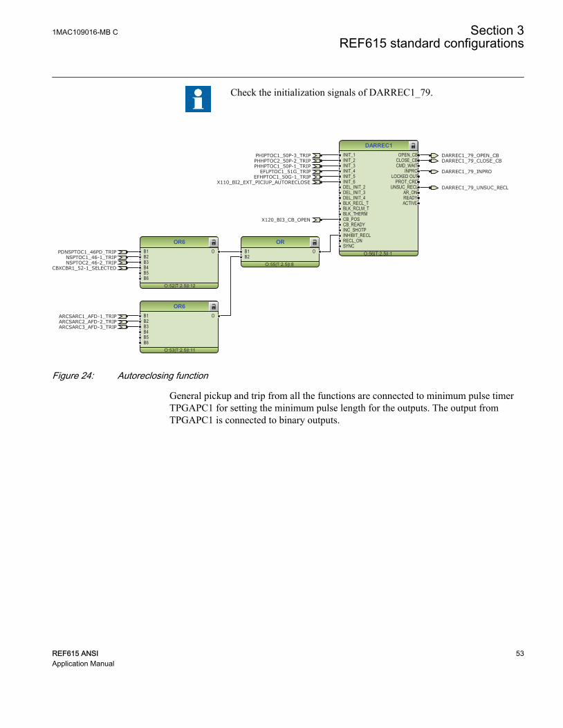
Check the initialization signals of DARREC1_79.
DARREC1
O:56|T:2.5|I:1
INIT_1INIT_2INIT_3INIT_4INIT_5INIT_6DEL_INIT_2DEL_INIT_3DEL_INIT_4BLK_RECL_TBLK_RCLM_TBLK_THERMCB_POSCB_READYINC_SHOTPINHIBIT_RECLRECL_ONSYNC
OPEN_CBCLOSE_CBCMD_WAIT
INPROLOCKED OUT
PROT_CRDUNSUC_RECL
AR_ONREADYACTIVE
OR6
O:52|T:2.5|I:12
B1B2B3B4B5B6
O
OR6
O:53|T:2.5|I:11
B1B2B3B4B5B6
O
OR
O:55|T:2.5|I:8
B1B2
O
X120_BI3_CB_OPEN
DARREC1_79_OPEN_CBDARREC1_79_CLOSE_CB
PHIPTOC1_50P-3_TRIP
PHHPTOC1_50P-1_TRIPPHHPTOC2_50P-2_TRIP
NSPTOC2_46-2_TRIP
EFLPTOC1_51G_TRIPEFHPTOC1_50G-1_TRIP
PDNSPTOC1_46PD_TRIP
ARCSARC1_AFD-1_TRIPARCSARC2_AFD-2_TRIPARCSARC3_AFD-3_TRIP
NSPTOC1_46-1_TRIP
CBXCBR1_52-1_SELECTED
X110_BI2_EXT_PICIUP_AUTORECLOSE
DARREC1_79_INPRO
DARREC1_79_UNSUC_RECL
GUID-842B6874-C3B5-42F1-9505-54EE6C1C0123 V1 EN
Figure 24: Autoreclosing function
General pickup and trip from all the functions are connected to minimum pulse timerTPGAPC1 for setting the minimum pulse length for the outputs. The output fromTPGAPC1 is connected to binary outputs.
1MAC109016-MB C Section 3REF615 standard configurations
REF615 ANSI 53Application Manual

OR6
O:80|T:2.5|I:23
B1B2B3B4B5B6
O
OR6
O:79|T:2.5|I:24
B1B2B3B4B5B6
O
OR6
O:81|T:2.5|I:22
B1B2B3B4B5B6
O
OR6
O:82|T:2.5|I:21
B1B2B3B4B5B6
O
OR6
O:84|T:2.5|I:26
B1B2B3B4B5B6
O
OR6
O:85|T:2.5|I:25
B1B2B3B4B5B6
O
TPGAPC1
O:86|T:2.5|I:1
IN1IN2
OUT1OUT2
OR6
O:83|T:2.5|I:20
B1B2B3B4B5B6
O
GENERAL_PICIUP_PULSEGENERAL_TRIP_PULSE
PHIPTOC1_50P-3_TRIP
PHLPTOC1_51P-1_TRIPPHHPTOC1_50P-1_TRIPPHHPTOC2_50P-2_TRIP
NSPTOC2_46-2_TRIP
EFLPTOC1_51G_TRIP
EFHPTOC1_50G-1_TRIPEFIPTOC1_50G-3_TRIP
EFLPTOC2_51N-1_TRIP
PDNSPTOC1_46PD_TRIP
ARCSARC1_AFD-1_TRIPARCSARC2_AFD-2_TRIPARCSARC3_AFD-3_TRIP
NSPTOC1_46-1_TRIP
PHLPTOC1_51P-1_PICKUPPHHPTOC1_50P-1_PICKUPPHHPTOC2_50P-2_PICKUPPHIPTOC1_50P-3_PICKUP
NSPTOC1_46-1_PICKUPNSPTOC2_46-2_PICKUP
EFLPTOC1_51G_PICKUPEFLPTOC2_51N-1_PICKUPEFIPTOC1_50G-3_PICKUPEFHPTOC1_50G-1_PICKUPPDNSPTOC1_46PD_PICKUP
GUID-52097E03-6891-45E2-9F24-A031AB0D74CF V1 EN
Figure 25:
The trip signals from the protection functions are connected to the two trip logicsTRPPTRC1_86/94-1 and TRPPTRC2_86/94-2. The output of these trip logic functionsare available at binary outputs X100:PO3 and X100:PO4. Both the trip logic functions areprovided with lockout and latching function, event generation and the trip signal durationsetting. If the lockout operation mode is selected, binary input has been assigned toRST_LKOUT input of both the trip logic to enable external reset with a push button.
Three other trip logics TRPPTRC3...5_86/94-3…5 are also available if the relay isordered with high speed binary outputs options.
Section 3 1MAC109016-MB CREF615 standard configurations
54 REF615 ANSIApplication Manual

TRPPTRC1
O:40|T:2.5|I:1
BLOCKTRIPRST_LKOUT
TRIPCL_LKOUT
OR6
O:29|T:2.5|I:8
B1B2B3B4B5B6
O
OR6
O:30|T:2.5|I:7
B1B2B3B4B5B6
O
OR6
O:36|T:2.5|I:10
B1B2B3B4B5B6
O
OR6
O:31|T:2.5|I:6
B1B2B3B4B5B6
O
TRPPTRC1_86/94-1_TRIP
PHIPTOC1_50P-3_TRIPPHLPTOC1_51P-1_TRIPPHHPTOC1_50P-1_TRIPPHHPTOC2_50P-2_TRIP
NSPTOC2_46-2_TRIP
EFLPTOC1_51G_TRIPEFHPTOC1_50G-1_TRIPEFIPTOC1_50G-3_TRIPEFLPTOC2_51N-1_TRIP
PDNSPTOC1_46PD_TRIP
X120_BI4_RST_LOCKOUT
ARCSARC1_AFD-1_TRIPARCSARC2_AFD-2_TRIPARCSARC3_AFD-3_TRIP
NSPTOC1_46-1_TRIP
GUID-15A33F46-498B-49E8-AEFB-E1E3059F0E49 V1 EN
Figure 26: Trip logic TRPPTRC1
OR6
O:37|T:2.5|I:9
B1B2B3B4B5B6
O
TRPPTRC2
O:41|T:2.5|I:2
BLOCKTRIPRST_LKOUT
TRIPCL_LKOUT
OR6
O:32|T:2.5|I:5
B1B2B3B4B5B6
O
OR6
O:33|T:2.5|I:4
B1B2B3B4B5B6
O
OR6
O:34|T:2.5|I:3
B1B2B3B4B5B6
O
TRPPTRC2_86/94-2_TRIP
PHIPTOC1_50P-3_TRIPPHLPTOC1_51P-1_TRIPPHHPTOC1_50P-1_TRIPPHHPTOC2_50P-2_TRIP
NSPTOC2_46-2_TRIP
EFLPTOC1_51G_TRIP
EFHPTOC1_50G-1_TRIP
EFIPTOC1_50G-3_TRIPEFLPTOC2_51N-1_TRIP
PDNSPTOC1_46PD_TRIP
X120_BI4_RST_LOCKOUT
ARCSARC1_AFD-1_TRIPARCSARC2_AFD-2_TRIPARCSARC3_AFD-3_TRIP
NSPTOC1_46-1_TRIP
CCBRBRF1_50BF-1_TRRET
GUID-7B33E0C0-9A07-48FD-B510-97E084498C2C V1 EN
Figure 27: Trip logic TRPPTRC2
1MAC109016-MB C Section 3REF615 standard configurations
REF615 ANSI 55Application Manual

TRPPTRC3
O:102|T:2.5|I:3
BLOCKTRIPRST_LKOUT
TRIPCL_LKOUT
TRPPTRC4
O:99|T:2.5|I:4
BLOCKTRIPRST_LKOUT
TRIPCL_LKOUT
TRPPTRC5
O:101|T:2.5|I:5
BLOCKTRIPRST_LKOUT
TRIPCL_LKOUT
TRPPTRC3_86/94-3_TRIP
TRPPTRC4_86/94-4_TRIP
TRPPTRC5_86/94-5_TRIP
X120_BI4_RST_LOCKOUT
X120_BI4_RST_LOCKOUT
X120_BI4_RST_LOCKOUT
ARCSARC1_AFD-1_TRIP
ARCSARC2_AFD-2_TRIP
ARCSARC3_AFD-3_TRIP
GUID-DE0353C0-B5E5-4225-8B6A-F6428FECA254 V1 EN
Figure 28: Trip logic TRPPTRC3/4/5
3.3.3.2 Functional diagrams for disturbance recorder
The PICKUP and TRIP outputs from the protection stages are routed to trigger thedisturbance recorder or, alternatively, only to be recorded by the disturbance recorderdepending on the parameter settings. Additionally, the selected signals from differentfunctions and the few binary inputs are also connected to the disturbance recorder.
Section 3 1MAC109016-MB CREF615 standard configurations
56 REF615 ANSIApplication Manual

RDRE1
O:70|T:2.5|I:1
C1C2C3C4C5C6C7C8C9C10C11C12C13C14C15C16C17C18C19C20C21C22C23C24C25C26C27C28C29C30C31C32C33C34C35C36C37C38C39C40C41C42C43C44C45C46C47C48C49C50C51C52C53C54C55C56C57C58C59C60C61C62C63C64
TRIGGERED
OR6
O:65|T:2.5|I:18
B1B2B3B4B5B6
O
OR6
O:66|T:2.5|I:17
B1B2B3B4B5B6
O
OR
O:68|T:2.5|I:12
B1B2
O
OR6
O:67|T:2.5|I:16
B1B2B3B4B5B6
O
CCBRBRF1_50BF-1_TRBU
X120_BI3_CB_OPENX120_BI2_CB_CLOSED
DARREC1_79_CLOSE_CB
PHIPTOC1_50P-3_TRIP
PHLPTOC1_51P-1_TRIP
PHHPTOC1_50P-1_TRIPPHHPTOC2_50P-2_TRIP
NSPTOC2_46-2_TRIP
EFLPTOC1_51G_TRIPEFHPTOC1_50G-1_TRIPEFIPTOC1_50G-3_TRIP
EFLPTOC2_51N-1_TRIPPDNSPTOC1_46PD_TRIP
ARCSARC1_AFD-1_TRIPARCSARC2_AFD-2_TRIPARCSARC3_AFD-3_TRIP
NSPTOC1_46-1_TRIP
CCBRBRF1_50BF-1_TRRET
PHLPTOC1_51P-1_PICKUPPHHPTOC1_50P-1_PICKUPPHHPTOC2_50P-2_PICKUPPHIPTOC1_50P-3_PICKUP
NSPTOC1_46-1_PICKUPNSPTOC2_46-2_PICKUPEFLPTOC1_51G_PICKUP
EFLPTOC2_51N-1_PICKUPEFIPTOC1_50G-3_PICKUPEFHPTOC1_50G-1_PICKUP
PDNSPTOC1_46PD_PICKUP
X120_BI1_EXT_OC_BLOCKING
X110_BI2_EXT_PICIUP_AUTORECLOSE
T1PTTR1_49F-1_PICKUP
ARCSARC1_AFD-1_ARC_FLT_DETARCSARC2_AFD-2_ARC_FLT_DETARCSARC3_AFD-3_ARC_FLT_DET
INRPHAR1_INR-1_BLK2HT1PTTR1_49F-1_TRIP
DARREC1_79_INPRO
DARREC1_79_UNSUC_RECL
DISTURB_RECORD_TRIGGERED
GUID-F324C488-27AE-4DE2-A588-E1B77C49EC5A V1 EN
Figure 29: Disturbance recorder
3.3.3.3 Functional diagrams for condition monitoring
Circuit-breaker condition monitoring SSCBR1_52CM-1 supervises the switch statusbased on the connected binary input information and the measured current levels.SSCBR1_52CM-1 introduces various supervision methods.
Set the parameters for SSCBR1_52CM-1 properly.
1MAC109016-MB C Section 3REF615 standard configurations
REF615 ANSI 57Application Manual
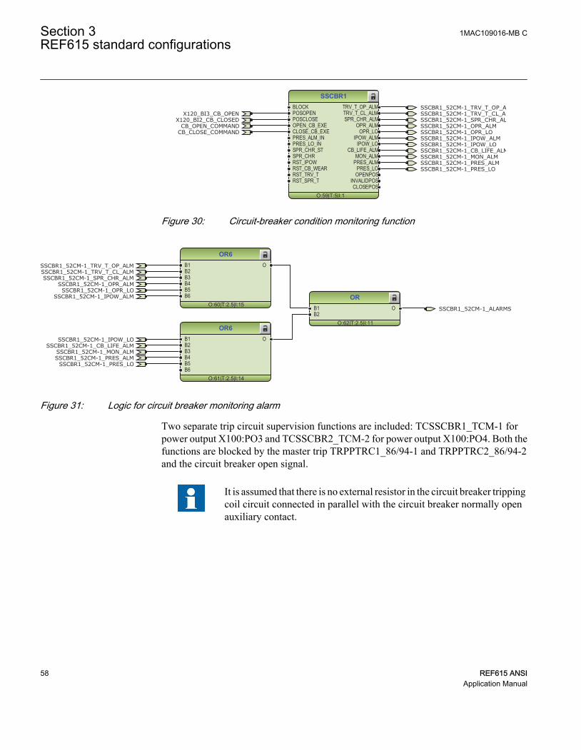
SSCBR1
O:59|T:5|I:1
BLOCKPOSOPENPOSCLOSEOPEN_CB_EXECLOSE_CB_EXEPRES_ALM_INPRES_LO_INSPR_CHR_STSPR_CHRRST_IPOWRST_CB_WEARRST_TRV_TRST_SPR_T
TRV_T_OP_ALMTRV_T_CL_ALMSPR_CHR_ALM
OPR_ALMOPR_LO
IPOW_ALMIPOW_LO
CB_LIFE_ALMMON_ALM
PRES_ALMPRES_LO
OPENPOSINVALIDPOSCLOSEPOS
CB_CLOSE_COMMANDCB_OPEN_COMMAND
X120_BI3_CB_OPENX120_BI2_CB_CLOSED
SSCBR1_52CM-1_TRV_T_OP_ALMSSCBR1_52CM-1_TRV_T_CL_ALMSSCBR1_52CM-1_SPR_CHR_ALMSSCBR1_52CM-1_OPR_ALMSSCBR1_52CM-1_OPR_LOSSCBR1_52CM-1_IPOW_ALMSSCBR1_52CM-1_IPOW_LO
SSCBR1_52CM-1_MON_ALMSSCBR1_52CM-1_PRES_ALMSSCBR1_52CM-1_PRES_LO
SSCBR1_52CM-1_CB_LIFE_ALM
GUID-0B65542D-6DE7-4B60-B79A-BE23D184A8C0 V1 EN
Figure 30: Circuit-breaker condition monitoring function
OR6
O:60|T:2.5|I:15
B1B2B3B4B5B6
O
OR6
O:61|T:2.5|I:14
B1B2B3B4B5B6
O
OR
O:62|T:2.5|I:11
B1B2
O
SSCBR1_52CM-1_TRV_T_OP_ALMSSCBR1_52CM-1_TRV_T_CL_ALMSSCBR1_52CM-1_SPR_CHR_ALM
SSCBR1_52CM-1_OPR_ALMSSCBR1_52CM-1_OPR_LO
SSCBR1_52CM-1_IPOW_ALM
SSCBR1_52CM-1_IPOW_LO
SSCBR1_52CM-1_MON_ALMSSCBR1_52CM-1_PRES_ALM
SSCBR1_52CM-1_PRES_LO
SSCBR1_52CM-1_CB_LIFE_ALM
SSCBR1_52CM-1_ALARMS
GUID-79BF3B58-B0F3-490A-96CB-52031D35EB2C V1 EN
Figure 31: Logic for circuit breaker monitoring alarm
Two separate trip circuit supervision functions are included: TCSSCBR1_TCM-1 forpower output X100:PO3 and TCSSCBR2_TCM-2 for power output X100:PO4. Both thefunctions are blocked by the master trip TRPPTRC1_86/94-1 and TRPPTRC2_86/94-2and the circuit breaker open signal.
It is assumed that there is no external resistor in the circuit breaker trippingcoil circuit connected in parallel with the circuit breaker normally openauxiliary contact.
Section 3 1MAC109016-MB CREF615 standard configurations
58 REF615 ANSIApplication Manual

TCSSCBR1
O:74|T:5|I:1BLOCK ALARM
TCSSCBR2
O:75|T:5|I:2BLOCK ALARM
OR
O:76|T:2.5|I:13
B1B2
O
TCSSCBR1_TCM-1_ALARM
TCSSCBR1_TCM-1_ALARM
TCSSCBR2_TCM-1_ALARM
TCSSCBR2_TCM-1_ALARM
TCSSCBR_BLOCKING
TCSSCBR_BLOCKING
TCSSCBR_ALARM
GUID-09D826A2-9C1F-45E2-8382-FFC58B98DAE7 V1 EN
Figure 32: Trip circuit supervision function
OR6
O:73|T:2.5|I:19
B1B2B3B4B5B6
OTRPPTRC2_86/94-2_TRIP
X120_BI3_CB_OPEN
TRPPTRC1_86/94-1_TRIP TCSSCBR_BLOCKING
GUID-A0E5F33A-B395-4EE7-92A9-C1222EF942BD V1 EN
Figure 33: Logic for blocking of trip circuit supervision
3.3.3.4 Functional diagrams for control and interlocking
The circuit breaker closing is enabled when the ENA_CLOSE input is activated. The inputcan be activated using the configuration logic, which is based on the status of the triplogics. However, other signals can be connected based on the application needs.
The SYNC_ITL_BYP input can be used, for example, to always enable the closing of thecircuit breaker when the circuit breaker truck is in the test position. SYNC_ITL_BYPoverrides, for example, active interlocking conditions when the circuit breaker truck isclosed in service position.
1MAC109016-MB C Section 3REF615 standard configurations
REF615 ANSI 59Application Manual

CBXCBR1
O:51|T:5|I:1
POSOPENPOSCLOSEENA_OPENENA_CLOSEBLK_OPENBLK_CLOSEAU_OPENAU_CLOSETRIPSYNC_OKSYNC_ITL_BYP
SELECTEDEXE_OPEXE_CL
OP_REQCL_REQ
OPENPOSCLOSEPOS
OKPOSOPEN_ENAD
CLOSE_ENAD
TRUE
X120_BI3_CB_OPENX120_BI2_CB_CLOSED
CBXCBR1_52-1_ENA_CLOSECBXCBR1_52-1_EXE_CLCBXCBR1_52-1_EXE_OP
FALSE
CBXCBR1_52-1_AU_OPENCBXCBR1_52-1_AU_CLOSE
CBXCBR1_52-1_SELECTED
GUID-C79FD0BB-613A-4D24-A6A9-8917D7B60584 V1 EN
Figure 34: Circuit breaker control logic: Circuit breaker 1
OR
O:58|T:2.5|I:10
B1B2
O CB_CLOSE_COMMANDCBXCBR1_52-1_EXE_CLDARREC1_79_CLOSE_CB
GUID-013DD8AC-2D27-4D1D-AA0B-F62645683AC1 V1 EN
Figure 35: Circuit breaker control logic: Signals for the closing coil of circuit breaker1
OR6
O:57|T:2.5|I:13
B1B2B3B4B5B6
O CB_OPEN_COMMANDCBXCBR1_52-1_EXE_OPTRPPTRC1_86/94-1_TRIP
DARREC1_79_OPEN_CB
GUID-DCD405D6-BD0D-4EB4-B5A9-57E84374B9CD V1 EN
Figure 36: Circuit breaker control logic: Signals for the opening coil of circuit breaker1
NOT
O:46|T:2.5|I:3IN OUT
NOT
O:47|T:2.5|I:2IN OUT
AND6
O:50|T:2.5|I:0
B1B2B3B4B5B6
O
TRPPTRC2_86/94-2_TRIP
CBXCBR1_52-1_ENA_CLOSETRPPTRC1_86/94-1_TRIP
GUID-B6706358-665E-47F2-98BC-6C4B130AF93F V1 EN
Figure 37: Circuit breaker close enable logic
The configuration includes the logic for generating circuit breaker external closing andopening command with the relay in local or remote mode.
Check the logic for the external circuit breaker closing command andmodify it according to the application.
Section 3 1MAC109016-MB CREF615 standard configurations
60 REF615 ANSIApplication Manual
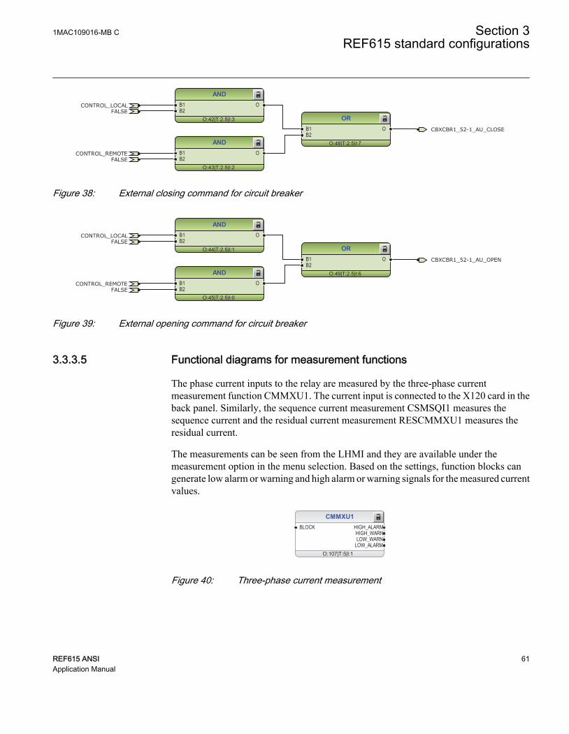
AND
O:42|T:2.5|I:3
B1B2
O
AND
O:43|T:2.5|I:2
B1B2
O
OR
O:48|T:2.5|I:7
B1B2
O
FALSE
FALSE
CONTROL_LOCAL
CONTROL_REMOTE
CBXCBR1_52-1_AU_CLOSE
GUID-BC662286-4C38-4CC0-B1AB-6C81A5668F27 V1 EN
Figure 38: External closing command for circuit breaker
AND
O:44|T:2.5|I:1
B1B2
O
AND
O:45|T:2.5|I:0
B1B2
O
OR
O:49|T:2.5|I:6
B1B2
O
FALSE
FALSE
CONTROL_LOCAL
CONTROL_REMOTE
CBXCBR1_52-1_AU_OPEN
GUID-86D156FC-CADB-49D4-B52A-119ED2D7FD22 V1 EN
Figure 39: External opening command for circuit breaker
3.3.3.5 Functional diagrams for measurement functions
The phase current inputs to the relay are measured by the three-phase currentmeasurement function CMMXU1. The current input is connected to the X120 card in theback panel. Similarly, the sequence current measurement CSMSQI1 measures thesequence current and the residual current measurement RESCMMXU1 measures theresidual current.
The measurements can be seen from the LHMI and they are available under themeasurement option in the menu selection. Based on the settings, function blocks cangenerate low alarm or warning and high alarm or warning signals for the measured currentvalues.
CMMXU1
O:107|T:5|I:1
BLOCK HIGH_ALARMHIGH_WARNLOW_WARN
LOW_ALARM
GUID-1C55C009-67CB-45E0-81D8-29B80AF77560 V1 EN
Figure 40: Three-phase current measurement
1MAC109016-MB C Section 3REF615 standard configurations
REF615 ANSI 61Application Manual

CSMSQI1
O:105|T:5|I:1
GUID-BE9CAFE5-027E-4438-8172-820F47E62CB7 V1 EN
Figure 41: Sequence current measurements
RESCMMXU1
O:109|T:5|I:1
BLOCK HIGH_ALARMHIGH_WARN
GUID-8152F264-1F67-4FF2-911C-5B50BF900F3A V1 EN
Figure 42: Ground current measurements
FLTRFRC1
O:7|T:2.5|I:1
BLOCKCB_CLRD
LDPRLRC1
O:110|T:5|I:1
RSTMEM MEM_WARNMEM_ALARM
GUID-723F3FEC-853F-400A-A21E-D5422D179B3E V1 EN
Figure 43: Data monitoring and load profile record
3.3.3.6 Functional diagrams for I/O and alarm LEDs
OR
O:54|T:2.5|I:9
B1B2
O X110_BI2_EXT_PICIUP_AUTORECLOSEX110 (BIO)_110.X110-Input 2
X110 (BIO-H)_110.X110-Input 2
GUID-CC85B6A3-30F0-4FE2-8FC6-DFB3417124EA V1 EN
Figure 44: Default binary inputs - X110
Section 3 1MAC109016-MB CREF615 standard configurations
62 REF615 ANSIApplication Manual

UPSTEAM_OC_BLOCKING
OC_TRIP_PULSE
EF_TRIP_PULSE
TRPPTRC3_86/94-3_TRIP
TRPPTRC4_86/94-4_TRIP
TRPPTRC5_86/94-5_TRIP
X110 (BIO)_110.X110-SO1
X110 (BIO-H)_110.X110-HSO1
X110 (BIO)_110.X110-SO2
X110 (BIO-H)_110.X110-HSO2
X110 (BIO)_110.X110-SO3
X110 (BIO-H)_110.X110-HSO3GUID-B3952352-B0FC-4EEB-A246-A4874399AFFF V1 EN
Figure 45: Default binary outputs - X110
CB_CLOSE_COMMAND
CCBRBRF1_50BF-1_TRBU
GENERAL_PICIUP_PULSE
GENERAL_TRIP_PULSE
CB_OPEN_COMMAND
TRPPTRC2_86/94-2_TRIP
X100 (PSM)_100.X100-PO1
X100 (PSM)_100.X100-PO2
X100 (PSM)_100.X100-SO1
X100 (PSM)_100.X100-SO2
X100 (PSM)_100.X100-PO3
X100 (PSM)_100.X100-PO4GUID-78C38048-7C8F-4F52-A846-6ED4645E197C V1 EN
Figure 46: Default binary outputs - X100
X120_BI3_CB_OPEN
X120_BI2_CB_CLOSED
X120_BI4_RST_LOCKOUT
X120_BI1_EXT_OC_BLOCKING
X120 (AIM)_120.X120-Input 1
X120 (AIM)_120.X120-Input 2
X120 (AIM)_120.X120-Input 3
X120 (AIM)_120.X120-Input 4GUID-CCD407A2-0FE6-4E34-9044-3DD8F5491AA4 V1 EN
Figure 47: Default binary inputs - X120
1MAC109016-MB C Section 3REF615 standard configurations
REF615 ANSI 63Application Manual

LED1
O:91|T:2.5|I:1
OKALARMRESET
LED2
O:100|T:2.5|I:2
OKALARMRESET
LED3
O:103|T:2.5|I:3
OKALARMRESET
LED4
O:89|T:2.5|I:4
OKALARMRESET
LED5
O:97|T:2.5|I:5
OKALARMRESET
LED6
O:78|T:2.5|I:6
OKALARMRESET
LED7
O:71|T:2.5|I:7
OKALARMRESET
LED8
O:63|T:2.5|I:8
OKALARMRESET
LED9
O:77|T:2.5|I:9
OKALARMRESET
LED10
O:93|T:2.5|I:10
OKALARMRESET
LED11
O:72|T:2.5|I:11
OKALARMRESET
OR
O:88|T:2.5|I:15
B1B2
O
CCBRBRF1_50BF-1_TRBU
EFLPTOC2_51N-1_TRIP
PDNSPTOC1_46PD_TRIP
EFxPTOC_TRIP
PHxPTOC_TRIP
DARREC1_79_INPRO
T1PTTR1_49F-1_ALARM
DISTURB_RECORD_TRIGGERED
TCSSCBR_ALARM
SSCBR1_52CM-1_ALARMS
ARCSARC_TRIP
NSPTOC_TRIP
GUID-4950AC9D-32A0-47D4-9DEF-BE4BC8C25F6E V1 EN
Figure 48: Default LED connection
Section 3 1MAC109016-MB CREF615 standard configurations
64 REF615 ANSIApplication Manual

3.3.3.7 Functional diagrams for other functions
Protection
O:10|T:2.5|I:0
BI_SG_2BI_SG_3BI_SG_4BI_SG_5BI_SG_6
SG_LOGIC_SELSG_1_ACTSG_2_ACTSG_3_ACTSG_4_ACTSG_5_ACTSG_6_ACTBEH_TEST
BEH_BLK
NOT
O:35|T:2.5|I:0IN OUT
Control
O:39|T:2.5|I:0
CTRL_OFFCTRL_LOCCTRL_STACTRL_REMCTRL_ALL
OFFLOCAL
STATIONREMOTE
ALLBEH_TEST
BEH_BLK
NOT
O:38|T:2.5|I:4IN OUT
TRUE
TRUE FALSE
CONTROL_LOCAL
CONTROL_REMOTE
GUID-36EC3158-6DEC-41C8-90B6-CC9561764A94 V1 EN
Figure 49: Functions for general logic states TRUE and FALSE, protection settinggroup selection and local and remote control
Other functions include generic function blocks which are related to the relay only, forexample, local/remote switch, some generic functions related to logic TRUE or FALSE,push button logic (valid for certain relay types) and so on.
3.3.3.8 Functional diagrams for other timer logics
The configuration also includes the overcurrent trip and ground-fault trip logic. The triplogics are connected to the minimum pulse timer TPGAPC2 for setting the minimumpulse length for the outputs. The output from TPGAPC2 is connected to binary outputs.
TPGAPC2
O:96|T:2.5|I:2
IN1IN2
OUT1OUT2
OR
O:95|T:2.5|I:16
B1B2
O
OC_TRIP_PULSEEF_TRIP_PULSE
EFLPTOC2_51N-1_TRIPEFxPTOC_TRIP
PHxPTOC_TRIP
GUID-F47C320C-5F06-4585-A052-B4C3DDDFF606 V1 EN
Figure 50: Timer logic for overcurrent and ground-fault trip pulse
1MAC109016-MB C Section 3REF615 standard configurations
REF615 ANSI 65Application Manual

TONGAPC1
O:111|T:2.5|I:1
IN1IN2IN3IN4IN5IN6IN7IN8
Q1Q2Q3Q4Q5Q6Q7Q8
TONGAPC2
O:117|T:2.5|I:2
IN1IN2IN3IN4IN5IN6IN7IN8
Q1Q2Q3Q4Q5Q6Q7Q8
TOFGAPC1
O:112|T:2.5|I:1
IN1IN2IN3IN4IN5IN6IN7IN8
Q1Q2Q3Q4Q5Q6Q7Q8
TOFGAPC2
O:114|T:2.5|I:2
IN1IN2IN3IN4IN5IN6IN7IN8
Q1Q2Q3Q4Q5Q6Q7Q8
GUID-6E2D9A50-C8C5-41DB-9285-6E97E21B1608 V1 EN
Figure 51: Programmable timers
3.3.3.9 Functional diagrams for communication
MBSLPRT1
O:122|T:2.5|I:1Status
DNPLPRT1
O:8|T:2.5|I:1Status
SCHLCCH1
O:4|T:2.5|I:1
CH1LIVLNK1LIV
SCHLCCH2
O:9|T:2.5|I:2
CH2LIVLNK2LIV
SCHLCCH3
O:119|T:2.5|I:3
CH3LIVLNK3LIV
SERLCCH1
O:115|T:2.5|I:1
CH1LIVLNK1LIV
SERLCCH2
O:104|T:2.5|I:2
CH2LIVLNK2LIV
RCHLCCH1
O:5|T:2.5|I:1
CHLIV_AREDCHLIV_B
LNKLIV_AREDLNKLIV_B
GUID-E1863D65-9CCD-4AF2-B6CB-174314975A86 V1 EN
Figure 52: Default communication function connection
Section 3 1MAC109016-MB CREF615 standard configurations
66 REF615 ANSIApplication Manual

3.4 Standard configuration F
3.4.1 Applications
The standard configuration includes directional overcurrent and directional ground-faultprotection with phase voltage based measurement, undervoltage and overvoltageprotection and measurement function. The configuration is mainly intended for cable andoverhead-line feeder applications in directly or resistance grounded distributionnetworks. The configuration also includes additional options for selecting ground-faultprotection based on admittance, wattmetric or harmonic-based principles.
The protection relay with a standard configuration is delivered from the factory withdefault settings and parameters. The end-user flexibility for incoming, outgoing andinternal signal designation within the protection relay enables this configuration to befurther adapted to different primary circuit layouts and the related functionality needs bymodifying the internal functionality using PCM600.
3.4.2 Functions
Δ
3
795
50G-1
1 Available with Admittance-based earth fault option2 Available with Wattmetric-based earth fault option3 Available with Harmonic-based earth fault option4 Available with Arc Flash Detection(AFD) option5 Available with Reclosing option6 Available with RTD option
3
52
AFD-34
AFD-14
AFD-24
3
Υ or Δ
51N-1
21YN-11
21YN-21
67/51P-1
67/51P-2
67/50P-1
50BF-1
67/51N-1
67/51N-2
21YN-31
50P-3
REF615 V5.0 FP1 ANSI Func Appl F
46-1
32N-12
67NIEF
HIZ 32N-32 32N-2251NHA3
67/50N-1
46-2 46PD 49F-1 59G
27-1
27-2
27-3
47-1
47U-1
59N-2
59N-1
INR-1
59-3
59-2
59-1
3
386
60-1
GUID-F91FF16B-BB2C-4919-868F-39EF29BAE01B V1 EN
Figure 53: Functionality overview for standard configuration F
1MAC109016-MB C Section 3REF615 standard configurations
REF615 ANSI 67Application Manual

3.4.2.1 Default I/O connections
Table 15: Default connections for analog inputs
Analog input Description Connector pinsIA Phase A current X120:7-8
IB Phase B current X120:9-10
IC Phase C current X120:11-12
IG Residual current IG X120:13-14
VA Phase voltage VA X130:11-12
VB Phase voltage VB X130:13-14
VC Phase voltage VC X130:15-16
VG Residual voltage VG X130:17-18
Table 16: Default connections for binary inputs
Binary input Description Connector pinsBIO0005 BIO0007
X110-BI1 MCB open X110:1-2 X110:1,5
X110-BI2 Directional ground-fault protection's basic angle control X110:3-4 X110:2,5
X110-BI3 - X110:5-6 X110:3,5
X110-BI4 - X110:7-6 X110:4-5
X110-BI5 - X110:8-9 X110:6,10
X110-BI6 - X110:10-9 X110:7,10
X110-BI7 - X110:11-12 X110:8,10
X110-BI8 - X110:13-12 X110:9-10
X120-BI1 Blocking of overcurrent instantaneous stage X120:1-2
X120-BI2 Circuit breaker closed position indication X120:3-2
X120-BI3 Circuit breaker open position indication X120:4-2
X120-BI4 Lock-out reset X120:5-6
X130-BI1 - X130:1-2
X130-BI2 - X130:3-4
X130-BI3 - X130:5-6
X130-BI4 - X130:7-8
Section 3 1MAC109016-MB CREF615 standard configurations
68 REF615 ANSIApplication Manual

Table 17: Default connections for binary outputs
Binary output Description Connector pinsX100-PO1 Close circuit breaker X100:6-7
X100-PO2 Circuit breaker failure protection trip to upstream breaker X100:8-9
X100-SO1 General pickup indication X100:10-11,(12)
X100-SO2 General trip indication X100:13-14
X100-PO3 Open circuit breaker/trip coil 1 X100:15-19
X100-PO4 Open circuit breaker/trip coil 2 X100:20-24
X110-SO1 Upstream overcurrent blocking X110:14-16
X110-SO2 Overcurrent trip alarm X110:17-19
X110-SO3 Ground-fault trip alarm X110:20-22
X110-SO4 Voltage protection trip alarm X110:23-24
X110-HSO1 Arc protection instance 1 trip activated X110:15-16
X110-HSO1 Arc protection instance 2 trip activated X110:19-20
X110-HSO1 Arc protection instance 3 trip activated X110:23-24
Table 18: Default connections for LEDs
LED Default usage ID Label description1 Overcurrent protection trip LED_Overcurrent_1 Overcurrent
2 Ground-fault protection trip LED_EarthFault_1 Ground-fault
3 Voltage protection trip LED_OverUnderVoltage_1 Over/under voltage
4 Negative sequence overcurrentor phase discontinuityprotection trip
LED_PhaseUnbalance_1 Phase unbalance
5 Thermal overload alarm LED_ThermalOverload_1 Thermal overload
6 Circuit breaker failureprotection backup protectiontrip
LED_BreakerFailure_1 Breaker failure
7 Disturbance recorder triggered LED_DisturbRecTriggered_1 Disturb. rec. triggered
8 Circuit breaker conditionmonitoring alarm
LED_CBConditionMonitoring_1
CB condition monitoring
9 Supervision alarm LED_Supervision_1 Supervision
10 Arc flash detection LED_ArcDetected_1 Arc detected
11 Autoreclose in progress LED_AutorecloseInProgress_1 Autoreclose shot in progr.
1MAC109016-MB C Section 3REF615 standard configurations
REF615 ANSI 69Application Manual
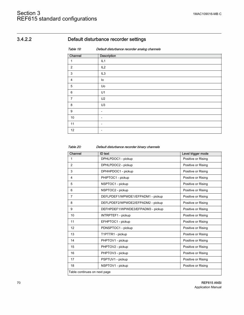
3.4.2.2 Default disturbance recorder settings
Table 19: Default disturbance recorder analog channels
Channel Description1 IL1
2 IL2
3 IL3
4 Io
5 Uo
6 U1
7 U2
8 U3
9 -
10 -
11 -
12 -
Table 20: Default disturbance recorder binary channels
Channel ID text Level trigger mode1 DPHLPDOC1 - pickup Positive or Rising
2 DPHLPDOC2 - pickup Positive or Rising
3 DPHHPDOC1 - pickup Positive or Rising
4 PHIPTOC1 - pickup Positive or Rising
5 NSPTOC1 - pickup Positive or Rising
6 NSPTOC2 - pickup Positive or Rising
7 DEFLPDEF1/WPWDE1/EFPADM1 - pickup Positive or Rising
8 DEFLPDEF2/WPWDE2/EFPADM2 - pickup Positive or Rising
9 DEFHPDEF1/WPWDE3/EFPADM3 - pickup Positive or Rising
10 INTRPTEF1 - pickup Positive or Rising
11 EFHPTOC1 - pickup Positive or Rising
12 PDNSPTOC1 - pickup Positive or Rising
13 T1PTTR1 - pickup Positive or Rising
14 PHPTOV1 - pickup Positive or Rising
15 PHPTOV2 - pickup Positive or Rising
16 PHPTOV3 - pickup Positive or Rising
17 PSPTUV1 - pickup Positive or Rising
18 NSPTOV1 - pickup Positive or Rising
Table continues on next page
Section 3 1MAC109016-MB CREF615 standard configurations
70 REF615 ANSIApplication Manual

Channel ID text Level trigger mode19 PHPTUV1 - pickup Positive or Rising
20 PHPTUV2 - pickup Positive or Rising
21 PHPTUV3 - pickup Positive or Rising
22 ROVPTOV1 - pickup Positive or Rising
23 ROVPTOV2 - pickup Positive or Rising
24 ROVPTOV3 - pickup Positive or Rising
25 CCBRBRF1 - trret Level trigger off
26 CCBRBRF1 - trbu Level trigger off
27 PHxPTOC - trip Level trigger off
28 NSPTOC - trip Level trigger off
29 DEFxPDEF/WPWDE/EFPADM - trip Level trigger off
30 INTRPTEF1 - trip Level trigger off
31 EFHPTOC1 - trip Level trigger off
32 PDNSPTOC1 - trip Level trigger off
33 INRPHAR1 - blk2h Level trigger off
34 T1PTTR1 - trip Level trigger off
35 PHPTOV - trip Level trigger off
36 PHPTUV - trip Level trigger off
37 ROVPTOV/PSPTUV1/NSPTOV1 - trip Level trigger off
38 SEQSPVC1 - fusef 3ph Level trigger off
39 SEQSPVC1 - fusef u Level trigger off
40 CCSPVC1 - fail Level trigger off
41 X120BI1 - ext OC blocking Level trigger off
42 X120BI2 - CB closed Level trigger off
43 X120BI3 - CB open Level trigger off
44 ARCSARC - ARC flt det Level trigger off
45 DARREC1 - close CB/unsuc recl Level trigger off
46 ARCSARC1 - trip Positive or Rising
47 ARCSARC2 - trip Positive or Rising
48 ARCSARC3 - trip Positive or Rising
49 DARREC1 - inpro Level trigger off
50 - -
51 - -
52 - -
53 - -
54 - -
Table continues on next page
1MAC109016-MB C Section 3REF615 standard configurations
REF615 ANSI 71Application Manual

Channel ID text Level trigger mode55 - -
56 - -
57 - -
58 - -
59 - -
60 - -
61 - -
62 - -
63 - -
64 - -
3.4.3 Functional diagrams
The functional diagrams describe the default input, output, alarm LED and function-to-function connections. The default connections can be viewed and changed with PCM600according to the application requirements.
The analog channels have fixed connections to the different function blocks inside theprotection relay’s standard configuration. However, the 12 analog channels available forthe disturbance recorder function are freely selectable as a part of the disturbancerecorder’s parameter settings.
The phase currents to the protection relay are fed from a current transformer. The residualcurrent to the protection relay is fed from either residually connected CTs, an external corebalance CT, neutral CT or calculated internally.
The signal marked with IA, IB and IC represents the three phase currents. The signal IGrepresents the measured ground current.
The signal marked with VA, VB and VC represents the three phase voltages. The signalVG represents the measured ground voltage.
The protection relay offers six different setting groups which can be set based onindividual needs. Each group can be activated or deactivated using the setting groupsettings available in the protection relay.
Depending on the communication protocol the required function block needs to beinstantiated in the configuration.
Section 3 1MAC109016-MB CREF615 standard configurations
72 REF615 ANSIApplication Manual

3.4.3.1 Functional diagrams for protection
The functional diagrams describe the relay's protection functionality in detail andaccording to the factory set default connections.
Four overcurrent stages are offered for overcurrent and short-circuit protection. Three ofthem include directional functionality DPHxPDOC_67/5xP. Three-phase non-directionalovercurrent protection, instantaneous stage, PHIPTOC1_50P-3 can be blocked byenergizing the binary input X120: BI1.
PHIPTOC1
O:14|T:2.5|I:1
BLOCKENA_MULT
TRIPPICKUP
PHIPTOC1_50P-3_TRIPPHIPTOC1_50P-3_PICKUP
X120_BI1_EXT_OC_BLOCKING
DPHHPDOC1
O:16|T:5|I:1
BLOCKENA_MULTNON_DIR
TRIPPICKUP
DPHLPDOC1
O:17|T:5|I:1
BLOCKENA_MULTNON_DIR
TRIPPICKUP
DPHLPDOC2
O:48|T:5|I:2
BLOCKENA_MULTNON_DIR
TRIPPICKUP
OR6
O:131|T:2.5|I:58
B1B2B3B4B5B6
O
DPHLPDOC2_67/51P-2_TRIP
DPHLPDOC2_67/51P-2_TRIP
DPHHPDOC1_67/50P-1_TRIP
DPHHPDOC1_67/50P-1_TRIP
DPHLPDOC1_67/51P-1_TRIP
DPHLPDOC1_67/51P-1_TRIP
DPHLPDOC1_67/51P-1_PICKUP
DPHLPDOC2_67/51P-2_PICKUP
DPHHPDOC1_67/50P-1_PICKUP
DPHxPDOC_TRIP
GUID-EDE3AC51-FC5F-4BCB-A1C1-EEA8AB7DA641 V1 EN
Figure 54: Overcurrent protection functions
The upstream blocking from the pickup of the second low stage of three-phase directionalovercurrent protection DPHLPDOC2_67/51P-2 is connected to the binary outputX110:SO1. This output can be used for sending a blocking signal to the relevantovercurrent protection stage of the relay at the infeeding bay.
1MAC109016-MB C Section 3REF615 standard configurations
REF615 ANSI 73Application Manual

OR6
O:160|T:2.5|I:62
B1B2B3B4B5B6
O UPSTEAM_OC_BLOCKINGDPHLPDOC2_67/51P-2_PICKUP
GUID-908E611F-601E-4D56-87FB-4B26D2609AA0 V1 EN
Figure 55: Upstream blocking logic
The output BLK2H of three-phase inrush detector INRPHAR1_INR-1 enables eitherblocking the function or multiplying the active settings for any of the availableovercurrent or ground-fault function blocks.
INRPHAR1
O:108|T:2.5|I:1BLOCK BLK2H INRPHAR1_INR-1_BLK2H
GUID-E08204A5-87A6-40CC-B6D3-C89231CD0286 V1 EN
Figure 56: Inrush detector function
Two negative-sequence overcurrent protection stages NSPTOC1_46-1 andNSPTOC2_46-2 are provided for phase unbalance protection. These functions are used toprotect the feeder against phase unbalance. Both the negative-sequence overcurrentprotections are blocked in case of detection in failure in secondary circuit of currenttransformer.
NSPTOC1
O:49|T:5|I:1
BLOCKENA_MULT
TRIPPICKUP
NSPTOC2
O:50|T:5|I:2
BLOCKENA_MULT
TRIPPICKUP
OR
O:149|T:2.5|I:19
B1B2
O
NSPTOC1_46-1_TRIP
NSPTOC1_46-1_TRIP
NSPTOC2_46-2_TRIP
NSPTOC2_46-2_TRIP
NSPTOC1_46-1_PICKUP
NSPTOC2_46-2_PICKUP
CCSPVC1_CCM_FAIL
CCSPVC1_CCM_FAIL
NSPTOC_TRIP
GUID-E761F91D-D886-48A3-B4D4-740E94220DAB V1 EN
Figure 57: Negative-sequence overcurrent protection function
Three stages are provided for directional ground-fault protection DEFxPDEF_67/5xN.One stage is provided for non-directional ground-fault protection EFHPTOC1_50G-1.According to the relay's order code, the directional ground-fault protection method can be
Section 3 1MAC109016-MB CREF615 standard configurations
74 REF615 ANSIApplication Manual

based on conventional directional ground-fault DEFxPDEF_67/5xN only or alternativelyused together with admittance-based ground-fault protection EFPADM_21YN orwattmetric-based ground-fault protection WPWDE_32N. A dedicated protection stageINTRPTEF_67NIEF is used either for transient-based ground-fault protection or for cableintermittent ground-fault protection in compensated networks. The binary inputX110:BI2 is intended for controlling directional ground-fault protection blocks' relaycharacteristic angle (RCA: 0°, -90°) or operation mode (IoSinφ, IoCosφ) change. Thesame input is also available for wattmetric protection.
OR6
O:128|T:2.5|I:53
B1B2B3B4B5B6
O
DEFLPDEF2
O:23|T:5|I:2
BLOCKENA_MULTRCA_CTL
TRIPPICKUP
DEFLPDEF1
O:46|T:5|I:1
BLOCKENA_MULTRCA_CTL
TRIPPICKUP
DEFHPDEF1
O:22|T:5|I:1
BLOCKENA_MULTRCA_CTL
TRIPPICKUP
DEFHPDEF1_67/50N-1_TRIP
DEFHPDEF1_67/50N-1_TRIP
DEFLPDEF1_67/51N-1_TRIP
DEFLPDEF1_67/51N-1_TRIP
DEFLPDEF2_67/51N-2_TRIP
DEFLPDEF2_67/51N-2_TRIP
DEFLPDEF1_67/51N-1_PICKUP
DEFLPDEF2_67/51N-2_PICKUP
DEFHPDEF1_67/50N-1_PICKUP
X110_BI2_RCA_CONTROL
X110_BI2_RCA_CONTROL
X110_BI2_RCA_CONTROL
DEFxPDEF_TRIP
CCSPVC1_CCM_FAIL
CCSPVC1_CCM_FAIL
CCSPVC1_CCM_FAIL
EFHPTOC1
O:36|T:5|I:1
BLOCKENA_MULT
TRIPPICKUP
EFHPTOC1_50G-1_TRIPEFHPTOC1_50G-1_PICKUP
CCSPVC1_CCM_FAIL
GUID-821D6A7E-37FC-4EBD-9C87-168C138EA1E6 V1 EN
Figure 58: Non-directional ground-fault protection
1MAC109016-MB C Section 3REF615 standard configurations
REF615 ANSI 75Application Manual

INTRPTEF1
O:35|T:2.5|I:1
BLOCK TRIPPICKUPBLK_EF
INTRPTEF1_67NIEF_TRIPINTRPTEF1_67NIEF_PICKUP
GUID-C45C44A5-CA08-4E6B-86E1-087A0BE8A64C V1 EN
Figure 59: Transient or intermittent ground-fault protection functions
WPWDE1
O:45|T:5|I:1
BLOCKRCA_CTL
TRIPPICKUP
WPWDE2
O:24|T:5|I:2
BLOCKRCA_CTL
TRIPPICKUP
WPWDE3
O:21|T:5|I:3
BLOCKRCA_CTL
TRIPPICKUP
OR6
O:127|T:2.5|I:55
B1B2B3B4B5B6
O
WPWDE1_32N-1_TRIP
WPWDE1_32N-1_TRIP
WPWDE2_32N-2_TRIP
WPWDE2_32N-2_TRIP
WPWDE3_32N-3_TRIP
WPWDE3_32N-3_TRIP
WPWDE1_32N-1_PICKUP
WPWDE2_32N-2_PICKUP
WPWDE3_32N-3_PICKUP
X110_BI2_RCA_CONTROL
X110_BI2_RCA_CONTROL
X110_BI2_RCA_CONTROL
WPWDE_TRIP
GUID-877620C9-C3BD-44EE-9528-4BE7942C1918 V1 EN
Figure 60: Wattmetric protection function
Section 3 1MAC109016-MB CREF615 standard configurations
76 REF615 ANSIApplication Manual

EFPADM1
O:47|T:5|I:1
BLOCKRELEASE
TRIPPICKUP
EFPADM2
O:19|T:5|I:2
BLOCKRELEASE
TRIPPICKUP
EFPADM3
O:20|T:5|I:3
BLOCKRELEASE
TRIPPICKUP
OR6
O:125|T:2.5|I:57
B1B2B3B4B5B6
O
EFPADM1_21YN-1_TRIP
EFPADM1_21YN-1_TRIP
EFPADM2_21YN-2_TRIP
EFPADM2_21YN-2_TRIP
EFPADM3_21YN-3_TRIP
EFPADM3_21YN-3_TRIP
EFPADM1_21YN-1_PICKUP
EFPADM2_21YN-2_PICKUP
EFPADM3_21YN-3_PICKUP
EFPADM_TRIP
GUID-70662C28-1D88-4880-9980-52E13F85D11A V1 EN
Figure 61: Admittance-based ground-fault protection function
Phase discontinuity protection PDNSPTOC1_46PD protects for interruptions in thenormal three-phase load supply, for example, in downed conductor situations. Thefunction is blocked in case of detection of a failure in secondary circuit of voltagetransformer.
PDNSPTOC1
O:33|T:5|I:1
BLOCK TRIPPICKUP
PDNSPTOC1_46PD_TRIPPDNSPTOC1_46PD_PICKUP
CCSPVC1_CCM_FAIL
GUID-DC0123F0-F3C2-42C0-8CC5-8BD4B3AB65D2 V1 EN
Figure 62: Phase discontinuity protection
Three-phase thermal protection for feeders, cables and distribution transformersT1PTTR1_49F-1 detects overloads under varying load conditions. The BLK_CLOSEoutput of the function is used to block the closing operation of circuit breaker.
T1PTTR1
O:70|T:5|I:1
BLOCKENA_MULTAMB_TEMP
TRIPPICKUPALARM
BLK_CLOSE T1PTTR1_49F-1_BLK_CLOSE
T1PTTR1_49F-1_PICKUPT1PTTR1_49F-1_TRIP
T1PTTR1_49F-1_ALARM
GUID-891DC1E3-EEBB-42CD-8EB5-D7E5C94277B0 V1 EN
Figure 63: Thermal overcurrent protection function
1MAC109016-MB C Section 3REF615 standard configurations
REF615 ANSI 77Application Manual

Circuit breaker failure protection CCBRBRF1_50BF-1 is initiated via the PICKUP inputby number of different protection functions available in the relay. The breaker failureprotection function offers different operating modes associated with the circuit breakerposition and the measured phase and residual currents.
The circuit breaker failure protection function has two operating outputs: TRRET andTRBU. The TRRET trip output is used for retripping its own breaker throughTRPPTRC2_86/94-2_TRIP. The TRBU output is used to give a backup trip to the breakerfeeding upstream. For this purpose, the TRBU trip output signal is connected to the binaryoutput X100:PO2.
CCBRBRF1
O:44|T:2.5|I:1
BLOCKPICKUPPOSCLOSECB_FAULT
CB_FAULT_ALTRBU
TRRET
OR6
O:26|T:2.5|I:1
B1B2B3B4B5B6
O
OR6
O:27|T:2.5|I:0
B1B2B3B4B5B6
O
OR6
O:29|T:2.5|I:2
B1B2B3B4B5B6
O
CCBRBRF1_50BF-1_TRBUX120_BI2_CB_CLOSED
PHIPTOC1_50P-3_TRIPDPHHPDOC1_67/50P-1_TRIPDPHLPDOC1_67/51P-1_TRIP
EFPADM2_21YN-2_TRIPEFPADM3_21YN-3_TRIP
DEFHPDEF1_67/50N-1_TRIPDEFLPDEF2_67/51N-2_TRIP
WPWDE2_32N-2_TRIPWPWDE3_32N-3_TRIP
ARCSARC1_AFD-1_TRIPARCSARC2_AFD-2_TRIPARCSARC3_AFD-3_TRIP
CCBRBRF1_50BF-1_TRRET
GUID-A783E6FC-1967-44F0-8452-D9D913556E2B V1 EN
Figure 64: Circuit breaker failure protection function
Three arc protection stages ARCSARC-1…3_AFD-1...3 are included as an optionalfunction. The arc protection offers individual function blocks for three arc sensors that canbe connected to the relay. Each arc protection function block has two different operationmodes, that is, with or without the phase and residual current check.
The trip signals from ARCSARC-1…3_AFD-1...3 are connected to both trip logicTRPPTRC1_86/94-1 and TRPPTRC2_86/94-2.
Section 3 1MAC109016-MB CREF615 standard configurations
78 REF615 ANSIApplication Manual

ARCSARC1
O:15|T:2.5|I:11
BLOCKREM_FLT_ARCOPR_MODE
TRIPARC_FLT_DET
ARCSARC2
O:13|T:2.5|I:21
BLOCKREM_FLT_ARCOPR_MODE
TRIPARC_FLT_DET
ARCSARC3
O:18|T:2.5|I:31
BLOCKREM_FLT_ARCOPR_MODE
TRIPARC_FLT_DET
OR6
O:154|T:2.5|I:61
B1B2B3B4B5B6
O
ARCSARC1_AFD-1_TRIP
ARCSARC1_AFD-1_TRIP
ARCSARC2_AFD-2_TRIP
ARCSARC2_AFD-2_TRIP
ARCSARC3_AFD-3_TRIP
ARCSARC3_AFD-3_TRIP
ARCSARC1_AFD-1_ARC_FLT_DET
ARCSARC2_AFD-2_ARC_FLT_DET
ARCSARC3_AFD-3_ARC_FLT_DET
ARCSARC_TRIP
GUID-834F0CCE-C98A-4EBF-82D1-E33A3F5C4111 V1 EN
Figure 65: Arc protection
The optional autoreclosing function is configured to be initiated by trip signals from anumber of protection stages through the INIT_1...5 inputs. It is possible to createindividual autoreclose sequences for each input.
The autoreclosing function can be inhibited with the INHIBIT_RECL input. By default,few selected protection function operations are connected to this input. A controlcommand to the circuit breaker, either local or remote, also blocks the autoreclosingfunction via the CBXCBR1_52-1_SELECTED signal.
The circuit breaker availability for the autoreclosing sequence is expressed with theCB_READY input in DARREC1_79. This signal is not connected in the configuration.
The open command from the autorecloser is connected directly to binary outputX100:PO3, whereas the close command is connected directly to binary output X100:PO1.
Set the parameters for DARREC1_79 properly.
1MAC109016-MB C Section 3REF615 standard configurations
REF615 ANSI 79Application Manual

Check the initialization signals of DARREC1_79.
DARREC1
O:87|T:2.5|I:1
INIT_1INIT_2INIT_3INIT_4INIT_5INIT_6DEL_INIT_2DEL_INIT_3DEL_INIT_4BLK_RECL_TBLK_RCLM_TBLK_THERMCB_POSCB_READYINC_SHOTPINHIBIT_RECLRECL_ONSYNC
OPEN_CBCLOSE_CBCMD_WAIT
INPROLOCKED OUT
PROT_CRDUNSUC_RECL
AR_ONREADYACTIVE
OR6
O:83|T:2.5|I:18
B1B2B3B4B5B6
O
OR6
O:85|T:2.5|I:20
B1B2B3B4B5B6
O
OR6
O:84|T:2.5|I:21
B1B2B3B4B5B6
O
OR6
O:82|T:2.5|I:19
B1B2B3B4B5B6
O
OR
O:86|T:2.5|I:10
B1B2
O
X120_BI3_CB_OPEN
DARREC1_79_OPEN_CBDARREC1_79_CLOSE_CB
PHIPTOC1_50P-3_TRIP
DPHLPDOC2_67/51P-2_TRIPDPHHPDOC1_67/50P-1_TRIP
NSPTOC1_46-1_TRIPNSPTOC2_46-2_TRIP
EFPADM2_21YN-2_TRIP
EFPADM3_21YN-3_TRIP
INTRPTEF1_67NIEF_TRIP
PDNSPTOC1_46PD_TRIP
DEFHPDEF1_67/50N-1_TRIP
DEFLPDEF2_67/51N-2_TRIP
WPWDE2_32N-2_TRIP
WPWDE3_32N-3_TRIP
ARCSARC1_AFD-1_TRIPARCSARC2_AFD-2_TRIPARCSARC3_AFD-3_TRIP
CBXCBR1_52-1_SELECTED
DARREC1_79_INPRO
DARREC1_79_UNSUC_RECL
GUID-B80EA4DF-263B-43DF-9C48-03B458068EF7 V1 EN
Figure 66: Autoreclosing function
Three overvoltage and undervoltage protection stages PHPTOV_59 and PHPTUV_27offer protection against abnormal phase voltage conditions. Positive-sequenceundervoltage protection PSPTUV_47U and negative-sequence overvoltage protectionNSPTOV_47 enable voltage-based unbalance protection. A failure in the voltagemeasuring circuit is detected by the fuse failure function. The activation is connected toblock undervoltage protection functions and voltage based unbalance protectionfunctions to avoid faulty tripping.
Section 3 1MAC109016-MB CREF615 standard configurations
80 REF615 ANSIApplication Manual

PHPTOV1
O:31|T:5|I:1
BLOCK TRIPPICKUP
PHPTOV2
O:32|T:5|I:2
BLOCK TRIPPICKUP
PHPTOV3
O:30|T:5|I:3
BLOCK TRIPPICKUP
OR6
O:119|T:2.5|I:38
B1B2B3B4B5B6
O
PHPTOV1_59-1_TRIP
PHPTOV1_59-1_TRIP
PHPTOV2_59-2_TRIP
PHPTOV2_59-2_TRIP
PHPTOV3_59-3_TRIP
PHPTOV3_59-3_TRIP
PHPTOV1_59-1_PICKUP
PHPTOV2_59-2_PICKUP
PHPTOV3_59-3_PICKUP
PHPTOV_TRIP
GUID-53771E3E-48CD-483E-98B4-1949E16F86EF V1 EN
Figure 67: Overvoltage protection function
1MAC109016-MB C Section 3REF615 standard configurations
REF615 ANSI 81Application Manual

PHPTUV1
O:40|T:5|I:1
BLOCK TRIPPICKUP
PHPTUV2
O:41|T:5|I:2
BLOCK TRIPPICKUP
PHPTUV3
O:39|T:5|I:3
BLOCK TRIPPICKUP
OR6
O:120|T:2.5|I:37
B1B2B3B4B5B6
O
PHPTUV1_27-1_TRIP
PHPTUV1_27-1_TRIP
PHPTUV2_27-2_TRIP
PHPTUV2_27-2_TRIP
PHPTUV3_27-3_TRIP
PHPTUV3_27-3_TRIP
PHPTUV1_27-1_PICKUP
PHPTUV2_27-2_PICKUP
PHPTUV3_27-3_PICKUP
SEQSPVC1_60-1_FUSEF_U
SEQSPVC1_60-1_FUSEF_U
SEQSPVC1_60-1_FUSEF_U
PHPTUV_TRIP
GUID-DDF13CF7-076D-4A12-87CB-9FDE302CF9D5 V1 EN
Figure 68: Undervoltage protection function
NSPTOV1
O:43|T:5|I:1
BLOCK TRIPPICKUP
NSPTOV1_47-1_TRIPNSPTOV1_47-1_PICKUP
SEQSPVC1_60-1_FUSEF_U
GUID-75D304B2-690F-4AE7-AB12-E5889805A85F V1 EN
Figure 69: Negative-sequence overvoltage protection function
PSPTUV1
O:42|T:5|I:1
BLOCK TRIPPICKUP
PSPTUV1_47U-1_TRIPPSPTUV1_47U-1_PICKUP
SEQSPVC1_60-1_FUSEF_U
GUID-85A0C79E-8B2B-4CCA-9EDB-DBB700216195 V1 EN
Figure 70: Positive-sequence undervoltage protection function
The residual overvoltage protection ROVPTOV_59G,59N provides ground-faultprotection by detecting an abnormal level of residual voltage. It can be used, for example,as a nonselective backup protection for the selective directional ground-faultfunctionality.
Section 3 1MAC109016-MB CREF615 standard configurations
82 REF615 ANSIApplication Manual

ROVPTOV1
O:38|T:5|I:1
BLOCK TRIPPICKUP
ROVPTOV2
O:34|T:5|I:2
BLOCK TRIPPICKUP
ROVPTOV3
O:37|T:5|I:3
BLOCK TRIPPICKUP
OR6
O:126|T:2.5|I:56
B1B2B3B4B5B6
O
ROVPTOV1_59G_TRIP
ROVPTOV1_59G_TRIP
ROVPTOV2_59N-1_TRIP
ROVPTOV2_59N-1_TRIP
ROVPTOV3_59N-2_TRIP
ROVPTOV3_59N-2_TRIP
ROVPTOV1_59G_PICKUP
ROVPTOV2_59N-1_PICKUP
ROVPTOV3_59N-2_PICKUPSEQSPVC1_60-1_FUSEF_U
SEQSPVC1_60-1_FUSEF_U
ROVPTOV_TRIP
GUID-828B7133-2C33-4FF9-99E4-1A8A527B61A3 V1 EN
Figure 71: Residual voltage protection function
General pickup and trip from all the functions are connected to minimum pulse timerTPGAPC1 for setting the minimum pulse length for the outputs. The output fromTPGAPC1 is connected to binary outputs.
1MAC109016-MB C Section 3REF615 standard configurations
REF615 ANSI 83Application Manual

OR6
O:139|T:2.5|I:46
B1B2B3B4B5B6
O
OR6
O:137|T:2.5|I:48
B1B2B3B4B5B6
O
OR6
O:136|T:2.5|I:49
B1B2B3B4B5B6
O
OR6
O:135|T:2.5|I:50
B1B2B3B4B5B6
O
OR6
O:140|T:2.5|I:45
B1B2B3B4B5B6
O
OR6
O:138|T:2.5|I:47
B1B2B3B4B5B6
O
TPGAPC1
O:148|T:2.5|I:1
IN1IN2
OUT1OUT2
OR6
O:141|T:2.5|I:44
B1B2B3B4B5B6
O
OR6
O:143|T:2.5|I:42
B1B2B3B4B5B6
O
OR6
O:142|T:2.5|I:43
B1B2B3B4B5B6
O
OR6
O:145|T:2.5|I:40
B1B2B3B4B5B6
O
OR6
O:144|T:2.5|I:41
B1B2B3B4B5B6
O
OR6
O:147|T:2.5|I:51
B1B2B3B4B5B6
O
OR6
O:146|T:2.5|I:52
B1B2B3B4B5B6
O
GENERAL_PICKUP_PULSEGENERAL_TRIP_PULSE
PHIPTOC1_50P-3_TRIP
DPHLPDOC2_67/51P-2_TRIPDPHHPDOC1_67/50P-1_TRIP
NSPTOC1_46-1_TRIP
DPHLPDOC1_67/51P-1_TRIP
NSPTOC2_46-2_TRIP
EFPADM1_21YN-1_TRIPEFPADM2_21YN-2_TRIPEFPADM3_21YN-3_TRIP
INTRPTEF1_67NIEF_TRIP
PDNSPTOC1_46PD_TRIP
ROVPTOV1_59G_TRIPROVPTOV2_59N-1_TRIPROVPTOV3_59N-2_TRIP
DEFHPDEF1_67/50N-1_TRIP
DEFLPDEF1_67/51N-1_TRIPDEFLPDEF2_67/51N-2_TRIP
EFHPTOC1_50G-1_TRIP
WPWDE1_32N-1_TRIPWPWDE2_32N-2_TRIPWPWDE3_32N-3_TRIP
PHPTOV1_59-1_TRIP
PHPTOV2_59-2_TRIPPHPTOV3_59-3_TRIP
PHPTUV1_27-1_TRIP
PSPTUV1_47U-1_TRIPNSPTOV1_47-1_TRIP
PHPTUV2_27-2_TRIPPHPTUV3_27-3_TRIP
ARCSARC1_AFD-1_TRIPARCSARC2_AFD-2_TRIPARCSARC3_AFD-3_TRIP
DPHLPDOC1_67/51P-1_PICKUPDPHLPDOC2_67/51P-2_PICKUPDPHHPDOC1_67/50P-1_PICKUP
PHIPTOC1_50P-3_PICKUPNSPTOC1_46-1_PICKUPNSPTOC2_46-2_PICKUP
DEFLPDEF1_67/51N-1_PICKUPDEFLPDEF2_67/51N-2_PICKUPDEFHPDEF1_67/50N-1_PICKUP
INTRPTEF1_67NIEF_PICKUPEFHPTOC1_50G-1_PICKUPPDNSPTOC1_46PD_PICKUP
PHPTOV1_59-1_PICKUPPHPTOV2_59-2_PICKUPPHPTOV3_59-3_PICKUP
PSPTUV1_47U-1_PICKUPNSPTOV1_47-1_PICKUPPHPTUV1_27-1_PICKUP
PHPTUV2_27-2_PICKUPPHPTUV3_27-3_PICKUP
ROVPTOV1_59G_PICKUPROVPTOV2_59N-1_PICKUPROVPTOV3_59N-2_PICKUP
EFPADM1_21YN-1_PICKUPEFPADM2_21YN-2_PICKUPEFPADM3_21YN-3_PICKUP
WPWDE1_32N-1_PICKUPWPWDE2_32N-2_PICKUPWPWDE3_32N-3_PICKUP
GUID-8252E9D6-13F1-483E-95F2-1892CAE9F937 V1 EN
Figure 72: General pickup and trip signals
The trip signals from the protection functions are connected to the two trip logicsTRPPTRC1_86/94-1 and TRPPTRC2_86/94-2. The output of these trip logic functionsare available at binary outputs X100:PO3 and X100:PO4. Both the trip logic functions areprovided with lockout and latching function, event generation and the trip signal durationsetting. If the lockout operation mode is selected, binary input has been assigned toRST_LKOUT input of both the trip logic to enable external reset with a push button.
Three other trip logics TRPPTRC3...5_86/94-3…5 are also available if the relay isordered with high speed binary outputs options.
Section 3 1MAC109016-MB CREF615 standard configurations
84 REF615 ANSIApplication Manual

TRPPTRC1
O:69|T:2.5|I:1
BLOCKTRIPRST_LKOUT
TRIPCL_LKOUT
OR6
O:57|T:2.5|I:8
B1B2B3B4B5B6
O
OR6
O:61|T:2.5|I:4
B1B2B3B4B5B6
O
OR6
O:58|T:2.5|I:7
B1B2B3B4B5B6
O
OR6
O:65|T:2.5|I:15
B1B2B3B4B5B6
O
OR6
O:59|T:2.5|I:6
B1B2B3B4B5B6
O
OR6
O:62|T:2.5|I:3
B1B2B3B4B5B6
O
OR6
O:60|T:2.5|I:5
B1B2B3B4B5B6
O
TRPPTRC1_86/94-1_TRIP
PHIPTOC1_50P-3_TRIPDPHLPDOC2_67/51P-2_TRIPDPHHPDOC1_67/50P-1_TRIP
NSPTOC1_46-1_TRIPDPHLPDOC1_67/51P-1_TRIP
NSPTOC2_46-2_TRIP
EFPADM1_21YN-1_TRIPEFPADM2_21YN-2_TRIPEFPADM3_21YN-3_TRIP
INTRPTEF1_67NIEF_TRIP
PDNSPTOC1_46PD_TRIPROVPTOV1_59G_TRIP
ROVPTOV2_59N-1_TRIPROVPTOV3_59N-2_TRIP
DEFHPDEF1_67/50N-1_TRIPDEFLPDEF1_67/51N-1_TRIPDEFLPDEF2_67/51N-2_TRIP
EFHPTOC1_50G-1_TRIP
WPWDE1_32N-1_TRIPWPWDE2_32N-2_TRIPWPWDE3_32N-3_TRIP
PHPTOV1_59-1_TRIPPHPTOV2_59-2_TRIPPHPTOV3_59-3_TRIP
PHPTUV1_27-1_TRIP
PSPTUV1_47U-1_TRIPNSPTOV1_47-1_TRIP
PHPTUV2_27-2_TRIPPHPTUV3_27-3_TRIP
ARCSARC1_AFD-1_TRIPARCSARC2_AFD-2_TRIPARCSARC3_AFD-3_TRIP
X120_BI4_RST_LOCKOUT
GUID-BA78851E-C735-41FF-8B14-2A34C42F1634 V1 EN
Figure 73: Trip logic TRPPTRC1
1MAC109016-MB C Section 3REF615 standard configurations
REF615 ANSI 85Application Manual
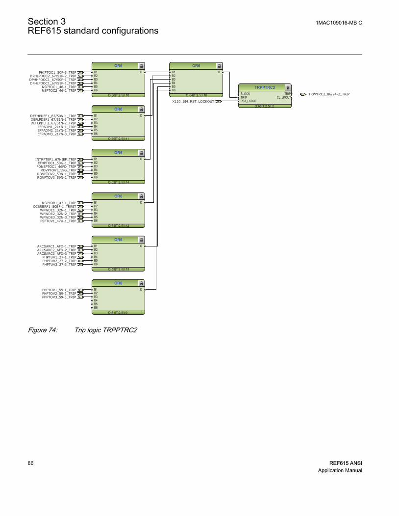
OR6
O:64|T:2.5|I:16
B1B2B3B4B5B6
O
TRPPTRC2
O:68|T:2.5|I:2
BLOCKTRIPRST_LKOUT
TRIPCL_LKOUT
OR6
O:56|T:2.5|I:10
B1B2B3B4B5B6
O
OR6
O:55|T:2.5|I:11
B1B2B3B4B5B6
O
OR6
O:52|T:2.5|I:14
B1B2B3B4B5B6
O
OR6
O:54|T:2.5|I:12
B1B2B3B4B5B6
O
OR6
O:53|T:2.5|I:13
B1B2B3B4B5B6
O
OR6
O:51|T:2.5|I:9
B1B2B3B4B5B6
O
TRPPTRC2_86/94-2_TRIP
PHIPTOC1_50P-3_TRIPDPHLPDOC2_67/51P-2_TRIPDPHHPDOC1_67/50P-1_TRIP
NSPTOC1_46-1_TRIPDPHLPDOC1_67/51P-1_TRIP
NSPTOC2_46-2_TRIP
EFPADM1_21YN-1_TRIPEFPADM2_21YN-2_TRIPEFPADM3_21YN-3_TRIP
INTRPTEF1_67NIEF_TRIP
PDNSPTOC1_46PD_TRIPROVPTOV1_59G_TRIP
ROVPTOV2_59N-1_TRIPROVPTOV3_59N-2_TRIP
DEFHPDEF1_67/50N-1_TRIPDEFLPDEF1_67/51N-1_TRIPDEFLPDEF2_67/51N-2_TRIP
EFHPTOC1_50G-1_TRIP
WPWDE1_32N-1_TRIPWPWDE2_32N-2_TRIPWPWDE3_32N-3_TRIP
PHPTOV1_59-1_TRIPPHPTOV2_59-2_TRIPPHPTOV3_59-3_TRIP
PHPTUV1_27-1_TRIP
PSPTUV1_47U-1_TRIP
NSPTOV1_47-1_TRIP
PHPTUV2_27-2_TRIPPHPTUV3_27-3_TRIP
ARCSARC1_AFD-1_TRIPARCSARC2_AFD-2_TRIPARCSARC3_AFD-3_TRIP
X120_BI4_RST_LOCKOUT
CCBRBRF1_50BF-1_TRRET
GUID-279968B2-DDD7-4155-9CA1-B834394ADFAD V1 EN
Figure 74: Trip logic TRPPTRC2
Section 3 1MAC109016-MB CREF615 standard configurations
86 REF615 ANSIApplication Manual

TRPPTRC3
O:159|T:2.5|I:3
BLOCKTRIPRST_LKOUT
TRIPCL_LKOUT
TRPPTRC4
O:157|T:2.5|I:4
BLOCKTRIPRST_LKOUT
TRIPCL_LKOUT
TRPPTRC5
O:158|T:2.5|I:5
BLOCKTRIPRST_LKOUT
TRIPCL_LKOUT
TRPPTRC3_86/94-3_TRIP
TRPPTRC4_86/94-4_TRIP
TRPPTRC5_86/94-5_TRIP
ARCSARC1_AFD-1_TRIP
ARCSARC2_AFD-2_TRIP
ARCSARC3_AFD-3_TRIP
X120_BI4_RST_LOCKOUT
X120_BI4_RST_LOCKOUT
X120_BI4_RST_LOCKOUT
GUID-04AD7438-DB0B-47BD-A3D2-C214E27B0799 V1 EN
Figure 75: Trip logic TRPPTRC3/4/5
3.4.3.2 Functional diagrams for disturbance recorder
The PICKUP and TRIP outputs from the protection stages are routed to trigger thedisturbance recorder or, alternatively, only to be recorded by the disturbance recorderdepending on the parameter settings. Additionally, the selected signals from differentfunctions and the few binary inputs are also connected to the disturbance recorder.
1MAC109016-MB C Section 3REF615 standard configurations
REF615 ANSI 87Application Manual

RDRE1
O:109|T:2.5|I:1
C1C2C3C4C5C6C7C8C9C10C11C12C13C14C15C16C17C18C19C20C21C22C23C24C25C26C27C28C29C30C31C32C33C34C35C36C37C38C39C40C41C42C43C44C45C46C47C48C49C50C51C52C53C54C55C56C57C58C59C60C61C62C63C64
TRIGGERED
OR6
O:99|T:2.5|I:32
B1B2B3B4B5B6
O
OR6
O:104|T:2.5|I:27
B1B2B3B4B5B6
O
OR
O:107|T:2.5|I:13
B1B2
O
OR6
O:97|T:2.5|I:34
B1B2B3B4B5B6
O
OR6
O:102|T:2.5|I:29
B1B2B3B4B5B6
O
OR6
O:98|T:2.5|I:33
B1B2B3B4B5B6
O
OR6
O:96|T:2.5|I:25
B1B2B3B4B5B6
O
OR6
O:95|T:2.5|I:26
B1B2B3B4B5B6
O
OR6
O:100|T:2.5|I:31
B1B2B3B4B5B6
O
OR6
O:103|T:2.5|I:28
B1B2B3B4B5B6
O
OR6
O:101|T:2.5|I:30
B1B2B3B4B5B6
O
OR
O:105|T:2.5|I:15
B1B2
O
OR
O:106|T:2.5|I:14
B1B2
O
CCBRBRF1_50BF-1_TRBU
X120_BI3_CB_OPENX120_BI2_CB_CLOSED
DARREC1_79_CLOSE_CB
PHIPTOC1_50P-3_TRIP
DPHLPDOC2_67/51P-2_TRIP
DPHHPDOC1_67/50P-1_TRIP
NSPTOC1_46-1_TRIP
DPHLPDOC1_67/51P-1_TRIP
NSPTOC2_46-2_TRIP
EFPADM1_21YN-1_TRIPEFPADM2_21YN-2_TRIPEFPADM3_21YN-3_TRIP
INTRPTEF1_67NIEF_TRIP
PDNSPTOC1_46PD_TRIP
ROVPTOV1_59G_TRIPROVPTOV2_59N-1_TRIPROVPTOV3_59N-2_TRIP
DEFHPDEF1_67/50N-1_TRIPDEFLPDEF1_67/51N-1_TRIPDEFLPDEF2_67/51N-2_TRIP
EFHPTOC1_50G-1_TRIP
WPWDE1_32N-1_TRIPWPWDE2_32N-2_TRIPWPWDE3_32N-3_TRIP
PHPTOV1_59-1_TRIPPHPTOV2_59-2_TRIPPHPTOV3_59-3_TRIP
PHPTUV1_27-1_TRIPPSPTUV1_47U-1_TRIPNSPTOV1_47-1_TRIP
PHPTUV2_27-2_TRIPPHPTUV3_27-3_TRIP
ARCSARC1_AFD-1_TRIPARCSARC2_AFD-2_TRIPARCSARC3_AFD-3_TRIP
CCBRBRF1_50BF-1_TRRET
DPHLPDOC1_67/51P-1_PICKUPDPHLPDOC2_67/51P-2_PICKUPDPHHPDOC1_67/50P-1_PICKUP
PHIPTOC1_50P-3_PICKUPNSPTOC1_46-1_PICKUPNSPTOC2_46-2_PICKUP
DEFLPDEF1_67/51N-1_PICKUP
DEFLPDEF2_67/51N-2_PICKUP
DEFHPDEF1_67/50N-1_PICKUP
INTRPTEF1_67NIEF_PICKUPEFHPTOC1_50G-1_PICKUPPDNSPTOC1_46PD_PICKUP
PHPTOV1_59-1_PICKUPPHPTOV2_59-2_PICKUPPHPTOV3_59-3_PICKUP
PSPTUV1_47U-1_PICKUPNSPTOV1_47-1_PICKUPPHPTUV1_27-1_PICKUPPHPTUV2_27-2_PICKUPPHPTUV3_27-3_PICKUP
ROVPTOV1_59G_PICKUPROVPTOV2_59N-1_PICKUPROVPTOV3_59N-2_PICKUP
EFPADM1_21YN-1_PICKUP
EFPADM2_21YN-2_PICKUP
EFPADM3_21YN-3_PICKUP
WPWDE1_32N-1_PICKUP
WPWDE2_32N-2_PICKUP
WPWDE3_32N-3_PICKUP
X120_BI1_EXT_OC_BLOCKINGCCSPVC1_CCM_FAIL
SEQSPVC1_60-1_FUSEF_U
T1PTTR1_49F-1_PICKUP
INRPHAR1_INR-1_BLK2H
SEQSPVC1_60-1_FUSEF_3PH
DARREC1_79_INPRO
T1PTTR1_49F-1_TRIP
ARCSARC1_AFD-1_ARC_FLT_DETARCSARC2_AFD-2_ARC_FLT_DETARCSARC3_AFD-3_ARC_FLT_DET
DARREC1_79_UNSUC_RECL
DISTURB_RECORD_TRIGGERED
GUID-ED521051-619C-4989-BCB1-912D93FE6DFE V1 EN
Figure 76: Disturbance recorder
3.4.3.3 Functional diagrams for condition monitoring
Failures in current measuring circuits are detected by CCSPVC1_CCM. When a failure isdetected, it can be used to block the current protection functions that are measuring thecalculated sequence component currents or residual current to avoid unnecessaryoperation.
CCSPVC1
O:12|T:2.5|I:1
BLOCK FAILALARM
CCSPVC1_CCM_FAILCCSPVC1_CCM_ALARM
GUID-7A4CB2BA-1B57-44CD-9F51-5F73A36FFA52 V1 EN
Figure 77: Current circuit supervision function
The fuse failure supervision SEQSPVC1_60-1 detects failures in the voltagemeasurement circuits. Failures, such as an open MCB, raise an alarm.
Section 3 1MAC109016-MB CREF615 standard configurations
88 REF615 ANSIApplication Manual

SEQSPVC1
O:28|T:2.5|I:1
BLOCKCB_CLOSEDDISCON_OPENMINCB_OPEN
FUSEF_3PHFUSEF_VX120_BI2_CB_CLOSED SEQSPVC1_60-1_FUSEF_U
X110_BI1_MCB_OPEN
SEQSPVC1_60-1_FUSEF_3PH
GUID-5B3039E4-0E32-40F3-A0BB-F358206E44F0 V1 EN
Figure 78: Fuse failure supervision function
Circuit-breaker condition monitoring SSCBR1_52CM-1 supervises the switch statusbased on the connected binary input information and the measured current levels.SSCBR1_52CM-1 introduces various supervision methods.
Set the parameters for SSCBR1_52CM-1 properly.
SSCBR1
O:90|T:5|I:1
BLOCKPOSOPENPOSCLOSEOPEN_CB_EXECLOSE_CB_EXEPRES_ALM_INPRES_LO_INSPR_CHR_STSPR_CHRRST_IPOWRST_CB_WEARRST_TRV_TRST_SPR_T
TRV_T_OP_ALMTRV_T_CL_ALMSPR_CHR_ALM
OPR_ALMOPR_LO
IPOW_ALMIPOW_LO
CB_LIFE_ALMMON_ALM
PRES_ALMPRES_LO
OPENPOSINVALIDPOSCLOSEPOS
CB_CLOSE_COMMANDCB_OPEN_COMMAND
X120_BI3_CB_OPENX120_BI2_CB_CLOSED
SSCBR1_52CM-1_TRV_T_OP_ALMSSCBR1_52CM-1_TRV_T_CL_ALMSSCBR1_52CM-1_SPR_CHR_ALMSSCBR1_52CM-1_OPR_ALMSSCBR1_52CM-1_OPR_LOSSCBR1_52CM-1_IPOW_ALMSSCBR1_52CM-1_IPOW_LOSSCBR1_52CM-1_CB_LIFE_ALMSSCBR1_52CM-1_MON_ALMSSCBR1_52CM-1_PRES_ALMSSCBR1_52CM-1_PRES_LO
GUID-2ACB76D8-D894-4B01-BAC4-C11817D98201 V1 EN
Figure 79: Circuit-breaker condition monitoring function
OR6
O:91|T:2.5|I:24
B1B2B3B4B5B6
O
OR6
O:92|T:2.5|I:23
B1B2B3B4B5B6
O
OR
O:93|T:2.5|I:12
B1B2
O
SSCBR1_52CM-1_TRV_T_OP_ALMSSCBR1_52CM-1_TRV_T_CL_ALMSSCBR1_52CM-1_SPR_CHR_ALM
SSCBR1_52CM-1_OPR_ALMSSCBR1_52CM-1_OPR_LO
SSCBR1_52CM-1_IPOW_ALM
SSCBR1_52CM-1_IPOW_LOSSCBR1_52CM-1_CB_LIFE_ALM
SSCBR1_52CM-1_MON_ALMSSCBR1_52CM-1_PRES_ALM
SSCBR1_52CM-1_PRES_LO
SSCBR1_52CM-1_ALARMS
GUID-DE2C5247-1CB4-4417-9A13-8854E815A237 V1 EN
Figure 80: Logic for circuit breaker monitoring alarm
Two separate trip circuit supervision functions are included: TCSSCBR1_TCM-1 forpower output X100:PO3 and TCSSCBR2_TCM-2 for power output X100:PO4. Both the
1MAC109016-MB C Section 3REF615 standard configurations
REF615 ANSI 89Application Manual
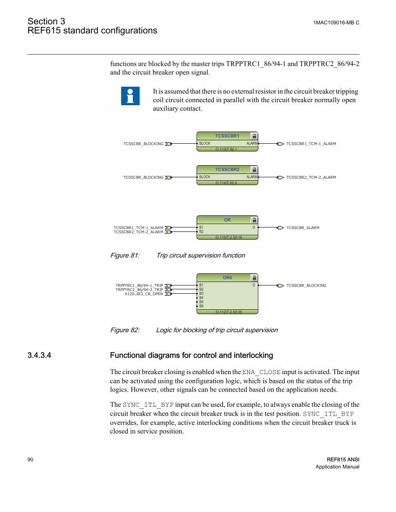
functions are blocked by the master trips TRPPTRC1_86/94-1 and TRPPTRC2_86/94-2and the circuit breaker open signal.
It is assumed that there is no external resistor in the circuit breaker trippingcoil circuit connected in parallel with the circuit breaker normally openauxiliary contact.
TCSSCBR1
O:113|T:5|I:1BLOCK ALARM
TCSSCBR2
O:114|T:5|I:2BLOCK ALARM
OR
O:115|T:2.5|I:16
B1B2
O
TCSSCBR1_TCM-1_ALARM
TCSSCBR1_TCM-1_ALARM
TCSSCBR2_TCM-2_ALARM
TCSSCBR2_TCM-2_ALARM
TCSSCBR_BLOCKING
TCSSCBR_BLOCKING
TCSSCBR_ALARM
GUID-2A1FB8E2-51CC-461D-B04D-8A2893C8F381 V1 EN
Figure 81: Trip circuit supervision function
OR6
O:112|T:2.5|I:35
B1B2B3B4B5B6
OTRPPTRC2_86/94-2_TRIP
X120_BI3_CB_OPEN
TRPPTRC1_86/94-1_TRIP TCSSCBR_BLOCKING
GUID-A43E0483-878F-4B65-A336-0794F43E61CC V1 EN
Figure 82: Logic for blocking of trip circuit supervision
3.4.3.4 Functional diagrams for control and interlocking
The circuit breaker closing is enabled when the ENA_CLOSE input is activated. The inputcan be activated using the configuration logic, which is based on the status of the triplogics. However, other signals can be connected based on the application needs.
The SYNC_ITL_BYP input can be used, for example, to always enable the closing of thecircuit breaker when the circuit breaker truck is in the test position. SYNC_ITL_BYPoverrides, for example, active interlocking conditions when the circuit breaker truck isclosed in service position.
Section 3 1MAC109016-MB CREF615 standard configurations
90 REF615 ANSIApplication Manual

CBXCBR1
O:81|T:5|I:1
POSOPENPOSCLOSEENA_OPENENA_CLOSEBLK_OPENBLK_CLOSEAU_OPENAU_CLOSETRIPSYNC_OKSYNC_ITL_BYP
SELECTEDEXE_OPEXE_CL
OP_REQCL_REQ
OPENPOSCLOSEPOS
OKPOSOPEN_ENAD
CLOSE_ENAD
TRUE
X120_BI3_CB_OPENX120_BI2_CB_CLOSED
CBXCBR1_52-1_ENA_CLOSECBXCBR1_52-1_EXE_CLCBXCBR1_52-1_EXE_OP
CBXCBR1_52-1_BLK_CLOSEFALSE
CBXCBR1_52-1_AU_OPENCBXCBR1_52-1_AU_CLOSE
CBXCBR1_52-1_SELECTED
GUID-F0EE29F3-8214-4968-97C0-A0B5C4531D24 V1 EN
Figure 83: Circuit breaker control logic: Circuit breaker 1
OR
O:89|T:2.5|I:11
B1B2
O CB_CLOSE_COMMANDCBXCBR1_52-1_EXE_CLDARREC1_79_CLOSE_CB
GUID-CC488E8F-AD35-4514-9168-960BF7A8C8C2 V1 EN
Figure 84: Circuit breaker control logic: Signals for the closing coil of circuit breaker1
OR6
O:88|T:2.5|I:22
B1B2B3B4B5B6
O CB_OPEN_COMMANDCBXCBR1_52-1_EXE_OPTRPPTRC1_86/94-1_TRIP
DARREC1_79_OPEN_CB
GUID-1B47925D-F420-4804-999B-35E9D60345CD V1 EN
Figure 85: Circuit breaker control logic: Signals for the opening coil of circuit breaker1
NOT
O:76|T:2.5|I:1IN OUT
NOT
O:75|T:2.5|I:2IN OUT
AND6
O:80|T:2.5|I:0
B1B2B3B4B5B6
O
TRPPTRC2_86/94-2_TRIP
CBXCBR1_52-1_ENA_CLOSETRPPTRC1_86/94-1_TRIP
GUID-CDD7F80B-97EC-44FB-AF4A-E84E3FDBA84E V1 EN
Figure 86: Circuit breaker close enable logic
The configuration includes the logic for generating circuit breaker external closing andopening command with the relay in local or remote mode.
Check the logic for the external circuit breaker closing command andmodify it according to the application.
1MAC109016-MB C Section 3REF615 standard configurations
REF615 ANSI 91Application Manual

AND
O:73|T:2.5|I:1
B1B2
O
AND
O:74|T:2.5|I:0
B1B2
O
OR
O:79|T:2.5|I:8
B1B2
O
FALSE
FALSE
CONTROL_LOCAL
CONTROL_REMOTE
CBXCBR1_52-1_AU_CLOSE
GUID-5D9126C5-2EAE-4467-A7C5-A8D07F935041 V1 EN
Figure 87: External closing command for circuit breaker
AND
O:71|T:2.5|I:3
B1B2
O
AND
O:72|T:2.5|I:2
B1B2
O
OR
O:78|T:2.5|I:9
B1B2
O
FALSE
FALSE
CONTROL_LOCAL
CONTROL_REMOTE
CBXCBR1_52-1_AU_OPEN
GUID-ED6A0BD0-7C1E-4E0A-8F86-0035674A811B V1 EN
Figure 88: External opening command for circuit breaker
OR6
O:77|T:2.5|I:17
B1B2B3B4B5B6
O CBXCBR1_52-1_BLK_CLOSET1PTTR1_49F-1_BLK_CLOSE
GUID-ECD8A66A-FFCA-4CD3-AA3E-E17954B9DB5F V1 EN
Figure 89: Circuit breaker 1 close blocking logic
3.4.3.5 Functional diagrams for measurement functions
The phase current inputs to the relay are measured by the three-phase currentmeasurement function CMMXU1. The current input is connected to the X120 card in theback panel. Similarly, the sequence current measurement CSMSQI1 measures thesequence current and the residual current measurement RESCMMXU1 measures theresidual current.
The three-phase bus side phase voltage inputs to the relay are measured by three-phasevoltage measurement VMMXU1. The voltage input is connected to the X130 card in theback panel. The sequence voltage measurement VSMSQI1 measures the sequencevoltage and the residual voltage measurement RESVMMXU1 measures the residualvoltage.
Section 3 1MAC109016-MB CREF615 standard configurations
92 REF615 ANSIApplication Manual

The measurements can be seen from the LHMI and they are available under themeasurement option in the menu selection. Based on the settings, function blocks cangenerate low alarm or warning and high alarm or warning signals for the measured currentvalues.
The frequency measurement FMMXU1 of the power system and the three-phase powerand energy measurement PEMMXU1 are available. Load profile record LDPRLRC1 isincluded in the measurements sheet. LDPRLRC1 offers the ability to observe the loadinghistory of the corresponding feeder.
CMMXU1
O:167|T:5|I:1
BLOCK HIGH_ALARMHIGH_WARNLOW_WARN
LOW_ALARM
GUID-555CF15B-E63F-4255-8A9C-56A40B55B637 V1 EN
Figure 90: Three-phase current measurement
CSMSQI1
O:164|T:5|I:1
GUID-0320BC79-07E5-4801-B7D9-E2368BDAA20E V1 EN
Figure 91: Sequence current measurements
RESCMMXU1
O:169|T:5|I:1
BLOCK HIGH_ALARMHIGH_WARN
GUID-C64219A5-3141-4198-875A-14DE3D413AA8 V1 EN
Figure 92: Ground current measurements
VMMXU1
O:9|T:5|I:1
BLOCK HIGH_ALARMHIGH_WARNLOW_WARN
LOW_ALARM
GUID-BC1AC3EC-B164-4AA0-8DC2-5B006FF790BE V1 EN
Figure 93: Three-phase voltage measurement
VSMSQI1
O:163|T:5|I:1
GUID-96F5FDA2-3854-47B8-B49C-BF095963B8DE V1 EN
Figure 94: Sequence voltage measurements
1MAC109016-MB C Section 3REF615 standard configurations
REF615 ANSI 93Application Manual

RESVMMXU1
O:166|T:5|I:1
BLOCK HIGH_ALARMHIGH_WARN
GUID-E42BDCEE-D8CD-4FAA-8491-0F8E03B8633F V1 EN
Figure 95: Ground voltage measurements
FMMXU1
O:181|T:5|I:1
GUID-7FF0F769-D5D5-4FE3-A073-2458F4574262 V1 EN
Figure 96: Frequency measurement
PEMMXU1
O:173|T:5|I:1RSTACM
GUID-2FEDC715-BBDB-48D6-8C58-FCC9415D1790 V1 EN
Figure 97: Three-phase power and energy measurement
FLTRFRC1
O:7|T:2.5|I:1
BLOCKCB_CLRD
LDPRLRC1
O:171|T:5|I:1
RSTMEM MEM_WARNMEM_ALARM
GUID-593AA65E-E848-4EDC-8A33-89ACCE514593 V1 EN
Figure 98: Data monitoring and load profile record
3.4.3.6 Functional diagrams for I/O and alarm LEDs
OR
O:25|T:2.5|I:1
B1B2
O
OR
O:11|T:2.5|I:0
B1B2
O X110_BI2_RCA_CONTROL
X110_BI1_MCB_OPENX110 (BIO)_110.X110-Input 1
X110 (BIO-H)_110.X110-Input 1
X110 (BIO)_110.X110-Input 2
X110 (BIO-H)_110.X110-Input 2GUID-61BCAD2B-3A68-4AF2-8B15-A279CA660180 V1 EN
Figure 99: Default binary inputs - X110
Section 3 1MAC109016-MB CREF615 standard configurations
94 REF615 ANSIApplication Manual

UPSTEAM_OC_BLOCKING
OC_TRIP_PULSE
EF_TRIP_PULSE
VOLTAGE_TRIP_PULSE
TRPPTRC3_86/94-3_TRIP
TRPPTRC4_86/94-4_TRIP
TRPPTRC5_86/94-5_TRIP
X110 (BIO)_110.X110-SO1
X110 (BIO-H)_110.X110-HSO1
X110 (BIO)_110.X110-SO2
X110 (BIO-H)_110.X110-HSO2
X110 (BIO)_110.X110-SO3
X110 (BIO-H)_110.X110-HSO3
X110 (BIO)_110.X110-SO4
GUID-A4E214C2-9D45-4832-9851-331F7AB44DBE V1 EN
Figure 100: Default binary outputs - X110
CCBRBRF1_50BF-1_TRBU
TRPPTRC2_86/94-2_TRIP
CB_CLOSE_COMMAND
CB_OPEN_COMMAND
GENERAL_PICKUP_PULSE
GENERAL_TRIP_PULSE
X100 (PSM)_100.X100-PO1
X100 (PSM)_100.X100-PO2
X100 (PSM)_100.X100-SO1
X100 (PSM)_100.X100-SO2
X100 (PSM)_100.X100-PO3
X100 (PSM)_100.X100-PO4
GUID-D8CF114E-9D8B-4D4A-986A-D050277F2C8F V1 EN
Figure 101: Default binary outputs - X100
1MAC109016-MB C Section 3REF615 standard configurations
REF615 ANSI 95Application Manual

X120_BI3_CB_OPEN
X120_BI2_CB_CLOSED
X120_BI4_RST_LOCKOUT
X120_BI1_EXT_OC_BLOCKING
X120 (AIM)_120.X120-Input 1
X120 (AIM)_120.X120-Input 2
X120 (AIM)_120.X120-Input 3
X120 (AIM)_120.X120-Input 4
GUID-C88EA342-AD0C-44DE-B466-A89007EA5B6C V1 EN
Figure 102: Default binary inputs - X120
LED1
O:153|T:2.5|I:1
OKALARMRESET
LED2
O:130|T:2.5|I:2
OKALARMRESET
LED3
O:124|T:2.5|I:3
OKALARMRESET
LED4
O:151|T:2.5|I:4
OKALARMRESET
LED5
O:156|T:2.5|I:5
OKALARMRESET
OR6
O:123|T:2.5|I:39
B1B2B3B4B5B6
O
OR6
O:129|T:2.5|I:60
B1B2B3B4B5B6
O
OR
O:152|T:2.5|I:17
B1B2
O
OR
O:150|T:2.5|I:20
B1B2
O
PHIPTOC1_50P-3_TRIP
INTRPTEF1_67NIEF_TRIP
PDNSPTOC1_46PD_TRIP
EFHPTOC1_50G-1_TRIP
PSPTUV1_47U-1_TRIPNSPTOV1_47-1_TRIP
PHPTUV_TRIPPHPTOV_TRIP
DPHxPDOC_TRIP
DEFxPDEF_TRIP
EFPADM_TRIPROVPTOV_TRIP
WPWDE_TRIP
T1PTTR1_49F-1_ALARM
NSPTOC_TRIP
LED6
O:118|T:2.5|I:6
OKALARMRESET
LED7
O:110|T:2.5|I:7
OKALARMRESET
LED8
O:94|T:2.5|I:8
OKALARMRESET
LED9
O:117|T:2.5|I:9
OKALARMRESET
LED10
O:155|T:2.5|I:10
OKALARMRESET
LED11
O:111|T:2.5|I:11
OKALARMRESET
OR6
O:116|T:2.5|I:36
B1B2B3B4B5B6
O
CCBRBRF1_50BF-1_TRBU
SEQSPVC1_60-1_FUSEF_USEQSPVC1_60-1_FUSEF_3PH
DARREC1_79_INPRO
SSCBR1_52CM-1_ALARMS
DISTURB_RECORD_TRIGGERED
TCSSCBR_ALARM
CCSPVC1_CCM_ALARM
ARCSARC_TRIP
GUID-6DDFE3DF-13FF-4243-8E13-80432DF1BD02 V1 EN
Figure 103: Default LED connection
Section 3 1MAC109016-MB CREF615 standard configurations
96 REF615 ANSIApplication Manual
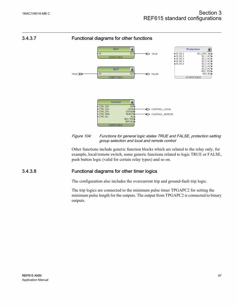
3.4.3.7 Functional diagrams for other functions
Protection
O:161|T:2.5|I:0
BI_SG_2BI_SG_3BI_SG_4BI_SG_5BI_SG_6
SG_LOGIC_SELSG_1_ACTSG_2_ACTSG_3_ACTSG_4_ACTSG_5_ACTSG_6_ACTBEH_TEST
BEH_BLK
Control
O:67|T:2.5|I:0
CTRL_OFFCTRL_LOCCTRL_STACTRL_REMCTRL_ALL
OFFLOCAL
STATIONREMOTE
ALLBEH_TEST
BEH_BLK
CONTROL_LOCAL
CONTROL_REMOTE
NOT
O:63|T:2.5|I:0IN OUT
NOT
O:66|T:2.5|I:4IN OUT
TRUE
TRUE FALSE
GUID-3B50DC95-CE59-4615-9271-756C88EF287C V1 EN
Figure 104: Functions for general logic states TRUE and FALSE, protection settinggroup selection and local and remote control
Other functions include generic function blocks which are related to the relay only, forexample, local/remote switch, some generic functions related to logic TRUE or FALSE,push button logic (valid for certain relay types) and so on.
3.4.3.8 Functional diagrams for other timer logics
The configuration also includes the overcurrent trip and ground-fault trip logic.
The trip logics are connected to the minimum pulse timer TPGAPC2 for setting theminimum pulse length for the outputs. The output from TPGAPC2 is connected to binaryoutputs.
1MAC109016-MB C Section 3REF615 standard configurations
REF615 ANSI 97Application Manual

TPGAPC2
O:134|T:2.5|I:2
IN1IN2
OUT1OUT2
OR6
O:132|T:2.5|I:59
B1B2B3B4B5B6
O
OR
O:133|T:2.5|I:18
B1B2
O OC_TRIP_PULSEEF_TRIP_PULSEPHIPTOC1_50P-3_TRIP
INTRPTEF1_67NIEF_TRIPEFHPTOC1_50G-1_TRIP
DPHxPDOC_TRIP
DEFxPDEF_TRIP
EFPADM_TRIPROVPTOV_TRIP
WPWDE_TRIP
GUID-623E9E39-F79A-4FC1-AD64-2AEDB59951C3 V1 EN
Figure 105: Timer logic for overcurrent and ground-fault trip pulse
TPGAPC3
O:122|T:2.5|I:3
IN1IN2
OUT1OUT2
OR6
O:121|T:2.5|I:54
B1B2B3B4B5B6
O VOLTAGE_TRIP_PULSEPSPTUV1_47U-1_TRIPNSPTOV1_47-1_TRIP
PHPTUV_TRIPPHPTOV_TRIP
GUID-2BE45503-12E9-42F1-90BB-9773A34161E6 V1 EN
Figure 106: Timer logic for voltage trip pulse
TONGAPC1
O:172|T:2.5|I:1
IN1IN2IN3IN4IN5IN6IN7IN8
Q1Q2Q3Q4Q5Q6Q7Q8
TONGAPC2
O:179|T:2.5|I:2
IN1IN2IN3IN4IN5IN6IN7IN8
Q1Q2Q3Q4Q5Q6Q7Q8
TOFGAPC1
O:174|T:2.5|I:1
IN1IN2IN3IN4IN5IN6IN7IN8
Q1Q2Q3Q4Q5Q6Q7Q8
TOFGAPC2
O:176|T:2.5|I:2
IN1IN2IN3IN4IN5IN6IN7IN8
Q1Q2Q3Q4Q5Q6Q7Q8
GUID-5F98BC83-8394-4CF8-8BAA-374A5490E827 V1 EN
Figure 107: Programmable timers
Section 3 1MAC109016-MB CREF615 standard configurations
98 REF615 ANSIApplication Manual

3.4.3.9 Functional diagrams for communication
MBSLPRT1
O:186|T:2.5|I:1Status
DNPLPRT1
O:8|T:2.5|I:1Status
SCHLCCH1
O:4|T:2.5|I:1
CH1LIVLNK1LIV
SCHLCCH2
O:10|T:2.5|I:2
CH2LIVLNK2LIV
SCHLCCH3
O:183|T:2.5|I:3
CH3LIVLNK3LIV
SERLCCH1
O:177|T:2.5|I:1
CH1LIVLNK1LIV
SERLCCH2
O:162|T:2.5|I:2
CH2LIVLNK2LIV
RCHLCCH1
O:5|T:2.5|I:1
CHLIV_AREDCHLIV_B
LNKLIV_AREDLNKLIV_B
GUID-EF662B2F-F4DC-4EFC-BDEB-7EB6B954C02F V1 EN
Figure 108: Default communication function connection
3.5 Standard configuration L
3.5.1 Applications
The standard configuration for directional overcurrent and directional ground-faultprotection with phase voltage-based measurements, undervoltage and overvoltageprotection, frequency protection and measurement functions is mainly intended for cableand overhead-line feeder applications in isolated or resonant-grounded distributionnetworks. The configuration also includes additional options for selecting ground-faultprotection based on admittance, wattmetric or harmonic-based principles.
The protection relay with a standard configuration is delivered from the factory withdefault settings and parameters. The end-user flexibility for incoming, outgoing andinternal signal designation within the protection relay enables this configuration to befurther adapted to different primary circuit layouts and the related functionality needs bymodifying the internal functionality using PCM600.
Standard configuration L provides the highest functionality level of REF615 standardconfigurations supporting sensor inputs. Standard configuration L is deliveredpreconfigured with directional overcurrent protection but it also supports non-directionalovercurrent protection as well as directional overpower. Depending on the specific feederapplication, the appropriate functionality can be selected and an own configuration
1MAC109016-MB C Section 3REF615 standard configurations
REF615 ANSI 99Application Manual

created with the Application Configuration tool in PCM600. Standard configuration L isnot designed for using all the available functionality content in one protection relay at thesame time. To ensure the performance of the protection relay, the user specificconfiguration load is verified with the Application Configuration tool of PCM600.
3.5.2 Functions
32U-1
c
3I
795
51G
1 Available with Admittance-based earth fault option2 Available with Wattmetric-based earth fault option3 Available with Harmonic-based earth fault option4 Available with Arc Flash Detection(AFD) option5 Available with Reclosing option6 Available with RTD option7 Available with IEC 61850-9-2LE option8 Available with Fault locator option9 Available with interconnection option
3
52
AFD-34
AFD-14
AFD-24
Va, Vb, Vc
21YN-11
21YN-21
21YN-31
50P-3
REF615 V5.0 FP1 ANSI Func Appl L
46-1
32N-12
67NIEF
32N-32 32N-2251NHA3
46-2 46PD 49F-1 27-1
27-2
27-3
47-1
47U-2
59N-2
59N-1
59-3
59-2
59-1
386
60-1
51P-2 50P-1 50P-2 50BF-1
67/51P-1
67/51P-2
67/50P-1
51N-1 67/51N-1
67/51N-2
67/50N-1
INR-1
67/50P-2
50N-350N-250N-1
50G-2 50G-3
67/50N-2
81-1
47-2
47U-1
81-3
81-2
81-4
81-5
81-6
32U-2
32R/32O-2
32R/32O-1
21FL-18
51P-1
32Q-279
67YN-1
78V-19
27RT-19
27RT-29
27RT-39
27R-17 257
59G
50G-1
GUID-F1CB1DF2-9417-4121-BF2B-78A35A9AE94B V1 EN
Figure 109: Functionality overview for standard configuration L
3.5.2.1 Default I/O connections
Table 21: Default connections for analog inputs
Analog input Description Connector pinsIA Phase A current X131:4-5
IB Phase B current X132:4-5
IC Phase C current X133:4-5
IG Residual current IG X130:1-2
Table continues on next page
Section 3 1MAC109016-MB CREF615 standard configurations
100 REF615 ANSIApplication Manual
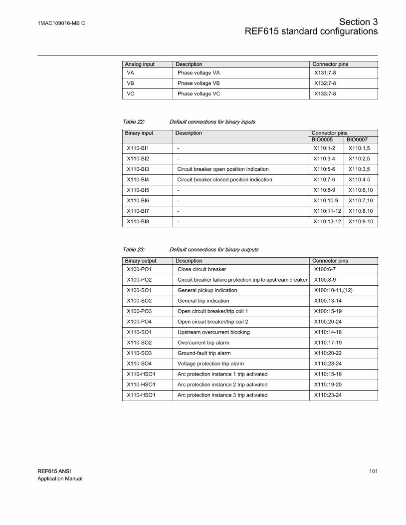
Analog input Description Connector pinsVA Phase voltage VA X131:7-8
VB Phase voltage VB X132:7-8
VC Phase voltage VC X133:7-8
Table 22: Default connections for binary inputs
Binary input Description Connector pinsBIO0005 BIO0007
X110-BI1 - X110:1-2 X110:1,5
X110-BI2 - X110:3-4 X110:2,5
X110-BI3 Circuit breaker open position indication X110:5-6 X110:3,5
X110-BI4 Circuit breaker closed position indication X110:7-6 X110:4-5
X110-BI5 - X110:8-9 X110:6,10
X110-BI6 - X110:10-9 X110:7,10
X110-BI7 - X110:11-12 X110:8,10
X110-BI8 - X110:13-12 X110:9-10
Table 23: Default connections for binary outputs
Binary output Description Connector pinsX100-PO1 Close circuit breaker X100:6-7
X100-PO2 Circuit breaker failure protection trip to upstream breaker X100:8-9
X100-SO1 General pickup indication X100:10-11,(12)
X100-SO2 General trip indication X100:13-14
X100-PO3 Open circuit breaker/trip coil 1 X100:15-19
X100-PO4 Open circuit breaker/trip coil 2 X100:20-24
X110-SO1 Upstream overcurrent blocking X110:14-16
X110-SO2 Overcurrent trip alarm X110:17-19
X110-SO3 Ground-fault trip alarm X110:20-22
X110-SO4 Voltage protection trip alarm X110:23-24
X110-HSO1 Arc protection instance 1 trip activated X110:15-16
X110-HSO1 Arc protection instance 2 trip activated X110:19-20
X110-HSO1 Arc protection instance 3 trip activated X110:23-24
1MAC109016-MB C Section 3REF615 standard configurations
REF615 ANSI 101Application Manual

Table 24: Default connections for LEDs
LED Default usage ID Label description1 Circuit breaker close enabled LED_CBcloseenabled_1 CB close enabled
2 Overcurrent protection trip LED_Overcurrent_1 Overcurrent
3 Ground-fault protection trip LED_EarthFault_1 Ground-fault
4 Current unbalance protectiontrip
LED_PhaseUnbalance_1 Phase unbalance
5 Sequence voltage protectiontrip
LED_NPSOrPPSvoltage_1 Sequence voltage
6 Overvoltage or residualovervoltage protection trip
LED_OVorResidualVoltage_1 OV / Residual voltage
7 Thermal overload alarm LED_ThermalOverload_1 Thermal overload
8 Undervoltage or frequencyprotection trip
LED_UVorFrequency_1 UV / Frequency
9 Supervision alarm LED_Supervision_1 Supervision
10 Circuit breaker conditionmonitoring alarm
LED_CBConditionMonitoring_1
CB condition monitoring
11 - - -
3.5.2.2 Default disturbance recorder settings
Table 25: Default disturbance recorder analog channels
Channel Description1 IL1
2 IL2
3 IL3
4 Io
5 U1
6 U2
7 U3
8 -
9 -
10 -
11 -
12 -
Section 3 1MAC109016-MB CREF615 standard configurations
102 REF615 ANSIApplication Manual

Table 26: Default disturbance recorder binary channels
Channel ID text Level trigger mode1 DPHLPDOC1 - pickup Positive or Rising
2 DPHLPDOC2 - pickup Positive or Rising
3 DPHHPDOC1 - pickup Positive or Rising
4 PHIPTOC1 - pickup Positive or Rising
5 NSPTOC1 - pickup Positive or Rising
6 NSPTOC2 - pickup Positive or Rising
7 DEFLPDEF1/WPWDE1/EFPADM1 - pickup Positive or Rising
8 DEFLPDEF2/WPWDE2/EFPADM2 - pickup Positive or Rising
9 DEFHPDEF1/WPWDE3/EFPADM3 - pickup Positive or Rising
10 INTRPTEF1 - pickup Positive or Rising
11 EFHPTOC1 - pickup Positive or Rising
12 PDNSPTOC1 - pickup Positive or Rising
13 T1PTTR1 - pickup Positive or Rising
14 PHPTOV1 - pickup Positive or Rising
15 PHPTOV2 - pickup Positive or Rising
16 PHPTOV3 - pickup Positive or Rising
17 PSPTUV1 - pickup Positive or Rising
18 NSPTOV1 - pickup Positive or Rising
19 PHPTUV1 - pickup Positive or Rising
20 PHPTUV2 - pickup Positive or Rising
21 PHPTUV3 - pickup Positive or Rising
22 ROVPTOV1 - pickup Positive or Rising
23 ROVPTOV2 - pickup Positive or Rising
24 ROVPTOV3 - pickup Positive or Rising
25 CCBRBRF1 - trret Level trigger off
26 CCBRBRF1 - trbu Level trigger off
27 PHxPTOC - trip Level trigger off
28 NSPTOC - trip Level trigger off
29 DEFxPDEF/WPWDE/EFPADM - trip Level trigger off
30 INTRPTEF1 - trip Level trigger off
31 EFHPTOC - trip Level trigger off
32 PDNSPTOC1 - trip Level trigger off
33 INRPHAR1 - blk2h Level trigger off
34 T1PTTR1 - trip Level trigger off
35 PHPTOV - trip Level trigger off
Table continues on next page
1MAC109016-MB C Section 3REF615 standard configurations
REF615 ANSI 103Application Manual

Channel ID text Level trigger mode36 PHPTUV - trip Level trigger off
37 ROVPTOV/PSPTUV1/NSPTOV1 - trip Level trigger off
38 SEQSPVC1 - fusef 3ph Level trigger off
39 SEQSPVC1 - fusef u Level trigger off
40 CCSPVC1 - fail Level trigger off
41 X110BI4 - CB closed Level trigger off
42 X110BI3 - CB open Level trigger off
43 ARCSARC - ARC flt det Level trigger off
44 DARREC1 - close CB/unsuc recl Level trigger off
45 ARCSARC1 - trip Positive or Rising
46 ARCSARC2 - trip Positive or Rising
47 ARCSARC3 - trip Positive or Rising
48 DARREC1 - inpro Level trigger off
49 FRPFRQ1 - pickup Positive or Rising
50 FRPFRQ2 - pickup Positive or Rising
51 FRPFRQ3 - pickup Positive or Rising
52 FRPFRQ - trip Level trigger off
53 DPHHPDOC2 - pickup Positive or Rising
54 EFHPTOC2 - pickup Positive or Rising
55 EFHPTOC3 - pickup Positive or Rising
56 EFHPTOC4 - pickup Positive or Rising
57 DEFHPDEF2 - pickup Positive or Rising
58 DUPPDPR1 - pickup Positive or Rising
59 DUPPDPR2 - pickup Positive or Rising
60 DUPPDPR1 - trip Level trigger off
61 MSVPR1 - U_LO Level trigger off
62 - -
63 - -
64 - -
3.5.3 Functional diagrams
The functional diagrams describe the default input, output, alarm LED and function-to-function connections. The default connections can be viewed and changed with PCM600according to the application requirements.
Section 3 1MAC109016-MB CREF615 standard configurations
104 REF615 ANSIApplication Manual

The analog channels have fixed connections to the different function blocks inside theprotection relay’s standard configuration. However, the 12 analog channels available forthe disturbance recorder function are freely selectable as a part of the disturbancerecorder’s parameter settings.
The phase currents to the protection relay are fed from Rogowski or Combi sensors. Theresidual current to the protection relay is fed from either residually connected CTs, anexternal core balance CT, neutral CT or calculated internally.
The phase voltages to the protection relay are fed from Combi sensors. The residualvoltage is calculated internally.
The signal marked with IA, IB and IC represents the three phase currents. The signal IGrepresents the measured ground current.
The signal marked with VA, VB and VC represents the three phase voltages.
The protection relay offers six different setting groups which can be set based onindividual needs. Each group can be activated or deactivated using the setting groupsettings available in the protection relay.
Depending on the communication protocol the required function block needs to beinstantiated in the configuration.
3.5.3.1 Functional diagrams for protection
The functional diagrams describe the relay's protection functionality in detail andaccording to the factory set default connections.
Five overcurrent stages are offered for overcurrent and short-circuit protection. Three ofthem include directional functionality DPHxPDOC_5xP-1/2.
1MAC109016-MB C Section 3REF615 standard configurations
REF615 ANSI 105Application Manual

PHIPTOC1
O:25|T:2.5|I:1
BLOCKENA_MULT
TRIPPICKUP
PHIPTOC1_50P-3_TRIPPHIPTOC1_50P-3_PICKUP
DPHHPDOC1
O:27|T:5|I:1
BLOCKENA_MULTNON_DIR
TRIPPICKUP
DPHLPDOC1
O:28|T:5|I:1
BLOCKENA_MULTNON_DIR
TRIPPICKUP
DPHLPDOC2
O:53|T:5|I:2
BLOCKENA_MULTNON_DIR
TRIPPICKUP
OR6
O:126|T:2.5|I:61
B1B2B3B4B5B6
O
DPHHPDOC2
O:14|T:5|I:2
BLOCKENA_MULTNON_DIR
TRIPPICKUP
DPHHPDOC1_67/50P-1_TRIP
DPHHPDOC1_67/50P-1_TRIP
DPHLPDOC1_67/51P-1_TRIP
DPHLPDOC1_67/51P-1_TRIP
DPHLPDOC2_67/51P-2_TRIP
DPHLPDOC2_67/51P-2_TRIP
DPHHPDOC2_67/50P-2_TRIP
DPHHPDOC2_67/50P-2_TRIP
DPHHPDOC1_67/50P-1_PICKUP
DPHLPDOC1_67/51P-1_PICKUP
DPHLPDOC2_67/51P-2_PICKUP
DPHHPDOC2_67/50P-2_PICKUP
DPHxPDOC_TRIP
GUID-995E6CBC-4321-4828-8B68-1D7C3EC3DD02 V1 EN
Figure 110: Overcurrent protection functions
The upstream blocking from the pickup of the second low stage of three-phase directionalovercurrent protection DPHLPDOC2_67/51P-2 is connected to the binary output. Thissignal is not connected in the configuration. This output can be used for sending a blockingsignal to the relevant overcurrent protection stage of the relay at the infeeding bay.
Section 3 1MAC109016-MB CREF615 standard configurations
106 REF615 ANSIApplication Manual

OR6
O:151|T:2.5|I:65
B1B2B3B4B5B6
O UPSTEAM_OC_BLOCKINGDPHLPDOC2_67/51P-2_PICKUP
GUID-ED03DF9D-6486-4D57-81B2-C7CFCCB7FC31 V1 EN
Figure 111: Upstream blocking logic
The output BLK2H of three-phase inrush detector INRPHAR1_INR-1 enables eitherblocking the function or multiplying the active settings for any of the availableovercurrent or ground-fault function blocks.
INRPHAR1
O:107|T:2.5|I:1BLOCK BLK2H INRPHAR1_INR-1_BLK2H
GUID-877B89DE-CBF8-4976-8121-4F5AAB01111B V1 EN
Figure 112: Inrush detector function
Two negative-sequence overcurrent protection stages NSPTOC1_46-1 andNSPTOC2_46-2 are provided for phase unbalance protection. These functions are used toprotect the feeder against phase unbalance. Both the negative-sequence overcurrentprotections are blocked in case of detection in failure in secondary circuit of currenttransformer.
NSPTOC1
O:24|T:5|I:1
BLOCKENA_MULT
TRIPPICKUP
NSPTOC2
O:25|T:5|I:2
BLOCKENA_MULT
TRIPPICKUP
NSPTOC2_46-2_TRIP
NSPTOC1_46-1_TRIPNSPTOC1_46-1_PICKUP
NSPTOC2_46-2_PICKUP
NSPTOC1
O:54|T:5|I:1
BLOCKENA_MULT
TRIPPICKUP
NSPTOC2
O:55|T:5|I:2
BLOCKENA_MULT
TRIPPICKUP
NSPTOC1_46-1_TRIP
NSPTOC2_46-2_TRIP
NSPTOC1_46-1_PICKUP
NSPTOC2_46-2_PICKUP
CCSPVC1_CCM_FAIL
CCSPVC1_CCM_FAIL
GUID-CB92D4CF-F779-45BE-A753-26A71FBF9556 V1 EN
Figure 113: Negative-sequence overcurrent protection function
Four stages are provided for non-directional ground-fault protection EFHPTOC1….4_50G-1/2, 50N-1/2. Three stages are provided for directional ground-fault protection.According to the relay's order code, the directional ground-fault protection method can bebased on conventional directional ground-fault DEFxPDEF_67/51N-1/2, 67/50N-1/2,only or alternatively used together with admittance-based ground-fault protectionEFPADM_21YN or wattmetric-based ground-fault protection WPWDE_32N. Adedicated protection stage INTRPTEF_67NIEF is used either for transient-based ground-fault protection or for cable intermittent ground-fault protection in compensatednetworks.
1MAC109016-MB C Section 3REF615 standard configurations
REF615 ANSI 107Application Manual

EFHPTOC1
O:13|T:5|I:1
BLOCKENA_MULT
TRIPPICKUP
EFHPTOC2
O:16|T:5|I:2
BLOCKENA_MULT
TRIPPICKUP
EFHPTOC3
O:15|T:5|I:3
BLOCKENA_MULT
TRIPPICKUP
EFHPTOC4
O:17|T:5|I:4
BLOCKENA_MULT
TRIPPICKUP
OR6
O:130|T:2.5|I:9
B1B2B3B4B5B6
O
EFHPTOC1_50G-1_TRIP
EFHPTOC1_50G-1_TRIP
EFHPTOC2_50G-2_TRIP
EFHPTOC2_50G-2_TRIP
EFHPTOC3_50N-1_TRIP
EFHPTOC3_50N-1_TRIP
EFHPTOC4_50N-2_TRIP
EFHPTOC4_50N-2_TRIP
EFHPTOC1_50G-1_PICKUP
EFHPTOC3_50N-1_PICKUP
EFHPTOC2_50G-2_PICKUP
EFHPTOC4_50N-2_PICKUP
EFxPTOC_TRIP
CCSPVC1_CCM_FAIL
CCSPVC1_CCM_FAIL
GUID-320A6916-976B-470D-BEA1-A41EEFD19FF2 V1 EN
Figure 114: Ground fault protection function
Section 3 1MAC109016-MB CREF615 standard configurations
108 REF615 ANSIApplication Manual

OR6
O:124|T:2.5|I:55
B1B2B3B4B5B6
O
DEFLPDEF2
O:22|T:5|I:2
BLOCKENA_MULTRCA_CTL
TRIPPICKUP
DEFLPDEF1
O:49|T:5|I:1
BLOCKENA_MULTRCA_CTL
TRIPPICKUP
DEFHPDEF1
O:21|T:5|I:1
BLOCKENA_MULTRCA_CTL
TRIPPICKUP
DEFHPDEF2
O:12|T:5|I:2
BLOCKENA_MULTRCA_CTL
TRIPPICKUP
DEFHPDEF1_67/50N-1_TRIP
DEFHPDEF1_67/50N-1_TRIP
DEFLPDEF2_67/51N-2_TRIP
DEFLPDEF2_67/51N-2_TRIP
DEFLPDEF1_67/51N-1_TRIP
DEFLPDEF1_67/51N-1_TRIP
DEFHPDEF2_67/50N-2_TRIP
DEFHPDEF2_67/50N-2_TRIP
DEFHPDEF1_67/50N-1_PICKUP
DEFLPDEF1_67/51N-1_PICKUP
DEFLPDEF2_67/51N-2_PICKUP
DEFHPDEF2_67/50N-2_PICKUP
DEFxPDEF_TRIP
CCSPVC1_CCM_FAIL
CCSPVC1_CCM_FAIL
CCSPVC1_CCM_FAIL
CCSPVC1_CCM_FAIL
GUID-9CF9D7D0-6762-453C-8A7C-72C01E77B30A V1 EN
Figure 115: Directional Ground fault protection function
INTRPTEF1
O:47|T:2.5|I:1
BLOCK TRIPPICKUPBLK_EF
INTRPTEF1_67NIEF_TRIPINTRPTEF1_67NIEF_PICKUP
GUID-9FD9A2CC-49A8-48FB-B4E5-2D8FCB32F929 V1 EN
Figure 116: Transient or intermittent ground-fault protection functions
1MAC109016-MB C Section 3REF615 standard configurations
REF615 ANSI 109Application Manual

WPWDE1
O:52|T:5|I:1
BLOCKRCA_CTL
TRIPPICKUP
WPWDE2
O:23|T:5|I:2
BLOCKRCA_CTL
TRIPPICKUP
WPWDE3
O:20|T:5|I:3
BLOCKRCA_CTL
TRIPPICKUP
OR6
O:125|T:2.5|I:54
B1B2B3B4B5B6
O
WPWDE3_32N-3_TRIP
WPWDE3_32N-3_TRIP
WPWDE2_32N-2_TRIP
WPWDE2_32N-2_TRIP
WPWDE1_32N-1_TRIP
WPWDE1_32N-1_TRIP
WPWDE1_32N-1_PICKUP
WPWDE2_32N-2_PICKUP
WPWDE3_32N-3_PICKUP
WPWDE_TRIP
GUID-22FAEF07-9FBA-4532-90AE-A33D7F80585D V1 EN
Figure 117: Wattmetric protection function
Section 3 1MAC109016-MB CREF615 standard configurations
110 REF615 ANSIApplication Manual

EFPADM1
O:51|T:5|I:1
BLOCKRELEASE
TRIPPICKUP
EFPADM2
O:18|T:5|I:2
BLOCKRELEASE
TRIPPICKUP
EFPADM3
O:19|T:5|I:3
BLOCKRELEASE
TRIPPICKUP
OR6
O:123|T:2.5|I:56
B1B2B3B4B5B6
O
EFPADM2_21YN-2_TRIP
EFPADM2_21YN-2_TRIP
EFPADM3_21YN-3_TRIP
EFPADM3_21YN-3_TRIP
EFPADM1_21YN-1_TRIP
EFPADM1_21YN-1_TRIP
EFPADM1_21YN-1_PICKUP
EFPADM2_21YN-2_PICKUP
EFPADM3_21YN-3_PICKUP
EFPADM_TRIP
GUID-774F99EE-223C-4A4E-9B2B-EED1A1CCA381 V1 EN
Figure 118: Admittance-based ground-fault protection function
Phase discontinuity protection PDNSPTOC1_46PD protects for interruptions in thenormal three-phase load supply, for example, in downed conductor situations. Thefunction is blocked in case of detection of a failure in secondary circuit of voltagetransformer.
PDNSPTOC1
O:36|T:5|I:1
BLOCK TRIPPICKUP
PDNSPTOC1_46PD_TRIPPDNSPTOC1_46PD_PICKUP
CCSPVC1_CCM_FAIL
GUID-42E0E6F1-17A3-4B6C-9A82-DF6A224E0120 V1 EN
Figure 119: Phase discontinuity protection
Three-phase thermal protection for feeders, cables and distribution transformersT1PTTR1_49F-1 detects overloads under varying load conditions. The BLK_CLOSEoutput of the function is used to block the closing operation of circuit breaker.
T1PTTR1
O:37|T:5|I:1
BLOCKENA_MULTAMB_TEMP
TRIPPICKUPALARM
BLK_CLOSE T1PTTR1_49F_BLK_CLOSE
T1PTTR1_49F_TRIPT1PTTR1_49F_PICKUPT1PTTR1_49F_ALARM
GUID-2EF3F93A-0087-4039-BFAA-B3678F99687B V1 EN
Figure 120: Thermal overcurrent protection function
1MAC109016-MB C Section 3REF615 standard configurations
REF615 ANSI 111Application Manual

Circuit breaker failure protection CCBRBRF1_50BF-1 is initiated via the PICKUP inputby a number of different protection functions available in the relay. The breaker failureprotection function offers different operating modes associated with the circuit breakerposition and the measured phase and residual currents.
The circuit breaker failure protection function has two operating outputs: TRRET andTRBU. The TRRET trip output is used for retripping its own breaker throughTRPPTRC2_TRIP. The same TRRET output is also connected to the binary outputX100:PO4.
CCBRBRF1
O:56|T:2.5|I:1
BLOCKPICKUPPOSCLOSECB_FAULT
CB_FAULT_ALTRBU
TRRET
OR6
O:33|T:2.5|I:0
B1B2B3B4B5B6
O
OR6
O:32|T:2.5|I:1
B1B2B3B4B5B6
O
OR6
O:35|T:2.5|I:2
B1B2B3B4B5B6
O
OR6
O:31|T:2.5|I:5
B1B2B3B4B5B6
O
CCBRBRF1_50BF-1_TRBUX110_BI4_CB_CLOSED
PHIPTOC1_50P-3_TRIPDPHHPDOC1_67/50P-1_TRIPDPHLPDOC1_67/51P-1_TRIP
DEFHPDEF1_67/50N-1_TRIPDEFLPDEF2_67/51N-2_TRIP
EFPADM2_21YN-2_TRIPEFPADM3_21YN-3_TRIP
EFHPTOC1_50G-1_TRIP
WPWDE3_32N-3_TRIPWPWDE2_32N-2_TRIP
EFHPTOC2_50G-2_TRIP
ARCSARC3_AFD-3_TRIPARCSARC2_AFD-2_TRIP
DPHHPDOC2_67/50P-2_TRIP
EFHPTOC3_50N-1_TRIP
DEFHPDEF2_67/50N-2_TRIP
EFHPTOC4_50N-2_TRIP
ARCSARC1_AFD-1_TRIP
CCBRBRF1_50BF-1_TRRET
GUID-D0CD6920-6F64-455F-89A9-2CED022A7510 V1 EN
Figure 121: Circuit breaker failure protection function
Three arc protection stages ARCSARC1...3_AFD-1…3 are included as an optionalfunction. The arc protection offers individual function blocks for three arc sensors that canbe connected to the relay. Each arc protection function block has two different operationmodes, that is, with or without the phase and residual current check.
The trip signals from ARCSARC1...3_AFD-1…3 are connected to both trip logicTRPPTRC1_86/94-1 and TRPPTRC2_86/94-2. If the relay has been ordered with high-speed binary outputs, the individual trip signals from ARCSARC1...3_AFD-1…3 areconnected to dedicated trip logic TRPPTRC3...5_ 86/94-3…5. The output ofTRPPTRC3...5_ 86/94-3…5 is available at high-speed outputs X110:HSO1, X110:HSO2and X110:HSO3.
Section 3 1MAC109016-MB CREF615 standard configurations
112 REF615 ANSIApplication Manual
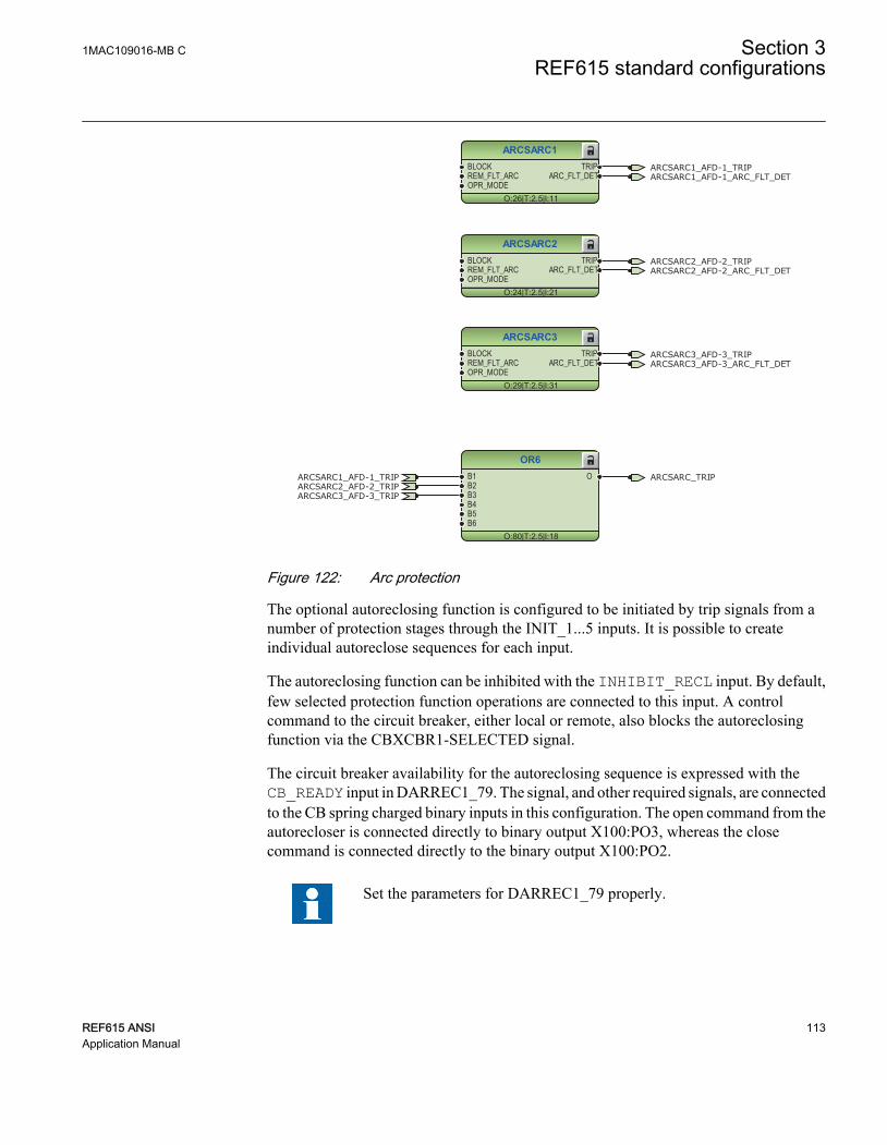
ARCSARC1
O:26|T:2.5|I:11
BLOCKREM_FLT_ARCOPR_MODE
TRIPARC_FLT_DET
ARCSARC2
O:24|T:2.5|I:21
BLOCKREM_FLT_ARCOPR_MODE
TRIPARC_FLT_DET
ARCSARC3
O:29|T:2.5|I:31
BLOCKREM_FLT_ARCOPR_MODE
TRIPARC_FLT_DET
OR6
O:80|T:2.5|I:18
B1B2B3B4B5B6
O
ARCSARC3_AFD-3_TRIP
ARCSARC3_AFD-3_TRIP
ARCSARC2_AFD-2_TRIP
ARCSARC2_AFD-2_TRIP
ARCSARC1_AFD-1_TRIP
ARCSARC1_AFD-1_TRIP ARCSARC_TRIP
ARCSARC3_AFD-3_ARC_FLT_DET
ARCSARC2_AFD-2_ARC_FLT_DET
ARCSARC1_AFD-1_ARC_FLT_DET
GUID-BC3586CA-9AA7-4B5A-8FD2-5A9FB63D3775 V1 EN
Figure 122: Arc protection
The optional autoreclosing function is configured to be initiated by trip signals from anumber of protection stages through the INIT_1...5 inputs. It is possible to createindividual autoreclose sequences for each input.
The autoreclosing function can be inhibited with the INHIBIT_RECL input. By default,few selected protection function operations are connected to this input. A controlcommand to the circuit breaker, either local or remote, also blocks the autoreclosingfunction via the CBXCBR1-SELECTED signal.
The circuit breaker availability for the autoreclosing sequence is expressed with theCB_READY input in DARREC1_79. The signal, and other required signals, are connectedto the CB spring charged binary inputs in this configuration. The open command from theautorecloser is connected directly to binary output X100:PO3, whereas the closecommand is connected directly to the binary output X100:PO2.
Set the parameters for DARREC1_79 properly.
1MAC109016-MB C Section 3REF615 standard configurations
REF615 ANSI 113Application Manual

Check the initialization signals of DARREC1_79.
DARREC1
O:84|T:2.5|I:1
INIT_1INIT_2INIT_3INIT_4INIT_5INIT_6DEL_INIT_2DEL_INIT_3DEL_INIT_4BLK_RECL_TBLK_RCLM_TBLK_THERMCB_POSCB_READYINC_SHOTPINHIBIT_RECLRECL_ONSYNC
OPEN_CBCLOSE_CBCMD_WAIT
INPROLOCKED OUT
PROT_CRDUNSUC_RECL
AR_ONREADYACTIVE
OR6
O:83|T:2.5|I:19
B1B2B3B4B5B6
O
OR6
O:81|T:2.5|I:21
B1B2B3B4B5B6
O
OR6
O:82|T:2.5|I:20
B1B2B3B4B5B6
O
DARREC1_79_CLOSE_CB
X110_BI3_CB_OPEN
DARREC1_79_OPEN_CBPHIPTOC1_50P-3_TRIPDPHHPDOC1_67/50P-1_TRIPDPHLPDOC2_67/51P-2_TRIP
NSPTOC1_46-1_TRIPNSPTOC2_46-2_TRIP
DEFHPDEF1_67/50N-1_TRIP
DEFLPDEF2_67/51N-2_TRIPEFPADM2_21YN-2_TRIP
EFPADM3_21YN-3_TRIP
INTRPTEF1_67NIEF_TRIP
WPWDE3_32N-3_TRIP
WPWDE2_32N-2_TRIP
PDNSPTOC1_46PD_TRIP
CBXCBR1_52-1_CLOSE_ENAD
CBXCBR1_52-1_SELECTED
ARCSARC_TRIP
DARREC1_79_INPRO
DARREC1_79_UNSUC_RECL
GUID-546CA3F6-573C-4D0A-8023-C7EB2EC52553 V1 EN
Figure 123: Autoreclosing function
Three overvoltage and undervoltage protection stages PHPTOV_59 and PHPTUV_27offer protection against abnormal phase voltage conditions. Positive-sequenceundervoltage protection PSPTUV_47U and negative-sequence overvoltage protectionNSPTOV_47 enable voltage-based unbalance protection. A failure in the voltagemeasuring circuit is detected by the fuse failure function. The activation is connected toblock undervoltage protection functions and voltage based unbalance protectionfunctions to avoid faulty tripping.
Section 3 1MAC109016-MB CREF615 standard configurations
114 REF615 ANSIApplication Manual

PHPTOV1
O:40|T:5|I:1
BLOCK TRIPPICKUP
PHPTOV2
O:44|T:5|I:2
BLOCK TRIPPICKUP
PHPTOV3
O:38|T:5|I:3
BLOCK TRIPPICKUP
OR6
O:117|T:2.5|I:58
B1B2B3B4B5B6
O
PHPTOV3_59-3_TRIP
PHPTOV3_59-3_TRIP
PHPTOV2_59-2_TRIP
PHPTOV2_59-2_TRIP
PHPTOV1_59-1_TRIP
PHPTOV1_59-1_TRIP
PHPTOV1_59-1_PICKUP
PHPTOV2_59-2_PICKUP
PHPTOV3_59-3_PICKUP
PHPTOV_TRIP
GUID-C8E495A1-1BEF-4349-AAA3-01547967E827 V1 EN
Figure 124: Overvoltage protection function
1MAC109016-MB C Section 3REF615 standard configurations
REF615 ANSI 115Application Manual

PHPTUV1
O:43|T:5|I:1
BLOCK TRIPPICKUP
PHPTUV2
O:45|T:5|I:2
BLOCK TRIPPICKUP
PHPTUV3
O:42|T:5|I:3
BLOCK TRIPPICKUP
OR6
O:120|T:2.5|I:39
B1B2B3B4B5B6
O
PHPTUV3_27-3_TRIP
PHPTUV3_27-3_TRIP
PHPTUV2_27-2_TRIP
PHPTUV2_27-2_TRIP
PHPTUV1_27-1_TRIP
PHPTUV1_27-1_TRIP
PHPTUV1_27-1_PICKUP
PHPTUV2_27-2_PICKUP
PHPTUV3_27-3_PICKUP
SEQSPVC1_60-1_FUSEF_U
SEQSPVC1_60-1_FUSEF_U
SEQSPVC1_60-1_FUSEF_U
PHPTUV_TRIP
GUID-64A8B59A-69CF-4D91-8838-ED8CA522C794 V1 EN
Figure 125: Undervoltage protection function
NSPTOV1
O:41|T:5|I:1
BLOCK TRIPPICKUP
NSPTOV1_47-1_TRIPNSPTOV1_47-1_PICKUP
SEQSPVC1_60-1_FUSEF_U
GUID-06A5B945-B764-4E65-9504-EF656413C56D V1 EN
Figure 126: Negative-sequence overvoltage protection function
PSPTUV1
O:39|T:5|I:1
BLOCK TRIPPICKUP
PSPTUV1_47U-1_TRIPPSPTUV1_47U-1_PICKUP
SEQSPVC1_60-1_FUSEF_U
GUID-9BE2998B-060E-46EB-91CA-B295578D6DDD V1 EN
Figure 127: Positive-sequence undervoltage protection function
The residual overvoltage protection ROVPTOV_59G,59N-1/2 provides ground-faultprotection by detecting an abnormal level of residual voltage. It can be used, for example,as a nonselective backup protection for the selective directional ground-faultfunctionality.
Section 3 1MAC109016-MB CREF615 standard configurations
116 REF615 ANSIApplication Manual
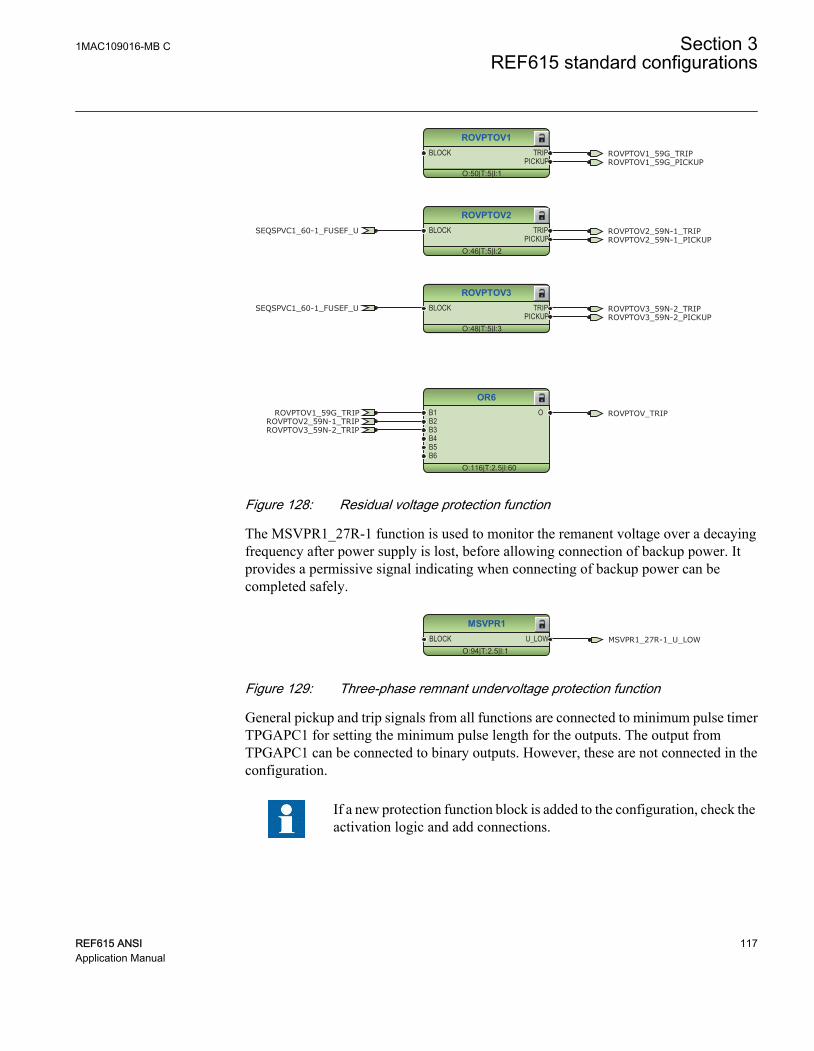
ROVPTOV1
O:50|T:5|I:1
BLOCK TRIPPICKUP
ROVPTOV2
O:46|T:5|I:2
BLOCK TRIPPICKUP
ROVPTOV3
O:48|T:5|I:3
BLOCK TRIPPICKUP
OR6
O:116|T:2.5|I:60
B1B2B3B4B5B6
O
ROVPTOV3_59N-2_TRIP
ROVPTOV3_59N-2_TRIP
ROVPTOV2_59N-1_TRIP
ROVPTOV2_59N-1_TRIP
ROVPTOV1_59G_TRIP
ROVPTOV1_59G_TRIP
ROVPTOV1_59G_PICKUP
ROVPTOV2_59N-1_PICKUP
ROVPTOV3_59N-2_PICKUP
ROVPTOV_TRIP
SEQSPVC1_60-1_FUSEF_U
SEQSPVC1_60-1_FUSEF_U
GUID-BF21470C-A5D6-4B50-9955-F9BF3A43FD7A V1 EN
Figure 128: Residual voltage protection function
The MSVPR1_27R-1 function is used to monitor the remanent voltage over a decayingfrequency after power supply is lost, before allowing connection of backup power. Itprovides a permissive signal indicating when connecting of backup power can becompleted safely.
MSVPR1
O:94|T:2.5|I:1BLOCK U_LOW MSVPR1_27R-1_U_LOW
GUID-58186369-0E59-4DFB-B73E-4A5DC4A62FF4 V1 EN
Figure 129: Three-phase remnant undervoltage protection function
General pickup and trip signals from all functions are connected to minimum pulse timerTPGAPC1 for setting the minimum pulse length for the outputs. The output fromTPGAPC1 can be connected to binary outputs. However, these are not connected in theconfiguration.
If a new protection function block is added to the configuration, check theactivation logic and add connections.
1MAC109016-MB C Section 3REF615 standard configurations
REF615 ANSI 117Application Manual
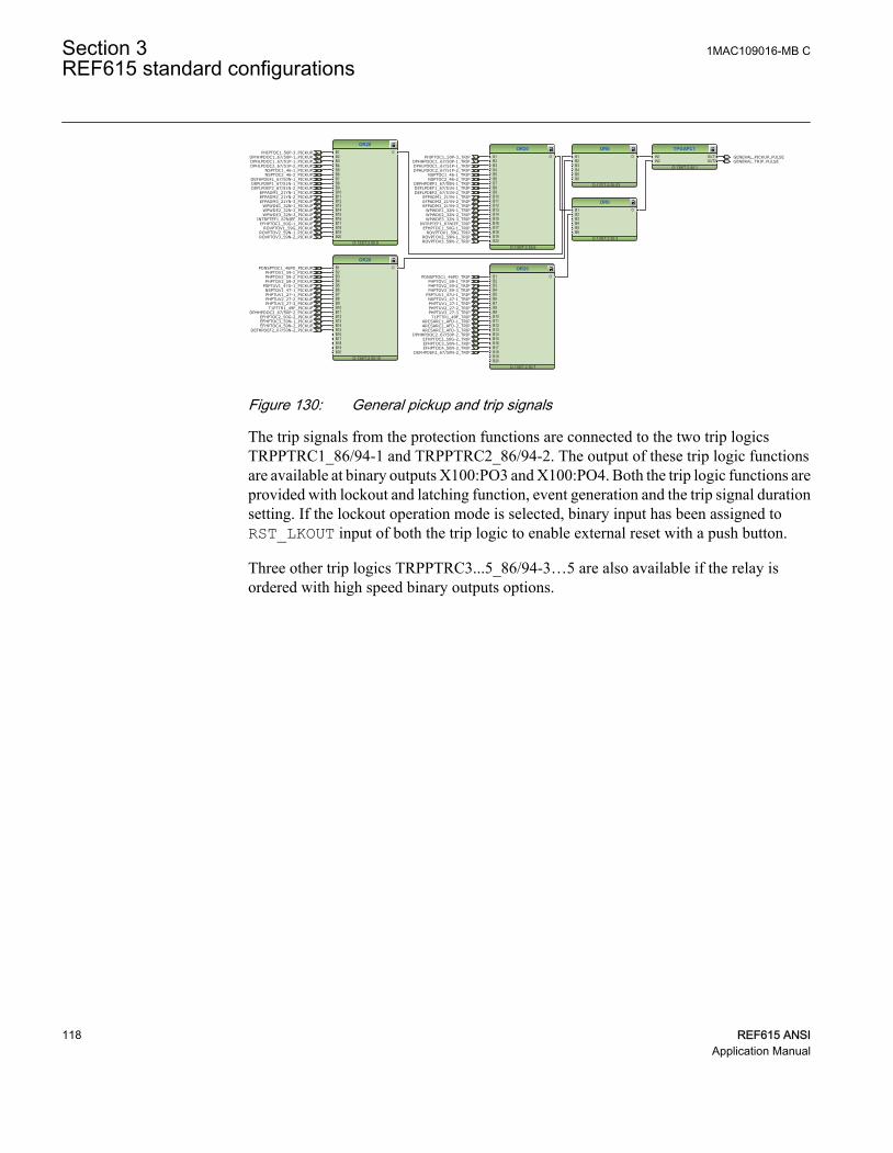
TPGAPC1
O:139|T:2.5|I:1
IN1IN2
OUT1OUT2
OR6
O:137|T:2.5|I:53
B1B2B3B4B5B6
O
OR20
O:136|T:2.5|I:6
B1B2B3B4B5B6B7B8B9B10B11B12B13B14B15B16B17B18B19B20
O
OR20
O:135|T:2.5|I:7
B1B2B3B4B5B6B7B8B9B10B11B12B13B14B15B16B17B18B19B20
O
OR20
O:134|T:2.5|I:10
B1B2B3B4B5B6B7B8B9B10B11B12B13B14B15B16B17B18B19B20
O
OR20
O:133|T:2.5|I:9
B1B2B3B4B5B6B7B8B9B10B11B12B13B14B15B16B17B18B19B20
O
OR6
O:138|T:2.5|I:3
B1B2B3B4B5B6
O
GENERAL_PICKUP_PULSEGENERAL_TRIP_PULSE
PHIPTOC1_50P-3_TRIPDPHHPDOC1_67/50P-1_TRIPDPHLPDOC1_67/51P-1_TRIPDPHLPDOC2_67/51P-2_TRIP
NSPTOC1_46-1_TRIPNSPTOC2_46-2_TRIP
DEFHPDEF1_67/50N-1_TRIP
DEFLPDEF2_67/51N-2_TRIPDEFLPDEF1_67/51N-1_TRIP
EFPADM2_21YN-2_TRIPEFPADM3_21YN-3_TRIP
EFPADM1_21YN-1_TRIP
ROVPTOV3_59N-2_TRIPROVPTOV2_59N-1_TRIP
ROVPTOV1_59G_TRIPEFHPTOC1_50G-1_TRIP
INTRPTEF1_67NIEF_TRIPWPWDE3_32N-3_TRIPWPWDE2_32N-2_TRIPWPWDE1_32N-1_TRIP
PDNSPTOC1_46PD_TRIP
PHPTUV3_27-3_TRIPPHPTUV2_27-2_TRIPPHPTUV1_27-1_TRIPNSPTOV1_47-1_TRIP
PSPTUV1_47U-1_TRIPPHPTOV3_59-3_TRIPPHPTOV2_59-2_TRIPPHPTOV1_59-1_TRIP
EFHPTOC2_50G-2_TRIP
ARCSARC3_AFD-3_TRIPARCSARC2_AFD-2_TRIP
DPHHPDOC2_67/50P-2_TRIP
EFHPTOC3_50N-1_TRIP
DEFHPDEF2_67/50N-2_TRIPEFHPTOC4_50N-2_TRIP
T1PTTR1_49F_TRIPARCSARC1_AFD-1_TRIP
PHIPTOC1_50P-3_PICKUPDPHHPDOC1_67/50P-1_PICKUPDPHLPDOC1_67/51P-1_PICKUPDPHLPDOC2_67/51P-2_PICKUP
NSPTOC1_46-1_PICKUPNSPTOC2_46-2_PICKUP
DEFHPDEF1_67/50N-1_PICKUPDEFLPDEF1_67/51N-1_PICKUPDEFLPDEF2_67/51N-2_PICKUP
EFPADM1_21YN-1_PICKUPEFPADM2_21YN-2_PICKUPEFPADM3_21YN-3_PICKUP
WPWDE1_32N-1_PICKUPWPWDE2_32N-2_PICKUPWPWDE3_32N-3_PICKUP
INTRPTEF1_67NIEF_PICKUPEFHPTOC1_50G-1_PICKUP
ROVPTOV1_59G_PICKUPROVPTOV2_59N-1_PICKUPROVPTOV3_59N-2_PICKUP
PDNSPTOC1_46PD_PICKUPPHPTOV1_59-1_PICKUPPHPTOV2_59-2_PICKUPPHPTOV3_59-3_PICKUP
PSPTUV1_47U-1_PICKUPNSPTOV1_47-1_PICKUPPHPTUV1_27-1_PICKUPPHPTUV2_27-2_PICKUPPHPTUV3_27-3_PICKUP
EFHPTOC3_50N-1_PICKUPEFHPTOC2_50G-2_PICKUP
DEFHPDEF2_67/50N-2_PICKUPEFHPTOC4_50N-2_PICKUP
T1PTTR1_49F_PICKUPDPHHPDOC2_67/50P-2_PICKUP
GUID-3ECF87A5-74E7-424E-B334-6B2F10386317 V1 EN
Figure 130: General pickup and trip signals
The trip signals from the protection functions are connected to the two trip logicsTRPPTRC1_86/94-1 and TRPPTRC2_86/94-2. The output of these trip logic functionsare available at binary outputs X100:PO3 and X100:PO4. Both the trip logic functions areprovided with lockout and latching function, event generation and the trip signal durationsetting. If the lockout operation mode is selected, binary input has been assigned toRST_LKOUT input of both the trip logic to enable external reset with a push button.
Three other trip logics TRPPTRC3...5_86/94-3…5 are also available if the relay isordered with high speed binary outputs options.
Section 3 1MAC109016-MB CREF615 standard configurations
118 REF615 ANSIApplication Manual

TRPPTRC1
O:66|T:2.5|I:1
BLOCKTRIPRST_LKOUT
TRIPCL_LKOUT
OR6
O:62|T:2.5|I:16
B1B2B3B4B5B6
O
OR20
O:58|T:2.5|I:0
B1B2B3B4B5B6B7B8B9B10B11B12B13B14B15B16B17B18B19B20
O
OR20
O:57|T:2.5|I:1
B1B2B3B4B5B6B7B8B9B10B11B12B13B14B15B16B17B18B19B20
O
TRPPTRC1_86/94-1_TRIPPHIPTOC1_50P-3_TRIP
DPHHPDOC1_67/50P-1_TRIPDPHLPDOC1_67/51P-1_TRIPDPHLPDOC2_67/51P-2_TRIP
NSPTOC1_46-1_TRIPNSPTOC2_46-2_TRIP
DEFHPDEF1_67/50N-1_TRIP
DEFLPDEF2_67/51N-2_TRIPDEFLPDEF1_67/51N-1_TRIP
EFPADM2_21YN-2_TRIPEFPADM3_21YN-3_TRIP
EFPADM1_21YN-1_TRIP
ROVPTOV3_59N-2_TRIPROVPTOV2_59N-1_TRIP
ROVPTOV1_59G_TRIPEFHPTOC1_50G-1_TRIP
INTRPTEF1_67NIEF_TRIPWPWDE3_32N-3_TRIPWPWDE2_32N-2_TRIPWPWDE1_32N-1_TRIP
PDNSPTOC1_46PD_TRIP
PHPTUV3_27-3_TRIPPHPTUV2_27-2_TRIPPHPTUV1_27-1_TRIPNSPTOV1_47-1_TRIP
PSPTUV1_47U-1_TRIPPHPTOV3_59-3_TRIPPHPTOV2_59-2_TRIPPHPTOV1_59-1_TRIP
EFHPTOC2_50G-2_TRIP
ARCSARC3_AFD-3_TRIPARCSARC2_AFD-2_TRIP
DPHHPDOC2_67/50P-2_TRIP
EFHPTOC3_50N-1_TRIP
DEFHPDEF2_67/50N-2_TRIPEFHPTOC4_50N-2_TRIP
T1PTTR1_49F_TRIPARCSARC1_AFD-1_TRIP
GUID-5595F04D-50A7-408E-8B68-00A0740C36BD V1 EN
Figure 131: Trip logic TRPPTRC1
1MAC109016-MB C Section 3REF615 standard configurations
REF615 ANSI 119Application Manual

OR6
O:63|T:2.5|I:15
B1B2B3B4B5B6
O
TRPPTRC2
O:67|T:2.5|I:2
BLOCKTRIPRST_LKOUT
TRIPCL_LKOUT
OR20
O:60|T:2.5|I:3
B1B2B3B4B5B6B7B8B9B10B11B12B13B14B15B16B17B18B19B20
O
OR20
O:59|T:2.5|I:4
B1B2B3B4B5B6B7B8B9B10B11B12B13B14B15B16B17B18B19B20
O
TRPPTRC2_86/94-2_TRIPPHIPTOC1_50P-3_TRIP
DPHHPDOC1_67/50P-1_TRIPDPHLPDOC1_67/51P-1_TRIPDPHLPDOC2_67/51P-2_TRIP
NSPTOC1_46-1_TRIPNSPTOC2_46-2_TRIP
DEFHPDEF1_67/50N-1_TRIP
DEFLPDEF2_67/51N-2_TRIPDEFLPDEF1_67/51N-1_TRIP
EFPADM2_21YN-2_TRIPEFPADM3_21YN-3_TRIP
EFPADM1_21YN-1_TRIP
ROVPTOV3_59N-2_TRIPROVPTOV2_59N-1_TRIP
ROVPTOV1_59G_TRIPEFHPTOC1_50G-1_TRIP
INTRPTEF1_67NIEF_TRIPWPWDE3_32N-3_TRIPWPWDE2_32N-2_TRIPWPWDE1_32N-1_TRIP
PDNSPTOC1_46PD_TRIP
PHPTUV3_27-3_TRIPPHPTUV2_27-2_TRIPPHPTUV1_27-1_TRIPNSPTOV1_47-1_TRIP
PSPTUV1_47U-1_TRIPPHPTOV3_59-3_TRIPPHPTOV2_59-2_TRIPPHPTOV1_59-1_TRIP
EFHPTOC2_50G-2_TRIP
ARCSARC3_AFD-3_TRIPARCSARC2_AFD-2_TRIP
DPHHPDOC2_67/50P-2_TRIP
EFHPTOC3_50N-1_TRIP
DEFHPDEF2_67/50N-2_TRIPEFHPTOC4_50N-2_TRIP
T1PTTR1_49F_TRIPARCSARC1_AFD-1_TRIP
CCBRBRF1_50BF-1_TRRET
GUID-C2512CA1-1CF9-48AE-85E7-BAE443787FE9 V1 EN
Figure 132: Trip logic TRPPTRC2
TRPPTRC3
O:150|T:2.5|I:3
BLOCKTRIPRST_LKOUT
TRIPCL_LKOUT
TRPPTRC4
O:148|T:2.5|I:4
BLOCKTRIPRST_LKOUT
TRIPCL_LKOUT
TRPPTRC5
O:149|T:2.5|I:5
BLOCKTRIPRST_LKOUT
TRIPCL_LKOUT
TRPPTRC3_86/94-3_TRIP
TRPPTRC4_86/94-4_TRIP
TRPPTRC5_86/94-5_TRIPARCSARC3_AFD-3_TRIP
ARCSARC2_AFD-2_TRIP
ARCSARC1_AFD-1_TRIP
GUID-173E722B-2634-4D1D-86F0-18D413B1AECA V1 EN
Figure 133: Trip logic TRPPTRC3/4/5
Section 3 1MAC109016-MB CREF615 standard configurations
120 REF615 ANSIApplication Manual
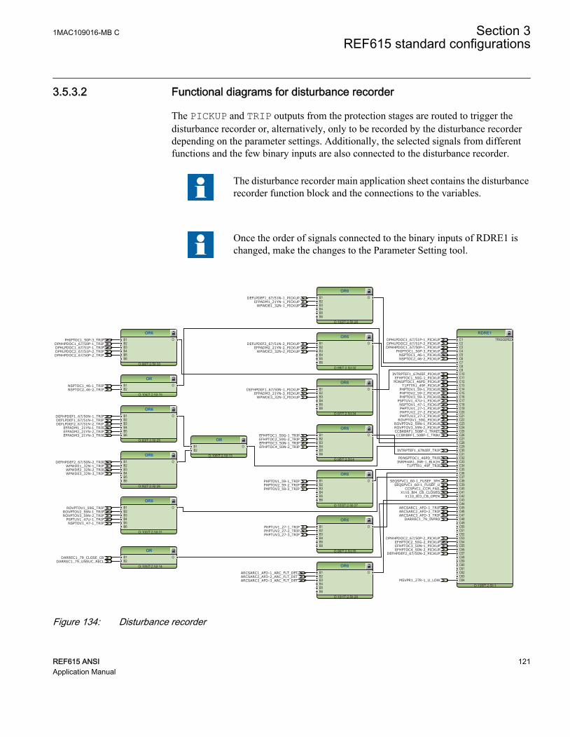
3.5.3.2 Functional diagrams for disturbance recorder
The PICKUP and TRIP outputs from the protection stages are routed to trigger thedisturbance recorder or, alternatively, only to be recorded by the disturbance recorderdepending on the parameter settings. Additionally, the selected signals from differentfunctions and the few binary inputs are also connected to the disturbance recorder.
The disturbance recorder main application sheet contains the disturbancerecorder function block and the connections to the variables.
Once the order of signals connected to the binary inputs of RDRE1 ischanged, make the changes to the Parameter Setting tool.
RDRE1
O:108|T:2.5|I:1
C1C2C3C4C5C6C7C8C9C10C11C12C13C14C15C16C17C18C19C20C21C22C23C24C25C26C27C28C29C30C31C32C33C34C35C36C37C38C39C40C41C42C43C44C45C46C47C48C49C50C51C52C53C54C55C56C57C58C59C60C61C62C63C64
TRIGGERED
OR6
O:98|T:2.5|I:33
B1B2B3B4B5B6
O
OR6
O:101|T:2.5|I:29
B1B2B3B4B5B6
O
OR
O:104|T:2.5|I:15
B1B2
O
OR6
O:100|T:2.5|I:31
B1B2B3B4B5B6
O
OR6
O:103|T:2.5|I:27
B1B2B3B4B5B6
O
OR6
O:96|T:2.5|I:35
B1B2B3B4B5B6
O
OR6
O:92|T:2.5|I:26
B1B2B3B4B5B6
O
OR6
O:93|T:2.5|I:25
B1B2B3B4B5B6
O
OR6
O:102|T:2.5|I:28
B1B2B3B4B5B6
O
OR6
O:99|T:2.5|I:32
B1B2B3B4B5B6
O
OR6
O:97|T:2.5|I:34
B1B2B3B4B5B6
O
OR
O:105|T:2.5|I:14
B1B2
O
OR
O:106|T:2.5|I:13
B1B2
O
OR6
O:95|T:2.5|I:4
B1B2B3B4B5B6
O CCBRBRF1_50BF-1_TRBU
DARREC1_79_CLOSE_CB
X110_BI3_CB_OPENX110_BI4_CB_CLOSED
PHIPTOC1_50P-3_TRIPDPHHPDOC1_67/50P-1_TRIPDPHLPDOC1_67/51P-1_TRIPDPHLPDOC2_67/51P-2_TRIP
NSPTOC1_46-1_TRIPNSPTOC2_46-2_TRIP
DEFHPDEF1_67/50N-1_TRIP
DEFLPDEF2_67/51N-2_TRIPDEFLPDEF1_67/51N-1_TRIP
EFPADM2_21YN-2_TRIPEFPADM3_21YN-3_TRIP
EFPADM1_21YN-1_TRIP
ROVPTOV3_59N-2_TRIPROVPTOV2_59N-1_TRIP
ROVPTOV1_59G_TRIP
EFHPTOC1_50G-1_TRIP
INTRPTEF1_67NIEF_TRIP
WPWDE3_32N-3_TRIPWPWDE2_32N-2_TRIPWPWDE1_32N-1_TRIP
PDNSPTOC1_46PD_TRIP
PHPTUV3_27-3_TRIPPHPTUV2_27-2_TRIPPHPTUV1_27-1_TRIP
NSPTOV1_47-1_TRIPPSPTUV1_47U-1_TRIP
PHPTOV3_59-3_TRIPPHPTOV2_59-2_TRIPPHPTOV1_59-1_TRIP
EFHPTOC2_50G-2_TRIP
ARCSARC3_AFD-3_TRIPARCSARC2_AFD-2_TRIP
DPHHPDOC2_67/50P-2_TRIP
EFHPTOC3_50N-1_TRIP
DEFHPDEF2_67/50N-2_TRIP
EFHPTOC4_50N-2_TRIP
T1PTTR1_49F_TRIP
ARCSARC1_AFD-1_TRIP
CCBRBRF1_50BF-1_TRRET
PHIPTOC1_50P-3_PICKUPDPHHPDOC1_67/50P-1_PICKUP
DPHLPDOC1_67/51P-1_PICKUPDPHLPDOC2_67/51P-2_PICKUP
NSPTOC1_46-1_PICKUPNSPTOC2_46-2_PICKUP
DEFHPDEF1_67/50N-1_PICKUP
DEFLPDEF1_67/51N-1_PICKUP
DEFLPDEF2_67/51N-2_PICKUP
EFPADM1_21YN-1_PICKUP
EFPADM2_21YN-2_PICKUP
EFPADM3_21YN-3_PICKUP
WPWDE1_32N-1_PICKUP
WPWDE2_32N-2_PICKUP
WPWDE3_32N-3_PICKUP
INTRPTEF1_67NIEF_PICKUPEFHPTOC1_50G-1_PICKUP
ROVPTOV1_59G_PICKUPROVPTOV2_59N-1_PICKUPROVPTOV3_59N-2_PICKUP
PDNSPTOC1_46PD_PICKUP
PHPTOV1_59-1_PICKUPPHPTOV2_59-2_PICKUPPHPTOV3_59-3_PICKUP
PSPTUV1_47U-1_PICKUPNSPTOV1_47-1_PICKUPPHPTUV1_27-1_PICKUPPHPTUV2_27-2_PICKUPPHPTUV3_27-3_PICKUP
EFHPTOC3_50N-1_PICKUPEFHPTOC2_50G-2_PICKUP
DEFHPDEF2_67/50N-2_PICKUPEFHPTOC4_50N-2_PICKUP
T1PTTR1_49F_PICKUP
DPHHPDOC2_67/50P-2_PICKUP
SEQSPVC1_60-1_FUSEF_U
INRPHAR1_INR-1_BLK2H
SEQSPVC1_60-1_FUSEF_3PH
CCSPVC1_CCM_FAIL
DARREC1_79_INPRO
DARREC1_79_UNSUC_RECL
ARCSARC3_AFD-3_ARC_FLT_DETARCSARC2_AFD-2_ARC_FLT_DETARCSARC1_AFD-1_ARC_FLT_DET
MSVPR1_27R-1_U_LOW
GUID-4AAD874B-4BA7-46B4-91D2-812DC25230CB V1 EN
Figure 134: Disturbance recorder
1MAC109016-MB C Section 3REF615 standard configurations
REF615 ANSI 121Application Manual

3.5.3.3 Functional diagrams for condition monitoring
Failures in current measuring circuits are detected by CCSPVC1_CCM. When a failure isdetected, it can be used to block the current protection functions that are measuring thecalculated sequence component currents or residual current to avoid unnecessaryoperation.
CCSPVC1
O:11|T:2.5|I:1
BLOCK FAILALARM
CCSPVC1_CCM_FAILCCSPVC1_CCM_ALARM
GUID-521225E7-D269-41D0-A4F4-A2FA15D14B27 V1 EN
Figure 135: Current circuit supervision function
The fuse failure supervision SEQSPVC1_60-1 detects failures in the voltagemeasurement circuits. Failures, such as an open MCB, raise an alarm.
SEQSPVC1
O:34|T:2.5|I:1
BLOCKCB_CLOSEDDISCON_OPENMINCB_OPEN
FUSEF_3PHFUSEF_VX110_BI4_CB_CLOSED SEQSPVC1_60-1_FUSEF_U
SEQSPVC1_60-1_FUSEF_3PH
GUID-B7EF86D5-51CF-431B-A963-8094829B7AB8 V1 EN
Figure 136: Fuse failure supervision function
Circuit-breaker condition monitoring SSCBR1_52CM-1 supervises the switch statusbased on the connected binary input information and the measured current levels.SSCBR1_52CM-1 introduces various supervision methods.
Set the parameters for SSCBR1_52CM-1 properly.
SSCBR1
O:87|T:5|I:1
BLOCKPOSOPENPOSCLOSEOPEN_CB_EXECLOSE_CB_EXEPRES_ALM_INPRES_LO_INSPR_CHR_STSPR_CHRRST_IPOWRST_CB_WEARRST_TRV_TRST_SPR_T
TRV_T_OP_ALMTRV_T_CL_ALMSPR_CHR_ALM
OPR_ALMOPR_LO
IPOW_ALMIPOW_LO
CB_LIFE_ALMMON_ALM
PRES_ALMPRES_LO
OPENPOSINVALIDPOSCLOSEPOS
CB_OPEN_COMMANDCB_CLOSE_COMMAND
X110_BI3_CB_OPENX110_BI4_CB_CLOSED
SSCBR1_52CM-1_TRV_T_OP_ALMSSCBR1_52CM-1_TRV_T_CL_ALMSSCBR1_52CM-1_SPR_CHR_ALMSSCBR1_52CM-1_OPR_ALMSSCBR1_52CM-1_OPR_LOSSCBR1_52CM-1_IPOW_ALMSSCBR1_52CM-1_IPOW_LO
SSCBR1_52CM-1_MON_ALMSSCBR1_52CM-1_PRES_ALMSSCBR1_52CM-1_PRES_LO
SSCBR1_52CM_CB_LIFE_ALM
GUID-89ABDDE0-52BA-41E0-A67C-5149FB984959 V1 EN
Figure 137: Circuit-breaker condition monitoring function
Section 3 1MAC109016-MB CREF615 standard configurations
122 REF615 ANSIApplication Manual

OR6
O:88|T:2.5|I:24
B1B2B3B4B5B6
O
OR6
O:89|T:2.5|I:23
B1B2B3B4B5B6
O
OR
O:90|T:2.5|I:11
B1B2
O
SSCBR1_52CM-1_TRV_T_OP_ALMSSCBR1_52CM-1_TRV_T_CL_ALMSSCBR1_52CM-1_SPR_CHR_ALM
SSCBR1_52CM-1_OPR_ALMSSCBR1_52CM-1_OPR_LO
SSCBR1_52CM-1_IPOW_ALM
SSCBR1_52CM-1_IPOW_LO
SSCBR1_52CM-1_MON_ALMSSCBR1_52CM-1_PRES_ALM
SSCBR1_52CM-1_PRES_LO
SSCBR1_52CM_CB_LIFE_ALM
SSCBR1_52CM-1_ALARMS
GUID-9CDF8457-46A0-40CA-9D2A-A1548D4800D8 V1 EN
Figure 138: Logic for circuit breaker monitoring alarm
Two separate trip circuit supervision functions are included: TCSSCBR1_TCM-1 forpower output X100:PO3 and TCSSCBR2_TCM-2 for power output X100:PO4. Both thefunctions are blocked by the master trips TRPPTRC1_86/94-1 and TRPPTRC2_86/94-2and the circuit breaker open signal.
It is assumed that there is no external resistor in the circuit breaker trippingcoil circuit connected in parallel with the circuit breaker normally openauxiliary contact.
TCSSCBR1
O:110|T:5|I:1BLOCK ALARM
TCSSCBR2
O:111|T:5|I:2BLOCK ALARM
OR
O:112|T:2.5|I:16
B1B2
O
TCSSCBR_BLOCKING
TCSSCBR_BLOCKING
TCSSCBR1_TCM-1_ALARM
TCSSCBR1_TCM-1_ALARM
TCSSCBR2_TCM-2_ALARM
TCSSCBR2_TCM-2_ALARMTCSSCBR_ALARM
GUID-DDFABA18-F276-40E5-84C3-1AAA5442C3B6 V1 EN
Figure 139: Trip circuit supervision function
1MAC109016-MB C Section 3REF615 standard configurations
REF615 ANSI 123Application Manual

OR6
O:109|T:2.5|I:36
B1B2B3B4B5B6
OTRPPTRC2_86/94-2_TRIP
X110_BI3_CB_OPEN
TRPPTRC1_86/94-1_TRIP TCSSCBR_BLOCKING
GUID-1F80DC73-AC36-40F2-B36F-91932BB9F7BD V1 EN
Figure 140: Logic for blocking of trip circuit supervision
3.5.3.4 Functional diagrams for control and interlocking
The main purpose of the synchronism and energizing check SECRSYN1 is to providecontrol over the closing of the circuit breakers in power networks to prevent the closing,if the conditions for synchronism are not detected. The energizing function allows closing,for example, when one side of the breaker is dead.
SECRSYN1
O:157|T:5|I:1
BLOCKCL_COMMANDBYPASS
SYNC_INPROSYNC_OK
CL_FAIL_ALCMD_FAIL_AL
LLDBLLLBDLLBDLDB
GUID-B440D451-BFF7-4ED4-B17C-D5F63770AB0E V1 EN
Figure 141: Synchronism and energizing check
The circuit breaker closing is enabled when the ENA_CLOSE input is activated. The inputcan be activated by the configuration logic, which is a combination of the disconnector orbreaker truck and ground switch position status, status of the trip logics, gas pressurealarm and circuit-breaker spring charging status.
The OKPOS output from DCSXSWI defines whether disconnector or breaker truck iseither open (in test position) or close (in service position). This output, together with theopen ground switch and non-active trip signals, activates the close-enable signal to thecircuit breaker control function block. The open operation for circuit breaker is alwaysenabled.
The SYNC_ITL_BYP input can be used, for example, to always enable the closing of thecircuit breaker when the circuit breaker truck is in the test position. SYNC_ITL_BYPoverrides, for example, active interlocking conditions when the circuit breaker truck isclosed in service position.
Section 3 1MAC109016-MB CREF615 standard configurations
124 REF615 ANSIApplication Manual

CBXCBR1
O:79|T:5|I:1
POSOPENPOSCLOSEENA_OPENENA_CLOSEBLK_OPENBLK_CLOSEAU_OPENAU_CLOSETRIPSYNC_OKSYNC_ITL_BYP
SELECTEDEXE_OPEXE_CL
OP_REQCL_REQ
OPENPOSCLOSEPOS
OKPOSOPEN_ENAD
CLOSE_ENAD
TRUECBXCBR1_52-1_ENA_CLOSE
CBXCBR1_52-1_EXE_CL
X110_BI3_CB_OPENX110_BI4_CB_CLOSED
CBXCBR1_52-1_BLK_CLOSE
CBXCBR1_52-1_EXE_OP
FALSE
CBXCBR1_52-1_AU_OPENCBXCBR1_52-1_AU_CLOSE
CBXCBR1_52-1_CLOSE_ENAD
CBXCBR1_52-1_SELECTED
GUID-40DD515C-E66E-472B-BCA6-5BAA4146EA4B V1 EN
Figure 142: Circuit breaker control logic: Circuit breaker 1
OR
O:86|T:2.5|I:10
B1B2
O CB_CLOSE_COMMANDCBXCBR1_52-1_EXE_CLDARREC1_79_CLOSE_CB
GUID-9B4C6575-7430-4D76-BF0A-AC790D93DFCD V1 EN
Figure 143: Circuit breaker control logic: Signals for the closing coil of circuit breaker1
OR6
O:85|T:2.5|I:22
B1B2B3B4B5B6
O CB_OPEN_COMMANDCBXCBR1_52-1_EXE_OPTRPPTRC1_86/94-1_TRIP
DARREC1_79_OPEN_CB
GUID-8083F101-48DA-4C7F-9F26-0A0A98A19A85 V1 EN
Figure 144: Circuit breaker control logic: Signals for the opening coil of circuit breaker1
NOT
O:72|T:2.5|I:3IN OUT
AND6
O:78|T:2.5|I:0
B1B2B3B4B5B6
O
NOT
O:73|T:2.5|I:2IN OUTTRPPTRC2_86/94-2_TRIP
CBXCBR1_52-1_ENA_CLOSETRPPTRC1_86/94-1_TRIP
GUID-1560EADA-0523-412F-A05C-55A6C9842A49 V1 EN
Figure 145: Circuit breaker close enable logic
Connect the higher-priority conditions before enabling the closing ofcircuit breaker. These conditions cannot be bypassed with bypass featureof the function.
1MAC109016-MB C Section 3REF615 standard configurations
REF615 ANSI 125Application Manual

OR6
O:74|T:2.5|I:17
B1B2B3B4B5B6
O CBXCBR1_52-1_BLK_CLOSET1PTTR1_49F_BLK_CLOSE
GUID-D770B4AE-D735-42F2-B34A-1FC5366F4E63 V1 EN
Figure 146: Circuit breaker close blocking logic
The configuration includes the logic for generating circuit breaker external closing andopening command with the relay in local or remote mode.
Check the logic for the external circuit breaker closing command andmodify it according to the application.
Connect the additional signal for closing and opening of circuit breaker inlocal or remote mode if applicable for the configuration.
AND
O:70|T:2.5|I:1
B1B2
O
AND
O:71|T:2.5|I:0
B1B2
O
OR
O:77|T:2.5|I:7
B1B2
O
CONTROL_REMOTE
CONTROL_LOCALFALSE
FALSE
CBXCBR1_52-1_AU_CLOSE
GUID-948D9F09-FBDB-424E-9469-FA28C2AD223D V1 EN
Figure 147: External closing command for circuit breaker
AND
O:69|T:2.5|I:2
B1B2
O
OR
O:75|T:2.5|I:9
B1B2
O
AND
O:68|T:2.5|I:3
B1B2
O
CONTROL_REMOTE
CONTROL_LOCALFALSE
FALSE
CBXCBR1_52-1_AU_OPEN
GUID-A36678F4-2A9B-4423-9971-F9EEF74E1602 V1 EN
Figure 148: External opening command for circuit breaker
Section 3 1MAC109016-MB CREF615 standard configurations
126 REF615 ANSIApplication Manual

OR6
O:74|T:2.5|I:17
B1B2B3B4B5B6
O CBXCBR1_52-1_BLK_CLOSET1PTTR1_49F_BLK_CLOSE
GUID-6ECB9CD1-5677-4EF2-990A-34EFD1C9F782 V1 EN
Figure 149: Circuit breaker 1 close blocking logic
3.5.3.5 Functional diagrams for measurement functions
The phase current inputs to the relay are measured by the three-phase currentmeasurement function CMMXU1. The three phase current input is connected to the X131,X132 and X133 card in the back panel for three phases. The sequence currentmeasurement CSMSQI1 measures the sequence current and the residual currentmeasurement RESCMMXU1 measures the residual current. Residual current input isconnected to the X130 card in the back panel.
The three-phase bus side phase voltage inputs to the relay are measured by three-phasevoltage measurement VMMXU1. The three-phase current input is connected to the X131,X132 and X133 card in the back panel for three phases. The sequence voltagemeasurement VSMSQI1 measures the sequence voltage and the residual voltagemeasurement RESCMMXU1 measures the voltage current.
The measurements can be seen in the LHMI and they are available under the measurementoption in the menu selection. Based on the settings, function blocks can generate lowalarm or warning and high alarm or warning signals for the measured current values.
The frequency measurement FMMXU1 of the power system and the three-phase powerand energy measurement PEMMXU1 are available. The load profile functionLDPRLRC1 is included in the measurements sheet. LDPRLRC1 offers the ability toobserve the loading history of the corresponding feeder.
CMMXU1
O:158|T:5|I:1
BLOCK HIGH_ALARMHIGH_WARNLOW_WARN
LOW_ALARM
GUID-0A3130A3-3FC3-495A-88E9-78923E6E31C6 V1 EN
Figure 150: Three-phase current measurement
CSMSQI1
O:155|T:5|I:1
GUID-FA6BE5C5-FAB2-4E34-AC50-6277C61FBF32 V1 EN
Figure 151: Sequence current measurements
1MAC109016-MB C Section 3REF615 standard configurations
REF615 ANSI 127Application Manual

RESCMMXU1
O:160|T:5|I:1
BLOCK HIGH_ALARMHIGH_WARN
GUID-6DD6E662-C260-4130-984B-F9922B7B92C2 V1 EN
Figure 152: Ground current measurements
VMMXU1
O:9|T:5|I:1
BLOCK HIGH_ALARMHIGH_WARNLOW_WARN
LOW_ALARM
GUID-4A3A8635-B84D-4BC1-A831-10759D06C85C V1 EN
Figure 153: Three-phase voltage measurement
VSMSQI1
O:154|T:5|I:1
GUID-39A6A89E-20E6-4D65-91F5-1CDCD268202B V1 EN
Figure 154: Sequence voltage measurements
FMMXU1
O:171|T:5|I:1
GUID-15A91535-DE43-4BAE-8B7F-8E32B352173F V1 EN
Figure 155: Frequency measurement
PEMMXU1
O:163|T:5|I:1RSTACM
GUID-23F0EE49-A241-4E02-B4DB-AFAD5EB72791 V1 EN
Figure 156: Three-phase power and energy measurement
FLTRFRC1
O:7|T:2.5|I:1
BLOCKCB_CLRD
LDPRLRC1
O:161|T:5|I:1
RSTMEM MEM_WARNMEM_ALARM
GUID-6AE082C2-E339-4C91-856F-8E442FC9691D V1 EN
Figure 157: Data monitoring and load profile record
Section 3 1MAC109016-MB CREF615 standard configurations
128 REF615 ANSIApplication Manual

3.5.3.6 Functional diagrams for I/O and alarm LEDs
OR
O:76|T:2.5|I:8
B1B2
O
OR
O:30|T:2.5|I:0
B1B2
O
X110_BI3_CB_OPEN
X110_BI4_CB_CLOSEDX110 (BIO)_110.X110-Input 4
X110 (BIO-H)_110.X110-Input 4
X110 (BIO)_110.X110-Input 3
X110 (BIO-H)_110.X110-Input 3
GUID-AE7B96B5-C893-4984-85A5-A892D8EC80B3 V1 EN
Figure 158: Default binary inputs - X110 terminal block
VOLTAGE_TRIP_PULSE
UPSTEAM_OC_BLOCKING
EF_TRIP_PULSE
OC_TRIP_PULSE
TRPPTRC3_86/94-3_TRIP
TRPPTRC4_86/94-4_TRIP
TRPPTRC5_86/94-5_TRIP
X110 (BIO)_110.X110-SO1
X110 (BIO-H)_110.X110-HSO1
X110 (BIO)_110.X110-SO2
X110 (BIO-H)_110.X110-HSO2
X110 (BIO)_110.X110-SO3
X110 (BIO-H)_110.X110-HSO3
X110 (BIO)_110.X110-SO4GUID-D43BE2E9-8092-43D8-B0A7-28FFEE707E91 V1 EN
Figure 159: Default binary outputs - X110 terminal block
1MAC109016-MB C Section 3REF615 standard configurations
REF615 ANSI 129Application Manual

CB_OPEN_COMMAND
GENERAL_PICKUP_PULSE
GENERAL_TRIP_PULSE
CB_CLOSE_COMMAND
CCBRBRF1_50BF-1_TRBU
TRPPTRC2_86/94-2_TRIP
X100 (PSM)_100.X100-SO2
X100 (PSM)_100.X100-PO3
X100 (PSM)_100.X100-SO1
X100 (PSM)_100.X100-PO1
X100 (PSM)_100.X100-PO2
X100 (PSM)_100.X100-PO4
GUID-A9D2C9D7-FB5F-43E5-A7FC-36100E67E338 V1 EN
Figure 160: Default binary outputs - X100 terminal block
LED1
O:115|T:2.5|I:1
OKALARMRESET
LED2
O:144|T:2.5|I:2
OKALARMRESET
LED3
O:132|T:2.5|I:3
OKALARMRESET
LED4
O:146|T:2.5|I:4
OKALARMRESET
LED5
O:141|T:2.5|I:5
OKALARMRESET
LED6
O:119|T:2.5|I:6
OKALARMRESET
LED7
O:147|T:2.5|I:7
OKALARMRESET
LED8
O:142|T:2.5|I:8
OKALARMRESET
LED9
O:114|T:2.5|I:9
OKALARMRESET
LED10
O:91|T:2.5|I:10
OKALARMRESET
OR6
O:113|T:2.5|I:37
B1B2B3B4B5B6
O
OR
O:143|T:2.5|I:21
B1B2
O
OR6
O:131|T:2.5|I:57
B1B2B3B4B5B6
O
OR
O:118|T:2.5|I:20
B1B2
O
OR6
O:145|T:2.5|I:63
B1B2B3B4B5B6
O
OR
O:140|T:2.5|I:18
B1B2
O
PHIPTOC1_50P-3_TRIP
NSPTOC1_46-1_TRIPNSPTOC2_46-2_TRIP
INTRPTEF1_67NIEF_TRIP
PDNSPTOC1_46PD_TRIP
NSPTOV1_47-1_TRIPPSPTUV1_47U-1_TRIP
SEQSPVC1_60-1_FUSEF_U
CBXCBR1_52-1_CLOSE_ENAD
DEFxPDEF_TRIP
DPHxPDOC_TRIP
ROVPTOV_TRIP
EFPADM_TRIPWPWDE_TRIP
PHPTOV_TRIP
PHPTUV_TRIP
SEQSPVC1_60-1_FUSEF_3PHTCSSCBR_ALARM
CCSPVC1_CCM_ALARM
T1PTTR1_49F_ALARM
EFxPTOC_TRIP
SSCBR1_52CM-1_ALARMS
GUID-9BA7E5A4-42C5-4CAD-BB8C-EF4571EF9873 V1 EN
Figure 161: Default LED connection
Section 3 1MAC109016-MB CREF615 standard configurations
130 REF615 ANSIApplication Manual

3.5.3.7 Functional diagrams for other functions
Protection
O:152|T:2.5|I:0
BI_SG_2BI_SG_3BI_SG_4BI_SG_5BI_SG_6
SG_LOGIC_SELSG_1_ACTSG_2_ACTSG_3_ACTSG_4_ACTSG_5_ACTSG_6_ACTBEH_TEST
BEH_BLK
Control
O:65|T:2.5|I:0
CTRL_OFFCTRL_LOCCTRL_STACTRL_REMCTRL_ALL
OFFLOCAL
STATIONREMOTE
ALLBEH_TEST
BEH_BLK
NOT
O:61|T:2.5|I:0IN OUT
NOT
O:64|T:2.5|I:4IN OUT
TRUE
TRUE
CONTROL_REMOTE
CONTROL_LOCAL
FALSE
GUID-BFC3F036-F7AE-4729-B814-43302925A886 V1 EN
Figure 162: Functions for general logic states TRUE and FALSE, protection settinggroup selection and local and remote control
Other functions include generic function blocks which are related to the relay only, forexample, local/remote switch, some generic functions related to logic TRUE or FALSE,push button logic (valid for certain relay types) and so on.
3.5.3.8 Functional diagrams for other timer logics
The configuration also includes the overcurrent trip and ground-fault trip logic.
The trip logics are connected to the minimum pulse timer TPGAPC2 for setting theminimum pulse length for the outputs. The output from TPGAPC2 is connected to binaryoutputs.
TPGAPC2
O:129|T:2.5|I:2
IN1IN2
OUT1OUT2
OR6
O:127|T:2.5|I:62
B1B2B3B4B5B6
O
OR
O:128|T:2.5|I:19
B1B2
OEF_TRIP_PULSEOC_TRIP_PULSE
PHIPTOC1_50P-3_TRIP
EFHPTOC1_50G-1_TRIPINTRPTEF1_67NIEF_TRIP
DEFxPDEF_TRIP
DPHxPDOC_TRIP
ROVPTOV_TRIP
EFPADM_TRIPWPWDE_TRIP
GUID-5E32E544-1F26-4552-A6B7-CAC3799D4971 V1 EN
Figure 163: Timer logic for overcurrent and ground-fault trip pulse
1MAC109016-MB C Section 3REF615 standard configurations
REF615 ANSI 131Application Manual

TPGAPC3
O:122|T:2.5|I:3
IN1IN2
OUT1OUT2
OR6
O:121|T:2.5|I:59
B1B2B3B4B5B6
O VOLTAGE_TRIP_PULSE
NSPTOV1_47-1_TRIPPSPTUV1_47U-1_TRIP
PHPTOV_TRIPPHPTUV_TRIP
GUID-A5E43724-FCB1-4B79-A801-1299A0479759 V1 EN
Figure 164: Timer logic for voltage trip and frequency protection trip alarm
TONGAPC1
O:162|T:2.5|I:1
IN1IN2IN3IN4IN5IN6IN7IN8
Q1Q2Q3Q4Q5Q6Q7Q8
TONGAPC2
O:169|T:2.5|I:2
IN1IN2IN3IN4IN5IN6IN7IN8
Q1Q2Q3Q4Q5Q6Q7Q8
TOFGAPC1
O:164|T:2.5|I:1
IN1IN2IN3IN4IN5IN6IN7IN8
Q1Q2Q3Q4Q5Q6Q7Q8
TOFGAPC2
O:166|T:2.5|I:2
IN1IN2IN3IN4IN5IN6IN7IN8
Q1Q2Q3Q4Q5Q6Q7Q8
GUID-03CE7E4F-79D1-4772-91D2-3EC8948F4C08 V1 EN
Figure 165: Programmable timers
3.5.3.9 Functional diagrams for communication
MBSLPRT1
O:177|T:2.5|I:1Status
SCHLCCH1
O:4|T:2.5|I:1
CH1LIVLNK1LIV
SCHLCCH2
O:10|T:2.5|I:2
CH2LIVLNK2LIV
SCHLCCH3
O:173|T:2.5|I:3
CH3LIVLNK3LIV
SERLCCH1
O:167|T:2.5|I:1
CH1LIVLNK1LIV
SERLCCH2
O:153|T:2.5|I:2
CH2LIVLNK2LIV
RCHLCCH1
O:5|T:2.5|I:1
CHLIV_AREDCHLIV_B
LNKLIV_AREDLNKLIV_B
DNPLPRT1
O:8|T:2.5|I:1Status
GUID-9F64B38C-6394-4C80-93F9-9486768F9B58 V1 EN
Figure 166: Default communication function connection
Section 3 1MAC109016-MB CREF615 standard configurations
132 REF615 ANSIApplication Manual

3.6 Standard configuration N
3.6.1 Applications
The standard configuration N provides the highest functionality level of all the REF615standard configurations. Standard configuration N is delivered as pre-configured with thesame configuration as standard configuration D. Standard configuration N provides thepossibility to standardize on one type of REF615. Depending on the specific feederapplication, the appropriate functionality can be selected and an own configurationcreated with the Application Configuration tool in PCM600. Standard configuration N isnot designed to utilize at once all the available functionality content in one protectionrelay. To ensure the performance of the protection relay, the user specific configurationload needs to be verified with the Application Configuration tool in PCM600.
3.6.2 Functions
32U-1
c
Δ
3
795
51G
1 Available with Admittance-based earth fault option2 Available with Wattmetric-based earth fault option3 Available with Harmonic-based earth fault option4 Available with Arc Flash Detection(AFD) option5 Available with Reclosing option6 Available with RTD option7 Reserve the 3 current inputs for HIB protection when used8 Available with Fault locator option9 Available with interconnection option
3
52
AFD-34
AFD-14
AFD-24
3
Υ or Δ
21YN-11
21YN-21
21YN-31
50P-3
REF615 V5.0 FP1 ANSI Func Appl N
46-1
32N-12
67NIEF
32N-32 32N-2251NHA3
46-2 46PD 49F-1 59G27-1
27-2
27-3
47-1
47U-2
59N-2
59N-1
59-3
59-2
59-1
3
386
60-1
51P-2 50P-1 50P-2 50BF-1
67/51P-1
67/51P-2
67/50P-1
51N-1 67/51N-1
67/51N-2
67/50N-1
INR-1
67/50P-2
50N-350N-250N-1
50G-2 50G-3
67/50N-2
81-1
47-2
25
47U-1
81-3
81-2
81-4
27R-181-5
81-6
87A7
87B7
87C7
1
32U-2
32R/32O-2
32R/32O-1
21FL-18
51P-1
32Q-279
67YN-1
78V-19
27RT-19
27RT-29
27RT-39
HIZ
50G-1
GUID-71377C7F-DC46-4424-A7BF-E39154E165A0 V1 EN
Figure 167: Functionality overview for standard configuration N
1MAC109016-MB C Section 3REF615 standard configurations
REF615 ANSI 133Application Manual
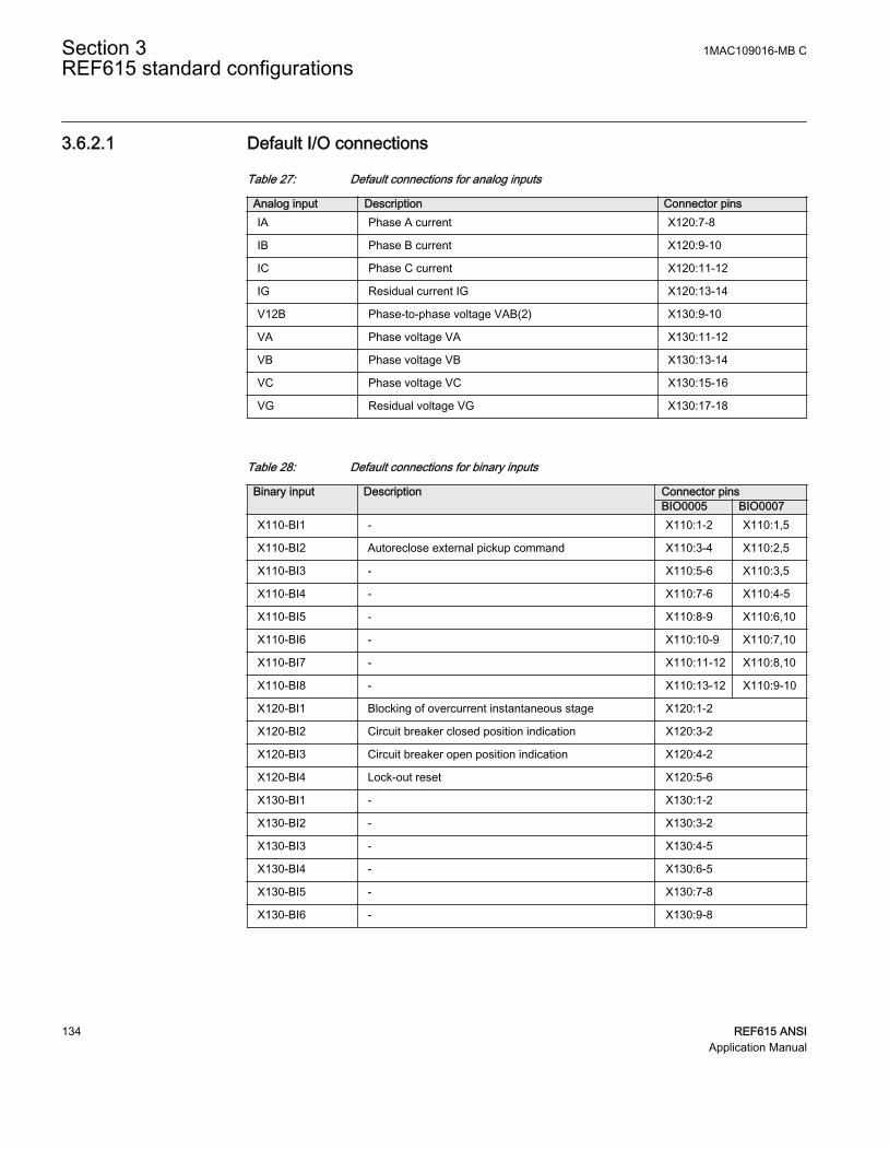
3.6.2.1 Default I/O connections
Table 27: Default connections for analog inputs
Analog input Description Connector pinsIA Phase A current X120:7-8
IB Phase B current X120:9-10
IC Phase C current X120:11-12
IG Residual current IG X120:13-14
V12B Phase-to-phase voltage VAB(2) X130:9-10
VA Phase voltage VA X130:11-12
VB Phase voltage VB X130:13-14
VC Phase voltage VC X130:15-16
VG Residual voltage VG X130:17-18
Table 28: Default connections for binary inputs
Binary input Description Connector pinsBIO0005 BIO0007
X110-BI1 - X110:1-2 X110:1,5
X110-BI2 Autoreclose external pickup command X110:3-4 X110:2,5
X110-BI3 - X110:5-6 X110:3,5
X110-BI4 - X110:7-6 X110:4-5
X110-BI5 - X110:8-9 X110:6,10
X110-BI6 - X110:10-9 X110:7,10
X110-BI7 - X110:11-12 X110:8,10
X110-BI8 - X110:13-12 X110:9-10
X120-BI1 Blocking of overcurrent instantaneous stage X120:1-2
X120-BI2 Circuit breaker closed position indication X120:3-2
X120-BI3 Circuit breaker open position indication X120:4-2
X120-BI4 Lock-out reset X120:5-6
X130-BI1 - X130:1-2
X130-BI2 - X130:3-2
X130-BI3 - X130:4-5
X130-BI4 - X130:6-5
X130-BI5 - X130:7-8
X130-BI6 - X130:9-8
Section 3 1MAC109016-MB CREF615 standard configurations
134 REF615 ANSIApplication Manual

Table 29: Default connections for binary outputs
Binary output Description Connector pinsX100-PO1 Close circuit breaker X100:6-7
X100-PO2 Circuit breaker failure protection trip to upstream breaker X100:8-9
X100-SO1 General pickup indication X100:10-11,(12)
X100-SO2 General trip indication X100:13-14
X100-PO3 Open circuit breaker/trip coil 1 X100:15-19
X100-PO4 Open circuit breaker/trip coil 2 X100:20-24
X110-SO1 Upstream overcurrent blocking X110:14-16
X110-SO2 Overcurrent trip alarm X110:17-19
X110-SO3 Ground-fault trip alarm X110:20-22
X110-SO4 Voltage protection trip alarm X110:23-24
X110-HSO1 Arc protection instance 1 trip activated X110:15-16
X110-HSO1 Arc protection instance 2 trip activated X110:19-20
X110-HSO1 Arc protection instance 3 trip activated X110:23-24
X130-SO1 - X130:10-12
X130-SO2 - X130:13-15
X130-SO3 - X130:16-18
Table 30: Default connections for LEDs
LED Default usage ID Label description1 Overcurrent protection trip LED_Overcurrent_1 Overcurrent
2 Ground-fault protection trip LED_EarthFault_1 Ground-fault
3 Sensitive ground-fault trip LED_SensitiveEarthFault_1 Sensitive ground-fault
4 Negative sequence overcurrentor phase discontinuity
LED_PhaseUnbalance_1 Phase unbalance
5 Thermal overload alarm LED_ThermalOverload_1 Thermal overload
6 Circuit breaker failureprotection backup protectiontrip
LED_BreakerFailure_1 Breaker failure
7 Disturbance recorder triggered LED_DisturbRecTriggered_1 Disturb. rec. triggered
8 Circuit breaker conditionmonitoring alarm
LED_CBConditionMonitoring_1
CB condition monitoring
9 Supervision alarm LED_TripCircuitFailure_1 Trip circuit failure
10 Arc flash detection LED_ArcDetected_1 Arc detected
11 Autoreclose in progress LED_AutorecloseInProgress_1 Autoreclose shot in progr.
1MAC109016-MB C Section 3REF615 standard configurations
REF615 ANSI 135Application Manual

3.6.2.2 Default disturbance recorder settings
Table 31: Default disturbance recorder analog channels
Channel Description1 IL1
2 IL2
3 IL3
4 Io
5 Uo
6 U1
7 U2
8 U3
9 U12B
10 -
11 -
12 -
Table 32: Default disturbance recorder binary channels
Channel ID text Level trigger mode1 PHLPTOC1 - pickup Positive or Rising
2 PHHPTOC1 - pickup Positive or Rising
3 PHLPTOC2 - pickup Positive or Rising
4 PHIPTOC1 - pickup Positive or Rising
5 NSPTOC1 - pickup Positive or Rising
6 NSPTOC2 - pickup Positive or Rising
7 EFLPTOC1 - pickup Positive or Rising
8 EFHPTOC1 - pickup Positive or Rising
9 EFIPTOC1 - pickup Positive or Rising
10 EFLPTOC2 - pickup Positive or Rising
11 - -
12 PDNSPTOC1 - pickup Positive or Rising
13 T1PTTR1 - pickup Positive or Rising
14 CCBRBRF1 - trret Level trigger off
15 CCBRBRF1 - trbu Level trigger off
16 PHxPTOC1 - trip Level trigger off
17 NSPTOC - trip Level trigger off
18 EFxPTOC1 - trip Level trigger off
Table continues on next page
Section 3 1MAC109016-MB CREF615 standard configurations
136 REF615 ANSIApplication Manual

Channel ID text Level trigger mode19 X110BI2 - ext pickup AutoReclose Level trigger off
20 EFLPTOC2 - trip Level trigger off
21 PDNSPTOC1 - trip Level trigger off
22 INRPHAR1 - blk2h Level trigger off
23 T1PTTR1 - trip Level trigger off
24 ARCSARC - ARC flt det Level trigger off
25 ARCSARC1 - trip Positive or Rising
26 ARCSARC2 - trip Positive or Rising
27 ARCSARC3 - trip Positive or Rising
28 DARREC1 - inpro Level trigger off
29 DARREC1 - close CB Level trigger off
30 DARREC1 - unsuc recl Level trigger off
31 X120BI1 - ext OC blocking Level trigger off
32 X120BI2 - CB closed Level trigger off
33 X120BI3 - CB open Level trigger off
34 PHHPTOC2 - pickup Positive or Rising
35 EFHPTOC2 - pickup Positive or Rising
36 EFHPTOC3 - pickup Positive or Rising
37 EFHPTOC4 - pickup Positive or Rising
38 EFIPTOC2 - pickup Positive or Rising
39 DUPPDPR1 - pickup Positive or Rising
40 DUPPDPR2 - pickup Positive or Rising
41 DUPPDPR1 - trip Level trigger off
42 MSVPR1 - U_LO Level trigger off
43 - -
44 - -
45 - -
46 - -
47 - -
48 - -
49 - -
50 - -
51 - -
52 - -
53 - -
54 - -
Table continues on next page
1MAC109016-MB C Section 3REF615 standard configurations
REF615 ANSI 137Application Manual

Channel ID text Level trigger mode55 - -
56 - -
57 - -
58 - -
59 - -
60 - -
61 - -
62 - -
63 - -
64 - -
3.6.3 Functional diagrams
The functional diagrams describe the default input, output, alarm LED and function-to-function connections. The default connections can be viewed and changed with PCM600according to the application requirements.
The analog channels have fixed connections to the different function blocks inside theprotection relay’s standard configuration. However, the 12 analog channels available forthe disturbance recorder function are freely selectable as a part of the disturbancerecorder’s parameter settings.
The phase currents to the protection relay are fed from a current transformer. The residualcurrent to the protection relay is fed from either residually connected CTs, an external corebalance CT, neutral CT or calculated internally.
The signal marked with IA, IB and IC represents the three phase currents. The signal IGrepresents the measured ground current.
The signal marked with VA, VB and VC represents the three phase voltages. The signalVG represents the measured ground voltage.
The protection relay offers six different setting groups which can be set based onindividual needs. Each group can be activated or deactivated using the setting groupsettings available in the protection relay.
Depending on the communication protocol the required function block needs to beinstantiated in the configuration.
Section 3 1MAC109016-MB CREF615 standard configurations
138 REF615 ANSIApplication Manual
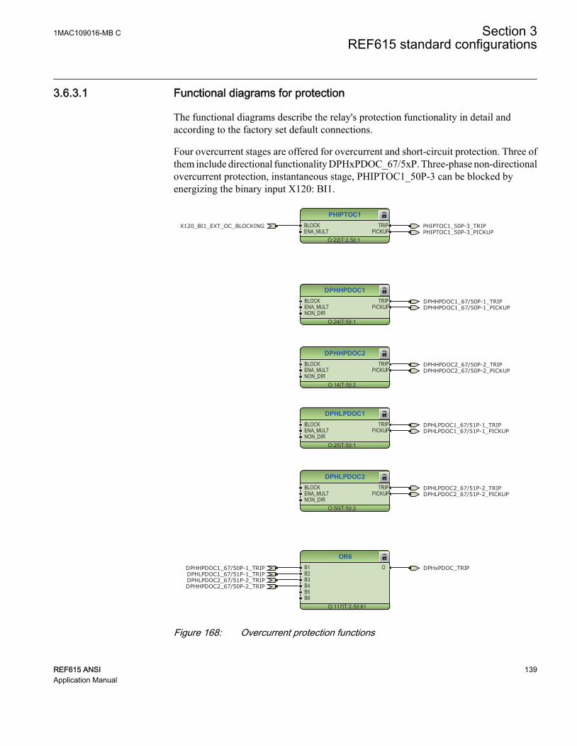
3.6.3.1 Functional diagrams for protection
The functional diagrams describe the relay's protection functionality in detail andaccording to the factory set default connections.
Four overcurrent stages are offered for overcurrent and short-circuit protection. Three ofthem include directional functionality DPHxPDOC_67/5xP. Three-phase non-directionalovercurrent protection, instantaneous stage, PHIPTOC1_50P-3 can be blocked byenergizing the binary input X120: BI1.
PHIPTOC1
O:22|T:2.5|I:1
BLOCKENA_MULT
TRIPPICKUP
DPHHPDOC1
O:24|T:5|I:1
BLOCKENA_MULTNON_DIR
TRIPPICKUP
DPHLPDOC1
O:25|T:5|I:1
BLOCKENA_MULTNON_DIR
TRIPPICKUP
DPHLPDOC2
O:50|T:5|I:2
BLOCKENA_MULTNON_DIR
TRIPPICKUP
OR6
O:117|T:2.5|I:61
B1B2B3B4B5B6
O
DPHHPDOC2
O:14|T:5|I:2
BLOCKENA_MULTNON_DIR
TRIPPICKUP
DPHHPDOC2_67/50P-2_TRIP
DPHHPDOC2_67/50P-2_TRIP
PHIPTOC1_50P-3_TRIP
DPHHPDOC1_67/50P-1_TRIP
DPHHPDOC1_67/50P-1_TRIP
DPHLPDOC1_67/51P-1_TRIP
DPHLPDOC1_67/51P-1_TRIP
DPHLPDOC2_67/51P-2_TRIP
DPHLPDOC2_67/51P-2_TRIP
PHIPTOC1_50P-3_PICKUP
DPHHPDOC1_67/50P-1_PICKUP
DPHLPDOC1_67/51P-1_PICKUP
DPHLPDOC2_67/51P-2_PICKUP
DPHHPDOC2_67/50P-2_PICKUP
X120_BI1_EXT_OC_BLOCKING
DPHxPDOC_TRIP
GUID-8293227D-FAB7-4E29-B3CF-52277091C321 V1 EN
Figure 168: Overcurrent protection functions
1MAC109016-MB C Section 3REF615 standard configurations
REF615 ANSI 139Application Manual

The upstream blocking from the pickup of the second low stage of three-phase directionalovercurrent protection DPHLPDOC2_67/51P-2 is connected to the binary outputX110:SO1. This output can be used for sending a blocking signal to the relevantovercurrent protection stage of the relay at the infeeding bay.
OR6
O:144|T:2.5|I:65
B1B2B3B4B5B6
O UPSTEAM_OC_BLOCKINGDPHLPDOC2_67/51P-2_PICKUP
GUID-521CF39B-4A35-4293-AC42-15BA90D21B36 V1 EN
Figure 169: Upstream blocking logic
The output BLK2H of three-phase inrush detector INRPHAR1_INR-1 enables eitherblocking the function or multiplying the active settings for any of the availableovercurrent or ground-fault function blocks.
INRPHAR1
O:103|T:2.5|I:1BLOCK BLK2H INRPHAR1_INR-1_BLK2H
GUID-C7820A35-3477-402F-90DC-C0C5D9992258 V1 EN
Figure 170: Inrush detector function
Two negative-sequence overcurrent protection stages NSPTOC1_46-1 andNSPTOC2_46-2 are provided for phase unbalance protection. These functions are used toprotect the feeder against phase unbalance. Both the negative-sequence overcurrentprotections are blocked in case of detection in failure in secondary circuit of currenttransformer.
NSPTOC1
O:51|T:5|I:1
BLOCKENA_MULT
TRIPPICKUP
NSPTOC2
O:52|T:5|I:2
BLOCKENA_MULT
TRIPPICKUP
NSPTOC1_46-1_TRIP
NSPTOC2_46-2_TRIP
NSPTOC1_46-1_PICKUP
NSPTOC2_46-2_PICKUP
CCSPVC1_CCM_FAIL
CCSPVC1_CCM_FAIL
GUID-3CDF9CBF-DBDC-44D0-A4CB-F8D207F22E34 V1 EN
Figure 171: Negative-sequence overcurrent protection function
Three stages are provided for directional ground-fault protection. According to the relay'sorder code, the directional ground-fault protection method can be based on conventionaldirectional ground-fault DEFxPDEF_67/5xN only or alternatively used together withadmittance-based ground-fault protection EFPADM_21YN or wattmetric-based ground-fault protection WPWDE_32N. A dedicated protection stage INTRPTEF_67NIEF is usedeither for transient-based ground-fault protection or for cable intermittent ground-fault
Section 3 1MAC109016-MB CREF615 standard configurations
140 REF615 ANSIApplication Manual

protection in compensated networks. The binary input X110:BI2 is intended forcontrolling directional ground-fault protection blocks' relay characteristic angle (RCA:0°, -90°) or operation mode (IoSinφ, IoCosφ) change. The same input is also available forwattmetric protection.
OR6
O:115|T:2.5|I:55
B1B2B3B4B5B6
O
DEFLPDEF2
O:19|T:5|I:2
BLOCKENA_MULTRCA_CTL
TRIPPICKUP
DEFLPDEF1
O:46|T:5|I:1
BLOCKENA_MULTRCA_CTL
TRIPPICKUP
DEFHPDEF1
O:18|T:5|I:1
BLOCKENA_MULTRCA_CTL
TRIPPICKUP
DEFHPDEF2
O:12|T:5|I:2
BLOCKENA_MULTRCA_CTL
TRIPPICKUP
DEFHPDEF2_67/50N-2_TRIP
DEFHPDEF2_67/50N-2_TRIP
DEFHPDEF1_67/50N-1_TRIP
DEFHPDEF1_67/50N-1_TRIP
DEFLPDEF2_67/51N-2_TRIP
DEFLPDEF2_67/51N-2_TRIP
DEFLPDEF1_67/51N-1_TRIP
DEFLPDEF1_67/51N-1_TRIP
DEFHPDEF1_67/50N-1_PICKUP
DEFLPDEF1_67/51N-1_PICKUP
DEFLPDEF2_67/51N-2_PICKUP
DEFHPDEF2_67/50N-2_PICKUP
DEFxPDEF_TRIP
CCSPVC1_CCM_FAIL
CCSPVC1_CCM_FAIL
CCSPVC1_CCM_FAIL
CCSPVC1_CCM_FAIL
GUID-E70FF7C3-5F0C-42B7-95A4-03F5BAC401ED V1 EN
Figure 172: Directional ground-fault protection function
EFHPTOC1
O:13|T:5|I:1
BLOCKENA_MULT
TRIPPICKUP
EFHPTOC1_50G-1_TRIPEFHPTOC1_50G-1_PICKUP
GUID-CEA9A04E-6E6B-4849-9989-619E68D65067 V1 EN
Figure 173: Non-directional ground-fault protection
1MAC109016-MB C Section 3REF615 standard configurations
REF615 ANSI 141Application Manual

INTRPTEF1
O:44|T:2.5|I:1
BLOCK TRIPPICKUPBLK_EF
INTRPTEF1_67NIEF_TRIPINTRPTEF1_67NIEF_PICKUP
GUID-1CD1898F-9445-430B-B7D0-460030C5BBA5 V1 EN
Figure 174: Transient or intermittent ground-fault protection functions
WPWDE1
O:49|T:5|I:1
BLOCKRCA_CTL
TRIPPICKUP
WPWDE2
O:20|T:5|I:2
BLOCKRCA_CTL
TRIPPICKUP
WPWDE3
O:17|T:5|I:3
BLOCKRCA_CTL
TRIPPICKUP
OR6
O:116|T:2.5|I:54
B1B2B3B4B5B6
O
WPWDE3_32N-3_TRIP
WPWDE3_32N-3_TRIP
WPWDE2_32N-2_TRIP
WPWDE2_32N-2_TRIP
WPWDE1_32N-1_TRIP
WPWDE1_32N-1_TRIP
WPWDE1_32N-1_PICKUP
WPWDE2_32N-2_PICKUP
WPWDE3_32N-3_PICKUP
WPWDE_TRIP
GUID-B94F6AEC-0371-44AF-AA58-9D24105A14FD V1 EN
Figure 175: Wattmetric protection function
Section 3 1MAC109016-MB CREF615 standard configurations
142 REF615 ANSIApplication Manual

EFPADM1
O:48|T:5|I:1
BLOCKRELEASE
TRIPPICKUP
EFPADM2
O:15|T:5|I:2
BLOCKRELEASE
TRIPPICKUP
EFPADM3
O:16|T:5|I:3
BLOCKRELEASE
TRIPPICKUP
OR6
O:114|T:2.5|I:56
B1B2B3B4B5B6
O
EFPADM2_21YN-2_TRIP
EFPADM2_21YN-2_TRIP
EFPADM3_21YN-3_TRIP
EFPADM3_21YN-3_TRIP
EFPADM1_21YN-1_TRIP
EFPADM1_21YN-1_TRIP
EFPADM1_21YN-1_PICKUP
EFPADM2_21YN-2_PICKUP
EFPADM3_21YN-3_PICKUP
EFPADM_TRIP
GUID-2B9E897B-DD34-4545-8DA1-CB80D2491960 V1 EN
Figure 176: Admittance-based ground-fault protection function
Phase discontinuity protection PDNSPTOC1_46PD protects for interruptions in thenormal three-phase load supply, for example, in downed conductor situations. Thefunction is blocked in case of detection of a failure in secondary circuit of voltagetransformer.
PDNSPTOC1
O:32|T:5|I:1
BLOCK TRIPPICKUP
PDNSPTOC1_46PD_TRIPPDNSPTOC1_46PD_PICKUP
CCSPVC1_CCM_FAIL
GUID-BA190033-3A47-42A2-8CF2-CF1171E90D6A V1 EN
Figure 177: Phase discontinuity protection
Three-phase thermal protection for feeders, cables and distribution transformersT1PTTR1_49F detects overloads under varying load conditions. The BLK_CLOSEoutput of the function is used to block the closing operation of circuit breaker.
T1PTTR1
O:33|T:5|I:1
BLOCKENA_MULTAMB_TEMP
TRIPPICKUPALARM
BLK_CLOSE T1PTTR1_49F_BLK_CLOSE
T1PTTR1_49F_TRIPT1PTTR1_49F_PICKUPT1PTTR1_49F_ALARM
GUID-7FB3A140-185F-40E3-AE77-CE80E262E940 V1 EN
Figure 178: Thermal overcurrent protection function
1MAC109016-MB C Section 3REF615 standard configurations
REF615 ANSI 143Application Manual

Circuit breaker failure protection CCBRBRF1_50BF-1 is initiated via the PICKUP inputby number of different protection functions available in the relay. The breaker failureprotection function offers different operating modes associated with the circuit breakerposition and the measured phase and residual currents.
The circuit breaker failure protection function has two operating outputs: TRRET andTRBU. The TRRET trip output is used for retripping its own breaker throughTRPPTRC2_86/94-2_TRIP. The TRBU output is used to give a backup trip to the breakerfeeding upstream. For this purpose, the TRBU trip output signal is connected to the binaryoutput X100:PO2.
CCBRBRF1
O:39|T:2.5|I:1
BLOCKPICKUPPOSCLOSECB_FAULT
CB_FAULT_ALTRBU
TRRET
OR6
O:29|T:2.5|I:0
B1B2B3B4B5B6
O
OR6
O:28|T:2.5|I:1
B1B2B3B4B5B6
O
OR6
O:31|T:2.5|I:2
B1B2B3B4B5B6
O
OR6
O:27|T:2.5|I:5
B1B2B3B4B5B6
O
CCBRBRF1_50BF-1_TRBUX120_BI2_CB_CLOSED
PHIPTOC1_50P-3_TRIPDPHHPDOC1_67/50P-1_TRIPDPHLPDOC1_67/51P-1_TRIP
DEFHPDEF1_67/50N-1_TRIPDEFLPDEF2_67/51N-2_TRIP
EFPADM2_21YN-2_TRIPEFPADM3_21YN-3_TRIP
EFHPTOC1_50G-1_TRIP
WPWDE3_32N-3_TRIPWPWDE2_32N-2_TRIP
ARCSARC3_AFD-3_TRIPARCSARC2_AFD-2_TRIPARCSARC1_AFD-1_TRIP
CCBRBRF1_50BF-1_TRRET
DEFHPDEF2_67/50N-2_TRIPDPHHPDOC2_67/50P-2_TRIP
GUID-B60DAF56-FF58-4F94-8E1B-3251CB861195 V1 EN
Figure 179: Circuit breaker failure protection function
Three arc protection stages ARCSARC-1…3_AFD-1...3 are included as an optionalfunction. The arc protection offers individual function blocks for three arc sensors that canbe connected to the relay. Each arc protection function block has two different operationmodes, that is, with or without the phase and residual current check.
The trip signals from ARCSARC-1…3AFD-1...3 are connected to both trip logicTRPPTRC1_86/94-1 and TRPPTRC2_86/94-2.
Section 3 1MAC109016-MB CREF615 standard configurations
144 REF615 ANSIApplication Manual

ARCSARC1
O:23|T:2.5|I:11
BLOCKREM_FLT_ARCOPR_MODE
TRIPARC_FLT_DET
ARCSARC2
O:21|T:2.5|I:21
BLOCKREM_FLT_ARCOPR_MODE
TRIPARC_FLT_DET
ARCSARC3
O:26|T:2.5|I:31
BLOCKREM_FLT_ARCOPR_MODE
TRIPARC_FLT_DET
OR6
O:75|T:2.5|I:18
B1B2B3B4B5B6
O
ARCSARC3_AFD-3_TRIP
ARCSARC3_AFD-3_TRIP
ARCSARC2_AFD-2_TRIP
ARCSARC2_AFD-2_TRIP
ARCSARC1_AFD-1_TRIP
ARCSARC1_AFD-1_TRIP ARCSARC_TRIP
ARCSARC3_AFD-3_ARC_FLT_DET
ARCSARC2_AFD-2_ARC_FLT_DET
ARCSARC1_AFD-1_ARC_FLT_DET
GUID-8435F618-4DC9-4F4B-91E4-760201BD567F V1 EN
Figure 180: Arc protection
The optional autoreclosing function is configured to be initiated by trip signals from anumber of protection stages through the INIT_1...5 inputs. It is possible to createindividual autoreclose sequences for each input.
The autoreclosing function can be inhibited with the INHIBIT_RECL input. By default,few selected protection function operations are connected to this input. A controlcommand to the circuit breaker, either local or remote, also blocks the autoreclosingfunction via the CBXCBR1_52-1_SELECTED signal.
The circuit breaker availability for the autoreclosing sequence is expressed with theCB_READY input in DARREC1_79. This signal is not connected in the configuration.
The open command from the autorecloser is connected directly to binary outputX100:PO3, whereas the close command is connected directly to binary output X100:PO1.
Set the parameters for DARREC1_79 properly.
1MAC109016-MB C Section 3REF615 standard configurations
REF615 ANSI 145Application Manual

Check the initialization signals of DARREC1_79.
DARREC1
O:80|T:2.5|I:1
INIT_1INIT_2INIT_3INIT_4INIT_5INIT_6DEL_INIT_2DEL_INIT_3DEL_INIT_4BLK_RECL_TBLK_RCLM_TBLK_THERMCB_POSCB_READYINC_SHOTPINHIBIT_RECLRECL_ONSYNC
OPEN_CBCLOSE_CBCMD_WAIT
INPROLOCKED OUT
PROT_CRDUNSUC_RECL
AR_ONREADYACTIVE
OR6
O:78|T:2.5|I:10
B1B2B3B4B5B6
O
OR6
O:76|T:2.5|I:21
B1B2B3B4B5B6
O
OR6
O:77|T:2.5|I:20
B1B2B3B4B5B6
O
X120_BI3_CB_OPEN
DARREC1_79_CLOSE_CBDARREC1_79_OPEN_CBPHIPTOC1_50P-3_TRIP
DPHHPDOC1_67/50P-1_TRIPDPHLPDOC2_67/51P-2_TRIP
NSPTOC1_46-1_TRIPNSPTOC2_46-2_TRIP
DEFHPDEF1_67/50N-1_TRIP
DEFLPDEF2_67/51N-2_TRIPEFPADM2_21YN-2_TRIP
EFPADM3_21YN-3_TRIP
INTRPTEF1_67NIEF_TRIP
WPWDE3_32N-3_TRIP
WPWDE2_32N-2_TRIP
PDNSPTOC1_46PD_TRIP
ARCSARC_TRIP
CBXCBR1_52-1_SELECTED
X110_BI2_EXT_PICKUP_AUTORECLOSE
DARREC1_79_INPRO
DARREC1_79_UNSUC_RECL
GUID-3152CEA3-34AD-45F6-8F61-BC5B99B34402 V1 EN
Figure 181: Autoreclosing function
Three overvoltage and undervoltage protection stages PHPTOV_59 and PHPTUV_27offer protection against abnormal phase voltage conditions. Positive-sequenceundervoltage protection PSPTUV_47U and negative-sequence overvoltage protectionNSPTOV_47 enable voltage-based unbalance protection. A failure in the voltagemeasuring circuit is detected by the fuse failure function. The activation is connected toblock undervoltage protection functions and voltage based unbalance protectionfunctions to avoid faulty tripping.
Section 3 1MAC109016-MB CREF615 standard configurations
146 REF615 ANSIApplication Manual

PHPTOV1
O:36|T:5|I:1
BLOCK TRIPPICKUP
PHPTOV2
O:41|T:5|I:2
BLOCK TRIPPICKUP
PHPTOV3
O:34|T:5|I:3
BLOCK TRIPPICKUP
OR6
O:131|T:2.5|I:58
B1B2B3B4B5B6
O
PHPTOV3_59-3_TRIP
PHPTOV3_59-3_TRIP
PHPTOV2_59-2_TRIP
PHPTOV2_59-2_TRIP
PHPTOV1_59-1_TRIP
PHPTOV1_59-1_TRIP
PHPTOV1_59-1_PICKUP
PHPTOV2_59-2_PICKUP
PHPTOV3_59-3_PICKUP
PHPTOV_TRIP
GUID-B7D861D1-C660-4B5A-8F73-0C0A2B8FB2A6 V1 EN
Figure 182: Overvoltage protection function
1MAC109016-MB C Section 3REF615 standard configurations
REF615 ANSI 147Application Manual

PHPTUV1
O:40|T:5|I:1
BLOCK TRIPPICKUP
PHPTUV2
O:42|T:5|I:2
BLOCK TRIPPICKUP
PHPTUV3
O:38|T:5|I:3
BLOCK TRIPPICKUP
OR6
O:132|T:2.5|I:39
B1B2B3B4B5B6
O
PHPTUV3_27-3_TRIP
PHPTUV3_27-3_TRIP
PHPTUV2_27-2_TRIP
PHPTUV2_27-2_TRIP
PHPTUV1_27-1_TRIP
PHPTUV1_27-1_TRIP
PHPTUV1_27-1_PICKUP
PHPTUV2_27-2_PICKUP
PHPTUV3_27-3_PICKUP
PHPTUV_TRIP
SEQSPVC1_60-1_FUSEF_U
SEQSPVC1_60-1_FUSEF_U
SEQSPVC1_60-1_FUSEF_U
GUID-5A14EE55-812F-4791-AD1E-DF0E958AC785 V1 EN
Figure 183: Undervoltage protection function
NSPTOV1
O:37|T:5|I:1
BLOCK TRIPPICKUP
NSPTOV1_47-1_TRIPNSPTOV1_47-1_PICKUP
SEQSPVC1_60-1_FUSEF_U
GUID-8378A87F-C340-43D6-A676-49AC56ACBE45 V1 EN
Figure 184: Negative-sequence overvoltage protection function
PSPTUV1
O:35|T:5|I:1
BLOCK TRIPPICKUP
PSPTUV1_47U-1_TRIPPSPTUV1_47U-1_PICKUP
SEQSPVC1_60-1_FUSEF_U
GUID-A4E21DBC-9431-45E9-8A8E-3F5B9EBC6F35 V1 EN
Figure 185: Positive-sequence undervoltage protection function
The residual overvoltage protection ROVPTOV_59G,59N provides ground-faultprotection by detecting an abnormal level of residual voltage. It can be used, for example,as a nonselective backup protection for the selective directional ground-faultfunctionality.
Section 3 1MAC109016-MB CREF615 standard configurations
148 REF615 ANSIApplication Manual

ROVPTOV1
O:47|T:5|I:1
BLOCK TRIPPICKUP
ROVPTOV2
O:43|T:5|I:2
BLOCK TRIPPICKUP
ROVPTOV3
O:45|T:5|I:3
BLOCK TRIPPICKUP
OR6
O:121|T:2.5|I:60
B1B2B3B4B5B6
O
ROVPTOV3_59N-2_TRIP
ROVPTOV3_59N-2_TRIP
ROVPTOV2_59N-1_TRIP
ROVPTOV2_59N-1_TRIP
ROVPTOV1_59G_TRIP
ROVPTOV1_59G_TRIP
ROVPTOV1_59G_PICKUP
ROVPTOV2_59N-1_PICKUP
ROVPTOV3_59N-2_PICKUP
ROVPTOV_TRIP
SEQSPVC1_60-1_FUSEF_U
SEQSPVC1_60-1_FUSEF_U
GUID-A36F8662-BEC9-473D-BF21-1FACEAE6220F V1 EN
Figure 186: Residual voltage protection function
MSVPR1
O:90|T:2.5|I:1BLOCK U_LOW MSVPR1_27R-1_U_LOW
GUID-68AA55AA-FBE5-42A1-86B9-ECECAACCCE3B V1 EN
Figure 187: Three-phase remnant undervoltage protection function
General pickup and trip from all the functions are connected to minimum pulse timerTPGAPC1 for setting the minimum pulse length for the outputs. The output fromTPGAPC1 is connected to binary outputs.
1MAC109016-MB C Section 3REF615 standard configurations
REF615 ANSI 149Application Manual

TPGAPC1
O:130|T:2.5|I:1
IN1IN2
OUT1OUT2
OR6
O:128|T:2.5|I:53
B1B2B3B4B5B6
O
OR20
O:127|T:2.5|I:6
B1B2B3B4B5B6B7B8B9B10B11B12B13B14B15B16B17B18B19B20
O
OR20
O:126|T:2.5|I:7
B1B2B3B4B5B6B7B8B9B10B11B12B13B14B15B16B17B18B19B20
O
OR20
O:125|T:2.5|I:10
B1B2B3B4B5B6B7B8B9B10B11B12B13B14B15B16B17B18B19B20
O
OR20
O:124|T:2.5|I:9
B1B2B3B4B5B6B7B8B9B10B11B12B13B14B15B16B17B18B19B20
O
OR6
O:129|T:2.5|I:3
B1B2B3B4B5B6
O
GENERAL_PICKUP_PULSEGENERAL_TRIP_PULSE
PHIPTOC1_50P-3_TRIPDPHHPDOC1_67/50P-1_TRIPDPHLPDOC1_67/51P-1_TRIPDPHLPDOC2_67/51P-2_TRIP
NSPTOC1_46-1_TRIPNSPTOC2_46-2_TRIP
DEFHPDEF1_67/50N-1_TRIP
DEFLPDEF2_67/51N-2_TRIPDEFLPDEF1_67/51N-1_TRIP
EFPADM2_21YN-2_TRIPEFPADM3_21YN-3_TRIP
EFPADM1_21YN-1_TRIP
EFHPTOC1_50G-1_TRIPINTRPTEF1_67NIEF_TRIP
WPWDE3_32N-3_TRIPWPWDE2_32N-2_TRIPWPWDE1_32N-1_TRIP
PDNSPTOC1_46PD_TRIP
PHPTUV3_27-3_TRIPPHPTUV2_27-2_TRIPPHPTUV1_27-1_TRIPNSPTOV1_47-1_TRIP
PSPTUV1_47U-1_TRIPPHPTOV3_59-3_TRIPPHPTOV2_59-2_TRIPPHPTOV1_59-1_TRIP
PHIPTOC1_50P-3_PICKUPDPHHPDOC1_67/50P-1_PICKUPDPHLPDOC1_67/51P-1_PICKUPDPHLPDOC2_67/51P-2_PICKUP
NSPTOC1_46-1_PICKUPNSPTOC2_46-2_PICKUP
DEFHPDEF1_67/50N-1_PICKUPDEFLPDEF1_67/51N-1_PICKUPDEFLPDEF2_67/51N-2_PICKUP
EFPADM1_21YN-1_PICKUPEFPADM2_21YN-2_PICKUPEFPADM3_21YN-3_PICKUP
WPWDE1_32N-1_PICKUPWPWDE2_32N-2_PICKUPWPWDE3_32N-3_PICKUP
INTRPTEF1_67NIEF_PICKUPEFHPTOC1_50G-1_PICKUP
PDNSPTOC1_46PD_PICKUPPHPTOV1_59-1_PICKUPPHPTOV2_59-2_PICKUPPHPTOV3_59-3_PICKUP
PSPTUV1_47U-1_PICKUPNSPTOV1_47-1_PICKUPPHPTUV1_27-1_PICKUPPHPTUV2_27-2_PICKUPPHPTUV3_27-3_PICKUP
DEFHPDEF2_67/50N-2_PICKUP
ARCSARC2_AFD-2_TRIP
DPHHPDOC2_67/50P-2_TRIP
ARCSARC1_AFD-1_TRIP
DPHHPDOC2_67/50P-2_PICKUP
ARCSARC3_AFD-3_TRIP
T1PTTR1_49F_TRIP
T1PTTR1_49F_PICKUP
DEFHPDEF2_67/50N-2_TRIP
ROVPTOV1_59G_PICKUPROVPTOV2_59N-1_PICKUPROVPTOV3_59N-2_PICKUP
ROVPTOV1_59G_TRIPROVPTOV2_59N-1_TRIPROVPTOV3_59N-2_TRIP
GUID-C663443E-751F-4608-B8AF-B78EC13414D4 V1 EN
Figure 188: General pickup and trip signals
The trip signals from the protection functions are connected to the two trip logicsTRPPTRC1_86/94-1 and TRPPTRC2_86/94-2. The output of these trip logic functionsare available at binary outputs X100:PO3 and X100:PO4. Both the trip logic functions areprovided with lockout and latching function, event generation and the trip signal durationsetting. If the lockout operation mode is selected, binary input has been assigned toRST_LKOUT input of both the trip logic to enable external reset with a push button.
Three other trip logics TRPPTRC3...5_86/94-3…5 are also available if the relay isordered with high speed binary outputs options.
Section 3 1MAC109016-MB CREF615 standard configurations
150 REF615 ANSIApplication Manual

TRPPTRC1
O:63|T:2.5|I:1
BLOCKTRIPRST_LKOUT
TRIPCL_LKOUT
OR6
O:59|T:2.5|I:16
B1B2B3B4B5B6
O
OR20
O:56|T:2.5|I:0
B1B2B3B4B5B6B7B8B9B10B11B12B13B14B15B16B17B18B19B20
O
OR20
O:55|T:2.5|I:1
B1B2B3B4B5B6B7B8B9B10B11B12B13B14B15B16B17B18B19B20
O
TRPPTRC1_86/94-1_TRIP
PHIPTOC1_50P-3_TRIPDPHHPDOC1_67/50P-1_TRIPDPHLPDOC1_67/51P-1_TRIPDPHLPDOC2_67/51P-2_TRIP
NSPTOC1_46-1_TRIPNSPTOC2_46-2_TRIP
DEFHPDEF1_67/50N-1_TRIP
DEFLPDEF2_67/51N-2_TRIPDEFLPDEF1_67/51N-1_TRIP
EFPADM2_21YN-2_TRIPEFPADM3_21YN-3_TRIP
EFPADM1_21YN-1_TRIP
EFHPTOC1_50G-1_TRIPINTRPTEF1_67NIEF_TRIP
WPWDE3_32N-3_TRIPWPWDE2_32N-2_TRIPWPWDE1_32N-1_TRIP
PDNSPTOC1_46PD_TRIP
PHPTUV3_27-3_TRIPPHPTUV2_27-2_TRIPPHPTUV1_27-1_TRIPNSPTOV1_47-1_TRIP
PSPTUV1_47U-1_TRIPPHPTOV3_59-3_TRIPPHPTOV2_59-2_TRIPPHPTOV1_59-1_TRIP
X120_BI4_RST_LOCKOUT
ARCSARC3_AFD-3_TRIPARCSARC2_AFD-2_TRIP
T1PTTR1_49F_TRIPARCSARC1_AFD-1_TRIP
DPHHPDOC2_67/50P-2_TRIPDEFHPDEF2_67/50N-2_TRIP
ROVPTOV1_59G_TRIPROVPTOV2_59N-1_TRIPROVPTOV3_59N-2_TRIP
GUID-B77FE9D7-813C-4BF5-BC0C-A5B3045310D9 V1 EN
Figure 189: Trip logic TRPPTRC1
1MAC109016-MB C Section 3REF615 standard configurations
REF615 ANSI 151Application Manual

OR6
O:58|T:2.5|I:8
B1B2B3B4B5B6
O
TRPPTRC2
O:62|T:2.5|I:2
BLOCKTRIPRST_LKOUT
TRIPCL_LKOUT
OR20
O:54|T:2.5|I:3
B1B2B3B4B5B6B7B8B9B10B11B12B13B14B15B16B17B18B19B20
O
OR20
O:53|T:2.5|I:4
B1B2B3B4B5B6B7B8B9B10B11B12B13B14B15B16B17B18B19B20
O
TRPPTRC2_86/94-2_TRIP
PHIPTOC1_50P-3_TRIPDPHHPDOC1_67/50P-1_TRIPDPHLPDOC1_67/51P-1_TRIPDPHLPDOC2_67/51P-2_TRIP
NSPTOC1_46-1_TRIPNSPTOC2_46-2_TRIP
DEFHPDEF1_67/50N-1_TRIP
DEFLPDEF2_67/51N-2_TRIPDEFLPDEF1_67/51N-1_TRIP
EFPADM2_21YN-2_TRIPEFPADM3_21YN-3_TRIP
EFPADM1_21YN-1_TRIP
EFHPTOC1_50G-1_TRIPINTRPTEF1_67NIEF_TRIP
WPWDE3_32N-3_TRIPWPWDE2_32N-2_TRIPWPWDE1_32N-1_TRIP
PDNSPTOC1_46PD_TRIP
PHPTUV3_27-3_TRIPPHPTUV2_27-2_TRIPPHPTUV1_27-1_TRIPNSPTOV1_47-1_TRIP
PSPTUV1_47U-1_TRIPPHPTOV3_59-3_TRIPPHPTOV2_59-2_TRIPPHPTOV1_59-1_TRIP
X120_BI4_RST_LOCKOUT
ARCSARC3_AFD-3_TRIP
ARCSARC1_AFD-1_TRIP
CCBRBRF1_50BF-1_TRRET
ARCSARC2_AFD-2_TRIP
DPHHPDOC2_67/50P-2_TRIPDEFHPDEF2_67/50N-2_TRIP
T1PTTR1_49F_TRIP
ROVPTOV1_59G_TRIPROVPTOV2_59N-1_TRIPROVPTOV3_59N-2_TRIP
GUID-E09FA3BE-B039-475C-BFEC-8DA052F412EE V1 EN
Figure 190: Trip logic TRPPTRC2
TRPPTRC3
O:143|T:2.5|I:3
BLOCKTRIPRST_LKOUT
TRIPCL_LKOUT
TRPPTRC4
O:141|T:2.5|I:4
BLOCKTRIPRST_LKOUT
TRIPCL_LKOUT
TRPPTRC5
O:142|T:2.5|I:5
BLOCKTRIPRST_LKOUT
TRIPCL_LKOUT
TRPPTRC3_86/94-3_TRIP
TRPPTRC4_86/94-4_TRIP
TRPPTRC5_86/94-5_TRIPARCSARC3_AFD-3_TRIP
ARCSARC2_AFD-2_TRIP
ARCSARC1_AFD-1_TRIPX120_BI4_RST_LOCKOUT
X120_BI4_RST_LOCKOUT
X120_BI4_RST_LOCKOUT
GUID-23260E96-EB14-4D3D-AE0D-5DD908D87E7A V1 EN
Figure 191: Trip logic TRPPTRC3/4/5
Section 3 1MAC109016-MB CREF615 standard configurations
152 REF615 ANSIApplication Manual

3.6.3.2 Functional diagrams for disturbance recorder
The PICKUP and TRIP outputs from the protection stages are routed to trigger thedisturbance recorder or, alternatively, only to be recorded by the disturbance recorderdepending on the parameter settings. Additionally, the selected signals from differentfunctions and the few binary inputs are also connected to the disturbance recorder.
RDRE1
O:104|T:2.5|I:1
C1C2C3C4C5C6C7C8C9C10C11C12C13C14C15C16C17C18C19C20C21C22C23C24C25C26C27C28C29C30C31C32C33C34C35C36C37C38C39C40C41C42C43C44C45C46C47C48C49C50C51C52C53C54C55C56C57C58C59C60C61C62C63C64
TRIGGERED
OR6
O:94|T:2.5|I:33
B1B2B3B4B5B6
O
OR6
O:97|T:2.5|I:29
B1B2B3B4B5B6
O
OR
O:101|T:2.5|I:4
B1B2
O
OR6
O:96|T:2.5|I:31
B1B2B3B4B5B6
O
OR6
O:99|T:2.5|I:27
B1B2B3B4B5B6
O
OR6
O:92|T:2.5|I:35
B1B2B3B4B5B6
O
OR6
O:88|T:2.5|I:26
B1B2B3B4B5B6
O
OR6
O:89|T:2.5|I:25
B1B2B3B4B5B6
O
OR6
O:98|T:2.5|I:28
B1B2B3B4B5B6
O
OR6
O:95|T:2.5|I:32
B1B2B3B4B5B6
O
OR6
O:93|T:2.5|I:34
B1B2B3B4B5B6
O
OR
O:102|T:2.5|I:14
B1B2
O
OR
O:100|T:2.5|I:5
B1B2
O
OR6
O:91|T:2.5|I:4
B1B2B3B4B5B6
O CCBRBRF1_50BF-1_TRBU
X120_BI3_CB_OPENX120_BI2_CB_CLOSED
DARREC1_79_CLOSE_CB
PHIPTOC1_50P-3_TRIPDPHHPDOC1_67/50P-1_TRIPDPHLPDOC1_67/51P-1_TRIPDPHLPDOC2_67/51P-2_TRIP
NSPTOC1_46-1_TRIPNSPTOC2_46-2_TRIP
DEFHPDEF1_67/50N-1_TRIP
DEFLPDEF2_67/51N-2_TRIPDEFLPDEF1_67/51N-1_TRIP
EFPADM2_21YN-2_TRIPEFPADM3_21YN-3_TRIP
EFPADM1_21YN-1_TRIP
EFHPTOC1_50G-1_TRIP
INTRPTEF1_67NIEF_TRIP
WPWDE3_32N-3_TRIPWPWDE2_32N-2_TRIPWPWDE1_32N-1_TRIP
PDNSPTOC1_46PD_TRIP
ARCSARC3_AFD-3_TRIPARCSARC2_AFD-2_TRIPARCSARC1_AFD-1_TRIP
T1PTTR1_49F_TRIP
PHPTUV3_27-3_TRIPPHPTUV2_27-2_TRIPPHPTUV1_27-1_TRIP
NSPTOV1_47-1_TRIPPSPTUV1_47U-1_TRIP
PHPTOV3_59-3_TRIPPHPTOV2_59-2_TRIPPHPTOV1_59-1_TRIP
CCBRBRF1_50BF-1_TRRET
PHIPTOC1_50P-3_PICKUPDPHHPDOC1_67/50P-1_PICKUP
DPHLPDOC1_67/51P-1_PICKUPDPHLPDOC2_67/51P-2_PICKUP
NSPTOC1_46-1_PICKUPNSPTOC2_46-2_PICKUP
DEFHPDEF1_67/50N-1_PICKUP
DEFLPDEF1_67/51N-1_PICKUP
DEFLPDEF2_67/51N-2_PICKUP
EFPADM1_21YN-1_PICKUP
EFPADM2_21YN-2_PICKUP
EFPADM3_21YN-3_PICKUP
WPWDE1_32N-1_PICKUP
WPWDE2_32N-2_PICKUP
WPWDE3_32N-3_PICKUP
INTRPTEF1_67NIEF_PICKUPEFHPTOC1_50G-1_PICKUPPDNSPTOC1_46PD_PICKUP
PHPTOV1_59-1_PICKUPPHPTOV2_59-2_PICKUPPHPTOV3_59-3_PICKUP
PSPTUV1_47U-1_PICKUPNSPTOV1_47-1_PICKUPPHPTUV1_27-1_PICKUPPHPTUV2_27-2_PICKUPPHPTUV3_27-3_PICKUP
T1PTTR1_49F_PICKUP
DPHHPDOC2_67/50P-2_PICKUP
DEFHPDEF2_67/50N-2_PICKUP
INRPHAR1_INR-1_BLK2H
DARREC1_79_INPRO
DARREC1_79_UNSUC_RECL
ARCSARC3_AFD-3_ARC_FLT_DETARCSARC2_AFD-2_ARC_FLT_DETARCSARC1_AFD-1_ARC_FLT_DET
MSVPR1_27R-1_U_LOW
SEQSPVC1_60-1_FUSEF_3PHSEQSPVC1_60-1_FUSEF_U
CCSPVC1_CCM_FAIL
DISTURB_RECORD_TRIGGERED
DEFHPDEF2_67/50N-2_TRIP
DPHHPDOC2_67/50P-2_TRIP
ROVPTOV1_59G_PICKUPROVPTOV2_59N-1_PICKUPROVPTOV3_59N-2_PICKUP
ROVPTOV1_59G_TRIPROVPTOV2_59N-1_TRIPROVPTOV3_59N-2_TRIP
GUID-095C7BD8-A98D-4935-8537-9744E02C93A2 V1 EN
Figure 192: Disturbance recorder
3.6.3.3 Functional diagrams for condition monitoring
Failures in current measuring circuits are detected by CCSPVC1_CCM. When a failure isdetected, it can be used to block the current protection functions that are measuring thecalculated sequence component currents or residual current to avoid unnecessaryoperation.
1MAC109016-MB C Section 3REF615 standard configurations
REF615 ANSI 153Application Manual

CCSPVC1
O:11|T:2.5|I:1
BLOCK FAILALARM
CCSPVC1_CCM_FAILCCSPVC1_CCM_ALARM
GUID-A148941E-8D92-4DDB-B497-20582B8FD341 V1 EN
Figure 193: Current circuit supervision function
The fuse failure supervision SEQSPVC1_60-1 detects failures in the voltagemeasurement circuits. Failures, such as an open MCB, raise an alarm.
SEQSPVC1
O:30|T:2.5|I:1
BLOCKCB_CLOSEDDISCON_OPENMINCB_OPEN
FUSEF_3PHFUSEF_VX120_BI2_CB_CLOSED
SEQSPVC1_60-1_FUSEF_3PHSEQSPVC1_60-1_FUSEF_U
GUID-ED37B113-A207-4CE2-9C10-72258E3DF7ED V1 EN
Figure 194: Fuse failure supervision function
Circuit-breaker condition monitoring SSCBR1_52CM-1 supervises the switch statusbased on the connected binary input information and the measured current levels.SSCBR1_52CM-1 introduces various supervision methods.
Set the parameters for SSCBR1_52CM-1 properly.
SSCBR1
O:83|T:5|I:1
BLOCKPOSOPENPOSCLOSEOPEN_CB_EXECLOSE_CB_EXEPRES_ALM_INPRES_LO_INSPR_CHR_STSPR_CHRRST_IPOWRST_CB_WEARRST_TRV_TRST_SPR_T
TRV_T_OP_ALMTRV_T_CL_ALMSPR_CHR_ALM
OPR_ALMOPR_LO
IPOW_ALMIPOW_LO
CB_LIFE_ALMMON_ALM
PRES_ALMPRES_LO
OPENPOSINVALIDPOSCLOSEPOS
CB_CLOSE_COMMANDCB_OPEN_COMMAND
X120_BI3_CB_OPENX120_BI2_CB_CLOSED
SSCBR1_52CM-1_TRV_T_OP_ALMSSCBR1_52CM-1_TRV_T_CL_ALMSSCBR1_52CM-1_SPR_CHR_ALMSSCBR1_52CM-1_OPR_ALMSSCBR1_52CM-1_OPR_LOSSCBR1_52CM-1_IPOW_ALMSSCBR1_52CM-1_IPOW_LOSSCBR1_52CM-1_CB_LIFE_ALMSSCBR1_52CM-1_MON_ALMSSCBR1_52CM-1_PRES_ALMSSCBR1_52CM-1_PRES_LO
GUID-91B90F36-39AB-4349-AA02-3D32B2F3A94B V1 EN
Figure 195: Circuit-breaker condition monitoring function
Section 3 1MAC109016-MB CREF615 standard configurations
154 REF615 ANSIApplication Manual

OR
O:86|T:2.5|I:11
B1B2
O
OR6
O:84|T:2.5|I:15
B1B2B3B4B5B6
O
OR6
O:85|T:2.5|I:14
B1B2B3B4B5B6
O
SSCBR1_52CM-1_TRV_T_OP_ALMSSCBR1_52CM-1_TRV_T_CL_ALMSSCBR1_52CM-1_SPR_CHR_ALM
SSCBR1_52CM-1_OPR_ALMSSCBR1_52CM-1_OPR_LO
SSCBR1_52CM-1_IPOW_ALM
SSCBR1_52CM-1_IPOW_LOSSCBR1_52CM-1_CB_LIFE_ALM
SSCBR1_52CM-1_MON_ALMSSCBR1_52CM-1_PRES_ALM
SSCBR1_52CM-1_PRES_LO
SSCBR1_52CM-1_ALARMS
GUID-E99EC5B6-CE3A-4837-A85C-811244F62BE0 V1 EN
Figure 196: Logic for circuit breaker monitoring alarm
Two separate trip circuit supervision functions are included: TCSSCBR1_TCM-1 forpower output X100:PO3 and TCSSCBR2_TCM-2 for power output X100:PO4. Both thefunctions are blocked by the master trip TRPPTRC1_86/94-1 and TRPPTRC2_86/94-2and the circuit breaker open signal.
It is assumed that there is no external resistor in the circuit breaker trippingcoil circuit connected in parallel with the circuit breaker normally openauxiliary contact.
TCSSCBR1
O:108|T:5|I:1BLOCK ALARM
TCSSCBR2
O:109|T:5|I:2BLOCK ALARM
OR
O:110|T:2.5|I:13
B1B2
O
TCSSCBR1_TCM-1_ALARM
TCSSCBR1_TCM-1_ALARM
TCSSCBR2_TCM-2_ALARM
TCSSCBR2_TCM-2_ALARM
TCSSCBR_BLOCKING
TCSSCBR_BLOCKING
TCSSCBR_ALARM
GUID-56B7F3E5-A508-4FB2-9B01-FDB3FFB89CC5 V1 EN
Figure 197: Trip circuit supervision function
1MAC109016-MB C Section 3REF615 standard configurations
REF615 ANSI 155Application Manual

OR6
O:107|T:2.5|I:19
B1B2B3B4B5B6
OTRPPTRC2_86/94-2_TRIP
X120_BI3_CB_OPEN
TRPPTRC1_86/94-1_TRIP TCSSCBR_BLOCKING
GUID-AB98D2B8-4D4A-4293-A333-094BFEDD198C V1 EN
Figure 198: Logic for blocking of trip circuit supervision
3.6.3.4 Functional diagrams for control and interlocking
The circuit breaker closing is enabled when the ENA_CLOSE input is activated. The inputcan be activated using the configuration logic, which is based on the status of the triplogics. However, other signals can be connected based on the application needs.
The SYNC_ITL_BYP input can be used, for example, to always enable the closing of thecircuit breaker when the circuit breaker truck is in the test position. SYNC_ITL_BYPoverrides, for example, active interlocking conditions when the circuit breaker truck isclosed in service position.
CBXCBR1
O:74|T:5|I:1
POSOPENPOSCLOSEENA_OPENENA_CLOSEBLK_OPENBLK_CLOSEAU_OPENAU_CLOSETRIPSYNC_OKSYNC_ITL_BYP
SELECTEDEXE_OPEXE_CL
OP_REQCL_REQ
OPENPOSCLOSEPOS
OKPOSOPEN_ENAD
CLOSE_ENAD
TRUE
X120_BI3_CB_OPENX120_BI2_CB_CLOSED
CBXCBR1_52-1_ENA_CLOSECBXCBR1_52-1_EXE_CLCBXCBR1_52-1_EXE_OP
FALSE
CBXCBR1_52-1_AU_OPENCBXCBR1_52-1_AU_CLOSE
CBXCBR1_52-1_BLK_CLOSE
CBXCBR1_52-1_SELECTED
GUID-11BD5557-CD74-4A83-9895-EB63C6FDEF0A V1 EN
Figure 199: Circuit breaker control logic: Circuit breaker 1
OR
O:82|T:2.5|I:10
B1B2
O CB_CLOSE_COMMANDCBXCBR1_52-1_EXE_CLDARREC1_79_CLOSE_CB
GUID-056B2A01-7F96-4035-9DBE-F6935F8EBF19 V1 EN
Figure 200: Circuit breaker control logic: Signals for the closing coil of circuit breaker1
Section 3 1MAC109016-MB CREF615 standard configurations
156 REF615 ANSIApplication Manual
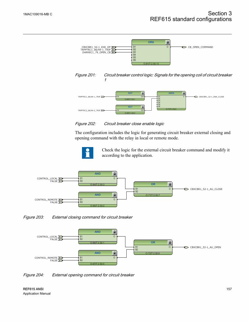
OR6
O:81|T:2.5|I:13
B1B2B3B4B5B6
O CB_OPEN_COMMANDCBXCBR1_52-1_EXE_OPTRPPTRC1_86/94-1_TRIP
DARREC1_79_OPEN_CB
GUID-802BB5E8-EA9B-426E-BB52-E0BAE9DF3EE8 V1 EN
Figure 201: Circuit breaker control logic: Signals for the opening coil of circuit breaker1
NOT
O:68|T:2.5|I:2IN OUT
NOT
O:69|T:2.5|I:1IN OUT
AND6
O:73|T:2.5|I:0
B1B2B3B4B5B6
O
TRPPTRC2_86/94-2_TRIP
CBXCBR1_52-1_ENA_CLOSETRPPTRC1_86/94-1_TRIP
GUID-C1074798-B71C-4DAC-9796-CCA042FCC297 V1 EN
Figure 202: Circuit breaker close enable logic
The configuration includes the logic for generating circuit breaker external closing andopening command with the relay in local or remote mode.
Check the logic for the external circuit breaker command and modify itaccording to the application.
AND
O:64|T:2.5|I:3
B1B2
O
AND
O:65|T:2.5|I:2
B1B2
O
OR
O:71|T:2.5|I:7
B1B2
O
FALSE
FALSE
CONTROL_LOCAL
CONTROL_REMOTE
CBXCBR1_52-1_AU_CLOSE
GUID-FF540181-E08A-4CF4-A841-51666A53563F V1 EN
Figure 203: External closing command for circuit breaker
AND
O:66|T:2.5|I:1
B1B2
O
AND
O:67|T:2.5|I:0
B1B2
O
OR
O:72|T:2.5|I:6
B1B2
O
FALSE
FALSE
CONTROL_LOCAL
CONTROL_REMOTE
CBXCBR1_52-1_AU_OPEN
GUID-2735B3B4-CD12-4A5B-8077-2954175B0520 V1 EN
Figure 204: External opening command for circuit breaker
1MAC109016-MB C Section 3REF615 standard configurations
REF615 ANSI 157Application Manual
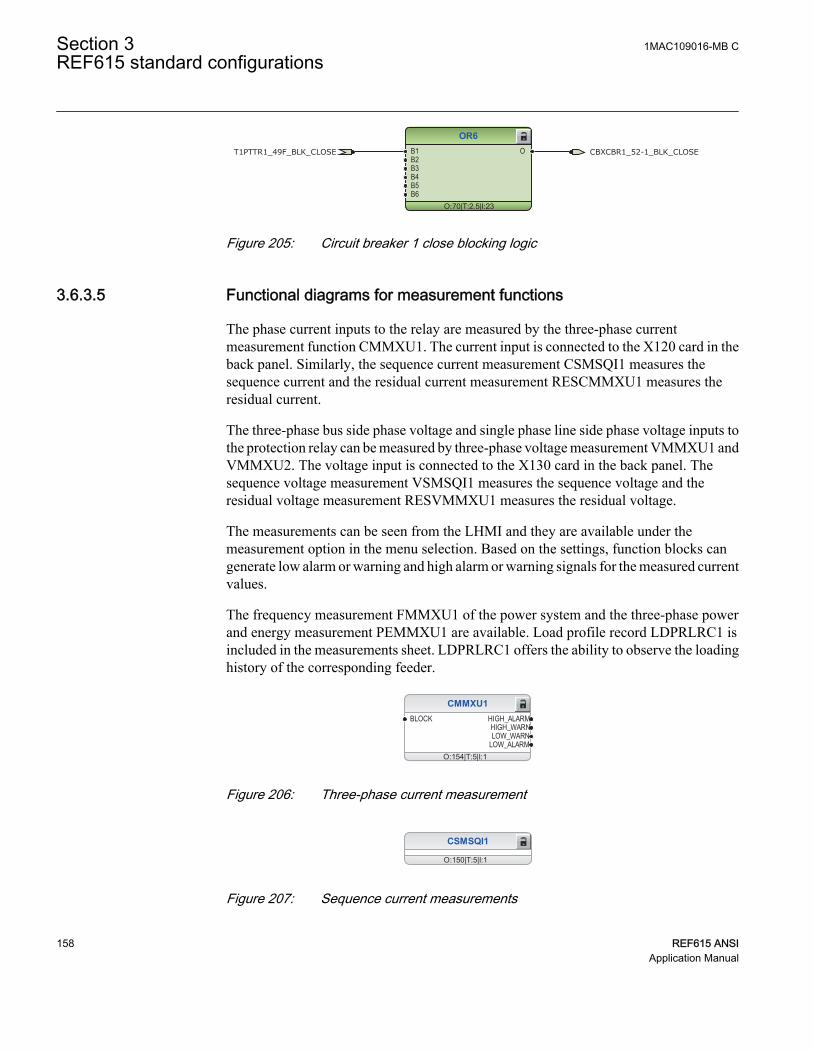
OR6
O:70|T:2.5|I:23
B1B2B3B4B5B6
O CBXCBR1_52-1_BLK_CLOSET1PTTR1_49F_BLK_CLOSE
GUID-E9EA0997-1241-47C5-B899-AC7D4E3411B4 V1 EN
Figure 205: Circuit breaker 1 close blocking logic
3.6.3.5 Functional diagrams for measurement functions
The phase current inputs to the relay are measured by the three-phase currentmeasurement function CMMXU1. The current input is connected to the X120 card in theback panel. Similarly, the sequence current measurement CSMSQI1 measures thesequence current and the residual current measurement RESCMMXU1 measures theresidual current.
The three-phase bus side phase voltage and single phase line side phase voltage inputs tothe protection relay can be measured by three-phase voltage measurement VMMXU1 andVMMXU2. The voltage input is connected to the X130 card in the back panel. Thesequence voltage measurement VSMSQI1 measures the sequence voltage and theresidual voltage measurement RESVMMXU1 measures the residual voltage.
The measurements can be seen from the LHMI and they are available under themeasurement option in the menu selection. Based on the settings, function blocks cangenerate low alarm or warning and high alarm or warning signals for the measured currentvalues.
The frequency measurement FMMXU1 of the power system and the three-phase powerand energy measurement PEMMXU1 are available. Load profile record LDPRLRC1 isincluded in the measurements sheet. LDPRLRC1 offers the ability to observe the loadinghistory of the corresponding feeder.
CMMXU1
O:154|T:5|I:1
BLOCK HIGH_ALARMHIGH_WARNLOW_WARN
LOW_ALARM
GUID-DE29661F-BEE7-45D4-A44F-9C8BA6E5FF52 V1 EN
Figure 206: Three-phase current measurement
CSMSQI1
O:150|T:5|I:1
GUID-A9D709EE-7B3D-43B1-A793-BFE289E02F9E V1 EN
Figure 207: Sequence current measurements
Section 3 1MAC109016-MB CREF615 standard configurations
158 REF615 ANSIApplication Manual

RESCMMXU1
O:157|T:5|I:1
BLOCK HIGH_ALARMHIGH_WARN
GUID-4733E919-495A-45A3-9441-217615A24D50 V1 EN
Figure 208: Ground current measurements
VMMXU1
O:145|T:5|I:1
BLOCK HIGH_ALARMHIGH_WARNLOW_WARN
LOW_ALARM
VMMXU2
O:160|T:5|I:2
BLOCK HIGH_ALARMHIGH_WARNLOW_WARN
LOW_ALARM
GUID-206CDC3B-E31E-4B43-B8C9-8F6F8A01DF8C V1 EN
Figure 209: Three-phase voltage measurement
VSMSQI1
O:149|T:5|I:1
GUID-97043D4F-8688-4A46-A213-AD5BED53EA22 V1 EN
Figure 210: Sequence voltage measurements
RESVMMXU1
O:153|T:5|I:1
BLOCK HIGH_ALARMHIGH_WARN
GUID-B99C075D-C845-4F4C-848F-8570DDCD903E V1 EN
Figure 211: Ground voltage measurements
FMMXU1
O:173|T:5|I:1
GUID-55EE1737-4A68-48EB-9E78-4A16962B9DCC V1 EN
Figure 212: Frequency measurement
PEMMXU1
O:164|T:5|I:1RSTACM
GUID-5CCE3F61-B40C-45C0-ADEA-1C4642ACDE5B V1 EN
Figure 213: Three-phase power and energy measurement
1MAC109016-MB C Section 3REF615 standard configurations
REF615 ANSI 159Application Manual

FLTRFRC1
O:9|T:2.5|I:1
BLOCKCB_CLRD
LDPRLRC1
O:162|T:5|I:1
RSTMEM MEM_WARNMEM_ALARM
GUID-2C6CB5F0-D7D5-427C-A92B-4FC56305C1DB V1 EN
Figure 214: Data monitoring and load profile record
3.6.3.6 Functional diagrams for I/O and alarm LEDs
OR
O:79|T:2.5|I:9
B1B2
O X110_BI2_EXT_PICKUP_AUTORECLOSEX110 (BIO)_110.X110-Input 2
X110 (BIO-H)_110.X110-Input 2GUID-829F7CBE-636A-455B-96B4-CBA2B121B224 V1 EN
Figure 215: Default binary inputs - X110
UPSTEAM_OC_BLOCKING
TRPPTRC3_86/94-3_TRIP
TRPPTRC4_86/94-4_TRIP
TRPPTRC5_86/94-5_TRIP
OC_TRIP_PULSE
EF_TRIP_PULSE
X110 (BIO)_110.X110-SO1
X110 (BIO)_110.X110-SO2
X110 (BIO-H)_110.X110-HSO2
X110 (BIO)_110.X110-SO3
X110 (BIO-H)_110.X110-HSO3
X110 (BIO-H)_110.X110-HSO1
GUID-4D9C6A27-CB26-4316-8E4A-9A3CA611D0C6 V1 EN
Figure 216: Default binary outputs - X110
Section 3 1MAC109016-MB CREF615 standard configurations
160 REF615 ANSIApplication Manual

CB_CLOSE_COMMAND
CB_OPEN_COMMAND
CCBRBRF1_50BF-1_TRBU
GENERAL_PICKUP_PULSE
GENERAL_TRIP_PULSE
TRPPTRC2_86/94-2_TRIP
X100 (PSM)_100.X100-PO1
X100 (PSM)_100.X100-PO2
X100 (PSM)_100.X100-SO1
X100 (PSM)_100.X100-SO2
X100 (PSM)_100.X100-PO3
X100 (PSM)_100.X100-PO4
GUID-0E948584-516F-4EBA-8610-7462088283CD V1 EN
Figure 217: Default binary outputs - X100
X120_BI3_CB_OPEN
X120_BI2_CB_CLOSED
X120_BI4_RST_LOCKOUT
X120_BI1_EXT_OC_BLOCKING
X120 (AIM)_120.X120-Input 1
X120 (AIM)_120.X120-Input 2
X120 (AIM)_120.X120-Input 3
X120 (AIM)_120.X120-Input 4
GUID-62840216-B7F9-481C-960A-115CEF437C88 V1 EN
Figure 218: Default binary inputs - X120
1MAC109016-MB C Section 3REF615 standard configurations
REF615 ANSI 161Application Manual

LED1
O:136|T:2.5|I:1
OKALARMRESET
LED2
O:123|T:2.5|I:2
OKALARMRESET
LED3
O:134|T:2.5|I:3
OKALARMRESET
LED4
O:138|T:2.5|I:4
OKALARMRESET
LED5
O:140|T:2.5|I:5
OKALARMRESET
LED6
O:113|T:2.5|I:6
OKALARMRESET
LED7
O:105|T:2.5|I:7
OKALARMRESET
LED8
O:87|T:2.5|I:8
OKALARMRESET
LED9
O:112|T:2.5|I:9
OKALARMRESET
LED10
O:139|T:2.5|I:10
OKALARMRESET
LED11
O:106|T:2.5|I:11
OKALARMRESET
OR6
O:137|T:2.5|I:11
B1B2B3B4B5B6
O
OR6
O:122|T:2.5|I:12
B1B2B3B4B5B6
O
OR6
O:133|T:2.5|I:17
B1B2B3B4B5B6
O
OR
O:135|T:2.5|I:0
B1B2
O
OR6
O:111|T:2.5|I:22
B1B2B3B4B5B6
O
CCBRBRF1_50BF-1_TRBUPHIPTOC1_50P-3_TRIP
NSPTOC1_46-1_TRIPNSPTOC2_46-2_TRIP
INTRPTEF1_67NIEF_TRIP
PDNSPTOC1_46PD_TRIP
NSPTOV1_47-1_TRIPPSPTUV1_47U-1_TRIP
ARCSARC_TRIP
DEFxPDEF_TRIP
DPHxPDOC_TRIP
EFPADM_TRIPWPWDE_TRIP
DARREC1_79_INPRO
SEQSPVC1_60-1_FUSEF_3PHSEQSPVC1_60-1_FUSEF_U
SSCBR1_52CM-1_ALARMS
DISTURB_RECORD_TRIGGERED
T1PTTR1_49F_ALARM
PHPTOV_TRIPPHPTUV_TRIP
TCSSCBR_ALARM
CCSPVC1_CCM_ALARM
EFHPTOC1_50G-1_TRIP
ROVPTOV_TRIP
GUID-40C4D53E-AA50-46B5-ACC3-E130BC976E0D V1 EN
Figure 219: Default LED connection
Section 3 1MAC109016-MB CREF615 standard configurations
162 REF615 ANSIApplication Manual

3.6.3.7 Functional diagrams for other functions
Protection
O:147|T:2.5|I:0
BI_SG_2BI_SG_3BI_SG_4BI_SG_5BI_SG_6
SG_LOGIC_SELSG_1_ACTSG_2_ACTSG_3_ACTSG_4_ACTSG_5_ACTSG_6_ACTBEH_TEST
BEH_BLK
NOT
O:57|T:2.5|I:0IN OUT
Control
O:61|T:2.5|I:0
CTRL_OFFCTRL_LOCCTRL_STACTRL_REMCTRL_ALL
OFFLOCAL
STATIONREMOTE
ALLBEH_TEST
BEH_BLK
NOT
O:60|T:2.5|I:4IN OUT
TRUE
TRUE FALSE
CONTROL_LOCAL
CONTROL_REMOTE
GUID-4E8295A0-26B5-4519-89EF-DF6ED1860E17 V1 EN
Figure 220: Functions for general logic states TRUE and FALSE, protection settinggroup selection and local and remote control
Other functions include generic function blocks which are related to the relay only, forexample, local/remote switch, some generic functions related to logic TRUE or FALSE,push button logic (valid for certain relay types) and so on.
3.6.3.8 Functional diagrams for other timer logics
The configuration also includes the overcurrent trip and ground-fault trip logic.
The trip logics are connected to the minimum pulse timer TPGAPC2 for setting theminimum pulse length for the outputs. The output from TPGAPC2 is connected to binaryoutputs.
TPGAPC2
O:120|T:2.5|I:2
IN1IN2
OUT1OUT2
OR6
O:118|T:2.5|I:62
B1B2B3B4B5B6
O
OR
O:119|T:2.5|I:19
B1B2
O OC_TRIP_PULSEEF_TRIP_PULSEPHIPTOC1_50P-3_TRIP
EFHPTOC1_50G-1_TRIPINTRPTEF1_67NIEF_TRIP
DEFxPDEF_TRIP
DPHxPDOC_TRIP
EFPADM_TRIPWPWDE_TRIP
GUID-D79A8F22-D177-40C2-A9FE-7ABDDBD86BA2 V1 EN
Figure 221: Timer logic for overcurrent and ground-fault trip pulse
1MAC109016-MB C Section 3REF615 standard configurations
REF615 ANSI 163Application Manual

TONGAPC1
O:163|T:2.5|I:1
IN1IN2IN3IN4IN5IN6IN7IN8
Q1Q2Q3Q4Q5Q6Q7Q8
TONGAPC2
O:171|T:2.5|I:2
IN1IN2IN3IN4IN5IN6IN7IN8
Q1Q2Q3Q4Q5Q6Q7Q8
TOFGAPC1
O:165|T:2.5|I:1
IN1IN2IN3IN4IN5IN6IN7IN8
Q1Q2Q3Q4Q5Q6Q7Q8
TOFGAPC2
O:168|T:2.5|I:2
IN1IN2IN3IN4IN5IN6IN7IN8
Q1Q2Q3Q4Q5Q6Q7Q8
GUID-4A8C6231-67CD-479F-8B95-D3FBC6B55065 V1 EN
Figure 222: Programmable functions
3.6.3.9 Functional diagrams for communication
MBSLPRT1
O:181|T:2.5|I:1Status
DNPLPRT1
O:10|T:2.5|I:1Status
SCHLCCH1
O:4|T:2.5|I:1
CH1LIVLNK1LIV
SCHLCCH2
O:146|T:2.5|I:2
CH2LIVLNK2LIV
SCHLCCH3
O:176|T:2.5|I:3
CH3LIVLNK3LIV
SERLCCH1
O:169|T:2.5|I:1
CH1LIVLNK1LIV
SERLCCH2
O:148|T:2.5|I:2
CH2LIVLNK2LIV
RCHLCCH1
O:7|T:2.5|I:1
CHLIV_AREDCHLIV_B
LNKLIV_AREDLNKLIV_B
GUID-1DA00E52-CF08-457E-A600-6D27086941DD V1 EN
Figure 223: Default communication function connection
Section 3 1MAC109016-MB CREF615 standard configurations
164 REF615 ANSIApplication Manual

3.7 Standard configuration P
3.7.1 Applications
This standard configuration is mainly intended for single or double tie breaker control inpower distribution systems. With the directional phase and ground overcurrent, voltageprotection, synch check and power system metering, this configuration can be applied forradial and loop feeders and intertie connections. In particular, this configuration providestwo sets of the remnant under voltage functions that can monitor two bus voltages with awide frequency range. As a result, it can be conveniently applied for automatic bustransfer schemes.
The protection relay with a standard configuration is delivered from the factory withdefault settings and parameters. The end-user flexibility for incoming, outgoing andinternal signal designation within the protection relay enables this configuration to befurther adapted to different primary circuit layouts and the related functionality needs bymodifying the internal functionality using PCM600.
3.7.2 Functions
3
50G-151G
1 Available with Fault Locator option2 Available with Arc Flash Detection(AFD) option3 Available with Reclosing option
3
52
AFD-32
AFD-12
AFD-22
3
Υ or Δ
50N-1
50BF-2
51N-1
46-2
50N-2 50N-3
50G-2 50G-3
67/50P-1
67/50P-2
50BF-1
67/50N-2
67/50N-1
INR-1
51P-1 50P-1 50P-3
REF615 V5.0 FP1 ANSI Func Appl P
50P-2 46-1
59N-1
52
3
25
27-2
59-2
47-2
59N-2
60-2
27R-2
793 21FL-11
27-1
59-1
47-1
27R-1
60-1
37-1
GUID-EC38092D-A19C-4665-B7C0-9EAE328A17C4 V1 EN
Figure 224: Functionality overview for standard configuration P
1MAC109016-MB C Section 3REF615 standard configurations
REF615 ANSI 165Application Manual

3.7.2.1 Default I/O connections
Table 33: Default connections for analog inputs
Analog input Description Connector pinsIA Phase A current X120:7-8
IB Phase B current X120:9-10
IC Phase C current X120:11-12
IG Residual current IG X120:13-14
VA(2) Phase voltage VA(2) X130:7-8
VB(2) Phase voltage VB(2) X130:9-10
VC(2) Phase voltage VC(2) X130:11-12
VA(1) Phase voltage VA(1) X130:13-14
VB(1) Phase voltage VB(1) X130:15-16
VC(1) Phase voltage VC(1) X130:17-18
Table 34: Default connections for binary inputs
Binary input Description Connector pinsBIO0005 BIO0007
X110-BI1 - X110:1-2 X110:1,5
X110-BI2 - X110:3-4 X110:2,5
X110-BI3 - X110:5-6 X110:3,5
X110-BI4 - X110:7-6 X110:4-5
X110-BI5 Circuit Breaker 2 closed position indication X110:8-9 X110:6,10
X110-BI6 Circuit Breaker 2 open position indication X110:10-9 X110:7,10
X110-BI7 Circuit Breaker 1 closed position indication X110:11-12 X110:8,10
X110-BI8 Circuit Breaker 1 open position indication X110:13-12 X110:9-10
X120-BI1 - X120:1-2
X120-BI2 - X120:3-2
X120-BI3 - X120:4-2
X120-BI4 - X120:5-6
X130-BI1 - X130:1-2
X130-BI2 - X130:3-4
X130-BI3 - X130:5-6
Section 3 1MAC109016-MB CREF615 standard configurations
166 REF615 ANSIApplication Manual

Table 35: Default connections for binary outputs
Binary output Description Connector pinsX100-PO1 Close circuit breaker 1 X100:6-7
X100-PO2 Close circuit breaker 2 X100:8-9
X100-SO1 Circuit breaker failure protection trip to upstream breaker X100:10-11,(12)
X100-SO2 - X100:13-14
X100-PO3 Open circuit breaker 1/ Master Trip (1) X100:15-19
X100-PO4 Open circuit breaker 2/ Master Trip (2) X100:20-24
X110-SO1 - X110:14-16
X110-SO2 - X110:17-19
X110-SO3 - X110:20-22
X110-SO4 - X110:23-24
X110-HSO1 Arc protection instance 1 trip activated X110:15-16
X110-HSO1 Arc protection instance 2 trip activated X110:19-20
X110-HSO1 Arc protection instance 3 trip activated X110:23-24
Table 36: Default connections for LEDs
LED Default usage ID Label description1 Phase A LED_Phase_A Phase A overcurrent
2 Phase B LED_Phase_B Phase B overcurrent
3 Phase C LED_Phase_C Phase C overcurrent
4 Neutral / Ground LED_Neutral Ground-fault
5 Time LED_Time Time overcurrent
6 Instantaneous LED_Instantaneous Instantaneous overcurrnt
7 Breaker 1 Failure/Alarm LED_Breaker_1_Failure_Alarm Breaker1 failure/alarm
8 Breaker 2 Failure/Alarm LED_Breaker_2_Failure_Alarm Breaker2 failure/alarm
9 Synchronism LED_Synchronism Synchronism OK
10 Arc flash detection LED_ArcDetected_1 Arc detected
11 Voltage LED_Voltage Voltage protection
1MAC109016-MB C Section 3REF615 standard configurations
REF615 ANSI 167Application Manual

3.7.2.2 Default disturbance recorder settings
Table 37: Default disturbance recorder analog channels
Channel Description1 IL1
2 IL2
3 IL3
4 Io
5 U1
6 U2
7 U3
8 U1B
9 U2B
10 U3B
11 -
12 -
Table 38: Default disturbance recorder binary channels
Channel ID text Level trigger mode1 TRPPTRC1_86/94-1_TRIP Positive or Rising
2 TRPPTRC2_86/94-2_TRIP Positive or Rising
3 CBXCBR1_52-1_EXE_OP Positive or Rising
4 CBXCBR1_52-1_EXE_CL Positive or Rising
5 CBXCBR2_52-2_EXE_OP Positive or Rising
6 CBXCBR2_52-2_EXE_CL Positive or Rising
7 CCBRBRF1_50BF-1_TRBU Positive or Rising
8 CCBRBRF1_50BF-2_TRBU Positive or Rising
9 ARCSARC1 - ARC flt det Positive or Rising
10 ARCSARC2 - ARC flt det Positive or Rising
11 ARCSARC3 - ARC flt det Positive or Rising
12 OC(1)_PICKUP_ALARM Positive or Rising
13 PHPTUC1_37-1_TRIP Positive or Rising
14 PHPTOV2_59-2_TRIP Positive or Rising
15 REMPTUV1_27R_TRIP Positive or Rising
16 NSPTOV1_47-1_TRIP Positive or Rising
17 NSPTOV2_47-2_TRIP Positive or Rising
18 ROVPTOV2_59N-1_TRIP Positive or Rising
Table continues on next page
Section 3 1MAC109016-MB CREF615 standard configurations
168 REF615 ANSIApplication Manual

Channel ID text Level trigger mode19 ROVPTOV3_59N-2_TRIP Positive or Rising
20 PHPTUV1_27-1_TRIP Positive or Rising
21 PHPTUV2_27-2_TRIP Positive or Rising
22 REMPTUV1_27R-1_TRIP Positive or Rising
23 REMPTUV2_27R-2_TRIP Positive or Rising
24 CCSPVC1_CCM_FAIL Positive or Rising
25 MSVPR1 - U_LO Positive or Rising
26 MSVPR2 - U_LO Positive or Rising
27 - -
28 - -
29 -
30 - -
31 - -
32 - -
33 - -
34 - -
35 - -
36 - -
37 - -
38 - -
39 - -
40 - -
41 - -
42 - -
43 - -
44 - -
45 - -
46 - -
47 - -
48 - -
49 - -
50 - -
51 - -
52 - -
53 - -
54 - -
Table continues on next page
1MAC109016-MB C Section 3REF615 standard configurations
REF615 ANSI 169Application Manual

Channel ID text Level trigger mode55 - -
56 - -
57 - -
58 - -
59 - -
60 - -
61 - -
62 - -
63 - -
64 - -
3.7.3 Functional diagrams
The functional diagrams describe the default input, output, alarm LED and function-to-function connections. The default connections can be viewed and changed with PCM600according to the application requirements.
The analog channels have fixed connections to the different function blocks inside theprotection relay’s standard configuration. However, the 12 analog channels available forthe disturbance recorder function are freely selectable as a part of the disturbancerecorder’s parameter settings.
The phase currents to the protection relay are fed from a current transformer. The residualcurrent to the protection relay is fed from either residually connected CTs, an external corebalance CT, neutral CT or calculated internally.
The signal marked with IA, IB and IC represents the three phase currents. The signal IGrepresents the measured ground current.
The signal marked with VA, VB and VC represents the three phase voltages. The signalVG represents the measured ground voltage.
The signal marked with (1) and (2) represents the voltage levels, for example, intransformer application or in the tie breaker control application it represents the name ofthe bus.
The protection relay offers six different setting groups which can be set based onindividual needs. Each group can be activated or deactivated using the setting groupsettings available in the protection relay.
Depending on the communication protocol the required function block needs to beinstantiated in the configuration.
Section 3 1MAC109016-MB CREF615 standard configurations
170 REF615 ANSIApplication Manual

3.7.3.1 Functional diagrams for protection
Four overcurrent stages for phase, neutral and ground are offered for non-directionalovercurrent and short-circuit protection. The non-directional high stagePHHPTOC1_50P-1 is blocked by cold load detection logic. The cold load detection logicstarts from closing of the circuit breaker and is active during set time. The cold loaddetection logic's active time can be set in a resolution of minutes or seconds to thefunctions TPSGAPC1 and TPMGAPC1.
For dual tie breaker application, since two breakers are in series, both the breakers mustbe closed to initiate the cold load pickup timer.
The directional overcurrent and short circuit protection are blocked by default also if thefuse failure situation is detected.
The inrush detection block's INRPHAR1_INR-1 output BLK2H offers the possibility toeither block the function or multiply the active settings for any of the shown protectionfunction blocks. By default, the output BLK2H is not connected to anywhere.
All trip signals are connected to the Master Trip and also to the alarm LEDs. The pickupinformation of all overcurrent functions is collected to the variableOC_PICKUP_ALARM and connected to the disturbance recorder. This signal can bemapped to the signal outputs depending on the application needs.
1MAC109016-MB C Section 3REF615 standard configurations
REF615 ANSI 171Application Manual
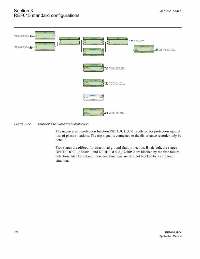
PHLPTOC1
O:24|T:5|I:1
BLOCKENA_MULT
TRIPPICKUP
PHHPTOC1
O:60|T:5|I:1
BLOCKENA_MULT
TRIPPICKUP
INRPHAR1
O:7|T:2.5|I:1BLOCK BLK2H
TPSGAPC1
O:122|T:2.5|I:1
IN1IN2
OUT1OUT2
TPMGAPC1
O:58|T:2.5|I:1
IN1IN2
OUT1OUT2
OR
O:59|T:2.5|I:7
B1B2
O
OR
O:57|T:2.5|I:8
B1B2
O
PHHPTOC2
O:25|T:5|I:2
BLOCKENA_MULT
TRIPPICKUP
PHIPTOC1
O:20|T:2.5|I:1
BLOCKENA_MULT
TRIPPICKUP
AND
O:56|T:2.5|I:3
B1B2
O
AND
O:92|T:2.5|I:4
B1B2
O
CBXCBR1_52-1_EXE_CL
CBXCBR2_52-2_EXE_CL
CB2_POSITION_CLOSE
CB1_POSITION_CLOSE
CLD_62_1_TRIP
PHLPTOC1_51P-1_PICKUP
PHHPTOC1_50P-1_PICKUP
PHHPTOC2_50P-2_PICKUP
PHIPTOC1_50P-3_PICKUP
PHLPTOC1_51P-1_TRIP
PHHPTOC1_50P-1_TRIP
PHHPTOC2_50P-2_TRIP
PHIPTOC1_50P-3_TRIP
GUID-3DD1EAEF-E4F0-4D1A-9AF6-A38564482440 V1 EN
Figure 225: Three-phase overcurrent protection
The undercurrent protection function PHPTUC1_37-1 is offered for protection againstloss of phase situations. The trip signal is connected to the disturbance recorder only bydefault.
Two stages are offered for directional ground-fault protection. By default, the stagesDPHHPDOC1_67/50P-1 and DPHHPDOC2_67/50P-2 are blocked by the fuse failuredetection. Also by default, these two functions are also not blocked by a cold loadsituation.
Section 3 1MAC109016-MB CREF615 standard configurations
172 REF615 ANSIApplication Manual

PHPTUC1
O:77|T:5|I:1
BLOCK TRIPTRIP_ATRIP_BTRIP_CPICKUP
PICKUP_APICKUP_BPICKUP_C
DPHHPDOC1
O:28|T:5|I:1
BLOCKENA_MULTNON_DIR
TRIPPICKUP
DPHHPDOC2
O:29|T:5|I:2
BLOCKENA_MULTNON_DIR
TRIPPICKUP
SEQRFUF1_60-1_FUSEF_U
SEQRFUF1_60-1_FUSEF_U
DPHHPDOC1_67/50P-1_PICKUP
DPHHPDOC2_67/50P-2_PICKUP
DPHHPDOC1_67/50P-1_TRIP
DPHHPDOC2_67/50P-2_TRIP
PHPTUC1_37-1_TRIP
GUID-01F74092-5C0E-4BC3-B764-38BE52522F18 V1 EN
Figure 226: Under current and directional overcurrent protections
Four stages are provided to non-directional neutral overcurrent protection. Additionallydepending on order option, one stage is offered as a sensitive ground-fault protection. Theneutral overcurrent protection uses calculated residual current component.
The operation of EFLPTOC1_51N-1, EFHPTOC1_50N-1, EFHPTOC2_50N-2 andEFHPTOC3_50N-3 are by default, not blocked by an external blocking input, but this canbe done through a binary input. EFHPTOC1_50N-1 is also blocked if the cold loaddetection logic is activated.
1MAC109016-MB C Section 3REF615 standard configurations
REF615 ANSI 173Application Manual

EFLPTOC2
O:27|T:5|I:2
BLOCKENA_MULT
TRIPPICKUP
EFHPTOC3
O:21|T:5|I:3
BLOCKENA_MULT
TRIPPICKUP
EFHPTOC4
O:23|T:5|I:4
BLOCKENA_MULT
TRIPPICKUP
EFIPTOC2
O:30|T:2.5|I:2
BLOCKENA_MULT
TRIPPICKUP
OR
O:13|T:2.5|I:20
B1B2
OCLD_62_1_TRIP
EFLPTOC2_51N-1_PICKUP
EFHPTOC3_50N-1_PICKUP
EFHPTOC4_50N-2_PICKUP
EFIPTOC2_50N-3_PICKUP
EFLPTOC2_51N-1_TRIP
EFHPTOC3_50N-1_TRIP
EFHPTOC4_50N-2_TRIP
EFIPTOC2_50N-3_TRIP
CCRDIF1_CCM_FAIL
CCRDIF1_CCM_FAIL
CCRDIF1_CCM_FAIL
CCRDIF1_CCM_FAIL
GUID-B825E105-AA47-441D-B674-6F8687FCBCA2 V1 EN
Figure 227: Non-directional calculated neutral overcurrent protection
Four stages are provided to non-directional ground-fault protection. Additionallydepending on order option, one stage is offered as a sensitive ground-fault protection. Theground-fault protection uses measured residual current component.
The operation of EFLPTOC1_51G, EFHPTOC2_51G-2 and EFHPTOC3_51G-3 are bydefault, not blocked by an external blocking input, but this can be done through a binaryinput.
Section 3 1MAC109016-MB CREF615 standard configurations
174 REF615 ANSIApplication Manual

EFHPTOC1
O:103|T:5|I:1
BLOCKENA_MULT
TRIPPICKUP
EFLPTOC1
O:26|T:5|I:1
BLOCKENA_MULT
TRIPPICKUP
EFIPTOC1
O:32|T:2.5|I:1
BLOCKENA_MULT
TRIPPICKUP
EFHPTOC2
O:31|T:5|I:2
BLOCKENA_MULT
TRIPPICKUP
CLD_62_1_TRIP
EFIPTOC1_50G-3_PICKUP
EFHPTOC2_50G-2_PICKUP
EFLPTOC1_51G_TRIP
EFHPTOC1_50G-1_TRIP
EFIPTOC1_50G-3_TRIP
EFHPTOC2_50G-2_TRIP
GUID-BFBB8FFE-06EE-4DA9-B151-9122E00D3E75 V1 EN
Figure 228: Non-directional ground-fault protection
Two stages are offered for directional ground-fault protection. By default the stagesDEFHPDEF1_67/50N-1 and DEFHPDEF2_67/50N-2 are blocked by the fuse failuredetection and the polarization choice is set to negative sequence voltage. Also by default,these two functions are also not blocked by a cold load situation.
The polarization should never be set to “measured” as there is nodedicated Vg input for this configuration. Setting polarization to Vg willresult in a settings error.
DEFHPDEF1
O:19|T:5|I:1
BLOCKENA_MULTRCA_CTL
TRIPPICKUP
DEFHPDEF2
O:18|T:5|I:2
BLOCKENA_MULTRCA_CTL
TRIPPICKUP DEFHPDEF2_67_50N-2_PICKUP
DEFHPDEF1_67_50N-1_PICKUPDEFHPDEF1_67_50N-1_TRIP
DEFHPDEF2_67_50N-2_TRIP
CCRDIF1_CCM_FAIL
CCRDIF1_CCM_FAIL
GUID-FFEAD23C-22CD-4ECD-8666-85AFD1F69D2D V1 EN
Figure 229: Directional calculated neutral overcurrent protections
1MAC109016-MB C Section 3REF615 standard configurations
REF615 ANSI 175Application Manual

Two negative-sequence overcurrent protection NSPTOC1_46-1 and NSPTOC2_46-2stages are provided for phase unbalance protection. These functions are used to protect thefeeder against phase unbalance.
The operation of NSPTOC1_46-1 and NSPTOC2_46-2 is not blocked as default by anyfunctionality. The pickup signals are connected to OC_PICKUP_ALARM variable inlogic.
NSPTOC1
O:22|T:5|I:1
BLOCKENA_MULT
TRIPPICKUP
NSPTOC2
O:33|T:5|I:2
BLOCKENA_MULT
TRIPPICKUP
NSPTOC1_46-1_PICKUP
NSPTOC2_46-2_PICKUP
NSPTOC1_46-1_TRIP
NSPTOC2_46-2_TRIP
CCRDIF1_CCM_FAIL
CCRDIF1_CCM_FAIL
GUID-B453FA0D-0D15-4FC5-A270-5C2B66CFA1B3 V1 EN
Figure 230: Negative-sequence overcurrent protection
All overcurrent pickup signals are merged together as variable OC_PICKUP_ALARM.This alarm is by default connected to disturbance recorder channel. It can be mapped also,for example, for alarming or blocking purposes to the binary output relays.
OR6
O:64|T:2.5|I:5
B1B2B3B4B5B6
O
OR6
O:63|T:2.5|I:9
B1B2B3B4B5B6
O
OR6
O:65|T:2.5|I:24
B1B2B3B4B5B6
O
OR6
O:72|T:2.5|I:25
B1B2B3B4B5B6
OPHLPTOC1_51P-1_PICKUPPHHPTOC1_50P-1_PICKUPPHHPTOC2_50P-2_PICKUP
NSPTOC1_46-1_PICKUPPHIPTOC1_50P-3_PICKUP
EFIPTOC1_50G-3_PICKUPNSPTOC2_46-2_PICKUP
EFLPTOC2_51N-1_PICKUPEFHPTOC3_50N-1_PICKUPEFHPTOC4_50N-2_PICKUP
EFIPTOC2_50N-3_PICKUPDPHHPDOC1_67/50P-1_PICKUPDPHHPDOC2_67/50P-2_PICKUP
EFHPTOC2_50G-2_PICKUPDEFHPDEF2_67_50N-2_PICKUPDEFHPDEF1_67_50N-1_PICKUP
OC(1)_PICKUP_ALARM
GUID-002DF69E-AAD7-48E4-B7CD-8FC751D2DCE6 V1 EN
Figure 231: Overcurrent pickup alarm
Two overvoltage and undervoltage protection stages PHPTUV1_27-1, PHPTUV2_27-2and PHPTOV1_59-1, PHPTOV2_59-2 offer protection against abnormal phase voltageconditions. A failure in the voltage measuring circuit is detected by the fuse failurefunction and the activation is connected to undervoltage protection functions to avoidfaulty undervoltage tripping.
Section 3 1MAC109016-MB CREF615 standard configurations
176 REF615 ANSIApplication Manual

Negative-sequence overvoltage NSPTOV1_47-1 and NSPTOV2_47-2 protectionfunctions enable voltage-based unbalance protection.
The residual overvoltage protections ROVPTOV1_59N-1 and ROVPTOV2_59N-2provide ground-fault protection by detecting abnormal level of residual voltage. They canbe used, for example, as a nonselective backup protection for the selective directionalground-fault functionality.
PHPTUV1_27-1, PHPTOV1_59-1, NSPTOV1_47-1 and ROVPTOV1_59N-1use thesource 1 (bus 1) voltages whereas PHPTUV2_27-2, PHPTOV2_59-2, NSPTOV2_47-2and ROVPTOV2_59N-2 use the source 2 (bus 2) voltages.
PHPTUV1
O:74|T:5|I:1
BLOCK TRIPPICKUP
PHPTOV1
O:70|T:5|I:1
BLOCK TRIPPICKUP
NSPTOV1
O:71|T:5|I:1
BLOCK TRIPPICKUP
ROVPTOV2
O:68|T:5|I:2
BLOCK TRIPPICKUP
SEQRFUF1_60-1_FUSEF_U
SEQRFUF1_60-1_FUSEF_U
SEQRFUF1_60-1_FUSEF_U
PHPTOV1_59-1_TRIP
PHPTUV1_27-1_TRIP
NSPTOV1_47-1_TRIP
ROVPTOV2_59N-1_TRIP
GUID-BFCBE7A4-59BD-42CA-B435-04E8F234AF9F V1 EN
Figure 232: Voltage functions on bus 1
1MAC109016-MB C Section 3REF615 standard configurations
REF615 ANSI 177Application Manual

PHPTUV2
O:78|T:5|I:2
BLOCK TRIPPICKUP
PHPTOV2
O:75|T:5|I:2
BLOCK TRIPPICKUP
NSPTOV2
O:76|T:5|I:2
BLOCK TRIPPICKUP
ROVPTOV3
O:73|T:5|I:3
BLOCK TRIPPICKUP
SEQRFUF2_60-2_FUSEF_U
SEQRFUF2_60-2_FUSEF_U
SEQRFUF2_60-2_FUSEF_U
PHPTOV2_59-2_TRIP
PHPTUV2_27-2_TRIP
NSPTOV2_47-2_TRIP
ROVPTOV3_59N-2_TRIP
GUID-9DE7CD91-E7CF-4259-8444-F319579843BC V1 EN
Figure 233: Voltage functions on bus 2
The circuit-breaker failure protection CCBRBRF_50BF is initiated via the PICKUP inputby a functions connected to the Master Trip 1 and by opening command of the circuitbreaker. CCBRBRF_50BF offers different operating modes associated with the circuit-breaker position and the measured phase and residual currents.
CCBRBRF_50BF has two operating outputs: TRRET and TRBU. The TRBU output can beused to give a backup trip to the circuit breaker feeding upstream. In the configuration theTRBU output signal is connected to the output SO1 (X100: 14, 15, 16).
CCBRBRF1_50BF-1 use the source 1 (bus 1) voltages whereas CCBRBRF2_50BF-2 usethe source 2 (bus 2) voltages.
Section 3 1MAC109016-MB CREF615 standard configurations
178 REF615 ANSIApplication Manual

CCBRBRF1
O:61|T:2.5|I:1
BLOCKPICKUPPOSCLOSECB_FAULT
CB_FAULT_ALTRBU
TRRET
OR6
O:127|T:2.5|I:1
B1B2B3B4B5B6
O
CB1_POSITION_CLOSE
TRPPTRC1_86_94-1_TRIPCBXCBR1_52-1_EXE_OP
CCBRBRF1_50BF-1_TRRETCCBRBRF1_50BF-1_TRBU
OR6
O:50|T:2.5|I:10
B1B2B3B4B5B6
O
CCBRBRF2
O:53|T:2.5|I:2
BLOCKPICKUPPOSCLOSECB_FAULT
CB_FAULT_ALTRBU
TRRETCB2_POSITION_CLOSE
TRPPTRC2_86_94-2_TRIPCBXCBR2_52-2_EXE_OP
CCBRBRF2_50BF-2_TRRETCCBRBRF2_50BF-2_TRBU
GUID-4FADF228-CE71-4D4B-9C7D-0959EA468F64 V1 EN
Figure 234: Circuit breaker failure protections
The TRRET trip output can be used for retripping its own circuit breakerthrough the Master Trip again. However, this is not connected in presentconfiguration.
In case of dual tie breaker application, the TRBU trip output from onetiebreaker can be used for tripping other tie breaker first to minimize thepoweroutage area. However, this is not connected in presentconfiguration.
Three arc protection stages ARCSARC1…3_AFD-1…3 are included as an optionalfunction. The arc protection offers individual function blocks for three ARC sensors thatcan be connected to the relay. Each arc protection function block has two differentoperation modes, with or without the phase and residual current check.
Trip signal from ARCSARC1_AFD-1 is connected to Master trip 1, available at PO3(X100: 15-19). Whereas the trip signal from ARCSARC2_AFD-2 andARCSARC3_AFD-3 is connected to master trip 2, available at PO4 (X100: 20-24).
If the relay has been ordered with high-speed binary outputs, the trip signal fromARCSARC2_AFD-2 and ARCSARC3_AFD-3 are connected directly to high-speedoutput HSO2 (X110:19-20) and HS03(X110:23-24) respectively.
1MAC109016-MB C Section 3REF615 standard configurations
REF615 ANSI 179Application Manual

ARCSARC1
O:16|T:2.5|I:11
BLOCKREM_FLT_ARCOPR_MODE
TRIPARC_FLT_DET
ARCSARC2
O:15|T:2.5|I:21
BLOCKREM_FLT_ARCOPR_MODE
TRIPARC_FLT_DET
ARCSARC3
O:17|T:2.5|I:31
BLOCKREM_FLT_ARCOPR_MODE
TRIPARC_FLT_DET
ARCSARC1_AFD-1_TRIP
ARCSARC2_AFD-2_TRIP
ARCSARC3_AFD-3_TRIP
ARCSARC1_AFD-1_ARC_FLT_DET
ARCSARC2_AFD-2_ARC_FLT_DET
ARCSARC3_AFD-3_ARC_FLT_DET
GUID-B3FCE485-1B78-4806-B704-00E3C3BDF541 V1 EN
Figure 235: Arc protection
Two master trip logics TRPPTRC1_86/94-1 and TRPPTRC2_86/94-2 are provided as atrip command collector. TRPPTRC1_86/94-1 is dedicated for the breaker 1 andTRPPTRC2_86/94-2 for breaker 2.
Circuit breaker failure protection CCBRBRF1_50BF-1 is initiated via the PICKUP inputby a number of different protection functions available in the relay and 50BF-1 protectionfunctions and is connected to trip output contact PO3 (X100:16-19), andTRPPTRC2_86/94-2 collects the almost the same trip signals except the one forCCBRBRF1_50BF-1, instead, CCBRBRF1_50BF-1 being replaced withCCBRBRF2_50BF-2 and is connected to trip output (X100:21-24).
Open control commands from circuit breaker control CBXCBR1_52 function block to thecircuit breaker from the local or remote are also connected directly to the outputs PO3(X100:16-19) and PO4 (X100:21-24) respectively.
With a high-speed binary output card, ARCSARC1…3_AFD-1…3 are connected tohigh-speed output HSO1 (X110:15-16), HSO1 (X110:19-20) and HSO1 (X110:23-24)respectively. Without the high-speed output card, it is the user's choice to connect the arcprotection outputs to whatever outputs available.
TRPPTRC1_86/94-1 and TRPPTRC2_86/94-2 provides the lockout/latching function,event generation and the trip signal duration setting. If the lockout operation mode isselected, one binary input can be reassigned to the RST_LKOUT input of the Master Tripto enable external reset with a push button.
Section 3 1MAC109016-MB CREF615 standard configurations
180 REF615 ANSIApplication Manual
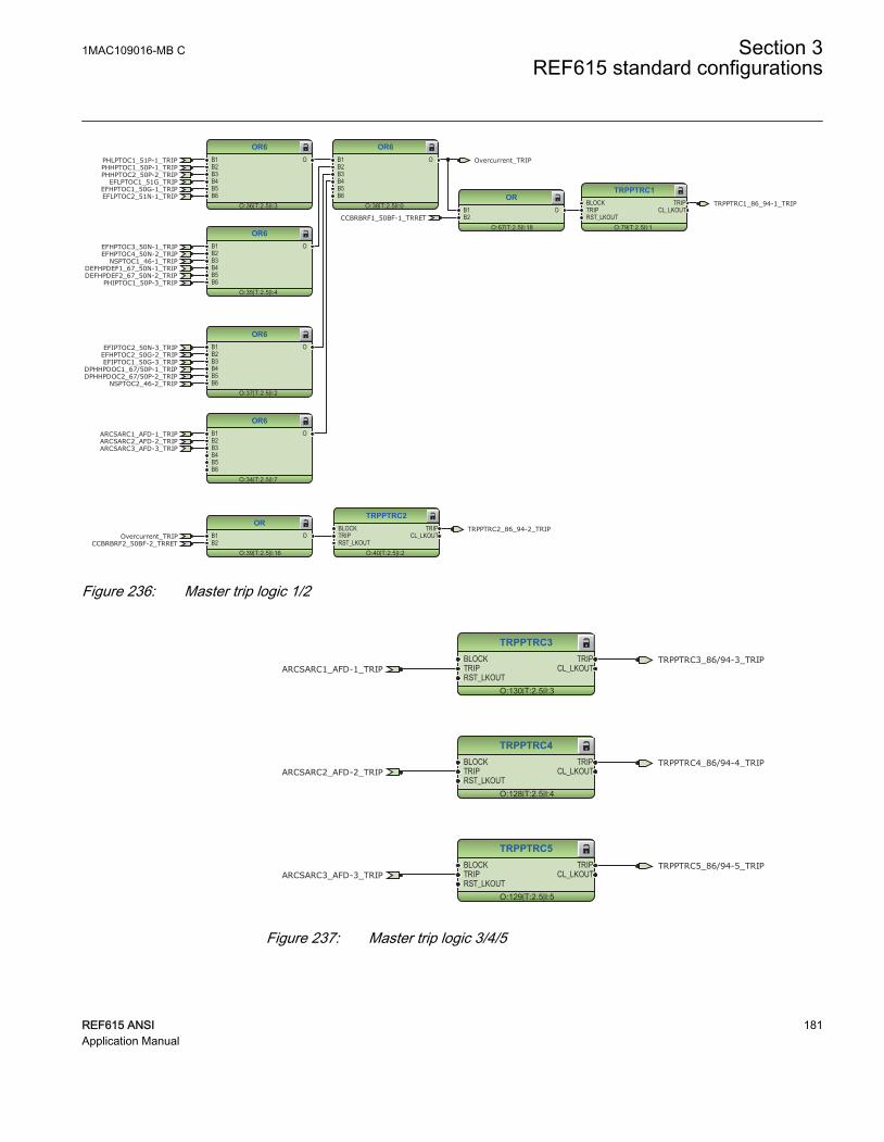
Overcurrent_TRIPCCBRBRF2_50BF-2_TRRET
TRPPTRC1
O:79|T:2.5|I:1
BLOCKTRIPRST_LKOUT
TRIPCL_LKOUT
OR6
O:38|T:2.5|I:0
B1B2B3B4B5B6
O
OR6
O:36|T:2.5|I:3
B1B2B3B4B5B6
O
OR6
O:35|T:2.5|I:4
B1B2B3B4B5B6
O
OR6
O:37|T:2.5|I:2
B1B2B3B4B5B6
O
OR
O:67|T:2.5|I:18
B1B2
O
OR6
O:34|T:2.5|I:7
B1B2B3B4B5B6
O
TRPPTRC1_86_94-1_TRIP
ARCSARC1_AFD-1_TRIPARCSARC2_AFD-2_TRIPARCSARC3_AFD-3_TRIP
PHLPTOC1_51P-1_TRIPPHHPTOC1_50P-1_TRIPPHHPTOC2_50P-2_TRIP
EFLPTOC1_51G_TRIPEFHPTOC1_50G-1_TRIP
NSPTOC1_46-1_TRIP
PHIPTOC1_50P-3_TRIP
EFIPTOC1_50G-3_TRIP
CCBRBRF1_50BF-1_TRRET
NSPTOC2_46-2_TRIP
EFLPTOC2_51N-1_TRIP
EFHPTOC3_50N-1_TRIPEFHPTOC4_50N-2_TRIP
DEFHPDEF1_67_50N-1_TRIPDEFHPDEF2_67_50N-2_TRIP
EFIPTOC2_50N-3_TRIPEFHPTOC2_50G-2_TRIP
DPHHPDOC1_67/50P-1_TRIPDPHHPDOC2_67/50P-2_TRIP
Overcurrent_TRIP
TRPPTRC2
O:40|T:2.5|I:2
BLOCKTRIPRST_LKOUT
TRIPCL_LKOUT
OR
O:39|T:2.5|I:16
B1B2
OTRPPTRC2_86_94-2_TRIP
Overcurrent_TRIPCCBRBRF2_50BF-2_TRRET
GUID-FF03164E-4B34-43B6-83EC-408F6AFAE479 V1 EN
Figure 236: Master trip logic 1/2
TRPPTRC3
O:130|T:2.5|I:3
BLOCKTRIPRST_LKOUT
TRIPCL_LKOUT
TRPPTRC4
O:128|T:2.5|I:4
BLOCKTRIPRST_LKOUT
TRIPCL_LKOUT
TRPPTRC5
O:129|T:2.5|I:5
BLOCKTRIPRST_LKOUT
TRIPCL_LKOUT
ARCSARC1_AFD-1_TRIP
ARCSARC2_AFD-2_TRIP
ARCSARC3_AFD-3_TRIP
TRPPTRC3_86/94-3_TRIP
TRPPTRC4_86/94-4_TRIP
TRPPTRC5_86/94-5_TRIP
GUID-380BD0E9-5635-4621-8C0F-2DCF620A0B32 V1 EN
Figure 237: Master trip logic 3/4/5
1MAC109016-MB C Section 3REF615 standard configurations
REF615 ANSI 181Application Manual

3.7.3.2 Functional diagrams for disturbance recorder
The PICKUP and TRIP outputs from the protection stages are routed to trigger thedisturbance recorder or, alternatively, only to be recorded by the disturbance recorderdepending on the parameter settings. Additionally, the selected signals from differentfunctions and the few binary inputs are also connected to the disturbance recorder.
RDRE1
O:80|T:2.5|I:1
C1C2C3C4C5C6C7C8C9C10C11C12C13C14C15C16C17C18C19C20C21C22C23C24C25C26C27C28C29C30C31C32C33C34C35C36C37C38C39C40C41C42C43C44C45C46C47C48C49C50C51C52C53C54C55C56C57C58C59C60C61C62C63C64
TRIGGERED
CBXCBR1_52-1_EXE_CL
CBXCBR2_52-2_EXE_CL
TRPPTRC1_86_94-1_TRIP
CBXCBR1_52-1_EXE_OPTRPPTRC2_86_94-2_TRIP
CBXCBR2_52-2_EXE_OP
CCBRBRF1_50BF-1_TRBUCCBRBRF2_50BF-2_TRBU
PHPTUC1_37-1_TRIPPHPTOV1_59-1_TRIPPHPTOV2_59-2_TRIP
PHPTUV1_27-1_TRIPPHPTUV2_27-2_TRIP
NSPTOV1_47-1_TRIPNSPTOV2_47-2_TRIP
ROVPTOV2_59N-1_TRIPROVPTOV3_59N-2_TRIP
OC(1)_PICKUP_ALARM
ARCSARC1_AFD-1_ARC_FLT_DETARCSARC2_AFD-2_ARC_FLT_DETARCSARC3_AFD-3_ARC_FLT_DET
CCRDIF1_CCM_FAIL
GUID-778F90AC-D1B1-4BDF-AD13-007786F71D32 V1 EN
Figure 238: Disturbance recorder
Section 3 1MAC109016-MB CREF615 standard configurations
182 REF615 ANSIApplication Manual
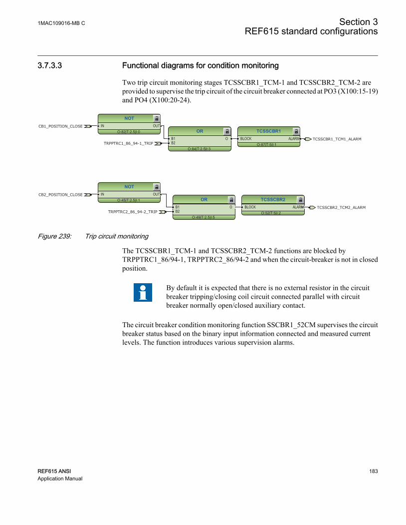
3.7.3.3 Functional diagrams for condition monitoring
Two trip circuit monitoring stages TCSSCBR1_TCM-1 and TCSSCBR2_TCM-2 areprovided to supervise the trip circuit of the circuit breaker connected at PO3 (X100:15-19)and PO4 (X100:20-24).
TCSSCBR1
O:87|T:5|I:1BLOCK ALARM
TCSSCBR2
O:52|T:5|I:2BLOCK ALARM
NOT
O:82|T:2.5|I:0IN OUT
OR
O:84|T:2.5|I:3
B1B2
O
NOT
O:45|T:2.5|I:1IN OUT
OR
O:49|T:2.5|I:5
B1B2
O
CB2_POSITION_CLOSE
CB1_POSITION_CLOSE
TRPPTRC1_86_94-1_TRIP
TRPPTRC2_86_94-2_TRIP
TCSSCBR1_TCM1_ALARM
TCSSCBR2_TCM2_ALARM
GUID-9DCED52D-3641-451C-9C16-A9FCE08F4CDE V1 EN
Figure 239: Trip circuit monitoring
The TCSSCBR1_TCM-1 and TCSSCBR2_TCM-2 functions are blocked byTRPPTRC1_86/94-1, TRPPTRC2_86/94-2 and when the circuit-breaker is not in closedposition.
By default it is expected that there is no external resistor in the circuitbreaker tripping/closing coil circuit connected parallel with circuitbreaker normally open/closed auxiliary contact.
The circuit breaker condition monitoring function SSCBR1_52CM supervises the circuitbreaker status based on the binary input information connected and measured currentlevels. The function introduces various supervision alarms.
1MAC109016-MB C Section 3REF615 standard configurations
REF615 ANSI 183Application Manual

SSCBR1
O:83|T:5|I:1
BLOCKPOSOPENPOSCLOSEOPEN_CB_EXECLOSE_CB_EXEPRES_ALM_INPRES_LO_INSPR_CHR_STSPR_CHRRST_IPOWRST_CB_WEARRST_TRV_TRST_SPR_T
TRV_T_OP_ALMTRV_T_CL_ALMSPR_CHR_ALM
OPR_ALMOPR_LO
IPOW_ALMIPOW_LO
CB_LIFE_ALMMON_ALM
PRES_ALMPRES_LO
OPENPOSINVALIDPOSCLOSEPOS
OR6
O:85|T:2.5|I:21
B1B2B3B4B5B6
O
OR6
O:86|T:2.5|I:13
B1B2B3B4B5B6
O
OR
O:88|T:2.5|I:6
B1B2
O
SSCBR2
O:44|T:5|I:2
BLOCKPOSOPENPOSCLOSEOPEN_CB_EXECLOSE_CB_EXEPRES_ALM_INPRES_LO_INSPR_CHR_STSPR_CHRRST_IPOWRST_CB_WEARRST_TRV_TRST_SPR_T
TRV_T_OP_ALMTRV_T_CL_ALMSPR_CHR_ALM
OPR_ALMOPR_LO
IPOW_ALMIPOW_LO
CB_LIFE_ALMMON_ALM
PRES_ALMPRES_LO
OPENPOSINVALIDPOSCLOSEPOS
OR6
O:48|T:2.5|I:29
B1B2B3B4B5B6
O
OR6
O:47|T:2.5|I:31
B1B2B3B4B5B6
O
OR
O:51|T:2.5|I:11
B1B2
O
CB2_POSITION_CLOSE
CB1_POSITION_CLOSECB1_POSITION_OPEN
CB2_POSITION_OPEN
SSCBR1_52CM-1_ALARM
SSCBR2_52CM-2_ALARM
GUID-E4C15DA6-8C33-4B9F-80B2-82AF567509F5 V1 EN
Figure 240: Circuit breaker condition monitoring
Failures in current measuring circuits are detected by CCSPVC1_CCM. When a failure isdetected, it can be used to block the current protection functions that are measuring thecalculated sequence component currents or residual current to avoid unnecessaryoperation.
CCSPVC1
O:11|T:2.5|I:1
BLOCK FAILALARM
CCRDIF1_CCM_FAIL
GUID-9DBBE25A-B268-4CC4-8E71-526D5ED330F0 V1 EN
Figure 241: Current circuit supervision function
The fuse failure supervision SEQRFUF1_60-1 and SEQRFUF2_60-2 detects failures involtage measurement circuits. Failures, such as an open miniature circuit breaker, aredetected and the alarm is connected to the few voltage based protection functions to avoidmisoperation.
Section 3 1MAC109016-MB CREF615 standard configurations
184 REF615 ANSIApplication Manual

SEQSPVC1
O:14|T:2.5|I:1
BLOCKCB_CLOSEDDISCON_OPENMINCB_OPEN
FUSEF_3PHFUSEF_V
SEQSPVC2
O:66|T:2.5|I:2
BLOCKCB_CLOSEDDISCON_OPENMINCB_OPEN
FUSEF_3PHFUSEF_VCB2_POSITION_CLOSE
CB1_POSITION_CLOSE SEQRFUF1_60-1_FUSEF_U
SEQRFUF2_60-2_FUSEF_U
GUID-0F178891-90AB-4A90-8E4F-53ACCEA7A9F0 V1 EN
Figure 242: Fuse failure monitoring
Note that BUS1_Voltage_Presence and BUS2_Voltage_Presence reflect Bus 1 and 2voltage status respectively. Depending on the application, these signals can be built on thestatus of all the breakers that are connected to voltage sources. Take the Main-Tie-Tie-Main application as an example and consider a rotating machine on the buses.
GUID-2CC2E9D5-B0B4-409D-A907-08A6F818175D V1 EN
Figure 243: Main-Tie-Tie-Main system
To properly determine the voltage presence on a bus, the positions of all the breakers thatare connected to the bus must be known. For example, consider the Bus 1 in the abovediagram, the incomer source 1, MT1 and other voltage through the tie breakers are
1MAC109016-MB C Section 3REF615 standard configurations
REF615 ANSI 185Application Manual

considered as the potential voltage sources. In this case, the input logic to CB_CLOSEDof SEQRFUF1_60-1 for bus 1 should be
(M1_52a OR MT1_52a OR (TIE1_52a AND TIE2_52a)).
Similarly for SEQRFUF2 for bus 2, it is (M2_52a OR MT2_52a
OR (TIE1_52a AND TIE2_52a)).
If it is convenient and the binary inputs are available, all the necessary breaker closepositions can be wired to the relay. The other option is to use GOOSE to reduce the wiringconnections. Usually all the breakers connected to the same bus are located in the samelocation, it would be easy to set up the GOOSE communication between the relays thatcontrol individual breaker respectively.
3.7.3.4 Functional diagrams for control and interlocking
The circuit breaker closing is enabled when the ENA_CLOSE input is activated. The inputcan be activated by the configuration logic, which is for example a combination of thedisconnector or breaker truck and ground switch position status and the status of theMaster Trip logics and gas pressure alarm and circuit-breaker spring charging. With thepresent configuration, the activation of ENA_CLOSE input is configured using onlyMaster Trip logic TRPPTRC1_86/94-1 and TRPPTRC2_86/94-2, that is, the circuitbreaker cannot be closed in case master trip is active.
The ITL_BYPASS input can be used, for example, to always enable the closing of thecircuit breaker when the circuit breaker truck is in the test position, despite of theinterlocking conditions being active when the circuit breaker truck is closed in serviceposition.
Section 3 1MAC109016-MB CREF615 standard configurations
186 REF615 ANSIApplication Manual

CBXCBR1
O:69|T:5|I:1
POSOPENPOSCLOSEENA_OPENENA_CLOSEBLK_OPENBLK_CLOSEAU_OPENAU_CLOSETRIPSYNC_OKSYNC_ITL_BYP
SELECTEDEXE_OPEXE_CL
OP_REQCL_REQ
OPENPOSCLOSEPOS
OKPOSOPEN_ENAD
CLOSE_ENAD
CBXCBR2
O:46|T:5|I:2
POSOPENPOSCLOSEENA_OPENENA_CLOSEBLK_OPENBLK_CLOSEAU_OPENAU_CLOSETRIPSYNC_OKSYNC_ITL_BYP
SELECTEDEXE_OPEXE_CL
OP_REQCL_REQ
OPENPOSCLOSEPOS
OKPOSOPEN_ENAD
CLOSE_ENAD
NOT
O:113|T:2.5|I:2IN OUT
NOT
O:43|T:2.5|I:3IN OUT
Control
O:4|T:2.5|I:0
CTRL_OFFCTRL_LOCCTRL_STACTRL_REMCTRL_ALL
OFFLOCAL
STATIONREMOTE
ALLBEH_TEST
BEH_BLK
CBXCBR1_52-1_EXE_CL
CBXCBR2_52-2_EXE_CLCB2_POSITION_CLOSE
CB1_POSITION_CLOSE
TRPPTRC1_86_94-1_TRIP
CBXCBR1_52-1_EXE_OP
TRPPTRC2_86_94-2_TRIP
CBXCBR2_52-2_EXE_OP
CB1_POSITION_OPEN
CB2_POSITION_OPEN
GUID-ACF312FD-FAE1-4AF9-9727-EA5701905F3D V1 EN
Figure 244: Circuit breaker control
If the ENA_CLOSE and BLK_CLOSE signals are completely removed from the breakercontrol function block CBXCBR_52 with PCM600, the function assumes that the breakerclose commands are allowed continuously.
The sync check function SECRSYN1_25 is provided in this standard configuration. Themain purpose of the synchronism and energizing check is to provide control over theclosing of the circuit breakers in power networks to prevent the closing if the conditionsfor synchronism are not detected. The energizing function allows closing, for example,when one side of the breaker is dead.
The sync check function measures the bus and line voltages and compares them to setconditions. When all the measured quantities are within set limits, the output SYNC_OK isactivated for allowing closing of the circuit breaker. The SYNC_OK output signal ofSECRSYN1_25 is connected to ENA_CLOSE input of CBXCBR1_52-1.
By default, Bus 1 is designated as the bus side and Bus 2 as the line side. Thus, LLDBmeans that Bus 2 is live and Bus 1 is dead; similarly, LLLB means that both Bus 2 and 1
1MAC109016-MB C Section 3REF615 standard configurations
REF615 ANSI 187Application Manual

are live. When the fuse failure detection from either set of VTs is active, the sync checkfunction will be blocked.
SECRSYN1
O:120|T:5|I:1
BLOCKCL_COMMANDBYPASS
SYNC_INPROSYNC_OK
CL_FAIL_ALCMD_FAIL_AL
LLDBLLLBDLLBDLDB
OR
O:119|T:2.5|I:19
B1B2
OSEQRFUF1_60-1_FUSEF_USEQRFUF2_60-2_FUSEF_U SECRSYN1_25_SYNC_OK
GUID-1D6C29B3-4B6A-425C-BBE3-852E0EE9472E V1 EN
Figure 245: Sync check function
3.7.3.5 Functional diagrams for measurement functions
The phase current inputs to the relay are measured by the three-phase currentmeasurement function CMMXU1. The current input is connected to the X120 card in theback panel. Similarly, the sequence current measurement CSMSQI1 measures thesequence current and the residual current measurement RESCMMXU1 measures theresidual current.
The three-phase source 1 (bus 1) voltages side phase voltage and the three-phase source2 (bus 2) voltages side phase voltage inputs to the relay can be measured by three-phasevoltage measurement VMMXU1 and VMMXU2. The voltage input is connected to theX130 card in the back panel. The sequence voltage measurement VSMSQI1 andVSMSQI2 measures the sequence voltage and the residual voltage measurementRESVMMXU1 measures the residual voltage.
The measurements can be seen from the LHMI and they are available under themeasurement option in the menu selection. Based on the settings, function blocks cangenerate low alarm or warning and high alarm or warning signals for the measured currentvalues.
The frequency measurement FMMXU1 of the power system and the three-phase powerand energy measurement PEMMXU1 are available. Load profile record LDPRLRC1 isincluded in the measurements sheet. LDPRLRC1 offers the ability to observe the loadinghistory of the corresponding feeder.
Section 3 1MAC109016-MB CREF615 standard configurations
188 REF615 ANSIApplication Manual

CMMXU1
O:138|T:5|I:1
BLOCK HIGH_ALARMHIGH_WARNLOW_WARN
LOW_ALARM
CSMSQI1
O:136|T:5|I:1
RESCMMXU1
O:140|T:5|I:1
BLOCK HIGH_ALARMHIGH_WARN
VMMXU1
O:10|T:5|I:1
BLOCK HIGH_ALARMHIGH_WARNLOW_WARN
LOW_ALARM
VSMSQI1
O:135|T:5|I:1
PEMMXU1
O:147|T:5|I:1RSTACM
FMMXU1
O:156|T:5|I:1
VSMSQI2
O:161|T:5|I:2
VMMXU2
O:141|T:5|I:2
BLOCK HIGH_ALARMHIGH_WARNLOW_WARN
LOW_ALARM
LDPRLRC1
O:143|T:5|I:1
RSTMEM MEM_WARNMEM_ALARM
GUID-07C7012B-479B-4323-A543-45A042F5DEA5 V1 EN
Figure 246: Measurements
FLTRFRC1
O:8|T:2.5|I:1
BLOCKCB_CLRD
GUID-EFF62F03-C9A6-480B-B84A-ABDF311DAC9C V1 EN
Figure 247: Fault recorder
1MAC109016-MB C Section 3REF615 standard configurations
REF615 ANSI 189Application Manual

3.7.3.6 Functional diagrams for I/O and alarm LEDs
OR
O:42|T:2.5|I:0
B1B2
O
OR
O:41|T:2.5|I:2
B1B2
O
OR
O:12|T:2.5|I:4
B1B2
O
OR
O:62|T:2.5|I:9
B1B2
O
CB2_POSITION_CLOSE
CB1_POSITION_CLOSE
CB1_POSITION_OPEN
CB2_POSITION_OPEN
X110 (BIO)_110.X110-Input 7
X110 (BIO-H)_110.X110-Input 7
X110 (BIO)_110.X110-Input 6
X110 (BIO-H)_110.X110-Input 6
X110 (BIO)_110.X110-Input 8
X110 (BIO-H)_110.X110-Input 8
X110 (BIO)_110.X110-Input 5
X110 (BIO-H)_110.X110-Input 5
GUID-D31133E1-DB57-4220-9279-81053C25E630 V1 EN
Figure 248: Default binary inputs - X110
TRPPTRC3_86/94-3_TRIP
TRPPTRC4_86/94-4_TRIP
TRPPTRC5_86/94-5_TRIP
X110 (BIO-H)_110.X110-HSO1
X110 (BIO-H)_110.X110-HSO2
X110 (BIO-H)_110.X110-HSO3
GUID-005F16E4-C14F-4FC9-90AF-2E417D6553FB V1 EN
Figure 249: Default binary outputs - X110
Section 3 1MAC109016-MB CREF615 standard configurations
190 REF615 ANSIApplication Manual

OR
O:114|T:2.5|I:1
B1B2
O
OR
O:91|T:2.5|I:10
B1B2
O
OR
O:81|T:2.5|I:12
B1B2
O
CBXCBR1_52-1_EXE_CL
CBXCBR2_52-2_EXE_CL
TRPPTRC1_86_94-1_TRIPCBXCBR1_52-1_EXE_OP
TRPPTRC2_86_94-2_TRIPCBXCBR2_52-2_EXE_OP
CCBRBRF1_50BF-1_TRBUCCBRBRF2_50BF-2_TRBU
X100 (PSM)_100.X100-PO1
X100 (PSM)_100.X100-PO2
X100 (PSM)_100.X100-PO3
X100 (PSM)_100.X100-PO4
X100 (PSM)_100.X100-SO1
GUID-8478F791-0E1C-4956-9B6C-E9979974A083 V1 EN
Figure 250: Default binary outputs - X100
1MAC109016-MB C Section 3REF615 standard configurations
REF615 ANSI 191Application Manual

LEDPTRC1
O:96|T:2.5|I:1
RESET OUT_STARTOUT_OPERATE
OUT_ST_AOUT_OPR_A
OUT_ST_BOUT_OPR_B
OUT_ST_COUT_OPR_C
OUT_ST_NEUTOUT_OPR_NEUT
AND
O:101|T:2.5|I:0
B1B2
O
AND
O:99|T:2.5|I:1
B1B2
O
AND
O:97|T:2.5|I:2
B1B2
O
OR6
O:93|T:2.5|I:12
B1B2B3B4B5B6
O
OR
O:94|T:2.5|I:13
B1B2
O
OR
O:95|T:2.5|I:14
B1B2
O
OR6
O:109|T:2.5|I:14
B1B2B3B4B5B6
O
OR
O:111|T:2.5|I:15
B1B2
O
OR6
O:123|T:2.5|I:17
B1B2B3B4B5B6
O
OR6
O:110|T:2.5|I:11
B1B2B3B4B5B6
O
LED1
O:102|T:2.5|I:1
OKALARMRESET
LED2
O:100|T:2.5|I:2
OKALARMRESET
LED3
O:98|T:2.5|I:3
OKALARMRESET
LED4
O:112|T:2.5|I:4
OKALARMRESET
LED5
O:124|T:2.5|I:5
OKALARMRESET
PHLPTOC1_51P-1_TRIP
PHLPTOC1_51P-1_TRIP
PHHPTOC1_50P-1_TRIPPHHPTOC2_50P-2_TRIP
EFLPTOC1_51G_TRIP
EFLPTOC1_51G_TRIP
EFHPTOC1_50G-1_TRIP
NSPTOC1_46-1_TRIP
PHIPTOC1_50P-3_TRIP
EFIPTOC1_50G-3_TRIP
NSPTOC2_46-2_TRIP
EFLPTOC2_51N-1_TRIP
EFLPTOC2_51N-1_TRIP
EFHPTOC3_50N-1_TRIP
EFHPTOC4_50N-2_TRIP
DEFHPDEF1_67_50N-1_TRIPDEFHPDEF2_67_50N-2_TRIP
EFIPTOC2_50N-3_TRIP
EFHPTOC2_50G-2_TRIP
DPHHPDOC1_67/50P-1_TRIP
DPHHPDOC2_67/50P-2_TRIP
PHPTUC1_37-1_TRIP
GUID-649B89E9-F584-43BF-8DF3-51E746549FBE V1 EN
Section 3 1MAC109016-MB CREF615 standard configurations
192 REF615 ANSIApplication Manual

OR6
O:105|T:2.5|I:18
B1B2B3B4B5B6
O
OR6
O:104|T:2.5|I:19
B1B2B3B4B5B6
O
OR6
O:89|T:2.5|I:20
B1B2B3B4B5B6
O
OR6
O:54|T:2.5|I:22
B1B2B3B4B5B6
O
OR6
O:106|T:2.5|I:16
B1B2B3B4B5B6
O
OR6
O:107|T:2.5|I:23
B1B2B3B4B5B6
O
LED6
O:108|T:2.5|I:6
OKALARMRESET
LED7
O:90|T:2.5|I:7
OKALARMRESET
LED8
O:55|T:2.5|I:8
OKALARMRESET
PHHPTOC1_50P-1_TRIPPHHPTOC2_50P-2_TRIP
EFHPTOC1_50G-1_TRIP
PHIPTOC1_50P-3_TRIP
EFIPTOC1_50G-3_TRIP
EFHPTOC3_50N-1_TRIP
EFHPTOC4_50N-2_TRIP
DEFHPDEF1_67_50N-1_TRIPDEFHPDEF2_67_50N-2_TRIP
EFIPTOC2_50N-3_TRIPEFHPTOC2_50G-2_TRIP
DPHHPDOC1_67/50P-1_TRIP
DPHHPDOC2_67/50P-2_TRIP
CCBRBRF1_50BF-1_TRBU
CCBRBRF2_50BF-2_TRBU
SSCBR1_52CM-1_ALARMTCSSCBR1_TCM1_ALARM
TCSSCBR2_TCM2_ALARMSSCBR2_52CM-2_ALARM
GUID-08AE4E4B-D5E0-4B20-83DC-1B6F1C46B951 V1 EN
1MAC109016-MB C Section 3REF615 standard configurations
REF615 ANSI 193Application Manual

OR6
O:116|T:2.5|I:27
B1B2B3B4B5B6
O
OR6
O:115|T:2.5|I:28
B1B2B3B4B5B6
O
OR
O:117|T:2.5|I:17
B1B2
O
LED9
O:121|T:2.5|I:9
OKALARMRESET
LED10
O:126|T:2.5|I:10
OKALARMRESET
LED11
O:118|T:2.5|I:11
OKALARMRESET
OR6
O:125|T:2.5|I:6
B1B2B3B4B5B6
OARCSARC1_AFD-1_TRIPARCSARC2_AFD-2_TRIPARCSARC3_AFD-3_TRIP
PHPTOV1_59-1_TRIPPHPTOV2_59-2_TRIPPHPTUV1_27-1_TRIPPHPTUV2_27-2_TRIPNSPTOV1_47-1_TRIPNSPTOV2_47-2_TRIP
ROVPTOV2_59N-1_TRIPROVPTOV3_59N-2_TRIP
SECRSYN1_25_SYNC_OK
GUID-354C22D6-04AA-4BEC-BBAB-58CFC584A3C2 V1 EN
Figure 251: Default LED connection
Section 3 1MAC109016-MB CREF615 standard configurations
194 REF615 ANSIApplication Manual
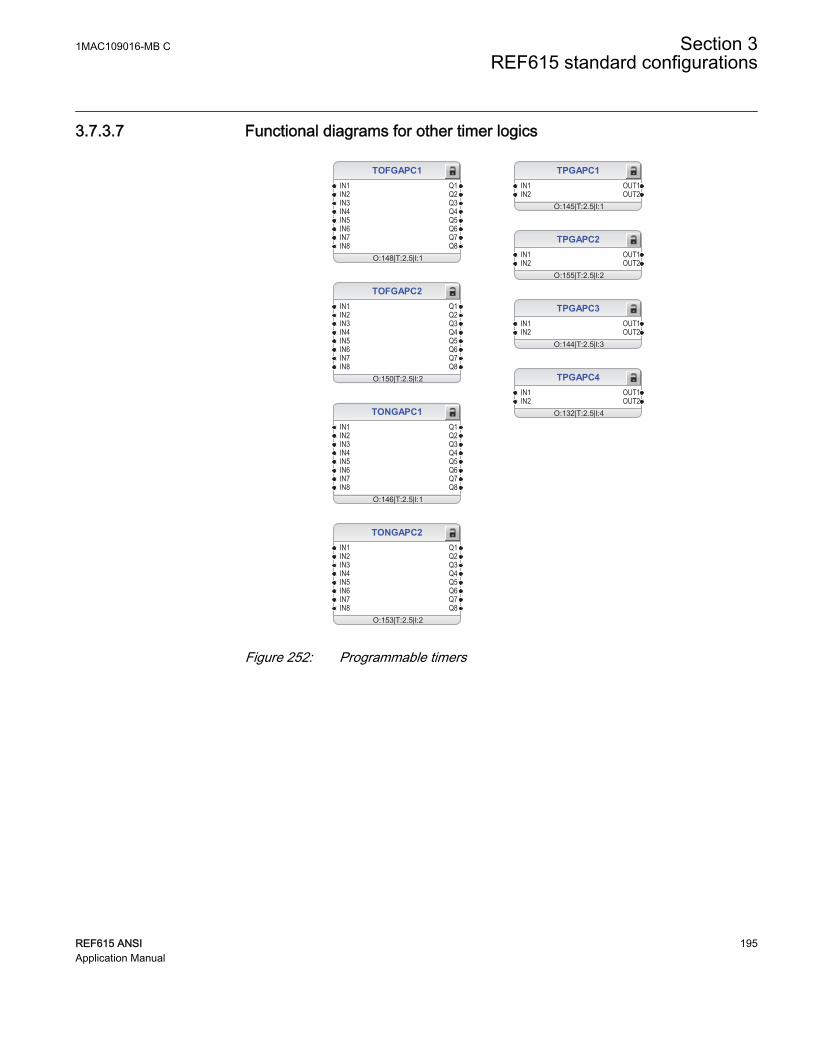
3.7.3.7 Functional diagrams for other timer logics
TOFGAPC1
O:148|T:2.5|I:1
IN1IN2IN3IN4IN5IN6IN7IN8
Q1Q2Q3Q4Q5Q6Q7Q8
TONGAPC1
O:146|T:2.5|I:1
IN1IN2IN3IN4IN5IN6IN7IN8
Q1Q2Q3Q4Q5Q6Q7Q8
TPGAPC1
O:145|T:2.5|I:1
IN1IN2
OUT1OUT2
TPGAPC2
O:155|T:2.5|I:2
IN1IN2
OUT1OUT2
TPGAPC3
O:144|T:2.5|I:3
IN1IN2
OUT1OUT2
TPGAPC4
O:132|T:2.5|I:4
IN1IN2
OUT1OUT2
TOFGAPC2
O:150|T:2.5|I:2
IN1IN2IN3IN4IN5IN6IN7IN8
Q1Q2Q3Q4Q5Q6Q7Q8
TONGAPC2
O:153|T:2.5|I:2
IN1IN2IN3IN4IN5IN6IN7IN8
Q1Q2Q3Q4Q5Q6Q7Q8
GUID-33A57EAE-A49B-4E25-BDBF-3125D318B21F V1 EN
Figure 252: Programmable timers
1MAC109016-MB C Section 3REF615 standard configurations
REF615 ANSI 195Application Manual

3.7.3.8 Functional diagrams for communication
MBSLPRT1
O:162|T:2.5|I:1Status
DNPLPRT1
O:9|T:2.5|I:1Status
SCHLCCH1
O:5|T:2.5|I:1
CH1LIVLNK1LIV
SCHLCCH2
O:131|T:2.5|I:2
CH2LIVLNK2LIV
SCHLCCH3
O:158|T:2.5|I:3
CH3LIVLNK3LIV
SERLCCH1
O:151|T:2.5|I:1
CH1LIVLNK1LIV
SERLCCH2
O:134|T:2.5|I:2
CH2LIVLNK2LIV
RCHLCCH1
O:6|T:2.5|I:1
CHLIV_AREDCHLIV_B
LNKLIV_AREDLNKLIV_B
GUID-32FEC355-9281-44AC-B0B5-A975FD4EA512 V1 EN
Figure 253: Default communication function connection
Section 3 1MAC109016-MB CREF615 standard configurations
196 REF615 ANSIApplication Manual

Section 4 Requirements for measurementtransformers
4.1 Current transformers
4.1.1 Current transformer requirements for overcurrent protection
For reliable and correct operation of the overcurrent protection, the CT has to be chosencarefully. The distortion of the secondary current of a saturated CT may endanger theoperation, selectivity, and co-ordination of protection. However, when the CT is correctlyselected, a fast and reliable short circuit protection can be enabled.
The selection of a CT depends not only on the CT specifications but also on the networkfault current magnitude, desired protection objectives, and the actual CT burden. Theprotection settings of the protection relay should be defined in accordance with the CTperformance as well as other factors.
4.1.1.1 Current transformer accuracy class and accuracy limit factor
The rated accuracy limit factor (Fn) is the ratio of the rated accuracy limit primary currentto the rated primary current. For example, a protective current transformer of type 5P10has the accuracy class 5P and the accuracy limit factor 10. For protective currenttransformers, the accuracy class is designed by the highest permissible percentagecomposite error at the rated accuracy limit primary current prescribed for the accuracyclass concerned, followed by the letter "P" (meaning protection).
Table 39: Limits of errors according to IEC 60044-1 for protective current transformers
Accuracy class Current error atrated primarycurrent (%)
Phase displacement at rated primarycurrent
Composite error atrated accuracy limitprimary current (%)minutes centiradians
5P ±1 ±60 ±1.8 5
10P ±3 - - 10
The accuracy classes 5P and 10P are both suitable for non-directional overcurrentprotection. The 5P class provides a better accuracy. This should be noted also if there areaccuracy requirements for the metering functions (current metering, power metering, andso on) of the protection relay.
1MAC109016-MB C Section 4Requirements for measurement transformers
REF615 ANSI 197Application Manual
The CT accuracy primary limit current describes the highest fault current magnitude atwhich the CT fulfils the specified accuracy. Beyond this level, the secondary current of theCT is distorted and it might have severe effects on the performance of the protection relay.
In practise, the actual accuracy limit factor (Fa) differs from the rated accuracy limit factor(Fn) and is proportional to the ratio of the rated CT burden and the actual CT burden.
The actual accuracy limit factor is calculated using the formula:
F FS S
S Sa n
in n
in
≈ ×
+
+
A071141 V1 EN
Fn the accuracy limit factor with the nominal external burden Sn
Sin the internal secondary burden of the CT
S the actual external burden
4.1.1.2 Non-directional overcurrent protection
The current transformer selectionNon-directional overcurrent protection does not set high requirements on the accuracyclass or on the actual accuracy limit factor (Fa) of the CTs. It is, however, recommendedto select a CT with Fa of at least 20.
The nominal primary current I1n should be chosen in such a way that the thermal anddynamic strength of the current measuring input of the protection relay is not exceeded.This is always fulfilled when
I1n > Ikmax / 100,
Ikmax is the highest fault current.
The saturation of the CT protects the measuring circuit and the current input of theprotection relay. For that reason, in practice, even a few times smaller nominal primarycurrent can be used than given by the formula.
Recommended pickup current settingsIf Ikmin is the lowest primary current at which the highest set overcurrent stage is to trip,the pickup current should be set using the formula:
Current pickup value < 0.7 × (Ikmin / I1n)
Section 4 1MAC109016-MB CRequirements for measurement transformers
198 REF615 ANSIApplication Manual

I1n is the nominal primary current of the CT.
The factor 0.7 takes into account the protection relay inaccuracy, current transformererrors, and imperfections of the short circuit calculations.
The adequate performance of the CT should be checked when the setting of the high setstage overcurrent protection is defined. The trip time delay caused by the CT saturation istypically small enough when the overcurrent setting is noticeably lower than Fa.
When defining the setting values for the low set stages, the saturation of the CT does notneed to be taken into account and the pickup current setting is simply according to theformula.
Delay in operation caused by saturation of current transformersThe saturation of CT may cause a delayed protection relay operation. To ensure the timeselectivity, the delay must be taken into account when setting the trip times of successiveprotection relays.
With definite time mode of operation, the saturation of CT may cause a delay that is aslong as the time constant of the DC component of the fault current, when the current is onlyslightly higher than the pickup current. This depends on the accuracy limit factor of theCT, on the remanence flux of the core of the CT, and on the trip time setting.
With inverse time mode of operation, the delay should always be considered as being aslong as the time constant of the DC component.
With inverse time mode of operation and when the high-set stages are not used, the ACcomponent of the fault current should not saturate the CT less than 20 times the pickupcurrent. Otherwise, the inverse operation time can be further prolonged. Therefore, theaccuracy limit factor Fa should be chosen using the formula:
Fa > 20 × Current pickup value / I1n
The Current pickup value is the primary pickup current setting of the protection relay.
4.1.1.3 Example for non-directional overcurrent protection
The following figure describes a typical medium voltage feeder. The protection isimplemented as three-stage definite time non-directional overcurrent protection.
1MAC109016-MB C Section 4Requirements for measurement transformers
REF615 ANSI 199Application Manual

A071142-ANSI V2 EN
Figure 254: Example of three-stage overcurrent protection
The maximum three-phase fault current is 41.7 kA and the minimum three-phase shortcircuit current is 22.8 kA. The actual accuracy limit factor of the CT is calculated to be 59.
The pickup current setting for low-set stage (51P) is selected to be about twice the nominalcurrent of the cable. The trip time is selected so that it is selective with the next protectionrelay (not visible in Figure 254). The settings for the high-set stage and instantaneousstage are defined also so that grading is ensured with the downstream protection. Inaddition, the pickup current settings have to be defined so that the protection relayoperates with the minimum fault current and it does not trip with the maximum loadcurrent. The settings for all three stages are as in Figure 254.
For the application point of view, the suitable setting for instantaneous stage (50P-3) inthis example is 3 500 A (5.83 × I2n). I2n is the 1.2 multiple with nominal primary currentof the CT. For the CT characteristics point of view, the criteria given by the currenttransformer selection formula is fulfilled and also the protection relay setting isconsiderably below the Fa. In this application, the CT rated burden could have beenselected much lower than 10 VA for economical reasons.
Section 4 1MAC109016-MB CRequirements for measurement transformers
200 REF615 ANSIApplication Manual

Section 5 Protection relay's physical connections
5.1 Inputs
5.1.1 Energizing inputs
5.1.1.1 Phase currents
The protection relay can also be used in single or two-phase applicationsby leaving one or two energizing inputs unoccupied. However, at leastterminals X120:7-8 must be connected.
Table 40: Phase current inputs included in configurations D, F, N and P
Terminal DescriptionX120:7-8 IA
X120:9-10 IB
X120:11-12 IC
5.1.1.2 Ground current
Table 41: Ground current input included in configurations D, F, N and P
Terminal DescriptionX120:13-14 IG
5.1.1.3 Phase voltages
Table 42: Phase voltage inputs included in configurations F and N
Terminal DescriptionX130:11-12 VA
X130:13-14 VB
X130:15-16 VC
1MAC109016-MB C Section 5Protection relay's physical connections
REF615 ANSI 201Application Manual

Table 43: Phase voltage inputs included in configuration P
Terminal DescriptionX130:7-8 VA(2)
X130:9-10 VB(2)
X130:11-12 VC(2)
X130:13-14 VA(1)
X130:15-16 VB(1)
X130:17-18 VC(1)
Table 44: Reference voltage input for SECRSYN1 included in configuration N
Terminal DescriptionX130:9-10 V12B
5.1.1.4 Ground voltage
Table 45: Additional residual voltage input included in configurations F and N
Terminal DescriptionX130:17-18 VG
5.1.1.5 Sensor inputs
Table 46: Combi sensor inputs included in configuration L
Terminal DescriptionX131 IA
VA
X132 IBVB
X133 ICVC
5.1.2 Auxiliary supply voltage input
The auxiliary voltage of the protection relay is connected to terminals X100:1-2. At DCsupply, the positive lead is connected to terminal X100:1. The permitted auxiliary voltagerange is marked on the LHMI of the protection relay on the top of the HMI of the plug-inunit.
Section 5 1MAC109016-MB CProtection relay's physical connections
202 REF615 ANSIApplication Manual

Table 47: Auxiliary voltage supply
Terminal DescriptionX100:1 + Input
X100:2 - Input
5.1.3 Binary inputs
The binary inputs can be used, for example, to generate a blocking signal, to unlatch outputcontacts, to trigger the digital fault recorder or for remote control of protection relay'ssettings.
Binary inputs of slot X110 are available with configurations D, F, L, N and P.
Table 48: Binary input terminals X110:1-13 with BIO0005 module
Terminal DescriptionX110:1 BI1, +
X110:2 BI1, -
X110:3 BI2, +
X110:4 BI2, -
X110:5 BI3, +
X110:6 BI3, -
X110:6 BI4, -
X110:7 BI4, +
X110:8 BI5, +
X110:9 BI5, -
X110:9 BI6, -
X110:10 BI6, +
X110:11 BI7, +
X110:12 BI7, -
X110:12 BI8, -
X110:13 BI8, +
Table 49: Binary input terminals X110:1-10 with BIO0007 module
Terminal DescriptionX110:1 BI1, +
X110:5 BI1, -
X110:2 BI2, +
X110:5 BI2, -
Table continues on next page
1MAC109016-MB C Section 5Protection relay's physical connections
REF615 ANSI 203Application Manual

Terminal DescriptionX110:3 BI3, +
X110:5 BI3, -
X110:4 BI4, +
X110:5 BI4, -
X110:6 BI5, +
X110:10 BI5, -
X110:7 BI6, +
X110:10 BI6, -
X110:8 BI7, +
X110:10 BI7, -
X110:9 BI8, +
X110:10 BI8, -
Binary inputs of slot X120 are available with configurations D, F, N and P.
Table 50: Binary input terminals X120-1...6
Terminal DescriptionX120:1 BI1, +
X120:2 BI1, -
X120:3 BI2, +
X120:2 BI2, -
X120:4 BI3, +
X120:2 BI3, -
X120:5 BI4, +
X120:6 BI4, -
Binary inputs of slot X130 is optional for configuration D.
Table 51: Binary input terminals X130:1-9
Terminal DescriptionX130:1 BI1, +
X130:2 BI1, -
X130:2 BI2, -
X130:3 BI2, +
X130:4 BI3, +
X130:5 BI3, -
X130:5 BI4, -
Table continues on next page
Section 5 1MAC109016-MB CProtection relay's physical connections
204 REF615 ANSIApplication Manual

Terminal DescriptionX130:6 BI4, +
X130:7 BI5, +
X130:8 BI5, -
X130:8 BI6, -
X130:9 BI6, +
Binary inputs of slot X130 are optional for configurations F and N.
Table 52: Binary input terminals X130:1-8 with AIM0006 module
Terminal DescriptionX130:1 BI1, +
X130:2 BI1, -
X130:3 BI2, +
X130:4 BI2, -
X130:5 BI3, +
X130:6 BI3, -
X130:7 BI4, +
X130:8 BI4, -
Binary inputs of slot X130 are optional for configuration P.
Table 53: Binary input terminals X130:1-6 with AIM0007 module
Terminal DescriptionX130:1 BI1, +
X130:2 BI1, -
X130:3 BI2, +
X130:4 BI2, -
X130:5 BI3, +
X130:6 BI3, -
5.1.4 Optional light sensor inputs
If the protection relay is provided with the optional communication module with lightsensor inputs, the pre-manufactured lens-sensor fibers are connected to inputs X13, X14and X15. See the connection diagrams.For further information, see arc flash detector.
1MAC109016-MB C Section 5Protection relay's physical connections
REF615 ANSI 205Application Manual

The protection relay is provided with connection sockets X13, X14 andX15 only if the optional communication module with light sensor inputshas been installed. If the arc flash detector option is selected whenordering a protection relay, the light sensor inputs are included in thecommunication module.
Table 54: Light sensor input connectors
Terminal DescriptionX13 Input Light sensor 1
X14 Input Light sensor 2
X15 Input Light sensor 3
5.1.5 RTD/mA inputs
It is possible to connect mA and RTD based measurement sensors to the protection relayif the protection relay is provided with the optional RTD0001 module in standardconfiguration D and with AIM0003 module in standard configurations F and N.
Table 55: Optional RTD/mA inputs with RTD0001 module
Terminal DescriptionX130:1 mA1 (AI1), +
X130:2 mA1 (AI1), -
X130:3 mA2 (AI2), +
X130:4 mA2 (AI2), -
X130:5 RTD1 (AI3), +
X130:6 RTD1 (AI3), -
X130:7 RTD2 (AI4), +
X130:8 RTD2 (AI4), -
X130:9 RTD3 (AI5), +
X130:10 RTD3 (AI5), -
X130:11 Common1)
X130:12 Common2)
X130:13 RTD4 (AI6), +
X130:14 RTD4 (AI6), -
X130:15 RTD5 (AI7), +
Table continues on next page
Section 5 1MAC109016-MB CProtection relay's physical connections
206 REF615 ANSIApplication Manual

Terminal DescriptionX130:16 RTD5 (AI7), -
X130:17 RTD6 (AI8), +
X130:18 RTD6 (AI8), -
1) Common ground for RTD channels 1-32) Common ground for RTD channels 4-6
Table 56: Optional RTD/mA inputs with AIM0003 module
Terminal DescriptionX130:1 mA 1 (AI1), +
X130:2 mA 1 (AI1), -
X130:3 RTD1 (AI2), +
X130:4 RTD1 (AI2), -
X130:5 RTD1 (AI2), ground
X130:6 RTD2 (AI3), +
X130:7 RTD2 (AI3), -
X130:8 RTD2 (AI3), ground
5.2 Outputs
5.2.1 Outputs for tripping and controlling
Output contacts PO1, PO2, PO3 and PO4 are heavy-duty trip contacts capable ofcontrolling most circuit breakers. In the factory default configuration, the trip signals fromall the protection stages are routed to PO3 and PO4.
Table 57: Output contacts
Terminal DescriptionX100:6 PO1, NO
X100:7 PO1, NO
X100:8 PO2, NO
X100:9 PO2, NO
X100:15 PO3, NO (TCM resistor)
X100:16 PO3, NO
X100:17 PO3, NO
X100:18 PO3 (TCM1 input), NO
X100:19 PO3 (TCM1 input), NO
Table continues on next page
1MAC109016-MB C Section 5Protection relay's physical connections
REF615 ANSI 207Application Manual

Terminal DescriptionX100:20 PO4, NO (TCM resistor)
X100:21 PO4, NO
X100:22 PO4, NO
X100:23 PO4 (TCM2 input), NO
X100:24 PO4 (TCM2 input), NO
5.2.2 Outputs for signalling
SO output contacts can be used for signalling on pickup and tripping of the protectionrelay. On delivery from the factory, the pickup and alarm signals from all the protectionstages are routed to signalling outputs.
Table 58: Output contacts X100:10-14
Terminal DescriptionX100:10 SO1, common
X100:11 SO1, NC
X100:12 SO1, NO
X100:13 SO2, NO
X100:14 SO2, NO
Output contacts of slot X110 are available with configurations D, F, L and N.
Output contacts of slot X110 are optional.
Table 59: Output contacts X110:14-24 with BIO0005
Terminal DescriptionX110:14 SO1, common
X110:15 SO1, NO
X110:16 SO1, NC
X110:17 SO2, common
X110:18 SO2, NO
X110:19 SO2, NC
X110:20 SO3, common
X110:21 SO3, NO
X110:22 SO3, NC
X110:23 SO4, common
X110:24 SO4, NO
Section 5 1MAC109016-MB CProtection relay's physical connections
208 REF615 ANSIApplication Manual

Table 60: Optional high-speed output contacts X110:15-24 with BIO0007
Terminal DescriptionX110:15 HSO1, NO
X110:16 HSO1, NO
X110:19 HSO2, NO
X110:20 HSO2, NO
X110:23 HSO3, NO
X110:24 HSO3, NO
Output contacts of slot X130 are available in the optional BIO module (BIO0006).
Output contacts of slot X130 are optional for configuration D.
Table 61: Output contacts X130:10-18
Terminal DescriptionX130:10 SO1, common
X130:11 SO1, NO
X130:12 SO1, NC
X130:13 SO2, common
X130:14 SO2, NO
X130:15 SO2, NC
X130:16 SO3, common
X130:17 SO3, NO
X130:18 SO3, NC
5.2.3 IRF
The IRF contact functions as an output contact for the self-supervision system of theprotection relay. Under normal operating conditions, the protection relay is energized andthe contact is closed (X100:3-5). When a fault is detected by the self-supervision systemor the auxiliary voltage is disconnected, the contact X100:3-5 drops off and the contactX100:3-4 closes.
Table 62: IRF contact
Terminal DescriptionX100:3 IRF, common
X100:4 Closed; IRF, or Vaux disconnected
X100:5 Closed; no IRF, and Vaux connected
1MAC109016-MB C Section 5Protection relay's physical connections
REF615 ANSI 209Application Manual

210

Section 6 Glossary
100BASE-FX A physical medium defined in the IEEE 802.3 Ethernetstandard for local area networks (LANs) that uses fiber opticcabling
100BASE-TX A physical medium defined in the IEEE 802.3 Ethernetstandard for local area networks (LANs) that uses twisted-pair cabling category 5 or higher with RJ-45 connectors
615 series Series of numerical protection and control relays forprotection and supervision applications of utilitysubstations, and industrial switchgear and equipment
AI Analog inputANSI American National Standards InstituteASCII American Standard Code for Information InterchangeBI Binary inputBIO Binary input and outputBO Binary outputCB Circuit breakerCT Current transformerDAN Doubly attached nodeDC 1. Direct current
2. Disconnector3. Double command
DFR Digital fault recorderDNP3 A distributed network protocol originally developed by
Westronic. The DNP3 Users Group has the ownership ofthe protocol and assumes responsibility for its evolution.
EMC Electromagnetic compatibilityEthernet A standard for connecting a family of frame-based computer
networking technologies into a LANFTP File transfer protocolFTPS FTP Secure
1MAC109016-MB C Section 6Glossary
REF615 ANSI 211Application Manual

GOOSE Generic Object-Oriented Substation EventHMI Human-machine interfaceHSO High-speed outputHSR High-availability seamless redundancyHTTPS Hypertext Transfer Protocol SecureHW HardwareI/O Input/outputIEC 61850 International standard for substation communication and
modelingIEC 61850-9-2 A communication protocol based on the IEC 61850
standard seriesIEC 61850-9-2 LE Lite Edition of IEC 61850-9-2 offering process bus interfaceIP Internet protocolIP address A set of four numbers between 0 and 255, separated by
periods. Each server connected to the Internet is assigned aunique IP address that specifies the location for the TCP/IPprotocol.
IRIG-B Inter-Range Instrumentation Group's time code format BLAN Local area networkLC Connector type for glass fiber cableLCD Liquid crystal displayLED Light-emitting diodeLHMI Local human-machine interfaceLLDB Live line dead busMAC Media access controlMCB Miniature circuit breakerModbus A serial communication protocol developed by the Modicon
company in 1979. Originally used for communication inPLCs and RTU devices.
NC Normally closedNO Normally openPCM600 Protection and Control IED ManagerPO Power outputPRP Parallel redundancy protocol
Section 6 1MAC109016-MB CGlossary
212 REF615 ANSIApplication Manual
REF615 Feeder protection and control relayRIO600 Remote I/O unitRJ-45 Galvanic connector typeRS-232 Serial interface standardRS-485 Serial link according to EIA standard RS485RSTP Rapid spanning tree protocolRTD Resistance temperature detectorRTU Remote terminal unitSAN Single attached nodeSingle-linediagram
Simplified notation for representing a three-phase powersystem. Instead of representing each of three phases with aseparate line or terminal, only one conductor is represented.
SLD Single-line diagramSNTP Simple Network Time ProtocolSO Signal outputTCP Transmission Control ProtocolTCP/IP Transmission Control Protocol/Internet ProtocolTCS Trip-circuit supervisionUDP User datagram protocolUL Underwriters LaboratoriesVT Voltage transformerWAN Wide area networkWHMI Web human-machine interface
1MAC109016-MB C Section 6Glossary
REF615 ANSI 213Application Manual

ABB Distribution SolutionsDistribution AutomationP.O. Box 699FI-65101 VAASA, FinlandPhone +358 10 22 11
ABB Inc.655 Century PointLake Mary, FL 32746, USAPhone +1-800-222 1946
www.abb.com/mediumvoltagewww.abb.com/relionwww.abb.com/substationautomation
—
© Copyright 2019 ABB. All rights reserved. 1MA
C10
9016
-MB
C