441 ANSI 442 ANSI - Armatec
22
02/01 LWN 482.01-E Type 441, 442 ANSI Type 442 ANSI Plain lever H3 Open bonnet Conventional design Type 441 ANSI Packed lever H4 Closed bonnet Conventional design Flanged Safety Relief Valves – spring loaded Contents Chapter/Page Materials • Conventional design 02/02 • Balanced bellows design 02/04 How to order • Numbering system 02/06 • Article numbers 02/08 Dimensions and weights • Metric Units 02/10 • US Units 02/11 Pressure temperature ratings • Metric Units 02/12 • US Units 02/13 Flange drillings and facings 02/14 Order information – Spare parts 02/15 Available options 02/16 Approvals 02/17 Capacities • Steam [Metric Units + US Units] 02/18 • Air [Metric Units + US Units] 02/19 • Water [Metric Units + US Units] 02/20 Determination of coefficient 02/21 of discharge K dr /α w Type 441 ANSI 442 ANSI Type 441 ANSI 442 ANSI
-
Upload
khangminh22 -
Category
Documents
-
view
3 -
download
0
Transcript of 441 ANSI 442 ANSI - Armatec

02/01LWN 482.01-E
Typ
e 44
1, 4
42 A
NS
I
Type 442 ANSIPlain lever H3Open bonnetConventional design
Type 441 ANSIPacked lever H4
Closed bonnetConventional design
Flanged Safety Relief Valves – spring loaded
Contents Chapter/Page
Materials • Conventional design 02/02 • Balanced bellows design 02/04
How to order
• Numbering system 02/06 • Article numbers 02/08
Dimensions and weights • Metric Units 02/10 • US Units 02/11
Pressure temperature ratings • Metric Units 02/12 • US Units 02/13
Flange drillings and facings 02/14 Order information – Spare parts 02/15 Available options 02/16 Approvals 02/17
Capacities • Steam [Metric Units + US Units] 02/18 • Air [Metric Units + US Units] 02/19 • Water [Metric Units + US Units] 02/20 Determination of coefficient 02/21 of discharge Kdr /αw
Type441 ANSI442 ANSI
Type441 ANSI442 ANSI
Conventional design
Type 441, 442 ANSIType 441, 442 ANSI
02/02 LWN 482.01-E
Typ
e 44
1, 4
42 A
NS
I
40 Cap H2
19 Lock nut
16 Upper spring plate
9 Bonnet
12 Spindle
54 Spring
14 Split ring
55 Stud
56 Nut
17 Lower spring plate
8 Guide with bushing
60 Gasket
57 Pin
61 Ball
7 Disc
5 Seat
18 Adjusting screw
1 Body

Conventional design
02/03LWN 482.01-E
Typ
e 44
1, 4
42 A
NS
I
Please notice:
– Modifications reserved by LESER.– LESER can upgrade materials without notice.– Every part can be replaced by other material acc. to customer specification.
Materials
Item Component Type 4412 / 4422 ANSI Type 4414 ANSI
1 Body1.0619 1.4408
SA 216 WCB SA 351 CF8M
5 Seat1.4404 1.4404316L 316L
7 Disc1.4122 1.4404
Hardened stainless steel 316L
8Guide
with bushing
1.4104, 1.0501, 0.7040 1.4404 Chrome or carbon steel 316L
1.4104 tenifer –Chrome steel tenifer –
9 Bonnet 0.7040, 0.7043, 1.0619
1.4408, 1.4404,1.4571
Ductile Gr. 60-40-18,SA 216 WCB
SA 351 CF8M, SA 479 316L, SA 479 316Ti
12 Spindle 1.4021 1.4404
420 316L
14 Split ring1.4104 1.4404
Chrome steel 316L
16/17 Spring plate 1.0718 1.4404Steel 316L
18Adjusting screw
with bushing1.4104 PTFE 1.4404 PTFE
Chrome steel PTFE 316L PTFE
19 Lock nut1.0718 1.4404Steel 316L
40 Cap H21.0718 or 0.7043 1.4404
12L13 or Gr. 60-40-18 316L
54Spring standard
1.1200, 1.8159, 1.7102 1.4310Carbon steel Stainless steel
Spring optional1.4310 –
Stainless steel –
55 Stud1.1181 1.4401Steel B8M
56 Nut1.0501 1.4401
2H 8M
57 Pin1.4310 1.4310
Stainless steel Stainless steel
60 GasketGraphite / 1.4401 Graphite / 1.4401
Graphite / 316 Graphite / 316
61 Ball1.3541 1.4401
Hardened stainless steel 316
Type 441, 442 ANSIType 441, 442 ANSI

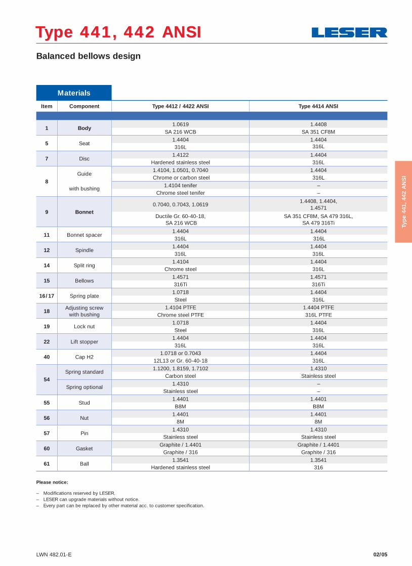
Balanced bellows design
02/04 LWN 482.01-E
Typ
e 44
1, 4
42 A
NS
I
Type 441, 442 ANSIType 441, 442 ANSI
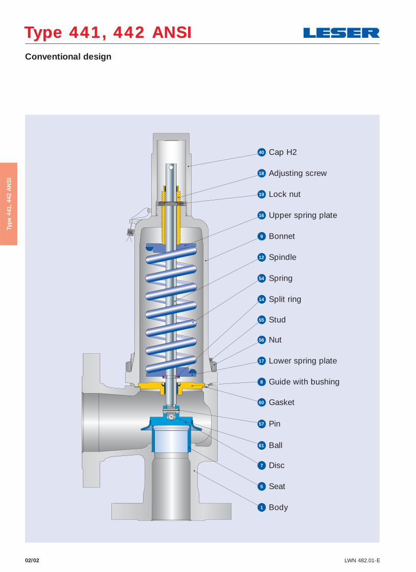
19 Lock nut
18 Adjusting screw
16 Upper spring plate
9 Bonnet
12 Spindle
54 Spring
14 Split ring
17 Lower spring plate
55 Stud
56 Nut
8 Guide with bushing
60 Gasket
11 Bonnet spacer
60 Gasket
22 Lift stopper
15 Bellows
57 Pin
61 Ball
7 Disc
5 Seat
1 Body
40 Cap H2
Balanced bellows design
02/05LWN 482.01-E
Typ
e 44
1, 4
42 A
NS
I
Materials
Item Component Type 4412 / 4422 ANSI Type 4414 ANSI
1 Body1.0619 1.4408
SA 216 WCB SA 351 CF8M
5 Seat1.4404 1.4404316L 316L
7 Disc1.4122 1.4404
Hardened stainless steel 316L
8Guide
with bushing
1.4104, 1.0501, 0.7040 1.4404 Chrome or carbon steel 316L
1.4104 tenifer –Chrome steel tenifer –
9 Bonnet 0.7040, 0.7043, 1.0619
1.4408, 1.4404,1.4571
Ductile Gr. 60-40-18, SA 216 WCB
SA 351 CF8M, SA 479 316L, SA 479 316Ti
11 Bonnet spacer 1.4404 1.4404 316L 316L
12 Spindle 1.4404 1.4404 316L 316L
14 Split ring1.4104 1.4404
Chrome steel 316L
15 Bellows 1.4571 1.4571 316Ti 316Ti
16/17 Spring plate1.0718 1.4404 Steel 316L
18Adjusting screw
with bushing1.4104 PTFE 1.4404 PTFE
Chrome steel PTFE 316L PTFE
19 Lock nut1.0718 1.4404Steel 316L
22 Lift stopper 1.4404 1.4404 316L 316L
40 Cap H2 1.0718 or 0.7043 1.4404
12L13 or Gr. 60-40-18 316L
54Spring standard
1.1200, 1.8159, 1.7102 1.4310Carbon steel Stainless steel
Spring optional1.4310 –
Stainless steel –
55 Stud 1.4401 1.4401B8M B8M
56 Nut1.4401 1.4401
8M 8M
57 Pin1.4310 1.4310
Stainless steel Stainless steel
60 GasketGraphite / 1.4401 Graphite / 1.4401
Graphite / 316 Graphite / 316
61 Ball1.3541 1.3541
Hardened stainless steel 316
Type 441, 442 ANSIType 441, 442 ANSI
Please notice:
– Modifications reserved by LESER.– LESER can upgrade materials without notice.– Every part can be replaced by other material acc. to customer specification.
How to order – Numbering system
02/06 LWN 482.01-E
Typ
e 44
1, 4
42 A
NS
I
Type 441, 442 ANSIType 441, 442 ANSI
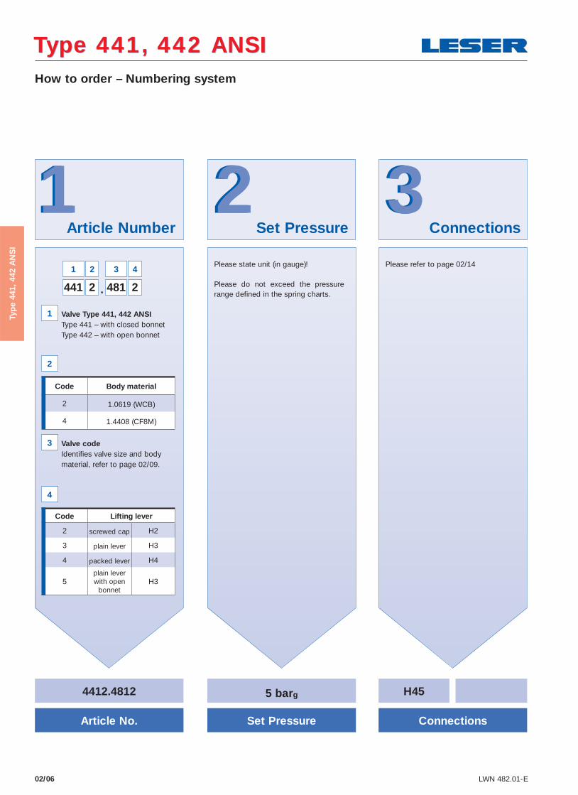
Article Number Set Pressure Connections332211
4412.4812
Article No.
5 barg
Set Pressure Connections
Please state unit (in gauge)!
Please do not exceed the pressure range defined in the spring charts.
441 2 481 2
1 2
1
2
3
4
3 4
.
Valve Type 441, 442 ANSI Type 441 – with closed bonnet
Type 442 – with open bonnet
Valve code Identifies valve size and body material, refer to page 02/09.
H45
Please refer to page 02/14
Code Body material
2 1.0619 (WCB)
4 1.4408 (CF8M)
Code Lifting lever
2 screwed cap H2
3 plain lever H3
4 packed lever H4
5plain lever with open
bonnetH3
02/07LWN 482.01-E
Typ
e 44
1, 4
42 A
NS
I
44 66Options Documentation Code and Medium
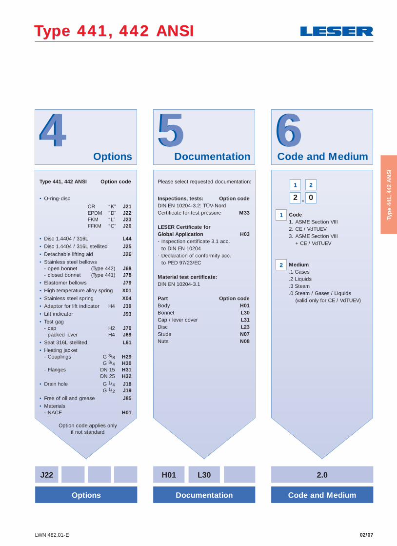
55Type 441, 442 ANSI Option code
• O-ring-disc CR “K” J21 EPDM “D” J22 FKM “L” J23 FFKM “C” J20
• Disc 1.4404 / 316L L44
• Disc 1.4404 / 316L stellited J25
• Detachable lifting aid J26
• Stainless steel bellows - open bonnet (Type 442) J68 - closed bonnet (Type 441) J78
• Elastomer bellows J79
• High temperature alloy spring X01
• Stainless steel spring X04
• Adaptor for lift indicator H4 J39
• Lift indicator J93
• Test gag - cap H2 J70 - packed lever H4 J69
• Seat 316L stellited L61
• Heating jacket - Couplings G 3/8 H29 G 3/4 H30 - Flanges DN 15 H31 DN 25 H32
• Drain hole G 1/4 J18 G 1/2 J19
• Free of oil and grease J85
• Materials - NACE H01
Option code applies onlyif not standard
Please select requested documentation:
Inspections, tests: Option codeDIN EN 10204-3.2: TÜV-NordCertificate for test pressure M33
LESER Certificate for Global Application H03- Inspection certificate 3.1 acc.
to DIN EN 10204- Declaration of conformity acc.
to PED 97/23/EC
Material test certificate:DIN EN 10204-3.1
Part Option codeBody H01Bonnet L30Cap / lever cover L31Disc L23Studs N07Nuts N08
J22 H01 L30
Options Documentation
2.0
Code and Medium
2 0
1 2
.
1
2
Code 1. ASME Section VIII 2. CE / VdTUEV 3. ASME Section VIII + CE / VdTUEV
Medium .1 Gases .2 Liquids .3 Steam .0 Steam / Gases / Liquids (valid only for CE / VdTUEV)
Type 441, 442 ANSIType 441, 442 ANSI

How to order – Article numbers
02/08 LWN 482.01-E
Typ
e 44
1, 4
42 A
NS
I
Type 441, 442 ANSIType 441, 442 ANSI
Type 441 Packed lever H4Closed bonnet
Conventional design
Type 441 Cap H2
Closed bonnetConventional design
Type 442 Plain lever H3Open bonnet
Conventional design

How to order – Article numbers
02/09LWN 482.01-E
Typ
e 44
1, 4
42 A
NS
I
Article numbers Valve size 1" x 2" 1 1/2" x 2" 1 1/2" x 2 1/2" 2" x 3" 3" x 4" 4" x 6" Actual Orifi ce diameter d0 [mm] 23 29 37 46 60 92 Actual Orifi ce area A0 [mm2] 416 661 1075 1662 2827 6648
Body material: 1.0619 (WCB)Bonnet H2 Art.-No. 4412. 4812 4822 4832 4842 4862 4872closed H3 Art.-No. 4412. 4813 4823 4833 4843 4863 4873
H4 Art.-No. 4412. 4814 4824 4834 4844 4864 4874open H3 Art.-No. 4422. 4815 4825 4835 4845 4865 4875
Body material: 1.4408 (CF8M)
Bonnet H2 Art.-No. 4414. 7912 – 7932 7942 7962 7972closed H4 Art.-No. 4414. 7914 – 7934 7944 7964 7974
Type 441, 442 ANSIType 441, 442 ANSI

Dimensions and weights
02/10 LWN 482.01-E
Typ
e 44
1, 4
42 A
NS
I
Metric Units Valve size 1" x 2" 1 1/2" x 2" 1 1/2" x 2 1/2" 2" x 3" 3" x 4" 4" x 6"
Actual Orifi ce diameter d0 [mm] 23 29 37 46 60 92
Actual Orifi ce area A0 [mm2] 416 661 1075 1662 2827 6648
Weight 10 13 16 22 33 75[lbs] with bellows 11 14 17 24 37 83
Center to face Inlet a 105 124 124 136 156 181[mm] Outlet b 114 121 121 124 165 229
Height (H4) Standard H max. 339 455 496 556 685 844[mm] Bellows H max. 378 497 534 602 741 902
Support brackets A 280[mm] B 160
(drilled only on request) C Ø 18
D 250
E 25
Body material: 1.0619 (WCB)
ANSI Flange Inlet CL150 or CL300Class1) Outlet CL150
Body material: 1.4408 (CF8M)
ANSI Flange Inlet CL150 or CL300 – CL150 or CL300Class1) Outlet CL150 – CL150
Conventional design Balanced bellows design
B
C
A
D
E
Support brackets
Type 441, 442 ANSIType 441, 442 ANSI
1) Standard flange rating. For other flange drillings and facings please refer to page 02/14.

Dimensions and weights
02/11LWN 482.01-E
Typ
e 44
1, 4
42 A
NS
I
US Units Valve size 1" x 2" 1 1/2" x 2" 1 1/2" x 2 1/2" 2" x 3" 3" x 4" 4" x 6"
Actual Orifi ce diameter d0 [inch] 0,91 1,14 1,46 1,81 2,36 3,62
Actual Orifi ce area A0 [inch2] 0,644 1,024 1,667 2,576 4,383 10,304
Weight 22 29 35 49 73 165[lbs] with bellows 23 30 38 52 81 183
Center to face Inlet a 4 1/8 4 7/8 4 7/8 5 3/8 6 1/8 7 1/8[inch] Outlet b 4 1/2 4 3/4 4 3/4 4 7/8 6 1/2 9
Height (H4) Standard H max. 13 11/32 17 29/32 19 17/32 21 1/16 26 31/32 33 7/32[inch] Bellows H max. 14 7/8 19 9/16 21 1/32 23 11/16 29 3/16 35 1/2
Support brackets A 11[inch] B 6 1/4
(drilled only on request) C Ø 3/4
D 9 7/8
E 25
Body material: 1.0619 (WCB)
ANSI Flange Inlet CL150 or CL300Class1) Outlet CL150
Body material: 1.4408 (CF8M)
ANSI Flange Inlet CL150 or CL300 – CL150 or CL300Class1) Outlet CL150 – CL150
Conventional design Balanced bellows design
B
C
A
D
E
Support brackets
Type 441, 442 ANSIType 441, 442 ANSI
1) Standard flange rating. For other flange drillings and facings please refer to page 02/14.

02/12 LWN 482.01-E
Pressure temperature ratings
Typ
e 44
1, 4
42 A
NS
I
Metric UnitsValve size 1" x 2" 11/2" x 2" 11/2" x 21/2" 2 x 3" 3 x 4" 4 x 6"
Actual Orifi ce diameter d0 [mm] 23 29 37 46 60 92 Actual Orifi ce area A0 [mm2] 416 661 1075 1662 2827 6648
Body material: 1.0619 (WCB)
ANSI Flange Inlet CL150 or CL300
Class1)Outlet CL150
Minimum p [barg] S/G/L 0,1 0,1 0,1 0,1 0,1 0,1 set pressure
Min. set pressure2)
p [barg] S/G/L 3 3 3 3 3 3 standard bellows
Min. set pressure p [barg] S/G/L 0,98 1,41 1,11 1,81 1,50 1,18 low press. bellows
Maximum p [barg] S/G/L 49 48 46 51 35 34 set pressure
Max. set pressure p [barg] S/G/L 51 48 46 51 40 34 with special spring
Temperature min. [°C] -85 acc. to DIN EN max. [°C] +450
Temperature min. [°C] -29 acc. to ASME max. [°C] +427
Body material: 1.4408 (CF8M)
ANSI Flange Inlet CL150 or CL 300 – CL 150 or CL 300
Class1)Outlet CL 150 – CL 150
Minimum p [barg] S/G/L 0,1 – 0,1 0,1 0,1 0,1 set pressure
Min. set pressure2)
p [barg] S/G/L 3 – 3 3 3 3 standard bellows
Min. set pressure p [barg] S/G/L 0,98 – 1,11 1,81 1,50 1,18 low press. bellows
Maximum p [barg] S/G/L 42,5 – 27 25 27 15 set pressure
Max. set pressure p [barg] S/G/L 51 – 38 40 27 25 with special spring
Temperature min. [°C] -270 – -270 acc. to DIN EN max. [°C] +400 – +400
Temperature min. [°C] -268 – -268 acc. to ASME max. [°C] +538 – +538
Type 441, 442 ANSIType 441, 442 ANSI
1) For fl ange rating class 150 the pressure temperature ratings according to ASME ANSI B 16.34 apply. 2) Min. set pressure standard bellows = Max. set pressure low pressure bellows.

Pressure temperature ratings
02/13LWN 482.01-E
Typ
e 44
1, 4
42 A
NS
I
Type 441, 442 ANSIType 441, 442 ANSI
US UnitsValve size 1" x 2" 11/2" x 2" 11/2" x 21/2" 2 x 3" 3 x 4" 4 x 6"
Actual Orifi ce diameter d0 [inch] 0,91 1,14 1,46 1,81 2,36 3,62 Actual Orifi ce area A0 [inch2] 0,644 1,024 1,667 2,576 4,383 1,304
Body material: 1.0619 (WCB)
ANSI Flange Inlet CL150 or CL300
Class1)Outlet CL150
Minimum p [psig] S/G/L 1,5 1,5 1,5 1,5 1,5 1,5 set pressure
Min. set pressure2)
p [psig] S/G/L 43,5 43,5 43,5 43,5 43,5 43,5 standard bellows
Min. set pressure p [psig] S/G/L 14 20 16 26 22 17 low press. bellows
Maximum p [psig] S/G/L 711 696 667 740 508 493 set pressure
Max. set pressure p [psig] S/G/L 740 696 667 740 580 493 with special spring
Temperature min. [°F] -121 acc. to DIN EN max. [°F] +842
Temperature min. [°F] -20 acc. to ASME max. [°F] +800
Body material: 1.4408 (CF8M)
ANSI Flange Inlet CL 150 or CL 300 – CL 150 or CL 300
Class1)Outlet CL 150 – CL 150
Minimum p [psig] S/G/L 1,5 – 1,5 1,5 1,5 1,5 set pressure
Min. set pressure2)
p [psig] S/G/L 43,5 – 43,5 43,5 43,5 43,5 standard bellows
Min. set pressure p [psig] S/G/L 14 – 16 26 22 17 low press. bellows
Maximum p [psig] S/G/L 616 – 392 363 392 218 set pressure
Max. set pressure p [psig] S/G/L 740 – 551 580 392 363 with special spring
Temperature min. [°F] -454 – -454 acc. to DIN EN max. [°F] +752 – +752
Temperature min. [°F] -450 – -450 acc. to ASME max. [°F] +1000 – +1000
1) For fl ange rating class 150 the pressure temperature ratings according to ASME ANSI B 16.34 apply. 2) Min. set pressure standard bellows = Max. set pressure low pressure bellows.

Flange drillings and facings
02/14 LWN 482.01-E
Typ
e 44
1, 4
42 A
NS
I
Type 441, 442 ANSIType 441, 442 ANSI
Flange drillings Valve size 1" x 2" 11/2" x 2" 11/2" x 21/2" 2" x 3" 3" x 4" 4" x 6"
Actual Orifi ce diameter d0 [mm] 23 29 37 46 60 92
Actual Orifi ce area A0 [mm2] 416 661 1075 1662 2827 6648 Body material: 0.6025 (cast iron)
Inlet ASME B16.5 CL150 H64 H64 H64 H64 H64 H64
CL300 * * * * * *Outlet ASME B16.5
CL150 * * * * * *CL300 – – – – – –
1) According to DIN EN 1092 groove depths and tongue heights increased compared to the formerly valid DIN (refer to LWN 313.40). LESER manufactures the groove at fl anged valves by milling. If a customer demands a turned surface in the soil of the groove according to DIN 2512 and/or DIN EN 1092-1 an additional option code is necessary: “S01: bottom of the groove drilled”. Groove and tongue for PN160 fl anges refer to DIN 2512/LWN 313.32.
Flange facingsIndication Standard Nozzle Outlet Remark
GeneralFlange undrilled – H38 H39
Linde-V-Nut, Form V48 Linde Standard 420-08
LWN 313.36
J07 J08 Groove: Rz 16
Linde-V-Nut, Form V48A J05 J06 Groove: Rz 4, e.g. with hydrogen
Lens seal form L(without sealing lens)
DIN 2696LWN 313.35
J11 J12
Acc. to DIN EN
Flange facing
Inlet Outlet
Remark
DIN EN 1092
(new) DIN 2526(old)
Rz-data according to
DIN EN 1092 in µm(see also LWN 313.40) PN 10 – PN 40 PN 10 – PN 40
Raised faceType B1
Type C
* * Facing: Rz = 12,5 – 50Type D
Type B2 Type E L36 L38 Facing: Rz = 3,2 – 12,5
Ste
el f
lang
es o
nly
Tongue face C1) Tongue face F H94 H92
Groove face D1) Groove face N H93 H91
Male face E Male face V13 H96 H98
Female face F Female face R13 H96 H99
O-ring male face G Male face V14 J01 J02
O-ring female face H Female face R14 J03 J04
Acc. to ASME B16.5
Body material Inlet Outlet
Smooth finish2) Serrated finish RTJ-groove
Inlet Outlet Inlet Outlet Inlet Outlet
Option code Option code RTJ-Class Option code RTJ-Class Option code
1.0619, 1.4408 all all L51 L53 * * CL150 H62 CL150 H63
For signs and symbols refer to page 00/07Note: Flange drillings and facings meet always the requirements of mentioned fl ange standards. Flange thickness and outer diameter may vary from fl ange standard.
2) Smooth fi nish is not defi ned in the effective standards. For LESER‘s defi nition for smooth fi nish see page 00/07.

Order information – Spare parts
02/15LWN 482.01-E
Typ
e 44
1, 4
42 A
NS
I
Type 441, 442 ANSIType 441, 442 ANSI
Spare parts Valve size 1" x 2" 11/2" x 2" 11/2" x 21/2" 2" x 3" 3" x 4" 4" x 6"
Actual Orifi ce diameter d0 [mm] 23 29 37 46 60 92
Actual Orifi ce area A0 [mm2] 416 661 1075 1662 2827 6648
Disc (Item 7): Metal to metal seat Material-No. / Art.-No.
Disc 1.4122 210.9739.9000 210.9839.9000 210.9939.9000 210.8739.9000 220.1639.9000 220.1839.9000detachable lifting aid 1.4404 210.9749.9000 210.9849.9000 210.9949.9000 210.8749.9000 220.1649.9000 220.1849.9000
Disc (Item 7): Soft seal Material-No. / Art.-No.
Disc CR “K” 200.5049.9051 200.5149.9051 200.5249.9051 200.5349.9051 200.5449.9051 on request
EPDM “D” 200.5049.9041 200.5149.9041 200.5249.9041 200.5349.9041 200.5449.9041 200.5649.9041
FPM “L” 200.5049.9071 200.5149.9071 200.5249.9071 200.5349.9071 200.5449.9071 200.5649.9071
FFKM “C” 200.5049.9091 200.5149.9091 200.5249.9091 200.5349.9091 on request on request
O-ring (Item 7.4): Soft seal Material-No. / Art.-No.
O-ring CR “K” 502.0249.3551 502.0313.3551 502.0408.3551 502.0503.3551 502.0660.5351 on request
EPDM “D” 502.0249.3541 502.0313.3541 502.0408.3541 502.0503.3541 502.0660.5341 502.1041.5341
FKM “L” 502.0249.3571 502.0313.3571 502.0408.3571 502.0503.3571 502.0660.5371 502.1041.5371
FFKM “C” 502.0249.3591 502.0313.3591 502.0408.3591 502.0503.3591 on request on request
Bellows (Item 15): 1.4571 Material-No. / Art.-No.
Standard bellows 400.0949.0000 400.1049.0000 400.1149.0000 400.1249.0000 400.1349.0000 400.0849.0000
Conversion kit standard1) 5021.1041 5021.1042 5021.1043 5021.1044 5021.1045 5021.1047
Low pressure bellows 400.0949.0021 400.1049.0021 400.1149.0021 400.1249.0021 400.1349.0021 400.0849.0021
Conversion kit low pressure1) please specify in writing
Gasket – Body / bonnet (Item 60) Material-No. / Art.-No.
Gasket Graphite + 1.4401 500.0607.0000 500.0807.0000 500.1007.0000 500.1207.0000 500.1607.0000 500.2107.0000
Option code L68 Gylon (filled PTFE) 500.0605.0000 500.0805.0000 500.1005.0000 500.1205.0000 500.1605.0000 500.2105.0000
Ball (Item 61) Material-No. / Art.-No.
Ball Ball Ø [mm] 6 6 9 9 12 15
1.4404 510.0104.0000 510.0104.0000 510.0204.0000 510.0204.0000 510.0304.0000 510.0404.0000
Split ring (Item 14) Material-No. / Art.-No.
Split ring Spindle Ø [mm] 12 16 16 16 20 24
1.4404 251.0149.0000 251.0249.0000 251.0249.0000 251.0249.0000 251.0349.0000 251.0449.0000
Pin (Item 57) Material-No. / Art.-No.
Pin 1.4310 480.0505.0000 480.0705.0000 480.0705.0000 480.0705.0000 480.1005.0000 480.1105.0000
Item Component No.
8 Guide 1
11 Bonnet spacer 1
12 Spindle 1
15 Bellows 1
55 Stud 4, 8 depends on valve size
60 Gasket 2, 3 depends on valve size
Installation instruction LWN 037.05 1
1) For pressure range see page 02/12 – 02/13. A conversion kit contains the following components:
Refer to page 02/04
02/16 LWN 482.01-E
Typ
e 44
1, 4
42 A
NS
I
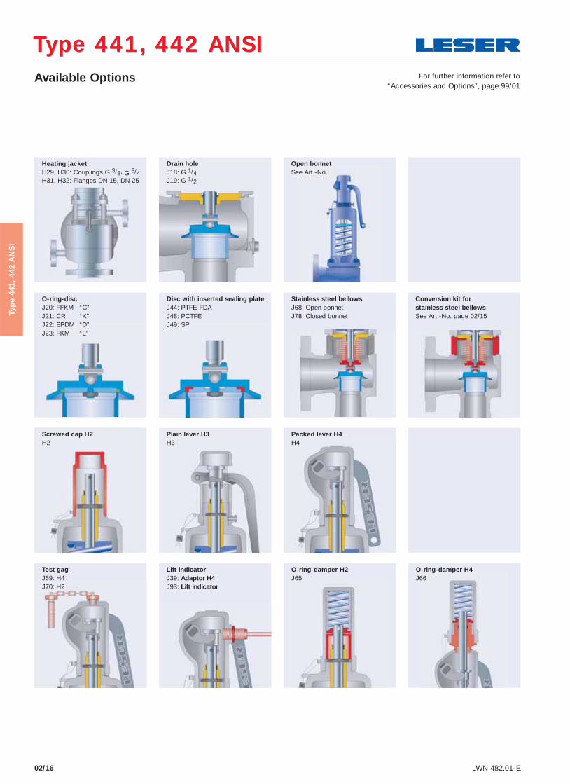
Type 441, 442 ANSIType 441, 442 ANSI Available Options
Heating jacket H29, H30: Couplings G 3/8, G 3/4 H31, H32: Flanges DN 15, DN 25
Open bonnet See Art.-No.
Drain hole J18: G 1/4 J19: G 1/2
O-ring-disc J20: FFKM “C” J21: CR “K” J22: EPDM “D” J23: FKM “L”
Packed lever H4 H4
Plain lever H3 H3
Screwed cap H2 H2
O-ring-damper H2 J65
Lift indicator J39: Adaptor H4 J93: Lift indicator
Test gag J69: H4 J70: H2
O-ring-damper H4 J66
Disc with inserted sealing plate J44: PTFE-FDA J48: PCTFE J49: SP
For further information refer to“Accessories and Options”, page 99/01
Stainless steel bellows J68: Open bonnet J78: Closed bonnet
Conversion kit for stainless steel bellows See Art.-No. page 02/15
02/17LWN 482.01-E
Typ
e 44
1, 4
42 A
NS
I
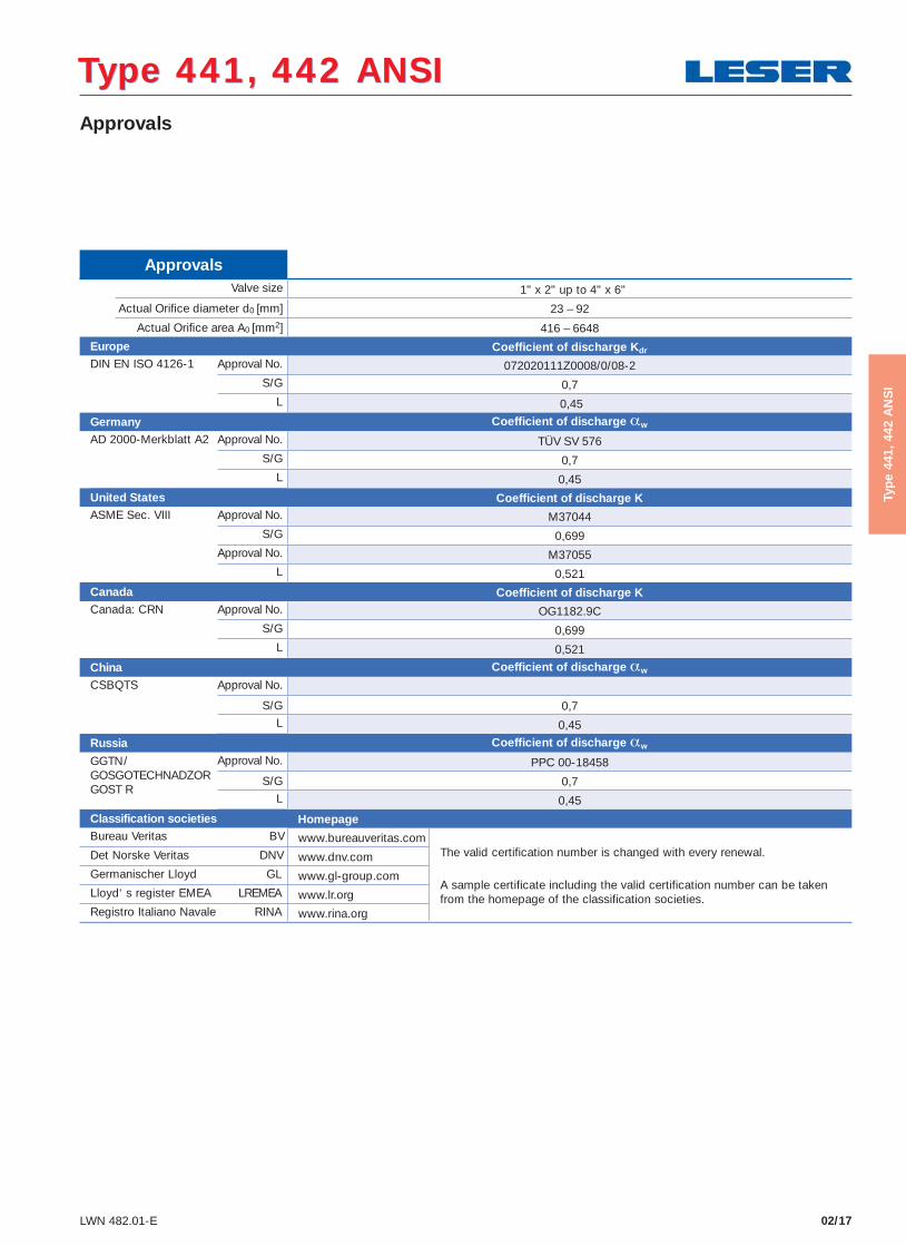
Type 441, 442 ANSIType 441, 442 ANSI Approvals
Approvals Valve size 1" x 2" up to 4" x 6"
Actual Orifi ce diameter d0 [mm] 23 – 92
Actual Orifi ce area A0 [mm2] 416 – 6648
Europe Coefficient of discharge Kdr
DIN EN ISO 4126-1 Approval No. 072020111Z0008/0/08-2S/G 0,7
L 0,45
Germany Coefficient of discharge αw
AD 2000-Merkblatt A2 Approval No. TÜV SV 576S/G 0,7
L 0,45
United States Coefficient of discharge KASME Sec. VIII Approval No. M37044
S/G 0,699 Approval No. M37055
L 0,521
Canada Coefficient of discharge KCanada: CRN Approval No. OG1182.9C
S/G 0,699L 0,521
China Coefficient of discharge αw
CSBQTS Approval No.
S/G 0,7L 0,45
Russia Coefficient of discharge αw
GGTN/GOSGOTECHNADZORGOST R
Approval No. PPC 00-18458
S/G 0,7L 0,45
Classification societies Homepage Bureau Veritas BV www.bureauveritas.com Det Norske Veritas DNV www.dnv.com Germanischer Lloyd GL www.gl-group.com Lloyd‘ s register EMEA LREMEA www.lr.org Registro Italiano Navale RINA www.rina.org
The valid certification number is changed with every renewal.
A sample certificate including the valid certification number can be taken from the homepage of the classification societies.
Capacities – Steam
02/18 LWN 482.01-E
Typ
e 44
1, 4
42 A
NS
I
Type 441, 442 ANSIType 441, 442 ANSI
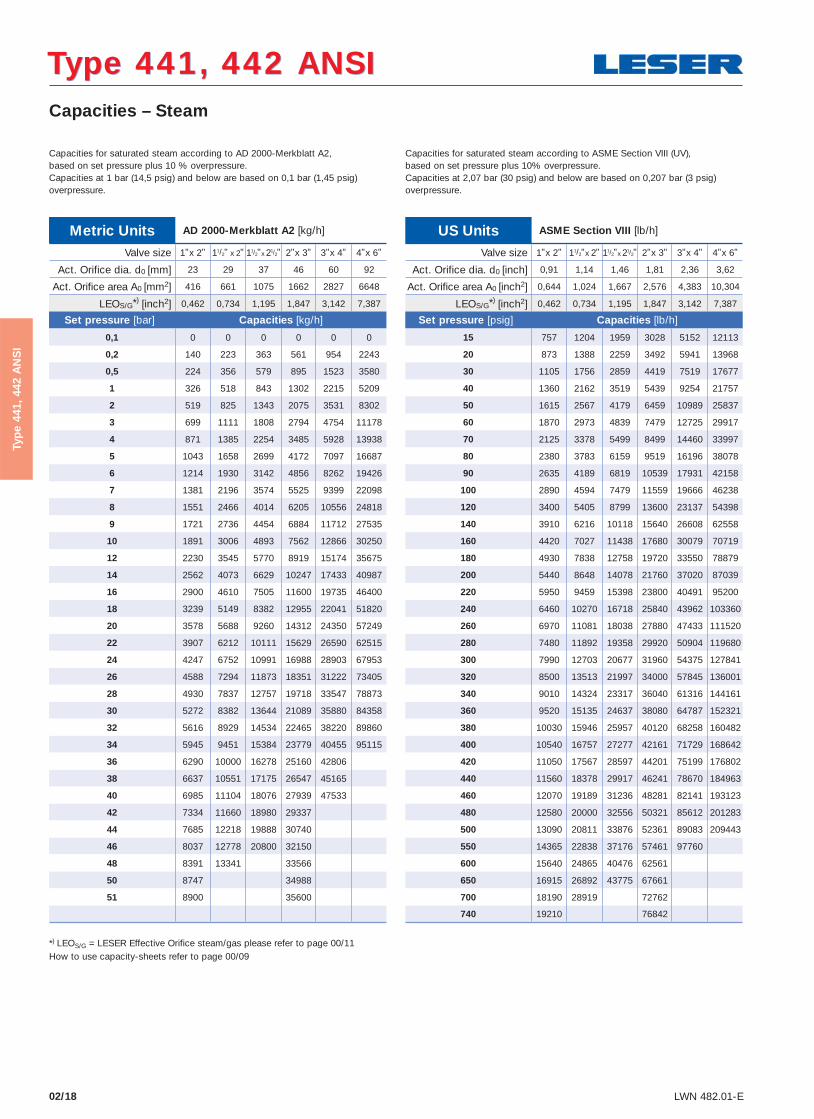
Metric Units AD 2000-Merkblatt A2 [ kg/h]
Valve size 1"x 2" 11/2" x 2" 11/2"x 21/2" 2"x 3" 3"x 4" 4"x 6"
Act. Orifice dia. d0 [mm] 23 29 37 46 60 92
Act. Orifice area A0 [mm2] 416 661 1075 1662 2827 6648
LEOS/G*) [inch2] 0,462 0,734 1,195 1,847 3,142 7,387
Set pressure [bar] Capacities [kg/h]
0,1 0 0 0 0 0 0
0,2 140 223 363 561 954 2243
0,5 224 356 579 895 1523 3580
1 326 518 843 1302 2215 5209
2 519 825 1343 2075 3531 8302
3 699 1111 1808 2794 4754 11178
4 871 1385 2254 3485 5928 13938
5 1043 1658 2699 4172 7097 16687
6 1214 1930 3142 4856 8262 19426
7 1381 2196 3574 5525 9399 22098
8 1551 2466 4014 6205 10556 24818
9 1721 2736 4454 6884 11712 27535
10 1891 3006 4893 7562 12866 30250
12 2230 3545 5770 8919 15174 35675
14 2562 4073 6629 10247 17433 40987
16 2900 4610 7505 11600 19735 46400
18 3239 5149 8382 12955 22041 51820
20 3578 5688 9260 14312 24350 57249
22 3907 6212 10111 15629 26590 62515
24 4247 6752 10991 16988 28903 67953
26 4588 7294 11873 18351 31222 73405
28 4930 7837 12757 19718 33547 78873
30 5272 8382 13644 21089 35880 84358
32 5616 8929 14534 22465 38220 89860
34 5945 9451 15384 23779 40455 95115
36 6290 10000 16278 25160 42806
38 6637 10551 17175 26547 45165
40 6985 11104 18076 27939 47533
42 7334 11660 18980 29337
44 7685 12218 19888 30740
46 8037 12778 20800 32150
48 8391 13341 33566
50 8747 34988
51 8900 35600
*) LEOS/G = LESER Effective Orifice steam/gas please refer to page 00/11How to use capacity-sheets refer to page 00/09
Capacities for saturated steam according to AD 2000-Merkblatt A2,based on set pressure plus 10 % overpressure.Capacities at 1 bar (14,5 psig) and below are based on 0,1 bar (1,45 psig) overpressure.
Capacities for saturated steam according to ASME Section VIII (UV),based on set pressure plus 10% overpressure.Capacities at 2,07 bar (30 psig) and below are based on 0,207 bar (3 psig) overpressure.
US Units ASME Section VIII [lb/h]
Valve size 1"x 2" 11/2"x 2" 11/2"x 21/2" 2"x 3" 3"x 4" 4"x 6"
Act. Orifice dia. d0 [inch] 0,91 1,14 1,46 1,81 2,36 3,62
Act. Orifice area A0 [inch2] 0,644 1,024 1,667 2,576 4,383 10,304
LEOS/G*) [inch2] 0,462 0,734 1,195 1,847 3,142 7,387
Set pressure [psig] Capacities [lb/h]
15 757 1204 1959 3028 5152 12113
20 873 1388 2259 3492 5941 13968
30 1105 1756 2859 4419 7519 17677
40 1360 2162 3519 5439 9254 21757
50 1615 2567 4179 6459 10989 25837
60 1870 2973 4839 7479 12725 29917
70 2125 3378 5499 8499 14460 33997
80 2380 3783 6159 9519 16196 38078
90 2635 4189 6819 10539 17931 42158
100 2890 4594 7479 11559 19666 46238
120 3400 5405 8799 13600 23137 54398
140 3910 6216 10118 15640 26608 62558
160 4420 7027 11438 17680 30079 70719
180 4930 7838 12758 19720 33550 78879
200 5440 8648 14078 21760 37020 87039
220 5950 9459 15398 23800 40491 95200
240 6460 10270 16718 25840 43962 103360
260 6970 11081 18038 27880 47433 111520
280 7480 11892 19358 29920 50904 119680
300 7990 12703 20677 31960 54375 127841
320 8500 13513 21997 34000 57845 136001
340 9010 14324 23317 36040 61316 144161
360 9520 15135 24637 38080 64787 152321
380 10030 15946 25957 40120 68258 160482
400 10540 16757 27277 42161 71729 168642
420 11050 17567 28597 44201 75199 176802
440 11560 18378 29917 46241 78670 184963
460 12070 19189 31236 48281 82141 193123
480 12580 20000 32556 50321 85612 201283
500 13090 20811 33876 52361 89083 209443
550 14365 22838 37176 57461 97760
600 15640 24865 40476 62561
650 16915 26892 43775 67661
700 18190 28919 72762
740 19210 76842

Capacities – Air
02/19LWN 482.01-E
Type 441, 442 ANSIType 441, 442 ANSI
Typ
e 44
1, 4
42 A
NS
I
Metric Units AD 2000-Merkblatt A2 [mn3/h]
Valve size 1"x 2" 11/2" x 2" 11/2"x 21/2" 2"x 3" 3"x 4" 4"x 6"
Act. Orifice dia. d0 [mm] 23 29 37 46 60 92
Act. Orifice area A0 [mm2] 416 661 1075 1662 2827 6648
LEOS/G*) [inch2] 0,462 0,734 1,195 1,847 3,142 7,387
Set pressure [bar] Capacities [mn3/h]
0,1 0 0 0 0 0 0
0,2 162 258 420 649 1105 2597
0,5 263 418 680 1051 1789 4206
1 388 617 1004 1552 2641 6209
2 627 996 1622 2507 4265 10026
3 854 1357 2209 3414 5809 13657
4 1071 1703 2773 4286 7291 17143
5 1289 2050 3337 5157 8774 20629
6 1507 2396 3900 6029 10257 24114
7 1725 2742 4464 6900 11739 27600
8 1943 3089 5028 7771 13222 31086
9 2161 3435 5592 8643 14704 34571
10 2379 3781 6155 9514 16187 38057
12 2814 4474 7283 11257 19152 45028
14 3250 5167 8411 13000 22117 52000
16 3686 5859 9538 14743 25082 58971
18 4121 6552 10666 16486 28047 65942
20 4557 7245 11793 18228 31012 72913
22 4993 7938 12921 19971 33977 79885
24 5429 8630 14048 21714 36943 86856
26 5864 9323 15176 23457 39908 93827
28 6300 10016 16304 25200 42873 100799
30 6736 10708 17431 26942 45838 107770
32 7171 11401 18559 28685 48803 114741
34 7607 12094 19686 30428 51768 121713
36 8043 12786 20814 32171 54733
38 8478 13479 21941 33914 57698
40 8914 14172 23069 35657 60663
42 9350 14864 24197 37399
44 9786 15557 25324 39142
46 10221 16250 26452 40885
48 10657 16942 42628
50 11093 44371
51 11311 45242
*) LEOS/G = LESER Effective Orifice steam/gas please refer to page 00/11How to use capacity-sheets refer to page 00/09
Capacities for air according to AD 2000-Merkblatt A2,based on set pressure plus 10 % overpressure at 0 °C and 1013 mbar.Capacities at 1 bar (14,5 psig) and below are based on 0,1 bar (1,45 psig) overpressure.
Capacities for air according to ASME Section VIII (UV),based on set pressure plus 10 % overpressure at 16 °C (60 °F).Capacities at 2,07 bar (30 psig) and below are based on 0,207 bar(3 psig) overpressure.
US Units ASME Section VIII [S.C.F.M.]
Valve size 1"x 2" 11/2"x 2" 11/2"x 21/2" 2"x 3" 3"x 4" 4"x 6"
Act. Orifice dia. d0 [inch] 0,91 1,14 1,46 1,81 2,36 3,62
Act. Orifice area A0 [inch2] 0,644 1,024 1,667 2,576 4,383 10,304
LEOS/G*) [inch2] 0,462 0,734 1,195 1,847 3,142 7,387
Set pressure [psig] Capacities [S.C.F.M.]
15 270 429 698 1079 1835 4315
20 311 494 805 1244 2116 4976
30 394 626 1019 1574 2679 6297
40 484 770 1254 1938 3297 7750
50 575 915 1489 2301 3915 9204
60 666 1059 1724 2664 4533 10657
70 757 1204 1959 3028 5152 12111
80 848 1348 2194 3391 5770 13564
90 939 1492 2430 3754 6388 15018
100 1029 1637 2665 4118 7006 16471
120 1211 1926 3135 4845 8243 19378
140 1393 2215 3605 5571 9479 22285
160 1574 2504 4076 6298 10716 25192
180 1756 2792 4546 7025 11952 28099
200 1938 3081 5016 7751 13189 31006
220 2120 3370 5486 8478 14425 33913
240 2301 3659 5957 9205 15662 36820
260 2483 3948 6427 9932 16898 39727
280 2665 4237 6897 10658 18135 42633
300 2846 4526 7368 11385 19371 45540
320 3028 4815 7838 12112 20608 48447
340 3210 5104 8308 12839 21844 51354
360 3391 5392 8778 13565 23081 54261
380 3573 5681 9249 14292 24317 57168
400 3755 5970 9719 15019 25554 60075
420 3936 6259 10189 15745 26791 62982
440 4118 6548 10660 16472 28027 65889
460 4300 6837 11130 17199 29264 68796
480 4481 7126 11600 17926 30500 71703
500 4663 7415 12070 18652 31737 74610
550 5117 8137 13246 20469 34828
600 5572 8859 14422 22286
650 6026 9581 15598 24103
700 6480 10303 25920
740 6843 27373
Capacities – Water
02/20 LWN 482.01-E
Typ
e 44
1, 4
42 A
NS
I
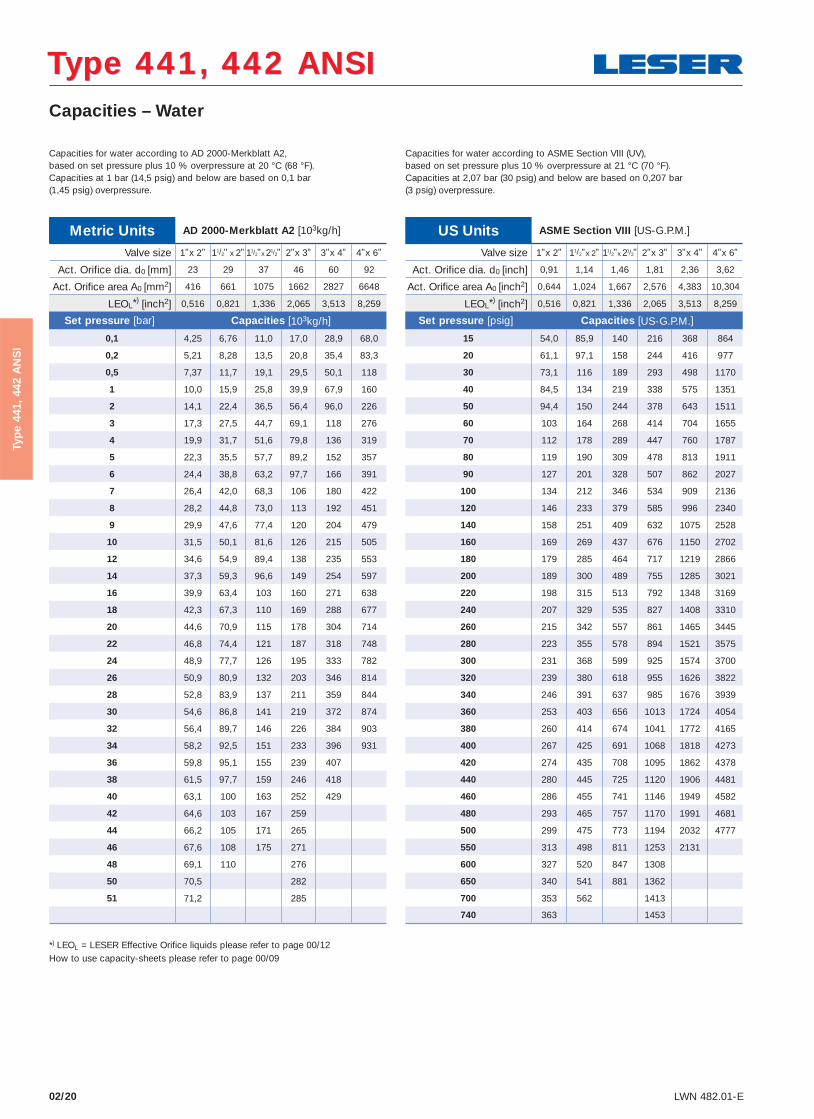
Metric Units AD 2000-Merkblatt A2 [103kg/h]
Valve size 1"x 2" 11/2" x 2" 11/2"x 21/2" 2"x 3" 3"x 4" 4"x 6"
Act. Orifice dia. d0 [mm] 23 29 37 46 60 92
Act. Orifice area A0 [mm2] 416 661 1075 1662 2827 6648
LEOL*) [inch2] 0,516 0,821 1,336 2,065 3,513 8,259
Set pressure [bar] Capacities [103kg/h]
0,1 4,25 6,76 11,0 17,0 28,9 68,0
0,2 5,21 8,28 13,5 20,8 35,4 83,3
0,5 7,37 11,7 19,1 29,5 50,1 118
1 10,0 15,9 25,8 39,9 67,9 160
2 14,1 22,4 36,5 56,4 96,0 226
3 17,3 27,5 44,7 69,1 118 276
4 19,9 31,7 51,6 79,8 136 319
5 22,3 35,5 57,7 89,2 152 357
6 24,4 38,8 63,2 97,7 166 391
7 26,4 42,0 68,3 106 180 422
8 28,2 44,8 73,0 113 192 451
9 29,9 47,6 77,4 120 204 479
10 31,5 50,1 81,6 126 215 505
12 34,6 54,9 89,4 138 235 553
14 37,3 59,3 96,6 149 254 597
16 39,9 63,4 103 160 271 638
18 42,3 67,3 110 169 288 677
20 44,6 70,9 115 178 304 714
22 46,8 74,4 121 187 318 748
24 48,9 77,7 126 195 333 782
26 50,9 80,9 132 203 346 814
28 52,8 83,9 137 211 359 844
30 54,6 86,8 141 219 372 874
32 56,4 89,7 146 226 384 903
34 58,2 92,5 151 233 396 931
36 59,8 95,1 155 239 407
38 61,5 97,7 159 246 418
40 63,1 100 163 252 429
42 64,6 103 167 259
44 66,2 105 171 265
46 67,6 108 175 271
48 69,1 110 276
50 70,5 282
51 71,2 285
*) LEOL = LESER Effective Orifice liquids please refer to page 00/12How to use capacity-sheets please refer to page 00/09
Capacities for water according to AD 2000-Merkblatt A2,based on set pressure plus 10 % overpressure at 20 °C (68 °F).Capacities at 1 bar (14,5 psig) and below are based on 0,1 bar (1,45 psig) overpressure.
Capacities for water according to ASME Section VIII (UV), based on set pressure plus 10 % overpressure at 21 °C (70 °F).Capacities at 2,07 bar (30 psig) and below are based on 0,207 bar (3 psig) overpressure.
US Units ASME Section VIII [US-G.P.M.]
Valve size 1"x 2" 11/2"x 2" 11/2"x 21/2" 2"x 3" 3"x 4" 4"x 6"
Act. Orifice dia. d0 [inch] 0,91 1,14 1,46 1,81 2,36 3,62
Act. Orifice area A0 [inch2] 0,644 1,024 1,667 2,576 4,383 10,304
LEOL*) [inch2] 0,516 0,821 1,336 2,065 3,513 8,259
Set pressure [psig] Capacities [US-G.P.M.]
15 54,0 85,9 140 216 368 864
20 61,1 97,1 158 244 416 977
30 73,1 116 189 293 498 1170
40 84,5 134 219 338 575 1351
50 94,4 150 244 378 643 1511
60 103 164 268 414 704 1655
70 112 178 289 447 760 1787
80 119 190 309 478 813 1911
90 127 201 328 507 862 2027
100 134 212 346 534 909 2136
120 146 233 379 585 996 2340
140 158 251 409 632 1075 2528
160 169 269 437 676 1150 2702
180 179 285 464 717 1219 2866
200 189 300 489 755 1285 3021
220 198 315 513 792 1348 3169
240 207 329 535 827 1408 3310
260 215 342 557 861 1465 3445
280 223 355 578 894 1521 3575
300 231 368 599 925 1574 3700
320 239 380 618 955 1626 3822
340 246 391 637 985 1676 3939
360 253 403 656 1013 1724 4054
380 260 414 674 1041 1772 4165
400 267 425 691 1068 1818 4273
420 274 435 708 1095 1862 4378
440 280 445 725 1120 1906 4481
460 286 455 741 1146 1949 4582
480 293 465 757 1170 1991 4681
500 299 475 773 1194 2032 4777
550 313 498 811 1253 2131
600 327 520 847 1308
650 340 541 881 1362
700 353 562 1413
740 363 1453
Type 441, 442 ANSIType 441, 442 ANSI

Determination of coefficent of discharge in case of lift restriction or back pressure
02/21LWN 482.01-E
How to use please refer to page 00/08
Type 441, 442 ANSIType 441, 442 ANSI
Typ
e 44
1, 4
42 A
NS
I
h = Lift [mm]d0 = Flow diameter [mm] of selected safety valve, refer to table article numbersh/d0 = Ratio of lift / flow diameter pa0 = Back pressure [bara]p0 = Set pressure [bara]pa0/p0 = Ratio of back pressure / set pressure Kdr = Coefficient of discharge acc. to DIN EN ISO 4126-1 αw = Coefficient of discharge acc. to AD 2000-Merkblatt A2Kb = Back pressure correction factor acc. to API 520 topic 3.3
0,7
0,8
0,5
0,6
0,3
0,4
0,910,80,40,3
0,1
0,20
0,5 0,6 0,7
0,2
1,0
0,7
0,8
0,9
0,5
0,6
0,1
0
0,2
0,3
0,4
Kdr = αw = f (pa0/p0) and Kb = f (pa0/p0)
Coe
ffici
ent
of d
isch
arge
Kd
r / α
w
Bac
k p
ress
ure
corr
ectio
n fa
ctor
Kb
Ratio of back pressure / set pressure pa0 / p0
1" – 4", L
1" - 4" , S/G
0,30,1 0,20
0,8
0,5
0,3
0,4
0,6
0,7
0,1
0
0,2
Kdr = αw = f (h/d0)
Ratio of lift / flow diameter h / d0
Coe
ffici
ent
of d
isch
arge
Kd
r / α
w
Diagram for evaluation of ratio of lift / fl ow diameter (h/d0)in reference to the coeffi cient of discharge (Kdr/αw)
Diagram for evaluation of coeffi cient of discharge (Kdr/αw) or Kb
in reference to the ratio of back pressure / set pressure (pa0/p0)

02/22 LWN 482.01-E
Type 441, 442 ANSIType 441, 442 ANSI
Typ
e 44
1, 4
42 A
NS
I