Liquid ring vacuum pumps - Armatec
13
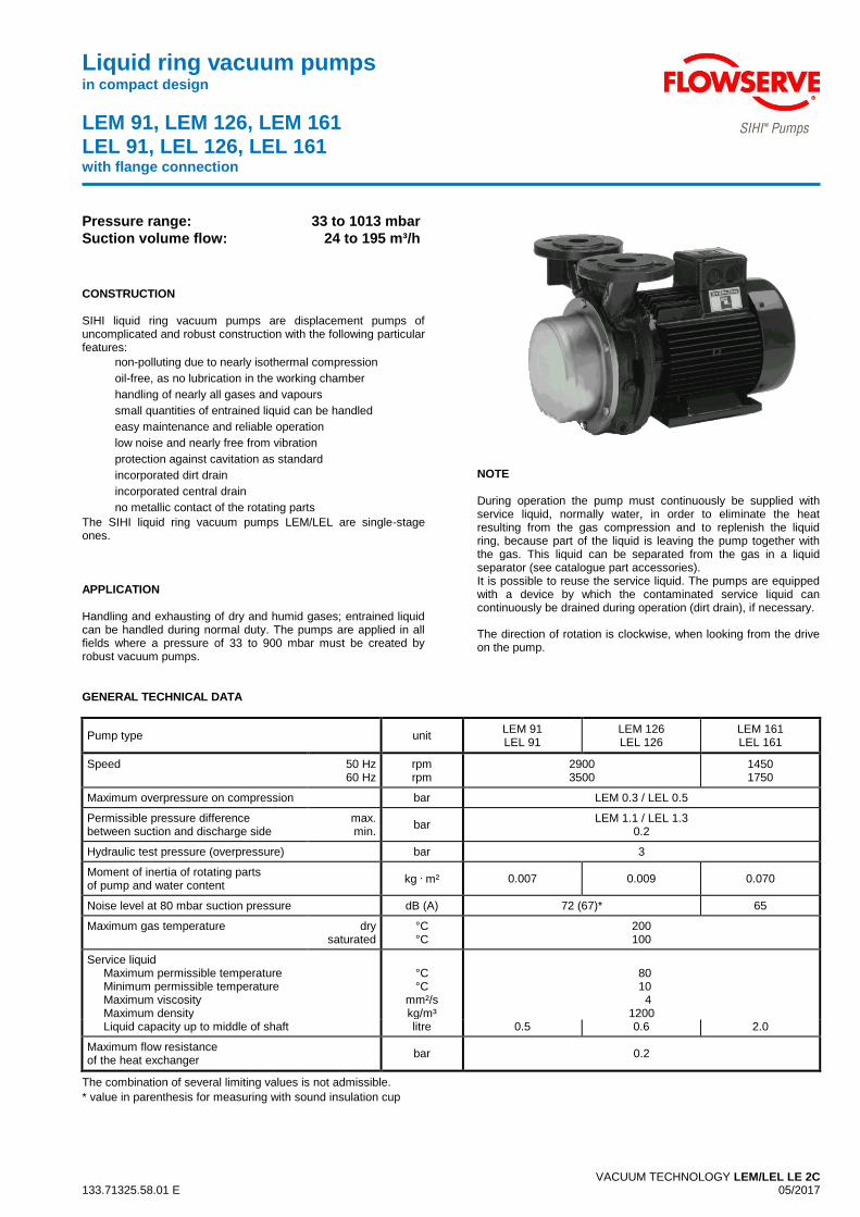
Liquid ring vacuum pumps in compact design LEM 91, LEM 126, LEM 161 LEL 91, LEL 126, LEL 161 with flange connection VACUUM TECHNOLOGY LEM/LEL LE 2C 133.71325.58.01 E 05/2017 Pressure range: 33 to 1013 mbar Suction volume flow: 24 to 195 m³/h CONSTRUCTION SIHI liquid ring vacuum pumps are displacement pumps of uncomplicated and robust construction with the following particular features: non-polluting due to nearly isothermal compression oil-free, as no lubrication in the working chamber handling of nearly all gases and vapours small quantities of entrained liquid can be handled easy maintenance and reliable operation low noise and nearly free from vibration protection against cavitation as standard incorporated dirt drain incorporated central drain no metallic contact of the rotating parts The SIHI liquid ring vacuum pumps LEM/LEL are single-stage ones. APPLICATION Handling and exhausting of dry and humid gases; entrained liquid can be handled during normal duty. The pumps are applied in all fields where a pressure of 33 to 900 mbar must be created by robust vacuum pumps. NOTE During operation the pump must continuously be supplied with service liquid, normally water, in order to eliminate the heat resulting from the gas compression and to replenish the liquid ring, because part of the liquid is leaving the pump together with the gas. This liquid can be separated from the gas in a liquid separator (see catalogue part accessories). It is possible to reuse the service liquid. The pumps are equipped with a device by which the contaminated service liquid can continuously be drained during operation (dirt drain), if necessary. The direction of rotation is clockwise, when looking from the drive on the pump. GENERAL TECHNICAL DATA Pump type unit LEM 91 LEL 91 LEM 126 LEL 126 LEM 161 LEL 161 Speed 50 Hz 60 Hz rpm rpm 2900 3500 1450 1750 Maximum overpressure on compression bar LEM 0.3 / LEL 0.5 Permissible pressure difference between suction and discharge side max. min. bar LEM 1.1 / LEL 1.3 0.2 Hydraulic test pressure (overpressure) bar 3 Moment of inertia of rotating parts of pump and water content kg . m² 0.007 0.009 0.070 Noise level at 80 mbar suction pressure dB (A) 72 (67)* 65 Maximum gas temperature dry saturated °C °C 200 100 Service liquid Maximum permissible temperature Minimum permissible temperature Maximum viscosity Maximum density °C °C mm²/s kg/m³ 80 10 4 1200 Liquid capacity up to middle of shaft litre 0.5 0.6 2.0 Maximum flow resistance of the heat exchanger bar 0.2 The combination of several limiting values is not admissible. * value in parenthesis for measuring with sound insulation cup
-
Upload
khangminh22 -
Category
Documents
-
view
1 -
download
0
Transcript of Liquid ring vacuum pumps - Armatec
Liquid ring vacuum pumps in compact design
LEM 91, LEM 126, LEM 161
LEL 91, LEL 126, LEL 161 with flange connection
VACUUM TECHNOLOGY LEM/LEL LE 2C 133.71325.58.01 E 05/2017
Pressure range: 33 to 1013 mbar
Suction volume flow: 24 to 195 m³/h
CONSTRUCTION SIHI liquid ring vacuum pumps are displacement pumps of uncomplicated and robust construction with the following particular features:
non-polluting due to nearly isothermal compression
oil-free, as no lubrication in the working chamber
handling of nearly all gases and vapours
small quantities of entrained liquid can be handled
easy maintenance and reliable operation
low noise and nearly free from vibration
protection against cavitation as standard
incorporated dirt drain
incorporated central drain
no metallic contact of the rotating parts
The SIHI liquid ring vacuum pumps LEM/LEL are single-stage ones.
APPLICATION Handling and exhausting of dry and humid gases; entrained liquid can be handled during normal duty. The pumps are applied in all fields where a pressure of 33 to 900 mbar must be created by robust vacuum pumps.
NOTE During operation the pump must continuously be supplied with service liquid, normally water, in order to eliminate the heat resulting from the gas compression and to replenish the liquid ring, because part of the liquid is leaving the pump together with the gas. This liquid can be separated from the gas in a liquid separator (see catalogue part accessories). It is possible to reuse the service liquid. The pumps are equipped with a device by which the contaminated service liquid can continuously be drained during operation (dirt drain), if necessary. The direction of rotation is clockwise, when looking from the drive on the pump.
GENERAL TECHNICAL DATA
Pump type unit LEM 91 LEL 91
LEM 126 LEL 126
LEM 161 LEL 161
Speed 50 Hz 60 Hz
rpm rpm
2900 3500
1450 1750
Maximum overpressure on compression bar LEM 0.3 / LEL 0.5
Permissible pressure difference between suction and discharge side
max. min.
bar LEM 1.1 / LEL 1.3
0.2
Hydraulic test pressure (overpressure) bar 3
Moment of inertia of rotating parts of pump and water content
kg . m² 0.007 0.009 0.070
Noise level at 80 mbar suction pressure dB (A) 72 (67)* 65
Maximum gas temperature dry saturated
°C °C
200 100
Service liquid Maximum permissible temperature Minimum permissible temperature Maximum viscosity Maximum density
°C °C
mm²/s kg/m³
80 10 4 1200
Liquid capacity up to middle of shaft litre 0.5 0.6 2.0
Maximum flow resistance of the heat exchanger
bar 0.2
The combination of several limiting values is not admissible.
* value in parenthesis for measuring with sound insulation cup
2
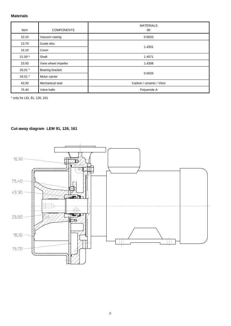
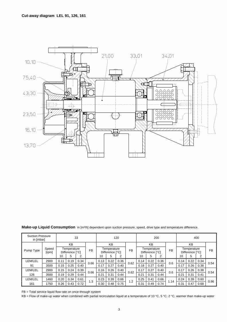
Materials
MATERIALS
Item COMPONENTS 0K
10.10 Vacuum casing 0.6025
13.70 Guide disc 1.4301
16.10 Cover
21.00 * Shaft 1.4571
23.50 Vane wheel impeller 1.4308
33.01 * Bearing bracket 0.6025
34.01 * Motor carrier
43.30 Mechanical seal Carbon / ceramic / Viton
75.40 Valve balls Polyamide A
* only for LEL 91, 126, 161
Cut-away diagram LEM 91, 126, 161
3
Cut-away diagram LEL 91, 126, 161
Make-up Liquid Consumption in [m³/h] dependent upon suction pressure, speed, drive type and temperature difference.
Suction Pressure in [mbar]
33 120 200 400
KB KB KB KB
Pump Type Speed [rpm]
Temperature Difference [°C]
FB Temperature
Difference [°C] FB
Temperature Difference [°C]
FB Temperature
Difference [°C] FB
10 5 2 10 5 2 10 5 2 10 5 2
LEM/LEL 2900 0.11 0.19 0.34 0.66
0.13 0.22 0.36 0.62
0.14 0.22 0.36 0.6
0.14 0.22 0.34 0.54
91 3500 0.15 0.25 0.40 0.17 0.27 0.40 0.18 0.27 0.40 0.17 0.26 0.38
LEM/LEL 2900 0.15 0.24 0.39 0.66
0.16 0.26 0.40 0.62
0.17 0.27 0.40 0.6
0.17 0.26 0.38 0.54
126 3500 0.19 0.29 0.44 0.21 0.31 0.44 0.21 0.31 0.44 0.21 0.31 0.41
LEM/LEL 1460 0.20 0.34 0.61 1.3
0.23 0.39 0.66 1.2
0.25 0.41 0.66 1.14
0.24 0.39 0.60 0.96
161 1750 0.26 0.43 0.72 0.30 0.48 0.75 0.31 0.49 0.74 0.31 0.47 0.68
FB = Total service liquid flow rate on once-through system
KB = Flow of make-up water when combined with partial recirculation liquid at a temperature of 10 °C, 5 °C, 2 °C, warmer than make-up water

4
Performance Characteristics LEM 91 / LEL 91
0
20
40
60
80
100
10 100 1000
suction pressure
su
cti
on
vo
lum
e f
low
2900 rpm
3500 rpm
m³/h
40 60 80 200 400 mbar
LEM/LEL 91
0
1
2
3
4
10 100 1000
suction pressure
po
wer
ab
so
rpti
on
kW
2900 rpm
3500 rpm
40 60 80 200 400 mbar
LEM/LEL 91
The operating data is valid under the following conditions:
process media: - dry air: 20°C - steam saturated air: 20°C
service liquid: - water: 15°C Pressure of gas to be evacuated: 1013 mbar (atmospheric pressure) The suction volume is related to the suction pressure. Tolerance on operating data is 10%. The maximum consumption of make-up water occurs at the lowest suction pressure.
5
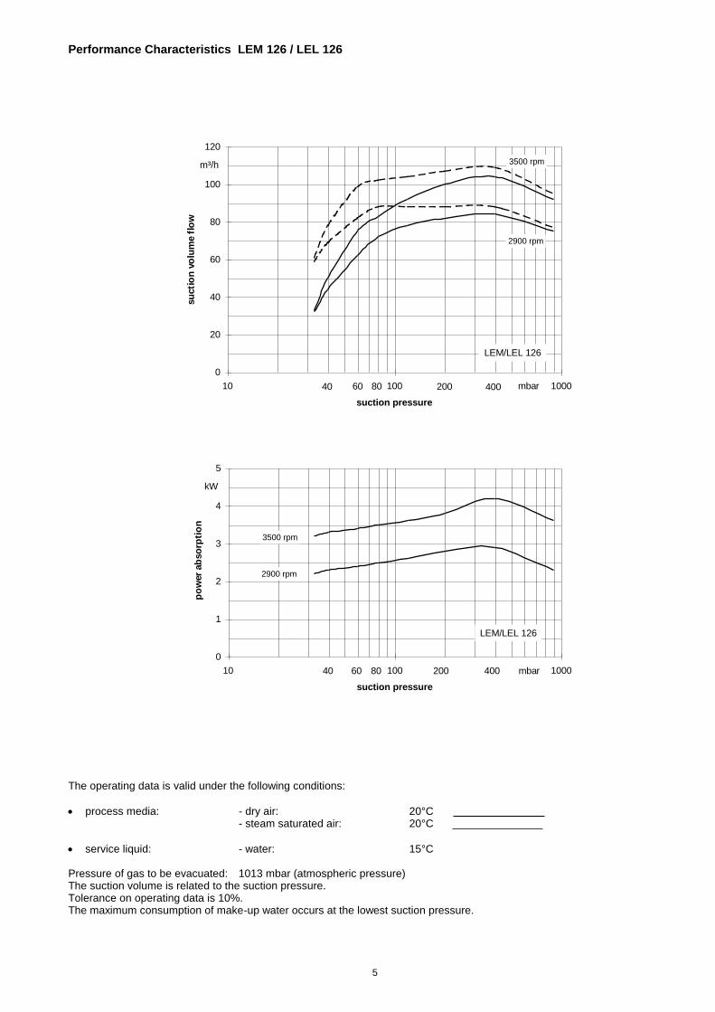
Performance Characteristics LEM 126 / LEL 126
0
20
40
60
80
100
120
10 100 1000
suction pressure
su
cti
on
vo
lum
e f
low
2900 rpm
3500 rpmm³/h
40 60 80 200 400 mbar
LEM/LEL 126
0
1
2
3
4
5
10 100 1000
suction pressure
po
wer
ab
so
rpti
on
kW
2900 rpm
3500 rpm
40 60 80 200 400 mbar
LEM/LEL 126
The operating data is valid under the following conditions:
process media: - dry air: 20°C - steam saturated air: 20°C
service liquid: - water: 15°C Pressure of gas to be evacuated: 1013 mbar (atmospheric pressure) The suction volume is related to the suction pressure. Tolerance on operating data is 10%. The maximum consumption of make-up water occurs at the lowest suction pressure.
6
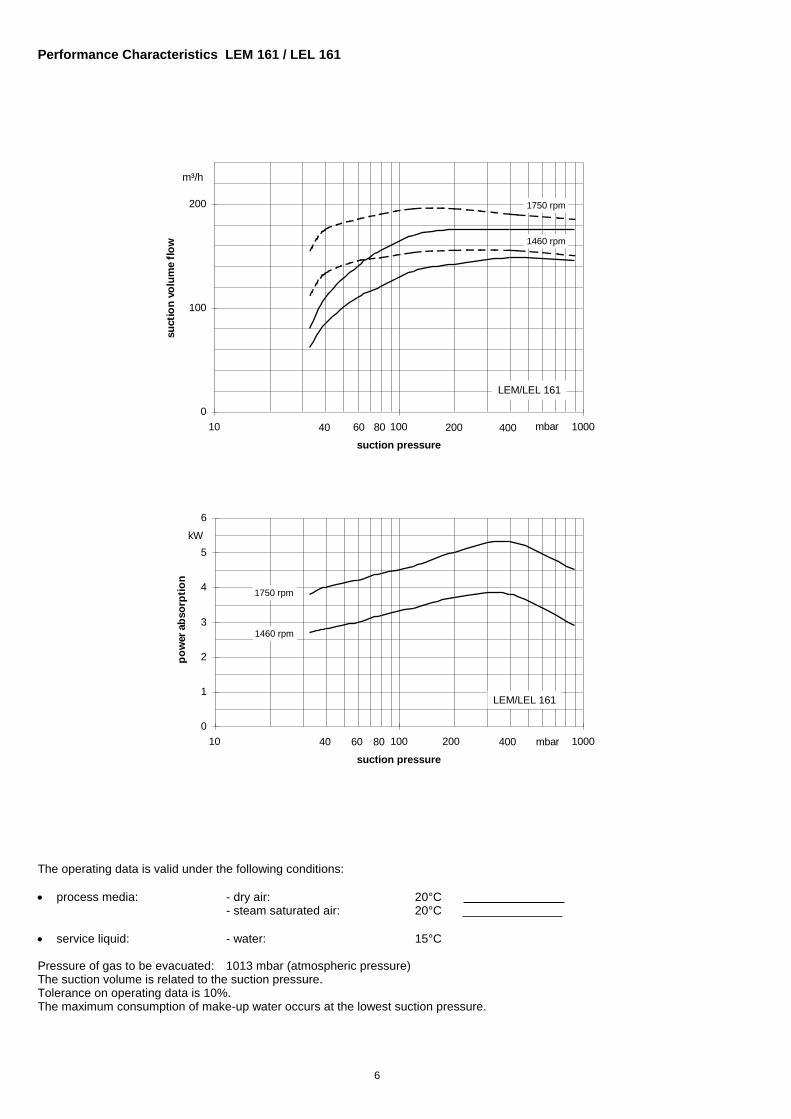
Performance Characteristics LEM 161 / LEL 161
0
100
200
10 100 1000
suction pressure
su
cti
on
vo
lum
e f
low 1460 rpm
1750 rpm
m³/h
40 60 80 200 400 mbar
LEM/LEL 161
0
1
2
3
4
5
6
10 100 1000
suction pressure
po
wer
ab
so
rpti
on
kW
1460 rpm
1750 rpm
40 60 80 200 400 mbar
LEM/LEL 161
The operating data is valid under the following conditions:
process media: - dry air: 20°C - steam saturated air: 20°C
service liquid: - water: 15°C Pressure of gas to be evacuated: 1013 mbar (atmospheric pressure) The suction volume is related to the suction pressure. Tolerance on operating data is 10%. The maximum consumption of make-up water occurs at the lowest suction pressure.
7
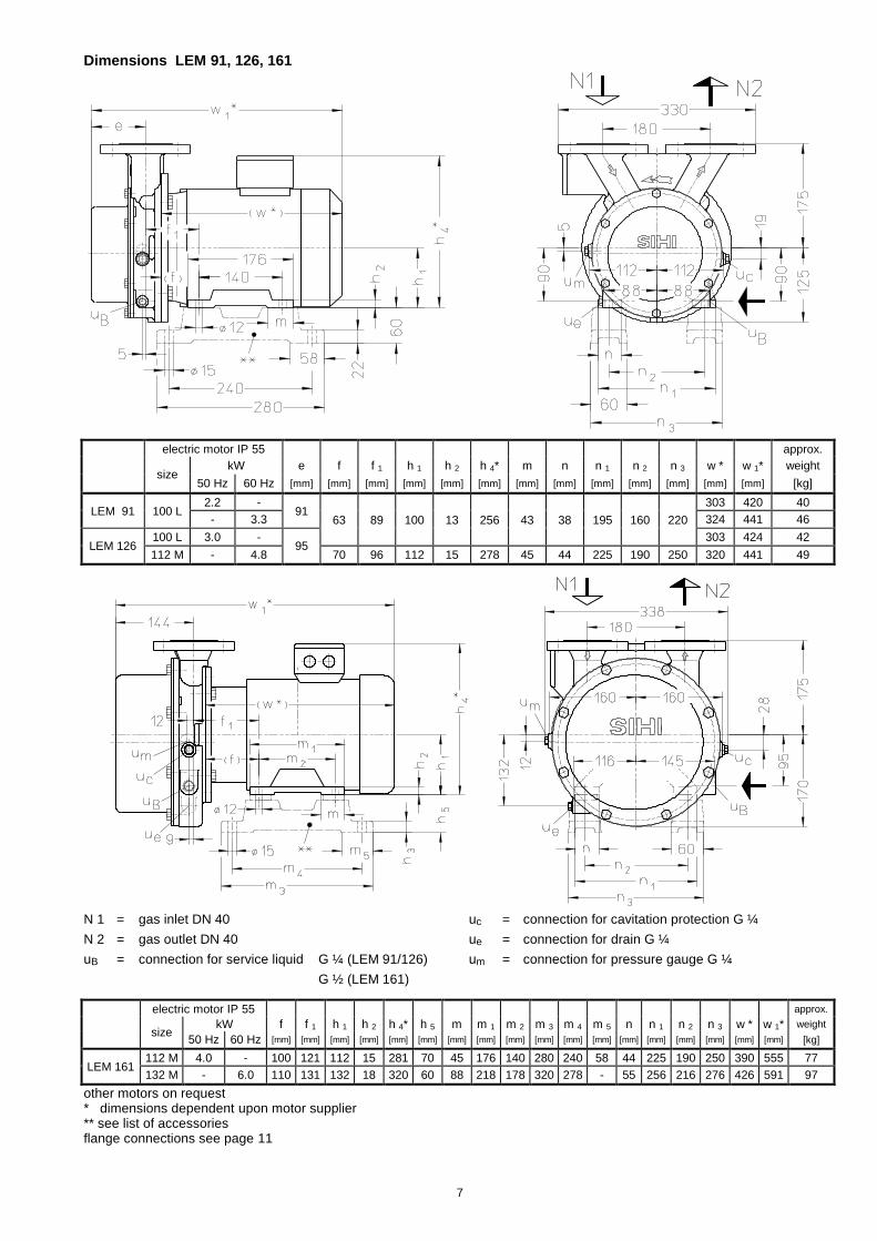
Dimensions LEM 91, 126, 161
electric motor IP 55 approx.
size
kW e f f 1 h 1 h 2 h 4* m n n 1 n 2 n 3 w * w 1* weight
50 Hz 60 Hz [mm] [mm] [mm] [mm] [mm] [mm] [mm] [mm] [mm] [mm] [mm] [mm] [mm] [kg]
LEM 91 100 L 2.2 -
91 63 89 100 13 256 43 38 195 160 220
303 420 40
- 3.3 324 441 46
LEM 126 100 L 3.0 -
95 303 424 42
112 M - 4.8 70 96 112 15 278 45 44 225 190 250 320 441 49
N 1 = gas inlet DN 40 uc = connection for cavitation protection G ¼
N 2 = gas outlet DN 40 ue = connection for drain G ¼
uB = connection for service liquid G ¼ (LEM 91/126) um = connection for pressure gauge G ¼
G ½ (LEM 161)
electric motor IP 55 approx.
size
kW f f 1 h 1 h 2 h 4* h 5 m m 1 m 2 m 3 m 4 m 5 n n 1 n 2 n 3 w * w 1* weight
50 Hz 60 Hz [mm] [mm] [mm] [mm] [mm] [mm] [mm] [mm] [mm] [mm] [mm] [mm] [mm] [mm] [mm] [mm] [mm] [mm] [kg]
LEM 161 112 M 4.0 - 100 121 112 15 281 70 45 176 140 280 240 58 44 225 190 250 390 555 77
132 M - 6.0 110 131 132 18 320 60 88 218 178 320 278 - 55 256 216 276 426 591 97
other motors on request * dimensions dependent upon motor supplier ** see list of accessories flange connections see page 11
8
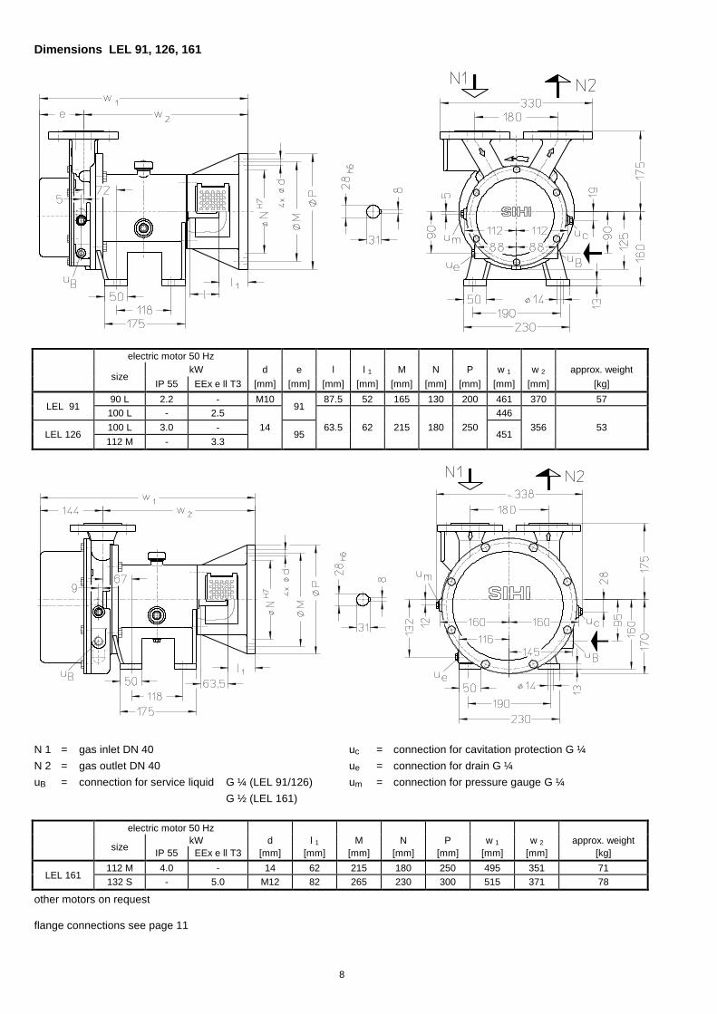
Dimensions LEL 91, 126, 161
electric motor 50 Hz
size
kW d e l l 1 M N P w 1 w 2 approx. weight
IP 55 EEx e ll T3 [mm] [mm] [mm] [mm] [mm] [mm] [mm] [mm] [mm] [kg]
LEL 91 90 L 2.2 - M10
91 87.5 52 165 130 200 461 370 57
100 L - 2.5 446
LEL 126 100 L 3.0 - 14
95 63.5 62 215 180 250
451 356 53
112 M - 3.3
N 1 = gas inlet DN 40 uc = connection for cavitation protection G ¼
N 2 = gas outlet DN 40 ue = connection for drain G ¼
uB = connection for service liquid G ¼ (LEL 91/126) um = connection for pressure gauge G ¼
G ½ (LEL 161)
electric motor 50 Hz
size
kW d l 1 M N P w 1 w 2 approx. weight
IP 55 EEx e ll T3 [mm] [mm] [mm] [mm] [mm] [mm] [mm] [kg]
LEL 161 112 M 4.0 - 14 62 215 180 250 495 351 71
132 S - 5.0 M12 82 265 230 300 515 371 78
other motors on request flange connections see page 11
9
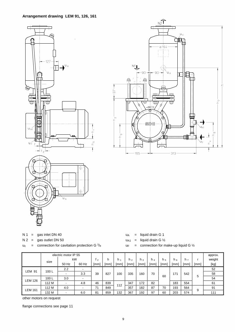
Arrangement drawing LEM 91, 126, 161
N 1 = gas inlet DN 40 uA = liquid drain G 1
N 2 = gas outlet DN 50 uA1 = liquid drain G ½
uc = connection for cavitation protection G 3/8 uF = connection for make-up liquid G ½
electric motor IP 55 approx.
size
kW f 2 h h 1 h 2 h 3 h 4 h 5 h 6 h 7 r weight
50 Hz 60 Hz [mm] [mm] [mm] [mm] [mm] [mm] [mm] [mm] [mm] [mm] [kg]
LEM 91 100 L 2.2 -
39 827 100 335 160 70 60
171 542 5
52
- 3.3 58
LEM 126 100 L 3.0 - 54
112 M - 4.8 46 839 112
347 172 82 183 554 61
LEM 161 112 M 4.0 - 71 849 357 182 87 70 193 564
9 91
132 M - 6.0 81 859 132 367 192 97 60 203 574 111
other motors on request flange connections see page 11
10
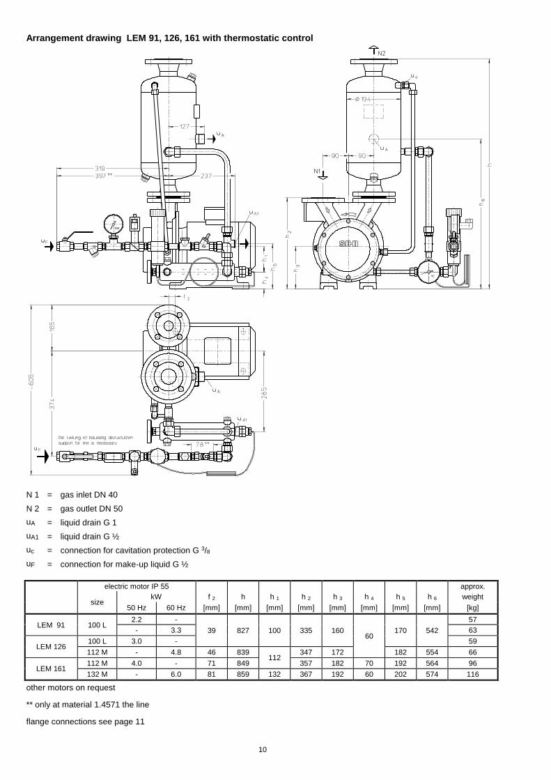
Arrangement drawing LEM 91, 126, 161 with thermostatic control
N 1 = gas inlet DN 40
N 2 = gas outlet DN 50
uA = liquid drain G 1
uA1 = liquid drain G ½
uc = connection for cavitation protection G 3/8
uF = connection for make-up liquid G ½
electric motor IP 55 approx.
size
kW f 2 h h 1 h 2 h 3 h 4 h 5 h 6 weight
50 Hz 60 Hz [mm] [mm] [mm] [mm] [mm] [mm] [mm] [mm] [kg]
LEM 91 100 L 2.2 -
39 827 100 335 160 60
170 542
57
- 3.3 63
LEM 126 100 L 3.0 - 59
112 M - 4.8 46 839 112
347 172 182 554 66
LEM 161 112 M 4.0 - 71 849 357 182 70 192 564 96
132 M - 6.0 81 859 132 367 192 60 202 574 116
other motors on request
** only at material 1.4571 the line
flange connections see page 11
11
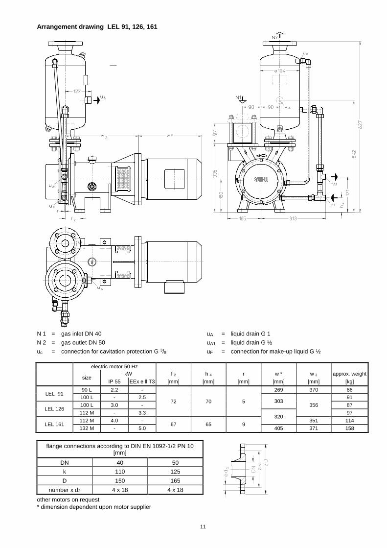
Arrangement drawing LEL 91, 126, 161
N 1 = gas inlet DN 40 uA = liquid drain G 1
N 2 = gas outlet DN 50 uA1 = liquid drain G ½
uc = connection for cavitation protection G 3/8 uF = connection for make-up liquid G ½
electric motor 50 Hz
size
kW f 2 h 4 r w * w 2 approx. weight
IP 55 EEx e ll T3 [mm] [mm] [mm] [mm] [mm] [kg]
LEL 91 90 L 2.2 -
72 70 5
269 370 86
100 L - 2.5 303
356
91
LEL 126 100 L 3.0 - 87
112 M - 3.3 320
97
LEL 161 112 M 4.0 -
67 65 9 351 114
132 M - 5.0 405 371 158
flange connections according to DIN EN 1092-1/2 PN 10 [mm]
DN 40 50
k 110 125
D 150 165
number x d2 4 x 18 4 x 18
other motors on request
* dimension dependent upon motor supplier
12
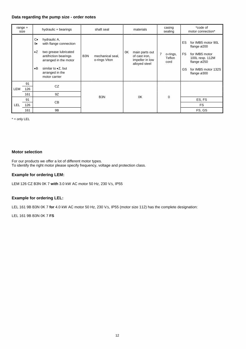
Data regarding the pump size - order notes
range + size
hydraulic + bearings shaft seal materials casing sealing
*code of motor connection*
C
9
Z
B
hydraulic A,
with flange connection
two grease lubricated
antifriction bearings
arranged in the motor
similar to Z, but
arranged in the
motor carrier
B3N
mechanical seal, o-rings Viton
0K
main parts out of cast iron, impeller in low alloyed steel
7
o-rings, Teflon cord
ES FS GS
for IMB5 motor 90L flange ø200 for IMB5 motor 100L resp. 112M flange ø250 for IMB5 motor 132S flange ø300
91 CZ
B3N 0K 0
LEM 126
161 9Z
91 CB
ES, FS
LEL 126 FS
161 9B FS, GS
* = only LEL
Motor selection For our products we offer a lot of different motor types. To identify the right motor please specify frequency, voltage and protection class.
Example for ordering LEM:
LEM 126 CZ B3N 0K 7 with 3.0 kW AC motor 50 Hz, 230 V, IP55
Example for ordering LEL:
LEL 161 9B B3N 0K 7 for 4.0 kW AC motor 50 Hz, 230 V, IP55 (motor size 112) has the complete designation:
LEL 161 9B B3N 0K 7 FS
13
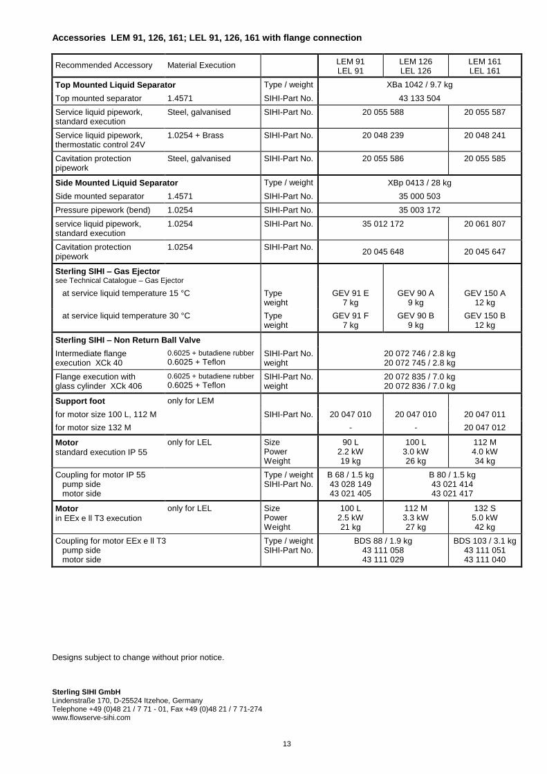
Accessories LEM 91, 126, 161; LEL 91, 126, 161 with flange connection
Recommended Accessory Material Execution LEM 91
LEL 91 LEM 126 LEL 126
LEM 161 LEL 161
Top Mounted Liquid Separator Type / weight XBa 1042 / 9.7 kg
Top mounted separator 1.4571 SIHI-Part No. 43 133 504
Service liquid pipework, standard execution
Steel, galvanised SIHI-Part No. 20 055 588 20 055 587
Service liquid pipework, thermostatic control 24V
1.0254 + Brass SIHI-Part No. 20 048 239 20 048 241
Cavitation protection pipework
Steel, galvanised SIHI-Part No. 20 055 586 20 055 585
Side Mounted Liquid Separator Type / weight XBp 0413 / 28 kg
Side mounted separator 1.4571 SIHI-Part No. 35 000 503
Pressure pipework (bend) 1.0254 SIHI-Part No. 35 003 172
service liquid pipework, standard execution
1.0254 SIHI-Part No. 35 012 172 20 061 807
Cavitation protection pipework
1.0254 SIHI-Part No. 20 045 648 20 045 647
Sterling SIHI – Gas Ejector
see Technical Catalogue – Gas Ejector
at service liquid temperature 15 °C Type weight
GEV 91 E 7 kg
GEV 90 A 9 kg
GEV 150 A 12 kg
at service liquid temperature 30 °C Type weight
GEV 91 F 7 kg
GEV 90 B 9 kg
GEV 150 B 12 kg
Sterling SIHI – Non Return Ball Valve
Intermediate flange execution XCk 40
0.6025 + butadiene rubber 0.6025 + Teflon
SIHI-Part No. weight
20 072 746 / 2.8 kg 20 072 745 / 2.8 kg
Flange execution with glass cylinder XCk 406
0.6025 + butadiene rubber
0.6025 + Teflon SIHI-Part No. weight
20 072 835 / 7.0 kg 20 072 836 / 7.0 kg
Support foot only for LEM
for motor size 100 L, 112 M SIHI-Part No. 20 047 010 20 047 010 20 047 011
for motor size 132 M - - 20 047 012
Motor standard execution IP 55
only for LEL Size Power Weight
90 L 2.2 kW 19 kg
100 L 3.0 kW 26 kg
112 M 4.0 kW 34 kg
Coupling for motor IP 55 pump side motor side
Type / weight SIHI-Part No.
B 68 / 1.5 kg 43 028 149 43 021 405
B 80 / 1.5 kg 43 021 414 43 021 417
Motor in EEx e ll T3 execution
only for LEL Size Power Weight
100 L 2.5 kW 21 kg
112 M 3.3 kW 27 kg
132 S 5.0 kW 42 kg
Coupling for motor EEx e ll T3 pump side motor side
Type / weight SIHI-Part No.
BDS 88 / 1.9 kg 43 111 058 43 111 029
BDS 103 / 3.1 kg 43 111 051 43 111 040
Designs subject to change without prior notice.
Sterling SIHI GmbH Lindenstraße 170, D-25524 Itzehoe, Germany Telephone +49 (0)48 21 / 7 71 - 01, Fax +49 (0)48 21 / 7 71-274 www.flowserve-sihi.com