INDUSTRIAL CENTRIFUGAL PUMPS - Tapflo
24
INDUSTRIAL CENTRIFUGAL PUMPS 2018 | 1 www.tapflo.com
-
Upload
khangminh22 -
Category
Documents
-
view
6 -
download
0
Transcript of INDUSTRIAL CENTRIFUGAL PUMPS - Tapflo

INDUSTRIAL CENTRIFUGAL PUMPS
2018 | 1
www.tapflo.com

2
1980Est. in Sweden
All about your flowTapflo is a leading pump manufacturer providing a wide range of premium products for various industrial applications. We focus on delivering the best solutions and support for our customers on all stages of the process – worldwide.
About Tapflo
Quality certifiedAt Tapflo we value quality as our top priority. As a result, we comply with various globally recognised certification and quality control institutions. Many of our products comply with EC ATEX directives for equipment intended for use in explosive and hazardous environments.The aseptic series is EHEDG certified (European Hygienic Engineering & Design Group) and the pharmaceutical series has EC 1935/2004 approval.All of our products are clearly CE marked and followed by our comprehensive instruction manuals. Tapflo manufacturing process is certified according to ISO 9001:2015.
Tapflo is a Swedish, family-owned manufacturer and global supplier of pumps and other industrial process equipment. Our products are designed and manufactured to meet our customers’ needs and the demands from our industry. The company was founded in Kungälv, Sweden in 1980 and has since then developed dynamically over the years. Today we are represented by our own companies and independent distributors all over the world, on 6 continents.
REACHCompliant
ROHSCompliant
9001:2015
Tapflo values
Commitment We are different from our competitors because of our willingness to exceed the customers’ expectations, move fast and be flexible. Our culture is based on the spirit of togetherness, enthusiasm and integrity. We come from all over the world but we share the same values and we respect each other. We are committed.
QualityWe understand that the quality in our work is never better than the weakest link, that’s why we focus on every small detail. We share a common passion for continuously finding more efficient and effective ways to provide value to our customers. As a manufacturer we have control of the complete process both in terms of our products and the way we operate internally. That is why we manufacture the highest quality pumps in our segment.
Simplicity We have a saying, “Simple is art” which means we try to find smooth and uncomplicated solutions in everything. By keeping it simple we can focus on the essential, like designing uncomplicated pumps with few components. For us it is a key to success; strive to simplify what is complex.
Our culture is concluded in Our values

3
ProcessRD Closed Impeller
RG Semi-Open Impeller
RB Channel Impleller
RC Vortex Impeller
4
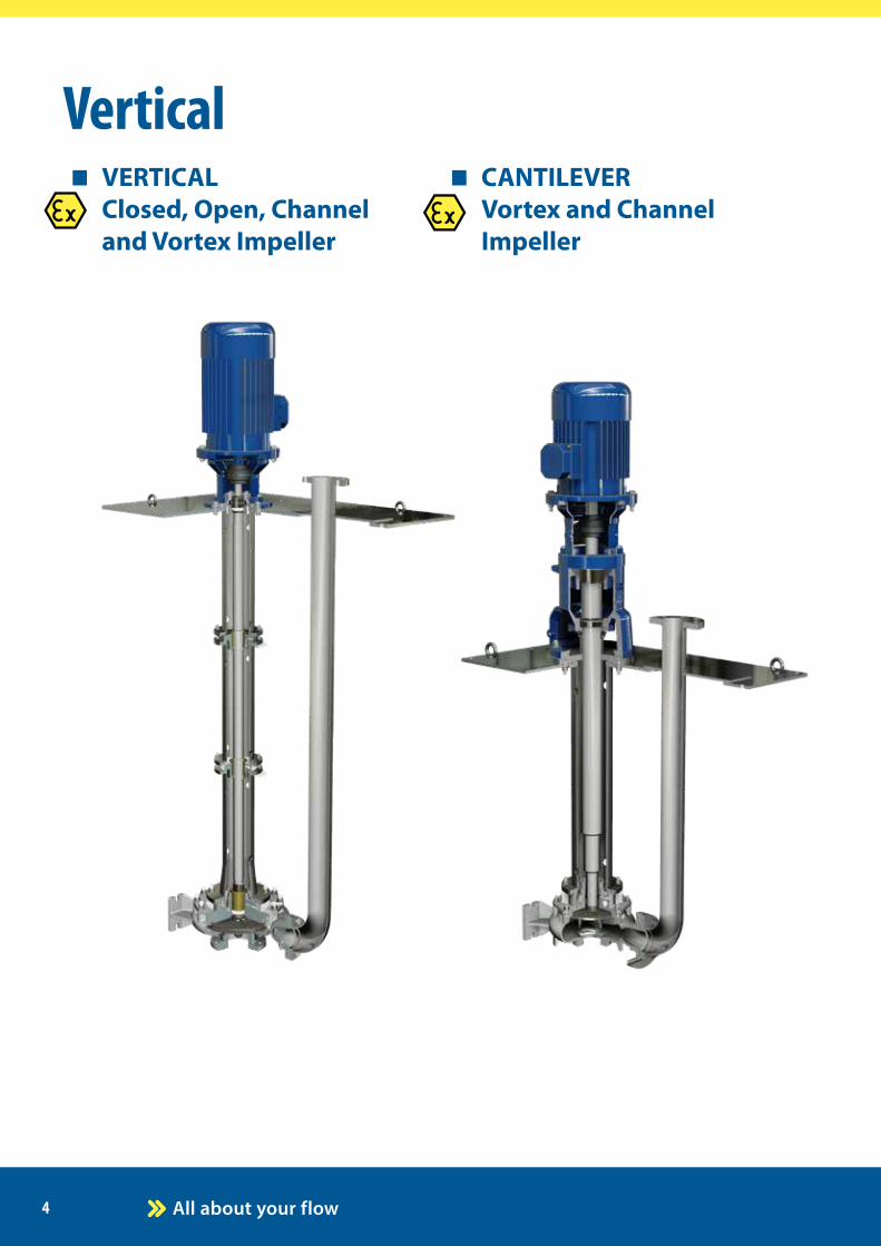
VerticalVERTICAL Closed, Open, Channel and Vortex Impeller
CANTILEVER Vortex and Channel Impeller
5
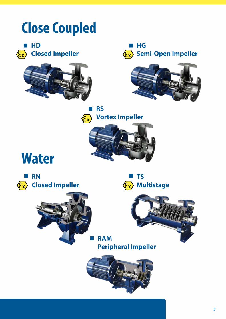
Close CoupledHDClosed Impeller
HGSemi-Open Impeller
RSVortex Impeller
WaterRNClosed Impeller
TSMultistage
RAMPeripheral Impeller

6
Fast factsDischarge sizes: from DN 32 to DN 125Maximum working pressure: 16 barFlow rate: up to 500 m3 /hDifferential head: up to 140 mTemperature: up to 180-220°C - according to the pumped liquidMaterials: AISI 316 Upon request AISI 304, AISI 904, duplex, superduplex, Hastelloy B and C
RD Closed Impeller
Selection Charts
Arrangement
Centrifugal pumps build according to ISO 2858/ISO 5199 norms. Heavy Duty Shaft and Bearings. Only 3 bearing brackets for the whole range. Only 1 casing cover fits every seal arrangement
FIELDS OF APPLICATION:handling aggressive organic and inorganic liquids in the chemical and petrochemical industries.
They are also used in: sea water desalination plants, absorption equipment in environmental engineering, power stations, steel industry, hot water distribution.
High hydraulic efficiencies and low NPSH requirements (investment casting impellers).
Capacity [m3/h]
Tota
l hea
d [m
]
Tota
l hea
d [m
]
Capacity [m3/h]

7
Centrifugal pumps build according to ISO 2858/ISO 5199 norms. Heavy Duty Shaft and Bearings. Only 3 bearing brackets for the whole range. Only 1 casing cover fits every seal arrangement
FIELDS OF APPLICATION:handling slightly contaminated liquids or not abrasive slurries in the chemical and petrochemical industries. Well suited for handling liquids with gas contents up to 15%.
They are also used in: refineries, general industrial service, pulp and paper industry, foodstuffs industry, sugar industry, sea water desalination plants, absorption equipment in environmental engineering, power stations, steel industries, hot water distribution.
Selection Charts
ArrangementCapacity [m3/h]
Tota
l hea
d [m
]
Tota
l hea
d [m
]
Capacity [m3/h]
Fast factsDischarge sizes: from DN 32 to DN 125Maximum working pressure: 16 bar - according to the pump sizeFlow rate: up to 300 m3 /hDifferential head: up to 95mTemperature: up to 180-220°C - according to the pumped liquidMaterials: AISI 316 Upon request AISI 304, AISI 904, duplex, superduplex, Hastelloy B and C
RG Semi-Open ImpellerHigh hydraulic efficiencies and low NPSH requirements (investment casting impellers).

8
Centrifugal pumps with bearing bracket in according to ISO 2858/ISO 5199 norms. Heavy Duty Shaft and Bearings. Only 5 bearing brackets for the whole range. Only 1 casing cover fits every seal arrangement
FIELDS OF APPLICATION:Handling slightly contaminated liquids in waste water treatment plants, clean water for cooling towers or condensate recovery plants, viscous liquids in evaporators in food or chemical industry.
They are also used in: refineries, general industrial service, pulp and paper industry, foodstuffs industry, sugar industry, sea water desalination plants, absorption equipment in environ-mental engineering, power stations, steel industries, hot water distribution.
Selection Charts
Arrangement
Capacity [m3/h]
Tota
l hea
d [m
]
Tota
l hea
d [m
]
Capacity [m3/h]
Fast factsDischarge sizes: from DN 65 to DN 300Maximum working pressure: 10 bar - according to the pump sizeFlow rate: up to 2400 m3/hDifferential head: up to 70 mTemperature: up to 150-220°C - according to the pumped liquidMaterials: AISI 316 Upon request AISI 304, AISI 904, duplex, superduplex, Hastelloy B and C
RB Channel ImpellerImpeller with special blades geometry for low NPSH and high free passage.

9
Fast factsDischarge sizes: from DN 32 to DN 250Maximum working pressure: 10 bar - according to the pump sizeFlow rate: up to 800 m3/hDifferential head: up to 60mTemperature: up to 150-220°C - according to the pumped liquidMaterials: Cast Iron GJL250 or AISI 316. Upon request AISI 304, AISI 904, duplex, superduplex, Hastelloy
RC Vortex Impeller
Selection Charts
Arrangement
Centrifugal pumps with bearing bracket in according to ISO 2858/ISO 5199 norms. Heavy Duty Shaft and Bearings. Only 4 bearing brackets for the whole range. Only 1 casing cover fits every seal arrangement
FIELDS OF APPLICATION:Handling chemical and crystalline suspensions, all viscous liquid, liquid with high concentrations of fibrous suspensions, municipal and industrial wastewater, every kind of sludge.
Textile and tannely: refineries, general industrial service, pulp and paper industry, foodstuffs industry, sugar industry, sea water desalination plants, absorption equipment in environ-mental engineering, power stations, steel industries.
Large free passage clearance up to 180 mm due to the completely recessed impeller.
Capacity [m3/h]
Tota
l hea
d [m
]
Tota
l hea
d [m
]
Capacity [m3/h]

10
SealsCylindrical chamber built in according to EN 12756 standards can be fitted with any type of mechanical seal or cartridge.
Single mechanical seals, double mechanical seals (tandem or back to back arrangements) or packing can be obtai-ned using few components . This modular system allow the customer to change seal arrangements using the same casing cover and replacing just few parts. Up to 15 different seal arrangement to cover all the customer needs. Seal arrangements can be fitted with flushing plans in according to API 682 standards (such as PLAN 11, PLAN 52, PLAN 53, PLAN 54).
Single mechanical seal
Red color parts used in the arrangement.
Double back to back mechanical seal
This is the most popular type of mechanical seal in clean (no solid particles or crystals) liquid service.The pumped medium lubricates mech. seal surfaces and remove friction heat.
Only one casing for different mechanical seal arrangement.
Red color parts used in the arrangement.
This type of double seal (with back to back faces) is pressurized above the pressure inside the seal chamber.An external buffer fluid serves to separate the product from the atmosphere. Buffer fluid pressure have to be around 0,5/1 bar above the pressure of the product. To obtain the benefits of this seal, it is necessary to install a gauge indicating the actual seal chamber pressure. Sensors and transmitters can be used to monitor and act on a pressure change.

11
Red color parts used in the arrangement.
Cartridge seal
Red color parts used in the arrangement.
Red color parts used in the arrangement.
Double tandem mechanical seal
Gland packing is a braided, rope like material that is packed around the shaft - physically stuffing the gap between the shaft and the pump housing.Gland packing is still commonly used in many applications.
This dual seal has both the rotary units facing in the same direction.The purpose of the mechanical seal on the atmo-sphere side of tandem is either two-stage pressure reduction or else to seal in the quenching medium and to monitor the primary mechanical seal on the product.An external buffer fluid serves to separate the product from the atmosphere.
Cartridge mechanical seals and component seals use similar components, but the stationary components of cartridge seals are preassembled in a housing, and the rotating components are preassembled on a shaft-mounted sleeve that is sealed with an O-ring. The cartridge seal housing typically replaces the gland cover plate and seals to the pump housing with a gasket, an O-ring or other elastomer. Since cartridge mechanical seal components are preassembled onto the sleeve and into the cart-ridge housing, errors in parts installation are unlikely.
Packing gland
12
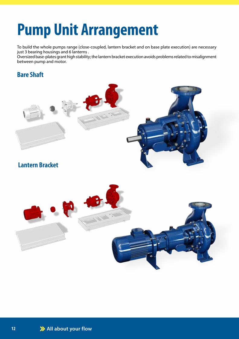
Pump Unit Arrangement
Lantern Bracket
Bare Shaft
To build the whole pumps range (close-coupled, lantern bracket and on base plate execution) are necessary just 3 bearing housings and 6 lanterns . Oversized base-plates grant high stability; the lantern bracket execution avoids problems related to misalignment between pump and motor.

13
Bare shaft on base
Lantern Bracket on base
Close-Coupled

14
Vertical - Closed, Open, Channel and Vortex Impeller
Impeller typeClosed Impeller Clean liquids.
Semi-open impeller with wear plate and external adjustmentSlightly contaminated liquids or non abrasive slurries. Well suited for handling liquids with gas contents up to 15%.
Channel Impeller Slightly contaminated liquids or non abrasive slurries. Special blade geometry for low NPSH and high free passage. High efficiency and low NPSH.
Vortex Impeller Chemical and crystalline suspensions, all viscous liquids, liquids with high concentrations of fibrous suspensions, municipal and industrial wastewater, every kind of sludge. Free passage up to 180 mm.
Vertical immersible sump pump (ISO 5199 norms) line-shaft with bearing bushes.
Fast factsPump length: up to 6 metersMounting plate: rectangular, circular or according to customer’s specifications PTFE LIP SEAL or CARTRIDGE SEAL for vapor proof construction or pressurized designs. Materials: Cast Iron GJL250 or AISI 316. Upon request AISI 304, AISI 904, duplex, superduplex.Bearing bush materials: bronze, rubber, RULON and PEEKSuction strainer and suction extension on request.
The pump body is immersed into the liquid, whilst the motor is mounted above the plate, keeping it away from the liquid.
The discharge pipe is separated from the column pipe and the lubrication of the line bearings is normally obtained by means of the same pumped fluid, or from an external lubricating source (such as clear liquid or grease) in abrasive services.
The possibility to customize mounting plate shape and dimensions, discharge flange position and column length, allows designers and end-users to match sump or tank plates or flanges.
FIELDS OF APPLICATION:Used in all industrial applications, refining, oil and gas production, chemical, pulp & paper and water facilities.
Typical applications include: drainage sumps, oily water sumps, tank transfer.

15
Arrangements
Lubrication by means of pumped fluid.
Pumped fluid lubricates all the bearing bushes (bottom and intermediates).
The liquid must be clean: suspended solids could clog the small pipes for intermediate bearing bush lubrication.
Vertical pumps with bottom bearing bush only, can also work with liquids with non abrasive small solids.
Lubrication by external lubricating source.
A clean external source, clean liquid or grease lubrica-tes all the bearing bushes (bottom and intermediates).
Used when the liquid is dirty, sticky or with suspen-ded solids.
This arrangement also allows also the pump to work without liquid in the sump or with tail pipe. The external fluid is pumped together with the main fluid.
Lubrication by fluid into the pipe column.
Used when the liquid is aggressive, dirty, sticky or with suspended solids.
A mechanical seal is placed between the shaft and the casing cover to fill the pipe column. All the bearing bushes (bottom and intermediates) are lubricated by flushing fluid.
Before startup, the pipe column must be filled with antifreeze solution. The level can be controlled by a dip-stick or level probe upon request.
16
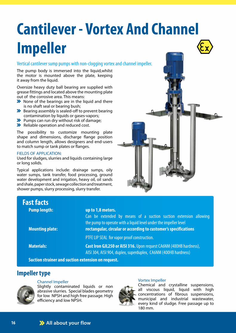
The pump body is immersed into the liquid,whilst the motor is mounted above the plate, keeping it away from the liquid.
Oversize heavy duty ball bearing are supplied with grease fittings and located above the mounting plate out of the corrosive area. This means:
None of the bearings are in the liquid and there is no shaft seal or bearing bush;
Bearing assembly is sealed-off to prevent bearing contamination by liquids or gases-vapors;
Pumps can run dry without risk of damage; Reliable operation and reduced cost.
The possibility to customize mounting plate shape and dimensions, discharge flange position and column length, allows designers and end-users to match sump or tank plates or flanges.
FIELDS OF APPLICATION:Used for sludges, slurries and liquids containing large or long solids.
Typical applications include: drainage sumps, oily water sumps, tank transfer, food processing, ground water development and irrigation, heavy oil, oil sands and shale, paper stock, sewage collection and treatment, shower pumps, slurry processing, slurry transfer.
Cantilever - Vortex And Channel Impeller
Impeller typeChannel Impeller Slightly contaminated liquids or non abrasive slurries. Special blades geometry for low NPSH and high free passage. High efficiency and low NPSH.
Vortex Impeller Chemical and crystalline suspensions, all viscous liquid, liquid with high concentrations of fibrous suspensions, municipal and industrial wastewater, every kind of sludge. Free passage up to 180 mm.
Vertical cantilever sump pumps with non-clogging vortex and channel impeller.
Fast factsPump length: up to 1,8 meters. Can be extended by means of a suction suction extension allowing the pump to operate with a liquid level under the impeller levelMounting plate: rectangular, circular or according to customer’s specifications
PTFE LIP SEAL for vapor proof construction.
Materials: Cast Iron GJL250 or AISI 316. Upon request CA6NM (400HB hardness), AISI 304, AISI 904, duplex, superduplex, CA6NM (400HB hardness)Suction strainer and suction extension on request.

17
Installation
Typical installation
The cantilever pump is installed at the top of sump/ tank and works without level controls.With liquid level above the pump “priming holes”, the pump works properly.
As soon as the liquid level is below the suction port, the pump will be unprimed and work dry.
The pump will restart to work when the liquid level reaches. the pump “priming holes”.
Typical installation with sution extension
The cantilever pump is installed at the top of sump/ tank and works without level controls. With liquid level above the pump “priming holes”, the pump works properly.
As soon as the liquid level is below the end of suction extension or when the NPSHa is lower then NPSHr, the pump will be unprimed and work dry.
This arrangement allows to empty tanks up to 5 meters below the suction port.
The pump will restart to work when the liquid level reaches the pump “priming holes”.
External installation
The cantilever pump is installed beside of sump/ tank and works without level controls. When the liquid level inside the tank is above the pump casing the pump can operate.
As soon as the liquid level is below the suction port, the pump will be unprimed and work dry.The pump will start again to work when the liquid level inside the tank is above the pump casing.
The liquid level inside the tank has to be lower than recirculation pipe in order to allow the liquid back to into the tank and not damage motor.
This arrangement allows to work with very hot fluid (up to 300°C) with suspended solids.
18
FLANGED or
FOOD CONNECTIONS
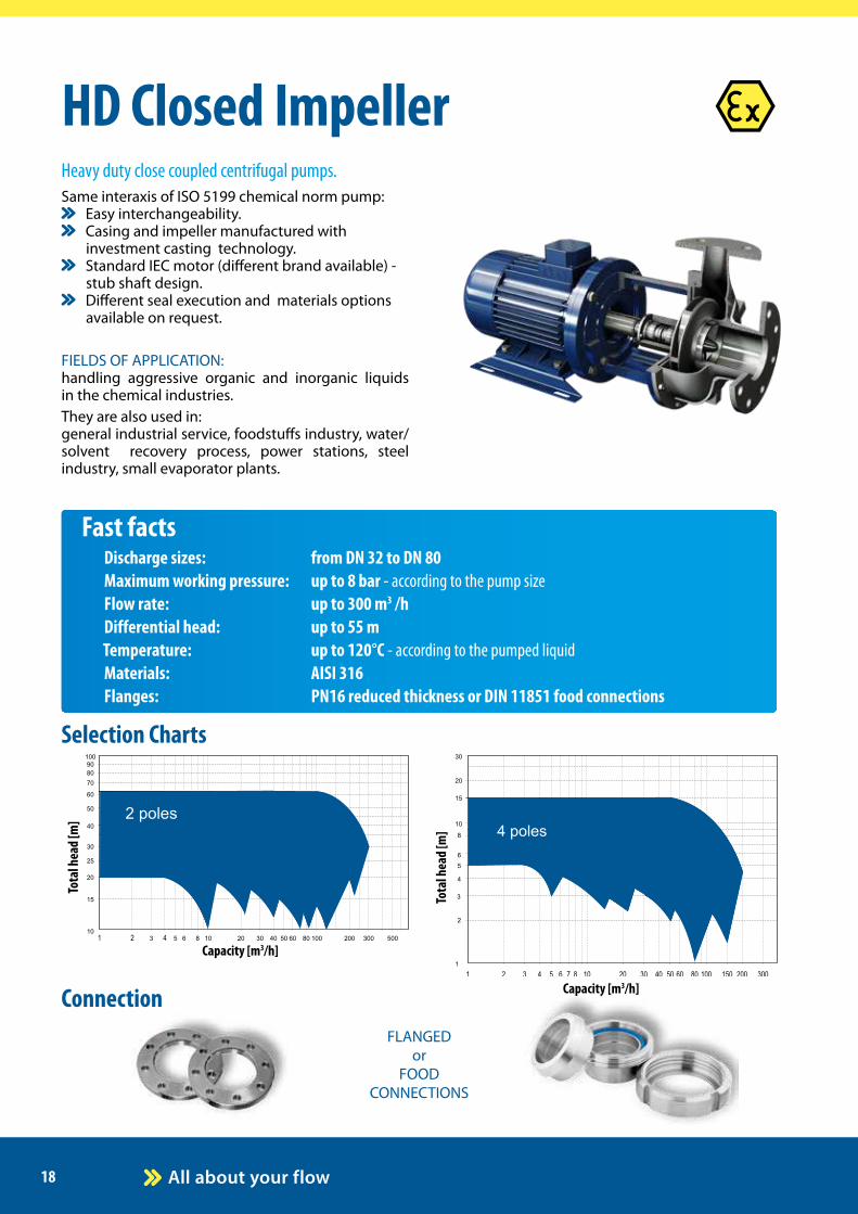
Fast factsDischarge sizes: from DN 32 to DN 80Maximum working pressure: up to 8 bar - according to the pump sizeFlow rate: up to 300 m3 /hDifferential head: up to 55 mTemperature: up to 120°C - according to the pumped liquidMaterials: AISI 316Flanges: PN16 reduced thickness or DIN 11851 food connections
HD Closed Impeller
Selection Charts
Connection
Same interaxis of ISO 5199 chemical norm pump: Easy interchangeability. Casing and impeller manufactured with
investment casting technology. Standard IEC motor (different brand available) -
stub shaft design. Different seal execution and materials options
available on request.
FIELDS OF APPLICATION:handling aggressive organic and inorganic liquids in the chemical industries.They are also used in: general industrial service, foodstuffs industry, water/solvent recovery process, power stations, steel industry, small evaporator plants.
Heavy duty close coupled centrifugal pumps.
Capacity [m3/h]
Tota
l hea
d [m
]
Tota
l hea
d [m
]
Capacity [m3/h]

19
Selection Charts
Capacity [m3/h]
Tota
l hea
d [m
]
Tota
l hea
d [m
]
Capacity [m3/h]
Fast factsDischarge sizes: from DN 32 to DN 80Maximum working pressure: up to 8 bar - according to the pump sizeFlow rate: up to 200 m3 /hDifferential head: up to 60 mTemperature: up to 120°C - according to the pumped liquidMaterials: AISI 316Flanges: PN16 reduced thickness or DIN 11851 food connections
HG Semi-Open ImpellerSame interaxis of ISO 5199 chemical norm pump:
Easy interchangeability. Casing and impeller manufactured with
investment casting technology. Standard IEC motor (different brand available) -
stub shaft design. Different seal execution and materials options
available on request.FIELDS OF APPLICATION:handling slightly contaminated liquids or non abrasive slurries in the chemical and petrochemical industries. Well suited for handling liquids with gas contents up to 10%.They are also used in: general industrial service, foodstuffs industry, dissol-ved air flotation systems, small evaporator plants, sugar industry, water/solvent recovery process, power stations, steel industry textile.
Heavy duty monoblock centrifugal pumps.
FLANGED or
FOOD CONNECTIONS
Connection

20
Same interaxis of ISO 5199 chemical norm pump: Easy interchangeability. Casing and impeller manufactured with
investment casting technology. Large free passage clearance up to 50 mm due
to the completely recessed impeller. Standard IEC motor (different brand available) -
stub shaft design. Different seal execution and materials options
available on request.FIELDS OF APPLICATION:Handling chemical and crystalline suspensions, all viscous liquid, liquid with high concentrations of fibrous suspensions, municipal and industrial waste water, sludge.They are also used in: general industrial service, dissolved air flotation sy-stems, water/solvent recovery process, steel industry.
FLANGED or
FOOD CONNECTIONS
Fast factsDischarge sizes: from 3/4 M to DN 65Maximum working pressure: up to 8 bar - according to the pump sizeFlow rate: up to 100 m3 /h Differential head: up to 60 mTemperature: up to 120°C - according to the pumped liquidMaterials: AISI 316Flanges: PN16 reduced thickness or DIN 11851 food connections
RS Vortex Impeller
Selection Charts
Connection
Heavy duty monoblock centrifugal pumps.
Capacity [m3/h]
Tota
l hea
d [m
]
Tota
l hea
d [m
]
Capacity [m3/h]

21
5
10
20
30
40
50
100
130
5 6 7 8 9 10 20 30 40 50 100 200 300 400 500
2 poles
5
10
20
30
40
50
3
4
2
70
10 20 30 40 50 100 200 300 400 5002 5 700
4 poles
5
10
20
30
40
50
100
130
5 6 7 8 9 10 20 30 40 50 100 200 300 400 500
2 poles
5
10
20
30
40
50
3
4
2
70
10 20 30 40 50 100 200 300 400 5002 5 700
4 poles
Selection Charts
Arrangement
Capacity [m3/h]
Tota
l hea
d [m
]
Tota
l hea
d [m
]
Capacity [m3/h]
Fast factsDischarge sizes: from DN 35 to DN 150Maximum working pressure: 10 bar Flow rate: up to 480 m3 /hDifferential head: up to 90 mTemperature: up to 130°C - according to the pumped liquidMaterials: CAST IRON GJL200 EN1561, Shaft in AISI 430 or AISI 316, Impeller in CAST IRON GJL200 EN1561 or BRASS according to the pump size
RN Closed ImpellerFIELDS OF APPLICATION:Clean and non-aggressive liquids for the pump materials (contents of solids up to 0,2% max).
They are also used for:non aggressive industrial liquids, water supply, heating, conditioning, cooling and circulation plants, civil and industrial applications, fire-fighting plants and irrigations.
Centrifugal pumps in according to EN 733 norms.

22
Fast factsDischarge sizes: from DN 25Maximum working pressure: up to 25 bar Flow rate: up to 6,3 m3 /hDifferential head: up to 180 mTemperature: up to 120°C Materials: Casing and diffusers in cast iron GJL250, Shaft in AISI 420, impellers in BRASS or AISI 316 SS upon requestFlanges: PN25
Fast factsDischarge sizes: from DN 32 to DN 150Maximum working pressure: 10 barFlow rate: up to 480 m3/hDifferential head: up to 90 mTemperature: up to 130°C - according to the pumped liquidMaterials: CAST IRON GJL200 EN1561, Shaft in AISI 430 or AISI 316, Impeller in CAST IRON GJL200 EN1561 or BRASS according to the pump size
TS Multistage
RAM Peripheral
Arrangement
FIELDS OF APPLICATION:Clean and non-aggressive liquids for the pump materials (contents of solids up to 0,2% max).
They are also used for:non aggressive industrial liquids, water supply, heating, conditioning, cooling and circulation plants, civil and industrial applications, fire-fighting plants and irrigations.
Centrifugal pumps in according to EN 733 norms.
ArrangementFIELDS OF APPLICATION:clean liquids without solid parts in suspension.
They are used in:boiler feeding, washing plants, flotation plants in waste water treatment, and whenever low capacity and high pressure are required.
Multistage centrifugal pumps.
23
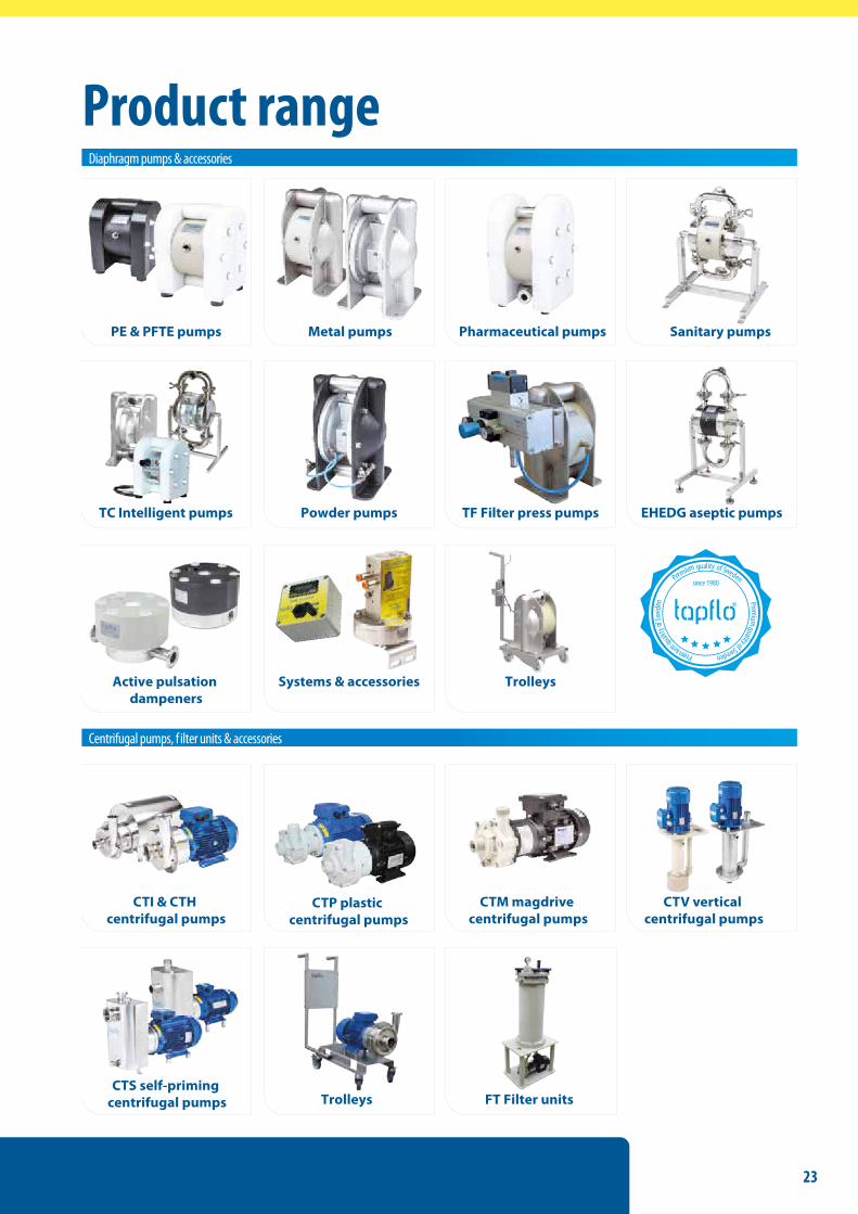
Product rangeDiaphragm pumps & accessories
Centrifugal pumps, f ilter units & accessories
PE & PFTE pumps Metal pumps Sanitary pumps
Powder pumps EHEDG aseptic pumps
Pharmaceutical pumps
TF Filter press pumps
CTS self-priming centrifugal pumps FT Filter units
CTI & CTH centrifugal pumps
CTM magdrive centrifugal pumps
CTV vertical centrifugal pumps
TC Intelligent pumps
Active pulsation dampeners
Systems & accessories Trolleys
Trolleys
P remium
qualityofSwedenPremiumquali
tyof
Swe d
e n
Premium quality of Sweden
CTP plastic centrifugal pumps

Sweden
TAPFLO AB
E-mail addresses: Commercial questions: [email protected] Orders: [email protected] Tech support: [email protected]
Tapflo is represented worldwide by own Tapflo Group Companies and carefully selected distributors assuring highest Tapflo service quality for our customers’ convenience.
Filaregatan 4 | S-442 34 Kungälv
Tel: +46 303 63390 Fax: +46 303 19916
Tapflo products and services are available in 75 countries on 6 continents.
AUSTRALIA | AUSTRIA | AZERBAIJAN | BAHRAIN | BELARUS | BELGIUM | BOSNIA | BRAZIL | BULGARIA | CANADA | CHILE | CHINA | COLOMBIA | CROATIA |
CZECH REPUBLIC | DENMARK | ECUADOR | EGYPT | ESTONIA | FINLAND | FRANCE | GREECE | GEORGIA | GERMANY | HONG-KONG | HUNGARY |
ICELAND | INDIA | INDONESIA | IRAN | IRELAND | ISRAEL | ITALY | JAPAN | JORDAN | KAZAKHSTAN | KUWAIT | LATVIA | LIBYA | LITHUANIA | MACEDONIA |
MALAYSIA | MEXICO | MONTENEGRO | MOROCCO | THE NETHERLANDS | NEW ZEALAND | NORWAY | POLAND | PORTUGAL | PHILIPPINES | QATAR |
ROMANIA | RUSSIA | SAUDI ARABIA | SERBIA | SINGAPORE | SLOVAKIA | SLOVENIA | SOUTH AFRICA | SOUTH KOREA | SPAIN | SUDAN | SWEDEN |
SWITZERLAND | SYRIA | TAIWAN | THAILAND | TURKEY | UKRAINE | UNITED ARAB EMIRATES | UNITED KINGDOM | USA | UZBEKISTAN | VIETNAM
Tapflo Group Companies
www.tapflo.comTapflo® is a registered trademark of Tapflo AB. All rights reserved.
Information in this document is subject to change without notice. Reproduction in any manner without written permission of Tapflo Group is forbidden. Tapflo Group reserves the right to make changes in product design, or detail, and to discontinue any product or material without notice.
Art. No. 10-2253
AustraliaTapflo Oceania (Pty)Tel: +61 1800 303 [email protected]
AustriaTapflo AustriaTel: +43 732 [email protected]
Baltic StatesTapflo LatviaTel: +371 67472205 [email protected]
BelarusTapflo BelarusTel: +375 17 [email protected]
BelgiumTapflo Benelux B.V.Tel: +31 (0)85 00 743 [email protected]
BulgariaTapflo EOODTel: +359 (0)2 974 18 [email protected]
CanadaTapflo CanadaTel: +1 514 813 [email protected]
CroatiaTapflo GmbHTel: +385 91 4884 [email protected]
Czech Republic Tapflo s.r.o.Tel: +420 513 033 [email protected]
ChinaTapflo (Wuxi)Tel: +86 510 8241 [email protected]
DenmarkTapflo DanmarkTel: +45 36 [email protected]
FranceTapflo FranceTel: +33 1 34 78 82 [email protected]
IndiaTapflo Fluid Handling India Pvt LtdTel: +91 20 [email protected]
IrelandTapflo Ireland LtdTel: +353 1 [email protected]
ItalyTapflo ItaliaTel: +39 [email protected]
JapanTapflo Japan K.K.Tel: [email protected]
KazakhstanTapflo KazakstanTel: +7 727 [email protected]
NetherlandsTapflo Benelux B.V.Tel: +31 (0)85 00 743 [email protected]
PolandTapflo Sp. z o.o.Tel: +48 58 530 42 [email protected]
RomaniaS.C. Tapflo Rom. S.r.l.Tel: +40 21 [email protected]
RussiaTapflo CompanyTel: +7 495 232 18 [email protected]
SerbiaTapflo d.o.o.Tel: +381 21 44 58 [email protected]
SlovakiaTapflo s.r.o.Tel: +421 911 137 [email protected]
SloveniaTapflo GmbHTel: +386 68 613 [email protected]
SpainTapflo IbericaTel: +34 91 [email protected]
South AfricaTapflo (Pty) LtdTel: +27 31 701 [email protected]
TurkeyTapflo Makina LtdTel: +90 216 467 33 [email protected]
UkraineTOB TapfloTel: +380 44 222 68 [email protected]
UzbekistanTapflo UzbekistanTel: +998 [email protected]
United KingdomTapflo (UK) LtdTel: +44 2380 [email protected]