G&L Pumps Series A-C 9100 Base Mounted Centrifugal ...
60
INSTRUCTION MANUAL AC5657C G&L Pumps Series A-C 9100 Base Mounted Centrifugal Pumps
-
Upload
khangminh22 -
Category
Documents
-
view
1 -
download
0
Transcript of G&L Pumps Series A-C 9100 Base Mounted Centrifugal ...

INSTRUCTION MANUALAC5657C
G&L Pumps Series A-C 9100Base Mounted CentrifugalPumps


Table of Contents
1 Introduction and Safety..............................................................................................................31.1 Introduction.......................................................................................................................... 31.2 Safety..................................................................................................................................... 3
1.2.1 Safety terminology and symbols.................................................................................31.2.2 Safety instruction decals.............................................................................................. 4
1.3 User safety.............................................................................................................................51.3.1 Wash the skin and eyes................................................................................................6
1.4 Protecting the environment................................................................................................6
2 Transportation and Storage...................................................................................................... 72.1 Examine the delivery........................................................................................................... 7
2.1.1 Examine the package................................................................................................... 72.1.2 Examine the unit............................................................................................................7
2.2 Safe handling requirements............................................................................................... 72.3 Storage requirements....................................................................................................... 10
3 Product Description................................................................................................................. 113.1 General description...........................................................................................................113.2 Operational specifications................................................................................................113.3 Nameplate information.....................................................................................................11
4 Installation................................................................................................................................. 134.1 Preinstallation.....................................................................................................................13
4.1.1 Pump location guidelines..........................................................................................134.1.2 Typical installation...................................................................................................... 144.1.3 Foundation requirements..........................................................................................144.1.4 Level the base on a concrete foundation ............................................................... 154.1.5 Grout the baseplate....................................................................................................15
4.2 Coupling alignment...........................................................................................................164.2.1 Prepare for alignment................................................................................................ 164.2.2 Align the pump using a straight edge and calipers...............................................164.2.3 Align the pump using a dial indicator......................................................................184.2.4 Final alignment............................................................................................................194.2.5 Optional alignment procedure.................................................................................194.2.6 Dowel the pump and driving unit.............................................................................194.2.7 Coupler limitations..................................................................................................... 19
4.3 Piping checklists.................................................................................................................194.3.1 Piping checklist........................................................................................................... 194.3.2 Suction piping checklist.............................................................................................20
5 Commissioning, Startup, Operation, and Shutdown.......................................................... 235.1 Preparation for startup...................................................................................................... 23
5.1.1 Pre-start checks........................................................................................................... 235.1.2 Priming.........................................................................................................................245.1.3 Starting.........................................................................................................................245.1.4 Operating checks....................................................................................................... 245.1.5 Check the rotation...................................................................................................... 245.1.6 Freezing protection.................................................................................................... 255.1.7 Change the rotation................................................................................................... 25
Table of Contents
G&L Pumps Series A-C 9100 Base Mounted Centrifugal Pumps INSTRUCTION MANUAL 1

6 Maintenance..............................................................................................................................276.1 Maintenance schedule...................................................................................................... 276.2 Flood-damaged pumps....................................................................................................286.3 Bearing maintenance........................................................................................................ 28
6.3.1 Regrease the grease-lubricated bearings............................................................... 296.3.2 Lubricating grease requirements............................................................................. 30
6.4 Shaft-seal maintenance..................................................................................................... 306.4.1 Mechanical seal maintenance................................................................................... 306.4.2 Packed stuffing box maintenance............................................................................ 31
6.5 Cleaning without dismantling the pump........................................................................ 316.6 Disassembly........................................................................................................................31
6.6.1 Disassembly precautions...........................................................................................316.6.2 Drain the pump...........................................................................................................326.6.3 Remove the hex coupling guard.............................................................................. 326.6.4 Disassemble the pump with packing on shaft sleeve............................................ 33
6.7 Pre-assembly inspections................................................................................................. 346.7.1 Replacement guidelines............................................................................................ 346.7.2 Shaft and sleeve inspection.......................................................................................34
6.8 Dimensions......................................................................................................................... 356.9 Reassembly.........................................................................................................................35
6.9.1 Reassemble the pump with the mechanical seals on the shaft sleeve................ 356.9.2 Reassemble the pump with the packing on the shaft sleeve................................386.9.3 Install the hex coupling guard...................................................................................416.9.4 Adjustable wear rings................................................................................................ 416.9.5 Install the oil ring.........................................................................................................426.9.6 Change the oil for oil lubricated bearings...............................................................426.9.7 Limited end float coupling........................................................................................ 436.9.8 Assembly references.................................................................................................. 43
7 Troubleshooting....................................................................................................................... 457.1 Operation troubleshooting.............................................................................................. 45
8 Parts Listings and Cross-Sectional Drawings........................................................................498.1 Parts list............................................................................................................................... 49
9 Product warranty...................................................................................................................... 52
Table of Contents
2 G&L Pumps Series A-C 9100 Base Mounted Centrifugal Pumps INSTRUCTION MANUAL

1 Introduction and Safety1.1 IntroductionPurpose of this manual
The purpose of this manual is to provide necessary information for:
• Installation• Operation• Maintenance
CAUTION:
Read this manual carefully before installing and using the product. Improper use of theproduct can cause personal injury and damage to property, and may void the warranty.
NOTICE:
Save this manual for future reference, and keep it readily available at the location of theunit.
1.2 SafetyWARNING:
• The operator must be aware of safety precautions to prevent physical injury.• Operating, installing, or maintaining the unit in any way that is not covered in this
manual could cause death, serious personal injury, or damage to the equipment. Thisincludes any modification to the equipment or use of parts not provided by Xylem. Ifthere is a question regarding the intended use of the equipment, please contact aXylem representative before proceeding.
• Do not change the service application without the approval of an authorized Xylemrepresentative.
CAUTION:
You must observe the instructions contained in this manual. Failure to do so could resultin physical injury, damage, or delays.
1.2.1 Safety terminology and symbols
About safety messages
It is extremely important that you read, understand, and follow the safety messages andregulations carefully before handling the product. They are published to help preventthese hazards:
• Personal accidents and health problems• Damage to the product and its surroundings• Product malfunction
Hazard levels
Hazard level Indication
DANGER:
A hazardous situation which, if not avoided, will result indeath or serious injury
1 Introduction and Safety
G&L Pumps Series A-C 9100 Base Mounted Centrifugal Pumps INSTRUCTION MANUAL 3

Hazard level Indication
WARNING:
A hazardous situation which, if not avoided, could resultin death or serious injury
CAUTION:
A hazardous situation which, if not avoided, could resultin minor or moderate injury
NOTICE:
Notices are used when there is a risk of equipmentdamage or decreased performance, but not personalinjury.
Special symbols
Some hazard categories have specific symbols, as shown in the following table.
Electrical hazard Magnetic fields hazard
Electrical Hazard:
CAUTION:
1.2.2 Safety instruction decals
WARNING:
Do NOT exceed the maximum working pressure of the pump. This information is listed onthe nameplate of the pump.
Alert symbol
This safety alert symbol is used in manuals and on the safety instruction decals on the pumpto draw attention to safety-related instructions.When used, the safety alert symbol means that failure to follow the instructions may result ina safety hazard.
Decals
Make sure your pump has these safety instruction decals and that they are located as thisfigure shows. If the decals are missing or illegible, contact your local sales and servicerepresentative for a replacement.
1 Introduction and Safety
4 G&L Pumps Series A-C 9100 Base Mounted Centrifugal Pumps INSTRUCTION MANUAL
P70642
P70643
EYEBOLTS OR LIFTING LUGS IF PROVIDED ARE FOR LIFTING ONLY THE COMPONENTS TO WHICH THEY ARE ATTACHED.FAILURE TO FOLLOWINSTRUCTIONS COULD RESULT IN INJURY OR DEATH.
DO NOT RUN PUMP DRY. SEAL DAMAGE MAY OCCUR.INSPECT PUMP SEALREGULARLY FOR LEAKS. REPLACE AS REQUIRED.LUBRICATION REQUIRMENTSCONSULT MANUALS.PUMP: POLYUREA-BASED GREASEFAILURE TO FOLLOWINSTRUCTIONS COULD RESULT IN INJURY OR PROPERTY DAMAGE.
ROTATING COMPONENTSDISCONNECT AND LOCK OUTPOWER BEFORE SERVICING.DO NOT OPERATE WITHOUTALL GUARDS IN PLACE.CONSULT INSTALLATIONAND SERVICE INSTRUCTIONSHEET BEFORE OPERATINGOR SERVICING.FAILURE TO FOLLOWINSTRUCTIONS COULDRESULT IN INJURY OR DEATH.
P70820
COUPLER ALIGNMENT ISREQUIRED! LEVEL ANDGROUT PUMP BEFORE USE!CHECK ALIGNMENT BEFOREGROUTING, AFTER SYSTEMIS FILLED, AFTER SERVICINGPUMP, AND AS REQUIRED.CONSULT THE SERVICEINSTRUCTIONS FOR DETAILS.FAILURE TO FOLLOW THESEINSTRUCTIONS COULDRESULT IN INJURY ORPROPERTY DAMAGE.
RATING PLATE
P2002458
Make sure that all safety instruction decals are always clearly visible and readable.
1.3 User safetyGeneral safety rules
These safety rules apply:
• Always keep the work area clean.• Pay attention to the risks presented by gas and vapors in the work area.• Avoid all electrical dangers. Pay attention to the risks of electric shock or arc flash
hazards.• Always bear in mind the risk of drowning, electrical accidents, and burn injuries.
Safety equipment
Use safety equipment according to the company regulations. Use this safety equipmentwithin the work area:
• Hard hat• Safety goggles, preferably with side shields• Protective shoes• Protective gloves• Gas mask• Hearing protection• First-aid kit• Safety devices
NOTICE:
Never operate a unit unless safety devices are installed. Also see specific informationabout safety devices in other chapters of this manual.
Electrical connections
Electrical connections must be made by certified electricians in compliance with allinternational, national, state, and local regulations. For more information aboutrequirements, see sections dealing specifically with electrical connections.
Precautions before work
Observe these safety precautions before you work with the product or are in connectionwith the product:
1 Introduction and Safety
G&L Pumps Series A-C 9100 Base Mounted Centrifugal Pumps INSTRUCTION MANUAL 5

• Provide a suitable barrier around the work area, for example, a guard rail.• Make sure that all safety guards are in place and secure.• Make sure that you have a clear path of retreat.• Make sure that the product cannot roll or fall over and injure people or damage
property.• Make sure that the lifting equipment is in good condition.• Use a lifting harness, a safety line, and a breathing device as required.• Allow all system and pump components to cool before you handle them.• Make sure that the product has been thoroughly cleaned.• Disconnect and lock out power before you service the pump.• Check the explosion risk before you weld or use electric hand tools.
1.3.1 Wash the skin and eyesFollow these procedures for chemicals or hazardous fluids that have come into contactwith your eyes or your skin:
Condition Action
Chemicals or hazardous fluids ineyes
1. Hold your eyelids apart forcibly with your fingers.2. Rinse the eyes with eyewash or running water for at least 15 minutes.3. Seek medical attention.
Chemicals or hazardous fluids onskin
1. Remove contaminated clothing.2. Wash the skin with soap and water for at least 1 minute.3. Seek medical attention, if necessary.
1.4 Protecting the environmentEmissions and waste disposal
Observe the local regulations and codes regarding:
• Reporting of emissions to the appropriate authorities• Sorting, recycling and disposal of solid or liquid waste• Clean-up of spills
Exceptional sites
CAUTION: Radiation Hazard
Do NOT send the product to Xylem if it has been exposed to nuclear radiation, unlessXylem has been informed and appropriate actions have been agreed upon.
Recycling guidelines
Always follow local laws and regulations regarding recycling.
1 Introduction and Safety
6 G&L Pumps Series A-C 9100 Base Mounted Centrifugal Pumps INSTRUCTION MANUAL

2 Transportation and Storage2.1 Examine the delivery2.1.1 Examine the package
1. Examine the package for damaged or missing items upon delivery.
2. Record any damaged or missing items on the receipt and freight bill.
3. If anything is out of order, then file a claim with the shipping company.
If the product has been picked up at a distributor, make a claim directly to thedistributor.
2.1.2 Examine the unit1. Remove packing materials from the product.
Dispose of all packing materials in accordance with local regulations.
2. To determine whether any parts have been damaged or are missing, examine theproduct.
3. If applicable, unfasten the product by removing any screws, bolts, or straps.
Use care around nails and straps.
4. If there is any issue, then contact a sales representative.
Shipping information
• Pumps and drivers are normally shipped from the factory mounted and painted withprimer and one finish coat.
• Couplings are shipped either assembled or have the coupling hubs mounted on theshafts and the connecting members removed.
• When the connecting members are removed, they will be packaged in a separatecontainer and shipped with the pump or attached to the base plate.
Shaft alignment
• Shafts are in alignment when the unit is shipped; however, misalignment can occurdue to shipping.
• Refer to recommended alignment procedures in this manual if it is necessary to realignthe shaft.
2.2 Safe handling requirementsWARNING:
• Personal protective equipment should be worn when handling this equipment.• Transportation & installation of this equipment should only be performed by qualified
personnel.• A professional rigging company should be consulted before lifting the pump
assembly.• Only use properly sized, certified lifting equipment & lifting devices, including slings,
suitably rated for the weights to be lifted.• Slings, when used, must be of identical materials to avoid differences in stretch rates.• Do not use lifting devices that are frayed, kinked, unmarked, or worn.• Lifting eyebolts fitted on single components of the assembly (pump or motor) must not
be used to lift the complete assembly.• Failure to observe these instructions could result in equipment or property damage,
serious injury, or death.
The pump assembly can arrive in a variety of ways:
2 Transportation and Storage
G&L Pumps Series A-C 9100 Base Mounted Centrifugal Pumps INSTRUCTION MANUAL 7

• Pump end only (bare pump)• Pump less motor• Pump, motor, & baseplate
Use the following recommended ways of handling HSC pump assemblies.
• The pump assembly should remain horizontal during transport and lifting.• Lifting the pump end only (bare pump) should be done by placing one end of the
slings around or as close to the casing barrel as possible. After the slings are attachedto the unit, recheck to ensure they are securely in place. Make sure the slings areadjusted to obtain an even lift.
Figure 1: Lifting pump end only with nylon sling, chain, or wire rope
• Lifting the pump less motor or the pump, motor, & baseplate should be done byutilizing a forklift under the entire unit. Always take extra precaution to ensure theweight is balanced & equally distributed across both forks. When the baseplate of theassembly is structural channel construction, the pump and base plate should be set inplace first. The motor should then be separately lifted & mounted to the unit.
• Pump, base, and driver assemblies where the base length exceeds 100 inches may notbe safe to lift as a complete assembly. Damage to the baseplate may occur. If thedriver has been mounted on the baseplate at the factory, it is safe to lift the entireassembly. If driver has not been mounted at the factory and the overall baseplatelength exceeds 100 inches, do not lift the entire assembly consisting of pump, base,and driver. Instead lift the pump and baseplate to its final location without the driver.Then mount the driver.
2 Transportation and Storage
8 G&L Pumps Series A-C 9100 Base Mounted Centrifugal Pumps INSTRUCTION MANUAL
Figure 2: Lift using a forklift
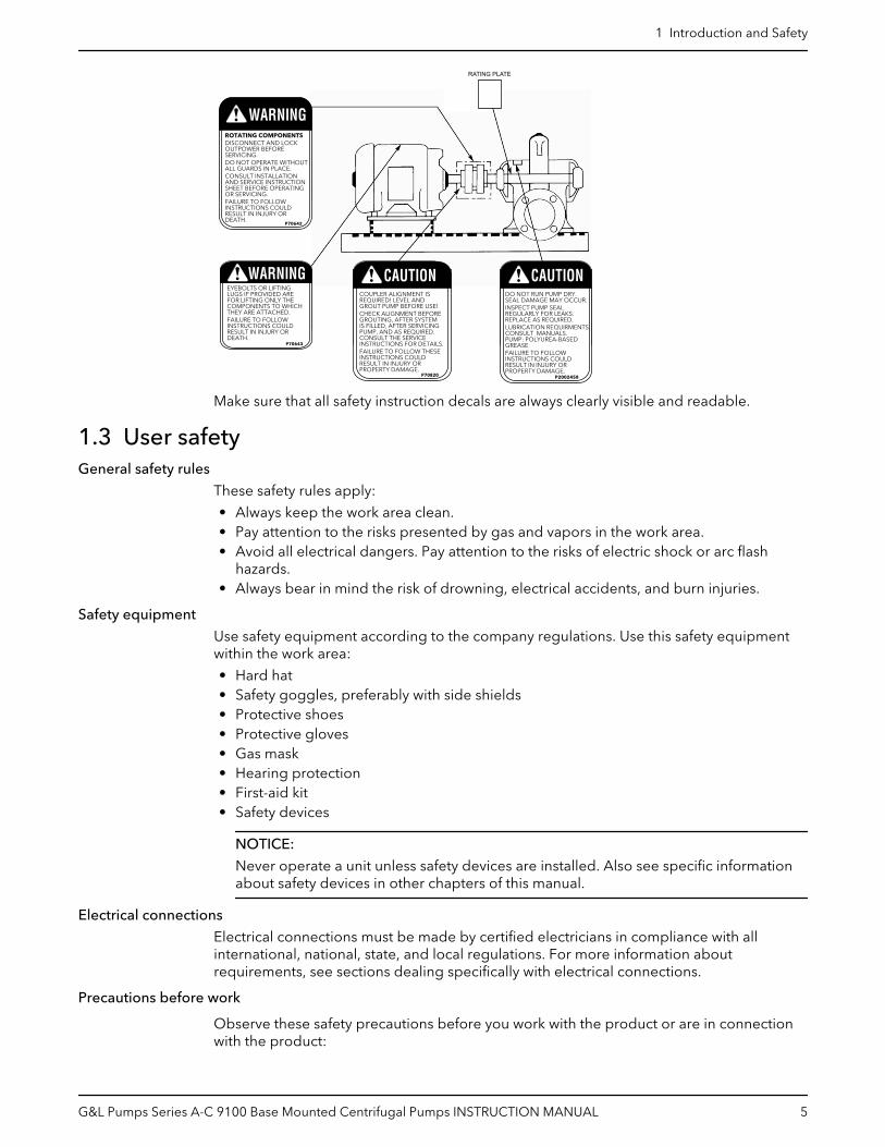
30° MAX.
Figure 3: Vertical - Half Pedestal - Model 200
• Place nylon sling, chain or wire rope around both flanges. Use a latch hook or standardshackle and end loops. Be sure the lifting equipment is of sufficient length to keep thelift angle less than 30° from the vertical (See Figure 3).
Storage location
The product must be stored in a covered and dry location free from heat, dirt, andvibrations.
2 Transportation and Storage
G&L Pumps Series A-C 9100 Base Mounted Centrifugal Pumps INSTRUCTION MANUAL 9
NOTICE:
Protect the product against humidity, heat sources, and mechanical damage.
NOTICE:
Do not place heavy weights on the packed product.
2.3 Storage requirementsIf the unit will not be installed and put into operation immediately upon arrival at the site,or for an extended shutdown after the unit is in operation, the following requirements forshort-term storage apply:
• Store in a covered and dry location.• Store the unit free from excessive cold or heat (below 32°F and above 110°F), dirt, and
vibration.• Rotate the shaft by hand several times (10–15 turns) at least every 30 days.
For initial storage longer than three months, or for pump shut down after being inoperation longer than three months, contact your local sales and service representativefor long-term storage guidelines.
2 Transportation and Storage
10 G&L Pumps Series A-C 9100 Base Mounted Centrifugal Pumps INSTRUCTION MANUAL

3 Product Description3.1 General descriptionDescription
The pump is a centrifugal, frame-mounted pump. The following pump features make iteasy to install, operate, and service:
• High efficiency• Rugged construction• Compact design• Foot-mounted volute• Center drop out coupler• regreasable bearings• Horizontal split case
Intended applications
WARNING:
This product can expose you to chemicals including Lead, which is known to the State ofCalifornia to cause cancer and birth defects or other reproductive harm. For moreinformation go to: www.P65Warnings.ca.gov.
The pump’s bronze fitted construction make it ideal for use with the following liquids:
• Unheated domestic and fresh water• Boiler feed water• Condensate• Hydronic cooling or heating• Pressure boosting• General pumping• Benign liquids
3.2 Operational specificationsMaximum working pressure
The maximum working pressure is listed on the pump nameplate.
Mechanical seal specifications
Seal type Parameter Value
Standard self-flushing pH range limits for Viton pH 7–9
Liquid temperature range thatcomplies with the pH range limits forViton
-10˚F to 220˚F (-23˚C to 104˚C)
Table notes
1. For use on closed or open systems which are relatively free of dirt and/or otherabrasive particles.
3.3 Nameplate informationThe pump nameplate gives identification and rating information about the pump.
Permanent records for this pump are kept by the serial number and it must be used will allcorrespondence and spare parts orders.
3 Product Description
G&L Pumps Series A-C 9100 Base Mounted Centrifugal Pumps INSTRUCTION MANUAL 11

Nameplate21 3 4 5 6
7 8 9
G&L PUMPS
1. Impeller diameter2. Pump rotation — for example, LHR = left hand rotation3. Pump size — for example, 8 x 8 x 17M4. Serial number — for example, 1–21937–1–15. Driver HP6. Identification number — for example, Month and year = CWP-117. Pump series and model number8. Duty points — GPM, feet, RPM9. Maximum working pressure
3 Product Description
12 G&L Pumps Series A-C 9100 Base Mounted Centrifugal Pumps INSTRUCTION MANUAL

4 Installation4.1 PreinstallationPrecautions
WARNING:
• When installing in a potentially explosive environment, make sure that the motor isproperly certified.
• You must ground (earth) all electrical equipment. This applies to the pump equipment,the driver, and any monitoring equipment. Test the ground (earth) lead to verify that itis connected correctly.
• Motors without built-in protection must be provided with contactors and thermaloverload protection for single-phase motors, or starters with heaters for three-phasemotors. (See the nameplate on the drive unit to select properly-sized overloads.)
NOTICE:
Supervision by an authorized Xylem representative is recommended to ensure properinstallation. Failure to do so may result in equipment damage or decreased performance.
4.1.1 Pump location guidelines
WARNING:
Assembled units and their components are heavy. Failure to properly lift and support thisequipment can result in serious physical injury and/or equipment damage. Lift equipmentonly at the specifically identified lifting points. Lifting devices such as eyebolts, slings, andspreaders must be rated, selected, and used for the entire load being lifted.
Guideline Explanation/comment
Keep the pump as close to the liquid source as practicallypossible.If the pump is not on a closed system, locate the pump so thatthe fewest number of bends or elbows in the suction pipe areneeded.
This minimizes the friction loss and keeps thesuction piping as short as possible.
Make sure that the space around the pump is sufficient. This facilitates ventilation, inspection,maintenance, and service.
If you require lifting equipment such as a hoist or tackle, makesure that there is enough space above the pump.
This makes it easier to properly use the liftingequipment and safely remove and relocate thecomponents to a safe location.
Protect the unit from weather and water damage due to rain,flooding, and freezing temperatures.
This is applicable if nothing else is specified.
Take into consideration the occurrence of unwanted noise andvibration.
The best pump location for noise and vibrationabsorption is on a concrete floor with subsoilunderneath.
If the pump location is overhead, undertake special precautionsto reduce possible noise transmission.
Consider a consultation with a noise specialist.
Make sure there is a suitable power source available for thepump driver.
The electrical supply must match the motornameplate specifications.
4 Installation
G&L Pumps Series A-C 9100 Base Mounted Centrifugal Pumps INSTRUCTION MANUAL 13

4.1.2 Typical installation
4
5
6
78
9
1
2
3
1. Compression tank (locate the compression tank on the suction side of the pump)2. Air separator3. Supply to system4. Circuit setter5. Triple duty valve6. Isolation valve7. From boiler chiller or converter8. Cold water supply9. Reducing valve
4.1.3 Foundation requirements
Requirements
• A substantial foundation and footing should be built to suit local conditions and form arigid support to maintain alignment.
• The foundation must be able to absorb any type of vibration and form a permanent,rigid support for the unit.
• The foundation must weigh at least five times the weight of the pump unit.• Pour the foundation without interruption to within 1/2 to 1–1/2 inches of the finished
height.• The top surface of the foundation should be scored and grooved before the concrete
sets. This provides a bonding surface for the grout.• Provide a flat, substantial concrete foundation in order to prevent strain and distortion
when you tighten the foundation bolts.• Sleeve-type and J-type foundation bolts are most commonly used. Both designs allow
movement for the final bolt adjustment.• Allow the foundation to cure for several days before you proceed with the pump
installation.
Diagram
• Allow enough bolt length for grout, shims, lower baseplate flange, nuts, and washers.
4 Installation
14 G&L Pumps Series A-C 9100 Base Mounted Centrifugal Pumps INSTRUCTION MANUAL

2
3
1
4
1. Foundation bolt2. Pipe sleeve3. Washer4. Built-up concrete foundation
4.1.4 Level the base on a concrete foundation1. Place the pump on its concrete foundation.
2. Place 1.00 in./(25.40 mm) thick steel shims or wedges on both sides of each anchorbolt in order to support the pump .
This also provides a means of leveling the base.
4
1
5
2
3
6
7
8
1. Pump Base Rail2. Grout only to top of base rail3. Locate the shims to allow removal after grouting.4. Grout5. Concrete foundation6. Shims7. 1” (25.40 mm) Gap8. Allow 1” for shims. Place on both sides of anchor bolts.
4.1.5 Grout the baseplate
Required equipment:
• Cleaners: Do not use an oil-based cleaner because the grout will not bond to it. Seethe instructions provided by the grout manufacturer.
• Grout: Non-shrink grout is required.
1. Clean all the areas of the baseplate that will come into contact with the grout.
2. Build a dam around the foundation.
3. Thoroughly wet the foundation that will come into contact with the grout.
4. Pour grout through the grout hole into the baseplate up to the level of the dam.
When you pour the grout, remove air bubbles from it by using one of these methods:
4 Installation
G&L Pumps Series A-C 9100 Base Mounted Centrifugal Pumps INSTRUCTION MANUAL 15
– Puddle with a vibrator.– Pump the grout into place.
5. After the grout has thoroughly hardened, check the foundation bolts and tighten ifnecessary. Check alignment after tightening the bolts.
6. After the grout has dried, apply an oil base paint to the exposed edges to preventmoisture from coming in contact with the grout.
4.2 Coupling alignmentWARNING:
Always disconnect and lock out power to the driver before you perform any installation ormaintenance tasks. Failure to disconnect and lock out driver power will result in seriousphysical injury.
Alignment guidelines
Follow these guidelines when you align the coupling:
• Only perform alignment by moving or shimming the motor.• Since adjustments in one direction can alter the alignment in another direction, check
the alignment in all directions after you make a correction.• Make sure that the pump and motor bolts are tight when you take all measurements.• Perform a final alignment check after the unit reaches its final operating temperature.
4.2.1 Prepare for alignment1. Check the pump and motor shafts and remove any paint, burrs, and rust.
2. Slide the hubs and bushings on the shafts with keys.
3. Hold one half element on the hubs in order to determine the appropriate hub spacing.
4. If you use spacer elements with high speed rings, hold both half elements on the hubsin order to make sure the hubs do not interfere with the rings.
5. You can install the hubs with the hub extension facing in or out.
Make sure the shaft extends into the hubs at least 0.8 times the diameter of the shaft.
6. Lightly fasten the hubs to the shafts in order to prevent them from moving duringalignment.
7. Align the hubs to the values shown in Maximum allowable misalignment for couplings.
You can perform alignment with lasers, dial indicators, or with a straight edge andcalipers.
4.2.2 Align the pump using a straight edge and calipers1. Check the angular misalignment:
Tool Procedure
Calipers 1. Gauge the distance between the two hubs at various points around the circumference.Do not rotate the shafts.
2. Reposition the equipment until the difference between the minimum and maximumdistance values is within the permissible range.See Maximum allowable misalignment for couplings.
Feelergauges
1. Insert feeler gauges between the coupling faces at various points around the circumference.Do not rotate the shafts.
2. Reposition the equipment until the difference between the minimum and maximumdistance values is within the permissible range.
2. Check the parallel alignment:
a) Place a straight edge across the two hubs.b) Measure the maximum offset at various points around the periphery of the hubs.
4 Installation
16 G&L Pumps Series A-C 9100 Base Mounted Centrifugal Pumps INSTRUCTION MANUAL

Do not rotate the shafts.c) Reposition the equipment until the offset is within the permissible range.
See Maximum allowable misalignment for couplings.
A coupling with a 3° angular misalignment will have a 0.191 in. (0.485 cm)difference in measurements between L1 and L2. This is within the 0° to 4°misalignment that is allowed for that size of coupling.
1
2
1. Straight edge2. Feeler guage
Figure 4: Check the alignment using a straight edge - correct
1
2Angular Parallel
1. Straight edge2. Feeler gauge
Figure 5: Check the alignment using a straight edge - incorrect
In the following Figure, the arrows show the angular misalignment:
Figure 6: Check the alignment using calipers
4 Installation
G&L Pumps Series A-C 9100 Base Mounted Centrifugal Pumps INSTRUCTION MANUAL 17

4.2.3 Align the pump using a dial indicator
• Make sure that each hub is secured to its respective shaft and that all connectingand/or spacing elements are removed at this time.
• The gap between the coupling hubs is set by the manufacturer before the units areshipped. However, this dimension should be checked. Refer to the couplingmanufacturer’s specifications supplied with the unit.
1. Check the angular misalignment:
a) Mount the dial indicator base to one coupling half, or shaft.b) Position the dial indicator button on the front face or rear face of the opposite
coupling half.c) Mark the index lines on the coupling halves as the following Figure shows:
P
A
R
1
1
2
3
A Angular alignment
P Parallel alignment
1 Dial indicators
2 Index line
3 Resilient separator
Figure 7: Pump alignment via dial indicator
d) Set the dial to zero.e) Rotate both coupling halves together and make sure that the index lines remain
matched.f) Reposition the equipment until the offset is within the permissible value.
2. Check the parallel misalignment:
a) Mount the dial indicator base to one coupling half, or shaft.b) Position the dial indicator button on the outside diameter of the opposite coupling
half.c) Set the dial to zero.d) Rotate both coupling halves together and make sure that the index lines remain
matched.e) Reposition the equipment until the offset is within the permissible value.f) Assemble coupling. Tighten all bolts and set screw(s). It may be necessary to repeat
steps for a final check.
For single element couplings, a satisfactory parallel misalignment is .004” T.I.R., while asatisfactory angular misalignment is .004” T.I.R. per inch of radius R.
4 Installation
18 G&L Pumps Series A-C 9100 Base Mounted Centrifugal Pumps INSTRUCTION MANUAL

4.2.4 Final alignmentYou cannot perform the final alignment until you initially operate the pump long enoughto reach operating temperature. When the pump reaches the normal operatingtemperature, then secure the pump and re-check the alignment. Make sure that youcompensate for temperature accordingly.
NOTICE:
Elastomeric couplings are specifically designed to accommodate angular shaftmisalignment, as well as parallel offset of the pump and motor shafts. However, theamount of the offset and/or misalignment depends on the style of the applied flexiblecoupling. If you do not correct this coupling misalignment, there is a significant impact onthe overall life of the mechanical seals and the bearings of the pump.
4.2.5 Optional alignment procedureIf desired, the pump and motor feet can be doweled to the base after final alignment iscomplete. This should not be done until the unit has been run for a sufficient length oftime and alignment is with the tolerance. See doweling section.
NOTE: Pump may have been doweled to base at factory.
4.2.6 Dowel the pump and driving unit1. Drill holes through diagonally opposite feet and into the base. Holes must be of a
diameter 1/64 inch less then the diameter of the dowel pins.
2. Ream the holes in feet and base to the proper diameter for the pins (light push fit).Clean out the chips.
3. Insert pins to be approximately flush with feet.
4.2.7 Coupler limitations
Brand name Suitable forvariable speedapplication
Coupler size Minimumrecommendedspeed
Angularmisalignmentinstallationlimits (inch)
Parallelmisalignmentinstallationlimits (inch)
Maximumtemperature
Minimumtemperature
Falk LifelignGearG20 (Non-Spacer)G32 (Spacer)
Yes
1010G 1030 RPM
All sizes: 1/8°per gear mesh
0.00200
250°F –20°F
1015G 700 RPM 0.00300
1020G 550 RPM 0.00300
1025G 460 RPM 0.00400
1030G 380 RPM 0.00500
1035G 330 RPM 0.00600
4.3 Piping checklists4.3.1 Piping checklist
WARNING:
• The heating of water and other fluids causes volumetric expansion. The associatedforces can cause the failure of system components and the release of high-temperature fluids. In order to prevent this, install properly sized and locatedcompression tanks and pressure-relief valves. Failure to follow these instructions canresult in serious personal injury or death, or property damage.
• Avoid serious personal injury and property damage. Make sure that the flange boltsare adequately torqued.
• Never force piping to make a connection with a pump.
4 Installation
G&L Pumps Series A-C 9100 Base Mounted Centrifugal Pumps INSTRUCTION MANUAL 19

Check Explanation/Comment
Always run piping to the pump. Do not move pump to pipe. This could make finalalignment impossible.
Check that the suction and discharge piping aresupported independently near the pump and properlyaligned.
This helps to avoid strain on the pump when the flangebolts are tightened.
Check that pipe hangers or other supports are installed. Place supports at necessary intervals.
Check if expansion joints are installed correctly. When expansion joints are used in the piping system,they must be installed beyond the piping supportsclosest to the pump. Tie bolts should be used withexpansion joints to prevent pipe strain. Do not installexpansion joints next to the pump or in any way thatwould cause a strain on the pump resulting in systempressure changes.
Check that pipe size is larger at pump connections. It is usually advisable to increase the size of both suctionand discharge pipes at the pump connection to decreasethe loss of head from friction.
Install piping as straight as possible to avoid unnecessarybends.
Use 45 degree or long sweep 90 degree fitting todecrease friction losses.
Make sure that all piping joints are air tight.
Where flanged joints are used, assure that insidediameters match properly.
Do not “spring” piping when making any connections.
Provide for pipe expansion when hot fluids are to bepumped.
4.3.2 Suction piping checklistThe sizing and installation of the suction piping is extremely important. It must be selectedand installed so that pressure losses are minimized and sufficient liquid flows into thepump when it is started and operated. Many NPSH problems can be directly attributed toimproper suction piping systems.
Piping checklist
Check Explanation/comment Checked
Keep the suction piping short in length, asdirect as possible, and never smaller indiameter than the pump suction opening.
If the suction pipe is short, the pipe diameter can bethe same size as the suction opening. If longer suctionpiping is required, pipes should be one or two sizeslarger than the opening depending on piping length.
Check that the elbows in the suction pipingfor horizontal double-suction pumps areinstalled per the Hydraulics InstituteStandards since there is always an uneventurbulent flow around an elbow.
When there is an elbow in a position other than thevertical when in relation to the pump suction nozzle,this causes more liquid to enter one side of theimpeller than the other. The result is highlyunequalized thrust loads that overheat the bearingsand cause rapid wear, which adversely affects thehydraulic performance. See the Example ofunbalanced loading figure.
Check that pipe reducers on the inlet sidehave no more than one pipe diameterreduction in a single reducer.
This avoids excessive turbulence and noise.
When operating on a suction lift, check thatthe suction pipe slopes upward to thepump nozzle.
A horizontal suction line must have a gradual rise tothe pump. Any high point in the pipe can becomefilled with air and prevent proper operation of thepump.
4 Installation
20 G&L Pumps Series A-C 9100 Base Mounted Centrifugal Pumps INSTRUCTION MANUAL

Check Explanation/comment Checked
(Optional) You can install a short section ofpipe adjacent to the suction flange such asDutchman or a spool piece that is designedso that it can be readily dropped out of theline.
This facilitates the cleansing of the liquid passage ofthe pump without dismantling the pump. With thisarrangement, anything that clogs the impeller isaccessible with the removal of the spool piece or pipesection.
Example of unbalanced loading
This figure shows the unbalanced loading of a double-suction impeller due to the unevenflow around an elbow that is adjacent to the pump:
1
234
5
1. Pump casing2. Impeller3. Pump suction flange4. Suction elbow5. Water velocity increases here and causes a greater flow to one side of the impeller.
Figure 8: Unbalanced loading of double-suction impeller
Examples2
34
1
1. Level centerline of pipe2. Check valve3. Gate valve4. Increaser
Figure 9: Suction pipe installed with a gradual rise to the pump – correct
1
1. Air pocket
Figure 10: Suction pipe installed with a gradual rise to the pump – incorrect
4 Installation
G&L Pumps Series A-C 9100 Base Mounted Centrifugal Pumps INSTRUCTION MANUAL 21

1
1. Air pocket
Figure 11: Suction pipe installed with a reducer – incorrect
1
1. Air pocket
Figure 12: Incorrect
2
1
1. No air pockets2. Gradual rise
Figure 13: Correct
3
2
1
1. No air pockets2. Eccentric reducer3. Gradual rise
Figure 14: Gradual rise to the pump – correct
1
1. Distance plus eccentric reducer straightens the flow
Figure 15: Suction pipe above the pump – correct
1
1. Path of the water
Figure 16: Suction pipe above the pump – incorrect
4 Installation
22 G&L Pumps Series A-C 9100 Base Mounted Centrifugal Pumps INSTRUCTION MANUAL

5 Commissioning, Startup,Operation, and Shutdown5.1 Preparation for startup
WARNING:
• Failure to follow these precautions before you start the unit will lead to seriouspersonal injury and equipment failure.
• Do not operate the pump below the minimum rated flows or with the suction ordischarge valves closed. These conditions can create an explosive hazard due tovaporization of pumped fluid and can quickly lead to pump failure and physical injury.
• Always disconnect and lock out power to the driver before you perform any installationor maintenance tasks. Failure to disconnect and lock out driver power will result inserious physical injury.
• Operating the pump in reverse rotation can result in the contact of metal parts, heatgeneration, and breach of containment.
• Make sure that all components are properly guarded or insulated when operating atextremely high or low temperatures.
NOTICE:
• Verify the driver settings before you start any pump.• Make sure that the warm-up rate does not exceed 2.5°F (1.4°C) per minute.
You must follow these precautions before you start the pump:
• Flush and clear the system thoroughly to remove dirt or debris in the pipe system inorder to prevent premature failure at initial startup.
• If temperatures of the pumped fluid will exceed 200°F (93°C), then warm up the pumpprior to operation. Circulate a small amount of fluid through the pump until the casingtemperature is within 100°F (38°C) of the fluid temperature.
At initial startup, do not adjust the variable-speed drivers or check for speed governor orover-speed trip settings while the variable-speed driver is coupled to the pump. If thesettings have not been verified, then uncouple the unit and refer to instructions suppliedby the driver manufacturer.
5.1.1 Pre-start checks
Before initial start of the pump, make the following inspections:
1. Check alignment between pump and motor.
2. Check all connections to motor and starting device with wiring diagram. Checkvoltage, phase, and frequency on motor nameplate with line circuit.
3. Check suction and discharge piping and pressure gauges for proper operation.
4. Check impeller adjustment, see specific section for proper adjustment.
5. Turn rotating element by hand to assure that it rotates freely.
6. Check driver lubrication.
7. Assure that pump bearings are properly lubricated.
8. Assure that coupling is properly lubricated, if required.
5 Commissioning, Startup, Operation, and Shutdown
G&L Pumps Series A-C 9100 Base Mounted Centrifugal Pumps INSTRUCTION MANUAL 23

9. Assure that pump is full of liquid (see priming) and all valves are properly set andoperational, with the discharge valve closed, and the suction valve open.
10.Check rotation. Be sure that the driver operates in the direction indicated by the arrowon the pump casing as serious damage can result if the pump is operated withincorrect rotation. Check rotation each time the motor leads have been disconnected.
5.1.2 Priming
Type of installation Procedure
Positive head on the suction Open the suction and vent valve and allow the liquid to enter thecasing.
Suction lift Use other methods such as foot valves, ejectors or by manually fillingthe casing and suction line.
5.1.3 Starting1. Close drain valves and valve in discharge line.
2. Open fully all valves in the suction line.
3. Prime the pump.
NOTE: If the pump does not prime properly, or loses prime during start-up, it shouldbe shut down and the condition corrected before the procedure is repeated.
4. When the pump is operating at full speed, open the discharge valve slowly. Thisshould be done after start-up to prevent damage to pump by operating at zero flow.
5.1.4 Operating checks1. Check the pump and piping to assure that there are no leaks.
2. Check and record pressure gauge readings for future reference.
3. Check and record voltage, amperage per phase, and kw if an indicating wattmeter isavailable.
4. Check bearings for lubrication and temperature. Normal temperature is 180°Fmaximum.
5. Make all pump output adjustments with the discharge line.
CAUTION:
• Do not throttle the suction line to adjust the pump output.• Do not let heated pump temperature rise above 150°F.
5.1.5 Check the rotation
WARNING:
• Operating the pump in reverse rotation can result in the contact of metal parts, heatgeneration, and breach of containment.
• Always disconnect and lock out power to the driver before you perform any installationor maintenance tasks. Failure to disconnect and lock out driver power will result inserious physical injury.
1. Unlock power to the driver.
2. Make sure that everyone is clear, and then jog the driver long enough to determinethat the direction of rotation corresponds to the arrow on the pump.
3. Lock out power to the driver.
5 Commissioning, Startup, Operation, and Shutdown
24 G&L Pumps Series A-C 9100 Base Mounted Centrifugal Pumps INSTRUCTION MANUAL

5.1.6 Freezing protection
NOTICE:
Do not expose an idle pump to freezing conditions. Drain all liquid that is inside the pumpand connected pipes. Failure to do so can cause liquid to freeze and damage the pump.
Pumps that are shut down during freezing conditions should be protected by one of thefollowing methods:
• Drain the pump; remove all liquids from the casing.• Keep fluid moving in the pump and insulate or heat the pump to prevent freezing.
5.1.7 Change the rotation
The pump can be operated left hand or right hand when viewed from the pump end ofthe pump. If you wish to reverse the suction and discharge nozzles, this can beaccomplished with the same pump as follows. IMPORTANT: Refer to the disassembly andassembly procedures in this manual for proper disassembly and assembly techniques.
1. Remove the impeller from the shaft, turn it 180° and replace it on the shaft. Note:Impeller can only come off from the outboard end.
2. With the rotating element out of the casing, remove the casing from the bedplate andturn 180°.
3. Set the rotating element back in the casing and reassemble the pump.
– The impeller and casing are in the same relationship to each other as they wereoriginally. The shaft and motor are also in the same relationship to each other asthey were originally.
4. Reassemble pump and realign the coupling as called for in the alignment procedures.
WARNING:
Never operate a pump without a properly installed coupling guard.Personal injury will occur if you run the pump without a coupling guard.
5. The rotation of the motor must be changed by switching the motor leads.
– Unless the motor rotation is reversed, the impeller will run backward.
1 1
2 2
3
4 5
Figure 17: Correct relationship of impeller and casing
1. Rotation2. Discharge3. Suction4. Left-hand rotation viewed from the pump end5. Right-hand rotation viewed from the pump end
5 Commissioning, Startup, Operation, and Shutdown
G&L Pumps Series A-C 9100 Base Mounted Centrifugal Pumps INSTRUCTION MANUAL 25

Figure 18: Main joint bolts
5 Commissioning, Startup, Operation, and Shutdown
26 G&L Pumps Series A-C 9100 Base Mounted Centrifugal Pumps INSTRUCTION MANUAL

6 Maintenance6.1 Maintenance schedule
CAUTION:
Shorten the inspection intervals if the pumped liquid is abrasive or corrosive, or if theenvironment is classified as potentially explosive.
NOTICE:
This timetable assumes that the unit has been constantly monitored after startup. Adjustthe timetable for any extreme or unusual applications or conditions.
Monthly inspections
Check the bearing temperature with a thermometer. Do not check the temperature byhand. If the bearings are running over 180°F (82°C), then there is too much or too littlelubricant.
If changing the lubricant or adjusting to the proper level does not correct the condition,then disassemble and inspect the bearings.
Three-month inspections
Perform these tasks every three months:
• Check the oil on oil-lubricated units.• Check the grease-lubricated bearings for saponification. This condition is usually
caused by the infiltration of water or other fluid. Saponification gives the grease awhitish color. If this condition occurs, then wash out the bearings with a clean industrialsolvent and replace the grease with the proper type as recommended.
Six-month inspections
Perform these tasks every six months:
• Check the packing and replace if necessary. Use the grade recommended. Make surethe seal cages are centered in the stuffing box at the entrance of the stuffing boxpiping connection.
• Take vibration readings on the bearing housings. Compare the readings with the lastset of readings to check for possible pump component failure.
• Check the shaft or shaft sleeve for scoring. Scoring accelerates packing wear.• Check the alignment of the pump and driver. Shim the units if necessary. If
misalignment reoccurs frequently, then inspect the entire piping system. Unbolt thepiping at the suction and discharge flanges to see if it springs away, which indicatesstrain on the casing. Inspect all piping supports for soundness and effective support ofload. Correct as necessary.
Annual inspections
Perform these inspections one time each year:
• Remove the upper half of the casing. Inspect the pump thoroughly for wear. Orderreplacement parts if necessary.
• Check the wear ring clearances. Replace the wear rings when clearances becomethree times their normal clearance or when you observe a significant decrease indischarge pressure for the same flow rate.
• Remove any deposit or scaling.• Clean out the stuffing box piping.• Measure the total dynamic suction and discharge head in order to test pump
performance and pipe condition. Record the figures and compare them with the
6 Maintenance
G&L Pumps Series A-C 9100 Base Mounted Centrifugal Pumps INSTRUCTION MANUAL 27
figures of the last test. This is especially important where the pumped liquid tends toform a deposit on internal surfaces.
• Inspect foot valves and check valves. A faulty foot or check valve will cause poorperformance. The check valve safeguards against water hammer when the pumpstops.
6.2 Flood-damaged pumpsIf the pump is properly sealed at all joints and connected to both suction and discharge,then it will exclude outside liquid. Therefore, it is only necessary to service the bearings,stuffing box, and coupling after flood damage.
Perform the following service on a centrifugal pump after a flooded condition:
• Dismantle the frame, and then inspect the bearings for any rusted or badly wornsurfaces. Clean as necessary. If the bearings are free from rust and wear, thenreassemble and relubricate them with one of the recommended lubricants.Depending on the length of time the pump has remained in the flooded area, it isunlikely that bearing replacement is necessary. Only replace the bearings if rust orworn surfaces appear.
• Inspect the stuffing box and clean out any foreign matter that will clog the box.Replace packing that appears to be worn or no longer regulates leakage properly.Clean and thoroughly flush mechanical seals.
• Dismantle and thoroughly clean the couplings. Lubricate the couplings where requiredwith one of the lubricants recommended by the coupling manufacturer.
6.3 Bearing maintenanceBearing lubrication — Oil
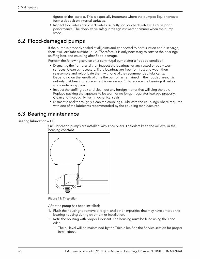
Oil lubrication pumps are installed with Trico oilers. The oilers keep the oil level in thehousing constant.
Figure 19: Trico oiler
After the pump has been installed:
1. Flush the housing to remove dirt, grit, and other impurities that may have entered thebearing housing during shipment or installation.
2. Refill the housing with proper lubricant. The housing must be filled using the Tricooiler.
– The oil level will be maintained by the Trico oiler. See the Service section for properinstructions.
6 Maintenance
28 G&L Pumps Series A-C 9100 Base Mounted Centrifugal Pumps INSTRUCTION MANUAL

A Mobile Oil, DTE Medium, or equal, meeting the following specification will providesatisfactory lubrication. Similar oils can be furnished by all major oil companies. It is theresponsibility of the oil vendor to supply a suitable lubricant.
Saybolt viscosity at 100°F 215 SSU-240 SSU
Saybolt viscosity at 210°F 49SSU
Viscosity index, minimum 95
API gravity 28–33
Pour point, maximum +20°F
Flash point, minimum 400°F
Additives Rust and oxidation inhibitors
ISO viscosity 46
NOTES:
• Oils from different suppliers should not be mixed.• Engine oils are not recommended.• The oil should be non-foaming, well refined, good grade, straight cut, filtered mineral
oil. It must be free from water, sediment, resin, soaps, acid, and fillers of any kind.
In installations with moderate temperature changes, low humidity, and a cleanatmosphere, the oil should be changed after approximately 1000 hours of operation. Theoil should be inspected at this time to determine the operating period before the next oilchange. Oil change periods may be increased up to 200–4000 hours based on an 8000hour year. Check the oil frequently for moisture, dirt, or signs of “breakdown,” especiallyduring the first 1000 hours.
CAUTION:
Do not over oil; This causes the bearings to run hot.
Bearing lubrication schedule
Type of bearing First lubrication,assembled pumpsand replacementbearing frames
First lubrication,replacement bearings
Lubrication interval, pump, polyurea-based grease,operating hours
Grease-lubricatedbearings
Not applicable,lubricated beforeshipment
Hand pack bearingsbefore pressing on theshaft. After bearingframe assembly, followrelube instructions tolube bearings.
• 3600 hours, 2 pole• 7200 hours, 4 pole• 50% for severe conditions: dirty, wet and/or
above 100°F (38°C) ambient• 50% for bearing frame temperature above 180°F
(82°C)• 75% for lithium-based grease
6.3.1 Regrease the grease-lubricated bearings
It is important to lubricate pumps and motors that require regreasing with the propergrease. See the motor service instructions and nameplate for motor regreasinginformation. Pumps are to be regreased using the grease types listed below or approvedequal. Always keep pump and motor properly lubricated.
NOTICE:
Make sure that the grease container, the greasing device, and the fittings are clean.Failure to do this can result in impurities entering the bearing housing when you regreasethe bearings.
6 Maintenance
G&L Pumps Series A-C 9100 Base Mounted Centrifugal Pumps INSTRUCTION MANUAL 29

1. With fully enclosed coupling guards, regrease pump while pump is running.
a) With old style open ended guards, stop pump, re-grease, and hand turn shaftbefore re-starting.
2. Wipe dirt from the grease fittings before greasing.
3. Fill both of the grease cavities through the fittings with the recommended grease. Stopwhen grease leaks out at shaft.
4. If needed, stop pump and wipe off excess grease.
5. Restart pump.
The bearing temperature usually rises after you regrease due to an excess supply ofgrease. Temperatures return to normal in about two to four operating hours as the pumpruns and purges the excess grease from the bearings. Maximum normal bearing housingtemperature for polyurea-based grease is 225°F (107°C) and for lithium-based grease180°F (82°C).
6.3.2 Lubricating grease requirements
NOTICE:
• Never mix greases of different consistencies (NLGI 1 or 3 with NLGI 2) or with differentthickeners. For example, never mix a lithium-based grease with a polyurea-basedgrease. This can result in decreased performance.
• Remove the bearings and old grease if you need to change the grease type orconsistency. Failure to do so can result in equipment damage or decreasedperformance.
Specifications — grease types
Polyurea-based greases Lithium-based greases, NLGI 2
Pumps built on or after Dec 1, 2014 use Polyurea-basedgreases. See date code label and lubrication label on
pump or bearing frame indicating polyurea-base grease
Pumps built before Dec 1, 2014 were built with Lithium-based greases, NLGI 2, and do not have lubrication labelon pump or bearing frame indicating pump grease type
ExxonMobil PolyrexTM EM Shell Gadus® S2 V100 2 (was Alvania RL 2)
Chevron SRI NLGI 2 Chevron Multifak® EP 2
Shell Gadus® S5 T100 2 ExxonMobil UnirexTM N2
6.4 Shaft-seal maintenance6.4.1 Mechanical seal maintenance
Keep in mind the following general rules regarding mechanical seal maintenance. Referto the instructions provided by the seal manufacturer for detailed information.
• Mechanical seals are precision products that must be treated with care. Use specialcare when handling seals. Make sure that oil and parts are clean in order to preventscratching the finely lapped sealing faces. Even light scratches on these faces canresult in leaky seals.
• Mechanical seals typically require no adjustment or maintenance except for routinereplacement of worn or broken parts.
• A used mechanical seal should not be put back into service unless the sealing faceshave been replaced or relapped. Relapping is practical only for seals that are 2 in. (5.1cm) or larger.
For optimum seal life, always follow these precautions:
• Keep the seal faces as clean as possible.• Keep the seal as cool as possible.• Make sure the seal always has proper lubrication.• If the seal is lubricated with filtered fluid, then clean the filter frequently.
6 Maintenance
30 G&L Pumps Series A-C 9100 Base Mounted Centrifugal Pumps INSTRUCTION MANUAL

6.4.2 Packed stuffing box maintenance
Check or instruction Explanation/comment
When starting a pump with fiber packing forthe first time, make sure that the packing isslightly loose without causing an air leak. Asthe pump runs in, gradually tighten thegland bolts evenly.
Never draw the gland to the point where the packing is compressedtoo tightly and no leakage occurs. This will burn the packing, scorethe shaft sleeve, and prevent circulation of the liquid that cools thepacking.
Turn the rotating element by hand. The stuffing box is improperly packed or adjusted if friction in the boxprevents turning the rotating element by hand. A properly operatedstuffing box runs lukewarm with a slow drip of sealing liquid.
After the pump has been in operation forsome time and the packing is completely runin, check that the stuffing box leaks at the rateof 40–60 drops per minute.
This indicates proper packing, shaft sleeve lubrication, and cooling.
NOTICE:Eccentricity of the shaft or sleeve through the packing can result inexcess leakage. Make sure that the parts are properly centered.
Check the packing frequently and replace asservice indicates.
Six months is a reasonable expected life, depending on operatingconditions. Use a packing tool in order to remove all old packingfrom the stuffing box. Never reuse old packing or add new rings toold packing. Clean the stuffing box thoroughly before you install newpacking.
Check the condition of the shaft or sleeve forpossible scoring or eccentricity and makereplacements as necessary.
—
When placing new, non-asbestos packinginto the stuffing box, open the molded ringssideways and push the joints into the stuffingbox first. Then install the rings one at a time,making sure to seat each ring firmly. Staggerthe joints at a 90° rotation from eachpreceding joint.
—
6.5 Cleaning without dismantling the pumpA short section of pipe so designed that it can be readily dropped out of the line can beinstalled adjacent to the suction flange. With this arrangement, any matter clogging theimpeller is accessible by removing the pipe section.
If the pump cannot be freed of clogging after the above methods have been tried,dismantle the unit as previously described to locate the trouble.
6.6 Disassembly6.6.1 Disassembly precautions
This manual clearly identifies accepted methods for disassembling units. These methodsmust be adhered to.
WARNING:
• Make sure that the pump is isolated from the system and that pressure is relievedbefore you disassemble the pump, remove plugs, open vent or drain valves, ordisconnect the piping.
• Always disconnect and lock out power to the driver before you perform any installationor maintenance tasks. Failure to disconnect and lock out driver power will result inserious physical injury.
• Crush hazard. The unit and the components can be heavy. Use proper lifting methodsand wear steel-toed shoes at all times.
6 Maintenance
G&L Pumps Series A-C 9100 Base Mounted Centrifugal Pumps INSTRUCTION MANUAL 31

NOTICE:
Make sure that all replacement parts are available before you disassemble the pump foroverhaul.
6.6.2 Drain the pump
CAUTION:
• Allow all system and pump components to cool before you handle them to preventphysical injury.
1. Close the isolation valves on the suction and discharge sides of the pump.
You must drain the system if no valves are installed.
2. Open the drain valve.
Do not proceed until liquid stops coming out of the drain valve. If liquid continues toflow from the drain valve, the isolation valves are not sealing properly and you mustrepair them before you proceed.
3. Leave the drain valve open and remove the drain plug located on the bottom of thepump housing.
Do not reinstall the plug or close the drain valve until the reassembly is complete.
4. Drain the liquid from the piping and flush the pump if it is necessary.
5. Disconnect all auxiliary piping and tubing.
6.6.3 Remove the hex coupling guard
1. Remove the two capscrews that hold the outer (motor side) coupling guard to thesupport brackets.
2. Spread the outer guard apart and pull it off the inner guard.
Do not spread the outer and inner guards more than necessary to remove the guard. Itcould alter their fit and appearance.
3. Remove the capscrew that holds the inner guard to the support bracket.
4. Spread the inner guard apart and pull it over the coupling.
1
2
3
4
56
12
10
987
11
6 Maintenance
32 G&L Pumps Series A-C 9100 Base Mounted Centrifugal Pumps INSTRUCTION MANUAL

1. Outer guard2. Inner guard3. Attach the support bracket inline with the bolt4. Support bracket5. Nut6. Lockwasher7. Capscrew8. Flat washer9. Spacer washer10.Option used instead of the spacer where overall guard length exceeds 12 in. (30 cm) or
the guard width is over 10 in. (25 cm) across the flats11.Locate the support arm between the outer guard ends. Align the arm with holes in the
outer guard and holes in the saddle bracket.12.Motor saddle bracket attached to the motor saddle
Figure 20: Hex guard exploded view for typical installation
6.6.4 Disassemble the pump with packing on shaft sleeve
See Parts list chapter for exploded view of the pump.
1. Close valves on suction and discharge sides of the pump. If no valves have beeninstalled, it will be necessary to drain the system.
2. Remove coupling guard and disconnect coupling. Refer to instructions on how toremove the hex coupling guard.
3. Loosen the cap screws which secure the coupler flanges to the coupler hubs. Removethe coupler flanges and sleeve by compressing the flanges and pulling out frombeneath the hubs or by loosening the allen set screws and sliding the hubs back onthe shafts. Remove the coupler hub from the pump shaft.
4. Drain the pump by opening the vent plug (0–910–0) and remove drain plugs (0–910–0)on suction and discharge nozzle.
5. Remove seal lines (0–901–0, 0–950–0, 0–952–0), if supplied.
6. Remove gland bolts (3–904–9), washers (1–909–9) and slide gland (3–014–2) away fromcasing.
7. Remove all casing main joint capscrews (2–904–1) and dowels (2–916–9). Use slot incasing main joint and separate the casing halves with a pry bar. Lift upper half casing(2–001–7) by cast lugs.
8. Remove packing (1–924–9) and seal cage (1–013–2) from each stuffing box.
9. Remove cap screws (1–904–9) which hold bearing housings (3–025–2) to the casingand lift rotating element out of lower casing (2–001–08). Rotating element may now bemoved to a suitable working location.
10.Pull coupling half and key (3–911–2) off shaft (3–007–0).
NOTE: A spare rotating element can be installed at this point.
11.Remove cap screws (3–904–9) from bearing covers (3–018–3, 4).
12.Remove bearing housings (3–025–2), locknut (3–516–4), and lockwasher (3–517–4).Mount bearing puller and remove bearings (3–026–2). Remove thrust washer (3–078–9)and snap ring (3–915–9).
NOTE: Locknut, lockwasher, and thrust washer are not on inboard side.
IMPORTANT: Do not reuse the ball bearings.
13.Remove bearing covers (3–018–5, 4) and push oil seals (3–177–9) out of bearing coversand coupling and bearing housing. Pull deflectors (3–136–9) off shaft.
14.Remove casing rings (3–003–9) from impellers (4–002–0).
15.Remove set screw (3–902–9) from shaft nuts. Remove shaft nuts (3–015–9), O-rings (3–914–9), sleeves (3–009–9), sleeve gaskets (1–428–1), and impeller (4–002–0).
NOTE: Apply heat uniformly to the shaft sleeve to loosen the sealant between the shaftand sleeve. DO NOT HEAT ABOVE 275°F. To further assist in removing the sleeves,
6 Maintenance
G&L Pumps Series A-C 9100 Base Mounted Centrifugal Pumps INSTRUCTION MANUAL 33

hold the shaft vertically and drop it on a block of wood. The impeller weight shouldforce both the impeller and sleeve from the shaft.
16.For impellers with replaceable rings, remove the rings (4–004–9) by cutting the ringswith a cold chisel.
For pumps equipped with adjustable rings, refer to Adjustable wear rings instructions.
6.7 Pre-assembly inspectionsGuidelines
Before you assemble the pump parts, make sure you follow these guidelines:
• Inspect the pump parts according to the information in these pre-assembly topicsbefore you reassemble your pump. Replace any part that does not meet the requiredcriteria.
• Make sure that the parts are clean. Clean the pump parts in solvent in order to removeoil, grease, and dirt.
NOTICE:
Protect machined surfaces while you clean the parts. Failure to do so may result inequipment damage.
6.7.1 Replacement guidelines
Impeller replacement
This table shows the criteria for replacing the impeller:
Impeller parts When to replace
Impeller vanes • When grooved deeper than 1/16 in. (1.6 mm), or• When worn evenly more than 1/32 in. (0.8 mm)
Vane edges When you see cracks, pitting, or corrosion damage
Gaskets, O-rings, and seats replacement
• Replace all gaskets and O-rings at each overhaul and disassembly.• Inspect the seats. They must be smooth and free of physical defects.• Replace parts if the seats are defective.
6.7.2 Shaft and sleeve inspection
Inspection criteria
Inspect the shaft and sleeve according to this criteria:
• Thoroughly clean the shaft and sleeve.• Thoroughly clean the coverplate seal cavity.• Inspect the surface for damage such as pitting, corrosion, nicks, and scratches.
Replace these parts if they are damaged.
6 Maintenance
34 G&L Pumps Series A-C 9100 Base Mounted Centrifugal Pumps INSTRUCTION MANUAL

6.8 Dimensions
Figure 21: Cross section
Pump sizeQuantity2–904–9
Dimension A
12x8x22M 2513.50
12x8x22L 26
14x10x20S 26
15.8116x12x23 26
16x14x17 24
18x14x23 32
14x10x20L 26 16.60
6.9 Reassembly6.9.1 Reassemble the pump with the mechanical seals on the shaft sleeve
All bearings, O-rings, seals, and gaskets should be replaced with new parts duringassembly. All reusable parts should be cleaned of all foreign matter before reassembling.The main casing joint gasket should be made using the upper half as a template. Lay thegasket material on the casing joint and mark it by pressing it against the edges of thecasing. Trim the gasket so that it is flush with the inside edges of the casing.
1. Place impeller key (3–911–1) in shaft (3–007–0).
2. Check the impeller (4–002–0) and casing to determine the correct impeller rotationand locate the impeller on the shaft per dimension “A” given in table.
NOTE: For impellers with replaceable rings, heat each new ring(4–004–9) and slide itonto the impeller. Hold the rings against the impeller shoulder until they cool.
3. Place both shaft sleeve keys (3–911–3) on shaft (3–007–0).
4. Slide sleeve gaskets (1–428–1) onto shaft and against hub of impeller.
5. Slide sleeves (3–009–9) onto shaft.
6. Place the sleeve O-ring (3–914–9) onto the shaft, into the sleeve counterbore. Verifythat Dimension “A” is maintained. Using a pin spanner wrench and hammer, securelytighten the shaft sleeve nuts (3–015–9). Then, drill a shallow recess in the shaft throughthe set screw hole in each of the shaft nuts. Lock each shaft sleeve nut in position withcup point set screws (3–902–9). A low strength sealant, such as Loctite 271, can beused to retain set screws.
6 Maintenance
G&L Pumps Series A-C 9100 Base Mounted Centrifugal Pumps INSTRUCTION MANUAL 35

7. Assemble casing rings (3–003–9). See figure for adjustable rings.
8. Install stationary seats (3–401–0) onto the glands (3–014–2) with lapped surface facingoutward. Do not scratch or damage seal faces during assembly.
Stationary seat must bottom squarely in gland.
9. Apply fine coat of silicon grease or equivalent to shaft sleeve, and slide seal headassembly (3–402–0) over sleeve. If seal is a John Crane Type 8, set to approximatedimension shown and tighten set screws. Next, install O-rings (3–914–2) onto glands(3–014–2) and install glands on shaft.
CAUTION:
Do not use petroleum-based products for installing the mechanical sealhead as it may attack the rubber elastomers.
10.Start heating bearings (3–026–2) so that they will be ready when called for the nextstep. Use dry heat from induction heat lamps or electric furnace, or a 10–15% solubleoil and water solution.
IMPORTANT: Do not exceed 275°F.
These are precision, high-quality bearings. Exercise care always to keep them cleanand free from foreign matter.
11.Assemble oil seal (3–177–9) in each bearing cover. Install gaskets (30409–9) on eachbearing cover.
NOTE: Seal lip or pressure side of oil seal must point towards the ends of the shaft thatthe oil seal is assembled on. See oil lubricated bearings.
The following figures show a grease lubricated bearing housing and an oil lubricatedbearing housing, respectively. The main difference between the two is the greasefitting and the oil ring, respectively.
Figure 22: Grease lubricated bearing housing
6 Maintenance
36 G&L Pumps Series A-C 9100 Base Mounted Centrifugal Pumps INSTRUCTION MANUAL

Figure 23: Oil lubricated bearing housing
12.Slide deflectors (3–136–9) and bearing covers (3–018–3), –4) on the shaft. Install snaprings (3–915–9). Install thrust washer (3–078–9) on the outboard end.
For ease of assembly and protection of rubber parts while sliding parts onto shaft,cover O-ring groove, keyways, and threads with electrical tape.
NOTE: Inboard bearing cover (3–018–3) is approximately 1/4 inch less in width thanthe outboard bearing cover (3–018–4). This is the only dimensional difference.
13.Press heated bearing (3–026–2) on shaft against snap ring or thrust washer. Installlocknut (3–516–4) and lock washer (3–517–4) on outboard end. Make certain thelocknut is secured and then bend over tab on lock washer.
14. Condition Action
Pumps with grease lubrication Cool bearings at room temperature and coat with 2 ounces or 3 ounces of arecommended grease.
Pumps with oil lubrication Refer to instructions for installation of oil lubricated parts.
15.Assemble oil seals (3–177–9) in each bearing housing. Refer to NOTE under number11 for direction of oil seal.
16.Slide bearing housings (3–025–2) over bearings (3–026–2).
17.Assemble bearing cover to bearing housing with two capscrews (3–904–9).
18.Replace pump coupling half and key (3–911–2).
19.Assemble rotating element in lower half casing (2–001–8). Correctly locate casing ringpins (3–943–9) in casing main joint slot.
NOTE: Sliding inboard bearing housing toward coupling before assembling rotatingelement in casing will ease assembly.
20.Bolt outboard bearing housing in place. Be sure that both housings are seated in lowerhalf casing.
21.Bolt inboard bearing housing in place. If seal is a John Crane Type 8, set seal todimension shown and tighten set screws.
22.Clean the gasket surfaces of the casing. Apply Scotch 3M-77 spray adhesive orequivalent to the lower half of the casing.
23.Within one minute of spraying, set the gaskets (2–123–5, –6) in place on the lower halfcasing. Align the holes in the gaskets with the holes in the casing and press the gasketsfirmly against the lower half casing face in the area coated by the adhesive.
6 Maintenance
G&L Pumps Series A-C 9100 Base Mounted Centrifugal Pumps INSTRUCTION MANUAL 37

24.Lower upper half casing (2–001–7) into place and locate using the taper dowels (2–916–9) and install casing main joint bolts (2–904–9). The casing joint bolts should betightened to the following torques: 300 ft-lb minimum for .75"-10 Ferry CapCounterbore screws (Grade 8), 400 ft-lb minimum for 1.0”-8 Ferry Cap Counterborescrews (Grade 8). Refer to bolt torque pattern. Before tightening bolt, be sure thattaper dowels are seated properly in reamed holes.
NOTE: Torque valves are essential in obtaining proper gasket compression so noleakage can occur at main joint.
CAUTION:
Double check rotation of pump before installing the upper half casing.
Figure 24: Bolt torquing pattern
25.Slide deflectors (3–136–9) toward bearing covers. Allow rotating clearance ofapproximately 1/16”.
26.Rotate shaft by hand to assure that it turns smoothly and is free from rubbing andbinding.
27.Bolt glands (3–014–2) to casing with gland bolts (3–904–9).
28.Assemble seal water lines (0–901–0, 0–950–0, 0–052–0) to stuffing box and casing. Sealwater lines go to outside holes. Refer to Dimension section for more information.
29.Check coupling alignment and redowel if necessary.
6.9.2 Reassemble the pump with the packing on the shaft sleeve
All bearings, O-rings, seals, and gaskets should be replaced with new parts duringassembly. All reusable parts should be cleaned of all foreign matter before reassembling.The main casing joint gasket should be made using the upper half as a template. Lay the
6 Maintenance
38 G&L Pumps Series A-C 9100 Base Mounted Centrifugal Pumps INSTRUCTION MANUAL
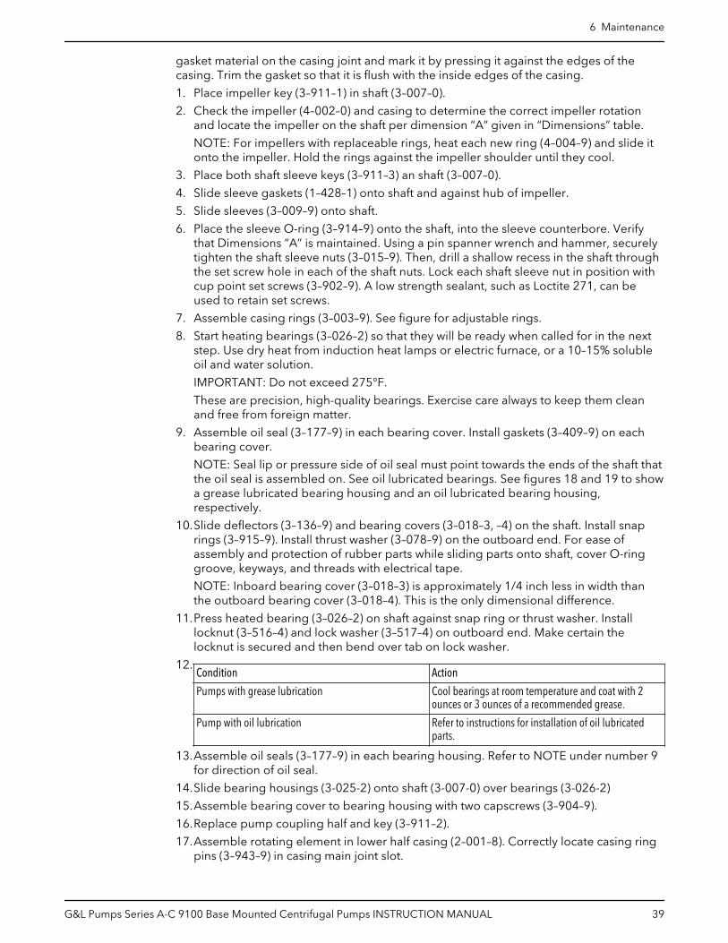
gasket material on the casing joint and mark it by pressing it against the edges of thecasing. Trim the gasket so that it is flush with the inside edges of the casing.
1. Place impeller key (3–911–1) in shaft (3–007–0).
2. Check the impeller (4–002–0) and casing to determine the correct impeller rotationand locate the impeller on the shaft per dimension “A” given in “Dimensions” table.
NOTE: For impellers with replaceable rings, heat each new ring (4–004–9) and slide itonto the impeller. Hold the rings against the impeller shoulder until they cool.
3. Place both shaft sleeve keys (3–911–3) an shaft (3–007–0).
4. Slide sleeve gaskets (1–428–1) onto shaft and against hub of impeller.
5. Slide sleeves (3–009–9) onto shaft.
6. Place the sleeve O-ring (3–914–9) onto the shaft, into the sleeve counterbore. Verifythat Dimensions “A” is maintained. Using a pin spanner wrench and hammer, securelytighten the shaft sleeve nuts (3–015–9). Then, drill a shallow recess in the shaft throughthe set screw hole in each of the shaft nuts. Lock each shaft sleeve nut in position withcup point set screws (3–902–9). A low strength sealant, such as Loctite 271, can beused to retain set screws.
7. Assemble casing rings (3–003–9). See figure for adjustable rings.
8. Start heating bearings (3–026–2) so that they will be ready when called for in the nextstep. Use dry heat from induction heat lamps or electric furnace, or a 10–15% solubleoil and water solution.
IMPORTANT: Do not exceed 275°F.
These are precision, high-quality bearings. Exercise care always to keep them cleanand free from foreign matter.
9. Assemble oil seal (3–177–9) in each bearing cover. Install gaskets (3–409–9) on eachbearing cover.
NOTE: Seal lip or pressure side of oil seal must point towards the ends of the shaft thatthe oil seal is assembled on. See oil lubricated bearings. See figures 18 and 19 to showa grease lubricated bearing housing and an oil lubricated bearing housing,respectively.
10.Slide deflectors (3–136–9) and bearing covers (3–018–3, –4) on the shaft. Install snaprings (3–915–9). Install thrust washer (3–078–9) on the outboard end. For ease ofassembly and protection of rubber parts while sliding parts onto shaft, cover O-ringgroove, keyways, and threads with electrical tape.
NOTE: Inboard bearing cover (3–018–3) is approximately 1/4 inch less in width thanthe outboard bearing cover (3–018–4). This is the only dimensional difference.
11.Press heated bearing (3–026–2) on shaft against snap ring or thrust washer. Installlocknut (3–516–4) and lock washer (3–517–4) on outboard end. Make certain thelocknut is secured and then bend over tab on lock washer.
12.Condition Action
Pumps with grease lubrication Cool bearings at room temperature and coat with 2ounces or 3 ounces of a recommended grease.
Pump with oil lubrication Refer to instructions for installation of oil lubricatedparts.
13.Assemble oil seals (3–177–9) in each bearing housing. Refer to NOTE under number 9for direction of oil seal.
14.Slide bearing housings (3-025-2) onto shaft (3-007-0) over bearings (3-026-2)
15.Assemble bearing cover to bearing housing with two capscrews (3–904–9).
16.Replace pump coupling half and key (3–911–2).
17.Assemble rotating element in lower half casing (2–001–8). Correctly locate casing ringpins (3–943–9) in casing main joint slot.
6 Maintenance
G&L Pumps Series A-C 9100 Base Mounted Centrifugal Pumps INSTRUCTION MANUAL 39

NOTE: Sliding inboard bearing housing toward coupling before assembling rotatingelement in casing will ease assembly.
18.Bolt outboard bearing housing in place. Be sure that both housings are seated in lowerhalf casing.
19.Bolt inboard bearing housing in place.
20.Clean the gasket surfaces of the casing. Apply Scotch 3M-77 spray adhesive orequivalent to the lower half of the casing.
21.Within one minute of spraying, set the gaskets (2–123–5, –6) in place on the lower halfcasing. Align the holes in the gaskets with the holes in the casing and press the gasketsfirmly against the lower half casing face in the area coated by the adhesive.
22.Lower upper half casing (2–001–7) into place and locate using the taper dowels (2–916–9) and install casing main joint bolts (2–904–9). The casing joint bolts should betightened to the following torques: 300 ft-lb minimum for .75”-10 Ferry CapCounterbore screws (Grade 8), 400 ft-lb minimum for 1.0”-8 Ferry Cap Counterborescrews (Grade 8). Refer to bolt torque pattern (Figure 20). Before tightening bolt, besure that taper dowels are seated properly in reamed holes.
NOTE: Torque valves are essential in obtaining proper gasket compression so noleafage can occur at main joint.
CAUTION: Double-check rotation of pump before installing the upper half casing.
23.Slide deflectors (3–136–9) toward bearing covers. Allow rotating clearance ofapproximately 1/16”.
24.Rotate shaft by hand to assure that it turns smoothly and is free from rubbing andbinding.
25.Cut full rings of 5/8 inch square packing so that ends butt, leaving no gap betweenpacking and casings. Install three rings of packing (1–924–9) and tap fully to bottom ofboth stuffing boxes. (See figure below) Stagger joints of each ring of packing at least90 degrees. Install seal cage (1–013–2) and be sure that it will line up with seal waterinlet when packing is compressed. Install remaining three rings of packing with jointsstaggered.
26.Assemble glands (1–014–2) square with stuffing box and pull tight. Then loosen glandbolts (1–904–9) to permit packing to expand and retighten finger tight. Finaladjustment of gland bolts must be done when pump is running.
27.Assemble seal water lines (0–901–0, 0–950–0, 0–952–0) to stuffing box and casing. Sealwater lines go to outside holes. Refer to Dimension section for more information.
28.Check coupling alignment and redowel if necessary.
6 Maintenance
40 G&L Pumps Series A-C 9100 Base Mounted Centrifugal Pumps INSTRUCTION MANUAL

6.9.3 Install the hex coupling guard1. Slide the inner guard into the outer guard.
2. Spread the guards and place them over the coupling.
Do not spread the inner and outer guards more than necessary for guard installation,as it can alter their fit and appearance.
3. Straddle the support bracket with the guards and install a capscrew through the holein the support bracket and guard located closest to the pump.
Do not tighten the capscrew.
4. Install the outer guard capscrews according to the directions in this table.
If... Then...
The pump has a motor saddlesupport bracket
Ensure that the outer guard straddles the support arm and install the tworemaining capscrews.Do not tighten the capscrews.
The pump does not have a motorsaddle support bracket
Insert the spacer washer between the holes located closest to the motor inthe outer guard and install the two remaining capscrews.Do not tighten the capscrews.
5. Position the outer guard so that there is less than 1/4 in. (0.64 cm) of exposed shaft.
6. Hold the guard in this position and tighten the three capscrews.
7. Open the isolation valves and inspect the pump for leaks.
8. Return the pump to service if it is not leaking.
6.9.4 Adjustable wear ringsAdjustable rings are an assembly of two threaded rings. The outer, stationary ring is heldin the casing by a flange and an anti-rotation pin in the lower half main joint. The inner,adjustable ring can be moved axially, in either direction, by rotating it. The ring is held inposition by a stainless steel locking pin. All rings have clockwise threads.
Adjustment
When the clearance between the impeller wear face and the adjustable wearing ringbecomes excessive; For example, approximately .020” to .030”.
1. Remove the upper half casing and pull the locking pin.2. Rotate the inner rings clockwise to restore .005” to .008” clearance greater than shaft
end float between the ring and the impeller.3. Drill a new hole in the inner ring for the locking pin. This is a blind hole, do not drill
through.4. Replace the locking pin and upper half casing.
1 2 3
6 5 4
1. Sleeve2. Impeller ring3. Casing ring
6 Maintenance
G&L Pumps Series A-C 9100 Base Mounted Centrifugal Pumps INSTRUCTION MANUAL 41

4. Impeller5. Casing6. Locking pin
Disassembly and reassembly
Adjustable rings are removed in the same manner as standard casing rings. They can beseparated for cleaning. Adjustable rings are installed in the pump with stationary and theadjustable members assembled but not pinned.
1. Turn the adjustable member counterclockwise to provide maximum impellerclearance and slide over shaft ends.
– With the rotating element in pump, the ring can be adjusted. Be sure that stationarymember has its flange flush against casing lower half.
2. Move rotating element toward outboard as far as bearings permit.3. Screw outboard end adjustable ring toward impeller to obtain .005” to .006” axial
impeller clearance.4. Drill through stationary ring hole into adjustable ring and insert locking pin.5. Move rotating element toward coupling and set coupling end ring in the same
manner.
6.9.5 Install the oil ring1. Place the oil ring in the bearing housing, directly under the pipe plug hole.
2. Run a wire through the pipe plug hole, around the oil ring and back through the pipeplug hole once again.
3. Tie the wire to a metal washer (being a larger diameter than the hole) causing the oilring to become tight against the inside top of the bearing housing.
4. Assemble the bearing housing over the bearing.
5. Untie the wire. The oil ring will drop down onto the shaft.
6. Check the position of the oil ring through the pipe plug hole at the top of the bearinghousing.
The oil ring must be resting on the shaft for correct operation. A screwdriver can beused to correct the oil ring position, if necessary.
6.9.6 Change the oil for oil lubricated bearings
11
2
3
4
5
1. Reservoir2. Vent assembly3. Bearing housing4. Pipe plug5. Lower casting
Figure 25: Oiler assembly
1. Remove the vent assembly from the top of the bearing housing.
2. Remove the pipe plug from the bottom of the bearing housing.
6 Maintenance
42 G&L Pumps Series A-C 9100 Base Mounted Centrifugal Pumps INSTRUCTION MANUAL

3. Unscrew the reservoir and remove.
4. Flush the oiler and bearing housing with a light grade of oil. Flush until all foreignparticles have been removed.
5. Screw the pipe plug and vent assembly back into place.
6. Fill the reservoir with a good grade filtered mineral oil.
Refer to oil lubrication instructions given previously in this manual for type of oil.
NOTE: You must fill through Trico reservoir.
7. Place thumb over reservoir spout, invert and place reservoir on lower casting whileremoving thumb. Allow reservoir to empty, filling the bearing housing.
Several fillings of the reservoir may be required before the actual level is reached. Nomore oil will run out of the reservoir.
8. When reservoir stays full, screw reservoir back into lower casting.
A periodic filling of the reservoir is required. When the oil becomes dirty, repeat steps 1through 8.
6.9.7 Limited end float couplingFor units with drivers having sleeve bearings, the coupling halves are set to limited totalshaft axial movement to less than one-half of the motor rotor assembly end float. This isaccomplished by inserting a phenolic disc, or equivalent, of a specified thickness betweenthe motor and pump shaft.
1 2
34
5
1. Cover2. Phenolic disc3. Pump shaft4. Motor shaft5. Hub
Figure 26: Limited end float coupling arrangement
For pump installations that use limited end float gear type couplings:
1. Slip fit the coupling hubs onto the pump and motor shafts.2. Install the coupling covers and hubs.3. With the motor set on its Magnetic Center, butt the pump and motor shafts with the
phenolic disc inserted between them.
– The pump thrust bearing limits end float towards the motor.– The thrust bearing of the pump is large enough to carry any magnetic thrust
developed by the motor when aligned properly.
Once the above instructions have been followed out copletely, the Alignment Proceduresshould be followed.
6.9.8 Assembly references
6.9.8.1 Ordering partsThe pumps covered by this manual have been designed and built with certainreplaceable wearing parts. The recommended inventory of spare parts depends upon theinstallation and the importance of continued operation.
For critical service requiring a minimum of “down time” a complete or “quick change”rotating element is recommended.
6 Maintenance
G&L Pumps Series A-C 9100 Base Mounted Centrifugal Pumps INSTRUCTION MANUAL 43

For normal service, with repairs to be made in the field, the following parts arerecommended for stock.
• 1 set of bearings• 1 set of wearing rings• 1 set of gaskets, O-rings, and grease seals• 2 mechanical seals (complete), or 2 sets of packing (if provided)• 1 set of shaft sleeves
Parts should be ordered as far in advance of their use as possible since circumstancesbeyond the control of the company may reduce existing stock. Not all parts are stockedand must be manufactured for each order.
To facilitate rapid handling of your order for spare parts, be sure to include the followinginformation:
1. Serial number of the pump.2. Catalog number of the part.3. Quantity of each part.4. Name of the part.5. Material desired. (Parts will be furnished in original materials unless specified as a
material change. All material substitutions should be discussed with the factory.
6.9.8.2 Screw torque values
Capscrew torque in ft-lb (Nm)
Capscrewtype
Headmarking
Capscrew diameter (in inches)
1/4 5/16 3/8 7/16 1/2 5/8 3/4 7/8 1
SAE grade2
6 (8) 13 (18) 25 (34) 38 (52) 60 (81) 120 (163) 190 (258) 210 (285) 300 (407)
Brass andstainlesssteel
or 4 (5) 10 (14) 17 (23) 27 (37) 42 (57) 83 (113) 130 (176) 200 (271) 300 (407)
SAE grade5
10 (14) 20 (27) 35 (47) 60 (81) 90 (122) 180 (244) 325 (440) 525 (712) 800 (1085)
*The M6 set screw has a rating of 10 N m.
6.9.8.3 Dealer servicing
If trouble occurs that cannot be rectified, contact your local sales and servicerepresentative and be prepared to provide this information:
1. Complete nameplate data of pump and motor
2. Suction and discharge pipe pressure gauge readings
3. Ampere draw of the motor
4. A sketch of the pump hook-up and piping
6 Maintenance
44 G&L Pumps Series A-C 9100 Base Mounted Centrifugal Pumps INSTRUCTION MANUAL

7 Troubleshooting7.1 Operation troubleshooting
Between regular maintenance inspections, be alert for signs of motor or pump trouble.Correct any trouble immediately and avoid costly repair and shutdown.
Symptom Cause Remedy
No liquid delivered
Lack of prime Fill pump and suction pipecompletely with liquid.
Loss of prime Check for leaks in suction pipe jointsand fittings; vent casing to removeaccumulated air.
Suction lift too high. If no obstruction at inlet, check forpipe friction losses. Static lift may betoo great. Measure with mercurycolumn or vacuum gauge whilepump operates. If static lift is toohigh, liquid to be pumped must beraised or pump lowered.
Discharge head too high. Check pipe friction losses. Largepiping may correct condition. Checkthat valves are wide open.
The motor speed is too low. Check whether motor is directlyacross-the-line and receiving fullvoltage. Or frequency may be too low;motor may have an open phase.
Wrong direction of rotation. Check motor rotation with directionalarrow on pump casing.
Impeller completely plugged. Dismantle pump and clean impeller.
7 Troubleshooting
G&L Pumps Series A-C 9100 Base Mounted Centrifugal Pumps INSTRUCTION MANUAL 45

Symptom Cause Remedy
Not enough liquid being delivered
Air leaks in suction piping If liquid pumped is water or othernon-explosive, and explosive gas ordust is not present, test flanges forleakage with flame or match, or byplugging inlet and putting line underpressure. A gauge will indicate a leakwith a drop of pressure.
The motor speed is too low. Check whether motor is directlyacross-the-line and receiving fullvoltage. Or frequency may be too low;motor may have an open phase.
Discharge head too high Check pipe friction losses. Largepiping may correct condition. Checkthat valves are wide open.
Suction lift too high If no obstruction at inlet, check forpipe friction losses. Static lift may betoo great. Measure with mercurycolumn or vacuum gauge whilepump operates. If static lift is toohigh, liquid to be pumped must beraised or pump lowered.
Impeller partially plugged Dismantle pump and clean impeller.
Cavitation; insufficient NPSH(depending on installation)
1. Increase positive suction head onpump by lowering pump.
2. Sub-cool suction piping at inlet tolower entering liquidtemperature.
3. Pressurization suction vessel.
Defective impeller. Inspect impeller, bearings and shaft.Replace is damaged or vane sectionsbadly eroded.
Foot valve too small or partiallyobstructed.
Area through ports of valve should beat least as large as area of suctionpipe — preferable 1½ times. Ifstrainer is used, net clear area shouldbe 3 to 4 times area of suction pipe.
Suction inlet not immersed deepenough.
If inlet cannot be lowered, or if eddiesthrough which air is sucked persistwhen it is lowered, chain a board tosuction pipe. It will be drawn intoeddies, smothering the vortex.
Too small impeller diameter.Probable cause if none of above)
Check with factory to see if a largerimpeller can be used; otherwise, cutpipe losses or increase speed — orboth, if needed. Be careful not toseriously overload drive.
7 Troubleshooting
46 G&L Pumps Series A-C 9100 Base Mounted Centrifugal Pumps INSTRUCTION MANUAL

Symptom Cause Remedy
Not enough pressure
Mechanical defects See “Defective impeller” and “Footvalve too small or partiallyobstructed”.
Obstruction in liquid passages. Dismantle pump and inspectpassages of impeller and casing.Remove obstruction.
Air or gases in liquid. (Test inlaboratory, reducing pressure onliquid to pressure in suction line.Watch for bubble formation.)
May be possible to over rate pump topoint where it will provide adequatepressure despite condition. Better toprovide gas separation chamber onsuction line near pump, andperiodically exhaust accumulatedgas. See “Cavitation; insufficientNPSH”.
Too small impeller diameter.(Probable cause if none above.)
Check with factory to see if a largerimpeller can be used; otherwise, cutpipe losses or increase speed — orboth, if needed. Be careful not toseriously overload drive.
Pump operates for short time, thenstops
Incomplete priming. Free pump, piping and valves of allair. If high points in suction preventthis, they need correcting.
Suction lift too high. If no obstruction at inlet, check forpipe friction losses. Static lift may betoo great. Measure with mercurycolumn or vacuum gauge whilepump operates. If static lift is toohigh, liquid to be pumped must beraised or pump lowered.
Air leaks in suction piping. If liquid pumped is water or othernon-explosive, and explosive gas ordust is not present, test flanges forleakage with flame or match, or byplugging inlet and putting line underpressure. A gauge will indicate a leakwith a drop of pressure.
Air or gasses in liquid. May be possible to over rate pump topoint where it will provide adequatepressure despite condition. Better toprovide gas separation chamber onsuction line near pump, andperiodically exhaust accumulatedgas. See “Cavitation; insufficientNPSH”.
Pump takes too much power
Head lower than rating; therebypumping too much liquid.
Machine impeller’s OD to sizeadvised by factory.
Cavitation 1. Increase positive suction head onpump by lowering pump.
2. Sub-cool suction piping at inlet tolower entering liquidtemperature.
3. Pressurization suction vessel.
Mechanical defects See “Defective impeller” and “Footvalve too small or partiallyobstructed”.
7 Troubleshooting
G&L Pumps Series A-C 9100 Base Mounted Centrifugal Pumps INSTRUCTION MANUAL 47

Symptom Cause Remedy
Suction inlet not immersed enough. If inlet cannot be lowered, or if eddiesthrough which air is sucked persistwhen it is lowered, chain a board tosuction pipe. It will be drawn intoeddies, smothering the vortex.
Liquid heavier (in either viscosity orspecific gravity) than allowed for.
Use larger driver. Consult factory forrecommended size. Test liquid forviscosity and specific gravity.
Wrong direction of rotation. Check motor rotation with directionalarrow on pump casing.
Casing distorted by excessive strainsfrom suction or discharge piping.
Check alignment. Examine pump forfriction between impeller and casing.Replace damaged parts.
Shaft bent due to damage — throughshipment, operation, or overhaul.
Check deflection of rotor by turningon bearing journals. Total indicatorrun-out should not exceed 0.002 onshaft and 0.004 on impeller wearingsurface.
Mechanical failure of critical pumpparts.
Check bearings and impeller fordamage. Any irregularity in theseparts will cause a drag on shaft.
Misalignment Realign pump and driver.
Speed may be too high (brake hp ofpump varies as the cube of the speed;therefore, any increase in speedmeans considerable increase inpower demand).
Check voltage on motor.
Electrical defects. The voltage and frequency of theelectrical current may be lower thanthat for which the motor was built; orthere may be defects in motor. Themotor may not be ventilated properlydue to poor location.
Mechanical defects in turbine, engineor other type of drive exclusive ofmotor.
If trouble cannot be located, consultfactory.
7 Troubleshooting
48 G&L Pumps Series A-C 9100 Base Mounted Centrifugal Pumps INSTRUCTION MANUAL

8 Parts Listings and Cross-SectionalDrawings8.1 Parts list
8 Parts Listings and Cross-Sectional Drawings
G&L Pumps Series A-C 9100 Base Mounted Centrifugal Pumps INSTRUCTION MANUAL 49

Part number Part nameQuantity
Packing Mechanical seal
0–901–0 Valve 2 (optional) 2
0–910–0 Pipe plug 20 18
0–950–0 Pipe nipple 2 (optional) 2
0–952–0 Tubing 2 (optional) 2
1–013–2 Seal cage 2
1–014–2 Gland (packing) 2
1–428–1 Sleeve gasket 2 2
1–904–9 Gland and housing bolt 12 8
1–909–9 Washer, gland bolt 4
1–924–9* Packing ring 12
2–001–7 Casing, upper half 1 1
2–001–8 Casing, lower half 1 1
2–123–5* Casing, joint gasket(suction)
1 1
2–133–6* Casing joint gasket(discharge)
1 1
2–904–1 Cap screw (casing) Varies with pump size Varies with pump size
2–916–9 Taper pin 2 2
3–003–9* Casing ring 2 2
3–007–0 Shaft 1 1
3–009–9* Shaft sleeve 2 2
3–014–2 Gland (mechanical seal) 2
3–015–9 Shaft sleeve nut 2 2
3–018–3 Bearing housing cover(inboard)
1 1
3–018–4 Bearing housing cover(outboard)
1 1
3–025–2 bearing housing 2 2
3–026–2* Bearing 2 2
3–078–9 Thrust washer (outboard) 1 1
3–136–9 Deflector 2 2
3–177–4* Lip seal (outboard bearing) 1 1
3–177–9* Lip seal (bearing) 3 3
3–401–0* Mechanical seal seat 2
3–402–0* Mechanical seal head 2
3–409–9 Gasket (bearing housingcover)
2 2
3–516–4 Locknut 1 1
3–517–4 Lockwasher 1 1
3–902–9 Set screw (shaft sleeve nut) 2 2
3–904–9 Gland and cover bolt 4 8
3–911–1 Key (impeller) 1 1
3–911–2 Key (coupling) 1 1
3–911–3 Key (shaft sleeve) 2 2
8 Parts Listings and Cross-Sectional Drawings
50 G&L Pumps Series A-C 9100 Base Mounted Centrifugal Pumps INSTRUCTION MANUAL

Part number Part nameQuantity
Packing Mechanical seal
3–914–2* O-ring (gland) 2
3–914–9* O-ring (shaft sleeve) 2 2
3–915–9 Snap ring 2 2
3–943–9 Spirol pin 2 2
4–002–0 Impeller 1 1
4–004–9 Impeller ring 2 (optional) 2 (optional)
* Recommended Spare parts
8 Parts Listings and Cross-Sectional Drawings
G&L Pumps Series A-C 9100 Base Mounted Centrifugal Pumps INSTRUCTION MANUAL 51
9 Product warrantyCommercial warranty
Warranty. For goods sold to commercial buyers, Seller warrants the goods sold to Buyerhereunder (with the exception of membranes, seals, gaskets, elastomer materials,coatings and other "wear parts" or consumables all of which are not warranted except asotherwise provided in the quotation or sales form) will be (i) be built in accordance withthe specifications referred to in the quotation or sales form, if such specifications areexpressly made a part of this Agreement, and (ii) free from defects in material andworkmanship for a period of one (1) year from the date of installation or eighteen (18)months from the date of shipment (which date of shipment shall not be greater thanndythirty (30) days after receipt of notice that the goods are ready to ship), whichever shalloccur first, unless a longer period is specified in the product documentation (the“Warranty”).
Except as otherwise required by law, Seller shall, at its option and at no cost to Buyer,either repair or replace any product which fails to conform with the Warranty providedBuyer gives written notice to Seller of any defects in material or workmanship within ten(10) days of the date when any defects or non-conformance are first manifest. Undereither repair or replacement option, Seller shall not be obligated to remove or pay for theremoval of the defective product or install or pay for the installation of the replaced orrepaired product and Buyer shall be responsible for all other costs, including, but notlimited to, service costs, shipping fees and expenses. Seller shall have sole discretion as tothe method or means of repair or replacement. Buyer’s failure to comply with Seller’srepair or replacement directions shall terminate Seller’s obligations under this Warrantyand render the Warranty void. Any parts repaired or replaced under the Warranty arewarranted only for the balance of the warranty period on the parts that were repaired orreplaced. Seller shall have no warranty obligations to Buyer with respect to any product orparts of a product that have been: (a) repaired by third parties other than Seller or withoutSeller’s written approval; (b) subject to misuse, misapplication, neglect, alteration,accident, or physical damage; (c) used in a manner contrary to Seller’s instructions forinstallation, operation and maintenance; (d) damaged from ordinary wear and tear,corrosion, or chemical attack; (e) damaged due to abnormal conditions, vibration, failureto properly prime, or operation without flow; (f) damaged due to a defective powersupply or improper electrical protection; or (g) damaged resulting from the use ofaccessory equipment not sold or approved by Seller. In any case of products notmanufactured by Seller, there is no warranty from Seller; however, Seller will extend toBuyer any warranty received from Seller’s supplier of such products.
THE FOREGOING WARRANTY IS EXCLUSIVE AND IN LIEU OF ANY AND ALL OTHEREXPRESS OR IMPLIED WARRANTIES, GUARANTEES, CONDITIONS OR TERMS OFWHATEVER NATURE RELATING TO THE GOODS PROVIDED HEREUNDER, INCLUDINGWITHOUT LIMITATION ANY IMPLIED WARRANTIES OF MERCHANTABILITY ANDFITNESS FOR A PARTICULAR PURPOSE, WHICH ARE HEREBY EXPRESSLY DISCLAIMEDAND EXCLUDED. EXCEPT AS OTHERWISE REQUIRED BY LAW, BUYER’S EXCLUSIVEREMEDY AND SELLER’S AGGREGATE LIABILITY FOR BREACH OF ANY OF THEFOREGOING WARRANTIES ARE LIMITED TO REPAIRING OR REPLACING THE PRODUCTAND SHALL IN ALL CASES BE LIMITED TO THE AMOUNT PAID BY THE BUYER FOR THEDEFECTIVE PRODUCT. IN NO EVENT SHALL SELLER BE LIABLE FOR ANY OTHER FORMOF DAMAGES, WHETHER DIRECT, INDIRECT, LIQUIDATED, INCIDENTAL,CONSEQUENTIAL, PUNITIVE, EXEMPLARY OR SPECIAL DAMAGES, INCLUDING BUTNOT LIMITED TO LOSS OF PROFIT, LOSS OF ANTICIPATED SAVINGS OR REVENUE,LOSS OF INCOME, LOSS OF BUSINESS, LOSS OF PRODUCTION, LOSS OFOPPORTUNITY OR LOSS OF REPUTATION.
9 Product warranty
52 G&L Pumps Series A-C 9100 Base Mounted Centrifugal Pumps INSTRUCTION MANUAL
Limited consumer warranty
Warranty. For goods sold for personal, family or household purposes, Seller warrants thegoods purchased hereunder (with the exception of membranes, seals, gaskets, elastomermaterials, coatings and other "wear parts" or consumables all of which are not warrantedexcept as otherwise provided in the quotation or sales form) will be free from defects inmaterial and workmanship for a period of one (1) year from the date of installation oreighteen (18) months from the product date code, whichever shall occur first, unless alonger period is provided by law or is specified in the product documentation (the“Warranty”).
Except as otherwise required by law, Seller shall, at its option and at no cost to Buyer,either repair or replace any product which fails to conform with the Warranty providedBuyer gives written notice to Seller of any defects in material or workmanship within ten(10) days of the date when any defects or non-conformance are first manifest. Undereither repair or replacement option, Seller shall not be obligated to remove or pay for theremoval of the defective product or install or pay for the installation of the replaced orrepaired product and Buyer shall be responsible for all other costs, including, but notlimited to, service costs, shipping fees and expenses. Seller shall have sole discretion as tothe method or means of repair or replacement. Buyer’s failure to comply with Seller’srepair or replacement directions shall terminate Seller’s obligations under this Warrantyand render this Warranty void. Any parts repaired or replaced under the Warranty arewarranted only for the balance of the warranty period on the parts that were repaired orreplaced. The Warranty is conditioned on Buyer giving written notice to Seller of anydefects in material or workmanship of warranted goods within ten (10) days of the datewhen any defects are first manifest.
Seller shall have no warranty obligations to Buyer with respect to any product or parts of aproduct that have been: (a) repaired by third parties other than Seller or without Seller’swritten approval; (b) subject to misuse, misapplication, neglect, alteration, accident, orphysical damage; (c) used in a manner contrary to Seller’s instructions for installation,operation and maintenance; (d) damaged from ordinary wear and tear, corrosion, orchemical attack; (e) damaged due to abnormal conditions, vibration, failure to properlyprime, or operation without flow; (f) damaged due to a defective power supply orimproper electrical protection; or (g) damaged resulting from the use of accessoryequipment not sold or approved by Seller. In any case of products not manufactured bySeller, there is no warranty from Seller; however, Seller will extend to Buyer any warrantyreceived from Seller’s supplier of such products.
THE FOREGOING WARRANTY IS PROVIDED IN PLACE OF ALL OTHER EXPRESSWARRANTIES. ALL IMPLIED WARRANTIES, INCLUDING BUT NOT LIMITED TO THEIMPLIED WARRANTIES OF MERCHANTABILITY AND FITNESS FOR A PARTICULARPURPOSE, ARE LIMITED TO ONE (1) YEAR FROM THE DATE OF INSTALLATION OREIGHTEEN (18) MONTHS FROM THE PRODUCT DATE CODE , WHICHEVER SHALLOCCUR FIRST. EXCEPT AS OTHERWISE REQUIRED BY LAW, BUYER’S EXCLUSIVEREMEDY AND SELLER’S AGGREGATE LIABILITY FOR BREACH OF ANY OF THEFOREGOING WARRANTIES ARE LIMITED TO REPAIRING OR REPLACING THE PRODUCTAND SHALL IN ALL CASES BE LIMITED TO THE AMOUNT PAID BY THE BUYER FOR THEDEFECTIVE PRODUCT. IN NO EVENT SHALL SELLER BE LIABLE FOR ANY OTHER FORMOF DAMAGES, WHETHER DIRECT, INDIRECT, LIQUIDATED, INCIDENTAL,CONSEQUENTIAL, PUNITIVE, EXEMPLARY OR SPECIAL DAMAGES, INCLUDING BUTNOT LIMITED TO LOSS OF PROFIT, LOSS OF ANTICIPATED SAVINGS OR REVENUE,LOSS OF INCOME, LOSS OF BUSINESS, LOSS OF PRODUCTION, LOSS OFOPPORTUNITY OR LOSS OF REPUTATION.
Some states do not allow limitations on how long an implied warranty lasts, so the abovelimitation may not apply to you. Some states do not allow the exclusion or limitation ofincidental or consequential damages, so the above exclusions may not apply to you. Thiswarranty gives you specific legal rights, and you may also have other rights which mayvary from state to state.
9 Product warranty
G&L Pumps Series A-C 9100 Base Mounted Centrifugal Pumps INSTRUCTION MANUAL 53
To make a warranty claim, check first with the dealer from whom you purchased theproduct or visit www.xyleminc.com for the name and location of the nearest dealerproviding warranty service.
9 Product warranty
54 G&L Pumps Series A-C 9100 Base Mounted Centrifugal Pumps INSTRUCTION MANUAL


Xylem |’zīləm|
1) The tissue in plants that brings water upward from the roots;2) a leading global water technology company.
We’re a global team unified in a common purpose: creating advancedtechnology solutions to the world’s water challenges. Developing newtechnologies that will improve the way water is used, conserved, and re-used inthe future is central to our work. Our products and services move, treat, analyze,monitor and return water to the environment, in public utility, industrial,residential and commercial building services settings. Xylem also provides aleading portfolio of smart metering, network technologies and advancedanalytics solutions for water, electric and gas utilities. In more than 150 countries,we have strong, long-standing relationships with customers who know us for ourpowerful combination of leading product brands and applications expertise witha strong focus on developing comprehensive, sustainable solutions.
For more information on how Xylem can help you, go to www.xylem.com
Xylem Inc.1 Goulds DriveAuburn - NY 13021USATel: +1 (866) 325-4210Fax: +1 (800) 322-5877www.xylem.com/goulds
Visit our Web site for the latest version of this documentand more information
The original instruction is in English. All non-Englishinstructions are translations of the original instruction.
© 2019 Xylem Inc
AC5657C_en-US_G&L Pumps Series A-C 9100 Base Mounted Centrifugal Pumps