YORK Centrifugal Compressors
11
YAC COMPRESSORS O riginally, YORK’s cen- trifugal compressors (for many years called “turbo” compressors) were two and three- stage air-conditioning machines manufactured for YORK by the Allis-Chalmers Manufacturing Company in West Allis, Wisconsin under a licensing agreement entered into by the York Corporation and Allis-Chalmers in 1938. Allis-Chalmers was itself licensed to manufacture centrifugal compressors by the Brown Boveri Corporation in Baden, Switzerland. Because Brown Boveri was a prestigious manufac- turer of turbomachinery that had been manufacturing centrifugal air-conditioning and refrigeration compressors since 1925, YORK’s early sales literature cited the Brown Boveri connection with Allis-Chalmers as evidence of the high quality of the YORK Allis- Chalmers (YAC) design. The first of the “YAC” compres- sors, as they came to be called, was a test compressor built in West Allis in 1939. The first production unit was shipped from West Allis in 1940. The heat exchangers and accessories needed to make a com- plete water-cooling (air-condition- ing) system were manufactured in York, Pennsylvania. Manufacture of the compressor was shifted to York in 1942. A unique feature of the YAC com- pressors, beginning in 1941, was their use of “pre-rotation vanes” (PRV) to adjust compressor perfor- mance for part-load operating con- ditions. The “PRV”, as they were named, were adjustable guide vanes located at the inlet of a com- pressor’s first centrifugal impeller. The vanes could swirl (rotate) the refrigerant flow as it entered the impeller and thereby reduce the volume of flow through the impeller when the cooling load was reduced. Other manufacturers used bypass valves and throttle valves to reduce load. YORK’s inlet guide vanes produced more efficient part-load flow reduction than did the control valves used by others. Today (1996) every cen- trifugal compressor manufacturer in the air-conditioning industry uses inlet pre-rotation vanes for part-load capacity control. YORK Centrifugal Compr Centrifugal Compr essors essors A BRIEF HISTOR A BRIEF HISTOR Y Y ... ... page 1 Figure 1 1944 Vintage Water Chiller with YAC Compressor ®
-
Upload
khangminh22 -
Category
Documents
-
view
2 -
download
0
Transcript of YORK Centrifugal Compressors

YAC COMPRESSORS
Originally, YORK’s cen-trifugal compressors (formany years called “turbo”
compressors) were two and three-stage air-conditioning machinesmanufactured for YORK by theAllis-Chalmers ManufacturingCompany in West Allis, Wisconsinunder a licensing agreemententered into by the YorkCorporation and Allis-Chalmers in1938. Allis-Chalmers was itselflicensed to manufacture centrifugalcompressors by the Brown BoveriCorporation in Baden,Switzerland. Because BrownBoveri was a prestigious manufac-turer of turbomachinery that hadbeen manufacturing centrifugalair-conditioning and refrigerationcompressors since 1925, YORK’searly sales literature cited theBrown Boveri connection withAllis-Chalmers as evidence of thehigh quality of the YORK Allis-Chalmers (YAC) design.
The first of the “YAC” compres-sors, as they came to be called, wasa test compressor built in WestAllis in 1939. The first productionunit was shipped from West Allisin 1940. The heat exchangers and
accessories needed to make a com-plete water-cooling (air-condition-ing) system were manufactured inYork, Pennsylvania. Manufactureof the compressor was shifted toYork in 1942.
A unique feature of the YAC com-pressors, beginning in 1941, wastheir use of “pre-rotation vanes”(PRV) to adjust compressor perfor-mance for part-load operating con-ditions. The “PRV”, as they werenamed, were adjustable guidevanes located at the inlet of a com-pressor’s first centrifugal impeller.
The vanes could swirl (rotate) therefrigerant flow as it entered theimpeller and thereby reduce thevolume of flow through theimpeller when the cooling load wasreduced. Other manufacturersused bypass valves and throttlevalves to reduce load. YORK’sinlet guide vanes produced moreefficient part-load flow reductionthan did the control valves used byothers. Today (1996) every cen-trifugal compressor manufacturerin the air-conditioning industryuses inlet pre-rotation vanes forpart-load capacity control.
YORK Centrifugal ComprCentrifugal CompressorsessorsA BRIEF HISTORA BRIEF HISTORYY......
page 1
Figure 1
1944 VintageWater Chillerwith YACCompressor
®

Some four-stage YAC refrigerationcompressors were manufactured inYork, beginning in 1945. YORKterminated its licensing agreementwith Allis-Chalmers in 1954, butcontinued to produce two, three,and four-stage compressors of theYAC design until 1960. Therewere 943 YAC compressors manu-factured in four frame sizesbetween 1939 and 1960. Thesecompressors used refrigerants 11,12, 13, and 114. Their largesthorsepower was 2500. Their air-conditioning capacities rangedfrom 200 to 2200 tons. Their low-
est refrigeration temperature was -130 deg F.Figures 1 and 2 show YAC com-pressors in water-cooling systems.These figures were first publishedin a YORK advertisement thatappeared in RefrigeratingEngineering in 1944. RefrigeratingEngineering was a monthly maga-zine published by the AmericanSociety of Refrigerating Engineers(ASRE), one of the two societiesthat merged in 1959 to become theAmerican Society of Heating,Refrigerating and Air-ConditioningEngineers (ASHRAE).
One of the YORK exhibits at theIndustrial Museum of YorkCounty, on West Princess Street inYork, is a two-stage YAC compres-sor that was manufactured in 1951.This compressor used refrigerant11 to produce 206 tons of air con-ditioning for a hosiery mill inNorth Carolina.
The YAC compressors werereplaced by two new YORKdesigns, the Series L compressor in1954, and the Series M compressorin 1956.
page 2
Figure 2
YAC ChillerCut-Away

L COMPRESSORS
The first of the newcompressors,known as “L”
compressors, used refriger-ants 11 and 114 in twoframe sizes for air-condi-tioning capacities between90 and 600 tons. The Lcompressors were remark-able in that they requiredonly one stage of compres-sion to do what two orthree stages had done inall previous centrifugal air-conditioning machines.This made L compressorsmuch smaller and simplerthan other designs.
YORK’s single-stage centrifugal air-conditioning compressor was anindustry “first” that was copied, in
one form or another, by almostevery other centrifugal air-condi-tioning manufacturer in the world.Even the Trane Company, whichmakes a point of only using multi-
stage centrifugal compressors inNorth America, uses a single stagecompresor for the 50 Hz market inEurope.
The first production Lcompressor, and a newwater-cooling system togo with it, was built in1954 and used to aircondition YORK’sthen-new EngineeringLaboratory on RichlandAvenue, Building 19.This unit provided 150tons of cooling withrefrigerant 11. Figure 3is a 1954 photograph ofthe historic Building 19unit, which wasremoved from service inearly 1996, after 41years of operation, andis slated to becomeanother YORK exhibit
page 3
Figure 3
Figure 4
1954 “L” Compressor Used in the New Bldg. 19

at the Industrial Museum of YorkCounty.
The L compressors were called“Turbomatic” compressors, and thewater-cooling systems in which theywere used were called “Turbomatic”systems. Figure 4 is another photo-graph of a Turbomatic compressorand system.
There were 485 L compressors builtbetween 1954 and 1959, afterwhich time another “industry-first”compressor superseded the L design.This was the Series T or “T” com-pressor which YORK still manufac-tures today.
T COMPRESSORS
Most centrifugal compres-sors are driven by electricmotors whose rotational
speeds are less than the speedsrequired by the compressors. Gearsare used to change the motor speed
to the compressor speed. Before theadvent of YORK’s T compressor,separate gear box assemblies wereinstalled between the motor and thecompressor, as can be seen in thepictures of the YAC and Turbomaticwater-cooling systems previously
mentioned. The T compressor didnot need a separate gear box becauseit had internal gears.
Making the speed-increasing gearsan integral part of the compressorreduced the size, complexity, andcost of the total motor-gear-com-pressor drive train. Most of theworld’s air-conditioning centrifugalcompressors today are single-stagecompressors with built-in (internal)gears. The industry’s first such com-pressor, the YORK T compressor,was made in York, Pennsylvania in1958.
To go with the industry’s most com-pact centrifugal compressor drivetrain, YORK developed the indus-try’s most compact water-coolingsystem. This was accomplished bycombining the evaporator, con-denser, and refrigerant flow controlinto one “tri-duty” shell (later called
page 4
Figure 5
Figure 6
An Industry First!

a “monoshell”) and then mountingthe motor-compressor assembly ontop of theshell.
The resultwas theindustry’s firstcompletelyfactory-pack-aged centrifu-gal water-cooling unit,introduced byYORK in1958. Thesepackaged cen-trifugalchillers werenamed“Turbopaks”.Refrigerants11, 113, and114 wereoriginallyused in two compressor frame sizesto cover the range from 65 to 600air-conditioning tons.
The number of frame sizes eventual-ly became four, using only refriger-ant 11, with a maximum capacity of1000 tons. The monoshell eventu-ally became two separate shells. Thename of the systems became“CodePaks”.
The compact T compressor andTurbopak system was very attractiveto the U.S. Navy, especially for sub-marine service. In the early 1960s,York began manufacturing special Tcompressors and systems that couldmeet the very stringent noise, vibra-tion, and shock-load requirements
of nuclear submarines. Since thattime, YORK has supplied virtually
all of the centrifugal air-condition-ing units used in all of the Navy’ssubmarines.
YORK’s first nuclear submarineunits used refrigerant 11 and pro-duced 110 tons of cooling. Now
(1996) one YORK submarine unitproduces 225 air-conditioning tons
using refrigerant 114.
Today’s commercial Tcompressors userefrigerant 123 infour frame sizes toprovide 150 to 850air-conditioning tons.Every other manufac-turer of centrifugalchillers has copied theYORK concept ofproviding “packaged”centrifugal units inplace of the former“field-erected”designs.
Figure 5 is a 1959shop photograph ofthe industry’s firstcentrifugal water-cooling package.
Figure 6 is a “cutaway” version ofFigure 5. Figure 7 is a photographof one of the first submarine units.The motors in these figures werecalled “hermetic” motors becausethey were built into the compressorsand operated in a refrigerant atmos-
phere. The compres-sors were called “her-metic compressors”because their motorswere hermetic.
Before the mid 1950s,no manufacturer butthe Trane Companyused hermetic motorsfor their centrifugalcompressors. By theend of the 1950s, all of
page 5
Figure 7
Figure 8
Early SubmarineWater Chiller

the centrifugal chiller manufacturersused hermetic motors. YORK’s firsthermetic centrifugal compressor wasproduced in 1958.YORK’s early Turbopaks could befurnished with an acoustic enclosureif a customer wanted an enclosure.Figure 8 is a 1959 photograph of ahermetic Turbopak in an acousticenclosure (called a “doghouse” bymany YORK employees). Theenclosures were discontinued afteronly a few years because most cus-tomers did not want to pay theadditional cost of an enclosure.
YORK T compressors were unusualin that they could be driven eitherby hermetic motors or by conven-tional “open” (open to the atmos-phere) motors, whichever a cus-tomer might prefer. The openmotors were air-cooled instead ofrefrigerant-cooled, and thus couldnot be enclosed in a “doghouse”.
During the 1960s, most customerspreferred hermetic motors, but ashift in favor of open motors, whichYORK strongly encouraged, beganin the 1970s. Open motors weremore efficient than hermeticmotors, and easier to service. By
1983, the demand forYORK’s open motorshad become so greatthat the use of hermeticmotors was discontin-ued in all T compressorsexcept those that wereused in nuclear sub-marines. Today, YORKis the industry’s onlymanufacturer of cen-trifugal chillers that usesopen motors in standardfactory packages.
K COMPRESSORS
YORK producedyet another sin-gle-stage com-
pressor, the Series K or “K” com-pressor, in 1962. This design usedrefrigerant 12 in two frame sizes tocover the air-conditioning rangebetween 400 and 1000 tons. Thesystems in which these compressors
page 6
Figure 9
Figure 10
Later “K”VersionUsed for Years
Early Design “K”

were used consisted of separate heat-exchanger and motor-compressorassemblies that were joined togetherat the jobsite.Figure 9 shows an early hermetic Kcompressor and its water-coolingsystem. Only 26 of these compres-sors and systems were built becausethe design was complex and costlyto manufacture.
In 1968, a completely redesignedK compres-sor wasintroduced,along with anewTurbopaksystem thatprovided theindustry’sthen-largestwater-cool-ing factorypackage.The com-pressor usedrefrigerant12 in oneframe size toprovide 650to 1030tons.Beginningin 1972,refrigerant500 was alsoused to increase the capacity to1335 tons.
Figure 10 shows the redesigned Kcompressor and its new Turbopaksystem. The motor in this figure isan open motor. YORK initiallyprovided both hermetic and open
motors for the redesigned units,but the hermetic motors were dis-continued in 1986.
The K compressor is still manu-factured by YORK today, in threeframe sizes that use refrigerants 22and 134a in factory-packaged sys-tems with capacities between 350and 2100 tons.
COMPRESSOR RETROFITS
Anoteworthy aspect ofYORK’s centrifugal com-pressors was their ability to
replace competitors’ compressors infield “retrofits” of competitors’
installations. The first such retrofitwas in the Sydney Opera House inSydney, Australia. There, in 1975,three 550-ton Worthington motor-compressor assemblies were replacedby three hermetic T compressors.What was unheard-of before 1975has become commonplace today.YORK’s centrifugal driveline retrofitassemblies, using both T compres-sors and K compressors, were called“Codekits”.
INVERTER DRIVES
Another industry-first forYORK was the use of asolid-state electronic inverter
to vary the speed of centrifugalcompressor drive motors. The
page 7
York Chiller Installation
Trane Chiller Installation Carrier Chiller Installation
Variable Sped Drive Installations (TM-1)Figure 11

inverter, named a “Turbo-Modulator”, changed the motor’sspeed by changing the electrical fre-quency of the motor’s power supply.Reducing the motor-compressorspeed during part-load operationreduced the compressor’s flowcapacity even more efficiently thandid PRV control. This lowered thepart-load power consumption (andpower cost) to previously-unachiev-able levels.
The first Turbo-Modulators wereadded to existing centrifugalchillers, beginning in 1977 with theretrofit of the Turbopak chiller thatwas cooling YORK’s AdministrationBuilding, Building 36. In 1978,YORK began retrofitting Carrierand Trane units with YORK Turbo-Modulators. Shipment of Turbo-Modulators with new YORKTurbopaks began in 1979.
Figure 11 contains photographs ofthree 1978 retrofits of existingchiller installations.
The Carrier Corporation began sup-plying inverters for their centrifugalchillers in the late 1980s. The TraneCompany followed suit in the early1990s. Because of that, YORK nolonger retrofits Carrier and Traneunits with YORK inverters.
The original Turbo-Modulator was alarge free-standing box that wasused for air-conditioning capacitiesof 150 to 550 tons. Today’s Turbo-Modulators are so compact thatthey can be included in YORK’scentrifugal water-cooling packagesfor capacities up to 650 tons.
M COMPRESSOR
Single-stage compressors playedonly a part in the gradualreplacement of YORK’s YAC
design that occurred between 1954and 1960. A new multi-stage cen-trifugal compressor, the Series M or“M” compressor, began replacinglarge YAC compressors in 1956.
Like the YAC compressors, the Mcompressors (also called“Turbomaster” compressors) wereused for air-conditioning and refrig-eration applications. But unlike theYACs, the M compressors were alsoused for process gas compression.Refrigerants 11, 12, 13, 13b1, 22,114, 134a, 500, 502, 503 andammonia, plus air, butadiene,butane, carbon dioxide, ethane, eth-ylene, iso-butane, propane, propy-lene, methane, natural gas, and
other hydrocarbon mixtures were allcompressed by M compressors.Many of the hydrocarbons on thelist were compressed as refrigerantsfor process cooling in chemicalplants and refineries.
Two to eight stages were employedin three frame sizes. The highesthorsepower was 10,000. The high-est pressure was 600 psig. The low-est temperature was -182 deg F.
Two stages were used in water-cool-ing systems. The largest air- condi-tioning load was 8500 tons. Figure12 is a picture of an early M com-pressor in a large water-cooling sys-tem that was called an “OMTurbomaster” system.
Two M compressors were sometimesconnected in series and driven by asingle driver. The two combinedcompressors were called one “tan-
page 8
Figure 12
Early OMSystem
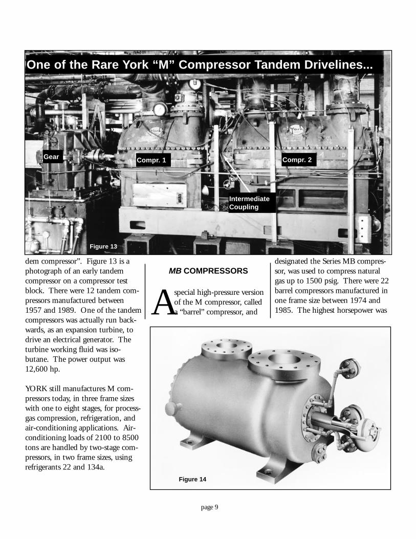
dem compressor”. Figure 13 is aphotograph of an early tandemcompressor on a compressor testblock. There were 12 tandem com-pressors manufactured between1957 and 1989. One of the tandemcompressors was actually run back-wards, as an expansion turbine, todrive an electrical generator. Theturbine working fluid was iso-butane. The power output was12,600 hp.
YORK still manufactures M com-pressors today, in three frame sizeswith one to eight stages, for process-gas compression, refrigeration, andair-conditioning applications. Air-conditioning loads of 2100 to 8500tons are handled by two-stage com-pressors, in two frame sizes, usingrefrigerants 22 and 134a.
MB COMPRESSORS
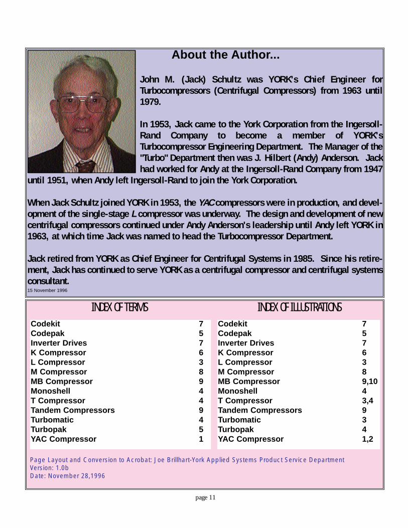
Aspecial high-pressure versionof the M compressor, calleda “barrel” compressor, and
designated the Series MB compres-sor, was used to compress naturalgas up to 1500 psig. There were 22barrel compressors manufactured inone frame size between 1974 and1985. The highest horsepower was
page 9
Figure 14
Figure 13
Gear
One of the Rare York “M” Compressor Tandem Drivelines...
IntermediateCoupling
Compr. 1 Compr. 2

4377. Figure 14 is a picture of abarrel compressor that was madefrom a 1973 photograph of the first(test) compressor.
Figure 15 is a 1973 photograph ofthe special “external” oil lubricatingand sealing system that was used bybarrel compressors. All previousYORK compressors had “internal”lube and seal systems which operat-ed in an atmosphere of the gas thatwas being compressed. The veryhigh pressures at which barrel com-pressors operated made an internallube system impractical. A more-complicated, external oil system wasrequired in which the lubricatingand seal oil operated under thepressure of atmospheric air.
OVERSEAS MANUFACTURE
YORK, which entered thecentrifugal compressorindustry in 1939 as a
licensee of the Allis-ChalmersManufacturing Company, itselfbecame a licensor of centrifugal
compressor technology in 1964when Mitsubishi Heavy Industries,Ltd. was licensed by the YorkDivision of the Borg-WarnerCorporation to manufacture cen-trifugal compressors and systems ofYORK design in Takasago, Japan.Both T compressors and M com-pressors were manufactured inTakasago. The licensing agreementended in 1990, but Mitsubishi stillproduces T compressors and Mcompressors in Takasago.
In 1984, the York Division of theBorg-Warner Corporation licensedBlue Star, Ltd. to manufacture Tcompressors in Thane, India. In1985, York Division licensed theMando Machinery Company tomanufacture T compressors inAnyang, South Korea. Both ofthese licensing agreements are stillin effect.
T compressors were also manufac-tured in Basildon, England by YorkShipley, Ltd., a wholly-owned sub-sidiary of YORK. Basildon manu-
facture began in 1962 and ended in1986.
TODAY
In 1996, YORK is the world’sleading manufacturer of centrifu-gal air-conditioning and refrigera-
tion compressors. These compres-sors, and the systems in which theyare used, are among YORK’s mostsuccessful and most important prod-ucts.
J.M.Schultz15 November 1996
page 10
Figure 15
About the Author...
John M. (Jack) Schultz was YORK's Chief Engineer forTurbocompressors (Centrifugal Compressors) from 1963 until1979.
In 1953, Jack came to the York Corporation from the Ingersoll-Rand Company to become a member of YORK'sTurbocompressor Engineering Department. The Manager of the"Turbo" Department then was J. Hilbert (Andy) Anderson. Jackhad worked for Andy at the Ingersoll-Rand Company from 1947
until 1951, when Andy left Ingersoll-Rand to join the York Corporation.
When Jack Schultz joined YORK in 1953, the YAC compressors were in production, and devel-opment of the single-stage L compressor was underway. The design and development of newcentrifugal compressors continued under Andy Anderson's leadership until Andy left YORK in1963, at which time Jack was named to head the Turbocompressor Department.
Jack retired from YORK as Chief Engineer for Centrifugal Systems in 1985. Since his retire-ment, Jack has continued to serve YORK as a centrifugal compressor and centrifugal systemsconsultant.15 November 1996
page 11
INDEX OF TERMSCodekit 7Codepak 5Inverter Drives 7K Compressor 6L Compressor 3M Compressor 8MB Compressor 9Monoshell 4T Compressor 4Tandem Compressors 9Turbomatic 4Turbopak 5YAC Compressor 1
Codekit 7Codepak 5Inverter Drives 7K Compressor 6L Compressor 3M Compressor 8MB Compressor 9,10Monoshell 4T Compressor 3,4Tandem Compressors 9Turbomatic 3Turbopak 4YAC Compressor 1,2
INDEX OF ILLUSTRATIONS
Page Layout and Conversion to Acrobat: Joe Brillhart-York Applied Systems Product Service DepartmentVersion: 1.0bDate: November 28,1996