centrifugal clutch
39
CENTRIFUGAL CLUTCHES BAHIR INSTITUTE OF TECHNOLOGY
-
Upload
independent -
Category
Documents
-
view
0 -
download
0
Transcript of centrifugal clutch

CENTRIFUGAL CLUTCHES
BAHIR INSTITUTE OF TECHNOLOGY

Introduction
A clutch is a machine member used to connect a driving shaft
to driven shaft so that the driven shaft may be started or stopped
at will, without stopping the driving shaft.

The use of a clutch is mostly found in automobiles.
A little consideration will show that in order to change gears
or to stop the vehicle, it is required that the driven shaft
should stop, but the engine should continue to run.
It is, therefore, necessary that the driven shaft should be
disengaged from the driving shaft.
The engagement and disengagement of the shafts is obtained by
means of a clutch which is operated by a lever

Following are the two main types of clutches commonly
used in engineering practice : 1. Positive clutches, and
2. Friction clutches.
Types of clutches

The positive clutches are used when a positive drive is
required.
The simplest type of a positive clutch is a jaw or claw
clutch.
Positive clutches

Friction clutches
There are many types of friction clutches,
yet the following are common : 1.Disc or plate clutches (single disc or multiple disc clutch), 2.Cone clutches, and
3.Centrifugal clutches.
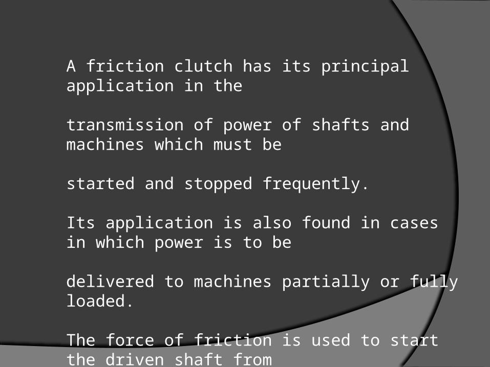
A friction clutch has its principal application in the
transmission of power of shafts and machines which must be
started and stopped frequently. Its application is also found in cases in which power is to be
delivered to machines partially or fully loaded. The force of friction is used to start the driven shaft from
rest and gradually brings it up to the proper speed without
excessive slipping of the friction surfaces.

In automobiles, friction clutch is used to connect the engine to
the drive shaft. In operating such a clutch, care should be
taken so that the friction surfaces engage easily and gradually
bring the driven shaft up to proper speed.

Centrifugal clutches


The centrifugal clutches are usually incorporated into the
motor pulleys.
It consists of a number of shoes on the inside.
The outer surface of the shoes are covered with a friction
material.These shoes, which can move radially in guides, are held
against the boss (or spider) on the driving shaft by means of
springs

The springs exert a radially inward force which is assumed
constant. The weight of the shoe, when revolving causes it to
exert a radially outward force (i.e. centrifugal force).
The magnitude of this centrifugal force depends upon the speed
at which the shoe is revolving.

A little consideration will show that when the centrifugal
force is less than the spring force, the shoe remains in the
same position as when the driving shaft was stationary,
but when the centrifugal force is equal to the spring force,
the shoe is just floating.
When the centrifugal force exceeds the spring force, the
shoe moves outward and comes into contact with the
driven member and presses against it

Design of centrifugal clutch
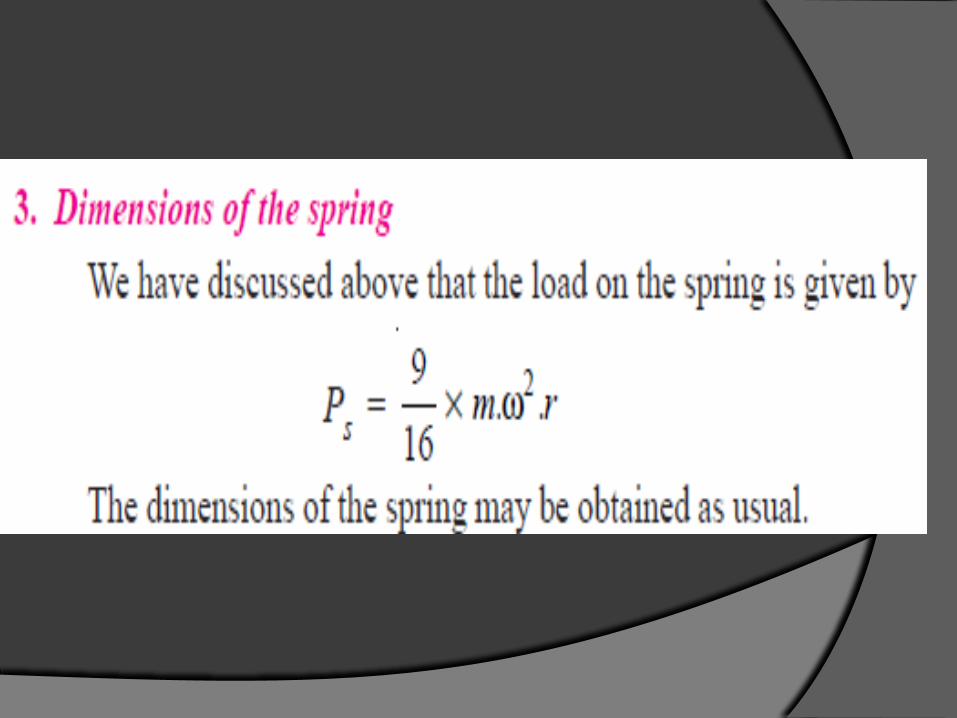
In designing a centrifugal clutch, it is required to determine the weight of the shoe, size of the shoe and dimensions of the spring.
The following procedure may be adopted for the design of a centrifugal clutch.

1. Mass of the shoes: Consider one shoe of a centrifugal clutch
Let m=Mass of each shoe, n=Number of shoes,
rR N
rR N
rR N
r=Distance of centre of gravity of the shoe from the centre of the spider,R =Inside radius of the pulley rim

rR N


Area of contact of the shoe
=l . B
and the force with which the shoe presses against the rim
=A × p = l.b.p Since the force with which the shoe presses against the rim at
the running speed is (P c – P s ), therefore
l.b.p=P c – P s
From this expression, the width of shoe (b) may be obtained

THE END


Deformation Work


Yield Criteria