Centrifugal Compressor Spiral Dry Gas Seal Simulation ...
8
Procedia Engineering 68 (2013) 285 – 292 Available online at www.sciencedirect.com 1877-7058 © 2013 The Authors. Published by Elsevier Ltd. Selection and peer-review under responsibility of The Malaysian Tribology Society (MYTRIBOS), Department of Mechanical Engineering, Universiti Malaya, 50603 Kuala Lumpur, Malaysia doi:10.1016/j.proeng.2013.12.181 ScienceDirect The Malaysian International Tribology Conference 2013, MITC2013 Centrifugal Compressor Spiral Dry Gas Seal Simulation Working at Reverse Rotation Ibrahim Shahin a , Mohamed Gadala b , Mohamed Alqaradawi b , Osama Badr c a Mechanical and Industrial Engineering Department, Collage of Engineering, Qatar University, Doha (2713), Qatar b Mechanical Engineering Department, UBC-University of British Columbia, Vancouver, BC, Canada c Mechanical Engineering Department ,UBE-University of British Egypt Abstract Unidirectional dry gas seal may experiences reverse rotation when equipped in a centrifugal compressor. This paper describes how the reverse rotation effects on the spiral unidirectional dry gas seal performance and pressure distribution inside the gas film, also an investigation of using a different herringbone shape grooves configurations has been done using ANSYS FLUENT 14.5 CFD simulation. The influence of decreasing rotational speed to the static condition and rotate in the reverse direction on internal flow and gas seal performance is examined from 10800 to -10380 rpm. The results indicate that the internal pressure distribution inside the gas seal in reverse rotation is decreased and the open force consequently decreased by 4%. The modification on the same seal is done to enhance its performance at reverse rotation condition. The herringbone spiral grooves is used with different configuration, the new configurations are examined in the forward and reverse rotation direction. The analysis for the pressure distribution is done and its effect on the seal performance is examined. Seal performance is compared with standard one for all geometrical and operating conditions. At high forward rotational speed 10380 rpm, the pressure at the end of the spiral groove is about 11.4 % higher than the inlet pressure at the seal outer diameter, while at reverse rotation, the pressure is not increased in radial direction. The open force corresponding to reverse rotation increased with a value 1.5 kN for both the 100 overlap and 50% forward overlap seal faces, but using seal face with 50% backward overlap failed to enhance the open force at reversal condition. Keywords: Dry gas seal; spiral grooves; reverse rotation; performance Nomenclature B land region width b 1 Groove width h groove depth μm P i inner pressure P o outer pressure R g Groove radius mm R i Seal face inner radius mm R o Seal face outer radius mm T Temperature U Rotating face tip speed m/s V Velocity m/s © 2013 The Authors. Published by Elsevier Ltd. Selection and peer-review under responsibility of The Malaysian Tribology Society (MYTRIBOS), Department of Mechanical Engineering, Universiti Malaya, 50603 Kuala Lumpur, Malaysia
-
Upload
khangminh22 -
Category
Documents
-
view
1 -
download
0
Transcript of Centrifugal Compressor Spiral Dry Gas Seal Simulation ...

Procedia Engineering 68 ( 2013 ) 285 – 292
Available online at www.sciencedirect.com
1877-7058 © 2013 The Authors. Published by Elsevier Ltd.Selection and peer-review under responsibility of The Malaysian Tribology Society (MYTRIBOS), Department of Mechanical Engineering, Universiti Malaya, 50603 Kuala Lumpur, Malaysiadoi: 10.1016/j.proeng.2013.12.181
ScienceDirect
The Malaysian International Tribology Conference 2013, MITC2013
Centrifugal Compressor Spiral Dry Gas Seal Simulation Working at Reverse Rotation
Ibrahim Shahina, Mohamed Gadalab, Mohamed Alqaradawib, Osama Badrc aMechanical and Industrial Engineering Department, Collage of Engineering, Qatar University, Doha (2713), Qatar
bMechanical Engineering Department, UBC-University of British Columbia, Vancouver, BC, Canada cMechanical Engineering Department ,UBE-University of British Egypt
Abstract Unidirectional dry gas seal may experiences reverse rotation when equipped in a centrifugal compressor. This paper describes how the reverse rotation effects on the spiral unidirectional dry gas seal performance and pressure distribution inside the gas film, also an investigation of using a different herringbone shape grooves configurations has been done using ANSYS FLUENT 14.5 CFD simulation. The influence of decreasing rotational speed to the static condition and rotate in the reverse direction on internal flow and gas seal performance is examined from 10800 to -10380 rpm. The results indicate that the internal pressure distribution inside the gas seal in reverse rotation is decreased and the open force consequently decreased by 4%. The modification on the same seal is done to enhance its performance at reverse rotation condition. The herringbone spiral grooves is used with different configuration, the new configurations are examined in the forward and reverse rotation direction. The analysis for the pressure distribution is done and its effect on the seal performance is examined. Seal performance is compared with standard one for all geometrical and operating conditions. At high forward rotational speed 10380 rpm, the pressure at the end of the spiral groove is about 11.4 % higher than the inlet pressure at the seal outer diameter, while at reverse rotation, the pressure is not increased in radial direction. The open force corresponding to reverse rotation increased with a value 1.5 kN for both the 100 overlap and 50% forward overlap seal faces, but using seal face with 50% backward overlap failed to enhance the open force at reversal condition. © 2013 The Authors. Published by Elsevier Ltd. Selection and peer-review under responsibility of The Malaysian Tribology Society (MYTRIBOS), Department of Mechanical Engineering, University Malaya, 50603 Kuala Lumpur, Malaysia. Keywords: Dry gas seal; spiral grooves; reverse rotation; performance
Nomenclature
B land region width b1 Groove width h groove depth μm Pi inner pressure Po outer pressure Rg Groove radius mm Ri Seal face inner radius mm Ro Seal face outer radius mm T Temperature U Rotating face tip speed m/s V Velocity m/s
© 2013 The Authors. Published by Elsevier Ltd.Selection and peer-review under responsibility of The Malaysian Tribology Society (MYTRIBOS), Department of Mechanical Engineering, Universiti Malaya, 50603 Kuala Lumpur, Malaysia

286 Ibrahim Shahin et al. / Procedia Engineering 68 ( 2013 ) 285 – 292
Greek symbols circumferential coordinate attached to rotating face
Gas film thickness μm the angle velocity of the rotator rpm land to groove area ratio =b1/b clearance ratio spiral groove angle Density
1. Introduction.
Centrifugal compressor experiences reverse rotation condition due to reverse flow of high pressure fluid from discharge to suction side through the rotor as soon as the machine is tripped at full load. Reverse rotation phenomena have potential to occur in the LPG refrigeration cycles. This phenomenon is more common in the motor driven compressors with relatively low machine inertia. Detailed surveillance of coast down speed trends of new units is recommended to ensure detection of Reverse Rotation. Condensate operation plants phase 1and phase 2, RasGas, Qatar, Loading compressors operate at reverse rotation since commissioning of the machines [1]. However, they were only discovered after 18 month of units operations. Late discovery was due to no reverse rotation detection system installed and no prior experience in-house with reverse rotation in this type of process configuration. Reverse hydraulic flow due to large amount of entrapped hydrocarbon volume in the piping and suction vessels of the MP & HP sections. These machines use unidirectional dry gas seal configuration, which are not guaranteed for such modes of operations .This paper, describes how the reverse rotation effects on the spiral unidirectional dry gas seal performance and pressure distribution inside the gas film.
The film stiffness of a unidirectional spiral groove seal is much higher than that of a corresponding
bidirectional seal. In reverse rotation, as the spiral-groove seal loses its film stiffness and may even become negative depending on operating pressure and speed as well as the groove design parameters. The failure of one or more of the compressor control system components can also cause some reverse rotation of the compressor rotor and therefore the dry gas seal. Some compressor operators have specified a reverse rotation requirement up to a minimal speed level for their gas seals. Dry gas seal is studied from a long period with little care with reverse rotation operating condition. Bing, et al. [2], made a CFD study for turbulence effects and methods for their evaluation which are not considered in the existing industrial designs of dry gas seal. Jing, et al. [3], make a CFD study for the three dimension micro-scale flow field in spiral groove dry gas seals(S-DGS). Effect of gas flow state on the Seal performance is analysed under different gas film thickness. Bing and Huiqiang [4] investigate the micro scale effects on spiral groove dry gas seal performance in a numerical solution of a corrected Reynolds equation. Miller, B., and Green, I., [6] developed two new methods for characterizing the properties of gas lubricated mechanical face seals. Results from both methods agree well with previously published results computed using the perturbation method.
Glienicke et al., [7] developed mathematical fundamentals concerning the Calculation of non-contacting gas lubricated face seals. The tests were performed with three seal designs at operating pressures pop up to 10 MPa and sliding velocities v up to 110 m/s. Numerical simulation is carried out by Heshun, W. and Cichang, C. [8], based on the Navier-Stokes (N-S) equation, the laminar model . Five geometric parameters are investigated and use one by one optimize method, take opening force, leakage, gas film stiffness and the ratio of stiffness and leakage as the assessing target. Heshun, et. al. [9], made a numerical simulation of face flow filed under different face clearances, based on the Navier Stokes equation, the laminar model. Hydrodynamic pressure weakens rapidly as face clearance increased and changes acutely at small clearance (less than 3 m) zone. Kowalskik, C. and Basu, P. [12] describes the analysis, design and testing of a spiral groove seal with reverse rotation capability. The spiral groove geometries optimized for good forward rotational stiffness at design pressure and speed, and acceptable reverse rotation capability at lower speed levels. The optimized parameters include number of grooves, groove angle, groove depth and land-to-groove width ratio. This paper describes the analysis of a spiral

287 Ibrahim Shahin et al. / Procedia Engineering 68 ( 2013 ) 285 – 292
groove seal with reverse rotation operating condition. The seal face geometry is modified to enhance the internal pressure distribution and seal performance at reverse rotation with considering also the forward rotation.
2. Governing equations and turbulence model Three-dimensional, steady Reynolds-averaged Navier-Stokes equations are solved. For a 3-dimensional,
steady, incompressible for the velocity field V= (V1, V2, V3) expressed in a reference Cartesian co-ordinate system x=(x1, x2, x3): the continuity equation (1), conservation of momentum (2) and energy equation, can be written as follows:
(1)
(2)
Where: p is the static pressure, Vi denotes a velocity component and xi stands for a coordinate direction. The turbulence is simulated by the K- RNG turbulence model with non-equilibrium near wall treatments, with 2% turbulence intensity at flow inlet. The FV discretization in space is of second order accuracy. The solution residuals is set less than 10e-4, the seal performance parameters are monitored while iteration to confirm solution convergence.
3. Model description and boundary conditions The model is used to simulate the fluid between the rotating and stationary faces of the dry gas seal. Fig.1a
shows the basic geometrical parameters of the simulated domain. The computational domain and grid generation are done by GAMBIT pre-processor shown in Fig.1b and 1c in which the fluid domain is magnified by 1000 times in the groove depth direction only to show geometry and grid detail. While calculations the dimensions are not scaled. The pressure inlet boundary condition is used at the inlet for the fluid, the pressure outlet boundary conditions is used at the domain outlet, the rotating periodic boundary condition is used and the wall boundary condition is used for both the rotating and stationary gas seal faces. The no slip velocity conditions are employed at the walls as the Kundsen number is less than 0.001 [2]. The single rotating reference frame model is used to model the fluid rotation. The code is validated with experimental and numerical work of [11] with the same geometric and operating conditions as in table1, Also these geometrical parameters are used for the present study. The hexahedral elements are used for domain meshing, using cooper method Fig.1c.
Fig. 1. Basic geometric parameters for dry gas seal (a) spiral groove, (b) Basic computational domain boundary conditions and (c) domain mesh.
(a) (b) (c)
288 Ibrahim Shahin et al. / Procedia Engineering 68 ( 2013 ) 285 – 292
Table 1. Calculation conditions of [11] experiment for validation of the numerical method Geometrical Parameter Value Operating Parameter Value
Inner radius mm 58.42 Film depth m 3.05 Outer radius mm 77.78 Sealed medium pressure bar 45.85 2
Groove root radius mm 69.0 Environmental medium pressure bar 1.01 3 Spiral angel (°) 15 Spin speed rpm 10 380
Ratio of groove to land 1 Temperature K 300 Groove number 12 Dynamics viscosity g • m • s -1 0.018
4. Results and discussion
4.1 Code validation and grid independence study
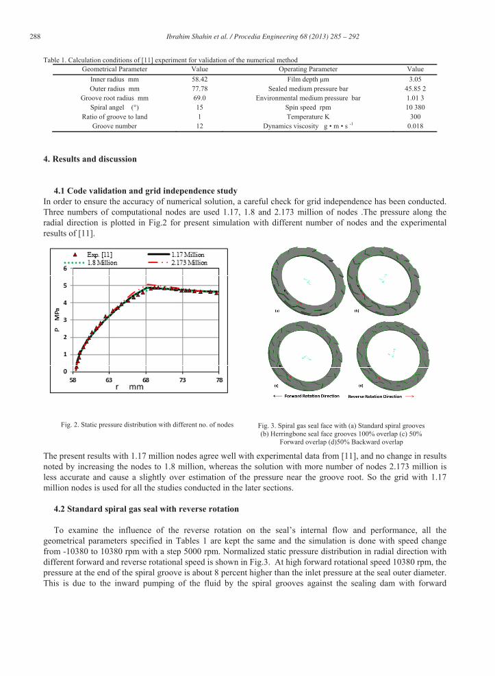
In order to ensure the accuracy of numerical solution, a careful check for grid independence has been conducted. Three numbers of computational nodes are used 1.17, 1.8 and 2.173 million of nodes .The pressure along the radial direction is plotted in Fig.2 for present simulation with different number of nodes and the experimental results of [11].
Fig. 2. Static pressure distribution with different no. of nodes The present results with 1.17 million nodes agree well with experimental data from [11], and no change in results noted by increasing the nodes to 1.8 million, whereas the solution with more number of nodes 2.173 million is less accurate and cause a slightly over estimation of the pressure near the groove root. So the grid with 1.17 million nodes is used for all the studies conducted in the later sections.
4.2 Standard spiral gas seal with reverse rotation To examine the influence of the reverse rotation on the seal’s internal flow and performance, all the
geometrical parameters specified in Tables 1 are kept the same and the simulation is done with speed change from -10380 to 10380 rpm with a step 5000 rpm. Normalized static pressure distribution in radial direction with different forward and reverse rotational speed is shown in Fig.3. At high forward rotational speed 10380 rpm, the pressure at the end of the spiral groove is about 8 percent higher than the inlet pressure at the seal outer diameter. This is due to the inward pumping of the fluid by the spiral grooves against the sealing dam with forward
Fig. 3. Spiral gas seal face with (a) Standard spiral grooves (b) Herringbone seal face grooves 100% overlap (c) 50%
Forward overlap (d)50% Backward overlap

289 Ibrahim Shahin et al. / Procedia Engineering 68 ( 2013 ) 285 – 292
rotation. At a smaller forward rotational speed, this pumping action will be proportionately even smaller. At reverse rotation, the curve corresponding to - 5000 rpm shows that the pressure is not increased. This is due to the outward pumping tendency of the spiral grooves with reverse rotation, which causes the film stiffness becomes negative and encourages instability and collapse. For all the reverse rotational speed the standard spiral grooves loss the inward pumping action, and inlet pressure decrease along the grooves with no any pressure peaks. The standard spiral groove seal performance also affected by the reversal rotation as shown in Fig. 4, as the speed reduced the open force and leakage rate decreased. At reverse rotation, the seal open force still decreased due to the absence of the inward pumping effect.
Fig. 4. Normalized static pressure distribution in radial direction at different circumferential angles.
(a) (b)
Fig. 5. Standard spiral seal reverse rotation effect on (a) open force and (b) Gas seal leakage volume flow rate. 4.3 Modified Seal face with herringbone grooves
To enhance the spiral seal performance at reverse rotation condition, an investigation of using herringbone spiral groove shape as shown in Fig. 3. The standard spiral groove is added to the dam area with the same profile but in the opposite direction, the two grooves are arranged at three different overlap configurations, total overlap, 50% forward overlap and 50% backward overlap. Fig.6 to fig.9 shows the normalized pressure contours for the standard spiral groove and the modified cases at forward, static and reverse rotational condition. The standard seal and the seal with 50% forward overlap have an inward pumping only at forward rotation and the pressure increased for both cases only with about 11.4% from the inlet pressure. But for the other two cases the pressure increased only by 6% from the inlet pressure.

290 Ibrahim Shahin et al. / Procedia Engineering 68 ( 2013 ) 285 – 292
Fig. 6. Normalized static pressure contours for standard spiral seal at forward rotation, static condition and reverse rotation.
Fig. 7. Normalized static pressure contours for herringbone with 100% overlap spiral at forward rotation, static condition and reverse rotation.
Fig. 8. Normalized static pressure contours for herringbone with 50% forward overlap spiral at forward rotation, static condition and reverse
rotation.
Fig. 9. Normalized static pressure contours for herringbone with 50% backward overlap spiral at forward rotation, static condition and reverse
rotation.
291 Ibrahim Shahin et al. / Procedia Engineering 68 ( 2013 ) 285 – 292
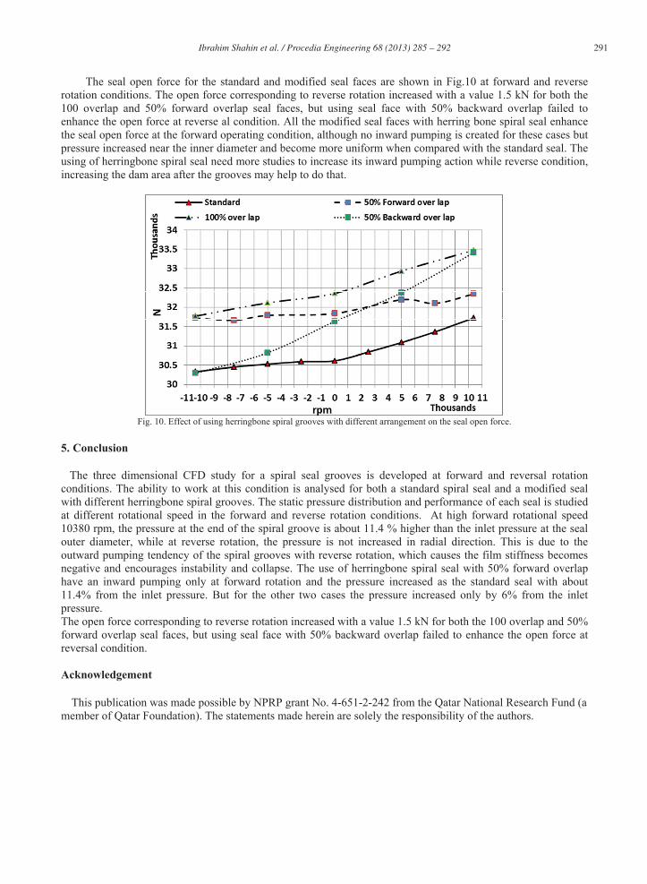
The seal open force for the standard and modified seal faces are shown in Fig.10 at forward and reverse rotation conditions. The open force corresponding to reverse rotation increased with a value 1.5 kN for both the 100 overlap and 50% forward overlap seal faces, but using seal face with 50% backward overlap failed to enhance the open force at reverse al condition. All the modified seal faces with herring bone spiral seal enhance the seal open force at the forward operating condition, although no inward pumping is created for these cases but pressure increased near the inner diameter and become more uniform when compared with the standard seal. The using of herringbone spiral seal need more studies to increase its inward pumping action while reverse condition, increasing the dam area after the grooves may help to do that.
Fig. 10. Effect of using herringbone spiral grooves with different arrangement on the seal open force.
5. Conclusion
The three dimensional CFD study for a spiral seal grooves is developed at forward and reversal rotation conditions. The ability to work at this condition is analysed for both a standard spiral seal and a modified seal with different herringbone spiral grooves. The static pressure distribution and performance of each seal is studied at different rotational speed in the forward and reverse rotation conditions. At high forward rotational speed 10380 rpm, the pressure at the end of the spiral groove is about 11.4 % higher than the inlet pressure at the seal outer diameter, while at reverse rotation, the pressure is not increased in radial direction. This is due to the outward pumping tendency of the spiral grooves with reverse rotation, which causes the film stiffness becomes negative and encourages instability and collapse. The use of herringbone spiral seal with 50% forward overlap have an inward pumping only at forward rotation and the pressure increased as the standard seal with about 11.4% from the inlet pressure. But for the other two cases the pressure increased only by 6% from the inlet pressure. The open force corresponding to reverse rotation increased with a value 1.5 kN for both the 100 overlap and 50% forward overlap seal faces, but using seal face with 50% backward overlap failed to enhance the open force at reversal condition. Acknowledgement This publication was made possible by NPRP grant No. 4-651-2-242 from the Qatar National Research Fund (a member of Qatar Foundation). The statements made herein are solely the responsibility of the authors.
292 Ibrahim Shahin et al. / Procedia Engineering 68 ( 2013 ) 285 – 292
References
[1] Gad, A., 2011. Reverse Rotation in Centrifugal Compressors. Proceedings of the 40th Turbo-machinery Symposium, 12-15 September – Houston, TX [2] Bing, W., Huiqiang, Z., and Hongjun , C., 2012. Flow Dynamics of a Spiral groove Dry gas Seal. Chinese Mechanical Engineering Society and Springer Verlag Berlin Heidelberg 2012, DOI: 10.3901/CJME. [3] Jing, X., Xudong, P., Shaoxian, B., Xiangkai, M., 2012. CFD Simulation of Micro scale Flow Field in Spiral Groove Dry Gas Seal. 978-1-4673-2349-9/12, IEEE. [4] Bing, W., and Huiqiang, Z., 2011. Numerical Analysis of a Spiral groove Dry gas Seal Considering Micro scale Effects” Chinese Journal of Mechanical Engineering, DOI: 10.3901/CJME.2011. [5] Hifumi, T., and Mitsuo, S., 2005.Development of High-Speed and High-Pressure Dry-Gas-Seal. IHI Engineering Review, Vol. 38 No. 1 2005. [6] Miller, B., and Green, I., 2002. Numerical Techniques for Computing Rotor dynamic Properties of Mechanical Gas Face Seals. Journal of Tribology, ASME, Vol. 124 - 755, DOI: 10.1115/1.1467635. [7] Glienicke, J., Launert, A., Schlums, H., and Kohring, B., 1994. None contacting gas lubricated face seals for hug P-V values. N95-13609. [8] Heshun, W. and Cichang, C., 2009. Numerical Simulation on the Geometric Parameters of Spiral Grooved Dry Gas Seals. Proceedings of International Colloquium on Computing, Communication, Control, and Management, 978-1-4244-4246-1/09, IEEE. [9] Heshun, W., Weibing, Z, Qiang, W., Zepei, H., and Chening, Z., 2010. Numerical Simulation on Flow Field of Spiral Grooved Dry Gas Seals. Proceedings of International Conference on Computer Design and Applications (ICCDA 2010). 978-1-4244-7164-5. [10] Weibing, Z., Heshun, W., Shengren, Z. and Xiuqin, C., 2009. Research on Face Fluid Field and Seal Performance of T-shape Groove Dry Gas Seal. Proceedings of Second International Conference on Intelligent Computation Technology and Automation, 978-0-7695-3804-4/09. [11]Gabriel, R., 1994. Fundamentals of spiral groove non-contacting face seals. Journal of Lubrication Engineering, 50(3): 215-224. [12] Kowalskik, C. and Basu, P., 1995. Reverse Rotation Capability of Spiral-Groove Gas Face Seals. Tribology transactions, Volume 38- 3, 549-556.