model yk centrifugal liquid chillers - Surplus Group
16
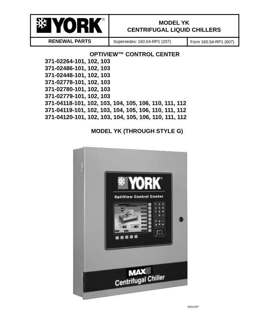
RENEWAL PARTS MODEL YK CENTRIFUGAL LIQUID CHILLERS Supersedes: 160.54-RP1 (207) Form 160.54-RP1 (607) OPTIVIEW™ CONTROL CENTER 371-02264-101, 102, 103 371-02486-101, 102, 103 371-02448-101, 102, 103 371-02778-101, 102, 103 371-02780-101, 102, 103 371-02779-101, 102, 103 371-04118-101, 102, 103, 104, 105, 106, 110, 111, 112 371-04119-101, 102, 103, 104, 105, 106, 110, 111, 112 371-04120-101, 102, 103, 104, 105, 106, 110, 111, 112 MODEL YK (THROUGH STYLE G) 00614VIP
-
Upload
khangminh22 -
Category
Documents
-
view
1 -
download
0
Transcript of model yk centrifugal liquid chillers - Surplus Group
RENEWAL PARTS
MODEL YKCENTRIFUGAL LIQUID CHILLERS
Supersedes: 160.54-RP1 (207) Form 160.54-RP1 (607)
OPTIVIEW™ CONTROL CENTER 371-02264-101, 102, 103 371-02486-101, 102, 103 371-02448-101, 102, 103 371-02778-101, 102, 103 371-02780-101, 102, 103 371-02779-101, 102, 103 371-04118-101, 102, 103, 104, 105, 106, 110, 111, 112 371-04119-101, 102, 103, 104, 105, 106, 110, 111, 112 371-04120-101, 102, 103, 104, 105, 106, 110, 111, 112
MODEL YK (THROUGH STYLE G)
00614VIP
JOHNSON CONTROLS2
FORM 160.54-RP1 (607)
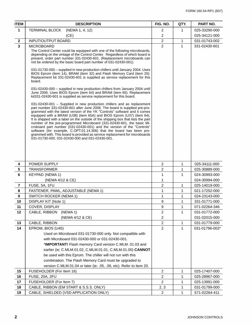
ITEM DESCRIPTION FIG. NO. QTY. PART NO. 1 TERMINAL BLOCK (NEMA 1, 4, 12) 2 1 025-33290-000 (CE) 2 025-34121-000 2 INPUT/OUTPUT BOARD 2 1 031-01743-002 3 MICROBOARD
4 POWER SUPPLY 2 1 025-34111-000 5 TRANSFORMER 2 1 025-30889-000 6 KEYPAD (NEMA 1) 1 1 024-30993-000 (NEMA 4/12 & CE) 1 024-30994-000 7 FUSE, 5A, 1FU 2 1 025-14019-000 8 FASTENER, PAWL, ADJUSTABLE (NEMA 1) 1 1 021-17252-000 9 SWITCH ROCKER (NEMA 1) 1 1 024-23143-000 10 DISPLAY KIT (Note 1) 9 1 331-01771-000 11 COVER, DISPLAY 9 1 071-02264-346 12 CABLE, RIBBON (NEMA 1) 2 1 031-01772-000 (NEMA 4/12 & CE) 2 031-02015-000 13 CABLE, RIBBON 2 1 031-01779-000 14 EPROM, BIOS (U45) 2 1 031-01796-002* Used on Microboard 031-01730-000 only. Not compatible with with Microboard 031-02430-000 or 031-02430-001. *IMPORTANT! Flash memory Card version C.MLM. 01.03 and earlier (ie; C.MLM.01.02, C.MLM.01.01, C.MLM.01.00) CANNOT be used with this Eprom. The chiller will not run with this combination. The Flash Memory Card must be upgraded to version C.MLM.01.04 or later (ie; .05, .06, etc). Refer to item 20. 15 FUSEHOLDER (For Item 16) 2 1 025-17407-000 16 FUSE, 20A, 2FU 2 1 025-28967-000 17 FUSEHOLDER (For Item 7) 2 1 025-13991-000 18 CABLE, RIBBON (EM START & S.S.S. ONLY) 2, 3 1 031-01799-000 19 CABLE, SHIELDED (VSD APPLICATION ONLY) 2 1 571-02264-411
The Control Center could be equipped with one of the following microboards, depending on the vintage of the Control Center. Regardless of which board is present, order part number 331-02430-601. (Replacement microboards can not be ordered by the basic board part number of 031-02430-001).
031-01730-000 – supplied in new production chillers until January 2004. Uses BIOS Eprom (item 14), BRAM (item 32) and Flash Memory Card (item 20). Replacement kit 331-02430-601 is supplied as service replacement for this board.
031-02430-000 – supplied in new production chillers from January 2004 until June 2006. Uses BIOS Eprom (item 64) and BRAM (item 65). Replacement kit331-02430-601 is supplied as service replacement for this board.
031-02430-001 – Supplied in new production chillers and as replacement part number 331-02430-601 after June 2006. The board is supplied pre-pro-grammed with the latest version of the YK "Controls" software and it comes equipped with a BRAM (U38) (item 65A) and BIOS Eprom (U37) (item 64). It is shipped with a label on the outside of the shipping box that lists the part number of the pre-programmed Microboard (331-02430-601, the basic Mi-croboard part number (031-02430-001) and the version of the "Controls" software (for example, C.OPT.01.14.306) that the board has been pro-grammed with. This board is provided as service replacement for microboards 031-01730-000, 031-02430-000 and 031-02430-001.
331-02430-6012 1
FORM 160.54-RP1 (607)
3JOHNSON CONTROLS
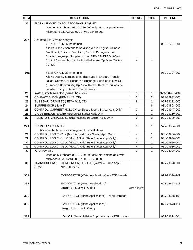
20 FLASH MEMORY CARD, PROGRAMMED (U46) Used on Microboard 031-01730-000 only. Not compatable with Microboard 031-02430-000 or 031-02430-001.
20A See note 5 for version analysis VERSION C.MLM.nn.nn.nnn
2 1
031-01797-001 Allows Display Screens to be displayed in English, Chinese Traditional, Chinese Simplifi ed, French, Portuguese or Spanish language. Supplied in new NEMA 1-4/12 OptiView Control Centers, but can be installed in any OptiView Control Center.
20B VERSION C.MLM.nn.nn.nnn 031-01797-002 Allows Display Screens to be displayed in English, French, Italian, German, or Hungarian language. Supplied in new CE (European Community) OptiView Control Centers, but can be installed in any OptiView Control Center. 21 switch, knob selector (nema 4/12, ce) 5 1 024-30931-000 22 CONTACT BLOCK (NEMA 4/12, CE) 5 2 024-30932-000 23 BUSS BAR (GROUND) (NEMA 4/12, CE) 8 1 025-34122-000 24 SUPPRESSOR (Note 3) 6 031-00808-000 25 CONTROL, CURRENT MOD. CM-2 (Electro-Mech. Starter App. Only) 3 1 031-00947-000 26 DIODE BRIDGE (Electro-Mechanical Starter App. Only) 3 1 031-00210-000 27 RESISTOR, VARIABLE (Electro-Mechanical Starter App. Only) 3 2 025-20789-000 27A RESISTOR ASSEMBLY 3 1 575-00364-001 (includes both resistors confi gured for installation) 28 CONTROL, LOGIC - 7LK (Mod. A Solid State Starter App. Only) 4 1 031-00936-002 29 CONTROL, LOGIC - 14LK (Mod. A Solid State Starter App. Only) 4 1 031-00936-003 30 CONTROL, LOGIC - 26LK (Mod. A Solid State Starter App. Only) 4 1 031-00936-004 31 CONTROL, LOGIC - 33LK (Mod. A Solid State Starter App. Only) 4 1 031-00936-005 32 IC, BRAM-U52 2 1 031-02028-000 Used on Microboard 031-01730-000 only. Not compatable with Microboard 031-02430-000 or 031-02430-001. 33 TRANSDUCERS CONDENSER, HIGH OIL (Water & Brine App.) – 025-28678-001 (R-22) NPTF threads
33A EVAPORATOR (Water Applications) – NPTF threads
(not shown)
025-28678-102 33B EVAPORATOR (Water Applications) – 025-28678-113 straight threads with O-ring
33C EVAPORATOR (Brine Applications) – NPTF threads 025-28678-103
33D EVAPORATOR (Brine Applications) – 025-28678-114 straight threads with O-ring 33E LOW OIL (Water & Brine Applications) - NPTF threads 025-28678-004
ITEM DESCRIPTION FIG. NO. QTY. PART NO.

JOHNSON CONTROLS4
FORM 160.54-RP1 (607)
ITEM DESCRIPTION FIG. NO. QTY. PART NO. 34 TRANSDUCERS COND., HIGH & LOW OIL (Water & Brine App.) –
(not shown)
025-28678-006 (R-134a) straight threads with O-ring 34A EVAPORATOR (Water & Brine App.) – 025-28678-112 straight threads with O-ring 34B EVAPORATOR (Water & Brine App.) – 025-28678-104 NPTF threads 34C STALL DETECTION - straight threads with O-ring Check actual (chillers equipped with Variable Geometry Diffuser) P/N installed: 025-39464-000 (early vintage) 025-40088-000 (later vintage) 34D SEAL, O-RING for items 33B, 33D, 34, 34A, 34B, and 34C 028-12961-002 35 THERMISTORS ENTERING CHILLED WATER TEMPERATURE (not shown) 025-29964-000
35A LEAVING CHILLED WATER TEMPERATURE 025-29964-000
35B SENSOR WELL WITH THREADED TOP 026-32328-000
35C ENTERING CONDENSER WATER TEMPERATURE 025-28935-000
35D LEAVING CONDENSER WATER TEMPERATURE 025-28935-000
35E OIL TEMPERATURE – NPTF threads 025-28936-000
35F OIL TEMPERATURE – 025-31301-000 straight threads with O-ring (Ref. item 56)
35G DISCHARGE TEMPERATURE – NPTF threads 025-28936-000
35H DISCHARGE TEMPERATURE – 025-31301-000 straight threads with O-ring (Ref. item 56) 36 PROBE, PROXIMITY (not shown) 1 (Refer to YORK YORK form 160.73-RP3) (See note 6)
IMPORTANT! - If control center is equipped with Microboard 031-01730-000, Flash Memory Card must be version C.MLM.01.03.xxx or later (ie; C.MM..01.04.xxx, C.MLM..01.05.xxx, etc.)
37 Not Used 38 BOARD, ADAPTIVE CAPACITY CONTROL (VSD App. Only) 2 1 (See 160.00-RP4 & 160.00-RP2) 39 CIRCUIT BREAKER, POLE, 6A (CE) 8 1 024-30935-000 40 SWITCH, DISCONNECT (CE) 8 1 024-34171-000 41 CIRCUIT BREAKER, 25A (CE) 8 1 024-30956-000 42 CIRCUIT BREAKER 16A (CE) 8 1 024-30947-000 43 CIRCUIT BREAKER (CE) 024-30936-000 44 MOUNT, ANTI-VIBRATION 2 4 021-19191-000 45 BACKLIGHT BULB 9 1 See Note 4
FORM 160.54-RP1 (607)
5JOHNSON CONTROLS
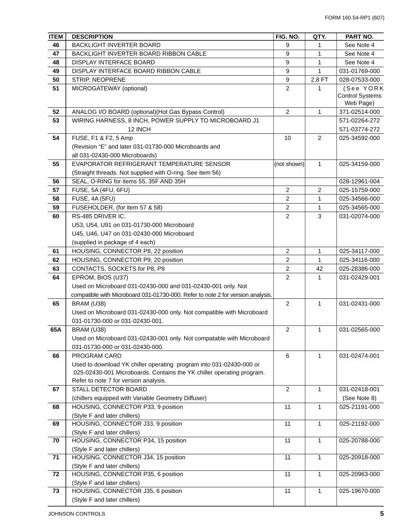
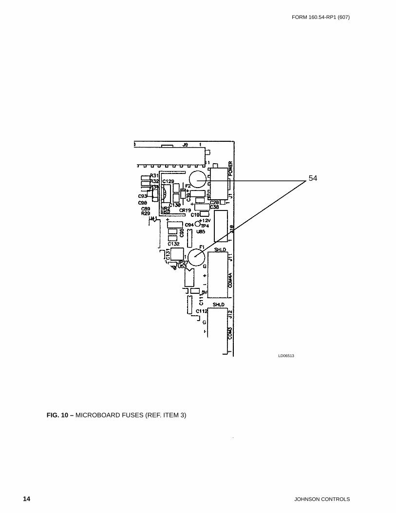
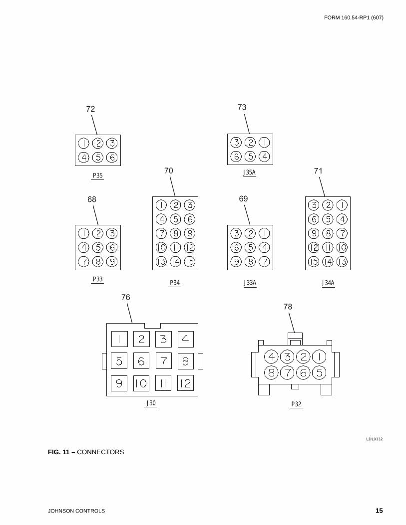
46 BACKLIGHT INVERTER BOARD 9 1 See Note 4 47 BACKLIGHT INVERTER BOARD RIBBON CABLE 9 1 See Note 4 48 DISPLAY INTERFACE BOARD 9 1 See Note 4 49 DISPLAY INTERFACE BOARD RIBBON CABLE 9 1 031-01769-000 50 STRIP, NEOPRENE 9 2.8 FT 028-07533-000 51 MICROGATEWAY (optional) 2 1 ( S e e Y O R K Control Systems Web Page) 52 ANALOG I/O BOARD (optional)(Hot Gas Bypass Control) 2 1 371-02514-000 53 WIRING HARNESS, 8 INCH, POWER SUPPLY TO MICROBOARD J1 571-02264-272 12 INCH 571-03774-272 54 FUSE, F1 & F2, 5 Amp 10 2 025-34592-000 (Revision “E” and later 031-01730-000 Microboards and all 031-02430-000 Microboards) 55 EVAPORATOR REFRIGERANT TEMPERATURE SENSOR (not shown) 1 025-34159-000 (Straight threads. Not supplied with O-ring. See item 56) 56 SEAL, O-RING for items 55, 35F AND 35H 028-12961-004 57 FUSE, 5A (4FU, 6FU) 2 2 025-15759-000 58 FUSE, 4A (5FU) 2 1 025-34566-000 59 FUSEHOLDER, (for item 57 & 58) 2 1 025-34565-000 60 RS-485 DRIVER IC. 2 3 031-02074-000 U53, U54, U91 on 031-01730-000 Microboard U45, U46, U47 on 031-02430-000 Microboard (supplied in package of 4 each) 61 HOUSING, CONNECTOR P8, 22 position 2 1 025-34117-000 62 HOUSING, CONNECTOR P9, 20 position 2 1 025-34116-000 63 CONTACTS, SOCKETS for P8, P9 2 42 025-28386-000 64 EPROM, BIOS (U37) 2 1 031-02429-001 Used on Microboard 031-02430-000 and 031-02430-001 only. Not compatible with Microboard 031-01730-000. Refer to note 2 for version analysis. 65 BRAM (U38) 2 1 031-02431-000 Used on Microboard 031-02430-000 only. Not compatible with Microboard 031-01730-000 or 031-02430-001. 65A BRAM (U38) 2 1 031-02565-000 Used on Microboard 031-02430-001 only. Not compatable with Microboard 031-01730-000 or 031-02430-000. 66 PROGRAM CARD 6 1 031-02474-001 Used to download YK chiller operating program into 031-02430-000 or 025-02430-001 Microboards. Contains the YK chiller operating program. Refer to note 7 for version analysis. 67 STALL DETECTOR BOARD 2 1 031-02418-001 (chillers equipped with Variable Geometry Diffuser) (See Note 8) 68 HOUSING, CONNECTOR P33, 9 position 11 1 025-21191-000 (Style F and later chillers) 69 HOUSING, CONNECTOR J33, 9 position 11 1 025-21192-000 (Style F and later chillers) 70 HOUSING, CONNECTOR P34, 15 position 11 1 025-20788-000 (Style F and later chillers) 71 HOUSING, CONNECTOR J34, 15 position 11 1 025-20918-000 (Style F and later chillers) 72 HOUSING, CONNECTOR P35, 6 position 11 1 025-20963-000 (Style F and later chillers) 73 HOUSING, CONNECTOR J35, 6 position 11 1 025-19670-000 (Style F and later chillers)
ITEM DESCRIPTION FIG. NO. QTY. PART NO.
JOHNSON CONTROLS6
FORM 160.54-RP1 (607)
NOTES: 1. The replacement Liquid Crystal Display supplied by YORK might not be by the same manufacturer as the original Display. Each Display
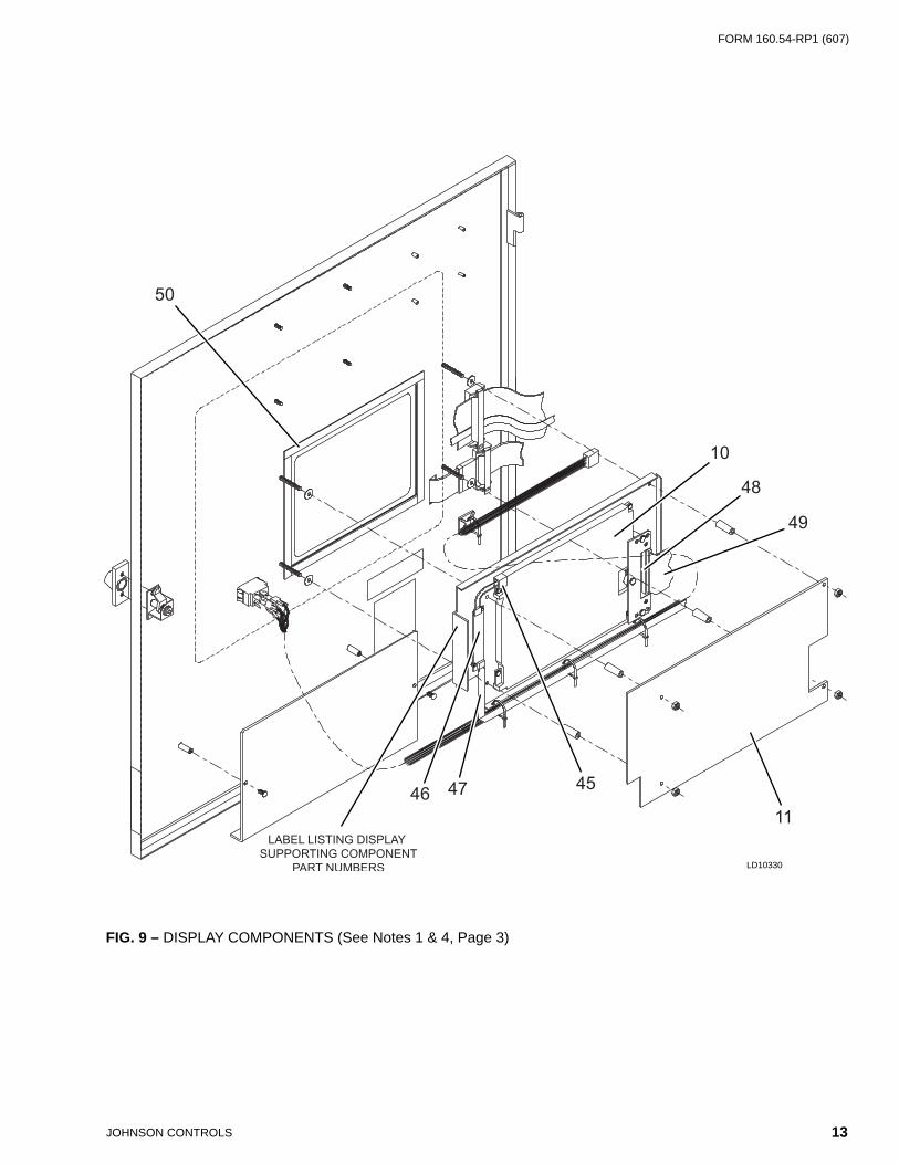
requires a specifi c Display Interface Board (Item 48), Backlight Inverter Board (Item 46), and Backlight Inverter Board ribbon cable (Item 47). Therefore, the Liquid Crystal Display is not available separately. Service replacement Displays or supporting components must not be arbitrarily selected! Non-compatibility of components will result in incorrect operation! To assure compatible supporting components, the Display is supplied as a kit (331-01771-000), which contains a replacement Display and all compatible supporting components on a mount-ing plate. For future reference, a label attached to the side of the mounting plate (Fig. 9) lists the YORK part numbers of these compatible components and the required confi guration of the Microboard Program Jumpers. These Program Jumpers must be confi gured for this Display by a qualifi ed Service Technician following instructions in YORK Service manual 160.54-M1. The contents of the kit are as follows:
a. Liquid Crystal Display e. Appropriate Back light Inverter Board (Item 46) for Display. b. Backlight Bulb (Item 45) f. Appropriate Backlight Inverter Board ribbon ca ble c. Appropriate Display Interface Board (Item 48) for Display (Item 47) for Item 46. d. Appropriate Display Interface Board ribbon cable g. All mounting hardware. (Item 49) for Item 48. h. Installation instructions. 2. BIOS Eprom (item 64) version analysis: C.OPT.00.nn
Revision Level (00,01, etc.) BIOS Eprom Optiview Control Center Commercial Chiller3. Extra Supressors are shipped in cloth bag. They are applied at solenoids and relays located on chiller.
4. Refer to label (Fig. 9) on Display mounting plate for YORK part number of applicable replacement part. Service replacement Display sup port ing components must not be arbitrarily selected! Non-compatibility of components will result in incorrect operation!
5. Flash Memory Card (item 20) version analysis: C.MLM.nn.nn.nnn Language Package Revision Level (00,01,etc) Language Package* (0=English only, 1=NEMA 1-4, 2=CE) Controls Revision Level (00,01,etc) Chiller Type (01=YK, 02=YT, 03=YS, 05=YR, 11=YD) Millennium Chiller Commercial Chiller *1 = Supplied in new NEMA 1-4 OptiView Control Centers 2 = Supplied in new CE (European Community) OptiView Control Centers
6. The Replacement Proximity Probe does not sense the High Speed Drain Line Temperature. Therefore, if equipped with Microboard 031-01730-000, the Flash Memory Card version must be revision C.MLM.01.03.xxx or later (ie;.04.05, etc.), since these revisions do not read nor perform safety shutdowns based on this parameter. If this Probe is installed in a chiller equipped with an earlier version, the chiller will be prevented from starting due to one of the High Speed Drain Line Oil temperature Safety faults. If the Control Center does not contain a Compatible Flash Memory Card version, it will have to be upgraded at the time of Probe replacement.
7. Program Card (item 66) version analysis: C.OPT.nn.nn.nnn
Language Package Revision Level (00,01,etc) Language Package (0=English only, 1=NEMA, 2=CE, 3=NEMA/CE) Controls Revision Level (00,01,etc) Chiller Type (01=YK, 02=YT, 03=YS, 05=YR, 11=YD) Optiview Control Center Commercial Chiller8. Supercedes Stall Detector Board 031-02418-000.
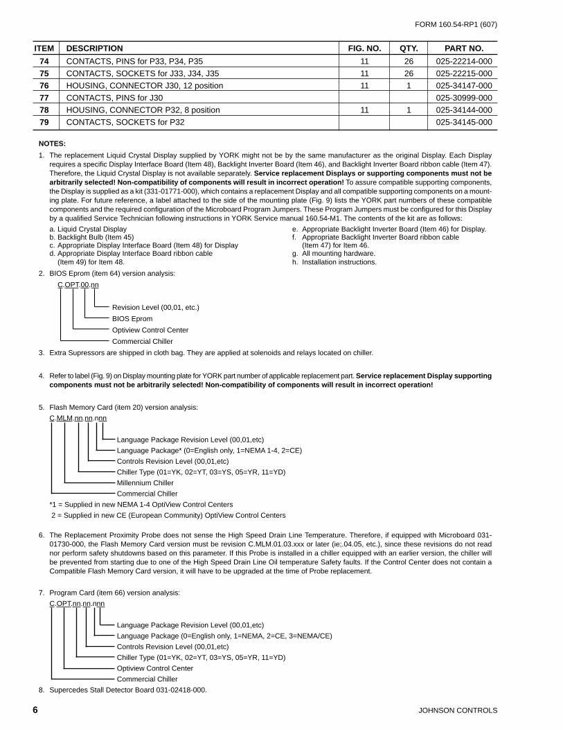
74 CONTACTS, PINS for P33, P34, P35 11 26 025-22214-000 75 CONTACTS, SOCKETS for J33, J34, J35 11 26 025-22215-000 76 HOUSING, CONNECTOR J30, 12 position 11 1 025-34147-000 77 CONTACTS, PINS for J30 025-30999-000 78 HOUSING, CONNECTOR P32, 8 position 11 1 025-34144-000 79 CONTACTS, SOCKETS for P32 025-34145-000
ITEM DESCRIPTION FIG. NO. QTY. PART NO.

FORM 160.54-RP1 (607)
7JOHNSON CONTROLS
THIS PAGE INTENTIONALLY LEFT BLANK
JOHNSON CONTROLS8
FORM 160.54-RP1 (607)
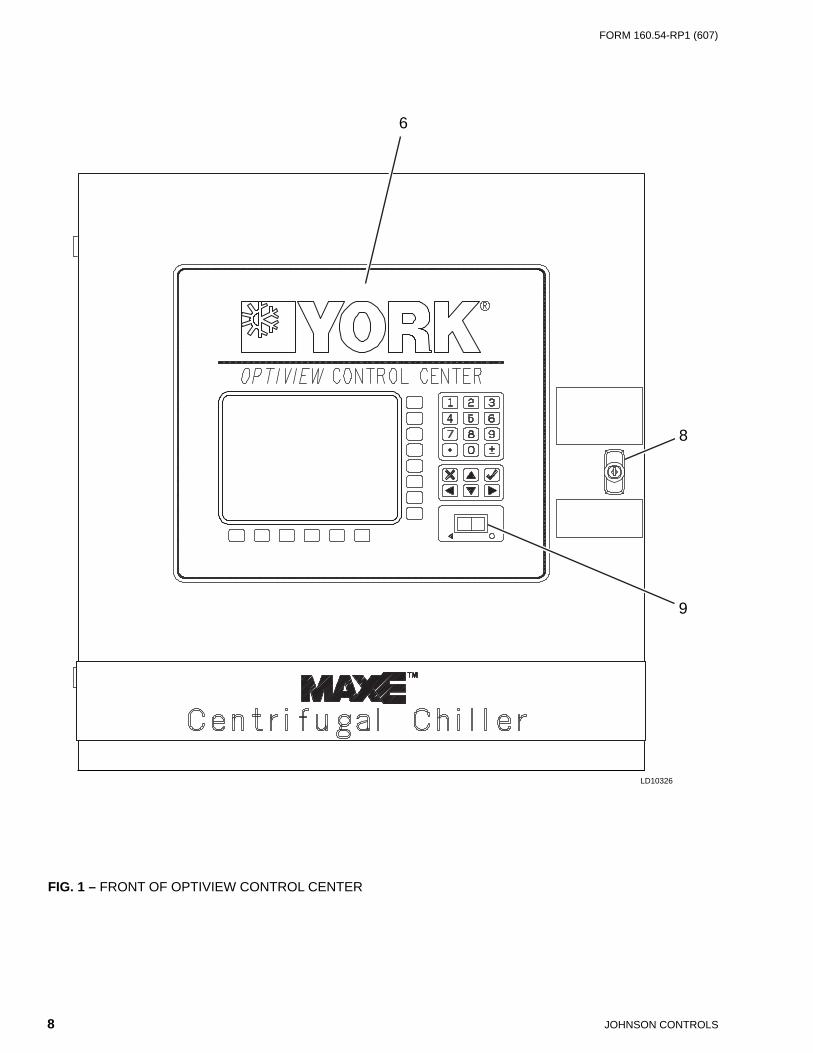
FIG. 1 – FRONT OF OPTIVIEW CONTROL CENTER
6
8
9
LD10326
FORM 160.54-RP1 (607)
9JOHNSON CONTROLS
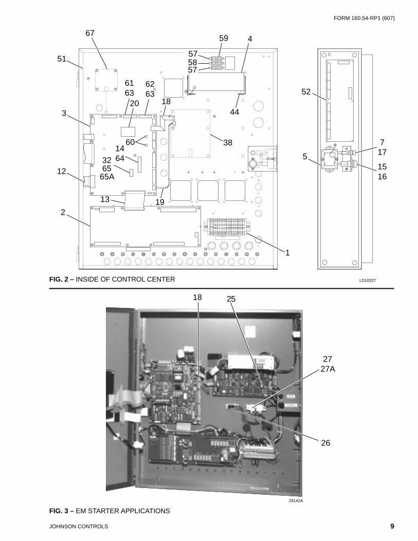
FIG. 2 – INSIDE OF CONTROL CENTER LD10327
67
6263
20 18
60
3
51
1464
12
2
1
5758
59
57
4
44
38
5
52
717
13 19
6163
3265
65A1516
29142A
18 25
2727A
26
FIG. 3 – EM STARTER APPLICATIONS

JOHNSON CONTROLS10
FORM 160.54-RP1 (607)
FIG. 4 – STYLE "A" SOLID STATE STARTER APPLICATIONS
FIG. 5 – INSIDE OF DOOR - NEMA 4/12, CE
29139A
28 – 7LK29 – 14LK30 – 26LK31 – 33LK
LD04031
FORM 160.54-RP1 (607)
11JOHNSON CONTROLS
27
27
27A
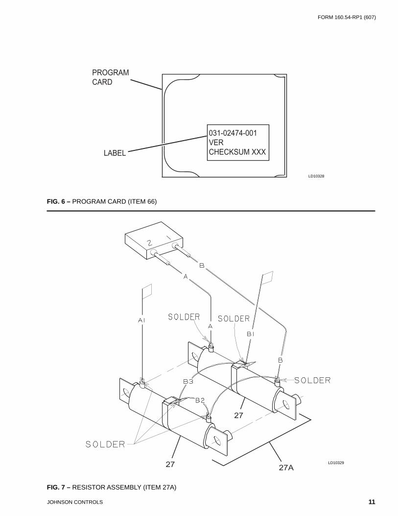
FIG. 6 – PROGRAM CARD (ITEM 66)
FIG. 7 – RESISTOR ASSEMBLY (ITEM 27A)
LD10329
031-02474-001VERCHECKSUM XXX
PROGRAMCARD
LABEL
LD10328
JOHNSON CONTROLS12
FORM 160.54-RP1 (607)
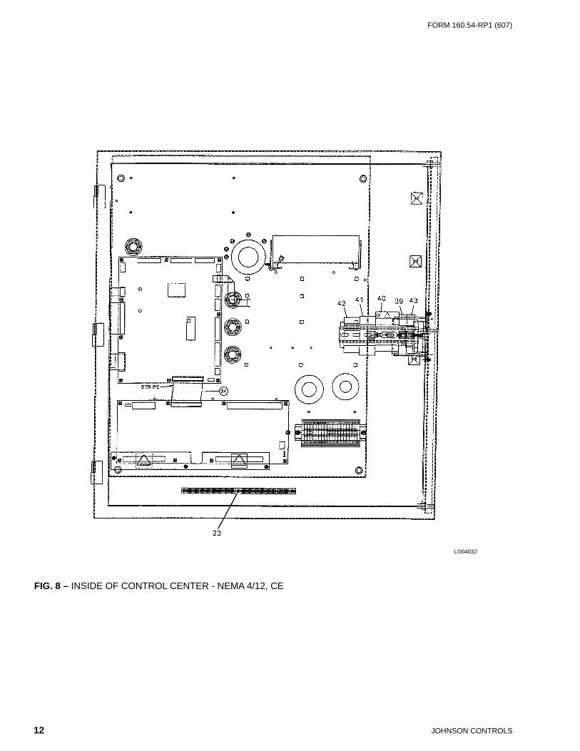
FIG. 8 – INSIDE OF CONTROL CENTER - NEMA 4/12, CE
LD04032
FORM 160.54-RP1 (607)
13JOHNSON CONTROLS
50
10
48
49
454746
LABEL LISTING DISPLAY SUPPORTING COMPONENT
PART NUMBERS
11
LD10330
FIG. 9 – DISPLAY COMPONENTS (See Notes 1 & 4, Page 3)
JOHNSON CONTROLS14
FORM 160.54-RP1 (607)
FIG. 10 – MICROBOARD FUSES (REF. ITEM 3)
LD06513
54
FORM 160.54-RP1 (607)
15JOHNSON CONTROLS
FIG. 11 – CONNECTORS
LD10332
72
70
73
71
6968
7678
J30 P32
J33A J34A
J35A
P34P33
P35

Tele. 800-861-1001www.york.com
P.O. Box 1592, York, Pennsylvania USA 17405-1592 Subject to change without notice. Printed in USACopyright © by JOHNSON CONROLS, INC. 2007 ALL RIGHTS RESERVEDForm 160.54-RP1 (607) Supersedes: 160.54-RP1 (207)