YCAS AIR-COOLED LIQUID CHILLERS MODELS YCAS0218 ...
96
RENEWAL PARTS AIR-COOLED SCREW LIQUID CHILLERS New Release Form: 201.19-RP7 (405) YCAS AIR-COOLED LIQUID CHILLERS MODELS YCAS0218, 0248, 0268, 0288, 0308 AND YCAS0328 (3 COMPRESSOR) MODELS YCAS0358, 0398, and YCAS0418 (4 COMPRESSOR) 200-3-60 230-3-60 315-3-60 460-3-60 575-3-60 MODELS ONLY 220 - 400 TON 850 - 1400Kw 60 Hz STYLE "G" R-407C 00258VIPa
-
Upload
khangminh22 -
Category
Documents
-
view
0 -
download
0
Transcript of YCAS AIR-COOLED LIQUID CHILLERS MODELS YCAS0218 ...

RENEWAL PARTS
AIR-COOLED SCREW LIQUID CHILLERS
New Release Form: 201.19-RP7 (405)
YCAS AIR-COOLED LIQUID CHILLERSMODELS YCAS0218, 0248, 0268, 0288, 0308 AND YCAS0328
(3 COMPRESSOR)MODELS YCAS0358, 0398, and YCAS0418
(4 COMPRESSOR)
200-3-60230-3-60315-3-60460-3-60575-3-60
MODELS ONLY
220 - 400 TON850 - 1400Kw
60 Hz
STYLE "G"R-407C
00258VIPa

YORK INTERNATIONAL2
FORM 201.19-RP7 (405)
In complying with YORK's policy for continuous improvement, the information contained in this document is subjected to change without notice. While YORK makes no commitment to update or provide current information automatically to the manual user, that information, if applicable, can be obtained by contacting the nearest YORK Engineered Systems Service offi ce.
It is the responsibility of operating/service personnel as to the applicability of these docu-ments to the equipment in question. If there is any question in the mind of operating/ service personnel as to the applicability of these documents, then, prior to working on the equipment, they should verify with the owner, whether the equipment has been modifi ed and if the current literature is available.
CHANGEABILITY OF THIS DOCUMENT
Work on electronic equipment should not be undertaken unless the individual(s) have been trained in the proper maintenance of equipment and is (are) familiar with its potential hazards.
Shut off power supply to the equipment before beginning work and follow lockout procedures. When working inside equipment with power off, take care to discharge every capacitor likely to hold dan ger ous potential.
Be careful not to contact high voltage connections when installing or operating this equipment.
LOW VOLTAGEDO NOT be misled by the term “low voltage.” Voltages as low as 50 volts may cause death.
WARNINGHIGH VOLTAGE
Is used in the operation of this equipment.DEATH OR SERIOUS INJURY
may result if personnel fail to observe safety precautions.

YORK INTERNATIONAL 3
FORM 201.19-RP7 (405)
TABLE OF CONTENTS
CONDENSER COILS
FAN
PIPING
COMPRESSOR
OPTIONS AND POWER PANELS
PAGE
UNIT NO MEN CLA TURE NAMEPLATE ENGINEERING DATA ...........................................4
EVAPORATOR COMPONENTS ..........................................................................................6
CONDENSER COIL COMPONENTS .................................................................................10
FAN COMPONENTS ..........................................................................................................14
REFRIGERANT PIPING COMPONENTS...........................................................................16
RELIEF VALVES AND HP CUTOUT SWITCHES...............................................................26
COMPRESSOR ..................................................................................................................28
CONTROL PANEL COMPONENTS....................................................................................38
OPTION AND POWER PANEL CONFIGURATION ............................................................40
POWER PANEL COMPONENTS .......................................................................................42
OPTIONS PANEL COMPONENTS.....................................................................................63
FAN CONTACTOR COMPONENTS ...................................................................................74
SENSOR HARNESSES......................................................................................................76
TRANSDUCERS AND TEMP SENSORS ...........................................................................80
TRANSDUCER AND THERMISTOR WIRE HARNESS CONNECTORS ..........................81
YCAS CHILLER OPTIONS - KITS .....................................................................................82
ENCLOSURE KIT OPTIONS ..............................................................................................83
OPTIVIEW REMOTE CONTROL CENTER .......................................................................84
REMOTE CURRENT/TEMPERATURE RESET PARTS BREAKDOWN ............................85
RECOMMENDED SPARE PARTS......................................................................................86
EVAPORATOR
CONTROL PANEL
CHILLER OP TIONS

YORK INTERNATIONAL4
FORM 201.19-RP7 (405)
PART NUMBER – LETTER CODES
UNIT NOMENCLATURE NAME PLATE ENGINEERING DATABASIC PART NUM BER
55 EXTENDED FIELD WARRANTY X B C D E F G H
: Aluminum: Copper: Black Fin: Phenolic: TEAO Fan Motors
EVAP. FIELD CONDENSER FIELD CABINET FIELD
: 1st Year Parts Only: 1st Year Parts & Labor: 2nd Year Parts Only: 2nd Year Parts & Labor: 5 Year Compressor Parts Only: 5 Year Compressor Parts & Labor Only: 5 Year Units Parts Only: 5 Year Unit Parts & Labor
: Wire Condenser Headers Only (factory): Wire (Full Unit) Enc. Panels (factory): Wire/Louvered Enc. Panels (factory): Louvered (Cond. Only) Enc. Panels (factory): Louvered (Full Unit) Enc. Panels (factory): Acoustic Sound Blanket: Dual Sound Attenuation: Compressor Sound Enclosure: Low Sound Fans: High Static Fans: 1" Defl ection: Seismic: Neoprene Pads
61 PLANT OF MANUFACTURE
B R
: Basildon: Monterrey
56 REFRIGERANT WARRANTY X 1 2 5
: No Refrigerant Warranty: 1 Year Refrigerant: 2 Year Refrigerant: 5 Year Refrigerant
NOTES: 1. Q :DENOTES SPECIAL / S.Q. 2. # :DENOTES STANDARD 3. X :w/in OPTIONS FIELD, DENOTES NO OPTION SELECTED 4. Agency Files (i.e. U.L. / ETL; CE; ARI; ETC.) will contain info. based on the fi rst 14 characters only. 5. Plant of manufacture to include PIN 61 upon entering the chiller order.
38 39 40 41 42 43 44 45 46 47 48 49 50 51 52 53 54
X X X 3 C 1 D B 3 W P 5 V X 7 S B D D A P L Q H 1 S N
MP = Multiple PointSP = Single PointNF = Non-FusedTB = Terminal BlockSer. = ServiceInd. Sys. Brkr. & L. Ext. Handles = IndividualSystem Breaker & Lockable External Handle
: No Ambient Kit: Temp. Reset / Offset : Current Reset / Offset: Temp. and Current Reset / Offset: ISN Microgateway: Spanish LCD & Keypad Display: French LCD & Keypad Display: : : : : N. American Safety Code (cU.L./cETL): No Listing (typically 50 HZ non-CE, non-U.L.: : Pump Control: OptiView Remote Panel: Sequence Control & Automatic Lead Transfer
:Low Temp. Brine (LBrT):Thermal Storage:Chicago Relief Code:Service Isolation Valve:Both Chicago Relief Code& Isolation Valve
: Standard Power Option: MP NF Disconnect Switch : MP TB w/Ind. Sys. CB: MP TB w/Ind. Sys. NFDS: SP TB w/Ind. Sys. CB : SP NF Disconnect Switch w/Ind. Sys. CB: MP NF Disconnect Switch w/Ind. Sys. CB: SP TB w/Ind. Sys. NFDS: SP NFDS w/Ind. Sys. NFDS: Control Transformer: Control Circuit Power Terminal Strip
16 17 18 19 20 21 22 23 24 25 26 27 28 29 30 31 32 33 34 35 36 37POWER FIELD CONTROLS FIELD COMPRESSOR / PIPING FIELD
X X X # #M D T T SM B C CM N B S S B M B D B S D P F S N D N T C L N P O S
: YORK: Chiller: Air Cooled: Screw
YCAS0328EB40XGA1 2 3 4 5 6 7 8 9 10 11 12 13 14 15BASE PRODUCT TYPE NOMINAL CAPACITY UNIT DESIGNATOR REFRIGERANT VOLTAGE/STARTER DESIGN/DEVELOPMENT LEVEL
Y # # # # S B 4 0 G C E 4 6 A 5 0 A S 5 8 X Y
Tons/Kw021802480268028803080328035803980418
StandardHigh Effi ciency
:R-407C :380/3/60:460/3/60:380-415/3/50:575/3/60:::Across the Line:Wye Delta
:Design Series G::Engineering Change or PIN Level
:150# PSI DWP:300# PSI DWP:Double Thick Insulation:Weld Flange:Victaulic Flange:Flow Switch:Diff. Press. Switch:ASME Pressure Vesseland Associated Codes:Special Cooler

YORK INTERNATIONAL 5
FORM 201.19-RP7 (405)
This page intentionally left blank

YORK INTERNATIONAL6
FORM 201.19-RP7 (405)
Service Note: Standard 150# DWP Cooler Flow Switch - 024-26116-000Optional 300# DWP Cooler Flow Switch - 024-12144-000Differential Pressure Switch - 025-30919-000
Service Note: Pin location 38 in Model Number will be "X" for 150# DWP Cooler.Pin location 38 in Model Number will be "3" for 300# DWP Cooler.
Evaporator
EVAPORATOR COMPONENTS
FIG. 1 – EVAPORATOR COMPONENTS (REF. TABLE 1, PAGE 7)
47182-000
11/4" PURGE
10" VICTAULICCONNECTION
10" VICTAULICCONNECTION
OUT
NOT SHOWN
IN
3/4" DRAIN
2
34
7
89 10
1112
1112
6
6

YORK INTERNATIONAL 7
FORM 201.19-RP7 (405)
ITEM NUMBER
QTYPERUNIT
DESCRIPTION DWP
UNIT MODELS YCAS0218, 0248 AND YCAS0268375-47182-001
UNIT MODELSYCAS0288, 0308THRU YCAS0328
375-47514-001
1 1 Evaporator, less Heater& Insulation ALL 375-47189-000 375-47515-000
2 1 Head, Connection End ALL 375-47197-000 375-47517-0003 1 Head, Back End ALL 375-47196-000 375-47524-0004 1 Baffl e, Cooler ALL 375-36019-000 375-35782-0006 4 Gasket, Baffl e and Head ALL 075-49357-000 075-49356-0007 2 Heater, Cooler 280 Watt ALL 025-22691-000 025-22691-0008 - Insulation (3/4"x49"x65")
ALL010-05997-000 010-05997-000
9 - Insulation (1 1/2"x49"x65") 010-05998-000 010-05998-00010 1 qt. Adhesive (Use with #6) ALL 013-03311-00011 2 Sensor, Water Temperature ALL 025-29964-000 025-29964-00012 2 Well, Thermo ALL 026-33627-000 026-33627-000
Evap
orat
or
EVAPORATOR COMPONENTS (CONT'D)
TABLE 1 – EVAPORATOR COMPONENTS - 150 PSIG (SEE FIG. 1, PAGE 6)
ITEM NUMBER
QTYPERUNIT
DESCRIPTION DWP
UNIT MODELSYCAS0358, 0398THRU YCAS0418
375-47114-001
1 1 Evaporator, less Heater& Insulation ALL 375-47115-000
2 1 Head, Connection End ALL 375-47117-0003 1 Head, Back End ALL 375-47123-0004 1 Baffl e, Cooler ALL 375-45150-0006 4 Gasket, Baffl e and Head ALL 075-49359-0007 2 Heater, Cooler 280 Watt ALL 025-22691-0008 - Insulation (3/4"x49"x65")
ALL010-05997-000
9 - Insulation (1 1/2"x49"x65") 010-05998-00010 1 qt. Adhesive (Use with #6) ALL 013-03311-00011 2 Sensor, Water Temperature ALL 025-29964-00012 2 Well, Thermo ALL 026-33627-000

YORK INTERNATIONAL8
FORM 201.19-RP7 (405)
Evaporator
Service Note: Standard 150# DWP Cooler Flow Switch - 024-26116-000Optional 300# DWP Cooler Flow Switch - 024-12144-000Differential Pressure Switch - 025-30919-000
Service Note: Pin location 38 in Model Number will be "X" for 150# DWP Cooler.Pin location 38 in Model Number will be "3" for 300# DWP Cooler.
EVAPORATOR COMPONENTS (CONT'D)
FIG. 1A – EVAPORATOR COMPONENTS (REF. TABLE 1A, PAGE 9)
50063-000a
11/4" PURGE
10" 300# R.F.S.O.FLANGES
10" 300# R.F.S.O.FLANGES
OUT
NOT SHOWN
IN
3/4" DRAIN
2
34
7
89
10
1112
1112
6
6

YORK INTERNATIONAL 9
FORM 201.19-RP7 (405)
EVAPORATOR COMPONENTS (CONT'D)
ITEM NUMBER
QTYPERUNIT
DESCRIPTION DWP
UNIT MODELS YCAS0218, 0248 AND YCAS0268
*
UNIT MODELSYCAS0288, 0308AND YCAS0328375-50063-001
1 1 Evaporator, less Heater& Insulation ALL N/A 375-50064-000
2 1 Head, Connection End ALL N/A 375-47517-0003 1 Head, Back End ALL N/A 375-47524-0004 1 Baffl e, Cooler ALL N/A 375-50065-0006 4 Gasket, Baffl e and Head ALL N/A 075-47527-0007 2 Heater, Cooler 280 Watt ALL N/A 025-22691-0008 - Insulation (3/4"x49"x65")
ALLN/A 010-05997-000
9 - Insulation (1 1/2"x49"x65") N/A 010-05998-00010 1 qt. Adhesive (Use with #6) ALL N/A 013-03311-00011 2 Sensor, Water Temperature ALL N/A 025-29964-00012 2 Well, Thermo ALL N/A 026-33627-000
TABLE 1A – EVAPORATOR COMPONENTS - 300 PSIG (SEE FIG. 1A, PAGE 8)
ITEM NUMBER
QTYPERUNIT
DESCRIPTION DWP
UNIT MODELSYCAS0358, 0398AND YCAS0418375-47170-001
1 1 Evaporator, less Heater& Insulation ALL 375-47171-000
2 1 Head, Connection End ALL 375-47117-0003 1 Head, Back End ALL 375-47123-0004 1 Baffl e, Cooler ALL 375-45159-0006 8 Gasket, Baffl e and Head ALL 075-49359-0007 2 Heater, Cooler 280 Watt ALL 025-22691-0008 - Insulation (3/4"x49"x65")
ALL010-05997-000
9 - Insulation (1 1/2"x49"x65") 010-05998-00010 1 qt. Adhesive (Use with #6) ALL 013-03311-00011 2 Sensor, Water Temperature ALL 025-29964-00012 2 Well, Thermo ALL 026-33627-000
Evap
orat
or

YORK INTERNATIONAL10
FORM 201.19-RP7 (405)
Condenser
CONDENSER COIL COMPONENTS
FIG. 2 – CONDENSER COIL COMPONENTS - YCAS0218, 0248, 0268 & YCAS0288 SHOWN(REF. TABLE 2, PAGES 11 AND 12)
29501-29658-1a
POWER PANEL
END OFCHILLER
4LH
5LH
5LH
4RH
5RH
5RH
4RH
4LH

YORK INTERNATIONAL 11
FORM 201.19-RP7 (405)
CONDENSER COIL COMPONENTS (CONT’D)
Con
dens
er
TABLE 2 – CONDENSER COIL COMPONENTS (SEE FIG. 2, PAGE 10)
ITEMNUMBER DESCRIPTION POSITION QTY
MODELSYCAS0218, 0248,
0268 & 028816' & 8' COILS
MODELYCAS0308
20' & 8' COILS
ALUMINUM FIN COILS
4Coil Assembly*
FrontRH 2 375-29501-001 375-25578-001LH 2 375-29501-002 375-25578-002
5 RearRH 2 375-29658-001 375-29658-001LH 2 375-29658-002 375-29658-002
BLACK FIN COILS
4Coil Assembly*
FrontRH 2 375-23770-001 375-23771-001LH 2 375-23770-002 375-23771-002
5 RearRH 2 375-29859-001 375-29859-001LH 2 375-29859-002 375-29859-002
PHENOLIC COILS
4Coil Assembly*
FrontRH 2 375-29010-001 375-29009-001
LH 2 375-29010-002 375-29009-002
5 RearRH 2 375-29860-001 375-29860-001
LH 2 375-29860-002 375-29860-002
COPPER COILS
4Coil Assembly*
FrontRH 2 375-23776-001 375-23777-001
LH 2 375-23776-002 375-23777-002
5 RearRH 2 375-29861-001 375-29861-001
LH 2 375-29861-002 375-29861-002
*Note: Coil Assembly includes coil and headers.
*Note: Coils for each circuit are denoted left and right as viewed from the power panel end of chiller.

YORK INTERNATIONAL12
FORM 201.19-RP7 (405)
*Note: Coil Assembly includes coil and headers.
*Note: Coils for each circuit are denoted left and right as viewed from the power panel end of chiller.
ITEMNUMBER DESCRIPTION POSITION QTY
MODELYCAS0328
20' & 12' COILS
MODELYCAS0358
16' & 16' COILS
MODELSYCAS0398 & 0418
20' & 16' COILSALUMINUM FIN COILS
4Coil Assembly*
FrontRH 2 375-25578-001 375-29501-001 375-25578-001LH 2 375-25578-002 375-29501-002 375-25578-002
5 RearRH 2 375-27435-001 375-29501-001 375-29501-001LH 2 375-27435-002 375-29501-002 375-29501-002
BLACK FIN COILS
4Coil Assembly*
FrontRH 2 375-23771-001 375-23770-001 375-23771-001LH 2 375-23771-002 375-23770-002 375-23771-002
5 RearRH 2 375-23772-001 375-23770-001 375-23770-001LH 2 375-23772-002 375-23770-002 375-23770-002
PHENOLIC COILS
4Coil Assembly*
FrontRH 2 375-29009-001 375-29010-001 375-29009-001
LH 2 375-29009-002 375-29010-002 375-29009-002
5 RearRH 2 375-29011-001 375-29010-001 375-29010-001
LH 2 375-29011-002 375-29010-002 375-29010-002
COPPER COILS
4Coil Assembly*
FrontRH 2 375-23777-001 375-23776-001 375-23777-001
LH 2 375-23777-002 375-23776-002 375-23777-002
5 RearRH 2 375-23778-001 375-23776-001 375-23776-001
LH 2 375-23778-002 375-23776-002 375-23776-002
Condenser
CONDENSER COIL COMPONENTS (CONT'D)
TABLE 2 (CONT'D) – CONDENSER COIL COMPONENTS (SEE FIG. 2, PAGE 10)

YORK INTERNATIONAL 13
FORM 201.19-RP7 (405)
This page intentionally left blank

YORK INTERNATIONAL14
FORM 201.19-RP7 (405)
FAN COMPONENTS
Fans
Service Note: Fan Hub to Shaft Joint should besealed with protective coating - useRUST VETO 344 - a solvent type,rust preventative coating.
FIG. 3 – FAN COMPONENTS
TABLE 3 – FAN COMPONENTS
Service Note: Pin Location 52 in Model Number will be “X” for Standard Fan, or “L” for Low Noise Fan. See page 4.
31620-01a
S = Recommended Spare Parts
ITEMNUMBER DESCRIPTION VOLTAGE
CODE
FAN TYPESTANDARD
7/8", 1160 RPMLOW NOISE
7/8", 850 RPM
1sMotor, Fan
3 HP(YCAS0218-YCAS0418)
-40024-25250-000 024-25247-001
-46-58 024-25179-001 024-25252-001
2s Blade (900mm) All 026-41595-000 026-41597-0003 Guard All 026-35605-0004 Orifi ce All 026-36141-0005 Support, Upper Left All 075-31611-000 075-31614-0006 Support, Upper Right All 075-31612-000 075-31615-000
7 Spacer (.375 I.D.) All 075-29007-000 075-29007-001
8 Screw, Cap (M8x125) (M12x175) All 021-17791-000 021-18019-000
9 Spacer (1.406 I.D.) All 075-40485-000 075-40486-000
10 Support, Lower All 075-31613-000 075-31616-000
11 Plate All 075-31635-000
14
7
3
11 10
526
89

YORK INTERNATIONAL 15
FORM 201.19-RP7 (405)
FAN COMPONENTS (CONT'D)
Fans
31621-1a
Service Note: Fan Hub to Shaft Joint should besealed with protective coating - useRUST VETO 344 - a solvent type,rust preventative coating.
FIG. 3a – FAN COMPONENTS
TABLE 3a – FAN COMPONENTS
Service Note: Pin Location 52 in Model Number will be “H” for High Static Fan. See page 4.
S = Recommended Spare Parts
ITEMNUMBER DESCRIPTION VOLTAGE
CODE
FAN TYPEHIGH STATIC
7/8", 1160 RPM
1sMotor, Fan
5 HP(YCAS0218-YCAS0418)
-40024-24604-001
-46-58 024-24758-000
2s Blade All 026-41598-0003 Guard All 026-35605-0004 Orifi ce All 026-36141-0005 Support, Motor All 075-57195-0006 Support, Lower All 075-31616-000
7 Spacer (.531 I.D.) All 075-29007-001
8 Screw, Cap (M8x125) All 021-18019-000
9 Spacer (1.406 I.D.) All 075-40486-000

YORK INTERNATIONAL16
FORM 201.19-RP7 (405)
11
12
12
12
FIG
. 4 –
3 C
OM
PR
ES
SO
R P
IPIN
G C
OM
PO
NE
NTS
- M
OD
EL
YC
AS
0218
SH
OW
N (R
EF.
TA
BLE
4, P
AG
ES
19
AN
D 2
0)
REFRIGERANT PIPING COMPONENTSCHILLER MODEL YCAS 3 COMPRESSOR
Piping
4884
1-01
a

YORK INTERNATIONAL 17
FORM 201.19-RP7 (405)
REFRIGERANT PIPING COMPONENTS (CONT'D)CHILLER MODEL YCAS 3 COMPRESSOR
FIG. 4a – 3 COMPRESSOR PIPING COMPONENTS (REF. TABLE 4, PAGES 19 AND 20)
Pipi
ng48841-02a
1
1
4 5
6 7
10
10
9
9
9
8
2
YORK INTERNATIONAL18
FORM 201.19-RP7 (405)
Piping
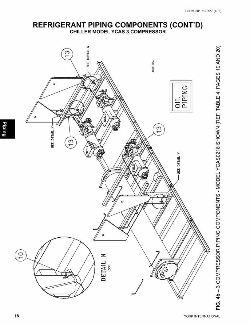
REFRIGERANT PIPING COMPONENTS (CONT’D)CHILLER MODEL YCAS 3 COMPRESSOR
FIG
. 4b
– 3
CO
MP
RE
SS
OR
PIP
ING
CO
MP
ON
EN
TS -
MO
DE
L Y
CA
S02
18 S
HO
WN
(RE
F. T
AB
LE 4
, PA
GE
S 1
9 A
ND
20)
4884
1-03
a
13
13
10
13

YORK INTERNATIONAL 19
FORM 201.19-RP7 (405)
Pipi
ng
REFRIGERANT PIPING COMPONENTS (CONT’D)CHILLER MODEL YCAS 3 COMPRESSOR
TABLE 4 – 3 COMPRESSOR PIPING COMPONENTS(SEE FIGS. 4, 4A AND 4B, PAGES 16, 17 AND 18)
S = Recommended Spare Parts
ITEMNO.
QTYPERUNIT
DESCRIPTION SYSTEMYCAS0218
375-48841-053YCAS0248
375-48841-054
1s 2Valve, Thermal Expansion
Sys 1&2 025-34560-010 025-34560-0101 Sys 3 025-34560-020 025-34559-020
22
Valve, SolenoidSys 1&2
025-33704-000025-33704-000
1 Sys 3 025-33281-000
42 Dehydrator, Body (Replaceable Core) Sys 1&2
026-21055-000026-21055-000
1 Dehydrator, Body (Replaceable Core) Sys 3 026-16960-0005s * Core, Dehydrator All 026-37540-000 (*6) 026-37540-000 (*7)6 3 Moisture Indicator, Body All 026-32800-000 026-32800-0007 3 Moisture Indicator, Sight Glass Cap All 026-32398-000 026-32398-000
82
Valve, Liquid StopSys 1&2
022-09778-000022-09778-000
1 Sys 3 022-09779-0009 3 Compressor All See pages 29 and 30
10 6 Valve, Charging All 022-09754-000 022-09754-00011 3 Economizer, Heat Exchanger All 375-32135-000 375-32135-000
122 Oil Separator Sys 1&3 075-56108-0021 Oil Separator Sys 2 075-56108-001
13 3 Valve, Ball (Oil Line) All 022-09172-000 022-09172-000
ITEMNO.
QTYPERUNIT
DESCRIPTION SYSTEMYCAS0268
375-48841-055YCAS0288
375-48841-056
1s1
Valve, Thermal ExpansionSys 1
025-34559-010025-34589-010
1 Sys 2 025-34559-0101 Sys 3 025-34559-020 025-34559-020
21
Valve, SolenoidSys 1
025-33704-000025-33281-000
2 Sys 2&3 025-33704-000
41 Dehydrator, Body (Replaceable Core) Sys 1
026-21055-000026-16960-000
2 Dehydrator, Body (Replaceable Core) Sys 2&3 026-21055-0005s * Core, Dehydrator All 026-37540-000 (*6) 026-37540-000 (*7)6 3 Moisture Indicator, Body All 026-32800-000 026-32800-000
71
Moisture Indicator, Sight Glass CapSys 1
026-32398-000026-32398-000
2 Sys 2&3 026-32399-000
81
Valve, Liquid StopSys 1
022-09778-000022-09779-000
2 Sys 2&3 022-09778-0009 3 Compressor All See pages 29 and 30
10 6 Valve, Charging All 022-09754-000 022-09754-00011 3 Economizer, Heat Exchanger All 375-32135-000 375-32135-000
122 Oil Separator Sys 1&3 075-56108-0021 Oil Separator Sys 2 075-56108-001
13 3 Valve, Ball (Oil Line) All 022-09172-000 022-09172-000

YORK INTERNATIONAL20
FORM 201.19-RP7 (405)
Piping
REFRIGERANT PIPING COMPONENTS (CONT’D)CHILLER MODEL YCAS 3 COMPRESSOR
TABLE 4 (CONT'D) – 3 COMPRESSOR PIPING COMPONENTS(SEE FIGS. 4, 4A AND 4B, PAGES 16, 17 AND 18)
ITEMNO.
QTYPERUNIT
DESCRIPTION SYSTEMYCAS0308
375-48842-051YCAS0328
375-48842-052
1s 2Valve, Thrmal Expansion
Sys 1&2 025-34589-010 025-34589-0101 Sys 3 025-34559-020 025-34589-020
22
Valve, SolenoidSys 1&2 025-33281-000
025-33281-0001 Sys 3 025-33704-000
42 Dehydrator, Body (Replaceable Core) Sys 1&2 026-16960-000
026-16960-0001 Dehydrator, Body (Replaceable Core) Sys 3 026-21055-000
5s * Core, Dehydrator All 026-37540-000(8) 026-37540-000(9)6 3 Moisture Indicator, Body All 026-32800-000 026-32800-000
72
Moisture Indicator, Sight Glass CapSys 1&2 026-32399-000
026-32399-0001 Sys 3 026-32398-000
82
Valve, Liquid StopSys 1&2 022-09779-000
022-09779-0001 Sys 3 022-09778-000
9 3 Compressor All See pages 29 and 3010 6 Valve, Charging All 022-09754-000 022-09754-00011 3 Economizer, Heat Exchanger All 375-32135-000 375-32135-000
122 Oil Separator Sys 1&3 075-56108-0021 Oil Separator Sys 2 075-56108-001
13 3 Valve, Ball (Oil Line) All 022-09172-000 022-09172-000

YORK INTERNATIONAL 21
FORM 201.19-RP7 (405)
FIG
. 5 –
4 C
OM
PR
ES
SO
R P
IPIN
G C
OM
PO
NE
NTS
- M
OD
EL
YC
AS
0418
SH
OW
N (R
EF.
TA
BLE
5, P
AG
E 2
4)4884
4-01
a
11
11
12
12
12
12
Pipi
ng
REFRIGERANT PIPING COMPONENTS (CONT’D)CHILLER MODEL YCAS 4 COMPRESSOR

YORK INTERNATIONAL22
FORM 201.19-RP7 (405)
Piping
REFRIGERANT PIPING COMPONENTS (CONT’D)CHILLER MODEL YCAS 4 COMPRESSOR
FIG. 5a – 4 COMPRESSOR PIPING COMPONENTS (REF. TABLE 5, PAGE 24)
48844-02a
1
10
1
9
9
9
9
4 56 7
8
2

YORK INTERNATIONAL 23
FORM 201.19-RP7 (405)
Pipi
ng
REFRIGERANT PIPING COMPONENTS (CONT’D)CHILLER MODEL YCAS 4 COMPRESSOR
13
13
13
1013
FIG
. 5b
– 4
CO
MP
RE
SS
OR
PIP
ING
CO
MP
ON
EN
TS -
MO
DE
L Y
CA
S04
18 S
HO
WN
(RE
F. T
AB
LE 5
, PA
GE
24)48
844-
03a

YORK INTERNATIONAL24
FORM 201.19-RP7 (405)
Piping
REFRIGERANT PIPING COMPONENTS (CONT’D)CHILLER MODEL YCAS 4 COMPRESSOR
TABLE 5 – 4 COMPRESSOR PIPING COMPONENTS(SEE FIGS. 5, 5A AND 5B, PAGES 21, 22 AND 23)
ITEMNO.
QTYPERUNIT
DESCRIPTION SYSTEMYCAS0358
375-48843-050YCAS0398
375-48844-050
1s 2Valve,Thermal Expansion
Sys 1&2025-34559-010
025-34589-0102 Sys 3&4 025-34559-010
22
Valve, SolenoidSys 1&2
025-33704-000025-33281-000
2 Sys 3&4 025-33704-000
42
Dehydrator, Body (Replacable Core)Sys 1&2
026-21055-000026-16960-000
2 Sys 3&4 026-21055-000
5s * Core, Dehydrator All 026-37540-000 (*8) 026-37540-000 (*10)6 4 Moisture Indicator, Body All 026-32800-000 026-32800-000
72
Moisture Indicator, Sight Glass CapSys 1&2
026-32398-000026-32399-000
2 Sys 3&4 026-32398-000
82
Valve, Liquid StopSys 1&2
022-09778-000022-09779-000
2 Sys 3&4 022-09778-0009 4 Compressor All See pages 29 and 30
10 8 Valve, Charging All 022-09754-000 022-09754-00011 - Economizer, Heat Exchanger All 375-32135-000 375-32135-000
122 Oil Separator Sys 1&3 075-56108-0022 Oil Separator Sys 2&4 075-56108-001
13 4 Valve, Ball (Oil Line) All 022-09172-000 022-09172-000
S = Recommended Spare Parts
ITEMNO.
QTYPERUNIT
DESCRIPTION SYSTEMYCAS0418
375-48845-050
1s 4 Valve, Thermal Expansion All 025-34589-0102 4 Valve, Solenoid All 025-33281-000
42
Dehydrator, Body (Replacable Core)Sys 1&2
026-16960-0002 Sys 3&4
5s * Core, Dehydrator All 026-37540-000 (*12)6 4 Moisture Indicator, Body All 026-32800-0007 4 Moisture Indicator, Sight Glass Cap All 026-32399-0008 4 Valve, Liquid Stop All 022-09779-0009 4 Compressor All See pages 29 and 30
10 8 Valve, Charging All 022-09754-00011 - Economizer, Heat Exchanger All 375-32135-000
122 Oil Separator Sys 1&3 075-56108-0022 Oil Separator Sys 2&4 075-56108-001
13 4 Valve, Ball (Oil Line) All 022-09172-000

YORK INTERNATIONAL 25
FORM 201.19-RP7 (405)
This page intentionally left blank
Pipi
ng

YORK INTERNATIONAL26
FORM 201.19-RP7 (405)
Piping
RELIEF VALVES AND CUTOUT SWITCHESCHILLER MODEL YCAS
FIG. 6 – RELIEF VALVES AND CUTOUT SWITCHES (REF. TABLE 6, PAGE 27)
38583-000-01bb
38583-000-01cc
26 25
26
2022
24
23
16 21
19
1921
17

YORK INTERNATIONAL 27
FORM 201.19-RP7 (405)
Pipi
ng
RELIEF VALVES AND CUTOUT SWITCHES (CONT’D)
ITEMNO.
QTYPERUNIT
DESCRIPTION SYSTEMALL
MODELS
13 * Valve, Stop All 022-09802-000
14 * Low Side Relief, Straight Thru xxx psig All 022-09803-000
15 * Low Side Relief, Angle V-21 Bar All 022-09793-000
16 * High Side Relief, Angle V-31 Bar All 022-09794-00017 * High Side Relief, Straight Thru 405 psig All 022-08863-00018 * Low Side Relief, Straight Thru 300 psig All 022-10045-000
19 *
Tube for 14
All
075-31211-000Tube for 15 & 16 075-30992-000
Tube for 17 075-30993-000Tube for 18 375-30919-000
20 * Adapter for 24 All 023-18092-000
21 *Adapter for 14
All023-16474-000
Adapter for 15 & 16 023-00094-000Adapter for 17 023-00124-000
22 * High Press Sw, Man Reset 27.9 Bar All 025-34119-00023 * High Press Sw, Man Reset 27.2 Bar All 025-34120-00024 * Tee for 22 & 23 All 023-00972-00025 * High Press Sw, Auto Reset 405 psig All 025-18087-00026 * O-ring, 3-904 All 028-13540-000
FIG. 6a – RELIEF VALVES AND CUTOUT SWITCHES (REF. TABLE 6, PAGE 27)
TABLE 6 – RELIEF VALVES AND CUTOUT SWITCHES (SEE FIGS. 6 AND 6A, PAGES 26 & 27)
38583-000-01aa
20
1813
1521
19
14 21
19

YORK INTERNATIONAL28
FORM 201.19-RP7 (405)
COMPRESSOR MODEL NOMENCLATURE
Com
pressor
DXS 36 L A R A 46 E
Type of YORK Economizer Utilization Semi-Hermetic Twin E = Economized Screw Compressor N = Non-economized Diameter of Male Rotor 45 = 145.3 mm 36 = 136.4 mm 24 = 124.0 mm 12 = 112.0 mm Compressor Rotor Length L = Length L/D S = Short L/D
Design Series Motor Vendor R = 2-Pole Reliance S = 2-Pole A.O. Smith T = 4-Pole Reliance
Motor Stack & Diameter Code A = 10-1/8 Dia. x 10.75 Stack B, C, etc. = TBA
Voltage and Frequency 40 = 380-3-60 46 = 460-3-60 58 = 575-3-60
COMPRESSOR WEIGHTSMM SIZE WEIGHT (LBS.)* WEIGHT (Kg.)
145 1310 594136 1250 567124 1175 533
Service Note: Compressor Isolator Pad Kit475-37845-000 one per compressor.
Service Note: Compressor feet hold-down bolts, tightenedfrom the underside of the frame rails mustbe removed when the isolator pad kit isinstalled.
*Note: Less Service Valves.

YORK INTERNATIONAL 29
FORM 201.19-RP7 (405)
Com
pres
sor
COMPRESSORTABLE 7 – COMPRESSOR PART NUMBERS - YCAS0250-YCAS0330
MODEL VOLTAGE CODE
SYSTEM #1 COMPRESSOR SYSTEM #2 COMPRESSORPART # MODEL # MM QTY PART # MODEL # MM QTY
YCAS0218-40 364-49095-214 DXS24LA 124 1 364-49095-214 DXS24LA 124 1-46 364-49095-215 DXS24LA 124 1 364-49095-215 DXS24LA 124 1-58 364-49095-216 DXS24LA 124 1 364-49095-216 DXS24LA 124 1
YCAS0248-40 364-49095-214 DXS24LA 124 1 364-49095-214 DXS24LA 124 1-46 364-49095-215 DXS24LA 124 1 364-49095-215 DXS24LA 124 1-58 364-49095-216 DXS24LA 124 1 364-49095-216 DXS24LA 124 1
YCAS0268-40 364-49093-214 DXS36LA 136 1 364-49093-214 DXS36LA 136 1-46 364-49093-215 DXS36LA 136 1 364-49093-215 DXS36LA 136 1-58 364-49093-216 DXS36LA 136 1 364-49093-216 DXS36LA 136 1
YCAS0288-40 364-49094-214 DXS45LA 145 1 364-49093-214 DXS36LA 136 1-46 364-49094-215 DXS45LA 145 1 364-49093-215 DXS36LA 136 1-58 364-49094-216 DXS45LA 145 1 364-49093-216 DXS36LA 136 1
YCAS0308-40 364-49094-214 DXS45LA 145 1 364-49094-214 DXS45LA 145 1-46 364-49094-215 DXS45LA 145 1 364-49094-215 DXS45LA 145 1-58 364-49094-216 DXS45LA 145 1 364-49094-216 DXS45LA 145 1
YCAS0328-40 364-49094-214 DXS45LA 145 1 364-49094-214 DXS45LA 145 1-46 364-49094-215 DXS45LA 145 1 364-49094-215 DXS45LA 145 1-58 364-49094-216 DXS45LA 145 1 364-49094-216 DXS45LA 145 1
Service Note: Compressor Change Out Kit - ALL Models - 464-49737-000 (Includes Gaskets and O-rings)
MODEL VOLTAGE CODE
SYSTEM #3 COMPRESSOR SYSTEM #4 COMPRESSORPART # MODEL # MM QTY PART # MODEL # MM QTY
YCAS0218-40 364-49095-214 DXS24LA 124 1 N/A-46 364-49095-215 DXS24LA 124 1 N/A-58 364-49095-216 DXS24LA 124 1 N/A
YCAS0248-40 364-49094-214 DXS45LA 145 1 N/A-46 364-49094-215 DXS45LA 145 1 N/A-58 364-49094-216 DXS45LA 145 1 N/A
YCAS0268-40 364-49093-214 DXS36LA 136 1 N/A-46 364-49093-215 DXS36LA 136 1 N/A-58 364-49093-216 DXS36LA 136 1 N/A
YCAS0288-40 364-49093-214 DXS36LA 136 1 N/A-46 364-49093-215 DXS36LA 136 1 N/A-58 364-49093-216 DXS36LA 136 1 N/A
YCAS0308-40 364-49093-214 DXS36LA 136 1 N/A-46 364-49093-215 DXS36LA 136 1 N/A-58 364-49093-216 DXS36LA 136 1 N/A
YCAS0328-40 364-49094-214 DXS45LA 145 1 N/A-46 364-49094-215 DXS45LA 145 1 N/A-58 364-49094-216 DXS45LA 145 1 N/A

YORK INTERNATIONAL30
FORM 201.19-RP7 (405)
TABLE 7 – COMPRESSOR PART NUMBERS - YCAS0360-YCAS0440
MODEL VOLTAGE CODE
SYSTEM #1 COMPRESSOR SYSTEM #2 COMPRESSORPART # MODEL # MM QTY PART # MODEL # MM QTY
YCAS0358-40 364-49093-214 DXS36LA 136 1 364-49093-214 DXS36LA 136 1-46 364-49093-215 DXS36LA 136 1 364-49093-215 DXS36LA 136 1-58 364-49093-216 DXS36LA 136 1 364-49093-216 DXS36LA 136 1
YCAS0398-40 364-49094-214 DXS45LA 145 1 364-49094-214 DXS45LA 145 1-46 364-49094-215 DXS45LA 145 1 364-49094-215 DXS45LA 145 1-58 364-49094-216 DXS45LA 145 1 364-49094-216 DXS45LA 145 1
YCAS0418-40 364-49094-214 DXS45LA 145 1 364-49094-214 DXS45LA 145 1-46 364-49094-215 DXS45LA 145 1 364-49094-215 DXS45LA 145 1-58 364-49094-216 DXS45LA 145 1 364-49094-216 DXS45LA 145 1
Service Note: Compressor Change Out Kit - ALL Models - 464-49737-000 (Includes Gaskets and O-rings)
MODEL VOLTAGE CODE
SYSTEM #3 COMPRESSOR SYSTEM #4 COMPRESSORPART # MODEL # MM QTY PART # MODEL # MM QTY
YCAS0358-40 364-49093-214 DXS36LA 136 1 364-49093-214 DXS36LA 136 1-46 364-49093-215 DXS36LA 136 1 364-49093-215 DXS36LA 136 1-58 364-49093-216 DXS36LA 136 1 364-49093-216 DXS36LA 136 1
YCAS0398-40 364-49093-214 DXS36LA 136 1 364-49093-214 DXS36LA 136 1-46 364-49093-215 DXS36LA 136 1 364-49093-215 DXS36LA 136 1-58 364-49093-216 DXS36LA 136 1 364-49093-216 DXS36LA 136 1
YCAS0418-40 364-49094-214 DXS45LA 145 1 364-49094-214 DXS45LA 145 1-46 364-49094-215 DXS45LA 145 1 364-49094-215 DXS45LA 145 1-58 364-49094-216 DXS45LA 145 1 364-49094-216 DXS45LA 145 1
Com
pressor
COMPRESSOR (CONT’D)

YORK INTERNATIONAL 31
FORM 201.19-RP7 (405)
Com
pres
sor
COMPRESSOR (CONT’D)
49094-3a
48
47
46
169
18
19
12
13
15
1312
13
12
13
12
14
1
FIG. 7 – 124MM, 136MM & 145MM DXS COMPRESSOR COMPONENTSPARTIAL EXPLODED VIEW (REF. TABLE 8, PAGES 34 AND 35)

YORK INTERNATIONAL32
FORM 201.19-RP7 (405)
Com
pressor
COMPRESSOR (CONT’D)49
094-
2a
FIG
. 7a
– 12
4MM
, 136
MM
& 1
45M
M D
XS
CO
MP
RE
SS
OR
CO
MP
ON
EN
TSPA
RTI
AL
EX
PLO
DE
D V
IEW
(RE
F. T
AB
LE 8
, PA
GE
S 3
4 A
ND
35)
361
33
3435
2
34
56
138
9
11 10
49
7
32
37

YORK INTERNATIONAL 33
FORM 201.19-RP7 (405)
Com
pres
sor
COMPRESSOR (CONT’D)
4909
4-4a
YORK
YORK
169
31
12
13 1419
201
18
3839
4142
303245
44
29
43
4025
1728
2726
24
2322
21
19 18
FIG
. 7b
– 13
6MM
& 1
45M
M D
XS
CO
MP
RE
SS
OR
CO
MP
ON
EN
TSPA
RTI
AL
EX
PLO
DE
D V
IEW
(RE
F. T
AB
LE 8
, PA
GE
S 3
4 A
ND
35)
*CA
UTI
ON
:1.
Val
ve B
ody
Torq
ue M
US
T N
OT
Exc
eed
10 ft
. lbs
.2.
Coi
l Nut
Tor
que
MU
ST
NO
T E
xcee
d 3
ft. lb
s.

YORK INTERNATIONAL34
FORM 201.19-RP7 (405)
Com
pressor
COMPRESSOR (CONT’D)
ITEM NO. PART DESCRIPTION PART NO. (Qty.)1 SCREW, SOCKET HD. CAP - M16 X 65MM LONG 021-19108-000 (26)2 SEAL, TERMINAL 028-13946-000 (6)3 INSULATOR, TOP 025-33201-000 (6)4 WASHER, TERMINAL 021-19117-000 (6)5 NUT, HEAVY HEX - 7/16" X 20UNF 021-19102-000 (12)6 WASHER, LOCK - 7/16" 021-19619-000 (6)7 THERMISTOR, 7/16" X 20UNF-2A 025-33202-000 (4)8 PIN, STATOR LOCKING 064-49954-0009 O-RING 3 - 908 028-13856-000 (4)10 PLUG, HOLLOW HEX - 1 7/8" 023-18926-00011 O-RING 3 - 924 028-13865-00012 PLUG, HOLLOW HEX - 9/16" 023-18922-000 (8)13 O-RING - 906 028-13855-000 (8)14 PLUG - 0.032 ORIFICE 029-22716-000 (3)15 PLUG - 0.093 ORIFICE 029-22994-000 (2)16 PLUG, HOLLOW HEX - 3/4" 023-18923-000 (7)17 VALVE, ACCESS 7/16" 022-09715-00018 PLUG, HOLLOW HEX - 7/16" 023-18921-000 (15)19 O-RING 3 - 904 028-13854-000 (9)20 PLATE, DATA 029-22722-00021 O-RING 2- 023 028-13859-000 (2)22 VALVE, OIL CONTROL 022-09710-00023 O-RING 3 - 916 028-13857-00024 PLUG, OIL RETURN VALVE 064-49135-00025s ELEMENT, OIL FILTER 026-35601-00026s O-RING 2 - 152 028-13849-00027 COVER, OIL FILTER 064-49003-00028 SCREW, SOCKET HD. CAP - M8 X 30MM LONG 021-19115-000 (8)29 SCREW, SOCKET HD. CAP - M10 X 45MM LONG 021-19112-000 (9)30 SCREW, SOCKET HD. CAP - M10 X 60MM LONG 021-19113-000 (8)31s VALVE, CAPACITY CONTROL 025-33205-00032 SCREW, SOCKET HD. CAP - M16 X 30MM LONG 021-19118-000 (8)
33PLATE, VALVE COVER (124MM) 064-49008-000
PLATE, VALVE COVER (136MM & 145MM) 064-49009-000
34GASKET, 3" (124MM) 028-13863-000
GASKET, 3 1/2" (136MM & 145MM) 028-13864-000
TABLE 8 – COMPRESSOR COMPONENTS (SEE FIGS. 7, 7A AND 7B, PAGES 31-33)
S = Recommended Spare Parts

YORK INTERNATIONAL 35
FORM 201.19-RP7 (405)
Com
pres
sor
COMPRESSOR (CONT’D)
ITEM NO. PART DESCRIPTION PART NO. (Qty.)
35STRAINER, SUCTION (124MM) 026-35623-000
STRAINER, SUCTION (136MM & 145MM) 026-35600-000
36COVER, SUCTION (124MM) 064-49375-000
COVER, SUCTION (136MM & 145MM) 064-49198-00037 O-RING 2 - 276 028-13852-000 (2)
38ORIFICE, MUFFLER (124MM) 064-49518-000
ORIFICE, MUFFLER (136MM & 145MM) 064-49516-000
39SPRING, MUFFLER PRELOAD (124MM) 029-22902-000
SPRING, MUFFLER PRELOAD (136MM & 145MM) 029-22904-000
40BUTTON, CHECK VALVE (124MM) 064-49521-000BUTTON, CHECK VALVE (136MM) 064-49517-000BUTTON, CHECK VALVE (145MM) 064-49504-000
41SPACER, MUFFLER (124MM) 064-49520-000
SPACER, MUFFLER (136MM & 145MM) 064-49513-000
42O-RING 2 -158 (124MM) 028-13603-000
O-RING 2 -161 (136MM & 145MM) 028-13851-000
43COVER, DISCHARGE (124MM) 064-49126-000COVER, DISCHARGE (136MM) 064-48990-000COVER, DISCHARGE (145MM) 064-49005-000
44GASKET, 2" (124MM) 028-13902-000
GASKET, 3" (136MM & 145MM) 028-13863-000
45PLATE, VALVE COVER (124MM) 064-49379-000
PLATE, VALVE COVER (136MM & 145MM) 064-49008-000
46O-RING 2 - 136 (124MM) 028-13863-000
O-RING 2 - 139 (136MM & 145MM) 028-13963-000
47PLUG, ECONOMIZER (124MM) 064-50004-000
PLUG, ECONOMIZER (136MM & 145MM) 064-50003-00048 SCREW, SOCKET HD. CAP - M12 X 25MM LONG 021-30148-00049 HEATER, 350 WATTS 025-32938-000
TABLE 8 CONT'D – COMPRESSOR COMPONENTS (SEE FIGS. 7, 7A AND 7B, PAGES 31-33)
ITEM REF. DESCRIPTION 5 GALLON
OILS R-22Oil, Type 'L' (Synthetic) 011-00592-000
R-407CS = Recommended Spare Parts

YORK INTERNATIONAL36
FORM 201.19-RP7 (405)
Com
pressor
COMPRESSOR (CONT’D)
FIG. 8 – COMPRESSOR AND CONTROL COMPONENTS (REF. TABLE 9)
COMPRESSOR LOCATION DESCRIPTION VALVE (A) GASKET (B)
124MMSuction Stop Valve - 2 5/8" 022-09777-001 028-13863-000
Discharge Stop Valve - 2 1/8" 022-01393-001 028-13902-000Economizer Stop Valve - 1 3/8" 022-03727-002 028-13862-000
136MMSuction Stop Valve - 3 5/8" 022-02845-001 028-13864-000
Discharge Stop Valve - 2 5/8" 022-09777-001 028-13863-000Economizer Stop Valve - 1 3/8" 022-03727-002 028-13862-000
145MMSuction Stop Valve - 3 5/8" 022-02845-001 028-13864-000
Discharge Stop Valve - 2 5/8" 022-09777-001 028-13863-000Economizer Stop Valve - 1 3/8" 022-03727-002 028-13862-000
TABLE 9 – COMPRESSOR STOP VALVES AND GASKETS (SEE FIG. 8)
LD05265b
BA
BA
BA
Suction
Discharge
Economizer

YORK INTERNATIONAL 37
FORM 201.19-RP7 (405)
Com
pres
sor
This page intentionally left blank

YORK INTERNATIONAL38
FORM 201.19-RP7 (405)
CONTROL PANEL COMPONENTS
FIG
. 9 –
CO
NTR
OL
PAN
EL
CO
MP
ON
EN
TS (R
EF.
TA
BLE
10,
PA
GE
39)
2018
02bb
Control Panel
1010
2121
20209
1919
1
2323 2323
1717
2
5,6
5,6
1515
7
8
4
1414
3
312 12
22222626
2727
1818 1616
1111
1313
2525 2424

YORK INTERNATIONAL 39
FORM 201.19-RP7 (405)
TABLE 10 – CONTROL PANEL COMPONENTS (SEE FIG. 9, PAGE 38)
Con
trol
Pan
el
CONTROL PANEL COMPONENTS (CONT’D)
ITEM NO. QTY DESCRIPTION PART
NUMBER1s 1 Micro Board 031-01095-0022 1 Power Supply Board 031-01094-0003 2 Relay Control Board 031-01093-0004 1 Transformer, 2T 025-27911-000 5 1 Terminal Block 025-33760-0006 1 Terminal Block 025-33761-000 7 3 Circuit Breaker, 6A (Not Shown) 024-30913-0008 1 Transformer, 3T 025-18452-0009 1 On/Off Switch 024-25517-000
10 1 Display 031-01110-000 11 1 Ribbon Cable Assembly 071-02253-251 12 4 Ribbon Cable Assembly 071-02253-252 13 1 Ribbon Cable Assembly 071-02253-253 14 1 Transformer, 4T 025-30889-00015 1 Control Relay 024-25598-00016s 1 EPROM (Use w/ Micro Board) 031-01798-00217 1 I/O Expansion Board 031-01788-00018 1 Ribbon Cable Assembly 071-02253-254 19 1 Keypad (English) 024-30910-00020 1 SMART I/O Expansion Board 031-01793-00121 1 EPROM (Use w/ SMART I/O Expansion Board) 031-02018-00122 2 EEV Board 031-02092-999
233 Transformer CL-2 (3 Compressor Units)
025-37679-0004 Transformer CL-2 (4 Compressor Units)
24 1 Temperature Reset Kit (Optional) 371-02590-10225 1 Current Reset Kit (Optional) 371-02590-10126 1 Micro-Gateway Power Supply Board (Optional) 031-02043-00027 1 Micro-Gateway Board (Optional) 031-02039-000
S = Recommended Spare Parts

YORK INTERNATIONAL40
FORM 201.19-RP7 (405)
OPTION AND POWER PANEL CONFIGURATIONS
Option &
Power Panel
PIN 16 & 17LETTER CODE
IDENTIFIERS
OPTION PANEL AND POWER PANEL CONFIGURATIONS
X X Multiple Point Supply Terminal Block (Standard)M B Multiple Point Supply Circuit BreakersM D Multiple Point Supply Non-Fused Disconnect SwitchesM N Multiple Point Supply Disconnect Switches Fused DINS B Single Point Supply Terminal Block w/ Separate System Circuit BreakersD B Single Point Supply Non-Fused Disconnect Switch w/ Separate System Circuit BreakersD P Multiple Point Supply Non-Fused Disconnect Switches w/ Separate System Circuit BreakersS N Single Point Supply Terminal Block w/ Separate System Disconnect Switches Fused DIND N Single Point Supply Non-Fused Disconnect Switches w/ Separate System Disconnect
Switches Fused DIN
Power panels and option panels are offered in several different confi gurations using three (3) major components:
1. TERMINAL BLOCKS2. CIRCUIT BREAKERS3. NON-FUSED DISCONNECT SWITCHES
The most basic chiller power wiring confi guration uses TERMINAL BLOCKS in the power panels, and an options panel with no power wire termination hardware. See fi gures on previ-ous page. The model pin number locations 16 and 17 would be X and X to refl ect this basic combination. Identify model pin number locations 16 and 17 to identify the chiller power wiring connections and hardware listed below.
FIG. 10 – CONTROL, OPTIONS AND POWER PANELS LAYOUT
System #1 System #2 Control Panel
Options Panel
System #3 System #4
Power Panel
Power Panel

YORK INTERNATIONAL 41
FORM 201.19-RP7 (405)
FIG. 11 – EXAMPLES OF POWER WIRING CONFIGURATIONS(3 AND 4 COMPRESSOR UNITS)
Opt
ion
& P
ower
Pan
el
OPTION AND POWER PANEL CONFIGURATIONS (CONT'D)
201812-1 (3Comp)
L1L1
MPMP
T1T1 T2T2 C S1S1 S2S2 S3S3 B M1M1 M2M2G
MPMP
T1T1 T2T2 C S1S1 S2S2 S3S3 B M1M1 M2M2G
T1T1 T2T2 T3T3
L2L2
PTBPTB
CB OR SWCB OR SW
L3L3
L1L1 L2L2 L3L3
P3P3
PEPE T6T6 T4T4 T5T5 T1T1 T2T2 T3T3T6T6 T4T4 T5T5PEPE PEPE
L1L1 L2L2
PTBPTB
CB OR SWCB OR SW
L3L3
L1L1 L2L2 L3L3
PEPE PEPE PEPE
L1L1
MPMP
T1T1 T2T2 C S1S1 S2S2 S3S3 B M1M1 M2M2G
T1T1 T2T2 T3T3
L2L2
PTBPTB
CB OR SWCB OR SW
L3L3
L1L1 L2L2 L3L3
P3P3
PEPE T6T6 T4T4 T5T5 PEPE PEPE
PE
PE
PE
PE
L1L1
MPMP
T1T1 T2T2 C S1S1 S2S2 S3S3 B M1M1 M2M2G
MPMP
T1T1 T2T2 C S1S1 S2S2 S3S3 B M1M1 M2M2G
T1T1 T2T2 T3T3
L2L2
PTBPTB
CB OR SWCB OR SW
L3L3
L1L1 L2L2 L3L3
P3P3
PEPE T6T6 T4T4 T5T5 T1T1 T2T2 T3T3T6T6 T4T4 T5T5PEPE PEPE
L1L1 L2L2
PTBPTB
CB OR SWCB OR SW
L3L3
L1L1 L2L2 L3L3
PEPE PEPE PEPE
PE
PE
PE
PE
L1L1
MPMP
T1T1 T2T2 C S1S1 S2S2 S3S3 B M1M1 M2M2G
T1T1 T2T2 T3T3
L2L2
PTBPTB
CB OR SWCB OR SW
L3L3
L1L1 L2L2 L3L3
P3P3
PEPE T6T6 T4T4 T5T5 PEPE PEPE
201812-2 (3Comp)
201812-3 (3Comp)
L1L1
MPMP
T1T1 T2T2 C S1S1 S2S2 S3S3 B M1M1 M2M2G
MPMP
T1T1 T2T2 C S1S1 S2S2 S3S3 B M1M1 M2M2G
T1T1 T2T2 T3T3
L2L2
PTBPTB
CB OR SWCB OR SW
L3L3
L1L1 L2L2 L3L3
P3P3
PEPE T6T6 T4T4 T5T5 T1T1 T2T2 T3T3T6T6 T4T4 T5T5PEPE PEPE
L1L1 L2L2
PTBPTB
CB OR SWCB OR SW
L3L3
L1L1 L2L2 L3L3
PEPE PEPE PEPE
L1L1
MPMP
T1T1 T2T2 C S1S1 S2S2 S3S3 B M1M1 M2M2G
T1T1 T2T2 T3T3
L2L2
PTBPTB
CB OR SWCB OR SW
L3L3
L1L1 L2L2 L3L3
P3P3
PEPE T6T6 T4T4 T5T5 PEPE PEPE
MPMP
T1T1 T2T2 C S1S1 S2S2 S3S3 B M1M1 M2M2G
T1T1 T2T2 T3T3T6T6 T4T4 T5T5
L1L1 L2L2
PTBPTB
CB OR SWCB OR SW
L3L3
L1L1 L2L2 L3L3
PEPE PEPE PEPE
PE
PE
PE
PE
L1L1
MPMP
T1T1 T2T2 C S1S1 S2S2 S3S3 B M1M1 M2M2G
MPMP
T1T1 T2T2 C S1S1 S2S2 S3S3 B M1M1 M2M2G
T1T1 T2T2 T3T3
L2L2
PTBPTB
CB OR SWCB OR SW
L3L3
L1L1 L2L2 L3L3
P3P3
PEPE T6T6 T4T4 T5T5 T1T1 T2T2 T3T3T6T6 T4T4 T5T5PEPE PEPE
L1L1 L2L2
PTBPTB
CB OR SWCB OR SW
L3L3
L1L1 L2L2 L3L3
PEPE PEPE PEPE
MPMP
T1T1 T2T2 C S1S1 S2S2 S3S3 B M1M1 M2M2G
T1T1 T2T2 T3T3T6T6 T4T4 T5T5
L1L1 L2L2
PTBPTB
CB OR SWCB OR SW
L3L3
L1L1 L2L2 L3L3
PEPE PEPE PEPE
PE
PE
PE
PE
L1L1
MPMP
T1T1 T2T2 C S1S1 S2S2 S3S3 B M1M1 M2M2G
T1T1 T2T2 T3T3
L2L2
PTBPTB
CB OR SWCB OR SW
L3L3
L1L1 L2L2 L3L3
P3P3
PEPE T6T6 T4T4 T5T5 PEPE PEPE
201812-1 (4Comp)
201812-2 (4Comp)
201812-3 (4Comp)

YORK INTERNATIONAL42
FORM 201.19-RP7 (405)
POWER PANEL COMPONENTS
Option &
Power Panel
CIRCUIT BREAKER AND NON-FUSED DISCONNECT SWITCH LUG KITS TABLE
CircuitBreakers Wire Size YORK Lug Kit
Part Number024-31852-000 S3H035TW
#14AWG-#2 AWG 025-34477-000024-31837-000 S3H040TW024-31838-000 S3H050TW024-31839-000 S3H060TW024-31840-000 S3H070TW
#14AWG-#1/0 AWG 025-34478-000024-31841-000 S3H080TW024-31842-000 S3H090TW024-31843-000 S3H100TW024-31844-000 S3H125TW (1) 2-4/0 AWG 025-34479-000024-31649-000 S3H150TW024-31820-000 S3H175TW
#14AWG-300KCMIL AWG 025-34480-000024-31851-000 S3H200TW024-31819-000 S3H225TW025-34419-000 S4H250BW #6AWG-350KCMIL AWG 025-34418-000024-34424-000 S5H400BW (1) 250-500KCMIL AWG 025-34481-000024-34425-000 S6H600BW (2) 250KCMIL AWG 025-34414-000024-34473-000 S6H800BW (2) 250KCMIL AWG 025-34414-000
Non-FusedDisconnect Switch Wire Size YORK Part
Number024-31888-000 S3H150DW (1) 2-4/0 AWG 025-34479-000024-31871-000 S3B225DW #14AWG-300KCMIL AWG 025-34480-000024-30963-000 S4H250DW #6AWG-350KCMIL AWG 025-34418-000024-30964-000 S5H400DW (1) 250-500KCMIL AWG 025-34481-000024-30965-000 S6H600DW (2) 250KCMIL AWG 025-34414-000

YORK INTERNATIONAL 43
FORM 201.19-RP7 (405)
POWER PANEL COMPONENTS (CONT’D)
FIG. 12 – ACROSS-THE-LINE POWER PANEL (REF. TABLE 11, PAGES 44-52)
LD05853aO
ptio
n &
Pow
er P
anel
Terminal Block,Circuit Breaker
orNon-FusedDisconnect
Switch

YORK INTERNATIONAL44
FORM 201.19-RP7 (405)
POWER PANEL COMPONENTS
Option &
Power Panel
Item Qty DescriptionYCAS0218-40 YCAS0218-46 YCAS0218-58
371-02493-100*XX-MD
371-02493-217*MB-SB-DB-DP
371-02493-100*XX-MD
371-02493-217*MB-SB-DB-DP
371-02493-118*XX-MD
371-02493-218*MB-SB-DB-DP
1A2 Compressor Contactor
(System 1 and 2) 024-31891-000 024-31891-000 024-31891-000 024-31891-000 024-31110-000 024-31110-000
1 Compressor Contactor (System 3) 024-31891-000 024-31891-000 024-31891-000 024-31891-000 024-31110-000 024-31110-000
1C 3 Surge Suppressor 031-02203-000 031-02203-000 031-02203-000 031-02203-000 031-02203-000 031-02203-000
1Gs 3 Motor Protector 024-30907-000 024-30907-000 024-30907-000 024-30907-000 024-30907-000 024-30907-000
1I 3 Ground Lug 025-34088-000 025-34088-000 025-34088-000 025-34088-000 025-34088-000 025-34088-000
3A
6 Terminal Block(System 1 and 2) 025-34454-000 N/A 025-34454-000 N/A 025-38346-000 N/A
3 Terminal Block(System 3) 025-34454-000 N/A 025-34454-000 N/A 025-38346-000 N/A
2 Circuit Breaker(System 1 and 2) N/A 024-31819-000 N/A 024-31819-000 N/A 024-31649-000
1 Circuit Breaker(System 3) N/A 024-31819-000 N/A 024-31819-000 N/A 024-31649-000
2 NF Disconnect Switch(System 1 and 2) N/A N/A N/A N/A N/A N/A
1 NF Disconnect Switch(System 3) N/A N/A N/A N/A N/A N/A
3B3 MP Handle
(CB & NFDS) N/A 025-35697-000 N/A 025-35697-000 N/A 025-35697-000
3 MP Shaft (CB & NFDS) N/A 025-35696-000 N/A 025-35696-000 N/A 025-35696-000
3C 3 Auxiliary Switch N/A 024-31646-000 N/A 024-31646-000 N/A 024-31646-000
3J 3 MP Ground Lug 025-34089-000 025-34085-000 025-34089-000 025-34085-000 025-34088-000 025-34089-000
TABLE 11 – ACROSS-THE-LINE POWER PANEL COMPONENTS - MODEL YCAS0218 (SEE FIG. 12, PAGE 43)
s Recommended Spare Part
XX* Multi Point supply TB DB* Single Point NFDS supply w/ Separate System CBs
MB* Multi Point supply CBs DP* Multi Point supply NFDS w/ Separate System CBs
MD* Multi Point supply NFDSs SN* Single Point supply TB w/ Separate System NFDSs
MN* Multi Point supply TB w/ Separate System NFDSs DN* Single Point NFDS supply w/ Separate System NFDSs
SB* Single Point TB supply w/ Separate System CBs
*Service Note: Locate the PANEL NUMBER sticker on the upper right hand corner of the power panel,then refer to the appropriate parts list for that number. Or, identify PIN numberpositions 16 and 17 on unit identifi cation plate (See example on Page 4) then compareto table at right for power confi guration options.

YORK INTERNATIONAL 45
FORM 201.19-RP7 (405)
POWER PANEL COMPONENTS (CONT’D)
Opt
ion
& P
ower
Pan
el
Item Qty DescriptionYCAS0248-40 YCAS0248-46 YCAS0248-58
371-02493-119*XX-MD
371-02493-219*MB-SB-DB-DP
371-02493-119*XX-MD
371-02493-219*MB-SB-DB-DP
371-02493-150*XX-MD
371-02493-250*MB-SB-DB-DP
1A2 Compressor Contactor
(System 1 and 2) 024-31891-000 024-31891-000 024-31891-000 024-31891-000 024-31110-000 024-31110-000
1 Compressor Contactor (System 3) 024-31894-000 024-31894-000 024-31894-000 024-31894-000 024-31892-000 024-31892-000
1C 3 Surge Suppressor 031-02203-000 031-02203-000 031-02203-000 031-02203-000 031-02203-000 031-02203-000
1Gs 3 Motor Protector 024-30907-000 024-30907-000 024-30907-000 024-30907-000 024-30907-000 024-30907-000
1I2
Ground Lug025-34088-000 025-34088-000 025-34088-000 025-34088-000 025-34088-000 025-34088-000
1 025-34089-000 025-34089-000 025-34089-000 025-34089-000 025-34089-000 025-34089-000
3A
6 Terminal Block(System 1 and 2) 025-34454-000 N/A 025-34454-000 N/A 025-38346-000 N/A
3 Terminal Block(System 3) 025-34405-000 N/A 025-34405-000 N/A 025-34454-000 N/A
2 Circuit Breaker(System 1 and 2) N/A 024-31819-000 N/A 024-31819-000 N/A 024-31649-000
1 Circuit Breaker(System 3) N/A 025-34424-000 N/A 025-34424-000 N/A 025-34419-000
2 NF Disconnect Switch(System 1 and 2) N/A N/A N/A N/A N/A N/A
1 NF Disconnect Switch(System 3) N/A N/A N/A N/A N/A N/A
3B3 MP Handle
(CB & NFDS) N/A 025-35697-000 N/A 025-35697-000 N/A 025-35697-000
3 MP Shaft (CB & NFDS) N/A 025-35696-000 N/A 025-35696-000 N/A 025-35696-000
3C 3 Auxiliary Switch N/A 024-31646-000 N/A 024-31646-000 N/A 024-31646-000
3J2
MP Ground Lug025-34089-000
025-34085-000025-34089-000
025-34085-000025-34088-000 025-34089-000
1 025-34087-000 025-34087-000 025-34089-000 025-34085-000
TABLE 11 – ACROSS-THE-LINE POWER PANEL COMPONENTS - MODEL YCAS0248 (SEE FIG. 12, PAGE 43)
s Recommended Spare Part
XX* Multi Point supply TB DB* Single Point NFDS supply w/ Separate System CBs
MB* Multi Point supply CBs DP* Multi Point supply NFDS w/ Separate System CBs
MD* Multi Point supply NFDSs SN* Single Point supply TB w/ Separate System NFDSs
MN* Multi Point supply TB w/ Separate System NFDSs DN* Single Point NFDS supply w/ Separate System NFDSs
SB* Single Point TB supply w/ Separate System CBs
*Service Note: Locate the PANEL NUMBER sticker on the upper right hand corner of the power panel,then refer to the appropriate parts list for that number. Or, identify PIN numberpositions 16 and 17 on unit identifi cation plate (See example on Page 4) then compareto table at right for power confi guration options.

YORK INTERNATIONAL46
FORM 201.19-RP7 (405)
Option &
Power Panel
POWER PANEL COMPONENTS (CONT’D)
Item Qty DescriptionYCAS0268-40 YCAS0268-46 YCAS0268-58
371-02493-110*XX-MD
371-02493-210*MB-SB-DB-DP
371-02493-102*XX-MD
371-02493-202*MB-SB-DB-DP
371-02493-100*XX-MD
371-02493-200*MB-SB-DB-DP
1A2 Compressor Contactor
(System 1 and 2) 024-31893-000 024-31893-000 024-31892-000 024-31892-000 024-31891-000 024-31891-000
1 Compressor Contactor (System 3) 024-31893-000 024-31893-000 024-31892-000 024-31892-000 024-31891-000 024-31891-000
1C 3 Surge Suppressor 031-02203-000 031-02203-000 031-02203-000 031-02203-000 031-02203-000 031-02203-000
1Gs 3 Motor Protector 024-30907-000 024-30907-000 024-30907-000 024-30907-000 024-30907-000 024-30907-000
1I2
Ground Lug 025-34089-000 025-34089-000 025-34089-000 025-34089-000 025-34088-000 025-34088-0001
3A
6 Terminal Block(System 1 and 2) 025-34408-000 N/A 025-34454-000 N/A 025-34454-000 N/A
3 Terminal Block(System 3) 025-34408-000 N/A 025-34454-000 N/A 025-34454-000 N/A
2 Circuit Breaker(System 1 and 2) N/A 025-34424-000 N/A 024-31819-000 N/A 025-34419-000
1 Circuit Breaker(System 3) N/A 025-34424-000 N/A 024-31819-000 N/A 025-34419-000
2 NF Disconnect Switch(System 1 and 2) N/A N/A N/A N/A N/A N/A
1 NF Disconnect Switch(System 3) N/A N/A N/A N/A N/A N/A
3B3 MP Handle
(CB & NFDS) N/A 025-35697-000 N/A 025-35697-000 N/A 025-35697-000
3 MP Shaft (CB & NFDS) N/A 025-35696-000 N/A 025-35696-000 N/A 025-35696-000
3C 3 Auxiliary Switch N/A 024-31646-000 N/A 024-31646-000 N/A 024-31646-000
3J 3 MP Ground Lug 025-34085-000 025-34085-000 025-34089-000 025-34085-000 025-34089-000 025-34085-000
TABLE 11 – ACROSS-THE-LINE POWER PANEL COMPONENTS - MODEL YCAS0268 (SEE FIG. 12, PAGE 43)
s Recommended Spare Part
XX* Multi Point supply TB DB* Single Point NFDS supply w/ Separate System CBs
MB* Multi Point supply CBs DP* Multi Point supply NFDS w/ Separate System CBs
MD* Multi Point supply NFDSs SN* Single Point supply TB w/ Separate System NFDSs
MN* Multi Point supply TB w/ Separate System NFDSs DN* Single Point NFDS supply w/ Separate System NFDSs
SB* Single Point TB supply w/ Separate System CBs
*Service Note: Locate the PANEL NUMBER sticker on the upper right hand corner of the power panel,then refer to the appropriate parts list for that number. Or, identify PIN numberpositions 16 and 17 on unit identifi cation plate (See example on Page 4) then compareto table at right for power confi guration options.

YORK INTERNATIONAL 47
FORM 201.19-RP7 (405)
Opt
ion
& P
ower
Pan
el
POWER PANEL COMPONENTS (CONT’D)
Item Qty DescriptionYCAS0288-40 YCAS0288-46 YCAS0288-58
371-02493-153*XX-MD
371-02493-253*MB-SB-DB-DP
371-02493-151*XX-MD
371-02493-251*MB-SB-DB-DP
371-02493-152*XX-MD
371-02493-252*MB-SB-DB-DP
1A2 Compressor Contactor
(System 1 and 2) 024-31894-000 024-31894-000 024-31892-000 024-31892-000 024-31891-000 024-31891-000
1 Compressor Contactor (System 3) 024-31893-000 024-31893-000 024-31894-000 024-31894-000 024-31892-000 024-31892-000
1C 3 Surge Suppressor 031-02203-000 031-02203-000 031-02203-000 031-02203-000 031-02203-000 031-02203-000
1Gs 3 Motor Protector 024-30907-000 024-30907-000 024-30907-000 024-30907-000 024-30907-000 024-30907-000
025-34089-000 025-34089-000 025-34089-000 025-34089-000025-34088-000 025-34088-000
1I 3 Ground Lug 025-34089-000 025-34089-000
3A
6 Terminal Block(System 1 and 2) 025-34405-000 N/A 025-34454-000 N/A 025-34454-000 N/A
3 Terminal Block(System 3) 025-34408-000 N/A 025-34405-000 N/A 025-34454-000 N/A
2 Circuit Breaker(System 1 and 2) N/A 025-34424-000 N/A 025-34419-000 N/A 025-34419-000
1 Circuit Breaker(System 3) N/A 025-34424-000 N/A 025-34424-000 N/A 025-34419-000
2 NF Disconnect Switch(System 1 and 2) N/A N/A N/A N/A N/A N/A
1 NF Disconnect Switch(System 3) N/A N/A N/A N/A N/A N/A
3B3 MP Handle
(CB & NFDS) N/A 025-35697-000 N/A 025-35697-000 N/A 025-35697-000
3 MP Shaft (CB & NFDS) N/A 025-35696-000 N/A 025-35696-000 N/A 025-35696-000
3C 3 Auxiliary Switch N/A 024-31646-000 N/A 024-31646-000 N/A 024-31646-000
3J2
MP Ground Lug025-34087-000
025-34085-000025-34089-000
025-34085-000 025-34089-000 025-34085-0001 025-34085-000 025-34087-000
TABLE 11 – ACROSS-THE-LINE POWER PANEL COMPONENTS - MODEL YCAS0288 (SEE FIG. 12, PAGE 43)
s Recommended Spare Part
XX* Multi Point supply TB DB* Single Point NFDS supply w/ Separate System CBs
MB* Multi Point supply CBs DP* Multi Point supply NFDS w/ Separate System CBs
MD* Multi Point supply NFDSs SN* Single Point supply TB w/ Separate System NFDSs
MN* Multi Point supply TB w/ Separate System NFDSs DN* Single Point NFDS supply w/ Separate System NFDSs
SB* Single Point TB supply w/ Separate System CBs
*Service Note: Locate the PANEL NUMBER sticker on the upper right hand corner of the power panel,then refer to the appropriate parts list for that number. Or, identify PIN numberpositions 16 and 17 on unit identifi cation plate (See example on Page 4) then compareto table at right for power confi guration options.

YORK INTERNATIONAL48
FORM 201.19-RP7 (405)
Option &
Power Panel
POWER PANEL COMPONENTS (CONT’D)
Item Qty DescriptionYCAS0308-40 YCAS0308-46 YCAS0308-58
371-02493-153*XX-MD
371-02493-253*MB-SB-DB-DP
371-02493-154*XX-MD
371-02493-254*MB-SB-DB-DP
371-02493-155*XX-MD
371-02493-255*MB-SB-DB-DP
1A2 Compressor Contactor
(System 1 and 2) 024-31894-000 024-31894-000 024-31893-000 024-31893-000 024-31892-000 024-31892-000
1 Compressor Contactor (System 3) 024-31893-000 024-31893-000 024-31892-000 024-31892-000 024-31891-000 024-31891-000
1C 3 Surge Suppressor 031-02203-000 031-02203-000 031-02203-000 031-02203-000 031-02203-000 031-02203-000
1Gs 3 Motor Protector 024-30907-000 024-30907-000 024-30907-000 024-30907-000 024-30907-000 024-30907-000
1I2
Ground Lug 025-34089-000 025-34089-000 025-34089-000 025-34089-000025-34089-000 025-34089-000
1 025-34088-000 025-34088-000
3A
6 Terminal Block(System 1 and 2) 025-34405-000 N/A 025-34408-000 N/A 025-34454-000 N/A
3 Terminal Block(System 3) 025-34408-000 N/A 025-34454-000 N/A 025-34454-000 N/A
2 Circuit Breaker(System 1 and 2) N/A 025-34424-000 N/A 025-34424-000 N/A 025-34419-000
1 Circuit Breaker(System 3) N/A 025-34424-000 N/A 025-34419-000 N/A 025-34419-000
2 NF Disconnect Switch(System 1 and 2) N/A N/A N/A N/A N/A N/A
1 NF Disconnect Switch(System 3) N/A N/A N/A N/A N/A N/A
3B3 MP Handle
(CB & NFDS) N/A 025-35697-000 N/A 025-35697-000 N/A 025-35697-000
3 MP Shaft (CB & NFDS) N/A 025-35696-000 N/A 025-35696-000 N/A 025-35696-000
3C 3 Auxiliary Switch N/A 024-31646-000 N/A 024-31646-000 N/A 024-31646-000
3J2
MP Ground Lug025-34087-000
025-34085-000025-34085-000
025-34085-000 025-34089-000 025-34085-0001 025-34085-000 025-34089-000
TABLE 11 – ACROSS-THE-LINE POWER PANEL COMPONENTS - MODEL YCAS0308 (SEE FIG. 12, PAGE 43)
s Recommended Spare Part
XX* Multi Point supply TB DB* Single Point NFDS supply w/ Separate System CBs
MB* Multi Point supply CBs DP* Multi Point supply NFDS w/ Separate System CBs
MD* Multi Point supply NFDSs SN* Single Point supply TB w/ Separate System NFDSs
MN* Multi Point supply TB w/ Separate System NFDSs DN* Single Point NFDS supply w/ Separate System NFDSs
SB* Single Point TB supply w/ Separate System CBs
*Service Note: Locate the PANEL NUMBER sticker on the upper right hand corner of the power panel,then refer to the appropriate parts list for that number. Or, identify PIN numberpositions 16 and 17 on unit identifi cation plate (See example on Page 4) then compareto table at right for power confi guration options.

YORK INTERNATIONAL 49
FORM 201.19-RP7 (405)
Opt
ion
& P
ower
Pan
el
POWER PANEL COMPONENTS (CONT’D)
Item Qty DescriptionYCAS0328-40 YCAS0328-46 YCAS0328-58
371-02493-114*XX-MD
371-02493-208*MB-SB-DB-DP
371-02493-110*XX-MD
371-02493-210*MB-SB-DB-DP
371-02493-106*XX-MD
371-02493-206*MB-SB-DB-DP
1A2 Compressor Contactor
(System 1 and 2) 024-31894-000 024-31894-000 024-31893-000 024-31893-000 024-31892-000 024-31892-000
1 Compressor Contactor (System 3) 024-31894-000 024-31894-000 024-31893-000 024-31893-000 024-31893-000 024-31893-000
1C 3 Surge Suppressor 031-02203-000 031-02203-000 031-02203-000 031-02203-000 031-02203-000 031-02203-000
1Gs 3 Motor Protector 024-30907-000 024-30907-000 024-30907-000 024-30907-000 024-30907-000 024-30907-000
1I 3 Ground Lug 025-34089-000 025-34089-000 025-34089-000 025-34089-000 025-34089-000 025-34089-000
3A
6 Terminal Block(System 1 and 2) 025-34405-000 N/A 025-34408-000 N/A 025-34454-000 N/A
3 Terminal Block(System 3) 025-34405-000 N/A 025-34408-000 N/A 025-34408-000 N/A
2 Circuit Breaker(System 1 and 2) N/A 025-34424-000 N/A 025-34424-000 N/A 025-34419-000
1 Circuit Breaker(System 3) N/A 025-34424-000 N/A 025-34424-000 N/A 025-34419-000
2 NF Disconnect Switch(System 1 and 2) N/A N/A N/A N/A N/A N/A
1 NF Disconnect Switch(System 3) N/A N/A N/A N/A N/A N/A
3B3 MP Handle
(CB & NFDS) N/A 025-35697-000 N/A 025-35697-000 N/A 025-35697-000
3 MP Shaft (CB & NFDS) N/A 025-35696-000 N/A 025-35696-000 N/A 025-35696-000
3C 3 Auxiliary Switch N/A 024-31646-000 N/A 024-31646-000 N/A 024-31646-000
3J2
MP Ground Lug 025-34087-000 025-34085-000 025-34085-000 025-34085-000025-34089-000
025-34085-0001 025-34085-000
TABLE 11 – ACROSS-THE-LINE POWER PANEL COMPONENTS - MODEL YCAS0328 (SEE FIG. 12, PAGE 43)
s Recommended Spare Part
XX* Multi Point supply TB DB* Single Point NFDS supply w/ Separate System CBs
MB* Multi Point supply CBs DP* Multi Point supply NFDS w/ Separate System CBs
MD* Multi Point supply NFDSs SN* Single Point supply TB w/ Separate System NFDSs
MN* Multi Point supply TB w/ Separate System NFDSs DN* Single Point NFDS supply w/ Separate System NFDSs
SB* Single Point TB supply w/ Separate System CBs
*Service Note: Locate the PANEL NUMBER sticker on the upper right hand corner of the power panel,then refer to the appropriate parts list for that number. Or, identify PIN numberpositions 16 and 17 on unit identifi cation plate (See example on Page 4) then compareto table at right for power confi guration options.

YORK INTERNATIONAL50
FORM 201.19-RP7 (405)
Option &
Power Panel
POWER PANEL COMPONENTS (CONT’D)
Item Qty DescriptionYCAS0358-40 YCAS0358-46 YCAS0358-58
371-02494-107*XX-MD
371-02494-206*MB-SB-DB-DP
371-02494-104*XX-MD
371-02494-214*MB-SB-DB-DP
371-02494-115*XX-MD
371-02494-215*MB-SB-DB-DP
1A2 Compressor Contactor
(System 1 and 2) 024-31893-000 024-31893-000 024-31892-000 024-31892-000 024-31891-000 024-31891-000
2 Compressor Contactor (System 3 and 4) 024-31893-000 024-31893-000 024-31892-000 024-31892-000 024-31891-000 024-31891-000
1C 4 Surge Suppressor 031-02203-000 031-02203-000 031-02203-000 031-02203-000 031-02203-000 031-02203-000
1Gs 4 Motor Protector 024-30907-000 024-30907-000 024-30907-000 024-30907-000 024-30907-000 024-30907-000
1I2
Ground Lug 025-34089-000 025-34089-000 025-34089-000 025-34089-000 025-34088-000 025-34088-0002
3A
6 Terminal Block(System 1 and 2) 025-34408-000 N/A 025-34454-000 N/A 025-34454-000 N/A
6 Terminal Block(System 3 and 4) 025-34408-000 N/A 025-34454-000 N/A 025-34454-000 N/A
2 Circuit Breaker(System 1 and 2) N/A 025-34424-000 N/A 024-31819-000 N/A 025-34419-000
2 Circuit Breaker(System 3 and 4) N/A 025-34424-000 N/A 024-31819-000 N/A 025-34419-000
2 NF Disconnect Switch(System 1 and 2) N/A N/A N/A N/A N/A N/A
2 NF Disconnect Switch(System 3 and 4) N/A N/A N/A N/A N/A N/A
3B4 MP Handle
(CB & NFDS) N/A 025-35697-000 N/A 025-35697-000 N/A 025-35697-000
4 MP Shaft (CB & NFDS) N/A 025-35696-000 N/A 025-35696-000 N/A 025-35696-000
3C 4 Auxiliary Switch N/A 024-31646-000 N/A 024-31646-000 N/A 024-31646-000
3J2
MP Ground Lug 025-34085-000 025-34085-000 025-34089-000 025-34085-000 025-34089-000 025-34085-0002
TABLE 11 – ACROSS-THE-LINE POWER PANEL COMPONENTS - MODEL YCAS0358 (SEE FIG. 12, PAGE 43)
s Recommended Spare Part
XX* Multi Point supply TB DB* Single Point NFDS supply w/ Separate System CBs
MB* Multi Point supply CBs DP* Multi Point supply NFDS w/ Separate System CBs
MD* Multi Point supply NFDSs SN* Single Point supply TB w/ Separate System NFDSs
MN* Multi Point supply TB w/ Separate System NFDSs DN* Single Point NFDS supply w/ Separate System NFDSs
SB* Single Point TB supply w/ Separate System CBs
*Service Note: Locate the PANEL NUMBER sticker on the upper right hand corner of the power panel,then refer to the appropriate parts list for that number. Or, identify PIN numberpositions 16 and 17 on unit identifi cation plate (See example on Page 4) then compareto table at right for power confi guration options.

YORK INTERNATIONAL 51
FORM 201.19-RP7 (405)
Opt
ion
& P
ower
Pan
el
POWER PANEL COMPONENTS (CONT’D)
Item Qty DescriptionYCAS0398-40 YCAS0398-46 YCAS0398-58
371-02494-116*XX-MD
371-02494-216*MB-SB-DB-DP
371-02494-103*XX-MD
371-02494-203*MB-SB-DB-DP
371-02494-101*XX-MD
371-02494-201*MB-SB-DB-DP
1A2 Compressor Contactor
(System 1 and 2) 024-31894-000 024-31894-000 024-31893-000 024-31893-000 024-31892-000 024-31892-000
2 Compressor Contactor (System 3 and 4) 024-31893-000 024-31893-000 024-31892-000 024-31892-000 024-31891-000 024-31891-000
1C 4 Surge Suppressor 031-02203-000 031-02203-000 031-02203-000 031-02203-000 031-02203-000 031-02203-000
1Gs 4 Motor Protector 024-30907-000 024-30907-000 024-30907-000 024-30907-000 024-30907-000 024-30907-000
1I2
Ground Lug 025-34089-000 025-34089-000 025-34089-000 025-34089-000025-34089-000 025-34089-000
2 025-34088-000 025-34088-000
3A
6 Terminal Block(System 1 and 2) 025-34405-000 N/A 025-34408-000 N/A 025-34454-000 N/A
6 Terminal Block(System 3 and 4) 025-34408-000 N/A 025-34454-000 N/A 025-34454-000 N/A
2 Circuit Breaker(System 1 and 2) N/A 025-34424-000 N/A 025-34424-000 N/A 025-34419-000
2 Circuit Breaker(System 3 and 4) N/A 025-34424-000 N/A 024-31819-000 N/A 025-34419-000
2 NF Disconnect Switch(System 1 and 2) N/A N/A N/A N/A N/A N/A
2 NF Disconnect Switch(System 3 and 4) N/A N/A N/A N/A N/A N/A
3B4 MP Handle
(CB & NFDS) N/A 025-35697-000 N/A 025-35697-000 N/A 025-35697-000
4 MP Shaft (CB & NFDS) N/A 025-35696-000 N/A 025-35696-000 N/A 025-35696-000
3C 4 Auxiliary Switch N/A 024-31646-000 N/A 024-31646-000 N/A 024-31646-000
3J2
MP Ground Lug025-34087-000
025-34085-000025-34085-000
025-34085-000 025-34089-000 025-34085-0002 025-34085-000 025-34089-000
TABLE 11 – ACROSS-THE-LINE POWER PANEL COMPONENTS - MODEL YCAS0398 (SEE FIG. 12, PAGE 43)
s Recommended Spare Part
XX* Multi Point supply TB DB* Single Point NFDS supply w/ Separate System CBs
MB* Multi Point supply CBs DP* Multi Point supply NFDS w/ Separate System CBs
MD* Multi Point supply NFDSs SN* Single Point supply TB w/ Separate System NFDSs
MN* Multi Point supply TB w/ Separate System NFDSs DN* Single Point NFDS supply w/ Separate System NFDSs
SB* Single Point TB supply w/ Separate System CBs
*Service Note: Locate the PANEL NUMBER sticker on the upper right hand corner of the power panel,then refer to the appropriate parts list for that number. Or, identify PIN numberpositions 16 and 17 on unit identifi cation plate (See example on Page 4) then compareto table at right for power confi guration options.

YORK INTERNATIONAL52
FORM 201.19-RP7 (405)
Option &
Power Panel
POWER PANEL COMPONENTS (CONT’D)
Item Qty DescriptionYCAS0418-40 YCAS0418-46 YCAS0418-58
371-02494-110*XX-MD
371-02494-210*MB-SB-DB-DP
371-02494-108*XX-MD
371-02494-208*MB-SB-DB-DP
371-02494-106*XX-MD
371-02494-206*MB-SB-DB-DP
1A2 Compressor Contactor
(System 1 and 3) 024-31894-000 024-31894-000 024-31893-000 024-31893-000 024-31893-000 024-31893-000
2 Compressor Contactor (System 2 and 4) 024-31894-000 024-31894-000 024-31894-000 024-31894-000 024-31893-000 024-31893-000
1C 4 Surge Suppressor 031-02203-000 031-02203-000 031-02203-000 031-02203-000 031-02203-000 031-02203-000
1Gs 4 Motor Protector 024-30907-000 024-30907-000 024-30907-000 024-30907-000 024-30907-000 024-30907-000
1I 4 Ground Lug 025-34089-000 025-34089-000 025-34089-000 025-34089-000 025-34089-000 025-34089-000
3A
6 Terminal Block(System 1 and 3) 025-34405-000 N/A 025-34408-000 N/A 025-34454-000 N/A
6 Terminal Block(System 2 and 4) 025-34405-000 N/A 025-34405-000 N/A 025-34454-000 N/A
2 Circuit Breaker(System 1 and 3) N/A 025-34424-000 N/A 025-34424-000 N/A 025-34424-000
2 Circuit Breaker(System 2 and 4) N/A 025-34424-000 N/A 025-34424-000 N/A 025-34424-000
2 NF Disconnect Switch(System 1 and 3) N/A N/A N/A N/A N/A N/A
2 NF Disconnect Switch(System 2 and 4) N/A N/A N/A N/A N/A N/A
3B4 MP Handle
(CB & NFDS) N/A 025-35697-000 N/A 025-35697-000 N/A 025-35697-000
4 MP Shaft (CB & NFDS) N/A 025-35696-000 N/A 025-35696-000 N/A 025-35696-000
3C 4 Auxiliary Switch N/A 024-31646-000 N/A 024-31646-000 N/A 024-31646-000
3J2
MP Ground Lug 025-34087-000 025-34085-000025-34085-000
025-34085-000 025-34089-000 025-34085-0002 025-34087-000
TABLE 11 – ACROSS-THE-LINE POWER PANEL COMPONENTS - MODEL YCAS0418 (SEE FIG. 12, PAGE 43)
s Recommended Spare Part
XX* Multi Point supply TB DB* Single Point NFDS supply w/ Separate System CBs
MB* Multi Point supply CBs DP* Multi Point supply NFDS w/ Separate System CBs
MD* Multi Point supply NFDSs SN* Single Point supply TB w/ Separate System NFDSs
MN* Multi Point supply TB w/ Separate System NFDSs DN* Single Point NFDS supply w/ Separate System NFDSs
SB* Single Point TB supply w/ Separate System CBs
*Service Note: Locate the PANEL NUMBER sticker on the upper right hand corner of the power panel,then refer to the appropriate parts list for that number. Or, identify PIN numberpositions 16 and 17 on unit identifi cation plate (See example on Page 4) then compareto table at right for power confi guration options.

YORK INTERNATIONAL 53
FORM 201.19-RP7 (405)
Opt
ion
& P
ower
Pan
el
POWER PANEL COMPONENTS (CONT’D)
FIG. 13 – WYE DELTA POWER PANEL (REF. TABLE 12, PAGES 54-62)
LD05852a

YORK INTERNATIONAL54
FORM 201.19-RP7 (405)
Option &
Power Panel
POWER PANEL COMPONENTS (CONT’D)
TABLE 12 – WYE DELTA POWER PANEL COMPONENTS - MODEL YCAS0218(SEE FIG. 13, PAGE 53)
s Recommended Spare Part
XX* Multi Point supply TB
MB* Multi Point supply CBs
SB* Single Point TB supply w/ Separate System CBs
DB* Single Point NFDS supply w/ Separate System CBs
DP* Multi Point NFDS supply w/ Separate System CBs
*Service Note: Locate the PANEL NUMBER sticker on the upper right hand corner of the power panel,then refer to the appropriate parts list for that number. Or, identify PIN number positions16 and 17 on unit identifi cation plate (See example on Page 4) then compare to table atright for power confi guration options.
Item Qty DescriptionYCAS0218-40 YCAS0218-46 YCAS0218-58
371-02493-222*MB-SB-DB-DP
371-02493-235*MB-SB-DB-DP
371-02493-236*MB-SB-DB-DP
1A
2 Compressor Contactor (System 1) 024-31109-000 024-31640-000 024-31107-000
2 Compressor Contactor (System 2) 024-31109-000 024-31640-000 024-31107-000
2 Compressor Contactor (System 3) 024-31109-000 024-31640-000 024-31107-000
1B
1 Compressor Contactor (System 1) 024-31106-000 024-31106-000 024-31106-000
1 Compressor Contactor (System 2) 024-31106-000 024-31106-000 024-31106-000
1 Compressor Contactor (System 3) 024-31106-000 024-31106-000 024-31106-000
1C 9 Surge Suppressor 031-02203-000 031-02203-000 031-02203-0001D 3 Mechanical Interlock 024-31601-000 024-31601-000 024-31601-000
1Gs 3 Motor Protector 024-30907-000 024-30907-000 024-30907-0001I 3 Ground Lug 025-34088-000 025-34088-000 025-34088-000
3A2 Circuit Breaker
(System 1 and 2) 024-31819-000 024-31819-000 024-31649-000
1 Circuit Breaker(System 3) 024-31819-000 024-31819-000 024-31649-000
3B3 MP Handle (CB & NFDS) 025-35697-000 025-35697-000 025-35697-000 3 MP Shaft (CB & NFDS) 025-35696-000 025-35696-000 025-35696-000
3C 3 Auxiliary Switch 024-31646-000 024-31646-000 024-31646-0003J 3 MP Ground Lug 025-34085-000 025-34085-000 025-34089-000

YORK INTERNATIONAL 55
FORM 201.19-RP7 (405)
Opt
ion
& P
ower
Pan
el
POWER PANEL COMPONENTS (CONT’D)
TABLE 12 – WYE DELTA POWER PANEL COMPONENTS - MODEL YCAS0248(SEE FIG. 13, PAGE 53)
s Recommended Spare Part
XX* Multi Point supply TB
MB* Multi Point supply CBs
SB* Single Point TB supply w/ Separate System CBs
DB* Single Point NFDS supply w/ Separate System CBs
DP* Multi Point NFDS supply w/ Separate System CBs
*Service Note: Locate the PANEL NUMBER sticker on the upper right hand corner of the power panel,then refer to the appropriate parts list for that number. Or, identify PIN number positions16 and 17 on unit identifi cation plate (See example on Page 4) then compare to table atright for power confi guration options.
Item Qty DescriptionYCAS0248-40 YCAS0248-46 YCAS0248-58
371-02493-237*MB-SB-DB-DP
371-02493-231*MB-SB-DB-DP
371-02493-238*MB-SB-DB-DP
1A
2 Compressor Contactor (System 1) 024-31109-000 024-31640-000 024-31107-000
2 Compressor Contactor (System 2) 024-31109-000 024-31640-000 024-31107-000
2 Compressor Contactor (System 3) 024-31891-000 024-31891-000 024-31107-000
1B
1 Compressor Contactor (System 1) 024-31106-000 024-31106-000 024-31106-000
1 Compressor Contactor (System 2) 024-31106-000 024-31106-000 024-31106-000
1 Compressor Contactor (System 3) 024-31639-000 024-31639-000 024-31107-000
1C 9 Surge Suppressor 031-02203-000 031-02203-000 031-02203-000
1D2
Mechanical Interlock024-31601-000 024-31601-000
024-31601-0001 024-34263-000 024-34263-000
1Gs 3 Motor Protector 024-30907-000 024-30907-000 024-30907-000
1I2
Ground Lug025-34088-000 025-34088-000 025-34088-000
1 025-34089-000 025-34089-000 025-34089-000
3A2 Circuit Breaker
(System 1 and 2) 024-31819-000 024-31819-000 024-31649-000
1 Circuit Breaker(System 3) 025-34424-000 025-34424-000 025-34419-000
3B3 MP Handle (CB & NFDS) 025-35697-000 025-35697-000 025-35697-000 3 MP Shaft (CB & NFDS) 025-35696-000 025-35696-000 025-35696-000
3C 3 Auxiliary Switch 024-31646-000 024-31646-000 024-31646-000
3J2
MP Ground Lug 025-34085-000 025-34085-000025-34089-000
1 025-34085-000

YORK INTERNATIONAL56
FORM 201.19-RP7 (405)
Option &
Power Panel
POWER PANEL COMPONENTS (CONT’D)
TABLE 12 – WYE DELTA POWER PANEL COMPONENTS - MODEL YCAS0268(SEE FIG. 13, PAGE 53)
s Recommended Spare Part
XX* Multi Point supply TB
MB* Multi Point supply CBs
SB* Single Point TB supply w/ Separate System CBs
DB* Single Point NFDS supply w/ Separate System CBs
DP* Multi Point NFDS supply w/ Separate System CBs
*Service Note: Locate the PANEL NUMBER sticker on the upper right hand corner of the power panel,then refer to the appropriate parts list for that number. Or, identify PIN number positions16 and 17 on unit identifi cation plate (See example on Page 4) then compare to table atright for power confi guration options.
Item Qty DescriptionYCAS0268-40 YCAS0268-46 YCAS0268-58
371-02493-228*MB-SB-DB-DP
371-02493-222*MB-SB-DB-DP
371-02493-220*MB-SB-DB-DP
1A
2 Compressor Contactor (System 1) 024-31891-000 024-31109-000 024-31640-000
2 Compressor Contactor (System 2) 024-31891-000 024-31109-000 024-31640-000
2 Compressor Contactor (System 3) 024-31891-000 024-31109-000 024-31640-000
1B
1 Compressor Contactor (System 1) 024-31639-000 024-31106-000 024-31106-000
1 Compressor Contactor (System 2) 024-31639-000 024-31106-000 024-31106-000
1 Compressor Contactor (System 3) 024-31639-000 024-31106-000 024-31106-000
1C 9 Surge Suppressor 031-02203-000 031-02203-000 031-02203-000
1D2
Mechanical Interlock 024-34263-000 024-31601-000 024-31601-0001
1Gs 3 Motor Protector 024-30907-000 024-30907-000 024-30907-0001I 3 Ground Lug 025-34089-000 025-34088-000 025-34088-000
3A2 Circuit Breaker
(System 1 and 2) 025-34424-000 024-31819-000 025-34419-000
1 Circuit Breaker(System 3) 025-34424-000 024-31819-000 025-34419-000
3B3 MP Handle (CB & NFDS) 025-35697-000 025-35697-000 025-35697-000 3 MP Shaft (CB & NFDS) 025-35696-000 025-35696-000 025-35696-000
3C 3 Auxiliary Switch 024-31646-000 024-31646-000 024-31646-0003J 3 MP Ground Lug 025-34085-000 025-34085-000 025-34085-000

YORK INTERNATIONAL 57
FORM 201.19-RP7 (405)
Opt
ion
& P
ower
Pan
el
POWER PANEL COMPONENTS (CONT’D)
TABLE 12 – WYE DELTA POWER PANEL COMPONENTS - MODEL YCAS0288(SEE FIG. 13, PAGE 53)
s Recommended Spare Part
XX* Multi Point supply TB
MB* Multi Point supply CBs
SB* Single Point TB supply w/ Separate System CBs
DB* Single Point NFDS supply w/ Separate System CBs
DP* Multi Point NFDS supply w/ Separate System CBs
*Service Note: Locate the PANEL NUMBER sticker on the upper right hand corner of the power panel,then refer to the appropriate parts list for that number. Or, identify PIN number positions16 and 17 on unit identifi cation plate (See example on Page 4) then compare to table atright for power confi guration options.
Item Qty DescriptionYCAS0288-40 YCAS0288-46 YCAS0288-58
371-02493-239*MB-SB-DB-DP
371-02493-233*MB-SB-DB-DP
371-02493-240*MB-SB-DB-DP
1A
2 Compressor Contactor (System 1) 024-31891-000 024-31891-000 024-31109-000
2 Compressor Contactor (System 2) 024-31891-000 024-31891-000 024-31109-000
2 Compressor Contactor (System 3) 024-31892-000 024-31891-000 024-31110-000
1B
1 Compressor Contactor (System 1) 024-31639-000 024-31639-000 024-31106-000
1 Compressor Contactor (System 2) 024-31639-000 024-31639-000 024-31106-000
1 Compressor Contactor (System 3) 024-31891-000 024-31639-000 024-31107-000
1C 9 Surge Suppressor 031-02203-000 031-02203-000 031-02203-0001D 3 Mechanical Interlock 024-34263-000 024-34263-000 024-31601-000
1Gs 3 Motor Protector 024-30907-000 024-30907-000 024-30907-000
1I2
Ground Lug 025-34089-000 025-34089-000025-34088-000
1 025-34089-000
3A2 Circuit Breaker
(System 1 and 2) 025-34424-000 025-34424-000 025-34419-000
1 Circuit Breaker(System 3) 025-34424-000 025-34424-000 025-34419-000
3B3 MP Handle (CB & NFDS) 025-35697-000 025-35697-000 025-35697-000 3 MP Shaft (CB & NFDS) 025-35696-000 025-35696-000 025-35696-000
3C 3 Auxiliary Switch 024-31646-000 024-31646-000 024-31646-0003J 2 MP Ground Lug 025-34085-000 025-34085-000 025-34085-000

YORK INTERNATIONAL58
FORM 201.19-RP7 (405)
Option &
Power Panel
POWER PANEL COMPONENTS (CONT’D)
TABLE 12 – WYE DELTA POWER PANEL COMPONENTS - MODEL YCAS0308(SEE FIG. 13, PAGE 53)
s Recommended Spare Part
XX* Multi Point supply TB
MB* Multi Point supply CBs
SB* Single Point TB supply w/ Separate System CBs
DB* Single Point NFDS supply w/ Separate System CBs
DP* Multi Point NFDS supply w/ Separate System CBs
*Service Note: Locate the PANEL NUMBER sticker on the upper right hand corner of the power panel,then refer to the appropriate parts list for that number. Or, identify PIN number positions16 and 17 on unit identifi cation plate (See example on Page 4) then compare to table atright for power confi guration options.
Item Qty DescriptionYCAS0308-40 YCAS0308-46 YCAS0308-58
371-02493-228*MB-SB-DB-DP
371-02493-241*MB-SB-DB-DP
371-02493-229*MB-SB-DB-DP
1A
2 Compressor Contactor (System 1) 024-31891-000 024-31891-000 024-31109-000
2 Compressor Contactor (System 2) 024-31891-000 024-31891-000 024-31109-000
2 Compressor Contactor (System 3) 024-31891-000 024-31109-000 024-31109-000
1B
1 Compressor Contactor (System 1) 024-31639-000 024-31639-000 024-31106-000
1 Compressor Contactor (System 2) 024-31639-000 024-31639-000 024-31106-000
1 Compressor Contactor (System 3) 024-31639-000 024-31106-000 024-31106-000
1C 9 Surge Suppressor 031-02203-000 031-02203-000 031-02203-000
1D2
Mechanical Interlock 024-34263-000024-34263-000
024-31601-0001 024-31601-000
1Gs 3 Motor Protector 024-30907-000 024-30907-000 024-30907-0001I 3 Ground Lug 025-34089-000 025-34089-000 025-34088-000
3A2 Circuit Breaker
(System 1 and 2) 025-34424-000 025-34424-000 025-34419-000
1 Circuit Breaker(System 3) 025-34424-000 024-31819-000 025-34419-000
3B3 MP Handle (CB & NFDS) 025-35697-000 025-35697-000 025-35697-000 3 MP Shaft (CB & NFDS) 025-35696-000 025-35696-000 025-35696-000
3C 3 Auxiliary Switch 024-31646-000 024-31646-000 024-31646-0003J 3 MP Ground Lug 025-34085-000 025-34085-000 025-34085-000

YORK INTERNATIONAL 59
FORM 201.19-RP7 (405)
Opt
ion
& P
ower
Pan
el
POWER PANEL COMPONENTS (CONT’D)
TABLE 12 – WYE DELTA POWER PANEL COMPONENTS - MODEL YCAS0328(SEE FIG. 13, PAGE 53)
s Recommended Spare Part
XX* Multi Point supply TB
MB* Multi Point supply CBs
SB* Single Point TB supply w/ Separate System CBs
DB* Single Point NFDS supply w/ Separate System CBs
DP* Multi Point NFDS supply w/ Separate System CBs
*Service Note: Locate the PANEL NUMBER sticker on the upper right hand corner of the power panel,then refer to the appropriate parts list for that number. Or, identify PIN number positions16 and 17 on unit identifi cation plate (See example on Page 4) then compare to table atright for power confi guration options.
Item Qty DescriptionYCAS0328-40 YCAS0328-46 YCAS0328-58
371-02493-228*MB-SB-DB-DP
371-02493-228*MB-SB-DB-DP
371-02493-229*MB-SB-DB-DP
1A
2 Compressor Contactor (System 1) 024-31891-000 024-31891-000 024-31109-000
2 Compressor Contactor (System 2) 024-31891-000 024-31891-000 024-31109-000
2 Compressor Contactor (System 3) 024-31891-000 024-31891-000 024-31109-000
1B
1 Compressor Contactor (System 1) 024-31639-000 024-31639-000 024-31106-000
1 Compressor Contactor (System 2) 024-31639-000 024-31639-000 024-31106-000
1 Compressor Contactor (System 3) 024-31639-000 024-31639-000 024-31106-000
1C 9 Surge Suppressor 031-02203-000 031-02203-000 031-02203-0001D 3 Mechanical Interlock 024-34263-000 024-34263-000 024-31601-000
1Gs 3 Motor Protector 024-30907-000 024-30907-000 024-30907-0001I 3 Ground Lug 025-34089-000 025-34089-000 025-34088-000
3A2 Circuit Breaker
(System 1 and 2) 025-34424-000 025-34424-000 025-34419-000
1 Circuit Breaker(System 3) 025-34424-000 025-34424-000 025-34419-000
3B3 MP Handle (CB & NFDS) 025-35697-000 025-35697-000 025-35697-000 3 MP Shaft (CB & NFDS) 025-35696-000 025-35696-000 025-35696-000
3C 3 Auxiliary Switch 024-31646-000 024-31646-000 024-31646-0003J 2 MP Ground Lug 025-34085-000 025-34085-000 025-34085-000

YORK INTERNATIONAL60
FORM 201.19-RP7 (405)
Option &
Power Panel
POWER PANEL COMPONENTS (CONT’D)
TABLE 12 – WYE DELTA POWER PANEL COMPONENTS - MODEL YCAS0358(SEE FIG. 13, PAGE 53)
s Recommended Spare Part
XX* Multi Point supply TB
MB* Multi Point supply CBs
SB* Single Point TB supply w/ Separate System CBs
DB* Single Point NFDS supply w/ Separate System CBs
DP* Multi Point NFDS supply w/ Separate System CBs
*Service Note: Locate the PANEL NUMBER sticker on the upper right hand corner of the power panel,then refer to the appropriate parts list for that number. Or, identify PIN number positions16 and 17 on unit identifi cation plate (See example on Page 4) then compare to table atright for power confi guration options.
Item Qty DescriptionYCAS0358-40 YCAS0358-46 YCAS0358-58
371-02494-227*MB-SB-DB-DP
371-02494-226*MB-SB-DB-DP
371-02494-220*MB-SB-DB-DP
1A
2 Compressor Contactor (System 1) 024-31891-000 024-31109-000 024-31640-000
2 Compressor Contactor (System 2) 024-31891-000 024-31109-000 024-31640-000
2 Compressor Contactor (System 3) 024-31891-000 024-31109-000 024-31640-000
2 Compressor Contactor (System 4) 024-31891-000 024-31109-000 024-31640-000
1B
1 Compressor Contactor (System 1) 024-31639-000 024-31106-000 024-31106-000
1 Compressor Contactor (System 2) 024-31639-000 024-31106-000 024-31106-000
1 Compressor Contactor (System 3) 024-31639-000 024-31106-000 024-31106-000
1 Compressor Contactor (System 4) 024-31639-000 024-31106-000 024-31106-000
1C 12 Surge Suppressor 031-02203-000 031-02203-000 031-02203-0001D 4 Mechanical Interlock 024-34263-000 024-31601-000 024-31601-000
1Gs 4 Motor Protector 024-30907-000 024-30907-000 024-30907-000
1I2
Ground Lug 025-34089-000 025-34088-000 025-34088-0002
3A2 Circuit Breaker
(System 1 and 2) 025-34424-000 024-31819-000 025-34419-000
2 Circuit Breaker(System 3 and 4) 025-34424-000 024-31819-000 025-34419-000
3B4 MP Handle (CB & NFDS) 025-35697-000 025-35697-000 025-35697-000 4 MP Shaft (CB & NFDS) 025-35696-000 025-35696-000 025-35696-000
3C 4 Auxiliary Switch 024-31646-000 024-31646-000 024-31646-0003J 4 MP Ground Lug 025-34085-000 025-34085-000 025-34085-000

YORK INTERNATIONAL 61
FORM 201.19-RP7 (405)
Opt
ion
& P
ower
Pan
el
POWER PANEL COMPONENTS (CONT’D)
TABLE 12 – WYE DELTA POWER PANEL COMPONENTS - MODEL YCAS0398(SEE FIG. 13, PAGE 53)
s Recommended Spare Part
XX* Multi Point supply TB
MB* Multi Point supply CBs
SB* Single Point TB supply w/ Separate System CBs
DB* Single Point NFDS supply w/ Separate System CBs
DP* Multi Point NFDS supply w/ Separate System CBs
*Service Note: Locate the PANEL NUMBER sticker on the upper right hand corner of the power panel,then refer to the appropriate parts list for that number. Or, identify PIN number positions16 and 17 on unit identifi cation plate (See example on Page 4) then compare to table atright for power confi guration options.
Item Qty DescriptionYCAS0398-40 YCAS0398-46 YCAS0398-58
371-02494-227*MB-SB-DB-DP
371-02494-224*MB-SB-DB-DP
371-02494-220*MB-SB-DB-DP
1A
2 Compressor Contactor (System 1) 024-31891-000 024-31109-000 024-31109-000
2 Compressor Contactor (System 2) 024-31891-000 024-31109-000 024-31109-000
2 Compressor Contactor (System 3) 024-31891-000 024-31891-000 024-31640-000
2 Compressor Contactor (System 4) 024-31891-000 024-31891-000 024-31640-000
1B
1 Compressor Contactor (System 1) 024-31639-000 024-31106-000 024-31106-000
1 Compressor Contactor (System 2) 024-31639-000 024-31106-000 024-31106-000
1 Compressor Contactor (System 3) 024-31639-000 024-31639-000 024-31106-000
1 Compressor Contactor (System 4) 024-31639-000 024-31639-000 024-31106-000
1C 12 Surge Suppressor 031-02203-000 031-02203-000 031-02203-000
1D2
Mechanical Interlock 024-34263-000024-34263-000
024-31601-0002 024-31601-000
1Gs 4 Motor Protector 024-30907-000 024-30907-000 024-30907-0001I 4 Ground Lug 025-34089-000 025-34089-000 025-34088-000
3A2 Circuit Breaker
(System 1 and 2) 025-34424-000 025-34424-000 025-34419-000
2 Circuit Breaker(System 3 and 4) 025-34424-000 024-31819-000 025-34419-000
3B4 MP Handle (CB & NFDS) 025-35697-000 025-35697-000 025-35697-000 4 MP Shaft (CB & NFDS) 025-35696-000 025-35696-000 025-35696-000
3C 4 Auxiliary Switch 024-31646-000 024-31646-000 024-31646-0003J 4 MP Ground Lug 025-34085-000 025-34085-000 025-34085-000

YORK INTERNATIONAL62
FORM 201.19-RP7 (405)
Option &
Power Panel
POWER PANEL COMPONENTS (CONT’D)TABLE 12 – WYE DELTA POWER PANEL COMPONENTS - MODEL YCAS0418(SEE FIG. 13, PAGE 53)
s Recommended Spare Part
XX* Multi Point supply TB
MB* Multi Point supply CBs
SB* Single Point TB supply w/ Separate System CBs
DB* Single Point NFDS supply w/ Separate System CBs
DP* Multi Point NFDS supply w/ Separate System CBs
*Service Note: Locate the PANEL NUMBER sticker on the upper right hand corner of the power panel,then refer to the appropriate parts list for that number. Or, identify PIN number positions16 and 17 on unit identifi cation plate (See example on Page 4) then compare to table atright for power confi guration options.
Item Qty DescriptionYCAS0418-40 YCAS0418-46 YCAS0418-58
371-02494-228*MB-SB-DB-DP
371-02494-227*MB-SB-DB-DP
371-02494-222*MB-SB-DB-DP
1A
2 Compressor Contactor (System 1) 024-31891-000 024-31891-000 024-31109-000
2 Compressor Contactor (System 2) 024-31891-000 024-31891-000 024-31109-000
2 Compressor Contactor (System 3) 024-31892-000 024-31891-000 024-31109-000
2 Compressor Contactor (System 4) 024-31892-000 024-31891-000 024-31109-000
1B
1 Compressor Contactor (System 1) 024-31639-000 024-31639-000 024-31106-000
1 Compressor Contactor (System 2) 024-31639-000 024-31639-000 024-31106-000
1 Compressor Contactor (System 3) 024-31891-000 024-31639-000 024-31106-000
1 Compressor Contactor (System 4) 024-31891-000 024-31639-000 024-31106-000
1C 12 Surge Suppressor 031-02203-000 031-02203-000 031-02203-000
1D2
Mechanical Interlock 024-34263-000 024-34263-000 024-31601-0002
1Gs 4 Motor Protector 024-30907-000 024-30907-000 024-30907-000
1I2
Ground Lug 025-34089-000 025-34089-000025-34088-000
2 025-34089-000
3A2 Circuit Breaker
(System 1 and 2) 025-34424-000 025-34424-000 025-34419-000
2 Circuit Breaker(System 3 and 4) 025-34424-000 025-34424-000 025-34419-000
3B4 MP Handle (CB & NFDS) 025-35697-000 025-35697-000 025-35697-000 4 MP Shaft (CB & NFDS) 025-35696-000 025-35696-000 025-35696-000
3C 4 Auxiliary Switch 024-31646-000 024-31646-000 024-31646-0003J 4 MP Ground Lug 025-34085-000 025-34085-000 025-34085-000

YORK INTERNATIONAL 63
FORM 201.19-RP7 (405)
Opt
ion
& P
ower
Pan
el
OPTIONS PANEL COMPONENTS
*OPTIONS PANEL:Single Point Non-FusedDisconnect Switch.
FIG. 14a – SINGLE POINT CIRCUIT BREAKER OR NON-FUSED DISCONNECT SWITCH OPTIONS PANEL COMPONENTS (REF. TABLES 13 AND 15)
204728-CB
Item Qty Voltage Code Description Part Number5A 1 All Handle 024-31832-000 5B 1 All Switch 024-31833-000
5C1 50
Fuse Block025-34427-000
1 40,46 & 58 025-35667-000
5D
2 17
Fuse
025-34433-0002 28 025-34428-0002 40 025-34435-0002 46 025-34430-0002 58 025-34431-000
5H1 40 & 50 Control Transformer 025-34483-0001 46 Control Transformer 025-37605-0001 58 Control Transformer 025-37633-000
TABLE 13 – OPTIONAL CONTROL TRANSFORMER KIT (SEE FIG. 14A)
PE
PE
PE
PE
5C 5D 5B
5H
5A
4A
4C
4B

YORK INTERNATIONAL64
FORM 201.19-RP7 (405)
Option &
Power Panel
*OPTIONS PANEL:Single Point TerminalBlock.
OPTIONS PANEL COMPONENTS (CONT’D)
201778-1aTB
FIG. 14b – SINGLE POINT TERMINAL BLOCK OPTIONS PANEL COMPONENTS(REF. TABLES 14 AND 15)
Item Qty Voltage Code Description Part Number5A 1 All Handle 024-31832-000 5B 1 All Switch 024-31833-000
5C1 50
Fuse Block025-34427-000
1 17,28,40,46 & 58 025-35667-000
5D
2 17
Fuse
025-34433-0002 28 025-34428-0002 40 025-34435-0002 46 025-34430-0002 58 025-34431-000
5H1 17,40 & 50 Control Transformer (On Back of Panel) 025-34483-0001 28 & 46 Control Transformer (On Back of Panel) 025-37605-0001 58 Control Transformer (On Back of Panel) 025-37633-000
TABLE 14 – OPTIONAL CONTROL TRANSFORMER KIT (SEE FIG. 14B)
5C 5D 5B
5H
5A
4C
4A4D

YORK INTERNATIONAL 65
FORM 201.19-RP7 (405)
Opt
ion
& P
ower
Pan
el
OPTIONS PANEL COMPONENTS (CONT’D)
TABLE 15 – OPTIONS PANEL COMPONENTS - MODEL YCAS0218(SEE FIGS. 14A AND 14B, PAGES 63 AND 64)
Item Qty DescriptionYCAS0218-40
371-02496-110SB
371-02496-141DB
4A
3Terminal Block
025-34405-000 N/A3 025-34454-000 N/A1 Non-Fused Disconnect
SwitchN/A 024-31870-000
1 N/A 024-30964-000
4B2 SP Handle (NFDS) N/A 025-35697-0002 SP Shaft (NFDS) N/A 025-35696-000
4C1
SP Ground Lug025-34087-000 025-34085-000
1 025-34089-000 025-34085-000
Item Qty DescriptionYCAS0218-46
371-02496-110SB
371-02496-140DB
4A
3Terminal Block
025-34405-000 N/A3 025-34454-000 N/A1 Non-Fused Disconnect
SwitchN/A 024-31888-000
1 N/A 024-30964-000
4B2 SP Handle (NFDS) N/A 025-35697-0002 SP Shaft (NFDS) N/A 025-35696-000
4C1
SP Ground Lug025-34087-000 025-34089-000
1 025-34089-000 025-34085-000
Item Qty DescriptionYCAS0218-58
371-02496-110SB
371-02496-146DB
4A
3Terminal Block
025-34405-000 N/A3 025-34454-000 N/A1 Non-Fused Disconnect
SwitchN/A 024-31888-000
1 N/A 024-30963-000
4B2 SP Handle (NFDS) N/A 025-35697-0002 SP Shaft (NFDS) N/A 025-35696-000
4C1
SP Ground Lug025-34087-000 025-34089-000
1 025-34089-000 025-34085-000

YORK INTERNATIONAL66
FORM 201.19-RP7 (405)
Option &
Power Panel
OPTIONS PANEL COMPONENTS (CONT’D)TABLE 15 – OPTIONS PANEL COMPONENTS - MODEL YCAS0248(SEE FIGS. 14A AND 14B, PAGES 63 AND 64)
Item Qty DescriptionYCAS0248-40
371-02496-113SB
371-02496-144DB
4A
6Terminal Block
025-34408-000 N/A3 025-34408-000 N/A1 Non-Fused Disconnect
SwitchN/A 024-30963-000
1 N/A 024-30965-000
4B2 SP Handle (NFDS) N/A 025-35697-0002 SP Shaft (NFDS) N/A 025-35696-000
4C1
SP Ground Lug025-34085-000 025-34085-000
1 025-34085-000 025-34086-0004D 3 Insertion Bridge 025-34422-000 N/A
Item Qty DescriptionYCAS0248-46
371-02496-110SB
371-02496-140DB
4A
3Terminal Block
025-34405-000 N/A3 025-34454-000 N/A1 Non-Fused Disconnect
SwitchN/A 024-31888-000
1 N/A 024-30964-000
4B2 SP Handle (NFDS) N/A 025-35697-0002 SP Shaft (NFDS) N/A 025-35696-000
4C1
SP Ground Lug025-34087-000 025-34089-000
1 025-34089-000 025-34085-000
Item Qty DescriptionYCAS0248-58
371-02496-110SB
371-02496-140DB
4A
3Terminal Block
025-34405-000 N/A3 025-34454-000 N/A1 Non-Fused Disconnect
SwitchN/A 024-31888-000
1 N/A 024-30964-000
4B2 SP Handle (NFDS) N/A 025-35697-0002 SP Shaft (NFDS) N/A 025-35696-000
4C1
SP Ground Lug025-34087-000 025-34089-000
1 025-34089-000 025-34085-000

YORK INTERNATIONAL 67
FORM 201.19-RP7 (405)
Opt
ion
& P
ower
Pan
el
OPTIONS PANEL COMPONENTS (CONT’D)
TABLE 15 – OPTIONS PANEL COMPONENTS - MODEL YCAS0268(SEE FIGS. 14A AND 14B, PAGES 63 AND 64)
Item Qty DescriptionYCAS0268-40
371-02496-113SB
371-02496-144DB
4A
3Terminal Block
025-34408-000 N/A3 025-34408-000 N/A1 Non-Fused Disconnect
SwitchN/A 024-30963-000
1 N/A 024-30965-000
4B2 SP Handle (NFDS) N/A 025-35697-0002 SP Shaft (NFDS) N/A 025-35696-000
4C1
SP Ground Lug025-34085-000 025-34085-000
1 025-34085-000 025-34086-0004D 3 Insertion Bridge 025-34422-000 N/A
Item Qty DescriptionYCAS0268-46
371-02496-110SB
371-02496-141DB
4A
3Terminal Block
025-34405-000 N/A3 025-34454-000 N/A1 Non-Fused Disconnect
SwitchN/A 024-31870-000
1 N/A 024-30964-000
4B2 SP Handle (NFDS) N/A 025-35697-0002 SP Shaft (NFDS) N/A 025-35696-000
4C1
SP Ground Lug025-34087-000 025-34085-000
1 025-34089-000 025-34085-000
Item Qty DescriptionYCAS0268-58
371-02496-110SB
371-02496-140DB
4A
3Terminal Block
025-34405-000 N/A3 025-34454-000 N/A1 Non-Fused Disconnect
SwitchN/A 024-31888-000
1 N/A 024-30964-000
4B2 SP Handle (NFDS) N/A 025-35697-0002 SP Shaft (NFDS) N/A 025-35696-000
4C1
SP Ground Lug025-34087-000 025-34089-000
1 025-34089-000 025-34085-000

YORK INTERNATIONAL68
FORM 201.19-RP7 (405)
Option &
Power Panel
TABLE 15 – OPTIONS PANEL COMPONENTS - MODEL YCAS0288(SEE FIGS. 14A AND 14B, PAGES 63 AND 64)
Item Qty DescriptionYCAS0288-40
371-02496-113SB
371-02496-144DB
4A
3Terminal Block
025-34405-000 N/A3 025-34408-000 N/A1 Non-Fused Disconnect
SwitchN/A 024-30963-000
1 N/A 024-30965-000
4B2 SP Handle (NFDS) N/A 025-35697-0002 SP Shaft (NFDS) N/A 025-35696-000
4C1
SP Ground Lug025-34089-000 025-34085-000
1 025-34087-000 025-34086-0004D 3 Insertion Bridge 025-34422-000 N/A
Item Qty DescriptionYCAS0288-46
371-02496-110SB
371-02496-143DB
4A
3Terminal Block
025-34405-000 N/A3 025-34454-000 N/A1 Non-Fused Disconnect
SwitchN/A 024-31870-000
1 N/A 024-30965-000
4B2 SP Handle (NFDS) N/A 025-35697-0002 SP Shaft (NFDS) N/A 025-35696-000
4C1
SP Ground Lug025-34087-000 025-34085-000
1 025-34089-000 025-34086-000
Item Qty DescriptionYCAS0288-58
371-02496-110SB
371-02496-140DB
4A
3Terminal Block
025-34405-000 N/A3 025-34454-000 N/A1 Non-Fused Disconnect
SwitchN/A 024-31888-000
1 N/A 024-30964-000
4B2 SP Handle (NFDS) N/A 025-35697-0002 SP Shaft (NFDS) N/A 025-35696-000
4C1
SP Ground Lug025-34087-000 025-34089-000
1 025-34089-000 025-34085-000
OPTIONS PANEL COMPONENTS (CONT’D)

YORK INTERNATIONAL 69
FORM 201.19-RP7 (405)
Opt
ion
& P
ower
Pan
el
OPTIONS PANEL COMPONENTS (CONT’D)
TABLE 15 – OPTIONS PANEL COMPONENTS - MODEL YCAS0308(SEE FIGS. 14A AND 14B, PAGES 63 AND 64)
Item Qty DescriptionYCAS0308-40
371-02496-114SB
371-02496-145DB
4A
6Terminal Block
025-34408-000 N/A3 025-34405-000 N/A1 Non-Fused Disconnect
SwitchN/A 024-30964-000
1 N/A 024-30965-000
4B2 SP Handle (NFDS) N/A 025-35697-0002 SP Shaft (NFDS) N/A 025-35696-000
4C2
SP Ground Lug025-34085-000 025-34085-000
1 025-34087-000 025-34086-000
Item Qty DescriptionYCAS0308-46
371-02496-111SB
371-02496-141DB
4A
3Terminal Block
025-34405-000 N/A3 025-34408-000 N/A1 Non-Fused Disconnect
SwitchN/A 024-31870-000
1 N/A 024-30964-000
4B2 SP Handle (NFDS) N/A 025-35697-0002 SP Shaft (NFDS) N/A 025-35696-000
4C1
SP Ground Lug025-34087-000 025-34085-000
1 025-34085-000 025-34085-000
Item Qty DescriptionYCAS0308-58
371-02496-110SB
371-02496-140DB
4A
3Terminal Block
025-34405-000 N/A3 025-34454-000 N/A1 Non-Fused Disconnect
SwitchN/A 024-31888-000
1 N/A 024-30964-000
4B2 SP Handle (NFDS) N/A 025-35697-0002 SP Shaft (NFDS) N/A 025-35696-000
4C1
SP Ground Lug025-34087-000 025-34089-000
1 025-34089-000 025-34085-000

YORK INTERNATIONAL70
FORM 201.19-RP7 (405)
Option &
Power Panel
TABLE 15 – OPTIONS PANEL COMPONENTS - MODEL YCAS0328(SEE FIGS. 14A AND 14B, PAGES 63 AND 64)
Item Qty DescriptionYCAS0328-40
371-02496-114SB
371-02496-145DB
4A
6Terminal Block
025-34408-000 N/A3 025-34405-000 N/A1 Non-Fused Disconnect
SwitchN/A 024-30964-000
1 N/A 024-30965-000
4B2 SP Handle (NFDS) N/A 025-35697-0002 SP Shaft (NFDS) N/A 025-35696-000
4C2
SP Ground Lug025-34085-000 025-34085-000
1 025-34087-000 025-34086-000
Item Qty DescriptionYCAS0328-46
371-02496-113SB
371-02496-143DB
4A
3Terminal Block
025-34405-000 N/A3 025-34454-000 N/A1 Non-Fused Disconnect
SwitchN/A 024-31870-000
1 N/A 024-30965-000
4B2 SP Handle (NFDS) N/A 025-35697-0002 SP Shaft (NFDS) N/A 025-35696-000
4C1
SP Ground Lug025-34089-000 025-34085-000
1 025-34087-000 025-34086-0004D 3 Insertion Bridge 025-34422-000 N/A
Item Qty DescriptionYCAS0328-58
371-02496-110SB
371-02496-140DB
4A
3Terminal Block
025-34405-000 N/A3 025-34454-000 N/A1 Non-Fused Disconnect
SwitchN/A 024-31888-000
1 N/A 024-30964-000
4B2 SP Handle (NFDS) N/A 025-35697-0002 SP Shaft (NFDS) N/A 025-35696-000
4C1
SP Ground Lug025-34087-000 025-34089-000
1 025-34089-000 025-34085-000
OPTIONS PANEL COMPONENTS (CONT’D)

YORK INTERNATIONAL 71
FORM 201.19-RP7 (405)
Opt
ion
& P
ower
Pan
el
TABLE 15 – OPTIONS PANEL COMPONENTS - MODEL YCAS0358(SEE FIGS. 14A AND 14B, PAGES 63 AND 64)
Item Qty DescriptionYCAS0358-40
371-02497-111SB
371-02497-141DB
4A
6Terminal Block
025-34408-000 N/A6 025-34408-000 N/A1 Non-Fused Disconnect
SwitchN/A 024-30965-000
1 N/A 024-30965-000
4B2 SP Handle (NFDS) N/A 025-35697-0002 SP Shaft (NFDS) N/A 025-35696-000
4C2
SP Ground Lug025-34085-000 025-34086-000
2 025-34085-000 025-34086-0004D 6 Insertion Bridge 025-34422-000 N/A
Item Qty DescriptionYCAS0358-46
371-02497-110SB
371-02497-140DB
4A
3Terminal Block
025-34405-000 N/A3 025-34405-000 N/A1 Non-Fused Disconnect
SwitchN/A 024-30964-000
1 N/A 024-30964-000
4B2 SP Handle (NFDS) N/A 025-35697-0002 SP Shaft (NFDS) N/A 025-35696-000
4C2
SP Ground Lug025-34087-000 025-34085-000
2 025-34087-000 025-34085-000
Item Qty DescriptionYCAS0358-58
371-02497-110SB
371-02497-140DB
4A
3Terminal Block
025-34405-000 N/A3 025-34405-000 N/A1 Non-Fused Disconnect
SwitchN/A 024-30964-000
1 N/A 024-30964-000
4B2 SP Handle (NFDS) N/A 025-35697-0002 SP Shaft (NFDS) N/A 025-35696-000
4C2
SP Ground Lug025-34087-000 025-34085-000
2 025-34087-000 025-34085-000
OPTIONS PANEL COMPONENTS (CONT’D)

YORK INTERNATIONAL72
FORM 201.19-RP7 (405)
Option &
Power Panel
TABLE 15 – OPTIONS PANEL COMPONENTS - MODEL YCAS0398(SEE FIGS. 14A AND 14B, PAGES 63 AND 64)
Item Qty DescriptionYCAS0398-40
371-02497-111SB
371-02497-141DB
4A
6Terminal Block
025-34408-000 N/A6 025-34408-000 N/A1 Non-Fused Disconnect
SwitchN/A 024-30965-000
1 N/A 024-30965-000
4B2 SP Handle (NFDS) N/A 025-35697-0002 SP Shaft (NFDS) N/A 025-35696-000
4C2
SP Ground Lug025-34085-000 025-34086-000
2 025-34085-000 025-34086-0004D 6 Insertion Bridge 025-34422-000 N/A
Item Qty DescriptionYCAS0398-46
371-02497-110SB
371-02497-140DB
4A
3Terminal Block
025-34405-000 N/A3 025-34405-000 N/A1 Non-Fused Disconnect
SwitchN/A 024-30964-000
1 N/A 024-30964-000
4B2 SP Handle (NFDS) N/A 025-35697-0002 SP Shaft (NFDS) N/A 025-35696-000
4C1
SP Ground Lug025-34087-000 025-34085-000
1 025-34087-000 025-34085-000
Item Qty DescriptionYCAS0398-58
371-02497-110SB
371-02497-140DB
4A
3Terminal Block
025-34405-000 N/A3 025-34405-000 N/A1 Non-Fused Disconnect
SwitchN/A 024-30964-000
1 N/A 024-30964-000
4B2 SP Handle (NFDS) N/A 025-35697-0002 SP Shaft (NFDS) N/A 025-35696-000
4C1
SP Ground Lug025-34087-000 025-34085-000
1 025-34087-000 025-34085-000
OPTIONS PANEL COMPONENTS (CONT’D)

YORK INTERNATIONAL 73
FORM 201.19-RP7 (405)
Opt
ion
& P
ower
Pan
el
TABLE 15 – OPTIONS PANEL COMPONENTS - MODEL YCAS0418(SEE FIGS. 14A AND 14B, PAGES 63 AND 64)
Item Qty DescriptionYCAS0418-40
371-02497-112SB
371-02497-141DB
4A
6Terminal Block
025-34405-000 N/A6 025-34405-000 N/A1 Non-Fused Disconnect
SwitchN/A 024-30965-000
1 N/A 024-30965-000
4B2 SP Handle (NFDS) N/A 025-35697-0002 SP Shaft (NFDS) N/A 025-35696-000
4C2
SP Ground Lug025-34087-000 025-34086-000
2 025-34087-000 025-34086-0004D 6 Insertion Bridge 025-34423-000 N/A
Item Qty DescriptionYCAS0418-46
371-02497-111SB
371-02497-141DB
4A
6Terminal Block
025-34408-000 N/A6 025-34408-000 N/A1 Non-Fused Disconnect
SwitchN/A 024-30965-000
1 N/A 024-30965-000
4B2 SP Handle (NFDS) N/A 025-35697-0002 SP Shaft (NFDS) N/A 025-35696-000
4C2
SP Ground Lug025-34085-000 025-34086-000
2 025-34085-000 025-34086-0004D 6 Insertion Bridge 025-34422-000 N/A
Item Qty DescriptionYCAS0418-58
371-02497-110SB
371-02497-140DB
4A
3Terminal Block
025-34405-000 N/A3 025-34405-000 N/A1 Non-Fused Disconnect
SwitchN/A 024-30964-000
1 N/A 024-30964-000
4B2 SP Handle (NFDS) N/A 025-35697-0002 SP Shaft (NFDS) N/A 025-35696-000
4C1
SP Ground Lug025-34087-000 025-34085-000
1 025-34087-000 025-34085-000
OPTIONS PANEL COMPONENTS (CONT’D)

YORK INTERNATIONAL74
FORM 201.19-RP7 (405)
FAN CONTACTOR COMPONENTS
Option &
Power Panel
FIG
. 15
– FA
N C
ON
TCTO
R C
OM
PO
NE
NTS
(RE
F. T
AB
LE 1
6, P
AG
E 7
5)
* Not
e: 4
fan
pane
l ass
embl
y sh
own.
3A3B
3A3B
2A
4
2C
2F
5
2B
6

YORK INTERNATIONAL 75
FORM 201.19-RP7 (405)
Opt
ion
& P
ower
Pan
el
FAN CONTACTOR COMPONENTS (CONT'D)
TABLE 16 – FAN CONTACTOR COMPONENTS - STYLE G (SEE FIG. 15, PAGE 74)
* NOTE: 4 fan quantities are shown in this table. Adjust quantities for 3, 5 and 6 fan assemblies as needed.s Recommended Spare Part
Item # Legend Description Qty* Part Number
2A SURGE SUPPRESSOR 4 031-02104-000
2Bs 9M-20MFAN CONTACTOR 380V, 460V & 575V
4024-34300-000
FAN CONTACTOR 200V & 230V 024-34302-0002C GROUND BAR 1 025-35685-000
2Fs 9OL-20OL6.3 Amp OVERLOAD
4024-33168-000
9.0 Amp OVERLOAD 024-33169-00012.0 Amp OVERLOAD 024-33178-000
3ACR & TR
CONTROL RELAY 4 024-33177-0003B SURGE SUPPRESSOR 4 031-02107-0004 3 POLE TERMINAL BLOCK 1 025-34451-0005 END CLAMP 3 025-34439-0006 DIN RAIL, SLOTTED 1 025-29167-000

YORK INTERNATIONAL76
FORM 201.19-RP7 (405)
SENSOR HARNESSES
FIG. 16 – HARNESS LAYOUT FOUR COMPRESSOR UNIT SHOWN (REF. TABLE 17, PAGES 78 AND 79)
35748-001
Option &
Power Panel

YORK INTERNATIONAL 77
FORM 201.19-RP7 (405)
SENSOR HARNESSES - CONT’D
FIG. 16A – HARNESS LAYOUT FOUR COMPRESSOR UNIT SHOWN (REF. TABLE 17, PAGES 78 AND 79)
52093-2
Opt
ion
& P
ower
Pan
el

YORK INTERNATIONAL78
FORM 201.19-RP7 (405)
SENSOR HARNESSES - CONT’DTABLE 17 – SENSOR HARNESS WIRING (SEE FIGS. 16 AND 16A, PAGES 76 AND 77)
BoardLocation
Cable Item No.
Cable Length Wire Color Plug Pin
No. Function Harness Assembly Part Number
MICROP13
104 201"
Red 4 System #1Suction
Pressure371-02504-211Black 1
White 7Drain 2
106 139"
Red 5 System #1Oil
Pressure371-02504-213Black 3
White 8Drain 9
MICROP14
105 144"
Red 4 System #2Suction
Pressure371-02504-212Black 1
White 7Drain 2
107 87"
Red 5 System #2Oil
Pressure371-02504-214Black 3
White 8Drain 9
MICROP11
120 438"Red 7 Leaving Chilled
Water Temperature 371-02504-236Black 4Drain 1
121 390"Red 8 Entering Chilled
Water Temperature 371-02504-237Black 5Drain 2
122 140"Red 9 Outside Air
Temperature 371-02504-238Black 6Drain 3
MICROP15
109 88"
Red 5 System #1DischargePressure
371-02504-216Black 3White 8Drain 9
108 141"
Red 4 System #2DischargePressure
371-02504-215Black 1White 7Drain 2
MICROP16
116 193"Red 5 System #1
Suction Temperature 371-02504-231Black 6Drain 1
117 138"Red 2 System #2
Suction Temperature 371-02504-232Black 4Drain 3
I/O 1 P10
100 157"Red 4 System #1
Oil Temperature 371-02504-201Black 7Drain 3
101 103"Red 5 System #2
Oil Temperature 371-02504-202Black 6Drain 2
I/O 1P8
118 157"Red 2 System #1
DischargeTemperature
371-02504-233Black 4Drain 1
119 107"Red 5 System #2
DischargeTemperature
371-02504-234Black 6Drain 3
I/O 2P4
110 310"
Red 5 System #3Suction
Pressure371-02504-221Black 1
White 10Drain 2
112 246"
Red 6 System #3Oil
Pressure371-02504-223Black 3
White 11Drain 4
114 252"
Red 7 System #3DischargePressure
371-02504-225Black 8White 12Drain 9
Option &
Power Panel

YORK INTERNATIONAL 79
FORM 201.19-RP7 (405)
TABLE 17 (CONT'D) – SENSOR HARNESS WIRING (SEE FIGS. 16 AND 16A, PAGES 76 AND 77)
BoardLocation
Cable Item No.
Cable Length Wire Color Plug Pin
No. Function Harness Assembly Part Number
I/O 2P6
102 251"Red 4 System #3
Oil Temperature 371-02504-203Black 8Drain 1
125 246"Red 5 System #3
Discharge Temperature 371-02504-243Black 9Drain 2
I/O 2P7
111 265"
Red 5 System #4Suction
Pressure371-02504-222Black 1
White 10Drain 2
113 200"
Red 6 System #4Oil
Pressure371-02504-224Black 3
White 11Drain 4
115 202"
Red 7 System #4DischargePressure
371-02504-226Black 8White 12Drain 9
I/O 2P8
103 194"Red 4 System #4
Oil Temperature 371-02504-204Black 8Drain 1
126 194"Red 5 System #4
Discharge Temperature 371-02504-244Black 9Drain 2
I/O 2P5
123 312"Red 4 System #3
Suction Temperature 371-02504-241Black 8Drain 1
124 261"Red 5 System #4
Suction Temperature 371-02504-242Black 9Drain 2
I/O 1P2 129 407"
Red 1 System #1Slide Valve 371-02504-253Black 2
Drain 6
I/O 1P12 130 343"
Red 1 Sysyem #2Slide Valve 371-02504-254Black 2
Drain 6
I/O 1P2 133 407"
Red 3 System #3Slide Valve 371-02504-263Black 4
Drain 5
I/O 1P12 134 343"
Red 3 Sysyem #4Slide Valve 371-02504-264Black 4
Drain 5
FIG. 16B – SENSOR HOUSING PART NUMBERS
SENSOR HARNESSES - CONT’D
Opt
ion
& P
ower
Pan
el025-28385-000
025-28384-000
025-28383-000
025-28383-000025-28382-000
025-28382-000025-19668-000

YORK INTERNATIONAL80
FORM 201.19-RP7 (405)
FIG. 17 – TRANSDUCERS AND TEMP SENSORS (REF. TABLE 18)
29612-1
TRANSDUCERS AND TEMP SENSORS
25
25
CoolerHeater
49393-1b
6
8
7
9
7
10
Option &
Power Panel
s Recommended Spare Part
TABLE 18 – TRANSDUCERS AND TEMP SENSORS (SEE FIG. 17)
Item # Quantity Description
Volt-age
CodePart Number
1s 1 Sensor, Outside Air Temperature (Not Shown) All 025-28663-0012 2 Sensor, Water Temp. (EWT, LWT) All 025-29964-0005 - Compound, Heat Conductive All 013-00898-000
6s 1 per system Transducer, Suction Pressure (0-200psi) All 025-29583-0007s 2 per system Transducer, Discharge Pressure (0-400psi) All 025-29139-0018 1 per system Sensor, EEV Suction Temperature All 025-28935-0009 1 per system Oil Temperature Sensor All 025-30440-000
10 1 per system Discharge Temperature Sensor All 025-32924-000

YORK INTERNATIONAL 81
FORM 201.19-RP7 (405)
Opt
ion
& P
ower
Pan
el
FIG. 18 – TRANSDUCER AND THERMISTOR WIRE HARNESS CONNECTORS - FIELDREPLACEMENT PART NUMBERS (REF. TABLE 19)
02492-2b
TRANSDUCER AND THERMISTOR WIRE HARNESSCONNECTORS - FIELD REPLACEMENT PART NUMBERS
TABLE 19 – TRANSDUCER AND THERMISTOR WIRE HARNESS CONNECTORS - FIELD REPLACEMENT PART NUMBERS (SEE FIG. 18)
Item No. Location Description Pins Part Number
1Transducer
Plug Connector3 Pin End
025-28953-0002 Contact Pins 025-28949-0003 Rubber Collar 025-28950-0004
Wire HarnessPlug Connector
3 Pin End
025-28954-0005 Contact Pins 025-28952-0006 Rubber Collar 025-28950-0007
TransducerPlug Connector
2 Pin End
025-28948-0008 Contact Pins 025-28949-0009 Rubber Collar 025-28950-000
10Wire Harness
Plug Connector2 Pin End
025-28951-00011 Contact Pins 025-28952-00012 Rubber Collar 025-28950-000
s Recommended Spare Part

YORK INTERNATIONAL82
FORM 201.19-RP7 (405)
YCAS CHILLER OPTIONS – KITSTABLE 20 – FIELD INSTALLED OPTIONS PART NUMBERS
* Note: Condenser Coil Fin Material.
Chiller O
ptions
MODELNUMBER
YCAS
VIBRATIONISOLATORSSPRING 1"DEFLEC.
ALUMINUM*& BLACK
FIN
VIBRATIONISOLATORSSPRING 2"(SEISMIC)
ALUMINUM*& BLACK
FIN
VIBRATIONISOLATORPAD 1/2" DEFLEC.
NEOPRENE
VIBRATIONISOLATORSSPRING 1"DEFLEC.COPPER*
VIBRATIONISOLATORSSPRING 2"(SEISMIC)COPPER*
VIBRATIONISOLATORPAD 1/2"DEFLEC.
NEOPRENE
BAS/EMSCURRENTRESET / OFFSET
BAS/EMSTEMPERA-
TURERESET / OFFSET
MODEL # 029-23707 029-23705 029-23706 029-23707 029-23705 029-23706 371-02492 371-02492
0218 -126 -333 -020 -194 -334 -057
-101 -102
0248 -126 -234 -020 -176 -305 -057
0268 -127 -234 -020 -177 -306 -057
0288 -128 -235 -020 -178 -307 -058
0308 -198 -236 -021 -179 -308 -058
0328 -130 -237 -022 -180 -309 -059
0358 -131 -238 -023 -181 -310 -060
0398 -131 -239 -023 -181 -311 -060
0418 -131 -239 -023 -181 -312 -060
MODELNUMBER
YCAS
MICRO-GATEWAY
STANDARD150#
FLOWSWITCH
OPTIONAL300#
FLOWSWITCH
CHICAGORELIEFVALVE
RELIEFSAFETYDEVICE
KIT
WELDFLANGE
KIT
VICTAULICFLANGE
KIT
COMPRESSORBLANKET KIT
MODEL # 371-04455 024-26116 024-12144 375-40377 375- 375-07023 023-19201 310-
0218
-013 -000 -000
-001 38584-001
-000 -000
06520-000
0248 06515-000
0268
06517-0000288030803280358
-002 38583-001 06518-00003980418

YORK INTERNATIONAL 83
FORM 201.19-RP7 (405)
Chi
ller O
ptio
ns
ENCLOSURE KIT OPTIONS
TABLE 21 – ENCLOSURE KIT OPTIONS - TOP AND BOTTOM SECTIONS (SEE FIGS. 19-22, PAGES 84-91)
MODELNUMBER
YCAS-
WIREENCLOSURE
LOUVEREDENCLOSURE
WIRE /LOUVERED
ENCLOSURE
LOUVEREDENCLOSURECONDENSER
ONLY0218 475-31584-000 475-40356-000 475-31590-000 475-31593-0000248 475-31584-000 475-40356-000 475-31590-000 475-31593-0000268 475-31584-000 475-40356-000 475-31590-000 475-31593-0000288 475-31584-000 475-38562-000 475-31590-000 475-31593-0000308 475-31583-000 475-40358-000 475-31589-000 475-31592-0000328 475-31596-000 475-38565-000 475-31604-000 475-31608-0000358 475-31597-000 475-38561-000 475-31605-000 475-31609-0000398 475-31595-000 475-40357-000 475-31603-000 475-31607-0000418 475-31595-000 475-40357-000 475-31603-000 475-31607-000

YORK INTERNATIONAL84
FORM 201.19-RP7 (405)
Chiller O
ptions
ENCLOSURE KIT OPTIONS (CONT’D)
FIG
. 19
– W
IRE
EN
CLO
SU
RE
(3 A
ND
4 C
OM
PR
ES
SO
R U
NIT
S) -
YC
AS
0218
, 024
8, 0
268
& Y
CA
S02
88 S
HO
WN
(RE
F. T
AB
LE 2
2, P
AG
E 8
5)
3158
4-00
0

YORK INTERNATIONAL 85
FORM 201.19-RP7 (405)
TABLE 22 – WIRE ENCLOSURE (3 COMPRESSOR) - (SEE FIG. 19, PAGE 84) Chi
ller O
ptio
ns
WIRE ENCLOSURE KIT COMPONENTS
ITEM # DESCRIPTION
YCAS0218, 0248, 0268 & YCAS0288 YCAS0308 YCAS0328
475-31584-000 QTY 475-31583-000 QTY 475-31596-000 QTY1 Z CHANNEL 075-29588-000 4 075-29588-000 4 075-29588-000 42 Z CHANNEL DXST 075-29589-000 8 075-29589-000 10 075-29589-000 123 SUPPORT - REAR 075-29590-000 1 075-29590-000 1 075-29590-000 14 VANITY PANEL - RH 075-56853-000 2 075-56853-000 2 075-56853-000 25 VANITY PANEL - LH 075-56854-000 2 075-56854-000 2 075-56854-000 26 REAR PANEL - LH 075-29532-000 1 075-29532-000 1 075-29532-000 17 REAR PANEL - RH 075-29533-000 1 075-29533-000 1 075-29533-000 18 SUPPORT RAIL 075-25535-000 1 075-25535-000 1 075-25535-000 150 WIRE GRILL - CONDENSER 026-36533-000 12 026-36533-000 14 026-36533-000 1651 WIRE GRILL - BOTTOM 026-36534-000 12 026-36534-000 14 026-36534-000 1652 WIRE GRILL - BOTTOM REAR 026-36535-000 2 026-36535-000 2 026-36535-000 2
ENCLOSURE KIT OPTIONS (CONT’D)
WIRE ENCLOSURE KIT COMPONENTS
ITEM # DESCRIPTION
YCAS0358 YCAS0398 & YCAS0418
475-31597-000 QTY 475-31595-000 QTY1 Z CHANNEL 075-29588-000 4 075-29588-000 42 Z CHANNEL DXST 075-29589-000 12 075-29589-000 143 SUPPORT - REAR 075-29590-000 1 075-29590-000 14 VANITY PANEL - RH 075-56853-000 2 075-56853-000 25 VANITY PANEL - LH 075-56854-000 2 075-56854-000 26 REAR PANEL - LH 075-29532-000 1 075-29532-000 17 REAR PANEL - RH 075-29533-000 1 075-29533-000 18 SUPPORT RAIL 075-25535-000 1 075-25535-000 1
50 WIRE GRILL - CONDENSER 026-36533-000 16 026-36533-000 1851 WIRE GRILL - BOTTOM 026-36534-000 16 026-36534-000 1852 WIRE GRILL - BOTTOM REAR 026-36535-000 2 026-36535-000 2
TABLE 22 (CONT'D) – WIRE ENCLOSURE (4 COMPRESSOR) - (SEE FIG. 19, PAGE 84)

YORK INTERNATIONAL86
FORM 201.19-RP7 (405)
Chi
ller O
ptio
ns
FIG
. 20
– LO
UV
ER
ED
EN
CLO
SU
RE
(3 A
ND
4 C
OM
PR
ES
SO
R U
NIT
S) -
YC
AS
0398
& Y
CA
S04
18 S
HO
WN
(RE
F. T
AB
LE 2
3, P
AG
E 8
7)
3159
9-00
0
ENCLOSURE KIT OPTIONS (CONT’D)

YORK INTERNATIONAL 87
FORM 201.19-RP7 (405)
Chi
ller O
ptio
ns
ENCLOSURE KIT OPTIONS (CONT’D)TABLE 23 – LOUVERED ENCLOSURE (3 COMPRESSOR) - (SEE FIG. 20, PAGE 86)
LOUVERED ENCLOSURE KIT COMPONENTS
ITEM # DESCRIPTION
YCAS0218, 0248& YCAS0268 YCAS0288 YCAS0308
475-40356-000 QTY 475-38562-000 QTY 475-40358-000 QTY1 LOUVERED PANEL - TOP 075-29580-000 12 075-29580-000 12 075-29580-000 142 Z CHANNEL 075-29588-000 4 075-29588-000 4 075-29588-000 43 Z CHANNEL DXST 075-29589-000 8 075-29589-000 8 075-29589-000 104 VANITY PANEL - RH 075-56853-000 2 075-56853-000 2 075-56853-000 25 VANITY PANEL - LH 075-56854-000 2 075-56854-000 2 075-56854-000 26 LOUVERED PANEL - BOTTOM 075-29581-000 10 075-29581-000 10 075-29581-000 127 LOUVERED PANEL - BOTTOM 075-29582-000 1 075-38563-000 1 075-30183-000 18 LOUVERED PANEL - BOTTOM 075-29584-000 1 075-31618-000 1 075-31618-000 19 ANGLE SUPPORT 075-29587-000 2 075-29587-000 2 075-29587-000 2
10 COVER PLATE 075-31619-000 2 075-31619-000 2 075-31619-000 211 LOUVERED PANEL - BOTTOM 075-29585-000 2 075-29585-000 2 075-29585-000 212 REAR SUPPORT 075-29590-000 1 075-29590-000 1 075-29590-000 114 REAR PANEL - LH 075-29532-000 1 075-29532-000 1 075-29532-000 115 REAR PANEL - RH 075-29533-000 1 075-29533-000 1 075-29533-000 116 SUPPORT RAIL 075-25535-000 1 075-25535-000 1 075-25535-000 1
LOUVERED ENCLOSURE KIT COMPONENTS
ITEM # DESCRIPTION
YCAS0328 YCAS0358 YCAS0398 & YCAS0418
475-38565-000 QTY 475-38561-000 QTY 475-40357-000 QTY1 LOUVERED PANEL - TOP 075-29580-000 16 075-29580-000 16 075-29580-000 182 Z CHANNEL 075-29588-000 4 075-29588-000 4 075-29588-000 43 Z CHANNEL DXST 075-29589-000 12 075-29589-000 12 075-29589-000 144 VANITY PANEL - RH 075-56853-000 2 075-56853-000 2 075-56853-000 25 VANITY PANEL - LH 075-56854-000 2 075-56854-000 2 075-56854-000 26 LOUVERED PANEL - BOTTOM 075-29581-000 14 075-29581-000 14 075-29581-000 167 LOUVERED PANEL - BOTTOM 075-38563-000 1 075-31617-000 2 075-31617-000 18 LOUVERED PANEL - BOTTOM 075-31618-000 1 N/A - 075-31622-000 19 ANGLE SUPPORT 075-29587-000 2 075-29587-000 2 075-29587-000 2
10 COVER PLATE 075-31619-000 2 075-31619-000 2 075-31619-000 211 LOUVERED PANEL - BOTTOM 075-29585-000 2 075-29585-000 2 075-29585-000 212 REAR SUPPORT 075-29590-000 1 075-29590-000 1 075-29590-000 114 REAR PANEL - LH 075-29532-000 1 075-29532-000 1 075-29532-000 115 REAR PANEL - RH 075-29533-000 1 075-29533-000 1 075-29533-000 116 SUPPORT RAIL 075-25535-000 1 075-25535-000 1 075-25535-000 1
TABLE 23 (CONT'D) – LOUVERED ENCLOSURE (3 & 4 COMPRESSOR) - (SEE FIG. 20, PAGE 86)

YORK INTERNATIONAL88
FORM 201.19-RP7 (405)
Chiller O
ptions
ENCLOSURE KIT OPTIONS (CONT’D)
FIG
. 21
– W
IRE
/ LO
UV
ER
ED
EN
CLO
SU
RE
(3 A
ND
4 C
OM
PR
ES
SO
R U
NIT
S) -
YC
AS
0308
SH
OW
N(R
EF.
TA
BLE
24,
PA
GE
89)
3158
9-00
0

YORK INTERNATIONAL 89
FORM 201.19-RP7 (405)
Chi
ller O
ptio
ns
ENCLOSURE KIT OPTIONS (CONT’D)
TABLE 24 – WIRE/LOUVERED ENCLOSURE (3 COMPRESSOR) - (SEE FIG. 21, PAGE 88)
WIRE/LOUVERED ENCLOSURE KIT COMPONENTS
ITEM # DESCRIPTION
YCAS0218, 0248, 0268 & YCAS0288 YCAS0308 YCAS0328
475-31590-000 QTY 475-31589-000 QTY 475-31604-000 QTY1 LOUVERED PANEL - TOP 075-29580-000 12 075-29580-000 14 075-29580-000 162 Z CHANNEL 075-29588-000 4 075-29588-000 4 075-29588-000 43 Z CHANNEL DXST 075-29589-000 8 075-29589-000 10 075-29589-000 124 REAR SUPPORT 075-29590-000 1 075-29590-000 1 075-29590-000 15 VANITY PANEL - RH 075-56853-000 2 075-56853-000 2 075-56853-000 26 VANITY PANEL - LH 075-56854-000 2 075-56854-000 2 075-56854-000 28 REAR PANEL - LH 075-29532-000 1 075-29532-000 1 075-29532-000 19 REAR PANEL - RH 075-29533-000 1 075-29533-000 1 075-29533-000 1
10 SUPPORT RAIL 075-25535-000 1 075-25535-000 1 075-25535-000 150 WIRE GRILL - BOTTOM 026-36534-000 12 026-36534-000 14 026-36534-000 1651 WIRE GRILL - BOTTOM REAR 026-36535-000 2 026-36535-000 2 026-36535-000 2
WIRE/LOUVERED ENCLOSURE KIT COMPONENTS
ITEM # DESCRIPTION
YCAS0358 YCAS0398 & YCAS0418
475-31605-000 QTY 475-31603-000 QTY1 LOUVERED PANEL - TOP 075-29580-000 16 075-29580-000 182 Z CHANNEL 075-29588-000 4 075-29588-000 43 Z CHANNEL DXST 075-29589-000 12 075-29589-000 144 REAR SUPPORT 075-29590-000 1 075-29590-000 15 VANITY PANEL - RH 075-56853-000 2 075-56853-000 26 VANITY PANEL - LH 075-56854-000 2 075-56854-000 28 REAR PANEL - LH 075-29532-000 1 075-29532-000 19 REAR PANEL - RH 075-29533-000 1 075-29533-000 1
10 SUPPORT RAIL 075-25535-000 1 075-25535-000 150 WIRE GRILL - BOTTOM 026-36534-000 16 026-36534-000 1851 WIRE GRILL - BOTTOM REAR 026-36535-000 2 026-36535-000 2
TABLE 24 (CONT'D) – WIRE/LOUVERED ENCLOSURE (4 COMPRESSOR) - (SEE FIG. 21, PAGE 88)

YORK INTERNATIONAL90
FORM 201.19-RP7 (405)
Chiller O
ptions
ENCLOSURE KIT OPTIONS (CONT’D)
FIG
. 22
– LO
UV
ER
ED
EN
CLO
SU
RE
CO
ON
DE
NS
ER
ON
LY (3
AN
D 4
CO
MP
RE
SS
OR
UN
ITS
) - Y
CA
S03
58 S
HO
WN
(RE
F. T
AB
LE 2
5, P
AG
E 9
1)
3160
9-00
0

YORK INTERNATIONAL 91
FORM 201.19-RP7 (405)
Chi
ller O
ptio
ns
ENCLOSURE KIT OPTIONS (CONT’D)
TABLE 25 – LOUVERED ENCLOSURE CONDENSER ONLY (3 COMPRESSOR) - (SEE FIG. 22, PAGE 90)
LOUVERED (CONDENSER ONLY) ENCLOSURE KIT COMPONENTS
ITEM # DESCRIPTION
YCAS0218, 0248, 0268 & YCAS0288 YCAS0308 YCAS0328
475-31593-000 QTY 475-31592-000 QTY 475-31608-000 QTY1 LOUVERED PANEL - TOP 075-29580-000 12 075-29580-000 14 075-29580-000 162 Z CHANNEL 075-29588-000 4 075-29588-000 4 075-29588-000 43 Z CHANNEL DXST 075-29589-000 8 075-29589-000 10 075-29589-000 125 REAR PANEL - LH 075-29532-000 1 075-29532-000 1 075-29532-000 16 REAR PANEL - RH 075-29533-000 1 075-29533-000 1 075-29533-000 17 SUPPORT RAIL 075-25535-000 1 075-25535-000 1 075-25535-000 18 COVER PLATE 075-39535-000 1 075-29535-000 1 075-29535-000 1
LOUVERED (CONDENSER ONLY) ENCLOSURE KIT COMPONENTS
ITEM # DESCRIPTION
YCAS0358 YCAS0398 & YCAS0418
475-31609-000 QTY 475-31607-000 QTY1 LOUVERED PANEL - TOP 075-29580-000 16 075-29580-000 182 Z CHANNEL 075-29588-000 4 075-29588-000 43 Z CHANNEL DXST 075-29589-000 12 075-29589-000 145 REAR PANEL - LH 075-29532-000 1 075-29532-000 16 REAR PANEL - RH 075-29533-000 1 075-29533-000 17 SUPPORT RAIL 075-25535-000 1 075-25535-000 18 COVER PLATE 075-39535-000 1 075-29535-000 1
TABLE 25 (CONT'D) – LOUVERED ENCLOSURE CONDENSER ONLY (4 COMPRESSOR) - (SEE FIG. 22, PAGE 90)

YORK INTERNATIONAL92
FORM 201.19-RP7 (405)
Chiller O
ptions
02750-3A
FIG. 23 – OPTIVIEW REMOTE CONTROL CENTER
OPTIVIEW REMOTE CONTROL CENTER
TABLE 26 – OPTIVIEW REMOTE CONTROL CENTER PARTS - 371-02750-101
ITEMNUMBER QTY DESCRIPTION PART
NUMBER1 1 MICROPROCESSOR BOARD 031-01730-0022 1 POWER SUPPLY ASSEMBLY 371-02750-4113 1 KEYPAD (NOT SHOWN) 024-30974-0014 1 TERMINAL BLOCK 025-35120-0005 1 DISPLAY (NOT SHOWN) 331-02053-0006 1 RIBBON CABLE 031-02056-0007 1 WIRE CABLE 571-02750-4218 8 LAN TRANSIENT PROTECTION MODULE 031-01586-0009 1 COVER, REMOTE CONTROL 371-02750-311
10 1 BASE, REMOTE CONTROL 071-02485-32011 1 EPROM 031-01796-00212 1 FLASH MEMORY CARD 031-02057-001
910
12
7
28
71
6
11
4

YORK INTERNATIONAL 93
FORM 201.19-RP7 (405)
Chi
ller O
ptio
ns
REMOTE CURRENT/TEMPERATURE RESET PARTS BREAKDOWN
FIG. 24 – REMOTE CURRENT/TEMPERATURE RESET COMPONENTS
LD05256
* Refer to Table 27A
TABLE 27 – REMOTE CURRENT OR TEMPERATURE RESET KIT NUMBER 375-90914-000
TABLE 27A – REMOTE RESET WIRING
ITEMNUMBER QTY DESCRIPTION PART
NUMBER1 1 CONTROL, REMOTE CURRENT/TEMPERATURE 031-00814-0002 1 BRACKET, REMOTE CURRENT/TEMPERATURE RESET 371-01232-3613 1 TRACK, SNAP 071-01232-3634 1 WIRING, REMOTE CURRENT/ TEMPERATURE RESET 571-02492-231*5 2 SCREW, MACHINE PAN HEAD #4 021-17594-0006 2 NUT, HEX #4-40UNC-2B 021-10056-0007 2 LOCKWASHER, HELICAL SPRING #4 REG. 021-17576-000
ITEMNUMBER QTY DESCRIPTION PART
NUMBER8 2 CONTROL, SOC AWG WIRE SIZE 20 025-19674-0009 2 TERMINAL PUSH ON STRAIGHT 025-06642-00010 4 TUBING HEAT SHRINKABLE 1/8 ID 025-29632-00011 1 HGS CONNECTOR ELECTRICAL PLUG 025-32564-000*12 1 CONNECTOR EDGE, 15 POSITION, 0.125 025-29631-000

YORK INTERNATIONAL94
FORM 201.19-RP7 (405)
RECOMMENDED SPARE PARTSYork Model YCAS Style G Air Cooled Screw Chillers
Suggested Spare Parts List for Critical Duty Applications
All parts should be purchased from your local YORK Sales and Service Center.
TABLE 28 – RECOMMENDED SPARE PARTS - YCAS0250-YCAS0440 CHILLERS
PAGE REF. &ITEM NUMBER DESCRIPTION MODEL NUMBER
YCASPART
NUMBER
Page 14, Item 1 Fan Motor (Standard)-40
024-25250-000-46-58 024-25179-001
Page 14, Item 1 Fan Motor (Low Noise)-40
024-25247-001-46-58 024-25252-001
Page 15, Item 1 Fan Motor (High Static)-40
024-24604-001-46-58 024-24758-000
Page 14, Item 2Fan Blade (Standard)
All026-41595-000
Fan Blade (Low Noise) 026-41597-000Page 15, Item 2 Fan Blade (High Static) All 026-41598-000Page 19, 20 and 24, Item 1 Valve, Thermal Expansion See Tables 4 and 5
Page 19, 20 and 24, Item 1 Core, Dehydrator All 026-37540-000
Page 34, Item 25 Element, Oil Filter All 026-35601-000Page 34, Item 26 O-Ring 2 - 152 All 028-13849-000Page 34, Item 31 Valve, Capacity Control All 025-33205-000
Page 35, Item OIL Oil, Compressor (Type 'L')R-22
011-00592-000407-C
Page 39, Item 1 Microboard All 031-01095-002Page 39, Item 16 EPROM All 031-01798-002Page 43-62, Item 1G Motor Protector All 024-30907-000
Page 75, Item 2B Fan Contactor380V-575V 025-34300-000200V-230V 025-34302-000
Page 75, Item 2F Fan Overload6.3 Amp 024-33168-0009.0 Amp 024-33169-00012.0 Amp 024-33178-000
Page 80, Item 1 Sensor, Outside Air Temperature All 025-28663-001Page 80, Item 6 Transducer, Suction Pressure (0-200psi) All 025-29583-000Page 80, Item 7 Transducer, Discharge Pressure (0-400psi) All 025-29139-001

YORK INTERNATIONAL 95
FORM 201.19-RP7 (405)
This page intentionally left blank

P.O. Box 1592, York, Pennsylvania USA 17405-1592 Subject to change without notice. Printed in USACopyright © by York International Corporation 2005 ALL RIGHTS RESERVEDForm 201.19-RP7 (405) New Release
Tele. 800-861-1001www.york.com