ACS1000 water-cooled user manual - ABB
166
— SYSTEM DRIVES ACS1000 water-cooled User manual OWNING ORGANIZATION ABB Switzerland Ltd. DATE 2021-11-17 STATUS Approved SECURITY LEVEL Public DOCUMENT KIND User manual DOCUMENT ID. 3BHS213400 E01 REV. J LANG. en PAGE 1/166 © Copyright 2009 ABB All rights reserved.
-
Upload
khangminh22 -
Category
Documents
-
view
4 -
download
0
Transcript of ACS1000 water-cooled user manual - ABB

—SYSTEM DRIVES
ACS1000 water-cooledUser manual
OWNING ORGANIZATION
ABB Switzerland Ltd.DATE
2021-11-17STATUS
ApprovedSECURITY LEVEL
Public
DOCUMENT KIND
User manualDOCUMENT ID.
3BHS213400 E01REV.
JLANG.
enPAGE
1/166
© Copyright 2009 ABB All rights reserved.

PRODUCT
ACS1000WDOCUMENT KIND
User manualDOCUMENT ID.
3BHS213400 E01REV.
JLANG.
enPAGE
2/166
—Legal disclaimerThis document contains information about one or more ABB products and may include a description of or a reference to one or more standards that are relevant to the ABB products. The presence of any such description of a standard or reference to a standard is not a representation that all of the ABB products referenced in this document include all the features of the described or referenced standard. In order to determine the specific features included in a particular ABB product, the product specifications for the particular ABB product apply.
The buyer acknowledges the proprietary and confidential nature of the information contained in this document and agrees that all rights to and concerning the information contained in this document remain vested in ABB, in particular with regard to any intellectual property rights. Nothing contained herein shall oblige ABB to furnish any particular information to the buyer.
The information in this document is subject to change without notice and should not be construed as a binding declaration of ABB. ABB assumes no responsibility for any errors or omissions in this document.
Products described or referenced in this document are designed to be connected with networks and provide information and data through network interfaces. The products must be connected to a secure network. It is the sole responsibility of the buyer of the products to provide and continuously ensure a secure connection between the product and the system network and/or any other networks that may be connected to the product. ABB is in no event liable for the security of the network used by buyer.
The buyer of the product must establish and maintain appropriate measures, including, but not limited to, the installation of firewalls, application of authentication measures, encryption of data, installation of antivirus programs, and so on, to protect these products, the network, its system, and interfaces against security breaches, unauthorized access, interference, intrusion, leakage, and/or theft of data or information. Any liability of ABB in this regard is excluded.
ABB may perform functionality testing on the products and may release updates. However, it is the sole responsibility of the buyer of the product to ensure that any product updates or other major system updates (to include but not limited to code changes, configuration file changes, third-party software updates or patches, hardware change out, and so on) are compatible with the security measures implemented. The buyer of the product must verify that the system and associated products function as expected in the environment in which they are deployed. ABB has no obligations in this regard.
In no event shall ABB be liable for any damages inclusive but not limited to indirect, special, incidental or consequential damages of any nature or kind whatsoever arising from the use of this document, nor shall ABB be liable for any damages inclusive but not limited to indirect, special, incidental or consequential damages arising from the use of any software or hardware described in this document.
This document and parts thereof must be kept strictly confidential and must not be reproduced or copied without the prior written permission from ABB, and the contents thereof must not be disclosed or made available to any third party nor used for any unauthorized purpose.
The software or hardware described in this document may be furnished under a license and may be used, copied, or disclosed only in accordance with the terms of such license.
—TrademarksABB is a registered trademark of ASEA BROWN BOVERI LTD.
All rights to copyrights, registered trademarks, and trademarks reside with their respective owners.
Copyright © 2009 ABB
All rights reserved

CONTENTS
PRODUCT
ACS1000WDOCUMENT KIND
User manualDOCUMENT ID.
3BHS213400 E01REV.
JLANG.
enPAGE
3/166
—Contents
1. About this manual ............................................................................................ 13
1.1. Equipment covered by this manual ................................................................. 131.2. Structure of the user documentation ............................................................. 131.3. Terms and abbreviations .................................................................................. 141.4. Related documents ........................................................................................... 161.5. Target groups and required qualification ....................................................... 17
1.5.1. Handling .................................................................................................... 171.5.2. Mechanical installation ............................................................................ 171.5.3. Electrical installation ............................................................................... 171.5.4. Operation .................................................................................................. 171.5.5. Maintenance ............................................................................................. 18
1.6. User’s responsibilities ...................................................................................... 181.7. Intended use of equipment .............................................................................. 181.8. Quality certificates and applicable standards ............................................... 191.10. Identifying the delivery ..................................................................................... 20
2. Important safety information ........................................................................ 21
2.1. Safety standards ............................................................................................... 212.2. Safety messages ............................................................................................... 212.3. Product safety labels ........................................................................................ 222.4. General safety instructions .............................................................................. 232.5. The 7 steps that save lives ............................................................................... 242.6. Possible residual risks ...................................................................................... 262.7. Main circuit breaker protection device ........................................................... 27
2.7.1. Safety and protection requirements ..................................................... 282.7.2. Minimum requirements for MCB and MCB control .............................. 28
2.8. Maintenance recommendation ........................................................................ 29
3. Power electronics and cabinet features .......................................................... 31
3.1. Overview ............................................................................................................. 313.2. Main components of the drive system ........................................................... 323.3. Power supply configurations ........................................................................... 33
3.3.1. Main power supply configurations ........................................................ 333.3.2. Auxiliary power supply configurations ................................................. 34
3.4. Drive topology ................................................................................................... 353.4.1. Overview ................................................................................................... 353.4.2. Control and terminal compartment ...................................................... 363.4.3. DC-link and filter compartment ............................................................. 373.4.4. Grounding switch .................................................................................... 383.4.5. Filter .......................................................................................................... 383.4.6. Rectifier and inverter compartment ...................................................... 393.4.7. Optional Braking Chopper ..................................................................... 403.4.8. Cooling systems ..................................................................................... 44
3.5. Cabinet design ................................................................................................. 443.6. Door locking system ......................................................................................... 45
3.6.1. Optional cabinets .................................................................................... 453.7. Arc resistant design (optional) ........................................................................46

CONTENTS
PRODUCT
ACS1000WDOCUMENT KIND
User manualDOCUMENT ID.
3BHS213400 E01REV.
JLANG.
enPAGE
4/166
3.7.1. Internal arc classification .......................................................................463.7.2. Power compartment doors ....................................................................463.7.3. Associated protection requirement ...................................................... 47
3.8. Space heaters .................................................................................................... 47
4. Control system ................................................................................................. 49
4.1. Overview .............................................................................................................494.2. Main components ..............................................................................................50
4.2.1. Local control panel .................................................................................. 514.2.2. AMC circuit board .................................................................................... 52
4.3. I/O interfaces .................................................................................................... 564.3.1. IOEC I/O modules .................................................................................... 564.3.2. Serial communication interface (fieldbus) ........................................... 614.3.3. Pulse encoder interface NTAC (option) ................................................. 62
5. Transportation, storage and disposal ............................................................. 63
5.1. Safety ................................................................................................................ 635.2. Transport conditions ........................................................................................ 635.3. Unpacking and inspection ............................................................................... 635.4. Lifting and transportation ...............................................................................64
5.4.1. General notes on transportation .........................................................645.4.2. Using a crane ...........................................................................................64
5.5. Storage ............................................................................................................... 675.5.1. Storage conditions .................................................................................. 675.5.2. Storing the drive ...................................................................................... 675.5.3. Storage and handling of spare parts ..................................................68
5.6. Disposal of packaging materials and components .......................................68
6. Mechanical installation .................................................................................... 69
6.1. Safety ................................................................................................................ 696.2. Overview of installation work .......................................................................... 696.3. General notes on installation ......................................................................... 69
6.3.1. Dimensions and clearances .................................................................... 696.3.2. Cabinet roof ............................................................................................. 696.3.3. Fire protection ......................................................................................... 706.3.4. Cable duct material ................................................................................. 70
6.4. Preparing the floor ............................................................................................ 706.5. Fixing the cabinet to the floor ......................................................................... 706.6. Installing the cabinet with the second rectifier ............................................ 736.7. Installing the redundant fan ............................................................................ 746.8. Preparing the water supply connections ........................................................ 756.9. Checking the door center posts ...................................................................... 75
7. Electrical installation ....................................................................................... 77
7.1. Safety ................................................................................................................ 777.2. Overview of installation work .......................................................................... 777.3. Cable requirements ........................................................................................... 777.4. Ground cable connection and cable shield connections .............................. 787.5. Cable entries ...................................................................................................... 79
7.5.1. Cable entry with EMC plates .................................................................. 797.5.2. Cable entry with type 1 sealing modules ............................................. 807.5.3. Cable entry with type 2 sealing modules .............................................. 817.5.4. Cable entry with cable glands ................................................................ 81

CONTENTS
PRODUCT
ACS1000WDOCUMENT KIND
User manualDOCUMENT ID.
3BHS213400 E01REV.
JLANG.
enPAGE
5/166
7.6. Power cables, ground cables and equipotential bonding conductor ........................................................................................... 82
7.6.1. Preparing the cable entry, the cable spacers and the cables ............................................................................................... 82
7.6.2. Connecting the cables ............................................................................947.6.3. Bolted connections .................................................................................94
7.7. Auxiliary power, control and serial communication cables ..........................967.7.1. Preparing the cable entry and the cables .............................................967.7.2. Connecting the cables .......................................................................... 101
7.8. Power supply cable for redundant fan unit .................................................. 1027.9. Final checks...................................................................................................... 102
8. Commissioning............................................................................................... 103
8.1. Overview ........................................................................................................... 1038.1.1. Required qualification ......................................................................... 1038.1.2. Commissioning procedure ................................................................. 1038.1.3. Commissioning checklist .................................................................... 1038.1.4. Customer assistance ........................................................................... 1038.1.5. Customer acceptance .......................................................................... 103
8.2. Commissioning checklists.............................................................................. 1048.2.1. Mechanical installation checklist ......................................................... 1048.2.2. Electrical installation checklist ............................................................ 1048.2.3. Main circuit breaker (MCB) ................................................................... 1058.2.4. Input transformer checklist .................................................................. 1058.2.5. Motor checklist ...................................................................................... 1058.2.6. Insulation tests checklist ...................................................................... 1058.2.7. Power supply checklist .......................................................................... 1068.2.8. Miscellaneous checklist ........................................................................ 106
9. Operation ....................................................................................................... 107
9.1. Safety .............................................................................................................. 1079.2. Overview ........................................................................................................... 1079.3. Operating conditions ...................................................................................... 1079.4. Sound pressure level ....................................................................................... 1079.5. Local operator panel ....................................................................................... 1089.6. Status messages ............................................................................................. 109
9.6.1. Start sequence of the drive ................................................................ 1109.6.2. Stop sequence of the drive .................................................................. 1119.6.3. Emergency off sequence of the drive ................................................ 112
9.7. Starting the drive ........................................................................................... 1129.7.1. Checks before starting the drive .......................................................... 1129.7.2. Starting the drive remotely ................................................................... 1139.7.3. Starting the drive locally ........................................................................ 113
9.8. Stopping the drive ........................................................................................... 1159.9. Emergency-off .................................................................................................. 116
9.9.1. Initiating an emergency-off .................................................................. 1169.9.2. Starting the drive after an emergency off ........................................... 117
10.CDP control panel ........................................................................................... 119
10.1. Overview ............................................................................................................ 11910.2. CDP control panel functions .......................................................................... 12010.3. CDP control panel modes ............................................................................... 120
10.3.1. Identification mode ............................................................................... 120

CONTENTS
PRODUCT
ACS1000WDOCUMENT KIND
User manualDOCUMENT ID.
3BHS213400 E01REV.
JLANG.
enPAGE
6/166
10.3.2. Actual signals mode ............................................................................... 12110.3.3. Parameters mode ................................................................................ 12810.3.4. Functions mode ..................................................................................... 134
10.4. Local and remote control ............................................................................... 13610.4.1. Local control ........................................................................................... 13610.4.2. Remote control ...................................................................................... 137
10.5. Operational commands .................................................................................. 13810.5.1. Setting the direction of rotation ......................................................... 13810.5.2. Entering a reference value .................................................................... 139
11. Preventive and corrective maintenance ........................................................ 141
11.1. General information ........................................................................................ 14111.1.1. Required qualification ........................................................................... 14111.1.2. Maintenance schedule ........................................................................... 14111.1.3. Logbook .................................................................................................. 14111.1.4. Spare parts ............................................................................................. 141
11.2. Identifying electrical equipment ................................................................... 14211.2.1. Device identification ............................................................................. 14211.2.2. Cables and wires .................................................................................... 14211.2.3. Understanding wiring diagrams .......................................................... 142
11.3. Alarm / fault indications ................................................................................ 14311.3.1. Messages ................................................................................................ 14311.3.2. Error message levels ............................................................................. 14311.3.3. Fault handling ........................................................................................ 14411.3.4. Standard troubleshooting procedure ................................................. 145
11.4. Removing the CDP control panel ................................................................... 14611.5. LEDs and switches on circuit boards............................................................ 147
11.5.1. AMC circuit board .................................................................................. 14711.5.2. IOEC I/O modules .................................................................................. 148
11.6. Corrective maintenance .................................................................................. 14911.6.1. Safety ................................................................................................. 14911.6.2. De-energizing the drive locally ............................................................. 15011.6.3. Grounding ............................................................................................... 15211.6.4. Grounding switch is not released ...................................................... 15311.6.5. Checking the release conditions for the grounding
switch .................................................................................................... 15411.6.6. Visual checks on the drive .................................................................... 15511.6.7. Cleaning the drive ................................................................................ 15611.6.8. Checking wire and cable connections ............................................... 15711.6.9. Cleaning and replacing filter mats ...................................................... 15711.6.10. Inspecting and replacing batteries ..................................................... 15911.6.11. Replacing the fan inside the water-cooling unit ............................... 16111.6.12. Replacing the redundant fan unit ...................................................... 163

FIGURES
PRODUCT
ACS1000WDOCUMENT KIND
User manualDOCUMENT ID.
3BHS213400 E01REV.
JLANG.
enPAGE
7/166
—Figures
Figure 1-1 Delivered items ............................................................................................. 20
Figure 2-1 Product warning label examples (label placement depends on the drive) ........................................................................ 22
Figure 2-2 Drive system overview ................................................................................... 27
Figure 2-3 MCB opening timing diagram .................................................................... 29
Figure 3-1 ACS1000 water-cooled................................................................................... 31
Figure 3-2 Block diagrams of an ACS1000W with a 12-pulse rectifier (A) and a drive with a 24-pulse rectifier (B) ...................................................................... 32
Figure 3-3 Drive overview with power supplies .......................................................... 33
Figure 3-4 ACS1000W ..................................................................................................... 35
Figure 3-5 Control and terminal compartment ........................................................... 36
Figure 3-6 DC link and filter compartment ................................................................. 37
Figure 3-7 Grounding switch ......................................................................................... 38
Figure 3-8 Voltage and current waveforms at drive output ........................................ 38
Figure 3-9 Rectifier and inverter compartment .......................................................... 39
Figure 3-10 Three-level voltage source inverter principle .......................................... 40
Figure 3-11 ACS1000W water-cooled with braking chopper (1) ................................. 40
Figure 3-12 Principle diagram ....................................................................................... 41
Figure 3-13 Braking chopper design ............................................................................ 42
Figure 3-14 Door locks ................................................................................................... 45
Figure 3-15 IAC label example .........................................................................................46
Figure 3-16 Door bolts .....................................................................................................46
Figure 3-17 Optional space heaters .............................................................................. 47
Figure 4-1 Block diagram of control system with customer interface (A), control system (B) and power electronics (C) .............................................................49
Figure 4-2 Control compartment ..................................................................................50
Figure 4-3 Control compartment – I/O devices .......................................................... 51
Figure 4-4 AMC circuit board ........................................................................................ 52
Figure 4-5 Direct torque control ................................................................................... 53
Figure 4-6 PID control mode ......................................................................................... 55
Figure 4-7 IOEC interfaces overview ............................................................................ 56
Figure 4-8 IOEC module ................................................................................................ 59
Figure 4-9 IOEC module identification ....................................................................... 60
Figure 4-10 NTAC-02 pulse encoder interface ............................................................. 62

FIGURES
PRODUCT
ACS1000WDOCUMENT KIND
User manualDOCUMENT ID.
3BHS213400 E01REV.
JLANG.
enPAGE
8/166
Figure 5-1 Transporting the cabinet by crane - standard case ................................. 65
Figure 5-2 Transporting the cabinet by crane - marine/offshore case .....................66
Figure 6-1 Leveling the drive ........................................................................................... 71
Figure 6-2 Location of screw holes in a standard cabinet base and anchor bolt example ........................................................................................................ 71
Figure 6-3 Shipping braces ............................................................................................. 72
Figure 6-4 Installing the cabinet with the second rectifier cabinet .......................... 73
Figure 6-5 Installing the redundant fan ....................................................................... 74
Figure 6-6 Door center posts (1) .................................................................................... 75
Figure 7-1 Grounding the drive system ........................................................................ 78
Figure 7-2 EMC plate example ...................................................................................... 79
Figure 7-3 EMC cushion .................................................................................................. 80
Figure 7-4 Type 1 sealing modules example .............................................................. 80
Figure 7-5 Type 2 sealing modules example ............................................................... 81
Figure 7-6 Cable entry with cable glands ...................................................................... 81
Figure 7-7 Busbars for 12- pulse drive (B) and 24-pulse drive (A and B) .................. 83
Figure 7-8 Cable spacer (A) and cable spacer with cables attached with cable ties (B) ...................................................................................................................84
Figure 7-9 Example of busbars with cable spacers - cable entry top ...................... 85
Figure 7-10 Cable entry top for motor-side and line-side - cable entry (A) and cable routing (B) ...............................................................................................86
Figure 7-11 Cable entry bottom for motor-side and line-side - cable entry (A) and cable routing (B) ..................................................................................... 87
Figure 7-12 Additional cable routing options - cable entry top for motor-side and cable entry bottom for line-side (A) and cable entry top line-side and cable entry bottom motor-side (B) ..............................................................88
Figure 7-13 Preparing cables for EMC plates: (A) cables with an outer screen or shield, (B) cables without an outer screen or shield ................................. 91
Figure 7-14 Preparing power cables for sealing modules ......................................... 92
Figure 7-15 Preparing power cables for cable glands ................................................ 93
Figure 7-16 Bolted busbar connections ....................................................................... 95
Figure 7-17 Cable entry from top (A), from bottom (B) ...............................................96
Figure 7-18 Preparing control cables for EMC plates................................................... 97
Figure 7-19 Frame with sealing modules .....................................................................98
Figure 7-20 Preparing control cables for sealing modules .......................................99
Figure 7-21 Preparing control cables for cable glands ............................................ 100
Figure 7-22 Shield grounding point for encoder cable .............................................. 101
Figure 7-23 Redundant fan - terminal box ................................................................... 102

FIGURES
PRODUCT
ACS1000WDOCUMENT KIND
User manualDOCUMENT ID.
3BHS213400 E01REV.
JLANG.
enPAGE
9/166
Figure 9-1 Local operator panel .................................................................................... 108
Figure 10-1 CDP control panel ...................................................................................... 119
Figure 10-2 Control panel - Actual signals mode ...................................................... 123
Figure 10-3 Control panel - Parameters mode .......................................................... 130
Figure 10-4 Control panel - Functions mode ............................................................. 134
Figure 11-1 Device identification .................................................................................. 142
Figure 11-2 AMC circuit board ..................................................................................... 147
Figure 11-3 IOEC module ............................................................................................. 148
Figure 11-4 Location of I/O modules and fuses ....................................................... 153
Figure 11-5 Cleaning and replacing filter mats ......................................................... 158
Figure 11-6 Control compartment – battery location ............................................... 159
Figure 11-7 Control compartment - replacing the batteries ..................................... 160
Figure 11-8 Water cooling unit – Replacing the internal fan ..................................... 161
Figure 11-9 Water cooling unit – replacing the internal fan ..................................... 162
Figure 11-10 Water cooling unit – replacing the redundant fan – bottom view (A) ............................................................................................................................ 163


TABLES
PRODUCT
ACS1000WDOCUMENT KIND
User manualDOCUMENT ID.
3BHS213400 E01REV.
JLANG.
enPAGE
11/166
—Tables
Table 1-1 Terms and abbreviations .........................................................................................................14
Table 1-2 Maintenance................................................................................................................................16
Table 1-3 Technical data.............................................................................................................................16
Table 1-4 Schematics..................................................................................................................................16
Table 1-5 Specifications and guidelines ................................................................................................16
Table 1-6 Serial communication interfaces...........................................................................................16
Table 1-7 Encoder ........................................................................................................................................ 17
Table 1-8 Standards ....................................................................................................................................19
Table 3-1 Braking ratings .......................................................................................................................... 43
Table 3-2 Cabinet dimensions and weight ..........................................................................................44
Table 3-3 Braking resistor cables ...........................................................................................................44
Table 3-4 ABB arc resistant classes........................................................................................................46
Table 4-1 IOEC module configuration - analog inputs...................................................................... 57
Table 4-2 IOEC module configuration - analog outputs .................................................................. 57
Table 4-3 IOEC module configuration - digital inputs...................................................................... 57
Table 4-5 24 V internal voltage supply................................................................................................... 58
Table 4-4 IOEC module configuration - digital inputs...................................................................... 58
Table 4-6 IOEC module identification...................................................................................................60
Table 7-1 Maximum number of cables per phase .............................................................................. 82
Table 7-2 Creepage distance ...................................................................................................................89
Table 10-1 Parameter groups................................................................................................................. 129
Table 11-1 Filter information .................................................................................................................. 158


ABOUT THIS MANUAL
PRODUCT
ACS1000WDOCUMENT KIND
User manualDOCUMENT ID.
3BHS213400 E01REV.
JLANG.
enPAGE
13/166
1. About this manual
1.1. Equipment covered by this manualThis manual covers a standard drive and provides generic information on the drive. The manual does not claim to cover all variations and details of the drive, nor to consider all eventualities that may arise during installation, commissioning, operation and maintenance of the drive.
If the drive is adapted to specific customer needs or applications, and handling, installation and operation of the drive are affected by these modifications, information on these modifications is provided in the appropriate documentation (eg, layout drawings, wiring diagrams, technical data, engineering notes).
If information is required beyond the instructions in this manual, refer the matter to ABB.
1.2. Structure of the user documentationThe documentation for a standard drive consists of this document and the following project-specific appendices.
NOTE – These appendices are NOT included in this document.
– Appendix A - Additional manuals provides manuals about additional equipment delivered with the drive (such as project-specific options such as pulse encoder or fieldbus interfaces), or information on modifications of the standard drive.
– Appendix B - Technical data contains the technical data sheets of the drive.
– Appendix C - Mechanical drawings provides the outline drawings of the drive. The drawings are generated according to the customer-specific project.
– Appendix D - Wiring diagrams contains the circuit diagrams with information on device identification, cross-reference and device identification conventions. The diagrams are generated according to the customer-specific project.
“Setting of protective devices” is generated according to the customer-specific project.
– Appendix E - Parts list produced for each project and contains all information to identify a component.
– Appendix F - Test reports and certificates provides the test reports of the drive. Quality certificates, and codes and standards the drive complies with are added if necessary for the project.
– Appendix G - Signal and parameter table includes descriptions of actual signals, control and status words, and control parameters and their default settings.

ABOUT THIS MANUAL
PRODUCT
ACS1000WDOCUMENT KIND
User manualDOCUMENT ID.
3BHS213400 E01REV.
JLANG.
enPAGE
14/166
1.3. Terms and abbreviationsThe following table lists terms and abbreviations you should be familiar with when using this user manual. Some of the terms and abbreviations used in this user manual are unique to ABB and might differ from the normal usage.
Table 1-1 Terms and abbreviations
Term/Abbreviation Definition
ACS1000W ACS1000 water-cooled drive
AMC circuit board Application and motor controller
The digital signal processor is the heart of the control system of the drive.
Cluster A cluster is a synonym for a group of hardware modules of the drive control system.
CDP Control and display panel
Basic user interface for operating and monitoring the drive when local operating mode is selected.
CTI Comparative tracking index
DDCS Distributed drive control system
DDCS is an acronym for a serial communication protocol designed for data transfer via optical fibers.
Drive Short form for ACS1000W drive
Drive system The drive system includes all equipment used to convert electrical into mechanical power to give motion to the machine.
DriveBus Communication link dedicated for ABB drives
DriveDebug DriveDebug is part of ABB’s DriveWare® software tools for drives using the DDCS communications protocol. DriveDebug runs on computers with Windows® operating systems. DriveDebug is a specialist’s tool used to diagnose, tune and troubleshoot ABB drives.
DriveWindow DriveWindow is a DriveWare® product. DriveWindow is a 32 bit Windows® application for commissioning and maintaining ABB drives equipped with optical communication links.
Equipment Frequency converter and related equipment
EMC Electromagnetic compatibility
All measures to suppress electromagnetic disturbances caused by different electrical equipment in the same electromagnetic environment, and to strengthen the immunity of the equipment to such disturbances.
Ground Earth
To ground The conducting path (eg, conductor) between the electric equipment (eg, frequency converter) and the earth. The electric equipment is connected to the earth, eg, by a grounding set or a grounding switch.

ABOUT THIS MANUAL
PRODUCT
ACS1000WDOCUMENT KIND
User manualDOCUMENT ID.
3BHS213400 E01REV.
JLANG.
enPAGE
15/166
INU Inverter unit of the drive. The INU converts the DC voltage to the required AC motor voltage and frequency.
IOEC module The IOEC module is an active input and output device for digital and analog signals.
Line voltage RMS voltage of the main power supply of the drive
MCB Main circuit breaker
The MCB is a major protection device of the drive and is the main connection and disconnection point between the main power supply and the drive.
MCD Minimum creepage distances
Molykote Brand name for lubricants
PCB Printed circuit board
PCC Point of common coupling
The PCC is the point in the electrical power supply system where the responsibility of the utility changes to the industrial customer. The utility is responsible to provide clean voltage and current with respect to harmonic distortion up to the PCC. The industrial customer is responsible not to distort voltage and current by its electrical systems.
PID controller Proportional-integral-derivative controller
Control loop feedback system for controlling process variables (eg, pressure, flow)
PE Protective earth
PPCS Power plate communication system
PPCS is an acronym for a serial communication protocol designed for data transfer via optical fibers between AMC circuit board and INTerface circuit boards.
RTD Resistance temperature detector or device
The RTD is a temperature sensor where the change in electrical resistance is used to measure the temperature.
Safeline ABB synonym for uninterruptable power supply
Supervisory signal Indicates the operating condition of a circuit or device.
SW Software
TC Short form for terminal compartment of the drive
UPS Uninterruptible power supply
Zero speed threshold
Used in the manual to indicate that the drive has reached the value “zero speed” that is set in a parameter. The value can be set in the range of 0 and maximum speed (the unit for the speed is rpm).
Table 1-1 Terms and abbreviations (continued)
Term/Abbreviation Definition

ABOUT THIS MANUAL
PRODUCT
ACS1000WDOCUMENT KIND
User manualDOCUMENT ID.
3BHS213400 E01REV.
JLANG.
enPAGE
16/166
1.4. Related documents
Table 1-2 Maintenance
Title Document number
ACS1000 preventive maintenance schedule 3BHS855276 E01
Table 1-3 Technical data
Title Document number
Technical data from DriveSmart(1) (configuration software for medium voltage drives)
(1) Configuration software for medium voltage drives
Table 1-4 Schematics
Title Document number
Layout drawing Project-specific
Fixing & Lifting details ACS1000W 3BHS853483 E01
Fixing & Lifting details ACS1000W Marine 3BHS853483 E02
Fixing & Lifting details ACS1000W Seismic 3BHS853483 E03
Table 1-5 Specifications and guidelines
Title Document number
Retrofit guideline 3BHS301179 E01
Input circuit breaker engineering guideline 3BHS104785 E01
Main transformer specification 3BHS356582 E01
Induction motor specification 3BHS260163 E01
Power cable specification 3BHS189994 E01
Power cables engineering guideline 3BHS542290 E01
Auxiliary power and control cables guideline 3BHS813742 E01
Table 1-6 Serial communication interfaces
Title Document number
Ethernet - NETA-21 remote monitoring tool user manual
3AUA0000096939
Modbus - NMBA-01 installation and start-up guide 3AFY58919772
Profibus - NPBA-12 installation and start-up guide 3BFE64341588
DeviceNet - NDNA-02 installation and start-up guide
3AFY58919829

ABOUT THIS MANUAL
PRODUCT
ACS1000WDOCUMENT KIND
User manualDOCUMENT ID.
3BHS213400 E01REV.
JLANG.
enPAGE
17/166
1.5. Target groups and required qualificationThe drive presented in this manual is part of an industrial environment where voltages are present that contain a potential hazard of electric shock and / or burn. For this reason, only personnel who have a thorough knowledge of the drive and the industrial environment and have obtained the required qualification should handle, install, operate, or maintain the drive.
The manual addresses personnel who are responsible for unpacking, transportation, installation, operation and maintenance of the drive. The personnel must carry out the below listed tasks in a manner that does not cause physical harm or danger, and ensures the safe and reliable functioning of the drive.
Commissioning of the drive must only be performed by qualified and certified ABB personnel.
1.5.1. Handling The personnel must be skilled and experienced in unpacking and transporting heavy equipment.
1.5.2. Mechanical installationThe personnel must be qualified to prepare the installation site according to the site and equipment requirements and to perform the installation accordingly.
1.5.3. Electrical installationThe personnel must have a sound knowledge of the relevant electrical codes and specifications covering low and medium voltage equipment, be experienced with electrical wiring principles and know the electrical symbols typically used in wiring diagrams.
1.5.4. OperationThe personnel include all persons who operate the drive from the local operator panel of the drive. The personnel must know the functions of the operator panel, be adequately trained for the drive, and know the driven process. Special knowledge of frequency converter technology is not required.
Table 1-7 Encoder
Title Document number
Installation and start-up guide for the pulse encoder module NTAC-0x
3AFY58919730

ABOUT THIS MANUAL
PRODUCT
ACS1000WDOCUMENT KIND
User manualDOCUMENT ID.
3BHS213400 E01REV.
JLANG.
enPAGE
18/166
1.5.5. Maintenance The personnel include all persons who
– Are qualified to carry out preventive and corrective maintenance on drive as described in this manual
– Are thoroughly familiar with the drive
– Have a sound knowledge of the relevant electrical codes and specifications covering low and medium voltage equipment
– Are able to assess the hazards associated with the energy sources of the drive and act correspondingly
– Know the safe shutdown and grounding procedures for the drive system
1.6. User’s responsibilitiesIt is the responsibility of those in charge of the drive to ensure that each person involved in the installation, operation or maintenance of the drive has received the appropriate training and has thoroughly read and clearly understood the instructions in this manual and the relevant safety instructions.
1.7. Intended use of equipmentThose in charge of the drive must ensure that the drive is only used as specified in the contractual documents, operated under the conditions stipulated in the technical specifications and on the rating plate of the drive, and serviced in the intervals specified by ABB.
Use of the drive outside the scope of the specifications is not permitted.
Intended equipment use also implies that only spare parts recommended and approved by ABB must be used.
Unauthorized modifications and constructional changes of the drive are not permitted.

ABOUT THIS MANUAL
PRODUCT
ACS1000WDOCUMENT KIND
User manualDOCUMENT ID.
3BHS213400 E01REV.
JLANG.
enPAGE
19/166
1.8. Quality certificates and applicable standardsThe following certificates and conformity declarations are available with ABB:
– ISO 9001 and ISO 14001 certificates stating that ABB Switzerland Ltd has implemented and maintains a management system which fulfills the requirements of the normative standards
– EC declaration of conformity
– List of standards the drive complies with
Table 1-8 Standards
Standard Title
ANSI Z535.6 American national standard for product safety information in product manuals, instructions, and other collateral materials
ISO 3864-2 2004 (E) - Graphical symbols – Safety colors and safety signs – Part 2: Design principles for product safety labels
ISO 7010 2011 (E) - Graphical symbols - Safety colours and safety signs - Registered safety sign
EN 50110 European standard code for electrical work safety
ISO 13849-1 Safety of machinery - Safety-related parts of control systems - Part 1: General principles for design, section 6.2.6 Category 3
IEC 60204-1 Safety of machinery - Electrical equipment of machines - Part 1: General requirements
IEC 60721-3-1 Classification of environmental conditions: Classification of groups of environmental parameters and their severities; Storage
IEC 60721-3-2 Classification of environmental conditions - Part 3-2: Classification of groups of environmental parameters and their severities - Transportation and Handling
IEC 60721-3-3 Classification of environmental conditions - Part 3: Classification of groups of environmental parameters and their severities - Section 3: Stationary use at weather-protected location
IEC 62477-2 Safety requirements for power electronic converter systems and equipment – Part 2: Power electronic converters from 1 000 V AC or 1 500 V DC up to 36 kV AC or 54 kV DC
IEC 81346-1 Industrial systems, installations and equipment and industrial products - Structuring principles and reference designations - Part 1: Basic rules

ABOUT THIS MANUAL
PRODUCT
ACS1000WDOCUMENT KIND
User manualDOCUMENT ID.
3BHS213400 E01REV.
JLANG.
enPAGE
20/166
1.9 Items covered by deliveryDelivery typically comprises the following items:
– Drive that is shipped in sea freight or airfreight packaging.
– Optional components and cabinets
– Set of door keys attached to lifting rail (1 in Fig. 1-1)
– Set of door keys inside the drive
– Rating label (2 in Fig. 1-1)
– Box with USB stick (3 in Fig. 1-1), which contains the user manual and related documents.
– Strain relief rails
– Air exhaust hood
– Redundant fan unit (option)
– Set of bolts, nuts and washers
Figure 1-1 Delivered items
For a complete list of the items in the delivery, see the shipping note.
1.10. Identifying the deliveryThe drive and accessories are identified by the type code printed on the rating label.
The label provides information on the type of drive, the rated voltage, the frequency and the current of the main and the auxiliary power supply.
1) Door keys
2) Rating label
3) Box with USB stick
4) Control compartment door
5) Inside control compartment door
1
2
3
45

IMPORTANT SAFETY INFORMATION
PRODUCT
ACS1000WDOCUMENT KIND
User manualDOCUMENT ID.
3BHS213400 E01REV.
JLANG.
enPAGE
21/166
2. Important safety information
2.1. Safety standardsThe following industry standards are observed:
– ANSI Z535.6
– ISO 3864-2
– ISO 7010
– EN 50110
2.2. Safety messagesThe following safety messages are provided to help prevent personal injury and damage to the equipment. The indicated hazard level is based on the ANSI Z535.6 standard.
Read this material carefully before working on or around the equipment. Failure to do so can result in serious Injury or DEATH! Keep for future reference.
This is the safety alert symbol. It is used to alert you to potential physical injury hazards. Obey all safety messages that follow this symbol to avoid possible injury or death.
DANGER Indicates a hazardous situation which, if not avoided, will result in death or serious injury.
WARNING Indicates a hazardous situation which, if not avoided, could result in death or serious injury.
CAUTION Indicates a hazardous situation which, if not avoided, could result in minor or moderate injury.
NOTICE Is used to address practices not related to physical injury, but which can result in equipment damage.

IMPORTANT SAFETY INFORMATION
PRODUCT
ACS1000WDOCUMENT KIND
User manualDOCUMENT ID.
3BHS213400 E01REV.
JLANG.
enPAGE
22/166
2.3. Product safety labelsSafety labels are affixed to the drive components to alert personnel of potential hazards when working on the equipment. For more information, see the label placement document for the drive. The instructions on the safety labels must always be followed and the labels must be kept in a perfectly legible condition.
Figure 2-1 Product warning label examples (label placement depends on the drive)
Additional safety labels, including the following, might also be provided:
1) Danger label
2) Warning label
3) Caution label
4) Notice label
Electricity warningThis sign can also have additional text below it, eg, “High voltage”.
Hot surface
Crushing of hands
No access for people with active implanted cardiac deviceThe magnetic field of the drive can influence the functioning of pacemakers. The pacemaker sign should be installed at the entrance to the drive room or at a minimum distance of 6 m from the drive to stop personnel with pacemakers approaching the drive.
Firefighting signOutlines the procedure when fighting fire in electrical equipment. The sign must be installed well visible near the drive.
High voltage signMust be installed clearly visible at the main circuit breaker in the switchgear room. The sign alerts personnel to the high voltage which can be present on the secondary side of the input transformer until the main circuit breaker has been opened and secured and the drive has been de-energized and grounded.
1
2
3
4

IMPORTANT SAFETY INFORMATION
PRODUCT
ACS1000WDOCUMENT KIND
User manualDOCUMENT ID.
3BHS213400 E01REV.
JLANG.
enPAGE
23/166
2.4. General safety instructions
1) Minimize hazards
2) Before energizing the drive:• Remove all foreign objects from the drive
• Fasten all internal and external covers securely
• Close, lock, and/or bolt all doors
• Move the release dial of the door safety switches into the locked position
3) Before working on the drive:• Turn off, lock out, and tag out the main and auxiliary power
supplies to the drive
• De-energize the drive
• Ensure that the safety ground connections are in place
• Ensure that the appropriate personal protective equipment (PPE) is available and used when required
• Inform the involved personnel about the potential safety hazards
• Wear hearing protection when a drive is running.
4) While working on the drive:• DO NOT step on the roof
• DO NOT install foreign objects on the roof
5) Before working on a water cooling unit (WCU): In addition to the safety instructions for working on a drive, always read the WCU safety data sheet for relevant safety information, eg, the type of ion exchange resin and glycol.
6) Before working simultaneously on the drive and on other drive system equipment:• Observe the relevant safety codes and standards
• Turn off all energy sources for the equipment
• Ensure that all lockout and tagout devices are in place
• Install barriers around and use appropriate covers on the equipment that is still energized
• Inform the involved personnel about the potential safety hazards
7) In case of fire in the drive room:• Observe the established rules and regulations for fire safety
• Only allow firefighters with the appropriate PPE to enter the drive room

IMPORTANT SAFETY INFORMATION
PRODUCT
ACS1000WDOCUMENT KIND
User manualDOCUMENT ID.
3BHS213400 E01REV.
JLANG.
enPAGE
24/166
2.5. The 7 steps that save livesABB’s 7 steps that save lives concept is a series of actions that must take place prior to commencing work on or near electrical installations.
1) Prepare for the work: do an on-site risk assessment or job hazard analysis that considers the limits of approach for shock and arc-flash.• Be in possession of a clear work order to execute the work.
• When required, the access or work permit is to be obtained by a person who is authorized for the specific electrical system.
• Engage the person responsible for electrical equipment or system to review single-line diagrams, schematics, switching plans, etc.
• Ensure the competence of workers.
• Check for proper tools for the job.
• Determine and select the proper arc-rated Personal Protective Equipment (PPE).
• Decide of the appropriate work methods and initiate the Permit To Work (PTW) process.
2) Clearly identify the work location and equipment.• Use your senses (sight, hearing and smell) to identify
problem areas.
• Define the work area via barriers and barricading and label equipment.
• Avoid distractions such as talking or texting on the phone.
3a. Disconnect all sources of supply.• If ABB is responsible for switching and it cannot be done
remotely, then the person performing the switching must be properly trained and wearing the proper PPE identified in step 1.
• The Person in Charge of Work (PICW) must ensure that switching is performed in the proper manner by witnessing it from a safe distance if present on site or by engaging the person responsible for switching to identify all isolation points.
3b. Secure against reconnection by applying Lockout/Tagout.• Apply Lockout/Tagout (LOTO) to the energy isolation device and
if multiple energy isolation devices are involved, then Group LOTO must be implemented with the PICW serving as the Group LOTO Leader.

IMPORTANT SAFETY INFORMATION
PRODUCT
ACS1000WDOCUMENT KIND
User manualDOCUMENT ID.
3BHS213400 E01REV.
JLANG.
enPAGE
25/166
4) Verify the absence of operating voltage: always test before you touch!Only use properly rated and inspected voltage detection devices and wear proper PPE identified in step 1:
• Test voltage detection device
• Test for voltage
• Test voltage detection device
It is highly important that the voltage detection device is tested on a known voltage source such as a Proving Unit or by performing an internal self-test, according to the manufacturer’s instructions, before and after testing for the absence of operating voltage.
5) Carry out earthing and short-circuiting.• Close and lock the earthing switch if the electrical equipment is
designed for this purpose or apply portable equipment for earthing and short-circuiting.
If this is carried out by the customer, then the PICW must ensure that this equipment is properly earthed as a part of the integration/verification and during step 7 when the PICW walks the PTW.
6) Protect against adjacent live parts and take special precautions when close to bare conductors.• Determine minimum approach distances, apply screening or
shrouding, and when applicable, padlock both cable and busbar shutters.
• If working within the restricted approach boundary or vicinity zone where inadvertent movement could cause contact with live parts, special precautions must be employed, such as the use of the properly rated insulated gloves and tools.
7) Complete the permit to work and “Walk the Permit”.• Check isolation points
• Verify that all circuits are isolated and secured
• Ensure all parties are integrated with the Lockout/Tagout
• Check the earths are properly applied
• Answer specific questions from the working group
• Ensure the work can proceed without danger
• Complete and verify the “Permit to Work”

IMPORTANT SAFETY INFORMATION
PRODUCT
ACS1000WDOCUMENT KIND
User manualDOCUMENT ID.
3BHS213400 E01REV.
JLANG.
enPAGE
26/166
2.6. Possible residual risksResidual risks must be considered by the drive system integrator and/or plant owner when assessing the hazards of the equipment to personnel. The following risks can pose a hazard to drive system personnel:
1) Electric power equipment generates electro-magnetic fields which can cause a hazard to people with metal implants and / or a pacemaker.
2) Drive system components can move unintentionally when being commissioned, operated, or serviced due to:• Operation of the equipment outside the scope of
the specifications
• Incorrectly assembled or installed equipment
• Wrongly connected cables
• External influence on, or damage of the equipment
• Wrong parameter settings
• Software errors
• Faulty hardware
3) Hazardous touch voltages can be present on drive system components, which can be caused by:• Operation of the equipment outside the scope of
the specifications
• External influence on, or damage of the equipment
• Induced voltages by external equipment
• Condensation on equipment components, or pollution
• Faulty hardware
4) High temperatures, noise, particles, or gases can be emitted from drive system components caused by:• Operation of the equipment outside the scope of the
specifications
• External influence on or damage of the equipment
• Wrong parameter settings
• Software errors
• Faulty hardware
5) Hazardous substances can be emitted from drive system components, eg, due to incorrect disposal of components.

IMPORTANT SAFETY INFORMATION
PRODUCT
ACS1000WDOCUMENT KIND
User manualDOCUMENT ID.
3BHS213400 E01REV.
JLANG.
enPAGE
27/166
2.7. Main circuit breaker protection deviceThe main circuit breaker (MCB) is a major protection device of the drive. If a serious fault occurs in the drive, the MCB must disconnect the main power supply to the drive immediately. The main power supply must be disconnected without delay on an open or trip command from the drive to prevent hazard to the personnel and further damage to the equipment. The MCB is located on the primary side of the converter transformer.
Figure 2-2 Drive system overview
NOTE – MCBs and protection relays are not included in the drive supply.
Typical MCBs devices
– Vacuum circuit breakers
– SF6 circuit breakers
– Fused contactors or motor control centers
Dedicated protection relay
– Transformer or drive primary cable protection (DTL)
– Transformer protection (if applicable)
– Transformer secondary cable protection (if applicable)
– Backing up the drive protection
1) Main power supply
2) MCB control interface
3) Higher-level control system
4) Local MCB control
5) MCB
6) Protection relay
7) Converter transformer
8) Drive
9) Motor
1
2
3
4
5 6 7 8
9

IMPORTANT SAFETY INFORMATION
PRODUCT
ACS1000WDOCUMENT KIND
User manualDOCUMENT ID.
3BHS213400 E01REV.
JLANG.
enPAGE
28/166
2.7.1. Safety and protection requirementsFor safety and protection reasons, the MCB must meet the stipulated minimum requirements of the specifications of ABB MV Drives. It is the system integrator's responsibility to ensure that the minimum requirements are met. The minimum requirements for the MCB are stated in this note and in the respective MCB specifications, which are available for each medium voltage drive from ABB.
The safety requirements for the drive are based on the following standards:
– ISO 13849-1
– IEC 60204-1
2.7.2. Minimum requirements for MCB and MCB controlThe following safety requirements are also in the MCB specifications for the drive:
– The MCB open and / or trip command has to be wired directly from the drive to the MCB.
• It is not permitted to wire the trip command through any PLC or DCS system if it is not certified to meet SIL three-level requirements and to fulfill the timing requirements outlined below.
• Opening of the MCB by the drive must be possible at any time. It is not permitted to interrupt the open and / or trip command, eg, by a local-remote switch in the MCB.
– When the MCB is in service position, the drive must have exclusive control of closing the MCB. Local closing of the MCB is not permitted.
– The maximum opening time of the MCB must never exceed the product- or project-specific maximum time defined in the MCB specifications.
Typical maximum values for the drive are defined as follows:
– Maximum protection trip time: 120 ms
The maximum protection trip time is the maximum allowed breaking time (open and arcing) of the breaking device after the open command has been initiated to prevent further damage to the drive, such as diode failures.
– Maximum safety trip time: 250 ms
The maximum safety trip time is the maximum allowed time to ensure safe disconnection of the main power supply to prevent any hazard to personnel.

IMPORTANT SAFETY INFORMATION
PRODUCT
ACS1000WDOCUMENT KIND
User manualDOCUMENT ID.
3BHS213400 E01REV.
JLANG.
enPAGE
29/166
Figure 2-3 MCB opening timing diagram
In order to meet the stipulated safety requirements, ABB recommends one of the following:
– MCB is equipped with 2 independent opening coils
– MCB is equipped with an opening coil and an undervoltage coil for monitoring of the control voltage
– Upstream protection coordination scheme is provided which uses the "breaker failure" (ANSI 50BF) signal to automatically trip the upstream breaker, in case the MCB does not open.
IMPORTANT! The upstream breaker must open within the maximum safety trip time after a failure has occurred.
2.8. Maintenance recommendationThe MCB trip circuits should be checked annually.
1) Short-circuit occurs
2) Open and or trip command is set at the drive control output
3) No further damage to the drive
4) No hazard to personnel
5) Maximum protection trip time
6) Maximum safety trip time
1
2
3
5
6
4


POWER ELECTRONICS AND CABINET FEATURES
PRODUCT
ACS1000WDOCUMENT KIND
User manualDOCUMENT ID.
3BHS213400 E01REV.
JLANG.
enPAGE
31/166
3. Power electronics and cabinet features
3.1. OverviewThe ACS1000W is a general-purpose frequency converter with an integrated converter transformer for the control of standard induction motors.
For information on the power and voltage range of the drive, see the technical specifications and the rating plate of the drive.
The following sections provide an overview of:
– Drive topology and main features
– Available main and auxiliary power configurations
– Power electronic components of the drive
– Cooling system
– Cabinet features such as the grounding switch and the electro-mechanical door interlock
Figure 3-1 ACS1000 water-cooled

POWER ELECTRONICS AND CABINET FEATURES
PRODUCT
ACS1000WDOCUMENT KIND
User manualDOCUMENT ID.
3BHS213400 E01REV.
JLANG.
enPAGE
32/166
3.2. Main components of the drive system
Figure 3-2 Block diagrams of an ACS1000W with a 12-pulse rectifier (A) and a drive with a 24-pulse rectifier (B)
The drive system consists of the following main components:
– Main circuit breaker (MCB): For more information, see Section 2.7 Main circuit breaker protection device.
– Transformer: For more information, see the “Main transformer specification” (3BHS356582 E01).
– Drive
– Asynchronous motor: For more information, see the motor specification.
1) Medium voltage switchgear including main circuit breaker and transformer protection
2) Transformer
3) Rectifier
4) Protection IGCTs
5) DC link
6) Inverter
7) Filter
8) Motor
A
B
1 2 3 4 5 6 7 8
1 2 3 4 5 6 7 8

POWER ELECTRONICS AND CABINET FEATURES
PRODUCT
ACS1000WDOCUMENT KIND
User manualDOCUMENT ID.
3BHS213400 E01REV.
JLANG.
enPAGE
33/166
3.3. Power supply configurationsThe drive requires 2 independent power supplies:
– Main power supply for the power electronic components
– Auxiliary power supply for the control and cooling system
Figure 3-3 Drive overview with power supplies
3.3.1. Main power supply configurationsThe drive is connected to the main power supply via a three-winding oil or dry-type transformer.
1) Auxiliary power supply
2) ACS1000W
3) Control and cooling system
4) Auxiliary power distribution
5) Cooling system
6) Control system
7) Main power supply
8) MCB
9) Transformer
10) Power electronic components
11) Rectifier
12) DC link
13) Inverter
14) Motor
1
2
3
4
5
6
7
8
9
10
11 12 13
14

POWER ELECTRONICS AND CABINET FEATURES
PRODUCT
ACS1000WDOCUMENT KIND
User manualDOCUMENT ID.
3BHS213400 E01REV.
JLANG.
enPAGE
34/166
3.3.2. Auxiliary power supply configurationsThe total auxiliary power demand of the drive includes:
– Auxiliary power for the cooling system
– Auxiliary power for the control hardware and the gate units which are used to trigger the power semiconductors
The total auxiliary power can be fed to the drive in the following ways:
– Through a common power supply
• The total auxiliary power is supplied to the drive by a three-phase AC power supply.
• If the power supply is interrupted, drive internal batteries provide a backup for the control system, thus enabling the drive to ride-through and/or to perform a controlled shutdown.
– Through separate power supplies
• The auxiliary power is supplied to the drive by a three-phase AC power supply and by an UPS to a separate one-phase AC or DC input.
• Feeding the control power separately by an UPS has the advantage that the main control hardware will remain energized, the full ride-through capabilities of the drive can be used, and the communication to a higher-level control system will not be lost in the event of an auxiliary power outage.
IMPORTANT! The power feed for the auxiliary supply must be protected with a suitable circuit protection rated for the inrush current.
– For more information on the auxiliary power interface of the drive, see “Appendix D - Wiring diagrams”.
– For information on the rated voltage(s) and current(s), see the rating plate of the drive.

POWER ELECTRONICS AND CABINET FEATURES
PRODUCT
ACS1000WDOCUMENT KIND
User manualDOCUMENT ID.
3BHS213400 E01REV.
JLANG.
enPAGE
35/166
3.4. Drive topologyThis section describes the main design features and introduces the major power electronics components of a typical drive.
3.4.1. Overview
Figure 3-4 ACS1000W
1) Control and terminal compartment
2) DC-link and filter compartment
3) Rectifier and inverter compartment
4) Water-cooling compartment
5) Cabinet with second 12-pulse rectifier
1 2 3 4
5
A
B

POWER ELECTRONICS AND CABINET FEATURES
PRODUCT
ACS1000WDOCUMENT KIND
User manualDOCUMENT ID.
3BHS213400 E01REV.
JLANG.
enPAGE
36/166
3.4.2. Control and terminal compartmentThe leftmost compartment of the drive divides into:
– Control compartment (1 in Fig. 3-5): the control compartment in the front contains the hardware of the control system of the drive. For more information on the control hardware, see Chapter 4 Control system.
– Terminal compartment (2 in Fig. 3-5): the terminal compartment in the back contains the busbars for the feeder and motor cables, the ground cable and the cable screens. A hinged bolted partition separates the terminal compartment from the control compartment. For more information on cable entry and cable connection, see Chapter 7 Electrical installation.
Figure 3-5 Control and terminal compartment
1) Control compartment 2) Terminal compartment
120°
1 2

POWER ELECTRONICS AND CABINET FEATURES
PRODUCT
ACS1000WDOCUMENT KIND
User manualDOCUMENT ID.
3BHS213400 E01REV.
JLANG.
enPAGE
37/166
3.4.3. DC-link and filter compartment
Figure 3-6 DC link and filter compartment
1) Filter capacitors
2) Grounding switch
3) Filter choke
4) DC-link capacitors
5) Common mode choke (option)
5
1
2
3
4

POWER ELECTRONICS AND CABINET FEATURES
PRODUCT
ACS1000WDOCUMENT KIND
User manualDOCUMENT ID.
3BHS213400 E01REV.
JLANG.
enPAGE
38/166
3.4.4. Grounding switchThe grounding switch is a safety device that enables safe access to the medium voltage compartments of the drive.
When the switch is in position grounded, the DC link of the drive is connected to the PE ground busbar.
The grounding switch is electro-mechanically interlocked with a discharge monitoring circuit that prevents closing of the switch while the DC link capacitors are still charged.
Grounding the drive is only possible after the main power supply has been disconnected, and the DC link has discharged. When the voltage is below 50 V (DC), the lamp grounding switch unlocked (1 in Fig. 3-7) on the door of the control compartment lights up, and the grounding switch can be turned to position grounded (2 in Fig. 3-7).
Figure 3-7 Grounding switch
When the grounding switch is in position grounded, the doors of the medium voltage compartments are released, and the doors can be opened.
3.4.5. FilterThe filter at the drive output reduces the harmonic content of the motor voltage and generates a nearly sinusoidal motor-friendly voltage waveform. The filter also eliminates all high dv/dt effects. Therefore, standard motors can be used, and voltage reflections in the motor cables are eliminated.
Figure 3-8 Voltage and current waveforms at drive output
1) Grounding switch unlocked lamp is on 2) Grounding switch in grounded position
Output voltage: 4.16 kV
Output frequency: 60 Hz
1
2

POWER ELECTRONICS AND CABINET FEATURES
PRODUCT
ACS1000WDOCUMENT KIND
User manualDOCUMENT ID.
3BHS213400 E01REV.
JLANG.
enPAGE
39/166
3.4.6. Rectifier and inverter compartmentThe compartment contains the rectifier, the inverter and the protection IGCTs.
Figure 3-9 Rectifier and inverter compartment
3.4.6.1. Rectifier
The diode rectifier converts the AC voltage of the main power supply and connects its output to the minus, neutral point, and plus side of the DC link.
Depending on the harmonics requirements for the main power supply, the drive is equipped with a 12-pulse or a 24-pulse rectifier.
3.4.6.2. Protection IGCTs
The drive features a fuseless protection design. The IGCTs are placed between the rectifier and the DC link. If necessary, the IGCTs directly isolate the inverter from the main power supply.
3.4.6.3. Inverter
The inverter converts the DC voltage to the required AC motor voltage and frequency.
1) Inverter phase U
2) Inverter phase V
3) Inverter phase W
4) Protection IGCTs
5) Rectifiers
1
2
3
4
5

POWER ELECTRONICS AND CABINET FEATURES
PRODUCT
ACS1000WDOCUMENT KIND
User manualDOCUMENT ID.
3BHS213400 E01REV.
JLANG.
enPAGE
40/166
Each phase of the three-phase inverter consists of a combination of four IGCTs and two NP diodes for three-level switching operation. The output is switched between positive DC voltage, neutral point (NP) and negative DC voltage. Hence, the drive can control the output voltage and the frequency continuously from zero to maximum using direct torque control. For more information, see Section 4.2.2.4 Direct torque control.
Figure 3-10 Three-level voltage source inverter principle
3.4.7. Optional Braking ChopperThe optional braking chopper uses resistor braking to provide motor braking and shorter deceleration times, eg, for:
– Reduction of coasting down time, eg, for conveyor belts, fans, and pumps
– Emergency stops
The braking chopper cabinet connects to the right side of the drive as well as to the braking resistors, which are external to the ACS1000W and not part of the product scope.
Figure 3-11 ACS1000W water-cooled with braking chopper (1)
The braking chopper is controlled and monitored by the ACS1000W.
+
0
-U=
1

POWER ELECTRONICS AND CABINET FEATURES
PRODUCT
ACS1000WDOCUMENT KIND
User manualDOCUMENT ID.
3BHS213400 E01REV.
JLANG.
enPAGE
41/166
Figure 3-12 Principle diagram
1) Rectifier
2) Braking chopper
3) Inverter
4) Braking resistor
1 2 3
4 Rb
VC1
VC2
VCs2
VCs1
C2
C1

POWER ELECTRONICS AND CABINET FEATURES
PRODUCT
ACS1000WDOCUMENT KIND
User manualDOCUMENT ID.
3BHS213400 E01REV.
JLANG.
enPAGE
42/166
3.4.7.1. Control principle
If the DC-link voltage rises above a preset limit, the control system of the ACS1000W automatically activates the braking chopper. A rise of the DC-link voltage can be caused by a machine, feeding into the DC link or by an increase of the voltage in the rectifier of the ACS1000W.
Figure 3-13 Braking chopper design
3.4.7.2. Monitoring and protective functions
Current monitoringInput currents of the braking chopper are monitored for overcurrent and imbalance in order to detect any defective component in the circuit. The current can become imbalanced if one of the IGCTs conducts a current permanently or if an IGCT fails to be switched on.
If a short-circuit or an imbalance is detected in the braking chopper, the drive is shut down.
Thermal protectionThe braking chopper and the braking resistors are monitored for over-temperature by the ACS1000W.
1) Semiconductor stack
1

POWER ELECTRONICS AND CABINET FEATURES
PRODUCT
ACS1000WDOCUMENT KIND
User manualDOCUMENT ID.
3BHS213400 E01REV.
JLANG.
enPAGE
43/166
In addition, an external thermal protection device can be connected to a digital input. As soon as the temperature of the braking resistors exceeds the response threshold of the external thermal protection device, the operation of the braking chopper is disabled and an alarm message is displayed on the control panel of the ACS1000W. Braking is then only possible when the temperature falls below the threshold.
3.4.7.3. External cooling for braking resistors
A digital output and a digital input can be used to control and monitor an external cooling fan or pump for the braking resistors.
3.4.7.4. Braking chopper ratings
The maximum braking power is limited to 60% of the nominal power of the ACS1000W and must not be greater than 2.5 MW (Table 3-1).
The relation between maximum braking energy (Ebrake max) and maximum chopper braking power (Pchopper max) is as follows:
(1)
After a braking period of 30 s with maximum braking power (2.5 MW), a cooling time of one hour is required. If two braking sequences of 30 s are necessary within an hour, the maximum braking power has to be reduced to 50% of the maximum possible braking power.
Table 3-1 Braking ratings
ACS1000W Braking chopper
Type Max. DC-link voltage (V)
Max. braking power (MW)
Max. braking power (MW)
Max. braking energy (MW)
ACS1012-A1
ACS 1013-A1
ACS 1014-A1
4200
6000
7270
0.426
0.426
0.426
2500 75
ACS1012-A2
ACS 1013-A2
ACS 1014-A2
4200
6000
7270
0.672
0.672
0.840
2500 75
ACS1012-A3
ACS 1013-A3
ACS 1014-A3
4200
6000
7270
0.960
1.080
0.960
2500 75
ACS1012-W1
ACS 1013-W1
ACS 1014-W1
4200
6000
7270
1.350
1.500
1.350
2500 75
ACS1012-W2
ACS 1013-W2
ACS 1014-W2
4200
6000
7270
1.680
2.130
2.130
2500 75
ACS 1013-W3
ACS 1014-W3
6000
7270
2.500
2.500
2500 75
Ebrake max MWs Pchopper max MW 30 sec=

POWER ELECTRONICS AND CABINET FEATURES
PRODUCT
ACS1000WDOCUMENT KIND
User manualDOCUMENT ID.
3BHS213400 E01REV.
JLANG.
enPAGE
44/166
The configuration and dimensions of the braking resistors depend on the specific application.
For information, see the “Dimensioning of braking resistors” application note.
3.4.8. Cooling systemsSee the user manual for the water cooling unit of the drive in “Appendix A - Additional manuals”.
3.5. Cabinet designThe riveted and folded cabinet construction of the drive ensures a strong, flexible and self-supporting framework. The construction avoids the need for additional skeletal support and provides effective protection against electromagnetic emissions.
EMC has been achieved by applying a cabinet design consisting of folded, galvanized sheet metal plates (approximately 2 mm thick) and minimizing the space between the rivets. The inside walls of the cabinet are not painted, because paint tends to reduce the effectiveness of metallic bonding which is important for successful EMC.
Accordingly, only the front of the cabinet is painted while all other walls are galvanized. However, the cabinet can be ordered optionally with the whole of the outside painted. EMC performance is further enhanced by the use of metal cable ducts.
Table 3-2 Cabinet dimensions and weight
Length 644 mm
Depth 902 mm
Height 2002 (2070 including lifting eyes)
Weight 460 kg
Table 3-3 Braking resistor cables
Cable type Shielded
Minimum cross sectional area
70 mm2
Voltage rating 1/2 of maximum converter DC-link voltage
If a multi-core cable is used, the full DC-link voltage must be taken into consideration.
Maximum length 50 m

POWER ELECTRONICS AND CABINET FEATURES
PRODUCT
ACS1000WDOCUMENT KIND
User manualDOCUMENT ID.
3BHS213400 E01REV.
JLANG.
enPAGE
45/166
3.6. Door locking systemTo ensure safety and to prevent the doors being opened unintentionally, all doors are lockable. The doors of compartments where medium voltages are present during operation (2 and 3 in Fig. 3-14) are electro-mechanically secured.
Additionally, the doors of the medium voltage compartments have locks with different inserts than the control compartment door. The different lock inserts ensure that these doors can only be opened by personnel authorized to do so.
Figure 3-14 Door locks
For more information, see Section 11.6.2 De-energizing the drive locally.
3.6.1. Optional cabinetsIf medium voltages are present in an optional cabinet during operation (eg, braking chopper and output disconnector), the door is secured by an electro-mechanical lock as well as a door monitoring switch. If the cabinet is UL certified, the door is further secured with extra screws. The lock and the switch release the door after the DC link of the drive has discharged and the drive has been grounded.
1) Door of control compartment: lockable
• Partition of terminal compartment behind control compartment: bolted
2) Door of DC-link and filter compartment: electro-mechanically locked
• Door cannot be opened when the drive is energized.
3) Door of rectifier and inverter compartment: electro-mechanically locked
• Door cannot be opened when the drive is energized.
4) Door of water cooling compartment: lockable
1 2 3 4

POWER ELECTRONICS AND CABINET FEATURES
PRODUCT
ACS1000WDOCUMENT KIND
User manualDOCUMENT ID.
3BHS213400 E01REV.
JLANG.
enPAGE
46/166
3.7. Arc resistant design (optional)The optional “Arc Resistant Design” provides the drive with arc fault protection in accordance with IEC 62477-2.
The ABB arc resistant classes in Table 3-4 indicate the type of arc proofing that a drive has. Depending on the drive configuration, classes I, II and III are available for an ACS1000W.
For information on the arc resistant design class of your drive, see the project-specific “Converter Data Sheet” (“Appendix B - Technical data” of the ACS1000W user manual).
3.7.1. Internal arc classificationThe arc fault rating, which is based on arc fault tests, is on the label underneath the drive rating plate on the control compartment door of the drive.
Figure 3-15 IAC label example
3.7.2. Power compartment doorsAs part of the arc resistant design of the drive, the doors of the power compartments must be secured with bolts and washers, which are in a bag (Fig. 3-16) in the loose parts box. The drive frame has captive nuts for the bolts.
Figure 3-16 Door bolts
Table 3-4 ABB arc resistant classes
ABB class Description
Class I Protection based on arc prevention (NOT certified according to IEC 62477-2)
Class II Protection based on arc resistant cabinet structure(1)
(1) IAC certified by 3rd body according to IEC 62477-2
Class III Protection based on external arc fault limitation and elimination. HV fuses
are applied externally to limit the arc fault current(1)
Class IV Fast arc detection and elimination(1)
IAC
IEC 62477-2
3BHB049908R1206
F L R T B APR SCIA tA
2b0.3 0.3 0.3 - -
2b 2b 1 1 6 kA 0.5 s Yes NoDistance [m]
Internal Arc Classification (IAC)ABB Class II

POWER ELECTRONICS AND CABINET FEATURES
PRODUCT
ACS1000WDOCUMENT KIND
User manualDOCUMENT ID.
3BHS213400 E01REV.
JLANG.
enPAGE
47/166
3.7.3. Associated protection requirementThe arc resistant design requires associated protections that are not included in the scope of the delivery, ie, a main circuit breaker.
For more information on the MCB:
– MCB overview: Section 2.7 Main circuit breaker protection device
– MCB requirements: “Input circuit breaker engineering guideline” (3BHS104785 E01)
3.8. Space heatersThe optional space heaters protect the cabinet from condensation.
The drive switches on the space heaters when the cooling system is switched off.
Figure 3-17 Optional space heaters
1) Drive with 24-pulse rectifier 2) Drive with 12-pulse or 24-pulse rectifier
1 2


CONTROL SYSTEM
PRODUCT
ACS1000WDOCUMENT KIND
User manualDOCUMENT ID.
3BHS213400 E01REV.
JLANG.
enPAGE
49/166
4. Control system
4.1. OverviewThe control compartment incorporates the hardware for the control, monitoring and protection functions of the drive, and the communication interfaces to the local control panel and to the remote control devices. Depending on the control concept of the drive system, the remote control devices include a higher-level control system and / or remote operator stations.
Figure 4-1 Block diagram of control system with customer interface (A), control system (B) and power electronics (C)
1) ABB Ability
2) Higher-level control system
3) Fieldbus
4) DDCS
5) RS485
6) CDP control panel
7) PC tools
8) AMC circuit board
9) Fiber-optics
10) INT circuit board
11) IOEC1
12) IOEC2
13) IOEC3 (optional)
14) IOEC4 (optional)
A
B
C
1
2
3
4 4
4
4
5
6
7
8
9
9
10
11
12
13
14

CONTROL SYSTEM
PRODUCT
ACS1000WDOCUMENT KIND
User manualDOCUMENT ID.
3BHS213400 E01REV.
JLANG.
enPAGE
50/166
4.2. Main componentsThis section provides an overview of the main hardware components of the control system and their interconnection.
Figure 4-2 Control compartment
– For information on the devices present in the control compartment, see “Appendix D - Wiring diagrams”.
– For information on the transformer protection, see “Appendix A - Additional manuals”.
1) Control power supply
2) AMC circuit board and INT circuit board
3) Pulse encoder (option)
4) Fieldbus interface (option)
5) IOEC1 module
6) Motor starters and circuit breakers
7) Control power supply
8) Local control panel
8
1
2
34
5
6
7

CONTROL SYSTEM
PRODUCT
ACS1000WDOCUMENT KIND
User manualDOCUMENT ID.
3BHS213400 E01REV.
JLANG.
enPAGE
51/166
Figure 4-3 Control compartment – I/O devices
For more information on the devices present in the control compartment, see “Appendix D - Wiring diagrams”.
4.2.1. Local control panelThe local control panel on the door of the control compartment serves as the basic user interface for monitoring, control, operation of the drive, and setting of parameters.
For more information, see Chapter 9 Operation and Chapter 10 CDP control panel.
1) IOEC2 module (standard)
2) IOEC4 module (option)
3) Auxiliary voltage terminals
4) IOEC3 module (option)
1
2
3
4

CONTROL SYSTEM
PRODUCT
ACS1000WDOCUMENT KIND
User manualDOCUMENT ID.
3BHS213400 E01REV.
JLANG.
enPAGE
52/166
4.2.2. AMC circuit boardThe AMC circuit board is the major component of the drive’s control system and performs general drive control, motor control, and closed loop functions. The main internal control devices and the peripheral input and output interfaces to the customer communicate with the AMC circuit board via optical fibers.
The circuit board is fitted with a Motorola DSP processor and features two PPCS and eight DDCS communication channels. These communication channels are used for high-speed data transfer via the INT circuit board to the inverter.
Figure 4-4 AMC circuit board
4.2.2.1. Control tasks
The AMC circuit board has specific control and closed-loop tasks assigned to it. It processes drive and status information, performs the speed and torque control tasks, and monitors the operation of the drive.
All relevant drive variables (eg, speed, torque, current, voltage) are continuously monitored by the control system. Pre-programmed protection functions ensure that these variables remain within certain limits in order to maintain safe operation of the drive. These internal functions are not programmable by the user.
Optionally, the AMC circuit board can monitor signals from external equipment. These can be activated and adjusted with parameters.
Other general control, protection and monitoring tasks regarding the whole drive include control and monitoring of:
– Main circuit breaker protection device → page 27
– Grounding switch → page 38
– Cooling systems → page 44
1) AMC circuit board 2) Interface circuit board (INT)
1
2

CONTROL SYSTEM
PRODUCT
ACS1000WDOCUMENT KIND
User manualDOCUMENT ID.
3BHS213400 E01REV.
JLANG.
enPAGE
53/166
4.2.2.2. Parameters
The control system is configured, customized, and tuned with a set of application parameters. The application parameters are organized in functional groups and have factory-set default values. The default parameter values are adjusted during commissioning to the specific application of the drive in order to activate the specific control, monitoring and protection functions for the driven process, and to define the signals and data transferred between drive and external equipment.
For more information on the parameters for signal allocation, signal type selection, signal inversion, scaling, and filtering, see “Appendix G - Signal and parameter table”.
4.2.2.3. Main circuit breaker
The main circuit breaker (MCB) is an important switching and protection device of the drive system. Therefore it must only be controlled and monitored by the drive.
For more information, see:
– “Input circuit breaker engineering guideline” (3BHS104785 E01)
– Main circuit breaker protection device → page 27
4.2.2.4. Direct torque control
The speed and torque of the motor is controlled by DTC (Direct Torque Control). DTC provides accurate speed and torque control, and high dynamic speed response.
Figure 4-5 Direct torque control
Switching of the semiconductors in the inverter is directly controlled in accordance with the motor core variables flux and torque.
1) Torque reference
2) Speed reference
3) Actual reference
4) Speed controller
5) Torque reference controller
6) Torque-flux comparator
7) Motor model
8) Switching logic
9) Switch positions
10) Voltage
11) Current
12) Motor
1
2
3
4
5 6
7
8
9
10
11
12

CONTROL SYSTEM
PRODUCT
ACS1000WDOCUMENT KIND
User manualDOCUMENT ID.
3BHS213400 E01REV.
JLANG.
enPAGE
54/166
The measured motor currents and DC link voltages are inputs to an adaptive motor model. The model produces exact values of torque and flux every 25 microseconds. Motor torque and flux comparators compare the actual values to reference values which are produced by the torque and flux reference controllers.
Depending on the outputs from the hysteresis controllers, the switching logic directly determines the optimum switch positions every 50 microseconds and initiates switching whenever required.
4.2.2.5. Peripheral I/O devices
The peripheral input and output devices connected to the AMC circuit board include:
– Local CDP control panel
– IOEC I/O modules for parallel signal transfer to external devices (see Section 4.3.1 IOEC I/O modules)
– Serial communication interface (fieldbus) for serial data transfer to a higher-level control system (see Section 4.3.2 Serial communication interface (fieldbus))
– Pulse encoder interface NTAC (option) (see Section 4.3.3 Pulse encoder interface NTAC (option))
– PC-based service tools comprising:
• DriveWare® software tools, commissioning and maintenance tools, ie, DriveWindow and DriveDebug, and DriveOPC for data transfer between ABB drives and Windows®-based applications.
• NETA-21 with ABB Ability monitoring contract (optional): monitoring and diagnostics tool that allows access to the drive from any location in the world via a secure Internet connection.
4.2.2.6. Control modes
The drive provides the following control modes:
– Speed control mode: Default control mode of the drive. The control mode can be used for applications where constant speed is required, such as pumps, fans and conveyors.
– Torque control mode: used for processes that require torque control (eg, mixers and slave drives). The torque reference comes from a process control system or a control panel.
– PID control mode: controls the process variable (eg, pressure, level or flow) by adjusting the speed of the motor accordingly.

CONTROL SYSTEM
PRODUCT
ACS1000WDOCUMENT KIND
User manualDOCUMENT ID.
3BHS213400 E01REV.
JLANG.
enPAGE
55/166
Figure 4-6 PID control mode
Application examples:
– Booster pumps of municipal water supply systems
– Automatic level control of water reservoirs
– Booster pumps of district heating systems
– Speed control of different types of material handling systems where the material flow has to be regulated.
– Sequential control mode: used in processes that require different constant speed settings and/or different acceleration and/or deceleration settings in addition to an adjustable speed reference value.
Up to seven constant speed settings and two acceleration and/or deceleration settings are possible. The selection of the different settings can be automated by a process control system or can be made manually by selector switches that are connected to the corresponding digital inputs of the drive.
The preset values of a control mode can be left unchanged or they can be set individually by the commissioning engineer as required for the application.
For more information on control mode settings, see “Appendix G - Signal and parameter table”.
1) Reference value
2) Level transducer
3) Actual value
4) Pump
1
23
4

CONTROL SYSTEM
PRODUCT
ACS1000WDOCUMENT KIND
User manualDOCUMENT ID.
3BHS213400 E01REV.
JLANG.
enPAGE
56/166
4.2.2.7. Operating modes
The drive provides the following operating modes:
– Master-follower operating mode: used for applications with several drives where the motor shafts are coupled to each other (eg, gearing, chain, belt). Owing to the master- follower operating mode the load can be evenly distributed between the drives or at some adjustable other ratio which depends on the process.
– Hand-auto operating mode: suitable for applications where the speed has to be controlled automatically by a process automation system and manually by an external control panel. The active control station is selected via a digital input.
The operating mode is also recommended when two external control stations exist from where the reference value can be set and the drive can be started and stopped. The external control station is selected via a digital input.
4.3. I/O interfaces
4.3.1. IOEC I/O modulesInternal and external, analog and binary I/O signals are connected to the control system by IOEC modules.
The standard I/O includes one external module (IOEC 2, IOEC 3) and one module that is internal to the drive operation (IOEC 1). The standard I/O provides standard control and supervision functionalities sufficient for most applications.
The drive can include an optional expansion I/O that includes an external module (IOEC 4). These expansion modules provide extra inputs and outputs for control and supervision as may be required by the drive or the customer to support various control options.
Figure 4-7 IOEC interfaces overview
1) IOEC 1
2) IOEC 2
3) IOEC 3
4) IOEC 4
5) AMC circuit board
6) Standard
7) Option
1 2 3 4
5
6 6 7 7

CONTROL SYSTEM
PRODUCT
ACS1000WDOCUMENT KIND
User manualDOCUMENT ID.
3BHS213400 E01REV.
JLANG.
enPAGE
57/166
4.3.1.1. IOEC module configuration
Each IOEC module is configured with both analog and digital inputs and outputs as shown in Table 4-1, Table 4-2, Table 4-3 and Table 4-4.
Table 4-1 IOEC module configuration - analog inputs
No. of I/O 4
Resolution 10 bit
Signal interface Floating, galvanically isolated
Signal level 0 - 20 mA, 4 - 20 mA, 0 - 10 V, 2 - 10 V
Individually scalable by parameter
Input resistance Rin = 105 Ω for current input
Rin = 250 k Ω for voltage input
Common mode voltage Maximum: 48 V
Isolation level 350 V (AC)
Table 4-2 IOEC module configuration - analog outputs
No. of I/O 2
Signal range 0 - 20 mA (load impedance: max. 250 Ω)
Resolution 12 bit
Isolation level 350 V (AC)
Table 4-3 IOEC module configuration - digital inputs
No. of I/O 14
Signal level 22 - 120 V (DC)(1)
22 - 250 V (AC)
(1) For the 80...120V range, an IOEC adapter board is required.
Logical threshold < 13 V (AC or DC) ≙ "0", > 16 V (AC or DC) ≙ "1"
Input current 13 mA steady state (14 mA max. inrush) at 24 V (DC)
11.5 mA steady state (80 mA max. inrush) at 120 V (DC)
10.5 mA steady state (92 mA max. inrush) at 230 V (AC)
Isolation level 1350 V (AC)

CONTROL SYSTEM
PRODUCT
ACS1000WDOCUMENT KIND
User manualDOCUMENT ID.
3BHS213400 E01REV.
JLANG.
enPAGE
58/166
4.3.1.2. Internal voltage supply (24 V)
One isolated DC/DC converter supplies an overload protected voltage of 24 V (DC) to operate digital inputs from passive contacts. The output is protected by a PTC-resistor against short-circuit and external applied overvoltages.
Table 4-4 IOEC module configuration - digital inputs
No. of I/O 6
Signal level Maximum: 120 V (DC) or 250 V (AC)
Isolation level 4000 V (AC)
Switching capacity Voltage Switching current Steady state current
24 V (DC) 8 A 6 A
24 V (AC) 8 A 6 A
48 V (DC) 1 A 6 A
48 V (AC) 8 A 6 A
120 V (DC) 0.4 A 6 A
120 V (AC) 8 A 6 A
230 V (AC) 8 A 6 A
Table 4-5 24 V internal voltage supply
Output voltage Available output voltage
Unregulated 24 V 180 mA

CONTROL SYSTEM
PRODUCT
ACS1000WDOCUMENT KIND
User manualDOCUMENT ID.
3BHS213400 E01REV.
JLANG.
enPAGE
59/166
4.3.1.3. Module terminals
The IOEC module has terminal blocks for internal wiring and indicator LEDs for diagnostic and I/O status.
Figure 4-8 IOEC module
1) Digital outputs
2) Digital inputs
3) 24 V internal voltage
4) Analog inputs
5) Analog outputs
6) DDCS fiber optics
7) I/O Emergency OFF function
8) Power supply (factory-installed wiring)
9) Voltage mode
10) Current mode
X21-1
X21-2
X21-3
X22-1
X22-2
X22-3
X23-1
X23-2
X23-3
X24-1
X24-2
X24-3
X25-1
X25-2
X25-3
X26-1
X26-2
X26-3
DO4
DO5
DO6LINKERROR
POWEROK
NODEADDRESS
DO1
DO2
DO3
X11-1
X11-2
DI1
X11-3
X11-4
DI2
X11-5
X11-6
DI3
X11-7
X11-8
DI4
X11-9
X11-10DI5
X12-1
X12-2DI6
X12-3
X12-4DI7
X12-5
X12-6DI8
X12-7
X12-8 DI9
X12-9
X12-10 DI10
X13-1
X13-2 DI11
X13-3
X13-4 DI12
X13-5
X13-6 DI13
X13-7
X13-8 DI14
DI1
DI2
DI3
DI4
DI5
DI6
DI7
DI8
DI9
DI10
DI11
DI12
DI13
DI14
24 VIR
OVIR
V IR
OK
OFF ON
X13-9
X13-10
-AI1OV
-AI2-AI3-AI4-AO1-AO2
+AI1+10V
+AI2
+AI3+AI4
AI1 20mAAI1 10VAI2 20mAAI2 10V
AI3 20mAAI3 10VAI4 20mAAI4 10V
+AO1+AO2
X6-1X6-2X6-3X6-4
2
DD
CS
TX
DD
CS
RX
MC
B-O
FF IN
4V DC
IOECI/O-INTERFACE
S1
S2
1234
1234
A3411X21
X22
X23
X24
X25
X28
X11
X12
X13
X31X32
X31X32
S1
S2
AI1 20mAAI1 10 VAI2 20mAAI2 10 V
OFF
ON
AI3 20mAAI3 10 VAI4 20mAAI4 10 V
S1
S2
AI1 20mAAI1 10 VAI2 20mAAI2 10 V
OFF
ON
AI3 20mAAI3 10 VAI4 20mAAI4 10 V
1
2
3
4
5
6
7
8
9 10

CONTROL SYSTEM
PRODUCT
ACS1000WDOCUMENT KIND
User manualDOCUMENT ID.
3BHS213400 E01REV.
JLANG.
enPAGE
60/166
4.3.1.4. I/O device identification
The I/O modules are identified on the part with an identification label (1 in Fig. 4-9), in the wiring diagram, and in the software by the wiring diagram identification number (2 in Fig. 4-9).
Figure 4-9 IOEC module identification
The way the identification number is built directly corresponds to the wiring diagram as can be seen in Fig. 4-9. The letter A represents the kind of part we have, an assembly, the next three digits are the page number the part is located on, page 191, and the last digit, 1, means that our part is the first assembly on the page. This identification label number is the key to track electrical devices throughout the drive and in the ABB documentation.
The designation for each IOEC module is shown in Table 4-6.
1) Identification label 2) Identification number
Table 4-6 IOEC module identification
I/O module type Wiring diagram designation for module identification
IOEC1 A5191
IOEC2 A5201
IOEC3 A5211
IOEC4 A5221
A5191
A5191
1 2

CONTROL SYSTEM
PRODUCT
ACS1000WDOCUMENT KIND
User manualDOCUMENT ID.
3BHS213400 E01REV.
JLANG.
enPAGE
61/166
4.3.2. Serial communication interface (fieldbus)To identify the serial communication interface in the drive, see “Appendix D - Wiring diagrams”.
For more information on the device, consult the relevant manual:
– Modbus TCP - “Ethernet - NETA-21 remote monitoring tool user manual” (3AUA0000096939)
– Modbus RTU - “Modbus - NMBA-01 installation and start-up guide” (3AFY58919772)
– Profibus - “Profibus - NPBA-12 installation and start-up guide” (3BFE64341588)
– DeviceNet - “DeviceNet - NDNA-02 installation and start-up guide” (3AFY58919829)

CONTROL SYSTEM
PRODUCT
ACS1000WDOCUMENT KIND
User manualDOCUMENT ID.
3BHS213400 E01REV.
JLANG.
enPAGE
62/166
4.3.3. Pulse encoder interface NTAC (option)The NTAC interface is part of the control system of the drive if pulse encoder feedback is used to control the motor.
For more information on the device, see “Installation and start-up guide for the pulse encoder module NTAC-0x” (3AFY58919730).
Figure 4-10 NTAC-02 pulse encoder interface
Terminals X1 Terminals X2
1 A+ Channel A 1 -V 0 V
2 A- 2 -V 24 V
3 B+ Channel B 3 +V
4 B- 4 24/25
5 Z+ Channel Z 5 15
6 Z- 6 24
7 SH Shield 7 0 V
8 SH 8 +24 V
A+
X1
X2
B+ B- B- SH SHZ+A-
+24V 24 15 +V -V -V24/150V

TRANSPORTATION, STORAGE AND DISPOSAL
PRODUCT
ACS1000WDOCUMENT KIND
User manualDOCUMENT ID.
3BHS213400 E01REV.
JLANG.
enPAGE
63/166
5. Transportation, storage and disposal
5.1. Safety
5.2. Transport conditionsThe transport conditions for the drive are based on IEC 60721-3-2.
– Transport conditions: 2K12 / 2B1 / 2C2 / 2S5 / 2M4
– Maximum transport time: 2 months
5.3. Unpacking and inspection1. Remove all packaging material carefully.
2. Check the drive and accompanying equipment for damages.
3. Compare the complete delivery with the purchase order and the packing list.
4. If parts are missing or damaged, immediately inform the shipping company and the ABB service organization.
NOTE – It is recommended to photograph the damages and send the photographs to ABB.
The drive must only be handled by personnel who are skilled and experienced in unpacking and transporting heavy equipment.

TRANSPORTATION, STORAGE AND DISPOSAL
PRODUCT
ACS1000WDOCUMENT KIND
User manualDOCUMENT ID.
3BHS213400 E01REV.
JLANG.
enPAGE
64/166
5.4. Lifting and transportationIt is recommended to have the following information, which is in “Appendix C - mechanical drawings”, at hand before transporting the cabinet:
– “Layout drawing” document
– “Fixing and Lifting details” document
5.4.1. General notes on transportation
5.4.2. Using a craneUse lifting equipment (eg, web slings, chain slings, round slings, safety hooks, shackles) that corresponds to the weight of the cabinet.
5.4.2.1. Standard case
– Attach a sling to the outer holes of the rails (arrows).
– The rails can be removed after the cabinet has been installed at its final location.
– To attach a sling, use appropriate safety hooks or shackles.
NOTICE Risk of component damage.
– DO NOT lift and move the drive or a transport unit using a forklift. The frame of the cabinets could be damaged. If a crane is not available, contact ABB for instructions on other means of moving.
– Transport the cabinet in upright position.
– To ensure that dirt cannot enter, keep the doors closed. Metallic dust in particular can cause damage and failure when the drive is energized
– If the drive is delivered in several transport units, do not lift and move the drive by crane after the transport units have been joined. Use appropriate transport means eg, heavy load hydraulic rollers or air cushions. If in doubt, contact ABB for instructions.

TRANSPORTATION, STORAGE AND DISPOSAL
PRODUCT
ACS1000WDOCUMENT KIND
User manualDOCUMENT ID.
3BHS213400 E01REV.
JLANG.
enPAGE
65/166
– Maximum slope angle is 60° (1 in Fig. 5-1).
Figure 5-1 Transporting the cabinet by crane - standard case
– Lift the cabinet slowly and steadily to the required clearance height maintaining the cabinet in upright position.
– Check the horizontal position of the cabinet and reposition the slings if necessary.
1) Slope angle
60° 60°
1 2

TRANSPORTATION, STORAGE AND DISPOSAL
PRODUCT
ACS1000WDOCUMENT KIND
User manualDOCUMENT ID.
3BHS213400 E01REV.
JLANG.
enPAGE
66/166
5.4.2.2. Extended mechanical design - marine/offshore case (optional)
– Attach slings to the lifting lugs on the front and on the back of the base frame (1 in Fig. 5-2).
– Do not pass a sling through the hole.
– To attach a sling, use appropriate safety hooks or shackles (2 in Fig. 5-2).
– Maximum slope angle is 15° (3 in Fig. 5-2).
– Protect the edges of the cabinet (4 in Fig. 5-2).
Figure 5-2 Transporting the cabinet by crane - marine/offshore case
– Lift the cabinet slowly and steadily to the required clearance height maintaining the cabinet in upright position.
– Check the horizontal position of the cabinet and reposition the slings if necessary.
1 1
2
4 4
3 3
15° 15°

TRANSPORTATION, STORAGE AND DISPOSAL
PRODUCT
ACS1000WDOCUMENT KIND
User manualDOCUMENT ID.
3BHS213400 E01REV.
JLANG.
enPAGE
67/166
5.5. Storage
5.5.1. Storage conditionsThe minimum requirements for storage are based on IEC 60721-3-1.
– Conditions: 1K22 / 1B1 / 1C2 / 1S11 / 1M11
5.5.1.1. Storage time
The drive can be stored for up to one year in the original packaging as long as it is not damaged or opened.
For information on longer storage periods, contact the ABB service organization.
5.5.2. Storing the driveIf the drive is taken out of service for a longer time proceed as follows:
1. Drain the cooling circuit and leave the drain valves open for at least two hours to ensure a completely drained system (for information, contact the ABB service organization) or add the appropriate amount of glycol for frost-proofing, if the drive is to be stored in ambient temperatures below 0 °C.
For information on frost-proofing, see the user manual for the water cooling unit.
2. Remove the batteries (if applicable).
3. Cover all cable inlets and ventilation slots with an impermeable plastic or aluminum foil and a wooden panel.
4. Add a desiccant of the appropriate quality:
• 1 unit desiccant (30 g) absorbs 6 g water vapor.
NOTE – The following quantity is needed when using a polyethylene foil:
• 10 units/m2 foil
5. Close and lock the doors of the cabinet.
6. Use polyethylene or equivalent for packaging:
• 0,3 g/m2/24h water vapor diffusion
7. Attach humidity indicators to the packaging.
The storage conditions and the packaging should be checked regularly. Any damages that occur during the storage period should be repaired immediately.

TRANSPORTATION, STORAGE AND DISPOSAL
PRODUCT
ACS1000WDOCUMENT KIND
User manualDOCUMENT ID.
3BHS213400 E01REV.
JLANG.
enPAGE
68/166
5.5.3. Storage and handling of spare parts
5.6. Disposal of packaging materials and componentsDispose of the packaging materials and the components at the end of the lifetime of the drive according to local regulations.
NOTICE Risk of component damage.
Electronic devices (eg, circuit boards, semiconductors) are sensitive to electrostatic discharge (ESD), which can damage these devices. Observe the following to maintain spare parts in good condition and to keep the warranty valid during the warranty period:
– Apply ESD handling precautions before handling these devices.
– Check the spare parts immediately after receipt for damage and report any damage to the shipping company and the ABB service organization.
– Keep spare parts in their original packaging
– Store printed circuit boards in antistatic bags or boxes
– Storage temperature range: -5 °C – +55 °C
– Storage place requirements:
• Free of vibration and shock
• Protected against dust, sand, vermin and insects
• Free of corrosive gases, salt or other impurities that could damage electronic equipment
• Dry with no condensation
• Relative air humidity: 5 – 85%
If in doubt whether the maximum allowed humidity is exceeded, protect the spare parts by an external heater.
– Do NOT touch a component without wearing a wrist grounding strap.
– Put the component on a grounded working surface protected against electrostatic discharges
– Hold the component only at the edge

MECHANICAL INSTALLATION
PRODUCT
ACS1000WDOCUMENT KIND
User manualDOCUMENT ID.
3BHS213400 E01REV.
JLANG.
enPAGE
69/166
6. Mechanical installation
6.1. Safety
6.2. Overview of installation workThe installation includes the following work:
– Preparing the floor → page 70
– Fixing the cabinet to the floor → page 70
– Installing the cabinet with the second rectifier → page 73
– Installing the redundant fan → page 74
– Preparing the water supply connections → page 75
– Checking the door center posts → page 75
6.3. General notes on installation
6.3.1. Dimensions and clearancesSee “Appendix C - Mechanical drawings” for information on:
– Cabinet dimensions
– Clearances to be observed
– Mounting hole sizes
6.3.2. Cabinet roofThe cabinet roof is not designed as a mounting base for, eg, foreign devices, cable ducts. Therefore, it is not permitted to install any foreign device on the roof.
All installation work must be carried out by qualified personnel according to the site and equipment requirements and in compliance with local regulations.
NOTICE Risk of component damage.
Foreign matter and particularly metallic dust can cause failure and damage when the drive is energized.
– Ensure that foreign matter cannot enter the cabinet:
• Close the doors and cover openings completely when work is discontinued.
• Retrieve any foreign matter which accidentally dropped into the cabinet.

MECHANICAL INSTALLATION
PRODUCT
ACS1000WDOCUMENT KIND
User manualDOCUMENT ID.
3BHS213400 E01REV.
JLANG.
enPAGE
70/166
6.3.3. Fire protection– To prevent fire spreading into the drive, apply suitable fire protection
measures
6.3.4. Cable duct material– Use non-flammable material with non-abrasive surface.
– To prevent dust, humidity and animals entering the cabinet, protect the cable entries.
6.4. Preparing the floorCondition of the floor:
– Must support the weight of the cabinet
– Overall incline across 5 m must not exceed 5 mm
– Even
– Non-flammable, smooth and non- abrasive
– Protected against humidity diffusion
6.5. Fixing the cabinet to the floorIMPORTANT! If the doors of medium voltage compartments cannot be opened, contact the ABB service organization.
Required layout drawingsRefer to the relevant layout drawing for detailed instructions on how to fix the cabinet to the floor:
– Standard cabinet base fixation: “Fixing & Lifting details ACS1000W” (3BHS853483 E01)
– Marine cabinet base fixation: “Fixing & Lifting details ACS1000W Marine” (3BHS853483 E02)
– Marine/seismic cabinet base and roof fixation: “Fixing & Lifting details ACS1000W Seismic” (3BHS853483 E03)

MECHANICAL INSTALLATION
PRODUCT
ACS1000WDOCUMENT KIND
User manualDOCUMENT ID.
3BHS213400 E01REV.
JLANG.
enPAGE
71/166
Procedure1. Drill fixing holes into the floor as indicated on the relevant layout drawing.
2. When the cabinet is in place, check if the doors are misaligned.
NOTE – If the doors do not open and close properly, place leveling plates at the appropriate points (arrows in Fig. 6-1).
– Recommended size: 80 x 300 x 0.5 mm
Figure 6-1 Leveling the drive
3. Fix the cabinet to the floor according the relevant layout drawing (see Required layout drawings → page 70).
NOTE – Floor fixings are not supplied.
Figure 6-2 Location of screw holes in a standard cabinet base and anchor bolt example
1
1

MECHANICAL INSTALLATION
PRODUCT
ACS1000WDOCUMENT KIND
User manualDOCUMENT ID.
3BHS213400 E01REV.
JLANG.
enPAGE
72/166
4. Remove the two shipping braces.
Keep the shipping braces for later use.
Figure 6-3 Shipping braces

MECHANICAL INSTALLATION
PRODUCT
ACS1000WDOCUMENT KIND
User manualDOCUMENT ID.
3BHS213400 E01REV.
JLANG.
enPAGE
73/166
6.6. Installing the cabinet with the second rectifier This section applies to 24-pulse drives if the cabinet with the 2nd rectifier is delivered separately.
1. Attach the cabinet to the drive with the supplied screws.
2. Connect the water tubes (1 and 2 in Fig. 6-4).
3. Connect the cables according to the wiring diagram.
Figure 6-4 Installing the cabinet with the second rectifier cabinet
1
2

MECHANICAL INSTALLATION
PRODUCT
ACS1000WDOCUMENT KIND
User manualDOCUMENT ID.
3BHS213400 E01REV.
JLANG.
enPAGE
74/166
6.7. Installing the redundant fan This section applies to drives that are equipped with the optional redundant fan.
1. Remove the lifting rails (1 in Fig. 6-5) and the cover (2 in Fig. 6-5).
2. Fasten the two parts of the fan casing (3 and 4 in Fig. 6-5) to the roof and with each other.
3. Put the fan (5 in Fig. 6-5) into the casing and fasten it to the vibration dampeners (6 in Fig. 6-5).
4. Route the power supply cable through the rectangular opening (7 in Fig. 6-5) into the cabinet and connect it inside the terminal box (8 in Fig. 6-5).
5. Install the cover of the fan housing (9 in Fig. 6-5).
Figure 6-5 Installing the redundant fan
1) Lifting rails
2) Cover
3) Fan casing
4) Fan casing
5) Fan
6) Vibration dampeners
7) Opening
8) Terminal box
9) Fan housing
27
61
1
6
6
4
3
5
9
8

MECHANICAL INSTALLATION
PRODUCT
ACS1000WDOCUMENT KIND
User manualDOCUMENT ID.
3BHS213400 E01REV.
JLANG.
enPAGE
75/166
6.8. Preparing the water supply connectionsFor information, see user manual of the water cooling unit in “Appendix A - Additional manuals”.
6.9. Checking the door center postsThe DC-link and filter compartment, and the rectifier and inverter compartment are equipped with center posts. If a center post has been removed for installation purposes, it must be installed again before the drive is energized. The center posts are important for securely locking the doors.
Figure 6-6 Door center posts (1)
1 1


ELECTRICAL INSTALLATION
PRODUCT
ACS1000WDOCUMENT KIND
User manualDOCUMENT ID.
3BHS213400 E01REV.
JLANG.
enPAGE
77/166
7. Electrical installation
7.1. Safety
7.2. Overview of installation workThe electrical installation includes the following wire and cable connections:
– Power cables, ground cables and equipotential bonding conductor → page 82
– Auxiliary power, control and serial communication cables → page 96
– Power supply cable for redundant fan unit → page 102
7.3. Cable requirementsFor information on the requirements for power cables, ground cable and equipotential bonding conductor, see:
– “Power cable specification” (3BHS189994 E01)
– “Power cables engineering guideline” (3BHS542290 E01)
For information on the requirements for the auxiliary power cable and the control cables, see the “Auxiliary power and control cables guideline” (3BHS813742 E01).
DANGER Hazardous voltage!
Improper work can result in DEATH or life-threatening injury.
– The electrical installation must be carried out by qualified personnel according to the site and equipment requirements, and the relevant electrical codes.
– When the electrical installation is completed, the main and auxiliary power supply to the drive must not be switched on without the consent of the ABB commissioning personnel.
– Take appropriate measures to prevent main and auxiliary power supply being switched on during installation.

ELECTRICAL INSTALLATION
PRODUCT
ACS1000WDOCUMENT KIND
User manualDOCUMENT ID.
3BHS213400 E01REV.
JLANG.
enPAGE
78/166
7.4. Ground cable connection and cable shield connectionsThe cabinet is equipped with a ground busbar (marked PE, Protective Earth) for grounding the armor and shields of the cables, and for the connection of the ground cable.
To identify the ground bus, see “Appendix D - Wiring diagrams”.
Figure 7-1 Grounding the drive system
1) Input transformer
2) Drive
3) Motor
4) Earth electrode
5) Ground cable
6) Cable screen
7) Equipotential bonding conductor
8) Motor
PEU V W
PE2U1
ACS1000
2V1 2W11U1 1V1 1W1
PEU2 V2 W2U2 V2 W2
U1 V1 W1
U2 V2 W2
1
2
3
4
5
5
5
6
7
8

ELECTRICAL INSTALLATION
PRODUCT
ACS1000WDOCUMENT KIND
User manualDOCUMENT ID.
3BHS213400 E01REV.
JLANG.
enPAGE
79/166
7.5. Cable entriesThe cables can be entered through the roof or the floor of the cabinet.
The cabinet is equipped with one of the following cable entries:
– Cable entry with EMC plates
– Cable entry with sealing modules, type 1
– Cable entry with sealing modules, type 2
– Cable entry with cable glands
For information on location and dimensions, see “Appendix C - Mechanical drawings”.
7.5.1. Cable entry with EMC plates– Usage:
• Power cables, ground cables and bonding conductors
• Auxiliary power cables and control cables
– Included in delivery: galvanized plate with net-like EMC sleeves (1 in Fig. 7-2) and sealing grommets (2)
Figure 7-2 EMC plate example
1) EMC sleeves 2) Sealing grommets
Ø45 mm
1.5 mm
1 2

ELECTRICAL INSTALLATION
PRODUCT
ACS1000WDOCUMENT KIND
User manualDOCUMENT ID.
3BHS213400 E01REV.
JLANG.
enPAGE
80/166
– EMC cushions (1 Fig. 7-3) on the underside of the EMC plate if the cable entry is used for control cables.
Figure 7-3 EMC cushion
7.5.2. Cable entry with type 1 sealing modules– Usage: power cables, ground cables and bonding conductors
– Included in delivery: cable entry frame (1 in Fig. 7-4)
– Not included in delivery: sealing modules (2 in Fig. 7-4), accessories and tools
Figure 7-4 Type 1 sealing modules example
1) Cable entry frame 2) Sealing modules
1
1
2 2

ELECTRICAL INSTALLATION
PRODUCT
ACS1000WDOCUMENT KIND
User manualDOCUMENT ID.
3BHS213400 E01REV.
JLANG.
enPAGE
81/166
7.5.3. Cable entry with type 2 sealing modules– Usage: auxiliary power cables and control cables
– Included in delivery: frame (1 in Fig. 7-5)
– Not included in delivery: tools, accessories and EMC sealing modules (2 in Fig. 7-5)
– Supplier: Roxtec AB (www.roxtec.com)
Figure 7-5 Type 2 sealing modules example
7.5.4. Cable entry with cable glands– Usage:
• Power cables, ground cables and bonding conductors
• Auxiliary power cables and control cables
– Included in delivery: undrilled plate for cable glands
– Not included in delivery: cable glands, tools and accessories
Figure 7-6 Cable entry with cable glands
1) Frame 2) EMC sealing modules
1
2

ELECTRICAL INSTALLATION
PRODUCT
ACS1000WDOCUMENT KIND
User manualDOCUMENT ID.
3BHS213400 E01REV.
JLANG.
enPAGE
82/166
7.6. Power cables, ground cables and equipotential bonding conductorSee layout drawing in “Appendix C - Mechanical drawings” for information on:
– Project-specific cable entry
– Distance between point of cable entry and terminals
– Busbar and fastening hole dimensions
– Busbar designations
See “Appendix D - Wiring diagrams” for information on:
– Conventions for cross-reference and device identification
7.6.1. Preparing the cable entry, the cable spacers and the cables
7.6.1.1. Maximum number of cables per phase
The maximum number of cables that can be used per phase depends on the type of the drive and its nominal voltage.
NOTICE Risk of damage or malfunction!
Waste inside the cabinet can cause damage or malfunction.
– If possible, DO NOT cut cables inside the terminal compartment.
– Retrieve any waste which accidentally dropped into the cabinet.
Table 7-1 Maximum number of cables per phase
ACS1000W type 3.3 kV nominal voltage 4.0 kV nominal voltage
W1 2 cables per phase 2 cables per phase
W2 2 cables per phase 2 cables per phase
W3 3 cables per phase 2 cables per phase

ELECTRICAL INSTALLATION
PRODUCT
ACS1000WDOCUMENT KIND
User manualDOCUMENT ID.
3BHS213400 E01REV.
JLANG.
enPAGE
83/166
Figure 7-7 Busbars for 12- pulse drive (B) and 24-pulse drive (A and B)
1) PE ground busbar
A B
2U14U1
4V1
4W1
3U1
3V1
3W1
2V1
2W1
U2
V2
W2
1U1
1V1
1W1
1

ELECTRICAL INSTALLATION
PRODUCT
ACS1000WDOCUMENT KIND
User manualDOCUMENT ID.
3BHS213400 E01REV.
JLANG.
enPAGE
84/166
7.6.1.2. Preparing the cable spacers
Cable spacers must be mounted on the busbars in order to guarantee the minimum required clearance between different potentials, such as busbars, cable lugs or screws.
Figure 7-8 Cable spacer (A) and cable spacer with cables attached with cable ties (B)
If the data sheet for the drive specifies the cable entry direction (ie, 'bottom'; 'top'), the drive is delivered with the cable spacers installed in the correct locations; otherwise, the factory-installed cable spacers must be moved to their correct locations on-site. These locations, which depend on the way the motor-side and line-side cables are routed, are shown in the mechanical drawing of the drive, ie, 3BHL000886 E02.
NOTE – For cables with twin hole cable lugs, install the cables first, then install the cable spacers over the attached cables.
7.6.1.3. Determining the cable length
1. Determine the required length of a cable between the point of entry and the connection point inside the cabinet.
2. Cut the cable to the required length before connection.
7.6.1.4. Best practices and cable routing
– Do not block access to the optional grounding studs when routing the cables.
– Use plastic cable ties, which you can insert through designated holes on the cable spacers (Fig. 7-8), to hold the cables in place.
– Install the cables starting at the back of the drive and move toward the front.
1) For mounting bolts
2) For cable ties
3) Cable tie
4) Cable spacer
5) Cables
12
3
4
5 5

ELECTRICAL INSTALLATION
PRODUCT
ACS1000WDOCUMENT KIND
User manualDOCUMENT ID.
3BHS213400 E01REV.
JLANG.
enPAGE
85/166
Figure 7-9 Example of busbars with cable spacers - cable entry top
The following variants show the recommended routing for the maximum amount of cabling, ie, when the space in the terminal unit is limited. Limits on the available space in the terminal unit are less critical if fewer cables are used.
The following images show the recommended cable routing for an ACS1000W/W3 (3 kV) drive that has three cables per phase.
1) Cable spacer
2U1
1V1
1W1
1U1
2W1
V2
U2
W2
2V1
1
1
1
1

ELECTRICAL INSTALLATION
PRODUCT
ACS1000WDOCUMENT KIND
User manualDOCUMENT ID.
3BHS213400 E01REV.
JLANG.
enPAGE
86/166
Figure 7-10 Cable entry top for motor-side and line-side - cable entry (A) and cable routing (B)
1) Cabinet front 2) Cable spacer
2W1
2W1
2W1
1W1
1W1
1W1
1V1
1V1
1V1
2U1
2U1
2U1
1U1
1U1
1U1
2V1
2V1
2V1
V2
V2
V2
U2
U2
U2
W2
W2
W2
2W1
1W1
1V1
2U1
1U1
2V1
V2
U2
W2
2
2
2
2
1
1
A
B

ELECTRICAL INSTALLATION
PRODUCT
ACS1000WDOCUMENT KIND
User manualDOCUMENT ID.
3BHS213400 E01REV.
JLANG.
enPAGE
87/166
Figure 7-11 Cable entry bottom for motor-side and line-side - cable entry (A) and cable routing (B)
1) Cabinet front 2) Cable spacer
2W1
2W1
2W1
1W1
1W1
1W1
2U1
2U1
2U1
1U1
1U1
1U1
2V1
2V1
2V1
1V1
1V1
1V1
V2
V2
V2
U2
U2
U2
W2
W2
W2
2W1
1W1
1V1
2U1
1U1
2V1
V2
U2
W2
2
2
2
2
1
1
A
B

ELECTRICAL INSTALLATION
PRODUCT
ACS1000WDOCUMENT KIND
User manualDOCUMENT ID.
3BHS213400 E01REV.
JLANG.
enPAGE
88/166
Figure 7-12 Additional cable routing options - cable entry top for motor-side and cable entry bottom for line-side (A) and cable entry top line-side and cable entry bottom motor-side (B)
1) Cabinet front 2) Cable spacer
2W1
1W1
1V1
2U1
1U1
2V1
V2
U2
W2
2W1
1W1
1V1
2U1
1U1
2V1
V2
U2
W2
2
2
2
2
2
2
2
2
2
1
1
A
B

ELECTRICAL INSTALLATION
PRODUCT
ACS1000WDOCUMENT KIND
User manualDOCUMENT ID.
3BHS213400 E01REV.
JLANG.
enPAGE
89/166
7.6.1.5. Minimum Creepage Distance
When using spacers for cable connection to a busbar, the minimum required creepage distance must be observed. Depending on the comparative tracking index (CTI) of the insulation material of the cable the following minimum creepage distances (MCD) apply:
If the CTI value of the insulation material is unknown, the values in row three of the table apply. The spacers shown in are installed to guarantee for the minimum creeping distance. Since cable sheaths are not normally rated for high voltage insulation, the minimum distance must be guaranteed.
7.6.1.6. Splitting multi-core cables
This section applies to drives without an additional cabinet.
– Check the distance between point of cable entry and closest busbar.
– Check the cable diameter.
– If distance and cable diameter do not allow bending the cable inside the terminal compartment, separate the conductors outside of the terminal compartment.
Continue with:
– Preparing cables for EMC plates → page 90
– Preparing cables for cable entries with sealing modules → page 92
– Preparing cables for cable entries with cable glands → page 93
Table 7-2 Creepage distance
MCD in mm CTI
63 600
71 400 to 600
80 175 to 400

ELECTRICAL INSTALLATION
PRODUCT
ACS1000WDOCUMENT KIND
User manualDOCUMENT ID.
3BHS213400 E01REV.
JLANG.
enPAGE
90/166
7.6.1.7. Preparing cables for EMC plates
As a standard, the cabinet is delivered for cable entry through the roof of the terminal compartment. If cables are entered through the floor, swap entry plate and cover plate.
The orientation of the EMC plates is the same for cable entry through the roof and through the floor, ie, the sealing grommets face upwards.
1. Remove the grommets.
2. To ensure proper sealing, cut along the marking that corresponds to the cable diameter. Slide the grommet onto the cable.
NOTE – The grommet must fit tightly to prevent water entering the cabinet. The grommets can be discarded if cables are entered through the floor.
3. If necessary, remove the entry plate and push the cable through the entry holes.

ELECTRICAL INSTALLATION
PRODUCT
ACS1000WDOCUMENT KIND
User manualDOCUMENT ID.
3BHS213400 E01REV.
JLANG.
enPAGE
91/166
4. Prepare the cables as illustrated.
• A in Fig. 7-13 illustrates how cables with an outer cable screen or shield are prepared for EMC bonding with the metal enclosure of the cabinet.
• B in Fig. 7-13 illustrates how cables without an outer screen or shield are prepared.
Figure 7-13 Preparing cables for EMC plates: (A) cables with an outer screen or shield, (B) cables without an outer screen or shield
5. Enter the equipotential bonding conductor through an unused hole of the entry plate.
1) Grommet
2) EMC sleeve
3) Cable tie
4) Heat-shrinkable termination
5) Outer cable sheath
6) Entry plate
7) Conductor insulation removed to expose cable shield
8) Cable screen extension to connect to the PE busbar
A B1
2
3
4
5
6
7
8

ELECTRICAL INSTALLATION
PRODUCT
ACS1000WDOCUMENT KIND
User manualDOCUMENT ID.
3BHS213400 E01REV.
JLANG.
enPAGE
92/166
7.6.1.8. Preparing cables for cable entries with sealing modules
If the data sheet for the drive specifies the cable entry direction (ie, 'bottom'; 'top'), the drive is delivered with the cable entry plates installed in the correct locations; otherwise, the factory-installed cable entry plates must be moved to their correct locations on-site.
– Prepare cables with an outer cable screen or shield for EMC bonding with the metal enclosure of the cabinet as illustrated in Fig. 7-14.
Figure 7-14 Preparing power cables for sealing modules
– Install the sealing modules according to the instructions of the sealing module supplier.
1) Sealing module
2) Frame
3) Conductive foil of sealing module
4) Cable clamp
5) Shrinkable sheath seal
6) Heat-shrinkable termination
7) Outer cable sheath
8) Cable sheath removed to expose cable shield
9) Shield extension to be connected to PG busbar
10) Screen extension to be connected to the PG busbar
11) Cable lug as specified by the cable supplier and suitable for M12 bolt
1
2
3
4
5
6
7
8
9
10
11

ELECTRICAL INSTALLATION
PRODUCT
ACS1000WDOCUMENT KIND
User manualDOCUMENT ID.
3BHS213400 E01REV.
JLANG.
enPAGE
93/166
7.6.1.9. Preparing cables for cable entries with cable glands
Prepare cables with an outer cable screen or shield for EMC bonding with the metal enclosure of the cabinet as illustrated in Fig. 7-15.
Figure 7-15 Preparing power cables for cable glands
1) Outer cable sheath
2) Cable gland
3) Conductor insulation removed to expose cable shield
4) Plate
5) Screen extension to be connected to PE ground busbar
6) Heat-shrinkable termination
1
2 3
4
5
6

ELECTRICAL INSTALLATION
PRODUCT
ACS1000WDOCUMENT KIND
User manualDOCUMENT ID.
3BHS213400 E01REV.
JLANG.
enPAGE
94/166
7.6.2. Connecting the cables
7.6.2.1. Checking the cable insulation
– Check the insulation of each cable before connection and verify that the results are within the specification of the cable manufacturer.
– Leave the cable conductors unconnected at both ends until the commissioning engineer has given permission.
7.6.2.2. Connections
Power and grounding cables
– Connect the feeder cable conductors to busbars
• 1U1, 1V1, 1W1, 2U1, 2V1, 2W1 (12-pulse and 24-pulse drive, Fig. 7-7)
• 3U1, 3V1, 3W1, 4U1, 4V1, 4W1 (24-pulse drive, Fig. 7-7)
– Connect the screens of all conductors and the shields of all cables to the PE ground busbar (1 in Fig. 7-7).
– Connect the equipotential bonding conductor to the PE ground busbar.
– Tie the cables to the strain relief rails or to the designated holes on the cable spacers (Fig. 7-8).
7.6.3. Bolted connections
7.6.3.1. Material requirements
Use stainless steel bolts and nuts with the appropriate steel grade and property class for the connection (recommended: A2-70 [designation according to ISO 3506]).
NOTE – Nuts with bonded coating can be used as an alternative to uncoated stainless steel nuts.
CAUTION Risk of flashover!
High voltages will be present in the terminal compartment. High voltages can cause flashover between conductors with different electric potential, and between a conductor and earth.
– Maintain the following minimum clearances:
• 20 mm between conductors
• 40 mm between a conductor and earth

ELECTRICAL INSTALLATION
PRODUCT
ACS1000WDOCUMENT KIND
User manualDOCUMENT ID.
3BHS213400 E01REV.
JLANG.
enPAGE
95/166
7.6.3.2. Connection type
The following connection type is recommended when a cable lug (4 in Fig. 7-16) is connected to a busbar:
– Spring washer (1 in Fig. 7-16) and flat washer (2 in Fig. 7-16) on each side of the busbar (3 in Fig. 7-16).
NOTE – Other washers can be used, provided they maintain the required contact pressure.
Figure 7-16 Bolted busbar connections
– Use cable lugs suitable for M12 bolts.
7.6.3.3. Lubrication
– If stainless steel bolts and nuts are used, lubricate the thread and head contact surface of the bolt using recommended pasts, eg, Molykote D paste.
NOTE – If a coated nut (eg, with bonded molybdenum-disulfide [MoS2] coating) is used, the connection does not need to be lubricated.
7.6.3.4. Tightening torque
– Tighten bolted connections with bolts of sizes M10 and greater with the recommended nominal torque for the bolt size used.
1) Spring washer
2) Flat washer
3) Busbar
4) Cable lug
1 2 3 4 2 1

ELECTRICAL INSTALLATION
PRODUCT
ACS1000WDOCUMENT KIND
User manualDOCUMENT ID.
3BHS213400 E01REV.
JLANG.
enPAGE
96/166
7.7. Auxiliary power, control and serial communication cablesSee Layout drawing in Appendix C - Mechanical drawings for information on:
– Project-specific cable entry
– Dimensions between point of cable entry and terminals
See Appendix D - Wiring diagrams for information on:
– Conventions for cross-references and device identification
– Terminal designations
7.7.1. Preparing the cable entry and the cables
7.7.1.1. Determining the cable length
1. Determine the required length of a cable between the point of entry and the connection point (1 in Fig. 7-17) inside the cabinet.
2. Cut the cable to the required length before connection.
Figure 7-17 Cable entry from top (A), from bottom (B)
1
1
A B

ELECTRICAL INSTALLATION
PRODUCT
ACS1000WDOCUMENT KIND
User manualDOCUMENT ID.
3BHS213400 E01REV.
JLANG.
enPAGE
97/166
7.7.1.2. Preparing cables for EMC plates
1. Remove the grommets.
2. To ensure proper sealing, cut along the marking that corresponds to the cable diameter and slide the grommet onto the cable.
NOTE – The grommet must fit tightly to prevent water entering the cabinet. The grommets can be discarded if cables are entered through the floor.
3. If necessary, remove the entry plate and pull the cable through the entry holes.
4. Loosen the screws of the EMC cushion brackets and push the cushions apart (arrows).
5. If the outer cable screen is non-conductive, cut open the cable screen in the middle of the stripped area (1), pull the screen ends over the cable insulation (2) and then connect the screen ends with a continuous conducting foil (3).
Figure 7-18 Preparing control cables for EMC plates
1 2
2
3

ELECTRICAL INSTALLATION
PRODUCT
ACS1000WDOCUMENT KIND
User manualDOCUMENT ID.
3BHS213400 E01REV.
JLANG.
enPAGE
98/166
6. Pull the cables through the EMC cushions.
7. Push the cushions together so they fit tightly around the bare screen and tighten the screws.
7.7.1.3. Preparing cables for cable entries with sealing modules
1. Unscrew the frame and remove the sealing modules.
For information on removing and installing the sealing modules and using the compression wedge (1), see “Appendix A - Additional manuals”.
Figure 7-19 Frame with sealing modules
1) Sealing modules 2) Compression wedge
1
2

ELECTRICAL INSTALLATION
PRODUCT
ACS1000WDOCUMENT KIND
User manualDOCUMENT ID.
3BHS213400 E01REV.
JLANG.
enPAGE
99/166
2. Prepare the cables with an outer cable screen for EMC bonding with the metal enclosure of the cabinet as illustrated in Fig. 7-20.
Figure 7-20 Preparing control cables for sealing modules
1) Sealing module
2) Conductive foil
3) Cable sheath removed to expose cable shield
4) Conductor screen extension to be connected to PE terminal
1
2
3
4
4
4

ELECTRICAL INSTALLATION
PRODUCT
ACS1000WDOCUMENT KIND
User manualDOCUMENT ID.
3BHS213400 E01REV.
JLANG.
enPAGE
100/166
7.7.1.4. Preparing cables for cable entries with cable glands
– Prepare the cables with an outer cable screen for EMC bonding with the metal enclosure of the cabinet as illustrated in Fig. 7-21.
Figure 7-21 Preparing control cables for cable glands
1) Outer cable sheath
2) Cable gland
3) Conductor insulation removed to expose cable shield
4) Plate
5) Conductor screen extension to be connected to PE terminal
1
5
2
3
4

ELECTRICAL INSTALLATION
PRODUCT
ACS1000WDOCUMENT KIND
User manualDOCUMENT ID.
3BHS213400 E01REV.
JLANG.
enPAGE
101/166
7.7.2. Connecting the cables
7.7.2.1. IOEC modules
– Connect the cables for digital and analog input and output signals to the distribution terminals.
7.7.2.2. Conductors
– If a twisted pair cable is used, leave the unshielded cable ends twisted until they reach the terminals.
– Leave unshielded conductor ends as short as possible (not longer than 50 mm).
7.7.2.3. Cable shields
– Connect the shield of serial communications cables to the fieldbus adapter.
– Connect the overall shield and the individual shields of the encoder cable to the separate shield grounding bracket (2 in Fig. 7-22)
IMPORTANT! DO NOT connect the shields directly to the encoder adapter (1 in Fig. 7-22).
NOTE – To accommodate encoder cables of different diameters, ground clamps (3 in Fig. 7-22) of different sizes are supplied.
Figure 7-22 Shield grounding point for encoder cable
1. Encoder adapter
2. Shield ground bracket
3. Grounding clamp
1
23

ELECTRICAL INSTALLATION
PRODUCT
ACS1000WDOCUMENT KIND
User manualDOCUMENT ID.
3BHS213400 E01REV.
JLANG.
enPAGE
102/166
7.8. Power supply cable for redundant fan unitThis section applies to drives that are equipped with the optional redundant fan.
For information on the cable connection, see “Appendix D - Wiring diagrams”.
– Connect each wire from the fan to the corresponding terminal inside the terminal box (arrow).
Wire and corresponding terminal have the same marking.
Figure 7-23 Redundant fan - terminal box
7.9. Final checks– Check that the entry plates are properly fastened.
– If EMC entry plates with grommets are used, check that the grommets fit tightly (arrows) to prevent water from entering the cabinet.
– If necessary, seal gaps with silicone.

COMMISSIONING
PRODUCT
ACS1000WDOCUMENT KIND
User manualDOCUMENT ID.
3BHS213400 E01REV.
JLANG.
enPAGE
103/166
8. Commissioning
8.1. OverviewThe following sections provide an overview of the commissioning process for your drive.
8.1.1. Required qualification
8.1.2. Commissioning procedure
8.1.3. Commissioning checklist
8.1.4. Customer assistance
8.1.5. Customer acceptance
Commissioning, parameter adjustments and functional tests must be carried out only by qualified commissioning personnel that have been certified by ABB.
Information on the commissioning procedure and the start conditions for commissioning can be obtained from ABB.
In order to ensure uncomplicated and speedy commissioning, it is important that drive and associated equipment are ready for commissioning. Reviewing and completing the items in the commissioning checklist before the commissioning personnel arrive on site will help to achieve this.
During the commissioning period, the customer is requested to provide qualified personnel for assistance, who are:
– Experienced with medium and low voltage equipment and with the local safety regulations,
– Familiar with the driven process
– Authorized to operate associated medium and low voltage equipment (eg, input circuit breaker, other low and medium voltage switchgear)
– Authorized to operate the driven process for functional tests
When commissioning has been completed, the commissioning report is signed by the responsible commissioning personnel and by the customer as a sign of acceptance. A copy of the report and a copy of the actual parameter settings are handed out to the customer.

COMMISSIONING
PRODUCT
ACS1000WDOCUMENT KIND
User manualDOCUMENT ID.
3BHS213400 E01REV.
JLANG.
enPAGE
104/166
8.2. Commissioning checklistsThe checklists are designed to help you prepare the drive and associated equipment for commissioning.
8.2.1. Mechanical installation checklist
1) Drive installed according to the instructions in this user manual (3BHS213400 E01 J).
2) Drive securely fastened to the floor (if applicable). 3) Redundant fan unit installed (if applicable). 4) Customer-side raw water piping completed and pipes connected to the
drive (if applicable)
5) Raw water supply ready (if applicable) 6) Visual inspection:
• No badly affixed or damaged components
• No foreign objects left in the cabinet
• No dirt, dust or moisture in the cabinet
8.2.2. Electrical installation checklist
1) Types and cross sections of control cables suitable for the signal type and signal level.
2) Types and cross sections of power cables selected according to the
instructions in this user manual (3BHS213400 E01 J).
3) Pulse encoder cable shields are connected to the shield earthing point and not connected directly to the pulse encoder interface (applies only to drives with pulse encoder interface).
4) Cable entries prepared according to the instructions in the user manual (3BHS213400 E01 J).
5) Control cable screens and conductors are connected as instructed in this
user manual (3BHS213400 E01 J), labeled appropriately, and the customer side connections are completed.
6) Equipotential bonding conductor of drive securely connected at both ends.
7) Converter transformer and motor cables not connected at both ends
(cables and drive must be insulation resistance tested (Megger test) before connection)

COMMISSIONING
PRODUCT
ACS1000WDOCUMENT KIND
User manualDOCUMENT ID.
3BHS213400 E01REV.
JLANG.
enPAGE
105/166
8.2.3. Main circuit breaker (MCB)
1) Type of MCB selected as per the MCB specification from ABB 2) High-voltage power connections completed 3) MCB ready to be tested with drive 4) MCB protection relay settings tested 5) Safety devices (eg, door locks) are tested and in operation.
8.2.4. Input transformer checklist
1) Grounding is completed 2) Transformer auxiliaries (eg, dehydrating breathers, cooling, protection
devices) are ready.
3) Safety devices (eg, door locks) are tested and in operation.
8.2.5. Motor checklist
1) Motor is installed, aligned and alignment protocol available. 2) Motor is not coupled to driven load. 3) Grounding is completed 4) Motor auxiliaries (eg, bearing lubrication) are ready 5) Control and monitoring signals are connected.
8.2.6. Insulation tests checklist
1) All power cables to converter transformer, between converter transformer and drive, and from drive to motor insulation resistance tested (Megger test), and measured values within the required limits.
2) Test report of the Megger insulation resistance test available.
IMPORTANT! If the test is carried out by the commissioning engineer of the drive, an additional day per drive motor combination needs to be reserved. After the test, the feeder cables can be connected, except at the drive end. The test must comply with the specification.
COMMISSIONING
PRODUCT
ACS1000WDOCUMENT KIND
User manualDOCUMENT ID.
3BHS213400 E01REV.
JLANG.
enPAGE
106/166
8.2.7. Power supply checklist
1) Medium voltage available for start-up of drive. 2) Low voltage is available for start-up of drive.
8.2.8. Miscellaneous checklist
1) Sufficient number and correct type of spare parts available 2) Air conditioning of drive room ready for load run of drive 3) Optional equipment ready

OPERATION
PRODUCT
ACS1000WDOCUMENT KIND
User manualDOCUMENT ID.
3BHS213400 E01REV.
JLANG.
enPAGE
107/166
9. Operation
9.1. Safety
9.2. OverviewThe chapter outlines the local operation of the drive.
Control of the drive via a PLC or higher-level control systems is not described in this chapter. If the drive is controlled from remote, see the appropriate manuals for information.
The panel messages and parameter settings used in this chapter are typical examples to illustrate the related instructions and display functions and can therefore differ from the actual messages and parameter settings in the drive.
9.3. Operating conditionsThe operating conditions for the drive are according to IEC 60721-3-3.
– Conditions: 3K22 / 3B1 / 3S6 / 3M11
If the operating conditions are not within the specifications, contact ABB.
9.4. Sound pressure level– Single fan: < 70 dB (A)
– Redundant fan: < 75 dB (A) for drives with IP42
The drive must only be operated by qualified and authorized personnel, ie, personnel who are familiar with the operation of the drive and the hazards involved.

OPERATION
PRODUCT
ACS1000WDOCUMENT KIND
User manualDOCUMENT ID.
3BHS213400 E01REV.
JLANG.
enPAGE
108/166
9.5. Local operator panelUnder normal operating conditions, the local operator panel allows you to operate the drive without restrictions. For example, you can use the panel to perform the following actions:
– Connect and disconnect the main power supply
– Set the reference value
– Start and stop the drive
– Display actual values, status messages, alarms and fault messages
– View and setting parameters
– Reset alarm and fault messages
– Activate the emergency off circuit
For more information, see Chapter 10 CDP control panel.
Figure 9-1 Local operator panel
1) Control and data panel (CDP)
• Starts and stops the motor
• Displays status messages
• Displays alarm and fault messages of the drive and monitored foreign equipment
• Resets alarm and fault messages
2) OFF illuminated push button
• Opens the main circuit breaker
3) ON illuminated push button
• Charges the DC link and closes the main circuit breaker
4) GND SWITCH UNLOCKED push button
• Lights up to indicate that the grounding switch of the drive can be turned to the grounded or ungrounded position
5) EMERGENCY OFF push button
• Prevents starting when pressed at standstill of the drive
• Main circuit breaker opens immediately and DC link discharges when pressed during operation of the drive
1
2 3
4
5

OPERATION
PRODUCT
ACS1000WDOCUMENT KIND
User manualDOCUMENT ID.
3BHS213400 E01REV.
JLANG.
enPAGE
109/166
9.6. Status messagesThis section lists the messages of the main operating states the drive passes through, when it is put into operation, when it is stopped, or when a fault condition has occurred. The messages are sent to the higher-level control system and are displayed on the CDP control panel of the drive.
For information on other status messages, such as fault status messages in particular, see the status words in the “Appendix G - Signal and parameter table” of the drive.
RdyForMCBOnThe status message signals that the drive is healthy and ready for the ON command. The ON command initiates the charging of the DC-link capacitors and the closing of the main circuit breaker of the drive. Depending on the control place, the command can either be sent from the higher-level control system to the drive or be initiated by pressing the Main circuit online push button on the control compartment door.
ChargingThe status message RdyForMCBOn changes to Charging when the DC-link capacitors of the drive are being charged.
Rdy to StrtThe status message Rdy to Strt tells the operator that the drive is energized and ready for operation. As soon as the start command is initiated, the motor is magnetized and the drive starts to modulate.
MagnetizingThe status message Rdy to Strt changes to Magnetizing when the firing pulses of the inverter are released.
RunningWhen the drive is in Running state, it is running and operating according to the set speed or torque reference value. When in remote control mode, the reference value is set by the higher-level control system. When in local control mode, the value is entered into the CDP control panel.
StoppingIndicates that the drive has received a stop command and that a ramp or coast stop has been initiated. The stopping mode depends on the parameter setting. The status message changes to Rdy to Strt when the zero speed threshold is reached.
When a start command is given while the drive is stopping, the drive resumes operation and the status message changes to Running again.
DischargingThe status message Rdy to Strt changes to Discharging when the MCB has opened and the DC-link capacitors are discharging.
TrippedThe status message indicates that a fault condition has occurred that requires a shutdown of the drive. The status message always alternates with the specific fault message. The type of shutdown depends on the fault class the fault condition is assigned to in the drive software.

OPERATION
PRODUCT
ACS1000WDOCUMENT KIND
User manualDOCUMENT ID.
3BHS213400 E01REV.
JLANG.
enPAGE
110/166
9.6.1. Start sequence of the drive1) NotReadyOn
ReadyOn conditions:
• Doors closed and locked
• Drive not grounded
• No emergency off
• No fault
2) ReadyForMCBOn
3) On command
4) Charging• DC link charges
• Fan switches on
• MCB closes
5) Rdy To Strt
6) Start command• Inverter starts to modulate
7) Magnetizing
8) Running
9) Operation

OPERATION
PRODUCT
ACS1000WDOCUMENT KIND
User manualDOCUMENT ID.
3BHS213400 E01REV.
JLANG.
enPAGE
111/166
9.6.2. Stop sequence of the drive
1) Operation
2) Running
3) Stop command
4) Stopping• Speed ramps down
• Inverter stops modulating
5) Ready To Strt
6) Off command
7) Discharging• MCB opens
• DC link discharges
• Fan switches off after a delay
8) RdyForMCBOn• Drive is grounded
• Doors are released for opening
• Auxiliary supply is switched off
9) NotReadyOn

OPERATION
PRODUCT
ACS1000WDOCUMENT KIND
User manualDOCUMENT ID.
3BHS213400 E01REV.
JLANG.
enPAGE
112/166
9.6.3. Emergency off sequence of the drive
9.7. Starting the drive
9.7.1. Checks before starting the driveIt is recommended to have the following documents at hand when starting the drive locally for the first time after commissioning:
– “Appendix D - Wiring diagrams” to identify the circuit breakers to be switched on
– Chapter 10 CDP control panel for information on functions and features of the CDP control panel
When the drive is put into service after it has been commissioned, or after it has been taken out of service for a longer period, check the drive according to the following list:
– Tools and foreign objects are inside the cabinet.
– All auxiliary power supplies from external sources are switched on.
– All internal circuit breakers of the drive are closed.
– All covers are mounted and the doors are closed, locked or bolted.
– Grounding switch is in the ungrounded position.
– MCB is in operating position.
– No run interlocks are active.
1) Operation
2) Running
3) Emergency off command• MCB opens
• Inverter stops modulating
• Speed coasts down
4) Not ready on
DANGER Hazardous voltages!
– All covers must be screwed in place to prevent unintentional contact with energized components.

OPERATION
PRODUCT
ACS1000WDOCUMENT KIND
User manualDOCUMENT ID.
3BHS213400 E01REV.
JLANG.
enPAGE
113/166
9.7.2. Starting the drive remotelyWhen the drive is operated from remote through a higher-level control system or an operator control desk, follow the instructions in the appropriate manuals.
9.7.3. Starting the drive locally1. Enable the local control mode of the drive.
2. Check that no alarm or fault messages are displayed on the CDP control panel.
• If a fault message is displayed on the CDP control panel, reset the fault.
• If a fault cannot be reset, it must be rectified by the responsible personnel.
When no alarms and faults are present and the drive is ready, the CDP control panel displays RdyForMCBOn:
3. Press the MAIN SUPPLY ON push button on the control compartment door to close the MCB and charge the DC link.
The push button lights up and the status line of the CDP control panel changes to Charging.
LOC
REM
RESET
1 L -> 0.0 rpmStatus RdyforMCBonMotorSpeed 0.00 rpmPower 0.0%
1 L -> 0.0 rpmStatus ChargingMotorSpeed 0.00 rpmPower 0.0 %

OPERATION
PRODUCT
ACS1000WDOCUMENT KIND
User manualDOCUMENT ID.
3BHS213400 E01REV.
JLANG.
enPAGE
114/166
After charging has been finished, the protection IGCTs are closed, the status line of the CDP control panel changes to Rdy to Strt and the motor can be started.
4. Enter the reference value.
5. Start the motor.
After the motor has been magnetized, the motor speed ramps up to the reference value.
While the motor is accelerating, the run status indication on the display blinks. When the motor speed has reached the reference value, the run status indication lights up permanently.
The display shows Running to indicate that the drive is operating.
1 L -> 0.0 rpm 0Status Rdy to Strt MotorSpeed 0.0 rpmPower 0.0 %
1 L -> [600.0 rpm] 0Status Rdy to Strt MotorSpeed 0.0 rpmPower 0.0 %
1 L -> [600.0 rpm] 0Status MagnetizingMotorSpeed 0.00 rpmPower 0.0 %
1 L -> 600.0 rpm IStatus RunningMotor Speed 600.0 rpmPower 75.0 %

OPERATION
PRODUCT
ACS1000WDOCUMENT KIND
User manualDOCUMENT ID.
3BHS213400 E01REV.
JLANG.
enPAGE
115/166
9.8. Stopping the drive1. Press the STOP key on the CDP control panel.
The motor stops according to the preset stop function and the drive stops modulating. While the motor stops, the status line of the display shows Stopping. The run status message blinks during the stop sequence.
NOTE – As long as the stop sequence is in progress, the drive can always be restarted by pressing the START key on the CDP control panel.
When the drive has stopped modulating, the CDP control panel displays Rdy to Strt.
NOTE – As long as the MCB has not been opened, the motor can be started again.
1 L -> 600.0 rpm IStatus StoppingMotorSpeed 300.0 rpmPower 20.0 %
1 L -> 0.0 rpm 0Status Rdy to Strt MotorSpeed 0.0 rpmPower 0.0 %

OPERATION
PRODUCT
ACS1000WDOCUMENT KIND
User manualDOCUMENT ID.
3BHS213400 E01REV.
JLANG.
enPAGE
116/166
9.9. Emergency-offThe drive is equipped with a hard-wired emergency off circuit. When an emergency situation occurs during operation, this safety feature ensures that the drive can be disconnected without delay from the main power supply. If the EMERGENCY-OFF push button has been pressed while the drive is at standstill, the main power supply cannot be connected to the drive, hence the drive cannot be started up.
The EMERGENCY-OFF push button of the drive is part of the operator control panel (Fig. 9-1) and features a latching switch action.
IMPORTANT! Pressing the EMERGENCY-OFF push button does not disconnect the auxiliary power supply from the drive.
9.9.1. Initiating an emergency-offTo initiate an emergency off, press the EMERGENCY-OFF push button on the control compartment door, or an external EMERGENCY-OFF push button (if present) linked to the emergency-off circuit.
When an emergency-off is initiated during drive operation, the following takes place:
– MCB opens
– Drive coasts down
– Status line of the CDP control panel displays the message Emerg Off
– The DC link of the drive discharges.
1 L -> 600.0 rpmACS 1000*** FAULT ***Emerg Off
1L -> 600.0 rpmACS 1000*** FAULT ***Emerg Off

OPERATION
PRODUCT
ACS1000WDOCUMENT KIND
User manualDOCUMENT ID.
3BHS213400 E01REV.
JLANG.
enPAGE
117/166
9.9.2. Starting the drive after an emergency off1. To start the drive after an emergency-off, unlatch the EMERGENCY-OFF push
button.
The EMERGENCY-OFF push button returns to its initial position when turned into the direction indicated by the arrows on the push button.
2. To reset the emergency-off safety relay of the drive, press the RESET button on the control keypad.
After resetting, the status message of the drive changes to RdyForMCBOn.
The main power supply can be connected to the drive and the drive can be started again.
RESET
1 L -> 0.0 rpmStatus RdyforMCBonMotorSpeed 0.00 rpmPower 0.0%


CDP CONTROL PANEL
PRODUCT
ACS1000WDOCUMENT KIND
User manualDOCUMENT ID.
3BHS213400 E01REV.
JLANG.
enPAGE
119/166
10. CDP control panel
10.1. OverviewThe panel messages and parameter settings used in this chapter are typical examples to illustrate the related instructions and display functions and can therefore differ from the actual messages and parameter settings in the drive.
Figure 10-1 CDP control panel
1) Display
2) Status line
3) Actual signal names and values
4) Keypad
5) Mode selection keys
6) Fast navigation key for selecting the actual signals display or the fault memory display
7) Local / remote selection key
8) Reset key
9) Forward key
10) Backward key
11) Slow navigation key for selecting signals or fault messages
12) Enter key, terminates a procedure
13) Reference key
14) Start key
15) Stop key
ACT PAR FUNC DRIVE
LOC
I 0
RESET REF
ENTER
REM
1 L -> 600.0 rpm IStatus RunningMotorSpeed 600.00 rpmPower 30.0 %
1
2
4
5
6
7
8
9
10
11
12
1314
15
3

CDP CONTROL PANEL
PRODUCT
ACS1000WDOCUMENT KIND
User manualDOCUMENT ID.
3BHS213400 E01REV.
JLANG.
enPAGE
120/166
10.2. CDP control panel functionsThe CDP control panel serves as the basic user interface for operating and monitoring the drive when the local operating mode has been selected.
The CDP control panel can be attached to or detached from the drive without having to switch off the auxiliary power supply first.
You can perform the following tasks with the CDP control panel:
– Enter start-up data
– Control the drive with a reference value, and start, stop and direction commands
– Display actual values (three values can be read simultaneously)
– Display and adjust parameters
– Display information on the most recent forty fault events
– Upload and download complete parameter sets from one drive to another
10.3. CDP control panel modesThe CDP control panel provides the following modes:
– Identification mode → page 120
– Actual signals mode → page 121
– Parameters mode → page 128
– Functions mode → page 134
10.3.1. Identification modeThe identification mode informs the user about the CDP control panel version and the ID number of the drive. The information appears on the display when the:
– Power supply is switched on
– CDP control panel is connected to the drive and the auxiliary voltage has already been switched on.
When the CDP control panel is initialized as described before, the display changes as follows:
CDP312 PANEL V5.30
........

CDP CONTROL PANEL
PRODUCT
ACS1000WDOCUMENT KIND
User manualDOCUMENT ID.
3BHS213400 E01REV.
JLANG.
enPAGE
121/166
After 2-3 seconds, information on the drive (1, 2) and the drive identification (3) is displayed.
After another few seconds:
After another few seconds, the display changes to the actual signals mode.
10.3.2. Actual signals mode
10.3.2.1. Overview
Two displays can be selected in the actual signals mode:
– Actual signals display
– Fault memory display
The actual signals display appears first when entering the actual signals mode. However, when the drive is in a fault condition, the fault memory display appears instead.
The actual signals display is used to monitor the drive without interfering with its operation. It continuously displays three selectable actual values.
The CDP control panel automatically returns to the actual signals display from other modes if no key is actuated within one minute (an exception from this is the fault memory display).
ACS1000 xxxx<Device Name>
ID-NUMBER 1
1
2
3
1 L -> 0.0 rpmStatus InitSeq....MotorSpeed 0.00 rpmPower 0.0 %
1 L -> 0.0 rpmStatus ErthIsoClosMotorSpeed 0.00 rpmPower 0.0 %

CDP CONTROL PANEL
PRODUCT
ACS1000WDOCUMENT KIND
User manualDOCUMENT ID.
3BHS213400 E01REV.
JLANG.
enPAGE
122/166
10.3.2.2. Actual values
The actual values are organized in groups.
For the complete list of selectable actual signals, see “Appendix G - Signal and parameter table”.
10.3.2.3. Fault memory
The fault memory display provides information on the 64 most recent fault events that occurred in the drive. It displays the name of the fault and the time it occurred. For instructions on how to display and reset the fault memory, see Section 10.3.2.5 Displaying and resetting the fault history.
When the drive generates a fault or alarm, the corresponding message displays immediately.
Changing from the fault memory mode to other modes is possible without resetting the fault first. When no key is actuated, the fault or warning text is displayed as long as the fault is active.
Group Description
Group 01 Measured or calculated motor values
Group 02 Measured or calculated drive values
Group 03 Speed and torque reference values
Group 04 I/O values
Group 05 Data values
Group 06 Information: software version, drive and motor nominal values
Group 07 Control words
Group 08 Status words
Group 09 Fault and alarm words

CDP CONTROL PANEL
PRODUCT
ACS1000WDOCUMENT KIND
User manualDOCUMENT ID.
3BHS213400 E01REV.
JLANG.
enPAGE
123/166
Control panel overview
Figure 10-2 Control panel - Actual signals mode
10.3.2.4. Opening the actual signals display
– To open the actual signals display, press the ACT key.
1) Status line
2) Actual signal names and values
3) Selection key for actual signals mode
4) Fast navigation key for selecting the actual signals display or the fault memory display
5) Slow navigation key for selecting signals or fault messages
6) Enter key for confirming the selection
ACT PAR FUNC DRIVE
LOC
I 0
RESET REF
ENTER
REM
5
PAR FUNC DRIVE
LOC
REM
RESET REF
0I
Status RdyForMCBonMotorSpeed 0.00 rpmPower 0.0 %
1
2
3
4 6
1 L -> 600.0 rpm
1 L -> 600.0 rpm 0Status RdyForMCBonMotorSpeed 0.00 rpmPower 0.0 %
ACT

CDP CONTROL PANEL
PRODUCT
ACS1000WDOCUMENT KIND
User manualDOCUMENT ID.
3BHS213400 E01REV.
JLANG.
enPAGE
124/166
Toggle between actual signals display and fault history– To toggle between actual signals display and fault history display, press a fast
navigation key.
Displaying three actual signals1. To display the full name of three actual signals, press and hold the ACT key.
2. To return to the actual signals display, release the ACT key.
Selecting actual signals1. To select the actual signals display, press the ACT key.
To select a line where the actual signal is to be displayed, press the corresponding slow navigation key.
1 L -> 600.0 rpm 01 LAST FAULT+ Panel Lost0707730 12:30:02 3256
1 L -> 600.0 rpm 0DriveStatusWordMotorSpeedPower
ACT
1 L -> 600.0 rpm IStatus RunningMotor Speed 600.0 rpmPower 75.0 %
ACT

CDP CONTROL PANEL
PRODUCT
ACS1000WDOCUMENT KIND
User manualDOCUMENT ID.
3BHS213400 E01REV.
JLANG.
enPAGE
125/166
A blinking cursor indicates the selected line.
2. To enter the actual signal selection function, press the ENTER key.
3. To select a parameter group, press a fast navigation key.
4. To select an actual signal, press a slow navigation key.
1 L -> 600.0 rpm IStatus RunningMotor Speed 600.0 rpmPower 75.0 %
1 L -> 600.0 rpm1 Actual Signals10 ShaftPower0.0 %
ENTER
1 L -> 600.0 rpm 02 Actual Signals01 ControlModeSPEED-CTRL
1 L -> 600.0 rpm 02 Actual Signals02 DC Voltage Udc11000.0 V

CDP CONTROL PANEL
PRODUCT
ACS1000WDOCUMENT KIND
User manualDOCUMENT ID.
3BHS213400 E01REV.
JLANG.
enPAGE
126/166
5. To confirm the selection and to return to the actual signals mode, press the ENTER key.
6. To cancel the selection and keep the original selection, press any of the mode selection keys.
The selected CDP control panel mode is entered.
10.3.2.5. Displaying and resetting the fault history
1. To enter the actual signals mode, press the ACT key.
2. To change to the fault memory display, press a fast navigation key.
1 L -> 600.0 rpm 0Status Rdy to StrtMotorSpeed 0.00 rpmDCVoltage Udc1 1000.0 V
ENTER
1 L -> 600.0 rpm 0Status Rdy to StrtMotorSpeed 0.0 rpmPower 0.0 %
ACT PAR FUNC DRIVE
1 L -> 600.0 rpm 0Status Rdy to StrtMotorSpeed 0.0 rpmPower 0.0 %
ACT
1 L -> 600.0 rpm 01 LAST FAULT+ Panel Lost0707730 12:30:02 3256

CDP CONTROL PANEL
PRODUCT
ACS1000WDOCUMENT KIND
User manualDOCUMENT ID.
3BHS213400 E01REV.
JLANG.
enPAGE
127/166
3. To display a specific fault, press the slow navigation keys.
The UP key selects the previous, the DOWN key the next fault.
4. To clear the fault memory, press the RESET key.
5. To return to the actual signals display, press a fast navigation key.
Displaying and resetting an active fault1. To display an active fault, press the ACT key.
1 L -> 600.0 rpm 02 LAST FAULT+ Panel Lost0707730 12:21:02.2452
1 L -> 600.0 rpm 01 LAST FAULT
H MIN SRESET
1 L -> 600.0 rpm 0Status Rdy to StrtMotorSpeed 0.0 rpmPower 0.0 %
1 L -> 600.0 rpm 0ACS1000*** FAULT ***MCB CloseControl
ACT

CDP CONTROL PANEL
PRODUCT
ACS1000WDOCUMENT KIND
User manualDOCUMENT ID.
3BHS213400 E01REV.
JLANG.
enPAGE
128/166
2. To reset the fault, press the RESET key.
10.3.3. Parameters mode
NOTICE Risk of component damage.
Running the drive system with incorrect data can result in improper operation, reduction of control accuracy and damage to equipment.
– Parameters must only be set by qualified personnel.
– DO NOT change any parameter, if the meaning of the parameter and the effects of the change are not fully understood.
1 L -> 600.0 rpm 0Status Rdy to StrtMotorSpeed 0.0 rpmPower 0.0 %
RESET

CDP CONTROL PANEL
PRODUCT
ACS1000WDOCUMENT KIND
User manualDOCUMENT ID.
3BHS213400 E01REV.
JLANG.
enPAGE
129/166
10.3.3.1. Overview
If the parameter lock is disabled or unlocked (see Section 10.3.3.3 Enabling / unlocking a parameter lock), the parameters mode allows entering the parameter settings for the required drive configuration depending on the application.
The parameters are organized in functional groups, so called parameter groups.
For details about the parameters, their settings and functions, see “Appendix G - Signal and parameter table”.
When entering the parameter mode for the first time after the auxiliary voltage of the drive has been switched on, the CDP control panel displays the first parameter of parameter group 99. The next time the parameters mode is entered, the previously selected parameter displays.
Some parameter values cannot be changed while the drive is running. If tried, the following warning displays.
Table 10-1 Parameter groups
Group Description
Group 07 Control words
Group 08 Status words
Group 09 Fault and alarm words
Group 11 Start, stop, direction, MCB and control
Group 12 Reference selection
Group 13 Basic analog inputs
Group 14 Basic digital outputs
Group 15 Basic analog outputs
Group 16 System control inputs
Group 17 Utilities
Group 18 Process speed
Group 19 Data storage
Group 20 Limits
Group 21 Start, stop and process stop
Group 22 Ramp functions
Group 23 Speed reference
** Warning **Write Access DeniedParameter SettingNot Posssible

CDP CONTROL PANEL
PRODUCT
ACS1000WDOCUMENT KIND
User manualDOCUMENT ID.
3BHS213400 E01REV.
JLANG.
enPAGE
130/166
Control panel overview
Figure 10-3 Control panel - Parameters mode
10.3.3.2. Selecting and changing parameters
1. To enter the parameters mode, press the PAR key.
1) Status line
2) Group number and name
3) Parameter number and name
4) Parameter value
5) Selection key for parameters mode
6) Fast navigation key for selecting a parameter group (and a parameter value)
7) Slow navigation key for selecting a parameter (and a parameter value)
8) Enter key for confirming the selection
ACT PAR FUNC DRIVE
LOC
I 0
RESET REF
ENTER
REM
1
234
5
6
1 L -> 600.0 rpm
75 OPTION MODULES01 IOEC3 OptionBoardYES
ACT FUNC DRIVE
LOC
REM
RESET REF
0I
87
1 L -> 600.0 rpm 012 REFERENCE SELECT01 KeypadRefSelect1
PAR

CDP CONTROL PANEL
PRODUCT
ACS1000WDOCUMENT KIND
User manualDOCUMENT ID.
3BHS213400 E01REV.
JLANG.
enPAGE
131/166
2. To select a different group, press the corresponding fast navigation key.
3. To select a parameter, press the corresponding slow navigation key.
4. To enter the parameter setting function, press the ENTER key.
5. To change the parameter value, press the:
• Slow navigation key for numbers and text
• Corresponding fast navigation key for numbers only
6. To confirm the selection and to return to the actual signals display, press the ENTER key.
1 L -> 600.0 rpm 075 OPTION MODULES01 IOEC3 OptionBoardYES
1 L -> 600.0 rpm 075 OPTION MODULES02 IOEC4 OptionBoardNO
1 L -> 600.0 rpm 075 OPTION MODULES02 IOEC4 OptionBoard[NO]
ENTER
1 L -> 600.0 rpm 075 OPTION MODULES02 IOEC4 OptionBoard[YES]

CDP CONTROL PANEL
PRODUCT
ACS1000WDOCUMENT KIND
User manualDOCUMENT ID.
3BHS213400 E01REV.
JLANG.
enPAGE
132/166
7. To cancel the setting and keep the original selection, press any of the mode selection keys.
The selected keypad mode is entered.
1 L -> 600.0 rpm 075 OPTION MODULES02 IOEC4 OptionBoard[YES]
ENTER
1 L -> 600.0 rpm 075 OPTION MODULES02 IOEC4 OptionBoard[NO]
ACT PAR FUNC DRIVE

CDP CONTROL PANEL
PRODUCT
ACS1000WDOCUMENT KIND
User manualDOCUMENT ID.
3BHS213400 E01REV.
JLANG.
enPAGE
133/166
10.3.3.3. Enabling / unlocking a parameter lock
Unwanted parameter entry can be prevented by activating the parameter lock function.
The corresponding parameters are 16.02 PARAMETER LOCK and 16.03 PASSCODE and belong to parameter group 16 SYSTEM CTRL INPUTS.
Enabling the parameter lock1. Select parameter 16.02.
2. Set parameter 16.02 to 1 (LOCKED).
3. Confirm the setting and exit the parameters mode.
Unlocking the parameter lock 1. Select parameter 16.03.
2. Set the correct pass code.
3. Confirm the setting and exit the parameters mode.
For more information, see “Appendix G - Signal and parameter table”.
10.3.3.4. User lock
For better cyber security, ABB recommends that you set a master pass code for the control panel to prevent the parameter values from being changed.
Pass code– To activate the user lock for the first time, enter the default pass code, 358,
into 16.03 Passcode. This will make parameters 16.06…16.07 changeable. Then enter the old pass code to 16.06 OldUserPasscode and change user pass code in 16.07 NewUserPasscode. In 16.02 Parameter Lock, the user lock functionality can now be enabled.
– To reopen the lock, enter your pass code into 16.03 Passcode. This will again make parameters 16.06 and 16.07 visible.
NOTICE Risk of component damage.
ABB is not be liable for damages or losses caused by the failure to activate the user lock with a new pass code.
– For more information, see Section 1.8 Quality certificates and applicable standards.

CDP CONTROL PANEL
PRODUCT
ACS1000WDOCUMENT KIND
User manualDOCUMENT ID.
3BHS213400 E01REV.
JLANG.
enPAGE
134/166
10.3.4. Functions modeThe functions mode is used to set the display contrast.
Figure 10-4 Control panel - Functions mode
10.3.4.1. Adjusting the display contrast
1. To enter the functions mode, press the FUNC key:
1) Status line
2) Selectable functions
3) Selection key for functions mode
4) Slow navigation key for selecting a line (and adjusting the contrast)
5) Enter key for confirming the selection
ACT PAR FUNC DRIVE
LOC
I 0
RESET REF
ENTER
REM
ACT PAR
1
2
3
4
UPLOAD <= <=DOWNLOAD => =>CONTRAST 4
1 L -> 0.0 rpm
5
DRIVE
LOC
REM
RESET REF
0I
1 L -> 0.0 rpm 0UPLOAD <= <=DOWNLOAD => =>CONTRAST 4
FUNC

CDP CONTROL PANEL
PRODUCT
ACS1000WDOCUMENT KIND
User manualDOCUMENT ID.
3BHS213400 E01REV.
JLANG.
enPAGE
135/166
2. To select the contrast adjustment function, press the slow navigation keys until the blinking cursor reaches the CONTRAST line.
3. Press the ENTER key.
4. To change the contrast value, press a slow navigation key.
5. To confirm the selection and to return to the actual signals display, press the ENTER key.
1 L -> 0.0 rpm 0UPLOAD <= <=DOWNLOAD => =>CONTRAST 4
1 L -> 0.0 rpm 0CONTRAST [4]
ENTER
1 L -> 0.0 rpm 0CONTRAST [6]
1 L -> 0.0 rpm 0UPLOAD <= <=DOWNLOAD => =>CONTRAST 6
ENTER

CDP CONTROL PANEL
PRODUCT
ACS1000WDOCUMENT KIND
User manualDOCUMENT ID.
3BHS213400 E01REV.
JLANG.
enPAGE
136/166
6. To cancel the setting and keep the original setting, press any of the mode selection keys.
The selected keypad mode is entered.
10.4. Local and remote controlThe local-remote feature of the CDP control panel allows selecting the control location of the drive. Possible are:
– Local control
– Remote control
In this context, remote control is not necessarily equivalent to higher-level control. For more information, see Section 10.4.2 Remote control.
10.4.1. Local controlIn local control mode, full operational control of the drive is enabled from the local operator panel. Commands from remote have no effect.
Entering local control mode– To enter the local control mode, press the LOC-REM key.
Local control is indicated by the letter L.
1 L -> 0.0 rpm 0UPLOAD <= <=DOWNLOAD => =>CONTRAST 6
ACT PAR FUNC DRIVE
1 L -> 600.0 rpm 0Status Rdy to StrtMotorSpeed 0.00 rpmPower 0.0 %
LOC
REM

CDP CONTROL PANEL
PRODUCT
ACS1000WDOCUMENT KIND
User manualDOCUMENT ID.
3BHS213400 E01REV.
JLANG.
enPAGE
137/166
10.4.2. Remote controlIn remote control mode, operational commands or reference values come from a higher-level control system via fieldbus or remote I/O.
However, with the following parameter settings it is possible to start and stop the drive, to set the motor’s direction of rotation, and to enter reference values from the CDP control panel.
– 11.01 EXT1 START/STOP/DIR = 10 (KEYPAD) or
12.03 EXT REF1 SELECT = 1 (KEYPAD) and
12.02 EXT1/EXT2 SELECT = 1 (EXT1)
– 11.02 EXT2 START/STOP/DIR 10 (KEYPAD) or
12.06 EXT REF2 SELECT = 1 (KEYPAD) and
12.02 EXT1/EXT2 SELECT = 2 (EXT2)
Entering remote control mode– To enter remote control, press the LOC-REM key.
Full remote control from a higher-level control system is indicated by a blank space.
Partial remote control (some commands enabled locally) is indicated by the letter R.
1 600.0 rpm 0Status Rdy to StrtMotorSpeed 0.00 rpmPower 0.0 %
LOC
REM
1 R 600.0 rpm 0Status Rdy to StrtMotorSpeed 0.00 rpmPower 0.0 %
LOC
REM

CDP CONTROL PANEL
PRODUCT
ACS1000WDOCUMENT KIND
User manualDOCUMENT ID.
3BHS213400 E01REV.
JLANG.
enPAGE
138/166
10.5. Operational commandsFor instructions on how to start and stop the drive system from the CDP control panel, see Section 9.7 Starting the drive and Section 9.8 Stopping the drive.
10.5.1. Setting the direction of rotationSetting the direction of rotation from the CDP control panel is possible in:
– Local control mode L
– Remote control mode R
The arrow on the display indicates the direction of rotation:
– When the motor is running, the arrow indicates the actual direction.
– When the motor is not running, the arrow indicates the preselected direction.
Procedure– To set the direction of rotation, press the forward or backward key.
NOTE – If you change the direction while the motor is running, the motor automatically ramps down to zero speed and re-accelerates in the opposite direction to the preset speed. The arrow changes at zero speed.
1 L -> 600.0 rpmStatus RunningMotorSpeed 600.00 rpmPower 75.0 %
I
1 L <- 600.0 rpmStatus RunningMotorSpeed 600.00 rpmPower 75.0 %
0

CDP CONTROL PANEL
PRODUCT
ACS1000WDOCUMENT KIND
User manualDOCUMENT ID.
3BHS213400 E01REV.
JLANG.
enPAGE
139/166
10.5.2. Entering a reference valueEntering a reference value from the CDP control panel is possible in:
– Local control mode L
– Remote control mode R
Procedure1. Press a mode selection key.
2. To enter the reference value input mode, press the REF key.
3. To enter / change the reference value, press the corresponding fast or slow navigation key.
1 L -> 600.0 rpm IStatus RunningMotorSpeed 600.00 rpmPower 75.0 %
ACT PAR FUNC DRIVE
1 L -> [600.0 rpm] IStatus RunningMotorSpeed 600.00 rpmPower 75.0 %
REF
1 L -> [550.0 rpm] IStatus RunningMotorSpeed 600.00 rpmPower 75.0 %

CDP CONTROL PANEL
PRODUCT
ACS1000WDOCUMENT KIND
User manualDOCUMENT ID.
3BHS213400 E01REV.
JLANG.
enPAGE
140/166
4. To exit the reference value input mode, press any of the mode selection keys.
1 L -> 550.0 rpm IStatus RunningMotorSpeed 550.00 rpmPower 75.0 %
ACT PAR FUNC DRIVE

PREVENTIVE AND CORRECTIVE MAINTENANCE
PRODUCT
ACS1000WDOCUMENT KIND
User manualDOCUMENT ID.
3BHS213400 E01REV.
JLANG.
enPAGE
141/166
11. Preventive and corrective maintenance
11.1. General informationDuring the warranty period of the drive, all maintenance must be performed exclusively by ABB service personnel. After the warranty period, maintenance must only be performed by certified personnel.
11.1.1. Required qualificationTo maintain safe and reliable operation of the drive, ABB recommends taking out a service contract with the ABB service organization.
11.1.2. Maintenance schedulePerform all maintenance tasks according to the maintenance schedule and the applicable service instructions, on time and at the intervals stated in the “ACS1000 preventive maintenance schedule” (3BHS855276 E01).
11.1.3. LogbookABB recommends that you keep track of all troubleshooting and maintenance work in a logbook including:
– Date and time
– Detailed description
11.1.4. Spare partsTo ensure safe and reliable operation, use only spare parts recommended and approved by ABB.
For information on types and identification codes, see “Appendix E - Parts list”.

PREVENTIVE AND CORRECTIVE MAINTENANCE
PRODUCT
ACS1000WDOCUMENT KIND
User manualDOCUMENT ID.
3BHS213400 E01REV.
JLANG.
enPAGE
142/166
11.2. Identifying electrical equipmentThis section describes how to identify electrical devices, cables, and wires.
11.2.1. Device identificationTo facilitate the identification in wiring diagrams and parts lists, all devices are labeled in accordance with IEC 81346-1.
Figure 11-1 Device identification
11.2.2. Cables and wiresCables and wires in the drive are equipped with marker sleeves which carry the same identification number as in the wiring diagrams.
11.2.3. Understanding wiring diagramsFor information on item designation and cross-reference conventions, see “Appendix D - Wiring diagrams”.

PREVENTIVE AND CORRECTIVE MAINTENANCE
PRODUCT
ACS1000WDOCUMENT KIND
User manualDOCUMENT ID.
3BHS213400 E01REV.
JLANG.
enPAGE
143/166
11.3. Alarm / fault indications
11.3.1. MessagesWhen a failure occurs in the drive or in the equipment monitored by the drive (eg, main circuit breaker, transformer, cooling system), the CDP control panel displays a corresponding alarm or fault message.
The message can be saved and viewed in the fault history of the drive when a PC with the DriveWindow or DriveDebug is connected to the drive. The fault logger can also be called up on the CDP control panel.
11.3.2. Error message levelsTwo error message levels are used in the drive:
– Alarm: Does not shut down the drive. If the condition causing the alarm is not corrected, a persisting alarm can lead to a fault. An alarm cannot be reset manually. The alarm message is deleted from the display as soon as the alarm condition has been corrected.
An exception is when an alarm of the cooling system (eg, FanDiffPres, AirFiltSupv) is not reset automatically. To reset the alarm, set parameter 41.04 FanAlarmReset to RESET.
– Fault: A fault shuts down the drive. The type of shutdown depends on the origin of the fault. Depending on the type of fault, the drive opens the main circuit breaker (MCB) or keeps it closed. A fault condition must be corrected and the fault be manually reset before the drive can be started again.
11.3.2.1. Alarm / fault messages
If an alarm or a fault occurs, a specific message is saved in the fault buffer of the drive. Information on the 64 most recent fault and alarm events are saved.
1 L -> 600.0 rpm 0ACS1000*** FAULT ***MCB CloseControl

PREVENTIVE AND CORRECTIVE MAINTENANCE
PRODUCT
ACS1000WDOCUMENT KIND
User manualDOCUMENT ID.
3BHS213400 E01REV.
JLANG.
enPAGE
144/166
11.3.3. Fault handlingThe faults are entered into the fault logger as they occur and are numbered:
– The last fault entered always has number 1 assigned to it.
– The first fault always has the highest number in the fault buffer.
Date and time stamps facilitate fault tracing, especially when a fault leads to several subsequent faults.
Example:
In the above example:
For more information on alarms and faults, see “Appendix G - Signal and parameter table”.
1) -Fault RESET FAULT 2011-04-26 14:57:56.5370
2) +Fault Undervoltage 2011-04-26 14:47:41.1110
3) +Warn Undervoltage 2011-04-26 14:47:41.1000
4) +Fault MCB Disturb 2011-04-26 14:47:38.0230
4) +Fault MCB Disturb is the reason for the failure of the drive, as it occurred first.
3) +Warn Undervoltage occurred approximately 3 seconds after the first fault.
2) +Fault Undervoltage immediately followed the warning.
1) -Fault RESET FAULT informs that the fault has been reset.

PREVENTIVE AND CORRECTIVE MAINTENANCE
PRODUCT
ACS1000WDOCUMENT KIND
User manualDOCUMENT ID.
3BHS213400 E01REV.
JLANG.
enPAGE
145/166
11.3.4. Standard troubleshooting procedureIf a fault shuts down the drive, proceed as follows:
1) DO NOT switch off the auxiliary supply voltage or try to reset a fault message before all information at the time of the occurrence of the fault condition has been saved.
2) Select the fault history display on the CDP control panel, but DO NOT clear the buffer!For more information, see Chapter 10 CDP control panel.
3) Identify the fault and make a logbook entry.
4) Save the content of the data logger when a PC is available that has the DriveWindow or DriveDebug tool installed.The data logger provides information (eg, waveforms of voltage, current, torque) for efficient troubleshooting.
5) Contact ABB service if a fault cannot be rectified.When calling ABB service, it is recommended to have the following data available at the time when the fault occurred:
• Operating, ambient and load conditions
• Unusual events
6) After the fault has been rectified, start the drive as described in Chapter 11 Preventive and corrective maintenance.

PREVENTIVE AND CORRECTIVE MAINTENANCE
PRODUCT
ACS1000WDOCUMENT KIND
User manualDOCUMENT ID.
3BHS213400 E01REV.
JLANG.
enPAGE
146/166
11.4. Removing the CDP control panelIMPORTANT! If the CDP control panel is removed during operation, the drive can only be stopped by pressing the EMERGENCY OFF button.
1. If the panel is removed while the drive is in operation, check the setting of parameter 31.06 PANEL LOSS SUPERVISION first.
If the parameter is set to NOT USED, the panel can be removed without interrupting drive operation.
For information on setting parameters, see “Appendix G - Signal and parameter table”.
2. Proceed as illustrated.
The green LED (4) signals that the control voltage has been switched on.
1 2 3
4

PREVENTIVE AND CORRECTIVE MAINTENANCE
PRODUCT
ACS1000WDOCUMENT KIND
User manualDOCUMENT ID.
3BHS213400 E01REV.
JLANG.
enPAGE
147/166
11.5. LEDs and switches on circuit boardsThe following section provides an overview on the meaning of LEDs and switches of the main circuit boards and I/O devices. The LEDs presented in the following section can be checked easily with the auxiliary voltage switched on and without having to remove covers first. The LEDs provide information on the status of the devices and can be used for diagnostic purposes.
11.5.1. AMC circuit board
Figure 11-2 AMC circuit board
LED Color Description Status when software has loaded
Status when software has not loaded
Booting ON Booting ON
F Red Fault ON OFF ON ON
R Green Run OFF OFF OFF OFF
M Green ON OFF ON ON
P Green Supply OK ON ON ON ON
T1 Yellow Receiving data on DDCS channel 0
Flashing ON / OFF Flashing ON / OFF
T2 Yellow Receiving data on DDCS channel 3
Flashing ON / OFF Flashing ON / OFF
S3 Yellow OFF OFF OFF OFF
S1 Yellow Flashing OFF Flashing OFF
S2 Yellow Flashing OFF Flashing OFF
S0 Yellow Flashing OFF Flashing OFF
F
M
T1
S3
S2
R
P
T2
S1
S0
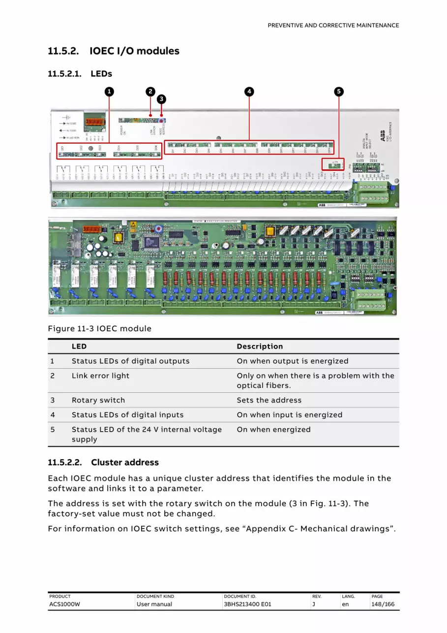
PREVENTIVE AND CORRECTIVE MAINTENANCE
PRODUCT
ACS1000WDOCUMENT KIND
User manualDOCUMENT ID.
3BHS213400 E01REV.
JLANG.
enPAGE
148/166
11.5.2. IOEC I/O modules
11.5.2.1. LEDs
Figure 11-3 IOEC module
11.5.2.2. Cluster address
Each IOEC module has a unique cluster address that identifies the module in the software and links it to a parameter.
The address is set with the rotary switch on the module (3 in Fig. 11-3). The factory-set value must not be changed.
For information on IOEC switch settings, see “Appendix C- Mechanical drawings”.
LED Description
1 Status LEDs of digital outputs On when output is energized
2 Link error light Only on when there is a problem with the optical fibers.
3 Rotary switch Sets the address
4 Status LEDs of digital inputs On when input is energized
5 Status LED of the 24 V internal voltage supply
On when energized
1 23
4 5

PREVENTIVE AND CORRECTIVE MAINTENANCE
PRODUCT
ACS1000WDOCUMENT KIND
User manualDOCUMENT ID.
3BHS213400 E01REV.
JLANG.
enPAGE
149/166
11.6. Corrective maintenanceOverview on maintenance tasks:
– Visual checks on the drive → page 155
– Cleaning the drive → page 156
– Checking wire and cable connections → page 157
– Cleaning and replacing filter mats → page 157
– Inspecting and replacing batteries → page 159
– Replacing the fan inside the water-cooling unit → page 161
– Replacing the redundant fan unit → page 163
– Inspection of cooling system
• Replacing pumps
• Replacing deionizer resin and micro filter
• Replacing fan
• Cleaning strainer
• Replenish water
For more information, see user manual of the water cooling unit in “Appendix A - Additional manuals”.
11.6.1. Safety
DANGER Hazardous voltages!
Before starting to work on the drive, make sure that:
– Main and auxiliary power supply to the drive is switched off, locked out, and tagged out
– Drive is de-energized
– Safety ground connections are in place
– Personal protective equipment is provided and used when required
– Everyone involved is informed
Before energizing the drive again, make sure that:
– All foreign objects are removed from the drive
– All internal and external covers are securely fastened and all doors are closed, locked and / or bolted

PREVENTIVE AND CORRECTIVE MAINTENANCE
PRODUCT
ACS1000WDOCUMENT KIND
User manualDOCUMENT ID.
3BHS213400 E01REV.
JLANG.
enPAGE
150/166
11.6.2. De-energizing the drive locallyThe following section describes how to de-energize the drive using the local operator panel of the drive. If the drive is controlled from remote, follow the established shutdown procedures.
1. Enable the local control mode of the CDP control panel.
For more information, see Chapter 10 CDP control panel
2. Press the stop key.
When the motor has reached zero speed, the display shows Rdy to Strt.
3. Press the MAIN SUPPLY OFF push button to disconnect the drive from the main power supply
The following takes place:
• MCB opens
• DC link discharges for approximately five minutes
While the DC link discharges, the display shows the following.
NOTICE Risk of component damage.
Foreign matter and particularly metallic dust can cause failure and damage when the drive is energized.
Ensure that foreign matter cannot enter the cabinet:
– Close the doors and cover openings completely when work is discontinued.
– Retrieve any foreign matter which accidentally dropped into the cabinet.
Alternating display message:
– Discharging
– CoolOFFDelay
– RdyForMCBon
1 L -> 0.0 rpm 0Status Rdy to Strt MotorSpeed 0.0 rpmPower 0.0 %
1 L -> 600.0 rpm 0Status DischargingMotorSpeed 0.00 rpmPower 0.0 %

PREVENTIVE AND CORRECTIVE MAINTENANCE
PRODUCT
ACS1000WDOCUMENT KIND
User manualDOCUMENT ID.
3BHS213400 E01REV.
JLANG.
enPAGE
151/166
When the DC link has discharged completely, the status line displays RdyforMCBOn and the MAIN SUPPLY OFF push button lights up.
4. Rack-out, lock-out, ground and tag-out the main power feeder.
5. If the grounding switch is equipped with the optional lock (1) that secures the switch in the ungrounded position, unlock the grounding switch.
6. Wait until the yellow lamp GROUNDING SWITCH UNLOCKED lights up.
The lamp lights up when cooling stops after a delay time.
7. If the yellow lamp is on, continue with Section 11.6.3 Grounding.
8. If the yellow lamp is not on, continue with Section 11.6.4 Grounding switch is not released.
1 L -> 0.0 rpmStatus RdyforMCBonMotorSpeed 0.00 rpmPower 0.0%
1

PREVENTIVE AND CORRECTIVE MAINTENANCE
PRODUCT
ACS1000WDOCUMENT KIND
User manualDOCUMENT ID.
3BHS213400 E01REV.
JLANG.
enPAGE
152/166
11.6.3. Grounding1. If the yellow lamp of the GND SWITCH UNLOCKED push button is on, turn the
grounding switch to the grounded position.
When the grounding switch is in the grounded position, the status line of the CDP control panel displays ErthIsoClos.
NOTE – Earth isolator closed = grounding switch is in grounded position.
2. To de-energize the drive completely, switch off and lockout all auxiliary voltages from external sources.
NOTE – To open the doors of medium voltage compartments and additional cabinets of the drive that are equipped with an electromechanical lock, you need to have the auxiliary voltage switched on.
3. If necessary, connect a grounding set.
1 L -> 0.0 rpmStatus ErthIsoClosMotorSpeed 0.00 rpmPower 0.0 %

PREVENTIVE AND CORRECTIVE MAINTENANCE
PRODUCT
ACS1000WDOCUMENT KIND
User manualDOCUMENT ID.
3BHS213400 E01REV.
JLANG.
enPAGE
153/166
11.6.4. Grounding switch is not released
Component location
Figure 11-4 Location of I/O modules and fuses
CAUTION Hazardous voltage!
Forcibly turning the grounding switch before the yellow lamp of the GND SWITCH UNLOCKED push button lights up can short-circuit the energized DC-link capacitors and create a loud bang or damage the grounding switch.
– DO NOT force the grounding switch in any direction before you know the reason why the lamp does not light up.
– To check why the grounding switch is not released, complete the list in Section 11.6.5 Checking the release conditions for the grounding switch.
To identify the components referred to in the check list, see the wiring diagrams and Fig. 11-4.
1) Fuses
2) IOEC1 / -A5191 (standard)
3) IOEC4 / -A5211 (option)
4) IOEC2 / -A5201 (standard)
5) IOEC3 / -A5221 (option)
1
2
3
4
5

PREVENTIVE AND CORRECTIVE MAINTENANCE
PRODUCT
ACS1000WDOCUMENT KIND
User manualDOCUMENT ID.
3BHS213400 E01REV.
JLANG.
enPAGE
154/166
11.6.5. Checking the release conditions for the grounding switch
1) Check that the auxiliary voltage is switched on. 2) Main power supply is disconnected from the drive.
– Check that the MCB is open.
When the MCB is open, secure it against closing.
– Check that the feedback signal "MCB is open" arrives at the drive, ie, if the following indicators are lit:
• LED of digital input DI08 of I/O module -A5201 (-A2) – (LED is not lit) Check the control-signal wiring between switchgear
and drive as per applicable wiring diagram.
• MAIN SUPPLY ON push button -S5152 (-S2)
When the LED and the push button are lit, the feedback signal “MCB is open” has arrived at the drive.
– (Push button is not lit) Check if the 24 V blade-type fuse (X27_P2:14) is blown.The fuse protects the control circuit of the pushbutton.
3) Discharge level of the DC link.
– Check if the value of parameter 2.06 DC VOLTAGE is below 50 V.
When the value is below 50 V, the DC link is regarded as discharged. For information on reading actual values on the CDP control panel, see Section 10.3.2 Actual signals mode.
4) GROUNDING SWITCH UNLOCKED lamp and the wiring of the lamp.
– Check if the CDP control panel displays a fault.
A fault prevents the lamp GROUNDING SWITCH UNLOCKED from lighting.
• If a fault is present, follow the instructions in Section 11.3.4 Standard troubleshooting procedure, before you reset a fault.
• If a fault cannot be rectified and reset, contact the ABB service organization.
– If the CDP control panel does not display a fault, check that digital output DO04 of I/O module -A5191 (-A1) is energized.
• DO04 releases the grounding switch and lights the lamp GROUNDING SWITCH UNLOCKED (–H5152).
• When the LED of DO04 is lit and the control voltage is present at terminals X24:2 and X24:3 of DO04, DO04 is energized.

PREVENTIVE AND CORRECTIVE MAINTENANCE
PRODUCT
ACS1000WDOCUMENT KIND
User manualDOCUMENT ID.
3BHS213400 E01REV.
JLANG.
enPAGE
155/166
IMPORTANT! When the checklist is completed, carefully try to turn the grounding switch to the grounded position. If you cannot turn the grounding switch but doors of medium voltage compartments have to be opened, call the ABB service organization.
11.6.6. Visual checks on the driveCheck the drive and its immediate vicinity visually at the intervals stated in the maintenance schedule and pay attention to the following items:
– Humidity inside the drive
– Permitted range of ambient air temperature and humidity of the drive
– Dust built-up inside the drive
– Appropriate fastening of cables and wires and connections of cable screens
– Integrity of cable insulation
– Signs for overheated components, wires, cables or busbars
– Corrosion on circuit boards, connectors or busbars
– Correct type of signal and power cables
For more information, see the applicable cable specifications.
– If digital output DO04 of the I/O module is not energized, check the I/O module -A5191 (-A1).
To do this, check if the auxiliary voltage is present at the supply terminals of the I/O module.
• X6:1.....24 V (DC)
• X6:2.....0 V
– Check that LED V726 and LED V740 of the I/O module -A5191 are lit.
The LEDs monitor the control voltages of the I/O module (Fig. 11-3).
When the LEDs are lit, the I/O module functions properly.
• LED V726.....24 V (DC)
• LED V740.....5 V (DC)
– If digital output DO04 I/O module -A5191 is energized, check that the control voltage is present at the terminals of the lamp GROUNDING SWITCH UNLOCKED.
• If the control voltage is present but the lamp is not lit, the lamp is burnt out and must be replaced.
• If the control voltage is not present, check the wiring of the lamp. Correct the wiring if necessary.
5) Check that hazardous voltages from the motor cannot be fed into the drive.

PREVENTIVE AND CORRECTIVE MAINTENANCE
PRODUCT
ACS1000WDOCUMENT KIND
User manualDOCUMENT ID.
3BHS213400 E01REV.
JLANG.
enPAGE
156/166
11.6.7. Cleaning the drive
OverviewWhen cleaning the drive, mind the following:
– To prevent dirt falling into equipment, cover the equipment.
The drive contains components which are sensitive to electrostatic discharge. Therefore, take electrostatic-sensitive precautions and use suitable tools.
– Clean circuit boards with special care. To prevent the components being damaged, use antistatic brushes and a vacuum cleaner with a soft nozzle.
– Remove dust on assemblies and busbars inside the cabinet with a vacuum cleaner and lint-free cleaning cloths.
– Remove water, oily or greasy deposits on assemblies, components and busbars with water- and oil-absorbing microfibers such as 3M Scotch Brite.
– Use a nylon brush or a vacuum cleaner for removing dust or deposits from recesses.
– Clean the outside of the cabinet with a vacuum cleaner and cleaning cloths.
NOTICE Risk of component damage.
Dust on electrical components and wiring can cause failure and damage the components. Dust and moisture can build up in loose connections and cause loss of low-level signals.
– Check the cabinet regularly for signs of dust and humidity and clean if necessary.
NOTE – Alcohol and solvents can damage the components.
– Use appropriate and recommended cleansing agents.

PREVENTIVE AND CORRECTIVE MAINTENANCE
PRODUCT
ACS1000WDOCUMENT KIND
User manualDOCUMENT ID.
3BHS213400 E01REV.
JLANG.
enPAGE
157/166
11.6.8. Checking wire and cable connections
11.6.9. Cleaning and replacing filter matsThis section applies to a drive without enclosure cooler in the water cooling compartment.
For information on inspection and replacement intervals, see “ACS1000 preventive maintenance schedule” (3BHS855276 E01).
NOTICE Risk of component damage.
Capacitor bushings are damaged when excessive force is applied.
– DO NOT exceed the maximum tightening torque.
• The tightening torque value is printed on a label which is attached to the capacitor.
• If not specified, the maximum torque must not exceed 20 Nm.
Vibration can loosen electrical connections and cause occasional malfunction or equipment failure.
– Check all power and control cable connections and tighten them if necessary.
– Check that all plugs and connectors are tight.
WARNING Hazardous voltage!
Removing the filter mat while the drive is running can cause serious injury or DEATH.
– Make sure that long, thin objects, such as wires and screwdrivers, DO NOT enter the air intake of a medium voltage compartment. These objects can cause FATAL short-circuits.
– To prevent foreign matter from entering the air intake, DO NOT stop work for lengthy periods.

PREVENTIVE AND CORRECTIVE MAINTENANCE
PRODUCT
ACS1000WDOCUMENT KIND
User manualDOCUMENT ID.
3BHS213400 E01REV.
JLANG.
enPAGE
158/166
Figure 11-5 Cleaning and replacing filter mats
– To remove a filter mat, roll the filter mat from the top down.
– Clean the filter mat with compressed air or a vacuum cleaner away from the drive so that dust cannot enter the drive.
1) Medium voltage compartment 2) Filter mat
Table 11-1 Filter information
Filter type Thickness (mm) Dimensions (mm)
Rittal 3172.100 ~10 22.1 x 22.1
1 1 1 1
2
2

PREVENTIVE AND CORRECTIVE MAINTENANCE
PRODUCT
ACS1000WDOCUMENT KIND
User manualDOCUMENT ID.
3BHS213400 E01REV.
JLANG.
enPAGE
159/166
11.6.10. Inspecting and replacing batteries
Figure 11-6 Control compartment – battery location
11.6.10.1. Checking and replacement indications
The end of the battery life is indicated as follows:
– CDP control panel displays an alarm message.
– Alarm LED on the power supply unit for the battery lights up (3 in Fig. 11-6).
When the end of the battery life is indicated, the drive continues to operate until the time set with parameter 145.26 Batt-Alm.Tim-out has elapsed.
ABB recommends replacing all of the batteries when one battery is at end-of-life.
1) Power supply unit for battery pack 1
2) Power supply unit for battery pack 2
3) Alarm LED
4) Battery pack 2 (option)
5) Battery pack 1
1 2
3
4 5

PREVENTIVE AND CORRECTIVE MAINTENANCE
PRODUCT
ACS1000WDOCUMENT KIND
User manualDOCUMENT ID.
3BHS213400 E01REV.
JLANG.
enPAGE
160/166
11.6.10.2. Replacing a battery
1. When the drive is in operation, disable the battery monitoring function first. To do this, set parameter 31.05 DISABLE BATTERY TEST to ON.
Parameter 31.05 is automatically set to OFF after 1 hour.
2. Disconnect the wires (1).
3. Unscrew the battery at the front (2) and at the back (not shown).
Figure 11-7 Control compartment - replacing the batteries
4. Install the new battery in reverse order of removal.
5. Record the date of battery replacement in the logbook.
CAUTION Heavy object.
Each battery weighs approximately 10 kg .
1 1
2 2 2 2

PREVENTIVE AND CORRECTIVE MAINTENANCE
PRODUCT
ACS1000WDOCUMENT KIND
User manualDOCUMENT ID.
3BHS213400 E01REV.
JLANG.
enPAGE
161/166
11.6.11. Replacing the fan inside the water-cooling unit
– Replacement intervals: see “ACS1000 preventive maintenance schedule” (3BHS855276 E01).
– Estimated working time: ~1 hour
Figure 11-8 Water cooling unit – Replacing the internal fan
CAUTION Heavy object.
The fan weighs approximately 26 kg !
1) Power supply cable
2) Fan housing cover
3) Phillips screwdriver
4) Flat head screwdriver
5) 1/4”
6) 10 mm
21
3
4
5
6

PREVENTIVE AND CORRECTIVE MAINTENANCE
PRODUCT
ACS1000WDOCUMENT KIND
User manualDOCUMENT ID.
3BHS213400 E01REV.
JLANG.
enPAGE
162/166
Procedure1. Disconnect all power supplies to the drive and ground the drive.
For more information, see Section 11.6.2 De-energizing the drive locally.
2. Disconnect and remove the power supply cable from the terminal box (1 in Fig. 11-8) inside the water cooling cabinet.
Figure 11-9 Water cooling unit – replacing the internal fan
3. Unscrew the cover of the fan housing (2 in Fig. 11-8).
4. Unscrew the fixing bolts on the underside of the fan (1 in Fig. 11-9).
IMPORTANT! If the fan is equipped with a baffle blade louver (2 in Fig. 11-9), secure the baffle blade louver against dropping before you remove the bolts.
5. Install the new fan in reverse order of removal.
1) Fixing bolt location
2) Baffle blade louver
3) 1/4”
4) 70 mm
5) 13 mm
1
2
3
4
5

PREVENTIVE AND CORRECTIVE MAINTENANCE
PRODUCT
ACS1000WDOCUMENT KIND
User manualDOCUMENT ID.
3BHS213400 E01REV.
JLANG.
enPAGE
163/166
11.6.12. Replacing the redundant fan unit
– Maintenance intervals: see “ACS1000 preventive maintenance schedule” (3BHS855276 E01).
Figure 11-10 Water cooling unit – replacing the redundant fan – bottom view (A)
Procedure1. Disconnect the power supply cable of the fan in the terminal box
(1 in Fig. 11-10) of the water cooling compartment.
2. Remove the cover (2 in Fig. 11-10).
3. If there is not enough room to lift the fan up, remove the plate in front of the fan (6 in Fig. 11-10).
4. Unscrew the fan from the vibration dampeners (3 in Fig. 11-10).
5. Unscrew the baffle blade louver (4 in Fig. 11-10) and the mounting supports (5 in Fig. 11-10) and attach them to the new fan.Install the new fan in reverse order of removal.
CAUTION Heavy object.
The fan weighs approximately 26 kg !
1) Terminal box
2) Top cover
3) Vibration dampener
4) Baffle blade louver
5) Mounting support
6) Front plate
7) Torx bit for removing top cover
8) 1/4”
9) 13 mm socket for removing vibration dampeners and mounting brackets
12
4
6
3
4
5
5
5
7
8
9
A


—ABB Switzerland Ltd.Bruggerstrasse 66CH-5400 BadenSwitzerland
new.abb.com/drives/medium-voltage-ac-drives
—© Copyright 2009 ABB. All rights reserved. The information in this document is subject to change without notice.
3BH
S21
340
0 E
01
Rev
. J 2
021
-11-
17
/166