Trip Unit Toolkit User Guide - ABB
27
GE Industrial Solutions Trip Unit Toolkit User Guide
-
Upload
khangminh22 -
Category
Documents
-
view
0 -
download
0
Transcript of Trip Unit Toolkit User Guide - ABB
GE
Industrial Solutions
Trip Unit Toolkit User Guide
Trip Unit Tool Kit Last update: April,2019
GE Industrial Solutions ©2019 GE Company All Right Reserved 1
Contents
Installation Requirements ................................................................................................................................................. 2
Hardware ................................................................................................................................................................................. 2
Trip Unit Support ................................................................................................................................................................... 2
Minimum System Requirements ..................................................................................................................................... 3
Features ................................................................................................................................................................................... 3
Title bar ..................................................................................................................................................................................... 3
Device tab ............................................................................................................................................................................... 4
Communication ........................................................................................................................................................................ 4
General Setting ......................................................................................................................................................................... 6
Protection Settings tab ....................................................................................................................................................... 9
Tool bar region ........................................................................................................................................................................ 10
Edit Settings region ............................................................................................................................................................... 12
Settings View region ............................................................................................................................................................. 12
Write Status region ............................................................................................................................................................... 13
Monitor tab .......................................................................................................................................................................... 13
Metering Values ...................................................................................................................................................................... 14
Phasor ......................................................................................................................................................................................... 14
Options Status ......................................................................................................................................................................... 14
Events Log ................................................................................................................................................................................. 15
Breaker Open Time Log ...................................................................................................................................................... 15
Waveform Capture ............................................................................................................................................................... 16
Test tab .................................................................................................................................................................................. 19
Tester Name ............................................................................................................................................................................. 19
Sequence Execution ............................................................................................................................................................. 19
Tested Protections ................................................................................................................................................................. 19
Test Settings ............................................................................................................................................................................. 20
Test Log ...................................................................................................................................................................................... 21
Trip Curve Validation ............................................................................................................................................................ 21
Troubleshooting Guide .................................................................................................................................................... 22
Trip Unit Tool Kit Last update: April,2019
GE Industrial Solutions ©2019 GE Company All Right Reserved 2
Installation Requirements
The Trip Unit Tool kit requires .Net Framework 4.5.1 to be installed for its operation. If the computer is
connected to the internet, the software installer setup file will automatically prompt to download the .Net
framework. For PremEon S and G communication, the USB driver must also be installed and is available in
the installation package.
Hardware
The Trip Unit Tool Kit package requires the GTUTK20 to power and communicate with EntelliGuard trip units.
The GTUTK20 utilizes a serial interface to communicate. For computers without a serial communication port
a USB to RS232 converter can be used.
Note: Some USB –RS232 adaptors have poor drivers for Windows 7 & 8. The following USB – RS232 adaptors
are recommended when being used with the Trip Unit Tool Kit software:
• FTDI Chip (available on DigiKey)
• TRENDnet TU-S9 (available on Amazon)
Trip Unit Support
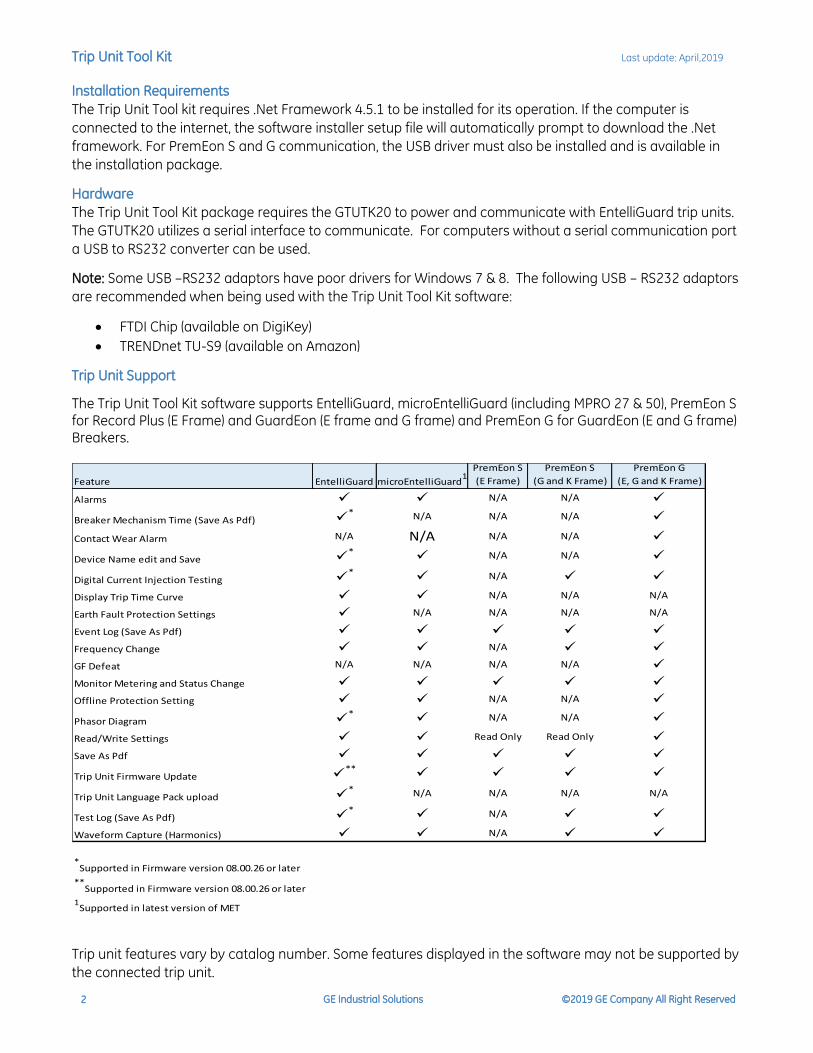
The Trip Unit Tool Kit software supports EntelliGuard, microEntelliGuard (including MPRO 27 & 50), PremEon S for Record Plus (E Frame) and GuardEon (E frame and G frame) and PremEon G for GuardEon (E and G frame) Breakers.
Trip unit features vary by catalog number. Some features displayed in the software may not be supported by
the connected trip unit.
Feature EntelliGuard microEntelliGuard1
PremEon S
(E Frame)
PremEon S
(G and K Frame)
PremEon G
(E, G and K Frame)
Alarms ✓ ✓ N/A N/A ✓
Breaker Mechanism Time (Save As Pdf) ✓* N/A N/A N/A ✓
Contact Wear Alarm N/A N/A N/A N/A ✓
Device Name edit and Save ✓*
✓ N/A N/A ✓
Digital Current Injection Testing ✓*
✓ N/A ✓ ✓
Display Trip Time Curve ✓ ✓ N/A N/A N/A
Earth Fault Protection Settings ✓ N/A N/A N/A N/A
Event Log (Save As Pdf) ✓ ✓ ✓ ✓ ✓
Frequency Change ✓ ✓ N/A ✓ ✓
GF Defeat N/A N/A N/A N/A ✓
Monitor Metering and Status Change ✓ ✓ ✓ ✓ ✓
Offline Protection Setting ✓ ✓ N/A N/A ✓
Phasor Diagram ✓*
✓ N/A N/A ✓
Read/Write Settings ✓ ✓ Read Only Read Only ✓
Save As Pdf ✓ ✓ ✓ ✓ ✓
Trip Unit Firmware Update ✓**
✓ ✓ ✓ ✓
Trip Unit Language Pack upload ✓* N/A N/A N/A N/A
Test Log (Save As Pdf) ✓*
✓ N/A ✓ ✓
Waveform Capture (Harmonics) ✓ ✓ N/A ✓ ✓
*Supported in Firmware version 08.00.26 or later
**Supported in Firmware version 08.00.26 or later
1Supported in latest version of MET
Trip Unit Tool Kit Last update: April,2019
GE Industrial Solutions ©2019 GE Company All Right Reserved 3
Minimum System Requirements
• Windows 7 (Service Pack 1 or higher, x86, x64) / Windows 8 (x86, x64)/Windows 10
• 1 GHz or faster processor
• 1 GB RAM
• 500 MB of available hard disk space
• Video capable of displaying 800x600 or higher in High Color (16-bit)
• Internet Explorer version 10 or above
Features
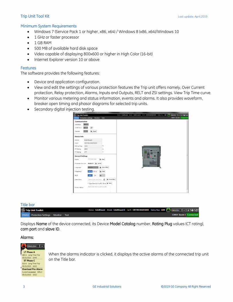
The software provides the following features:
• Device and application configuration.
• View and edit the settings of various protection features the Trip unit offers namely, Over Current
protection, Relay protection, Alarms, Inputs and Outputs, RELT and ZSI settings. View Trip Time curve.
• Monitor various metering and status information, events and alarms. It also provides waveform,
breaker open timing and phasor diagrams for selected trip units.
• Secondary digital injection testing.
Title bar
Displays Name of the device connected, its Device Model Catalog number, Rating Plug values (CT rating),
com port and slave ID.
Alarms:
When the alarms indicator is clicked, it displays the active alarms of the connected trip unit
on the Title bar.
Trip Unit Tool Kit Last update: April,2019
GE Industrial Solutions ©2019 GE Company All Right Reserved 4
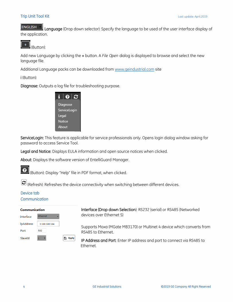
Language (Drop down selector): Specify the language to be used of the user interface display of
the application.
(Button):
Add new Language by clicking the + button. A File Open dialog is displayed to browse and select the new
language file.
Additional Language packs can be downloaded from www.geindustrial.com site
i (Button):
Diagnose: Outputs a log file for troubleshooting purpose.
ServiceLogin: This feature is applicable for service professionals only. Opens login dialog window asking for
password to access Service Tool.
Legal and Notice: Displays EULA information and open source notices when clicked.
About: Displays the software version of EntelliGuard Manager.
(Button): Display “Help” file in PDF format, when clicked.
(Refresh): Refreshes the device connectivity when switching between different devices.
Device tab
Communication
Interface (Drop down Selection): RS232 (serial) or RS485 (Networked
devices over Ethernet S)
Supports Moxa (MGate MB3170) or Multinet 4 device which converts from
RS485 to Ethernet.
IP Address and Port: Enter IP address and port to connect via RS485 to
Ethernet.

Trip Unit Tool Kit Last update: April,2019
GE Industrial Solutions ©2019 GE Company All Right Reserved 5
COM Port (Drop down selection): Specify the PC’s COM port number to
connect the device via serial (RS232), using the drop-down selector. Hit
refresh to show the current used com ports.
Slave Id (Drop down selection): Specify the MODBUS Slave Id of the device,
using the drop-down selector.
Apply (Button): Click the “Apply” button to confirm the COM Port / IP
Address and Slave Id selection to establish the communication with trip
unit.
Device Info/Device Selection
When connected to a device: Displays the type of the device
connected, e.g. EntelliGuard / MET/PremEon S/ PremEon G.
Device Type (Read only field):
When not connected to a device: Specify the type of the device, for which to create a Settings file, using the
drop-down selection.
Catalog number (Read only field):
When connected to a device: Displays the catalog number of the device connected, by reading from the
device, if the connected device has a catalog number already available.
Rating Plug (Read only field):
When connected to a device: Displays the Rating Plug value of the device connected, by reading from
the device.
CT Rating (Read only field):
When connected to a device: Displays the CT Rating value of the device connected, by reading from
the device.
Note: User cannot change the CTRating and Frame Rating via RS-485 for Mpro conversion kits (EntelliGuard-L
breakers). It can only be changed via RS-232 (front port) communication.
Trip Unit Tool Kit Last update: April,2019
GE Industrial Solutions ©2019 GE Company All Right Reserved 6
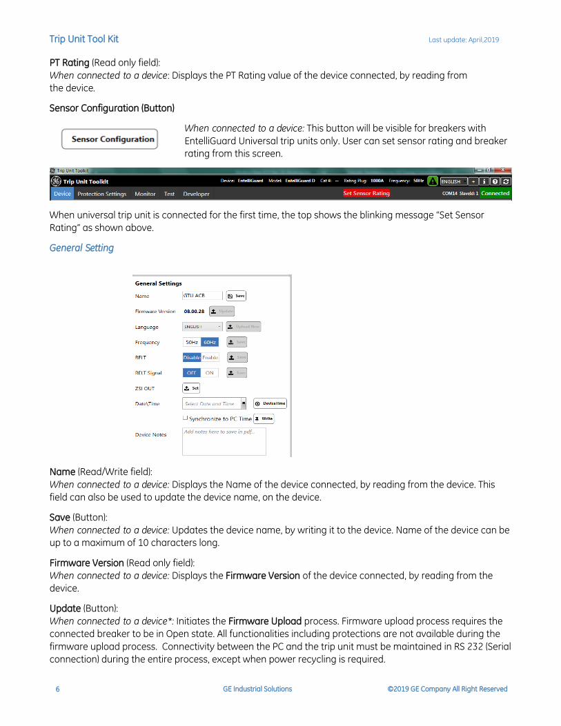
PT Rating (Read only field):
When connected to a device: Displays the PT Rating value of the device connected, by reading from
the device.
Sensor Configuration (Button)
When connected to a device: This button will be visible for breakers with
EntelliGuard Universal trip units only. User can set sensor rating and breaker
rating from this screen.
When universal trip unit is connected for the first time, the top shows the blinking message “Set Sensor
Rating” as shown above.
General Setting
Name (Read/Write field):
When connected to a device: Displays the Name of the device connected, by reading from the device. This
field can also be used to update the device name, on the device.
Save (Button):
When connected to a device: Updates the device name, by writing it to the device. Name of the device can be
up to a maximum of 10 characters long.
Firmware Version (Read only field):
When connected to a device: Displays the Firmware Version of the device connected, by reading from the
device.
Update (Button):
When connected to a device*: Initiates the Firmware Upload process. Firmware upload process requires the
connected breaker to be in Open state. All functionalities including protections are not available during the
firmware upload process. Connectivity between the PC and the trip unit must be maintained in RS 232 (Serial
connection) during the entire process, except when power recycling is required.

Trip Unit Tool Kit Last update: April,2019
GE Industrial Solutions ©2019 GE Company All Right Reserved 7
*When connecting to a device that was previously erased but no firmware was loaded the connection
indicator will show orange disconnected but firmware upload is functional to load the selected firmware file.
Before selecting firmware file in this case, make sure you have selected appropriate device type and frame in
device info/device selection area.
Follow below process:
1. Specify the PC’s COM port number to connect the device via serial (RS232), using the COM port drop
down selector.
2. Select Modbus Slave ID as 1, using the Slave ID drop down selector.
3. Select the device type using device type drop down and continue Firmware upload process.
Note: Firmware update is unavailable if Modbus/Slave ID is not set to 1. Firmware update is unavailable via
RS485 connection. User should ensure that the trip unit is connected either via RS232(Serial) to
EntelliGuard/microEntelliGuard breakers and via micro-USB for PremEon breakers before initiating a
firmware update.
For PremEon G devices, do not unzip the firmware file folder, provide the path of the zip folder as it is
received by us.
Language (Drop down selection):
When connected to a device: Displays the selected Language of the device connected that used on its LCD
display, by reading from the device. Language can be changed by selecting a new language from the drop-
down menu.
Upload New (Button):
When connected to a device: Initiates the Language Upload process. The language upload process requires the
connected device to be in Open state. All functionalities including protections are not available during the
language upload process. Connectivity between the PC and the trip unit must be maintained in RS 232 9Serial
connection) during the entire process. This is supported only by selected EntelliGuard trip units with firmware
version 08.00.26 later.
Frequency (Read/Write field):
When connected to a device: Indicates the frequency of the device. Click on the desired frequency and click
Save to update the frequency.
Note: PremEon G Trip Unit resets when frequency is updated. Protections are not available during reset.
Certain Trip units that are optioned for other than 50 Hz/ 60 Hz frequency will not display frequency option on
the user interface.
RELT (Reduced Energy Let Through):
When connected to a device: This feature offered in selected *EntelliGuard and 1microEntelliGuard trip units. If
the connected device has valid catalog number and device is optioned with RELT, RELT feature can be
Enabled/Disabled via Modbus Communication.
* Supported in firmware version 08.00.26 or later
1 Supported in the latest version of microEntelliGuard.
Trip Unit Tool Kit Last update: April,2019
GE Industrial Solutions ©2019 GE Company All Right Reserved 8
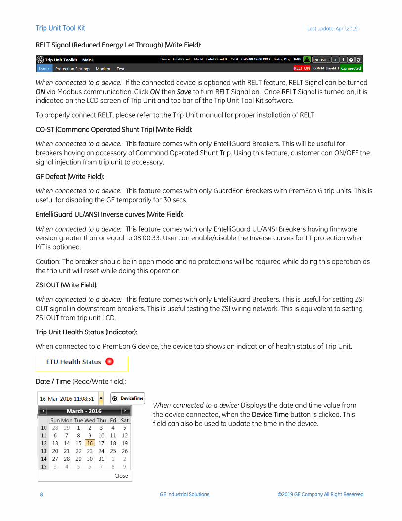
RELT Signal (Reduced Energy Let Through) (Write Field):
When connected to a device: If the connected device is optioned with RELT feature, RELT Signal can be turned
ON via Modbus communication. Click ON then Save to turn RELT Signal on. Once RELT Signal is turned on, it is
indicated on the LCD screen of Trip Unit and top bar of the Trip Unit Tool Kit software.
To properly connect RELT, please refer to the Trip Unit manual for proper installation of RELT
CO-ST (Command Operated Shunt Trip) (Write Field):
When connected to a device: This feature comes with only EntelliGuard Breakers. This will be useful for
breakers having an accessory of Command Operated Shunt Trip. Using this feature, customer can ON/OFF the
signal injection from trip unit to accessory.
GF Defeat (Write Field):
When connected to a device: This feature comes with only GuardEon Breakers with PremEon G trip units. This is
useful for disabling the GF temporarily for 30 secs.
EntelliGuard UL/ANSI Inverse curves (Write Field):
When connected to a device: This feature comes with only EntelliGuard UL/ANSI Breakers having firmware
version greater than or equal to 08.00.33. User can enable/disable the Inverse curves for LT protection when
I4T is optioned.
Caution: The breaker should be in open mode and no protections will be required while doing this operation as
the trip unit will reset while doing this operation.
ZSI OUT (Write Field):
When connected to a device: This feature comes with only EntelliGuard Breakers. This is useful for setting ZSI
OUT signal in downstream breakers. This is useful testing the ZSI wiring network. This is equivalent to setting
ZSI OUT from trip unit LCD.
Trip Unit Health Status (Indicator):
When connected to a PremEon G device, the device tab shows an indication of health status of Trip Unit.
Date / Time (Read/Write field):
When connected to a device: Displays the date and time value from
the device connected, when the Device Time button is clicked. This
field can also be used to update the time in the device.
Trip Unit Tool Kit Last update: April,2019
GE Industrial Solutions ©2019 GE Company All Right Reserved 9
Write (Button):
When connected to a device: Select the date from calendar and enter the time values in text fields and click
the write button, date and time information is updated in the connected device.
Synchronize to PC Time (Check box):
When connected to a device: Synchronizes the time value of the device connected with the PC’s time, by
writing the time info provided by the Operating System of the PC to the device, when the Write button is
clicked.
Note: If a trip unit has operational battery, date and time will not reset once the unit is disconnected from self
or auxiliary power.
Device Notes (Edit box) User notes can be typed in the text box. These notes will be saved in the pdf when
Save as Pdf is clicked in the protection Settings tab.
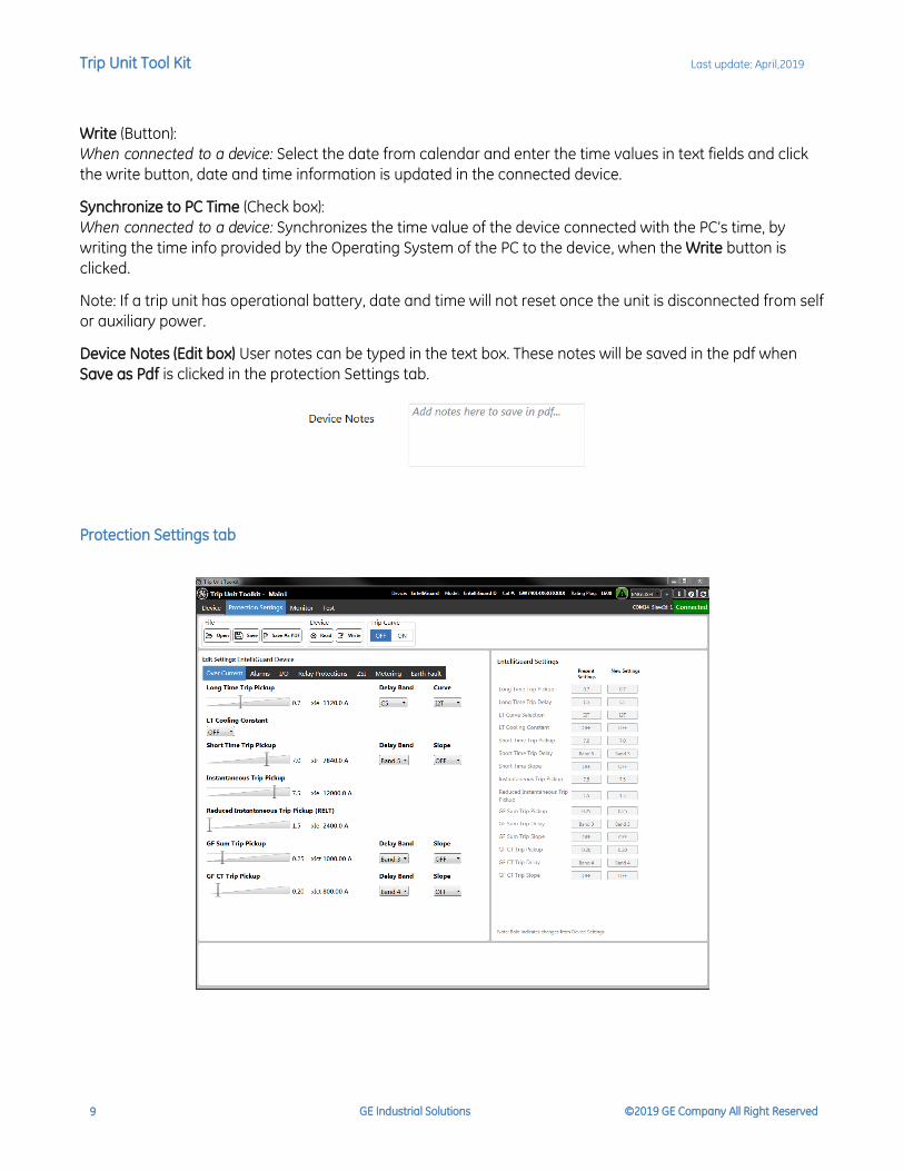
Protection Settings tab

Trip Unit Tool Kit Last update: April,2019
GE Industrial Solutions ©2019 GE Company All Right Reserved 10
Tool bar region
File tool bar
Open (Button): Displays a File Open dialog to select a Settings file to be opened, and upon a Settings file
selection, displays all the setting values from the selected Settings file corresponding to the Over Current
Protection, Relay Protection, I/O s, RELT, Alarms, ZSI, Metering and Earth Fault settings in the edit region (left
side of the screen) and the present and new settings view region (Right side of the screen).
Save (Button): Displays a File Save dialog to specify the name of the Settings file to be created and creates a
new Settings file with chosen name in XML format, by copying all the settings from the Settings Edit region to
the created file. A Settings file thus created can be opened by the application by using the Open button.
Save As PDF (Button): Displays a File Save dialog to specify the name of the Settings file to be created and
creates a new Settings file with chosen name in PDF format, by copying all the settings from the Settings Edit
region to the created file.
Device tool bar
Read (Button): Reads all the setting values corresponding to the Over Current Protection, Relay Protection, I/O
s, RELT, Alarms, ZSI, metering and Earth Fault settings from the device connected, and updates in both the
settings edit region and the settings view region. A busy indicator will be displayed while the Read operation
is in progress.
Write (Button): Writes to the device connected, the setting values that were changed in the Over Current
Protection, Relay Protection, I/O s, RELT, Alarms, ZSI and metering settings tabs in the Settings Edit region. A
busy indicator will be displayed while the Write operation is in progress.
OFF (Button): Turns off the trip time curve.
ON (Button): Provides a graphic representation of protection parameters L, S, I and G of the connected trip
unit. Both edit and current settings curves are displayed.
- Individual protection settings (Long time, short time, instantaneous, Ground Fault and RELT) on the
graph can be turned on/off for the new and present settings of the trip unit for viewing purpose only.
Trip Unit Tool Kit Last update: April,2019
GE Industrial Solutions ©2019 GE Company All Right Reserved 11
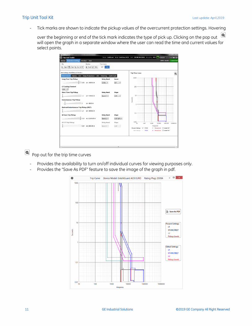
- Tick marks are shown to indicate the pickup values of the overcurrent protection settings. Hovering
over the beginning or end of the tick mark indicates the type of pick up. Clicking on the pop out will open the graph in a separate window where the user can read the time and current values for select points.
Pop out for the trip time curves
- Provides the availability to turn on/off individual curves for viewing purposes only.
- Provides the “Save As PDF” feature to save the image of the graph in pdf.

Trip Unit Tool Kit Last update: April,2019
GE Industrial Solutions ©2019 GE Company All Right Reserved 12
Edit Settings region
Displays the setting values corresponding to the various Protections functions in Over Current, Alarms, RELT,
I/O, Relay Protections, ZSI, metering and Earth Fault tabs.
The setting values can be modified by using various user interface elements on these tabs like sliders, drop
down boxes and combo buttons. An asterisk (*) symbol will be displayed on the tab when there are any
changes between the current settings and device settings to mark the modification. The asterisk symbol
disappears when the modified values are saved to the trip unit by clicking on Write button.
If the trip unit is not optioned with a feature, it will be disabled or grayed on the user interface.
Note: If a Trip unit is optioned with switchable protections, to turn off a feature in EntelliGuard / MET, click
OFF from Delay Band drop down. For PremEon G, click OFF next to the protection label.
Also for PremEon G units, if I4T is selected in LT Curve, ST K cannot be set and will be disabled and will have a
default value OFF.
Whenever you a see a difference in the present settings and new settings after a device write operation,
chances are that the changes you have done for some settings has changed other dependent settings in the
device. You can review those changes as those are highlighted and click on read device settings to sync all
the current and new settings.
If you see anything red in the edit settings region, it means the value that is loaded from a file is not in the
range acceptable, change the setting and write it device.
Settings View region
Displays the setting values corresponding to the tab selected on the Edit Settings region - among the tabs
are Protections functions in Over Current, Alarms, RELT, I/O, Relay Protections, ZSI and metering.
When a setting value in the Edit Settings region is modified, its corresponding entry in the New settings (Right
hand side) would be highlighted in bold. Side by side comparison of the present and new setting provides the
user with better visual of the intended changes to the trip unit. The highlighting disappears when the
modified values are written to the device connected by clicking on the Write button from the Device Tool bar.

Trip Unit Tool Kit Last update: April,2019
GE Industrial Solutions ©2019 GE Company All Right Reserved 13
Write Status region
When connected to the trip unit, displays informative messages regarding the settings updates and status of
on-going communication activity.
Monitor tab
Status (Read only): Displays status information about various data items in the connected device like Voltage,
Measured Frequency, Breaker status (Open/Close), RELT Status, ZSI Status, trip total since reset, power
direction and Energy total etc.

Trip Unit Tool Kit Last update: April,2019
GE Industrial Solutions ©2019 GE Company All Right Reserved 14
Metering Values
Metering (Read Only): Displays various metering data like Currents, Voltages, Power and Power Factor for
different phases. Also, displays the PT system configuration (Star or Delta). The user can select to view real,
reactive or apparent power from the selection box.
Note: For PremEon G trip units, Total Harmonic Distortion (THD) for voltages and currents are shown as
percentage.
Phasor
When clicked on the Phasor
button, a pop out screen displays
the phasor of the signals,
voltages, currents, Power factor
(%), phase angles and
assumptions about lead and lag
are displayed.
When individual phases of a three-phase system differ, an unbalance results, the measure of unbalance is calculated and is represented as a percentage. When the unbalance is above 15% it is highlighted in red.
Options Status
Displays the optioning status of various features for the connected device like, Over Current protection, Relays protection, Input and Output lines and Relay status.
Trip Unit Tool Kit Last update: April,2019
GE Industrial Solutions ©2019 GE Company All Right Reserved 15
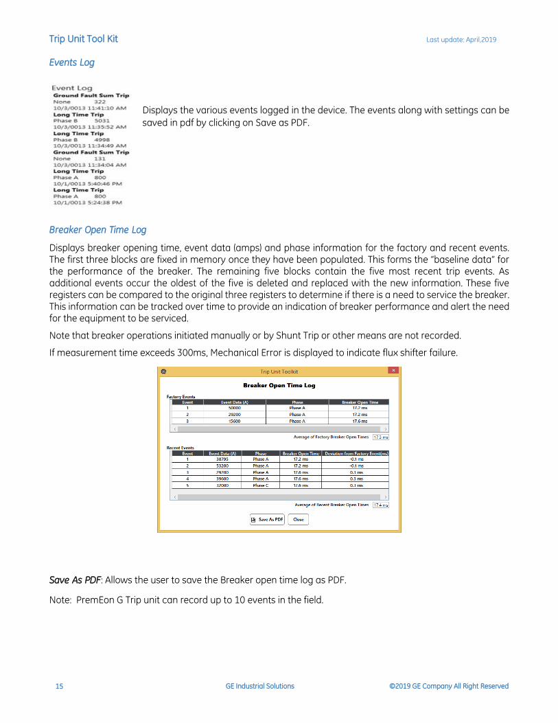
Events Log
Displays the various events logged in the device. The events along with settings can be
saved in pdf by clicking on Save as PDF.
Breaker Open Time Log
Displays breaker opening time, event data (amps) and phase information for the factory and recent events. The first three blocks are fixed in memory once they have been populated. This forms the “baseline data” for the performance of the breaker. The remaining five blocks contain the five most recent trip events. As additional events occur the oldest of the five is deleted and replaced with the new information. These five registers can be compared to the original three registers to determine if there is a need to service the breaker. This information can be tracked over time to provide an indication of breaker performance and alert the need for the equipment to be serviced.
Note that breaker operations initiated manually or by Shunt Trip or other means are not recorded.
If measurement time exceeds 300ms, Mechanical Error is displayed to indicate flux shifter failure.
Save As PDF: Allows the user to save the Breaker open time log as PDF.
Note: PremEon G Trip unit can record up to 10 events in the field.

Trip Unit Tool Kit Last update: April,2019
GE Industrial Solutions ©2019 GE Company All Right Reserved 16
Waveform Capture
Clear (button): Clears the waveform capture data in the connected device.
Trigger (button): Triggers the waveform capture in the connected device. The device captures the complete
waveform data and stores in device memory.
View (button): Reads waveform capture data from the connected device and plots the waveform in viewable
format in new Waveform viewer screen.
Load (button): Loads the existing COMMTRADE waveform capture data from the selected path and plots the waveform in viewable format in new Waveform viewer screen. Settings (Radio Button): Displays the trigger type available that can be selected from the list. Select the
trigger type and click on Save
Status: Displays the waveform capture data availability in connected device.
GREEN: Waveform data available in device.
RED: Waveform data not available in device.

Trip Unit Tool Kit Last update: April,2019
GE Industrial Solutions ©2019 GE Company All Right Reserved 17
Waveform Viewer screen
Load (button): Loads the existing COMMTRADE waveform capture data and plots the waveform in viewable
format in new Waveform viewer screen.
Save (button): Saves the waveform in COMMTRADE format at selected path.
Save Harmonics (button): Saves the Harmonics calculation data in csv format at selected path.
Close (button): Closes the Waveform viewer screen.
Filter: Toggles the selected phase for plotting of waveform.
Zooming the waveform
Waveform can be zoomed out by selecting the portion of curve with the help of mouse click and drag.
Scroll bar
Scroll bar below waveform is used to navigate through the zoomed waveform.

Trip Unit Tool Kit Last update: April,2019
GE Industrial Solutions ©2019 GE Company All Right Reserved 18
Reset Zoom
When the waveform is zoomed-out, Reset Zoom is shown. By clicking this button, zoom is reset.
Delta between Cursors
Displays the time and voltage/current differences between the two cursors selected by the user.
Harmonics
Harmonics (Check box)
Acts as a toggle switch to show either Harmonics data or Delta between Cursors.
When Checked, the wave form viewer shows harmonics data when clicked on the waveform from the cursor
position to the next full cycle waveform.
When unchecked, shows delta between cursors when two cursors are selected by the user.
Harmonics Pop-up
Shows the bar graph showing the harmonics content of the waveform from the selected cursor point to next
full cycle of waveform. The harmonics are shown from 2nd harmonic to 25th harmonic data.

Trip Unit Tool Kit Last update: April,2019
GE Industrial Solutions ©2019 GE Company All Right Reserved 19
Short Time Delay Selection
When Connected to device: This feature offered in Premeon
S (G Frame) trip units with the firmware version 17.00.15 or
later.
If the trip unit is not optioned with ST feature, it will be hidden
on the user interface.
If the Short Time Selection is set to “ON”, allows user to
configure Short Time Delay and Short Time Slope settings
and modified values are written to device by clicking on the
write button.
If the Short Time Selection is “OFF”, Short Time Delay and
Short Time Slope selection will be hidden or disabled on the
user interface.
Test tab
Tester Name
Maximum 30 characters can be specified as tester name. This is used for log purposes only.
Clear Thermal Memory
When Connected to device: This feature offered in EntelliGuard and microEntelliGuard trip
units only. Allows user to clear thermal memory if optioned already.
Sequence Execution
Allows the user to queue up multiple tests in a row at user defined current for digital injection.
Tested Protections
Over Current : Enables or disables the Over Current protection test functionality on the device.
GF Sum : Enables or disables the GF Sum protection test functionality on the device.
Trip Unit Tool Kit Last update: April,2019
GE Industrial Solutions ©2019 GE Company All Right Reserved 20
Test Settings
Current: Allows the user to set the currents for the different phases.
No Trip: The breaker will not trip when No Trip test is selected. The observed trip time is the algorithm timing
plus a constant mechanism timing of the breaker.
Trip Test: When Trip test is selected, it will check for the breaker position to ensure it is closed. Observed trip
time includes the actual breaker transition t and algorithm time.
Note: In case aux switch is not installed, Trip test will send a signal to trip the breaker but might show “Error:
Breaker did not trip due to Mechanical error” as it has no feedback. User needs to ensure that the breaker
tripped and reclose before the next trip test in the queue.
In case when the breaker position is detected as open, a message is displayed asking the user to close the
breaker to continue the sequence tests.
Load: Loads an Xml file of previously created test sequences.
Save: Saves the current test queue in XML file for later use.
Add to Queue: After choosing the currents, click on Add to Queue to add the tests in the sequence. Any
modification to the currents requires the user to click on Add to Queue to add the test.
Clear Queue: Clears the test queue.
Start: When enable, click to start the tests in the queue. Start will be disabled and the tests will not be
allowed to run due to the following reasons:
- Active currents are flowing
- Test already in progress or no tests added to queue
- Device does not support this functionality
- Device is not connected
Stop: Stops the test currently being executed and reports Test Interrupted by user in observed trip time area.
If no tests are running, Stop is disabled.
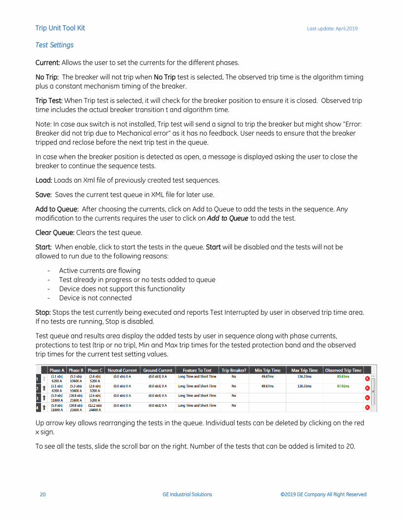
Test queue and results area display the added tests by user in sequence along with phase currents,
protections to test (trip or no trip), Min and Max trip times for the tested protection band and the observed
trip times for the current test setting values.
Up arrow key allows rearranging the tests in the queue. Individual tests can be deleted by clicking on the red
x sign.
To see all the tests, slide the scroll bar on the right. Number of the tests that can be added is limited to 20.
Trip Unit Tool Kit Last update: April,2019
GE Industrial Solutions ©2019 GE Company All Right Reserved 21
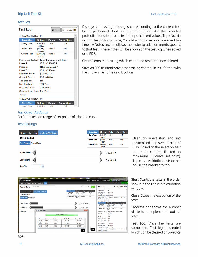
Test Log
Displays various log messages corresponding to the current test
being performed, that include information like the selected
protection functions to be tested, input current values, Trip / No trip
setting, test initiation time, Min / Max trip times, and observed trip
times. A Notes section allows the tester to add comments specific
to that test. These notes will be shown on the test log when saved
as a PDF.
Clear: Clears the test log which cannot be restored once deleted.
Save As PDF (Button): Saves the test log content in PDF format with
the chosen file name and location.
Trip Curve Validation
Performs test on range of set points of trip time curve
Test Settings
User can select start, end and
customized step size in terms of
0.1X. Based on the selection, test
queue is created (limited to
maximum 30 curve set point).
Trip curve validation tests do not
cause the breaker to trip.
Start: Starts the tests in the order
shown in the Trip curve validation
window.
Close: Stops the execution of the
tests
Progress bar shows the number
of tests complemeted out of
total.
Test Log: Once the tests are
completed, Test log is created
which can be cleared or Saved as
PDF.
Trip Unit Tool Kit Last update: April,2019
GE Industrial Solutions ©2019 GE Company All Right Reserved 22
Troubleshooting Guide
1. The program does not start up after install
a) Verify NET Framework 4.5.1 installed (see below)
2. The Program starts up but displays close program dialog box
a) If you have Digital Guardian agent (Formerly VERDASYS) installed, it will conflict with the
EntelliGuard Manager application. Please contact your IT department to have EntelliGuard
manager whitelisted in Digital Guardian
3. Program starts but I cannot get it to connect, Disconnected indicator red
a) Close and Restart the program
4. Program starts but I cannot get it to connect, Disconnected indicator Orange
a) Verify USB to RS232 COM port address
b) Are the Slave Ids matching (Device & Software)?
c) Confirm installation of USB – RS232 drivers
d) Is the USB – RS232 a recommended adaptor?
5. During digital injection, my actual time exceeds the specification limits?
Some variance is expected due to breaker wear and injection timing. The specification limits are
determined by the trip curves. If there is a deviation from the specification limits, inspect the breaker
wiring. Mechanism timing is determined by the auxiliary switch (during a trip test) and added to the
trip time. Service to the switch may be required.
6. Waveform window is blank
View or loading of waveform requires IE 10 or above.
7. Harmonics check box is not visible.
When the waveform data is not proper this may lead to exceptions in the calculation of harmonics
and hence not visible.
8. I am connected via RS485 but cannot upload firmware or languages to the trip unit.
Firmware and language upload currently is not supported via the Rs485 communication. Please
connect via RS232 (Serial connection, front port) for this feature.
9. Display Trip Time curve ON is disabled
Reasons for the Trip curve ON is disabled is listed below based on the Trip unit type:
PremEon G
o Not supported in current release.
PremEon S
o Device not Connected o Incorrect catalog number or no catalog number: Please go to Device tab and enter catalog
number in the Cat # field under the Device info o Currently Trip Time curve is available only for UL Standard o Relevant protection options are not enabled in the Trip unit.
Trip Unit Tool Kit Last update: April,2019
GE Industrial Solutions ©2019 GE Company All Right Reserved 23
GTU
o Supported only for EntelliGuard G Breakers
o Not supported when Inverse curves is selected for LT Curve
o Device not connected
o Incorrect Frame and Sensor Rating
o No rating plug
o Relevant protection options are not enabled in the trip unit
10. Observed Trip time is showing Error: Breaker did not trip due to mechanical error
a. Ensure that the auxiliary switch is installed properly. If it is still showing error, inspect the switch
and flux shifter is functional.
b. If the user has old test kit and does not have self-power breaker, then trip test will give error in
observed trip time.
11. I am connected to the trip unit (shows green connect on the upper right hand corner) but cannot see
Trip unit settings
We have seen this issue with the prolific RS232 to USB converter drivers. Please update the drive and
connect again.
12. Intermittent disconnections and connection stable while connected to a RS-485 network.
Check if you have more than one trip unit in the RS-485 network with the same slave Id. Ensure to
assign different slave Id for each trip unit when connected in a network either via RS-485 or Serial to
Ethernet Connectors.
13. Breaker position showing as N/A for PremEon G breakers.
Breaker position doesn’t work if you don’t have ICM module connected to the trip unit.
14. Firmware upload failed for PREMEON G/GR.
Recycle the power to the trip unit by turning off all the power sources like aux power and unplug the
USB and connect it again and then turn on the aux power and then re-try.
Verification of .NET Framework 4.5.1 requirements:
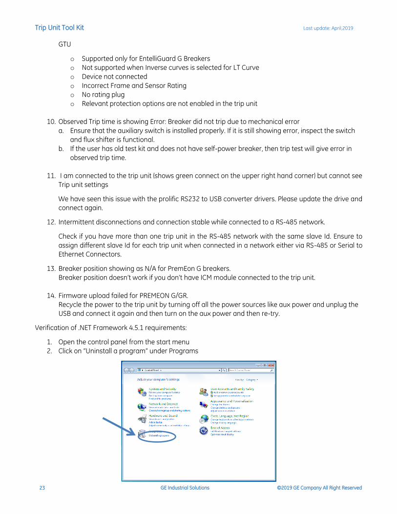
1. Open the control panel from the start menu
2. Click on “Uninstall a program” under Programs
Trip Unit Tool Kit Last update: April,2019
GE Industrial Solutions ©2019 GE Company All Right Reserved 24
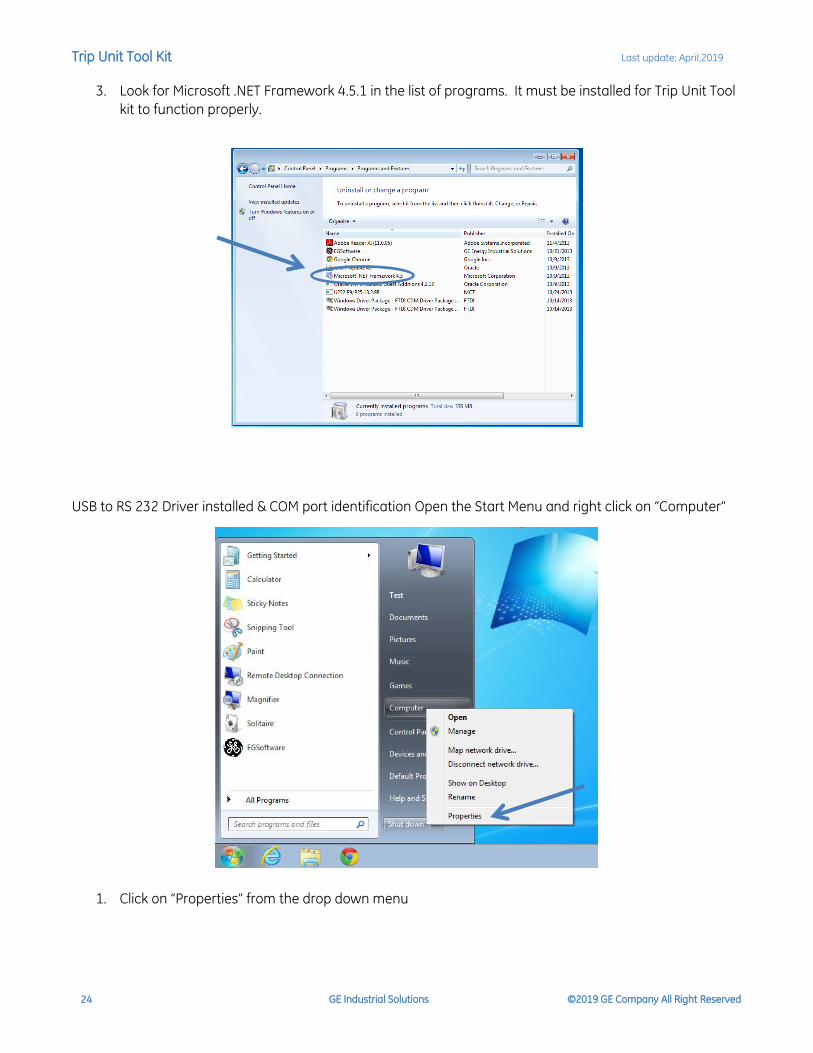
3. Look for Microsoft .NET Framework 4.5.1 in the list of programs. It must be installed for Trip Unit Tool
kit to function properly.
USB to RS 232 Driver installed & COM port identification Open the Start Menu and right click on “Computer”
1. Click on “Properties” from the drop down menu
Trip Unit Tool Kit Last update: April,2019
GE Industrial Solutions ©2019 GE Company All Right Reserved 25
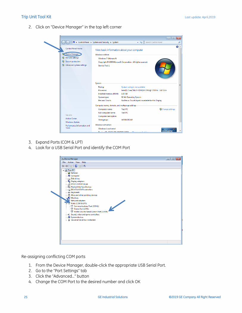
2. Click on “Device Manager” in the top left corner
3. Expand Ports (COM & LPT)
4. Look for a USB Serial Port and identify the COM Port
Re-assigning conflicting COM ports
1. From the Device Manager, double-click the appropriate USB Serial Port.
2. Go to the “Port Settings” tab
3. Click the “Advanced…” button
4. Change the COM Port to the desired number and click OK

Trip Unit Tool Kit Last update: April,2019
GE Industrial Solutions ©2019 GE Company All Right Reserved 26
GE Industrial Solutions 41 Woodford Avenue Plainville, CT 06062 www.geindustrial.com © Copyright GE Industrial Solutions 2019
Information provided is subject to change without notice. Please verify all details with GE. All values are design or typical values when measured under laboratory conditions, and GE makes no warranty or guarantee, express or implied, that such performance will be obtained under end-use conditions.
DEE-689C (04/19)