Instruction manual Blast chillers EN 5 Trays - cloudfront.net
24
Instruction manual Blast chillers EN 5 Trays - 10 Trays - 15 Trays - 30 Trays
-
Upload
khangminh22 -
Category
Documents
-
view
1 -
download
0
Transcript of Instruction manual Blast chillers EN 5 Trays - cloudfront.net

Instruction manual
Blast chillers EN
5 Trays - 10 Trays - 15 Trays - 30 Trays
ENG
LISH
2 71503136-0-R000
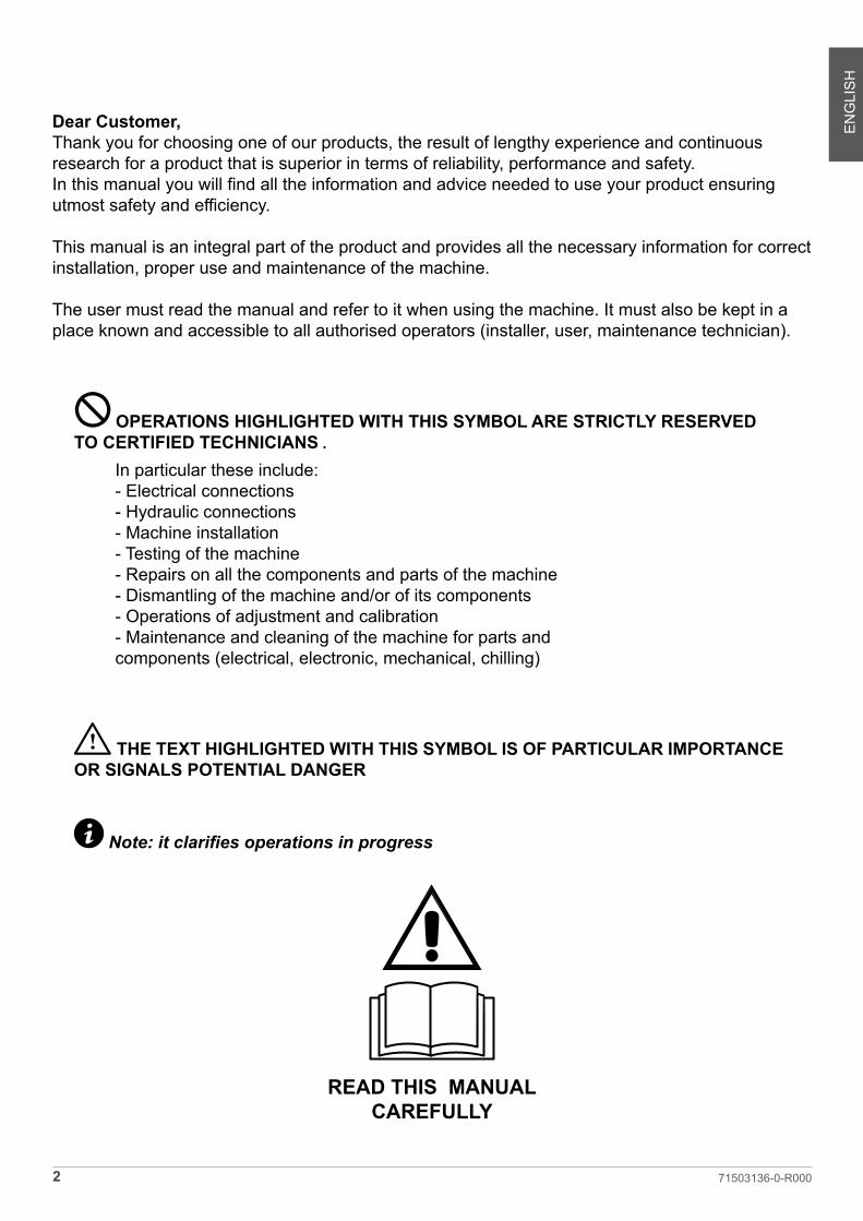
Dear Customer,Thank you for choosing one of our products, the result of lengthy experience and continuous research for a product that is superior in terms of reliability, performance and safety. In this manual you will find all the information and advice needed to use your product ensuring utmost safety and efficiency.
This manual is an integral part of the product and provides all the necessary information for correct installation, proper use and maintenance of the machine.
The user must read the manual and refer to it when using the machine. It must also be kept in a place known and accessible to all authorised operators (installer, user, maintenance technician).
1 OPERATIONS HIGHLIGHTED WITH THIS SYMBOL ARE STRICTLY RESERVED TO CERTIFIED TECHNICIANS .
In particular these include:- Electrical connections- Hydraulic connections- Machine installation- Testing of the machine- Repairs on all the components and parts of the machine- Dismantling of the machine and/or of its components- Operations of adjustment and calibration- Maintenance and cleaning of the machine for parts and components (electrical, electronic, mechanical, chilling)
I THE TEXT HIGHLIGHTED WITH THIS SYMBOL IS OF PARTICULAR IMPORTANCE OR SIGNALS POTENTIAL DANGER
i Note: it clarifies operations in progress
READ THIS MANUAL CAREFULLY

ENG
LISH
3 71503136-0-R000
TABLE OF CONTENTS
1 WARNINGS AND IMPORTANT ADVICE ................................52 TECHNICAL DATA ..................................................................6
2.1 Plate data .......................................................................62.2 Refrigerant .........................................................................62.3 Measurements ...................................................................6
3 INSTALLATION .......................................................................83.1 Transportation and handling ..............................................83.2 Unpacking and disposal .....................................................83.3 Positioning ..........................................................................83.4 Ambient temperature and air exchange .............................93.5 Hydraulic connection for water cooled condensing units ...93.6 Electrical connection ..........................................................93.7 Remote group refrigerator connection ..............................93.8 Condensate drainage connection (if applicable) ................93.9 Notes for the installer .......................................................103.10 Commissioning ...............................................................103.11 Safety and control systems ............................................103.12 Stop modes ....................................................................103.13 Signalling/reports of malfunctioning ...............................103.14 Waste electrical and electronic equipment WEEE (not valid for fixed installations) .............................................................10
4 COMMAND INTERFACE SYMBOLS ...................................115 MACHINE ON/OFF ...............................................................12
5.1 Compressor preheating management ..............................126 DATE AND TIME SETTING ...................................................127 BLAST CHILLING CYCLES ..................................................12
7.1 General operating principles ............................................12Chilling Time ������������������������������������������������������������������������12
Temperature Chilling �����������������������������������������������������������12
Chilling and storage status symbols �����������������������������������12
7.2 Chilling phases .................................................................137.3 Selecting and starting the Positive chilling cycle .............137.4 Selection and starting the Negative chilling cycle ............137.5 Storage phase ..................................................................14
8 DEFROST MODE ..................................................................149 DRYING WITH MACHINE AT STANDSTILL .........................1410 DOOR OPENING ...............................................................1511 OZONATOR ........................................................................1512 ICE-CREAM CYCLE ...........................................................1513 DEFROST CYCLE ..............................................................15
14 CHILLING PROGRAM STORAGE ......................................1615 CHILLING PROGRAM EXECUTION ..................................1616 ALARMS ..............................................................................16
16.1 Evaporator probe alarm ................................................1616.2 Product probe alarm .......................................................1716.3 Cell probe alarm ............................................................1716.4) Door micro-switch alarm ...............................................1716.5 Alarm - Differential Thermal Breaker - Oil Pressure .......1716.6 Automatic reset minimum pressure switch alarm 16.6. .1716.7 Automatic reset Kriwan Alarm ......................................1816.8 Input alarm HT1 - fusable ...............................................1816.9 Overtemperature alarm ................................................1816.10 Black-Out Alarm ..........................................................1816.11 Compressor preventative maintenance alarm .............1816.12 Temperature not reached in the time set alarm ............1916.13 Power keypad-card connection alarm ..........................1916.14 Maximum pressure switch alarm ................................19
17 HACCP ALARM MEMORIES RESET ................................1918 HACCP DATA READING ....................................................1919 HACCP DATA EXPORT WITH USB ....................................20
19.1 Extracted data format .....................................................2019.2 Data downloading with USB ...........................................20
20 ORDINARY MAINTENANCE ..............................................2120.1 Operations by the user that do not require the assistance of a qualified technician ..........................................................21
20�1�1 Cell cleaning �������������������������������������������������������������21
20�1�2 Outer casing cleaning �����������������������������������������������21
20�1�3 Defrost water drainage ����������������������������������������������21
20.2 Operations that must be performed by an authorised installer ...............................................................................................21
20�2�1 Condenser cleaning ��������������������������������������������������21
20�2�2 Condenser filter cleaning ������������������������������������������21
20�2�3 Evaporator cleaning ��������������������������������������������������21
20�2�4 Ozonator maintenance ����������������������������������������������21
21 TIPS FOR SMOOTH OPERATION .....................................2221.1 Operating instructions ....................................................2221.2 Pre-cooling .....................................................................2221.3 Loading of the machine .................................................22

ENG
LISH
4 71503136-0-R000
1 WARNINGS AND IMPORTANT ADVICE
IThis manual is an integral part of the product and provides all the necessary information for correct installation, proper use and maintenance of the machine.
In the event of sale or transfer of the appliance, this manual must be handed over to the new user.
The user must read the manual and refer to it when using the machine. It must also be kept in a place known and accessible to all authorised op-erators (installer, user, maintenance technician).
The manufacturer does not accept any contractual or non-contractual liability for damage caused by incorrect installation, misuse or failure to comply with the applicable national and local regulations and the instructions provided by the same manu-facturer.
Carefully read this manual before installing and using the appliance. In particular pay attention to the safety warnings. Be sure to only use the installation components supplied or specified.
IThe machine is designed for professional use and therefore only qualified persons may use it.
The machine is only intended for the use for which it was designed, namely for the freezing and storage of foodstuffs. Excluded are prod-ucts that require constant temperature moni-toring and recording, such as thermo-reagent chemicals, medicines and blood products
The manufacturer declines all responsibility for any damage caused by improper or un-reasonable use, such as misuse by untrained personnel, technical modifications or inter-ventions not specific for the models or non-compliance, even partial, with the instructions in this manual
Do not store explosives, such as pressurised containers with flammable propellant, in this
appliance
ATTENTION: Do not use electrical appliances inside the appliance compartments for the storage of frozen foods if they are not of the type recommended by the manufacturer
For appliances with a water condensing sys-tem the maximum inlet water temperature must not exceed 35°CThe maximum load per shelf is 25 Kg
Do not touch the machine with damp or wet hands or feetDo not operate the appliance with bare feet
Do not insert screwdrivers, cooking utensils or other items between the guards and the moving parts
Before carrying out cleaning or ordinary main-tenance operations, disconnect the machine from the mains by means of the on/off switch (if present also turn off the main switch of the machine)
Do not pull the power cable to disconnect the machine from the mainsIt is prohibited to use the appliance in environ-ments with flammable gases and in areas with the risk of explosion.
Check correspondence of the plate data and the specifications of the electrical power line (V, KW, Hz, no. of phases and power available)
Installation of the appliance and of the remote refrigerating unit (if any) must only be carried out by the manufacturer or by skilled techni-cians

ENG
LISH
5 71503136-0-R000
2 TECHNICAL DATA2.1 Plate data
The plate bearing the equipment specifications should be applied on the outside rear part of the machine and/or on the electrical panels. Any preparation of machines only for relo-cation of the condensing units must follow the regulations in force in the country of installation regarding fire safety (refer to the command of the local fire department for the relevant indications). It should also be considered that the possible intervention of safety valves or fusible plugs, located in the refrigerant circuit, entail the immediate discharge of all the refrigerant into the environment. Code Model
Age IP
S/N V A W Gas Kg CO2 eq
L’apparecchio contiene gas fluorurati ad effetto serra - Ermeticamente sigillatoThe equipment contains fluorinated green-house gases - Hermetically sealed
The appliance's climate class is stated on the serial plate
Environmental climatic classes (ISO 23953-2)Climate class Temperature Humidity
1 16°C 80%2 22°C 65%3 25°C 60%4 30°C 55%5 40°C 40%6 27°C 70%
ModelloModelsModèlesModelleModelos
AlimentazionePower supply
Source de courantEnergieversorgungFuente de alimen-
tación
RefrigeranteRefrigerant
Fluide frigorigèneKühlgas
Fluido refrigerante
Carica refrigerante Refrigerant chargeCharge de fluide
frigorigèneKältemittelfüllung
Carga de refrigerante(Kg)
GWP
Ciclo Abbattimento Positivo - Chilling Cycle - Cycle ChillingKühlzyklus - Ciclo de enfriamiento
Ciclo Abbattimento Negativo - Freezing Cycle - Cycle de Congélation - Gefrierzyklus - Ciclo de congelación
Ciclo temperat.Temp. Cycle
Cycle de temp.TemperaturzyklusCiclo de temperat.
(°C)
CapacitàCapacityCapacitéKapazität
Capacidad(Kg)
Durata cicloCycle time
Temps de cycleTaktzeit
Tiempo de ciclo(min)
Consumo EnergiaEnergy Consumpt.
Conso. EnergieEnergieverbrauchCons. de energía
(kWh/Kg)
Ciclo temperat.Temp. Cycle
Cycle de temp.TemperaturzyklusCiclo de temperat.
(°C)
Durata cicloCycle time
Temps de cycleTaktzeit
Tiempo de ciclo(min)
CapacitàCapacityCapacitéKapazität
Capacidad(Kg)
Consumo EnergiaEnergy Consumpt.
Conso. EnergieEnergieverbrauchCons. de energía
(kWh/Kg)
5.20 A 220-240V/50Hz R404A 1,27 3922 +65° / +10° 19,2 98 0,099 +65° / -18° 14,4 268 0,384
5.20 W 220-240V/50Hz R404A 1,27 3922 +65° / +10° 19,2 98 0,099 +65° / -18° 14,4 268 0,384
10.35 A 400V/3N/50Hz R404A 2,20 3922 +65° / +10° 37,6 93 0,116 +65° / -18° 27,1 269 0,315
10.35 W 400V/3N/50Hz R404A 1,80 3922 +65° / +10° 37,6 93 0,116 +65° / -18° 27,1 269 0,315
15.40 A 400V/3N/50Hz R404A 2,20 3922 +65° / +10° 43,2 94 0,093 +65° / -18° 32,2 265 0,350
15.40 W 400V/3N/50Hz R404A 2,00 3922 +65° / +10° 43,2 94 0,093 +65° / -18° 32,2 265 0,350
15.65 A 400V/3N/50Hz R404A 2,50 3922 +65° / +10° 62,4 100 0,089 +65° / -18° 50,6 262 0,288
15.65 W 400V/3N/50Hz R404A 2,00 3922 +65° / +10° 62,4 100 0,089 +65° / -18° 50,6 262 0,288
15.2/70 A 400V/3N/50Hz R404A 2,50 3922 +65° / +10° 72,0 105 0,082 +65° / -18° 55,2 267 0,271
15.2/70 W 400V/3N/50Hz R404A 2,00 3922 +65° / +10° 72,0 105 0,082 +65° / -18° 55,2 267 0,271
REGOLAMENTO (UE) 2015/1095 REGULATION (EU) 2015/1095 VERORDNUNG (EU) 2015/1095 RÈGLEMENT (UE) 2015/1095REGLAMENTO (UE) 2015/1095

ENG
LISH
6 71503136-0-R000
2.2 Refrigerant
The appliance contains fluorinated greenhouse gases covered by the Kyoto Protocol in the quantities indi-cated on the serial plate.The type of refrigerant gas present in the refrigerant circuit of the appliance is shown on the serial plateThe GWP (global warming potential) of the HFC R134a gas is 1430 and of the HFC R404A gas it is 3922.The system is hermetically sealed:The CO2 equivalent data is shown on the serial plate
IAccording to Regulation (EC) 1272/2008, R134a and R404A gases are non-flamma-ble and non-toxic. In high concentrations they can be asphyxiating. Contact with liquid may cause burns and frostbite.In the system the gas is pressurised; it may explode if heated.
5 Trays
2.3 Measurements

ENG
LISH
7 71503136-0-R000
10 Trays
15 Trays
30 Trays

ENG
LISH
8 71503136-0-R000
3 INSTALLATION
1 ALL STAGES OF INSTALLATION MUST BE CAR-RIED OUT IN COMPLIANCE WITH THE NATIONAL STANDARDS IN FORCE ACCORDING TO THE MANU-FACTURER'S INSTRUCTIONS AND BY PROFESSION-ALLY QUALIFIED PERSONNEL
Installation of the appliance and of the refrigerating unit must only be carried out by technicians of the manufacturer or by skilled personnel.If the machine was supplied with a remote condensing unit, it is the installer's responsibility to check all the connections in accordance with the instructions provided for the instal-lation of systems and machinery.The installer is advised to use the appropriate personal protective equipment necessary for processing and in compliance with the regulations in force.
3.1 Transportation and handling
The net and gross weight of this appliance can be found on the external packaging.Loading and unloading of the appliance and/or of the sub-systems from the means of transport can be performed using a forklift truck or fork pallet truck, the length of which is more than half that of the unit or using cranes where the appliance/subsystem is fitted with eyebolts. The lifting equip-ment must be chosen according to the size of the packaged machine/components and with sufficient capacity.For handling of the appliance/subsystems, every precaution must be taken not to damage them, respecting the indica-tions on the packaging.
3.2 Unpacking and disposal
Remove all cardboard or the wooden crate from the base on which the machine is placed. Then lift the machine/sub-assemblies with a suitable means (forklift truck); remove the wooden base and position the machine/sub-assemblies in the place provided.After removing the packaging, verify the integrity of the machine/sub-assemblies In case of uncertainty do not use it and contact the distributor.
Remove the protective PVC film on the stainless steel pan-els from all sides both internally and externally.
iNote: all the various components of the packaging must be disposed of according to the regulations in force in the country where the appliance is being used� In any case nothing must be disposed of into the environment�
3.3 Positioning
The appliance:• must be installed in places where it can be checked by qualified personnel.• it must not be installed outdoors.• it must not be installed in dusty environments.• it must not be placed in locations with the presence of water jets.• it must not be washed with water jets.• It must be installed and tested in full compliance with safety laws, traditional systems and with the regu-lations in force.• it must be positioned at a minimum distance of 120 mm from the rear wall
The installer must verify any requirements for fire safety (refer to the command of the local fire department for the relevant indications).
Level the appliance through adjustment of the feet. For the setting up of heavier machines, use dedicated hoists (fig. A - Chap. 3.1).If the appliances are not levelled their functioning and the flow of condensates could be impaired.
fig. A

ENG
LISH
9 71503136-0-R000
I Avoid locations exposed to direct sunlight, indoor envi-ronments at high temperatures and poor air circulation and avoid installing the machine near any heat sources
3.4 Ambient temperature and air exchange
For air cooled liquid chillers, the ambient operating temperature must not exceed 32°C. Above this tem-perature the declared performance is not guaranteed. The machine can operate safely up to a temperature that is referred to by the climatic class indicated on the serial plate. Remote condensing units must be installed in special rooms or, if outdoors, in a place protected from direct sunlight, from adverse weather conditions and from heavy wind (above 5 m/sec. Where circumstances so require, it is the responsibility of the installer to evaluate the use of a cover or canopy (costs to be borne by the purchaser). In any case sufficient air circulation must be guaranteed.
3.5 Hydraulic connection for water cooled condensing units
It is advisable to install a valve between the mains and the appliance's inlet hose in order to be able to stop the pas-sage of water if necessary.For appliances with water cooled units the water supply temperature must be between 10°C (50°F) and 30°C (86°F) and the operating pressure must be between 0.1 MPa (1 bar - 14psi) and 0.5 MPa (5 bar - 72 psi)
3.6 Electrical connection
I No responsibility is accepted for damage to per-sons, animals or property caused by failure to earth the appliance and the creation of an electrical installation that does not comply with current standards.The mains connection must be made according to existing national rules and by experienced, qualified personnel.Before connecting the appliance to the mains make sure that the mains voltage corresponds to the voltage indicated
on the data plate.Verify that the electrical installation is adequate to the maximum power of the appliance, as indicated on the plate.Upstream of each device it is mandatory to install a differ-ential thermal breaker according to current regulations in the country of installation.The electric connecting cables must be dimensioned in ac-cordance with the rules in force in the country of installation.In cases where the power cord of the appliance is damaged, it must be replaced with another with characteristics that comply with the rules in force in the country of installation and performed by qualified personnel in order to prevent any risk to persons.The earthing conductor must be correctly connected to an efficient earthing system.
The manufacturer declines any responsibility and any war-ranty obligation in the event of damage to the equipment, to persons and to property caused by incorrect installation and/or failure to respect the applicable laws.
3.7 Remote group refrigerator connection
The diameters of the supply lines of the equipment are sized for distances of up to 10 meters.Contact the manufacturer for longer distances.
3.8 Condensate drainage connection (if ap-plicable)
It is necessary to provide a drainage pipe for the condensa-tion and washing water of a minimum diameter of 1".It is advisable to dispose of the condensate through an open drain at ground level and fitted with a siphon with a minimum diameter of 1/2 "

ENG
LISH
10 71503136-0-R000
3.9 Notes for the installer • Verify the correct installation and system testing before starting up the machine (test report)• Check for any gas leaks from the welds or joints made during the installation phase.• Check the efficient insulation of the connecting pipes between the condenser and the remote condensing unit.• Check the electrical connection• Check the electrical input• Verify the standard pressures of the refrigerating sys-tem.• Check the water connections with adjustment of the pressure valve during operation and good circulation of the condensation water (water cooled groups).
3.10 Commissioning
I Commissioning must be carried out by authorised and qualified personnel.
Perform at least one complete cycle of rapid storage freezing (to reach the SET temperature), and a manual defrost cycle. If the equipment or the remote condensing units were de-livered in an upright position (e.g. on their back) or were overturned during installation, do not turn on immediately but wait at least 4 hours before use.Inform the customer of the exact use of the equipment with specific reference to the use and to customer requirements.
3.11 Safety and control systems
• Door microswitch: this locks operation of the fans in the cell when the door is opened• General protection fuses: they protect the entire power circuit against short circuits and possible overloads.• Compressor thermal relay: this intervenes in case of overloads or malfunctions• Safety pressure switch: this operates in the case of excess pressure in the refrigerant circuit• Fusible plug: this intervenes in the case of overpressure and failure of the afore-mentioned safety pressure switch • Chamber temperature control: this is operated by the electronic card via the probe positioned inside the cell• Defrost termination temperature control: this is man-aged by the electronic card via the probe located on the evaporator.
3.12 Stop modes
In an emergency, to stop the machine remove power from the main panel using the earthing switch or by removing the plug from the socket making sure hands are not wet
or damp.
3.13 Signalling/reports of malfunctioning
In cases of malfunction of the machine and for report signal-ling concerning the blast chillers supplied:
Assembled You are requested to communicate to the retailer/service centre the machine model, code and the serial number shown on the registration plate located on the rear of the machine and inside the door.
Dismantled (with condensing units/remote condensers)You are requested to communicate to the retailer/service centre the machine model and the code shown on the reg-istration plate located above the control panel.
3.14 Waste electrical and electronic equipment WEEE (not valid for fixed installations)
The following information applies to EU Member States.The crossed out wheelie bin symbol indicates that this product cannot be disposed of as household waste.Ascertaining that this product is disposed of correctly will help prevent potential negative consequences for the envi-ronment and human health that might otherwise be caused by incorrect disposal of the same.
ENG
LISH
11 71503136-0-R000
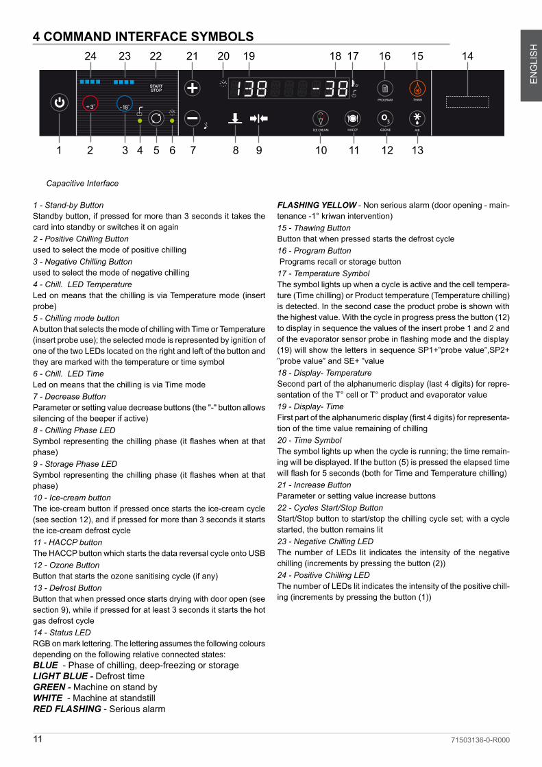
Capacitive Interface
1 - Stand-by ButtonStandby button, if pressed for more than 3 seconds it takes the card into standby or switches it on again2 - Positive Chilling Buttonused to select the mode of positive chilling3 - Negative Chilling Buttonused to select the mode of negative chilling4 - Chill� LED TemperatureLed on means that the chilling is via Temperature mode (insert probe)5 - Chilling mode button A button that selects the mode of chilling with Time or Temperature (insert probe use); the selected mode is represented by ignition of one of the two LEDs located on the right and left of the button and they are marked with the temperature or time symbol6 - Chill� LED TimeLed on means that the chilling is via Time mode7 - Decrease ButtonParameter or setting value decrease buttons (the "-" button allows silencing of the beeper if active)8 - Chilling Phase LEDSymbol representing the chilling phase (it flashes when at that phase)9 - Storage Phase LEDSymbol representing the chilling phase (it flashes when at that phase)10 - Ice-cream buttonThe ice-cream button if pressed once starts the ice-cream cycle (see section 12), and if pressed for more than 3 seconds it starts the ice-cream defrost cycle11 - HACCP buttonThe HACCP button which starts the data reversal cycle onto USB12 - Ozone ButtonButton that starts the ozone sanitising cycle (if any)13 - Defrost ButtonButton that when pressed once starts drying with door open (see section 9), while if pressed for at least 3 seconds it starts the hot gas defrost cycle14 - Status LEDRGB on mark lettering. The lettering assumes the following colours depending on the following relative connected states:BLUE - Phase of chilling, deep-freezing or storageLIGHT BLUE - Defrost time GREEN - Machine on stand byWHITE - Machine at standstillRED FLASHING - Serious alarm
FLASHING YELLOW - Non serious alarm (door opening - main-tenance -1° kriwan intervention)15 - Thawing ButtonButton that when pressed starts the defrost cycle 16 - Program Button Programs recall or storage button 17 - Temperature SymbolThe symbol lights up when a cycle is active and the cell tempera-ture (Time chilling) or Product temperature (Temperature chilling) is detected. In the second case the product probe is shown with the highest value. With the cycle in progress press the button (12) to display in sequence the values of the insert probe 1 and 2 and of the evaporator sensor probe in flashing mode and the display(19) will show the letters in sequence SP1+”probe value”,SP2+ ”probe value” and SE+ ”value18 - Display- TemperatureSecond part of the alphanumeric display (last 4 digits) for repre-sentation of the T° cell or T° product and evaporator value19 - Display- TimeFirst part of the alphanumeric display (first 4 digits) for representa-tion of the time value remaining of chilling20 - Time SymbolThe symbol lights up when the cycle is running; the time remain-ing will be displayed. If the button (5) is pressed the elapsed time will flash for 5 seconds (both for Time and Temperature chilling)21 - Increase ButtonParameter or setting value increase buttons22 - Cycles Start/Stop ButtonStart/Stop button to start/stop the chilling cycle set; with a cycle started, the button remains lit23 - Negative Chilling LEDThe number of LEDs lit indicates the intensity of the negative chilling (increments by pressing the button (2)) 24 - Positive Chilling LEDThe number of LEDs lit indicates the intensity of the positive chill-ing (increments by pressing the button (1))
4 COMMAND INTERFACE SYMBOLS
O3OZONE
THAW
AIR
PROGRAM
HACCPICE CREAM
1 2 3 4 5 6 7 8 9 10 11 12 13
1418 17 16 1522 21 20 192324

ENG
LISH
12 71503136-0-R000
• Chilling phase (limited duration) • Storage phase (unlimited period).
The chilling phase starts upon pressing of the "Start/Stop" button (22) and continues until the end of the chilling phase that is used to achieve the time set (Time chilling) or for reaching of the product temperature set (Temperature chill-ing); changing to the unlimited duration storage cycle takes place automatically (except for the HARD+HARD negative chilling cycle). It is possible to stop the chilling or storage at any time by pressing the "Start/Stop" button (22).
Chilling Time
During this type of chilling, the display (18) shows the cell probe temperature while the other display (19) shows the time remaining at the end of the chilling phase. The Time chilling LED (6) is lit as is the time symbol (20).
Temperature Chilling
If Temperature chilling is selected, at the start of a cycle a check is performed of the correct insertion of the product probe (if enabled). If the test provides a negative result an alert appears on the display “SONDA NON INSERITA - PROBE NOT INSERT” and the beeper sounds for 60 seconds (parameter c9); that symbol disappears when the beeper is silenced by pressing the button (7). If instead the button is pressed again (5) switching to Temperature cycle, the cycle continues based on the data read by the the product probe. If nothing is pressed, the temperature cycle automatically switches into a Time cycle for the remaining duration of the countdown.
During this type of chilling, a display (18) will show the temperature of the probe (the highest value of the two) and the other (19) will show a countdown. The countdown only starts when the insert temperature is less than 65°C. The temperature chilling LED (4) is on as is the probe insert symbol (17).
Chilling and storage status symbols
During chilling the LED that lights the symbol will be lit and flashing. Upon completion of chilling, this LED flashes al-ternately with the LED located beneath the storage symbol (8) while the beeper sounds for 60 sec, and the scrolling text appears “End Cycle - Fine ciclo”. After this time, the chilling LED (9) switches off, the storage one starts flashing (8) and the scrolling text disappears (even when the beeper silencer button (7)) is pressed
5 MACHINE ON/OFF
When the equipment is powered, it will appear in STANDBY conditions (scrolling text on the display). To start the ma-chine press the button (1) for at least 3". Similar to machine without cycles in progress, to switch it off simply press the button (1) for at least 3".
Where a cycle was in progress, and the situation is return-ing from a blackout the appliance, once reconnected, will resume from the interrupted cycle.
5.1 Compressor preheating management
Upon ignition of the equipment a compressor preheating time of 120 minutes must be respected where the blast chiller is not available.The scrolling text will appear “Compressor Heating-Riscal-damento Compressore” and then the fixed lettering "XXX min" to represent the time remaining. These two messages will alternate until the end of heating. This phase can be bypassed by pressing the "HACCP" (11) button for approxi-mately 5 seconds.
6 DATE AND TIME SETTING
Upon initial ignition, it is advisable to check the date and time set; their accuracy is beneficial in relation to HACCP management.To access the clock setting, press for more than 5 sec the Temperature/Time button (5) with the machine in Stop mode. The Labels shown below will appear on the left dis-play; the right display will show the 2-digit numeric value to be set:
Hour(Ora) / Minute(Minuti) / Day(Giorno) / Month(Mese) / Year(Anno)
The Temperature/Time button (5) can be used to scroll through the Labels, while with the +/-buttons (21/7) it is possible to change the values.After the year value the change will be automatically saved
7 BLAST CHILLING CYCLES
7.1 General operating principles
Pre-cooling of the machine should always be performed upon initial running of a blast chilling or deep freezing operation. This optimises the subsequent work cycle, reducing the time.
Blast chillers are refrigeration systems that work with a two-phase cycle:

ENG
LISH
13 71503136-0-R000
The LED (8) will flash when the compressor is on while if the set value has been reached, they will only remain lit until transition to storage. Similarly with storage, the LED (9) will flash when the compressor is active and will remain lit for the rest of the storage.
7.2 Chilling phases
Pressing the positive chilling button (2) or negative chilling button (3) allows selection of a different chilling mode. The number of LEDs lit (23) or (24) define the "intensity" of chill-ing. The "Time" or "Temperature" chilling mode will be set by pressing the button (5). Lighting up of the corresponding LEDs on the sides will define the type of chilling
Each time the positive chilling button (2) is pressed the display will show successively for 3 seconds one of the following cycles: LIGHT, SOFT, MEDIUM, FAST
Each time the negative chilling button (3) is pressed the display will show successively for 3 seconds one of the following cycles: LIGHT, SOFT, HARD, RUN
7.3 Selecting and starting the Positive chilling cycle
When the button (2) is pressed for the first time,"SOFT" mode will be selected, represented with lighting up of two of the four LEDs (24); subsequent pressing takes to 3 and 4 the LEDs lit and results in the "HARD" mode. Successive pressing reduces from 4 to 1 the LEDs lit and so on.
“LIGHT” - 1 LED only onIn this condition, there will be a cell temperature set of -3°C. This avoids the risk of ice formation during the positive chilling phase and it will be used for loads which can be damaged by excessively heavy treatment (vegetables etc.)
“SOFT” - 2 LEDs on (Default)In this condition, there will be a cell temperature set of -5°C. This set will allow quicker chilling for products that in any case are fairly resistant to the freezing process.
“MEDIUM” - 3 LEDS onIn this condition, there will be an initial cell temperature set of -20°C; after the HARD time, this will be taken to a cell temperature of -3°C. This method accelerates cooling in the presence of products that are resistant and very hot initially.
“FAST” - 4 LEDs on In this condition, there will be an initial cell temperature set
of -20°C; after the HARD time, this will be taken to a cell temperature of -5°C. This method accelerates cooling in the presence of products that are resistant and very hot initially.
With the MEDIUM or FAST temperature chilling, the set change will be decided by the product temperature detected according to the parameter (Cd).
Once the MEDIUM or FAST cycles are started, to modify the HARD phase duration simply press the button (2) that will show on the display (19) the words "Hard" and will result in flashing on the display (18) the value in minutes of the HARD phase. With the +/- buttons it is possible to increase or decrease this value and confirm with the button (2) or wait 5 seconds (N.B. THE CHANGED VALUE ONLY APPLIES TO THE CYCLE IN PROGRESS).
Once the cycle is selected, it is necessary to select the Time or Temperature mode by pressing the button (5) until coming on of the relevant LED�
At this point to start the cycle press the START/STOP button (22)
In the event of Temperature chilling, it is possible to change this chilling end value by pressing the button (2) or (3) de-pending on the type of chilling in progress. Having pressed the button, the display (19) will show the lettering "Set" and on the display (18) will appear the value of the end chilling temperature set, which can be modified within the envis-aged range. Having pressed the button (2) or (3) or after 5 seconds the changed value is saved.
7.4 Selection and starting the Negative chill-ing cycle
Pressing the button (3) for the first time will select the "HARD" mode, represented by coming on of three of the four LEDs (23) present. Subsequent pressing will take to 4 the LEDs lit and will return into “RUN+HARD” mode. Suc-cessive presses reduce from 4 to 1 the LEDs and so on.
“LIGHT” - 1 LED only onIn this condition, there will be an initial cell temperature set of -5°C; after the SOFT time defined by the parameter (ts) this will move to a temperature of -30°C. This mode is for use on large pieces where it is important to homogenise the chilling cycle.
ENG
LISH
14 71503136-0-R000
“SOFT” - 2 LEDs on In this condition, there will be an initial cell temperature set of -20°C; after the SOFT time defined by the parameter (ts) this will move to a temperature of -30°C. This mode is for use on large pieces where it is important to homogenise the chilling cycle.
In the case of SOFT or LIGHT temperature chilling, the set change will be decided by the product temperature detected according to the parameter (C2).
Once the cycle to change the duration of the SOFT phase is started (never greater than the parameter C4) simply press the button (3) which will show on the display (19) the wording "Soft" and on the display (18) the value in minutes of the SOFT phase. With the +/- buttons, it is possible to increase or decrease this value and confirm it with the but-ton (3) or wait for 5 seconds (N.B. THE CHANGED VALUE ONLY APPLIES TO THE CYCLE IN PROGRESS).
In the case of temperature chilling, the set change will be decided by the product temperature detected (see param-eter cd)
"HARD"-3 LEDs on (Default)In this condition and in the absence of adjustments 0/10V of the compressor, there will be a set of cell temperature of -40°C. This set accelerates the freezing process in the pres-ence of products that do not require particular preparation.
"RUN" - 4 LEDs on flashing In this condition and in the absence of adjustments 0/10V of the compressor, there will be a set of cell temperature of -40°C. This set accelerates the freezing process in the pres-ence of products that do not require particular preparation. In this case then the deep-freezing cycle will be continuous without moving into storage. The move to storage will be performed by pressing the button (3) and reducing the LEDs from 4 to 3. That process should be used in continuous in-sertion and extraction condition produced by the blast chiller.During negative chilling, the compressor stops when the air temperature reaches the planned set point. In this cycle there will NOT BE automatic defrosting.
- Probes value reading
With the cycle in progress, pressing the button (12) will show in sequence, after the cell probe value, the values of the insert probe 1 and 2 and the evaporator probe in flash-ing mode on the display (18) while on the display (19) will appear the wording in sequence of SP1, SP2, and SE that represent the type of probe being displayed.
7.5 Storage phase
Storage always takes over and automatically after every
chilling event (apart from the negative RUN+HARD excep-tion) and keeps the product at the storage temperature of +2°C or -25°C, depending on the type of chilling.These values will be editable in all cases by pressing the button (2) or (3). It is possible to change during the stor-age phase the temperature set which appears flashing on the display (18), while on the display (19) the wording SET appears. To adjust the value (within 6 seconds) press the buttons +/-.
8 DEFROST MODE"Gas-hot" or "air" defrosting takes place:- in automatic mode only during the storage phase and with a default time of 8 hours that is editable;- manually both with machine in storage and with machine in STOP (not during chilling) by pressing the defrost button (13). All defrosting in progress can be interrupted by press-ing the defrost button.
Duration of the defrost cycle is given by reaching the defrost end temperature measured by the evaporator probe; there is in any case a maximum length for defrost after which defrosting ends automatically.Whenever possible, namely during the cycles of chilling, of ice-cream hardening, of storage, defrosting in storage and defrosting at machine standstill, it is possible to view the evaporator probe temperature by pressing the button (12): the display will show for 5 seconds the wording “S.EV + valore”.Manual defrosts cannot be activated in the event that the value of the evaporator probe is higher than a certain temperature value, in which case a series of beeps will be emitted to alert the user to the fact that it is not possible to defrost and the wording "NoDefrost" will appear for 5 seconds.
9 DRYING WITH MACHINE AT STAND-STILL
When the machine is stopped by pressing the button (13) for more than 3 sec, ventilation will be activated for a maximum time of 20 minutes (either with door open or closed). Dur-ing this function the LED flashes and the display shows the scrolling text "Air Defrost". To exit from this function press (short press) the defrost button (13). This mode is used when the machine is at a standstill for air defrost or to dry the machine after cleaning.
10 DOOR OPENINGWhen the machine is running (chilling, storage, defrost), the door is opened, the display shows the scrolling text "DOOR OPEN" every 5 seconds, alternating with the values read,

ENG
LISH
15 71503136-0-R000
and the beeper emits beeps.When closing the door, the fan starts without delays.
If the machine is running the door remains open for more than 5 minutes, the fan does NOT start again. The com-pressor is also locked and the open door alarm is given. Door reclosing, resetting of the audible alarm, visual and alarm relay.If the door is opened while the machine is in "stop" the beeper does not sound but the appearance of the wording DOOR OPEN continues.
11 OZONATORThis function is only available when the machine is stopped and is activated by pressing the ozonation button (12) (the LED of the button comes on). The ozone is released for 120 minutes after which the release ends (the LED goes off). At the same time as the Ozonator the fan is also activated to facilitate movement.During the sterilisation cycle the word "Ozone" will flash on the display (18) and the display (19) will show the count-down of the cycle time. If the door is opened during the 120 minutes, the sterilisation cycle will stop IMMEDIATELY; it will not even start upon closing of the door, and the scroll-ing text "STOP Ozone Cycle" will appear for 5 seconds. If the ozonator is not installed the scrolling text “Ozone Not Present - Ozono non presente” will appear on the display for 10 seconds.
12 ICE-CREAM CYCLEThis cycle enables the user to use the chiller in negative chiller mode with a Timer that schedules the introduction and extraction of ice-cream containers, allowing the surfaces to harden, after leaving the ice-cream making machine.
With the machine in stop mode, press the "ice-cream" but-ton (10); the beeper will emit a beep and the LED of the button will start to flash. The negative chilling cycle will start immediately (to cool the machine), the display (19) of the time will show the flashing cycle time while the display (18) will indicate the temperature of the cell probe.
The user has the option, at this point, to modify the time of the hardening cycle by pressing the "+" and "-", and to confirm the time by pressing the "ice-cream" button (10).
After this setting when the user opens the door (to introduce the ice-cream) and then recloses it, a beep is emitted as confirmation and the countdown will start. When the time reaches zero, the beeper will sound for 60 seconds, and the sliding text “carica gelato - charge ice cream” will ap-pear. Then whenever the door is closed, any countdown in progress is interrupted and a new one starts.
During the cycle the user may at any time change the time
and the temperature Set as default as follows:
1) by pressing the "ice-cream" button (10), with the first time press the time on the display (19) will flash and it can be changed with the buttons +/-.
2) the next press of the button (10) will acquire the new value.
3) now using the buttons +/- it is possible to change the flashing set represented on the display 1(8) with a value that can range from the minimum value to a maximum one (this theoretically allows setting of the long softening cycles for ice-cream which, extracted from the storage machine, must be placed on display).
4) pressing the button (10) allows saving of the new value followed by return to the cycle.
The user can stop this cycle at any time by pressing the START/STOP button (22).
13 THAWING CYCLEThis function aims to safely thaw (below 10°C of tempera-ture) cell) previously frozen or deep-frozen products. The process is based both on cell temperature control, with a positive value between 3°C and 10°C average, and on the action of forced ventilation.
When the machine is stopped, select the thawing cycle by pressing the button (15); the cycle will start immediately showing on the "display 19" the standard thawing time and on display 18" the measured cell temperature .
To change the values of time and temperature set, simply press the button (15) until the display flashes which will present the time value set. With the +/-buttons it is possible to modify the thawing time. With the modification completed with the +/-buttons it is possible to change the SET which will be confirmed by pressing the button (5) or by waiting 5 seconds.
Then the temperature set value flashes on the display (8) which can also be changed with the +/- buttons. With the modification completed with the +/-buttons (6) it is possible to change the SET by pressing the button (3) or by waiting 5 seconds.
Then on the display, if VE2 is different from 100, the word-ing "HARD FANS" will be represented (if fan regulation is enabled). To confirm press the button (5), while to change press the +/- buttons until appearance of the second option "SOFT FANS" (reduced evaporator fan speed); pressing the button (5) the value selected is confirmed.
After this operation, the cycle in function is resumed which when finished will activate the beeper and the scrolling text
ENG
LISH
16 71503136-0-R000
“End Cycle - Fine ciclo” will appear. At that time the cycle will go into storage.
To see the value of the insert probe during thawing, simply press the button (12) which will display the product probe value for 5 seconds flashing on the display (18) and the wording "SP1" and "SP2" is shown on the display (19) to distinguish the probe reading.
14 CHILLING PROGRAM STORAGEThe user has the button (16), which allows the saving or recalling of 99 chilling cycles.
To store a chilling cycle the user must:
1) set a chilling type (buttons (1)-(2) ).
2) set the mode of chilling (by temperature or by time, but-ton (5) ).
3) set the total time or the final temperature +/- buttons.
4) press and hold (long press) the "PROGRAM" button (16) until the beeper emits a beep; the LED of the button starts to flash. On the basis of the first display it will flash signifying waiting for setting of the first letter/number.
4) then using the keys +/- set the first letter/number and confirm with the button (5). This will confirm the value, passing on to the next one. Arriving at the ninth character or even before, it is possible to press the START button for start and storage (ATTENTION, if a program with the same name already exists, it will be overwritten).
5) press START/STP (22).
With Start the software stores the "type" and "mode" of chilling selected.To discontinue saving of the program, press the storage button again or wait for the Time out (approximately 10 sec.).If time chilling has been set, the duration set is stored.
In the case of Temperature chilling, it will store the time in which the insert probe reaches the PRODUCT TEMPERA-TURE SET set, and will store this time as duration of the chilling.
In addition, if the chilling is Positive Hard, it also saves the time necessary to reach the core at +20°C (Hard))
When saving a temperature (insert probe) chilling cycle, the LED of the programming button flashes to indicate that stor-age of the times is in progress. As soon as the temperature chilling cycle ends, the LED stops flashing to indicate that storage has been successful.
If storing a temperature cycle, this stops (due to alarms,
button stop, etc.), the cycle times are not saved. The initial settings however remain saved.
15 CHILLING PROGRAM EXECUTIONTo call up and run a memory-resident program, the user must:
1) press the "PROG" button (short press), the LED lights up and with the +/- buttons, select one of the saved programs.
2) press START
If the save button is pressed by accident, pressing it again will exit that function.While a program is running, by pressing the "PROG" button, the display shows the name of the program in progress.
16 ALARMSSummarised here are the main alarms that can appear and that will be represented by the scrolling text on the display:
16.1 Evaporator probe alarm
Cause: Being outside the operating range (-50°C / +100°C) for more than 30 seconds.
Effect: Interruption of any defrosting in progress. Inhibition of all periodic defrosting. Inhibition of manual defrosting (except forcing of fans with machine at standstill).
Beeper: The beeper sounds (3 seconds and then pauses for 30 seconds) until the silencer button is pressed.
Display: The display shows the scrolling text “AL01 - SON-DA EVAPORATORE DIFETTOSA - FAULT EVAPORATOR PROBEFlashing RED symbol (14)
Reset: It resets by itself if the value of the probe falls (ap-proximately 20 seconds), or if the probe is excluded with parameter "/5"
16.2 Product probe alarm
Cause: Being outside the operating range (-50°C / +100°C) for more than 30 seconds with a temperature chilling cycle in progress.
Effect: Interruption of the temperature chilling cycle in pro-gress resulting in automatic start of Time chilling. Inhibition of temperature chilling button.
Beeper: The beeper sounds (3 seconds and then pauses for

ENG
LISH
17 71503136-0-R000
30 seconds) until the silencer button is pressed (minus (6)).
Display: The display shows the scrolling text “AL02 - SONDA PRODOTTO 1(2) DIFETTOSA - FAULT PRODUCT PROBE 1(2). The symbol flashes RED (14)
Reset: Press the alarm silencer button (with beeper off) or exclude with parameter "/9" (temperature chilling disabled)
16.3 Cell probe alarm
Cause: Being outside the operating range (-50°C / +100°C) for more than 30 seconds.
Effect: If START is given to a positive chilling (both with Time and Temperature) or if the latter is already in progress, it immediately goes into pause-work positive storage mode (C5 and C6 parameters).If START is given to a negative chilling (both with Time and Temperature) or if the latter is already in progress, it continues (as it is not conditioned by the cell temperature (until passing into negative storage which will be in pause-work mode (C5 and C7 parameters). If the event takes over during storage, this continues in pause-work mode.
Beeper: The beeper sounds (3 seconds and then pauses for 30 seconds) until the silencer button is pressed.Display: The display shows the scrolling text “AL03- SONDA CELLA DIFETTOSA - FAULT ROOM PROBE”Flashing RED symbol (14)
Reset: It resets by itself if the value of the probe is activated.
Note: With cell probe anomaly it is in any case possible to perform RUN+HARD chilling (compressor goes into continuous mode).
16.4) Door micro-switch alarm
Cause: Active input for more than 5 minutes (uF parameter) with machine in start.
Effect: The blast chiller behaves as described in the sec-tion "7 Door opening 7".
Beeper: The beeper sounds (3 seconds and then pauses for 30 seconds) until the silencer button is pressed.
Display: The display shows the scrolling text “PORTA AP-ERTA - OPEN DOOR”The symbol (14) flashes YELLOW
Reset: Press the alarm silencer button (with beeper off), or it resets by itself if the input status is activated
16.5 Alarm - Differential Thermal Breaker - Oil Pressure
Cause: When the input alarm is activated for more than 5 seconds
Effect: It places the machine in STOP. Inhibition of all the buttons except that of silence/reset, entering the parameter menu and ON/OFF.
Beeper: The beeper sounds (3 seconds and then pauses for 30 seconds) until the silencer button is pressed.
Display/LED: The display shows the scrolling text “AL06-MAGNETOTERMICO-PRESS. OLIO - BREAKER - OIL PRESS.”Flashing RED symbol (14)
Reset: pressing the off beeper alarm silencer button and alarm cause disappearance.
16.6 Automatic reset minimum pressure switch alarm 16.6.
Cause: When the machine is in start the alarm input is ac-tivated for more than 5 seconds (with machine in STOP it is not activated). The alarm is inhibited for approximately 2 minutes with each compressor start. The alarm is inhibited during "pump downs".
Effect: It places the machine in STOP. Inhibition of the Start/Stop and Defrost buttons
Beeper: The beeper sounds (3 seconds and then pauses for 30 seconds) until the silencer button is pressed.Display/LED: The display shows the scrolling text “AL07- PRESSIONE MINIMA - MIN. PRESSURE”.Flashing RED symbol (14)
Reset: Pressing the off beeper alarm silencer button or switching off and switching on the card again (stand-by).
16.7 Automatic reset Kriwan Alarm
Cause: When the input is activated with machine in start for more than 5 seconds, at least 3 times in the same cycle.
Effect: Each time only the compressor stops and starts up again when the input is activated. Upon the third time the machine is placed in STOP.
Beeper: The beeper sounds (3 seconds and then pauses for 30 seconds) until the silencer button is pressed.Display/LED: If the Kriwan alarm is activated, for the first two times only the word "Kriwan" appears, alternating with the Temperature and Time values represented, without lock-ing the machine but only the compressor. Upon the third

ENG
LISH
18 71503136-0-R000
time the scrolling text “AL08 - KRIWAN COMPRESSORE -COMPRESSOR KRIWAN” will appear.Flashing RED symbol (14)
Reset: Pressing the off beeper alarm silencer button or switching off and switching on the card again (stand-by).
16.8 Input alarm HT1 - fusable
Cause: When the alarm is activated for more than 5 sec-onds.
Effect: electrical disconnection of certain components downstream of the fuse.
Beeper: The beeper sounds (3 seconds and then pauses for 30 seconds) until the silencer button is pressed.
Display/LED: The display shows the scrolling text “AL09 - CAMBIA FUSIBILE - REPLACE FUSE”.Flashing RED symbol (14)
Reset: It resets itself when the status of the input is acti-vated.
16.9 Overtemperature alarm
Cause: The overtemperature alarm is activated (only during storage) when the cell probe detects a certain temperature value time time greater than the sum of the positive or nega-tive storage set with the relevant alarm delta (parameter A2 or parameter A4). The overtemperature alarm is in any case disabled for a certain length of time (parameter A5) from the start of the storage phase and after a defrost. This alarm is not activated/managed if the cell probe is in alarm.
Effect: Storing of the alarm in the HACCP memory together with the date and time.
Beeper: The beeper sounds (3 seconds and then pauses for 30 seconds) until the silencer button is pressed.
Display/LED: The display shows the scrolling text “AL11 - SOVRATEMPERATURA - OVER TEMPERATURE”.The symbol (14) flashes yellow.
Reset: Pressing the off beeper alarm silencer button or switching off and switching on the card again (stand-by).
16.10 Black-Out Alarm
Cause: it is activated when a cycle in progress is interrupted by a blackout, and when the duration of the blackout is greater than the time defined by the parameter "uL".
Effect: Storing of the alarm in the HACCP memory together with the date and time. The machine restarts the cycle set,
in the case of chilling time from the total time.
Beeper: The beeper sounds (3 seconds and then pauses for 30 seconds) until the silencer button is pressed.
Display/LED: The display shows the scrolling text “AL12-BLACKOUT DURATA 00 h 00’ - DURATION BLACKOUT 00h00’ ‘”. The symbol (14) lights up flashing YELLOW (21)
Reset: Press the alarm silencer beeper off button
16.11 Compressor preventative maintenance alarm
Cause: When the operating hours of the compressor are an integer multiple of the hours set (if alarm activated).
Effect: none
Beeper: The beeper sounds (3 seconds and then pauses for 30 seconds) until the silencer button is pressed.
Display/LED: The display shows the scrolling text “SERVICE + TEL . 00000000000000 "(see parameter TEL)Alternating with the time and temperature values repre-sented. The symbol (14) flashes yellow.
Reset: Press the alarm silencer beeper off button
16.12 Temperature not reached in the time set alarm
Cause: When temperature chilling lasts longer than the times for Time out (parameter c1 or c4).
Effect: signalling with flashing time or temperature dis-play and beeper sound; press the "-" button (7) to stop the signals.
Beeper: The beeper sounds (3 seconds and then pauses for 30 seconds) until the silencer button is pressed.
Reset: Press the alarm silencer beeper off button
16.13 Power keypad-card connection alarm
Cause: When there is no connection between the interface and the power card
Effect: All the buttons are disabled. All the relays are de-activated. All the inputs are ignored. The LED comes on corresponding to the button that was pressed.
Beeper: The beeper sounds (3 seconds and then pauses for 30 seconds) indefinitely.Display/LED: The display (with scrolling text “AL15 - CON-NESSIONE TASTIERA - KEYBOARD CONNECTION”.

ENG
LISH
19 71503136-0-R000
Flashing RED symbol (14)
Reset: Removing and restoring the power supply to the card.
Notes: As long as this warning persists, the chiller is unus-able.
16.14 Maximum pressure switch alarm
Cause: When the alarm is activated for more than 5 sec-onds. Or in the presence of maximum pressure gauge if the maximum pressure value defined by the parameter "uH" is exceeded
Effect: The machine goes into STOP Inhibition of all the buttons except that of silence/reset, entering the parameter menu and ON/OFF.
Beeper: The beeper sounds (3 seconds and then pauses for 30 seconds) until the silencer button is pressed.
Display/LED: The display shows the scrolling text “AL16- PRESS.. MASSIMA - MAX PRESS.”Flashing RED symbol (14)
Reset: press the alarm silencer button (7) in the condition of the beeper off and alarm cause disappeared.
In the case of multiple simultaneous alarms, all the active alarms will be displayed alternately.
When the beeper sounds the user can silence it with the silencer button (7), by repressing the button (7). If the conditions no longer persist, the alarm can be reset.
17 HACCP ALARM MEMORIES RESET With the appliance in standby mode press the HACCP button (11) for at least 5 seconds; the display will show the scrolling text "OFF RESET". Use the +/-keys (6) to show "ON RESET" and then confirm the alarms cancellation by pressing the HACCP button (11). The card goes back automatically to stand-by.
18 HACCP DATA READING For HACCP management there will be three types of alarms recorded:
-overtemperature alarm (only active in storage mode) -black-out alarm-the alarm of chilling/deep-freezing that is overly long that will only be recorded in the Cycles file that can be down-loaded using the USB key.
Of these alarms the last 20 alarms are stored.
To view this history press (long press) the HACCP button (11) with machine in stop. To scroll through the Alarms on the display, press the + and - buttons as if they were the UP/DOWN buttons; to exit press the HACCP button (11) again or the standby button (1)
Here is an example of what will appear in succession, by pressing the down button (7):
1) the scrolling display “Alarm 1” + “Sovratemperatura- Overtemperature” or “Black-out”
2) scrolling “ Data Inizio- Start Date” “ 01/02/15”
3) scrolling “ Ora Inizio- Start Hours” “ 01:25”
4) scrolling “ Data Fine- End Date” “ 02/02/15”
5) scrolling “ Ora FIne- End Hours” “ 01:37”
19 HACCP DATA EXPORT WITH USBThere now follows a description on how to record data and to extract it onto a USB stick
19.1 Extracted data format
The data that can be exported in txt format are the Alarms and the Working cycles
Alarms Each individual alarm is recorded, with its number linked to the type of alarm, in a dedicated file and marked with the following nomenclature:
Date - alarm start time - ALXX.txt
For example for a high pressure alarm we will have:
05_04_2014-12h24-AL16.txt
Inside the txt file generated should be recorded all the sizes of Digital/Analogue I/O; the alarm start and end data will also be recorded.
Work cyclesEvery single work cycle in progress will be recorded with the following nomenclature: Date - cycle start time - Cycle type .txt
In the event of positive SOFT chilling we will have:05_04_2014-13h54-POS2.txtBy cycle Type it is meant:
Positive chilling: POS2-POS1-POS3 (depending on the

ENG
LISH
20 71503136-0-R000
LEDs lit)
Negative chilling: NEG1-NEG2-NEG3-NEG4 (depending on the LEDs lit)
Chilling program: PROG no
Defrost. THAW
Ice-cream GEL
Ozone Cycle: OZN
The cycle start and end conditions will typically be recorded. and any alarms that intervene in the cycle and sampling of all the sensitive values will be provided.
19.2 Data downloading with USB
To extract the data with the machine at standstill insert the USB stick. The card will propose on the display (7) the scroll-ing text “Download Giorno-Day”; with the buttons (6) it will be possible to select the scrolling text “SETTIMANA-WEEK” or “MESE-MONTH” or “TUTTO-ALL”, which will select the time range for which to download the files recorded on the USB stick.Downloading will be performed as soon as the HACCP button (16) is pressed. During downloading the segments that will increase from 1 to 9 will appear on the display to simulate the download. With downloading finished, for at least 10 sec (if no button is pressed), the scrolling text “FINE DOWNLOAD- END DOWNLOAD” will appear on the display (7) .
Possible saturation of the memory will be resolved by eras-ing older files and replacing them with new ones.The information and instructions in this chapter are in-tended for all staff who work on the machine: the user, the maintainer and unskilled personnel. All cleaning and main-tenance operations must be performed after disconnecting the electricity supply from the system.

ENG
LISH
21 71503136-0-R000
20 ORDINARY MAINTENANCE
20.1 Operations by the user that do not require the assistance of a qualified technician
20.1.1 Cell cleaning
In order to ensure hygiene and protection of the quantity of the food being processed, internal cleaning of the cell must be performed frequently, depending on the type of food stored.
Suggested frequency: weekly cleaning.
-The shape of the cell and of the internal components allow its cleaning using a cloth or sponge.
-Clean with water and non-abrasive neutral detergents.
Rinsing is possible with a cloth or sponge soaked in water or with a moderate water jet (not exceeding the system pressure). Do not scrape the surfaces with sharp or abra-sive items.
20.1.2 Outer casing cleaning
For cleaning of the casing simply use a cloth dampened with a chlorine-free product, suitable for stainless steel.
20.1.3 Defrost water drainage
The system was designed for automatic and manual de-frosting when needed.Check for correct water drainage of the evaporator on the drip tray (if supplied), avoiding the occurrence of obstruc-tions of the drainage pipe.
I20.2 Operations that must be performed by an authorised installer
Below are listed the routine maintenance operations that must only be performed by qualified installation technicians. The manufacturer declines all liability for accidents caused by non-compliance with this requirement.
Below is a list of operations useful to preserve the efficient operation of the appliance with related recommended fre-quencies.Detailed maintenance operations are described in the Service Manual kept by installers and qualified technicians.
20.2.1 Condenser cleaning(for air cooled models only)
For the correct and efficient operation of the condenser, the air cooled condenser must be kept clean to allow the circulation of air.
Recommended frequency: operation to be performed every 30 days or in any case according to the working conditions of the appliance (the presence of dust and flour in the work environment of the appliance significantly affects dirt ac-cumulation of the condenser thus making it less efficient).
20.2.2 Condenser filter cleaning(for air cooled models only)
Recommended frequency: operation to be performed every 30 days. or in any case according to the working conditions of the appliance (the presence of dust and flour in the work environment of the appliance significantly affects dirt ac-cumulation of the condenser thus making it less efficient).
20.2.3 Evaporator cleaning
For the correct and efficient operation of the appliance, the evaporator battery must be kept clean to allow free air circulation and especially to remove food residue and grease that can be a source of bacteria harmful to human health.
Suggested frequency: operation to be performed every 30 days. or depending on the type of food being pro-cessed.
20.2.4 Ozonator maintenance
Dirty and dusty environments reduce efficiency of the ozonator: for longer lamp life and for greater efficiency, the bulb of the ozonator should be cleaned periodically. To ensure maximum functionality the bulb must be replaced every 12 months.For the correct maintenance and cleaning practices com-ply with the instructions in the service manual. Suggested frequency: clean the lamp of the ozonator at least every 3 months .Replacement of the lamp every 12 months (only genuine spare parts).

ENG
LISH
22 71503136-0-R000
c) Place the trays in the inner part of the door, making sure that they are as close as possible to the evaporator.
d) The core probe must be positioned correctly in the centre of the product with the largest cut or piece, making sure that the tip of the probe does not protrude out or touch the tray.The probe must be cleaned and sanitised before each new cycle (work) in order to avoid undesirable contamination.
e) Do not cover the trays and/or container with lids or insu-lating films: the more the food is insulated the greater the time required for chilling and rapid freezing.Packaging of the trays must be performed when the product is already frozen, before it is put into storage.
21 TIPS FOR SMOOTH OPERATION
21.1 Operating instructions
Before operating the machine it is necessary to perform thorough cleaning inside the cell.
21.2 Pre-cooling
Before using the machine for the first time or after a period of disuse, pre-cool the cell by running the machine empty until it reaches the working temperature set.To obtain good performance of the machine and to avoid food alterations, it is advisable to:• stack the products in order to promote the circulation of cold air in the entire cell;• avoid prolonged and frequent door openings.
21.3 Loading of the machine
a) Make sure that the food to be chilled and/or deep-frozen does not overlap an in any case that it does not have have thicknesses greater than 50-80 mm. Do not overload the machine beyond what is stated by the manufacturer.
b) Ensure a sufficient distance is maintained between the trays to allow adequate air circulation.If the machine is not completely loaded, distribute the trays and the load over the entire useful height avoiding concentrations.


La s
ocie
tà s
i ris
erva
il d
iritto
di a
ppor
tare
mod
ifich
e si
a te
cnic
he c
he e
stet
iche
sen
za p
reav
viso
. The
Com
pany
rese
rves
the
right
to c
hang
e m
odel
s an
d sp
ecifi
catio
ns w
ithou
t prio
r not
ice.
C
M71
5031
36/0
- R
EV.0
0 -
04/2
016