Ascend® Air-cooled Chillers Model ACR - Trane
176
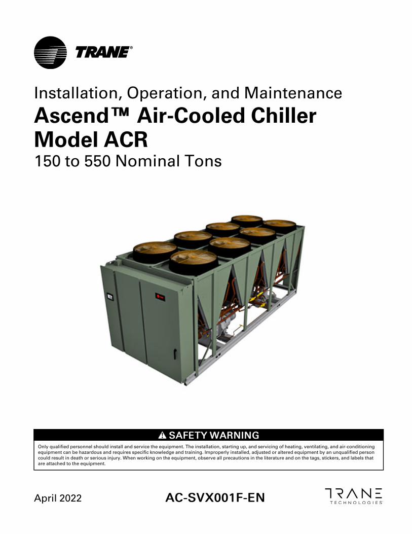
SAFETY WARNING Only qualified personnel should install and service the equipment. The installation, starting up, and servicing of heating, ventilating, and air-conditioning equipment can be hazardous and requires specific knowledge and training. Improperly installed, adjusted or altered equipment by an unqualified person could result in death or serious injury. When working on the equipment, observe all precautions in the literature and on the tags, stickers, and labels that are attached to the equipment. April 2022 AC-SVX001F-EN Installation, Operation, and Maintenance Ascend™™ Air-Cooled Chiller Model ACR 150 to 550 Nominal Tons
-
Upload
khangminh22 -
Category
Documents
-
view
0 -
download
0
Transcript of Ascend® Air-cooled Chillers Model ACR - Trane
SSAAFFEETTYY WWAARRNNIINNGGOnly qualified personnel should install and service the equipment. The installation, starting up, and servicing of heating, ventilating, and air-conditioningequipment can be hazardous and requires specific knowledge and training. Improperly installed, adjusted or altered equipment by an unqualified personcould result in death or serious injury. When working on the equipment, observe all precautions in the literature and on the tags, stickers, and labels thatare attached to the equipment.
April 2022 AACC--SSVVXX000011FF--EENN
Installation, Operation, and Maintenance
Ascend™™ Air-Cooled ChillerModel ACR150 to 550 Nominal Tons

©2022 Trane AC-SVX001F-EN
IntroductionRead this manual thoroughly before operating orservicing this unit.
Warnings, Cautions, and NoticesSafety advisories appear throughout this manual asrequired. Your personal safety and the properoperation of this machine depend upon the strictobservance of these precautions.
The three types of advisories are defined as follows:
WARNINGIndicates a potentially hazardous situationwhich, if not avoided, could result in death orserious injury.
CAUTIONIndicates a potentially hazardous situationwhich, if not avoided, could result in minor ormoderate injury. It could also be used to alertagainst unsafe practices.
NOTICEIndicates a situation that could result inequipment or property-damage onlyaccidents.
Important Environmental ConcernsScientific research has shown that certain man-madechemicals can affect the earth’s naturally occurringstratospheric ozone layer when released to theatmosphere. In particular, several of the identifiedchemicals that may affect the ozone layer arerefrigerants that contain Chlorine, Fluorine and Carbon(CFCs) and those containing Hydrogen, Chlorine,Fluorine and Carbon (HCFCs). Not all refrigerantscontaining these compounds have the same potentialimpact to the environment. Trane advocates theresponsible handling of all refrigerants-includingindustry replacements for CFCs and HCFCs such assaturated or unsaturated HFCs and HCFCs.
Important Responsible RefrigerantPracticesTrane believes that responsible refrigerant practicesare important to the environment, our customers, andthe air conditioning industry. All technicians whohandle refrigerants must be certified according to localrules. For the USA, the Federal Clean Air Act (Section608) sets forth the requirements for handling,reclaiming, recovering and recycling of certainrefrigerants and the equipment that is used in theseservice procedures. In addition, some states ormunicipalities may have additional requirements thatmust also be adhered to for responsible managementof refrigerants. Know the applicable laws and followthem.
WWAARRNNIINNGGPPrrooppeerr FFiieelldd WWiirriinngg aanndd GGrroouunnddiinnggRReeqquuiirreedd!!FFaaiilluurree ttoo ffoollllooww ccooddee ccoouulldd rreessuulltt iinn ddeeaatthh oorrsseerriioouuss iinnjjuurryy..AAllll ffiieelldd wwiirriinngg MMUUSSTT bbee ppeerrffoorrmmeedd bbyy qquuaalliiffiieeddppeerrssoonnnneell.. IImmpprrooppeerrllyy iinnssttaalllleedd aanndd ggrroouunnddeeddffiieelldd wwiirriinngg ppoosseess FFIIRREE aanndd EELLEECCTTRROOCCUUTTIIOONNhhaazzaarrddss.. TToo aavvooiidd tthheessee hhaazzaarrddss,, yyoouu MMUUSSTT ffoolllloowwrreeqquuiirreemmeennttss ffoorr ffiieelldd wwiirriinngg iinnssttaallllaattiioonn aannddggrroouunnddiinngg aass ddeessccrriibbeedd iinn NNEECC aanndd yyoouurr llooccaall//ssttaattee//nnaattiioonnaall eelleeccttrriiccaall ccooddeess..
WWAARRNNIINNGGPPeerrssoonnaall PPrrootteeccttiivvee EEqquuiippmmeenntt ((PPPPEE))RReeqquuiirreedd!!FFaaiilluurree ttoo wweeaarr pprrooppeerr PPPPEE ffoorr tthhee jjoobb bbeeiinngguunnddeerrttaakkeenn ccoouulldd rreessuulltt iinn ddeeaatthh oorr sseerriioouuss iinnjjuurryy..TTeecchhnniicciiaannss,, iinn oorrddeerr ttoo pprrootteecctt tthheemmsseellvveess ffrroommppootteennttiiaall eelleeccttrriiccaall,, mmeecchhaanniiccaall,, aanndd cchheemmiiccaallhhaazzaarrddss,, MMUUSSTT ffoollllooww pprreeccaauuttiioonnss iinn tthhiiss mmaannuuaallaanndd oonn tthhee ttaaggss,, ssttiicckkeerrss,, aanndd llaabbeellss,, aass wweellll aass tthheeiinnssttrruuccttiioonnss bbeellooww::
•• BBeeffoorree iinnssttaalllliinngg//sseerrvviicciinngg tthhiiss uunniitt,,tteecchhnniicciiaannss MMUUSSTT ppuutt oonn aallll PPPPEE rreeqquuiirreedd ffoorrtthhee wwoorrkk bbeeiinngg uunnddeerrttaakkeenn ((EExxaammpplleess;; ccuuttrreessiissttaanntt gglloovveess//sslleeeevveess,, bbuuttyyll gglloovveess,, ssaaffeettyyggllaasssseess,, hhaarrdd hhaatt//bbuummpp ccaapp,, ffaallll pprrootteeccttiioonn,,eelleeccttrriiccaall PPPPEE aanndd aarrcc ffllaasshh ccllootthhiinngg))..AALLWWAAYYSS rreeffeerr ttoo aapppprroopprriiaattee SSaaffeettyy DDaattaaSShheeeettss ((SSDDSS)) aanndd OOSSHHAA gguuiiddeelliinneess ffoorrpprrooppeerr PPPPEE..
•• WWhheenn wwoorrkkiinngg wwiitthh oorr aarroouunndd hhaazzaarrddoouusscchheemmiiccaallss,, AALLWWAAYYSS rreeffeerr ttoo tthhee aapppprroopprriiaatteeSSDDSS aanndd OOSSHHAA//GGHHSS ((GGlloobbaall HHaarrmmoonniizzeeddSSyysstteemm ooff CCllaassssiiffiiccaattiioonn aanndd LLaabbeelllliinngg ooffCChheemmiiccaallss)) gguuiiddeelliinneess ffoorr iinnffoorrmmaattiioonn oonnaalllloowwaabbllee ppeerrssoonnaall eexxppoossuurree lleevveellss,, pprrooppeerrrreessppiirraattoorryy pprrootteeccttiioonn aanndd hhaannddlliinnggiinnssttrruuccttiioonnss..
•• IIff tthheerree iiss aa rriisskk ooff eenneerrggiizzeedd eelleeccttrriiccaallccoonnttaacctt,, aarrcc,, oorr ffllaasshh,, tteecchhnniicciiaannss MMUUSSTT ppuuttoonn aallll PPPPEE iinn aaccccoorrddaannccee wwiitthh OOSSHHAA,, NNFFPPAA7700EE,, oorr ootthheerr ccoouunnttrryy--ssppeecciiffiicc rreeqquuiirreemmeennttssffoorr aarrcc ffllaasshh pprrootteeccttiioonn,, PPRRIIOORR ttoo sseerrvviicciinnggtthhee uunniitt.. NNEEVVEERR PPEERRFFOORRMM AANNYY SSWWIITTCCHHIINNGG,,DDIISSCCOONNNNEECCTTIINNGG,, OORR VVOOLLTTAAGGEE TTEESSTTIINNGGWWIITTHHOOUUTT PPRROOPPEERR EELLEECCTTRRIICCAALL PPPPEE AANNDDAARRCC FFLLAASSHH CCLLOOTTHHIINNGG.. EENNSSUURREEEELLEECCTTRRIICCAALL MMEETTEERRSS AANNDD EEQQUUIIPPMMEENNTT AARREEPPRROOPPEERRLLYY RRAATTEEDD FFOORR IINNTTEENNDDEEDDVVOOLLTTAAGGEE..

AC-SVX001F-EN 3
WWAARRNNIINNGGFFoollllooww EEHHSS PPoolliicciieess!!FFaaiilluurree ttoo ffoollllooww iinnssttrruuccttiioonnss bbeellooww ccoouulldd rreessuulltt iinnddeeaatthh oorr sseerriioouuss iinnjjuurryy..
•• AAllll TTrraannee ppeerrssoonnnneell mmuusstt ffoollllooww tthheeccoommppaannyy’’ss EEnnvviirroonnmmeennttaall,, HHeeaalltthh aanndd SSaaffeettyy((EEHHSS)) ppoolliicciieess wwhheenn ppeerrffoorrmmiinngg wwoorrkk ssuucchh aasshhoott wwoorrkk,, eelleeccttrriiccaall,, ffaallll pprrootteeccttiioonn,, lloocckkoouutt//ttaaggoouutt,, rreeffrriiggeerraanntt hhaannddlliinngg,, eettcc.. WWhheerree llooccaallrreegguullaattiioonnss aarree mmoorree ssttrriinnggeenntt tthhaann tthheesseeppoolliicciieess,, tthhoossee rreegguullaattiioonnss ssuuppeerrsseeddee tthheesseeppoolliicciieess..
•• NNoonn--TTrraannee ppeerrssoonnnneell sshhoouulldd aallwwaayyss ffoolllloowwllooccaall rreegguullaattiioonnss..
WWAARRNNIINNGGRReeffrriiggeerraanntt uunnddeerr HHiigghh PPrreessssuurree!!FFaaiilluurree ttoo ffoollllooww iinnssttrruuccttiioonnss bbeellooww ccoouulldd rreessuulltt iinnaann eexxpplloossiioonn wwhhiicchh ccoouulldd rreessuulltt iinn ddeeaatthh oorrsseerriioouuss iinnjjuurryy oorr eeqquuiippmmeenntt ddaammaaggee..SSyysstteemm ccoonnttaaiinnss rreeffrriiggeerraanntt uunnddeerr hhiigghh pprreessssuurree..RReeccoovveerr rreeffrriiggeerraanntt ttoo rreelliieevvee pprreessssuurree bbeeffoorreeooppeenniinngg tthhee ssyysstteemm.. SSeeee uunniitt nnaammeeppllaattee ffoorrrreeffrriiggeerraanntt ttyyppee.. DDoo nnoott uussee nnoonn--aapppprroovveeddrreeffrriiggeerraannttss,, rreeffrriiggeerraanntt ssuubbssttiittuutteess,, oorr rreeffrriiggeerraannttaaddddiittiivveess..
Factory Warranty InformationCompliance with the following is required to preservethe factory warranty:
AAllll UUnniitt IInnssttaallllaattiioonnss
Startup MUST be performed by Trane, or an authorizedagent of Trane, to VALIDATE this WARRANTY.Contractor must provide a two-week startupnotification to Trane (or an agent
CopyrightThis document and the information in it are theproperty of Trane, and may not be used or reproducedin whole or in part without written permission. Tranereserves the right to revise this publication at any time,and to make changes to its content without obligationto notify any person of such revision or change.
TrademarksAll trademarks referenced in this document are thetrademarks of their respective owners.
Factory TrainingFactory training is available through Trane University™to help you learn more about the operation andmaintenance of your equipment. To learn aboutavailable training opportunities contact TraneUniversity™.
Online: www.trane.com/traneuniversity
Phone: 855-803-3563
Email: [email protected]
Revision History• Updated the Unit Nameplate in the Model Number
Information chapter.
• Updated the Model Number Description chapter.
• Updated the General Data tables.
• Updated Weights and Unit Dimensions sections inthe Dimension and Weights chapter.
• Added 10-point lift configuration – 300 ton graphicto the Installation Mechanical chapter.
• Added Elastomeric Pads section to the InstallationMechanical chapter.
• Updated the Point Weights tables in the InstallationMechanical chapter.
• Added Pump Package section to the InstallationElectrical Chapter.
IInnttrroodduuccttiioonn

4 AC-SVX001F-EN
Model Number Information . . . . . . . . . . . . . . . . 7Nameplates . . . . . . . . . . . . . . . . . . . . . . . . . . . . . . 7
Unit Nameplate . . . . . . . . . . . . . . . . . . . . . . . . . . 7Model Number Coding System. . . . . . . . . 7
Compressor Nameplate . . . . . . . . . . . . . . . . . . . 7
Model Number Descriptions. . . . . . . . . . . . . . . . 8Unit Model Number. . . . . . . . . . . . . . . . . . . . . . . 8
Compressor Information . . . . . . . . . . . . . . . . . 10
General Information . . . . . . . . . . . . . . . . . . . . . . . 11Unit Description . . . . . . . . . . . . . . . . . . . . . . . . . 11
Unit Length . . . . . . . . . . . . . . . . . . . . . . . . . . . . . 11
Accessory/Option Information . . . . . . . . . . . . 11
General Data . . . . . . . . . . . . . . . . . . . . . . . . . . . . 12
Drive Cooling Fluid . . . . . . . . . . . . . . . . . . . . . . 19
Pre-Installation . . . . . . . . . . . . . . . . . . . . . . . . . . . . 20Unit Inspection . . . . . . . . . . . . . . . . . . . . . . . . . . 20
Exterior Inspection . . . . . . . . . . . . . . . . . . . 20Inspection for ConcealedDamage . . . . . . . . . . . . . . . . . . . . . . . . . . . . . 20Repair. . . . . . . . . . . . . . . . . . . . . . . . . . . . . . . 20
Storage Requirements . . . . . . . . . . . . . . . . . . . 20
Installation Requirements . . . . . . . . . . . . . . . . 21
Dimensions and Weights . . . . . . . . . . . . . . . . . . 22Weights. . . . . . . . . . . . . . . . . . . . . . . . . . . . . . . . . 22
Service Clearance . . . . . . . . . . . . . . . . . . . . . . . 25
Unit Dimensions. . . . . . . . . . . . . . . . . . . . . . . . . 26Unit Sizes 150 to 300 Tons . . . . . . . . . . . . 26Unit Sizes — Units Larger than 300tons. . . . . . . . . . . . . . . . . . . . . . . . . . . . . . . . . 40
Installation Mechanical . . . . . . . . . . . . . . . . . . . . 43Location Requirements . . . . . . . . . . . . . . . . . . 43
Sound Considerations . . . . . . . . . . . . . . . . 43Foundation . . . . . . . . . . . . . . . . . . . . . . . . . . 43Clearances . . . . . . . . . . . . . . . . . . . . . . . . . . 43
Lifting and Moving Instructions . . . . . . . . . . . 43
Isolation and Sound Emission . . . . . . . . . . . . 45Unit Isolation and Leveling. . . . . . . . . . . . 45Elastomeric Isolators . . . . . . . . . . . . . . . . . 45
Elastomeric Pads. . . . . . . . . . . . . . . . . . . . . 46Mounting Locations, Weights,Isolators. . . . . . . . . . . . . . . . . . . . . . . . . . . . . 47
Compressor Mounting BoltRemoval . . . . . . . . . . . . . . . . . . . . . . . . . . . . . . . . 57
Drainage. . . . . . . . . . . . . . . . . . . . . . . . . . . . . . . . 58
Refrigerant Pressure Relief Valves . . . . . . . . 58
Evaporator Piping . . . . . . . . . . . . . . . . . . . . . . . 59Evaporator Piping Components . . . . . . . 61
Evaporator Waterside Pressure DropCurves . . . . . . . . . . . . . . . . . . . . . . . . . . . . . . . . . . 63
150 to 300 Ton Units without DirectFree-Cooling Option. . . . . . . . . . . . . . . . . . 63150 to 300 Ton Units with DirectFree-Cooling (DFC) Option . . . . . . . . . . . . 64300 Ton Units with Indirect Free-Cooling (IFC) Option. . . . . . . . . . . . . . . . . . 66Units Larger than 300 Tons withoutDirect Free-Cooling Option. . . . . . . . . . . . 69Units Larger than 300 Tons withDirect Free-Cooling (DFC)Option . . . . . . . . . . . . . . . . . . . . . . . . . . . . . . 71
Pump Package . . . . . . . . . . . . . . . . . . . . . . . . . . 74Pump Package — Available Headand Net Positive Suction HeadRequired . . . . . . . . . . . . . . . . . . . . . . . . . . . . 76
Freeze Protection . . . . . . . . . . . . . . . . . . . . . . . . 84
Low Evaporator Refrigerant Cutout,Glycol Requirements . . . . . . . . . . . . . . . . . . . . 85
Installation Electrical . . . . . . . . . . . . . . . . . . . . . . 88General Recommendations. . . . . . . . . . . . . . . 88
Adaptive Frequency™ DriveCapacitor Discharge. . . . . . . . . . . . . . . . . . 89Adaptive Frequency™ Drive PowerJumper Configuration . . . . . . . . . . . . . . . . 89Units with Nitrogen ChargeOption . . . . . . . . . . . . . . . . . . . . . . . . . . . . . . 90
Installer-Supplied Components . . . . . . . . . . . 90Power Supply Wiring. . . . . . . . . . . . . . . . . 90Control Power Supply . . . . . . . . . . . . . . . . 92Service Power Connection . . . . . . . . . . . . 92Heater Power Supply . . . . . . . . . . . . . . . . . 92
Chilled Water Pump Control . . . . . . . . . . . . . . 93
Table of Contents

AC-SVX001F-EN 5
Programmable Relays . . . . . . . . . . . . . . . . . . . 94
Relay Assignments Using Tracer TU . . . . . . 94
Low Voltage Wiring. . . . . . . . . . . . . . . . . . . . . . 95Emergency Stop . . . . . . . . . . . . . . . . . . . . . 95External Auto/Stop . . . . . . . . . . . . . . . . . . . 95External Circuit Lockout – Circuit #1and #2 . . . . . . . . . . . . . . . . . . . . . . . . . . . . . . 95Ice Building Option . . . . . . . . . . . . . . . . . . 95External Chilled Water Setpoint(ECWS) Option . . . . . . . . . . . . . . . . . . . . . . 96External Demand Limit Setpoint(EDLS) Option . . . . . . . . . . . . . . . . . . . . . . . 96EDLS and ECWS Analog Input SignalWiring . . . . . . . . . . . . . . . . . . . . . . . . . . . . . . 97Chilled Water Reset (CWR) . . . . . . . . . . . 97
Transformer Power Rating . . . . . . . . . . . . . . . 98
Building Automation Systems . . . . . . . . . . . . 98BACnet Building Automation ControlNetwork. . . . . . . . . . . . . . . . . . . . . . . . . . . . . 98Modbus Automation ControlNetwork. . . . . . . . . . . . . . . . . . . . . . . . . . . . . 98LonTalk Building AutomationSystems. . . . . . . . . . . . . . . . . . . . . . . . . . . . . 98
Operating Principles . . . . . . . . . . . . . . . . . . . . . . . 99Refrigeration Circuits . . . . . . . . . . . . . . . . . . . . 99
Refrigeration Cycle . . . . . . . . . . . . . . . . . . . . . . 99
Refrigerant R-134a . . . . . . . . . . . . . . . . . . . . . . . 99
Compressor and Oil System . . . . . . . . . . . . . . 99
Condenser and Fans . . . . . . . . . . . . . . . . . . . . . 99
Evaporator . . . . . . . . . . . . . . . . . . . . . . . . . . . . . 100
Drive Cooling System . . . . . . . . . . . . . . . . . . . 100
Free-Cooling Operating Modes . . . . . . . . . . 100Mechanical Cooling Mode . . . . . . . . . . . 100Combined Mechanical and Free-Cooling Mode . . . . . . . . . . . . . . . . . . . . . . 100Free-Cooling Only Mode. . . . . . . . . . . . . 101
Controls . . . . . . . . . . . . . . . . . . . . . . . . . . . . . . . . . . 102Overview . . . . . . . . . . . . . . . . . . . . . . . . . . . . . . 102
Symbio 800 . . . . . . . . . . . . . . . . . . . . . . . . . . . . 102
AdaptiView Display . . . . . . . . . . . . . . . . . . . . . 102
Noise Reduction Mode . . . . . . . . . . . . . . . . . . 102
Tracer TU . . . . . . . . . . . . . . . . . . . . . . . . . . . . . . 103
Integrated Rapid Restart. . . . . . . . . . . . . . . . . 103
Pre-Start. . . . . . . . . . . . . . . . . . . . . . . . . . . . . . . . . . 104
Start-up and Shutdown. . . . . . . . . . . . . . . . . . . 105Unit Start-up . . . . . . . . . . . . . . . . . . . . . . . . . . . 105
Temporary Shutdown And Restart . . . . . . . 105
Extended Shutdown Procedure . . . . . . . . . 105
Seasonal Unit Start-up Procedure . . . . . . . 106
System Restart After ExtendedShutdown . . . . . . . . . . . . . . . . . . . . . . . . . . . . . 106
Sequence of Operation. . . . . . . . . . . . . . . . . . 107Software Operation Overview. . . . . . . . 107Power Up Diagram . . . . . . . . . . . . . . . . . 108Power Up to Starting . . . . . . . . . . . . . . . . 109Stopped to Starting . . . . . . . . . . . . . . . . . 110Running (Lead Compressor/CircuitStart and Run) . . . . . . . . . . . . . . . . . . . . . . 111Running (Lag Compressor/CircuitStart and Run) . . . . . . . . . . . . . . . . . . . . . . 112Satisfied Setpoint . . . . . . . . . . . . . . . . . . . 113Unloading Unstaging. . . . . . . . . . . . . . . . 114Normal Shutdown to Stopped orRun Inhibit . . . . . . . . . . . . . . . . . . . . . . . . . 115Immediate Shutdown to Stopped orRun Inhibit . . . . . . . . . . . . . . . . . . . . . . . . . 116Ice Making (Running to Ice Making toRunning) . . . . . . . . . . . . . . . . . . . . . . . . . . . 117Ice Making (Auto to Ice Making to IceMaking Complete) . . . . . . . . . . . . . . . . . . 118
Maintenance . . . . . . . . . . . . . . . . . . . . . . . . . . . . . 119Recommended Maintenance . . . . . . . . . . . . 119
Weekly . . . . . . . . . . . . . . . . . . . . . . . . . . . . . 119Monthly . . . . . . . . . . . . . . . . . . . . . . . . . . . . 120Annual . . . . . . . . . . . . . . . . . . . . . . . . . . . . . 120
Refrigerant and Oil ChargeManagement . . . . . . . . . . . . . . . . . . . . . . . . . . 120
Lubrication System . . . . . . . . . . . . . . . . . . . . . 120Oil Sump Level Check . . . . . . . . . . . . . . . 120
Drive Cooling System . . . . . . . . . . . . . . . . . . . 121Service Intervals . . . . . . . . . . . . . . . . . . . . 121Unit Diagnostics . . . . . . . . . . . . . . . . . . . . 121pH Test. . . . . . . . . . . . . . . . . . . . . . . . . . . . . 122
TTaabbllee ooff CCoonntteennttss

6 AC-SVX001F-EN
Pressure Relief Cap . . . . . . . . . . . . . . . . . 122Drive Cooling Expansion Tank . . . . . . . 122
Condenser Coil Corrosion ProtectionInspection. . . . . . . . . . . . . . . . . . . . . . . . . . . . . . 122
Condenser Coil Cleaning . . . . . . . . . . . . . . . . 122Coil Cleaning Interval . . . . . . . . . . . . . . . 122Cleaning Air Side of Coils . . . . . . . . . . . 123Cleaning Microchannel Coils . . . . . . . . . 123
Cleaning the Evaporator. . . . . . . . . . . . . . . . . 123
Pump Package . . . . . . . . . . . . . . . . . . . . . . . . . 123
Free-Cooling Coil . . . . . . . . . . . . . . . . . . . . . . . 124Free-Cooling Coil Cleaning. . . . . . . . . . . 124Free-Cooling FluidManagement . . . . . . . . . . . . . . . . . . . . . . . 124
Reinstallation of Compressor MountingBolts . . . . . . . . . . . . . . . . . . . . . . . . . . . . . . . . . . 125
Servicing Chiller Roof . . . . . . . . . . . . . . . . . . 125
Diagnostics . . . . . . . . . . . . . . . . . . . . . . . . . . . . . . . 126
General Diagnostics Information. . . . . . . . . 126
150 to 300 Ton Units . . . . . . . . . . . . . . . . . . . . 126AFD Diagnostics . . . . . . . . . . . . . . . . . . . . 126Main Processor Diagnostics. . . . . . . . . . 135Communication Diagnostics . . . . . . . . . 146
Units Larger than 300 Tons . . . . . . . . . . . . . . 150AFD Diagnostics . . . . . . . . . . . . . . . . . . . . 150Starter Diagnostics . . . . . . . . . . . . . . . . . . 155Main Processor Diagnostics. . . . . . . . . . 157Communication Diagnostics . . . . . . . . . 165
Unit Wiring . . . . . . . . . . . . . . . . . . . . . . . . . . . . . . . 169
Log and Check Sheets . . . . . . . . . . . . . . . . . . . . 170Ascend™ Model ACR InstallationCompletion Check Sheet and Request forTrane Service . . . . . . . . . . . . . . . . . . . . . . . . . . 171
Operator Log . . . . . . . . . . . . . . . . . . . . . . . . . . . 173
TTaabbllee ooff CCoonntteennttss

AC-SVX001F-EN 7
Model Number InformationNameplatesUnit nameplates are applied to the exterior of thecontrol panel. A compressor nameplate is located oneach compressor. When the unit arrives, compare allnameplate data with ordering, submittal, and shippinginformation.
Unit NameplateSee figure below for a typical unit nameplate. Theoutdoor unit nameplate provides the followinginformation:
• Unit model and size description.
• Unit serial number.
• Unit electrical requirements.
• Operating charges of R-134a and refrigerant oil(Trane OIL00311).
• Unit design pressures.
• Installation, operation and maintenance and servicedata literature.
• Drawing numbers for unit wiring diagrams
Model Number Coding SystemModel numbers are composed of numbers and lettersthat represent features of the equipment. Shown belowis a sample of typical unit model number.
ACRB 2005 EUAA EUUC XNC2 XCNX BDEV 1HACBDXA A1TX XX0XC
Each position, or group of positions, in the modelnumber is used to represent a feature. Unit modelnumber digits are selected and assigned in accordancewith the definitions as listed in Model NumberDescriptions chapter. For example, position 09 of theunit model number above contains the letter “E” whichindicates the unit voltage is 460/60/3.
Compressor NameplateThe compressor nameplate provides the followinginformation:
• Compressor model number.
• Compressor serial number.
• Compressor electrical characteristics
• Utilization range.
• Recommended refrigerant
See Model Number Descriptions chapter forcompressor model and serial number descriptions.

8 AC-SVX001F-EN
Model Number DescriptionsUnit Model Number
Digit 1, 2, 3, 4 — Unit Model
ACRB = Air-Cooled Screw Chiller
Digit 5, 6, 7 — Nominal Tonnage
150 = 150 Tons165 = 165 Tons180 = 180 Tons200 = 200 Tons225 = 225 Tons250 = 250 Tons275 = 275 Tons300 = 300 Tons375 = 375 Tons380 = 380 Tons440 = 440 Tons450 = 450 Tons500 = 500 Tons550 = 550 Tons
Digit 8 — Compressor Type
4 =Mixed screw types5 = Screw with Variable Volume Ratio
Digit 9— Unit Voltage
A = 200/60/3B = 230/60/3C = 380/60/3D = 400/60/3E = 460/60/3F = 575/60/3G = 400/50/3H = 380/50/3
Digit 10—Manufacturing Location
U = Trane Commercial Systems,Pueblo, CO USA
Digits 11, 12— Design Sequence
** = Factory assigned
Digit 13— Unit Sound Package
X = InvisiSound™ StandardL = InvisiSound™ SuperiorE = InvisiSound™ UltimateR = InvisiSound™ Standard with NoiseReduction RequestQ = InvisiSound™ Superior with NoiseReduction Request
Digit 14— Agency Listing
C = No Agency ListingU = UL/cUL Listing
Digit 15 — Pressure Vessel Code
U= ASME Pressure Vessel CodeC= CRN or Canadian Equivalent PressureVessel CodeA = Australia Pressure Vessel Code
Digit 16 — Factory Charge
C= Refrigerant Charge R-134aD = Nitrogen Charge, R-134a Field Supplied
Digit 17 — Auxiliary Items
X= No Auxiliary Items
Digit 18 — Evaporator Application
N = Standard CoolingP = Low Temp Process CoolingC= Ice Making
Digit 19, 20 — Evaporator Type
C1 = CHIL 1-passC2 = CHIL 2-passC3 = CHIL 3-passD1 = CHIL 1-pass with ALT tubeD2 = CHIL 2-pass with ALT tube
Digit 21 —Water Connection
X= Grooved PipeA = Grooved Pipe + Flange
Digit 22 — Flow Switch
C= Flow Switch Set Point 15 cm/secD = Flow Switch Set Point 25 cm/secF= Flow Switch Set Point 35 cm/secH= Flow Switch Set Point 45 cm/sec
Digit 23 — Insulation
N = Factory Insulation — All Cold Parts 0.75”H= Evaporator-only Insulation for HighHumidity/Low Evap Temp 1.25”
Digit 24 —Unit Application
X= Standard AmbientL = Low AmbientE= Extreme Low AmbientH= High AmbientW =Wide Ambient
Digit 25— Condenser Length
A = 4V Condenser Coil ModulesB = 5V Condenser Coil ModulesC = 6V Condenser Coil ModulesD = 7V Condenser Coil ModulesE = 8V Condenser Coil ModulesF = 9V Condenser Coil ModulesH = 11V Condenser Coil Modules
Digit 26— Condenser Fin Options
A = Aluminum Round Tube, Aluminum PlateFinC = Coated MicrochannelD = CompleteCoat™ Epoxy Coated AluminumFins, Aluminum Round TubeK = Coated Copper Round Tube, AluminumPlate FinM = Aluminum MicrochannelR = Copper Round Tube, Aluminum Plate Fin
Digit 27— Fan Type
E = EC Condenser Fan Motors
Digit 28— Compressor Starter
V = Variable Frequency Drive (1 compressor/circuit)
Digit 29— Incoming Unit Power LineConnection1 = Single Point Power2 = Dual Point Unit Power Connection3 = Single Point Power including 115V
Digit 30— Power Line ConnectionTypeT = Terminal BlockC = Circuit BreakerH = Circuit Breaker with High Fault RatedControl PanelM = High Fault Rated Circuit Breaker withEnergy Meter
Digit 31— Short Circuit CurrentRatingA = Default Short Circuit Amp RatingB = High Short Circuit Amp Rating
Digit 32— Electrical Accessories
X = NoneB = Convenience Outlet and Under/OverVoltage ProtectionC = 15A 115V Convenience Outlet (Type B)N = 20A 115V Convenience OutletU = Under/Over Voltage Protection

AC-SVX001F-EN 9
Digit 33— Remote CommunicationOptionX = NoneL = LonTalk® InterfaceB = BACnet® TP InterfaceM =Modbus™ InterfaceP = BACnet® Interface (IP)
Digit 34— HardWire Communication
X = NoneA = Hard Wired Bundle - AllB = Remote Leaving Water Temp SetpointC = Remote Leaving Temp and Demand LimitSetpointsD = Unit Status Programmable RelayE = Programmable Relay and Leaving Waterand Demand Limit SetpointF = Percent CapacityG = Percent Capacity and Leaving Water andDemand Limit SetpointH = Percent Capacity and ProgrammableRelay
Digit 35— Smart Flow Control
X = NoneF = Flow Measurement Factory Installed
Digit 36— Structural Options
A = Standard Unit StructureB = IBC Seismic CertificationD =Wind Load CertificationE = Combination IBC Seismic and Wind LoadCertification
Digit 37— Appearance Accessories
X = No Appearance OptionsA = Architectural Louvered Panels
Digit 38— Unit Isolation
X = None1 = Elastomeric Isolators4 = Seismic Elastomeric Pads
Digit 39— Shipping Package
X = NoneA = ContainerizationT = Shipping Tarp Covering Full UnitB = Containerization and Tarp
Digit 40— Pump Package
X = None5 = 50 HP Single Pump High Pressure withSingle VFD6 = 60 HP Single Pump High Pressure withSingle VFD7 = 75 HP Single Pump High Pressure withSingle VFD
Digit 41— Heat Recovery
X = None
Digit 42 — Free-Cooling
X= NoneT= Total Direct Free-CoolingE= Total Indirect Free-Cooling + 2V Free-Cooling CoilsH= Total Direct Free Cooling + 2V Free-Cooling CoilsF= Total Indirect Free Cooling
Digit 43 — Special
0 = NoneS = SpecialF= Ship to Final Finisher
Digit 44 — Line Voltage HarmonicMitigationX= DC Reactors (~30% TDD)L = 5% TDD (IEEE519 Compliant)
Digit 45 —Wireless Connectivity
A =Wi-FiB = LTE ModemC= Air-FiD =Wi-Fi and LTE ModemE=Wi-Fi and Air-FiF= LTE Modem and Air-FiG =Wi-Fi, LTE Modem, and Air-Fi
MMooddeell NNuummbbeerr DDeessccrriippttiioonnss

10 AC-SVX001F-EN
Compressor InformationCHHSMODEL NUMBER CHHWMODEL NUMBER SERIAL NUMBER
Digit 1, 2, 3, 4 — Compressor Type
CHHS = Positive displacement, helical rotary(twin screw) hermetic compressor
Digit 5 — Frame Size
R = R Frame: 70 - 100 tonsS = S Frame: 112 - 165 tons
Digit 6 —Motor Length
B = 145 mmC = 170 mmE = 165 mmF = 190 mm
Digit 7—MotorWindingCharacteristics* = Factory assigned
Digit 8 — Volume Ratio
E = Variable Volume Ratio
Digit 9— Refrigerant
1 = R-134a
Digits 10, 11— Design Sequence
** = Factory assigned
Digit 1, 2, 3, 4 — Compressor Family
CHHW = Positive displacement, helicalrotary. hermetic compressor
Digit 5 — Economizer Port Detail
0 = No Economizer Port
Digit 6 — Frame Size
N = N Frame
Digit 7— Compressor Capacity
6 = GP2.5 Larger capacity (major)
Digit 8 —Motor Voltage
D = 380/60/3H= 575/60/3K= 460 /60/3 (N6 only)J = 460 /50/3 (N6 only)
Digit 9— Internal Relief
K= 450 psid
Digits 10, 11 — Design Sequence
**= Factory assigned
Digit 12 — Capacity Limit
N = Standard capacity
Digits 13, 14, 15 —Motor kW Rating
112 = N6 50 Hz134 = N6 60 Hz
Digit 16 — Capacity Limit
A = High Volume Ratio
Digit 1, 2 — Year
YY = Last two digits of year of manufacture
Digit 3, 4 —Week
WW =Week of build, from 00 to 52
Digit 5 — Day
1 = Monday2 = Tuesday3 =Wednesday4 = Thursday5 = Friday6 = Saturday7 = Sunday
Digit 6, 7, 8 — Coded Time Stamp
TTT = Used to ensure uniqueness of serialnumber
Digit 9 — Assembly Line
Assembly line compressor was built on.Varies with facility.
Digit 10— Build Location
A = Monterrey
MMooddeell NNuummbbeerr DDeessccrriippttiioonnss

AC-SVX001F-EN 11
General InformationUnit DescriptionThe Ascend™ ACR units are helical-rotary type, air-cooled chillers designed for outdoor installation. Therefrigerant circuits are factory-piped, leak tested anddehydrated. Every unit is electrically tested for propercontrol operation before shipment.
Chilled water inlet and outlet openings are covered forshipment. The chiller features Trane’s exclusiveAdaptive Control™ logic, which monitors the controlvariables that govern the operation of the chiller unit.Adaptive Control logic can adjust capacity variables toavoid chiller shutdown when necessary, and keepproducing chilled water. The units feature twoindependent refrigerant circuits. Each circuit utilizes atleast one compressor driven by an Adaptive FrequencyDrive. Each refrigerant circuit is provided with filter,sight glass, electronic expansion valve, and chargingvalves. The shell-and-tube evaporator is manufacturedin accordance with the ASME standards or otherinternational codes. Each evaporator is fully insulatedand equipped with water drain and vent connections.
Units are shipped with full oil charge and can beordered with either a factory refrigerant charge, oroptional nitrogen charge.
Unit LengthFor unit sizes 300 tons and smaller, units areEXTENDED length if either of the following areselected:
• Voltage: 200, 230 or 575V (model number digit 9 =A, B, or F)
• Harmonic Filtration Option: Filter circuit (modelnumber digit 44 = L)
Accessory/Option InformationCheck all the accessories and loose parts which areshipped with the unit against the shipping list. Includedin these items will be water vessel drain plugs,electrical diagrams, and service literature, which areplaced inside the control panel for shipment.
If optional elastomeric isolators are ordered with unit(model number digit 38 = 1), they are shipped eithermounted on diagonal supports on the end of the unitopposite control panel (for 150 to 300 ton units), or onthe horizontal support frame of the chiller (for unitslarger than 300 tons).

12 AC-SVX001F-EN
General Data
Tab
le1.
Gen
eraldata—
150to
275tonunits
UnitSize(tons)
150
165
180
200
225
250
275
CondenserLength(a)
4V
4V
5V
4V
5V
5V
6V
5V
6V
5V
6V
6V
7V
CompressorModel
CHHSR
CHHSR
CHHSR
CHHSR
CHHSS
CHHSS
CHHSS
Quantity
#2
22
22
22
Evaporator
WaterStorage
(gal)
17.5
18.7
21.9
23.9
26.6
28.7
33.0
(L)
66.1
70.9
82.8
90.5
100.6
108.8
125.0
2Passarrangement
EvapWaterConnectionSize(b)
(in)
55
66
66
8
(mm)
125
125
150
150
150
150
200
Minimum
Flow
(c)(gpm)
171
187
202
228
261
288
318
(l/s)
10.8
11.8
12.7
14.4
16.5
18.2
20.1
Maximum
Flow
(c)(gpm)
626
684
742
835
957
1055
1165
(l/s)
39.5
43.1
46.8
52.7
60.4
66.5
73.5
3Passarrangement
EvapWaterConnectionSize(b)
(in)
44
55
55
6
(mm)
100
100
125
125
125
125
150
Minimum
Flow
(c)(gpm)
114
124
135
152
174
192
212
(l/s)
7.2
7.8
8.5
9.6
11.0
12.1
13.4
Maximum
Flow
(c)(gpm)
417
456
495
557
638
703
777
(l/s)
26.3
28.8
31.2
35.1
40.2
44.3
49.0
Condenser
QuantityofCoils
88
108
1010
1210
1210
1212
14
CoilLength
(in)
78.74
78.74
78.74
78.74
78.74
78.74
78.74
(mm)
2000
2000
2000
2000
2000
2000
2000
CoilHeight
(in)
5050
5050
5050
50
(mm)
1270
1270
1270
1270
1270
1270
1270
Fins/Ft
192
192
192
192
192
192
192
Rows
33
33
33
3
QuantityofFans
#8
810
810
1012
1012
1012
1214
Free-Cooling(d)
CustomerWaterConnectionSize
(in)
n/a
n/a
6n/a
6n/a
6n/a
6n/a
6n/a
8
(mm)
n/a
n/a
152
n/a
152
n/a
152
n/a
152
n/a
152
n/a
203
QtyofCoilsCkt1-StdLength(e)
n/a
n/a
4n/a
4n/a
5n/a
5n/a
5n/a
6
QtyofCoilsCkt1-ExtLength(e)
n/a
n/a
5n/a
5n/a
6n/a
6n/a
6n/a
7
GGeenneerraall IInnffoorrmmaattiioonn

AC-SVX001F-EN 13
Tab
le1.
Gen
eraldata—
150to
275tonunits(continued
)
UnitSize(tons)
150
165
180
200
225
250
275
CondenserLength(a)
4V
4V
5V
4V
5V
5V
6V
5V
6V
5V
6V
6V
7V
QtyofCoilsCkt2
n/a
n/a
5n/a
5n/a
6n/a
6n/a
6n/a
7
CoilLength
(in)
n/a
n/a
72.49
n/a
72.49
n/a
72.49
n/a
72.49
n/a
72.49
n/a
72.49
(mm)
n/a
n/a
1841
n/a
1841
n/a
1841
n/a
1841
n/a
1841
n/a
1841
CoilHeight
(in)
n/a
n/a
40n/a
40n/a
40n/a
40n/a
40n/a
40
(mm)
n/a
n/a
1016
n/a
1016
n/a
1016
n/a
1016
n/a
1016
n/a
1016
Fins/Ft
n/a
n/a
192
n/a
192
n/a
192
n/a
192
n/a
192
n/a
192
Rows
n/a
n/a
3n/a
3n/a
3n/a
3n/a
3n/a
3
GlycolStorageVolume-StdLength (e)
(gal)
n/a
n/a
123
n/a
123
n/a
145
n/a
145
n/a
145
n/a
173
(l)
n/a
n/a
467
n/a
467
n/a
550
n/a
550
n/a
550
n/a
656
GlycolStorageVolume-ExtLength (e)
(gal)
n/a
n/a
129
n/a
129
n/a
151
n/a
151
n/a
151
n/a
179
(l)
n/a
n/a
489
n/a
489
n/a
572
n/a
572
n/a
572
n/a
679
AmbientTemperatureRange
StandardAmbient°F(°C)
32to105(0to40.6)
LowAmbient°F(°C)
0to105(-17.7to40.6)
ExtremeLowAmbient°F(°C)
-16to105(-26.7to40.6)
HighAmbient°F(°C)
32to125(0to52)
WideAmbient°F(°C)
0to125(-17.7to52)
GeneralUnit
Refrigerant
HFC-134a
RefrigerantCkts
#2
Minimum
Load
%20
1818
1717
1515
2020
1818
1616
RefrigerantCharge/ckt
(lbs)
172
171
181
200
210
208
218
251
265
255
261
308
318
(kg)
7878
8291
9594
99114
120
116
118
140
144
Oil
TraneOIL00311
OilCharge/ckt
(gal)
3.0
3.0
3.0
3.0
3.0
3.0
3.0
4.0
4.0
4.0
4.0
4.0
4.0
(L)
11.4
11.4
11.4
11.4
11.4
11.4
11.4
15.1
15.1
15.1
15.1
15.1
15.1
(a)Condenserlengthdefinedbymodelnumberdigit25:4V=A;5V=B;6V=C;7V=D.
(b)Sizesareforunitswithoutfree-coolingoption(modelnumberdigit42=X).Seefree-coolingsectionoftableforwaterconnectionssizesforunitswithmodelnumberdigit42=T.
(c)Minimum
andmaximum
flowratesapplytoconstant-flowchilledwatersystemsrunningatAHRIconditions,withoutfreezeinhibitorsaddedtothewaterloop.
(d)Unitswithfree-coolingoptionareindicatedbymodelnumberdigit42=T.
(e)SeeUnitLengthsection.
GGeenneerraall IInnffoorrmmaattiioonn

14 AC-SVX001F-EN
Tab
le2.
Gen
eraldata—
300tonsunits
UnitSize(tons)
300
CondenserLength(a)
7V
8V
Com
pressorModel
CHHSS
CHHSS
Quantity
#2
2
Evaporator
WaterStorage
(gal)
36.0
36.0
(L)
136.1
136.1
2Passarrangement
EvapWaterConnectionSize(b)
(in)
88
(mm)
200
200
Minimum
Flow
(gpm)
354
354
(l/s)
22.3
22.3
Maximum
Flow
(gpm)
1299
1299
(l/s)
81.9
81.9
3Passarrangement
EvapWaterConnectionSize(b)
(in)
66
(mm)
150
150
Minimum
Flow
(gpm)
236
236
(l/s)
14.9
14.9
Maximum
Flow
(gpm)
866
866
(l/s)
54.6
54.6
Condenser
QuantityofCoils
1416
CoilLength
(in)
78.74
78.74
(mm)
2000
2000
CoilHeight
(in)
5050
(mm)
1270
1270
Fins/Ft
192
192
Rows
33
QuantityofFans
#14
16
Free-Cooling(c)
Free-CoolingOption(modelnumberdigit42)
XT
HE
F
Free-CoolingType
n/a
Direct
Direct
Indirect
Indirect
CustomerWaterConnectionSize(b)
(in)
n/a
88
88
(mm)
n/a
203
203
203
203
GGeenneerraall IInnffoorrmmaattiioonn

AC-SVX001F-EN 15
Tab
le2.
Gen
eraldata—
300tonsunits(continued
)
UnitSize(tons)
300
CondenserLength(a)
7V
8V
QuantityofFree-CoolingCoils(Extended)(d)
n/a
15(16)
19(20)
15(16)
19(20)
QuantityofFree-CoolingOnlyfans
n/a
n/a
4N/A
4
CoilLength
(in)
n/a
72.49
72.49
72.49
72.49
(mm)
n/a
1841
1841
1841
1841
CoilHeight
(in)
n/a
4040
4040
(mm)
n/a
1016
1016
1016
1016
Fins/Ft
n/a
192
192
192
192
Rows
n/a
33
33
Additionalcustomerwaterloopstorage(Extended
Length)(d)
(gal)
n/a
211.5(217.5)
211.5(217.5)
117
117
(l)
n/a
800.7(823.2)
800.7(823.2)
671
671
Free-CoolingChillerinternalglycolvolume
(ExtendedLength)(d)
(gal)
n/a
n/a
n/a
258(263)
301(307)
(l)
n/a
n/a
n/a
977(997)
1141(1161)
Custom
erSidePump
PumpPackageOption(modelnumberdigit40)(e)
n/a
56
75
67
56
75
67
PumpHP
n/a
5060
7550
6075
5060
7550
6075
CustomerWaterConnectionSize(b)
(in)
n/a
68
68
68
68
(mm)
n/a
150
200
150
200
150
200
150
200
AdditionalWaterStorageinPumpSystem
(gal)
n/a
117
148
151
117
148
151
117
148
151
117
148
151
(l)
n/a
443
560
572
443
560
572
443
560
572
443
560
572
UAPPAmbientStartingTemperatures
StandardAmbient
°F(°C)
32to105(0to40.6)
LowAmbient
°F(°C)
0to105(-17.7to40.6)
ExtremeLowAmbient
°F(°C)
-20to105(-26.1to40.6)
HighAmbient
°F(°C)
32to125(0to52)
WideAmbient
°F(°C)
0to125(-17.7to52)
GeneralUnit
Refrigerant
HFC-134a
HFC-134a
RefrigerantCkts
#2
2
Minimum
Load
%15
15
RefrigerantCharge/ckt
(lbs)
315
325
(kg)
143
148
Oil
TraneOIL00311
TraneOIL00311
GGeenneerraall IInnffoorrmmaattiioonn

16 AC-SVX001F-EN
Tab
le2.
Gen
eraldata—
300tonsunits(continued
)
UnitSize(tons)
300
CondenserLength(a)
7V
8V
OilCharge/ckt
(gal)
44
(L)
15.1
15.1
(a)Condenserlengthdefinedbymodelnumberdigit25:7V=D;8V=E.
(b)Inletandoutletsizingchangeswithoptions.Freecoolingpipesizesoverrideevaporatorsizesandpumpssizesoverridealloptions.
(c)DirectFreeCoolingdefinedbymodelnumberdigit42:T=TDFC;H=DFCP;F=TIFC;E=IFCP.
(d)ExtendedLengthisrequiredforvoltages200V,230V,575V(modelnumberdigit9=A,B,F)andharmonicfiltration(modelnumberdigit44=L).
(e)PumpPackagedefinedbymodelnumberdigit40=5,6,7.
GGeenneerraall IInnffoorrmmaattiioonn

AC-SVX001F-EN 17
Tab
le3.
Gen
eraldata—
unitlarger
than
300tons
UnitSize(tons)
375
380
440
450
500
550
CondenserLength(a)
9V
11V
9V
11V
11V
11V
Com
pressorModel(ckt1/2)
CHHSS-120/CHHSSCHHSS-120/CHHSSCHHSS-120/CHHSSCHHSS-120/CHHSS
CHHSS-120/
CHHSS-120
CHHSS-120/
CHHSS-120
Quantity(ckt1/2)
#2/1
2/1
2/1
2/1
2/2
2/2
Evaporator
WaterStorage
(gal)
36.3
36.3
39.5
39.5
45.0
49.3
(L)
137.3
137.3
149.6
149.6
170.3
186.8
1Passarrangement
EvapWaterConnectionSize(b)
(in)
88
88
88
(mm)
200
200
200
200
200
200
Minimum
Flow
(c)
(gpm)
398
398
450
450
523
591
(l/s)
25.1
25.1
28.4
2833.0
37.3
Maximum
Flow
(c)
(gpm)
1750
1750
1981
1981
2303
2603
(l/s)
110.4
110.4
125.0
125
145.3
164.2
2Passarrangement
EvapWaterConnectionSize(b)
(in)
88
88
88
(mm)
200
200
200
200
200
200
Minimum
Flow
(c)
(gpm)
198
198
224
224
260
294
(l/s)
12.5
12.5
14.0
14.1
16.4
18.5
Maximum
Flow
(c)
(gpm)
871
871
986
986
1146
1295
(l/s)
55.0
55.0
62.2
62.2
72.3
81.7
Condenser
QuantityofCoils(ckt1/2)
12/6
14/8
12/6
14/8
12/10
12/10
CoilLength
(in)
78.22
78.22
78.22
78.22
78.22
78.22
(mm)
1987
1987
1987
1987
1987
1987
CoilHeight
(in)
4949
4949
4949
(mm)
1252
1252
1252
1252
1252
1252
Fins/Ft
276
276
276
276
276
276
QuantityofFans(ckt1/2)
#12/6
14/8
12/6
14/8
12/10
12/10
Free-Cooling(d)
CustomerWater
ConnectionSize
(in)
n/a
8.0
n/a
8.0
8.0
8.0
(mm)
n/a
203.0
n/a
203.0
203.0
203.0
QtyofCoilsCkt1
n/a
13.0
n/a
13.0
1010
QtyofCoilsCkt2
n/a
7.0
n/a
7.0
1010
GGeenneerraall IInnffoorrmmaattiioonn

18 AC-SVX001F-EN
Tab
le3.
Gen
eraldata—
unitlarger
than
300tons(continued
)
UnitSize(tons)
375
380
440
450
500
550
CondenserLength(a)
9V
11V
9V
11V
11V
11V
CoilLength
(in)
n/a
72.49
n/a
72.49
72.49
72.49
(mm)
n/a
1841
n/a
1841
1841
1841
CoilHeight
(in)
n/a
40n/a
4040
40
(mm)
n/a
1016
n/a
1016
1016
1016
Fins/Ft
n/a
192
n/a
192
192
192
Rows
n/a
3n/a
33
3
GlycolStorageVolume
(gal)
n/a
231.9
n/a
231.9
231.9
231.9
(l)
n/a
878.2
n/a
878.2
878.2
878.2
AmbientTemperatureRange
StandardAmbient
°F(°C)
32to105(0to40.6)
LowAmbient
°F(°C)
0to105(-17.7to40.6)
ExtremeLowAmbient
°F(°C)
-15to105(-26.1to40.6)
HighAmbient
°F(°C)
32to125(0to52)
WideAmbient
°F(°C)
0to125(-17.7to52)
GeneralUnit
Refrigerant
HFC-134a
RefrigerantCkts
#2
Minimum
Load
%15%
15%
15%
15%
10%
10%
RefrigerantCharge(ckt1/2)
(lbs)
305/143
322/160
305/143
328/163
294/265
300/270
(kg)
138/65
146/73
138/65
149/74
133/120
136/122
Oil
OIL00311
OilCharge(ckt1/2)
(gal)
5.8/4.0
5.8/4.0
5.8/4.0
5.8/4.0
5.8/5.8
5.8/5.8
(L)
22.0/15.1
22.0/15.1
22.0/15.1
22.0/15.1
22.0/22.0
22.0/22.0
(a)Condenserlengthdefinedbymodelnumberdigit25:4V=A;5V=B;6V=C;7V=D;8V=E;9V=F;11V=H
(b)Sizesareforunitswithoutfree-coolingoption(modelnumberdigit42=X).
(c)Minimum
andmaximum
flowratesapplytoconstant-flowchilledwatersystemsrunningatAHRIconditions,withoutfreezeinhibitorsaddedtothewaterloop.
(d)Unitswithfree-coolingoptionareindicatedbymodelnumberdigit42=T.
GGeenneerraall IInnffoorrmmaattiioonn

AC-SVX001F-EN 19
Drive Cooling FluidNNOOTTIICCEE
EEqquuiippmmeenntt DDaammaaggee!!UUssee ooff uunnaapppprroovveedd fflluuiiddss,, oorr ddiilluuttiioonn ooff aapppprroovveeddfflluuiidd,, ccoouulldd rreessuulltt iinn ccaattaassttrroopphhiicc eeqquuiippmmeennttddaammaaggee..UUssee oonnllyy TTrraannee HHeeaatt TTrraannssffeerr FFlluuiidd PP//NN CCHHMM0011002233..TThhiiss fflluuiidd iiss aa ddiirreecctt uussee ccoonncceennttrraattiioonn aanndd iiss nnoottttoo bbee ddiilluutteedd.. DDoo nnoott ttoopp ooffff wwiitthh wwaatteerr oorr aannyyootthheerr fflluuiidd..
NNoottee:: The use of incorrect compounds in the drivecooling systemmay result in scaling, erosion,corrosion or freezing. The Trane Companywarranty specifically excludes liability forcorrosion, erosion, freezing or deterioration ofTrane equipment.
Proper fluid level is important to the operation of theunit. See Drive Cooling Expansion Tank section inMaintenance chapter for fluid level check instructions.The circuit capacities are shown in table below.
If the level is below the recommended minimum levels,contact your local Trane office.
NNoottee:: Drive cooling fluid service life is 5 years. Seemaintenance chapter for more drive coolingsystem information.
Table 4. Drive cooling
Unit Size(tons)
UnitLength(a)
Fluid Volume (gal) Fluid Volume (l)
Ckt1 Ckt2 Ckt 1 Ckt2
150 to 200Standard 1.4 2.0 5.5 7.7
Extended 1.5 2.1 5.8 8.1
225 to 300Standard 1.7 2.2 6.2 8.5
Extended 1.7 2.3 6.6 8.8
375, 440 n/a 1.7 1.6 6.4 6.0
375, 440 with options(b) n/a 1.7 1.7 6.4 6.4
380, 450 n/a 1.8 1.7 6.8 6.4
500, 550 n/a 1.8 1.7 6.8 6.4
(a) Extended Length is required for voltages 200V, 230V, 575V model number digit 9 = A, B, F and harmonic filtration model number digit 44 = L.(b) Option defined by Unit Voltage = 575V (model number digit 9 = F) or Harmonic Filter = Low (model number digit 44 = L)
GGeenneerraall IInnffoorrmmaattiioonn

20 AC-SVX001F-EN
Pre-InstallationUnit InspectionTo protect against loss due to damage incurred intransit, perform inspection immediately upon receipt ofthe unit.
Exterior InspectionIf the job site inspection reveals damage or materialshortages, file a claim with the carrier immediately.Specify the type and extent of the damage on the bill oflading before signing. Notify the appropriate salesrepresentative.
IImmppoorrttaanntt:: Do not proceed with installation of adamaged unit without salesrepresentative’s approval.
• Visually inspect the complete exterior for signs ofshipping damages to unit or packing material.
• Verify that the nameplate data matches the salesorder and bill of lading.
• Verify that the unit is properly equipped and thereare no material shortages.
NNoottee:: Corrosion due to dirt, road grim, road salt, andother contaminates picked up during shipping isnot the responsibility of the carrier.
Inspection for Concealed DamageVisually inspect the components for concealed damageas soon as possible after delivery and before it isstored.
If concealed damage is discovered:
• Notify the carrier’s terminal of the damageimmediately by phone and by mail.
• Concealed damage must be reported within 15days.
• Request an immediate, joint inspection of thedamage with the carrier and consignee.
• Stop unpacking the unit.
• Do not remove damaged material from receivinglocation.
• Take photos of the damage, if possible.
• The owner must provide reasonable evidence thatthe damage did not occur after delivery.
RepairNotify the appropriate sales representative beforearranging unit installation or repair.
IImmppoorrttaanntt:: Do not repair unit until the damage hasbeen inspected by the carrier’srepresentative.
Storage RequirementsExtended storage of outdoor unit prior to installationrequires these precautionary measures:
• Store the outdoor unit in a secure area.
• For units that have been charged with refrigerant,verify the following valves are closed on eachcircuit:
– Suction service valve (butterfly valve)
– Liquid line angle valve or EXV (EXV is drivenclosed whenever circuit is powered)
– Oil line shutoff valves to brazed plate heatexchangers
NNoottee:: Units with factory refrigerant charge (modelnumber digit 16 = C) are shipped with suction,liquid and oil line shutoff valves closed, isolatingmost of refrigerant charge in the evaporator. Ifunit goes directly into long term storage, it isrecommended that these valve positions beconfirmed.
• For units with nitrogen charge option (modelnumber digit 16 = D), units are shipped with valvesopen. If unit goes directly into storage prior torefrigerant charge, confirm all service valves areopen.
N2
• At least every three months (quarterly), check thepressure in the refrigerant circuits to verify that therefrigerant charge is intact. If it is not, contact aqualified service organization and the appropriateTrane sales office.

AC-SVX001F-EN 21
Installation RequirementsType Trane Supplied
Trane InstalledTrane SuppliedField Installed
Field SuppliedField Installed
Foundation • Meet foundation requirements
Rigging
• Safety chains• Clevis connectors• Lifting beam• Spreader bar
Disassembly/Reassembly(as required)
Trane, or an agent of Tranespecifically authorized toperform start-up of Trane®products (contact your localTrane office for pricing)
IsolationElastomeric isolators(optional) • Elastomeric isolators (optional)
Electrical • Circuit breakers (optional)• Unit Mounted Starter
• Circuit breakers (optional)• Electrical connections to unit mounted starter• Wiring sizes per submittal and NEC• Terminal lugs• Ground connection(s)• Ground type specified (Center Ground-Y or not)• BAS wiring (optional)• Control voltage wiring• Chilled water pump contactor and wiring• Option relays and wiring
Water piping Flow switch
• Taps for thermometers and gauges• Thermometers• Water flow pressure gauges• Isolation and balancing valves in water piping• Vents and drain• Waterside pressure relief valves• Water strainer
Insulation Insulation InsulationWater Piping ConnectionComponents Grooved pipe Flange kit (optional)
Other Materials• R-134a refrigerant• Dry nitrogen (optional)
Ascend™ Model ACRInstallation Completion CheckSheet and Request for TraneService(AC-ADF001*-EN)See Log and Check Sheetchapter
Chiller Start-upCommissioning
Trane, or an agent of Tranespecifically authorized toperform start-up of Trane®products
Trane specifically authorizedto perform start-up of Trane®products
PPrree--IInnssttaallllaattiioonn

22 AC-SVX001F-EN
Dimensions and WeightsWeightsTable 5. Weights — 150 to 275 ton units
Unit Size(tons)
CondenserLength(a)
Standard Length(b) Extended Length(b)
Shipping Operating Shipping Operating
lb kg lb kg lb kg lb kg
Units without Seismic or Direct Free-Cooling Options(b)
150 4V 12000 5443 12200 5534 14200 6441 14400 6532
1654V 12100 5489 12200 5534 14200 6441 14400 6532
5V 13100 5942 13200 5987 15200 6895 15400 6985
1804V 12200 5534 12400 5625 14600 6623 14800 6713
5V 13400 6078 13500 6124 15500 7031 15700 7121
2005V 13400 6078 13600 6169 15600 7076 15700 7121
6V 14600 6623 14800 6713 16600 7530 16800 7620
2255V 14800 6713 15000 6804 17000 7711 17200 7802
6V 15900 7212 16100 7303 18100 8210 18300 8301
2505V 14900 6759 15100 6849 17000 7711 17200 7802
6V 16300 7394 16500 7484 18400 8346 18700 8482
2756V 16300 7394 16600 7530 18500 8392 18800 8528
7V 17400 7893 17700 8029 19600 8891 19800 8981
Units with Direct Free-Cooling Option (no Seismic)(b)
150 4V n/a n/a n/a n/a n/a n/a n/a n/a
1654V n/a n/a n/a n/a n/a n/a n/a n/a
5V 16000 7258 17200 7802 18800 8528 20100 9117
1804V n/a n/a n/a n/a n/a n/a n/a n/a
5V 16800 7620 18000 8165 19700 8936 19900 9027
2005V n/a n/a n/a n/a n/a n/a n/a n/a
6V 18600 8437 20000 9072 20900 9480 22400 10161
2255V n/a n/a n/a n/a n/a n/a n/a n/a
6V 19900 9027 21300 9662 22300 10115 23800 10796
2505V n/a n/a n/a n/a n/a n/a n/a n/a
6V 20300 9208 21700 9843 22700 10297 24200 10977
2756V n/a n/a n/a n/a n/a n/a n/a n/a
7V 23900 10900 24200 10950 26400 12000 26600 12050
Units with Seismic Option (no Direct Free-Cooling)(b)
150 4V 12600 5727 12800 5818 14800 6727 15000 6818
1654V 12700 5773 12800 5818 14800 6727 15000 6818
5V 13750 6250 13850 6295 15850 7205 16050 7295
1804V 12800 5818 13000 5909 15200 6909 15400 7000
5V 14050 6386 14150 6432 16150 7341 16350 7432
2005V 14050 6386 14250 6477 16250 7386 16350 7432
6V 15400 7000 15600 7091 17400 7909 17600 8000
2255V 15450 7023 15650 7114 17650 8023 17850 8114
6V 16700 7591 16900 7682 18900 8591 19100 8682

AC-SVX001F-EN 23
Table 5. Weights — 150 to 275 ton units (continued)
Unit Size(tons)
CondenserLength(a)
Standard Length(b) Extended Length(b)
Shipping Operating Shipping Operating
lb kg lb kg lb kg lb kg
2505V 15550 7068 15750 7159 17650 8023 17850 8114
6V 17100 7773 17300 7864 19200 8727 19500 8864
2756V 17100 7773 17400 7909 19300 8773 19600 8909
7V 18250 8295 18550 8432 20450 9295 20650 9386
Units with Seismic and Direct Free-Cooling Options(b)
150 4V n/a n/a n/a n/a n/a n/a n/a n/a
1654V n/a n/a n/a n/a n/a n/a n/a n/a
5V 16650 7568 17850 8114 19450 8841 20750 9432
1804V n/a n/a n/a n/a n/a n/a n/a n/a
5V 17450 7932 18650 8477 20350 9250 20550 9341
2005V n/a n/a n/a n/a n/a n/a n/a n/a
6V 19400 8818 20800 9455 21700 9864 23200 10545
2255V n/a n/a n/a n/a n/a n/a n/a n/a
6V 20700 9409 22100 10045 23100 10500 24600 11182
2505V n/a n/a n/a n/a n/a n/a n/a n/a
6V 21100 9591 22500 10227 23500 10682 25000 11364
2756V n/a n/a n/a n/a n/a n/a n/a n/a
7V 24750 11250 25050 11386 27250 12386 27450 12477Notes:
1. Weights include factory charge of refrigerant and oil, ultimate sound option, and architectural louvered panels.2. All weights are plus/minus 10%.
(a) Condenser length defined by model number digit 25: 4V = A; 5V = B; 6V = C; 7V = D.(b) Direct Free-Cooling defined by model number digit 42 = T. Seismic option is defined by model number digit 36 = B, D, or E.
Table 6. Weights — 300 ton units
Unit Size(tons)
CondenserLength(a)
With PumpPackage(b)
Free-CoolingType(c)
Standard Length Extended Length(d)
Shipping Operating Shipping Operating
lb kg lb kg lb kg lb kg
Without Seismic Option(e)
300 7V n/a n/a 17500 7938 17700 8029 19600 8891 19900 9027
300 8V
n/a n/a 18500 8392 18800 8528 20700 9389 20900 9480
n/a TDFC 23400 10590 25300 11460 25800 11670 27700 12560
PUMP TDFC 27600 12470 31100 14080 26900 12160 33500 15180
n/a DFCP 25600 11600 27500 12470 27800 12540 30000 13570
PUMP DFCP 29800 13490 33300 15090 31900 14420 35700 16190
n/a TIFC 26300 11900 29500 13350 28700 12980 31900 14460
n/a IFCP 28200 12770 31700 14370 30700 13850 34200 15470
PUMP IFCP 32400 14660 37500 16990 34800 15730 39900 18090
With Seismic Option(e)
300 7V n/a n/a 18350 8324 18550 8414 20450 9276 20750 9412
300 8Vn/a n/a 19500 8845 19800 8981 21700 9843 21900 9934
n/a TDFC 24400 11068 26300 11930 26800 12156 28700 13018Notes:
1. Weights include factory charge of refrigerant and oil, ultimate sound option, and architectural louvered panels.2. All weights are plus/minus 10%.
(a) Condenser length defined by model number digit 25: 7V = D; 8V = E.
DDiimmeennssiioonnss aanndd WWeeiigghhttss

24 AC-SVX001F-EN
Table 6. Weights — 300 ton units (continued)(b) Pump Package defined by model number digit 40 = 5, 6, 7.(c) Direct Free Cooling defined by model number digit 42: T = TDFC; H = DFCP; F = TIFC; E = IFCP.(d) Extended Length is required for voltages 200V, 230V, or 575V (model number digit 9 = A, B, or F) and harmonic filtration model number digit 44 = L.(e) Seismic defined by model number digit 36 = B, D, or E.
Table 7. Weights — units larger than 300 tons
UnitSize(tons)
Standard Unit with SPP(a) Std Unit with SPP and Options Box(b) Additional OptionWeight(c)
Shipping Operating Shipping Operating Louver
lb kg lb kg lb kg lb kg lb kg
Units without Direct Free-Cooling(d)
375 17300 7847 17676 8018 19554 8869 19931 9040 757 / 839 343 / 381
380 18797 8526 19174 8697 20484 9291 20860 9462 921 418
440 17300 7847 17676 8018 19554 8869 19931 9040 757 / 839 343 / 381
450 18797 8526 19174 8697 20484 9291 20860 9462 921 418
500 20678 9379 21169 9602 22365 10144 22856 10367 921 418
550 20678 9379 21169 9602 22365 10144 22856 10367 921 418
Units with Direct Free-Cooling(d)
375 n/a n/a n/a n/a n/a n/a n/a n/a n/a n/a
380 26000 11890 26500 12010 27700 12660 28200 12780 1136 515
440 n/a n/a n/a n/a n/a n/a n/a n/a n/a n/a
450 26000 11890 26500 12010 27700 12660 28200 12780 1136 515
500 27900 12770 28500 12890 29600 13530 30100 13650 1136 515
550 27900 12770 28500 12890 29600 13530 30100 13650 1136 515Notes:
1. Weights include factory charge of refrigerant and oil, and Superior sound option.2. All weights are plus/minus 10%.
(a) Single Point Power (SPP) is indicated by model number digit 29 = 1(b) Options box is used for units with either 575V (model number digit 9 = F) or Low Harmonics Option (model number digit 44 = L).(c) Option weight is in addition to standard unit with SPP weight. (Std Unit/Unit with Options Box)(d) Direct Free-Cooling defined by model number digit 42 = T.
DDiimmeennssiioonnss aanndd WWeeiigghhttss

AC-SVX001F-EN 25
Service ClearanceFigure 1. Unit service clearance requirements — 150 to 300 ton units
36” (914.4mm)
40”(1016mm) 24”
(600.1mm)
ControlPanel
NO OBSTRUCTIONS ABOVE UNIT
TOP VIEW
Seenote 1
85” (2160mm)See note 2
Figure 2. Unit service clearance requirements — units larger than 300 tons
85” (2160mm)
36” (914.4mm)
See notes
40” (1016mm)See notes
40”(1016mm)See notes
Circu
it 1
Circu
it 2
ControlPanel
with TD7User
Interface
ControlPanel
NNootteess::
1. A full 40” clearance is required in front ofthe control panel(s). Must be measured fromfront of panel, not end of unit base. Installermust also follow NEC and local/state codesfor electrical clearance requirements.
2. Area above unit is required for operation,maintenance, access panel and air flow. Noobstructions above unit.
3. Clearance of 85” on the side of the unit isrequired for coil replacement. Preferred sidefor coil replacement is shown (left side ofthe unit, as facing control panel), howevereither side is acceptable.
4. For obstructions or multiple units, refer toclose spacing bulletin.
DDiimmeennssiioonnss aanndd WWeeiigghhttss

26 AC-SVX001F-EN
Unit DimensionsUnit Sizes 150 to 300 TonsFigure 3. Dimensions — 150 to 300 ton units, standard length, 2–pass
AC (OUTLET)
AB (INLET)
AAZ
OUTLET WATERCONNECTION
INLET WATERCONNECTION
AFINLET/OUTLET
2 PASS OPTIONDRIVE COOLING BOX
37,5[1,5]
2155,0[84,8]
KL
MN
O
QR
CD
EF
GH
JI
P
MOUNTING LOCATIONS
DDiimmeennssiioonnss aanndd WWeeiigghhttss

AC-SVX001F-EN 27
Figure 4. Dimensions — 150 to 300 ton units, standard length, 3–pass
AEAD
RELIEF VALVE3/8" (9.5mm)1 PER OIL SEPARATOR
RELIEF VALVE5/8" (15.8mm)
RELIEF VALVE5/8" (15.8mm)
3 PASS OPTION
V
AB
2 1/2"(63.5mm)
ST
U
INCOMING CUSTOMERPOWER LOCATION
LIFTING LOCATION
1117,5[44,0]
OUTLET X INLET Y
2496,7[98,3]
2235,00[88,0]
50,00[2,0]
DDiimmeennssiioonnss aanndd WWeeiigghhttss

28 AC-SVX001F-EN
Table 8. Dimensions — 150 to 275 ton units, standard length
Unit Size(tons) 150, 165, 180 165, 180, 200,
225, 250200, 225,250, 275 275
CondenserLength(a) 4V 5V 6V 7V
Dimension in mm in mm in mm in mm
A 228.9 5813 281.7 7155 334.5 8497 387.4 9839
B 223.0 5664 275.8 7006 328.6 8348 381.5 9690
C 11.8 300 11.8 300 11.8 300 11.8 300
D 63.0 1600 63.0 1600 63.0 1600 63.0 1600
E 141.7 3600 137.8 3500 137.8 3500 124.4 3160
F 204.7 5200 255.9 6500 238.6 6060 196.9 5000
G n/a n/a n/a n/a 315.0 8000 334.6 8500
K 15.7 400 15.7 400 15.7 400 15.7 400
L 82.7 2100 82.7 2100 82.7 2100 82.7 2100
M 141.7 3600 137.8 3500 137.8 3500 124.4 3160
N 204.7 5200 255.9 6500 238.6 6060 196.9 5000
O n/a n/a n/a n/a 315.0 8000 334.6 8500
S 25.0 635 25.0 635 25.0 635 25.0 635
T 128.1 3255 145.6 3699 65.9 1674 65.9 1674
U n/a n/a n/a n/a 120.5 3061 158.5 4026
(a) Condenser length defined by model number digit 25: 4V = A; 5V = B; 6V = C; 7V = D.
DDiimmeennssiioonnss aanndd WWeeiigghhttss

AC-SVX001F-EN 29
Tab
le9.
Dim
ensions—
300tonunits,stan
dardlength,w
ithoutseismicoption
Cond
Length(a)
7V
8V
Free-
Cooling(b)
n/a
None
TDFC
TIFC
TDFC
DFCP,IFCP
DFCP
IFCP
Pump
Option
(c)
n/a
None
None
None
Pump
None
Pump
Pump
Dim
inmm
inmm
inmm
inmm
inmm
inmm
inmm
inmm
A387.4
9839
440.2
11181
440.2
11181
440.2
11181
440.2
11181
545.8
13863
545.8
13863
545.8
13863
B381.5
9690
434.3
11032
434.3
11032
434.3
11032
434.3
11032
540.0
13716
540.0
13716
540.0
13716
C11.8
300
11.8
300
11.8
300
11.8
300
11.8
300
11.8
300
11.8
300
11.8
300
D63.0
1600
63.0
1600
63.0
1600
63.0
1600
63.0
1600
63.0
1600
63.0
1600
63.0
1600
E124.4
3160
137.8
3500
137.8
3500
137.8
3500
137.8
3500
137.8
3500
137.8
3500
137.8
3500
F196.9
5000
238.6
6060
196.9
5000
196.9
5000
196.9
5000
196.9
5000
196.9
5000
196.9
5000
Gn/a
n/a
n/a
n/a
311.3
7908
413.4
10500
311.3
7908
413.4
10500
311.3
7908
413.4
10500
H334.6
8500
413.4
10500
413.4
10500
311.3
7908
238.6
6060
311.3
7908
238.6
6060
311.3
7908
In/a
n/a
n/a
n/a
n/a
n/a
n/a
n/a
413.4
10500
518.0
13158
413.4
10500
449.1
11408
Jn/a
n/a
n/a
n/a
n/a
n/a
n/a
n/a
n/a
n/a
n/a
n/a
518.0
13158
518.0
13158
K15.7
400
15.7
400
15.7
400
15.7
400
15.7
400
15.7
400
15.7
400
15.7
400
L82.7
2100
82.7
2100
82.7
2100
82.7
2100
82.7
2100
82.7
2100
82.7
2100
82.7
2100
M124.4
3160
137.8
3500
137.8
3500
137.8
3500
137.8
3500
137.8
3500
137.8
3500
137.8
3500
N196.9
5000
238.6
6060
196.9
5000
196.9
5000
196.9
5000
196.9
5000
196.9
5000
196.9
5000
On/a
n/a
n/a
n/a
311.3
7908
311.3
7908
238.6
6060
311.3
7908
238.6
6060
311.3
7908
P334.6
8500
393.7
10000
393.7
10000
393.7
10000
311.3
7908
393.7
10000
311.3
7908
393.7
10000
Qn/a
n/a
n/a
n/a
n/a
n/a
n/a
n/a
393.7
10000
518.0
13158
393.7
10000
449.1
11408
Rn/a
n/a
n/a
n/a
n/a
n/a
n/a
n/a
n/a
n/a
n/a
n/a
518.0
13158
518.0
13158
S25.0
635
25.0
635
25.0
635
25.0
635
25.0
635
25.0
635
25.0
635
25.0
635
T65.9
1674
65.9
1674
65.9
1674
65.9
1674
65.9
1674
65.9
1674
65.9
1674
65.9
1674
U158.5
4026
79.7
2024
79.7
2024
79.7
2024
79.7
2024
79.7
2024
79.7
2024
79.7
2024
Vn/a
n/a
184.5
4686
184.5
4686
184.5
4686
184.5
4686
184.5
4686
184.5
4686
184.5
4686
Wn/a
n/a
n/a
n/a
n/a
n/a
n/a
n/a
n/a
n/a
487.0
12369
487.0
12369
487.0
12369
(a)Condenserlengthdefinedbymodelnumberdigit25:7V=D;8V=E.
(b)FreeCoolingdefinedbymodelnumberdigit42:T=TDFC;H=DFCP;F=TIFC;E=IFCP.
(c)PumpPackagedefinedbymodelnumberdigit40=5,6,7.
DDiimmeennssiioonnss aanndd WWeeiigghhttss

30 AC-SVX001F-EN
Table 10. Dimensions — 300 ton units, standard length, with seismic option
Cond Length(a) 8V
Free- Cooling(b) None TDFC
Pump Option(c) None None
Dim in mm in mm
A 440.2 11181 440.2 11181
B 434.3 11032 434.3 11032
C 11.8 300 11.8 300
D 63.0 1600 63.0 1600
E 137.8 3500 137.8 3500
F 238.6 6060 238.6 6060
G 311.3 7908 311.3 7908
H 413.4 10500 413.4 10500
I n/a n/a n/a n/a
J n/a n/a n/a n/a
K 15.7 400 15.7 400
L 82.7 2100 82.7 2100
M 137.8 3500 137.8 3500
N 238.6 6060 238.6 6060
O 311.3 7908 311.3 7908
P 393.7 10000 393.7 10000
Q n/a n/a n/a n/a
R n/a n/a n/a n/a
S 25.0 635 25.0 635
T 65.9 1674 65.9 1674
U 79.7 2024 79.7 2024
V 184.5 4686 184.5 4686
W n/a n/a n/a n/a
Note: Seismic is defined by model number digit 36 = B or E.
(a) Condenser length defined by model number digit 25: 7V = D; 8V = E.(b) Free Cooling defined by model number digit 42: T = TDFC; H = DFCP; F = TIFC; E = IFCP.(c) Pump Package defined by model number digit 40 = 5, 6, 7.
DDiimmeennssiioonnss aanndd WWeeiigghhttss

AC-SVX001F-EN 31
Table 11. Water connection dimensions — 150 to 300 ton units, standard length, without free-cooling or pumppackage
Unit Size(tons) 150, 165 180, 200 225, 250 275, 300
Dim in mm in mm in mm in mm
X 20.4 519.5 19.6 497.5 21.8 553.6 20.6 522.5
Y 17.7 449.5 15.4 390.5 17.6 446.6 16.1 407.7
Z 49.3 1252.5 49.9 1268.0 49.9 1268.0 51.3 1303.3
AA 38.5 977.5 37.9 962.0 37.9 962.0 36.5 927.3
AB 19.3 489.5 17.6 447.5 19.8 503.6 18.2 462.5
AC 19.7 499.5 18.2 462.5 20.4 518.6 18.9 480.5
AD 176.5 4483.1 178.2 4526.3 178.1 4523.7 178.4 4531.4
AE 70.3 1785.6 69.2 1757.7 69.2 1757.7 69.3 1760.2
AF 175.3 4452.6 176.2 4475.5 176.2 4475.5 177.1 4498.3
DDiimmeennssiioonnss aanndd WWeeiigghhttss

32 AC-SVX001F-EN
Figure 5. Dimensions — 150 to 300 ton units, extended length
S
T
U
V
B
A
VOLTAGE AUTO TRANSFORMER OPTIONUSED WITH 200, 230 & 575V
LIFTING LOCATIONSINCOMING CUSTOMERPOWER
VOLTAGE AUTO TRANSFORMERWITH UNIT DISCONNECT
DRIVE COOLING BOX(FAR SIDE)
KL
MN
OP
QR
CD
EF
GH
IJ
MOUNTING LOCATIONS
HARMONIC FILTRATION OPTIONINCOMING CUSTOMER POWER
DRIVE COOLING BOX(FAR SIDE)
HARMONIC FILTERNOTE: Side dimension locations are the same as shown for Voltage Auto Transformer option above.
DDiimmeennssiioonnss aanndd WWeeiigghhttss

AC-SVX001F-EN 33
Table 12. Dimensions — 150 to 275 ton units, extended length
Unit Size(tons) 150, 165, 180 165, 180, 200,
225, 250200, 225,250, 275 275
CondenserLength(a) 4V 5V 6V 7V
Dimension in mm in mm in mm in mm
A 281.7 7155 334.5 8497 387.4 9839 440.2 11181
B 275.8 7006 328.6 8348 381.5 9690 434.3 11032
C 27.6 700 27.6 700 51.2 1300 51.2 1300
D 114.2 2900 114.2 2900 114.2 2900 114.2 2900
E 194.6 4942 190.6 4842 190.6 4842 177.2 4502
F 257.6 6542 308.7 7842 249.7 6342 249.7 6342
G n/a n/a n/a n/a 367.8 9342 387.5 9842
K 27.6 700 27.6 700 51.2 1300 51.2 1300
L 114.2 2900 114.2 2900 114.2 2900 114.2 2900
M 194.6 4942 190.6 4842 190.6 4842 177.2 4502
N 257.6 6542 308.7 7842 249.7 6342 249.7 6342
O n/a n/a n/a n/a 367.8 9342 387.5 9842
S 55.1 1400 55.1 1400 58.3 1482 58.3 1482
T 150.9 3832 168.4 4276 85.4 2169 85.4 2169
U n/a n/a n/a n/a 120.5 3061 158.5 4026
(a) Condenser length defined by model number digit 25: 4V = A; 5V = B; 6V = C; 7V = D.
DDiimmeennssiioonnss aanndd WWeeiigghhttss

34 AC-SVX001F-EN
Tab
le13
.UnitDim
ensions—
300tonunits,ex
tended
length,w
ithoutseismicoption
Cond
Length(a)
7V
8V
Free-
Cooling(b)
n/a
None
TDFC
TIFC
TDFC
DFCP
IFCP
DFCP,IFCP
Pump
Option
(c)
n/a
None
None
None
Pump
None
None
Pump
Dim
inmm
inmm
inmm
inmm
inmm
inmm
inmm
inmm
A440.2
11181
493.0
12523
493.0
12523
493.0
12523
493.0
12523
598.6
15204
598.6
15204
598.6
15204
B434.3
11032
487.1
12374
487.1
12374
487.1
12374
487.1
12374
592.7
15053
592.7
15053
592.7
15053
C51.2
1300
51.2
1300
51.2
1300
51.2
1300
51.2
1300
51.2
1300
51.2
1300
51.2
1300
D114.2
2900
114.2
2900
114.2
2900
114.2
2900
114.2
2900
114.2
2900
114.2
2900
114.2
2900
E177.2
4502
190.6
4842
190.7
4843
190.7
4843
190.7
4843
190.7
4843
190.7
4843
190.7
4843
F249.7
6342
291.4
7402
249.7
6342
249.7
6342
249.7
6342
249.7
6342
249.7
6342
249.7
6342
Gn/a
n/a
n/a
n/a
291.4
7402
291.4
7402
291.4
7402
291.4
7402
291.4
7402
291.4
7402
H387.5
9842
466.2
11842
466.3
11843
466.3
11843
364.2
9250
364.2
9250
364.2
9250
364.2
9250
In/a
n/a
n/a
n/a
n/a
n/a
n/a
n/a
466.2
11842
502.0
12750
466.3
11843
466.3
11843
Jn/a
n/a
n/a
n/a
n/a
n/a
n/a
n/a
n/a
n/a
570.9
14500
570.9
14500
570.9
14500
K51.2
1300
51.2
1300
51.2
1300
51.2
1300
51.2
1300
51.2
1300
51.2
1300
51.2
1300
L114.2
2900
114.2
2900
114.2
2900
114.2
2900
114.2
2900
114.2
2900
114.2
2900
114.2
2900
M177.2
4502
190.6
4842
190.7
4843
190.7
4843
190.7
4843
190.7
4843
190.7
4843
190.7
4843
N249.7
6342
291.4
7402
249.7
6342
249.7
6342
249.7
6342
249.7
6342
249.7
6342
249.7
6342
On/a
n/a
n/a
n/a
291.4
7402
291.4
7402
291.4
7402
291.4
7402
291.4
7402
291.4
7402
P387.5
9842
446.5
11342
446.5
11342
446.5
11342
364.2
9250
364.2
9250
364.2
9250
364.2
9250
Qn/a
n/a
n/a
n/a
n/a
n/a
n/a
n/a
446.6
11343
502.0
12750
446.6
11343
446.6
11343
Rn/a
n/a
n/a
n/a
n/a
n/a
n/a
n/a
n/a
n/a
570.9
14500
570.9
14500
570.9
14500
S58.3
1482
58.3
1482
58.3
1482
58.3
1482
58.3
1482
58.3
1482
58.3
1482
58.3
1482
T85.4
2169
85.4
2169
85.4
2169
85.4
2169
85.4
2169
85.4
2169
85.4
2169
85.4
2169
U158.5
4026
79.7
2024
79.7
2024
79.7
2024
79.7
2024
79.7
2024
79.7
2024
79.7
2024
Vn/a
n/a
184.5
4686
184.5
4686
184.5
4686
184.5
4686
184.5
4686
184.5
4686
184.5
4686
Wn/a
n/a
n/a
n/a
n/a
n/a
n/a
n/a
n/a
n/a
131.2
3550
131.2
3550
131.2
3550
(a)Condenserlengthdefinedbymodelnumberdigit25:7V=D;8V=E.
(b)FreeCoolingdefinedbymodelnumberdigit42:T=TDFC;H=DFCP;F=TIFC;E=IFCP.
(c)PumpPackagedefinedbymodelnumberdigit40=5,6,7.
DDiimmeennssiioonnss aanndd WWeeiigghhttss

AC-SVX001F-EN 35
Table 14. Unit Dimensions — 300 ton units, extended length, with seismic option
Cond Length(a) 8V
Free- Cooling(b) None TDFC
Pump Option(c) None None
Dim in mm in mm
A 493.0 12523 493.0 12523
B 487.1 12374 487.1 12374
C 51.2 1300 51.2 1300
D 114.2 2900 114.2 2900
E 190.6 4842 190.7 4843
F 291.4 7402 291.4 7402
G 364.2 9250 364.2 9250
H 466.2 11842 466.2 11842
I n/a n/a n/a n/a
J n/a n/a n/a n/a
K 51.2 1300 51.2 1300
L 114.2 2900 114.2 2900
M 190.6 4842 190.7 4843
N 291.4 7402 291.4 7402
O 364.2 9250 364.2 9250
P 446.5 11342 446.5 11342
Q n/a n/a n/a n/a
R n/a n/a n/a n/a
S 58.3 1482 58.3 1482
T 85.4 2169 85.4 2169
U 79.7 2024 79.7 2024
V 184.5 4686 184.5 4686
W n/a n/a n/a n/a
Note: Seismic is defined by model number digit 36 = B or E.
(a) Condenser length defined by model number digit 25: 7V = D; 8V = E.(b) Free Cooling defined by model number digit 42: T = TDFC; H = DFCP; F = TIFC; E = IFCP.(c) Pump Package defined by model number digit 40 = 5, 6, 7.
DDiimmeennssiioonnss aanndd WWeeiigghhttss

36 AC-SVX001F-EN
Table 15. Water connection dimensions — 150 to 300 ton units, extended length, without free-cooling or pumppackage
Unit Size(tons) 150, 165 180, 200 225, 250 275, 300
Dim in mm in mm in mm in mm
X 20.4 519.5 19.6 497.5 21.8 553.6 20.6 522.5
Y 17.7 449.5 15.4 390.5 17.6 446.6 16.1 407.7
Z 49.3 1252.5 49.9 1268.0 49.9 1268.0 51.3 1303.3
AA 38.5 977.5 37.9 962.0 37.9 962.0 36.5 927.3
AB 19.3 489.5 17.6 447.5 19.8 503.6 18.2 462.5
AC 19.7 499.5 18.2 462.5 20.4 518.6 18.9 480.5
AD 229.3 5824.2 231.0 5867.4 231.0 5867.4 231.2 5872.5
AE 123.1 3126.7 122.1 3101.3 122.1 3101.3 122.1 3101.3
AF 227.9 5793.7 229.1 5819.1 229.1 5819.1 229.9 5839.5
DDiimmeennssiioonnss aanndd WWeeiigghhttss

AC-SVX001F-EN 37
Figure 6. Water connection dimensions — 150 to 300 ton units with free-cooling or pump package option
ALAI
AJ AMAJ
AI
PUMP PACKAGE OPTIONSINLET AND OUTLET/ 2PASS AND 3PASS
AD
DIRECT FREE COOLING OPTION
AK
INDIRECT FREE COOLING OPTION
996,6[39,2]
408,1[16,1]
FREE COOLING OPTIONS
AHAK
AH
DDiimmeennssiioonnss aanndd WWeeiigghhttss

38 AC-SVX001F-EN
Table 16. Water connection dimensions — 150 to 300 ton units with free-cooling (no pump package)
Unit Size(tons) 165 180, 200 225, 250 275 300
Dim in mm in mm in mm in mm in mm
Standard Length
X 20.4 519.5 19.6 497.5 21.8 553.6 20.6 523.2 20.6 523.2
Z 49.3 1252.5 49.9 1268.0 49.9 1268.0 51.3 1303.0 51.3 1303.0
AC 19.7 499.5 18.2 462.5 20.4 518.6 18.9 480.1 18.9 480.1
AD(a) 270.9 6881.6 270.9 6880.9 270.9 6880.9 298.8 7588.3 298.8 7588.3
AE 70.3 1785.6 69.2 1757.7 69.2 1757.7 69.3 1760.2 69.3 1760.2
AF 176.2 4475.5 176.2 4475.5 176.2 4475.5 177.1 4498.3 177.1 4498.3
AG 270.9 6880.9 270.9 6880.9 270.9 6880.9 298.8 7588.3 298.8 7588.3
AK(b) n/a n/a n/a n/a n/a n/a n/a n/a 404.1 10264.2
Extended Length(c)
X 20.4 519.5 19.6 497.5 21.8 553.6 20.6 523.2 20.6 523.2
Z 49.3 1252.5 49.9 1268.0 49.9 1268.0 51.3 1303.0 51.3 1303.0
AC 19.7 499.5 18.2 462.5 20.4 518.6 18.9 480.1 18.9 480.1
AD(a) 323.7 8222.0 323.7 8222.0 323.7 8222.0 351.6 8930.4 351.6 8930.4
AE 123.1 3126.7 122.0 3099.8 122.0 3099.8 122.0 3099.8 122.0 3099.8
AF 228.0 5791.2 229.1 5819.1 229.1 5819.1 229.1 5819.1 229.1 5819.1
AG 323.7 8222.0 323.7 8222.0 326.5 8293.1 351.6 8930.4 351.6 8930.4
AK(b) n/a n/a n/a n/a n/a n/a n/a n/a 456.9 11606.2
Note: Free-cooling defined by model number digit 42: T = TDFC; H = DFCP; F = TIFC; E = IFCP.
(a) Only applicable on units with direct free-cooling cooling option (model number digit 42 = Tor H).(b) Only applicable on units with indirect free-cooling cooling option (model number digit 42 = F or E).(c) Extended Length is required for voltages 200V, 230V, 575V model number digit 9 = A,B,F and harmonic filtration model number digit 44 = L.
DDiimmeennssiioonnss aanndd WWeeiigghhttss

AC-SVX001F-EN 39
Table 17. Water connection inlet dimensions — 300 ton unit with pump package option
Unit Option Indirect Free-Cooling Direct Free-Cooling
Dim in mm in mm
Standard Length
AK 489.0 12419.7 383.5 9741.0
AL 3.0 75.0 2.9 72.6
AM 27.2 691.3 27.2 690.8
Extended Length(a)
AK 541.9 13763.7 436.3 11081.0
AL 3.0 75.0 2.9 72.6
AM 27.2 691.3 27.2 690.8
Note: Free-cooling defined by model number digit 42: T = TDFC; H = DFCP; F = TIFC; E = IFCP.
(a) Extended Length is required for voltages 200V, 230V, 575V model number digit 9 = A,B,F and harmonic filtration model number digit 44 = L.
Table 18. Water connection outlet dimensions — 300 ton unit with pump package option
Unit Option 50HP 2-Pass 60HP or 75HP 2-Pass 50HP 3-Pass 60HP or 75HP 3-Pass
Dim in mm in mm in mm in mm
Standard Length
AH 54.5 1384.5 52.3 1327.4 191.6 4866.4 193.4 4913.1
AI 7.7 196.0 8.0 203.8 7.7 196.1 0.6 15.5
AJ 20.8 528.6 19.8 503.2 18.9 480.2 18.9 480.2
Extended Length(a)
AH 244.4 6208.4 246.3 6255.1 107.3 2726.5 105.1 2669.4
AI 7.7 196 8 203.8 7.7 196.1 0.6 15.5
AJ 20.8 528.9 19.8 503.5 18.9 480.5 18.9 480.5Note: Pump Package defined by model number digit 40 = 5 (50 HP), 6 (60 HP), 7 (75 HP). Pass options are defined by model number digits 19 and 20 (C2
or D2 are 2-pass, C3 is 3-pass).(a) Extended Length is required for voltages 200V, 230V, 575V model number digit 9 = A,B,F and harmonic filtration model number digit 44 = L.
DDiimmeennssiioonnss aanndd WWeeiigghhttss
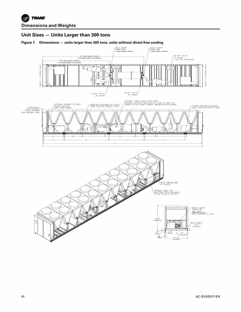
40 AC-SVX001F-EN
Unit Sizes — Units Larger than 300 tons
Figure 7. Dimensions — units larger than 300 tons, units without direct-free cooling
N (1-pass option, shown)O (2-pass option, not shown)
M (1-pass option, shown)P (2-pass option, not shown)
(1-pass option, shown)(1-pass option, shown)
(1115.0mm)
DDiimmeennssiioonnss aanndd WWeeiigghhttss

AC-SVX001F-EN 41
Table 19. Dimensions — units larger than 300 tons
Unit Size (tons) 375, 440 375, 440 380, 450 500, 550
Unit Voltage(a) All except 575V 575V All All
Harmonic Filter(b) Standard Low Low and Standard Low and Standard
Dimension in mm in mm in mm in mm
A 55.1 1400 78.7 2000 78.7 2000 78.7 2000
B 102.4 2600 149.6 3800 149.6 3800 149.6 3800
C 183.4 4658 236.2 6000 236.2 6000 236.2 6000
D 301.5 7658 354.3 9000 354.3 9000 354.3 9000
E 498.3 9658 433.1 11000 433.1 11000 433.1 11000
F n/a n/a 551.2 14000 551.2 14000 551.2 14000
G 80.0 2032 80.0 2032 80.0 2032 80.0 2032
H 199.2 5060 252.0 6402 252.0 6402 252.0 6402
I 335.6 8525 388.5 9867 388.5 9867 388.5 9867
J 446.9 11350 545.4 13852 545.4 13852 545.4 13852
K 504.3 12810 610.0 15494 610.0 15494 610.0 15494
L 510.4 12965 616.1 15648 616.1 15648 616.1 15648
M 200.7 5098 200.7 5098 253.5 6440 253.5 6440
N 333.9 8480 333.9 8480 386.7 9822 389.8 9902
O 200.7 5098 200.7 5098 253.5 6440 253.5 6440
P 200.7 5098 200.7 5098 253.5 6440 253.5 6440(a) Unit voltage defined by model number digit 9: 575V = F.(b) Harmonic filter defined by model number digit 44: STANDARD = X; LOW = L.
DDiimmeennssiioonnss aanndd WWeeiigghhttss

42 AC-SVX001F-EN
Figure 8. Dimensions — units larger than 300 tons, with direct free-cooling option
NNoottee:: Dimensions not shown remain the same as units without direct free-cooling option.
DDiimmeennssiioonnss aanndd WWeeiigghhttss

AC-SVX001F-EN 43
Installation MechanicalLocation RequirementsSound Considerations• Locate the unit away from sound-sensitive areas.
• Install the optional elastomeric isolators under theunit. See Isolation and Sound Emission section.
• Chilled water piping should not be supported bychiller frame.
• Install rubber vibration isolators in all water piping.
• Use flexible electrical conduit.
• Seal all wall penetrations.
NNoottee:: Consult an acoustical engineer for criticalapplications.
FoundationProvide rigid, non-warping mounting pads or aconcrete foundation of sufficient strength and mass tosupport the applicable operating weight (i.e., includingcompleted piping, and full operating charges ofrefrigerant, oil and water). The expectation for ourequipment is that attached piping is fully supported byan independent structure/system, without beingconnected to the waterbox. Once in place, the unitmust be level within 1/2” (12.7 mm) across the lengthand width of the unit. Trane is not responsible forequipment problems resulting from an improperlydesigned or constructed foundation.
ClearancesProvide enough space around the unit to allow theinstallation and maintenance personnel unrestrictedaccess to all service points. See submittal drawings forthe unit dimensions, to provide sufficient clearance forthe opening of control panel doors and unit service.See Dimensions and Weights chapter for minimumclearances. In all cases, local codes which requireadditional clearances will take precedence over theserecommendations.
For close spacing information, see AC-PRB001*-EN.
Lifting and Moving Instructions
WWAARRNNIINNGGHHeeaavvyy OObbjjeecctt!!FFaaiilluurree ttoo ffoollllooww iinnssttrruuccttiioonnss bbeellooww ccoouulldd rreessuulltt iinnuunniitt ddrrooppppiinngg wwhhiicchh ccoouulldd rreessuulltt iinn ddeeaatthh oorrsseerriioouuss iinnjjuurryy,, aanndd eeqquuiippmmeenntt oorr pprrooppeerrttyy--oonnllyyddaammaaggee..EEnnssuurree tthhaatt aallll tthhee lliiffttiinngg eeqquuiippmmeenntt uusseedd iisspprrooppeerrllyy rraatteedd ffoorr tthhee wweeiigghhtt ooff tthhee uunniitt bbeeiinngglliifftteedd.. EEaacchh ooff tthhee ccaabblleess ((cchhaaiinnss oorr sslliinnggss)),, hhooookkss,,aanndd sshhaacckklleess uusseedd ttoo lliifftt tthhee uunniitt mmuusstt bbee ccaappaabblleeooff ssuuppppoorrttiinngg tthhee eennttiirree wweeiigghhtt ooff tthhee uunniitt.. LLiiffttiinnggccaabblleess ((cchhaaiinnss oorr sslliinnggss)) mmaayy nnoott bbee ooff tthhee ssaammeelleennggtthh.. AAddjjuusstt aass nneecceessssaarryy ffoorr eevveenn uunniitt lliifftt..
WWAARRNNIINNGGIImmpprrooppeerr UUnniitt LLiifftt!!FFaaiilluurree ttoo pprrooppeerrllyy lliifftt uunniitt iinn aa LLEEVVEELL ppoossiittiioonnccoouulldd rreessuulltt iinn uunniitt ddrrooppppiinngg aanndd ppoossssiibbllyyccrruusshhiinngg ooppeerraattoorr//tteecchhnniicciiaann wwhhiicchh ccoouulldd rreessuulltt iinnddeeaatthh oorr sseerriioouuss iinnjjuurryy,, aanndd eeqquuiippmmeenntt oorrpprrooppeerrttyy--oonnllyy ddaammaaggee..TTeesstt lliifftt uunniitt aapppprrooxxiimmaatteellyy 2244 iinncchheess ((6611 ccmm)) ttoovveerriiffyy pprrooppeerr cceenntteerr ooff ggrraavviittyy lliifftt ppooiinntt.. TToo aavvooiiddddrrooppppiinngg ooff uunniitt,, rreeppoossiittiioonn lliiffttiinngg ppooiinntt iiff uunniitt iissnnoott lleevveell..
WWAARRNNIINNGGPPrrooppeerr LLiiffttiinngg CCoonnffiigguurraattiioonnRReeqquuiirreedd!!FFaaiilluurree ttoo ffoollllooww iinnssttrruuccttiioonnss bbeellooww ccoouulldd ccaauusseetthhee uunniitt ttoo ddrroopp wwhhiicchh ccoouulldd rreessuulltt iinn ddeeaatthh,,sseerriioouuss iinnjjuurryy oorr eeqquuiippmmeenntt ddaammaaggee..UUssee OONNLLYY lliiffttiinngg llooccaattiioonnss ddeessiiggnnaatteedd wwiitthh llaabbeellsshhoowwnn bbeellooww.. DDOO NNOOTT uussee llooccaattiioonnss mmaarrkkeedd wwiitthhddoo--nnoott--lliifftt llaabbeell.. SSeeee ffoolllloowwiinngg ffiigguurreess ffoorraacccceeppttaabbllee lliiffttiinngg ccoonnffiigguurraattiioonn,, aanndd rreeffeerr ttoo llaabbeellssoonn tthhee uunniitt..
Figure 9. Lift/Do Not Lift labels
Lift Do Not Lift

44 AC-SVX001F-EN
NNOOTTIICCEEEEqquuiippmmeenntt DDaammaaggee!!MMoovviinngg tthhee cchhiilllleerr uussiinngg aa ffoorrkk lliifftt ccoouulldd rreessuulltt iinneeqquuiippmmeenntt oorr pprrooppeerrttyy--oonnllyy ddaammaaggee..DDoo nnoott uussee aa ffoorrkk lliifftt ttoo mmoovvee tthhee cchhiilllleerr!!
IImmppoorrttaanntt::
• See unit nameplate and/or unitsubmittal for total shipping weight.
• See following figures for unit liftingconfiguration.
• See Dimensions and Weights chapter,or unit submittal, for lifting pointlocations.
• Diagram is generic representation ofunit.
• The maximum rigging angle at eachchiller lift point is 30° from vertical.
• Do not allow lifting straps to contactunit during lifting.
Figure 10. 4–point lift configuration — 4V and 5V units (model number digit 25 = A, B)
Spreader bar/lifting rig width: 96 inch
Figure 11. 6–point lift configuration — 6V and 7V units (model number digit 25 = C, D)
Spreader bar/lifting rig width: 96 inch
Figure 12. 8–point lift configuration — 8V, 9V, and 11V units (model number digit 25 = E, F, or H)
Spreader bar/lifting rig width:120 inch (11V units with direct free-cooling option)96 inch (all other units)
IInnssttaallllaattiioonn MMeecchhaanniiccaall

AC-SVX001F-EN 45
Figure 13. 10–point lift configuration—300 ton extended free cooling units (model number digit 42 = E, F)
Spreader bar/lifting rig width:96 inch
Isolation and Sound EmissionThe most effective form of isolation is to locate the unitaway from any sound sensitive area. Structurallytransmitted sound can be reduced by elastomericvibration eliminators. Spring isolators are notrecommended. Consult an acoustical engineer incritical sound applications.
For maximum isolation effect, isolate water lines andelectrical conduit. Wall sleeves and rubber isolatedpiping hangers can be used to reduce the soundtransmitted through water piping. To reduce the soundtransmitted through electrical conduit, use flexibleelectrical conduit.
State and local codes on sound emissions shouldalways be considered. Since the environment in whicha sound source is located affects sound pressure, unitplacement must be carefully evaluated. Sound powerlevels for Stealth chillers are available on request.
Unit Isolation and LevelingFor additional reduction of sound and vibration, installthe optional elastomeric isolators.
Construct an isolated concrete pad for the unit orprovide concrete footings at the unit mounting points.
Mount the unit directly to the concrete pads orfootings.
Level the unit using the base rail as a reference. Theunit must be level within 1/4” (6.4 mm) over the entirelength and width. Use shims as necessary to level theunit.
Elastomeric IsolatorsNNoottee:: See unit submittal, or tables in this section, for
point weights, isolator locations and isolatorselections.
1. Secure the isolators to the mounting surface usingthe mounting slots in the isolator base plate. Do notfully tighten the isolator mounting bolts at this time.
2. Align the mounting holes in the base of the unitwith the threaded positioning pins on the top of theisolators.
3. Lower the unit onto the isolators and secure theisolator to the unit with a nut.
4. Level the unit carefully. Fully tighten the isolatormounting bolts.
IInnssttaallllaattiioonn MMeecchhaanniiccaall

46 AC-SVX001F-EN
Figure 14. Elastomeric isolator
0.50 in 1.60±0.25
Mounting molded in neoprene
3.0
2.75
0.38
1/2 - 13NC - 2B
0.56 in
FE
G
D A
B
C
Table 20. Elastomeric isolator specifications
IsolatorMax Load(lbs)
MaxDeflection
(in)A B C D E F G Type
Black 60 1100 0.5 2.5 2.88 0.25 1.13 5.50 4.12 3.38 RDP3-WR
Brown 61 1500 0.5 3.0 2.75 0.38 1.60 6.25 5.00 4.63 RDP4-WR
Red 62 2250 0.5 3.0 2.75 0.38 1.60 6.25 5.00 4.63 RDP4-WR
Green 63 3000 0.5 3.0 2.75 0.38 1.60 6.25 5.00 4.63 RDP4-WR
Black 64 4000 0.5 3.0 2.75 0.38 1.60 6.25 5.00 4.63 RDP4-WR
Elastomeric PadsElastomeric pads are required for units with seismicoption (model number digit 17 = D). See Table 34, p. 55for information on quantities required and mountingpoint identification.
Elastomeric pads ship inside the unit control panel.They are provided with an isolation washer and 3/4”free hole in the center of the plate.
Figure 15. Isolation pad — installed
Grade 8 WasherFender Washer
IsolationWasher
Unit Base Rail
Steel Plate
Isolation Pad
Grade 8 Bolt
Building Support Structure
Grade 8 WasherFender Washer
(Washers under support structure recommended if job site has an I-beam or C-channel.)
Nut
Table 21. Seismically rated elastomeric isolation pad
Dimension (in.)
Model MaxLoad
Length Width Height
B-36 2520 6 6 0.625
IInnssttaallllaattiioonn MMeecchhaanniiccaall

AC-SVX001F-EN 47
Mounting Locations, Weights, IsolatorsSee figure below for mounting point locationdesignations.
Figure 16. Mounting point locations (top view)
2 4 6 8 10 12 14 16
1 3 5 7 9 11 13 15
Mai
n Co
ntro
l Pan
el(W
ith u
ser i
nter
face
TD
7)
Control Panel(N
ot present on all con!gurations)
NNoottee:: Quantity of isolators varies with unit. See submittal for actual number required for specific unit.
Point Weights
150 to 300 Ton Units
Table 22. Point weights, 150 to 275 ton units without direct free-cooling option - I-P (lb)
UnitSize
CondenserLength
PointWeights (lb)
1 2 3 4 5 6 7 8 9 10
Standard Length Units
150 4V 1820 1610 1870 1680 1720 1790 740 940 n/a n/a
1654V 1820 1620 1870 1690 1730 1800 740 940 n/a n/a
5V 1760 1710 1910 1860 1950 1970 950 1100 n/a n/a
1804V 1830 1630 1890 1710 1750 1830 750 960 n/a n/a
5V 1780 1760 1940 1930 1980 2050 960 1130 n/a n/a
2005V 1780 1770 1950 1930 1990 2060 960 1130 n/a n/a
6V 1800 1850 1990 1910 1970 1950 1290 1400 280 300
2255V 1960 1880 2170 2150 2210 2330 1020 1270 n/a n/a
6V 2000 1930 2240 2140 2120 2130 1370 1550 280 330
2505V 1970 1890 2180 2160 2220 2340 1020 1270 n/a n/a
6V 2050 1980 2300 2200 2180 2190 1390 1560 280 330
2756V 2060 2000 2320 2220 2200 2200 1400 1570 280 330
7V 1950 1850 2120 1990 2040 2010 1840 2030 870 960
Extended Length Units
150 4V 2270 2030 2240 2050 1890 2090 740 1010 n/a n/a
1654V 2270 2030 2240 2060 1900 2090 750 1020 n/a n/a
5V 2190 1970 2320 2210 2340 2590 770 970 n/a n/a
1804V 2150 1940 2390 2250 2430 2780 780 980 n/a n/a
5V 2150 1940 2390 2250 2430 2780 780 980 n/a n/a
2005V 2150 1940 2390 2250 2440 2790 780 980 n/a n/a
6V 2590 2380 2360 2290 2040 2250 740 860 620 700
IInnssttaallllaattiioonn MMeecchhaanniiccaall

48 AC-SVX001F-EN
Table 22. Point weights, 150 to 275 ton units without direct free-cooling option - I-P (lb) (continued)
UnitSize
CondenserLength
PointWeights (lb)
1 2 3 4 5 6 7 8 9 10
2255V 2260 1990 2660 2470 2700 3160 820 1090 n/a n/a
6V 2810 2480 2620 2470 2240 2520 790 970 610 750
2505V 2260 1990 2680 2490 2720 3180 820 1090 n/a n/a
6V 2850 2520 2700 2550 2320 2590 810 990 600 730
2756V 2860 2530 2720 2560 2340 2610 810 990 600 730
7V 2700 2400 2620 2490 2500 2740 1000 1210 1020 1140Notes:
1. Weights include factory charge of refrigerant and oil, ultimate sound, and architectural louvered panels.2. Condenser length defined by model number digit 25: 4V = A; 5V = B; 6V = C; 7V = D3. All weights are plus/minus 10%4. Extended Length is required for voltages 200V, 230V, 575V model number digit 9 = A, B, F and harmonic filtration model
number digit 44 = L.
IInnssttaallllaattiioonn MMeecchhaanniiccaall

AC-SVX001F-EN 49
Tab
le23
.Pointweights,300
tonunitswithoutseismicoption-I-P
(lb)
Cond(a)
Free-
Cooling(b)Pump(c)
MountingLocation
12
34
56
78
910
11
12
13
14
15
16
StandardLengthUnits
7VNone
None
1950
1850
2130
2000
2050
2020
1840
2030
880
960
n/a
n/a
n/a
n/a
n/a
n/a
8VNone
None
1990
1940
2340
2240
2350
2310
1950
2060
750
870
n/a
n/a
n/a
n/a
n/a
n/a
8VTDFC
None
1760
1810
2380
2390
2320
2490
2300
2590
1720
1760
1470
2280
n/a
n/a
n/a
n/a
8VTDFC
PUMP
1910
1960
1970
1960
2450
2600
1290
1900
1720
1890
2640
2830
2570
3340
n/a
n/a
8VDFCP
None
1940
1760
2030
2450
2670
2710
1990
2240
1910
2160
1750
2150
740
1010
n/a
n/a
8VDFCP
PUMP
1920
1780
1930
2350
2310
2430
1590
1880
1620
1930
2650
2940
2830
3280
780
1040
8VTIFC
None
1890
1880
1970
1930
2640
2750
2820
3100
3200
3230
1730
2310
n/a
n/a
n/a
n/a
8VIFCP
None
1890
1890
1980
1940
2640
2750
2810
3070
3120
3080
2210
2850
680
770
n/a
n/a
8VIFCP
PUMP
1900
1880
1990
1940
2650
2760
2800
3090
2930
3080
2480
2740
1750
1980
1610
1880
ExtendedLengthUnits(d)
7VNone
None
2710
2400
2630
2500
2510
2750
1000
1210
1020
1140
n/a
n/a
n/a
n/a
n/a
n/a
8VNone
None
2890
2490
2780
2580
2290
2480
1820
2090
710
810
n/a
n/a
n/a
n/a
n/a
n/a
8VTDFC
None
2710
2650
2490
1870
1830
2530
1860
1850
2010
2490
2120
3260
n/a
n/a
n/a
n/a
8VTDFC
PUMP
2860
2570
1980
1920
2410
2650
1730
2600
1350
1490
2800
2970
2680
3450
n/a
n/a
8VDFCP
None
2900
2400
2130
2320
2010
2440
1830
2340
1340
1720
1930
2500
1400
1480
560
620
8VDFCP
PUMP
2650
2180
2580
2800
1980
2320
1480
1720
1500
2230
2970
3130
3040
3480
690
950
8VTIFC
None
3180
2910
2920
2720
2160
2090
1670
2780
3270
2950
2300
2930
n/a
n/a
n/a
n/a
8VIFCP
None
2860
2530
2210
1910
2280
2710
1690
2060
1670
2050
2960
2880
2200
2450
700
940
8VIFCP
PUMP
3240
2900
2790
2680
2470
2750
1730
2030
1300
1500
2550
2740
3100
3220
2180
2710
Notes: 1.Weightsincludefactorychargeofrefrigerantandoil,ultim
atesounds,andarchitecturallouveredpanels.
2.Allweightsareplus/minus10%
(a)Condenserlengthdefinedbymodelnumberdigit25:7V=D;8V=E
(b)Free-coolingdefinedbymodelnumberdigit42:T=TDFC;H=DFCP;F=TIFC;E=IFCP
(c)PumpPackagedefinedbymodelnumberdigit40=5,6,7
(d)ExtendedLengthisrequiredforvoltages200V,230V,575Vmodelnumberdigit9=A,B,Fandharmonicfiltrationmodelnumberdigit44=L
IInnssttaallllaattiioonn MMeecchhaanniiccaall

50 AC-SVX001F-EN
Table 24. Point weights, 150 to 275 ton units without direct free-cooling option - SI (kg)
UnitSize
CondenserLength
PointWeight (kg)
1 2 3 4 5 6 7 8 9 10
Standard Length Units
150 4V 830 730 850 770 780 810 340 430 n/a n/a
1654V 830 740 850 770 790 820 340 430 n/a n/a
5V 800 780 870 840 890 900 430 500 n/a n/a
1804V 840 740 860 780 800 830 340 440 n/a n/a
5V 810 800 880 880 900 930 440 510 n/a n/a
2005V 810 800 890 880 910 940 440 520 n/a n/a
6V 820 840 910 870 890 890 590 640 130 140
2255V 890 860 990 980 1010 1060 470 580 n/a n/a
6V 910 880 1020 970 960 970 630 710 130 150
2505V 890 860 990 980 1010 1060 470 580 n/a n/a
6V 930 900 1050 1000 990 990 630 710 130 150
2756V 940 910 1060 1010 1000 1000 640 720 130 150
7V 890 840 960 910 930 920 840 920 400 440
Extended Length Units
150 4V 1030 920 1020 930 860 950 340 460 n/a n/a
1654V 1030 920 1020 940 860 950 340 460 n/a n/a
5V 990 900 1060 1010 1070 1180 350 440 n/a n/a
1804V 980 880 1080 1020 1100 1260 350 450 n/a n/a
5V 980 880 1080 1020 1100 1260 350 450 n/a n/a
2005V 980 880 1090 1030 1110 1270 360 450 n/a n/a
6V 1180 1080 1070 1040 930 1020 340 390 280 320
2255V 1030 900 1210 1120 1230 1440 370 500 n/a n/a
6V 1280 1130 1190 1120 1020 1140 360 440 280 340
2505V 1030 910 1220 1130 1240 1440 370 500 n/a n/a
6V 1300 1150 1230 1160 1050 1180 370 450 280 330
2756V 1300 1150 1240 1170 1060 1190 370 450 280 330
7V 1230 1090 1190 1130 1140 1250 450 550 460 520Notes:
1. Weights include factory charge of refrigerant and oil, ultimate sound, and architectural louvered panels.2. Condenser length defined by model number digit 25: 4V = A; 5V = B; 6V = C; 7V = D3. All weights are plus/minus 10%4. Extended Length is required for voltages 200V, 230V, 575V model number digit 9 = A, B, F and harmonic filtration model
number digit 44 = L.
IInnssttaallllaattiioonn MMeecchhaanniiccaall

AC-SVX001F-EN 51
Tab
le25
.Pointweights,300
tonunitswithoutseismicoption-S
I(kg
)
Cond(a)
Free-
Cooling(b)Pump(c)
MountingLocation
12
34
56
78
910
11
12
13
14
15
16
StandardLengthUnits
7VNone
None
880
840
970
910
930
920
830
920
400
440
n/a
n/a
n/a
n/a
n/a
n/a
8VNone
None
900
880
1060
1020
1070
1050
880
930
340
390
n/a
n/a
n/a
n/a
n/a
n/a
8VTDFC
None
800
820
1080
1080
1050
1130
1040
1170
780
800
670
1030
n/a
n/a
n/a
n/a
8VTDFC
PUMP
870
890
890
890
1110
1180
590
860
780
860
1200
1280
1170
1510
n/a
n/a
8VDFCP
None
880
800
920
1110
1210
1230
900
1020
870
980
790
980
340
460
n/a
n/a
8VDFCP
PUMP
870
810
880
1070
1050
1100
720
850
730
880
1200
1330
1280
1490
350
470
8VTIFC
None
860
850
890
880
1200
1250
1280
1410
1450
1470
780
1050
n/a
n/a
n/a
n/a
8VIFCP
None
860
860
900
880
1200
1250
1270
1390
1420
1400
1000
1290
310
350
n/a
n/a
8VIFCP
PUMP
860
850
900
880
1200
1250
1270
1400
1330
1400
1120
1240
790
900
730
850
ExtendedLengthUnits(d)
7VNone
None
1230
1090
1190
1130
1140
1250
450
550
460
520
n/a
n/a
n/a
n/a
n/a
n/a
8VNone
None
1310
1130
1260
1170
1040
1120
830
950
320
370
n/a
n/a
n/a
n/a
n/a
n/a
8VTDFC
None
1230
1200
1130
850
830
1150
840
840
910
1130
960
1480
n/a
n/a
n/a
n/a
8VTDFC
PUMP
1300
1170
900
870
1090
1200
780
1180
610
680
1270
1350
1220
1560
n/a
n/a
8VDFCP
None
1320
1090
970
1050
910
1110
830
1060
610
780
880
1130
640
670
250
280
8VDFCP
PUMP
1200
990
1170
1270
900
1050
670
780
680
1010
1350
1420
1380
1580
310
430
8VTIFC
None
1440
1320
1320
1230
980
950
760
1260
1480
1340
1040
1330
n/a
n/a
n/a
n/a
8VIFCP
None
1300
1150
1000
870
1030
1230
770
930
760
930
1340
1310
1000
1110
320
430
8VIFCP
PUMP
1470
1320
1270
1220
1120
1250
780
920
590
680
1160
1240
1410
1460
990
1230
Notes: 1.Weightsincludefactorychargeofrefrigerantandoil,ultim
atesounds,andarchitecturallouveredpanels.
2.Allweightsareplus/minus10%
(a)Condenserlengthdefinedbymodelnumberdigit25:7V=D;8V=E
(b)Free-coolingdefinedbymodelnumberdigit42:T=TDFC;H=DFCP;F=TIFC;E=IFCP
(c)PumpPackagedefinedbymodelnumberdigit40=5,6,7
(d)ExtendedLengthisrequiredforvoltages200V,230V,575Vmodelnumberdigit9=A,B,Fandharmonicfiltrationmodelnumberdigit44=L
IInnssttaallllaattiioonn MMeecchhaanniiccaall

52 AC-SVX001F-EN
Table 26. Point weights, 150 to 275 ton units with direct free-cooling option - I-P (lb)
UnitSize
PointWeights (lb)
1 2 3 4 5 6 7 8 9 10
Standard Length Units-Direct Free Cooling
165 1910 1960 2010 2070 2620 2880 1200 1530 n/a n/a
180 1750 1860 2480 2600 2560 2810 1290 1610 n/a n/a
200 1900 2030 2130 2210 3070 3340 1090 1310 780 930
225 1840 1980 2850 2870 3090 3000 1080 1960 840 720
250 1880 2030 2930 2950 3160 3060 1090 1970 830 710
275 1901 1991 2638 2699 2506 2746 2314 2972 1734 2563
Extended Length Units- Direct Free Cooling
165 2390 2220 2500 2470 2230 2580 2040 2630 n/a n/a
180 2350 2220 2980 3040 2880 3290 1120 1560 n/a n/a
200 2700 2620 2720 2690 2690 2710 1060 2070 1010 980
225 2910 2760 2960 2760 2880 2660 1120 2620 1030 960
250 2950 2810 3050 2840 2960 2740 1140 2650 1010 930
275 2919 2695 2772 2820 2484 2999 2468 3403 1591 2332Notes:
1. Weights include factory charge of refrigerant and oil, ultimate sound, and architectural louvered panels.2. All weights are plus/minus 10%3. Extended Length is required for voltages 200V, 230V, 575V model number digit 9 = A, B, F and harmonic filtration model
number digit 44 = L.
Table 27. Point weights, 300 ton units with seismic option - I-P (lb)
Cond(a) Free-Cooling(b)
Mounting Location
1 2 3 4 5 6 7 8 9 10 11 12
Seismic Standard Length Units
7V None 1990 1900 2170 2060 2120 2080 1950 2120 980 1060 n/a n/a
8V None 2080 2030 2410 2300 2340 2300 1680 1790 710 730 580 670
8V TDFC 1810 1880 2610 2670 2690 2890 2280 2520 1550 1590 1440 2230
Seismic Extended Length Units(c)
7V None 2740 2430 2690 2560 2610 2850 1060 1280 1110 1240 n/a n/a
8V None 2980 2580 2850 2650 2320 2500 1590 1860 580 620 600 670
8V TDFC 2740 2670 2850 2170 2390 3330 2100 2140 1810 2250 1570 2520Notes:
1. Weights include factory charge of refrigerant and oil, ultimate sounds, and architectural louvered panels.2. All weights are plus/minus 10%
(a) Condenser length defined by model number digit 25: 7V = D; 8V = E(b) Free-cooling defined by model number digit 42: T=TDFC; H=DFCP; F=TIFC; E=IFCP(c) Extended Length is required for voltages 200V, 230V, 575V model number digit 9=A,B,F and harmonic filtration model number digit 44=L
Table 28. Point weights, 150 to 275 ton units with direct free-cooling option - SI (kg)
UnitSize
PointWeight (kg)
1 2 3 4 5 6 7 8 9 10
Standard Length Units-Direct Free Cooling
165 870 890 910 940 1190 1300 540 690 n/a n/a
180 800 840 1120 1180 1160 1280 580 730 n/a n/a
200 860 920 970 1000 1390 1520 500 600 350 420
225 830 890 1290 1300 1400 1360 490 890 380 360
IInnssttaallllaattiioonn MMeecchhaanniiccaall

AC-SVX001F-EN 53
Table 28. Point weights, 150 to 275 ton units with direct free-cooling option - SI (kg) (continued)
UnitSize
PointWeight (kg)
1 2 3 4 5 6 7 8 9 10
250 850 920 1330 1340 1430 1390 500 900 380 320
275 864 905 1199 1227 1139 1248 1052 1351 788 1165
Extended Length Units- Direct Free Cooling
165 1080 1010 1130 1120 1010 1170 930 1190 n/a n/a
180 1070 1000 1350 1380 1310 1490 510 710 n/a n/a
200 1220 1190 1230 1220 1220 1230 480 940 460 450
225 1320 1250 1340 1250 1300 1210 510 1190 470 440
250 1340 1270 1380 1290 1340 1240 510 1200 460 420
275 1327 1225 1260 1282 1129 1363 1122 1547 723 1060Notes:
1. Weights include factory charge of refrigerant and oil, ultimate sound, and architectural louvered panels.2. All weights are plus/minus 10%3. Extended Length is required for voltages 200V, 230V, 575V model number digit 9 = A, B, F and harmonic filtration model
number digit 44 = L.
Table 29. Point weights, 300 ton units with seismic option - SI (kg)
Cond(a) Free-Cooling(b)
Mounting Location
1 2 3 4 5 6 7 8 9 10 11 12
Seismic Standard Length Units
7V None 903 862 984 934 962 943 885 962 445 481 n/a n/a
8V None 943 921 1093 1043 1061 1042 762 812 322 331 263 304
8V TDFC 821 853 1184 1211 1220 1311 1034 1143 703 721 653 1012
Seismic Extended Length Units(c)
7V None 1243 1102 1220 1161 1184 1293 481 581 503 562 n/a n/a
8V None 1352 1170 1293 1202 1052 1134 721 844 580 281 272 304
8V TDFC 1243 1211 1293 984 1084 1510 953 971 821 1021 712 1143Notes:
1. Weights include factory charge of refrigerant and oil, ultimate sounds, and architectural louvered panels.2. All weights are plus/minus 10%
(a) Condenser length defined by model number digit 25: 7V = D; 8V = E(b) Free-cooling defined by model number digit 42: T=TDFC; H=DFCP; F=TIFC; E=IFCP(c) Extended Length is required for voltages 200V, 230V, 575V model number digit 9=A,B,F and harmonic filtration model number digit 44=L
Units Larger than 300 Tons
Table 30. Point weights, units larger than 300 tons - IP (lb)
UnitSize
PointWeights (lb)
1 2 3 4 5 6 7 8 9 10 11 12
Standard Unit
375 1430 1736 1525 1753 1764 1834 1975 1688 2305 1667 n/a n/a
380 1405 1669 1434 1579 1647 1646 1746 1549 1740 1474 1731 1548
440 1430 1736 1525 1753 1764 1834 1975 1688 2305 1667 n/a n/a
450 1405 1669 1434 1579 1647 1646 1746 1549 1740 1474 1731 1548
500 1616 1470 1634 1743 1855 1906 1987 1905 1978 1819 1860 1860
550 1616 1470 1634 1743 1855 1906 1987 1905 1978 1819 1860 1860
Unit with 575V or low harmonic filter(a)
375 1947 2433 1929 2264 1960 2048 1658 1412 1412 985 1220 663
IInnssttaallllaattiioonn MMeecchhaanniiccaall

54 AC-SVX001F-EN
Table 30. Point weights, units larger than 300 tons - IP (lb) (continued)
UnitSize
PointWeights (lb)
1 2 3 4 5 6 7 8 9 10 11 12
380 1577 2102 1497 1774 1638 1669 1769 1527 1885 1506 2181 1728
440 1947 2433 1929 2264 1960 2048 1658 1412 1412 985 1220 663
450 1577 2102 1497 1774 1638 1669 1769 1527 1885 1506 2181 1728
500 1568 2050 1533 1829 1734 1878 1929 1965 2049 2010 2269 2040
550 1568 2050 1533 1829 1734 1878 1929 1965 2049 2010 2269 2040
(a) Units where unit voltage = 575V (model number digit 9 = F) or where harmonic filter = low (model number digit 44 = L)
Table 31. Point weights, units larger than 300 tons - SI (kg)
UnitSize
PointWeight (kg)
1 2 3 4 5 6 7 8 9 10 11 12
Standard Unit
375 648 787 691 795 800 832 895 765 1045 756 n/a n/a
380 637 757 650 716 747 746 792 702 789 668 785 702
440 648 787 691 795 800 832 895 765 1045 756 n/a n/a
450 637 757 650 716 747 746 792 702 789 668 785 702
500 733 666 741 790 841 864 901 864 897 825 843 843
550 733 666 741 790 841 864 901 864 897 825 843 843
Unit with 575V or low harmonic filter(a)
375 883 1103 875 1026 889 929 752 640 640 447 553 301
380 715 953 679 804 743 757 802 692 855 683 989 783
440 883 1103 875 1026 889 929 752 640 640 447 553 301
450 715 953 679 804 743 757 802 692 855 683 989 783
500 711 929 695 829 786 851 875 891 929 911 1029 925
550 711 929 695 829 786 851 875 891 929 911 1029 925
(a) Units where unit voltage = 575V (model number digit 9 = F) or where harmonic filter = low (model number digit 44 = L)
Isolator Selections
150 to 300 Ton UnitsSee Dimensions and Weights chapter for isolatormounting position dimensions.
Table 32. Elastomeric isolator selections, 150 to 275 ton units without direct free-cooling
CondenserLength
Isolator Position
1 2 3 4 5 6 7 8 9 10
Standard Length Units
4V Green 63 Green 63 Green 63 Green 63 Green 63 Green 63 Brown 61 Brown 61 - -
5V Green 63 Green 63 Green 63 Green 63 Green 63 Green 63 Red 62 Red 62 - -
6V Green 63 Green 63 Green 63 Green 63 Green 63 Green 63 Green 63 Green 63 Black 60 Black 60
7V Green 63 Green 63 Green 63 Green 63 Green 63 Green 63 Green 63 Green 63 Brown 61 Brown 61
7V
8V Green 63 Green 63 Green 63 Green 63 Green 63 Green 63 Green 63 Green 63 Brown 61 Brown 61
Extended Length Units
4V Green 63 Green 63 Green 63 Green 63 Green 63 Green 63 Brown 61 Brown 61 - -
IInnssttaallllaattiioonn MMeecchhaanniiccaall

AC-SVX001F-EN 55
Table 32. Elastomeric isolator selections, 150 to 275 ton units without direct free-cooling (continued)
CondenserLength
Isolator Position
1 2 3 4 5 6 7 8 9 10
5V Black 64 Black 64 Black 64 Black 64 Black 64 Black 64 Brown 61 Brown 61 - -
6V Black 64 Black 64 Black 64 Black 64 Black 64 Black 64 Brown 61 Brown 61 Brown 61 Brown 61
7V Black 64 Black 64 Black 64 Black 64 Black 64 Black 64 Brown 61 Brown 61 Brown 61 Brown 61
7V Black 64 Black 64 Black 64 Black 64 Black 64 Black 64 Black 65 Black 66 Red 62 Green 63Notes:
1. Condenser length defined by model number digit 25: 4V = A; 5V = B; 6V = C; 7V = D2. Extended Length is required for voltages 200V, 230V, 575V model number digit 9 = A, B ,F and harmonic filtration model number digit
44 = L.
Table 33. Elastomeric isolator selections, 150 to 275 ton units with direct free-cooling
Unit SizeIsolator Position
1 2 3 4 5 6 7 8 9 10
Standard Length Units-Direct Free Cooling
165 Green 63 Green 63 Green 63 Green 63 Black 64 Black 64 Green 63 Green 63 - -
180 Green 63 Green 63 Black 64 Black 64 Black 64 Black 64 Green 63 Green 63 - -
200 Green 63 Green 63 Green 63 Green 63 Black 64 Black 64 Brown 61 Brown 61 Brown 61 Brown 61
225/250 Green 63 Green 63 Black 64 Black 64 Black 64 Black 64 Brown 61 Green 63 Brown 61 Brown 61
275 Green 63 Green 63 Black 64 Black 64 Black 64 Black 64 Black 64 Black 64 Green 63 Green 63
300 Green 63 Green 63 Black 64 Black 64 Black 64 Black 64 Black 64 Black 64 Brown 61 Green 63
Extended Length Units-Direct Free Cooling
165 Black 64 Black 64 Black 64 Black 64 Black 64 Black 64 Black 64 Black 64 - -
180 Green 63 Green 63 Black 64 Black 64 Black 64 Black 64 Brown 61 Green 63 - -
200 Green 63 Green 63 Green 63 Green 63 Green 63 Green 63 Brown 61 Green 63 Brown 61 Brown 61
225/250 Black 64 Black 64 Black 64 Black 64 Black 64 Black 64 Brown 61 Black 64 Brown 61 Brown 61
275 Black 64 Black 64 Black 64 Black 64 Black 64 Black 64 Black 64 Black 64 Red 62 Green 63Notes:
1. Condenser length defined by model number digit 25: 4V = A; 5V = B; 6V = C; 7V = D2. Extended Length is required for voltages 200V, 230V, 575V model number digit 9 = A, B ,F and harmonic filtration model number digit
44 = L.
Table 34. Elastomeric pad quantities - units with seismic option
Unit Size Condenser LengthUnit Length
Standard Ext
150, 165,180 4V 8 8
165, 180, 200, 225, 250 5V 8 8
200, 225, 250, 275 6V 10 10
275 7V 10 10
300 8V 12 12Notes:
1. Condenser length defined by model number digit 25: 4V = A; 5V = B; 6V = C; 7V = D; 8V = E2. Extended Length is required for voltages 200V, 230V, 575V model number digit 9 = A, B ,F and harmonic filtration model
number digit 44 = L.
IInnssttaallllaattiioonn MMeecchhaanniiccaall

56 AC-SVX001F-EN
Tab
le35
.Elastomericisolatorselections,30
0tonunits
Cond(a)
Free-
Cooling(b)Pump(c)
IsolatorPosition
12
34
56
78
910
11
12
13
14
15
16
StandardLengthUnits
7VNone
None
Green
63Green
63Green
63Green
63Green
63Green
63Green
63Green
63Brown
61Brown
61-
--
--
-
8VNone
None
Black
64Black
64Black
64Black
64Black
64Black
64Black
64Black
64Brown
61Brown
61-
--
--
-
8VTDFC
None
Green
63Green
63Black
64Black
64Black
64Black
64Black
64Black
64Green
63Green
63Green
63Black
64-
--
-
8VTDFC
PUMP
Green
63Green
63Green
63Green
63Black
64Black
64Red62
Green
63Green
63Green
63Black
64Black
64Black
64Black
64-
-
8VDFCP
None
Green
63Green
63Green
63Black
64Black
64Black
64Green
63Green
63Green
63Green
63Green
63Green
63Brown
61Brown
61-
-
8VDFCP
PUMP
Green
63Green
63Green
63Black
64Black
64Black
64Green
63Green
63Green
63Green
63Black
64Black
64Black
64Black
64Brown
61Brown
61
8VTIFC
None
Green
63Green
63Green
63Green
63Black
64Black
64Black
64Black
64Black
64Black
64Red62
Green
63-
--
-
8VIFCP
None
Green
63Green
63Green
63Green
63Black
64Black
64Black
64Black
64Black
64Black
64Green
63Black
64Gray60
Gray60
--
8VIFCP
PUMP
Green
63Green
63Green
63Green
63Black
64Black
64Black
64Black
64Black
64Black
64Black
64Black
64Green
63Green
63Green
63Green
63ExtendedLengthUnits(d)
7VNone
None
Black
64Black
64Black
64Black
64Black
64Black
64Brown
61Brown
61Brown
61Brown
61-
--
--
-
8VNone
None
Black
64Black
64Black
64Black
64Black
64Black
64Black
64Black
64Brown
61Brown
61-
--
--
-
8VTDFC
None
Black
64Black
64Black
64Green
63Green
63Black
64Green
63Green
63Green
63Black
64Green
63Black
64-
--
-
8VTDFC
PUMP
Black
64Black
64Green
63Green
63Black
64Black
64Green
63Black
64Red62
Red62
Black
64Black
64Black
64Black
64-
-
8VDFCP
None
Black
64Black
64Green
63Black
64Green
63Black
64Green
63Black
64Red62
Green
63Green
63Black
64Gray60
Gray60
--
8VDFCP
PUMP
Black
64Green
63Black
64Black
64Green
63Green
63Red62
Red62
Red62
Green
63Black
64Black
64Black
64Black
64Gray60
Gray60
8VTIFC
None
Black
64Black
64Black
64Black
64Green
63Green
63Red62
Black
64Black
64Black
64Green
63Black
64-
--
-
8VIFCP
None
Black
64Black
64Green
63Green
63Green
63Black
64Red62
Green
63Red62
Green
63Black
64Black
64Green
63Green
63Gray60
Gray60
8VIFCP
PUMP
Black
64Black
64Black
64Black
64Black
64Black
64Green
63Green
63Red62
Red62
Black
64Black
64Black
64Black
64Green
63Black
64(a)Condenserlengthdefinedbymodelnumberdigit25:7V=D;8V=E
(b)Free-coolingdefinedbymodelnumberdigit42:T=TDFC;H=DFCP;F=TIFC;E=IFCP
(c)PumpPackagedefinedbymodelnumberdigit40=5,6,7
(d)ExtendedLengthisrequiredforvoltages200V,230V,575Vmodelnumberdigit9=A,B,Fandharmonicfiltrationmodelnumberdigit44=L
IInnssttaallllaattiioonn MMeecchhaanniiccaall

AC-SVX001F-EN 57
Units Larger than 300 Tons
Table 36. Elastomeric isolator selections, units larger than 300 tons without direct free-cooling
UnitSize
Isolator Position
1 2 3 4 5 6 7 8 9 10 11 12
375 Green 63 Green 63 Green 63 Green 63 Green 63 Green 63 Green 63 Green 63 Green 63 Green 63 n/a n/a
375(a) Green 63 Green 63 Green 63 Green 63 Green 63 Green 63 Green 63 Green 63 Green 63 Green 63 Green 63 Green 63
380 Green 63 Green 63 Green 63 Green 63 Green 63 Green 63 Green 63 Green 63 Green 63 Green 63 Green 63 Green 63
440 Green 63 Green 63 Green 63 Green 63 Green 63 Green 63 Green 63 Green 63 Green 63 Green 63 n/a n/a
440(a) Green 63 Green 63 Green 63 Green 63 Green 63 Green 63 Green 63 Green 63 Green 63 Green 63 Green 63 Green 63
450 Green 63 Green 63 Green 63 Green 63 Green 63 Green 63 Green 63 Green 63 Green 63 Green 63 Green 63 Green 63
500 Green 63 Green 63 Green 63 Green 63 Green 63 Green 63 Green 63 Green 63 Green 63 Green 63 Green 63 Green 63
550 Green 63 Green 63 Green 63 Green 63 Green 63 Green 63 Green 63 Green 63 Green 63 Green 63 Green 63 Green 63
(a) Units where unit voltage = 575V (model number digit 9 = F) or where harmonic filter = low (model number digit 44 = L)
Table 37. Elastomeric isolator selections, units larger than 300 tons with direct free-cooling
UnitSize
Isolator Position
1 2 3 4 5 6 7 8 9 10 11 12
375 n/a n/a n/a n/a n/a n/a n/a n/a n/a n/a n/a n/a
375(a) n/a n/a n/a n/a n/a n/a n/a n/a n/a n/a n/a n/a
380 Grey 64 Grey 64 Grey 64 Grey 64 Grey 64 Grey 64 Grey 64 Grey 64 Grey 64 Grey 64 Grey 64 Grey 64
440 n/a n/a n/a n/a n/a n/a n/a n/a n/a n/a n/a n/a
440(a) n/a n/a n/a n/a n/a n/a n/a n/a n/a n/a n/a n/a
450 Grey 64 Grey 64 Grey 64 Grey 64 Grey 64 Grey 64 Grey 64 Grey 64 Grey 64 Grey 64 Grey 64 Grey 64
500 Grey 64 Grey 64 Grey 64 Grey 64 Grey 64 Grey 64 Grey 64 Grey 64 Grey 64 Grey 64 Grey 64 Grey 64
550 Grey 64 Grey 64 Grey 64 Grey 64 Grey 64 Grey 64 Grey 64 Grey 64 Grey 64 Grey 64 Grey 64 Grey 64
(a) Units where unit voltage = 575V (model number digit 9 = F) or where harmonic filter = low (model number digit 44 = L)
Compressor Mounting BoltRemovalUUnniittss wwiitthh IInnvviissiiSSoouunndd™™ UUllttiimmaattee OOppttiioonn ((MMooddeellNNuummbbeerr DDiiggiitt 1133 == EE))
For chillers built with InvisiSound Ultimate option,compressor mounting bolts must be removed toassure minimum noise during operation. Use a 24mmsocket to remove the (3) M15 x 75mm mounting boltsfor each compressor. They are located undercompressor mounting feet. See figure below.
IImmppoorrttaanntt::
• DO NOT DISCARD MOUNTING BOLTS.Store bolts in the control panel forfuture use.
• All mounting bolts MUST be reinstalledprior to compressor removal or unitmove.
NNOOTTIICCEEEEqquuiippmmeenntt DDaammaaggee!!FFaaiilluurree ttoo rreeiinnssttaallll bboollttss ccoouulldd ccaauussee sshhiiffttiinngg ooffppaarrttss aanndd rreessuulltt iinn eeqquuiippmmeenntt ddaammaaggee..DDoo nnoott rreemmoovvee ccoommpprreessssoorr oorr mmoovvee uunniitt wwiitthhoouuttrreeaattttaacchhiinngg ccoommpprreessssoorr mmoouunnttiinngg bboollttss..
Figure 17. Compressor mounting bolt removal
Compressor
Mounting Bolt
CompressorMounting
Foot
Isolator
IInnssttaallllaattiioonn MMeecchhaanniiccaall

58 AC-SVX001F-EN
DrainageLocate the unit near a large capacity drain for watervessel drain-down during shutdown or repair.Evaporators are provided with drain connections. Avent on top of evaporator waterbox prevents vacuumby allowing air into evaporator for complete drainage.All local and national codes apply.
Refrigerant Pressure ReliefValvesTable 38. Refrigerant pressure relief valves — 150 to
300 ton units
QtyReliefValveSetting
RatedCapacity(lba/min)
Connection Size (in)
Field(Pipe)
Factory(Shell)
Evaporator
2 200 28.9 3/4 7/8-14
Oil Separator
2 350 13.3 3/8 1/4-18
Table 39. Refrigerant pressure relief valves — unitslarger than 300 tons
QtyReliefValveSetting
RatedCapacity(lba/min)
Connection Size (in)
Field(Pipe)
Factory(Shell)
Evaporator
2 200 28.9 3/4 7/8-14
Single Inlet Oil Separator
1 or 0 350 13.3 3/8 1/4-18
Dual Inlet Oil Separator
1 or 2 350 13.3 3/8 3/8
IInnssttaallllaattiioonn MMeecchhaanniiccaall

AC-SVX001F-EN 59
Evaporator PipingAvailable pass configurations:
• 150 to 300 ton units: Two or three passes
• Units larger than 300 tons: One or two passes
NNoottee:: The following figures are top views. Condenserremoved for clarity.
Figure 18. Evaporator pass configurations — 150 to 300 ton units
3-Pass
Contr
ol Pa
nel
End
Outlet Waterbox
Inlet Waterbox
2-Pass
Contr
ol Pa
nel
End
Outlet WaterConnection
Inlet WaterConnection
Figure 19. Evaporator pass configurations — units larger than 300 tons
1-Pass Outlet WaterConnection
Inlet WaterConnection
Circu
it 1
Contr
ol Pa
nel
Circu
it 2 C
ontro
l Panel
2-Pass
Inlet WaterConnection
Outlet WaterConnection
Circu
it 2 C
ontro
l PanelC
ircu
it 1
Contr
ol Pa
nel
IInnssttaallllaattiioonn MMeecchhaanniiccaall

60 AC-SVX001F-EN
NNOOTTIICCEEPPrrooppeerr WWaatteerr TTrreeaattmmeenntt RReeqquuiirreedd!!TThhee uussee ooff uunnttrreeaatteedd oorr iimmpprrooppeerrllyy ttrreeaatteedd wwaatteerrccoouulldd rreessuulltt iinn ssccaalliinngg,, eerroossiioonn,, ccoorrrroossiioonn,, aallggaaee oorrsslliimmee..UUssee tthhee sseerrvviicceess ooff aa qquuaalliiffiieedd wwaatteerr ttrreeaattmmeennttssppeecciiaalliisstt ttoo ddeetteerrmmiinnee wwhhaatt wwaatteerr ttrreeaattmmeenntt,, iiffaannyy,, iiss rreeqquuiirreedd.. TTrraannee aassssuummeess nnoo rreessppoonnssiibbiilliittyyffoorr eeqquuiippmmeenntt ffaaiilluurreess wwhhiicchh rreessuulltt ffrroomm uunnttrreeaatteeddoorr iimmpprrooppeerrllyy ttrreeaatteedd wwaatteerr,, oorr ssaalliinnee oorr bbrraacckkiisshhwwaatteerr..
NNOOTTIICCEEEEvvaappoorraattoorr DDaammaaggee!!FFaaiilluurree ttoo ffoollllooww iinnssttrruuccttiioonnss bbeellooww ccoouulldd ccaauusseeddaammaaggee ttoo tthhee eevvaappoorraattoorr..TThhee cchhiilllleedd wwaatteerr ccoonnnneeccttiioonnss ttoo tthhee eevvaappoorraattoorraarree ttoo bbee ““vviiccttaauulliicc”” ttyyppee ccoonnnneeccttiioonnss.. DDoo nnoottaatttteemmpptt ttoo wweelldd tthheessee ccoonnnneeccttiioonnss,, aass tthhee hheeaattggeenneerraatteedd ffrroomm wweellddiinngg ccaann ccaauussee mmiiccrroossccooppiiccaanndd mmaaccrroossccooppiicc ffrraaccttuurreess oonn tthhee ccaasstt iirroonnwwaatteerrbbooxxeess tthhaatt ccaann lleeaadd ttoo pprreemmaattuurree ffaaiilluurree oofftthhee wwaatteerrbbooxx.. TToo pprreevveenntt ddaammaaggee ttoo cchhiilllleedd wwaatteerrccoommppoonneennttss,, ddoo nnoott aallllooww eevvaappoorraattoorr pprreessssuurree((mmaaxxiimmuumm wwoorrkkiinngg pprreessssuurree)) ttoo eexxcceeeedd 115500 ppssiigg((1100..55 bbaarr))..
• Evaporator water connections are grooved.
• Thoroughly flush all water piping to the unit beforemaking the final piping connections to the unit.
• Components and layout will vary slightly,depending on the location of connections and thewater source.
• A vent is provided on the top of the evaporator atthe chilled water inlet. Be sure to provide additionalvents at high points in the piping to bleed air fromthe chilled water system. Install necessary pressuregauges to monitor the entering and leaving chilledwater pressures.
• Provide shutoff valves in lines to the gauges toisolate them from the system when they are not inuse. Use rubber vibration eliminators to preventvibration transmission through the water lines.
• If desired, install thermometers in the lines tomonitor entering and leaving water temperatures.
• Install a balancing valve in the leaving water line tocontrol water flow balance.
• Install shutoff valves on both the entering andleaving water lines so that the evaporator can beisolated for service.
IInnssttaallllaattiioonn MMeecchhaanniiccaall

AC-SVX001F-EN 61
Evaporator Piping ComponentsPiping components include all devices and controlsused to provide proper water system operation and
unit operating safety. These components and theirgeneral locations are given below.
Figure 20. Typical water piping components
A
2
1
2
3
378
6 4
5
2
2
A
A
B
8 C
Item Description Item Description
1 Bypass Valve Pi Pressure Gauge
2 Isolation Valve FT Water Flow Switch
3 Vibration Eliminator T1 EvapWater Inlet Temp Sensor
4 Evaporator - End View (2-pass) T2 EvapWater Outlet Temp Sensor
5 Evaporator Waterbox (2-pass) NOTES
6 Vent A Isolate unit for initial water loop cleaning
7 Strainer B Vent must be installed at the high point of the line
8 Drain C Drain must be installed at the low point of the line
Entering Chilled Water Piping• Air vents (to bleed air from system).
• Water pressure gauges with shutoff valves.
• Vibration eliminators.
• Shutoff (isolation) valves.
• Thermometers (if desired).
• Clean-out tees.
• Pipe strainer.
Leaving Chilled water Piping• Air vents (to bleed air from system).
• Water pressure gauges with shutoff valves.
• Vibration eliminators.
• Shutoff (isolation) valves.
• Thermometers.
• Clean-out tees.
• Balancing valve.
DrainsA 1/2” drain connection is located under outlet end ofevaporator waterbox for drainage during unitservicing. A shutoff valve must be installed on drainline.
Pressure GaugesInstall field-supplied pressure components as shown infigure above. Locate pressure gauges or taps in astraight run of pipe; avoid placement near elbows, etc.Be sure to install the gauges at the same elevation oneach shell if the shells have opposite-end waterconnections.
To read manifolded pressure gauges, open one valveand close the other (depending upon the readingdesired). This eliminates errors resulting fromdifferently calibrated gauges installed at unmatchedelevations.
IInnssttaallllaattiioonn MMeecchhaanniiccaall

62 AC-SVX001F-EN
Pressure Relief Valves
NNOOTTIICCEEEEvvaappoorraattoorr DDaammaaggee!!FFaaiilluurree ttoo ffoollllooww iinnssttrruuccttiioonnss bbeellooww ccoouulldd ccaauusseeddaammaaggee ttoo tthhee eevvaappoorraattoorr..TToo pprreevveenntt eevvaappoorraattoorr ddaammaaggee,, iinnssttaallll pprreessssuurreerreelliieeff vvaallvveess iinn tthhee eevvaappoorraattoorr wwaatteerr ssyysstteemm..
Install a water pressure relief valve in the evaporatorinlet piping between the evaporator and the inletshutoff valve, as shown in figure above. Water vesselswith close-coupled shutoff valves have a high potentialfor hydrostatic pressure buildup on a watertemperature increase. Refer to applicable codes forrelief valve installation guidelines.
Evaporator Flow Switch
NNOOTTIICCEEFFllooww SSwwiittcchh DDaammaaggee!!IInnccoorrrreecctt vvoollttaaggee aapppplliiccaattiioonn ccoouulldd ccaauussee ddaammaaggeettoo tthhee ffllooww sswwiittcchh..FFllooww sswwiittcchh iiss oonn aa 2244VV cciirrccuuiitt.. DDoo NNOOTT aappppllyy 112200VVttoo tthhee ffllooww sswwiittcchh..
The flow switch is factory-installed and programmedbased on the operating conditions submitted with theorder. The leaving evaporator temperature, fluid typeand fluid concentration affect the selected flow switch.If the operating conditions on the job site change, theflow switch may need to be replaced. Contact yourlocal Trane Sales office for more information.
The sensor head includes 3 LEDs, two yellow and onegreen. Wait 15 seconds after power is applied to thesensor before evaluating LEDs for flow status. Whenwired correctly and flow is established, only the greenLED should be lit. Following are the LED indicators:
• Green ON, both yellow OFF — Flow
• Green and outside yellow ON — No Flow
• Center yellow ON continuously — Miswire
Factory installed jumper wire W11 must be removed ifusing auxiliary contacts and/or additional proof of flow.See schematics in AC-SVE001*-EN for more details.
NNOOTTIICCEEEEqquuiippmmeenntt DDaammaaggee!!IInnccoorrrreecctt wwiirriinngg ooff aauuxxiilliiaarryy ccoonnttaaccttss ccoouulldd ccaauusseeeeqquuiippmmeenntt ddaammaaggee..SSeeee sscchheemmaattiiccss ffoorr pprrooppeerr wwiirriinngg..
If using auxiliary flow sensing, both yellow LEDs comeon initially when flow is stopped. The center yellowLED will turn off after approximately 7 seconds. TheLED indicators are otherwise the same as indicatedabove.
Indexing Flow SwitchTo properly index the flow switch, the followingrequirements must be met:
• The dot must be at a position no greater than 90° offIndex.
• The torque must be between 22 ft-lb minimum and74 ft-lb maximum.
• A minimum distance of 5x pipe diameter must bemaintained between flow switch and any bends,valves, changes in cross sections, etc.
Figure 21. Proper flow switch indexing
Flow
Top View
Index
The flow switch must have the dot in the shaded area to the left of this linefor proper indexing (±90° off Index).
IInnssttaallllaattiioonn MMeecchhaanniiccaall

AC-SVX001F-EN 63
Evaporator Waterside PressureDrop Curves150 to 300 Ton Units without Direct Free-Cooling Option
Figure 22. Evaporator waterside pressure drop curve — 150 to 300 ton units, 2–pass
0
2.5
5
7.5
10
12.5
15
17.5
20
22.5
25
27.5
30
32.5
35
37.5
40
42.5
45
47.5
50
0 200 400 600 800 1000 1200 1400
Pres
sure
Dro
p (
ft.
H2O
)
Water Flow (GPM)
300T
275T
250T
225T
200T
185T
165T
150T
Figure 23. Evaporator waterside pressure drop curve — 150 to 300 ton units, 3–pass
0
5
10
15
20
25
30
35
40
45
50
55
60
65
70
75
0 100 200 300 400 500 600 700 800 900 1000
Pres
sure
Dro
p (
ft.
H2O
)
Water Flow (GPM)
300T
275T
250T
225T
200T
185T
165T
150T
IInnssttaallllaattiioonn MMeecchhaanniiccaall

64 AC-SVX001F-EN
150 to 300 Ton Units with Direct Free-Cooling (DFC) OptionNNoottee:: All pressure drop curves are for 35% ethylene
glycol (EG) at 62°F
Direct Free-Cooling: Off
Figure 24. Evaporator waterside pressure drop curve — 150 to 300 ton units, DFC off, 2–pass
0.0
5.0
10.0
15.0
20.0
25.0
30.0
35.0
40.0
45.0
50.0
55.0
0 100 200 300 400 500 600 700 800 900 1000 1100 1200 1300 1400
Pre
ssur
e D
rop
(ft H
2O)
Flow (GPM)
300T DFC 10V
300T
275T
250T
225T
200T
180T
165T
Figure 25. Evaporator waterside pressure drop curve — 150 to 300 ton units, DFC off, 3–pass
0.0
10.0
20.0
30.0
40.0
50.0
60.0
70.0
80.0
0 100 200 300 400 500 600 700 800 900 1000
Pre
ssur
e D
rop
(ft H
2O)
Flow (GPM)
300T DFC 10V
300T
275T
250T
225T
200T
180T
165T
IInnssttaallllaattiioonn MMeecchhaanniiccaall

AC-SVX001F-EN 65
Direct Free-Cooling: On
Figure 26. Evaporator waterside pressure drop curve — 150 to 300 ton units, DFC on, standard, 2–pass
0.0
10.0
20.0
30.0
40.0
50.0
60.0
70.0
80.0
90.0
100.0
110.0
120.0
130.0
0 100 200 300 400 500 600 700 800 900 1000 1100 1200 1300 1400
Pre
ssur
e D
rop
(ft H
2O)
Flow (GPM)
300T DFC 10V
300T
275T
250T
225T
200T
180T
165T
Figure 27. Evaporator waterside pressure drop curve — 150 to 300 ton units, DFC on, standard, 3–pass
0.0
10.0
20.0
30.0
40.0
50.0
60.0
70.0
80.0
90.0
100.0
110.0
120.0
0 100 200 300 400 500 600 700 800 900 1000
Pre
ssur
e D
rop
(ft H
2O)
Flow (GPM)
300T DFC 10V
300T
275T
250T
225T
200T
180T
165T
IInnssttaallllaattiioonn MMeecchhaanniiccaall

66 AC-SVX001F-EN
Figure 28. Evaporator waterside pressure drop curve — 150 to 300 ton units, DFC on, extended, 2–pass
0.0
10.0
20.0
30.0
40.0
50.0
60.0
70.0
80.0
90.0
100.0
110.0
120.0
0 100 200 300 400 500 600 700 800 900 1000 1100 1200 1300 1400
Pre
ssur
e D
rop
(ft H
2O)
Flow (GPM)
300T DFC 10V
300T
275T
250T
225T
200T
180T
165T
Figure 29. Evaporator waterside pressure drop curve — 150 to 300 ton units, DFC on, extended, 3–pass
0.0
10.0
20.0
30.0
40.0
50.0
60.0
70.0
80.0
90.0
100.0
110.0
0 100 200 300 400 500 600 700 800 900 1000
Pre
ssur
e D
rop
(ft H
2O)
Flow (GPM)
300T DFC 10V
300T
275T
250T
225T
200T
180T
165T
300 Ton Units with Indirect Free-Cooling(IFC) OptionNNoottee:: All pressure drop curves are for 35% ethylene
glycol (EG) at 62°F
IInnssttaallllaattiioonn MMeecchhaanniiccaall

AC-SVX001F-EN 67
Indirect Free-Cooling: Off
Figure 30. Evaporator waterside pressure drop curve — 300 ton units, IFC off, 2–pass
0.0
5.0
10.0
15.0
20.0
25.0
30.0
35.0
40.0
45.0
50.0
0 100 200 300 400 500 600 700 800 900 1000 1100 1200 1300 1400
Pre
ssur
e D
rop
(ft H
2O)
Flow (GPM)
300T IFC
Figure 31. Evaporator waterside pressure drop curve — 300 ton units, IFC off, 3–pass
0.0
10.0
20.0
30.0
40.0
50.0
60.0
70.0
80.0
0 100 200 300 400 500 600 700 800 900 1000
Pre
ssur
e D
rop
(ft H
2O)
Flow (GPM)
300T IFC
IInnssttaallllaattiioonn MMeecchhaanniiccaall

68 AC-SVX001F-EN
Indirect Free-Cooling: On
Figure 32. Evaporator waterside pressure drop curve — 300 ton units, IFC on, standard and extended, 2–pass
0.0
10.0
20.0
30.0
40.0
50.0
60.0
70.0
80.0
90.0
0 100 200 300 400 500 600 700 800 900 1000 1100 1200 1300 1400
Pre
ssur
e D
rop
(ft H
2O)
Flow (GPM)
300T IFC
Figure 33. Evaporator waterside pressure drop curve — 300 ton units, IFC on, standard and extended, 3–pass
0.0
10.0
20.0
30.0
40.0
50.0
60.0
70.0
80.0
90.0
0 100 200 300 400 500 600 700 800 900 1000
Pre
ssur
e D
rop
(ft H
2O)
Flow (GPM)
300T IFC
IInnssttaallllaattiioonn MMeecchhaanniiccaall

AC-SVX001F-EN 69
Units Larger than 300 Tons without Direct Free-Cooling Option
Figure 34. Evaporator waterside pressure drop curve — units larger than 300 tons, standard tube, 1–pass
0
4
8
12
16
20
24
28
32
36
40
44
48
0 500 1000 1500 2000 2500 3000
Pre
ssu
re D
rop
(ft
. H
2O
)
Water Flow (GPM)
550T
500T
440, 450T
375, 380T
Figure 35. Evaporator waterside pressure drop curve — units larger than 300 tons, standard tube, 2–pass
0.0
5.0
10.0
15.0
20.0
25.0
30.0
35.0
40.0
45.0
50.0
55.0
60.0
65.0
70.0
75.0
80.0
0 200 400 600 800 1000 1200 1400
Pre
ssu
re D
rop
(ft
. H
2O
)
Water Flow (GPM)
550T
500T
440, 450T
375, 380T
IInnssttaallllaattiioonn MMeecchhaanniiccaall

70 AC-SVX001F-EN
Figure 36. Evaporator waterside pressure drop curve — units larger than 300 tons, alternate tube, 1–pass
0.0
4.0
8.0
12.0
16.0
20.0
24.0
28.0
32.0
36.0
40.0
44.0
48.0
0 500 1000 1500 2000 2500 3000
Pre
ssu
re D
rop
(ft
. H
2O
)
Water Flow (GPM)
550T
500T
440, 450T
375, 380T
Figure 37. Evaporator waterside pressure drop curve — units larger than 300 tons, alternate tube, 2–pass
0.0
4.0
8.0
12.0
16.0
20.0
24.0
28.0
32.0
36.0
40.0
44.0
48.0
0 200 400 600 800 1000 1200 1400
Pre
ssu
re D
rop
(ft
. H
2O
)
Water Flow (GPM)
550T
500T
440, 450T
375, 380T
IInnssttaallllaattiioonn MMeecchhaanniiccaall

AC-SVX001F-EN 71
Units Larger than 300 Tons with DirectFree-Cooling (DFC) Option
Direct Free-Cooling: Off
Figure 38. Evaporator waterside pressure drop curve — units larger than 300 tons, DFC off, standard tube, 1–pass
0.0
10.0
20.0
30.0
40.0
50.0
60.0
0 500 1000 1500 2000 2500 3000
Pre
ssure
Dro
p (
ft H
2O
)
Flow (GPM)
550T
500T
450T
380T
Figure 39. Evaporator waterside pressure drop curve — units larger than 300 tons, DFC off, standard tube, 2–pass
0.0
20.0
40.0
60.0
80.0
100.0
0 200 400 600 800 1000 1200 1400
Pre
ssure
Dro
p (
ft H
2O
)
Flow (GPM)
550T
500T
450T
380T
IInnssttaallllaattiioonn MMeecchhaanniiccaall

72 AC-SVX001F-EN
Figure 40. Evaporator waterside pressure drop curve — units larger than 300 tons, DFC off, alternate tube, 1–pass
0.0
10.0
20.0
30.0
40.0
0 500 1000 1500 2000 2500 3000
Pre
ssure
Dro
p (
ft H
2O
)
Flow (GPM)
550T
500T
450T
380T
Figure 41. Evaporator waterside pressure drop curve — units larger than 300 tons, DFC off, alternate tube, 2–pass
0.0
10.0
20.0
30.0
40.0
50.0
60.0
0 200 400 600 800 1000 1200 1400
Pre
ssure
Dro
p (
ft H
2O
)
Flow (GPM)
550T
500T
450T
380T
Direct Free-Cooling: On
Figure 42. Evaporator waterside pressure drop curve — units larger than 300 tons, DFC on, standard tube, 1–pass
0.0
50.0
100.0
150.0
200.0
250.0
300.0
0 500 1000 1500 2000 2500 3000
Pre
ssure
Dro
p (
ft H
2O
)
Flow (GPM)
550T
500T
450T
380T
IInnssttaallllaattiioonn MMeecchhaanniiccaall
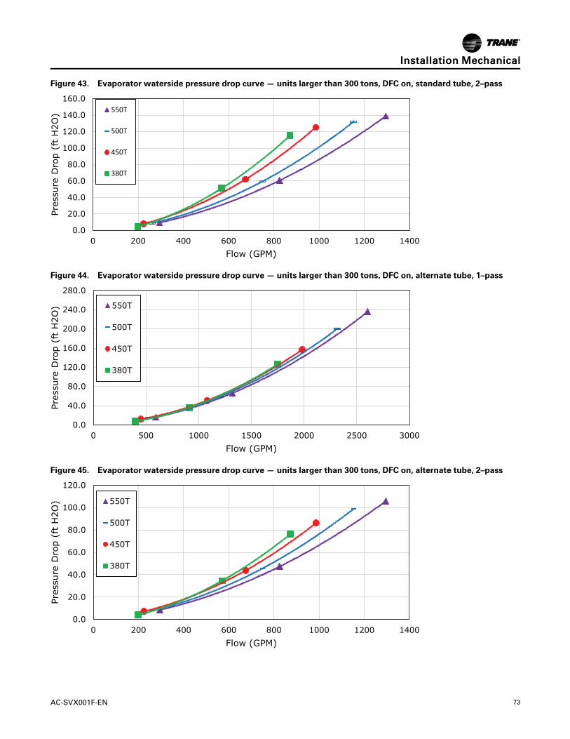
AC-SVX001F-EN 73
Figure 43. Evaporator waterside pressure drop curve — units larger than 300 tons, DFC on, standard tube, 2–pass
0.0
20.0
40.0
60.0
80.0
100.0
120.0
140.0
160.0
0 200 400 600 800 1000 1200 1400
Pre
ssure
Dro
p (
ft H
2O
)
Flow (GPM)
550T
500T
450T
380T
Figure 44. Evaporator waterside pressure drop curve — units larger than 300 tons, DFC on, alternate tube, 1–pass
0.0
40.0
80.0
120.0
160.0
200.0
240.0
280.0
0 500 1000 1500 2000 2500 3000
Pre
ssure
Dro
p (
ft H
2O
)
Flow (GPM)
550T
500T
450T
380T
Figure 45. Evaporator waterside pressure drop curve — units larger than 300 tons, DFC on, alternate tube, 2–pass
0.0
20.0
40.0
60.0
80.0
100.0
120.0
0 200 400 600 800 1000 1200 1400
Pre
ssure
Dro
p (
ft H
2O
)
Flow (GPM)
550T
500T
450T
380T
IInnssttaallllaattiioonn MMeecchhaanniiccaall

74 AC-SVX001F-EN
Pump PackageThe pump package contains a single pump, triple-dutyvalves, service isolation valves, pressure ports, airseparator, expansion tank, and fluid strainer. Includedis -20°F (-29°C) ambient freeze protection for water.
The pump skid contains an independent pump motorstarter panel. The pump starter panel’s power supply isprewired into the chiller’s control panel assembly. Anindependent pump motor supply is not required.Variable pump speed command is integrated with thechiller controller, allowing variable flow functionality.Harmonic filtration is standard.
Pump package applications include short loops,decoupled systems, and service for an entire loopvolume. Because the fluid distribution system beyondthe chiller is unknown, Trane Select Assist reportsAvailable Head as the head leaving the chiller at the
system supply connection point. Available Headincludes the evaporator head loss, pump package andfree-cooling piping frictional effects head losses, valvehead losses, air separator head loss, and strainer headloss summation.
See for generally recommended field installed pipingcomponents and locations.
NNOOTTIICCEEEEqquuiippmmeenntt DDaammaaggee!!FFaaiilluurree ttoo ffoollllooww iinnssttrruuccttiioonnss ccoouulldd rreessuulltt iinneeqquuiippmmeenntt ddaammaaggee..DDoo nnoott ooppeerraattee tthhee ppuummpp ppaacckkaaggee aatt NNPPSSHHRR..OOppeerraattiioonn aatt tthhiiss ssuuccttiioonn hheeaadd wwiillll ccaauusseeccaavviittaattiioonn.. NNPPSSHHAA sshhoouulldd bbee aatt lleeaasstt 11..55 ttoo 22..55ttiimmeess NNPPSSHHRR..
IInnssttaallllaattiioonn MMeecchhaanniiccaall

AC-SVX001F-EN 75
Figure 46. Pump package schematic
Bal
lVal
veee
Pre
ssur
eG
auge
Bal
lVal
vee
Pre
ssur
ega
uge
Air
Sep
arat
orA
irS
epar
ator
Pre
ssur
eG
auge
Bal
lVal
veB
utte
rfly
Val
ve
Suc
tion
Diff
user
Bal
lVal
ve
Bal
lVal
ve
Dra
in
Bal
lVal
ve
Hig
hC
apac
ityA
irV
ent
Bal
lVal
ve
Ret
urn
Fro
m
Bui
ldin
g
Bal
lVal
ve
Dra
in
Bal
lVal
ve
Exp
ansi
onta
nk
Aut
oA
irV
ent
Bal
lVal
ve
Bal
lVal
ve
Dra
in
Pre
ssur
ega
uge
Bal
lVal
ve
Pre
ssur
eS
enso
rP
ress
ure
Gau
ge
Trip
leD
uty
Val
ve
Eva
pora
tor
Fre
eC
oolin
gIs
olat
ion
Val
vesIss
Fre
eC
oolin
gIs
olat
ion
Val
ve
Byp
ass
Val
veE
WT
Sen
sor
LWT
Sen
sor
Flo
wS
witc
hF
ree
Coo
ling
Tem
pS
enso
r
Chi
lled
Wat
erP
ump
Fre
eco
olin
g
ACRChiller
Sup
ply
To
Bui
ldin
g
EW
PT
rans
duce
r
LWP
Tra
nsdu
cer
Tota
l Pum
pH
ead
(ft)
Ava
ilabl
e H
ead
(ft)
Net
Pos
itive
Suc
tion
Hea
dA
vaila
ble
(ft)
Ava
ilabl
e H
ead
(ft)
= T
otal
Hea
d Lo
ss +
Fre
e-C
oolin
g H
ead
Loss
+ P
ipin
g H
ead
Loss
es =
Com
pone
nt H
ead
Loss
es
IInnssttaallllaattiioonn MMeecchhaanniiccaall

76 AC-SVX001F-EN
Pump Package — Available Head and NetPositive Suction Head RequiredPump package available head and NPSHR illustrated inthese graphs are for the noted fluid types. Use Trane
Select Assist to determine these values for applicationswith other freeze avoidance solutions.
50 HP Pump Package
Figure 47. 50 HP Pump package NPSHR — 300 ton units (water)
5
10
15
20
25
30
35
225 275 325 375 425 475 525 575 625 675
HE
AD
(F
T)
FLOW RATE (GPM)
3-Pass 2-Pass
IInnssttaallllaattiioonn MMeecchhaanniiccaall

AC-SVX001F-EN 77
Figure 48. 50 HP Pump package available head— 300 ton units with direct free-cooling (35% ethylene glycol), 8Vcondenser length
120
140
160
180
200
220
240
260
225 275 325 375 425 475 525 575 625 675
HE
AD
(F
T)
FLOW RATE (GPM)
2-Pass DFC On 2-Pass DFC Off
3-Pass DFC On 3-Pass DFC Off
Figure 49. 50 HP Pump package available head— 300 ton units with direct free-cooling (35% ethylene glycol), 10Vcondenser length
120
140
160
180
200
220
240
260
225 275 325 375 425 475 525 575 625 675
HE
AD
(F
T)
FLOW RATE (GPM)
2-Pass DFC On 2-Pass DFC Off
3-Pass DFC On 3-Pass DFC Off
IInnssttaallllaattiioonn MMeecchhaanniiccaall

78 AC-SVX001F-EN
Figure 50. 50 HP Pump package available head— 300 ton units with indirect free-cooling (water)
120
140
160
180
200
220
240
260
225 275 325 375 425 475 525 575 625 675
HE
AD
(F
T)
FLOW RATE (GPM)
2-Pass IFC On
3-Pass IFC On
2-Pass IFC Off
3-Pass IFC Off
IInnssttaallllaattiioonn MMeecchhaanniiccaall

AC-SVX001F-EN 79
60 HP Pump Package
Figure 51. 60 HP Pump package NPSHR — 300 ton units (water)
10
15
20
25
225 275 325 375 425 475 525 575 625 675 725 775
HE
AD
(F
T)
FLOW RATE (GPM)
3-Pass 2-Pass
IInnssttaallllaattiioonn MMeecchhaanniiccaall

80 AC-SVX001F-EN
Figure 52. 60 HP Pump package available head— 300 ton units with direct free-cooling (35% ethylene glycol), 8Vcondenser length
100
120
140
160
180
200
220
240
260
280
225 275 325 375 425 475 525 575 625 675 725 775
HE
AD
(F
T)
FLOW RATE (GPM)
2-Pass DFC On 2-Pass DFC Off
3-Pass DFC On 3-Pass DFC Off
Figure 53. 60 HP Pump package available head— 300 ton units with direct free-cooling (35% ethylene glycol), 10Vcondenser length
100
120
140
160
180
200
220
240
260
280
225 275 325 375 425 475 525 575 625 675 725 775
HE
AD
(F
T)
FLOW RATE (GPM)
2-Pass DFC On 2-Pass DFC Off
3-Pass DFC On 3-Pass DFC Off
IInnssttaallllaattiioonn MMeecchhaanniiccaall

AC-SVX001F-EN 81
Figure 54. 60 HP Pump package available head— 300 ton units with indirect free-cooling (water)
100
120
140
160
180
200
220
240
260
280
225 275 325 375 425 475 525 575 625 675 725 775
HE
AD
(F
T)
FLOW RATE (GPM)
2-Pass IFC On 2-Pass IFC Off
3-Pass IFC On 3-Pass IFC Off
75 HP Pump Package
Figure 55. 75 HP Pump package NPSHR — 300 ton units (water)
15
20
25
30
35
225 325 425 525 625 725 825 925 1025 1125 1225 1325
HE
AD
(F
T)
FLOW RATE (GPM)
3-Pass 2-Pass
IInnssttaallllaattiioonn MMeecchhaanniiccaall

82 AC-SVX001F-EN
Figure 56. 75 HP Pump package available head— 300 ton units with direct free-cooling (35% ethylene glycol), 8Vcondenser length
30
50
70
90
110
130
150
170
190
210
230
225 325 425 525 625 725 825 925 1025 1125 1225 1325
HE
AD
(F
T)
FLOW RATE (GPM)
2-Pass DFC On 2-Pass DFC Off
3-Pass DFC On 3-Pass DFC Off
Figure 57. 75 HP Pump package available head— 300 ton units with direct free-cooling (35% ethylene glycol), 10Vcondenser length
50
70
90
110
130
150
170
190
210
230
225 325 425 525 625 725 825 925 1025 1125 1225 1325
HE
AD
(F
T)
FLOW RATE (GPM)
2-Pass DFC On 2-Pass DFC Off
3-Pass DFC On 3-Pass DFC Off
IInnssttaallllaattiioonn MMeecchhaanniiccaall

AC-SVX001F-EN 83
Figure 58. 75 HP Pump package available head— 300 ton units with indirect free-cooling (water)
65
85
105
125
145
165
185
205
225
225 325 425 525 625 725 825 925 1025 1125 1225 1325
HE
AD
(F
T)
FLOW RATE (GPM)
2-Pass IFC On 2-Pass IFC Off
3-Pass IFC On 3-Pass IFC Off
IInnssttaallllaattiioonn MMeecchhaanniiccaall

84 AC-SVX001F-EN
Freeze ProtectionOne or more of the ambient freeze avoidance methodsin the table below must be used to protect the chiller
from ambient freeze damage. See RF-PRB002*-EN formore information.
MethodProtects toambienttemperature
Notes
WaterPumpControlANDHeaters
Down to -20°F
• Heaters alone will provide low ambient protection down to -20°F (-29°C), but will NOTprotect the evaporator from freezing as a result of chargemigration. Therefore, it isrequired that water pump control be used in conjunction with heaters.
• The optional factory installed pump package includes -20°F (-29°C) ambient freeze protection forwater.
• Heaters are factory-installed on the evaporator and will protect it from freezing.
• Install heat tape on all water piping, pumps, and other components that may be damaged if exposedto freezing temperatures. Heat tape must be designed for low ambient temperature applications. Heattape selection should be based on the lowest expected ambient temperature.
• The controller can start the pump when freezing conditions are detected. For this option the pumpmust to be controlled by the Stealth unit and this function must be validated.
• Water circuit valves need to stay open at all times.
• Water pump control and heater combination will protect the evaporator down to anyambient temperature provided power is available to the pump and the controller. Thisoption will NOT protect the evaporator in the event of a power failure to the chiller unlessbackup power is supplied to the necessary components.
• When no chiller operation is possible and the pump is already off, controller pump control function forfreeze protection will command the pump to turn:
– ON if average of the evaporator entering water temperature, the evaporator leaving watertemperature, and the evaporator refrigerant pool temperature is less than Low EvaporatorRefrigerant Temperature Cutout (LERTC) + 4°F for a period of time.
– OFF again if the evaporator refrigerant pool temperature rises above the LERTC + 6°F for a periodof time.
Note: Time period referenced for ON and Off conditions above is dependent on past runningconditions and present temperatures measured.
– ON if entering OR leaving water temperature< LWTC for 30°F-sec (17°C-sec)
– OFF again if water temperature > LWTC for 30 min
FreezeInhibitor
Varies. See LowEvaporatorRefrigerant Cutout,GlycolRequirements.
• Freeze protection can be accomplished by adding sufficient glycol to protect against freezing below thelowest ambient expected.
• Use of glycol type antifreeze reduces the cooling capacity of the unit andmust beconsidered in the design of the system specifications.
• For units with free-cooling option, glycol solution is REQUIRED. See Free-Cooling Fluid Managementsection.
DrainWaterCircuit
Below -20°F• Shut off the power supply to the unit and to all heaters.
• Purge the water circuit.
• Blow out the evaporator to ensure no liquid is left in the evaporator.
IInnssttaallllaattiioonn MMeecchhaanniiccaall

AC-SVX001F-EN 85
NNOOTTIICCEEEEvvaappoorraattoorr DDaammaaggee!!FFaaiilluurree ttoo ffoollllooww tthheessee iinnssttrruuccttiioonnss ccoouulldd rreessuulltt iinnddaammaaggee ttoo tthhee eevvaappoorraattoorr..IIff iinnssuuffffiicciieenntt ccoonncceennttrraattiioonn oorr nnoo ffrreeeezzee iinnhhiibbiittoorriiss uusseedd,, tthhee eevvaappoorraattoorr wwaatteerr ffllooww mmuusstt bbeeccoonnttrroolllleedd bbyy tthhee uunniitt ccoonnttrroolllleerr AANNDD hheeaatteerrss mmuussttbbee uusseedd ttoo aavvooiidd ccaattaassttrroopphhiicc ddaammaaggee ttoo tthheeeevvaappoorraattoorr dduuee ttoo ffrreeeezziinngg.. IItt iiss tthhee rreessppoonnssiibbiilliittyyooff tthhee iinnssttaalllliinngg ccoonnttrraaccttoorr aanndd//oorr tthhee ccuussttoommeerr ttooeennssuurree tthhaatt aa ppuummpp wwiillll ssttaarrtt wwhheenn ccaalllleedd uuppoonn bbyytthhee cchhiilllleerr ccoonnttrroollss.. EEvveenn wwiitthh wwaatteerr ppuummpp ccoonnttrrooll,,aa ppoowweerr lloossss ooff aass lliittttllee aass 1155 mmiinnuutteess uunnddeerrffrreeeezziinngg ccoonnddiittiioonnss ccaann ddaammaaggee tthhee eevvaappoorraattoorr..OOnnllyy tthhee pprrooppeerr aaddddiittiioonn ooff ffrreeeezzee iinnhhiibbiittoorr oorrccoommpplleettee ddrraaiinnaaggee ooff tthhee wwaatteerr cciirrccuuiitt ccaann eennssuurreennoo eevvaappoorraattoorr ddaammaaggee iinn tthhee eevveenntt ooff aa ppoowweerrffaaiilluurree..
Low Evaporator RefrigerantCutout, Glycol RequirementsThe table below shows the low evaporator temperaturecutout for different glycol levels. Additional glycolbeyond the recommendations will adversely effect unitperformance. The unit efficiency will be reduced andthe saturated evaporator temperature will be reduced.For some operating conditions this effect can besignificant.
additional glycol is used, then use the actual percentglycol to establish the low refrigerant cutout setpoint.
NNoottee:: Tables below are not substitutes for full unitsimulation for proper prediction of unitperformance with specific operating conditions.For information on specific conditions, contactTrane product support.
Table 40. Low evaporator refrigerant temperature cutout (LERTC) and low water temperature cutout (LWTC) — 150to 300 ton units
Ethylene Glycol Propylene Glycol
GlycolPercentage
(%)
SolutionFreeze Point
(°F)
MinimumRecommendedLERTC (°F)
MinimumRecommendedLWTC (°F)
GlycolPercentage
(%)
SolutionFreeze Point
(°F)
MinimumRecommendedLERTC (°F)
MinimumRecommendedLWTC (°F)
0 32 28.6 35 0 32 28.6 35
2 31 27.6 34 2 31 27.6 34
4 29.7 26.3 32.7 4 29.9 26.5 32.9
5 29 25.6 32 5 29.3 25.9 32.3
6 28.3 24.9 31.3 6 28.7 25.3 31.7
8 26.9 23.5 29.9 8 27.6 24.2 30.6
10 25.5 22.1 28.5 10 26.4 23 29.4
12 23.9 20.5 26.9 12 25.1 21.7 28.1
14 22.3 18.9 25.3 14 23.8 20.4 26.8
15 21.5 18.1 24.5 15 23.1 19.7 26.1
16 20.6 17.2 23.6 16 22.4 19 25.4
18 18.7 15.3 21.7 18 20.9 17.5 23.9
20 16.8 13.4 19.8 20 19.3 15.9 22.3
22 14.7 11.3 17.7 22 17.6 14.2 20.6
24 12.5 9.1 15.5 24 15.7 12.3 18.7
25 11.4 8 14.4 25 14.8 11.4 17.8
26 10.2 6.8 13.2 26 13.8 10.4 16.8
28 7.7 4.3 10.7 28 11.6 8.2 14.6
30 5.1 1.7 8.1 30 9.3 5.9 12.3
32 2.3 -1.1 5.3 32 6.8 3.4 9.8
34 -0.7 -4.1 5 34 4.1 0.7 7.1
35 -2.3 -5 5 35 2.7 -0.7 5.7
36 -3.9 -5 5 36 1.3 -2.1 5
38 -7.3 -5 5 38 -1.8 -5 5
40 -10.8 -5 5 40 -5.2 -5 5
IInnssttaallllaattiioonn MMeecchhaanniiccaall

86 AC-SVX001F-EN
Table 40. Low evaporator refrigerant temperature cutout (LERTC) and low water temperature cutout (LWTC) — 150to 300 ton units (continued)
Ethylene Glycol Propylene Glycol
GlycolPercentage
(%)
SolutionFreeze Point
(°F)
MinimumRecommendedLERTC (°F)
MinimumRecommendedLWTC (°F)
GlycolPercentage
(%)
SolutionFreeze Point
(°F)
MinimumRecommendedLERTC (°F)
MinimumRecommendedLWTC (°F)
42 -14.6 -5 5 42 -8.8 -5 5
44 -18.6 -5 5 44 -12.6 -5 5
45 -20.7 -5 5 45 -14.6 -5 5
46 -22.9 -5 5 46 -16.7 -5 5
48 -27.3 -5 5 48 -21.1 -5 5
50 -32.1 -5 5 50 -25.8 -5 5
Table 41. Low evaporator refrigerant temperature cutout (LERTC) and low water temperature cutout (LWTC) — unitslarger than 300 tons
Ethylene Glycol Propylene Glycol
GlycolPercentage
(%)
SolutionFreeze Point
(°F)
MinimumRecommendedLERTC (°F)
MinimumRecommendedLWTC (°F)
GlycolPercentage
(%)
SolutionFreeze Point
(°F)
MinimumRecommendedLERTC (°F)
MinimumRecommendedLWTC (°F)
0 32.0 32.0 37.0 0 32.0 32.0 37.0
2 31.0 29.5 36.0 2 31.0 29.5 36.0
4 29.7 28.2 34.7 4 29.9 28.4 34.9
5 29.0 27.5 34.0 5 29.3 27.8 34.3
6 28.3 26.8 33.3 6 28.7 27.2 33.7
8 26.9 25.4 31.9 8 27.6 26.1 32.6
10 25.5 24.0 30.5 10 26.4 24.9 31.4
12 23.9 22.4 28.9 12 25.1 23.6 30.1
14 22.3 20.8 27.3 14 23.8 22.3 28.8
15 21.5 20.0 26.5 15 23.1 21.6 28.1
16 20.6 19.1 25.6 16 22.4 20.9 27.4
18 18.7 17.2 23.7 18 20.9 19.4 25.9
20 16.8 15.3 21.8 20 19.3 17.8 24.3
22 14.7 13.2 19.7 22 17.6 16.1 22.6
24 12.5 11.0 17.5 24 15.7 14.2 20.7
25 11.4 9.9 16.4 25 14.8 13.3 19.8
26 10.2 8.7 15.2 26 13.8 12.3 18.8
28 7.7 6.2 12.7 28 11.6 10.1 16.6
30 5.1 3.6 10.1 30 9.3 7.8 14.3
32 2.3 0.8 7.3 32 6.8 5.3 11.8
34 -0.7 -2.2 5.0 34 4.1 2.6 9.1
35 -2.3 -3.8 5.0 35 2.7 1.2 7.7
36 -3.9 -5.0 5.0 36 1.3 -0.2 6.3
38 -7.3 -5.0 5.0 38 -1.8 -3.3 5.0
40 -10.8 -5.0 5.0 40 -5.2 -5.0 5.0
42 -14.6 -5.0 5.0 42 -8.8 -5.0 5.0
44 -18.6 -5.0 5.0 44 -12.6 -5.0 5.0
45 -20.7 -5.0 5.0 45 -14.6 -5.0 5.0
IInnssttaallllaattiioonn MMeecchhaanniiccaall

AC-SVX001F-EN 87
Table 41. Low evaporator refrigerant temperature cutout (LERTC) and low water temperature cutout (LWTC) — unitslarger than 300 tons (continued)
Ethylene Glycol Propylene Glycol
GlycolPercentage
(%)
SolutionFreeze Point
(°F)
MinimumRecommendedLERTC (°F)
MinimumRecommendedLWTC (°F)
GlycolPercentage
(%)
SolutionFreeze Point
(°F)
MinimumRecommendedLERTC (°F)
MinimumRecommendedLWTC (°F)
46 -22.9 -5.0 5.0 46 -16.7 -5.0 5.0
48 -27.3 -5.0 5.0 48 -21.1 -5.0 5.0
50 -32.1 -5.0 5.0 50 -25.8 -5.0 5.0
IInnssttaallllaattiioonn MMeecchhaanniiccaall

88 AC-SVX001F-EN
Installation ElectricalGeneral RecommendationsAs you review this manual, keep in mind that:
• All field-installed wiring must conform to NationalElectric Code (NEC) guidelines, and any applicablestate and local codes. Be sure to satisfy properequipment grounding requirements per NEC.
• Compressor motor and unit electrical data(including motor kW, voltage utilization range,rated load amps) is listed on the chiller nameplate.
• All field-installed wiring must be checked for properterminations, and for possible shorts or grounds.
NNoottee:: Always refer to wiring diagrams shipped withchiller or unit submittal for specific electricalschematic and connection information.
WWAARRNNIINNGGHHaazzaarrddoouuss VVoollttaaggee -- PPrreessssuurriizzeeddFFllaammmmaabbllee FFlluuiidd!!FFaaiilluurree ttoo ffoollllooww aallll eelleeccttrriiccaall ssaaffeettyy pprreeccaauuttiioonnssccoouulldd rreessuulltt iinn ddeeaatthh oorr sseerriioouuss iinnjjuurryy..DDoo nnoott ooppeerraattee ccoommpprreessssoorr wwiitthhoouutt tteerrmmiinnaall bbooxxccoovveerr iinn ppllaaccee..TThhee mmoottoorrss iinn tthhee ccoommpprreessssoorrss hhaavvee ssttrroonnggppeerrmmaanneenntt mmaaggnneett mmoottoorrss aanndd hhaavvee tthhee ccaappaabbiilliittyyttoo ggeenneerraattee vvoollttaaggee dduurriinngg ssiittuuaattiioonnss wwhheenn tthheerreeffrriiggeerraanntt cchhaarrggee iiss bbeeiinngg mmiiggrraatteedd.. TThhiissppootteennttiiaall wwiillll bbee pprreesseenntt aatt tthhee mmoottoorr tteerrmmiinnaallssaanndd aatt tthhee oouuttppuutt ooff tthhee vvaarriiaabbllee ssppeeeedd ddrriivveess iinntthhee ppoowweerr ppaanneell..BBeeffoorree rreemmoovviinngg ccoommpprreessssoorr tteerrmmiinnaall bbooxx ccoovveerrffoorr sseerrvviicciinngg,, oorr sseerrvviicciinngg ppoowweerr ssiiddee ooff ccoonnttrroollppaanneell,, CCLLOOSSEE CCOOMMPPRREESSSSOORR DDIISSCCHHAARRGGEESSEERRVVIICCEE VVAALLVVEE aanndd ddiissccoonnnneecctt aallll eelleeccttrriicc ppoowweerriinncclluuddiinngg rreemmoottee ddiissccoonnnneeccttss.. DDiisscchhaarrggee aallll mmoottoorrssttaarrtt//rruunn ccaappaacciittoorrss.. FFoollllooww lloocckkoouutt//ttaaggoouuttpprroocceedduurreess ttoo eennssuurree tthhee ppoowweerr ccaannnnoott bbeeiinnaaddvveerrtteennttllyy eenneerrggiizzeedd.. VVeerriiffyy wwiitthh aannaapppprroopprriiaattee vvoollttmmeetteerr tthhaatt aallll ccaappaacciittoorrss hhaavveeddiisscchhaarrggeedd..TThhee ccoommpprreessssoorr ccoonnttaaiinnss hhoott,, pprreessssuurriizzeeddrreeffrriiggeerraanntt.. MMoottoorr tteerrmmiinnaallss aacctt aass aa sseeaall aaggaaiinnsstttthhiiss rreeffrriiggeerraanntt.. CCaarree sshhoouulldd bbee ttaakkeenn wwhheennsseerrvviicciinngg NNOOTT ttoo ddaammaaggee oorr lloooosseenn mmoottoorrtteerrmmiinnaallss..
WWAARRNNIINNGGHHaazzaarrddoouuss VVoollttaaggee ww//CCaappaacciittoorrss!!FFaaiilluurree ttoo ffoollllooww tthheessee iinnssttrruuccttiioonnss ccoouulldd rreessuulltt iinnddeeaatthh oorr sseerriioouuss iinnjjuurryy..DDiissccoonnnneecctt aallll eelleeccttrriicc ppoowweerr,, iinncclluuddiinngg rreemmootteeddiissccoonnnneeccttss aanndd ddiisscchhaarrggee aallll mmoottoorr ssttaarrtt//rruunn aannddAAFFDD ((AAddaappttiivvee FFrreeqquueennccyy™™ DDrriivvee)) ccaappaacciittoorrssbbeeffoorree sseerrvviicciinngg.. FFoollllooww pprrooppeerr lloocckkoouutt//ttaaggoouuttpprroocceedduurreess ttoo eennssuurree tthhee ppoowweerr ccaannnnoott bbeeiinnaaddvveerrtteennttllyy eenneerrggiizzeedd..
•• FFoorr vvaarriiaabbllee ffrreeqquueennccyy ddrriivveess oorr ootthheerr eenneerrggyyssttoorriinngg ccoommppoonneennttss pprroovviiddeedd bbyy TTrraannee oorrootthheerrss,, rreeffeerr ttoo tthhee aapppprroopprriiaatteemmaannuuffaaccttuurreerr’’ss lliitteerraattuurree ffoorr aalllloowwaabblleewwaaiittiinngg ppeerriiooddss ffoorr ddiisscchhaarrggee ooff ccaappaacciittoorrss..VVeerriiffyy wwiitthh aann aapppprroopprriiaattee vvoollttmmeetteerr tthhaatt aallllccaappaacciittoorrss hhaavvee ddiisscchhaarrggeedd..
•• DDCC bbuuss ccaappaacciittoorrss rreettaaiinn hhaazzaarrddoouuss vvoollttaaggeessaafftteerr iinnppuutt ppoowweerr hhaass bbeeeenn ddiissccoonnnneecctteedd..FFoollllooww pprrooppeerr lloocckkoouutt//ttaaggoouutt pprroocceedduurreess ttooeennssuurree tthhee ppoowweerr ccaannnnoott bbee iinnaaddvveerrtteennttllyyeenneerrggiizzeedd.. AAfftteerr ddiissccoonnnneeccttiinngg iinnppuutt ppoowweerr,,wwaaiitt ffiivvee ((55)) mmiinnuutteess ffoorr tthhee DDCC ccaappaacciittoorrss ttooddiisscchhaarrggee,, tthheenn cchheecckk tthhee vvoollttaaggee wwiitthh aavvoollttmmeetteerr.. MMaakkee ssuurree DDCC bbuuss ccaappaacciittoorrss aarreeddiisscchhaarrggeedd ((00 VVDDCC)) bbeeffoorree ttoouucchhiinngg aannyyiinntteerrnnaall ccoommppoonneennttss..
WWAARRNNIINNGGPPrrooppeerr FFiieelldd WWiirriinngg aanndd GGrroouunnddiinnggRReeqquuiirreedd!!FFaaiilluurree ttoo ffoollllooww ccooddee ccoouulldd rreessuulltt iinn ddeeaatthh oorrsseerriioouuss iinnjjuurryy..AAllll ffiieelldd wwiirriinngg MMUUSSTT bbee ppeerrffoorrmmeedd bbyy qquuaalliiffiieeddppeerrssoonnnneell.. IImmpprrooppeerrllyy iinnssttaalllleedd aanndd ggrroouunnddeeddffiieelldd wwiirriinngg ppoosseess FFIIRREE aanndd EELLEECCTTRROOCCUUTTIIOONNhhaazzaarrddss.. TToo aavvooiidd tthheessee hhaazzaarrddss,, yyoouu MMUUSSTT ffoolllloowwrreeqquuiirreemmeennttss ffoorr ffiieelldd wwiirriinngg iinnssttaallllaattiioonn aannddggrroouunnddiinngg aass ddeessccrriibbeedd iinn NNEECC aanndd yyoouurr llooccaall//ssttaattee//nnaattiioonnaall eelleeccttrriiccaall ccooddeess..
NNOOTTIICCEEUUssee CCooppppeerr CCoonndduuccttoorrss OOnnllyy!!FFaaiilluurree ttoo uussee ccooppppeerr ccoonndduuccttoorrss ccoouulldd rreessuulltt iinneeqquuiippmmeenntt ddaammaaggee aass tthhee eeqquuiippmmeenntt wwaass nnoottddeessiiggnneedd oorr qquuaalliiffiieedd ttoo aacccceepptt ootthheerr ttyyppeess ooffccoonndduuccttoorrss..
IImmppoorrttaanntt::
To prevent control malfunctions, do not run lowvoltage wiring (<30 V) in conduit with conductorscarrying more than 30 volts.

AC-SVX001F-EN 89
Adaptive Frequency™™ Drive CapacitorDischargeAfter disconnecting input power, wait five (5) minutesfor the DC capacitors to discharge.
Using voltmeter, measure voltage on bus at bus accesspoints. See figures below for location of bus accesspoints, and details. Capacitors are fully dischargedwhen voltage across these plus (+) and minus (-) pointsmeasures 0 VDC.
Figure 59. AFD dc bus measurement location
BusMeasurementPoints
Figure 60. Bus measurement nodes detail
Positive (+)Node
Negative (-)Node
Adaptive Frequency™ Drive PowerJumper ConfigurationThe Adaptive Frequency Drives (AFDs) on both circuitscontain protective MOVs and common mode capacitorcircuits that are referenced to ground. To guard againstdrive damage and/or operation problems, thesedevices must be properly configured according to thetable below.
For jumpers configurations, refer to Figure 61, p. 89and Figure 62, p. 90. For more information, refer toAFD Service Guide (AFD-SVG002*-EN). Allow forsufficient time after removing power to performmodifications to the AFD power jumpers. Refer to theAdaptive Frequency™ Drive Capacitor Dischargeinstructions .
Table 42. AFD power jumper configurations
Power SourceType
Jumper PE-A(MOV)
Jumper PE-B(CommonModeCaps)
Solid Ground:
• CenterGround-Wye(Y)
Connected(a) Connected(a)
Non-Solid Ground:
• Any Delta (∆)
• UndergroundWye (Y)
• HighImpedanceGround Wye(Y)
Disconnected Disconnected
(a) Default configuration shipped from the factory. If grounding type isunknown at customer installation, leave PE-A and PE-B connected.
Figure 61. AFD frame 6 power jumper locations
Solid Ground Non - Solid Ground
IInnssttaallllaattiioonn EElleeccttrriiccaall

90 AC-SVX001F-EN
Figure 62. AFD frame 7 power jumper locations
Solid Ground Non-Solid Ground
Units with Nitrogen Charge Option
N2
For units with nitrogencharge option (modelnumber digit 16 = D), the unitmust NOT have shore power,or unit power applied untilthe unit has been charged.Applying power will driveEXV valves closed, and willinhibit sufficient vac for unitcharging.
Installer-Supplied ComponentsCustomer wiring interface connections are shown inthe electrical schematics and connection diagrams thatare shipped with the unit. The installer must providethe following components if not ordered with the unit:
• Power supply wiring (in conduit) for all field-wiredconnections.
• All control (interconnecting) wiring (in conduit) forfield supplied devices.
• Fused-disconnect switches or circuit breakers.
Power Supply Wiring
WWAARRNNIINNGGHHaazzaarrddoouuss VVoollttaaggee ww//CCaappaacciittoorrss!!FFaaiilluurree ttoo ffoollllooww tthheessee iinnssttrruuccttiioonnss ccoouulldd rreessuulltt iinnddeeaatthh oorr sseerriioouuss iinnjjuurryy..DDiissccoonnnneecctt aallll eelleeccttrriicc ppoowweerr,, iinncclluuddiinngg rreemmootteeddiissccoonnnneeccttss aanndd ddiisscchhaarrggee aallll mmoottoorr ssttaarrtt//rruunn aannddAAFFDD ((AAddaappttiivvee FFrreeqquueennccyy™™ DDrriivvee)) ccaappaacciittoorrssbbeeffoorree sseerrvviicciinngg.. FFoollllooww pprrooppeerr lloocckkoouutt//ttaaggoouuttpprroocceedduurreess ttoo eennssuurree tthhee ppoowweerr ccaannnnoott bbeeiinnaaddvveerrtteennttllyy eenneerrggiizzeedd..
•• FFoorr vvaarriiaabbllee ffrreeqquueennccyy ddrriivveess oorr ootthheerr eenneerrggyyssttoorriinngg ccoommppoonneennttss pprroovviiddeedd bbyy TTrraannee oorrootthheerrss,, rreeffeerr ttoo tthhee aapppprroopprriiaatteemmaannuuffaaccttuurreerr’’ss lliitteerraattuurree ffoorr aalllloowwaabblleewwaaiittiinngg ppeerriiooddss ffoorr ddiisscchhaarrggee ooff ccaappaacciittoorrss..VVeerriiffyy wwiitthh aann aapppprroopprriiaattee vvoollttmmeetteerr tthhaatt aallllccaappaacciittoorrss hhaavvee ddiisscchhaarrggeedd..
•• DDCC bbuuss ccaappaacciittoorrss rreettaaiinn hhaazzaarrddoouuss vvoollttaaggeessaafftteerr iinnppuutt ppoowweerr hhaass bbeeeenn ddiissccoonnnneecctteedd..FFoollllooww pprrooppeerr lloocckkoouutt//ttaaggoouutt pprroocceedduurreess ttooeennssuurree tthhee ppoowweerr ccaannnnoott bbee iinnaaddvveerrtteennttllyyeenneerrggiizzeedd.. AAfftteerr ddiissccoonnnneeccttiinngg iinnppuutt ppoowweerr,,wwaaiitt ffiivvee ((55)) mmiinnuutteess ffoorr tthhee DDCC ccaappaacciittoorrss ttooddiisscchhaarrggee,, tthheenn cchheecckk tthhee vvoollttaaggee wwiitthh aavvoollttmmeetteerr.. MMaakkee ssuurree DDCC bbuuss ccaappaacciittoorrss aarreeddiisscchhaarrggeedd ((00 VVDDCC)) bbeeffoorree ttoouucchhiinngg aannyyiinntteerrnnaall ccoommppoonneennttss..
WWAARRNNIINNGGPPrrooppeerr FFiieelldd WWiirriinngg aanndd GGrroouunnddiinnggRReeqquuiirreedd!!FFaaiilluurree ttoo ffoollllooww ccooddee ccoouulldd rreessuulltt iinn ddeeaatthh oorrsseerriioouuss iinnjjuurryy..AAllll ffiieelldd wwiirriinngg MMUUSSTT bbee ppeerrffoorrmmeedd bbyy qquuaalliiffiieeddppeerrssoonnnneell.. IImmpprrooppeerrllyy iinnssttaalllleedd aanndd ggrroouunnddeeddffiieelldd wwiirriinngg ppoosseess FFIIRREE aanndd EELLEECCTTRROOCCUUTTIIOONNhhaazzaarrddss.. TToo aavvooiidd tthheessee hhaazzaarrddss,, yyoouu MMUUSSTT ffoolllloowwrreeqquuiirreemmeennttss ffoorr ffiieelldd wwiirriinngg iinnssttaallllaattiioonn aannddggrroouunnddiinngg aass ddeessccrriibbeedd iinn NNEECC aanndd yyoouurr llooccaall//ssttaattee//nnaattiioonnaall eelleeccttrriiccaall ccooddeess..
All power supply wiring must be sized and selectedaccordingly by the project engineer in accordance withNEC Table 310.15(B)(16); formerly Table 310-16.
All wiring must comply with local codes and theNational Electrical Code. The installing (or electrical)contractor must provide and install the systeminterconnecting wiring, as well as the power supplywiring. It must be properly sized and equipped with theappropriate overcurrent protection device.
The type and installation location(s) of the overcurrentprotection devices must comply with all applicablecodes.
IInnssttaallllaattiioonn EElleeccttrriiccaall
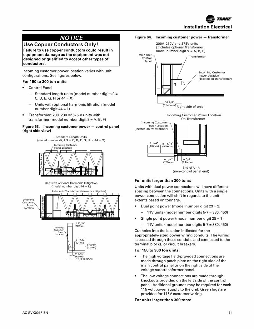
AC-SVX001F-EN 91
NNOOTTIICCEEUUssee CCooppppeerr CCoonndduuccttoorrss OOnnllyy!!FFaaiilluurree ttoo uussee ccooppppeerr ccoonndduuccttoorrss ccoouulldd rreessuulltt iinneeqquuiippmmeenntt ddaammaaggee aass tthhee eeqquuiippmmeenntt wwaass nnoottddeessiiggnneedd oorr qquuaalliiffiieedd ttoo aacccceepptt ootthheerr ttyyppeess ooffccoonndduuccttoorrss..
Incoming customer power location varies with unitconfigurations. See figures below.
FFoorr 115500 ttoo 330000 ttoonn uunniittss::
• Control Panel
– Standard length units (model number digits 9 =C, D, E, G, H or 44 = X)
– Units with optional harmonic filtration (modelnumber digit 44 = L)
• Transformer: 200, 230 or 575 V units withtransformer (model number digit 9 = A, B, F)
Figure 63. Incoming customer power — control panel(right side view)
Contr
ol Pa
nel
Incoming CustomerPower Location
Standard Length Units(model number digit 9 = C, D, E, G, H or 44 = X)
Unit with optional Harmonic Mitigation(model number digit 44 = L)
IncomingCustomer
PowerLocation
IncomingCustomer
PowerLocation
Pulse Auto Transformer (harmonic mitigation)
Contr
ol Pa
nel
Figure 64. Incoming customer power — transformer
200V, 230V and 575V units(Includes optional Transformermodel number digit 9 = A, B, F)
Incoming Customer Power LocationOn Transformer
End of Unit(non-control panel end)
Right side of unit
Incoming CustomerPower Location
(located on transformer)
Incoming CustomerPower Location(located on transformer)
TransformerMain Unit
ControlPanel
60 7/8”(1546mm)
FFoorr uunniittss llaarrggeerr tthhaann 330000 ttoonnss::
Units with dual power connections will have differentspacing between the connections. Units with a singlepower connection will shift in regards to the unitextents based on tonnage.
• Dual point power (model number digit 29 = 2)
– 11V units (model number digits 5-7 = 380, 450)
• Single point power (model number digit 29 = 1)
– 11V units (model number digits 5-7 = 380, 450)
Cut holes into the location indicated for theappropriately-sized power wiring conduits. The wiringis passed through these conduits and connected to theterminal blocks, or circuit breakers.
FFoorr 115500 ttoo 330000 ttoonn uunniittss::
• The high voltage field-provided connections aremade through patch plate on the right side of themain control panel or on the right side of thevoltage autotransformer panel.
• The low voltage connections are made throughknockouts provided on the left side of the controlpanel. Additional grounds may be required for each115 volt power supply to the unit. Green lugs areprovided for 115V customer wiring.
FFoorr uunniittss llaarrggeerr tthhaann 330000 ttoonnss::
IInnssttaallllaattiioonn EElleeccttrriiccaall

92 AC-SVX001F-EN
• For dual point power units, the high voltage field-provided connections are made through patch plateon the right side of each control panel. Dimensionsof incoming power location on each control panelare as shown in Figure 63, p. 91.
• For single point power units, the high voltage field-provided connections are made through the leftside of the center enclosure as noted per thelabeling on it. See the following figure.
Figure 65. Incoming customer power — singlepoint power
IncomingCustomerPower
Location
• The low voltage connections are made throughknockouts provided on the left side of the circuitone / main control panel.
• Additional grounds may be required for each 115volt power supply to the unit. Green terminals areprovided for 115V customer wiring.
Control Power SupplyThe unit is equipped with a control power transformer.It is not necessary to provide additional control powervoltage to the unit. No other loads should be connectedto the control power transformer.
All units are factory-connected for appropriate labeledvoltages.
Service Power ConnectionThe service power connection is a touch safeprocedure to allow for binding the control system andLLIDs. Service power connection allows for a NEMA 5-15 style extension cord to power on Class 2 devices (i.e.Symbio 800, LLIDs, EXVs, and TD7 display) with anexternal power source, without the need of line voltageapplied to the unit. For 150 to 300 ton units, thisconnection is to be made at 1XJ50. For units largerthan 300 tons, two connections are to be made at 1XJ1/ 2XJ1. The extension cord power source is required to
have upstream current protection rated at no morethan 10A. The required voltage for the service powerconnection is 115V at 60Hz and 110V at 50Hz.
Heater Power SupplyThe evaporator shell, indirect free cooling watercontaining components and factory installed pumppackages are insulated and protected from ambienttemperatures down to -20°F (-29°C) bythermostatically-controlled immersion heaters. If thefreeze protection method of “Water pump control ANDheaters” is chosen for a non-free cooling unit, see“Freeze Protection,” p. 84, the installing contractorneeds to supply an appropriate 115V 60Hz or 220V 50Hzsingle phase circuit to terminals 1X4-1, 2, and 5. Theseterminals are located below the low voltage controlpanel behind the sheet metal cover. See Figure 66, p.92.
For units with model number digit 29 = 3, this electricalconnection is already made by the factory wiring and ison the line side of the main disconnect. See Table 43,p. 93 for heater summary.
For evaporators, whenever the water temperaturedrops to approximately 37°F (2.8°C), the thermostatenergizes the heaters.
For the indirect free cooling water containingcomponents and factory installed pump packages,whenever the water temperature drops toapproximately 37°F (2.8°C) and there is not a pumpcommand present the thermostat energizes theheaters.
Figure 66. Evaporator heater view
IInnssttaallllaattiioonn EElleeccttrriiccaall

AC-SVX001F-EN 93
NNOOTTIICCEEEEvvaappoorraattoorr DDaammaaggee!!FFaaiilluurree ttoo ffoollllooww iinnssttrruuccttiioonnss bbeellooww ccoouulldd rreessuulltt iinneevvaappoorraattoorr ddaammaaggee..AA qquuaalliiffiieedd tteecchhnniicciiaann mmuusstt ccoonnffiirrmm ooppeerraattiioonn oofftthhee tthheerrmmoossttaatt.. CCoonnttrrooll ppaanneell mmaaiinn pprroocceessssoorrddooeess nnoott vveerriiffyy tthheerrmmoossttaatt ooppeerraattiioonn..
Table 43. Factory installed water heater summary
Unit Size (tons)Waterboxes
Supply Return
1–pass Evaporator
Units larger than 300tons
400W (Qty 2) 400W (Qty 2)
2-pass Evaporator
150 to 165 400W 400W
180 to 200 400W (Qty 2) 400W
225 to 300 600W 600W
Units larger than 300tons
400W (Qty 2) 400W (Qty 2)
3-pass Evaporator
All sizes 400W (Qty 2) 400W
Indirect Free Cooling(a)
300 ton 200W (Qty 13) 2600W
Factory Installed Pump Package(a)
300 ton 300W (Qty 4) 1200W
(a) These heaters are in addition to the evaporator waterbox heaters.
Chilled Water Pump ControlNNOOTTIICCEE
EEvvaappoorraattoorr DDaammaaggee!!IIff tthhee mmiiccrroopprroocceessssoorr ccaallllss ffoorr aa ppuummpp ttoo ssttaarrtt aannddwwaatteerr ddooeess nnoott ffllooww,, tthhee eevvaappoorraattoorr mmaayy bbeeddaammaaggeedd ccaattaassttrroopphhiiccaallllyy..IItt iiss tthhee rreessppoonnssiibbiilliittyy ooff tthhee iinnssttaalllliinngg ccoonnttrraaccttoorraanndd//oorr tthhee ccuussttoommeerr ttoo eennssuurree tthhaatt aa ppuummpp wwiillllaallwwaayyss bbee rruunnnniinngg wwhheenn ccaalllleedd uuppoonn bbyy tthhee cchhiilllleerrccoonnttrroollss..
An evaporator water pump output relay’s normally-open contact closes to start the evaporator water pumpwhen the chiller is given a signal to go into the Automode of operation from any source. The contact isopened to turn off the pump in the event of mostmachine level diagnostics to prevent the build up ofpump heat.
The relay output is required to operate the EvaporatorWater Pump (EWP) contactor. The relay’s contacts arecompatible with 115/240 VAC control circuits. See
Programmable Relays section for rating details.Normally, the EWP relay follows the AUTO mode of thechiller. Whenever the chiller has no diagnostics and isin the AUTO mode, regardless of where the autocommand is coming from, the relay is energized andthe normally-open contact is closed. When the chillerexits the AUTO mode, the relay’s normally-opencontact is timed to open in an adjustable (usingTracer® TU service tool) 0 to 30 minutes. The non-AUTO modes in which the pump is stopped, includeReset, Stop, External Stop, Remote Display Stop,Stopped by Tracer, Start Inhibited by Low AmbientTemp, and Ice Building complete.
Table 44. Pump relay operation
Chiller Mode Relay Operation
Auto Instant Close
Ice Building Instant Close
Tracer Override Close
Stop Timed Open
Ice Complete Instant Open
Diagnostics Instant Operation(a)
Chiller ShutdownDiagnostics
(except freeze protection)Instant Open
Freeze Protection relatedchiller shutdown diagnostics
Initially: Remain ClosedThen: Delayed/Dependent Open
Chiller Off Cycle FreezeDiagnostics Instant Close – Dependent Open
(a) Operation can be instant open or instant close, depending ondiagnostic.
When going from Stop to Auto, the EWP relay isenergized immediately. If evaporator water flow is notestablished in 20 minutes (for normal transition) or 4minutes, 15 seconds (for pump commanded ON due toan override safety), the unit controller de-energizes theEWP relay and generates a non-latching diagnostic. Ifflow returns (e.g. someone else is controlling thepump), the diagnostic is cleared, the EWP is re-energized, and normal control resumed.
If evaporator water flow is lost once it had beenestablished, the EWP relay remains energized and anon-latching diagnostic is generated. If flow returns,the diagnostic is cleared and the chiller returns tonormal operation.
In general, when there is either a non-latching orlatching diagnostic, the EWP relay is turned off asthough there was a zero time delay. Exceptionswhereby the relay continues to be energized occurwith:
• LLooww CChhiilllleedd WWaatteerr TTeemmppeerraattuurree ddiiaaggnnoossttiicc (non-latching unless also accompanied by an EvapLeaving Water Temperature Sensor Diagnostic)
OR
IInnssttaallllaattiioonn EElleeccttrriiccaall

94 AC-SVX001F-EN
• IInntteerrrruupptt FFaaiilluurree ——AAFFDDxxAA ddiiaaggnnoossttiicc where x iseither 1 or 2 to indicate which drive is affected), inwhich a compressor continues to draw current evenafter commanded to have shutdown.
OR
• LLoossss ooff EEvvaappoorraattoorr WWaatteerr FFllooww ddiiaaggnnoossttiicc (non-latching) and the unit is in the AUTO mode, afterinitially having proven evaporator water flow.
Programmable RelaysA programmable relay concept provides forenunciation or hardwired interlocking of certain eventsor states of the chiller, selected from a list of likelyneeds, while only using four physical output relays, asshown in the field wiring diagram. The four relays areprovided (generally with a Quad Relay Output LLID) aspart of the Programmable Relay Option. The relay’scontacts are isolated Form C (SPDT), suitable for usewith 120 VAC circuits drawing up to 2.8 amps inductive,7.2 amps resistive, or 1/3 HP and for 240 VAC circuitsdrawing up to 0.5 amp resistive.
The list of events/states that can be assigned to theprogrammable relays can be found in the followingtable. The relay will be energized when the event/stateoccurs.
Table 45. Alarm and status relay outputconfigurations
Description
Alarm(Latching)
This output is true whenever there is anyactive latching shutdown diagnostic thattargets the Unit, Circuit, or any of theCompressors on a circuit.
Alarm(Non-Latching)
This output is true whenever there is anyactive non-latching shutdown diagnostic thattargets the Unit, Circuit, or any of theCompressors on a circuit.
Alarm
This output is true whenever there is anyactive latching or non-latching shutdowndiagnostic that targets the Unit, Circuit, orany of the Compressors on a circuit.
Alarm Ckt 1
This output is true whenever there is anyactive latching or non-latching shutdowndiagnostic that targets Circuit 1, or any of theCompressors on Circuit 1.
Alarm Ckt 2
This output is true whenever there is anyactive latching or non-latching shutdowndiagnostic that targets Circuit 2, or any of theCompressors on Circuit 2.
Unit Limit Mode
This output is true whenever a circuit on theunit has been running in one of the limitmodes continuously for the Limit Relaydebounce time. A given limit or overlapping ofdifferent limits must be in effect continuouslyfor the debounce time prior to the outputbecoming true. It will become false if no limitsare present for the debounce time.
CompressorRunning
The output is true whenever any compressoris running.
Table 45. Alarm and status relay outputconfigurations (continued)
Description
Circuit 1Running
The output is true whenever any compressorof Circuit 1 is running.
Circuit 2Running
The output is true whenever any compressorof Circuit 2 is running.
Ice Making This output is true when Ice Building status isactive.
MaximumCapacity
The output is true whenever the unit hasreached maximum capacity continuously forthe Max Capacity Relay debounce time. Theoutput is false when the unit is not atmaximum capacity continuously for the filterdebounce time.
EvaporatorWater FreezeAvoidanceRequest
This relay output is energized any time eitherthe Low Evaporator Water Temperature – UnitOff or the Low Evaporator Temperature Ckt x– Unit Off diagnostics are active. This relay isintended for use as an external interlock for afield engineered and provided solution tomitigate the freeze danger implied by thesediagnostics. Generally, this would be used incases where operation of the evaporatorwater pump is unacceptable due to thesystem constraints, (i.e. such as mixingunconditioned warm water with controlledsupply water as provided by other parallelchillers. The relay’s output can provide themethod to close bypass valves so thecirculation becomes local to the evap andexcludes the load, or can be used to defeatthe evap pump override entirely whileinitiating an independent source of heat / flowto the evap.
ServiceRequest
This relay will be energized when at least oneMaintenance alert condition (refer to Servicerequired message specification) occurs, aslong as at least one of associatedinformational diagnostic(s) will be active.
Free-CoolingStatus
The output is true (closed) whenever FreeCooling is active and the capacity is > 0%.The output is false (open) whenever FreeCooling is inactive or capacity = 0%.
Note: Free-cooling option is not available onall sizes.
Free-CoolingMaximumCapacity
The output is true (closed) whenever FreeCooling capacity – 100%. The output is false(open) whenever Free Cooling is <100%capacity.
Note: Free-cooling option is not available onall sizes.
Relay Assignments Using TracerTUTracer®TU Service Tool is used to install theProgrammable Relay Option package and assign any ofthe above list of events or status to each of the fourrelays provided with the option. (See Tracer® TUsection of Controls chapter for more information onthis service tool.) The relays to be programmed are
IInnssttaallllaattiioonn EElleeccttrriiccaall

AC-SVX001F-EN 95
referred to by the relay’s terminal numbers on theProgrammable Unit Status LLID board.
The default assignments for the four available relays ofthe Programmable Relay option are show in the tablebelow.
Table 46. Default assignments
Relay Assignment
Relay 1 Terminals J2-1,2,3: Unit Limit Mode
Relay 2 Terminals J2-4,5,6: Maximum Capacity
Relay 3 Terminals J2 - 7,8,9: Compressor Running
Relay 4 Terminals J2 -10,11,12: Alarm
If any of the Alarm/Status relays are used, provideelectrical power, 115 VAC with fused-disconnect to thepanel and wire through the appropriate relays(terminals on the LLID board). Provide wiring (switchedhot, neutral, and ground connections) to the remoteannunciation devices. Do not use power from thechiller’s control panel transformer to power theseremote devices. See the field wiring diagrams whichare shipped with the unit.
Low Voltage WiringThe remote devices described below require lowvoltage wiring. All wiring between these remote inputdevices and the control panel must be made withshielded, twisted pair conductors. Ground the shieldingonly at the panel.
IImmppoorrttaanntt:: The remote devices described belowrequire low voltage wiring. All wiring toand from these remote input devices to theControl Panel must be made with shielded,twisted pair conductors. Be sure to groundthe shielding only at the panel.
Emergency StopThe unit controller provides auxiliary control for acustomer specified/installed latching trip out. Whenthis customer-furnished remote contact is provided,the chiller will run normally when the contact is closed.When the contact opens, the unit will trip on a latchingdiagnostic. This latched condition requires either amanual reset at the front of the control panel or apower cycle of the unit controller to clear.
Connect low voltage leads to Emergency Stop terminalstrip locations on External Auto-Stop and EmergencyStop Inputs LLID board. Refer to the field diagrams thatare shipped with the unit.
Silver or gold-plated contacts are recommended. Thesecustomer-furnished contacts must be compatible with24 VDC, 12 mA resistive load.
External Auto/StopIf the unit requires the external Auto/Stop function, theinstaller must provide leads from the remote contactsto the External Auto-Stop terminals of the ExternalAuto-Stop and Emergency Stop Inputs LLID board inon the control panel.
The chiller will run normally when the contacts areclosed. When either contact opens, the compressor(s),if operating, will go to the RUN:UNLOAD operatingmode and cycle off. Unit operation will be inhibited.Closure of the contacts will permit the unit to return tonormal operation.
Field-supplied contacts for all low voltage connectionsmust be compatible with dry circuit 24 VDC for a 12 mAresistive load. Refer to the field diagrams that areshipped with the unit.
External Circuit Lockout – Circuit #1 and#2The unit controller provides for an auxiliary input of acustomer specified or installed contact closure, forindividual inhibition of the operation of either or bothcircuits. If the contact is closed, the respectiverefrigerant circuit will not operate.
Upon contact opening, the respective refrigerant circuitwill run normally. This feature is used to restrict totalchiller operation, e.g. during emergency generatoroperations.
Connections to External Circuit Lockout Inputs LLIDinputs are shown in the field diagrams that are shippedwith the unit.
These customer-supplied contact closures must becompatible with 24 VDC, 12 mA resistive load. Silver orgold plated contacts are recommended
Ice Building OptionThe unit controller provides auxiliary control for acustomer specified/installed contact closure for icebuilding if so configured and enabled. This output isknown as the Ice Building Status Relay. The normallyopen contact will be closed when ice building is inprogress and open when ice building has beennormally terminated either through Ice Terminationsetpoint being reached or removal of the Ice Buildingcommand. This output is for use with the ice storagesystem equipment or controls (provided by others) tosignal the system changes required as the chiller modechanges from “ice building” to “ice complete”. WhenIce Making Control contact is provided, the chiller willrun normally when the contact is open.
The unit controller will accept either an isolated contactclosure (External Ice Building command) or a RemoteCommunicated input (Tracer) to initiate and commandthe Ice Building mode.
The unit controller also provides a “Front Panel IceTermination Setpoint”, settable through Tracer® TU,
IInnssttaallllaattiioonn EElleeccttrriiccaall

96 AC-SVX001F-EN
and adjustable from 20 to 31°F (-6.7 to -0.5°C) in at least1°F (1°C) increments.
NNoottee:: When in the ice building mode, and theevaporator entering water temperature dropsbelow the ice termination setpoint, the chillerterminates the ice building mode and changes tothe ice building complete mode.
NNOOTTIICCEEEEqquuiippmmeenntt DDaammaaggee!!FFaaiilluurree ttoo ffoollllooww iinnssttrruuccttiioonnss ccoouulldd rreessuulltt iinnddaammaaggee ttoo ssyysstteemm ccoommppoonneennttss..FFrreeeezzee iinnhhiibbiittoorr mmuusstt bbee aaddeeqquuaattee ffoorr tthhee lleeaavviinnggwwaatteerr tteemmppeerraattuurree..
Tracer® TU must also be used to enable or disable IceMachine Control. This setting does not prevent theTracer from commanding Ice Building mode.
Upon contact closure, the unit controller will initiate anice building mode, in which the unit runs fully loaded atall times. Ice building shall be terminated either byopening the contact or based on the enteringevaporator water temperature. The unit controller willnot permit the ice building mode to be reentered untilthe unit has been switched out of ice building mode(open Ice Making Control contacts) and then switchedback into ice building mode (close Ice Making Controlcontacts.)
In ice building, all limits (freeze avoidance, evaporator,condenser, current) will be ignored. All safeties will beenforced.
If, while in ice building mode, the unit gets down to thefreeze stat setting (water or refrigerant), the unit willshut down on a manually resettable diagnostic, just asin normal operation.
Connect leads from 5K36 to the proper terminals of1K8. Refer to the field diagrams which are shipped withthe unit.
Silver or gold-plated contacts are recommended. Thesecustomer furnished contacts must be compatible with24 VDC, 12 mA resistive load.
External Chilled Water Setpoint (ECWS)OptionThe unit controller provides inputs that accept either 4-20 mA or 2-10 VDC signals to set the external chilledwater setpoint (ECWS). This is not a reset function. Theinput defines the setpoint. This input is primarily usedwith generic building automation systems (BAS). Thechilled water setpoint set via the Tracer AdaptiView™TD7 or through digital communication. The arbitrationof the various chilled water setpoint sources isdescribed in the flow charts at the end of the section.
The chilled water setpoint may be changed from aremote location by sending either a 2-10 VDC or 4-20mA signal to the External Demand Limit and Chilled
Water Setpoint Inputs LLID board, terminals 5 and 6LLID. 2-10 VDC and 4-20 mA each correspond to a 10 to65°F (-12 to 18°C) external chilled water setpoint.
The following equations apply:
Voltage Signal
As generated from externalsource VDC=0.1455*(ECWS) + 0.5454
As processed by controller ECWS=6.875*(VDC) - 3.75
Current Signal
As generated from externalsource mA=0.2909(ECWS) + 1.0909
As processed by controller ECWS=3.4375(mA) - 3.75
If the ECWS input develops an open or short, the LLIDwill report either a very high or very low value back tothe main processor. This will generate an informationaldiagnostic and the unit will default to using the frontPanel (TD7) Chilled Water Setpoint.
Tracer® TU Service Tool is used to set the input signaltype from the factory default of 2-10 VDC to that of 4-20mA. Tracer® TU is also used to install or remove theExternal Chilled Water Setpoint option as well as ameans to enable and disable ECWS.
External Demand Limit Setpoint (EDLS)OptionSimilar to the above, the unit controller also providesfor an optional External Demand Limit Setpoint thatwill accept either a 2–10 VDC (default) or a 4–20 mAsignal. The Demand Limit Setting can also be set viathe Tracer AdaptiView™ TD7 or through digitalcommunication. The arbitration of the various sourcesof demand limit is described in the flow charts at theend of this section. The External Demand LimitSetpoint may be changed from a remote location byhooking up the analog input signal to the ExternalDemand Limit and Chilled Water Setpoint Inputs LLIDboard terminals 2 and 3. Refer to the followingparagraph on Analog Input Signal Wiring Details. Thefollowing equations apply for EDLS:
Voltage Signal
As generated from externalsource VDC+0.133*(%)-6.0
As processed by the unitcontroller %=7.5*(VDC)+45.0
Current Signal
As generated from externalsource mA=0.266*(%)-12.0
As processed by the unitcontroller %=3.75*(mA)+45.0
If the EDLS input develops an open or short, the LLIDwill report either a very high or very low value back to
IInnssttaallllaattiioonn EElleeccttrriiccaall

AC-SVX001F-EN 97
the man processor. This will generate an informationaldiagnostic and the unit will default to using the FrontPanel (Tracer AdaptiView™ TD7) Demand LimitSetpoint.
The Tracer® TU Service Tool must be used to set theinput signal type from the factory default of 2-10 VDCto that of 4–20 mA current. Tracer TU must also beused to install or remove the External Demand LimitSetpoint Option for field installation, or can be used toenable or disable the feature (if installed).
EDLS and ECWS Analog Input SignalWiringBoth the ECWS and EDLS can be connected and setupas either a 2–10 VDC (factory default), 4-20 mA, orresistance input (also a form of 4–20mA) as indicatedbelow. Depending on the type to be used, the Tracer®TU Service Tool must be used to configure the LLIDand the main processor for the proper input type that isbeing used. This is accomplished by a setting changeon the Custom Tab of the Configuration View withinTracer® TU.
IImmppoorrttaanntt:: For proper unit operation, BOTH the EDLSand ECWS settings MUST be the same (2-10 VDC or 4-20mA), even if only one inputis to be used.
The J2–3 and J2–6 terminal is chassis grounded andterminal J2–1 and J2–4 can be used to source 12 VDC.The EDLS uses terminals J2–2 and J2–3. ECWS usesterminals J2–5 and J2–6. Both inputs are onlycompatible with highside current sources.
Figure 67. Wiring examples for EDLS and ECWS
J2-1 & 4 DualJ2-2 & 5 AnalogJ2-3 & 6 I/O LLID
J2-1 & 4 DualJ2-2 & 5 AnalogJ2-3 & 6 I/O LLID
J2-1 & 4 DualJ2-2 & 5 AnalogJ2-3 & 6 I/O LLID
Resistor
2-10 VDC, 4-20mA
I = 20/(R + 200)
I
Chilled Water Reset (CWR)The unit controller resets the chilled water temperatureset point based on either return water temperature, oroutdoor air temperature. Return Reset is standard,Outdoor Reset is optional.
The following shall be selectable:
• One of three Reset types:None, Return WaterTemperature Reset, Outdoor Air TemperatureReset, or Constant Return Water TemperatureReset.
• Reset Ratio setpoints: For outdoor air temperaturereset there shall be both positive and negative resetratios.
• Start Reset Setpoints.
• Maximum Reset setpints.
The equations for each type of reset are as follows:
RReettuurrnn
CWS' = CWS + RATIO (START RESET - (TWE - TWL))
and CWS' > or = CWS
and CWS' - CWS < or = Maximum Reset
OOuuttddoooorr
CWS' = CWS + RATIO * (START RESET - TOD)
and CWS' > or = CWS
and CWS' - CWS < or = Maximum Reset
wwhheerree
• CWS' is the new chilled water set point or the "resetCWS"
• CWS is the active chilled water set point before anyreset has occurred, e.g. normally Front Panel,Tracer, or ECWS
• RESET RATIO is a user adjustable gain
• START RESET is a user adjustable reference
• TOD is the outdoor temperature
• TWE is entering evap. water temperature
• TWL is leaving evap. water temperature
• MAXIMUM RESET is a user adjustable limitproviding the maximum amount of reset. For alltypes of reset, CWS' - CWS < or = Maximum Reset.
Reset Type Range Reset Ratio Start Reset Max Reset Increment Factory Default
Return 10 to 120%4 to 30°F
(2.2 to 16.7 °C)0 to 20°F
(0.0 to 11.1°C) 1% 50%
Outdoor 80 to -80%50 to 130°F(10 to 54.4°C)
0 to 20°F0.0 to 11.1°C) 1% 10%
IInnssttaallllaattiioonn EElleeccttrriiccaall

98 AC-SVX001F-EN
In addition to Return and Outdoor Reset, the MPprovides a menu item for the operator to select aConstant Return Reset. Constant Return Reset will resetthe leaving water temperature set point so as toprovide a constant entering water temperature. TheConstant Return Reset equation is the same as theReturn Reset equation except on selection of ConstantReturn Reset, the MP will automatically set Ratio, StartReset, and Maximum Reset to the following:
• RATIO = 100%
• START RESET = Design Delta Temp.
• MAXIMUM RESET = Design Delta Temp.
The equation for Constant Return is then as follows:
• CWS' = CWS + 100% (Design Delta Temp. - (TWE -TWL)) and CWS' > or = CWS
• and CWS' - CWS < or = Maximum Reset
When any type of CWR is enabled, the MP will step theActive CWS toward the desired CWS' (based on theabove equations and setup parameters) at a rate of 1degree F every 5 minutes until the Active CWS equalsthe desired CWS'. This applies when the chiller isrunning.
When the chiller is not running, CWS is resetimmediately (within one minute) for Return Reset andat a rate of 1 degree F every 5 minutes for OutdoorReset. The chiller will start at the Differential to Startvalue above a fully reset CWS or CWS' for both Returnand Outdoor Reset.
Transformer Power RatingSee table below for power rating of optionaltransformer (unit model number digit 9 = A, B, F).
Unit Size Power Rating
150 to 200 tons 340 kVA
225 to 300 tons 470 kVA
Building Automation SystemsBACnet Building Automation ControlNetworkThe BACnet® control network for Symbio® 800expands communications from the unit UCM networkto the Tracer® Ensemble™ or Tracer SC+ buildingautomation system or third party building automationsystem. Utilizing BACnet, the BAS allows externalsetpoint and configuration adjustment and monitoringof status and diagnostics. The Symbio 800 utilizes theBACnet defined TP protocol as defined in ASHRAEstandard 135-2004. This controller works in standalonemode, with Tracer® Ensemble™, Tracer SC+ or whenconnected to a third party building automation systemthat supports BACnet.
Modbus Automation Control NetworkAllows the user to easily interface with Modbus™ RTUcommunication protocol via a single twisted pairwiring from the Symbio 800 controller to a factoryinstalled device.
LonTalk Building Automation SystemsThe LonTalk® communication protocol for theSymbio™ 800 controller expands communicationsfrom the unit UCM network to a Tracer® Ensemble™building automation system or third party buildingautomation system. Utilizing LonTalk®, the BAS allowsexternal setpoint and configuration adjustment andmonitoring of status and diagnostics. The Symbio™800 utilizes an FTT-10A free topology transceiver,which supports non-polarity sensitive, free topologywiring—which in turn allows the system installer toutilize star, bus, and loop architectures. This controllerworks in standalone mode, peer-to-peer with one ormore other units, or when connected to a Tracer®Ensemble™, Tracer SC+, or a third party buildingautomation system that supports LonTalk®.
IInnssttaallllaattiioonn EElleeccttrriiccaall

AC-SVX001F-EN 99
Operating PrinciplesThis section contains an overview of the operation andmaintenance of units equipped with Symbio™ 800control systems. It describes the overall operatingprinciples of the Ascend™ ACR design.
Refrigeration CircuitsEach unit has two refrigerant circuits, with one rotaryscrew compressor per circuit. Each refrigerant circuitincludes compressor suction and discharge servicevalves, liquid line shutoff valve, removable core filter,liquid line sight glass with moisture indicator, chargingport and an electronic expansion valve. Fullymodulating compressors and electronic expansionvalves provide variable capacity modulation over theentire operating range. Lower condensingtemperatures and higher suction temperatures alongwith more efficient compressors and fans result in thepremium efficiency level.
Refrigeration CycleThe refrigeration cycle of the chiller is represented inthe pressure enthalpy diagram shown in figure below.Key state points are indicated on the figure. The cyclefor the full load AHRI design point is represented in theplot.
Figure 68. Pressure-enthalpy (P-h) diagram
R-134a
h (btu/lb)
P (
psi
a)
1
1b
2
2b3
3b
4
120 14010080604020030
50
100
200
500
600
The chiller uses a shell and tube evaporator designwith refrigerant evaporating on the shell side and waterflowing inside tubes having enhanced surfaces (states4 to 1). The suction lines are designed to minimizepressure drop.(states 1 to 1b). The compressor is atwin-rotor helical rotary compressor designed similarlyto the compressors offered in other Trane ScrewCompressor Based Chillers (states 1b to 2). Thedischarge lines include a highly efficient oil separationsystem that removes 99.8% of the oil from therefrigerant stream going to the heat exchangers (states2 to 2b). De-superheating, condensing and sub-cooling
is accomplished in a fin and tube or microchannel aircooled heat exchanger where refrigerant is condensedin the tube (states 2b to 3b). Refrigerant flow throughthe system is balanced by an electronic expansionvalve (states 3b to 4).
Refrigerant R-134aThe Ascend™ ACR chiller uses environmentallyfriendly R-134a. Trane believes responsible refrigerantpractices are important to the environment, ourcustomers, and the air conditioning industry. Alltechnicians who handle refrigerants must be certified.The Federal Clean Air Act (Section 608) sets forth therequirements for handling, reclaiming, recovering andrecycling of certain refrigerants and the equipment thatis used in these service procedures. In addition, somestates or municipalities may have additionalrequirements that must also be adhered to forresponsible management of refrigerants. Know theapplicable laws and follow them.
Refrigerant R-134a is a medium pressure refrigerant. Itmay not be used in any condition that would cause thechiller to operate in a vacuum without a purge system.Ascend™ ACR is not equipped with a purge system.Therefore, the chiller may not be operated in acondition that would result in a saturated condition inthe chiller of -15°F (-26°C) or lower.
Refrigerant R-134a requires the use of specific POE oilsas designated on the unit nameplate.
IImmppoorrttaanntt:: Use only R-134a and Trane Oil 00311 (bulk)/00315 (1gal)/00317 (5gal) .
Compressor and Oil SystemEach rotary screw compressor is semi-hermetic, directdrive with capacity control via a variable speed drive,rolling element bearings, differential refrigerantpressure oil pump and oil heater. To maximizeefficiency, the variable Vi (variable pressur ratio)compressor is controlled to one of two possible statesdepending on the chiller system operating point and toprovide ease of starting. The motor is a suction gascooled, hermetically sealed, permanent magnet motor.An oil separator is provided separately from thecompressor. Oil filtration is provided internal to thecompressor. Check valves in the compressor dischargeand lube oil system are also provided.
Condenser and FansAir-cooled condenser coils have aluminum finsmechanically bonded to internally finned seamlessaluminum or copper tubing. The aluminum tubing is along life alloy designed to deliver corrosionperformance that meets or exceeds microchannel coils.

100 AC-SVX001F-EN
The condenser coil has an integral subcooling circuit.Condensers are factory proof tested and leak tested.Condenser fans are direct-drive vertical discharge. Thecondenser fan motors are permanent magnet motorswith an integrated drive to provide variable speed fancontrol for all fans and are designed with permanentlylubricated ball bearings, internal temperature andcurrent overload protection, and fault feedback as astandard product offering. The fan impeller is a ninebladed-shrouded fan made from heavy-duty moldedplastic. Standard units will start and operate between32 to 105°F (0 to 40°C) ambient.
The unit controller calculates optimum fan speed formaximum efficiency based on compressor load andoutdoor air, resulting in high IPLV values
EvaporatorThe evaporator is a tube-in-shell heat exchanger designconstructed from carbon steel shells and tubesheets.Internally and externally finned seamless copper tubesare mechanically expanded into the tube sheets. Theevaporator is designed, tested and marked inaccordance with the ASME Boiler and Pressure VesselCode for a refrigerant side working pressure of 200psig. The evaporator is designed for a water sideworking pressure of 150 psig. Standard waterconnections are grooved for Victaulic style pipecouplings, with flange style connections optionallyavailable. Waterboxes are available in 2– and 3–passconfigurations for 150 to 300 ton units, and in 1– and 2–pass configurations for units larger than 300 tons.Waterboxes include a vent, a drain and fittings fortemperature control sensors. Evaporators are insulated
with 3/4 inch closed cell insulation. Evaporator waterheaters with thermostat are provided to help protectthe evaporator from freezing at ambient temperaturesdown to -20°F (-29°C). A factory installed flow switch isinstalled on the supply water box in the evaporatorinlet connection.
Drive Cooling SystemEach refrigeration circuit has a compressor drivecooling circuit. Each drive cooling circuit is a closedsystem, and includes a wet rotor pump that circulates asecondary heat transfer fluid between the adaptivefrequency drive components, the heat sinks of theadaptive frequency drive, and a brazed plate heatexchanger. The pump is fed from a thermal expansiontank with a vented-pressure cap, which is also used asthe circuit pressure relief. The circuit also includes aparticulate strainer and a drain valve for servicing.
Free-Cooling Operating ModesThe advantage of optional chiller integrated free-cooling is the ability to utilize outdoor air temperaturesto assist in making chilled water when appropriate. Theunit controls direct flow through or around the free-cooling coils to optimize chiller efficiency. Determiningthe operating mode depends on four temperatures:
• Ambient air temperature
• Evaporator entering fluid temperature
• Evaporator leaving fluid temperature
• Chilled water setpoint
Table 47. Free-cooling operation
Component Mechanical Cooling Combined Mechanicaland Free-Cooling
Free-Cooling Only
Fan Control Valve Control
Ambient Air Greater than Fluid Less than Fluid Less than Fluid Less than Fluid
Compressors On — Modulating On— Modulating Off Off
Fans On— Modulating On— Modulating Modulating 15%
Free-CoolingCoil Flow Off 100% 100% Modulating
Mechanical Cooling ModeIn this operating mode, ambient temperature is thesame or higher than the temperature of the fluidentering the evaporator. Free-cooling coils arebypassed, compressors are running, and the controlsmodulate compressors and fans to meet cooling loadat optimum efficiency.
Combined Mechanical and Free-CoolingModeIf the ambient temperature is below the evaporatorentering fluid temperature, and free-cooling onlycannot satisfy the load, the controls modulatecompressors and fans to meet the remaining coolingload at optimum efficiency. Fluid will continue to flowthrough free-cooling coils, reducing the evaporatorentering fluid temperature.
NNoottee:: Depending on load, one or both circuits mayengage mechanical cooling.
OOppeerraattiinngg PPrriinncciipplleess

AC-SVX001F-EN 101
Free-Cooling Only ModeIn this operating mode, free-cooling is enabled andcapable of meeting the cooling load without the needfor mechanical cooling. As ambient falls below thetemperature at which full load capacity is provided by
freecooling only (or the load drops), fan controlmodulates fan speed down to a minimum of 15%. Ifambient (or load) continues to drop, valve controlprovides modulation between free-cooling coils.
OOppeerraattiinngg PPrriinncciipplleess
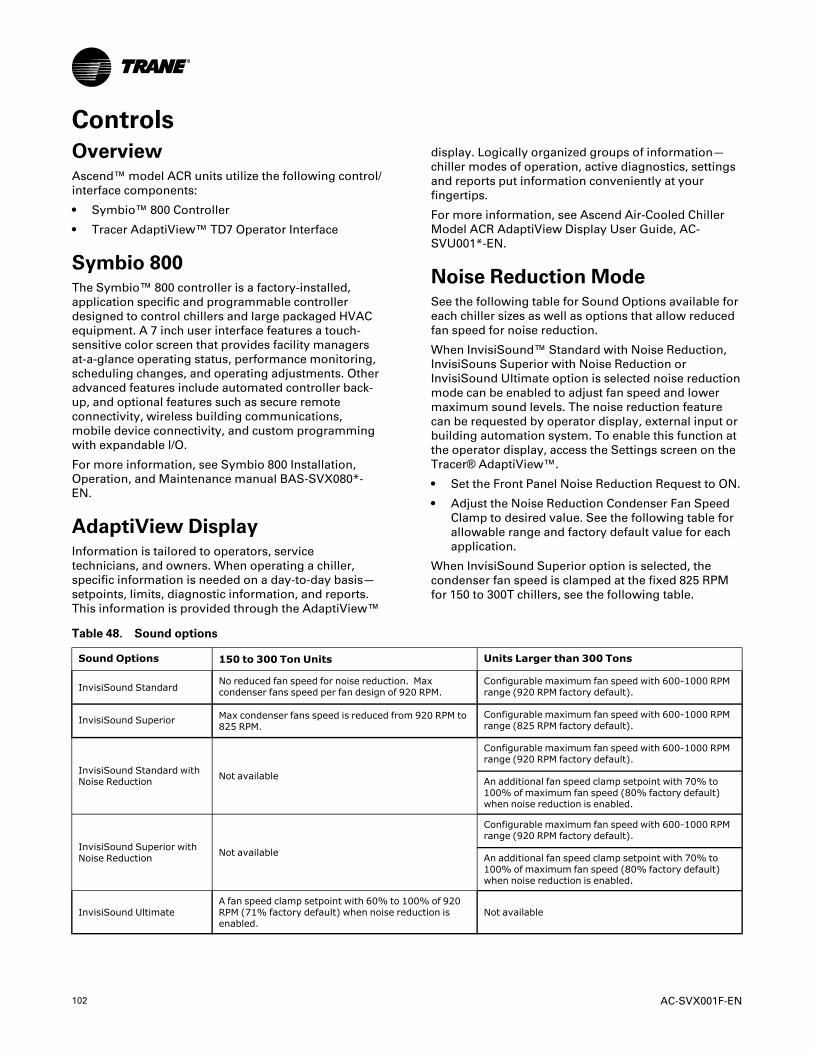
102 AC-SVX001F-EN
ControlsOverviewAscend™ model ACR units utilize the following control/interface components:
• Symbio™ 800 Controller
• Tracer AdaptiView™ TD7 Operator Interface
Symbio 800The Symbio™ 800 controller is a factory-installed,application specific and programmable controllerdesigned to control chillers and large packaged HVACequipment. A 7 inch user interface features a touch-sensitive color screen that provides facility managersat-a-glance operating status, performance monitoring,scheduling changes, and operating adjustments. Otheradvanced features include automated controller back-up, and optional features such as secure remoteconnectivity, wireless building communications,mobile device connectivity, and custom programmingwith expandable I/O.
For more information, see Symbio 800 Installation,Operation, and Maintenance manual BAS-SVX080*-EN.
AdaptiView DisplayInformation is tailored to operators, servicetechnicians, and owners. When operating a chiller,specific information is needed on a day-to-day basis—setpoints, limits, diagnostic information, and reports.This information is provided through the AdaptiView™
display. Logically organized groups of information—chiller modes of operation, active diagnostics, settingsand reports put information conveniently at yourfingertips.
For more information, see Ascend Air-Cooled ChillerModel ACR AdaptiView Display User Guide, AC-SVU001*-EN.
Noise Reduction ModeSee the following table for Sound Options available foreach chiller sizes as well as options that allow reducedfan speed for noise reduction.
When InvisiSound™ Standard with Noise Reduction,InvisiSouns Superior with Noise Reduction orInvisiSound Ultimate option is selected noise reductionmode can be enabled to adjust fan speed and lowermaximum sound levels. The noise reduction featurecan be requested by operator display, external input orbuilding automation system. To enable this function atthe operator display, access the Settings screen on theTracer® AdaptiView™.
• Set the Front Panel Noise Reduction Request to ON.
• Adjust the Noise Reduction Condenser Fan SpeedClamp to desired value. See the following table forallowable range and factory default value for eachapplication.
When InvisiSound Superior option is selected, thecondenser fan speed is clamped at the fixed 825 RPMfor 150 to 300T chillers, see the following table.
Table 48. Sound options
Sound Options 150 to 300 Ton Units Units Larger than 300 Tons
InvisiSound StandardNo reduced fan speed for noise reduction. Maxcondenser fans speed per fan design of 920 RPM.
Configurable maximum fan speed with 600-1000 RPMrange (920 RPM factory default).
InvisiSound Superior Max condenser fans speed is reduced from 920 RPM to825 RPM.
Configurable maximum fan speed with 600-1000 RPMrange (825 RPM factory default).
InvisiSound Standard withNoise Reduction Not available
Configurable maximum fan speed with 600-1000 RPMrange (920 RPM factory default).
An additional fan speed clamp setpoint with 70% to100% of maximum fan speed (80% factory default)when noise reduction is enabled.
InvisiSound Superior withNoise Reduction Not available
Configurable maximum fan speed with 600-1000 RPMrange (920 RPM factory default).
An additional fan speed clamp setpoint with 70% to100% of maximum fan speed (80% factory default)when noise reduction is enabled.
InvisiSound UltimateA fan speed clamp setpoint with 60% to 100% of 920RPM (71% factory default) when noise reduction isenabled.
Not available

AC-SVX001F-EN 103
Tracer TUThe AdaptiView™ TD7 operator interface allows fordaily operational tasks and setpoint changes. However,to adequately service chillers, Tracer® TU service toolis required. (Non-Trane personnel, contact your localTrane office for software purchase information.) TracerTU adds a level of sophistication that improves servicetechnician effectiveness and minimizes chillerdowntime. This portable PC-based service-toolsoftware supports service and maintenance tasks, andis required for software upgrades, configurationchanges and major service tasks.
Tracer TU serves as a common interface to all Tranechillers, and will customize itself based on theproperties of the chiller with which it iscommunicating. Thus, the service technician learnsonly one service interface.
The panel bus is easy to troubleshoot using LED sensorverification. Only the defective device is replaced.Tracer TU can communicate with individual devices orgroups of devices.
All chiller status, machine configuration settings,customizable limits, and up to 100 active or historicdiagnostics are displayed through the service-toolsoftware interface.
LEDs and their respective Tracer TU indicators visuallyconfirm the availability of each connected sensor,relay, and actuator.
Tracer TU is designed to run on a customer’s laptop,connected to the Tracer AdaptiView control panel witha USB cable. Your laptop must meet the followinghardware and software requirements:
• 1 GB RAM (minimum)
• 1024 x 768 screen resolution
• CD-ROM drive
• Ethernet 10/100 LAN card
• An available USB 2.0 port
• Windows 7 Enterprise or Professional operatingsystem (32-bit or 64-bit)
NNoottee:: Tracer TU versions 8.6 and earlier will alsosupport Microsoft®Windows® XPProfessional operation system with ServicePack 3 (SP3) .
• Microsoft .NET Framework 4.0 or later
NNootteess::
• Tracer® TU is designed and validated forthis minimum laptop configuration. Anyvariation from this configuration may havedifferent results. Therefore, support forTracer TU is limited to only those laptopswith the configuration previously specified.
• For more information, see TTU-SVN01*-ENTracer ®TU Getting Started Guide.
Figure 69. Tracer TU
Integrated Rapid RestartChiller controls are designed and engineered for RapidRestart™. In the event of a power interruption, thechiller will start a compressor before the front paneldisplay is fully powered up, eliminating the need for anuninterrupted power supply (UPS). Advanced featuresand functionality are built into the chillers. Bringing achiller back online rapidly after a loss of power iscritical to operations in mission critical environments,which demand the highest levels of reliability.
Under optimal conditions, it can restart in as little as 45seconds with no need for uninterrupted power supply(UPS). An 80 percent cooling load can be achieved inless than 2.5 minutes after power restoration.
CCoonnttrroollss

104 AC-SVX001F-EN
Pre-Start
Upon completion of installation, complete theInstallation Completion Check Sheet and Request forTrane Service checklist in Log and Check Sheetchapter.
IImmppoorrttaanntt:: Start-up must be performed by Trane or anagent of Trane specifically authorized toperform start-up and warranty of Traneproducts. Contractor shall provide Trane(or an agent of Trane specificallyauthorized to perform start-up) with noticeof the scheduled start-up at least two weeksprior to the scheduled start-up.

AC-SVX001F-EN 105
Start-up and ShutdownIImmppoorrttaanntt:: Initial unit commissioning start-up must be
performed by Trane or an agent of Tranespecifically authorized to perform start-upand warranty of Trane products. Contractorshall provide Trane (or an agent of Tranespecifically authorized to perform start-up)with notice of the scheduled start-up atleast two weeks prior to the scheduledstart-up.
Unit Start-upNNOOTTIICCEE
EEqquuiippmmeenntt DDaammaaggee!!FFaaiilluurree ttoo ffoollllooww iinnssttrruuccttiioonnss ccoouulldd rreessuulltt iinneeqquuiippmmeenntt ddaammaaggee..EEnnssuurree tthhaatt tthhee ccoommpprreessssoorr aanndd ooiill ssuummpp hheeaatteerrsshhaavvee bbeeeenn ooppeerraattiinngg pprrooppeerrllyy ffoorr aa mmiinniimmuumm ooff 2244hhoouurrss bbeeffoorree ssttaarrttiinngg..
NNOOTTIICCEEEEqquuiippmmeenntt DDaammaaggee!!SSnnooww,, iiccee,, oorr ddeebbrriiss bbuuiilldd uupp oonn ffaannss ccoouulldd ccaauusseeeexxcceessssiivvee iimmbbaallaannccee aanndd eeqquuiippmmeenntt ddaammaaggee..CClleeaarr ffaannss ooff bbuuiilldd uupp pprriioorr ttoo mmaacchhiinnee ssttaarrtt--uupp..
If required, once the system has been operating forapproximately 30 minutes and has become stabilized,complete the remaining start-up procedures, asfollows:
1. Check the evaporator refrigerant pressure and thecondenser refrigerant pressure under RefrigerantReport on the AdaptiView™ TD7. The pressures arereferenced to sea level (14.6960 psia).
2. Check the EXV sight glasses after sufficient timehas elapsed to stabilize the chiller. The refrigerantflow past the sight glasses should be clear. Bubblesin the refrigerant indicate either low refrigerantcharge or excessive pressure drop in the liquid lineor a stuck open expansion valve. A restriction in theline can sometimes be identified by a noticeabletemperature differential between the two sides ofthe restriction. Frost will often form on the line atthis point. Proper refrigerant charges are shown inthe General Information Section.
IImmppoorrttaanntt:: A clear sight glass alone does not meanthat the system is properly charged. Alsocheck system subcooling, liquid levelcontrol and unit operating pressures.
If chiller is limited by any limiting conditions, contactlocal Trane service organization for more information.
Temporary Shutdown AndRestartTo shut the unit down for a short time, use thefollowing procedure:
1. Press the STOP key on the AdaptiView™ TD7. Thecompressors will continue to operate and anoperational pumpdown cycle may be initiated.
2. Symbio™ 800 pump control will turn off the pump(after a minimum 1 min. delay) when the STOP keyis pressed and automatically restart the pump whenthe unit starts normally.
To restart the unit after a temporary shutdown, enablethe chilled-water pump and press the AUTO key. Theunit will start normally, provided the followingconditions exist:
• The Symbio 800 receives a call for cooling and thedifferential-to-start is above the setpoint.
• All system operating interlocks and safety circuitsare satisfied.
Extended Shutdown ProcedureThe following procedure is to be followed if the systemis to be taken out of service for an extended period oftime, e.g. seasonal shutdown:
1. Test the unit for refrigerant leaks and repair asnecessary.
2. Open the electrical disconnect for the chilled waterpump. Lock the switches in the "OPEN" position.
NNOOTTIICCEEPPuummpp DDaammaaggee!!FFaaiilluurree ttoo ffoollllooww iinnssttrruuccttiioonnss ccoouulldd rreessuulltt iinn ppuummppddaammaaggee..LLoocckk tthhee cchhiilllleedd wwaatteerr ppuummpp ddiissccoonnnneeccttss ooppeenn aannddvveerriiffyy ppuummpp iiss ooffff bbeeffoorree ddrraaiinniinngg wwaatteerr..
3. Close all chilled water supply valves. Drain thewater from the evaporator.
4. With water drained from the evaporator, removepower from heaters as follows:
• For units with model number digit 29 = 3,disable power upstream from the chiller.
• For all other units, disconnect 115 power fromevaporator heaters at terminals 1X4-1 and 1X4-2.

106 AC-SVX001F-EN
NNOOTTIICCEEHHeeaatteerr DDaammaaggee!!FFaaiilluurree ttoo ffoollllooww iinnssttrruuccttiioonnss ccoouulldd rreessuulltt iinn hheeaatteerrddaammaaggee..DDoo nnoott aappppllyy ppoowweerr ttoo tthhee eevvaappoorraattoorr hheeaatteerrsswwhheenn nnoo wwaatteerr iiss pprreesseenntt..
5. Open the main electrical disconnect and lock in the"OPEN" position.
NNOOTTIICCEEEEqquuiippmmeenntt DDaammaaggee!!FFaaiilluurree ttoo ffoollllooww iinnssttrruuccttiioonnss ccoouulldd rreessuulltt iinneeqquuiippmmeenntt ddaammaaggee..LLoocckk tthhee ddiissccoonnnneecctt iinn tthhee ""OOPPEENN"" ppoossiittiioonn ttoopprreevveenntt aacccciiddeennttaall ssttaarrtt--uupp aanndd ddaammaaggee ttoo tthheessyysstteemm wwhheenn iitt hhaass bbeeeenn sshhuutt ddoowwnn ffoorr eexxtteennddeeddppeerriiooddss..
6. At least every three months (quarterly), check therefrigerant pressure in the unit to verify that therefrigerant charge is intact.
Seasonal Unit Start-upProcedure1. PRIOR to water being pumped into system, use
gauges to verify positive pressure in the evaporatorand condenser. Lack of pressure could indicate asystem leak. When charging in the factory,approximately 95% of the refrigerant charge isisolated in the evaporator, and the other 5% iscontained in the condenser and compressor. In theevent that no pressure is present, contact localTrane service.
2. Close all drain valves and re-install the drain plugsin the evaporator.
3. Service the auxiliary equipment according to thestart-up/maintenance instructions provided by therespective equipment manufacturers.
4. Close the vents in the evaporator chilled watercircuits.
5. Open all the valves in the evaporator chilled watercircuits.
6. Open all refrigerant valves or verify they are in theopen condition.
7. If the evaporator was previously drained, vent andfill the evaporator and chilled water circuit. Whenall air is removed from the system (including eachpass), install the vent plugs in the evaporator waterboxes.
8. Check the adjustment and operation of each safetyand operating control.
9. Refer to the sequence for daily unit startup for theremainder of the seasonal startup.
System Restart After ExtendedShutdown
NNOOTTIICCEEEEqquuiippmmeenntt DDaammaaggee!!FFaaiilluurree ttoo ffoollllooww iinnssttrruuccttiioonnss ccoouulldd rreessuulltt iinneeqquuiippmmeenntt ddaammaaggee..EEnnssuurree tthhaatt tthhee ccoommpprreessssoorr aanndd ooiill ssuummpp hheeaatteerrsshhaavvee bbeeeenn ooppeerraattiinngg pprrooppeerrllyy ffoorr aa mmiinniimmuumm ooff 2244hhoouurrss bbeeffoorree ssttaarrttiinngg..
Follow the procedures below to restart the unit afterextended shutdown:
1. Check refrigerant pressure as noted in SeasonalUnit Start-Up procedure.
2. Verify that the liquid line service valves, oil line,compressor discharge service valves and suctionservice valves are open (backseated).
NNOOTTIICCEECCoommpprreessssoorr DDaammaaggee!!FFaaiilluurree ttoo ffoollllooww iinnssttrruuccttiioonnss bbeellooww ccoouulldd ccaauusseeccaattaassttrroopphhiicc ddaammaaggee ttoo tthhee ccoommpprreessssoorr..DDoo nnoott lleeaavvee ooiill lliinnee sshhuutt ooffff vvaallvvee oorr tthhee iissoollaattiioonnvvaallvveess cclloosseedd oonn uunniitt ssttaarrtt--uupp..
3. Check the oil sump level. See instructions inMaintenance chapter.
4. Fill the evaporator water circuit. Vent the systemwhile it is being filled. Open the vent on the top ofthe evaporator and condenser while filling andclose when filling is completed.
NNOOTTIICCEEPPrrooppeerr WWaatteerr TTrreeaattmmeenntt RReeqquuiirreedd!!TThhee uussee ooff uunnttrreeaatteedd oorr iimmpprrooppeerrllyy ttrreeaatteedd wwaatteerrccoouulldd rreessuulltt iinn ssccaalliinngg,, eerroossiioonn,, ccoorrrroossiioonn,, aallggaaee oorrsslliimmee..UUssee tthhee sseerrvviicceess ooff aa qquuaalliiffiieedd wwaatteerr ttrreeaattmmeennttssppeecciiaalliisstt ttoo ddeetteerrmmiinnee wwhhaatt wwaatteerr ttrreeaattmmeenntt,, iiffaannyy,, iiss rreeqquuiirreedd.. TTrraannee aassssuummeess nnoo rreessppoonnssiibbiilliittyyffoorr eeqquuiippmmeenntt ffaaiilluurreess wwhhiicchh rreessuulltt ffrroomm uunnttrreeaatteeddoorr iimmpprrooppeerrllyy ttrreeaatteedd wwaatteerr,, oorr ssaalliinnee oorr bbrraacckkiisshhwwaatteerr..
5. Close the fused-disconnect switches that providespower to the chilled water pump.
6. Start the evaporator water pump and, while wateris circulating, inspect all piping for leakage. Makeany necessary repairs before starting the unit.
7. While the water is circulating, adjust the waterflows and check the water pressure drops throughthe evaporator. See Evaporator Waterside PressureDrop Curves in Installation Mechanical chapter, andwater flow rates in General Data tables.
8. Verify proper operation of flow switch on the
SSttaarrtt--uupp aanndd SShhuuttddoowwnn

AC-SVX001F-EN 107
evaporator waterbox.
9. Stop the water pump. The unit is now ready forstart-up as described previously
Sequence of OperationThis section provides basic information on chilleroperation for common events. Adaptive controlalgorithms are used on these chillers. This sectionillustrates common control sequences.
Software Operation OverviewThe following figure is a diagram of the five possiblesoftware states. This diagram can be thought of as astate chart, with the arrows and arrow text, depictingthe transitions between states:
• The text in the circles is the internal softwaredesignations for each state.
• The shading of each software state circlecorresponds to the shading on the time lines thatshow the chiller’s state.
There are five generic states that the software can bein:
• Power Up
• Stopped
• Starting
• Running
• Stopping
S hutting D ow n
R unningor
R unn ing L im it
S toppedor
R un Inh ib itAutoCom m and
Confirmed S tart
S top Com m andD iagnostic
Confirmed
Shutdow n
B oot andS elf Test
S top C om m and or D iagnostic
A utoor
W aiting to S tart
Check forDifferentialto Start
Check forDifferentialto Stop
Releaseof Inh ib it
P ow er U p
In the following diagrams:
• The time line indicates the upper level operatingmode, as it would be viewed in the Tracer®AdaptiView™.
• The shading color of the cylinder indicates thesoftware state.
• Text in parentheses indicates sub-mode text asviewed in the Tracer® AdaptiView™.
• Text above the time line cylinder is used to illustrateinputs to the Symbio 800. This may include userinput to the Tracer® AdaptiView™ touch screen,control inputs from sensors, or control inputs froma generic BAS.
• Boxes indicate control actions such as turning onrelays, or pulsing compressor load or unloadsolenoids.
• Smaller cylinders under the main cylinder indicatediagnostic checks.
• Text outside a box or cylinder indicates time-basedfunctions.
• Solid double arrows indicate fixed timers.
• Dashed double arrows indicate variable timers.
SSttaarrtt--uupp aanndd SShhuuttddoowwnn

108 AC-SVX001F-EN
Power Up DiagramThe following diagram shows the respective TD7AdaptiView™ screens during a power up of the Symbio800 and display. This process takes 15 seconds for theSymbio 800, and 105 seconds for the display. On all
power ups, the software model always will transitionthrough the 'Stopped' Software state independent ofthe last mode. If the last mode before power down was'Auto', the transition from 'Stopped' to 'Starting'occurs, but it is not apparent to the user.
Figure 70. Sequence of operation: power up diagram
*Display will showeither Auto or Stopbutton as “active” (depressed) once
it is ready
ExternalPower
Applied
Symbio 800 Fully Operational
Booting Symbio 800(15 Seconds)
Operator Display and Symbio 800 Start Booting
Last ModeAuto*
Last ModeStop*
IPC Bus Comm Begins
Remain in“Stop” indefinitely
until “Auto” command- See
“Stopped To Starting”
IF
(45 Seconds)Minimum Time Until 1st Compressor Could Restart
(if “Power Up Delay Inhibit” set to 0; Default is 105 sec)
Continue Along Start Sequence
See “Power Upto Starting”
10 Sec
First Trane Logo Grey Screen
Second Trane Logo - Loading
User Interface Template...
Black Screen
Loading Data….
Display Ready
20 Seconds 30 Seconds 25 Seconds
Operator Display Boot Up and Load - 105 sec Total to Display Ready
15 Sec5 Sec
Stopped
White Screen
Starting SequenceSee “Power Up to
Starting” Sequence DiagramSymbio 800Boot Up
SSttaarrtt--uupp aanndd SShhuuttddoowwnn

AC-SVX001F-EN 109
Power Up to StartingThe following diagram shows the timing from a powerup event to energizing the first compressor. Theshortest allowable time would be under the followingconditions:
• No motor restart inhibit time left from subsequentstarts
• Evaporator water flow occurs quickly with pump oncommand
• Power up Start Delay set to 0 minutes
• Need to cool (differential to start) already exists
• Oil level is detected immediately
The above conditions would allow for a minimumpower up to starting the first compressor time of about45 seconds. (Variations may exist due to optionsinstalled.)
NNoottee:: It is not advisable to start a chiller “cold”. The oilheaters should be in operation for a sufficientlength of time prior to first start.
Figure 71. Sequence of events: power up to starting
Confirm Presence of Oil Within90 Seconds
Power Applied
* Lead Compressor (and its lead circuit) is determined by staging algorithm – “Balanced”, “Circuit 1 Lead”, or “Circuit 2 Lead” selection – also influenced by lockouts, restart inhibit, or diagnostics present.
On manifolded circuit for ACRB above 300T, GP4 will be the first to start and last to stop; GP2 will not run by itself.
Fans pre-start,EXVs moving to
Preposition0 to 25 Seconds;
Compressor Delay Time has expired
PowerUp
Symbio 800Boot Time(15 Sec)
Auto Mode commandedby Front Panel or BAS
EXVs self-close onpower up
Confirm Evaporator Water Flow(6 Second Filter)
Enforce Restart Inhibit Timer(0 to 1 minute)
Power Up Delay Inhibit Timer(User Adjustable 0 to 30 minutes)
Auto
Energize Evaporator Water Pump Relay
Confirm Evaporator Water Flow Within 20 minutes
(6 Second Filter)
Oil Heaters Always Energized when Compressor
is De-energized
EXV remains closed
Wait for NeedTo Cool
(Diff to Start)
Auto
Call for Cooling **(Differential to Start is met)
WaitingTo Start
Confirm Presence of Oil
(0 to 90 seconds)
WaitingTo Start
Send Start Command to Lead Compressor*
Transition toRunning
Start Control ofCondenser Fan Flow
Pre-Position EXV ofLead Circuit
Check Evap Pressure forLow Pressure Cutout
** If Free Cooling is available, it shall be the first level control to start.Total Free Cooling: balanced starts and hours or circuit x lead are available.
SSttaarrtt--uupp aanndd SShhuuttddoowwnn

110 AC-SVX001F-EN
Stopped to StartingThe following diagram shows the timing from astopped mode to energizing the first compressor. Theshortest allowable time would be under the followingconditions:
• No motor restart inhibit time left from subsequentstarts
• Evaporator water flow occurs quickly with pump oncommand
• Need to cool (differential to start) already exists
The above conditions would allow a compressor tostart in about 20 seconds.
Figure 72. Sequence of events: stopped to starting
Confirm Presence of Oil Within90 Seconds
StoppedOr RunInhibit
* Lead Compressor (and its lead circuit) is determined by staging algorithm – “Balanced”, “Circuit 1 Lead”, or “Circuit 2 Lead” selection – also influenced by lockouts, restart inhibit, or diagnostics present. On manifolded circuit for ACRB above 300T, GP4 will be the first to start and last to stop; GP2 will not run by itself.
**Note: If Free Cooling is active, it will be the first stage of cooling to stage on.
Stop
Auto Mode commandedby Front Panel or BAS
Confirm Evaporator Water Flow(6 Second Filter)
Enforce Restart Inhibit Timer(0 to 1 minute)
Auto
Energize Evaporator Water Pump Relay
Confirm Evaporator Water Flow Within 20 minutes
(6 Second Filter)
Oil Heaters Always Energized when
Compressor is De-energized
EXV remains closed
Wait for NeedTo Cool
(Diff to Start)
Auto
Call for Cooling**(Differential to Start is met)
WaitingTo Start
Confirm Presence of Oil
(0 to 90 seconds)
WaitingTo Start
Fans pre-start, EXV moving to
Preposition0 to 25 Seconds,
Compressor Delay Time has expired
Send Start Command to Lead Compressor*
Transition toRunning
Start Control ofCondenser Fan Flow
Pre-Position EXV ofLead Circuit
Check Evap Pressure forLow Pressure Cutout
SSttaarrtt--uupp aanndd SShhuuttddoowwnn

AC-SVX001F-EN 111
Running (Lead Compressor/Circuit Startand Run)The following diagram shows a typical start and runsequence for the lead compressor and its circuit.
Figure 73. Sequence of events: running (lead compressor/circuit start and run)
Hold EXV Pre-position
LeadCompressor
Running
Chiller and Lead CircuitMode is “Running” - Lag Circuit Mode is “Auto”
Hold EXV of LeadCircuit at pre-
position
De-energizeOil Heaters
Of Lead Circuit
Control Lead Circuit Condenser Fans for Optimum Differential
Pressure, ƒ(Cprsr Spd, OA Temp)
Enforce All Running Mode Diagnostics for Chiller
Modulate EXV for Pressure Control &
Liquid Level (if applicable
Modulate Compressor
for Limit Control
Modulate Compressor for
Capacity Control
Modulate Compressor for
Capacity Control
Running RunningRunning
Lead Circuit:Running Limit
Running
ExitLimit Mode
Enter Limit Mode
Stage OnSetpoint Met*
RunningLag Circuit:
Waiting to Start
Prepare to Start Lag Compressor,
Check for Oil,Check for LPC
EXV moving to preposition0 to 25 Seconds
Start Control of Condenser Fan Flow
on Lag Circuit
Send Start Command to Lag Compressor
ContinueRunning
Pre-Position EXV ofLag Circuit
*Note: The decision to stage on or off another compressor is determined by the Average Running Compressor Load Command, Water Temperature Error, and Time Since Last StageCircuit X Lead: XA compressor on the selected circuit will lead followed by a compressor on the alternate circuit, given an appropriately increasing chiller load. Additional compressors will alternate between lead and lag circuits.On manifolded circuit for ACRB above 300T, GP4 will be the first to start and last to stop; GP2 will not run by itself.
SSttaarrtt--uupp aanndd SShhuuttddoowwnn

112 AC-SVX001F-EN
Running (Lag Compressor/Circuit Startand Run)The following diagram shows a typical start and runsequence for the lag compressor and its circuit.
Figure 74. Sequence of operation: running (lag compressor/circuit start and run)
*Note: The decision to stage on or off another compressor is determined by the Average Running Compressor Load Command, Water Temperature Error, and Time Since Last StageOn manifolded circuit for ACRB above 300T, GP4 will be the first to start and last to stop; GP2 will not run by itself.
CompressorsRunning
Chiller and Both CircuitModes are “Running”
De-energizeOil Heaters
Of Lag Circuit
Control Both Circuit Condenser Fans for Optimum Differential
Pressure, ƒ(Cprsr Spd, OA Temp)
Enforce All Running Mode Diagnostics for Chiller
Modulate Compressor
for Limit Control
Modulate Compressor for
Capacity Control
Running Running
ExitLimit Mode
Enter Limit Mode
Running
Energize Maximum Capacity Relay after the Adjustable Filter Time(0 to 1500 Seconds)
ContinueRunning
(All Cprsrs &
Max Capacity
Maximum CapacitySubmode
RunningRunning
Lag Circuit:Running Limit
All Compressors RunningAt or Near Max Capacity(Unable to Achieve CWSP)
Modulate Compressor for Capacity Control
Modulate EXV for Pressure Control &
Liquid Level (if applicable
Hold EXV Pre-position
Hold EXV pre-position
SSttaarrtt--uupp aanndd SShhuuttddoowwnn

AC-SVX001F-EN 113
Satisfied SetpointThe following diagram shows the normal transitionfrom running to shutting down due to the evaporator
leaving water temperature falling below the differentialto stop setpoint. It also outlines the termination criteriafor operational pumpdown.
Figure 75. Sequence of events: satisfied setpoint
300T and Below:* Operational Pumpdown is required if the Outdoor Air Temperature is less than 50F.** Operational Pumpdown is Terminated Normally when the Evaporator Refrigerant Pressure is at or below 20 PSIA.
Above 300T:* Operational Pumpdown is required if the Outdoor Air Temperature is less than 50F, or the Entering Evaporator Water Temperature is greater than (outdoor air temperature – 10°F). With AFD, compressors will be at max speed for operational pumpdown. ** Operational pumpdown is terminated normally when:
-The evaporator (suction) pressure is at or below the “Pumpdown Termination Pressure” setting OR LERTC saturated pressure (32F for water [default]; -5F for glycol), which ever is greater-The condenser (compressor discharge) pressure exceeds 315psia.-The compressor pressure ratio exceeds 12.3-The system differential pressure exceeds 265psid
** The maximum allowed time for Operational Pumpdown is Max Pumpdown Time setting (default to 120 sec.) * number of compressors configured on the circuit.
**** If Condenser Refrigerant Tanks are installed
Shutting DownLast Circuit Mode: Shutting Down
SubMode: Operational Pumpdown*
RunningLast Circuit Mode:
Running
AutoBoth Circuit Modes:
Waiting for Need to Cool
Running Last
CompressorAt Min
Capacity
Differential to Stop is Met
Operational Pumpdown(See max time allowed below)
Fully Close EXV
Condenser Rfgt Tank Solenoid
Valve****
Send Stop CommandTo Compressor(s)
IF*No Pumpdown Required
PumpdownRequired
Turn Off Last Circuit’sCondenser Fans
Normal Pumpdown Termination**Criteria is Met for Last Circuit
Enforce All Non RunningMode Diagnostics
Auto
Close EXV(0 to 25 Seconds)
Energize Last CircuitOil HeatersCheck for
Normal PumpdownTermination Criteria Met **
Perform Operational Pumpdown for Last Circuit if Required
SSttaarrtt--uupp aanndd SShhuuttddoowwnn

114 AC-SVX001F-EN
Unloading UnstagingThe following diagram shows the normal transitionfrom full load to minimum load while the chiller isrunning.
Figure 76. Sequence of events: unloading unstaging
Running(All
Compressors & Max
Capacity)
All Compressors Running AtLess Than Max Capacity
De-Energize the Maximum Capacity
Relay after Adjustable Filter
Time (0 to 600 Sec)
Remove Maximum Capacity Submode
Running
StageOff Setpoint Met***
RunningLag Circuit Mode: Shutting Down
SubMode: Operational Pumpdown*Operational Pumpdown
(0 Seconds to Max Pumpdown Timer(Default: 2 min.))
Fully Close EXV
Close Condenser Rfgt Tank Solenoid
Valve****
IF*No Pumpdown Required
PumpdownRequired
Close EXV(0 to 25 Seconds)
Normal Pumpdown Termination**Criteria is Met for Last Circuit
Send Stop Command To Lag
Compressor
Continue to Control Capacity by Modulating Compressor
Capacity
*** Note: The decision to stage off another compressor is determined by the Average Running Compressor Load Command, Water Temperature Error, and Time since Last Stage. Compressors will stage off in the reverse order they staged on. All fixed speed compressors will stage off before variable speed compressors stage off.On manifolded circuit for ACRB above 300T, GP4 will be the first to start and last to stop; GP2 will not run by itself.
Stop Lag Circuits Condenser Fans
Energize Lag Circuit Heaters
RunningLag Circuit Mode: Auto
Continue to Control Capacity by Modulating
Lead Compressor
Running Last Compressor at Min Capacity
Running
Enforce All Running Mode Diagnostics
Enforce All Non Operational PumpdownDiagnostics
Enforce Running Mode Diagnostics for Chiller,Last Compressor and its Circuit
Check for Normal Pumpdown Termination
Criteria Met **
* & ** Operational Pumpdown Requirement and Termination - See Satisfied Setpoint Operational Pumpdown sequence diagram for specific criteria.
**** If Condenser Refrigerant Tank is installed.
Perform Operational Pumpdown for Last Circuit if Required*
SSttaarrtt--uupp aanndd SShhuuttddoowwnn

AC-SVX001F-EN 115
Normal Shutdown to Stopped or RunInhibitThe following diagram shows the transition fromRunning through a Normal (friendly) Shutdown. The
dashed lines on the top attempt to show the final modeif stop is selected via various inputs.
Figure 77. Sequence of events: normal shutdown to stopped or run inhibit
* & ** Operational Pumpdown Requirement and Termination - See Satisfied Setpoint Operational Pumpdown sequence diagram for specific criteria.
Note: If Free Cooling is active, the last stage of cooling to turn off will be Free Cooling.
Shutting DownRunning Circuit Modes: Shutting Down
SubMode: Operational Pumpdown*
Operational Pumpdown(See max allowed time below)
Fully Close EXV
Perform Operational Pumpdown for All Running Circuits if
Required*
IF*
Close EXV(0 to 25 Seconds)
Check for Normal Pumpdown
Termination Criteria Met **
No Pumpdown Required
Pumpdown Required
Evaporator Pump Off Delay(Adjustable 1 to 30 Minutes)
Send Stop Command to All
Running Compressors
Energize All Heaters
Fully Close Both EXVs
Turn Off All Running Circuits Condenser Fans
De-Energize EvaporatorWater Pump Relay
Stoppedor
Run InhibitOne or More
CircuitsRunning
Normal Pumpdown Termination** Criteria is Met for All Circuits
Local StopChiller Level Diagnostic – Normal Shutdown LatchedChiller Level Diagnostic – Normal Shutdown NonlatchedBuilding Automation System StopExternal Auto-Stop
Shutting DownCircuit Modes:
Auto
Stopped or Run InhibitCircuit Modes:
Stopped or Auto
SSttaarrtt--uupp aanndd SShhuuttddoowwnn

116 AC-SVX001F-EN
Immediate Shutdown to Stopped or RunInhibitThe following diagram shows the transition fromRunning through an Immediate Shutdown. The dashed
lines on the top attempt to show the final mode if stopis selected via various inputs.
Figure 78. Sequence of events: immediate shutdown to stopped or run inhibit
Chiller Level Diagnostic – Immediate Shutdown Non-LatchingChiller Level Diagnostic – Immediate Shutdown LatchingFront Panel Immediate Shutdown
Run Inhibitor
StoppedCompressor Deceleration Time
De-Energize EvaporatorWater Pump Relay
StoppedShutting DownOne or More
Running Compressors
Send Stop Command to All Running Compressors
Energize All Heaters
Fully Close Both EXVs
Turn Off All Running CircuitsCondenser Fans
SSttaarrtt--uupp aanndd SShhuuttddoowwnn

AC-SVX001F-EN 117
Ice Making (Running to Ice Making toRunning)The following diagram shows the transition fromnormal cooling to ice making, and back to normalcooling.
Figure 79. Sequence of events: ice making (running to ice making to running)
Running
Ice Making Command: 1. Tracer 2. External 3. Front Panel
Running (Unit is Building Ice)
Ice Making Command Withdrawn (prior to ice complete)
Running
Stage and modulate all compressors in sequence to full load (if not already)
Start Compressors and Circuits per Normal Staging – See other sequence diagrams
Run Inhibit (Ice to Normal Transition)
Ice To Normal Transition Timer(fixed 2 mins)
Run Unload, Close EXVs and Perform Operational Pumpdown (if reqd) then Shutoff Compressors, Energize Heaters
Ignore Softloading and Set CLS = 100%
Energize Ice Building Relay
Enforce All Limits and Running Mode Diagnostics
Evap Leaving Water Temp Rises Above the Differential To Start
Maximum 1:10 to fully loaded
De-energize Heaters, Control EXVs and Oil Return Solenoids* per Normal Staging - See other sequence diagrams
De-energize Heaters, Control EXVs and Oil Return Solenoids* per Normal Staging - See other sequence diagrams
RunningAuto
Enforce All Limits and Running Mode Diagnostics
Control Circuit’s Condenser Fans for Diff Pressure
Control Circuit’s Condenser Fans for Diff Pressure
Turn off both Circuits’ Condenser Fans
Confirm No Compressor Currents
Close EXVs or leave closed for Circuits’ Off Cycle
De-Energize Oil Return Solenoids*
Pre-position EXV, Prestart Condenser Fans
De-Energize Ice Building Relay
Continue to Run Evap Water Pump Throughout
* If Oil Return Solenoids are installed
SSttaarrtt--uupp aanndd SShhuuttddoowwnn

118 AC-SVX001F-EN
Ice Making (Auto to Ice Making to IceMaking Complete)The following diagram shows the transition from autoto ice making, to ice making complete.
Figure 80. Sequence of events: ice making (auto to ice making to ice making complete)
Confirm No Compressor Currents
Auto
Evap Entering Water Temp Falls Below the Ice Termination Setpoint
Run Inhibit – Submode: Ice
Building Complete
Running (Unit is Building Ice)
Ice Making Command:1. Front Panel2. Tracer3. External Input
Auto Shutting Down
Maximum 1:10 to fully loaded
Run Unload, Close EXVs and Perform Operational Pumpdown (if reqd) then Shutoff Compressors, Energize Heaters
Enforce All Non- Running Mode Diagnostics
will return to “Auto” and normal cooling mode with removal of Ice Command
Stage and modulate all compressors in sequence to full load (if not already)
Ignore Softloading and Set CLS = 100%
Energize Ice Building Relay
Enforce All Limits and Running Mode Diagnostics
De-energize Heaters, Control EXVs and Oil Return Solenoids* per Normal Staging - See other sequence diagrams
Control Circuit’s Condenser Fans for Diff Pressure
Turn off both Circuits’ Condenser Fans
Leave EXVs Closed or Close EXV for Circuits’ Off Cycle
De-Energize Oil Return Solenoids*
De-Energize Evaporator Water Pump Relay (no delay time applied)
De-Energize Ice Building Relay
* If Oil Return Solenoids are installed
SSttaarrtt--uupp aanndd SShhuuttddoowwnn

AC-SVX001F-EN 119
MaintenanceWWAARRNNIINNGG
HHaazzaarrddoouuss VVoollttaaggee -- PPrreessssuurriizzeeddFFllaammmmaabbllee FFlluuiidd!!FFaaiilluurree ttoo ffoollllooww aallll eelleeccttrriiccaall ssaaffeettyy pprreeccaauuttiioonnssccoouulldd rreessuulltt iinn ddeeaatthh oorr sseerriioouuss iinnjjuurryy..DDoo nnoott ooppeerraattee ccoommpprreessssoorr wwiitthhoouutt tteerrmmiinnaall bbooxxccoovveerr iinn ppllaaccee..TThhee mmoottoorrss iinn tthhee ccoommpprreessssoorrss hhaavvee ssttrroonnggppeerrmmaanneenntt mmaaggnneett mmoottoorrss aanndd hhaavvee tthhee ccaappaabbiilliittyyttoo ggeenneerraattee vvoollttaaggee dduurriinngg ssiittuuaattiioonnss wwhheenn tthheerreeffrriiggeerraanntt cchhaarrggee iiss bbeeiinngg mmiiggrraatteedd.. TThhiissppootteennttiiaall wwiillll bbee pprreesseenntt aatt tthhee mmoottoorr tteerrmmiinnaallssaanndd aatt tthhee oouuttppuutt ooff tthhee vvaarriiaabbllee ssppeeeedd ddrriivveess iinntthhee ppoowweerr ppaanneell..BBeeffoorree rreemmoovviinngg ccoommpprreessssoorr tteerrmmiinnaall bbooxx ccoovveerrffoorr sseerrvviicciinngg,, oorr sseerrvviicciinngg ppoowweerr ssiiddee ooff ccoonnttrroollppaanneell,, CCLLOOSSEE CCOOMMPPRREESSSSOORR DDIISSCCHHAARRGGEESSEERRVVIICCEE VVAALLVVEE aanndd ddiissccoonnnneecctt aallll eelleeccttrriicc ppoowweerriinncclluuddiinngg rreemmoottee ddiissccoonnnneeccttss.. DDiisscchhaarrggee aallll mmoottoorrssttaarrtt//rruunn ccaappaacciittoorrss.. FFoollllooww lloocckkoouutt//ttaaggoouuttpprroocceedduurreess ttoo eennssuurree tthhee ppoowweerr ccaannnnoott bbeeiinnaaddvveerrtteennttllyy eenneerrggiizzeedd.. VVeerriiffyy wwiitthh aannaapppprroopprriiaattee vvoollttmmeetteerr tthhaatt aallll ccaappaacciittoorrss hhaavveeddiisscchhaarrggeedd..TThhee ccoommpprreessssoorr ccoonnttaaiinnss hhoott,, pprreessssuurriizzeeddrreeffrriiggeerraanntt.. MMoottoorr tteerrmmiinnaallss aacctt aass aa sseeaall aaggaaiinnsstttthhiiss rreeffrriiggeerraanntt.. CCaarree sshhoouulldd bbee ttaakkeenn wwhheennsseerrvviicciinngg NNOOTT ttoo ddaammaaggee oorr lloooosseenn mmoottoorrtteerrmmiinnaallss..
WWAARRNNIINNGGPPrreessssuurriizzeedd BBuurrnniinngg FFlluuiidd!!FFaaiilluurree ttoo ffoollllooww tthhee iinnssttrruuccttiioonnss bbeellooww ccoouullddrreessuulltt iinn ddeeaatthh oorr sseerriioouuss iinnjjuurryy..DDoo nnoott ooppeerraattee ccoommpprreessssoorr wwiitthhoouutt tteerrmmiinnaall bbooxxccoovveerr iinn ppllaaccee..TThhee ccoommpprreessssoorr ccoonnttaaiinnss hhoott,, pprreessssuurriizzeeddrreeffrriiggeerraanntt.. MMoottoorr tteerrmmiinnaallss aacctt aass aa sseeaall aaggaaiinnsstttthhiiss rreeffrriiggeerraanntt.. CCaarree sshhoouulldd bbee ttaakkeenn wwhheennsseerrvviicciinngg NNOOTT ttoo ddaammaaggee oorr lloooosseenn mmoottoorrtteerrmmiinnaallss..
WWAARRNNIINNGGHHaazzaarrddoouuss VVoollttaaggee ww//CCaappaacciittoorrss!!FFaaiilluurree ttoo ffoollllooww tthheessee iinnssttrruuccttiioonnss ccoouulldd rreessuulltt iinnddeeaatthh oorr sseerriioouuss iinnjjuurryy..DDiissccoonnnneecctt aallll eelleeccttrriicc ppoowweerr,, iinncclluuddiinngg rreemmootteeddiissccoonnnneeccttss aanndd ddiisscchhaarrggee aallll mmoottoorr ssttaarrtt//rruunn aannddAAFFDD ((AAddaappttiivvee FFrreeqquueennccyy™™ DDrriivvee)) ccaappaacciittoorrssbbeeffoorree sseerrvviicciinngg.. FFoollllooww pprrooppeerr lloocckkoouutt//ttaaggoouuttpprroocceedduurreess ttoo eennssuurree tthhee ppoowweerr ccaannnnoott bbeeiinnaaddvveerrtteennttllyy eenneerrggiizzeedd..
•• FFoorr vvaarriiaabbllee ffrreeqquueennccyy ddrriivveess oorr ootthheerr eenneerrggyyssttoorriinngg ccoommppoonneennttss pprroovviiddeedd bbyy TTrraannee oorrootthheerrss,, rreeffeerr ttoo tthhee aapppprroopprriiaatteemmaannuuffaaccttuurreerr’’ss lliitteerraattuurree ffoorr aalllloowwaabblleewwaaiittiinngg ppeerriiooddss ffoorr ddiisscchhaarrggee ooff ccaappaacciittoorrss..VVeerriiffyy wwiitthh aann aapppprroopprriiaattee vvoollttmmeetteerr tthhaatt aallllccaappaacciittoorrss hhaavvee ddiisscchhaarrggeedd..
•• DDCC bbuuss ccaappaacciittoorrss rreettaaiinn hhaazzaarrddoouuss vvoollttaaggeessaafftteerr iinnppuutt ppoowweerr hhaass bbeeeenn ddiissccoonnnneecctteedd..FFoollllooww pprrooppeerr lloocckkoouutt//ttaaggoouutt pprroocceedduurreess ttooeennssuurree tthhee ppoowweerr ccaannnnoott bbee iinnaaddvveerrtteennttllyyeenneerrggiizzeedd.. AAfftteerr ddiissccoonnnneeccttiinngg iinnppuutt ppoowweerr,,wwaaiitt ffiivvee ((55)) mmiinnuutteess ffoorr tthhee DDCC ccaappaacciittoorrss ttooddiisscchhaarrggee,, tthheenn cchheecckk tthhee vvoollttaaggee wwiitthh aavvoollttmmeetteerr.. MMaakkee ssuurree DDCC bbuuss ccaappaacciittoorrss aarreeddiisscchhaarrggeedd ((00 VVDDCC)) bbeeffoorree ttoouucchhiinngg aannyyiinntteerrnnaall ccoommppoonneennttss..
This section describes the basic chiller preventivemaintenance procedures, and recommends theintervals at which these procedures should beperformed. Use of a periodic maintenance program isimportant to ensure the best possible performance andefficiency.
Use an Operator Log (see Log and Check Sheetchapter) to record an operating history for unit. The logserves as a valuable diagnostic tool for servicepersonnel. By observing trends in operatingconditions, an operator can anticipate and preventproblem situations before they occur.
If unit does not operate properly during inspections,see Diagnostics chapter.
Recommended MaintenanceWeeklyWhile unit is running in stable conditions.
1. At AdaptiView™ TD7 or Tracer® TU service tool,check pressure for evaporator, condenser andintermediate oil.
2. Observe liquid line sight glass on EXV. If liquid linesight glass has bubbles measure the subcooling

120 AC-SVX001F-EN
entering the EXV. Subcooling should always begreater than 10°F for single compressor circuits,and 5°F for dual compressor circuits.
3. Inspect the entire system for unusual operation.
4. Inspect the condenser coils for dirt and debris. If thecoils are dirty, see Condenser Coil Cleaning sectionof Maintenance chapter.
NNOOTTIICCEECCooiill DDaammaaggee!!UUssee ooff ddeetteerrggeennttss ccoouulldd ccaauussee ddaammaaggee ttoo ccooiillss..DDoo nnoott uussee ddeetteerrggeennttss ttoo cclleeaann ccooiillss.. UUssee cclleeaannwwaatteerr oonnllyy..
Monthly1. Perform all weekly maintenance procedures.
2. Record the system subcooling.
Annual1. Perform all weekly and monthly procedures.
2. Check oil level while unit is off. See Maintenancechapter.
3. Perform pH test of drive cooling fluid. See pH Testsection of Maintenance chapter.
4. Have a qualified laboratory perform a compressoroil analysis to determine system moisture contentand acid level.
5. Contact a Trane service organization to leak test thechiller, to check operating and safety controls, andto inspect electrical components for deficiencies.
6. Clean and repaint any areas that show signs ofcorrosion.
7. Clean the condenser coils. See Condenser CoilCleaning section of Maintenance chapter.
NNOOTTIICCEECCooiill DDaammaaggee!!UUssee ooff ddeetteerrggeennttss ccoouulldd ccaauussee ddaammaaggee ttoo ccooiillss..DDoo nnoott uussee ddeetteerrggeennttss ttoo cclleeaann ccooiillss.. UUssee cclleeaannwwaatteerr oonnllyy..
Refrigerant and Oil ChargeManagementProper oil and refrigerant charge is essential for properunit operation, unit performance, and environmentalprotection. Only trained and licensed service personnelshould service the chiller.
The following table lists baseline measurements forchillers running at AHRI standard operating conditions.If chiller measurements vary significantly from values
listed below, problems may exist with refrigerant andoil charge levels. Contact your local Trane office.
NNoottee:: Low temperature applications units will havevalues that vary from the following table.Contact your local Trane office for moreinformation.
Table 49. Typical baselines (AHRI conditions)
Measurement Baseline
Evaporator Pressure 51 psia
Evaporator Approach 3.4°F average
EXV Position 45-65% open
Evaporator Temp - entering 54°F
Evaporator Temp - leaving 44°F
Discharge Superheat 16.5°F
Condenser Pressure 212 psia
Subcooling 10 to 20°F
Lubrication SystemThe lubrication system has been designed to keepmost of the oil lines filled with oil as long as there is aproper oil level in the oil sump.
Oil Sump Level CheckThe oil level in the sump can be measured to give anindication of the system oil charge. Follow theprocedures below to measure the level.
1. Run the unit as near to full load as possible for aminimum of 30 minutes. For an accurate reading,40 or more minutes at full load with normal/steadydischarge superheat readings and no limits/warnings is recommended. Assessing oil chargeafter running at minimum or low loads may lead toan inaccurate reading.
2. Cycle the compressors off.
3. Let the chiller sit (powered, but off line) to allow theoil separator heater to boil off the refrigerant thatmay be in the oil separator. An initial assessment ofthe oil separator level may be made after 30minutes of heater ON dwell time, but oil chargeadjustments should not be made without allowingthe oil heaters to run for a minimum of 4 hours.
NNOOTTIICCEEEEqquuiippmmeenntt DDaammaaggee!!OOppeerraattiinngg ccoommpprreessssoorrss wwiitthh sseerrvviiccee vvaallvveess ooppeennwwiillll rreessuulltt iinn sseevveerree ooiill lloossss aanndd eeqquuiippmmeennttddaammaaggee..NNeevveerr ooppeerraattee tthhee ccoommpprreessssoorr wwiitthh tthhee ssiigghhtt ggllaasssssseerrvviiccee vvaallvveess ooppeenneedd.. CClloossee tthhee vvaallvveess aafftteerrcchheecckkiinngg tthhee ooiill lleevveell..
MMaaiinntteennaannccee

AC-SVX001F-EN 121
4. Attach a 3/8” or 1/2” hose with a sightglass in themiddle to the oil sump service valve (1/4” flare) andthe oil separator service valve (1/4” flare). See thefollowing figure for valve locations.
NNoottee:: High pressure rated clear hose withappropriate fittings can help speed up theprocess. Hose must be rated to withstandsystem pressures as found on unit nameplate.
Figure 81. Oil service valves
To Oil Separator Service Valve
Oil Service Valve
5. After the unit is off line for 30 minutes, move thesightglass along the side of the oil sump.
6. The nominal oil level from the bottom of the oilseparator should be as shown in the following tableand figure. Depending on running conditions andoil heater dwell time, some deviation from nominallevels is expected.
IImmppoorrttaanntt:: If level is less than 4 inches from thebottom of the oil separator, contactyour local Trane office.
Unit Size(tons)
Oil SeparatorSize(in)
Nominal OilCharge Height
(in)
150 to 200 10 9.0
225 to 300 12 8.5
375 to 55012 8.5
14 9.7
Figure 82. Nominal oil level
Nominal oil level:10 in oil sep: 9.0 in12 in oil sep: 8.5 in14 in oil sep: 9.8 in
To Oil SeparatorService Valve
Drive Cooling SystemNNOOTTIICCEE
EEqquuiippmmeenntt DDaammaaggee!!UUssee ooff uunnaapppprroovveedd fflluuiiddss,, oorr ddiilluuttiioonn ooff aapppprroovveeddfflluuiidd ccoouulldd rreessuulltt iinn ccaattaassttrroopphhiicc eeqquuiippmmeennttddaammaaggee..UUssee oonnllyy TTrraannee HHeeaatt TTrraannssffeerr FFlluuiidd PP//NN CCHHMM0011002233..TThhiiss fflluuiidd iiss aa ddiirreecctt uussee ccoonncceennttrraattiioonn aanndd iiss nnoottttoo bbee ddiilluutteedd.. DDoo nnoott ttoopp ooffff wwiitthh wwaatteerr oorr aannyyootthheerr fflluuiidd..
Service Intervals
NNOOTTIICCEEEEqquuiippmmeenntt DDaammaaggee!!FFaaiilluurree ttoo ffoollllooww iinnssttrruuccttiioonnss ccoouulldd rreessuulltt iinneeqquuiippmmeenntt ddaammaaggee..DDrriivvee ccoooolliinngg fflluuiidd aanndd ssttrraaiinneerr mmuusstt bbee sseerrvviicceeddeevveerryy ffiivvee ((55)) yyeeaarrss..
• Every (5) years, contact your local Trane office toservice drive fluid and strainer.
• On a yearly basis, a fluid pH test should beperformed.
Unit DiagnosticsAn improperly filled drive cooling system (either lowfluid level or entrapped air in the circuit) can result inthe AFD drive overheating. This condition may result inthe following diagnostic(s):
MMaaiinntteennaannccee

122 AC-SVX001F-EN
• AFD xA Over Temperature
A front panel warning of Low Oil Return or AFDCooling – CktX does not indicate an issue with the drivecooling fluid system, but represents a low refrigerantlevel reported by the liquid level sensor for a givenlength of time.
If chiller diagnostics indicated drive cooling systemproblem, contact your local Trane office.
pH TestObtain a sample of fluid from the drive cooling loop viathe loop drain located near the oil return heatexchanger. Test for pH level using litmus paper with a0.5 resolution.
• pH < 8 indicates fluid to be changed
• pH < 7 indicates potential component damage
Pressure Relief CapThe pressure relief cap is an automotive style pressure-vent radiator cap. See figure below. The setting for therelief spring is 16 lbs. The function of the relief cap canbe verified with a standard automotive radiator captester.
Figure 83. Pressure relief cap
Pressure Relief Cap
Drive CoolingFluid
ExpansionTank
Drive Cooling Expansion TankProper fluid level is important to the operation of theunit. To verify proper level, inspect the liquid level ineach of the fluid reservoirs (located behind the chillercontrol panel). See figure below for fluid levels undervarious temperature conditions. If levels levels are low,contact your local Trane office.
Figure 84. Drive cooling expansion tank fill
A
B
C
Max Fill70°F (21°C)Design Fill125°F (51.7°C)
Max Fill -20°F (-28.9°C)Design Fill70°F (21°C)
Min Fill70°F (21°C)Design Fill-20°F (-28.9°C)
NNoottee:: Fill lines are NOT marked on tank. The A level isjust below upper fitting. C level is above lowerfitting. B is in the middle of the fittings.
Condenser Coil CorrosionProtection InspectionPerform coil inspection each time coils are cleaned.
For units with aluminum manifolds, inspect corrosionprotection at each coil refrigerant connection where thecopper tube joins the aluminum manifold. If damagedor missing, wrap new Prestite Insulated tar tape(STR01506) on joint to cover area from the aluminumheader body to at least 2 inches of the copper tube.Seal insulation using hand pressure. Rubber gloves aresuggested when handling insulation.
NNoottee:: Prestite insulated tar tape is required for all unitsat each copper/aluminum connection. Thisrequirement is NOT associated with the coatedcoil option.
Condenser Coil CleaningCoil Cleaning IntervalClean condenser coils at least once a year or morefrequently if it is in a "dirty" environment. A cleancondenser coil will help maintain chiller operatingefficiency.
MMaaiinntteennaannccee

AC-SVX001F-EN 123
Cleaning Air Side of Coils
NNOOTTIICCEECCooiill DDaammaaggee!!UUssee ooff ccooiill cclleeaanniinngg aaggeennttss oonn uunnccooaatteedd ccooiillssccoouulldd ccaauussee ddaammaaggee ttoo ccooiillss..DDoo nnoott uussee ccooiill cclleeaanniinngg aaggeennttss ttoo uunnccooaatteedd cclleeaannccooiillss.. UUssee cclleeaann wwaatteerr oonnllyy..
Do not use detergents to clean the air side of coils. Useclean water only. Clean from inside out by removingend panels.
Cleaning Microchannel CoilsFor proper operation, microchannel condenser coilsmust be cleaned regularly. Eliminate pollution andother residual material help to extend the life of thecoils and the
Regular coil maintenance, including annual cleaning,enhances the unit’s operating efficiency by minimizingcompressor head pressure and amperage draw. Thecondenser coil should be cleaned at minimum onceeach year, or more if the unit is located in a “dirty” orcorrosive environment.
NNOOTTIICCEECCooiill DDaammaaggee!!UUssee ooff ddeetteerrggeennttss ccoouulldd ccaauussee ddaammaaggee ttoo ccooiillss..DDoo nnoott uussee ddeetteerrggeennttss ttoo cclleeaann ccooiillss.. UUssee cclleeaannwwaatteerr oonnllyy..
Cleaning with cleansers or detergents is stronglydiscouraged. Water should prove sufficient. Anybreach in the tubes can result in refrigerant leaks.
WWAARRNNIINNGGHHaazzaarrddoouuss VVoollttaaggee ww//CCaappaacciittoorrss!!FFaaiilluurree ttoo ddiissccoonnnneecctt ppoowweerr aanndd ddiisscchhaarrggeeccaappaacciittoorrss bbeeffoorree sseerrvviicciinngg ccoouulldd rreessuulltt iinn ddeeaatthh oorrsseerriioouuss iinnjjuurryy..DDiissccoonnnneecctt aallll eelleeccttrriicc ppoowweerr,, iinncclluuddiinngg rreemmootteeddiissccoonnnneeccttss aanndd ddiisscchhaarrggee aallll mmoottoorr ssttaarrtt//rruunnccaappaacciittoorrss bbeeffoorree sseerrvviicciinngg.. FFoollllooww pprrooppeerrlloocckkoouutt//ttaaggoouutt pprroocceedduurreess ttoo eennssuurree tthhee ppoowweerrccaannnnoott bbee iinnaaddvveerrtteennttllyy eenneerrggiizzeedd.. FFoorr vvaarriiaabblleeffrreeqquueennccyy ddrriivveess oorr ootthheerr eenneerrggyy ssttoorriinnggccoommppoonneennttss pprroovviiddeedd bbyy TTrraannee oorr ootthheerrss,, rreeffeerr ttootthhee aapppprroopprriiaattee mmaannuuffaaccttuurreerr’’ss lliitteerraattuurree ffoorraalllloowwaabbllee wwaaiittiinngg ppeerriiooddss ffoorr ddiisscchhaarrggee ooffccaappaacciittoorrss.. VVeerriiffyy wwiitthh aa CCAATT IIIIII oorr IIVV vvoollttmmeetteerrrraatteedd ppeerr NNFFPPAA 7700EE tthhaatt aallll ccaappaacciittoorrss hhaavveeddiisscchhaarrggeedd..
1. Disconnect power to the unit.
Use a soft brush or vacuum to remove base debrisor surface loaded fibers from both sides of the coil.
NNoottee:: When possible, clean the coil from theopposite direction of normal air flow (insideof unit out) to push debris out.
Using a sprayer and water ONLY, clean the coilfollowing the guidelines below.
a. Sprayer nozzle pressure should not exceed 580psi.
b. The maximum source angle should not exceed25° to the face of the coil. See figure below. Forbest results spray the microchannelperpendicular to face of the coil.
c. Spray nozzle should be approximately 1 to 3inches from the coil surface.
d. Use at least a 15º fan type of spray nozzle.
NNoottee:: To avoid damage from the spray wandcontacting the coil, make sure the 90º attachmentdoes not come in contact with the tube and fin asabrasion to the coil could result.
Cleaning the EvaporatorBecause the evaporator is typically part of a closedcircuit, it does not accumulate appreciable amounts ofscale or sludge with properly treated working fluids.However, if cleaning is deemed necessary, chemicaland mechanical means are both acceptable. If usingchemical means, any and all materials used in theexternal circulation system, the quantity of thesolution, the duration of the cleaning period, and anyrequired safety precautions should be approved by thecompany furnishing materials or performing thecleaning. When using mechanical means, care must betaken in selecting the cleaning method and equipment,as well as appropriate brush type and size if used. Theevaporator utilizes highly enhanced tubes which can bedamaged by some cleaning methods, resulting in aloss of system performance.
In particular, evaporators in units larger than 300nominal tons may be equipped with a highly enhanced"micro" structure that will not behave like a typicalhelical structure when cleaned mechanically. This mayrequire specialized equipment or methods to force tubecleaning heads through the tubes. In these instances,determination of brush/head type and size is critical, asusing an oversized brush/head may damage the tubeenhancement, while using a brush/head that is toosmall could result in incomplete cleaning.
Pump PackagePumps not immediately placed into service, orremoved from service and stored, must be properlyprepared to prevent excessive rusting.
• Pump port protection plates must not be removeduntil the pump is ready to connect to the piping.
MMaaiinntteennaannccee

124 AC-SVX001F-EN
• Rotate the shaft periodically (at least monthly) tokeep rotating element free and bearings fullyfunctional.
• For long term storage (3 months or longer), preventinternal rust buildup and possibility of freezing byperforming the following steps:
– Remove the casing plugs.
– If water is to be drained:
• Disconnect evaporator and piping heaters.
• Drain or blow out all water.
– As an optional step, it is acceptable to rustproofor pack the casing with moisture absorbingmaterial and cover the flanges.
When returning pumps to service.
• Remove drying agent from the pump, if used.
• Reinstall casing plugs.
• If water had been drained:
– Refill water.
– Reconnect evaporator and piping heaters.
A blow–down valve may be installed on the SuctionGuide drain connection. Suction Guides are suppliedwith an inlet tapped gauge connection. Monitoring thedifferential pressure across the fitting, from the suctionguide inlet gauge to the pump inlet gauge, will alert theoperator should the strainer need to be removed andcleaned.
NNOOTTIICCEEEEqquuiippmmeenntt DDaammaaggee!!FFaaiilluurree ttoo ffoollllooww iinnssttrruuccttiioonnss bbeellooww ccoouulldd rreessuulltt iinneeqquuiippmmeenntt ddaammaaggee..TThhee ffaaccttoorryy iinnssttaalllleedd tteemmppoorraarryy ffiinnee––mmeesshh ssttaarrtt--uupp ssttrraaiinneerr mmuusstt bbee rreemmoovveedd ffoolllloowwiinngg ssyysstteemmcclleeaann uupp..
After all debris has been removed from the system, ora maximum of 24 running hours, stop the pump andclose the pump isolation valves. Drain the SuctionGuide by removing the drain plug or opening theblowdown valve, if installed. Remove the SuctionGuide cover and remove the strainer assembly fromthe valve body. A temporary fine–mesh start-upstrainer is tack–welded to the permanent stainless steelstrainer. This temporary strainer should now beremoved from the permanent strainer. The fine–meshstrainer is designed to remove small particulate fromnew piping systems and could easily clog with debris ifleft in place. This will be detrimental to the operation ofthe pump. Replace the permanent strainer into thefitting body, once the temporary strainer is removed.Inspect the cover O–ring and replace if necessary.Replace the cover into the body. Ensuring that thestrainer is properly seated, tighten the cover boltsdiagonally, evenly and firmly.
Figure 85. Pump package
Free-Cooling CoilFree-Cooling Coil CleaningRegular coil maintenance enhances the unit'soperating efficiency by optimizing free-cooling heattransfer and amperage draw. The free cooling coilshould be cleaned at minimum once each year, ormore if the unit is located in a dirty or corrosiveenvironment.
Free-cooling coil cleaning process is the same ascondenser coil cleaning.
Free-Cooling Fluid Management
NNOOTTIICCEEEEqquuiippmmeenntt DDaammaaggee!!FFaaiilluurree ttoo ffoollllooww iinnssttrruuccttiioonnss bbeellooww ccoouulldd rreessuulltt iinneeqquuiippmmeenntt ddaammaaggee..DDOO NNOOTT UUSSEE UUNNTTRREEAATTEEDD WWAATTEERR.. GGllyyccooll ssoolluuttiioonnmmuusstt bbee uuttiilliizzeedd wwiitthh tthhee DDiirreecctt FFrreeee CCoooolliinnggooppttiioonnss aanndd iinn tthhee ffrreeee ccoooolliinngg lloooopp ooff IInnddiirreeccttFFrreeee CCoooolliinngg ooppttiioonnss.. GGllyyccooll ppeerrcceennttaaggee sshhoouulldd bbeebbaasseedd oonn ffrreeeezzee aavvooiiddaannccee rreeqquuiirreemmeennttss.. TThheeggllyyccooll ssoolluuttiioonn rreeqquuiirreess aann iinnhhiibbiittoorr ppaacckkaaggee ttoo bbeeccaarreeffuullllyy cchhoosseenn wwiitthh tthhee aaiidd ooff qquuaalliiffiieedd wwaatteerrttrreeaattmmeenntt ssppeecciiaalliisstt ttoo aabbaattee ccoorrrroossiioonn iinn aa mmiixxeeddmmeettaall ssyysstteemm..TThhee bbuuiillddiinngg ggllyyccooll lloooopp sshhoouulldd nnoott bbee vveenntteedd ttooaattmmoosspphheerree.. AA cclloosseedd ssyysstteemm iiss rreeqquuiirreedd ttoo lliimmiittooxxiiddaattiioonn ppootteennttiiaall wwiitthhiinn tthhee lloooopp..MMaakkee--uupp wwaatteerr sshhoouulldd bbee aavvooiiddeedd..
MMaaiinntteennaannccee

AC-SVX001F-EN 125
NNOOTTIICCEECCooiill DDaammaaggee!!FFaaiilluurree ttoo ffoollllooww iinnssttrruuccttiioonnss bbeellooww ccoouulldd rreessuulltt iinnffrreeee--ccoooolliinngg ccooiill ffrreeeezzee..FFoorr uunniittss wwiitthh ffrreeee--ccoooolliinngg ooppttiioonn,, iinnttrroodduuccttiioonn ooffuunniinnhhiibbiitteedd wwaatteerr iinnttoo tthhee ssyysstteemm iiss nnoottrreeccoommmmeennddeedd,, aass iitt ccoouulldd lleeaadd ttoo iinntteerrnnaallccoorrrroossiioonn aanndd rriisskk ooff ccooiill ffrreeeezzee.. TToo aavvooiidd ffrreeee--ccoooolliinngg ccooiill ddaammaaggee::
•• IIff tthhee bbuuiillddiinngg lloooopp nneeeeddss ttoo bbee cchhaarrggeedd wwiitthhwwaatteerr ffoorr tteessttiinngg ppuurrppoosseess,, iissoollaattee ffrreeee--ccoooolliinngg ccooiillss bbyy cclloossiinngg ffrreeee--ccoooolliinngg sseerrvviicceesshhuutt--ooffff vvaallvvee aanndd mmoodduullaattiinngg vvaallvvee..
•• CCoommpplleetteellyy ddrraaiinn aannyy wwaatteerr iinnaaddvveerrtteennttllyyiinnttrroodduucceedd iinnttoo tthhee ssyysstteemm,, aanndd rreeppllaaccee wwiitthhggllyyccooll fflluuiidd aass rreeqquuiirreedd ffoorr tthhee ffrreeee--ccoooolliinnggssyysstteemm..
•• IIff wwaatteerr wwaass iinnttrroodduucceedd ffoorr hhyyddrroonniicc tteessttiinngg,,aanndd wwaass nnoott iimmmmeeddiiaatteellyy rreeppllaacceedd wwiitthhggllyyccooll ssoolluuttiioonn,, aa ggllyyccooll ((ffrreeeezzee iinnhhiibbiittoorr))ssoolluuttiioonn mmuusstt bbee iinnttrroodduucceedd ttoo tthhee ffrreeee--ccoooolliinngg ssyysstteemm//ccooiillss ffoorr aannyy lloonngg tteerrmmssttoorraaggee..
The free cooling option circuit consists of copper,carbon steel, cast iron, zinc, EPDM rubber, brass, andAluminum AA3102, AA3003, AA4045. Direct freecooling units will also have the addition of othermaterials that may be in the building loop connected tothe chiller. An inhibitor is required in the glycol/watersystem to passivate metal surfaces and decrease the
corrosion rate. The effectiveness of a corrosioninhibitor depends on the fluid composition andquantity of water. Avoid system fluid dilution andensure a level of reserve alkalinity is maintained. Glycolfluid should be free from foreign solid particles. Amaintenance schedule should be selected per theglycol manufacturer’s requirements to insure adequateprotection during product usage.
Reinstallation of CompressorMounting BoltsUUnniittss wwiitthh IInnvviissiiSSoouunndd™™ UUllttiimmaattee OOnnllyy ((MMooddeellNNuummbbeerr DDiiggiitt 1133 == EE))
If compressor removal or unit move is required on aunit with InvisiSound™ Ultimate option, reinstallcompressor mounting bolts which were removed perinstallation or maintenance instructions.
Servicing Chiller Roof
WWAARRNNIINNGGDDoo NNoott CClliimmbb oonn TToopp ooff UUnniitt!!FFaaiilluurree ttoo ffoollllooww tthheessee iinnssttrruuccttiioonnss ccoouulldd rreessuulltt iinntteecchhnniicciiaann ffaalllliinngg ooffff tthhee eeqquuiippmmeenntt wwhhiicchh ccoouullddrreessuulltt iinn ddeeaatthh oorr sseerriioouuss iinnjjuurryy..DDoo nnoott cclliimmbb oonn rrooooff ttoo sseerrvviiccee uunniitt.. UUssee sseerrvviicceettoooollss ddeessiiggnneedd ttoo aacccceessss ttoopp ooff cchhiilllleerr..
Service tools are available to access top of chiller. Entryon chiller roof is not required.
MMaaiinntteennaannccee

126 AC-SVX001F-EN
DiagnosticsGeneral Diagnostics InformationDDiiaaggnnoossttiicc NNaammee aanndd SSoouurrccee:: Name of Diagnosticand its source. The variable “x” in the AFD diagnosticname string denotes a circuit designator (either 1 or 2).With that exception, this is the exact text used in theUser Interface and/or Service Tool displays.
AAffffeeccttss TTaarrggeett:: Defines the "target" or what is affectedby the diagnostic. Usually either the entire Chiller, or aparticular Circuit or Compressor is affected by thediagnostic (the same one as the source), but in specialcases functions are modified or disabled by thediagnostic. "None" implies that there is no direct affectto the chiller, sub components or functional operation.
DDeessiiggnn NNoottee:: Functions that are affected by adiagnostic are simply reported as "chiller or circuit x"targets in Tracer TU and on the Alarms page of theAdaptiView™ display, even though only a specificfunction and not the entire circuit or chiller would beeffected.
SSeevveerriittyy:: Defines the severity of the above effect.Immediate means immediate shutdown of the affectedportion, Normal means normal or friendly shutdown ofthe affected portion, Special Action means a specialaction or mode of operation (limp along) is invoked,but without shutdown, and Info means anInformational Note or Warning is generated. DesignNote: Tracer TU does not support display of "SpecialAction", on its Diagnostics pages, so that if a diagnostichas a special action defined in the table below, it will bedisplayed only as "Informational Warning" as long asno circuit or chiller shutdown results. If there is a
shutdown and special action defined in the table, thenthe Tracer® TU Diagnostics Page display will indicatethe shutdown type only.
PPeerrssiisstteennccee:: Defines whether or not the diagnostic andits effects are to be manually reset (Latched), or can beeither manually or automatically reset when and if thecondition returns to normal (Nonlatched).
AAccttiivvee MMooddeess [[IInnaaccttiivvee MMooddeess]]:: States the modes orperiods of operation that the diagnostic is active in and,as necessary, those modes or periods that it isspecifically "not active" in as an exception to the activemodes. The inactive modes are enclosed in brackets, []. Note that the modes used in this column are internaland not generally annunciated to any of the formalmode displays.
CCrriitteerriiaa:: Quantitatively defines the criteria used ingenerating the diagnostic and, if nonlatching, thecriteria for auto reset.
RReesseett LLeevveell:: Defines the lowest level of manualdiagnostic reset command which can clear thediagnostic. The manual diagnostic reset levels in orderof priority are: Local or Remote. For example, adiagnostic that has a reset level of Remote, can be resetby either a remote diagnostic reset command or by alocal diagnostic reset command.
150 to 300 Ton UnitsAFD Diagnostics
Table 50. Diagnostics — AFD (150 to 300 ton units)
DiagnosticName andSource
AffectsTarget Severity Persistence
ActiveModes[InactiveModes]
Criteria ResetLevel
AFD 1A MotorCurrentOverload
CircuitImmediate(decel) Latch Running Compressor Motor Overload “Time to Trip” vs Current
curve exceeded Local
AFD 2A MotorCurrentOverload
CircuitImmediate(decel) Latch Running Compressor Motor Overload “Time to Trip” vs Current
curve exceeded Local
AFD 1AInstantaneous
CurrentOverload
Circuit Immediate Latch Running The instantaneous current of any of the outputphases exceeded the drive capacity Local
AFD 2AInstantaneous
CurrentOverload
Circuit Immediate Latch Running The instantaneous current of any of the outputphases exceeded the drive capacity Local
AFD 1A OutputPhase Loss Circuit
Immediate(decel) Latch Running
Drive sensed that an output phase is missing. Outputphase loss is defined as greater than 15% outputcurrent imbalance for more than 5.0 seconds
Local

AC-SVX001F-EN 127
Table 50. Diagnostics — AFD (150 to 300 ton units) (continued)
DiagnosticName andSource
AffectsTarget Severity Persistence
ActiveModes[InactiveModes]
Criteria ResetLevel
AFD 2A OutputPhase Loss Circuit
Immediate(decel) Latch Running
Drive sensed that an output phase is missing. Outputphase loss is defined as greater than 15% outputcurrent imbalance for more than 5.0 seconds
Local
AFD 1A GroundFault Circuit
Immediate(decel) Latch Running Measured ground current exceeds ground current
sensitivity Local
AFD 2A GroundFault Circuit
Immediate(decel) Latch Running Measured ground current exceeds ground current
sensitivity Local
AFD 1A CommLoss: MainProcessor
CircuitImmediate(decel) Latch All
The AFD detected a continual loss of communicationwith the main processor for greater than theCommunications Loss Time (bound setpoint)
Local
AFD 2A CommLoss: MainProcessor
CircuitImmediate(decel) Latch All
The AFD detected a continual loss of communicationwith the main processor for greater than theCommunications Loss Time (bound setpoint)
Local
AFD 1A Bus OverVoltage Circuit Immediate NonLatch
Holding,Running
Bus overvoltage indicated the high bus voltage cutout has been exceeded while the AFD is in a non-stopped mode. The diagnostic will auto-reset whenthe bus voltage returns to its normal range for 1
minute
Local
AFD 2A Bus OverVoltage Circuit Immediate NonLatch
Holding,Running
Bus overvoltage indicated the high bus voltage cutout has been exceeded while the AFD is in a non-stopped mode. The diagnostic will auto-reset whenthe bus voltage returns to its normal range for 1
minute
Local
AFD 1A BusUnder Voltage Circuit
Immediate(decel) NonLatch
Holding,Running
The bus voltage dropped below the Low Bus Cutoutthreshold and there is not enough voltage to reliablyoperate the load. The diagnostic will auto-reset whenthe bus voltage returns to its normal range for 1
minute
Local
AFD 2A BusUnder Voltage Circuit
Immediate(decel) NonLatch
Holding,Running
The bus voltage dropped below the Low Bus Cutoutthreshold and there is not enough voltage to reliablyoperate the load. The diagnostic will auto-reset whenthe bus voltage returns to its normal range for 1
minute
Local
AFD 1A GeneralFailure Circuit
Immediate(decel) Latch All Drive fault other than those supported in this list Local
AFD 2A GeneralFailure Circuit
Immediate(decel) Latch All Drive fault other than those supported in this list Local
AFD 1A DSPBoard OverTemp
CircuitImmediate(decel) NonLatch All DSP board thermal switch indicates a temperature
above 85°C Local
AFD 2A DSPBoard OverTemp
CircuitImmediate(decel) NonLatch All DSP board thermal switch indicates a temperature
above 85°C Local
AFD 1A DSPBoard
InitializationFailure
CircuitImmediate(decel) Latch Power Up
This results from address bus checking, data buschecking, line sync test, RAM test, each performed
during the initializationLocal
AFD 2A DSPBoard
InitializationFailure
CircuitImmediate(decel) Latch Power Up
This results from address bus checking, data buschecking, line sync test, RAM test, each performed
during the initializationLocal
DDiiaaggnnoossttiiccss

128 AC-SVX001F-EN
Table 50. Diagnostics — AFD (150 to 300 ton units) (continued)
DiagnosticName andSource
AffectsTarget Severity Persistence
ActiveModes[InactiveModes]
Criteria ResetLevel
AFD 1A DSPBoard ID Error Circuit
Immediate(decel) Latch Power Up
Occurs when frame size identification does not matchthe drive software. May occur upon DSP board
replacement. Requires rebindingLocal
AFD 2A DSPBoard ID Error Circuit
Immediate(decel) Latch Power Up
Occurs when frame size identification does not matchthe drive software. May occur upon DSP board
replacement. Requires rebindingLocal
AFD 1A Non-Volatile Memory
FailureCircuit
Immediate(decel) Latch Power Up
NV Memory does not pass CRC checks duringinitialization. This fault will normally occur when
firmware is upgraded, and can be ignored and resetin that circumstance
Local
AFD 2A Non-Volatile Memory
FailureCircuit
Immediate(decel) Latch Power Up
NV Memory does not pass CRC checks duringinitialization. This fault will normally occur when
firmware is upgraded, and can be ignored and resetin that circumstance
Local
AFD 1A A/DCalibration Error Circuit
Immediate(decel) Latch Starting
Before each start, the A/D converters are calibratedagainst a known zero-voltage measurement. If themeasurement reads more than 3% of full scale, theAFD asserts this A/D Calibration Error diagnostic
Local
AFD 2A A/DCalibration Error Circuit
Immediate(decel) Latch Starting
Before each start, the A/D converters are calibratedagainst a known zero-voltage measurement. If themeasurement reads more than 3% of full scale, theAFD asserts this A/D Calibration Error diagnostic
Local
AFD 1AWatchdog Timer
OverflowCircuit Immediate Latch All
Watchdog timer overflowed. Requires power cycle torestore operation Local
AFD 2AWatchdog Timer
OverflowCircuit Immediate Latch All
Watchdog timer overflowed. Requires power cycle torestore operation Local
AFD 1A OverSpeed Circuit Immediate Latch All
The compressor motor’s speed either exceededAbsolute Maximum Speed, or the drive has lost
control.Local
AFD 2A OverSpeed Circuit Immediate Latch All
The compressor motor’s speed either exceededAbsolute Maximum Speed, or the drive has lost
controlLocal
AFD 1A LowRotor FluxFeedback
CircuitImmediate(decel) Latch Running The estimated rotor flux dropped below the minimum
threshold. Local
AFD 2A LowRotor FluxFeedback
CircuitImmediate(decel) Latch Running The estimated rotor flux dropped below the minimum
threshold. Local
AFD 1A BumpFailure Circuit Immediate Latch Bump Mode During the compressor bump operation, the motor
current exceeded Bump Cutout Current Local
AFD 2A BumpFailure Circuit Immediate Latch Bump Mode During the compressor bump operation, the motor
current exceeded Bump Cutout Current Local
AFD 1ACompressorStart Failure
Circuit Immediate Latch StartingThe compressor motor failed to start. This is mostlikely due to load torque (possibly transients)
exceeding the torque capabilityLocal
AFD 2ACompressorStart Failure
Circuit Immediate Latch StartingThe compressor motor failed to start. This is mostlikely due to load torque (possibly transients)
exceeding the torque capabilityLocal
AFD 1A IGBTSelf Test Failure Circuit Immediate Latch Starting Self testing indicates one or more IGBT’s is not
working Local
DDiiaaggnnoossttiiccss

AC-SVX001F-EN 129
Table 50. Diagnostics — AFD (150 to 300 ton units) (continued)
DiagnosticName andSource
AffectsTarget Severity Persistence
ActiveModes[InactiveModes]
Criteria ResetLevel
AFD 2A IGBTSelf Test Failure Circuit Immediate Latch Starting Self testing indicates one or more IGBT’s is not
working Local
AFD 1A Gate KillActive Circuit Immediate Latch All
The respective drive’s gate-kill circuitry wasactivated (open circuit). For RTAE, the respectivecompressor’s High Pressure Cutout Switch is wiredinto this circuit, and will cause an immediate
shutdown of the drive and compressor in the event ofan HPC trip. A 2nd separate HPC diagnostic will occurin conjunction with this diagnostic – see details of theMain Processor Diagnostic “High Pressure Cutout”
below
Local
AFD 2A Gate KillActive Circuit Immediate Latch All
The respective drive’s gate-kill circuitry wasactivated (open circuit). For RTAE, the respectivecompressor’s High Pressure Cutout Switch is wiredinto this circuit, and will cause an immediate
shutdown of the drive and compressor in the event ofan HPC trip. A 2nd separate HPC diagnostic will occurin conjunction with this diagnostic – see details of theMain Processor Diagnostic “High Pressure Cutout”
below
Local
AFD 1A InverterHeatsink Over
TempCircuit
Immediate(decel) NonLatch All
The IGBT heatsink temperature exceeded the cut outtemperature Local
AFD 2A InverterHeatsink Over
TempCircuit
Immediate(decel) NonLatch All
The IGBT heatsink temperature exceeded the cut outtemperature Local
AFD 1A RectifierHeatsink Over
TempCircuit
Immediate(decel) NonLatch All
The diode heatsink temperature exceeded the cutout temperature Local
AFD 2A RectifierHeatsink Over
TempCircuit
Immediate(decel) NonLatch All
The diode heatsink temperature exceeded the cutout temperature Local
AFD 1A GateDrive BoardOver Temp
CircuitImmediate(decel) NonLatch All
Thermal switch on gate-drive board indicates itstemperature exceeds 99°C Local
AFD 2A GateDrive BoardOver Temp
CircuitImmediate(decel) NonLatch All
Thermal switch on gate-drive board indicates itstemperature exceeds 99°C Local
AFD 1A BusVoltage RippleToo High
Circuit Immediate Latch Running The DC power bus voltage’s ripple exceeds thedrive’s capability to operate reliably Local
AFD 2A BusVoltage RippleToo High
Circuit Immediate Latch Running The DC power bus voltage’s ripple exceeds thedrive’s capability to operate reliably Local
AFD 1A DSPBoard Low
Voltage FailureCircuit Immediate NonLatch All
One of the AFD internal power supplies’ voltage hasdropped below a reliable operation threshold Local
AFD 2A DSPBoard Low
Voltage FailureCircuit Immediate NonLatch All
One of the AFD internal power supplies’ voltage hasdropped below a reliable operation threshold Local
AFD 1A CurrentSensor Self Test
FailureCircuit Immediate Latch Starting
Self testing indicates a current sensor is not working.Either it output is out of range or it significantlydeviates from the expected current trajectory on
self-test
Local
DDiiaaggnnoossttiiccss

130 AC-SVX001F-EN
Table 50. Diagnostics — AFD (150 to 300 ton units) (continued)
DiagnosticName andSource
AffectsTarget Severity Persistence
ActiveModes[InactiveModes]
Criteria ResetLevel
AFD 2A CurrentSensor Self Test
FailureCircuit Immediate Latch Starting
Self testing indicates a current sensor is not working.Either it output is out of range or it significantlydeviates from the expected current trajectory on
self-test
Local
AFD 1A GateDrive Fault Circuit Immediate NonLatch Running Gate-drive board faults - One of the gate drive
module power supplies is out of range Local
AFD 2A GateDrive Fault Circuit Immediate NonLatch Running Gate-drive board faults - One of the gate drive
module power supplies is out of range Local
AFD 1A LoadInductor HighTemperature
CircuitImmediate(decel) NonLatch All
Circuitry for respective AFD “Panel Interlock Fault”was activated. For RTAE units, the panel interlockfault input circuitry is used to sense the state of thehigh limit thermostat of its associated load inductors.A tripped (open) state of the circuit, suggest a hightemperature of the load inductors – Check the glycol
cooling loop and the control panel ventilation
Local
AFD 2A LoadInductor HighTemperature
CircuitImmediate(decel) NonLatch All
Circuitry for respective AFD “Panel Interlock Fault”was activated. For RTAE units, the panel interlockfault input circuitry is used to sense the state of thehigh limit thermostat of its associated load inductors.A tripped (open) state of the circuit, suggest a hightemperature of the load inductors – Check the glycol
cooling loop and the control panel ventilation
Local
AFD 1A VoltageTransient
Protection LossCircuit Info NonLatch All
Circuitry for respective AFD “Panel InterlockWarning” was activated. For RTAE the panel interlockwarning input circuitry of AFD1A, is used to monitorthe state of the entire unit’s Surge Arresters, which is
an array of 4 Metal Oxide Varistors intended toprotect the entire unit. An open state of the circuitsuggests at least one of the MOV’s of has opened andthe transient suppression protection is therebycompromised. Although the unit is not shutdown
from this warning diagnostic, it is highlyrecommended to replace the protection MOVs assoon as practical, in order to protect from furtherdamage to the drives as a result of incoming linetransients. Even though the diagnostic has an AFD
1A prefix, it applies to the entire unit
Local
AFD 2A VoltageTransient
Protection LossCircuit Info NonLatch All
Circuitry for respective AFD “Panel InterlockWarning” was activated. For RTAE the panel interlockwarning input circuitry of AFD2A is unused. andfactory wiring has this input shorted. If the inputbecomes opened, this diagnostic will occur
Local
AFD 1A GateDrive ModuleComm Loss
CircuitImmediate(decel) Latch All Loss of communication between DSP module and
Gate Drive Module Local
AFD 2A GateDrive ModuleComm Loss
CircuitImmediate(decel) Latch All Loss of communication between DSP module and
Gate Drive Module Local
DDiiaaggnnoossttiiccss

AC-SVX001F-EN 131
Table 50. Diagnostics — AFD (150 to 300 ton units) (continued)
DiagnosticName andSource
AffectsTarget Severity Persistence
ActiveModes[InactiveModes]
Criteria ResetLevel
AFD 1A 12-Pulseor Auto TransfHigh Temp
Circuit Immediate Latch All
The emergency stop input of the respective AFD wasactivated (open circuit has been detected). For RTAEunits with the Input Harmonic Distortion Optioninstalled, (TDD<5%), the respective drive’sEmergency Stop Fault input circuitry is used to
monitor and trip on the series connected high limitthermostats of its associated 12-Pulse
Autotransformer. For 200, 230 & 575 V units, thesame input is used to monitor and trip on the seriesconnected high limit thermostats of the Step-up/Step-down Voltage Autotransformer. Both circuitdiagnostics will occur in the event of a high
temperature trip of the Voltage Autotransformer. Atripped (open) state of the circuit, suggests anexcessively high temperature of the respectivetransformer– Check the glycol cooling loop, the
control panel ventilation or the VoltageAutotransformer panel ventilation fan as applicable
Local
AFD 2A 12-Pulseor Auto TransfHigh Temp
Circuit Immediate Latch All
The emergency stop input of the respective AFD wasactivated (open circuit has been detected). For RTAEunits with the Input Harmonic Distortion Optioninstalled, (TDD<5%), the respective drive’sEmergency Stop Fault input circuitry is used to
monitor and trip on the series connected high limitthermostats of its associated 12-Pulse
Autotransformer. For 200, 230 & 575 V units, thesame input is used to monitor and trip on the seriesconnected high limit thermostats of the Step-up/Step-down Voltage Autotransformer. Both circuitdiagnostics will occur in the event of a high
temperature trip of the Voltage Autotransformer. Atripped (open) state of the circuit, suggests anexcessively high temperature of the respectivetransformer– Check the glycol cooling loop, the
control panel ventilation or the VoltageAutotransformer panel ventilation fan as applicable
Local
AFD 1ADesaturationDetected
Circuit Immediate Latch AllOutput Short circuit sufficient to drive IGBT
transistor gate into desaturation has been detected Local
AFD 2ADesaturationDetected
Circuit Immediate Latch AllOutput Short circuit sufficient to drive IGBT
transistor gate into desaturation has been detected Local
AFD 1AEstimated
Junction OverTemp
CircuitImmediate(decel) Latch Running
The AFD has exceeded the allowed IGBT junctiontemperature. Suspect a problem with the Drivecooling system or if occurring during startacceleration, a damaged and/or locked rotor
compressor
Local
AFD 2AEstimated
Junction OverTemp
CircuitImmediate(decel) Latch Running
The AFD has exceeded the allowed IGBT junctiontemperature. Suspect a problem with the Drivecooling system or if occurring during startacceleration, a damaged and/or locked rotor
compressor
Local
AFD 1A IMC 24VLow Voltage Circuit
Immediate(decel) NonLatch All
Loss of 24V on the IMC/IPC machine bus has beendetected by the AFD Local
AFD 2A IMC 24VLow Voltage Circuit
Immediate(decel) NonLatch All
Loss of 24V on the IMC/IPC machine bus has beendetected by the AFD Local
AFD 1A AHDFrequency Outof Range
Circuit Info NonLatch Running
The input frequency for the Active HarmonicDamping function of the respective AFD is outsidethe range 47 Hz < Fin < 63 Hz for more than oneminute. This diagnostic is automatically reset whenthe input frequency returns to the range 47 Hz < Fin
< 63 Hz
Local
DDiiaaggnnoossttiiccss

132 AC-SVX001F-EN
Table 50. Diagnostics — AFD (150 to 300 ton units) (continued)
DiagnosticName andSource
AffectsTarget Severity Persistence
ActiveModes[InactiveModes]
Criteria ResetLevel
AFD 2A AHDFrequency Outof Range
Circuit Info NonLatch Running
The input frequency for the Active HarmonicDamping function of the respective AFD is outsidethe range 47 Hz < Fin < 63 Hz for more than oneminute. This diagnostic is automatically reset whenthe input frequency returns to the range 47 Hz < Fin
< 63 Hz.
Local
AFD 1A Loss ofAHD Sync Signal Circuit Info NonLatch Running
The Active Harmonic Damping function of therespective AFD has received no valid input line sync
signals for 1 minuteLocal
AFD 2A Loss ofAHD Sync Signal Circuit Info NonLatch Running
The Active Harmonic Damping function of therespective AFD has received no valid input line sync
signals for 1 minuteLocal
AFD 1A AHDSync SignalError
Circuit Info NonLatch Running
The Active Harmonic Damping function of therespective AFD is experiencing noise or glitching ofthe input line sync signal continuously for one
minute. This diagnostic is automatically reset whenthe condition clears
Local
AFD 2A AHDSync SignalError
Circuit Info NonLatch Running
The Active Harmonic Damping function of therespective AFD is experiencing noise or glitching ofthe input line sync signal continuously for one
minute. This diagnostic is automatically reset whenthe condition clears
Local
AFD 1AExcessive AHD
InhibitCircuit Info Latch All
The Active Harmonic Damping function of therespective AFD is experiencing noise or glitching ofthe input line sync signal and has experienced 3inhibits in one minute or 10 inhibits in one hour
Local
AFD 2AExcessive AHD
InhibitCircuit Info Latch All
The Active Harmonic Damping function of therespective AFD is experiencing noise or glitching ofthe input line sync signal and has experienced 3inhibits in one minute or 10 inhibits in one hour.
Local
AFD 1A GateDrive Low
Voltage FailureCircuit Immediate NonLatch All
The 24Vdc gate drive supply to the gate drive modulehas dropped below a reliable operation threshold Local
AFD 2A GateDrive Low
Voltage FailureCircuit Immediate NonLatch All
The 24Vdc gate drive supply to the gate drive modulehas dropped below a reliable operation threshold Local
AFD 1ATemperatureSensor Warning
Circuit Info NonLatch –timed reset All
Any of the 3 IGBT modules (one per phase) has anopen or out of range temperature sensor Local
AFD 2ATemperatureSensor Warning
Circuit Info NonLatch –timed reset All
Any of the 3 IGBT modules (one per phase) has anopen or out of range temperature sensor Local
Table 51. Diagnostics — AFD Rockwell PF755 (150 to 300 ton units)
DiagnosticName andSource
AffectsTarget Severity Persistence
ActiveModes[InactiveModes]
Criteria ResetLevel
AFD 1A InputPhase Loss Circuit Immediate Latch
All compressorstarting andrunning modes
The respective AFD has detected high ripple on theDC bus indicative of an input phase loss. Suspectopen phase, check input voltage and current
capability on all legs.
Local
AFD 2A InputPhase Loss Circuit Immediate Latch
All compressorstarting andrunning modes
The respective AFD has detected high ripple on theDC bus indicative of an input phase loss. Suspectopen phase, check input voltage and current
capability on all legs.
Local
DDiiaaggnnoossttiiccss

AC-SVX001F-EN 133
Table 51. Diagnostics — AFD Rockwell PF755 (150 to 300 ton units) (continued)
DiagnosticName andSource
AffectsTarget Severity Persistence
ActiveModes[InactiveModes]
Criteria ResetLevel
AFD 1A BusUnder Voltage Circuit
Immediate(decel) NonLatch All
The bus voltage dropped below the Under VoltageLevel and there is not enough voltage to reliablyoperate the load, or input voltage was lost on allphases (Power Loss). The drive shall automaticallyclear this diagnostic if the undervoltage is correctedwithin 15s, or if a power loss event, when power is
restored at any later time
Local
AFD 2A BusUnder Voltage Circuit
Immediate(decel) NonLatch All
The bus voltage dropped below the Under VoltageLevel and there is not enough voltage to reliablyoperate the load, or input voltage was lost on allphases (Power Loss). The drive shall automaticallyclear this diagnostic if the undervoltage is correctedwithin 15s, or if a power loss event, when power is
restored.
Local
AFD 1A Bus OverVoltage Circuit Immediate NonLatch
Holding,Running
Bus overvoltage indicated the high bus voltage cutout has been exceeded while the AFD is in a non-stopped mode. The drive shall automatically clear
this diagnostic if the dc bus voltage returns to normalrange within 15s.
Local
AFD 2A Bus OverVoltage Circuit Immediate NonLatch
Holding,Running
Bus overvoltage indicated the high bus voltage cutout has been exceeded while the AFD is in a non-stopped mode. The drive shall automatically clear
this diagnostic if the dc bus voltage returns to normalrange within 15s.
Local
AFD 1A Loss OfMotor Control Circuit Immediate NonLatch All
AFD generated faults that can occur due to externalpower anomalies or abnormal motor loading thatrequire ability to auto reset. This diagnostic maps tothe occurrence of AFD generated faults of: HardwareOver Current, Over Speed Limit, IPM Over Current,Drive Powerup, IPM and Speed Estimate Error.
AFD 2A Loss OfMotor Control Circuit Immediate NonLatch All
AFD generated faults that can occur due to externalpower anomalies or abnormal motor loading thatcould be a transient or temporary condition. This
diagnostic maps to the occurrence of AFD generatedfaults of: Hardware Over Current, Over Speed Limit,IPM Over Current, Drive Powerup, IPM and Speed
Estimate Error.
AFD 1A MotorFault Circuit Immediate Latch All
AFD generated faults that imply internal failures.This diagnostic maps to the occurrence of AFD
generated faults of: Motor Overload, Load Loss, andOutput Phase Loss. Check output wiring and motor
health.
Local
AFD 2A MotorFault Circuit Immediate Latch All
AFD generated faults that imply internal failures.This diagnostic maps to the occurrence of AFD
generated faults of: Motor Overload, Load Loss, andOutput Phase Loss. Check output wiring and motor
health.
Local
AFD 1A OverTemperature Circuit Immediate Latch All
Heatsink Over Temperature (185°F/85°C),Transistor Over Temperature (320°F/160°C) or
Control Board Over Temperature. Check drive liquidor air cooling.
Local
AFD 2A OverTemperature Circuit Immediate Latch All
Heatsink Over Temperature (185°F/85°C),Transistor Over Temperature (320°F/160°C) or
Control Board Over Temperature. Check drive liquidor air cooling.
Local
AFD 1A MotorCurrentOverload
CircuitImmediate(decel) Latch Running Software Filtered Overcurrent has been detected.
Can be loss of control of motor, or hardware failure. Local
AFD 2A MotorCurrentOverload
CircuitImmediate(decel) Latch Running Software Filtered Overcurrent has been detected.
Can be loss of control of motor, or hardware failure. Local
DDiiaaggnnoossttiiccss

134 AC-SVX001F-EN
Table 51. Diagnostics — AFD Rockwell PF755 (150 to 300 ton units) (continued)
DiagnosticName andSource
AffectsTarget Severity Persistence
ActiveModes[InactiveModes]
Criteria ResetLevel
AFD 1ACustomized
Protection FaultCircuit Immediate Latch* All
One of drive custom protections has occurred(Pump-Out Failed, Low Rotor Flux Feedback, orBump Failure) OR drive custom protections notenabled or programmed. Contact Trane Service.*This diagnostic is uniquely latched by the AFD, not
by the UC800.
Local
AFD 2ACustomized
Protection FaultCircuit Immediate Latch* All
One of drive custom protections has occurred(Pump-Out Failed, Low Rotor Flux Feedback, orBump Failure) OR drive custom protections notenabled or programmed. Contact Trane Service.*This diagnostic is uniquely latched by the AFD, not
by the UC800.
Local
AFD 1A GroundFault Circuit Immediate Latch All
Measured ground current exceeds ground currentsensitivity. Read the specific drive fault value overTracer TU and refer to drive programming manual todetermine which output leg and transistors are
indicated.
Local
AFD 2A GroundFault Circuit Immediate Latch All
Measured ground current exceeds ground currentsensitivity. Read drive fault value over Tracer TU andrefer to drive programming manual to determinewhich output leg and transistors are indicated.
Local
AFD 1A MotorShorted Circuit Immediate Latch All
Motor or power stage is shorted line-to-line. Readdrive fault value over Tracer TU and refer to drive
programming manual to determine which phases areindicated.
Local
AFD 2A MotorShorted Circuit Immediate Latch All
Motor or power stage is shorted line-to-line. Readdrive fault value over Tracer TU and refer to drive
programming manual to determine which phases areindicated
Local
AFD 1A CommLoss: MainProcessor
CircuitImmediate(decel) Latch All
The AFD detected a continual loss of communicationwith the main processor for greater than 10s. Local
AFD 2A CommLoss: MainProcessor
CircuitImmediate(decel) Latch All
The AFD detected a continual loss of communicationwith the main processor for greater than 10s. Local
AFD 1APrecharge Fault Circuit Immediate Latch All
The drives internal precharge was commanded toopen while the drive was running. This can occur if
the DC bus drops to a low level.Local
AFD 2APrecharge Fault Circuit Immediate Latch All
The drives internal precharge was commanded toopen while the drive was running. This can occur if
the DC bus drops to a low level.Local
AFD 1A GeneralFailure Circuit
Immediate(decel) Latch All
Drive fault other than those supported in this list.Read drive fault value over Tracer TU and refer to
drive programming manual.Local
AFD 2A GeneralFailure Circuit
Immediate(decel) Latch All
Drive fault other than those supported in this list.Read drive fault value over Tracer TU and refer to
drive programming manual.Local
AFD 1A Gate KillActive Circuit Immediate NonLatch All
The respective drive’s gate-kill circuitry wasactivated (open circuit). The respective compressor’sHigh Pressure Cutout Switch is wired into this circuit,and will cause an immediate shutdown of the driveand compressor in the event of an HPC trip. A 2ndseparate HPC diagnostic will occur in conjunctionwith this diagnostic – see details of the Main
Processor Diagnostic “High Pressure Cutout” below(that is latching).
Local
DDiiaaggnnoossttiiccss

AC-SVX001F-EN 135
Table 51. Diagnostics — AFD Rockwell PF755 (150 to 300 ton units) (continued)
DiagnosticName andSource
AffectsTarget Severity Persistence
ActiveModes[InactiveModes]
Criteria ResetLevel
AFD 2A Gate KillActive Circuit Immediate NonLatch All
The respective drive’s gate-kill circuitry wasactivated (open circuit). The respective compressor’sHigh Pressure Cutout Switch is wired into this circuit,and will cause an immediate shutdown of the driveand compressor in the event of an HPC trip. A 2ndseparate HPC diagnostic will occur in conjunctionwith this diagnostic – see details of the Main
Processor Diagnostic “High Pressure Cutout” below(that is latching).
Local
AFD 1A InputTransformer orFilter High Temp
Circuit ImmediateShutdown Latch All
The AFD is tripped by Input Transformer or FilterHigh Temperature Cutout. Local
AFD 2A InputTransformer orFilter High Temp
Circuit ImmediateShutdown Latch All
The AFD is tripped by Input Transformer or FilterHigh Temperature Cutout. Local
AFD 1A LowRotor FluxFeedback
CircuitImmediate(decel) Latch* Running
The estimated rotor flux dropped below the minimumthreshold. Suspect motor demagnetization. *Thisdiagnostic is uniquely latched by the AFD, not by the
UC800.
Local
AFD 2A LowRotor FluxFeedback
CircuitImmediate(decel) Latch* Running
The estimated rotor flux dropped below the minimumthreshold. Suspect motor demagnetization. *Thisdiagnostic is uniquely latched by the AFD, not by the
UC800.
Local
Main Processor Diagnostics
Table 52. Diagnostics — main processor (150 to 300 ton units)
DiagnosticName
AffectsTarget Severity Persistence
ActiveModes[InactiveModes]
Criteria ResetLevel
Check Clock Chiller Info Latch All
The real time clock had detected loss of its oscillatorat some time in the past. Check / replace battery Thisdiagnostic can be effectively cleared only by writing anew value to the chiller’s time clock using the TU or
DynaView’s “set chiller time” functions
Remote
Condenser FanInverter Fault -
Ckt1Circuit Info NonLatch All
A fault signal has been detected from at least one ofthe Variable Speed Inverter Drive Condenser Fans ofCircuit 1 (including the right hand fan of the Shared
Fan Module if present). No action is taken
Remote
Condenser FanInverter Fault -
Ckt2Circuit Info NonLatch All
A fault signal has been detected from at least one ofthe Variable Speed Inverter Drive Condenser Fans ofCircuit 2 (including the left hand fan of the Shared
Fan Module if present). No action is taken
Remote
Condenser RfgtPressure
Transducer -Ckt1
Circuit Immediate Latch All Bad Sensor or LLID Remote
Condenser RfgtPressure
Transducer -Ckt2
Circuit Immediate Latch All Bad Sensor or LLID Remote
Discharge RfgtTemp Sensor –
Cprsr1ACircuit Immediate Latch All Bad Sensor or LLID Remote
DDiiaaggnnoossttiiccss

136 AC-SVX001F-EN
Table 52. Diagnostics — main processor (150 to 300 ton units) (continued)
DiagnosticName
AffectsTarget Severity Persistence
ActiveModes[InactiveModes]
Criteria ResetLevel
Discharge RfgtTemp Sensor –
Cprsr2ACircuit Immediate Latch All Bad Sensor or LLID Remote
Drive CoolingSupply
TemperatureSensor
Circuit Normal Latch All Bad Sensor or LLID. Remote
Drive CoolingSupply
TemperatureSensor – Ckt1
Circuit Normal Latch All Bad Sensor or LLID. Remote
EmergencyStop Chiller Immediate Latch All
EMERGENCY STOP input is open. An externalinterlock has tripped. Time to trip from input opening
to unit stop shall be 0.1 to 1.0 secondsLocal
Evap Rfgt PoolTemp Sensor –
Ckt1
Circuit andChiller
Special Actionand Info NonLatch All
Bad Sensor or LLID. Note: The Evap Pool TempSensors are used for evaporator freeze protection
(running and non-running)Remote
Evap Rfgt PoolTemp Sensor –
Ckt2
Circuit andChiller
Special Actionand Info NonLatch All
Bad Sensor or LLID. Note: The Evap Pool TempSensors are used for evaporator freeze protection
(running and non-running)Remote
Evap SpilloverLiquid LevelSensor – Ckt1
Circuit Normal Latch AllBad Sensor or LLID detected for a minimum of 10
seconds continuously Remote
Evap SpilloverLiquid LevelSensor – Ckt2
Circuit Normal Latch AllBad Sensor or LLID detected for a minimum of 10
seconds continuously Remote
Evap WaterFlow (EnteringWater Temp)
Chiller Info NonLatch
Any CktEnergized[No CktsEnergized]
The entering evaporator water temp fell below theleaving evaporator water temp by more than 2°F for180 °F-sec, minimum trip time 30 seconds. It canwarn of improper flow direction through the
evaporator, misbound water temperature sensors,improper sensor installation, partially failed sensors,or other system problems. Note that either enteringor leaving water temp sensor or the water system
could be at fault
Remote
EvaporatorApproach Error
– Ckt1Circuit Immediate Latch
Respectivecircuit running
The Evaporator approach temperature for therespective circuit (ELWT– Evap Sat Temp Ckt 1) is
negative by more than 10°F for 1 minutecontinuously while the circuit / compressor isoperating. Either the Evap Leaving Water Temp
sensor, or Evap Suction Rfgt Pressure Transducer Ckt1 is in error
Remote
EvaporatorApproach Error
– Ckt2Circuit Immediate Latch
Respectivecircuit running
The Evaporator approach temperature for therespective circuit (ELWT– Evap Sat Temp Ckt 2) is
negative by more than 10°F for 1 minutecontinuously while the circuit / compressor isoperating. Either the Evap Leaving Water Temp
sensor, or Evap Suction Rfgt Pressure Transducer Ckt2 is in error
Remote
EvaporatorEntering WaterTemp Sensor
Chiller Normal Latch All
Bad Sensor or LLID. Note: Entering Water TempSensor is used in EXV pressure control as well as icemaking so it must cause a unit shutdown even if ice
or CHW reset is not installed
Remote
EvaporatorLeaving WaterTemp Sensor
Chiller Normal Latch All Bad Sensor or LLID Remote
DDiiaaggnnoossttiiccss

AC-SVX001F-EN 137
Table 52. Diagnostics — main processor (150 to 300 ton units) (continued)
DiagnosticName
AffectsTarget Severity Persistence
ActiveModes[InactiveModes]
Criteria ResetLevel
EvaporatorRefrigerant
PoolTemperatureSensor Error –
Ckt1
CircuitInfo and
Special Action LatchCkt Energized[Ckt NotEnergized
The evaporator refrigerant pool temperature sensoris indicating a temperature significantly warmer thanthe evaporator entering water temperature (by more
than 7.2°F for 5 continuous min excluding cktnonoperation and a 2 min ignore time relative to cktstartup). While this diagnostic is active, it will
invalidate the evaporator pool temperature sensorbut continue to display the temperature. Freeze
protection functions (i.e. freeze diagnostics and EvapPump Override) will default to the respective
evaporator pressure transducer and its calculatedsaturation temperature.
Local
EvaporatorRefrigerant
PoolTemperatureSensor Error –
Ckt2
CircuitInfo and
Special Action LatchCkt Energized[Ckt NotEnergized
The evaporator refrigerant pool temperature sensoris indicating a temperature significantly warmer thanthe evaporator entering water temperature (by more
than 7.2°F for 5 continuous min excluding cktnonoperation and a 2 min ignore time relative to cktstartup). While this diagnostic is active, it will
invalidate the evaporator pool temperature sensorbut continue to display the temperature. Freeze
protection functions (i.e. freeze diagnostics and EvapPump Override) will default to the respective
evaporator pressure transducer and its calculatedsaturation temperature.
Local
EvaporatorWater Flow
LostChiller Immediate NonLatch
[All Stopmodes]
a. The Evaporator water flow switch input was openfor more than 6 contiguous seconds (or 15 secondsfor thermal dispersion type flow switch). b. Thisdiagnostic does not de-energize the evap pumpoutput. c. 6 seconds of contiguous flow shall clear
this diagnostic
Remote
EvaporatorWater FlowOverdue
Chiller Normal NonLatch
Estab. Evap.Water Flow ongoing fromSTOP to AUTOor Evap PumpOverride.
Evaporator water flow was not proven within 20minutes of the Evaporator water pump relay beingenergized in normal “Stop” to “Auto” transition. If thepump is overridden to “On” for certain diagnostics,the delay on diagnostic callout shall be only 255seconds. The pump command status will not be
affected by this diagnostic in either case
Remote
ExcessiveCondenserPressure –Ckt1
Circuit Immediate Latch All
The condenser pressure transducer of this circuit hasdetected a condensing pressure in excess of the
design high side pressure as limited by the particularcompressor type
Remote
ExcessiveCondenserPressure –Ckt2
Circuit Immediate Latch All
The condenser pressure transducer of this circuit hasdetected a condensing pressure in excess of the
design high side pressure as limited by the particularcompressor type
Remote
ExternalChilled/Hot
Water SetpointChiller Info Latch All
a. Function Not "Enabled": no diagnostics. b."Enabled ": Out-Of-Range Low or Hi or bad LLID, setdiagnostic, default CWS to next level of priority (e.g.
Front Panel SetPoint)
Remote
ExternalDemand LimitSetpoint
Chiller Info Latch All
a. Not "Enabled": no diagnostics. b. "Enabled ": Out-Of-Range Low or Hi or bad LLID, set diagnostic,
default CLS to next level of priority (e.g. Front PanelSetPoint
Remote
Failure to Armor Hold - AFD
1ACircuit Info Nonlatch All
AFD 1A (controlling Compressor 1A) failed torespond in an appropriate time with its status ofArmed to Hold or Hold within the allotted time of 1
minute of the sent command. (Arm to Hold commandsent; armed to Hold status received; Hold command
sent; Hold status received)
Local
DDiiaaggnnoossttiiccss

138 AC-SVX001F-EN
Table 52. Diagnostics — main processor (150 to 300 ton units) (continued)
DiagnosticName
AffectsTarget Severity Persistence
ActiveModes[InactiveModes]
Criteria ResetLevel
Failure to Armor Hold - AFD
2ACircuit Info Nonlatch All
AFD 2A (controlling Compressor 2A) failed torespond in an appropriate time with its status ofArmed to Hold or Hold within the allotted time of 1
minute of the sent command. (Arm to Hold commandsent; armed to Hold status received; Hold command
sent; Hold status received)
Local
Failure to Armor Start - AFD
1ACircuit Immediate Latch All
AFD 1A (controlling Compressor 1A) failed to arm orstart within the allotted time of 1 minute. (Arm to
Start command sent; armed to Start status received;Start command sent; Started status received)
Local
Failure to Armor Start - AFD
2ACircuit Immediate Latch All
AFD 2A (controlling Compressor 2A) failed to arm orstart within the allotted time of 1 minute. (Arm to
Start command sent; armed to Start status received;Start command sent; Started status received)
Local
Free CoolingEntering WaterTemperature
Free Cooling Normal Latch All Bad Sensor or LLID Remote
HighDifferential
Rfgt Pressure -Ckt1
Circuit Normal Latch
CprsrEnergized[Service/OpPumpdown]
The differential pressure for the respective circuitwas above 275 Psid (1890 kPa) for 2 consecutive
samples 5 seconds apartRemote
HighDifferential
Rfgt Pressure -Ckt2
Circuit Normal Latch
CprsrEnergized[Service/OpPumpdown]
The differential pressure for the respective circuitwas above 275 Psid (1890 kPa) for 2 consecutive
samples 5 seconds apartRemote
High DischargeTemperature –Cprsr1A
Circuit Immediate Latch
All[compressorrun unload orcompressor not
running]
The compressor discharge temperature exceeded200°F (without oil cooler) or 230ºF (with oil cooler).This diagnostic will be suppressed during Stoppingmode or after the compressor has stopped. Note: Aspart of the Compressor High Temperature Limit Mode(aka Minimum Capacity Limit), the compressor shall
be forced loaded as the filtered dischargetemperature reaches 190ºF (without oil coolers), or
220ºF (with oil coolers)
Remote
High DischargeTemperature –Cprsr2A
Circuit Immediate Latch
All[compressorrun unload orcompressor not
running]
The compressor discharge temperature exceeded200°F (without oil cooler) or 230ºF (with oil cooler).This diagnostic will be suppressed during StoppingMode or after the compressor has stopped. Note: Aspart of the Compressor High Temperature Limit Mode(aka Minimum Capacity Limit), the compressor shall
be forced loaded as the filtered dischargetemperature reaches 190ºF (without oil coolers), or
220ºF (with oil coolers)
Remote
HighEvaporatorRefrigerantPressure
Chiller Immediate NonLatch All
The evaporator refrigerant pressure of either circuithas risen above 190 psig. The evaporator waterpump relay will be de-energized to stop the pumpregardless of why the pump is running. The
diagnostic will auto reset and the pump will return tonormal control when all of the evaporator pressuresfall below 185 psig. The primary purpose is to stopthe evaporator water pump and its associated pumpheat from causing refrigerant side pressures, close tothe evaporator relief valve setting, when the chiller isnot running, such as could occur with Evap WaterFlow Overdue or Evaporator Water Flow Loss
Diagnostics
Remote
DDiiaaggnnoossttiiccss

AC-SVX001F-EN 139
Table 52. Diagnostics — main processor (150 to 300 ton units) (continued)
DiagnosticName
AffectsTarget Severity Persistence
ActiveModes[InactiveModes]
Criteria ResetLevel
HighEvaporatorWater
Temperature
ChillerInfo and
Special Action NonLatch
Only effective ifeither
1)Evap WtrFlow Overdue,2)Evap Wtr
Flow Loss, or 3)Low Evap RfgtTemp,-Unit Off,diagnostic isactive.
Either the leaving or the entering water temperatureexceeded the high evap water temp limit (TV servicemenu settable –default 105F) for 15 continuousseconds. The evaporator water pump relay will bede-energized to stop the pump but only if it is
running due one of the diagnostics listed on the left .The diagnostic will auto reset and the pump will
return to normal control when both the entering andleaving temperatures fall 5°F below the trip setting.The primary purpose is to stop the evaporator waterpump and its associated pump heat from causingexcessive waterside temperatures and watersidepressures when the chiller is not running but theevap pump is on due to either Evap Water Flow
Overdue, Evaporator Water Flow Loss , or Low EvapTemp – Unit Off Diagnostics. This diagnostic will notauto clear solely due to the clearing of the enabling
diagnostic
Remote
High MotorWinding
Temperature -Cprsr1A
Circuit Immediate Latch AllAny of the compressor’s motor winding temperaturesensors is seen to be beyond the windings rated
temperature of 265°F (129.4°C)Local
High MotorWinding
Temperature -Cprsr2A
Circuit Immediate Latch AllAny of the respective compressor’s motor windingtemperature sensors is seen to be beyond thewindings rated temperature of 265°F (129.4°C)
Local
High PressureCutout -Cprsr1A
Circuit Immediate Latch AllA high pressure cutout was detected by AFD 1A Gate
Kill Input ; trip at 315 ± 5 PSIG Local
High PressureCutout -Cprsr2A
Circuit Immediate Latch AllA high pressure cutout was detected by AFD 2A Gate
Kill Input ; trip at 315 ± 5 PSIG Local
HighRefrigerantPressure Ratio
– Ckt1
Circuit Immediate LatchCprsr
Energized
The pressure ratio for the respective circuit exceeded12.3 for 1 contiguous minute while running in anymode. The pressure ratio is defined as Pcond (abs)/
Pevap(abs)
Remote
HighRefrigerantPressure Ratio
– Ckt2
Circuit Immediate LatchCprsr
Energized
The pressure ratio for the respective circuit exceeded12.3 for 1 contiguous minute while running in anymode. The pressure ratio is defined as Pcond (abs)/
Pevap(abs)
Remote
InterruptFailure –AFD1A
CircuitImmediate
Shutdown andSpecial Action
Latch AFD intendedto be OFF
Respective AFD is reporting that it is still running thecompressor(indicated by AFD running status) whenthe MP has commanded the drive/compressor to beOff. Detection time shall be 10 seconds minimum and15 seconds maximum. With build rev 2.13 and later:22 sec min, 27sec max. On detection and until thecontroller is manually reset: this diagnostic shall beactive and the alarm relay shall be energized, theEvap Pump Output will be energized, the effectedcompressor will be continually commanded off, andbe unloaded., For as long as compressor operationcontinues, the MP shall continue liquid level, oilreturn, and fan control on the circuit effected.
Local
DDiiaaggnnoossttiiccss

140 AC-SVX001F-EN
Table 52. Diagnostics — main processor (150 to 300 ton units) (continued)
DiagnosticName
AffectsTarget Severity Persistence
ActiveModes[InactiveModes]
Criteria ResetLevel
InterruptFailure –AFD2A
CircuitImmediate
Shutdown andSpecial Action
Latch AFD intendedto be OFF
Respective AFD is reporting that it is still running thecompressor(indicated by AFD running status) whenthe MP has commanded the drive/compressor to beOff. Detection time shall be 10 seconds minimum and15 seconds maximum. With build rev 2.13 and later:22 sec min, 27sec max. On detection and until thecontroller is manually reset: this diagnostic shall beactive and the alarm relay shall be energized, theEvap Pump Output will be energized, the effectedcompressor will be continually commanded off, andbe unloaded. For as long as compressor operationcontinues, the MP shall continue liquid level, oilreturn, and fan control on the circuit effected.
Local
Loss of Oil(Running) -Cprsr1A
Circuit Immediate LatchStarterContactorEnergized
In running modes , Oil Loss Level Sensor detects lackof oil in the oil sump feeding the compressor(distinguishing a liquid flow from a vapor flow)
Local
Loss of Oil(Running) -Cprsr2A
Circuit Immediate LatchStarterContactorEnergized
In running modes , Oil Loss Level Sensor detects lackof oil in the oil sump feeding the compressor(distinguishing a liquid flow from a vapor flow)
Local
Loss of Oil(Stopped) –Cprsr1A
CircuitImmediate
Shutdown andSpecial Action
LatchCompressorPre-start [allother modes]
Oil Loss Level Sensor detects a lack of oil in the oilsump feeding the compressor for 90 seconds afterEXV preposition is completed on an attempted circuitstart. Note: Compressor start is delayed pending oildetection during that time, but not allowed once the
diagnostic occurs
Local
Loss of Oil(Stopped) –Cprsr2A
CircuitImmediate
Shutdown andSpecial Action
LatchCompressorPre-start [allother modes]
Oil Loss Level Sensor detects a lack of oil in the oilsump feeding the compressor for 90 seconds afterEXV preposition is completed on an attempted circuitstart. Note: Compressor start is delayed pending oildetection during that time, but not allowed once the
diagnostic occurs
Local
LowDifferential
Rfgt Pressure -Ckt1
Circuit Immediate LatchCprsr
Energized
The system differential pressure (Pc-Pe) for therespective circuit was below 15 psid (240.5 kPa) orthe pressure ratio (Pc/Pe) was less than 1.1 while thecompressor is running for a period of time dependenton the deficit (15 sec ignore time from circuit start)Refer to the Oil Flow Protection specification for the
time to trip function.
Remote
LowDifferential
Rfgt Pressure -Ckt2
Circuit Immediate LatchCprsr
Energized
The system differential pressure (Pc-Pe) for therespective circuit was below 15 psid (240.5 kPa) orthe pressure ratio (Pc/Pe) was less than 1.1 while thecompressor is running for a period of time dependenton the deficit (15 sec ignore time from circuit start)Refer to the Oil Flow Protection specification for the
time to trip function.
Remote
Low DischargeSuperheat –
Ckt1Circuit Normal Latch Any Running
Mode
While Running Normally, the Discharge Superheatwas less than 9 degrees F for more than 4878 degree
F seconds. At circuit startup, the DischargeSuperheat will be ignored for 5 minutes
Remote
Low DischargeSuperheat –
Ckt2Circuit Normal Latch Any Running
Mode
While Running Normally, the Discharge Superheatwas less than 9 degrees F for more than 4878 degree
F seconds. At circuit startup, the DischargeSuperheat will be ignored for 5 minutes
Remote
DDiiaaggnnoossttiiccss

AC-SVX001F-EN 141
Table 52. Diagnostics — main processor (150 to 300 ton units) (continued)
DiagnosticName
AffectsTarget Severity Persistence
ActiveModes[InactiveModes]
Criteria ResetLevel
Low DriveCooling SupplyTemperature-
Ckt1
Circuit Info NonLatch All Ckt RunningModes
The Drive Cooling Supply temperature for therespective circuit is seen to be more than 5F coolerthan its setpoint for more than 30 minutes. Auto-reset if temperatures return to Undesirable
condensation is possible on the cooled surfacesinside the control panel. Inspect the Drive CoolingSystem components for misoperation or failure
Low DriveCooling SupplyTemperature-
Ckt2
Circuit Info NonLatch All Ckt RunningModes
The Drive Cooling Supply Temperature for therespective circuit is seen to be more than 5F cooler
than its setpoint for more than 30 minutes.Undesirable condensation is possible on the cooledsurfaces inside the control panel. Inspect the DriveCooling System components for misoperation or
failure
LowEvaporator
Rfgt Pressure -Ckt1
Circuit Immediate LatchCprsr Prestartand CprsrEnergized
a. The Evap Refrig Pressure dropped below 10 Psiajust prior to compressor start (after EXV
preposition). b. During Early Startup Period: theEvap Refrig Pressure fell below a pressure equal toCondenser Pressure ÷ 8 but as limited to not lessthan 6 or greater than 10 psia. c. After Early StartupPeriod expires: The Evap Refrig Pressure fell below16 Psia for 30 seconds or below 10 psia for 5
seconds.(Note: the Early Startup Period is between 1 and 5min as an inverse function of the Cond Temp
measured at time of circuit startup)
Local
LowEvaporator
Rfgt Pressure -Ckt2
Circuit Immediate LatchCprsr Prestartand CprsrEnergized
a. The Evap Refrig Pressure dropped below 10 Psiajust prior to compressor start (after EXV
preposition). b. During Early Startup Period: theEvap Refrig Pressure fell below a pressure equal toCondenser Pressure ÷ 8 but as limited to not lessthan 6 or greater than 10 psia. c. After Early StartupPeriod expires: The Evap Refrig Pressure fell below16 Psia for 30 seconds or below 10 psia for 5
seconds.(Note: the Early Startup Period is between 1 and 5min as an inverse function of the Cond Temp
measured at time of circuit startup)
Local
LowEvaporator
RfgtTemperature -
Ckt1
Circuit Immediate Latch
All Ckt RunningModes[Service
Pumpdown]
The warmer of either the Evaporator Refrigerant PoolTemperature or the Evaporator Saturated
Temperature for the respective circuit, droppedbelow the Low Refrigerant Temperature Cutout
Setpoint for 2250°F-sec (12°F-sec/sec max rate forearly circuit startup period) while the circuit wasrunning. The minimum LERTC setpoint is -5°F thepoint at which oil separates from the refrigerant. Theintegral is held nonvolatily though power down, iscontinuously calculated, and can decay or buildduring the circuit’s off cycle as conditions warrant
Remote
LowEvaporator
RfgtTemperature -
Ckt2
Circuit Immediate Latch
All Ckt RunningModes[Service
Pumpdown]
The warmer of either the Evaporator Refrigerant PoolTemperature or the Evaporator Saturated
Temperature for the respective circuit, droppedbelow the Low Refrigerant Temperature Cutout
Setpoint for 2250°F-sec (12°F-sec/sec max rate forearly circuit startup period) while the circuit wasrunning. The minimum LERTC setpoint is -5°F thepoint at which oil separates from the refrigerant. Theintegral is held nonvolatily though power down, iscontinuously calculated, and can decay or buildduring the circuit’s off cycle as conditions warrant.
Remote
DDiiaaggnnoossttiiccss

142 AC-SVX001F-EN
Table 52. Diagnostics — main processor (150 to 300 ton units) (continued)
DiagnosticName
AffectsTarget Severity Persistence
ActiveModes[InactiveModes]
Criteria ResetLevel
LowEvaporator
Temp (Unit Off)– Ckt1
Evap Pump Info andSpecial Action NonLatch
Unit in StopMode, or in
Auto Mode andNo Ckt's
Energzd [AnyCkt Energzd]
The respective circuit’s “Chiller Off Cycle FreezeProtection Integral” was seen to be higher than ½ ofits trip value while the chiller is in the Stop mode, orin Auto mode with no compressors running, for oneminute and more. The COCFP integral is increased ifthe Average of the Evap Water Temperature and theEvap Refrigerant Pool Temp is below the value of theLow Evap Rfgt Temp Cutout + 4°F. Energize Evap
Water Pump and Off-Cycle Freeze Avoidance RequestRelay until diagnostic auto resets, then return tonormal evap pump control and de-energize the
Freeze Avoidance Request. Automatic reset occurswhen the respective Evap Rfgt Pool Temp rises 2°F(1.1°C) above the LERTC cutout setting and the
COCFP Integral is less than 1/3 of its trip value. Thisdiagnostic even while active, does not prevent
operation of either circuit. (At each circuit shutdown,the COCFP integral is initialized to the LERTC
integral)
Remote
LowEvaporator
Temp (Unit Off)– Ckt2
Evap Pump Special Action NonLatch
Unit in StopMode, or in
Auto Mode andNo Ckt's
Energzd [AnyCkt Energzd]
The respective circuit’s “Chiller Off Cycle FreezeProtection Integral” was seen to be higher than ½ ofits trip value while the chiller is in the Stop mode, orin Auto mode with no compressors running, for oneminute and more. The COCFP integral is increased ifthe Average of the Evap Water Temperatures and theEvap Refrigerant Pool Temp is below the value of theLow Evap Rfgt Temp Cutout + 4°F. Energize Evap
Water Pump and Off-Cycle Freeze Avoidance RequestRelay until diagnostic auto resets, then return tonormal evap pump control and de-energize the
Freeze Avoidance Request. Automatic reset occurswhen the respective Evap Rfgt Pool Temp rises 2°F(1.1°C) above the LERTC cutout setting AND the
COCFP Integral is less than 1/3 of its trip value. Thisdiagnostic even while active, does not prevent
operation of either circuit. (At each circuit shutdown,the COCFP integral is initialized to the LERTC
integral)
Remote
LowEvaporatorWater Temp(Unit Off)
Evap Pump andFreeze
AvoidanceRequest Relay
Info andSpecial Action NonLatch
Unit in StopMode, or in
Auto Mode andNo Ckt(s)
Energzd [AnyCkt Energzd]
Either the entering or leaving evaporator water tempfell below the leaving water temp cutout setting for30 °F-seconds while the Chiller is in the Stop mode,or in Auto mode with no compressors running.
Energize Freeze Avoidance Request Relay and EvapWater Pump Relay until diagnostic auto resets, thende-energize the Freeze Avoidance Request Relay andreturn to normal evap pump control. Automatic resetoccurs when both temps rise 2°F (1.1°C) above thecutout setting for 5 minutes, or either circuit starts.This diagnostic even while active, does not prevent
operation of either circuit
Remote
LowEvaporatorWater Temp:Unit On
ChillerImmediate
Shutdown andSpecial Action
NonLatch
Any Ckt[s]Energzd [NoCkt(s)Energzd]
The evaporator entering or leaving water temp fellbelow the cutout setpoint for 30° F-seconds while thecompressor was running. Automatic reset occurswhen both of the temperature rises 2 °F (1.1°C)above the cutout setting for 2 minutes. This
diagnostic shall not de-energize the EvaporatorWater Pump Output
Remote
DDiiaaggnnoossttiiccss

AC-SVX001F-EN 143
Table 52. Diagnostics — main processor (150 to 300 ton units) (continued)
DiagnosticName
AffectsTarget Severity Persistence
ActiveModes[InactiveModes]
Criteria ResetLevel
Low Oil Flow -Cprsr 1A Circuit Immediate Latch
CprsrEnergized andDelta P above15 Psid
The oil pressure transducer for this compressor wasindicating an unacceptable oil pressure drop as a%of the available oil pressure to move oil, suggestingsignificantly reduced oil flow to the compressor.Possible root causes include oil line service valveclosed or restricted, dirty or restricted oil filter, orcompressor oil line kepner valve malfunction
Local
Low Oil Flow -Cprsr2A Circuit Immediate Latch
CprsrEnergized andDelta P above15 Psid
The oil pressure transducer for this compressor wasindicating an unacceptable oil pressure drop as a%of the available oil pressure to move oil, suggestingsignificantly reduced oil flow to the compressor.Possible root causes include oil line service valveclosed or restricted, dirty or restricted oil filter, orcompressor oil line kepner valve malfunction
Local
Low Oil Returnor AFD Cooling
– Ckt1Circuit Info NonLatch All Ckt Running
Modes
The evaporator’s spillover tank refrigerant liquidlevel, which feeds the oil return and drive coolingheat exchanger, is seen to be less than 90% of itsmin level for 20 continuous minutes – reset when
level gets to 88% of min level. The occurrence of thiswarning in conjunction with the “Loss of Oil
(Running)” or any of the” AFD Over Temp” shutdowndiagnostics, suggests either EXV problems or loss of
charge is a contributing factor
Low Oil Returnor AFD Cooling
– Ckt2Circuit Info NonLatch All Ckt Running
Modes
The evaporator’s spillover tank refrigerant liquidlevel, which feeds the oil return and drive coolingheat exchanger, is seen to be less than 90% of itsmin level for 20 continuous minutes – reset when
level gets to 88% of min level. The occurrence of thiswarning in conjunction with the “Loss of Oil
(Running)” or any of the” AFD Over Temperature”shutdown diagnostics, suggests either EXV problems
or loss of charge is a contributing factor
Motor WindingTemp Sensor -Cprsr1A
Circuit Info or None Latch AllBoth of the motor winding temperature sensors areseen to be out of their normal range. (Severity isadjustable via TU Service Tool – default is Info)
Local
Motor WindingTemp Sensor-Cprsr2A
Circuit Info or None Latch AllBoth of the motor winding temperature sensors areseen to be out of their normal range. (Severity isadjustable via TU Service Tool – default is Info)
Local
MP: InvalidConfiguration Platform Immediate Latch All MP has an invalid configuration based on the current
software installed Remote
MP: Reset HasOccurred Platform Info NonLatch All
The main processor has successfully come out of areset and built its application. A reset may have beendue to a power up, or a power loss of a minimum orlonger duration to cause an MP power down reset, orwhen installing new software or defining a newconfiguration. This diagnostic is immediately andautomatically cleared and thus can only be seen in
the Historic Diagnostic List in TU
Remote
No DifferentialRfgt Pressure –
Ckt1Circuit Immediate
AutoReset ontimer – Latch if3 instances in
30 min
Compressorrunning onCircuit
The system differential pressure was below 7.7 Psid(53 kPa) for 6 seconds after the 11 seconds ignoretime relative to cprsr/circuit startup had expired.Auto Reset on a 3 min timer, 2 retries allowed
beginning with RTAE Rev 2.15
Remote
No DifferentialRfgt Pressure –
Ckt2Circuit Immediate
Auto Reset ontimer – Latch if3 instances in
30 min
Compressorrunning onCircuit
The system differential pressure was below 7.7 Psid(53 kPa) for 6 seconds after the 11 seconds ignoretime relative to cprsr/circuit startup had expired.Auto Reset on a 3 min timer, 2 retries allowed
beginning with RTAE Rev 2.15
Remote
DDiiaaggnnoossttiiccss

144 AC-SVX001F-EN
Table 52. Diagnostics — main processor (150 to 300 ton units) (continued)
DiagnosticName
AffectsTarget Severity Persistence
ActiveModes[InactiveModes]
Criteria ResetLevel
Oil AnalysisRecommended
– Ckt1Circuit Info Latch
“ServiceMessages”enabled
Diagnostic occurs when accumulated circuitoperating hours since last initialized exceeds 2000hours. Diagnostic can be manually cleared but willreoccur every month (720 hours on real time clock)
as long as accumulator is not re-initialized
Remote
Oil AnalysisRecommended
– Ckt2Circuit Info Latch
“ServiceMessages”enabled
Diagnostic occurs when accumulated circuitoperating hours since last initialized exceeds 2000hours. Diagnostic can be manually cleared but willreoccur every month (720 hours on real time clock)
as long as accumulator is not re-initialized
Remote
Oil FilterChange
Recommended– Cprsr1A
Circuit Info Latch“ServiceMessages”enabled
Diagnostic occurs only when “service messages” areenabled and when average oil pressure drop exceeds18%. Diagnostic can be manually cleared but willreoccur every month (720 hours on real time clock)as long as average pressure drop does not fall below
16%
Remote
Oil FilterChange
Recommended– Cprsr2A
Circuit Info Latch“ServiceMessages”enabled
Diagnostic occurs only when “service messages” areenabled and when average oil pressure drop exceeds18%. Diagnostic can be manually cleared but willreoccur every month (720 hours on real time clock)as long as average pressure drop does not fall below
16%
Remote
Oil FlowProtectionFault – Ck 1
Circuit Immediate Latch
StarterContactor
Energized [allStop modes]
The Intermediate Oil Pressure Transducer for thiscprsr is reading a pressure either above its respectivecircuit’s Condenser Pressure by 15 Psia or more, orbelow its respective Suction Pressure 10 Psia or more
for 30 seconds continuously
Local
Oil FlowProtectionFault – Ckt2
Circuit Immediate Latch
StarterContactor
Energized [allStop modes]
The Intermediate Oil Pressure Transducer for thiscprsr is reading a pressure either above its respectivecircuit’s Condenser Pressure by 15 Psia or more, orbelow its respective Suction Pressure 10 Psia or more
for 30 seconds continuously
Local
Oil PressureTransducer –Cprsr1A
Circuit Immediate Latch All Bad Sensor or LLID Remote
Oil PressureTransducer –Cprsr2A
Circuit Immediate Latch All Bad Sensor or LLID Remote
Outdoor AirTemperatureSensor
ChillerNormal
Shutdown; Latch AllBad Sensor or LLID. If this diagnostic occurs,
operational pumpdown will be performed regardlessof the last valid temperature
Remote
PumpdownTerminated -
Ckt1Circuit Info NonLatch
ServicePumpdown
Service Pumpdown cycle for this circuit wasterminated abnormally due to excessive time.(RTAE
max Service Pumpdown = 4 min)Local
PumpdownTerminated -
Ckt2Circuit Info NonLatch
ServicePumpdown
Service Pumpdown cycle for this circuit wasterminated abnormally due to excessive. (RTAE max
Service Pumpdown = 4 min)Local
Software Error1001: CallTrane Service
All functions Immediate Latch All
A high level software watchdog has detected acondition in which there was a continuous 1 minuteperiod of compressor operation, with neither
Evaporator water flow nor a” contactor interruptfailure” diagnostic active. The presence of thissoftware error message suggests an internal
software problem has been detected. The eventsthat led up to this failure, if known, should berecorded and transmitted to Trane Controls
Engineering
Local
DDiiaaggnnoossttiiccss

AC-SVX001F-EN 145
Table 52. Diagnostics — main processor (150 to 300 ton units) (continued)
DiagnosticName
AffectsTarget Severity Persistence
ActiveModes[InactiveModes]
Criteria ResetLevel
Software Error1002: CallTrane Service
All functions Immediate Latch All
Reported if state chart misalignment in stopped orinactive state occurred while a compressor was seento be operating and this condition lasted for at least 1minute (cmprsr operation due to Service Pumpdownor with Contactor Interrupt Failure diagnostic isexcluded). The presence of this software error
message suggests an internal software problem hasbeen detected. The events that led up to this failure,if known, should be recorded and transmitted to
Trane Controls Engineering
Local
Software Error1003: CallTrane Service
All functions Immediate Latch All
Reported if state chart misalignment occurredinferred from either Capacity Control, Circuit, orCompressor State Machines remaining in theStopping state for more than 3 minutes. The
presence of this software error message suggests aninternal software problem has been detected. Theevents that led up to this failure, if known, should be
recorded and transmitted to Trane ControlsEngineering
Local
Starts or HoursModified –Cprsr1A
Circuit Info NonLatch AllThe current value for the cumulative starts and orhours for the given compressor have been modified
by a write override from TUNA
Starts or HoursModified –Cprsr2A
Circuit Info NonLatch AllThe current value for the cumulative starts and orhours for the given compressor have been modified
by a write override from TUNA
Suction RfgtPressure
Transducer –Cprsr1A
Circuit Immediate Latch All Bad Sensor or LLID Remote
Suction RfgtPressure
Transducer –Cprsr2A
Circuit Immediate Latch All Bad Sensor or LLID Remote
UnexpectedShutdown –AFD1A
Circuit Normal Nonlatch
All CprsrRunningmodes,Starting,
Running andPreparing toShutdown
The respective AFD status reported back that it isstopped when the MP thinks it should be running andno AFD shutdown diagnostic exists. This diagnostic
will be logged in the active buffer and thenautomatically cleared. This diagnostic could becaused by intermittent communication problemsfrom the AFD to the MP, or due to misbinding
Remote
UnexpectedShutdown –AFD2A
Circuit Normal Nonlatch
All CprsrRunningmodes,Starting,
Running andPreparing toShutdown
The respective AFD status reported back that it isstopped when the MP thinks it should be running andno AFD shutdown diagnostic exists. This diagnostic
will be logged in the active buffer and thenautomatically cleared. This diagnostic could becaused by intermittent communication problemsfrom the AFD to the MP, or due to misbinding
Remote
DDiiaaggnnoossttiiccss

146 AC-SVX001F-EN
Table 52. Diagnostics — main processor (150 to 300 ton units) (continued)
DiagnosticName
AffectsTarget Severity Persistence
ActiveModes[InactiveModes]
Criteria ResetLevel
Very LowEvaporator
Rfgt Pressure –Ckt1
Chiller Immediate Latch All
The respective circuit’s evaporator pressure droppedbelow 80% of the current Low Evap Refrig PressCutout setting (see above) or 8 psia, whichever isless, regardless of the running state of the circuit’scompressor. Note: Unlike previous products, even ifthe circuit associated with the suction pressuretransducer is locked out, it will not defeat the
protection afforded by this diagnostic
Local
Very LowEvaporator
Rfgt Pressure –Ckt2
Chiller Immediate Latch All
The respective circuit’s evaporator pressure droppedbelow 80% of the current Low Evap Refrig PressCutout setting (see above) or 8 psia, whichever isless, regardless of the running state of the circuit’scompressor. Note: Unlike previous products, even ifthe circuit associated with the suction pressuretransducer is locked out, it will not defeat the
protection afforded by this diagnostic
Local
Communication DiagnosticsNNootteess::
1. The following communication lossdiagnostics will not occur unless that inputor output is required to be present by theparticular configuration and installedoptions for the chiller.
2. Communication diagnostics (with theexception of “Excessive Loss of Comm” )are named by the Functional Name of theinput or output that is no longer being heardfrom by the Main Processor. Many LLIDs,such as the Quad Relay LLID, have morethan one functional output associated with it.A comm loss with such a multiple functionboard, will generate multiple diagnostics.Refer to the chiller's wiring diagrams torelate the occurrence of multiplecommunication diagnostics back to thephysical LLID boards that they have beenassigned to (bound).
Table 53. Diagnostics — communication (150 to 300 ton units)
DiagnosticName
AffectsTarget Severity Persistence
ActiveModes[InactiveModes]
Criteria ResetLevel
Comm Loss:AFD 1A Circuit Immediate NonLatch All
Continual loss of communication between the MP andthe Functional ID has occurred for a 30 second period Remote
Comm Loss:AFD 2A Circuit Immediate NonLatch All
Continual loss of communication between the MP andthe Functional ID has occurred for a 30 second period Remote
Comm Loss:Chiller %CapacityOutput
Chiller Info Latch AllContinual loss of communication between the MP andthe Functional ID has occurred for a 30 second period Remote
DDiiaaggnnoossttiiccss

AC-SVX001F-EN 147
Table 53. Diagnostics — communication (150 to 300 ton units) (continued)
DiagnosticName
AffectsTarget Severity Persistence
ActiveModes[InactiveModes]
Criteria ResetLevel
Comm Loss:Cond Fan
Enable SharedCkt1&2
Circuit Info Latch All
Continual loss of communication between the MP andthe Functional ID has occurred for a 30 second
period. This is an info warning, as it is conceivablethat the circuit may run without the center sharedfan deck working if there are many other coils/fans
on the circuits
Remote
Comm Loss:Cond Rfgt
Pressure Ckt1Circuit Immediate Latch All
Continual loss of communication between the MP andthe Functional ID has occurred for a 30 second period Remote
Comm Loss:Cond Rfgt
Pressure Ckt2Circuit Immediate Latch All
Continual loss of communication between the MP andthe Functional ID has occurred for a 30 second period Remote
Comm Loss:Condenser FanEnable Ckt1
Circuit Normal Latch AllContinual loss of communication between the MP andthe Functional ID has occurred for a 30 second period Remote
Comm Loss:Condenser FanEnable Ckt2
Circuit Normal Latch AllContinual loss of communication between the MP andthe Functional ID has occurred for a 30 second period Remote
Comm Loss:DischargeTemperature
Ckt1
Circuit Normal Latch AllContinual loss of communication between the MP andthe Functional ID has occurred for a 30 second period Remote
Comm Loss:DischargeTemperature
Ckt2
Circuit Normal Latch AllContinual loss of communication between the MP andthe Functional ID has occurred for a 30 second period Remote
Comm Loss:Drive CoolingBP Valve Ckt1
Circuit Normal Latch All
Continual loss of communication between the MP andthe Functional ID has occurred for a 30 second
period. Note: The same diagnostic is used for commloss with the stepper motor driven bypass valve inthe Drive Cooling Temp Control = DCTC or DCTWconfigurations as for comm loss with the “DriveCooling 3-Way Valve Command Outputs Ckt1 &2”dual analog I/O llid in the TWAV configuration
Remote
Comm Loss:Drive CoolingBP Valve Ckt2
Circuit Normal Latch All
Continual loss of communication between the MP andthe Functional ID has occurred for a 30 second
period. Note: The same diagnostic is used for commloss with the stepper motor driven bypass valve inthe Drive Cooling Temp Control = DCTC or DCTWconfigurations as for comm loss with the “DriveCooling 3-Way Valve Command Outputs Ckt1 &2”dual analog I/O llid in the TWAV configuration
Remote
Comm Loss:Drive CoolingIL Valve Ckt1
Circuit Normal Latch AllContinual loss of communication between the MP andthe Functional ID has occurred for a 30 second period Remote
Comm Loss:Drive CoolingIL Valve Ckt2
Circuit Normal Latch AllContinual loss of communication between the MP andthe Functional ID has occurred for a 30 second period Remote
Comm Loss:Drive CoolingSply Temp Ckt1
Circuit Norma Latch All
Continual loss of communication between the MP andthe Functional ID has occurred for a 30 second
period. While this diagnostic is active, the associatedDrive Cooling ByPass Valve shall be commanded fully
closed
Remote
Comm Loss:Drive CoolingSply Temp Ckt2
Circuit Norma Latch All
Continual loss of communication between the MP andthe Functional ID has occurred for a 30 second
period. While this diagnostic is active, the associatedDrive Cooling ByPass Valve shall be commanded fully
closed
Remote
Comm Loss:Emergency
StopChiller Normal Latch All
Continual loss of communication between the MP andthe Functional ID has occurred for a 30 second period Remote
DDiiaaggnnoossttiiccss

148 AC-SVX001F-EN
Table 53. Diagnostics — communication (150 to 300 ton units) (continued)
DiagnosticName
AffectsTarget Severity Persistence
ActiveModes[InactiveModes]
Criteria ResetLevel
Comm Loss:Evap Rfgt PoolTemp Ckt1
Circuit andChiller
Special Actionand Info Latch All
Continual loss of communication between the MP andthe Functional ID has occurred for a 30 second periodNote: The Evap Pool Temp Sensors are used for bothOn and Off -cycle freeze protection. SubstituteSuction Pressure to Temperature conversion for
freeze protection functions
Remote
Comm Loss:Evap Rfgt PoolTemp Ckt2
Circuit andChiller
Special Actionand Info Latch All
Continual loss of communication between the MP andthe Functional ID has occurred for a 30 second periodNote: The Evap Pool Temp Sensors are used for bothOn and Off -cycle freeze protection. SubstituteSuction Pressure to Temperature conversion for
freeze protection functions
Remote
Comm Loss:Evaporator
Entering WaterTemperature
Chiller Normal Latch All
Continual loss of communication between the MP andthe Functional ID has occurred for a 30 second
period. Note: Entering Water Temp Sensor is used inEXV pressure control as well as ice making & CHWreset, so it must cause a unit shutdown even if Ice or
CHW reset is not installed
Remote
Comm Loss:EvaporatorLeaving WaterTemperature
Chiller Normal Latch AllContinual loss of communication between the MP andthe Functional ID has occurred for a 30 second period Remote
Comm Loss:EvaporatorRfgt LiquidLevel Ckt1
Circuit Normal Latch AllContinual loss of communication between the MP andthe Functional ID has occurred for a 30 second period Remote
Comm Loss:EvaporatorRfgt LiquidLevel Ckt2
Circuit Normal Latch AllContinual loss of communication between the MP andthe Functional ID has occurred for a 30 second period Remote
Comm Loss:EvaporatorWater FlowSwitch
Chiller Immediate Latch AllContinual loss of communication between the MP andthe Functional ID has occurred for a 30 second period Remote
Comm Loss:EvaporatorWater Pump
Relay
Chiller Normal Latch AllContinual loss of communication between the MP and
the Functional ID has occurred for a 30 secondperiod.
Remote
Comm Loss:ExpansionValve Ckt1
Circuit Normal Latch AllContinual loss of communication between the MP andthe Functional ID has occurred for a 30 second period Remote
Comm Loss:ExpansionValve Ckt2
Circuit Normal Latch AllContinual loss of communication between the MP andthe Functional ID has occurred for a 30 second period Remote
Comm Loss:Ext NoiseReductionCommand
Chiller Info Latch AllContinual loss of communication between the MP andthe Functional ID has occurred for a 30 second period Remote
Comm Loss:External Auto/
StopChiller Normal Latch All
Continual loss of communication between the MP andthe Functional ID has occurred for a 30 second period Remote
Comm Loss:ExternalChilled/Hot
Water Setpoint
ExternalChilled WaterSetpoint
Special Action Latch All
Continual loss of communication between the MP andthe Functional ID has occurred for a 30 second
period. Chiller shall discontinue use of the ExternalChilled Water Setpoint source and revert to the next
higher priority for setpoint arbitration
Remote
Comm Loss:External CktLockout Ckt1
Chiller Info Latch All
Continual loss of communication between the MP andthe Functional ID has occurred for a 30 second
period. MP will hold the last lockout state (enabled ordisabled) that was in effect at the time of comm loss
Remote
DDiiaaggnnoossttiiccss

AC-SVX001F-EN 149
Table 53. Diagnostics — communication (150 to 300 ton units) (continued)
DiagnosticName
AffectsTarget Severity Persistence
ActiveModes[InactiveModes]
Criteria ResetLevel
Comm Loss:External CktLockout Ckt2
Chiller Info Latch All
Continual loss of communication between the MP andthe Functional ID has occurred for a 30 second
period. MP will hold the last lockout state (enabled ordisabled) that was in effect at the time of comm loss
Remote
Comm Loss:External
Demand LimitSetpoint
ExternalCurrent Limitsetpoint
Special Action Latch All
Continual loss of communication between the MP andthe Functional ID has occurred for a 30 second
period. Chiller shall discontinue use of the ExternalCurrent limit setpoint and revert to the next higherpriority for Current Limit setpoint arbitration
Remote
Comm Loss:External IceBuildingCommand
Ice MakingMode
Special Action Latch All
Continual loss of communication between the MP andthe Functional ID has occurred for a 30 secondperiod. Chiller shall revert to normal (non-ice
building) mode regardless of last state
Remote
Comm Loss:Fan InverterFault Ckt1
Circuit Info Latch AllContinual loss of communication between the MP andthe Functional ID has occurred for a 30 second period Remote
Comm Loss:Fan InverterFault Ckt2
Circuit Info Latch AllContinual loss of communication between the MP and
the Functional ID has occurred for a 30 secondperiod.
Remote
Comm Loss:Fan InverterSpeed Cmd
Ckt1
Circuit Normal Latch AllContinual loss of communication between the MP andthe Functional ID has occurred for a 30 second period Remote
Comm Loss:Fan InverterSpeed Cmd
Ckt2
Circuit Normal Latch AllContinual loss of communication between the MP andthe Functional ID has occurred for a 30 second period Remote
Comm Loss:Fan InverterSpeed Cmd
Shared Ckt1&2
Circuit Info Latch All
Continual loss of communication between the MP andthe Functional ID has occurred for a 30 second
period. This is an info warning, as it is conceivablethat the circuit may run without the center sharedfan deck working if there are many other coils/fans
on the circuitsComm Loss: FCEntering Water
TempFree Cooling Normal Latch All
Continual loss of communication between the MP andthe Functional ID has occurred for a 30 second period Remote
Comm Loss:Free CoolingBypass Valve
Free Cooling Normal Latch AllContinual loss of communication between the MP andthe Functional ID has occurred for a 30 second period Remote
Comm Loss:Free Cooling
ValveFree Cooling Normal Latch All
Continual loss of communication between the MP andthe Functional ID has occurred for a 30 second period Remote
Comm Loss:Ice-MakingStatus
Ice-Machine Special Action Latch All
Continual loss of communication between the MP andthe Functional ID has occurred for a 30 secondperiod. Chiller shall revert to normal (non-ice
building) mode regardless of last state
Remote
Comm Loss:Off-cycleFreeze
ProtectionRelay
Chiller Info Latch AllContinual loss of communication between the MP and
the Functional ID has occurred for a 30 secondperiod.
Remote
Comm Loss:Oil Loss LevelSensor Input –
Ckt1
Circuit Normal Latch AllContinual loss of communication between the MP andthe Functional ID has occurred for a 30 second period Remote
Comm Loss:Oil Loss LevelSensor Input –
Ckt2
Circuit Normal Latch AllContinual loss of communication between the MP andthe Functional ID has occurred for a 30 second period Remote
Comm Loss:Oil PressureCprsr1A
Circuit Immediate Latch AllContinual loss of communication between the MP andthe Functional ID has occurred for a 30 second period Remote
DDiiaaggnnoossttiiccss

150 AC-SVX001F-EN
Table 53. Diagnostics — communication (150 to 300 ton units) (continued)
DiagnosticName
AffectsTarget Severity Persistence
ActiveModes[InactiveModes]
Criteria ResetLevel
Comm Loss:Oil PressureCprsr2A
Circuit Immediate Latch AllContinual loss of communication between the MP andthe Functional ID has occurred for a 30 second period Remote
Comm Loss:Op Status
ProgrammableRelays
Chiller Info Latch AllContinual loss of communication between the MP andthe Functional ID has occurred for a 30 second period Remote
Comm Loss:Outdoor AirTemperature
Chiller NormalShutdown Latch All
Continual loss of communication between the MP andthe Functional ID has occurred for a 30 second
period. For RTAE if this diagnostic occurs, operationalpumpdown will be performed regardless of the last
valid temperature
Remote
Comm Loss:Suction RfgtPressure Ckt1
Circuit Immediate LatchAll
[Ckt/Cprsr lockout]
Continual loss of communication between the MP andthe Functional ID has occurred for a 30 secondperiod. Note: This diagnostic is replaced by
diagnostic 5FB below with Rev 15.0
Remote
Comm Loss:Suction RfgtPressure Ckt2
Circuit Immediate LatchAll
[Ckt/Cprsr lockout]
Continual loss of communication between the MP andthe Functional ID has occurred for a 30 secondperiod. Note: This diagnostic is replaced by
diagnostic 5FD below with Rev 15.0
Remote
Comm Loss:Var Vi Valve –Cprsr 1A
Circuit Normal Latch AllContinual loss of communication between the MP andthe Functional ID has occurred for a 30 second period Remote
Comm Loss:Var Vi Valve –Cprsr 2A
Circuit Normal Latch AllContinual loss of communication between the MP andthe Functional ID has occurred for a 30 second period Remote
Comm Loss:Winding Temp1 Cprsr1A
Circuit Normal Latch AllContinual loss of communication between the MP andthe Functional ID has occurred for a 30 second period Remote
Comm Loss:Winding Temp1 Cprsr2A
Circuit Normal Latch AllContinual loss of communication between the MP andthe Functional ID has occurred for a 30 second period Remote
Comm Loss:Winding Temp2 Cprsr1A
Circuit Normal Latch AllContinual loss of communication between the MP andthe Functional ID has occurred for a 30 second period Remote
Comm Loss:Winding Temp2 Cprsr2A
Circuit Normal Latch AllContinual loss of communication between the MP andthe Functional ID has occurred for a 30 second period Remote
Units Larger than 300 TonsAFD Diagnostics
Table 54. Diagnostics — AFD Rockwell PF755 (units larger than 300 tons)
DiagnosticName andSource
AffectsTarget Severity Persistence
ActiveModes[InactiveModes]
Criteria ResetLevel
AFD 1A InputPhase Loss
Cprsr Immediate LatchAll compressorstarting andrunning modes
The respective AFD has detected high ripple on theDC bus indicative of an input phase loss. Suspectopen phase, check input voltage and currentcapability on all legs.
Local
AFD 2A InputPhase Loss
Cprsr Immediate LatchAll compressorstarting andrunning modes
The respective AFD has detected high ripple on theDC bus indicative of an input phase loss. Suspectopen phase, check input voltage and currentcapability on all legs.
Local
DDiiaaggnnoossttiiccss

AC-SVX001F-EN 151
Table 54. Diagnostics — AFD Rockwell PF755 (units larger than 300 tons) (continued)
DiagnosticName andSource
AffectsTarget Severity Persistence
ActiveModes[InactiveModes]
Criteria ResetLevel
AFD 1A BusUnder Voltage Cprsr Immediate
(decel) NonLatch All
The bus voltage dropped below the Under VoltageLevel and there is not enough voltage to reliablyoperate the load, or input voltage was lost on allphases (Power Loss). The drive shall automaticallyclear this diagnostic if the undervoltage is correctedwithin 15s, or if a power loss event, when power isrestored at any later time
Local
AFD 2A BusUnder Voltage Cprsr Immediate
(decel) NonLatch All
The bus voltage dropped below the Under VoltageLevel and there is not enough voltage to reliablyoperate the load, or input voltage was lost on allphases (Power Loss). The drive shall automaticallyclear this diagnostic if the undervoltage is correctedwithin 15s, or if a power loss event, when power isrestored.
Local
AFD 1A Bus OverVoltage Cprsr Immediate NonLatch
Holding,Running
Bus overvoltage indicated the high bus voltage cutout has been exceeded while the AFD is in a non-stopped mode. The drive shall automatically clearthis diagnostic if the dc bus voltage returns to normalrange within 15s.
Local
AFD 2A Bus OverVoltage Cprsr Immediate NonLatch
Holding,Running
Bus overvoltage indicated the high bus voltage cutout has been exceeded while the AFD is in a non-stopped mode. The drive shall automatically clearthis diagnostic if the dc bus voltage returns to normalrange within 15s.
Local
AFD 1A Loss OfMotor Control
Cprsr Immediate NonLatch All
AFD generated faults that can occur due to externalpower anomalies or abnormal motor loading thatcould be a transient or temporary condition. Thisdiagnostic maps to the occurrence of AFD generatedfaults of: Hardware Over Current, Over Speed Limit,IPM Over Current, Drive Powerup, IPM and SpeedEstimate Error.
Remote
DDiiaaggnnoossttiiccss

152 AC-SVX001F-EN
Table 54. Diagnostics — AFD Rockwell PF755 (units larger than 300 tons) (continued)
DiagnosticName andSource
AffectsTarget Severity Persistence
ActiveModes[InactiveModes]
Criteria ResetLevel
AFD 1A Loss OfMotor Control
Cprsr Immediate NonLatch All
AFD generated faults that can occur due to externalpower anomalies or abnormal motor loading thatcould be a transient or temporary condition. Thisdiagnostic maps to the occurrence of AFD generatedfaults of: Hardware Over Current, Over Speed Limit,IPM Over Current, Drive Powerup, IPM and SpeedEstimate Error.
Remote
AFD 1A MotorFault
Cprsr Immediate Latch All
AFD generated faults that imply internal failures.This diagnostic maps to the occurrence of AFDgenerated faults of: Motor Overload, Load Loss, andOutput Phase Loss. Check output wiring and motorhealth.
Local
AFD 2A MotorFault
Cprsr Immediate Latch All
AFD generated faults that imply internal failures.This diagnostic maps to the occurrence of AFDgenerated faults of: Motor Overload, Load Loss, andOutput Phase Loss. Check output wiring and motorhealth.
Local
AFD 1A OverTemperature Cprsr Immediate Latch All
Heatsink Over Temperature (185°F/85°C),Transistor Over Temperature (320°F/160°C) orControl Board Over Temperature. Check drive liquidor air cooling.
Local
AFD 2A OverTemperature Cprsr Immediate Latch All
Heatsink Over Temperature (185°F/85°C),Transistor Over Temperature (320°F/160°C) orControl Board Over Temperature. Check drive liquidor air cooling.
Local
AFD 1A MotorCurrentOverload
Cprsr Immediate(decel) Latch Running Software Filtered Overcurrent has been detected.
Can be loss of control of motor, or hardware failure. Local
AFD 2A MotorCurrentOverload
Cprsr Immediate(decel) Latch Running Software Filtered Overcurrent has been detected.
Can be loss of control of motor, or hardware failure. Local
DDiiaaggnnoossttiiccss

AC-SVX001F-EN 153
Table 54. Diagnostics — AFD Rockwell PF755 (units larger than 300 tons) (continued)
DiagnosticName andSource
AffectsTarget Severity Persistence
ActiveModes[InactiveModes]
Criteria ResetLevel
AFD 1ACustomizedProtection Fault
Cprsr Immediate Latch* All
One of drive custom protections has occurred(Pump-Out Failed, Low Rotor Flux Feedback, orBump Failure) OR drive custom protections notenabled or programmed. Contact Trane Service.*This diagnostic is uniquely latched by the AFD, notby the UC800.
Local
AFD 2ACustomizedProtection Fault
Cprsr Immediate Latch* All
One of drive custom protections has occurred(Pump-Out Failed, Low Rotor Flux Feedback, orBump Failure) OR drive custom protections notenabled or programmed. Contact Trane Service.*This diagnostic is uniquely latched by the AFD, notby the UC800.
Local
AFD 1A GroundFault
Cprsr Immediate Latch All
Measured ground current exceeds ground currentsensitivity. Read the specific drive fault value overTracer TU and refer to drive programming manual todetermine which output leg and transistors areindicated.
Local
AFD 2A GroundFault
Cprsr Immediate Latch All
Measured ground current exceeds ground currentsensitivity. Read drive fault value over Tracer TU andrefer to drive programming manual to determinewhich output leg and transistors are indicated.
Local
AFD 1A MotorShorted
Cprsr Immediate Latch All
Motor or power stage is shorted line-to-line. Readdrive fault value over Tracer TU and refer to driveprogramming manual to determine which phases areindicated.
Local
AFD 2A MotorShorted
Cprsr Immediate Latch All
Motor or power stage is shorted line-to-line. Readdrive fault value over Tracer TU and refer to driveprogramming manual to determine which phases areindicated
Local
AFD 1A CommLoss: MainProcessor
Cprsr Immediate(decel) Latch All
The AFD detected a continual loss of communicationwith the main processor for greater than 10s. Local
AFD 2A CommLoss: MainProcessor
Cprsr Immediate(decel) Latch All
The AFD detected a continual loss of communicationwith the main processor for greater than 10s. Local
AFD 1APrecharge Fault Cprsr Immediate Latch All
The drives internal precharge was commanded toopen while the drive was running. This can occur ifthe DC bus drops to a low level.
Local
DDiiaaggnnoossttiiccss

154 AC-SVX001F-EN
Table 54. Diagnostics — AFD Rockwell PF755 (units larger than 300 tons) (continued)
DiagnosticName andSource
AffectsTarget Severity Persistence
ActiveModes[InactiveModes]
Criteria ResetLevel
AFD 2APrecharge Fault Cprsr Immediate Latch All
The drives internal precharge was commanded toopen while the drive was running. This can occur ifthe DC bus drops to a low level.
Local
AFD 1A GeneralFailure
Cprsr Immediate(decel) Latch All
Drive fault other than those supported in this list.Read drive fault value over Tracer TU and refer todrive programming manual.
Local
AFD 2A GeneralFailure
Cprsr Immediate(decel) Latch All
Drive fault other than those supported in this list.Read drive fault value over Tracer TU and refer todrive programming manual.
Local
AFD 1A Gate KillActive
Cprsr Immediate NonLatch All
The respective drive’s gate-kill circuitry wasactivated (open circuit). The respective compressor’sHigh Pressure Cutout Switch is wired into this circuit,and will cause an immediate shutdown of the driveand compressor in the event of an HPC trip. A 2ndseparate HPC diagnostic will occur in conjunctionwith this diagnostic – see details of the MainProcessor Diagnostic “High Pressure Cutout” (that islatching).
Local
AFD 2A Gate KillActive
Cprsr Immediate NonLatch All
The respective drive’s gate-kill circuitry wasactivated (open circuit). The respective compressor’sHigh Pressure Cutout Switch is wired into this circuit,and will cause an immediate shutdown of the driveand compressor in the event of an HPC trip. A 2ndseparate HPC diagnostic will occur in conjunctionwith this diagnostic – see details of the MainProcessor Diagnostic “High Pressure Cutout” (that islatching).
Local
AFD 1A InputTransformer orFilter High Temp
Cprsr ImmediateShutdown Latch All
The AFD is tripped by Input Transformer or FilterHigh Temperature Cutout. Local
AFD 2A InputTransformer orFilter High Temp
Cprsr ImmediateShutdown Latch All
The AFD is tripped by Input Transformer or FilterHigh Temperature Cutout. Local
DDiiaaggnnoossttiiccss

AC-SVX001F-EN 155
Table 54. Diagnostics — AFD Rockwell PF755 (units larger than 300 tons) (continued)
DiagnosticName andSource
AffectsTarget Severity Persistence
ActiveModes[InactiveModes]
Criteria ResetLevel
AFD 1A LowRotor FluxFeedback
Cprsr Immediate(decel) Latch Running
The estimated rotor flux dropped below the minimumthreshold. Suspect motor demagnetization. Thisdiagnostic should reset when cleared on the UC whenthe diagnostic condition is not active on the AFD.
Local
AFD 2A LowRotor FluxFeedback
Cprsr Immediate(decel) Latch Running
The estimated rotor flux dropped below the minimumthreshold. Suspect motor demagnetization. Thisdiagnostic should reset when cleared on the UC whenthe diagnostic condition is not active on the AFD.
Local
Starter Diagnostics
Table 55. Diagnostics — starter (units larger than 300 tons)
DiagnosticName
AffectsTarget Severity Persistence
ActiveModes[InactiveModes]
Criteria ResetLevel
Motor CurrentOverload - xB Circuit Immediate Latch
CprsrEnergized
Compressor current exceeded overload time vs. tripcharacteristic. Must trip = 140% RLA, Must hold=125%, nominal trip 132.5% in 30 seconds
Local
Over Voltage Chiller Normal NonLatchPre-Start andAny Ckt(s)Energized
Nom. trip: 60 seconds at greater than 112.5%,2.5%, Auto Reset at 110% or less for 10 continuousseconds.
Remote
Phase Loss - xy Cprsr Immediate Latch Start Sequenceand Run modes
a) No current was sensed on one or two of thecurrent transformer inputs while running or starting(See Non-latching Power Loss Diagnostic for all threephases lost while running). Must hold = 20% RLA.Must trip = 5% RLA. Time to trip shall be longer thanguaranteed reset on Starter Module at a minimum, 3seconds maximum. Actual design trip point is 10%.The actual design trip time is 2.64 seconds.b) If Phase reversal protection is enabled and currentis not sensed on one or more current transformerinputs. Logic will detect and trip in a maximum of 0.3seconds from compressor start.
Local
Phase Reversal- xy Cprsr Immediate Latch
Compressorenergized totransitioncommand[All OtherTimes]
A phase reversal was detected on the incomingcurrent. On a compressor startup, the phase reversallogic must detect and trip in a maximum of .3 secondfrom compressor start.
Local
DDiiaaggnnoossttiiccss

156 AC-SVX001F-EN
Table 55. Diagnostics — starter (units larger than 300 tons) (continued)
DiagnosticName
AffectsTarget Severity Persistence
ActiveModes[InactiveModes]
Criteria ResetLevel
Power Loss - xy Cprsr Immediate NonLatchAll compressorrunning modes
The compressor had previously established currentswhile running and then all three phases of currentwere lost. Design: Less than 10% RLA, trip in 2.64seconds. This diagnostic will preclude the Phase LossDiagnostic and the Transition Complete InputOpened Diagnostic from being called out. To preventthis diagnostic from occurring with the intendeddisconnect of main power, the minimum time to tripmust be greater than the guaranteed reset time ofthe Starter module. Note: This diagnostic preventsnuisance latching diagnostics due to a momentarypower loss – It does not protect motor/compressorfrom uncontrolled power reapplication. SeeMomentary Power Loss Diagnostic for this protection.This diagnostic is not active during the start modebefore the transition complete input is proven. Thusa random power loss during a start would result ineither a “Starter Fault Type 3” or a “Starter Did NotTransition” latching diagnostic.
Remote
Severe CurrentImbalance - xy Circuit Immediate Latch All Running
Modes
A 30% Current Imbalance has been detected on onephase relative to the average of all 3 phases for 90continuous seconds.
Local
Starter CommLoss: MainProcessor - xy
Cprsr Immediate Latch AllThe Starter module detected a continual loss ofcommunication with the main processor for greaterthan the Communications Loss Time bound setpoint.
Local
StarterContactorInterruptFailure - xy
ChillerImmediate andSpecial Action Latch
StarterContactor notEnergized[StarterContactorEnergized]
Detected compressor currents greater than 10% RLAon any or all phases when the compressor wascommanded off. Detection time shall be 5 secondminimum and 10 seconds maximum. On detectionand until the controller is manually reset: generatediagnostic, energize the appropriate alarm relay,continue to energize the Evap Pump Output, andcontinue to command the affected compressor off,fully unload the effected compressor and command anormal stop to all other compressors. For as long ascurrent continues, perform liquid level, oil return,and fan control on the circuit effected. Duringcontactor interrupt failure, circuit will not beconfirmed off, so THR unit sequence should continuerunning. If THR turns off due to a diagnostic orlockout during contactor interrupt failure, the circuitreverts to air-cooled condenser fan control within 1second.
Local
Starter Did NotTransition - xy Cprsr Immediate Latch
On the firstcheck aftertransition
The Starter Module did not receive a transitioncomplete signal in the designated time from itscommand to transition. The Must Hold time from theStarter Module transition command is 1 second. TheMust Trip time from the transition command is 6seconds. Actual design is 2.5 seconds. Thisdiagnostic is active only for Y-Delta, Auto-Transformer, Primary Reactor, and X-Line Starters.
Local
Starter DryRun Test - xy Cprsr Immediate Latch Starter Dry
Run Mode
While in the Starter Dry Run Mode either 50% LineVoltage was sensed at the Potential Transformers or10% RLA Current was sensed at the CurrentTransformers.
Local
Starter Failedto Arm/Start -xy
Cprsr Immediate Latch AllStarter failed to arm or start within the allotted time(15 seconds). Local
Starter FaultType I - xy Cprsr Immediate Latch
Starting - YDelta Starters
Only
This is a specific starter test where 1M(1K1) is closedfirst and a check is made to ensure that there are nocurrents detected by the CT's. If currents aredetected when only 1M is closed first at start, thenone of the other contactors is shorted.
Local
DDiiaaggnnoossttiiccss

AC-SVX001F-EN 157
Table 55. Diagnostics — starter (units larger than 300 tons) (continued)
DiagnosticName
AffectsTarget Severity Persistence
ActiveModes[InactiveModes]
Criteria ResetLevel
Starter FaultType II - xy Cprsr Immediate Latch
Starting - Alltypes ofstarters
a. This is a specific starter test where the ShortingContactor (1K3) is individually energized and a checkis made to ensure that there are no currents detectedby the CT's. If current is detected when only S isenergized at Start, then 1M is shorted. b. This test ina. above applies to all forms of starters (Note: It isunderstood that many starters do not connect to theShorting Contactor.).
Local
Starter FaultType III - xy Cprsr Immediate Latch
Starting[AdaptiveFrequencyStarter Type]
As part of the normal start sequence to apply powerto the compressor, the Shorting Contactor (1K3) andthen the Main Contactor (1K1) were energized. 1.6seconds later there were no currents detected by theCT's for the last 1.2 Seconds on all three phases. Thetest above applies to all forms of starters exceptAdaptive Frequency Drives.
Local
Starter ModuleMemory ErrorType 1 - xy
Cprsr Warning Latch AllChecksum on RAM copy of the Starter LLIDconfiguration failed. Configuration recalled fromEEPROM.
Local
Starter ModuleMemory ErrorType 2 - xy
Cprsr Immediate Latch AllChecksum on EEPROM copy of the Starter LLIDconfiguration failed. Default configuration loadedinto RAM and EEPROM.
Local
TransitionComplete InputOpened - xy
Cprsr Immediate Latch All RunningModes
The Transition Complete input was found to beshorted before the compressor was started. This isactive for all electromechanical starters.
Local
TransitionComplete InputShorted - xy
Cprsr Immediate Latch Pre-StartThe Transition Complete input was found to beshorted before the compressor was started. This isactive for all electromechanical starters.
Local
Under Voltage Chiller Normal NonLatchPre-Start andAny Ckt(s)Energized
Nom. trip: 60 seconds at less than 87.5%, 2.8% at200V 1.8% at 575V, Auto Reset at 90% or greaterfor 10 continuous seconds.
Remote
Main Processor Diagnostics
Table 56. Diagnostics — main processor (units larger than 300 tons)
DiagnosticName
AffectsTarget Severity Persistence
ActiveModes[InactiveModes]
Criteria ResetLevel
AFD CommLoss - xA
Cprsr Immediate NonLatch All
Communication has been lost between the UC800and the applicable AFD. Once triggered, thisdiagnostic will auto-reset after 10 continuousminutes of restored communication to thecompressor. (Note: The timer only starts oncecommunication to the compressor is restored, whichthe UC800 will detect. If a manual reset requestoccurs during the timer period, it shall reset thediagnostic and the ‘auto-reset’ function will then bebypassed.)
Local
AFD Failure toArm or Start -xA
Cprsr Immediate Latch Running
The AFD failed to start within the allotted time (1min). Definition of the “starting” value is the runningstatus of the AFD. Note: This is a Controllerdiagnostic, not one originating from the AFD.
DDiiaaggnnoossttiiccss

158 AC-SVX001F-EN
Table 56. Diagnostics — main processor (units larger than 300 tons) (continued)
DiagnosticName
AffectsTarget Severity Persistence
ActiveModes[InactiveModes]
Criteria ResetLevel
AFD InterruptFailure - xA Chiller
ImmediateShutdown andSpecial Action
Latch AFD Intendedto be OFF
Respective AFD is reporting that it is still running thecompressor when the MP has commanded the drive/compressor to be Off. Detection time shall be 10seconds minimum and 15 seconds maximum. Ondetection and until the controller is manually reset:this diagnostic shall be active and the alarm relayshall be energized, the Evap Pump Output will beenergized, the effected compressor will becontinually commanded off, and be unloaded, while anormal stop shall be commanded to all othercompressors. For as long as compressor operationcontinues, the MP shall continue oil return and fancontrol on the circuit affected. During AFD interruptfailure, circuit will not be confirmed off, so THR unitsequence should continue running. If THR turns offdue to a diagnostic or lockout during AFD interruptfailure, the circuit reverts to air-cooled condenser fancontrol within 1 second.
Local
AFDUnexpectedShutdown - xA
Cprsr Normal NonLatch Running
The AFD status reported back that it is stopped whenthe MP thinks it should be running and no AFDdiagnostic exists. This diagnostic will be logged in theactive buffer and then automatically cleared. Thisdiagnostic could be caused by intermittentcommunication problems from the AFD to the MP ordue to mis-binding. Note: This is a Controllerdiagnostic, not one originating from the AFD.
Local
Chiller ServiceRecommended Chiller Warning Latch
ServiceMessagesEnabled
Chiller service interval time has elapsed. Chillerservice is recommended. Remote
CompressorDischargeRefrigerantTemperatureSensor - xy
Cprsr Immediate Latch All Bad Sensor or LLID Remote
CondenserRefrigerantPressureSensor
Circuit Immediate Latch All Bad Sensor or LLID Remote
Drive CoolingSupplyTemperatureSensor - xA
Circuit Normal Latch All Bad Sensor or LLID. Remote
EmergencyStop FeedbackInput
Chiller Immediate Latch AllA. Emergency stop feedback input is open. Anexternal interlock has tripped. Time to trip from inputopening to unit stop shall be 0.1 to 1.0 seconds.
Local
EvaporatorApproach Error Circuit Immediate Latch
Respectivecircuit running
The Evaporator approach temperature for therespective circuit (ELWT– Evap Sat Temp Ckt x) isnegative by more than 10°F for 1 minutecontinuously while the circuit / compressor isoperating. Either the Evap Leaving Water Tempsensor or Evap Suction Rfgt Pressure Sensor Ckt x isin error.
Remote
EvaporatorEntering WaterTemperatureSensor
Chiller Normal Latch All
Bad Sensor or LLID. Note: Entering Water TempSensor is used in EXV pressure control as well as icemaking so it must cause a unit shutdown even if iceor CHW reset is not installed.
Remote
DDiiaaggnnoossttiiccss

AC-SVX001F-EN 159
Table 56. Diagnostics — main processor (units larger than 300 tons) (continued)
DiagnosticName
AffectsTarget Severity Persistence
ActiveModes[InactiveModes]
Criteria ResetLevel
EvaporatorLeaving WaterTemperatureSensor
Chiller Normal Latch All Bad Sensor or LLID Remote
EvaporatorRefrigerantPoolTemperatureSensor Error
CircuitWarning andSpecial Action Latch
Ckt Energized[Ckt NotEnergized]
This diagnostic can be triggered in two ways: 1.) Theevaporator refrigerant pool temperaturemeasurement is larger than the evaporator enteringwater temperature by more than 4°C (7.2°F) for 5continuous minutes. There is an ignore time of 2minutes following circuit startup. The trip criteria isnot evaluated (and time above the threshold is notcounted) until the ignore time passes. 2.) If theabsolute value of the Actual Evap Pool TempCorrection CktX is greater than the ‘Evap Pool TempDiagnostic Threshold CktX’ AND the absolute value ofthe Pool Temp Error is greater than the ‘Evap PoolTemp Diagnostic Threshold CktX’, the diagnostic willoccur.Continue to display the pool temperaturemeasurement if the diagnostic is active. Ifevaporator isolation valves are installed, revert toEvaporator Shell Refrigerant Saturated Temperaturefor freeze protection functions. If evaporatorisolation valves are not installed, revert toEvaporator Saturated Temperature for freezeprotection functions. Pool Temp Sensor may havefailed due to incorrect installation, improperinsulation, or an offset pool temperaturemeasurement typically caused by moisture intrusion.
Local
EvaporatorRefrigerantPoolTemperatureSensor
CircuitWarning andSpecial Action Latch All
Bad Sensor or LLID. Note: The Evap Pool TempSensors are used for evaporator freeze protection(running and non-running). Invalidate evaporatorpool temperature sensor measurement if thisdiagnostic is active. If evaporator isolation valves areinstalled, revert to Evaporator Shell RefrigerantSaturated Temperature for freeze protectionfunctions. If evaporator isolation valves are notinstalled, revert to Evaporator SaturatedTemperature for freeze protection functions.
Remote
EvaporatorWater FlowLost
Chiller Immediate NonLatch[All StopModes]
A. The Evaporator water flow switch input was openfor more than 6 contiguous seconds (or 20 secondsfor thermal dispersion type flow switch).B. This diagnostic does not de-energize the evappump output.C. 6 seconds of contiguous flow shall clear thisdiagnostic. (further review needed whenimplementing thermal dispersion for Pueblo)
Remote
EvaporatorWater FlowOverdue
Chiller Normal NonLatch
Unit in StopMode, or in
Auto Mode andNo Ckt(s)Energized[Any CktEnergized]
Evaporator water flow was not proven within 20minutes of the Evaporator water pump relay beingenergized in normal “Stop” to “Auto” transition. If thepump is overridden to “On” for certain diagnostics,the delay on diagnostic callout shall be only 255seconds. The pump command status will not beeffected by this diagnostic in either case.
Remote
ExcessiveCondenserPressure
Circuit Immediate Latch All
The condenser pressure sensor of this circuit hasdetected a condensing pressure in excess of thedesign high side pressure as limited by the particularcompressor type.
Remote
DDiiaaggnnoossttiiccss

160 AC-SVX001F-EN
Table 56. Diagnostics — main processor (units larger than 300 tons) (continued)
DiagnosticName
AffectsTarget Severity Persistence
ActiveModes[InactiveModes]
Criteria ResetLevel
ExternalChilled WaterSetpoint
Chiller Warning Latch All
A. Function Not "Enabled": no diagnostics.B. "Enabled ": Out-Of-Range Low or Hi or bad LLID,set diagnostic, default CWS to next level of priority(e.g. Front Panel SetPoint).
Remote
ExternalDemand LimitSetpoint
Chiller Warning Latch All
A. Not "Enabled": no diagnostics.B. "Enabled ": Out-Of-Range Low or Hi or bad LLID,set diagnostic, default CLS to next level of priority (e.g. Front Panel SetPoint.)
Remote
Free CoolingEntering WaterTemperature
FreeCooling Normal Latch All Bad Sensor or LLID. Remote
HighCompressorRefrigerantDischargeTemp - xy
Cprsr Immediate Latch
All[compressorrun unload orcompressor not
running]
The compressor discharge temperature exceeded199.4°F(without oil cooler) or 230°F (with oil cooler).This diagnostic will be suppressed during Stoppingmode or after the compressor has stopped. Note: Aspart of the Compressor High Temperature Limit Mode(aka Minimum Capacity Limit), the compressor shallbe forced loaded as the filtered dischargetemperature reaches 190°F (without oil coolers), or220°F (with oil coolers).
Remote
HighDifferentialRefrigerantPressure - xy
Cprsr Normal LatchCprsr
Energized
GP2 Cprsr: The differential pressure for therespective circuit was above 275 Psid (1890kPa) for 2 consecutive samples 5 secondsapart.
Remote
HighEvaporatorRefrigerantPressure
Chiller Immediate NonLatch All
The evaporator refrigerant pressure of either circuithas risen above 190 psig. The evaporator waterpump relay will be de-energized to stop the pumpregardless of why the pump is running. Thediagnostic will auto reset and the pump will return tonormal control when all of the evaporator pressuresfall below 185 psig. The primary purpose is to stopthe evaporator water pump and its associated pumpheat from causing refrigerant side pressures, close tothe evaporator relief valve setting, when the chiller isnot running, such as could occur with Evap WaterFlow Overdue or Evaporator Water Flow LossDiagnostics.
Remote
HighEvaporatorWaterTemperature
ChillerWarning andSpecial Action NonLatch
Only effective ifeither
1) EvapWtrFlow Overdue,2) EvapWtr
Flow Loss, or 3)Low Evap RfgtTemp,-Unit Off,diagnostic isactive.
Either the leaving or the entering water temperatureexceeded the high evap water temp limit (TU servicemenu settable –default 105°F (65.55°C), range 80°F(26.67°C)-150°F(65.55°C) for 15 continuousseconds. The evaporator water pump relay will bede-energized to stop the pump but only if it isrunning due one of the diagnostics listed on the left.The diagnostic will auto reset and the pump willreturn to normal control when both the entering andleaving temperatures fall 5°F below the trip setting.The primary purpose is to stop the evaporator waterpump and its associated pump heat from causingexcessive waterside temperatures and watersidepressures when the chiller is not running but theevap pump is on due to either EvapWater FlowOverdue, Evaporator Water Flow Loss , or Low EvapTemp – Unit Off Diagnostics. This diagnostic will notauto clear solely due to the clearing of the enablingdiagnostic.
Remote
DDiiaaggnnoossttiiccss

AC-SVX001F-EN 161
Table 56. Diagnostics — main processor (units larger than 300 tons) (continued)
DiagnosticName
AffectsTarget Severity Persistence
ActiveModes[InactiveModes]
Criteria ResetLevel
High MotorWindingTemperature -xA
Cprsr Immediate Latch All
The respective compressor’s motor windingthermostat is detected to be open. The compressorshall stop within 5 seconds of this diagnostic.For GP4 with triple RTD temperature sensors, atemperature greater than 265°F will generate thisdiagnostic.
Local
High PressureCutout - xy Cprsr Immediate Latch All
A high pressure cutout was detected; trip at 315 ± 5PSIG. For AFD compressor configurations, the HPC isconnected directly to the AFD and the UC800 will getan AFD Fault – xA diagnostic when the HPC is tripped.
Local
HighRefrigerantPressure Ratio- xy
Cprsr Immediate LatchCprsr
Energized
The pressure ratio for the respective circuit exceeded12.3 for 1 contiguous minute while any compressor isrunning or in service pumpdown. This pressure ratiois a fundamental limitation of the HiVi compressor.The pressure ratio is defined as Pcond (abs)/Pevap(abs).
Remote
InvertedEvaporatorWaterTemperature
Chiller Warning/Normal
NonLatch/Latch
Any CktEnergized[No CktsEnergized]
*Function: Not Enabled (Default): diagnostic is Non-Latching and Warning. Enabled: diagnostic isLatching and Normal Shutdown. The enteringevaporator water temp fell below the leavingevaporator water temp by more than 2°F for 180 °F-sec, minimum trip time 30 seconds. Diagnostic willauto clear if the leaving water temp – entering watertemp < 2F. It can warn of improper flow directionthrough the evaporator, misbound watertemperature sensors, improper sensor installation,partially failed sensors, or other system problems.Note that either entering or leaving water tempsensor or the water system could be at fault.
Remote
Liquid LinePressureSensor
Circuit Normal Latch AllBad Sensor or LLID. Note: This is the subcooled liquidline temp sensor. Remote
Liquid LineTemperatureSensor
Circuit Normal Latch AllBad Sensor or LLID. Note: This is the subcooled liquidline temp sensor. Remote
Loss of Oil forCompressor(Running)
Circuit Immediate LatchStarterContactorEnergized
In running modes, Oil Loss Level Sensor detects lackof oil in the oil sump feeding the compressor(distinguishing a liquid flow from a vapor flow).
Local
Loss of Oil forCompressor(Stopped)
CircuitImmediate
Shutdown andSpecial Action
Latch
CompressorPre-Start[all othermodes]
In running modes, Oil Loss Level Sensor detects lackof oil in the oil sump feeding the compressor(distinguishing a liquid flow from a vapor flow).
Local
LowDifferentialRefrigerantPressure - xy
Cprsr Immediate LatchCprsr
Energized
For startup, please refer to oil flow protection spec.For running, the system differential pressure for therespective circuit was below the greater of 25 psid(240.5 kPa) or the pressure ratio listed in the table inGP2 Compressor Type FSpec while the compressor isrunning for a period of time dependent on the deficit(15 sec ignore time from circuit start) – refer to theOil Flow Protection specification for the time to tripfunction.
Remote
DDiiaaggnnoossttiiccss

162 AC-SVX001F-EN
Table 56. Diagnostics — main processor (units larger than 300 tons) (continued)
DiagnosticName
AffectsTarget Severity Persistence
ActiveModes[InactiveModes]
Criteria ResetLevel
Low DischargeSuperheat - xy Cprsr Normal Latch Any Running
Mode
While Running Normally, the Oil Superheat CktX wasless than the Low Discharge Superheat SetpointCprsrXY for more than (650* Low DischargeSuperheat Setpoint) degree F seconds, for GP2 ormore than (542* Low Discharge Superheat Setpoint)degree F seconds, for GP4. At circuit startup, theDischarge Superheat will be ignored for 5 minutes.
Remote
Low DriveCooling SupplyTemperature -xA
Circuit Info NonLatch All Ckt RunningModes
The Drive Cooling Supply temperature for therespective circuit is seen to be more than 5F coolerthan its setpoint for more than 30 minutes. Auto-reset if temperatures return to a value above thissetpoint offset. Undesirable condensation is possibleon the cooled surfaces inside the control panel.Inspect the Drive Cooling System components formisoperation or failure
Remote
LowEvaporatorRefrigerantTemperatureCircuit 1: UnitOff
Chiller Special Action NonLatch
Unit in StopMode, or in
Auto Mode andNo Ckt(s)Energized[Any CktEnergized]
The respective circuit’s LERTC Integral was seen tobe > 0 while the chiller is in the Stop mode, or in Automode with no compressors running for at least oneminute. The LERTC integral is increased if the EvapRefrigerant Pool Temp is below the value of the LowEvap Rfgt Temp Cutout + 2°F. Energize Evap WaterPump and Off-Cycle Freeze Avoidance Request Relayuntil diagnostic auto resets, then return to normalevap pump control and de-energize the FreezeAvoidance Request. Automatic reset occurs when therespective Evap Rfgt Pool Temp rises 4°F(1.1°C)above the LERTC cutout setting for 1 minute and theChiller Off LERTC Integral = 0.. This diagnostic evenwhile active, does not prevent operation of eithercircuit.
Remote
LowEvaporatorRefrigerantTemperatureCircuit 2: UnitOff
Chiller Special Action NonLatch
Unit in StopMode, or in
Auto Mode andNo Ckt(s)Energized[Any CktEnergized]
The respective circuit’s LERTC Integral was seen tobe > 0 while the chiller is in the Stop mode, or in Automode with no compressors running for at least oneminute. The LERTC integral is increased if the EvapRefrigerant Pool Temp is below the value of the LowEvap Rfgt Temp Cutout + 2°F. Energize Evap WaterPump and Off-Cycle Freeze Avoidance Request Relayuntil diagnostic auto resets, then return to normalevap pump control and de-energize the FreezeAvoidance Request. Automatic reset occurs when therespective Evap Rfgt Pool Temp rises 4°F(1.1°C)above the LERTC cutout setting for 1 minute and theChiller Off LERTC Integral = 0.. This diagnostic evenwhile active, does not prevent operation of eithercircuit.
Remote
LowEvaporatorWaterTemperature(Unit Off)
Chiller Special Action NonLatch
Unit in StopMode, or in
Auto Mode andNo Ckt(s)Energized[Any CktEnergized]
Either the entering or leaving evaporator water tempfell below the leaving water temp cutout setting for30 degree F-seconds while the Chiller is in the Stopmode, or in Auto mode with no compressors running.Energize Freeze Avoidance Request Relay and EvapWater Pump Relay until diagnostic auto resets, thende-energize the Freeze Avoidance Request Relay andreturn to normal evap pump control. Automatic resetoccurs when both temps rise 2°F(1.1°C) above thecutout setting for 5 minutes, or either circuit starts.This diagnostic even while active, does not preventoperation of either circuit.
Remote
DDiiaaggnnoossttiiccss

AC-SVX001F-EN 163
Table 56. Diagnostics — main processor (units larger than 300 tons) (continued)
DiagnosticName
AffectsTarget Severity Persistence
ActiveModes[InactiveModes]
Criteria ResetLevel
LowEvaporatorWaterTemperature(Unit On)
ChillerImmediate
Shutdown andSpecial Action
NonLatch
Any Ckt[s]Energized[No Ckt(s)Energized]
The evaporator entering or leaving watertemperature fell below the cutout setpoint for 30degree F Seconds while the compressor was running.Automatic reset occurs when both of thetemperature rises 2°F(1.1°C) above the cutoutsetting for 2 minutes. This diagnostic shall not de-energize the Evaporator Water Pump Output.
Remote
Low Oil Flow -xy Cprsr Immediate Latch
CprsrEnergized andDelta P above15 Psid
The intermediate oil pressure sensor for thiscompressor was out of the acceptable pressure rangefor 15 seconds, while the Delta Pressure was greaterthan 15 Psid. See Oil Flow Protection
Local
LowRefrigerantTemperature
Circuit Immediate Latch All Ckt RunningModes
The warmer of either the either the EvaporatorRefrigerant Pool Temperature or Active Rfgt SatTemp for the respective circuit dropped below theLow Refrigerant Temperature Cutout Setpoint for2250°F-sec (12°F-sec max rate for early circuitstartup period) while the circuit was running. Theminimum LRTC setpoint is -5°F the point at which oilseparates from the refrigerant. The integral is heldnonvolatile though power down, is continuouslycalculated, and can decay or build during the circuitoff cycle as conditions warrant.
Remote
Low SuctionRefrigerantPressure
Circuit Immediate LatchCprsr Prestartand CprsrEnergized
A. The Suction Pressure dropped below 10 Psia justprior to compressor start (after EXV preposition).B. During Early Startup Period: the Suction Pressurefell below a pressure equal to Condenser Pressure ÷8 but as limited to not less than 6 or greater than10psia.C. After Early Startup Period expires: The SuctionPressure fell below 16 Psia.
Local
MfrMaintenanceRecommended- xy
Cprsr Warning LatchServiceMessagesEnabled
Compressor service recommended as serviceinterval hours have elapsed. Remote
Motor WindingTemperatureSensor - xA
CprsrWarning(default) orNormal
Latch All
Bad Sensor or LLID. See High Motor WindingTemperature Protection functional spec for other keydetails related to setting and the effects of thesetting on the Severity.
Remote
MP: InvalidConfiguration Platform Immediate Latch All MP has an invalid configuration based on the current
software installed. Remote
MP: Reset HasOccurred Platform Warning NonLatch All
The main processor has successfully come out of areset and built its application. A reset may have beendue to a power up, installing new software orconfiguration. This diagnostic is immediately andautomatically cleared and thus can only be seen inthe Historic Diagnostic List in Tracer TU.
Remote
No DifferentialRefrigerantPressure - xy
Cprsr Immediate LatchCompressorrunning onCircuit
The system differential pressure was below 7.7 Psid(53 kPa) for 6 seconds after the 11 seconds ignoretime relative to cprsr/circuit startup had expired. In atwo compressor circuit, the lower of the two suctionpressure is used for circuit DP.
Remote
Oil FlowProtectionFault - xy
Cprsr Immediate Latch
StarterContactorEnergized[all Stopmodes]
The Intermediate Oil Pressure Sensor for this cprsr isreading a pressure either above its respectivecircuit’s Condenser Pressure by 15 Psid or more, orbelow its respective compressor Suction Pressure 10Psid or more for 30 seconds continuously.
Local
DDiiaaggnnoossttiiccss

164 AC-SVX001F-EN
Table 56. Diagnostics — main processor (units larger than 300 tons) (continued)
DiagnosticName
AffectsTarget Severity Persistence
ActiveModes[InactiveModes]
Criteria ResetLevel
Oil PressureSensor - xy Cprsr Immediate Latch All Bad Sensor or LLID Remote
Oil SupplyTemperatureSensor - xy
Circuit Normal Latch All Bad Sensor or LLID Remote
Outdoor AirTemperatureSensor
Chiller Normal Latch All Bad Sensor or LLID. Remote
PumpdownTerminated ByTime
Circuit Warning LatchService
Pumpdown
Service Pumpdown cycle for this circuit wasterminated abnormally due to excessive time.Reference Service Pumpdown spec for maximumtime allowed.
Local
Restart InhibitInvoked - xy Cprsr Warning NonLatch All
When restart inhibit warning is enabled, the warningexists when unit has been inhibited from starting andis cleared when a start of a compressor is possible(Start-to-Start Timer expires)
Remote
Software Error1001: CallTrane Service
Chiller Immediate Latch All
A high level software watchdog has detected acondition in which there was a continuous 1 minuteperiod of compressor operation, with neitherEvaporator water flow nor a” contactor interruptfailure” diagnostic active. The presence of thissoftware error message suggests an internalsoftware problem has been detected. The eventsthat led up to this failure, if known, should berecorded and transmitted to Trane ControlsEngineering.
Local
Software Error1002: CallTrane Service
Chiller Immediate Latch All
Reported if state chart misalignment in stopped orinactive state occurred while a compressor was seento be operating and this condition lasted for at least 1minute (cprsr operation due to Service Pumpdown orwith Contactor Interrupt Failure diagnostic isexcluded). The presence of this software errormessage suggests an internal software problem hasbeen detected. The events that led up to this failure,if known, should be recorded and transmitted toTrane Controls Engineering.
Local
Software Error1003: CallTrane Service
Chiller Immediate Latch All
Reported if state chart misalignment occurredinferred from the Capacity Control, Circuit, orCompressor State Machines remaining in theStopping state for more than 3 minutes. Thepresence of this software error message suggests aninternal software problem has been detected. Theevents that led up to this failure, if known, should berecorded and transmitted to Trane ControlsEngineering.NOTE: this diagnostic will only apply toGP2 compressors with starter module.
Local
Starts/HoursModified - xy Cprsr Warning NonLatch All
The current value for the cumulative starts and orhours for the given compressor have been modifiedby a write override from TU in any running mode. Thediagnostic will only appear in the Historic Alarms list.
Remote
SuctionRefrigerantPressureSensor - xy
Cprsr Immediate Latch All Bad Sensor or LLID Remote
DDiiaaggnnoossttiiccss

AC-SVX001F-EN 165
Table 56. Diagnostics — main processor (units larger than 300 tons) (continued)
DiagnosticName
AffectsTarget Severity Persistence
ActiveModes[InactiveModes]
Criteria ResetLevel
UnexpectedStarterShutdown - xy
Cprsr Normal NonLatch
All CprsrRunningmodes,Starting,
Running andPreparing toShutdown
The Starter module status reported back that it isstopped when the MP thinks it should be running andno Starter diagnostic exist. This diagnostic will belogged in the active buffer and then automaticallycleared. This diagnostic could be caused byintermittent communication problems from theStarter to the MP or due to mis-binding
Local
Very LowEvaporatorRefrigerantPressure - xy
Chiller Immediate Latch All
The respective circuit’s evaporator pressure droppedbelow 80% of the current Low Evap Refrigerant PressCutout setting (see above) or 8 psia, whichever isless, regardless of the running state of the circuit’scompressor. Note: Unlike previous products, even ifthe circuit associated with the suction pressuresensor is locked out, it will not defeat the protectionafforded by this diagnostic.
Local
Communication Diagnostics
Table 57. Diagnostics — communication (units larger than 300 tons)
DiagnosticName
AffectsTarget Severity Persistence
ActiveModes[InactiveModes]
Criteria ResetLevel
Comm Loss: %RLA IndicationOutput(Vdc)
Chiller Warning Latch AllContinual loss of communication between the MP andthe Functional ID has occurred for a 30 secondperiod.
Remote
Comm Loss:AuxiliarySetpointCom-mand
Chiller Warning Latch AllContinual loss of communication between the MP andthe Functional ID has occurred for a 30 secondperiod.
Remote
Comm Loss:CompressorDischargeRefrigerantTemperature -xy
Cprsr Normal Latch AllContinual loss of communication between the MP andthe Functional ID has occurred for a 30 secondperiod.
Remote
Comm Loss:Condenser FanEnable
Circuit Normal Latch AllContinual loss of communication between the MP andthe Functional ID has occurred for a 30 secondperiod.
Remote
Comm Loss:CondenserReceiver TankValve
Circuit Warning Latch AllContinual loss of communication between the MP andthe Functional ID has occurred for a 30 secondperiod.
Remote
Comm Loss:CondenserRefrigerantPressure
Circuit Immediate Latch AllContinual loss of communication between the MP andthe Functional ID has occurred for a 30 secondperiod.
Remote
Comm Loss:Drive CoolingBypass ValvexA
Circuit Normal Latch AllContinual loss of communication between the MP andthe Functional ID has occurred for a 30 secondperiod.
Remote
Comm Loss:Drive CoolingSupplyTemperature
Circuit Normal Latch All
Continual loss of communication between the MP andthe Functional ID has occurred for a 30 secondperiod. While this diagnostic is active, the associatedDrive Cooling ByPass Valve shall be commanded fullyclosed
Remote
DDiiaaggnnoossttiiccss

166 AC-SVX001F-EN
Table 57. Diagnostics — communication (units larger than 300 tons) (continued)
DiagnosticName
AffectsTarget Severity Persistence
ActiveModes[InactiveModes]
Criteria ResetLevel
Comm Loss:ElectronicExpansionValve
Circuit Normal Latch All
Continual loss of communication between the MP andthe EXV Step Status has occurred for a 30 secondperiod, OR EXV Steps Maximum Position has notbeen received. If EXV Steps Maximum Position hasnot been received, MP will periodically request EXVSteps Maximum Position, since it is only transmittedupon request.
Remote
Comm Loss:EmergencyStop FeedbackInput
Chiller Normal Latch AllContinual loss of communication between the MP andthe Functional ID has occurred for a 30 secondperiod.
Remote
Comm Loss:Energy Meter X Chiller Warning Latch All
Continual loss of communication between the MP andthe Power Meter has occurred for a 30 second period. Remote
Comm Loss:EvaporatorEntering WaterTemperature
Chiller Normal Latch All
Continual loss of communication between the MP andthe Functional ID has occurred for a 30 secondperiod. Note: Entering Water Temp Sensor is used inEXV pressure control as well as ice making & CHWreset, so it must cause a unit shutdown even if Ice orCHW reset is not installed.
Remote
Comm Loss:EvaporatorLeaving WaterTemperature
Chiller Normal Latch AllContinual loss of communication between the MP andthe Functional ID has occurred for a 30 secondperiod.
Remote
Comm Loss:EvaporatorRefrigerantPoolTemperature
CircuitSpecial Actionand Warning Latch All
Continual loss of communication between the MP andthe Functional ID has occurred for a 30 secondperiod. Invalidate evaporator pool temperaturesensor measurement if this diagnostic is active. Ifevaporator isolation valves are installed, revert toEvaporator Shell Refrigerant Saturated Temperaturefor freeze protection functions. If evaporatorisolation valves are not installed, revert toEvaporator Saturated Temperature for freezeprotection functions.
Remote
Comm Loss:EvaporatorWater FlowSwitch
Chiller Immediate Latch AllContinual loss of communication between the MP andthe Functional ID has occurred for a 30 secondperiod.
Remote
Comm Loss:EvaporatorWater PumpRelay
Chiller Normal Latch AllContinual loss of communication between the MP andthe Functional ID has occurred for a 30 secondperiod.
Remote
Comm Loss:Ext NoiseReductionRequest
Chiller Warning Latch AllContinual loss of communication between the MP andthe Functional ID has occurred for a 30 secondperiod.
Remote
Comm Loss:External Auto/Stop
Chiller Normal Latch AllContinual loss of communication between the MP andthe Functional ID has occurred for a 30 secondperiod.
Remote
Comm Loss:ExternalChilled WaterSetpoint
Chiller Special Action Latch All
Continual loss of communication between the MP andthe Functional ID has occurred for a 30 secondperiod. Chiller shall discontinue use of the ExternalChilled Water Setpoint source and revert to the nexthigher priority for setpoint arbitration
Remote
Comm Loss:External CktLockout
Circuit Special Action Latch All
Continual loss of communication between the MP andthe Functional ID has occurred for a 30 secondperiod. MP will nonvolatile hold the lockout state(enabled or disabled) that was in effect at the time ofcomm loss.
Remote
DDiiaaggnnoossttiiccss

AC-SVX001F-EN 167
Table 57. Diagnostics — communication (units larger than 300 tons) (continued)
DiagnosticName
AffectsTarget Severity Persistence
ActiveModes[InactiveModes]
Criteria ResetLevel
Comm Loss:ExternalDemand LimitSetpoint
Chiller Special Action Latch All
Continual loss of communication between the MP andthe Functional ID has occurred for a 30 secondperiod. Chiller shall discontinue use of the ExternalDemand limit setpoint and revert to the next higherpriority for Demand Limit setpoint arbitration.
Remote
Comm Loss:External IceBuildingCom-mand
Chiller Special Action Latch All
Continual loss of communication between the MP andthe Functional ID has occurred for a 30 secondperiod. Chiller shall revert to normal (non-icebuilding) mode regardless of last state.
Remote
Comm Loss:Fan InverterSpeedCom-mand
Circuit Normal Latch AllContinual loss of communication between the MP andthe Functional ID has occurred for a 30 secondperiod.
Remote
Comm Loss:Free CoolingBypass Valve
Free Cooling Normal Latch AllContinual loss of communication between the MP andthe Functional ID has occurred for a 30 secondperiod.
Remote
Comm Loss:Free CoolingEntering WaterTemperature
Free Cooling Normal Latch AllContinual loss of communication between the MP andthe Functional ID has occurred for a 30 secondperiod.
Remote
Comm Loss:Free CoolingValve
Free Cooling Normal Latch AllContinual loss of communication between the MP andthe Functional ID has occurred for a 30 secondperiod.
Remote
Comm Loss:High PressureCutout Switch -xy
Cprsr Normal Latch AllContinual loss of communication between the MP andthe Functional ID has occurred for a 30 secondperiod.
Remote
Comm Loss:Liquid LinePressure
Circuit Normal Latch AllContinual loss of communication between the MP andthe Functional ID has occurred for a 30 secondperiod.
Remote
Comm Loss:Liquid LineTemperature
Circuit Normal Latch All
Continual loss of communication between the MP andthe Functional ID has occurred for a 30 secondperiod. Note: The Subcooled Liquid Line TemperatureSensors are used for determination of charge andaccurate tonnage predictions
Remote
Comm Loss:Motor WindingTemperature 1,CprsrXY
Cprsr Normal Latch AllContinual loss of communication between the MP andthe Functional ID has occurred for a 30 secondperiod.
Remote
Comm Loss:Motor WindingTemperature 2,CprsrXY
Cprsr Normal Latch AllContinual loss of communication between the MP andthe Functional ID has occurred for a 30 secondperiod.
Remote
Comm Loss:Oil Loss LevelSensor Input
Circuit Normal Latch AllContinual loss of communication between the MP andthe Functional ID has occurred for a 30 secondperiod.
Remote
Comm Loss:Oil Pressure -xy
Cprsr Immediate Latch AllContinual loss of communication between the MP andthe Functional ID has occurred for a 30 secondperiod.
Remote
Comm Loss:Oil Return LineSolenoid Valve- xy
Cprsr Normal Latch AllContinual loss of communication between the MP andthe Functional ID has occurred for a 30 secondperiod.
Remote
DDiiaaggnnoossttiiccss

168 AC-SVX001F-EN
Table 57. Diagnostics — communication (units larger than 300 tons) (continued)
DiagnosticName
AffectsTarget Severity Persistence
ActiveModes[InactiveModes]
Criteria ResetLevel
Comm Loss:Oil ReturnValve - xy
Circuit Normal Latch All
Continual loss of communication between the MP andthe Functional ID has occurred for a 30 secondperiod. Design Note: this diagnostic is intended forthe GP4 compressors only (Cprsrs 1A and 2A). Someconsideration was given to making this a circuitshutdown since without the valve, the GP4 oil returncannot work properly, and if the GP4 can’t run,neither can its manifolded GP2 - but if the valve isopen somewhere between its min and max, thecircuit may be able to run reasonably well – andother diagnostics can protect against oil loss, or lowdisch SH, or lack of drive cooling that may result.
Remote
Comm Loss:Oil SupplyTemperature
Circuit Normal Latch AllContinual loss of communication between the MP andthe Functional ID has occurred for a 30 secondperiod.
Remote
Comm Loss:Outdoor AirTemperature
Chiller Normal Latch AllContinual loss of communication between the MP andthe Functional ID has occurred for a 30 secondperiod.
Remote
Comm Loss:ProgrammableRelay Board 1
Chiller Warning Latch AllContinual loss of communication between the MP andthe Functional ID has occurred for a 30 secondperiod.
Remote
Comm Loss:ProgrammableRelay Board 2
Chiller Warning Latch AllContinual loss of communication between the MP andthe Functional ID has occurred for a 30 secondperiod.
Remote
Comm Loss:Slide ValveLoad - xy
Cprsr Normal Latch AllContinual loss of communication between the MP andthe Functional ID has occurred for a 30 secondperiod.
Remote
Comm Loss:Slide ValveUnload - xy
Cprsr Normal Latch AllContinual loss of communication between the MP andthe Functional ID has occurred for a 30 secondperiod.
Remote
Comm Loss:Starter xy Cprsr Immediate Latch All
Continual loss of communication between the MP andthe Functional ID has occurred for a 30 secondperiod.
Local
Comm Loss:Step Load - xy Cprsr Normal Latch All
Continual loss of communication between the MP andthe Functional ID has occurred for a 30 secondperiod.
Remote
Comm Loss:SuctionRefrigerantPressure - xy
Cprsr Immediate LatchAll
[Ckt/Cprsr lockout]
Continual loss of communication between the MP andthe Functional ID has occurred for a 30 secondperiod.
Remote
Comm Loss:Variable ViValve - CprsrXY
Cprsr Normal Latch AllContinual loss of communication between the MP andthe Functional ID has occurred for a 30 secondperiod.
Remote
WriteCommandFailure EnergyMeter X
Chiller Warning Latch All
Loss of communication to the Energy Meter duringwrite command process (Controller writes to EnergyMeter). Or Energy Meter X's 'Command Status'returns value that is NOTequal to 0 or 3 (0:successful, 3: in Progress).
Remote
DDiiaaggnnoossttiiccss

AC-SVX001F-EN 169
Unit Wiring
The following table provides a list of electricalschematics, field wiring diagrams and connectiondiagrams.
Wiring diagrams can be accessed via e-Library. Alaminated wiring diagram booklet is also shipped witheach unit.
Table 58. Wiring diagrams — 150 to 300 ton units
Document Number Description
2311-5509
Sheet 1
Schematic Wiring
Devices, Descriptions, Locations, Notes
Sheet 2 Adaptive Frequency Drive, Circuit 1
Sheet 3 Adaptive Frequency Drive, Circuit 2
Sheet 4 Condenser Fans, Circuit 1
Sheet 5 Condenser Fans, Circuit 2
Sheet 6 Circuit Boards
Sheet 7 Circuit Boards and Unit Sensors
2311-5513 Unit Field Wiring
2311-5066 Panel Component Location
5724-2711 Unit Component Location
5724-2721 Assembly; Sensor Routing
5724-2731 Fan/Harness Location Diagram
Table 59. Wiring diagrams — units larger than 300 tons
Document Number Description
2311-5186
Sheet 1
Schematic Wiring
Device Designations, Descriptions, Locationand Notes
Sheet 2Main Unit Disconnect and Drive Circuit 1 -Compressor 1A
Sheet 3 Starter Circuit 1 - Compressor 1B
Sheet 4 Drive Circuit 2 - Compressor 2A
Sheet 5 Starter Circuit 2 - Compressor 2B
Sheet 6 Condenser Fans and Controls - Circuit 1
Sheet 7 Condenser Fans and Controls - Circuit 2
Sheet 8 Unit Controls and Sensors - Circuit 1 and 2
Sheet 9 Unit Controls and Sensors - Circuit 1 and 2
Sheet 10 Customer Field Wiring
2311-5360 Unit Field Wiring
5732–2302 Panel Component Location
5732–2301 Unit Component Location

170 AC-SVX001F-EN
Log and Check SheetsThe following are included for use as appropriate, forinstallation completion verification before Trane start-up is scheduled, and for reference during the Tranestart-up. Where the log or check sheet also existsoutside of this publication as standalone literature, theliterature order number is also listed.
• Ascend™ Model ACR Installation Completion CheckSheet and Request for Trane Service (AC-ADF001*-EN)
• Operator Log

AC-SVX001F-EN 171
Ascend™™Model ACRInstallation Completion CheckSheet and Request for TraneServiceIImmppoorrttaanntt:: A copy of this completed form must be
submitted to the Trane service agency thatwill be responsible for the start-up of thechiller. Start-up will NOT proceed unlessapplicable items listed in this form havebeen satisfactorily completed.
To:
Trane Service Office:
S.O. Number:
Serial Numbers:
Job/Project Name:
Address:
The following itemsare being installedand will be completed by:
IImmppoorrttaanntt:: Start-up must be performed by Trane or anagent of Trane specifically authorized toperform start-up and warranty of Trane®products. Contractor shall provide Trane(or an agent of Trane specificallyauthorized to perform start-up) with noticeof the scheduled start-up at least two weeksprior to the scheduled start-up.
IImmppoorrttaanntt:: IItt iiss rreeqquuiirreedd tthhaatt hheeaatteerrss aarree eenneerrggiizzeeddffoorr aa mmiinniimmuumm ooff 2244 hhoouurrss pprriioorr ttoo ssttaarrttuupp.. TThheerreeffoorree,, cchhiilllleerr sshhoouulldd hhaavvee ppoowweerrffoorr tthhiiss aammoouunntt ooff ttiimmee bbeeffoorree TTrraanneeSSeerrvviiccee aarrrriivveess ttoo ddoo ssttaarrtt--uupp..
Check boxes if the task is complete or if the answer is“yes”.
1. CChhiilllleerr
☐ Installation meets foundation requirements.
☐ In place and piped.
☐ Isolation pads or elastomeric pads installed(optional).
☐ For units with InvisiSound™ Ultimate Option(model number digit 13 = E), compressormounting bolts have been removed.
2. RReeffrriiggeerraanntt PPrreessssuurree CChheecckk
☐ PRIOR to water being pumped into system, usegauges to verify positive pressure in theevaporator and condenser. Lack of pressurecould indicate a system leak. When charging inthe factory, approximately 95% of therefrigerant charge is isolated in the evaporator,
and the other 5% is contained in the condenserand compressor. In the event that no pressure ispresent, contact local Trane service.
NNoottee:: Verification must be done by gauges. Do NOTrely only on values from unit controls.
3. PPiippiinngg
☐ Water piping flushed before making finalconnections to the system
Chilled water piping connected to:
☐ Evaporator
☐ Pumps
☐ Flow switch or flow proving deviceinstalled (if not factory provided)
☐ Strainer installed and cleaned
☐ Water supply connected to filling system
☐ Does unit have freeze inhibitor? If unit hasfreeze inhibitor:
☐ Verify type and concentration is correct perunit submittal
☐ Calculate and record freeze point of thesolution: __________
☐ Systems filled
☐ Pumps run, air bled from system
☐ Relief valve ventilation piping installed (ifapplicable)
4. FFllooww bbaallaanncciinngg vvaallvveess iinnssttaalllleedd
☐ Leaving chilled water
5. GGaauuggeess,, tthheerrmmoommeetteerrss,, aanndd aaiirr vveennttss
☐ Installed on both sides of evaporator
6. EElleeccttrriiccaall
☐ Wire size per submittal and NEC table 310.15(B)(16); formerly NEC table 310-16
☐ Full power available
☐ Interconnecting wiring, starter to panel (asrequired)
☐ External interlocks (flow switch, pumpsauxiliary, etc.)
☐ Chilled water pump (connected and tested)
☐ 115 Vac power available for service tools
☐ All controls installed and connected
☐ Power distribution grounding type identified:
☐ Solidly Grounded (Center Ground Wye)
-or-
☐ Non-Solidly Grounded (Any Delta, HighImpedance Ground, or Ungrounded Wye
7. TTeessttiinngg
☐ Dry nitrogen available for pressure testing
☐ Trace gas amounts of R-134a available for leak
LLoogg aanndd CChheecckk SShheeeettss

172 AC-SVX001F-EN
testing, if necessary
8. RReeffrriiggeerraanntt oonn jjoobb ssiittee ((iiff nniittrrooggeenn cchhaarrggeeooppttiioonn,, mmooddeell nnuummbbeerr ddiiggiitt 1166 == DD,, iiss cchhoosseenn))
9. SSyysstteemmss ccaann bbee ooppeerraatteedd uunnddeerr llooaadd ccoonnddiittiioonnss
10. HHeeaatteerrss
☐ If unit was factory charged (model number digit16 = C), energize heaters for 24 hours prior tostart up.
IImmppoorrttaanntt:: IItt iiss rreeqquuiirreedd tthhaatt cchhiilllleerr hheeaatteerrssaarree eenneerrggiizzeedd ffoorr aa mmiinniimmuumm ooff2244 hhoouurrss pprriioorr ttoo ssttaarrtt uupp..TThheerreeffoorree,, cchhiilllleerr sshhoouulldd hhaavveeppoowweerr ffoorr tthhiiss aammoouunntt ooff ttiimmeebbeeffoorree TTrraannee SSeerrvviiccee aarrrriivveess ttoo ddoossttaarrtt--uupp..
☐ If unit has nitrogen charge (model number digit16 = D), contact Trane Service for unit chargingprior to start-up.
IImmppoorrttaanntt:: Do NOT apply shore/service power tounit with nitrogen charge. Shore/servicepower will drive EXV valves, inhibitingability to adequately Vac and chargeunit.
11. OOwwnneerr AAwwaarreenneessss
☐ Does the owner have a copy of the MSDS forrefrigerant?
NNoottee:: Additional time required to properly completethe start-up and commissioning, due to anyincompleteness of the installation, will beinvoiced at prevailing rates.
This is to certify that the Trane® equipment has beenproperly and completely installed, and that the
applicable items listed above have been satisfactorilycompleted.
Checklistcompleted by: ________________________________
Signed: ________________________________
Date: ________________________________
In accordance with your quotation and our purchaseorder number __________________, we will thereforerequire the presence of Trane service on this site, forthe purpose of start-up and commissioning, by__________________ (date).
NNoottee:: Minimum two-week advance notification isrequired to allow scheduling of the chiller start-up.
Additional Comments/Instructions:
NNoottee:: A copy of this completed from must besubmitted to the Trane Service Office that will beresponsible for start-up of chiller.
LLoogg aanndd CChheecckk SShheeeettss

AC-SVX001F-EN 173
Operator LogAscend™™ ACR Chiller with Symbio 800 Controller - AdaptiView™ Reports - Log Sheet
Start 15minutes 30minutes 1 hour
EVAPORATOR
Active Chilled Water Setpoint
Entering Water Temperature
Leaving Water Temperature
Ckt 1
Saturated Refrigerant Temperature (°F)
Refrigerant Pressure (psia)
Approach Temperature (°F)
Water Flow Status
Spillover Tank Liquid Level (in) — only applicable for 150to 300 ton units
EXV% Open
Ckt 2
Saturated Refrigerant Temperature (°F)
Refrigerant Pressure (psia)
Approach Temperature (°F)
Water Flow Status
Spillover Tank Liquid Level (in) — only applicable for 150to 300 ton units
EXV% Open
CONDENSER
Outdoor Air Temperature
Ckt 1
Air Flow%
Saturated Refrigerant Temperature (°F)
Refrigerant Pressure (psia)
Ckt 2
Air Flow%
Saturated Refrigerant Temperature (°F)
Refrigerant Pressure (psia)
COMPRESSOR 1A
Running Status
Starts
Running Time (Hr:Min)
Oil Pressure (psia)
COMPRESSOR 1B
Running Status
Starts
LLoogg aanndd CChheecckk SShheeeettss

174 AC-SVX001F-EN
Ascend™™ ACR Chiller with Symbio 800 Controller - AdaptiView™ Reports - Log Sheet
Start 15minutes 30minutes 1 hour
Running Time (Hr:Min)
Oil Pressure (psia)
MOTOR 1A
Active Demand Limit Setpoint
Average Motor Current (%)
Percent Speed
AFD Average Input Voltage (Volts)
AFD Input Power (kW)
AFD Output Power (kW)
AFD Speed (rpm)
MOTOR 1B
Active Demand Limit Setpoint
Average Motor Current (%)
COMPRESSOR 2A
Running Status
Starts
Running Time (Hr:Min)
Oil Pressure (psia)
COMPRESSOR 2B
Running Status
Starts
Running Time (Hr:Min)
Oil Pressure (psia)
MOTOR 2A
Active Demand Limit Setpoint
Average Motor Current (%)
Percent Speed
AFD Average Input Voltage (Volts)
AFD Input Power (kW)
AFD Output Power (kW)
AFD Speed (rpm)
MOTOR 1B
Active Demand Limit Setpoint
Average Motor Current (%)
Date:
Technician:
Owner:
LLoogg aanndd CChheecckk SShheeeettss
AC-SVX001F-EN 175
NNootteess

Trane - by Trane Technologies (NYSE: TT), a global innovator - creates comfortable, energy efficientindoor environments for commercial and residential applications. For more information, please visittrane.com or tranetechnologies.com.
Trane has a policy of continuous product and product data improvements and reserves the right to change design and specifications withoutnotice. We are committed to using environmentally conscious print practices.
AC-SVX001F-EN 07 Apr 2022
Supersedes AC-SVX001E-EN (July 2021) ©2022 Trane