
Investigation on the causes of failure of Tana Beles Weir ...
Upload
khangminh22Category
view
2download
0
RAJEEV GANDHI MEMORIAL COLLEGE OFENGINEERING AND TECHNOLOGY
DR G SREENIVASULU
SCHOOL OF CIVIL ENGINEERING
DESIGN OF SURPLUS WEIR
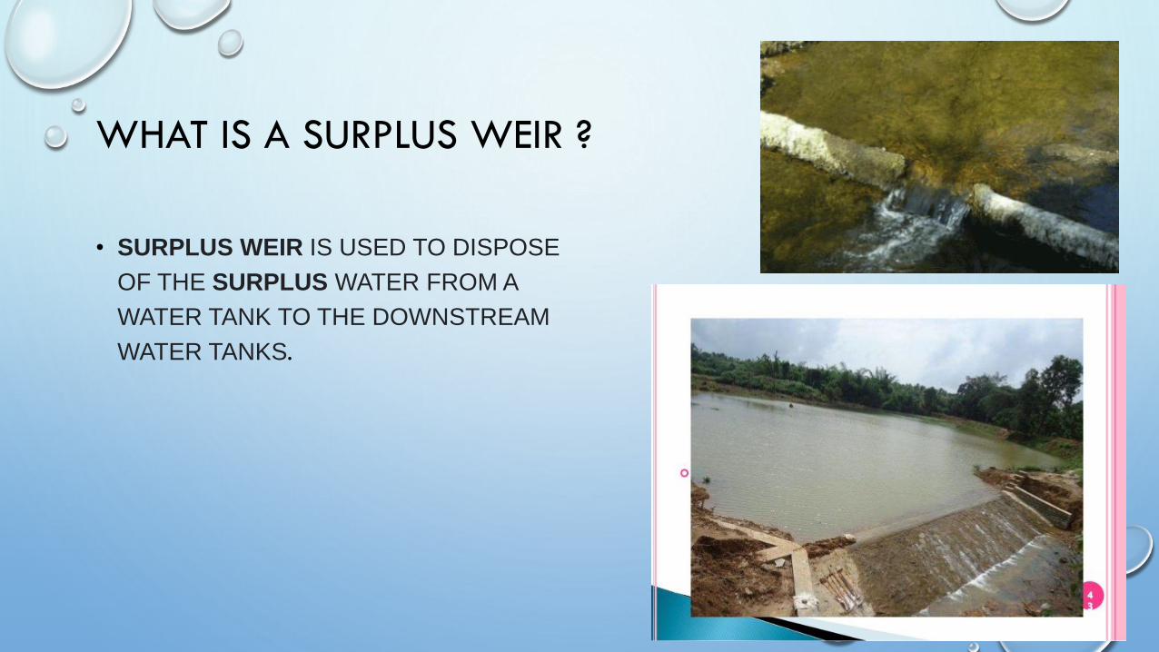
WHAT IS A SURPLUS WEIR ?
• SURPLUS WEIR IS USED TO DISPOSE
OF THE SURPLUS WATER FROM A
WATER TANK TO THE DOWNSTREAM
WATER TANKS.
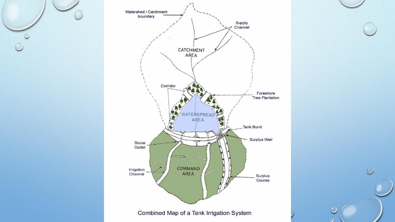
• The surplus work of a tank is usually either a weir or flush escape.
• The length of such a weir or an escape must be such that the quantity of water estimated as the
maximum flood discharge likely to enter from the catchment into the tank, can be disposed off
with a depth of water over the weir equal to the difference between the maximum water level
(MWL) and full tank level (FTL).
• The effective storage capacity is limited by the FTL but the area submerged by the tank water
spread, height of the tank bund, etc., are all dependent on the MWL.
• Generally it is better to limit the difference between the MWL and the FTL to as small a height
as possible.
• This difference is called the “head over the surplus weir” with which the flood water can be
disposed off.
• For small tanks, this head is limited to between 50 and 75 cm.
PURPOSES OF SURPLUS WEIR:
• Weirs are commonly used to control the flow rates of rivers during periods of high
discharge. Sluice gates (or in some cases the height of the weir crest) can be altered to increase or
decrease the volume of water flowing downstream. Weirs for this purpose are commonly found
upstream of towns and villages and can either be automated or manually operated.
• By slowing the rate at which water moves downstream even slightly a disproportionate effect can
be had on the likelihood of flooding. On larger rivers, a weir can also alter the flow characteristics
of the waterway to the point that vessels are able to navigate areas previously inaccessible due to
extreme currents or eddies. Many larger weirs will have features built in that allow boats and river
users to "shoot the weir" and navigate by passing up or down stream without having to exit the
river
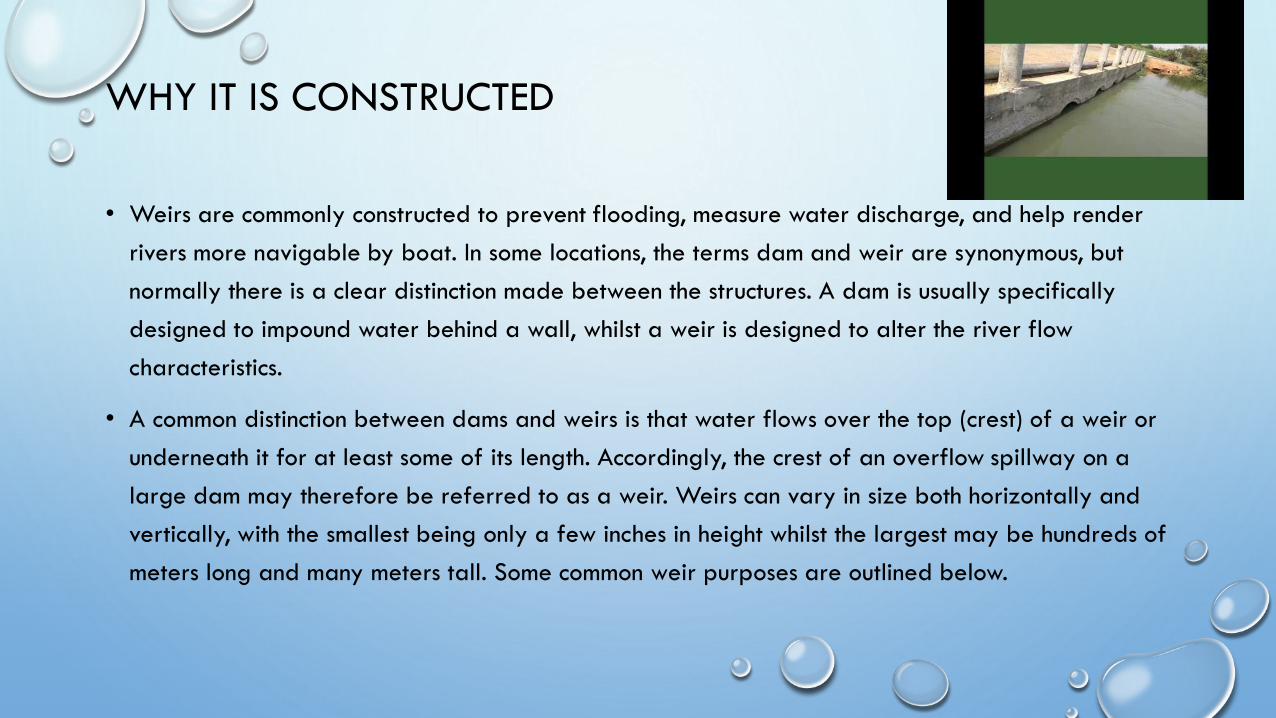
WHY IT IS CONSTRUCTED
• Weirs are commonly constructed to prevent flooding, measure water discharge, and help render
rivers more navigable by boat. In some locations, the terms dam and weir are synonymous, but
normally there is a clear distinction made between the structures. A dam is usually specifically
designed to impound water behind a wall, whilst a weir is designed to alter the river flow
characteristics.
• A common distinction between dams and weirs is that water flows over the top (crest) of a weir or
underneath it for at least some of its length. Accordingly, the crest of an overflow spillway on a
large dam may therefore be referred to as a weir. Weirs can vary in size both horizontally and
vertically, with the smallest being only a few inches in height whilst the largest may be hundreds of
meters long and many meters tall. Some common weir purposes are outlined below.
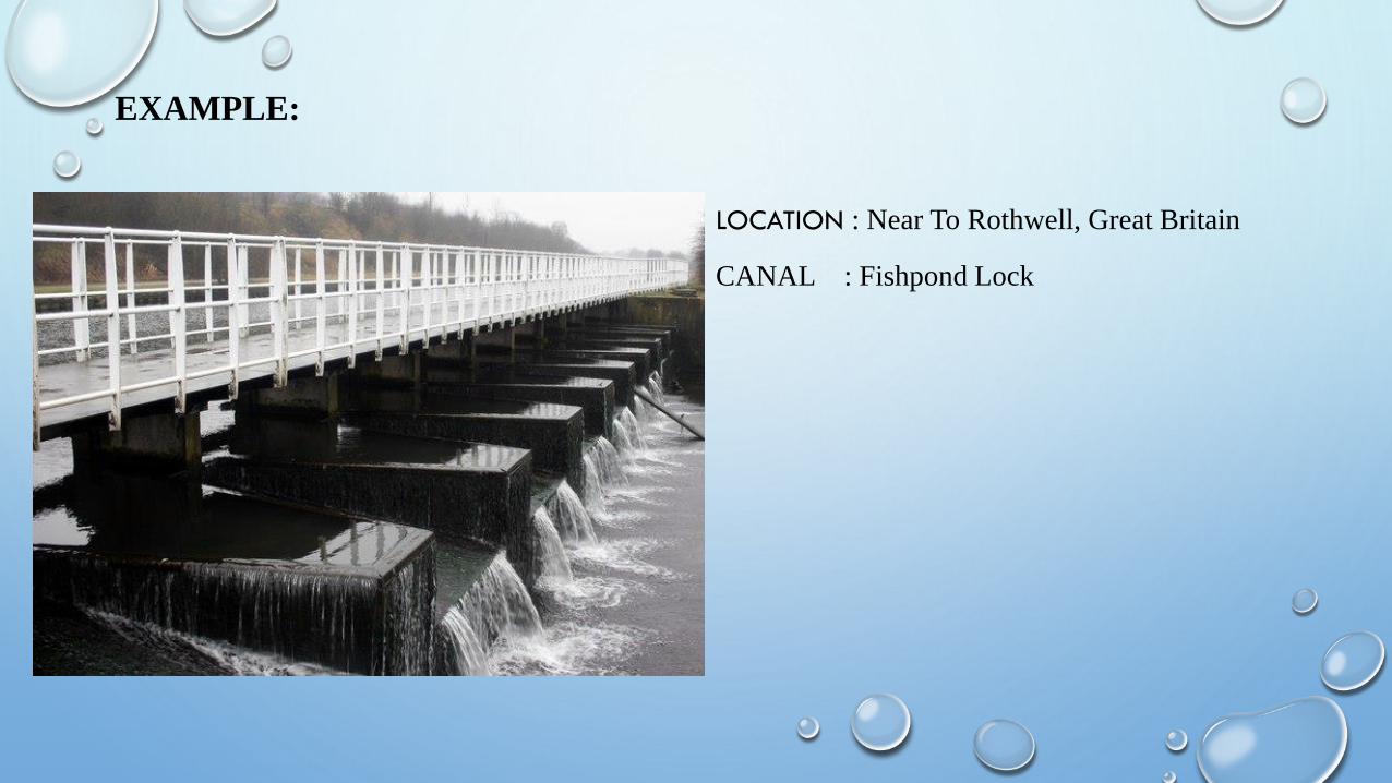
EXAMPLE:
LOCATION : Near To Rothwell, Great Britain
CANAL : Fishpond Lock
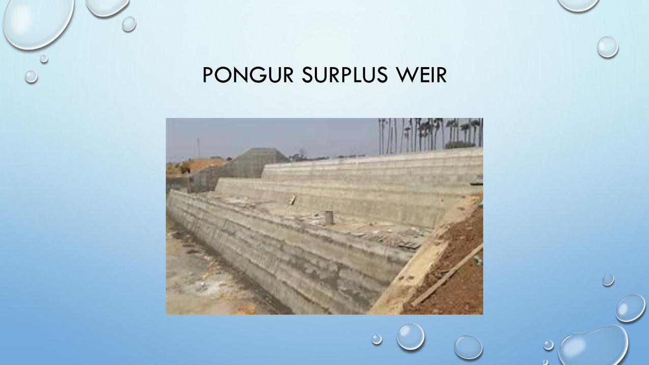
PONGUR SURPLUS WEIR
• Design the surplus of a tank forming a part of a chain tanks. The combined
catchment area of the group of tanks is 25.89sq. kilometres and the area of the
catchment intercepted by the upper tanks is 20.71 sq. kilometres.
• It is decided to store water in the tank to a level of +12.00m above the M.S.L
limiting the submersion of foreshore lands up to a level of +12.75m above M.S.L.
The general ground level at the proposed site of work is +11.00m and the
ground level below the proposed surplus slopes off till it reaches +10.00m in
about 6m distance.
• The tank bund has a top width of 2m at a level +14.50 with 2:1side slopes on
either side.The tank bunds are designed for a saturation gradient of 4:1 with 1m
clear cover.
• Provision may be made to make kutcha regulating arrangements to store water
up to M.W.L at times of necessity.
The foundations are of hard gravel at a level of 9.50m near the site of work.
Design Problem
DESIGN STEPS
• Estimation of flood discharge entering the tank
• Length of the surplus weir
• Weir
• Crest width
• Base width
• Abutments, wings, and returns
• Section of the wing wall at C
• Level wing and return
• Downstream side wings and returns
• Downstream transition
• Downstream aprons
• Thickness of solid apron
DESIGN OF SURPLUS WEIR
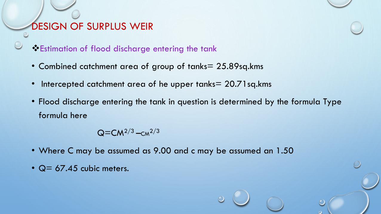
❖Estimation of flood discharge entering the tank
• Combined catchment area of group of tanks= 25.89sq.kms
• Intercepted catchment area of he upper tanks= 20.71sq.kms
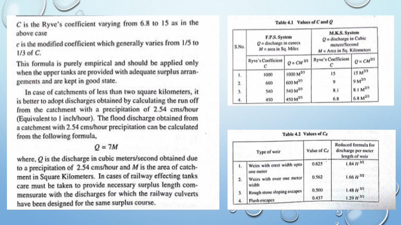
• Flood discharge entering the tank in question is determined by the formula Type
formula here
Q=CM2/3 –CM2/3
• Where C may be assumed as 9.00 and c may be assumed an 1.50
• Q= 67.45 cubic meters.
Length of the surplus weir
• Water is to be stored up to level of 12.00m. I.E FTL of tank is 12.00 and so, the
crest level of the surplus weir has to be kept at 12.00m
• Submersion of foreshore lands is limited to 12.75m i.e MWL of the tank is kept at
12.75m therefore head of discharge over the weir is 12.75- 12.00= .75m
• Since temporary regulating arrangement are to be made on top of the weir, to
store water at times of necessity, grooved dam stones of 15cms x 15cms, will be
fixed in the center of the crest at 1 meter intervals with top at MWL
• The weir may be assumed as a broad crested weir. So the discharge per meter
length of the weir is given by
Length of the surplus weir
• Q=2/3 Cd L 2𝑔 h3/2
• Where cd is 0.562 and h=0.75m
• Q= 1.66 h(3/2)
= 1.66 h(3/2)
= 1.08 cubic meters/second
• clear length of surplus weir required = 67.45/1.08
= 63.00 meters
Since the dam stones are to be fixed on top at 1 meter clear intervals, the number of openings will be 63.
So the number of dam stones required is 62 nos.
Size of dam stone 15cms x 15cms. And the projecting length above crest will be 75cms. Therefore the
overall length of surplus weir between abutment s is 63.00+ 62x 0.15= 73.50 meters
however provide an overall length of 75.00meters.
Weir
• Crest level + 12.00 FTL
• top of dam stone = 12.75 MWL
• ground level =11.00
• level where hard soil at foundations is met with 9.50
• Taking foundations about 0.50meters deeper into hard soil, the foundation level
can be fixed at 9.00. The foundation concrete may be usually 0.60m thick
• top of the foundation concrete = 9.60
• height of weir above foundations = 12.00 – 9.60 = 2.40m
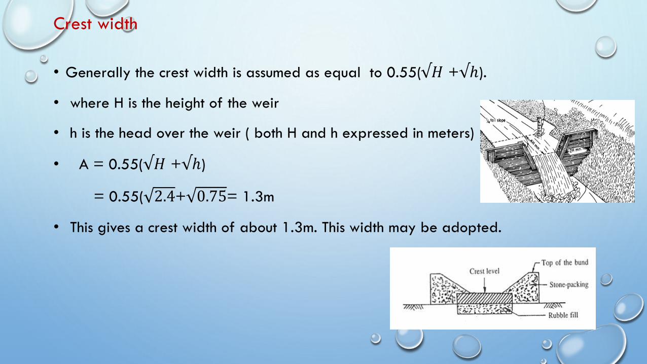
Crest width
• Generally the crest width is assumed as equal to 0.55(√𝐻 +√ℎ).
• where H is the height of the weir
• h is the head over the weir ( both H and h expressed in meters)
• A = 0.55(√𝐻 +√ℎ)
= 0.55( 2.4+ 0.75= 1.3m
• This gives a crest width of about 1.3m. This width may be adopted.
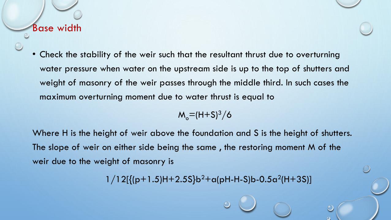
Base width
• Check the stability of the weir such that the resultant thrust due to overturning
water pressure when water on the upstream side is up to the top of shutters and
weight of masonry of the weir passes through the middle third. In such cases the
maximum overturning moment due to water thrust is equal to
Mo=(H+S)3/6
Where H is the height of weir above the foundation and S is the height of shutters.
The slope of weir on either side being the same , the restoring moment M of the
weir due to the weight of masonry is
1/12[{(p+1.5)H+2.5S}b2+a(pH-H-S)b-0.5a2(H+3S)]
Continued…
• Where p= specific gravity of masonry
• H= height of weir
• A= crest of the weir
• B= base of the weir
• S= height of the shutters above the weir crest. i.e
1.30 m
• S= 0.75, p may be taken as 2.25 substituting
these values b will be 2.40 meters. The weir will
have a trapezoidal profile as shown in figure.
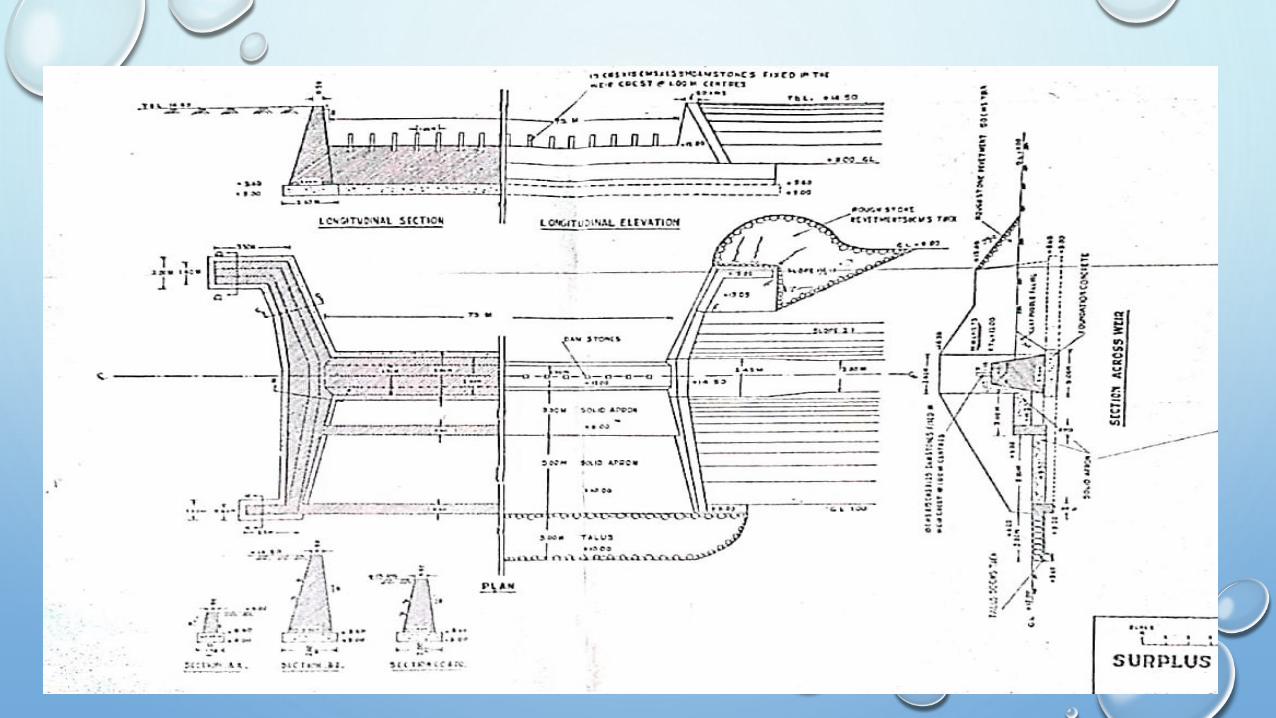
Fig 4.1
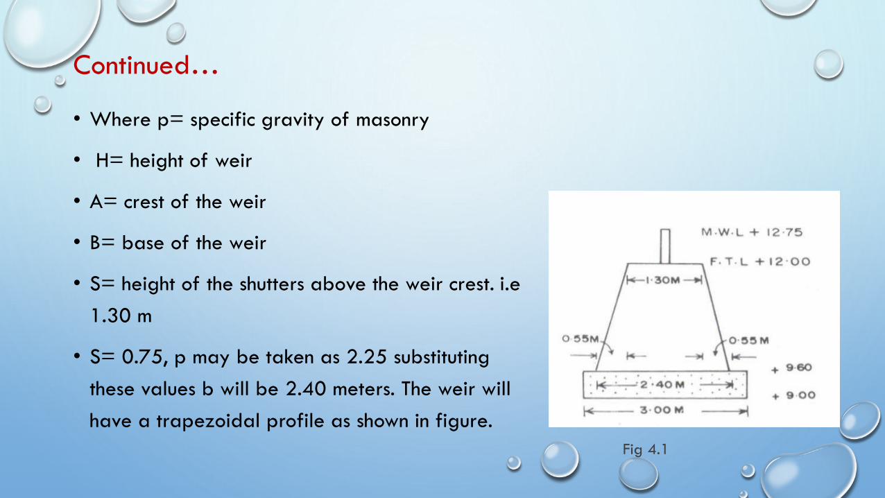
Abutments, wings, and returns
• The top width of abutments, wings, and returns will all be uniformly 0.50m with a front batter of 1
in 8. Length of the wing walls must be enough to completely encase the tank bund as shown in
figure
❖ Abutments
▪ Portion AB is called the abutment. It has its top level same as that of the tank bund at 14.50 and
has its length at top same as that of the top width of bund
Fig 4.2
Continued…
• The height of abutment above foundation concrete = 14.50 – 9.60= 4.90m. The
bottom width required is about 4.90x 0.4 = 1.96 or say 2.00m
• the section indicated in figure.
• The wall BD is called upstream wing wall. The section of the wing wall at B is same
as the section of the abutment.
• This wing wall start sloping down from B till it reaches about 30cms above MWL
i.e level of 12.75+0.30 = 13.05 at C.
• So , the portion of wing wall BC will be having its top sloping down from 14.50
to 13.05.
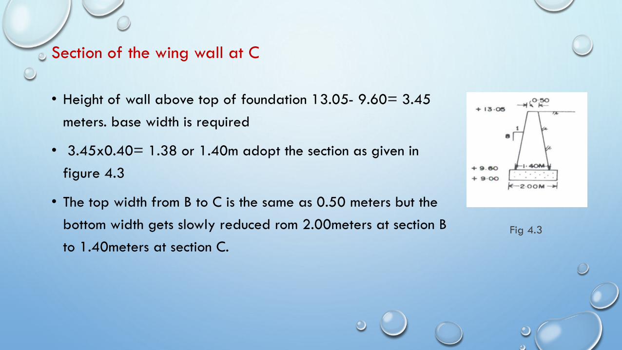
Section of the wing wall at C
• Height of wall above top of foundation 13.05- 9.60= 3.45
meters. base width is required
• 3.45x0.40= 1.38 or 1.40m adopt the section as given in
figure 4.3
• The top width from B to C is the same as 0.50 meters but the
bottom width gets slowly reduced rom 2.00meters at section B
to 1.40meters at section C.
Fig 4.3
Level wing and return
• Since the level wing and return i.e portions CD and DE have to be throught out
30cms above MWL the same section of wall at C can be adopted.
❖Upstream side transition
• In order to give an easy approach , the upstream side wing wall may be splayed
as shown . i.e generally at 1 in 3.
Downstream side wings and returns
• As the water after passing over the weir goes down rapidly to normal MFL in the
water course, the wings and returns need not be high as those on the upstream
side. The wing wall from A to F will slope down till the top reaches the ground
level at F. The section of wing wall at A will be the same as that of the abutments.
• The top wing wall at F may be fixed at 11.00 same as the ground level/ So the
height of wall above foundation concrete is 11.00- 9.60= 1.40 m
• The base width required is 1.40x0.40= 0.56meters or adopt a minimum base
width of 0.60meters. provide a section as indicated in figure 4.4
• The same section is continued for the return FG also.
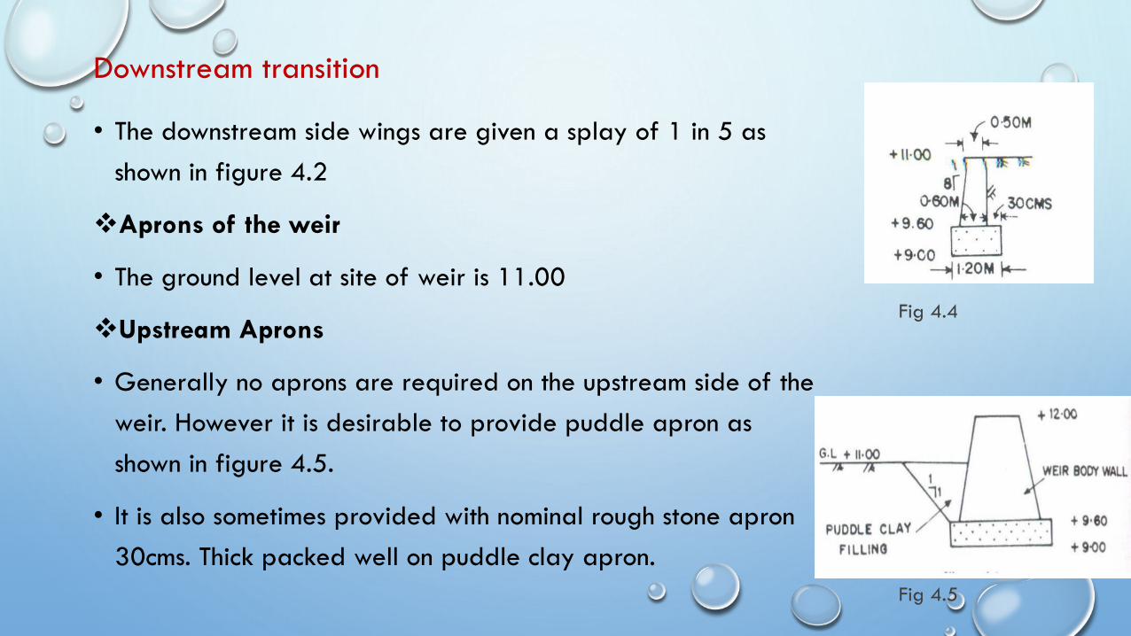
Downstream transition
• The downstream side wings are given a splay of 1 in 5 as
shown in figure 4.2
❖Aprons of the weir
• The ground level at site of weir is 11.00
❖Upstream Aprons
• Generally no aprons are required on the upstream side of the
weir. However it is desirable to provide puddle apron as
shown in figure 4.5.
• It is also sometimes provided with nominal rough stone apron
30cms. Thick packed well on puddle clay apron.
Fig 4.5
Fig 4.4
CONTINUED…
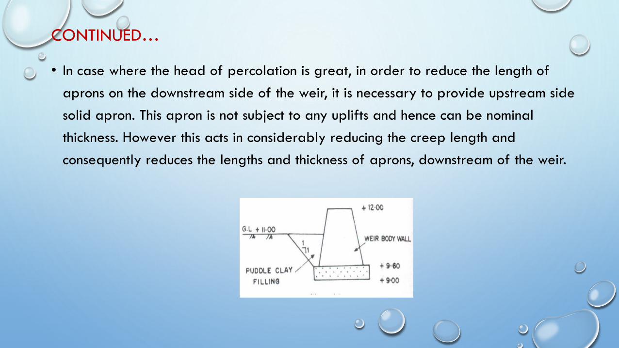
• In case where the head of percolation is great, in order to reduce the length of
aprons on the downstream side of the weir, it is necessary to provide upstream side
solid apron. This apron is not subject to any uplifts and hence can be nominal
thickness. However this acts in considerably reducing the creep length and
consequently reduces the lengths and thickness of aprons, downstream of the weir.

Downstream aprons
Fig 4.6
Downstream aprons
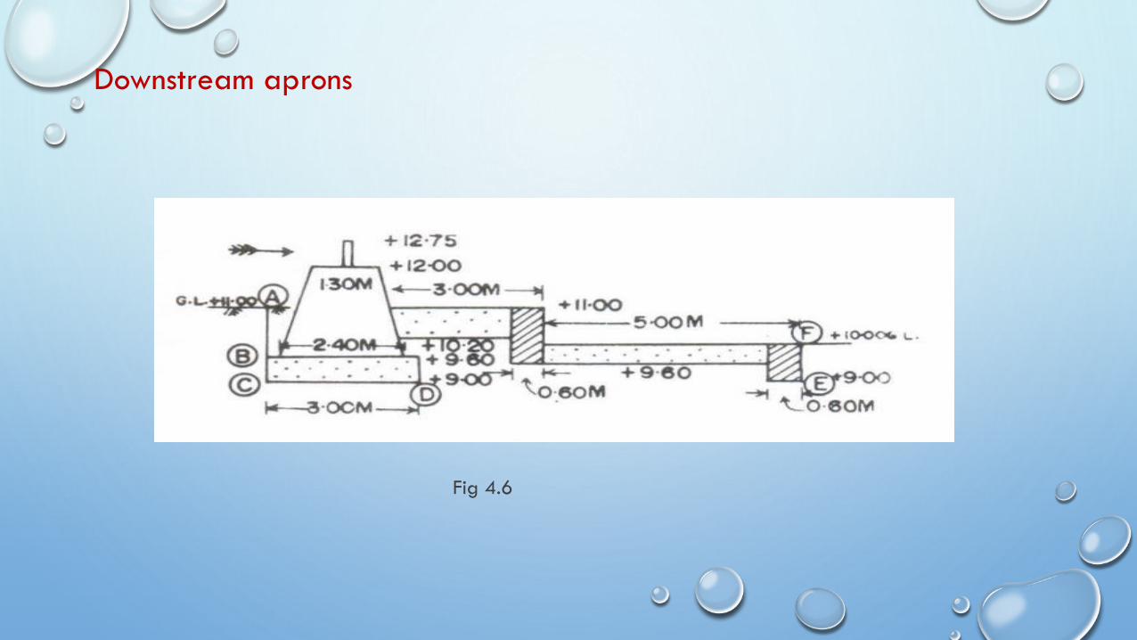
• Since the ground level is falling down to 10.00 in a distance of about 6 meters, it
is desirable to provide a stepped apron as shown in figure.4.6. The stepping may
be in two stages.
• The aprons may be designed for a hydraulic gradient of 1 in 5 so that the
residual gradient at the exit of aprons can be limited to 1 in 5 which is safe
enough and will not start undermining the structure.
• Maximum uplift pressure are experienced on the down stream aprons when the
water level in the tank is upto top of dam stone level i.e to 12.75 with no water
on the downstream side.
• However assume that the downstream water elevation is ta 10.00 i.e the level of
the lowest solid apron.
Continued…
• Total uplift head acting= 12.75 – 10.00= 2.75meters.
• If the residual uplift gradient is to be limited to 1/5, then we require aprons to
accommodate a total creep length of 2.75 x 5= 13.75meters. The upstream
water has to percolate under the foundations of the weir, if it has to establish any
uplifts under the aprons. The possible path of percolation is shown in the figure.
4.7.
• Assuming the puddle apron formed on the upstream of the weir to be not
impervoius , the water will start percolating from A at a level of 11.00 and reach
B and C . then it will follw CD under the foundation concrete. From here, it will
follow the least path D to E under the end cut-off and then appear at F. ie the
lower solid apron. So the total length of percolation
Downstream aprons
Fig 4.6
Continued…
• AB+BC+CD+DE+EF = 1.40+ 0.60+ 3.00+DE+ 1.00
= DE+ 6.00
This length must not be less than 13.75 meters , if the structures is to be safe.
DE+ 6.000= 13.75
DE = 7.75meters.
The total length to of solid apron from the body wall as provided in the drawing is
8 meters and this will be enough. These can be reduced if the upstream side puddle
clay apron is really impervious . to ensure safety, the whole upstream side apron
can be packed with stone and well grouted with cement concrete.
Continued…
• At the end of the second apron retaining wall of the downstream side apron , a
nominal 3 to 5 meter length of talus with a thickness of 50cms may be provided
as a safety device.
Thickness of solid apron
• The maximum uplift on the apron floor is felt immediately above point D in the
sketch. Assuming a thickness of 80cms of apron the bottom level of apron is 10.20
creep length from D to the bottom of apron is 1.20meters.
• Total creep length from point a on the upstream side upto the point above d
under the solid apron is 1.40+ 0.60+3.00+1.20 = 6.20
• Head lost in percolation along the path upto the point = 6.20/5 = 1.24meters.
Residual head exerting uplift under the apron= 2.75- 1.24= 1.51 meters.
• Since the bottom of apron is above the assumed tail water elevation , the weight
of concrete fully takes care of the uplift, as there is no loss of weight in concrete
due to buoyancy.
CONTINUED…
• Each meter depth of concrete can withstand a head of 2.25 meters by a self
weight of apron alone. Allowing an extra 20percent thickness to withstand any
variations, the thickness of apron required is
(1.51/2.25) x (6/5)= 0.805 meters or say 80cms
• So, provide the first solid apron as 80 cms thick . the second apron can be
similarly checked and a thickness of 50cms. Will be quite sufficient.
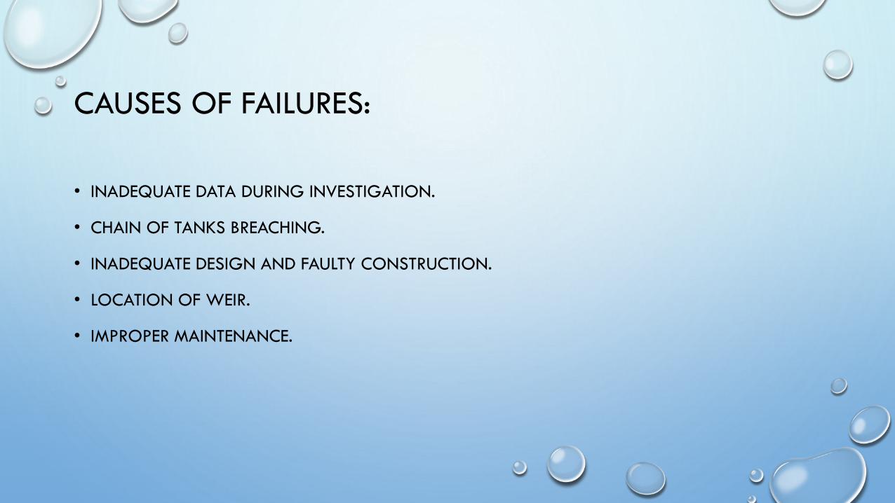
CAUSES OF FAILURES:
• INADEQUATE DATA DURING INVESTIGATION.
• CHAIN OF TANKS BREACHING.
• INADEQUATE DESIGN AND FAULTY CONSTRUCTION.
• LOCATION OF WEIR.
• IMPROPER MAINTENANCE.
SPECIFICATIONS:
Generally tank weirs are always located in interior and out of way places, where individual
quality control methods are difficult to enforce. Weigh batching of concrete proportions, etc.., are
well neigh impossible. So, all measurements have to be made by volume measurement only.
FOUNDATIONS :
As the pressures under the body walls and the retaining walls will not be high, the foundation
concrete can be in lean cement mortar. Proportions generally used for Mud Mat Concrete is 1:4:8,
using local coarse aggregate might suffice.
Sometimes mass concrete in 1:4:8 can be used. Use of fly ash as a pozzalonic material replacing up
to 20% of cement is permissible as it will affect economy without sacrificing strength.
The masonry of the body wall and the retaining walls may be plastered with cement mortar 1:6.
DAM STONES: These could be either in cut stones with grooves or in pre-cast reinforced cement
concrete 1:2:4. these stones are embedded in the crest of the body wall of the weir with enough
anchorage.
SOLID APRONS AND APRON RETAINING WALLS
Solid aprons and aprons retaining walls can be either in stone masonry in cement mortar 1:6, or in lean
cement concrete , say 1:4:8. Hare the density and imperviousness are important. If the thickness of
masonry aprons is considered, sufficiently large sized stones can be used as plums in the apron concrete
to add to the weight of the concrete.
The top of aprons and crest of the body may be laid with rich concrete, say 1:2:4 using 20mm coarse
aggregate of about 7.5 to 10cms thick, to avoid pitting during flow. This layer is better laid when the
body wall masonry and apron concrete are green so that this wearing coat concrete will be monolithic
with the rest of the construction. Otherwise, the layer may come out like a cake during heavy flows.
HIGH COEFFICIENT CAP: The high coefficient cap is always in reinforced concrete, say 1:2:4 or M
150 with nominal reinforcement both in longitudinal and transverse directions, well anchored into the
body wall. The surface of the cap must be made smooth to get the desired high coefficient of discharge.
TALUS : The talus i.e. the rough stone apron in rear of the solid apron, should always be one stone
thickness whatever may be the thickness. Small stones should not be used as they are likely to be
washed away in high floods. Heavier and bigger stones, instead of getting washed away will ink
into the scours developed. These depressions are to be filled each year and in course of time the
talus would have settled well.
CONNECTING REVETMENTS:
These should be laid on well consolidated gravel backing of at least 15cms thickness. Now-a-days,
it is found that lean stone masonry or surki concrete with gravel backing reduces the slips, scours
and consequently maintenance.
UPSTREAM APRON: Upstream solid apron in tank surplus weirs are generally not required to
reduce the uplift pressures on rear aprons. However, impervious clay dumped in front of the body
wall could be useful.

Copyright © 2022 FDOKUMEN