Compund Weir Study - Bureau of Reclamation
34
-
Upload
khangminh22 -
Category
Documents
-
view
2 -
download
0
Transcript of Compund Weir Study - Bureau of Reclamation


The information contained in this r e - port may not be used in any publica- tion, advertising, o r other promotion in such a manner as to constitute an endorsement by the Government o r the aureau of Reclamation, either explicit o r implicit, of any material, product, device, o r process that may be re- ferred to in the report.

CONTENTS
Page
Summary and Conclusions . . . . . . . . . . . . . . . . . . . . . . . . . . . . . . 1 . . . . . . . . . . . . . . . . . . . . . . . . . . . . . . . . . . . . . . . . . . . Introduction 2
................................. Laboratory Installation 2 ...................................... Weir Calibration 3
Data Analysis ......................................... 3
Horizontal Extensions . . . . . . . . . . . . . . . . . . . . . . . . .. ..... 4 Sloping Extensions .................................. 7
References ........................................... 8
Figure
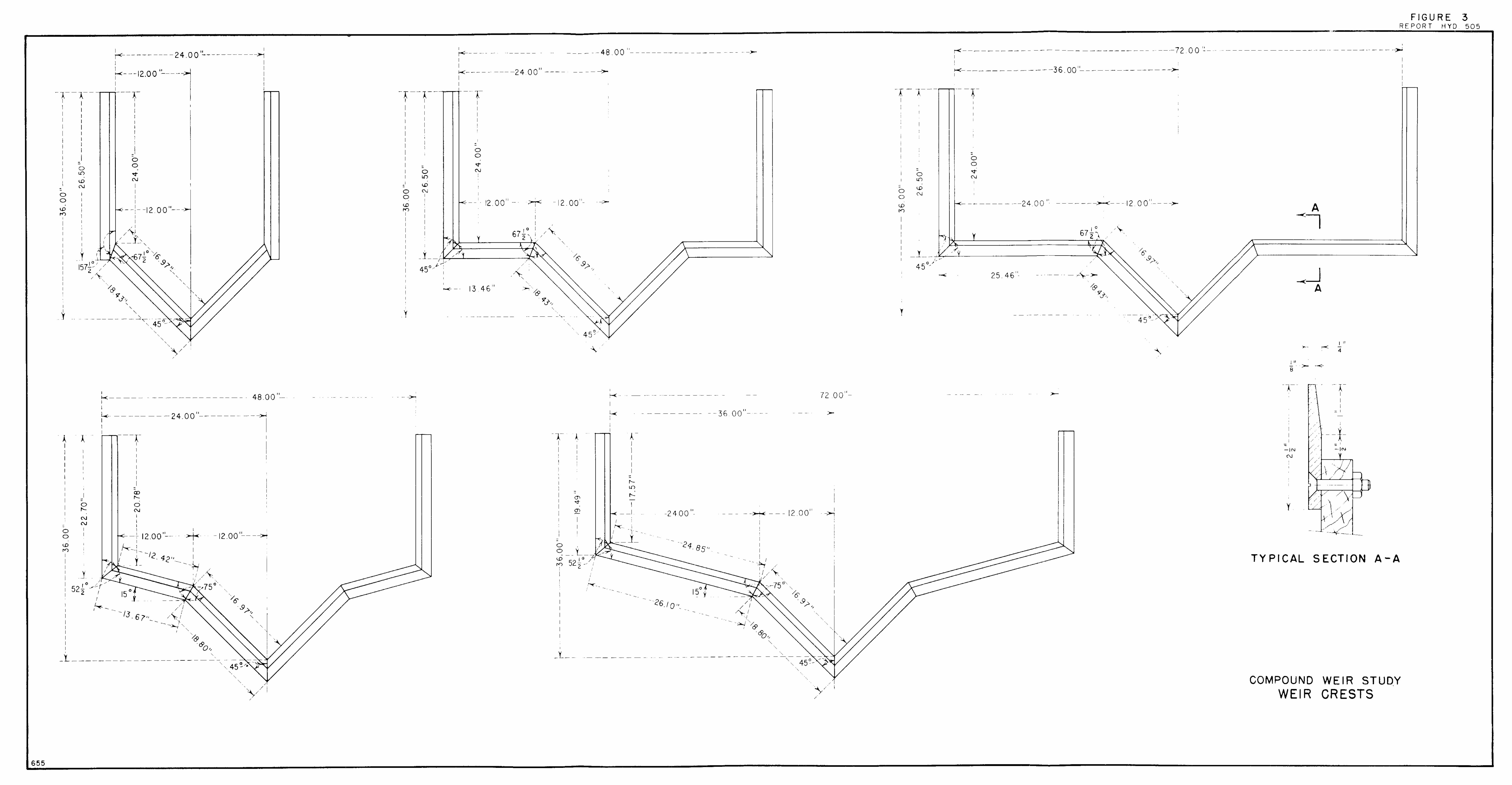
. . . . . . Field and Laboratory Installation of Compound Weirs 1 Laboratory Tes t Facility . . . . . . . . . . . . . . . . . . . . . . . . . . . . . . . 2 Weir Cres ts ........................................... 3 V-notch with Horizontal Extensions . . . . . . . . . . . . . . . . . . . . . . 4
................ V-notch with 2-foot Horizontd Extensions 5
................ V-notch with 1-foot Horizontal Extensions 6 V-notch with Vertical Extensions. ........................ 7 V-notch with 15" slope. 1-foot Extensions ................ 8
............. V-notch Data Comparison with Co'ne Equation 9 Calibration Data for 90" V-notch with Vertical and
Horizontal Extensions . . . . . . . . . . . . . . . . . . . . . . . . . . . . . . . . 10 Head-Discharge Curves for 90" V-notch Weirs with
..................... Vertical and Horizontal Extensions 11 . . . . . . . . . . . . . . . . . . . . . . . . . . Constant Determination Curves 12
................ Calibration Curve for Vertical Extensions 13 .............. Calibration Curve for Horizontal Extensions 14
Calibration Data for 90" V-notch Weirs with Sloping .......................................... Extensions 15
Head-Discharge Curves for Weirs with Sloping Extensions .......................................... 16
Table
Calibration Data for V-notch with 2-foot Horizontal Extensions .......................................... 1
Calibration Data for V-notch with 1-foot Horizontal Extensions ........................................... 2 ..... Calibration Data for V-notch with Vertical Extensions 3
Calibration Data for V-notch with 15" slope 1 -foot Extensions .......................................... 4
Calibration Data fo r V-notch with 15" slope 2-foot ........................................... Extensions 5

FOREWORD
The studies discussed in this repor t w e r e performed during
November 1959 to Februa ry 1960 by the Special Investigations
Unit of the Hydraulics Branch. Laboratory experiments were
made by W. B. McBirney, S. G. P a r k e r and J. L. Harper under
the supervision of J. C. Schuster. The data and analysis con-
tained were compiled for the report by J. M. Bergmann. The
Special Investigations Unit is i n the Special Investigations Section
headed by A. J. Peterka. H. M. Mart in is Chief of the Hydraulics
Branch.

UNITED STATES DEPARTMENT O F THE INTERIOR
BUREAU O F RECLAMATION
Office of Chief Engineer Laboratory Report No. Hyd. 505 Division of Resea rch Compiled by: J. M. Bergmann Hydraulics Branch Checked by: J. C. Schuster Denver, Colorado Reviewed by: A. J. Pe terka April 5, 1963 Submitted by: H. M. Martin
COMPOUND WEIR STUDY
SUMMARY AND CONCLUSIONS
Experiments on five wei rs , each composed of a 1-foot-deep V-notch we i r with ver t ical , 1- and 2-foot horizontal o r 1 5 O upward sloping extensions (F igure 3) were performed to determine the flow charac- t e r i s t i c s in t e r m s of head-discharge (H-Q) relationships. An anal- y s i s of the data was made to obtain correlat ions between the (H-Q) relationships that could be used to determine the discharge of l - foot- deep V-notch wei rs having other lengths of extensions.
The V-notch we i r s with horizontal extensions produced a smooth head-discharge curve except in the t ransi t ion zone where the head just exceeded the depth of the V-notch portion of the weir , i. e. , heads f rom 1 . 0 to 1.1 feet. The thin sheet of water tended to dribble over the extension because the vert ical component of veloc- i ty a t the wei r c r e s t was not sufficient to establish a t rue contrac- tion.
Weirs with sloping extensions f rom the V-notch produced bet ter contractions of the lower surface of the nappe fo r very low heads resulting in a m o r e uniform head discharge curve.
At points of change in the slope of the c r e s t , the r a t e s of discharge change in the H- Q relationships were not completely definable. Therefore, compound we i r s should be se t s o that discharge deter- mination in the t ransi t ion regions will be of minimum importance. In other ranges of flow the compound we i r s were a s accura te a s any weir can be. The head-discharge relationships in the fo rm of equations a r e cumbersome, but s imple graphs and tables can be prepared fo r determining discharge.
Generalized head- discharge equations derived i n this repor t f rom the t e s t data need to be confirmed by fur ther testing before they a r e extended to applications outside the range of the data.
INTRODUCTION
Frequently, a single water-measuring device is desired that will accurately measure a wide range of discharges, e. g. , both the normal and flood flows of s t r e a m s , F igure 1A. Proportional we i r s and specially shaped flumes, can be designed to be generally acceptable but these devices a r e often complicated and may cost m o r e to construct than is warranted by the value of the data obtained. The compound weir resolves the cost problem but introduces the problem of complicated head-discharge relationships.
F ive compound we i r s were tested in the Bureau ' s Laboratory to define the flow charac ter i s t ics in t e r m s of the H-Q relationships and to possibly co r re l a t e the discharge equations. The wei rs , sharp c res t ed and tested under free flow, contracted conditions, consisted of a 90' V-notch 1 foot deep with one of the following extensions:
1. Vert ical
2. Horizontal
a. 1 foot in length on each s ide and vert ical s ides
b. 2 feet in length on each s ide and vert ical s ides
3. Sloping (1 5" above horizontal)
a. 1-foot horizontal length each s ide and vertical s ides
b. 2-foot horizontal length each s ide and vertical s ides
Accurate head and discharge measurements were used to calibrate the weirs. Equations determined by mathematical and graphical methods, were used to general ize the H-Q relationships. The sloping extensions were tested in an attempt to obtain a uniform transi t ion of the flow f rom the V-notch weir to the compound shape.
LABORATORY INSTALLATION
The weir c r e s t s were installed in the s ide of a 20-foot by 18-foot 9-inch head box, with the root of the V-notch portion of the weir s e t 3 feet 0 inch above the floor of the box, F igures 1 B and 2. This arrangement provided a minimum of 60 square feet in the approach c ross - section and allowed the velocity of approach for the discharges used in the study to be neglected in determining the total head on the c res t . A 6-inch-thick rock baffle, 13 feet

9 inches upstream f rom the c res t , was placed a c r o s s the head box to stabilize the flow in the we i r pool. Calibrated Venturi m e t e r s were used to measure the flows f rom three pumps discharging up to a total of 32 cubic feet p e r second into the head box. The pumps and Venturi m e t e r s a r e permanent installations of the laboratory. Static head measurements were made with a hook gage in a st i l l ing well located outside the head box. The stilling well connection was tapped into the side of the head box about 8 feet upstream of the we i r bulkhead.
The c r e s t s , shown in Figure 3 , were forrned f rom 2-114- by 114- inch b r a s s s t r i p s and were bolted to a 314-inch plywood bulkhead. The top edge of the s t r i p s was beveled to 118-inch thickness to fo rm the s h a r p c r e s t .
WEIR CALIBRATION
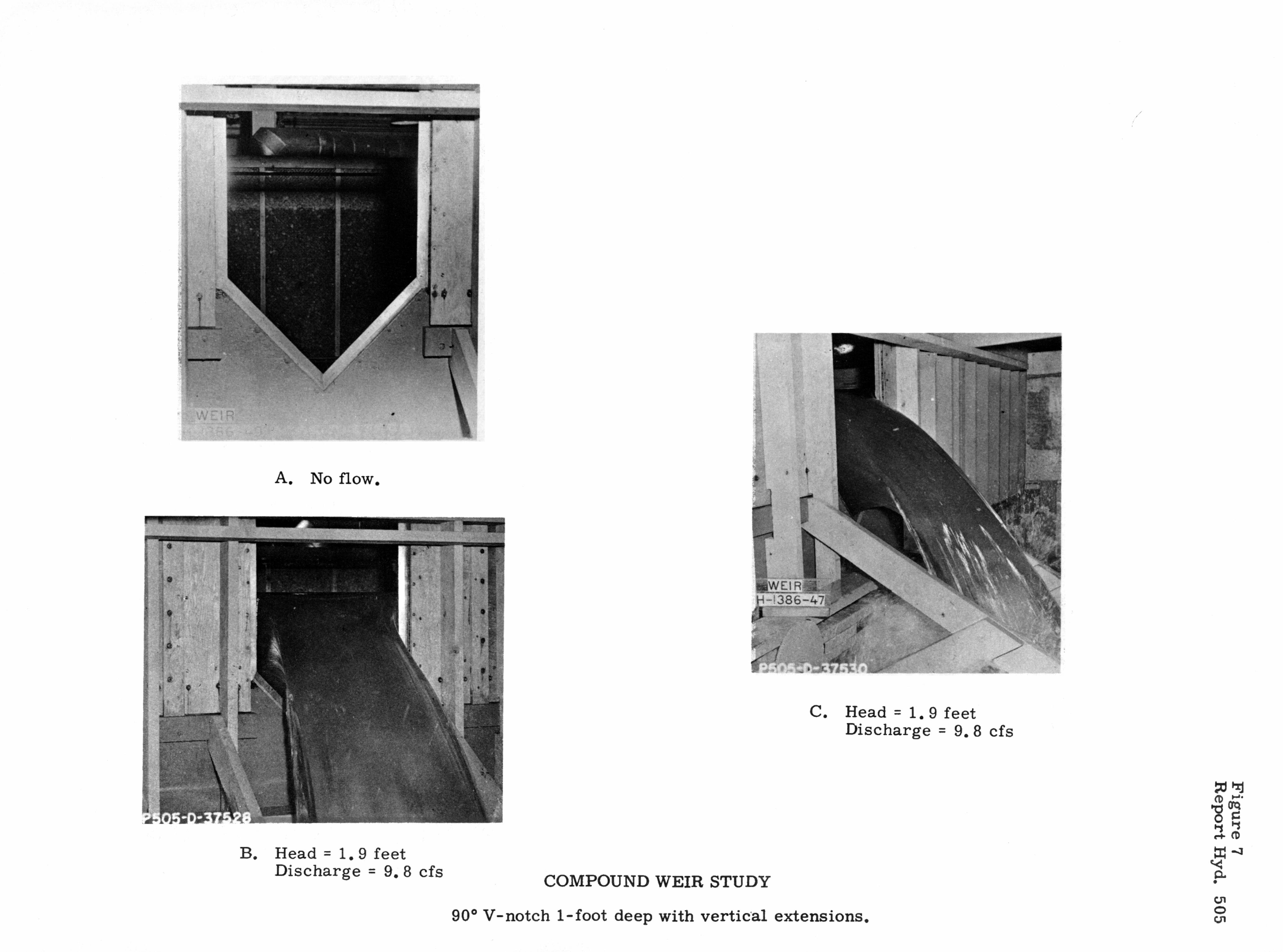
The we i r s were calibrated by measuring and recording the heads over the we i r c r e s t when steady conditions existed in the wei r pool for known discharges. The data were plotted a s they were obtained to determine the coherency of the t e s t s and to verify the recorded head-discharge relationship. The data, thus obtained, a r e p re - sented in Tables 1 through 5 . Discharges and heads for the V-notch portion of the we i r s were measured in conjunction with the f i r s t weir tested, Table I , and periodically checked at random thereaf ter .
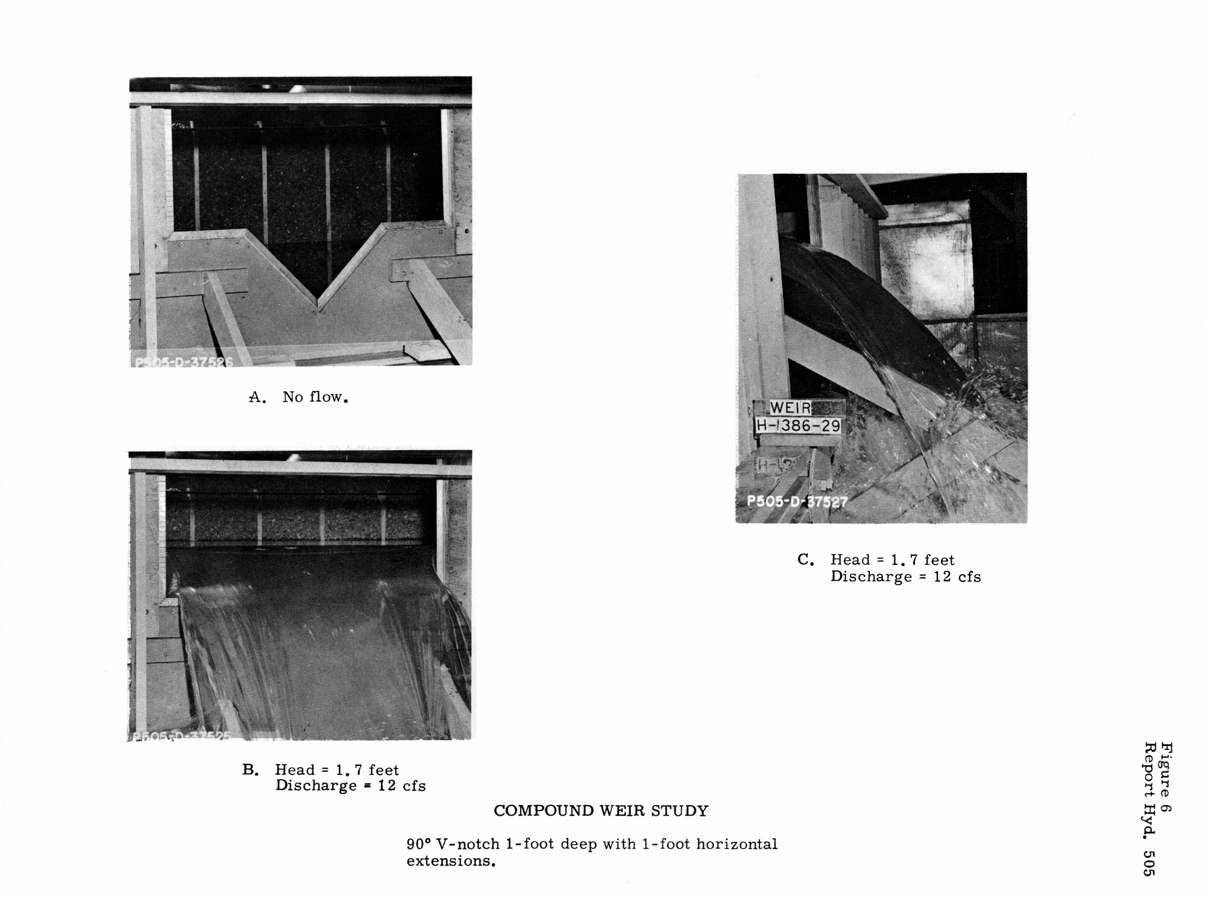
A pictorial r eco rd , partially presented a s F igures 4 through 8, was kept during the t e s t s . Of par t icular in te res t a r e the photographs shown as Figure 4, where the head on the V-notch portion of the wei r is slightly in excess of 1 . 0 foot and flow i s just beginning to pass over the horizontal portion of the wei r . It was noted that fo r heads f rom approximately 1 .0 to 1.1 feet, the discharge over the horizontal c r e s t s was neither uniform nor stable due to the draw- down over the V-notch. F igures 5 through 8 show four of the five wei rs before and during testing.
DATA ANALYSIS
F o r analytical purposes, the V-notch wei r with ver t ical extensions was considered a V-notch weir with zero-length horizontal exten- sions. Thus, two types of compound we i r s were analyzed:
1. V-notch with extensions horizontal
2 . V-notch with extensions 15" above horizontal

Fur the r , the data for the 90' V-notch portion of the we i r s shows good agreement , F igure 9 with the Cone Equation
therefore , Equation (1) was considered to be representat ive of the V-notch data in the following analyses.
Horizontal Extensions
The data foi. the V-notches with horizontal extensions were plotted, head ve r sus discharge, on rectangular and log-log graph paper. F r o m the log-log plot, F igure 10, and observations during the tes t s , i t was noted that a t ransi t ion zone existed a t heads between I . 0 and 1.1 fee t for the I - and 2-foot extensions, caused by the change f rom a s imple weir to a compound weir. Therefore, these data were not included in determining H-Q relationships f o r the upper portion of the weirs . Next, it was assumed that the H-& relationship for the remaining data was a polynomial of the form,
Successive differences of discharges a t equally spaced, increasing heads indicated that the polynomial was of the second degree. Thus, Equation (2) becomes
Q = a1 + a 2 H + a3H 2
( 3 )
The constants w e r e determined f r o m the data in Tables 1 through 3 for heads g rea te r than 1.1 feet by the method of least squares , which resul ted in the following equations:
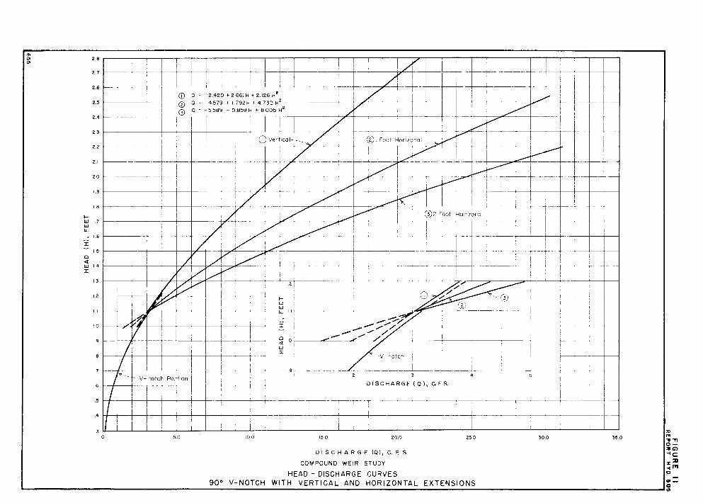
1. QO (ze ro extensions) = -2.420 + 2.661H+ 2 . 1 2 6 ~ ~ (4)
3. Q2 (2-foot extensions) = -5.589 -0.859H + 8 . 0 0 5 ~ ~ (6)
These equations a r e shown graphically on Figure 11.
Correlat ion of the horizontal c r e s t lengths with the constants i n Equations (4) , (5), and (6) , corresponding to a l , a2, and a3 of Equation (3), was performed by plotting the constants against the corresponding length of horizontal c r e s t s , F igure 1 2 . The mdi- cated t rends of the constants a r e speculative, s ince the re a r e only th ree points, and should not be rel ied on for accurate formulation. However, if horizontal weir extensions a r e used, in conjunction with a 1-foot V-notch, a n es t imate of the constants in Equation (3) may b e obtained f rom F igure 12 .

As an al ternat ive to the use of Equation ( 3 ) which requi res a determination of the constants, a general equation was derived for the head-discharge relationship of V-notch we i r s with hori- zontal extensions when flows exceed the capacity of the V-notch. To derive the general equation, head-discharge relationships were determined for the V-notch with ver t ical extensions and for the discharge pe r foot of horizontal extension regard less of total length.
The head-discharge relationship for the V-notch weir with ver t ical extensions was assumed to be of the form,
By t r i a l and e r r o r , 1 . 5 cubic feet p e r second was chosen fo r b in o r d e r to produce a l i nea r relationship between the logari thms of the heads and the corresponding "adjusted" (Q plus b) , discharges, Figure 13. The constants a and rn of Equation ( 7 ) were deter- mined f rom this graph. The resul t ing equation i s :
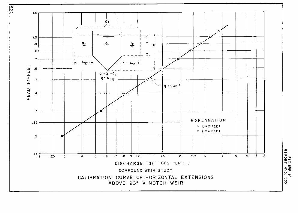
Eleven discharges for. the V-notch with ver t ical extensions were subtracted f rom the total discharges over the we i r s with 1- and 2-foot extensions when under the s a m e head. The remaining f rac- tion of the discharge was then divided by the total length of hori- zontal c res t . This gave a discharge pe r foot of horizontal c r e s t , q, for various heads above the horizontal c r e s t , h. Equation (9) is the resulting relationship determined f rom the head-discharge, log-log plot, F igure 14.
A general equation fo r computing discharges over we i r s with hori- zontal extensions resu l t s f rom the combining of Equations ( 8 ) . and (9), into Equation (1 0)
where E i s the total length of the horizontal extensions.
Equation (9) is in good agreement with equations determined by various investigators a s reported by King (Reference I ) ,
where K depends on the velocity of approach and weir pool shape.

Discharges in the transit ion zone, heads between 1 . 0 and 1 . 1 feet, a r e affected by the approach flow charac ter i s t ics and wei r c r e s t sharpness and roughness. The laboratory t e s t s indicated the simple V-notch Equation (1) to be applicable for heads up to 1 .05 feet when the V was 1.00 foot deep. However, in a field installation, where weir c r e s t imperfections and sma l l waves a r e more likely to occur , the decision a s to when Equation (1) no longer applies may not be well defined. Therefore , the s ize and vert ical placement of the compound wei r , based on anticipated flows, should be such that heads of 1 .0 foot to 1 . 1 feet will be in minimum usage.
The discharge over a compound wei r composed of a 1.0-foot V-notch with horizontal extensions may be computed by ei ther Equation (3) o r Equation (10). Equation (3) requi res the use of Figure 12 for determining constants in addition to knowing the head over the weir and the length of the horizontal extensions, which i s required when Equation (10) i s used.
Two example problems follow. The f i r s t i l lustrates the use of Figure 11 and the second i l lus t ra tes the use of Equations (3) and (10).
Example 1. Determine f rom Figure 11, the discharge over a 1-foot V-notch wei r with 1-foot horizontal extensions on each side, when the head is 1 . 8 feet.
The discharge is obtained by going horizontally f rom H = 1 . 8 until the 1-foot horizontal extension l ine is intersected. At the intersection, go vertically down to read Q = 14 cubic feet p e r second.
Example 2 . Determine the discharge over a 1-foot V-notch we i r with 18-inch horizontal extensions on both s ides of the V-notch when operating under a 2.0-foot head.
F r o m Figure 12, f o r L = 3.0 feet a1 = -5 .13 a2 = 0.69 a3 = 6.30
therefore, by Equation (3) for H = 2.0 feet Q = -5.13 + 0.69(2) + 6.30(4) = 21.45
cubic feet p e r second
By Equation ( lo ) , for H = 2.0 feet, h = 1 . 0 foot and L = 3.0 feet,
Q = 3. 9(2)1-72 -1 .5 + 3.3(3)(1)'s5 = 21.28 cubic feet pe r second

Sloping Extensions
Compound we i r s with sloping extensions necessitate the use of three equations to adequately express the head-discharge relation- ship of the we i r . The three relationships correspond to the follow- ing portions of the weir :
1. The V-notch, previously discussed
2. The sloping extensions, a straight-l ine plot on log-log paper
3. The portion above the sloping extensions, which was assumed to be of the s a m e form a s Equation (3) .
The H-Q relationship for the sloping extension portion of these com- pound we i r s was found to be
f r o m a log-log plot of the tes t data, Figure 15.
The relationship f o r the portion of the wei rs above the sloping exten- s ions was computed by the method of leas t squa res af ter the form of the equation was assumed. The equations for the two wei rs a r e
1. Q1 (1-foot extensions) = -1 1.345 + 7.484H + 3.360H2 (13)
2. Q2 (2-foot extensions) = -14.106 + 6.943H + 5 . 1 1 0 ~ ~ (14)
Equations (12), (13), and (14) a r e shown graphically on Figure 16.
There was no apparent advantage in sloping the extensions in com- parison with having them horizontal, therefore, no fur ther analysis of the data was undertaken. The sloping extensions do produce a more uniform transi t ion zone at the top of the V-notch; however, another transit ion zone, at the top of the sloping extension, is en- countered. Both t ransi t ion zones cover a l a r g e r range of heads than the one t ransi t ion zone f o r the horizontal extensions.
Example 3 i l lustrates the use of F igure 16.
Example 3. Determine, f rom Figure 16, the discharge over a 1-foot V-notch wei r with 1-foot, 15" upward sloping extensions on each side, when the head is 1 . 8 feet.
The discharge is obtained by going horizontally f rom H = 1 . 8 until the 1-foot sloping extension l ine is intersected. At the intersection, go vertically down to read Q = 13. 2 cubic feet pe r second.
REFERENCES
1. King, H. W., Handbook of Hydraulics, Thi rd Edition, McGraw- Hill Book Company, Inc . , 1939.
2 . USBR, Water Measurement Manual, F i r s t Edition. U. S. Gov- e rnment Pr int ing Office, Washington, 1953.
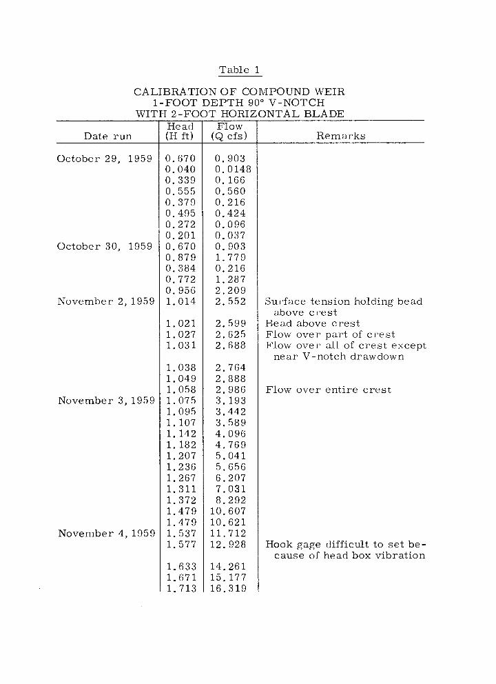
Table 1
CALIBRATION O F COMPOUND WEIR 1 - F O O T D E P T H 90" V-NOTCH
WITH 2 - F O O T HORIZONTAL BLADE
Date run
October 29, 1959
October 30, 1959
November 2, 1959
November 3, 1959
November 4 , 1 9 5 9
Flow ( Q cfs )
0 . 9 0 3 0 .0148 0 .166 0 .560 0 . 2 1 6 0 .424 0 . 0 9 6 0 .037 0 . 9 0 3 1 . 7 7 9 0 .216 1 . 2 8 7 2 . 2 0 9 2 .552
2 .599 2 . 6 2 5 2 . 6 8 8
2 . 7 6 4 2 .888 2 .986 3 . 1 9 3 3 .442 3 . 5 8 9 4 .096 4 . 7 6 9 5 . 0 4 1 5 . 6 5 6 6 . 2 0 7 7 . 0 3 1 8 .292
10 .607 1 0 . 6 2 1 1 1 . 7 1 2 12 .928
1 4 . 2 6 1 15 .177 1 6 . 3 1 9
Remarks
Surface tension holding bead above cres t
Bead above cres t Flow over part of cres t Flow over all of cres t except
near V-notch drawdown
Flow over entire cres t
Hook gage difficult to se t be- cause of head box vibration

Table 1 --Continued
Date run
November 4, 1959
Flow (Q cfs) Remarks
He ad box not vibrating
Columns of a i r noted to form in the nappe from floor at discharge back into the tank through the V-notch. The columns would collapse and then dissipate into the dis- charge with an audible noise.

Table 2
CALIBRATION O F COMPOUND WEIR 1-FOOT DEPTH 90" V-NOTCH
WITH
Date run
December 1, 1959
December 2, 1959
Note: V-notch portion not run.
1-FOOT Head ( H f t )
1 . 0 2 7
1 . 0 4 7 1 . 0 6 4 1 . 0 8 4 1 . 1 0 1 1 . 1 0 2 1 . 1 4 3 1 . 1 9 3 1 . 2 4 7 1 . 2 9 3 1 .344 1 . 3 9 8 1 . 4 4 9 1 .497 1 .542 1 . 5 9 4 1 .647 1 .697 1 . 7 4 8 1 .798 1 . 8 4 2 1 .897 1 .963 1 . 9 9 1 2 .040 2 .088 2 .148 2 .218 2 .274 2 .314 2 .378 2 .444 2 . 5 0 7 2 . 5 5 0
F l o w ( Q c f s )
2 . 6 0
2 . 7 5 8 2 . 9 1 4 3 .095 3 . 2 6 1 3 . 2 6 3 3 .703 4 .294 4 . 9 6 7 5 . 5 7 7 6 . 2 8 3 7 . 0 9 8 7 .894 8 . 6 4 9 9 . 3 6 3
1 0 . 2 5 8 11 .159 1 2 . 0 4 1 13 .003 13 .918 14 .743 16 .066 1 7 . 1 7 4 1 7 . 8 1 4 1 8 . 8 5 1 19 .835 21 .197 22 .728 24 .003 25 .044 26 .437 28 .007 2 9 . 5 2 9 30 .660
HOHZONTAL BLADES
Remarks
Impending flow ove r horizon- t d c r e s t
F l o w over horizontall c r e s t

T a b l e 3
CALIBRATION O F COMPOUND W E I R 1 - F O O T D E P T H 90" V-NOTCH W
D a t e run
D e c e m b e r 21,1955
D e c e m b e r 22, 195E
H e a d (H ft)
F l o w (Q c f s )
2 .596 2 .736 3 . 0 2 3 3 .167 3 .382 3 . 6 3 1 4 . 1 1 4 4 . 5 3 7 4 .517 5 . 0 9 1 5 . 5 4 9 6 .182 6 . 7 3 7 7 . 3 9 6 7 . 8 4 5 8 . 5 4 8 9 .308 9 . 8 2 3
1 0 . 5 1 5 8 . 5 3 3
10 .868 1 2 . 5 2 1 1 4 . 2 3 1 16 .043 17 .992 19 .627 21 .682
R e m a r k s
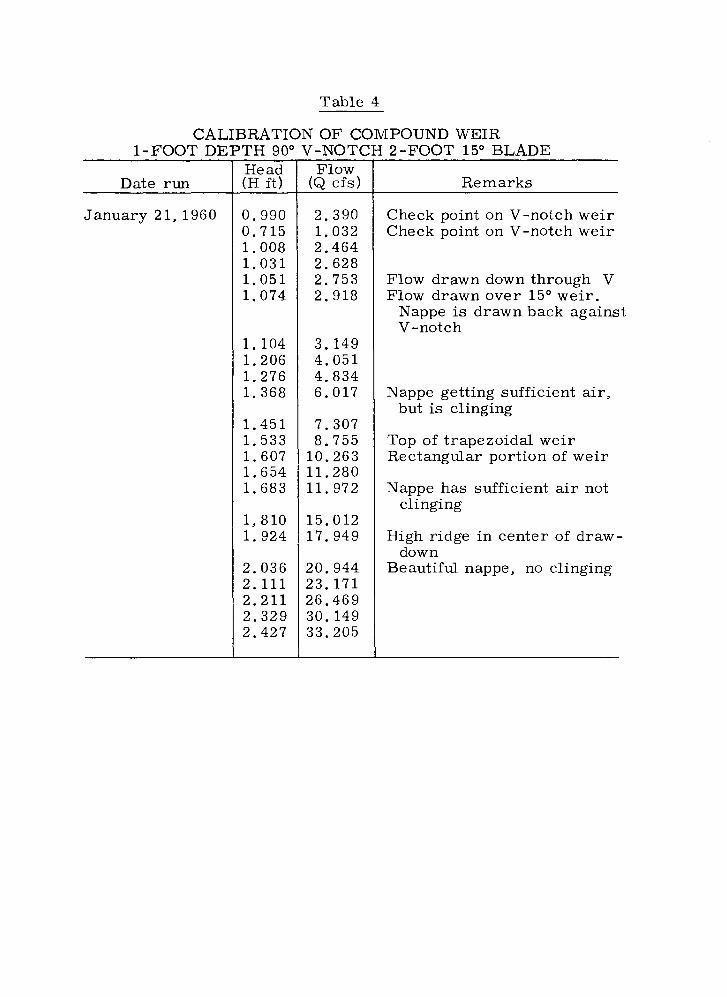
Table 4
CALIBRATION OF COMPOUND WEIR 1-FOOT DE
Date run -
January 21, 1960
: 2 -FOOT 15" BLADE 'TH 90" Head (H ft) Remarks
V-NOTC Flow
(Q cfs)
A
Check point on V-notch weir Check point on V-notch weir
Flow drawn down through V Flow drawn over 15" weir .
Nappe is drawn back against V-notch
Nappe getting sufficient a i r , but is clinging
Top of trapezoidal weir Rectangular portion of weir
Nappe has sufficient a i r not clinging
High ridge in center of draw- down
Beautiful nappe, no clinging
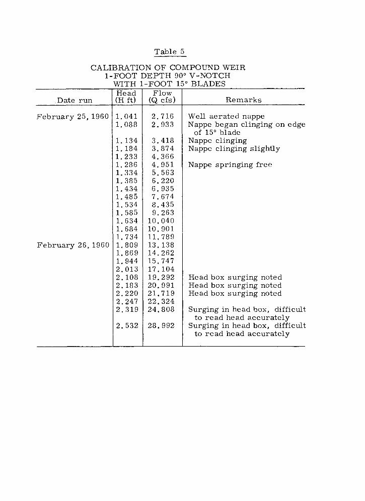
Table 5
CALIBRATION OF COMPOUND WEIR 1-FOOT DEPTH 90" V-NOTCH
Date run
February 25, 1960
February 26,1960
WITH Flow
(Q cfs )
' BLADES
Remarks
Wel l aerated nappe Nappe began clinging on edge
of 15" blade Nappe clinging Nappe clinging slightly
Nappe springing free
Head box surging noted Head box surging noted Head box surging noted
Surging in head box, difficult to read head accurately
Surging in head box, difficult to read head accurately


COMPOUND WE1 R STUDY L A B O R A T O R Y TEST F A C I L I T Y


D l S C H A R G E ( Q ) - C F S
COMPOUND WEIR S T U D Y
V - N O T C H D A T A COMPARISON WITH C O N E E Q U A T I O N

I TOP OF V-NOTCH----- ,
3.0 4.0 5.0 6.0 7.0 8.0 9.0 10.0 15.0 20.0
D l S C H A R G E ( Q ) - C F S
COMPOUND WEIR STUDY
C A L I B R A T I O N D A T A 90" V - N O T C H W I T H V E R T I C A L A N D H O R I Z O N T A L E X T E N S I O N S
I
I
-
E X P L A N A T I O N I
I V-NOTCH O VERTICAL
O 1 ' - H O R I Z O N T A L
x 2 ' -HORIZONTAL
D I S C H A R G E (Q), C . F S .
COMPOUND WEIR STUDY
HEAD - DISCHARGE CURVES 90' V-NOTCH WITH VERT ICAL AND HORIZONTAL EXTENSIONS

< FIGURE 12
R E P O R T H Y D . 5 0 5
COMPOUND WEIR STUDY
VARIATION OF THE CONSTANTS IN T H E DISCHARGE EQUATIONS FOR V-NOTCH WEIRS
WITH HORIZONTAL E X T E N S I O N S

3.0 4.0 5.0 6.0 7.0 8.0 9.0 0 0 15.0 20.0 30.0 40.0 50.0 60.0
D I S C H A R G E (AJUSTEDI - (Q I -CFS
COMPOUND WEIR S T U D Y
C A L l B R A T I O N C U R V E OF V E R T I C A L E X T E N S I O N S A B O V E 90' V - N O T C H
E X P L A N A T I O N O L = 2 F E E T t- X L = 4 F E E T
.6 .7 .8 .9 1.0 1.5 2 2.5 3 4 5 6 7 8
D I S C H A R G E ( 9 ) - C F S PER FT.
COMPOUND WElR S T U D Y
CALIBRATION CURVE OF HORIZONTAL EXTENSIONS ABOVE 90" V - N O T C H W E l R

I I TOP OF 15'-2' E X T E N . - - - - - .
I
E X P L A N A T I O N O V - N O T C H
3 15' E X T E N S I O N S
O ABOVE I ' E X T E N .
X ABOVE 2 ' E X T E N .
2.0 3.0 4.0 5.0 6.0 7.0 8.0 9.0 10.0 15.0 2 0 . 0 3 0 . 0 4 0.0
D I S C H A R G E ( Q l - C F S
C O M P O U N D W E I R S T U D Y
C A L I B R A T I O N DATA OF 9 0 ' V-NOTCH WITH 15' UPWARD SLOPING EXTENSIONS

5 10 15 2 0 2 5
D I S C H A R G E ( Q ) , C F. S
COMPOUND WEIR STUDY
HEAD - DISCHARGE CURVES 9 0 " V NOTCH WITH 15O UPWARD SLOPING EXTENSIONS