
4.1 RECLAMATION PLAN
283
• • • 4.1 RECLAMATION PLAN - INTRODPCTION Reclamation activities at th mine site, conveyor route and load-out facilities are, and will continue to be, directed towards minimizing the overall impacts of coal mining activities on the environment. It is recognized, however, that land management policies and dist land reclamation technology can, and probably will, change the life of the Skyline Mines Project. In view of this, reclamation of the mine site will satisfy the standards cur ent at the time of reclamation and will be conducted using the mos applicable current technology. AS now proposed, the mine site will be wildlife/grazing habitat at the conclusion operation. The conveyor route land load-out will I postmining grazing landuse. The premining postmining uses are identical fraIl areas. returned to a of the mining be returned to a and proposed It is not intended that all of the disturbed areas be returned to their original contours or onfigurations. These areas, as addressed in Section 4.6 - TOPSOIL AND SUBSOIL HANDLING PLAN and Section 4.7 - REVEGETATION are currently being stabilized and revegetated and consist pr"marily of those steep slopes where return to original configura ion is impractical. The stream diversions, other than those in the portal area, will also be left in their present chann Is. (See Section 4.19 STREAM DIVERSIONS) The initial step in the fina reclamation plan is to seal all large diameter openings. This will be accomplished by backfilling these openings noncombustible material. The seals will be designed such th t mine drainage, if any, will not enter surface water bodies. or a more detai led description of the sealing of openings see ection 4.9 - OPENING AND SEALING PLANS. 4-1
-
Upload
khangminh22 -
Category
Documents
-
view
0 -
download
0
Transcript of 4.1 RECLAMATION PLAN

•
•
•
4.1 RECLAMATION PLAN - INTRODPCTION
Reclamation activities at th mine site, conveyor route and
load-out facilities are, and will continue to be, directed
towards minimizing the overall impacts of coal mining activities
on the environment. It is recognized, however, that land
management policies and dist land reclamation technology
can, and probably will, change the life of the Skyline Mines
Project. In view of this, reclamation of the mine site
will satisfy the standards cur ent at the time of reclamation and
will be conducted using the mos applicable current technology.
AS now proposed, the mine site will be
wildlife/grazing habitat at the conclusion
operation. The conveyor route land load-out will I
postmining grazing landuse. The premining
postmining uses are identical fraIl areas.
returned to a
of the mining
be returned to a
and proposed
It is not intended that all of the disturbed areas be returned to
their original contours or onfigurations. These areas, as
addressed in Section 4.6 - TOPSOIL AND SUBSOIL HANDLING PLAN and
Section 4.7 - REVEGETATION are currently being stabilized
and revegetated and consist pr"marily of those steep slopes where
return to original configura ion is impractical. The stream
diversions, other than those in the portal area, will also be
left in their present chann Is. (See Section 4.19 STREAM
DIVERSIONS)
The initial step in the fina reclamation plan is to seal all
large diameter openings. This will be accomplished by
backfilling these openings noncombustible material. The
seals will be designed such th t mine drainage, if any, will not
enter surface water bodies. or a more detai led description of
the sealing of openings see ection 4.9 - OPENING AND SEALING
PLANS.
4-1

•
•
•
The next step in reclamation
structures and equipment .
solid waste generated in
collected and removed from the
information concerning this
presented in subsection 3.
Construction, Modification,
Backfilling of the subterranea
depressions will be the
backfilling is completed, the
returned to a surface channel
graded and recontoured. A
reclamation phase is found
STAB ILl ZATION, COMPACTION,
subsection 4.19.5
be the removal of all surface
this has been accomplished, all
abandonment operation will be
being reclaimed. Additional
of the reclamation plan is
Components of Operation
Maintenance and Removal.
portion of the silos, holes and
reclamation activity. Once the
tream in the portal area will be
and the disturbed areas will be
detai led description of this
Section 4.4 BACKFILL, SOIL
ONTOURING AND GRADING and in
of Diversions and Channels
Portal Area. As approved in t e original application, these new
stream channels will be on fill material with erosion protection
as described .
As soon as the grading and re ontouring operation is completed,
the ground at the sites will b _:s_C?arified to a m~ni~um depth of 6
inches so as to reduce compact·on and allow better soil retention "-, ...•. -.-."
and vegetation establishment. Following completion of scarifying
procedures, topsoil will be u iformly spread over the disturbed
areas in such a manner as to avoid excessive compaction of the
topsoil. The topsoil will be tested to determine if
fertilization and/or neutraliz tion is required. (Section 4.6 -
TOPSOIL AND SUBSOIL HANDLING PL N)
The disturbed areas will then e revegetated. Upon completion of
the soil testing and necessary fertilization or
neutralization, a seed re sui table for achieving the
objectives of the postmining 1 nduse plan will be spread over the
disturbed areas. The methods sed for revegetation are discussed
in Section 4.7 - REVEGETATION PAN .
4-2

•
The proposed timetable for t • reclamation plan activiti.s is
presented in section 4.2 - REC TION TIMETABLE.
Once the revegetation proced res are completed, a monitoring program will be established to ensure that an acceptable vegetational cover is establ shed. If during the monitoring program erosion develops in revegetated areas, regrading and reseeding " will be conducted n the affected areas. When the disturbed areas are stabilized by revegetation and surface runoff is demonstrated to meet water uality standards without detention time, the drainage ditches and sedimentation pond will be backfilled and revegetated.
That portion of the project a ea used for the new state highway (SR-264), and for which the tah Department of Transportation (UDOT) now has jurisdiction, will not be reclaimed. UDOT jurisdiction also includes slo es attendant to the highway.
No impoundments, sedimentation ponds or treatment facilities will remain upon abandonment. Dive sions and culverts which may remain will be renovated to the appr ved design specification prior to abandonment of the area.
4-3
'.'C";! l 0 19.94
~-~~~7 J ')J l
--_:.:.~ ',< ,-.. J L:~1i

4.1.1 Reclamation Plan - Rock Disposal Site
Reclamation activities will be conducted on portions of the affected areas as twenty foot lifts are filled to design
capacity. The final contours of the rock disposal site are presented in Drawing 4.16.1-1 B. Part of diversion
ditch DD-16 will be removed during final reclamation as needed. Diversion ditch UD-6 will remain after final
reclamation. Part of the disturbed are affected by the disposal operation will, at the request of the property
owner's representative, be leveled off and reclaimed to native rangeland for subsequent use as a corral. The
access road to the site will not be reclaimed except for the removal of the guard rail (Exhibit 4.1.1-1).
4.1.2 Reclamation Plan - Winter Quarters Ventilation Facility
Reclamation activities will include removing any existing structures such as the fan structure, retaining walls, a
mobile field office for emergency evacuation, substation with associated pad, fencing, etc. Compliant to both
State Regulations R645-301-551 and MSHA 30 CFR 1711, both the vent shaft and emergency escape shaft
will be sealed and backfilled with an engineered fill. The shafts will be backfilled above the pad surface with the
excess fill allowed to settle for approximately one year prior to removing the pad (See Section 4.9 for
details)closed with a six-inch thick concrete cap or other equivalent means and vented with a two-inch diameter
or larger pipe extending a minimum of 15-feet above the surface of the shaft(s). Consistent with the same
regulations, the slope will be sealed with solid, substantial, incombustible material such as concrete blocks,
bricks or tile, or shall be completely filled with incombustible material for a distance of at least 25-feet into the
opening. Once all structures are removed and openings sealed, the slopes will be reclaimed to the
approximate original contours (AOC) using extreme surface roughening (pocking) as the primary form of
sediment control. The site will be reseeded as outlined in Section 4.7 of the M&RP, and the sediment pond
removed. In the event the extreme surface roughening shows signs of failure, additional work will be
conducted to insure sediment is controlled on site. Improvements that were made to the preexisting Winter
Quarters Canyon road while the WQVF was operational will remain intact for the landowner as outlined in the
easement of the lease.
4.1.3 Reclamation Plan - North of Graben (NOG) Bleeder Shaft
Reclamation activities will include removing any structures such as the fan structure, diesel engine, fuel tanks,
etc. Compliant to both State Regulations R645-301-551 and MSHA 30 CFR 1711, the shaft will be backfilled
with an engineered fill. The shaft will be backfilled above the pad surface with excess fill, allowed to settle for
approximately one year prior to removing the pad (See Section 4.9 for details), closed with a six-inch concrete
cap or other equivalent means and vented with a two-inch diameter or larger pipe extending a minimum of 15-
feet above the surface of the shaft. Once all structures are removed and the shaft sealed, the slopes will be
reclaimed to the approximately original contour (AOC) using extreme surface roughening as the primary form of
sediment control. The site will be reseeded as outlined in Section 4.7 of the M&RP. In the event of re
vegetation not achieving reclamation standards, additional work will be conducted to insure sediment control on
the site.
Revised: 9-18-2015 INCORPORATED4_3(a)
0CT 0 9 2015
Div. of Oil, Gas ~ roJiining

4.1.4 Reclamation Plan - Swens Canyon Ventilation Shaft
Reclamation activities will include removing any structures, such as electrical facilities, any mobile field
offices, emergency hoist structures, etc. Compliant to both State Regulations R645-301-551 and MSHA
30 CFR 1711, the shaft(s) will be completely backfilled with an engineered fill. Assuming the shaft(s)
were originally drilled using the blind-bore method, the cuttings stored in the cuttings pond area will be
used to backfill the shaft(s). If the raised-bore method was used, the fill will need to be shipped to the
site. The shaft will be backfilled above the pad surface with excess fill, allowed to settle for approximately
one (1) year prior to removing the pad (See Section 4.9 and Figure 4.9-8 for details). Once all structures
are removed and the shaft sealed, the slopes will be reclaimed to the approximately original contour
(AOC) using extreme roughening as the primary form of sediment control. The small section of the USFS
road that was rerouted for the access to the pond will be re-established in its former location. Plates
4.4.2-4A and 4.4.2-48 illustrate the proposed final reclamation designs. The site will be reseeded as
outlined in Section 4.7 of the M&RP. In the event of revegetation not adhieving reclamation standards,
additional work will be conducted to insure sediment control on the site. '
Revised: 5-27-16 4-3(b)
INCORPORATED
JUL 1 9 ~U1t
Div. of Oil, Gas & Mining

•
\ •••
Mr. Vernal J. Mortensen Vice President Coastal States Energy Co. 411 West 7200 South Midvale, Utah 84047
Dear Mr. Mortensen:
XHIBIT 1
August 27, 1982
I understand your firm needs clarification on the future use of the "strip pit" area you have under lease from the Telonis estate, to use as a mine rock waste dump si te._
The land surrounding te" strip pi t II area will continue to be used for grazing in t e future and, as such, I would prefer the reclaimed dump s'te to be leveled off so it could be used for corrals and a livestock containment area if we so desire.
The improved road leadiing to the waste dump si te should not be reclaimed, since we ~ould need the road-to allow for easier access to the dump S'lite when working with livestock in the area. .. 0.
Thank you for your consideration in this matter.
~inc elYY~t ...--
:/,,,P ;tZ//J~ ;//Z I ,
- I. I
Ahgelo Georgedes, Administrator for the Telonis Estate
4-4

•
•
•
4.2 RECLAMATION TIMETABLE
A suitably permanent and diverse vegetative cover, as required by
R6l4-301-353, will be establis ed on all affected areas of land,
except areas of railroad rights of-way and travelled roadways.
Land reclamation will take
surface disturbance. Steep
recommended in Section 4.7
as soon
slopes will
REVEGETATION
as possible after
be revegetated as
PLAN. The "first
appropriate growing season" defined as the earliest possible
available growing season. Permittee interprets available
growing seasons to be the arable spring and fall intervals
during which revegetation att mpts have the optimum chance for
success. Areas occupied by facilities such as roads,
office buildings, shops, coal handling structures and conveyors
will not be reclaimed until co elusion of the mining operations.
The reclamation sequence is sho n on Table 4.2-1.
4-5

0 :c:
O
0 --0
G'> Dl (f)
Qo
;s: ;J0 :;i" co
TABLE 4.2-1
z '- (") c: .- 0
:D '1J
c.c 0 ,,~ :D
~ ~ m 0
Revised: 5-27-16
RECLAMATION TIMETABLE
- . .....
Page 4-6

•
•
The following pages hay been deleted from the text:
Pages 4i through 4-11
INCORPORATED
JUL 2 9 2010
Oiv. of Oil, Gas & Mining


Ref
Skyline Mine
D~smprJOI1
Administration BId 02 strudure's Demolition Cost
trudure's Vol. Demolished
RubbI,,"s WeiutJt {exdode steel}
'Truck's Capacity
HautiilQI!
filInSpof1.ation Cost Non Ste~ Truck
r.mspor1alion Cosl Non Sleej Drive
~posBl Cost Non 51!!!!
Steers VVeignt
Truck's capacity Haulage
rnnsoor1allon Cost Steel Truck.
Tr.:ms00l1ation Cost Steel Truck Drive
o..sposal Cost Sleel
)'.lbtota'
Eq,uipmenl 's O(SPOsaJ Cost Oismantllng Cost
EQuioment '5 Vol. Demolished
loadiog Cosls
TrarasportCos,ls Disposal Costs
StJotQt~l
Tool
o :;=:" o -Q G)
~ Rc ;; ::J
Pnnte<j7J6r.i!OU~, S-ec
'C r-
f.D
,,~ •
Malenair
/o!lxo<j_8ki ~
ClI't _
z () o :D "'U o :D
~ m C
DemoIitlOfl Costs Rewed June 2016
Mf'Dns Untr Untt Lelll}th Widtll H~ighc Dlamet~r Art'o Volume Weight Density Time Number Unit 5welf Quanlity Urn' COS!
R~f~rt'n(e Co<;t f ador Numb~r
i 02 41 18 13 0100 D. 1CF 71lOO1l (f 7!OO! CF 2:l400t
0 ) 1181 CY
::lySe""" PIIoe < ,3 ~ Be CV 375~
Z715<II
21154
Fde Name Copy of DEMO_20160705, Woruheet Name AdmlnlslraUonBkl02 Page 1 of 1

Skyline Mine Otmohtion Cosl.5 Revrsod June 2016
OUC/IW-Nt'r MC ft:lIa!5 Mf!CM Unir ""., t~ngth Wi dth Hf!igh ! Diemert:r ..:a , ,. ,~ Vot!Jm e We'9hr Ot"tlSl l~" Time NUmb,,! Umt Swell QuonClry Ufl/r e l l:,t
Rr; Ae/t.lenet! Con FoClOl
Number - - - .-Mine No 1 Transrer Tower 03 Orthll:l ~ no InlMorolll' lUs • Strudure's Oemoh(fQn Cost _Mal ...... BId [.0"", t 41 18130100 O: 'CF ,- t F ~ PlIO Sirudure"s Vol. Demolished Q,3 Y Rubb;o'$ Wd;tIt ,c=xduCkI ~!ed} Tnxt.',s CII XII ItO . Transpo}ta!ion Cost Non Sleel Truck T", ... "",oOion cc.I NO<! SIoi~ O!:i SOIl Cost Non Sleel CI 5efW:es C· _Prlce 4.33 IC'f ~ Y 8!1t5Q Sfe-c:rs:V. T ........ C Haulaoe Trarr.;portntlon Co:sl Stec=l Truck r.."., oIlon <;o,J Sktl TNd< On .. 0_<01 Cost 51",,! Ii. i J;:t-. *I!..~
Ii IEQuipment "s Disposal Cosl
0""""''''00 CO>! ~" !'.j Vot Ottmoil!rlOO
!.OIOIOOC~
r""" .... ""'" Cl: .. w~ \·':-t:!al
Cancrcto OomoflClOa Dl!tb;If.dJatj eM.! ........ CCIocro!o~W -Quote ' 3, y _~C ou CClnCtUe'r. Vot Ottr.lOli::Jl~ 1.3 88CY LO'4!nG Cl'Gt.:.
__ ~3CY 31 23 111 42 ,3OQ 10 Y 88CY , .. ,
fransporl31ion Co~1 12CY 18Tcn Truck 1/2 mi. md ... 3, 23 23 21) '0'4 ~ V 88 t v 253 OisPO$31 Costs 1Qn_ 5ke dIspoul 241,. r.zuu ..!'jl C 74.
i '- ;;v;.a;,)~
T~ ------ -- --~- - -------- - - --- ------ - --~
No1e Volume is ,n Cy
0 :<" Z s.. '- (')
9 c 0 .- JJ
(;) - -0 Cl CD 0 (J)
~ • JJ
s: ~ ;5" m
Pnnled71512016 ~ .. 0 File ~me Copy of OEMO_2016070S Worksheet Name MlneNo1TransrerTawer03 Page 1 of 1

Sk)lllneMine Demol~lon Cosls Revtsed Junt.'l 2016
Dl!!u:riplian Materiots Means Unit Oml lIm9 rh Width HeIght Diame!er ~/f!a Volume Wl!!ight Dl!nsity Time Number Unit S'well Quantity Umt COS"t
Rej: Rtlerence
~lImber COSl Far::lc f
Be 2 Drive House 04 Octdud.s.o'A.ftOlnl:lldorw;b 51","""" 0._ C ... C~IJ; BkI. uJUG ~_~llaI3005Q O.Jll 30 F 7556 ~NCtI.Ite'~ VIlLOc-rnor&:ihcd 113 .e31 <!y lituutMD'" \\~igr"!4 6ducJe il-etq. TnJek's C'oWl, _t:>oo n.maari.Uon ~t Nan S!l:.clTNd.. r~I1.S:PCJI1'IIo:n.Clllllt Non Slt'ol On. OI.'ilJOlali Cosa Non ~ecJ a,_ elY SoMca P!Ice U Y "', Y 1~
s.:ftlr", Vlcloht Tru~"::Cil
-oana TroiIl15QGrt.11liOn Cc::1 S':iIttI Trude llans~nDn ~I Stif~ TNI!~ ~
OI>l>OW CO"liIllcl SWllOtal
T .... 942l
0 :;::" Z 0 t- O - C 0 r- 0
JJ G) - "'0 Dl c,Q 0 (f)
S2<> ~ ~
~ i ~ 5" m S" CJ to
Primetl715J201B Fila Name COP)' of DEMO_2D160705, \NQrtlstleet Name MineNc2DriveHDuse04 Page 1 uf 1

Skyltne Mme Demolition Costs ReVIsed June 2016
DeSCflptl()n M:.,r ,.. r:v,'·, ~\fenm IJnir Unit LemJU1 Widlh Height Diameter Area 'Volume Welghl Densiry Time Nl1mber Umf Swell QlJonnry Umt Co" R<f f/eJeren<1! Cost Faclor
Number
Be 3 Drive House 05 Clo<!u<i loO!O ,., .. trIM WOIIs ~ UI~~ De-~Ion Cc;$I --""''''- oz., 1813 D10CJ a 3 :F l c.oooG CI' 27600 :Sll\ll:tW'f!!'s\l~I.Qc.rooI.l1.ht:d 2001 CY ~"!I ~'" '~!r9ld'a :!.t(!~
Tn,Q', Cooa<i\Y H,I:I.rIDtJO
lransllOt1sllon Cosl Non Steel Trudl I "",lojlOOUlJan CQII "'on Slt<, 0. ..
DI!I.PCUI Cog,' '40" Sl\'ItI ~y·s._ COy s.......,Pdo .. ~,33 y 2001< e s.es, !tllr~V'~1 ruck's Cil
.,.uloq< Tr.l:t.l:podU,cu, CO~ ste-cl Trua. l'ranspOf1allon Cast Steel Truck DriV'l ,,_C<>>lS, .. , 'h.t1;tll)t.d
·EQuiOMl'nt '!' Ob.~ COj!
DlS_ Co<! ~q __ .. '<c"",,,O.""""hod
lOHinoco!U "f1JtSt#1Cd\~ De!Io,oI eo.l> Suhtot<li
COAa1I'I'cDeJ1)Cll'ItQ1 I ~-C~ CoMRle<"1 .. ~QuQ(e 1:1, ey ,II5CY 255Il
CotII:It'l." Vol OIQ"JOI;:'b.cd 1 .3 2': 0 ... ' l .... "'!LCO>! F,""Und L ..... ' 3 C'f l, 2l11J 42 ,.300 18 ... 24 0 '0\ ThI"~IIU,o"~1 '2CY • '0<\) DJ" .. Truck,/2 OIL me 31232320 1014 2115 :Y 24> CY 714: 0"' .... 0]0_ 0.,10_ 11!2 .' '8,14200 S.81 y ' Z .. C 2DOlt :5",~vh '
T ..... ~
Note Volume IS In CY
0 :;::' Z So '- (') c: 0 0 r- :D - "'CJ G)
CD 0 Cl CIl ..... ~ :IJ 9<>
i ~ ~ m 5' 0 5"
to
Pnnl~716J2D16 File Name Copy or DEMO_2018070S, lNo~hoet Nlilme MlneN02N03DnveHouseOS Page 1 of1

Sky1ioeMioe Otmoli1iQO Costs R~VISt'd June 201 B
.-f)~!'(IrpllCln M aft!'rlo f .. MeoM Unlr Unir ef'19 lh Wldlh H~H)1H Dlometer ~t'a 'Volume Wt' iqhf Ol!'nsily rime Number Unit Swelf Quonlity Um f [os r
lItl Ref erence Coo, Focfor
Number
Crusher Raw Coal 06 Gh1w:d .!Q.~ no Into:rior wa:ll StnJcture's Demolition Cost Bll. Laroe 2"1O,n'fOO O.3>cF - CF IIUiCICl CF 1(1200 s..trudu:ra't- Vot ~hod U WI Y Ru-.bbIo"$ '..~ ft1 (t~e 11 """,,,Co
H.au!o • Transoor1mion CDSt NOll Ste~ Truc..k traD.sQOl1atio., Cost NOl\ Stetl Drive
D Hl C4SlNQa~1 ""'" 433 Y un -<:Y '235 SI..r.y",,,1II
ruck's Capac;,y
""u T .... bor\ e Ml Su~d T1\Ic.k TfmP~~ C·=t $ted TI'1K.k 01"1\1'0 O~sal Cost $Ittl
'5:.: coL ~.
..... C." 0i5;m:u.19 CO>1 81ulllment 's Vol Demolished l.a:aa C .... 1 c.. .. C_=u ;)<.lb\ iJi
CotN::RleO.moI~ ca.;1 concmecl5"' -"""'* 13' Y 1l1li CY I~
CGnC'1IIUI':: Vot Otmoli)tled U I
lOOd>lg """ nr.i _ocs lcI!IIOO1 ~ c:r 31 1310421JOO 1$1 I. CY 23<
TlthSlW)tlat irln COS! 12 CY 10 T", o..mo TNeI< 1/2 .... mel • 3123 23 20 10H 2.~ I. CY 413 D;s eo ... On sMe dlsoosat 02 .,10 17 200 a y " c y t2 H 3'-Uh'D~l:~
Tocol 20m
Note
0 :;:- z 0 C- C1 - c: 0 r- 0 - ::c G) - '"tJ CJ CD 0 en ::c S20 i ~ s:: ;5- m 5- 0
CO
Pnnled7~f2018 File Name Copy of OEMO_2Q18070S Wotkshed Name CrushetRawCoalO6 Page 10'1

Skylinc Mine DemoUtioo Cosis Rellised June 2016
Oesctlp(;oo Moteriol5 M~onf t rnr Unit l (!n.} fh W,dth HI!H} h r Oiotnf'tt"1 A, ,,"o Volume Wt'lghr DeM.i1r Jimr Number Unit .swell Quonfl f} tI"a Co,H --
Re/ f/~Jt!'r encl! (os f Foct<x
NIJ(r1ber
Truc1 Lat601A D7 06cktd. $Olio no lfl\iUlOfWa/Js;
SII\IdLlltJ'S O~ ChsJ ~"""IIII.Is Dl<l ,lMoo 024, 18130100 0.3 ~ Of 3000II CF :;~
Sirucc",re?s Vol Demolished 33 CY RLJOOla:> Weight eXClude !.teel TrucJr.'s CBPilcrty .......... Tran,cortit.lOn Ccul Non Sfe.irliR.dl
1'3Il1PC)rulbtn Cc!;1 Non Sleet am. OlsDO"aa COllol NQn-Sllt~ C ..... a..-.".... 4.» ;Yo 33ltC ""2 6tcer,.w&!~1
Tftlclrlc:._ ... "' .... TtlM~::lIlan Cost Siul lJ\loCi. Tl'ilnsportallon CosL Silfel TrucA Drive DesPQsal Co.1l Steel SUbtot;r,1
C-oocrele Demolition IPI...mont RerrJJ'iaJ 4- OH,,3 '/50!jIJ HI IfiY 25C> SY ~ SY "~,S
O~loOC:",' C4na!rt."s wl Dcmobh,,;J LOBeling Cost FronllN'ld L.oaderl CY 3123 , e 42.3110 U CV st Tr.aosPQr1alion Cosl Q_~,..gICo~b 01 .- So 4 TOO 1.35 '" 47 0fI .~
----- -- '---,),'"",,
ToOr MA.$
CJ ~. Z 0 C- O - C 0 Q r- :0 GJ - -0 ~ CD 0 CII :0 S2<> • ~ s: S· I"n S· CJ to
Prtn'ed7~1201H File N~me Copy of OEMO_2Q160705, 'JVor1t$f'lect N8m~ Trucio.LoiJdouto7 Page 1 of 1

Skyline Min~ DemoUtlon Cos1$ Rfllvised June 2016
Dt!scriprion MQ(~rials !Weans Unir UnO l.ength Wldeh Height D,arnet~,. ;Areo Volumll!! Weight !Jensity Time Number Unit Swell QU<Jntity UllIe Con Ite/. Referenc~ (os! FadOf
Number
Railcar Loadout 08 ONtla s.a .... no lMedot'llll4lb SWell':"!:"S [)crmoi'"rli(I,n CO,.\ 1Ml>acl.-= ""'. iAVO " a 13 GIgo 0.3 "_ CF 17100 Strua&Jrd'S' V.:.L IDcrnoI1s.hacl 0 3 131, CY ~~ WI3.~1 ~~t,~~
TN«> con& •• Ha~o:
T,." ..... C<»1 N<rn $".' Trutl "'Tlilnspat'"tb n Ceil N(ln s~~ om. tr.7pOU1 ~ Non iSal;cl' ; .... Sol\i<n ::.._p- 4.» y 1311 CY S6n s...,<lrs 1I.1t: lQ.tlt rtl.iO.~s caP3Qty
11".10 • Tt'C.n~tio" CO'~ sutt Trucj: T~3tion C6$., Sb!..-I TnJd: Cd""
Il!>..,.. ' ~$." -, ""~"Do""'''C<o'' O:rtngn1.llnuCO~l
,''''_,_', VeL C .... IlIbr<l DOd Cour Tnan~f.I'K\ C01il$ Ctrp.;mlil'Cg.5i~
"U~I':;'·;:':II
f .... ~
0 :;::" Z 0 '- 0 - C 0 Q r- :Xl G) "tI I» CoD 0 en :Xl S2C i ~ :s: ~: m ::l a co
Prinled7.1512016 F~e Nsma Copy oJ DEMO_20150705. \NDrk5tleet Name Raik;.srLoadoul08 Page 1 or1

Ret
Skyline Mine
D~H·ripri01J
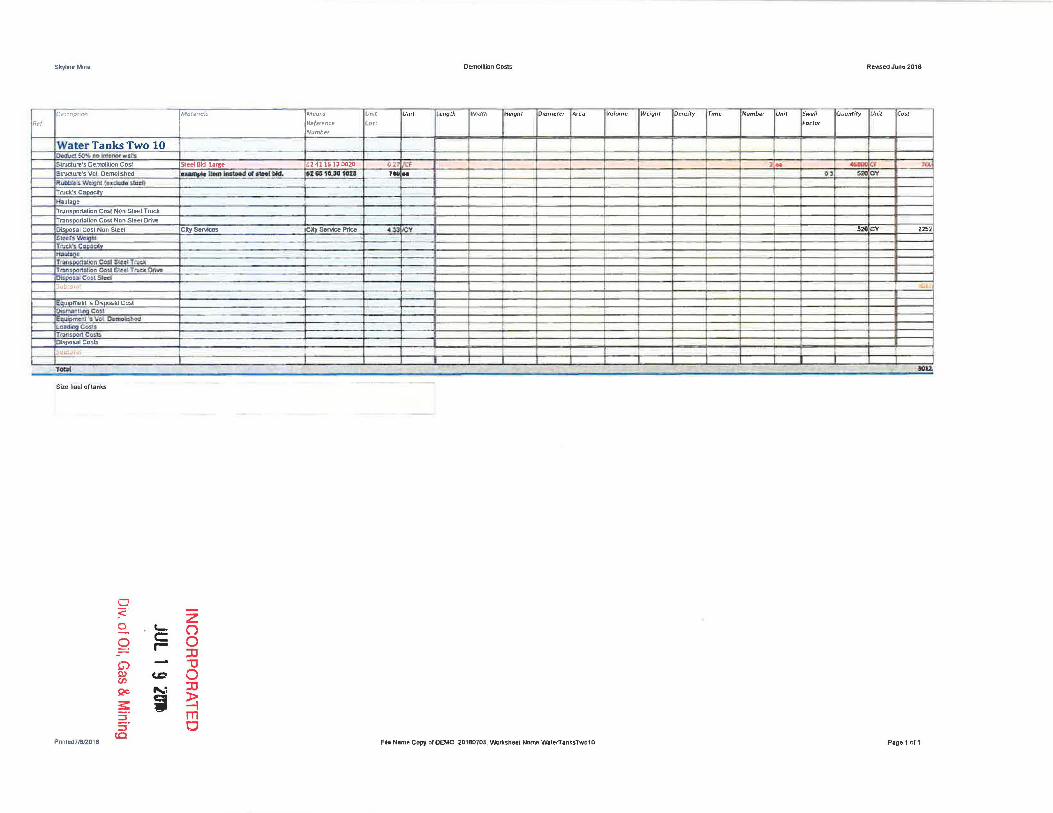
Water Tanks Two 10 O~ . .II:l !iml..D.DI~IMOI' 'wdl
Structure's Demolition Cost
Sirudure's Vol Demolished
RUIlIlI*. "Jol!IftS!._>UIl!l) Trucl;'sCaDacity
~ul'Q. TlOmspoc1aUon Cost Ntlll Sleel Truck
Tr.an5pQf1~tion Cost Non Sleel Drive
Disposal Cost Non steel
SlffiS V~1
rucIl\C . ... "" 1-1.111_ T ..... oot101lon CAsI ~.I T<II<lI
rurt;ipotlllll:ln Co~ Steal l"lVCJI; Dri .... Dl1pa~cn~~cd
'obwt"
E~l2...ment 's O~~sal Cost O5milnUb] CO!.I Eq~I "\I"' O._ LJI_Cu>l. Tr3.n:DOf1Co~ Disposal CastS
~UO~G\~!
TOIOI
Size haul of lanks
Pnnled1 m12016
o :c:" o o G) tI> IJ)
Qe
:s: ::J S· ec
'C r-
tD
.... ~ i
[MatenalS
I
~ Sl:ed SkI L.u&e
1....",.,.._Ins_ "'a. bid.
CIlySeMces
z (') o :0 '"'C o :0
~ m CI
Means
Reference
Number
024116' 13 0020
21810.= 102:1
ly_Prlce
DemoliUon Costs ReVISed June 2016
UmC Uml l engCh Width N~!g!ll Diameter Area lIo/ume Weight Density T,me N umber Unit Swell Quont;ry Unit ( cst
(osr Factor
02 ICf ,N _0 lQI
7"' .. a, ~ r;y
;y 52(1 CY 2252
""u,
File Name Copy ofOEMO_2D16070S, \Nor\shoet Name WaierTanksTwol0 Pago 1 of1

Skyline Mine
(He'! JD es<f!pr,on
Wump-Iiousell ID~d smc. no tnk:mr",,~.is
~ We.<lht (OUIlJcfc ~tcll:n
>I. T ... Tr;1J'i'$ nt;;;O)t r"(on
0*"' CO:!.I Non 'Str~
I-_-F.;~::'~I",~ ...... IJh\
>1-TIM><
~J>POU! con SteM S u~
: ~lf(!. V~J Orthc~brd
1 ~~t"7'lAJ
IDemolition Cost
h-~t01
ToIoI
Note Volume Is in CY
0 :e:-0 C-- C 0 r-G) S)) c.c en Qc i ~ 5' :::l (0
Pnnted7~12016
z O 0 :IJ "0 0 :IJ
~ m 0
JM::Itenal5
jr.o.<.d .. 6l<ILoII!C _
<:aSe"""'"
,_nCoflCRllO<15"
; t'CIfIl end l.o*r 1 C,"
~\.jeQ,;;S
Reference Number
I~'
12CY (IGToo) o....p Truck IJ2 rn1. tM ,If"a;pos:at Itt241 18 17 "200
DelTlo:ition CDSls
lu"" (l'St
IUnlt IHt! igh l [OIClmp( l"f JAr ll'u Ileng lh fWidth
~
File Nitflle Cop)! of OEMO_20160705, "NoBslleet Name PumpHouse11
[VoIum.- r"9nr lo,"",y 17im • Ji'umber IUfllt
~ CF
SWt!JI Foctor
0,:
RelnSed June 2016
IQvonrJf)i ~
eng
BOley IOlCV "iiii "iiii
~
'20
43
6l
--51 S
- 00
Page 1 of1

Sk.v1mfl Mine Oemolilian Costs Revised June 201 a
Dt"~cripC/on MoterIO/$ Mean$" rJnir U".t Len91h Width /-f~igh~ Ocametu Area Volume. W~jght Df"/uity rime Numbf?r Unrt Swell Quantjty Unit Cosr
ReI, Rl!jf"HmCe ["os.t Foctor
Number
Well House Three 12 IJ.tGud ~ OQ Lnlt.lio(~ ~W't! - O.emriijlQO.c,.c,!;1 ..... _ ..... ..-
<>Z~I1e !lOI'''' O~ I:F 2.00 CF :saoo SlNd"fG's; vol. D~Jnor~l'ued Q.l Cl' fWW.'ti WI:IiQlLf u:d!.id& ~I.§.t!l TI\I<k" C.,.d!y ><atbrJ" r""" ~Ifo" Co'" NOlI ~dl TtuQ nm~nCHIr.:"n Stt.fil~
OLi.pM.Il.I ~t Uon Sl~ ~ C. .. SeMce_ Ul 20 1IS/l Ist~l. 1'kQ1Il tuclt.·~C~
tl.uIo"" llOlfU,J3'G:!:tallm CC:1I Sled iNcA. rr'Ur\~~.tiCr'I CO:J1 Sloe! Tn.JdII Drt\lo ,[k;clM., Co" S'<fl
..J1x;..,:.l 4J'S .. ,
EqUlli'melJl '~~"Ca~
Olsmon1:tnn cu" Eou "V.t~""''''he<l LCI~t.ngCO't.j Tnm~CtJ~5
Disposal COS15
·'.1'J1,Jl TOIIII 4756
0 :cO z 0 ~ (') - C 0 0 r- :IJ G) "tl ~ CoD 0 CJ) :IJ Si?O I ~ ~ :S" m :s" a co
Prinled7M12016 FUa Name Copy of DEMO_201607Q5. Wor1tsheet Name WetlHou5eThree12 Page1of1

R.e/.
Sh.ylin0Mlne
De5C1iplion MaterlOls
Water Treatment Bid 13 o",""~",,ii;iiilcii'v.". ~LlIb'S DttnaI:t.iOh C~"
~"""""" .. Vbl. Ilo-Nli>I>'" .fl~I!I"!I: ~hl (eoxdudo ~farn TndSCDe2!t ~la'UI'?9" iltUMpo!!:!tM)n CQ.:l \ ~fon Ste:cI"T.w
'ranlOO(1Wo/\ Co." Non !i.u!iI!f O;iw, 1O§iO .... Co," IlOnSl«i Sll!Id'l~t'll
Tnd'sCoOlCly 1Wl.,... TI:an~poctAtIan C'Glt Slw TI'\I~ TllIIl!II(I!X1ilfloa QuI Sfe-II::I Trvd. Ort"o"C! O~~Io1J Ca~' SfiJ .,'-...iy.
Biolipma-nl ~ Oi!Spa~al Co~ D~Co",l e",,_." .. Vol Oe'1lOf!ll\od Iloadi!i9cOS15 TnnS.J'i'f1CGQ.b Oi.wo~CUtl;
__ BId.
50"""""
Means
Reference Numl;Jer
.116130100
ill'_krkcPl1cD
Unfr
Cost
Demolition Co::!ts Revis~ June 2016
lJnl~ ~ f;'m}th Width Height Diomeh!r IArea Volume IWeight (lkmirY I Time (Number IUnit ISweli tluontiry IUmt Cost f actor
O.3\!CF
0,31 = 13500
4,;l:1I1<:Y 1000 ~
,';0:....,
;lObl ,~
0 :;::. Z
S. '- () C 0 9 .- :IJ - "U G! f.D 0 Il'
::XJ w ...:.
~ SilO I ~ rn 2. CJ :=l
(0
Printed716f2016 File Name Copy 01 OEMO_20160705, Workshe~1 Name WalerT~almenlBIdU Page 1 af f

Skyhne Mn1e Demolittan Costs R~tcI.AIf1I1:20'e
Df'5uTpfmn Motenois Means Unit Umt ",ength Width tfelght D JOmetf"r A rl!U Vofume Weigh( DensIty Tlm~ Numb~r Umt Swt':/I Q uanriry Umt Cost
fir! Reler~nc.e Cost Factor
Number
Mise Stora2e BId 14 Oc.dud SQ~ flO kliC'flOI was.s S~1&1tn'S ~ c~
_ _ mLl/flO 1Ol. 41 1& 13010Cl 0,3 :;F &:/!.S Cf "Oi
struaJau.'.s Obn'dlloll Coli S!""_~ 2: 41 ,..,. , al102O 02 CF . 0 tOOlXl CF 21&0 SUUt:u.)~~.$ Vat. Ot""'IQii~WIi~{1 O. lUCY R ubl:l:e"s We(lhl c.:Jude 51'~ Tn.c>."s_ Hlilluma= TrlIM t~" C"" .... n Steel T...a l'2rfa.patI..Atian Cosi N-aon. Stell::! 0Ilw::
Dc:.potQ] Cost ~1\ Sled ::., selViCeS SOI\iCePrlal 433 JCY 70 C" 303 Stel!lr1~b,
Tn.d<.C_ HO~II~ TnllI!UXlfl4lllan CIJ5t Sled TIl.IO. T .. .,1>OtL011On CC-~ 51«1 TI\ICk D<ml 0Cr~ Cfosl,sIHI ~1 • ..tH.(:.·.'1 34IB
£Q~Z'nI ".5 clzlsaJ cast Dilmanlfl~ Cost :~m"s ..... al c('marMf'O
l •• dlnQ C",,-, fr:ansQOl1 Co.ttI ~OO!;IlIC(ls.u
Su,:;,ct;:',
CODa'ClIIt' Dl:lmou,)on D~CQ!.:t ~<I'- N~_~ 13,7 C It t'( 15811 .... ot')CRl6~VoL ~hd 1.3 14. cV LOllcl~ttg: _COlol
_ _ _ 3C'f
31llfGU1:J.OO 111, Y t 4l! cY 241 ranspo~tion Cost 1 15 '" llutno Trudlll2 mi. md "" 31nn211 014 2 9 V 1451C 437
ispos3.1 Costs On slte I1l::wtuI ~41'0 1 4200 B.a. Y 148I CY 1280
~ 'o C~le Oc-rno!:if1lOn D01T!O'11On C«I ~'COncr'ri'<"'IS' ,,"_0001. 13,15 C OUC Sf 2S CV (01 C~·S vai Ot-mO,",~ I ~ 311 l.gadr.o Cust Fl'DtU I"nd' ~r' cv 123 ~a.u 1!m , POy 3II.C'( 63 T..", Ik>. Co<I 12 CV e Tonj Dump Truck 112m1. mil II"! 3 2'3-23 20 1014, 2. .. V 20 311 '( 112 ~lItC'ORS 011 .. ·-..1 02"4' 1a 1 420D eDll II: ~, acv ,2!I
l..;;c' ' . WU!pI!II" Gar2-00 addootf two '\Q,Is
DiOimamina Ccr.;.t ___ StlLI/flO
H l 101U'0II 0 ... lEau.oCm.e:r.l ~$ veL Oe.rnobft,ed SloclBlil. ~. O241,,,'3"'!;!11 0.21 <:F .. 211 .. ..,.,. CF ~_Co'" 5O'1o !lOcUcli:>n Jorno ....... ...... 2IIOCl OF ~
1,,- ,~
T"",! _ - - ~
Note: see drQWing 3 2.1*1
0 :2 Z S, '- ()
Q c 0 .- :tI
GJ - -a ~ tD 0 (1) ::rJ Qo i ~ s: 2. m ::J CJ
CO
Prinled7~12016 fHei Namf:! Copy ofOEMO_2016070S, lNoooheel Name MlscSlorage81d14 Page 1 or 1

Sky1~8 Min~ DemoliUon CD:sl, ReYi:ied June 2019
O"'U(iptloo Matenals f"o!feons Unit Urn' Len9th Width Height Diamete( Area volume Wti9h~ DeMlty rime Number Unit 5welf QuantifY Uni r [rlSI
Ref. Rt!/erence Co'!il f ocror Number
Overland Conveyor 15 DrdlJa~nolml!riat'WilU:: 5Irudun!l's Demolition Cosl 024 11 13 01110 0 3 - " 1200( Strud.Uft!)'S Vel. Oemollshed 0.' J333 CY Rubble's WeiQ.hl (e)[rJude sled)
flVClLS CSpuclly
HSUlaae 'TlBl)sporlaUon Cost NDn SI.~el TNcA
·n]/;05pO"~UOI} CosJ Non Sleel Ofive
OisoosaJ Co£.l Non Steel ely .......... CKy_""'" 4,SS ICY 5333 CV 2'09 51eeJs I TNC:1'sCi ~CIt H.ullIOO 11I~1.at1oa Co!il Slec'i~
T[~S ti)a C~t Sl.eeli/Ud( Onw: 0.,. "-lit: Co~ su=o(
.~
EVi m '~ 04s Ulr C'cst O~1mb CO>! Eq"ptl!eM .. VoL Dtmol51\od l~IIIngC($$
T~rt'aon Co~15 DISPO~I Costs
T_ ~
0 :;;:. Z
0 '-- (') - c= 0 r- 0 JJ
Cj) 1J S» c.D 0 en JJ S2<>
,,: s: i ~ 5" m 5" 0
10
Pftn(ed71Sf.j!01e File Name Copy Qf OEMO_2016070S. ~heet N.lmo OvntandCorweyo"5 Page 1 ofl

Slt,yilneMine Demol~ion Costs Reloised June 201 ft
Description Materials Means Unit Unif t~ngth Width Hf!i9hl OJamt!rer ".0 Volume Wtighr Otnsity nm~ Numb~r (Jnit SW~/) QuantIty Unif Cost
N. t!/. Flejt!rt!ncc Cos l Fo<tor
Numoer
Guard Rail 16 Strw::lIl:~'1i O-c:~C~ ~ .......... OH1 13 ,ao~oo 12.1 LF '500 LF ' .... LF 14HJ5
Sirudure's Vol. Oemol~l1ed 01 nov Rubble's 'tNeiQhl (exclude steen
TrucJU; Capacitll
Haulage
Trnnsportaltol1 Cosl Non Sleel Truck
Tran:s.POrtaUon C(I~ 1.101'1 Sl~~ Orive
Oi$~CoutiQJ'l Steel 'ySoNbs e'r 8eMce Pdao 4,33 V Hev 7. 61«ltl_, TI\kI(I Co:
"" T~loo ~ SteOJTruck T",_alJon Cos. SI .. , lUCIe Il<M Olsoasal COY Slee! SUtitatil L: .. ~
EtI.......,,,, "< 0<.fN"" CG1j Oi.smanULnoCo51 E ;u~i;I'j'VbtJ~ed
l "'"' C4$l.> T ..... II co,,1.$ l%.PC::IIIlCam
\QtQill',
Tabil U2GS
0 -:;::" Z 0 c.- O - C 0 Q. r- :IJ - -U G")
(,Q 0 ~ :IJ CJ)
i !20 );>: --\ s: m
2~ CJ ::J to
Pnnled7~12016 File Name C(lP')' of DEMO_201SQ705. VVoI'1t5hecl Name GUl!lmRail16 P&gIll of 1

Skyline Mme Demolition Costs Rev.sed June- 2016
De5CfipticIfl Matefwl!: Mt"ons Unir .unit ieng!/! Width H~Jght OJamf!tt!'r Alr-G Volvme WeJghr Oensrey Trme- Number Umt Swdi Q uontJty Umt [rut
(lef Refer~nc.e Cost Factor
I Number
Rock Dust Bid 17 SWt:Iu:rt"1 DemQIfion C011 W 41 1"3QQl!1l D.27 ;/' 1550( CF " e8(
51ruClure's Vot DemolIShed 0 Lr.! C'I' Rubble's Weighl (exclude sleel)
Truck's Capadty f1aul~e
Tmnsporta1ion Cost Ncn Sleel Truck.
TrnnspartBlion Cost Non Sleel Dnve
OlspoSiI C(l~l N.on Sleel ely SOMces ely Sor.b>1'7IcIt 4.33 V 17 CV 745 ,
Sl ..... \ · .. l!!hl f"""" c.._ o~l)Q:e
'f 11l1l~QOI1ablin Cti1 :::tu1 Trw:1 r:= Cnl Slce Truclr; Dalo'e
OiSIIOUI ~'" 5!001
I,"""", I n I:
u '~ D4 nil CoSl 0...".. CO>! 1 EI:Iu.".:1'It ., vot CC'mo~tG
O~II::1tn1'l' Co'Sots mMlIQI'ICOII.S
DtsdOSll C'O'ab ~ ll.::J,-,-,~.,d I Coocro: fC: DalllCJ4liOo
ol')lll:llilion CCSf NAeI50n Conaele <15- N!o!s<» OUdo 13.71 t;V &'cY ... -Concre:lO':c Vbl. OcolDal:1iN6 13 iIIICY
lo,,"~ CC>l FmdOflll ....-lCY :)1 Z!,&.t2,,.,. 1~ tIOiC V no T~n'.PMoMn ~I I CV 15 ""' DumpY",,, , " ,,,- ,,,,, "" 3.1 Z3 : 2Q '014 z. .. O'C OOleY clll 01>"""" Ce ... 00 ... -' 10241 " " UDO .~ c n;
5-ubt;>tal I ". r_ ~
itoF.""SoreIlolcs ro!<al .... PliO, 10 :Ill ..
0 ~.
Z 0 \.- (') --..
C 0 r- 0 :0
G) ~ tlJ CD 0 en Qe ....-: :0
s: i ~ ~ m S· 0 c.a
Pnnled71S12016 File Name Copy (If OEMO_201B0705, 'tAIGrkshecl Name RodtOusl81d17 Page 1 of1
S.kyiine Mine Oe~~1on Casts ReviseQ June 201 H
Oescriplion MQI~riQls Means Unit Unit h ngth Widlh Height Diame.er Alea Volume Weight DensIty nme Number Unit Swell QUDrtflly Unit ( 'ost
Ref. Reference Cost f octor
Number
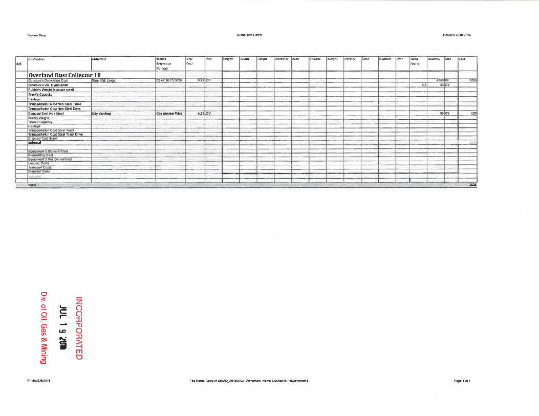
Overland Dust Collector 18 S/ltJdun", ~ c ... Slftl BIC!" '--0 Hl.alJIJO<j> D.2l i:F {600 CF 12S0 structure's Vol. OemolistJed 0.3 53 V
Rubble's WelQht (e~e steeO
Truck's Capacjly
1iauJo.,. rransDOrtlilllon Cost Non Sleel Truek Tl1JnsportaUon Cost NDn Sleel Drive
ClsoosaJ Co$!. Non steel CltySeMces ~y-""",, •• 3 I/CV 5l CY 229
Si!HfI W!..grll r ....... c."",,,~
"""-T'~_~non Can Slcll:.l TI\d, Transportatkm Co=ot Sleel Truck Drille Olspc~:Ol GMt Sh:r1 SWtobl L.. __
... '>0 tldCO:R OI:mlnfljt1G. Colo! ""'Wom",.", Vo" O<:_ed LooOlnoCO>IIi rj';JM(XK1C=~ Ci:lpogJ eMU
~U ... "
rGCII I.5Z5
0 :<" Z 0 e.- n ...... c:: 0 0 r- :IJ Ci) "U ro CD 0 en Qo fII.,: :0
s: I ~ ;:l m 5" 0 to
Pnnted1JSa018 File Name copy of DEMO_2016070S, \Norkshcet Name OVertandDustcoNedor1a Page 1 af1

Skyl!l'le Mlne Demolition Cosls Rewed June 2018
Dt!5wpt-on Marenais Meons Vnir Umt I t'"ngth Width Heighr D lOmt.'/er ArpD' V W /JrT/!:! Weigl'l r Dt'n.s ity rime Numb l!!' Umt $wdl QUaMllY Unit COil
(l. cl ReferencP Co">! f'oaor Nvmber
Substation 19 S.~'SC~CoS1 SI .... ~ (l2 41 1 e l~~ 027 CF 27Q Strudun!!'s Vol. Demolished U 11 CY
R_ ', iI\!!V" <.-0 "OCn TrucJo.'s Capacity
HaUlage f raosPQrtaholl Cost Non Steel Truck
'rlillnsprn1.a1ion Cost Non Sleel Orive
/spout Cost Non Sleel CIlySeNices CIIy SeMce Price 4 3a 11 Y •• Sl1:t.fs VC' I TNd'.Copoc.ly ... .tl:i~. TrOfUpot\4'l.icn CO$I Sk_d Tfl'C;k Tn:ln5~ft eou S4c.d TI\III:l onve OlSposot CO" SIod !ua.!c!.11
ISqu.Gm_Al'S Od~C~ O'\sman(]Joa Cost E mc.n1 's Vo LOc.mo.li:s.b.ed lCilding Cc3il!J TI'iln~pcpr1co;~
D~p)I.Il COl.tJ. :,,,,",'W,
Cona:(t- DemOhl~ [)enolil!oo CGSI _"""""" <1 -.CluoIo 13, 3 CY • C\' 1010 C~(I·:i. Vot Demoloru:d I.J R CY t.ooo c;.., ftOnllftCl l..OODtt' l 3t.n 10,.&21300 ' G7 CY ,~
T~:!IQCWU~a cost 12cy , e TCIII 1lu!TC>'1lld< 1/Z mi. mcI lit! l, 232320 ' 01' 2.IlS Y Pa C 25 Dl>po~CG:ib on sre CfbpCISa ~2 " Ie 17 QGO ',M~' IiC C 8.."0 5t;~~ .. w. l .
TCIbI -.,:
Neill" YQ'urnr- 0 1" CY
0 ~.
0 Z - C0- O
0 C - I 0
:IJ G) Ol
iJ CJ)
<.D 0 S20 ..... : J'j
:5: i ~ ;:;' ;:;'
111 CJ
to Prinlt!fJ7M12016 FItB Name Copy 01 DEMO_20160705, \Nof1tsheel Name SubstaUon19 Page 1 or 1

SkyhncMme D~molition Casts ReViSed June 2016
Of'S.!jpclon Matenals M~an:5 Unit Unit Lenglh Width H6ght Dlamete! ~re'a Voiume WeigM Ol!nslty r,me Number Unir Swell QUantiry Unit CO$.r
R'I R~/~rl!'ncr? Co:;r f actor
Number
Power Line 20 ~f1lo·$D~C~l EIomIc>I Dt:mo«.on I_SJOOUI70 1.1 c:t :IOCLF 52~
SINa>ItD" V ... D«rooI""'" R..-" Wliom ...n.du".g ~,""""'COC_ Hm;lllge Tmr\:lpot'I'otlcn CO$t N.c" Sh~1 ~ ·Tn.x:Jt
fllMOOtlI tICt1 Cost Non SJee1 C~ O~"CMl"'oro~ Stt,efl-\.\' (
T ....... c.~ .HeIs!ogo It;;t;ruoonl:.tl,n Cdri Slt!d Truc.t
J1IMQOrtIJlon Cost $lc:r:1 TnrdI: DfI'IIC' Ili$p;;t$ai COil St«1
_1!;10:. 't ,
EJ1'*ft':llI!ns's~C~ DCmimt:~C~1
E nt "'V,gL~tI:C!dI
l .. ~."Ilc.." ransDOI'1 Costs
OisPOSll1 Costs
£Ubt0t~1
T_ 1§lI ---- ----- - --- - - -- -
"'ole Demo wlume (or Me Is Insignirlcanl and Bccounled for 'NIttlln concrete of facility
0 :;::" Z 0 '- () - c Q r- 0
JJ G) - "U 0> CD 0 (f)
S20 ..... : :IJ
~ i ~ ;:J m S" CJ
CO
Prinled7J812016 FHe Neme Copy of DEMO_2016070S Worksheet Name PowerUne20 Page 1 of 1

Skyline Mine Demolition C(']sl:; Re'ot'ised June 2016
D~lcriptiorl Materials M~(Jns Unit Unit Length Width Height f) iameter Area Volume Wf!ight Density rime Number Unit SlNell quontilv Unit Cost
~'f Reference Cost Factor
Numb~r
Cap Magazine 21 Strua~'Ji D~.an CMJ lSloe! BId. lJugo D2411613 D02fl 0.27 iIcI' CF 34 structure's Vol OemoUshed 0.3 1 CY
Ru_ .. WtiDIII 1'-•• "'.11 Truck's CaDacit'V H iI_UICijl tt
TrJMporIatlon COlI Non S\e:cJ TI'UdI. Tmnscortilllon Cost Non Steel Oflve
Olspo~dl Co3i1 Non Steel City SoNiccs City Senlico Pl1co Ol iJCY , y
SIIUf!'1~m TI'IJO'i. Cl:tmef~ Hliul; II'
T COil SllI.li!1 TI\W.k
nlM~ (..oj, S!¢G4 TftJI:k DnVD
O*:liIl C-alil S3lCe-I So ,.
IEqI.lIprrw:nt "'$ Dl:spcJll c~ DW11l1l1WUQCOS' I~"""" VOl. 0."", cd l~_IngCg.s.j!l
TOU'9G'\(;Q.<t:o Oi'sposat CD-sts
Subtuuil
ToW . -- - .. - - ~
0 :cO z 0 '- () - c: 0 0 r- ::D G) "U ~ CD 0 (J')
::D QO ~
~ i ~ ::J m ::J Cl to
Prlnted71612016 File Nilme Copy of DEMO_20160705, \Nor:k.sheet NiifTle ClilpMagulfle21 Page 1 0(1


Skytina Min~ Delnotihon CosCs Re'VlSed JUlIe 2016
DeSCflpWM Mareflofs Means Unit Um t Length Width Hf' ight l);"amltf.tr Area Vo/um~ W~lghr O~ml ty rime Number UnIT Sw eJl QuanCity Ul'llt {"ost
Rei R~/erenu Cosl Foctor Numbu
Propane Tanks 23 !
Sirudure's DemoliUon Cost Steel BId t..rs. Z41 16UtIOlO 02'1 f(;f ~ .. 3! CF 1132
S,,,,,,,,,"'>VoID_..s .. - lUl .... 011. _ lOA OJ CI '=l'f Rutclt-~ v.: tJlf:l~'~G Truc:i.'SoCt ....... ,....._ eo .. No!> SI.d r""" 7i'i111'\"5ilocuiUon C(.Jt NDft Slc.d o.;..,.e Oi1;oo$.llll CaSt Non Sled :av "SetWz.s SOM:a Prico 4s.J o V 0 StC!er~ Wc' I ..:.cheo
Tfi.l~~SlC'<tITtUdc
Tr:liIIflsOOl12,oon Cost Sleel Truck Oriye ~posaJ Co,, steel S .W'to~ .. i
1Equc:ml!'nt ~I [)i$pcIW CG!.l ~ . Ce.>t
uilom~~ .. \/01. Omnc~ed I.lw&IQ Cost> TnmsDOftCosts OISpOsal Costs 5 t!b~Ofil!
C""","", !)GmoG!;oo
OeIOClWanC()ll Jetson Concrete "::1 NI*onOuole ,:1 C 303 COC'lUClte~!i Vol Oe.tnOl4tIC<I t,3 CY Looa c." roal end I oador 3 CY 'l12l1lU 1300 18 Y :lie •• ,.,. 1100"'..;1 12CY '.T"'1I""""'T"""' 1JZml.mO~ 3123 23 20 '01. 2~ Y ZI Y ell oaposal Cos\s 0.. ... -" 02 41 nl 1 . 200 ee IC :II Y 25' :<.ubt:)t:)i ;>'
T ..... IDI
Needs to size the lank b.tseCi on 02 eS 10 3(1 0011 thrl)UjJh (1130
0 .< Z a c... (") -- C 0 r- 0
:rJ G) "U OJ c.c 0 CJ)
QO ..... : :rJ
s:: ;; ~ ~. rTI ~ CJ
10
Prfn\ed7~12016 F~e Nama Copy 0( 0EM0_2016070S Womheet Name PraPfinoTanks23 Page 1 of 1

Rpl
Skyllno Mine
IOe'Krlpfion
IStacking Tube 24 ~Cft.n:'~C~
iNa". C4tpxily ~-
it Ncn $edTNtl ~I Non Slectl Onve
);';po,ot' itee1's'Wllctn g"' .... ~pot>!,
"'IJloQO ,1s/edTN" ,1 stHi TNCl Oti ....
,Str<1
I ~""'''''
I'"
IC~·51
11c"""'l1I:""
1000000>l c.~
-7_
Nolo Volume I!i in CY
0 :::: ~ '-0 c:
r-(j) --"
p) c.D en QO ....: :s:: i ::l S ·
CO
Pnnled7"'12016
IMolClI015
"'" lDicoot 3 C'I
!:J2i" l"""'_
Z () 0 :D ""Cl 0 :D
~ m 0
eJeren(e Number
31 23 18 • • 1:100 3\ Zl 2'320 '01~ 02.041 t 'I
luo;' Cos t
IUnit
1:T,75jCY
1.1151 "2:i3 ~
Il f!ngth
Demolition CoSis
IW'dth r"o", IDlcm("ter IArll!' (;
Fife NSffi@C09)'o'OEMO_201807DS. WorbhDOI Name SIadtlngTubo24
IVollJm e IWeight I"em:iry ITime INum ber IUmt I.>wefl PQct",
RtVlSed June 2016
IOuantl ty lUna
iO 3li 3li
Ico"
:l<SlI
IIO'l ~
nq
P;tge1of1

Sk.,.lIne Mine Oemolitlon Costs ReVlSed June 201 a.
fDl'~Cflp' lon Malerials Means Unif Umt engfh Width tfelght Diameter IArl?G 'Volume W t'lghr DenslCy Time Numbu Unit Swell Quantity Umt Cost
Ref. Refl'renc(' Co~t f actor
~mber
Reclaim Tunnel 25 Sttudum's DcrnofiJan Co~ sttLtdl~It'1 VQI, tmncrlSJ'lHl R.,;,bt!Ws V c::D:Ndo 51 TNd.'. C<Ip>CiOy HJII1.I~'e
TIUf)!.DOItDilOI'II ~I No.n $te'e-l 'f1Udt nlfl:Ipon;l1l(1t1 CMj Non stt"r1On-w. O_~ .. I eo.. Non Sk«1 SJlM!n. ~1
IVdI. C_ty ~ul;lQCI
T"""J>O<!>I<>n Cool S .... T,"'" TrQn"fXM"\:.o1ktn Ca:;! S!t:'P!'1 TNd 0rlW D!sQofl' co.sl Stel. ;;'lrbt:Jt3;
E<!'_"O~Cool DlsmanUIr:lQ-CoM EQLI'I g.R'"~ Il' "s vol. OcmoE:iQcrd l.oOd .... eou. T,.". = .. i:,;1'JCI-'.:aL~~
H.iMotJ]
OQcnI!t!! Oe:mcdkH\ Oemolition Cost NWson Cornc..nIII:I <1!''"' N_Q"". 'US y 1\150 CY 2$1150 Cona'IIcl.t-'o. VOL O.c:rnW::lh~ 13! 2MlI cy LoadlotGCoot F""" .... L_lCY • 23'1& 42 .300 1 ,5 y Bey • rtiln~porUSlan C~ 1 HI ruCI< IJ2 3, ZI :z:t""JD'4 2 Y .... 1,>17 Disposal CoslS on,...~pClt"" 02411517 QCO US .,... 22040 SubotCt.i.
1* WJSlI
0 :;2'
Z S. '- () 0 c:: 0 r-
:0 Ci) "'U ro (.Q 0 en Qc ii
:0
:s: ~ 2: m ::J CJ
CO
Pnnled7~12016 File Name Copy of DEMO_20l6D705. 'INorksheel Name RedaimTunnel25 Pagelof1
Skyline Mine Oemolihon Costs Revtsed June 2016
De5ulpliCn MotenaiJ. M eanS" Unit Unit I..Imgfh Widrh Helgh[ V,umerel Areo Volume Weltjht Drnsity rime Number Unit $wef/ Quantity U .. , Co~r
f ef Hefer~nce Cost Factor
Number
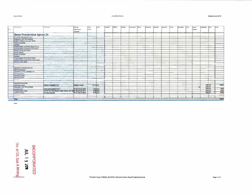
Slope Proctection Apron 26 Structure's Demolition Cost ~-5VClL. D~ed
a:~tION', ~ftI ~ :5le~ Trudi.~C"~
HI~e T~,ot.Jan C~ NCln S!md TI'1.Idc ,..". C-M1 NQ" Gird 0riYD ~pDuoi Cma NDn stl'~ .Stei:!'b'loitiQ.hJ Truck', c._ Ha",-Tr:Ll1:;porutfiCIn C::.m:I St~T.nd Tfi:l.tf$J)IXUI;tlOn COlli S(~Truek CfI¥ICI 011-.>1 Co<l 51«1
ISI1""'"
EIl._", .. Db..,...., C<IU
oo,;m.:KIIMooC~ nt ":s Yo!.. Qm;aUti..a
Load' Cosls T<=JIoIKIc..... ~nlCO~
S \ ;b~lJt;ai
C<>ner.to Ot"lnOl_ DIi~COU I_C_<15· Nieban Quote '31' Y CY ICl54 Cano't!~'e:: Vol ~odI 1.3 g Cy L ... IY:JC"" ~- L_JC 3' ::131542,:100 1.D V g g 1635 T"", " 12C ,e Il2mLm<l 31232320 un .. 2. ona CY .&11 Olspo"JlI1Co1lS On,xo_' I"'" I." ..... a.., , C a~
;ubt:.lt;.)1 .i;
TC!!:>! me
NO<,
0 :c:. z 0 '- (") -- C 0 0 ..
:0 G) "0 Al CD 0 en :0 Qo "" s: ~ ~ S· m :J 0 to
Pr1nted7!e12016 File Name Copy of DEMO_2(]16()7()S, VVorkstleel Naml! SJopeProdec:UoAAprcn26 Page 1 uf1

Shyline Mine Demolition Costs ReVlSed June 2016
--Dn.:rrotlJtJ Mo[enols Means fJmt Uml l.ength Width HeIght Diameter fA reQ Volume W elghc Density 7iml" Number Un;r 5Wf?ll Quantity Unir Cost
fl.,,! Rejerence ~OS( Falfor
Number
Concrete Lined Ditch 27 l~J1JCI~~ Cl!'~ C05l SIJI,oc:I",." VOI, O"""",,.'" ROObIa'o ','Iohlht __ ""OJ) In;c. ... ,CDCIGCItV H.aulaae I Transportation Cost Non Steel Truck Tnm~pr;wi.llllion Cw Non Sle,cI 0nvD r>i>I>a,.o1Co" Noo SlJloJ 5let;sWlIIQN Trur.k'sCe~ty I H".I>gt Tf1U'I:.OOI2.tia-n CD!1 Steel. Truc:k r~POf'hllJoo CO~! Sl:aCi' "TNCk Onw ObDG"'" C1;11' Slm
5""10,"_, Sib t r:aP ......... 1.1 II:W00ut _\'1"~"", .. "",, 00IN.~1oO Ca>l Nic_ Cooc:mo <1,'
._c_ 1375 Y 17 IJ 5 17 CV 234
e.'.","'" ~ VoL o-.molltll«i • 22,1
LQa.dLf1io; CQ1.tJ. F_ . ...,~3CY 3'23"842'300 U V I 22,lC l1 rrAlu~.Coa.U. 12CY'8T"""""",_l rucl< 'Ir.lmLm<l1rIr 3123 23211 .B14 2 liS Y I 22.' CY D$
O~paLlll~"" On sIl. "'Sf>O«Ol B2 • "8 '4200 U!5 2Z.' CY Iii
~·:ltnu_~ J
Cf3'f'IUtfQ Dt:1'n<I9IoC'1 i
~ItIQflCOSJ ItiebcIn COoc:nI!Io <15'" _QIIoIo 13 ~Y 21 CY Wl' GatJctt.(a'.,) \101 Olllmo1l:;h.ed 1.:1 2 CY
l Olldioo Cost F _ _ UMIdot 3CY 31 23 18 42 1300 18 ICV 2 CV ~'
ral1spon;;r,llon Cost 2 CY 18 Torn eo.". T",,,, 112 mI, md.1rIr 312323211 101 .. us cY 2 c U Disoosal Costs On site dtsposa 024118 4200 los leY 2CY 234
~\I;.t.:r.~1 -Tib! 'U~
Sec drawtflQ 011 page 3-4"a for concreLe slilirap delo1l and See Plale 3 2 '-3
0 :;::" Z 0 '- 0 -<- C 0 0 r- ::0 G> "U PJ c.c 0 en ::Il S2C .....:. s:: i ~ ~, m ~ 0
Prinled7f512016 CO Fie NBmll Copy of DEMO_21116070S, Worf\.sl'lc-et Name ConcreteUnedDd.ch27 Pa!;le 1 of 1

SkylJne Mine DemolitIOn Costs Revised June2016
CctIl'rl.ClhM Mat~fla!$ Me-om Uni! Umt i..fmgth Width Height Diameter Areu V~/tlme Weight DelHil}l rime Number Umt 5wt'li Quanhty Unil ( oH
FI .. ,! Reference (os-t factor
Number
Raw Coal Silo 28 Stn.k:SUt'D~~rlCO.:;t
Sirua\j",'. Vol. D_ ~'~~~§.l~
t"Nd!.' .. ·c. " H.I:Iul~JJ' r~~lCIn C~I Non SlI'dTNtCj;
Til"' .... ,,""" COo, N •• S!o<! Dr~ 01>00 ... Co<1No<> S\<!., S<eo-h: We. , TruCl."i Copaclty "'-T~. CO"..tSOool True> T .1lCln COSI Slm"TnJdI;.DI1n DlsPl?-=-" C~I SlRI Subtot.1
EQ~" Dl>oo>oJ CO« Ohman Cc;.:;:' Ea~_~~ ~$ VcJ. OmtO'=l'Ie<I
l_C""" Tra5!:)CX1Costs
-'''"''' ~i.t\..r'totili
CQoctlno OCi1tlQf!bOn a._~ _ Conao:e <1 5" NIoIson a....;e ~ :r _S omo Concrcl." Va!. a_ u 18& CY L .... c ... "."_...-..a_",, 1 03'0,02'_ 1.0 !5'_'t 18& CY 147& Transportation Cosl 12C .8 TDI1) 0Um0l rud<.J2 ml md ... ~.232320 10" ...... Y 18& CY 200II ~pos.aICosrs 00"'_" ez ~1 .a . ' <200 005 ~C 1&(7
Subwtll~ , .. T ..... 1l1li1.
Note
0 ~. z 8- t- () 0 C 0 r- :IJ C) "U 0> c.c 0 en S2G i
::II
~ ~ POnled7'!!!' B m
::J 0 Fie Name Copy or DEMO_20160705 'IJorksheet Nome RawCoalSllo2S Page 1 of1
:c

Skyline Mine Oe~jhoo CD5ls Revssed June 2018
O!'.lCn,ll ion !Mat~nalS' M(;QM Unif UflIr l englh Width H~,gflt OJametr:T ~'ea VOlume Wei!?I'Jt Dcnsily T,m e Number fJnit Swefl QUan fi ty Unit C(ls f
fit:/. I Rej'f',ence (O~t f acto( 1 Number
Parkin!:! Area Middle 29 &tnJdW'D'S D~~ CCiIl.I _ "",',vO\c_
ulJobin iJ.: eDlUQ ~t.,-CI
TiucA'. C._ Ho<dlI"" T .. " .... =,_ 51..,' TnJ<l T .. ,[diGn CMl Ng~ mrcf on .... D1soo:oal Cost Non S leel SletU\\lt-OftA:
T"""' .. Co-", ... r,..,. a:..on C~ Gft'd T",c-.k T 2110" COil Slc cl TI\IQ onw 0Cs00sa1 Cost S iref
'·:lMO;<.l.l
" 'sO"" 01 Cos, Dismanlling Cost E<>_ 'SWLtloIIIWb .. LOll Cow. Trans rteosts OIsPOsal Costs
~"lbtNi;ll
Co.naa:le O~ll P~~3 ., '317~'O mY Cemolition Co.sl _C<Ioaato<1S" NIobcnQuol. 13 Y ' 2IDO IN CV ' 4H CClDCtC:~::Ii VGl.D~ 0 'I'D 1.3 1>C Load lno Cos, FrooI_ 3ey 1231842 300 1.111 137 m .. JtDn cosa 2C1 o T"'l "'""P TNCk \12 mI. mel "" 1 23.23 20 .016 2.&5 I';.Y 13 004 otIPOSQI Costs 1"""·_ oz 4118 17 4200 5.6l1C1 Pl 1115
5 , .~J ':f
~ _ 351
Nole
0 :;::' Z 0 '- (") -- c:= 0 I 0
::0 Ci) "'C III c.D 0 ell ~ .... :D
~ i ~ 5" m 5" 0 to
Pnnteod7/t1112016 Ftle Namo Copy cf OEMO_2016070S W:H'kshee-1 Name Par1l.IogAreaMkkile29 Page 1 or1

skYline Mine Demolition Costs RClo'I.!I:ed June 2016
De5CllpUQlJ Moreno!!. M~ans Unit Unit Lf'l'Ig/h W,drh k f' ight Diamerer jArC"CI Vo/umto WeIght !Density Tim t: Number Un i t Swell QUDl'l firy Um t [ o sf
Ref. Re!eref'J (e CO$( Fa( tor
Number
Truck Loadout Foundation 30 I - -~
SlRldLno'S Ce.~ c ast i!IlI\.Ic::IuRI',s VOl. OC'_mall~eo
-,\ hlj~SI.cIl::
f"""''' CIl>ICO'f
TnKI' nJWoft cot! Non Sleot Trude lktn CGSf. Nan $lr:d 0010'1
0;, ~OJ.~1 OPSl:o(ti ~l!rs'Nelahl
Tnd.'>Co;:oo<i!y . I1$>
Tron ilion eo.t "'celT""'" to ' CO<lSIHITII.Ck DIM
~()Osa' Cost Sle~1 , :< !
_"0' .I~I I Oi:snwoUir:lQ Cost Equlp1T.ettI ~ VOl 0ema0;.aI-~ loadlng Costs T Co~'" D<>~C<>w 5> ',10':.<11
Coac:teto Clt'1I'IOt.Jon Dttmrhl,n eMt _ eoacm. <IS"
_~QUOI' 13. C , CY 1:18 Concma"tVoI.. Oemo~Md 1.3 I CY ."...., co.. nMH ftad LMdItr3 3' 23 1 , JOG 13CY 12 TraII!i at;onCc-.$1 12 18
TNOIt ' I2'mi. _ _ \Ill 31 23 2320 1014 :tJI I CY la
C~58tCoslS on sle dbponl 102., \0 1 , ._ &.G' IICY , CY 112
~u' ,
TatII 310
N"'.
0 :;2 ' Z g, C- O 0 C 0 r- :rJ G) 1J OJ (D 0 (f)
~ ...-. :rJ
~ i ~ 2. m ::::l 0 co
Printed716J2016 File Name Copy or DEMO _20160705, ~heel Name TruckLoadoutFoundaUonJO Page 1 011

SkyUne Mine Oemolition Casls Re\Il5ed June 2016
DE'5r:flpfiO!l MoICfl(tJ:r- Means Unit Unit l ength Width H~(glJr Plomerer A'~G Voll.lme Welgnt ensll)t TJme Number Unit Swell Quanti~ Umr COSt
.,' Reference Cost Faeror Number
Road Pad Lower 31 ~ro:, D<moIolOn C<I<l I S,,,,,,,,,, VQL O~ R'UtoIc!:lI WOgI'rI e.ll:l:N3 itnl) nxt:'s C.lJl)acty
HII01J1!!_ I r~1Won CMl Non Slefll TI\.IC.l TIilnKlGf1~ CG51 Non su.ct OtIvo O-..po~~ No"t'l Sl~<e'I SII:t!r' ~1 TIUdI'. C. .. dY HliOloR< "rtll'l~6IJo.n C-Gfi st~t "Tn..d.
Tfllt:I~~co:n "5tr:tet Trud. ClnPI
OdllOul C"", s..... $UiJ,-otJi I I
E _ .. ~ 0."", .. 1 COOl
~c"'" Eoull)1'N'MI ') vot ~ft"JOi4hcO l_ .... C0l> Trunr.oon Co:.t'). Di'",.oour Co~:5
5....:nI.'l-Ui
c.ontft: lo Ofttr)O).t;lon PI"Wt'mDntRamDWIY 02.1 1311 SC10 4,2 ISY C4mD1lhon Co;t I_C ......... <15' I"""""'CUOOo '3 1 Y '000 SY ,11: Y 2201 C ....... 'o'>VOi. D ...... "... 0, ,n> 13 21 CY l o""",,, CO>l ront_..,....... " 3' 23 If'" :100 I.e 1C' 21 I<:<Y JS< rr.o IIUonCrx.1 ,2 CY 10 T"1 """" Truok , /2 m mel ~ 3,2323'211 , 01' 2 21 CY 52'S C"OOJlIl e~ ""-- 241 10 <'lOO .~ Ie' 21 C 10J< Subtot<l t -'"
- -"-TOiiI n -Not,
0 :;::. Z
0 t-- 0 0 C
- r- 0 :::0
G) Il)
l:.1
CJ) (D 0
S2<> .... : :IJ
~ it :t> 5"
-I
S" rTI 0
CO
Pnmed71812016 File Name Copy 01 OEMO_201a0705, VVorksJleel Name Road PadLcwer31 Page 1 all

Skytna MinI! DenDlillon Co~ls. R~ed JWlfl2018
OelCrJptlOn Male-flo/;' M('(}n ~ Unrt UnU Length Width Ht!igtJt Diameter ~rt'o lIoJum l! Weight Demi lY r,me Number Uni t Swelt Quan tiry Umt Casr
Ref Refel tfiCe Cosl Factor
Number
Silo Rail Loadout 32 6IIucIurn C ..... ion ~ SlfQdute·~ Vel. ~nC!'Cl
R"-" f-cotduUe ste t\lCA'S C~
HAId.oQ. Trans aUon Cosl Non Steel Truck
r""" n Cosl Non S leel Drive Dis .al Cost Non Sled
Sleet" .. •• N TnD."C. __
~-r"", >1ion COS, Slecd Tnd Tm ~ btl Cost $ecl Ttueil Onw 04~J~S~1
:"t.:>.i.lJ~"
" ~':sC* sOllCo.st ElI'.m;r~t:'" Eq_ .. Vc>!, Dome.." ... l~~C&!;H
frans rt Casls Di:;pa.nI_~
~l!bH.n<l:1
Conc:1l1e:Ccmol!\.lod O. _C«OI IoIsoa C<InInto ~W Nlobonev.to ~ Y 602IJ6f a2M~
COtlUelels Vol, Dcmot:sftec 7_ CY
L_Co<' Ft'OPf t(l(l 1.Aror:l4lr'3 CY '1 23 1042 1300 U R Y C ,:NIall
TransPOrtal ion Cost , 2 ey 10 TCIlI Duono RId< , m<I 31 23 23 2G D,. 2~ 7.,. .CY 23t16 oega1oJlC~..cs "" ,..~ 02 41 Ht 17 UOQ U 7Ql CY anll
1868611 T_ ' .....
Nol.
0 ~ .
Z 0 '- (") -- C 0 r- 0
:0 G) "1J m tD 0 en R<> ....:. :0
~ ~ ~ :=l m ::l 0
CO
Priflted7i612016 FIle Name Copy of OEMO_2016010S. VWfks,heet Name SitoRallloadou132 Pagelofl

Skyline Mine Demolition Costs Revised June 2016
De-.KflptlOn Ma!erTC!5 ~eans Un/I Umt l englh Width Hpight Diameter Arfo Volume Weight Dem;ty rJm~ Number Unit Swell Quontity Umt Cost
fief (lejerencf' Cost f actor
Number
Loadout Foundation RR 33 Stf'bClun:o"$ CcmaWcwt C.a~ 6 lJ\it1unf.s VOl Den'ICIl4t1CC Ru_ ........ "'.1 _u<Io;l<t/l TNd.',C._ K .... .., Tm> ~Non~fIT~
TnIIn~lJGn C~ NDn Sltld Drive 00(1(1 sQl CCll( Non stod SIHlT. W."," T~Ca:
... ""!~ TliinspIk'I~n CaJ,i SlutTnu:.k TfUn~1I01\ COM-Steet TN~ Drrvo O~51M~I:s.i'!I
'5Llbtcta:
Eq_n ... D<>po.u,CmI CbmoneJ..,Co>'
lJ ~ VDf, Dtmc~nHl Loadino Costs TllIn,pott CO:Jlj 100000lAi Cow. , ,bM"
CQtl.('n~o DrmoatlI:In
C • .-Ca.t NJeboo corcr;.a "\5- NIobonOUOlo '315 CY oec J4\G CCk\ch:!te-!j Vol OMlO.fc1h~ " H~ cy l C'" FI"CIfdIllndL 3eY 31 2'3104Z l300 " Y 3221'C <"I T ... , UDn~ , CY Trud< 1IZml 31 %3,23201014 :t 32ZC 95CI OiripOsal Costs On 51:8 disoosll 41 1~ 1 4'ZOO 32:1 Y Va. ',"oro,",
Toul - - - ~- -. Ncle
0 ;<-0
z --.. ~
0 c:: 0
- r- 0 :Il
G) ~ CD
"1J en 0 Qo to..; :Il
s: i ~ 5- m 5- 0
Pnnted7 !SI2oifl Fill:! Name CQPY 01 OEMO_2016070S, V\IOrkSheel Name L04IdoulFoundaUonRR33 Pagelof1


Skytfne Mine DemofiUon Cas's Revised June 2016
OeJcrjptJon MalerUlls Meon$ Unit UnJl l.en9 1h Wldlh fH,ight D/Qmeter fArea Volume W~ight pensity rime Number Unjt 5w~JI QlJontity UnU Cost
R~f flt'jert'(tce Cast ~octor Number
Steel 35 SD\lClw~·S~CQ.l1 5lrudw'a~ V.al Dcmqli1.hc<l RII~",,"'Ilnl _." T"""". CAj>oCily How:.oe TnM'I:ipon~ C411 Nono Sh~:et TrW TfDI1~_~R Colil Non Sltcl oaw. O<SPO'" COst Non Sled tl!ltt:r:s \\It:lQbl 2000 TON 2000 TON TnA. C ... OI •
• nUU...tollon C .. I Slftl TNC!< TrudcdumpI8,""_",, I ~3320 5300 811£; ildar Ie DY I DY 11075 r.ansponl:6oft CtW. Sled TI\idL 0tI\IID ~Co"SI .. 1
!I..; ... ~\..;. :.!.{:';"
Toal ,~
0 ~ .
Z 0 '- 0 - c Q r- 0
:c G) - iJ III tD 0 en Qo ,,~ :c ~ i ~ 2: m ::J 0
CO
Pr1fltecHJet2016 File Namo Copy of DEMO_2D1807DS, WorUh&Ct Nlima SleBl35 Pave Ion

.'1,.1
Slt),lioo Mine
Dr:5cnp(ion
I J,ur~s CIlnVon ~
lemovc I !2lLJC-I 'ru.) .
Ig: CoQc:n.:!.6~
T,wupgniJOon C~I
;~Il$
Marena/)
i31llCY
~ ,~fl\MJ I'IdwP Rtl ....
~
~....2:"'-Y-&OOifiiOf <lotoen"_1Mix~psI
Unit
["5(
Unit I~ngth
Demolition COSI~
Widrh Ht:iglll D;Qmt!C~r Ar~Q
Relli~ June 2016
Volume Wf!ighc Demir), 1i"me Numc!!( Ullir Swell QUDn (iry Unit COH
factor MeoM
Rete/ence Number
==~=4r==~~~~==+=~~~~~~=+=+==~+=~~ '0150 : ~ !ForIman •.... '" .$'"
_<Q~ .. R 101504 lS40 720CI
!@W1:%0412 ~ll~. lS •' 11 1\ Y
40 "11
'I'jR
HI1 WI 1I1l_
.,.., .,. ~
"':' -
BTIiG .,GO 0113.
2lSDO
T_ _
0 ~.
8- I.-Z
0 c:: ()
- r- 0 :u
G) $:I)
1]
(J) c.c 0
QO .... : :Il
s: i l> S·
-I m
S· 0 to
Printecj71812D16 File Namo CoPt at DEMO_2016Q10S, WOr1uhae1 Name JamesCanvon36 Page 1 of 1

Skyline Mine Demolitton Costs ReVISed June 201 e
O~s..:ripti(!n Marerlal.:; Means Unir Unit I t>ngth Width H~ight DlUmeler fA"" Volume Weight D~n5ity fim~ (Vumber- Unit Swell Quantify Unit r.ost Ref ReJerenre CD~t F'actor
Number
Cu.\'CII Bxlr.!!o>,l 17 J CUM" CU·l '0 Inoli fE>C* ........ _ B>I\O. 2 CY [J22BL .'231&4211211Q I .' 5& 4 a FT &&4 943
Bo .... l"""'_oJ ... IU'14CY 3'231013~ I , 5& 4 - 1175 Cu.~d CIJ.l
&1:0 ___ 2
!21!1: ,231842= I . 4 FT au1 cv 9<0 _ Tronch _at HIIul2 1/4 CY .,23,8, ...... 17 9< • • FT Olr. Y 1234
Cut ..... CIJ.;l ' ...... _2CY~ 31 23 ,a 42 D2ISO t ... ., • FT .aa CY 590 _ ronch_0I1i01II214C 3'UI813 ..... I , V 41 I 1FT • CY 860
_ "CtJ·:z., _DvIl<BW<2CV !2!!1.. 3\ ZJ la 2l12i5O 1.': .1 • a FT 110 V 12:;5 _ I1IIICh_HIIul21/4CY 1 23 1813 3010 1 V ., • 8 1FT 57 cv IWl
uMI1 w .... R.eHI ... ~(UC-1 2' .. ,,-_80"'_ CYI'l22Bl '1 <:l ~,a 421121!O I .' 11 5 :FT 100 cy 142 _TronchMJ~"dHll<ll2114 CY "Z'l ,. 13 ..... 1 :v 1& FT 100 Y 111 l1li-' eooa.:.a <IS· N ~ I' C • Cy • CY 55
SUt'itDt.:H -- ~ - j iA,
ToUI IIMlt
'See drawings 3 2 6-1 . 32 8-1a and 3.2 8-2
0 ~.
Z S. C- O 0 C 0 r-
::IJ G) 1J Cl c.D 0 en Qo ""
::IJ
;; ~ ~ ::l m :::J 0
CO
Printed7,~J20'6 Fife Name Copy 01 DEMO_2D160705. VVorlI.sheel Name Cu~I1Backr"'ngJ7 Page 1 of 1

Skyline Mine Dcmolitton Costs ReVised June 2016
DeHrtptlOn Materla/5 Means Umt Umt Lenglh W idth H/!! Ignt Diam~ter Are-o Vo/um!! Wf'lght De-nsity Time Number Um[ Swell Quanlity Unit CC!it
Rei R#!ferenc:p. Lost f actor Number
" ..... Ic...'_l!I
Sln!!~A
FlBt::rM.atcA61 Pu .$1QMI Il!!.OS '325,,00 2ACY 'OIl Y 'OIl, CY =1 ~f "I" ..... -_: .ll ~ 13 ,OOllK) 52.35 1241 CY 124' CY 8<& ... ~ 'ib ~
Sl=mB fijr:cW1Jmet -""-- .30 »,251,00 24CV 1.251 Y 12S' cY 31>02' R·piI"I' !.!1II .... 1
! "I>o .... __ la, ~1 '3 10 Q1DO ~2.35 CY .. Y '41 C 1".!
iub:~I': . tH. ~
lIMIne
flte<"""'ml ~8~ Ol 05 13,2~ ,'00 24CY IIZ\Iij Y G~ CY .me R~~M.:a1C1i.1J ............ ZU 1 '00100 ..!i:!.35 :;y. I~l Y 1~1 CY 5~C SUbtC~4
Stream 0 i'UrrM:ncns Po.""" 0513.25 1100 24 Y 2m y 2:l .y 55~,
Rfo;I •• M.I ....
_e ____ """"' 3,31" 100100 52.35C y .004 CY SZSS;
1.II;LII)'U! .:.;<j;~55 1
SII~mE
Fiftel" ... .,.geNJ P':UII~1t "" oS \3.25 ., 1 00 2ACY 21 Y 2.1i~ Y S2560 RIj.'oR.., ,,,,,-,
M_.~®-____ '11'l ;3 a C;Y 01. Y 9 , Y 5110>2
!ts..bitliJ.J m~::
'SllnmS 10 DlraltiSilUm FlI\ct""'l.rioJ PolI=-Or.lO (Q 05 13.25 1100 24 CY 31 Y 31<0 CY 7~ RfpR~ M"'efIlil ~ ........ 3, J ,. 10 D,OO ~.:!S CY ,5< Y • CV MI&, Sl,ll,l:o)~~ - -':'; '-
51f~tnC 10 0 T~3o!IIan F&( ~tan&l PeD=no 00 0513.25 " 00 24C 1 Cy 7 V l600 Rlr.R=M~!C11J1i' ft'!!E!!! '301 '30711100100 Q'l' "3.:l Y JIl C'f J,$11
~b:"~O(.J '
ArchCLILMn fil\e( ...... riol Po"..",. os OS 13.251\00 24 CV Cy !3a C'f 5'/12 RI_ " o1Mf.1 • -- I ,7 I. 10 0100 = CY CY 4c'!C 25\3
oocrclo 0 __ 1.lb1lOOOp:J
0331133.04" 1'~ Y C t~C'l' In~ Sleel PllI1e """0 & 11M SlOCl"'_ Bums 05'2O ,"0 1lSG' U LIl . eQl 10 4·800 Ib !iBn ~ Z'f.l:(l ~
TOI>I - !.2!liIOIIj
0 ~.
Z 0 - ~ 0 0 C
r- 0 ::u
G) m
"'U (J)
f.Q 0 S20 "'"
:xJ
~ i ~ 5" m
pnnt~~01B Cl File Name Cop~ of DEMO_201B070S. Wortsheet Name ChlilnnelConstructlon38 Page 1 0'1

Skylme Mine Demolition C051$ ReVISed June 2{)16
Ot:!>uIIJtron MCJ1(!na!;' '"of''''' Umt Umr l.l!nqtfl Y.(,dlh H~r9ht Dmm eter AreCJ Volume Wt!igi'rr OensJty Time Number Unit Swell Ouanlity Umt (o~t
"ef Rt1t.t~,e Cost Foetor NJUttb H
.Equi{:lm~nt 3B Structure's Demoltlon Cost 8()..ton CnJine with C11!W (.}..31 41_ 152: ""'. 152\ ON 711>75 stnduuf!S VOl De.ltlObl1cd E_ ct>oh'OrT~ 11100 1~ , ... 1525 TON 1~5
RUbble's We----"lhl exclude steel NCb"_.....,. ...... - 0 1 334 - .... 1525 ON 31!50 HouI_ ,.". GOa Ccd Non Stilol TI\ICk ran'JDO{ta!Joft Cos.t Non Sted Dnw o~sar Cost Non Sleel steers~iohl
rvcl"$C~
H. T""" ~COiSlstHITNCir.
r.msoortatkm Cosl Sreel Truck Onve-OGpo~1 Cost Steer
\Lt:tOH~ s::.-..c'"
Int "jOh ~ICos~
ClSll1anlling Cost Sl .. I_ ... Clew LE4' E4 VGIIOO .sa .... .$2S TON '<e4<X1 enl .,. Val Ocrncli!hcd
L.o.a:O Cost> TrlIrts co. .. DiSposal Costs
lomot.l ,=oe
CQllQ1:!1.I)~
Oemoli1:lon Cost C4I'Ic'.n:Ila'$ \fot Dt:~~ea '0>4ina eo.. T IOnC~ 0I:s: stllCOs!S ~u.,
~UlOemdilM ~CO<l
""""".... .~ 1loIno",I.e" LO>dlo!L =. Transoof'1.i1lior. CCl51
'''Cctls f ' J,;~;n1l1
Q~le Defnolilion DemolitJon Co:;l C~to~ Vot O.moU:iftCOd Loll Cool Tnons IIlooC"" OGoosal C05.ts
I IT., -. Ne~ 10 lr.IDt Il'us dOwn
0 ? '
Z 0 C0.- O - c: 0 r- 0 :0
G) '1J m CD 0 U)
Qo ....-. :0
s: ~ ~ Prinff!fJ71512{)16 S" m File Name Copy of OEMO_2016070S, Woft..sheel Name EqUipmenC39
S" 0 CO
Page 1 011


Ref,
Skylino Mine
O!!5WpUOn
Co<.cm~ IlUll:lino ~ I ~1J.mQMJc.nCa:st SJl\.Idun~·'s VoL O!lf1'llClbl1cd1 Rut.bJo~~ _Y~DUC:~:II ~.ec!t rNdi.'j CDPIlcl:lW-~ Transpor1a\lon Cost Non Stee/iruclt TlII"n.!JOOI1aUOO COSI Non SUIII!l Drllo'a
·'~olc:o.uNO/1Sl.~ Sle~nyw~! :r~'Scap!Qi!ly H,,,,)' TI'IIllSflCl!W»n Catil Sl.1:d Ttud\ _ T~.atU ~l S'tol)"l Trudt OrNe IOI1po .. I':." 51.0<1 !utirillul
[~u1Pmtnl 'I otiipo1ilfCo:l1 OiS .... """'CO>l EauiDmelll '!i Vol. [lemallshed ~c.fu l'11I~~LCo~Jil,S Oispa.GTCOW'
Sirtitolil
COlluele OernoliHon
o.mo"'lon':~ conae-Uls Vol CcrnobMd L..oe..!!.!!:!a..CoSI Tmnsf)Or1ation Cosl
C~ ..... 'CUIs subi:otoll
:C(J-ncrele Demolition
~"""'IonC." Co,ocIllIU',t. VoL O'emOJI:!be.d t.iioil!iiQc." rrB~allon Cost C~ICo"'-
C'loaele Demolition C.e~(onCOl' Conc/~He"·) Vat. D~ecf I.GClidinQCos.ll [email protected]!ot Oi:iPQsal Costs
Tocol
Prinied71B(2016
CJ :;::. SO
G) c:> (J)
s;.>o
s: ;:l S· to
\C r-
(D
....: j
Maled,,/s
""""""'SJd.,"--
z (') o :0 U o ::IJ
~ m o
-
Mf"Qn5
R'!fe!~nce
Number
OZ~l 'G IJ
UfJlt
Cos!
Dcmolrtwll eelsl:s
UnU t englh Widr.h Height Dir1mr!t~! i,-1. !eG
0.3; 1B ,a ,a
File NIlfTI" Copy of DEMO_2018C705, WoOOheel Name CDncreleBuildlog41
VO(I.Jme IWoC'ight ID~nsiry (Time Numbe! IUni! !J'Wfc'JI
if cc!or
0 .. 3
RClIIsed JUn& 201 fI
Quantity llin;! Cosr
:;a32 W4-U aSICY
l.;. ... -.
.~
PaQe 1 011
Skylme MIne DemoJiOOn CD~:i Revised June 201 B
Oualpolon Milierial5 Me,!!n::; Unit Un> l engffl 'Md1h Height Diameter Area Voltlme VVeIgIlI Density 11m. NumDt!r Un~ swon Quanlily Ullii. Cosl Ref. Relenmce Cost Fador
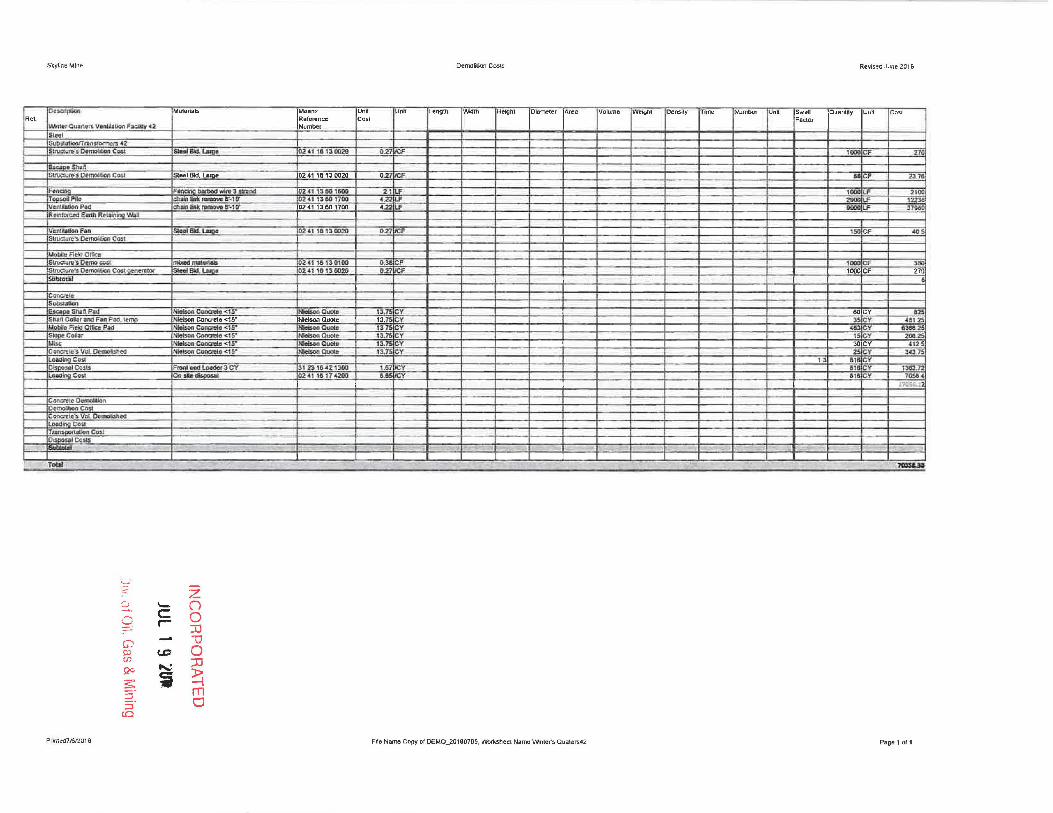
~.e-rQI./;.nors VemJ.b Fxbt;"2 Number
SINI SUb:SIu.th;l(1J"rf1lll~DITl'lCB.c2
SUuclute:'s OenlOltbn C.Da "",,"Btl.LaI{}& O~'11a 130020 021 CF !J1!1!l CF ~a
ec.ac-o SInII'I: Stt\Od" ... ~ 0.",0"" '" C ... stooIBld.~ 024116130020 021 e.- •• CF 23_18
Fal'l~ " ___ 3_.001
024) 13501_ ", LF '000 LP 2111Cl TOj>>OiPlic chl:ln"~G"·10" ~'" \318C·11'OO 422 U' ~lF 12.U1! V~~P"!:I cn...IiAiiflknmo....aS"·ur 02'" 138111100 4.22 LF 11000 U' ~1115O fil.~ Earth R~I~~ 'MIl E!
V~~lr:ulon FiSn SloolBl<l.I..Iaoa 02', ,a"\3 0Q3) 021 :f' ,. CF 40S SllUCUI~':s Ocmal.tIan COli
/,40""'I'ld<!O_ ~fII'!iIDl!mo~1 mbI:cd I'IWIIrl.ab ~"t 18 130100 O.~ Il. 1000 eF 3"
In.J,c::UfIlI"lI OemofjJcn Cosl ·Oft'I,tl:tlX _BId . ....". 10241 1613 DOlO 021 CF 1000 CF 27n bhl:ctil 6
CG"nQ'CJa: SLf{b"I.Uoil E>cooo s .. np •• .._ Coocni1<o <1S'
_0 .... IU_ Y I BOCY 125
sn.an Cclllllnoo F:a.n Foo.. [ Concnrte <15- Nielson Quote 13.75 CY 35 CY U1Ui Mobllof;tlOOlfit:<P" Wsoa~OIoC.1s""
_CIIOio 131 Y 40: CY eWl25
SIooeC .... -.... Coo<n1I. <1S" _Quo<.
13.75 CY nCY 200.2S ~IC 11_ Cona.IO <1S" -Quo!. 13.1 CY 30 CY 4125 Concrato); Vgt DHnObt'led _Co_~I~' N_OuoIo 1:US CY 25 Y !4l75 L06D"In!')O:K1 13 ala CY Ob:opo,1ll Cc!15 F"",I IIOd l.Go6ot 3 CY 31 23 'uS <112 "\:100 !.a7 .'~ cy Il&l:7l LOIllOr.,g C01J anJSl.~ 0241 181 74200 a .,. elY 7Me<
1711S6 ••. 1
COtV.n!tl! OttmClitJon
OcmoliJo<1 Ca>l CO\X-"IIlc~ Vol DI.rnobbtG la.:M:Ilno COil TIlII1 n Co>! D,,-,I CC ..
- -- ~- ; 1 I , C - , - ' -. T_ - --
2: Z ::; '-" 0 0 C 0 r- ::0 G) -a Cl C.D 0 (f: :IJ !2C ....:. s: ~ ~ 2. m ::J a
(C)
Pnll1ed7..1312016 File Name copy 01 OEMO_20160705. Worksheet Nama Wnter's QLJa\erM2 Page 1 011

Skylinll Mine Demolition Custs. Revised June 2(116
Oescflp1lon Malerhlls Means Unri Un' l ength wall> Height piam~lef A",. Volume We""" Oen~jty TrmB [N umber Unit rsw;'U Q uantity Una Cool R~'- Reference Cost Fado<
Nor1h 01 Graben B!~ederShatt 43 Number
s .... 1 I
V~I1I~UGa SnQ.ft I
"""' . .. fH:odlo * F81I..File:lG'::f1-ef1lorm' SloelBld. """" "'1"'30020 0.27 OJ' e.><l<l f 8500 CF 175!l
C .... IN IJIIItFEP4CE Cbiil lnHnk Removal 2 padsl 8'-'0- lI2 .. ' '3.eo HDO ~ • t.f " lUI
hainiink Ralls. Fence laD lind bottom nJU 41 13..62 .coo D.68 4 '11[ U' ~Il
Gaa'r!lt ~M3IUa1\ F_ 2" IN<I< and 3"_ Gala jIOd> ~ 411617 110W 2'11 U' 3 • U' 25.'11 COC"IICnItt'oll:!ri»llkin _ZUOckIUll!3"""""uno ..... U118 1711'" 2 1 U' :N U' 12241 L04d"W'tg Ceil ~-..,. rJC 3'2:3 1D4Z l:lDO Ie] Y 2.\ I. CY • Tj'DI~ bnCo')l 'lCY 18 "" "'""PTrui:k ,I2JI"""tin! ~1 ~23l:1)'OI' 2.~ lIV' Ol1pG$.,CaS(J C"" _ .PIICo. U1 OUI '817'200 H 2,1 21 CY
1 c~nRct~ , I-kIcb C-MP c:ulucn. fttnOv''' 2.1 I::U QlOO 1M u> .~ • U' IIIIl
I GATES I C:baio Ii It '~I11I~ 111 ........ _ ....... 1lldo Q2" 11S,e2.!I2IIO a:EA ~ EA 1II1II lalUlno Co:sa 31 23 11!1'42 1300 1.0 I . CY I !~.C4" • 2 CY (to Ton Dllmo T",'" '/2 mI. rOO. ~ 31 ~2J21I101' ~ I CY DBfIGdoQ!CQ f!j~ 'y -.... •. P1I<a. U1 Z4 D 1 42j)Q <.33 V \.6 Y
Vcr4l~b011 fon Re:l'T'Ii~:.aJ 001 Oemoe:tlGo ~".tt of ~0Yj' CIQUlpmaot U OS M .\O 3eOO 7~ '" . "" 1741J
lube.!" ,t;5::.S I
ConU131.
OIIOI!!d(tSblaflP;Q,d _~~15" '-QUoto ,''- y '"'C lOU,,5-1
c""em ..... J'I""""'C4_ •• ,~.
"'-~ 1 C ,tl< CY 2!I42.S
Fuel pad. ~ CGncrDte <1 .. NIeIsoo a""", 13.7 C 4 C Y 8.9 NIirIiSOe COQI:nto "'1 * .. _auoo. , 3Il oY 41111 N_conc:.-eIo<,5' Iobon Qual. 13 C
l a.c.ai'lgCOU 1.3 • OltPli~'J Co:.u FIOOI ""'......,...~ CY l 23 1D 4% 1'300 1.'11 :V ... CY 1000
LtlI4D:J eo,1 On,,"_ 411817<200 a.as :Y <III y 47&2'
i ul:ltOfill lOS3
. - . " .. -. .. --- TOld - ----- ---- -------- - - - ------ -- - - '- UlIS'I
. .-2' Z ~ '-' Cl C! C '-' .- U
:Il -(j)
--" -0 p) CD 0 (fl
90 .....:: :0
:s: i ~ 2: m ::J CJ to
Printed71612016 File Name copy of DEMO_2015D705. WoJksheaL Name NOG Blpeder shan43 Page 1 of'
Sk),lineMrntl Oemol~lon Casls. RI)w;cd June 2016
[)~ f.~btn:ll~ MOlim. LIn< \1M l l!nijUl iW"'" He;gtrt Cia-meIer An" alume WelQr\l Denslll' !Time! Number nn Sweij Quanflly Uno Cos1
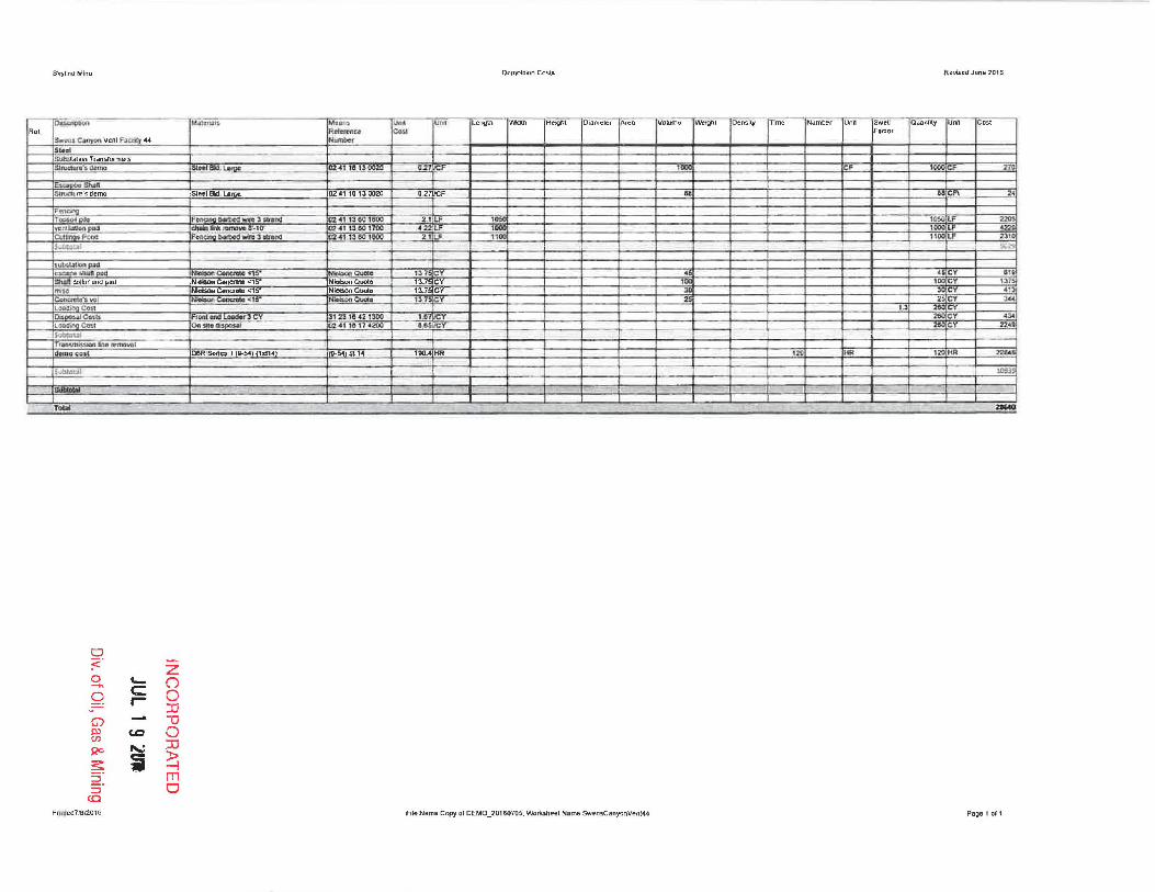
Re' RelcR'ftu C(I..'I.I Flildor Sw~:ii Canyoo Vent.'F.ucty <44 Number ... 1
SoAlalion Tr.msI0fTTJt!f5 8l.n ,cUn"5 Gtma _BIll. Lome 0'241101300.., a..27 F lODC CI' III< CF .270
"' .. 51\_. Jl!'S demo SI .. , BId. Lm\ie 0241 16130020 027 F 2. F_
r ... oiI""" Fonc::lnI:I~W'Itt!3S1t.DG 241 "ell 1Il00 2.1i.F 'PSO 10000lF 220' vCHtlJ.lga"npaa dl .... -"""" ... O··,D" 1c24' "00 1700 ' 22LF 100 1000 I.F 4220 ClAU..,.P" ".
1'.0 __ ...... 3_ 241 13 all IDOO 2.1L.F II 1100 I.F 2310
-.. .. 1 "'''' s~lI1lOr1lPK'
~naJ.mnlpti:ld ConctelCl~ CUOIo 13 :<r • • CY 8'9 sl1In collDr and ~d NIttbon C~e <.15· Nleboo Quote 13.75C I 1DOCY 1::nS .... Hlalson Cona1rle <15- NieIsof1 Cool. 13.7 C 3C 3IlCY ., CCll"Wntc", I0IO N'_Co<Ic:nlIo<1 S"" N.Wton Quale 13.7 C Y 2. 2! CY J4.I LoadinQ Cos. ..> 2II<l DcioO>iII CO<U I rleV 123'8421300 U l:Cy 26IJ CY- .34
'_"'11=' On$lCod" 2 .. , 1& 17 4200 1.65..w:·Y 2aIl CY 224"
Sv""" r.ao!.m~.!I,"'nlln.!lP'l!llXl'v.ll
demo COt' 08R~ II Q..54) 1stU 540114 190. HR 121) HI< lZC HR 2204
5lJb.tr..tll ID!Il , __ I, "
T .... '-.0 -- - - - - -
0 :;::. Z
0 '- (") -. c Q r- 0 JJ
G) lJ PJ c.c 0 (r.
$2C ~ :c s: ~ ~ 2: m ::J 0
CO
Pnn(ed7f512016 File Name Copy 01 DEMO_20160-f05, Wor1u.heel Nal"J)Q SwensCanyonVent44 Page 1 or 1


Skyline Mine
Skyline Mine Backfilling and Grading
Portal 01
ST-15Z 15CY
CLAB
--
o :C::.
8. Q G)
ffi S2<> ~ :J
Pmt"" 312016
to
-
'c: ,-
CD
~
Reference
Page
(21-10)
z () o :D '1J o ::c ~ m CJ
Year
(1st1~)
Hourly Operator 's
Equipment Op~rat;ng Equipment Hourly
Cost Costs Overhead WQaeRote
19140 1182.5 01 554
-- -
Earthwo<1< Costs ReViSed June 2016
Number Totol Equip +
Hourly a[Men Eq. & Lab. Production Labor
Cost arEa. Costs Units Quantity Units Rate Units Time/Dis. Un;ts Co.s-t
3051 1 305.1 SIHR 1674() CV 7915 CYIHR 211 HR 64J76
36.~ 05 18.33 $IHR 211 HR 3868
. - - --
68Z44
FIle Name Earlh_20160620 and lNor1<sheet Portal01 Page 1 011

Skyline MLne Ear1hwof1< Cosls Revised Juno 2016
~eference Hourly Operator's Number ToCol Equip. +
Equipmenr Operating Equipmen t Hourly Hourly a/Men £q. & lab ProductIon labor Page Year Cost Costs Overhead Wage Rote Cost or Eo. Costs Units Quantity Units Rate Units Time/Dis. Units Cost
Skyline Mine
Water Tank 02 026 areas
Backfilling and GradIng -
~
9B8G EROPS (9--37) (15114) 21000 11 9 32 01 52.25 31475 1 31475 SIHR 1683 CY 276.1S CY/HR 6HR 1J89 769D (20-11) (1sl14) 21000 11932 0.1 4915 31165 ~ 934.95 SIHR 6 HR 5610 Pid<up Truck Crew 4.4 1 Ion (20-17) ( lsl14) 1105 1555 01 4195 65JIE 1 65:96 SIHR 6HR 396 CtAS JE65 1 36.68 SIHR SHR 220 foreman Average, OLttsido 51 1 51.9 SlHR SHR 3U
Place Topsoil
769D (20-11\ (15114) 21000 11932 0 1 49.15 31165 1 31168 SIHR. 420 CY 92 CYIHR 4.6 HR lAM 968G EROPS (9-37) (1sI14) 21000 11932 0.1 5225 31475 1 31"-75 $Il:IR 46 HR 1448 DaR Series II (9-54) (15114) 19000 3S2.27 0.1 554 56165 0 o 5IHR 48 HR 0
CtAB 36.65 1.5 5498 SIHR 46 HR 253
410G EROPS 4V11O EXTEN (9-26) (ls114) 3E2O 27.05 01 S5A 10778 1 107.78 S/HR 03 AI; 1 AI;JHR 03 HR 32 CtAB JE65 1.5 54.98 $lHR 03 HR 16
-J Pid<uo Truck Crew 4x4 1 Ion (20-17) (15114) 1105 1555 0 ' 41.95 6596 1 65 96 SIHR 46 HR .1!13 Fomman Average. Outside 519 1 519 $IHR 4.6 HR 239
-- _.
U151
u ;2- Z 0 '- 0 0 C
--r- 0
:D G) ~
1J Cj)
c.c 0 S20 ~ :D
s:: i ~ 5'
P 5' m
nnted 1lII)'20 16 0
FIla Nama Earth_20160620 and Wo<1<shoal W.lerTank02 Page 1 of 1

Skyline Mine Earthwork COSIS Revised June 2016
Reference Hourly Operator's Number Total Equip. +
Equipment Operating Equipment Hourly Hourly a/Men Eq. & Lab. Production Labor
PI1!}e Yeaf Cost Costs Overhead Wllqe Rate Cost or Ea. Costs Units Quantity Units Rate Units Time/DIs. Units Cost
Skyl,'lII Mine Mlno Fao~uos Alan
Lower Terrace 03 Back/illing and Grading
PBR Seri.s II (9-54) (1sI14) 19000 35227 0.1 55 4 56165 0 O!$IHR 79 5 HR u
631G (9-51) 11s(14) 16500 9375 01 554 261-65 3 784.95 iSlHR 795 HR 61~(4
CLAB 36 65 1 36..65 ISIHR 795 HR 2:.914
Foreman Average. Outside 519 1 51._9 I$IHR 4(1 HR ~076
Pickup Truck Crew 4x4 1 ton [20-17) (ls114) '105 1555 0' 41.95 6596 1 65.96 :MiR 4Il HR 2633.
Pfu(;e Topsoil
DBR Series II (9-54) (1s114) 19000 35227 D.1 55 4 56165 IJ o ISIHR 211 HR 0
631G 19-51) (15114) 16500 9379 D_1 554 26165 1 261.65 IISIHR 211 HR 5521 CLAB 3665 1 36.65 ISIHR 211 HR 113
14H EROPS 19-11) (2H2014) 14500 82.39 0,1 554 23665 1 236.65 ISIHR 21.1 HR ~993
410G EROPS 400 EXTEN. 19-26) (15114) 3620 2705 0.1 55 4 107,78 1 107.78 ISIHR 21.1 HR 2274
ClAB 3665 1 36.65 ISIHR 211 HR 773
Foreman Averaf!e~ Outside 519 1 51.9 $IHR 211 HR lu<JS,
Pickup Truck Crew 4x4 1 ton (20-17) (15114) 1105 1555 0_1 4195 6596 1 6596 S/HR 21-1 HR l3n.
SUbfolal U1J
0 ~.
Z 0 '- () -- c: 0 0 r- ::D G) "0 III (D 0 (f) ::D QO ...:. s: i ~ ::!. m ::l CJ
CO Pnnled 716/2016 File Name Eat1h_2016062O and VIiofksheel lowerTerrace03 Page 1 ofl

Skyline Mine Earthwolk Costs Revised June 2016
Reference Hourly Opera for's Number TMal t-qulp +
EQUipment Operatmg Equipment Hourly Hourly a/Men Eq, & lab. Production Labor
Page YeGr Cost Costs Overhead Wage Rate Cost orEq_ C05tS Units Quantity Units Rate Units Time/Drs. Units Cost
Skyline Mine M ino FaCIlities Area
Middle Bench 04
oaR Serio. II (9-54) 15t14) 19000 35221 01 55.4 561.65 1 561.65 S/HR 122.48 HR 63]80
631G (9-51) (15t14) 16500 9375 01 55.4 261.65 3 784.95 $lHR 122.48 HR 96125
CLAB 3665 1 36.65 $IHR 12248 HR 4~(,~
foreman Average, Outside SUI 1 51.9 $IHR 61 HR 315~
Pickup Truck Crew 4x4 1 ton (20-17) 11st14} 1105 1555 01 4195 6596 1 6596 $lHR 61 HR 40, ~
PI"". Topsoil
D6R Series II (9-54) l.t14) 19000 35227 01 55." 561 .65 5 2BOB.25 SIHR 20.9 HR S8S9Z
631G 19-51) (1st14) 16500 9375 01 554 261 .65 1 261.65 SII:IR 20_9 HR 54S~
CLAB 3665 1 3865 $lHR 20.9 HR 1£a
14HEROPS (9-11) (2H2014) 14500 6239 01 554 23665 1 23IL65 $IHR 209 HR 4940
410G EROPS 41t\ID EXTEN (9-2B) (15114) 3620 2705 01 55.4 10776 1 ,107.78 S/HR 20.9 HR 2253
etAs 3665 1 36.65 $lHR 209 HR 766
Foreman Average. Outside 519 1 51.9 $lHR- 209 HR lUB~
Pickup Truck Crew 4x4 1 ton 120-17) (1st14) 1105 1555 01 4195 65.96 1 65~ $IHR 20.9 HR 1379
~
Z5UiI8
0 :;::" Z ~ '- ()
0 <= 0 r- :n G) "'0 ~ CD 0 en :n QO '" s: i ~ 5" m S" 0 tC
Pnnted 7/612016 File Name Earth_20160620 and VIIoIksheet Mlddl.Bonch04 Page 1011

Skyline Mlne EanhwO<1< Cosls ROVlsed Juno 2016
Re/e renCf!! Hourly Operator's Number Tata r Equip +
Equ ipment Operating Equjpment Hourly Hour1v ofM~n Eq. & Lab Production Labo,
Page Year Cost Costs Overh~ad Wa ge Rate Cost or £'1. Costs Units Quantity Units Rate Units Tim';Ois Units Cast
Skyline MinD Mine Facilities Area
Upper Bench West Fork 05
DBR Sooos" (9-54) (lsI14) 19000 352Zl 01 554 S61.S5 1 S61.55 $IHR 315 HR 210G;;
631G (9-61 ) (ls114) 18500 9315 0 1 554 261,65 3 784.95 lsIHR 375 HR 29436
CLAB 36.65 1 36.55 SlHR 375 HR B74
Foreman Average, Outside 519 1 51.9 ~ 19 HR 98t Pickup Truck Craw 4x4 1 Ion (20-17) (15114) 1105 1555 01 4195 5595 1 65.Qe $IHR 19 HR 253
Place Topsoil
D8R Serios" (9-54) (ls114) 19tJOO 352.27 0.1 55." S6165 5 280825 $IHR 23.7 HR ti6SSfi
1631G (9-511 (15114) 18500 93.75 01 55.4 261.65 1 261_65 SlHR 23.1 HR 62Dl
CLAB 36.65 1 36.55 So4iR 237 HR 869
14H EROPS (9-11) (2H20141 14500 B2.39 0 1 554 23665 1 .236_65 SIHR 952 HR 2253
410G EROPS 4WD EXTEN 9-26) (ls114J 3620 ZlOS 0.1 55." 107.78 1 107.78 So4iR 952 HR lOr CLAB 3665 1 3655 $IHR 952 HR '4. Foreman Average Outside 519 1 51.9 $,iHR 237 HR 123'
Pickup Truck Crew 4x4 1 Ion (20-17) (l sI14) 1105 1555 01 4195 65.91; 1 6595 SIHR 237 HR 1563
.
134158,
0 <: Z 0 '-- () --~ C 0 r- 0
::IJ G) - -U tu (.Q 0 (J) ::IJ S2C ~
~ i ~ ;:J m 5" 0 to
Pnnlod 7/6/2016 Fllo Na"," E.rth_20160620 ond 'Ml<1<shool UppereonchWsslFO<1<05 Page 1 or1

Skyline Mine E.rthwOf1< CoS!S ReYlsed June 201 6
Hourly Operator's Number Total Equip, + Reference
EqulpmefH Ope-rating Equipment Hourly Hourly a/Men £q. & Lab Production Labor
Page Year Cosr Costs Overhead Wage Rate Cost or Eq. Costs Units QUDlltit}! Units Rate Units Time/Dis. Units cosr
Skyline Mine Mine Facilities Area
Upper Bench West Fork 05
D8R Senes II (9-54) (ls!14) 19000 35227 01 5sA 56165 1 561.65 iSIHR 375 HR 2.05J
1631G (9-51) (lsI14) 16500 9375 c, 554 26165 3 78495 SIHR 375 HR l",t> CLAB 3665 1 3665 t.tIR 37.5 HR 137" Foreman Average, Ou's~e 519 1 ~1. $IHR. 19 HR 981>
Picku.D Truck Crew 4)(4 1 (on (20-17) (1.114) l10S 1555 01 4195 6596 I 65.96 SIHR 19HR :2,3
Place Topsoil
DBR Series II (9-54) (1.114) 19000 35227 01 554 561 .65 5 280825 SIHR 23.7 HR 665~) :..
631G (9-51) (l.tI4) 16500 9375 Q 1 55 4 261 .S!:! 1 261 .65 SIHR 23.7 HR OlD (
CLAB 3665 1 36.65 WR 237 HR ,t/.; i)
14H EROPS (9-11) (2H2014) 14500 82 39 01 554 23665 1 236.65 $IHR 9.52 HR 2253
410G EROPS 41Ml EXTEN 9·28) (15114) 3620 27 05 01 55.4 107.78 1 10778 SIHR 952 HR 102;
CLAB 3665 1 3665 S/HR 952 HR 34Q,
Foreman Average, Outside 519 1 519 SIHR 237 HR 23!J'
Pickup Truck Crew 4x4 1 ton (20-17) (lsI14) 110S 1555 01 4195 65,96 1 65.96 S/HR 237 HR L:ib>
I
-D4158
::J :C. z ~~ '- (")
0 C 0 r-- :D G) "tl ll) CD 0 (Jl :D $20 ....::
~ ~ ~ ::!- m ::J 0
CO
Pnnled 7/612016 File Name Earth_20160620 and \NO<t<sheet UpparBenchWeslFOfI<OS Page 1 of '


Skyline MlI1e
Skyline Mine
Loadout Fadities 07
B •• kf1lllng and G~lng
bBR Series II
631G
CLAB
Foreman Averago. Outside
PlCIwp Tt\JCk CrllW 4x4 1 ton
Topsoil
1631G
D6RSanes II
CLAB
,4H EROPS
410G EROPS 400 EXTEN
etAS Foreman Average Outside
Pickup Truck Crew 4x41 Ion
lsubtatlll
:-:1 <: z 0 c.- O .....
C 0 0 r-JJ
G) -0 Pl ~ 0 (J)
::IJ s;.>c> ..... : ~ ~ ~ 5 - m 5 - 0 (0
Pnnlo>d 71612016
Reference
Paqe I Year
(9-54) 1(15114)
(9-S1) 1(15114}
(20-1711 (lstI4)
(9-51) 1(1.114)
(!J..54) 1(1511 4)
(9-1') 1(2H2014)
1(9-2.B) II lsl'4)
(20-Hl l [1sI14)
Equipment
Cost
19000 16500
n os
16500
19000
14500
3620
1105
Hourly
Operating
Costs
35227 9375
1555
93 75
35227
92 39 27 OS
15.551
Equipment
Overhead
01
01
01
01
0 1
01 0.1
0 1
EarthwOf1< Cosls
Operator's
Hourly
Wage Rate
Number I Total
Hourly I of Men Eq. & Lab
Cost or Eq. Costs Units I Quantity I Units
5541 56165 561.65IS1HR 5541 261.65 3 784.9SISIHR
3665 36.65I$IHR 5H 51 .GJ$IHR
41.951 65.96 6596ISIHR
5541 261_65 784.9SISlHR 55-41 561.65 561.65!siHR
36651 3665tSIHR
55 ~1 23665 236.651S/1:1R 5541 10778 107.78IS1HR
36.65 36.651SIHR 519' 5j s lSIHR
41951 65 ,9E 65961&11:!.R
F,I. Name Eal1h_20160620 and VIIo<1<sheel LoadoutFaclillOs07
Production
Rare
Equip. +
Labor
Units I Time/ Dis. Uni t's
ee SIHR ee alHR ee 81HR
44IHR 44IHR
28.41HR 2841HR 28.41HR
2841HR
28411'iR 2B41HR 28.4IHR
28.IHR
R.Vlsec June 2016
Cost
49875 69104
3255 2284 290
22293
1S9S~
104
67U 30U 104 1414
1873
181.475
Pag.1 of 1

Skyline Mine EarthwO<1< COSIS Revised June 2016
Reference Hourly OD~'Qtor's Number Total EqUJp +
Equipment Operutmg Equipment Hourlv Hourfy at Men £q, & lob. ProductIon t.abor
Page Year Cost Costs Overht?ad Wage Rate Cost ortQ. Casts Units Quanrity UfJlts Rote Units rime/Dis. Units Cost
Skyl ine Mine
South Fork Portal Area 08
Backfilling and Grilding
CAT 345BL II (10-23) (l sI14) 17095 1131 01 55.4 2B665 1 296,65 $IHR 252 HR 7224 I6x4 70,0001bs 12-18 CY (20-1 1) (l sI14) 4410 6345 01 554 15216 2 305.52 $MR 252 HR 7699 ~GEROPS (9-37) (ls114) 21000 11932 01 52,25 314.75 1 31475 $IHR 252 HR 7932 D6R Series II (9-54) (l sI14) 10800 6136 01 554 190 4 1 190.4 $IHR 252 I-IR 4798 PickuD rruck Crew 4x4 1 Ion (20-17) llsl14) 1105 1555 01 41.95 6598 1 65,96 SlHR 252 HR 1662
CLAB 36~6!! l~ _54-98 $Il:!R 252 HR 13~ Foreman Average Outside 51 9 1 51,9 SlHR 252 I-IR 1308
Topsoil
988G EROPS (9-37) (lsI14) 21000 11932 01 52.25 31475 1 314,75 SlHR 3S82 HR 1U74 D6R Series II (9-54) ( l sI14) 10800 6136 01 554 1904 1 1904 SlHR 3562 HR 6IIZO:
14H EROPS (9-11 ] (2H2014) 14500 8239 0,1 554 236,65 1 236.65 SlHR 3562 HR 84n' 410G EROPS 4'MJ EXTEN (9-28) (ls(14] 3620 2705 01 55,4 10778 1 107.78 SlHR 3582 HR 3861
PIckup Truck Crew 4x4 1 Ion (20-17) (ls114) 1105 1555 01 4195 6596 1 65.96 $lHR 35,82 HR 2363
eLAS 3665 1 3665 SlHR 3582 HR 1313 Foreman AVer.:I'Je. Outside 519 1 51 ,9 $lHR 3562 HR 1lIS9
- - -- -- ~- .-
61915
0 '2' Z <3 .. I- 0 0 C 0 r- :D (j) "'0 ~ CD 0 CFl
S20 ~ :JJ
~ i ~ ;J m S· 0 (0
Pnnled 71612016 File Name Earth_20160620 and Wor1<sheel SoulhFo",PortalAreaOB Pagel of 1

Skyline Mine Earthworl< Cos Is ReVised June 2016
Rf1erence Hourly Opera tor's Number ToCa} EqUIp . +-
Equipment Op!'roting Equipment Hourly Hourly a/Men £q. & Lab Production Labor
PQQ~ Year Cost "'.IS Overhead W-Dge- Rate Cosr or fq~ C",," Units QuonUl)l Ufll ts Rore' Units Ti~/O ... Unjr. (0$1
Skyline Mine
Waste Rock Disposal 09
e.ck/liling and Gndlng
CAT 345BlII (1(1.23) p .11 4) 17095 113 1 0.1 55. ~ 286.SS 1 286.SS SIHR 45 IiR 12.90 6)(: 70 OOCIbs l Z-18 CY (2(1.1 1) (10114) 4410 63~ 01 554 152.76 2 305 52 $lHR 45 HR 1375 geilG S""1I5 II EROPS (9·37) 0 51141 1300C 73.86 01 554 217 9 I 2179 sn-!R 4 5 HR 981 06R Series II (9--54) (1<114 ) 10000 61 .:16 01 554 1904 1 190.4 $lHR 45 HR 857 P!d<U1I Truck Cmw 4x4 1 Ion [2()..11) ( 15114) 1105 15.55 01 4t95 SS-,-96 1 ~ ~. 4 5 HR 29l
In 511u TopspoU
CAT 345BL II (10-23) (15114) 11095 1131 01 -S5..4 _ ,SS 1 286.SS SIHR 20.9 HR S99-.! 6X4 70.00c1bs 12-1 8 CY (ZO-11 ) (1$114) 4410 63~ 01 55 4 152.76 2 305:52 S/MR ZO.9 HR 6185 9SOG Serios II EROPS (9--37) (15114) l 300C 1386 01 55.4 2179 1 2179 S/MR Z0 9 HR 4SS4 D6R Series II (9-&1) (15114) 101100 61.36 0 1 554 1904 1 190-4 $IHR Z0 9 HR 3979 PIC!<U1I T!1Jck Cmw 4x4 1 Ion (20-17) (1.114) 1105 1555 01 41...95 SSJl!i 1 65.96 $IHR 209 HR 1379
Toj>5Oll l'loco_nt
6X410.000lbs 12-18 CY (2(1.11) lst l4) 4410 63.45 01 55.4 152.76 3 458 28 SlHR 2798 HR l2822J B86G EROPS (9--371 (1$114) 21000 119.32 01 52·25 31475 1 31.(76 $IHR 279.8 HR 118067 ClAB 3665 1 36.6 SIHR 279.8 HR 10255
14H EROPS (9-11 ) (2H201 4) 14500 82.39 0 1 55_4 236 SS 1 236.65 SlHR 279.J HR 6621S 410G EROPS 4WD EXTEN (9.28) ( 1ot lo1) ~ 27.05 01 554 10778 1 1()7-78 $IHR 2T9.S HR 3OJS7 Pdwp Truck Crew 4x4 1 ton (10-17) 11.114) 1105 1555 0 .1 41 95 SS.96 1 e5:96 ISIIiR 2798 HR 18456
F MlmiI<I Average. Ou\s;de 51_9 1 51 .9 $IHR 2798 HR lAS22
'----- --- - - - '----- - L _ - '----- - _._-- - -- -
SUIi4Ol:ll 382981
0 < 0
Z ->. "-
_9 c (')
r- 0 :D
G) lJ Q> U>
c.c 0 Qo ,,~ :D
~ ii ~ 5- rn 5'
PnnlefM)s,2016 0
File Name Earth_20160620 and Wor1<sheel WasleRockDlsposalO9 Page 1 of 1

Skyline Mine Ear1hwor1< Cost. Revised June 2016
Reference Hourly Operator's Number Totol Equip_ +
Equipment Operating Equipment Hourly Hourly aIMen £q. & Lab. Production Labor
Page Year Cost Casts Overhead Wage Rate Cast orECJ_ Costs Units Quantitv Units Rote Units Time/D;s_ Units Cost
Skyline Mine Interim Sediment Control
loadoul Facilities Sediment
Pond Enlargement Interim 10
960G Series II EROPS (9 -37) (1.114) 13000 73B6 01 554 217 9 1 217,9 $IHR 43 HR 931 CLAB 3665 1 .36.6!; $lHR 43 HR 158 Foreman Average, Outs ida 51 S 1 51,9 $/HR 43 HR 223 Pickup Truck Crew 4x4 1 ~ (20-17) (15114) 1105 1555 0.1 4195 65.96 1 65.96 ~ 4.3 HR 284 - - -
SUbtotal D
0 <:
0 Z
~ (") - c: Q r- 0 JJ
G) -0 til tD 0 (f)
R<> ......: JJ
:s:: ~ ~ 5' m
Pnnted 7~D1 6 0 File Name Earth_20160620 and 'VVorksheet PonclEnlargementlntenm 1 a Pagelof1
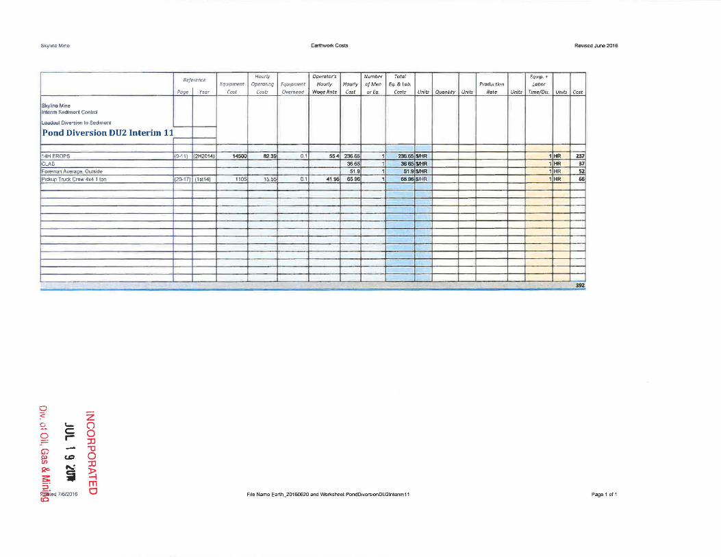
Skylrne Mtne Earthwot1< Costs RevIsed June 2016
Reference Hourly Operaror's Number Tota l EQIJ;p. +
fquipment Operarfng Equipm~nr Hourly Hourly o/Men £q. & lob. Production Labor
Page Yeor Cost Costs Overhead Wage' Rare Cost DrEQ. Costs Units Quanti ty Units Rate Units Tim~Dis_ Units Cost
S~ylinO Mine
""""m Sediment Control
LDad<>.ol Diversion to Sedim ent
Pond Diversion nU2 Interim 11
14H EROPS (9-11) (2H2014) 14500 8239 01 554 236.65 1 236.65 SIHR 1 HR 231 CLAB 3665 1 36.65 S/HR 1 HR 31 Foreman Average Oulside 519 1 61 .9 $lHR 1 HR S2
Pickup Trud< Crew 4x4 1 Ion (20-17 (1.114) 1105 15>55 01 4195 6596 1 65.96 $lHR 1 HR 66
392'
Q ~ Z 0 \- (') - C 0 r- 0
:II G) ""0 III CD 0 en R<> ...... :II
s: ~ ~ ;5- m Fiiied 7/612016 a !O
FIle Name Earth_20160620 and VVOrksheet Pondo.verslOODU2tntenmll Page 1 of 1

Skyline Mine
Skyline Mine
Interim Sediment Control 12
SJlckflll Pond Wilh
Emb""kment M."'f\;I.l 988G EROPS
CLAS
Foreman Average. Outside
Pickup Truck Crew 4.4 1 Ion
Topsoil Placement
1Ft Depth
988G EROPS
CLAS
Foreman Aver.age, Outside
PickuD Truck Crew 4x4 1 ton
Diversion Removal CU2
14H EROPS
CLA8
Foreman Average, Outstde
Pickup Truck Craw 4.4 1 Ion
0 :c:' 2-Q G) W (f)
S2C :s: 5" S" ec
~ c .--CD
.....: ~
Pnnted 7/612016
z () o ::D "'0 o ::D
~ m o
RfOJerence Equipment
Page YeDr Cost
(9·37) (15114) 21000
120·17) (15114) 1105
[9-37) (1 5114) 21000
(20.17) [1 5(14) 1105
(9·11) (2H2014) 14500
[20·17) (lstI4) 1105
EarthworK Costs RevI5ed June 2016
Hourly Operator's Number Tatol Equip + Operating EQujpment Hourly Hourly at Men fQ & lab. Production Labor
Costs Overhead Woqe Rare Cost or El1 __ Costs Units Quantity Units Rote Units Time/Dis_ Units Cost
11932 01 5225 314.75 1 ~14:75 SIHR 68 HR Z140 3665 1 3665 ~R B8 HR 149 519 1 519 i$IHR 6.B HR 353
15.55 01 41.95 6596 1 65,96 SiHR 6.8 HR 449
11932 01 5225 31475 I 314,75 5IHR 22 HR 692 3665 I 36.65 ~R 22 fiR 81.
519 1 51.9 $MR 2.2 HR 114 1555 0 1 41.95 6596 1 65.96 $lHR 22 HR 145
~
8239 01 554 236.65 1 23665 $lHR 1 HR 237
36~ 1 36.65 $IHR 1 HR 37
519 1 51,9 ~ 1 HR 52
1555 0. , 4195 6596 1 65,96 $IHR 1 HR 66·
46lS:
FIle Name Earth_20160620 and Worksheet IntefimSedlmentControl12 Page 1 ofl

Skyline Mine E.rthwork Cosls ReVISed June 2016
Reference Hourly Operator's Number Total Equip +
Equipment Operating Equipment Hourly Hourly o/Men Eq. !I lab. Production Lobor
Paqe Year CV5t Costs Overhead Wage Rote Cost orEq Costs Units Quantity Units Rate Units Time/Dis. Umts Cost
Skyline Mine
Overland Conveyor 13
6X4 70,OOOlbs 12-18 CY (20-11] (15114] 4410 63.45 0.1 554 15276 1 152.76 S/HR 23 HR 351 988G EROPS (9-37] (15114) 21000 119.32 01 5225 31475 1 314.75 S/HR 23 HR 724
CLAB 3665 1 36.65 SiHR 23 HR 114 Foreman Average, Outside 5H 1 51..9 $II:lR 2,3 HR 1U Pickup Truck Crew 4x4 1 Ion (20-171 [1.114) 1105 15.55 01 41 .95 65.96 1 65.96 :SIHR 23 HR 151 410G EROPS 4Vv'D EXTEN (9-28l (1sI14) 3620 2705 01 554 10778 1 107.78 lSIHR 23 HR 148
!iIlbtolOI 161.
CJ ~. Z 0 '- (") - C 0 9. r- :0 - "0 0
"' 0 P> :0 CFl .....:. ~ $20
~ s m 2: a :::l
pnnl • .Hilol2016 File Name Earth_20160620 and Worksheet OvertandConvoyor13 Page lor,
Skyline Mine Ear1hWOfI\ COSIS Revised June 2016
Reference Hourly Operators Number rolal Equip + Equipmenl Operating Equipmen1 Hourly Hourly 01 Man Eq, & Lab Produclion Labor
Page Year Cosl Costs Overllead Wage Rale Cost orE", Costs Units QuanlilV Unit. Rate Un~s TIme/Dis Unils Cost
James Canyon 14
See Demo wOfksheat
21-101 15114
SU!tota/ - I' 'j' -
CJ :;::" 0 C0-
2 - () 0 c: . r- 0
:D G) '1J Ol en (D 0 QO ""
:D
s:: i ~ ~: m
0 PnnloQ:Zl6l2016 File Name Earlh_20160620 end VIIor1<sheat JamesCanyon14 Page I orl

Skyline Mine
Reference Equipment
Page Year Cost Winter Quarters Ventilation Facility 15
Sealing S/laft
(+) 6 inch rock 20 38
2: Inch - 4inch Rock 2929 Gra>el 2929 Sand 23,Q!! Bentonile 21·10 1sl14 3535 Concrete 120 Fill Malerial 7 0 6R Saies II IS-54 ,.114) 10800 Eo Op Medium Equlmenl
~'V:Ol<:l'
S1Ialing Es<~J!G SI>oI\ + 6 loch rock 2038
2.inch .• inch Rock 292 Gravel 2929 Sand 2308 Bentomte 3535 Concrete 120 Fi l Molerial 7 5>.Jb;o~
Cementateous Groul 125 Benlooite 35.35 Concrete 120 Fj lMillenal 7 06R Series II !J.54) 15\14 l 0a00 Eo. Op medium equipmenl
~tnnr.'li
Ilackfiliing and grading CAT 3451lL II 10-23 (15(14 17095 P6R Series II 9-54 1s114 l 0a00 Pickup Truck Crew 4x4 1 Ion 20·17 15(14) 1105 eLAB Foreman Averaae. Outside
Suh!iJt<.l1
~t D6R Senes II 9-54 1st14 10800 PickLI.P Truck Crew 4x4 1 ton 20·17 15114 1105 e LAS Foreman Average, OutSide
$ubtot~t -!fO!~ ': ___ . -~- ---.-----. - -- ~
Pnnle<J 7/612016
o <: g" o 1:."') 0-m Qc
~ ~"
5" ec
'C r-
CD
~
ii
z (") o :0 "1J o :IJ
~ m a
Hourly
Operating
Costs
6136
61 ,36
1131 61,36
1555
6138 1555
..
Earthwor1< Cosls Revised June 2016
Operaror's Number Total Equip, +
Equipment Hourly Hourly of Men Eq & lab, Production Labor
Overhead Wage Rat~ Cost orEq. Costs Units Quantity Units Rote Units Time/Dis. Units Cost
2038 1 2038 CY 283 283 CY 5768
2929 1 29.29 IJ.<' 95 95CY 2783 2929 1 29,21; cy 614 614 cy 1798<\ 23 CIS , 23.tlE CY 47 47 CY 1085 3535 1 35.3! cy 127 127 CY 44B9
120 1 121 CY 114 114 CY 13680 7 I cy 2839 2839 CY 19873
01 55. 1904 1 1911 HR BO HR 1 80 HR 15232
6172 6172. 1 61;7 HR BOHR 1 IlO HR 4!!38 g583~
2038 1 20,38 CY 32 32 CY 652 292 1 29 CY 105 105 CY 301
2929 1 2929 Cy' 213 213 CY 6239 230e 1 23.oe CY 5 CY 115
35.35 1 35.35 CY 22 22 CY 178 120 1 120 CY 30 3C CY 3600
7 , 7ey ~3 323 CY 2261
13952
12,§ , 125 Cy 89 89 HR 11125 35.35 I 3535 CY 45 45 HR 1591
121l 1 120 CY 11.5 115 HR 1380 7 1 cy, 4<15 ~ HR 3115
01 554 190·4 , 1004 HR ao HR BOHR 15232 61.42 1 6L~ HR. BO HR IlO HR 4!!14
3'/35J
" 01 554 286.65 1 286.65 HR 12HR 3440 0.1 55A 19O.A , ·190. HR 16 HR 3046 01 4195 65.96 1 65.95 fIR 20 HR 1319
36.65 1.5 54.95 HR. 20 HR 1100 51, 1 51..9 HR' 20 HR 1038
9943
01 554 190 4 1 190.4 fiR 20HR 380e
0' 4195 65.96 1 65,96 HR 20 HR 1319 36.65 , 36.65 HR 20 HR 733
51. 1 S1<Jj HR 20 HR 1038 6898
" " , 'l:: . ~ , ~ ~ .. ~ .. r . ~~~ - - _. - .. l.
FIle Name Earth_20160620 and Worksheet VVinter Quarters venlllatlOfl Page 1 of 1

Skyline MIne Earthwork Cosls RevISed June 2016
J Hourly Operator's Number Total Equip ~
Reference EqUJpme-nt Operatmg Equipment Hourly Hourly atMen Eq. & lab. Production Labor
Cost Costs OVerhead Wage Rote Cost orfa CDSts Units Quantity Units Rate Units Time/Dis. Units Cast
North of Graben Bleeder Shan 16 Page Yeor
Sealirl.9.Shall -.. 6 inch rock 2038 20.38 , 20.38 r:v 27 27 CY 550
2 Inch • 41nch Rock 2929 29.29 1 29.29 CY 9 9CY 264
Gravel 29 2S 2929 , 2929 CY 179 179 CY 5'243 Sand 2308 2308 , 2308 I':'f 4 4 CY 92 Bentonite 3535 3535 1 35..35 r:v " 19 19CY 672 Concrete 120 120 1 120 r:v 25 25 r:v 3000 FtiL Material 7 7 1 7 r:v 1656 1656 CY 11592
Gener;alfll l by dozer 312323170320 1.67 CY 6739 CY 5739 HR 126/12 Sl..'bto~a' 3401 5
SvotNul
5(Jtrtot;::a~
Backfilllnq .nd grading CAT 345BlII 10·23 1..114 17095 1131 01 554 292 'ill 1 292·97 HR 12 HR 351 6 08R Series II 90S<! 15114 19000 35227 0.1 55.<1 &42.'ill 1 &42<'ill HR 1 HR 102.1!8 Pidw» Truck Crew 4.4 1 ton 20-17 1st1 1105 15.55 0.1 4195 83~ I 83.28 I-lR 20HR 1666 CLAB 36.65 15 ~98 HR 20 HR 11 00 Foreman Average, Outside 519 1 7635 HR 20 HR 1527
S-,b· o.!.ll 1809"1
TOIl,oil DaR Series II S-54 ,.114 19000 352.27 0.1 55A &42..97 1 642.l17 HR 20 HR 12859 Pickuo Truck Crew 4J<4 1 too 20-17 lstl 1105 1555 0 1 41 .fl:5 8328 I 83..28 HR 20 HR 1666 ClAB 36.65 1 36,65 HIt 2Q HR 73.3 Foreman Average. Oulside 51 .9 1 76.35 fiR 20 HR 1527 S:..Jb~otdi 1618S
mAL . . - -. - - .,; -----~ - ------ - - ~.-- -- - - ,
,
C) '-
:z
2 c:: ()
r- 0 G:'
:0 Pnnled 71612016 -0 File Name Earth_20160620 and Wor1<sheel NOG 16 Pagel 011
Q) ef) c.o 0 Qc "'-: :0 ~ i l> 5' -i m s- O CO

Skyline Mine
Swens Canyon Ventilation Facility 17
Sealing Shaft 16ft 0 + Slnch rock
2 Inch - 4inch Rock Gravel Sand eenlonite Concrete
General fill bV doz.er
5ubtot,"l1
Sut.':vtai
Sl.-1:)tot~1
B.ckfDlIng,and g •• ding CAT 3458lII DBR Series U PICkUDTruck. Crew 4x4 1 Ion CLAB Foreman Averaqe. Outside
SubtotZl I
Topsoil OaR Series II P>ekuD Truck Crew 4.1<4 1 ton CLAB Foreman A'Io!eume Oulslde Sr,.;l':lwta\
~~N.
Pnnled 71612016
o :;::.
8.. o G) m en S20
~ ::!. ::I
CO
tC r-
CoD
..... : ij
I Reference
EquJpment
C05t
Page Year
20.38
2929 2929 230B 3585
120
312323 17 0320
lG-23 94l 2!}.17
9·54 20·\7
z (") o ::0 1J o ::0
~ m o
1.114 17095 l!i11 4 1!1OOO 1011 1105
tol14 19000 1.11 l1 D5
Hourly
Operating
Costs
113 I 35227
15.65
35227 15..55
Earthwor1< Costs RevISed June 2016
Operator's Number Tot.! EquIp +
Equipment Hourly Hourly afMen £q. & l.b Production Labor
OVerhead Wag-eRate Cost orEq. Costs Units QUantity Units Rate Units Time/Dis. Units Cost
20 38 1 ,20.38 CY 226 CY 226 CY 4606
2929 1 29.29 CY 76 CY 76 CY 2226 29 29 1 29.29 CY 491 CY 491 Cy 14381 2308 1 .23.08 CY 38 CY 38 CY 677 35.35 1 35.85 CY 1(12 CY 102 CV 3606
120 1 120 CY 91 CV 91 CV 10920
1.1J7 CV 7074 CV 7074 HR 13226
49844
I
I
01 554 29297 1 292.97 HR 1 HR 3516 0.1 654 642.97 I 642.97 HR 161-lR 10288 01 4195 83.28 1 83.28 HR 20HR 1668
36.65 IS S4.9S HR 20HR 1100 51 .9 1 76 35 HR 20 HR 1527
1S091
01. 654 642.97 I 642.97 HR 2Q HR 12859 0.1 41 95 B3 2S 1 B3..28 HR 20HR 1666
36.65 1 36.65 HR 20 HR 73-.1 51 9 I 76.35 HR lO HR 1527
1678,. • ~- !. .. ... , . :JmIIII
File Name Earth_20160620 and Wo!\<sheel SwensVenll7 Pagel of I

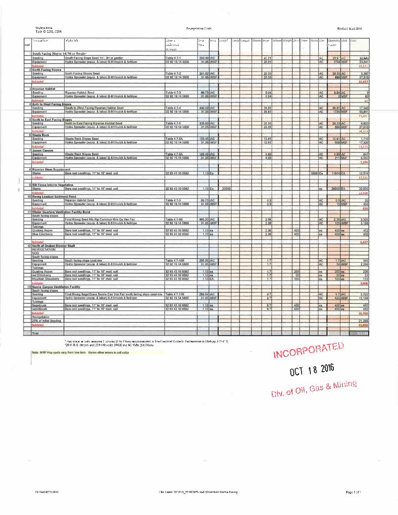

•
4.4 BACKFILL, SOIL STABILIZATI N, COMPACTION, CONTOURING AND GRADING
The objective of the propo backfilling, soil stabilizing,
compacting, contouring and rading process is to achieve a
reclaimed surface which will provide a variety of topographic
features effecting enhanced po tmining land use.
Reclamation earthwork activities will be conducted as outlined in
sections
TIMETABLE.
4.12--POSTMINING
The steps to
LANDUSE AND 4.2--RECLAMATION
e taken in the backfill, soil
stabilization, compaction, c ntouring and grading program are
described in the following sub ections.
4.4.1 Backfill and ion
Backfilling operations, utili equipment such as rubber-tired
scrapers, front-end loaders, ulldozers, and dump trucks, will be
conducted in the portal, sedi entation pond, and subsurface silo
areas. Holes or depressions will be filled when the mining
operation is concluded. Compaction operations, utilizing
equipment such as sheeps-fo tampers, will be conducted to
stabilize all filled holes nd depressions. The portal fill
material will be put in plac using special equipment such as a
LHD (load, haul, dump) unit to ensure proper backfilling.
When mining is completed, all buildings and steel structures will
be removed from the mine s teo Concrete foundations, walls,
stack tube, reclaim tunnel, be broken up and will
be used as backfill in the m'ne portals, or buried and covered
with minimum of four of cov r material to provide an adequate
growth material for the propos d perennial vegetation.

•
•
Foundations that will be in de will not need to be broken
up. All asphalt will be bro and hauled to a certified
landfill. No asphalt will be b ried on site.
Structural removal will inc concealment .or removal of
structures containing obtrusive form, line, color or texture. Area
cleanup will also include alter tion, concealment or removal
Revised: 2/23/2006 4-27(a)
INCORPORATED
MAY 0 2 2006
Div. of Oil, Gas & Mining

4.4.2 Grading and Final Contour
All highwalls and cutslopes will be reclaimed using geotechnically stable fill slopes with surfaces
that have been sufficiently roughened with deep gouging. The operational bench slopes will be graded
back to the approximate original contour at a two horizontal to one vertical slope (2h: 1 v) or shallower upon
abandonment, utilizing a bulldozer working along the slopes. A geotechnical analysis will be made of this
slope at the time of reclamation and design adjustment made as necessary to insure slope stability. The
sediment pond at the portal area will be removed during the initial reclamation phase.
The reclamation plan is shown on in maps 4.4.2-1A, 4.4.2-1AA. 4.4.2-1 B. 4.4.2-1 BA, 4.4.2-1 B1 and 4.4.2-
1AC. Costs and mass balance data associated with reclamation may be found in the Engineering
Calculations, Volume 5.
Grading operations will be possible at the railroad load-out site which will be returned to the approximate
original contour and shown on Maps 4.4.2-1C and 4.4.2-1D. Water Tank final reclamation contours are
shown on Maps 4.4.2-1 E and 4.4.2-1 F. The waste rock disposal site final reclamation contours are shown
on Map 4.16.1-1 B.
The Winter Quarters Ventilation Facility grading and final contour plan will be similar to the sites listed
above. Once excess material has been used in sealing the slope and shaft as outlined in Sections 4.1.2
and 4.9, any retaining walls, highwalls or cutslopes will be reclaimed using geotechnically stable fill slopes
with the final surface being roughened with deep gouging. The pad will be graded back to the approximate
original contour, unless the post-mining land use changes. The sedimentation pond will be removed once
sufficient re-contouring of the pad has taken place. See Plates 4.4.2-3A and 4.4.2-3B for the reclaimed
site configuration.
The North of Graben (NOG) Bleeder Shaft is similar to all previously listed sites. Once the shaft has been
filled as outlined in 4.1.2 and 4.9, any cut-slopes will be reclaimed with the final surface being roughened
with deep gouging. The pad will be graded back to the original contour. Plates 4.4.2-5A and -5B illustrate
the reclaimed surface.
The Swens Canyon Ventilation Facility will continue with the grading and contour plans listed above, using
geotechnically stable fill slopes. Material generated during construction of the shafts and stored in the
cuttings pond area, will be used as backfill for the shafts following the backfill designs located in Section
4.9 and Figure 4.9-B. The pad will be graded back to the approximate original contour. The small section
of the USFS road that was rerouted for access to the pad will be re-established in its former location.
Plates 4.4.2-4A and 4.4.2-4B illustrate the proposed final reclamation designs.
Revised: 5-27-16 'NCO~&>RATED
JUL 1 9 1lJR
Div. of Oil, Gas & Mining

• 4.4.2 Grading and Final Contour
All highwalls and cutslopes will be reclaimed using geotechnically stable fill slopes
with surfaces that have been sufficiently oughened with deep gouging. The operational
bench slopes will be graded back to the pproximate original contour at a two horizontal
to one vertical slope (2h: 1 v) or shallo er upon abandonment, utilizing a bulldozer
working along the slopes. A geotechnic I analysis will be made of this slope at the time
of reclamation and design adjustment m de as necessary to insure slope stability. The
sediment pond at the portal area will be r moved during the initial reclamation phase.
The reclamation plan is shown on in m ps 4.4.2-1A, 4.4.2-1AA. 4.4.2-1 B. 4.4.2-1 BA,
4.4.2-1 B1 and 4.4.2-1AC. Costs and mass balance data associated with reclamation
may be found in the Engineering Calculat ons, Volume 5.
Grading operations will be possible at th railroad load-out site which will be returned to
the approximate original contour and sh wn on Maps 4.4.2-1 C and 4.4.2-1 D. Water
• Tank final reclamation contours are sho n on Maps 4.4.2-1 E and 4.4.2-1 F. The waste
rock disposal site final reclamation conto rs are shown on Map 4.16.1-1 B.
•
The Winter Quarters Ventilation Facility rading and final contour plan will be similar to
the sites listed above. Once excess ma erial has been used in sealing the slope and
shaft as outlined in Sections 4.1.2 and 4.9, any retaining walls, highwalls or cutslopes will
be reclaimed using geotechnically sta Ie fill slopes with the final surface being
roughened with deep gouging. The pad ill be graded back to the approximate original
contour, unless the post-mining land us changes. The sedimentation pond will be
removed once sufficient re-contouring of he pad has taken place. See Plates 4.4.2-3A
and 4.4.2-3B for the reclaimed site config ration .
Revised: 3-24-1 0 I~~PORATEO
JUL 2 9 20\0
Oiv. of on, Gas & Mining

•
of this slope at the time of re
contours are disposal ,. si
4.16.1~
4.4.3 Soil Stabilization
ible at the railroad load-out site approximate original contour and -10. Water tank final reclamation
4.4.2-1F. The waste rock are shown on Map
In addition to the vegetative stabilization discussed in Section 4.7 - REVEGETATION PLAN, physic 1 stabilization of the soil is also planned. The specific methods 0 be implemented will be defined on the basis of additional soil a alyses at the time of reclamation. An example of the soil stabiliz tian methodology that might be used includes the placement of crus ed and heavier material at the toe of road fill slopes and along tream banks.
4.4.4 Stabilization of R'lls and Gul!ies
All rills and gullies which er e to a depth of nine inches or more will be filled, regraded and re eeded unless there is less than two feet of cover; then when the r'lls reach six inches in depth, the areas will be regraded and rese ded. The areas may be regraded and reseeded for other situations f deemed necessary by the Permittee and the regulatory agencies.
~---- --.-.-.~ ...... ~.,.--~ ~~."
CHANGE TO:
Section 4.4 4.4.2 Pag j--- - .. _---
Ii' ...... .-I ., . 4-29
O!"iSjU~, Ui 01 'GAS g. MI~;;NG PRICE tHAti ---------- _ ........ ------~~
/93

• 4.4.5 Acid and Toxic-For ing Materials
Extensive testing of soil mat rial near the coal seams failed to
identify the presence of y materials capable of causing
acidity or toxicity problems. (Refer to Hydrology Section of
Volume A-I for test resul These test, however, were
conducted using different rocedures than those currently
requested by the Division. re recent tests on waste material
removed from the mine have giv n mixed signals, particularly on
acid forming potential. (Rec nt test data from representative !
samples are attached as an exhibit to this section.)
Material placed at the waste disposal site will be compositely
sampled on a quarterly basis curing periods of deposition at the
• site within a minimum of 1 sample per 2000 tons hauled, unless
it has already been sampled at the temporary minesite gob pile.
Composite samples will also l::e taken during recontouring prior
to final reclamation at the We ste rock disposal site and on the
waste material to be left at the loadout facility site.
Analyses of potential toxic or acid forming materials will
follow the parameter list and will use the methods outlined on
Table 6 of the Divisionis approved Soil and Overburden Handling
Guidelines. Operational test iata will be submitted to the
Division annually. However, slould acidity or toxicity problems
CHANGE TO: TEXT
Section 4.4 Page 4-29 Sect on 4.4.2 Page 4-29(a) Date 08/10/93
• I NC01=lrotlMED
JUl 2 9 2010
Div. of Oil, Gas & Mining

•
•
•
be defined either during operation or reclamation, the Division
will be notified immediately and mutually acceptable remedial
action will be taken.
waste material temporarily sto ed in the mine site gob pile will
be tested for each accumulation of approximately 2,000 tons if it
is going to remain at the tem~orary site longer than three
months. The location in the s40ckPile from which the sample is
taken will be identified. Ie will be a composite sample from
throughout the pile. Material found to be toxic will be removed
to the permanent disposal sit within 30 days or as soon
thereafter as weather conditions permit. Drainage from the
temporary storage si te
the discharge is tested
conditions.
Waste material generated
Facility (WQVF) Declined Sl
facility pad itself.
to the sedimentation pond where
rdance with UPDES Discharge Permit
the Winter Quarters ventilation
will be used to create the
will be placed in lifts and
compacted and reinforced with a retaining wall. In the event
there is an exces s of rna teri that cannot be stored on site,
whether from or Vertical Shaft construction,
this material will be rted to the Scof ield Waste Rock
site. Material used in the co struction of the pad or sent to
the Scofield Waste Rock
approximately every 2,000
will be analyzed for toxicity
of material sent to the site.
Waste Rock generated from c nstruction of the vertical shaft
using the raised-bore technique will likely be placed
underground. Similarly, any a ditional material required to fill
the shafts at reclamation, will come from the Waste Rock site.
Revised: 3-24-10 INCOR~TED
JUL 2 9 2010
Div. of Oil, Gas & Mining

James Canyon Road and Drill Pad (Section 4.4)
The James Canyon was reopened to allow a cess to construct a drill pad for the drilling of two mine
de-watering wells in the canyon and burial 0 a pipeline from the wells to Electric Lake. The road
had been reclaimed in the 1970's after the construction of Electric Lake. To reopen the road
between the well site and the Manti La Sal N ional Forest Monument Peak road, soil was removed
from the road surface and pushed to the sid for use as a temporary berm. Four inches of gravel
was placed on the road. Drainage controls ere put in place to minimize erosion.
A t the time of final reclamation, the drill pa area will be returned to the extent possible to AOC
using the subsoil material within the pad an on the out slopes of the pad. The sediment pond will
be backfilled and compacted to reduce s ttlement. Before the sediment pond is backfilled,
sediments in the pond will be sampled an analyzed using methods outlined on Table 6 of the
Division's approved Soil and Overburden H ndling Guidelines. Once the site has been returned
to near AOC, the 126 cubic yards of topso I stored at the top of the James Canyon road will be
transported back to the drill pad and spr ad across the area. The topsoil will be spread for
approximate depth of 2 inches.
To reclaim the road, the material from the t mporary soil berm will be set aside and the gravel will
be pushed to the cut slope side of the road. he out slope will be pulled back to the extent possible I
to be used as fill and the material from the t~mporary berm will be placed on top. The road will be I
returned to near approximate original con our (AOC), dependant upon on the total amount of
outslope material available for reclamation. The amount of material required to bring the road to
AOC will be determined at the time of re lamation to insure that the disturbance is kept to a
minimum. The road and drill pad will be ri ped to approximately four feet prior to the placement
of topsoil to ensure a proper bond. Following placement of topsoil, a track-hoe excavator will be
used to gouge the reclaimed surface to a inimum depth of 18 inches. Logs and/or rocks will be
placed as wildlife enhancement and to prev nt travel on the road. As material is placed on the road
area, compaction will be kept to a minimu . See attached letter from the U. S. Forest Service.
The reclamation earthwork activities will b conducted as outlined in the following sections:
4.4 Backfilling, Soil Stabilization, C mpaction, Contouring, Grading
4.5 Soil Preparation - Fertilization Ian
Revised 11-2002 4-30(a)

4.6 Topsoil/Subsoil Handling Plan
Planting and revegetation of the James C nyon road and drill pad area will proceed once the
backfilling, grading, and topsoiling has bee completed. The road will be roughened using deep
gouging techniques to reduce runoff and cap ure moisture, reseeded, and certified weed-free straw
or alfalfa mulch and/or hydro-mulch will be s read or sprayed on the road. If used, straw or alfalfa
mulch will be applied at a rate of 1500 poun s per acre. It will be crimped into the soil using either
the teeth of a trackhoe or similar equipment or by hand shovel. If used, hydro-mulch will be
applied at the rate of 2,000 pounds per acr plus 140 pounds of tackifier. Supplemental organic
material will be incorporated into the soil pr or to seeding, the type of material will be determined
in cooperation with the USFS, the Division and the permittee, prior to reclamation of the James
Canyon Road and drill pay area. The appro ed seed mix for this area as described in Section 2.7.5
of this M&RP will be used. Noxious weeds invading the road will be controlled by hand grubbing
and/or approved herbicides. Monitoring a d maintenance will be continued annually during the
period of liability.
The portion of the James Canyon Road in hich the 16-inch pipeline was buried was reclaimed at
the time of construction. The road reclam tion was started around 4 September and completed
by 14 September 2002. Referto Section 2.11) Soils, under subheading "James Canyon" for details
concerning the handing of soils. Reseedin of the buried pipeline area was completed once the
seed mix was approved in November 200 , mulch was not incorporated into the soils over the
buried pipeline. Additionally, the power cab e trench excavated in the borrow ditch adjacent to the
Forest Service Road was restored at the ti e of project completion from the intersection of the
James Canyon Road with the Monument eak Road to the UP&L power poles on the Questar
property was restored at the time of project completion since it was excavated in the borrow ditch
adjacent to the Forest road. A short section f disturbance between the Monument Peak Road and
the Questar property was outside of the oad borrow ditch. This section of disturbance was
reclaimed using deep gouging techniques a d reseeded. Both this section of the power trench and
the entire length of the pipeline disturbance ill be monitored and maintained throughout the period
of liability.
At the time of final reclamation, the staging rea at the top of James Canyon will be returned to the
extent possible to AOC using subsoil mat rial in the area. The amount of subsoil moved during
construction and stored on the out slope of he area was not measured. The out slope material will
be pulled back to the extent possible and sed as fill.
Revised 11/2002

Hansen, Chris
i6:: .0: Cc: Subject:
Carter Reed/R4/USDAFS [cr Wednesday, July 03,20024: pamg rubaugh [email protected] Hansen, Chris Reclamation of the James Ca
In regard to reclamation requirements for no objection to complete recontouring of t instead of waterbars. We would also like and rocks to be placed along the slope to and concentration of livestock during use tend to concentrate on newly planted grass across the slopes. In addition, silt fe silt from reaching James Canyon Creek unti established.
Originally we required only partial recont conditions as existed on this reclaimed ro Fuel). In this case the final slope would erosion and ATV usei therefore we specifie and provide obstructions to prevent ATV
If you have any questions, call. Later
Carter Reed Forest Geologist Manti-La Sal National Supervisor's Office
• West Price River
ce, DT 84501 435-637-2817 [email protected]
•
Forest
Dr.
d01 @fs.fed.us1 9 PM
yon Road
he James Canyon Road, the FS has e road prism and deep gouging s much debris consisting of logs elp prevent unauthorized ATV use f the grazing allotment. They s where it is easy to walk ces would be needed to prevent vegetation is adequately
uring (back to similar d prior to reopening by Canyon not be sufficient to prevent
waterbars to control erosion
'\ .
... .l .":::, ~ ;' .
DJV CF OiL (.'.\~ & A"i\II~'''''' -....... l\1l,1~lh'u
4-30(c)

• Exhi it 4.4.5
Acid and Toxic-F rrning Material Data
•
• 4-31

: :.. .. ~ ... ~.~,_L-_C_O.-:.M_M_E_R_C_IAL TES1~ING Ie ENGINEERING CO. ~_~ GINI;RAL OFFICES: 191, IOUTW HIGHLANO A\ E .• surre 210-8. lOM8ARO. t"L'NOfS 60'''. 008) 953-9300
· UJCI •• _ ' ...... s. _. :.' . PlEASE ADORESS AU.. CORRESPONO£HC&: TO: P.O. BOX 1020. HUNTlNGTON. UT I45ZI
TUEPHONE: (101) 853-23:t 1 FAX: (801) e53024l'i
I
i J i • !
·i ·
I I .
\ £.MS i i
October 3 f 1991
UTAH FUEL COMPANY P.O. 80x 719 Helper Utah 84526
-.-.~-. _. .~ple identification by
.. ..JTAH FUEL COMPANY
lind of saaple Soil reported to us
8a.ple taken .at Utab Fuel
Suple taken by Utah Fuel
Date suplee). July 17,
Date received July 17,
1991
1991
SCOFIELD GOB PIT
- Coarse fra~eDts were primarily coal. This .aterial was processed ~ith the sample and vas not identified as coarse fragments.
ADalysis report no. 59-137494
SOIL AlALYSIS
7.9 units pi COllductivity Saturatioa ,
3.0 IItmhos/em" 40.6
Rock. rrapeuts Total Ii trogeD Xitrate-Ditrogea Organic Carboa
0.74 % 1.10 atg/kg 5.9 %
PUTICLE SIZE AJlALYSIS , Sand 73.1 , silt 20.5 , Clay 6.4
SOLUBLE gTIOIS Caleiua 27.2 meq/l
'MagDesiu. 8.93 meq/l Sodiua 2.66 meq/l
Sodiu. AdeorptioD Ratio
ACID BASE roT£ltllL Raxi.ua Acid Potential Jeutralizatioa Potential Acid-Base Potential
o 62
Total Available Seleniua 0.02 <Mq/lcq
Total Ivail~ble BoroD 1.2611g/kg
Available Yater Capacity 8.1 (1/3) 6.6 (IS)
11.6· tons CaC03/ 1000 tons 39.6 tons CaC03/ 1000 tons 28.0 tons CaC031 1000 tons
Re8pectfu1y autInibIJd. COMMERCW.. 1BJ1NG • EHGINEEAfNG co.

Fe415
COMMERCIAL TESTI G" ENGINEERING CO. GENERAL OFFICES; 1919 SOUTH HIGHLAND A SUITE 21~B. LOMBARD. ILLINOIS 60148. (7081 953·9300
August 27, 1991
UTAH FUEL COMPANY P.O. Box 719 Helper Utah 84526
lind of Duple Soil reported to us·
Sample taken at Utab Fuel
SaJlple taken by Utah Fuel
Date sa.pled ... -~ ... .--
Date received ·June 3, 1991
PlEASE ADORESS ALL CORRESPONDENCE TO: P.o. BOX 1020. HUNTINGTON. UT 84S28
T8..EPHON£: \1101) 65302311 FAX: (801) 653a247V
sa.ple identification hI uTAH FUEL COMPANY
Skyline Soil
Analysis 'rAnL\'r"" no. 59-132420
8.2 units pH CODdnctivity Saturation %
4. 95mmhos/cm 20.0
Rock Fragents Total Nitrogen litrate-nitrogen OrgaDic carbon
3.39 % 0.50 % 1.5 mg/kg 35.99%
PARTICLE SIZE AlALYSIS , Sand 40 % Silt 38 % clay 22
SOLUBLE CATIONS Calcium 21.0 meq/l Magnesium 5.59 meq/l Sodium 8.70 meq/l
Sodiua Adsorption iatio
ACID BASE POTENTIAL Kaxi.u. Acid Potential Neutralization Potential Acid-Base Potential
5 01
Total Available Seleniu. .02 my/leg
Total ATailable Boron 9.0 JIg/kg
Available Vater Capacity 13.9 (1/3) 9.1 (15)
11.2 tons CaC03/ 1000 tons 140 tons CaC031 1000 tons 128. 5tons CaC031 1000 tons
Respeccfully submilled. COMMERCIAl TEST1NG & ENGINEEAtNG co.
vU tXt Manager, HuntlnglDnl.aboratory
OVER 040 DRANCH L\OORA.TORIES STRA.TEGICA~lV lOCATED IN PRINCIPAl. MINING AAE.AS. TIOeWATeR AND GREAT VJ(ES POATS. AND RIVER LOADING FACIUT1ES
/!'")riG11'UI1 W.t.rmark9d ~or Your ~rowctlon TEAMS AND ON ReVERSE

COMMERCIAL TEST. G. I!NGINEERING CO. GENERAL OfFICES: 1919 SOUTH HIGHLAND _".=--_I~'U' 210.8, LOMBARD. ILUNOIS S01M. (708) 953·9300
PlEASE ADDRESS AU. CORRESPONDENCE TO: P.O. BOX 1020. HUNTlNGTON. UT &.4S28
TELEPf1ONE: (101) 1S3-2311 FAX; (801) 153-2479
~ Utah Fuel Co. P.O. Box 719 Hel~er, UT 84526
Sept. 27, 1990
Kindof ..... reponed to US
Sample taken at
Sample taken by
D8tt~PIed
Data raca1wd
Soil •
_~"-'-:'lj_P/SfltPy..D ], LL
K,-!!:I-'~--.Itl.:.:~l: :If?
,pH El.~tri~al conductivity Satur-ation Y.
PARTICLE SIZE: Y. Sand Y. Silt I. Clay
SOL.UBL.E CATIONS: Calt:ium Magnesium Sodium
Sodium Adsorption Ratio
Total Nitrogen Nitrate-nitrogen Organic carbon Rock .f:,.-agmen'ts
Sample IdenttfIGatIon by
Utah Fuel Tabla 6 Tests
no. 59-117921
8.4 units 1.5 mmhos/cm
15.1
82.1 10.0 7.9
18.23 9.03 ~.20
0.87
0.86 0.004 42.67 73.4
meq/l meq/l meq/l
% mg/kg % (.
Available water ~apa~ity* 11.2 (1/3) (i.ATM) 5.9 (15)
<*analysis by Utah state Univ.) Respectfully submfntd. COMMERCtAL TESTfNG' ENGINEERING co.
Manager. HurnlngCon ~
O'YER 40 IlAANCH l..AaOf!tATOAJE8 S'lM.TEGICAUV LOCATED IN PFUNCIPA\.. MiNING AREAS. noewATER AND GREAT LAKES PORTS. ANO RIVER LOADING FACILmES
~ _I ".~_..t--..... -- w ....... _._._ ... __ "'I"E1Ii&M' ....... ¥a.1P'11 ........... rtal ftC'\.,ftCI'C"

COMMERCIAL TES ING. ENGINEERING CO. GENERAL OFFICES: 1919 SOUTH HIGHLAN D AV ., SUITE 210-8. LOMBARD. ILUNOIS 80148 • (708) $63-9300
~Slke.I.I~ .,)
'.
January 15, 1991
UTAH FUEL COMPANY P.O. Box 719 Helper Utah 84526
lind of sa.ple Soil reported to us
Sapie taken at Utah Fuel Xof;flJ 9~I'O:
Suple taken by , Utah Fuel K tp. A.
Date 8upled ------ ~ -"-10
Date received
PLEASe ADOAeSS ALL CORRESPONoe«;E TO: P.O. BOX 1020. HUNTINGTON. UT ~
TELEPHONE: (SO,) 6&3-2311 FAX: (801) 663-2419
Sa.ple identification by
Utah Fuel Soil Sample Table 6 Tests
~1l (page 2)
59-117921
SOIL DALY IS
ACID BASE lOTENTIAL
lentralizatioD Potential Naxi.u. Acid Potential
let Acid Base Potential
BOlOI (total available) SELEIIUK (total available)
173.75 tons CaCOa/ 1000 tons 13.75 tons CaCOtt 1000 tons
160.00 tons CaC03/ 1000 tons
0 .. 12 mg/kg <0.1 mq/kg
Aespec:ttully submitted. COMMEAClAL TEsnNG 6 ENGINEERING co.
Manager. Huntington LabOratory
F...t&5 OYeR M) BR4NCH LABORATORIES a-mATEGICAlL Y LOCATeD IN PRINCIPAl MINING ~ i1O£WATER ANO GREAT lNtE$ PORTS, AND RIVER LOADING FACILmes
nr-~"'I w.o\t.nnllrit9d For Your pl"l)t~ion ttAM..q ANn cnNfl£TlON.~ .... .w~

COMMERCIAL TESTING Ie ENGINEERING CO. GENEFtAI.OFFfCESi 1919 SOUTl-lfoC.GHLANCAVE. SUiTe 210-8. LOMBAAO.1LUNOtSI0148. (312)"3-8300
Utah Fuel Co. P.O. Box 719 Helper, OT 84526
KInd of sample Soil reponed to us
Sample taken at Utah Fuel
sample taken by Utah Fuel
Oat. sampled Nov. 2, 1989
Date received Nov. 15 J 1989
Dec. 15., 1989
Sample identification by Utah F1,.lel
Waste Rock Sample
Scofield Wa5te Rock Fourth Quarter
~
Analysis port no. 59-107744
Neutralization Potential Maximum Acid PQtentlal* Acid Base Account
<*acid potential ba5ed
pH El~ctr1cal Conductivity Saturation Percent Sodium Adsorption Ratio
Particle size analV51~: Sand Silt Clay
Selenium (w~ter ~oluble) 'Boron (~ater soluble)
207,5 tons CaCO, / 1000 ton~ 16~6 ton5 CaCO~ ! 1000 tons
190.9 tons CaC03 / 1000 tons
n non-sulfate 5ulfur)
8,2 unlt3 6. 9 mmhos /cm 25.5% 0.47
81. 1% 6.6%
12.1%
<0.1 ppm 4.7 ppm
~lyau~ COMMERCIAL TESTING & ENGINEERING CO.
OVER 40 BAANCH LABORATOR.ES STRATE ICAU-Y lOCATED IN PRJNC1PA\. COAt MINING AREAS. TlOEWATEA AND GREAT S PORTS. AND RM:R LOADING FAClUTlES
\

COMMERCIAL-TE-ST NO II ENGINEERING CO .. GENERAL OFACES; 191V SOUTH HIGHLAND
Utah Fuel Co, 'P.,O. Box 719 Helper, OT 64526
KJnd of sample So'" 1 reported to' U8 -
sample taken at Utah Fuel
Utah Fuel
SUITE 21()'B. LOMBARO.llUNOIS 80148 • (312) 953·9300
Dec. 15, 1989
Sampl@ identification by Ot.,h Fuel
Wa~te Rock Sample
$ample ~en by
D.~aampled I ,
, /
Nov. ~. 1969 (S:;iJ ~ ft"'~~) Scofield Wa~te Rock Third. Quarter
) rreceNed Nov. 15 7 1989
•• ,
". /
Analy$i$
,Neutralization Potential
/M8Ximum Acid Potentlal* Acid Base Account
I (~acid potential based- 0
pH Electrical Conductivity Saturation Percent S9dium Adsorption ~stio
Particle size analysis. Sand Silt Clay
Selenium (water soluble) 'Boron (water soluble)
~ Copy WatermarQd ForVour~
no. 59-107743
86.2 tons CaCOs / 1000 ton~ 7,~ tens CaCO~ ! 1000 tons
78.7 tons CaCOs / 1000 tons
non-Bultate Bulfur)
S.1 units 5,;; rnmhos I CIt]
21.2% 0.2Q
87.2% 5,9% 6.9%
<Orl ppm 2.5 ppm
AespecttuIJy submttted, OOMUEAOIAl TEST1PG " ENGINEERING CO.
&) uJ· , Manager, Hunangton LaDora1oey
oveR 40 BAANCH LABORATORIES C'1'1:t,l"!'l:lllIll'AI Y LOCATED IN PRI~AL COAL MINING AREAS. TIDEWATER AND GREAT PORTs. ANO RIVER LOADING FACIUTIES

,e
COMMERCIAL TESTI.IG • ENGINEERING CO. -. GENERAL OFFICES: 181'· SOUTH HIGHLAND AVE •• SUITE 21o-e. LOMBAAD.IUJNOIS eo1" • (312) eu.8300
Branch Code
Job. No.
Date Rec'd.
Date Sampled
Sampled By
5900
81025
May 5. 1988
April 26. 1988
Utah Fuel Sample 1.0.
PLEASE ADDRESS ALL CORRESPONDENCE TO: P.O. lOX 1020, HUNTINGTON, UT tI528
'I'EL9HONE: ~1) 15W311
UTAH FUEL CO.P.O. Box 719 Helper. UT 84526
Rock Sample Scofield Waste Rock Site S1ty Shale. 1 bag
Boron. Water Soluble .068ppm
Selenium. Water Soluble .007ppm
AMpecIfuIy .. bmIaed, COMMERCIAL TESTING • ENGINEERING co .
...".,. HunIngb. L..Ibora:wy
OYER 40 BRANCH LABORATORIES STRATCn""...a.IIY LOCATED IN PAlClPAL CClAL. MtNINB AREAS, noEWATER AHD GREAT LAKI:8 PORTS, AND RIVER LOADING FACtUTIES

COMMERCIAL TESTII~G • ENGINEERING CO. GENERAL OFFICES: una SOUTH HIGHLAND AVE .• isUITE 21o-a. LOMBARD.IWNOIS eo, .. • (312) 853-8300
Branch Code 5900
Job, No. 81028
Date Rec'd. May 5, 1988
Date Sampled April 26, 1988
Sampled By Utah Fuel
UTAH FUEL CO'. P.O. Box 719 Helper. UT 84526
Boron. water soluble
Selenium, wate~ soluble
Sample 1.0.
PLEASE ADDRESS ALL CORRESPONDENCE. TO: P.o. BOX 1020, HUNTINGTON. VT MS28
TELEPHONE: (101) -.w311
Rock sample Scofield Waste ROCK Site Highwall Sandstone
.104 ppm
.001 ppm
OVER «) BRANCH LABORATORIES STRATE( tCALLY LOCAlS) IN PRINCIPAL COAL MINING AREAS. TIDEWATER AND GREAT LN<~ PORTS, AND RIVER LOADING FACIUllES

,... I-I
,
Branch Code 5900
Job. No. 81026
Date Rec'd. May 5. 1988
Date Sampled April 26, .1988
Sampled By Utah Fuel
UTAH FUEL CO.· P.O. Box 719 Helper, UT 84526
Boron, Water Soluble
S e 1 e n i u m , ; W ate r :. Sol u b 1 e
Sample 1.0.
Rock. Sample
PLEASE ADDRESS AU. CQRRESP()IC)ENCE 10: P.O. lOX 1020. HIJNllNOTC*. UT ...
1B.EPHONE: (101) 15N'.S11
Scofi.eld Waste Rock. Site S1ty Sandstone. 1 b~g
.070ppm
.004ppm
AeIpectfuIty IUbmtlIed. COMMERCIAL TESTING & ENGINEEFWtG co.
VAll{ ...... HunIingDI t..bcnkJry
OVER 40 BRANCH LABORATORIES STRATEC.tCALLY L.OCA11:D IN PRINCIPAL COAL MINING AJIIE.M. ~ ... ~ AND GREAT LN<ES PORTS, AND RIVER LOADING FACIUTES

COMMERCIAL TESTING. ENGINEERING CO. GENERAL OFFICES: 1818 SOUTH HIGHLAND AVE • SUITE 21~. LOMBAAD.IWNOIS eo, ..... (312) 853--8300
.. ~ ~ (~'~ll-~--~-------------------~----~-~--~-S-G~ll~--~--~-'-~----.-~--~--_-I----------------------------
Branch Cod~ _ ...... S.J-9 ...... 0 ...... D __________ _
Job. No. 81 ° 1 6
Date Rec'd. May 5. ]988
Date Sampled Apr j J 26. 1988
Sampled By ____ l ...... 1 t .... a ...... h""'---"EL-.oIulool...le_l"'-____ _
UTAH FUEL CO.P.O. -Sox 719 Helper, UT 84526
Sample 1.0.
PLEASE ADDRESS AU.. CORRESPONDENCE TO: P.O. BOX 1020. HUNllNGTON. UT M52I
TELEPHONE: (101) 15).23"
Rock Sample_ Scofield Waste Rock Site Peridefite, 1 bag
Boron, Water Soluble .114ppm
Original Copy WatenT\8ft(ed For Your Protection
Selenium, Water Soluble .004ppm
~Ity .. bmIa8d. COMMERCIAL TEST1NG & ENGINEERING CO.
rJAcA/ MenIIQer. tUdingIiDn l.IbcnIory
OVER 40 BRANCH LABORATORIES STAA.TE~Y LOCA~D IN PRINCIPAL cc:w. MINING AREAS, TIDEWATER_AND OREAT LAkEs PORTS. AND FWER LOADfNG FAClUT1ES

•
COMMERCIAL TESTI G. ENGINEERING CO. GENERAL OFFICES: 1818 SOUTH HIGHLAND AVE.. UITE 21o-a. LOMBARO.IWNOIS eo1'" • (312'853·8300
Member 01 the 80S
Branch Code 5900
Job. No. 81024
Date Rec'd. May 5, 1988
Date Sampled April 21, 1988
Sampled By Utah Fuel
UTAH FUEL CO.' P.O. Box 719 Helper, UT 84526
Boron, Water Snluble
Selenium, Water soluble
Sample 1.0.
PLEASE ADDRESS ALl CORRESPONDENCE TO: P.O. lOX 1020. HUNTtNOTON,lIT 14528
TELEPHONE: (101) 153-2311
Rock Sample Scofield Waste ROCK Site Siltstone, 1 bag
.08Bppm
<.OOl~pm
RIIpIcduIty IUbmIfted, CQIIIUERClAL TEsnNG & ENGINEERING co.
vlAtJI Original Copy Watennarited
For Your PrcMc:tion ........ HuntIngton I..8bcnIDry
OVER 40 BRANCH LABORATORIES STRA GICALLY LOCAlB) IN PRINCIPAL c::oAL .... NING AREAS, TIDEWATER AND GREAT S PORTS. AND RIVER LOADfNG FACIUT1ES

.~~----~~-----------------. ::-:! ~IJ
lib. No __ -------------
(.~·d . !17.:':O.fi
C7.17.B7 ~.~ ~------------------------------
your~ELVES ~9y--.....:::..;;;~-------- • . i ~:.
:-- ~ .. "' . -. ~ .' .... : <.'
, .' '.'
---(
..
~ •. . '
-. J
' -., ..... , '.
UT.;!! reEL COHPk'Tl CO,;.s';hl, s:'hTES ' £HE~Y
17~ ;'.~T 400 SODTH ':. !.:.~ .. ~~4t ~.'. ; .: i~ crr~·, u'!A.r: (B~j l) ~2 S-7~2e
C,. · r . .... .-:' \.." J •
5;- (,-1 t:.~L. C.O€~
.... - .. ,,'
c.~111
-. :
I:LECTP.! C1-.L roJ-~!{1CT
p;'2-Tr~ SIZE
ROCl SI ~.Pi. r. -- SCOFI~L]J .:..
-;: - .-. ~
.... ,
lLln'. _;; :-· ~' . . . r .. : . ' ' :' . . . • ' .
. 1=QUI,? ·· ('l'C::~S/l reo :roNS . C>.! ·_I~'rE~~) I .
1J~';.:: .- '""f':" . ..... ~_ .... .. ... 6
~;-:=,~~:" .. .. . : - _ . . .. . LACr.S5 37.27 ·
~ ;:;" ,.-. -. . - ' .. : .
PASTE pH ~.
·7.$(
. ~ .. ,.~ '.:'
.:-,.
-- . ,. _ .. ' . . ,' ..
. ~~:?: ; ': . , SAND ..•. ~ ;;..~; ___ .. " ..
" -~'- ' . ' :;·.?~i~. ~ ;; .::: ... ~; ~ :e '~ ~: ; J!:~,:;~} ?;~~;;.i~i1 ii.;c~~~ .:.:.>~iij~~--··: ' ." ~ ' .. SODIOH --ABSORPl'lOJrl 10 -' 0."193 . Jaeq/L .. ' ~: .. ~>~: .;>. ~·s~~i·:::-.,~-:;:·::i;:-
. ,.. . . .. .. ;.. . ~ : ... .; ~.. ...... . ' '. _ .. - '. -~; ~ ." .. _>- .. .. ~=- .~,. ~~ f:..!;· .. t~ .
'SATOPATEO ·WATER·· PE C~1-"'TAGE ·- 39.·SCi ;' . .·: .~.~S{:·.:<;~- ·: · . ,. . . : . ~ .. .
TOTAL :SELENIOM ,.:'1. rOB p~ ' .~, ~ .: . -.~
~~;.,~; ~t:'f}:\:)~L . ' -
.... -
RB~~-·----~~ __ ~.~~----~~~.-#-·-·--~~ ________ _?
-:::,CLlr/ ~~:AAT ·CS.21:li7 , .z . • 4.
. ) ~ .. _ . . . -
t,~. ~" t , -f .: r
' . ,# . ',

Br .J !lC ll C0de _ .. . 4 3
Gb t ~u
YOlfRSEtVES ____ _
U T II it F U E L C 0 ~l PAN Y COASTAL STATES ENERGY ~ .. IES'f 72Cv .)vU!H H1 D\'J.::c-, L !l\a 8~Ctrl
ACID - BASE ACCOUNTABILITY
~ ~# ' I r ··· .. " ., '/ -"
WASTE ROCK SAMPLE -SCOFIELD
~~~ol_~g~!~~_i!2~~Ll222_!2~~_Q!_~~!~~I~~l ,\ ~ r MAX.
MAX. FROM AMOUNT NEEDED COLOR rJZZ "/~SUL. ~~~~~____ f~~~~~I E~_2 __ 10YR 5/1 0 0.704 22.00 7 • 73 - 14.27
~ I ) ~ ZZ, () 0 - ,
~/
ELECTRICAL CONDUCTIVITY 700 J-lmhos/cm
PAR T TeA J. S 1 Z F. 1\ N A L Y S T S (R Y H Y n R 0 ~j E T F. R ) ----------------------- --------------
I" SAND 7 .60
iQ SILT 2 .20
.20
SODT1! ~~ ABSORPTION RATl - 1.16
SATURATED WATER PERCEN AGE - 39.16°/"
:.I~:.I~~_~~~~~1.!!!1 - 0.45 ppm
!Q!~~_~2~Q~ = 46.8 ~g/g 1)0 1
FOR YOUR PROTlCTION THIS DOCUMENT HAS R~s~(:ct:ulty Subnlitled BEEN PRINTED ON CONTROLLED PAPER!;; lOCK
PASTE EXCESS
o 7 • 8 (]

•
•
•
4.5 SOIL PREPARATION AND FER ILIZATION PLAN
Prior to redistribution, the
by ripping, disking or other
topsoil.
Following redistribution,
Fertilizer application and
redistributed topsoil will
analysis of stockpiled
topsoil that has been
opsoi 1 stockpi Ie wi 11 be loosened
reclaiming means to break up the
topsoil
rate to
based
will be fertilized.
be applied to the
on and established by
and/or by analyses conducted on
prior to revegetation. The
topsoil will be analyzed for K, Fe, Mg, Mn, Zn, Ca, and pH
to determine the fertilizer formulation and application. The
fertilizer will be applied whe there is suitable moisture in the
soil; and initial application done at the time of seeding
by the same method as the i.e., drilling, broadcasting
or with the hydromulch but be mixed with the seed. If
follow up applications are they will be applied by
broadcasting.
Chemical analyses for
conducted by testing
micro- utrients on the permi t areas
with DTPA solution
was
and soil
measured by use of an
acetate was used to extract
atomic absorption analysis.
by using sodium bicarbona
analysis. The Kjeldahl
total nitrogen. Soil texture
hydrometer method (sodium
absorption analyzer. Ammonium
tassium, calcium and magnesium for
hosphorous determination was made
extraction and colorimetric
was used for determination of
as determined by using a Bouyoucus
ametaphosphate dispersing agent).
Soil pH was determined on a soil/water mixture tested with an
electrode pH meter. Salinity as analyzed by using a Wheatstone
conductivity cellon an of each soil sample. These
analyses correlated with the c nsultant's recommendation that 100
pounds per acre of available itrogen be applied during initial
seeding on all areas for seed ing establishment and to assist in
the breakdown of straw be used for mulch. Actual
mulching will be done as in Section 4.7.2. Additional
4-32

•
•
•
fertilization will be determin d on a case-by-case basis. After
seedlings are established, add tional fertilizer will not be used
to increase production .
4-33

•
4.6 TOPSOIL AND SUBSOIL HANDL NG PLAN
To prevent suitable topsoil f om being wasted or contaminated by
spoi 1 or other waste materi the Penni ttee removed topsoi 1
from the designated areas as a separate operation. The topsoil
was stockpiled and protected from wind and water erosion and
contamination which might its capability to support
vegetation. The following sub ections deal specifically with the
various phases of the topsoil nd subsoil handling plan.
4.6.1 Topsoil Removal
At the start of the constru tion phase, topsoil was collected
site, the from the four major operatio i . e., the mine
load-out site, the conveyor c t areas and the South Fork Breakout
area. Existing vegetation
prior to excavation or
within the affected areas.
Soils are of a sandy loam m
large stones and with solubl
were harvested from 0 to 15
communities and 0 to 8 inches
i
removed and topsoil collected
surface disturbance operations
xture, with a minimum of small to
salts of less than 10 ppm. Soils
tnches in the aspen, spruce and fir
in the sagebrush communities.
The equipment used for topsoil removal consisted of rubber-tired
scrapers (where suitable), ulldozers, front-end loaders, and
dump trucks. The use of crapers allowed the transport of
removed topsoil directly to topsoil stockpile. Bulldozers
were also used to push the topsoil to a collection point for
loading into dump trucks or
designated stockpile.
transportation to the
4-34
DIvWON On... GAS A-m MINING
--I------------_J

The majority of the topsoil in t e portal yard stockpile was originally
4It removed from National Forest lands nd will be returned to National Forest
lands. However, a portion (15.295 quare yards) was removed from prive
land along the conveyor bench.
on private land. Topsoil
topsoil be returned to disturbed areas
o stockpile was originally removed from
private lands and will be returned 0 private lands.
Topsoil and suitable subsoil to be removed from the Winter Quarters
Ventilation Facility (WQVF) area w'll be collected from the disturbed area
as construction advances. the Soil survey (see Appendix A-2,
Volume 2) the depth of suitable m terial ranges from approximately 1,0 to
1.5 feet. Due to the limited amoun of A horizon material, subsoil will be
collected to approximately the 1.5- depth - identified by the increased
percentage of clastics. Constructio will take place on south-facing slopes
dominated by sagebrush and bitter The brush, topsoil, and suitable
subsoil will be salvaged simulta eously and stored in the designated
topsoil storage area.
The soils identified in the soil s rvey are a sandy-silty loam. A mixture
~ of alluvial sediments in the minor iparian areas increase the percentage
•
of fine sand, however this soil wi I remain in place - providing the base
to the topsoil pile. Lab analysis of the various pits suggest suitable
subsoil will be available to approx'mately 1,5 feet where the percentage of
clastics becomes a problem. areas where topsoil/subsoil will be
removed, the EC values range from 0.22-0.9 dS/m (>6dS/m), Sodium Absorption
Ratio (SAR) values range 0.16-0.37, TKN percentage ranges from <0.01-0.04,
Boron ranges from 0.29-0.64ppm«5, and the Field Capacity/Wilt Point
percentage difference ranges from 13-24% - all acceptable ranges to use the
available material. The topsoil an suitable subsoil stockpile is designed
to store approximately 4,421
storage area will be located
of material. An area for the topsoil
ly east of the pad facility (See Plate
3.2.4-3A through -3C). Once stockp'led two composite samples of the
salvaged topsoil will be and analyzed for phosphorus and
potassium. See section 4.6.3 for To soil Protection measures.
Revised:3-24-10-09 4-34(a)
INCORPORATED
JUL 2 9 2010
Div, of Oil, Gas & Mining

Topsoil to be removed from the North of Graben (NOG) Bleeder Shaft area will
be collected from the disturbed area as construction advances. Based on
the Order 2 Soil survey (See Appendix A-2, Long Resources Consultants, Inc.)
the depth of suitable topsoil will be approximately 4-inches from the A
horizon and up to 4-inches of the B-horizon if necessary. Construction will
take place predominantly on the south-facing slope (Soil Profile 14SKY07)
dominated by quaking aspen, mountain big sagebrush and grasses. Brush and
topsoil will be salvaged simultaneously and stored in the designated topsoil
storage area. Larger trees will be placed in a brush pile wi thin the
disturbed area to be redistributed at reclamation. A small portion of the
existing US Forest service road will be re-routed to utilize flat, previously
disturbed areas adj acent to the road. The northslope is dominated by
Englemann spruce, and other conifers.
The soils identified in the survey are classified as loam and sandy-loam.
The slope is 41 percent. The taxonomic classification is McCadden family,
lithic Haplocryolls loamy-skeletal, mixed superactive. At site 14SKY07,
which is most representative of the site, the EC values range from 0.23-
.037dS/m, Sodium Absorption Ration (SAR) 0.14-0.21, and an estimated
Available Water Capacity range of 0.76-1.35 in/ft. - all acceptable ranges
to use the available material. The topsoil stockpile is designed to store
approximately 1,129 cu-yds of material, and an as-built survey of the pile
and site will be conducted at post-construction to confirm the amount of
material salvaged. The topsoil stockpile will be located at the west end
of the disturbed area where the pad access road leaves the USFS road (See
Plates 3.2.4-5A through -5C). Prior to re-distribution, a sampling of the
nutrient content (N:P:K)will be conducted to deterimine the need for
fertilizer application when compared to the baseline information. See
Section 4.6.3 for Topsoil Protection measures.
The topsoil and subsoil from the Swens Canyon ventilation Facility (SCVF)
area will be collected from the disturbed area as construction advances.
Prior to construction, soil samples will be collected from the A and B
horizion at sample locations 14SKY14 and 14SKY15 and analyzed for available
nutrients nitrogen, phosphorus, and potassium per DOGM 2008 guidelines. The
associated soil survey (see Appendix A-2, Volume 2) the depth of topsoil
ranges from approximately 0.83 to 1.3 feet. It is estimated approximately
8,750 cu-yds of topsoil and 6,350 cu-yds of subsoil will be collected and
stored. The total topsoil, subsoil removal will store approximately 15 '1~~ORPORATED
Revised: 5-27-16 4-34(b) JUL 1 9 itrP
Div. of Oil. Gas & Minin:
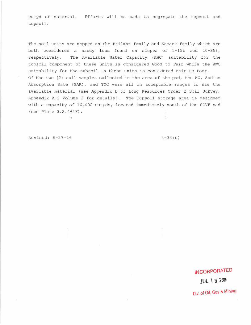
cu-yd of material.
topsoil.
Efforts will be made to segregate the topsoil and
The soil units are mapped as the Hailman family and Karnack family which are
both considered a sandy loam found on slopes of 5-15% and 10-35%,
respectively. The Available Water Capacity (AWC) sui tabili ty for the
topsoil component of these units is considered Good to Fair while the AWC
suitability for the subsoil in these units is considered Fair to Poor.
Of the two (2) soil samples collected in the area of the pad, the EC, Sodium
Absorption Rate (SAR), and TOC were all in acceptable ranges to use the
available material (see Appendix 0 of Long Resources Order 2 Soil Survey,
Appendix A-2 Volume 2 for details). The Topsoil storage area is designed
with a capacity of 16,400 cu-yds, located immediately south of the SCVF pad
(see Plate 3.2.4~4F).
Revised: 5-27-16 4-34 (c)
INCORPORATED
JUL 1 9 lUI
Oiv. of Oil, Gas & Mining

•
•
LA ~GES TO
4.6.2 Topsoil Stockpile
Topsoil is stored within areas 0 the permit boundary which will not
be routinely disturbed (See Maps 3.2.1-11 3.2.1-3 1 3.2.4-3AI 3.2.8-2 1
3.2.11-11 and Volume 5 Section 2L). Four topsoil stockpile areas are
utilized: the first at the portal areal the second at the loadout
facilitYI the third at the waste rock disposal site l and the fourth at
the Winter Quarters Ventilation Facility.
Long-Term Topsoil Storage Areas
During construction at the mine site, a stockpile area of
approximately 0.6 surface acre vas established in the draw on the
north side of the site. The lpng-term stockpile is composed of
topsoil collected at the mine site and portions of the conveyor bench.
It will later be used for post-mining reclamation of the benches and
conveyor routes.
A second long-term topsoil stockpile l covering approximately 0.3
surface acre, was established at the load-out site for later
reclamation use in that area. TV10 topsoil piles are located at the
South Fork breakout area (see Map 3.2.11-1)1 and one at the waste rock
disposal site.
4.6.3 Topsoil Protection
Long-term topsoil stockpile protection is achieved by the performance
of the following operational ste~s:
Section 4.6 Page 4-35 Sectior 4.6.2 Page 4-35 Date 3-23-09
• 4-35 INCORPORATED
JUl 2 9 2010
Div. of Oil, Gas & Mining

.;- --•
•
~ • •
A stable surface is prov~ded in an area outside the influence
ot a~ive operation. --
As a stockpile was complE ted, it was left in a rough condition
to minimize erosion.
• A diversion ditch was du~ around these piles to divert runoff
fro~ entering the stock~iled area.
• Storage piles were vegetated with quick-growing,
soil-stabilizing plants. Revegetation involved the immediate
seeding of stockpiled to'psoil with the seed mixtures listed on
Table 4.6-1.
CHANGE TO ~" -" -.;jV
Section 4.6 Page 4 'lC:: ~"H .. t on 4.6.3 Page 4·35 (a}h-:',_JDate 08/10/ c 3
I ~~nv I b '~~J 3 5 (a) f
f !
I Pf"I,; ~ I H. • ,q~~ I
.- . -····_r_ .... · _. _____ .. -.,.~._~_~ UTAH DIVISION Oll., GAS AND MINING

I~----------------------------------------~-----------------------
• Signs are posted to protect the stockpiles from accidental
use as fill or from other inadvertent material
contamination.
• The establishment of no~ious plant species is prevented.
• The slope of stockpiles does not exceed 2h:1v.
The stockpiled topsoil will net be removed or otherwise disturbed
until required for redistribution operations on a prepared,
regraded disturbed area.
4.6.4 Topsoil Redistributior
Topsoil redistribution on slo~es steeper than 3h:1v will be done
immediately prior to revegetation. other surfaces will have
topsoil redistributed prior tc seeding and will be left in a
roughened condition to help assure stabilization. Prior to
topsoil redistribution, regraced land will be scarified by a
ripper-equipped tractor. The ground surface will be ripped to a
suitable depth in order to .recuce surface compaction, provide a
roughened surface assuring tOlsoil adherence and to promote root
penetration.
I MAR 2 31993
r UTAH ]~ON OIL, GAS AND MINING
ADDITION TO TEXT
Section 4.6 Page 4-36 Sec1ion 4.6.4 Page 4-36 Date 01/20/93
4-36

The concrete footers of the o~erland conveyor will be fractured
to a minimum of two feet belo~ the surface. A minimum of two
feet of fractured concrete will be removed and the hole filled
with topsoil. since this topsoil will be hand placed, no
scarifing will be need, the feoter holes will then be seeded and
mulched
within a suitable time (7-14 days) period prior to seeding,
topsoil will be distributed on all areas to be reclaimed. During
this time period, the topsoil ~ill be allowed to settle and
attain equilibrium with its na~ural environment. This procedure
will be followed for all areas in which facilities such as road
beds, mine pads, and building ~ites are to be abandoned. The
Permittee does not anticipate ~he use of any SUbstitute or
supplemental topsoil. Should ~uch use become necessary, the
Permittee will notify the regu~atory authority of such proposed
use and will provide informatiDn on the suitability of the
supplemental or SUbstitute top~oil.
To minimize compaction of the topsoil following redistribution,
travel on reclamation areas will be limited. After topsoil has
been applied, surface compactiJn will be reduced by ripping to a
suitable depth. This operatio~ will also help prepare a proper
seed bed and protect the ~;~:;, 7'·,~":'tt;.r'::w.~?,-':·D'~I~:'l;.~g-ra"'-r--t'~oi~. ,fx~.m wind and water erosion. ,! Jlt~'Q~((JJruP)OJR-~~,::,'r" "
EFfr"ECTIY·~. ~l,,-, <,' .. 2,'.>,,- ; , _ E. , • J 11; I MAR 231993 J
I jT--------.J ~ I ~ ,. UTAH DllVlSION Oa, GAS AM> MINING
ADDITION TO ._- J
section 4.6 Page 4-36 Sect on 4.6.4 Page 4-36(a)
Date 01/20/93
4-36(a)

•
•
,
T ble 4.6-1
TOPSOIL STOC PILE SEED MIXTURE
Smooth Brome (Lincol 3-4 lbs/acre
Timothy or Meadow Fo tail 1-2 lbs/acre
Lewis Flax (native) 1-2 lbs/acre
Orchard Grass 1-2 lbs/acre
Slender Wheatgrass 2-3 lbs/acre
Cicer Milkvetch 2-3 lbs/acre
NOTE: This is a seed mixture r commended in a report on vegetation
and plant community analysis in compliance with U.S. Forest Service
requirements. Yellow Sweet Alfalfa were replaced with
Slender Wheatgrass and Utah in 2008. The seed mix may
need to be altered based on see availability. Modifications will
be based on consultation with personnel.
INCORPOR/\T~:-D
n~ i' of ,: 2008 ,,- ,-_ , l
Div. of Oil, G2: -" ]
Revised: 7/2008
4-37

Topsoil redistribution procedures will ensure an approximate
uniform thickness consistent w~th the proposed reclamation plan as shown on Table 4.6-4.
The Permittee will exercise c~re to guard against erosion during
and after application of top!~oil and will employ the necessary
measures to ensure the stabil~ty of all redistributed topsoil by
mulching. All areas to be res~eded will be mulched. All mulching
will be applied after the ar~as have been reseeded. Slopes of
3h:1v or less will be mulche~ with straw. Slopes steeper than
3h:1v will be treated with weod fiber mulch. All mulch will be
anchored by chemical tacifer~ or crimping. All mats will be
anchored with 6" staples on 2 foot centers. Mulching will be
applied at the rate of 2,00 P pounds per acre. All mulching,
anchoring techniques and appl~cation rates will be determined by
using BeTA at the time of re(~lamation. For this permit renewal
(1992), 2,000 pounds of wood fiber, plus 140 pounds of conweb
tacifer has been used to ~etermine the reclamation bonding
calculations. Any rills or cullies deeper than nine (9) inches
which form in areas which have been regraded and topsoiled will be
regraded and reseeded. The d~sturbed areas adjacent to any rills
or gullies which have been filled, regraded or otherwise
stabilized, will be reseeded cr stabilized accordingly.
1
_ J
CHANGE TO TEXT
section 4.6 Page 4-38 section 4.6.4 Page 4-38 Date 01/20/93
4/38
l
I i

•
•
•
4.6.4.1 Coal Mine waste Disposal si e
Canyon Fuel Company, LLC proposes 0 perform the revegetation of the waste
disposal area in successive stages wi a stage representing the portions of the
site that have been filled to design When a stage is completely full,
that area will be graded subsoil a d topsoil will be placed over the waste
material. Topsoil derived from the 1992 AML project and aspen or sagebrush
vegetative type areas will be placed n the fill area. Additional soil will be
brought into the disposal site from t e mine site stockpile (which contain soil
from non-National Forest areas), si ce previous mining activity has rendered
insufficient topsoil available at the ite. Imported topsoil will be analyzed for
N-P-K, pH, EC, and texture to assess suitability as a topsoil medium.
The road cut and fill slopes will be reclaimed when construction is completed.
The cut slopes will be hydro-seeded here the soils and sub-soils will support
growth. Cut slopes without sufficient soils and sub-soils will be topsoil-ed and
hydro-seeded. Fill slopes not cove ed by waste rock will be topsoil-ed and
hydro-seeded .
There is not enough subsoil cover mat rial available on site to cover the entire
7.68 area disturbed with 16 inches of aterial. As has been the practice in the
past, subsoil cover material will be
up the difference between what is
requirements of the plan. The
urchased from a commercial source to make
n site and what is needed to meet the
material will be tested using the
Division's Guideline #6 requirements. The entire disturbed reclaimed site will
have 12 inches of topsoil added over the subsoil cover material. To meet the
requirements of R645-301-553.252, the site will have a minimum of 20 inches of
non-potentially toxic or acid forming aterials placed immediately under the 16"
of subsoil. Waste rock is routinel sampled for potentially toxic or acid
forming materials. If any unsatisfac ory waste rock is found it will be placed
where it will have a minimum of 48" of total non-toxic or acid forming materials
over it. Analysis of the Scofield to soil and subsoil are shown on pages 4-38e
and 4-38f.
Revised: 5/16/08
INCORPORATED
r'" 1 : 2008
Div. oJ Oil, G8.S c1 r
4-38(a)

•
•
All non-toxic, non-combustibl material, as well as the top soil and subsoi~will come from a s ngle source, and will be tested for toxicity, ~id/base accounting, selenium, boron and complete soil analysis, as outlined on Tabl 1 of the Division's quideline for topsoil management. Topsoil w 11 be applied to the final layer of moderately-compacted rock te material and subsoil cover. Typically, the coal mine wast which will be disposed of consists of 36.00 percent less than 1/4 x 0 inch material and 28.6 percent between 1 x 1/2 and 1/2 x 1/ inch (Exhibit 3). Therefore, the loss of topsoil into the pore space of the fill should not be a
problem. The
.. r::~~ L~Vi
......... _--- ~-~-.-~ --." ... -. ~ .1
, ~.-j •• • 11 '.1::. 't". I
'--.---~~:':J ..... _____ ._
4-38 (b)
R05/02/94

Table 4.6-4
*1.69 acres does not include acreace of topsoil pile; total disturbed area
including topsoil pile area equal 2 36 acres
Sub-Total 1.69 4090
CHANGE TO TEXT
Paqe 4-3S(c) Table 4.6-4 Paqe 4-3S(c) Date OS/10/9
4-3S(c)
INCORPORATED
JUl 2 9 2010
Div. of Oil, Gas & Mining

Acreage
Overland Conveyor
Route .39
NOG Bleeder Shaft 1.7*
TABLE 4.6-4 (Continued)
TOPSOIL REDISTRIBUTION
Planned
Depth
Inches Cubic Yds
12 ____ ~6~2~9 (Private)
19 4,388 (USFS)
*1.7 acres is only the disturbed area.
approximately 3.0 acres.
The permit area encompasses
Swens Canyon Ventilation Facility
North Slope I 5.4**** 12
GRAND TOTAL 65.70
48,056 (Private)
90,607 (USFS)
138,663**
*Both of these areas are located on National Forest lands and 78,593 cubic
yards of National Forest topsoil was removed and stored from these area. The
topsoil over and above that planned for redistribution that came from
National Forest lands will be redistributed on National Forest lands, as
directed by the Manti-LaSal National.
**81,852cubic yards are need for revegetation on National Forest lands and
43,966 cubic yards are needed for revegetation on private lands. As
indicated in Section 2.11, there is 79,281 cubic yards of topsoil available
for revegetation on National Forest Lands and 44,526 cubic yards of topsoil
available for revegetation on private lands.
***2,198 cubic yards are available at the Scofield site. The remainder of
the topsoil will come from the portal yard stockpile or other outside source.
****5.4 acres does not include the acreage of the topsoil pile and areas not
disturbed in the permit area. Plate 3.2.4-4F illustrates topsoil (-8,755 cu
yds.)and subsoil removal area. Only topsoil is included in the table
although approximately 6,345 cu-yds of subsoil will be stored in the pile as
well.
Revised: 5-27-16 4-38(d) INCORPORATED
JUL 1 9 1Ut
Div. of Oil, Gas & Mining

••••
•
COMMERCIAL TES INO. ENGINEERING CO. GENeRAL OFAC£S: 1919 SOUlH HIGHLANO AVE.. SUITE LOMIAAO. IUJNOIS eol48. TEL: ,...953-9300 FAX: 7(8.913-9301
February 17, 1994
UTAH FUEL COMPANY P.O. Box 719 Helper Ot 84526
,.
Kind of sample SOIL reported to u.
Sample taken at XXXXX
Sample taken by UTAH FUEL COMPANY
Date sampled November 9, 1993
Date received December 2, 1993
Results:
Analy.i.
PAJWq'lD
Maximum Acid Conductivity Neutralization Potent Nitrate Saturation Percent Paste pH Nitrogen, Kjeldahl Organic Carbon Total Texture - tClay Texture - tSilt Texture - tSand Boron, B Calcium, Soluble MAngesium, Soluble Sodium, Soluble Extractable Selenium Sodium Absorption Ra 0
Sodium, Exchangable
Results are reported basis.
--~ •• ~ .--.. ••• y -~~.-.-
M __ • _ .. _~ __ ._ ...... _
OVER 40 BRANCH LA8ORATORIES STRATEGICALLY LOCATED IN PRINCIPAL
crt DO •
PlEASE AOORESS AU CORRESPONDENCE TO: 4885 PARIS. &.200. DENVER. CO 80231
TEL; (303) 373-4m FAX: (303) 3734191
Sample identification by CTE HUNTINGTON
SAMPLE NO. SCOFIELD TOPSOIL
REStlLTS
0.78 590 12.75 18.2 38.46
7.37 1500
2.39 24.00 36.00 40.00
0.26 3.6 1.2 0.28
<0.002 0.18 0.6
T/1000 T umho/cm T/1000 T mg/Kg t s.u. mg/Kg t t t t mg/Kg meq/L meq/L meq/L mg/Kg
mg/Kg
indicated, on an as received
4-38e
MINING AREAS. TIDEWATER AND GREAT LAKES PORTS. AND RIVER LOADING FACIUTIES
F45I072194 OriQInai WaMrmattced For Your P,otection TERMS CONDfT1ONS ON REVERSE

COMMERCIAL TES INO. ENGINEERING CO. GENERAl. OFRCES: 191. SOUTH HIGHLAND AVE.. I.OM8AAO.1UJNOCS 801". TEl; JOI.853.83OO FAX: )01.853.1301
~.-• February 11, 199.
trrAH FUEL COMPANY P.O. Box 719 Helper at 84526
," Kind of sampla raportacl to u. SOIL
Sample taken at xxxxx
Sample taken by trI'AH FUEL COMPANY
Date samplad November 9, 1993
Data recaivecl December 2, 1993
Analysis
PARAMETER
MAximum Acid Potenti Conductivity Neutralization Potent a1 Nitrate Saturation Percent Paste pH Nitrogen, Kjeldahl Organic Carbon Total Texture • 'Clay Texture - tSilt Texture - tSand Boron, B Calcium, Soluble Mangesium, Soluble Sodium, Soluble Extractable Selenium Sodium Absorption Rat"o Sodium, Exchangable
PLEASE ADDRESS AU CORRESPONDENCE TO: 41115 PARIS. 8-200, OENVER. CO 80231
TEL: (303) 373-4712 FAX: (303) 373-4711
Sample idantification by trrAli FUEL COMPANY
SAMPLE NO. SCOFIELD TOPSOIL (Subsoi 1 )
72-265348
RESULTS llHW
0.71 T/1000 T 380 umbO/OIl 16.75 T/1000 T
8.90 mg/Kg 38.44 " 1.84 s.u.
900 mg/Kg 1.58 t
26.00 " 36.00 t 38.00 t
0.30 mg/Kg 2.5 meq;L 0.82 meq/L 0.31 meq/L
<0.002 mg/Kg 0.24 0.6 mg/Kg
Results: Results are reported basis.
indicated, on t!ftII-!I'~"""""'''''''''''--'''-- ."
• ,.-.--.~-. -,-.- --.-.-------1-----
-f"""-------__ "_"---I
199:1 .. --------------_.....J--'
. - .) ~
" .. '--' "f~ ~ ~ . ~'i;) ;
4 ""'f38f i
I I
Respectfully COMMEAC
Ii. OVER.to BRANCH LABORATORIES STRATEGICALLY LOCATED IN PRINCIPAL
F"'85I072194 Original W81811'n81ked For Your ProtectiOn TEAMS CONOlllONS ON REVEASf
ThT~O~1Q)O::;- -:: ··:V·-.. ~jD JU. ~ 'V RUl '-- - _ OJ • __ -A
EFFECt J v~:.:
I 0 lCj.~l _~ ... f·(J· RNGcO.-· _0
'I & .... ,
~:.ii.Aii;;;;iiii~' ~ONOn... GAS A.~ MINDD

• moderately-compacted final layer f fill should not, on the other hand,
be an impermeable barrier which w 11 redirect drainage.
The topsoil will be spread 12 i ches thick in a manner to provide a
roughened surface so that seed mulch can remain during germination
and initial growth of the Topsoil depth was determined from
soil pits in the reference area. jRipping the surface prior to planting
seeds may be needed to provide the necessary roughened surface. Any
rocks that are on the surface ill be left in place to aid in the
vegetation effort.
The potential for upward migratio of salts is unknown for the top soil
and cover material. The commits to analyze this material for
electrical conductivity sodium co tent and sodium absorption ratio prior
to revegetation efforts.
Fertilizer rates may change after the soil's analyses of the topsoil are
4It completed. The Permittee plans to apply 100 pounds per acre of available
nitrogen. Mulching will be as outlined in Section 4.7.2. The
Permittee's consultant has that phosphorous and potassium
concentration based upon Skyline' data should be adequate in the aspen
soils, and, therefore,
potassium or phosphorous
topsoil before it is seeded t
topsoil will be an aspen type, no
nded. The Permittee plans to test the
determine the type and amount of
fertilizer or neutralizer require. The soil's analyses will determine
the following components: (a) micro-nutrients, (b) potassium, (c)
calcium, (d) magnesium, (e) phos
salinity, and (h) soil texture.
(f) nitrogen, (g) soil pH and
The majority of drainage diversio ditch DD-17 will not be reclaimed as
it expected to be fully revegetat d and in stable condition. However,
the lower portion will be recon tructed to direct any drainage into
4It the natural drainage channel. IN CORP ORF .. TED
Revised 12-2007 4-39 r

• The Scofield Waste Disposal sit
undisturbed by mining in
surrounding area were evaluate
of Agriculture (USDA), Natura
(NRCS) WEB Soil Survey utility
in Appendix Volume A-2 Volum
approximately 18-20 inches of t
was expanded into areas previously
7. The Disposal site and the
using the United States Department
Resources Conservation Services'
See the Clement Soil Survey located
2) . Based on the soil survey,
horizon will be salvaged from
the proposed Waste Rock Expans'on area. Assuming the entire 5.13
acres of the proposed expansio are eventually disturbed, a total
of approximately 13,822 cu-yds of topsoil (AlB horizon) would be
salvaged and used in reclamatio . These volumes will not be stored
all at one time however, as ex ansion will only take place on an
as-needed basis. The topsoil volumes will be identified in the
field based on abundant root m color, and general depth.
No topsoil pile currently exi ts at the site, so all suitable
topsoil will be salvaged as th site is expanded. The expansion
will be incremental, with cont mporaneous reclamation activities
• being conducted simultaneously. It is estimated that no than more
than approximately 3-acres wil be without topsoil at one time.
•
A stockpile of topsoil will Ii ely not exceed approximately 4,500
cu-yds because it will be in contemporaneous reclamation.
Topsoil storage will be conta' ned in areas identified on Plate
3.2.8.2. As stated in other sections of this M&RP the topsoil will
be stored, marked with appropri te signage for protection, and used
during reclamation. The placement will be stable,
protected from wind and through prompt establishment
of vegetative cover. Sedime control measures such as silt
fencing or straw bales will be 'mplemented temporarily at the base
of pile until vegetation is e tablished. Should other storage
areas be necessary, the site wi located in an UDOGM-approved
location. Should a topsoil defi it exist at final reclamation, the
necessary topsoil will be impor ed to the site .. Tr:rD. INCORPOR1~;'K c:~
Revised 12-2007 4-39a


•
•
At reclamation, cover will con
will be preceded by approximat
the 18-20 inches of topsoil
feet of the best available,
non-toxic and noncombustible terial, in a manner that does not
impede drainage from the derdrains. As has been done
historically, additional subso'l cover will be purchased from a
commercial source to make difference between what is on site
and a total soil/subsoil dep h of approximately 28-inches. This
is consistent with both R645- 01-553.252 and placement of cover
over portions of the Waste Rock site that were previously
disturbed.
Skyline tests waste rock material every 2,000 tons for acid and
toxic-forming materials.
be either acid or toxic-form
rock analyzed has been found to
in the history of the mine.
Selenium and Acid Base Potenti 1 (T.S ABP) are two parameters for
acid and toxic-forming tracked by Utah oil Gas and
Mining. The Selenium range's well within acceptable limits
(unacceptable- ~ 0.15 ppm soil). Unacceptable levels for Acid Base
Potential are less than or equ I to 0 tons CaCO 3 /1000 tons
overburden - which is an indic
potential. The Waste Rock has
the C horizon. The
combustible material. Waste
of the materials neutralizing
etter neutralizing potential than
k is also considered to be non
samples associated with North
Lease are representative of samples surrounding the Lower
O'Conner B Seam. Mining the Lease area will require mining
through a graben zone. This material is not intended to be
included in the Waste Rock site and will be stored underground.
Based on the 2006 Clement Soil urvey, the proposed expansion site
has approximately 38 in. (97 cm) of soil above hard-packed C
horizon. A large portion of t cover is BC or C material
(starting at 14 in. and 22 in. respectively). Suitable topsoil
was found to have a thickness r nge of 14-22 inches.
Averages and ranges of selected arameters from waste rock analyses • C,:c;c'r,?C?,,2:T':::~J
Revised 2-2008 4-39b

performed from 2005 through 20 7 (Total samples; 53) are presented
~ in Table 4.6-5. Coupled with these data are averages and ranges
for the same selected paramete s for the C horizon (Total samples
; 2) from Clement 2006 Soil Su ey, holes SP-l and SP-2 (depth for
~
Table 4.6-5
Avg. for Waste Rock '05-'07 7.98 1.41 2.91 12.49 73 0.70 0.84 0.66 <0.02 45.3 Range for Waste <0.02-Rock 7.3-8.7 0.27-4.42 0.96-8.45 8.1-29.4 <0.2-1.74 0.05-1.3 0.39-1.23 0.08 11.6- 142 Avg. for C Horizons 6.8 0.205 0.215 16.5 1.22 0.01 0.24 <0.02 5.4 Range for C Horizons 6.7-6.9 0.19-0.22 0.20-0.23 16-17 13 0.14-2.3 0.01 0.21-0.27 <0.02 4.5-6.4
both profiles; 38 in.). omparison demonstrates the waste
rock is slightly different f the C horizon material but the
difference should not have an effect on revegetation
efforts.
• EC- The higher salts (EC) i compared to C horizon (0.21 if any, on the vegetation vegetation report. The was saline. Of the literature common species of the veget tolerant to salinity (up to resides in the upper horiz slightly higher salinity in
the waste rock (1.4 dS/m) dS/m) should have little effect, ecified in the Mt. Nebo June 2007 e rock is considered to be nonvailable, several of the more tion report are moderately 6 dS/m). The majority of roots
and would not be affected by a the waste rock.
• SAR- Sodium Adsorption Rati (SAR) is higher for waste rock (2.91) than the soil (0.22) but still not within a range that
Revised 12-2007 4-39c

•
•
•
•
•
•
•
would have a significant e feet on growth and water penetration. The limit un er the Guidelines for Management of Topsoil and Overburden- Utah Oil Gas and Mining for SAR is > 15.
Soil Nitrogen- Total Kjehl combination of organically is much greater in waste r the same value (0.08 ppm) of SP-2, illustrating that is an improvement over the inorganic nitrogen, N-Nitr that the range for both wa are not significantly diff vital nutrients in the soi
ahl Nitrogen (TKN) is the bound nitrogen and ammonia. TKN ck; however, the waste rock has s the more nutrient rich A horizon with respect to TKN the waste rock C horizon. The comparison of the te, does not accurately express te rock and C horizon overlap and rent. Nitrogen is one of the most but the C horizon is an
insignificant source for p ant nutrients. The A horizon of both SP-l and SP-2 has 5 t 10 times greater concentrations of N-Nitrate than the C ho izon or waste rock. The C horizon starts at 18 in. and 23 in which is well above the current practice of 28 in. of cove material over waste rock. The current practice would pro ide a greater quantity of nutrients in the cover mat rial because of the greater depth, and the same or greater co centration of nitrogen in the waste rock.
Boron- Boron (B) is a micr nutrient and the Mancos Shale in eastern Utah can contain b ron at high levels. The high B levels in the soil can cau e plant toxicities when >5 ppm B. Both the waste rock and so'l are at low concentrations and are within the limitations set by the Guidelines for Management of Topsoil and verburden.
Field Capacity and Wilting waste rock has a slightly decreased average field capacity (waste rock = 12.5%, C horizon = 16.5%) nd wilting point (waste rock = 7.73%, C horizon = 12.5%) han the C horizon. However, the difference between field c pacity and wilting point is to some extent more important. The difference indicates the amount of water available or plant uptake and it is slightly greater in waste rock (was e rock = 4.76%, C horizon = 4.0%), making the waste rock a be ter source of water at depth.
Root Zone- Waste rock is c pacted throughout the placement process for the purpose of stabilizing the waste and
~~, r ',~ ~ c ~. ~ ~ .. ,:,"7'::-:: ~ [1\ .~"A .. .;., c, , __ " .. t. _..-I
Revised 12-2007 4-39d ........ ,/ I.-Jo '-'" .-- ..-'- -"
""':" ~~ ("iL Gas & Mining

•
•
•
increasing storage efficie cy. This compaction does not form an aquitard or restrict th penetration of deep rooted vegetation. Lab analysis f the waste rock indicates that the texture of the unconso idated waste is mostly sand with some sandy loam, clay loam, and loamy sand. Most vegetation in both reference areas me tioned in the Mt. Nebo report have shallow root systems and h ve the majority of their root systems in the A and B hor'zon (approximately 18-23 in.), making the material at dep h less relevant.
Consultation with former Skyli e personnel, Keith Zobell, indicated the currently approv d plan (12in. topsoil, 16in. subsoil) was developed by hims If and DOGM personnel Henry Sauer. Zobell and Sauer dug soil pits at the site to develop the current plan. Their findings (and the current plan) are consistent with the findings of the Clement So'l Survey.
Areas of the Waste Rock Site p below in Figures 4.6.4-1 and 4 success of the current plan an after seeding. Woody species the future Skyline decides to the purpose of selling.
Revised 12-2007
eviously revegetated are shown 6.4-2. The pictures represent the
were taken approximately 5 years ave not been planted in case in ine and wash the waste rock for
4-3ge

•
•
I • c
Revised 12-2007 • ~..J .. J ___ .)
4-39f
,. """ ..

• 4.6.5 South Fork Breakout
Before any top soil was removed, all oody vegetation was removed from the project area. Soils are basically a andy loam mixture and have been classified by the S.C.S. as Uinta Fam'ly loam/tozc Family fine Sandy loam. Core sampling in the area shows that he soils vary in depth from 24 - 36+" in depth .
•
L C PO ATED
• Revised 12-2007 nin 4 - 39g

•
•
•
After the vegetation had been re oved , the A & B ho rizons of so il were
remove d using a track hoe . The track hoe s tacke d the soil where a
front-end loader picked it up and transpo rted it to the storage area on
the abandoned temporar y Forest Se vice road and on the small open ing at
the mouth of the canyon where t e knob was -removed . The fro nt - end
loader spread the soil in approximately two foot lifts . By handli ng
the s o il in this manner , it wil l not be compacted in the storage area
and the roots of the revege tat i n plants will penetrate the entire
depth of the soil . This will a 10 the soil to maintain itself as
viab le top soil to be used durin final reclamation . It is es timated
that approximate l y 2 , 990 cubic yards of topsoil was removed and stored .
As subsoils were encountered , t ey were used to bring the anc illary
access road up to grade . not used as road wa .s also stored on
the small opening at the mout of th e canyon where the knob was
removed. It is estimated that approx imate ly 2 , 840 cubic ya rds of
subsoil was remove d . Approxima ely 1,820 cubic yards of the subsoil
were used in the road fill and he remaining 1 , 020 cub i c ya rds were
stored for final reclamati on .
As the coal in the coal seam was encountered , it was hauled o ut so as
to eliminate the poss i bility of spontaneous combustion occurring .
On ce the constructi on was camp ete , a ll of the d i sturbed areas were
seeded and all the roads that re on Nat i onal Forest Lands and the
disturbed areas were water barr d and seeded with the mixture shown on
Table 4 . 6 - 1 . A combinati on of s' 1 t fences and strawbales were used t o -
treat surface run - off from the isturbed area of the ancillary road,
the breakout pad and the topsoil-subsoil storage areas until adequate
vegetation is established . The. il t f ences and strawbales were located
as needed between the disturbed and undisturbed areas to treat run - of f
from the disturbed area.
Revised 09/19/03
CORPORATED
SEP 252003
DIV OF OIL GAS & MINING
4-40

• During portal reclamation , the ncill a r y road int o the breakout site
will be reopened. The portals ill be s ealed as o utlined in Section
4 . 9 . Approximately 400 to 450 ub i c yard s of s ediment from Electric
Lake will be used as the require n oncombu s t ib l e backf ill bet ween the
portal opening and the block sea s . Two samp l e s o f the ma t er ial t o be
used as backfill were obtained and analyzed in accordance with the
parameters listed in Table 6 o f the Division ' s " Guidelines for
Management of Topsoil and Overb rden f o r Underground a nd Surface Coal
Mining ", Revised by James rwood and Dan Duce , ,ll,pril 1988 . The
laboratory data sheets are ed in Appendix Volume A- 2 in the Soils
and Vegetation section and the t 0 samp les are identified as Electric
Lake Site #1 and Site #2 .
The highwall at the breakout a ea will be eliminated by front - end ,
backhoe , or other types of tra ked or rubber tired e quipment . The
permittee will use waste rock r om the mi ne 's temporary waste rock
• storage site to return the portal a r ea to approx imate original contour.
•
The waste rock has been analyz d in ac c o rdance with th e parameters
presented in Section 4 . 4 . 5 of this chapter and the resul ts a re included
in Appendix Volume A- 2 in the So il s and Vegetation section . The
samples from the temporary w .ste rock si te to be used In the
reclamation of the South Fork Po tals are listed on the data sheets as
samples 11 through 13. The resu ts of the analyses indicate the waste
rock is not toxic - or acid- f Th e use of waste rock for
reclamation is necessary since 1 , 000 o r mor e c ubi c yards of
coal and coaly soil was reported y removed fr om the si t e during portal
construction . It is anticipated based on an August 2003 survey of the
portal area used to create the t pography and c ross-sections presented
in Drawing 4 . 6 . 5-1 , that 1 , 300 r mo r e cub i c ya rds of was t e ro ck c o u l d
be used to reclaim the site al d r eturn i t t o AOC .
Revised 09/19/03
INCORPORATED
SEP 252003
nlv or 0 GA~ MIl\.JING
4-41

• The waste rock will be buried b y a mi n i mum of f i ve feet of subsoil and
topsoil (The init i al five feet of cover should all o w for de e p gouging
of the topsoil surface whil e ma nt a i ni ng at leas t f o ur f eet o f cover
over the waste rock . ) The wa st rock and overlying subsoils wil l be
placed in not more than 2 f oo t l ' ft s and compact ed by mu l tiple p asses
of large tracked and rubber t' red con struction e quipme nt (do zer,
trackhoe , front - end loader, et . ) .
Runoff from the portal canyon access r oad wi l l be treat ed during
construction activities . This wi l l require th e temporar y use o f
gravel , silt fences, a nd/o r straw bale d i kes in low a r eas and whe r e
runoff from the road o ccurs . These temporary t re a t ments will be
eliminated/removed or , if app i cab l e , u s ed as pa rt of t h e final
reclamation treatment faciliti s .
Subsoil from the storage areas wi 1 b e uniformly p l ace d in the breakout
• area and then topsoil will be ni fo rmly spread over the a r e a . The
ancillary road up the side c the b re a kout a r ea and t h e
temporary road used for s o i l s t o r age wil l t h e n be retu r ned t o
approximate original contour of urrounding terrain . Th e r oa ds will be
brought back to as close to o rigi a l con t o ur as possib l e wi th t he least
amount of new surface disturban No new cut s l o pe s will be c reated
and existing ones will be smoothed to the extent poss i b le . As
requested by the Forest Serv i ce , VJater b ar s will be p l aced as n eeded t o
dissuade vehicular trave l after eclamati on . The sur f a c es of t he roads
in the portal canyon will als o deep go u ge d to encourage
runoff retention and eliminate 1 n g , un interrupt e d runoff f l ow pa ths. '
Silt fences and / or straw bale d i ~ es will b e p la ced at loc ations where
concentrated runoff occurs from ecl a i med are a s s u c h as t h e downstream
end of the water bars on the r ec a ime d Fo r e st Serv ice road o r natural
drainage crossings on any of the acce ss t h e r o ads . Th e a rea where the
• Revised 09/19/03
CORPORATED
SEP 252003
DIV OF OIL GAS & MINING
4-4 1(a)

• knob was , if used for reclamati n , will also b e c ontoured t o b lend in
with the surrounding terrain .
As described in Section 4 . 7 . 8 , dl l ~oils will be spread ane! trea ted in
a manner to provide a roughene d s ur fac e so that seed , f ert iI i ze r a nd
mulch can remain during germ' nati on a n d initia l gro YJth o f th e
seedlings . The permittee inte1 d s t o r o ugh e n al l r ec l a i med s urfaces
using deep gouging or pock - moc kin g technique s . Ho we ver , r a king
surfaces prior to planting ma y a so be needed t o provi d e t he necessary
roughened surface in areas tha ca nno t be d eep goug ed .
As described previously , subs o i s we r e used t o bring th e porta l ac c ess
road up to grade . Subsoils were use d as fill ac r o ss the narro w canyon
to allow the access road to cro s from the south side o f the canyon to
the north side wh e re the portals are located . A culvert was p laced in
the bottom of the drainage prior to b ac kfilli ng wi th subs o i l . During )
• final reclamation , these subs oi ;::; \",il l lJe u s ed f o r r e cl a ma t i o n o f the
•
portal area and the culvert 1 be removed . Upon r e moval of the
subsoils , the newly exposed inage s lopes will be mu lched, deep
gouged , and reseeded . The gougi g wi l l b e frequent en o ugh t o eliminate
extended runoff flow paths th t c ou ld re s ult in e r o si on . I t is
anticipated that the gouges will be at l e ast 12 -inc hes dee p a nd should
not fill naturally until vegeta ion has been established . The deep
gouging of the slope will be e x t nded f r om th e t o p o f th e slope t o the
channel edge. Straw , vegetati v e debris , and rock , if available , will
be incorporated in the lower-mos g ouge s adj acent t o th e channel floor
to increase the durability of the s t ream channel walls while vegetation
is being re - established .
The channel floor exposed aft r r e moval of the c ulve rt will be
roughened sufficiently to impede .u r face fl ows and bring th e n a turall y -
Revised 09/19/03 INCO PORA ED
SEP 252 3
DIV OF Oil GAS
4-4\ (b)
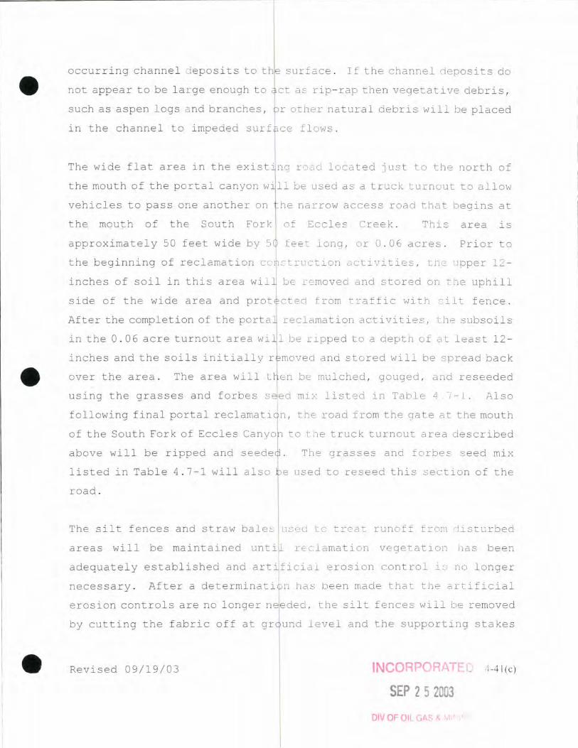
•
•
•
occu rring channel d eposits to the surface . If the ch annel deposits do
not appear to be la r ge enough to c t as r ip- rap then vegetative debr is ,
such as aspen logs a nd branches, r othe r na tu ral debri s \!Jill be placed
in the channel to impeded su rf ce flows .
The wide flat area in the exist' n9 r oad loca ted ju s t to th e north of
the mouth of the portal can yon YJ ' 11 be used as a truck turnout to al low
vehicles to pass one anothe r on
the mouth of the South Fork
approximately 50 feet wide by 5
he narrow acce ss road that beg ins at
of Eccles Creek . Thi s area i s
feet long , o r 0 . 06 ac re s . Prior to
th e beginning of reclamati on co ::truction ac tivities , the upper 1 2 -
inches of soil in this area wil be removed and s t o r ed on tl e uphill
side of the wide area and prot cted from traf fic with ~ ilt fence .
After the completion of the porta reclamation activities, t h e subsoil s
in the 0 . 06 acre turnout area wi 1 be r ipped to a depth of a t least 12-
inches and the soils initiall y r moved and st o red will be .spread b ack
over the area . The area will
using the grasses and forb es s
following final portal reclamati
b e mulched , gouged , and reseede d
mix lis ted in Table 4 7-1 . Also
the road from the gate a t the mouth
of th e South Fork of Eccles Canyol to the truck turnout area de scribed
above will be ripped
lis ted in Table 4 . 7 - 1 will a ls o
road .
The grasses and forbes seed mi x
e used t o reseed th i s s e c tion of the
The silt fences and straw ba l es used to treat runoff fro~ rl istu rbed
areas will be maintained reclamati on vegeta ti on has been
adequately established and artifi c i al erosion contro l i s no longer
neces sary . After a determinati n has been made that the artific ial
erosion contro ls are n o longer neede d , the silt f ences wi ll be removed
by cutt ing the fabric off at gr und level and the suppo r ting stakes
Revised 09/19/03 INCORPORATE. <'1-41 (c)
SEP 252 3
DIV OF OIL GAr--

• pulled from the ground . Stra bales will rema in in-place and be
a l lowed to naturally decompos e .
The dis t u r bed are are I ate d tot h e::; 0 I J t h For k po r t a lsi sO . 9 6 a c res .
Th i s 0 . 96 acres includes the acc ss road up the side canyon! including
the portion where tops o il is st red, t he portal pad , and the area at
the mouth of the canyon where to soi l and subsoil is s tored . The truck
turnout area is within an existing p r e -mi ning road and does not
represent addi tional dis tu rban e . The road that traverse s from the
mouth of the South Fo rk of Ecc les Canyon continues for some distance on
Forest lands beyond the mouth 0 the side canyon in which the portals
are located . However , access t this road is cont ro ll ed by a gate at
the mouth of the South Fork of Ec le~. Canyon . l::",s described prev i ous l y ,
the mine intends to rip an d seed the road from the gate at the mouth of
the canyon to the lower end of t e truck turnout . The port i on of the
road where topso i l is stored at he mouth of the portal canyon will be
• reclaimed by pocking or gouging, mul c hing , a nd seed ing . No fu r ther
reclamation activit i es are plan ed on the pre - existing road south of
the topsoil stockpile area .
•
The t ruck turnout is approximate yO . 06 acres . The road from the truck
turnout to the mouth of the Sout Fork o f Eccles has approximate l y 1
acre of surface area . Theief o e , approximate l y 1 . 06 acres of road
between the south end of the t ru c <. turnout will be recla imed ; the tru ck
turnout by ripping the subsoil t relieve compaction , respread ing the
upper 12 - inches of soi l previousl? moved aside , mulch ing , deep gouging ,
and seeding , and ripping and reseeding the remainder of the Sou th Fork
road from the truck turnout to the road ' s northern te r minus .
Rev i sed 09/ 1 9/03 INCORPORATED 11-4 1 (d)
SEP 252003
DIV OF Oil GAS & MI ING

4.6.6 Winter Quarters Ventilation Facility Topsoil Redistribution
Topsoil redistribution will commence once removal of all facilities and modification of the pad site to achieve the approximate original contours (AOC) is completed. Distribution of the topsoil will take place immediately prior to re-vegetation activities to minimize erosion. Topsoil will be placed with a bulldozer or comparable machinery to approximate grade. Following topsoil placement to approximate grade, a trackhoe or comparable machinery will deep-gouge or roughen the surface prior to commencement of re-vegetat i on activities.
4.6.7 NOG Bleeder Shaft Topsoil Redistribution
The topsoil redistribution will start one-year after the shaft has been backfilled to allow for settling, any facilities have been removed, and the earthwork has regarded the road and pad to the approximate original contours (AOC). Re-vegetation activities will immediately follow the distribution of topsoil to , minimize erosion. Topsoil will be placed with a bulldozer or comparable machinery to approximate grade, followed by deep-gouging of the surface. Mulch, matting or other best technology currently available (BTCA) will be used as a top-dressing once seed has been distributed.
4.6.8 Swens Canyon Ventilation Facility Topsoil and subsoil Redistribution
As with previous sites, both subsoil and topsoil redistribution will commence once the shafts have been adequately backfilled, and the area of the pad site has been roughly re-graded, subsoil will be redistributed to achieve approximate original contours (AOC). Prior to topsoil placement, any highly-compacted areas such as roads will be ripped prior to topsoil placement. Topsoil will then be placed with a bulldozer or comparable machinery to achieve approximate grade. Once topsoil is placed, a trackhoe or comparable machinery will deep-gouge or roughen the surface. Prior to commencement of re-vegetation activities, the topsoil will be analyzed for available nutrients nitrogen, phosphorus, and potassium per DOGM 2008 guidelines to evaluate whether any soil treatment is necessary. Following seed distribution, and any remedial soil treatments, topsoil and seed will be retained using a hydro-mulch, certified weed-free straw, erosion control blankets, a combination or other best technology currently available at the time. These procedures apply to both areas associated with the vent facility and any disturbance associated with the power line installation.
Revised: 5-27-16 4-41(e)
INCORPORATED
JUL 1 9 lUI,
Div. of Oil, Gas & Mining

4.7 REVEGETATION PLAN
Planting and revegetation of 11 disturbed areas will take place
following grading and/or top oil redistribution procedures and
will include, as necessary, the addition of remedial soil
treatments. Fall seeding is preferred. A suitable, permanent,
diverse vegetative cover wil be established on all reclaimed
areas and be capable of self regeneration and plant succession.
At the Scofield disposal si reclamation activities will be
conducted on areas that filled to design capacity. All
vegetation species will meet he requirements of applicable utah
and Federal seed, poisonous and noxious plant; and introduced
species laws or regulations. All revegetation will meet the
requirement of R614-301-356.232 and R614-301-356.233. The
proposed reclamation schedul
RECLAMATION TIMETABLE. The
major aspects of the proposed
is presented in Section 4.2
ollowing subsections describe the
evegetation plan.
4 . 7.1 Species and nt per Acre, Portal, Train Loadout
and Conveyor Be ch Areas
A suitable permanent, effecti and diverse vegetation cover of
species native to the area, or suitable substitutes, will be
established on all affected ar as.
After the initial constructiO j disturbance, the species selected
for use and the numbers or amo nts per acre depended on the steep
ness and exposure of the slop s to be revegetated. South facing
slopes Ih:3v (or lower) and f at areas were treated with seeding
efforts at the rate as shown in Table 4.7-1. South facing slopes
at angles of 2h:1v to 1h:2v w re treated with hand-set plantings
of sagebrush (Artemisia rabbitbrush (Chrysothamnus
nauseosus), and snowberry or red elderberry at not less than 1
meter (3.25 feet) intervals, ith interspacings being seeded by
the species shown in Table 1.7-1. The woody species stocking
density for south facing slopes were established at approximately
1 meter intervals with minor a justments for terrain .
4-42

North fa~ing slopes, which ar
seedlings of Englemann sprue
of 2.5 meters in all
mixtures spread on the
shaded, were planted with hand-set
and/or subalpine fir at intervals
Table 4.7-2 lists the seed
acing on the north-facing slopes.
Riparian zones were revegetat d with handset seedlings of yellow
willow, blue spruce, Woods and American red raspberry at
intervals at 1/2-1 meter. lists the seed mixture
spread on the inter-spaces. Steep slopes which have been
rip-rapped were not revegetate .
4.7.2 Final Reclamation Seeding and Tillage, Portal and
Train Loadout Area and Other Small Areas
Seed mixture for final
4~7-5, 4.7-6 and 4.7-6A.
Seeding of the south-facing
are shown on Tables 4.7-4,
lopes (lh:3v) or lower flat areas
will be conducted using a cyc one spreader. For slopes less than
2h:lv, seeding will be a complished using a hydro-seeder.
Plantings of shrubs and trees will be hand-set to ensure a plant
cover of a permanent nature.
Tillage practices on level round and on slopes flatter than
lOh:lv will include leveling, il1ing and mulching.
Planting on slopes less than lOh:lv will be accomplished by
drilling seed with a mechanical drill. Slopes between lOh:lv and
MAR 2 3 1993
4-43

1. 5h: Iv will be seeded by ha d broadcast and manually buried by
raking. Mulch will be applie over the hand broadcast seed. The
Permi ttee elects to revegeta e areas wi th s lopes greater than
I.Sh:lv without topsoil; sue areas will be treated to handset
plantings in basins filled w'th topsoil and with hydro seeding,
and then mulched as d in Section 4.6.4. Where the
substrate consists of ings of stone, no attempt will be
made to revegetate.
Revegetation on slopes steepe than 3h:lv will be undertaken as
soon as possible following topsoil placement, mainly during
spring and early fall, with fall seeding preferred. Where too
steep for topsoil planting will be followed
immediately after the area becomes available during construction
activities. Revegetation on slopes less steep than 3h:lv will
follow topsoil placement. A 1 tree and shrub transplants will
only be planted in the spring.
The Permittee will create a n tural appearance during post mining
reclamation by extending tree and shrub planting past the toes of
slopes. However, linkages will be left short or extended
slightly as necessary to provide an irregular appearance.
Grasses and forbs will be ree tablished from seed. Trees will be
planted as seedlings. The will additionally place
rocks, originally designated s wind barriers, at the bottom of
large rock cuts in an info way so as to provide a more
natural appearance. All -facing slopes will be seeded with
the south-slope mixture, an all north-facing slopes will be
" ~j
j ~
~' UTAHDMsroN OIL. GAS AND IV1LNING
/vlAR 2 3 1993
4-44
I I ~ j ! I i J
1 i t

All riparian areas will
shown on Table 4.7-6.
mixtures to be used on
be included in the revegetatio
egetated with handset seedlings as
4.7-4 and 4.7-5 list the seed
ter-spaces. Rip-rapped banks will
process where physically possible.
Noxious plants invading the d"sturbed areas will be controlled by
hand grubbing and/or approved erbicides. Surveillance will be
f/iAR 2 3 1993
UTAH Drl/lS10N O~ GAS AND MINING
4-44(a)

maintained annually during th period of liability.
type for each disturbed area i shown in Table 4.7-7.
Acreage by
4.7.3 Revegetation,
Conveyor Bench
and Reclamation of the
Revegetation, stabilization a d reclamation of the conveyor belt
slopes have been evaluated the middle of each growing
season, during the first five
and composi tion studies were
placed on slopes at the time
random numbers was used to
acceptable techniques have be
and composi tion of disturbed
conducted annually from
regulatory authority.
after construction when cover
feasible. Erosion pins were
f reseeding operations; a table of
location. Statistically
in determining percent cover
area. Revegetation analyses were
to 1985, and reported to the
ep slopes (60%+) have continued to
slough, which has precluded otal revegetation on these slopes.
The Permi ttee has developed special revegetation plan for the
conveyor bench slopes th have not been successfully
revegetated. This complete evegetation plan, as developed by
the S.C.S., is included in V lume A-2 and is directed at final
reclamation. This special revegetation plan covers four
treatment areas, three areas along the conveyor bench and once
area at the RRLO.
treatment areas:
The plan utlines six practices for the four
(1) apply 40-60 Ibs/AC of N2 in late fall or early spring;
(2) provide drip irrigation to existing shrubs;
(3) plant new shrubs ea h year (area 4 to also be planted
with douglas fir, i addition to the shrubs);
(4) provide irrigation for new plants on area 1-3;
(5) use in-line fertilization; and
.,
j MAR 23/993 4-45

(6) broadcast a light application of grass/forb seed each year.
In addi tion to the six three experimental trials are outlined:
(1) different rates of f rtilizer application;
(2) cut aspen to see if esprouting can be encouraged; and
(3) establish a plant aterials trial to determine plant
adaption.
Along with mine personnel, t plan is visually evaluated each
year by sese Results of the annual evaluation will be included
in the annual report to the To date (through 1991) I
practices 1, 2, 3, and 6 been utilized. Practice 4 is
inherent into practice 2, as the mine uses miniature sprays
instead of a drip system. P actice 5 has not been used, since
slow release fertilizer pel ets were used when planting the
shrubs. All experimental tr als have been conducted, with the
following evaluations:
Exp. 1 (conducted in 1989) - drought conditions precluded any
significant results Further trials deferred until a
better climatical pattern occurs;
Exp. 2 (conducted in fall of 1988) no results have been
observed. Re-evaluate in next three to five years; and
EXp. 3 defer using fertilization until slow release
pellets are used up
The final reclamation is to 1 ave the conveyor bench intact. The
current condition of the con ey~r bench is an area that is well
drained with drainage being teated with silt fences and/or straw
bales. The bench itself becoming well vegetated and is
functioning as a safety bene to prevent rolling material from
2!
4 4S(a) i.~--___ --.J
:-vifJlVLS10N On.. GAS AI . ~ NDMINING

rolling onto SR264. The revegetation plan is planned to
establish the necessary vegetction for final reclamation. During
final reclamation, the conve]or will be removed along with the
supporting structures. The only areas requiring treatment will
be the disturbed areas whele the supporting structures were
located. These small areas ~ill be revegetated as outlined in
Section 4.7.1 and 4.7.2.
4.7.4 Irrigation, Portal & Train Loadout Areas
Since the species used for reclamation were known for their
survival characteristics, i was felt that application of
ADDITIONS lQ I I TEXT
4-45(b)
additional water will not be needed. If irrigation is needed, an irrigation
plan will be developed at that time and submitted to the Division of Oil, Gas
and Mining tor approval. The special revegetation plan (see Section 4.'1.3) tor
__ the_conve_llOr_YOute_does __ include_some_drip_irrigation_for_establishment.
iJ. 'I.!:J Monitoring Procedures
All areas of final revegetation will be qualitatively evaluated on an annual
basis. In addition, shrub survival will be quantified using permanent transects
for the first three years after planting. Woody plant density and total living
cover will be estimated during the third year (and fifth year on areas with 10
year liability). Woody plant success standards will meet the requirement of
R645-301-356.231 & R645-301-356. 232. Shrub density will be determined for
individual areas prior to cessation of mining in consultation with DOGM 1 I J
biofogist and DWR to enhance wildlife hab~tat where appropriate.
For bond release, data will be collected and submitted using sampling techniques
approved in the Division "Vegetation Information Guidelines" Appendix A. These
data will be from those communities disturbed and for established reference
areas which will be used for comparison. Vegetative parameters to be measured
are: cover, density, productivity and species composition. Sampling of the
approved reference area and revegetated area will occur for the last two years
of the liability period and will meet sample adequacy tests for 90 percent
confidence level with a 10 percent change in the mean.
A minimum of the following data will be provided: 1) canopy cover by species
and total canopy cover excluding trees, 2) productivity by life form, and 3)
density of woody species by life form (trees and shrubs).
provide results
Revised 8/15/2016
The Permittee will
4-46
INCORPORATED 11/28/94
Division of Oil, Gas & Mining
INCORPORATED
SEP 0 2 tlrn
Div. of Oil, Gas & Mining
of statistical analyses showing similarity between disturbance areas and
reference areas.
The Permittee has ins~ted all seeded areas at the end of each growing season
Lo determine the success of the seeding program for a period of at least five
Yl;!dU::i (1.1;;!t-.:J.dlllclLllJ 1J y~dl. S l - !J ).
Any area not achieving 90 percent original cover in the first five years are
investigated to determine the possible failure cause(s) so steps can be taken
to establish the desired permanent vegetation.
The Permittee has monitored the vegetative reference area to determine if the
reference areas have been subjected to heavy animal use or have been
significantly alfered by subsidence or other man-inducrd degradation. If the
reference ' areas I are subsided or subj ect to subsideljlce the Permittee will
quantitatively monitor the reference areas. During the last two years of
mining, prior to the initiation of final restoration efforts, reference areas
will be evaluated to determine the adequacy of the reference area vegetative
parameters. If damage is such that the reference area is no longer viable, an
additional reference area proposal will be submitted to the regulatory authority
for approval from existing reference areas from baseline studies in appendix A-
2 or from areas representative of the baseline area.
The Permittee understands that the extended period of liability is ten years,
unless site-specific data can be submitted which justifies a five-year period,
beginning after the last period of augmented seeding, fertilizing or other
mechanical practice and that the revegetated areas will be monitored the last
years of liability and comparisons made with reference areas. On-site
climatological data will be evaluated at the beginning of f i nal reclamation to
determine the liability period. The length of the liability period will be
established based on the conditions outlined in R6l4-~01-820.3l0.
Revised 8/15/2016 4-47
INCORPORATED
SEP 02 nrp Div. of Oil, Gas & Mining
INCORPORATED
Division of Oil, Gas & Mining

• 4.7.6 Soil Testing, Port 1 & Train Loadout Areas
The Permittee tested the topsoil before it was seeded, after
initial construction, to de ermine the type and amount of
fertilizer or neutralizer re uired for seeding at that time.
Soil analyses measured the fol owing components:
• Micro-nutrients
• Potassium, Calcium, Magne
• Phosphorus
• Nitrogen
• Soil pH and Salinity
• Soil Texture
Chemical analyses for
soil extracts with DTPA
absorption analyzer. Ammoni
I ,
ium
trients was conducted by testing
and measured by use of an atomic
acetate was used to extract
potassium, calcium and magnesi m for atomic absorption analysis.
~ Phosphorus determination was by using sodium bicarbonate
extraction and colorimetric
used for determination of
determined by using a Bou
The Kj eldahl method was
nitrogen. Soil texture was
hydrometer method (sodium
herametaphosphate dispersing a~ent). Soil pH was determined on a
1:1 soil/water mixture test4d with an electrode pH meter.
Sa 1 ini ty was ana lyzed by USingl a Wheatstone conducti vi ty cell on
an extract of each soil sampl These analyses correlated with
the consultant's recommendati n that 100 pounds per acre of
available nitrogen be applied ring this initial seeding.
4.7.7 Scofield Waste Roc Disposal Site
The disturbed area affected the disposal operation will, at
the request of the property representative, be leveled
off and reclaimed to native angeland for subsequent use as a
corral. The drainage diversio ditch will be left as constructed
as it will be fully revegetated and in a stable condition.
4-48

The revegetation of the waste disposal area will be in successive
stages wi th a stage represen ing the portions of the si te that
have been filled to design c pacity. When a stage is completely
full, that area will be grad d and topsoil will be placed over
the waste rock as outlined in Section 4.6.
Revegetation will be accom lished by the orderly placement,
scarification of the topsoil, and seeding during the late fall.
The potential for upward mig ation of salts is unknown for the
topsoil and cover material. The Permittee will analyze this
material for electrical conductivity, sodium content, and sodium
absorption ratio prior to rev getation efforts.
Fertilizer rates and applic tions are discussed in the soil
preparation and fertilizer pI n (Section 4.5).
The species to be planted a d the rates per acre are shown on
Table 4.7-6A.
The seeds will be sown by h nd (broadcast) and a mulch will be
placed atop the seeded surfac as outlined in Section 4.7.2. No
:/,' 2 3 1993
-, ON OIL, GAS AND MININa
p 09/Z8/92L
4-49

than 1. 5h : Iv. Revegetation success will be evaluated. All ditches and retaining
walls will be maintained until the vegetation success standards of R614-301-356 are
met. No reclamation is planned for the access roadway at the request of the property
owner's representative.
The livestock permittee through the owner has requested that the sedimentation pond
not be reclaimed. If, over a period of time, it shows that the pond holds natural
runoff water and will be beneficial for livestock and wildlife use, it will not be
removed. However, for planning and bonding purposes the sedimentation pond is to
be removed and reclaimed (Map 4.16.1C). In the event the pond is not removed, Map
4.16.1B illustrates the reclamation work.
4.7.8 South Fork Breakout
After the area has had the soils redistributed, as outlined in Section 4.6.5, the
site will be revegetated. The aspen site will use the seed mixture shown on Table
4.7-4 while the spruce-fir site will use the mixture shown on Table 4.7-5. Following
the distribution of topsoil, the area will be evenly covered with certified weed-
free straw mulch. The soil with the straw cover will then be deep gouged. The
straw will be incorporated in the soil during the deep gouging acti vi ties. The
appropriate seed mix will then be hand-broadcast and/or through the use of an
appropriate hand-held mechanical device at the prescribed rate of application.
Fertilizer rates and applications are discussed in the soil preparation and
fertilizer plan (Section 4.5).
Information submitted in 2012 demonstrated the South Fork of Eccles Creek Breakout
area qualified for Phase II bond release (See Vegetation Sampling for Phase II Bond
Release in South Fork Canyon, 2011, Mt. Nebo Scientific, Inc. - Appendix A-2 Volume
2). To insure Phase III bond release, Skyline conducted husbandry practices and
planted additional woody species as a rate of 1,800 to 2,000 plants per acre in
2012. Table 4.7-8 outlines a list of recommended woody species (tublings) based on
Dr. Patrick Collins review of the site. The additional woody species were necessary
because they were not planted originally due to an oversight.
In 2017, the road and topsoil area were approved for full bond release to allow
logging as approved by the US Forest Service. See plate 3.2.11-1 for details
James Canyon Area
Refer to Section 2.7 for a discussion of the revegetation
James Can yon Project area . Refers t :ldnS0J11S !?!J.]j l a'nd 4- 20
information pertaining to the project.
Revised 10-13-17
NOV 1 6 2017 4-50
[liv. O¥ Oil, Gas &. ~'v~ining
the

4.7.9 . Winter Quarters Ventilation Facility (WQVF)
Refer to both Section 2.7 and the Mt. Nebo Vegetation report located in Appendix A-2, Volume 2 for a discussion of the vegetation for the WQVF. The
interim and final revegetation seed mixes for the WQVF area are listed in Tables 4.7-SA through 4.7-SC. Reclamation success standards are based on the
reference area(s) identified in the Mt. Nebo report. Noxious plants invading
the WQVF permit area will be controlled by hand-grubbing, and/or approved
herbicides. Surveillance will be monitored annually during the liability period.
4.7.10 NOG Bleeder Shaft
Refer to both Section 2.7 and the Mt. Nebo Vegetation report located in Appendix A-2 Volume 2 for a discussion of the vegetation of the NOG Bleeder Shaft site.
Portions of the area were previously disturbed and re-vegetated, while other
portions are undisturbed. Both the interim and final re-vegetation seed mixes are listed in Tables 4.7.-10A and -lOB, with the areas seeded being top-dressed
mulch, straw, or matting when the seed is distributed. Reclamation success standards are based on the reference areas identified in the Mt. Nebo report.
Noxious weeds will be controlled during the liability period. Sediment control
structures used during construction such as silt fencing and straw bales will remain in place for one year after construction and will be removed anytime
thereafter. Erosion control blankets, wattles, or straw bales will be used to
control erosion during interim vegetation establishment.
4.7.11 Swens Canyon Ventilation Facility (SCVF)
Refer to both Section 2.7 and the Mt. Nebo Vegetation report located in
Appendix A-2, Volume 2 for a discussion of the vegetation for the SCVF. The
interim and final revegetation seed mixes for the SCVF area are listed in
Tables 4.7-11A, and 4.7-11B, respectively. Following topsoil and subsoil
handling outlined in Section 4.6, seed distribution, and any remedial soil treatments, seed will be retained using a hydro-mulch, certified weed-free
straw, erosion control blankets, a combination or other best technology
currently available at the time. Reclamation standards are based on a
combination of the reference area identified in the Mt. Nebo report, and the recommendations within the report. The area has been mapped as crucial
summer range for deer and elk by the Utah Division of Wildlife Resources
(DWR). Consequently, a pre-set woody species value of 2,500 plants per acre is currently proposed for a revegetation success standard at the proposed
disturbed Sagebrush/Grass area. However, that may be re-evaluated at bond
release if an increased percentage of forbs and grasses is determined more
desirable for the post-mining land uses. A modification in the woody-species
will be based on consultation with USFS, DWR, DOGM, and mine personnel.
Noxious plants invading the SCVF permit area will be controlled by hand-grubbing, and/or approved herbicides. Surveillance will be monitored INCORPORATED annually during the liability period.
Revised 5-27-16
JUL 1 9 2UJl·
Div. of Oil, Gas & Mining 4-50 ra j

Table 4.7-1
SEED MIXTURE South-facing slopes of 1h:3v or lower and flat areas
Species a) Rate b)
(Lbs PLS/Ac)
Grasses
Bromus marginatus (Mountain brome)
Elymus spicatus (Bluebunch wheatgrass)
Elymus glaucus (Blue Wildrye)
Poa pratensis (Kentucky Bluegrass)
Forbs Lathyrus lanszwertii (Thickleaf peavine)
Geranium viscosissimum (Sticky geranium)
Lupinus alpestris (Mountain lupine)
Shrubs and trees (handset at 1 m intervals)')
Populus tremuloides (Quaking Aspen)
Symphoricorpos utahensis (Mountain snowberry)
Artemesia tridentata (Big Sagebrush)
Total
a) Depending on commercial availability, species can be substituted by a qualified
botanist or range specialist
b) Rates based on broadcast seeding methods
c) Containerized shrubs may be used
Revised 5-27-16 4-51
2.00
2.00
2.00
0.50
4.00
1.00
2.00
13.50
INCORPORATED
JUL 1 9 1U'1'
Div. of Oil, Gas & Mining

Species a)
Grasses
Table 4.7-2
SEED MIXTURE North-Facing Slopes
Bromus marginatus (Mountain brome)
Poa pratensis (Kentucky Bluegrass)
Forbs
Arnica cordi/olia (Heart-leaf arnica)
Osmorhiza berteroi (Sweetroot, spreading)
Geranium viscosissimum (Sticky geranium)
Lupinus alpestris (Mountain lupine)
Lathyrus lanszwertii (Thickleaf sweetpea)
Shrubs and trees (handset at 1 - 2.5 m intervals)')
Symphoricarpos utahensis (Mountain snowberry)
Engelmann spruce (Engelmann spruce)
Abies lasiocarpa (Subalpine fir)
Total
Rate b)
(Lbs PLS/Ac)
2.00
0.50
0.50
0.50
1.00
2.00
4.00
10.50
al Depending on commercial availability, species can be substituted by a qualified
botanist or range specialist
bl Rates based on broadcast seeding methods
01 Containerized shrubs may be used
Revised 5-27-16 4-52
INCORPORATED
JUL , 9 lUJ
Div. of Oil, Gas & Mining

Species a)
Grasses
Table 4.7-3
SEED MIXTURE
Riparian Habitat Seed Mixture
Elymus trachycaulus (Slender wheatgrass) (on terrace areas)
Bromus marginatus (Mountain brome) (on terrace areas)
Deschampsia cespitosa (Tufted hairgrass) (along bank areas)
Poa pratensis (Kentucky Bluegrass)
(along terrace areas and bank margins)
Shrubs and trees (handset at 1/2 - 1 m intervals)c)
Salix lutea (Yellow willow)
-rooted cuttings 1/2 m interval (on banks and rip-rap areas)
Picea pungens (Blue Spruce)
- 1 m intervals (tublings) (on terrace areas)
Rosa woodsii (Woods rose)
- 1/2 m intervals (tublings) (on bank areas)
Rubus idaeus (American red raspberry)
- 1/2 m intervals (tublings) (on rip-rap areas)
Total
Rate b)
(Lbs PLS/Ac)
3.00
3.00
2.00
2.00
10.00
a) Depending on commercial availability, species can be substituted by a qualified botanist or range specialist
b) Rates based on broadcast seeding methods
c) Containerized shrubs may be used
Revised 5-27-16 4-53
INCORPORATED
JUL 1 9 ltJl
Oiv. of Oil, Gas & Mining

Table 4.7-4
SEED MIXTURE South to West Facing Slopes
Species a)
Grasses
Elymus lanceolatus (Streambank wheatgrass)
Elytrigia dasystachya (Thickspike wheatgrass)
Bromus marginatus (Mountain brome)
Phleum pratensis (Timothy)
Poa pratensis (Kentucky Bluegrass)
Forbs
Achilliea millifolium (Yarrow)
Artemisia ludoviciana ('Summit' louisiana sagewort)
Linumm lewisii (Lewis flax)
Melilotus officinalis (Yellow sweetclover)
Penstemon strictus ('Bandera' rocky mountain penstemon)
Shrubs and trees
Amelanchier alnifolia (Sacatoon serviceberry)
Artemisia tridentata vaseyana (Mountain big sagebrush)
Rhus trilobata (Squawbush)
Rosa woodsii (Woods rose)
Symphoricarpos utahensis (Mountain snowberry)
Total
Transplants c)
Chrysothamnus nauseosus albicaulis
(Whitestem rubber rabbitbrush)
Populus tremuloides (Quaking Aspen)
Sambucus cerulea (Blue elderberry)
Rate b)
(Lbs PLS/Ac)
#/acre
4.0
4.0
5.0
0.5
0.1
0.1 0.1 1.0
2.0
0.5
1.0
0.2
3.0
1.0
2.0
24.50
250.0
400.0
400.0
a) Depending on commercial availability, species can be substituted by a qualified botanist or range
specialist
b) Rates based on broadcast seeding methods
c) Containerized shrubs may be used
Revised 5-27-16 4-54 INCORPORATED
JUL 1 9 lUI
Div. of Oil, Gas & Mining

Table 4.7-5
SEED MIXTURE
North to East-facing slopes
Species a)
Grasses
Elymus lanceolatus (Streambank wheatgrass)
Bromus marginatus (Mountain brome)
Festuca ovina (Hard sheep fescue)
Poa pratensis (Kentucky Bluegrass)
Forbs
Achilliea millifolium (Yarrow)
Aster chilensis (Pacific aster)
Lupinus sericeus (Silky lupine)
Melilotus officinalis (Yellow sweetclover)
Osmorhiza occidentalis (Sweet anise)
Penstemon strictus ('Bandera' rocky mountain penstemon)
Shrubs and treesc)
Sambucus racemosa (Red elderberry)
Symphoricarpos utahensis (Mountain snowberry)
Total
Transplants c)
Abies concolor (White fir)
Picea englemanii (Engelmann spruce)
Potentilla fruiticosa (Woody cinquefoil)
Rubus idaeus (American raspberry)
Rate b)
(Lbs PLS/Ac)
#/acre
3.0
6.0
1.0 0.2
0.1 0.1 2.0 1.5
2.0 0.5
1.0 2.0
19.40
200.0 400.0 100.0 100.0
a) Depending on commercial availability, species can be substituted by a qualified botanist or range
b) Rates based on broadcast seeding methods
<) Containerized shrubs may be used
Revised 5-27-16 4-55
INCORPORATED
JUL 1 9 1111,
Div. of Oil, Gas & Mining
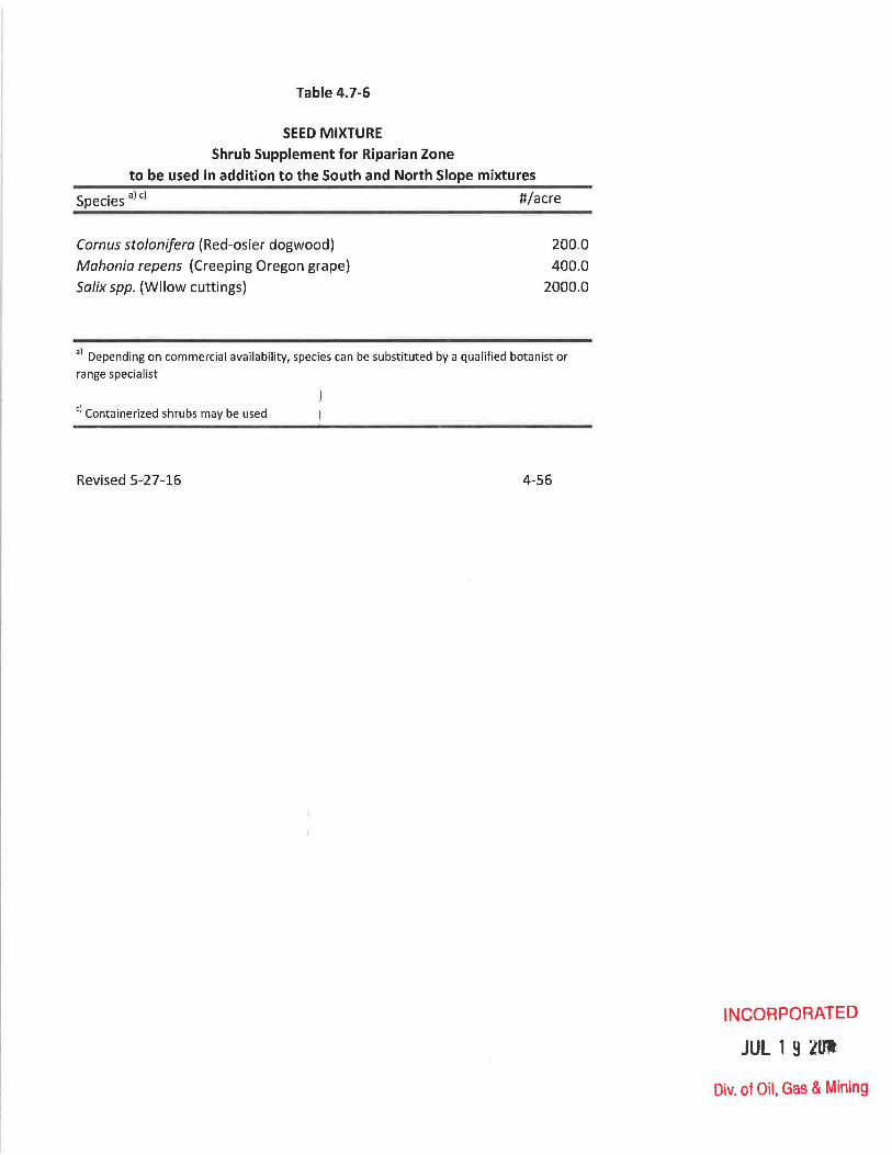
Table 4.7-6
SEED MIXTURE
Shrub Supplement for Riparian Zone
to be used in addition to the South and North Slope mixtures
Species a) c) #/acre
Comus stolonifera (Red-osier dogwood)
Mahonia repens (Creeping Oregon grape)
Salix spp. (Wllow cuttings)
200.0
400.0
2000.0
aj Depending on commercial availability, species can be substituted by a qualified botanist or
range specialist
cj Containerized shrubs may be used
Revised 5-27-16 4-56
INCORPORATED
JUL 1 9 2Ult
Div. of Oil, Gas & Mining

Species a)
Grasses
Table 4.7-6A
SEED MIXTURE
Waste Rock Disposal Area
Paseopyrum smithii (Western wheatgrass)
Elytrigia dasystaehya (Thickspike wheatgrass)
Bromus marginatus (Mountain brome)
Poa pratensis (Kentucky Bluegrass)
Forbs i Artemisia ludoviciana ('Summit' louisiana sagewort)
Linumm lewisii (Lewis flax)
Melilotus officinalis (Yellow sweetclover)
Penstemon strietus ('Bandera' rocky mountain penstemon)
Astragalus cieer (Cicer milkvetch)
Total
Transplants c)
Chrysothamnus nauseosus albieaulis
(Whitestem rubber rabbitbrush)
Artemisia tridentata vaseyana (Mountain big sagebrush)
Rosa woodsii (Woods rose)
Rate b)
(Lbs
PLS/Ac)
4.0
4.0
6.0
0.1
0.1
1.5
1.5
0.5
0.5
18.20
#/acre
200.0
1000.0
500.0
aj Depending on commercial availability, species can be substituted by a qualified botanist or
bj Rates based on broadcast seeding methods
cj Containerized shrubs may be used
Revised 5-27-16 4-57
INCORPORATED
JUL 1 9 2Ul,
Div. of Oil, Gas & Mining

-------------------------------,---------------------------------.
Table 4.7-7 • The acreage and seed mixture of each dis urbance area is as follows:
•
Seed Mixture
Loadout South Fork
(including transplant area)
North Slope
Riparian
Portal Yard South Slope
(including transplant area)
North Slope
South Slope
(already disturbed)
Water Tank and
Well Pads
Conveyor Route
Waste Rock
Disposal
South Slope
Soutr. Slope
Waste Rock Seed Mix
Contempora~eous Reclarlation 2.64
South Fork
Breakout
CHANGE TO
~ew Expansion
South Slope
North Slope
5.04
Table 4.7-7 Page 4-58 Table 4.7-7
•
Acreage
10.52
3.30
~
13.86
10.92
16.37
2.:.l.l 36.40
.26
8.97
7.68
.3
~
~
68.13
TEXT
Page 4-58
1.
76
24
-----100
30
-45
~
100
100
1CO
100
31
100
Date 08/11/93
4-58
R8/27/98

Table 4.7-8
Suggestions for Containerized Plants for Revegetation in South Fork Canyon
at the Skyline Mine in Carbon County, Utah
Scientific Name
Abies lasiocarpa
Chrysothamnus viscidiflorus
Chrysothamnus nauseosus
Lonicera involucrata
Pice a engelmannii
Populus tremuloides
Ribes aureum
Ribes viscosissimum
Ribes cereum
Sambucus racemosa
Symphoricarpos oreophilus ·Species used wil be dependent on commercial availability. Substitutions possible if reviewed beforehand if reviewed by a qualified botanist or range
specialist.
Revised 5-27-16
Common Name
Subalpine Fir
Low Rabbitbrush
Rubber Rabbitbrush
Black Twinberry
Engelmann spruce
Aspen
Golden Currant
Sticky Currant
Wax Currant
Red Elderberry
Mountain Snowberry
4-58(a)
INCORPORATED
JUL 1 9 lU'1
Div. of Oil, Gas & Mining

•
•
•
Table 4.7 - 8A
Interim Revegetation Seed Mixture for ~he Winter Quarters Ventilation Facilitv. Species a) Rate b) Seeds/ff
Elymus lanceolatus Elymus smithii
Elymus trachycaulus Hedysarum boreale
Poa pratensis
TOTAL a) Depending on commercial availabil ity, species can b substituted by a qualified botan ist.
b) R~tes h~sed on seedina methods
Revised: 9-24-09
(# PLS/Ac\
4.00 14.14 5.00 14 .46
4 .00 14.69 10.00 7.7 1
0 .30 14 .99
23.30 66.00
INCORPORATED
JUl- 2~( 2010
Div. of Oil, Gas & Mining

•
•
•
Tab l e 4 .7-8B
Final Revegetation Seed Mixture for thl. Riparian
Communitv at the Winter Quarters Ven ilation Facilitv. Species a) ~ate b) Seeds/ft2
'# PlS/Ac) FORBS Aquilegia caerulea
Geranium viscosissimum
GRASSES (or Grass-likes) Agrostis sfolonifera
Carex microptera
Carex nebrascensis Elymus trachycaulus Juncus arcticus
Poa pratensis
TOTAL UJ Depending on commercial availabil ity, species can be substituted by a qualified botan ist.
b) Rates based on broadcast seeding methods .
c) W il lows from containerized , bareroot or local cuttings will be planted in a :staggered or clumped" fash ion at a average rate of one plant per 10 linear feet of
Revised: 9-2 4 -0 9
1.00 7.00
0 .05 0.40 0.50 2 .00 0.03 0 .10
11.08
8.45 8 .36
7.35 7.78 6 .1 3 7.35 7 .51 5.00 0 .00
57 .91
INCORPORATED 4- 58(b) JUL 2 9 2010
Div. of Oil, Gas & Mining

•
•
•
Table 4 .7-8C
Final Revegetation Seed Mixture for th Sagebrush/Grass Communit at the Winter Quarters Ven ilation Facilit Species a) Rate b Seeds/ft2
SHRUBS Amelanchier utahensis 6.00 3 .55 Artemisia tridentata var. vaseyana 0.10 5 .74 Ceratoides lanata 4 .00 5.05 Purshia tridentata 15.00 5. 17 Symphoricarpos oreophilus 3.00 5 .1 7
FORBS Achillea millefolium 0.03 1.91 Hedysarum boreale 5.00 3.86 Unum lewisii 0.70 4.47 Lupinus sericeus 8.00 4 .51 Penstemon rydbergii 1.50 4.54 Viguiera multiflora 0.20 4 .84
GRASSES Bromus carinatus 1.50 3.44 Elymus spicatus 1.50 4 .82 Elymus trachycaulus 1.00 3.67 Poa pratensis 0.10 5 .00 Poa secunda 0.20 4.25
TOTAL 47.83 69 .98 Depending on commercial availability, species can b
substituted by a qualified botanist.
b)
Revised: 9- 24 - 0 9
'NCORPORATEO
JUL 2 9 2010
D\v. of Oil, Gas & Mining 4-58 (c )

TaDle 4.7-8D
Suggestions for Containerized Plants for Revegetation in South Fork Canyon at the
Skyline Mine in Carbon County, Utah
Scientific Name*
Abies lasiocarpa
Chrysothamnus viscidiflorus
Chrysothamnus nauseosus
Lonicera involucrata
Picea engelmannii
Populus tremuloides
Ribes aureum
Ribes viscosissimum
Ribes cereum
Sambucus racemosa
Symphoricarpos oreophilus
* Species used will be dependent on commercial availability . Subst i tutions possible if reviewed befo rehand by a qua l ified botanist.
Revised: 7-9-12
Common Name
Subalpine Fir
Low Rabbitbrush
Rubber Rabbitbrush
Black Twinberry
Engelmann's Spruce
Aspen
Golden Current
Sticky Current
Wax Current
Red Elderberry
Mountain Snowberry
INCORPORATED 07/31/12
Division of Oil, Gas & Mining
4-58(d)

Table 4.7-9A
Interim Revegetation Seed Mixture for the Winter Quarters Ventilation Facility
Species a) Rate b) Seeds/ft2
(Lbs PLS/Ac)
Elymus lanceolatus (Thickspike wheatgrass) 4.00
Elymus smithii (Western wheatgrass) 5.00
Elymus trachycaulus (Slender wheatgrass) 4.00
Hedysarum boreale (Utah sweetvetch) 10.00
Poa pratensis (Sandberg bluegrass) 0.30
Total 23.3 )
14.14
14.46
14.69
7.71
14.99
66.0
I I
a) Depending on commercia) availability, species can be substituted by a qualified botanist or range specialist
b) Rates based on broadcast seeding methods
Revised 5-27-16 4-58{b)
INCORPORATED
JUL 1 9 llfJ
Div. of Oil, Gas & Mining

Table 4.7-98
Final Revegetation Seed Mixture for the Riparian Community at the Winter
Quarters Ventilation Facility
Species a)
Forbs
Aqui/egio caeru/eo (Rocky Mountain columbine)
Geranium viscosissimum (Sticky geranium)
Grasses
Agrostis st%nifera (Creeping bentgrass)
Corex microptera (Smallwing sedge)
Corex nebraskensis (Nebraska sedge)
E/ymus trachycou/us (Slender wheatgrass)
Juncus orticus (Mountain rush)
Poo pratensis (Kentucky bluegrass)
Total
Rate b) Seeds/ftz
(Lbs PLS/Ac)
1.0
7.0
0.05
0.40
0.50 2.00
0.03
0.10
11.08
8.45
8.36
7.35
7.78
6.13
7.35
7.51
5.00
57.93
a) Depending on commercial availability, species can be substituted by a qualified botanist or range
specialist
b) Rates based on broadcast seeding methods
Revised 5-27-16 4-58 (c)
INCORPORATED
JUL 1 9 lUI·
Div. of Oil, Gas & Mining

Table 4.7-9C
Final Revegetation Seed Mixture for the Sagebrush/Grass Community at the Winter
Quarters Ventilation Facility
Species a)
Shrubs c)
Amelanchier utahensis (Utah serviceberry)
Artemesia tridentata vaseyana (Mountain big sagebrush)
Krascheninnikovia lanata (Winterfat)
Purshia tridentata (Antelope bitterbrush)
Symphoricarpos oreophilus (Mountain snowberry)
Forbs
Achilliea millifolium (Yarrow)
Hedysarum boreale (Utah sweetvetch)
Linumm lewisii (Lewis flax)
Lupinus sericeus (Silky lupine)
Penstemon rydbergii (Rydberg's penstemon)
Viguiera mUltiflora (Showy goldeneye)
Grasses
Bromus marginatus (Mountain brome)
Elymus spicatus (Blue bunch wheatgrass)
Elymus trachycaulus (Slender wheatgrass)
Poa pratensis (Kentucky bluegrass)
Poa Secunda (Sandberg bluegrass)
Total
Rate b) Seeds/ft2
(Lbs PLS/Ac)
6.0 3.55
0.1 5.74
4.0 5.05
15.0 5.17
3.0 5.17
0.0 1.91
5.0 3.86
0.7 4.47
8.0 4.51
1.5 4.54
0.2 4.84
1.5 3.44
1.5 4.82
1.0 3.67
0.1 5.00
0.2 4.25
47.83 69.99
. ) Depending on commercial availability, species can be substituted by a qualified botanist or range specialist
b) Rates based on broadcast seeding methods
c) Containerized shrubs may be used
Revised 5-27-16 4-58 ( d)
INCORPORATED
JUL 1 9 lUI
Div. of Oil, Gas & Mining

Table 4.7-10A
Interim Revegetation seed Mixture for the North of Graben Bleeder Shaft
Species a)
Forbs Achillea millefolium (Common yarrow) Rudbeckia occidentalis (Western coneflower)
Grasses Bromus carinatus (Mountian brome) Elymus trachycaulus (Slender wheatgrass) Poa secunda (Sandberg bluegrass)
Rate b) Seeds/ftl
(# PlS/Ac)
0.6 51 1 51
8 15 8 25 3 46
a)
b)
Depending on commercial availability, species can be substituted by a qualified botanist
Rates based on broadcast seeding methods
Revised: 9/18/2015 4-58(e)
INCORPOHATED
JCT 0 9 2ot~
D!v. o~ Oil, U2S ~". Mining

Table 4.7-10B
Final Revegetation seed Mixture for the North of Graben Bleeder Shaft
Species a)
Shrubs and Trees c)
Populus tremuloides (Quaking Aspen) Sambucus racemosa (Red Elderberry) Symphoricarpos oreophilus (Mountain snowberry)
Forbs Achillea millefolium (Common yarrow) Rudbeckia occidentalis (Western coneflower) Heliomeris miltiflora (Showy goldeneye)
Grasses Bromus carinatus (Mountian brome) Elymus trachycaulus (Slender wheatgrass) Elymus spicatus (Bluebunch wheatgrass) Poa secunda (Sandberg bluegrass)
Rate b) Seeds/ftl (#/ac or Lbs PLS/Ac)
(#/ac) 200 n/a
20 n/a 100 n/a
(Lbs PLS/ac) 0.6 46
1 51
(Lbs PLS/ac) 8 51 8 15 6 26 3 25
a)
b)
c)
Depending on commercial availability, species can be substituted by a qualified botanist Rates based on broadcast seeding methods
Containerized Planting as appropriate
Revised: 9/18/2015 4-58(f)
INCORPC)RATED
Div. o~ Oil, G~s & Mining

Table 4.7-11A
Interim Revegetation Seed Mixture for the Sagebrush/Grass
Community at the Swens Canyon Ventilation Facility
Species a) Rate b) Seeds/ft2
Forbs
Achillea millefolium (Yarrow) 0.06 4
Penstemon spp (Penstemon spp)
Grasses
Bromus marginatus (Mountain brome)
Elymus spicatus (Bluebunch wheatgrass)
Elymus trachycaulus (Slender wheatgrass)
Poa Secund (Sandberg bluegrass)
Total
3.00
6.00
3.00
3.00
0.50
15.56
01 Depending on commercial availability, species can be substituted by a qualified
botanist or range specialist
bl Rates based on broadcast seeding methods
01 Containerized shrubs may be used
10
22
10 10 11
67.00
Revised 5-27-16 4-58(g)
INCORPORATED
JUL 1 9 ~mt,
Div. of Oil, Gas & Mining
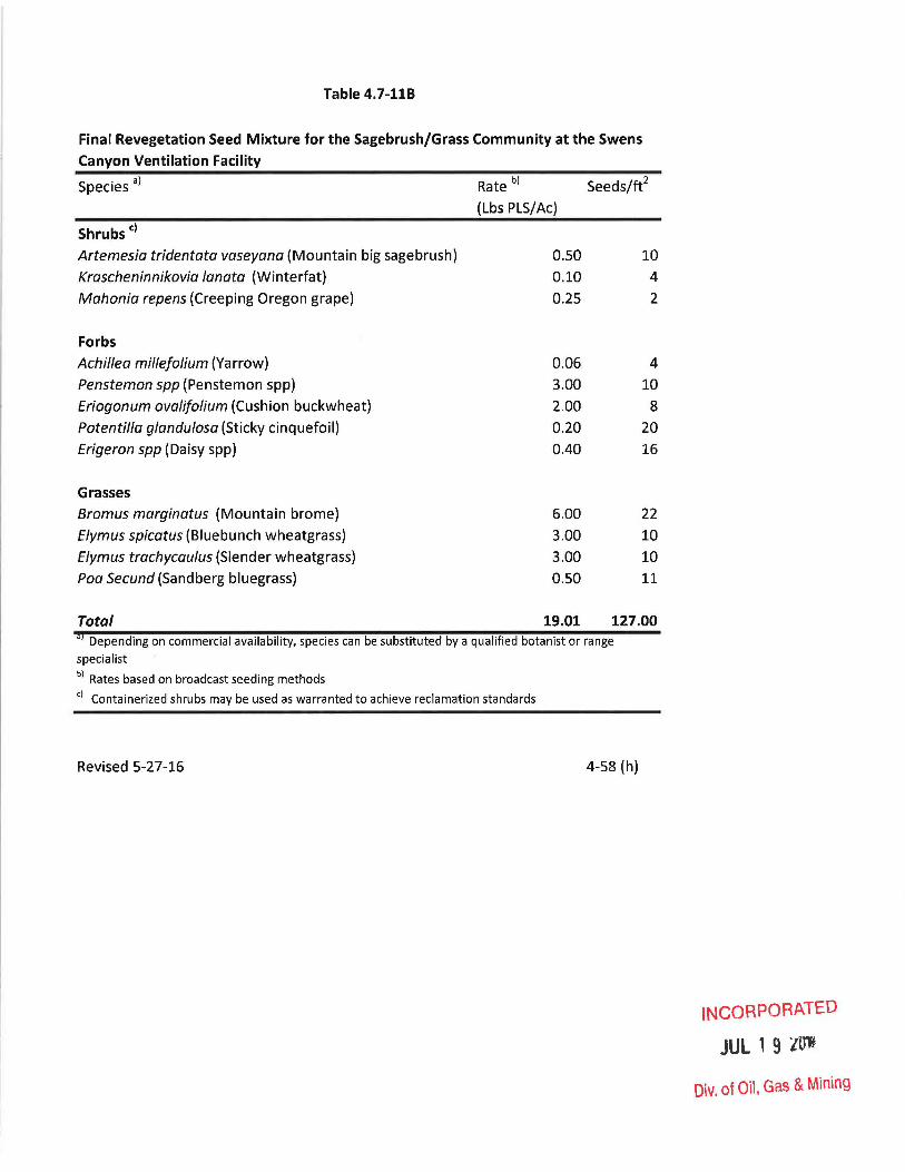
Table 4.7-118
Final Revegetation Seed Mixture for the Sagebrush/Grass Community at the Swens
Canyon Ventilation Facility
Species a)
Shrubs c)
Artemesia tridentata vaseyana (Mountain big sagebrush)
Krascheninnikovia lanata (Winterfat)
Mahonia repens (Creeping Oregon grape)
Forbs
Achillea mille/olium (Yarrow)
Penstemon spp (Penstemon spp)
Eriogonum ovalifolium (Cushion buckwheat)
Potentilla glandulosa (Sticky cinquefoil)
Erigeron spp (Daisy spp)
Grasses
Bromus marginatus (Mountain brome)
Elymus spicatus (Bluebunch wheatgrass)
Elymus trachycaulus (Slender wheatgrass)
Poa Secund (Sandberg bluegrass)
Total
Rate b)
(Lbs PLS/Ac)
0.50
0.10
0.25
0.06
3.00
2.00
0.20
0040
6.00
3.00
3.00
0.50
19.01
Seeds/ft2
10
4
2
4
10
8 20
16
22
10
10
11
127.00 aj Depending on commercial availability, species can be substituted by a qualified botanist or range
specialist
b) Rates based on broadcast seeding methods
c) Containerized shrubs may be used as warranted to achieve reclamation standards
Revised 5-27-16 4-58 (h)
INCORPORATED
JUL 1 9 lUI
Div. of Oil. Gas & Mining

• 4.8 HAZARDOUS & FLAMMABLE MATE IALS DISPOSAL & CONTINGENCY PLAN
4.8.1 Non-Coal waste Materials Disposal
A facility for temporary stora e of waste materials is located at
the mine site. The storage facility, as shown in Map 3.2.1-1,
has been constructed reed concrete. This main storage
facility is used for storage 0 non-coal waste materials from the
underground operations that ar free of toxic wastes, oil, grease
and other liquids. These mat rials consist basically of paper,
wood, metal and plastic produ ts. Since the drainage from the
storage facility contains toxic wastes, oil or grease
products, it enters the normal surface drainage system and enters
the sedimentation pond. A hydrant is located near the
structure.
Portable dumpster trash bins are located at the mine si te and
train loadout areas. waste products from the surface operations
~ and any oil, grease or liquid aterial containers from the under
ground operations-are deposite directly into these trash bins.
In the course of operations, each time the temporary facility is
full, the solid waste material will be loaded into one of the
portable dumpsters and rted to a state approved sani tary
landfill area. The current d sposal site is the Price sanitary
landfill. The waste remov.al ruck will be sufficiently covered
and sealed so as to prevent 1 ss of solid waste material during
transportation.
Although no toxic waste materi Is are anticipated, if identified,
they will be stored and/or sposed of in accordance with all
applicable state and federal
4.8.2 Diesel Fuel and Gasoline and Oil Storage
• Diesel fuel and gasoline is stored in three above ground tanks
wi th a total capaci ty of 26, 00 and 4,000 gallons respectively
4-59

• (Map 3.2.1-1) .
lubricating oil
gallons total},
The oil
(6,000
waste oil
ground storage consists of:
total), hydraulic oil (4,000
( ,000 gallons total), stoker oil
(20,000 gallons total). Each of the above ground storage tanks
is located behind imperviou concrete walls which form a
containment area which will the entire contents of the
single largest tank plus su ficient freeboard to allow for
average annual precipitation
less than 5 inches of
positioned so as not to affec
storage tanks are protected
protection or other effective
with existing soil conditio
periodically to ensure that
not occur.
evaporation or approximately
reo The tanks are located and
any slope or shaft opening. The
corrosion by cathodic coat
ethods considered most compatible
The tanks will be tested
akage into the surroundings does
The Permittee has prepared and has available at the mine site a
Spill Prevention Control Plan as required to be implemented in
• the event of a spill or leakag of the stored fuels, oils or oil
products.
•
4.8.3 Explosive Magazines
In compliance with Federal an State of Utah regulations, the
explosive magazine is not located near power lines, fuel tanks,
storage areas or other possible sources of fire (see Map
3.2.1-1). Construction material for the magazine is of a
noncombustible type covered wi fire resistant material. The
construction of each structure 5 interior entails utilization of
non-sparking materials for wal s and floors. Each structure is
equipped wi th screened venti 1 tion openings near the floor and
cei ling. The structure let resistant and "Danger" signs
are located such that bullets assing through the signs will not
strike the magazine structure. Each magazine is equipped with a
security lock designed to preve t intrusion .
The explosive magazine is
underground construction and
rily used to store explosives for
ining activities. The types of
4-60

•
underground construction and mining activities could be: 1)
overcast and undercast constr~ction, 2) construction of mine
sumps, 3) crossing of fault! in the coal seam, and 4) mining
through dike. The explosive magazine is also used to store a small
amount of explosives for sUlface activities. These types of
activities could be: 1) ]~emoving building foundation, 2)
removing rocks from side hills for safety reasons, 3) excavating
foundation' for buildings thai are in rock, and 4) cleaning
plugged chutes.
4.8.4 Hazardous Materials
The Permittee has reviewed the "ReRA" and 40 CFR Part 261 list of
hazardous materials and will handle any such materials according to
subtitle C of "RCRA". Any :,.isted hazardous materials will be
stored in the hazardous waste storage building.
4.8.5 Slides and Other Damage
Any damage to roads or ot]~er surface facilities due to a
catastrophic event such as f.",oods, earthquakes, or land slides
which may have a potential c dverse effect on public property,
health, safety or the environml.nt will be reported to the Division
by the fastest means available. Remedial measures will be decided,
as appropriate, by the Permittee and the land owner and will be
coordinated with the Division for the repair as soon as practical
after the damage has occurred.
-, -----.l--__ ~----.~-
1ITJ ~"' .. ,~(\: ~ ,-. ,
L
4-61
R05/02/fJ4 ! J
----------_.---........

4.9 OPENING AND SEALING PLANS
Exploratory Holes, Bore Holes, and Wells
In accordance with the approved plan for exploratory drilling
during 1979, all drill holes upon abandonment of drilling
operations were cemented witr. an approved slurry. The slurry
mixture was made using 5.2-5.5 gallons of water per bag of cement.
An appropriate slurry device WeS lowered to the bottom of the hole
and sufficient slurry pumped through the device to fill 200 feet of
hole. The device was then raised 200 feet and the process
repeated. The holes were thus completely plugged from the bottom
to the collar using this me ~hod.
approved exploratory drilling plan,
As stipulated in the 1979
drill hole locations were
appropriately marked. There are presently no plans to transfer any
exploratory or monitoring weJ Is to use as water wells by the " Permittee.
Temporary or permanent abandor.~ent of water and monitoring wells
will be in accordance with the State of Utah Administrative Rules
for Water Well Drillers, Divis on of Water Rights, or other agency
procedure as appropriate.
MAR 2 3 1993
OTAH DIVWONOIL. GAS AND MlNINo
ADDITION TO: TEXT
Section 4.9 Page 4·62 Section 4.9 Page 4·62 Date 02/24/93
4-62

Shafts
Skyline Mine does not have any shafts initiated permitting the Winter Quarters Ventilation Shaft (WQVF) in 2010. Should any be designed in the future, Rreclamation will be in compliance with State regulation R645-301-551 and consistent with MSHA, CFR 75.1771. Shafts or other opening to the surfa~e from an underground mine will be capped, sealed and backfilled, or otherwise properly managed, as required by the Oi vision. Permanent closure measures will be designed to prevent access to mine workings by people, livestock, fish and wildlife, and to keep acid or other toxic drainage form entering groundwater or surface waters.
Figure 4.9-B illustrates how the WQVF shafts will be reclaimed through backfilling. The bottom 50-feet of the shaft will be filled with non-combustible material as follows: starting at the bottom with large, course 6+ inch rock for approximately 20 feet (including mine area); followed by successively by smaller rock; culminating with a 5-foot bentonite layer, 5-foot concrete layer, and an additional 5-foot bentonite layer. The remainder of the shaft will be filled to the surface with pit run or other reject fill. The bottom 50 feet of the shaft has been designed to both minimize accumulation of gas and filling of the shaft with water - should either condition occur. The shaft(s) reclamation design addresses both mass stability and movement in multiple ways: grading of the fill from coarse to fine minimized movement while allowing pore space for possible saturation; the bentonite-concrete layers (~15 total feet) are utilized as both a cap and seal, providing a barrier for both saturation and mass movement; and finally, once the shaft is full to the surface, a 20-foot mound is placed over the former opening to accommodate additional compaction. The mound provides approximately an additio~al 5 percent of material for compaction. It is proposed the shaft be filled and allowed to settle for approximately one (1) year prior to completely reclaiming the WQVF pad to approximate original contours (AOC).
A shaft in the North of Graben area (NOG Bleeder Shaft) will be abandoned in the same fashion. Figure 4.9-0 illustrates the abandonment. Notable differences include the diameter of the shaft (5-feet) and the depth (~1, 400-feet). The shaft will not be lined and since the shaft was drilled using the raise-bore method, all the backfill material will need to be imported to the site.
Shafts in the Swens Canyon Ventilation Facility (SCVF) area will be abandoned in the same fashion. Figure 4.9-0 illustrates the abandonment. The notable differences are the depth(s) and diameter of the shaft(s). Cuttings from the drilling of the shaft(s) will be used in the backfill at reclamation (Blind-bore). - If the raised-bore method is used, all the material will need to be imported to the site.
Mine Entries
In compliance with 30 CFR 75.1711-2, seals will be installed in all entries as soon as mining is completed and the mine is to be abandoned. (See Figure 4.9-A for typical portal seal.) The seals will be located at least 25 feet inside the portal entry. The opening will be sealed with solid, substantial, incombustible material, such as concrete blocks, bricks or tile, or shall be completely filled with incombustible material. Figure 4.9-C illustrates a cross section of the WQVF seal. The WQVF seal
has incorporated a water-tight seal in the event water is encountered at rel'N-CO~tpaRATED
Revised: 5-27-16 4-62 (ajUL 1 9 ~Ul
Div. of Oil, Gas & Mining
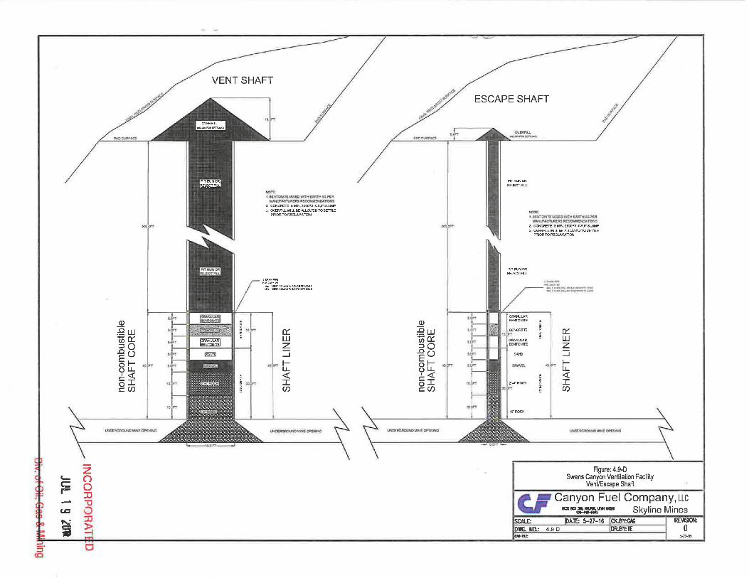
(])
:f!w 000::: ::JO .00 §~ ULL 1« 5I c:CJ)
~o:!l\GAOI.IIiIO.~CfIENWO
VENT SHAFT
.ott. LaQtTatlZllCll:W WIH£ .... tH~ ~ """'-"'I~kM~~~""'~
2. CONCRETE IS MIN 2500PSI es,S" SLUMP
3 OVERFILL WILL BE ALLOWED TO SETTLE PRIOR TO RECLAMATION
.OR ... NPIPE ~w G.oLV WI
III"" 'SEEPeNLAR lN eC>lCR~E !ONE
1oI1I'<1S"' COUAR"l !ENTONfT'ELOOE
0::: W Z ---l
~ LL « I Cf)
~~oPCfM.
(])
;Qw 000::: ::JO .00 §~ uLL 1« 5I C:Cf)
U~WJ(t:ClPUJJHQ
ESCAPE SHAFT
PITRUNCf{ REJECT FILL
NIT.I. . ',~.t.ILUO~aMTWjl:i~ WM.F~fIC!i~~
2 CONCRETE IS MIN, 2S00PSI CS,6"' SLUMP
3 OVERFlLL 'MLL BE ALLOWED TO SEmE FRIOR TO RECLAMATlON
~--.. _ .. """IUII·CftIU"_~~ _'RI'~~"""""'~
0::: W Z ---l
~ LL « I CJ)
/; ~
"':Z~Cu.NICJIIItN~
Figure: 4.9-0 Swens Canyon Ventilation Facility
VentlEscape Shaft
5-27-18

•
•
• .~~
r·-~"~7""''''~'''''",,, I' •• ..:=..- r~.:..:;. ... ~';';:.,.:~'""'":"'~ .. -~~=.:.:~ .... ___....... ...-...--.~~ .... -r.c-.-..._.h."""""" bt..,......-l.._-~~»t ..... ~~ ....... ~I1111::....;:" .............. r_· __ i:~_·.~ ... ':. ....... ..............-.. --~-.. ·.-... - ... ..J~ ..... ..,..'tI~......--:..a::.-..= .• ., ... '.:" ___ ~~_"' . .:..
MI NE ENTRIES
;J~
DODD
PLAN VIEW
---- - -,
.- .. ",- .. " ""'. • o. V l/I> .. • 'If? ' tIfI .~.-... ~ .....
eJ ~ e>- 0_ ... t:J.,,"w . -.-_11 • ' '',,''': Co ~ - .. 0 .. , • o ... t:t • _ ~ • ;. #I
_" "-II?,. " .. II ., ,.-.- .. _ ..
PORT At SE AL
SECT ION VIEW
BLOCK SEAL
NONCOMBUSTIBLE BACKFILL
OUTCROP
BACKFILL ..
r---------------------------------.~,--------------------------------------------~ COASTAL STATES ENERGY COMPANY St~VllP\E PROJECT
.... , I
T Y PIC A I. ! PO RT A L SEA L
ApP'ICOVSO w--=-~ 7--" -Sq I MAP OR 4.q-A I . - ;- ;;''''.'0"' I fIGU::E !lO.
DV/G. f~? I\.- ! _.-•. ---....... ~-.--~._. __ .,-__ !O!. __ •
.. _. 4-63 ---~------,----__ . ________ 2_. ____ ~c~~~~~_~ ________________________________________________________ __
~~ _ ..... t~O $~"L[
• • __ .. __ ,.., r __ ._ ... __ ... __ ..... ~-... ..,- -r

o :;::-o -_9 G)
~ Ro s:: S-5-co
......., to
"-.) <:::)
c;
(') o :0 '1J o :0
~ m c
Q.)
~L1J t)o::: ::JO ..ell)
El-8LL
45. FT
1« C I gU)
VENT SHAFT
'. BENTONITE MIXED WITH EARTH AS PER MANUFACTURERS RECOMMENDATIONS
2. CONCRETE IS MIN. 2500PSI eS,6" SLUMP
3. OVERFIL L Will BE ALLOWED TO SETIlE PRIOR TO REClAMATION
M~ . 1 SEEP COllAR IN CONCRETE ZONE MIN 1 SEEP COlLAR IN BENTONrreZONE
cr: L1J Z .....J
I-45. FT LL
« I U)
Q.)
;:QL1J t)o::: ::JO ..ell)
El-°LL 45. FT
y« C I gU)
UNDERGROUND MINE OPENING
ESCAPE SHAFT c.,'" ,.-
;:,'1:' {)<;
q
OVERFil l
CONCRETE
GRAvEL
1. BENTONITE MIXED wITH EARTH AS PER
MANUFACTURERS RECOMMENDATIONS 2. CONCRETE IS MIN, 2500PSI CS.6~ SLUMP
3. OVERFILL WILL BE AlLOWED TO SETTLE PRIOR TO RECLAMATION
MIN 1 SEEP COUAR f-I CONCRETE !ONE M .. lSEEPCOUARlNeen"""-E~
0::: L1J Z .....J
I-45.0FT
I
LL « I U)
UNDERGROuND MINE OPENING
Figure: 4.9-8 Winter Quarters Ventilation Facility
VenUEscape Shaft
.. Canyon Fuel CompanY,LLC Skyline Mines
REVISION: o
312212010

CJ :c:"
8-Q G) n> U>
Qo
s:: ::J 5"
(Q
5FT OVERFILL (FOR SETTLING)
'-c:: r......., u::;,
r-..,) <:::)
25
z ('") o :n "'U o :a ~ m o
f\~P.\.. R'C.C\"P.\WI'C.O
SIJRfP.C'C.
PIT RUN BACKFILL
CONCRETE BLOCK (8"X16") WALL PLACED WI LONG AXIS PARALLEL
TO SLOPE LONG AXIS
DRY STACKED AND WEDGED TIGHT
BENTONITE MIXED WITH EARTH AS PER
MANUFACTURERS RECOMMENDATIONS PLACED AS CONCRETE BLOCK WALL
IS CONSTRUCTED
CEMENTATEOUS GROUT
;;
50-70 LBS/CUFT
- BRATTICE FACING WI SPRAY
BULKHEAD ~ FOAM SEALED PERIMETER
WOOD POSTS (MIN. 8" DIA.)
~ ~------- WOOD LAGGING (MIN. 3" THICKNES)
Figure: 4.9-C Winter Quarters Ventilation Facility
Slope
I' ~ Canyon Fuel CompanY,LLc ~ t«:J51!01(~UTAII_ Skyline Mines
REVlSlON: o
312212010

Q)
;Qw (j)0::: :JO .au EJ-8LL.. Ie::(
C I gC/)
FT
ESCAPE SHAFT
0::: w Z ....J
lLL.. « I C/)
INconr

•
•
•
Since all entries are down ip, no hydraulic seals will be
needed. Prior to installation, all loose material within three
feet of the seal area will b removed from the roof, rib and
floor. The mine entry seals will be made of solid concrete
blocks (average minimum compressive strength of 1,800 psi; tested
in accordance with A.S.T.M. C- 40-70) and mortar (1 part cement,
3 parts sand and no more tha 7 gallons of water per sack of
cement) .
Seals will be installed in
be recessed at least 16
deep into the floor. No
blocks will be at least six
and eight inches wide. The
transverse pattern. In
following manner: The seal will
deep into the rib and 12 inches
will be made into the roof. The
high except in the top course,
will be laid and mortared in a
course, each block wi 11 be
laid with its long axis paral el to the rib. The long axis in
succeeding courses wi 11 be to the long axi s block
in the preceding course. interlaced pilaster will be
constructed in the center. Th seals will have a total thickness
of 16 inches. The entry then be backfilled and sloped to
match the cut slope at the 1 entry_
During periods of temporary abandonment, the operator will
effectively barricade each inactive mine opening and
wi 11 conduct inspect ion and m intenance in accordance wi th the
requirements of 30 CFR 75.1711- .
Should the mine workings e entually fill with water where
discharge from one of the port 1 openings becomes a possibility,
discharge control structures s all be designed and constructed in
accordance with 30 CFR 75. 711. Design of these control
structures will be deferred un il final reclamation when need and
potential discharge conditions an be better evaluated.
4-64

•
•
•
4.10 SAFETY AND COMPLIANCE PRO RAM
Compliance with the requirements of the Clean Air Act (42 U.S.C.,
Sec. 7401 et seq.) and the Cle n water Act (33 U.S.C., Sec. 1251,
et seq.) is accomplished by fulfilling the conditions of a
Prevention of Significant terioration (PSD) permit and a
National Pollution Discharge El'mination System (NPDES) permit.
PSD permi t application,
project, was filed with the
1979 and approved on August
to the proposed Skyline Mines
Region VIII office on March 8,
1980. The air quality control
devices and procedures in the PSD permi t application
have been incorporated design of the Skyline project.
The control system, as incorpo ated, is presented in Section 4.22
- AIR POLLUTION CONTROL PLAN.
The Permittee's current NPDES ermit application was approved by
EPA Region VIII office gust 15, 1990 (see documents in
Volume A-I, Hydrology) Contr I measures, in the NPDES permi t
application, have been into this Mining and
Reclamation plan as those meas res governing compliance in areas
where they are duplicated addressed by other rules or
regulations.
Concurrently with the
applications with the EPA,
were filed with the appropri
Intent to Construct was
of the PSD and NPDES permit
ntical copies of the applications
state agencies. A notice of
filed with the Utah state Air
Conservation Committee and a c py of the NPDES permit application
was filed with the Utah Stat Water Pollution Committee. They
were approved on January 7, 198 and July 8, 1980 respectively.
The Permittee has incorporated procedures in its mining operation
to ensure timely reporting any spill or accident which
endangers environmental within the area affected by the
Skyline mining operation and i required by law to be reported to
state and/or federal agencies. Mine employees are instructed to
4-65

•
•
•
report any such spill or accid nt to the Mine Superintendent or a
designated representative in h's absence. The Mine Superintendent
or his representative will re ort any spill or accident to the
appropriate regulatory authori ies.
The Permittee intends to ply with the health and safety
standards required by state and federal regulations and has
incorporated the necessary tecti ve measures into the design
plan of the overall project to ensure such compliance .
4-66

•
•
•
4.11 PROTECTION OF HYDROLOGICAL BALANCE--PERMIT AND ADJACENT AREAS
The Permittee conducts all min site operations in such a way as
to minimize potential impact to surface and subsurface water
quality. water originating in or flowing through disturbed areas
is collected by a drainage con rol system and suspended material
allowed to settle in nt control ponds before being
discharged into the natural
circuiting of the natural d
minimum. Since postmining
premining use, the hydrologica
have been planned accordingly.
ainage system.
channels
will be
Changes or short
were kept to a
similar to the
aspects of the reclamation effort
The long history of mining in the area shows that past adverse
effects to water supplies coal mining activities do not
destroy the use of the water for stockwatering or irrigation.
Mining in the area sometimes t nds to improve the quality of the
water by intercepting some gro nd water and reducing its contact
time wi th underground formati ns. water pumped from the mine
augments low stream flows uring the summer months, thus
enhancing stream conditions.
4.11.1 Water Rights and R placements
The Permittee presently owns 2 8 acre-feet of water rights in the
Scofield Reservoir. Of these ater rights, water sufficient for
the Permittee's needs were xchanged for rights from wells
located near the mine site a d at the mouth of Eccles Canyon.
(See, also, discussion of water rights, Section 2.3.5.)
The Permittee will replace the water rights of any land owner, if
such a water supply is contami ated, diminished or interrupted as
a result of the Skyline mining operations. If reclamation of the
permit area proved unsuccessfu and consequently damaged existing
water rights or if mining rsely affected flow from springs
and/or seeps and damaged rights, the Permittee would
provide alternative water supp ies either from drilling new wells
4-67

•
•
•
in Pleasant Valley Canyon or by pumping wa er up the canyon from Scofield Reservoir.
Culinary water usage at the mine site qualifi s as a public water supply and will be treated to meet State of Utah primary and secondary w ter standards.
4.11.2 Monitoring Program
In order to concentrate on areas of immediat impact, surface water stations located in Eccles Canyon were sampled more frequently than hose on Huntington Creek during the initial phases of mining. (See Sections 2.3 and 2.4.)
As mining progresses toward the Huntington Creek area, sampling in this drainage has increased to more closely monitor mining im acts. The monitoring schedules in Section 2.3 reflect this intensified monitoring activity.
Surface water monitoring will continue accor ing to the monitoring schedule, presented in Section 2.3.7 and 2.4.4, throughout the mini g and reclamation operations. Postmining data collection will continue at each of the station until the reclamation effort is determined successful by the regulatory authority. Quart rly samplings will continue to be analyzed according to Tables 2.3.7-1 and 2.3.7-2 duri g the postmining period.
Water quality data collected from surface an ground water monitoring stations will be submitted quarterly to the regulatory authorit . These reports will normally be submitted electronically within 90 days of the completio of the quarterly monitoring program.
In addition to the above outlined monitoring rogram, UPDES discharge permit monitoring is conducted in accordance with the stipulated ermit conditions.
4.11.3 Water Quality Control
The ground water that is intercepted and bro ght to the surface as a result of mining operations normally has a lower dissolved solids conten than would exist if the water was to continue its downward movement through the existing sh Ie layers, picking up increased amounts of salt with distance through the rock formations. G nerally, mine water is expected to occur when pockets of perched water are interrupted and drained .. Although suspended sediment and oil and grease may increase at the mine mouth rea, these constituents will be removed by retention and sediment pond skimmers prior 0 any potential discharge to adjacent streams. As a result, operation of the Skyline Mines is ex ected to have an overall beneficial impact on water quality in the region.
4.11.4 Water Quantity - Impacts
The Blackhawk Formation, extending over th entire Skyline property, consists of interbedded layers of sandstone and shale separated by arious mineable and nonmineable coal seams. The sandstone beds are generally massive hile the shale layers are generally bentonitic, tending to swell when wet and decompose in 0 an impervious clay. Investigations at springs on the project area have indicated that the shal beds prevent significant downward percolation of
Revised 3-24-10 INCOR~ATED
JUL 2 9 2010
Div. of Oil, Gas & Mining
•
•
•
water through the Blackhawk Formation, wit much of the water entering the upper layers and surfacing a short distance away as a spring. In addition, due to the ability of the shale material to swell and decompose into an impervious lay, fractures in the Blackhawk Formation do not act as conduits but instead as barriers to pot ntial infiltrating water.
As a result of these observations, it has bee concluded that the mining activity in the Skyline Mines will have minimum adverse
Revised: 3-24-10 INCORP~~TED
JUL 2 9 2010
Div. of Oil, Gas & Mining

impacts on the quantity of water in the area. When subsidence occurs, the subsidence cracks should seal rapidly, preventing deep percolation of water and subsequent loss of springs and other water sources. The location of a particular spring may change by a few feet, but no significant loss of water is anticipated as a result of mining. In over 30 years of mining since the mine opened in1981, inflows into the mine have varied due to changes in the geology from the underlying geology. Throughout the same time period the water quantity in the Blackhawk Formation has not recorded any adverse effects due to mining.
Although the Blackhawk Formation may be saturateci above the mine workings, a relatively minor quantity of water is being encountered at each active face due to the impermeable nature of the formation and its inability to readily yield water. Water production at each active face is 10-15 gallons per minute with mine entries generally dry approximately 200 feet updip from the face. Flows of 1-2 gallons per minute occasionally continue from roof bolt holes.
Because of the westerly dip of the strata in the area, some subsurface water naturally moves from the Price River Basin towards Huntington Creek. However, because most water encountered in the mine would not be naturally discharged to the surface in the immediate area, no significant depletion will occur in the amount of water reaching either Huntington Creek or Eccles Creek.
Water quantity will remain generally unaffected due to the geological conditions in the mine area. Therefore, the Skyline Mines will have little or no adverse impact on the hydrological system.
Revised: 10-1-13 4-70
\NCORPORA1EO
JAN 0 3 20\4
0 ' Gas & Mining 01\1 01 II,

•
•
•
4.11.5 Mine Facilities Drainage Area
The original drainage plan for the mine surfa e facilities was designed by Kaiser Engineers for the Permittee. Streams crossing the mine si e are collected outside of the disturbed area and diverted into corrugated metal pipe (CMP) cu vert of adequate size for the 100 year, 24-hour precipitation event. The CMP culverts are 10 ated to transfer the upstream flow under the minesite to Eccles Creek below the minesite. Diversion channels were constructed above the disturbed area to collect the runoff from the ndisturbed areas and direct it to Eccles Creek.
4.11.6 Load-out Site Drainage
The original drainage plan for the load-out sit was designed by Kaiser Engineers for the Permittee. The creek in Eccles Canyon was iverted from its natural state to gain space. Diversion channels were constructed south 0 the disturbed area to collect runoff from the undisturbed areas and direct it to Eccles Cre k. The disturbed area surface runoff is collected and diverted to the sedimentation pond locat d adjacent to the storage silos.
4. 11.7 Portal Locations
The mine portals have been designed to ens re that water will not be gravity discharged from the mine. The portals will have a minimum n gative (in mine) slope of four percent to prevent any gravity discharge.
4.11.8 Underground Water Treatme t
The mine water encountered at the working f ce is collected in the face area and pumped to collection points located within each mine. T ese collection points (or abandoned areas of the mine)The impoundments allow some time fo suspended solids to settle. Underground water is permitted to be pumped from the Mine directl to Eccles Creek or Winter Quarters Creek when discharge parameters are met. The water is pumped from the mine into the portal are sediment pond which is the principle treatment
facility. Mechanical devices have been instal ed at collection points to screen grease and oil which might be present in the water before it s pumped out of the mine.
All of the mine workings are located down di from the entries which precludes gravity discharge. Upon abandonment of mining ac 'vities, the entries will be sealed as indicated in Section 4.9.
4.11.9 Winter Quarters Ventilation Fa ility (WQVF)
The ventilation facility design includes the 10 tions of the declined slope, exhaust shaft, emergency escapeway shaft, sediment pond and drainage plan for both the disturbed and undisturbed drainage. The pad is located a inimum of approximately 30 feet north of Winter Quarters Creek and approximately 20 feet h gher in elevation to minimize water entering the mine. The mine openings (shafts/slope) are ocate up dip of the mine workings, eliminating
Revised: 3-24-10 INCORPp-l1t'TED
JUL 2 9 2010
niv. of Oil, Gas & Mining

discharged from this location when discharge parameters are met. A Utah Pollution Discharge Elimination System (UPDES) water discharge point was added to the Skyline Mine water discharge permit in December 2009 to accommodate discharging water to Winter Quarters Creek both from the sedimentation pond and potentially future mine water discharge.
The Winter Quarters decline slope portal is at an elevation of 8120 feet which is down dip and at a lower elevation than portions of the Mine workings. To safeguard against a gravity discharge at reclamation, should the mine flood to the portal level, both the shafts and slope have been sealed and backfilled to prevent any discharge at reclamation (See Section 4.9).
4.11.10 North of Graben (NOG) Bleeder Shaft
The NOG Bleeder shaft includes a 3.0 acre bonded permit area, with approximately 1.7 acres of disturbance with a 50-ft by 80-ft pad, 784-ft road , topsoil pile, diesel storage tanks, generator, and a 5-ft diameter shaft. The site is adjacent to an existing USFS road located at the top of Granger Ridge. No pond is necessary for sediment control due to minimal disturbance. The shaft opening is located approximately 1,400 feet above the mine workings eliminating concern of any gravity discharge during the operation of the shaft.
4.11.11 Swens Canyon Ventilation Facility (SCVF) The Swens Canyon Ventilation Facility included the designs of an exhaust shaft and an emergency escapeway shaft, and a drainage plan for both the disturbed and undisturbed drainage. The majority of undisturbed drainage has been diverted around the site, while the disturbed area drainage has been minimized with a number of Alternate Sediment Control Areas (ASCAs) that eliminate the need for a sedimentation pond. The shafts are located significantly higher than the flow in Swens Canyon eliminating any chance of water from the creek entering the shaft. Similarly, the shaft is approximately 900 feet above and up dip of the majority mine workings, eliminating concern of gravity discharge during the operation of the mine. See Section 4.9 for the detailed reclamation of the shafts.
Revised: 5-27-16 4-72
INCORPORATED
JUL 1 9 ~UJ
Div. of Oil, Gas & Mining

•
•
4.12 POSTMINING LANDUSE
This section presents a detailed delineation of the abandonment
and reclamation steps to be t ken which will allow a return to
the original wildlife/grazi g (rangeland) habitat landuse
following the completion of min ng operations.
In general, the mine site area will be returned to its original
wildlife/grazing (rangeland) abitat, the conveyor route and
loadout site will be returned to the original premining use as
grazing land. The new State Highway SR-264, which has been
constructed through the permit rea, will be left in place.
4.12.1 Method of Achieving and Supporting Postmining Landuses
Table 4. 12-1 summarizes
alternate landuses. Maps
emining,
.4.2-1A,
proposed
4.4.2-1B
postmining and
and 4.7.2-1
illustrate proposed reclamatio areas and types. The following
presents, in detail, the steps and revegetation/
reclamation activities which epresent the method of achieving
and supporting postmining land sese The list of activities are
organized in the approximate 0 der of execution. A majority of
the listed activities are a ditionally discussed in further
detail in various sections of t is Renewal Application.
Sealing of Large Diameter Openi
Miscellaneous portal openings a d ventilation shafts:
• •
Openings will first be seal
Any remaining opening will
Plugging of Small Diameter Open
with concrete blocks and mortar .
backfilled .
Exploratory holes and water w
4It monitoring or postmining landus
not approved for abandonment
4-73

• Each hole will be cased a d sealed with a cement plug.
• A monument will then be e ected over sealed holes.
Removal of Buildings
Office, shop, storage,
explosive storage:
changehouses,
• Each structure will be re
treatment buildings,
• Removal or fracture of
close to the surface.
undations will follow if they are
foundations will be covered
with at least six feet of dirt.
Equipment Removal
Mining equipment, conveyors, power structure and line, coal
processing and handling equipm nt:
• The above mentioned items will be removed.
• Support structures will then be removed and foundations
fractured and covered.
Mine Operational System Remova
Systems such as domestic wate will be phased out and removed or
buried.
4.7 P
4-74

Present Area Ownership
Mine Site and USFS Exploratory Excavations
Conveyor and Private Pipeline
Main Access State
Road
Loadout Private
Waste Rock Private Disposal
South Fork USFS Breakout
James Canyon USFS/Private
Winter Quarters Private
Ventilation Facility
NOG Bleeder Shaft USFS Compatible
Swens Canyon USFS Ventilation Facility
Revised: 10-13-2017
TABLE 4.12-1
PROPOSED POSTMINING LANDUSE
Proposed Premining Postmining Alternative Landuse Use Use
Wildlife/ Wildlife/ Picnic Adequate Grazing Grazing Area Habitat Habitat
Grazing/ Grazing/ Wildlife Adequate Wildlife Wildlife Habitat Habitat Habitat
Forest State None Compatible Access and Road Service Road
Grazing, Grazing/ Wildlife Adequate Picnic and Wildlife Habitat Stock Pens*
Grazing/ Grazing/ Wildlife Adequate Wildlife Wildlife Habitat Habitat Habitat
Wildlife/ Wildlife/ Wildlife Adequate Grazing Grazing Habitat Habitat Habitat
Forestry
Wildlife/ Wildlife/ Wildlife Adequate Grazing Grazing Habitat Habitat Habitat
Capacity Relationship
To Support To Existing Proposed Landuse Use Policies
Compatible
Compatible
Adequate
Compatible
Compatible
Compatibf cOnoOelT'-C" 1.,..-\ Lw.J
NOV 1 6 2017
iv. of Oil Ca~ & I ,- -Compatlore J ;l:::; YII n/ Of>
Grazing Grazing Adequate Adequate Compatible
Mining Wildlife Wildlife
Wildlife Wildlife Adequate Adequate
Wildlife/ Wildlife/ Adequate Adequate Compatible Grazing Grazing
4-75

"Note: The loadout area picnic facilities and stock pens are not proposed to be included in the proposed
post-mining use. The permittee is the landowner of this site and is not in the recreation or livestock
business, and therefore, elects not to reestablish the picnic and livestock facilities. This land was
purchased by quit-claim deed dated, May 24, 1991, for the area occupied by the loadout facilities in 5-1/2S
E1/4, Section 1), T.13S R.7E SLBM. There is no pending litigation subject to the quit-claim deed. The
grantor reserves the coal rights under the lands.
Revised 9-18/2015 4-75(a)
INCORPORATED
OCT 0 9 206
Div. of Oil, Gas & Mining

•
•
•
Area Cleanup
Solid waste generated in th
collected and removed.
Backfilling of Ponds
abandonment operations will be
Ponds will be drained, the se iment will be tested for toxicity
and removed for disposal as a propriate, then the pond will be
allowed to dry out. When the soil is dry, the railroad loadout
pond will be backfilled. The portal pond will be configured as
part of stream reclamation.
Stream Reclamation
The stream at the mine site
4.4.2-lA according to the plan
Recontouring of the General Are
I be rechannelled as shown on Map
utlined in Section 4.19.5.
Final grading and backfillin will achieve a final contour
suitable for the wildlife/grazi g habitat postmining landuse.
• Operational benches will n t be removed. Their banks will be
reduced to a 3h: Iv slope; their surface areas will have a
10h:1v slope for drainage.
• Side hill cuts range betwe n 1h:lv and 1h:2v. Most of these
cuts will remain upon a andonment. Any physical support
systems used to control hese cuts along with any small
terraces used for control will also remain.
• Abandoned road banks will b sloped to an average of Ih:lv.
Distribution of Topsoil
Topsoil from the stockpiles iII be spread over the disturbed
areas in a manner to reduce exc ssive compaction .
4-76

Scarifying Areas
Operational areas will be ified to reduce compaction and to
preve~t topsoil slippage. ep slope areas which must remain
after abandonment will receiv special ripping to create ledges,
crevices, pockets, and 5. This will allow better soil
retention and vegetation ishment.
Fertilization and Neutralizati n
All necessary fertilization 0 neutralization, as determined by
soil testing, will be done acc rding to the plan in Section 4.5 -
SOIL PREPARATION AND FERTILIZA ION PLAN.
Seeding and Tree Planting
Vegetation will be establishe
the edge effect
to prevent erosion, to optimize
cover. Perennia 1 woody species
will be emphasized along with those of proven nutritional value
and ability to support wildlif. The types and amounts discussed
in the revegetation section (S ction 4.7) will be used.
Moisture Retention
All areas to be reseeded will be mulched. various mulches will
be used including straw, woo
Section 4.6.4)
Maintenance
fibers and excellisor mats (see
Fencing, irrigation, and we d control will be used only as
needed, according to operation 1 testing results.
4-77 UTAH DIVISION OIL, GAS AND M!NINr;

•
i·e
•
Regrading and Reseeding
Erosion that develops in coapleted areas will be minimized by
repeated grading, seeding and mulching.
Success Monitoring and ExtendE~d Responsibility Period
vegetatipn will be rnonitore(~ during the applicable period of liability as outl ined in R6 4 - 301- 356 to determine success of abandonment reclamation. will then be made.
A ~etermination of vegetation success
Removal of Site Drainage I itches and Railroad Loadout Area
Sedimentation Pond
After the disturbed areas a~e stabilized and runoff meets the
applicable state and federal standards without detention time, the site drainage system will be removed. The site drainage system
areas, including the railroad loadout sedi~e~tation pond, will then
be backfilled and revegetated.
Removal of Portal Area Sedimentation Pond
The portal area sedimentation pond will be removed during early Phase I reclamation. Alternat ive sediment control measures such as silt fences, straw bales and c·heck dams will be used until the area
is revegetated and runoff meEts the applicable standards.
Road Abandonment
ADDITION TO TEXT
Section 4.6 - Date 09/11/93
\1 t\~ \~ .. : . . .lJ,J.~ ' .. ~:"t:,\
~.---.. 4 - 78 1
~---~ ----,--..
& -'9~4 I ~
, 1 ;
i,JV , !
i f
'-
I
f ~
;~! I ". , '.: !". ,I
,V~, " r i"iCi :;:-1;11 ; ... , ...... , - 'J
", , L- -- \
' ;-", U AS p.~1) MIN1NO UT '-1-\ D1VlS10: < V! :'-',
n. ~_-.:l
--...----------------_ .......... c-

The mine support roads will be reclaimed in the permit area. Culverts and
blacktop surfacing material will be removed. Reclamation would then include
recontouring, ripping, adding cross drains, water bars, topsoil and seed.
Removal of Scofield Waste Disposal Site Sedimentation Pond
The livestock permittee through the owner has requested that the
sedimentation pond not be reclaimed. If, over a period of time, it shows
that these ponds hold natural runoff water and will be beneficial for
livestock and wildlife use, they will not be removed. However, for planning
and bonding purposes the sedimentation pond is to be removed and reclaimed
(Map 4.16.1C). In the event the pond is not removed, Map 4.16.1B illustrates
the reclamation work.
Removal of Winter Quarters Ventilation Facility (WQFV) Sedimentation Pond
The WQVF area sedimentation pond will be removed during early Phase II
reclamation. Alternate sediment control measures such as silt fences, straw
bales and check dams will be used until the area is vegetated and runoff
meets applicable standards.
Removal of the Swens Canyon Ventilation Facility (SCVF) Cuttings Pond
The SCVF area sedimentation pond is solely used for cuttings from
construction of the shafts. It is not intended as a sediment control
structure for the site. Once the shafts are constructed, the ponds will only
collect water from the immediate vicinity of the pond. Material from the
pond will be used in the backfilling of the shafts at reclamation. As shown
in Table 4.12-1, both pre- and post-mining uses are the same;
Wildlife/grazing habitat. For details on the management plans and
performance standards see pertinent Chapter 4 section of this M&RP such as
Sections 4.4 (Backfilling), 4.6 (Topsoil handling), 4.7 (Revegetation) ,and
4.9 (Openings Sealing.
Revised: 5-27-16 4-78(a)
INCORPORATED
JUL 1 9 ~lJ1t
Div. of Oil, Gas & Mining

NICK AMPINOS Attor ey at Law
1pr ~ '')rth Carbon Avenue it Jlah84501 Telephone: (435) 637-8100
Fax: (435) 637-2111
•
•
VIA - FACSIMILE - 435/448-2632 Hard Copy to Follow
Gary E. Taylor Sr. Environmental Engineer Canyon Fuel Company, LC P.O. Box 719 Scofield, UT 84526
Augu t 25, 1998
RE: Telonis Property - UP Canyo
Dear Gary:
Thank you for your letter of August 20, 1998. As you are aware, I serve as attorney-in-fact for the Telonis family conc rning management of the properties which include, but are not limited to, the UP Can on disposal site.
Request is hereby made that the st ck ponds within the disposal site remain as part of the final reclamation plan. Those stock ponds are most helpful for livestock and wildlife use.
Thank you.
NS~ xc: Telonis Family
'I lNCOlItWOJRA ]fED . EFFECTIVE: \
_,~ I
UTAH DIVISION 0lW to ~~9 1 __ --

•
•
•
Additional Information Con erning The Post Mining Land
Use at the Scofield Waste ock Site is located in the
CONFIDENTIAL FILE
Revised: 02/12/08
1 " i
• "_ .. ) ~ 'J ,:", __ ,";

Compliance Documentation
Upon expiration of the respon ibility period and at the time of
bond release, compliance docu entation will be presented by the
Permittee.
4.12.2 Proposed Underground Mining Activities and
Consistency wit Landuse Plans
The mine site is on U.S. Forest Service land. The U.S. Forest
Service has indicated that the land should be returned to
wildlife/grazing (rangeland) habitat. (Manti-LaSal National
Forest Land and Resource Ma agement Plan, 1986) The Longwall
underground mining system consistent with this plan as it
controls the effects of subsid nce.
Final Surface Configuration
The proposed final surface co tour plan would allow the side hill
cuts and operational benches at the mine si te to remain after
abandonment. The fill banks between each bench level would be
reduced to 3.0h:1v.
various illustrations, Maps .4. 2-1A, and 4.2. 2-1B present the
proposed topography of area. The final
abandonment contours have bee drawn with heavier .lines over the
lighter original contour line. As the drawings illustrate, the
final surface drainage chann
structures to allow
location of operational faci
Upon abandonment, all surface
wi 11 inc lude meanders and drop
dissipation. The maps include
reference purposes only.
will be removed.
4-79

4.12.3 Visual Resourc Assessment to Achieve Postmining
Landuse
The abandonment assessment w'll concentrate on how effectively
final drainages and slope patt rns fit into the area's general
~----------~~~~~------
"---~1
MAR 231993 I ~ i ~
~ .~
TAR DMsIONou.. GAS ANDMlNINa i ~~--------------------~~j
I I T Xl n 4.12.2 Page 4-79(a) Date 09/28/92!
4-79(a)

•
•
•
visual resources. This assess ent will occur through the period
of liability .
4.12.4 Recreational
Postmining Landus
During the life of the
abandonment, recreational
urce Assessment to Achieve the
and with special emphasis at
as assessed by the u.s. Forest Service, will a review of postmining fishing,
hunting, camping, hiking, recreational landuse. If it is
found, during the liability pe iod, that any of these activities
are decreased due to the minin operation, corrective actions may
be taken.
4.12.5 Mineral
Postmining Landus
Assessment to Achieve the
Before abandonment, the resources contained wi thin the
Skyline permit area will The abandonment assessment
will ensure that oil and velopment will be possible at the
conclusion of mining. Measures taken to protect the unmined coal,
such as portal sealing, will a so be assessed. No other mineral
resources are known to be prese t in commercial quantities.
4.12.6 Rock Disposal Sit
The assumed pre-mining rangeland. The pi t
area will be reclaimed to native rangeland per the reclamation
plan. The access road will no be reclaimed {see Map 4.16.1-1B}
and at the request of the landowner, the guard rail along
portions of the road will be re oved during reclamation.
The representat i ve of of the leased property have,
through a letter to the Applic tion, stated that the land around
the proposed disposal be used for grazing once the
abandoned strip pit is filled. The letter is attached as Exhibit
1 in Section 4.1.
4-80

The owner's representative requests that the pit fill be leveled off
so that it can be used for corrals. The leveled-off fill will be
reclaimed to native rangeland per the Reclamation Plan.
4.12.7Winter Quarters Ventilation Facility (WQVF)
The pre-mining land use was native rangeland providing habitat for
grazing and wildlife, with associated impacts from mining and timber
harvesting. The WQVF pad site and access are all on private land.
The pre-existing road will not be reclaimed and any associated road
improvements will remain. At reclamation, the mine openings will be
sealed and/or backfilled, the pad, pad-access road, and associated
facilities will be removed and the Approximate Original Contour
(AOC) be returned. Once the reclamation commitments have been
achieved, the pre-mining land uses will be adequately re
established.
4.12.8 NOG Bleeder Shaft
The pre-mining land use provided habitat for grazing and wildlife
with associated impacts from timber harvesting. At reclamation, the
mine opening will be backfilled, capped, the pad, access road, and
associated facilities will be removed and the approximate original
contours (AOC) will be returned. At the completion of reclamation
activities, the pre-mining land uses will be adequately re
established prior to liabilities being released.
4.12.9 South Fork Breakout
The pre-mining land use provided habitat for wildlife, wildlife
grazing,and forestry. A portion of the 0.96 acre disturbed and
permit area boundary was approved for full bond release in 2017, and
released from the disturbed and permit area boundary. 0.36 acres,
including the road and topsoil area, were approved for full bond
INCOR r:I .... ,r'! A"r"-o release while 0.60 acres remains wi thin the disturbed and permit ' I 11..."" lH L:
area boundary and will be reclaimed by Skyline Mine.
3.2.11-1 for details.
Revised: 10-13-2017
See plate
NOV 1 6 2017
4-81 j ': " (., Gil, C;;l.S & IViininQ

•
•
•
4.13 PONDS, IMPOUNDMENTS, BANKS, DAMS & EMBANKMENTS-MINE PLAN AREA
4.13.1 Sedimentation Ponds
Four sediment ponds for surface water runoff are required, one at the mine site, the second at the
coal load-out site, the third at the rock dispos I site, and the fourth at the Winter Quarters
Ventilation Facility. Each pond is designed t provide adequate volume for sediment
containment plus an adequate volume for a th oretical 24-hour detention of runoff from a
24-hour, 10 year precipitation event (Mine Si e Pond Section 7, Volume 5 Loadout Site Pond
Section 13, Volume 5) ,Rock Disposal Pond ection 15, Volume 5, and Winter Quarters
Ventilation Facility (Volume 5 Section 24). he location and preliminary design characteristics
of each of these three ponds is described in S ction 3.2 - COMPONENTS OF OPERATION,
subsection 3.2.1-Ponds, Impoundments and ams. The maintenance for each pond is described
in Section 3.2 - COMPONENTS OF OPERA ION, subsection 3.2.6 - Procedures for
Construction through Removal of Major Stru tures and Facilities. The reclamation timetable for
removing the pond structures is presented in ection 4.2 - RECLAMATION TIMETABLE.
The design drawings for the mine site, load-o t sedimentation, Waste Rock disposal, and Winter
Quarter ponds are shown in Maps 3.2.1-1 an 3.2.1-2, and Maps 3.2.1-3 and 3.2.1-4, Map
4.16.1-1B, and 3.2.4-3D respectively.
The area under the sedimentation ponds will ot be subsided. The ponds shall be operated in
accordance with UPDES Discharge Permit co ditions. Operations effecting the UPDES
Discharge Permit, which are not clearly defin d in the permit, shall be coordinated with the
Revised: 12-30-09 4-82
INCORPORATED
JUL 2 9 2010
Div. of Oil, Gas & Mfning

•
•
•
Division of Environmental Quality. The Pe ittee will operate the ponds in a prudent manner
and will attempt to reduce the sediment loadi g to the receiving waters. Pond decanting will be
utilized to minimize sediment loading into th receiving stream. When decanting operations are
conducted, they will conform with applicable water quality standards including exercising the
settleable solids measurement option of the DES Discharge Permit during periods of storm
runoff or snow melt.
Revised: 12-30-09 4-82(a)
INCORPORATED
JUL 2 9 2010
Div. of Oil, Gas & Mining

The portal area sedimentation pond is recessed and, therefore, has no embankments requiring
geotechnical investigations. The engineering evaluation for the load- out area sedimentation pond is
discussed in Section 3.2.1 and in Volume 5.
The loadout area sedimentation pond was designed and built with a combined slope of 4: 1.
Engineering justification for departure from the recommended 5: 1 combined slope is included in
the Engineering Calculations, Section 1 of Volume 5. During sediment clean out of the loadout
sedimentation pond, the pond shall be drained of all the water that will meet permit requirements .
Water not meeting discharge requirements may be used to water roads for dust suppression, water
vegetation within the area reporting back to the sediment pond or may be hauled to the portal
area sedimentation pond.
The rock disposal area sedimentation pond is recessed and, therefore, has no embankments
requiring geotechnical investigation. During sediment clean out of the rock disposal sedimentation
pond, the pond shall be drained of all the water that will meet permit requirements. Water not
meeting discharge requirements may be used to water roads for dust suppression, water vegetation
within the area reporting back to the sediment pond or may be hauled to the portal area
sedimentation pond.
The Winter Quarters Ventilation Facility pond has an embankment that will be built according to
designed specifications. Engineering Calculations are located in Volume 5, Section 24, and
illustrated on Map 3.2.4- 3D.
The four sediment ponds will be inspected, at a minimum, once each calendar quarter for
structural weakness, erosion, and other hazardous conditions. Any deficiencies found will be
reported to DOGM. Reports are kept at the mine office and are available upon request.
The Swens Canyon pond is technically not a sediment pond for storm water sediment control at the
site, but a drill- cuttings pond from the drilling of the shafts. The pond is designed to contain the
storm water runoff from a 100- year, 24-hour storm event and is not designed to discharge.
Engineering Calculations are located in Appendix Volume 5, Section 24 of the M,&RP (Swens Canyon
Ventilation Shaft Pad, EarthFax, 2014), and illustrated on Plate 3.2.4- 4C.. It will be inspected for
structural integrity on a frequency similar to the other sedimentation ponds.
Revised: 5-27-16 4-83 INCORPORATED
JUL 1 9 lUI
Oiv. of Oil, Gas & Mining

~ 4.13.2 Impoundments
Two sediment ponds will be use to impound water from surface
runoff at the waste rock site. The water will be used for live-
stock and wildlife. Each pond is designed to provide adequate
volumes of water.
4.13.2.1 Upper Stock Pond
The upper stock pond will be c nstructed as part of final
reclamation of the waste rock isposal site. The pond was
designed with a bank slope of :1. The upper stock pond is
incised and has no embankments requiring geotechnical
investigations. Water will fl w into and out of the pond via
ditch UD-S. The location and reliminary design characteristics
• of the ditch are described in olume 5, Section 14 - Drainage
Control Waste Rock Disposal Si e and on Drawing No. 4.16.1-1B.
The pond will have a capacity f 0.83 ac.-ft. The maintenance of
the pond is described in Secti n 3.2 - COMPONENTS OF OPERATION.
These procedures will be folIo ed during the active life of the
waste rock site and the land 0 ner will maintain the pond after
reclamation. The water flowin into the pond is from undisturbed
drainage. The quality of the ater coming from the undisturbed
drainage is to meet standards or usage in agriculture and
recreation.
4-83 (a)
• I nNCOIR1P\OfM~I)iD : I.~C!I,_~~.~~:. .
J MAR o:~ 1999 y ... ---
UTAH DIVISION OIL, GAS AND MINING

~ Water from the pond will flow 'nto the ephemeral stream in u P
Canyon. The-pond will improve the post mine land use since no
•
•
active water source is present y available for live stock and
wildlife.
4.13.2.2 Lower Pond
The lower pond has two embankm nts, one on the south side and one
on the west side. The geotech ical report for the embankments is
found in Volume 5, Section 1 - Slope Stability Evaluations and
Access Roads Embankments - Sed'mentation Ponds, Miscellaneous
Fills, Facilities and Designs. The slopes of the embankment were
designed and built with a comb'ned slope of 2:1. Water will flow
into the pond via ditchs DD-16 and DD-17. The location and
preliminary design characteris ics of the ditch are described in
Volume 5, Section 14 - Drainag Control Waste Rock Disposal Site
and on Drawing No. 4.16.1-1B. The pond will have a capacity of
2.53 ac.-ft. The outflow from the pond will occur at the the
decant pipe through the reclam tion and bond period. The outflow
from the pond will occur at th emergency spillway located on
the south embankment of the po d after bond release. The
emergency spillway is designed to discharge runoff from 25 year 6
hour storm event or approximat ly 5.41 ft 3/s for calculations
refer to Volume 5, Section 15- Waste

4It The spillway and out slope wil be riprapped to prevent erosion
of the soils. The maintenance for the pond is described in
Section 3.2 - COMPONENTS OF OP RATION. These procedures will be
followed during the active lif of the waste rock site and the
land owner will maintain the p nd after reclamation. The water
flowing into the pond is from he reclaimed area. The discharge
water quality must meet efflue t standards under UPDES Discharge
Permit UT-0023540 through recl mation and bond period. The water
from the pond will be used for agriculture and recreation. Water
from the pond will flow into t e ephemeral stream in U P Canyon.
The pond will improve the post mine land use since no active
water source is presently avai able for live stock and wildlife .
•
• UTAH DIVISION OIL, GAS AND MINING

4.14 PROTECTION OF PUBLIC PARK AND HISTORIC PLACES
No public parks or registered historic places are located in areas affected by the Skyline
mining operation. The Permittee agrees, ho ever, to notify the regulatory authority and the
Utah State Historic Preservation Office (SH 0) of previously unidentified cultural resources
discovered in the course of mining operatio s. The Permittee also agrees to have any such
cultural resources evaluated in terms ofNati nal Register of Historic Places eligibility criteria.
Protection of eligible cultural resources will e in accordance with regulatory authority and
Utah SHPO requirements.
The Winter Quarters Ventilation Facility ( VF) is located on the westernmost edge of the
Winter Quarters town site. A historical surv y was conducted by Earth Touch, Inc. and is
located in the Confidential File. A second r port submitted by Canyon Environmental serves
as an addendum to the first report due to ch ges in the pad design which ultimately had the
potential to affect other features. The cult al resources in the Winter Quarters town site has f
been evaluated numerous times in terms oft e National Register of Historic Places eligibility
criteria and been determined to qualify. Ho ever, the affected landowners have expressed to
SHPO (on numerous occasions), that they a amantly do not want the site to be listed. The vast
majority of features with historical signific ce associated with the Winter Quarters town site
are located at least ~- mile east of the ventil tion facility and do not compromise the integrity
of the site. A total of ten (10) dilapidated e hen and/or stone foundations may possibly be
impacted by the ventilation facility. Sites loc ted along the existing road up Winter Quarters
Canyon were avoided when conducting road improvements. A meeting conducted with
Skyline Mine, SHPO, DOGM, and Public L nds Policy Coordination Office personnel
determined the most suitable protection of t e Winter Quarters Canyon site was to create a
booklet on the Winter Quarters area that pro ides the public with an awareness of the cultural
activities that were historically in the area. Memorandum of Understanding (MOU) was
drafted that outlines the direction of the boo let that is scheduled to be completed in 2011.
Revised: 7-22-10 4-84
INCORPORATED
AUG 2 3 2010
Div. of Oil, Gas & Mining

•
•
•
4.15 RELOCATION OR USE OF PUBLIC ROADS
Relocation of Forest Developmen Road 50227
Forest Development Road 50227, most commonly referred to as the
"Eccles Canyon Highway", and d signated by the Utah Department of
Transportation as SR 264 as part of the Utah State Highway system,
was constructed according to utah State and Federal highway design
criteria and standards.
The original mine plan called for the construction of a by-pass
road in South Fork Canyon. UD T and USFS engineers concluded the
road should be constructed Canyon through the mine site.
SR 264 was officially placed 0 the Utah State Highway system in
the Spring of 1986 by a action of the Utah State
Transportation Commission and ubsequent legislative approval and
acceptance by the Utah State L gislature. Eccles Canyon highway,
SR 264, received final gradi and surfacing during the 1986
construction season.
Since the Skyline mines access and haulage roads join in such
right of way line with State oad 264, and since the mine portal
area was proposed to be adj cent to the public road in the
original permi t application s 1979 I the Permi ttee is
exempt from the requirements identified in R614-103-234. The
Permittee is working closely w th UDOT to address impacts of coal
mining activities with SR 264 s follows:
1. Jersey barriers placed along the road from the
2 •
3 .
truck loadout to the uppe property entrance.
Present 24" stop signs
with larger 30" signs by
Battery operated flashin
above and below the
the public that coal
roads have been replaced
caution signs will be installed
access roads on SR 264, alerting
may be in use.
4-85

•
•
•
4 . Truck drivers
individually
transportin
alerted to
special consideration
ensure their safety.
TOpsoil was removed prior
properly protected and
the Permittee's coal have been
e especially watchful and give
blic vehicles traveling SR 264 to
initial road
as outlined
construction
in Section 4.6
and
TOPSOIL AND SUBSOIL HANDLING PL N .
4-86
4.16 UNDERGROUND DEVELOPMENT ASTE AND EXCESS SURFACE SPOIL
Rock and earth materials produced in the unde ground mines will normally be disposed of in the
underground working areas either through con ntional back stowing or through slurry placement.
A complete description of the slurry process s provided in Section 3.2.8, Plan for Disposal of
Waste Rock. Excess material produced th t cannot be stored underground in the existing
operation will be brought to the surface and s ored in temporary gob piles (locations shown on
Map 3.2.1-1) until the material can be transp rted to the approved waste rock disposal site near
Scofield, properly used as fill material within the disturbed area or returned underground within
the permitted area. Material returned undergr und will comply with 30 CFR Part 75 Subpart E,
"Combustible Materials and Rock Dusting".
Coal mine waste produced in the undergroun Soldier Canyon and Dugout Canyon mines will
normally be disposed of in the underground orking areas of the respective mines. Excess gob
material produced that cannot be disposed of erground will be brought to the surface and stored
in a temporary gob pole until the material can hauled to the approved Skyline Mine Waste Rock
Disposal Site. Any gob material hauled from e Soldier Canyon or Dugout Canyon mines to the
Skyline mine Waste Rock Disposal Site will e tested for toxicity as outline in Section 4.4.5 of
the permit.
There is approximately 35,000 cubic yards 0 underground development waste material at the
Sky line railroad loadout area. This material is located just east of the topsoil stockpile. Toxicity
tests were made on the material before DOGM gave approval for the material to be placed at this
site. It is planned for this material to rem in on site and be used as fill material in final
reclamation as shown on Map 4.4.2-1C.
Development waste and surface spoil produc d in the construction of the surface facilities and
portal entries of the mine have been used as f 11 material for building, the mine pad areas.. ">'-::""-'_",.
" II ,",;!
Revised 5/28/98

~ COMMERCIAL TESTINC:: & ENGINEERING CO. a... CJelEAAL O",CIS: ,.10 SOUTH HIGHLAND AVG •• SlIlTE 210-8. LOMIA"O.IU.JNOtS tol4t • (701t 163-~
&a.~-------+-----Wembt, of '" SGS Graup '" '* a.MhIt dt SvwIIucII .... '-•
~
•
•
September 16,1992'
UTAH PUEL COMPANY . P.O. lox 719 Belper Utah 84526
Kind of .'1)1'18 Soil reported to us
Salftple taJcen at Utah Fuel
I_le" taken by Utah Fuel
Date .a"pled August 11,
Date received August 12,
1992
1992
P1.£AU AOOA£SS JU COAAeSPOHOENC! TO: ,.0. lOX 1020, HU~T1NOTOH. UT",28 . TQ.&PHONI: (t01) _lSi 1
fU:. (101) 153-211179
Sample identification by UTAH FUEL COMPANY
Loadout Gob 26.'15 Ibs. 1030 hr.
Anal}sis report DO. 59-150800
SOIL IllALYSI~
Carbonate pI conductivity Saturation "
6.S'& 7.3 units 4. 29mmhos/cra
34.6
PARTICLE SIZE ANALYSIS , Sand 79.6 , Silt 6,9 , Clay 13.5 rexture Sandy Loam
SOLUBLE CATIONS Calcium 23.7.aq/l Hagnesium 18.6 meq/l Sodium 10.3 seq/l Potassium 0.79 seq/l
IodIn. AdsorptioD Ratio 2.24
Rock Frlg1lents Alkalinity Total litroqen
Organic CarbOll ."
49.4' 1.94 seq!l 0.49 ,
10.8 ,
ll~IIJlB1J: WAnR CAPACITY . 12.' Cl/3)
7.9 (15)
Available Phosphorons " 2.83 .. g/kg
~,
Munsell Color 2 .. 5 YR 3/0
CJV!R 4Q IAAHCtt L.UM:)MTO"'fS STRATDc,\U.Y lOCAteD IN PfUN¢IPIIl. COAL "'" tHO AREM. notwATIAAH) OA5AT ~ N)Ms. AND MIlA LOACINO FACIUlIU ,....5 4-87(b)

"'I. COMMERCIAL TESTING &. ENuINt;t;t\II"U ~u . .. ._~ __ O_tN_C_ftA_L._O_F-fl-CE_S_; _'B_1'_S_O_un1_H_1G_H_""A_N_O_A-V_L_. _1U_rT_I+1O--1-, L_O_M_B_AR_D_, _IlL_IN_O_IS_8_01_4_S ._'_'08_'_m_-._30_0 ______ _
.-..cl ••
• ~ .
Septeaber 25, 1992
DTAH FUEL COMPANY P.O. Box 719 Selper Utah 84526
lind of .aMple Soil reported to as
Sample taken at Utah Fuel
Sample tak~n by Utah Fuel·
Date sample4 ~ugust 11,
Date received August 12,
•
Sample identifi~attnn by UTAH FUEL COMPANY
l.oadout Gob 26.151bs. 1030 hr.
1992
1992
~al!8is report o. 59-1S0800
. BOIL AllAI.,YSTS
Total Available Sa enium O.04rnq/kg
Total Availahle oron O.84Ilg/kq
;
.",
MpH 2 3 1993
UTlill DIvISION OJ... OAS AND h'fINING
.... peclIuit,ubmltttd, CO.aERClAl TUTINO , !N01NE!fVHQ CO.
~~y~ oAR S. llDlWATeR AHa GREAT UJ<U PORts-~ AIV&R LOADING FAQUiltS
4-87(c)

COMMERCIAL TESTI G It ENGINEERING CO. GENERAL OFFICES: 1919 SOUTH HIGHLAND AVE .• SUITE 210·B, LOMBARD, ILLINOIS 60148· (708) 953·9300
S,NCE '908 Member of the SGS Gro p (Soc~" GaMrale de Surv"lIance)
• ~
•
•
December 11, 1992
lind of saJlple Coal reported to us
Saaple taken at Utah Fuel
Saaple taken by Utah Fuel
Date sCUlpled November
Date received November
19, 1992
20, 1992
PLEASE ADDRESS ALL CORRESPONDENCE TO: P.O. BOX 1020, HUNTINGTON, UT 84528
TELEPHONE: (801) 653-2311 FAX: (801) 653-2479
Saaple identification by UTAH FUEL COMPANY
BRID GOB - Loadout Area 1130 hr. Top Size 2"
RAN BY INTERMOUNTAIN LABS
Analysis eport no. 59-154399
ACID BASE POTENTIAL Maxiaua Acid Potential Neutralization Potential Acid-Base Potential
SOIL ALYSIS
24 7 tons CaC03/ lOOP tons 14 .0 tons CaC03/ 1000 tons 11 .0 tons CaC03/ 1000 tons
Respectfully submined, COMMERCIAL TESTING & ENGINEERING CO .
Manager, Huntington Laboratory
OVER 40 8RANCH LABORATORIES STRATEGICALLY LOCATED IN PRINCIPAL COA MINING AREAS, TIDEWATER AND GREAT LAKES PORTS. AND RIVER LOADING FACILITIES
TERMS AND ONDITIONS ON REVERSE 4-87(d)

COMMERCIAL TEST NO • ENGINEERING CO. GENERAl. OFFices: 1919 SOUTH HIGHLAND AV '. SUliE 210-8. LOMBARD, ILLINOIS 60148· (7081953-9300
• ,'"co''" Member of the SGS
PLEAse ADDRESS ALL CORRESPONOENCE TO: P.O. BOX 1020. HUNTINGTON. UT 84528
TELEPHONE: (SOl) 653-2311 FAX: (801) 653·2479
•
Auqust 17, 1992
UTAH FUEL COMPANY P.O. Box 719 Helper Utah 84526
Kind of sallple Coal reported to us
Sa.pIe taken at Utah
Sa.pIe taken by Utah
Date sa.pled June
Date received July
pH Conductivity Saturation \;
Fuel
Fuel
29, 1992
10, 1992
Analysis
7.4 units 3.36mmhos/cm
35.2
PARTICLE SIZE ANALYSIS % Sand 62.0 % Silt 26.2 % Clay 11.8 Texture Sandy Loam
SOLUBLE CATIONS Calcium 26.2 meq/l Magnesium 11.1 meq/l Sodium 5.42 meq/l
Sodiu. Adsorption Ratio Exchangeable Sodiu. Percentage
1. 5 5. 5
Sample identification by UTAH FUEL COMPANY
Skyline Gob 1030 hr. ~ iit .h-::_·:'ri\/ i::
·---·-·------·1 I
,.. 1 ? I) 1on') : ;" ... ,) J",~ r ..... _ L - •• - .... --------
.... y. r""-"iII"'~~_"""·'·-".-Jl.I.
59-149R23
Rock Fraqments Total Nitrogen Nitrate-nitrogen Organic Carbon
46.5 % 0.66 % 1.32 mg/kg 16.5 %
Total Available Selenium <0.02mg/kg
Total Available Boron O.70mg/kg
Available Water Capacity 14.7 (1/3) 7.3 (15)
ACID BASE POTENTIAL Naximn. Acid Potential Neutralization Potential Acid-Base Potential
9.68 tons CaC03/ 1000 tons 101.5 tons CaC03/ 1000 tons 91.8 tons CaC03/ 1000 tons
• OVER 40 BRANCH LABORATORIES STRATEGICALLY LOCATED IN PRINCIPAL
F-465 Orlgmal Watermarked For Your Protection TERMS
Respectfully submitted. COMMERCIAL TESTING & ENGINEERING CO .
Manager. Huntington Laboratory
MINING AREAS. TIDEWATER AND GREAT LAKES PORTS. AND RIVER LOADING FACILITIES
1- 31[e..) CONDITIONS ON REVERSE

Approximately 2700 cubic yards of early oper tional waste material were used as fill at the loadout
site. This material was placed on natural gra e. After stripping, the topsoil is well above the 100
year flood plain for the Eccles Creek strea channel. Ground water levels in the loadout area
were found to range between 4.5 and 17.7 fee; consequently, no waste material was placed below
prepared to aid in silo foundation dewatering nd provide water level information only incidentally
its intended purpose.) Copies available at m nesite or at the Salt Lake City offices.
A seep and spring survey in the immediate a ea of the loadout waste disposal site has identified
only one source. A French drain was constru ted to drain subsurface flow for part of the loadout
area including that waste disposal section. low from this source is monitored and reported as
station CS-13.
This loadout area waste material will be left a the site during reclamation but will be recontoured
to achieve final configuration as shown on Plate 4.4.2-1 D. During recontouring, the waste
material will not be placed below groundwat r table level or within the 100 year flood plain.
Other mine wastes from the sediment ponds d earthen materials from clean up of pads, ditches,
etc., may be disposed of at the Scofield Was e Rock Disposal site. Sediments will be tested for
toxicity before disposal. Sediment from the p rtal yard sediment pond may also be pumped back
into the mine if suitable mined out areas are vailable.
4.16 .1 Waste Rock Disposal Genera Description
A rock waste disposal site has been develop d and approved at a location southeas~ of Scofield.,
Utah and approximately 3.6 air miles from th Skyline mine s~te ~t1~~r,(~~·Jll~-r)f._)1\~~Pf~9.~~~i.e
disposal site is an abandoned strip mine pit ac essed by an exifg road r~tili[~~ded.
\ i JUN 04 1998 \
\ L_--------.l , , UTAH D1V1StDN OIL,. GAS AND lYhN!NG
Revised 5/28/98 1 QCbf3:_ .. 4-88 __ __ -j'~-" ~~""V""I"._~-fi!F'

The rock wastes are hauled by truck from the Skyline Mine site (portal area) and the unit train loadout facility to the waste disposal area.
The rock disposal site and access road are loc ted upon land owned by the Estate of George Telonis. The legal right of access and use of he lands for the disposal of rock waste has been granted to the Permittee by the heirs of the Es ate in a lease effective January 1, 1982 and expiring, unless renewed on December 31 20 1. The lease agreement was modified in 2006 and 2007 to include additional lands totaling appr ximately 37.5 acres and extending the lease through December 31, 2020. The access road d part of the disposal site are part of a larger area previously disturbed by surface and undergro nd mining and never reclaimed. The 2007 expansion area was previously disturbed with timbering activities.
Portions of the surface affected have been us for grazing after abandonment of the strip pit, although the pre-existing conditions (lack of clamation and underground coal fires) have greatly reduced the area's potential for grazin or for any other use. As the pit has been filled in with waste rock and contemporaneously recla med, the Landuse of the site has increasingly been used for livestock grazing and incidental wild ife use.
Investigations as to potential cultural resourc s within the area to be affected and the adjacent areas have been conducted.
Water is present only for a brief period durin and immediately following precipitation events and/or during spring runoff.
The climate of the study area is similar to tha described for the lower elevations of the Skyline permit area.
The Permittee uses the rock disposal site to d·spose of underground rock waste produced during mining operations which cannot be permanen ly stored underground due to either the lack of adequate storage room or the content of coal xceeding the limits specified in 30 CFR:75.400 through 30CFR:75.403.
The volume of material which must be dispos d of at a surface disposal site will be a very small fraction of the total rock waste produced beca se of the large volume of potential underground
) .1, j u
Revised: 11115/2007 4-89

•
•
•
rock waste storage areas which result from mi ing coal. The economics of loading, hauling and disposing of rock waste at any point other than underground effectively prohibit the extensive use of a surface rock waste storage site.-
If favorable market conditions exist, material ay occasionally be recovered from the waste storage site and returned to the product stream. Surfac royalties and fees will be paid for all recovered material. Material placed in the waste rock dis osal site is neither toxic nor acid generating as indicated by routine sampling and analysis. T e sample results are submitted to the Division annually.
The roof and floor rock for the three mineable kyline coal seams are estimated to be 60 percent sandstone, 30 percent shale, and 10 percent cIa stone. The igneous dike rock varies in composition, but is essentially comprised of ferromagnesian inerals. The majority of dike rock which would require surface disposal is anticipated to be ve similar to basalt and would be very durable and extremely resistant to weathering. The volume ric swell factor for the igneous and sedimentary rock is estimated to be 30 percent.
The Permittee expanded the storage capacity f the Waste Rock site in 2007. Due to changing mining conditions it is hard to provide a reaso ably accurate estimate of the amount of material that will be deposited at the site. The expansi n provides an estimated 300,294 yds3 of additional storage, which should be adequate for the te of the lease .
4.16.2 Winter Quarters Ventil ion Facility (WQVF)
Similar to the surface facilities at the Main Mi e Site, developmental waste generated from the construction of Declined Slope and possibly fr m the vertical shaft will be used as fill material for the remainder of the WQVF pad. All develop ental waste will be tested for toxicity and acidgenerating potential at a rate of one (1) sample er 2,000 tons generated to determine whether special storage is necessary. Approximately 8, 00 cubic yards of material is anticipated to be generated from the Declined Slope. Approxim tely 4,050 cubic yards will be generated from the Vertical Shafts if they are sunk from the surfac using conventional methods. If the raise-bore technique is used for the construction of the sh ft, very little material will be stored at the surface. Construction of the WQVF pad is a minimum 0 feet above the elevation of any existing ground or surface water. The WQVF pad will be built a inimum of two streambank widths away from Winter Quarters Creek, thus maintaining a buf r zone and minimizing the potential for stream or pad to impact each other. At reclamation, the evelopmental waste will be used in backfilling of the Declined Slope, the vertical shafts. To achieve Approximate Original Contours (AOC), additional material will be brought from the Waste Rock ite or purchased from an outside source if necessary.
Revised 3-24-10 4-90
INCORPORATED
JUL 2 9 2010
Div. of Oil, Gas & Mining

4.17 SUBSIDENCE CONTROL PLAN
This section describes in further detail the Permitteels mine plan
design, ensuring subsidence effec the Skyline Mine produce
minimum environmental impact. Se tion 3.1 - SKYLINE MINING OPERATION
PLAN describes in detail the prop sed methods of coal extraction and
mine development which were selec partly on subsidence and
nonsubsidence criteria. Section .2 presents the detailed geological
information which provided base for mine plan and
subsidence control design. lowing subs~ccions describe the
principal factors involved uring and controlling subsidence
resultant of the proposed mining perations.
4.17.1 Subsidence Probabili y Survey
Prior to mining, a careful review of the permit area shows that the
following areas could face potent al subsidence impact which may be
of concern: Mountain Fuel Supply gas pipeline, U-264, Burnout Creek
and James Creek which cross the p Upper reaches of
Electric Lake Reservoir, upper Hu tington Creek, Bolger Creek and
South Fork of Eccles Creek will n t be subsided. The gas line was
moved to Burnout Canyon in
the previous location. The gas 1
ly 1990 l s to allow for undermining
was re-established in its
original location in the fall of 000 and a second gas line was
placed in the corridor in the fal of 2001.
A pre-subsidence survey was condu ted in the fall of 2002 of the
North Lease area (Winter Quarters Lease). A map was generated to
illustrate the locations of any s ructures, water rights, and " '
-~ .,~-~ ... ~ ... :. '"
renewable resource lands that cou d be adversely affected by
subsidence. This map is included as Drawing 4.17.3-1A and
illustrates the locations where s rface cracks may appear as OiV OF OIL GAS 8"
result of subsidence, the expe ted maximum amount of
subsidence, locations of water rights, and the area where the
overburden is 700 feet or less over the mineable coal seam,
Revised: 8-24-05 4-91

the Lower O'Connor "A"(See Section 4.17.3 Subsidence Prevention Measures). No buildings, pipelines, or
maintained roads were found in the areas to be subsided as a result of implementing the North Lease mine
plan. In 2010 the panels located north of the Winter Quarters Canyon graben (North-of-Graben), were rotated
90 degrees to maximize coal recovery further east that originally outlined in 2002. The modification did not
impact any additional buildings, pipelines or maintained roads with the additional acreage being undermined. In
2013 a modification to the underground coal lease extended the mining area to the north to include the
northern extent of Granger Ridge. A short jeep trail exists on the western portion of panel 14-Left where there
is an estimated subsidence in the range of approximately 2 feet. The subsidence should not impact the trail,
but it will be monitored for any necessary repairs.
As discussed in detail in Section 2.2 of this M&RP, the rocks in the North Lease area are in compression.
The state of compression of the rocks in the North Lease area will likely allow the subsidence forces to be
transmitted across fault and fracture planes thus resulting in uniform subsidence. Previous mining in Mine # 3,
where the rocks are also under compression, did not result in focused subsidence along faults or fractures.
Indeed, in the southern portion of the mine permit area where the rocks are subjected to extensional forces,
focused subsidence did not take place.
Drilling and field work conducted in the North Lease by Skyline geologist Mr. Mark Bunnell indicates-the
Castlegate Sandstone in the head of Winter Quarters and Woods Canyons in the permit area consist of two
thin sandstone units, separated by slope-forming shale and siltstone. Because of the thinner, "ledge and slope"
nature of the Castlegate in the permit area, the potential for subsidence-induced escarpment failures or
landslides is minimal (3/3/05 M.Bunnell memo). As discussed in Section 4.17.3 and illustrated in Drawing
4.17.3-1A, the combination of geology, depth of cover, and mine plan should keep subsidence affects to a
minimum (See Section 2.2 for detailed geology discussion). Drawings 4.17.1-1 and 4.17.1-2 illustrate that, if
the maximum subsidence does occur, no reduction or significant alteration of the perennial stream flow should
occur. This is due primarily to the existing
Revised: 10-1-13 4-92
INCORPOHi\TE:.D
Jt\N 0 3 2014
Oiv. of Oil, Gas & Mining

stream gradient, projected wors -case subsidence, depth of cover,
and depth of alluvium within th drainage corridor. Although the
gradient is reduced in some are s, no significant ponding or over
steepening of the gradient is a ticipated. Potential areas of
minor cracking, as illustrated n Drawing 4.17.3-1A, are primarily
a function of the advancement d rection of the longwall panel,
steepness of slope, the lack of confining pressure, and how the
bedrock subsides into the void eft by longwall mining.
The mine will not subside any 0 the perennial streams in the North
Lease without approval Forest and Division. The rotating
of the panels north of the Wint r Quarters Canyon graben in 2010
did not impact the undermining
on the Manti-La Sal Forest.
f the portions of perennial streams
Burnout Canyon Study (Appendix A-
I, Volume 2), conducted in coop ration with Canyon Fuel Company,
LLC, and The Manti-La Sal al Forest, was completed in July
1998. Quoting the Burnout Report, "This study was initiated
in 1992 ... to address the effect of longwall minnig and related
subsidence in the Wasatch Pleat au on hydrology, channel condition
and habitat changes in perennia and intermittent reaches of a
mountain stream." The Burnout C nyon study concluded that any
changes in flow in Burnout areas were likely related to
climatic changes (drought) and ot mining activities (DOGM EDI) .
The stratigraphy, depth of , and general dip of the formations
in Woods and Winter Quarters Ca yons are very similar to Burnout
Canyon (See sections 2.3.1, 2.5 4.17.3, and Appendix A-I, Volume 2
for details). The permittee be ieves the Burnout Canyon Study can
be used to predict the impacts f undermining both Winter Quarters
and Woods Canyons and that mini g in the North Lease area can be
conducted with minimal impacts 0 perennial streams due to
subsidence.
The Forest has indicated that t e forest land is considered to have
renewable resources related to ildlife and grazing.
resources are extremely limited and isolated in this
Revised: 9-16-10 4-93
INr()~POp ,. ..... "') The 1: 1 rob"e r
Div. of Oil, Gas & Mining

area of the forest and will likely never be harvested (Carter Reed, Manti-La Sal National Forest, Oral Communication 10-2002).
Included in the Subsidence Probability Survey for Woods Canyon, Skyline contracted Agapito Associates, Inc. (AAI) to evaluate the subsidence impacts of conducting full-extraction mining in areas with as little as 400 feet of overburden (Appendix A-1 , VoI.2) . The AAI analysis utilizes a numerical model - Surface Deformation Prediction System (SOPS) (Agiotuantis and Karmis 2002) that incorporates, information from the Burnout Canyon area study, local geology, mining and subsidence data. The study predicted less than five(5) feet of subsidence would occur in the Woods Canyon area and mining could safely be conducted in areas with 475 feet of overburden. Other items identified in the AAI study inculde: 1) the average gradient in Woods Canyon (5.71 %)is greater than in Burnout Canyon (4.12%) which suggests the hoizontal strain will be spread along a longer stream path and dampen direct impacts of tensile strain; and 2) the US Bureau of Mines (USBM) criteria for subsidence classifies Woods Canyon as having class III (shaley and silty sandstone) overburden, and the appropriate overburden thickness multiplier would be 461 feet. Incidentally, the same USBM report (1979) originated the 60 times the bodies of water of 'catastrophic' potential size such as large rivers and lakes. The 60 time the extraction thickness is a conservative generalization that somewhat mis-characterizes the USBM study recommendations.
Prior to acquiring the Flat Canyon Lease, additional mining was conducted in the Upper Huntington drainage in existing leases. The Swens Canyon Ventilation shaft was constructed to facilitate this mining . A pre-subsidence survey was conducted over the area to insure no adverse effects from subsidence would impact road SR-264, the proposed ventilation shaft or the power line. No buildings exist in the area. Plate 4.17-3-1 A illustrates the anticipated areas of subsidence.
In the case of Boulger Reservoir and the Flat Canyon Campground, the existing overburden separating the coal seam from the reservoir is approximately 1,200 or roughly 120 times the extraction thickness. No adverse impacts are anticipated, however the reservoir may be drained prior to undermining as a safety precaution. Any necessary mitigation measures will be negotiated prior to actual undermining of the reservoir being conducted . Special Stipulations #25 and #26 for Coal Lease UTU-77114 (attached to lease in appendix 118-A outlines specific requirements that need to be met prior to undermining. Undermining of the reservoir and campground may occur at a future date.
Special Stipulations for Coal Lease UTU-77114 (#25 - #27) require prior plan approval from the Authorized Officer of the BLM , consent of USFS and other regulatory agencies prior to development of panels that would cause subsidence of the Boulger Reservoir. Specifics of the plan include type of mining , when and how the dam will be taken out of service while undermining and/or subjected to mining-induced acceleration of 0.1 g and greater, and what mitigation measures will be taken to place the dam and reservoir back into full service. Similarly, a plan for undermining of the Flat Canyon Campground will require specific mitigation measures while it is out of service requiring multiple agency approval prior to mining. In addition, a detailed evaluation of the Flat Canyon campground drinking water system will be conducted to assess any future mitigation measures. The evaluation will include a detailed map of the system and any potential mitigation measures. Monitoring of perennial streams within the lease and any associated effects are discussed further in Sections 2.3, 2.7, 4 .7, and 4.17.4 of this M&RP.
INCORPORATED
Revised : 12-30-16 4-94 FEB 13 2017
Div. of Oil, Gas & Mininp

4.17.2 Mining Methods
The mining methods to be used by the Permittee include longwall mining, room and pillar mining with
pillar removal , and room and pillar mining with pillars left in place. Certain room and pillar mining systems are designed to provide full support and will prevent subsidence. Subsection 3.1.5 contains descriptions
of the mining methods to be implemented.
Full extraction areas include room and pillar panels with pillar removal and longwall panels. Subsidence
prediction work has shown the expected maximum planned and controlled subsidence will vary from 0 to 24 feet, assuming that the total cumulative extraction from the three mineable seams will not exceed 30 feet.
4.17.3 Subsidence Effect Prevention Measures It is anticipated that the planned subsidence will result in a generally uniform lowering of the surface lands
in broad areas, thereby limiting the extent of material effect to those lands and causing no appreciable change to present land uses and renewable resources . The Permittee established a subsidence monitoring program in the early stage of mining for use in reviewing the surface effect of mining and as an
aid in futu re mine planning.
In areas where mining related subsidence would damage resources, room and pillar mining methods will be used. Wherever the pipeline and creek buffer zones coincide, creek buffer zone requirements take precedence. Where the yield pillar/barrier system is used, the critical area will not influence the surface. The width of the area of supportive mining is equal to 50 feet (25 feet on each side of the pipeline centerline no surface movement) plus the tangent of 22° draw angle as shown in the 1988 Annual Report and included in Vol. 4, multiplied by the overburden depth of the mined coal bed :
• Nonsubsidence Mining Width = 50 feet + (2 X tan 22° x depth)
The width of the supportive mining area will be adjusted, as appropriate, when future information and
monitoring shows it to be necessary.
The 22 degree draw angle is conservative and conforms to the Permittee's data on permit area subsidence as well as experience from other comparable mining activity in the Wasatch Plateau (Plate 4.17.3-1) .
There will be no mining caused subsidence under either the Electric Lake Reservoir, Upper Huntington Creek and Boulger reservoir, and no mining from which subsidence at a 22-degree (from vertical) angle of draw would influence either these reservoir inlets or the high-water level of Electric Lake Reservoir. Any undermining of Boulger Reservoir will be permitted separately under a specific permit modification. The width of the buffer zone was calculated as follows:
• Buffer zone width = tan 22° x overburden depth The width of the buffer zone has been calculated using the overburden depths to the coal seams. There is a very substantial tonnage of coal which lies to the west of Upper Huntington Creek and Electric Lake Reservoir, which the Permittee plans to mine.
Mains under the Huntington Creek (Drawing 3.1.8-3) will be a full support room anl:N~rp@RA~D These mains will be designed to avoid short or long-term surface affects from mining. Prior to abandonment of these mains, H:B 13 2017 Revised: 12-30-16 4-95 Oiv. of Oil, Gas & Mining

•
failure of the entries, as mutually a reed with regulatory agencies. The
entries in Skyline Mine No.2 will en er the Huntington Creek buffer zone for a
short distance as approved by the Div'sion/U.S. Forest Service
NO mining will be conducted beneath E ectric Lake.
Full extration mining techniques unde the creek buffer zones will only be
proposed if evidence shows surface ef ects, if any, can be mitigated. Full
extraction mining techniques and asso iated mitigation plans must first be
approved by the Division/U.S. Forest ervice.
Drill holes show that there are clay ich shale layers present which will
likely swell into an impervious clay hen wet. This characteristic is expected
to seal possible subsidence cracks to prevent downward migration of water and
subsequent loss of springs and other ater sources based on information
supplied by Roy Full (Volume A-3)and upported by the Burnout Canyon Study
(Appendix 1-A, Vol.2).
Extensive experience with mining-indu ed subsidence at Skyline Mine indicates
the subsidence factor (SF) relative t mining height is as follows:
Overburden 200-500' - SF 0.7
Overburden 500-1000' - SF 0.5
Overburden 1000-1500' - SF 0.3
Overburden 1500-2000' - SF 0.15
Approximately 20-30 percent of the pl nned subsidence will be occurring where
overburden thickness ranges from 500 0 1000 ft. and 70-80 percent of the
subsidence occurring where overburden thicknesses are greater than 1000
ft(3/3/05 M. Bunnell memo). Given th projected mining thickness is 9-11 feet,
and the approximate minimum overburde is 600 feet in the North Lease area, the
maximum subsidence anticipated is les than 6 feet. Drawing 4.17.3-1A
illustrates most of the subsidence wi 1 be in the 2 to 4 ft. range. Areas
identified as having 6-feet of subsid nce were rounded-upward to provide a six
foot contour line. Six-feet of subsi ence is generally a worse-case scenario.
The subsidence factor identified abov suggests subsidence in the range of
seven (7) feet could be seen in Woods Through 2009, this has been a
conservative factor since the most su sidence that has been noted is
approximately four (4) feet in Winter Quarters Canyon and its tributaries. The
AAI modeling report in Appendix A-1, olume 2 suggest subsidence will remain INCORD0 f? ~TED
less than six (6}feet even in areas w'th 500 feet of overburden.
f; FEB 0 9 2011
Revised: 9-16-10 4-95a

A section of a natural gas pipeline in the Burnout Canyon-Huntington Creek
area was decommissioned in October 2000. Its replacement section was
constructed in the pre-existing pipeline right-of-way on top of Trough
Spring Ridge. Since the Trough Springs Ridge area will not be undermined
again and subsidence from previous mining under this area is essentially
complete, the Burnout Canyon-Huntington Creek portion of the pipeline is
labeled as "old pipeline" on the mine maps and is still owned by Questar.
However, it has been decommissioned by Questar to allow undermining by
Skyline Mine . The future utilization and status of decommissioned portion
of the pipeline is Questar's responsibility.
4.17.4 Mitigation of Subsidence Effects
Surface structures which may be affected by subsidence include the
Permittee's buildings and facilities incidental to the coal operation, the
natural gas pipeline which crosses the coal lease area, and roads within
the area. No additional structures are located within the new UP&L lease
area.
Should subsidence damage any of the surface structures despite the planned
subsidence prevention measures, the Permittee will arrange for their
repair. Any subsidence related damage to SR 264 will be repaired by the
Permittee in accordance with the DOT Subsidence Impact Agreement dated
July 17, 1989 (see Exhibit 1). With the addition of Flat Canyon Lease UTU-
77114, the initial mining plan indicates approximately 4,500 linear-feet
of SR-264 will potential be impacted by subsidence. The overburden ranges
from approximately 700-1,300 feet with the maximum subsidence anticipated
to range from approximately 0.3-0.5 feet. Spread over approximately 4,500
feet, minimal impacts are anticipated. Prior to undermining, the
Permittee commits to coordinating with UDOT to insure repairs are prompt,
and in accordance with UDOT standards.
Hydrologic information during a four year period (1984-1989) at the
Skyline Mine indicates that there is a reasonably good correlation between
the amount of mine water discharged from Mine #3 and the amount of coal
mined (see Drawing 4.11.4-A). The mine water historically encountered in
Mine #3 was produced from the Blackhawk Formation. Data from the approved
water monitoring program Indicate mine dewatering is not affecting any
surface springs or seeps. Water monitoring data suggests the migration of
water through the aquifer in Mine #3 is extremely slow to the extent that
the water should be considered "perched or trapped water." Since the
North Lease mining will be occurring in the area adjacent to the previous
Mine #3 workings and under the same geologic environment, ~~()~~Ft~fED conditions are anticipated.
I-t:B 1 3 2017 Revised: 12-30-16 4-95b
Oiv. of Oil , Gas & Minim'

In 2010 full extraction mining in Woods Canyon was extended Y2 mile
further east into areas with less than 600 feet of overburden. As a
mitigating effort to monitor subsidence, a total of nine (9) piezometers
or shallow groundwater wells have been established adjacent to the creek
starting at the USFS boundary and extending east of the proposed mining.
The piezometers were established to monitor the shallow groundwater
adjacent to the stream to both determine whether Woods Canyon creek is
an gaining or losing stream, and to gauge any flow impacts associated
with mining.
As required in Special Stipulations for Coal Lease UTU-77114 #27, the
stream gradient of perennial streams to be undermined will be monitored.
Monitoring of the sections of perennial streams being undermined using
longwall mining methods will be monitored both before and after mining
takes place, with the information being added to Appendix A-I. The
survey following mining will be conducted within the first year following
complete subsidence. A report providing the pre- and post-mining survey
will be submitted with the ensuing Annual Report. The method of
monitoring will include an on-ground survey using survey-grade equipment
encompassing the length of the stream channel beginning upstream of the
anticipated zone of subsidence, through the subsidence zone, and
terminating downstream of the subsidence zone. If necessary, this
information will be used in any future mitigation with efforts
coordinated through consultation with the Division.
If it is determined that subsidence causes material damage or a loss of
flow in a perennial stream, the Permittee commits to using the best
technology currently available (BTCA)to mitigate the damage. Methods
may include backfilling with surrounding native material, incorporating
bentonite or other water-retaining native material into the backfill,
or possibly even temporarily bypassing/piping flow thf~~O~'RA11:D
areas until mitigation is achieved.
FEB 1 3 2017 Revised: 12-30-16 4-95c
Div. of Oil, Gas & Mining

•
•
•
Coastal States Energy Com any EXHIBIT 1 •• r.tb,idial, 01 The Co .. ,a. COIDOlaho"
175 E. 400 S. • .-3 • Suite 800' Salt Lake City, U 84111
July 17, 1989
Mr. Dyke LeFevre Director. District 4 Utah Department of Transportatio P.o. Box R Price. Utah 84501
Re: State of Utah Highway SR-26 -Subsidence Impact Agreement
Dear Mr. LeFevre:
Since SR-264 traverses area by Coastal States Energy Compa may be affected by subs idence mining operations. This letter obligations and rights of Coasta Coastal' 5 Skyline mining operat if any, on SR-264.
which are proposed to be mined y (Coastal). portions of SR-264 from Coastal f 6 underground coal agreement is to set forth the
with respect to subsidence from ons, and the effects theref rom,
If accepted and agreed by the Utah Department of Transportation {UDOT}, UDOT has no objection to and will allow Coastal's mining operations bing conducted, as proposed by Coastal, within the area of influence of SR-264. In consideration for such authorization. Coasta agrees to repair promptly all damage, such as surface impact. to SR-264 due to subsidence caused by the mining activities t Coastal's Skyline Mines.
If UDOT agrees to the pro lS10ns conta ined herein. please sign all three copies of this 1 tter agreement and return one of which to Coastal.
Very truly yours,
.1/,/ h.--A} 1-_~, -.,-;; J , )_7) -/'7' / ..... l~.," ·1/
f:'/~- :-1' ..". " .. ' /../ ~ .. /.- ,- • _ ......... ---t4Qernai 'S-: Mottensen senior Vice President
VJM/jm/0201c
Agreed and accepted this
Director. District 4
-..)
Utah Department of Transportatio
OfJ'~ , 1989
~J~-:? Howard Richardson Assistant Director Utah Department of Transportation
4-96

Canyon Fuel Company, LLC
A ~oryd __ HoIdIngo, U C
April 17, 2017
Mr. Rick Torgerson, Region 4 Director Utah Department of Transportation 210 West 800 South Richfield, Utah 84701
RE: State of Utah Highway SR-264; Subsidence Impact Agreement
To Whom It May Concern:
Skyline Mine Corey Heaps Gen&,a' Ma1ager He2;;, Box 380 Helper, Utah 81.526 {1!3S} 4t~o ~26 i 8 Fen: (~3:J) 448-2E32
Canyon Fuel Company, LLC (CFC) Skyline Mines is notifying you of the mine's plan to expand mining into Sections 21,28, and 33 in Township 13 South, Range 6 East, SLB&M, and Sections 4 and 5 in Township 14 South, Range 6 East, SLB&M. CFC recently acquired this coal lease in this area, and plans to undermine portions of SR-264 in these areas; specifically in areas north of Boulger Reservoir between mile markers approximately 4.5 to 6 (see attached map). Since SR-264 traverses areas which may be affected by subsidence from mining operations, this letter is intended to identify both the obligations and rights of CFC with respect to subsidence from mining operations, and the effects, if any on SR-264.
If accepted and agreed to by the Utah Department of Transportation (UDOT), UDOT has no objection to and will allow CFC's mining operations being conducted, as proposed by CFC, within the area of influence of SR-264. In consideration for such authorization, CFC agrees to repair promptly all damage, such as surface impacts, to SR-264 due to subsidence caused by CFC as we have done previously on other sections of the road.
If UDOT agrees to the provisions as noted, please sign both copies of this letter agreement and return one copy to Canyon Fuel Company, LLC.
If you have any questions regarding this letter or would like to discuss future mining plans for the above referenced sections, please call Gregg Galecki at (435) 448-2636 or me at (435) 448-2662.
Sincerely,
~e~ Mine Manager, Skyline Mine Canyon Fuel Company, LLC
Agreed and accepted this __ day of ____ , 2017.
Rick Torgerson Director, Region 4 Utah Department of Transportation
INCORPORATED
FEB 13 2017
Div of 1');1 G ~" & 1\'" • o. '-", a~ I'fllnlrlC!
~,
4-96A
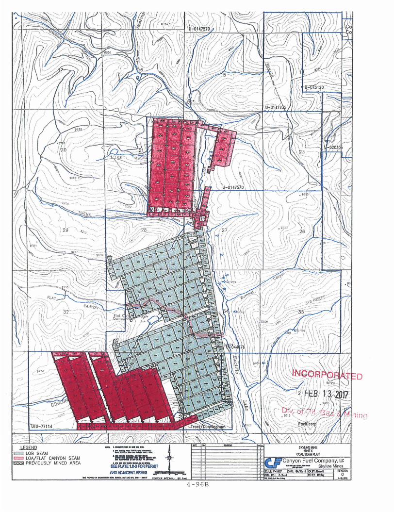
4-96B

At this point in time it is difficult to suggest specific
mitigation of impacts or reclama ion on renewable resources
that are impacted by under.mining since we can only assume
those impacts and their effect. Mitigation measures are site
specific, and will be contingent upon the findings of the
subsidence monitoring program. ubsidence data is available
on Drawing 4.17.3-1 and is updat d in annual reports submitted
to DOGM. Mining in the area has been conducted since 1982,
providing over twenty (20) years of subsidence data. As noted
in Section 4.17.3 and substantia ed within the Burnout Canyon
study (Appendix A-1,Volume 2), t e amount of subsidence is
directly related to surface subsurface geology and depth
of cover. To date, the only are s where mitigation efforts
have been implemented are in ar as where two-seam mining was
conducted. Tension cracks where a barrier
between panels was present in effectively
creating a 20-foot pedestal. ese associated cracks were
mitigated by backfilling using dozer and/or a trackhoe. As
data are collected, methods of itigation will be for.mulated.
This will be done in coordinati n with appropriate regulatory
agencies. Since subsidence may continue to occur after final
mining, the monitoring program ill continue until it is
determined by the Per.mittee in ooperation with the regulatory
agency that it is no longer ed, or subsidence has stopped.
Impacted water rights, if any, ill be replaced as discussed
in Section 2.5.2.
4 . 17 .5 Subsidence Monitor I ng Program 01\1 n!~ '<\IL (~A~~ (~ I\J!I;"~ING
The Per.mittee blish a subsidence monitoring
program using aerial photogr
program developed by the
deter.mine the effects of
Revised: 8-24-05
trics patterned after a
National Forest to
coal mining on surface
4-97

renewable resources and surface improvements. The monitoring program
secures adequate baseline data prior to any subsidence to quantify the
existing surface renewable resources
immediately adjacent to the permit
and surface
area. The
improvements on and
baseline data was
established so that future programs of observation can be incorporated
at regular intervals for comparison. The monitoring program
establishes a system to locate, measure, and quantify the progressive
and final effect of underground mining activities on the surface
renewable resources and surface improvements. The system utilizes
techniques which will provide a continuing record of change over time
and an analytical method for location and measurement of a number of
points over the permitted area. The continuum of data shall
incorporate and be an extension of the baseline data.
A network of control monuments consistent with the desired
photogrammetric map accuracy are being established over both the
permit area and the immediate adjacent areas not expected to be
disturbed by subsidence. The monuments are constructed as survey
control points for monitoring the effects of subsidence on surface
renewable resources and surface improvements (Map 4.17.5-1) The
monuments are located and tied to a state plane coordinate system
which is the same for both the surface and mine control surveys. This
allows the surface survey to be superimposed over the subsurface mine
workings. The monuments have the X, Y, and Z coordinates accurately
measured and established by ground survey methods. During the
photogrammetric exercise, control points are marked with rebar and
white biodegradable sheeting. These will be reclaimed at the
completion of the project as necessary.
The initial aerial photography covers the entire permit area and will
be either color or black and white, flown at a scale such that
elevations to within one foot vertically and horizontally (± 0.5') can be attained by photogrammetric
Revised: 10-1-13 4-98
INCORPORATED
Jt\N 0 3 2014
Div. of OIL Go.s & Mining

methods. It is anticipated th t the nominal or mean scale will be 1:6,000 for a 6" focal leng h camera, unless aerial
constraints such as safety dic ate flying at a high altitude, but will not exceed 1:7,200. his photography was used for constructing the initial basel'ne surface map. It also provides the master base to assist in d cumenting changes caused by subsidence.
To aid in the collection of ad itional base data on surface renewable resources, color inf ared aerial photography (eIR) of
the permit area may be utilize. If this technique is used, the photographs will be of the sam scale as the other aerial photography.
Subsequent annual black and wh'te or color photography for subsidence monitoring will cov r the area mined and the area to be mined in the next 18 months (plus angle of draw). Subsequent CIR photography for monitoring surface resource trends will be flown as needed.
In 2012, a comprehensive revie of the eIR data collected
annually from 2005 through 201 was evaluated by Dr. Patrick Collins of Mt. Nebo Scientific, Inc. The review determined no
adverse impact had been observ in the eIR data. The results of the report, combined with t e intensive riparian study that
is conducted in perennial drai ages support the determination that the eIR survey no longer eeds to be collected.
On all aerial photography for the baseline data and subsequent flights, a photogra hic overlap of 30 percent between adjacent flight lines and an a erage of 60 percent overlap of photographs along the same fli ht line will be obtained. The baseline data will be digitize to show the undisturbed presubsided ground elevations and will use a grid with a nominal mean grid scale of 200 x 200 feet. The subsequent flights for subsidence will also be digitized using the same grid scale as
the baseline to show the elevational deviation from the baseline elevations. The digitized information will be submitted annually to the regulatory age cy after subsidence commences.
INCORPORATED Revised: 7-9-12 4-99 7/31/2012
Division of Oil, Gas & Mining

An on-the-ground visual inspecti n will be made of the ground
surface of subsidence areas (inc uding angle of draw)where the
potential for tension cracks or fissures exist. The
inspection will be conducted een six (6) and 12 months
after mining has occurred. information is supplemented
with the annual subsidence repo t and corresponding map
supplied to the Division.
This inspection will attempt to locate, photograph, and
document the presence of subsid nce effects to surface
improvements, tension cracks, f'ssures and other surface
effects.
The subsidence monitoring data ould be used to determine: 1)
the critical width across the p essure arch; 2) the draw
angle; 3) the ratio of observed subsidence to predicted
maximum subsidence (S/Smax)i 4) the relationship between
mining and onset of subsidence nd the correspondence between
the face advance and subsidence profile development; and 5)
the bulking factor.
Table 4.17.SA illustrates
(where single-seam mining
(where two-seam mining
anticipated subsidence
ence points in both Mine #3
curred) and Mines #1 and #2
red, and compares the
4.17.3) with actual subsidence
that has occurred. idence locations used were
located where a creek crosses t e center of a panel. These
sites were used due since there is typically better ground
control in a stream channel ve
related to subsiding streams.
Revised: 8-24-05
a slope, and the concerns
4-99a

Table 4.17.SA
Subsidence Location Calculate Subsidence Actual Subsidence
Mine#3, panel 7R 4.oS-ft 5-ft
Mine#3, panel R6 1.95-ft 2-ft
Mine#3, panel 6R 3.9-ft 4-5-ft
Mine#3, panel R5 3 .. 9-ft 4-ft
Mine#3, Panel R4 3.9-ft 3-ft
Mine#2/1, pan .. 11.o5-ft 12-ft
6L/7L
Mine#2/1, pan .. 14-ft 12-ft
5L/6L
Mine#2/1, pan. 12-ft 12-ft
4L/5L
Mine#2, panel llL 6-ft 6-ft
Mine#2, panel 8L 6-ft 6-ft
Table 4.17.SB cites examples 0 the maximum extent of
subsidence observed at specifi sites within the Skyline Mine
pennit area.
Table 4.17.5B
Subsidence Location Subsiden e Buffer
Angle
Actual Maximum
Extent of
Subsidence i ',: ,,' ',--"" ,~ ,,~ I
"-",' I "~., '.
Mine#3 Panel 7R
Mine#2 Panel 9L
Mine #2 Panel llL DIVr Gf Oii... GAS & r'II1INING
It is important to understand he points of zero subsidence used to calculate the angle of draw are somewhat subjective
due to the accuracy of the sur ey method. The points of zero
subsidence used in these calcu ations are very conservative,
potentially resulting in a gre ter angle of draw than actually may exist. Revised: 8-24-05 4-99b

The following monitoring progr
Canyon Study:
was initiated as part of the Burnout
1.
2 •
3 .
4.
5.
6.
7 •
8.
Description
Install parshall flumes fo
stream flow monitoring as
shown on plate 2.3.6-1.
Select and install monitor ng
for spring flows in the
subsidence areas as shown
on plate 2.3.6-1.
Install subsidence monitor ng
adjacent to stream drainag s
on a maximum 200 ft. cente s
as shown on plate 2.3.6-1.
Points will be 3 1 rebar wi h
no concrete.
Develop summary report of
observed subsidence effect
on stream drainages as weI
as surface and subsurface
hydrology to date.
Monitor stream, spring,
subsidence points -- mont
during field season.
any surface cracks that f
Year-end summary reports
Final report
Evaluation and review
Revised: 8-24-05
Skyline July 91
Skyline July 91
Skyline July 91
Skyline Dec. 91
Skyline June-Nov. 91
June-Nov. 92 June-Nov. 93*?
Skyline Jan. 92 & 93
Skyline Jan. 94
Skyline, DOGM
& USFS
Feb. 94
4-100

4.17.6 Subsidence Control
The Permittee plans to conduct the underground mining operations so as
to prevent subsidence from causing material effect to the surface and to maintain the value and reasonable foreseeable use of that surface in accordance with the preceding subsidence control plan.
4.17.7 Public Notice
Since the surface ownership of the areas of planned subsidence is vested in the United States and is under the authority of the U. S.
Forest Service, the annual subsidence monitoring report will be provided to them and to the regulatory authority.
4.17.8 North Lease
Infrared aerial photographs (CIR) will be taken either in August or September of each year. An interpretation of the photographs will be made and a written report will be included in the Skyline Mine Annual
Report. I f a reduction in renewable resources is noted because of
subsidence, the appropriate agencies will be notified and mitigation measures will be developed.
4.17.9 Reduction of Subsidence Monitoring Program
Mining operations were completed in the southern section of Mine #3
(Panels 3R-7R and 1R NM-6R NM) in August 1996. No adverse effects related to subsidence were observed in the area after 1997. The subsidence monitoring program was terminated after monitoring in 2003.
Mining operations were completed and April 2004, respectively.
subsidence were observed in the
for Mines #1 and #2 in August 1998 No adverse effects related to
area after 2004. The subsidence moni toring program was terminated for this area after monitoring in
2006.
Mining operations were completed for panels 1L-6L in Mine #3 in June of 2012. Subsidence monitoring indicates that subsidence has ceased. The subsidence monitoring program was terminated for this area after monitoring in 2014.
Revised: 8/27/2015 4-101 INCORPORATED
SEP 1 B 201 'V. 01 Oil, Gas & Mining

4.18 FISH AND WILDLIFE PLAN
The Permittee is conducting the Skyline p(oject operations in a manner which minimizes
disturbances and adverse impacts on fish , wildlife, and the related environmental values identified
in environmental baseline studies . The desi ~ n of the Skyline Project incorporates many of the
suggestions and proposals of the various 6nvironmental consultants to provide acceptable
environmental protection features.
4 .18.1 Aquatic Resources - Eccles C eek
During construction activities, sections of Ec les Creek were diverted , channelized and relocated
causing some disturbance of the aquatic ommunities. These construction activities were
conducted in accordance with approved plans and were monitored for impact. The construction
effort also included stream enhancement for tr ose sections which were permanently altered. Post
construction rehabilitation has included reveg tation and other improvements to the riparian habitat.
A more complete discussion of the impact a d plans for the aquatic community can be found in
Section 2.8 - AQUATIC RESOURCES , an in Section 4.19 - STREAM DIVERSIONS. The
revegetation plan is addressed in Section 4. . Hydrologic impacts are discussed in Sections 2.3
and 2.4.
4.18.2 Terrestrial Wildlife Resource
Eccles Canyon Road , which nearly parallel the conveyor route , has a posted speed limit. This
measure seems to minimize the number of . nimal-vehicle collisions in Eccles Canyon. Warning
signs indicating animal crossings are install d at each end of the overland conveyor system. The
Permittee will continue consultation with vari us agencies to determine additional measures to be
taken to reduce road kills of big game.
Power transmission lines for underground ining and related activities in the permit area were
designed and constructed to comply with t e guidelines set forth in "Environmental Criteria for
Electric Transmission System" (USDI , USDA (1970)) . Power distribution was designed and
constructed in accordance with REA Bulletin 61-1 0 "Powerline Contacts by Eagles and Other Large
Birds". Revised 03/26/98
4-102 I ~ .""':( ., • • OJ' _f \..; ~


• Raptor surveys indicate that there may be ra tors nesting in the vicinity of the Scofield Waste I
Rock Disposal site. A raptor survey was conpucted in 1995 by Skyline Mines to determine if
there were any active nests with in a 1/2 mile radius of the disposal site. No nests were found
by environmental personnel from Skyline Min . Another raptor survey was conducted in 2007
for the waste rock expansion site and one raptor nest was identified within % mile. According to
the analysis , the nest has been in place for some time and the raptors have habituated to the
activities of the waste rock site. This nest wil be monitored in spring 2008 for its status.
Results of the status will be reported in the A nual report.
Additional information on wildlife can be foun in this document in Section 2.9 - TERRESTRIAL
WILDLIFE and Section 2.10 - RAPTORS.
The South Fork Breakout is located in an Elkl Calving area. Construction of the face up area
should be done after calving season . The tributary to South Fork is a contributing stream for
aquatic insect drift to the fishery in Eccles Cr~ek. Construction operations were done in a
manner to minimize disturbances and i nfluen~es on the stream.
I
• James Canyon Area
•
Fish and Wildlife Enhancement Measures:
• Woody species seedl ings will be plan ed.
• Seeds and seedlings planted during reclamati n wi ll include diverse palatable species.
• Rocks and/or logs will be placed on rec laim d road and drill pad area wh ich can be used by small wi ldli fe
species as shelter.
• Erosion associated with rills and gull ies wi ll e monitored and repaired as described in Section 4.4.4.
The James Canyon Project construction was performed to comply with the commitments made in
this "Fish and W ildlife Plan".
Revised 12-03-2007
f-103A
F.:l$ 9 2 08
Waste Rock Site
Fish and Wildlife Enhancement Measures: $ Species to be planted and the rates per acre will follow the specifications in Table 4.7-6A. $ Seeds and seedlings planted during reclamation will include diverse palatable species. $ See Section 2.9 for additional discussion of Wildlife at the Waste Rock site.
Winter Quarters Ventilation Facility (WQVF) Fish and Wildlife Enhancement Measures: $Species to be planted and seeded and rates per acre are outlined in Mt Nebo Report (Appendix A-2, Volume 2). will be used in reclamation as outlined by Dr. Shiozawa (Appendix A-3, Volume 2) • Photo documentation of the pre-disturbed stream wcollected for re-construction of the stream bank morphology • The WQVF was specifically designed to be constructed a minimum of two (2) stream widths
from the stream 'channel, thus providing a buffer zone of riparian and other upland vegetation to minimize impacts and maintain appropriate habitat. .
• During construction, operation, and reclamation of the WQVF site, noxious plants invading the permit area will be controlled by hand-grubbing, and/or approved herbicides. Surveillance wi" be monitored annually during the liability period .
NOG Bleeder Shaft Fish and Wildlife Enhancement Measures:
Species wi" be planted and seeded as outlined in Section 4.7 During construction, operation, and reclamation of the site, noxious plants invading the site will be controlled by approved herbicides. Monitoring and treatment will continue annually during the liability period.
Swens Canyon Ventilation Facility (SCVF) Fish and Wildlife Enhancement Measures: Species to be planted and seeded at the prescribed rates per acre are outlined in Section 4.7, Tables 4.7-11A and -11 B. This wi" provide better wildlife habitat in the future . Any areas disturbed along the pipe line corridor needing repair after the first growing season after construction wi" be reclaimed in a similar manner. No enhancement measures are necessary along Swens Canyon Creek. During construction , operation, and reclamation of the SCVF site, noxious plants invading the permit area will be controlled by hand-grubbing, and/or approved herbicides. The areas wi" be monitored annually throughout the liability period
Revised 5-27-16 4-103B
INCORPORATED
JUL 1 9 I:Ul
Div. of Oil, Gas & Mining

•
•
•
4.19 STREAM DIVERSIONS
The objective of the stream c annelization and runoff diversion
channelization program has b to minimize impacts to the
surface water quality of th Skyline project area. Stream
diversions and channelizations were undertaken pursuant to an
approved Army Corps of Engi 404 Permit, and with the
approval of the regulatory a thority and of the Division of
Wildlife Resources. No additio al diversions of Eccles Creek are
planned until final reclamation, at which time the streams in the
portal area will be returned to the surface.
4.19.1 Mine Site Stream D version
The confluence area of the three tributaries of Eccles Creek form
a crowsfoot drainage pattern at the mine site. The combined
drainage area for these is approximately 778.12 acres
(Map 3.2.4-2). The from a 100 year, 24-hour
rainstorm is expected ut 3.50 inches (Section 2, Volume
5). After infiltration surface runoff will be
approximately 0.80 inches on the assumption that the
overland flow from the majorit of the watershed is essentially
non-existent. The resulting peak runoff flow would be
about 419.67 cfs (Section 2, 5). The proposed culverts
are designed such that during the winter months, adequate
through-put spacing remains s fficient even if ice accumulates
inside the culverts.
The culverts for use in the n rthern tributary are 48 inches in
diameter and approximately feet in length to a point of
connection with a 72-inch iameter culvert. The northwest
tributary culvert is 48-inches diameter and approximately 836
feet long. The Northwest culv was extended approximately 100
feet in 1990 to accommodate
area. This culvert connects
The culvert for the southwest
and approximately 846 feet
the expanded North coal storage
into a 60-inch diameter culvert.
ributary is 48 inches in diameter
1 ng, and also connects into the
4-104

•
•
•
60-inch culvert 0 The culvert originates at the
confluence of these two 48- o nch culverts and continues for
approximately 526 feet to the confluence wi th the north 48-inch
culvert. From this point 72-inch culvert extends for
approximately 1,058 feet to a pint beyond the portal area.
The inlet for each culvert w s constructed of concrete wi th a
trash rack installed to preven drift material from plugging the
culverts 0 Riprap was used at each inlet structure to
erosion. A rock structure was constructed, during
construction by UDOT, immedOately downstream of the
structure.
minimize
Highway
outlet
4019.2 Mine Site Diversion Channels
Mine site diversion channels w re designed and constructed around
the perimeter of the disturbed area to prevent overland flow from
reaching the sedimentation pon. These channels were designed to
carry the peak flow resulting from a 10 year, 24-hour precipi
tation event. The calculati from the channel design and
energy dissipators used on di ches DU-2 and DU-3 are shown in
volume 5 section 50
The channels were placed
shown on Map 3.2.1-1. Ditche
in 1990 to accommodate the
storage area (see Vol. 5
channels are triangular or
Volume 5 gives detailed as-buil
the mine site facilities, as
DU-2 and DU-3 were each extended
xpanded area for the North coal
design calculations). The
apezoidal in shape. Section 5,
information for these channels.
4.19.3 Coal Storage Stream Diversion (RRLO)
To provide sufficient area
mouth of Eccles Canyon, approxOmately
loadout facilities at the
600 feet of stream channel
were relocated to the north, the canyon road. This was
done after receiving appropria e approvals. The new channel was
designed to safely pass the 100 year, 24-hour precipitation
4-105

•
•
•
event. The peak flow expect d will be approximately 1186 cfs
(Section 13, Volume 5). The n w channel is trapezoidal in shape
and 10 feet wide at the with a top width of 19 feet. The
new channel was constructed wi h 20 foot center meanders within a
19 foot wide zone so that the of stream length is minimized
and original gradient is rved. The stream water channel,
with a mean width of 4 feet, as diverted to meander within the
created 10 foot wide channel. Log deflectors, log dams or large
rocks were used to instream meanders. The original
stream channel was 600 feet 1 compared to the new channel of
500 feet resulting in a of 100 feet of stream. The
pre-construction gradient was 0.024 compared to the new channel
gradient of o. 027 resulting an increase of 3 foot vertical
drop per 1,000 feet of strea length. The log dams, 12 to 15
inches high and spaced at 80 t 120 foot centers, prevent washout
of spawning gravels and cause the stream waters to dig pools on
the downstream side. The log ~ms have notched top logs to help
confine the flow to channel during low flow periods.
The log dams are sufficiently low to allow even the highest flow
to pass over the top without fl oding of the channel banks.
The created stream bottom, installed per an
contain a combination of gravels appropriate
approved
for both
plan,
fish
spawning and macroinvertebrat reproduction purposes. Stream
banks were riprapped in potent·al erosional areas with all other
stream bank areas composed of
willows and other scattered tre s.
revegetated with grasses, some
4.19.4 Coal Storage Diversion Channel (RRLO)
The coal storage diversion
carry the peak runoff from
The peak runoff flow is expec
el was designed and constructed to
year, 24-hour precipitation event.
be approximately 18.41 cfs.
The channel is located just s uth of the coal storage facility.
Map 3.2.1-3, Section la, Volume 5 shows the typical ditch design .
4-106

•
•
•
When the coal storage facility is no longer required, the channel
will remain until the area has been stabilized. with the
completion of revegetation stabilization activities, the
channel will be backfilled, top oiled and revegetated.
4.19.5 Reclamation of Dive sions and Channels - Portal Area
Reclamation after cessation of mining will be directed towards
providing the needs of the mac oinvertebrates since this area is
not directly used by the fish f Eccles Canyon. Reclamation will
include removal or burial of he culverts, replacing the stream
into a channel providing optim 1 substrates for macroinvertebrate
production, revegetation of riparian zones, riprapping stream
banks and channels.
Whether a culvert is removed 0
depth that the culvert is
economically removed, it will
be bulk headed and backf i lIed
backfilling measure. The UDOT
be uncovered at the permit bou
buried will be determined by the
If the culvert can be
The culverts not removed will
slurry or other acceptable
in the southwest fork will
stream will enter the
open channel. The open channe will again enter a UDOT culvert
going under SR 264 at the perm t boundary at the east end of the
disturbed area. Any culvert Ie t in place will have a minimum of
four feet of cover backfill ave it.
The natural stream channels disturbed area contain a
good natural supply of high quality macroinvertebrates. The
stream channel stabilization should provide an excellent
environment for the natural drOft of upstream macroinvertebrates.
To assist in the adequacy of the portal area channel
reclamation effort, Maps 4.1 .5-1 through 4.19.5-4 have been
included, which show stream ch nnel cross sections in the three
forks above the disturbed area and in Eccles Creek below the
disturbed area .
4-107

•
•
•
The design of the reclaimed c annels is shown in Map 4.4. 2-1A,
4.4.2-1B and 4.4.2-1B1 and is generally described herein. The
final design, with engineering documentation, is included in the
Engineering Calculation section of Volume 5.
The access roads to both well ouses will be removed and will be
reclaimed to UDOT specificati ns. At a minimum, these access
roads, pads and culverts will e removed, the stream channel will
be reconstructed consistent w' th the existing channel, and the
road slope to the creek will receive the same treatment as now
exists above and below the pad. The culverts at the well houses
will handle the 10 year, 24 storm (Volume 5, Section 3).
The recently installed NOAA weather station enables
collection of precipitation on a 15 minute basis. To
complete determination of runo f coefficients, flood crest gauges
will be installed in at least two of the stream culverts. Flow
will be determined using pipe size and slope. Using the site
specific runoff coefficients, the reclaimed stream channel will
be appropriately sized and prop rly armored.
The North, Northwest and Sout
the forks will be built mostly
Forks and Eccles Creek below
slope between 2 percent and 4
percent. Space drop areas whe e the slope varies from 10 percent
to as high as 16 percent for short distances (Section 18, Volume
5) •
In areas of steep slopes the
large rocks varying from one
Cobbles and coarse gravel will
channel will be rip-rapped with
foot to three feet in diameter.
e placed among the boulders.
The stream channel on the flat er slopes (2 percent to 4 percent)
will be covered with coarse (1-3 inches diameter) and
rubble (up to one foot in dia The bottom of the channel
will be shaped so that the h of flow will approach 11 inches
even during very small flows .
4-108

•
•
•
Riparian vegetation will be e tablished to reference standards
along the stream and along any ut slopes near the stream .
4.19.6 Reclamation of Dive sions and Channels - Loadout Area
The diverted section of Eccles Creek will be left in place after
mining operations are complete, since restoration to the original
channel would only cause unnecessary disturbance. The culverts
into the loadout area will no be removed since these culverts
are replacements for those in p ace prior to construction.
Calculations addressing the dr inage and stability requirements
of R614-301-413 may be found in Volume 5.
The diversion channels will be handled the same as those at the
portal area.
4.19.7 Diversion Channel a Rock Disposal Site
A diversion channel has been in taIled as shown on Map 4.16.1-1B.
The swale to redirect the dra' nage across the access road and
into the original stream channe was constructed of concrete.
The swale outlet was lined with 4 inch x 4 inch or larger rock to
reduce exit velocity of from the swale. Engineering
Calculations for the waste site channel design are
included in Volume 5.
4.19.8 South Fork Breakout
A new ancillary road was constr cted which crossed a drainage way
to the South Fork of Eccles C eek. This drainage way flows in
all but extremely dry years When the creek crossing was
constructed, the top soil was removed with a track hoe to help
minimize disturbance to the itself. The culvert was
placed in the existing
over it. Although this
channe , and then the road fill placed
d culvert was left in place, the
4-109

•
'.
4.19.8 South Fork Breakcut
A new ancillary road was constructed which crossed a drainage way to the South Pork of Eccles Creek. This drainage way flows in all but extremely dry years. When the creek crossing was constructed, the top soil was removed w. th a track hoe to help minimize disturbance to the channel itself. The culvert was placed in the existing,~hannel, and then the road fill placed over it. Although
this road and culvert was left in place, the
• .1-. __
ADDITION TO ·,,··~EXT
Section 4.19 Page 4-109 Sec ion 4. 19. 7 Pag'e-~4 ~'f09, (a) Date 08/11/93
----------------+---! " :,,-., - . 4 .. 1 a 9~ (a)
'" , ,., I~
. - '_k::: (;i.L) Gi~_.s A: -n~~1NG • NOV 2 8 I9g~
DIVISION Of Oil . ~ .. --------______ J GAS & MI~::NG PRICE UTAH

•
•
•
area has been reseeded and will not be used again until final reclamation .
During reclamation , the fill material will be remo ed and then the culvert lifted out of the channel.
Top soil will then be placed back on the disturb d area with a track hoe and the area reseeded .
Although no permanent disturbance to the chan el is planned or expected, if it should occur it will
be rip-rapped with a gradation of material from "to a maximum size of 38" (Section 18, Volume 5).
All culverts used for access to the area will be c mpletely removed from the area during final
reclamation .
This final reclamation plan outlines the minimu reclamation to be accomplished. At the time of final
reclamation , a meeting will be held with the U.S. Forest Service to determine if additional reclamation work
over-and-above that outlined in the plan is need d.
4.19.9 Winter Quarters Ventilation Facil ty
Plates 3.2.4-3A through 3.2.4-3G illustrate the c nstruction designs. Plates 4.4.2-3A and 4.4.2-38
illustrate the final reclamation of the WQVF site. Engineering Calculations, designs, and other maps of
the facility can be found in a report titled "Winter Quarters Ventilation Shaft Pad , Runoff and Sediment
Control Design Report", located in Volume 5, S ction 24 of the M&RP.
The reclamation of the WQVF pad will be straigrlrt-forward , being located on a south-facing slope with only
very minimal impacts to the riparian corridor of 'tinter Quarters Creek. No topsoil in the minimal riparian
areas needed to be removed during constructiom or reclamation of the site - only minor traffic that will be
read ily re-vegetated . Any concerns of excessiv runoff are minimized with the undisturbed ditch on the
existing road located above the site. The road rainage was improved to accommodate a 6-hour, 1 ~O-year
storm event from the majority of the hillside loca ed above the site.
Revised: 12-30-09 4-110
INCORPORATED
JUL 2 9 2010
Div. of Oil, Gas & Mining

•
•
4.20 TRANSPORTATION FACILITIE - ROADS, CONVEYORS, RAIL SYSTEMS
It is the intent of the Permi tee to ensure that the activities
associated with the and reclamation of surface
acreage disturbed for transpor ation facilities be conducted in
compliance with all state and ederal regulations and are planned
in a manner most appropriate or the control and mitigation of
related environmental impacts.
This section describes in detail the major engineering and design
features selected to mitigate ransportation related erosion and
air and water pollution r suIting from the Skyline Mine
operations.
Road design was performed by
engineers
All roads
in accordance with
for the transporta
egistered, qualified professional
all available design technology.
system. of the Skyline Mines
operation are classified primary roads. Reclamation
activities, to be conducted fo each area of surface disturbance,
will follow the applicable pro edures described in Sections 4.4,
4.5, 4,6 and 4.7. In all topsoil and vegetation were
cleared only to the extent ecessary to accommodate road and
ditch construction. Stabilization and initial revegetation of
all cut and fill slopes resulting from road construction was
performed during the first nal opportunity.
4.20.1 Transportation
Eccles Canyon Road
The Eccles Canyon Road has bee
Canyon (Highway U-96) to
U-3l). This road has been in
with the designation of SR-264
improved from the mouth of Eccles
Fairview Canyon Road (Highway
in the State Highway System
nd is the responsibility of UDOT.
4-111
.~ ~,
Mine Portal Road
The mine access road is classified as a primary road and runs from
the mine #3 portal to the maintenance complex area. The
certification statement for t is road is found in this section.
Fiqur •• 4.20.1& and 4.20.1b sho typical cross sections of the mine
portal roads. Since the length of the road is approximately 1,200
feet, no road culverts were ins aIled. As shown in the design, the
steepest portion of the access oad is a 10.0% grade sustained for
250 feet. No other grades on t e access road exceeds 10.0%. There
are no switchbacks on the acces road. None of the access road cut
exceeds 1h: Iv in unconsolidated material and. 025h: 1v in rock. The
access road is be 20 feet wi e with a 3 foot height berm and
concrete jersey barriers at th shoulder. The road is flat with a
drainage ditch against the hig wall. The drainage ditch has been
designed to safely pass the peak from a 10 year, 24 hour
precipitation event (Section ,Volume 5). No trash racks and
debris basins have been led, as the ditch will be cleaned
periodically. The road faced with crushed gravel and tar
sands. Once mining is comple ed, the road will be topsoiled and
terraces will be constructed t prevent soil erosion.
Other roads within the portal a ea are shown on map 3.2.1-1. These
roads provide access to the mi e portals, storage areas and access
to various buildings. The ertification documents for these
primary roads are found section.
water Tank Access Road
__ t'Jt'~C1J VB: Access to the water tank area ·s via utah State H ghway SR-2Q
Breakout Area Access Road JAN 1 2 lY95.·" The ancillary road which was onstructed to obta ess to he
breakout area in the South Fo k of Eccles creek-~N~diPJa~ir~~d
during final reclamation. Aft r the face up area has been
R11/14/94
4-112

reclaimed, the new ancillary roa , the small opening at the mouth
~ of the canyon and the road wher the topsoil was stored will be
returned to the approximate ori inal contour and seeded with the
~
•
approved seed mixture.
The access road up the side cany n will be reopened to accomplish
final reclamation work at the b eakout area. After reclamation
work is completed at the breakou area, the road will be returned
to approximate contour and seede with the approved seed mixture.
All culverts and the trash rack u ed in the project will be removed
from the area. All disturbed ar as will be seeded as outlined in
Section 4.7.2.
The road from the Forest boundar to the mouth of the side canyon
will be ripped, outsloped, water arred and blocked so that vehicle
traffic cannot use the road.
Waste Rock Disposal Road
The access roads to the disposa site are classified as primary
roads. The certification docume t for this road is found in this
section. It is approximately 3, feet long of pre-existing road
and 700 feet of newly construe road. The pre-existing road
which was up graded by spot surf cing with 211 minus pit to provide
a total graveled surface. The gavelled surface is approximately
16' wide. The new road will be graveled surface for a width of
30 feet. A guard rail will be laced on portions of the road as
required by MSHA. Drainage ditches and cross drains were
constructed to safely pass the d signed storm (see Vol. 5 Section
14) . This road is maintained on a routine basis with a road
patrol.
"~-'l
'j IS~1\J i
4-113
R8/27/98

Ie
4.20.2 Overland Conveyor Belt
The locatiOD ot the pipe convoyor trusses on the upper portion of the conveyor is on a bench o]~ the north slope of Eccles Canyon,
while the lower portion is i.upported by towers and trusses on
natural ground slopes. The s~eepest portion of the pipe conveyor
"
CHANGES TO TEXT
Section 4.20 Page 4-113 Sec~ion 4.20.1 Page 4--113 (a) Date 08/1:/93
__ --------------r--~.-~ RECEi\IED
1 I
NOV 2. 8 1994 1
'~i' - DIVISION Of OIL "j.~ tAS & Mlt\:NG PRICE Ul~H I , -
l I >
j i ! I
I
.. ~,
-- " 4-113 ( a) , r- ~, - .~.", . ~ .- , , ~
; i ! , ! c; I r
.-.-~ I --.
-------_._-----_.,.....!.-

is a negative 14.0 percent gr de. The average negative grade of
the conveyo~ route is 6.0 perc nt. Cut slopes along the route do
not exceed lb:lv in unconsolida ed materials and 1h:4v in rock. As
part of the air quality control program, the belt system rolls into
a tube and there are dust colI ctors at each end of the system to
reduce fugitive dust.
4.20.3 Railroad System
The grade of the railroad does not exceed 3 percent Cut slopes do
not exceed 1h:lv in unconsol'dated materials. Vegetation was
cleared only to the width n cessary to accommodate the track
ballast and associated ditch c nstruction.
The Denver and Rio Grande Wes ern Railroad Company designed the
rail haulage system and ensure that no refuse coal, acid producing
or toxic material will be us d in the rail ballast which will
contaminate surface drainage. he rail haulage system was designed'
to maintain the water qualit of runoff from the facilities in
Pleasant Valley Creek.
4.20.4 Loadout Area
The loadout area roads are classified as primary roads (see
engineering certifications att ched to this section) and are shown
on Map 3.2.1-3. I'iqure 4.201& and 4.20.1)) show typical cross
sections of these roads. The e are no switchbacks on any of the
roads. None of the
material and O.25h:1v in rock.
exceed 1h: 1v in unconsolidated
The roads are typically 20 feet
wide with a 3 foot high berm at the shoulder where needed. The
roads are sloped so that water will stay on the disturbed area and
be directed to constructed dr inage ditches. N~t'}leffVE:racks have
been installed as the roads ar periodically a1n ained. e roads
are surfaced with crushed gra el and or asp a~N 1 011Sii5m' ing is
completed, the road will topsoiled a ces ill' be
constructed to prevent soil e osion. -~DMSJONOn..GASAMiJJ4/94
4-114

4.20.5 Winter Quarters Ventilation Facility Road
The pre-existing road in Winter Quarters Canyon is classified as an ancillary road based on the following criteria: it is not used to transport coal or spoil; it is not used for access or other purposes for a period in excess of six months; and it will not be retained for a specifically approved postmining land use. The access is primarily across private land. Although improvements to the road were made by the Mine, the improvements were included in the easement of the lease and will not be altered during reclamation.
The approximately 450 foot access road built for the Winter Quarters Ventilation Facility pad will be removed during reclamation. See Plates 3.2.4-3b and -3e for detailed road illustrations and Plates 4.4.2-3A and 4.4.2-3B for reclamation details.
4.20.6 North of Graben (NOG) Bleeder Shaft Road. i,
I The NOG Bleeder Shaft access road is classified as an ancillary road since 1) it is not used to transport coal or spoil: 2) it is not used for access or other purposes for a period in excess of six (6) months; and 3) it will not be retained for a specifically approved post-mining land use. The access is located on land exclusively managed by the US Forest Service. The approximately 780-foot road built for the NOG Bleeder Shaft will be removed during reclamation. See Plates 3.2.4-5A through -50 for detailed road illustrations and Plates 4.4.2-5A and -5B for reclamation details.
4.20.7 Swens Canyon Ventilation Facility (SCVF) Road
Both the pre-existing and new access road in the SCVF area are classified as ancillary roads. The pre-existing road will be slightly rerouted while the SCVF is functional, but will be reestablished in its original location at reclamation. The approximately 900 foot access road built for the SCVF pad will be removed during reclamation. See Plates 3.2.4-4A, and -4B for detailed road illustrations, and Plates 4.4.2-4A and -4B for reclamation details.
Revised: 5-27-16 4-114(a)
INCORPORATED
JUl 1 9 llll'
Div. of Oil, Gas & Minmp

•
•
•
SKYLINE MINESITE AN RAILROAD LOADOUT AREA ROADS
I, William W. Shriver, hereby do ce tify that all operational roads at the Skyline Minesite and Railroad Load t areas are primary roads as defined in R6l4-30l-527.l20 and have the foll ing characteristics.
1. All roads are located, in so far as practical, on the most stable surfaces and are built for double lane traffic.
2. All roads are surfaced with a variety of materials including asphalt, concrete, tar sands, crushrock, and pitrun rock. These surfacing materials ar sufficiently durable to support the traffic using them.
3. All roads have adequat drainage to direct the surface runoff into designed drainage ditches and natrual channels.
4. All roads are routinel maintained to repair any damage to the running surface and to keep the drainage system functional.
5. The grades of the roads varies from level to a maximum pitch that does not exceed 15 per ent.
6. All road cuts and fills have been stabilized as far as practical .
William W. Shriver Registered Professional Engineer Utah Registration No. 8632
4-115

•
•
•
DISPOSAL ACCESS ROAD
I, William W. Shriver, hereby do ce tify that the access road to the Scofield Rock Disposal site is a primary roa and has the following characteristics.
1. Is and already existin road which is located on stable areas, and will not be reclai ed.
2. The road has been upgr ded to a double paved road and has been surfaced with pit run ock. This surfacing is sufficient to handle the trucks haul ng material to the disposal pit. (A short section is narrow but as good site distance).
3. The road is crowned an has designed drainage ditches with cross drains at strategic 10 ations to direct surface run off into natural channels. Out alls of all cross drains are rip rapped.
4. The road is routinely aintained to repair any damage to the running surface and to keep the drainage system functional.
5. The grade of the road aries from level to a maximum pitch that does not exceed 15 per ent.
6. All road cuts and fill have been stabilized.
William W. Shriver Registered Professional Engineer Utah Registration No. 88632
4-116

::::0 ~ I
'-....._ 01 ~ (IJ ~
--........... l.D ~
e • PRIMARY ROAD - TYPICAL SECTION
'l
-t-__________ ----- ~t ~~~~ -.;~I--;~~j, ..
2-4" -CRUSHROCK,ASPHALT, OR CONCRETE SURFACE ON COMPACTED SUBGRADE
~
~ ~
? C)
~ > ~ s: ~
'-1> ! fT. Z ';~
/"'i .- tr. ('j
!"'\..:) ~ -
MINESITE AND RRLO PRIMARY ROADS lyriCAL SECTION
e
- - - - - - - -\ ~ATURAL GROUND SLOPE
Utah Fuel Company A SUBSIDIARY or TH£ COASTAL CORPORATION
ROAD TYPICAL SECTION
11/14/94 4 . 20 . 18
1~4

::::0 -P>-I
------"~
------"~
~Q) ------" » -P>-~ 1O -J:::..
_ -" PRIMARY ROAD - TYPICAL SECTION
~ ~ ~ -- -- -- __ __ / 4' ~ CUT SECTION -±-EMBANKMENT SECTION
"'" 'Y4' ~ ~4'1 ~:'% I ~:~ I
~ 1 L" I -- '.>Cd' r ,I, ' , 1 - -------
---2-4" -CRUSHROCK,ASPHAL.,
i ~
.It C ~ > ~ :: ~
SURFACE ON COMPACTED SUBGRADE -
c.. l> • ?-¥'"
:z: ~-: ..;:..
.- 5 r"\:.l -' - .<" ....0 ·m '" t .. c..n
MINESITE AND RRLO PRIMARY ROADS TYPICAL SECTION
"----
6 ~" "~ ~ I. Utah Fuel Company " ,./ ,:?,~~;'" A SUBSIDIARY Of TJ-I£ COASTAl CORPORATION
I ROAD \i L.(~7~/, ,. :. : '..::;,'" J/_. 5"~' ., / I'!I TYPICAL SECTION . \.1 / " II] V" ., L
I'i 1 t' of v'\ 1'-~-~ I K. zoeru OMIN BY:
~: 11/14/94 4 . 20 . 1A 1"-8'
-

•
•
•
4.21 RETURN OF COAL PROCESSIN WASTE TO ABANDONED
UNDERGROUND WORKINGS
On occasion, the Permittee may utilize off-sit coal processing facilities as a part of the Skyline
project. If processing is conducted at a facili located closer to the Dugout Canyon Mine than
Skyline Mine, the reject from processing may e disposed of at the Dugout Canyon Mine Waste
Rock site or returned to the Skyline disposal s teo This process is noted and approved in the
Dugout Canyon Mine M&RP. Therefore, ex ess spoil, mine development waste, coal waste and
sediment pond waste will be deposited at an a proved waste rock disposal site - whether near
Scofield, Utah or near Wellington, Utah, resp ctively.
Revised: 03/26/07 4-117 JRATED
APR 1 0 2007
... ·v fOIl S & Mining
4.22 AIR POLLUTION CONTROL PL N
Prior to any construction eff rt at the mine site Permittee filed
an application for Preconst uction Review and Prevention of
Significant Deterioration (PS ) with the EPA Region V,III office
and a Notice of Intent Construct with the Utah Air Conservation Committee. All equested approvals were obtained as
required.
Approvals for subsequent modi ications have been granted through
Approval Orders issued by Division of Air Quality. The
current Approval Order,
previous approvals. A
Exhibit 4.22-1.
dated September I,
copy is attached
1992, supercedes all
to this section as
The submitted
fugitive dust
application
emissions Emissions reports, as
Conservation Committee in
PSD
the
are
ac ordance
review isolated potential
principal air pollutant.
submi t ted to the ut ah Ai r
with Section
Emissions
26-13-23,
from the
Utah
coal
annotated, the requirements of
1953, as amended.
reduced by the
run-of-mine coal.
moisture
han ling operations
(a proximately 10%)
4.22.1 Fugitive Dust Sou ces
are significantly
inherent in the
The following sources of dust have been identified:
1.
2 •
3 .
4 •
Conveyors and Chutes
Crushers and sizing quipment
Truck Dumping
Silos
4-118

5. Stockpile Surfaces
6 • Equipment Activity
7. Front-end Loading
8 . Truck Travel and Unp ved Roads
9 . Mobile Equipment
Emissions factors used in pre aration of the annual reports are
taken from EPA publication P-42, Section II, 5/83, or from
information provided by Bureau of Air Quality personnel.
------)
}
j MAR 231993
I UTAH DlVlSlON On., GAS AND MINING
!
4-118(a)

•
•
•
4.22.2 Description of Emis ion Sources and Controls
1. Conveyors and Chutes
All permanent conveyors are fully covered and originate and
terminate either underground 0 at facilities equipped with dust
control. Open conveyors are used infrequently.
either adjustable or are set at minimum drop height.
2. Crushers and sizing equipme t
Chutes are
Prior to distribution the coal is passed through a single crusher
facility. Emissions from the crushing operation are limited by
the use of a baghouse for dust control. Stoker coal is screened
out at the railroad loadout silos. Fugitive emissions are
limited by the use of a baghous .
3. Truck Dumping
That portion of the coal m ved by truck is handled almost
exclusively by bottom dump trailers which reduces the coal drop
height. The trucks routinely haul 40 tons per load, however,
during certain inclement weather conditions, the trucks may use a
single trailer which reduces t e load to 20 tons. Truck dumping
at the site is normally to a g izzly at the railroad loadout site
which feeds the silos, but be into a stockpile during
overflow and emergency when a mechanical/electrical
condition prohibits the use of he conveyor system.
4. Silos and Bins
Several silos are used in the oal handling operation. Coal from
the mine is stored in an 8, oo-ton capacity run-of-mine silo
pending transfer to the facility. Coal from the crusher
is currently moved to a capacity tipple bin. (After the
canyon conveyor is completed, t e flow of coal through the tipple
bin will be greatly reduced.) Co"al awaiting train loadout is
4-119

•
•
•
currently stored in two 15,000 ton capacity silos. A 22S-ton bin
is located at the train loa for surge control. Fugitive
emissions from all of os and bins are controlled by a
baghouse at each silo.
5. stockpile Surfaces
The mine plan has been approv d permitting open storage of coal
at two sites on the mine prope ty and one at the railroad loadout
area. These stockpiles d as surge control for those times
when production exceeds the i ediate demand. The coal for the
North coal storage area normal y is transported to the area via a
conveyor to a stack tube, is reclaimed with underground
feeders and a conveyor. Th South coal storage area is an
emergency area and will not be used, except when a
mechanical/electrical conditio prohibits the use of the stacking
or reclaim system in the North oal storage area.
While stockpiles are normally usceptible to wind, site specific
weather data (Radian Corporati 1979) indicate wind veloci ties
at Skyline lack sufficient magnitude to create a problem.
6. Equipment Activity
Heavy equipment, such as front end loaders, used in the movement
of coal causes some emissio s from wheel contact with dry
surfaces. Only the emission from such heavy equipment are
monitored. No attempt is mad to analyze emissions from light
vehicular activity.
7. Front End Loading
Coal from the South coal storage stockpile is loaded into trucks
by front-end loaders. Coal i the North coal storage area will
normally be transferred by co veyor belt; however, in emergency
conditions, when mechanical/e ectrical breakdown prohibits the
use of the reclaim system, 1 may be loaded out of this pi Ie
4-120

•
•
•
wi th a front
rushing air,
end loader.
displaced
emissions. These emissions ar
of the coal.
Ie drop height is minimized, up
coal, tends to cause some
low due to the inherent moisture
8. Truck Travel on Unpaved Roa s
Normal movement of coal by tru k from the tipple loadout and the
movement of coal at the South oal stockpile is over some unpaved
roads. Truck wheels disturb t e road base silt, creating minor
fugitive dust emissions.
9. Mobile Equipment
This category includes
equipment. Engine emissions
are not quantified.
emissions from heavy diesel
small gasoline powered vehicles
4.22.3 Air Quality Contr 1 Monitoring
The Permi ttee contracted wi th Radian Corporation to prepare the
baseline air quality study fo the mine area. A copy of the
Radian report can be found in A pendix volume A-I.
The air pollution control plan is based upon the requirements of
the Bureau of Air Quality and upon preventative measures
initiated by the operator.
The following describes the Permittee's ongoing and proposed
Monitoring Programs.
4.22.4 Operational ures and Monitoring
To achieve minimal emissions t e following operational steps will
be taken:
1. All emission control
maintained and operated.
ent shall be properly installed,
4-121

•
•
•
2. No visible emissions from any point shall exceed 20 percent
opacity as measured by 40 FR 6e, Appendix A, Method 9 or as
required by the Utah Division of Air Quality.
3. Mine personnel shall be ce tified annually to measure opacity.
4. Normally coal shall be transferred primarily by covered
conveyor, except lage will be used for the South
Coal stockpile operatio, when a mechanical/electrical
condition prohibits the use of the North coal storage area.
The use of open conveyors shall be minimized.
5. Water or chemical
unpaved roadways as requir
sprays shall be applied on
meet opacity limitations.
The overland conveyor is belt system, and is an extremely
clean system as the coal pletely enclosed. Dust collectors
are located at the loading a d unloading areas to capture any
potential fugitive dust. Any future air quality monitoring will
be conducted as requested by t Division of Air Quality .
4-122

c
Dea f . T ),lor:
R
cc: Southeast m lah Di~trici H lIth De artm 'nt
•
G t engm t1 r. Pleas dir
reached at (
o
'v. of 0'1, G s

Ul H
......... ,._ ... ta a
ir Q . lity
o
• p
• ~.I\!~ ? G 2008
i'. fO'I,

p
•
J) 2) 3)
)
Ecc
Na.tl llal Ambl flt Ai,. Qualit> Standard. o\r.llAQS for all
= 17.64, 0 = 2.22 0 = 7.2
R %
in tons l' r year, ()C:;;; 1.0 , nd
4526
Univers I nmsvers Mer ator M) C finale Sy~tcm: lJTh.1 atum NAD21 .392.5 kil m~ler NOl1h r\g, 482.7 omClc~ stingt Zonl: 12

3.
s.
6.
•
•
009
o
ceeded wilh ut prior apt r v II in accord ce
Skylil c in acc()fd~ e n purs:uant to Notic at 11 [ t; rt(
.2003 .

•
•
•
DAQEPai)c"
1 •
1.
14.
9200703
D.
F. . ge i1
J. dust hi a ] pre. so
hy the E~ecu1'v cr'I::!tary.
ntr lied by two b llHJse~, Day crated when II - coal heing
it)' readings Jt d 0%.

17. in op.;:~1ton
1 _
B.
E.
F.
R
19.
CO la' in
-pH
om the up r elevation stockpile
pile
~,1 '\'!') .., A 20nQ L .. ~H t~ l) UU

•
24. of fugitive du { as dry
2 .
27 . At all
• 2. I'ies. ntaric ~ 'lLng aml
E . I~ i its na
for COl pI iance wi h all oth r
• M.\n 2 D 2008

•
•
•
A. Be..
E. E
I it (VI ) e J . ss ionl for thO SOlJfC (Sky ine IVfine) ar currently ca lculat d a
Pl ........ ........ ............. .................... ................ 91 SOl ...... .... ................................. ..... ....... ........ .. 2.22
Se~ -tUl)'
.0

•
•
•
4.23 ALLUVIAL VALLEY FLOORS
Introduction
The loadout area could potent classified as an alluvial
valley floor even though has no agricultural valley.
Therefore, under the provision of R614-302-323.l00 the following
information is submitted as documentation that the area is
neither arid nor semi-arid an consequently does not require a
special permit for coal mining activities.
4.23.1 Climatological C nditions
Figure 12 of Jeppson et a1. (1968) indicates that the normal
annual precipitation in the S permit area varies from 25
inches at the mouth of Eccles Canyon where the coal storage and
unit train load-out facility i located to over 30 inches at the
portal area. Altitude appears to have a large influence on
precipi tation (Mundorff, wi th the higher elevations
experiencing more rain and sno Site specific precipitation
records are available to Clear Creek (latitude 39 0 39', longitude
1110
09', elevation 8,300 feet) and Scofield (latitude 39 0 44',
longitude 1110 09', elevation 7,700 feet previously known as
Winter Quarters), and recently at the Skyline mine portal area.
As shown in the annual summar of NOAA Climatological Data for Utah, the long-term annual mea
1956 was 21.65 inches, and
Scofield (Winter Quarters)
precipitation at Clear Creek in
he mean annual precipitation at
1893 and 1924 was 19.46 inches. These amounts corres ond qui te closely to the values
shown on maps by Jeppson et. a1. (1968) although they are
slightly lower than Jeppson's v lues. This fact seems to confirm
that the generalized precipitat"on data given in Jeppson et. ale
(1968) are quite accurate relat ve to the vicinity of the Skyline permit area.
Figure 25 of Jeppson et. ale (1968) indicates that annual
potential evapotranspiration in the permit area varies from about
4-123

17 to 19 inches, with the rates being at the lower
~ elevations. Because preci itation significantly exceeds
~
~
potential evapotranspiration ideal or upper limit of actual
evapotranspiration), it is definition not reasonable to
classify the climate of the are as arid or semiarid.
4.23.2 Consumptive Use
As previously stated, the majo drainages in the Skyline permi t
area are Eccles Canyon and Huntington Creek Canyon. There are no
known flood irrigation system in drainages similar to these
drainages in the general area f the Skyline Mine. The lack of
flood irrigation practices is d e to several factors, including a
very short growing season, gradients of canyon floors,
shallow soil, and the of precipitation. Flood
irrigation practices in the drainages associated with the Skyline
property are restricted to the lower elevations where conditions
are more favorable.
vegetational consumptive use
paragraphs.
s as described in the following
Silver sagebrush (~~~~~~~~~ and various grasses and sedges
dominate the small alluvial of the Skyline permit and
adjacent areas. Data Sturges (1977; see Table
4.23.1) indicate that big agebrush (Artemesja tridentata)
consumptively uses an average f 13.8 inches of water annually.
Sturges has suggested average values presented in Table
4.23-1 be increased by 20 perc nt to reflect climatic differences
between the areas and the fa t that silver sagebrush commonly
extends its roots below the table. Thus, the sagebrush
portion of the riparian i ties in the Skyline permi t area
can be expected to consumptivel use 16.5 inches annually.
The SCS-modified Blaney-Criddl
Service, 1970) was used to
grasses in the riparian zones
method (U.S. Soil Conservation
the consumptive use of
f the pro pe r ty are a . No est i ma...::-tJ~~:----__ -----c __ ---
4-124

•
•
•
~~ was made of water used by the sedges because of their lower use / -~--.... . •.. -" .... _--,-" ......
relative to the grasses. For he purposes of calculation, it was
assumed that the pasture gra s crop growth stage coefficient
curve given by the U.S. Soil Conservation Service (1970) would
adequately describe the wate use condition of the riparian
grasses. Further, a conservati e growing season of June through
October was assumed. The data re presented in Table 4.23-2.
4.23.3 Conclusions
Normal annual precipitation the Skyline permit area varies
from 18 to 30 inches. Annual onsumptive use of water by native
riparian plants in the area va ies from less than 13.1 inches for . 7 ... ~~/C/;J ~-------'-'-
. sedges to approximately 16. inches for silver sagebrush.
Because of the large differen e between precipi tation and water
use, the area cannot be classif ed as arid or semi-arid .
4-125

-------------------------------------~--------------------------------------------
•
•
•
Ye..aI:.
1969
1970
1971
1972
1973
1975
4.23-1
CONSUMPTIVE USE OF WATER BY BIG SAGEBRUSH
(FROM ST RGES, 1977)
PRECIPITATION SOIL MOISTURE DEFICIT
mID inches .c..m inches
116 4.57 24.6 9.69
161 6.34 20.5 8.07
77 3.03 22.1 8.70
121 4.76 20.6 8.11
137 5.39 29.3 11.54
58 2.28 25.9 10.20
Average
4.23-2
WATER USE
(inches)
14.26
14.41
11.73
12.87
16.93
12.48
13.78
CONSUMPTIVE USE CALCULAT ONS FOR RIPARIAN GRASSES IN
THE SKYLI AREA
t* p** ** Kt K U c Month (2
June 52.1 10.06 0 92 0.59 0.54 2.83
July 58.7 10.19 0 92 0.70 0.65 3.86
August 57.7 9.53 0 91 0.68 0.62 3.42
September 50.5 8.38 0 87 0.56 0.49 2.06
October 40.7 7.76 0 79 0.39 0.31 0.97
Total 13.14
*Clear Creek, Utah station (fro Utah Division of Water Resources,
1975)
** From U.S. Soil Conservation ervice (1970)
4-126

•
•
•
1. Jeppson, R. W., G. L. Ashc oft, A. L. Huber, G. V. Skogerboe, and J. M. Bagley, 19 8. Hydrologic Atlas of Utah. Utah Water Research Laboratory and State of Utah Department of Natural Resources. PRWG35-1. Utah State University. Logan, Utah.
2. Mundorff, J. C. 1972. Rec nnaissance of Chemical Quality of Surface Water and FI vial Sediment in the Price River Basin, Utah. Utah Department of Natural Resources, Division of Water Ri hts, Technical Publication No. 39. Salt Lake City, Utah.
3. sturges, D. L. 1977. Soil Moisture Response to Spraying Big
4 •
5.
Sagebrush: A Sev n-Year Study and Literature Interpretation. USD Forest Service Research Paper RM-188. Rocky Moun ain Forest and Range Experiment Station. Fort Collins, Colorado.
U.S. Soil Conservation Ser ice. 1970 (revised). Irrigation Water Requirements. U.S. Dept. of Agriculture. Technical Release No. 21.
Utah Division of Water Res of the Price River Resources. Salt Lake
1975. asin. Utah ity, Utah.
Hydrologic Inventory Department of Natural
4-127

•
•
~.
4.24 SUPPORT FACILITIES NOT LO ATED WITHIN THE PERMIT AREA
The mlnlng operation plan
construct any addi tional supp
designated permit boundaries .
not require the Permittee to
facilities located beyond the
4-128

•
•
•
4.25 EXPLORATION
All exploration for coal sha 1 be performed according to an
approved exploration plan. Th Permittee will comply with all
state and federal laws and regulations applicable to coal
exploration activities.
The Permittee began explorator core drilling during 1979, with
an exploration plan approved by the Area Mining Supervisor of the
United States Geological Surve and by the United States Forest
Service. Drill logs from
included in Appendix Volume
Other than core drillin ,
1979 and previous drilling are
methods utilized included
high-resolution seismic, resis ivity - IP, magnetometer, VLF-EM,
and magneto-tellurics. rmittee will continue to utilize
such t~chniques as approved by roper regulatory authority .
4-129