BACK UP POWER SYSTEM WATER RECLAMATION ... - JEA
572
Building Community SPECIFICATIONS this project, contact: For information regarding For the Construction of the VOLUME 1 OF 2 STATE OF FLORIDA JACKSONVILLE, FLORIDA 32202 245 RIVERSIDE AVENUE, SUITE 300 SUBSIDIARY OF JACOBS ENGINEERING GROUP INC. CH2M HILL ENGINEERS, INC., A WHOLLY OWNED BACK UP POWER SYSTEM WATER RECLAMATION FACILITY CEDAR BAY 904-665-6325 JACKSONVILLE, FL 32202 21 WEST CHURCH ST OLIVER DOMINGO FINAL DOCUMENTS MARCH 2020 JACOBS Proj No. 705890 JEA No. XXXXXXX
-
Upload
khangminh22 -
Category
Documents
-
view
1 -
download
0
Transcript of BACK UP POWER SYSTEM WATER RECLAMATION ... - JEA

Building Community
SPECIFICATIONS
this project, contact:
For information regarding
For the Construction of the
VOLUME 1 OF 2
STATE OF FLORIDA
JACKSONVILLE, FLORIDA 32202
245 RIVERSIDE AVENUE, SUITE 300
SUBSIDIARY OF JACOBS ENGINEERING GROUP INC.
CH2M HILL ENGINEERS, INC., A WHOLLY OWNED
BACK UP POWER SYSTEMWATER RECLAMATION FACILITY
CEDAR BAY
904-665-6325
JACKSONVILLE, FL 32202
21 WEST CHURCH ST
OLIVER DOMINGO
FINAL DOCUMENTS
MARCH 2020
JACOBS Proj No. 705890
JEA No. XXXXXXX


JEA BUILDING COMMUNITY
JACKSONVILLE, FL
BIDDING REQUIREMENTS AND
CONTRACT DOCUMENTS
for the construction of the
CEDAR BAY WATER RECLAMATION FACILITY BACKUP POWER SYSTEM
Contract No. ________
****
****
JACOBS
MARCH 2020
© JACOBS 2020. All rights reserved.
Project No. 705890 Copy No.

Cedar Bay Water Reclamation Facility Backup Power System
Pages
PW\DEN003\705890 TABLE OF CONTENTS MARCH 26, 2020 00 01 10 - 1 ©COPYRIGHT 2020 JACOBS
TABLE OF CONTENTS
TECHNICAL SPECIFICATIONS
DIVISION 01—GENERAL REQUIREMENTS
01 11 00 Summary of Work .................................................................... 1- 4 01 29 00 Payment Procedures ................................................................. 1- 9 01 31 13 Project Coordination ................................................................ 1- 6 01 31 19 Project Meetings ...................................................................... 1- 3 01 32 00 Construction Progress Documentation .................................... 1- 7 01 33 00 Submittal Procedures ............................................................... 1- 8 Supplement 1, Form: Transmittal of Contractor’s Submittal .. 1- 1 01 42 13 Abbreviations and Acronyms .................................................. 1- 5 01 43 33 Manufacturers’ Field Services ................................................. 1- 4 Supplement 1, Form: Manufacturer’s Certificate of
Compliance .............................................................................. 1- 1 Supplement 2, Form: Manufacturer’s Certificate of Proper
Installation................................................................................ 1- 1 01 50 00 Temporary Facilities and Controls ........................................... 1- 7 01 61 00 Common Product Requirements .............................................. 1- 7 01 77 00 Closeout Procedures and As-Built Drawings .......................... 1- 5 01 78 23 Operation and Maintenance Data ............................................. 1- 7 Supplement 1, Form: Maintenance Summary Form ................ 1- 2 01 88 15 Anchorage and Bracing ............................................................ 1- 5 01 91 14 Equipment Testing and Facility Startup .................................. 1- 6 Supplement 1, Unit Process Startup Form ............................... 1- 1 Supplement 2, Facility Performance Demonstration/
Certification Form .................................................................... 1- 1 DIVISION 02—EXISTING CONDITIONS
02 41 26 Selective Electrical Demolition ............................................... 1- 6 DIVISION 03—CONCRETE
03 30 10 Structural Concrete .................................................................. 1- 21 Supplement 1, Concrete Mix Design, Class 4500F2S1P1C1 .. 1- 2 03 63 00 Concrete Doweling .................................................................. 1- 4 DIVISION 04—MASONRY (NOT USED)
Cedar Bay Water Reclamation Facility Backup Power System Pages
TABLE OF CONTENTS PW\DEN003\705890 00 01 10 - 2 MARCH 26, 2020 ©COPYRIGHT 2020 JACOBS
DIVISION 05—METALS
05 05 19 Post-Installed Anchors ............................................................. 1- 9 05 50 00 Metal Fabrications ................................................................... 1- 11 DIVISIONS 06 THROUGH 08 (NOT USED)
DIVISION 09—FINISHES
09 90 00 Painting and Coating ................................................................ 1- 23 Supplement 1, Paint System Data Sheet (PSDS) ..................... 1- 1 Supplement 2, Product Data Sheet (PPDS) ............................. 1- 1 DIVISIONS 10 THROUGH 25 (NOT USED)
DIVISION 26—ELECTRICAL
26 05 02 Basic Electrical Requirements ................................................. 1- 12 26 05 04 Basic Electrical Materials and Methods .................................. 1- 14 26 05 05 Conductors ............................................................................... 1- 20 26 05 26 Grounding and Bonding for Electrical Systems ...................... 1- 6 26 05 33 Raceway and Boxes ................................................................. 1- 33 26 05 70 Electrical Systems Analysis ..................................................... 1- 12 Supplement 1, Figure 1: Example Arc Flash Label ................. 1- 1 Supplement 2, Process Electrical Loads .................................. 1- 1 26 08 00 Commissioning of Electrical Systems ..................................... 1- 26 26 09 13 Power Measurement and Control ............................................. 1- 3 26 22 00 Low-Voltage Transformers ...................................................... 1- 4 26 24 13 Low-Voltage Switchboard ....................................................... 1- 38 Supplement 1, PLC I/O Data Exchange List
(Operations Building). ............................................................. 1- 2 Supplement 2, PLC I/O Data Exchange List (Building 9) ....... 1- 2 26 24 16 Panelboards .............................................................................. 1- 9 26 24 19 Low-Voltage Motor Control .................................................... 1- 12 26 27 26 Wiring Devices ........................................................................ 1- 7 26 29 23 Low-Voltage Adjustable Frequency Drive System ................. 1- 12 26 32 13.13 Diesel Engine Generator Set .................................................... 1- 24 26 41 00 Facility Lightning Protection ................................................... 1- 6 26 43 00 Surge Protective Devices ......................................................... 1- 6 DIVISIONS 27 THROUGH 30 (NOT USED)

Cedar Bay Water Reclamation Facility Backup Power System
Pages
PW\DEN003\705890 TABLE OF CONTENTS MARCH 26, 2020 00 01 10 - 3 ©COPYRIGHT 2020 JACOBS
DIVISION 31—EARTHWORK
31 10 00 Site Clearing............................................................................. 1- 2 31 23 13 Subgrade Preparation ............................................................... 1- 3 31 23 16 Excavation................................................................................ 1- 3 31 23 23.15 Trench Backfill ........................................................................ 1- 7 DIVISION 32—EXTERIOR IMPROVEMENTS
32 13 13 Concrete Paving ....................................................................... 1- 11 32 16 00 Curbs and Gutters and Sidewalks ............................................ 1- 4 32 92 00 Turf and Grasses ...................................................................... 1- 4 DIVISIONS 33 THROUGH 39 (NOT USED)
DIVISION 40—PROCESS INTERCONNECTIONS
40 96 90 Facility Control System Integration ......................................... 1- 29 40 99 90 Package Control Systems ......................................................... 1- 9 Supplement 1, Generator Control System Special
Requirements ........................................................................... 1- 5 Supplement 2, Switchboard Control System Special
Requirements ........................................................................... 1- 31 DIVISIONS 41 THROUGH 49 (NOT USED)
DRAWINGS (BOUND SEPARATELY)
END OF SECTION


TECHNICAL
SPECIFICATIONS


Cedar Bay Water Reclamation Facility Backup Power System
PW\DEN003\705890 SUMMARY OF WORK MARCH 26, 2020 01 11 00 - 1 ©COPYRIGHT 2020 JACOBS
SECTION 01 11 00 SUMMARY OF WORK
PART 1 GENERAL
1.01 WORK COVERED BY CONTRACT DOCUMENTS
A. The completed Work will provide Owner with a new backup power system for the Headworks and the UV system, the project includes:
1. Provide permanent backup power to critical loads at MCC-1, MCC-4, and new MCC-4A at the Operations Building, MCC-3 Sludge Pump Station, and associated appurtenances. The emergency generator for Operations Building will be a 250 kW, 480 V, 3-phase, 60-hertz diesel generator. The emergency generator for the UV System/Reuse Water Pump Station will be a 600 kW, 480 V, 3-phase, 60-hertz diesel generator.
2. The 250 kW generator will be provided with a walk-in aluminum acoustic enclosure, air filters and discharge silencers, 1,420-gallon dual-walled diesel sub-base tank, direct current battery starting system, engine control panel, and accessories.
3. The 600 kW generator will be provided with a walk-in aluminum acoustic enclosure, air inlet filters and discharge silencers, 2,400-gallon dual-walled diesel sub-base tank, direct current battery starting system, engine control panel, and accessories.
4. The emergency backup power system at the Operations Building will include a 480 V SWBD-4A consisting of Main and Generator breakers, feeder breakers section; protective relays, power quality meters, surge protection, and appurtenances as shown. An automatic transfer controller with PLC will be part of the SWBD-4A control system.
5. The emergency backup power system near the UV/Reuse Water Pump Station will include replacement of the existing Main-Tie-Main breakers in existing MCC-100, addition of a new Genset SWBD complete with generator breaker and ATC control system PLC as shown.
6. The new backup power systems will include instrumentation and controls to monitor status and to perform automatic switchover between utility and generator power feeds. This includes but is not limited to two new programmable logic controllers, programming, and appurtenances.
7. Asphalt access drive to each generator. 8. Minor modifications to the Operations Building electrical room. 9. Demolition of existing electrical equipment as shown.

Cedar Bay Water Reclamation Facility Backup Power System
SUMMARY OF WORK PW\DEN003\705890 01 11 00 - 2 MARCH 26, 2020 ©COPYRIGHT 2020 JACOBS
PART 2 PRODUCTS (NOT USED)
PART 3 CONSTRUCTION SEQUENCE GUIDELINES
3.01 NEW 250KW GENSET, SWBD-4A, AND MCC-4A INSTALLATION
A. The following construction sequence is a guideline to the General Contractor (GC) for the installation of the new 250kW Genset, SWBD-4A, MCC-4A and associated power and control equipment. Some of the tasks can occur concurrently.
1. Install new 125A, 3P, breaker in spare cubicle (9C) of existing MCC-4A.
2. Install new 60A, 3P, breaker in spare cubicle (9D) of existing MCC-4A. 3. Install new 75kVA dry type transformer (TX-PP) and feed temporarily
from existing MCC-4A (9C) thru new 125A, 3P, breaker installed previously.
4. Install new panel (PP) and provide new conduit from panel (PP) to existing AC Sub Panel.
5. Demolish existing feeder of AC Sub Panel from existing MCC-4 and refeed panel from new panel (PP) thru conduit installed previously.
6. Intercept feeder from MCC-4 to AC-1 and provide a new junction box to re-route the feeder to MCC-4A (9D).
7. Refeed AC-1 temporarily from MCC-4A (9D) thru new and existing conduit.
8. Relocate active loads of panel (P) (inside MCC-4) to new panel (PP). 9. Demolish MCC-4, cable tray, and concrete pad as indicated in
Drawing E-80-201. 10. Relocate horn/strobe to east wall of Operations Building. Refer to
Drawing E-80-202. 11. Demolish Storage Room of Operations Building. 12. Construct new concrete pad for new SWBD-4A and new MCC-4A. 13. Demolish cavity wall in east wall of Operations Building and install
new door as indicated in architectural and structural drawings. 14. Install duct banks, manhole, and conduits rough-in from Operations
Building to new 250kW genset location, PLC-3, panel (1A) lighting contactor, panel (3A), and PLC-5.
15. Construct pad for new 250kW Genset. 16. Install new 250kW Genset. 17. Install new SWBD-4A and MCC-4A. 18. Install new feeder from 250kW generator to new SWBD-4A. 19. Install new feeder to panel (3A). 20. Disconnect the existing feeder from existing transformer to existing
Automatic Transfer Switch (ATS) which runs through upper conduits inside the Operations Building. Refer to Drawing E-80-202.

Cedar Bay Water Reclamation Facility Backup Power System
PW\DEN003\705890 SUMMARY OF WORK MARCH 26, 2020 01 11 00 - 3 ©COPYRIGHT 2020 JACOBS
21. Install new feeder from existing transformer to new SWBD-4A (Utility Source A) thru existing and new conduits and install new conduits from exterior junction box to new SWBD-4A (Utility Source B) location.
22. Install new panels LP1, LP2, LC, PP1, and control panel ATC-4A. 23. Install feeders to loads associated to the above panels. 24. Relocate feeders of active loads in MCC-1 to new SWBD-4A,
MCC-4A, LP1, and PP. 25. Demolish MCC-1. 26. Transfer loads from existing MCC-4A to SWBD-4A and new MCC-4A. 27. Disconnect power from existing transformer to existing ATS and
existing MCC-4A. 28. Install new feeder from existing transformer to SWBD-4A (Utility
Source B) thru existing and new conduits. 29. Demolish existing MCC-4A, ATS, and concrete pad. 30. Repair tiles of demolished concrete pads and storage room to match
existing.
3.02 EXISTING MCC-100 MODIFICATIONS, NEW 600KW GENSET AND NEW GENERATOR SWBD AND ATC INSTALLATION
A. The following tasks serve as guidelines to the GC for the installation of the new 600kW generator, outdoor generator switchboard and ATC, and modifications to existing MCC-100.
1. Provide new 70A, 3P, breaker in cubicle 7F of existing MCC-100. 2. Install duct banks from new location of 600kW generator to outdoor
generator breaker and ATC enclosure and from outdoor enclosure to new outdoor junction box. See Drawings E-05-203 and E-80-205.
3. Construct new pads for 600kW generator, outdoor main breaker and ATC, and addition to MCC-100 pad.
4. Install new 600kW Generator. 5. Install new outdoor main generator breaker and ATC. 6. Install new feeder to generator’s utility transformer from new 70A
breaker installed in MCC-100(7F). 7. Provide temporary power to UV power distribution centers (PDCs), UV
Control Panel, and PLC-100. Refer to Drawings E-80-204 and E-80-603.
8. De-energize MCC-100 from Transformers (E) and (F). 9. Relocate AFD-5 and AFD-6 as shown in Drawing E-80-205. 10. Remove Main Utility Breaker Section 1 and Tie Breaker Section 6. 11. Install new Main Utility Breaker Section, transition section, and service
feeder from Transformer (E) as shown on drawings. 12. Install new Tie Breaker Section and reconnect existing feeder to it. 13. Install control wiring from new Main Utility Breaker Section 1 and new
Tie Breaker Section 6 to new outdoor ATC-100.

Cedar Bay Water Reclamation Facility Backup Power System
SUMMARY OF WORK PW\DEN003\705890 01 11 00 - 4 MARCH 26, 2020 ©COPYRIGHT 2020 JACOBS
14. Remove Main Utility Breaker Section 11. 15. Remove portable generator connection from MCC-100, Section 7, up to
outdoor switch. 16. Install new Main Utility Breaker Section 11. 17. Install new feeder from outdoor generator breaker to load side (Main
Bus B) of Main Utility Breaker at Section 11. 18. Install control wiring from new Main Utility Breaker at Section 11 to
new outdoor ATC-100. 19. Energize modified MCC-100 from existing transformers (E) and (F). 20. Remove temporary power to UV PDCs, UV Control Panel, and
PLC-100 and reconnect to existing conductors.
END OF SECTION
Cedar Bay Water Reclamation Facility Backup Power System
PW\DEN003\705890 PAYMENT PROCEDURES MARCH 26, 2020 01 29 00 - 1 ©COPYRIGHT 2020 JACOBS
SECTION 01 29 00 PAYMENT PROCEDURES
PART 1 GENERAL
1.01 SUBMITTALS
A. Informational Submittals:
1. Schedule of Values: Submit on Contractor’s standard form. 2. Schedule of Estimated Progress Payments:
a. Submit with initially acceptable Schedule of Values. b. Submit adjustments thereto with Application for Payment.
3. Application for Payment. 4. Final Application for Payment.
1.02 SCHEDULE OF VALUES
A. Prepare a separate Schedule of Values for each schedule of the Work under the Agreement.
B. Upon request of Owner, provide documentation to support the accuracy of the Schedule of Values.
C. Unit Price Work: Reflect unit price quantity and price breakdown from conformed Bid Form.
D. Lump Sum Work:
1. Reflect Schedule of Values format included in conformed Bid Form specified allowances, alternates, and equipment selected by Owner, as applicable.
2. List bonds and insurance premiums, mobilization, demobilization, preliminary and detailed progress schedule preparation, equipment testing, facility startup, and contract closeout separately.
E. An unbalanced or front-end loaded schedule will not be acceptable.
F. Summation of the complete Schedule of Values representing all the Work shall equal the Contract Price.
G. Standard General Conditions of the Construction Contract are included in the Front End Documents provided by JEA.

Cedar Bay Water Reclamation Facility Backup Power System
PAYMENT PROCEDURES PW\DEN003\705890 01 29 00 - 2 MARCH 26, 2020 ©COPYRIGHT 2020 JACOBS
H. Form and Content of Schedule of Values:
1. Type schedule on an 8 1/2-inch by 11-inch white sheet furnished by JEA upon Contractor’s request. Identify schedule with: a. Title of Project and location. b. JEA Project number. c. Name and Address of Contractor. d. Contract designation. e. Date of Submission.
2. Schedule shall list the installed value of the components of the work in sufficient detail to serve as a basis for computing values for progress payments during construction.
3. Identify each line item with the number and title of the respective section.
4. For each major line item list sub-values of major products or operations under the item.
5. For the various portions of the work: a. Each item shall include a directly proportional amount of the
Contractor's overhead and profit. b. For items on which progress payments will be requested for stored
materials, break down the value into: 1) The cost of the materials, delivered and unloaded, with taxes
paid. Paid invoices are required for materials. 2) The total installed value.
I. Subschedule of Unit Material Values:
1. Submit a sub-schedule of unit costs and quantities for: Products on which progress payments will be requested for stored products.
2. The form of submittal shall parallel that of the Schedule of Values, with each item identified the same as the line item in the Schedule of Values.
3. The unit quantity for bulk materials shall include an allowance for normal waste.
4. The unit values for the materials shall be broken down into: a. Cost of the material, delivered and unloaded at the site, with taxes
paid. b. Copies of invoices for component material shall be included with
the payment request in which the material first appears. 5. The installed unit value multiplied by the quantity listed shall equal the
cost of that item in the Schedule of Values.

Cedar Bay Water Reclamation Facility Backup Power System
PW\DEN003\705890 PAYMENT PROCEDURES MARCH 26, 2020 01 29 00 - 3 ©COPYRIGHT 2020 JACOBS
J. Form and Content of Schedule of Asset Values:
1. The Table 01 29 00-1 includes the assets to be accounted for in the Schedule of Asset Values.
2. For each asset listed, provide a constructed cost which will include an allocation of construction activities including but not limited to, demolition, sitework, specialties, materials, labor, general conditions, and overhead and profit associated with the construction of the asset.
3. The combined value of the assets will equal the bid price for the project and will require adjustments as necessary due to change orders. The schedule of asset values will be updated on a monthly basis and will be included in the monthly pay request application for approval.
4. The Owner reserves the right to edit this list prior to the first pay request application and may add up to 20 percent more items than have been identified in the list:
Table 01 29 00-1 Schedule of Assets
Cedar Bay WRF Backup Power System

Cedar Bay Water Reclamation Facility Backup Power System
PAYMENT PROCEDURES PW\DEN003\705890 01 29 00 - 4 MARCH 26, 2020 ©COPYRIGHT 2020 JACOBS
Table 01 29 00-1 Schedule of Assets
Cedar Bay WRF Backup Power System
1.03 BID ITEM DESCRIPTIONS
A. Work shall include, but is not limited to, mobilization; demolition; site preparation; erosion control; excavation and earthwork; landscaping; mechanical; electrical; instrumentation and control (I&C); restoration; and startup. Work not shown or called out in either the Drawings or the Specifications, but necessary in carrying out the intent of the Project or in the complete and proper execution of the Work, is required and shall be performed by the Contractor as though it were specifically delineated or described. No additional compensation will be considered for this associated and necessary Work.
B. Work shall be bid as a lump sum including SWA work as described in the Instructions to Bidders.
1.04 SCHEDULE OF ESTIMATED PROGRESS PAYMENTS
A. Show estimated payment requests throughout Contract Times aggregating initial Contract Price.
B. Base estimated progress payments on initially acceptable progress schedule. Adjust to reflect subsequent adjustments in progress schedule and Contract Price as reflected by modifications to the Contract Documents.
Cedar Bay Water Reclamation Facility Backup Power System
PW\DEN003\705890 PAYMENT PROCEDURES MARCH 26, 2020 01 29 00 - 5 ©COPYRIGHT 2020 JACOBS
1.05 APPLICATION FOR PAYMENT
A. Transmittal Summary Form: Attach one Summary Form with each detailed Application for Payment for each schedule and include Request for Payment of Materials and Equipment on Hand as applicable. Execute certification by authorized officer of Contractor.
B. Use detailed Application for Payment Form provided by Owner.
C. Provide separate form for each schedule as applicable.
D. Include accepted Schedule of Values for each schedule or portion of lump sum Work and the unit price breakdown for the Work to be paid on a unit priced basis.
E. Include separate line item for each Change Order and Work Change Directive executed prior to date of submission. Provide further breakdown of such as requested by Owner.
F. Preparation:
1. Round values to nearest dollar. 2. Submit Application for Payment, including a Transmittal Summary
Form and detailed Application for Payment Form(s) for each schedule as applicable, a listing of materials on hand for each schedule as applicable, and such supporting data as may be requested by Owner.
1.06 MEASUREMENT—GENERAL
A. Weighing, measuring, and metering devices used to measure quantity of materials for Work shall be suitable for purpose intended and conform to tolerances and specifications as specified in National Institute of Standards and Technology, Handbook 44.
B. Whenever pay quantities of material are determined by weight, material shall be weighed on scales furnished by Contractor and certified accurate by state agency responsible. Weight or load slip shall be obtained from weigher and delivered to Owner’s representative at point of delivery of material.
C. If material is shipped by rail, car weights will be accepted provided that actual weight of material only will be paid for and not minimum car weight used for assessing freight tariff and provided further that car weights will not be acceptable for material to be passed through mixing plants.

Cedar Bay Water Reclamation Facility Backup Power System
PAYMENT PROCEDURES PW\DEN003\705890 01 29 00 - 6 MARCH 26, 2020 ©COPYRIGHT 2020 JACOBS
D. Vehicles used to haul material being paid for by weight shall be weighed empty daily and at such additional times as required by Engineer. Each vehicle shall bear a plainly legible identification mark.
E. Materials that are specified for measurement by the cubic yard measured in the vehicle shall be hauled in vehicles of such type and size that actual contents may be readily and accurately determined. Unless all vehicles are of uniform capacity, each vehicle must bear a plainly legible identification mark indicating its water level capacity. Vehicles shall be loaded to at least their water level capacity. Loads hauled in vehicles not meeting above requirements or loads of a quantity less than the capacity of the vehicle, measured after being leveled off as above provided, will be subject to rejection, and no compensation will be allowed for such material.
F. Quantities Based on Profile Elevations.
G. Quantities will be based on ground profiles shown. Field surveys will not be made to confirm accuracy of elevations shown.
H. Where measurement of quantities depends on elevation of existing ground, elevations obtained during construction will be compared with those shown on Drawings. Variations of 1 foot or less will be ignored, and profiles shown on Drawings will be used for determining quantities.
I. Units of measure shown on Bid Form shall be as follows, unless specified otherwise.
Item Method of Measurement
AC Acre—Field Measure by Engineer
CY Cubic Yard—Field Measure by Engineer within limits specified or shown
CY-VM Cubic Yard—Measured in Vehicle by Volume
EA Each—Field Count by Engineer
GAL Gallon—Field Measure by Engineer
HR Hour
LB Pound(s)—Weight Measure by Scale
LF Linear Foot—Field Measure by Engineer
MFBM Thousand Foot Board Measure—Delivery Invoice
SF Square Foot
SY Square Yard
TON Ton—Weight Measure by Scale (2,000 pounds)

Cedar Bay Water Reclamation Facility Backup Power System
PW\DEN003\705890 PAYMENT PROCEDURES MARCH 26, 2020 01 29 00 - 7 ©COPYRIGHT 2020 JACOBS
J. Measurement of Linear Items: Where payment will be made based on linear quantities and on parameters other than length, those parameters shall be as follows:
Item Measurement Parameters
Trench Safety System
Depth of Trench: 0 to 4 feet; 4 to 10 feet; over 10 feet in 2-foot increments. The depth of trench will be measured at intervals of 25 feet along the centerline of the trench. The depth of each measuring point will be the depth from existing at grade surface to bottom of pipe base, 6 inches below pipe invert and will used for computing the depth of trench for a distance of 25 feet ahead of the point of measurement. The depth figures indicated in Bid Form are inclusive to nearest 0.1 foot; that is, a trench depth measured as 11.9 feet will be paid for at the unit price for excavation 10 to 12 feet deep. A trench depth measured as 12 feet will be paid for at the unit price for excavation 12 to 14 feet deep.
Unclassified Trench Excavation
Depth of Trench: Same as Trench Safety System above.
Trench Backfill and Compaction
Depth of Trench: Same as Unclassified Trench Excavation above.
1.07 PAYMENT
A. General:
1. Progress Payments will be made monthly. 2. The date for Contractor’s submission of monthly Application for
Payment shall be established at the Preconstruction Conference.
B. Payment for unit price items covers all the labor, materials, and services necessary to furnish and install the following items.
Item Description
Imported Pipe Bedding
Includes providing imported pipe bedding where required by Owner.
Imported Pipe Zone Includes providing imported pipe zone where required by Owner.

Cedar Bay Water Reclamation Facility Backup Power System
PAYMENT PROCEDURES PW\DEN003\705890 01 29 00 - 8 MARCH 26, 2020 ©COPYRIGHT 2020 JACOBS
Item Description
Trench Excavation and Backfill-Class D
Includes excavation, disposal of excavated material and providing imported backfill, backfill compaction, surface restoration, and associated Work as specified.
1.08 NONPAYMENT FOR REJECTED OR UNUSED PRODUCTS
A. Payment will not be made for following:
1. Loading, hauling, and disposing of rejected material. 2. Quantities of material wasted or disposed of in manner not called for
under Contract Documents. 3. Rejected loads of material, including material rejected after it has been
placed by reason of failure of Contractor to conform to provisions of Contract Documents.
4. Material not unloaded from transporting vehicle. 5. Defective Work not accepted by Owner. 6. Material remaining on hand after completion of Work.
1.09 PARTIAL PAYMENT FOR STORED MATERIALS AND EQUIPMENT
A. Partial Payment: No partial payments will be made for materials and equipment delivered or stored unless Shop Drawings and preliminary operation and maintenance data is acceptable to Owner.
B. Final Payment: Will be made only for products incorporated in Work; remaining products, for which partial payments have been made, shall revert to Contractor unless otherwise agreed, and partial payments made for those items will be deducted from final payment.
1.10 PARTIAL PAYMENT FOR UNDELIVERED, PROJECT-SPECIFIC MANUFACTURED OR FABRICATED EQUIPMENT
A. Notwithstanding above provisions, partial payments for undelivered (not yet delivered to Site or not stored in the vicinity of Site) products specifically manufactured for this Project, excluding off the shelf or catalog items, will be made for products listed below when all following conditions exist:
1. Partial payment request is supported by written acknowledgment from Suppliers that invoice requirements have been met.
2. Equipment is adequately insured, maintained, stored, and protected by appropriate security measures.
3. Each equipment item is clearly marked and segregated from other items to permit inventory and accountability.

Cedar Bay Water Reclamation Facility Backup Power System
PW\DEN003\705890 PAYMENT PROCEDURES MARCH 26, 2020 01 29 00 - 9 ©COPYRIGHT 2020 JACOBS
4. Authorization has been provided for access to storage Site for Engineer and Owner.
5. Equipment meets applicable Specifications of these Contract Documents.
B. Payment of 15 percent of manufacturer’s quoted price for undelivered, Project-specific manufactured equipment will be made following Shop Drawing approval. Thereafter, monthly payments will be made based on progress of fabrication as determined by Engineer, but in no case will total of payments prior to delivery exceed 75 percent of manufacturer’s quoted price.
C. Failure of Contractor to continue compliance with above requirements shall give cause for Owner to withhold payments made for such equipment from future partial payments.
PART 2 PRODUCTS (NOT USED)
PART 3 EXECUTION (NOT USED)
END OF SECTION


Cedar Bay Water Reclamation Facility Backup Power System
PW\DEN003\705890 PROJECT COORDINATION MARCH 26, 2020 01 31 13 - 1 ©COPYRIGHT 2020 JACOBS
SECTION 01 31 13 PROJECT COORDINATION
PART 1 GENERAL
1.01 RELATED WORK AT SITE
A. General:
1. Other work that is either directly or indirectly related to scheduled performance of the Work under these Contract Documents, listed henceforth, is anticipated to be performed at Site by others.
2. Coordinate the Work of these Contract Documents with work of others as specified in General Conditions.
3. Include sequencing constraints specified herein as a part of Progress Schedule.
1.02 SUBMITTALS
A. Action:
1. Statement of Qualification (SOQ) for land surveyor or civil Engineer. 2. Photographs:
a. Color Photographs (digital images of at least 2.5 mega pixels each): Submit on flash drive with the monthly pay request.
3. Pre-construction Video Recordings on DVD: Submit two copies (one for the Owner and one for the Engineer), within 14 calendar days of being taken.
4. Contractor’s health and safety plan for the Engineer and Owner’s Resident Engineer to document the Contractor has a plan in-place.
5. Contractor shall submit a facility startup plan describing the activities that will affect the Owner’s operations at the Cedar Bay WRF Site.
1.03 COORDINATION AND INTERFERENCES
A. Engineer's Drawings are generally diagrammatic and indicative of Work but are restrictive in showing actual construction conditions. Modify Work to compensate for minor interferences and structural obstructions as part of Work at no additional cost to Owner.
B. Contractor shall assume responsibility for coordinating Shop Drawing information. Engineer will not be responsible for coordinating Shop Drawing data. Engineer and Owner will not pay Change Order costs due to improper coordination should errors and omissions occur during construction as a result of poor communication relative to Shop Drawing information.

Cedar Bay Water Reclamation Facility Backup Power System
PROJECT COORDINATION PW\DEN003\705890 01 31 13 - 2 MARCH 26, 2020 ©COPYRIGHT 2020 JACOBS
C. Make available to other Contractors and Subcontractors, Shop Drawings required for construction of this Project. Maintain a current, up-to-date Shop Drawing file in field office for this purpose.
1.04 USE OF TERM CONTRACTOR IN THESE DOCUMENTS
A. The drawings and specifications use the term Contractor for the entity performing the Work. The Owner plans to select a Construction Manager at Risk (CMAR) to perform the Work of this project and other projects currently under design. The term Contractor and CMAR shall be sued interchangeably in these documents.
1.05 FIELD TESTING REQUIREMENTS
A. The Contract Documents define field testing requirements that are required by the Contractor. All field testing shall be included in the Contractor’s Bid including but not limited to soil density testing, concrete strength testing, soil proctor testing, grout strength testing, electrical demonstration testing.
1.06 SPECIAL FACILITY OPERATIONS REQUIREMENTS
A. The following are special requirements for continuous work required on this Project:
1. Continuous Operation: Continuous operation of Owner’s facilities at the Cedar Bay WRF is of critical importance. Schedule and conduct activities to enable existing facilities to operate continuously, unless otherwise specified.
2. Continuous Work during Critical Connections and Changeovers: Perform work continuously (7 days per week and 24 hours per day if necessary) during critical connections and changeovers, and as required to prevent interruption of the Owner’s facilities and operations.
B. When necessary, plan, design, and provide various temporary services, utilities, connections, temporary piping and heating, access, and similar items to maintain continuous operations of Owner’s facility.
C. Critical Requirement – Valves: Do not close lines, open or close valves, or take other action which would affect the operation of existing systems, except as specifically required by the Contract Documents and only after coordination and authorization by Owner and Engineer. Such authorization will be considered within 48 hours after receipt of Contractor’s written request.
D. Critical Requirement – Facility Operation: Do not proceed with Work affecting a facilities operation without obtaining Owner’s and Engineer’s 48-hour advance written approval of the need and duration of the Work.

Cedar Bay Water Reclamation Facility Backup Power System
PW\DEN003\705890 PROJECT COORDINATION MARCH 26, 2020 01 31 13 - 3 ©COPYRIGHT 2020 JACOBS
E. Relocation of Existing Utilities:
1. During construction, it is expected that minor relocations of buried and exposed utilities (including pipe/valves, ductbank, conduit, cable, conductors, wire, and fiber optic cable) will be necessary.
2. Provide complete relocation of buried and exposed utilities, (including pipe/valves, ductbank, conduit, cable, conductors, wire, fiber and other necessary items).
3. Use only new materials for relocated utilities. Match materials of existing facility, unless otherwise shown or specified.
4. Perform relocations to minimize downtime of existing facilities. All downtimes shall be coordinated with Owner and Engineer.
5. Install new portions of existing utilities in their relocated position prior to removal of existing utilities, unless otherwise approved by Owner and Engineer.
1.07 OWNER-FURNISHED PRODUCTS
A. Not Used.
1.08 UTILITY NOTIFICATION AND COORDINATION
A. Coordinate the Work with various utilities within Project limits. Notify applicable utilities prior to commencing Work, if damage occurs, or if conflicts or emergencies arise during Work.
1. JEA – Electric. 2. JEA – Water and Sewer:
a. Contact Person: Oliver Domingo, Project Manager. b. Office Telephone: 904-665-6325.
1) Cell: 904-571-7146. 3. AT&T – Telephone.
1.09 CONTRACTOR’S ACCESS TO SITE
A. Contractor’s staff, subcontractors, manufacturer’s and vendors shall be pre-approved prior to being granted access to the Cedar Bay WRF site. Any staff who have not been pre-approved will be escorted off the site by the Owner’s staff.
B. Contractor shall submit a list of all staff who will be working on the Cedar Bay WRF site to the Owner’s project manager and resident inspector. Comply with the Owner’s procedures to pre-approve staff including getting a picture ID, if required.

Cedar Bay Water Reclamation Facility Backup Power System
PROJECT COORDINATION PW\DEN003\705890 01 31 13 - 4 MARCH 26, 2020 ©COPYRIGHT 2020 JACOBS
1.10 CONSTRUCTION PHOTOGRAPHS AND AUDIO-VIDEO RECORDINGS
A. Photographically document all phases of the project including preconstruction, construction progress, and post-construction.
B. Owner shall have the right to select the subject matter and vantage point from which photographs are to be taken.
C. Preconstruction and Post-Construction Photographs and Video:
1. Photographs. The pre-construction after Effective Date of the Agreement and before Work at Site is started, and again upon issuance of Substantial Completion, take a minimum of 50 exposures of construction site, Operations Building and Sludge Pump Building.
2. Video. The preconstruction and post-construction video shall be taken by a professional videographer qualified with at least 5 years of experience. a. Aerophoto, St. Petersburg. FL b. Engineer Approved Or Equal.
3. Video Format and Quality: a. Digital format, with sound. b. Video:
1) Produce bright, sharp, and clear images with accurate colors, free of distortion and other forms of picture imperfections.
2) Electronically, and accurately display the month, day, year, and time of day of the recording.
c. Audio: 1) Audio documentation shall be done clearly, precisely, and at
a moderate pace. 2) Indicate date, Project name, and a brief description of the
location of taping, including: a) Facility name. b) Street names or easements. c) Addresses of private property. d) Direction of coverage, including engineering
stationing, if applicable. e) Documentation.
d. DVD Label: 1) Disc number (numbered sequentially, beginning with 001). 2) Project Name. 3) Date and time of coverage.
e. Project DVD Log: Maintain an ongoing log that incorporates above noted label information for videotapes on Project.

Cedar Bay Water Reclamation Facility Backup Power System
PW\DEN003\705890 PROJECT COORDINATION MARCH 26, 2020 01 31 13 - 5 ©COPYRIGHT 2020 JACOBS
D. Construction Progress Photos:
1. Photographically demonstrate progress of construction, showing every aspect of Site and adjacent properties as well as interior and exterior of new or impacted structures.
2. Monthly: Take 50 exposures using Digital, minimum resolution of 2.5 Mega bits of color.
E. Digital Images:
1. Archive using a commercially available photo management system. 2. Label each flash drive disk with Project and Owner’s name, and week
and year images were produced.
1.11 FIELD TESTING REQUIREMENTS
A. The Contract documents define the field-testing requirements that are required by the Contractor. All field testing shall be included in the Contractor’s Bid.
1.12 REFERENCE POINTS AND SURVEYS
A. Owner’s Responsibilities:
1. Establish bench marks convenient to Work. 2. Establish horizontal reference points or coordinate system with bench
marks and reference points for Contractor’s use as necessary to lay out Work.
B. Location and elevation of bench marks are shown on Drawings.
C. Contractor’s Responsibilities:
1. Provide additional survey and layout required to layout the Work. 2. Notify Owner at least 3 working days in advance of time when grade
and line to be provided by Owner will be needed. 3. Check and establish exact location of existing facilities prior to
construction of new facilities and any connections thereto. 4. In event of discrepancy in data or staking provided by Owner, request
clarification before proceeding with Work. 5. Retain professional land surveyor or civil engineer registered in state of
Project who shall perform or supervise engineering surveying necessary for additional construction staking and layout.
6. Maintain complete accurate log of survey Work as it progresses as a Record Document.
7. On request of Owner, submit documentation.

Cedar Bay Water Reclamation Facility Backup Power System
PROJECT COORDINATION PW\DEN003\705890 01 31 13 - 6 MARCH 26, 2020 ©COPYRIGHT 2020 JACOBS
8. Provide competent employee(s), tools, stakes, and other equipment and materials as Owner may require to: a. Establish control points, lines, and easement boundaries. b. Check layout, survey, and measurement Work performed by
others. c. Measure quantities for payment purposes.
PART 2 PRODUCTS (NOT USED)
PART 3 EXECUTION (NOT USED)
END OF SECTION

Cedar Bay Water Reclamation Facility Backup Power System
PW\DEN003\705890 PROJECT MEETINGS MARCH 26, 2020 01 31 19 - 1 ©COPYRIGHT 2020 JACOBS
SECTION 01 31 19 PROJECT MEETINGS
PART 1 GENERAL
1.01 GENERAL
A. JEA shall schedule physical arrangements for meetings throughout progress of the Work, prepare meeting agenda with regular participant input and distribute with written notice of each meeting, preside at meetings, record minutes to include significant proceedings and decisions, and reproduce and distribute copies of meeting notes within 7 calendar days after each meeting to participants and parties affected by meeting decisions.
1.02 PRECONSTRUCTION CONFERENCE
A. Contractor shall be prepared to discuss the following subjects, as a minimum:
1. Required schedules. 2. Status of Bonds and insurance. 3. Sequencing of critical path work items. 4. Progress payment procedures. 5. Project changes and clarification procedures. 6. Use of Site, access, office and storage areas, security and temporary
facilities. 7. Major product delivery and priorities. 8. Contractor’s safety plan and representative. 9. Schedule of values. 10. Shop drawing processing.
B. Attendees will include:
1. JEA’s representatives. 2. Contractor’s office representative. 3. Contractor’s resident superintendent. 4. Contractor’s quality control representative. 5. Subcontractors’ representatives whom Contractor may desire or Owner
may request to attend. 6. Engineer’s representatives. 7. Others as appropriate.

Cedar Bay Water Reclamation Facility Backup Power System
PROJECT MEETINGS PW\DEN003\705890 01 31 19 - 2 MARCH 26, 2020 ©COPYRIGHT 2020 JACOBS
1.03 PROGRESS MEETINGS
A. JEA will schedule regular progress meetings at Site, conducted monthly from notice to proceed to final completion to review the Work progress, Progress Schedule, Schedule of Submittals, Application for Payment, contract modifications, and other matters needing discussion and resolution.
B. Attendees will include:
1. JEA’s representative(s), as appropriate. 2. Contractor, Subcontractors, and Suppliers, as appropriate. 3. Engineer’s representative(s). 4. Others as appropriate.
1.04 PROCESS INSTRUMENTATION AND CONTROL SYSTEMS (PICS) AND ELECTRICAL COORDINATION MEETINGS
A. JEA will schedule meetings, up to four meetings at Site, to review specific requirements of PICS work and the electrical subcontractors work.
B. Attendees will include:
1. Contractor. 2. JEA. 3. PICS Subcontractor/Installer. 4. Electrical Subcontractor. 5. Engineer’s representatives.
1.05 PREINSTALLATION MEETINGS
A. When required in individual Specification sections, convene at Site prior to commencing the Work of that section.
B. Require attendance of entities directly affecting, or affected by, the Work of that section.
C. Notify Owner 4 work days in advance of meeting date.
D. Provide suggested agenda to JEA to include reviewing conditions of installation, preparation and installation or application procedures, and coordination with related Work and work of others.

Cedar Bay Water Reclamation Facility Backup Power System
PW\DEN003\705890 PROJECT MEETINGS MARCH 26, 2020 01 31 19 - 3 ©COPYRIGHT 2020 JACOBS
1.06 FACILITY STARTUP MEETINGS
A. Schedule and attend facility startup meetings. The first of such meetings shall be held prior to submitting Facility Startup Plan, as specified in Section 01 91 14, Equipment Testing and Facility Startup, and shall include preliminary discussions regarding such plan.
B. Agenda items shall include, but not be limited to, content of Facility Startup Plan, coordination needed between various parties in attendance, and potential problems associated with startup.
C. Attendees will include:
1. Contractor. 2. Contractor’s designated quality control representative. 3. Subcontractors and equipment manufacturer’s representatives whom
Contractor deems to be directly involved in facility startup. 4. Engineer’s representatives. 5. JEA’s operations personnel. 6. Others as required by Contract Documents or as deemed necessary by
Contractor.
1.07 OTHER MEETINGS
A. In accordance with Contract Documents and as may be required by JEA and Engineer.
PART 2 PRODUCTS (NOT USED)
PART 3 EXECUTION (NOT USED)
END OF SECTION


Cedar Bay Water Reclamation Facility Backup Power System
PW\DEN003\705890 CONSTRUCTION PROGRESS MARCH 26, 2020 DOCUMENTATION ©COPYRIGHT 2020 JACOBS 01 32 00 - 1
SECTION 01 32 00 CONSTRUCTION PROGRESS DOCUMENTATION
PART 1 GENERAL
1.01 SUBMITTALS
A. Informational Submittals:
1. Preliminary Progress Schedule: Submit at the preconstruction conference. Submit within 15 work days after Effective Date of the Agreement.
2. Detailed Progress Schedule: a. Submit initial Detailed Progress Schedule within 60 calendar days
after Effective Date of the Agreement. b. Submit an Updated Progress Schedule at each update, in
accordance with Article Detailed Progress Schedule. 3. Submit with Each Progress Schedule Submission:
a. Contractor’s certification that Progress Schedule submission is actual schedule being utilized for execution of the Work.
b. Progress Schedule: Four legible copies. c. Narrative Progress Report: Same number of copies as specified
for Progress Schedule. 4. Prior to final payment, submit a final Updated Progress Schedule.
1.02 PRELIMINARY PROGRESS SCHEDULE
A. In addition to basic requirements outlined in General Conditions, show a detailed schedule, beginning with Notice to Proceed, for minimum duration of 90 days, and a summary of balance of Project through Final Completion.
B. Show activities including, but not limited to the following:
1. Notice to Proceed. 2. Permits. 3. Submittals, with review time. Contractor may use Schedule of
Submittals specified in Section 01 33 00, Submittal Procedures. 4. Early procurement activities for long lead equipment and materials. 5. Initial Site work. 6. Earthwork. 7. Specified Work sequences and construction constraints. 8. Contract Milestone and Completion Dates. 9. Owner-furnished products delivery dates or ranges of dates. 10. Major structural, mechanical, equipment, electrical, architectural, and
instrumentation and control Work. 11. System startup summary.

Cedar Bay Water Reclamation Facility Backup Power System
CONSTRUCTION PROGRESS PW\DEN003\705890 DOCUMENTATION MARCH 26, 2020 01 32 00 - 2 ©COPYRIGHT 2020 JACOBS
12. Project close-out summary. 13. Demobilization summary.
C. Update Preliminary Progress Schedule monthly as part of progress payment process. Failure to do so may result in the Owner withholding all or part of the monthly progress payment until the Preliminary Progress Schedule is updated in a manner acceptable to Engineer.
D. Format: In accordance with Article Progress Schedule—Critical Path Network.
1.03 DETAILED PROGRESS SCHEDULE
A. In addition to requirements of General Conditions, submit Detailed Progress Schedule beginning with Notice to Proceed and continuing through Final Completion.
B. Show the duration and sequences of activities required for complete performance of the Work reflecting means and methods chosen by Contractor.
C. When accepted by Owner, Detailed Progress Schedule will replace Preliminary Progress Schedule and become Baseline Schedule. Subsequent revisions will be considered as Updated Progress Schedules.
D. Format: In accordance with Article Progress Schedule—Critical Path Network.
E. Update monthly to reflect actual progress and occurrences to date, including weather delays.
1.04 PROGRESS SCHEDULE—CRITICAL PATH NETWORK
A. General: Comprehensive computer-generated schedule using CPM, generally as outlined in Associated General Contractors of America (AGC) 580, “Construction Project Planning and Scheduling Guidelines.” If a conflict occurs between the AGC publication and this Specification, this Specification shall govern.
B. Contents:
1. Schedule shall begin with the date of Notice to Proceed and conclude with the date of Final Completion.
2. Identify Work calendar basis using days as a unit of measure. 3. Show complete interdependence and sequence of construction and
Project-related activities reasonably required to complete the Work.

Cedar Bay Water Reclamation Facility Backup Power System
PW\DEN003\705890 CONSTRUCTION PROGRESS MARCH 26, 2020 DOCUMENTATION ©COPYRIGHT 2020 JACOBS 01 32 00 - 3
4. Identify the Work of separate stages and other logically grouped activities, and clearly identify critical path of activities.
5. Reflect sequences of the Work, restraints, delivery windows, review times, Contract Times and Project Milestones set forth in the Agreement and Section 01 31 13, Project Coordination.
6. Include as applicable, at a minimum: a. Obtaining permits, submittals for early product procurement, and
long lead time items. b. Mobilization and other preliminary activities. c. Initial Site work. d. Specified Work sequences, constraints, and Milestones, including
Substantial Completion date(s) Subcontract Work. e. Major equipment design, fabrication, factory testing, and delivery
dates. f. Sitework an. g. Concrete Work. h. Structural steel Work. i. Architectural features Work. j. Demolition. k. Mechanical Work. l. Yard piping. m. Electrical Work and any required plant shutdowns required to tie-
in feeders. n. Instrumentation and control Work. o. Interfaces with Owner-furnished equipment. p. Other important Work for each major facility. q. Equipment and system startup and test activities. r. Project closeout and cleanup. s. Demobilization.
7. No activity duration, exclusive of those for Submittals review and product fabrication/delivery, shall be less than 1 work day nor more than 14 work days, unless otherwise approved.
8. Activity duration for Submittal review shall not be less than review time specified unless clearly identified and prior written acceptance has been obtained from Engineer.
C. Network Graphical Display:
1. Plot or print on white paper at 11 inches by 17 inches, unless otherwise approved.
2. Title Block: Show name of Project, Owner, date submitted, revision or update number, and the name of the scheduler. Updated schedules shall indicate data date.
3. Identify horizontally across top of schedule the time frame by year, month, and day.

Cedar Bay Water Reclamation Facility Backup Power System
CONSTRUCTION PROGRESS PW\DEN003\705890 DOCUMENTATION MARCH 26, 2020 01 32 00 - 4 ©COPYRIGHT 2020 JACOBS
4. Identify each activity with a unique number and a brief description of the Work associated with that activity.
5. Indicate the critical path. 6. Show, at a minimum, the controlling relationships between activities. 7. Plot activities on a time-scaled basis, with the length of each activity
proportional to the current estimate of the duration. 8. Plot activities on an early start basis unless otherwise requested by
Engineer. 9. Provide a legend to describe standard and special symbols used.
D. Schedule Report:
1. On 8-1/2-inch by 11-inch white paper, unless otherwise approved. 2. List information for each activity in tabular format, including at a
minimum: a. Activity Identification Number. b. Activity Description. c. Original Duration. d. Remaining Duration. e. Early Start Date (Actual start on Updated Progress Schedules). f. Early Finish Date (Actual finish on Updated Progress Schedules). g. Late Start Date. h. Late Finish Date. i. Total Float.
3. Sort reports, in ascending order, as listed below: a. Activity number sequence with predecessor and successor
activity. b. Activity number sequence. c. Early-start. d. Total float.
1.05 PROGRESS OF THE WORK
A. Updated Progress Schedule shall reflect:
1. Progress of Work to within 5 working days prior to submission. 2. Approved changes in Work scope and activities modified since
submission. 3. Delays in Submittals or resubmittals, deliveries, or Work. 4. Adjusted or modified sequences of Work. 5. Other identifiable changes. 6. Revised projections of progress and completion. 7. Report of changed logic.

Cedar Bay Water Reclamation Facility Backup Power System
PW\DEN003\705890 CONSTRUCTION PROGRESS MARCH 26, 2020 DOCUMENTATION ©COPYRIGHT 2020 JACOBS 01 32 00 - 5
B. Produce detailed subschedules during Project, upon request of Owner or Engineer, to further define critical portions of the Work such as facility shutdowns.
C. If Contractor fails to complete activity by its latest scheduled completion date and this Failure is anticipated to extend Contract Times (or Milestones), Contractor shall, within 7 work days of such failure, submit a written statement as to how Contractor intends to correct nonperformance and return to acceptable current Progress Schedule. Actions by Contractor to complete the Work within Contract Times (or Milestones) will not be justification for adjustment to Contract Price or Contract Times.
D. Owner may order Contractor to increase plant, equipment, labor force or working hours if Contractor fails to:
1. Complete a Milestone activity by its completion date. 2. Satisfactorily execute Work as necessary to prevent delay to overall
completion of Project, at no additional cost to Owner.
1.06 NARRATIVE PROGRESS REPORT
A. Format:
1. Organize same as Progress Schedule. 2. Identify, on a cover letter, reporting period, date submitted, and name of
author of report.
B. Contents:
1. Number of days worked over the period, work force on hand, construction equipment on hand (including utility vehicles such as pickup trucks, maintenance vehicles, stake trucks).
2. General progress of Work, including a listing of activities started and completed over the reporting period, mobilization/demobilization of subcontractors, and major milestones achieved.
3. Contractor’s plan for management of Site (e.g., lay down and staging areas, construction traffic), utilization of construction equipment, buildup of trade labor, and identification of potential Contract changes.
4. Identification of new activities and sequences as a result of executed Contract changes.
5. Documentation of weather conditions over the reporting period, and any resulting impacts to the work.
6. Description of actual or potential delays, including related causes, and the steps taken or anticipated to mitigate their impact.
7. Changes to activity logic. 8. Changes to the critical path.
Cedar Bay Water Reclamation Facility Backup Power System
CONSTRUCTION PROGRESS PW\DEN003\705890 DOCUMENTATION MARCH 26, 2020 01 32 00 - 6 ©COPYRIGHT 2020 JACOBS
9. Identification of, and accompanying reason for, any activities added or deleted since the last report.
10. Steps taken to recover the schedule from Contractor-caused delays.
1.07 SCHEDULE ACCEPTANCE
A. Engineer’s acceptance will demonstrate agreement that:
1. Proposed schedule is accepted with respect to: a. Contract Times, including Final Completion and all intermediate
Milestones are within the specified times. b. Specified Work sequences and constraints are shown as specified. c. Specified Owner-furnished Equipment or Material arrival dates,
or range of dates, are included. d. Access restrictions are accurately reflected. e. Startup and testing times are as specified. f. Submittal review times are as specified. g. Startup testing duration is as specified, and timing is acceptable.
2. In all other respects, Engineer’s acceptance of Contractor’s schedule indicates that, in Engineer’s judgement, schedule represents reasonable plan for constructing Project in accordance with the Contract Documents. Engineer’s review will not make any change in Contract requirements. Lack of comment on any aspect of schedule that is not in accordance with the Contract Documents will not thereby indicate acceptance of that change, unless Contractor has explicitly called the nonconformance to Engineer’s attention in submittal. Schedule remains Contractor’s responsibility and Contractor retains responsibility for performing all activities, for activity durations, and for activity sequences required to construct Project in accordance with the Contract Documents.
B. Unacceptable Preliminary Progress Schedule:
1. Make requested corrections; resubmit within 10 work days. 2. Until acceptable to Engineer as Baseline Progress Schedule, continue
review and revision process, during which time Contractor shall update schedule on a monthly basis to reflect actual progress and occurrences to date.
C. Unacceptable Detailed Progress Schedule:
1. Make requested corrections; resubmit within 10 work days. 2. Until acceptable to Engineer as Baseline Progress Schedule, continue
review and revision process.

Cedar Bay Water Reclamation Facility Backup Power System
PW\DEN003\705890 CONSTRUCTION PROGRESS MARCH 26, 2020 DOCUMENTATION ©COPYRIGHT 2020 JACOBS 01 32 00 - 7
D. Narrative Report: All changes to activity duration and sequences, including addition or deletion of activities subsequent to Engineer’s acceptance of Baseline Progress Schedule, shall be delineated in Narrative Report current with proposed Updated Progress Schedule.
1.08 ADJUSTMENT OF CONTRACT TIMES
A. Float:
1. Float time is a Project resource available to both parties to meet contract Milestones and Contract Times.
2. Use of float suppression techniques such as preferential sequencing or logic, special lead/lag logic restraints, and extended activity times are prohibited, and use of float time disclosed or implied by use of alternate float-suppression techniques shall be shared to proportionate benefit of Owner and Contractor.
3. Pursuant to above float-sharing requirement, no time extensions will be granted nor delay damages paid until a delay occurs which (i) impacts Project’s critical path, (ii) consumes available float or contingency time, and (iii) extends Work beyond contract completion date.
B. Claims Based on Contract Times:
1. Where Engineer has not yet rendered formal decision on Contractor’s Claim for adjustment of Contract Times, and parties are unable to agree as to amount of adjustment to be reflected in Progress Schedule, Contractor shall reflect an interim adjustment in the Progress Schedule as acceptable to Engineer.
2. It is understood and agreed that such interim acceptance will not be binding on either Contractor or Owner, and will be made only for the purpose of continuing to schedule Work until such time as formal decision has been rendered as to an adjustment, if any, of the Contract Times.
3. Contractor shall revise Progress Schedule prepared thereafter in accordance with Engineer’s formal decision.
PART 2 PRODUCTS (NOT USED)
PART 3 EXECUTION (NOT USED)
END OF SECTION


Cedar Bay Water Reclamation Facility Backup Power System
PW\DEN003\705890 SUBMITTAL PROCEDURES MARCH 26, 2020 01 33 00 - 1 ©COPYRIGHT 2020 JACOBS
SECTION 01 33 00 SUBMITTAL PROCEDURES
PART 1 GENERAL
1.01 DEFINITIONS
A. Action Submittal: Written and graphic information submitted by Contractor that requires Engineer’s approval.
B. Informational Submittal: Information submitted by Contractor that does not require Engineer’s approval.
1.02 PROCEDURES
A. Establish an electronic drop box using Prolog, to save shop drawing files, provide access to this drop box to the Owner and Engineer.
B. Contractor shall furnish required submittals with sufficient information and accuracy in order to obtain required approval of an item with no more than two reviews by Engineer for substantially the same submittal. Engineer will record time for reviewing subsequent submittals of Shop Drawings, samples or other items requiring approval and Contractor shall reimburse Owner for Engineer’s charges for such time and expenses, if applicable.
C. Direct paper copies of the shop drawings and submittals to Engineer at the following address, unless specified otherwise.
1. Jacobs Engineering 653 SW 4th Avenue, Suite 400 Gainesville, Florida 32601
Attn: Donna Henley
D. Transmittal of Submittal:
1. Contractor shall: a. Review each submittal and check for compliance with Contract
Documents. b. Stamp each submittal with uniform approval stamp before
submitting to Engineer. 1) Stamp to include Project name, submittal number,
Specification number, Contractor’s reviewer name, date of Contractor’s approval, and statement certifying that submittal has been reviewed, checked, and approved for compliance with Contract Documents.

Cedar Bay Water Reclamation Facility Backup Power System
SUBMITTAL PROCEDURES PW\DEN003\705890 01 33 00 - 2 MARCH 26, 2020 ©COPYRIGHT 2020 JACOBS
2) Engineer will not review submittals that do not bear Contractor’s approval stamp and will return them without action.
2. Complete, sign, and transmit with each submittal package, one Transmittal of Contractor’s Submittal form in format approved by Engineer.
3. Identify each submittal with the following: a. Numbering and Tracking System:
1) Sequentially number each submittal. 2) Resubmission of submittal shall have original number with
sequential alphabetic suffix. b. Specification section and paragraph to which submittal applies. c. Project title and Engineer’s project number. d. Date of transmittal. e. Names of Contractor, Subcontractor or Supplier, and
manufacturer as appropriate. 4. Identify and describe each deviation or variation from Contract
Documents.
E. Format:
1. Do not base Shop Drawings on reproductions of Contract Documents. 2. Package submittal information by individual Specification section. Do
not combine different Specification sections together in submittal package, unless otherwise directed in Specification.
3. Present in a clear and thorough manner and in sufficient detail to show kind, size, arrangement, and function of components, materials, and devices, and compliance with Contract Documents.
4. Index with labeled tab dividers in orderly manner.
F. Timeliness: Schedule and submit in accordance Schedule of Submittals, and requirements of individual Specification sections.
G. Processing Time:
1. Time for review shall commence on Engineer’s receipt of submittal. 2. Engineer will act upon Contractor’s submittal and transmit response to
Contractor not later than 30 calendar days after receipt, unless otherwise specified.
3. Resubmittals will be subject to same review time. 4. No adjustment of Contract Times or Price will be allowed due to delays
in progress of Work caused by rejection and subsequent resubmittals.
H. Resubmittals: Clearly identify each correction or change made.

Cedar Bay Water Reclamation Facility Backup Power System
PW\DEN003\705890 SUBMITTAL PROCEDURES MARCH 26, 2020 01 33 00 - 3 ©COPYRIGHT 2020 JACOBS
I. Incomplete Submittals:
1. Engineer will return entire submittal for Contractor’s revision if preliminary review deems it incomplete.
2. When any of the following are missing, submittal will be deemed incomplete: a. Contractor’s review stamp, completed and signed. b. Transmittal of Contractor’s Submittal, completed and signed. c. Insufficient number of copies.
J. Submittals not required by Contract Documents:
1. Will not be reviewed and will be returned stamped “Not Subject to Review.”
2. Engineer will keep one copy and return all remaining copies to Contractor.
1.03 ACTION SUBMITTALS
A. Prepare and submit Action Submittals required by individual Specification sections.
B. Shop Drawings:
1. Paper Copies: Four. 2. Electronic Files: Saved to the electronic Prolog drop box. 3. Identify and Indicate:
a. Applicable Contract Drawing and Detail number, products, units and assemblies, and system or equipment identification or tag numbers.
b. Equipment and Component Title: Identical to title shown on Drawings.
c. Critical field dimensions and relationships to other critical features of Work. Note dimensions established by field measurement.
d. Project-specific information drawn accurately to scale. 4. Manufacturer’s standard schematic drawings and diagrams as follows:
a. Modify to delete information that is not applicable to the Work. b. Supplement standard information to provide information
specifically applicable to the Work. 5. Product Data: Provide as specified in individual Specifications. 6. Foreign Manufacturers: When proposed, include following additional
information: a. Names and addresses of at least two companies that maintain
technical service representatives close to Project. b. Complete list of spare parts and accessories for each piece of
equipment.

Cedar Bay Water Reclamation Facility Backup Power System
SUBMITTAL PROCEDURES PW\DEN003\705890 01 33 00 - 4 MARCH 26, 2020 ©COPYRIGHT 2020 JACOBS
C. Samples:
1. Copies: Two, unless otherwise specified in individual Specifications. 2. Preparation: Mount, display, or package Samples in manner specified to
facilitate review of quality. Attach label on unexposed side that includes the following: a. Manufacturer name. b. Model number. c. Material. d. Sample source.
3. Manufacturer’s Color Chart: Units or sections of units showing full range of colors, textures, and patterns available.
4. Full-size Samples: a. Size as indicated in individual Specification section. b. Prepared from same materials to be used for the Work. c. Cured and finished in manner specified. d. Physically identical with product proposed for use.
D. Action Submittal Dispositions: Engineer will review, mark, and stamp as appropriate, and distribute marked-up copies as noted:
1. Approved: a. Contractor may incorporate product(s) or implement Work
covered by submittal. b. Distribution:
1) One copy furnished Resident Project Representative. 2) One copy retained in Engineer’s file. 3) Remaining copies returned to Contractor appropriately
annotated. 2. Approved as Noted:
a. Contractor may incorporate product(s) or implement Work covered by submittal, in accordance with Engineer’s notations.
b. Distribution: 1) One copy furnished Resident Project Representative. 2) One copy retained in Engineer’s file. 3) Remaining copies returned to Contractor appropriately
annotated. 3. Revise and Resubmit:
a. Contractor may not incorporate product(s) or implement Work covered by submittal.
b. Distribution: 1) One copy retained in Engineer’s file. 2) Remaining copies returned to Contractor appropriately
annotated.

Cedar Bay Water Reclamation Facility Backup Power System
PW\DEN003\705890 SUBMITTAL PROCEDURES MARCH 26, 2020 01 33 00 - 5 ©COPYRIGHT 2020 JACOBS
1.04 INFORMATIONAL SUBMITTALS
A. General:
1. Copies: Submit three copies, unless otherwise indicated in individual Specification section.
2. Refer to individual Specification sections for specific submittal requirements.
3. Engineer will review each submittal. If submittal meets conditions of the Contract, Engineer will forward copies to appropriate parties. If Engineer determines submittal does not meet conditions of the Contract and is therefore considered unacceptable, Engineer will retain one copy and return remaining copies with review comments to Contractor, and require that submittal be corrected and resubmitted.
B. Application for Payment: In accordance with Section 01 29 00, Payment Procedures.
C. Certificates:
1. General: a. Provide notarized statement that includes signature of entity
responsible for preparing certification. b. Signed by officer or other individual authorized to sign documents
on behalf of that entity. 2. Welding: In accordance with individual Specification sections. 3. Installer: Prepare written statements on manufacturer’s letterhead
certifying that installer complies with requirements as specified in individual Specification sections.
4. Material Test: Prepared by qualified testing agency, on testing agency’s standard form, indicating and interpreting test results of material for compliance with requirements.
5. Certificates of Successful Testing or Inspection: Submit when testing or inspection is required by Laws and Regulations or governing agency or specified in individual Specification sections.
6. Manufacturer’s Certificate of Compliance: In accordance with Section 01 43 33, Manufacturers’ Field Services.
7. Manufacturer’s Certificate of Proper Installation: In accordance with Section 01 43 33, Manufacturers’ Field Services.
D. Construction Photographs: In accordance with Section 01 31 13, Project Coordination, and as may otherwise be required in Contract Documents.

Cedar Bay Water Reclamation Facility Backup Power System
SUBMITTAL PROCEDURES PW\DEN003\705890 01 33 00 - 6 MARCH 26, 2020 ©COPYRIGHT 2020 JACOBS
E. Contract Closeout Submittals: In accordance with Section 01 77 00, Closeout Procedures.
F. Contractor-Design Data:
1. Written and graphic information. 2. List of assumptions. 3. List of performance and design criteria. 4. Summary of loads or load diagram, if applicable. 5. Calculations. 6. List of applicable codes and regulations. 7. Name and version of software. 8. Information requested in individual Specification section.
G. Manufacturer’s Instructions: Written or published information that documents manufacturer’s recommendations, guidelines, and procedures in accordance with individual Specification sections.
H. Operation and Maintenance Data: As required in Section 01 78 23, Operation and Maintenance Data.
I. Schedules:
1. Schedule of Submittals: Prepare separately or in combination with Progress Schedule as specified in Section 01 32 00, Construction Progress Documentation. a. Show for each, at a minimum, the following:
1) Specification section number. 2) Identification by numbering and tracking system as
specified under Paragraph Transmittal of Submittal. 3) Estimated date of submission to Engineer, including
reviewing and processing time. b. On a monthly basis, submit updated schedule to Engineer if
changes have occurred or resubmittals are required. 2. Schedule of Values: In accordance with Section 01 29 00,
Payment Procedures. 3. Schedule of Estimated Progress Payments: In accordance with
Section 01 29 00, Payment Procedures. 4. Progress Schedules: In accordance with Section 01 32 00,
Construction Progress Documentation.
J. Special Guarantee: Supplier’s written guarantee as required in individual Specification sections.

Cedar Bay Water Reclamation Facility Backup Power System
PW\DEN003\705890 SUBMITTAL PROCEDURES MARCH 26, 2020 01 33 00 - 7 ©COPYRIGHT 2020 JACOBS
K. Statement of Qualification: Evidence of qualification, certification, or registration as required in Contract Documents to verify qualifications of professional land surveyor, engineer, materials testing laboratory, specialty Subcontractor, trade, Specialist, consultant, installer, and other professionals.
L. Submittals Required by Laws, Regulations, and Governing Agencies:
1. Submit promptly notifications, reports, certifications, payrolls, and otherwise as may be required, directly to the applicable federal, state, or local governing agency or their representative.
2. Transmit to Engineer for Owner’s records one copy of correspondence and transmittals (to include enclosures and attachments) between Contractor and governing agency.
M. Test and Inspection Reports:
1. General: Shall contain signature of person responsible for test or report. 2. Factory:
a. Identification of product and Specification section, type of inspection or test with referenced standard or code.
b. Date of test, Project title and number, and name and signature of authorized person.
c. Test results. d. If test or inspection deems material or equipment not in
compliance with Contract Documents, identify corrective action necessary to bring into compliance.
e. Provide interpretation of test results, when requested by Engineer. f. Other items as identified in individual Specification sections.
3. Field: As a minimum, include the following: a. Project title and number. b. Date and time. c. Record of temperature and weather conditions. d. Identification of product and Specification section. e. Type and location of test, Sample, or inspection, including
referenced standard or code. f. Date issued, testing laboratory name, address, and telephone
number, and name and signature of laboratory inspector. g. If test or inspection deems material or equipment not in
compliance with Contract Documents, identify corrective action necessary to bring into compliance.
h. Provide interpretation of test results, when requested by Engineer. i. Other items as identified in individual Specification sections.

Cedar Bay Water Reclamation Facility Backup Power System
SUBMITTAL PROCEDURES PW\DEN003\705890 01 33 00 - 8 MARCH 26, 2020 ©COPYRIGHT 2020 JACOBS
N. Testing and Startup Data: In accordance with Section 01 91 14, Equipment Testing and Facility Startup.
O. Training Data: In accordance with Section 01 43 33, Manufacturers’ Field Services.
1.05 SUPPLEMENTS
A. The supplement listed below, following “End of Section”, is part of this Specification.
1. Form: Transmittal of Contractor’s Submittal.
PART 2 PRODUCTS (NOT USED)
PART 3 EXECUTION (NOT USED)
END OF SECTION

Cedar Bay Water Reclamation Facility Backup Power System
PW\DEN003\705890 SUBMITTAL PROCEDURES MARCH 26, 2020 01 33 00 SUPPLEMENT - 1 ©COPYRIGHT 2020 JACOBS
TRANSMITTAL OF CONTRACTOR’S SUBMITTAL (ATTACH TO EACH SUBMITTAL)
DATE:
TO:
FROM: Contractor
Submittal No.:
New Submittal Resubmittal
Project:
Project No.:
Specification Section No.: (Cover only one section with each transmittal)
Schedule Date of Submittal:
SUBMITTAL TYPE: Shop Drawing Sample Informational The following items are hereby submitted:
Number of Copies
Description of Item Submitted (Type, Size, Model Number, Etc.)
Spec. and Para. No.
Drawing or Brochure Number
Contains Variation to Contract
No Yes
Contractor hereby certifies that (i) Contractor has complied with the requirements of Contract Documents in preparation, review, and submission of designated Submittal and (ii) the Submittal is complete and in accordance with the Contract Documents and requirements of laws and regulations and governing agencies.
By:___________________________________ Contractor (Authorized Signature)


Cedar Bay Water Reclamation Facility Backup Power System
PW\DEN003\705890 ABBREVIATIONS AND ACRONYMS MARCH 26, 2020 01 42 13 - 1 ©COPYRIGHT 2020 JACOBS
SECTION 01 42 13 ABBREVIATIONS AND ACRONYMS
PART 1 GENERAL
1.01 REFERENCE TO STANDARDS AND SPECIFICATIONS OF TECHNICAL SOCIETIES
A. Reference to standards and specifications of technical societies and reporting and resolving discrepancies associated therewith shall be as provided in Article 3 of the General Conditions, and as may otherwise be required herein and in the individual Specification sections.
B. Work specified by reference to published standard or specification of government agency, technical association, trade association, professional society or institute, testing agency, or other organization shall meet requirements or surpass minimum standards of quality for materials and workmanship established by designated standard or specification.
C. Where so specified, products or workmanship shall also meet or exceed additional prescriptive or performance requirements included within Contract Documents to establish a higher or more stringent standard of quality than required by referenced standard.
D. Where two or more standards are specified to establish quality, product and workmanship shall meet or exceed requirements of most stringent.
E. Where both a standard and a brand name are specified for a product in Contract Documents, proprietary product named shall meet or exceed requirements of specified reference standard.
F. Copies of standards and specifications of technical societies:
1. Copies of applicable referenced standards have not been bound in these Contract Documents.
2. Where copies of standards are needed by Contractor, obtain a copy or copies directly from publication source and maintain in an orderly manner at the Site as Work Site records, available to Contractor’s personnel, Subcontractors, Owner, and Engineer.

Cedar Bay Water Reclamation Facility Backup Power System
ABBREVIATIONS AND ACRONYMS PW\DEN003\705890 01 42 13 - 2 MARCH 26, 2020 ©COPYRIGHT 2020 JACOBS
1.02 ABBREVIATIONS
A. Abbreviations for trade organizations and government agencies: Following is a list of construction industry organizations and government agencies to which references may be made in the Contract Documents, with abbreviations used.
1. AA Aluminum Association 2. AABC Associated Air Balance Council 3. AAMA American Architectural Manufacturers
Association 4. AASHTO American Association of State Highway and
Transportation Officials 5. ABMA American Bearing Manufacturers’ Association 6. ACI American Concrete Institute 7. AEIC Association of Edison Illuminating Companies 8. AGA American Gas Association 9. AGMA American Gear Manufacturers’ Association 10. AI Asphalt Institute 11. AISC American Institute of Steel Construction 12. AISI American Iron and Steel Institute 13. AITC American Institute of Timber Construction 14. ALS American Lumber Standards 15. AMCA Air Movement and Control Association 16. ANSI American National Standards Institute 17. APA APA – The Engineered Wood Association 18. API American Petroleum Institute 19. APWA American Public Works Association 20. AHRI Air-Conditioning, Heating, and Refrigeration
Institute 21. ASA Acoustical Society of America 22. ASABE American Society of Agricultural and
Biological Engineers 23. ASCE American Society of Civil Engineers 24. ASHRAE American Society of Heating, Refrigerating and
Air-Conditioning Engineers, Inc. 25. ASME American Society of Mechanical Engineers 26. ASNT American Society for Nondestructive Testing 27. ASSE American Society of Sanitary Engineering 28. ASTM ASTM International 29. AWI Architectural Woodwork Institute 30. AWPA American Wood Preservers’ Association 31. AWPI American Wood Preservers’ Institute 32. AWS American Welding Society
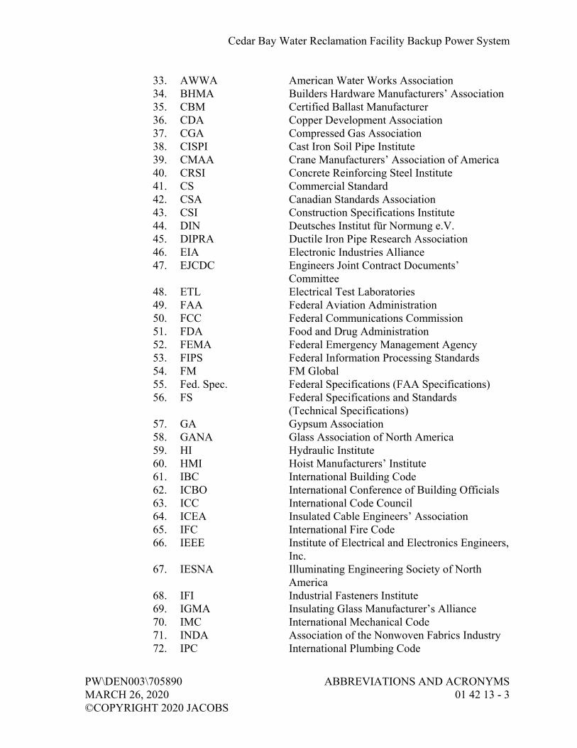
Cedar Bay Water Reclamation Facility Backup Power System
PW\DEN003\705890 ABBREVIATIONS AND ACRONYMS MARCH 26, 2020 01 42 13 - 3 ©COPYRIGHT 2020 JACOBS
33. AWWA American Water Works Association 34. BHMA Builders Hardware Manufacturers’ Association 35. CBM Certified Ballast Manufacturer 36. CDA Copper Development Association 37. CGA Compressed Gas Association 38. CISPI Cast Iron Soil Pipe Institute 39. CMAA Crane Manufacturers’ Association of America 40. CRSI Concrete Reinforcing Steel Institute 41. CS Commercial Standard 42. CSA Canadian Standards Association 43. CSI Construction Specifications Institute 44. DIN Deutsches Institut für Normung e.V. 45. DIPRA Ductile Iron Pipe Research Association 46. EIA Electronic Industries Alliance 47. EJCDC Engineers Joint Contract Documents’
Committee 48. ETL Electrical Test Laboratories 49. FAA Federal Aviation Administration 50. FCC Federal Communications Commission 51. FDA Food and Drug Administration 52. FEMA Federal Emergency Management Agency 53. FIPS Federal Information Processing Standards 54. FM FM Global 55. Fed. Spec. Federal Specifications (FAA Specifications) 56. FS Federal Specifications and Standards
(Technical Specifications) 57. GA Gypsum Association 58. GANA Glass Association of North America 59. HI Hydraulic Institute 60. HMI Hoist Manufacturers’ Institute 61. IBC International Building Code 62. ICBO International Conference of Building Officials 63. ICC International Code Council 64. ICEA Insulated Cable Engineers’ Association 65. IFC International Fire Code 66. IEEE Institute of Electrical and Electronics Engineers,
Inc. 67. IESNA Illuminating Engineering Society of North
America 68. IFI Industrial Fasteners Institute 69. IGMA Insulating Glass Manufacturer’s Alliance 70. IMC International Mechanical Code 71. INDA Association of the Nonwoven Fabrics Industry 72. IPC International Plumbing Code

Cedar Bay Water Reclamation Facility Backup Power System
ABBREVIATIONS AND ACRONYMS PW\DEN003\705890 01 42 13 - 4 MARCH 26, 2020 ©COPYRIGHT 2020 JACOBS
73. ISA Instrumentation, Systems, and Automation Society
74. ISO International Organization for Standardization 75. ITL Independent Testing Laboratory 76. JIC Joint Industry Conferences of Hydraulic
Manufacturers 77. MIA Marble Institute of America 78. MIL Military Specifications 79. MMA Monorail Manufacturers’ Association 80. MSS Manufacturer’s Standardization Society 81. NAAMM National Association of Architectural Metal
Manufacturers 82. NACE NACE International 83. NBGQA National Building Granite Quarries Association 84. NEBB National Environmental Balancing Bureau 85. NEC National Electrical Code 86. NECA National Electrical Contractor’s Association 87. NEMA National Electrical Manufacturers’ Association 88. NESC National Electrical Safety Code 89. NETA InterNational Electrical Testing Association 90. NFPA National Fire Protection Association 91. NHLA National Hardwood Lumber Association 92. NICET National Institute for Certification in
Engineering Technologies 93. NIST National Institute of Standards and Technology 94. NRCA National Roofing Contractors Association 95. NRTL Nationally Recognized Testing Laboratories 96. NSF NSF International 97. NSPE National Society of Professional Engineers 98. NTMA National Terrazzo and Mosaic Association 99. NWWDA National Wood Window and Door Association 100. OSHA Occupational Safety and Health Act (both
Federal and State) 101. PCI Precast/Prestressed Concrete Institute 102. PEI Porcelain Enamel Institute 103. PPI Plastic Pipe Institute 104. PS Product Standards Section-U.S. Department of
Commerce 105. RMA Rubber Manufacturers’ Association 106. RUS Rural Utilities Service 107. SAE Society of Automotive Engineers 108. SDI Steel Deck Institute 109. SDI Steel Door Institute 110. SJI Steel Joist Institute
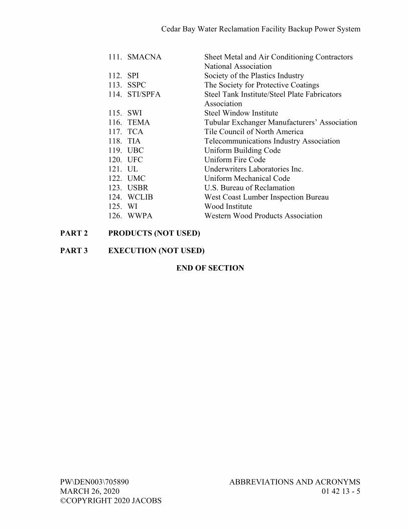
Cedar Bay Water Reclamation Facility Backup Power System
PW\DEN003\705890 ABBREVIATIONS AND ACRONYMS MARCH 26, 2020 01 42 13 - 5 ©COPYRIGHT 2020 JACOBS
111. SMACNA Sheet Metal and Air Conditioning Contractors National Association
112. SPI Society of the Plastics Industry 113. SSPC The Society for Protective Coatings 114. STI/SPFA Steel Tank Institute/Steel Plate Fabricators
Association 115. SWI Steel Window Institute 116. TEMA Tubular Exchanger Manufacturers’ Association 117. TCA Tile Council of North America 118. TIA Telecommunications Industry Association 119. UBC Uniform Building Code 120. UFC Uniform Fire Code 121. UL Underwriters Laboratories Inc. 122. UMC Uniform Mechanical Code 123. USBR U.S. Bureau of Reclamation 124. WCLIB West Coast Lumber Inspection Bureau 125. WI Wood Institute 126. WWPA Western Wood Products Association
PART 2 PRODUCTS (NOT USED)
PART 3 EXECUTION (NOT USED)
END OF SECTION


Cedar Bay Water Reclamation Facility Backup Power System
PW\DEN003\705890 MANUFACTURERS’ FIELD SERVICES MARCH 26, 2020 01 43 33 - 1 ©COPYRIGHT 2020 JACOBS
SECTION 01 43 33 MANUFACTURERS’ FIELD SERVICES
PART 1 GENERAL
1.01 DEFINITIONS
A. Person-Day: One person for 8 hours within regular Contractor working hours.
1.02 SUBMITTALS
A. Informational Submittals:
1. Training Schedule: Submit, in accordance with requirements of this specification, not less than 21 calendar days prior to start of equipment installation and revise as necessary for acceptance.
2. Lesson Plan: Submit, in accordance with requirements of this specification, proposed lesson plan not less than 21 calendar days prior to scheduled training and revise as necessary for acceptance.
3. Training Session Tapes: Furnish Owner with two complete sets of tapes fully indexed and cataloged with printed label stating session and date taped.
1.03 QUALIFICATION OF MANUFACTURER’S REPRESENTATIVE
A. Authorized representative of the manufacturer, factory trained, and experienced in the technical applications, installation, operation, and maintenance of respective equipment, subsystem, or system, with full authority by the equipment manufacturer to issue the certifications required of the manufacturer. Additional qualifications may be specified elsewhere.
B. Representative subject to acceptance by Owner. No substitute representatives will be allowed unless prior written approval by such has been given.
PART 2 PRODUCTS (NOT USED)
PART 3 EXECUTION
3.01 FULFILLMENT OF SPECIFIED MINIMUM SERVICES
A. Furnish manufacturers’ services when required by an individual specification section, to meet the requirements of this section.
B. Where time is necessary in excess of that stated in the Specifications for manufacturers’ services, or when a minimum time is not specified, the time required to perform the specified services shall be considered incidental.

Cedar Bay Water Reclamation Facility Backup Power System
MANUFACTURERS’ FIELD SERVICES PW\DEN003\705890 01 43 33 - 2 MARCH 26, 2020 ©COPYRIGHT 2020 JACOBS
C. Schedule manufacturer’ services to avoid conflict with other onsite testing or other manufacturers’ onsite services.
D. Determine, before scheduling services, that all conditions necessary to allow successful testing have been met.
E. Only those days of service approved by Engineer will be credited to fulfill the specified minimum services.
F. When specified in individual specification sections, manufacturer’s onsite services shall include:
1. Assistance during product (system, subsystem, or component) installation to include observation, guidance, instruction of Contractor’s assembly, erection, installation or application procedures.
2. Inspection, checking, and adjustment as required for product (system, subsystem, or component) to function as warranted by manufacturer and necessary to furnish Manufacturer’s Certificate of Proper Installation.
3. Providing, on a daily basis, copies of all manufacturers’ representatives’ field notes and data to Owner.
4. Revisiting the Site as required to correct problems and until installation and operation are acceptable to Engineer.
5. Resolution of assembly or installation problems attributable to, or associated with, respective manufacturer’s products and systems.
6. Assistance during functional and performance testing, and facility startup and evaluation.
7. Training of Owner’s personnel in the operation and maintenance of respective product as required.
8. Additional requirements may be specified elsewhere.
3.02 MANUFACTURER’S CERTIFICATE OF COMPLIANCE
A. When so specified, a Manufacturer’s Certificate of Compliance, a copy of which is attached to this section, shall be completed in full, signed by the entity supplying the product, material, or service, and submitted prior to shipment of product or material or the execution of the services.
B. Owner may permit use of certain materials or assemblies prior to sampling and testing if accompanied by accepted certification of compliance.
C. Such form shall certify that the proposed product, material, or service complies with that specified. Attach supporting reference data, affidavits, and certifications as appropriate.
D. May reflect recent or previous test results on material or product, if acceptable to Owner.

Cedar Bay Water Reclamation Facility Backup Power System
PW\DEN003\705890 MANUFACTURERS’ FIELD SERVICES MARCH 26, 2020 01 43 33 - 3 ©COPYRIGHT 2020 JACOBS
3.03 MANUFACTURER’S CERTIFICATE OF PROPER INSTALLATION
A. When so specified, a Manufacturer’s Certificate of Proper Installation form, a copy of which is attached to this section, shall be completed and signed by the equipment manufacturer’s representative.
B. Such form shall certify that the signing party is a duly authorized representative of the manufacturer, is empowered by the manufacturer to inspect, approve, and operate their equipment and is authorized to make recommendations required to assure that the equipment is complete and operational.
3.04 TRAINING
A. General:
1. Furnish manufacturers’ representatives for detailed classroom and hands-on training to Owner’s personnel on operation and maintenance of specified product (system, subsystem, component) and as may be required in applicable Specifications.
2. Furnish trained, articulate personnel to coordinate and expedite training, to be present during training coordination meetings with Owner, and familiar with operation and maintenance manual information specified in Section 01 78 23, Operation and Maintenance Data.
3. Manufacturer’s representative shall be familiar with facility operation and maintenance requirements as well as with specified equipment.
4. Furnish complete training materials, to include operation and maintenance data, to be retained by each trainee.
B. Training Schedule:
1. List specified equipment and systems that require training services and show: a. Respective manufacturer. b. Estimated dates for installation completion. c. Estimated training dates.
2. Allow for multiple sessions when several shifts are involved. 3. Adjust schedule to ensure training of appropriate personnel as deemed
necessary by Owner, and to allow full participation by manufacturers’ representatives. Adjust schedule for interruptions in operability of equipment.
4. Coordinate with Section 01 32 00, Construction Progress. Documentation, and Section 01 91 14, Equipment Testing and Facility Startup.

Cedar Bay Water Reclamation Facility Backup Power System
MANUFACTURERS’ FIELD SERVICES PW\DEN003\705890 01 43 33 - 4 MARCH 26, 2020 ©COPYRIGHT 2020 JACOBS
C. Lesson Plan: When manufacturer or vendor training of Owner personnel is specified, prepare a lesson plan for each required course containing the following minimum information:
1. Title and objectives. 2. Recommended attendees (e.g., managers, engineers, operators,
maintenance). 3. Course description, outline of course content, and estimated class
duration. 4. Format (e.g., lecture, self-study, demonstration, hands-on). 5. Instruction materials and equipment requirements. 6. Resumes of instructors providing the training.
D. Pre-startup Training:
1. Coordinate training sessions with Owner’s operating personnel and manufacturers’ representatives, and with submission of operation and maintenance manuals in accordance with Section 01 78 23, Operation and Maintenance Data.
2. Complete at least 14 work days prior to beginning of facility startup.
E. Post-startup Training: If required in Specifications, furnish and coordinate training of Owner’s operating personnel by respective manufacturer’s representatives.
3.05 SUPPLEMENTS
A. The supplements listed below, following “End of Section”, are part of this Specification.
1. Form: Manufacturer’s Certificate of Compliance. 2. Form: Manufacturer’s Certificate of Proper Installation.
END OF SECTION

Cedar Bay Water Reclamation Facility Backup Power System
PW\DEN003\705890 MANUFACTURERS’ CERTIFICATE MARCH 26, 2020 OF COMPLIANCE ©COPYRIGHT 2020 JACOBS 01 43 33 SUPPLEMENT 1 - 1
MANUFACTURER’S CERTIFICATE OF COMPLIANCE
OWNER: PRODUCT, MATERIAL, OR SERVICE SUBMITTED:
PROJECT NAME:
PROJECT NO:
Comments:
I hereby certify that the above-referenced product, material, or service called for by the contract for the named project will be furnished in accordance with all applicable requirements. I further certify that the product, material, or service are of the quality specified and conform in all respects with the contract requirements, and are in the quantity shown.
Date of Execution: ________________________________________, 20___
Manufacturer:
Manufacturer’s Authorized Representative (print): (Authorized Signature)


Cedar Bay Water Reclamation Facility Backup Power System
PW\DEN003\705890 MANUFACTURER’S CERTIFICATE OF MARCH 26, 2020 PROPER INSTALLATION ©COPYRIGHT 2020 JACOBS 01 43 33 SUPPLEMENT 2 - 1
MANUFACTURER’S CERTIFICATE OF PROPER INSTALLATION
OWNER EQPT SERIAL NO:
EQPT TAG NO: EQPT/SYSTEM:
PROJECT NO: SPEC. SECTION:
I hereby certify that the above-referenced equipment/system has been:
(Check Applicable)
Installed in accordance with Manufacturer’s recommendations.
Inspected, checked, and adjusted.
Serviced with proper initial lubricants.
Electrical and mechanical connections meet quality and safety standards.
All applicable safety equipment has been properly installed.
Functional tests.
System has been performance tested and meets or exceeds specified performance requirements. (When complete system of one manufacturer)
Note: Attach any performance test documentation from manufacturer.
Comments:
I, the undersigned Manufacturer’s Representative, hereby certify that I am (i) a duly authorized representative of the manufacturer, (ii) empowered by the manufacturer to inspect, approve, and operate his equipment and (iii) authorized to make recommendations required to assure that the equipment furnished by the manufacturer is complete and operational, except as may be otherwise indicated herein. I further certify that all information contained herein is true and accurate.
Date: _________________________________, 20___
Manufacturer:
By Manufacturer’s Authorized Representative: (Authorized Signature)

Cedar Bay Water Reclamation Facility Backup Power System
PW\DEN003\705890 TEMPORARY FACILITIES AND CONTROLS MARCH 26, 2020 01 50 00 - 1 ©COPYRIGHT 2020 JACOBS
SECTION 01 50 00 TEMPORARY FACILITIES AND CONTROLS
PART 1 GENERAL
1.01 REFERENCES
A. The following is a list of standards which may be referenced in this section:
1. American Association of Nurserymen (AAN): American Standards for Nursery Stock.
2. Federal Emergency Management Agency (FEMA). 3. National Fire Prevention Association (NFPA): 241, Standard for
Safeguarding Construction, Alteration, and Demolition Operations. 4. Telecommunications Industry Association (TIA); Electronic Industries
Alliance (EIA): 568B, Commercial Building Telecommunications Cabling Standard.
5. U.S. Department of Agriculture (USDA): Urban Hydrology for Small Watersheds.
6. U.S. Weather Bureau: Rainfall-Frequency Atlas of the U.S. for Durations from 30 Minutes to 24 Hours and Return Periods from 1 to 100 Years.
1.02 MOBILIZATION
A. Mobilization shall include, but not be limited to, these principal items:
1. Obtaining required permits. 2. Moving Contractor’s field office and equipment required for first month
operations onto Site. 3. Installing temporary construction power, wiring, and lighting facilities. 4. Providing onsite communication facilities, including telephones. 5. Providing onsite sanitary facilities and potable water facilities as
specified and as required by Laws and Regulations, and governing agencies.
6. Arranging for and erection of Contractor’s work and storage yard. 7. Posting OSHA required notices and establishing safety programs and
procedures. 8. Having Contractor’s superintendent at Site full time.
1.03 PROTECTION OF WORK AND PROPERTY
A. Comply with Owner’s safety rules while on Owner’s property.
B. Keep Owner informed of serious onsite accidents and related claims.

Cedar Bay Water Reclamation Facility Backup Power System
TEMPORARY FACILITIES AND CONTROLS PW\DEN003\705890 01 50 00 - 2 MARCH 26, 2020 ©COPYRIGHT 2020 JACOBS
PART 2 PRODUCTS
2.01 PROJECT SIGN
A. Provide and maintain one, 8-foot wide by 4-foot high sign constructed of 3/4-inch exterior high-density overlaid plywood. Sign shall bear name of Project, Owner, Contractor, Engineer, and other participating agencies. Lettering shall be blue applied on a white background by an experienced sign painter. Paint shall be exterior type enamel. Information to be included will be provided by Owner.
PART 3 EXECUTION
3.01 TEMPORARY UTILITIES
A. Power and Water: Contractor may connect into the existing Cedar Bay WRF electric and water systems for use in this construction.
1. The cost of making the connection to the electric and water systems shall be included in the Contractor’s lump sum bid.
2. The cost of electric power and water will be provided by the Owner (free service).
B. Lighting: Provide temporary lighting to meet applicable safety requirements to allow erection, application, or installation of materials and equipment, and observation or inspection of the Work.
C. Heating, Cooling, and Ventilating:
1. Provide as required to maintain adequate environmental conditions to facilitate progress of the Work, to meet specified minimum conditions for installation of materials, and to protect materials, equipment, and finishes from damage due to temperature or humidity.
2. Provide adequate forced air ventilation of enclosed areas to cure installed materials, to dispense humidity, and to prevent hazardous accumulations of dust, fumes, vapors, or gases.
3. Pay all costs of installation, maintenance, operation, removal, and fuel consumed.
4. Provide portable unit heaters, complete with controls, oil- or gas-fired, and suitably vented to outside as required for protection of health and property.
5. If permanent natural gas piping is used for temporary heating units, do not modify or reroute gas piping without approval of utility company. Provide separate gas metering as required by utility.

Cedar Bay Water Reclamation Facility Backup Power System
PW\DEN003\705890 TEMPORARY FACILITIES AND CONTROLS MARCH 26, 2020 01 50 00 - 3 ©COPYRIGHT 2020 JACOBS
D. Sanitary and Personnel Facilities: Provide and maintain facilities for Contractor’s employees, Subcontractors, and all other onsite employers’ employees. Service, clean, and maintain facilities and enclosures.
E. Telephone Service:
1. Contractor: Arrange and provide onsite telephone service for use during construction. Pay costs of installation and monthly bills. Cell phone service is acceptable versus land line.
F. Fire Protection: Furnish and maintain on Site adequate firefighting equipment capable of extinguishing incipient fires. Comply with applicable parts of NFPA 241.
3.02 PROTECTION OF WORK AND PROPERTY
A. General:
1. Perform Work within right-of-way and easements in a systematic manner that minimizes inconvenience to property owners and the public.
2. Protect, shore, brace, support, and maintain underground pipes, conduits, drains, and other underground utility construction uncovered or otherwise affected by construction operations.
3. In areas where Contractor’s operations are adjacent to or near a utility, such as gas, telephone, television, electric power, water, sewer, or irrigation system, and such operations may cause damage or inconvenience, suspend operations until arrangements necessary for protection have been made by Contractor.
4. Do not impair operation of existing sewer system. Prevent construction material, pavement, concrete, earth, volatile and corrosive wastes, and other debris from entering sewers, pump stations, or other sewer structures.
5. Maintain original Site drainage wherever possible.
B. Site Security: Provide and maintain additional temporary security fences as necessary to protect the Work and Contractor-furnished products not yet installed.
C. Barricades and Lights:
1. Provide as necessary to prevent unauthorized entry to construction areas and affected roads, streets, and alleyways, inside and outside of fenced area, and as required to ensure public safety and the safety of Contractor’s employees, other employer’s employees, and others who may be affected by the Work.

Cedar Bay Water Reclamation Facility Backup Power System
TEMPORARY FACILITIES AND CONTROLS PW\DEN003\705890 01 50 00 - 4 MARCH 26, 2020 ©COPYRIGHT 2020 JACOBS
2. Provide to protect existing facilities and adjacent properties from potential damage.
3. Locate to enable access by facility operators and property owners.
D. Signs and Equipment:
1. Conform to requirements of manual published by the State Department of Transportation.
2. Provide at obstructions, such as material piles and equipment. 3. Use to alert general public of construction hazards, which would include
surface irregularities, unramped walkways, grade changes, and trenches or excavations in roadways and in other public access areas.
E. Trees and Plantings:
1. Protect from damage and preserve trees, shrubs, and other plants outside limits of the Work and within limits of the Work, which are designated on the Drawings to remain undisturbed. a. Where practical, tunnel beneath trees when on or near line of
trench. b. Employ hand excavation as necessary to prevent tree injury. c. Do not stockpile materials or permit traffic within drip lines of
trees. d. Provide and maintain temporary barricades around trees. e. Water vegetation as necessary to maintain health. f. Cover temporarily exposed roots with wet burlap, and keep burlap
moist until soil is replaced around roots. g. No trees, except those specifically shown on Drawings to be
removed, shall be removed without written approval of Engineer. h. Dispose of removed trees in a legal manner off the Site.
2. In event of damage to bark, trunks, limbs, or roots of plants that are not designated for removal, treat damage by corrective pruning, bark tracing, application of a heavy coating of tree paint, and other accepted horticultural and tree surgery practices.
3. Replace each plant that dies as a result of construction activities.
F. Finished Construction: Protect finished floors and concrete floors exposed as well as those covered with composition tile or other applied surfacing.
G. Waterways: Keep ditches, culverts, and natural drainages continuously free of construction materials and debris.

Cedar Bay Water Reclamation Facility Backup Power System
PW\DEN003\705890 TEMPORARY FACILITIES AND CONTROLS MARCH 26, 2020 01 50 00 - 5 ©COPYRIGHT 2020 JACOBS
3.03 TEMPORARY CONTROLS
A. Air Pollution Control:
1. Minimize air pollution from construction operations. 2. Burning: Flammable debris and refuse may be burned onsite provided
requirements set forth by proper fire authorities and air quality control agencies are met.
3. Conduct operations of dumping rock and of carrying rock away in trucks to cause a minimum of dust. Give unpaved streets, roads, detours, or haul roads used in construction area a dust-preventive treatment or periodically water to prevent dust. Strictly adhere to applicable environmental regulations for dust prevention.
B. Noise Control: Provide acoustical barriers so noise emanating from tools or equipment will not exceed legal noise levels.
C. Water Pollution Control:
1. Prior to commencing excavation and construction, obtain Owner’s agreement with detailed plans showing procedures intended to handle and dispose of sewage, groundwater, and stormwater flow, including dewatering pump discharges.
2. Comply with procedures outlined in U.S. Environmental Protection Agency manuals entitled, “Guidelines for Erosion and Sedimentation Control Planning” and “Implementation, Processes, Procedures, and Methods to Control Pollution Resulting from All Construction Activity,” and “Erosion and Sediment Control-Surface Mining in Eastern United States.”
3. Do not dispose of volatile wastes such as mineral spirits, oil, chemicals, or paint thinner in storm or sanitary drains. Disposal of wastes into streams or waterways is prohibited. Provide acceptable containers for collection and disposal of waste materials, debris, and rubbish.
D. Erosion, Sediment, and Flood Control: Provide, maintain, and operate temporary facilities to control erosion and sediment releases, and to protect the Work and existing facilities from flooding during construction period.
3.04 STORAGE YARDS AND BUILDINGS
A. Coordinate requirements with Section 01 61 00, Common Product Requirements.
B. Temporary Storage Yards: Construct temporary storage yards for storage of products that are not subject to damage by weather conditions.

Cedar Bay Water Reclamation Facility Backup Power System
TEMPORARY FACILITIES AND CONTROLS PW\DEN003\705890 01 50 00 - 6 MARCH 26, 2020 ©COPYRIGHT 2020 JACOBS
C. Temporary Storage Buildings:
1. Provide environmental control systems that meet recommendations of manufacturers of equipment and materials stored.
2. Arrange or partition to provide security of contents and ready access for inspection and inventory.
3. Store combustible materials (paints, solvents, fuels) in a well-ventilated and remote building meeting safety standards.
3.05 PARKING AREAS
A. Control vehicular parking to preclude interference with public traffic or parking, access by emergency vehicles, Owner’s operations, or construction operations.
3.06 VEHICULAR TRAFFIC
A. Comply with Laws and Regulations regarding closing or restricting use of public streets or highways. No public or private road shall be closed, except by written permission of proper authority. Assure the least possible obstruction to traffic and normal commercial pursuits.
B. Conduct the Work to interfere as little as possible with public travel, whether vehicular or pedestrian.
C. Whenever it is necessary to cross, close, or obstruct roads, driveways, and walks, whether public or private, provide and maintain suitable and safe bridges, detours, or other temporary expedients for accommodation of public and private travel.
D. Road Closures: Maintain satisfactory means of exit for persons residing or having occasion to transact business along route of the Work. If it is necessary to close off roadway or alley providing sole vehicular access to property for periods greater than 2 hours, provide written notice to each owner so affected 3 work days prior to such closure. In such cases, closings of up to 4 hours may be allowed. Closures of up to 10 hours may be allowed if a week’s written notice is given and undue hardship does not result.
E. Maintenance of traffic is not required if Contractor obtains written permission from Owner and tenant of private property, or from authority having jurisdiction over public property involved, to obstruct traffic at designated point.

Cedar Bay Water Reclamation Facility Backup Power System
PW\DEN003\705890 TEMPORARY FACILITIES AND CONTROLS MARCH 26, 2020 01 50 00 - 7 ©COPYRIGHT 2020 JACOBS
F. Maintain top of backfilled trenches before they are paved, to allow normal vehicular traffic to pass over. Provide temporary access driveways where required. Cleanup operations shall follow immediately behind backfilling.
G. When flaggers and guards are required by regulation or when deemed necessary for safety, furnish them with approved orange wearing apparel and other regulation traffic control devices.
END OF SECTION


Cedar Bay Water Reclamation Facility Backup Power System
PW\DEN003\705890 COMMON PRODUCT REQUIREMENTS MARCH 26, 2020 01 61 00 - 1 ©COPYRIGHT 2020 JACOBS
SECTION 01 61 00 COMMON PRODUCT REQUIREMENTS
PART 1 GENERAL
1.01 DEFINITIONS
A. Products:
1. New items for incorporation in the Work, whether purchased by Contractor or Owner for the Project, or taken from previously purchased stock, and may also include existing materials or components required for reuse.
2. Includes the terms material, equipment, machinery, components, subsystem, system, hardware, software, and terms of similar intent and is not intended to change meaning of such other terms used in Contract Documents, as those terms are self-explanatory and have well recognized meanings in construction industry.
3. Items identified by manufacturer’s product name, including make or model designation, indicated in manufacturer’s published product literature, that is current as of the date of the Contract Documents.
1.02 DESIGN REQUIREMENTS
A. Where Contractor design is specified, design of installation, systems, equipment, and components, including supports and anchorage, shall be in accordance with provisions of Florida Building Code Sixth Edition (2017).
1. Refer to Sheet Structural General Notes in the Drawings for additional Project specific information.
1.03 PREPARATION FOR SHIPMENT
A. When practical, factory assemble products. Mark or tag separate parts and assemblies to facilitate field assembly. Cover machined and unpainted parts that may be damaged by the elements with strippable protective coating.
B. Package products to facilitate handling and protect from damage during shipping, handling, and storage. Mark or tag outside of each package or crate to indicate its purchase order number, bill of lading number, contents by name, name of Project and Contractor, equipment number, and approximate weight. Include complete packing list and bill of materials with each shipment.

Cedar Bay Water Reclamation Facility Backup Power System
COMMON PRODUCT REQUIREMENTS PW\DEN003\705890 01 61 00 - 2 MARCH 26, 2020 ©COPYRIGHT 2020 JACOBS
C. Extra Materials, Special Tools, Test Equipment, and Expendables:
1. Furnish as required by individual Specifications. 2. Schedule:
a. Ensure that shipment and delivery occurs concurrent with shipment of associated equipment.
b. Transfer to Owner shall occur immediately subsequent to Contractor’s acceptance of equipment from Supplier.
3. Packaging and Shipment: a. Package and ship extra materials and special tools to avoid
damage during long term storage in original cartons insofar as possible, or in appropriately sized, hinged-cover, wood, plastic, or metal box.
b. Prominently displayed on each package, the following: 1) Manufacturer’s part nomenclature and number, consistent
with Operation and Maintenance Manual identification system.
2) Applicable equipment description. 3) Quantity of parts in package. 4) Equipment manufacturer.
4. Deliver materials to Site. 5. Replace extra materials and special tools found to be damaged or
otherwise inoperable at time of transfer to Owner.
1.04 DELIVERY AND INSPECTION
A. Deliver products in accordance with accepted current Progress Schedule and coordinate to avoid conflict with the Work and conditions at Site. Deliver anchor bolts and templates sufficiently early to permit setting prior to placement of structural concrete.
B. Deliver products in undamaged condition, in manufacturer’s original container or packaging, with identifying labels intact and legible. Include on label, date of manufacture and shelf life, where applicable.
C. Unload products in accordance with manufacturer’s instructions for unloading or as specified. Record receipt of products at Site. Promptly inspect for completeness and evidence of damage during shipment.
D. Remove damaged products from Site and expedite delivery of identical new undamaged products, and remedy incomplete or lost products to provide that specified, so as not to delay progress of the Work.

Cedar Bay Water Reclamation Facility Backup Power System
PW\DEN003\705890 COMMON PRODUCT REQUIREMENTS MARCH 26, 2020 01 61 00 - 3 ©COPYRIGHT 2020 JACOBS
1.05 HANDLING, STORAGE, AND PROTECTION
A. Handle and store products in accordance with manufacturer’s written instructions and in a manner to prevent damage. Store in approved storage yards or sheds provided in accordance with Section 01 50 00, Temporary Facilities and Controls. Provide manufacturer’s recommended maintenance during storage, installation, and until products are accepted for use by Owner.
B. Manufacturer’s instructions for material requiring special handling, storage, or protection shall be provided prior to delivery of material.
C. Arrange storage in a manner to provide easy access for inspection. Make periodic inspections of stored products to assure that products are maintained under specified conditions, and free from damage or deterioration. Keep running account of products in storage to facilitate inspection and to estimate progress payments for products delivered, but not installed in the Work.
D. Store electrical, instrumentation, and control products, and equipment with bearings in weather-tight structures maintained above 60 degrees F. Protect electrical, instrumentation, and control products, and insulate against moisture, water, and dust damage. Connect and operate continuously space heaters furnished in electrical equipment.
E. Store fabricated products above ground on blocking or skids, and prevent soiling or staining. Store loose granular materials in well-drained area on solid surface to prevent mixing with foreign matter. Cover products that are subject to deterioration with impervious sheet coverings; provide adequate ventilation to avoid condensation.
F. Store finished products that are ready for installation in dry and well-ventilated areas. Do not subject to extreme changes in temperature or humidity.
G. After installation, provide coverings to protect products from damage due to traffic and construction operations. Remove coverings when no longer needed.
PART 2 PRODUCTS
2.01 GENERAL
A. Provide manufacturer’s standard materials suitable for service conditions, unless otherwise specified in the individual Specifications.
B. Where product specifications include a named manufacturer, with or without model number, and also include performance requirements, named manufacturer’s products must meet the performance specifications.

Cedar Bay Water Reclamation Facility Backup Power System
COMMON PRODUCT REQUIREMENTS PW\DEN003\705890 01 61 00 - 4 MARCH 26, 2020 ©COPYRIGHT 2020 JACOBS
C. Like items of products furnished and installed in the Work shall be end products of one manufacturer and of the same series or family of models to achieve standardization for appearance, operation and maintenance, spare parts and replacement, manufacturer’s services, and implement same or similar process instrumentation and control functions in same or similar manner.
D. Do not use materials and equipment removed from existing premises, except as specifically permitted by Contract Documents.
E. Provide interchangeable components of the same manufacturer, for similar components, unless otherwise specified.
F. Equipment, Components, Systems, and Subsystems: Design and manufacture with due regard for health and safety of operation, maintenance, and accessibility, durability of parts, and shall comply with applicable OSHA, state, and local health and safety regulations.
G. Regulatory Requirement: Coating materials shall meet federal, state, and local requirements limiting the emission of volatile organic compounds and for worker exposure.
H. Safety Guards: Provide for all belt or chain drives, fan blades, couplings, or other moving or rotary parts. Cover rotating part on all sides. Design for easy installation and removal. Use 16-gauge or heavier; galvanized steel, aluminum coated steel, or galvanized or aluminum coated 1/2-inch mesh expanded steel. Provide galvanized steel accessories and supports, including bolts. For outdoors application, prevent entrance of rain and dripping water.
I. Authority Having Jurisdiction (AHJ):
1. Provide the Work in accordance with NFPA 70, National Electrical Code (NEC). Where required by the AHJ, material and equipment shall be labeled or listed by a nationally recognized testing laboratory or other organization acceptable to the AHJ in order to provide a basis for approval under NEC.
2. Materials and equipment manufactured within the scope of standards published by Underwriters Laboratories, Inc. shall conform to those standards and shall have an applied UL listing mark.
J. Equipment Finish:
1. Provide manufacturer’s standard finish and color, except where specific color is indicated.
2. If manufacturer has no standard color, provide equipment with gray finish as approved by Owner.

Cedar Bay Water Reclamation Facility Backup Power System
PW\DEN003\705890 COMMON PRODUCT REQUIREMENTS MARCH 26, 2020 01 61 00 - 5 ©COPYRIGHT 2020 JACOBS
K. Special Tools and Accessories: Furnish to Owner, upon acceptance of equipment, all accessories required to place each item of equipment in full operation. These accessory items include, but are not limited to, adequate oil and grease (as required for first lubrication of equipment after field testing), light bulbs, fuses, hydrant wrenches, valve keys, handwheels, chain operators, special tools, and other spare parts as required for maintenance.
L. Lubricant: Provide initial lubricant recommended by equipment manufacturer in sufficient quantity to fill lubricant reservoirs and to replace consumption during testing, startup, and operation until final acceptance by Owner.
2.02 FABRICATION AND MANUFACTURE
A. General:
1. Manufacture parts to U.S.A. standard sizes and gauges. 2. Two or more items of the same type shall be identical, by the same
manufacturer, and interchangeable. 3. Design structural members for anticipated shock and vibratory loads. 4. Use 1/4-inch minimum thickness for steel that will be submerged,
wholly or partially, during normal operation. 5. Modify standard products as necessary to meet performance
Specifications.
B. Lubrication System:
1. Require no more than weekly attention during continuous operation. 2. Convenient and accessible; oil drains with bronze or stainless steel
valves and fill-plugs easily accessible from the normal operating area or platform. Locate drains to allow convenient collection of oil during oil changes without removing equipment from its installed position.
3. Provide constant-level oilers or oil level indicators for oil lubrication systems.
4. For grease type bearings, which are not easily accessible, provide and install stainless steel tubing; protect and extend tubing to convenient location with suitable grease fitting.
2.03 SOURCE QUALITY CONTROL
A. Where Specifications call for factory testing to be witnessed by Engineer, notify Engineer not less than 14 days prior to scheduled test date, unless otherwise specified.
B. Calibration Instruments: Bear the seal of a reputable laboratory certifying instrument has been calibrated within the previous 12 months to a standard endorsed by the National Institute of Standards and Technology (NIST).

Cedar Bay Water Reclamation Facility Backup Power System
COMMON PRODUCT REQUIREMENTS PW\DEN003\705890 01 61 00 - 6 MARCH 26, 2020 ©COPYRIGHT 2020 JACOBS
C. Factory Tests: Perform in accordance with accepted test procedures and document successful completion.
PART 3 EXECUTION
3.01 INSPECTION
A. Inspect materials and equipment for signs of pitting, rust decay, or other deleterious effects of storage. Do not install material or equipment showing such effects. Remove damaged material or equipment from the Site and expedite delivery of identical new material or equipment. Delays to the Work resulting from material or equipment damage that necessitates procurement of new products will be considered delays within Contractor’s control.
3.02 INSTALLATION
A. Equipment Drawings show general locations of equipment, devices, and raceway, unless specifically dimensioned.
B. No shimming between machined surfaces is allowed.
C. Install the Work in accordance with NECA Standard of Installation, unless otherwise specified.
D. Repaint painted surfaces that are damaged prior to equipment acceptance.
E. Do not cut or notch any structural member or building surface without specific approval of Engineer.
F. Handle, install, connect, clean, condition, and adjust products in accordance with manufacturer’s instructions, and as may be specified. Retain a copy of manufacturers’ instruction at Site, available for review at all times.
G. For material and equipment specifically indicated or specified to be reused in the Work:
1. Use special care in removal, handling, storage, and reinstallation to assure proper function in the completed Work.
2. Arrange for transportation, storage, and handling of products that require offsite storage, restoration, or renovation. Include costs for such Work in the Contract Price.
3.03 FIELD FINISHING
A. In accordance with Section 09 90 00, Painting and Coating, and individual Specification sections.

Cedar Bay Water Reclamation Facility Backup Power System
PW\DEN003\705890 COMMON PRODUCT REQUIREMENTS MARCH 26, 2020 01 61 00 - 7 ©COPYRIGHT 2020 JACOBS
3.04 ADJUSTMENT AND CLEANING
A. Perform required adjustments, tests, operation checks, and other startup activities.
3.05 LUBRICANTS
A. Fill lubricant reservoirs and replace consumption during testing, startup, and operation prior to acceptance of equipment by Owner.
END OF SECTION


Cedar Bay Water Reclamation Facility Backup Power System
PW\DEN003\705890 CLOSEOUT PROCEDURES MARCH 26, 2020 AND AS-BUILT DRAWINGS ©COPYRIGHT 2020 JACOBS 01 77 00 - 1
SECTION 01 77 00 CLOSEOUT PROCEDURES AND AS-BUILT DRAWINGS
PART 1 GENERAL
1.01 SUBMITTALS
A. Informational Submittals:
1. Submit prior to application for final payment. a. Record Documents: As required in General Conditions. b. Special bonds, Special Guarantees, and Service Agreements. c. Consent of Surety to Final Payment: As required in General
Conditions. d. Releases or Waivers of Liens and Claims: As required in General
Conditions. e. Releases from Agreements. f. Final Application for Payment: Submit in accordance with
procedures and requirements stated in Section 01 29 00, Payment Procedures.
g. Extra Materials: As required by individual Specification sections. h. Completed JEA Asset Management spreadsheets.
1.02 RECORD DOCUMENTS
A. Quality Assurance:
1. Furnish qualified and experienced person, whose duty and responsibility shall be to maintain record documents.
2. Accuracy of Records: a. Coordinate changes within record documents, making legible and
accurate entries on each sheet of Drawings and other documents where such entry is required to show change.
b. Purpose of Project record documents is to document factual information regarding aspects of the Work, both concealed and visible, to enable future modification of the Work to proceed without lengthy and expensive Site measurement, investigation, and examination.
3. Make entries within 24 hours after receipt of information that a change in the Work has occurred.
4. Prior to submitting each request for progress payment, request Engineer’s review and approval of current status of record documents. Failure to properly maintain, update, and submit record documents may result in a deferral by Engineer to recommend whole or any part of Contractor’s Application for Payment, either partial or final.

Cedar Bay Water Reclamation Facility Backup Power System
CLOSEOUT PROCEDURES PW\DEN003\705890 AND AS-BUILT DRAWINGS MARCH 26, 2020 01 77 00 - 2 ©COPYRIGHT 2020 JACOBS
1.03 RELEASES FROM AGREEMENTS
A. Furnish Owner written releases from property owners or public agencies where side agreements or special easements have been made, or where Contractor’s operations have not been kept within the Owner’s construction right-of-way.
B. In the event Contractor is unable to secure written releases:
1. Inform Owner of the reasons. 2. Owner or its representatives will examine the Site, and Owner will
direct Contractor to complete the Work that may be necessary to satisfy terms of the side agreement or special easement.
3. Should Contractor refuse to perform this Work, Owner reserves right to have it done by separate contract and deduct cost of same from Contract Price, or require Contractor to furnish a satisfactory bond in a sum to cover legal Claims for damages.
4. When Owner is satisfied that the Work has been completed in agreement with Contract Documents and terms of side agreement or special easement, right is reserved to waive requirement for written release if: (i) Contractor’s failure to obtain such statement is due to grantor’s refusal to sign, and this refusal is not based upon any legitimate Claims that Contractor has failed to fulfill terms of side agreement or special easement, or (ii) Contractor is unable to contact or has had undue hardship in contacting grantor.
PART 2 PRODUCTS (NOT USED)
PART 3 EXECUTION
3.01 MAINTENANCE OF RECORD DOCUMENTS
A. General: Requirements for maintaining record drawings during the project shall be as defined in JEA Water and Wastewater Standards, Section 501 AS-BUILT DRAWINGS. The following paragraphs supplement the JEA requirements.
1. Promptly following commencement of Contract Times, secure from Engineer at no cost to Contractor, one complete set of Contract Documents. Drawings will be full size.
2. Label or stamp each record document with title, “RECORD DOCUMENTS,” in neat large printed letters.
3. Record information concurrently with construction progress and within 24 hours after receipt of information that change has occurred. Do not cover or conceal Work until required information is recorded.

Cedar Bay Water Reclamation Facility Backup Power System
PW\DEN003\705890 CLOSEOUT PROCEDURES MARCH 26, 2020 AND AS-BUILT DRAWINGS ©COPYRIGHT 2020 JACOBS 01 77 00 - 3
B. Preservation:
1. Maintain documents in a clean, dry, legible condition and in good order. Do not use record documents for construction purposes.
2. Make documents and Samples available at all times for observation by Engineer.
C. Making Entries on Drawings:
1. Using an erasable colored pencil (not ink or indelible pencil), clearly describe change by graphic line and note as required. a. Color Coding:
1) Green when showing information deleted from Drawings. 2) Red when showing information added to Drawings. 3) Blue and circled in blue to show notes.
2. Date entries. 3. Call attention to entry by “cloud” drawn around area or areas affected. 4. Legibly mark to record actual changes made during construction,
including, but not limited to: a. Depths of various elements of foundation in relation to finished
first floor data if not shown or where depth differs from that shown.
b. Horizontal and vertical locations of existing and new Underground Facilities and appurtenances, and other underground structures, equipment, or Work. Reference to at least two measurements to permanent surface improvements.
c. Location of internal utilities and appurtenances concealed in the construction referenced to visible and accessible features of the structure.
d. Locate existing facilities, piping, equipment, and items critical to the interface between existing physical conditions or construction and new construction.
e. Changes made by Addenda and Field Orders, SWAs, Change Order, and Engineer’s written interpretation and clarification using consistent symbols for each and showing appropriate document tracking number.
5. Dimensions on Schematic Layouts: Show on record drawings, by dimension, the centerline of each run of items such as are described in previous subparagraph above. a. Clearly identify the item by accurate note such as “cast iron
drain,” “galv. water,” and the like. b. Show, by symbol or note, vertical location of item (“under slab,”
“in ceiling plenum,” “exposed,” and the like). c. Make identification so descriptive that it may be related reliably
to Specifications.

Cedar Bay Water Reclamation Facility Backup Power System
CLOSEOUT PROCEDURES PW\DEN003\705890 AND AS-BUILT DRAWINGS MARCH 26, 2020 01 77 00 - 4 ©COPYRIGHT 2020 JACOBS
D. Preparation of AutoCAD Drawings, PDF and Paper Prints:
1. The requirements for as-built drawings is provided in JEA Water and Wastewater Standards, As-Built Drawings – Section 501. The following is an abbreviated summary of the requirements.
2. Contractor shall furnish to JEA an electronic file in AutoCAD 2017 and certified paper copies of the as-built drawings, which have been re-drawn/revised to indicate the final as-built data (true to scale) and in accordance with addenda, work orders, Supplemental Work Account and all other requirements. An electronic file of the original project drawings will be furnished to the Contractor.
3. Each page of the as-built drawings shall bear the name of the signed as-built certification of the general contractor, and professional surveyor who provides the horizontal and vertical elevations. The certification forms are provided in JEA Water and Wastewater Standards, As-Built Drawings – Section 501.
4. Upon completion of the work Contractor shall deliver the as-built drawings including electronic files, two certified and embossed prints made from the as-built drawings, and an electronic file in ASCII format (with AutoCAD 2017, PDF).
5. Use the Plane Coordinate System using Florida East Zone and North American Datum of 1983 for horizontal data. North American Vertical Datum (NAVD) 1988 shall be used for elevation data.
6. All valves, bends, tee’s, and changes if direction shall be located vertically and horizontally, in addition grade shall be identified at each point. A table shall be provided in a conspicuous location specifying the northing/easting, latitude/longitude, pipe elevation, final grade, cover, utility size and separation. For all valves provide a table that identifies valves size, valve type, manufacturer, number of turns to open valve and valve open direction (right/left)
7. Provide physical dimensioning of the separation of water mains at crossing with all sanitary wastewater pipes.
8. Provide a table identifying all fire hydrants. 9. Submit JEA Record Drawing submittal checklist and the transmittal
form as provided in JEA Water and Wastewater Standards, As-Built Drawings – Section 501.

Cedar Bay Water Reclamation Facility Backup Power System
PW\DEN003\705890 CLOSEOUT PROCEDURES MARCH 26, 2020 AND AS-BUILT DRAWINGS ©COPYRIGHT 2020 JACOBS 01 77 00 - 5
3.02 FINAL CLEANING
A. At completion of the Work or of a part thereof and immediately prior to Contractor’s request for certificate of Substantial Completion; or if no certificate is issued, immediately prior to Contractor’s notice of completion, clean entire Site or parts thereof, as applicable.
1. Leave the Work and adjacent areas affected in a cleaned condition satisfactory to Owner.
2. Remove grease, dirt, dust, paint or plaster splatter, stains, labels, fingerprints, and other foreign materials from exposed surfaces.
3. Repair, patch, and touch up marred surfaces to specified finish and match adjacent surfaces.
4. Clean all windows. 5. Clean and wax wood, vinyl, or painted floors. 6. Broom clean exterior paved driveways and parking areas. 7. Hose clean sidewalks, loading areas, and others contiguous with
principal structures. 8. Rake clean all other surfaces. 9. Remove snow and ice from access to buildings. 10. Replace air-handling filters and clean ducts, blowers, and coils of
ventilation units operated during construction. 11. Leave water courses, gutters, and ditches open and clean.
B. Use only cleaning materials recommended by manufacturer of surfaces to be cleaned.
END OF SECTION


Cedar Bay Water Reclamation Facility Backup Power System
PW\DEN003\705890 OPERATION AND MAINTENANCE DATA MARCH 26, 2020 01 78 23 - 1 ©COPYRIGHT 2020 JACOBS
SECTION 01 78 23 OPERATION AND MAINTENANCE DATA
PART 1 GENERAL
1.01 SECTION INCLUDES
A. Detailed information for the preparation, submission, and Owner’s review of Operations and Maintenance (O&M) Data, as required by individual Specification sections.
1.02 DEFINITIONS
A. Preliminary Data: Initial and subsequent submissions for Owner’s review.
B. Final Data: Engineer-accepted data, submitted as specified herein.
C. Maintenance Operation: As used on Maintenance Summary Form is defined to mean any routine operation required to ensure satisfactory performance and longevity of equipment. Examples of typical maintenance operations are lubrication, belt tensioning, adjustment of pump packing glands, and routine adjustments.
1.03 SEQUENCING AND SCHEDULING
A. Equipment and System Data:
1. Preliminary Data: a. Do not submit until Shop Drawing for equipment or system has
been reviewed and approved by Engineer. b. Submit prior to shipment date.
2. Final Data: Submit Instructional Manual Formatted data not less than 30 calendar days prior to equipment or system field functional testing Submit Compilation Formatted and Electronic Media Formatted data prior to Substantial Completion of Project.
1.04 DATA FORMAT
A. Prepare preliminary data in the form of an instructional manual. Prepare final data in data compilation format on electronic media.
B. Instructional Manual Format:
1. Binder: Commercial quality, permanent, three-ring or three-post binders with durable plastic cover.
2. Size: 8-1/2 inches by 11 inches, minimum.
Cedar Bay Water Reclamation Facility Backup Power System
OPERATION AND MAINTENANCE DATA PW\DEN003\705890 01 78 23 - 2 MARCH 26, 2020 ©COPYRIGHT 2020 JACOBS
3. Cover: Identify manual with typed or printed title “OPERATION AND MAINTENANCE DATA” and list: a. Project title. b. Designate applicable system, equipment, material, or finish. c. Identity of separate structure as applicable. d. Identify volume number if more than one volume. e. Identity of general subject matter covered in manual. Identity of
equipment number and Specification section. 4. Spine:
a. Project title. b. Identify volume number if more than one volume.
5. Title Page: a. Contractor name, address, and telephone number. b. Subcontractor, Supplier, installer, or maintenance contractor’s
name, address, and telephone number, as appropriate. 1) Identify area of responsibility of each. 2) Provide name and telephone number of local source of
supply for parts and replacement. 6. Table of Contents:
a. Neatly typewritten and arranged in systematic order with consecutive page numbers.
b. Identify each product by product name and other identifying numbers or symbols as set forth in Contract Documents.
7. Paper: 20-pound minimum, white for typed pages. 8. Text: Manufacturer’s printed data, or neatly typewritten. 9. Three-hole punch data for binding and composition; arrange printing so
that punched holes do not obliterate data. 10. Material shall be suitable for reproduction, with quality equal to
original. Photocopying of material will be acceptable, except for material containing photographs.
C. Data Compilation Format:
1. Compile all Engineer-accepted preliminary O&M data into a hard-copy, hard-bound set.
2. Each set shall consist of the following: a. Binder: Commercial quality, permanent, three-ring or three-post
binders with durable plastic cover. b. Cover: Identify each volume with typed or printed title
“OPERATION AND MAINTENANCE DATA, VOLUME NO. ___ OF ___”, and list: 1) Project title. 2) Contractor’s name, address, and telephone number.

Cedar Bay Water Reclamation Facility Backup Power System
PW\DEN003\705890 OPERATION AND MAINTENANCE DATA MARCH 26, 2020 01 78 23 - 3 ©COPYRIGHT 2020 JACOBS
3) If entire volume covers equipment or system provided by one Supplier include the following: a) Identity of general subject matter covered in manual. b) Identity of equipment number and Specification
section. c. Provide each volume with title page and typed table of contents
with consecutive page numbers. Place contents of entire set, identified by volume number, in each binder.
d. Table of contents neatly typewritten, arranged in a systematic order: 1) Include list of each product, indexed to content of each
volume. 2) Designate system or equipment for which it is intended. 3) Identify each product by product name and other identifying
numbers or symbols as set forth in Contract Documents. e. Section Dividers:
1) Heavy, 80 pound cover weight, tabbed with numbered plastic index tabs.
2) Fly-Leaf: a) For each separate product, or each piece of operating
equipment, with typed description of product and major component parts of equipment.
b) List with Each Product: (1) Name, address, and telephone number of
Subcontractor, Supplier, installer, and maintenance contractor, as appropriate.
(2) Identify area of responsibility of each. (3) Provide local source of supply for parts and
replacement. c) Identity of separate structure as applicable.
f. Assemble and bind material, as much as possible, in same order as specified in the Contract Documents.
D. Electronic Media Format:
1. Portable Document Format (PDF): a. After all preliminary data has been found to be acceptable to
Engineer, submit Operation and Maintenance data in PDF format on CD.
b. Files to be exact duplicates of Owner-accepted preliminary data. Arrange by specification number and name.
c. Files to be fully functional and viewable in most recent version of Adobe Acrobat.

Cedar Bay Water Reclamation Facility Backup Power System
OPERATION AND MAINTENANCE DATA PW\DEN003\705890 01 78 23 - 4 MARCH 26, 2020 ©COPYRIGHT 2020 JACOBS
1.05 SUBMITTALS
A. Informational:
1. Data Outline: Submit one copy of a detailed outline of proposed organization and contents of Final Data prior to preparation of Preliminary Data.
2. Preliminary Data: a. Submit three copies for Engineer’s review. b. If data meets conditions of the Contract:
1) One copy will be returned to Contractor. 2) One copy will be forwarded to Resident Project
Representative. 3) One copy will be retained in Engineer’s file.
c. If data does not meet conditions of the Contract: 1) All copies will be returned to Contractor with Engineer’s
comments (on separate document) for revision. 2) Engineer’s comments will be retained in Engineer’s file. 3) Resubmit three copies revised in accordance with
Engineer’s comments. 3. Final Data: Submit two copies in format specified herein.
1.06 DATA FOR EQUIPMENT AND SYSTEMS
A. Content For Each Unit (or Common Units) and System:
1. Product Data: a. Include only those sheets that are pertinent to specific product. b. Clearly annotate each sheet to:
1) Identify specific product or part installed. 2) Identify data applicable to installation. 3) Delete references to inapplicable information.
c. Function, normal operating characteristics, and limiting conditions.
d. Performance curves, engineering data, nameplate data, and tests. e. Complete nomenclature and commercial number of replaceable
parts. f. Original manufacturer’s parts list, illustrations, detailed assembly
drawings showing each part with part numbers and sequentially numbered parts list, and diagrams required for maintenance.
g. Spare parts ordering instructions. h. Where applicable, identify installed spares and other provisions
for future work (e.g., reserved panel space, unused components, wiring, terminals).

Cedar Bay Water Reclamation Facility Backup Power System
PW\DEN003\705890 OPERATION AND MAINTENANCE DATA MARCH 26, 2020 01 78 23 - 5 ©COPYRIGHT 2020 JACOBS
2. As-installed, color-coded piping diagrams. 3. Charts of valve tag numbers, with the location and function of each
valve. 4. Drawings: Supplement product data with Drawings as necessary to
clearly illustrate: a. Format:
1) Provide reinforced, punched, binder tab; bind in with text. 2) Reduced to 8-1/2 inches by 11 inches, or 11 inches by
17 inches folded to 8-1/2 inches by 11 inches. 3) Where reduction is impractical, fold and place in 8-1/2-inch
by 11-inch envelopes bound in text. 4) Identify Specification section and product on Drawings and
envelopes. b. Relations of component parts of equipment and systems. c. Control and flow diagrams. d. Coordinate drawings with Project record documents to assure
correct illustration of completed installation. 5. Instructions and Procedures: Within text, as required to supplement
product data. a. Format:
1) Organize in consistent format under separate heading for each different procedure.
2) Provide logical sequence of instructions for each procedure. 3) Provide information sheet for Owner’s personnel, including:
a) Proper procedures in event of failure. b) Instances that might affect validity of guarantee or
Bond. b. Installation Instructions: Including alignment, adjusting,
calibrating, and checking. c. Operating Procedures:
1) Startup, break-in, routine, and normal operating instructions. 2) Test procedures and results of factory tests where required. 3) Regulation, control, stopping, and emergency instructions. 4) Description of operation sequence by control manufacturer. 5) Shutdown instructions for both short and extended duration. 6) Summer and winter operating instructions, as applicable. 7) Safety precautions. 8) Special operating instructions.
d. Maintenance and Overhaul Procedures: 1) Routine maintenance. 2) Guide to troubleshooting. 3) Disassembly, removal, repair, reinstallation, and re-
assembly. 6. Guarantee, Bond, and Service Agreement: In accordance with
Section 01 77 00, Closeout Procedures.

Cedar Bay Water Reclamation Facility Backup Power System
OPERATION AND MAINTENANCE DATA PW\DEN003\705890 01 78 23 - 6 MARCH 26, 2020 ©COPYRIGHT 2020 JACOBS
B. Content for Each Electric or Electronic Item or System:
1. Description of Unit and Component Parts: a. Function, normal operating characteristics, and limiting
conditions. b. Performance curves, engineering data, nameplate data, and tests. c. Complete nomenclature and commercial number of replaceable
parts. d. Interconnection wiring diagrams, including control and lighting
systems. 2. Circuit Directories of Panelboards: 3. Electrical service. 4. Control requirements and interfaces. 5. Communication requirements and interfaces. 6. List of electrical relay settings, and control and alarm contact settings. 7. Electrical interconnection wiring diagram, including as applicable,
single-line, three-line, schematic and internal wiring, and external interconnection wiring.
8. As-installed control diagrams by control manufacturer. 9. Operating Procedures:
a. Routine and normal operating instructions. b. Startup and shutdown sequences, normal and emergency. c. Safety precautions. d. Special operating instructions.
10. Maintenance Procedures: a. Routine maintenance. b. Guide to troubleshooting. c. Adjustment and checking. d. List of relay settings, control and alarm contact settings.
11. Manufacturer’s printed operating and maintenance instructions. 12. List of original manufacturer’s spare parts, manufacturer’s current
prices, and recommended quantities to be maintained in storage.
C. Maintenance Summary:
1. Compile individual Maintenance Summary for each applicable equipment item, respective unit or system, and for components or sub-units.
2. Format: a. Use Maintenance Summary Form bound with this section or
electronic facsimile of such. b. Each Maintenance Summary may take as many pages as required. c. Use only 8-1/2-inch by 11-inch size paper. d. Complete using typewriter or electronic printing.

Cedar Bay Water Reclamation Facility Backup Power System
PW\DEN003\705890 OPERATION AND MAINTENANCE DATA MARCH 26, 2020 01 78 23 - 7 ©COPYRIGHT 2020 JACOBS
3. Include detailed lubrication instructions and diagrams showing points to be greased or oiled; recommend type, grade, and temperature range of lubricants and frequency of lubrication.
4. Recommended Spare Parts: a. Data to be consistent with manufacturer’s Bill of Materials/Parts
List furnished in O&M manuals. b. “Unit” is the unit of measure for ordering the part. c. “Quantity” is the number of units recommended. d. “Unit Cost” is the current purchase price.
1.07 DATA FOR MATERIALS AND FINISHES
A. Content for Architectural Products, Applied Materials, and Finishes:
1. Manufacturer’s data, giving full information on products: a. Catalog number, size, and composition. b. Color and texture designations. c. Information required for reordering special-manufactured
products. 2. Instructions for Care and Maintenance:
a. Manufacturer’s recommendation for types of cleaning agents and methods.
b. Cautions against cleaning agents and methods that are detrimental to product.
c. Recommended schedule for cleaning and maintenance.
B. Content for Moisture Protection and Weather Exposed Products:
1. Manufacturer’s data, giving full information on products: a. Applicable standards. b. Chemical composition. c. Details of installation.
2. Instructions for inspection, maintenance, and repair.
1.08 SUPPLEMENTS
A. The supplement listed below, following “End of Section,” is part of this Specification.
1. Form: Maintenance Summary Form.
PART 2 PRODUCTS (NOT USED)
PART 3 EXECUTION (NOT USED)
END OF SECTION


Cedar Bay Water Reclamation Facility Backup Power System
PW\DEN003\705890 MAINTENANCE SUMMARY FORM MARCH 26, 2020 01 78 23 SUPPLEMENT - 1 ©COPYRIGHT 2020 JACOBS
MAINTENANCE SUMMARY FORM
PROJECT: CONTRACT NO.:
1. EQUIPMENT ITEM
2. MANUFACTURER
3. EQUIPMENT/TAG NUMBER(S)
4. WEIGHT OF INDIVIDUAL COMPONENTS (OVER 100 POUNDS)
5. NAMEPLATE DATA (hp, voltage, speed, etc.)
6. MANUFACTURER’S LOCAL REPRESENTATIVE
a. Name Telephone No.
b. Address
7. MAINTENANCE REQUIREMENTS
Maintenance Operation Comments Frequency
Lubricant (If Applicable)
List briefly each maintenance operation required and refer to specific information in manufacturer’s standard maintenance manual, if applicable. (Reference to manufacturer’s catalog or sales literature is not acceptable.)
List required frequency of each maintenance operation.
Refer by symbol to lubricant required.

Cedar Bay Water Reclamation Facility Backup Power System
MAINTENANCE SUMMARY FORM PW\DEN003\705890 01 78 23 SUPPLEMENT - 2 MARCH 26, 2020 ©COPYRIGHT 2020 JACOBS
8. LUBRICANT LIST
Reference Symbol Shell
Exxon Mobile
Chevron Texaco BP Amoco Or Equal
List symbols used in No. 7 above.
List equivalent lubricants, as distributed by each manufacturer for the specific use recommended.
9. RECOMMENDED SPARE PARTS FOR OWNER’S INVENTORY.
Part No. Description Unit Quantity Unit Cost
Note: Identify parts provided by this Contract with two asterisks.

Cedar Bay Water Reclamation Facility Backup Power System
PW\DEN003\705890 ANCHORAGE AND BRACING MARCH 26, 2020 01 88 15 - 1 ©COPYRIGHT 2020 JACOBS
SECTION 01 88 15 ANCHORAGE AND BRACING
PART 1 GENERAL
1.01 SUMMARY
A. This section covers requirements for anchorage and bracing of equipment, distribution systems, and other nonstructural components required in accordance with the Florida Building Code (FBC), 6th Edition (2017), for wind, gravity, soil, and operational loads.
1.02 REFERENCES
A. The following is a list of standards which may be referenced in this section:
1. American Institute of Steel Construction (AISC) 360, Specification for Structural Steel Buildings.
2. American Society of Civil Engineers (ASCE): ASCE 7, Minimum Design Loads for Buildings and Other Structures.
3. International Code Council (ICC): Florida Building Code (FBC). 4. National Fire Protection Association (NFPA): 13, Standard for the
Installation of Sprinkler Systems.
1.03 DEFINITIONS
A. Authority Having Jurisdiction (AHJ): Permitting building agency; may be a federal, state, local, or other regional department, or individual including building official, fire chief, fire marshal, chief of a fire prevention bureau, labor department, or health department, electrical inspector; or others having statutory authority. AHJ may be Owner when authorized to be self-permitting by governmental permitting agency or when no governmental agency has authority.
1.04 DESIGN AND PERFORMANCE REQUIREMENTS
A. General:
1. Anchorage and bracing systems shall be designed by a qualified professional engineer registered in the State of Florida.
2. Design anchorage into concrete including embedment in accordance with ACI 318-14; Chapter 17 (or other industry standard approved by Engineer), and Project Specifications. a. Unless otherwise noted, design for cracked concrete condition.

Cedar Bay Water Reclamation Facility Backup Power System
ANCHORAGE AND BRACING PW\DEN003\705890 01 88 15 - 2 MARCH 26, 2020 ©COPYRIGHT 2020 JACOBS
3. Design anchorage and bracing of architectural, mechanical, and electrical components and systems in accordance with this section, unless a design is specifically provided within Contract Documents or where exempted hereinafter.
4. Design attachments, braces, and anchors for equipment, components, and distribution systems to structure for gravity, wind, and operational loading.
5. Anchor and brace piping and ductwork, whether exempt or not exempt for this section, so that lateral or vertical displacement does not result in damage or failure to essential architectural, mechanical, or electrical equipment.
6. Architectural Components: Includes, but are not limited to, nonstructural walls and elements, partitions, cladding and veneer, access flooring, signs, cabinets, suspended ceilings, and glass in glazed curtain walls and partitions.
7. Provide supplementary framing where required to transfer anchorage and bracing loads to structure.
8. Adjust equipment pad sizes or provide additional anchorage confinement reinforcing to provide required anchorage capacities.
9. Design anchorage and bracing for: a. Equipment and components that weigh more than 400 pounds and
have center of mass located 4 feet or less above adjacent finished floor.
b. Equipment weighing more than 75 pounds that has center of mass located more than 4 feet above adjacent finished floor.
c. Mechanical and electrical components that are not provided with flexible connections between components and associated ductwork, piping, or conduit.
d. Distribution systems that weigh more than 5 pounds per foot that have center of mass located more than 4 feet above adjacent finished floor.
10. For components exempted from design requirements of this section, provide bolted, welded, or otherwise positively fastened attachments to supporting structure.
B. Design Loads:
1. Gravity: Design anchorage and bracing for self-weight and superimposed loads on components and equipment.
2. Wind: Design anchorage and bracing for wind criteria provided on General Structural Notes on Drawings for exposed architectural components and exterior and wind-exposed mechanical and electrical equipment. Alternately, manufacturer certification may be provided for components such as roofing and flashing to verify attachments meet Project-specific design criteria.

Cedar Bay Water Reclamation Facility Backup Power System
PW\DEN003\705890 ANCHORAGE AND BRACING MARCH 26, 2020 01 88 15 - 3 ©COPYRIGHT 2020 JACOBS
3. Operational: a. For loading supplied by equipment manufacturer for FBC
required load cases. b. Loads may include equipment vibration, torque, thermal effects,
effects of internal contents (weight and sloshing), water hammer, and other load-inducing conditions.
c. Locate braces to minimize vibration to or movement of structure. d. For vibrating loads, use anchors meeting requirements of
Section 05 50 00, Metal Fabrications or Section 05 05 19, Post-Installed Anchors, for anchors with designated capacities for vibratory loading per manufacturer’s ICC-ES report.
1.05 SUBMITTALS
A. Action Submittals:
1. Shop Drawings: a. List of architectural, mechanical, and electrical equipment
requiring Contractor-designed anchorage and bracing, unless specifically exempted.
b. List of existing architectural, mechanical, and electrical equipment or components to be modified in Project requiring Contractor-designed anchorage and bracing in final retrofitted condition.
c. Submittal will be rejected if proposed anchorage method would create excessive stress to supporting member. Revise anchorages and strengthen structural support to eliminate overstressed condition.
B. Informational Submittals:
1. Anchorage and Bracing Calculations: For attachments, braces, and anchorages, include FBC and Project-specific criteria as noted on General Structural Notes on Drawings, in addition to manufacturer’s specific criteria used for design; sealed by a civil or structural engineer registered in the State of Florida.
2. Manufacturer’s hardware installation requirements.
C. Deferred Submittals:
1. Submit deferred Action Submittals such as Shop Drawings with supporting deferred informational submittals such as calculations no less than 4 weeks in advance of installation of component, equipment or distribution system to be anchored to structure.

Cedar Bay Water Reclamation Facility Backup Power System
ANCHORAGE AND BRACING PW\DEN003\705890 01 88 15 - 4 MARCH 26, 2020 ©COPYRIGHT 2020 JACOBS
1.06 SOURCE QUALITY CONTROL
A. Provide all other specified, regulatory required, or required repair verification inspection and testing in accordance with Section 01 45 16.13, Contractor Quality Control.
B. Provide Source Quality Control for welding and hot-dip galvanizing of anchors in accordance with Section 05 50 00, Metal Fabrications.
PART 2 PRODUCTS
2.01 GENERAL
A. Provide anchor bolts for anchorage of equipment to concrete or masonry in accordance with Section 05 50 00, Metal Fabrications. Provide anchor bolts of the size, minimum embedment, and spacing designated in calculations submitted by Contractor and accepted by Engineer.
B. Provide post-installed concrete and masonry anchors for anchorage of equipment to concrete or masonry in accordance with Section 05 05 19, Post-Installed Anchors. Provide post-installed anchors of the size, minimum embedment, and spacing designated in calculations submitted by Contractor and accepted by Engineer.
PART 3 EXECUTION
3.01 GENERAL
A. Make attachments, bracing, and anchorage in such a manner that component lateral force is transferred to lateral force resisting system of structure through a complete load path.
B. Provide snubbers in each horizontal direction and vertical restraints for components mounted on vibration isolation systems where required to resist overturning.
C. Provide piping anchorage that maintains design flexibility and expansion capabilities at flexible connections and expansion joints.
D. Anchor tall and narrow equipment such as motor control centers and telemetry equipment at base and within 12 inches from top of equipment, unless approved otherwise by Engineer.

Cedar Bay Water Reclamation Facility Backup Power System
PW\DEN003\705890 ANCHORAGE AND BRACING MARCH 26, 2020 01 88 15 - 5 ©COPYRIGHT 2020 JACOBS
3.02 INSTALLATION
A. Do not install components or their anchorages or restraints prior to review and acceptance by Engineer and AHJ.
3.03 FIELD QUALITY ASSURANCE AND QUALITY CONTROL
A. In accordance with Section 05 50 00, Metal Fabrications and Section 05 05 19, Post-Installed Anchors.
END OF SECTION


Cedar Bay Water Reclamation Facility Backup Power System
PW\DEN003\705890 EQUIPMENT TESTING AND MARCH 26, 2020 FACILITY STARTUP ©COPYRIGHT 2020 JACOBS 01 91 14 - 1
SECTION 01 91 14 EQUIPMENT TESTING AND FACILITY STARTUP
PART 1 GENERAL
1.01 DEFINITIONS
A. Facility: Entire Project, or an agreed-upon portion, including all of its unit processes.
B. Functional Test: Test or tests in presence of Engineer and Owner to demonstrate that installed equipment meets manufacturer’s installation, calibration, and adjustment requirements and other requirements as specified.
C. Performance Test: Test or tests performed after any required functional test in presence of Engineer and Owner to demonstrate and confirm individual equipment meets performance requirements specified in individual sections.
D. Unit Process: As used in this section, a unit process is a portion of the facility that performs a specific process function.
E. Facility Performance Demonstration:
1. A demonstration, conducted by Contractor, with assistance of Owner, to demonstrate and document the performance of the entire operating facility, both manually and automatically (if required), based on criteria developed in conjunction with Owner and as accepted by Engineer.
2. Such demonstration is for the purposes of (i) verifying to Owner entire facility performs as a whole, and (ii) documenting performance characteristics of completed facility for Owner’s records. Neither the demonstration nor the evaluation is intended in any way to make performance of a unit process or entire facility the responsibility of Contractor, unless such performance is otherwise specified.
1.02 SUBMITTALS
A. Informational Submittals:
1. Facility Startup and Performance Demonstration Plan. 2. Functional and performance test results. 3. Completed Unit Process Startup Form for each unit process. 4. Completed Facility Performance Demonstration/Certification Form.

Cedar Bay Water Reclamation Facility Backup Power System
EQUIPMENT TESTING AND PW\DEN003\705890 FACILITY STARTUP MARCH 26, 2020 01 91 14 - 2 ©COPYRIGHT 2020 JACOBS
1.03 FACILITY STARTUP AND PERFORMANCE DEMONSTRATION PLAN
A. Develop a written plan, in conjunction with Owner’s operations personnel; to include the following:
1. Step-by-step instructions for startup of each unit process and the complete facility.
2. Unit Process Startup Form (sample attached), to minimally include the following: a. Description of the unit process, including equipment
numbers/nomenclature of each item of equipment and all included devices.
b. Detailed procedure for startup of the unit process, including valves to be opened/closed, order of equipment startup, etc.
c. Startup requirements for each unit process, including water, power, chemicals, etc.
d. Space for evaluation comments. 3. Facility Performance Demonstration/Certification Form (sample
attached), to minimally include the following: a. Description of unit processes included in the facility startup. b. Sequence of unit process startup to achieve facility startup. c. Description of computerized operations, if any, included in the
facility. d. Contractor certification facility is capable of performing its
intended function(s), including fully automatic operation. e. Signature spaces for Contractor and Engineer.
PART 2 PRODUCTS (NOT USED)
PART 3 EXECUTION
3.01 GENERAL
A. Facility Startup Meetings: Schedule, in accordance with requirements of Section 01 31 19, Project Meetings, to discuss test schedule, test methods, materials, chemicals and liquids required, facilities operations interface, and Owner involvement.
B. Contractor’s Testing and Startup Representative:
1. Designate and furnish one or more personnel to coordinate and expedite testing and facility startup.
2. Representative(s) shall be present during startup meetings and shall be available at all times during testing and startup.

Cedar Bay Water Reclamation Facility Backup Power System
PW\DEN003\705890 EQUIPMENT TESTING AND MARCH 26, 2020 FACILITY STARTUP ©COPYRIGHT 2020 JACOBS 01 91 14 - 3
C. Provide temporary valves, gauges, piping, test equipment and other materials and equipment required for testing and startup.
D. Provide Subcontractor and equipment manufacturers’ staff adequate to prevent delays. Schedule ongoing work so as not to interfere with or delay testing and startup.
E. Owner will:
1. Provide water, power, chemicals, and other items as required for startup, unless otherwise indicated.
2. Operate process units and facility with support of Contractor. 3. Provide labor and materials as required for laboratory analyses. 4.
3.02 EQUIPMENT TESTING
A. Preparation:
1. Complete installation before testing. 2. Furnish qualified manufacturers’ representatives, when required by
individual Specification sections. 3. Obtain and submit from equipment manufacturer’s representative
Manufacturer’s Certificate of Proper Installation Form, in accordance with Section 01 43 33, Manufacturers’ Field Services, when required by individual Specification sections.
4. Equipment Test Report Form: Provide written test report for each item of equipment to be tested, to include the minimum information: a. Owner/Project Name. b. Equipment or item tested. c. Date and time of test. d. Type of test performed (Functional or Performance). e. Test method. f. Test conditions. g. Test results. h. Signature spaces for Contractor and Engineer as witness.
5. Cleaning and Checking: Prior to beginning functional testing: a. Calibrate testing equipment in accordance with manufacturer’s
instructions. b. Inspect and clean equipment, devices, connected piping, and
structures to ensure they are free of foreign material. c. Lubricate equipment in accordance with manufacturer’s
instructions. d. Turn rotating equipment by hand when possible to confirm that
equipment is not bound.

Cedar Bay Water Reclamation Facility Backup Power System
EQUIPMENT TESTING AND PW\DEN003\705890 FACILITY STARTUP MARCH 26, 2020 01 91 14 - 4 ©COPYRIGHT 2020 JACOBS
e. Open and close valves by hand and operate other devices to check for binding, interference, or improper functioning.
f. Check power supply to electric-powered equipment for correct voltage.
g. Adjust clearances and torque. h. Test piping for leaks.
6. Ready-to-test determination will be by Owner based at least on the following: a. Acceptable Operation and Maintenance Data. b. Notification by Contractor of equipment readiness for testing. c. Receipt of Manufacturer’s Certificate of Proper Installation, if so
specified. d. Adequate completion of work adjacent to, or interfacing with,
equipment to be tested, including items to be furnished by Owner. e. Availability and acceptability of manufacturer’s representative,
when specified, to assist in testing of respective equipment. f. Satisfactory fulfillment of other specified manufacturer’s
responsibilities. g. Equipment and electrical tagging complete. h. Delivery of all spare parts and special tools.
B. Functional Testing:
1. Conduct as specified in individual Specification sections. 2. Notify Owner and Engineer in writing at least 10 days prior to
scheduled date of testing. 3. Prepare Equipment Test Report summarizing test method and results. 4. When, in Engineer’s opinion, equipment meets functional requirements
specified, such equipment will be accepted for purposes of advancing to performance testing phase, if required by individual Specification sections. Such acceptance will be evidenced by Engineer/Owner’s signature as witness on Equipment Test Report.
C. Performance Testing:
1. Conduct as specified in individual Specification sections. 2. Notify Engineer and Owner in writing at least 10 work days prior to
scheduled date of test. 3. Performance testing shall not commence until equipment has been
accepted by Engineer as having satisfied functional test requirements specified.
4. Type of fluid, gas, or solid for testing shall be as specified. 5. Unless otherwise indicated, furnish labor, materials, and supplies for
conducting the test and taking samples and performance measurements. 6. Prepare Equipment Test Report summarizing test method and results.

Cedar Bay Water Reclamation Facility Backup Power System
PW\DEN003\705890 EQUIPMENT TESTING AND MARCH 26, 2020 FACILITY STARTUP ©COPYRIGHT 2020 JACOBS 01 91 14 - 5
7. When, in Engineer’s opinion, equipment meets performance requirements specified, such equipment will be accepted as to conforming to Contract requirements. Such acceptance will be evidenced by Engineer’s signature on Equipment Test Report.
3.03 STARTUP OF UNIT PROCESSES
A. Prior to unit process startup, equipment within unit process shall be accepted by Engineer as having met functional and performance testing requirements specified.
B. Make adjustments, repairs, and corrections necessary to complete unit process startup.
C. Startup shall be considered complete when, in opinion of Owner, unit process has operated in manner intended for 5 continuous days without significant interruption. This period is in addition to functional or performance test periods specified elsewhere.
D. Significant Interruption: May include any of the following events:
1. Failure of Contractor to provide and maintain qualified onsite startup personnel as scheduled.
2. Failure to meet specified functional operation for more than 2 consecutive hours.
3. Failure of any critical equipment or unit process that is not satisfactorily corrected within 5 hours after failure.
4. Failure of any noncritical equipment or unit process that is not satisfactorily corrected within 8 hours after failure.
5. As determined by Engineer.
E. A significant interruption will require startup then in progress to be stopped. After corrections are made, startup test period to start from beginning again.
3.04 FACILITY PERFORMANCE DEMONSTRATION
A. When, in the opinion of Engineer, startup of all unit processes has been achieved, sequence each unit process to the point that facility is operational.
B. Demonstrate proper operation of required interfaces within and between individual unit processes.
C. After facility is operating, complete performance testing of equipment and systems not previously tested.

Cedar Bay Water Reclamation Facility Backup Power System
EQUIPMENT TESTING AND PW\DEN003\705890 FACILITY STARTUP MARCH 26, 2020 01 91 14 - 6 ©COPYRIGHT 2020 JACOBS
D. Document, as defined in Facility Startup and Performance Demonstration Plan, the performance of the facility.
E. Certify, on the Facility Performance Demonstration/Certification Form, that facility is capable of performing its intended function(s), including fully automatic operation.
3.05 SUPPLEMENTS
A. Supplements listed below, following “End of Section,” are a part of this Specification:
1. Unit Process Startup Form. 2. Facility Performance Demonstration/Certification Form.
END OF SECTION

Cedar Bay Water Reclamation Facility Backup Power System
PW\DEN003\705890 UNIT PROCESS MARCH 26, 2020 STARTUP FORM ©COPYRIGHT 2020 JACOBS 01 91 14 SUPPLEMENT 1 - 1
UNIT PROCESS STARTUP FORM
OWNER: PROJECT:
Unit Process Description: (Include description and equipment number of all equipment and devices):
Startup Procedure (Describe procedure for sequential startup and evaluation, including valves to be opened/closed, order of equipment startup, etc.):
Startup Requirements (Water, power, chemicals, etc.):
Evaluation Comments:


Cedar Bay Water Reclamation Facility Backup Power System
PW\DEN003\705890 FACILITY PERFORMANCE DEMONSTRATION/ MARCH 26, 2020 CERTIFICATION FORM ©COPYRIGHT 2020 JACOBS 01 91 14 SUPPLEMENT 2 - 1
FACILITY PERFORMANCE DEMONSTRATION/CERTIFICATION FORM
OWNER: PROJECT:
Unit Processes Description (List unit processes involved in facility startup):
Unit Processes Startup Sequence (Describe sequence for startup, including computerized operations, if any):
Contractor Certification that Facility is capable of performing its intended function(s), including fully automatic operation:
Contractor: Date: _________________________, 20____
Engineer: (Authorized Signature)
Date: _________________________, 20____


Cedar Bay Water Reclamation Facility Backup Power System
PW\DEN003\705890 SELECTIVE ELECTRICAL DEMOLITION MARCH 26, 2020 02 41 26 - 1 ©COPYRIGHT 2020 JACOBS
SECTION 02 41 26 SELECTIVE ELECTRICAL DEMOLITION
PART 1 GENERAL
1.01 SUMMARY
A. Section includes the requirements necessary to perform minor electrical demolition and repair for remodeling.
B. Related Section: Section 26 05 02, Basic Electrical Requirements.
1.02 SUBMITTALS
A. Not Applicable.
1.03 QUALITY ASSURANCE
A. Provide the Work in accordance with National Fire Protection Association (NFPA) 70 (US National Electric Code). Where required by Authority Having Jurisdiction (AHJ), material and equipment shall be listed and labeled by a nationally recognized testing laboratory or other organization acceptable to the AHJ, in order to provide a basis for approval under the above listed agency.
PART 2 PRODUCTS
2.01 MATERIALS AND EQUIPMENT
A. Materials and Equipment for Patching, Cleaning, Drying, Replacing and Extending Work: As specified in individual sections.
PART 3 EXECUTION
3.01 GENERAL
A. Verify existing conditions before starting work.
B. Verify that field measurements and circuiting arrangements are as shown on Drawings.
C. Verify termination points for services.
D. Beginning of work means installer accepts existing conditions.

Cedar Bay Water Reclamation Facility Backup Power System
SELECTIVE ELECTRICAL DEMOLITION PW\DEN003\705890 02 41 26 - 2 MARCH 26, 2020 ©COPYRIGHT 2020 JACOBS
E. Conduct demolition/rework to minimize interference with adjacent and occupied building areas. Coordinate rework with other crafts, owner representative and Architect/Engineer.
F. Coordinate and sequence demolition/repair so as not to cause shutdown of operation of adjacent areas.
G. Shut-down Periods:
1. Arrange timing of shutdown periods of in service panels with Owner. Do not shutdown any utility without prior written approval submitted 7 days prior to shut down.
2. Keep shutdown period to a minimum of four hours or use intermittent period as directed by Owner.
3. Maintain life safety systems in full operation in occupied facilities or provide written notice a minimum of seven days in advance of outage.
H. Identify salvage items in cooperation with Owner.
I. Erect and maintain temporary safeguards, including warning signs and lights, barricades, and similar measures, for protection of the public, Owner, Contractors’ employees.
J. Coordinate utility service outages with Utility Company.
K. Identify and provide new supporting means for existing electrical equipment such as low voltage cabling, conduits, boxes, pullboxes, conduit bodies, and conduit racks that will need additional support due to repair/demolition of the existing supports, including ceilings. Provide new supports from structural members not slated for demolition, prior to any demolition.
L. Electrical Service: Maintain existing system throughout construction in service until new system is complete and ready for service. Disable system only to make switchovers and connections. Notify and obtain permission from Owner and Architect/Engineer at least 72 hours before partially or completely disabling system. Minimize outage duration. Make temporary connections to maintain service in areas adjacent to work area.
M. Remove abandoned wiring to source of supply.
N. Disconnect electrical systems in walls, floors, and ceilings schedule for repair.
O. Reconnect equipment being disturbed by renovation work and required for continued service to temporary panel or nearest available panel.
P. Disconnect or shutoff service to areas where electrical work is to be repaired.

Cedar Bay Water Reclamation Facility Backup Power System
PW\DEN003\705890 SELECTIVE ELECTRICAL DEMOLITION MARCH 26, 2020 02 41 26 - 3 ©COPYRIGHT 2020 JACOBS
Q. Disconnect abandoned outlets and remove devices. Remove abandoned outlets if conduit servicing them is abandoned and removed. Provide blank cover for abandoned outlets which are not removed.
R. Disconnect and remove abandoned panelboards and distribution equipment.
S. Disconnect and remove electrical devices and equipment serving utilization equipment that has been removed.
T. Remove electrical luminaires, equipment, and related switches, outlets, conduit and wiring back to source which are not part of the final project. Remove brackets, stems, hangers, and other accessories.
U. Install temporary wiring and connections to maintain existing systems in service during construction.
V. In the event work is to be performed on energized equipment or circuits, it shall be performed by experienced and trained personnel.
W. Remove, relocate and extend existing installations to accommodate new construction or to maintain systems downstream from repair area.
X. Repair adjacent construction and finishes damaged during repair and extension work.
Y. Remove exposed abandoned grounding and bonding components, fasteners and supports, and electrical identification components, including abandoned components above accessible ceiling finish. Cut embedded support elements flush with walls and floors. Patch all surfaces.
Z. Protect and retain power to existing active equipment. Maintain access to existing electrical installations which remain active. Modify installation or provide access panel as appropriate.
AA. Cap abandoned empty conduit at both ends.
BB. Extend existing installations using materials and methods compatible with existing electrical installations, or as specified. Relocate and reroute conduit and wiring as required for conduit concealed in walls or structure being altered as part of the remodeling. Maintain continuity to all devices in and downstream of remodeled work.
CC. If conductors are required to be removed from existing raceways, install with new conductors.

Cedar Bay Water Reclamation Facility Backup Power System
SELECTIVE ELECTRICAL DEMOLITION PW\DEN003\705890 02 41 26 - 4 MARCH 26, 2020 ©COPYRIGHT 2020 JACOBS
DD. Dispose of fluorescent lamps, ballasts, and other hazardous materials in accordance with State and Federal regulations.
EE. Circuit and conduit modifications and/or rerouting should be anticipated.
FF. All existing circuit numbers shall be verified by Contractor.
GG. Contractor shall furnish all labor and materials needed to preserve the fire, smoke, and water containment ratings and integrity of floors, walls, ceilings, and partitions. All barriers/sealing systems shall be UL Listed and be installed in accordance with all the manufacturer’s instructions.
HH. Ring out circuits in existing panelboards affected by the work. Where additional circuits are needed, reuse circuits available for reuse.
II. Tag unused circuits as spares and turn breakers and/or switches off.
JJ. Where existing circuits are indicated to be reused, use sensing measuring devices to verify circuits feeding project area or not in use.
KK. Remove existing wire no longer in use from panel to equipment.
LL. Provide new updated directories where circuits have been modified or rewired.
MM. Install relocated materials and equipment as indicated on the drawings.
NN. Remove and protect items indicated on drawings and/or in Schedule to be salvaged and turnover to Owner.
OO. Carefully remove equipment, materials, or luminaires which are to be re-used.
PP. Disconnect, remove, or relocate existing electrical material and equipment interfering with new repair.
QQ. Prior to reinstallation of used equipment, thoroughly inspect each item and report any defects to the Engineer/Architect in writing. Instructions for corrective measures will be given at the time. If no defects are reported, the material will be included under the contractor's one year guarantee.
RR. Panelboards: Clean exposed surfaces and check tightness of electrical connections. Replace damaged circuit breakers and provide closure plates for vacant positions. Provide typed circuit directory showing revised circuiting arrangement.

Cedar Bay Water Reclamation Facility Backup Power System
PW\DEN003\705890 SELECTIVE ELECTRICAL DEMOLITION MARCH 26, 2020 02 41 26 - 5 ©COPYRIGHT 2020 JACOBS
SS. Junction Boxes: Check for gasket integrity, water and moisture intrusion, corroded internal parts, conduit seals and any standing water in conduits and the junction box. Replace conduit seals, damaged internal parts and seals. Flush out any standing water inside the junction box or the conduits. Clean and dry conduits and junction box.
TT. Clean and repair existing equipment to be reinstalled.
UU. Clean and repair existing equipment that is affected by demolition.
VV. Repair adjacent construction and finishes damaged during demolition and the work. Patching shall be performed in such a manner as to leave no visible trace. Patching shall be performed by workers experienced, skilled, and licensed for the particular type of work involved, Inferior work will not be accepted.
3.02 EXAMINATION
A. Demolition/repair drawings are based on casual field observation. Report discrepancies to Owner before disturbing existing installation.
3.03 FIELD PREPARATION
A. Disconnect electrical systems in walls, floors, and ceilings scheduled for removal or repair.
B. Coordinate utility service outages via owner with utility company.
C. Provide temporary wiring and connections to maintain existing systems in service during construction. When work must be performed on energized equipment or circuits, use personnel experienced in such operations.
D. Existing Fire Alarm System: Maintain existing system in service until new system is accepted. Disable system only to make switchovers and connections.
E. Existing Telephone System: Maintain existing system in service until new system is complete and accepted. Disable system only to make switchovers and connections. Make temporary connections to maintain service in areas adjacent to work area.
F. Maintain grounding, lightning protection, and bonding continuity.

Cedar Bay Water Reclamation Facility Backup Power System
SELECTIVE ELECTRICAL DEMOLITION PW\DEN003\705890 02 41 26 - 6 MARCH 26, 2020 ©COPYRIGHT 2020 JACOBS
3.04 DEMOLITION AND EXTENSION OF EXISTING ELECTRICAL WORK
A. Remove, relocate, and extend existing installations to accommodate new construction.
B. Remove abandoned conductors to source of supply.
C. Remove exposed abandoned raceways, including abandoned conduit above accessible ceiling finishes. Cut embedded or concealed conduit flush with walls and floors and patch surfaces.
D. Disconnect abandoned outlets and switches and remove devices. Remove abandoned outlets and switches if conduit servicing them is abandoned and removed. Provide blank covers for boxes not removed.
E. Disconnect and remove abandoned panelboards and distribution equipment.
F. Disconnect and remove electrical devices and equipment serving removed utilization equipment.
G. Disconnect and remove abandoned luminaires. Remove brackets, stems, hangers, and other accessories.
H. Repair adjacent construction and finishes damaged during demolition and extension work.
I. Maintain access to existing electrical installations which remain active. Modify installation or provide access panels as appropriate.
J. Extend existing installations using materials and methods compatible with existing electrical installations.
K. Close raceway and enclosure openings.
L. Revise or add nameplates, raceway identification, and wire markers to equipment and systems affected by demolition.
3.05 CLEANING AND REPAIR
A. Clean and repair existing materials and equipment which remain or are to be reused.
3.06 SUBMITTAL SCHEDULE
A. Not Applicable.
END OF SECTION

Cedar Bay Water Reclamation Facility Backup Power System
PW\DEN003\705890 STRUCTURAL CONCRETE MARCH 26, 2020 03 30 10 - 1 ©COPYRIGHT 2020 JACOBS
SECTION 03 30 10 STRUCTURAL CONCRETE
PART 1 GENERAL
1.01 GENERAL
A. Work shall conform to requirements of ACI 301, Specifications for Structural Concrete, unless otherwise specified.
1.02 REFERENCES
A. In accordance with ACI 301 and the following:
1. American Concrete Institute (ACI): a. 301, Specifications for Structural Concrete. b. 305.1, Specification for Hot Weather Concreting. c. 306.1, Specification for Cold Weather Concreting. d. 308.1, Specification for Curing Concrete. e. SP-66, Detailing Manual.
2. ASTM International (ASTM): a. C1260, Standard Test Method for Potential Alkali Reactivity of
Aggregates (Mortar-Bar Method). 3. Concrete Reinforcing Steel Institute (CRSI):
a. Manual of Standard Practice.Placing Reinforcing Bars. b. ANSI/CRSI – RB 4.1, CRSI Standard for Supports for
Reinforcement Used in Concrete. 4. National Ready Mixed Concrete Association (NRMCA).
1.03 DEFINITIONS
A. Cold Weather: When ambient temperature is below 40 degrees F or is approaching 40 degrees F and falling.
B. Defective Area: Surface defects that include honeycomb, rock pockets, indentations, and surface voids greater than 3/16-inch deep, surface voids greater than 3/4 inch in diameter, cracks in liquid containment structures and below grade habitable spaces that are 0.005-inch wide and wider, spalls, chips, embedded debris, sand streaks, mortar leakage from form joints, deviations in formed surface that exceed specified tolerances and include but are not limited to fins, form pop-outs, and other projections. At exposed concrete, defective areas also include texture irregularities, stains, and other color variations that cannot be removed by cleaning.

Cedar Bay Water Reclamation Facility Backup Power System
STRUCTURAL CONCRETE PW\DEN003\705890 03 30 10 - 2 MARCH 26, 2020 ©COPYRIGHT 2020 JACOBS
C. Exposed Concrete: Concrete surface that can be seen inside or outside of structure regardless of whether concrete is above water, dry at all times, or can be seen when structure is drained.
D. Hot Weather: As defined in ACI 305.1.
E. Hydraulic Structure: Liquid containment structure.
F. New Concrete: Concrete less than 60 days old.
G. Top Bars: Horizontal bars placed such that 12 inches of fresh concrete is cast below in single placement.
1.04 SUBMITTALS
A. Action Submittals:
1. Shop Drawings: a. Formwork and Formwork Accessories: Unless otherwise
specified, conform to requirements of ACI 301. b. Reinforcing steel prepared in accordance with CRSI Manual of
Standard Practice and ACI SP-66 Detailing Manual: 1) Bending lists. 2) Placing drawings.
2. Mix Design: a. Contain proportions of materials and admixtures to be used on
Project, signed by mix designer. b. Documentation of average strength for each proposed mix design
in accordance with ACI 301. c. Manufacturer’s Certificate of Compliance, in accordance with
Section 01 61 00, Common product Requirements, for the following: 1) Portland cement. 2) Fly ash. 3) Slag cement. 4) Aggregates, including specified class designation for coarse
aggregate. 5) Admixtures. 6) Concrete producer has verified compatibility of constituent
materials in design mix. d. Test Reports:
1) Cement: Chemical analysis report. 2) Supplementary Cementitious Materials: Chemical analysis
report and report of other specified test analyses.

Cedar Bay Water Reclamation Facility Backup Power System
PW\DEN003\705890 STRUCTURAL CONCRETE MARCH 26, 2020 03 30 10 - 3 ©COPYRIGHT 2020 JACOBS
3) Aggregates: a) Deleterious substances in fine aggregate per
ASTM C33/C33M, Table 2. b) Deleterious substances in coarse aggregate per
ASTM C33/C33M, Table 4. e. Product Data:
1) Admixtures: Manufacturer’s product data sheets for each admixture used in proposed mix designs.
3. Detailed plan for curing and protection of concrete placed and cured in cold weather. Details shall include, but not be limited to, the following: a. Procedures for protecting subgrade from frost and accumulation
of ice or snow on reinforcement, other metallic embeds, and forms prior to placement.
b. Documentation of embeds that must be at a temperature above freezing prior to placement of concrete.
c. Procedures for measuring and recording temperatures of reinforcement and other embedded items prior to concrete placement.
d. Methods for temperature protection during placement. e. Types of covering, insulation, housing, or heating to be provided. f. Curing methods to be used during and following protection
period. g. Use of strength accelerating admixtures. h. Methods for verification of in-place strength. i. Procedures for measuring and recording concrete temperatures. j. Procedures for preventing drying during dry, windy conditions.
4. Detailed plan for hot-weather placements including curing and protection for concrete placed in ambient temperatures over 80 degrees F. Plan shall include, but not be limited to, the following: a. Procedures for measuring and recording temperatures of
reinforcement and other embedded items prior to concrete placement.
b. Use of retarding admixture. c. Methods for controlling temperature of reinforcement and other
embedded items and concrete materials before and during placement.
d. Types of shading and wind protection to be provided. e. Curing methods, including use of evaporation retardant. f. Procedures for measuring and recording concrete temperatures. g. Procedures for preventing drying during dry, windy conditions.
5. Concrete repair techniques.
Cedar Bay Water Reclamation Facility Backup Power System
STRUCTURAL CONCRETE PW\DEN003\705890 03 30 10 - 4 MARCH 26, 2020 ©COPYRIGHT 2020 JACOBS
B. Informational Submittals:
1. Manufacturer’s application instructions for bonding agent and bond breaker.
2. Manufacturer’s Certificate of Compliance to specified standards: a. Bonding agent. b. Bond breaker. c. Repair materials.
3. Statement of Qualification: a. Batch Plant: Certification as specified herein. b. Mix designer. c. Installer. d. Testing agency.
4. Concrete Delivery Tickets: a. For each batch of concrete before unloading at Site. b. In accordance with ASTM C94/C94M, including
Requirement 14.2.1. through Requirement 14.2.10. c. Indicate amount of mixing water withheld and maximum amount
that may be permitted to be added at Site.
1.05 QUALITY ASSURANCE
A. Qualifications:
1. Batch Plant: NRMCA Program for Certification of Ready-Mixed Concrete Production Facilities or approved equivalent program.
2. Mix Designer: Person responsible for developing concrete mixture proportions certified as NRMCA Concrete Technologist Level 2 or DOT certified mix designer in jurisdiction of the Work. Requirement may be waived if individual is Contractor’s Licensed Design Engineer.
3. Flatwork Finisher: Unless otherwise permitted, at least one person on finishing crew shall be certified as an ACI Flatwork Finisher, or equivalent.
4. Testing Agency: Unless otherwise permitted, an independent agency, acceptable to authorities having jurisdiction, qualified according to ASTM C1077 and ASTM E329 for testing indicated. a. Where field testing is required of Contractor, personnel
conducting field tests shall be qualified as ACI Concrete Field Testing Technician, Grade 1, according to ACI CP-1 or an equivalent certification program.
b. Personnel performing laboratory tests shall be ACI-certified Concrete Strength Testing Technician and Concrete Laboratory Testing Technician–Grade I. Testing Agency laboratory supervisor shall be an ACI-certified Concrete Laboratory Testing Technician–Grade II.

Cedar Bay Water Reclamation Facility Backup Power System
PW\DEN003\705890 STRUCTURAL CONCRETE MARCH 26, 2020 03 30 10 - 5 ©COPYRIGHT 2020 JACOBS
PART 2 PRODUCTS
2.01 FORMWORK
A. Form Materials:
1. For exposed areas, use hard plastic finished plywood, overlaid waterproof particle board, or steel in new and undamaged condition, of sufficient strength and surface smoothness to produce specified finish.
2. For unexposed areas, use new shiplap or plywood. 3. Earth cuts may be used for forming footings.
B. Beveled Edge Corner Strips: Nonabsorbent material, compatible with form surface, fully sealed on all sides prohibiting loss of paste or water between the two surfaces.
2.02 CONCRETE
A. Materials:
1. Cementitious Materials: a. Cement:
1) Portland Cement: Unless otherwise specified, conform to requirements of ASTM C150/C150M.
2) Blended Hydraulic Cement: a) Unless otherwise specified, conform to requirements
of ASTM C595/C595M. b) Portland cement used in blended hydraulic cement;
conform to requirements of ASTM C150/C150M. 3) Furnish from one source.
b. Supplementary Cementitious Materials (SCM): 1) Fly Ash (Pozzolan): Class F fly ash in accordance with
ASTM C618, except as modified herein: a) ASTM C618, Table 1, Loss on Ignition: Unless
permitted otherwise, maximum 3 percent. 2) Slag Cement: In accordance with ASTM C989/C989M,
Grade 100 or Grade 120. 2. Aggregates: Unless otherwise permitted, furnish from one source for
each aggregate type used in a mix design. a. Aggregates:
1) In accordance with ASTM C33/C33M, except as modified herein. a) Class Designation: 4S, unless otherwise specified. b) Free of materials and aggregate types causing
popouts, discoloration, staining, or other defects on surface of concrete.
c) Alkali Silica Reactivity: See Article Concrete Mix Design.

Cedar Bay Water Reclamation Facility Backup Power System
STRUCTURAL CONCRETE PW\DEN003\705890 03 30 10 - 6 MARCH 26, 2020 ©COPYRIGHT 2020 JACOBS
2) Fine Aggregates: a) Clean, sharp, natural sand. b) ASTM C33/C33M. c) Limit deleterious substances in accordance with
ASTM C33/C33M, Table 2 and as follows: (1) Limit material finer than 75-μm (No. 200) sieve
to 3 percent mass of total sample. (2) Limit coal and lignite to 0.5 percent.
3) Coarse Aggregate: a) Natural gravels, combination of gravels and crushed
gravels, crushed stone, or combination of these materials containing no more than 15 percent flat or elongated particles (long dimension more than five times the short dimension).
b) Limit deleterious substances in accordance with ASTM C33/C33M, Table 4 for specified class designation.
3. Admixtures: a. Characteristics:
1) Compatible with other constituents in mix. 2) Contain at most, only trace amount chlorides in solution. 3) Furnish type of admixture as recommended by manufacturer
for anticipated temperature ranges. b. Air-Entraining Admixture: ASTM C260/C260M. c. Water-Reducing Admixture: ASTM C494/C494M, Type A or
Type D. d. Retarding Admixture: ASTM C 494/C 494M, Type B. e. Accelerating Admixture: ASTM C 494/C 494M, Type C. f. High-Range, Water-Reducing Admixture: ASTM C494/C494M,
Type F or Type G. g. Plasticizing Admixture: ASTM C1017/C1017M, Type I or
Type II. h. Do not use calcium chloride as an admixture. i. Admixtures with no standard, ASTM or other, designation may be
used where permitted. 4. Water and Ice: Mixing water for concrete and water used to make ice
shall be potable water, unless alternative sources of water are permitted. a. Water from alternative sources shall comply with requirements of
ASTM C1602/C1602M, and concentration of chemicals in combined mixing water shall be less than: 1) Chloride Content: 1,000 ppm. 2) Sulfate Content as SO4: 3,000 ppm. 3) Alkalis as (Na2O + 0.658 K2O): 600 ppm. 4) Total Solids by Mass: Less than 50,000 ppm.

Cedar Bay Water Reclamation Facility Backup Power System
PW\DEN003\705890 STRUCTURAL CONCRETE MARCH 26, 2020 03 30 10 - 7 ©COPYRIGHT 2020 JACOBS
B. Concrete Mix Design:
1. General: a. See Supplement at the end of this section for mix design
requirements for each class of concrete used on Project. b. Prepare design mixtures for each type and strength of concrete,
selecting and proportioning ingredients in accordance with requirements of ACI 301, unless otherwise specified.
c. Selection of constituent materials and products in mix design are optional, unless specified otherwise.
d. Unless otherwise permitted, use water-reducing admixture or water-reducing admixture and high-range, water-reducing admixture, or plasticizing admixture in pumped concrete, in concrete with a water-cementitious materials ratio below 0.50, and in concrete that is part of a liquid-containment structure.
e. Use water-reducing admixture or high-range, water-reducing admixture, or plasticizing admixture to achieve fresh properties that facilitate handling, placing, and consolidating of concrete, and specified hardened properties.
f. Use water-reducing and retarding admixture when anticipated high temperatures, low humidity, or other adverse placement conditions can adversely affect fresh properties of concrete.
g. Unless otherwise specified, desired fresh properties of concrete shall be determined by Contractor, and coordinated with concrete producer. Fresh properties of concrete shall remain stable to satisfaction of Contractor, for duration of placement and consolidation, and shall remain in conformance with requirements of Contract Documents.
h. Contractor is encouraged to consider using environmentally sustainable concrete mix design technologies such as use of supplementary cementitious materials, aggregate packing, and self-consolidating concrete.
2. Potential Alkali-Aggregate Reactivity of Concrete: a. Do not use aggregates known to be susceptible to alkali-carbonate
reaction (ACR). b. Unless otherwise specified, or unless members are assigned to
Exposure Class C0, use one of the three options below for qualifying concrete mixtures to reduce the potential of alkali-silica reaction. Option 3) shall not be used with natural pozzolans, or fly ash that has a CaO content more than 18 percent, or for aggregates with expansions greater than or equal to 0.24 percent when tested in accordance with ASTM C1293. Fly ash with an alkali content greater than 4.0 percent shall not be used in option 2) or 3). 1) For each aggregate used in concrete, the expansion result
determined in accordance with ASTM C1293 shall not exceed 0.04 percent at 1 year.
Cedar Bay Water Reclamation Facility Backup Power System
STRUCTURAL CONCRETE PW\DEN003\705890 03 30 10 - 8 MARCH 26, 2020 ©COPYRIGHT 2020 JACOBS
2) For each aggregate used in concrete, the expansion result of the aggregate and cementitious materials combination determined in accordance with ASTM C1567 shall not exceed 0.10 percent at an age of 16 days. Submit supporting data for each aggregate showing expansion in excess of 0.10 percent at 16 days when tested in accordance with ASTM C1260.
3) Alkali content in concrete (LBA), excluding that from supplementary cementitious materials and the pozzolans and slags in blended cements, shall not exceed 4 lb/yd3 for aggregates with expansions more than or equal to 0.04 percent and less than 0.12 percent or 3 lb/yd3 for aggregates with expansions greater than or equal to 0.12 percent and less than 0.24 percent. Reactivity shall be determined by testing in accordance with ASTM C1293. Alkali content shall be calculated as follows: a) LBA = (cement content, lb/yd3) × (equivalent alkali
content of portland cement in percent/100 percent) 3. Proportions:
a. Design mix to meet aesthetic, durability, and strength requirements.
b. Where fly ash is included in mix, minimum fly ash content shall be a minimum of 15 percent of weight of total cementitious materials.
4. Slump: a. Contractor shall select a target slump at the point of delivery of
concrete mixtures for each application. b. Selected target slump shall not exceed 9 inches. c. Concrete shall show no signs of visible segregation. d. Determine the slump by ASTM C143/C143M. e. Slump tolerances shall meet the requirements of ACI 117.
C. Concrete Mixing:
1. General: In accordance with ACI 301, except as modified herein. 2. Truck Mixers:
a. For every truck, test slump, or slump flow of samples taken per ASTM C94/C94M, Paragraph 12.5.1.
b. Where specified slump is more than 4 inches, and if slump tests differ by more than 2 inches, discontinue use of truck mixer, unless causing condition is corrected and satisfactory performance is verified by additional slump tests.

Cedar Bay Water Reclamation Facility Backup Power System
PW\DEN003\705890 STRUCTURAL CONCRETE MARCH 26, 2020 03 30 10 - 9 ©COPYRIGHT 2020 JACOBS
2.03 REINFORCING STEEL
A. Deformed Steel Reinforcing Bars: ASTM A615/A615M, Grade 60. Welding of reinforcing bars is not permitted.
B. Fabrication: Follow CRSI Manual of Standard Practice.
2.04 ANCILLARY MATERIALS
A. Bonding Agent:
1. Unless otherwise specified, in accordance with the following: a. ASTM C881/C881M, Type V. b. Two-component, moisture-insensitive, 100 percent solids epoxy. c. Consult manufacturer for surface finish, pot life, set time, vertical
or horizontal application, and forming restrictions. d. Manufacturers and Products:
1) BASF Building Systems Inc., Shakopee, MN; MasterInject 1500.
2) Euclid Chemical Co., Cleveland, OH; Euco # 352 Epoxy System LV.
3) Prime Resins, Conyers, GA; Prime Bond 3000 to 3900 Series.
4) Sika Chemical Corp., Lyndhurst, NJ; Sikadur 32 Hi-Mod.
B. Bond Breaker:
1. Nonstaining type, providing positive bond prevention. 2. Manufacturers and Products:
a. Dayton Superior Corporation, Kansas City, KS; EDOCO Clean Lift Bond Breaker.
b. Nox-Crete Products Group, Omaha, NE; Silcoseal Select.
C. Reinforcing Steel Accessories:
1. Plastic Protected Wire Bar Supports: In compliance with ANSI/CRSI – RB 4.1 Class 1 Reinforcement Supports.
2. Stainless Steel Protected Wire Bar Supports: In compliance with ANSI/CRSI – RB 4.1 Class 2 Reinforcement Supports, except legs shall be made wholly from stainless steel wire.
3. Precast Concrete Bar Supports: In compliance with ANSI/CRSI – RB 4.1 Cementitious (Precast) Reinforcement Supports. a. Precast concrete bar supports shall have equal or greater strength
than the surrounding concrete. b. Precast concrete bar supports shall be four square inches
minimum, in plan. c. Precast concrete bar supports shall have tie wires.

Cedar Bay Water Reclamation Facility Backup Power System
STRUCTURAL CONCRETE PW\DEN003\705890 03 30 10 - 10 MARCH 26, 2020 ©COPYRIGHT 2020 JACOBS
D. Tie Wire:
1. Black, soft-annealed 16-gauge wire. 2. Nylon-coated, epoxy-coated, or plastic-coated wire.
E. Premolded Joint Filler:
1. Bituminous Type: ASTM D994/D994M or ASTM D1751.
F. Curing Compound:
1. Water-based, high-solids content, nonyellowing, curing compound meeting requirements of ASTM C1315 Type I, Class A.
2. Manufacturers and Products: a. Euclid Chemical Co., Cleveland, OH; Super Diamond
Clear VOX. b. WR Meadows, Inc., Hampshire, IL; VOCOMP-30. c. Vexcon Chemical, Inc., Philadelphia, PA; Starseal 1315. d. Dayton Superior; Safe Cure and Seal 1315 EF.
G. Evaporation Retardant:
1. Optional: Fluorescent fugitive dye color tint that disappears completely upon drying.
2. Manufacturers and Products: a. BASF Construction Chemicals, Shakopee, MN;
MasterKure ER 50. b. Euclid Chemical Co., Cleveland, OH; Eucobar.
H. Nonshrink Grout:
1. Nonmetallic, nongas-liberating. 2. Prepackaged natural aggregate grout requiring only the addition of
water. 3. Aggregate shall show no segregation or settlement at fluid consistency
at specified times or temperatures. 4. Test in accordance with ASTM C1107/C1107M:
a. Fluid consistency 20 seconds to 30 seconds in accordance with ASTM C939.
b. Temperatures of 40 degrees F, 80 degrees F, and 100 degrees F. 5. Pass fluid grout through flow cone with continuous flow 1 hour after
mixing. 6. Minimum Strength of Fluid Grout:
a. 3,500 psi at 1 day. b. 4,500 psi at 3 days. c. 7,500 psi at 28 days.
Cedar Bay Water Reclamation Facility Backup Power System
PW\DEN003\705890 STRUCTURAL CONCRETE MARCH 26, 2020 03 30 10 - 11 ©COPYRIGHT 2020 JACOBS
7. Maintain fluid consistency when mixed in 1 yard to 9 yard loads in ready-mix truck.
8. Manufacturers and Products: a. BASF Building Systems, Inc., Shakopee, MN; MasterFlow 928. b. Five Star Products Inc., Fairfield, CT; Five Star Fluid Grout 100. c. Euclid Chemical Co., Cleveland, OH; Hi Flow Grout. d. Dayton Superior Corp., Miamisburg, OH; Sure Grip High
Performance Grout.
I. Repair Material:
1. Contain only trace amounts of chlorides and other chemicals that can potentially cause steel to oxidize.
2. Where repairs of exposed concrete are required, prepare mockup using proposed repair materials and methods, for confirmation of appearance compatibility prior to use.
3. Obtain Manufacturer’s Certificate of Compliance that products selected are appropriate for specific applications.
4. Repair mortar shall be Site mixed. 5. Prepare concrete substrate and mix, place, and cure repair material in
accordance with manufacturer’s written recommendations. 6. Manufacturers and Products:
a. BASF Building Systems Inc., Shakopee, MN; MasterEmaco S Series products.
b. Sika Chemical Corp., Lyndhurst, NJ; SikaTop Series.
J. Crack Repair:
1. Obtain Letter of Certification from manufacturer’s technical representative, that products selected are appropriate for the specific applications.
2. Prepare concrete substrate and mix, place, and cure repair material in accordance with manufacturer’s written recommendations.
3. Use part epoxy injection resin for structural crack repairs. a. Manufacturers:
1) BASF Construction Chemicals, LLC-Building Systems Shakopee, MN; MasterInject Series.
2) Euclid Chemical Co., Cleveland, OH.; Euco Series (#452). 3) Sika Chemical Corp., Lyndhurst, NJ.; Sikadur Series.
2.05 SOURCE QUALITY CONTROL
A. Source Quality Control Inspection: Engineer shall have access to and have right to inspect batch plants, cement mills, and supply facilities of suppliers, manufacturers, and subcontractors, providing products included in this section.

Cedar Bay Water Reclamation Facility Backup Power System
STRUCTURAL CONCRETE PW\DEN003\705890 03 30 10 - 12 MARCH 26, 2020 ©COPYRIGHT 2020 JACOBS
PART 3 EXECUTION
3.01 FORMWORK
A. Form Construction:
1. Construct forms and provide smooth-form finish. 2. Form 3/4-inch bevels at concrete edges, unless otherwise shown. 3. Make joints tight to prevent escape of mortar and to avoid formation of
fins. 4. Brace as required to prevent distortion during concrete placement. 5. On exposed surfaces, locate form ties in uniform pattern or as shown. 6. Construct so ties remain embedded in the member with no metal within
1 inch of concrete surface when forms, inserts, and tie ends are removed.
B. Form Removal:
1. Nonsupporting forms (walls and similar parts of Work) may be removed after cumulatively curing at not less than 50 degrees F for 24 hours from time of concrete placement if: a. Concrete is sufficiently hard so as not to sustain damage by form
removal operations. b. Curing and protection operations are maintained.
2. Remove forms with care to prevent scarring and damaging the surface. 3. Prior to form removal, provide thermal protection for concrete being
placed under the requirements of cold weather concreting.
3.02 PLACING REINFORCING STEEL
A. Unless otherwise specified, in accordance with ACI 301.
B. Accessories:
1. Bar Supports in Contact with Ground: Provide precast concrete block supports. a. Do not use brick, broken concrete masonry units, spalls, rocks,
construction debris, or similar material for supporting reinforcing steel.
2. Bar Supports in Contact with Forms: Unless otherwise noted, bar supports shall be plastic protected wire bar supports, stainless steel protected wire bar supports, or precast concrete block bar supports. a. Use stainless steel protected wire bar supports or precast concrete
block bar supports at formed surfaces that will receive abrasive blasting, hydro-blasting, or grinding.

Cedar Bay Water Reclamation Facility Backup Power System
PW\DEN003\705890 STRUCTURAL CONCRETE MARCH 26, 2020 03 30 10 - 13 ©COPYRIGHT 2020 JACOBS
3. Bar supports shall have sufficient strength and stiffness to carry loads without failure, displacement, or significant deformation. Space bar supports so minimum concrete cover is maintained for reinforcing between supports, and location of reinforcement remains within tolerance throughout work.
C. Splices and Laps:
1. Lap Splice Reinforcing: Refer to Structural General Notes on Drawings for additional information.
2. Tie splices with 18-gauge annealed wire as specified in CRSI Standard.
3.03 CONCRETE PLACEMENT INTO FORMWORK
A. Inspection: Notify Engineer at least 1 work day in advance before starting to place concrete.
B. Placement into Formwork:
1. Reinforcement: Secure in position before placing concrete. 2. Place concrete as soon as possible after leaving mixer, without
segregation or loss of ingredients, without splashing forms or steel above, and in layers not over 1.5 feet deep, except for slabs that shall be placed full depth. Place and consolidate successive layers prior to initial set of first layer to prevent cold joints.
3. Placement frequency shall be such that lift lines will not be visible in exposed concrete finishes.
4. Use placement devices (such as, chutes, pouring spouts, and pumps) as required to prevent segregation.
5. Vertical Free Fall Drop to Final Placement: a. Forms 8 Inches or Less Wide: 5 feet. b. Forms Wider than 8 Inches: 8 feet, except as specified.
6. For placements where drops are greater than specified, use placement device such that free fall below placement device conforms to required value. a. Limit free fall to prevent segregation caused by aggregates hitting
steel reinforcement. 7. Provide sufficient illumination in the interior of forms so concrete
deposition is visible, permitting confirmation of consolidation quality. 8. Trowel and round off top exposed edges of walls with 1/4-inch radius
steel edging tool.
C. Conveyor Belts and Chutes:
1. Design and arrange ends of chutes, hopper gates, and other points of concrete discharge throughout conveying, hoisting, and placing system for concrete to pass without becoming segregated.
Cedar Bay Water Reclamation Facility Backup Power System
STRUCTURAL CONCRETE PW\DEN003\705890 03 30 10 - 14 MARCH 26, 2020 ©COPYRIGHT 2020 JACOBS
2. Do not use chutes longer than 50 feet. 3. Wipe clean with device that does not allow mortar to adhere to belt. 4. Cover conveyor belts and chutes.
D. Retempering: Not permitted for concrete where cement has partially hydrated.
E. Pumping of Concrete:
1. Provide standby pump, conveyor system, crane and concrete bucket, or other system onsite during pumping, for adequate redundancy to ensure completion of concrete placement without cold joints in case of primary placing equipment breakdown.
2. Minimum Pump Hose (Conduit) Diameter: 4 inches. 3. Replace pumping equipment and hoses (conduits) that are not
functioning properly.
F. Maximum Size of Concrete Placements:
1. Locate expansion, control, and contraction, joints where shown. 2. Construction Joints:
a. Unless otherwise shown or permitted, locate construction joints as follows: Locate construction joints as shown on Drawings or where approved in the joint location submittal.
G. Minimum Time between Adjacent Placements:
1. Typical Unless Noted Otherwise: As soon as can safely be done without damaging previously cast concrete or interrupting curing thereof, but not less than 24 hours.
3.04 CONSOLIDATION AND VISUAL OBSERVATION
A. Provide at least one standby vibrator in operable condition at placement site prior to placing concrete.
3.05 COLD WEATHER PLACEMENT
A. Unless otherwise permitted, shall be in accordance with requirements of ACI 301, ACI 306.1, and as follows:
1. Cold weather requirements shall apply when ambient temperature is below 40 degrees F or approaching 40 degrees F and falling.
2. Do not place concrete over frozen earth or against surfaces with frost or ice present. Frozen earth shall be thawed to acceptance of Engineer.

Cedar Bay Water Reclamation Facility Backup Power System
PW\DEN003\705890 STRUCTURAL CONCRETE MARCH 26, 2020 03 30 10 - 15 ©COPYRIGHT 2020 JACOBS
3. Unless otherwise permitted, do not place concrete in contact with surfaces less than 35 degrees F; requirement is applicable to all surfaces including reinforcement and other embedded items.
4. Provide supplemental external heat as needed when other means of thermal protection are unable to maintain minimum surface temperature of concrete as specified in ACI 306.1.
5. Maintain minimum surface temperature of concrete as specified in ACI 306.1 for no less than 3 days during cold weather conditions.
6. Protect concrete from freezing until end of curing period and until concrete has attained a compressive strength of 3,500 psi or design compressive strength if less than 3,500 psi.
B. Provide maximum and minimum temperature sensors placed on concrete surfaces spaced throughout Work to allow monitoring of concrete surface temperatures representative of Work. Unless otherwise permitted, record surface temperature of concrete at least once every 12 hours during specified curing period.
C. External Heating Units: Do not exhaust heater flue gases directly into enclosed area as it causes concrete carbonation as a result of concentrated carbon dioxide.
D. Cure as specified.
3.06 HOT WEATHER PLACEMENT
A. Prepare ingredients, mix, place, cure, and protect in accordance with ACI 301, ACI 305.1, and as follows:
1. Maintain concrete temperature below 95 degrees F at time of placement, or furnish test data or other proof that admixtures and mix ingredients do not produce flash set plastic shrinkage, or cracking as a result of heat of hydration. Cool ingredients before mixing to maintain fresh concrete temperatures as specified or less.
2. Internal concrete temperature in structure shall not exceed 158 degrees F, and maximum temperature differential between center of section and external surfaces of concrete shall not exceed 35 degrees F.
3. Provide for windbreaks, shading, fog spraying, sprinkling, ice, wet cover, or other means as necessary to maintain concrete at or below specified temperature.
4. Cure as specified.

Cedar Bay Water Reclamation Facility Backup Power System
STRUCTURAL CONCRETE PW\DEN003\705890 03 30 10 - 16 MARCH 26, 2020 ©COPYRIGHT 2020 JACOBS
3.07 CONCRETE BONDING
A. Construction Joints at Existing Concrete:
1. Thoroughly clean and roughen existing concrete surfaces to roughness profile of 1/4 inch.
2. Saturate surface with water for 24 hours prior to placing new concrete.
3.08 PREMOLDED JOINT FILLER INSTALLATION
A. Sufficient in width to completely fill joint space where shown.
B. Drive nails approximately 1 foot 6 inches on center through filler, prior to installing, to provide anchorage embedment into concrete during concrete placement.
C. Secure premolded joint filler in forms before concrete is placed.
3.09 FINISHING FORMED SURFACES
A. Provide surface finish 2.0 (SF-2.0) in accordance with ACI 301 and as herein specified.
B. Prepare substrate and mix, place, and cure repair material per manufacturer’s written recommendations.
C. Repair defective areas of concrete.
1. Cut edges perpendicular to surface at least 1/2 inch deep. Do not feather edges. Soak area with water for 24 hours.
2. Patch with specified repair material. 3. Repair concrete surfaces using specified materials. Select system,
submit for review, and obtain approval from Engineer prior to use. 4. Develop repair techniques with material manufacturer on surface that
will not be visible in final construction prior to starting actual repair work and show how finish color will blend with adjacent surfaces. Obtain approval from Engineer.
5. Obtain quantities of repair material and manufacturer’s detailed instructions for use to provide repair with finish to match adjacent surface or apply sufficient repair material adjacent to repair to blend finish appearance.
6. Repair of concrete shall provide structurally sound surface finish, uniform in appearance or upgrade finish by other means until acceptable to Engineer.

Cedar Bay Water Reclamation Facility Backup Power System
PW\DEN003\705890 STRUCTURAL CONCRETE MARCH 26, 2020 03 30 10 - 17 ©COPYRIGHT 2020 JACOBS
3.10 FINISHING UNFORMED SURFACES
A. General:
1. Use manual screeds, vibrating screeds, or roller compacting screeds to place concrete level and smooth.
2. Do not use “jitterbugs” or other special tools designed for purpose of forcing coarse aggregate away from surface and allowing layer of mortar, which will be weak and cause surface cracks or delamination, to accumulate.
3. Do not dust surfaces with dry materials nor add water to surfaces. 4. Cure concrete as specified.
B. Slab Tolerances:
1. Exposed Slab Surfaces: Comprise of flat planes as required within tolerances specified.
2. Slab Finish Tolerances and Slope Tolerances: Crowns on floor surface not too high as to prevent 10-foot straightedge from resting on end blocks, nor low spots that allow block of twice the tolerance in thickness to pass under supported 10-foot straightedge.
3. Steel gauge block 5/16 inch thick. 4. Finish Slab Elevation: Slope slabs to floor drain and gutter, and shall
adequately drain regardless of tolerances. 5. Thickness: Maximum 1/4 inch minus or 1/2 inch plus from thickness
shown. Where thickness tolerance will not affect slope, drainage, or slab elevation, thickness tolerance may exceed 1/2 inch plus.
C. Interior Slab Finish: Provide trowel finish unless specified otherwise.
D. Exterior Slab Finish:
1. Provide broom finish unless specified otherwise. 2. Finish exposed edges with steel edging tool.
3.11 EXPOSED METAL OBJECTS
A. Remove metal objects not intended to be exposed in as-built condition of structure including wire, nails, and bolts, by chipping back concrete to depth of 1 inch and then cutting or removing metal object.
B. Repair area of chipped-out concrete as specified for defective areas.

Cedar Bay Water Reclamation Facility Backup Power System
STRUCTURAL CONCRETE PW\DEN003\705890 03 30 10 - 18 MARCH 26, 2020 ©COPYRIGHT 2020 JACOBS
3.12 PROTECTION AND CURING
A. Protect and cure concrete in accordance with requirements of ACI 301, ACI 308.1, and as follows:
1. Protect fresh concrete from direct rays of sunlight, drying winds, and wash by rain.
2. Keep concrete slabs continuously wet for a 7-day period. Intermittent wetting is not acceptable.
3. Use curing compound only where approved by Engineer. 4. Cure formed surfaces with curing compound applied in accordance with
manufacturer’s written instructions as soon as forms are removed and finishing is completed.
5. Remove and replace concrete damaged by freezing. 6. Repair areas damaged by construction, using specified repair materials
and approved repair methods.
3.13 NONSHRINK GROUT
A. General: Mix, place, and cure nonshrink grout in accordance with grout manufacturer’s written instructions.
B. Grouting Machinery Foundations:
1. Block out original concrete or finish off at distance shown below bottom of machinery base with grout. Prepare concrete surface by sandblasting, chipping, or by mechanical means to remove any soft material. Surface roughness in accordance with manufacturer’s written instructions.
2. Clean metal surfaces of all paint, oil, grease, loose rust, and other foreign material that will be in contact with grout.
3. Set machinery in position and wedge to elevation with steel wedges, or use cast-in leveling bolts. Remove wedges after grout is set and pack void with grout.
4. Form with watertight forms at least 2 inches higher than bottom of plate. 5. Fill space between bottom of machinery base and original concrete in
accordance with manufacturer’s written instructions.
3.14 BACKFILL AGAINST STRUCTURES
A. Do not backfill against walls until concrete has obtained specified 28-day compressive strength.
B. Refer to General Structural Notes on the Drawings for additional requirements, including elevated slab and diaphragm completion prior to backfill.

Cedar Bay Water Reclamation Facility Backup Power System
PW\DEN003\705890 STRUCTURAL CONCRETE MARCH 26, 2020 03 30 10 - 19 ©COPYRIGHT 2020 JACOBS
C. Unless otherwise permitted, place backfill simultaneously on both sides of structure, where such fill is required, to prevent differential pressures.
3.15 FIELD QUALITY ASSURANCE AND QUALITY CONTROL
A. General:
1. Provide adequate facilities for safe storage and proper curing of concrete test specimens onsite for first 24 hours and for additional time as may be required before transporting to test lab.
2. Unless otherwise specified, sample concrete for testing for making test specimens, from point of delivery.
3. When concrete is pumped, sample and test air content at point of delivery and at point of placement.
4. Evaluation will be in accordance with ACI 301 and Specifications. 5. Test specimens shall be made, cured, and tested in accordance with
ASTM C31/C31M and ASTM C39/C39M. 6. Frequency of testing may be changed at discretion of Engineer. 7. Pumped Concrete: Take concrete samples for slump,
ASTM C143/C143M, and test specimens, ASTM C31/C31M and ASTM C39/C39M.
8. If measured air content at delivery is greater than specified limit, check test of air content will be performed immediately on a new sample from delivery unit. If check test fails, concrete has failed to meet requirements of Contract Documents. If measured air content is less than lower specified limit, adjustments will be permitted in accordance with ASTM C94/C94M, unless otherwise specified. If check test of adjusted mixture fails, concrete has failed to meet requirements of Contract Documents. Concrete that has failed to meet requirements of Contract Documents shall be rejected.
B. Concrete Strength Test:
1. Unless otherwise specified, one specimen at age of 7 days for information, and two 6-inch diameter or when permitted three 4-inch diameter test specimens at age of 28 days for acceptance.
2. If result of 7-day concrete strength test is less than 50 percent of specified 28-day strength, extend period of moist curing by 7 additional days.
3. Provide a minimum of one spare test specimen per sample. Test spare cylinder as directed by Engineer.
4. Segregation Test Objective: Concrete shall stay together when slumped. Segregation is assumed to cause mortar to flow out of mix even though aggregate may stay piled enough to meet slump or slump flow test.

Cedar Bay Water Reclamation Facility Backup Power System
STRUCTURAL CONCRETE PW\DEN003\705890 03 30 10 - 20 MARCH 26, 2020 ©COPYRIGHT 2020 JACOBS
5. Test Procedure: Make slump or slump flow test and check for excessive slump or slump flow. Observe to see if mortar or moisture flows from slumped concrete.
6. Reject concrete if mortar or moisture separates and flows out of mix.
C. Cold Weather Placement Tests:
1. During cold weather concreting, cast cylinders for field curing as follows. Use method that will produce greater number of specimens: a. Six extra test cylinders from last 100 cubic yards of concrete. b. Minimum three specimens for each 2 hours of placing time or for
each 100 cubic yards. 2. These specimens shall be in addition to those cast for lab testing. 3. Protect test cylinders from weather until they can be placed under same
protection provided for concrete of structure that they represent. 4. Keep field test cylinders in same protective environment as parts of
structure they represent to determine if specified strength has been obtained.
5. Test cylinders in accordance with applicable sections of ASTM C31/C31M and ASTM C39/C39M.
6. Use test results to determine specified strength gain prior to falsework removal.
D. Slab Finish Tolerances and Slope Tolerances:
1. Support 10-foot-long straightedge at each end with steel gauge blocks of thicknesses equal to specified tolerance.
2. Compliance with designated limits in four of five consecutive measurements is satisfactory, unless defective conditions are observed.
3.16 MANUFACTURER’S SERVICES
A. Provide representative at Site for installation assistance, inspection, and certification of proper installation for concrete ingredients, mix design, mixing, and placement.
B. Admixture Manufacturer’s Representative: Available for consultations as required to ensure proper installation and performance of specified products.
C. Bonding Agent Manufacturer’s Representative: Available for consultations as required to ensure proper installation and performance of specified products.

Cedar Bay Water Reclamation Facility Backup Power System
PW\DEN003\705890 STRUCTURAL CONCRETE MARCH 26, 2020 03 30 10 - 21 ©COPYRIGHT 2020 JACOBS
3.17 SUPPLEMENTS
A. Requirements of concrete mix designs following “End of Section,” are a part of this Specification and supplement requirements of Part 1 through Part 3 of this section:
1. Concrete Mix Design, Class 4500F2S1P1C1.
END OF SECTION


Cedar Bay Water Reclamation Facility Backup Power System
PW\DEN003\705890 STRUCTURAL CONCRETE MARCH 26, 2020 03 30 10 SUPPLEMENT - 1 ©COPYRIGHT 2020 CH2M HILL
CONCRETE MIX DESIGN, CLASS 4500F2S1P1C1
A. Mix Locations: Where specified in Contract Documents.
B. Exposure Categories and Classifications: F2S1P1C1.
C. Mix Properties:
1. Limit water to cementitious materials ratio (W/Cm) in mix design to maximum value of 0.45.
2. Minimum concrete compressive strength (f’c) shall be 4,000 psi at 28 days. a. Air-entraining admixtures are prohibited in concrete mixtures and
total air content shall not be greater than 3 percent, for the following: 1) Slabs to receive a hard-troweled finish.
b. Unless otherwise specified, provide air content based on nominal maximum size of aggregate as follows:
Nominal Maximum Aggregate Size in. ‡
Air Content (%)*
3/8 7.5
1/2 7.0
3/4 6.0
1 6.0
1-1/2 5.5
2§ 5.0
3§ 4.5
‡See ASTM C33/C33M for tolerance on oversize for various nominal maximum size designations.
*Tolerance of air content is +1-1/2 percent.
§Air contents apply to total mixture. When testing concretes, however, aggregate particles larger than 1-1/2 inches are to be removed by sieving and air content will be measured on sieved fraction (tolerance on air content as delivered applies to this value). Air content of total mixture is computed from value measured on sieved fraction passing 1-1/2-inch sieve in accordance with ASTM C231/C231M.

Cedar Bay Water Reclamation Facility Backup Power System
STRUCTURAL CONCRETE PW\DEN003\705890 03 30 10 SUPPLEMENT - 2 MARCH 26, 2020 ©COPYRIGHT 2020 CH2M HILL
3. Provide cementitious materials in accordance with one of the following: a. ASTM C150/C150M Type II; inclusion of supplementary
cementitious materials in design mix is optional. b. ASTM C150/C150M types other than Type II, plus supplementary
cementitious materials in accordance with one of the following: 1) Tricalcium Aluminate Content of Total Cementitious
Materials: Maximum 8 percent by weight. 2) Provide documentation of test results in accordance with
ASTM C1012/C1012M, for combinations of cementitious materials providing sulfate resistance with expansion less than 0.10 percent at 6 months.
3) ASTM C595/C595M Type IP or Type IS (less than 70), tested to comply with moderate sulfate resistance option (MS).
D. Refer to PART 1 through PART 3 of this section for additional requirements.

Cedar Bay Water Reclamation Facility Backup Power System
PW\DEN003\705890 CONCRETE DOWELING MARCH 26, 2020 03 63 00 - 1 ©COPYRIGHT 2020 JACOBS
SECTION 03 63 00 CONCRETE DOWELING
PART 1 GENERAL
1.01 REFERENCES
A. The following is a list of standards that may be referenced in this section:
1. American National Standards Institute (ANSI). 2. ASTM International (ASTM):
a. C881/C881M, Standard Specification for Epoxy-Resin-Base Bonding Systems for Concrete.
b. E488, Standard Test Methods for Strength of Anchors in Concrete and Masonry Elements.
3. International Code Council (ICC): a. Florida Building Code (FBC), 6th Edition (2017). b. Evaluation Services Reports.
1.02 DEFINITIONS
A. ICC Evaluation Services Report: Published by ICC for products provided by concrete adhesive anchor manufacturers.
1.03 SUBMITTALS
A. Action Submittals:
1. Product Data: Manufacturer’s catalog information.
B. Informational Submittals:
1. Manufacturer’s instructions for preparation, placement, drilling of holes, installation of anchors and adhesive, and handling of cartridges, nozzles, and equipment.
2. Manufacturer’s written letter of certification identifying installer’s qualifications to install products.
3. ICC Evaluation Services Report: Specific to proposed doweling system manufacturer.

Cedar Bay Water Reclamation Facility Backup Power System
CONCRETE DOWELING PW\DEN003\705890 03 63 00 - 2 MARCH 26, 2020 ©COPYRIGHT 2020 JACOBS
1.04 QUALITY ASSURANCE
A. Qualifications:
1. Manufacturer: At least three similar projects with same products within last 3 years.
2. Installer: Trained and certified by manufacturer.
1.05 DELIVERY, STORAGE, AND HANDLING
A. Container Markings: Include manufacturer’s name, product name, batch number, mix ratio by volume, product expiration date, ANSI hazard classification, and appropriate ANSI handling precautions.
B. Store adhesive components in accordance with manufacturer’s written instructions.
C. Dispose of when:
1. Shelf life has expired. 2. Stored other than per manufacturer’s instructions.
PART 2 PRODUCTS
2.01 MATERIALS
A. Adhesive:
1. Approved by an ICC Evaluation Services Report for conformance to 2015 IBC requirements for doweling of steel reinforcing bars in cracked concrete.
2. Suitable for long-term loads as well as for wind loads. 3. Meet requirements of ASTM C881/C881M. 4. Two-component, insensitive to moisture, designed to be used in adverse
freeze/thaw environments. 5. Disposable, Self-Contained Cartridge System:
a. Capable of dispensing both components in proper mixing ratio. b. Fit into manually or pneumatically operated caulking gun.
6. Mixed Adhesive: Nonsag, light paste consistency with ability to remain in a 1-inch diameter overhead drilled hole without runout.
7. Cure Temperature, Pot Life, and Workability: Compatible for intended use and anticipated environmental conditions.

Cedar Bay Water Reclamation Facility Backup Power System
PW\DEN003\705890 CONCRETE DOWELING MARCH 26, 2020 03 63 00 - 3 ©COPYRIGHT 2020 JACOBS
8. Manufacturers and Products: a. Hilti, Inc., Tulsa, OK; HIT-RE 500-SD (ESR-2322) or
HIT-HY 200 (ESR-3187) Adhesive Anchors. b. Powers Fasteners, Brewster, NY; Power PURE110+ Epoxy
Adhesive Anchor System (ESR-3298). c. Simpson Strong-Tie Co., Inc., Pleasanton, CA; SET-XP Epoxy
Adhesive Anchors (ESR-2508).
B. Mixing Nozzles: Disposable, manufactured in several sizes to accommodate size of reinforcing dowels.
PART 3 EXECUTION
3.01 INSTALLATION
A. Drilling Equipment:
1. Drilling Hammers for Dowel Holes: a. Electric or pneumatic rotary type with medium or light impact. b. Hollow drills with flushing air systems are preferred.
2. Where edge distances are less than 2 inches, use lighter impact equipment to prevent microcracking and concrete spalling during drilling process.
B. Hole Diameter: Use drill bit diameter meeting ICC Evaluation Services Report requirements and as recommended by manufacturer.
C. Obstructions in Drill Path: When existing steel reinforcement is encountered during drilling, obtain Engineer approval for proposed fix.
D. Doweling:
1. Install per details shown on Drawings and in accordance with adhesive manufacturer’s instructions.
2. When using epoxy anchors, dowels may be prebent prior to installation to 15 degrees to align with other bars. Do not heat dowels to bend.
3. Bent Bar Dowels: Where edge distances are critical, and intersection with steel reinforcement is likely, drill hole at 10-degree angle or less and use prebent reinforcing bars.
E. Adhesive:
1. Install in accordance with written manufacturer’s instructions. 2. Dispense components through specially designed static mixing nozzle
that thoroughly mixes components and places mixed adhesive at base of predrilled hole.

Cedar Bay Water Reclamation Facility Backup Power System
CONCRETE DOWELING PW\DEN003\705890 03 63 00 - 4 MARCH 26, 2020 ©COPYRIGHT 2020 JACOBS
3.02 FIELD QUALITY ASSURANCE AND QUALITY CONTROL
A. Contractor-Furnished Quality Control: Inspection and testing as required in Division 1, General Requirements.
END OF SECTION

Cedar Bay Water Reclamation Facility Backup Power System
PW\DEN003\705890 POST-INSTALLED ANCHORS MARCH 26, 2020 05 05 19 - 1 ©COPYRIGHT 2020 JACOBS
SECTION 05 05 19 POST-INSTALLED ANCHORS
PART 1 GENERAL
1.01 REFERENCES
A. The following is a list of standards which may be referenced in this section:
1. American Concrete Institute (ACI): a. 318, Building Code Requirements for Structural Concrete. b. 355.2, Qualification of Post-Installed Mechanical Anchors in
Concrete. c. 355.4, Qualification of Post-Installed Adhesive Anchors in
Concrete. 2. American Iron and Steel Institute (AISI): Stainless Steel Type 316. 3. American National Standards Institute (ANSI). 4. ASTM International (ASTM):
a. A123/A123M, Specification for Zinc (Hot-Dip Galvanized) Coatings on Iron and Steel Products.
b. A143, Practice for Safeguarding Against Embrittlement of Hot-Dip Galvanized Structural Steel Products and Procedure for Detecting Embrittlement.
c. A153/A153M, Specification for Zinc Coating (Hot-Dip) on Iron and Steel Hardware.
d. A193/A193M, Specification for Alloy-Steel and Stainless Steel Bolting Materials for High-Temperature Service.
e. A194/A194M, Specification for Carbon and Alloy Steel Nuts for Bolts for High-Pressure or High-Temperature Service, or Both.
f. A380, Practice for Cleaning, Descaling, and Passivation of Stainless Steel Parts, Equipment, and Systems.
g. A385, Practice for Providing High-Quality Zinc Coatings (Hot-Dip).
h. A563, Specification for Carbon and Alloy Steel Nuts. i. A780, Practice for Repair of Damaged and Uncoated Areas of
Hot-Dip Galvanized Coatings. j. A967, Specification for Chemical Passivation Treatments for
Stainless Steel Parts. k. E488, Standard Test Methods for Strength of Anchors in Concrete
Elements. l. F436, Specification for Hardened Steel Washers. m. F468, Specification for Nonferrous Bolts, Hex Cap Screws, and
Studs for General Use.

Cedar Bay Water Reclamation Facility Backup Power System
POST-INSTALLED ANCHORS PW\DEN003\705890 05 05 19 - 2 MARCH 26, 2020 ©COPYRIGHT 2020 JACOBS
n. F568M, Specification for Carbon and Alloy Steel Externally Threaded Metric Fasteners.
o. F593, Specification for Stainless Steel Bolts, Hex Cap Screws, and Studs.
p. F594, Specification for Stainless Steel Nuts. q. F1554, Specification for Anchor Bolts, Steel, 36, 55, and 105-ksi
Yield Strength. 5. International Association of Plumbing and Mechanical Officials
Uniform ES (IAPMO-UES): Evaluation Reports for Concrete and Masonry Anchors.
6. International Code Council Evaluation Service (ICC-ES): a. Evaluation Reports for Concrete and Masonry Anchors. b. AC01, Acceptance Criteria for Expansion Anchors in Masonry
Elements. c. AC70, Acceptance Criteria for Fasteners Power-driven into
Concrete, Steel and Masonry Elements. d. AC106, Acceptance Criteria for Predrilled Fasteners (Screw
Anchors) in Masonry Elements. e. AC193, Acceptance Criteria for Mechanical Anchors in Concrete
Elements. f. AC308, Acceptance Criteria for Post-Installed Adhesive Anchors in
Concrete Elements. Evaluation Reports for Concrete and Masonry Anchors.
7. Specialty Steel Industry of North America (SSINA): a. Specifications for Stainless Steel. b. Design Guidelines for the Selection and Use of Stainless Steel. c. Stainless Steel Fabrication. d. Stainless Steel Fasteners.
1.02 DEFINITIONS
A. Corrosive Area: Containment area or area exposed to delivery, storage, transfer, or use of chemicals.
B. Exterior Area: Location not protected from weather by a building or other enclosed structure to include buried roof structures.
C. Interior Dry Area: Location inside building or structure where floor is not subject to liquid spills or wash down, and where wall or roof slab is not common to a water-holding or earth-retaining structure.
D. Interior Wet Area: Location inside building or structure where floor is sloped to floor drains or gutters and is subject to liquid spills or wash down, or where wall, floor, or roof slab is common to a water-holding or earth-retaining structure.

Cedar Bay Water Reclamation Facility Backup Power System
PW\DEN003\705890 POST-INSTALLED ANCHORS MARCH 26, 2020 05 05 19 - 3 ©COPYRIGHT 2020 JACOBS
E. Submerged: Location at or below top of wall of open water-holding structure, such as a basin or channel, or wall, ceiling, or floor surface inside a covered water-holding structure, or exterior belowgrade wall or roof surface of water-holding structure, open or covered.
1.03 SUBMITTALS
A. Action Submittals:
1. Shop Drawings: Specific instructions for concrete anchor installation, including drilled hole size and depth, preparation, placement, procedures, and instructions for safe handling of anchoring systems.
B. Informational Submittals:
1. Concrete and Masonry Anchors: a. Manufacturer’s product description and installation instructions. b. Current ICC-ES or IAPMO-UES Report for each type of post-
installed anchor to be used. c. Adhesive Anchor Installer Certification.
2. Passivation method for stainless steel members. 3. Hot-Dip Galvanizing: Certificate of Compliance signed by galvanizer,
with description of material processed and ASTM standard used for coating.
1.04 QUALITY ASSURANCE
A. Qualifications:
1. Installers of adhesive anchors horizontally or upwardly inclined to support sustained tension loads shall be certified by an applicable certification program. Certification shall include written and performance tests in accordance with the ACI/CRSI Adhesive Installer Certification Program or equivalent.
2. Galvanized Coating Applicator: Company specializing in hot-dip galvanizing after fabrication and following procedures of Quality Assurance Manual of the American Galvanizers Association.
1.05 DELIVERY, STORAGE, AND HANDLING
A. Package stainless steel items in a manner to provide protection from carbon impregnation.
B. Protect hot-dip galvanized finishes from damage as a result of metal banding and rough handling.
Cedar Bay Water Reclamation Facility Backup Power System
POST-INSTALLED ANCHORS PW\DEN003\705890 05 05 19 - 4 MARCH 26, 2020 ©COPYRIGHT 2020 JACOBS
PART 2 PRODUCTS
2.01 GENERAL
A. Unless otherwise indicated, meet the following requirements:
Item ASTM Reference
Stainless Steel:
Threaded Rods F593, AISI Type 316, Condition CW
Nuts* F594, AISI Type 316, Condition CW
Carbon Steel:
Threaded Rods F1554, Grade 36 or F568M Class 5.8
Flat and Beveled Washers (Hardened)
F436
Nuts* A194/A194M, Grade 2H
Galvanized Steel:
All A153/A153M
*Nuts of other grades and styles having specified proof load stresses greater than specified grade and style are also suitable. Nuts must have specified proof load stresses equal to or greater than minimum tensile strength of specified threaded rod.
B. Bolts, Washers, and Nuts: Use stainless steel, hot-dip galvanized steel, and zinc-plated steel material types as indicated in Fastener Schedule at end of this section.
2.02 POST-INSTALLED CONCRETE ANCHORS
A. General:
1. AISI Type 316 stainless, hot-dip galvanized or zinc-plated steel, as shown in Fastener Schedule at end of this section.
2. Post-installed anchor systems used in concrete shall be approved by ICC Evaluation Services Report or equivalent for use in cracked concrete and for short-term and long-term loads including wind and earthquake.
3. Mechanical Anchors: Comply with the requirements of ICC-ES AC193 or ACI 355.2.
4. Adhesive Anchors: Comply with the requirements of ICC-ES AC308 or ACI 355.4.

Cedar Bay Water Reclamation Facility Backup Power System
PW\DEN003\705890 POST-INSTALLED ANCHORS MARCH 26, 2020 05 05 19 - 5 ©COPYRIGHT 2020 JACOBS
B. Torque-Controlled Expansion Anchors (Wedge Anchors):
1. Manufacturers and Products: a. Hilti, Inc., Tulsa, OK; Kwik-Bolt –TZ (KB-TZ) Anchors
(ESR-1917). b. DeWalt/Powers Fasteners, Brewster, NY; Power-Stud +SD1,
+SD2, +SD4, or +SD6 Anchors (ESR-2502 and ESR-2818). c. Simpson Strong-Tie Co., Inc., Pleasanton, CA; Strong-Bolt 2
Anchors (ESR-1771 and ESR-3037).
C. Self-Tapping Concrete Screw Anchors:
1. Manufacturers and Products: a. DeWalt/Powers Fasteners, Brewster, NY; Wedge-Bolt+
(ESR-2526). b. DeWalt/Powers Fasteners, Brewster, NY; Vertigo+ Rod Hanger
Screw Anchor (ESR-2989). c. DeWalt/Powers Fasteners, Brewster, NY; Snake+ Flush Mount
Screw Anchor (ESR-2272). d. Hilti, Inc., Tulsa, OK; HUS-EZ Screw Anchor (ESR-3027). e. Simpson Strong-Tie Co., Inc., Pleasanton, CA; Titen HD Screw
Anchor (ESR-2713).
D. Adhesive Anchors:
1. Threaded Rod: a. Diameter as shown on Drawings. b. Length as required to provide minimum depth of embedment
indicated and thread projection required. c. Clean and free of grease, oil, or other deleterious material.
2. Adhesive: a. Two-component, insensitive to moisture, designed to be used in
adverse freeze/thaw environments. b. Cure Temperature, Pot Life, and Workability: Compatible for
intended use and anticipated environmental conditions. 3. Packaging and Storage:
a. Disposable, self-contained system capable of dispensing both components in proper mixing ratio and fitting into a manually or pneumatically operated caulking gun.
b. Store adhesive on pallets or shelving in a covered storage area. c. Package Markings: Include manufacturer’s name, product name,
batch number, product expiration date, ANSI hazard classification, and appropriate ANSI handling precautions.
d. Dispose of When: 1) Shelf life has expired. 2) Stored other than in accordance with manufacturer’s
instructions.

Cedar Bay Water Reclamation Facility Backup Power System
POST-INSTALLED ANCHORS PW\DEN003\705890 05 05 19 - 6 MARCH 26, 2020 ©COPYRIGHT 2020 JACOBS
4. Manufacturers and Products: a. Hilti, Inc., Tulsa, OK; HIT Doweling Anchor System, HIT
RE 500 V3 (ESR-3814), or HIT-HY 200 (ESR-3187). b. Simpson Strong-Tie Co., Inc., Pleasanton, CA; SET-XP Epoxy
Adhesive Anchors (ESR-2508), or AT-XP Adhesive Anchors (IAPMO UES-263).
c. DeWalt/Powers Fasteners, Brewster NY; Pure 110+ Epoxy adhesive anchor system (ESR-3298).
E. Adhesive Threaded Inserts:
1. Type 316 stainless steel, internally threaded inserts. 2. Manufacturer and Product: Hilti, Inc., Tulsa, OK; HIS-RN Insert with
HIT-RE 500-V3 or HIT-HY 200 adhesive.
2.03 POST-INSTALLED MASONRY ANCHORS
A. General: AISI Type 316 stainless, hot-dip galvanized, or zinc-plated steel, as shown in Fastener Schedule at end of section.
B. Current ICC Evaluation Report indicating acceptance for anchors at structural applications in masonry.
C. Manufacturers and Products:
1. Hilti, Inc., Tulsa, OK; Kwik-Bolt-3 (KB-3) (ESR-1385), for grout-filled masonry, HIT-HY 70 (ESR-2682) for grout filled CMU, hollow CMU, or unreinforced masonry.
2. Simpson Strong-Tie Co., Inc., Pleasanton, CA; Strong-Bolt 2 (IAPMO ER 240) for grout filled CMU, Titen-HD (ESR-1056) for grout filled or hollow CMU, AT-XP (IAPMO ER-281) for grout filled CMU.
3. DeWalt/Powers Fasteners, Brewster NY; Power-Stud+ SD1 (ESR-2966) for grout-filled masonry, Wedgebolt+ (ESR-1678) for grout-filled masonry.
PART 3 EXECUTION
3.01 CONCRETE AND MASONRY ANCHORS
A. Begin installation only after concrete or masonry to receive anchors has attained design strength.
B. Locate existing reinforcing with Ground Penetrating Radar or other method approved by Engineer prior to drilling. Coordinate with Engineer to adjust anchor locations where installation would result in hitting reinforcing.

Cedar Bay Water Reclamation Facility Backup Power System
PW\DEN003\705890 POST-INSTALLED ANCHORS MARCH 26, 2020 05 05 19 - 7 ©COPYRIGHT 2020 JACOBS
C. Install in accordance with written manufacturer’s instructions.
D. Provide minimum embedment, edge distance, and spacing as indicated on Drawings.
E. Use only drill type and bit type and diameter recommended by anchor manufacturer.
F. Clean hole of debris and dust per manufacturer’s requirements.
G. When unidentified embedded steel, rebar, or other obstruction is encountered in drill path, slant drill to clear obstruction. If drill must be slanted more than indicated in manufacturer’s installation instructions to clear obstruction, notify Engineer for direction on how to proceed.
H. Adhesive Anchors:
1. Unless otherwise approved by Engineer and adhesive manufacturer: a. Do not install adhesive anchors when temperature of concrete or
masonry is below 40 degrees F or above 100 degrees F. b. Do not install prior to concrete attaining an age of 21 days. c. Remove any standing water from hole with oil-free compressed
air. Inside surface of hole shall be dry. d. Do not disturb anchor during recommended curing time. e. Do not exceed maximum torque as specified in manufacturer’s
instructions. 2. For hollow-unit masonry, install screen tube in accordance with
manufacturer’s instructions.
I. Prestressed Concrete: Do not use drilled-in anchors in prestressed or post-tensioned concrete members without Engineer’s prior approval unless specifically shown on Drawings.
3.02 FIELD QUALITY ASSURANCE AND QUALITY CONTROL
A. Contractor Furnished Quality Control: Inspection and testing as required in Section 01 45 16.13, Contractor Quality Control.
3.03 MANUFACTURER’S SERVICES
A. Adhesive and Mechanical Anchors: Conduct Site training of installation personnel for proper installation, handling, and storage of adhesive anchor system. Notify Engineer of time and place for sessions.

Cedar Bay Water Reclamation Facility Backup Power System
POST-INSTALLED ANCHORS PW\DEN003\705890 05 05 19 - 8 MARCH 26, 2020 ©COPYRIGHT 2020 JACOBS
3.04 FASTENER SCHEDULE
A. Unless indicated otherwise on Drawings, provide fasteners as follows:
Service Use and Location Product Remarks
1. Post-Installed Anchors for Metal Components to Cast-in-Place Concrete (such as, Ladders, Handrail Posts, Electrical Panels, Platforms, and Equipment)
Interior Dry Areas Anchor material type to match material being anchored (for example, stainless steel anchors to anchor stainless steel equipment, zinc-plated anchors to anchor painted equipment, galvanized anchors to anchor galvanized equipment).
Verify product acceptability and manufacturer’s requirements if anchor installation will occur in an overhead application
Submerged, Exterior, Interior Wet, and Corrosive Areas
Stainless steel adhesive anchors
Verify product acceptability and manufacturer’s requirements if anchor installation will occur in an overhead application
2. Anchors in Grout-Filled Concrete Masonry Units
Interior Dry Areas Anchor material type to match material being anchored (for example, stainless steel anchors to anchor stainless steel equipment, zinc-plated anchors to anchor painted equipment, galvanized anchors to anchor galvanized equipment).
Submerged, Exterior, Interior Wet, and Corrosive Areas
Stainless steel adhesive anchors

Cedar Bay Water Reclamation Facility Backup Power System
PW\DEN003\705890 POST-INSTALLED ANCHORS MARCH 26, 2020 05 05 19 - 9 ©COPYRIGHT 2020 JACOBS
Service Use and Location Product Remarks
3. Anchors in Hollow Concrete Masonry Units
Interior Dry Areas Anchor material type to match material being anchored (for example, stainless steel anchors to anchor stainless steel equipment, zinc-plated anchors to anchor painted equipment, galvanized anchors to anchor galvanized equipment).
Adhesive anchors shall be installed with screen tubes.
Exterior, Interior Wet, and Corrosive Areas
Stainless steel adhesive anchors
Adhesive anchors shall be installed with screen tubes.
4. All Others
All service uses and locations
Stainless steel fasteners
B. Antiseizing Lubricant: Use on all stainless steel threads.
C. Do not use adhesive anchors to support fire-resistive construction or where ambient temperature will exceed 120 degrees F.
END OF SECTION


Cedar Bay Water Reclamation Facility Backup Power System
PW\DEN003\705890 METAL FABRICATIONS MARCH 26, 2020 05 50 00 - 1 ©COPYRIGHT 2020 JACOBS
SECTION 05 50 00 METAL FABRICATIONS
PART 1 GENERAL
1.01 REFERENCES
A. The following is a list of standards which may be referenced in this section:
1. The Aluminum Association, Inc. (AA): The Aluminum Design Manual. 2. American Galvanizers Association (AGA):
a. Inspection of Hot-Dip Galvanized Steel Products. b. Quality Assurance Manual.
3. American Iron and Steel Institute (AISI): Stainless Steel Types. 4. American National Standards Institute (ANSI). 5. American Society of Safety Engineers (ASSE): A10.11, Safety
Requirements for Personnel and Debris Nets. 6. American Welding Society (AWS):
a. D1.1/D1.1M, Structural Welding Code - Steel. b. D1.2/D1.2M, Structural Welding Code - Aluminum. c. D1.6/D1.6M, Structural Welding Code - Stainless Steel.
7. ASTM International (ASTM): a. A36/A36M, Standard Specification for Carbon Structural Steel. b. A48/A48M, Specification for Gray Iron Castings. c. A53/A53M, Standard Specification for Pipe, Steel, Black and
Hot-Dipped, Zinc-Coated, Welded and Seamless. d. A108, Standard Specification for Steel Bar, Carbon and Alloy,
Cold-Finished. e. A123/A123M, Standard Specification for Zinc (Hot-Dip
Galvanized) Coatings on Iron and Steel Products. f. A143/A143M, Standard for Safeguarding Against Embrittlement
of Hot-Dip Galvanized Structural Steel Products and Procedure for Detecting Embrittlement.
g. A153/A153M, Standard Specification for Zinc Coating (Hot-Dip) on Iron and Steel Hardware.
h. A193/A193M, Standard Specification for Alloy-Steel and Stainless Steel Bolting for High Temperature or High Pressure Service and Other Special Purpose Applications.
i. A194/A194M, Standard Specification for Carbon and Alloy Steel Nuts for Bolts for High Pressure or High Temperature Service, or Both.
j. A240/A240M, Standard Specification for Chromium and Chromium-Nickel Stainless Steel Plate, Sheet, and Strip for Pressure Vessels and for General Applications.

Cedar Bay Water Reclamation Facility Backup Power System
METAL FABRICATIONS PW\DEN003\705890 05 50 00 - 2 MARCH 26, 2020 ©COPYRIGHT 2020 JACOBS
k. A276, Standard Specification for Stainless Steel Bars and Shapes. l. A283/A283M, Standard Specification for Low and Intermediate
Tensile Strength Carbon Steel Plates. m. A307, Standard Specification for Carbon Steel Bolts and Studs,
60,000 PSI Tensile Strength. n. A325, Standard Specification for Structural Bolts, Steel, Heat
Treated 120/105 ksi Minimum Tensile Strength. o. A380, Standard Practice for Cleaning, Descaling, and Passivation
of Stainless Steel Parts, Equipment, and Systems. p. A384/A384M, Standard Practice for Safeguarding Against
Warpage and Distortion During Hot-Dip Galvanizing of Steel Assemblies.
q. A385/A385M, Standard Practice for Providing High-Quality Zinc Coatings (Hot-Dip).
r. A489, Standard Specification for Carbon Steel Lifting Eyes. s. A500/A500M, Standard Specification for Cold-Formed Welded
and Seamless Carbon Steel Structural Tubing in Rounds and Shapes.
t. A501, Standard Specification for Hot-Formed Welded and Seamless Carbon Steel Structural Tubing.
u. A563, Standard Specification for Carbon and Alloy Steel Nuts. v. A653/A653M, Standard Specification for Steel Sheet, Zinc-
Coated (Galvanized) or Zinc-Iron Alloy-Coated (Galvannealed) by the Hot-Dip Process.
w. A780/A780, Standard Practice for Repair of Damaged and Uncoated Areas of Hot-Dip Galvanized Coatings.
x. A786/A786M, Standard Specification for Hot-Rolled Carbon, Low-Alloy, High-Strength Low-Alloy, and Alloy Steel Floor Plates.
y. A793, Standard Specification for Rolled Floor Plate, Stainless Steel.
z. A967, Standard Specification for Chemical Passivation Treatments for Stainless Steel Parts.
aa. A992/A992M, Standard Specification for Structural Steel Shapes. bb. A1085, Standard Specification for Cold-Formed Welded Carbon
Steel Hollow Structural Sections (HSS). cc. B209, Standard Specification for Aluminum and Aluminum-Alloy
Sheet and Plate. dd. B308/B308M, Standard Specification for Aluminum-
Alloy 6061-T6 Standard Structural Profiles. ee. B429/B429M, Standard Specification for Aluminum-Alloy
Extruded Structural Pipe and Tube. ff. B632/B632M, Standard Specification for Aluminum-Alloy Rolled
Tread Plate.
Cedar Bay Water Reclamation Facility Backup Power System
PW\DEN003\705890 METAL FABRICATIONS MARCH 26, 2020 05 50 00 - 3 ©COPYRIGHT 2020 JACOBS
gg. C881/C881M, Standard Specification for Epoxy-Resin-Base Bonding Systems for Concrete.
hh. D1056, Standard Specification for Flexible Cellular Materials - Sponge or Expanded Rubber.
ii. F436, Standard Specification for Hardened Steel Washers. jj. F468, Standard Specification for Nonferrous Bolts, Hex Cap
Screws, and Studs for General Use. kk. F593, Standard Specification for Stainless Steel Bolts, Hex Cap
Screws, and Studs. ll. F594, Standard Specification for Stainless Steel Nuts. mm. F844, Standard Specification for Washers, Steel, Plain (Flat),
Unhardened for General Use. nn. F1554, Standard Specification for Anchor Bolts, Steel, 36, 55, and
105-ksi Yield Strength. 8. Occupational Safety and Health Administration (OSHA):
a. 29 CFR 1926.105, Safety Nets. b. 29 CFR 1926.502, Fall Protection Systems Criteria and Practices.
9. Specialty Steel Industry of North America (SSINA): a. Specifications for Stainless Steel. b. Design Guidelines for the Selection and Use of Stainless Steel. c. Stainless Steel Fabrication. d. Stainless Steel Fasteners.
1.02 DEFINITIONS
A. Anchor Bolt: Cast-in-place anchor; concrete or masonry.
B. Corrosive Area: Containment area or area exposed to delivery, storage, transfer, or use of chemicals.
C. Exterior Area: Location not protected from weather by building or other enclosed structure.
D. Interior Dry Area: Location inside building or structure where floor is not subject to liquid spills or washdown, nor where wall or roof slab is common to a water-holding or earth-retaining structure.
E. Interior Wet Area: Location inside building or structure where floor is sloped to floor drains or gutters and is subject to liquid spills or washdown, or where wall, floor, or roof slab is common to a water-holding or earth-retaining structure.
F. Submerged: Location at or below top of wall of open water-holding structure, such as basin or channel, or wall, ceiling or floor surface inside a covered water-holding structure, or exterior belowgrade wall or roof surface of water-holding structure, open or covered.

Cedar Bay Water Reclamation Facility Backup Power System
METAL FABRICATIONS PW\DEN003\705890 05 50 00 - 4 MARCH 26, 2020 ©COPYRIGHT 2020 JACOBS
1.03 SUBMITTALS
A. Action Submittals:
1. Shop Drawings: Metal fabrications, including welding and fastener information.
B. Informational Submittals:
1. Galvanized coating applicator qualifications. 2. Hot-Dip Galvanizing: Certificate of compliance signed by galvanizer,
with description of material processed and ASTM standard used for coating.
1.04 QUALITY ASSURANCE
A. Qualifications:
1. Galvanized Coating Applicator: Company specializing in hot-dip galvanizing after fabrication and following procedures of Quality Assurance Manual of the American Galvanizers Association.
1.05 DELIVERY, STORAGE, AND HANDLING
A. Insofar as practical, factory assemble specified items. Package assemblies, which have to be shipped unassembled to protect materials from damage and tag to facilitate identification and field assembly.
B. Package stainless steel items to provide protection from carbon impregnation.
C. Protect painted coatings and hot-dip galvanized finishes from damage as a result of metal banding and rough handling. Use padded slings and straps.
D. Store fabricated items in dry area, not in direct contact with ground.
PART 2 PRODUCTS
2.01 GENERAL
A. For hot-dip galvanized steel that is exposed to view and does not receive paint, limit the combined phosphorus and silicon content to 0.04 percent. For steels that require a minimum of 0.15 percent silicon (such as plates over 1.5 inches thick for ASTM A36/A36M steel), limit maximum silicon content to 0.21 percent and phosphorous content to 0.03 percent.

Cedar Bay Water Reclamation Facility Backup Power System
PW\DEN003\705890 METAL FABRICATIONS MARCH 26, 2020 05 50 00 - 5 ©COPYRIGHT 2020 JACOBS
B. Unless otherwise indicated, meet the following requirements:
Item ASTM Reference
Steel Wide Flange Shapes A992/992M
Other Steel Shapes and Plates A36/A36M or A572/A572M, Grade 50 or A992/A992M for other steel shapes
Steel Pipe A500, Grade B
Hollow Structural Sections (HSS) A500/A500M, Grade C
Aluminum:
Aluminum Plates B209, Alloy y6061-T6
Aluminum Structural Shapes B308/B308M, Alloy 6061-T6
Stainless Steel:
Bars and Angles A276, AISI Type 316 (316L for welded connections)
Shapes A276, AISI Type 304 (304L for welded connections)
Steel Plate, Sheet, and Strip A240/A240M, AISI Type 316 (316L for welded connections)
Bolts, Threaded Rods, Anchor Bolts, and Anchor Studs
F593, AISI Type 316, Group 2, Condition SH
Nuts F594, AISI Type 316, Condition CW
Steel Bolts and Nuts:
Carbon Steel A307 bolts, with A563 nuts
High-Strength A325, Type 1 bolts, with A563 nuts
Anchor Bolts and Rods F1554, Grade 36, with weldability supplement S1.
Eyebolts A489
Threaded Rods A36/A36M
Flat Washers (Unhardened) F844
Flat and Beveled Washers (Hardened)
F436

Cedar Bay Water Reclamation Facility Backup Power System
METAL FABRICATIONS PW\DEN003\705890 05 50 00 - 6 MARCH 26, 2020 ©COPYRIGHT 2020 JACOBS
Item ASTM Reference
Thrust Ties for Steel Pipe:
Threaded Rods A193/A193M, Grade B7
Nuts A194/A194M, Grade 2H
Plate A283/A283M, Grade D
Aluminum Bolts and Nuts F468, Alloy 2024-T4
Cast Iron A48/A48M, Class 35
C. Bolts, Washers, and Nuts: Use stainless steel, hot-dip galvanized steel, zinc-plated steel, and aluminum material types as indicated in Fastener Schedule at end of this section.
2.02 ANCHOR BOLTS AND ANCHOR BOLT SLEEVES
A. Cast-In-Place Anchor Bolts:
1. Headed type, unless otherwise shown on Drawings. 2. Material type and protective coating as shown in Fastener Schedule at
end of this section.
B. Anchor Bolt Sleeves:
1. Plastic: a. Single unit construction with corrugated sleeve. b. Top of sleeve shall be self-threading to provide adjustment of
threaded anchor bolt projection. c. Material: High-density polyethylene.
2. Fabricated Steel: ASTM A36/A36M.
2.03 POST-INSTALLED CONCRETE AND MASONRY ANCHORS
A. See Section 05 05 19, Post-Installed Anchors.
2.04 FABRICATION
A. General:
1. Finish exposed surfaces smooth, sharp, and to well-defined lines. 2. Furnish necessary rabbets, lugs, and brackets so work can be assembled
in neat, substantial manner. 3. Conceal fastenings where practical; where exposed, flush countersink. 4. Drill metalwork and countersink holes as required for attaching
hardware or other materials.

Cedar Bay Water Reclamation Facility Backup Power System
PW\DEN003\705890 METAL FABRICATIONS MARCH 26, 2020 05 50 00 - 7 ©COPYRIGHT 2020 JACOBS
5. Grind cut edges smooth and straight. Round sharp edges to small uniform radius. Grind burrs, jagged edges, and surface defects smooth.
6. Fit and assemble in largest practical sections for delivery to Site.
B. Materials:
1. Use steel shapes, unless otherwise noted. 2. Steel to be hot-dip galvanized: Limit silicon content to less than
0.04 percent or to between 0.15 percent and 0.25 percent. 3. Fabricate aluminum in accordance with AA Specifications for
Aluminum Structures–Allowable Stress Design.
C. Welding:
1. Weld connections and grind exposed welds smooth. When required to be watertight, make welds continuous.
2. Welded fabrications shall be free from twisting or distortion caused by improper welding techniques.
3. Steel: Meet fabrication requirements of AWS D1.1/D1.1M, Section 5. 4. Aluminum: Meet requirements of AWS D1.2/D1.2M. 5. Stainless Steel: Meet requirements of AWS D1.6/D1.6M. 6. Welded Anchor Studs: Prepare surface to be welded and weld with stud
welding gun in accordance with AWS D1.1/D1.1M, Section 7, and manufacturer’s instructions.
7. Complete welding before applying finish.
D. Painting: Do not apply protective coating to galvanized steel anchor bolts or galvanized steel welded anchor studs, unless indicated otherwise.
E. Galvanizing:
1. Fabricate steel to be galvanized in accordance with ASTM A143/A143M, ASTM A384/A384M, and ASTM A385/A385M. Avoid fabrication techniques that could cause distortion or embrittlement of the steel.
2. Provide venting and drain holes for tubular members and fabricated assemblies in accordance with ASTM A385/A385M.
3. Remove welding slag, splatter, burrs, grease, oil, paint, lacquer, and other deleterious material prior to delivery for galvanizing.
4. Remove by blast cleaning or other methods surface contaminants and coatings not removable by normal chemical cleaning process in the galvanizing operation.
5. Hot-dip galvanize steel members, fabrications, and assemblies after fabrication in accordance with ASTM A123/A123M.

Cedar Bay Water Reclamation Facility Backup Power System
METAL FABRICATIONS PW\DEN003\705890 05 50 00 - 8 MARCH 26, 2020 ©COPYRIGHT 2020 JACOBS
6. Hot-dip galvanize bolts, nuts, washers, and hardware components in accordance with ASTM A153/A153M. Oversize holes to allow for zinc alloy growth. Shop assemble bolts and nuts.
7. Galvanized steel sheets in accordance with ASTM A653/A653M. 8. Galvanize components of bolted assemblies separately before assembly.
Galvanizing of tapped holes is not required.
F. Fitting: Where movement of fabrications is required or shown, cut, fit, and align items for smooth operation. Make corners square and opposite sides parallel.
G. Accessories: Furnish as required for a complete installation. Fasten by welding or with stainless steel bolts or screws.
2.05 SOURCE QUALITY CONTROL
A. Visually inspect all fabrication welds and correct deficiencies.
1. Steel: AWS D1.1/D1.1M, Section 6 and Table 6.1, Visual Inspection Acceptance Criteria.
2. Aluminum: AWS D1.2/D1.2M. 3. Stainless Steel: AWS D1.6/D1.6M.
PART 3 EXECUTION
3.01 INSTALLATION OF METAL FABRICATIONS
A. General:
1. Install metal fabrications plumb and level, accurately fitted, free from distortion or defects.
2. Install rigid, substantial, and neat in appearance. 3. Install manufactured products in accordance with manufacturer’s
recommendations. 4. Obtain Engineer approval prior to field cutting steel members or making
adjustments not scheduled.
B. Aluminum:
1. Do not remove mill markings from concealed surfaces. 2. Remove inked or painted identification marks on exposed surfaces not
otherwise coated after installed material has been inspected and approved.
3. Fabrication, mechanical connections, and welded construction shall be in accordance with the AA Aluminum Design Manual.
Cedar Bay Water Reclamation Facility Backup Power System
PW\DEN003\705890 METAL FABRICATIONS MARCH 26, 2020 05 50 00 - 9 ©COPYRIGHT 2020 JACOBS
3.02 CAST-IN-PLACE ANCHOR BOLTS
A. Locate and hold anchor bolts in place with templates at time concrete is placed.
B. Use anchor bolt sleeves for location adjustment and provide two nuts and one washer per bolt of same material as bolt.
C. Minimum Bolt Size: 1/2-inch diameter by 12 inches long, unless otherwise shown.
3.03 ELECTROLYTIC PROTECTION
A. Aluminum and Galvanized Steel:
1. Coat surfaces of galvanized steel and aluminum fabricated items to be in direct contact with concrete, grout, masonry, or dissimilar metals, as specified in Section 09 90 00, Painting and Coating, unless indicated otherwise.
2. Do not apply protective coating to galvanized steel anchor bolts or galvanized steel welded anchor studs, unless indicated otherwise.
3. Allow coating to dry before installation of the material. 4. Protect coated surfaces during installation. 5. Should coating become marred, prepare and touch up in accordance
with paint manufacturer’s written instructions.
B. Stainless Steel:
1. During handling and installation, take necessary precautions to prevent carbon impregnation of stainless steel members.
2. After installation, visually inspect stainless steel surfaces for evidence of iron rust, oil, paint, and other forms of contamination.
3. Remove contamination using cleaning and passivation methods in accordance with requirements of ASTM A380 and ASTM A967.
4. Brushes used to remove foreign substances shall utilize only stainless steel or nonmetallic bristles.
5. After treatment, visually inspect surfaces for compliance.
3.04 PAINTING
A. Repair of Damaged Hot-Dip Galvanized Coating:
1. Conform to ASTM A780/A780M. 2. For minor repairs at abraded areas, use sprayed zinc conforming to
ASTM A780/A780M.

Cedar Bay Water Reclamation Facility Backup Power System
METAL FABRICATIONS PW\DEN003\705890 05 50 00 - 10 MARCH 26, 2020 ©COPYRIGHT 2020 JACOBS
3. For flame cut or welded areas, use zinc-based solder, or zinc sticks, conforming to ASTM A780/A780M.
4. Use magnetic gauge to determine thickness is equal to or greater than base galvanized coating.
3.05 FIELD QUALITY ASSURANCE AND QUALITY CONTROL
A. Contractor-Furnished Quality Control:
1. Manufacturer’s Certificate of Compliance per Section 01 61 00, Common Product Requirements, for test results, or calculations, or drawings that ensure material and equipment design and design criteria meet requirements of Section 01 61 00, Common Product Requirements and Section 01 88 15, Anchorage and Bracing.
3.06 FASTENER SCHEDULE
A. Unless indicated otherwise on Drawings, provide fasteners as follows:
Service Use and Location Product Remarks
1. Anchor Bolts Cast Into Concrete for Structural Steel, Metal Fabrications and Castings
Interior Dry Areas Hot-dip galvanized steel headed anchor bolts, unless indicated otherwise
Exterior and Interior Wet Areas
Stainless steel headed anchor bolts
Submerged and Corrosive Areas
Stainless steel headed anchor bolts with fusion bonded coating
See Section 09 90 00, Painting and Coating
2. Anchor Bolts Cast Into Concrete for Equipment Bases
Interior Dry Areas Hot-dip galvanized steel headed anchor bolts, unless otherwise specified with equipment
Submerged, Exterior, Interior Wet, and Corrosive Areas
Stainless steel headed anchor bolts with fusion bonded coating, unless otherwise specified with equipment
See Section 09 90 00, Painting and Coating

Cedar Bay Water Reclamation Facility Backup Power System
PW\DEN003\705890 METAL FABRICATIONS MARCH 26, 2020 05 50 00 - 11 ©COPYRIGHT 2020 JACOBS
Service Use and Location Product Remarks
3. Post-Installed Anchors: See Section 05 05 19, Post-Installed Anchors
4. Anchors Cast in Grout-Filled Concrete Masonry Units
Dry Areas Hot-dip galvanized steel headed anchor bolts or zinc-plated steel sleeve anchors
Exterior and Interior Wet Areas
Hot-dip galvanized steel headed anchor bolts, zinc-plated or stainless steel sleeve anchors
5. Connections for Structural Steel Framing
Exterior and Interior Wet and Dry Areas
High-strength steel bolted connections
Use hot-dipped galvanized high-strength bolted connections for galvanized steel framing members.
6. Connections of Aluminum Components
Submerged, Exterior and Interior Wet and Dry Areas
Stainless steel bolted connections, unless otherwise specified with equipment
7. All Others
Exterior and Interior Wet and Dry Areas
Stainless steel fasteners
B. Antiseizing Lubricant: Use on stainless steel threads.
END OF SECTION


Cedar Bay Water Reclamation Facility Backup Power System
PW\DEN003\705890 PAINTING AND COATING MARCH 26, 2020 09 90 00 - 1 ©COPYRIGHT 2020 JACOBS
SECTION 09 90 00 PAINTING AND COATING
PART 1 GENERAL
1.01 REFERENCES
A. The following is a list of standards which may be referenced in this section:
1. American Water Works Association (AWWA): a. C203, Coal-Tar Protective Coatings and Linings for Steel Water
Pipelines—Enamel and Tape—Hot-Applied. b. C209, Cold-Applied Tape Coatings for the Exterior of Special
Sections, Connections, and Fittings for Steel Water Pipelines. c. C213, Fusion-Bonded Epoxy Coating for the Interior and Exterior
of Steel Water Pipelines. d. C214, Tape Coating Systems for the Exterior of Steel Water
Pipelines. 2. Environmental Protection Agency (EPA). 3. NACE International (NACE): SP0188, Discontinuity (Holiday) Testing
of New Protective Coatings on Conductive Substrates. 4. NSF International (NSF): 61, Drinking Water System Components -
Health Effects. 5. Occupational Safety and Health Act (OSHA). 6. Research Council on Structural Connections (RCSC): Specification for
Structural Joints using High-Strength Bolts. 7. The Society for Protective Coatings (SSPC):
a. PA 2, Procedure for Determining Conformance to Dry Coating Thickness Requirements.
b. PA 10, Guide to Safety and Health Requirements for Industrial Painting Projects.
c. SP 1, Solvent Cleaning. d. SP 2, Hand Tool Cleaning. e. SP 3, Power Tool Cleaning. f. SP 5, White Metal Blast Cleaning. g. SP 6, Commercial Blast Cleaning. h. SP 7, Joint Surface Preparation Standard Brush-Off Blast
Cleaning. i. SP 10, Near-White Blast Cleaning. j. SP 11, Power Tool Cleaning to Bare Metal. k. SP 16, Brush-Off Blast Cleaning of Coated and Uncoated
Galvanized Steel, Stainless Steels, and Non-Ferrous Metals. l. SP 13, Surface Preparation of Concrete. m. Guide 15, Field Methods for Retrieval and Analysis of Soluble
Salts on Steel and Other Nonporous Substrates.

Cedar Bay Water Reclamation Facility Backup Power System
PAINTING AND COATING PW\DEN003\705890 09 90 00 - 2 MARCH 26, 2020 ©COPYRIGHT 2020 JACOBS
1.02 DEFINITIONS
A. Terms used in this section:
1. Coverage: Total minimum dry film thickness in mils or square feet per gallon.
2. FRP: Fiberglass Reinforced Plastic. 3. HCl: Hydrochloric Acid. 4. MDFT: Minimum Dry Film Thickness, mils. 5. MDFTPC: Minimum Dry Film Thickness per Coat, mils. 6. Mil: Thousandth of an inch. 7. PDS: Product Data Sheet. 8. PSDS: Paint System Data Sheet. 9. PVC: Polyvinyl Chloride. 10. SFPG: Square Feet per Gallon. 11. SFPGPC: Square Feet per Gallon per Coat. 12. SP: Surface Preparation.
1.03 SUBMITTALS
A. Action Submittals:
1. Shop Drawings: a. Data Sheets:
1) For each product, furnish a Product Data Sheet (PDS), the manufacturer’s technical data sheets, and paint colors available (where applicable). The PDS form is appended to the end of this section.
2) For each paint system, furnish a Paint System Data Sheet (PSDS). The PSDS form is appended to the end of this section.
3) Technical and performance information that demonstrates compliance with specification.
4) Furnish copies of paint system submittals to the coating applicator.
5) Indiscriminate submittal of only manufacturer’s literature is not acceptable.
b. Detailed chemical and gradation analysis for each proposed abrasive material.

Cedar Bay Water Reclamation Facility Backup Power System
PW\DEN003\705890 PAINTING AND COATING MARCH 26, 2020 09 90 00 - 3 ©COPYRIGHT 2020 JACOBS
2. Samples: a. Proposed Abrasive Materials: Minimum 5-pound sample for each
type. b. Reference Panel:
1) Surface Preparation: a) Prior to start of surface preparation, furnish a 4-inch
by 4-inch steel panel for each grade of sandblast specified herein, prepared to specified requirements.
b) Provide panel representative of the steel used; prevent deterioration of surface quality.
c) Panel to be reference source for inspection upon approval by Engineer.
2) Paint: a) Unless otherwise specified, before painting work is
started, prepare minimum 8-inch by 10-inch sample with type of paint and application specified on similar substrate to which paint is to be applied.
b) Furnish additional samples as required until colors, finishes, and textures are approved.
c) Approved samples to be the quality standard for final finishes.
B. Informational Submittals:
1. Applicator’s Qualification: List of references substantiating experience. 2. Coating manufacturer’s Certificate of Compliance, in accordance with
Section 01 43 33, Manufacturers’ Field Services. 3. Factory Applied Coatings: Manufacturer’s certification stating factory
applied coating system meets or exceeds requirements specified. 4. Manufacturer’s written verification that submitted material is suitable
for the intended use. 5. Coating for Faying Surfaces: Manufacturer’s test results that show the
proposed coating meets the slip resistance requirements of the AISC Specification for Structural Joints using ASTM A325 or ASTM A490 bolts.
6. If the manufacturer of finish coating differs from that of shop primer, provide finish coating manufacturer’s written confirmation that materials are compatible.
7. Manufacturer’s written instructions and special details for applying each type of paint.
Cedar Bay Water Reclamation Facility Backup Power System
PAINTING AND COATING PW\DEN003\705890 09 90 00 - 4 MARCH 26, 2020 ©COPYRIGHT 2020 JACOBS
1.04 QUALITY ASSURANCE
A. Applicator Qualifications: Minimum 5 years’ experience in application of specified products.
B. Regulatory Requirements:
1. Meet federal, state, and local requirements limiting the emission of volatile organic compounds.
2. Perform surface preparation and painting in accordance with recommendations of the following: a. Paint manufacturer’s instructions. b. SSPC PA 10. c. Federal, state, and local agencies having jurisdiction.
C. Mockup:
1. Before proceeding with Work under this section, finish one complete space or item of each color scheme required showing selected colors, finish texture, materials, quality of work, and special details.
2. After Engineer approval, sample spaces or items shall serve as a standard for similar work throughout the Project.
1.05 DELIVERY, STORAGE, AND HANDLING
A. Shipping:
1. Where precoated items are to be shipped to the Site, protect coating from damage. Batten coated items to prevent abrasion.
2. Protect shop painted surfaces during shipment and handling by suitable provisions including padding, blocking, and use of canvas or nylon slings.
B. Storage:
1. Store products in a protected area that is heated or cooled to maintain temperatures within the range recommended by paint manufacturer.
2. Primed surfaces shall not be exposed to weather for more than 2 months before being topcoated, or less time if recommended by coating manufacturer.

Cedar Bay Water Reclamation Facility Backup Power System
PW\DEN003\705890 PAINTING AND COATING MARCH 26, 2020 09 90 00 - 5 ©COPYRIGHT 2020 JACOBS
1.06 PROJECT CONDITIONS
A. Environmental Requirements:
1. Do not apply paint in temperatures or moisture conditions outside of manufacturer’s recommended maximum or minimum allowable.
2. Do not perform final abrasive blast cleaning whenever relative humidity exceeds 85 percent, or whenever surface temperature is less than 5 degrees F above dew point of ambient air.
B. Status of Existing Coatings: The following information on existing coatings or substrate conditions is provided for information only, and is generally believed to be accurate, but is not guaranteed. Perform tests as required to verify applicability of this information to the Work.
PART 2 PRODUCTS
2.01 MANUFACTURERS
A. Nationally recognized manufacturers of paints and protective coatings who are regularly engaged in the production of such materials for essentially identical service conditions.
B. Minimum of 5 years’ verifiable experience in manufacture of specified product.
C. Each of the following manufacturers is capable of supplying most of the products specified herein:
1. Sherwin-Williams. 2. Tnemac. 3. Benjamin-Moore.
2.02 ABRASIVE MATERIALS
A. Select abrasive type and size to produce surface profile that meets coating manufacturer’s recommendations for specific primer and coating system to be applied.
2.03 PAINT MATERIALS
A. General:
1. Manufacturer’s highest quality products suitable for intended service. 2. Compatibility: Only compatible materials from a single manufacturer
shall be used in the Work. Particular attention shall be directed to compatibility of primers and finish coats.
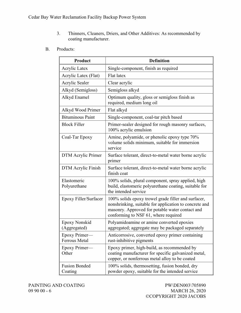
Cedar Bay Water Reclamation Facility Backup Power System
PAINTING AND COATING PW\DEN003\705890 09 90 00 - 6 MARCH 26, 2020 ©COPYRIGHT 2020 JACOBS
3. Thinners, Cleaners, Driers, and Other Additives: As recommended by coating manufacturer.
B. Products:
Product Definition
Acrylic Latex Single-component, finish as required
Acrylic Latex (Flat) Flat latex
Acrylic Sealer Clear acrylic
Alkyd (Semigloss) Semigloss alkyd
Alkyd Enamel Optimum quality, gloss or semigloss finish as required, medium long oil
Alkyd Wood Primer Flat alkyd
Bituminous Paint Single-component, coal-tar pitch based
Block Filler Primer-sealer designed for rough masonry surfaces, 100% acrylic emulsion
Coal-Tar Epoxy Amine, polyamide, or phenolic epoxy type 70% volume solids minimum, suitable for immersion service
DTM Acrylic Primer Surface tolerant, direct-to-metal water borne acrylic primer
DTM Acrylic Finish Surface tolerant, direct-to-metal water borne acrylic finish coat
Elastomeric Polyurethane
100% solids, plural component, spray applied, high build, elastomeric polyurethane coating, suitable for the intended service
Epoxy Filler/Surfacer 100% solids epoxy trowel grade filler and surfacer, nonshrinking, suitable for application to concrete and masonry. Approved for potable water contact and conforming to NSF 61, where required
Epoxy Nonskid (Aggregated)
Polyamidoamine or amine converted epoxies aggregated; aggregate may be packaged separately
Epoxy Primer—Ferrous Metal
Anticorrosive, converted epoxy primer containing rust-inhibitive pigments
Epoxy Primer—Other
Epoxy primer, high-build, as recommended by coating manufacturer for specific galvanized metal, copper, or nonferrous metal alloy to be coated
Fusion Bonded Coating
100% solids, thermosetting, fusion bonded, dry powder epoxy, suitable for the intended service

Cedar Bay Water Reclamation Facility Backup Power System
PW\DEN003\705890 PAINTING AND COATING MARCH 26, 2020 09 90 00 - 7 ©COPYRIGHT 2020 JACOBS
Product Definition
TFE Lube or Grease Lube
Tetrafluoroethylene, liquid coating, or open gear grease as supplied by McMaster-Carr Supply Corporation, Elmhurst, IL
High Build Epoxy Polyamidoamine epoxy, minimum 69% volume solids, capability of 4 to 8 MDFT per coat
Inorganic Zinc Primer
Solvent or water based, having 85% metallic zinc content in the dry film; follow manufacturer’s recommendation for topcoating
Latex Primer Sealer Waterborne vinyl acrylic primer/sealer for interior gypsum board and plaster. Capable of providing uniform seal and suitable for use with specified finish coats
NSF Epoxy Polyamidoamine epoxy, approved for potable water contact and conforming to NSF 61
Epoxy, High Solids Polyamidoamine epoxy, 80% volume solids, minimum, suitable for immersion service
Polyurethane Enamel Two-component, aliphatic or acrylic based polyurethane; high gloss finish
Organic Zinc Rich Primer
Epoxy or moisture cured urethane with 85-percent zinc content in the dry film, meeting the requirements of RCSC Specification for Structural Joints using High Strength Bolts, Class A or Class B, as required.
Rust-Inhibitive Primer
Single-package steel primers with anticorrosive pigment loading
Sanding Sealer Co-polymer oil, clear, dull luster
Silicone/Silicone Acrylic
Elevated temperature silicone or silicone/acrylic based
Stain, Concrete Acrylic, water repellant, penetrating stain
Stain, Wood Satin luster, linseed oil, solid or transparent as required
Varnish Nonpigmented vehicle based on a variety of resins (alkyd, phenolic, urethane) in gloss, semigloss, or flat finishes, as required
Water Base Epoxy Two-component, polyamide epoxy emulsion, finish as required
Cedar Bay Water Reclamation Facility Backup Power System
PAINTING AND COATING PW\DEN003\705890 09 90 00 - 8 MARCH 26, 2020 ©COPYRIGHT 2020 JACOBS
2.04 MIXING
A. Multiple-Component Coatings:
1. Prepare using each component as packaged by paint manufacturer. 2. No partial batches will be permitted. 3. Do not use multiple-component coatings that have been mixed beyond
their pot life. 4. Furnish small quantity kits for touchup painting and for painting other
small areas. 5. Mix only components specified and furnished by paint manufacturer. 6. Do not intermix additional components for reasons of color or
otherwise, even within the same generic type of coating.
B. Colors: Formulate paints with colorants free of lead, lead compounds, or other materials that might be affected by presence of hydrogen sulfide or other gas likely to be present at Site.
2.05 SHOP FINISHES
A. Shop Blast Cleaning: Reference Paragraph, Shop Coating Requirements.
B. Surface Preparation: Provide Engineer minimum 7 days’ advance notice to start of shop surface preparation work and coating application work.
C. Shop Coating Requirements:
1. When required by equipment specifications, such equipment shall be primed and finish coated in shop by manufacturer and touched up in field with identical material after installation.
2. Where manufacturer’s standard coating is not suitable for intended service condition, Engineer may approve use of a tie-coat to be used between manufacturer’s standard coating and specified field finish. In such cases, tie-coat shall be surface tolerant epoxy as recommended by manufacturer of specified field finish coat. Coordinate details of equipment manufacturer’s standard coating with field coating manufacturer.
PART 3 EXECUTION
3.01 GENERAL
A. Provide Engineer minimum 7 days’ advance notice to start of field surface preparation work and coating application work.

Cedar Bay Water Reclamation Facility Backup Power System
PW\DEN003\705890 PAINTING AND COATING MARCH 26, 2020 09 90 00 - 9 ©COPYRIGHT 2020 JACOBS
B. Perform the Work only in presence of Engineer, unless Engineer grants prior approval to perform the Work in Engineer’s absence.
C. Schedule inspection of cleaned surfaces and all coats prior to succeeding coat in advance with Engineer.
3.02 EXAMINATION
A. Factory Finished Items:
1. Schedule inspection with Engineer before repairing damaged factory-finished items delivered to Site.
2. Repair abraded or otherwise damaged areas on factory-finished items as recommended by coating manufacturer. Carefully blend repaired areas into original finish. If required to match colors, provide full finish coat in field.
B. Surface Preparation Verification: Inspect and provide substrate surfaces prepared in accordance with these Specifications and printed directions and recommendations of paint manufacturer whose product is to be applied. The more stringent requirements shall apply.
3.03 PROTECTION OF ITEMS NOT TO BE PAINTED
A. Remove, mask, or otherwise protect hardware, lighting fixtures, switchplates, aluminum surfaces, machined surfaces, couplings, shafts, bearings, nameplates on machinery, and other surfaces not specified elsewhere to be painted.
B. Provide drop cloths to prevent paint materials from falling on or marring adjacent surfaces.
C. Protect working parts of mechanical and electrical equipment from damage during surface preparation and painting process.
D. Mask openings in motors to prevent paint and other materials from entering.
E. Protect surfaces adjacent to or downwind of Work area from overspray.
3.04 SURFACE PREPARATION
A. Field Abrasive Blasting:
1. Perform blasting for items and equipment where specified and as required to restore damaged surfaces previously shop or field blasted and primed or coated.

Cedar Bay Water Reclamation Facility Backup Power System
PAINTING AND COATING PW\DEN003\705890 09 90 00 - 10 MARCH 26, 2020 ©COPYRIGHT 2020 JACOBS
2. Refer to coating systems for degree of abrasive blasting required. 3. Where the specified degree of surface preparation differs from
manufacturer’s recommendations, the more stringent shall apply.
B. Surface Contamination Testing:
1. A surface contamination analysis test shall be performed every 500 square feet by means of a Chlor Test CSN Saltsor approved equivalent.
2. Surface with chloride levels exceeding 3 µg/square centimeter for submerged surfaces and 5 µg/square centimeter for exposed surfaces shall be treated with a liquid soluble salt remover equivalent to CHLOR*RID (CHLOR*RID International, Chandler, AZ).
3. Follow manufacturer’s recommendations and procedures for the use of this product to remove the surface contamination.
C. Metal Surface Preparation:
1. Where indicated, meet requirements of SSPC Specifications summarized below: a. SP 1, Solvent Cleaning: Removal of visible oil, grease, soil,
drawing and cutting compounds, and other soluble contaminants by cleaning with solvent.
b. SP 2, Hand Tool Cleaning: Removal of loose rust, loose mill scale, loose paint, and other loose detrimental foreign matter, using nonpower hand tools.
c. SP 3, Power Tool Cleaning: Removal of loose rust, loose mill scale, loose paint, and other loose detrimental foreign matter, using power-assisted hand tools.
d. SP 5, White Metal Blast Cleaning: Removal of visible oil, grease, dust, dirt, mill scale, rust, coatings, oxides, corrosion products, and other foreign matter by blast cleaning.
e. SP 6, Commercial Blast Cleaning: Removal of visible oil, grease, dust, dirt, mill scale, rust, coatings, oxides, corrosion products, and other foreign matter, except for random staining limited to no more than 33 percent of each unit area of surface which may consist of light shadows, slight streaks, or minor discolorations caused by stains of rust, stains of mill scale, or stains of previously applied coatings.
f. SP 7, Brush-Off Blast Cleaning: Removal of visible rust, oil, grease, soil, dust, loose mill scale, loose rust, and loose coatings. Tightly adherent mill scale, rust, and coating may remain on surface.
Cedar Bay Water Reclamation Facility Backup Power System
PW\DEN003\705890 PAINTING AND COATING MARCH 26, 2020 09 90 00 - 11 ©COPYRIGHT 2020 JACOBS
g. SP 10, Near-White Blast Cleaning: Removal of visible oil, grease, dust, dirt, mill scale, rust, coatings, oxides, corrosion products, and other foreign matter, except for random staining limited to no more than 5 percent of each unit area of surface which may consist of light shadows, slight streaks, or minor discolorations caused by stains of rust, stains of mill scale, or stains of previously applied coatings.
h. SP 11, Power Tool Cleaning to Bare Metal: Removal of visible oil, grease, dirt, dust, mill scale, rust, paint, oxide, corrosion products, and other foreign matter using power-assisted hand tools capable of producing suitable surface profile. Slight residues of rust and paint may be left in lower portion of pits if original surface is pitted.
i. SP-16, Brush Blasting of Non-Ferrous Metals: A brush-off blast cleaned non-ferrous metal surface, when viewed without magnification, shall be free of all visible oil, grease, dirt, dust, metal oxides (corrosion products), and other foreign matter. Intact, tightly adherent coating is permitted to remain. A coating is considered tightly adherent if it cannot be removed by lifting with a dull putty knife. Bare metal substrates shall have a minimum profile of 19 micrometers (0.75 mil).
2. The words “solvent cleaning”, “hand tool cleaning”, “wire brushing”, and “blast cleaning”, or similar words of equal intent in these Specifications or in paint manufacturer’s specification refer to the applicable SSPC Specification.
3. Where OSHA or EPA regulations preclude standard abrasive blast cleaning, wet or vacu-blast methods may be required. Coating manufacturers’ recommendations for wet blast additives and first coat application shall apply.
4. Ductile Iron Pipe Supplied with Asphaltic Varnish Finish: Remove asphaltic varnish finish prior to performing specified surface preparation.
5. Hand tool clean areas that cannot be cleaned by power tool cleaning. 6. Round or chamfer sharp edges and grind smooth burrs, jagged edges,
and surface defects. 7. Welds and Adjacent Areas:
a. Prepare such that there is: 1) No undercutting or reverse ridges on weld bead. 2) No weld spatter on or adjacent to weld or any area to be
painted. 3) No sharp peaks or ridges along weld bead.
b. Grind embedded pieces of electrode or wire flush with adjacent surface of weld bead.

Cedar Bay Water Reclamation Facility Backup Power System
PAINTING AND COATING PW\DEN003\705890 09 90 00 - 12 MARCH 26, 2020 ©COPYRIGHT 2020 JACOBS
8. Preblast Cleaning Requirements: a. Remove oil, grease, welding fluxes, and other surface
contaminants prior to blast cleaning. b. Cleaning Methods: Steam, open flame, hot water, or cold water
with appropriate detergent additives followed with clean water rinsing.
c. Clean small isolated areas as above or solvent clean with suitable solvent and clean cloth.
9. Blast Cleaning Requirements: a. Type of Equipment and Speed of Travel: Design to obtain
specified degree of cleanliness. Minimum surface preparation is as specified herein and takes precedence over coating manufacturer’s recommendations.
b. Select type and size of abrasive to produce surface profile that meets coating manufacturer’s recommendations for particular primer to be used.
c. Use only dry blast cleaning methods. d. Do not reuse abrasive, except for designed recyclable systems. e. Meet applicable federal, state, and local air pollution and
environmental control regulations for blast cleaning, confined space entry (if required), and disposition of spent aggregate and debris.
10. Post-Blast Cleaning and Other Cleaning Requirements: a. Clean surfaces of dust and residual particles from cleaning
operations by dry (no oil or water vapor) air blast cleaning or other method prior to painting. Vacuum clean enclosed areas and other areas where dust settling is a problem and wipe with a tack cloth.
b. Paint surfaces the same day they are blasted. Reblast surfaces that have started to rust before they are painted.
D. Galvanized Metal, Copper, and Nonferrous Metal Alloy Surface Preparation:
1. Remove soil, cement spatter, and other surface dirt with appropriate hand or power tools.
2. Brush blast in accordance with SSPC SP 16. 3. Obtain and follow coating manufacturer’s recommendations for
additional preparation that may be required.
E. Concrete Surface Preparation:
1. Do not begin until 30 days after concrete has been placed. 2. Meet requirements of SSPC SP 13.

Cedar Bay Water Reclamation Facility Backup Power System
PW\DEN003\705890 PAINTING AND COATING MARCH 26, 2020 09 90 00 - 13 ©COPYRIGHT 2020 JACOBS
3. Remove grease, oil, dirt, salts or other chemicals, loose materials, or other foreign matter by solvent, detergent, or other suitable cleaning methods.
4. Brush-off blast clean to remove loose concrete and laitance, and provide a tooth for binding. Upon approval by Engineer, surface may be cleaned by acid etching method. Approval is subject to producing desired profile equivalent to No. 80 grit flint sandpaper. Acid etching of vertical or overhead surfaces shall not be allowed.
5. Secure coating manufacturer’s recommendations for additional preparation, if required, for excessive bug holes exposed after blasting.
6. Unless otherwise required for proper adhesion, ensure surfaces are dry prior to painting.
F. Masonry Surface Preparation:
1. Complete and cure masonry construction for 14 days or more before starting surface preparation work.
2. Remove oil, grease, dirt, salts or other chemicals, loose materials, or other foreign matter by solvent, detergent washing, or other suitable cleaning methods.
3. Clean masonry surfaces of mortar and grout spillage and other surface deposits using one of the following: a. Nonmetallic fiber brushes and commercial muriatic acid followed
by rinsing with clean water. b. Brush-off blasting. c. Water blasting.
4. Do not damage masonry mortar joints or adjacent surfaces. 5. Leave surfaces clean and, unless otherwise required for proper adhesion,
dry prior to painting. 6. Masonry Surfaces to be Painted: Uniform texture and free of surface
imperfections that would impair intended finished appearance. 7. Masonry Surfaces to be Clear Coated: Free of discolorations and
uniform in texture after cleaning.
G. Existing Painted Surfaces to be Repainted Surface Preparation:
1. Detergent wash and freshwater rinse. 2. Clean loose, abraded, or damaged coatings to substrate by hand or
power tool, SP 2 or SP 3. 3. Feather surrounding intact coating. 4. Apply one spot coat of specified primer to bare areas, overlapping
prepared existing coating. 5. Apply one full finish coat of specified primer to entire surface. 6. If an aged, plural-component material is to be topcoated, contact coating
manufacturer for additional surface preparation requirements.

Cedar Bay Water Reclamation Facility Backup Power System
PAINTING AND COATING PW\DEN003\705890 09 90 00 - 14 MARCH 26, 2020 ©COPYRIGHT 2020 JACOBS
7. Application of Cosmetic Coat: a. It is assumed that existing coatings have oxidized sufficiently to
prevent lifting or peeling when overcoated with paints specified. b. Check compatibility by application to a small area prior to starting
painting. c. If lifting or other problems occur, request disposition from
Engineer. 8. Perform blasting as required to restore damaged surfaces. Materials,
equipment, procedures shall meet requirements of SSPC.
3.05 SURFACE CLEANING
A. Brush-off Blast Cleaning:
1. Equipment, procedure, and degree of cleaning shall meet requirements of SSPC SP 7.
2. Abrasive: Either wet or dry blasting sand, grit, or nutshell. 3. Select various surface preparation parameters, such as size and hardness
of abrasive, nozzle size, air pressure, and nozzle distance from surface such that surface is cleaned without pitting, chipping, or other damage.
4. Verify parameter selection by blast cleaning a trial area that will not be exposed to view.
5. Engineer will review acceptable trial blast cleaned area and use area as a representative sample of surface preparation.
6. Repair or replace surface damaged by blast cleaning.
B. Acid Etching:
1. After precleaning, spread the following solution by brush or plastic sprinkling can: One part commercial muriatic acid reduced by two parts water by volume. Adding acid to water in these proportions gives an approximate 10 percent solution of HCl.
2. Application: a. Rate: Approximately 2 gallons per 100 square feet. b. Work acid solution into surface by hard-bristled brushes or
brooms until complete wetting and coverage is obtained. c. Acid will react vigorously for a few minutes, during which time
brushing shall be continued. d. After bubbling subsides (10 minutes), hose down remaining slurry
with high pressure clean water. e. Rinse immediately to avoid formation on the surface of salts that
are difficult to remove. f. Thoroughly rinse to remove any residual acid surface condition
that may impair adhesion.

Cedar Bay Water Reclamation Facility Backup Power System
PW\DEN003\705890 PAINTING AND COATING MARCH 26, 2020 09 90 00 - 15 ©COPYRIGHT 2020 JACOBS
3. Ensure surface is completely dry before application of coating. 4. Apply acid etching to obtain a “grit sandpaper” surface profile. If not,
repeat treatment.
C. Solvent Cleaning:
1. Consists of removal of foreign matter such as oil, grease, soil, drawing and cutting compounds, and any other surface contaminants by using solvents, emulsions, cleaning compounds, steam cleaning, or similar materials and methods that involve a solvent or cleaning action.
2. Meet requirements of SSPC SP 1.
3.06 APPLICATION
A. General:
1. The intention of these Specifications is for existing and new, interior and exterior masonry, concrete, metal, and submerged metal surfaces to be painted, whether specifically mentioned or not, except as specified otherwise. Do not paint exterior concrete surfaces, unless specifically indicated.
2. Extent of Coating (Immersion): Coatings shall be applied to internal vessel and pipe surfaces, nozzle bores, flange gasket sealing surfaces, carbon steel internals, and stainless steel internals, unless otherwise specified.
3. For coatings subject to immersion, obtain full cure for completed system. Consult coatings manufacturer’s written instructions for these requirements. Do not immerse coating until completion of curing cycle.
4. Apply coatings in accordance with these Specifications and paint manufacturers’ printed recommendations and special details. The more stringent requirements shall apply. Allow sufficient time between coats to assure thorough drying of previously applied paint.
5. Sand wood lightly between coats to achieve required finish. 6. Vacuum clean surfaces free of loose particles. Use tack cloth just prior
to applying next coat. 7. Fusion Bonded Coatings Method Application: Electrostatic, fluidized
bed, or flocking. 8. Coat units or surfaces to be bolted together or joined closely to
structures or to one another prior to assembly or installation. 9. Water-Resistant Gypsum Board: Use only solvent type paints and
coatings. 10. On pipelines, terminate coatings along pipe runs to 1 inch inside pipe
penetrations. 11. Keep paint materials sealed when not in use.

Cedar Bay Water Reclamation Facility Backup Power System
PAINTING AND COATING PW\DEN003\705890 09 90 00 - 16 MARCH 26, 2020 ©COPYRIGHT 2020 JACOBS
12. Where more than one coat is applied within a given system, alternate colors to provide a visual reference showing required number of coats have been applied.
B. Galvanized Metal, Copper, and Nonferrous Metal Alloys:
1. Concealed galvanized, copper, and nonferrous metal alloy surfaces (behind building panels or walls) do not require painting, unless specifically indicated herein.
2. Prepare surface and apply primer in accordance with System No. 10 specification.
3. Apply intermediate and finish coats of the coating system appropriate for the exposure.
C. Porous Surfaces, Such As Concrete and Masonry:
1. Filler/Surfacer: Use coating manufacturer’s recommended product to fill air holes, bug holes, and other surface voids or defects.
2. Prime Coat: May be thinned to provide maximum penetration and adhesion. a. Type and Amount of Thinning: Determined by paint manufacturer
and dependent on surface density and type of coating. 3. Surface Specified to Receive Water Base Coating: Damp, but free of
running water, just prior to application of coating.
D. Film Thickness and Coverage:
1. Number of Coats: a. Minimum required without regard to coating thickness. b. Additional coats may be required to obtain minimum required
paint thickness, depending on method of application, differences in manufacturers’ products, and atmospheric conditions.
2. Application Thickness: a. Do not exceed coating manufacturer’s recommendations. b. Measure using a wet film thickness gauge to ensure proper
coating thickness during application. 3. Film Thickness Measurements and Electrical Inspection of Coated
Surfaces: a. Perform with properly calibrated instruments. b. Recoat and repair as necessary for compliance with specification. c. Coats are subject to inspection by Engineer and coating
manufacturer’s representative. 4. Visually inspect concrete, masonry, nonferrous metal, plastic, and wood
surfaces to ensure proper and complete coverage has been attained.

Cedar Bay Water Reclamation Facility Backup Power System
PW\DEN003\705890 PAINTING AND COATING MARCH 26, 2020 09 90 00 - 17 ©COPYRIGHT 2020 JACOBS
5. Give particular attention to edges, angles, flanges, and other similar areas, where insufficient film thicknesses are likely to be present, and ensure proper millage in these areas.
6. Apply additional coats as required to achieve complete hiding of underlying coats. Hiding shall be so complete that additional coats would not increase the hiding.
3.07 PROTECTIVE COATINGS SYSTEMS AND APPLICATION SCHEDULE
A. Unless otherwise shown or specified, paint surfaces in accordance with the following application schedule. In the event of discrepancies or omissions in the following, request clarification from Engineer before starting work in question.
B. As shown in Finish Schedule on Drawings.
C. System No. 2 Submerged Metal—Domestic Sewage:
Surface Prep. Paint Material Min. Coats, Cover
SP 5, White Metal Blast Cleaning
Prime in accordance with manufacturer’s recommendations
Coal-Tar Epoxy -OR- High Build Epoxy
2 coats, 16 MDFT 2 coats, 16 MDFT
1. Use on the following items or areas: a. Metal surfaces new and existing below a plane 1 foot above
maximum liquid surface, metal surfaces above maximum liquid surface that are a part of immersed equipment, concrete embedded surfaces of metallic items, such as wall pipes, pipes, pipe sleeves, access manholes, gate guides and thimbles, and structural steel, and the following specific surfaces:
D. System No. 3 Submerged Metal—Other:
1. Use on the following items or areas: a. Metal surfaces new and existing below a plane 1 foot above
maximum liquid surface, metal surfaces above maximum liquid surface which are a part of immersed equipment, and the following specific surfaces:

Cedar Bay Water Reclamation Facility Backup Power System
PAINTING AND COATING PW\DEN003\705890 09 90 00 - 18 MARCH 26, 2020 ©COPYRIGHT 2020 JACOBS
E. System No. 4 Exposed Metal—Highly Corrosive:
Surface Prep. Paint Material Min. Coats, Cover
SP 10, Near-White Blast Cleaning
Epoxy Primer—Ferrous Metal
1 coat, 2.5 MDFT
High Build Epoxy 1 coat, 4 MDFT
Polyurethane Enamel 1 coat, 3 MDFT 1. Use on the following items or areas:
a. Exposed metal surfaces, new and existing located inside or outside of structures and exposed to weather.
F. System No. 5 Exposed Metal—Mildly Corrosive:
Surface Prep. Paint Material Min. Coats, Cover
SP 10, Near-White Blast Cleaning
Epoxy Primer—Ferrous Metal
1 coat, 2.5 MDFT
Polyurethane Enamel 1 coat, 3 MDFT 1. Use on the following items or areas:
a. Exposed metal surfaces, new and existing located inside or outside of structures and exposed to weather or in a highly humid atmosphere, such as pipe galleries and similar areas.
G. System No. 6 Exposed Metal—Atmospheric:
Surface Prep. Paint Material Min. Coats, Cover
SP 6, Commercial Blast Cleaning
Rust-Inhibitive Primer 1 coat, 2 MDFT
Alkyd Enamel 2 coats, 4 MDFT 1. Use on the following items or areas:
a. Exposed metal surfaces, new and existing located inside or outside of structures or exposed to weather.
b. Apply surface preparation and primer to surfaces prior to installation. Finish coats need only be applied to surfaces exposed after completion of construction.

Cedar Bay Water Reclamation Facility Backup Power System
PW\DEN003\705890 PAINTING AND COATING MARCH 26, 2020 09 90 00 - 19 ©COPYRIGHT 2020 JACOBS
H. System No. 7 Concrete Encased Metal:
Surface Prep. Paint Material Min. Coats, Cover
SP 6, Commercial Blast Cleaning
Coal-Tar Epoxy 2 coats, 16 MDFT
High Build Epoxy
1. Use on the following items or areas: a. Use on concrete encased ferrous metals including wall pipes, pipe
sleeves, access manholes, gate guides, and thimbles; and the following specific surfaces:
3.08 ARCHITECTURAL PAINT SYSTEMS AND APPLICATION SCHEDULE
A. Unless otherwise shown or specified, paint surfaces in accordance with the following application schedule. In the event of discrepancies or omissions in the following, request clarification from Engineer before starting work in question.
B. As shown in Finish Schedule on Drawings.
C. System No. 106 Galvanized Metal:
Surface Prep. Paint Material Min. Coats, Cover
In accordance with Paragraph Galvanized Metal, Copper, and Nonferrous Metal Alloy Surface Preparation
Manufacturer’s Recommended Primer
1 coat, as recommended by manufacturer
Alkyd Enamel (Semigloss)
2 coats, 4 MDFT
1. Use on the following items or areas: a. Hollow metal frames and doors.
D. System No. 108 Masonry, Flat:
Surface Prep. Paint Material Min. Coats, Cover
In accordance with Paragraph Masonry Surface Preparation
Block Filler 1 coat, 75 SFPG
Acrylic Latex (Flat) 2 coats, 240 SFPGPC

Cedar Bay Water Reclamation Facility Backup Power System
PAINTING AND COATING PW\DEN003\705890 09 90 00 - 20 MARCH 26, 2020 ©COPYRIGHT 2020 JACOBS
E. System No. 109 Masonry, Semigloss:
Surface Prep. Paint Material Min. Coats, Cover
In accordance with Paragraph Masonry Surface Preparation
Block Filler 1 coat, 75 SFPG
Acrylic Latex (Semigloss
2 coats, 240 SFPGPC
F. System No. 110 Masonry Sealer:
Surface Prep. Paint Material Min. Coats, Cover
In accordance with Paragraph Masonry Surface Preparation
Acrylic Sealer 2 coats, 100 SFPGPC
G. System No. 111 Concrete and Masonry, Stain and Seal:
Surface Prep. Paint Material Min. Coats, Cover
Concrete: In accordance with Paragraph Concrete Surface Preparation
-OR-
Masonry: In accordance with Paragraph Masonry Surface Preparation
Stain, Concrete 2 coats, 250 SFPGPC
Acrylic Sealer 2 coats, 100 SFPGPC
H. System No. 112 Concrete, Flat:
Surface Prep. Paint Material Min. Coats, Cover
In accordance with Paragraph Concrete Surface Preparation
Acrylic Latex (Flat) 2 coats, 240 SFPGPC

Cedar Bay Water Reclamation Facility Backup Power System
PW\DEN003\705890 PAINTING AND COATING MARCH 26, 2020 09 90 00 - 21 ©COPYRIGHT 2020 JACOBS
I. System No. 113 Concrete, Semigloss:
Surface Prep. Paint Material Min. Coats, Cover
In accordance with Paragraph Concrete Surface Preparation
Acrylic Latex (Semigloss
2 coats, 240 SFPGPC
J. System No. 117 Concrete Masonry, Gloss Epoxy:
Surface Prep. Paint Material Min. Coats, Cover
In accordance with Paragraph Masonry Surface Preparation
Block Filler 1 coat, 75 SFPG
Water Base Epoxy (Gloss)
2 coats, 300 SFPGPC
K. System No. 121 Concrete, Skid-Resistant:
Surface Prep. Paint Material Min. Coats, Cover
In accordance with Paragraph Concrete Surface Preparation
Epoxy Nonskid (Aggregated)
1 coat, 160 SFPG
3.09 COLORS
A. Provide as selected by Owner.
B. Proprietary identification of colors is for identification only. Selected manufacturer may supply matches.
3.10 FIELD QUALITY CONTROL
A. Testing Equipment:
1. Provide calibrated electronic type dry film thickness gauge to test coating thickness specified in mils.
2. Provide low-voltage wet sponge electrical holiday detector to test completed coating systems, 20 mils dry film thickness or less, except zinc primer, high-build elastomeric coatings, and galvanizing, for pinholes, holidays, and discontinuities, as manufactured by Tinker and Rasor, San Gabriel, CA, Model M-1.

Cedar Bay Water Reclamation Facility Backup Power System
PAINTING AND COATING PW\DEN003\705890 09 90 00 - 22 MARCH 26, 2020 ©COPYRIGHT 2020 JACOBS
3. Provide high-voltage spark tester to test completed coating systems in excess of 20 mils dry film thickness. Unit as recommended by coating manufacturer.
B. Testing:
1. Thickness and Continuity Testing: a. Measure coating thickness specified in mils with a magnetic type,
dry film thickness gauge, in accordance with SSPC PA 2. Check each coat for correct millage. Do not make measurement before a minimum of 8 hours after application of coating.
b. Holiday detect coatings 20 mils thick or less, except zinc primer and galvanizing, with low voltage wet sponge electrical holiday detector in accordance with NACE SP0188.
c. Holiday detect coatings in excess of 20 mils dry with high voltage spark tester as recommended by coating manufacturer and in accordance with NACE SP0188.
d. After repaired and recoated areas have dried sufficiently, retest each repaired area. Final tests may also be conducted by Engineer.
C. Inspection: Leave staging and lighting in place until Engineer has inspected surface or coating. Replace staging removed prior to approval by Engineer. Provide additional staging and lighting as requested by Engineer.
D. Unsatisfactory Application:
1. If item has an improper finish color or insufficient film thickness, clean surface and topcoat with specified paint material to obtain specified color and coverage. Obtain specific surface preparation information from coating manufacturer.
2. Evidence of runs, bridges, shiners, laps, or other imperfections is cause for rejection.
3. Repair defects in accordance with written recommendations of coating manufacturer.
E. Damaged Coatings, Pinholes, and Holidays:
1. Hand or power sand visible areas of chipped, peeled, or abraded paint, and feather edges. Follow with primer and finish coat. Depending on extent of repair and appearance, a finish sanding and topcoat may be required.
2. Remove rust and contaminants from metal surface. Provide surface cleanliness and profile in accordance with surface preparation requirements for specified paint system.

Cedar Bay Water Reclamation Facility Backup Power System
PW\DEN003\705890 PAINTING AND COATING MARCH 26, 2020 09 90 00 - 23 ©COPYRIGHT 2020 JACOBS
3. Feather edges and repair in accordance with recommendations of paint manufacturer.
4. Apply finish coats, including touchup and damage-repair coats in a manner that will present a uniform texture and color-matched appearance.
3.11 MANUFACTURER’S SERVICES
A. In accordance with Section 01 43 33, Manufacturers’ Field Services, coating manufacturer’s representative shall be present at Site as follows:
1. On first day of application of any coating system. 2. A minimum of two additional Site inspection visits, each for a minimum
of 4 hours, in order to provide Manufacturer’s Certificate of Proper Installation.
3. As required to resolve field problems attributable to or associated with manufacturer’s product.
4. To verify full cure of coating prior to coated surfaces being placed into immersion service.
3.12 CLEANUP
A. Place cloths and waste that might constitute a fire hazard in closed metal containers or destroy at end of each day.
B. Upon completion of the Work, remove staging, scaffolding, and containers from Site or destroy in a legal manner.
C. Remove paint spots, oil, or stains upon adjacent surfaces and floors and leave entire job clean.
3.13 SUPPLEMENTS
A. The supplements listed below, following “End of Section,” are a part of this specification:
1. Paint System Data Sheet (PSDS). 2. Paint Product Data Sheet (PPDS).
END OF SECTION


Cedar Bay Water Reclamation Facility Backup Power System
PW\DEN003\705890 PAINTING AND COATING MARCH 26, 2020 09 90 00 SUPPLEMENT 1 - 1 ©COPYRIGHT 2020 JACOBS
PAINT SYSTEM DATA SHEET
Complete this PSDS for each coating system, include all components of the system (surface preparation, primer, intermediate coats, and finish coats). Include all components of a given coating system on a single PSDS.
Paint System Number (from Spec.):
Paint System Title (from Spec.):
Coating Supplier:
Representative:
Surface Preparation:
Paint Material (Generic)
Product Name/Number (Proprietary) Min. Coats, Coverage

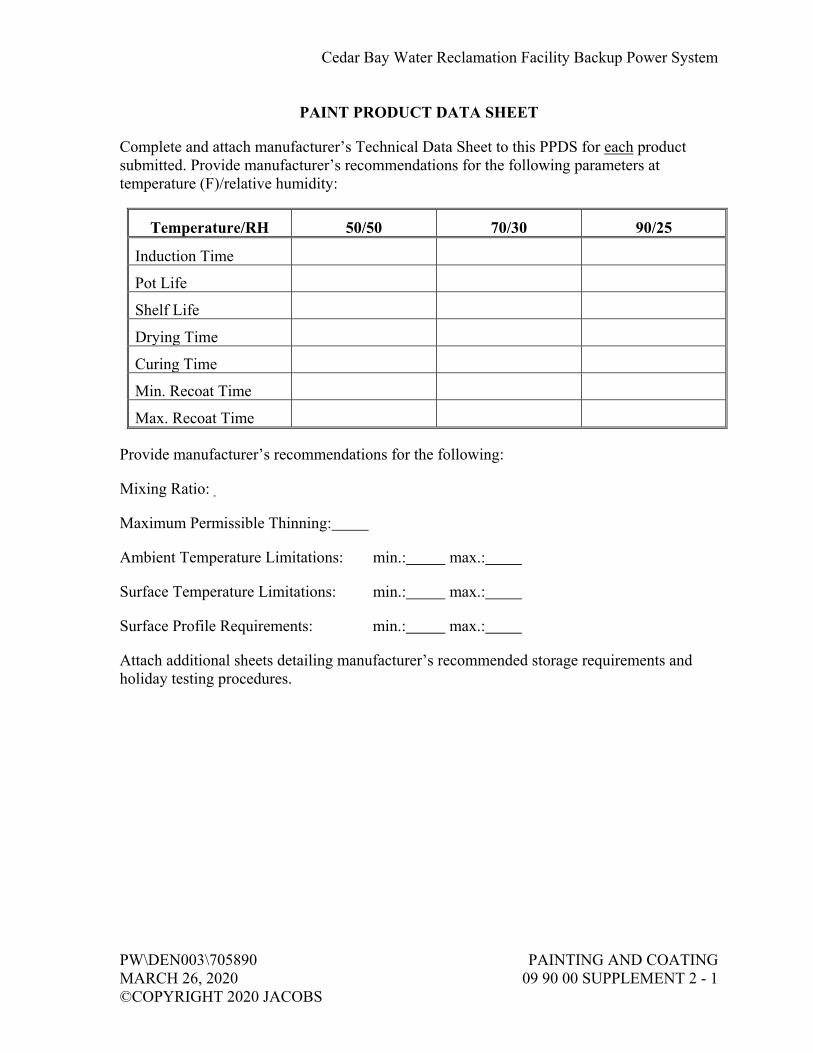
Cedar Bay Water Reclamation Facility Backup Power System
PW\DEN003\705890 PAINTING AND COATING MARCH 26, 2020 09 90 00 SUPPLEMENT 2 - 1 ©COPYRIGHT 2020 JACOBS
PAINT PRODUCT DATA SHEET
Complete and attach manufacturer’s Technical Data Sheet to this PPDS for each product submitted. Provide manufacturer’s recommendations for the following parameters at temperature (F)/relative humidity:
Temperature/RH 50/50 70/30 90/25
Induction Time
Pot Life
Shelf Life
Drying Time
Curing Time
Min. Recoat Time
Max. Recoat Time
Provide manufacturer’s recommendations for the following:
Mixing Ratio:
Maximum Permissible Thinning:
Ambient Temperature Limitations: min.: max.:
Surface Temperature Limitations: min.: max.:
Surface Profile Requirements: min.: max.:
Attach additional sheets detailing manufacturer’s recommended storage requirements and holiday testing procedures.


Cedar Bay Water Reclamation Facility Backup Power System
PW\DEN003\705890 BASIC ELECTRICAL REQUIREMENTS MARCH 26, 2020 26 05 02 - 1 ©COPYRIGHT 2020 JACOBS
SECTION 26 05 02 BASIC ELECTRICAL REQUIREMENTS
PART 1 GENERAL
1.01 RELATED SECTIONS
A. Requirements specified within this section apply to Division 26, Electrical. Work specified herein shall be performed as if specified in the individual sections.
1.02 REFERENCES
A. The following is a list of standards which may be referenced in this section:
1. Institute of Electrical and Electronics Engineers (IEEE): 1584, Guide for Performing Arc-Flash Calculations.
2. National Electrical Contractors Association (NECA). 3. National Electrical Manufacturers Association (NEMA): Z535.4, Product
Safety Signs and Labels. 4. National Fire Protection Association (NFPA):
a. 70, National Electrical Code (NEC). b. 70E, Electrical Safety Requirements for Employee Workplaces.
1.03 SUBMITTALS
A. Action Submittals:
1. Provide manufacturers’ data for the following: a. Electrical service components. b. Nameplates, signs, and labels.
B. Quality Control Submittals:
1. Voltage field test results. 2. Voltage balance report. 3. Equipment line current report. 4. Factory test certification and reports for all major electrical equipment. 5. Site test certification and reports as specified in other Division 26, Electrical
sections.

Cedar Bay Water Reclamation Facility Backup Power System
BASIC ELECTRICAL REQUIREMENTS PW\DEN003\705890 26 05 02 - 2 MARCH 26, 2020 ©COPYRIGHT 2020 JACOBS
1.04 QUALITY ASSURANCE
A. Provide comprehensive short circuit, protective device coordination, arc flash, and harmonic distortion studies per Section 26 05 70, Electrical Systems Analysis. Initial complete short circuit, protective device coordination, arc flash and harmonic distortion studies shall be submitted, reviewed, and approved before major electrical equipment Shop Drawings will be reviewed.
B. Provide lightning protection design and construction for abovegrade structures per Section 26 41 00, Facility Lightning Protection.
1.05 SCOPE OF WORK
A. Demolish existing motor control centers as shown on the drawings. This is a heavy retrofit project. All construction, including new equipment, retrofit of existing equipment, and demolition of existing equipment, must be done according to a well thought out construction sequence to minimize impact on ongoing treatment process. Prepare a construction sequence for approval of Engineer and Owner. Approval of construction sequence is pre-requisite to starting construction. Any shut down required must have owner’s prior approval.
B. Provide, install, and test two low voltage switchboards and one low voltage motor control center.
C. Provide, install, and test modifications to existing low voltage switchboard and low voltage motor control centers as shown.
D. Provide, install, and test two diesel engine generator sets.
E. Furnish, install, and test low voltage site power distribution system as specified and/or shown.
F. Furnish and install the low voltage and control duct bank systems as shown.
G. Furnish, install, terminate, and test all interconnecting power, control, and instrumentation wiring as shown on the One-Line Diagrams, riser diagrams and P&ID Drawings.
H. Furnish and install all conduit, wiring, and field connections for all motors, motor controllers, control devices, control panels, and electrical equipment furnished under other divisions of these Specifications.
I. Furnish and install equipment grounding conductors sized per Table 250-122 of the NEC unless otherwise shown on the Drawings, in all conduits throughout the entire plant.

Cedar Bay Water Reclamation Facility Backup Power System
PW\DEN003\705890 BASIC ELECTRICAL REQUIREMENTS MARCH 26, 2020 26 05 02 - 3 ©COPYRIGHT 2020 JACOBS
J. Furnish and install raceways for the fiber optic cable system as required to implement fiber optic data links shown on the P&ID Drawings. Install an inner duct/outer duct system as shown and specified. Install fiber optic cable furnished by PICS subcontractor. Termination and testing by PICS subcontractor. Provide accurate estimate of fiber optic cable lengths to the PICS subcontractor.
K. Furnish and install a complete raceway system for data highway cables and specialty cables systems. Install manufacturer-supplied data highway cables and other specialty cable systems in accordance with the system manufactures’ installation instructions. Review the raceway layout, prior to installation, with the PICS subcontractor and cable manufacture to ensure raceway compatibility with the systems and materials being furnished. Where redundant cables are furnished, install cables in separate raceways.
L. Provide support to the PICS subcontractor for installation, wiring, and termination of all control panels, field instruments, lightning, and surge protection equipment at process instrumentation transmitters, and computer equipment. Install vendor furnished cables specified under other Divisions of the Specification.
M. Furnish and install conduit, wiring, and terminations for adjustable frequency drives, harmonic filters, and transformers furnished under other Divisions of these Specifications.
N. Furnish and install power wiring for all heating, ventilation, and air conditioning (HVAC) equipment furnished under other divisions of these specifications, including power wiring for 120-volt unit heaters, thermostats, fan motors, dampers and other HVAC inline unit wiring shown on the Drawings.
O. Furnish, install, and wire all site and facility lighting as shown on the Drawings.
P. Conduct and participate in all electrical and PICS subcontractor’s testing. Specifically all operational readiness tests and functional acceptance tests shall be jointly conducted by the PICS subcontractor and the Electrical subcontractor.
Q. Furnish and install all telephone/data outlet raceway systems as shown and required for satisfactory operation.
R. Sequence work to meet the Contractor’s overall schedule and construction sequence.
S. Prepare and furnish electrical and instrumentation conduit layout Shop Drawings for yard electrical, within and under all roads, buildings and structures to the Engineer for approval prior to commencing work. Layouts shall include but not be limited to equipment, pull boxes, manholes, handholes, conduit routing, dimensioning, methods and location of supports, reinforcing, encasement, materials, conduit sizing, equipment access, potential conflicts, building and yard lighting, and all other pertinent technical specifications for all electrical and instrumentation conduits and equipment to be furnished.

Cedar Bay Water Reclamation Facility Backup Power System
BASIC ELECTRICAL REQUIREMENTS PW\DEN003\705890 26 05 02 - 4 MARCH 26, 2020 ©COPYRIGHT 2020 JACOBS
T. The work shall include complete testing of all equipment and wiring at the completion of work and making any necessary corrections or adjustments necessary for the proper functioning of the system and equipment. All workmanship shall be of the highest quality; substandard work will be rejected.
U. Contractor shall provide their own temporary power for miscellaneous power (drills, pumps, etc.). Any temporary added shall be removed at job completion.
V. Complete coordination with other Contractors. Contractor shall coordinate with all other Contractor’s equipment submittals and obtain all relevant submittals.
1.06 ELECTRIC AND TELEPHONE SERVICE DIVISION OF RESPONSIBILITY
A. Incoming aerial electrical service facilities provided by the serving utility as part of its normal obligation to customers is work provided outside this Contract. Under this Contract provide customer required service provisions and electrical work including, but not limited to, primary trench and backfill, primary duct system, transformer pad site preparation, transformer pad, metering components and associated conduit, and secondary facilities. Schedule and coordinate work of serving utility as required to provide electric service to the Work.
B. Incoming telephone service facilities provided by the serving utilities as part of their normal obligation to customers. Under this Contract provide customer required service provisions and electrical work.
1.07 AUTHORITY HAVING JURISDICTION APPROVAL
A. As a minimum, provide the Work in accordance with NFPA 70, National Electrical Code (NEC). Where required by the Authority having Jurisdiction (AHJ) or the specifications, material and equipment shall be labeled or listed by a Nationally Recognized Testing Laboratory (NRTL) or other organization acceptable to the AHJ, in order to provide a basis for approval under the NEC.
B. Materials and equipment manufactured within the scope of standards published by Underwriters Laboratories Inc. shall conform to those standards and shall have an applied listing mark or label by a NRTL.
C. Provide materials and equipment acceptable to AHJ for Class, Division, and Group of hazardous area indicated.
PART 2 PRODUCTS
2.01 GENERAL
A. Where two or more units of the same class of material or equipment are required, provide products of a single manufacturer. Component parts of materials or equipment need not be products of the same manufacturer.
Cedar Bay Water Reclamation Facility Backup Power System
PW\DEN003\705890 BASIC ELECTRICAL REQUIREMENTS MARCH 26, 2020 26 05 02 - 5 ©COPYRIGHT 2020 JACOBS
B. Material and equipment installed in heated and ventilated areas shall be capable of continuous operation at their specified ratings within an ambient temperature range of 40 degrees F to 104 degrees F.
C. Materials and equipment installed outdoors shall be capable of continuous operation at their specified rating within the ambient temperature range stated in Section 01 61 00, Common Product Requirements.
D. Provide equipment panels installed outdoors in direct sun with sun shields.
E. Provide materials and equipment listed/labeled by a NRTL to UL standards where they have been established by the agency.
F. Interior: Manufacturer’s standard finish color, except where specific color is indicated. If manufacturer has no standard color, finish equipment in accordance with ANSI No. 61, light gray color.
G. Exterior: White color.
2.02 NAMEPLATES
A. Material: Laminated plastic.
B. Attachment Screws: Stainless steel.
C. Color: Red, engraved to a white core.
D. Letter Height:
1. Pushbuttons/Selector Switches: 1/8 inch. 2. Other Electrical Equipment: 1/4 inch.
2.03 SIGNS AND LABELS
A. Sign size, lettering, and color shall be in accordance with NEMA Z535.4.
B. Warning labels for arc flash hazards shall be provided per NEC code.
C. Based on the results of arc-flash calculations performed as specified in Section 26 05 70, Electrical Systems Analysis, provide appropriate warning labels on all electrical equipment.

Cedar Bay Water Reclamation Facility Backup Power System
BASIC ELECTRICAL REQUIREMENTS PW\DEN003\705890 26 05 02 - 6 MARCH 26, 2020 ©COPYRIGHT 2020 JACOBS
PART 3 EXECUTION
3.01 GENERAL
A. Electrical Drawings show general locations of equipment, devices, and raceway, unless specifically dimensioned. Contractor shall be responsible for actual location of equipment and devices and for proper routing and support of raceways, subject to approval of Engineer. Coordinate the conduit installation with other trades and the actual supplied equipment. Obtain information relevant to the placement of electrical work and in case of any interference with other work, processed as directed by the Engineer and furnished all labor and materials necessary to complete the Work in an approved manner.
B. Check approximate locations of light luminaires, switches, receptacles, disconnect switches, equipment, and other electrical system components shown on Drawings for conflicts with openings, structural members, and components of other systems and equipment having fixed locations. In the event of conflicts, notify Engineer in writing. Any adjustments required in the field shall be provided at no additional cost to the Owner.
C. Install work in accordance with NECA Standard of Installation, unless otherwise specified.
D. Keep openings in boxes and equipment closed during construction.
E. Lay out work carefully in advance. Do not cut or notch any structural member or building surface without specific approval of Engineer. Carefully perform cutting, channeling, chasing, or drilling of floors, walls, partitions, ceilings, paving, or other surfaces required for the installation, support, or anchorage of conduit, raceways, or other electrical materials and equipment. Following such work, restore surfaces to original condition.
F. Unless otherwise approved by the Engineer, conduit shown exposed shall be installed exposed; conduit shown concealed shall be installed concealed.
G. Circuit layouts are not intended to show the number of fittings, or other installation details. Furnish all labor and materials necessary to install and place in satisfactory operation all power, lighting, and other electrical systems shown. Additional circuits shall be installed wherever needed to conform to the specific requirements of the approved equipment at no additional cost to the Owner.
H. Redesign of electrical or mechanical work, which is required due to the Contractor’s use of an alternate item, arrangement or equipment and/or layout other than specified herein, shall be done by the Contractor at his/her own expense. Redesign and detailed plans shall be submitted to the Engineer for approval. No additional compensation will be provided for changes in the work, either his/her own or others, caused by such redesign.

Cedar Bay Water Reclamation Facility Backup Power System
PW\DEN003\705890 BASIC ELECTRICAL REQUIREMENTS MARCH 26, 2020 26 05 02 - 7 ©COPYRIGHT 2020 JACOBS
I. Surface mounted panel boxes, junction boxes, conduit, etc., shall be supported with 1/2-inch spacers to provide a clearance between wall and equipment.
J. All floor mounted electrical equipment shall be placed on 4-inch thick (3/4-inch, 45-degree chamfer at all exposed edges) concrete pads, provide reinforcement, anchors, etc.
K. The Contractor shall coordinate with the work of the different trades so that interferences between conduits, piping, equipment, architectural and structural work will be avoided. All necessary offsets shall be furnished so as to take up a minimum space and all such offsets, fittings, etc., required to accomplish this shall be furnished and installed by the Contractor without additional expense to the Owner. In case interference develops, the Engineer is to decide which equipment, piping, etc., must be relocated, regardless of which was installed first.
L. Raceways and conductors for lighting, switches, receptacles, and other miscellaneous low voltage power and signal system as specified are not shown on the Drawings. Raceways and conductors shall be provided as required for a complete and operating system. Homeruns, as shown on the Drawings, are to assist the Contractor in identifying raceways to be run exposed and raceways to be run concealed. Raceways shall be installed concealed in all finished spaces and may be installed exposed or concealed in all process spaces. Raceways installed exposed shall be near the ceiling or along walls of the areas through which they pass and shall be routed to avoid conflicts with HVAC ducts, cranes hoists, monorails, equipment hatches, doors, windows, etc. Raceways installed concealed shall be run in the center of concrete floor slabs, above suspended ceilings, or in partitions as required.
M. Investigate each space in the structure through which equipment must pass to reach its final location. Coordinate shipping splits with the manufacturer to permit safe handling and passage through restricted areas in the structure.
N. The equipment shall be kept upright at all times during storage and handling. When equipment must be tilted for passage through restricted areas, brace the equipment to ensure that the tilting does not impair the functional integrity of the equipment.
3.02 CONSTRUCTION SEQUENCE GUIDELINES
A. Coordination: Effective coordination techniques are prerequisite to successful sequencing. A timely coordination process is necessary to minimize or eliminate disruptions to field work.
1. Timing – Should be performed before the equipment is installed. 2. Responsibility – Should be controlled by the General Contractor (GC). 3. Personnel – Best person: blend of foremen experience, CAD ability,
communicator.

Cedar Bay Water Reclamation Facility Backup Power System
BASIC ELECTRICAL REQUIREMENTS PW\DEN003\705890 26 05 02 - 8 MARCH 26, 2020 ©COPYRIGHT 2020 JACOBS
B. Planning Sequences: Partnering between trades is necessary to understand each trade’s sequencing and material and methods constraints. Productive sequences are largely unique to each project and need to be developed as a team.
1. Perform sequence planning like partnering. 2. Develop detailed work breakdowns for each trade that can be aligned with
work of other trades. 3. Follow building models – e.g., the best way to build an interstitial space. 4. Establish flow patterns and rates of work.
C. Material and Methods: Strategies that reduce field labor or reduce cycle times of trades are an effective method to streamline sequences and align sequential activities.
1. Eliminate field work through prefabrication – only assembly should be performed in the field; no shaping, cutting, welding, etc.
2. Choose methods that EASE the FLOW (rolling scaffold, etc.). 3. Perform work WHEN it is easiest. 4. Plan material storage and movement.
D. Reliable Work Assignments: Making work assignments for crews based on complete design information, available materials, and accessible work space is a vital element of production. Sequence planning must endeavor to create a predictable work environment and establish reliable production rates for crews of sequential activities.
1. Require formal planning at the foreman level. 2. Organize design information for use in the field. 3. Track reliability of work assignments.
E. Feedback: Data gathering on progress and potential disruption allows continuous improvement of sequence plans. This feedback from the field plays vital role in adjusting crew assignment and reducing interference problems that disrupt field operations.
1. Use recurring update meetings. 2. Monitor all efforts of coordination, planning, and construction and the
impacts the performance has on future work. 3. Identify hindrances through planning reliability check and pass on to GC.
3.03 ANCHORING, BRACING, AND MOUNTING
A. Equipment anchoring and mounting shall be in accordance with manufacturer’s requirements for seismic zone criteria given in Section 01 61 00, Common Product Requirements.

Cedar Bay Water Reclamation Facility Backup Power System
PW\DEN003\705890 BASIC ELECTRICAL REQUIREMENTS MARCH 26, 2020 26 05 02 - 9 ©COPYRIGHT 2020 JACOBS
3.04 COMBINING CIRCUITS INTO COMMON RACEWAY
A. Homerun circuits shown on Drawings indicate functional wiring requirements for power and control circuits. Circuits may be combined into common raceways in accordance with the following requirements:
1. Analog control circuits from devices in same general area to same destination. a. No power or AC discrete control circuits shall be combined in same
conduit with analog circuits. b. No Class 2 or Class 3 circuits including, but not limited to, HVAC
control circuits, fire alarm circuits, paging system circuits shall be combined with power or Class 1 circuits.
c. Analog circuits shall be continuous from source to destination. Do not add TJB, splice, or combine into a multi-pair cable without authorization of Engineer.
d. Raceways shall be sized per General Circuit and Raceway Schedule and shall not exceed 40 percent fill.
e. Changes shall be documented on Record Drawings. 2. Discrete control circuits from devices in the same general area to the same
destination. a. No power or analog control circuits shall be combined in same
conduit with discrete circuits. b. No Class 2 or Class 3 circuits including, but not limited to, HVAC
control circuits, fire alarm circuits, and paging system circuits shall be combined with power or Class 1 circuits.
c. Raceways shall be sized per the General Circuit and Raceway Schedule and shall not exceed 40 percent fill.
d. Changes shall be documented on Record Drawings. 3. Power circuits from loads in same general area to same source location
(such as: panelboard, switchboard, low voltage motor control center). a. Lighting Circuits: Combine no more than three circuits, with separate
neutrals, to a single raceway. Contractor shall be responsible for increasing conduit and conductor size if derating is required by NEC.
b. Receptacle Circuits, 120-Volt Only: Combine no more than three circuits, with separate neutrals, to a single raceway. Provide a separate neutral conductor for each circuit. Contractor shall be responsible for increasing conduit and conductor size if derating is required by NEC.
c. All Other Power Circuits: Do not combine power circuits without authorization of Engineer.

Cedar Bay Water Reclamation Facility Backup Power System
BASIC ELECTRICAL REQUIREMENTS PW\DEN003\705890 26 05 02 - 10 MARCH 26, 2020 ©COPYRIGHT 2020 JACOBS
3.05 NAMEPLATES, SIGNS, AND LABELS
A. Arc Flash Protection Warning Signs: Field mark switchgear, motor control centers, panelboards, etc. to warn qualified persons of potential arc-flash hazards. Locate marking so to be clearly visible to persons before working on energized equipment. Refer to Section 26 05 70, Electrical Systems Analysis for additional requirements.
B. Multiple Power Supply Sign: Install permanent plaque or directory at each service disconnect location denoting other services, feeders, and branch circuits supplying a building, and the area served by each.
C. Equipment Nameplates:
1. Provide a nameplate to label electrical equipment including switchgear, switchboards, motor control centers, panelboards, motor starters, transformers, terminal junction boxes, disconnect switches, switches and control stations.
2. Switchgear, motor control center, dry-type transformer, and terminal junction box nameplates shall include equipment designation.
3. Disconnect switch, starter, and control station nameplates shall include name and number of equipment powered or controlled by that device.
4. Switchboard and panelboard nameplates shall include equipment designation, service voltage, and phases.
3.06 LOAD BALANCE
A. Drawings and Specifications indicate circuiting to electrical loads and distribution equipment.
B. Balance electrical load between phases as nearly as possible on switchboards, panelboards, motor control centers, and other equipment where balancing is required.
C. When loads must be reconnected to different circuits to balance phase loads, maintain accurate record of changes made, and provide circuit directory that lists final circuit arrangement.
3.07 SLEEVES AND FORMS FOR OPENINGS
A. Provide and place all sleeves for conduits penetrating floors, walls, partitions, etc. Locate all necessary slots for electrical work and form before concrete is poured.
B. Exact locations are required for stubbing-up and terminating concealed conduit. Obtain Shop Drawings and templates from equipment vendors or other subcontractors and locate the concealed conduits before the floor slab is poured.

Cedar Bay Water Reclamation Facility Backup Power System
PW\DEN003\705890 BASIC ELECTRICAL REQUIREMENTS MARCH 26, 2020 26 05 02 - 11 ©COPYRIGHT 2020 JACOBS
C. Where setting Drawings are not available in time to avoid delay in scheduled floor slab pours, the Engineer may allow the installation of such conduits to be exposed. Request for this deviation must be submitted in writing. No additional compensation for such change will be allowed.
D. Seal all openings, sleeves, penetrations and slots as specified in Section 26 05 33, Raceway and Boxes.
3.08 CUTTING AND PATCHING
A. Cutting and patching shall be done in a thoroughly workmanlike manner and be in compliance with modifications and repair to concrete as specified in Division 03, Concrete.
B. Install work at such time as to require the minimum amount of cutting and patching.
C. Do not cut joists, beams, girders, columns, or any other structural members.
D. Cut openings only large enough to allow easy installation of the conduit.
E. Patching to be of the same kind and quality of material as was removed.
F. The completed patching work shall restore the surface to its original appearance or better.
G. Patching of waterproofed surfaces shall render the area of the patching completely waterproofed.
H. Remove rubble and excess patching materials from the premises.
3.09 CLEANING AND TOUCHUP PAINTING
A. Cleaning: Throughout the Work, clean interior and exterior of devices and equipment by removing debris and vacuuming.
B. Touchup Paint:
1. Touchup scratches, scrapes and chips on exterior and interior surfaces of devices and equipment with finish matching type, color, and consistency and type of surface of original finish.
2. If extensive damage is done to equipment paint surfaces, refinish entire equipment in a manner that provides a finish equal to or better than factory finish, that meets requirements of Specification, and is acceptable to Engineer.
Cedar Bay Water Reclamation Facility Backup Power System
BASIC ELECTRICAL REQUIREMENTS PW\DEN003\705890 26 05 02 - 12 MARCH 26, 2020 ©COPYRIGHT 2020 JACOBS
3.10 PROTECTION FOLLOWING INSTALLATION
A. Protect materials and equipment from corrosion, physical damage, and effects of moisture on insulation and contact surfaces.
B. When equipment intended for indoor installation is installed at Contractor’s convenience in areas where subject to dampness, moisture, dirt or other adverse atmosphere until completion of construction, ensure adequate protection from these atmospheres is provided and acceptable to Engineer.
3.11 CHECKOUT AND STARTUP
A. Voltage Field Test:
1. Check voltage at point of termination of power company supply system to project when installation is essentially complete and is in operation.
2. Check voltage amplitude and balance between phases for loaded and unloaded conditions.
3. Record supply voltage (all three phases simultaneously on same graph) for 24 hours during normal working day. a. Submit Voltage Field Test Report within 5 days of test.
4. Unbalance Corrections: a. Make written request to power company to correct condition if
balance (as defined by NEMA) exceeds 1 percent, or if voltage varies throughout the day and from loaded to unloaded condition more than plus or minus 4 percent of nominal.
b. Obtain a written certification from a responsible power company official that the voltage variations and unbalance are within their normal standards if corrections are not made.
B. Equipment Line Current Tests:
1. Check line current in each phase for each piece of equipment. 2. Make line current check after power company has made final adjustments to
supply voltage magnitude or balance. 3. If any phase current for any piece of equipment is above rated nameplate
current, prepare Equipment Line Phase Current Report that identifies cause of problem and corrective action taken.
END OF SECTION

Cedar Bay Water Reclamation Facility Backup Power System
PW\DEN003\705890 BASIC ELECTRICAL MATERIALS MARCH 26, 2020 AND METHODS ©COPYRIGHT 2020 JACOBS 26 05 04 - 1
SECTION 26 05 04 BASIC ELECTRICAL MATERIALS AND METHODS
PART 1 GENERAL
1.01 REFERENCES
A. The following is a list of standards which may be referenced in this section:
1. ASTM International (ASTM): a. A1011/A1011M, Standard Specification for Steel, Sheet, and
Strip, Hot-Rolled, Carbon, Structural, High-Strength Low Alloy and High-Strength Low Alloy Formability.
b. E814, Method of Fire Tests of Through-Penetration Fire Stops. 2. Canadian Standards Association (CSA). 3. Institute of Electrical and Electronics Engineers, Inc. (IEEE): 18,
Standard for Shunt Power Capacitors. 4. International Society of Automation (ISA): RP12.06.01, Wiring
Practices for Hazardous (Classified) Locations Instrumentation–Part 1: Intrinsic Safety.
5. National Electrical Manufacturers Association (NEMA): a. 250, Enclosures for Electrical Equipment (1,000 Volts
Maximum). b. C12.1, Code for Electricity Metering. c. C12.6, Phase-Shifting Devices Used in Metering, Marking and
Arrangement of Terminals. d. ICS 2, Industrial Control and Systems: Controllers, Contactors,
and Overload Relays Rated 600 Volts. e. ICS 5, Industrial Control and Systems: Control Circuit and Pilot
Devices. f. KS 1, Enclosed and Miscellaneous Distribution Switches
(600 Volts Maximum). 6. National Fire Protection Association (NFPA): 70, National Electrical
Code (NEC). 7. UL:
a. 98, Standard for Enclosed and Dead-Front Switches. b. 248, Standard for Low Voltage Fuses. c. 486E, Standard for Equipment Wiring Terminals for use with
Aluminum and/or Copper Conductors. d. 489, Standard for Molded-Case Circuit Breakers, Molded-Case
Switches, and Circuit Breaker Enclosures. e. 508, Standard for Industrial Control Equipment. f. 810, Standard for Capacitors. g. 943, Standard for Ground-Fault Circuit-Interrupters.

Cedar Bay Water Reclamation Facility Backup Power System
BASIC ELECTRICAL MATERIALS PW\DEN003\705890 AND METHODS MARCH 26, 2020 26 05 04 - 2 ©COPYRIGHT 2020 JACOBS
h. 1059, Standard for Terminal Blocks. i. 1479, Fire Tests of Through-Penetration Fire Stops.
1.02 SUBMITTALS
A. Action Submittals:
1. Provide manufacturers’ data for the following: a. Control devices. b. Control relays. c. Circuit breakers. d. Fused switches. e. Nonfused switches. f. Timers. g. Fuses. h. Magnetic contactors. i. Intrinsic safety barriers. j. Firestopping. k. Enclosures: Include enclosure data for products having
enclosures. 2. Seismic anchorage and bracing drawings and cut sheets, as required by
Section 26 05 02, Basic Electrical Requirements.
B. Informational Submittals: Seismic anchorage and bracing calculations as required by Section 26 05 02, Basic Electrical Requirements.
1.03 EXTRA MATERIALS
A. Furnish, tag, and box for shipment and storage the following spare parts and special tools:
1. Fuses, 0 Volt to 600 Volts: Six of each type and each current rating installed.
2. Indicator Lamps, LED: Two of each type.
PART 2 PRODUCTS
2.01 MOLDED CASE CIRCUIT BREAKER THERMAL MAGNETIC, LOW VOLTAGE
A. General:
1. Type: Molded case. 2. Trip Ratings: 15 amps to 800 amps. 3. Voltage Ratings: 120, 240, 277, 480, and 600V ac.

Cedar Bay Water Reclamation Facility Backup Power System
PW\DEN003\705890 BASIC ELECTRICAL MATERIALS MARCH 26, 2020 AND METHODS ©COPYRIGHT 2020 JACOBS 26 05 04 - 3
4. Suitable for mounting and operating in any position. 5. UL 489.
B. Operating Mechanism:
1. Overcenter, trip-free, toggle type handle. 2. Quick-make, quick-break action. 3. Locking provisions for padlocking breaker in OPEN position. 4. ON/OFF and TRIPPED indicating positions of operating handle. 5. Operating handle to assume a CENTER position when tripped.
C. Trip Mechanism:
1. Individual permanent thermal and magnetic trip elements in each pole. 2. Variable magnetic trip elements with a single continuous adjustment 3X
to 10X for frames greater than 100 amps. 3. Two and three pole, common trip. 4. Automatically opens all poles when overcurrent occurs on one pole. 5. Test button on cover. 6. Calibrated for 40 degrees C ambient, unless shown otherwise. 7. Do not provide single-pole circuit breakers with handle ties where
multi-pole circuit breakers are shown. 8. Do not furnish three-pole devices for two- or single-pole circuits.
D. Short Circuit Interrupting Ratings: Equal to, or greater than, available fault current or interrupting rating as shown on Drawings.
E. Ground Fault Circuit Interrupter (GFCI):
1. Where indicated, equip circuit breaker with ground fault sensor and rated to trip on 4-mA to 6-mA ground fault within 0.025 second (UL 943, Class A sensitivity, for protection of personnel).
2. Ground fault sensor shall be rated same as circuit breaker. 3. Push-to-test button.
F. Equipment Ground Fault Interrupter (EGFI): Where indicated, equip circuit breaker specified above with ground fault sensor and rated to trip on 30-mA ground fault (UL-listed for equipment ground fault protection).
G. Accessories: Shunt trip, auxiliary switches, handle lock ON devices, mechanical interlocks, key interlocks, unit mounting bases, double lugs as shown or otherwise required. Shunt trip operators shall be continuous duty rated or have coil-clearing contacts.

Cedar Bay Water Reclamation Facility Backup Power System
BASIC ELECTRICAL MATERIALS PW\DEN003\705890 AND METHODS MARCH 26, 2020 26 05 04 - 4 ©COPYRIGHT 2020 JACOBS
H. Connections:
1. Supply (line side) at either end. 2. Mechanical wire lugs, except crimp compression lugs where shown. 3. Lugs removable/replaceable for breaker frames greater than
100 amperes. 4. Suitable for 75 degrees C rated conductors without derating breaker or
conductor ampacity. 5. Use bolted bus connections, all devices.
I. Enclosures for Independent Mounting:
1. As indicated on Drawings and required elsewhere in these Specifications.
2. Service Entrance Use: Breakers in required enclosure and required accessories shall be UL 489 listed.
3. Interlock: Enclosure and switch shall interlock to prevent opening cover with switch in the ON position. Provide bypass feature for use by qualified personnel.
2.02 FUSED SWITCH, INDIVIDUAL, LOW VOLTAGE
A. UL 98 listed for use and location of installation.
B. NEMA KS 1.
C. Short Circuit Rating: 200,000 amps rms symmetrical with Class R, Class J, or Class L fuses installed.
D. Quick-make, quick-break, motor rated, load-break, heavy-duty (HD) type with external markings clearly indicating ON/OFF positions.
E. Connections:
1. Mechanical lugs, except crimp compression lugs where shown. 2. Lugs removable/replaceable. 3. Suitable for 75 degrees C rated conductors at NEC 75 degrees C
ampacity.
F. Fuse Provisions:
1. 30-amp to 600-amp rated shall incorporate rejection feature to reject all fuses except Class R.
2. 601-amp rated and greater shall accept Class L fuses, unless otherwise shown.

Cedar Bay Water Reclamation Facility Backup Power System
PW\DEN003\705890 BASIC ELECTRICAL MATERIALS MARCH 26, 2020 AND METHODS ©COPYRIGHT 2020 JACOBS 26 05 04 - 5
G. Enclosures: See Article Enclosures.
H. Interlock: Enclosure and switch to prevent opening cover with switch in ON position. Provide bypass feature for use by qualified personnel.
2.03 NON-FUSED SWITCH, INDIVIDUAL, LOW VOLTAGE
A. NEMA KS 1.
B. Quick-make, quick-break, motor rated, load-break, heavy-duty (HD) type with external markings clearly indicating ON/OFF positions.
C. Lugs: Suitable for use with 75 degrees C wire at NEC 75 degrees C ampacity.
D. Auxiliary Contact:
1. Operation: Make before power contacts make, and break before power contacts break.
2. Contact Rating: 7,200VA make, 720VA break, at 600V, NEMA ICS 5 Designation A600.
E. Enclosures: As indicated on Drawings and required elsewhere in these Specifications.
F. Interlock: Enclosure and switch to prevent opening cover with switch in ON position. Provide bypass feature for use by qualified personnel.
2.04 FUSE, 250-VOLT AND 600-VOLT
A. Power Distribution, General:
1. Current-limiting, with 200,000 ampere rms interrupting rating. 2. Provide to fit mountings specified with switches. 3. UL 248.
B. Power Distribution, Ampere Ratings 1 Amp to 600 Amps:
1. Class: RK-1. 2. Type: Dual element, with time delay. 3. Manufacturers and Products:
a. Bussmann; Types LPS-RK (600 volts) and LPN-RK (250 volts). b. Littelfuse; Types LLS-RK (600 volts) and LLN-RK (250 volts).
C. Power Distribution, Ampere Ratings 601 Amps to 6,000 Amps:
1. Class: L. 2. Double O-rings and silver links.

Cedar Bay Water Reclamation Facility Backup Power System
BASIC ELECTRICAL MATERIALS PW\DEN003\705890 AND METHODS MARCH 26, 2020 26 05 04 - 6 ©COPYRIGHT 2020 JACOBS
3. Manufacturers and Products: a. Bussmann; Type KRP-C. b. Littelfuse, Inc.; Type KLPC.
D. Ferrule:
1. 600V or less, rated for applied voltage, small dimension. 2. Ampere Ratings: 1/10 amp to 30 amps. 3. Dual-element time-delay, time-delay, or nontime-delay as required. 4. Provide with blocks or holders as indicated and suitable for location and
use. 5. Manufacturers:
a. Bussmann. b. Littlefuse, Inc.
2.05 PUSHBUTTON, INDICATING LIGHT, AND SELECTOR SWITCH
A. Contact Rating: 7,200VA make, 720VA break, at 600V, NEMA ICS 5 Designation A600.
B. Selector Switch Operating Lever: Standard.
C. Indicating Light: LED, full voltage, Push-to-Test.
D. Pushbutton Color:
1. ON or START: Green. 2. OFF or STOP: Red.
E. Pushbutton and selector switch lockable in OFF position where indicated.
F. Legend Plate:
1. Material: Aluminum. 2. Engraving: Enamel filled in high contrasting color. 3. Text Arrangement: 11-character/spaces on one line, 14-character/spaces
on each of two lines, as required, indicating specific function. 4. Letter Height: 7/64 inch.
G. Manufacturers and Products:
1. Heavy-Duty, Oil-Tight Type: a. General Electric Co.; Type CR 104P. b. Square D Co.; Type T. c. Eaton/Cutler-Hammer; Type 10250T.
Cedar Bay Water Reclamation Facility Backup Power System
PW\DEN003\705890 BASIC ELECTRICAL MATERIALS MARCH 26, 2020 AND METHODS ©COPYRIGHT 2020 JACOBS 26 05 04 - 7
2. Heavy-Duty, Watertight, and Corrosion-Resistant Type: a. Square D Co.; Type SK. b. General Electric Co.; Type CR 104P. c. Eaton/Cutler-Hammer; Type E34. d. Crouse-Hinds; Type NCS.
2.06 TERMINAL BLOCK, 600 VOLTS
A. UL 486E and UL 1059.
B. Size components to allow insertion of necessary wire sizes.
C. Capable of termination of control circuits entering or leaving equipment, panels, or boxes.
D. Screw clamp compression, dead front barrier type, with current bar providing direct contact with wire between compression screw and yoke.
E. Yoke, current bar, and clamping screw of high strength and high conductivity metal.
F. Yoke shall guide all strands of wire into terminal.
G. Current bar shall ensure vibration-proof connection.
H. Terminals:
1. Capable of wire connections without special preparation other than stripping.
2. Capable of jumper installation with no loss of terminal or rail space. 3. Individual, rail mounted.
I. Marking system, allowing use of preprinted or field-marked tags.
J. Manufacturers:
1. Weidmuller, Inc. 2. Ideal. 3. Electrovert USA Corp.
2.07 MAGNETIC CONTROL RELAY
A. Industrial control with field convertible contacts rated 10 amps continuous, 7,200VA make, 720VA break.
B. NEMA ICS 2, Designation: A600 (600 volts).

Cedar Bay Water Reclamation Facility Backup Power System
BASIC ELECTRICAL MATERIALS PW\DEN003\705890 AND METHODS MARCH 26, 2020 26 05 04 - 8 ©COPYRIGHT 2020 JACOBS
C. Time Delay Relay Attachment:
1. Pneumatic type, timer adjustable from 0.2 second to 60 seconds (minimum), or as indicated on Drawings.
2. Field convertible from ON delay to OFF delay and vice versa.
D. Latching Attachment: Mechanical latch, having unlatching coil and coil clearing contacts.
E. Manufacturers and Products:
1. Eaton/Cutler-Hammer; D26 Type M. 2. General Electric Co.; Type CR120B. 3. Square D; Type X.
2.08 TIME DELAY RELAY
A. Industrial relay with contacts rated 5 amps continuous, 3,600VA make, 360VA break.
B. NEMA ICS 2 Designation: B150 (150 volts).
C. Solid-state electronic, field convertible ON/OFF delay.
D. One normally open and one normally closed contact (minimum).
E. Repeat accuracy plus or minus 2 percent.
F. Timer adjustment from 1 second to 60 seconds, unless otherwise indicated on Drawings.
G. Manufacturers and Products:
1. Square D Co.; Type XO. 2. Eaton/Cutler-Hammer; Type D26MR. 3. General Electric Co.; Type CR120.
2.09 RESET TIMER
A. Drive: Synchronous motor, solenoid-operated clutch.
B. Mounting: Semiflush panel.
C. Contacts: 10 amps, 120 volts.
D. Manufacturers and Products:
1. Eagle Signal Controls; Bulletin 125. 2. Automatic Timing and Controls; Bulletin 305.

Cedar Bay Water Reclamation Facility Backup Power System
PW\DEN003\705890 BASIC ELECTRICAL MATERIALS MARCH 26, 2020 AND METHODS ©COPYRIGHT 2020 JACOBS 26 05 04 - 9
2.10 ELAPSED TIME METER
A. Drive: Synchronous motor.
B. Range: 0 hour to 99,999.9 hours, nonreset type.
C. Mounting: Semiflush panel.
D. Manufacturers and Products:
1. General Electric Co.; Type 240, 2-1/2-inch Big Look. 2. Eagle Signal Controls; Bulletin 705.
2.11 MAGNETIC CONTACTOR
A. UL listed.
B. Electrically operated, electrically held.
C. Main Contacts:
1. Power driven in one direction with mechanical spring dropout. 2. Silver alloy with wiping action and arc quenchers. 3. Continuous-duty, rated 30 amperes, or as shown on Drawings. 4. Poles: Three, or as shown on Drawings.
D. Control: Two-wire.
E. Auxiliary Contacts: Quantity as shown on Drawings, rated 7200VA make, 720VA break, at 600V, A600 per NEMA ICS 5.
F. Enclosures: As indicated on Drawings and required elsewhere in these Specifications.
G. Manufacturers and Products:
1. Eaton/Cutler-Hammer; Class A201. 2. General Electric Co.; CR 353. 3. Square D Co.; Class 8910.
2.12 PHASE MONITOR RELAY
A. Features:
1. Voltage and phase monitor relay shall drop out on low voltage, voltage unbalance, loss of phase, or phase reversal.

Cedar Bay Water Reclamation Facility Backup Power System
BASIC ELECTRICAL MATERIALS PW\DEN003\705890 AND METHODS MARCH 26, 2020 26 05 04 - 10 ©COPYRIGHT 2020 JACOBS
2. Contacts: Single-pole, double-throw, 10 amperes, 120/240V ac. Where additional contacts are shown or required, provide magnetic control relays.
3. Adjustable trip and time delay settings. 4. Transient Protection: 1,000V ac. 5. Mounting: Multipin plug-in socket base.
B. Manufacturer and Product: Automatic Timing and Controls; SLD Series.
2.13 MAGNETIC LIGHTING CONTACTOR
A. Comply with NEMA ICS 2; provide UL 508 listing.
B. Electrically operated by dual-acting, single coil mechanism.
C. Inherently interlocked and electrically held in the CLOSED position.
D. Main Contacts:
1. Double-break, continuous-duty, rated 30 amperes, 600 volts, withstand rating of both 22,000 amps rms symmetrical at 250 volts, and 14,000 amps rms symmetrical at 480 volts.
2. Marked for LED, electric discharge lamps, tungsten, and general purpose loads.
3. Position not dependent on gravity, hooks, latches, or semipermanent magnets.
4. Capable of operating in any position. 5. Visual indication for each contact.
E. Auxiliary contact relay for two-wire control.
F. One normally open and one normally closed auxiliary contact rated 10 amperes continuous, 7,200VA make, 720VA break with NEMA designation of A600 (600 volts).
G. Fully rated neutral terminal.
H. Provision for remote pilot lamp with use of auxiliary contacts.
I. Clamp type, self-rising terminal plates for solderless connections.
J. Enclosures: See Article Enclosures.
K. Manufacturers and Products:
1. ASCO. 2. Eaton/Cutler-Hammer; Class A202.

Cedar Bay Water Reclamation Facility Backup Power System
PW\DEN003\705890 BASIC ELECTRICAL MATERIALS MARCH 26, 2020 AND METHODS ©COPYRIGHT 2020 JACOBS 26 05 04 - 11
3. General Electric Co.; Class 360 (electrically held). 4. Square D; Class 8903, Type L (electrically held).
2.14 SUPPORT AND FRAMING CHANNELS
A. Carbon Steel Framing Channel:
1. Material: Rolled, mild strip steel, 12-gauge minimum, ASTM A1011/ A1011M, Grade 33.
2. Finish: Hot-dip galvanized after fabrication.
B. Paint Coated Framing Channel: Carbon steel framing channel with electro-deposited rust inhibiting acrylic or epoxy paint.
C. PVC-Coated Framing Channel: Carbon steel framing channel with 40-mil polyvinyl chloride coating.
D. Stainless Steel Framing Channel: Rolled, Type 316 stainless steel, 12-gauge minimum.
E. Extruded Aluminum Framing Channel:
1. Material: Extruded from Type 6063-T6 aluminum alloy. 2. Fittings fabricated from Alloy 5052-H32.
F. Nonmetallic Framing Channel:
1. Material: Fire retardant, fiber reinforced vinyl ester resin. 2. Channel fitting of same material as channel. 3. Nuts and bolts of long glass fiber reinforced polyurethane.
G. Manufacturers:
1. B-Line Systems, Inc. 2. Unistrut Corp. 3. Aickinstrut.
2.15 SWITCHBOARD MATTING
A. Provide matting having a breakdown of 20 kV minimum.
B. Manufacturer: U.S. Mat and Rubber Company.

Cedar Bay Water Reclamation Facility Backup Power System
BASIC ELECTRICAL MATERIALS PW\DEN003\705890 AND METHODS MARCH 26, 2020 26 05 04 - 12 ©COPYRIGHT 2020 JACOBS
2.16 FIRESTOPS
A. General:
1. Provide UL 1479 classified hourly fire rating equal to, or greater than, the assembly penetrated.
2. Prevent the passage of cold smoke, toxic fumes, and water before and after exposure to flame.
3. Sealants and accessories shall have fire-resistance ratings as established by testing identical assemblies in accordance with ASTM E814, by UL, or other testing and inspection agency acceptable to authorities having jurisdiction.
B. Firestop System:
1. Formulated for use in through-penetration firestopping around cables, conduit, pipes, and duct penetrations through fire-rated walls and floors.
2. Fill, Void, or Cavity Material: 3M Brand Fire Barrier Caulk CP25, Putty 303, Wrap/Strip FS195, Composite Sheet CS195 and Penetration Sealing Systems 7902 and 7904 Series.
3. Two-Part, Foamed-In-Place, Silicone Sealant: Dow Corning Corp. Fire Stop Foam, General Electric Co. Pensil 851.
4. Fire Stop Devices: See Section 26 05 33, Raceway and Boxes, for raceway and cable fittings.
2.17 ENCLOSURES
A. Finish: Aluminum, and Type 304 stainless steel, structural and enclosure parts shall be completely painted using an electrodeposition process so interior and exterior surfaces, as well as bolted structural joints, have a complete finish coat on and between them.
B. Color: Manufacturer’s standard color (ANSI No. 61, Sky Blue Grey) baked-on enamel, unless otherwise indicated on Drawings or elsewhere in these Specifications.
C. Barriers: Provide non-metallic barriers within enclosures to separate wiring of different systems and voltage.

Cedar Bay Water Reclamation Facility Backup Power System
PW\DEN003\705890 BASIC ELECTRICAL MATERIALS MARCH 26, 2020 AND METHODS ©COPYRIGHT 2020 JACOBS 26 05 04 - 13
D. Enclosure Selections:
1. Except as indicated otherwise on Drawings or in these Specifications, provide electrical enclosures according to the following table:
Enclosures
Location Finish Environment NEMA 250 Type
Indoor Unfinished Dry 12
Indoor and Outdoor
Any Wet/Damp 3R or 4X as shown on the Drawings
PART 3 EXECUTION
3.01 GENERAL
A. Install equipment in accordance with manufacturer’s recommendations.
3.02 PUSHBUTTON, INDICATING LIGHT, AND SELECTOR SWITCH
A. Install heavy-duty, oil-tight type in nonhazardous, indoor, dry locations, including motor control centers, control panels, and individual stations, unless otherwise shown.
B. Install heavy-duty, watertight and corrosion-resistant type in nonhazardous, outdoor, or normally wet areas, unless otherwise shown.
3.03 SUPPORT AND FRAMING CHANNEL
A. Install where required for mounting and supporting electrical equipment, raceway, and cable tray systems.
B. Channel Type:
1. Interior, Wet or Dry (Noncorrosive) Locations: a. Aluminum Raceway: Aluminum framing channel, and Type 304
stainless steel hardware. b. Steel Raceway and Other Systems Not Covered: Type 304
stainless steel framing channel and hardware. 2. Outdoor, Noncorrosive Locations:
a. Steel Raceway: Type 304 stainless steel framing channel and hardware.
b. Aluminum Raceway and Other Systems Not Covered: Aluminum framing channel and Type 304 stainless steel hardware.
3. Aluminum Railings: Devices mounted on aluminum railing shall use aluminum framing channel.

Cedar Bay Water Reclamation Facility Backup Power System
BASIC ELECTRICAL MATERIALS PW\DEN003\705890 AND METHODS MARCH 26, 2020 26 05 04 - 14 ©COPYRIGHT 2020 JACOBS
C. Paint cut ends prior to installation with the following:
1. Carbon Steel Channel: Zinc-rich primer. 2. Painted Channel: Rust-inhibiting epoxy or acrylic paint. 3. Nonmetallic Channel: Epoxy resin sealer. 4. PVC-Coated Channel: PVC patch.
3.04 SWITCHBOARD MATTING
A. Install 36-inch width at switchgear, switchboard, motor control centers, and panelboards.
B. Matting shall run full length of all sides of equipment that have operator controls or afford access to devices.
C. Provide in front of all electrical panels in buildings, rooms, and other walk-in style enclosures.
3.05 FIRESTOPS
A. Install in strict conformance with manufacturer’s instructions. Comply with installation requirements established by testing and inspecting agency.
B. Sealant: Install sealant including forming, packing, and other accessory materials, to fill openings around electrical services penetrating floors and walls, to provide firestops with fire-resistance ratings indicated for floor or wall assembly in which penetration occurs.
END OF SECTION

Cedar Bay Water Reclamation Facility Backup Power System
PW\DEN003\705890 CONDUCTORS MARCH 26, 2020 26 05 05 - 1 ©COPYRIGHT 2020 JACOBS
SECTION 26 05 05 CONDUCTORS
PART 1 GENERAL
1.01 REFERENCES
A. The following is a list of standards which may be referenced in this section:
1. Association of Edison Illuminating Companies (AEIC): CS 8, Specification for Extruded Dielectric Shielded Power Cables Rated 5 kV through 46 kV.
2. ASTM International (ASTM): a. A167, Standard Specification for Stainless and Heat-Resisting
Chromium-Nickel Steel Plate, Sheet, and Strip. b. B3, Standard Specification for Soft or Annealed Copper Wire. c. B8, Standard Specification for Concentric-Lay-Stranded Copper
Conductors, Hard, Medium-Hard, or Soft. d. B496, Standard Specification for Compact Round Concentric-
Lay-Stranded Copper Conductors. 3. Institute of Electrical and Electronics Engineers, Inc. (IEEE):
a. 48, Standard Test Procedures and Requirements for Alternating-Current Cable Terminations Used on Shielded Cables Having Laminated Insulation Rated 2.5 kV through 765 kV or Extruded Insulation Rated 2.5 kV Through 500 kV.
b. 386, Standard for Separable Insulated Connector Systems for Power Distribution Systems Above 600V.
c. 404, Standard for Extruded and Laminated Dielectric Shielded Cable Joints Rated 2500 V to 500000 V.
4. Insulated Cable Engineer’s Association, Inc. (ICEA): a. S-58-679, Standard for Control Cable Conductor Identification. b. S-73-532, Standard for Control Thermocouple Extensions and
Instrumentation Cables. c. T-29-520, Conducting Vertical Cable Tray Flame Tests with
Theoretical Heat Input of 210,000 Btu/hour. 5. National Electrical Manufacturers’ Association (NEMA):
a. CC 1, Electric Power Connectors for Substations. b. WC 57, Standard for Control, Thermocouple Extension, and
Instrumentation Cables. c. WC 70, Standard for Power Cables Rated 2000 Volts or Less for
the Distribution of Electrical Energy. d. WC 71, Standard for Nonshielded Cables Rated 2001-5000 Volts
for Use in the Distribution of Electric Energy. e. WC 74, 5-46 kV Shielded Power Cable for Use in the
Transmission and Distribution of Electric Energy.

Cedar Bay Water Reclamation Facility Backup Power System
CONDUCTORS PW\DEN003\705890 26 05 05 - 2 MARCH 26, 2020 ©COPYRIGHT 2020 JACOBS
6. National Fire Protection Association (NFPA): a. 70, National Electrical Code (NEC). b. 262, Standard Method of Test for Flame Travel and Smoke of
Wires and Cables for Use in Air-Handling Spaces. 7. Telecommunications Industry Association (TIA): TIA-568-C,
Commercial Building Telecommunications Cabling Standard. 8. Underwriters Laboratories Inc. (UL):
a. 13, Standard for Safety for Power-Limited Circuit Cables. b. 44, Standard for Safety for Thermoset-Insulated Wires and
Cables. c. 62, Standard for Safety for Flexible Cord and Cables. d. 486A-486B, Standard for Safety for Wire Connectors. e. 486C, Standard for Safety for Splicing Wire Connectors. f. 510, Standard for Safety for Polyvinyl Chloride, Polyethylene,
and Rubber Insulating Tape. g. 854, Standard for Safety for Service-Entrance Cables. h. 1072, Standard for Safety for Medium-Voltage Power Cables. i. 1277, Standard for Safety for Electrical Power and Control Tray
Cables with Optional Optical-Fiber Members. j. 1569, Standard for Safety for Metal-Clad Cables. k. 1581, Standard for Safety for Reference Standard for Electrical
Wires, Cables, and Flexible Cords.
1.02 SUBMITTALS
A. Action Submittals:
1. Wire and cable descriptive product information. 2. Wire and cable accessories descriptive product information. 3. Cable Pulling Calculations:
a. Calculations shall be submitted and reviewed before cable installation.
b. Provide cable pulling calculations for the following cable installations: 1) Multi-conductor 600-volt cable sizes larger than
No. 2 AWG that cannot be hand pulled. 2) Power and control conductor, and control and
instrumentation cable installations in ductbanks. 3) Feeder circuits, single conductors No. 4/0 and larger.
B. Informational Submittals: Certified Factory Test Report for conductors 600 volts and below.

Cedar Bay Water Reclamation Facility Backup Power System
PW\DEN003\705890 CONDUCTORS MARCH 26, 2020 26 05 05 - 3 ©COPYRIGHT 2020 JACOBS
1.03 QUALITY ASSURANCE
A. Authority Having Jurisdiction (AHJ):
1. Provide the Work in accordance with NFPA 70. Where required by the AHJ, material and equipment shall be labeled or listed by a nationally recognized testing laboratory or other organization acceptable to the AHJ in order to provide a basis for approval under NEC.
2. Materials and equipment manufactured within the scope of standards published by Underwriters Laboratories Inc. shall conform to those standards and shall have an applied UL listing mark.
PART 2 PRODUCTS
2.01 CONDUCTORS 600 VOLTS AND BELOW
A. Conform to applicable requirements of NEMA WC 70.
B. Conductor Type:
1. 120-Volt and 277-Volt Lighting, 10 AWG and Smaller: Solid copper. 2. 120-Volt Receptacle Circuits, 10 AWG and Smaller: Solid copper. 3. All Other Circuits: Stranded copper.
C. Insulation: THHN/THWN-2, except for sizes No. 6 and larger, with XHHW-2 insulation.
D. Direct Burial and Aerial Conductors and Cables:
1. Type USE/RHH/RHW insulation, UL 854 listed, or Type RHW-2/USE-2.
2. Conform to physical and minimum thickness requirements of NEMA WC 70.
E. Flexible Cords and Cables:
1. Type SOW-A/50 with ethylene propylene rubber insulation in accordance with UL 62.
2. Conform to physical and minimum thickness requirements of NEMA WC 70.

Cedar Bay Water Reclamation Facility Backup Power System
CONDUCTORS PW\DEN003\705890 26 05 05 - 4 MARCH 26, 2020 ©COPYRIGHT 2020 JACOBS
2.02 600-VOLT RATED CABLE
A. General:
1. Type TC, meeting requirements of UL 1277, including Vertical Tray Flame Test at 70,000 Btu per hour, and NFPA 70, Article 340, or UL 13 meeting requirements of NFPA 70, Article 725.
2. Permanently and legibly marked with manufacturer’s name, maximum working voltage for which cable was tested, type of cable, and UL listing mark.
3. Suitable for installation in open air, in cable trays, or conduit. 4. Minimum Temperature Rating: 90 degrees C dry locations,
75 degrees C wet locations. 5. Overall Outer Jacket: PVC, flame-retardant, sunlight- and oil-resistant.
B. Type 1, Multiconductor Control Cable:
1. Conductors: a. 14 AWG, seven-strand copper. b. Insulation: 15-mil PVC with 4-mil nylon. c. UL 1581 listed as Type THHN/THWN rated VW-1. d. Conductor group bound with spiral wrap of barrier tape. e. Color Code: In accordance with ICEA S-58-679, Method 1,
Table 2. 2. Cable: Passes the ICEA T-29-520, 210,000 Btu per hour Vertical Tray
Flame Test. 3. Cable Sizes:
No. of Conductors Max. Outside Diameter
(Inches) Jacket Thickness
(Mils)
3 0.41 45
5 0.48 45
7 0.52 45
12 0.72 60
19 0.83 60
25 1.00 60
37 1.15 80
4. Manufacturers: a. Okonite Co. b. Southwire. c. Or approved equal.

Cedar Bay Water Reclamation Facility Backup Power System
PW\DEN003\705890 CONDUCTORS MARCH 26, 2020 26 05 05 - 5 ©COPYRIGHT 2020 JACOBS
C. Type 2, Multiconductor Power Cable:
1. General: a. Meet or exceed UL 1581 for cable tray use. b. Meet or exceed UL 1277 for direct burial and sunlight-resistance. c. Overall Jacket: PVC.
2. Conductors: a. Class B stranded, coated copper. b. Insulation: Chemically cross-linked ethylene-propylene or cross-
linked polyethylene. c. UL rated VW-1 or listed Type XHHW-2. d. Color Code:
1) Conductors, size 8 AWG and smaller, colored conductors, ICEA S-58-679, Method 1, Table 1.
2) Conductors, size 6 AWG and larger, ICEA S-73-532, Method 4.
3. Cable shall pass ICEA T-29-520, 210,000 Btu per hour Vertical Tray Flame Test.
4. Cable Sizes:
Conductor Size
Minimum Ground
Wire Size
No. of Current Carrying
Conductors
Max. Outside
Diameter (Inches)
Nominal Jacket
Thickness (Mils)
12 12 2 3 4
0.42 0.45 0.49
45
10 10 2 3 4
0.54 0.58 0.63
60
8 10 3 4
0.66 0.75
60
6 8 3 4
0.74 0.88
60
4 6 3 4
0.88 1.04
60 80
2 6 3 4
1.01 1.16
80
1 6 3 4
1.10 1.25
80
1/0 6 3 4
1.22 1.35
80

Cedar Bay Water Reclamation Facility Backup Power System
CONDUCTORS PW\DEN003\705890 26 05 05 - 6 MARCH 26, 2020 ©COPYRIGHT 2020 JACOBS
Conductor Size
Minimum Ground
Wire Size
No. of Current Carrying
Conductors
Max. Outside
Diameter (Inches)
Nominal Jacket
Thickness (Mils)
2/0 4 3 4
1.32 1.53
80
3/0 4 3 4
1.40 1.60
80
4/0 4 3 4
1.56 1.78
80 110
5. Manufacturers: a. Okonite Co. b. Southwire. c. Or approved equal.
D. Type 3, 16 AWG, Twisted, Shielded Pair, Instrumentation Cable: Single pair, designed for noise rejection for process control, computer, or data log applications meeting NEMA WC 57 requirements.
1. Outer Jacket: 45-mil nominal thickness. 2. Individual Pair Shield: 1.35-mil, double-faced aluminum/synthetic
polymer overlapped to provide 100 percent coverage. 3. Dimension: 0.31-inch nominal OD. 4. Conductors:
a. Bare soft annealed copper, Class B, seven-strand concentric, meeting requirements of ASTM B8.
b. 20 AWG, seven-strand tinned copper drain wire. c. Insulation: 15-mil nominal PVC. d. Jacket: 4-mil nominal nylon. e. Color Code: Pair conductors, black and red.
5. Manufacturers: a. Okonite Co. b. Alpha Wire Corp. c. Belden. d. Or approved equal.
E. Type 4, 16 AWG, Twisted, Shielded Triad Instrumentation Cable: Single triad, designed for noise rejection for process control, computer, or data log applications meeting NEMA WC 57 requirements.
1. Outer Jacket: 45-mil nominal. 2. Individual Pair Shield: 1.35-mil, double-faced aluminum/synthetic
polymer, overlapped to provide 100 percent coverage.

Cedar Bay Water Reclamation Facility Backup Power System
PW\DEN003\705890 CONDUCTORS MARCH 26, 2020 26 05 05 - 7 ©COPYRIGHT 2020 JACOBS
3. Dimension: 0.32-inch nominal OD. 4. Conductors:
a. Bare soft annealed copper, Class B, seven-strand concentric, meeting requirements of ASTM B8.
b. 20 AWG, seven-strand, tinned copper drain wire. c. Insulation: 15-mil nominal PVC. d. Jacket: 4-mil nylon. e. Color Code: Triad conductors black, red, and blue.
5. Manufacturers: a. Okonite Co. b. Alpha Wire Corp. c. Belden. d. Or approved equal.
F. Type 5, 18 AWG, Multitwisted Shielded Pairs, with a Common Overall Shield, Instrumentation Cable: Designed for use as instrumentation, process control, and computer cable, meeting NEMA WC 57 requirements.
1. Conductors: a. Bare soft annealed copper, Class B, seven-strand concentric, in
accordance with ASTM B8. b. Tinned copper drain wires. c. Pair drain wire size AWG 20, group drain wire size AWG 18. d. Insulation: 15-mil PVC. e. Jacket: 4-mil nylon. f. Color Code: Pair conductors, black and red with red conductor
numerically printed for group identification. g. Individual Pair Shield: 1.35-mil, double-faced aluminum/synthetic
polymer. 2. Cable Shield: 2.35-mil, double-faced aluminum/synthetic polymer,
overlapped for 100 percent coverage. 3. Cable Sizes:
Number of Pairs
Maximum Outside Diameter (Inches)
Nominal Jacket Thickness
(Mils)
4 0.50 45
8 0.68 60
12 0.82 60
16 0.95 80
24 1.16 80
36 1.33 80
50 1.56 80

Cedar Bay Water Reclamation Facility Backup Power System
CONDUCTORS PW\DEN003\705890 26 05 05 - 8 MARCH 26, 2020 ©COPYRIGHT 2020 JACOBS
4. Manufacturers: a. Okonite Co. b. Alpha Wire Corp. c. Belden. d. Or approved equal.
G. Type 6, 18 AWG, Multitwisted Pairs with Common Overall Shield Instrumentation Cable: Designed for use as instrumentation, process control, and computer cable meeting NEMA WC 57.
1. Conductors: a. Bare soft annealed copper, Class B, seven-strand concentric, in
accordance with ASTM B8. b. Tinned copper drain wire size AWG 18. c. Insulation: 15-mil nominal PVC. d. Jacket: 4-mil nylon. e. Color Code: Pair conductors, black and red with red conductor
numerically printed for group identification. 2. Cable Shield: 2.35-mil, double-faced aluminum/synthetic polymer,
overlapped for 100 percent coverage.
Cable Sizes: Number of Pairs
Maximum Outside Diameter (Inches)
Nominal Jacket Thickness
(Mils)
4 0.48 45 8 0.63 60 12 0.75 60 16 0.83 60 24 1.10 80 36 1.21 80 50 1.50 80
3. Manufacturers: a. Okonite Co. b. Alpha Wire Corp. c. Belden. d. Or approved equal.
H. Type 7, Multiconductor Metal-Clad (UL Type MC) Power Cable:
1. Meeting requirements of UL 44 and UL 1569. 2. Conductors:
a. Class B stranded, coated copper. b. Insulation: 600-volt cross-linked polyethylene, UL Type XHHW
or EPR. c. Grounding Conductors: Bare, stranded copper.
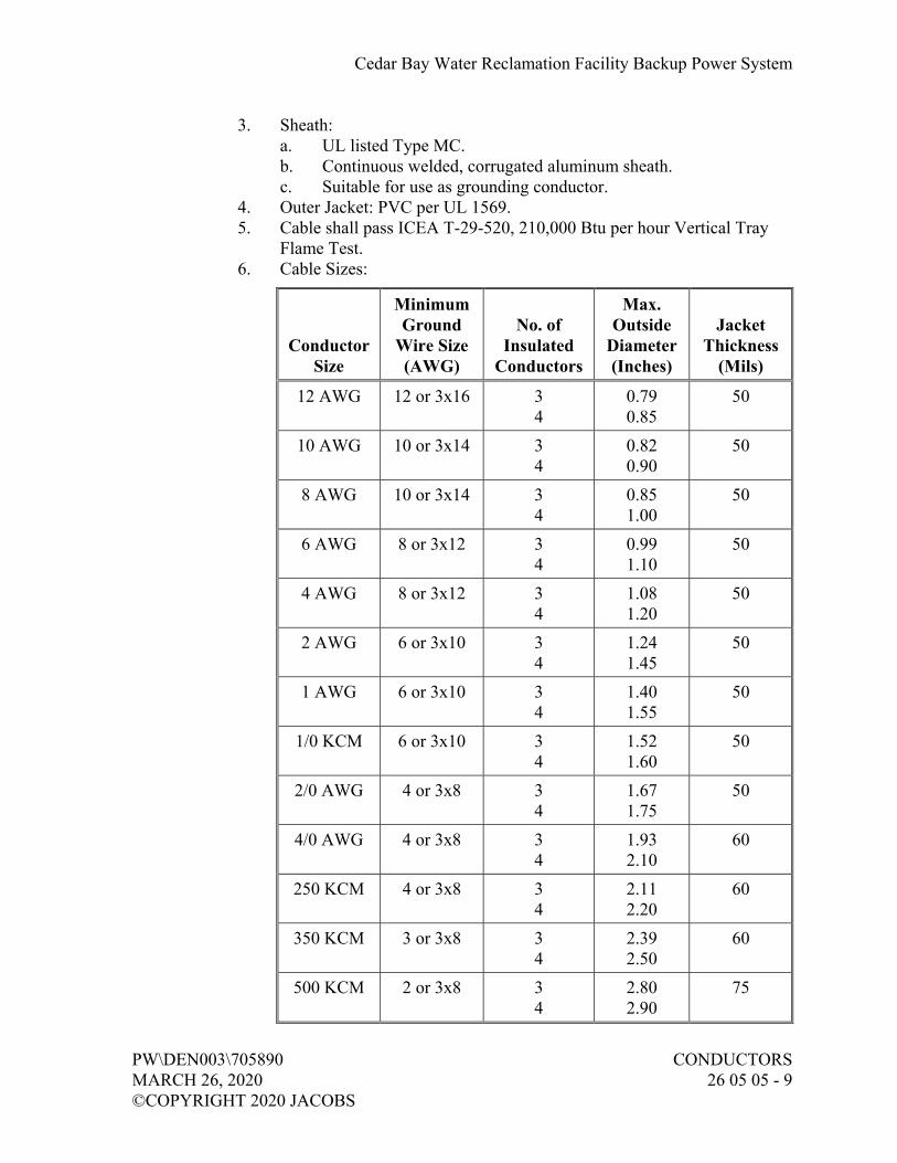
Cedar Bay Water Reclamation Facility Backup Power System
PW\DEN003\705890 CONDUCTORS MARCH 26, 2020 26 05 05 - 9 ©COPYRIGHT 2020 JACOBS
3. Sheath: a. UL listed Type MC. b. Continuous welded, corrugated aluminum sheath. c. Suitable for use as grounding conductor.
4. Outer Jacket: PVC per UL 1569. 5. Cable shall pass ICEA T-29-520, 210,000 Btu per hour Vertical Tray
Flame Test. 6. Cable Sizes:
Conductor Size
Minimum Ground
Wire Size (AWG)
No. of Insulated
Conductors
Max. Outside
Diameter (Inches)
Jacket Thickness
(Mils)
12 AWG 12 or 3x16 3 4
0.79 0.85
50
10 AWG 10 or 3x14 3 4
0.82 0.90
50
8 AWG 10 or 3x14 3 4
0.85 1.00
50
6 AWG 8 or 3x12 3 4
0.99 1.10
50
4 AWG 8 or 3x12 3 4
1.08 1.20
50
2 AWG 6 or 3x10 3 4
1.24 1.45
50
1 AWG 6 or 3x10 3 4
1.40 1.55
50
1/0 KCM 6 or 3x10 3 4
1.52 1.60
50
2/0 AWG 4 or 3x8 3 4
1.67 1.75
50
4/0 AWG 4 or 3x8 3 4
1.93 2.10
60
250 KCM 4 or 3x8 3 4
2.11 2.20
60
350 KCM 3 or 3x8 3 4
2.39 2.50
60
500 KCM 2 or 3x8 3 4
2.80 2.90
75

Cedar Bay Water Reclamation Facility Backup Power System
CONDUCTORS PW\DEN003\705890 26 05 05 - 10 MARCH 26, 2020 ©COPYRIGHT 2020 JACOBS
7. Manufacturers and Products: a. Okonite Co.; Type CLX. b. Southwire Type MC. c. General Cable, CCW Armored Power. d. Or approved equal.
I. Type 8, Multiconductor Adjustable Frequency Drive Power Cable:
1. Conductors: a. Class B, stranded coated copper. b. Insulation: 600-volt cross-linked polyethylene, UL
Type XHHW-2. c. Grounding Conductors: Insulated stranded copper.
2. Sheath: a. UL 1277 Type TC, 90 degrees C. b. Continuous shield, A1/polyester foil, drain wires, overall copper
braid. 3. Outer Jacket: Polyvinyl chloride (PVC) per UL 1569. 4. Cable Sizes:
Conductor Size
Minimum Ground
Wire Size (AWG)
No. of Insulated
Conductors
Max. Outside
Diameter (Inches)
Minimum Jacket
Thickness (Mils)
12 AWG 12 4 0.655 50
10 AWG 10 4 0.769 50
8 AWG 8 4 0.940 50
6 AWG 6 4 1.038 50
4 AWG 4 4 1.180 50
2 AWG 2 4 1.351 50
5. Manufacturers and Products: a. Alpha Wire; Series V. b. Belden; Series 29500. c. LAPP USA; OLFLEX VFD Slim. d. Or approved equal.
J. Type 9, Multiconductor Metal-Clad (UL Type MC) Power Cable for Adjustable Frequency Drive Applications:
1. Meeting requirements of UL 44 and UL 1569.

Cedar Bay Water Reclamation Facility Backup Power System
PW\DEN003\705890 CONDUCTORS MARCH 26, 2020 26 05 05 - 11 ©COPYRIGHT 2020 JACOBS
2. Conductors: a. Class B, stranded coated copper. b. Insulation: 600-volt cross-linked polyethylene, UL Type XHHW
or EPR. c. Grounding Conductors: Bare, stranded copper. Provide three
symmetrical grounding conductors. 3. Sheath:
a. UL listed Type MC. b. Continuous welded, corrugated aluminum sheath. c. Suitable for use as grounding conductor.
4. Outer Jacket: PVC per UL 1569. 5. Cable shall pass ICEA T-29-520, 210,000 Btu per hour Vertical Tray
Flame Test. 6. Cable Sizes:
Conductor Size
Minimum Ground
Wire Size (AWG)
No. of Insulated
Conductors
Max. Outside
Diameter (Inches)
Jacket Thickness
(Mils)
12 AWG 3x16 3 4
0.79 0.85
50
10 AWG 3x14 3 4
0.82 0.90
50
8 AWG 3x14 3 4
0.85 1.00
50
6 AWG 3x12 3 4
0.99 1.10
50
4 AWG 3x12 3 4
1.08 1.20
50
2 AWG 3x10 3 4
1.24 1.45
50
1 AWG 3x10 3 4
1.40 1.55
50
1/0 KCM 3x10 3 4
1.52 1.60
50
2/0 AWG 3x8 3 4
1.67 1.75
50
4/0 AWG 3x8 3 4
1.93 2.10
60

Cedar Bay Water Reclamation Facility Backup Power System
CONDUCTORS PW\DEN003\705890 26 05 05 - 12 MARCH 26, 2020 ©COPYRIGHT 2020 JACOBS
Conductor Size
Minimum Ground
Wire Size (AWG)
No. of Insulated
Conductors
Max. Outside
Diameter (Inches)
Jacket Thickness
(Mils)
250 KCM 3x8 3 4
2.11 2.20
60
350 KCM 3x8 3 4
2.39 2.50
60
500 KCM 3x8 3 4
2.80 2.90
75
7. Manufacturer and Product: a. Okonite Co.; Type CLX MC-HL. b. Or approved equal.
2.03 SPECIAL CABLES
A. Type 30, Unshielded Twisted Pair (UTP) Telephone and Data Cable, 300V:
1. Category 6 UTP, UL listed, and third party verified to comply with TIA/EIA 568-C Category 6 requirements.
2. Suitable for high speed network applications including gigabit ethernet and video. Cable shall be interoperable with other standards compliant products and shall be backward compatible with Category 5 and Category 5e.
3. Provide four each individually twisted pair, 23 AWG conductors, with FEP insulation and blue PVC jacket.
4. NFPA 70 Plenum (CMP) rated; comply with flammability plenum requirements of NFPA 70 and NFPA 262.
5. Cable shall withstand a bend radius of 1-inch minimum at a temperature of minus 20 degrees C maximum without jacket or insulation cracking.
6. Manufacturer and Product: a. Belden; 7852A. b. Or approved equal.
2.04 GROUNDING CONDUCTORS
A. Equipment: Stranded copper with green, Type USE/RHH/RHW-XLPE or THHN/THWN, insulation.
B. Direct Buried: Bare stranded copper.

Cedar Bay Water Reclamation Facility Backup Power System
PW\DEN003\705890 CONDUCTORS MARCH 26, 2020 26 05 05 - 13 ©COPYRIGHT 2020 JACOBS
2.05 ACCESSORIES FOR CONDUCTORS 600 VOLTS AND BELOW
A. Tape:
1. General Purpose, Flame Retardant: 7-mil, vinyl plastic, Scotch Brand 33+, rated for 90 degrees C minimum, meeting requirements of UL 510.
2. Flame Retardant, Cold and Weather Resistant: 8.5-mil, vinyl plastic, Scotch Brand 88.
3. Arc and Fireproofing: a. 30-mil, elastomer. b. Manufacturers and Products:
1) 3M; Scotch Brand 77, with Scotch Brand 69 glass cloth tapebinder.
2) Plymouth; 53 Plyarc, with 77 Plyglas glass cloth tapebinder. 3) Or approved equal.
B. Identification Devices:
1. Sleeve: a. Permanent, PVC, yellow or white, with legible machine-printed
black markings. b. Manufacturers and Products:
1) Raychem; Type D-SCE or ZH-SCE. 2) Brady, Type 3PS. 3) Or approved equal.
2. Heat Bond Marker: a. Transparent thermoplastic heat bonding film with acrylic pressure
sensitive adhesive. b. Self-laminating protective shield over text. c. Machine printed black text. d. Manufacturer and Product:
1) 3M Co.; Type SCS-HB. 2) Or approved equal.
3. Marker Plate: Nylon, with legible designations permanently hot stamped on plate.
4. Tie-On Cable Marker Tags: a. Chemical-resistant white tag. b. Size: 1/2 inch by 2 inches. c. Manufacturer and Product:
1) Raychem; Type CM-SCE. 2) Or approved equal.
5. Grounding Conductor: Permanent green heat-shrink sleeve, 2-inch minimum.

Cedar Bay Water Reclamation Facility Backup Power System
CONDUCTORS PW\DEN003\705890 26 05 05 - 14 MARCH 26, 2020 ©COPYRIGHT 2020 JACOBS
C. Connectors and Terminations:
1. Nylon, Self-Insulated Crimp Connectors: a. Manufacturers and Products:
1) Thomas & Betts; Sta-Kon. 2) Burndy; Insulug. 3) ILSCO. 4) Or approved equal.
2. Nylon, Self-Insulated, Crimp Locking-Fork, Torque-Type Terminator: a. Suitable for use with 75 degrees C wire at full NFPA 70,
75 degrees C ampacity. b. Seamless. c. Manufacturers and Products:
1) Thomas & Betts; Sta-Kon. 2) Burndy; Insulink. 3) ILSCO; ILSCONS. 4) Or approved equal.
3. Self-Insulated, Freespring Wire Connector (Wire Nuts): a. UL 486C. b. Plated steel, square wire springs. c. Manufacturers and Products:
1) Thomas & Betts. 2) Ideal; Twister. 3) Or approved equal.
4. Self-Insulated, Set Screw Wire Connector: a. Two piece compression type with set screw in brass barrel. b. Insulated by insulator cap screwed over brass barrel. c. Manufacturers:
1) 3M Co. 2) Thomas & Betts. 3) Marrette. 4) Or approved equal.
D. Cable Lugs:
1. In accordance with NEMA CC 1. 2. Rated 600 volts of same material as conductor metal. 3. Uninsulated Crimp Connectors and Terminators:
a. Suitable for use with 75 degrees C wire at full NFPA 70, 75 degrees C ampacity.
b. Manufacturers and Products: 1) Thomas & Betts; Color-Keyed. 2) Burndy; Hydent. 3) ILSCO. 4) Or approved equal.

Cedar Bay Water Reclamation Facility Backup Power System
PW\DEN003\705890 CONDUCTORS MARCH 26, 2020 26 05 05 - 15 ©COPYRIGHT 2020 JACOBS
4. Uninsulated, Bolted, Two-Way Connectors and Terminators: a. Manufacturers and Products:
1) Thomas & Betts; Locktite. 2) Burndy; Quiklug. 3) ILSCO. 4) Or approved equal.
E. Cable Ties:
1. Nylon, adjustable, self-locking, and reusable. 2. Manufacturer and Product:
a. Thomas & Betts; TY-RAP. b. Or approved equal.
F. Heat Shrinkable Insulation:
1. Thermally stabilized cross-linked polyolefin. 2. Single wall for insulation and strain relief. 3. Dual Wall, adhesive sealant lined, for sealing and corrosion resistance. 4. Manufacturers and Products:
a. Thomas & Betts; SHRINK-KON. b. Raychem; RNF-100 and ES-2000. c. Or approved equal.
G. Data Cable Accessories: Terminators, connectors, and junctions necessary for a complete Profibus DP or Profinet system.
1. Profibus DP connector: a. Manufacturers and Products:
1) Brad Harrison; MA9D00-42 and MA9D01-42. 2) Or approved equal.
2. Profinet connector: RJ-45.
2.06 PULLING COMPOUND
A. Nontoxic, noncorrosive, noncombustible, nonflammable, water-based lubricant; UL listed.
B. Suitable for rubber, neoprene, PVC, polyethylene, hypalon, CPE, and lead-covered wire and cable.
C. Approved for intended use by cable manufacturer.
D. Suitable for zinc-coated steel, aluminum, PVC, bituminized fiber, and fiberglass raceways.
Cedar Bay Water Reclamation Facility Backup Power System
CONDUCTORS PW\DEN003\705890 26 05 05 - 16 MARCH 26, 2020 ©COPYRIGHT 2020 JACOBS
E. Manufacturers:
1. Ideal Co. 2. Polywater, Inc. 3. Cable Grip Co. 4. Or approved equal.
2.07 WARNING TAPE
A. As specified in Section 26 05 33, Raceway and Boxes.
2.08 SOURCE QUALITY CONTROL
A. Conductors 600 Volts and Below: Test in accordance with UL 44 and UL 854.
PART 3 EXECUTION
3.01 GENERAL
A. Conductor installation shall be in accordance with manufacturer’s recommendations.
B. Conductor and cable sizing shown is based on copper conductors, unless noted otherwise.
C. Do not exceed cable manufacturer’s recommendations for maximum pulling tensions and minimum bending radii.
D. Terminate conductors and cables, unless otherwise indicated.
E. Tighten screws and terminal bolts in accordance with UL 486A-486B for copper conductors and aluminum conductors.
F. Cable Lugs: Provide with correct number of holes, bolt size, and center-to-center spacing as required by equipment terminals.
G. Bundling: Where single conductors and cables in manholes, handholes, vaults, cable trays, and other indicated locations are not wrapped together by some other means, bundle conductors from each conduit throughout their exposed length with cable ties placed at intervals not exceeding 12 inches on center.
H. Ream, remove burrs, and clear interior of installed conduit before pulling wires or cables.

Cedar Bay Water Reclamation Facility Backup Power System
PW\DEN003\705890 CONDUCTORS MARCH 26, 2020 26 05 05 - 17 ©COPYRIGHT 2020 JACOBS
I. Concrete-Encased Raceway Installation: Prior to installation of conductors, pull through each raceway a mandrel approximately 1/4 inch smaller than raceway inside diameter.
3.02 POWER CONDUCTOR COLOR CODING
A. Conductors 600 Volts and Below:
1. 6 AWG and Larger: Apply general purpose, flame retardant tape at each end, and at accessible locations wrapped at least six full overlapping turns, covering area 1-1/2 inches to 2 inches wide.
2. 8 AWG and Smaller: Provide colored conductors. 3. Colors:
System Conductor Color
All Systems Equipment Grounding
Green
240/120 Volts, Single-Phase, Three-Wire
Grounded Neutral One Hot Leg
Other Hot Leg
White Black Red
208Y/120 Volts, Three-Phase, Four-Wire
Grounded Neutral Phase A Phase B Phase C
White Black Red Blue
240/120 Volts, Three-Phase, Four-Wire, Delta, Center Tap, Ground on Single-Phase
Grounded Neutral Phase A
High (wild) Leg Phase C
White Black
Orange Blue
480Y/277 Volts, Three-Phase, Four-Wire
Grounded Neutral Phase A Phase B Phase C
White Brown Orange Yellow
Note: Phase A, B, C implies direction of positive phase rotation.
4. Tracer: Outer covering of white with identifiable colored strip, other than green, in accordance with NFPA 70.
3.03 CIRCUIT IDENTIFICATION
A. Identify power, instrumentation, and control conductor circuits at each termination, and in accessible locations such as manholes, handholes, panels, switchboards, motor control centers, pull boxes, and terminal boxes.

Cedar Bay Water Reclamation Facility Backup Power System
CONDUCTORS PW\DEN003\705890 26 05 05 - 18 MARCH 26, 2020 ©COPYRIGHT 2020 JACOBS
B. Circuits:
1. Assign circuit name based on device or equipment at load end of circuit. 2. Where this would result in same name being assigned to more than one
circuit, add number or letter to each otherwise identical circuit name to make it unique.
C. Method:
1. Conductors 3 AWG and Smaller: Identify with sleeves or heat bond markers.
2. Cables and Conductors 2 AWG and Larger: a. Identify with marker plates or tie-on cable marker tags. b. Attach with nylon tie cord.
3. Taped-on markers or tags relying on adhesives not permitted.
3.04 CONDUCTORS 600 VOLTS AND BELOW
A. Install 10 AWG or 12 AWG conductors for branch circuit power wiring in lighting and receptacle circuits.
B. Do not splice incoming service conductors and branch power distribution conductors 6 AWG and larger, unless specifically indicated or approved by Engineer.
C. Connections and Terminations:
1. Install wire nuts only on solid conductors. Wire nuts are not allowed on stranded conductors.
2. Install nylon self-insulated crimp connectors and terminators for instrumentation and control, circuit conductors.
3. Install self-insulated, set screw wire connectors for two-way connection of power circuit conductors 12 AWG and smaller.
4. Install uninsulated crimp connectors and terminators for instrumentation, control, and power circuit conductors 4 AWG through 2/0 AWG.
5. Install uninsulated, bolted, two-way connectors and terminators for power circuit conductors 3/0 AWG and larger.
6. Install uninsulated terminators bolted together on motor circuit conductors 10 AWG and larger.
7. Place no more than one conductor in any single-barrel pressure connection.
8. Install crimp connectors with tools approved by connector manufacturer.
9. Install terminals and connectors acceptable for type of material used.

Cedar Bay Water Reclamation Facility Backup Power System
PW\DEN003\705890 CONDUCTORS MARCH 26, 2020 26 05 05 - 19 ©COPYRIGHT 2020 JACOBS
10. Compression Lugs: a. Attach with a tool specifically designed for purpose. Tool shall
provide complete, controlled crimp and shall not release until crimp is complete.
b. Do not use plier type crimpers.
D. Do not use soldered mechanical joints.
E. Splices and Terminations:
1. Insulate uninsulated connections. 2. Indoors: Use general purpose, flame retardant tape or single wall heat
shrink. 3. Outdoors, Dry Locations: Use flame retardant, cold- and weather-
resistant tape or single wall heat shrink. 4. Below Grade and Wet or Damp Locations: Use dual wall heat shrink.
F. Cap spare conductors with UL listed end caps.
G. Cabinets, Panels, and Motor Control Centers:
1. Remove surplus wire, bridle and secure. 2. Where conductors pass through openings or over edges in sheet metal,
remove burrs, chamfer edges, and install bushings and protective strips of insulating material to protect the conductors.
H. Control and Instrumentation Wiring:
1. Where terminals provided will accept such lugs, terminate control and instrumentation wiring, except solid thermocouple leads, with insulated, locking-fork compression lugs.
2. Terminate with methods consistent with terminals provided, and in accordance with terminal manufacturer’s instructions.
3. Locate splices in readily accessible cabinets or junction boxes using terminal strips.
4. Where connections of cables installed under this section are to be made under Section 40 90 00, Instrumentation and Control for Process Systems, leave pigtails of adequate length for bundled connections.
5. Cable Protection: a. Under Infinite Access Floors: May install without bundling. b. All Other Areas: Install individual wires, pairs, or triads in flex
conduit under floor or grouped into bundles at least 1/2 inch in diameter.
c. Maintain integrity of shielding of instrumentation cables. d. Ensure grounds do not occur because of damage to jacket over
shield.

Cedar Bay Water Reclamation Facility Backup Power System
CONDUCTORS PW\DEN003\705890 26 05 05 - 20 MARCH 26, 2020 ©COPYRIGHT 2020 JACOBS
I. Extra Conductor Length: For conductors to be connected by others, install minimum 6 feet of extra conductor in freestanding panels and minimum 2 feet in other assemblies.
3.05 CONDUCTOR ARC AND FIREPROOFING
A. Install arc and fireproofing tape on 600-volt single conductors and cables, except those rated Type TC throughout their entire exposed length, at splices in manholes, handholes, vaults, cable trays, and other indicated locations.
B. Wrap conductors of same circuit entering from separate conduit together as a single cable.
C. Follow tape manufacturer’s installation instructions.
D. Secure tape at intervals of 5 feet with bands of tapebinder. Each band to consist of a minimum of two wraps directly over each other.
3.06 UNDERGROUND DIRECT BURIAL CABLE
A. Install in trench as specified in Section 31 23 23.15, Trench Backfill.
B. Warning Tape: Install approximately 6 inches above cable, aligned parallel to, and within 12 inches of centerline of the run.
END OF SECTION

Cedar Bay Water Reclamation Facility Backup Power System
PW\DEN003\705890 GROUNDING AND BONDING MARCH 26, 2020 FOR ELECTRICAL SYSTEMS ©COPYRIGHT 2020 JACOBS 26 05 26 - 1
SECTION 26 05 26 GROUNDING AND BONDING FOR ELECTRICAL SYSTEMS
PART 1 GENERAL
1.01 REFERENCES
A. The following is a list of standards which may be referenced in this section:
1. Institute of Electrical and Electronics Engineers (IEEE): C2, National Electrical Safety Code (NESC).
2. National Fire Protection Association (NFPA): 70, National Electrical Code (NEC).
1.02 SUBMITTALS
A. Action Submittals:
1. Shop Drawings: a. Product data for the following:
1) Exothermic weld connectors. 2) Mechanical connectors. 3) Compression connectors.
1.03 QUALITY ASSURANCE
A. Authority Having Jurisdiction (AHJ):
1. Provide the Work in accordance with NFPA 70, National Electrical Code (NEC). Where required by the AHJ, provide material and equipment labeled or listed by a nationally recognized testing laboratory or other organization acceptable to the AHJ to provide a basis for approval under NEC.
2. Materials and equipment manufactured within the scope of standards published by UL: a. Confirm conformance with UL standards. b. Supply with an applied UL listing mark.
PART 2 PRODUCTS
2.01 GROUND ROD
A. Material: Copper-clad.
B. Diameter: Minimum 3/4 inch.
C. Length: 20 feet.

Cedar Bay Water Reclamation Facility Backup Power System
GROUNDING AND BONDING PW\DEN003\705890 FOR ELECTRICAL SYSTEMS MARCH 26, 2020 26 05 26 - 2 ©COPYRIGHT 2020 JACOBS
2.02 GROUND CONDUCTORS
A. As specified in Section 26 05 05, Conductors.
2.03 CONNECTORS
A. Exothermic Weld Type:
1. Outdoor Weld: Suitable for exposure to elements or direct burial. 2. Indoor Weld: Use low-smoke, low-emission process. 3. Manufacturers:
a. Erico Products, Inc. Cadweld and Cadweld Exolon. b. Thermoweld. c. Or approved equal.
B. Compression Type:
1. Compress-deforming type; wrought copper extrusion material. 2. Single indentation for conductors 6 AWG and smaller. 3. Double indentation with extended barrel for conductors 4 AWG and
larger. 4. Barrels prefilled with oxide-inhibiting and antiseizing compound and
sealed. 5. Manufacturers:
a. Burndy Corp.; Hyground Irreversible Compression. b. Thomas and Betts Co. c. ILSCO. d. Or approved equal.
C. Mechanical Type: Split-bolt, saddle, or cone screw type; copper alloy material.
1. Manufacturers: a. Burndy Corp. b. Thomas and Betts Co. c. Or approved equal.
2.04 GROUNDING WELLS
A. Ground rod box complete with cast-iron riser ring and traffic cover marked “GROUND ROD”.
B. Manufacturers and Products:
1. Christy Co.; No. G5. 2. Lightning and Grounding Systems, Inc.; I-R Series. 3. Or approved equal.

Cedar Bay Water Reclamation Facility Backup Power System
PW\DEN003\705890 GROUNDING AND BONDING MARCH 26, 2020 FOR ELECTRICAL SYSTEMS ©COPYRIGHT 2020 JACOBS 26 05 26 - 3
PART 3 EXECUTION
3.01 GENERAL
A. Grounding: In compliance with NFPA 70 and IEEE C2.
B. Ground electrical service neutral at service entrance equipment with grounding electrode conductor to grounding electrode system.
C. Ground each separately derived system neutral with common grounding electrode conductor to grounding electrode system.
D. Bond together all grounding electrodes that are present at each building or structure served to form one common grounding electrode system.
E. Bond together system neutrals, service equipment enclosures, exposed noncurrent-carrying metal parts of electrical equipment, metal raceways, ground conductor in raceways and cables, receptacle ground connections, and metal piping systems.
F. Shielded Power Cables: Ground shields at each splice or termination in accordance with recommendations of splice or termination manufacturer.
G. Shielded Instrumentation Cables:
1. Ground shield to ground bus at power supply for analog signal. 2. Expose shield minimum 1 inch at termination to field instrument and
apply heat shrink tube. 3. Do not ground instrumentation cable shield at more than one point.
3.02 WIRE CONNECTIONS
A. Ground Conductors: Install in conduit containing power conductors and control circuits above 50 volts.
B. Nonmetallic Raceways and Flexible Tubing: Install equipment grounding conductor connected at both ends to noncurrent-carrying grounding bus.
C. Connect ground conductors to raceway grounding bushings.
D. Extend and connect ground conductors to ground bus in all equipment containing a ground bus.
E. Connect enclosure of equipment containing ground bus to that bus.
F. Bolt connections to equipment ground bus.

Cedar Bay Water Reclamation Facility Backup Power System
GROUNDING AND BONDING PW\DEN003\705890 FOR ELECTRICAL SYSTEMS MARCH 26, 2020 26 05 26 - 4 ©COPYRIGHT 2020 JACOBS
G. Bond grounding conductors to metallic enclosures at each end, and to intermediate metallic enclosures.
H. Junction Boxes: Furnish materials and connect to equipment grounding system with grounding clips mounted directly on box, or with 3/8-inch machine screws.
I. Metallic Equipment Enclosures: Use furnished ground lug; if none furnished, tap equipment housing and install solderless terminal connected to box with machine screw. For circuits greater than 20 amps use minimum 5/16-inch diameter bolt.
3.03 MOTOR GROUNDING
A. Extend equipment ground bus via grounding conductor installed in motor feeder raceway; connect to motor frame.
B. Nonmetallic Raceways and Flexible Tubing: Install an equipment grounding conductor connected at both ends to noncurrent-carrying grounding bus.
C. Motors Less than 10 hp: Use furnished ground lug in motor connection box. If none furnished, provide compression, spade-type terminal connected to conduit box mounting screw.
D. Motors 10 hp and Above: Use furnished ground lug in motor connection box. If none furnished, tap motor frame or equipment housing; furnish compression, one-hole, lug type terminal connected with minimum 5/16-inch brass threaded stud with bolt and washer.
E. Circuits 20 Amps or Above: Tap motor frame or equipment housing. Install solderless terminal with minimum 5/16-inch diameter bolt.
3.04 GROUND RODS
A. Install full length with conductor connection at upper end.
B. Install with connection point below finished grade, unless otherwise shown.
C. Space multiple ground rods by one rod length.
3.05 GROUNDING WELLS
A. Install for ground rods located inside buildings, asphalt and paved areas, and where shown on Drawings.
B. Install riser ring and cover flush with surface.
C. Place 9 inches of crushed rock in bottom of each well.

Cedar Bay Water Reclamation Facility Backup Power System
PW\DEN003\705890 GROUNDING AND BONDING MARCH 26, 2020 FOR ELECTRICAL SYSTEMS ©COPYRIGHT 2020 JACOBS 26 05 26 - 5
3.06 CONNECTIONS
A. General:
1. Abovegrade Connections: Install exothermic weld, mechanical, or compression-type connectors; or brazing.
2. Belowgrade Connections: Install exothermic weld or compression type connectors.
3. Remove paint, dirt, or other surface coverings at connection points to allow good metal-to-metal contact.
4. Notify Engineer prior to backfilling ground connections.
B. Exothermic Weld Type:
1. Wire brush or file contact point to bare metal surface. 2. Use welding cartridges and molds in accordance with manufacturer’s
recommendations. 3. Avoid using badly worn molds. 4. Mold to be completely filled with metal when making welds. 5. After completed welds have cooled, brush slag from weld area and
thoroughly clean joint.
C. Compression Type:
1. Install in accordance with connector manufacturer’s recommendations. 2. Install connectors of proper size for grounding conductors and ground
rods specified. 3. Install using connector manufacturer’s compression tool having proper
sized dies and operate per manufacturer’s instructions.
D. Mechanical Type:
1. Apply homogeneous blend of colloidal copper and rust and corrosion inhibitor before making connection.
2. Install in accordance with connector manufacturer’s recommendations. 3. Do not conceal mechanical connections.
3.07 METAL STRUCTURE GROUNDING
A. Bond metal sheathing and exposed metal vertical structural elements to grounding system.
B. Bond electrical equipment supported by metal platforms to the platforms.
C. Provide electrical contact between metal frames and railings supporting pushbutton stations, receptacles, and instrument cabinets, and raceways carrying circuits to these devices.

Cedar Bay Water Reclamation Facility Backup Power System
GROUNDING AND BONDING PW\DEN003\705890 FOR ELECTRICAL SYSTEMS MARCH 26, 2020 26 05 26 - 6 ©COPYRIGHT 2020 JACOBS
3.08 MANHOLE AND HANDHOLE GROUNDING
A. Install one ground rod inside each manhole and handhole larger than 24-inch by 24-inch inside dimensions.
B. Ground Rod Floor Protrusion: 4 inches to 6 inches above floor.
C. Make connections of grounding conductors fully visible and accessible.
D. Connect all noncurrent-carrying metal parts and any metallic raceway grounding bushings to ground rod with 6 AWG copper conductor.
3.09 TRANSFORMER GROUNDING
A. Bond neutrals of transformers within buildings to system ground network and to any additional indicated grounding electrodes.
B. Bond neutrals of substation transformers to substation grounding grid and system grounding network.
C. Bond neutrals of pad-mounted transformers to locally driven ground rods and buried ground wire encircling transformer and system ground network.
3.10 STAND-BY GENERATOR GROUNDING
A. Generator neutral should be brought in to service entrance equipment, bonded to the utility transformer neutral and grounded at a common ground to create a non-separately derive system per NEC.
B. Ground generator frame to nearest ground.
3.11 LIGHTNING PROTECTION SYSTEMS
A. Bond lightning protection system ground terminals to building or structure grounding electrode system.
3.12 SURGE PROTECTION EQUIPMENT GROUNDING
A. Connect surge arrestor ground terminals to equipment ground bus.
3.13 FIELD QUALITY CONTROL
A. As specified in Section 26 08 00, Commissioning of Electrical Systems.
END OF SECTION
Cedar Bay Water Reclamation Facility Backup Power System
PW\DEN003\705890 RACEWAY AND BOXES MARCH 26, 2020 26 05 33 - 1 ©COPYRIGHT 2020 JACOBS
SECTION 26 05 33 RACEWAY AND BOXES
PART 1 GENERAL
1.01 REFERENCES
A. The following is a list of standards which may be referenced in this section:
1. American Association of State Highway and Transportation Officials (AASHTO): HB, Standard Specifications for Highway Bridges.
2. ASTM International (ASTM): a. A123/123M, Standard Specification for Zinc (Hot-Dipped
Galvanized) Coatings on Iron and Steel Products. b. A167, Standard Specification for Stainless and Heat-Resisting
Chromium-Nickel Steel Plate, Sheet, and Strip. c. A240/A240M, Standard Specification for Chromium and
Chromium-Nickel Stainless Steel Plate, Sheet, and Strip for Pressure Vessels and for General Applications.
d. C857, Standard Practice for Minimum Structural Design Loading for Underground Precast Concrete Utility Structures.
e. D149, Standard Test Method for Dielectric Breakdown Voltage and Dielectric Strength of Solid Electrical Insulating Materials at Commercial Power Frequencies.
3. Telecommunications Industry Association (TIA): 569B, Commercial Building Standard for Telecommunications Pathways and Spaces. a. National Electrical Contractor’s Association, Inc. (NECA):
Installation standards: b. 101, Standard for Installing Steel Conduit (Rigid, IMC, EMT). c. 105, Recommended Practice for Installing Metal Cable Trays. d. 111, Standard for Installing Nonmetallic Raceway (RNC, ENT,
LFNC). 4. National Electrical Manufacturers Association (NEMA):
a. 250, Enclosures for Electrical Equipment (1000 Volts Maximum). b. C80.1, Electrical Rigid Steel Conduit (ERSC). c. C80.3, Steel Electrical Metallic Tubing (EMT). d. C80.6, Electrical Intermediate Metal Conduit (EIMC). e. RN 1, Polyvinyl Chloride (PVC) Externally Coated Galvanized
Rigid Steel Conduit and Intermediate Metal Conduit. f. TC 2, Electrical Polyvinyl Chloride (PVC) Conduit. g. TC 3, Polyvinyl Chloride (PVC) Fittings for Use with Rigid PVC
Conduit and Tubing. h. TC 6, Polyvinyl Chloride (PVC) Plastic Utilities Duct for
Underground Installation.

Cedar Bay Water Reclamation Facility Backup Power System
RACEWAY AND BOXES PW\DEN003\705890 26 05 33 - 2 MARCH 26, 2020 ©COPYRIGHT 2020 JACOBS
i. TC 14, Reinforced Thermosetting Resin Conduit (RTRC) and Fittings.
j. VE 1, Metallic Cable Tray Systems. 5. National Fire Protection Association (NFPA): 70, National Electrical
Code (NEC). 6. Underwriters Laboratories Inc. (UL):
a. 1, Standard for Safety for Flexible Metal Conduit. b. 5, Standard for Safety for Surface Metal Raceways and Fittings. c. 6, Standard for Safety for Electrical Rigid Metal Conduit – Steel. d. 360, Standard for Safety for Liquid-Tight Flexible Steel Conduit. e. 514B, Standard for Safety for Conduit, Tubing, and Cable
Fittings. f. 651, Standard for Safety for Schedule 40 and 80 Rigid PVC
Conduit and Fittings. g. 651A, Standard for Safety for Type EB and A Rigid PVC Conduit
and HDPE Conduit. h. 797, Standard for Safety for Electrical Metallic Tubing – Steel. i. 870, Standard for Safety for Wireways, Auxiliary Gutters, and
Associated Fittings. j. 1242, Standard for Safety for Electrical Intermediate Metal
Conduit – Steel. k. 1660, Standard for Safety for Liquid-Tight Flexible Nonmetallic
Conduit. l. 1684, Standard for Safety for Reinforced Thermosetting Resin
Conduit (RTRC) and Fittings. m. 2024, Standard for Safety for Optical Fiber and Communication
Cable Raceway.
1.02 SUBMITTALS
A. Action Submittals:
1. Manufacturer’s Literature: a. Rigid galvanized steel conduit. b. Electric metallic tubing. c. PVC Schedule 40 conduit. d. PVC Schedule 80 conduit. e. PVC-coated rigid galvanized steel. f. Flexible metal, liquid-tight conduit. g. Flexible metal, nonliquid-tight conduit. h. Conduit fittings. i. Device boxes for use in hazardous areas. j. Junction and pull boxes used at or below grade. k. Large junction and pull boxes. l. Terminal junction boxes.

Cedar Bay Water Reclamation Facility Backup Power System
PW\DEN003\705890 RACEWAY AND BOXES MARCH 26, 2020 26 05 33 - 3 ©COPYRIGHT 2020 JACOBS
2. Precast Manholes and Handholes: a. Dimensional drawings and descriptive literature. b. Traffic loading calculations. c. Accessory information.
3. Equipment and machinery proposed for bending metal conduit. 4. Method for bending PVC conduit less than 30 degrees.
B. Informational Submittals:
1. Seismic anchorage and bracing calculations as required by Section 01 88 15, Anchorage and Bracing.
2. Component and attachment testing seismic certificate of compliance as required by Division 01, General Requirements.
3. Manufacturer’s certification of training for PVC-coated rigid galvanized steel conduit installer.
1.03 QUALITY ASSURANCE
A. Authority Having Jurisdiction (AHJ):
1. Provide the Work in accordance with NFPA 70, National Electrical Code (NEC). Where required by the AHJ, material and equipment shall be labeled or listed by a nationally recognized testing laboratory or other organization acceptable to the AHJ in order to provide a basis for approval under NEC.
2. Materials and equipment manufactured within scope of standards published by Underwriters Laboratories, Inc. shall conform to those standards and shall have an applied UL listing mark.
B. PVC-Coated, Rigid Galvanized Steel Conduit Installer: Certified by conduit manufacturer as having received minimum 2 hours of training on installation procedures.
C. PVC-coated conduit bodies and cast metal boxes shall be provided by the PVC-coated rigid steel conduit manufacturer.
PART 2 PRODUCTS
2.01 CONDUIT AND TUBING
A. Rigid Galvanized Steel Conduit (RGS):
1. Meet requirements of NEMA C80.1 and UL 6. 2. Material: Hot-dip galvanized with chromated protective layer.
Cedar Bay Water Reclamation Facility Backup Power System
RACEWAY AND BOXES PW\DEN003\705890 26 05 33 - 4 MARCH 26, 2020 ©COPYRIGHT 2020 JACOBS
B. Intermediate Metal Conduit (IMC):
1. Meet requirements of NEMA C80.6 and UL 1242. 2. Material: Hot-dip galvanized with chromated and lacquered protective
layer.
C. Electric Metallic Tubing (EMT):
1. Meet requirements of NEMA C80.3 and UL 797. 2. Material: Hot-dip galvanized with chromated and lacquered protective
layer.
D. PVC Schedule 40 Conduit:
1. Meet requirements of NEMA TC 2 and UL 651. 2. UL listed for concrete encasement, underground direct burial, concealed
or direct sunlight exposure, and 90 degrees C insulated conductors. 3. Furnish without factory-formed bell.
E. PVC Schedule 80 Conduit:
1. Meet requirements of NEMA TC 2 and UL 651. 2. UL listed for concrete encasement, underground direct burial, concealed
or direct sunlight exposure, and 90 degrees C insulated conductors.
F. PVC Tubing (Type EB):
1. Meet requirements of NEMA TC 6 and UL 651A. 2. UL listed for reinforced concrete encasement and 90 degrees C insulated
conductors.
G. PVC-Coated Rigid Galvanized Steel Conduit:
1. Meet requirements of NEMA RN 1. 2. Material:
a. Meet requirements of NEMA C80.1 and UL 6. b. Exterior Finish: PVC coating, 40-mil nominal thickness; bond to
metal shall have tensile strength greater than PVC. c. Interior finish: Urethane coating, 2-mil nominal thickness.
3. Threads: Hot-dipped galvanized and factory coated with urethane. 4. Bendable without damage to interior or exterior coating.
H. Flexible Metal, Liquid-Tight Conduit:
1. UL 360 listed for 105 degrees C insulated conductors. 2. Material: Galvanized steel with extruded PVC jacket.

Cedar Bay Water Reclamation Facility Backup Power System
PW\DEN003\705890 RACEWAY AND BOXES MARCH 26, 2020 26 05 33 - 5 ©COPYRIGHT 2020 JACOBS
I. Flexible Metal, Nonliquid-Tight Conduit:
1. Meet requirements of UL 1. 2. Material: Galvanized steel.
J. Flexible, Nonmetallic, Liquid-Tight Conduit:
1. Material: PVC core with fused flexible PVC jacket. 2. UL 1660 listed for:
a. Dry Conditions: 80 degrees C insulated conductors. b. Wet Conditions: 60 degrees C insulated conductors.
3. Manufacturers and Products: a. Carlon; Carflex or X-Flex. b. T & B; Xtraflex LTC or EFC. c. Or approved equal.
K. Innerduct:
1. Resistant to spread of fire, per requirements of UL 2024. 2. Smooth or corrugated HDPE.
2.02 FITTINGS
A. Rigid Galvanized Steel and Intermediate Metal Conduit:
1. General: a. Meet requirements of UL 514B. b. Type: Threaded, galvanized. Set screw and threadless
compression fittings not permitted. 2. Bushing:
a. Material: Malleable iron with integral insulated throat, rated for 150 degrees C.
b. Manufacturers and Products: 1) Appleton; Series BU-I. 2) O-Z/Gedney; Type HB. 3) Or approved equal.
3. Grounding Bushing: a. Material: Malleable iron with integral insulated throat rated for
150 degrees C, with solderless lugs. b. Manufacturers and Products:
1) Appleton; Series GIB. 2) O-Z/Gedney; Type HBLG. 3) Or approved equal.
4. Conduit Hub: a. Material: Malleable iron with insulated throat with bonding screw. b. UL listed for use in wet locations.

Cedar Bay Water Reclamation Facility Backup Power System
RACEWAY AND BOXES PW\DEN003\705890 26 05 33 - 6 MARCH 26, 2020 ©COPYRIGHT 2020 JACOBS
c. Manufacturers and Products: 1) Appleton, Series HUB-B. 2) O-Z/Gedney; Series CH. 3) Meyers; ST Series. 4) Or approved equal.
5. Conduit Bodies: a. Sized as required by NFPA 70. b. Manufacturers and Products (For Normal Conditions):
1) Appleton; Form 35 threaded unilets. 2) Crouse-Hinds; Form 7 or Form 8 threaded condulets. 3) Killark; Series O electrolets. 4) Thomas & Betts; Form 7 or Form 8. 5) Or approved equal.
c. Manufacturers (For Hazardous Locations): 1) Appleton. 2) Crouse-Hinds. 3) Killark. 4) Or approved equal.
6. Couplings: As supplied by conduit manufacturer. 7. Unions:
a. Concrete tight, hot-dip galvanized malleable iron. b. Manufacturers and Products:
1) Appleton; Series SCC bolt-on coupling or Series EC three-piece union.
2) O-Z/Gedney; Type SSP split coupling or Type 4 Series, three-piece coupling.
3) Or approved equal. 8. Conduit Sealing Fitting:
a. Manufacturers and Products: 1) Appleton; Type EYF, EYM, or ESU. 2) Crouse-Hinds; Type EYS or EZS. 3) Killark; Type EY or Type EYS. 4) Or approved equal.
9. Drain Seal: a. Manufacturers and Products:
1) Appleton; Type EYD. 2) Crouse-Hinds; Type EYD or Type EZD. 3) Or approved equal.
10. Drain/Breather Fitting: a. Manufacturers and Products:
1) Appleton; Type ECDB. 2) Crouse-Hinds; ECD. 3) Or approved equal.

Cedar Bay Water Reclamation Facility Backup Power System
PW\DEN003\705890 RACEWAY AND BOXES MARCH 26, 2020 26 05 33 - 7 ©COPYRIGHT 2020 JACOBS
11. Expansion Fitting: a. Manufacturers and Products:
1) Deflection/Expansion Movement: a) Appleton; Type DF. b) Crouse-Hinds; Type XD. c) Or approved equal.
2) Expansion Movement Only: a) Appleton; Type XJ. b) Crouse-Hinds; Type XJ. c) Thomas & Betts; XJG-TP. d) Or approved equal.
12. Cable Sealing Fitting: a. To form watertight nonslip cord or cable connection to conduit. b. For Conductors with OD of 1/2 inch or Less: Neoprene bushing at
connector entry. c. Manufacturers and Products:
1) Appleton; CG-S. 2) Crouse-Hinds; CGBS. 3) Or approved equal.
B. Electric Metallic Tubing:
1. Meet requirements of UL 514B. 2. Type: Steel body and locknuts with steel or malleable iron compression
nuts. Set screw and drive-on fittings not permitted. 3. Electro zinc-plated inside and out. 4. Raintight. 5. Coupling Manufacturers and Products:
a. Appleton; Type 95T. b. Crouse-Hinds. c. Thomas & Betts. d. Or approved equal.
6. Connector Manufacturers and Products: a. Appleton; Type ETP. b. Crouse-Hinds. c. Thomas & Betts. d. Or approved equal.
C. PVC Conduit and Tubing:
1. Meet requirements of NEMA TC 3. 2. Type: PVC, slip-on.

Cedar Bay Water Reclamation Facility Backup Power System
RACEWAY AND BOXES PW\DEN003\705890 26 05 33 - 8 MARCH 26, 2020 ©COPYRIGHT 2020 JACOBS
D. Flexible Metal, Liquid-Tight Conduit:
1. Metal insulated throat connectors with integral nylon or plastic bushing rated for 105 degrees C.
2. Insulated throat and sealing O-rings. 3. Manufacturers and Products:
a. Thomas & Betts; Series 5331. b. O-Z/Gedney; Series 4Q. c. Or approved equal.
E. Flexible Metal, Nonliquid-Tight Conduit:
1. Meet requirements of UL 514B. 2. Body: Galvanized steel. 3. Throat: Nylon insulated. 4. 1-1/4-Inch Conduit and Smaller: One screw body. 5. 1-1/2-Inch Conduit and Larger: Two screw body. 6. Manufacturer and Product:
a. Appleton; Series 7400. b. Or approved equal.
F. Flexible, Nonmetallic, Liquid-Tight Conduit:
1. Meet requirements of UL 514B. 2. Type: High strength plastic body, complete with lock nut, O-ring,
threaded ferrule, sealing ring, and compression nut. 3. Body/compression nut (gland) design to ensure high mechanical pullout
strength and watertight seal. 4. Manufacturers and Products:
a. Carlon; Type LT. b. O-Z/Gedney; Type 4Q-P. c. Thomas & Betts; Series 6300. d. Or approved equal.
G. Flexible Coupling, Hazardous Locations:
1. Approved for use in atmosphere involved. 2. Rating: Watertight and UL listed for use in Class I, Division 1 and 2
areas. 3. Outer bronze braid and an insulating liner. 4. Conductivity equal to a similar length of rigid metal conduit. 5. Manufacturers and Products:
a. Crouse-Hinds; Type ECGJH or Type ECLK. b. Appleton; EXGJH or EXLK. c. Or approved equal.
Cedar Bay Water Reclamation Facility Backup Power System
PW\DEN003\705890 RACEWAY AND BOXES MARCH 26, 2020 26 05 33 - 9 ©COPYRIGHT 2020 JACOBS
H. Watertight Entrance Seal Device:
1. New Construction: a. Material: Oversized sleeve, malleable iron body with sealing ring,
pressure ring, grommet seal, and pressure clamp. b. Manufacturer and Product:
1) O-Z/Gedney; Type FSK 2) Type WSK, as required. 3) Or approved equal.
2. Cored-Hole Application: a. Material: Assembled dual pressure disks, neoprene sealing ring,
and membrane clamp. b. Manufacturer and Product:
1) O-Z/Gedney; Series CSM. 2) Or approved equal.
2.03 OUTLET AND DEVICE BOXES
A. Sheet Steel: One-piece drawn type, zinc-plated or cadmium-plated.
B. Cast Metal:
1. Box: Malleable iron. 2. Cover: Gasketed, weatherproof, malleable iron, with stainless steel
screws. 3. Hubs: Threaded. 4. Lugs: Cast Mounting. 5. Manufacturers and Products, Nonhazardous Locations:
a. Crouse-Hinds; Type FS or Type FD. b. Appleton; Type FS or Type FD. c. Killark. d. Or approved equal.
6. Manufacturers and Products, Hazardous Locations: a. Crouse-Hinds; Type GUA or Type EAJ. b. Appleton; Type GR. c. Or approved equal.
C. Cast Aluminum:
1. Material: a. Box: Cast, copper-free aluminum. b. Cover: Gasketed, weatherproof, cast copper-free aluminum with
stainless steel screws. 2. Hubs: Threaded. 3. Lugs: Cast mounting.

Cedar Bay Water Reclamation Facility Backup Power System
RACEWAY AND BOXES PW\DEN003\705890 26 05 33 - 10 MARCH 26, 2020 ©COPYRIGHT 2020 JACOBS
4. Manufacturers and Products, Nonhazardous Locations: a. Crouse-Hinds; Type FS-SA or Type FD-SA. b. Appleton; Type FS or Type FD. c. Killark. d. Or approved equal.
5. Manufacturers and Products, Hazardous Locations: a. Crouse-Hinds; Type GUA-SA. b. Appleton; Type GR. c. Or approved equal.
D. PVC-Coated Cast Metal:
1. Type: One-piece. 2. Material: Malleable iron, cast ferrous metal, or cast aluminum. 3. Coating:
a. Exterior Surfaces: 40-mil PVC. b. Interior Surfaces: 2-mil urethane.
4. Manufacturers: a. Robroy Industries. b. Ocal. c. Or approved equal.
E. Nonmetallic:
1. Box: PVC. 2. Cover: PVC, weatherproof, with stainless steel screws. 3. Manufacturer and Product: Carlon; Type FS or Type FD, with Type E98
or Type E96 covers or approved equal.
2.04 JUNCTION AND PULL BOXES
A. Outlet Box Used as Junction or Pull Box: As specified under paragraph Outlet and Device Boxes.
B. Conduit Bodies Used as Junction Boxes: As specified under paragraph Fittings.
C. Large Sheet Steel Box:
1. NEMA 250, Type 1. 2. Box: Code-gauge, galvanized steel. 3. Cover: Full access, screw type. 4. Machine Screws: Corrosion-resistant.

Cedar Bay Water Reclamation Facility Backup Power System
PW\DEN003\705890 RACEWAY AND BOXES MARCH 26, 2020 26 05 33 - 11 ©COPYRIGHT 2020 JACOBS
D. Large Cast Metal Box:
1. NEMA 250, Type 4. 2. Box: Cast malleable iron, electrogalvanized finished, with drilled and
tapped conduit entrances and exterior mounting lugs. 3. Cover: Hinged with screws. 4. Gasket: Neoprene. 5. Hardware and Machine Screws: ASTM A167, Type 316 stainless steel. 6. Manufacturers and Products, Surface Mounted Nonhinged Type:
a. Crouse-Hinds; Series W. b. O-Z/Gedney; Series Y. c. Or approved equal.
7. Manufacturer and Product, Surface Mounted, Hinged Type: a. Z/Gedney; Series YW. b. Or approved equal.
8. Manufacturers and Products, Recessed Type: a. Crouse-Hinds; Type WJBF. b. O-Z/Gedney; Series YR. c. Or approved equal.
E. Large Cast Metal Box, Hazardous Locations:
1. NEMA 250 Type 7 or Type 9 as required for Class, Division, and Group involved.
2. Box: Cast ferrous metal, electro-galvanize finished or copper-free aluminum with drilled and tapped conduit entrances.
3. Cover: Nonhinged with screws. 4. Hardware and Machine Screws: ASTM A167, Type 316 stainless steel. 5. Manufacturers and Products:
a. Crouse-Hinds; Type EJB. b. Appleton; Type AJBEW. c. Or approved equal.
F. Large Cast Aluminum Box:
1. NEMA 250 Type 4. 2. Box: Cast copper-free aluminum, with drilled and tapped conduit
entrances and exterior mounting lugs. 3. Cover: Nonhinged. 4. Gasket: Neoprene. 5. Hardware and Machine Screws: ASTM A167, Type 316 stainless steel. 6. Manufacturers and Products, Surface Mounted Type:
a. Crouse-Hinds; Series W-SA. b. O-Z/Gedney; Series YS-A, YL-A.

Cedar Bay Water Reclamation Facility Backup Power System
RACEWAY AND BOXES PW\DEN003\705890 26 05 33 - 12 MARCH 26, 2020 ©COPYRIGHT 2020 JACOBS
c. Killark. d. Or approved equal.
G. Large Stainless Steel Box:
1. NEMA 250 Type 4X. 2. Box: 14-gauge, ASTM A240/A240M, Type 316 stainless steel, with
white enamel painted interior mounting panel. 3. Cover: Hinged with screws. 4. Hardware and Machine Screws: ASTM A167, Type 316 stainless steel. 5. Manufacturers:
a. Hoffman Engineering Co. b. Robroy Industries. c. Wiegman. d. Or approved equal.
H. Large Steel Box:
1. NEMA 250 Type 12. 2. Box: 12-gauge steel, with white enamel painted interior and gray primed
exterior, over phosphated surfaces. 3. Cover: Hinged with screws. 4. Hardware and Machine Screws: ASTM A167, Type 316 stainless steel. 5. Manufacturers:
a. Hoffman Engineering Co. b. Robroy Industries. c. Wiegman. d. Or approved equal.
I. Large Nonmetallic Box:
1. NEMA 250 Type 4X. 2. Box: High-impact, fiberglass-reinforced polyester or engineered
thermoplastic, with stability to high heat. 3. Cover: Nonhinged with clamps. 4. Hardware and Machine Screws: ASTM A167, Type 316 stainless steel. 5. Conduit hubs and mounting lugs. 6. Manufacturers and Products:
a. Crouse-Hinds; Type NJB. b. Carlon; Series N, C, or H. c. Robroy Industries. d. Or approved equal.

Cedar Bay Water Reclamation Facility Backup Power System
PW\DEN003\705890 RACEWAY AND BOXES MARCH 26, 2020 26 05 33 - 13 ©COPYRIGHT 2020 JACOBS
J. Concrete Box, Nontraffic Areas:
1. Box: Reinforced, cast concrete with extension. 2. Cover: Steel diamond plate with locking bolts. 3. Cover Marking: ELECTRICAL, TELEPHONE, or as shown. 4. Size: 10 inches by 17 inches, minimum. 5. Manufacturers and Products:
a. Utility Vault Co.; Series 36-1017. b. Christy, Concrete Products, Inc.; N9. c. Quazite; “PG” Style. d. Or approved equal.
K. Concrete Box, Traffic Areas:
1. Box: Reinforced, cast concrete with extension and bottom slab. 2. Cover: Steel checked plate; H/20 loading with screw down. 3. Cover Marking: ELECTRICAL, TELEPHONE, or as shown. 4. Manufacturers and Products:
a. Christy, Concrete Products, Inc.; B1017BOX. b. Utility Vault Co.; 3030 SB. c. Or approved equal.
2.05 TELEPHONE AND DATA OUTLET
A. Provide outlet boxes and cover plates meeting requirements of TIA 569B.
2.06 TERMINAL JUNCTION BOX
A. Cover: Hinged, unless otherwise shown.
B. Interior Finish: Paint with white enamel or lacquer.
C. Terminal Blocks:
1. Separate connection point for each conductor entering or leaving box. 2. Spare Terminal Points: 50 percent, minimum.
2.07 SURFACE METAL RACEWAY
A. General:
1. Meet requirements of UL 5. 2. Material: Two-piece, code-gauge steel. 3. Finish: Factory applied rust inhibiting primer and gray semi-gloss finish
suitable for field painting. 4. Configuration: Single, 1-17/32-inch by 2-3/4-inch section, unless
otherwise indicated.

Cedar Bay Water Reclamation Facility Backup Power System
RACEWAY AND BOXES PW\DEN003\705890 26 05 33 - 14 MARCH 26, 2020 ©COPYRIGHT 2020 JACOBS
B. Fittings and Accessories:
1. Wire clips at 30 inches on center. 2. Couplings, cover clips, supporting clips, ground clamps, and elbows as
required; to comply with manufacturer’s recommendations.
C. Outlets:
1. Provide bracket or device covers as required to support wiring devices indicated.
2. Wiring Devices and Device Plates: In accordance with Section 26 27 26, Wiring Devices.
3. Manufacturers: a. The Wiremold Co. b. Walker. c. Or approved equal.
2.08 METAL WIREWAYS
A. Meet requirements of UL 870.
B. Type: Steel-enclosed, lay-in type.
C. Cover: Removable, screw type.
D. Rating: Indoor.
E. Finish: Rust inhibiting phosphatizing primer and gray baked enamel.
F. Hardware: Plated to prevent corrosion; screws installed toward the inside protected by spring nuts or otherwise guarded to prevent wire insulation damage.
G. Knockouts: Without knockouts, unless otherwise indicated.
H. Manufacturers:
1. Circle AW. 2. Hoffman. 3. Square D. 4. Or approved equal.
2.09 NONMETALLIC WIREWAY
A. Rating: Outdoor, corrosion resistant, raintight, NEMA Type 12 and Type 3R.
B. Type: Fiberglass-enclosed, with removable cover.
Cedar Bay Water Reclamation Facility Backup Power System
PW\DEN003\705890 RACEWAY AND BOXES MARCH 26, 2020 26 05 33 - 15 ©COPYRIGHT 2020 JACOBS
C. Captivated, corrosion-resistant cover screws.
D. Oil-resistant gaskets.
E. Meet UL cold impact test to minus 35 degrees C.
F. Manufacturer: Hoffman or approved equal.
2.10 PRECAST MANHOLES AND HANDHOLES
A. Concrete Strength: Minimum, 3,000 psi compressive, in 28 days.
B. Loading: AASHTO, H-20 in accordance with ASTM C857.
C. Access: Provide cast concrete 6- or 12-inch risers and access hole adapters between top of manhole and finished grade at required elevations.
D. Drainage:
1. Slope floors toward drain points, leaving no pockets or other nondraining areas.
2. Provide drainage outlet or sump at low point of floor constructed with a heavy, cast iron, slotted or perforated hinged cover, and a minimum 4-inch outlet and outlet pipe.
E. Raceway Entrances:
1. Provide on all four sides. 2. Provide knockout panels or precast individual raceway openings. 3. At entrances where raceways are to be installed by others, provide
minimum 12-inch high by 24-inch wide knockout panels for future raceway installation.
F. Embedded Pulling Iron:
1. Material: 3/4-inch diameter stock, fastened to overall steel reinforcement before concrete is placed.
2. Location: a. Wall: Opposite each raceway entrance and knockout panel for
future raceway entrance. b. Floor: Centered below manhole or handhole cover.
G. Cable Racks:
1. Arms and Insulators: Adjustable, of sufficient number to accommodate cables for each raceway entering or leaving manhole, including spares.

Cedar Bay Water Reclamation Facility Backup Power System
RACEWAY AND BOXES PW\DEN003\705890 26 05 33 - 16 MARCH 26, 2020 ©COPYRIGHT 2020 JACOBS
2. Wall Attachment: a. Adjustable inserts in concrete walls. Bolts or embedded studs not
permitted. b. Insert Spacing: Maximum 3 feet on center for inside perimeter of
manhole. c. Arrange in order that spare raceway ends are clear for future cable
installation.
H. Manhole Frames and Covers:
1. Material: Machined cast iron. 2. Diameter: 36-1/2 inch. 3. Cover Type: Indented, solid top design, with two drop handles each. 4. Cover Loading: AASHTO H-20. 5. Cover Designation: Cast, on upper side, in integral letters, minimum
2 inches in height, appropriate titles: a. Above 600 Volts: Electric HV. b. 600 Volts and Below: Electric LV. c. Telephone.
I. Handhole Frames and Covers:
1. Material: Steel, hot-dipped galvanized. 2. Cover Type: Solid, bolt-on, of nonskid design. 3. Cover Loading: AASHTO H-20. 4. Cover Designation: Burn by welder, on upper side in integral letters,
minimum 2 inches in height, appropriate titles: a. 600 Volts and Below: Electric LV. b. Telephone.
J. Hardware: Steel, hot-dip galvanized.
K. Manufacturers:
1. Utility Vault Co. 2. Penn-Cast Products, Inc. 3. Concrete Conduit Co. 4. Associated Concrete Products, Inc. 5. Pipe, Inc. 6. Or approved equal.

Cedar Bay Water Reclamation Facility Backup Power System
PW\DEN003\705890 RACEWAY AND BOXES MARCH 26, 2020 26 05 33 - 17 ©COPYRIGHT 2020 JACOBS
2.11 ACCESSORIES
A. Duct Bank Spacers:
1. Modular Type: a. Nonmetallic, interlocking, for multiple conduit sizes. b. Suitable for all types of conduit. c. Manufacturers:
1) Underground Device, Inc. 2) Carlon. 3) Or approved equal.
2. Template Type: a. Nonmetallic, custom made one-piece spacers. b. Suitable for all types of conduit. c. Material: HDPE or polypropylene, 1/2-inch minimum thickness. d. Conduit openings cut 1 inch larger than conduit outside diameter. e. Additional openings for stake-down, rebar, and concrete flow
through as required. f. Manufacturer and Product:
1) SP Products; Qwik Duct. 2) Or approved equal.
B. Identification Devices:
1. Raceway Tags: a. Material: Permanent, nonferrous metal. b. Shape: Round. c. Raceway Designation: Pressure stamped, embossed, or engraved. d. Tags relying on adhesives or taped-on markers not permitted.
2. Warning Tape: a. Material: Polyethylene, 4-mil gauge with detectable strip. b. Color: Red. c. Width: Minimum 6 inches. d. Designation: Warning on tape that electric circuit is located below
tape. e. Identifying Letters: Minimum 1-inch high permanent black
lettering imprinted continuously over entire length. f. Manufacturers and Products:
1) Panduit; Type HTDU. 2) Reef Industries; Terra Tape. 3) Or approved equal.
3. Buried Raceway Marker: a. Material: Sheet bronze, consisting of double-ended arrows,
straight for straight runs and bent at locations where runs change direction.
Cedar Bay Water Reclamation Facility Backup Power System
RACEWAY AND BOXES PW\DEN003\705890 26 05 33 - 18 MARCH 26, 2020 ©COPYRIGHT 2020 JACOBS
b. Designation: Engrave to depth of 3/32 inch; ELECTRIC CABLES, in letters 1/4-inch high.
c. Minimum Dimension: 1/4-inch thick, 10 inches long, and 3/4-inch wide.
C. Raceway Coating: Clean and paint in accordance with Section 09 90 00, Painting and Coating.
D. Heat Shrinkable Tubing:
1. Material: Heat-shrinkable, cross-linked polyolefin. 2. Semi-flexible with meltable adhesive inner liner. 3. Color: Black. 4. Manufacturers:
a. Raychem. b. 3M. c. Or approved equal.
E. Wraparound Duct Band:
1. Material: Heat-shrinkable, cross-linked polyolefin, precoated with hot-melt adhesive.
2. Width: 50 mm minimum. 3. Manufacturer and Product:
a. Raychem; Type TWDB. b. Or approved equal.
PART 3 EXECUTION
3.01 GENERAL
A. Conduit and tubing sizes shown are based on use of copper conductors. Reference Section 26 05 05, Conductors, concerning conduit sizing for aluminum conductors.
B. Comply with NECA Installation Standards.
C. Crushed or deformed raceways not permitted.
D. Maintain raceway entirely free of obstructions and moisture.
E. Immediately after installation, plug or cap raceway ends with watertight and dust-tight seals until time for pulling in conductors.
F. Sealing Fittings: Provide drain seal in vertical raceways where condensate may collect above sealing fitting.

Cedar Bay Water Reclamation Facility Backup Power System
PW\DEN003\705890 RACEWAY AND BOXES MARCH 26, 2020 26 05 33 - 19 ©COPYRIGHT 2020 JACOBS
G. Avoid moisture traps where possible. When unavoidable in exposed conduit runs, provide junction box and drain fitting at conduit low point.
H. Group raceways installed in same area.
I. Proximity to Heated Piping: Install raceways minimum 12 inches from parallel runs.
J. Follow structural surface contours when installing exposed raceways. Avoid obstruction of passageways.
K. Run exposed raceways parallel or perpendicular to walls, structural members, or intersections of vertical planes.
L. Block Walls: Do not install raceways in same horizontal course or vertical cell with reinforcing steel.
M. Install watertight fittings in outdoor, underground, or wet locations.
N. Paint threads and cut ends, before assembly of fittings, galvanized conduit, PVC-coated galvanized conduit, or IMC installed in exposed or damp locations with zinc-rich paint or liquid galvanizing compound.
O. Metal conduit shall be reamed, burrs removed, and cleaned before installation of conductors, wires, or cables.
P. Do not install raceways in concrete equipment pads, foundations, or beams without Engineer approval.
Q. Horizontal raceways installed under floor slabs shall lie completely under slab, with no part embedded within slab.
R. Install concealed, embedded, and buried raceways so that they emerge at right angles to surface and have no curved portion exposed.
S. Install conduits for fiber optic cables, telephone cables, and Category 6 data cables in strict conformance with the requirements of TIA 569B.
3.02 REUSE OF EXISTING CONDUITS
A. Where Drawings indicate existing conduits may be reused, they may be reused only where they meet the following criteria.
1. Conduit is in useable condition with no deformation, corrosion, or damage to exterior surface.
2. Conduit is sized per the NEC.

Cedar Bay Water Reclamation Facility Backup Power System
RACEWAY AND BOXES PW\DEN003\705890 26 05 33 - 20 MARCH 26, 2020 ©COPYRIGHT 2020 JACOBS
3. Conduit is of the type specified in Contract Documents. 4. Conduit is supported as specified in Contract Documents.
B. Conduit shall be reamed with wire brush, then with a mandrel approximately 1/4-inch smaller than raceway inside diameter then cleaned prior to pulling new conductors.
3.03 INSTALLATION IN CAST-IN-PLACE STRUCTURAL CONCRETE
A. Minimum Cover: 2 inches, including fittings.
B. Conduit placement shall not require changes in reinforcing steel location or configuration.
C. Provide nonmetallic support during placement of concrete to ensure raceways remain in position.
D. Conduit larger than 1 inch shall not be embedded in concrete slabs, walls, foundations, columns, or beams unless approved by Engineer.
E. Slabs and Walls (Requires Engineer Approval):
1. Trade size of conduit not to exceed one-fourth of slab or wall thickness. 2. Install within middle two-fourths of slab or wall. 3. Separate conduit less than 2-inch trade size by a minimum ten times
conduit trade size, center-to-center, unless otherwise shown. 4. Separate conduit 2-inch and greater trade size by a minimum eight times
conduit trade size, center-to-center, unless otherwise shown. 5. Cross conduit at an angle greater than 45 degrees, with minimum
separation of 1 inch. 6. Separate conduit by a minimum six times the outside dimension of
expansion/deflection fittings at expansion joints. 7. Conduit shall not be installed below the maximum water surface
elevation in walls of water holding structures.
F. Columns and Beams (Requires Engineer Approval):
1. Trade size of conduit not to exceed one-fourth of beam thickness. 2. Conduit cross-sectional area not to exceed 4 percent of beam or column
cross section.
3.04 CONDUIT APPLICATION
A. Diameter: Minimum 3/4 inch interior and exposed. Minimum 1 inch underground or embedded in concrete masonry. Minimum 2 inches in ductbanks.

Cedar Bay Water Reclamation Facility Backup Power System
PW\DEN003\705890 RACEWAY AND BOXES MARCH 26, 2020 26 05 33 - 21 ©COPYRIGHT 2020 JACOBS
B. Exterior, Exposed: PVC-coated rigid galvanized steel.
C. Interior, Exposed:
1. PVC-coated rigid galvanized steel. 2. Electrical metallic tubing for ceiling portion of lighting circuits in
administration areas only.
D. Interior, Concealed (Not Embedded in Concrete):
1. PVC-coated rigid galvanized steel. 2. Electrical metallic tubing in administration areas only.
E. Aboveground, Embedded in Concrete Walls, Ceilings, or Floors: PVC Schedule 40, rigid galvanized steel for analog circuits.
F. Direct Earth Burial: PVC Schedule 80, rigid galvanized steel for analog circuits.
G. Concrete-Encased Ductbank: PVC Schedule 40, rigid galvanized steel for analog circuits.
H. Under Slabs-On-Grade: PVC Schedule 80, rigid galvanized steel for analog circuit.
I. Transition from Underground or Concrete Embedded to Exposed: Rigid galvanized steel.
J. Under Equipment Mounting Pads: PVC Schedule 80 conduit.
K. Exterior Light Pole Foundations: Rigid galvanized steel PVC-coated rigid
L. Corrosive Areas: PVC Schedule 80.
M. Hazardous Gas Areas: PVC-coated rigid galvanized steel.
3.05 FLEXIBLE CONNECTIONS
A. For motors, wall or ceiling mounted fans and unit heaters, dry type transformers, electrically operated valves, instrumentation, and other locations approved by Engineer where flexible connection is required to minimize vibration:
1. Conduit Size 4 Inches or Less: Flexible, liquid-tight conduit. 2. Conduit Size Over 4 Inches: Nonflexible. 3. Wet or Corrosive Areas: Flexible nonmetallic, liquid-tight.

Cedar Bay Water Reclamation Facility Backup Power System
RACEWAY AND BOXES PW\DEN003\705890 26 05 33 - 22 MARCH 26, 2020 ©COPYRIGHT 2020 JACOBS
4. Dry Areas: Flexible, metallic liquid-tight. 5. Hazardous Areas: Flexible coupling suitable for Class I, Division 1
and 2 areas.
B. Suspended Lighting Fixtures in Dry Areas: Flexible steel, nonliquid-tight conduit.
C. Outdoor Areas, Process Areas Exposed to Moisture, and Areas Required to be Oiltight and Dust-Tight: Flexible metal, liquid-tight conduit.
D. Flexible Conduit Length: 18 inches minimum, 60 inches maximum; sufficient to allow movement or adjustment of equipment.
3.06 PENETRATIONS
A. Make at right angles, unless otherwise shown.
B. Notching or penetration of structural members, including footings and beams, not permitted.
A. Fire-Rated Walls, Floors, or Ceilings: Firestop openings around penetrations to maintain fire-resistance.
B. Apply heat shrinkable tubing to metallic conduit protruding through concrete floor slabs to a point 2 inches above and 2 inches below concrete surface.
C. Concrete Walls, Floors, or Ceilings (Aboveground): Provide nonshrink grout dry-pack, or use watertight seal device.
D. Entering Structures:
1. General: Seal raceway at first box or outlet with oakum or expandable plastic compound to prevent entrance of gases or liquids from one area to another.
2. Concrete Roof or Membrane Waterproofed Wall or Floor: a. Provide a watertight seal. b. Without Concrete Encasement: Install watertight entrance seal
device on each side. c. With Concrete Encasement: Install watertight entrance seal device
on accessible side. d. Securely anchor malleable iron body of watertight entrance seal
device into construction with one or more integral flanges. e. Secure membrane waterproofing to watertight entrance seal
device in a permanent, watertight manner.

Cedar Bay Water Reclamation Facility Backup Power System
PW\DEN003\705890 RACEWAY AND BOXES MARCH 26, 2020 26 05 33 - 23 ©COPYRIGHT 2020 JACOBS
3. Heating, Ventilating, and Air Conditioning Equipment: a. Penetrate equipment in area established by manufacturer. b. Terminate conduit with flexible metal conduit at junction box or
condulet attached to exterior surface of equipment prior to penetrating equipment.
c. Seal penetration with Type 5 sealant, as specified in Section 07 92 00, Joint Sealants.
4. Corrosive-Sensitive Areas: a. Seal all conduit passing through chlorine room walls. b. Seal conduit entering equipment panel boards and field panels
containing electronic equipment. c. Seal penetration with Type 5 sealant, as specified.
5. Existing or Precast Wall (Underground): Core drill wall and install watertight entrance seal device.
6. Nonwaterproofed Wall or Floor (Underground, without Concrete Encasement): a. Provide Schedule 40 galvanized pipe sleeve, or watertight
entrance seal device. b. Fill space between raceway and sleeve with expandable plastic
compound or oakum and lead joint, on each side. 7. Manholes and Handholes:
a. Metallic Raceways: Provide insulated grounding bushings. b. Nonmetallic Raceways: Provide bell ends flush with wall. c. Install such that raceways enter as near as possible to one end of
wall, unless otherwise shown.
3.07 SUPPORT
A. Support from structural members only, at intervals not exceeding NFPA 70 requirements, and in any case not exceeding 10 feet. Do not support from piping, pipe supports, or other raceways.
B. Multiple Adjacent Raceways: Provide ceiling trapeze.
C. Application/Type of Conduit Strap:
1. Rigid Steel or EMT Conduit: Zinc coated steel, pregalvanized steel or malleable iron.
2. PVC-Coated Rigid Steel Conduit: PVC-coated metal. 3. Nonmetallic Conduit: Nonmetallic or PVC-coated metal.
D. Provide and attach wall brackets, strap hangers, or ceiling trapeze as follows:
1. Wood: Wood screws. 2. Hollow Masonry Units: Toggle bolts.

Cedar Bay Water Reclamation Facility Backup Power System
RACEWAY AND BOXES PW\DEN003\705890 26 05 33 - 24 MARCH 26, 2020 ©COPYRIGHT 2020 JACOBS
3. Concrete or Brick: Expansion shields, or threaded studs driven in by powder charge, with lock washers and nuts.
4. Steelwork: Machine screws. 5. Location/Type of Hardware:
a. Dry, Noncorrosive Areas: Galvanized. b. Wet, Noncorrosive Areas: Stainless steel. c. Corrosive Areas: Stainless steel.
E. Nails or wooden plugs inserted in concrete or masonry for attaching raceway not permitted. Do not weld raceways or pipe straps to steel structures. Do not use wire in lieu of straps or hangers.
3.08 BENDS
A. Install concealed raceways with a minimum of bends in the shortest practical distance.
B. Make bends and offsets of longest practical radius. Bends in conduits and ducts being installed for fiber optic cables shall be not less than 20 times cable diameter, 15 inches minimum.
C. Install with symmetrical bends or cast metal fittings.
D. Avoid field-made bends and offsets, but where necessary, make with acceptable hickey or bending machine. Do not heat metal raceways to facilitate bending.
E. Make bends in parallel or banked runs from same center or centerline with same radius so that bends are parallel.
F. Factory elbows may be installed in parallel or banked raceways if there is change in plane of run, and raceways are same size.
G. PVC Conduit:
1. Bends 30 Degrees and Larger: Provide factory-made elbows. 2. 90-Degree Bends: Provide PVC-coated rigid steel conduits where
direct buried. 3. Use manufacturer’s recommended method for forming smaller bends.
H. Flexible Conduit: Do not make bends that exceed allowable conductor bending radius of cable to be installed or that significantly restricts conduit flexibility.

Cedar Bay Water Reclamation Facility Backup Power System
PW\DEN003\705890 RACEWAY AND BOXES MARCH 26, 2020 26 05 33 - 25 ©COPYRIGHT 2020 JACOBS
3.09 EXPANSION/DEFLECTION FITTINGS
A. Provide on raceways at structural expansion joints and in long tangential runs.
B. Provide expansion/deflection joints for 50 degrees F maximum temperature variation.
C. Install in accordance with manufacturer’s instructions.
3.10 PVC CONDUIT
A. Solvent Welding:
1. Apply manufacturer recommended solvent to joints. 2. Install in order that joint is watertight.
B. Adapters:
1. PVC to Metallic Fittings: PVC terminal type. 2. PVC to Rigid Metal Conduit or IMC: PVC female adapter.
C. Belled-End Conduit: Bevel unbelled end of joint prior to joining.
3.11 PVC-COATED RIGID STEEL CONDUIT
A. Install in accordance with manufacturer’s instructions.
B. Tools and equipment used in cutting, bending, threading and installation of PVC-coated rigid conduit shall be designed to limit damage to PVC coating.
C. Provide PVC boot to cover exposed threading.
3.12 WIREWAYS
A. Install in accordance with manufacturer’s instructions.
B. Locate with cover on accessible vertical face of wireway, unless otherwise shown.
C. Applications:
1. Metal wireway in indoor dry locations. 2. Nonmetallic wireway in indoor wet, outdoor, and corrosive locations.

Cedar Bay Water Reclamation Facility Backup Power System
RACEWAY AND BOXES PW\DEN003\705890 26 05 33 - 26 MARCH 26, 2020 ©COPYRIGHT 2020 JACOBS
3.13 TERMINATION AT ENCLOSURES
A. Cast Metal Enclosure: Install manufacturer’s premolded insulating sleeve inside metallic conduit terminating in threaded hubs.
B. Nonmetallic, Cabinets, and Enclosures:
1. Terminate conduit in threaded conduit hubs, maintaining enclosure integrity.
2. Metallic Conduit: Provide ground terminal for connection to maintain continuity of ground system.
C. Sheet Metal Boxes, Cabinets, and Enclosures:
1. General: a. Install insulated bushing on ends of conduit where grounding is
not required. b. Provide insulated throat when conduit terminates in sheet metal
boxes having threaded hubs. c. Utilize sealing locknuts or threaded hubs on sides and bottom of
NEMA 3R and NEMA 12 enclosures. d. Terminate conduits at threaded hubs at the tops of NEMA 3R and
NEMA 12 boxes and enclosures. e. Terminate conduits at threaded conduit hubs at NEMA 4 and
NEMA 4X boxes and enclosures. 2. Rigid Galvanized Conduit:
a. Provide one lock nut each on inside and outside of enclosure. b. Install grounding bushing at source enclosure. c. Provide bonding jumper from grounding bushing to equipment
ground bus or ground pad. 3. Electric Metallic Tubing: Provide gland compression, insulated
connectors. 4. Flexible Metal Conduit: Provide two screw type, insulated, malleable
iron connectors. 5. Flexible, Nonmetallic Conduit: Provide nonmetallic, liquid-tight strain
relief connectors. 6. PVC-Coated Rigid Galvanized Steel Conduit: Provide PVC-coated,
liquid-tight, metallic connector. 7. PVC Schedule 40 Conduit: Provide PVC terminal adapter with lock nut,
except where threaded hubs required above.

Cedar Bay Water Reclamation Facility Backup Power System
PW\DEN003\705890 RACEWAY AND BOXES MARCH 26, 2020 26 05 33 - 27 ©COPYRIGHT 2020 JACOBS
D. Motor Control Center, Switchboard, Switchgear, and Free-Standing Enclosures:
1. Terminate metal conduit entering bottom with grounding bushing; provide grounding jumper extending to equipment ground bus or grounding pad.
2. Terminate PVC conduit entering bottom with bell end fittings.
3.14 UNDERGROUND RACEWAYS
A. Grade: Maintain minimum grade of 4 inches in 100 feet, either from one manhole, handhole, or pull box to the next, or from a high point between them, depending on surface contour.
B. Cover: Maintain minimum 2-foot cover above conduit unless otherwise shown.
C. Make routing changes as necessary to avoid obstructions or conflicts.
D. Couplings: In multiple conduit runs, stagger so couplings in adjacent runs are not in same transverse line.
E. Union type fittings not permitted.
F. Spacers:
1. Provide preformed, nonmetallic spacers designed for such purpose, to secure and separate parallel conduit runs in a trench or concrete encasement.
2. Install at intervals not greater than that specified in NFPA 70 for support of the type conduit used, but in no case greater than 10 feet.
G. Support conduit so as to prevent bending or displacement during backfilling or concrete placement.
H. Transition from Underground to Exposed: Rigid galvanized steel conduit.
I. Installation with Other Piping Systems:
1. Crossings: Maintain minimum 12-inch vertical separation. 2. Parallel Runs: Maintain minimum 12-inch separation. 3. Installation over valves or couplings not permitted.
J. Metallic Raceway Coating: Along entire length, coat with raceway coating.
Cedar Bay Water Reclamation Facility Backup Power System
RACEWAY AND BOXES PW\DEN003\705890 26 05 33 - 28 MARCH 26, 2020 ©COPYRIGHT 2020 JACOBS
K. Provide expansion fittings that allow minimum of 4 inches of movement in vertical conduit runs from underground where exposed conduit will be fastened to or will enter building or structure.
L. Provide deflectional/expansion fittings in conduit runs that exit building or structure belowgrade. Conduit from building wall to fitting shall be PVC-coated rigid steel.
M. Concrete Encasement:
1. As specified in Section 03 30 10, Structural Concrete. 2. Concrete Color: Red.
N. Backfill:
1. As specified in Section 31 23 23.15, Trench Backfill. 2. Do not backfill until inspected by Engineer.
3.15 UNDER SLAB RACEWAYS
A. Make routing changes as necessary to avoid obstructions or conflicts.
B. Support raceways so as to prevent bending or displacement during backfilling or concrete placement.
C. Install raceways with no part embedded within slab and with no interference with slab on grade construction.
D. Raceway spacing, in a single layer or multiple layers:
1. 3 inches clear between adjacent 2-inch or larger raceway. 2. 2 inches clear between adjacent 1-1/2-inch or smaller raceway.
E. Multiple Layers of Raceways: Install under slab on grade in trench below backfill zone, as specified in Section 31 23 23.15, Trench Backfill.
F. Individual Raceways and Single Layer Multiple Raceways: Install at lowest elevation of backfill zone with spacing as specified herein. Where conduits cross at perpendicular orientation, installation of conduits shall not interfere with placement of under slab fill that meets compaction and void limitations of earthwork specifications.
G. Under slab raceways that emerge from below slab to top of slab as exposed, shall be located to avoid conflicts with structural slab rebar. Coordinate raceway stub ups with location of structural rebar.

Cedar Bay Water Reclamation Facility Backup Power System
PW\DEN003\705890 RACEWAY AND BOXES MARCH 26, 2020 26 05 33 - 29 ©COPYRIGHT 2020 JACOBS
H. Fittings:
1. Union type fittings are not permitted. 2. Provide expansion/deflection fittings in raceway runs that exit building
or structure below slab. Locate fittings 18 inches, maximum, beyond exterior wall. Raceway type between building exterior wall to fitting shall be PVC-coated rigid steel.
3. Couplings: In multiple raceway runs, stagger so couplings in adjacent runs are not in same traverse line.
3.16 OUTLET AND DEVICE BOXES
A. General:
1. Install plumb and level. 2. Install suitable for conditions encountered at each outlet or device in
wiring or raceway system, sized to meet NFPA 70 requirements. 3. Open no more knockouts in sheet steel device boxes than are required;
seal unused openings. 4. Install galvanized mounting hardware in industrial areas.
B. Size:
1. Depth: Minimum 2 inches, unless otherwise required by structural conditions. Box extensions not permitted. a. Hollow Masonry Construction: Install with sufficient depth such
that conduit knockouts or hubs are in masonry void space. 2. Ceiling Outlet: Minimum 4-inch octagonal device box, unless otherwise
required for installed fixture. 3. Switch and Receptacle: Minimum 2-inch by 4-inch device box.
C. Locations:
1. Drawing locations are approximate. 2. To avoid interference with mechanical equipment or structural features,
relocate outlets as directed by Engineer. 3. Light Switch: Install on lock side of doors. 4. Light Fixture: Install in symmetrical pattern according to room layout,
unless otherwise shown.
D. Mounting Height:
1. General: a. Dimensions given to centerline of box. b. Where specified heights do not suit building construction or
finish, adjust up or down to avoid interference. c. Do not straddle CMU block or other construction joints.
Cedar Bay Water Reclamation Facility Backup Power System
RACEWAY AND BOXES PW\DEN003\705890 26 05 33 - 30 MARCH 26, 2020 ©COPYRIGHT 2020 JACOBS
2. Light Switch: a. 48 inches above floor. b. When located next to door, install on lock side of door.
3. Thermostat: 54 inches above floor. 4. Telephone Outlet:
a. 15 inches above floor. b. 6 inches above counter tops. c. Wall Mounted: 52 inches above floor.
5. Convenience Receptacle: a. General Interior Areas: 15 inches above floor. b. General Interior Areas (Counter Tops): Install device plate bottom
or side flush with top of splashback, or 6 inches above counter tops without splashback.
c. Industrial Areas, Workshops: 48 inches above floor. d. Outdoor, All Areas: 24 inches above finished grade.
6. Special-Purpose Receptacle: 30 inches above floor or as shown. 7. Switch, Motor Starting: 48 inches above floor, unless otherwise
indicated on Drawings.
E. Flush Mounted:
1. Install with concealed conduit. 2. Install proper type extension rings or plaster covers to make edges of
boxes flush with finished surface. 3. Holes in surrounding surface shall be no larger than required to receive
box.
F. Supports:
1. Support boxes independently of conduit by attachment to building structure or structural member.
2. Install bar hangers in frame construction or fasten boxes directly as follows: a. Wood: Wood screws. b. Concrete or Brick: Bolts and expansion shields. c. Hollow Masonry Units: Toggle bolts. d. Steelwork: Machine screws.
3. Threaded studs driven in by powder charge and provided with lock washers and nuts are acceptable in lieu of expansion shields.
4. Provide plaster rings where necessary. 5. Boxes embedded in concrete or masonry need not be additionally
supported.
G. Install separate junction boxes for flush or recessed lighting fixtures where required by fixture terminal temperature.

Cedar Bay Water Reclamation Facility Backup Power System
PW\DEN003\705890 RACEWAY AND BOXES MARCH 26, 2020 26 05 33 - 31 ©COPYRIGHT 2020 JACOBS
H. Boxes Supporting Fixtures: Provide means of attachment with adequate strength to support fixture.
3.17 JUNCTION AND PULL BOXES
A. General:
1. Install plumb and level. 2. Installed boxes shall be accessible. 3. Do not install on finished surfaces. 4. Use outlet boxes as junction and pull boxes wherever possible and
allowed by applicable codes. 5. Use conduit bodies as junction and pull boxes where no splices are
required and allowed by applicable codes. 6. Install pull boxes where necessary in raceway system to facilitate
conductor installation. 7. Install where shown and where necessary to terminate, tap-off, or
redirect multiple conduit runs. 8. Install in conduit runs at least every 150 feet or after the equivalent of
three right-angle bends.
B. Flush Mounted:
1. Install with concealed conduit. 2. Holes in surrounding surface shall be no larger than required to receive
box. 3. Make edges of boxes flush with final surface.
C. Mounting Hardware:
1. Noncorrosive Dry Areas: Galvanized. 2. Noncorrosive Wet Areas: Stainless steel. 3. Corrosive Areas: Stainless steel.
D. Supports:
1. Support boxes independently of conduit by attachment to building structure or structural member.
2. Install bar hangers in frame construction or fasten boxes directly as follows: a. Wood: Wood screws. b. Concrete or Brick: Bolts and expansion shields. c. Hollow Masonry Units: Toggle bolts. d. Steelwork: Machine screws.
3. Threaded studs driven in by powder charge and provided with lock washers and nuts are acceptable in lieu of expansion shields.

Cedar Bay Water Reclamation Facility Backup Power System
RACEWAY AND BOXES PW\DEN003\705890 26 05 33 - 32 MARCH 26, 2020 ©COPYRIGHT 2020 JACOBS
4. Boxes embedded in concrete or masonry need not be additionally supported.
E. At or Below Grade:
1. Install boxes for below grade conduit flush with finished grade in locations outside of paved areas, roadways, or walkways.
2. If adjacent structure is available, box may be mounted on structure surface just above finished grade in accessible but unobtrusive location.
3. Obtain Engineer’s written acceptance prior to installation in paved areas, roadways, or walkways.
4. Use boxes and covers suitable to support anticipated weights.
F. Install Drain/breather fittings in NEMA 250 Type 4 and Type 4X enclosures.
3.18 TELEPHONE AND DATA OUTLET
A. Provide empty 4-11/16-inch square, deep outlet box.
B. Provide blank single gang raised device cover if cables are not installed.
3.19 MANHOLES AND HANDHOLES
A. Excavate, shore, brace, backfill, and final grade in accordance with Section 31 23 16, Excavation, and Section 31 23 23.15, Trench Backfill.
B. Do not install until final raceway grading has been determined.
C. Install such that raceway enters at nearly right angle and as near as possible to end of wall, unless otherwise shown.
D. Grounding: As specified in Section 26 05 26, Grounding and Bonding for Electrical Systems.
E. Identification: Field stamp covers with manhole or handhole number as shown. Stamped numbers to be 1-inch minimum height.
3.20 EMPTY RACEWAYS
A. Provide permanent, removable cap over each end.
B. Provide PVC plug with pull tab for underground raceways with end bells.
C. Provide nylon pull cord.
D. Identify, as specified in Article Identification Devices, with waterproof tags attached to pull cord at each end, and at intermediate pull point.

Cedar Bay Water Reclamation Facility Backup Power System
PW\DEN003\705890 RACEWAY AND BOXES MARCH 26, 2020 26 05 33 - 33 ©COPYRIGHT 2020 JACOBS
3.21 IDENTIFICATION DEVICES
A. Raceway Tags:
1. Identify origin, destination, voltage and circuit number. 2. Install at each exposed terminus (switchgear, switchboard, MCC,
junction boxes, pull boxes, instruments, control panels, power panels, lighting panels, disconnect switches, control stations, receptacles, light switches, etc.), near midpoint, and at minimum intervals of every 50 feet of exposed Raceway, whether in ceiling space or surface mounted.
3. Provide nylon strap for attachment.
B. Warning Tape:
1. Install approximately 12 inches above underground or concrete-encased raceways. Align parallel to, and within 12 inches of, centerline of runs.
2. Install minimum of 24 inches of the ends of detectable warning tape inside nearest below grade manholes, and handholes.
3. Stub up a minimum of 24 inches of the ends of detectable warning tape at above grade where conduit transition from below grade to above grade, or at the exterior of building or structures where underground conduit go under the building structure slabs and footers.
C. Buried Raceway Marker:
1. Install at grade to indicate direction of underground raceway. 2. Install at bends and at intervals not exceeding 100 feet in straight runs. 3. Embed and secure to top of concrete base, sized 14 inches long, 6 inches
wide, and 8 inches deep; top set flush with finished grade.
3.22 PROTECTION OF INSTALLED WORK
A. Protect products from effects of moisture, corrosion, and physical damage during construction.
B. Provide and maintain manufactured watertight and dust-tight seals over conduit openings during construction.
C. Touchup painted conduit threads after assembly to cover nicks or scars.
D. Touchup coating damage to PVC-coated conduit with patching compound approved by manufacturer. Compound shall be kept refrigerated according to manufacturers’ instructions until time of use.
END OF SECTION


Cedar Bay Water Reclamation Facility Backup Power System
PW\DEN003\705890 ELECTRICAL SYSTEMS ANALYSIS MARCH 26, 2020 26 05 70 - 1 ©COPYRIGHT 2020 JACOBS
SECTION 26 05 70 ELECTRICAL SYSTEMS ANALYSIS
PART 1 GENERAL
1.01 REFERENCES
A. The following is a list of standards which may be referenced in this section:
1. American National Standards Institute (ANSI). 2. Institute of Electrical and Electronics Engineers, Inc. (IEEE):
a. C57.12.00, Standard General Requirements for Liquid-Immersed Distribution, Power, and Regulating Transformers.
b. 242, Recommended Practice for Protection and Coordination of Industrial and Commercial Power Systems.
c. 399, Recommended Practice for Industrial and Commercial Power System Analysis.
d. 1584, Guide for Performing Arc Flash Hazard Calculations. 3. National Electrical Manufacturers Association (NEMA): Z535.4,
Product Safety Signs and Labels. 4. National Fire Protection Association (NFPA):
a. 70, National Electrical Code (NEC). b. 70E, Standard for Electrical Safety in the Workplace.
5. Occupational Safety and Health Standards (OSHA): 29 CFR, Part 1910 Subpart S, Electrical.
1.02 SUBMITTALS
A. Action Submittals Signed and Sealed by Professional Engineer (PE) in Florida:
1. Short circuit study. 2. Protective Device Coordination Study. 3. Arc flash study. 4. Arc flash warning labels. 5. Harmonic Distortion Study for MCC-100.
1.03 QUALITY ASSURANCE
A. Short circuit and protective device coordination and arc flash studies shall be prepared by manufacturer furnishing motor control centers or a professional engineer (PE) registered in the State of Florida.
B. The short circuit, protective device coordination and arc flash studies shall be signed and sealed by a professional engineer (PE) registered in the State of Florida.

Cedar Bay Water Reclamation Facility Backup Power System
ELECTRICAL SYSTEMS ANALYSIS PW\DEN003\705890 26 05 70 - 2 MARCH 26, 2020 ©COPYRIGHT 2020 JACOBS
1.04 SEQUENCING AND SCHEDULING
A. Initial complete short circuit, protective device coordination, arc-flash, and harmonic studies shall be submitted and reviewed before Engineer will review Shop Drawings for overcurrent protective equipment. It is imperative that the electrical subcontractor begin this work immediately after award of the contract. This task requires extensive coordination and work with numerous Vendors. Failure of the electrical subcontractor to provide the initial complete short circuit study before any Shop Drawing for any overcurrent protective equipment will result in rejection of the Shop Drawing without review.
B. Revised short circuit, protective device coordination, arc flash, and MCC-100 harmonic studies, and arc flash labels shall be submitted 10 days before energizing electrical equipment.
C. Final short circuit, protective device coordination, arc flash, and MCC-100 harmonic studies shall be completed prior to Project Substantial Completion. Final version of study shall include as-installed equipment, materials, and parameter data or settings entered into equipment based on study.
D. Submit final arc flash labels described herein and in compliance with NEMA Z535.4 prior to Project Substantial Completion.
1.05 GENERAL STUDY REQUIREMENTS
A. Equipment and component titles used in the studies shall be identical to equipment and component titles shown on Drawings.
B. Perform studies using one of the following electrical engineering software packages:
1. SKM Power Tools for Windows. 2. ETAP. 3. Paladin. 4. Easy Power.
C. Perform complete fault calculations for each existing proposed and ultimate source combination.
1. Source combination may include present and future power company supply circuits, large motors, or generators. Obtain and verify with the Power Company in writing all information needed to conduct this study. Provide this correspondence and information including contacts and phone numbers with the Study Submittal.

Cedar Bay Water Reclamation Facility Backup Power System
PW\DEN003\705890 ELECTRICAL SYSTEMS ANALYSIS MARCH 26, 2020 26 05 70 - 3 ©COPYRIGHT 2020 JACOBS
D. Utilize proposed and existing load data for study obtained from Contract Documents and from field investigation of system configuration, wiring information, and equipment.
E. Existing System and Equipment:
1. Entire of existing system to be included in studies. 2. Include fault contribution of existing motors and equipment in study. 3. Include impedance elements that affect new system and equipment. 4. Include protective devices in series with new equipment.
F. Device coordination time-current curves for low voltage distribution system; include individual protective device time-current characteristics.
1.06 SPECIFIC STUDY REQUIREMENTS:
A. Coordinate with JEA to have CE Company to perform the previous mentioned studies for the entire plant. The following scenarios shall be considered when performing the studies:
1. Utility Main Breaker “A” in MCC-100 closed with Tie breaker closed and Utility Main Breaker “B” open.
2. Utility Main Breaker “B” in MCC-100 closed with Tie Breaker closed and Utility Main Breaker “A” open.
3. New 600kW Generator Breaker closed, Tie Breaker closed, and both Utility Main Breakers open.
4. Utility Main Breaker “A” in SWBD-4A closed and Utility Main Breaker “B” and new 250kW Generator Breaker open.
5. Utility Main Breaker “B” in SWBD-4A closed and Utility Main Breaker “A” and new 250kW Generator Breaker open.
6. New 250kW Generator Breaker in SWBD-4A closed and both Utility Main Breakers open.
1.07 SHORT CIRCUIT STUDY
A. General:
1. Prepare in accordance with IEEE 399. 2. Use cable impedances based on copper conductors, except where
aluminum conductors are specified or shown. 3. Use bus impedances based on copper bus bars, except where aluminum
bus bars are specified or shown. 4. Use cable and bus resistances calculated at 25 degrees C. 5. Use medium-voltage cable reactances based on use of typical
dimensions of shielded cables with 133 percent insulation levels.

Cedar Bay Water Reclamation Facility Backup Power System
ELECTRICAL SYSTEMS ANALYSIS PW\DEN003\705890 26 05 70 - 4 MARCH 26, 2020 ©COPYRIGHT 2020 JACOBS
6. Use 600-volt cable reactances based on use of typical dimensions of THHN/THWN conductors.
7. Use transformer impedances 92.5 percent of “nominal” impedance based on tolerances specified in IEEE C57.12.00.
B. Provide:
1. Calculation methods and assumptions. 2. Typical calculation. 3. Tabulations of calculated quantities. 4. Results, conclusions, and recommendations. 5. Selected base per unit quantities. 6. One-line diagrams. 7. Source impedance data, including electric utility system and motor fault
contribution characteristics. 8. Impedance diagrams. 9. Zero-sequence impedance diagrams.
C. Calculate short circuit interrupting and momentary (when applicable) duties for an assumed three-phase bolted fault at each:
1. Electric utility’s supply termination point. 2. Motor control centers MCC-4A and MCC-100. 3. Transfer switches. 4. Adjustable frequency drives. 5. All disconnect switches. 6. Switchboard SWBD-4A. 7. Branch circuit panelboard. 8. Future load contributions as shown on one-line diagram.
D. Provide bolted line-to-ground fault current study for areas as defined for three-phase bolted fault short circuit study.
E. Provide bolted line-to-line fault current study for areas as defined for three-phase bolted fault short circuit study.
F. Verify:
1. Equipment and protective devices are applied within their ratings. 2. Adequacy of unit substations and motor control centers bus bars to
withstand short circuit stresses. 3. Adequacy of transformer windings to withstand short circuit stresses. 4. Cable and busway sizes for ability to withstand short circuit heating, in
addition to normal load currents.

Cedar Bay Water Reclamation Facility Backup Power System
PW\DEN003\705890 ELECTRICAL SYSTEMS ANALYSIS MARCH 26, 2020 26 05 70 - 5 ©COPYRIGHT 2020 JACOBS
G. Tabulations:
1. General Data: a. Short circuit reactances of rotating machines. b. Cable and conduit material data. c. Bus data. d. Transformer data. e. Circuit resistance and reactance values.
2. Short Circuit Data (for each source combination): a. Fault impedances. b. X to R ratios. c. Asymmetry factors. d. Motor contributions. e. Short circuit kVA. f. Symmetrical and asymmetrical fault currents.
3. Equipment Evaluation: a. Equipment bus bracing, equipment short circuit rating,
transformer, cable, busway. b. Maximum fault current available.
H. Written Summary:
1. Scope of studies performed. 2. Explanation of bus and branch numbering system. 3. Prevailing conditions. 4. Selected equipment deficiencies. 5. Results of short circuit study. 6. Comments or suggestions.
I. Suggest changes and additions to equipment rating and/or characteristics.
J. Notify Engineer in writing of existing circuit protective devices improperly rated for new fault conditions.
K. Revise data for “as-installed” condition.
1.08 PROTECTIVE DEVICE COORDINATION STUDY
A. General:
1. Prepare in accordance with IEEE 242. 2. Coordination study shall be limited to the power distribution system fed
by the transformers feeding new SWBD-4A and related downstream branches including new 250kW backup generator and to the power distribution system fed by the transformers feeding MCC-100 and related downstream branches including new 600kW backup generator.

Cedar Bay Water Reclamation Facility Backup Power System
ELECTRICAL SYSTEMS ANALYSIS PW\DEN003\705890 26 05 70 - 6 MARCH 26, 2020 ©COPYRIGHT 2020 JACOBS
3. Proposed protective device coordination time-current curves for distribution system, graphically displayed on conventional log-log curve sheets. a. Provide separate curve sheets for phase and ground fault
coordination for each scenario. b. Each curve sheet to have title and one-line diagram that applies to
specific portion of system associated with time-current curves on that sheet. Limit number of devices shown to four to six.
c. Identify device associated with each curve by manufacturer type, function, and, if applicable, recommended tap, time delay, instantaneous and other settings recommended.
d. Terminate device characteristic curves at a point reflecting maximum symmetrical or asymmetrical fault current to which device is exposed.
e. Apply motor protection methods that comply with NFPA 70.
B. Plot Characteristics on Curve Sheets:
1. Electric utility’s relays. 2. Electric utility’s fuses including manufacturer’s minimum melt, total
clearing, tolerance, and damage bands. 3. Low-voltage fuses including manufacturer’s minimum melt, total
clearing, tolerance, and damage bands. 4. Low-voltage equipment circuit breaker trip devices, including
manufacturers tolerance bands. 5. Pertinent transformer full-load currents at 100 percent. 6. Transformer magnetizing inrush currents. 7. Transformer damage curves; appropriate for system operation and
location. 8. ANSI transformer withstand parameters. 9. Significant symmetrical and asymmetrical fault currents. 10. Motor overload relay settings for motors greater than 40 horsepower. 11. Ground fault protective device settings. 12. Other system load protective devices for largest branch circuit and
feeder circuit breaker in each motor control center.
C. Primary Protective Device Settings for Delta-Wye Connected Transformer:
1. Secondary Line-to-Ground Fault Protection: Primary protective device operating band within transformer’s characteristics curve, including a point equal to 58 percent of IEEE C57.12.00 withstand point.
2. Secondary Line-to-Line Faults: 16 percent current margin between primary protective device and associated secondary device characteristic curves.

Cedar Bay Water Reclamation Facility Backup Power System
PW\DEN003\705890 ELECTRICAL SYSTEMS ANALYSIS MARCH 26, 2020 26 05 70 - 7 ©COPYRIGHT 2020 JACOBS
D. Tabulate Recommended Protective Device Settings:
1. Relays: a. Current tap. b. Time dial. c. Instantaneous pickup. d. Electronic settings data file.
2. Circuit Breakers: a. Adjustable pickups. b. Adjustable time-current characteristics. c. Adjustable time delays. d. Adjustable instantaneous pickups. e. I2t In/Out. f. Zone interlocking. g. Electronic settings data file.
E. Written Summary:
1. Scope of studies performed. 2. Summary of protective device coordination methodology. 3. Prevailing conditions. 4. Selected equipment deficiencies. 5. Results of coordination study. 6. Appendix of complete relay and circuit breaker electronic setting files. 7. Comments or suggestions.
1.09 ARC FLASH STUDY
A. Perform arc flash hazard study after short circuit and protective device coordination study has been completed, reviewed and accepted.
B. Perform arc flash study in accordance with NFPA 70E, OSHA 29 CFR, Part 1910 Subpart S, and IEEE 1584-2018.
C. Base Calculation: For each major part of electrical power system, determine the following:
1. Flash hazard protection boundary. 2. Limited approach boundary. 3. Restricted approach boundary. 4. Incident energy level. 5. Glove class required.

Cedar Bay Water Reclamation Facility Backup Power System
ELECTRICAL SYSTEMS ANALYSIS PW\DEN003\705890 26 05 70 - 8 MARCH 26, 2020 ©COPYRIGHT 2020 JACOBS
D. Produce arc flash warning labels that list items in Paragraph Base Calculation and the following additional items.
1. Bus name. 2. Bus voltage.
E. Produce bus detail sheets that list items in Paragraph Base Calculation and the following additional items:
1. Bus name. 2. Upstream protective device name, type, and settings. 3. Bus line-to-line voltage.
F. Produce arc flash evaluation summary sheet listing the following additional items:
1. Bus name. 2. Upstream protective device name, type, settings. 3. Bus line-to-line voltage. 4. Bus bolted fault. 5. Protective device bolted fault current. 6. Arcing fault current. 7. Protective device trip/delay time. 8. Breaker opening time. 9. Solidly grounded column. 10. Equipment type. 11. Gap. 12. Arc flash boundary. 13. Working distance. 14. Incident energy.
G. Analyze short circuit, protective device coordination, and arc flash calculations and highlight equipment that is determined to be underrated or causes incident energy values greater than 40 cal/cm2. Propose approaches to reduce energy levels.
H. Prepare report summarizing arc flash study with conclusions and recommendations which may affect integrity of electric power distribution system. As a minimum, include the following:
1. Equipment manufacturer’s information used to prepare study. 2. Assumptions made during study. 3. Reduced copy of one-line drawing; 11 inches by 17 inches maximum. 4. Arc flash evaluations summary spreadsheet.

Cedar Bay Water Reclamation Facility Backup Power System
PW\DEN003\705890 ELECTRICAL SYSTEMS ANALYSIS MARCH 26, 2020 26 05 70 - 9 ©COPYRIGHT 2020 JACOBS
5. Bus detail sheets. 6. Arc flash warning labels printed in color on thermally bonded adhesive
backed UV and weather-resistant labels.
1.10 HARMONIC DISTORTION STUDY FOR EXISTING UPGRADED MCC-100
A. Basis for Harmonic Calculations:
1. Use following drawings, documentation, and information shown on these drawings as basis of this study: a. Drawing E-80-611, Simplified Overall Single Line Diagram: This
drawing provides an overview of the entire Cedar Bay Power System. However, this harmonic study is limited to MCC-100 and the utility transformers’ primary incoming point.
b. Drawing E-80-603, MCC-100 Single Line Diagram – Demolition: This drawing shows existing MCC-100 single line diagram that includes following non-linear loads and related filtering equipment that must be included in the evaluation of harmonic distortion as follows: 1) Several VFD’s ranging from 50 HP to 200 HP. 2) Six U.V. System Power Distribution Centers (PDCs)
ranging from 41 kVA to 100 kVA. 3) Two Harmonic Filters HC-1 and HC-2.
c. Drawing E-80-605, MCC-100 Single Line Diagram – Modified: This drawing shows the new upgrades to MCC-100, including the new Main-Tie-Main breakers and the new Genset SWBD and ATC. The new 600kW generator connects to MCC-100 as shown. As noted earlier, the Harmonic Study is limited to the points just upstream of the utility transformers.
d. Drawing E-80-206, 600kW Generator Elevation and Grounding Plan: This drawing includes a table summarizing loads in backup power. Note that this load includes significant non-linear loads that must be included to evaluate harmonic distortion during generator operation.
e. Summary of Major Process Electrical Loads: This summary of process electrical loads is included in the supplements of this specification. The list of loads for MCC-100 are relevant to this harmonic study.
B. Scenarios to be used for the Harmonic Calculations (Drawings E-80-603 and E-80-604):
1. Scenario No. 1 – Worst case operation on single utility source: a. Tie breaker is closed and one of the utility main breakers is open,
generator breaker is open.

Cedar Bay Water Reclamation Facility Backup Power System
ELECTRICAL SYSTEMS ANALYSIS PW\DEN003\705890 26 05 70 - 10 MARCH 26, 2020 ©COPYRIGHT 2020 JACOBS
b. Major non-linear loads running: 1) One 200 HP, one 50 HP, and one 60 HP VFD is running. 2) All UV PDCs are running.
c. Estimated Maximum Demand Load. Referring to the load list in the supplement the Max. Demand Load is estimated at: 725 kVA (IL equals 873 A) (This includes both linear and non-linear loads).
2. Scenario No. 2 – Worst case operation on the standby source (600kW Generator): a. Both incoming main utility breakers are open, tie breaker is
closed. Generator is running and generator breaker is closed. b. Major non-linear and linear load running during generator
operation are listed in a table in drawing E-80-206. Note that most of the VFD pumping load will not be running during generator operation. All non-linear UV load shall be operational during standby generator operation.
c. Maximum demand load during standby generator operation is estimated at 486 kVA (585 Amps). Tis includes both linear and non-linear loads.
C. Information currently available on the existing system:
1. The VFDs are 6 pulse drives with diode bridge converter “front ends” as manufactured by ABB.
2. The UV system PDCs are manufactured by TROJAN. 3. Each of the two Harmonic Conditioners are manufactured by
ACCUSINE. 4. Rating of each incoming utility transformers:
1000kVA, 26.4kV/480V; %Z equals 5.75.
D. Contractor’s responsibility for collecting following specific information:
1. Available fault current at the primary of each utility transformer. Obtain this data from JEA.
2. Get exact model number of each VFD from site visit and contact ABB to obtain harmonic spectrum of each VFD.
3. Get exact model number for each UV PDC during site visit, provide the model number and rating of each PDC to TROJAN and obtain the current harmonic spectrum for all PDC units as shown on the one line diagram.
4. Get exact make, model number, and ratings of the two ACCUSINE Harmonic Conditioners HC-1 and HC-2. Obtain filter data and incorporate in the study’s network model.

Cedar Bay Water Reclamation Facility Backup Power System
PW\DEN003\705890 ELECTRICAL SYSTEMS ANALYSIS MARCH 26, 2020 26 05 70 - 11 ©COPYRIGHT 2020 JACOBS
5. Obtain %Z for the 600kW generator from the generator supplier to be used in the analysis.
6. Obtain any other data required for the complete harmonic analysis as specified.
E. Harmonic Distortion Analysis:
Perform the harmonic analysis using any of the specified electrical engineering software packages using information provided in paragraphs A, B, C, and the information obtained as specified in paragraph D above. Use the following methodology for the Harmonic Distortion Analysis:
1. The analysis shall follow requirements specified in IEEE Standard 519 2014. The point of common coupling (PCC) for this study shall be the MCC-100 bus.
2. Perform harmonic analysis for the two scenarios specified, namely utility single source operation and the standby generation operation. For each scenario, compute current and voltage individual and total harmonic distortion values with the specified load conditions. The individual and total current harmonic distortion values shall be expressed as percent of the maximum demand load current. Likewise, the voltage distortion shall be expressed as percent of rated bus voltage. Tabulate percent distortion values up to and including 35th harmonic. Following results shall be submitted: a. Scenario No. 1, with harmonic conditioners HC-1 and HC-2
turned OFF. b. Scenario No. 1, with harmonic conditioners HC-1 and HC-2
turned ON. c. Scenario No. 2, with harmonic conditioners HC-1 and HC-2
turned OFF. d. Scenario No. 2, with harmonic conditioners HC-1 and HC-2
turned ON. 3. Compare the current harmonic distortion results for all scenarios with
the current harmonic limits specified in IEEE STD 519-2014, Para. 5.2. “Table 2 – Current distortion limits for systems rated 120V through 69kV” use the individual and Total Harmonic Distortion (THD) limits specified in the first row of this table corresponding to a short circuit ratio of Isc/IL greater than 20. For both scenarios of operation, the percent distortion values with harmonic conditioners OFF may violate the IEEE limits. However, with the harmonic conditioners ON, the calculated percent current distortion values should be within the IEEE specified limits. If computed distortion values are in violation of the limits, recommend remedial solutions including replacing the existing filters with new filters with a better filtering capability. Recommend make and model numbers for the new filter.

Cedar Bay Water Reclamation Facility Backup Power System
ELECTRICAL SYSTEMS ANALYSIS PW\DEN003\705890 26 05 70 - 12 MARCH 26, 2020 ©COPYRIGHT 2020 JACOBS
4. Compare the voltage harmonic distortion results for all scenarios with the voltage harmonic limits specified in IEEE STD 519-2014, Para. 5.1, “Table 1 – Voltage Distortion Limits” specified in the first row for voltages V less than or equal to 1.0 kV. For all scenarios of operation, the individual harmonic distortion up to the 35th harmonic shall be less than 5 percent and the total harmonic voltage distortion shall be less than 8 percent. Any excursions shall be reported and appropriate solutions to mitigate the excursions shall be recommended in the report.
5. The report must include an executive summary that summarizes the results including any excursions of harmonic limits, recommended solutions to mitigate the distortion excursions and associated estimated costs.
PART 2 PRODUCTS
2.01 ARC FLASH WARNING LABELS
A. Arc flash warning labels printed in color on thermally bonded adhesive backed, UV- and weather-resistant labels. An example label is located following end of section in Figure 1.
PART 3 EXECUTION
3.01 GENERAL
A. Adjust relay and protective device settings according to values established by coordination study.
B. Make minor modifications to equipment as required to accomplish conformance with short circuit and protective device coordination studies.
C. Notify Engineer in writing of required major equipment modifications.
D. Provide laminated one-line diagrams (minimum size 11 inches by 17 inches) to post on interior of electrical room doors.
E. Provide arc flash warning labels on equipment as specified in this section.
3.02 SUPPLEMENTS
A. The supplement listed below, following “End of Section,” is a part of this Specification:
1. Figure 1: Example Arc Flash Label. 2. Process Electrical Loads.
END OF SECTION
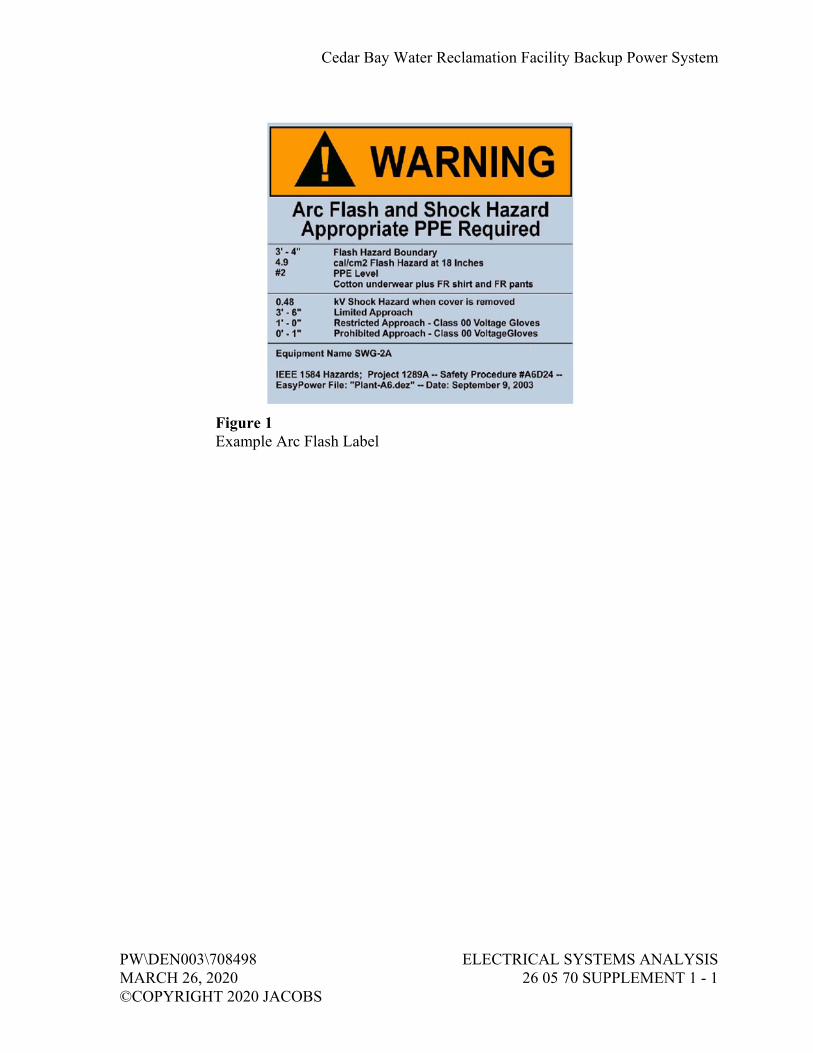
Cedar Bay Water Reclamation Facility Backup Power System
PW\DEN003\708498 ELECTRICAL SYSTEMS ANALYSIS MARCH 26, 2020 26 05 70 SUPPLEMENT 1 - 1 ©COPYRIGHT 2020 JACOBS
Figure 1 Example Arc Flash Label


Cedar Bay Water Reclamation Facility Backup Power System
PW\DEN003\708498 ELECTRICAL SYSTEMS ANALYSIS MARCH 26, 2020 26 05 70 SUPPLEMENT 2 - 1 ©COPYRIGHT 2020 JACOBS
PROCESS ELECTRICAL LOADS
Loads in Backup Power Cedar Bay Wastewater Treatment Plant, JEA Task Order No. 10
Key No.
Major Load Description Item Designation LOAD KVA
Motor Rating
(HP)
LOADS IN BACKUP POWER AT BUILDING 9 LOADS AT EXISTING MCC-100 (UV/REUSE PUMP STATION)
1 Harmonic Conditioner-1 HC-1 1.66 2 UV-PDC-1B 49.88 3 UV-PDC-2D 95.6 4 UV-PDC-2B 57.37 5 Non Potable Water Reuse Pump NPP-901 38.24 50 6 Clarifier CRA-401 1.66 0.25 7 Lighting Transformer (LT-1) 10 8 UV-PDC-2C 99.77 9 Non Potable Water Reuse Pump NPP-902 38.24 50 10 UV-PDC-2A 42.4 11 UV-PDC-1A 41.57 12 SG-103 3.26 2 13 SG-102 3.26 2 14 SG-101 3.26 2 15 Panel (P-1) 2.49 16 SG-105 3.26 2 17 SG-104 3.26 2 18 Harmonic Conditioner-2 HC-2 1.66

Cedar Bay Water Reclamation Facility Backup Power System
PW\DEN003\705890 COMMISSIONING OF ELECTRICAL SYSTEMS MARCH 26, 2020 26 08 00 - 1 ©COPYRIGHT 2020 JACOBS
SECTION 26 08 00 COMMISSIONING OF ELECTRICAL SYSTEMS
PART 1 GENERAL
1.01 REFERENCES
A. The following is a list of standards which may be referenced in this section:
1. ASTM International (ASTM): a. D877/D877M, Standard Test Method for Dielectric Breakdown
Voltage of Insulating Liquids Using Disk Electrodes. b. D923, Standard Practices for Sampling Electrical Insulating
Liquids. c. D924, Standard Test Method for Dissipation Factor (or Power
Factor) and Relative Permittivity (Dielectric Constant) of Electrical Insulating Liquids.
d. D971, Standard Test Method for Interfacial Tension of Oil Against Water by the Ring Method.
e. D974, Standard Test Method for Acid and Base Number by Color-Indicator Titration.
f. D1298, Standard Test Method for Density, Relative Density, or API Gravity of Crude Petroleum and Liquid Petroleum Products by Hydrometer Method.
g. D1500, Standard Test Method for ASTM Color of Petroleum Products (ASTM Color Scale).
h. D1524, Standard Test Method for Visual Examination of Used Electrical Insulating Liquids in the Field.
i. D1533, Standard Test Method for Water in Insulating Liquids by Coulometric Karl Fischer Titration.
j. D1816, Standard Test Method for Dielectric Breakdown Voltage of Insulating Liquids Using VDE Electrodes.
2. Insulated Cable Engineers Association (ICEA): a. S-93-639, Shielded Power Cables 5000V-4600V. b. S-94-649, Concentric Neutral Cables Rated 5 through 46 kV. c. S-97-682, Utility Shielded Power Cables Rated 5 through 46 kV.
3. Institute of Electrical and Electronics Engineers (IEEE): a. 43, Recommended Practice for Testing Insulation Resistance of
Electric Machinery. b. 48, Standard Test Procedures and Requirements for Alternating-
Current Cable Terminators Used on Shielded Cables Having Laminated Insulation Rated 2.5 kV through 765 kV or Extruded Insulation Rated 2.5 kV through 500 kV.
Cedar Bay Water Reclamation Facility Backup Power System
COMMISSIONING OF ELECTRICAL SYSTEMS PW\DEN003\705890 26 08 00 - 2 MARCH 26, 2020 ©COPYRIGHT 2020 JACOBS
c. 81, Guide for Measuring Earth Resistivity, Ground Impedance, and Earth Surface Potentials of a Ground System.
d. 95, Recommended Practice for Insulation Testing of AC Electric Machinery (2300V and Above) with High Direct Voltage.
e. 386, Standard for Separable Insulated Connector Systems for Power Distribution Systems Above 600V.
f. 400, Guide for Field Testing and Evaluation of the Insulation of Shielded Power Cable Systems Rated 5 kV and Above.
g. 450, Recommended Practice for Maintenance, Testing, and Replacement of Vented Lead-Acid Batteries for Stationary Applications.
h. C2, National Electrical Safety Code. i. C37.20.1, Standard for Metal-Enclosed Low-Voltage (1000 Vac
and below, 3200 Vdc and below) Power Circuit Breaker Switchgear.
j. C37.20.2, Standard for Metal-Clad Switchgear. k. C37.20.3, Standard for Metal-Enclosed Interrupter Switchgear. l. C37.23, Standard for Metal-Enclosed Bus. m. C62.33, Standard Test Methods and Performance Values for
Metal-Oxide Varistor Surge Protective Components. 4. National Electrical Manufacturers Association (NEMA):
a. AB 4, Guidelines for Inspection and Preventive Maintenance of Molded Case Circuit Breakers Used in Commercial and Industrial Applications.
b. PB 2, Deadfront Distribution Switchboards. c. WC 74, 5-46 kV Shielded Power Cable for Use in the
Transmission and Distribution of Electric Energy. 5. InterNational Electrical Testing Association (NETA): ATS, Acceptance
Testing Specifications for Electrical Power Equipment and Systems. 6. National Fire Protection Association (NFPA):
a. 70, National Electrical Code (NEC). b. 70B, Recommended Practice for Electrical Equipment
Maintenance. c. 70E, Standard for Electrical Safety in the Workplace. d. 101, Life Safety Code.
7. National Institute for Certification in Engineering Technologies (NICET).
8. Occupational Safety and Health Administration (OSHA): CFR 29, Part 1910, Occupational Safety and Health Standards.

Cedar Bay Water Reclamation Facility Backup Power System
PW\DEN003\705890 COMMISSIONING OF ELECTRICAL SYSTEMS MARCH 26, 2020 26 08 00 - 3 ©COPYRIGHT 2020 JACOBS
1.02 SUBMITTALS
A. Informational Submittals:
1. Submit 30 days prior to performing inspections or tests: a. Schedule for performing inspection and tests. b. Schedule for performing inspection and tests. c. List of references to be used for each test. d. Sample copy of equipment and materials inspection form(s). e. Sample copy of individual device test form. f. Sample copy of individual system test form.
2. Energization Plan: Prior to initial energization of electrical distribution equipment; include the following: a. Owner’s representative sign-off form for complete and accurate
arc flash labeling and proper protective device settings for equipment to be energized.
b. Staged sequence of initial energization of electrical equipment. c. Lock-Out-Tag-Out plan for each stage of the progressive
energization. d. Barricading, signage, and communication plan notifying
personnel of newly energized equipment. 3. Submit test or inspection reports and certificates for each electrical item
tested within 30 days after completion of test. 4. Operation and Maintenance Data:
a. In accordance with Section 01 78 23, Operation and Maintenance Data.
b. After test or inspection reports and certificates have been reviewed by Engineer and returned, insert a copy of each in Operation and Maintenance Manual.
5. Programmable Settings: At completion of Performance Demonstration Test, submit final hardcopy printout and electronic files on compact disc of as-left setpoints, programs, and device configuration files for: a. Protective relays. b. Intelligent overload relays. c. Adjustable frequency drives. d. Power metering devices. e. Uninterruptible power supplies. f. Electrical communications modules.
1.03 QUALITY ASSURANCE
A. Testing Firm Qualifications:
1. Corporately and financially independent organization functioning as an unbiased testing authority.
Cedar Bay Water Reclamation Facility Backup Power System
COMMISSIONING OF ELECTRICAL SYSTEMS PW\DEN003\705890 26 08 00 - 4 MARCH 26, 2020 ©COPYRIGHT 2020 JACOBS
2. Professionally independent of manufacturers, suppliers, and installers of electrical equipment and systems being tested.
3. Employer of engineers and technicians regularly engaged in testing and inspecting of electrical equipment, installations, and systems.
4. Supervising engineer accredited as Certified Electrical Test Technologist by NICET or NETA and having a minimum of 5 years’ testing experience on similar projects.
5. Technicians certified by NICET or NETA. 6. Assistants and apprentices assigned to Project at ratio not to exceed two
certified to one noncertified assistant or apprentice. 7. Registered Professional Engineer to provide comprehensive Project
report outlining services performed, results of such services, recommendations, actions taken, and opinions.
8. In compliance with OSHA CFR 29, Part 1910.7 criteria for accreditation of testing laboratories or a full member company of NETA.
B. Test equipment shall have an operating accuracy equal to or greater than requirements established by NETA ATS.
C. Test Instrument Calibration: In accordance with NETA ATS.
1.04 SEQUENCING AND SCHEDULING
A. Perform inspection and electrical tests after equipment listed herein has been installed.
B. Perform tests with apparatus de-energized whenever feasible.
1. Scheduled with Owner prior to de-energization. 2. Minimized to avoid extended period of interruption to the operating
plant equipment.
C. Notify Owner at least 24 hours prior to performing tests on energized electrical equipment.
PART 2 PRODUCTS (NOT USED)
PART 3 EXECUTION
3.01 GENERAL
A. Perform tests in accordance with requirements of Section 01 91 14, Equipment Testing and Facility Startup.

Cedar Bay Water Reclamation Facility Backup Power System
PW\DEN003\705890 COMMISSIONING OF ELECTRICAL SYSTEMS MARCH 26, 2020 26 08 00 - 5 ©COPYRIGHT 2020 JACOBS
B. Tests and inspections shall establish:
1. Electrical equipment is operational within industry and manufacturer’s tolerances and standards.
2. Installation operates properly. 3. Equipment is suitable for energization. 4. Installation conforms to requirements of Contract Documents and
NFPA 70, NFPA 70E, NFPA 101, and IEEE C2.
C. Perform inspection and testing in accordance with NETA ATS, industry standards, and manufacturer’s recommendations.
A. Set, test, and calibrate protective relays, circuit breakers, fuses, power monitoring meters, and other applicable devices in accordance with values established by the short circuit, coordination and harmonics studies as specified in Section 26 05 70, Electrical Systems Analysis.
B. Adjust mechanisms and moving parts of equipment for free mechanical movement.
C. Adjust and set electromechanical electronic relays and sensors to correspond to operating conditions, or as recommended by manufacturer.
D. Verify nameplate data for conformance to Contract Documents and approved Submittals.
E. Realign equipment not properly aligned and correct unlevelness.
F. Properly anchor electrical equipment found to be inadequately anchored.
G. Tighten accessible bolted connections, including wiring connections, with calibrated torque wrench/screw driver to manufacturer’s recommendations, or as otherwise specified in NETA ATS.
H. Clean contaminated surfaces with cleaning solvents as recommended by manufacturer.
I. Provide proper lubrication of applicable moving parts.
J. Inform Engineer of working clearances not in accordance with NFPA 70.
K. Investigate and repair or replace:
1. Electrical items that fail tests. 2. Active components not operating in accordance with manufacturer’s
instructions. 3. Damaged electrical equipment.

Cedar Bay Water Reclamation Facility Backup Power System
COMMISSIONING OF ELECTRICAL SYSTEMS PW\DEN003\705890 26 08 00 - 6 MARCH 26, 2020 ©COPYRIGHT 2020 JACOBS
L. Electrical Enclosures:
1. Remove foreign material and moisture from enclosure interior. 2. Vacuum and wipe clean enclosure interior. 3. Remove corrosion found on metal surfaces. 4. Repair or replace, as determined by Engineer door and panel sections
having dented surfaces. 5. Repair or replace, as determined by Engineer poor fitting doors and
panel sections. 6. Repair or replace improperly operating latching, locking, or interlocking
devices. 7. Replace missing or damaged hardware. 8. Finish:
a. Provide matching paint and touchup scratches and mars. b. If required due to extensive damage, as determined by Engineer,
refinish entire assembly.
M. Replace fuses and circuit breakers that do not conform to size and type required by the Contract Documents or approved Submittals.
A. Replace transformer insulating oil not in compliance with ASTM D923.
3.02 CHECKOUT AND STARTUP
A. Voltage Field Test:
1. Check voltage at point of termination of power company supply system to Project when installation is essentially complete and is in operation.
2. Check voltage amplitude and balance between phases for loaded and unloaded conditions.
3. Record supply voltage (all three phases simultaneously on same graph) for 24 hours during normal working day: a. Submit Voltage Field Test Report within 5 days of test.
4. Unbalance Corrections: a. Make written request to power company to correct condition if
balance (as defined by NEMA) exceeds 1 percent, or if voltage varies throughout the day and from loaded to unloaded condition more than plus or minus 4 percent of nominal.
b. Obtain written certification from responsible power company official that voltage variations and unbalance are within their normal standards if corrections are not made.
B. Equipment Line Current Tests:
1. Check line current in each phase for each piece of equipment. 2. Make line current check after power company has made final
adjustments to supply voltage magnitude or balance.
Cedar Bay Water Reclamation Facility Backup Power System
PW\DEN003\705890 COMMISSIONING OF ELECTRICAL SYSTEMS MARCH 26, 2020 26 08 00 - 7 ©COPYRIGHT 2020 JACOBS
3. If phase current for a piece of equipment is above rated nameplate current, prepare Equipment Line Phase Current Report that identifies cause of problem and corrective action taken.
3.03 SWITCHGEAR ASSEMBLIES
A. Visual and Mechanical Inspection:
1. Insulator damage and contaminated surfaces. 2. Proper barrier and shutter installation and operation. 3. Proper operation of indicating devices. 4. Improper blockage of air-cooling passages. 5. Proper operation of drawout elements. 6. Integrity and contamination of bus insulation system. 7. Check door and device interlocking system by:
a. Closure attempt of device when door is in OFF or OPEN position. b. Opening attempt of door when device is in ON or CLOSED
position. 8. Check key interlocking systems for:
a. Key captivity when device is in ON or CLOSED position. b. Key removal when device is in ON or CLOSED position. c. Closure attempt of device when key has been removed. d. Correct number of keys in relationship to number of lock
cylinders. e. Existence of other keys capable of operating lock cylinders:
Destroy duplicate sets of keys. 9. Check nameplates for proper identification of:
a. Equipment title and tag number with latest one-line diagram. b. Pushbutton. c. Control switch. d. Pilot light. e. Control relay. f. Circuit breaker. g. Indicating meter.
10. Verify fuse and circuit breaker ratings, sizes, and types conform to those specified.
11. Check bus and cable connections for high resistance by low resistance ohmmeter and calibrated torque wrench or thermographic survey applied to bolted joints. a. Ohmic value to be zero. b. Bolt torque level in accordance with NETA ATS, Table 100.12,
unless otherwise specified by manufacturer. c. Thermographic survey temperature gradient of 2 degrees C, or
less.

Cedar Bay Water Reclamation Facility Backup Power System
COMMISSIONING OF ELECTRICAL SYSTEMS PW\DEN003\705890 26 08 00 - 8 MARCH 26, 2020 ©COPYRIGHT 2020 JACOBS
12. Check operation and sequencing of electrical and mechanical interlock systems by: a. Closure attempt for locked open devices. b. Opening attempt for locked closed devices. c. Key exchange to operate devices in OFF-NORMAL positions.
13. Verify performance of each control device and feature. 14. Control Wiring:
a. Compare wiring to local and remote control and protective devices with elementary diagrams.
b. Proper conductor lacing and bundling. c. Proper conductor identification. d. Proper conductor lugs and connections.
15. Exercise active components. 16. Perform phasing check on double-ended equipment to ensure proper bus
phasing from each source.
B. Electrical Tests:
1. Insulation Resistance Tests: a. Applied megohmmeter dc voltage in accordance with
NETA ATS, Table 100.1. b. Each phase of each bus section. c. Phase-to-phase and phase-to-ground for 1 minute. d. With switches and breakers open. e. With switches and breakers closed. f. Control wiring except that connected to solid state components. g. Insulation resistance values equal to, or greater than, ohmic values
established by manufacturer. 2. Overpotential Tests:
a. Applied ac or dc voltage and test procedure in accordance with IEEE C37.20.2, C37.20.3 and NEMA PB 2. Alternatively, use NETA ATS Table 100.2.
b. Each phase of each bus section. c. Phase-to-phase and phase-to-ground for 1 minute. d. Test results evaluated on a pass/fail basis.
3. Current Injection Tests: a. For entire current circuit in each section. b. Secondary injection for current flow of 1 ampere. c. Test current at each device.
4. Control Wiring: a. Apply secondary voltage to control power and potential circuits. b. Check voltage levels at each point on terminal boards and each
device terminal. 5. Operational Test:
a. Initiate control devices. b. Check proper operation of control system in each section.

Cedar Bay Water Reclamation Facility Backup Power System
PW\DEN003\705890 COMMISSIONING OF ELECTRICAL SYSTEMS MARCH 26, 2020 26 08 00 - 9 ©COPYRIGHT 2020 JACOBS
3.04 PANELBOARDS
A. Visual and Mechanical Inspection: Include the following inspections and related work:
1. Inspect for defects and physical damage, labeling, and nameplate compliance with requirements of up-to-date drawings and panelboard schedules.
2. Exercise and perform operational tests of mechanical components and other operable devices in accordance with manufacturer’s instruction manual.
3. Check panelboard mounting, area clearances, and alignment and fit of components.
4. Check tightness of bolted electrical connections with calibrated torque wrench. Refer to manufacturer’s instructions for proper torque values.
5. Perform visual and mechanical inspection for overcurrent protective devices.
B. Electrical Tests: Include the following items performed in accordance with manufacturer’s instruction:
1. Insulation Resistance Tests: a. Applied megohmmeter dc voltage in accordance with
NETA ATS, Table 100.1. b. Each phase of each bus section. c. Phase-to-phase and phase-to-ground for 1 minute. d. With switches and breakers open. e. With switches and breakers closed. f. Control wiring except that connected to solid state components. g. Insulation resistance values equal to, or greater than, ohmic values
established by manufacturer. 2. Ground continuity test ground bus to system ground.
3.05 DRY TYPE TRANSFORMERS
A. Visual and Mechanical Inspection:
1. Physical and insulator damage. 2. Proper winding connections. 3. Bolt torque level in accordance with NETA ATS, Table 100.12, unless
otherwise specified by manufacturer. 4. Defective wiring. 5. Proper operation of fans, indicators, and auxiliary devices. 6. Removal of shipping brackets, fixtures, or bracing. 7. Free and properly installed resilient mounts. 8. Cleanliness and improper blockage of ventilation passages.

Cedar Bay Water Reclamation Facility Backup Power System
COMMISSIONING OF ELECTRICAL SYSTEMS PW\DEN003\705890 26 08 00 - 10 MARCH 26, 2020 ©COPYRIGHT 2020 JACOBS
9. Verify tap-changer is set at correct ratio for rated output voltage under normal operating conditions.
10. Verify proper secondary voltage phase-to-phase and phase-to-ground after energization and prior to loading.
B. Electrical Tests:
1. Insulation Resistance Tests: a. Applied megohmmeter dc voltage in accordance with
NETA ATS, Table 100.5 for each: 1) Winding-to-winding. 2) Winding-to-ground.
b. Test Duration: 10 minutes with resistances tabulated at 30 seconds, 1 minute, and 10 minutes.
c. Results temperature corrected in accordance with NETA ATS, Table 100.14.
d. Temperature corrected insulation resistance values equal to, or greater than, ohmic values established by manufacturer.
e. Insulation resistance test results to compare within 1 percent of adjacent windings.
2. Perform tests and adjustments for fans, controls, and alarm functions as suggested by manufacturer.
3.06 LOW VOLTAGE CABLES, 600 VOLTS MAXIMUM
A. Visual and Mechanical Inspection:
1. Inspect each individual exposed power cable No. 6 and larger for: a. Physical damage. b. Proper connections in accordance with single-line diagram. c. Cable bends not in conformance with manufacturer’s minimum
allowable bending radius where applicable. d. Color coding conformance with specification. e. Proper circuit identification.
2. Mechanical Connections for: a. Proper lug type for conductor material. b. Proper lug installation. c. Bolt torque level in accordance with NETA ATS, Table 100.12,
unless otherwise specified by manufacturer. 3. Shielded Instrumentation Cables for:
a. Proper shield grounding. b. Proper terminations. c. Proper circuit identification.

Cedar Bay Water Reclamation Facility Backup Power System
PW\DEN003\705890 COMMISSIONING OF ELECTRICAL SYSTEMS MARCH 26, 2020 26 08 00 - 11 ©COPYRIGHT 2020 JACOBS
4. Control Cables for: a. Proper termination. b. Proper circuit identification.
5. Cables Terminated Through Window Type CTs: Verify neutrals and grounds are terminated for correct operation of protective devices.
B. Electrical Tests for Conductors No. 6 and Larger:
1. Insulation Resistance Tests: a. Utilize 1,000-volt dc megohmmeter for 600-volt insulated
conductors. b. Test each conductor with respect to ground and to adjacent
conductors for 1 minute. c. Evaluate ohmic values by comparison with conductors of same
length and type. d. Investigate values less than 50 megohms.
2. Continuity test by ohmmeter method to ensure proper cable connections.
3.07 SAFETY SWITCHES, 600 VOLTS MAXIMUM
A. Visual and Mechanical Inspection:
1. Proper blade pressure and alignment. 2. Proper operation of switch operating handle. 3. Adequate mechanical support for each fuse. 4. Proper contact-to-contact tightness between fuse clip and fuse. 5. Cable connection bolt torque level in accordance with NETA ATS,
Table 100.12. 6. Proper phase barrier material and installation. 7. Verify fuse sizes and types correspond to one-line diagram or approved
Submittals. 8. Perform mechanical operational test and verify electrical and
mechanical interlocking system operation and sequencing.
B. Electrical Tests:
1. Insulation Resistance Tests: a. Applied megohmmeter dc voltage in accordance with
NETA ATS, Table 100.1. b. Phase-to-phase and phase-to-ground for 1 minute on each pole. c. Insulation resistance values equal to, or greater than, ohmic values
established by manufacturer.

Cedar Bay Water Reclamation Facility Backup Power System
COMMISSIONING OF ELECTRICAL SYSTEMS PW\DEN003\705890 26 08 00 - 12 MARCH 26, 2020 ©COPYRIGHT 2020 JACOBS
2. Contact Resistance Tests: a. Contact resistance in microhms across each switch blade and fuse
holder. b. Investigate deviation of 50 percent or more from adjacent poles or
similar switches.
3.08 MOLDED AND INSULATED CASE CIRCUIT BREAKERS
A. General: Inspection and testing limited to circuit breakers rated 100 amperes and larger and to motor circuit protector breakers rated 100 amperes and larger.
B. Visual and Mechanical Inspection:
1. Proper mounting. 2. Proper conductor size. 3. Feeder designation according to nameplate and one-line diagram. 4. Cracked casings. 5. Connection bolt torque level in accordance with NETA ATS,
Table 100.12. 6. Operate breaker to verify smooth operation. 7. Compare frame size and trip setting with circuit breaker schedules or
one-line diagram. 8. Verify that terminals are suitable for 75 degrees C rated insulated
conductors.
C. Electrical Tests:
1. Insulation Resistance Tests: a. Utilize 1,000-volt dc megohmmeter for 480-volt and 600-volt
circuit breakers. b. Pole-to-pole and pole-to-ground with breaker contacts opened for
1 minute. c. Pole-to-pole and pole-to-ground with breaker contacts closed for
1 minute. d. Test values to comply with NETA ATS, Table 100.1.
2. Contact Resistance Tests: a. Contact resistance in microhms across each pole. b. Investigate deviation of 50 percent or more from adjacent poles
and similar breakers. 3. Primary Current Injection Test to Verify:
a. Long-time minimum pickup and delay. b. Short-time pickup and delay. c. Ground fault pickup and delay. d. Instantaneous pickup by run-up or pulse method.
Cedar Bay Water Reclamation Facility Backup Power System
PW\DEN003\705890 COMMISSIONING OF ELECTRICAL SYSTEMS MARCH 26, 2020 26 08 00 - 13 ©COPYRIGHT 2020 JACOBS
e. Trip characteristics of adjustable trip breakers shall be within manufacturer’s published time-current characteristic tolerance band, including adjustment factors.
f. Trip times shall be within limits established by NEMA AB 4, Table 5-3. Alternatively, use NETA ATS, Table 100.7.
g. Instantaneous pickup value shall be within values established by NEMA AB 4, Table 5-4. Alternatively, use NETA ATS, Table 100.8.
3.09 LOW VOLTAGE POWER CIRCUIT BREAKERS
A. Visual and Mechanical Inspection:
1. Proper mounting, cell fit, and element alignment. 2. Proper operation of racking interlocks. 3. Check for damaged arc chutes. 4. Proper contact condition. 5. Bolt torque level in accordance with NETA ATS, Table 100.12. 6. Perform mechanical operational and contact alignment tests in
accordance with manufacturer’s instructions. 7. Check operation of closing and tripping functions of trip devices by
activating ground fault relays, undervoltage shunt relays, and other auxiliary protective devices.
8. Verify primary and secondary contact wipe, gap setting, and other dimensions vital to breaker operation are correct.
9. Check charging motor, motor brushes, associated mechanism, and limit switches for proper operation and condition.
10. Check operation of electrically operated breakers in accordance with manufacturer’s instructions.
11. Check for adequate lubrication on contact, moving, and sliding surfaces.
B. Electrical Tests:
1. Insulation Resistance Tests: a. Utilize 1,000-volt dc megohmmeter for 480-volt and 600-volt
circuit breakers. b. Pole-to-pole and pole-to-ground with breaker contacts opened for
1 minute. c. Pole-to-pole and pole-to-ground with breaker contacts closed for
1 minute. d. Test values to comply with NETA ATS, Table 100.1.
2. Contact Resistance Tests: a. Contact resistance in microhms across each pole. b. Investigate deviation of 50 percent or more from adjacent poles
and similar breakers.

Cedar Bay Water Reclamation Facility Backup Power System
COMMISSIONING OF ELECTRICAL SYSTEMS PW\DEN003\705890 26 08 00 - 14 MARCH 26, 2020 ©COPYRIGHT 2020 JACOBS
3. Primary Current Injection Test to Verify: a. Long-time minimum pickup and delay. b. Short-time pickup and delay. c. Ground fault pickup and delay. d. Instantaneous pickup by run-up or pulse method. e. Trip characteristic when adjusted to setting sheet parameters shall
be within manufacturer’s published time-current tolerance band.
3.10 PROTECTIVE RELAYS
A. Visual and Mechanical Inspection:
1. Visually check each relay for: a. Tight cover gasket and proper seal. b. Unbroken cover glass. c. Condition of spiral spring and contacts. d. Disc clearance. e. Condition of case shorting contacts if present.
2. Mechanically check each relay for: a. Freedom of movement. b. Proper travel and alignment.
3. Verify each relay: a. Complies with Contract Documents, approved Submittal, and
application. b. Is set in accordance with recommended settings from
Coordination Study.
B. Electrical Tests:
1. Insulation resistance test on each circuit to frame, except for solid state devices.
2. Test on nominal recommended setting for: a. Pickup parameters on each operating element. b. Timing at three points on time-current curve. c. Pickup target and seal-in units. d. Special tests as required to check operation of restraint,
directional, and other elements in accordance with manufacturer’s instruction manual.
3. Phase angle and magnitude contribution tests on differential and directional relays after energization to vectorially verify proper polarity and connections.
4. Current Injection Tests: a. For entire current circuit in each section. b. Secondary injection for current flow of 1 ampere. c. Test current at each device.

Cedar Bay Water Reclamation Facility Backup Power System
PW\DEN003\705890 COMMISSIONING OF ELECTRICAL SYSTEMS MARCH 26, 2020 26 08 00 - 15 ©COPYRIGHT 2020 JACOBS
3.11 INSTRUMENT TRANSFORMERS
A. Visual and Mechanical Inspection:
1. Visually check current, potential, and control transformers for: a. Cracked insulation. b. Broken leads or defective wiring. c. Proper connections. d. Adequate clearances between primary and secondary circuit
wiring. 2. Verify Mechanically:
a. Grounding and shorting connections have good contact. b. Withdrawal mechanism and grounding operation, when
applicable, operate properly. 3. Verify proper primary and secondary fuse sizes for potential
transformers.
B. Electrical Tests:
1. Current Transformer Tests: a. Insulation resistance test of transformer and wiring-to-ground at
1,000 volts dc for 30 seconds. b. Polarity test. c. Ratio and accuracy test.
2. Potential Transformer Tests: a. Insulation resistance test at test voltages in accordance with
NETA ATS, Table 100.9, for 1 minute on: 1) Winding-to-winding. 2) Winding-to-ground.
b. Polarity test to verify polarity marks or H1-X1 relationship as applicable.
c. Ratio and accuracy test. 3. Insulation resistance measurement on instrument transformer shall not
be less than that shown in NETA ATS, Table 100.5.
3.12 METERING
A. Visual and Mechanical Inspection:
1. Verify meter connections in accordance with appropriate diagrams. 2. Verify meter multipliers. 3. Verify meter types and scales conform to Contract Documents. 4. Check calibration of meters at cardinal points. 5. Check calibration of electrical transducers.

Cedar Bay Water Reclamation Facility Backup Power System
COMMISSIONING OF ELECTRICAL SYSTEMS PW\DEN003\705890 26 08 00 - 16 MARCH 26, 2020 ©COPYRIGHT 2020 JACOBS
3.13 GROUNDING SYSTEMS
A. Visual and Mechanical Inspection:
1. Equipment and circuit grounds in motor control center, panelboards, and switchgear assemblies for proper connection and tightness.
2. Ground bus connections in motor control center, panelboard, and switchgear assemblies for proper termination and tightness.
3. Effective transformer core and equipment grounding. 4. Accessible connections to grounding electrodes for proper fit and
tightness. 5. Accessible exothermic-weld grounding connections to verify that molds
were fully filled and proper bonding was obtained.
B. Electrical Tests:
1. Fall-of-Potential Test: a. In accordance with IEEE 81, Section 8.2.1.5 for measurement of
main ground system’s resistance. b. Main ground electrode system resistance to ground to be no
greater than 3 ohm(s). 2. Two-Point Direct Method Test:
a. In accordance with IEEE 81, Section 8.2.1.1 for measurement of ground resistance between main ground system, equipment frames, and system neutral and derived neutral points.
b. Equipment ground resistance shall not exceed main ground system resistance by 0.25 ohm.
3.14 GROUND FAULT SYSTEMS
A. Inspection and testing limited to:
1. Zero sequence grounding systems. 2. Residual ground fault systems.
B. Visual and Manual Inspection:
1. Neutral main bonding connection to ensure: a. Zero sequence sensing system is grounded ahead of neutral
disconnect link. b. Ground strap sensing system is grounded through sensing device. c. Neutral ground conductor is solidly grounded.
2. Verify control power has adequate capacity for system.
Cedar Bay Water Reclamation Facility Backup Power System
PW\DEN003\705890 COMMISSIONING OF ELECTRICAL SYSTEMS MARCH 26, 2020 26 08 00 - 17 ©COPYRIGHT 2020 JACOBS
3. Manually operate monitor panels for: a. Trip test. b. No trip test. c. Nonautomatic rest.
4. Zero sequence system for symmetrical alignment of core balance transformers about current carrying conductors.
5. Relay check for pickup and time under simulated ground fault conditions.
6. Verify nameplate identification by device operation.
C. Electrical Tests:
1. Test system neutral insulation resistance with neutral ground link removed; minimum 1 megohm.
2. Determine relay pickup by primary current injection at the sensor. Relay pickup current within plus or minus 10 percent of device dial or fixed setting.
3. Test relay timing by injecting 300 percent of pick-up current or as specified by manufacturer. Relay operating time in accordance with manufacturer’s time-current characteristic curves.
4. Test system operation at 55 percent rated control voltage, if applicable. 5. Test zone interlock system by simultaneous sensor current injection and
monitoring zone blocking functions.
3.15 AC INDUCTION MOTORS
A. General: Inspection and testing limited to motors rated 5 hp and larger.
B. Visual and Mechanical Inspection:
1. Proper electrical and grounding connections. 2. Shaft alignment. 3. Blockage of ventilating air passageways. 4. Operate motor and check for:
a. Excessive mechanical and electrical noise. b. Overheating. c. Correct rotation. d. Check vibration detectors, resistance temperature detectors, or
motor inherent protectors for functionability and proper operation. e. Excessive vibration, in excess of values in NETA ATS,
Table 100.10. 5. Check operation of space heaters.

Cedar Bay Water Reclamation Facility Backup Power System
COMMISSIONING OF ELECTRICAL SYSTEMS PW\DEN003\705890 26 08 00 - 18 MARCH 26, 2020 ©COPYRIGHT 2020 JACOBS
C. Electrical Tests:
1. Insulation Resistance Tests: a. In accordance with IEEE 43 at test voltages established by
NETA ATS, Table 100.1 for: 1) Motors above 200 horsepower for 10-minute duration with
resistances tabulated at 30 seconds, 1 minute, and 10 minutes.
2) Motors 200 horsepower and less for 1-minute duration with resistances tabulated at 30 seconds and 60 seconds.
b. Insulation resistance values equal to, or greater than, ohmic values established by manufacturers.
2. Calculate polarization index ratios for motors above 200 horsepower. Investigate index ratios less than 1.5 for Class A insulation and 2.0 for Class B insulation.
3. Insulation resistance test on insulated bearings in accordance with manufacturer’s instructions.
4. Measure running current and voltage, and evaluate relative to load conditions and nameplate full-load amperes.
5. Overpotential Tests: a. Applied ac or dc voltage and test procedure in accordance with
IEEE C37.20.2, C37.20.3 and NEMA PB 2. Alternatively, use NETA ATS Table 100.2.
b. Each phase of each bus section. c. Phase-to-phase and phase-to-ground for 1 minute. d. Test results evaluated on a pass/fail basis.
6. Current Injection Tests: a. For entire current circuit in each section. b. Secondary injection for current flow of 1 ampere. c. Test current at each device.
7. Control Wiring: a. Apply secondary voltage to control power and potential circuits. b. Check voltage levels at each point on terminal boards and each
device terminal. 8. Operational Test:
a. Initiate control devices. b. Check proper operation of control system in each section.
3.16 LOW-VOLTAGE MOTOR CONTROL
A. Visual and Mechanical Inspection:
1. Proper barrier and shutter installation and operation. 2. Proper operation of indicating and monitoring devices. 3. Proper overload protection for each motor.

Cedar Bay Water Reclamation Facility Backup Power System
PW\DEN003\705890 COMMISSIONING OF ELECTRICAL SYSTEMS MARCH 26, 2020 26 08 00 - 19 ©COPYRIGHT 2020 JACOBS
4. Improper blockage of air-cooling passages. 5. Proper operation of drawout elements. 6. Integrity and contamination of bus insulation system. 7. Check door and device interlocking system by:
a. Closure attempt of device when door is in OFF or OPEN position. b. Opening attempt of door when device is in ON or CLOSED
position. 8. Check nameplates for proper identification of:
a. Equipment title and tag number with latest one-line diagram. b. Pushbuttons. c. Control switches. d. Pilot lights. e. Control relays. f. Circuit breakers. g. Indicating meters.
9. Verify fuse and circuit breaker sizes and types conform to Contract Documents.
10. Verify current and potential transformer ratios conform to Contract Documents.
11. Check bus connections for high resistance by low resistance ohmmeter and calibrated torque wrench applied to bolted joints or thermographic survey: a. Ohmic value to be zero. b. Bolt torque level in accordance with NETA ATS, Table 100.12,
unless otherwise specified by manufacturer. c. Thermographic survey temperature gradient of 2 degrees C, or
less per NETA ATS Table 100.18. 12. Check operation and sequencing of electrical and mechanical interlock
systems by: a. Closure attempt for locked open devices. b. Opening attempt for locked closed devices. c. Key exchange to operate devices in OFF-NORMAL positions.
13. Check operation and sequencing of electrical and mechanical interlock systems by: a. Closure attempt for locked open devices. b. Opening attempt for locked closed devices. c. Key exchange to operate devices in OFF-NORMAL positions.
14. Verify performance of each control device and feature furnished as part of motor control center.
15. Control Wiring: a. Compare wiring to local and remote control, and protective
devices with elementary diagrams. b. Check for proper conductor lacing and bundling. c. Check for proper conductor identification. d. Check for proper conductor lugs and connections.

Cedar Bay Water Reclamation Facility Backup Power System
COMMISSIONING OF ELECTRICAL SYSTEMS PW\DEN003\705890 26 08 00 - 20 MARCH 26, 2020 ©COPYRIGHT 2020 JACOBS
16. Exercise active components. 17. Inspect contactors for:
a. Correct mechanical operations. b. Correct contact gap, wipe, alignment, and pressure. c. Correct torque of connections.
18. Compare overload heater rating with full-load current for proper size. 19. Compare motor protector and circuit breaker with motor characteristics
for proper size. 20. Perform phasing check on double-ended motor control centers to ensure
proper bus phasing from each source.
B. Electrical Tests:
1. Insulation Resistance Tests: a. Applied megohmmeter dc voltage in accordance with
NETA ATS, Table 100.1. b. Bus section phase-to-phase and phase-to-ground for 1 minute on
each phase. c. Contactor phase-to-ground and across open contacts for 1 minute
on each phase. d. Starter section phase-to-phase and phase-to-ground on each phase
with starter contacts closed and protective devices open. e. Test values to comply with NETA ATS, Table 100.1.
2. Current Injection through Overload Unit at 300 Percent of Motor Full-Load Current and Monitor Trip Time: a. Trip time in accordance with manufacturer’s published data. b. Investigate values in excess of 120 seconds.
3. Control Wiring Tests: a. Apply secondary voltage to control power and potential circuits. b. Check voltage levels at each point on terminal board and each
device terminal. c. Insulation resistance test at 1,000 volts dc on control wiring,
except that connected to solid state components; 1 megohm minimum insulation resistance.
4. Operational test by initiating control devices to affect proper operation.
3.17 AUTOMATIC TRANSFER SWITCHES
A. Visual and Mechanical Inspection:
1. Check doors and panels for proper interlocking. 2. Check connections for high resistance by low resistance ohmmeter
and calibrated torque wrench applied to bolted joints. 3. Check positive mechanical and electrical interlock between normal and
alternate sources.

Cedar Bay Water Reclamation Facility Backup Power System
PW\DEN003\705890 COMMISSIONING OF ELECTRICAL SYSTEMS MARCH 26, 2020 26 08 00 - 21 ©COPYRIGHT 2020 JACOBS
4. Check for proper operation: a. Manual transfer function switch. b. Generator under load and nonload conditions. c. Auto-exerciser of generator under load and no-load conditions.
5. Verify settings and operation of control devices.
B. Electrical Tests:
1. Insulation Resistance Tests: a. Applied megohmmeter dc voltage in accordance with
NETA ATS, Table 100.1, for each phase with switch CLOSED in both source positions.
b. Phase-to-phase and phase-to-ground for 1 minute. c. Test values in accordance with manufacturer’s published data.
2. Contact Resistance Test: a. Contact resistance in microhms across each switch blade for both
source positions. b. Investigate values exceeding 500 micro-ohms. c. Investigate values deviating from adjacent pole by more than
50 percent. 3. Set and calibrate in accordance with Specifications, Manufacturer’s
recommendations and Coordination Study: a. Voltage and frequency sensing relays. b. Time delay relays. c. Engine start and shutdown relays.
4. Perform automatic transfer tests by: a. Simulating loss of normal power. b. Return to normal power. c. Simulating loss of alternate power. d. Simulating single-phase conditions for normal and alternate
sources. 5. Monitor and verify operation and timing of:
a. Normal and alternate voltage sensing relays. b. Engine-start sequence. c. Timing delay upon transfer and retransfer. d. Engine cool down and shutdown. e. Interlocks and limit switch functions. f. Engine cool down and shutdown feature.
3.18 BATTERY SYSTEM
A. Visual and Mechanical Inspection:
1. Physical damage and electrolyte leakage. 2. Evidence of corrosion.

Cedar Bay Water Reclamation Facility Backup Power System
COMMISSIONING OF ELECTRICAL SYSTEMS PW\DEN003\705890 26 08 00 - 22 MARCH 26, 2020 ©COPYRIGHT 2020 JACOBS
3. Intercell bus link integrity. 4. Battery cable insulation damage and contaminated surfaces. 5. Operating conditions of ventilating equipment. 6. Visual check of electrolyte level.
B. Electrical Tests:
1. Measure: a. Bank charging voltage. b. Individual cell voltage. c. Electrolyte specific gravity in each cell. d. Measured test values to be in accordance with manufacturer’s
published data. 2. Verify during recharge mode:
a. Charging rates from charger. b. Individual cell acceptance of charge.
3. Load tests for integrity and capacity; test values in accordance with IEEE 450.
3.19 LOW VOLTAGE SURGE ARRESTORS
A. Visual and Mechanical Inspection:
1. Adequate clearances between arrestors and enclosures. 2. Ground connections to ground bus.
B. Electrical Tests:
1. Varistor Type Arrestors: a. Clamping voltage test. b. Rated RMS voltage test. c. Rated dc voltage test. d. Varistor arrestor test values in accordance with IEEE C62.33,
Section 4.4 and Section 4.9.
3.20 STANDBY GENERATOR SYSTEMS
A. Visual and Mechanical Inspection:
1. Proper grounding. 2. Blockage of ventilating passageways. 3. Proper operation of jack water heaters. 4. Integrity of engine cooling and fuel supply systems. 5. Excessive mechanical and electrical noise. 6. Overheating of engine or generator.

Cedar Bay Water Reclamation Facility Backup Power System
PW\DEN003\705890 COMMISSIONING OF ELECTRICAL SYSTEMS MARCH 26, 2020 26 08 00 - 23 ©COPYRIGHT 2020 JACOBS
7. Proper installation of vibration isolators. 8. Proper cooling liquid type and level. 9. Operate engine-generator and check for:
a. Excessive mechanical and electrical noise. b. Overheating. c. Correct rotation. d. Check resistance temperature detectors or generator inherent
thermal protectors for functionability and proper operation. e. Excessive vibration.
10. Verify voltage regulator and governor operation will cause unit speed and output voltage to stabilize at proper values within reasonable length of time.
11. Proper operation of meters and instruments. 12. Compare generator nameplate rating and connection with one-line
diagram or approved Submittal. 1. Verify engine-generator operation with adjustable frequency drives
energized and operating under normal load conditions.
B. Electrical and Mechanical Tests:
1. Cold start test by interrupting normal power source with test load consisting of connected building load to verify: a. Transfer switch operation. b. Automatic starting operation. c. Operating ability of engine-generator. d. Overcurrent devices capability to withstand inrush currents.
2. Phase rotation tests. 3. Test engine protective shutdown features for:
a. Low oil pressure. b. Overtemperature. c. Overspeed.
4. Load bank test with resistors for each load step. Record voltage, frequency, load current, oil pressure, and engine coolant temperature at 15-minute intervals: a. 25 percent applied load for 30 minutes. b. 50 percent applied load for 30 minutes. c. 75 percent applied load for 30 minutes. d. 100 percent applied load for 3 hours. e. Load test results to demonstrate ability of unit to deliver rated load
for test period. 5. One-Step Rated kW Load Pickup Test:
a. Perform test immediately after performing load bank test. b. Apply rated load, minus largest rated hp motor, to generator. c. Start largest rated horsepower motor and record voltage drop for
20 cycles minimum with high-speed chart recorder or digital storage oscilloscope.

Cedar Bay Water Reclamation Facility Backup Power System
COMMISSIONING OF ELECTRICAL SYSTEMS PW\DEN003\705890 26 08 00 - 24 MARCH 26, 2020 ©COPYRIGHT 2020 JACOBS
d. Compare voltage drop with maximum allowable voltage dip for specified starting situation.
3.21 UNINTERRUPTIBLE POWER SUPPLIES (UPS)
A. UPS Start-up Inspection and Testing:
1. Visual Inspection: a. Inspect equipment for signs of damage. b. Verify installation per Drawings. c. Inspect cabinets for foreign objects. d. Verify neutral and ground conductors are properly sized and
configured per vendor requirements as noted in vendor drawings supplied with installation manuals or submittal package.
e. Inspect all battery cell cases. f. Inspect each cell for proper polarity.
2. Mechanical Inspection: a. Check all control wiring connections for tightness. b. Check all power wiring connections for tightness. c. Check all terminal screws, nuts, and spade lugs for tightness.
3. Electrical Inspection: a. Check all fuses for continuity. b. Confirm input bypass voltage and phase rotation is correct. c. Verify control transformer connections are correct for voltages
being used. d. Assure connections and voltage of the battery string(s). e. Battery inspection and certification according to IEEE standards.
4. Unit Start-Up: a. Energize control power. b. Perform control/logic checks and adjust to meet manufacturer
specification. c. Verify DC float and equalize voltage levels. d. Verify DC voltage clamp and over-voltage shutdown levels. e. Verify battery discharge, low-battery warning, and low-battery
shutdown levels. f. Verify fuse monitor alarms and system shutdown. g. Verify inverter voltages and regulation circuits. h. Verify inverter/bypass sync circuits and set overlap time. i. Perform manual transfers and returns. j. Simulate utility outage at no load. k. Verify proper recharge.

Cedar Bay Water Reclamation Facility Backup Power System
PW\DEN003\705890 COMMISSIONING OF ELECTRICAL SYSTEMS MARCH 26, 2020 26 08 00 - 25 ©COPYRIGHT 2020 JACOBS
B. Provide test instruments to record elapsed time between transfers, voltage, current, frequency, waveform, and transients.
1. Include services of an experienced technician to make final adjustments, final connections, and perform final testing.
2. Evidence of transients or phase shifts in graphs will be cause for rejection of system.
3.22 THERMOGRAPHIC SURVEY
A. Provide a thermographic survey per NETA ATS Table 100.18 of connections associated with incoming service conductors, bus work, and branch feeder conductors No. 2 and larger at each:
1. Low voltage switchgear. 2. Low voltage motor control center. 3. Panelboard.
B. Provide a thermographic survey of feeder conductors No. 4 and larger terminating at:
1. Motors rated 50 hp and larger. 2. Low voltage disconnect switches. 3. Transfer switches. 4. Engine-generators.
C. Remove necessary enclosure metal panels and covers prior to performing survey.
D. Perform with equipment energized during periods of maximum possible loading per NFPA 70B, Section 20.17.
E. Do not perform survey on equipment operating at less than 20 percent of rated load.
F. Utilize thermographic equipment capable of:
1. Detecting emitted radiation. 2. Converting detected radiation to visual signal. 3. Detecting 1 degree C temperature difference between subject area and
reference point of 30 degrees C.
G. Temperature Gradients:
1. 3 degrees C to 7 degrees C indicates possible deficiency that warrants investigation.

Cedar Bay Water Reclamation Facility Backup Power System
COMMISSIONING OF ELECTRICAL SYSTEMS PW\DEN003\705890 26 08 00 - 26 MARCH 26, 2020 ©COPYRIGHT 2020 JACOBS
2. 7 degrees C to 15 degrees C indicates deficiency that is to be corrected as time permits.
3. 16 degrees C and above indicates deficiency that is to be corrected immediately.
H. Provide written report of:
1. Areas surveyed and the resultant temperature gradients. 2. Locations of areas having temperature gradients of 3 degrees C or
greater. 3. Cause of heat rise and actions taken to correct the cause of heat rise. 4. Detected phase unbalance.
END OF SECTION

Cedar Bay Water Reclamation Facility Backup Power System
PW\DEN003\705890 POWER MEASUREMENT AND CONTROL MARCH 26, 2020 26 09 13 - 1 ©COPYRIGHT 2020 JACOBS
SECTION 26 09 13 POWER MEASUREMENT AND CONTROL
PART 1 GENERAL
1.01 REFERENCES
A. The following is a list of standards which may be referenced in this section:
1. American National Standards Institute (ANSI). 2. National Electrical Manufacturers Association (NEMA):
a. C12.1, Electric Meters Code for Electricity Metering. b. 250, Enclosures for Electrical Equipment (1,000 Volts
Maximum).
1.02 DEFINITIONS
A. CT: Current Transformer.
B. DNP: Distributed Network Protocol.
C. LCD: Liquid Crystal Display.
D. LED: Light Emitting Diode.
E. MPR: Motor Protection Relay.
F. PLC: Programmable Logic Controller.
G. PT: Potential Transformer.
H. RTD: Resistance Temperature Detectors.
I. UCA: Utility Communications Architecture.
1.03 SUBMITTALS
A. Action Submittals:
1. Instruction manuals for each type of device. 2. Special features, licensed programming software. 3. Potential and current schematic diagrams. 4. Control and metering schematic diagrams. 5. Interconnection wiring diagrams. 6. Installation and mounting requirements. 7. Complete descriptive literature and renewal parts data.

Cedar Bay Water Reclamation Facility Backup Power System
POWER MEASUREMENT AND CONTROL PW\DEN003\705890 26 09 13 - 2 MARCH 26, 2020 ©COPYRIGHT 2020 JACOBS
B. Informational Submittals:
1. Programming software used to configure devices, along with settings files necessary to reload or revise settings as left by Contractor.
2. Operation and Maintenance Data as specified in Section 01 78 23, Operation and Maintenance Data.
PART 2 PRODUCTS
2.01 DIGITAL POWER METER (DPM)
A. General:
1. Solid state device with LED displays. 2. Direct voltage input up to 600V ac. 3. Current input via current transformer with 5-ampere secondary. 4. Programmable current and potential transformer ratios. 5. Programmable limits to activate up to four alarms. 6. Selectable Voltage Measurements: Line-to-line or line-to-neutral and
wye or delta. 7. Ethernet Modbus TCP.
B. Simultaneous Display:
1. Volts, 3-phase. 2. Amperes, 3-phase. 3. Kilowatts. 4. Kilowatt hours. 5. Ethernet/IP communications network capable. 6. Frequency. 7. kW Demand with programmable period intervals. 8. kVA. 9. kVAR. 10. kVARh. 11. Manufacturer: SIEMENS, Model PAC4200, no substitution with the
following expansion cards: a. 7KM9200-0AB00-0AA0 = Expansion card Port No. 1 4DI/2DO. b. 7KM9300-0AE01-0AA0 = Expansion card Port No. 2 ProfiNET
Card.
2.02 INSTRUMENT TRANSFORMERS
A. Current Transformer (CT), 600 Volts and Below:
1. Type: Molded bar or donut. 2. Accuracy: 0.6 percent for metering. 3. Shorting type terminal boards for current transformer leads.

Cedar Bay Water Reclamation Facility Backup Power System
PW\DEN003\705890 POWER MEASUREMENT AND CONTROL MARCH 26, 2020 26 09 13 - 3 ©COPYRIGHT 2020 JACOBS
B. Potential Transformer (PT), 600 Volts and Below:
1. Type: Molded. 2. Accuracy Classification: 0.3 at burden imposed by meters and
instruments, including future. 3. Primary Fuses: Two, current-limiting. 4. Secondary Fuses: One, current-limiting.
PART 3 EXECUTION
3.01 INSTALLATION
A. In accordance with manufacturer’s written instructions.
B. As defined in Section 26 08 00, Commissioning of Electrical Systems.
3.02 MANUFACTURER’S SERVICES
A. See Section 01 43 33, Manufacturers’ Field Services, and Section 01 91 14, Equipment Testing and Facility Startup.
END OF SECTION


Cedar Bay Water Reclamation Facility Backup Power System
PW\DEN003\705890 LOW-VOLTAGE TRANSFORMERS MARCH 26, 2020 26 22 00 - 1 ©COPYRIGHT 2020 JACOBS
SECTION 26 22 00 LOW-VOLTAGE TRANSFORMERS
PART 1 GENERAL
1.01 REFERENCES
A. The following is a list of standards which may be referenced in this section:
1. Code of Federal Regulations (CFR): 10 CFR Part 431, DOE 2016 efficiency.
2. Institute of Electrical and Electronics Engineers (IEEE): C57.96, Guide for Loading Dry Type Transformers.
3. National Electrical Contractor’s Association (NECA): 409, Recommended Practice for Installing and Maintaining Dry-Type Transformers.
4. National Electrical Manufacturers Association (NEMA): a. 250, Enclosures for Electrical Equipment (1000 Volts Maximum). b. ST 20, Dry-Type Transformers for General Applications.
5. National Fire Protection Association (NFPA): 70, National Electrical Code (NEC).
6. Underwriters Laboratories, Inc. (UL): a. 486E, Standard for Equipment Wiring Terminals for use with
Aluminum and/or Copper Conductors. b. 489, Standard for Molded-Case Circuit Breakers, Molded-Case
Switches, and Circuit Breaker Enclosures. c. 1561, Standard for Dry-Type, General Purpose, and Power
Transformers.
1.02 SUBMITTALS
A. Action Submittals:
1. Descriptive information. 2. Dimensions and weight. 3. Transformer nameplate data, including efficiency. 4. Schematic and connection diagrams.
B. Informational Submittals:
1. Anchorage and bracing calculations as required by Section 01 88 15, Anchorage and Bracing.
2. Test Report: Sound test certification for dry type power transformers (0 volt to 600 volt, primary).
3. Component and attachment testing seismic certificate of compliance as required by Division 01, General Requirements.

Cedar Bay Water Reclamation Facility Backup Power System
LOW-VOLTAGE TRANSFORMERS PW\DEN003\705890 26 22 00 - 2 MARCH 26, 2020 ©COPYRIGHT 2020 JACOBS
PART 2 PRODUCTS
2.01 GENERAL
A. UL 1561, NEMA ST 20, unless otherwise indicated.
B. Dry-type, self-cooled, two-winding, with copper windings.
C. Units larger than 5 kVA suitable for use with 75 degrees C wire at full NFPA 70, 75 degrees C ampacity.
A. Efficiency: Meet or exceed values in Table 4.2 of NEMA TP 1.
B. Maximum Sound Level per NEMA ST 20:
1. 40 decibels for 0 kVA to 9 kVA. 2. 45 decibels for 10 kVA to 50 kVA. 3. 50 decibels for 51 kVA to 150 kVA. 4. 55 decibels for 151 kVA to 300 kVA. 5. 60 decibels for 301 kVA to 500 kVA.
C. Overload capability: Short-term overload per IEEE C57.96.
D. Wall Bracket: For single-phase units, 15 kVA to 37-1/2 kVA, and for three-phase units, 15 kVA to 30 kVA.
E. Vibration Isolators:
1. Rated for transformer’s weight. 2. Isolation Efficiency: 99 percent, at fundamental frequency of sound
emitted by transformer. 3. Less than 30 kVA: Isolate entire unit from structure with external
vibration isolators. 4. 30 kVA and Above: Isolate core and coil assembly from transformer
enclosure with integral vibration isolator.
F. Manufacturers:
1. General Electric Co. 2. Square D Co. 3. Eaton/Cutler-Hammer. 4. Or approved equal.

Cedar Bay Water Reclamation Facility Backup Power System
PW\DEN003\705890 LOW-VOLTAGE TRANSFORMERS MARCH 26, 2020 26 22 00 - 3 ©COPYRIGHT 2020 JACOBS
2.02 MINI-POWER CENTER (MPC)
A. General: Transformer, primary and secondary main circuit breakers, and secondary panelboard section enclosed in NEMA 250, Type 3R, Type 316 stainless steel enclosure.
B. Transformer:
1. Insulation Class and Temperature Rise: Manufacturer’s standard. 2. Core and Coil: Encapsulated. 3. Full Capacity, 2-1/2 percent voltage taps, two above and two below
normal voltage. 4. Primary Voltage: 480V, three-phase, unless otherwise shown. 5. Secondary Voltage: 208/120V three-phase, four-wire unless otherwise
shown.
C. Panelboard: Full UL 489, short-circuit current rated.
1. Type: Thermal magnetic quick-make, quick-break, indicating, with noninterchangeable molded case circuit breaker.
2. Number and Breaker Ampere Ratings: Refer to panel schedule in Drawings.
2.03 GENERAL PURPOSE TRANSFORMER
A. Insulation Class and Temperature Rise: Manufacturer’s standard.
B. Core and Coil:
1. Encapsulated for single-phase units 1/2 kVA to 25 kVA and for three-phase units 3 kVA to 15 kVA.
2. Thermosetting varnish impregnated for single-phase units 37.5 kVA and above, and for three-phase units 30 kVA and above.
C. Enclosure:
1. Single-Phase, 3 kVA to 25 kVA: NEMA 250, Type 3R, nonventilated. 2. Single-Phase, 37-1/2 kVA and Above: NEMA 250, Type 2, ventilated. 3. Three-Phase, 3 kVA to 15 kVA: NEMA 250, Type 3R, nonventilated. 4. Three-Phase, 30 kVA and Above: NEMA 250, Type 2, ventilated. 5. Outdoor Locations: NEMA 250, Type 3R. 6. Corrosive Locations: NEMA 250, Type 3R stainless steel.

Cedar Bay Water Reclamation Facility Backup Power System
LOW-VOLTAGE TRANSFORMERS PW\DEN003\705890 26 22 00 - 4 MARCH 26, 2020 ©COPYRIGHT 2020 JACOBS
D. Voltage Taps:
1. Single-Phase, 3 kVA to 10 kVA: Four 2-1/2 percent, full capacity; two above and two below normal voltage rating.
2. Single-Phase, 15 kVA and Above: Four 2-1/2 percent, full capacity; two above and two below normal voltage rating.
3. Three-Phase, 3 kVA to 15 kVA: Four 2-1/2 percent, full capacity; two above and two below normal voltage rating.
4. Three-Phase, 30 kVA and Above: Four 2-1/2 percent, full capacity; two above and two below normal voltage rating.
E. Impedance: 4.5 percent minimum on units 75 kVA and larger.
PART 3 EXECUTION
3.01 INSTALLATION
A. Install in accordance with NECA and manufacturer’s instructions.
B. Load external vibration isolator such that no direct transformer unit metal is in direct contact with mounting surface.
C. Provide moisture-proof, flexible conduit for electrical connections.
D. Connect voltage taps to achieve (approximately) rated output voltage under normal plant load conditions.
E. Provide wall brackets for single-phase units, 15 kVA to 167-1/2 kVA, and three-phase units, 15 kVA to 30 kVA.
F. Isolation Transformer: Ground isolation shields to unit enclosure with conductor of same material, and same size minimum, as shield ground lead provided with unit.
END OF SECTION

Cedar Bay Water Reclamation Facility Backup Power System
PW\DEN003\705890 LOW-VOLTAGE SWITCHBOARD MARCH 26, 2020 26 24 13 - 1 ©COPYRIGHT 2020 JACOBS
SECTION 26 24 13 LOW-VOLTAGE SWITCHBOARD
PART 1 GENERAL
1.01 REFERENCES
A. The following is a list of standards which may be referenced in this section:
1. American National Standards Institute (ANSI): C37.50, Switchgear—Low-Voltage AC Power Circuit Breakers Used in Enclosures—Test Procedures.
2. Institute of Electrical and Electronics Engineers (IEEE): a. C37.13, Standard for Low-Voltage AC Power Circuit Breakers
Used in Enclosures. b. C37.16, Standard for Preferred Ratings, Related Requirements,
and Application Recommendation for Low-Voltage AC (635V and below) and DC (3200V and below) Power Circuit Breakers.
c. C37.20.1, Standard for Metal-Enclosed Low-Voltage Power Circuit Breaker Switchgear.
d. C37.20.3, Standard for Metal Enclosed Interrupter Switchgear. e. C37.100, Standard Definitions for Power Switchgear.
3. National Electrical Manufacturers Association (NEMA): 250, Enclosures for Electrical Equipment (1,000 Volts Maximum).
4. National Fire Protection Association (NFPA): 70, National Electrical Code (NEC).
5. Underwriters Laboratories, Inc. (UL): a. 489, Standard for Safety for Molded-Case Circuit Breakers,
Molded-Case Switches, and Circuit-Breaker Enclosures. b. 891, Standard for Safety Switchboards.
1.02 WORK INCLUDED
A. This section does not stand alone. Read this section with Section 26 32 13.13, Diesel Engine Generator Set. Coordinate all Generator Control System requirements with the low-voltage switchboard control and protection schemes to provide a completely coordinated overall system.
1.03 SUBMITTALS
A. Action Submittals:
1. Descriptive product information. 2. Itemized Bill of Material. 3. Dimensional drawings. 4. Operational description.

Cedar Bay Water Reclamation Facility Backup Power System
LOW-VOLTAGE SWITCHBOARD PW\DEN003\705890 26 24 13 - 2 MARCH 26, 2020 ©COPYRIGHT 2020 JACOBS
5. Anchoring instructions and details. 6. One-line, three-line, and control schematic drawings. 7. Connection and interconnection drawings, including interconnection
with generator system control panels. 8. Bus data. 9. Conduit entrance locations. 10. Mimic bus layout. 11. Electrical schematic for the generator/switchboard control panel. 12. Complete electrical elementary control and connection diagrams
covering the electrical devices and functions provided with the switchboard an in the generator/switchboard control panel.
13. Interconnect wiring diagrams showing wiring between the engine generator control panel, and the switchboard control panel.
14. Sequence of operations for the generator control system including step-by-step descriptions of each operating mode. Descriptions shall also include the system’s response to an abnormal condition or response failure.
15. Catalog cuts of all major equipment items, accessories, and instrumentation and control items and a bill-of-materials of miscellaneous equipment.
16. Short circuit and coordination study are provided in Section 26 05 70B, Electrical System Analysis. Vendor shall coordinate any proposed settings for the multi-function digital protective relays required for the switchboard and generator protection.
B. Informational Submittals:
1. Compilation of final or as-shipped Shop Drawing information specified above.
2. Seismic anchorage and bracing calculations as required by Section 01 88 15, Anchorage and Bracing.
3. Manufacturer’s installation instructions. 4. Certified Factory Test Report. 5. Operation and Maintenance Data: As specified in Section 01 78 23,
Operation and Maintenance Data. 6. Manufacturer’s Certificate of Proper Installation, in accordance with
Section 01 43 33, Manufacturers’ Field Services.
1.04 QUALITY ASSURANCE
A. Authority Having Jurisdiction (AHJ):
1. Provide the Work in accordance with NFPA 70, National Electrical Code (NEC). Where required by the AHJ, material and equipment shall be labeled or listed by a nationally recognized testing laboratory or other organization acceptable to the AHJ in order to provide a basis for approval under NEC.

Cedar Bay Water Reclamation Facility Backup Power System
PW\DEN003\705890 LOW-VOLTAGE SWITCHBOARD MARCH 26, 2020 26 24 13 - 3 ©COPYRIGHT 2020 JACOBS
2. Materials and equipment manufactured within the scope of standards published by Underwriters Laboratories, Inc. shall conform to those standards and shall have an applied UL listing mark.
1.05 EXTRA MATERIALS
A. Furnish, tag, and box for shipment and storage the following spare parts:
1. Power and Control Fuses: One complete set. 2. Indicating Lights: One complete set. 3. Paint: One pint, to match enclosure exterior finish in color and quality. 4. Indicating Lamp Pullers: Two each. 5. Indicating Lamp Resistors and Sockets: Two each.
PART 2 PRODUCTS
2.01 MANUFACTURER:
A. Square D/ Schneider Electric.
B. Cutler Hammer/Eaton.
C. Siemens.
D. Asea Brown Boveri (ABB).
2.02 GENERAL REQUIREMENTS
A. Service: 480Y/277 volts, three-phase, four-wire solid grounded wye, having an available short circuit current at line terminals as shown on Drawings.
B. Generator neutral to be brought to switchboard and bonded to ground bus to make a no-separately derived standby generator system.
C. Designed and assembled in accordance with UL 981, IEEE C37.20.3, IEEE C37.100, and ANSI C37.50.
D. Switchboard and its major components shall be end products of one manufacturer in order to achieve standardization for appearance, operation and maintenance, spare parts replacement, and manufacturer’s services.
E. Operating Conditions:
1. Ambient Temperature: Maximum 40 degrees C. 2. Equipment shall be fully rated without derating for operating conditions.
F. Lifting lugs on equipment and devices weighing over 100 pounds.
Cedar Bay Water Reclamation Facility Backup Power System
LOW-VOLTAGE SWITCHBOARD PW\DEN003\705890 26 24 13 - 4 MARCH 26, 2020 ©COPYRIGHT 2020 JACOBS
G. Anchor Bolts: Type 316 stainless steel, sized by equipment manufacturer, and as specified in Section 05 50 00, Metal Fabrications.
2.03 STATIONARY STRUCTURE
A. Type: NEMA PB-2 and UL-891 switchboard construction, consisting of breaker, transition, and auxiliary sections assembled to form a rigid, self-supporting, metal enclosed structure.
B. Material: 11-gauge minimum cold-rolled steel, formed with reinforced steel members.
C. Grounded metal barriers between each breaker, main bus, branch cabling, and instrumentation/control.
D. Modular-designed steel frame with removable plates and individual, bolted, steel-framed vertical sections.
E. Individual, hinged doors over each breaker, metering, and auxiliary compartments.
F. Cable Installation and Termination Compartments:
1. Rear hinged doors, capable of being bolted closed. 2. Cable bending space in accordance with NFPA 70. 3. Cable supports in each vertical section.
G. Breaker Compartments:
1. Individual, grounded compartments, with: a. Sheet steel, top, bottom, sides, and ventilated compartment door
with padlocking features. b. Flame-retardant, arc track-resistant nonmetallic rear barrier. c. Drawout rails, stationary breaker contacts, interlocks, and
necessary control and indicating devices. d. Shutters over stationary contacts when breaker is in TEST or
DISCONNECT position. e. Padlocking provision on rackout rails for locking breaker in TEST
or DISCONNECT position. 2. Drawout Mechanism:
a. Shall retain removable element in connected position. b. Mechanical interlocks to ensure breaker is open before moved
from a position, or when between positions. c. Four Distinct Breaker Positions: CONNECTED, TEST,
DISCONNECTED, and WITHDRAW.

Cedar Bay Water Reclamation Facility Backup Power System
PW\DEN003\705890 LOW-VOLTAGE SWITCHBOARD MARCH 26, 2020 26 24 13 - 5 ©COPYRIGHT 2020 JACOBS
d. Indicators to display breaker position. e. Capable of being operated without opening breaker door.
3. Breaker frame grounded to steel frame throughout travel of drawout mechanism.
4. Each compartment designed for specific breaker frame size.
H. Auxiliary sections equipped with devices shown on Drawings, auxiliary relays, potential transformers, and control transformers, with hinged door over each compartment.
2.04 ENCLOSURE
A. Finish: Baked enamel applied over rust-inhibiting phosphated base coating.
1. Color: a. Exterior/Interior: Provide manufacturer’s standard gray finish. b. Unpainted Parts: Plated for corrosion resistance.
B. Indoor Enclosure:
1. NEMA 250, Type 1, with formed edges on hinged and nonhinged panels.
2. Rear, full-height, bolt-on panels for each enclosure section. 3. Cable Termination Access: Padlock provision.
C. Outdoor Enclosure
1. NEMA 250, Type 4X, with formed edges on hinged and nonhinged panels.
2. Rear, full-height, bolt-on panels for each enclosure section. 3. Cable Termination Access: Padlock provision.
2.05 BUSWORK
A. Material: Phase isolated and insulated tin or silver-plated copper throughout entire length of sufficient cross section to limit temperature rise at rated current to 55 degrees C.
B. Bus Arrangement: A-B-C, left-to-right, top-to-bottom, and front-to-rear, as viewed from front.
C. Brace for short circuit currents as shown on drawings.
D. Main Horizontal Bus: Nontapered, continuous current rating as shown.

Cedar Bay Water Reclamation Facility Backup Power System
LOW-VOLTAGE SWITCHBOARD PW\DEN003\705890 26 24 13 - 6 MARCH 26, 2020 ©COPYRIGHT 2020 JACOBS
E. Neutral Bus: Continuous current rating minimum 50 percent of main horizontal bus rating.
F. Ground Bus:
1. Material: Tin or silver-plate copper. 2. Rating: 800 amperes minimum. 3. Bolted to each vertical section. 4. Ground lug for 4/0 copper conductor on each end of bus. 5. Bus Connections and Joints: Bolted, with Belleville or conical type
washers.
G. Extend each bus entire length of switchboard.
2.06 PROTECTIVE DEVICES
A. Power Air Circuit Breakers:
1. Mains and Generator breakers in accordance with IEEE C37.13 and IEEE C37.16.
2. Arrangement: Fully rated circuit breakers. 3. Three-pole electrically and mechanically trip-free with:
a. Self-aligning primary and secondary contacts. b. Integral, solid state, over-current trip programmer. c. Arc quenchers. d. Closing Mechanism: Electric. e. Stored energy mechanism with maximum five-cycle closing. f. Solid state trip device.
4. Individually mounted, drawout breaker listed for 100 percent continuous ampere rating.
5. Frame Size: Amperes as shown on drawings. 6. Interrupting Rating: 65,000 amperes rms symmetrical at 480 volts.
B. Mechanical Operation:
1. Front mounted, spring charging handle. 2. Mechanical closing escutcheon mounted pushbutton. 3. Mechanical trip, escutcheon mounted, trip pushbutton handle.
C. Electrical Operation:
1. Motor or solenoid automatic charging, plus manual charging. 2. Electrically closing, escutcheon mounted pushbutton with mechanical
closing upon loss of control power. 3. Electrical trip, escutcheon mounted, trip pushbutton. 4. Control Power Voltage: 120V ac.

Cedar Bay Water Reclamation Facility Backup Power System
PW\DEN003\705890 LOW-VOLTAGE SWITCHBOARD MARCH 26, 2020 26 24 13 - 7 ©COPYRIGHT 2020 JACOBS
D. Color-Coded Visual Indicators: Contacts OPEN and CLOSED, plus mechanism CHARGED and DISCHARGED.
E. Accessories:
1. Breaker lifting hoist and travel rail on top of switchboard. 2. Auxiliary a/b contacts on mains and generator breakers. 3. Shunt trip for main breakers.
F. Solid State Trip Units: Flux-shift trip and current sensors.
1. Protective Programmers: a. Self-powered, automatic rms sensing micro-electronic processor. b. No external relays or accessories. c. Printed circuit cards with gold-plated contacts. d. Programmable Controls:
1) Fixed-point, with repetitive accuracy and precise unit settings.
2) Trip adjustments made by nonremovable, discrete step switching.
e. Field-Installable Rating Plugs: 1) Long-time pickup LED indicator and test receptacle. 2) Matching load and cable requirements. 3) Interlocked with tripping mechanism. 4) Breaker to remain trip-free with plug removed. 5) Keyed rating plugs to prevent incorrect application.
f. Long-time pickup light. g. Selective coordination time/current curve shaping adjustable
functions: 1) Current setting. 2) Long-time pickup. 3) Long-time delay. 4) Instantaneous pickup. 5) Short-time pickup. 6) Short-time delay with I2T function, and IN-OUT switch. 7) Ground fault pickup where indicated. 8) Ground fault delay with I2T function when ground fault
pickup is provided. 9) High instantaneous pickup with short-time delay. 10) Zone selective interlock.
h. Fixed, instantaneous pickup. i. Fault Trip Indicators: Mechanical push-to-reset type for overload
and short circuit overload plus ground fault trip. j. Rejection Pins: For each programmer frame size.

Cedar Bay Water Reclamation Facility Backup Power System
LOW-VOLTAGE SWITCHBOARD PW\DEN003\705890 26 24 13 - 8 MARCH 26, 2020 ©COPYRIGHT 2020 JACOBS
2. To meet the requirements of NEC 240.87, trip units for breakers 1200A frame or greater shall each be equipped with the arc flash reduction maintenance system. The arc flash reduction maintenance system shall allow the operator to turn front-of-door-mounted switches to enable a maintenance mode which implements a preset accelerated instantaneous override trip to reduce arc flash energy for the respective circuit breaker cubicle. An LED or indicator flag on the trip unit shall indicate the trip unit is in the maintenance mode.
3. Phase Current Sensors: a. Multi ratio or Single-ratio type. b. Fixed, mounted on breaker frame. c. Molded epoxy construction. d. One toroidal type for each phase.
4. Ground Fault Sensor: a. Neutral bar single-ratio CT mounted in cable compartment. b. Molded epoxy construction. c. Shorting bar.
5. Ground fault relays for double-ended, multiply grounded configurations shall be fully responsive to ground fault currents returning to either Source And shall not respond to line-to-neutral currents.
G. Provide hard wire interlock between the two main incoming breakers and the generator breaker of Switchboard (SWBD) 4A such that two breakers cannot be closed simultaneously when one breakers is closed.
H. Provide hard wire interlock between the two main incoming breakers, tie breaker, and the generator breaker of MCC-100 such that:
a. Either one or two utility main breakers cannot be closed when generator breaker is closed.
b. Tie breaker and generator breaker cannot be closed when both utility main breakers are closed.
c. If either one of the two utility breakers and tie breaker are closed no other breaker can be closed.
2.07 SURGE PROTECTION DEVICE
A. General:
1. Unless indicated otherwise SPD devices shall be direct bus connected and factory installed inside the distribution equipment.
2. SPD devices shall be capable of performance at ambient temperatures between minus 40 degrees C and 60 degrees C, at relative humidity ranging from 0 percent to 95 percent, and at altitudes ranging from sea level to 12,000 feet.
Cedar Bay Water Reclamation Facility Backup Power System
PW\DEN003\705890 LOW-VOLTAGE SWITCHBOARD MARCH 26, 2020 26 24 13 - 9 ©COPYRIGHT 2020 JACOBS
3. Design SPD devices to protect all modes (L-L, L-N, L-G, N-G) of the electrical system being utilized
4. Provide SPD meeting IEEE C62.41.1 and IEEE C62.41.2 Location in accordance with Category C. Provide SPDs with the following monitoring and diagnostics: a. LED-type indication lights to show the normal and failed status of
each protected phase. b. Surge event counter. c. Form C dry contact which operates when the unit fails.
5. Provide UL Type 2 SPDs. 6. EMI/RFI Noise Suppression: Minus 50dB attenuation at 100 kHz, tested
per MIL-STD 220B. 7. Voltage Protection Rating (VPR): 1200 L-N, N-G, L-G and L-L.
B. Surge Current Capacity: Service Entrance: 240 kA per phase; 120 kA per mode.
C. Maximum Continuous Operating Voltage (MCOV): Not less than 115 percent of the nominal system voltage.
D. Nominal Discharge Current (IN): 20 kA.
2.08 CONTROL WIRING
A. NFPA 70, Type SIS, single-conductor, Class B, stranded copper, rated 600 volts for control, instrumentation, and power/current circuits.
B. Shielded cable rated 600 volts for transducer output and analog circuits.
C. Enclosed in top and vertical steel wiring troughs, and front-to-rear in nonmetallic wiring troughs.
D. Conductor Lugs: Preinsulated, self-locking, spade type, with reinforced sleeves.
E. Identification: Individually, with permanent wire markers at each end.
F. Splices: Not permitted in switchboard wiring.
2.09 TERMINAL BLOCKS
A. Enclosed in steel wiring troughs.
B. Rated 600 volts, 30 amperes minimum, one-piece barrier type with strap screws.
C. Shorting type for current transformer leads.

Cedar Bay Water Reclamation Facility Backup Power System
LOW-VOLTAGE SWITCHBOARD PW\DEN003\705890 26 24 13 - 10 MARCH 26, 2020 ©COPYRIGHT 2020 JACOBS
D. Provide terminal blocks for:
1. Conductors connecting to circuits external to switchboard. 2. Internal circuits crossing shipping splits. 3. Equipment parts requiring replacement and maintenance.
E. Spare Terminals: Not less than 20 percent.
F. Group terminal blocks for external circuit wiring leads.
G. Maintain 6-inch minimum space between columns of terminal blocks.
H. Identification: Permanent, for each terminal and columns of terminals blocks.
I. Manufacturer: General Electric; Type EB-5.
2.10 INSTRUMENTATION AND METERING
A. Current Transformer (CT), 600 Volts and Below:
1. Type: Molded bar or donut. 2. Accuracy: 0.3 at burden imposed by meters and instruments. 3. Shorting type terminal boards for current transformer leads.
B. Potential Transformer (PT), 600 Volts and Below:
1. Type: Molded. 2. Accuracy Classification: 0.3 at burden imposed by meters and
instruments, including future. 3. Primary Fuses: Two, current-limiting. 4. Secondary Fuses: One, current-limiting.
C. Power Meter:
1. Manufacturer: Siemens 2. Model: PAC4200, No substitution.
2.11 PROTECTIVE RELAYS
A. Main Management Relay (MMR):
1. MMR shall provide primary protection and management of utility main breakers. Protection elements shall include: 27, 47, 59, 81U/O.
2. Provide drawout construction to facilitate testing, maintenance, and interchange flexibility.
3. Power from the 120V ac control power transformer.

Cedar Bay Water Reclamation Facility Backup Power System
PW\DEN003\705890 LOW-VOLTAGE SWITCHBOARD MARCH 26, 2020 26 24 13 - 11 ©COPYRIGHT 2020 JACOBS
4. Operate with either wye-connected (four-wire) or open-delta-connected (three-wire) potential transformers, and three-phase, four-wire connected current transformers.
5. Control shall include manual close control, cold load pickup control, programmable logic inputs, two breaker control relay outputs, internal failure relay output, programmable relay outputs, solid state trip output, analog transducer input, and analog transducer outputs.
6. Power metering functions shall be accessible on the front-of-panel user interface and transmitted over the Ethernet data port.
7. User interfaces shall include: a. Large 40-character display, navigation keys, and keypad. b. Indicator LEDs on front panel which provide a quick visual
indication of status. c. Front panel RS232 serial port that provides easy computer access. d. Two rear RS485 ports, one of which can be configured as a
RS422 port. e. RJ45 Ethernet port to allow 10BaseT Ethernet connectivity to
local or wide area networks. f. Relay capable of being set by Windows-based, easy to use setup
graphical terminal interface. 8. Manufacturers and Products: Schweitzer Engineering Laboratories;
SEL-351, or equal.
B. Generator Protection Relay (GPR):
1. Primary protection for generator shall be integrated digital relay package suitable for incorporation into integrated station control system. Protection elements shall include: 27, 59, 81U/O.
2. Provide drawout construction to facilitate testing, maintenance, and interchange flexibility.
3. User Interface: a. Large 40-character display, navigation keys, and keypad. b. Indicator LEDs on front panel which provide a quick visual
indication of status. c. Front panel RS232 serial port that provides easy computer access. d. Two rear RS485 ports, one of which can be configured as a
RS422 port. e. RJ45 Ethernet port to allow 10BaseT Ethernet connectivity to
local or wide area networks. f. Relay capable of being set by Windows-based, easy to use setup
graphical terminal interface. 4. Power from 120V ac control power transformer. 5. Manufacturers and Products: Schweitzer Engineering Laboratories;
SEL-300G or equal.

Cedar Bay Water Reclamation Facility Backup Power System
LOW-VOLTAGE SWITCHBOARD PW\DEN003\705890 26 24 13 - 12 MARCH 26, 2020 ©COPYRIGHT 2020 JACOBS
C. Phase Balance Relay (47N/27):
1. Input: a. Voltage: 480 volts. b. Frequency: 60Hz. c. Burden: Less than 2VA. d. Overload: 1.5 times nominal continuous, 2 times nominal for 3 sec.
2. Output: a. Relay type: DPDT. b. AC Rating: 250V, 5A, nonresistive, 1200VA. c. DC Rating: 125V, 1A, resistive, 120 watts.
3. Manufacturer and Product: Basler; BE-47N/27.
2.12 CONTROL POWER SYSTEMS
A. Provide one 120V ac control power transformer, for switchboard bus, to power the circuit breaker spring charging motors and the 120V controls.
2.13 EQUIPMENT IDENTIFICATION
A. Master Nameplate:
1. Deep-etched aluminum, phenolic, or plastic with manufacturer’s name and model number.
2. Riveted or fastened with stainless steel screws to main vertical section.
B. Section Identification:
1. Stamped metallic, phenolic, or plastic riveted or fastened with stainless steel screws to each vertical section.
2. Serial number, bus rating, and section reference number. 3. Size: Manufacturer’s standard.
C. Nameplate:
1. Engraved, phenolic for each circuit breaker cubicle and door-mounted device.
2. White with black block type characters. 3. Character Height: 1/4-inch. 4. Size: Manufacturer’s standard. 5. Inscriptions: As shown on one-line diagram. 6. Blank plates for future spaces. 7. Attachment Screws: Stainless steel panhead.
D. Cubicle Labels:
1. Nonmetallic, applied inside each cubicle compartment. 2. Device serial number, rating, and description. 3. Size: As required.

Cedar Bay Water Reclamation Facility Backup Power System
PW\DEN003\705890 LOW-VOLTAGE SWITCHBOARD MARCH 26, 2020 26 24 13 - 13 ©COPYRIGHT 2020 JACOBS
E. Metering Instruments: Meter type identified on meter face below pointer or dial.
F. Control Switches: Deep-etched aluminum, phenolic, or plastic escutcheon plate.
G. Relays and Devices:
1. Stamped metallic, phenolic, or plastic riveted to instrument case. 2. Manufacturer’s name, model number, relay type, and rating data.
H. Switchboard Signs:
1. Two signs each on front and back of switchboard. 2. Size: Manufacturer’s standard. 3. Engraved, phenolic. 4. Color: Red with white characters. 5. Inscription: DANGER/HIGH VOLTAGE/KEEP OUT. 6. Characters: Gothic type, 2 inches high. 7. Attachment: Four rivets or stainless-steel screws each sign.
I. Mimic Bus:
1. One-line displaying Bus Arrangement, circuit protective devices, and branch circuit extensions.
2. Provide breaker status indicating lights on cubicle door. 3. Buses: 3/8-inch wide, with red colored strips. 4. Devices: 3/8-inch wide, with red colored strips. 5. Strips: Self-sticking plastic tape, applied to face of switchboard. 6. Nameplates to identify incoming lines, protective devices, and feeder
circuits.
2.14 GENERATOR CONTROL SYSTEM
A. The system shall consist of the necessary breakers and controls for automatic operation of one engine generator and for open-transition transfer operations between the two Utility Sources and the generator. See Drawing E-80-604, E-80-605, and Section 26 32 13.13, Diesel Engine Generator Sets, for reference.
1. The control system is PLC-based consisting of a PLC in the master control panel and distributed I/O (or PLC) for each main and generator breaker. The remote I/O rack (or PLC) in the Automatic Transfer Control Panel (ATC) shall communicate with the local Engine Control Panel (ECP). The engine control panel shall include manufacturer’s standard microprocessor that allows communications with the master PLC.

Cedar Bay Water Reclamation Facility Backup Power System
LOW-VOLTAGE SWITCHBOARD PW\DEN003\705890 26 24 13 - 14 MARCH 26, 2020 ©COPYRIGHT 2020 JACOBS
2. Configure the system so that should there be a complete PLC failure then the operator could manually operate the generator and manually connect it to the distribution system (circuit breaker switch).
3. Provide master PLCs meeting the following requirements: a. Solid state dc powered Programmable Logic Controller (PLC);
programmable in the field. PLC logic shall meet all functional requirements specified herein. Reference standard.
b. PLC architecture shall consist of two main PLC, operating simultaneously as a main and a backup in hot standby mode. PLC redundancy features and configuration shall meet requirements specified in Section 40 99 90, Supplement 2.
c. Provide PLC program on removable either Compact Flash or Secure Digital EEPROM memory that does not require a battery backup and can be moved to a replacement processor.
d. PLC replacement parts should be commonly available from local distributors.
e. Establish and configure data link between the PLC and the local mounted HMI and Plant SCADA servers. Coordinate with system integrator.
f. Provide ProfiNET communications between the PLC and the Plant SCADA system for monitoring of the Generator/Switchboard system. Provide necessary hardware and software to establish this communication link. Provide read and write bit and word locations within the PLC memory. Coordinate all data exchange with the Plant SCADA system with the PICS subcontractor.
g. Provide PLC with an ProfiNET certified communications module. h. Provide PLC with all required local and remote I/O and
communications modules to meet all requirements shown and specified.
B. Master Control Panel:
1. Provide a complete freestanding control panel assembly for operation and control of the standby generation system. The control panel sections shall be UL 508 Listed. For other requirements see Section 40 99 90, Package Control Systems.
2. Provide the following operator interface devices: a. Manual-Off-Auto (MOA) keyed selector switch. Dedicated
hardwire switch on panel door is required. b. One 19-inch minimum touchscreen HMIs. c. Meet all graphic screening requirements specified herein.
3. Provide all other control device and instrument functions indicated in this section, shown on Drawings, and as required for satisfactory operation as touchscreen elements on the HMIs.

Cedar Bay Water Reclamation Facility Backup Power System
PW\DEN003\705890 LOW-VOLTAGE SWITCHBOARD MARCH 26, 2020 26 24 13 - 15 ©COPYRIGHT 2020 JACOBS
4. Panel control power shall be 120V ac. Provide a 120V ac power supply/converter that is backed up by the generator.
5. Send dry contact run command to the diesel generator system.
C. Provide manufacturer graphic screens for the generator control system touchscreen HMIs. Graphics screens shall follow Owners standard Specified in Section 40 96 90, Application Software. Provide graphic screens for all functional requirements including:
1. Overall online diagram showing breaker positions and power flow including dynamic display of kW, Volts, Amps and PF data for each bus. Include max kW Demand and kWh for each source for user-defined time intervals.
2. Generator data screen showing engine and alternator data including the basic functions listed below. Generator and alternator data shall be acquired over the data link between the engine control panel and/or generator controller and PLC-SWBD. a. ac voltmeter, scale as required. b. Voltmeter switch. c. ac ammeter, scale as required. d. Ammeter switch. e. ac wattmeter, scale as required. f. Circuit breaker control switch. g. Running time meter. h. Frequency meter, 55-Hz to 65-Hz scale. i. Voltage control potentiometer. j. Engine control switch with OFF-AUTO-MAN (NO LOAD
TEST)-MAN (LOAD BANK TEST) nameplate. k. Reset button. l. Annunciator with the following Alarms:
1) Low lube oil pressure, shutdown. 2) High water temperature, shutdown. 3) Overcrank, shutdown. 4) Overspeed, shutdown. 5) Overcurrent (breaker trip), shutdown. 6) Reverse power, shutdown. 7) Fail to synchronize, shutdown. 8) High water temperature, alarm. 9) Low lube oil pressure, alarm. 10) Battery charger failure, alarm. 11) Engine not in AUTO, flashing status. 12) Engine running, status. 13) Circuit breaker open, status. 14) Circuit breaker closed, status. 15) Overvoltage, shutdown. 16) Undervoltage, alarm.

Cedar Bay Water Reclamation Facility Backup Power System
LOW-VOLTAGE SWITCHBOARD PW\DEN003\705890 26 24 13 - 16 MARCH 26, 2020 ©COPYRIGHT 2020 JACOBS
17) Loss of field. 18) Fuel Tank Low Level, Low-Low Level, and Low Level
Shutdown. 19) Fuel Tank High Level and High-High Level. 20) Fuel Tank Leak. 21) Water detected in fuel filter.
m. Totalize fuel consumption on a daily, monthly, and yearly basis. 3. System control screen showing each control mode and allowing for
control mode selection. 4. Control screen for each mode of control as described in the sequence of
operations. 5. Alarm summary visible on a small band on one side of each screen. 6. Alarm screen showing alarm history log with date stamp, time stamp,
and alarm status. Include at least the following minimum alarms: a. Generator bus under frequency. b. Generator bus over frequency. c. Generator bus undervoltage. d. Generator bus overvoltage. e. System not in auto. f. Start signal received. g. System under test. h. PLC malfunction. i. Low battery voltage. j. Breaker open/closed for mains and generator breakers. k. Normal light available per phase (typical for Utility Sources A
and B). l. Horn silence.
7. Provide power meter functions for each main utility breaker and generator main breaker.
D. Provide the generator control system with a Manual-Off-Auto (MOA) selector switch (keyed). When the MOA switch is in the Off position, the generator cannot be operated.
E. When the MOA switch of the 250kW generator is in the Auto position, provide for the following automatic modes of operation:
1. Loss of Utility Source A with SWBD-4A on Utility Source A. 2. Return of Utility Source A with SWBD-4A on Utility Source B. 3. Loss of Utility Source B with SWBD-4A on Utility Source A. 4. Return of Utility Source B with SWBD-4A on Utility Source A. 5. Simultaneous loss of both Utility Sources. 6. Return of Utility Source A with SWBD-4A on generator power. 7. Return of Utility Source B with SWBD-4A on generator power. 8. Simultaneous return of both Utility Sources with SWBD-4A on
generator power.

Cedar Bay Water Reclamation Facility Backup Power System
PW\DEN003\705890 LOW-VOLTAGE SWITCHBOARD MARCH 26, 2020 26 24 13 - 17 ©COPYRIGHT 2020 JACOBS
F. When the MOA switch of the 600kW generator is in the Auto position, provide for the following automatic modes of operation:
1. Loss of Utility Source A with Bus A and Bus B of MCC-100 on Utility Sources A and B.
2. Return of Utility Source A with Bus A and Bus B of MCC-100 on Utility Source B.
3. Loss of Utility Source B with Bus A and Bus B of MCC-100 on Utility Sources A and B.
4. Return of Utility Source B with Bus A and Bus B of MCC-100 on Utility Source A.
5. Simultaneous loss of both Utility Sources. 6. Return of Utility Source A with MCC-100 on generator power. 7. Return of Utility Source B with MCC-100 on generator power. 8. Simultaneous return of both Utility Sources with MCC-100 on generator
power.
G. Also, when the MOA switch of the 250kW generator is in the Auto position, provide for the following test (operator initiated but PLC/genset controller managed) modes of operation. Provide for these modes to be initiated at the HMI touchscreen.
1. Transfer SWBD-4A from normal bus configuration (preferred Utility Source A) to standby Utility Source B.
2. Transfer SWBD-4A from standby Utility Source B to preferred Utility Source A.
3. Load Test A - Transfer SWBD-4A bus from preferred Utility Source A power to generator power.
4. Transfer SWBD-4A from generator power to preferred Utility Source A power.
5. Load Test B - Transfer SWBD-4A bus from standby Utility Source B power to generator power.
6. Transfer SWBD-4A from generator power to standby Utility Source B power.
7. No load test.
H. Also, when the MOA switch of the 600kW generator is in the Auto position, provide for the following test (operator initiated but PLC/genset controller managed) modes of operation. Provide for these modes to be initiated at the HMI touchscreen.
1. Transfer MCC-100, Bus A power, from Utility Source A to Utility Source B.
2. Transfer MCC-100 back to normal configuration, Bus A to Source A and Bus B to Source B.

Cedar Bay Water Reclamation Facility Backup Power System
LOW-VOLTAGE SWITCHBOARD PW\DEN003\705890 26 24 13 - 18 MARCH 26, 2020 ©COPYRIGHT 2020 JACOBS
3. Transfer MCC-100, Bus B power, from Utility Source B to Utility Source A.
4. Transfer MCC-100 back to normal configuration, Bus A to Source A and Bus B to Source B.
5. Load Test - Transfer MCC-100, Bus A and Bus B to generator power. 6. Transfer MCC-100 from generator power to Utility Source A and B
power. 7. No load test.
I. When the MOA switch is in the Manual position the operations bypass the PLC and utilize the backup electromechanical system and hardwired safety interlocks. Provide for manually starting the generator, adjusting its voltage and frequency, closing its generator breaker, and operating main breakers. This mode of operation does not enable closed-transition transfer operations with the utility.
J. Provide hardwired breaker interlocks to prevent the closing of breakers that would parallel sources that are not in synchronization. Provide interlocks to prevent paralleling Utility Sources.
K. Load Shed Operations:
1. Load shed/add will be performed automatically through SCADA PLC. The generator control system shall not open/close feeder breakers.
2. When operating on generator power and the system detects an overload condition the system shall transmit to the plant SCADA system the following pre-alarms. Incorporate a 30-second delay to avoid nuisance alarm for momentary overloads: a. Generator at 90 percent Capacity. b. Generator at 105 percent Capacity.
L. Network Components:
1. Provide a managed Ethernet switch for connection to plant Ethernet network and for connection of all Generator/Switchboard Ethernet components.
2. Ports: a. 10/100BASE TX RJ-45 ports as required. b. Minimum one 100BASE FX multimode ST port for possible
future use. c. Multiple Ethernet switches may be provided at the option of the
manufacturer to meet requirements for the number of RJ-45 ports required. All switches shall be the same manufacturer and series.
3. Manufacturer and Product: Siemens; SCALANCE XB213-3, no substitution.

Cedar Bay Water Reclamation Facility Backup Power System
PW\DEN003\705890 LOW-VOLTAGE SWITCHBOARD MARCH 26, 2020 26 24 13 - 19 ©COPYRIGHT 2020 JACOBS
2.15 PLANT CONTROL SYSTEM DATA EXCHANGE
A. Physical Input/Output (I/O) points are shown on Drawings and are included in the Input/Output List, which is a supplement to this section. Provide these points as the minimum data exchange to the Plant Control System. This data exchange shall be accomplished over Ethernet link as shown on the Block Diagrams in Drawings. Communication protocol shall be ProfiNET. Provide the appropriate hardware and software necessary to communicate with the Owner’s SCADA system via the Ethernet network. In addition to the I/O points included in the list provide all data needed to implement SCADA functions at the plant control system HMI. Coordinate with the PICS sub-contractor to implement the data exchange.
1. See Supplement 1, PLC I/O Data Exchange List (Operations Building). 2. See Supplement 2, PLC I/O Data Exchange List (Building 9). 3. Allow for the Owner to add 10 additional points to be monitored over
this data exchange.
B. Coordinate IP address assignment for the Generator Control System and implement the data acquisition with PICS contractor. Provide data exchange tables for PICS contractor’s use.
2.16 250KW GENERATOR CONTROL SYSTEM SEQUENCE OF OPERATIONS – AUTOMATIC MODES
A. The generator system is design for a Single Feed on Utility Source A (Preferred Source) with Utility Source B placed as STANDBY. System manufacturer shall augment the descriptions of the below operating modes as necessary to provide a safe and operable system. Incorporate the manufacturer’s standard approaches for how the system should respond to abnormal conditions or response failures.
B. Configuration – A and B Utility Feed/B source is placed Standby:
1. Genset is in standby mode (generator control is Auto mode with the engine not running).
2. Generator breaker G1 is open. 3. Utility Source A is available and breaker UMA is closed feeding the
loads on SWBD-4A bus. 4. Utility Source B is available/Standby and breaker UMB is open.
Main SWBD-4A Breaker States
Normal State UMA G1 UMB X O O

Cedar Bay Water Reclamation Facility Backup Power System
LOW-VOLTAGE SWITCHBOARD PW\DEN003\705890 26 24 13 - 20 MARCH 26, 2020 ©COPYRIGHT 2020 JACOBS
C. When the master MOA switch is in the Auto position, provide for the following eight automatic modes of operation:
1. Loss of Utility Source A with Switchboard Fed on Utility Source A: If the switchboard bus is fed on Utility Source A and Utility Source B is available, but in standby, and the system senses a loss of Utility Source A, the system will transfer the switchboard to Utility Source B.
Main SWBD-4A Breaker States Initial State UMA G1 UMB
X O O
a. Loss of Utility Source A – start loss of Utility Source A transition timer.
b. Utility Source A transition timer expires – open breaker UMA and start open transfer timer.
c. Open transfer timer expires and Utility Source B is normal - close breaker UMB.
d. System on Utility Source B.
Main SWBD-4A Breaker States Final State UMA G1 UMB
O O X
2. Return of Utility Source A with Switchboard on Utility Source B: If the switchboard is on Utility Source B and Utility Source A returns then, the system will transfer the switchboard to Utility Source A.
Main SWBD-4A Breaker States Initial State UMA G1 UMB
O O X
a. Utility Source A is normal – start Utility Source B transition timer.
b. Utility Source B transition timer expires – open breaker UMB and start open transfer timer.
c. Open transfer timer expires and Utility Source A is normal - close breaker UMA.
Main SWBD-4A Breaker States Final State UMA G1 UMB
X O O

Cedar Bay Water Reclamation Facility Backup Power System
PW\DEN003\705890 LOW-VOLTAGE SWITCHBOARD MARCH 26, 2020 26 24 13 - 21 ©COPYRIGHT 2020 JACOBS
3. Loss of Utility Source B with Switchboard on Utility Source A: When the system senses that Utility Source B has failed, the system remains unchanged.
Main SWBD-4A Breaker States Initial State UMA G1 UMB
X O O
4. Return of Utility Source B with Switchboard on Utility Source A: When the system senses that Utility Source B returns, the system remains unchanged.
Main SWBD-4A Breaker States Final State UMA G1 UMB
X O O
5. Simultaneous Loss of Both Utility Sources: If the switchboard is in its normal configuration and the system senses a loss of both sources A and B, the system will transfer the switchboard to generator power.
Main SWBD-4A Breaker States Initial State UMA G1 UMB
X O O
or
Main SWBD-4A Breaker States Initial State UMA G1 UMB
O O X
a. Loss of Utility Source A and B – start loss of Utility Sources transition timer.
b. Utility Sources transition timer expires – open main breakers UMA and/or UMB and start genset.
c. The generator reaches rated voltage and frequency – close the generator breaker to switchboard bus.
d. System on generator power.
Main SWBD-4A Breaker States Final State UMA G1 UMB
O X O

Cedar Bay Water Reclamation Facility Backup Power System
LOW-VOLTAGE SWITCHBOARD PW\DEN003\705890 26 24 13 - 22 MARCH 26, 2020 ©COPYRIGHT 2020 JACOBS
6. Return of Utility Source A When Switchboard is on Generator Power: When the system senses that Utility Source A returns, the Utility Source A stable timer begins. When this timer expires then the system starts a generator transition timer to open the generator breaker and transfer switchboard bus to Source A.
Main SWBD-4A Breaker States Initial State UMA G1 UMB
O X O
a. Utility Source A is normal – start Utility Source A stable timer. b. Utility Source A stable timer expires – open generator breaker and
close main breaker UMA. c. The generator breaker is open – run the genset at no load in cool-
down mode for a pre-set time period. d. The cool-down period is complete – shut down the gensets and
return the system to normal standby mode.
Main SWBD-4A Breaker States Final State UMA G1 UMB
X O O
7. Return of Utility Source B When Switchboard is on Generator Power: When the system senses that Utility Source B returns, the Utility Source B stable timer begins. When this timer expires then the system starts a generator transition timer to open the generator breaker and transfer switchboard bus to Source B.
Main SWBD-4A Breaker States Initial State UMA G1 UMB
O X O
a. Utility Source B is normal – start Utility Source B stable timer. b. Utility Source B stable timer expires – open generator breaker and
close main breaker UMB. c. The generator breaker is open – run the genset at no load in cool-
down mode for a pre-set time period. d. The cool-down period is complete – shut down the gensets and
return the system to normal standby mode.
Main SWBD-4A Breaker States Final State UMA G1 UMB
O O X

Cedar Bay Water Reclamation Facility Backup Power System
PW\DEN003\705890 LOW-VOLTAGE SWITCHBOARD MARCH 26, 2020 26 24 13 - 23 ©COPYRIGHT 2020 JACOBS
8. Simultaneous Return of both Utility Sources with Switchboard on Generator Power: When the system senses that Utility Source A and B returns, the Utility Source A stable timer begins. When this timer expires then the system starts a generator transition timer to open the generator breaker and transfer switchboard bus to Source A.
Main SWBD-4A Breaker States Initial State UMA G1 UMB
O X O
a. Utility Source A is normal – start Utility Source A stable timer. b. Utility Source A stable timer expires – open generator breaker and
close main breaker UMA. Main breaker UMB remains open. c. The generator breaker is open – run the genset at no load in cool-
down mode for a pre-set time period. d. The cool-down period is complete – shut down the genset and
return the system to normal standby mode.
Main SWBD-4A Breaker States Final State UMA G1 UMB
X O O
2.17 600KW GENERATOR CONTROL SYSTEM SEQUENCE OF OPERATIONS – AUTOMATIC MODES
A. The generator system is design for a Single Feed on Utility Source A and Utility Source B with tie breaker OPEN. System manufacturer shall augment the descriptions of the below operating modes as necessary to provide a safe and operable system. Incorporate the manufacturer’s standard approaches for how the system should respond to abnormal conditions or response failures.
B. Configuration – A and B; Both Utility Breakers A and B CLOSED and TIE breaker OPEN:
1. Genset is in standby mode (generator control is Auto mode with the engine not running).
2. Generator breaker G1 is open. 3. Utility Source A is available and breaker UMA is closed feeding the
loads on MCC-100 Bus A. 4. Utility Source B is available and breaker UMB is closed feeding the
loads on MCC-100 Bus B.
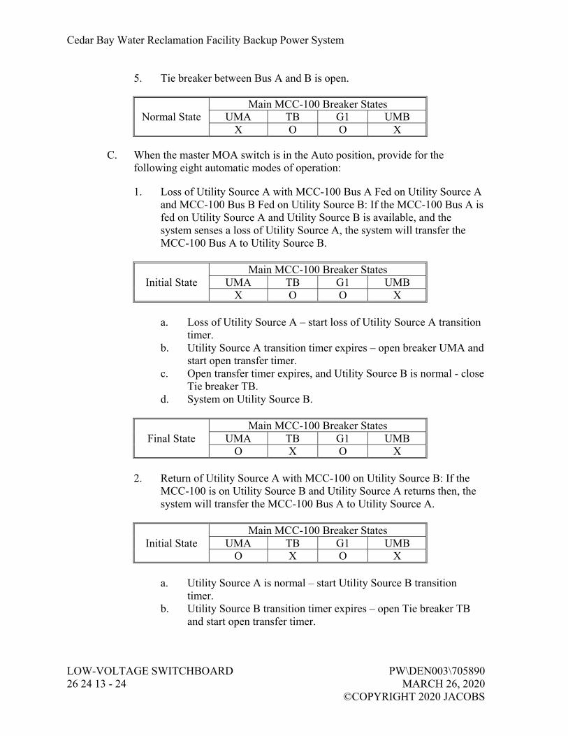
Cedar Bay Water Reclamation Facility Backup Power System
LOW-VOLTAGE SWITCHBOARD PW\DEN003\705890 26 24 13 - 24 MARCH 26, 2020 ©COPYRIGHT 2020 JACOBS
5. Tie breaker between Bus A and B is open.
Main MCC-100 Breaker States Normal State UMA TB G1 UMB
X O O X
C. When the master MOA switch is in the Auto position, provide for the following eight automatic modes of operation:
1. Loss of Utility Source A with MCC-100 Bus A Fed on Utility Source A and MCC-100 Bus B Fed on Utility Source B: If the MCC-100 Bus A is fed on Utility Source A and Utility Source B is available, and the system senses a loss of Utility Source A, the system will transfer the MCC-100 Bus A to Utility Source B.
Main MCC-100 Breaker States Initial State UMA TB G1 UMB
X O O X
a. Loss of Utility Source A – start loss of Utility Source A transition timer.
b. Utility Source A transition timer expires – open breaker UMA and start open transfer timer.
c. Open transfer timer expires, and Utility Source B is normal - close Tie breaker TB.
d. System on Utility Source B.
Main MCC-100 Breaker States Final State UMA TB G1 UMB
O X O X
2. Return of Utility Source A with MCC-100 on Utility Source B: If the MCC-100 is on Utility Source B and Utility Source A returns then, the system will transfer the MCC-100 Bus A to Utility Source A.
Main MCC-100 Breaker States Initial State UMA TB G1 UMB
O X O X
a. Utility Source A is normal – start Utility Source B transition timer.
b. Utility Source B transition timer expires – open Tie breaker TB and start open transfer timer.

Cedar Bay Water Reclamation Facility Backup Power System
PW\DEN003\705890 LOW-VOLTAGE SWITCHBOARD MARCH 26, 2020 26 24 13 - 25 ©COPYRIGHT 2020 JACOBS
c. Open transfer timer expires, and Utility Source A is normal - close breaker UMA.
Main MCC-100 Breaker States
Final State UMA TB G1 UMB X O O X
3. Loss of Utility Source B with MCC-100 Bus A Fed on Utility Source A
and MCC-100 Bus B Fed on Utility Source B: If the MCC-100 Bus B is fed on Utility Source B and Utility Source A is available, and the system senses a loss of Utility Source B, the system will transfer the MCC-100 Bus B to Utility Source A.
Main MCC-100 Breaker States Initial State UMA TB G1 UMB
X O O X
a. Loss of Utility Source B – start loss of Utility Source B transition timer.
b. Utility Source B transition timer expires – open breaker UMB and start open transfer timer.
c. Open transfer timer expires, and Utility Source A is normal - close Tie breaker TB.
d. System on Utility Source A.
Main MCC-100 Breaker States Final State UMA TB G1 UMB
X X O O
4. Return of Utility Source B with MCC-100 on Utility Source A: If the MCC-100 is on Utility Source A and Utility Source B returns then, the system will transfer the MCC-100 Bus B to Utility Source B.
Main MCC-100 Breaker States Initial State UMA TB G1 UMB
X X O O
a. Utility Source B is normal – start Utility Source A transition timer.
b. Utility Source A transition timer expires – open Tie breaker TB and start open transfer timer.

Cedar Bay Water Reclamation Facility Backup Power System
LOW-VOLTAGE SWITCHBOARD PW\DEN003\705890 26 24 13 - 26 MARCH 26, 2020 ©COPYRIGHT 2020 JACOBS
c. Open transfer timer expires, and Utility Source B is normal - close breaker UMB.
Main MCC-100 Breaker States
Final State UMA TB G1 UMB X O O X
5. Simultaneous Loss of Both Utility Sources: If the MCC-100 is in its
normal configuration and the system senses a loss of both sources A and B, the system will transfer the MCC-100 to generator power.
Main MCC-100 Breaker States Initial State UMA TB G1 UMB
X O O X
a. Loss of Utility Source A and B – start loss of Utility Sources transition timer.
b. Utility Sources transition timer expires – open main breakers UMA and UMB and start genset.
c. The generator reaches rated voltage and frequency – close tie breaker TB and close the generator breaker to MCC-100 Bus B.
d. System on generator power.
Main MCC-100 Breaker States Final State UMA TB G1 UMB
O X X O
6. Return of Utility Source A When MCC-100 is on Generator Power: When the system senses that Utility Source A returns, the Utility Source A stable timer begins. When this timer expires then the system starts a generator transition timer to open the generator breaker and transfer MCC-100 Bus A and B to Source A.
Main MCC-100 Breaker States Initial State UMA TB G1 UMB
O X X O a. Utility Source A is normal – start Utility Source A stable timer. b. Utility Source A stable timer expires – open generator breaker,
and close main breaker UMA. c. The generator breaker is open – run the genset at no load in cool-
down mode for a pre-set time period.

Cedar Bay Water Reclamation Facility Backup Power System
PW\DEN003\705890 LOW-VOLTAGE SWITCHBOARD MARCH 26, 2020 26 24 13 - 27 ©COPYRIGHT 2020 JACOBS
d. The cool-down period is complete – shut down the gensets and return the system to normal standby mode.
Main MCC-100 Breaker States Final State UMA TB G1 UMB
X X O O
7. Return of Utility Source B When MCC-100 is on Generator Power: When the system senses that Utility Source B returns, the Utility Source B stable timer begins. When this timer expires then the system starts a generator transition timer to open the generator breaker and transfer MCC-100 Bus A and B to Source B.
Main MCC-100 Breaker States Initial State UMA TB G1 UMB
O X X O
a. Utility Source B is normal – start Utility Source B stable timer. b. Utility Source B stable timer expires – open generator breaker and
close main breaker UMB. c. The generator breaker is open – run the genset at no load in cool-
down mode for a pre-set time period. d. The cool-down period is complete – shut down the gensets and
return the system to normal standby mode.
Main MCC-100 Breaker States Final State UMA TB G1 UMB
O X O X
8. Simultaneous Return of both Utility Sources with MCC-100 on Generator Power: When the system senses that Utility Source A and B returns, the Utility Source A stable timer begins. When this timer expires then the system starts a generator transition timer to open the generator breaker and transfer MCC-100 Bus A to Source A and Bus B to Source B.
Main MCC-100 Breaker States Initial State UMA TB G1 UMB
O X X O
a. Utility Source A is normal – start Utility Source A stable timer. b. Utility Source A stable timer expires – open generator breaker,
open Tie breaker TB, and close main breaker UMA. c. Utility Source B is normal – start Utility Source B stable timer. d. Utility Source B stable timer expires – close main breaker UMB.

Cedar Bay Water Reclamation Facility Backup Power System
LOW-VOLTAGE SWITCHBOARD PW\DEN003\705890 26 24 13 - 28 MARCH 26, 2020 ©COPYRIGHT 2020 JACOBS
e. The generator breaker is open – run the genset at no load in cool-down mode for a pre-set time period.
f. The cool-down period is complete – shut down the genset and return the system to normal standby mode.
Main MCC-100 Breaker States Final State UMA TB G1 UMB
X O O X
2.18 250KW GENERATOR CONTROL SYSTEM SEQUENCE OF OPERATIONS – OPERATOR INITIATED MODES
A. System manufacturer shall augment the descriptions of the below operating modes as necessary to provide a safe and operable system. Incorporate the manufacturer’s standard approaches for how the system should respond to abnormal conditions or response failures.
B. When the MOA switch is in the Auto position, provide for the following seven test (operator initiated but PLC managed) modes of operation.
1. Transfer SWBD-4A from Preferred Utility Source A to Utility Source B: In anticipation of non-availability of Utility Source A the system will transfer SWBD-4A to Utility Source B. The system will remain in this configuration until the operator transfers the system to a different state or until Utility Source B fails. In this configuration Utility Source A is considered unavailable, and a failure of Utility Source B will cause the system to transfer to generator power even if Utility Source A is present and normal.
Main SWBD-4A Breaker States Initial State UMA G1 UMB
X O O a. Operator initiates transfer to Utility Source B – start loss of Utility
Source A transition timer. b. Utility Source A transition timer expires – open breaker UMA and
start open transfer timer. c. Open transfer timer expires, and Utility Source B is normal - close
breaker UMB. d. System on Utility Source B.
Main SWBD-4A Breaker States Final State UMA G1 UMB
O O X

Cedar Bay Water Reclamation Facility Backup Power System
PW\DEN003\705890 LOW-VOLTAGE SWITCHBOARD MARCH 26, 2020 26 24 13 - 29 ©COPYRIGHT 2020 JACOBS
2. Transfer SWBD-4A from Utility Source B to Preferred Utility Source A: The system will transfer the switchboard from the above single source configuration back to its normal configuration on preferred Utility Source A.
Main SWBD-4A Breaker States Initial State UMA G1 UMB
O O X
a. Operator initiates transfer to preferred Utility Source A – start Utility Source B transition timer.
b. Utility Source B transition timer expires – open breaker UMB and start open transfer timer.
c. Open transfer timer expires and Utility Source A is normal – close breaker UMA.
d. System on Utility Source A.
Main SWBD-4A Breaker States Final State UMA G1 UMB
X O O
3. Load Test - Transfer SWBD-4A from Preferred Utility Source A to Generator Power: For routine load testing (even when both Utility Sources are available) the system will transfer the switchboard from the preferred Utility Source to generator power using open transition transfer. The system will remain on generator power until the operator initiates a transfer to utility.
Main SWBD-4A Breaker States Initial State UMA G1 UMB
X O O
a. Operator initiates transfer - start genset. b. The generator reaches rated voltage and frequency – start Utility
Source A transition timer. c. Utility Source A transition timer expires – open breaker UMA and
start open transition timer. d. Open transition timer expires – close generator breaker. e. System on generator power.
Main SWBD-4A Breaker States Final State UMA G1 UMB
O X O

Cedar Bay Water Reclamation Facility Backup Power System
LOW-VOLTAGE SWITCHBOARD PW\DEN003\705890 26 24 13 - 30 MARCH 26, 2020 ©COPYRIGHT 2020 JACOBS
4. Transfer SWBD-4A from Generator Power to Preferred Utility Source A: The system will transfer the switchboard from generator power back to preferred Utility Source A using open transition transfer.
Main SWBD-4A Breaker States Initial State UMA G1 UMB
O X O
a. Operator initiates transfer – start Utility Source A stable timer. b. Utility Source A stable timer expires – open generator breaker and
start open transition timer. c. Open transition timer expires – close main breaker UMA. Main
breaker UMB remains open. d. The generator breaker is open – the generator run at no load in
cool-down mode for a pre-set time period. e. The cool-down period is complete – the genset shut down and
return to normal standby mode.
Main SWBD-4A Breaker States Final State UMA G1 UMB
X O O
5. Load Test - Transfer SWBD-4A from Standby Utility Source B to Generator Power: For routine load testing (even when both Utility Sources are available) the system will transfer the switchboard from preferred Utility Source A to the standby Utility Source B and then, from Utility Source B to generator power using open transition transfer. The system will remain on generator power until the operator initiates a transfer to utility.
Main SWBD-4A Breaker States Initial State UMA G1 UMB
X O O
a. Operator initiates transfer - start Utility Source A transition timer. b. Utility Source A transition timer expires – open breaker UMA and
start open transition timer. c. Open transition timer expires, and Utility Source B is normal –
close breaker UMB. d. System on Utility Source B – start genset. e. The generator reaches rated voltage and frequency – start Utility
Source B transition timer. f. Utility Source B transition timer expires – open breaker UMB and
start open transition timer.

Cedar Bay Water Reclamation Facility Backup Power System
PW\DEN003\705890 LOW-VOLTAGE SWITCHBOARD MARCH 26, 2020 26 24 13 - 31 ©COPYRIGHT 2020 JACOBS
g. Open transition timer expires – close generator breaker. h. System on generator power
Main SWBD-4A Breaker States Final State UMA G1 UMB
O X O 6. Transfer SWBD-4A from Generator Power to Standby Utility Source B:
The system will transfer the switchboard from generator power back to standby Utility Source B and then back to preferred Utility Source A using open transition transfer.
Main SWBD-4A Breaker States Initial State UMA G1 UMB
O X O
a. Operator initiates transfer – start Utility Source B stable timer. b. Utility Source B stable timer expires – open generator breaker and
start open transition timer. c. Open transition timer expires – close utility main breaker UMB
and start Utility Source B transition timer. d. The generator breaker is open – the generator run at no load in
cool-down mode for a pre-set time period. e. The cool-down period is complete – the genset shut down and
return to normal standby mode.
Main SWBD-4A Breaker States Intermediate
State UMA G1 UMB
O O X f. Utility transition timer expires – open utility main breaker UMB
and start open transition timer. g. Open transition timer expires – close utility main breaker UMA. h. System on Utility Source A.
Main SWBD-4A Breaker States Final State UMA G1 UMB
X O O

Cedar Bay Water Reclamation Facility Backup Power System
LOW-VOLTAGE SWITCHBOARD PW\DEN003\705890 26 24 13 - 32 MARCH 26, 2020 ©COPYRIGHT 2020 JACOBS
7. No-Load Test: The system will start and run the generator. Main breaker UMA will remain closed, main breaker UMB will remain open, and the switchboard bus will remain powered from Utility Source A.
Main SWBD-4A Breaker States Initial State UMA G1 UMB
X O O
a. Operator initiates test - start genset. b. The generator reaches rated voltage and frequency – generator
runs with no load for a pre-set time period. c. The pre-set time period is complete – shut down the genset and
return the system to normal standby mode.
Main SWBD-4A Breaker States Final State UMA G1 UMB
X O O
2.19 600KW GENERATOR CONTROL SYSTEM SEQUENCE OF OPERATIONS – OPERATOR INITIATED MODES
A. System manufacturer shall augment the descriptions of the below operating modes as necessary to provide a safe and operable system. Incorporate the manufacturer’s standard approaches for how the system should respond to abnormal conditions or response failures.
B. When the MOA switch is in the Auto position, provide for the following seven test (operator initiated but PLC managed) modes of operation.
1. Transfer MCC-100 Bus A from Utility Source A to Utility Source B: In anticipation of non-availability of Utility Source A the system will transfer MCC-100 Bus A to Utility Source B. The system will remain in this configuration until the operator transfers the system to a different state or until Utility Source B fails. In this configuration Utility Source A is considered unavailable, and a failure of Utility Source B will cause the system to transfer to generator power even if Utility Source A is present and normal.
Main MCC-100 Breaker States Initial State UMA TB G1 UMB
X O O X a. Operator initiates transfer to Utility Source B – start loss of Utility
Source A transition timer. b. Utility Source A transition timer expires – open breaker UMA and
start open transfer timer.
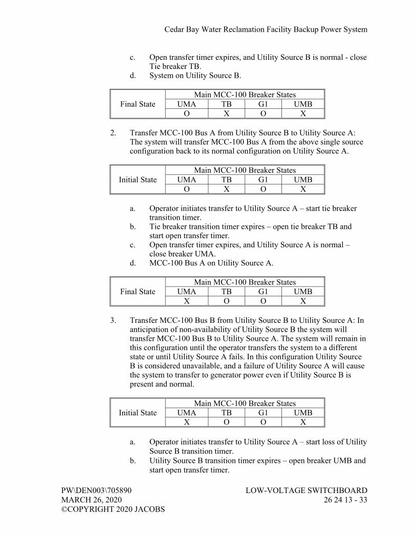
Cedar Bay Water Reclamation Facility Backup Power System
PW\DEN003\705890 LOW-VOLTAGE SWITCHBOARD MARCH 26, 2020 26 24 13 - 33 ©COPYRIGHT 2020 JACOBS
c. Open transfer timer expires, and Utility Source B is normal - close Tie breaker TB.
d. System on Utility Source B.
Main MCC-100 Breaker States Final State UMA TB G1 UMB
O X O X
2. Transfer MCC-100 Bus A from Utility Source B to Utility Source A: The system will transfer MCC-100 Bus A from the above single source configuration back to its normal configuration on Utility Source A.
Main MCC-100 Breaker States Initial State UMA TB G1 UMB
O X O X
a. Operator initiates transfer to Utility Source A – start tie breaker transition timer.
b. Tie breaker transition timer expires – open tie breaker TB and start open transfer timer.
c. Open transfer timer expires, and Utility Source A is normal – close breaker UMA.
d. MCC-100 Bus A on Utility Source A.
Main MCC-100 Breaker States Final State UMA TB G1 UMB
X O O X
3. Transfer MCC-100 Bus B from Utility Source B to Utility Source A: In anticipation of non-availability of Utility Source B the system will transfer MCC-100 Bus B to Utility Source A. The system will remain in this configuration until the operator transfers the system to a different state or until Utility Source A fails. In this configuration Utility Source B is considered unavailable, and a failure of Utility Source A will cause the system to transfer to generator power even if Utility Source B is present and normal.
Main MCC-100 Breaker States Initial State UMA TB G1 UMB
X O O X a. Operator initiates transfer to Utility Source A – start loss of Utility
Source B transition timer. b. Utility Source B transition timer expires – open breaker UMB and
start open transfer timer.

Cedar Bay Water Reclamation Facility Backup Power System
LOW-VOLTAGE SWITCHBOARD PW\DEN003\705890 26 24 13 - 34 MARCH 26, 2020 ©COPYRIGHT 2020 JACOBS
c. Open transfer timer expires, and Utility Source A is normal - close Tie breaker TB.
d. System on Utility Source A.
Main MCC-100 Breaker States Final State UMA TB G1 UMB
X X O O
4. Transfer MCC-100 Bus B from Utility Source A to Utility Source B: The system will transfer MCC-100 Bus B from the above single source configuration back to its normal configuration on Utility Source B.
Main MCC-100 Breaker States Initial State UMA TB G1 UMB
X X O O
a. Operator initiates transfer to Utility Source B – start tie breaker transition timer.
b. Tie breaker transition timer expires – open tie breaker TB and start open transfer timer.
c. Open transfer timer expires, and Utility Source B is normal – close breaker UMB.
d. MCC-100 Bus B on Utility Source B.
Main MCC-100 Breaker States Final State UMA TB G1 UMB
X O O X
5. Load Test - Transfer MCC-100 Bus A and Bus B from Utility Source A and Utility Source B to Generator Power: For routine load testing (even when both Utility Sources are available) the system will transfer the MCC-100 from both Utility Sources to generator power using open transition transfer. The system will remain on generator power until the operator initiates a transfer to utility.
Main MCC-100 Breaker States Initial State UMA TB G1 UMB
X O O X
a. Operator initiates transfer - start genset. b. The generator reaches rated voltage and frequency – start Utility
Source A and B transition timer. c. Utility Source A and B transition timer expires – open breaker
UMA, open breaker UMB, and start open transition timer.

Cedar Bay Water Reclamation Facility Backup Power System
PW\DEN003\705890 LOW-VOLTAGE SWITCHBOARD MARCH 26, 2020 26 24 13 - 35 ©COPYRIGHT 2020 JACOBS
d. Open transition timer expires – close tie breaker TB and generator breaker.
e. System on generator power.
Main MCC-100 Breaker States Final State UMA TB G1 UMB
O X X O
6. Transfer MCC-100 from Generator Power to Utility Source A and Utility Source B: The system will transfer the MCC-100 from generator power back to Utility Source A and Utility Source B using open transition transfer.
Main MCC-100 Breaker States Initial State UMA TB G1 UMB
O X X O
a. Operator initiates transfer – start Utility Source A and B stable timer.
b. Utility Source A and B stable timer expires – open tie breaker TB and generator breaker and start open transition timer.
c. Open transition timer expires – close main breaker UMA and main breaker UMB.
d. The generator breaker is open – the generator run at no load in cool-down mode for a pre-set time period.
e. The cool-down period is complete – the genset shut down and return to normal standby mode.
Main MCC-100 Breaker States Final State UMA TB G1 UMB
X O O X
7. No-Load Test: The system will start and run the generator. Main breaker UMA and UMB will remain closed, tie breaker TB will remain open, and the MCC-100 Bus A and Bus B will remain powered from Utility Source A and Utility Source B.
Main MCC-100 Breaker States Initial State UMA TB G1 UMB
X O O X
a. Operator initiates test - start genset. b. The generator reaches rated voltage and frequency – generator
runs with no load for a pre-set time period.

Cedar Bay Water Reclamation Facility Backup Power System
LOW-VOLTAGE SWITCHBOARD PW\DEN003\705890 26 24 13 - 36 MARCH 26, 2020 ©COPYRIGHT 2020 JACOBS
c. The pre-set time period is complete – shut down the genset and return the system to normal standby mode.
Main MCC-100 Breaker States Final State UMA TB G1 UMB
X O O X
2.20 FACTORY TESTING
A. In accordance with IEEE C37.20.1.
B. Coordinate factory testing with the testing requirements specified in Section 26 32 13.13, Diesel Engine Generator Sets.
C. Provide factory test on the generator/switchboard control system including simulation of entire control system as specified in the functional requirements.
1. Use a laptop to simulate the Ethernet data exchange with PLC. 2. An approved test plan must be in-place before scheduling a factory test. 3. The factory test shall include integration of all data that is to be
transmitted to the plant control system. 4. Although current system will work with single Source A, include all
scenarios of the control system specified in paragraph 2.16 through 2.18. Simulation of sources for tests is acceptable.
D. Provide 4 weeks' notice to the Owner and Owner’s Representative before any factory test is conducted to allow witnessing the tests. Travel costs for Owner and Owner’s Representative shall not be included in this Contract.
E. Submit test results prior to shipment.
PART 3 EXECUTION
3.01 INSTALLATION
A. Install equipment in accordance with manufacturer’s instructions and recommendations.
B. Secure equipment to floor with anchor bolts of sufficient size and number adequate for specified seismic conditions.
C. Install equipment plumb and in longitudinal alignment with pad or wall.
D. Tighten current-carrying bolted bus connections and enclosure framing and panel bolts to manufacturer’s recommendations.
E. Coordinate terminal connections with installation of secondary feeders.

Cedar Bay Water Reclamation Facility Backup Power System
PW\DEN003\705890 LOW-VOLTAGE SWITCHBOARD MARCH 26, 2020 26 24 13 - 37 ©COPYRIGHT 2020 JACOBS
3.02 FIELD TESTS
A. Coordinate the tests with the Owner so as to minimize disruptions to Plant operations.
B. Configure and calibrate protective relays before conducting any tests.
C. Initial Commissioning:
1. Perform initial commissioning to energize the switchboard from the new utility transformers and to test the generator control system.
2. Complete transfer/retransfer operational tests of the generator control system shall be performed proving automatic and manual transfer operations as specified in Part 2. All specified functional requirements shall be verified by actual tests, including load assumption and transfer back to utility.
3. Put the switchboard into service to supply the feeders to the downstream loads as they are transferred over to this new switchboard.
D. Final Commissioning:
1. Following the transfer of all loads to the new switchboard the system shall be given operational tests under full Plant load in conjunction with the Generator Performance Test.
2. Complete transfer/retransfer operational tests of the generator control system shall be performed proving automatic and manual transfer operations as specified in Part 2 and in Section 26 32 13.13, Diesel Engine Generator Sets. All specified functional requirements shall be verified by actual tests, including load assumption and transfer back to utility.
3. Generator control system test must be jointly performed with the PICS Subcontractor. Show that data exchange between the generator control system PLCs and the plant control system is working satisfactorily and the graphics at the plant HMI dynamically and accurately display all data acquired from generator PLC.
3.03 MANUFACTURER’S SERVICES
A. Manufacturer's Onsite Services shall include:
1. Assistance during product (system, subsystem, or component) installation to include observation, guidance, instruction of Contractor's assembly, erection, installation or application procedures.
2. Inspection, checking, and adjustment as required for product (system, subsystem, or component) to function as warranted by manufacturer and necessary to furnish Manufacturer's Certificate of Proper Installation.

Cedar Bay Water Reclamation Facility Backup Power System
LOW-VOLTAGE SWITCHBOARD PW\DEN003\705890 26 24 13 - 38 MARCH 26, 2020 ©COPYRIGHT 2020 JACOBS
3. Revisiting the site as required to correct problems and until installation and operation are acceptable to Contractor.
4. Resolution of assembly or installation problems attributable to, or associated with, respective manufacturer's products and systems.
5. Assistance during functional and performance testing, and facility startup and evaluation.
6. Training of Owner's personnel in the operation and maintenance of respective product as required.
7. Additional requirements may be specified elsewhere.
B. Training:
1. Furnish manufacturers' representatives for detailed classroom and hands-on training to Owner's personnel on operation and maintenance of specified product (system, subsystem, component).
2. Furnish trained, articulate personnel to coordinate and expedite training, to be present during training coordination meetings with Owner.
3. Manufacturer's representative shall be familiar with facility operation and maintenance requirements as well as with specified equipment.
4. Furnish complete training materials, to include operation and maintenance data, to be retained by each trainee.
C. Onsite Services: Present at Site or classroom designated by Owner, for minimum person-days listed below, travel time excluded:
1. 2 person-days for installation assistance and inspection. 2. 6 person-days for functional and performance testing and completion of
Manufacturer’s Certificate of Proper Installation. 3. 2 person-days for pre-startup classroom or Site training. 4. 2 person-days for facility startup. 5. 1 person-day for post-startup training. Training shall not commence
until an accepted detailed lesson plan for each training activity has been reviewed and approved by Owner and Owner’s Representative.
6. At least six separate trips will be required to cover work listed above.
D. Provide Manufacturer’s Certificate of Proper Installation in accordance with Section 01 43 33, Manufacturers’ Services.
3.04 SUPPLEMENTS
A. Supplements listed below, follows “END OF SECTION,” are part of this Specification.
1. Supplement 1, PLC I/O Data Exchange List (Operations Building). 2. Supplement 2, PLC I/O Data Exchange List (Building 9).
END OF SECTION

Cedar Bay Water Reclamation Facility Backup Power System
PW\DEN003\705890 LOW-VOLTAGE SWITCHBOARD MARCH 26, 2020 26 24 13 SUPPLEMENT 1 - 1 ©COPYRIGHT 2020 JACOBS
I/O Data Exchange List (Operations Building)
PLC/RIO Description DI DO AI AO
ATC-4A-PLC 250kW Generator Fuel Tank Level 1
ATC-4A-PLC 250kW Generator Fuel Leak Detection 1
ATC-4A-PLC 250kW Generator Run Status 1
ATC-4A-PLC 250kW Generator Fault Status 1
ATC-4A-PLC 250kW Generator Battery Low Status 1
ATC-4A-PLC 250kW Generator Battery Charger Fault Status 1
ATC-4A-PLC 250kW Generator Not in Auto Status 1
ATC-4A-PLC 250kW Generator E-Stop Status 1
ATC-4A-PLC 250kW Generator Run Command 1
ATC-4A-PLC 250kW Generator Breaker Open/Closed/Tripped/In Auto 4
ATC-4A-PLC 250kW Generator Breaker Open Command 1
ATC-4A-PLC 250kW Generator Breaker Close Command 1
ATC-4A-PLC 250kW Generator Volts 3
ATC-4A-PLC 250kW Generator Amps 3
ATC-4A-PLC 250kW Generator kW 1
ATC-4A-PLC 250kW Generator Power Factor 1
ATC-4A-PLC 250kW Generator Capacity Used in kW 1
ATC-4A-PLC 250kW Generator Capacity Available in kW 1
ATC-4A-PLC 250kW Generator Capacity Used in percent 1
ATC-4A-PLC Utility Breaker "UMA" Open/Closed/Tripped/In Auto 4
ATC-4A-PLC UMA Breaker Open Command 1
ATC-4A-PLC UMA Breaker Close Command 1
ATC-4A-PLC Single Phasing in Source "A" 1
ATC-4A-PLC Utility “A” Volts 3
ATC-4A-PLC Utility “A” Amps 3
ATC-4A-PLC Utility “A” kW 1
ATC-4A-PLC Utility “A” Power Factor 1
ATC-4A-PLC Utility Breaker "UMB" Open/Closed/Tripped/In Auto 4
ATC-4A-PLC UMB Breaker Open Command 1
ATC-4A-PLC UMB Breaker Close Command 1
ATC-4A-PLC Single Phasing in Source "B" 1

Cedar Bay Water Reclamation Facility Backup Power System
LOW-VOLTAGE SWITCHBOARD PW\DEN003\705890 26 24 13 SUPPLEMENT 1 - 2 MARCH 26, 2020 ©COPYRIGHT 2020 JACOBS
I/O Data Exchange List (Operations Building)
PLC/RIO Description DI DO AI AO
ATC-4A-PLC Utility “B” Volts 3
ATC-4A-PLC Utility “B” Amps 3
ATC-4A-PLC Utility “B” kW 1
ATC-4A-PLC Utility “B” Power Factor 1
ATC-4A-PLC SCADA PLC-3 Load Shed Completed 1
ATC-4A-PLC UMA Breaker Open / Closed status to SCADA PLC-3 2
ATC-4A-PLC UMB Breaker Open / Closed Status to SCADA PLC-3 2
ATC-4A-PLC 250kW Gen. Breaker Open / Closed Status to SCADA PLC-3 2
ATC-4A-PLC Initiate SCADA PLC-3 Load Shedding Interlocks 1
ATC-4A-PLC Power Available at SWBD-4A to SCADA PLC-3 1
ATC-4A-PLC SCADA PLC-4A Load Shed Completed 1
ATC-4A-PLC UMA Breaker Open / Closed status to SCADA PLC-4A 2
ATC-4A-PLC UMB Breaker Open / Closed Status to SCADA PLC-4A 2
ATC-4A-PLC 250kW Gen. Breaker Open / Closed Status to SCADA PLC-4A 2
ATC-4A-PLC Initiate PLC-4A Load Shedding Interlocks 1
ATC-4A-PLC Power Available at SWBD-4A to SCADA PLC-4A 1
ATC-4A-PLC SCADA PLC-5 Load Shed Completed 1
ATC-4A-PLC UMA Breaker Open / Closed status to SCADA PLC-5 2
ATC-4A-PLC UMB Breaker Open / Closed Status to SCADA PLC-5 2
ATC-4A-PLC 250kW Gen. Breaker Open / Closed Status to SCADA PLC-5 2
ATC-4A-PLC Initiate PLC-5 Load Shedding Interlocks 1
ATC-4A-PLC Power Available at SWBD-4A to SCADA PLC-5 1
I/O Totals 24 31 28 0
Total I/O, All Type 83

Cedar Bay Water Reclamation Facility Backup Power System
PW\DEN003\705890 LOW-VOLTAGE SWITCHBOARD MARCH 26, 2020 26 24 13 SUPPLEMENT 2 - 1 ©COPYRIGHT 2020 JACOBS
I/O Data Exchange List (Building 9)
PLC/RIO Description DI DO AI AO
ATC-100-PLC 600kW Generator Fuel Tank Level 1
ATC-100-PLC 600kW Generator Fuel Leak Detection 1
ATC-100-PLC 600kW Generator Run Status 1
ATC-100-PLC 600kW Generator Fault Status 1
ATC-100-PLC 600kW Generator Battery Low Status 1
ATC-100-PLC 600kW Generator Battery Charger Fault Status 1
ATC-100-PLC 600kW Generator Not in Auto Status 1
ATC-100-PLC 600kW Generator E-Stop Status 1
ATC-100-PLC 600kW Generator Run Command 1
ATC-100-PLC 600kW Generator Breaker Open/Closed/Tripped/In Auto 4
ATC-100-PLC 600kW Generator Breaker Open Command 1
ATC-100-PLC 600kW Generator Breaker Close Command 1
ATC-100-PLC 600kW Generator Volts 3
ATC-100-PLC 600kW Generator Amps 3
ATC-100-PLC 600kW Generator kW 1
ATC-100-PLC 600kW Generator Power Factor 1
ATC-100-PLC 600kW Generator Capacity Used in kW 1
ATC-100-PLC 600kW Generator Capacity Available in kW 1
ATC-100-PLC 600kW Generator Capacity Used in percent 1
ATC-100-PLC Utility Breaker "UMA" Open/Closed/Tripped/In Auto 4
ATC-100-PLC UMA Breaker Open Command 1
ATC-100-PLC UMA Breaker Close Command 1
ATC-100-PLC Single Phasing in Source "A" 1
ATC-100-PLC Utility “A” Volts 3
ATC-100-PLC Utility “A” Amps 3
ATC-100-PLC Utility “A” kW 1
ATC-100-PLC Utility “A” Power Factor 1
ATC-100-PLC Utility Breaker "UMB" Open/Closed/Tripped/In Auto 4
ATC-100-PLC UMB Breaker Open Command 1
ATC-100-PLC UMB Breaker Close Command 1
ATC-100-PLC Single Phasing in Source "B" 1

Cedar Bay Water Reclamation Facility Backup Power System
LOW-VOLTAGE SWITCHBOARD PW\DEN003\705890 26 24 13 SUPPLEMENT 2 - 2 MARCH 26, 2020 ©COPYRIGHT 2020 JACOBS
I/O Data Exchange List (Building 9)
PLC/RIO Description DI DO AI AO
ATC-100-PLC Utility “B” Volts 3
ATC-100-PLC Utility “B” Amps 3
ATC-100-PLC Utility “B” kW 1
ATC-100-PLC Utility “B” Power Factor 1
ATC-100-PLC Tie Breaker "TB" Open/Closed/Tripped/In Auto 4
ATC-100-PLC TB Breaker Open Command 1
ATC-100-PLC TB Breaker Close Command 1
ATC-100-PLC SCADA PLC-100 Load Shed Completed 1
ATC-100-PLC UMA Breaker Open / Closed status to SCADA PLC-100 2
ATC-100-PLC UMB Breaker Open / Closed Status to SCADA PLC-100 2
ATC-100-PLC Tie Breaker Open / Closed Status to SCADA PLC-100 2
ATC-100-PLC 600kW Gen. Breaker Open / Closed Status to SCADA
PLC-100 2
ATC-100-PLC Initiate SCADA PLC-100 Load Shedding Interlocks 1
ATC-100-PLC Power Available at MCC-100 BUS A to SCADA PLC-100 1
ATC-100-PLC Power Available at MCC-100 BUS B to SCADA PLC-100 1
I/O Totals 26 20 28 0
Total I/O, All Type 74
Cedar Bay Water Reclamation Facility Backup Power System
PW\DEN003\705890 PANELBOARDS MARCH 26, 2020 26 24 16 - 1 ©COPYRIGHT 2020 JACOBS
SECTION 26 24 16 PANELBOARDS
PART 1 GENERAL
1.01 REFERENCES
A. The following is a list of standards which may be referenced in this section:
1. National Electrical Contractor’s Association (NECA): 407, Recommended Practice for Installing and Maintaining Panelboards.
2. National Electrical Manufacturers Association (NEMA): a. 250, Enclosures for Electrical Equipment (1000 Volts Maximum). b. 289, Application Guide for Ground Fault Circuit Interrupters. c. KS 1, Enclosed Switches. d. PB 1, Panelboards. e. PB 1.1, General Instructions for Proper Installation, Operation and
Maintenance of Panelboards Rated 600 Volts or Less. 3. National Fire Protection Association (NFPA): 70, National Electrical
Code (NEC). 4. Underwriters Laboratories, Inc. (UL):
a. 67, Standard for Panelboards. b. 98, Standard for Enclosed and Dead-Front Switches. c. 486E, Standard for Equipment Wiring Terminals for use with
Aluminum and/or Copper Conductors. d. 489, Molded-Case Circuit Breakers, Molded-Case Switches, and
Circuit Breaker Enclosures. e. 508, Standard for Industrial Control Equipment. f. 870, Wireways, Auxiliary Gutters and Associated Fittings. g. 943, Ground-Fault Circuit-Interrupters. h. 1699, Standard for Arc-Fault Circuit-Interrupters.
5. Institute of Electrical and Electronics Engineers (IEEE): a. C62.1, Surge Arresters for Alternating Current Power Circuits. b. C62.11, Standards for Metal-Oxide Surge Arrestors for AC Power
Circuits.
1.02 SUBMITTALS
A. Action Submittals:
1. Manufacturer’s data sheets for each type of panelboard, protective device, accessory item, and component.
2. Manufacturer’s shop drawings including dimensioned plan, section, and elevation for each panelboard type, enclosure, and general arrangement.

Cedar Bay Water Reclamation Facility Backup Power System
PANELBOARDS PW\DEN003\705890 26 24 16 - 2 MARCH 26, 2020 ©COPYRIGHT 2020 JACOBS
3. Tabulation of features for each panelboard to include the following: a. Protective devices with factory settings. b. Provisions for future protective devices. c. Space for future protective devices. d. Voltage, frequency, and phase ratings. e. Enclosure type. f. Bus and terminal bar configurations and current ratings. g. Provisions for circuit terminations with wire range. h. Short circuit current rating of assembled panelboard at system
voltage. i. Features, characteristics, ratings, and factory settings of auxiliary
components. j. Wiring and schematic diagrams detailing control wiring,
and differentiating between manufacturer-installed and field-installed wiring.
B. Informational Submittals:
1. Anchorage and bracing calculations as required by Section 01 88 15, Anchorage and Bracing.
2. Manufacturer’s recommended installation instructions. 3. Component and attachment testing seismic certificate of compliance as
required by Division 01, General Requirements.
1.03 QUALITY ASSURANCE
A. Listing and Labeling: Provide products specified in this section that are listed and labeled as defined in NEC Article 100.
PART 2 PRODUCTS
2.01 MANUFACTURERS
A. Materials, equipment, and accessories specified in this section shall be products of:
1. Eaton/Cutler-Hammer. 2. General Electric Co. 3. Square D Co. 4. Siemens. 5. Or approved equal.
B. Panelboards shall be of the same manufacturer as equipment furnished under Section 26 24 19, Low-Voltage Motor Control.
Cedar Bay Water Reclamation Facility Backup Power System
PW\DEN003\705890 PANELBOARDS MARCH 26, 2020 26 24 16 - 3 ©COPYRIGHT 2020 JACOBS
2.02 GENERAL
A. Provide low voltage panelboards for application at 600V or less in accordance with this Section including panelboards installed in other equipment specified in Section 26 24 19, Low-Voltage Motor Control.
B. Provide equipment in accordance with NEMA PB 1, NFPA 70, and UL 67.
C. Wire Terminations:
1. Panelboard assemblies, including protective devices, shall be suitable for use with 75 degrees C or greater wire insulation systems at NEC 75 degrees C conductor ampacity.
2. In accordance with UL 486E.
D. Load Current Ratings:
1. Unless otherwise indicated, load current ratings for panelboard assemblies, including bus and circuit breakers, are noncontinuous as defined by NEC. Continuous ratings shall be 80 percent of noncontinuous rating.
2. Where indicated “continuous” or “100 percent”, selected components and protective devices shall be rated for continuous load current at value shown.
A. Short Circuit Current Rating (SCCR): Equipment short circuit rating for each panelboard assembly shall be fully rated at the indicated SCCR on the Drawing or the following:
1. Minimum SCCR at 208Y/120 or 120/240 volts shall be 22,000 amperes rms symmetrical, unless otherwise shown on Drawings.
2. Minimum SCCR at 480Y/277 volts shall be 42,000 amperes rms symmetrical, unless otherwise shown on Drawings.
2.03 OVERCURRENT PROTECTIVE DEVICES
A. Overcurrent Device Mounting and Arrangement: Design panelboards to accommodate device installation and replacement without disturbing adjacent devices and without removing main bus.
B. Overcurrent Protective Devices: In accordance with NEMA KS 1, UL 98, and UL 489. Protective devices shall be adapted to panelboard installation.

Cedar Bay Water Reclamation Facility Backup Power System
PANELBOARDS PW\DEN003\705890 26 24 16 - 4 MARCH 26, 2020 ©COPYRIGHT 2020 JACOBS
C. Provisions for Future Overcurrent Device:
1. Provide space, mountings and bus connections such that like device may be installed without additional hardware.
2. Panel openings shall be closed with individual removable cover for each provision for future device.
3. Unless otherwise indicated, “spaces” in panelboards shall be fully equipped provision for future like devices.
4. Provisions for future devices shall be suitable devices rated no less than 60 amperes.
D. Protective Device Locking: Furnish provisions for handle padlocking for main, subfeed, and branch devices where indicated.
E. Branch Protective Devices:
1. Locking: Furnish devices with provisions for handle padlocking. 2. Load Connections: Wire lugs shall be mechanical or crimp compression
type, removable/replaceable, and suitable for 75 degrees C rated conductors without derating switch nor conductor ampacity.
3. Provide a nameplate for each circuit, blanks for spares.
2.04 CIRCUIT BREAKERS
A. General: Thermal-magnetic unless otherwise indicated, quick-make, quick-break, molded case, of indicating type showing ON/OFF and TRIPPED positions of operating handle.
B. Noninterchangeable: In accordance with NEC.
C. Bus Connection: Bolt-on circuit breakers in all panelboards.
D. Trip Mechanism:
1. Individual permanent thermal and magnetic trip elements in each pole. 2. Variable magnetic trip elements with a single continuous adjustment 3X
to 10X for frames greater than 100 amps. 3. Two and three pole, common trip. 4. Automatically opens all poles when overcurrent occurs on one pole. 5. Test button on cover. 6. Calibrated for 40 degrees C ambient, unless shown otherwise.
E. Unacceptable Substitution:
1. Do not substitute single-pole circuit breakers with handle ties for multi-pole breakers.
2. Do not use tandem or dual circuit breakers in normal single-pole spaces.

Cedar Bay Water Reclamation Facility Backup Power System
PW\DEN003\705890 PANELBOARDS MARCH 26, 2020 26 24 16 - 5 ©COPYRIGHT 2020 JACOBS
F. Specialty Breakers: Where indicated, provide breakers with the following features:
1. Ground Fault Circuit Interrupter (GFCI): Where indicated, equip breaker as specified above with ground fault sensor and rated to trip on 5-mA ground fault within 0.025 second (UL 943, Class A sensitivity, for protection of personnel). a. Ground fault sensor shall be rated same as circuit breaker. b. Push-to-test button. c. Reset button.
2. Equipment Ground Fault Interrupter (EGFI): Where indicated, equip breaker specified above with ground fault sensor and rated to trip on 30-mA ground fault (UL listed for equipment ground fault protection).
G. Solid State Trip Units: Where indicated, equip breakers with solid state trip units in accordance with Division 26, Electrical.
1. Long (Time) Short (Time) Instantaneous (LSI): Electronic trip unit with fixed long-time trip, adjustable short-time trip and delay, and adjustable instantaneous trip settings.
2. Long (Time) Short (Time) Instantaneous Ground (Fault) (LSIG): Electronic trip unit as above and also with adjustable ground fault trip and delay settings.
2.05 ENCLOSURES
A. General:
1. Provide as specified in Division 26, Electrical. 2. Type 1, Type 3R, and Type 3S material code-gauge, hot-dip galvanized
sheet steel with reinforced steel frame. 3. Provide surface-mount panelboard from trim with same dimensions as
box front. 4. Finish: Rust inhibitor prime followed by manufacturer’s standard gray
baked enamel or lacquer.
B. NEMA 250 Type 1 Branch Panelboard Enclosure:
1. Secure front trim to box with concealed trim clamps. 2. Overlap flush panelboards front trims with box nominal 3/4 inch on all sides. 3. Provide door in panelboard front trim, with concealed hinges, to access
protective device operating handles. 4. Provide multi-point latching for doors over 30 inches in height. 5. Door Lock: Secure with flush catch and tumbler lock; all panelboards keyed
alike, with two milled keys each lock. 6. Circuit Directory: Metal frame with transparent plastic face and enclosed
card, mounted inside each panel door.

Cedar Bay Water Reclamation Facility Backup Power System
PANELBOARDS PW\DEN003\705890 26 24 16 - 6 MARCH 26, 2020 ©COPYRIGHT 2020 JACOBS
C. Multi-Section Panelboards: Where more than one section is required, provide multiple panelboard sections with separate fronts.
1. Sections shall be suitable for individual mounting to be field interconnected to form a single electrical unit.
2. Recessed-mount sections of the same panel shall all have the same size tubs and flush covers.
3. Surface-mount multi-section panelboards may be comprised of sections of unequal heights.
4. Provide feed-through and main lugs in individual sections as required for field assembly of a complete multi-section panelboard. Unless otherwise indicated, provide feed-through lugs on each section but last.
5. Provide neutral and ground terminal bars in each section.
2.06 BUSSING AND TERMINAL BARS
A. Bus:
1. Material: Tin-plated copper full sized throughout length. 2. Provide for mounting of future protective devices along full length of
bus regardless of number of units and spaces shown. Machine, drill, and tap as required for current and future positions.
B. Equipment Ground Terminal Bus: Copper with suitably sized provisions for termination of ground conductors, and bonded to box.
1. Provide individual mechanical termination points no less than the quantity of breaker pole positions.
2. Provide individual termination points for all other grounding conductors such as feeder, grounding electrode, etc.
3. Termination points shall be bolted crimp compression lugs for conductors 6 AWG and larger.
C. Neutral Terminal Bus: Copper with suitably sized provisions for termination of neutral conductors, and isolated from box.
1. Provide individual mechanical termination points no less than the quantity of breaker pole positions.
2. Provide individual termination points for all other neutral conductors. 3. Termination points shall be bolted crimp compression lugs for
conductors 6 AWG and larger. 4. Oversize Neutral: Provide oversized neutral terminal bus as indicated.
D. Provision for Future Devices: Equip with mounting brackets, bus connections, and necessary appurtenances for future protective device ampere ratings indicated.

Cedar Bay Water Reclamation Facility Backup Power System
PW\DEN003\705890 PANELBOARDS MARCH 26, 2020 26 24 16 - 7 ©COPYRIGHT 2020 JACOBS
2.07 SPECIAL FEATURES
A. General: Where indicated on Drawings or schedules, provide special features as specified.
1. Service Equipment Approval: Labeled for use as service equipment for panelboards having service disconnecting means.
2. Isolated Equipment Ground Terminal Bar: a. Provide in addition to equipment ground terminal bar
specified above. b. Insulated from box. c. Provide individual conductor termination points equal to
quantity of breaker pole positions plus all feeder, subfeed, and feed-through isolated ground conductors.
3. Controls: a. Provide controls in accordance with UL 508. b. Controls shall be Class I, 120V ac. c. Control circuits shall be protected by fuse or circuit breaker.
4. Extra Gutter Space: Dimensions and arrangement indicated. 5. Gutter Barrier: Arranged to isolate section of gutter as shown. 6. Subfeed: Protective device or lugs indicated, with additional terminals
on neutral and ground bus to accommodate feeder. 7. Feed-Through Lugs: At opposite end of phase bus from mains, with
additional terminals on neutral and ground buses, sized to accommodate feeders indicated.
8. Double Main Lugs: Furnish additional terminals on neutral and ground buses, sized to accommodate feeders indicated.
B. Surge Arresters:
1. Comply with Section 26 43 00, Surge Protection Devices. 2. Coordinate impulse sparkover voltage with system voltage. 3. Provide protective device within panelboard as disconnecting means
and short circuit protection per manufacturer’s recommendation. 4. Provide factory mounting within panelboard utilizing UL-recognized
mounting device.
2.08 LIGHTING AND APPLIANCE BRANCH CIRCUIT PANELBOARDS
A. Protective Device Locking: Furnish provisions for handle padlocking for main and subfeed devices; also provide for branch devices where indicated.

Cedar Bay Water Reclamation Facility Backup Power System
PANELBOARDS PW\DEN003\705890 26 24 16 - 8 MARCH 26, 2020 ©COPYRIGHT 2020 JACOBS
B. Multi-Section Panelboards: Where more than 42 poles are required or more than one section is otherwise indicated, provide multiple panelboards with separate fronts.
1. Panelboard sections shall be individually installed and field interconnected to form a single electrical unit.
2. Unless otherwise indicated, provide feed-through lugs on each section but last.
3. Surface-mount panels shall be individually mounted and may be different sizes.
4. Recessed-mount panels shall be individually mounted and the same size tub and flush cover.
5. Surface-mount multi-section panelboards may be comprised of sections of unequal heights.
6. Provide feed-through and main lugs in individual sections as required for field assembly of a complete multi-section panelboard.
7. Provide neutral and ground terminal bars in each section.
C. NEMA 250 Type 1 Branch Panelboard Enclosure:
1. Front trim shall be secured to box with concealed trim clamps. 2. Surface-mount panelboard front trim shall have same dimensions
as box. 3. Flush panelboards front trims shall overlap box nominal 3/4 inch on all
sides. 4. Door in panelboard front trim, with concealed hinges, shall provide
access to protective device operating handles. 5. Doors over 30 inches in height shall have multi-point latching. 6. Door lock shall be secure with flush catch and tumbler lock; all
panelboards keyed alike, with two milled keys each lock. 7. Circuit Directory: Metal frame with transparent plastic face and
enclosed card, mounted inside each panel door. 8. Hinged Front Cover (Door In Door): Entire front trim hinged to surface
box with standard door within hinged trim cover.
2.09 POWER DISTRIBUTION PANELBOARDS
A. Branch Protective Devices:
1. Locking: Furnish devices with provisions for handle padlocking. 2. Load Connections: Wire lugs shall be mechanical or crimp compression
type, removable/replaceable, and suitable for 75 degrees C rated conductors without derating switch nor conductor ampacity.
3. Provide a nameplate for each circuit, blanks for spares.

Cedar Bay Water Reclamation Facility Backup Power System
PW\DEN003\705890 PANELBOARDS MARCH 26, 2020 26 24 16 - 9 ©COPYRIGHT 2020 JACOBS
PART 3 EXECUTION
3.01 GENERAL
A. Install in accordance with NECA 407, NEMA PB 1.1, and manufacturers’ written installation instructions.
B. Install securely, plumb, in-line and square with walls.
C. Install top of cabinet trim 78 inches above floor, unless otherwise shown. Install cabinet so tops of protective device operating handles are no more than 78 inches above the floor.
D. Ground Fault Protection: Install panelboard ground fault circuit interrupter devices in accordance with installation guidelines of NEMA 289.
E. Install filler plates in unused spaces.
F. Wiring in Panel Gutters: Train conductors neatly in groups; bundle and wrap with nylon wire ties.
G. Mount flush panels uniformly flush with wall finish.
H. Provide typewritten circuit directory for each panelboard.
I. In addition to conduit or nipples otherwise required for feeder and branch circuit wiring between multi-section panelboard sections, provide nipples for branch circuits two trade sizes larger than required for installed branch circuit wires or an empty 2-inch nipple, or a 1-1/4-inch trade size conduit if tubs are more than 24 inches apart.
J. Provide engraved identification for each protective device.
END OF SECTION

Cedar Bay Water Reclamation Facility Backup Power System
PW\DEN003\705890 LOW-VOLTAGE MOTOR CONTROL MARCH 26, 2020 26 24 19 - 1 ©COPYRIGHT 2020 JACOBS
SECTION 26 24 19 LOW-VOLTAGE MOTOR CONTROL
PART 1 GENERAL
1.01 REFERENCES
A. The following is a list of standards which shall be followed for this section:
1. Institute of Electrical and Electronics Engineers (IEEE): a. American National Standard Institute (ANSI): C2, National
Electrical Safety Code (NESC). b. C37.20.7, Guide for Testing Metal Enclosed Switchgear Rated up
to 38 kV for Internal Arcing Faults. 2. National Electrical Contractors Association (NECA): 402, Standard for
Installing and Maintaining Motor Control Centers. 3. National Electrical Manufacturers Association (NEMA):
a. 250, Enclosures for Electrical Equipment (1,000 volts maximum). b. ICS 1, Industrial Control and Systems: General Requirements. c. ICS 2, Controllers, Contactors, and Overload Relays Rated
600 Volts. d. ICS 2.3, Instructions for the Handling, Installation, Operation, and
Maintenance of Motor Control Centers Rated Not More Than 600V.
e. ICS 18, Motor Control Centers. f. KS 1, Enclosed and Miscellaneous Distribution Equipment
Switches (600 Volts Maximum). 4. National Fire Protection Association (NFPA): 70, National Electrical
Code (NEC). 5. UL:
a. 98, Enclosed and Dead-Front Switches. b. 489, Molded-Case Circuit Breakers, Molded-Case Switches, and
Circuit Breaker Enclosures. c. 845, Motor Control Centers.
1.02 DEFINITIONS
A. LCD: Liquid Crystal Display.
B. N.C.: Normally Closed.
C. N.O.: Normally Open.
D. SPD: Surge Protection Device.
E. VT: Voltage Transformer.

Cedar Bay Water Reclamation Facility Backup Power System
LOW-VOLTAGE MOTOR CONTROL PW\DEN003\705890 26 24 19 - 2 MARCH 26, 2020 ©COPYRIGHT 2020 JACOBS
1.03 SUBMITTALS
A. Action Submittals:
1. Descriptive information. 2. Itemized Bill of Material. 3. Dimensional drawings. 4. Front Panel Elevations. 5. Conduit entrance locations. 6. Bus data. 7. Protective Devices: Copies of time-current characteristics. 8. Anchorage and bracing drawings and cut sheets, as required by
Section 01 88 15, Anchorage and Bracing. 9. Anchoring instructions and details. 10. Anchoring instructions and details. 11. Typed Tabulation:
a. Motor name; tag (equipment) numbers as shown on Drawings. b. Motor horsepower. c. Nameplate full load current. d. Measured load current and voltage. e. Overload model number and setting. f. Protective device trip settings. g. Manufacturer’s solid state starter switch or dip switch or program
settings. h. Attach above typed, tabulated data to a copy of starter
manufacturer’s overload relay or setting selection tables for starters provided.
12. Control diagrams. 13. One-line diagrams. 14. Schematic (elementary) diagrams. 15. Outline diagrams. 16. Interconnection diagrams. 17. Operational description.
B. Informational Submittals:
1. Anchorage and bracing calculations as required by Section 01 88 15, Anchorage and Bracing.
2. Manufacturer’s installation instructions. 3. Factory test reports, certified.
1.04 QUALITY ASSURANCE
A. Provide products manufactured within scope of UL that conform to UL Standards and have applied UL Listing Mark.

Cedar Bay Water Reclamation Facility Backup Power System
PW\DEN003\705890 LOW-VOLTAGE MOTOR CONTROL MARCH 26, 2020 26 24 19 - 3 ©COPYRIGHT 2020 JACOBS
1.05 DELIVERY, STORAGE, AND HANDLING
A. Shipping Splits: Established by the electrical subcontractor to facilitate ingress of equipment to final installation location within building.
PART 2 PRODUCTS
2.01 MANUFACTURERS
A. Provide materials, equipment, and accessories specified in this section manufactured by:
1. Eaton Electrical/Cutler-Hammer. 2. GE Industrial Systems. 3. Schneider Electric/Square D Services. 4. Allen-Bradley. 5. Siemens. 6. Or approved equal.
2.02 GENERAL
A. Make adjustments necessary to wiring, conduit, disconnect devices, motor starters, branch circuit protection, and other affected material or equipment to accommodate motors actually provided under this Contract.
B. Controllers: NEMA ICS 1, NEMA ICS 2, Class A.
C. Control Transformer:
1. Two winding, 120-volt secondary, primary voltage to suit. 2. Two current-limiting fuses for primary circuit. 3. One fuse in secondary circuit. 4. Mount within starter unit. 5. Minimum rating 500 VA.
D. Suitable for use with 75 degrees C wire at full NFPA 70, 75 degrees C ampacity.
E. Lifting lugs on equipment and devices weighing over 100 pounds.
F. Anchor Bolts: Type 316 stainless steel, and as specified in Section 05 50 00, Metal Fabrications. Seismic Zone and Importance Factor shall be as specified in Section 01 61 00, Common Product Requirements.
G. Seismic Zone and Importance Factor: As specified in Section 01 61 00, Common Product Requirements.

Cedar Bay Water Reclamation Facility Backup Power System
LOW-VOLTAGE MOTOR CONTROL PW\DEN003\705890 26 24 19 - 4 MARCH 26, 2020 ©COPYRIGHT 2020 JACOBS
H. Operating Conditions:
1. Ambient Temperature: Maximum 40 degrees C. 2. Altitude: Zero feet. 3. Equipment to be fully rated.
I. Enclosures: In accordance with NEMA 250.
J. Equipment Finish:
1. Electrocoating process applied over rust-inhibiting phosphated base coating.
2. Exterior Color: Manufacturer’s standard.
2.03 MOTOR CONTROL CENTERS
A. General:
1. New sections and starter units shall be in accordance with NEMA ICS 1, NEMA ICS 2, NEMA ICS 18, and UL 845.
2. Voltage Rating: As shown. 3. Short Circuit Rating: 65,000 amperes rms symmetrical at 480 volts for
entire motor control center as a complete assembly. 4. Main and branch circuit breakers, controllers, wire connections, and
other devices to be front mounted and accessible, unless otherwise noted.
5. NEMA ICS 18, Part 3: a. Class: II. b. Type: B. c. Provide blank spaces on interconnection diagrams to add control
conductor code designations during installation of equipment.
B. Enclosure:
1. Type: NEMA 250, Type 1, indoor gasketed. 2. Vertical Section Indoor Dimensions for NEMA 1 Type: 90 inches high,
20 inches wide, 21 inches deep, nominal. Alternative width dimensions of 24 inches and 30 inches are acceptable for oversize devices or panels. Do not exceed space shown.
3. Construction: a. Sheet steel reinforced with channel or angle irons. b. Butt sections flush, end-to-end against similar section without
bolts, nuts, or cover plates causing interference. c. Removable top cover plates and bottom cover plates. d. Removable plates on end panels for future bus extension.
4. Section Mounting: Removable formed-steel channel sills and lifting angles.

Cedar Bay Water Reclamation Facility Backup Power System
PW\DEN003\705890 LOW-VOLTAGE MOTOR CONTROL MARCH 26, 2020 26 24 19 - 5 ©COPYRIGHT 2020 JACOBS
5. Horizontal Wiring Compartments: Accessible from front, full width, top and bottom.
6. Vertical Wiring Compartment: Full height, isolated from unit starters with separate hinged door and tie supports. No terminal blocks allowed in vertical wireway compartment.
7. Unit Compartment: Individual compartments separated by steel barriers for each starter, feeder, or other unit capable of being wired from front without unit removal.
8. Compartment Doors: Separate hinged doors for each starter, feeder, or other unit.
9. Door Interlocking: Mechanically interlock starter and feeder doors so doors cannot be opened with unit energized. Provide defeater mechanism to allow intentional access and energizing at any time by qualified individual.
10. External disconnect handles with ON/OFF and trip positions showing, padlockable in OFF position with up to three-lock capability.
11. Cable Entrance: Main leads enter from top control and feeder circuits enter from top.
C. Bus:
1. Horizontal Power Bus: a. Three-phase tin-plated copper non-tapered, entire width of control
center, rated amperes as indicated. b. Silver-plated at joints. c. Construct to allow future extension of additional sections. d. Isolated from tap horizontal wireway. e. Provide Belleville washers on bus connection belts. f. Current rating: as shown on Drawings.
2. Vertical Power Bus: a. Three-phase, tin plated copper, full height of section, rated
300 amperes minimum. b. Sandwich type bus insulation providing deadfront construction
with starter units removed except for bus stab openings. c. Insulated and isolated barrier, complete with automatic shutters
over stub openings. 3. Neutral Bus: None. 4. Ground Bus: Tin plated copper, bare, entire width of control center. 5. Bus Bracing: Amperes rms symmetrical, as shown.
D. Motor Controller Unit:
1. Provide indicated individual components and control devices including pushbuttons, selector switches, indicating lights, control relays, time delay relays, and elapsed time meters as specified in Section 26 05 04, Basic Electrical Materials and Methods.

Cedar Bay Water Reclamation Facility Backup Power System
LOW-VOLTAGE MOTOR CONTROL PW\DEN003\705890 26 24 19 - 6 MARCH 26, 2020 ©COPYRIGHT 2020 JACOBS
2. Construction: a. Drawout combination type with stab connections for starters
NEMA ICS, Size 5 and smaller. b. Bolt-on combination type with cable connection to riser for
starters NEMA ICS, Size 6 and larger. c. Readily interchangeable with starters of similar size.
3. Starters: a. NEMA ICS 18, standard rating, except none smaller than
NEMA ICS, Size 1. b. Rating: Horsepower rated at 600 volt, UL labeled for
65,000 amperes at 480 volts short circuit capacity with overload protection or as shown on Drawings.
c. Three-phase, nonreversing, unless specified otherwise. d. Disconnect Type: Motor circuit protector. e. Combination Full Voltage, Magnetic Starter:
1) Control: As shown. f. Combination Reduced Voltage, Solid State Starter:
1) Control: HAND/OFF/AUTO selector switch; STOP/START pushbutton as shown on Drawings.
2) Bypass contactor. 3) Class 10/20/30 electronic overload relay, switch, or
dip switch selectable. 4) Kick start, with adjustable torque and time settings. 5) Ramp start, selectable current or torque, and adjustable time. 6) Smooth stop ramp, adjustable time. 7) Phase loss unbalance and phase reversal protection. 8) LED display or LCD of fault, N.O. contact to communicate
fault condition. g. Combination Adjustable Frequency Drive, Solid State Starter:
Drives as specified in Section 26 29 23, Low-Voltage Adjustable Frequency Drive System.
h. Padlockable operating handle when de-energized with up to three-lock capability.
i. Unit door interlocked to prevent opening when disconnect is in closed position.
j. Mechanical interlocked to prevent placing disconnect in ON position when unit door is open.
k. Minimum Dimensions: 12 inches high by full section width, less vertical wireway.
4. Disconnecting Device: a. As indicated. b. Padlockable in OPEN position for up to three locks.

Cedar Bay Water Reclamation Facility Backup Power System
PW\DEN003\705890 LOW-VOLTAGE MOTOR CONTROL MARCH 26, 2020 26 24 19 - 7 ©COPYRIGHT 2020 JACOBS
5. Circuit Breaker: a. Meet requirements of NEMA AB 1 and UL 489. b. Molded case with manufacturer’s recommended trip setting for
maximum motor protection. c. Thermal-magnetic trip or magnetic trip only as shown. d. Tripping indicated by operating-handle position. e. Interrupting capacity required for connection to system with short
circuit capacity indicated. 6. Thermal Motor Overload Protection:
a. Inverse-time-limit characteristic. b. Heater: Bimetallic overload, adjustable trip, or directly heated
melting alloy, ratchet principle type element. c. Relay Trip: Quick, Class 10. d. Manual reset. e. Provide in each ungrounded phase. f. Mount within starter unit.
7. Solid State Motor Overload Protection: a. Inverse-time-limit characteristic. b. Phase loss, phase unbalance and Class II ground fault protection. c. Current operated electronic circuitry with adjustable trip. d. Class 10/20/30 relay trip, switch selectable. e. One N.O. auxiliary contact for remote monitoring. f. Manual reset. g. Provide in each ungrounded phase. h. Mount within starter unit.
8. Motor Thermal Protector Interface: Manual-reset interposing relay for connection to motor-mounted thermal protector system.
9. Ground Fault Protection: Where indicated and as specified in Paragraph Main Protective Device and Feeder Units, except provide instantaneous operation device.
10. Capacitor Connection: Terminals to allow easy connection of power factor correction capacitors on source side of starter overload relays on starters where capacitor connection is shown.
E. Control Unit:
1. Disconnecting Device: Pull-apart terminal blocks capable of de-energizing external source control circuits in unit.
2. Control Devices: As indicated and as specified in Division 26, Electrical.
3. Control Wiring: a. Copper, 14 AWG, minimum. b. Permanent sleeve type markers with wire numbers applied to each
end of wires.

Cedar Bay Water Reclamation Facility Backup Power System
LOW-VOLTAGE MOTOR CONTROL PW\DEN003\705890 26 24 19 - 8 MARCH 26, 2020 ©COPYRIGHT 2020 JACOBS
c. Terminate wires using insulated locking fork or ring type crimp terminals.
d. Terminate current transformer leads on shorting type terminal blocks.
F. Incoming Line Terminal:
1. Construction: As specified in Paragraph, Motor Controller Unit. 2. Incoming Service Feeder: As shown on Drawing. 3. Mechanical type CU-/AL lugs for 75 degrees C cable.
G. Main Protective Device and Feeder Unit:
1. Construction: As specified in Paragraph Motor Controller Unit. 2. Incoming Service Feeder: Cable. As shown. 3. Solid State Trip Circuit Breaker:
a. In accordance with UL 489. b. Main and tie protective device and feeder protective devices
100 amp and larger. c. UL labeled as suitable for service entrance as shown. d. Fixed mounted insulated or molded case breakers with ambient
insensitive solid-state trips and having current sensors and logic circuits integral in breaker frame.
e. Solid-state current control with adjustable ampere setting, adjustable long-time delay, adjustable short-time trip and delay band, fixed or adjustable instantaneous trip, and adjustable ground fault trip and delay band.
f. Setting adjustments to be covered by a sealable, tamper-proof, transparent cover (insulated case breakers only) or by compartment door for other breakers).
g. Locate trip button on front cover of breaker to permit mechanical simulation overcurrent tripping for test purposes and to trip breaker quickly in emergency situation.
4. Molded Case Circuit Breaker: a. In accordance with UL 489. b. Feeder protective device less than 100 amps. c. Thermal-magnetic trip and interrupting capacity required for
connection to system with short circuit capacity indicated. d. Indicate tripping by operating-handle position. e. Suitable for use with 75 degrees C wire at full NEC 75 degrees C
ampacity. 5. Ground Fault Protection:
a. Suitable for 480-volt, three-phase, three-wire, solidly grounded wye system.

Cedar Bay Water Reclamation Facility Backup Power System
PW\DEN003\705890 LOW-VOLTAGE MOTOR CONTROL MARCH 26, 2020 26 24 19 - 9 ©COPYRIGHT 2020 JACOBS
b. Ground sensors to encircle phase conductors where used, and connected to ground relays with adjustable pickup settings and time-current characteristics indicated.
c. Circuit breaker shunt trip and relay operating from fused 120-volt ac control source within control center.
6. Phase Monitoring Relay: a. Three-phase monitoring relay to protect against low voltage,
voltage unbalance, and phase reversal. b. Manufacturer and Product: Basler Electric; BE3-47N/27 or
approved equal.
H. SPD: As specified in Section 26 43 00, Surge Protection Devices.
I. Protective Relays, Power Monitors, CTs and PTs: As specified in section 26 09 13, Power Measurement and Control.
J. Pushbuttons, Indicating Lights, Selector Switches, Elapsed Time Meters, Control Relays, Time-Delay Relays, and Reset Timers: As specified in Division 26, Electrical.
K. Nameplates:
1. Laminated plastic; white, engraved to black core. 2. Provide for each motor control center and each unit. 3. Engrave with inscription shown on single-line diagram. 4. Provide blank nameplates on spaces for future units. 5. Attach with stainless steel panhead screws on face of control center.
L. Space Heaters: Thermostatically controlled. Locate in bottom of each vertical section for operation from 120-volt power source derived internal to MCC.
2.04 SOURCE QUALITY CONTROL
A. Factory Testing:
1. Applicable Standards: NEMA ICS 18, UL 845, and NEC Article 430, Part VIII.
2. Perform standard factory inspection and tests in accordance with NEMA requirements to verify components have been designed to Specification, assembled in accordance with applicable standards, and each unit functions in accordance with electrical diagrams.
3. Actual operation shall be performed wherever possible. Otherwise, inspect and perform continuity checks.
4. Verify component devices operated correctly in circuits as shown on diagrams or as called for in Specification.

Cedar Bay Water Reclamation Facility Backup Power System
LOW-VOLTAGE MOTOR CONTROL PW\DEN003\705890 26 24 19 - 10 MARCH 26, 2020 ©COPYRIGHT 2020 JACOBS
5. Control Circuits and Devices: a. Energize circuit at rated voltage. b. Operate control devices. c. Perform continuity check.
6. Instruments, Meters, Protective Relays, and Equipment: a. Verify devices functioned by energizing potential to rated values
with connection to devices made at outgoing terminal blocks. b. Verify protective relays operated for functional checks and trips
manually initiated to verify functioning of operation for indicator and associated circuits.
7. Perform dielectric tests on primary circuits and equipment, except potential transformers. a. Tests: Phase-to-phase and phase-to-around with 60-cycle test
voltages applied for 1 second at 2,640 volts. 8. Verify equipment passed tests and inspection. 9. Provide standard factory inspection and test checklists, and final
certified and signed test report.
PART 3 EXECUTION
3.01 INSTALLATION
A. General:
1. Install equipment in accordance with NEMA ICS 2.3, IEEE C2, NECA 402, Submittals, and manufacturer’s written instructions and recommendations.
2. Secure equipment to mounting pads with anchor bolts of sufficient size and number adequate for specified seismic conditions.
3. Install equipment plumb and in longitudinal alignment with pad or wall. 4. Coordinate terminal connections with installation of secondary feeders. 5. Grout mounting channels into floor or mounting pads. 6. Retighten current-carrying bolted connections and enclosure support
framing and panels to manufacturer’s recommendations. 7. Motor Data: Provide typed, self-adhesive label attached inside each
motor starter enclosure door displaying the following information: a. Motor served by tag number and equipment name. b. Nameplate horsepower. c. Motor code letter. d. Full load amperes. e. Service factor. f. Installed overload relay catalog number.

Cedar Bay Water Reclamation Facility Backup Power System
PW\DEN003\705890 LOW-VOLTAGE MOTOR CONTROL MARCH 26, 2020 26 24 19 - 11 ©COPYRIGHT 2020 JACOBS
B. Circuit Breakers:
1. Field adjust trip settings of motor starter magnetic-trip-only circuit breakers.
2. Adjust to approximately 11 times motor rated current. 3. Determine motor rated current from motor nameplate following
installation.
C. Thermal Overload Relay:
1. Select and install overload relays and apply settings after actual nameplate full-load current rating of motor has been determined.
2. Initial Settings: In accordance with manufacturer’s recommendation.
3.02 RETROFIT AND UPGRADE OF EXISTING MCC-100
A. Replacement of existing Main-Tie-Main Breakers:
1. Replace the existing two main and one tie breakers with new breakers with ratings as shown on the drawings. Breaker specifications as specified under paragraph 2.04.G.
B. Protective Relays, Power Monitors, CTs and PTs as specified in Section 26 09 13, Power Measurement and Control.
C. Generator Connection: Make provision for “lugs only” connection to Bus “B” of existing MCC-100.
D. Implement load shedding interlocks in to non-priority load starters, VFDs controls, and shunt trip breakers as shown on the drawings.
3.03 MISCELLANEOUS MODIFICATIONS TO OTHER MCCS:
A. Replace existing MCC-4A with new MCC-4A as shown.
B. Disconnect existing MCCs No. 3 and No. 5 feeders from existing MCC-4A (which shall be demolished) and re-connect to new Switchboard-4A as shown.
C. Implement load shedding interlocks in the non-priority load starters, VFDs control, and shunt trip breakers as shown on the drawings, for MCC-4A, MCC-3 and MCC-5.
3.04 SEQUENCE
A. All modifications noted in paragraph 3.02 and 3.03 shall be carried out in accordance with the approved construction sequence.
Cedar Bay Water Reclamation Facility Backup Power System
LOW-VOLTAGE MOTOR CONTROL PW\DEN003\705890 26 24 19 - 12 MARCH 26, 2020 ©COPYRIGHT 2020 JACOBS
3.05 MANUFACTURER’S SERVICES
A. Furnish manufacturer’s representative in accordance with Section 01 43 33, Manufacturers’ Field Services, for the following services at jobsite or classroom as designated by Owner, for minimum person-days listed below, travel time excluded:
1. 1/2 person-day for installation assistance, and inspection of installation. 2. 1/2 person-day for functional and performance testing. 3. 2 person-days for plant startup. 4. 1 person-day for training of Owner’s personnel.
END OF SECTION

Cedar Bay Water Reclamation Facility Backup Power System
PW\DEN003\705890 WIRING DEVICES MARCH 26, 2020 26 27 26 - 1 ©COPYRIGHT 2020 JACOBS
SECTION 26 27 26 WIRING DEVICES
PART 1 GENERAL
1.01 REFERENCES
A. The following is a list of standards which may be referenced in this section:
1. ASTM International (ASTM): A167, Standard Specification for Stainless and Heat-Resisting Chromium-Nickel Steel Plate, Sheet, and Strip.
2. Federal Specifications (FS): a. W-C-596, General Specification for Connector, Electrical, Power. b. FW-S-896F/GEN, Switches, Toggle (Toggle and Lock), Flush
Mounted (General Specification). 3. National Electrical Manufacturers Association (NEMA):
a. 250, Enclosures for Electrical Equipment (1,000 Volts Maximum).
b. WD 1, General Requirements for Wiring Devices. 4. National Fire Protection Association (NFPA): 70, National Electrical
Code (NEC). 5. Underwriters Laboratories Inc. (UL):
a. 498, Standard for Attachment Plugs and Receptacles. b. 508, Standard for Safety for Industrial Control Equipment. c. 943, Standard for Ground-Fault Circuit-Interrupters. d. 1449, Standard for Transient Voltage Surge Suppressors.
1.02 SUBMITTALS
A. Action Submittals: Manufacturer’s product data for wiring devices.
PART 2 PRODUCTS
2.01 SWITCHES
A. Switch, General Purpose:
1. NEMA WD 1 and FS W-S-896F/GEN. 2. Totally enclosed, ac type, with quiet tumbler switches and screw
terminals. 3. Rivetless one-piece brass or copper alloy contact arm with silver alloy
contacts. 4. Capable of controlling 100 percent tungsten filament and fluorescent
lamp loads.

Cedar Bay Water Reclamation Facility Backup Power System
WIRING DEVICES PW\DEN003\705890 26 27 26 - 2 MARCH 26, 2020 ©COPYRIGHT 2020 JACOBS
5. Rating: 20 amps, 120/277 volts. 6. Color:
a. Office Areas: White. b. Other Areas: Brown.
7. Automatic grounding clip and integral grounding terminal on mounting strap.
8. Manufacturers and Products, Industrial Grade: a. Arrow Hart; 1201/2221 Series. b. Bryant; 4801/4901 Series. c. Hubbell; 1202/1222 Series. d. Leviton; 1201/1221 Series. e. Or approved equal.
B. Switch, Motor Rated:
1. Type: Two-pole or three-pole, manual motor starting/disconnect switch without overload protection.
2. Enclosure/Mounting and Rating: a. General Purpose:
1) Totally enclosed snap-action switch. Quick-make, slow-break design with silver alloy contacts. UL 508 listed.
2) General Purpose Rating: 30 amperes, 600V ac. 3) Minimum Motor Ratings:
a) 2 hp for 120V ac, single-phase, two-pole. b) 3 hp for 240V ac, single-phase, two-pole. c) 15 hp for 480V ac, three-phase, three-pole.
4) Screw-type terminals. b. Explosion-Proof:
1) Provide enclosed manual motor starter-type. Three-pole nonreversing contactor.
2) Minimum Motor Rating: 10 hp, 480V ac, three-phase, three-pole.
3) Enclosure: NEMA 250, Type 7. 4) Provide lockable external handle operator.
3. Manufacturers: a. General Purpose:
1) Bryant. 2) Hubbell. 3) Or approved equal.
b. Explosion-Proof: Eaton, Type B101 or approved equal..
Cedar Bay Water Reclamation Facility Backup Power System
PW\DEN003\705890 WIRING DEVICES MARCH 26, 2020 26 27 26 - 3 ©COPYRIGHT 2020 JACOBS
2.02 RECEPTACLES
A. Receptacle, General Purpose:
1. NEMA WD 1 and FS W-C-596. 2. Duplex, two-pole, three-wire grounding type with screw type wire
terminals. 3. Impact resistant nylon cover and body. 4. One-piece mounting strap with integral ground contact (rivetless
construction). 5. Contact Arrangement: Contact to be made on two sides of each inserted
blade without detent. 6. Rating: 125 volts, NEMA WD 1, Configuration 5-20R, 20 amps. 7. Size: For 2-inch by 4-inch outlet boxes. 8. Industrial Grade:
a. Color: 1) Office Areas: White. 2) Other Areas: Brown.
b. Manufacturers and Products: 1) Arrow Hart; 5262/5362 Series. 2) Bryant; 5262/5362 Series. 3) Hubbell; 5262/5362 Series. 4) Leviton; 5262/5362 Series. 5) Or approved equal.
B. Receptacle, Ground Fault Circuit Interrupter:
1. Meet requirements of general-purpose receptacles. 2. Listed Class A to UL 943, tripping at 5 mA. 3. Color: Ivory. 4. Standard Model: NEMA WD 1, with No. 12 AWG copper
USE/RHH/RHW-XLPE insulated pigtails and provisions for testing. 5. Feed-Through Model: NEMA WD 1, with No. 12 AWG copper
USE/RHH/RHW-XLPE insulated pigtails and provisions for testing. 6. Manufacturers:
a. Bryant. b. Hubbell. c. Arrow Hart. d. Leviton. e. Or approved equal.
C. Receptacle, Corrosion-Resistant.
1. Meet requirements of general-purpose receptacles. 2. Nickel coated metal parts.
Cedar Bay Water Reclamation Facility Backup Power System
WIRING DEVICES PW\DEN003\705890 26 27 26 - 4 MARCH 26, 2020 ©COPYRIGHT 2020 JACOBS
3. Color: Yellow. 4. Manufacturer and Product:
a. Hubbell; 52CM62/53CM62. b. Leviton; 52CM-62/53CM-62. c. Or approved equal.
D. Receptacle, Special-Purpose:
1. Rating and number of poles as indicated or required for anticipated purpose.
2. One matching plug with cord-grip features for each special-purpose receptacle.
2.03 DEVICE PLATES
A. General: Sectional type plates not permitted.
B. Plastic:
1. Material: Specification grade, 0.10-inch minimum thickness, noncombustible, thermosetting.
2. Color: To match associated wiring device. 3. Mounting Screw: Oval-head metal, color matched to plate.
C. Metal:
1. Material: Specification grade, one-piece, 0.040-inch nominal thickness stainless steel.
2. Finish: ASTM A167, Type 302/304, satin. 3. Mounting Screw: Oval-head, finish matched to plate.
D. Cast Metal:
1. Material: Malleable ferrous metal, or aluminum with gaskets. 2. Screw: Oval-head stainless steel.
E. Sheet Steel:
1. Finish: Zinc electroplate. 2. Screws: Oval-head stainless steel. 3. Manufacturers:
a. Appleton. b. Crouse-Hinds. c. Or approved equal.

Cedar Bay Water Reclamation Facility Backup Power System
PW\DEN003\705890 WIRING DEVICES MARCH 26, 2020 26 27 26 - 5 ©COPYRIGHT 2020 JACOBS
F. Engraved:
1. Character Height: 3/16-inch. 2. Filler: White.
G. Weatherproof:
1. Receptacles, Weatherproof Type 1: a. Gasketed, cast-aluminum, with individual cap over each
receptacle opening. b. Mounting Screw and Cap Spring: Stainless steel. c. Manufacturers and Products:
1) Crouse-Hinds; Type WLRD-1. 2) Appleton; Type FSK-WRD. 3) Or approved equal.
2. Receptacles, Weatherproof Type 2: a. UL listed for WET location while in use. b. Die cast metal cover. c. Locking type. d. Manufacturers and Products:
1) TayMac; Type Multi-Mac. 2) Or approved equal.
3. Switches: a. Gasketed, cast-metal or cast-aluminum, incorporating external
operator for internal switch. b. Mounting Screw: Stainless steel. c. Manufacturers and Products:
1) Crouse-Hinds; DS-181 or DS-185. 2) Appleton; FSK-1VTS or FSK-1VS. 3) Or approved equal.
H. Raised Sheet Metal: 1/2-inch high zinc- or cadmium-plated steel designed for one-piece drawn type sheet steel boxes.
I. Sheet Steel: Formed sheet steel or Feraloy designed for installation on cast metal boxes.
PART 3 EXECUTION
3.01 SWITCHES
A. Switch, General Purpose:
1. Mounting Height: See Section 26 05 33, Raceway and Boxes. 2. Install with switch operation in vertical position. 3. Install single-pole, two-way switches so toggle is in up position when
switch is on.

Cedar Bay Water Reclamation Facility Backup Power System
WIRING DEVICES PW\DEN003\705890 26 27 26 - 6 MARCH 26, 2020 ©COPYRIGHT 2020 JACOBS
B. Switch, Motor Rated:
1. Mounting Height: See Section 26 05 33, Raceway and Boxes. 2. Install with switch operation in vertical position so toggle is in up
position when ON. 3. Install within sight of motor when used as a disconnect switch.
3.02 RECEPTACLES
A. Duplex Receptacles:
1. Install with grounding slot up, except where horizontal mounting is shown, in which case install with neutral slot down.
2. Ground receptacles to boxes with grounding wire only. 3. Weatherproof Receptacles:
a. Install in cast metal box. b. Install such that hinge for protective cover is above receptacle
opening. 4. Ground Fault Interrupter: Install feed-through model at locations where
ground fault protection is specified for “downstream” conventional receptacles.
5. Special-Purpose Receptacles: Install in accordance with manufacturer’s instructions.
3.03 DEVICE PLATES
A. Securely fasten to wiring device; ensure a tight fit to box.
B. Flush Mounted: Install with all four edges in continuous contact with finished wall surfaces without use of mats or similar materials. Plaster fillings will not be acceptable.
C. Surface Mounted: Plate shall not extend beyond sides of box, unless plates have no sharp corners or edges.
D. Install with alignment tolerance to box of 1/16 inch.
E. Engrave with designated titles.
F. Types (Unless Otherwise Shown):
1. Office: Metal. 2. Exterior:
a. Switch: Weatherproof. b. Receptacle in DAMP location: Weatherproof Type 1. c. Receptacle in WET location: Weatherproof Type 2.

Cedar Bay Water Reclamation Facility Backup Power System
PW\DEN003\705890 WIRING DEVICES MARCH 26, 2020 26 27 26 - 7 ©COPYRIGHT 2020 JACOBS
G. Interior:
1. Flush Mounted Boxes: Metal. 2. Surface Mounted, Metal Boxes:
a. General Purpose Areas: Sheet Steel. b. Other Areas: Cast.
3. Surface Mounted, Aluminum Boxes: a. General Purpose Areas: Stamped. b. Other Areas: Cast aluminum.
4. Surface Mounted, Sheet Steel Boxes: Raised sheet steel. 5. Surface Mounted, Nonmetallic Boxes: Manufacturer’s standard. 6. Receptacle shown as Weatherproof on Drawings: Weatherproof Type 1.
END OF SECTION


Cedar Bay Water Reclamation Facility Backup Power System
PW\DEN003\705890 LOW-VOLTAGE ADJUSTABLE MARCH 26, 2020 FREQUENCY DRIVE SYSTEM ©COPYRIGHT 2020 JACOBS 26 29 23 - 1
SECTION 26 29 23 LOW-VOLTAGE ADJUSTABLE FREQUENCY DRIVE SYSTEM
PART 1 GENERAL
1.01 REFERENCES
A. The following is a list of standards which may be referenced in this section:
1. Electronic Industries Alliance (EIA): 359-A-1, Special Colors. 2. Hydraulic Institute Standards (HIS). 3. Institute of Electrical and Electronics Engineers (IEEE):
a. 112, Standard Test Procedure for Polyphase Induction Motors and Generators.
b. 519, Recommended Practices and Requirements for Harmonic Control in Electrical Power Systems.
c. C62.41, Recommended Practice on Surge Voltages in Low-Voltage AC Power Circuits.
4. National Electrical Manufacturer’s Association (NEMA): a. 250, Enclosures for Electrical Equipment (1,000 Volts
Maximum). b. CP 1, Shunt Capacitors. c. MG 1, Motors and Generators. d. WC 57, Standard for Control, Thermocouple Extensions, and
Instrumentation Cables. 5. National Fire Protection Association (NFPA): 79, Electrical Standard
for Industrial Machinery.
1.02 DEFINITIONS
A. Terms that may be used in this section:
1. AFD: Adjustable frequency drive. 2. CMOS: Complementary metal oxide semiconductor. 3. CSI: Current source inverter. 4. EMU: Energy monitoring unit. 5. GTO: Gate turn-off thyristor. 6. MPR: Motor protection relay. 7. MTBF: Mean time between failure. 8. PWM: Pulse width modulation. 9. ROM: Read only memory. 10. RTD: Resistance temperature detector. 11. RTU: Remote Telemetry Unit. 12. Rated Load: Load specified for equipment. 13. Rated Speed: Nominal rated (100 percent) speed specified for
equipment.

Cedar Bay Water Reclamation Facility Backup Power System
LOW-VOLTAGE ADJUSTABLE PW\DEN003\705890 FREQUENCY DRIVE SYSTEM MARCH 26, 2020 26 29 23 - 2 ©COPYRIGHT 2020 JACOBS
14. TDD: Total demand distortion. 15. THD: Total harmonic distortion. 16. TTL: Transistor logic.
1.03 SYSTEM DESCRIPTION
A. Performance Requirements:
1. This Specification covers supply, installation, testing and commissioning of Adjustable Frequency Drives. As a minimum, all drives 100 hp and less shall be 6-pulse.
2. Rated Continuous Operation Capacity: Not less than 1.15 times full load current rating of driven motor, as indicated on motor nameplate, and suitable for continuous operation at continuous overload which may be imposed on motor by driven pump operating over specified speed range.
3. Furnish output reactors or filters for installations having motor feeders
longer that 100 ft to limit voltage peak and voltage rise time.
B. Design Requirements:
1. Design and provide drive system consisting of adjustable frequency controller, drive motor, certain auxiliary items, and components necessary for complete operating system.
2. Furnish AFDs rated on basis of actual motor full load nameplate current rating. (AFDs rating = 1.15* full load motor nameplant current.)
3. Drive System: Convert incoming three-phase, 60-Hz ac power to variable voltage, adjustable frequency output for adjustable speed operation of a standard ac induction squirrel-cage motor, using the pulse-width-modulation (PWM) technique to produce the adjustable frequency output.
4. System rated for continuous industrial duty and suitable for use with Standard NEMA MG 1, Design B motors.
5. Incoming Line Circuit Breaker: Provide positive means of disconnecting incoming power, and overcurrent protection for the drive system.
6. Output Reactor or dV/Dt Filter: Design to minimize voltage spikes at motor where long motor leads are indicated.
7. The equipment furnished, including filters, transformed reactors, and contactors, must fit within the enclosures dimensions on the Drawings.

Cedar Bay Water Reclamation Facility Backup Power System
PW\DEN003\705890 LOW-VOLTAGE ADJUSTABLE MARCH 26, 2020 FREQUENCY DRIVE SYSTEM ©COPYRIGHT 2020 JACOBS 26 29 23 - 3
1.04 SUBMITTALS
A. Action Submittals:
1. Overall drive system operating data, including efficiencies, input currents, and power factors, at driven equipment actual load and rated system input voltage, at 0, 40, 60, 80, 100, and 110 percent of rated speed.
2. AFD output pulse maximum peak voltage, pulse rise time, and pulse rate of rise.
3. Data on shelf life of “dc link” capacitor. 4. Complete system rating, including nameplate data, continuous operation
load capability throughout speed range of 0 percent to 120 percent of rated speed.
5. Complete adjustable frequency controller rating coordinated with motor full load nameplate current rating; list controller special features being supplied.
6. Controller, reactor, harmonic filter, and isolating transformer (if applicable) dimensional drawings; information on size and location of space for incoming and outgoing conduit.
7. Maximum heat dissipation from enclosure. 8. Layout of controller face showing pushbuttons, switches, instruments,
and indicating lights. 9. Complete system operating description. 10. Complete system schematic (elementary) wiring diagrams. 11. Complete system interconnection diagrams between controller, drive
motor, and related components or controls external to system, including wire numbers and terminal board point identification.
12. One-line diagram of system, including component ratings. 13. Description of diagnostic features being provided. 14. Descriptive literature for control devices such as relays and timers. 15. Itemized bill-of-materials listing system components. 16. Specific description of provisions, such as filters being made to ensure
proper system operation. 17. Provide information on interface with PLC.
B. Informational Submittals:
1. Statement of Supplier qualifications. 2. Factory functional test reports. 3. Certified copy of test report for identical motor tested in accordance
with NEMA MG 1-12.53a and IEEE Standard 112, Test Method B, showing rated load, rated speed efficiency meeting or exceeding specified values; motors not as specified will be rejected.
4. Special shipping, storage and protection, and handling instructions.

Cedar Bay Water Reclamation Facility Backup Power System
LOW-VOLTAGE ADJUSTABLE PW\DEN003\705890 FREQUENCY DRIVE SYSTEM MARCH 26, 2020 26 29 23 - 4 ©COPYRIGHT 2020 JACOBS
5. Manufacturer’s printed installation instructions. 6. Field test reports. 7. Manufacturer’s Certification of Proper Installation. 8. Suggested spare parts list to maintain equipment in service for a period
of 1 year and 5 years. Include a list of special tools required for checking, testing, parts replacement, and maintenance with current price information.
9. List special tools, materials, and supplies furnished with equipment for use prior to and during startup and for future maintenance.
10. Operation and Maintenance Data: As specified in Section 01 78 23, Operation and Maintenance Data.
1.05 QUALITY ASSURANCE
A. Supplier: Minimum 5 years’ experience in furnishing similar size and type adjustable frequency, controlled speed, drive systems.
1.06 EXTRA MATERIALS
A. Furnish for each drive unit:
1. Complete set of components likely to fail in normal service. 2. Plug-in subassemblies. 3. Printed circuit boards. 4. Potentiometers. 5. Integrated circuits. 6. One complete power bridge and one spare printed circuit card for each
modular, plug-in type card in controller.
PART 2 PRODUCTS
2.01 MANUFACTURERS
A. Components and accessories specified in this section shall be products of:
1. Eaton Cutler Hammer. 2. Danfoss. 3. Siemens Robicon. 4. Allen-Bradley. 5. ABB. 6. Toshiba. 7. Square D. 8. Or approved equal.

Cedar Bay Water Reclamation Facility Backup Power System
PW\DEN003\705890 LOW-VOLTAGE ADJUSTABLE MARCH 26, 2020 FREQUENCY DRIVE SYSTEM ©COPYRIGHT 2020 JACOBS 26 29 23 - 5
2.02 SERVICE CONDITIONS
A. Ambient Operating Temperature: 32 degrees F to 104 degrees F.
B. Storage Temperature: Minus 40 degrees F to 158 degrees F.
C. Humidity: 0 percent to 95 percent relative (noncondensing).
D. Altitude: 0 to 3,300 feet.
E. Frequency Stability: Plus or minus 0.1 percent of maximum frequency.
F. Atmosphere: Corrosive.
2.03 COMPONENTS
A. Drive Units:
1. Incorporate switching power supply operating from dc bus, to produce PWM output waveform simulating sine wave and providing power loss ride through of 2 milliseconds at full load, full speed.
2. Current-limiting semiconductor fuses for protection of internal power semiconductors.
3. Employ diode bridge rectifier providing constant displacement power factor of 0.95 minimum at all operating speeds and loads.
4. Use transistors for output section, providing a minimum 97 percent drive efficiency at full speed, full load.
5. Employ dc power discharge circuit so that after removal of input power dc link capacitor voltage level will decay below 50 volts dc within 1 minute after de-energizing following NEMA CP 1 and NFPA 79. Design dc link capacitor for MTBF of 5 years.
6. Operate with open circuited output. 7. Input Voltage: 480V ac plus or minus 10 percent. 8. Output Voltage: 0 to 480 volts, three-phase, 0 to 66-Hz, minimum. 9. Maximum peak voltage of PWM AFD output pulse of 1,000 volts, with
pulse rise time of not less than 2 microseconds, and a maximum rate of rise of 500 volts per microsecond. Maximum frequency of PWM AFD output pulse (carrier) frequency of 3,000-Hz. Should magnitudes of these characteristics be more stressful to motor insulation than specified values, furnish insulation systems on the motors suitable for the proposed values.
10. Motor Audible Noise Level: When operating throughout speed range of PWM AFD, no more than 3 dBA above that designated in NEMA MG 1 for same motor operated at constant speed with a 60-Hz supply voltage.

Cedar Bay Water Reclamation Facility Backup Power System
LOW-VOLTAGE ADJUSTABLE PW\DEN003\705890 FREQUENCY DRIVE SYSTEM MARCH 26, 2020 26 29 23 - 6 ©COPYRIGHT 2020 JACOBS
11. Short-Time Overload Capacity: 125 percent of rated load in rms current for 1 minute following full load, full speed operation.
12. Equipment Short-Circuit Rating: Suitable for connection to system with maximum source three-phase, bolted fault, short-circuit available of 65,000 amps rms symmetrical at 480 volts.
13. Furnish drives with output current-limiting reactors mounted within equipment enclosure.
14. Diagnostics: Comprehensive for drive adjustment and troubleshooting: a. Memory battery backup; 100-hour minimum during power loss. b. Status messages will not stop drive from running but will prevent
it from starting. c. Fault Condition Messages and History: First fault protection
function to be activated, ability to store six successive fault occurrences in order. Minimum faults numerically: 1) Overcurrent (time and instantaneous). 2) Overvoltage. 3) Undervoltage (dc and ac). 4) Overtemperature (drive, motor windings, motor bearing,
pump bearing). 5) Serial communication fault. 6) Short-circuit/ground fault (motor and drive). 7) Motor stalled. 8) Semiconductor fault. 9) Microprocessor fault. 10) Single-phase voltage condition.
15. Drive Protection: a. Fast-acting semiconductor fuses. b. Overcurrent, instantaneous overcurrent trip. c. Dc undervoltage protection, 70 percent dropout. d. Dc overvoltage protection, 130 percent pickup. e. Overtemperature, drive, inverter, converter, and dc link
components. f. Overtemperature, motor, and pump. g. Single-phase protection. h. Reset overcurrent protection (manual or automatic reset). i. Active current limit/torque limit protection. j. Semiconductor fault protection. k. Short-circuit/ground fault protection. l. Serial communication fault protection. m. Microprocessor fault. n. Surge protection for transient overvoltage (6,000 volts, 80 joule
surge, tested per IEEE C62.41). o. Visual display of specific fault conditions.

Cedar Bay Water Reclamation Facility Backup Power System
PW\DEN003\705890 LOW-VOLTAGE ADJUSTABLE MARCH 26, 2020 FREQUENCY DRIVE SYSTEM ©COPYRIGHT 2020 JACOBS 26 29 23 - 7
16. Operational Features: a. Use manufacturer’s standard unless otherwise indicated. b. Sustained power loss. c. Momentary power loss. d. Power interruption. e. Power loss ride through (0.1 second). f. Start on the fly. g. Electronic motor overload protection. h. Stall protection. i. Slip compensation. j. Automatic restart after power return (ability to enable/disable
function). k. Critical frequency lockout (three selectable points minimum, by
1.5-Hz steps in 10-Hz bands, to prevent resonance of system). l. Drive maintenance system software for complete programming
and diagnostics. m. Ground fault protection, drive, and motor. n. Operate with no motor connected to output terminals.
B. Rectifier: Three-phase 6-pulse full wave diode bridge rectifier for motors under 100 hp (unless noted otherwise) to provide constant dc voltage to drive’s dc bus. Three phase 18-pulse full wave diode bridge rectifier for motor 75 hp and larger.
C. Incoming Line Reactor/Filter:
1. Provide minimum of 3 percent line impedance for all motors 15 hp or less. If impedance isn’t integral to drive provide separately mounted impedance for each drive.
2. Include isolation contactor to disconnect the filter from the line when the drive is stopped.
D. Furnish series choke and capacitors on dc bus to reduce ripple in rectifier output and to reduce harmonic distortion reflected into incoming power feeders.
E. Controller: Microprocessor-controller PWM inverter to convert to dc voltage to variable voltage, adjustable frequency, three-phase ac output. Output voltage shall vary proportionally with frequency to maintain constant ratio of volts to hertz up to 60-Hz; above 60-Hz, voltage shall remain constant with drive operating in constant horsepower output mode.

Cedar Bay Water Reclamation Facility Backup Power System
LOW-VOLTAGE ADJUSTABLE PW\DEN003\705890 FREQUENCY DRIVE SYSTEM MARCH 26, 2020 26 29 23 - 8 ©COPYRIGHT 2020 JACOBS
F. Enclosure:
1. NEMA 250, Type 1, gasketed, freestanding, enclosure for mounting against wall, completely front accessible, and hinged doors. Properly sized to dissipate heat generated by controller within limits of specified operating conditions (including ambient temperature and ambient airflow). Enclosure not to exceed dimensions shown on Drawings.
2. Furnish drive complete with cable termination compartment door interlocked main circuit breaker, defeatable (lockable in the open position), emergency stop pushbutton, alphanumeric keypad and display, and operator’s controls. Components and controls specified in Division 26, Electrical.
3. Wire drive from below and above for power and control wiring. 4. Size forced-ventilation for periodic operation to cool each unit with
maximum room ambient temperature of 95 degrees F. Furnish redundant fans such that if one fan fails remaining fans furnish adequate ventilation for drive when operating at maximum capacity. Furnish filters on ventilation intakes.
5. Wiring: a. Bundle stranded copper wiring neatly with nylon tie wraps or with
continuous plastic spiral binding. b. Label each terminal for permanent identification of leads. c. Identify each wire at each end with imprinted mylar adhesive-
back wire markers. d. Incorporate in as-installed wiring diagrams for wire and terminal
numbers shown. e. Wiring across door hinge, use 19-strand, NEMA WC 57 Class C
stranding looped for proper twist rather than bending at hinge. f. Wire connections internal to panels by crimp-on terminal types. g. For multiple enclosure systems, complete interconnection wiring
with gasketed enclosure openings for wiring. h. Multipoint plug receptacles for control wiring crossing equipment
shipping splits. 6. Selector switches, indicating lights, potentiometers, instruments,
protective devices, and major system components identified by means of mechanically attached, engraved, laminated nameplates.
G. Operator Interface:
1. Controls: Mount drive local control on front door of enclosure and include control switch and membrane type keypad for the following operator functions: a. Start (when in local mode). b. Stop (when in local mode).

Cedar Bay Water Reclamation Facility Backup Power System
PW\DEN003\705890 LOW-VOLTAGE ADJUSTABLE MARCH 26, 2020 FREQUENCY DRIVE SYSTEM ©COPYRIGHT 2020 JACOBS 26 29 23 - 9
c. Speed increase (when in local mode). d. Speed decrease (when in local mode). e. Parameter mode selection (recall programmed parameters). f. LOCAL/OFF/REMOTE control selection (in remote, furnish for
remote RUN command signal and speed control via Profinet datalink).
g. Fault reset, manual for faults, except loss of ac voltage which is automatic upon return.
h. RUN/preset speed. i. Parameter lock, password or key switch lockout of changes to
parameters. j. Start disable, key switch or programmed code.
2. 120 volts, single-phase, 60-Hz circuits for control power and operator controls from internal control power transformer. Furnish power for motor space heaters rated 120 volts.
3. Arrange component and circuit such that failure of a single component cannot cause cascading failure(s) of other component(s).
4. Alphanumeric Display: During normal operation and routine test, the following parameters shall be available: a. Motor current (percent of drive rated current). b. Output frequency (Hertz). c. Output voltage. d. Running time. e. Local/remote indicator. f. Status of digital inputs and outputs. g. Analog input and output values. h. Output motor current per leg. i. All test points.
5. Adjustable Parameters: Set drive operating parameters and indicate in numeric form. Potentiometers may not be used for parameter adjustment. Minimum setup parameters available: a. Frequency range, minimum, maximum. b. Adjustable acceleration/deceleration rate. c. Volts per Hertz (field weakening point). d. Active current limit/torque limit, 0 percent to 140 percent of drive
rating. e. Adjustable voltage boost (IR compensation). f. Preset speed (adjustable, preset operating point). g. Provision for adjustment of minimum and maximum pump speed
to be furnished as function of remote speed signal. 6. Control Diagrams: For control logic and interlock requirements, see
applicable control diagrams shown on Contract Drawings.

Cedar Bay Water Reclamation Facility Backup Power System
LOW-VOLTAGE ADJUSTABLE PW\DEN003\705890 FREQUENCY DRIVE SYSTEM MARCH 26, 2020 26 29 23 - 10 ©COPYRIGHT 2020 JACOBS
H. Signal Interface:
1. Ethernet Data Link: a. Profinet communications protocol.
2. Inputs (Received at drive): a. Run Command from SCADA system. b. Drive Speed Control from SCADA system (in units of 0-100%
speed). c. Drive Fault Reset from SCADA system.
3. Outputs (Transmitter from drive): a. Drive Local/Remote status. b. Drive Run status. c. Drive Fault status. d. Drive Speed Feedback (in units of 0-100% speed).
I. Provide output reactor or dV/Dt filter limit voltage spikes at the motor as recommended by manufacturer and/or as shown on the Drawings.
J. Accessories:
1. Equipment Identification Plate: 16-gauge stainless steel with 1/4-inch die-stamped equipment tag number securely mounted in a readily visible location.
2. Lifting Lugs: Equipment weighing over 100 pounds. 3. Anchor Bolts: Type 316 stainless steel, sized by equipment
manufacturer, and as specified in Section 05 50 00, Metal Fabrications.
2.04 FACTORY FINISHING
A. Enclosure:
1. Primer: One coat of rust-inhibiting coating. 2. Finish:
a. Interior: One coat white enamel. b. Exterior: One coat manufacturer’s standard gray enamel or
TIA/EIA 359-1, No. 61.
2.05 SOURCE QUALITY CONTROL
A. Factory Inspections: Inspect control panels for required construction, electrical connection, and intended function.
B. Factory Tests and Adjustments: Test one control panels identical to that furnished.
C. Record test data for report.

Cedar Bay Water Reclamation Facility Backup Power System
PW\DEN003\705890 LOW-VOLTAGE ADJUSTABLE MARCH 26, 2020 FREQUENCY DRIVE SYSTEM ©COPYRIGHT 2020 JACOBS 26 29 23 - 11
D. Functional Test: Perform manufacturer’s standard.
1. Test diodes, transistors, and GTOs at a thermal level of 125 degrees C. 2. Test TTL and CMOS chips at 70 degrees C. 3. Test printed circuit boards while heat cycled to maximum temperature
of 65 degrees C. 4. Test run power sections at maximum 40 degrees C for 12 hours and run
with motors for 6 hours. 5. Test assembled drive at maximum 40 degrees C and full load, full speed
for 4 hours. 6. Test power capacitors and active components. 7. Operate controller with motor throughout its specified range, and at
rated power supply load for 1 hour. 8. Resonance: When harmonic filters are furnished to meet specified
harmonic distortion requirements, perform analysis and furnish documentary evidence that filter elements do not resonate with remainder of system parameters at harmonic frequencies present.
PART 3 EXECUTION
3.01 INSTALLATION
A. Install in accordance with manufacturer’s printed instructions.
3.02 FIELD QUALITY CONTROL
A. Functional Test:
1. Conduct on each controller. 2. Inspect controller for electrical supply termination connections,
interconnections, proper installation, and quiet operation. 3. Vibration Test:
a. Complete assembly, consisting of motor, load, and flexible shafting, connected and in normal operation shall not develop amplitudes of vibration exceeding limits recommended by HIS.
b. Where loads and drives are separated by intermediate flexible shafting, measure vibration both at top motor bearing and at two points on top pump bearing, 90 degrees apart.
4. Record test data for report.
B. Performance Test:
1. Conduct on each controller. 2. Perform under actual or approved simulated operating conditions. 3. Test for continuous 12-hour period without malfunction.
Cedar Bay Water Reclamation Facility Backup Power System
LOW-VOLTAGE ADJUSTABLE PW\DEN003\705890 FREQUENCY DRIVE SYSTEM MARCH 26, 2020 26 29 23 - 12 ©COPYRIGHT 2020 JACOBS
4. Demonstrate performance by operating continuous period while varying application load, as input conditions allow, to verify system performance.
C. Test Equipment:
1. Provide diagnostic plug-in test card complete with instructions, multiposition selector switch, and meters or built-in diagnostic control panel or ROM-based processor for monitoring ac, dc, and digital signals to assist in troubleshooting and startup of drive.
D. Field PLC Testing: Coordinate field PLC testing of each drive with the PICS Subcontractor. Testing of link between the plant control system and each standalone AFD shall be performed in three different stages as follows, and as specified in Section 40 96 90, Facility Control System Integration.
1. Pre-Functional Testing: Perform these tests on each drive. These tests are essentially repeats of the factory protocol tests except that the plant control PLC and the laptop is replaced with SCADA workstation HMI. Commands are issue from the workstation and response observed at the drive and at the work station graphic display. Verify the specified data exchange and document results.
2. Functional Testing: Repeat of Prefunctional testing with motors actually connected to the drives.
3. Performance Testing: As specified in Section 40 96 90, Facility Control System Integration.
3.03 MANUFACTURERS’ SERVICES
A. Manufacturer’s Representative: Present at Site or classroom designated by Owner, for minimum person-days listed below, travel time excluded:
1. 1 person-day for installation assistance and inspection. 2. 1 person-day for functional and performance testing and completion of
Manufacturer’s Certificate of Proper Installation. 3. 1/2 person-day for prestartup classroom or Site training. 4. 1/2 person-day for facility startup. 5. 1/2 person-day for post-startup training. Training shall not commence
until an accepted detailed lesson plan for each training activity has been reviewed by Engineer.
END OF SECTION

Cedar Bay Water Reclamation Facility Backup Power System
PW\DEN003\705890 DIESEL ENGINE GENERATOR SET MARCH 26, 2020 26 32 13.13 - 1 ©COPYRIGHT 2020 JACOBS
SECTION 26 32 13.13 DIESEL ENGINE GENERATOR SETS
PART 1 GENERAL
1.01 WORK INCLUDED
A. Covers work necessary to furnish, install, connect, and test two complete factory assembled skid mounted diesel engine generator sets. Each engine generator set shall be complete and inclusive of an engine control panel, weather protected sound attenuated enclosure and double walled sub-base fuel tank.
B. See Division 26, Electrical for interface requirements.
C. The Contractor shall be responsible for furnishing, installing, and testing the low voltage switchboard as specified in Section 26 24 13, Low-Voltage Switchboard, and for coordinating its operation with each engine generator set.
D. This section does not stand alone. Read this section with Section 26 24 13, Low-Voltage Switchboard, Section 26 24 19, Low-Voltage Motor Control, and Section 40 99 90, Package Control Systems. Coordinate all generator system control panel requirements with the low voltage switchgear control and protection schemes to provide a completely coordinated overall system.
1.02 SUBMITTALS
A. Action Submittals:
1. Dimensioned outline drawing showing plan and elevations of engine generator set and drive system, sub-base fuel tank, outdoor enclosure, and the fuel monitoring system including nozzle and vent arrangements and for the fuel tank.
2. Paragraph by paragraph specification compliance statement, describing differences between specified and proposed equipment.
3. Engine and generator weight, and anchoring requirements. 4. Catalog information and technical description; include materials for
block, heads, valves, rings, cylinders, pistons, crankshaft, and major bearings and wear surfaces.
5. Complete list of accessories provided. 6. Performance curves showing engine efficiency (fuel consumed per kWh
output), gross fuel consumption rate, and kW output at design rated output, one-half load, and one-quarter load. Account for design altitude, temperature corrections, and engine parasitic loads.

Cedar Bay Water Reclamation Facility Backup Power System
DIESEL ENGINE GENERATOR SET PW\DEN003\705890 26 32 13.13 - 2 MARCH 26, 2020 ©COPYRIGHT 2020 JACOBS
7. Transient and subtransient reactances per unit. 8. Output waveform and telephone interference factor (TIF). 9. Circuit breaker data, including make model, catalog number, settings,
and time current curves and enclosure size. 10. Cable termination lug data sheets. 11. Control panel instrument identification inscriptions. 12. Sample guarantee. 13. Electrical schematic and wiring diagrams for the following:
a. Generator control panel. b. Main generator. c. Voltage regulator. d. Battery charging system. e. Governing system. f. Interconnection wiring diagram for automatic transfer specified in
Division 26, Electrical. g. Enclosed electrical components.
14. Engine generator set motor starting capability and percent voltage dip curve.
15. Block heater size and voltage. 16. Heated fuel strainer system size and voltage. 17. Jacket water heater size and voltage. 18. Subbase tank size and dimensions. 19. Noise data for enclosed engine generator at 50 percent, 75 percent, and
full load. 20. Exhaust system silencer pipe supports. 21. Recommended settings for the protective relaying functions of the
engine-generator control panel 22. Anchorage and bracing drawings and cut sheets as required by
Section 01 88 15, Anchorage and Bracing.
B. Informational Submittals:
1. Anchorage and bracing calculations as required by Section 01 88 15, Anchorage and Bracing.
2. Calculations for generator enclosure building, stairs, and access platform, including gravity and lateral force resisting system and anchors.
3. Generator set manufacturer qualifications. 4. Generator set UL 2200 certification documentation or independent
certification. 5. Certification, copies of analyses, or test reports demonstrating
appropriate vibration analysis and design in all modes. 6. Certified Factory Test Report. 7. Operation and Maintenance Data: As specified in Section 01 78 23,
Operation and Maintenance Data.

Cedar Bay Water Reclamation Facility Backup Power System
PW\DEN003\705890 DIESEL ENGINE GENERATOR SET MARCH 26, 2020 26 32 13.13 - 3 ©COPYRIGHT 2020 JACOBS
8. Description of parts and service availability. 9. Manufacturer’s Certificate of Proper Installation, in accordance with
Section 01 43 33, Manufacturers’ Field Services. 10. Special guarantee. 11. Air quality permit.
1.03 QUALITY ASSURANCE
A. Authority Having Jurisdiction (AHJ):
1. Provide Work in accordance with NFPA 70, National Electrical Code (NEC). Where required by the AHJ, provide material and equipment labeled or listed by a nationally recognized testing laboratory or other organization acceptable to the AHJ to provide a basis for approval under NEC.
2. Provide materials and equipment manufactured within the scope of standards published by UL in conformance with those standards documented with an applied UL listing mark.
B. Manufacturer Special Requirements:
1. Generator Set: Listed to UL 2200 or submitted to an independent third party certification process to verify compliance as installed.
2. Generator Set Manufacturer: Certified to ISO 9001 with third party certification verifying quality assurance in design/development, production, installation, and service, in accordance with ISO 9001.
1.04 AIR QUALITY PERMIT
A. Obtain prior to releasing generators for production.
1.05 SPECIAL GUARANTEE
A. Provide manufacturer’s guarantee or warranty with no deductibles and including travel time, service hours, repair parts and expendables (oil, filters, antifreeze and other items required for the complete repair) with Owner named as beneficiary, in writing, as special guarantee. Special guarantee shall provide for correction of the Work specified in this Specification section found defective during a period of 5 years after the date of Substantial Completion. Duties and obligations for correction or removal and replacement of defective Work as specified in the General Conditions.
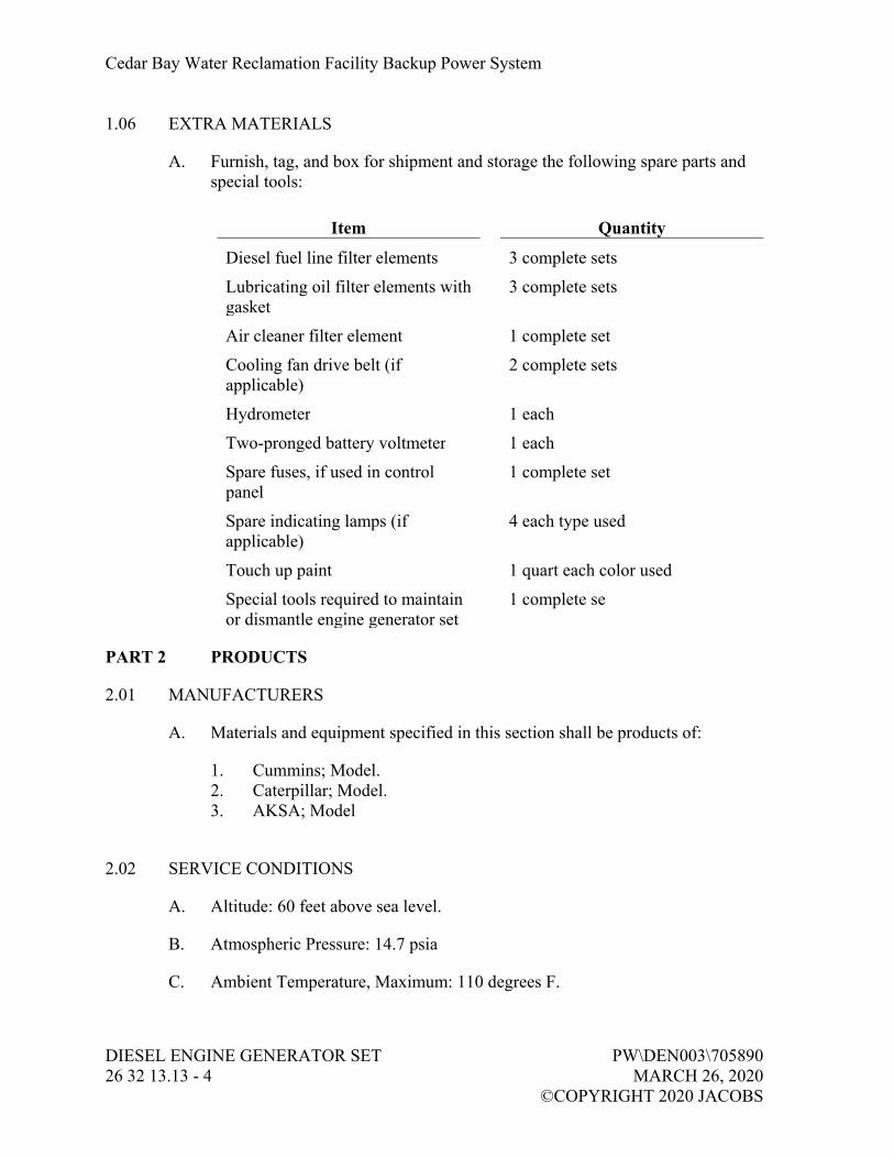
Cedar Bay Water Reclamation Facility Backup Power System
DIESEL ENGINE GENERATOR SET PW\DEN003\705890 26 32 13.13 - 4 MARCH 26, 2020 ©COPYRIGHT 2020 JACOBS
1.06 EXTRA MATERIALS
A. Furnish, tag, and box for shipment and storage the following spare parts and special tools:
Item Quantity
Diesel fuel line filter elements 3 complete sets
Lubricating oil filter elements with gasket
3 complete sets
Air cleaner filter element 1 complete set
Cooling fan drive belt (if applicable)
2 complete sets
Hydrometer 1 each
Two-pronged battery voltmeter 1 each
Spare fuses, if used in control panel
1 complete set
Spare indicating lamps (if applicable)
4 each type used
Touch up paint 1 quart each color used
Special tools required to maintain or dismantle engine generator set
1 complete se
PART 2 PRODUCTS
2.01 MANUFACTURERS
A. Materials and equipment specified in this section shall be products of:
1. Cummins; Model. 2. Caterpillar; Model. 3. AKSA; Model
2.02 SERVICE CONDITIONS
A. Altitude: 60 feet above sea level.
B. Atmospheric Pressure: 14.7 psia
C. Ambient Temperature, Maximum: 110 degrees F.

Cedar Bay Water Reclamation Facility Backup Power System
PW\DEN003\705890 DIESEL ENGINE GENERATOR SET MARCH 26, 2020 26 32 13.13 - 5 ©COPYRIGHT 2020 JACOBS
D. Ambient Temperature, Minimum: 0 degree F.
E. Relative Humidity: 40 percent to 100 percent, high humidity.
F. The enclosures shall be designed to allow operation of the engine/generator within the environment specified above.
2.03 GENERAL
A. Ratings, Unit 1:
1. Operate at 1,800 rpm. 2. Rated at 250 kW, 313 kVA at 0.8 PF, based on specified service
conditions. 3. Voltage: 480Y/277 volts, three-phase, four-wire, 60-Hz, wye connected
alternator output. 4. Rated based on standby service.
B. Ratings, Unit 2:
1. Operate at 1,800 rpm. 2. Rated at 600 kW, 750 kVA at 0.8 PF, based on specified service
conditions. 3. Voltage: 480Y/277 volts, three-phase, four-wire, 60-Hz, wye connected
alternator output. 4. Rated based on standby service.
C. Emissions:
1. Engines: Meet emission requirements specified in 40 CFR Chapter I Part 89 for stationary Internal Combustion (IC) engines.
2. Engine-generator set will be used strictly for standby emergency use, therefore the emissions are not required to meet Tier 4 requirements. Provide a nameplate on the unit that states “For emergency use during utility power failures only”
D. Vibration Design:
1. Use vibration analytical techniques to determine shaft critical speeds, and to develop bearing design and shaft balancing to mitigate vibration.
2. Apply torsional analysis and design to mitigate torsional vibration. 3. Engine and generator, individually, shall not exhibit vibration in any
plane exceeding 10 mils at continuous rating point, when measured at attachment points to common steel subbase.

Cedar Bay Water Reclamation Facility Backup Power System
DIESEL ENGINE GENERATOR SET PW\DEN003\705890 26 32 13.13 - 6 MARCH 26, 2020 ©COPYRIGHT 2020 JACOBS
2.04 ENGINE
A. General:
1. Manufacturer’s standard design, unless otherwise specified. 2. Engine parts designed with adequate strength for specified duty.
B. Type:
1. Diesel Cycle, four-stroke type with unit mounted radiator and fan cooling.
2. Minimum Displacement: As recommended by generator manufacturer. 3. Minimum Number of Cylinders: Twelve.
C. Starting System:
1. Type: Automatic, using 24-volt battery-driven starter acting in response to control panel.
2. Starter: Capable of three complete cranking cycles without overheating. 3. Batteries:
a. Sized as recommended by engine manufacturer. Battery shall be capable of supplying 24V dc power to the engine generator control panel.
b. Lead-acid type. c. Capable of providing 15 seconds minimum of cranking current at
0 degree C and three complete 15-second cranking cycles at 40 degrees C.
d. Housed in acid-resistant frame isolated from engine generator main frame.
e. Located such that maintenance and inspection of engine is not hindered.
f. Complete with battery cables and connectors. 4. Battery Charger:
a. UL 1236 listed and labeled. b. 20-amp automatic float, taper and equalize charge type, with plus
or minus 1 percent voltage regulation over a plus or minus 10 percent input voltage variation.
c. Temperature compensated to operate over an ambient range of minus 30 degrees C to 50 degrees C.
d. Located by generator manufacturer in generator control panel, or wall mounted in generator enclosure.
e. Include: 1) Ammeter and voltmeter. 2) Fused ac input and dc output. 3) Power ON pilot light. 4) AC failure relay and light. 5) Low and high dc voltage alarm relay and light.

Cedar Bay Water Reclamation Facility Backup Power System
PW\DEN003\705890 DIESEL ENGINE GENERATOR SET MARCH 26, 2020 26 32 13.13 - 7 ©COPYRIGHT 2020 JACOBS
f. Alarm relay dry contacts rated 4 amps at 120V ac. g. Wire battery charger status and alarm contacts back to generator
control panel, terminate and identify contacts. Interlock the alarm circuits with an adjustable time delay relay to avoid nuisance system alarms.
D. Fuel System:
1. Engine driven, mechanical, positive displacement fuel pump. 2. Fuel filter with replaceable spin-on canister element. 3. Provide fuel cooler, suitable for operation of generator set at full rated
load in ambient temperature specified if required for operation due to design of engine and installation.
4. Fuel strainer system. 5. As specified under Article Integral Subbase Fuel Tank. 6. Fuel Connections to Engine: Flexible hose, suitable for application.
E. Governing System:
1. Electronic type. 2. Regulates speed as required to hold generating frequency within
tolerable limits and within 5 percent of nominal design speed. 3. Accessories:
a. Manual speed control device. b. Positive overspeed trip switch.
F. Jacket Water Cooling System:
1. Radiator: a. Engine mounted. b. Consisting of jacket water pump, fan assembly, fan guard, and
duct flange outlet. c. Cooling System: Rated for full load operation in 122 degrees F
(50 degrees C) ambient as measured at alternator air inlet. d. Fan: Suitable for use in a system with 0.5 in H2O restriction. e. Sized based on a core temperature that is 20 degrees F higher than
rated operation temperature. 2. Engine Thermostat: As recommended by manufacturer to regulate
engine water temperature. 3. Jacket Water Heater:
a. Suitable for operation on 208–volt, single-phase, 60-Hz current. b. Maintain engine water temperature at 120 degrees F with an
ambient temperature of 50 degrees F. c. Thermostatically controlled.
4. Engine Cooling Liquid: Fill cooling system with a 50/50-ethylene glycol/water mixture prior to shipping.

Cedar Bay Water Reclamation Facility Backup Power System
DIESEL ENGINE GENERATOR SET PW\DEN003\705890 26 32 13.13 - 8 MARCH 26, 2020 ©COPYRIGHT 2020 JACOBS
G. Lubrication System:
1. Type: Full-pressure. 2. Accessories:
a. Pressure switch to initiate shutdown on low oil pressure. b. Oil filter with replaceable element. c. Bayonet type oil level stick. d. Valved oil drain extension.
3. Oil Cooling System: Water-cooled heat exchanger utilizing jacket.
H. Exhaust System:
1. Muffler: Rated for critical grade silencing and coordinated with the noise limits specified for the generator enclosure; sized so as not to exceed allowable engine backpressure.
2. Pipe Connections: Welded. 3. Engine Connection:
a. Flanged, flexible, corrugated, Type 321 stainless steel expansion fitting, specifically suited for diesel exhaust service.
b. Length as required for flexibility and expansion in piping arrangement shown on Drawings.
I. Air Intake System: Equip with dry type air cleaner with filter service (restriction) indicator.
2.05 GENERATOR
A. General:
1. Meet requirements of NEMA MG 1. 2. Synchronous type with 2/3 pitch, revolving field, drip-proof
construction, air cooled by a direct drive centrifugal blower fan. 3. Stator Windings:
a. Skewed for smooth voltage waveform. b. Reconnectable, 12 lead.
4. Overspeed Capability: 125 percent. 5. Waveform Deviation from Sine Wave: 5 percent maximum. 6. Telephone Interference Factor: 50 maximum. 7. Total Harmonic Current and Voltage Distortion: 5 percent maximum,
measured at generator main circuit breaker.
B. Insulation System:
1. Class H, with a maximum rise of 105 degrees C over 40 degree C ambient in accordance with NEMA MG 1.
2. Vacuum pressure impregnated (VPI).

Cedar Bay Water Reclamation Facility Backup Power System
PW\DEN003\705890 DIESEL ENGINE GENERATOR SET MARCH 26, 2020 26 32 13.13 - 9 ©COPYRIGHT 2020 JACOBS
C. Excitation System:
1. Stationary exciter field powered by voltage regulator with rotating exciter/rectifier assembly. Permanent magnet generator (PMG) power supply for voltage regulator.
2. PMG and Controls: Capable of providing regulated current, at a rate of 300 percent of nameplate current, to a single-phase or three-phase fault for 10 seconds.
D. Voltage Regulation:
1. Solid state, three-phase sensing type. 2. Adjustable output voltage level to plus or minus 5 percent. 3. Provisions for proper voltage regulation in presence of heavy non-linear
loads on the breaker as shown. 4. Conformal coating environmental protection.
E. Voltage and Frequency Regulation Performance:
1. Steady State Voltage Regulation: Less than plus or minus 1 percent from no load to continuous rating point.
2. NEMA MG 1 Defined Transient Voltage Dip: a. Less than 20 percent at rapid application of rated load. b. Recovery to rated voltage and frequency within 2 seconds
following initial load application. 3. Steady State Frequency Regulation: Plus or minus 1.5-Hz overload
range.
F. Non-Linear Loads:
1. The generators will be subjected to non-linear loads. Specifically, the larger 600kW generator will be subjected to significant non-linear loads. Although the larger VFDs will be locked out during generator operation, several UV Power Distribution Panels and non-potable water pumps will be operational as listed in the Table shown on drawing E-80-206. The generator supplier shall design the generator system to operate satisfactorily under these conditions.
2. Coordinate with the supplier of the short circuit study to determine the extent of harmonic distortion under generator operation. Verify that 600kW generator shall perform satisfactorily under the specified non-linear load conditions.

Cedar Bay Water Reclamation Facility Backup Power System
DIESEL ENGINE GENERATOR SET PW\DEN003\705890 26 32 13.13 - 10 MARCH 26, 2020 ©COPYRIGHT 2020 JACOBS
G. Motor Starting Capability (600kW Generator):
1. Apply loads listed in the following table:
Key No. Major Load Description Item Designation LOAD KVA
Motor Rating (HP)
LOADS IN BACKUP POWER AT BUILDING 9 LOADS AT EXISTING MCC-100 (UV/REUSE PUMP STATION)
1 Harmonic Conditioner-1 HC-1 1.66 2 UV-PDC-1B 49.88 3 UV-PDC-2D 95.6 4 UV-PDC-2B 57.37 5 Non Potable Water Reuse Pump NPP-901 38.24 50 6 Clarifier CRA-401 1.66 0.25 7 Lighting Transformer (LT-1) 10 8 UV-PDC-2C 99.77 9 Non Potable Water Reuse Pump NPP-902 38.24 50 10 UV-PDC-2A 42.4 11 UV-PDC-1A 41.57 12 SG-103 3.26 2 13 SG-102 3.26 2 14 SG-101 3.26 2 15 Panel (P-1) 2.49 16 SG-105 3.26 2 17 SG-104 3.26 2 18 Harmonic Conditioner-2 HC-2 1.66
H. Motor Starting Capability (250kW Generator)
Key No. Major Load Description Item Designation LOAD KVA
Motor Rating (HP)
LOADS IN BACKUP POWER AT OPERATIONS BUILDING LOADS AT NEW SWBD-4A AND NEW MCC-4A (OPERATIONS BUILDING)
1 A/C Unit 46.55 2 Panel (LP1) 4.4 3 Panel (PP) 56.43 4 Panel (PP1) 20.95 5 AC Condensing Unit 4.16
LOADS AT EXISTING MCC-3 (SLUDGE PUMP STATION)
1 Panel (1A) 26.6
2 Street Lighting Contactor 25.8
3 Bar Screen #1 3
4 Transformer (2A) 4.16
5 Bar Screen #2 3

Cedar Bay Water Reclamation Facility Backup Power System
PW\DEN003\705890 DIESEL ENGINE GENERATOR SET MARCH 26, 2020 26 32 13.13 - 11 ©COPYRIGHT 2020 JACOBS
I. Short Circuit Capabilities: Sustain 300 percent of rated current for 10 seconds for external three-phase bolted fault without exceeding rated temperatures.
J. The engine generator system shall include two bearing and six generator winding RTDs wire to an RTD module part of the generator protector relay in the switchboard.
K. Generator shall include a space heater with temperature switch for automatic control.
L. Main Circuit Breaker:
1. Type: Insulated case. 2. Current Rating: As recommended by generator manufacturer. 3. Interrupt Rating: 65,000 amps RMS symmetrical at 480 volts. 4. Short Time Rating: 35,000 amps RMS symmetrical. 5. Compression lugs for all feeder conductors including neutral and
ground. 6. Trips:
a. Solid state, RMS sensing. b. Adjustable Functions:
1) Long-time current pickup. 2) Long-time delay. 3) High range instantaneous 4) short-time pickup. 5) Short-time delay with I2t function. 6) Ground fault pickup. 7) Ground fault delay.
7. Enclosure: a. Rating: NEMA 250, Type 12. b. Mounted with vibration isolation from engine generator set.
8. Surge Protective Devices: Three-phase capacitors and arresters mounted in terminal compartment.
9. CAMLOCK SWITCH: For each generator furnish a manually operated “Camlock Switch” to allow easy manual switching of generator output from plant load to an owner furnished temporary load bank, as shown on the drawings. The switch shall be installed and wired by the electrical contractor as shown on the drawings. Provide a pre-requisite contact closure output from the camlock switch to engine control panel. This contact closes when the camlock is in the load test position.
M. Grounding Pads: Provide grounding terminals inside the alternator termination housing.
N. Noncorrosive stainless steel nameplate with not less than the minimum information called for in publication MG-1.

Cedar Bay Water Reclamation Facility Backup Power System
DIESEL ENGINE GENERATOR SET PW\DEN003\705890 26 32 13.13 - 12 MARCH 26, 2020 ©COPYRIGHT 2020 JACOBS
2.06 BASEPLATE
A. Mount engine generator set on a rigid common steel base frame.
B. Stiffen base frame to minimize deflections.
2.07 INTEGRAL SUBBASE FUEL TANK
A. General:
1. Tank capacity sufficient to allow full load operation of generator set for 60 hours.
2. UL 142 listed and labeled. 3. Installation: In compliance with NFPA 37. 4. Double-walled, steel construction including the following features:
a. Emergency tank and basin vents. b. Mechanical level gauge. c. Fuel supply and return lines, connected to generator set with
flexible fuel lines as recommended by engine manufacturer and in compliance to UL 2200 and NFPA 37 requirements.
d. Fuel Fill Port: Locate external to the generator enclosure. Include a 7-gallon over-spill catch bucket and an over-spill prevention valve
e. Leak detection provisions, wired to generator set control for local and remote alarm indication.
f. High and low level float switches to indicate fuel level. Wire switches to generator control for local and remote indication of fuel level.
g. The level monitoring system shall be solar gage model EFG-8000 with a Green Leaf Gauge interface providing level and leak detection contacts and analog level signal for remote monitoring.
h. Basin drain. i. Integral lifting provisions.
2.08 VIBRATION ISOLATORS
A. Provide vibration isolators, spring/pad type.
B. Include seismic restraints if required by Site location.
2.09 FUNCTIONAL REQUIREMENTS-GENERATOR CONTROL SYSTEM
A. Local MANUAL – NO LOAD TEST Operation: when engine control switch on engine control panel is in MANUAL NO LOAD TEST mode (with generator switchboard circuit breaker in the switchboard is OPEN), the engine will start and the generator will be brought to rated voltage and frequency.

Cedar Bay Water Reclamation Facility Backup Power System
PW\DEN003\705890 DIESEL ENGINE GENERATOR SET MARCH 26, 2020 26 32 13.13 - 13 ©COPYRIGHT 2020 JACOBS
This mode of operation is used for no load testing of the generator. When the switch is in the OFF position, the engine cannot be started. Provide a pre-requisite interlock with the local generator breaker to ensure the breaker is in the OPEN position.
B. Provide a four-position selector switch on the Engine Control Panel (ECP). The four positions will allow following operations:
1. Position 1: MANUAL – NO LOAD TEST. 2. Position 2: MANUAL – LOAD BANK TEST. 3. Position 3: AUTO – REMOTE. 4. Position 4: OFF.
The functionality of each position is specified herein after.
C. When the engine control switch is in MANUAL-LOAD BANK TEST position, the engine generator is started and loaded via a rented load bank. Pre-requisite for the engine to start in this position is that the CAMLOCK SWITCH should be in a position to connect the generator to load bank. Provide a pre-requisite interlock contact from the CAMLOCK SWITCH to ensure the camlock’s correct position for this operation.
D. When engine control switch on engine control panel is in AUTOMATIC position, the engine START and STOP shall be controlled from the low voltage switchboard. Engine generator set shall start and run upon closure of a remote dry contact output from the Automatic Transfer Controller (ATC) part of the corresponding switchboard as shown on the drawings and specified in Section 26 24 13, Low-Voltage Switchboard and Section 40 99 90, Package Control Systems.
2.10 ENGINE CONTROL PANEL
A. Provide an engine mounted Engine Control Panel (ECP). This control panel shall include all indicators, control switches, alarms, and signal interfaces required for satisfactory operation of the engine generator set. The control panel shall receive signals from a variety of sensors on the engine and alternator including, but not limited to the following:
1. Temperatures: Coolant, after cooler, turbo inlet and exhaust, inlet air, engine oil.
2. Pressures: Atmospheric, turbo inlet/outlet, crank case, oil, fuel, etc. 3. Level: Coolant and fuel. 4. Speed sensors. 5. Alternator voltage/currents.

Cedar Bay Water Reclamation Facility Backup Power System
DIESEL ENGINE GENERATOR SET PW\DEN003\705890 26 32 13.13 - 14 MARCH 26, 2020 ©COPYRIGHT 2020 JACOBS
B. Control Panel:
1. Rating: NEMA 250, Type 12. 2. Material: Steel. 3. Instrument Identification: Face label or engraved, black, laminated
plastic nameplate with white 1/4-inch high letters, attached with Type 422 stainless steel screws.
4. UL 508 listed. 5. Tested to meet or exceed IEEE 587 requirements for voltage surge
resistance. 6. Controls: Solid-state, microprocessor based. Control panel shall be
designed and built by generator manufacturer to provide operating, monitoring, and control functions for generator set.
C. Instrumentation:
1. Type: Suitable for engine-mounted vibration environment. 2. Mounting: Nonshock mounted. 3. Alarm and Signal Contacts: Rated 5 amps at 120V ac, dry. 4. Fault Indication Lamps: Manufacturer’s standard. 5. Meters: Digital with analog display, plus or minus 2 percent accuracy.
D. Operator Controls and Indicators:
1. “MANUAL-NO LOAD TEST / MANUAL-LOAD BANK TEST / AUTO-REM / OFF” selector switch.
2. Generator voltage adjustment. 3. Voltmeter PHASE SELECTOR switch. 4. Ammeter PHASE SELECTOR switch. 5. Voltmeter. 6. Ammeter. 7. Kilo-Watts (kW). 8. Percent kW. 9. Power Factor. 10. FREQUENCY meter. 11. Engine OIL PRESSURE indicator. 12. Engine jacket WATER TEMPERATURE indicator. 13. Engine SPEED indicator (RPM). 14. Engine OIL TEMPERATURE indicator. 15. RUNNING TIME indicator. 16. DC battery voltage. 17. Emergency Stop button.

Cedar Bay Water Reclamation Facility Backup Power System
PW\DEN003\705890 DIESEL ENGINE GENERATOR SET MARCH 26, 2020 26 32 13.13 - 15 ©COPYRIGHT 2020 JACOBS
E. Alarm Indicators with Manual Pushbutton RESET:
1. Low oil pressure. 2. High jacket water temperature. 3. Engine overspeed. 4. Engine overcrank. 5. Low/high dc voltage. 6. Control switch Not In Auto. 7. Battery charger Fail
F. External Interfaces:
1. Provide the following signal interface with each corresponding Automatic Transfer Control (ATC) in the switchboard via Modbus TCP data link: a. Generator Run Status. b. Generator Fail. c. Battery Low. d. Battery Charger Fail. e. Generator not in Auto. f. E-Stop Status. g. Fuel leak Detection. h. Generator Run Command from ATC.
2. Furnish a single, common DPDT relay output upon occurrence of alarm condition.
3. Output: Dry contact rated 5 amps at 120V ac. 4. Accept generator local breaker OPEN contact 5. Accept a contact from CAMLOCK that switch is in LOAD BANK
position.
G. Functional Requirements:
1. LCD text display of alarm/event descriptions. 2. Recranking Lockout: When engine fires, starting control shall
automatically disconnect cranking control to prevent recranking for a preset period of time after engine stop.
3. Overcranking Lockout: Initiate after four cranking cycles of 10 seconds on and 10 seconds off or provide continuous cranking cycle with crank time limiter.
4. Cooldown timer, adjustable from 5 minutes to 60 minutes. 5. Alarms:
a. Low coolant level. b. Low fuel level. c. Low battery voltage d. High battery voltage. e. Battery charger failure.

Cedar Bay Water Reclamation Facility Backup Power System
DIESEL ENGINE GENERATOR SET PW\DEN003\705890 26 32 13.13 - 16 MARCH 26, 2020 ©COPYRIGHT 2020 JACOBS
6. Engine shutdown upon any of the following conditions: a. Engine overspeed. b. Emergency stop button depressed. c. High jacket water temperature. d. Low oil pressure.
7. Air Inlet Damper Opening: a. Upon engine start sequence initiation, a normally closed, dry
contact, rated 5 amps at 120V ac, from engine start circuit shall open to provide a signal to open air inlet dampers.
b. Air Inlet Dampers: Fail open.
H. Special Requirements:
1. Mount battery charger generator enclosure. 2. The voltage regulator and related signal interfaces shall be preferably
part of the ECP. 3. The governor control shall be included in the ECP.
I. Power Requirements: Manufacturers standard, internally connected to engine batteries or to load center in genset enclosure.
2.11 OUTDOOR WEATHER-PROTECTIVE ENCLOSURE
A. General:
1. Provide each generator set with a walk-in type outdoor enclosure, with entire package listed under UL 2200. The minimum distance around the engine-generator shall not be less than 3 feet – 0 inches from engine-generator to end walls 24 inches minimum walk around clearance on sides not including radiator with a minimum 6-foot minimum head clearance. All fasteners and hardware used in construction of the enclosure shall be Type 316 stainless steel. The enclosure shall be designed to withstand 150-mph wind without damage.
2. Package shall comply with requirements of NEC for wiring materials and component spacing.
3. Design total assembly of generator set, enclosure, and subbase fuel tank (when used) to be lifted into place using spreader bars.
4. Housing: a. Provide ample airflow for generator set operation at rated load in
ambient temperature of 100 degrees F. b. Doors:
1) Hinged access doors as required to maintain easy access for operating and service functions. Doors shall be a minimum of 36 inches in width.

Cedar Bay Water Reclamation Facility Backup Power System
PW\DEN003\705890 DIESEL ENGINE GENERATOR SET MARCH 26, 2020 26 32 13.13 - 17 ©COPYRIGHT 2020 JACOBS
2) Lockable and include retainers to hold door open during service.
3) Able to open 180 degrees without obstruction, except rear control panel door, which must open at least 135 degrees.
5. Roof: Cambered to prevent rainwater accumulation. 6. Openings: Screened to limit rodent and insect access into enclosure. 7. Make electrical power and control interconnections within perimeter of
enclosure. 8. Finishes:
a. Prime marine grade aluminum and finish painted with JEA’s standard color using a two-step electrocoating paint process, or equal meeting performance requirements specified below. JEA color is Padmount Green and is Steel-Master 9500 30 Percent Silicone Alkyd Enamel Ultra deep/clear tint base distributed by Sherman-Williams.
b. Prime and paint surfaces of metal parts. Minimum coating requirements: 1) Primer: 0.5 mil to 2.0 mils thick. 2) Top Coat: 0.8 mil to 1.2 mils thick. 3) Gloss:
a) In accordance with ASTM D523, 80 percent plus or minus 5 percent.
b) Gloss Retention After 1 Year: 50 percent minimum. 4) Crosshatch Adhesion: In accordance with ASTM D3359,
4B-5B. 5) Impact Resistance: In accordance with ASTM D2794,
120-inch to 160-inch pounds. 6) Salt Spray: In accordance with ASTM B117, plus
1,000 hours. 7) Humidity: In accordance with ASTM D2247, plus
1,000 hours. 8) Water Soak: In accordance with ASTM D2247, plus
1,000 hours. c. Do not paint hoses, clamps, wiring harnesses, and other
nonmetallic service parts. d. Provide corrosion-resistant fasteners designed to minimize
marring of painted surface when removed for normal installation or service work.
9. Enclosure Minimum Marine Grade Aluminum Thickness: 12-gauge for framework and 14-gauge for panels.
10. Hardware and Hinges: Austenitic stainless steel.

Cedar Bay Water Reclamation Facility Backup Power System
DIESEL ENGINE GENERATOR SET PW\DEN003\705890 26 32 13.13 - 18 MARCH 26, 2020 ©COPYRIGHT 2020 JACOBS
11. Exhaust System: Complete exhaust system includes a stainless steel exhaust silencer, all-stainless steel piping, all-stainless expansion joints and accessories for a complete system. a. The exhaust silencer shall be chamber type, of all welded
Type 304L stainless steel construction with all stainless steel hardware and fasteners secured in position at no less than 4 points.
b. The silencer shall be supported by a welded Type 304 or Type 316 stainless angle iron cradle; silencer shall be bolted or strapped to cradle and then bolted to the roof with horizontal mounting external on top of enclosure. Additional support members shall be mounted inside the roof of the enclosure as required.
c. Roof penetrations for the installation of the silencer shall have a gasket to prevent entrance of rain.
d. The silencer shall be sized so that the backpressure at rated capacity of the engine does not exceed one half the supplier’s maximum allowable backpressure. The silencer shall be suitable for critical type silencing and shall be a Maxim “Model M51” or equal.
e. All exhaust piping shall be Type 304L, Schedule 10S stainless steel, and the exhaust shall discharge horizontally at the silencer outlet, with a 45 degree bevel cut with a stainless expanded metal bird screen.
f. The intake of the silencer shall connect to the flexible exhaust connection by stainless steel pipe. Size as required by engine manufacturer. A flexible stainless steel exhaust adapter, 18 inch minimum length, shall be furnished for mounting between the engine and silencer. The flexible exhaust connection as specified shall mount directly on the exhaust manifold and shall be mounted so that no weight is exerted on the manifold at any time.
12. Maintenance Provisions: a. Flexible coolant and lubricating oil drain lines shall be piped to
outside of enclosure with shutoff valves and have threaded stainless steel or aluminum caps. The threaded drain lines shall be labeled on the outside of the enclosure with an aluminum label or stainless rivets.
b. External radiator-fill provision. c. External fuel fill provision (if equipped with a sub-based fuel
tank). 13. Provide louvers that are screened from the inside to prevent the entry of
insects. The enclosure shall have all penetrations gasketed or sealed to prevent the entry of rodents. “Rain Resistant” louvers, as manufactured by Ruskin or Cesco, vertical air turning plenums, or equal shall be provided to prevent the entrance of rain when the unit is operating, and the wind direction is at 90 degrees to the air intake at 120 mph. The entire enclosure, except for the louvered openings, shall be provided with noise suppression insulation mechanically secured and fastened.

Cedar Bay Water Reclamation Facility Backup Power System
PW\DEN003\705890 DIESEL ENGINE GENERATOR SET MARCH 26, 2020 26 32 13.13 - 19 ©COPYRIGHT 2020 JACOBS
14. Provide rain hoods for inlet ducts. 15. Provide external emergency stop switch that is protected from
accidental actuation. 16. Provide factory mounted and wired electrical distribution panel to serve
all the auxiliaries of the generator set and enclosure, including, but not limited to, jacket water heater, battery chargers, alternator space heater, and engine control panel. Provisions required include: a. A single 480-volt, 3-phase, 60A power feed. b. Fused Disconnect: 60A, 3-pole, NEMA 12. Fuse rating: 45A. c. Step-Down Transformer: 15KVA, 480V-208Y/120V; mounted on
rubber isolator pads. d. Distribution Panelboard: 100A, 208/120V, 3-phase, 4-wire;
copper bus; NEMA 12; 100A main breaker; all necessary branch circuit breakers to feed enclosure lights, receptacles, engine block heaters, battery charger, and other accessories.
e. Two duplex GFI receptacles, one inside enclosure, and one weatherproof receptacle on outside of enclosure.
f. Two three-way switches controlling three ac lamps mounted in vapor tight and gasketed fixtures.
g. Factory-wired normal ac service from panelboard to engine coolant and alternator heaters, and battery charger.
17. Internal Wiring: All wiring within the enclosure shall be EMT. Connections at the generator set shall be flexible, and shall be factory provided prior to shipment to the installation site.
18. Sound Attenuation: a. Provide with sound-attenuated housing which allows generator set
to operate at full rated load in an ambient temperature of up to 100 degrees F.
b. Design, provide, and install enclosure to reduce sound level of generator set while operating at full rated load to a maximum of 86 dBA at any location 15 feet from generator set in a free field environment when tested in accordance with SAE J1074.
c. Insulate enclosure with nonhydroscopic materials. 19. Enclosure shall be Phoenix Products, Advanced Manufacturing &
Power Systems Inc., or Fidelity Manufacturing.
2.12 PLATFORM
A. Features:
1. Cantilever supported off base with 10-gauge formed steel frame, toe plates, railing posts (pipes), rails, and grate assemblies coated with powder black.
2. Do not connect platform to subbase tank.

Cedar Bay Water Reclamation Facility Backup Power System
DIESEL ENGINE GENERATOR SET PW\DEN003\705890 26 32 13.13 - 20 MARCH 26, 2020 ©COPYRIGHT 2020 JACOBS
3. Laser cut structural materials to a tolerance of 1/16 inch, allowing no sharp edges.
4. Bolts: 5/16-inch diameter, minimum. 5. Design platform to provide access to generator enclosure service doors
for maintenance and inspection and, at minimum, wrap around sides and back of generator.
6. Provide ship’s ladder to access platform. 7. Platform Height: No greater than 1.5 inches above bottom of generator
base frame. 8. Walkway Tread: 1-inch vertical steel grating, black powder coated, on
1-3/16-inch centers, connected by horizontal steel rods on 4-inch centers. Cover cut grate edges with 14-gauge, black powder coated, 1/2-inch by 1/2-inch angled steel.
9. Handrails: Horizontal, 42 inches above walkway. 10. Steel Component Coating: Pressure wash clean with an iron phosphate
solution and apply 3 mils of high gloss black powder baked paint. 11. Platform, Walkway, and Ladder: Meet requirements of OSHA 3124. 12. Manufacturer: Generator System Support, Inc. or approved equal.
2.13 FACTORY FINISHING
A. Engine Generator Set and Instrument Panel: Factory-applied primer and two finish coats of manufacturer’s standard heat-resistant engine paint.
2.14 FACTORY TESTS
A. General: Conform to NFPA 110.
B. Steady Load Test: Conduct a steady load run for the durations listed below at each applied load rating:
1. 50 percent applied load for 1 hour. 2. 75 percent applied load for 1 hour. 3. 100 percent applied load for 3 hours. 4. Record at 15-minute intervals the generator output voltage, frequency,
load current, oil pressure, and engine coolant temperature. Complete test reports shall be made which shall show the engine fuel consumption and kW output. Test results to be reviewed and approved prior to shipment.
C. Record and Report:
1. Engine fuel consumption. 2. Power output.

Cedar Bay Water Reclamation Facility Backup Power System
PW\DEN003\705890 DIESEL ENGINE GENERATOR SET MARCH 26, 2020 26 32 13.13 - 21 ©COPYRIGHT 2020 JACOBS
D. Factory Tests shall also include:
1. Resistance of all windings (cold). 2. Insulation resistance of all windings. 3. High potential on all windings. 4. Open circuit saturation. 5. Voltage balance on windings. 6. Current balance on windings. 7. Voltage transient at rated kVA (voltage regulation, stability, and
response). 8. Regulator range test (voltage adjust). 9. Phase sequence. 10. Mechanical balance (vibration). 11. Inherent voltage regulation. 12. Shaft currents with calculated summary of parallel operation.
E. Provide 4 weeks' notice to the Owner and Owner’s Representative before any factory test is conducted to allow witnessing the tests.
PART 3 EXECUTION
3.01 INSTALLATION
A. Level and securely mount engine generator set in accordance with manufacturer’s recommendations.
B. Install in accordance with NECA 404.
C. Where applicable, mount engine generator set on vibration isolators in accordance with isolator manufacturer’s recommendations.
3.02 FIELD FINISHING
A. Touchup damaged coating with paint system compatible to existing.
3.03 FIELD TESTS
A. Submit a test plan that includes switchboard and plant SCADA load shedding tests. Coordinate with PICS contractor to prepare completely integrated test plan. An approved test plan is a pre-requisite to scheduling a field test.
B. General:
1. Conform to NFPA 110. 2. Fuel provided by Contractor. 3. Top off fuel after testing.

Cedar Bay Water Reclamation Facility Backup Power System
DIESEL ENGINE GENERATOR SET PW\DEN003\705890 26 32 13.13 - 22 MARCH 26, 2020 ©COPYRIGHT 2020 JACOBS
C. Perform field relay coordination and calibration before conducting any tests.
D. Coordinate the tests with the Owner so as to minimize disruptions to Plant operations.
E. Initial Commissioning:
1. Calibrate the generator with a minimum 4-hours load bank (resistive and reactive) operation including at least 1 hour at 25, 50, 75, and 100 percent rated load. Provide connections for load bank equipment and cables that are furnished by manufacturer.
2. Verify that the engine generator meets the EPA Air Permit Limits and the Tier 2 emissions limits. Tests performed shall include measuring the actual emissions from each engine generator when operating at 100 percent load.
3. Manufacturer’s representative shall make necessary adjustments. 4. Complete transfer/retransfer operational tests shall be performed
proving automatic and manual transfer operations as shown on Drawings and specified in Sections 26 24 13, Low-Voltage Switchboard, 40 99 90, Package Control Systems, and 40 96 90, Facility Control System Integration. All specified functional requirements shall be verified by actual tests, including load shedding through plant SCADA, load assumption, reset of load shed interlocks, and transfer back to utility.
5. Put the generator into service to provide standby power to switchgear in the event that there is a utility outage while the Electrical Upgrade project is under way.
F. Performance Test:
1. Following the transfer of all loads to new switchgear the generator shall be given operational tests under full Plant load.
2. Operate 2 hours minimum under Plant load. 3. Load the generator with building loads and Plant treatment systems. 4. Manufacturer’s representative shall make necessary adjustments. 5. Demonstrate ability of engine generator set to carry specified loads. 6. Demonstrate engine generator set preliminary alarms and safety
shutdowns. 7. Complete transfer/retransfer operational tests shall be performed
proving automatic and manual transfer operations as specified in specification sections noted above under paragraph E, Initial Commissioning. All specified functional requirements shall be verified by actual tests, including load assumption and transfer back to utility.

Cedar Bay Water Reclamation Facility Backup Power System
PW\DEN003\705890 DIESEL ENGINE GENERATOR SET MARCH 26, 2020 26 32 13.13 - 23 ©COPYRIGHT 2020 JACOBS
8. Control system test must be jointly performed with the PICS Subcontractor. a. Show that data exchange between the generator PLCs and the
plant control system is working satisfactorily and the graphics at the plant HMI dynamically and accurately display all data acquired from generator PLC.
b. The load shedding interlocks for plant loads are implemented via plant SCADA PLC whereas the auto load transfer is part of ATC in the switchboard. PICS contractor is responsible for load shedding logic and data exchange whereas ATC control is the responsibility of switchboard supplier and electrical subcontractor.
9. Demonstrate ability of engine generator set to carry specified loads. 10. Demonstrate engine generator set safety shutdowns.
G. Test Report: Record and report the following:
1. Electric load on generator. 2. Fuel consumption. 3. Exhaust temperature. 4. Ambient air temperature. 5. Safety shutdown performance results. 6. Noise levels at 7 meters Property line.
H. Post-test Requirements:
1. Make final adjustments. 2. Replace fuel and oil filters. 3. Check belt drive tensions. 4. Demonstrate proper operation of equipment, including automatic
operation with control from automatic transfer switch, to Engineer and Owner.
3.04 MANUFACTURER’S SERVICES
A. Manufacturer’s Representative: Present at Site or classroom designated by Owner, for minimum person-days listed below, travel time excluded:
1. 3 person-days for installation assistance and inspection. 2. 3 person-days for functional and performance testing and completion of
Manufacturer’s Certificate of Proper Installation. 3. 3 person-days for prestartup classroom or Site training. 4. 3 person-days for facility startup.

Cedar Bay Water Reclamation Facility Backup Power System
DIESEL ENGINE GENERATOR SET PW\DEN003\705890 26 32 13.13 - 24 MARCH 26, 2020 ©COPYRIGHT 2020 JACOBS
5. 1 person-day for post-startup training of Owner’s personnel. Training shall not commence until an accepted detailed lesson plan for each training activity has been reviewed by Engineer.
B. See Section 01 43 33, Manufacturers’ Field Services and Section 01 91 14, Equipment Testing and Facility Startup.
END OF SECTION

Cedar Bay Water Reclamation Facility Backup Power System
PW\DEN003\705890 FACILITY LIGHTNING PROTECTION MARCH 26, 2020 26 41 00 - 1 ©COPYRIGHT 2020 JACOBS
SECTION 26 41 00 FACILITY LIGHTNING PROTECTION
PART 1 GENERAL
1.01 REFERENCES
A. The following is a list of standards which may be referenced in this section:
1. Lightning Protection Institute (LPI): 175, Standard of Practice. 2. National Fire Protection Association (NFPA):
a. 70, National Electrical Code (NEC). b. 780, Standard for the Installation of Lightning Protection Systems.
3. UL: a. 96, Standard for Lightning Protection Components. b. 96A, Standard for Installation Requirements for Lightning
Protection Systems.
1.02 DESIGN REQUIREMENTS
A. Provide lightning protection system design for the following structures:
1. 250kW Generator Walk-in Enclosure. 2. 600kW Generator Walk-in Enclosure.
B. Design lightning protection system to comply with applicable provisions of LPI 175, UL 96, UL 96A, and NFPA 780.
1.03 SUBMITTALS
A. Action Submittals:
1. Reproducible Drawings, signed and sealed by a Florida Professional Engineer (PE): a. Lightning protection system layout. b. Component locations. c. Detailed plans.
2. Down conductor. 3. Connecting conductor. 4. Bond strap. 5. Air terminals. 6. Fittings. 7. Connectors. 8. Ground rods.

Cedar Bay Water Reclamation Facility Backup Power System
FACILITY LIGHTNING PROTECTION PW\DEN003\705890 26 41 00 - 2 MARCH 26, 2020 ©COPYRIGHT 2020 JACOBS
B. Informational Submittals:
1. Field test report. 2. Ground Witness Certification-Form LPI-175A. 3. Post-Installation Certification-Form LPI-175B. 4. UL 96 Master Label Certification for the complete, installed system.
1.04 QUALITY ASSURANCE
A. Designer: Lightning protection system design shall be prepared by an LPI-certified designer, or recognized lightning protection manufacturer, signed and sealed by a Florida Professional Engineer (PE).
B. System components shall be the product of a manufacturer regularly engaged in the manufacturing of lightning protection components in accordance with UL 96.
C. Lightning protection system shall be installed under direct supervision of an LPI 175 Certified Master Installer.
D. Inspection of final installation and grounding connection shall be performed by an LPI-certified inspector.
E. Provide the Work in accordance with NFPA 70, National Electrical Code (NEC). Where required by Authority Having Jurisdiction (AHJ), material and equipment shall be labeled or listed by a nationally recognized testing laboratory (NRTL) or other organization acceptable to the AHJ in order to provide a basis for approval under NEC.
F. Materials and equipment manufactured within the scope of standards published by UL shall conform to those standards and shall have an applied NRTL Listing or Labeling mark.
PART 2 PRODUCTS
2.01 MANUFACTURERS
A. Materials, equipment, and accessories specified in this section shall be products of:
1. Thompson Lightning. 2. IPC Protection. 3. Erico Eritech Lightning Protection Systems. 4. VFC, Inc. 5. Robbins Lightning, Inc.

Cedar Bay Water Reclamation Facility Backup Power System
PW\DEN003\705890 FACILITY LIGHTNING PROTECTION MARCH 26, 2020 26 41 00 - 3 ©COPYRIGHT 2020 JACOBS
2.02 GENERAL
A. Complete system shall bear UL 96 Master Label Certification.
B. Power system surge protection is provided under other sections of these Specifications.
C. System Material: Copper or high copper content, heavy-duty bronze castings, or aluminum, unless otherwise specified.
D. Material shall comply in weight, size, and composition for the class of structure to be protected as established by NFPA 780.
2.03 COMPONENTS
A. Air Terminal:
1. Material: Solid aluminum with tapered or blunt points as required for application.
2. Length: Sufficient to extend minimum 10 inches above object being protected.
3. UL 96 Label B applied to each terminal.
B. Conductors:
1. Lightning System Conductors: Bare medium hard-drawn stranded copper, or stranded aluminum as required for the application.
2. Main Down Conductor: Smooth twist stranding. 3. Connecting Conductor: Concentric stranding. 4. Bonding Conductor: Flexible strap. 5. Main down and connecting conductors shall bear the UL 96 Label A,
applied every 10 feet. 6. Grounding Conductors: Stranded bare copper.
C. Cable Fastener and Accessories: Capable of withstanding minimum pull of 100 pounds.
D. Fittings:
1. Heavy-duty. 2. Bolts, Screws, and Related Hardware: Stainless steel.
E. Ground Rods: As specified in Section 26 05 26, Grounding and Bonding for Electrical Systems.
Cedar Bay Water Reclamation Facility Backup Power System
FACILITY LIGHTNING PROTECTION PW\DEN003\705890 26 41 00 - 4 MARCH 26, 2020 ©COPYRIGHT 2020 JACOBS
F. Grounding Connections: As specified in Section 26 05 26, Grounding and Bonding for Electrical Systems.
G. Cable Connections and Splicers: As specified in Section 26 05 26, Grounding and Bonding for Electrical Systems.
H. Conduit: Schedule 40 PVC, as specified in Section 26 05 33, Raceway and Boxes.
PART 3 EXECUTION
3.01 GENERAL
A. Workmanship to comply with all applicable provisions of LPI 175, UL 96, UL 96A, and NFPA 780.
B. Aluminum materials shall be used where required to meet the galvanic corrosion requirements of UL 96A.
C. Provide pitchpockets or method compatible with roofing to waterproof roof penetrations.
D. Install system in inconspicuous manner so components blend with equipment aesthetics.
3.02 EXAMINATION
A. Verify conditions prior to installation. Actual conditions may require adjustments in air terminal and ground rod locations.
3.03 INSTALLATION
A. Air Terminals:
1. Supports: Brackets or braces. 2. Parapet Bracket Attachment: Lag or expansion bolts. 3. Secure base to roof surface with adhesive or pitch compatible with
roofing bond. 4. Provide terminal flashing at roof penetrations. 5. Perimeter Terminals:
a. Maximum Spacing: 20 feet. b. Maximum Distance From Outside Edge of Building: 2 feet.
6. Roof Ridge Terminals: Maximum spacing 20 feet. 7. Mid-Roof Terminals: Maximum spacing 50 feet. 8. Provide blunt point air terminals for applications exposed to personnel.

Cedar Bay Water Reclamation Facility Backup Power System
PW\DEN003\705890 FACILITY LIGHTNING PROTECTION MARCH 26, 2020 26 41 00 - 5 ©COPYRIGHT 2020 JACOBS
B. Conductors:
1. Conceal whenever practical. 2. Provide 1-inch PVC conduit in enclosure walls or columns for main
downleads and roof risers. 3. Support: Maximum spacing for exposed conductors.
a. Vertical: 3 foot. b. Horizontal: 4 foot.
4. Maintain horizontal and vertical conductor courses free from dips or pockets.
5. Bends: Maximum 90 degrees, with minimum 8-inch radius. 6. Install air terminal conductors on the structural roof surface before
roofing composition is applied.
C. Bonding:
1. Bond to Main Conductor System: a. Roof-mounted ventilators, fans, air handlers, masts, flues, cooling
towers, handrails, and other sizeable metal objects. b. Roof flashing, gravel stops, insulation vents, ridge vents, roof
drains, soil pipe vents, and other small metal objects if located within 6 feet of main conductors or another grounded object.
2. Bond each steel column or major framing members to grounding system.
3. Bond each main down conductor to grounding system.
D. Grounding Electrode System: Bond all down conductors to the generator’s grounding electrode system as shown on Drawings. Design of the grounding electrode system is responsibility of Owner’s Engineer and shall provide a maximum resistance to remote earth 5 ohms.
3.04 FIELD QUALITY CONTROL
A. Field Testing:
1. Coordinate with the requirements of Section 26 05 26, Grounding and Bonding for Electrical Systems.
2. Isolate lightning protection system from other ground conditions while performing tests.
Cedar Bay Water Reclamation Facility Backup Power System
FACILITY LIGHTNING PROTECTION PW\DEN003\705890 26 41 00 - 6 MARCH 26, 2020 ©COPYRIGHT 2020 JACOBS
3. Resistance: Test ground resistance to remote earth after power system is energized and with utility neutral connected. Testing shall utilize a clamp-on ground resistance meter such as AEMC 3711, Fluke 1630, Greenlee CMGRT-100, or equivalent device. Ground resistance meter must have a current certificate of calibration not exceeding 12 months at time of installation testing. Fall-of-Potential testing is not acceptable. a. Test shall be conducted on the grounding electrode conductor of
the service-entrance equipment. b. Resistance to Remote Earth: Maximum 5 ohms. c. Contact Owner’s Engineer for remediation solutions should
measurement exceed the maximum value allowed. 4. Test Report:
a. Description of equipment tested. b. Description of test. c. Test results. d. Conclusions and recommendations. e. Appendix, including appropriate test forms. f. Identification of test equipment used. g. Signature of responsible test organization authority.
END OF SECTION

Cedar Bay Water Reclamation Facility Backup Power System
PW\DEN003\705890 SURGE PROTECTIVE DEVICES MARCH 26, 2020 26 43 00 - 1 ©COPYRIGHT 2020 JACOBS
SECTION 26 43 00 SURGE PROTECTIVE DEVICES
PART 1 GENERAL
1.01 REFERENCES
A. The following is a list of standards which may be referenced in this section:
1. American National Standards Institute (ANSI). 2. Department of Defense: MIL-STD-220C, Test Method Standard –
Method of Insertion Loss Measurement. 3. Institute of Electrical and Electronics Engineers, Inc. (IEEE):
a. C62.41.1, IEEE Guide on the Surge Environment in Low-Voltage (1000 V and less) AC Power Circuits.
b. C62.41.2, IEEE Recommended Practice on Characterization of Surges in Low-Voltage (1000 V and less) AC Power Circuits.
c. C62.45, IEEE Recommended Practice on Surge Testing for Equipment Connected to Low-Voltage (1000 V and less) AC Power Circuits.
4. National Fire Protection Association (NFPA): 70, National Electrical Code (NEC).
5. UL: a. 497A, Standard for Secondary Protectors for Communications
Circuits. b. 1283, Standard for Electromagnetic Interference Filters. c. 1449, Standard for Surge Protective Devices.
1.02 SUBMITTALS
A. Action Submittals:
1. Product data on each suppressor type, indicating component values, part numbers, and conductor sizes. Include dimensional drawing for each, showing mounting arrangements.
2. Electrical single-line diagram showing location of each SPD. 3. Manufacturer’s UL certified test data and nameplate data for each surge
protective device (SPD).

Cedar Bay Water Reclamation Facility Backup Power System
SURGE PROTECTIVE DEVICES PW\DEN003\705890 26 43 00 - 2 MARCH 26, 2020 ©COPYRIGHT 2020 JACOBS
1.03 QUALITY ASSURANCE
A. UL Compliance and Labeling:
1. SPDs for Power and Signal Circuits: Comply with UL 1449 and complimentary listed to UL 1283 as an electromagnetic interference filter. Provide units listed and labeled by UL.
2. SPDs for Telephone Circuit Protection: Comply with UL 497A.
B. ANSI Compliance: Use SPD devices in compliance with the recommendations of IEEE C62.41.1, IEEE C62.41.2, and IEEE C62.45.
PART 2 PRODUCTS
2.01 MANUFACTURER
A. Eaton, SPD Series.
B. General Electric, Tranquell.
C. Square D, Surelogic.
D. Advanced Protection Technologies, Inc.
E. CITEL, MDS Series.
F. Or approved equal.
2.02 GENERAL
A. Unless indicated otherwise, provide direct bus-connected and factory-installed SPDs inside distribution equipment.
B. SPD Operating Conditions: Capable of performing at ambient temperatures between minus 40 degrees C and 60 degrees C, at relative humidity ranging from 0 percent to 95 percent, and at altitudes ranging from sea level to 12,000 feet.
C. Connect SPDs through a fused switch or circuit breaker as selected by manufacturer. Provide overcurrent protection to allow full surge handling capabilities and afford safety protection from thermal overloads and short circuits.
D. SPD Short Circuit Current Rating (SCCR): No less than the SCCR of distribution equipment.

Cedar Bay Water Reclamation Facility Backup Power System
PW\DEN003\705890 SURGE PROTECTIVE DEVICES MARCH 26, 2020 26 43 00 - 3 ©COPYRIGHT 2020 JACOBS
E. Design SPD devices to protect all modes (L-L, L-N, L-G, N-G) of electrical system being used.
F. Power Filter: Include a high-frequency extended range power filter for each SPD complimentary listed to UL 1283 as an electromagnetic interference filter.
G. Provide SPDs with the following monitoring and diagnostics:
1. LED-type indication lights to show normal and failed status of each protected phase.
2. Surge event counter. 3. Form C dry contact which operates when unit fails.
H. Provide UL Type 2 SPDs.
I. EMI/RFI Noise Suppression: -50dB attenuation at 100 kHz, tested per MIL-STD 220C.
J. Voltage Protection Rating (VPR):
Voltage Rating L-N N-G L-G L-L
208Y/120 800 800 800 1200
480Y/277 1200 1200 1200 2000
240 ∆ -- -- 1200 1200
480 ∆ -- -- 2000 2000
2.03 SERVICE ENTRANCE AND DISTRIBUTION SPD
A. Provide SPD meeting IEEE C62.41.1 and IEEE C62.41.2 Location in accordance with Category C.
B. Surge current capacity shall be not less than the following:
1. L-L Capacity: 200 kA. 2. L-N Capacity: 200 kA. 3. L-G Capacity: 120 kA. 4. N-G Capacity: 120 kA.
C. Maximum Continuous Operating Voltage (MCOV): Not less than 115 percent of nominal system voltage.
D. Nominal Discharge Current (IN): 20kA.

Cedar Bay Water Reclamation Facility Backup Power System
SURGE PROTECTIVE DEVICES PW\DEN003\705890 26 43 00 - 4 MARCH 26, 2020 ©COPYRIGHT 2020 JACOBS
2.04 PANELBOARD SPD
A. Provide SPD meeting IEEE C62.41.1 and IEEE C62.41.2 Location in accordance with Category B.
B. Surge current capacity shall be not less than the following:
1. L-L Capacity: 80 kA. 2. L-N Capacity: 80 kA. 3. L-G Capacity: 80 kA. 4. N-G Capacity: 80 kA.
C. Nominal Discharge Current: 20 kA.
D. Suppressor shall be in an enclosure that has the same NEMA rating as the panel it protects or the TVSS may be integral to a panelboard.
E. UL 1449 maximum clamp voltage shall not be more than:
System Voltage Phase L-L or L-N Clamp
Voltage
120 1 400
208Y/120 3 400
240 3 800
480Y/277 3 800
2.05 ANNUNCIATION
A. Provide unit or separately mounted LED-type indication lights to show the normal and failed status of each module. Provide one normally open and one normally closed contacts which operate when the unit fails.
2.06 SURGE COUNTER
A. Provide each TVSS rated above 100 kA with a counter displaying the number of voltage transients that have occurred on the unit input. The counter shall be battery backed and retain the count through system power outages.
2.07 PAIRED CABLE DATA LINE INTERIOR SUPPRESSORS
A. Provide units meeting IEEE C62.41, Location Category A.
B. Use bi-polar 1,500-watt silicon avalanche diodes between the protected conductor and earth ground.

Cedar Bay Water Reclamation Facility Backup Power System
PW\DEN003\705890 SURGE PROTECTIVE DEVICES MARCH 26, 2020 26 43 00 - 5 ©COPYRIGHT 2020 JACOBS
C. Provide units with a maximum single impulse current rating of 80 amperes (10 by 1,000 microsecond-waveform).
D. Breakdown voltage shall not exceed 36 volts.
2.08 PAIRED CABLE DATA LINE EXTERIOR SUPPRESSORS
A. Provide units meeting IEEE C62.41, Location Category A.
B. Suppressors shall be a hybrid design with a minimum of three stages, utilizing solid-state components and operating bi-directionally.
C. Suppressors shall meet or exceed the following criteria:
1. Maximum single impulse current rating of 10,000 amperes (8 by 20 microsecond-waveform).
2. Pulse Life Rating: 3,000 amperes (8 by 20 microsecond-waveform): 2,000 occurrences.
3. Maximum clamping voltage at 10,000 amperes (8 by 20 microsecond current waveform), shall not exceed the peak of the normal applied signal voltage by 200 percent.
PART 3 EXECUTION
3.01 APPLICATION REQUIREMENTS
A. Provide SPDs when indicated on Drawings or in the equipment specifications.
B. Provide factory-installed SPDs as integral components to new switchgear, switchboards, motor control centers, panelboards and transfer switches. Externally mounted SPDs are not acceptable for new distribution equipment.
C. Externally mounted SPDs are acceptable for SPDs added to existing equipment as described below.
D. Electronic Equipment Paired Cable Conductors: Install data line suppressors at the low voltage input and output of each piece of equipment, including telephone cable entrance.
1. Use secondary protectors on lines that do not exit the structure. 2. Use primary protectors on lines that exit and enter the structure.
3.02 GENERAL INSTALLATION REQUIREMENTS
A. Install suppressors according to manufacturer’s recommendations.

Cedar Bay Water Reclamation Facility Backup Power System
SURGE PROTECTIVE DEVICES PW\DEN003\705890 26 43 00 - 6 MARCH 26, 2020 ©COPYRIGHT 2020 JACOBS
B. Install suppressors directly to the cabinet which houses the circuit to be protected so that the suppressor leads are straight and short, with conductors laced, running directly to the point of connection within the panel, without loops or bends. If bends are unavoidable, no bend may exceed 90 degrees and bending radius may not be less than 6 inches.
C. Provide connecting wires as short as possible with gently twisted conductors, tied together, to prevent separation.
1. Maximum Length: 24 inches.
D. Field Installed Conductors: As specified for building wire, not smaller than 8 AWG and not larger than 4 AWG. Provide device leads not longer than the maximum length recommended by manufacturer, unless specifically reviewed and approved by manufacturer.
E. Provide dedicated disconnecting means for SPD devices installed at main service entrance location, switchgear, and motor control centers. Provide dedicated 30-60-ampere circuit breakers (size dependent upon wire size used) with number of poles as required, as disconnecting means for SPD devices. Provide circuit breakers with interrupting capacity equal to that specified for other breakers at that location.
END OF SECTION

Cedar Bay Water Reclamation Facility Backup Power System
PW\DEN003\705890 SITE CLEARING MARCH 26, 2020 31 10 00 - 1 ©COPYRIGHT 2020 JACOBS
SECTION 31 10 00 SITE CLEARING
PART 1 GENERAL
1.01 DEFINITIONS
A. Interfering or Objectionable Material: Trash, rubbish, and junk; vegetation and other organic matter, whether alive, dead, or decaying; topsoil.
B. Clearing: Removal of interfering or objectionable material lying on or protruding above ground surface.
C. Grubbing: Removal of vegetation and other organic matter including stumps, buried logs, and roots greater than 2-inch caliper to a depth of 6 inches below subgrade.
D. Project Limits: Areas, as shown or specified, within which Work is to be performed.
1.02 QUALITY ASSURANCE
A. Obtain Engineer’s approval of staked clearing, grubbing limits, prior to commencing clearing, grubbing.
1.03 SCHEDULING AND SEQUENCING
A. Prepare Site only after adequate erosion and sediment controls are in place. Limit areas exposed uncontrolled to erosion during installation of temporary erosion and sediment controls.
PART 2 PRODUCTS (NOT USED)
PART 3 EXECUTION
3.01 GENERAL
A. Clear, grub areas actually needed for Site improvements within limits shown or specified.
B. Do not injure or deface vegetation that is not designated for removal.

Cedar Bay Water Reclamation Facility Backup Power System
SITE CLEARING PW\DEN003\705890 31 10 00 - 2 MARCH 26, 2020 ©COPYRIGHT 2020 JACOBS
3.02 LIMITS
A. As follows, but not to extend beyond Project limits.
1. Excavation: 5 feet beyond top of cut slopes. 2. Fill: Clearing and Grubbing: 5 feet beyond toe of permanent fill. 3. Structures: 15 feet outside of new structures. 4. Other Areas: As shown.
B. Remove rubbish, trash, and junk from entire area within Project limits.
3.03 CLEARING
A. Clear areas within limits shown or specified.
B. Fell trees so that they fall away from facilities and vegetation not designated for removal.
C. Cut stumps not designated for grubbing flush with ground surface.
D. Cut off shrubs, brush, weeds, and grasses to within 2 inches of ground surface.
3.04 GRUBBING
A. Grub areas within limits shown or specified.
3.05 DISPOSAL
A. Clearing and Grubbing Debris:
1. Dispose of debris offsite. 2. Burning of debris onsite will not be allowed. 3. Limit offsite disposal of clearing and grubbing debris to locations that
are approved by federal, state, and local authorities, and that will not be visible from Project.
END OF SECTION

Cedar Bay Water Reclamation Facility Backup Power System
PW\DEN003\705890 SUBGRADE PREPARATION MARCH 26, 2020 31 23 13 - 1 ©COPYRIGHT 2020 JACOBS
SECTION 31 23 13 SUBGRADE PREPARATION
PART 1 GENERAL
1.01 REFERENCES
A. The following is a list of standards which may be referenced in this section:
1. ASTM International (ASTM): D1557, Standard Test Method for Laboratory Compaction Characteristics of Soil Using Modified Effort (56,000 ft-lbf/ft3 (2,700 kN-m/m3)).
1.02 DEFINITIONS
A. Optimum Moisture Content: As defined in Section 31 23 23.15, Trench Backfill.
B. Prepared Ground Surface: Ground surface after completion of clearing and grubbing, stripping of topsoil, excavation to grade, and scarification and compaction of subgrade.
C. Relative Compaction: As defined in Section 31 23 23.15, Trench Backfill.
D. Subgrade: Layer of existing soil after completion of clearing, grubbing, stripping of topsoil prior to placement of fill, roadway structure or foundations.
E. Proof-Rolling: Testing of subgrade by compactive effort to identify areas that will not support the future loading without excessive settlement.
1.03 SEQUENCING AND SCHEDULING
A. Complete applicable Work specified in Sections 31 10 00, Site Clearing; and 31 23 16, Excavation, prior to subgrade preparation.
1.04 QUALITY ASSURANCE
A. Notify Engineer when subgrade is ready for compaction or proof-rolling or whenever compaction or proof-rolling is resumed after a period of extended inactivity.

Cedar Bay Water Reclamation Facility Backup Power System
SUBGRADE PREPARATION PW\DEN003\705890 31 23 13 - 2 MARCH 26, 2020 COPYRIGHT 2020 JACOBS
PART 2 PRODUCTS (NOT USED)
PART 3 EXECUTION
3.01 GENERAL
A. Keep subgrade free of water, debris, and foreign matter during compaction or proof-rolling.
B. Bring subgrade to proper grade and cross-section and uniformly compact surface.
C. Do not use sections of prepared ground surface as haul roads. Protect prepared subgrade from traffic.
D. Maintain prepared ground surface in finished condition until next course is placed.
3.02 COMPACTION
A. Under Foundations, Roadways and Structural Fill: Proof-roll subgrade with at least 15 overlapping vibratory passes using a 10-ton or heavier vibratory roller.
B. Under Foundations, Roadways and Structural Fill: Compact the upper 12 inches to minimum 95 percent relative compaction as determined by ASTM D1557.
3.03 MOISTURE CONDITIONING
A. Dry Subgrade: Add water, then mix to Optimum Moisture Content uniformly throughout.
B. Wet Subgrade: Aerate material to Optimum Moisture Content uniformly throughout by blading, discing, harrowing, or other methods, to hasten drying process.
3.04 TESTING
A. One compaction test shall be performed under each generator pad and each concrete driveway for a total of four tests.
Cedar Bay Water Reclamation Facility Backup Power System
PW\DEN003\705890 SUBGRADE PREPARATION MARCH 26, 2020 31 23 13 - 3 ©COPYRIGHT 2020 JACOBS
3.05 CORRECTION
A. Soft or Loose Subgrade:
1. Adjust moisture content and recompact, or 2. Over excavate as specified in Section 31 23 16, Excavation, and
replace with suitable material from the excavation, as specified in Section 31 23 23.15, Trench Backfill.
B. Unsuitable Material: Over excavate as specified in Section 31 23 16, Excavation, and replace with suitable material from the excavation, as specified in Section 31 23 23.15, Trench Backfill.
END OF SECTION


Cedar Bay Water Reclamation Facility Backup Power System
PW\DEN003\705890 EXCAVATION MARCH 26, 2020 31 23 16 - 1 ©COPYRIGHT 2020 JACOBS
SECTION 31 23 16 EXCAVATION
PART 1 GENERAL
1.01 QUALITY ASSURANCE
A. Provide adequate survey control to avoid unauthorized overexcavation.
1.02 WEATHER LIMITATIONS
A. Material excavated during inclement weather shall not be used as fill or backfill until after material drains and dries sufficiently for proper compaction.
1.03 SEQUENCING AND SCHEDULING
A. Clearing, Grubbing, and Stripping: Complete applicable Work specified in Section 31 10 00, Site Clearing, prior to excavating.
PART 2 PRODUCTS (NOT USED)
PART 3 EXECUTION
3.01 GENERAL
A. Excavate to lines, grades, and dimensions shown and as necessary to accomplish Work. Excavate to within tolerance of plus or minus 0.1 foot, except where dimensions or grades are shown or specified as maximum or minimum. Allow for forms, working space, granular base, topsoil, and similar items, wherever applicable. Trim to neat lines where concrete is to be deposited against earth.
B. Do not overexcavate without written authorization of Engineer.
C. Remove or protect obstructions as shown and as specified in Section 01 50 00, Temporary Facilities and Controls, Article Protection of Work and Property.
3.02 UNCLASSIFIED EXCAVATION
A. Excavation is unclassified. Complete all excavation regardless of the type, nature, or condition of the materials encountered.

Cedar Bay Water Reclamation Facility Backup Power System
EXCAVATION PW\DEN003\705890 31 23 16 - 2 MARCH 26, 2020 ©COPYRIGHT 2020 JACOBS
3.03 TRENCH WIDTH
A. Minimum Width of Trenches:
1. Single Pipes, Conduits, Direct-Buried Cables, and Duct Banks: a. Less than 4-inch Outside Diameter or Width: 18 inches. b. Greater than 4-inch Outside Diameter or Width: 18 inches greater
than outside diameter or width of pipe, conduit, direct-buried cable, or duct bank.
2. Multiple Pipes, Conduits, Cables, or Duct Banks in Single Trench: 18 inches greater than aggregate width of pipes, conduits, cables, duct banks, plus space between.
3. Increase trench widths by thicknesses of sheeting.
B. Maximum Trench Width: Unlimited, unless otherwise shown or specified, or unless excess width will cause damage to existing facilities, adjacent property, or completed Work. Pipe of greater strength or superior pipe bedding, when approved in writing by Engineer, may be used in lieu of maintaining the pipe widths shown or specified.
3.04 EMBANKMENT AND CUT SLOPES
A. Shape, trim, and finish cut slopes to conform with lines, grades, and cross-sections shown, with proper allowance for topsoil or slope protection, where shown.
B. Remove stones and rock that exceed 3-inch diameter and that are loose and may roll down slope. Remove exposed roots from cut slopes.
3.05 STOCKPILING EXCAVATED MATERIAL
A. Stockpile excavated material that is suitable for use as fill or backfill until material is needed.
B. Confine stockpiles to within approved work areas. Do not obstruct roads or streets.
C. Do not stockpile excavated material adjacent to trenches and other excavations, unless excavation side slopes and excavation support systems are designed, constructed, and maintained for stockpile loads.
D. Do not stockpile excavated materials near or over existing facilities, adjacent property, or completed Work, if weight of stockpiled material could induce excessive settlement.
Cedar Bay Water Reclamation Facility Backup Power System
PW\DEN003\705890 EXCAVATION MARCH 26, 2020 31 23 16 - 3 ©COPYRIGHT 2020 JACOBS
3.06 DISPOSAL OF SPOIL
A. Dispose of excavated materials, which are unsuitable or exceed quantity needed for fill or backfill, offsite.
B. Dispose of debris resulting from removal of underground facilities offsite.
C. Dispose of debris resulting from removal of organic matter, trash, refuse, and junk as specified in Section 31 10 00, Site Clearing, for clearing and grubbing debris.
END OF SECTION

Cedar Bay Water Reclamation Facility Backup Power System
PW\DEN003\705890 TRENCH BACKFILL MARCH 26, 2020 31 23 23.15 - 1 ©COPYRIGHT 2020 JACOBS
SECTION 31 23 23.15 TRENCH BACKFILL
PART 1 GENERAL
1.01 REFERENCES
A. The following is a list of standards which may be referenced in this section:
1. American Public Works Association (APWA): Uniform Color Code. 2. ASTM International (ASTM):
a. C33/C33M, Standard Specification for Concrete Aggregates. b. C94/C94M, Standard Specification for Ready-Mixed Concrete. c. C117, Standard Test Method for Materials Finer than
75 Micrometer (No. 200) Sieve in Mineral Aggregates by Washing.
d. C136, Standard Test Method for Sieve Analysis of Fine and Coarse Aggregates.
e. C150/C150M, Standard Specification for Portland Cement. f. C618, Standard Specification for Coal Fly Ash and Raw or
Calcined Natural Pozzolan for Use in Concrete. g. C1012/C1012M, Standard Test Method for Length Change of
Hydraulic-Cement Mortars Exposed to a Sulfate Solution. h. D698, Standard Test Methods for Laboratory Compaction
Characteristics of Soil Using Standard Effort (12,400 ft-lbf/ft3 (600 kN-m/m3)).
i. D1140, Standard Test Methods for Amount of Material in Soils Finer than No. 200 (75 micrometer) Sieve.
j. D421, Standard Practice for Dry Preparation of Soil Samples for Particle-Size Analysis and Determination of Soil Constants.
k. D1557, Standard Test Methods for Laboratory Compaction Characteristics of Soil using Modified Effort (56,000 ft-lbf/ft3 (2,700 kN-m/m3)).
l. D2487, Standard Practice for Classification of Soils for Engineering Purposes (Unified Soil Classification System).
m. D4253, Standard Test Methods for Maximum Index Density and Unit Weight of Soils Using a Vibratory Table.
n. D4254, Standard Test Methods for Minimum Index Density and Unit Weight of Soils and Calculation of Relative Density.
o. D4318, Standard Test Methods for Liquid Limit, Plastic Limit, and Plasticity Index of Soils.
p. D4832, Standard Test Method for Preparation and Testing of Controlled Low Strength Material (CLSM) Test Cylinders.
3. National Electrical Manufacturers Association (NEMA): Z535.1, Safety Colors.
Cedar Bay Water Reclamation Facility Backup Power System
TRENCH BACKFILL PW\DEN003\705890 31 23 23.15 - 2 MARCH 26, 2020 ©COPYRIGHT 2020 JACOBS
1.02 DEFINITIONS
A. Bedding Material: Granular material upon which pipes, conduits, cables, or duct banks are placed.
B. Imported Material: Material obtained by Contractor from source(s) offsite.
C. Lift: Loose (uncompacted) layer of material.
D. Optimum Moisture Content:
1. Determined in accordance with ASTM Standard specified to determine maximum dry density for relative compaction.
2. Determine field moisture content on basis of fraction passing 3/4-inch sieve.
E. Pipe Zone: Backfill zone that includes full trench width and extends from prepared trench bottom to an upper limit above top outside surface of pipe, conduit, cable or duct bank.
F. Prepared Trench Bottom: Graded trench bottom after excavation and installation of stabilization material, if required, but before installation of bedding material.
G. Relative Compaction: The ratio, in percent, of the as-compacted field dry density to the laboratory maximum dry density as determined by ASTM D1557. Corrections for oversize material may be applied to either as-compacted field dry density or maximum dry density, as determined by Engineer.
H. Selected Backfill Material: Material available onsite that Engineer determines to be suitable for a specific use.
I. Well-Graded: A mixture of particle sizes that has no specific concentration or lack thereof of one or more sizes producing a material type that, when compacted, produces a strong and relatively incompressible soil mass free from detrimental voids. Satisfying both of the following requirements, as defined in ASTM D2487:
1. Coefficient of Curvature: Greater than or equal to 1 and less than or equal to 3.
2. Coefficient of Uniformity: Greater than or equal to 4 for materials classified as gravel, and greater than or equal to 6 for materials classified as sand.

Cedar Bay Water Reclamation Facility Backup Power System
PW\DEN003\705890 TRENCH BACKFILL MARCH 26, 2020 31 23 23.15 - 3 ©COPYRIGHT 2020 JACOBS
1.03 SUBMITTALS
A. Action Submittals:
1. Shop Drawings: Manufacturer’s descriptive literature for marking tape.
PART 2 PRODUCTS
2.01 MARKING TAPE
A. Detectable:
1. Solid aluminum foil, visible on unprinted side, encased in protective high visibility, inert polyethylene plastic jacket.
2. Foil Thickness: Minimum 0.35 mils. 3. Laminate Thickness: Minimum 5 mils. 4. Width: 6 inches. 5. Identifying Lettering: Minimum 1-inch high, permanent black lettering
imprinted continuously over entire length. 6. Joining Clips: Tin or nickel-coated furnished by tape manufacturer. 7. Manufacturers and Products:
a. Reef Industries; Terra Tape, Sentry Line Detectable. b. Mutual Industries; Detectable Tape. c. Presco; Detectable Tape.
B. Color: In accordance with APWA Uniform Color Code.
Color* Facility
Red Electric power lines, cables, conduit, and lightning cables
Orange Communicating alarm or signal lines, cables, or conduit
Yellow Gas, oil, steam, petroleum, or gaseous materials
Green Sewers and drain lines
Blue Potable water
Purple Reclaimed water, irrigation, and slurry lines
*As specified in NEMA Z535.1, Safety Color Code.
2.02 TRENCH STABILIZATION MATERIAL
A. Granular Backfill:
1. Clean gravel or crushed rock, reasonably well-graded from coarse to fine.

Cedar Bay Water Reclamation Facility Backup Power System
TRENCH BACKFILL PW\DEN003\705890 31 23 23.15 - 4 MARCH 26, 2020 ©COPYRIGHT 2020 JACOBS
2. Maximum Particle Size: 1-inch. 3. Dry sand, accepted by Engineer, may be provided for trenches
above maximum groundwater level.
2.03 BEDDING MATERIAL AND PIPE ZONE MATERIAL
A. Unfrozen, friable, and no clay balls, roots, or other organic material.
B. Clean or gravelly sand with less than 8 percent passing No. 200 sieve, as determined in accordance with ASTM D1140, or gravel or crushed rock within maximum particle size and other requirements as follows unless otherwise specified.
1. Duct Banks: 3/4-inch maximum particle size. 2. Conduit and Direct-Buried Cable:
a. Sand, clean or clean to silty, less than 10 percent passing No. 200 sieve.
b. Individual Particles: Free of sharp edges. c. Maximum Size Particle: Passing a No. 4 sieve. d. If more than 5 percent passes No. 200 sieve, the fraction that
passes No. 40 sieve shall be nonplastic as determined in accordance with ASTM D4318.
2.04 EARTH BACKFILL
A. Soil, loam, or other excavated material suitable for use as backfill.
B. Free from roots or organic matter, refuse, boulders and material larger than 1/2 cubic foot, or other deleterious materials.
2.05 PROCESSED EARTH BACKFILL
A. Class A Backfill: Earth backfill, meeting the following additional requirement.
1. Cohesionless, free-draining material with 100 percent passing 3-inch sieve, at least 70 percent passing 1-1/2-inch sieve, and less than 10 percent passing No. 200 sieve.
2.06 SOURCE QUALITY CONTROL
A. Perform gradation analysis in accordance with ASTM D421 or C136 for:
1. Earth backfill, including specified class. 2. Trench stabilization material. 3. Bedding and pipe zone material.

Cedar Bay Water Reclamation Facility Backup Power System
PW\DEN003\705890 TRENCH BACKFILL MARCH 26, 2020 31 23 23.15 - 5 ©COPYRIGHT 2020 JACOBS
PART 3 EXECUTION
3.01 TRENCH PREPARATION
A. Water Control: Provide continuous water control until trench backfill is complete.
B. Remove foreign material and backfill contaminated with foreign material that falls into trench.
3.02 TRENCH BOTTOM
A. Firm Subgrade: Grade with hand tools, remove loose and disturbed material, and trim off high areas and ridges left by excavating bucket teeth. Allow space for bedding material if shown or specified.
B. Soft Subgrade: If subgrade is encountered that may require removal to prevent pipe settlement, notify Engineer. Engineer will determine depth of overexcavation, if any required.
3.03 TRENCH STABILIZATION MATERIAL INSTALLATION
A. Rebuild trench bottom with trench stabilization material.
B. Place material over full width of trench in 6-inch lifts to required grade, providing allowance for bedding thickness.
C. Compact each lift so as to provide a firm, unyielding support for the bedding material prior to placing succeeding lifts.
3.04 BEDDING
A. Furnish imported bedding material where, in the opinion of Engineer, excavated material is unsuitable for bedding or insufficient in quantity.
B. Place over full width of prepared trench bottom in two equal lifts when required depth exceeds 8 inches.
C. Hand grade and compact each lift to provide a firm, unyielding surface.
D. Minimum Thickness: As follows:
1. Conduit: 3 inches. 2. Direct-Buried Cable: 3 inches. 3. Duct Banks: 3 inches.

Cedar Bay Water Reclamation Facility Backup Power System
TRENCH BACKFILL PW\DEN003\705890 31 23 23.15 - 6 MARCH 26, 2020 ©COPYRIGHT 2020 JACOBS
E. Check grade and correct irregularities in bedding material. Loosen top 1 inch to 2 inches of compacted bedding material with a rake or by other means to provide a cushion before laying each section of pipe, conduit, direct-buried cable, or duct bank.
F. Install to form continuous and uniform support except at bell holes, if applicable, or minor disturbances resulting from removal of lifting tackle.
G. Bell or Coupling Holes: Excavate in bedding at each joint to permit proper assembly and inspection of joint and to provide uniform bearing along barrel of pipe or conduit.
3.05 BACKFILL PIPE ZONE
A. Upper limit of pipe zone shall not be less than following:
1. Conduit: 3 inches, unless shown otherwise. 2. Direct-Buried Cable: 3 inches, unless shown otherwise. 3. Duct Bank: 3 inches, unless shown otherwise.
B. Restrain pipe, conduit, cables, and duct banks as necessary to prevent their movement during backfill operations.
C. Place material simultaneously in maximum 6” lifts on both sides of pipe and, if applicable, between pipes, conduit, cables, and duct banks installed in same trench.
D. Thoroughly tamp each lift, including area under haunches, with handheld tamping bars supplemented by “walking in” and slicing material under haunches with a shovel to ensure voids are completely filled before placing each succeeding lift.
E. Do not use power-driven impact compactors to compact pipe zone material. After full depth of pipe zone material has been placed as specified, compact material by a minimum of three passes with a vibratory plate compactor only over area between sides of pipe and trench walls.
3.06 MARKING TAPE INSTALLATION
A. Continuously install marking tape along centerline of buried piping as shown on Drawings. Coordinate with piping installation drawings.
Cedar Bay Water Reclamation Facility Backup Power System
PW\DEN003\705890 TRENCH BACKFILL MARCH 26, 2020 31 23 23.15 - 7 ©COPYRIGHT 2020 JACOBS
3.07 BACKFILL ABOVE PIPE ZONE
A. General:
1. Process excavated material to meet specified gradation requirements. 2. Adjust moisture content as necessary to obtain specified compaction. 3. Do not allow backfill to free fall into trench or allow heavy, sharp
pieces of material to be placed as backfill until after at least 2 feet of backfill has been provided over top of pipe.
4. Backfill to grade with proper allowances for topsoil, , and pavement thicknesses, wherever applicable.
5. Backfill around structures with same class backfill as specified for adjacent trench, unless otherwise shown or specified.
B. Class A Backfill:
1. Place in lifts not exceeding thickness of 9 inches. 2. Mechanically compact each lift to a minimum of 95 percent
relative compaction prior to placing succeeding lifts.
3.08 REPLACEMENT OF TOPSOIL
A. Replace topsoil in top 6 inches of backfilled trench where shown on the Drawings.
B. Maintain finished grade of topsoil even with adjacent area and grade as necessary to restore drainage.
3.09 MAINTENANCE OF TRENCH BACKFILL
A. After each section of trench is backfilled, maintain surface of backfilled trench even with adjacent ground surface until final surface restoration is completed.
B. Concrete Pavement: Replace settled slabs as specified in Section 32 13 13, Concrete Paving.
C. Other Areas: Add excavated material where applicable and keep surface of backfilled trench level with adjacent ground surface.
3.10 SETTLEMENT OF BACKFILL
A. Settlement of trench backfill, or of fill, or facilities constructed over trench backfill will be considered a result of defective compaction of trench backfill.
END OF SECTION


Cedar Bay Water Reclamation Facility Backup Power System
PW\DEN003\705890 CONCRETE PAVING MARCH 26, 2020 32 13 13 - 1 ©COPYRIGHT 2020 JACOBS
SECTION 32 13 13 CONCRETE PAVING
PART 1 GENERAL
1.01 REFERENCES
A. The following is a list of standards which may be referenced in this section:
1. American Association of State Highway and Transportation Officials (AASHTO). a. M6, Standard Specification for Fine Aggregate for Portland
Cement Concrete. b. M80, Standard Specification for Coarse Aggregate for Portland
Cement Concrete. c. M153, Standard Specification for Preformed Sponge Rubber and
Cork Expansion Joint Fillers for Concrete Paving and Structural Construction.
d. M157, Standard Specification for Ready-Mixed Concrete. e. M213, Standard Specification for Preformed Expansion Joint
Fillers for Concrete Paving and Structural Construction (Nonextruding and Resilient Bituminous Types).
f. M227/M227M, Standard Specification for Steel Bars, Carbon, Merchant Quality, Mechanical Properties.
2. American Concrete Institute (ACI): a. 305R, Hot Weather Concreting. b. 306R, Cold Weather Concreting. c. 308, Standard Practice for Curing Concrete. d. 318/318R, Building Code Requirements for Structural Concrete
and Commentary. e. 325.9R, Guide for Construction of Concrete Pavements and
Concrete Bases. 3. ASTM International (ASTM):
a. A615/A615M, Specification for Deformed and Plain Billet-Steel Bars for Concrete Reinforcement.
b. C31/C31M, Standard Practice for Making and Curing Concrete Test Specimens in the Field.
c. C33, Specification for Concrete Aggregates. d. C39/C39M, Standard Test Method for Compressive Strength of
Cylindrical Concrete Specimens. e. C42/C42M, Standard Test Method for Obtaining and Testing
Drilled Cores and Sawed Beams of Concrete. f. C78, Test Method for Flexural Strength of Concrete (Using
Simple Beam with Third-Point Loading).

Cedar Bay Water Reclamation Facility Backup Power System
CONCRETE PAVING PW\DEN003\705890 32 13 13 - 2 MARCH 26, 2020 ©COPYRIGHT 2020 JACOBS
g. C88, Standard Test Method for Soundness of Aggregates by Use of Sodium Sulfate or Magnesium Sulfate.
h. C94/C94M, Standard Specification for Ready-Mixed Concrete. i. C143/C143M, Standard Test Method for Slump of Hydraulic
Cement Concrete. j. C150, Specification for Portland Cement. k. C172, Standard Practice for Sampling Freshly Mixed Concrete. l. C231, Standard Test Method for Air Content of Freshly Mixed
Concrete by the Pressure Method. m. C260, Standard Specification for Air-Entraining Admixtures for
Concrete. n. C309, Standard Specification for Liquid Membrane-Forming
Compounds for Curing Concrete. o. C494/C494M, Standard Specification for Chemical Admixtures
for Concrete. p. C618, Standard Specification for Coal Fly Ash and Raw or
Calcined Natural Pozzolan for Use as a Mineral Admixture in Concrete.
q. C803/C803M, Test Method for Penetration Resistance of Hardened Concrete.
r. C1330, Specification for Cylindrical Seal Backing for Use With Cold Liquid Applied Sealants.
s. C805, Test Method for Rebound Number of Hardened Concrete. t. D920, Standard Specification for Elastomeric Joint Seals. u. D994, Standard Specification for Preformed Expansion Joint
Filler for Concrete (Bituminous Type). v. D1751, Standard Specification for Preformed Expansion Joint
Filler for Concrete Paving and Structural Construction (Nonextruding and Resilient Bituminous Types).
w. D1752, Specification for Preformed Sponge Rubber and Cork Expansion Joint Fillers for Concrete Paving and Structural Construction.
x. D2628, Specification for Preformed Polychloroprene Elastomeric Joint Seals for Concrete.
y. D2828, Specification for Non-Bituminous Inserts for Contraction Joints in Portland Cement Concrete Airfield Pavements, Sawable Type.
z. D3406, Specification for Joint Sealant, Hot-Applied, Elastomeric-Type, for Portland Cement Concrete Pavements.
aa. D3569, Specification for Joint Sealant, Hot-Applied, Elastomeric, Jet-Fuel-Resistant Type for Portland Cement Concrete Pavements.
bb. D3581, Specification for Joint Sealant, Hot-Applied, Jet-Fuel-Resistant-Type, for Portland Cement and Tar-Concrete Pavements.
Cedar Bay Water Reclamation Facility Backup Power System
PW\DEN003\705890 CONCRETE PAVING MARCH 26, 2020 32 13 13 - 3 ©COPYRIGHT 2020 JACOBS
cc. D5249, Specification for Backer Material for Use With Cold- and Hot-Applied Joint Sealants in Portland Cement Concrete and Asphalt Joints.
dd. D5893, Specification for Cold-Applied, Single Component, Chemically Curing Silicone Joint Sealant for Portland Cement Concrete Pavements.
ee. E329, Specification for Agencies Engaged in the Testing and/or Inspection of Materials Used in Construction.
4. National Ready Mixed Concrete Association (NRMCA).
1.02 DEFINITIONS
A. Standard Specification: Florida Department of Transportation Standard Specifications for Road and Bridge Construction, latest edition.
1.03 SUBMITTALS
A. Provide as required in Section 03 30 10, Structural Concrete.
1.04 QUALITY ASSURANCE
A. Provide as required in Section 03 30 10, Structural Concrete.
1.05 DELIVERY, STORAGE, AND HANDLING
A. Transporting of ready-mix concrete shall be in accordance with ASTM C94/C94M.
PART 2 PRODUCTS
2.01 CONCRETE MATERIALS
A. Cement:
1. Furnish cement for Project from one source. 2. Provide as required in Section 03 30 10, Structural Concrete. 3. In accordance with ASTM C150.
B. Aggregates:
1. General: a. As specified in Section 03 30 10, Structural Concrete. b. Aggregate for portland cement concrete mixture shall meet
requirements of Section 347 of the Standard Specification. c. Material: Natural aggregates, free from deleterious coatings. d. Aggregates shall not be potentially reactive as defined in
ASTM C33.

Cedar Bay Water Reclamation Facility Backup Power System
CONCRETE PAVING PW\DEN003\705890 32 13 13 - 4 MARCH 26, 2020 ©COPYRIGHT 2020 JACOBS
e. Aggregates not in compliance with soundness and durability requirements of ASTM C33 may be used with prior approval of Engineer; provided it can be shown by special testing or record of past performance that these aggregates produce concrete of adequate strength and durability. Aggregate soundness testing for fine and coarse aggregates shall be in accordance with ASTM C33 and ASTM C88.
2.02 ANCILLARY MATERIALS
A. Tie Bars: Grade 40 deformed steel bars conforming to Section 03 30 10, Structural Concrete.
B. Dowels: Conform to requirements of AASHTO M227/M227M, Grade 70.
C. Joint Filler:
1. Preformed expansion joint filler as specified in Section 03 30 10, Structural Concrete.
2. Fillers furnished under AASHTO M213 shall be tested in accordance with ASTM D1751.
D. Joint Sealant:
1. Preformed elastomeric joint seal conforming to AASHTO M220. 2. Hot-poured elastomeric joint seal conforming to AASHTO M282. 3. Cold-applied single component joint sealant conforming to
ASTM D5893. 4. Elastomeric joint sealant conforming to ASTM C920.
E. Backer Rod:
1. Backer material conforming to ASTM D5249. 2. Cylindrical sealant backing conforming to ASTM C1330.
F. Curing Compound: ASTM C309, Type 1, Class A, suitable for spray application.
G. Curing Membranes:
1. White polyethylene sheeting. 2. Waterproof paper. 3. Cotton or jute mats.
H. Evaporation Retardant: Confilm as manufactured by Master Builders Company.

Cedar Bay Water Reclamation Facility Backup Power System
PW\DEN003\705890 CONCRETE PAVING MARCH 26, 2020 32 13 13 - 5 ©COPYRIGHT 2020 JACOBS
2.03 EQUIPMENT
A. Ready-Mix Concrete Batch Plants: Certified by NRMCA.
B. Batch Plants: Conform to requirements of Section 350 of the Standard Specifications.
C. Ready-Mix Concrete Trucks: As specified in Section 350 of the Standard Specifications.
D. Hauling Equipment: As specified in Section 350 of the Standard Specifications.
E. Paving Equipment: As specified in Section 350 of the Standard Specifications.
F. Concrete Saws:
1. Provide power driven concrete saws for sawing joints or finishing concrete, adequate in number of units and power to complete sawing at required rate.
2. Saws and related equipment shall be of proven adequacy and design to perform efficiently and shall be subject to immediate replacement, if specified results are not obtained.
3. Standby saw shall be available at Site.
G. Smoothness Testing Equipment: Supply two 12-foot straightedges for determining smoothness.
2.04 CONCRETE MIX DESIGN
A. As specified in Section 347 of the Standard Specifications.
B. Concrete target strengths shall be in accordance with ACI 318/318R.
PART 3 EXECUTION
3.01 WEATHER LIMITATIONS
A. Concrete shall not be placed:
1. Until the air temperature in the shade is 35 degrees F and rising. 2. During periods of rain.
B. Concrete placement shall not continue when air temperature drops below 40 degrees F.

Cedar Bay Water Reclamation Facility Backup Power System
CONCRETE PAVING PW\DEN003\705890 32 13 13 - 6 MARCH 26, 2020 ©COPYRIGHT 2020 JACOBS
C. Protect concrete pavement from inclement weather for 7 days after it has been placed, when rain is imminent, and when air temperature drops or is forecast to drop below 35 degrees F.
3.02 PREPARATION
A. Prepare subgrade as specified in Section 31 23 13, Subgrade Preparation.
B. Dampen base thoroughly prior to concrete placement; standing water will not be permitted.
C. Formwork shall be complete prior to placement of concrete. Area in which concrete is to be placed, shall be smooth and free of ruts, projections, debris, spilled concrete, mud, sloughed soil, standing water, organic and other objectionable materials.
D. Construction Joints: Inspect prior to placement of concrete.
E. Prior to placing paving equipment in position, full width and length of the area on which the tracks of the paving equipment is to operate shall be brought to density and surface tolerances required.
F. Protect existing exposed surfaces such as grates, catch basins, air valves, manholes, and cleanout lids from splattered and spilled concrete during concrete placement by use of durable waterproof paper.
G. Furnish operable backup vibrator on Site prior to concrete placement.
3.03 STATIONARY SIDE FORM CONSTRUCTION
A. Where width of pavement is narrow, tapering, or of irregular pattern not lending itself to being constructed by machine methods, Contractor shall be permitted to place concrete as specified in Section 03 30 10, Structural Concrete.
B. Defects:
1. Fill areas of minor honeycomb or other minor defect in composition of portland cement concrete along exposed edges of portland cement concrete with a stiff mortar of cement and fine aggregate. Apply to moistened portland cement concrete to satisfaction of Engineer.
2. Area showing serious defects in composition of concrete shall be removed and replaced with pavement of specified quality for full width of strip between longitudinal joints or edges and for a length not less than between the nearest transverse joints.

Cedar Bay Water Reclamation Facility Backup Power System
PW\DEN003\705890 CONCRETE PAVING MARCH 26, 2020 32 13 13 - 7 ©COPYRIGHT 2020 JACOBS
3.04 JOINTS
A. General:
1. Referred to as contraction or construction, either of which may be transverse or longitudinal, as called for by Drawings or as approved by Engineer.
2. Joints, backer material, joint filler and joint sealants shall extend to pavement edges or to each other, as the case may be, and shall be constructed perpendicular to surface of pavement.
3. Joints shall not vary from specified or indicated line by more than 1/4 inch.
4. Contractor shall submit jointing plan and details to Engineer for approval. Take into consideration placement of joints in curb and gutter, at catch basins, and position of manholes and other large structures, as well as other limitations herein mentioned.
5. Place manhole or similar large structure in line of joint, or if impractical, isolate structure from pavement with premolded joint filler, 1/2-inch wide, conforming to AASHTO M213 and ASTM D1751.
B. Contraction Joints:
1. Sawed Type with Poured Filler: a. Sawing shall be to a depth as shown on Drawings with a
maximum width of 1/4 inch and a minimum width of 1/8 inch, in straight lines as shown or as approved by Engineer.
b. Perform saw cuts as soon as portland cement concrete has set enough to permit sawing without tearing or raveling, before uncontrolled cracking results, and within 24 hours of placing portland cement concrete.
c. Saws may be single or tandem, as Contractor may elect, and shall be controlled by guides to true line.
d. Clean joints thoroughly of foreign matter before pouring approved rubber asphalt filler.
e. Tops of joint filler shall be true to pavement cross section within 1/8 inch and shall be protected from damage by portland cement concrete operations.
f. Areas containing uncontrolled cracks shall be removed and replaced.
g. Restore curing agents broken or damaged by sawing operations. 2. Space longitudinal joints as shown on Drawings at the interface between
lanes, normally at intervals between 12 feet to 16 feet. 3. Transverse joints shall be as shown on Drawings or as approved by
Engineer, with intervals of 12 feet to 16 feet.

Cedar Bay Water Reclamation Facility Backup Power System
CONCRETE PAVING PW\DEN003\705890 32 13 13 - 8 MARCH 26, 2020 ©COPYRIGHT 2020 JACOBS
C. Construction Joints:
1. Construct when there is an interruption of longer 45 minutes in portland cement concrete placing operations or where specified.
2. Place parallel with intended contraction joint. 3. Tool both free edges of joints with 1/8 inch radius rounder to remove
laitance and mortar resulting from finishing operations and to provide clean rounded edge. Tooling shall not form ridges on surface of concrete.
4. New portland cement concrete placed contiguous to joint shall conform to proportions and consistency of previously placed concrete.
5. Transverse Construction Joint: a. Doweled type using No. 8 by 36-inch long dowels at 12-inch
centers coated with plastic, grease, heavy oil or other approved material that will neither bond with nor be harmful to operation at a depth of 1/2 the pavement thickness parallel to centerline.
b. If sufficient portland cement concrete has not been mixed at the time of interruption to place a construction joint at least 3 feet from a planned contraction joint, remove excess portland cement concrete back to a position to satisfactorily meet these criteria and to satisfaction of Engineer.
c. Fill joint which has opened to a width of 1/8 inch or greater during construction or maintenance periods with poured filler.
d. Do not construct within 3 feet of a transverse contraction joint. 6. Longitudinal Construction Joint:
a. Tied type using No. 5 by 36-inch deformed tie bars at 12-inch centers.
b. Tie Bars: 1) Not required at construction joint between portland cement
concrete pavement and gutter, except where shown on Drawings and mentioned above.
2) Placement: a) Plastic Portland Cement Concrete: Insert before
vibrating and finishing portland cement concrete; or b) Hardened Concrete:
(1) Drill hole, insert, and grout tie bars into place. (2) Drill holes large and deep enough to allow tie
bars to be inserted with grout. (3) Perform any time after portland cement concrete
has attained enough strength to resist any damage caused by drilling.
(4) Tie bars shall be grouted a maximum of 3 hours prior to placement of adjacent portland cement concrete.
3) Replace loose tie bars by drilling and grouting as described.
Cedar Bay Water Reclamation Facility Backup Power System
PW\DEN003\705890 CONCRETE PAVING MARCH 26, 2020 32 13 13 - 9 ©COPYRIGHT 2020 JACOBS
D. Scored Joints:
1. Configuration: 1/4-inch wide by 1/4-inch deep at locations indicated on Drawings formed by tooling of concrete while it is still fresh.
2. Do not fill or seal. 3. Layout of joints shall be straight and true and shall not vary from
indicated line by more than 1/4 inch.
3.05 SURFACE FINISHING
A. In accordance with Section 346 of the Standard Specifications.
3.06 CURING OF PORTLAND CEMENT CONCRETE
A. Immediately after the final floating, surface finishing, and edging has been completed, and while portland cement concrete surface is still moist, cover and cure entire exposed surface for at least 72 hours in accordance with one of the following provisions:
1. Liquid Membrane-Forming Compounds: Apply compound uniformly to portland cement concrete by pressure spray methods at a rate which will form an impervious membrane, but at least at a rate of 1 gallon per 150 square feet.
2. Other Membranes: a. Apply to damp portland cement concrete as soon as it can be
placed without marring surface. b. Place in contact with surface, extend beyond sides or edges of
slabs or forms, and fasten down to hold it in position as a waterproof and moistureproof covering.
c. Laps shall be sufficient to maintain tightness equivalent to sheeting.
d. Transverse laps for waterproof paper shall be at least 18 inches, and longitudinal seams shall be cemented.
e. Cotton or jute mats shall be saturated with water prior to placing and kept fully wetted during curing period.
B. Concrete shall be cured by use of curing compound, for minimum of 7 days after concrete placement, in accordance with ACI 308. Curing compounds shall be applied in accordance with manufacturer’s written instructions.
C. Exposed surfaces shall be sprayed with curing compound immediately after free surface water has disappeared from finished surface.
D. Concrete temperature shall be maintained in accordance with ACI 306R.
E. Curing compounds shall not come in contact with hardened concrete that is to be concreted against.

Cedar Bay Water Reclamation Facility Backup Power System
CONCRETE PAVING PW\DEN003\705890 32 13 13 - 10 MARCH 26, 2020 ©COPYRIGHT 2020 JACOBS
3.07 FIELD QUALITY CONTROL
A. Retain independent testing or inspection agency to perform inspection, sampling, and testing.
B. Concrete Sampling: In accordance with ASTM C172. Take sample not less than every 5,000 square feet or fraction thereof of concrete placed each day.
C. Perform following tests on each sampling:
1. Slump: ASTM C143/C143M. 2. Air Content: ASTM C231. 3. Compressive Strength: ASTM C39/C39M. 4. Flexural Strength: ASTM C78.
D. Strength Tests:
1. Make and cure cylinders and beams in accordance with ASTM C31/C31M.
2. Cylinders: Make four, standard 6-inch diameter by 12 inches high. Cure one in field and three in laboratory.
3. Beams: Make three, standard 6 inches by 6 inches by 21 inches. Cure in field.
4. Compressive: Test one field-cured cylinder at 7 days and two laboratory-cured cylinders at 28 days. Test last cylinder at 56 days if 28-day cylinder is below specified strength.
5. Flexural: Test one beam at 7 days and two beams at 28 days.
E. Acceptance of concrete shall be in accordance with ACI 318/318R.
F. Concrete with compressive strength less than specified, as evidenced by cylinder tested at 56 days, shall be additionally tested as follows:
1. Less Than 500 psi Low in Compression or Less Than 75 psi Low in Flexure: a. Penetration Resistance Test: ASTM C803. b. Rebound Hammer Test: ASTM C805. c. Perform tests within 24 hours of noncomplying strength tests.
2. More Than 500 psi Low in Compression or More Than 75 psi Low in Flexure: a. Concrete Coring: Take three standard cores from concrete
representing original specimens. b. Take and prepare cores in accordance with ASTM C42/C42M. c. Test cores in accordance with ASTM C39/C39M. d. Take cores within 24 hours of noncomplying strength test.

Cedar Bay Water Reclamation Facility Backup Power System
PW\DEN003\705890 CONCRETE PAVING MARCH 26, 2020 32 13 13 - 11 ©COPYRIGHT 2020 JACOBS
3.08 CLEANING
A. Clean concrete splatter from exposed surfaces.
B. Thoroughly broom and wash concrete surfaces before opening to traffic.
3.09 PROTECTION OF CONCRETE
A. Do not operate construction equipment or allow traffic on newly placed portland cement concrete until the following requirements are met:
1. Joints have been filled as per Article Joints. 2. Concrete has attained a compressive strength of at least 4,000 pounds
per square inch.
B. Protect new concrete from construction operations, mechanical disturbances, water flow, and soiling until open for traffic.
C. Erect and maintain suitable barriers to protect concrete from traffic or other detrimental trespass until pavement is opened to traffic.
D. Maintain watchmen after normal working hours for at least a 24-hour period to ensure barriers are not removed or destroyed, and that trespass and vandalism upon pavement does not occur.
E. Wherever it is necessary that traffic, including Contractor’s vehicles and equipment, be carried from one side of pavement to the other, construct suitable bridges over pavement, and maintain them in good condition as long as they may be required. Leaving gaps in pavement to facilitate movement of traffic will not be allowed, unless prior written permission is obtained from Engineer.
F. Protect new concrete from dirt, asphalt, and other deleterious substances that may be tracked onto new pavement from construction activities.
G. Pavement damaged by traffic or damaged from any other cause, prior to its official acceptance, shall be repaired or replaced to the satisfaction of Engineer.
END OF SECTION


Cedar Bay Water Reclamation Facility Backup Power System
PW\DEN003\705890 CURBS AND GUTTERS AND SIDEWALKS MARCH 26, 2020 32 16 00 - 1 ©COPYRIGHT 2020 JACOBS
SECTION 32 16 00 CURBS AND GUTTERS AND SIDEWALKS
PART 1 GENERAL
1.01 REFERENCES
A. The following is a list of standards which may be referenced in this section:
1. American Association of State Highway and Transportation Officials (AASHTO): T 99, Standard Specification for the Moisture-Density Relations of Soils Using a 2.5 kg (5.5 pound) Rammer and a 305 mm (12 in.) Drop.
2. American Concrete Institute (ACI): 304R, Guide for Measuring, Mixing, Transporting, and Placing Concrete.
3. ASTM International (ASTM): a. C94, Standard Specification for Ready-Mixed Concrete. b. C309, Standard Specification for Liquid Membrane-Forming
Compounds for Curing Concrete. c. D994, Standard Specification for Preformed Expansion Joint
Filler for Concrete (Bituminous Type). 4. Standard Specification: State of Florida Department of Transportation
Standard Specifications for Road and Bridge Construction, latest edition.
1.02 SUBMITTALS
A. Action Submittals: Complete data on concrete mix, including aggregate gradations and admixtures in accordance with requirements of ASTM C94.
1.03 QUALITY ASSURANCE
A. Regulatory Requirements: Conform to the Standard Specifications.
PART 2 PRODUCTS
2.01 MATERIALS
A. Conform to the requirements of the referenced Standard Specification.
2.02 EXPANSION JOINT FILLER
A. Conform to the requirements of the referenced Standard Specification.

Cedar Bay Water Reclamation Facility Backup Power System
CURBS AND GUTTERS AND SIDEWALKS PW\DEN003\705890 32 16 00 - 2 MARCH 26, 2020 ©COPYRIGHT 2020 JACOBS
2.03 CONCRETE
A. As specified in Sections 520 and 522 of the Standard Specifications.
PART 3 EXECUTION
3.01 INSTALLATION
A. Perform Work in accordance with the referenced Standard Specification.
3.02 PLACING CONCRETE
A. Prior to placing concrete, remove water from excavation and debris and foreign material from forms.
B. Place concrete as soon as possible, and within 1-1/2 hours after adding cement to mix without segregation or loss of ingredients, and without splashing.
C. Place, process, finish, and cure concrete in accordance with applicable requirements of ACI 304, and this section. Wherever requirements differ, the more stringent shall govern.
D. To compact, vibrate until concrete becomes uniformly plastic.
3.03 CURB CONSTRUCTION
A. Construct ramps at pedestrian crossings.
B. Expansion Joints: Place at maximum 45-foot intervals and at the beginning and end of curved portions of curb, and at connections to existing curbs. Install expansion joint filler at each joint.
C. Curb Facing: Do not allow horizontal joints within 7 inches from top of curb.
D. Contraction Joints:
1. Maximum 15-foot intervals in curb. 2. Provide open joint type by inserting thin, oiled steel sheet vertically in
fresh concrete to force coarse aggregate away from joint. 3. Insert steel sheet to full depth of curb. 4. Remove steel sheet with sawing motion after initial set has occurred in
concrete and prior to removing front curb form. 5. Finish top of curb with steel trowel and finish edges with steel
edging tool.

Cedar Bay Water Reclamation Facility Backup Power System
PW\DEN003\705890 CURBS AND GUTTERS AND SIDEWALKS MARCH 26, 2020 32 16 00 - 3 ©COPYRIGHT 2020 JACOBS
E. Front Face:
1. Remove front form and finish exposed surfaces when concrete has set sufficiently to support its own weight.
2. Finish formed face by rubbing with burlap sack or similar device to produce uniformly textured surface, free of form marks, honeycomb, and other defects.
3. Remove and replace defective concrete. 4. Apply curing compound to exposed surfaces of curb upon completion of
finishing. 5. Continue curing for minimum of 5 days.
F. Backfill curb with earth upon completion of curing period, but not before 7 days has elapsed since placing concrete.
1. Backfill shall be free from rocks 2 inches and larger and other foreign material.
2. Compact backfill firmly.
3.04 SIDEWALK CONSTRUCTION
A. Thickness:
1. 4 inches in walk areas. 2. 6 inches in driveway areas.
B. Connection to Existing Sidewalk:
1. Remove old concrete back to an existing contraction joint. 2. Clean the surface. 3. Apply a neat cement paste immediately prior to placing new sidewalk.
C. Expansion Joints: Place in adjacent curb, where sidewalk ends at curb, and around posts, poles, or other objects penetrating sidewalk. Install expansion joint filler at each joint. Place transversely to walks at locations shown in FDOT Standard Index 310.
D. Contraction Joints:
1. Provide transversely to walks at locations shown in FDOT Standard Index 310.
2. Dimensions: As shown in FDOT Standard Index 310. 3. Construct straight and at right angles to surface of walk.
Cedar Bay Water Reclamation Facility Backup Power System
CURBS AND GUTTERS AND SIDEWALKS PW\DEN003\705890 32 16 00 - 4 MARCH 26, 2020 ©COPYRIGHT 2020 JACOBS
E. Finish:
1. Broom surface with fine-hair broom at right angles to length of walk and tool at edges, joints, and markings.
2. Apply curing compound to exposed surfaces upon completion of finishing.
3. Protect sidewalk from damage and allow to cure for at least 7 days.
END OF SECTION

Cedar Bay Water Reclamation Facility Backup Power System
PW\DEN003\705890 TURF AND GRASSES MARCH 26, 2020 32 92 00 - 1 ©COPYRIGHT 2020 JACOBS
SECTION 32 92 00 TURF AND GRASSES
PART 1 GENERAL
1.01 DEFINITIONS
A. Maintenance Period: Begin maintenance immediately after each area is planted (sod) and continue for a period of 8 weeks after all planting under this section is completed.
B. Standard Specifications: Florida Department of Transportation Standard Specifications for Road and Bridge Construction, latest edition.
C. Satisfactory Stand: Grass or section of grass of 10,000 square feet or larger that has:
1. No bare spots larger than 3 square feet. 2. Not more than 10 percent of total area with bare spots larger than
1 square foot. 3. Not more than 15 percent of total area with bare spots larger than
6 square inches.
1.02 SUBMITTALS
A. Action Submittals: Product labels/data sheets.
B. Informational Submittals:
1. Certification of sod; include source and harvest date of sod, and sod seed mix.
2. Description of required maintenance activities and activity frequency.
1.03 DELIVERY, STORAGE, AND PROTECTION
A. Sod:
1. Do not harvest if sod is excessively dry or wet to the extent survival may be adversely affected.
2. Harvest and deliver sod only after laying bed is prepared for sodding. 3. Roll or stack to prevent yellowing. 4. Deliver and lay within 24 hours of harvesting. 5. Keep moist and covered to protect from drying from time of harvesting
until laid.

Cedar Bay Water Reclamation Facility Backup Power System
TURF AND GRASSES PW\DEN003\705890 32 92 00 - 2 MARCH 26, 2020 ©COPYRIGHT 2020 JACOBS
1.04 WEATHER RESTRICTIONS
A. Perform Work under favorable weather and soil moisture conditions as determined by accepted local practice.
1.05 SEQUENCING AND SCHEDULING
A. Complete Work under this section within 3 days following completion of soil preparation.
B. Notify Engineer at least 3 days in advance of:
1. Each material delivery. 2. Start of planting activity.
C. Planting Season: Those times of year that are normal for such Work as determined by accepted local practice.
1.06 MAINTENANCE SERVICE
A. Contractor: Perform maintenance operations during maintenance period to include:
1. Watering: Keep surface moist. 2. Washouts: Repair by filling with soil, fertilizing, sodding. 3. Mowing: Mow to 2 inches after grass height reaches 3 inches, and mow
to maintain grass height from exceeding 3-1/2 inches. 4. Resod unsatisfactory areas or portions thereof immediately at the end of
the maintenance period if a satisfactory stand has not been produced.
PART 2 PRODUCTS
2.01 SOD
A. All sod shall be Bahia grass in accordance with Section 981 of the Standard Specifications.
B. Strongly rooted pads, capable of supporting own weight and retaining size and shape when suspended vertically from a firm grasp on upper 10 percent of pad.
1. Grass Height: Normal. 2. Strip Size: Supplier’s standard. 3. Soil Thickness: Uniform; 1 inch plus or minus 1/4 inch at time
of cutting. 4. Age: Not less than 10 months or more than 30 months.

Cedar Bay Water Reclamation Facility Backup Power System
PW\DEN003\705890 TURF AND GRASSES MARCH 26, 2020 32 92 00 - 3 ©COPYRIGHT 2020 JACOBS
5. Condition: Healthy, green, moist; free of diseases, nematodes and insects, and of undesirable grassy and broadleaf weeds. Yellow sod, or broken pads, or torn or uneven ends will not be accepted.
PART 3 EXECUTION
3.01 PREPARATION
A. Grade areas to smooth, even surface with loose, uniformly fine texture.
1. Roll and rake, remove ridges, fill depressions to meet finish grades. 2. Limit such Work to areas to be planted within immediate future. 3. Remove debris, and stones larger than 1-1/2-inch diameter, and other
objects that may interfere with planting and maintenance operations.
B. Moisten prepared areas before planting if soil is dry. Water thoroughly and allow surface to dry off before seeding. Do not create muddy soil.
C. Restore prepared areas to specified condition if eroded or otherwise disturbed after preparation and before planting.
3.02 SODDING
A. Do not plant dormant sod.
B. Lay sod to form solid mass with tightly fitted joints; butt ends and sides, do not overlap.
1. Stagger strips to offset joints in adjacent courses. 2. Work from boards to avoid damage to subgrade or sod. 3. Tamp or roll lightly to ensure contact with subgrade; work sifted soil
into minor cracks between pieces of sod, remove excess to avoid smothering adjacent grass.
4. Complete sod surface true to finished grade, even, and firm.
C. Fasten sod on slopes to prevent slippage with wooden pins 6 inches long driven through sod into subgrade, until flush with top of sod. Install at sufficiently close intervals to securely hold sod.
D. Water sod with fine spray immediately after planting. During first week, water daily or more frequently to maintain moist soil to depth of 4 inches. Continue watering until the turf is established.

Cedar Bay Water Reclamation Facility Backup Power System
TURF AND GRASSES PW\DEN003\705890 32 92 00 - 4 MARCH 26, 2020 ©COPYRIGHT 2020 JACOBS
3.03 FIELD QUALITY CONTROL
A. 8 weeks after sodding is complete and on written notice from Contractor, Engineer will, within 15 days of receipt, determine if a satisfactory stand has been established.
B. If a satisfactory stand has not been established, Engineer will make another determination after written notice from Contractor following the next growing season.
END OF SECTION

Cedar Bay Water Reclamation Facility Backup Power System
PW\DEN003\705890 FACILITY CONTROL SYSTEM INTEGRATION MARCH 26, 2020 40 96 90 - 1 ©COPYRIGHT 2020 JACOBS
SECTION 40 96 90 FACILITY CONTROL SYSTEM INTEGRATION
PART 1 GENERAL
1.01 SUMMARY
A. This section gives general requirements for Process Instrumentation and Control System (PICS). The following PICS subsections expand on requirements of this section:
1. Section 40 99 90, Package Control Systems. 2. Section 26 14 13, Low-Voltage Switchboard. 3. Section 26 24 19, Low-Voltage Motor Control.
B. Major Work Items: Includes but is not limited to engineering, furnishing, installing, calibrating, adjusting, testing, documenting, starting up, and training for complete PICS.
1. Fiber-optic and Ethernet network interconnections between the existing JEA Cedar Bay WRF SCADA system and the new ATC control systems part of the new 480V switchboards.
2. Programming modifications to the existing facility SCADA system HMI to provide remote monitoring of the new backup power systems.
3. Programming and hardware modifications to the existing facility SCADA system PLCs to incorporate load shedding control as shown on Drawings and noted as follows: a. Between new ATC-4A-PLC, existing SCADA PLCs (PLC-3,
PLC-4A, and PLC-5), and corresponding MCCs (MCC-3, MCC-4A, and MCC-5).
b. Between new ATC-100-PLC, existing SCADA PLC-100 and existing MCC-100.
4. Programming modifications to existing clarifier panel PLC-4A to incorporate Profinet data link monitoring and control of existing adjustable frequency drives.
5. Coordination of data exchange signals between the existing facility SCADA system and the new ATC control system, as specified.
6. Verification of interconnection between the newly installed clarifier adjustable frequency drives at MCC-4A and the OCS.
7. Testing, commissioning, and training services to ensure successful and seamless integration of the ATC control system with the existing facility control network.

Cedar Bay Water Reclamation Facility Backup Power System
FACILITY CONTROL SYSTEM INTEGRATION PW\DEN003\705890 40 90 00 - 2 MARCH 26, 2020 ©COPYRIGHT 2020 JACOBS
1.02 REFERENCES
A. The following is a list of standards which may be referenced in this section and other PICS subsections:
1. American National Standards Institute (ANSI). 2. ASTM International (ASTM):
a. A182/A182M, Standard Specification for Forged or Rolled Alloy and Stainless Steel Pipe Flanges, Forged Fittings, and Valves and Parts for High-Temperature Service.
b. A276, Standard Specification for Stainless Steel Bars and Shapes. c. A312/A312M, Standard Specification for Seamless, Welded, and
Heavily Cold Worked Austenitic Stainless Steel Pipes. d. B32, Standard Specification for Solder Metal. e. B88, Standard Specification for Seamless Copper Water Tube.
3. Deutsche Industrie-Norm (DIN): VDE 0611, Specification for modular terminal blocks for connection of copper conductors up to 1,000V ac and up to 1,200V dc.
4. Institute of Electrical and Electronics Engineers, Inc. (IEEE): C62.41, Recommended Practice on Surge Voltages in Low-Voltage AC Power Circuits.
5. The Instrument, Systems, and Automation Society (ISA): a. RP12.06.01, Recommended Practice for Wiring Methods for
Hazardous (Classified) Locations Instrumentation Part 1: Instrinsic Safety.
b. S5.1, Instrumentation Symbols and Identification. c. S5.4, Instrument Loop Diagrams. d. S50.1, Compatibility of Analog Signals for Electronic Industrial
Process Instruments. e. TR20.00.01, Specification Forms for Process Measurement and
Control Instruments, Part 1: General. 6. International Conference on Energy Conversion and Application
(ICECA). 7. National Electrical Code (NEC). 8. National Electrical Manufacturers Association (NEMA):
a. 250, Enclosures for Electrical Equipment (1,000 Volts Maximum).
b. ICS 1, Industrial Control and Systems General Requirements. 9. National Fire Protection Association (NFPA): 820, Standard for Fire
Protection in Wastewater Treatment and Collection Facilities. 10. Underwriters Laboratory, Inc. (UL): 508A, Standard for Safety,
Industrial Control Panels.

Cedar Bay Water Reclamation Facility Backup Power System
PW\DEN003\705890 FACILITY CONTROL SYSTEM INTEGRATION MARCH 26, 2020 40 96 90 - 3 ©COPYRIGHT 2020 JACOBS
1.03 DEFINITIONS
A. Abbreviations:
1. AFD: Adjustable Frequency Drive. 2. ATC: Automatic Transfer Controller. 3. DCS: Distributed Control System. 4. DCU: Distributed Control Unit. 5. ECP: Engine Control Panel. 6. ENS: Ethernet Switch. 7. FOPP: Fiber-Optic Patch Panel. 8. GPSS: Generator Package System Supplier. 9. HMI: Human-Machine Interface. 10. I&C: Instrumentation and Control. 11. I/O: Input and Output. 12. O&M: Operation and Maintenance. 13. OCS: Owner’s Control System. 14. OIT: Operator Interface Terminal. 15. OPC: Object-Linked-Embedding for Process Control. 16. ORT: Operational Readiness Test. 17. OTDR: Optical Time Domain Reflectometer. 18. PAT: Performance Acceptance Test. 19. P&ID: Piping and Instrumentation Diagram. 20. PC: Personal Computer. 21. PICS: Process Instrumentation and Control. 22. PLC: Programmable Logic Controller. 23. PS: Power Supply. 24. RIO: Remote I/O. 25. RTU: Remote Terminal Unit. 26. SCADA: Supervisory Control and Data Acquisition. 27. SLDC: Single Loop Digital Controller. 28. SPSS: Switchboard Package System Supplier. 29. SS: Surge Suppressor. 30. UPS: Uninterruptible Power Supply. 31. WRF: Water Reclamation Facility.
B. Enclosure: Control panel, console, cabinet, or instrument housing.
C. Instructor Day: Eight hours of actual instruction time.
D. Standard Software: Software packages that are independent of Project on which they are used. Standard software includes system software, supervisory control, and data acquisition (SCADA) software.

Cedar Bay Water Reclamation Facility Backup Power System
FACILITY CONTROL SYSTEM INTEGRATION PW\DEN003\705890 40 90 00 - 4 MARCH 26, 2020 ©COPYRIGHT 2020 JACOBS
1. System Software: Application independent (non-project specific) software developed by digital equipment manufacturers and software companies. Includes, but is not limited to, operating systems; network support, programming languages (C, C++, Visual C++, BASIC, Visual Basic, etc.); Office Suites (word processor, spreadsheet, database, etc.); e-mail; security (firewall, antivirus; spam, spyware, etc.) debugging aids; and diagnostics.
2. SCADA Software: Software packages independent of specific process control project on which they are used. Includes, but is not limited to, providing configuring and run-time capability for, data acquisition (I/O driver, OPC servers, etc.), monitoring, alarming, human-machine interface, supervisory control, data collection, data retrieval, trending, report generation, control, and diagnostics.
3. Controller Programming Software: Software packages for the configuring of PLCs, RTUs, DCUs, SLDC, and fieldbus devices.
E. Application Software: Software to provide functions unique to this Project and that are not provided by standard software alone, including but not limited to:
1. Configuring databases, tables, displays, historians, reports, parameter lists, ladder logic, function block, and control strategies required to implement functions unique to this Project.
2. Programming in any programming or scripting language.
F. Rising/Falling: Define action of discrete devices about their set point.
1. Rising: Contacts close when an increasing process variable rises through set point.
2. Falling: Contacts close when a decreasing process variable falls through set point.
G. Signal Types:
1. Analog Signal, Current Type: a. 4 to 20 mA dc signals conforming to ISA S50.1. b. Unless otherwise indicated for specific PICS subsection
components, use the following ISA S50.1 options. 1) Transmitter Type: Number 2, two-wire. 2) Transmitter Load Resistance Capacity: Class L. 3) Fully isolated transmitters and receivers.
2. Analog Signal, Voltage Type: 1 to 5 volts dc within panel where common high precision dropping resistor is used.
3. Discrete signals, two-state logic signals using dc or 120V ac sources as indicated.
Cedar Bay Water Reclamation Facility Backup Power System
PW\DEN003\705890 FACILITY CONTROL SYSTEM INTEGRATION MARCH 26, 2020 40 96 90 - 5 ©COPYRIGHT 2020 JACOBS
4. Pulse Frequency Signals: a. Direct-current pulses whose repetition rate is linearly proportional
to process variable. b. Pulses generated by contact closures or solid state switches. c. Power source less than 30V dc.
5. Special Signals: Other types of signals used to transmit analog and digital information between field elements, transmitters, receivers, controllers, and digital devices.
1.04 SYSTEM DESCRIPTION
A. Design Requirements:
1. Complete detailed design of PICS components and PICS drawings. 2. Provide consistent hardware and software functions for PICS. For
example, provide functions in control logic, sequence controls, and display layouts in same or similar manner.
3. PICS design as shown and specified includes: a. Functional requirements, performance requirements, and
component specifications. b. P&IDs, block diagrams, and network diagrams.
4. Typical drawings for installation details, control panel layouts, control panel schedules, PLC I/O module wiring, panel power, and control diagrams.
B. Use a qualified PICS System Integrator for at least the following work:
1. For PICS Equipment and Ancillaries: a. Completing detail design. b. Submittals. c. Equipment, enclosures, and ancillaries. d. Instructions, details, and recommendations to, and coordination
with Contractor for Certificate of Proper Installation. e. Verify readiness for operation. f. Verify correctness of final power and signal connections (lugging
and connecting). g. Adjusting and calibrating. h. Starting up. i. Testing and coordination of testing. j. Training.
2. Verify following Work not by PICS System Integrator is provided: a. Correct type, size, and number of signal wires with their
raceways. b. Correct electrical power circuits and raceways.

Cedar Bay Water Reclamation Facility Backup Power System
FACILITY CONTROL SYSTEM INTEGRATION PW\DEN003\705890 40 90 00 - 6 MARCH 26, 2020 ©COPYRIGHT 2020 JACOBS
c. Correct size, type, and number of PICS-related pipes, valves, fittings, and tubes.
d. Correct size, type, materials, and connections of process mechanical piping for in-line primary elements.
3. Non-PICS Equipment Directly Connected to Owner’s Control System (OCS): a. OCS pertains to existing control system components at the facility
that will be modified to interface with the Non-PICS Equipment. PICS Supplier is responsible for successful integration between the two systems. Relevant components of the OCS include, but are not limited to: 1) Fiber-optic patch panels. 2) Network switches. 3) HMI servers and computer equipment. 4) Historian servers.
b. Obtain from Contractor, manufacturers’ information on installation, interface, function, and adjustment.
c. Coordinate with Contractor to allow required interface and operation with OCS.
d. For operation and control, verify installations, interfacing signal terminations, and adjustments have been completed in accordance with manufacturer’s recommendations.
e. Test to demonstrate required interface and operation with OCS. f. Examples of items in this category, but not limited to the
following: 1) Packaged switchgear controllers ATC-4A and ATC-100
with associated control components. 2) Power monitors. 3) Generators GEN-911 and GEN-921 with associated
instrumentation and engine control panels. g. Examples of items not in this category:
1) Internal portions of equipment provided under Division 26, Electrical, that are not directly connected to OCS equipment.
2) Internal portions of package system instrumentation and controls that are not directly connected to OCS equipment.
1.05 SUBMITTALS
A. General:
1. Submit proposed Submittal breakdown consisting of sequencing and packaging of information in accordance with Project Schedule.
2. Partial Submittals not in accordance with Project Schedule will not be accepted.

Cedar Bay Water Reclamation Facility Backup Power System
PW\DEN003\705890 FACILITY CONTROL SYSTEM INTEGRATION MARCH 26, 2020 40 96 90 - 7 ©COPYRIGHT 2020 JACOBS
3. Submittal Format: a. Hard Copy: Required for all submittals.
4. Identify proposed items, options, installed spares, and other provisions for future work (for example, reserved panel space; unused components, wiring, and terminals).
5. Legends and Abbreviation Lists: a. Definition of symbols and abbreviations used; for example,
engineering units, flowstreams, instruments, structures, and other process items used in nameplates, legends, data sheets, point descriptions, HMI displays, alarm/status logs, and reports.
b. Use identical abbreviations in PICS subsections. c. Submit updated versions as they occur.
6. Activity Completion: a. Action Submittals: Completed when reviewed and approved. b. Informational Submittals: Completed when reviewed and found to
meet conditions of the Contract.
B. Action Submittals:
1. Bill of Materials: List of required equipment. a. Group equipment items by enclosure and field, and within an
enclosure, as follows: 1) PICS Components: By component identification code. 2) Other Equipment: By equipment type.
b. Data Included: 1) Equipment tag number. 2) Description. 3) Manufacturer, complete model number and all options not
defined by model number. 4) Quantity supplied. 5) Component identification code where applicable. 6) For panels, include panel reference number and name plate
inscription. c. Formats: Hard copy.
2. Catalog Cuts: I&C components, electrical devices, and mechanical devices: a. Catalog information marked to identify proposed items and
options. b. Descriptive literature. c. External power and signal connections. d. Scaled drawings showing exterior dimensions and locations of
electrical and mechanical interfaces.

Cedar Bay Water Reclamation Facility Backup Power System
FACILITY CONTROL SYSTEM INTEGRATION PW\DEN003\705890 40 90 00 - 8 MARCH 26, 2020 ©COPYRIGHT 2020 JACOBS
3. Component Data Sheets: Data sheets for I&C components. a. Format:
1) Similar to ISA TR20.00.01. 2) One component per data sheet. 3) Submit proposed format for Component Data Sheets before
completing data sheets for individual components. b. Content: Specific features and configuration data for each
component, including but not limited to: 1) Tag Number. 2) Component type identification code and description. 3) Location or service. 4) Service conditions. 5) Manufacturer and complete model number. 6) Size and scale range. 7) Set points. 8) Materials of construction. 9) Options included. 10) Power requirements. 11) Signal interfaces. 12) Name, address, and telephone number of manufacturer’s
local office, representative, distributor, or service facility. 4. HMI Software Submittals:
a. New HMI screens, including object graphics, faceplates, and alarms.
b. Proposed modifications to OCS HMI screens to include updated graphics, faceplates, or alarms to accommodate the new ATS control system components.
c. SCADA system tag list, including description and data type, for all new signals transmitted to or received from the ATS control system.
5. Communications and Digital Networks Diagrams: a. Scope: Includes connections to OCS network, Ethernet network,
remote I/O, and fieldbus (for example, Modbus, Profinet, etc.). b. Format: Network schematic diagrams for each different type of
network. c. Show:
1) Interconnected devices, both passive and active. 2) Device names and numbers. 3) Terminal numbers. 4) Communication Media: Type of cable. 5) Connection Type: Type of connector. 6) Node and device address numbers. 7) Wire and cable numbers and colors.
Cedar Bay Water Reclamation Facility Backup Power System
PW\DEN003\705890 FACILITY CONTROL SYSTEM INTEGRATION MARCH 26, 2020 40 96 90 - 9 ©COPYRIGHT 2020 JACOBS
6. Installation Details: Include modifications or further details required and define installation of I&C components.
7. Spares, expendables, and test equipment. 8. Application Software Preliminary Design:
a. Application Software Standards: Standards and procedures to be used by persons developing, programming, configuring, and testing application software. 1) Standard graphic display pre-built symbol library. 2) Alarming and alarm management standard display and
operations routine. 3) Standard color table for process equipment, equipment
status, and process piping. 4) Graphic display hierarchy organization and mapping of
displays for operations migration. 5) Standard trending routine for real and historical trends.
b. Preliminary layout of Process Graphic Displays. c. HMI tag database listing, including tag description, tag type,
analog tag ranges, discrete tag zero and one states, and PLC memory location.
d. Preliminary Layout of monthly reports. 9. Application Software Final Design: One copy of the HMI Application
Software saved to compact disk (CD). 10. Other Configurable Device Software Submittals:
a. Complete configuration documentation for microprocessor based configurationally devices.
b. For each device, include a block diagram showing: 1) Functional blocks or modules used. 2) Configuration, calibration, and tuning parameters. 3) Descriptive annotations.
11. Applications Software Documentation: a. Complete configuration documentation for microprocessor based
programmable devices. b. For each device, include program listings and function block
diagrams, as appropriate, showing: 1) Functional blocks or modules used. 2) Configuration, calibration, and tuning parameters. 3) Descriptive annotations.
c. Refer to PICS subsections for additional requirements.
C. Informational Submittals:
1. Statements of Qualification: a. PICS System Integrator. b. PICS System Integrator’s site representative.

Cedar Bay Water Reclamation Facility Backup Power System
FACILITY CONTROL SYSTEM INTEGRATION PW\DEN003\705890 40 90 00 - 10 MARCH 26, 2020 ©COPYRIGHT 2020 JACOBS
c. Resume for each PICS System Integrator’s onsite startup and testing team member (engineers, technicians, and software/configuring personnel).
d. Final versions of Legend and Abbreviation Lists. e. Process and Instrumentation Diagrams: Marked up copy of
revised P&ID and block diagrams to reflect as-built installation. f. Provide the following items as defined under heading Action
Submittals: 1) Bill of materials. 2) Catalog cuts. 3) Instrument list. 4) Component data sheets. 5) Detailed Wiring Diagrams: As-built drawings.
a) Panel wiring diagrams. b) Loop diagrams. c) Interconnecting wiring diagrams.
6) Panel plumbing diagrams. 7) Applications software documentation.
g. Manufacturer’s O&M manuals for components, electrical devices, and mechanical devices: 1) Content for Each O&M Manual:
a) Table of Contents. b) Operations procedures. c) Installation requirements and procedures. d) Maintenance requirements and procedures. e) Troubleshooting procedures. f) Calibration procedures. g) Internal schematic and wiring diagrams. h) Component and I/O Module Calibration Sheets from
field quality control calibrations. h. List of spares, expendables, test equipment and tools provided. i. List of additional recommended spares, expendables, test
equipment, and tools. Include quantities, unit prices, and total costs.
2. Provide Manufacturer’s Certificate of Proper Installation where specified.
3. Testing Related Submittals: a. Operational Readiness Test:
1) Preliminary Test Procedures: Outline of proposed tests, forms, and checklists.
2) Final Test Procedures: Proposed test procedures, forms, and checklists.

Cedar Bay Water Reclamation Facility Backup Power System
PW\DEN003\705890 FACILITY CONTROL SYSTEM INTEGRATION MARCH 26, 2020 40 96 90 - 11 ©COPYRIGHT 2020 JACOBS
3) Test Documentation: a) Copy of signed-off test results. b) Completed component calibration sheets.
b. Performance Test: 1) Preliminary Test Procedures: Outline of proposed tests,
forms, and checklists. 2) Final Test Procedures: Proposed test procedures, forms, and
checklists. 3) Test Documentation: Copy of signed-off test results.
4. Owner Training Plan: In accordance with Division 1, General Requirements.
1.06 DELIVERY, STORAGE, AND HANDLING
A. In accordance with Division 1, General Requirements.
B. Prior to installation, store items in dry indoor locations. Provide heating in storage areas for items subject to corrosion under damp conditions.
1.07 SEQUENCING AND SCHEDULING
A. Prerequisite Activities and Lead Times: Do not start following key Project activities until prerequisite activities and lead times listed below have been completed and satisfied:
1. Shop Drawing Reviews by Engineer: a. Prerequisite: Engineer acceptance of Schedule of Values and
Progress Schedule. b. Schedule: In accordance with completed schedule of Shop
Drawing and Sample submittals specified in Section 01 33 00, Submittal Procedures.
2. Test Prerequisite: Associated test procedures Submittals completed. 3. Training Prerequisite: Associated training plan Submittal completed. 4. PICS Shipment to Site:
a. General Prerequisites: 1) Approval of PICS Shop Drawings and preliminary
operation and maintenance data. 5. PICS Installation Prerequisite: Equipment received at Site, ATC control
system components delivered and installed by Contractor and Package System Supplier.
6. Operational Readiness Test Prerequisite: PICS installation complete. 7. Performance Test Prerequisite: Operational Readiness Test completed
and facility started up.

Cedar Bay Water Reclamation Facility Backup Power System
FACILITY CONTROL SYSTEM INTEGRATION PW\DEN003\705890 40 90 00 - 12 MARCH 26, 2020 ©COPYRIGHT 2020 JACOBS
PART 2 PRODUCTS
2.01 GENERAL
A. Provide PICS functions shown on Drawings and required in PICS subsections for each system and loop. Furnish equipment items required in PICS subsections. Furnish materials, equipment, and software, whether indicated or not, necessary to effect required system and loop performance.
B. First Named Manufacturer: PICS design is based on first named manufacturers of equipment, materials, and software.
1. If an item is proposed from other than first named manufacturer, obtain approval from Engineer for such changes during the submittal review process.
2. If proposed item requires, but not limited to, different installation, wiring, raceway, enclosures, intrinsically safe barriers, and accessories, provide such equipment and work.
C. Like Equipment Items:
1. Use products of one manufacturer and of the same series or family of models to achieve standardization for appearance, operation, maintenance, spare parts, and manufacturer’s services.
2. Implement same or similar functions in same or similar manner. For example control logic, sequence controls, and display layouts.
2.02 NAMEPLATES AND TAGS
A. Panel Nameplates: Enclosure identification located on enclosure face.
1. Location and Inscription: As shown on Drawings. 2. Materials: Laminated plastic attached to panel with stainless steel
screws. 3. Letters: 1/2-inch high, white on black background, unless otherwise
noted.
B. Component Nameplates, Panel Face: Component identification located on panel face under or near component.
1. Location and Inscription: As shown on panel drawing. 2. Materials: Adhesive-backed, laminated plastic. 3. Letters: 3/16-inch high, white on black background, unless otherwise
noted.

Cedar Bay Water Reclamation Facility Backup Power System
PW\DEN003\705890 FACILITY CONTROL SYSTEM INTEGRATION MARCH 26, 2020 40 96 90 - 13 ©COPYRIGHT 2020 JACOBS
C. Component Nameplates, Back of Panel: Component identification located on or near component inside of enclosure.
1. Inscription: Component tag number. 2. Materials: Adhesive-backed, laminated plastic. 3. Letters: 3/16-inch high, white on black background, unless otherwise
noted.
D. Legend Plates for Panel Mounted Pushbuttons, Lights, and Switches.
1. Inscription: a. Refer to table under Paragraph Standard Pushbutton Colors and
Inscriptions. b. Refer to table under Paragraph Standard Light Colors and
Inscriptions. c. Refer to P&IDs on Drawings.
2. Materials: Stainless steel, keyed legend plates. Secured to panel by mounting nut for pushbutton, light, or switch.
3. Letters: Black on gray or white background.
E. Service Legends: Component identification nameplate located on face of component.
1. Inscription: As shown on panel drawing. 2. Materials: Adhesive-backed, laminated plastic. 3. Letters: 3/16-inch high, white on black background, unless otherwise
noted.
F. Nametags: Component identification for field devices.
1. Inscription: Component tag number. 2. Materials: 16-gauge, Type 304 stainless steel. 3. Letters: 3/16-inch high, imposed. 4. Mounting: Affix to component with 16-guage or 18-gauge stainless
steel wire or stainless steel screws.
2.03 NETWORK HARDWARE
A. The OCS network contains existing server rack equipment to incorporate the network connections from the new ATC systems. PICS Contractor is responsible for the network cabling required to connect the endpoints.
B. Copper Ethernet Cable:
1. Application: Connect ATC-4A network switch to the existing facility server rack switch.
2. Category 6, UTP.

Cedar Bay Water Reclamation Facility Backup Power System
FACILITY CONTROL SYSTEM INTEGRATION PW\DEN003\705890 40 90 00 - 14 MARCH 26, 2020 ©COPYRIGHT 2020 JACOBS
3. TIA 568.C.2 compliant. 4. uL Voltage Rating: 300 V RMS. 5. Minimum Bend Radius: 0.25 inches. 6. Maximum Pulling Tension: 45 lbs-f. 7. Temperature Rating: Minus 40 degrees C to 75 degrees C. 8. Suitable for indoor use. 9. Manufacturer and Product:
a. Belden, 7927A. b. Or approved equal.
C. Fiber-Optic Patch Cable:
1. Application: Connect ATC-100 network switch to the existing fiber-optic patch panel located beside the UV control panel.
2. Multimode, OM1. 3. Connectors: ST. 4. Fiber count: 8 fibers, minimum. 5. Suitable for indoor and outdoor use. 6. Manufacturer and Product:
a. Belden, FX Series. b. Or approved equal.
D. Integration of ATC-100 Fiber-Optic Cable to Existing Facility Fiber-Optic Patch Panel:
1. PICS Contractor shall terminate the new fiber-optic patch cable from the ATC-100 FOPP to the existing FOPP inside the MCC-100 building.
2. PICS Contractor shall repurpose existing spare fibers at the existing FOPP to connect the new ATC-100 fiber to the Operations Building Server Rack.
3. PICS Contractor shall perform testing of the fiber-optic connection from the ATC-100 FOPP to the Operations Building Server Rack.
4. Fiber-optic cabling test forms, in addition to modified as-builts reflecting the repurposed fibers at the existing FOPP, shall be submitted to Engineer and Owner.
2.04 NETWORK DATA EXCHANGE BETWEEN EXISTING FACILITY CONTROL SYSTEM AND NEW AUTOMATIC TRANSFER CONTROLLERS
A. Each ATC will be connected to the existing facility SCADA system to actively monitor the backup power systems from the WRF control room HMI and from the Ridenour Control Room.
B. Each ATC will employ a Siemens PLC system with a Profinet network link to the WRF control system network. The ATC PLC will transmit the switchboard and generator system data over the network link.

Cedar Bay Water Reclamation Facility Backup Power System
PW\DEN003\705890 FACILITY CONTROL SYSTEM INTEGRATION MARCH 26, 2020 40 96 90 - 15 ©COPYRIGHT 2020 JACOBS
C. Refer to the data table listed in 40 99 90, Supplement 2 on the Switchboard Package Control System, for signal exchange requirements.
D. For all IP-networked devices in the Switchboard Package System, PICS Contractor shall obtain valid IP addresses from the Owner. PICS Contractor shall relay the IP address information, along with any additional network configuration requirements, to the SPSS within 45 days after Notice to Proceed.
E. PICS Contractor is ultimately responsible for incorporating the new data points into the existing facility SCADA system, including HMI display and historian recording.
2.05 MODIFICATIONS TO EXISTING FACILITY HMI GRAPHICS
A. PICS Contractor shall modify the existing JEA Cedar Bay WRF HMI graphics to incorporate the new switchboard and emergency generator components added at the SWBD-4A and MCC-100 locations.
B. Provide a new HMI screen for each backup power system.
1. Title each page to clearly indicate the function of the equipment displayed. For example, “SWBD-4A Backup Power System” or similar wording.
2. Include navigation buttons on the existing overview screen to access each new screen.
3. Include new graphic screen showing a simplified one-line diagram of the backup power system. a. One-line diagram shall match the layout shown on Drawings E-
80-604 and E-80-605. b. The one-line diagram shall be dynamically displayed to represent
energized and de-energized paths based on breaker positions and power detection monitored by the PLC system.
4. Include new graphic screen showing the network layout of the backup power system. a. Network topology and layout shall match the layout shown on
Drawing I-08-701. b. The network graphic screen shall be dynamically displayed so that
active and disconnected communications links are shown between network devices.
C. For each backup power system screen, display the following live data:
1. Emergency generator. Display the following signals: a. Generator Run Status. b. Generator E-Stop Status.

Cedar Bay Water Reclamation Facility Backup Power System
FACILITY CONTROL SYSTEM INTEGRATION PW\DEN003\705890 40 90 00 - 16 MARCH 26, 2020 ©COPYRIGHT 2020 JACOBS
c. Generator Not-In-Auto Status. d. Generator Fault Status. e. Generator Fail-To-Run Status. f. Generator Fail-To-Stop Status. g. Generator Battery Undervoltage Status. h. Battery Charger Fault Status. i. Active Run command signal sent to the ECP. j. Generator Fuel Level. k. Generator Fuel Leak Status. l. Generator No-Load Test Active Status.
2. Electronically controlled circuit breakers at the switchboard. For each breaker, display: a. Open/Close Status. b. Tripped Status. c. Active Open/Close command signals sent to the breaker.
3. Switchboard ATC. Display the following signals: a. PLC Fault Status. b. ATC Panel Intrusion Status. c. ATC Panel Loss of Control Power Status. d. ATC Panel UPS Active. e. ATC Panel UPS Charging. f. ATC Panel UPS Low Battery. g. ATC Panel UPS Fault.
D. Include a button labeled “Power Monitor Data” or similar wording for each networked power monitor in the system to display the power measurement readings described in the data exchange table.
E. Include a button labeled “Generator Operation Data” or similar wording by the generator object. The button shall generate a popup indicating additional generator status info, including:
1. Generator Runtime: Display in units of hours. 2. Generator Number of Starts.
2.06 MODIFICATIONS TO THE EXISTING PLC CONTROLS
A. At both MCC-100 and SWBD-4A, the new generator system cannot sufficiently supply full load across the switchboard. Therefore, load shedding will be implemented to prevent overloading the generator during a power loss event.
B. At minimum, the following existing PLCs shall be modified to incorporate I/O hardware and power loss logic specified herein:
1. Hardwired control signal interfaces between ATC-100-PLC, PLC-100, and MCC-100 as shown on Drawing I-08-602.

Cedar Bay Water Reclamation Facility Backup Power System
PW\DEN003\705890 FACILITY CONTROL SYSTEM INTEGRATION MARCH 26, 2020 40 96 90 - 17 ©COPYRIGHT 2020 JACOBS
2. Hardwired control signal interfaces between ATC-4A-PLC, existing PLCs (PLC-3, PLC-4A, and PLC-5), and existing MCCs (MCC-3, MCC-4A, and MCC-5) as shown on Drawing I-08-601.
3. Furnish and install additional I/O modules as needed in the existing SCADA PLCs to accommodate the hardwired interfaces shown and specified in the Contract Documents. New I/O module selection shall match existing PLC I/O modules installed.
C. Functional Requirements for Hardware and Programming Modifications of the existing SCADA PLC systems:
1. General: Some of the existing SCADA PLC nodes require extensive interfacing and integration between the new ATC PLCs, existing PLCs, and existing MCCs as shown on the Drawings and as specified herein. The functional logic requirements of the ATC systems and the plant SCADA PLC nodes have been specified together section 40 99 90, Package Control Systems, Supplement 2, Paragraph 3.02, Detailed Control Functions, which must be read to understand overall functionality of the ATC/SCADA PLC nodes. Several scenarios of the ATC system require control actions from the existing SCADA PLC nodes for successful operation. The PICS subcontractor is responsible to implement the functional logic related to SCADA PLCs specified in these scenarios, whereas the ATC System Supplier is responsible for implementation of all specified logic for the ATC PLCs.
D. SCADA PLC Logic for Power Loss, Load Shedding, and Transfer to Available Sources
1. Section is applicable to PLC nodes: PLC-100, PLC-3, PLC-4A, and PLC-5.
2. Each PLC shall continuously monitor and store the run status of each motorized equipment monitored by the control system. The run status bits will be copied to a separate data block in reserve for a power loss scenario. In the event of a power loss, the following logic is performed: a. PLC-100: Loss of power signal from ATC-PLC-100 immediately
latches the current status bits in the data block. b. PLC-3, PLC-4A, and PLC-5: A loss of power signal from the
ATC-PLC-4A immediately latches the current status bits in the data blocks.
3. Load Shedding and Transfer Available Source: a. Upon power loss if both preferred and backup source breakers are
open as confirmed from the status signals received by the corresponding ATC PLC, then:
Cedar Bay Water Reclamation Facility Backup Power System
FACILITY CONTROL SYSTEM INTEGRATION PW\DEN003\705890 40 90 00 - 18 MARCH 26, 2020 ©COPYRIGHT 2020 JACOBS
1) Corresponding SCADA PLCs implement “load shedding” interlocks to respective non-priority motor starters as indicated in the Drawings and send a “load shed complete” status signal back to the respective ATC PLC once the sequence is complete.
2) Each ATC executes transfer to corresponding generator power, closes the generator breaker and generator power is made available to MCC-100 and SWBD-4A busses as applicable.
3) Each SCADA PLC issues run commands to all motor loads that were previously on but were dropped during the power loss event. Run commands will be issued and staggered to motor loads that are recorded as running in the reserved data block with the exception of loads disabled by the load shedding interlocks. All essential loads are started on generator power. Afterwards, the run status bit is unlatched and starts continuously updating again with the current state of the equipment.
b. Upon power loss if the backup utility source breaker is closed and power is available at MCC-100 or SWBD-4A bus as confirmed by the corresponding ATC PLC signals, then: 1) Each SCADA PLC issues run commands to all motor loads
that were on but dropped during the power loss event. Run commands will be issued and staggered to motor loads that are recorded as running in the reserved data block. These loads are started on the backup utility source. Afterwards, the run status bit is unlatched and starts continuously updating again with the current state of the equipment.
E. SCADA PLC Logic for Power Recovery Back to the Preferred Power Source:
1. If the loads are powered by the backup utility source and the preferred utility source becomes available, the ATC PLC engages transfer to the preferred source and the current motor run statuses are latched. The running loads are dropped during transfer and the SCADA PLCs re-initiate the run commands to the motors. Run commands will be issued and staggered to motor loads that are recorded as running in the reserved data block. These loads are started on the preferred utility source. Afterwards, the run status bit is unlatched and starts continuously updating again with the current state of the equipment.
2. If the loads are powered by the standby generator and the backup or preferred utility source becomes available, then the ATC PLC will engage transfer from the generator source to the utility source and the current motor run statuses are latched. The running loads are dropped during transfer and the SCADA PLCs re-initiate the run commands to

Cedar Bay Water Reclamation Facility Backup Power System
PW\DEN003\705890 FACILITY CONTROL SYSTEM INTEGRATION MARCH 26, 2020 40 96 90 - 19 ©COPYRIGHT 2020 JACOBS
the motors. Run commands will be issued and staggered to motor loads that are recorded as running in the reserved data block. These loads are started on the preferred utility source. Afterwards, the run status bit is unlatched and starts continuously updating again with the current state of the equipment. Additionally, the load shedding interlocks are removed, enabling previously disabled non-essential motor loads to resume operation once called by the existing process logic.
3. Note that not all interlocked loads are called by the PLC process logic. The interlock signals may inhibit supply fans, transformers, or unit heaters that run independently from automatic PLC control. However, all hardwired interlocks issued from the PLC shall prevent the motorized loads even from running in Local, as the interlock is integrated into the control circuit; refer to Electrical Drawings for implementation examples.
F. Profinet Drive Communications
1. As shown on Contract Drawings, the existing North Plant #3 North Pump and North Plant #2 South Pump shall be re-equipped with network-capable adjustable frequency drives. Each AFD will be linked to the existing clarifier PLC panel inside the operations building via Profinet. PICS Contractor is responsible for successful communication between the AFDs and the existing PLC-4A.
2. Modify the existing PLC-4A to incorporate the AFD network signals as follows: a. Connect Profinet cables from AFDs to existing network switch
inside panel. b. Add each AFD drive on the program hardware configuration and
establish Profinet links to the PLC. c. Modify programming to incorporate network data exchange
between PLC-4A and each AFD, including the following signals: 1) From each AFD:
a) Run Status b) Remote/Local Status c) Drive Fault d) Speed Feedback in units of 0-100% Speed
2) To each AFD: a) Run Command b) Speed Feedback in units of 100% Speed c) Fault Reset
d. Modify existing pump controls to incorporate network signal tags instead of hardwired I/O tags. All existing process control logic and interlocks shall remain.

Cedar Bay Water Reclamation Facility Backup Power System
FACILITY CONTROL SYSTEM INTEGRATION PW\DEN003\705890 40 90 00 - 20 MARCH 26, 2020 ©COPYRIGHT 2020 JACOBS
e. Add code for loss of communications between PLC-4A and the AFDs. The Profinet data link shall be monitored by a watchdog or heartbeat function. If communications are lost for more than 60 seconds, generate a communications failure alarm and display the alarm over the pump graphics on the SCADA system HMI. Include the loss of communications alarm in the SCADA system HMI alarm stack.
f. Remove hardwired AFD control wiring from PLC-4A I/O and repurpose I/O points as spares. Perform redline markups on as-built drawings on-site.
2.07 I/O LISTS
A. PICS Contractor is responsible for modifying the existing SCADA PLC hardware configuration and programming software to incorporate the new I/O signals interfaced with the new backup power control system and existing field devices.
B. The following tables denote the hardwired interface required for each existing PLC. All signal directions are relative to the SCADA PLC; for example, a digital input (DI) or analog input (AI) is a signal received by the SCADA PLC from a target device, and a digital output (DO) or analog output (AO) is a signal transmitted by the SCADA PLC to a target device. Rack/Slot/Point assignment shall be determined by PICS Contractor to accommodate the I/O and PLC hardware specified.
C. PLC-100 I/O List
Device Tag Device Description I/O Function I/O Type
ATC-PLC-100 Source A Breaker Open Feedback DI
ATC-PLC-100 Source A Breaker Closed Feedback DI
ATC-PLC-100 Source B Breaker Open Feedback DI
ATC-PLC-100 Source B Breaker Closed Feedback DI
ATC-PLC-100 Generator Breaker Open Feedback DI
ATC-PLC-100 Generator Breaker Closed Feedback DI
ATC-PLC-100 Tie Breaker Open Feedback DI
ATC-PLC-100 Tie Breaker Closed Feedback DI
ATC-PLC-100 Bus A Power Available DI
ATC-PLC-100 Bus B Power Available DI

Cedar Bay Water Reclamation Facility Backup Power System
PW\DEN003\705890 FACILITY CONTROL SYSTEM INTEGRATION MARCH 26, 2020 40 96 90 - 21 ©COPYRIGHT 2020 JACOBS
Device Tag Device Description I/O Function I/O Type
ATC-PLC-100 N/A Initiate Load Shedding Command
DI
ATC-PLC-100 N/A Load Shedding Complete Status
DO
SCP-204 Scum Pump 4 Engage Load Shedding Interlock
DO
SCP-205 Scum Pump 5 Engage Load Shedding Interlock
DO
DF-801 Disc Filter Control Panel 1
Engage Load Shedding Interlock
DO
DF-802 Disc Filter Control Panel 2
Engage Load Shedding Interlock
DO
FMP-101 Filter Mud Well Pump 1 Engage Load Shedding Interlock
DO
FMP-102 Filter Mud Well Pump 2 Engage Load Shedding Interlock
DO
SP-1 Sump Pump 1 Engage Load Shedding Interlock
DO
SP-2 Sump Pump 2 Engage Load Shedding Interlock
DO
ERP-901 On-Site Reuse Pump 1 Engage Load Shedding Interlock
DO
ERP-902 On-Site Reuse Pump 2 Engage Load Shedding Interlock
DO
ERP-903 On-Site Reuse Pump 3 Engage Load Shedding Interlock
DO
ERP-904 On-Site Reuse Pump 4 Engage Load Shedding Interlock
DO
PP-1 Panel Engage Load Shedding Interlock
DO
AFS-1 N/A Engage Load Shedding Interlock
DO

Cedar Bay Water Reclamation Facility Backup Power System
FACILITY CONTROL SYSTEM INTEGRATION PW\DEN003\705890 40 90 00 - 22 MARCH 26, 2020 ©COPYRIGHT 2020 JACOBS
D. PLC-3 I/O List
Device Tag Device Description I/O Function I/O Type
ATC-PLC-4A Preferred Source Breaker Open Feedback DI
ATC-PLC-4A Preferred Source Breaker Closed Feedback DI
ATC-PLC-4A Backup Source Breaker Open Feedback DI
ATC-PLC-4A Backup Source Breaker Closed Feedback DI
ATC-PLC-4A Generator Breaker Open Feedback DI
ATC-PLC-4A Generator Breaker Closed Feedback DI
ATC-PLC-4A SWBD-4A Bus Power Available DI
ATC-PLC-4A N/A Initiate Load Shedding Command
DI
ATC-PLC-4A N/A Load Shedding Complete Status
DO
N/A Sludge Transfer Pump 1 Engage Load Shedding Interlock
DO
N/A Sludge Transfer Pump 2 Engage Load Shedding Interlock
DO
N/A Sludge Transfer Pump 3 Engage Load Shedding Interlock
DO
N/A Sludge Transfer Pump 4 Engage Load Shedding Interlock
DO
N/A Water Seal Pump 1 Engage Load Shedding Interlock
DO
N/A Water Seal Pump 2 Engage Load Shedding Interlock
DO
N/A Blower Engage Load Shedding Interlock
DO
E. PLC-4A I/O List
Device Tag Device Description I/O Function I/O Type
ATC-PLC-4A Preferred Source Breaker
Open Feedback DI
ATC-PLC-4A Preferred Source Breaker
Closed Feedback DI

Cedar Bay Water Reclamation Facility Backup Power System
PW\DEN003\705890 FACILITY CONTROL SYSTEM INTEGRATION MARCH 26, 2020 40 96 90 - 23 ©COPYRIGHT 2020 JACOBS
Device Tag Device Description I/O Function I/O Type
ATC-PLC-4A Backup Source Breaker Open Feedback DI
ATC-PLC-4A Backup Source Breaker Closed Feedback DI
ATC-PLC-4A Generator Breaker Open Feedback DI
ATC-PLC-4A Generator Breaker Closed Feedback DI
ATC-PLC-4A SWBD-4A Bus Power Available DI
ATC-PLC-4A N/A Initiate Load Shedding Command
DI
ATC-PLC-4A N/A Load Shedding Complete Status
DO
PV-204 N/A Engage Load Shedding Interlock
DO
TX-AL Transformer Engage Load Shedding Interlock
DO
P-8 Primary Scum Pump 8 Engage Load Shedding Interlock
DO
P-9 Primary Scum Pump 9 Engage Load Shedding Interlock
DO
N/A Primary Clarifier 2 Engage Load Shedding Interlock
DO
N/A Primary Clarifier 3 Engage Load Shedding Interlock
DO
P-4 Waste Activated Sludge Pump 4
Engage Load Shedding Interlock
DO
P-5 Waste Activated Sludge Pump 5
Engage Load Shedding Interlock
DO
N/A North Plant #3 North Pump VFD
Engage Load Shedding Interlock
DO
N/A North Plant #3 South Pump VFD
Engage Load Shedding Interlock
DO
N/A Air Compressor Engage Load Shedding Interlock
DO

Cedar Bay Water Reclamation Facility Backup Power System
FACILITY CONTROL SYSTEM INTEGRATION PW\DEN003\705890 40 90 00 - 24 MARCH 26, 2020 ©COPYRIGHT 2020 JACOBS
F. PLC-5 I/O list
Device Tag Device Description I/O Function I/O Type
ATC-PLC-4A Preferred Source Breaker
Open Feedback DI
ATC-PLC-4A Preferred Source Breaker
Closed Feedback DI
ATC-PLC-4A Backup Source Breaker Open Feedback DI
ATC-PLC-4A Backup Source Breaker Closed Feedback DI
ATC-PLC-4A Generator Breaker Open Feedback DI
ATC-PLC-4A Generator Breaker Closed Feedback DI
ATC-PLC-4A SWBD-4A Bus Power Available DI
ATC-PLC-4A N/A Initiate Load Shedding Command
DI
ATC-PLC-4A N/A Load Shedding Complete Status
DO
N/A Supply Fan 1 Engage Load Shedding Interlock
DO
N/A Supply Fan 2 Engage Load Shedding Interlock
DO
N/A Water Seal Pump 1 Engage Load Shedding Interlock
DO
N/A Water Seal Pump 2 Engage Load Shedding Interlock
DO
N/A Secondary Clarifier 2 Engage Load Shedding Interlock
DO
N/A Secondary Clarifier 3 Engage Load Shedding Interlock
DO
N/A Sump Pump 3 Engage Load Shedding Interlock
DO
N/A Sump Pump 4 Engage Load Shedding Interlock
DO
N/A Return Sludge Pump 1 Engage Load Shedding Interlock
DO
N/A Return Sludge Pump 2 Engage Load Shedding Interlock
DO
N/A Return Sludge Pump 3 Engage Load DO

Cedar Bay Water Reclamation Facility Backup Power System
PW\DEN003\705890 FACILITY CONTROL SYSTEM INTEGRATION MARCH 26, 2020 40 96 90 - 25 ©COPYRIGHT 2020 JACOBS
Device Tag Device Description I/O Function I/O Type Shedding Interlock
N/A Secondary Clarifier 2 Scum Pump
Engage Load Shedding Interlock
DO
N/A Secondary Clarifier Scum Pump 10
Engage Load Shedding Interlock
DO
N/A Secondary Clarifier Scum Pump 11
Engage Load Shedding Interlock
DO
N/A Unit Heater Engage Load Shedding Interlock
DO
N/A 30 kVA Transformer Engage Load Shedding Interlock
DO
2.08 APPLICATIONS SOFTWARE REQUIREMENTS
A. All applications software programming shall be performed on the following platforms:
1. SCADA System HMI Programming: Intellution iFix. a. Within 30 days after Notice to Proceed, PICS Contractor shall
request information on the current version of iFix software used by the Owner.
2. PLC Programming: Siemens TIA Portal. a. V15.1 or higher.
B. PICS Contractor is responsible for obtaining the appropriate applications software and required software licenses for performing modifications to the existing WRF SCADA system.
C. PICS Contractor shall obtain a copy of the current WRF HMI programs from the Owner to perform the programming modifications specified herein.
1. Request shall be made within 30 days after Notice to Proceed. 2. PICS Contractor shall adhere to Owner cybersecurity requirements and
procedures for obtaining, modifying, and delivering program files.
D. Graphic objects, faceplates, styles, and color schemes shall match current JEA standards.
E. All PLC data blocks (DBs) programmed shall be configured with non-optimized access in order to allow communications between the HMI platform and PLC.

Cedar Bay Water Reclamation Facility Backup Power System
FACILITY CONTROL SYSTEM INTEGRATION PW\DEN003\705890 40 90 00 - 26 MARCH 26, 2020 ©COPYRIGHT 2020 JACOBS
F. All PLC code modifications shall match existing PLC programming language. If a new function block or function call is created, programming language shall be in ladder (LAD) or C-based structured code language (SCL). Assembly code, such as structured text language (STL), shall not be accepted. Provide sufficient annotation on each function network detailing the purpose and functionality of the code.
PART 3 EXECUTION
3.01 EXAMINATION
A. For equipment not provided by PICS System Integrator, but that directly interfaces with PICS, verify the following conditions:
1. Proper installation of connecting conduits. 2. Non-PICS equipment is installed and powered on, verified ready for use
by the equipment package supplier.
3.02 INSTALLATION
A. Material and Equipment Installation: Follow manufacturers’ installation instructions, unless otherwise indicated or directed by Engineer.
B. Wiring connected to PICS components and assemblies, including power wiring in accordance with requirements in Division 26, Electrical.
C. Electrical Raceways: As specified in Division 26, Electrical.
3.03 FIELD QUALITY CONTROL
A. General:
1. Coordinate PICS testing with Owner, package system suppliers (GPSS and SPSS) and affected Subcontractors.
2. Engineer may actively participate in tests. 3. Engineer reserves right to test or retest specified functions. 4. Engineer’s decision will be final regarding acceptability and
completeness of testing.
B. Onsite Supervision:
1. Require PICS System Integrator to observe PICS equipment installation to extent required in order to provide Certificates of Proper Installation.
2. Require PICS System Integrator to be supervised by Owner personnel during any online changes to the OCS.
3. Require PICS site representative to supervise and coordinate onsite PICS activities.
Cedar Bay Water Reclamation Facility Backup Power System
PW\DEN003\705890 FACILITY CONTROL SYSTEM INTEGRATION MARCH 26, 2020 40 96 90 - 27 ©COPYRIGHT 2020 JACOBS
4. Require PICS site representative to be onsite while onsite work covered by this section and PICS subsystems is in progress.
C. Testing Sequence:
1. Testing shall be performed in conjunction with the generator and switchboard package system suppliers (GPSS and SPSS) to verify a fully functional backup power system for MCC-100 and SWBD-4A.
2. Include existing SCADA PLC-100, PLC-3, PLC-4A, and PLC-5, along with associated existing MCCs in the tests.
3. Include the new package system HMIs and existing SCADA system control room HMI in the tests.
4. Refer to article Sequence of Work under Section 01 31 13, Project Coordination, for a definition of project milestones.
5. Refer to Section 01 91 14, Equipment Testing and Facility Startup, for overall testing requirements.
6. Completion: When tests (except Functional Test) have been completed and required test documentation has been accepted.
D. Testing:
1. Prior to Facility Startup and Performance Evaluation period for each facility, inspect, test, and document that associated PICS equipment is ready for operation.
2. Operational Readiness Test: a. Scope: Confirm PICS, including applications software, is ready
for operation. b. The ORT will be performed primarily by the SPSS for proper
connection of all devices with each ATC system with support from PICS Contractor and GPSS. 1) Additionally, PICS Contractor will verify point-to-point
connections between the clarifier drives in MCC-4A and the SCADA system are maintained after switchboard installation, including the network data links between the North Plant pump drives and the existing PLC-4A. a) Perform both local and remote operation of each AFD
and verify the OCS HMI graphic updates appropriately.
2) Refer to Package System specifications for additional requirements.
c. Completed when signal checkout has been completed and has witnessed and approved the associated test documentation.
3. Required Test Documentation: Test procedures, forms, and checklists. Signed by Engineer and Contractor except for Functional Test items signed only by Contractor.

Cedar Bay Water Reclamation Facility Backup Power System
FACILITY CONTROL SYSTEM INTEGRATION PW\DEN003\705890 40 90 00 - 28 MARCH 26, 2020 ©COPYRIGHT 2020 JACOBS
E. Performance Test During and After Facility Startup:
1. Once a facility’s Operational Readiness Test has been completed and that facility has been started up, perform a witnessed Performance Test on associated PICS equipment to demonstrate that it is operating as required by Contract Documents.
2. Perform local and manual tests for each area before proceeding to remote and automatic modes.
3. Where possible, verify test results using visual confirmation of process equipment and actual process variable. Unless otherwise directed, exercise and observe devices supplied by others, as needed to verify correct signals to and from such devices and to confirm overall system functionality. Test verification by means of disconnecting wires or measuring signal levels is acceptable only where direct operation of plant equipment is not possible.
4. Make updated versions of documentation required for Performance Test available to Engineer at Site, both before and during tests.
5. Make O&M data available to Engineer at Site both before and during testing.
6. Determination of Ready for Operation: When Operational Readiness Test has been completed.
7. Refer to examples of Performance Test procedures and forms in Article Supplements.
3.04 TRAINING
A. General:
1. Provide an integrated training program for Owner’s personnel. 2. Perform training to meet specific needs of Owner’s personnel. 3. Include classroom training sessions for managers, engineers, operators,
and maintenance personnel. 4. Provide instruction on one working shift(s) as needed to accommodate
the Owner’s personnel schedule. 5. Owner reserves the right to reuse videotapes of training sessions.
B. Management Seminar:
1. Length: 1/2 day. 2. Location: Owner’s facility. 3. Objective: Provide overview for nonoperations and maintenance
personnel for understanding the modified OCS. 4. Attended by management, engineering, and other nonoperations and
nonmaintenance personnel.

Cedar Bay Water Reclamation Facility Backup Power System
PW\DEN003\705890 FACILITY CONTROL SYSTEM INTEGRATION MARCH 26, 2020 40 96 90 - 29 ©COPYRIGHT 2020 JACOBS
5. Primary Topics: a. OCS Modifications Overview: How hardware and software are
used for operation and control of facilities. b. Block Diagram Presentation of OCS Modifications: How and
what information flows within system and what is done by each functional unit.
c. Process/Operator Interface: Explanation and demonstration of how to use HMI PC to access displays, reports, and controls.
d. Management-oriented explanation of data management displays and printouts.
e. Walk-through of installed systems.
3.05 CLEANING
A. Upon completion of Work, remove materials, scraps, and debris from interior and exterior of equipment.
END OF SECTION


Cedar Bay Water Reclamation Facility Backup Power System
PW\DEN003\705890 PACKAGE CONTROL SYSTEMS MARCH 26, 2020 40 99 90 - 1 ©COPYRIGHT 2020 JACOBS
SECTION 40 99 90 PACKAGE CONTROL SYSTEMS
PART 1 GENERAL
1.01 SUMMARY
A. This section gives general requirements for instrumentation and controls associated with packaged systems. Packaged systems will be interfaced with the existing facility SCADA system in coordination with the Plant Instrumentation and Control (PIC) Supplier. Coordination is required between the Package System Suppliers and PIC Supplier for successful integration. Refer to Section 40 96 90, Facility Control System Integration.
B. There are two packaged system suppliers. The 480V switchboards are defined under the Switchboard Package System Supplier (SPSS), and the generator sets are defined under the Generator Package System Supplier (GPSS). This section includes supplements detailing requirements for each package system supplier.
C. This section does not stand alone. Read this section in conjunction with the following specifications:
1. Section 26 14 13, Low-Voltage Switchboards. 2. Section 26 09 13, Power Measurement and Control. 3. Section 26 24 19, Low-Voltage Motor Control. 4. Section 26 32 13.13, Diesel Engine Generator Sets.
1.02 REFERENCES
A. The following is a list of standards which may be referenced in this section:
1. Instrumentation, Systems, Automation Society (ISA): S50.1, Compatibility of Analog Signals for Electronic Process Instruments.
2. National Electrical Manufacturers Association (NEMA): a. 250, Enclosures for Electrical Equipment (1,000 Volts
Maximum). b. AB 1, Molded Case Circuit Breakers and Molded Case Switches. c. ICS 2, Industrial Control Devices, Controllers and Assemblies.
3. National Fire Protection Association (NFPA): 70, National Electrical Code (NEC).
4. Underwriters Laboratories Inc. (UL): 508A, Standards for Safety, Industrial Control Panels.

Cedar Bay Water Reclamation Facility Backup Power System
PACKAGE CONTROL SYSTEMS PW\DEN003\676802 40 99 90 - 2 MARCH 26, 2020 ©COPYRIGHT 2020 JACOBS
1.03 DEFINITIONS
A. Abbreviations:
1. ATC: Automatic Transfer Controller. 2. ECP: Engine Control Panel. 3. ENS: Ethernet Switch. 4. FAT: Factory Acceptance Test. 5. FOPP: Fiber-Optic Patch Panel. 6. GPSS: Generator Package System Supplier. 7. HMI: Human-Machine Interface. 8. I&C: Instrumentation and Control. 9. I/O: Input and Output. 10. O&M: Operation and Maintenance. 11. OCS: Owner’s Control System. 12. OIT: Operator Interface Terminal. 13. ORT: Operational Readiness Test. 14. PAT: Performance Acceptance Test. 15. P&ID: Piping and Instrumentation Diagram. 16. PC: Personal Computer. 17. PICS: Plant/Process Instrumentation and Control System. 18. PLC: Programmable Logic Controller. 19. PS: Power Supply. 20. RIO: Remote I/O. 21. SCADA: Supervisory Control and Data Acquisition. 22. SPSS: Switchboard Package System Supplier. 23. SS: Surge Suppressor. 24. UPS: Uninterruptible Power Supply. 25. WRF: Water Reclamation Facility.
1.04 SYSTEM DESCRIPTION
A. The scope of supply for this Project includes two packaged systems, each with associated control components. The two control systems are interconnected and will be further interfaced to the OCS as part of a complete backup power system. Special requirements on component selection, panel construction, and control logic functions for each system are provided in the supplements to this specification section. The primary contents of each packaged system are described below.
1. Generator Control System: a. GEN-911, GEN-921. b. ECP-911, ECP-921. c. Associated generator instrumentation and appurtenances as shown
on the Contract Drawings, and as specified in Section 26 32 13.13, Diesel Engine Generator Set.
Cedar Bay Water Reclamation Facility Backup Power System
PW\DEN003\705890 PACKAGE CONTROL SYSTEMS MARCH 26, 2020 40 99 90 - 3 ©COPYRIGHT 2020 JACOBS
2. Switchboard Control System: a. ATC-100, ATC-4A b. Associated ATC control components as shown on the Contract
Drawings, and as specified in Supplement 2 of this section. c. Associated switchboard components and measuring devices for
MCC-100 and SWBD-4A as shown on the Contract Drawings, and as specified in Section 26 14 13, Low-Voltage Switchboard, Section 26 09 13, Power Measurement and Control, and 26 24 19, Low Voltage Motor Control.
1.05 SUBMITTALS
A. Action Submittals:
1. Bill of material, catalog information, descriptive literature, wiring diagrams, and Shop Drawings for components of control system.
2. Catalog information on electrical devices furnished with system. 3. Shop Drawings, catalog material, and dimensional layout drawings for
hardware and enclosures. 4. Panel heat load calculations showing internal temperature which does
not exceed the panel component ratings. 5. Panel power budget calculations verifying sufficient power supply and
UPS quantities and sizing to power all connected control system loads. 6. Elementary diagrams of prewired hardware. Include in diagrams control
devices and auxiliary devices, for example, relays, alarms, fuses, lights, fans, and heaters.
7. Interconnection wiring diagrams that include numbered terminal designations showing external interfaces.
8. Network block diagrams, including component tag numbers, network cabling and end piece connectors, protocol converters, network port addresses, and IP addresses.
B. Informational Submittals:
1. Programmable Controller Submittals: a. Complete set of user manuals. b. Fully documented ladder logic listings. c. Function listing for function blocks not fully documented by
ladder logic listings. d. Cross-reference listing.
2. Operator Interface Submittals: a. Completed OIT graphic screens, including faceplates, popups, and
alarm stack entries. b. Include color codes for dynamic graphics.
3. Manufacturer’s list of proposed spares, expendables, and test equipment.
Cedar Bay Water Reclamation Facility Backup Power System
PACKAGE CONTROL SYSTEMS PW\DEN003\676802 40 99 90 - 4 MARCH 26, 2020 ©COPYRIGHT 2020 JACOBS
4. Manufacturer’s Certificate of Proper Installation in accordance with Section 01 43 33, Manufacturers’ Services.
1.06 DELIVERY, STORAGE, AND HANDLING
A. Controller ATC-4A is within switchboard SWBD-4A, a NEMA 12 enclosure. Controller ATC-100 is located outdoors in a NEMA 4X enclosure. Refer to Specification 26 14 13, Low-Voltage Switchboard, for delivery, storage, and handling detailed requirements.
1.07 EXTRA MATERIALS
A. Spares, Expendables, and Test Equipment:
1. Selector Switch, Pushbutton, and Indicating Light: 20 percent, one minimum, of each type used.
2. Light Bulb: 100 percent, 2 minimum, of each type used. 3. Fuse: 100 percent, 5 minimum, of each type used. 4. Surge Suppressors: 20 percent, one minimum, of each type used.
PART 2 PRODUCTS
2.01 SIGNAL CHARACTERISTICS
A. Analog Signals:
1. 4 to 20 mA dc, in accordance with compatibility requirements of ISA S50.1.
2. Unless otherwise specified or shown, use Type 2, two-wire circuits. 3. Transmitters: Load resistance capability conforming to Class L. 4. Fully isolate input and output signals of transmitters and receivers.
B. Pulse Frequency Signals: dc pulses whose repetition rate is linearly proportional to process variable over 10:1 range. Generate pulses by contact closures or solid-state switches.
1. Power source: Less than 30V dc.
C. Discrete Signals:
1. Two-state logic signals. 2. Utilize 120V ac sources for control and alarm signals. 3. Alarm signals shall be normally open, close to alarm isolated contacts
rated for 5-ampere at 120V ac and 2-ampere at 30V dc.
D. Network Signals: Refer to Supplements and Contract Drawings for detailed signal requirements.

Cedar Bay Water Reclamation Facility Backup Power System
PW\DEN003\705890 PACKAGE CONTROL SYSTEMS MARCH 26, 2020 40 99 90 - 5 ©COPYRIGHT 2020 JACOBS
2.02 CORROSION PROTECTION
A. Corrosion-Inhibiting Vapor Capsule Manufacturers:
1. Northern Technologies International Corporation; Model Zerust VC. 2. Hoffmann Engineering; Model A-HCI. 3. Or equal.
2.03 CONTROL HARDWARE GENERAL REQUIREMENTS
A. Construction and Interior Wiring: In accordance with the National Electrical Code (NEC), UL 508, state and local codes, and applicable sections of NEMA, ANSI, and ICECA.
B. Conform to NEMA ratings as specified in individual equipment sections.
C. Corrosion Protection: For outdoor control enclosures, provide conformal coating to electronic circuits to minimize corrosion.
D. Enclosure Ratings: Provide enclosures rated as specified for the following environments:
1. Indoors, air-conditioned: NEMA 12. 2. Outdoors: NEMA X.
E. Cutouts shall be cut, punched, or drilled and finished smoothly with rounded edges.
F. Access: Front, suitable for installation with back and sides adjacent to or in contact with other surfaces, unless otherwise specified.
G. Temperature Control:
1. Size enclosures to adequately dissipate heat generated by equipment mounted in the enclosures.
2. Furnish cooling device if required to dissipate heat. Provide cooling device meeting the NEMA rating of the enclosure.
3. For enclosures outdoors or in unheated areas, furnish thermostatically controlled heaters to maintain temperature above 40 degrees F.
H. Push-to-Test Circuitry: For each push-to-test indicating light, provide a fused push-to-test circuit.
I. Lighting: Minimum of one hand switch controlled internal 120-volt fluorescent light for panels 12 cubic feet and larger.
J. Minimum of one 120-volt GFCI duplex receptacle for panels 12 cubic feet and larger.

Cedar Bay Water Reclamation Facility Backup Power System
PACKAGE CONTROL SYSTEMS PW\DEN003\676802 40 99 90 - 6 MARCH 26, 2020 ©COPYRIGHT 2020 JACOBS
K. Factory Finishing:
1. Stainless Steel and Aluminum: a. Indoor: Not painted. b. Outdoor: All inside and outside surfaces painted white using
electrostatically applied TGIC polyester urethane powder coating. 2. Steel Panels:
a. Sand panel and remove mill scale, rust, grease, and oil. b. Fill imperfections and sand smooth. c. Paint panel interior and exterior with one coat of epoxy coating
metal primer, two finish coats of two-component type epoxy enamel.
d. Sand surfaces lightly between coats. e. Dry Film Thickness: 3 mils, minimum.
L. Color: Manufacturer’s standard, unless otherwise noted.
2.04 CONTROL PANEL ELECTRICAL
A. UL Listing Mark for Enclosures: Mark stating “Listed Enclosed Industrial Control Panel” per UL 508A.
B. I&C and electrical components, terminals, wires, and enclosures UL recognized or UL listed.
C. For equipment supplied by the GPSS, refer to Specification 26 32 13.13, Diesel Engine Generator Set, for detailed requirements.
D. For equipment supplied by the SPSS, refer to Specification 26 14 13, Low-Voltage Motor Control, for detailed requirements.
2.05 COMPONENT TAG NUMBERS
A. Refer to Contract Drawings for component tags.
2.06 NAMEPLATES, NAMETAGS, AND SERVICE LEGENDS
A. Nametags: Permanently mounted bearing entire ISA tag number.
1. Panel Mounted: Plastic, mounted to instrument behind panel face. 2. Field Mounted: Engraved Type 316 stainless steel, 22-gauge minimum
thickness, attached with stainless steel.
B. Service Legends (Integrally Mounted with Instrument) and Nameplates:
1. Engraved, rigid, laminated plastic type with adhesive back. Furnish service legends and nameplates to adequately describe functions of panel face mounted instruments.

Cedar Bay Water Reclamation Facility Backup Power System
PW\DEN003\705890 PACKAGE CONTROL SYSTEMS MARCH 26, 2020 40 99 90 - 7 ©COPYRIGHT 2020 JACOBS
2. Color: Black with white letters. 3. Letter Height: 3/16 inch. 4. For each panel, face mounted laminated nameplate inscribed with the
panel name and tag number. Color shall be black with white letters 1/2-inch high.
C. Standard Light Colors and Inscriptions: Unless otherwise specified in individual equipment specifications, use the following color code and inscriptions:
Tag Inscription(s) Color
ON ON Red
OFF OFF Green
OPEN OPEN Red
CLOSED CLOSED Green
LOW LOW Amber
FAIL FAIL Amber
HIGH HIGH Amber
AUTO AUTO White
MANUAL MANUAL Yellow
LOCAL LOCAL White
REMOTE REMOTE Yellow
FORWARD FORWARD Red
REVERSE REVERSE Blue
1. Lettering: Black on white and amber lenses; white on red and green lenses.
2. Standard Pushbutton Colors and Inscriptions: a. Use following unless otherwise noted in individual Loop
Specifications:
Tag Function Inscription(s) Color
OO ON OFF
Black Black
OC OPEN CLOSE
Black Black
OCA OPEN CLOSE AUTO
Black Black Black

Cedar Bay Water Reclamation Facility Backup Power System
PACKAGE CONTROL SYSTEMS PW\DEN003\676802 40 99 90 - 8 MARCH 26, 2020 ©COPYRIGHT 2020 JACOBS
Tag Function Inscription(s) Color
OOA ON OFF
AUTO
Black Black Black
MA MANUAL AUTO
Black Black
SS START STOP
Black Black
RESET RESET Black EMERGENCY
STOP EMERGENCY
STOP Red
b. Lettering Color: 1) Black on white and yellow buttons. 2) White on black, red, and green buttons.
2.07 ELECTRICAL SURGE AND TRANSIENT PROTECTION
A. General: Equip control panels with surge-arresting devices to protect equipment from damage due to electrical transients induced in interconnecting lines from lightning discharges and nearby electrical devices.
B. Suppressor Locations:
1. At point of connection between each equipment item, including ac powered transmitters and its power supply conductors (direct wired equipment).
2. On analog pairs at each end when the pair travels outside of building. 3. In other locations where equipment sensitivity to surges and transients
requires additional protection beyond that inherent to design of equipment.
C. “Type 1” Power Supply Suppressor (SS1) Assemblies:
1. Suitable for connection to 120-volt, single-phase power supplies having less than or equal to 15A operating current EDCO “HSP SERIES.”
2. Suitable for connection to all other single-phase or 3-phase 480-volt or less; EDCO “IL” Series.
D. Analog Signal Cable Suppressor Assemblies:
1. Epoxy encapsulated within a phenolic enclosure. 2. Flame retardant. 3. Four lead devices; include a threaded mounting/grounding stud.

Cedar Bay Water Reclamation Facility Backup Power System
PW\DEN003\705890 PACKAGE CONTROL SYSTEMS MARCH 26, 2020 40 99 90 - 9 ©COPYRIGHT 2020 JACOBS
4. Manufacturers and Products: a. EDCO; PC-642 Series panel mounted. b. EDCO; SS64 for field mounted 2-wire instruments. c. EDCO; SLAC series for field mounted 4-wire instruments. d. Or equal.
E. Grounding: Coordinate surge suppressor grounding in field panels and field instrumentation as specified in Division 26, Electrical, and suppressor manufacturer’s requirements. Furnish control panels with an integral copper grounding bus for connection of suppressors and other required instrumentation.
PART 3 EXECUTION
3.01 ELECTRICAL POWER AND SIGNAL WIRING
A. Restrain control and signal wiring in control compartments by plastic ties or ducts. Secure hinge wiring at each end so bending or twisting will occur around the longitudinal axis of wire. Protect bend area with a sleeve.
B. Arrange wiring neatly, cut to proper length, and remove surplus wire. Install abrasion protection for wire bundles passing through holes or across edges of sheet metal.
C. Use manufacturer’s recommended tool with sized anvil for crimp terminations. No more than one wire may be terminated in a single crimp lug. No more than two lugs may be installed on a single screw terminal.
D. Do not splice or tap wiring except at device terminals or terminal blocks.
3.02 PROTECTION
A. Protect enclosures and other equipment containing electrical, instrumentation and control devices, including spare parts, from corrosion through the use of corrosion-inhibiting vapor capsules.
B. During Work, periodically replace capsules in accordance with capsule manufacturer’s recommendations. Replace capsules at Substantial Completion.
3.03 SUPPLEMENTS
A. The supplements listed below, following “End of Section,” are a part of this Specification.
1. Generator Control System Special Requirements. 2. Switchboard Control System Special Requirements.
END OF SECTION


Cedar Bay Water Reclamation Facility Backup Power System
PW\DEN003\705890 PACKAGE CONTROL SYSTEMS MARCH 26, 2020 40 99 90 SUPPLEMENT 1 - 1 ©COPYRIGHT 2020 JACOBS
SUPPLEMENT 1 GENERATOR CONTROL SYSTEM SPECIAL REQUIREMENTS
PART 1 GENERAL
1.01 SUMMARY
A. This supplement provides additional requirements pertaining to the Engine Control Panel and generator instrumentation that are included as part of the packaged emergency generator system.
B. Unless otherwise noted or shown, the requirements below pertain to both generators GEN-911 and GEN-921.
C. Multiple requirements in this specification involve extensive coordination with the Switchboard Package System Supplier (SPSS), Electrical Contractor, and PICS contractor. The Generator Package System Supplier (GPSS) is responsible for reviewing the complete set of Contract Documents, identifying points of interdependence, and performing coordination activities as specified and as required to supply a complete backup power system.
D. This supplement does not stand alone. Read this supplement in conjunction with Section 26 32 13.13, Diesel Engine Generator Set, and Supplement 2 of Section 40 99 90, Switchboard System Special Requirements, for additional requirements.
PART 2 CONTROL SYSTEM COMPONENTS
2.01 INSTRUMENTATION
A. Fuel Leak and Fuel Level Transmitter:
1. Functions: a. Measure and transmit fuel level inside the emergency generator
fuel tank. b. Detect and alert fuel leak condition through emergency generator
fuel tank. 2. Features:
a. Combined transmitter for fuel level and fuel leak signal output. b. Include front-of-device LCD display that indicates current fuel
level and alerts on fuel leak detection. c. Include alarm buzzer with push-to-test/reset button on transmitter. d. Fuel level: Analog, 4-20 mA current signal, twisted shielded pair.
Cedar Bay Water Reclamation Facility Backup Power System
PACKAGE CONTROL SYSTEMS PW\DEN003\705890 40 99 90 SUPPLEMENT 1 - 2 MARCH 26, 2020 ©COPYRIGHT 2020 JACOBS
e. Fuel leak: Digital, #14 AWG conductor pair. f. Solar powered unit
3. Manufacturer and Model: Greenleaf Gauge, Solar Gauge EFG-8000.
2.02 ENGINE CONTROL PANEL
A. Provide the following signals at each engine control panel to accommodate the following generator interface with the corresponding Automatic Transfer Controller:
1. Inputs (From ATC to ECP): a. Generator run command.
2. Outputs (From ECP to ATC): a. Generator run status. b. Generator fault status. c. Generator battery low status. d. Battery charger fault status. e. Generator not-in-auto status. f. Generator E-stop status.
B. Signals shall be transmitted via Modbus TCP Ethernet protocol.
C. Control panel shall allow for complete manual operation of the generator without necessitating input from outside devices.
D. Provide emergency stop (E-STOP) button on control panel face that is NFPA-79 compliant.
E. Provide indicators at the face of the control panel that displays the operating status of the generator, including all alarms and faults.
PART 3 TESTING AND COMMISSIONING REQUIREMENTS
3.01 FACTORY ACCEPTANCE TEST
A. Purpose:
1. Verify proper installation of generator engine control panel components, including microcontroller configuration, power and signal circuitry, and front-of-panel devices. Factory Acceptance Test (FAT) will be performed at the supplier’s factory location. All components must be successfully tested before delivery to the project site.
2. FAT will be performed by the Generator Package System Supplier (GPSS) and witnessed by Engineer and Owner’s personnel.
Cedar Bay Water Reclamation Facility Backup Power System
PW\DEN003\705890 PACKAGE CONTROL SYSTEMS MARCH 26, 2020 40 99 90 SUPPLEMENT 1 - 3 ©COPYRIGHT 2020 JACOBS
B. Test Requirements:
1. Engine Control Panel Verification: a. GPSS shall verify that all components inside the ATC are fully
wired and powered. b. GPSS shall verify that all I/O signal circuitry are correctly wired
to the ECP. 1) Conduct point testing of all I/O terminations to the ECP I/O
modules. 2) I/O points may be simulated if the corresponding field
device is not available at the GPSS facility. Simulation may be performed by jumper, multimeter, or similar method. Examples may include field transmitters or separately provided control panels.
3) All other I/O points shall be tested by direct manipulation of the end devices at the GPSS facility.
4) For networked devices, establish a data exchange table and verify each signal transmitter between the two devices. a) Additionally, test loss of communications by
temporarily removing the network connection, and then verify communications are restored after replacing the connection.
c. GPSS shall verify successful operation of the emergency generator through both manual operation and remote start operation.
d. Engineer and Owner reserve the right to request retesting of documented procedures or additional test procedures if needed during the FAT. GPSS shall include all deviations on the completed test forms.
C. Schedule:
1. GPSS shall submit test plan for Engineer and Owner approval prior to scheduling the FAT. An approved test plan is a prerequisite for scheduling the FAT.
2. Engineer and Owner shall be notified of the factory test date at least four weeks in advance of the scheduled date.
3. GPSS shall include copies of the approved testing forms, in addition to a daily agenda for each day of testing, for Engineer and Owner.
4. Upon successful completion of the FAT, the completed test forms shall be signed by the GPSS and Engineer and submitted for final Engineer and Owner approval.

Cedar Bay Water Reclamation Facility Backup Power System
PACKAGE CONTROL SYSTEMS PW\DEN003\705890 40 99 90 SUPPLEMENT 1 - 4 MARCH 26, 2020 ©COPYRIGHT 2020 JACOBS
3.02 OPERATIONAL READINESS TEST
A. Purpose:
1. Verify proper interconnection between field components and the generator system.
2. Operational Readiness Test (ORT) will be performed at the project site prior to performance testing.
3. All field components and end devices interfaced with the ATC must be installed, powered, and cleared to operate before testing may begin.
4. ORT will be performed jointly by the Switchboard Package System Supplier (SPSS) and Electrical Contractor. However, the GPSS shall be present on-site to assist the SPSS conduct testing, including verification of generator operation and interconnect wiring between the switchboard ATC and generator ECP.
B. Test Requirements: Refer to 40 99 90, Supplement 2, for detailed test requirements for the SPSS ORT. Prior to test procedure, GPSS shall coordinate with SPSS on breakdown of responsibilities and level of support required during the ORT.
C. Schedule: Refer to 40 99 90, Supplement 2, for scheduling requirements for the SPSS ORT. Prior to test procedure, GPSS shall coordinate with SPSS on joint availability for ORT.
3.03 PERFORMANCE ACCEPTANCE TEST
A. Purpose:
1. Verify successful operation of the automatic control system, including interlocks, sequences, and alarms, as identified in the Contract Specifications.
2. Performance Acceptance Test (PAT) will be performed at the project site after the ORT has been completed and all equipment has been cleared to operate.
3. All field components and end devices interfaced with the ATC must be installed, powered, and cleared to operate before testing may begin.
4. PAT will be performed by the SPSS in conjunction with the Electrical Contractor and PICS Subcontractor, and testing will be witnessed by Engineer and Owner’s personnel. However, the GPSS shall be present on-site to assist the SPSS conduct testing, including verification of generator operation during PAT.

Cedar Bay Water Reclamation Facility Backup Power System
PW\DEN003\705890 PACKAGE CONTROL SYSTEMS MARCH 26, 2020 40 99 90 SUPPLEMENT 1 - 5 ©COPYRIGHT 2020 JACOBS
B. Test Requirements: Refer to 40 99 90, Supplement 2, for detailed test requirements for the SPSS PAT. Prior to test procedure, GPSS shall coordinate with SPSS on breakdown of responsibilities and level of support required during the PAT.
C. Schedule: Refer to 40 99 90, Supplement 2, for scheduling requirements for the SPSS ORT. Prior to test procedure, GPSS shall coordinate with SPSS on joint availability for PAT.
3.04 CLOSEOUT TASKS
A. Training:
1. Within 48 hours after successful completion of the PAT, the GPSS shall conduct training for Owner’s designated personnel on operation and maintenance of the emergency generator system.
2. Course Duration: a. Each training session shall be allotted sufficient time to review all
elements of the generator control system. b. The minimum training duration shall be:
1) Two hours per session. 2) One session per shift. Coordinate with Owner to determine
the number of shifts requiring training and the availability of each shift for training.
3) No more than two sessions may be performed on the same day.
END OF SUPPLEMENT 1

Cedar Bay Water Reclamation Facility Backup Power System
PW\DEN003\705890 PACKAGE CONTROL SYSTEMS MARCH 26, 2020 40 99 90 SUPPLEMENT 2 - 1 ©COPYRIGHT 2020 JACOBS
SUPPLEMENT 2 SWITCHBOARD CONTROL SYSTEM SPECIAL REQUIREMENTS
PART 1 GENERAL
1.01 SUMMARY
A. This supplement provides additional requirements pertaining to the Switchboard Control System and Automatic Transfer Controllers that are packaged as part of the new SWBD-4A and MCC-100 switchboards.
B. Unless otherwise noted or shown, the requirements below pertain to both SWBD-4A and MCC-100 automatic transfer control systems.
C. Multiple requirements in this specification involve extensive coordination with the General Contractor, Electrical Contractor, Switchboard Package System Supplier (SPSS) Process Instrumentation and Control System (PICS) Contractor, and Owner. The SPSS is responsible for reviewing the complete set of Contract Documents, identifying points of interdependence, and performing coordination activities as specified and as required to supply a complete backup power system.
D. This supplement does not stand alone. Read this supplement with Section 26 14 13, Low-Voltage Switchboard and Section 26 32 13.13, Diesel Engine Generator Set, in addition to Supplement 1 of Section 40 99 90, Package Control Systems, for detailed requirements.
PART 2 CONTROL SYSTEM COMPONENTS
2.01 GENERAL
A. Control Hardware Requirements:
1. ATC-4A: a. Controller Location: Within control cabinet provided as part of
SWBD-4A. b. Facility Location: Administration Building. Refer to Drawings for
specific locations and layout within building. c. Environment: Indoors, air-conditioned space.
2. ATC-100 Enclosure: a. Controller Location: Within control cabinet provided as part of
MCC-100. b. Facility Location: Adjacent to UV Electrical Building. Refer to
Drawings for specific location ns and layout within area.
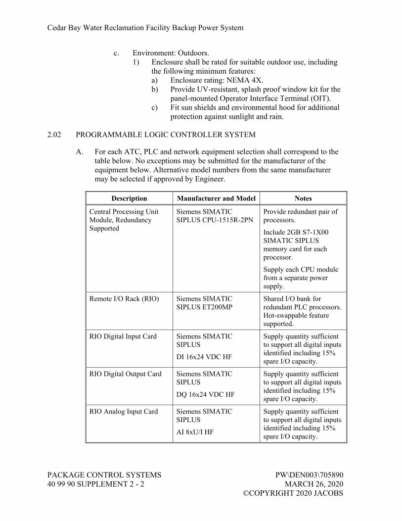
Cedar Bay Water Reclamation Facility Backup Power System
PACKAGE CONTROL SYSTEMS PW\DEN003\705890 40 99 90 SUPPLEMENT 2 - 2 MARCH 26, 2020 ©COPYRIGHT 2020 JACOBS
c. Environment: Outdoors. 1) Enclosure shall be rated for suitable outdoor use, including
the following minimum features: a) Enclosure rating: NEMA 4X. b) Provide UV-resistant, splash proof window kit for the
panel-mounted Operator Interface Terminal (OIT). c) Fit sun shields and environmental hood for additional
protection against sunlight and rain.
2.02 PROGRAMMABLE LOGIC CONTROLLER SYSTEM
A. For each ATC, PLC and network equipment selection shall correspond to the table below. No exceptions may be submitted for the manufacturer of the equipment below. Alternative model numbers from the same manufacturer may be selected if approved by Engineer.
Description Manufacturer and Model Notes
Central Processing Unit Module, Redundancy Supported
Siemens SIMATIC SIPLUS CPU-1515R-2PN
Provide redundant pair of processors.
Include 2GB S7-1X00 SIMATIC SIPLUS memory card for each processor.
Supply each CPU module from a separate power supply.
Remote I/O Rack (RIO) Siemens SIMATIC SIPLUS ET200MP
Shared I/O bank for redundant PLC processors. Hot-swappable feature supported.
RIO Digital Input Card Siemens SIMATIC SIPLUS
DI 16x24 VDC HF
Supply quantity sufficient to support all digital inputs identified including 15% spare I/O capacity.
RIO Digital Output Card Siemens SIMATIC SIPLUS
DQ 16x24 VDC HF
Supply quantity sufficient to support all digital inputs identified including 15% spare I/O capacity.
RIO Analog Input Card Siemens SIMATIC SIPLUS
AI 8xU/I HF
Supply quantity sufficient to support all digital inputs identified including 15% spare I/O capacity.

Cedar Bay Water Reclamation Facility Backup Power System
PW\DEN003\705890 PACKAGE CONTROL SYSTEMS MARCH 26, 2020 40 99 90 SUPPLEMENT 2 - 3 ©COPYRIGHT 2020 JACOBS
Description Manufacturer and Model Notes
PLC/RIO Power Supply Siemens SITOP SIPLUS
PM 70W
Provide separate power supply for each PLC and RIO rack.
Operator Interface Terminal
Siemens SIPLUS TP-1500 Comfort
Provide OIT on the face of the ATC enclosure. Mount at an elevation of 5 feet, 6 inches from the centerline of the OIT screen to the floor.
Include 2GB SIMATIC SIPLUS memory card for OIT.
For ATC-100, select the SIPLUS Outdoor Comfort version.
Managed Ethernet Switch Siemens SCALANCE SIPLUS X212-2
Switch shall include integrated fiber-optic ports.
2.03 UNINTERRUPTIBLE POWER SUPPLY
A. Provide UPS to maintain all switchgear controls and power monitoring equipment in the event of a short-term feed power failure.
B. Size UPS for at least 30 minutes of control system load availability.
C. UPS shall include hardwired signal interface with ATC for remote status monitoring of the device. Detailed I/O requirements are defined in the I/O list below.
D. Manufacturers:
1. Schneider Electric. 2. Siemens. 3. Or Approved Equal.
2.04 ATC PLC I/O LISTS
A. The following tables denote the hardwired interface required for each ATC PLC system. All signal directions are relative to the ATC PLC; for example, a digital input (DI) or analog input (AI) is a signal received by the ATC from a target device, and a digital output (DO) or analog output (AO) is a signal transmitted by the ATC to a target device. In addition to signals listed, provide and wire spares as specified in above section. Rack/Slot/Point assignment shall be determined by SPSS to accommodate the I/O and PLC hardware specified.

Cedar Bay Water Reclamation Facility Backup Power System
PACKAGE CONTROL SYSTEMS PW\DEN003\705890 40 99 90 SUPPLEMENT 2 - 4 MARCH 26, 2020 ©COPYRIGHT 2020 JACOBS
B. ATC-4A PLC I/O List
Device Tag Device Description I/O Function I/O Type
LIT-911-1 Generator Fuel Level Transmitter Fuel Level Reading
AI
ATC-4A Automatic Transfer Controller PLC Fault, Primary
DI
ATC-4A Automatic Transfer Controller PLC Fault, Secondary
DI
ATC-4A Automatic Transfer Controller Enclosure Intrusion Switch
DI
ATC-4A Automatic Transfer Controller Control Power Status
DI
ATC-4A Automatic Transfer Controller UPS Low Battery DI
ATC-4A Automatic Transfer Controller UPS Charging DI
ATC-4A Automatic Transfer Controller UPS Fault DI
ATC-4A Automatic Transfer Controller UPS Active DI
CB-004A-1 Main #1 Breaker (Source “C”) Open Feedback DI
CB-004A-1 Main #1 Breaker (Source “C”) Closed Feedback DI
CB-004A-1 Main #1 Breaker (Source “C”) Tripped DI
CB-004A-1 Main #1 Breaker (Source “C”) Source Available DI
CB-004A-1 Main #1 Breaker (Source “C”) In Remote DI
CB-004A-2 Main #2 Breaker (Source “D”) Open Feedback DI
CB-004A-2 Main #2 Breaker (Source “D”) Closed Feedback DI
CB-004A-2 Main #2 Breaker (Source “D”) Tripped DI
CB-004A-2 Main #2 Breaker (Source “D”) Source Available DI
CB-004A-2 Main #2 Breaker (Source “D”) In Remote DI
CB-004A-3 Generator Breaker Open Feedback DI
CB-004A-3 Generator Breaker Closed Feedback DI
CB-004A-3 Generator Breaker Tripped DI
CB-004A-3 Generator Breaker In Remote DI
LIT-911-1 Generator Fuel Level Transmitter Fuel Leak Detection Alarm
DI
PLC-3 Existing SCADA PLC Load Shed Sequence Complete
DI
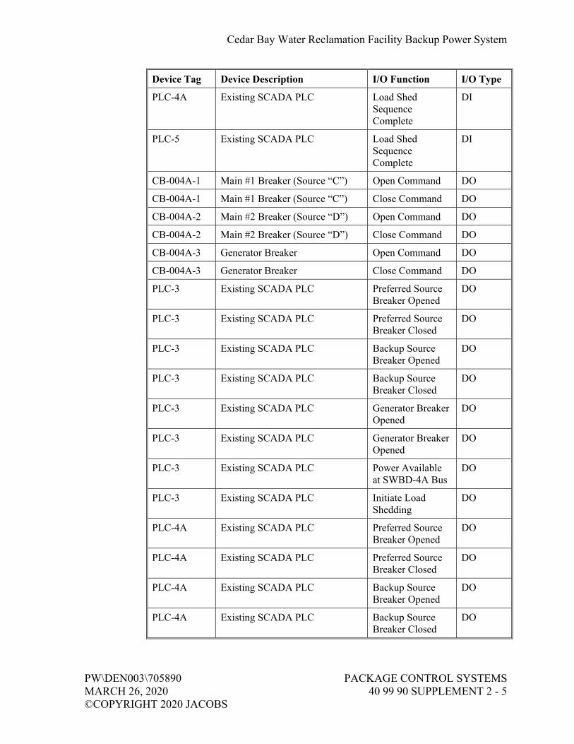
Cedar Bay Water Reclamation Facility Backup Power System
PW\DEN003\705890 PACKAGE CONTROL SYSTEMS MARCH 26, 2020 40 99 90 SUPPLEMENT 2 - 5 ©COPYRIGHT 2020 JACOBS
Device Tag Device Description I/O Function I/O Type
PLC-4A Existing SCADA PLC Load Shed Sequence Complete
DI
PLC-5 Existing SCADA PLC Load Shed Sequence Complete
DI
CB-004A-1 Main #1 Breaker (Source “C”) Open Command DO
CB-004A-1 Main #1 Breaker (Source “C”) Close Command DO
CB-004A-2 Main #2 Breaker (Source “D”) Open Command DO
CB-004A-2 Main #2 Breaker (Source “D”) Close Command DO
CB-004A-3 Generator Breaker Open Command DO
CB-004A-3 Generator Breaker Close Command DO
PLC-3 Existing SCADA PLC Preferred Source Breaker Opened
DO
PLC-3 Existing SCADA PLC Preferred Source Breaker Closed
DO
PLC-3 Existing SCADA PLC Backup Source Breaker Opened
DO
PLC-3 Existing SCADA PLC Backup Source Breaker Closed
DO
PLC-3 Existing SCADA PLC Generator Breaker Opened
DO
PLC-3 Existing SCADA PLC Generator Breaker Opened
DO
PLC-3 Existing SCADA PLC Power Available at SWBD-4A Bus
DO
PLC-3 Existing SCADA PLC Initiate Load Shedding
DO
PLC-4A Existing SCADA PLC Preferred Source Breaker Opened
DO
PLC-4A Existing SCADA PLC Preferred Source Breaker Closed
DO
PLC-4A Existing SCADA PLC Backup Source Breaker Opened
DO
PLC-4A Existing SCADA PLC Backup Source Breaker Closed
DO

Cedar Bay Water Reclamation Facility Backup Power System
PACKAGE CONTROL SYSTEMS PW\DEN003\705890 40 99 90 SUPPLEMENT 2 - 6 MARCH 26, 2020 ©COPYRIGHT 2020 JACOBS
Device Tag Device Description I/O Function I/O Type
PLC-4A Existing SCADA PLC Generator Breaker Opened
DO
PLC-4A Existing SCADA PLC Generator Breaker Opened
DO
PLC-4A Existing SCADA PLC Power Available at SWBD-4A Bus
DO
PLC-4A Existing SCADA PLC Initiate Load Shedding
DO
PLC-5 Existing SCADA PLC Preferred Source Breaker Opened
DO
PLC-5 Existing SCADA PLC Preferred Source Breaker Closed
DO
PLC-5 Existing SCADA PLC Backup Source Breaker Opened
DO
PLC-5 Existing SCADA PLC Backup Source Breaker Closed
DO
PLC-5 Existing SCADA PLC Generator Breaker Opened
DO
PLC-5 Existing SCADA PLC Generator Breaker Closed
DO
PLC-5 Existing SCADA PLC Power Available at SWBD-4A Bus
DO
PLC-5 Existing SCADA PLC Initiate Load Shedding
DO
C. ATC-100 PLC I/O List
Device Tag Device Description I/O Function I/O Type
LIT-921-1 Generator Fuel Level Transmitter
Fuel Level Reading AI
ATC-100 Automatic Transfer Controller PLC Fault, Primary DI
ATC-100 Automatic Transfer Controller PLC Fault, Secondary
DI
ATC-100 Automatic Transfer Controller Enclosure Intrusion Switch
DI
ATC-100 Automatic Transfer Controller Control Power Status
DI
ATC-100 Automatic Transfer Controller UPS Low Battery DI

Cedar Bay Water Reclamation Facility Backup Power System
PW\DEN003\705890 PACKAGE CONTROL SYSTEMS MARCH 26, 2020 40 99 90 SUPPLEMENT 2 - 7 ©COPYRIGHT 2020 JACOBS
Device Tag Device Description I/O Function I/O Type
ATC-100 Automatic Transfer Controller UPS Charging DI
ATC-100 Automatic Transfer Controller UPS Fault DI
ATC-100 Automatic Transfer Controller UPS Active DI
CB-100-1 Main #1 Breaker (Source “E”) Open Feedback DI
CB-100-1 Main #1 Breaker (Source “E”) Closed Feedback DI
CB-100-1 Main #1 Breaker (Source “E”) Tripped DI
CB-100-1 Main #1 Breaker (Source “E”) Source Available DI
CB-100-1 Main #1 Breaker (Source “E”) In Remote DI
CB-100-2 Main #2 Breaker (Source “F”) Open Feedback DI
CB-100-2 Main #2 Breaker (Source “F”) Closed Feedback DI
CB-100-2 Main #2 Breaker (Source “F”) Tripped DI
CB-100-2 Main #2 Breaker (Source “F”) Source Available DI
CB-100-2 Main #2 Breaker (Source “F”) In Remote DI
CB-100-3 Generator Breaker Open Feedback DI
CB-100-3 Generator Breaker Closed Feedback DI
CB-100-3 Generator Breaker Tripped DI
CB-100-3 Generator Breaker In Remote DI
CB-100-4 Tie Breaker Open Feedback DI
CB-100-4 Tie Breaker Closed Feedback DI
CB-100-4 Tie Breaker Tripped DI
CB-100-4 Tie Breaker In Remote DI
LIT-921-1 Generator Fuel Level Transmitter
Fuel Leak Detection Alarm
DI
PLC-100 Existing SCADA PLC Load Shed Sequence Complete
DI
CB-100-1 Main #1 Breaker (Source “E”) Open Command DO
CB-100-1 Main #1 Breaker (Source “E”) Close Command DO
CB-100-2 Main #2 Breaker (Source “F”) Open Command DO
CB-100-2 Main #2 Breaker (Source “F”) Close Command DO
CB-100-3 Generator Breaker Open Command DO
CB-100-3 Generator Breaker Close Command DO
CB-100-4 Tie Breaker Open Command DO
CB-100-4 Tie Breaker Close Command DO
PLC-100 Existing SCADA PLC Preferred Source Breaker Opened
DO
PLC-100 Existing SCADA PLC Preferred Source DO

Cedar Bay Water Reclamation Facility Backup Power System
PACKAGE CONTROL SYSTEMS PW\DEN003\705890 40 99 90 SUPPLEMENT 2 - 8 MARCH 26, 2020 ©COPYRIGHT 2020 JACOBS
Device Tag Device Description I/O Function I/O Type Breaker Closed
PLC-100 Existing SCADA PLC Backup Source Breaker Opened
DO
PLC-100 Existing SCADA PLC Backup Source Breaker Closed
DO
PLC-100 Existing SCADA PLC Generator Breaker Opened
DO
PLC-100 Existing SCADA PLC Generator Breaker Closed
DO
PLC-100 Existing SCADA PLC Tie Breaker Opened
DO
PLC-100 Existing SCADA PLC Tie Breaker Closed DO
PLC-100 Existing SCADA PLC Power Available at MCC-100 Bus
DO
PLC-100 Existing SCADA PLC Initiate Load Shedding
DO
PART 3 CONTROL SYSTEM REQUIREMENTS
3.01 STANDARD OPERATING REQUIREMENTS
A. Standard operating requirements describe the overall functionality of the automatic transfer controller during normal operation. Additional detailed requirements are described in the sections below.
B. At each new switchboard location, there are two utility feed sources (one preferred, one backup), in addition to a generator feed.
1. For SWBD-4A, the preferred utility source is fed from transformer “C”, and the backup utility source is fed from transformer “D”.
2. For MCC-100, the preferred utility source is fed from transformer “E”, and the backup utility source is fed from transformer “F”.
C. During normal operation, power is sourced solely through the preferred feed. Upon failure of the preferred feed, the switchboard breakers will be changed over to the backup utility source until the preferred source is restored. Note that SWBD-4A has two main utility incoming breakers and one generator breaker, whereas MCC-100 has main-tie-main breakers and a generator breaker. If both utility feeds are unavailable, the emergency generator is called to run and breakers are switched over to the generator feed once the voltage and current are within acceptable values. The system will remain on generator power until a utility source is available. The generator will continue to run until the system faults or runs out of fuel.

Cedar Bay Water Reclamation Facility Backup Power System
PW\DEN003\705890 PACKAGE CONTROL SYSTEMS MARCH 26, 2020 40 99 90 SUPPLEMENT 2 - 9 ©COPYRIGHT 2020 JACOBS
D. Upon initial loss of power, the switchboard ATC will remain active on UPS power for at least 30 minutes and maintain automatic control of the breaker system. It is intended for power to be automatically restored on one of the backup feeds before the UPS battery drains.
E. In the event of a complete PLC system failure, the switchboard breakers shall be available for local operation with mechanical interlocks to prevent simultaneous conflicting positions of connected breakers.
F. The ATC OIT and facility SCADA system HMI shall monitor the status of each backup power system, including the ATCs, circuit breakers, and generator system, regardless of operating mode.
3.02 DETAILED CONTROL FUNCTIONS
A. This section describes multiple operating scenarios for transfer between the utility and generator feeds. Each operating scenario also describes the response of the ATC PLC, including input checks and output commands. Additionally, each scenario includes the functional requirements of the existing SCADA PLC nodes which need to be closely integrated with the ATC systems. Although SCADA PLC modifications are not within the scope of the SPSS, both the ATC systems and the SCADA PLCs shall be tested jointly on-site, and coordination between the SPSS and PICS Contractor is required for successful operation. Review this specification in conjunction with Specification 40 96, 90, Facility Control System Integration, for a comprehensive overview of scope boundaries, coordination activities, and performance requirements of the entire backup power control system.
B. Scenarios 1 through 4 are common to both ATC-4A and ATC-100 during automatic operations. Each breaker must be placed In Remote in order to be controlled by the ATC.
C. Scenario 1 – Failure of Preferred Utility Source During Normal Operation:
1. Starting conditions: a. Preferred utility source circuit breaker is closed. b. Backup utility source circuit breaker is open. c. Generator source circuit breaker is open. d. Generator is off. e. Live power feeding through preferred utility source.
2. Power is lost on preferred utility source. a. ATC detects loss of power on preferred utility source and
generates alarm. b. ATC verifies that the preferred utility source circuit breaker is
opened. 1) If the circuit breaker is not confirmed open (input not
received at RIO), an open command is issued to the circuit breaker.
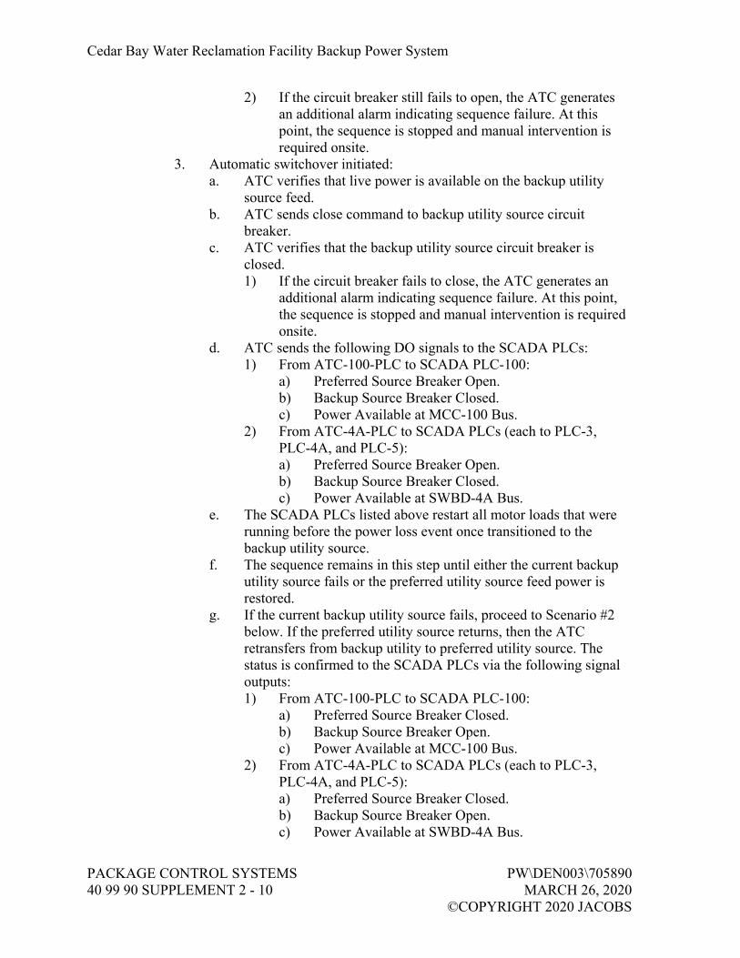
Cedar Bay Water Reclamation Facility Backup Power System
PACKAGE CONTROL SYSTEMS PW\DEN003\705890 40 99 90 SUPPLEMENT 2 - 10 MARCH 26, 2020 ©COPYRIGHT 2020 JACOBS
2) If the circuit breaker still fails to open, the ATC generates an additional alarm indicating sequence failure. At this point, the sequence is stopped and manual intervention is required onsite.
3. Automatic switchover initiated: a. ATC verifies that live power is available on the backup utility
source feed. b. ATC sends close command to backup utility source circuit
breaker. c. ATC verifies that the backup utility source circuit breaker is
closed. 1) If the circuit breaker fails to close, the ATC generates an
additional alarm indicating sequence failure. At this point, the sequence is stopped and manual intervention is required onsite.
d. ATC sends the following DO signals to the SCADA PLCs: 1) From ATC-100-PLC to SCADA PLC-100:
a) Preferred Source Breaker Open. b) Backup Source Breaker Closed. c) Power Available at MCC-100 Bus.
2) From ATC-4A-PLC to SCADA PLCs (each to PLC-3, PLC-4A, and PLC-5): a) Preferred Source Breaker Open. b) Backup Source Breaker Closed. c) Power Available at SWBD-4A Bus.
e. The SCADA PLCs listed above restart all motor loads that were running before the power loss event once transitioned to the backup utility source.
f. The sequence remains in this step until either the current backup utility source fails or the preferred utility source feed power is restored.
g. If the current backup utility source fails, proceed to Scenario #2 below. If the preferred utility source returns, then the ATC retransfers from backup utility to preferred utility source. The status is confirmed to the SCADA PLCs via the following signal outputs: 1) From ATC-100-PLC to SCADA PLC-100:
a) Preferred Source Breaker Closed. b) Backup Source Breaker Open. c) Power Available at MCC-100 Bus.
2) From ATC-4A-PLC to SCADA PLCs (each to PLC-3, PLC-4A, and PLC-5): a) Preferred Source Breaker Closed. b) Backup Source Breaker Open. c) Power Available at SWBD-4A Bus.

Cedar Bay Water Reclamation Facility Backup Power System
PW\DEN003\705890 PACKAGE CONTROL SYSTEMS MARCH 26, 2020 40 99 90 SUPPLEMENT 2 - 11 ©COPYRIGHT 2020 JACOBS
h. The SCADA PLCs listed above restart all motor loads that were running before the power loss event once transitioned to the backup utility source.
D. Scenario 2 – Failure of the backup utility source after previous failure of the preferred utility source:
1. Starting conditions: a. Preferred utility source circuit breaker is open. b. Backup utility source circuit breaker is closed. c. Generator source circuit breaker is open. d. Generator is off. e. Live power feeding through backup utility source.
2. Power is lost on backup utility source. a. ATC detects loss of power on backup utility source and generates
alarm. b. ATC verifies that the backup utility source circuit breaker is
opened. 1) If the circuit breaker is not confirmed open (input not
received at RIO), an open command is issued to the circuit breaker.
2) If the circuit breaker still fails to open, the ATC generates an additional alarm indicating sequence failure. At this point, the sequence is stopped and manual intervention is required onsite.
c. ATC sends the following hardwired DO signals to the SCADA PLCs: 1) From ATC-100-PLC to SCADA PLC-100:
a) Preferred Source Breaker Open. b) Backup Source Breaker Open. c) Initiate Load Shedding Command.
2) From ATC-4A-PLC to SCADA PLCs (each to PLC-3, PLC-4A, and PLC-5): a) Preferred Source Breaker Open. b) Backup Source Breaker Open. c) Initiate Load Shedding Command.
d. Additionally, the ATC will remove the following hardwired DO signals to the SCADA PLCs. 1) From ATC-100-PLC to SCADA PLC-100:
a) Power Available at MCC-100 Bus (Remove output signal to indicate power is no longer available).
2) From ATC-4A-PLC to SCADA PLCs (each to PLC-3, PLC-4A, and PLC-5): a) Power Available at SWBD-4A Bus (Remove output
signal to indicate power is no longer available).

Cedar Bay Water Reclamation Facility Backup Power System
PACKAGE CONTROL SYSTEMS PW\DEN003\705890 40 99 90 SUPPLEMENT 2 - 12 MARCH 26, 2020 ©COPYRIGHT 2020 JACOBS
e. The plant SCADA PLCs will then begin the load shedding sequence, interlocking and prohibiting the corresponding motor loads to run during an emergency power event. Disabled loads are identified on drawings I-08-601 and I-08-602. After the loads are disabled, each SCADA PLC listed above will issue feedback to the respective ATC, represented as the following DI signals: 1) From SCADA PLC-100 to ATC-100-PLC: Load Shedding
Sequence Complete. 2) From SCADA PLCs (each from PLC-3, PLC-4A, and PLC-
5 to ATC-4A-PLC): Load Shedding Sequence Complete. 3. Generator startup:
a. The ATC verifies that the associated generator is available in auto, and the corresponding load shed completion signals from the SCADA PLC nodes have been received at the ATC. 1) If the generator is not in auto, faulted, or has an E-Stop
active at this step, generate an alarm indicating that the generator is not available. The sequence is stopped until the generator becomes available or manual intervention is performed.
b. The ATC sends a run command output to the generator ECP. 1) ATC-100 to 600 kW generator engine control panel (ECP). 2) ATC-4A to 250 kW generator ECP.
c. The ATC waits until the generator is confirmed running and the measured source voltage and frequency values are within range. 1) If the generator run status is not received after 30 seconds,
generate an alarm indicating a fail-to-start condition. The sequence will maintain the run command to the generator until the generator starts or manual intervention is performed.
2) If the generator voltage or frequency remains out of range for more than 60 seconds, generate an alarm indicating that the generator system source is rejected. The sequence will maintain the run command to the generator until the values are within range or manual intervention is performed.
4. Automatic switchover initiated: a. ATC verifies that live power is available on the generator source
feed and the generator is running. b. ATC sends close command to the generator source circuit breaker. c. ATC verifies that the generator source circuit breaker is closed.
1) If the circuit breaker fails to close, the ATC generates an additional alarm indicating sequence failure. At this point, the sequence is stopped and manual intervention is required onsite.

Cedar Bay Water Reclamation Facility Backup Power System
PW\DEN003\705890 PACKAGE CONTROL SYSTEMS MARCH 26, 2020 40 99 90 SUPPLEMENT 2 - 13 ©COPYRIGHT 2020 JACOBS
d. The following signals are sent from each ATC to the respective plant SCADA system PLCs: 1) From ATC-100-PLC to SCADA PLC-100:
a) Backup Utility Breaker Open. b) Generator Breaker Closed. c) Generator Power Available at MCC-100 Bus
2) From ATC-4A-PLC to SCADA PLCs (each to PLC-3, PLC-4A, and PLC-5): a) Backup Utility Breaker Open. b) Generator Breaker Closed. c) Generator Power Available at SWBD-4A Bus
e. The SCADA PLCs listed above restart all motor loads that were running before the power loss event once transitioned to the generator source, with the exception of all loads interlocked by the load shedding logic.
E. Scenario 3 – Backup utility source restored while running on generator system:
1. Starting conditions: a. Preferred utility source circuit breaker is open. b. Backup utility source circuit breaker is open. c. Generator source circuit breaker is closed. d. Generator is on. e. Live power feeding through generator source.
2. Power is restored on backup utility source. a. ATC detects power on the backup utility source feed. b. The ATC waits to ensure that the backup utility source feed power
remains stable to prevent premature switchover. 1) Default delay of five minutes. However, value may be
adjusted at the OIT with elevated user login. 2) If the source fails during the delay period, the timer is reset
and only re-instated once the source power is again available.
3. Automatic switchover: a. ATC sends open command to the generator source circuit breaker. b. ATC verifies that the generator source circuit breaker is opened.
1) If the circuit breaker fails to open, the ATC generates an additional alarm indicating sequence failure. At this point, the sequence is stopped and manual intervention is required onsite.
c. ATC sends close command to the backup utility source circuit breaker.

Cedar Bay Water Reclamation Facility Backup Power System
PACKAGE CONTROL SYSTEMS PW\DEN003\705890 40 99 90 SUPPLEMENT 2 - 14 MARCH 26, 2020 ©COPYRIGHT 2020 JACOBS
d. ATC verifies that the backup utility source circuit breaker is closed. 1) If the circuit breaker fails to close, the ATC generates an
additional alarm indicating sequence failure. At this point, the sequence is stopped and manual intervention is required onsite.
e. The following signals are sent from each ATC to the respective plant SCADA system PLCs: 1) From ATC-100-PLC to SCADA PLC-100:
a) Generator Breaker Open. b) Backup Utility Breaker Closed. c) Utility Power Available at MCC-100 Bus.
2) From ATC-4A-PLC to SCADA PLCs (each to PLC-3, PLC-4A, and PLC-5): a) Generator Breaker Open. b) Backup Utility Breaker Closed. c) Utility Power Available at SWBD-4A Bus.
f. The SCADA PLCs listed above restart all motor loads that were running before the power loss event once transitioned to the utility source. The motor loads that were previously disabled from the load shedding logic will now be available to operate, once called from the existing process logic.
4. Generator shutdown: a. The ATC sends shutdown command (removes run signal) to the
generator ECP. b. The generator begins its cooldown cycle and the run status is
removed. 1) If the generator run status is not removed after 30 seconds,
generate an alarm indicating a fail-to-stop condition. c. At this point, the generator is off and power is active solely
through the backup utility source. The sequence will remain in this condition until the preferred utility source is restored.
F. Scenario 4 – Preferred utility source restored while feeding through backup utility source:
1. Starting conditions: a. Preferred utility source circuit breaker is open. b. Backup utility source circuit breaker is closed. c. Generator source circuit breaker is open. d. Generator is off. e. Live power feeding through backup utility source.

Cedar Bay Water Reclamation Facility Backup Power System
PW\DEN003\705890 PACKAGE CONTROL SYSTEMS MARCH 26, 2020 40 99 90 SUPPLEMENT 2 - 15 ©COPYRIGHT 2020 JACOBS
2. Power is restored on preferred utility source. a. ATC detects power on the preferred utility source feed. b. The ATC waits to ensure that the preferred utility source feed
power remains stable to prevent premature switchover. 1) Default delay of five minutes. However, value may be
adjusted at the OIT with elevated user login. 2) If the source fails during the delay period, the timer is reset
and only re-instated once the source power is again available.
3. Automatic switchover: a. ATC sends open command to the backup utility source circuit
breaker. b. ATC verifies that the backup utility source circuit breaker is
opened. 1) If the circuit breaker fails to open, the ATC generates an
additional alarm indicating sequence failure. At this point, the sequence is stopped and manual intervention is required onsite.
c. ATC sends close command to the preferred utility source circuit breaker.
d. ATC verifies that the preferred utility source circuit breaker is closed. 1) If the circuit breaker fails to close, the ATC generates an
additional alarm indicating sequence failure. At this point, the sequence is stopped and manual intervention is required onsite.
e. The following signals are sent from each ATC to the respective plant SCADA system PLCs: 1) From ATC-100-PLC to SCADA PLC-100:
a) Backup Utility Breaker Open. b) Preferred Utility Breaker Closed. c) Utility Power Available at MCC-100 Bus.
2) From ATC-4A-PLC to SCADA PLCs (each to PLC-3, PLC-4A, and PLC-5): a) Backup Utility Breaker Open. b) Preferred Utility Breaker Closed c) Utility Power Available at SWBD-4A Bus
f. The SCADA PLCs listed above restart all motor loads that were running before the power loss event once transitioned to the preferred utility source.
G. MCC-100 Tie Breaker Functional Description
1. In normal operation, the tie breaker is normally open to allow for split feed power from Transformers E and F as indicated on Drawing-E-80-605.

Cedar Bay Water Reclamation Facility Backup Power System
PACKAGE CONTROL SYSTEMS PW\DEN003\705890 40 99 90 SUPPLEMENT 2 - 16 MARCH 26, 2020 ©COPYRIGHT 2020 JACOBS
2. In the event of a power loss on one of the two utility feeds, the faulted utility feed breaker will open.
3. Once the feed breaker is confirmed open by the ATC, and available power remains on the other utility source, the tie breaker is then issued a close command from the ATC, allowing the remaining utility source to power the entire bus.
4. During this time, if the remaining utility source fails, the associated utility feed breaker is then opened and the generator sequence in Scenario 2 above is started. The tie breaker remains closed to allow for the generator power to feed the entire bus.
5. Otherwise, if the faulted utility source is restored and confirmed available by the ATC while still on the backup utility source, the tie breaker will then reopen, allowing for the original utility source breaker to close and resume split-bus operation.
3.03 CRITICAL INTERLOCKS AND ALARMS
A. Automatic controls wills be interlocked so that the PLC shall not attempt to simultaneously close breakers on multiple feeds. Additionally, hardwired interlocks as shown on Drawings E-80-604 and E-80-605 shall be configured to prevent unsafe arrangement of the breakers.
B. In the event of a PLC failure, the breakers shall be held in position so that an unsafe configuration does not result. An alarm shall be generated and transmitted to the SCADA system indicating that the breaker transition sequence has failed.
3.04 INTERFACE WITH GENERATOR SYSTEM ENGINE CONTROL PANELS
A. Each ATC-PLC will be interfaced with the respective generator engine control panel via Modbus TCP.
B. The tables below describe the minimum required data signals to be transmitted from each ATC system to the OCS. Coordinate with the generator system supplier to ensure successful integration of the ATC and generator controllers.
Table 3.1: ECP-911-to-ATC-4A-PLC Data Exchange Table
DEVICE TAG DEVICE DESCRIPTION FUNCTION TYPE
ECP-911 Generator Engine Control Panel Generator Run Status Bool
ECP-911 Generator Engine Control Panel Generator Fault Bool
ECP-911 Generator Engine Control Panel Generator Battery Low Alarm
Bool
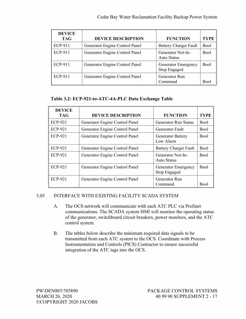
Cedar Bay Water Reclamation Facility Backup Power System
PW\DEN003\705890 PACKAGE CONTROL SYSTEMS MARCH 26, 2020 40 99 90 SUPPLEMENT 2 - 17 ©COPYRIGHT 2020 JACOBS
DEVICE TAG DEVICE DESCRIPTION FUNCTION TYPE
ECP-911 Generator Engine Control Panel Battery Charger Fault Bool
ECP-911 Generator Engine Control Panel Generator Not-In-Auto Status
Bool
ECP-911 Generator Engine Control Panel Generator Emergency Stop Engaged
Bool
ECP-911 Generator Engine Control Panel Generator Run Command Bool
Table 3.2: ECP-921-to-ATC-4A-PLC Data Exchange Table
DEVICE TAG DEVICE DESCRIPTION FUNCTION TYPE
ECP-921 Generator Engine Control Panel Generator Run Status Bool
ECP-921 Generator Engine Control Panel Generator Fault Bool
ECP-921 Generator Engine Control Panel Generator Battery Low Alarm
Bool
ECP-921 Generator Engine Control Panel Battery Charger Fault Bool
ECP-921 Generator Engine Control Panel Generator Not-In-Auto Status
Bool
ECP-921 Generator Engine Control Panel Generator Emergency Stop Engaged
Bool
ECP-921 Generator Engine Control Panel Generator Run Command Bool
3.05 INTERFACE WITH EXISTING FACILITY SCADA SYSTEM
A. The OCS network will communicate with each ATC PLC via Profinet communications. The SCADA system HMI will monitor the operating status of the generator, switchboard circuit breakers, power monitors, and the ATC control system.
B. The tables below describe the minimum required data signals to be transmitted from each ATC system to the OCS. Coordinate with Process Instrumentation and Controls (PICS) Contractor to ensure successful integration of the ATC tags into the OCS.

Cedar Bay Water Reclamation Facility Backup Power System
PACKAGE CONTROL SYSTEMS PW\DEN003\705890 40 99 90 SUPPLEMENT 2 - 18 MARCH 26, 2020 ©COPYRIGHT 2020 JACOBS
Table 3.3: ATC-4A Data Transmitted to OCS Network
DEVICE TAG DEVICE DESCRIPTION FUNCTION TYPE
GEN-911 Emergency Generator Running Bool
GEN-911 Emergency Generator Fault Bool
GEN-911 Emergency Generator Battery Undervoltage Bool
GEN-911 Emergency Generator Battery Charger Fail Bool
GEN-911 Emergency Generator Not-In-Auto Status Bool
GEN-911 Emergency Generator E-Stop Engaged Bool
GEN-911 Emergency Generator Generator Number of Starts Int
GEN-911 Emergency Generator Generator Runtime (hrs) Int
LIT-911 Fuel Level Transmitter Fuel Leak Detection Bool
LIT-911 Fuel Level Transmitter Fuel Level Real
ATC-4A Automatic Transfer Controller PLC Fault (Redundant CPU A) Bool
ATC-4A Automatic Transfer Controller PLC Fault (Redundant CPU B) Bool
ATC-4A Automatic Transfer Controller RIO Station Failure Bool
ATC-4A Automatic Transfer Controller Panel Intrusion Alarm Real
ATC-4A Automatic Transfer Controller Loss of Control Power Bool
ATC-4A Automatic Transfer Controller UPS Active Bool
ATC-4A Automatic Transfer Controller UPS Charging Bool
ATC-4A Automatic Transfer Controller UPS Fault Bool
ATC-4A Automatic Transfer Controller UPS Low Battery Alarm Bool
CB-004A-1 Main #1 Breaker Opened Bool
CB-004A-1 Main #1 Breaker Closed Bool
CB-004A-1 Main #1 Breaker Tripped Bool
CB-004A-1 Main #1 Breaker Source Available Bool
CB-004A-1 Main #1 Breaker In Remote Bool
CB-004A-1 Main #1 Breaker ATC Issuing Open Command Bool
CB-004A-1 Main #1 Breaker ATC Issuing Close Command Bool
CB-004A-1 Main #1 Breaker Fail-to-Open Bool

Cedar Bay Water Reclamation Facility Backup Power System
PW\DEN003\705890 PACKAGE CONTROL SYSTEMS MARCH 26, 2020 40 99 90 SUPPLEMENT 2 - 19 ©COPYRIGHT 2020 JACOBS
DEVICE TAG DEVICE DESCRIPTION FUNCTION TYPE
CB-004A-1 Main #1 Breaker Fail-to-Close Bool
CB-004A-2 Main #2 Breaker Opened Bool
CB-004A-2 Main #2 Breaker Closed Bool
CB-004A-2 Main #2 Breaker Tripped Bool
CB-004A-2 Main #2 Breaker Source Available Bool
CB-004A-2 Main #2 Breaker In Remote Bool
CB-004A-2 Main #2 Breaker ATC Issuing Open Command Bool
CB-004A-2 Main #2 Breaker ATC Issuing Close Command Bool
CB-004A-2 Main #2 Breaker Fail-to-Open Bool
CB-004A-2 Main #2 Breaker Fail-to-Close Bool
CB-004A-3 Generator Breaker Opened Bool
CB-004A-3 Generator Breaker Closed Bool
CB-004A-3 Generator Breaker Tripped Bool
CB-004A-3 Generator Breaker In Remote Bool
CB-004A-3 Generator Breaker ATC Issuing Open Command Bool
CB-004A-3 Generator Breaker ATC Issuing Close Command Bool
CB-004A-3 Generator Breaker Fail-to-Open Bool
CB-004A-3 Generator Breaker Fail-to-Close Bool
PM-GEN-911 Generator Feed Power Monitor Fault/Error Bool
PM-GEN-911 Generator Feed Power Monitor Voltage Phase AB Real
PM-GEN-911 Generator Feed Power Monitor Voltage Phase BC Real
PM-GEN-911 Generator Feed Power Monitor Voltage Phase CA Real
PM-GEN-911 Generator Feed Power Monitor Frequency Real
PM-GEN-911 Generator Feed Power Monitor Phase Current A Real
PM-GEN-911 Generator Feed Power Monitor Phase Current B Real
PM-GEN-911 Generator Feed Power Monitor Phase Current C Real
PM-GEN-911 Generator Feed Power Monitor Total Active Power Real
PM-XC Transformer "C" Feed Power Monitor Fault/Error Bool
PM-XC Transformer "C" Feed Power Monitor Voltage Phase AB Real
PM-XC Transformer "C" Feed Power Monitor Voltage Phase BC Real

Cedar Bay Water Reclamation Facility Backup Power System
PACKAGE CONTROL SYSTEMS PW\DEN003\705890 40 99 90 SUPPLEMENT 2 - 20 MARCH 26, 2020 ©COPYRIGHT 2020 JACOBS
DEVICE TAG DEVICE DESCRIPTION FUNCTION TYPE
PM-XC Transformer "C" Feed Power Monitor Voltage Phase CA Real
PM-XC Transformer "C" Feed Power Monitor Frequency Real
PM-XC Transformer "C" Feed Power Monitor Phase Current A Real
PM-XC Transformer "C" Feed Power Monitor Phase Current B Real
PM-XC Transformer "C" Feed Power Monitor Phase Current C Real
PM-XC Transformer "C" Feed Power Monitor Total Active Power Real
PM-XD Transformer "D" Feed Power Monitor Fault/Error Bool
PM-XD Transformer "D" Feed Power Monitor Voltage Phase AB Real
PM-XD Transformer "D" Feed Power Monitor Voltage Phase BC Real
PM-XD Transformer "D" Feed Power Monitor Voltage Phase CA Real
PM-XD Transformer "D" Feed Power Monitor Frequency Real
PM-XD Transformer "D" Feed Power Monitor Phase Current A Real
PM-XD Transformer "D" Feed Power Monitor Phase Current B Real
PM-XD Transformer "D" Feed Power Monitor Phase Current C Real
PM-XD Transformer "D" Feed Power Monitor Total Active Power Real
GPR-911 Generator Feed Protection Relay Source Available/Detected Bool
GPR-911 Generator Feed Protection Relay Tripped Bool
MMR-004A-1 Main #1 Feed Monitoring Relay Source Available/Detected Bool
MMR-004A-1 Main #1 Feed Monitoring Relay Tripped Bool
MMR-004A-2 Main #2 Feed Monitoring Relay Source Available/Detected Bool
MMR-004A-2 Main #2 Feed Monitoring Relay Tripped Bool
Table 3.4: ATC-100 Data Transmitted to OCS Network
DEVICE TAG DEVICE DESCRIPTION FUNCTION TYPE
GEN-921 Emergency Generator Running Bool
GEN-921 Emergency Generator Fault Bool
GEN-921 Emergency Generator Battery Undervoltage Bool
GEN-921 Emergency Generator Battery Charger Fail Bool
GEN-921 Emergency Generator Not-In-Auto Status Bool
GEN-921 Emergency Generator E-Stop Engaged Bool
GEN-921 Emergency Generator Generator Number of Starts Int

Cedar Bay Water Reclamation Facility Backup Power System
PW\DEN003\705890 PACKAGE CONTROL SYSTEMS MARCH 26, 2020 40 99 90 SUPPLEMENT 2 - 21 ©COPYRIGHT 2020 JACOBS
DEVICE TAG DEVICE DESCRIPTION FUNCTION TYPE
GEN-921 Emergency Generator Generator Runtime (hrs) Int
LIT-921 Fuel Level Transmitter Fuel Leak Detection Bool
LIT-921 Fuel Level Transmitter Fuel Level Real
ATC-100 Automatic Transfer Controller No-Load Test Active Bool
ATC-100 Automatic Transfer Controller PLC Fault (Redundant CPU A) Bool
ATC-100 Automatic Transfer Controller PLC Fault (Redundant CPU B) Bool
ATC-100 Automatic Transfer Controller RIO Station Failure Bool
ATC-100 Automatic Transfer Controller Panel Intrusion Alarm Real
ATC-100 Automatic Transfer Controller Loss of Control Power Bool
ATC-100 Automatic Transfer Controller UPS Active Bool
ATC-100 Automatic Transfer Controller UPS Charging Bool
ATC-100 Automatic Transfer Controller UPS Fault Bool
ATC-100 Automatic Transfer Controller UPS Low Battery Alarm Bool
CB-100-1 Main #1 Breaker Opened Bool
CB-100-1 Main #1 Breaker Closed Bool
CB-100-1 Main #1 Breaker Tripped Bool
CB-100-1 Main #1 Breaker Source Available Bool
CB-100-1 Main #1 Breaker In Remote Bool
CB-100-1 Main #1 Breaker ATC Issuing Open Command Bool
CB-100-1 Main #1 Breaker ATC Issuing Close Command Bool
CB-100-1 Main #1 Breaker Fail-to-Open Bool
CB-100-1 Main #1 Breaker Fail-to-Close Bool
CB-100-2 Main #2 Breaker Opened Bool
CB-100-2 Main #2 Breaker Closed Bool
CB-100-2 Main #2 Breaker Tripped Bool
CB-100-2 Main #2 Breaker Source Available Bool
CB-100-2 Main #2 Breaker In Remote Bool
CB-100-2 Main #2 Breaker ATC Issuing Open Command Bool

Cedar Bay Water Reclamation Facility Backup Power System
PACKAGE CONTROL SYSTEMS PW\DEN003\705890 40 99 90 SUPPLEMENT 2 - 22 MARCH 26, 2020 ©COPYRIGHT 2020 JACOBS
DEVICE TAG DEVICE DESCRIPTION FUNCTION TYPE
CB-100-2 Main #2 Breaker ATC Issuing Close Command Bool
CB-100-2 Main #2 Breaker Fail-to-Open Bool
CB-100-2 Main #2 Breaker Fail-to-Close Bool
CB-100-3 Generator Breaker Opened Bool
CB-100-3 Generator Breaker Closed Bool
CB-100-3 Generator Breaker Tripped Bool
CB-100-3 Generator Breaker In Remote Bool
CB-100-3 Generator Breaker ATC Issuing Open Command Bool
CB-100-3 Generator Breaker ATC Issuing Close Command Bool
CB-100-3 Generator Breaker Fail-to-Open Bool
CB-100-3 Generator Breaker Fail-to-Close Bool
CB-100-4 Tie Breaker Opened Bool
CB-100-4 Tie Breaker Closed Bool
CB-100-4 Tie Breaker Tripped Bool
CB-100-4 Tie Breaker In Remote Bool
CB-100-4 Tie Breaker ATC Issuing Open Command Bool
CB-100-4 Tie Breaker ATC Issuing Close Command Bool
CB-100-4 Tie Breaker Fail-to-Open Bool
CB-100-4 Tie Breaker Fail-to-Close Bool
PM-GEN-921 Generator Feed Power Monitor Fault/Error Bool
PM-GEN-921 Generator Feed Power Monitor Voltage Phase AB Real
PM-GEN-921 Generator Feed Power Monitor Voltage Phase BC Real
PM-GEN-921 Generator Feed Power Monitor Voltage Phase CA Real
PM-GEN-921 Generator Feed Power Monitor Frequency Real
PM-GEN-921 Generator Feed Power Monitor Phase Current A Real
PM-GEN-921 Generator Feed Power Monitor Phase Current B Real
PM-GEN-921 Generator Feed Power Monitor Phase Current C Real
PM-GEN-921 Generator Feed Power Monitor Total Active Power Real
PM-XE Transformer "E" Feed Power Monitor Fault/Error Bool
PM-XE Transformer "E" Feed Power Monitor Voltage Phase AB Real

Cedar Bay Water Reclamation Facility Backup Power System
PW\DEN003\705890 PACKAGE CONTROL SYSTEMS MARCH 26, 2020 40 99 90 SUPPLEMENT 2 - 23 ©COPYRIGHT 2020 JACOBS
DEVICE TAG DEVICE DESCRIPTION FUNCTION TYPE
PM-XE Transformer "E" Feed Power Monitor Voltage Phase BC Real
PM-XE Transformer "E" Feed Power Monitor Voltage Phase CA Real
PM-XE Transformer "E" Feed Power Monitor Frequency Real
PM-XE Transformer "E" Feed Power Monitor Phase Current A Real
PM-XE Transformer "E" Feed Power Monitor Phase Current B Real
PM-XE Transformer "E" Feed Power Monitor Phase Current C Real
PM-XE Transformer "E" Feed Power Monitor Total Active Power Real
PM-XF Transformer "F" Feed Power Monitor Fault/Error Bool
PM-XF Transformer "F" Feed Power Monitor Voltage Phase AB Real
PM-XF Transformer "F" Feed Power Monitor Voltage Phase BC Real
PM-XF Transformer "F" Feed Power Monitor Voltage Phase CA Real
PM-XF Transformer "F" Feed Power Monitor Frequency Real
PM-XF Transformer "F" Feed Power Monitor Phase Current A Real
PM-XF Transformer "F" Feed Power Monitor Phase Current B Real
PM-XF Transformer "F" Feed Power Monitor Phase Current C Real
PM-XF Transformer "F" Feed Power Monitor Total Active Power Real
GPR-921 Generator Feed Protection Relay Source Available/ Detected Bool
GPR-921 Generator Feed Protection Relay Tripped Bool
MMR-100-1 Main #1 Feed Monitoring Relay Source Available/ Detected Bool
MMR-100-1 Main #1 Feed Monitoring Relay Tripped Bool
MMR-100-2 Main #2 Feed Monitoring Relay Source Available/ Detected Bool
MMR-100-2 Main #2 Feed Monitoring Relay Tripped Bool

Cedar Bay Water Reclamation Facility Backup Power System
PACKAGE CONTROL SYSTEMS PW\DEN003\705890 40 99 90 SUPPLEMENT 2 - 24 MARCH 26, 2020 ©COPYRIGHT 2020 JACOBS
C. In the above data exchange table, tripped relays require manual reset before the alarm condition can be cleared.
D. Provide a network communications watchdog that actively monitors the network link between the OCS servers and ATC system. In the event of a communications failure, provide an alarm on the OIT indicating a loss of communications. Alarm shall automatically reset once communications are re-established. Provide a separate communications watchdog for each networked component, including the ATC PLCs, power monitors, and protection relays.
3.06 OPERATOR INTERFACE TERMINAL ACCESS
A. At minimum, OIT security will be based on Owner’s current HMI access levels. SPSS shall obtain the users and access levels from the Owner in coordination with the PICS Contractor.
B. All OIT screens and page navigation may be viewable without operator login.
C. All OIT command buttons shall require elevated login access. If a user is not logged in, the command button will be greyed out.
D. Each OIT screen shall include space to show the current user logged into the device.
E. Include logic that if the current user is inactive for more than 30 minutes, the user is automatically logged out of the OIT.
3.07 AUTOMATIC TRANSFER CONTROLLER SOFTWARE REQUIREMENTS
A. Prior to the factory acceptance test of the switchboard control system, the SPSS shall submit a copy of the TIA Portal program that is loaded in the ATC PLC for Engineer and Owner review.
B. General requirements:
1. All functions and function blocks shall be created using one of the following programming languages: a. Ladder (LAD).
1) Required language for all logic operations involved in monitoring and controlling the backup power system components.
b. Structured Code Language (SCL). 1) Language useable for non-essential tasks that do not govern
the backup power system. Examples include block calls, data management (ex: MOVE and CONVERT functions) and numerical calculations for data recording.

Cedar Bay Water Reclamation Facility Backup Power System
PW\DEN003\705890 PACKAGE CONTROL SYSTEMS MARCH 26, 2020 40 99 90 SUPPLEMENT 2 - 25 ©COPYRIGHT 2020 JACOBS
2) SCL code must be approved by Engineer. If rejected, equivalent LAD code shall be implemented.
2. Other programming languages, such as assembly-based code (STL), will not be accepted, and no exceptions will be granted.
3. Provide sufficient comments and annotation in each function to describe the purpose and methodology of each function or function block used in the program. Data block tags shall include descriptions clearly indicating the purpose of each entry.
4. All program blocks will be grouped and organized in a logical manner. Remove all unused program blocks in the program.
5. All data blocks (DBs) programmed for direct communication with the OCS shall be configured in a non-optimized format to allow for the HMI platform to communicate with the PLC.
6. Security: a. All functions and function blocks must be reviewable by Owner’s
staff when monitoring the control code during troubleshooting conditions. Owner staff shall not be “locked out” of the system.
b. If a security key is included for any function blocks in the program, a copy of the working password must be provided to the Owner’s staff.
7. Provide a functional description of the programmed logic for each ATC in narrative format, summarizing the LAD logic performed in the controller, in addition to call structure, network communications, and miscellaneous functions, in conjunction with a copy of the PLC program for Engineer and Owner approval.
C. OIT Graphic Screen Requirements:
1. Use one-line shown on Drawings E-80-604 and E-80-605 to prepare two dynamic overview screens showing the real-time status and alarms of the backup power system for each ATC system. Graphics shall indicate live or de-energized power segments in the one-line screen representation based on detected power available and status of the breakers.
2. Provide two block diagram screens, one for each ATC system, as shown on Drawing I-08-701 representing the communications status of each network device in the system.
3. A graphic display coordination meeting is required with the Owner and Engineer for approval of the number of screens, object faceplates, colors, and alarms presented on the display.

Cedar Bay Water Reclamation Facility Backup Power System
PACKAGE CONTROL SYSTEMS PW\DEN003\705890 40 99 90 SUPPLEMENT 2 - 26 MARCH 26, 2020 ©COPYRIGHT 2020 JACOBS
PART 4 TESTING AND COMMISSIONING REQUIREMENTS
4.01 FACTORY ACCEPTANCE TEST
A. Purpose:
1. Verify proper installation of ATC control components, including PLC configuration, power and signal circuitry, and panel front devices. Factory Acceptance Test (FAT) will be performed at the supplier’s factory location. All components must be successfully tested before delivery to the project site.
2. FAT will be performed by the Switchboard Package System Supplier (SPSS) and witnessed by Engineer and Owner’s personnel.
3. The contents of this Specification section pertain to factory testing of the switchboard ATC system. Refer to Section 26 14 13, Low-Voltage Switchboard, for detailed testing requirements of the switchboard electrical components and hardwired interlocks.
B. Factory Test Setup:
1. Prepare switchboard SWBD-4A (ATC-4A) and 600 kW generator switchboard (ATC-100) in the factory.
2. It is not practical for MCC-100, the two generator sets, and several plant SCADA PLCs to be available for the factory test. Therefore, elements of the system will be simulated as follows: a. Use a simulation panel with switches to simulate the following:
1) MCC-100 Main-Tie-Main breakers – Open, Close, Trip Status
2) The two engine control panels as shown 3) Any other I/O needed to simulate the ATC functionality.
b. Use a small-scale PLC I/O system to simulate the existing plant SCADA PLCs (PLC-3, PLC-4A, PLC-5, and PLC-100) to verify hardwired I/O between the plant PLCs and each ATC. Examples of the small-scale system include: 1) Several basic Siemens S7-1200 or LOGO controllers
indicating each SCADA PLC. 2) One standalone basic Siemens S7-1500 controller
combining all SCADA PLCs as a single unit. 3) Relay logic panel accepting inputs from the ATC and
generating outputs back to the ATC c. Use a laptop to simulate the plant SCADA control room screen.
Verify data exchange listed in Tables 3.1 and 3.2. Test data by modifying values in the ATC and observing the appropriate change on the laptop screen.
3. Connect a dedicated OIT to each ATC and display the one-line graphics with dynamic values.

Cedar Bay Water Reclamation Facility Backup Power System
PW\DEN003\705890 PACKAGE CONTROL SYSTEMS MARCH 26, 2020 40 99 90 SUPPLEMENT 2 - 27 ©COPYRIGHT 2020 JACOBS
C. Test Requirements:
1. ATC Control Panel Verification: a. SPSS shall verify that all components inside the ATC are fully
wired and powered. b. SPSS shall verify that all digital and analog I/O signal circuitry
are correctly wired to the ATC PLC system. 1) Conduct point testing of all I/O terminations to the ATC
RIO rack. 2) I/O points may be simulated if the corresponding field
device is not available at the SPSS facility. Simulation may be performed by jumper, multimeter, or similar method. Examples may include field transmitters or separately provided control panels.
3) All other I/O points shall be tested by direct manipulation of the end devices at the SPSS facility.
c. SPSS shall verify control logic to demonstrate successful operation of the switchboard control system to meet control requirements specified. 1) SPSS shall implement simulated code to allow for complete
testing of the ATC functions without the need for unavailable field equipment or inoperable devices.
2) SPSS shall verify all operating scenarios, sequences, and failure modes as identified in the Contract Specifications.
3) SPSS shall include live graphics of the switchboard system on the ATC Operator Interface Terminal (OIT) located on the ATC panel face.
d. Engineer and Owner reserve the right to request retesting of documented procedures or additional test procedures if needed during the FAT. SPSS shall include all deviations on the completed test forms.
D. Schedule:
1. SPSS shall submit test plan for Engineer and Owner approval prior to scheduling the FAT. An approved test plan is a prerequisite for scheduling the FAT.
2. Engineer and Owner shall be notified of the factory test date at least four weeks in advance of the scheduled date.
3. SPSS shall include copies of the approved testing forms, in addition to a daily agenda for each day of testing, for Engineer and Owner.
4. Upon successful completion of the FAT, the completed test forms shall be signed by the SPSS and Engineer and submitted for final Engineer and Owner approval.

Cedar Bay Water Reclamation Facility Backup Power System
PACKAGE CONTROL SYSTEMS PW\DEN003\705890 40 99 90 SUPPLEMENT 2 - 28 MARCH 26, 2020 ©COPYRIGHT 2020 JACOBS
4.02 OPERATIONAL READINESS TEST
A. Purpose:
1. Verify proper interconnection between ATC and field components, including the generator system and OCS network.
2. Operational Readiness Test (ORT) will be performed at the project site prior to performance testing.
3. All field components and end devices interfaced with the ATC must be installed, powered, and cleared to operate before testing may begin.
4. ORT will be performed by the SPSS in conjunction with the PICS Contractor, Electrical Contractor, and Generator Package System Supplier (GPSS), and testing will be witnessed by Engineer and Owner’s personnel.
B. Test Requirements:
1. Field Interconnections Verification: a. SPSS shall verify that all field devices and end devices have been
successfully wired and interfaced with the ATC system. b. SPSS shall verify that all digital and analog I/O signal circuitry
are correctly wired to the ATC PLC system. 1) Conduct point testing of all field I/O terminations to the
ATC RIO rack by direct manipulation of field components and end devices. Simulated I/O is not acceptable.
2) Verify the functionality of all specified hardwired interlocks via simulation before energizing the switchboard bus.
c. In coordination with PICS Contractor, SPSS shall verify successful communications between the packaged control system and facility SCADA system HMI. 1) Verify network connection has been established between the
ATC and OCS network. 2) Verify with PICS Contractor that live graphics of the
switchboard system are properly displayed on the OCS HMI screens.
3) Verify data points transmitted to the OCS network are displaying the correct values on the OCS HMI screens.
4) Test communications failures by disconnecting the ATC from the OCS network. a) Verify communications failure alarms appear on both
the ATC OIT and on the OCS HMI screens. b) Re-establish network connection and verify that the
communications failure is reset and values are once again updating correctly.

Cedar Bay Water Reclamation Facility Backup Power System
PW\DEN003\705890 PACKAGE CONTROL SYSTEMS MARCH 26, 2020 40 99 90 SUPPLEMENT 2 - 29 ©COPYRIGHT 2020 JACOBS
c) Repeat item for each networked component in the ATC system, including the power monitors and protection relays.
d. Engineer and Owner reserve the right to request retesting of documented procedures or additional test procedures if needed during the ORT. SPSS shall include all deviations on the completed test forms.
C. Schedule:
1. SPSS shall submit test plan for Engineer and Owner approval prior to scheduling the ORT. An approved test plan is a prerequisite for scheduling the ORT.
2. Engineer and Owner shall be notified of the ORT date at least two weeks in advance of the scheduled date. a. The first day of testing shall include a coordination meeting
between the SPSS, Engineer, Contractor, GPSS, PICS Contractor, and Owner. The objective of the coordination meeting is to identify any interference between the equipment being tested and the existing facility operations. A workplan will be determined and followed to mitigate interruptions in existing facility operations.
3. SPSS shall include copies of the approved testing forms, in addition to a daily agenda for each day of testing, for Engineer and Owner.
4. Upon successful completion of the ORT, the completed test forms shall be signed by the SPSS and Engineer and submitted for final Engineer and Owner approval.
4.03 PERFORMANCE ACCEPTANCE TEST
A. Purpose:
1. Verify successful operation of the automatic control system, including interlocks, sequences, and alarms, as identified in the Contract Specifications.
2. Performance Acceptance Test (PAT) will be performed at the project site after the ORT has been completed and all equipment has been cleared to operate.
3. All field components and end devices interfaced with the ATC must be installed, powered, and cleared to operate before testing may begin.
4. PAT will be performed by the SPSS in conjunction with the PICS Contractor, and testing will be witnessed by Engineer and Owner’s personnel.

Cedar Bay Water Reclamation Facility Backup Power System
PACKAGE CONTROL SYSTEMS PW\DEN003\705890 40 99 90 SUPPLEMENT 2 - 30 MARCH 26, 2020 ©COPYRIGHT 2020 JACOBS
B. Test Requirements:
1. Verify successful completion of a no-load test for the emergency generator. Verify load testing via camlock switch and load banks.
2. Prior to operation of the ATC system, verify that breakers can be locally operated at the breakers to successfully transition between power sources.
3. Verify that breakers can be manually operated via breaker control switches in Hand mode with successful transition between power sources.
4. Return the system to automatic mode and trigger loss of power scenarios identified in the Contract Specifications. Verify successful automatic transition of the breakers.
5. Verify faults and fail-safe operations successfully function during automatic operation of the breakers and emergency generator.
6. Verify all runtimes and number of start values are updating correctly at the ATC OIT and on the OCS HMI screens.
C. Schedule:
1. SPSS shall submit test plan for Engineer and Owner approval prior to scheduling the PAT. An approved test plan is a prerequisite to scheduling the PAT.
2. Engineer and Owner shall be notified of the performance test date at least two weeks in advance of the scheduled date. However, the PAT may take place immediately after ORT completion. a. The first day of testing shall include a coordination meeting
between the SPSS, Engineer, Contractor, GPSS, PICS Contractor, and Owner. The objective of the coordination meeting is to identify any interference between the equipment being tested and the existing facility operations. A workplan will be determined and followed to mitigate interruptions in existing facility operations.
b. On the final day of testing, SPSS, GPSS, Electrical Contractor, and PICS Contractor shall remain onsite for at least one hour after PAT completion to verify that no inadvertent operation of the backup power system occurs.
3. SPSS shall include copies of the approved testing forms, in addition to a daily agenda for each day of testing, for Engineer and Owner.
4. Upon successful completion of the PAT, the completed test forms shall be signed by the SPSS and Engineer and submitted for final Engineer and Owner approval.
Cedar Bay Water Reclamation Facility Backup Power System
PW\DEN003\705890 PACKAGE CONTROL SYSTEMS MARCH 26, 2020 40 99 90 SUPPLEMENT 2 - 31 ©COPYRIGHT 2020 JACOBS
4.04 CLOSEOUT TASKS
A. Training:
1. Within 48 hours after successful completion of the PAT, the SPSS shall conduct training for Owner’s designated personnel on operation and maintenance of the switchboard control system.
2. Course Duration: a. Each training session shall be allotted sufficient time to review all
elements of the ATC control system. b. The minimum training duration shall be:
1) Four hours per session. 2) One session per shift. Coordinate with Owner to determine
the number of shifts requiring training and the availability of each shift for training.
3) No more than two sessions may be performed on the same day.
END OF SUPPLEMENT 2


DRAWINGS
(BOUND SEPARATELY)