[ i'-Any - Bureau of Reclamation
51
J. . f / HYDRAULICS BRANCH O FFICIAL FILE COPY BU~AU OF RECLAMAJ.l-0'N HYD~ LI C LABQR1t'T O RY UNITED STATES _ __ ,RTMENT oF THE INTERIOR [ i'-Any BUREAU OF RECLAMATION l,01(. WHEN ioRROWiD RETURN~OMPTLY HYDRAULIC MODEL STUDIES OF THE TRINITY DAM SPILLWAY FLIP BUCKET CENTRAL VALLEY PROJECT --CALIFORNIA Hydraulic Laboratory Report No. Hyd-467 • DIVISION OF ENGINEERING LABORATORIES COMMISSIONER'S OFFICE DENVER, COLORADO August 10, 1960
-
Upload
khangminh22 -
Category
Documents
-
view
2 -
download
0
Transcript of [ i'-Any - Bureau of Reclamation

J.
. f
/
HYDRAULICS BRANCH OFFICIAL FILE COPY BU~AU OF RECLAMAJ.l-0'N
HYD~LIC LABQR1t'TORY
UNITED STATES ~ _ _ _ ,RTMENT oF THE INTERIOR [ i'-Any
BUREAU OF RECLAMATION l,01(.
WHEN ioRROWiD RETURN~OMPTLY
HYDRAULIC MODEL STUDIES OF THE
TRINITY DAM SPILLWAY FLIP BUCKET
CENTRAL VALLEY PROJECT --CALIFORNIA
Hydraulic Laboratory Report No. Hyd-467
•
DIVISION OF ENGINEERING LABORATORIES
COMMISSIONER'S OFFICE DENVER, COLORADO
August 10, 1960

Summary. Introduction . . The Model •.. The 'Investigation Flip Buckets. • .
CONT;ENTS
. . . . . . . . . . . . . . . . . . . . . . . . . . . . . . . . . .
. . . . . . . . . . . . . . . . . . . . . . . . . . . . . . . . . . . . . . . . . . . . . . . . . . . . . . . . . . . . . . . . .
. . . . . . . . .
. .
Bucket No. 1 Bucket No. 2 Bucket No. 3 Bucket No. 4 Bucket No. 5 Bucket No. 6 Bucket No. 7- . . . . . . . . . . . . . . . . . . . . .
Dispersion Buckets . . . . . . . . . . . . •.: . . . . . . . . Dispersion Bucket No. 1 • . . . • . . • • . • .• • . . • _Dispersion Bucket No. 2 • • . . • . Dispersion Bucket No. 3 • • • • • . . • • •
. . . . . . . . Dispersion Bucket No. 4 • • . • • • . . • . • • Water surface drawdown • • . • • • • . • . • • • • Wave heigP,ts . . . . . . . . . . . . . . . . . . . Eddie·s . . . . . . • . . . . . . . . . · · · · · · · • Low flows' . . . . . . . . . . . . . . . . . . . . . . Low eleyation flip buckets • • • • • . . • • • • • Low Level Bucket No. 1 • . . . • • • . • • • . • . • Low Level Bucket No. 2 •· • . • • • . . . . . • Low Level Bucket No. 2A . • • • • • • • • . . . • Low Level Bucket No. 3 • . • • . . . . . • Low Level Bucket No. 4 • . . . • • • . . • . • • . • • Low Level Bucket No. 5 • • • . • • • • • . . • • Low Level Bucket No. 6 • . • • . • • . • • . ~ • . • • Low Level Bucket No. 7 • . • • • • • • • . . . • • Recommended Bucket • • . • • • • • . • • • . • •
Location Map • • • • • • • • • • • • • • • • • • General Plan and Sections • • . • • • . • • • • . . • • Spill way Plan and Sections • • . • • • • • , • . . • • . . • The 1: 80 Scale Model • • • • • . . , • • • • • • • . . • • Flip BuckefS' No. 1 and 2 • • • . • • • • • • • • • • • . • • Flip Buckets No. 3 and 4 • • . . • • • • • • • • • • • . . • Flip Buckets No. 5 and 6 • • . • • • • • • • • • • • • Flip Bucket No. 7 • • • • • • • • • • • • • • • Flow in Flip Bucket No. 7 and Dispersion Bucket No. 1 ••••
Page
1 2 2 3 4
4 4 4 5 5 5 5
6
6 6 7 7 7 7 8 8 8 8 9 9 9
10 10 10 ·11 11
Figure
1 2 3 4 5 6 7 8 9
Sam Peng
Sticky Note
None set by Sam Peng
Sam Peng
Sticky Note
MigrationNone set by Sam Peng
Sam Peng
Sticky Note
Unmarked set by Sam Peng
Sam Peng
Sticky Note
None set by Sam Peng
Sam Peng
Sticky Note
MigrationNone set by Sam Peng
Sam Peng
Sticky Note
Unmarked set by Sam Peng
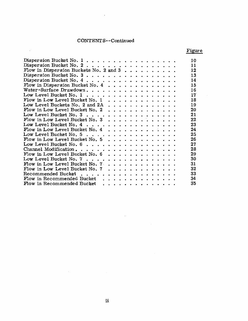
CONTENT $--Continued
Dispersion Bucket No. 1 • • . • • • . Dispersion Bucket No. 2 . . • . • . • . • .
Flow in Dispersion Buckets No. 2 and 3 • . • Dispersion Bucket No. 3 • . . • . . • . . • . • • • Dispersion Bucket No. 4 • • • . Flow in Dispersion Bucket No . 4 • • • • • • . • • • Water-Surface Drawdown ••.• Low Level Bucket No. 1 • . . • Flow in Low Level Bucket No. 1 Low Level Buckets No. 2 and 2A Flow in Low Level Bucket No. 2 Low Level Bucket No. 3 • . . . Flow in Low Level Bucket No. 3 L0w Leve 1 Bucket No. 4 • • . . Flow in Low Level Bucket No. 4 Low Level Bucket No. 5 • . . . Flow in Low Level Bucket No. 5 Low Level Bucket No. 6 • . • . Channel Modification • • • . . . Flow in Low Level Bucket No. 6 Low Level Bucket No. 7 . . . .
. . . . . . . . . . . . . . . . . . . . . . .
. . . . . . . . . . . . .
. . . . . . . . . . . . . . . . . .
. . . . . .
. . . . . . . . . . . . . . . . . . .
. . . . . . . . . . .
. . . . . . . . . . . . .
. . . . . . .
Flow in Low Level Bucket No. 7 • • • . • • • • • • Flow in Low Leve 1 Bucket No. 7 • • Recommended Bucket . . . • • • • • • . • • • Flow in Recommended Bucket Flow in Recommended Bucket ••••••
ii
Figure
10 11 12 13 14 15 16 17 18 19 20 21 22 23 24 25 26 27 28 29 30 31 32 33 34 3'5
Sam Peng
Sticky Note
None set by Sam Peng
Sam Peng
Sticky Note
MigrationNone set by Sam Peng
Sam Peng
Sticky Note
Unmarked set by Sam Peng
Sam Peng
Sticky Note
None set by Sam Peng
Sam Peng
Sticky Note
MigrationNone set by Sam Peng
Sam Peng
Sticky Note
Unmarked set by Sam Peng

UNITED ST ATES DEPARTMENT OF THE INTERIOR
BUREAU OF RECLAMATION
Commissioner's Office- -Denver Division of Engineering Laboratories Hydraulic Laboratory Branch
. Denver. Colorado August 10. 1960
Laboratory ijeport No. Hyd-467 Compiled by: T. J.. Rhone Checked by: A. J. Peterka Reviewed by: J. W. Ball Submitted by: H. M. Martin
Subject: Hydraulic model studies of the Trinity Dam spillway flip bucket--Central Valley Project, California ·
SUMMARY
The model studies of the Trinity Dam spillway flip bucket. described herein, were performed on a 1:80 scale model. Figure 4. The model included a section of the spillway tunnel, the open channel semicircular conduit. the flip bucket. and a section of the channel downstream from the gate structure .
In the preliminary design. Figure 5A, the upward curved deflector at the end of the semicircular conduit did not provide sufficient lift or dispersion of the jet. Tests were made with seven flip buckets. Figures 5. 6. 7. and 8, in which different. invert and sidewall deflectors were tried. None of the flip buckets provided adequate lift or dispersion of the jet.
Tests were next made on four diapers.ion-type buckets, Figur~s 10, 11, 13, and 14. These buckets used abrupt upward curved deflectors on the conduit invert and dispersed the jet over a greater area than the flip buckets. Figure 12. However. the lip of each bucket was from 40 to 60 feet above the foundation, and at spillway discharges of 2,000 cfs or less, a hydraulic jump formed in the conduit and the flow pumped over the end of the bucket, Figure 15. The energy contained in 2. 000 cfs, falling 40 to 60 feet from the lip of the bucket, would no doubt, cause considerable damage to the bucket foundation structure; tests were. the ref ore. continued to develop a flip bucket at a lower elevation.
To lower the bucket, the semicircular conduit was placed on a trajectory curve. Figure 17. Several different flip- and dispersion-type buckets were tested at the end of the trajectory curve, Figures 17, 19, 21, 23, 25, 27, and 30. before a bucket was developed to provide adequate jet · dispersion with a minimum amount of channel-bed erosion and bank scour.
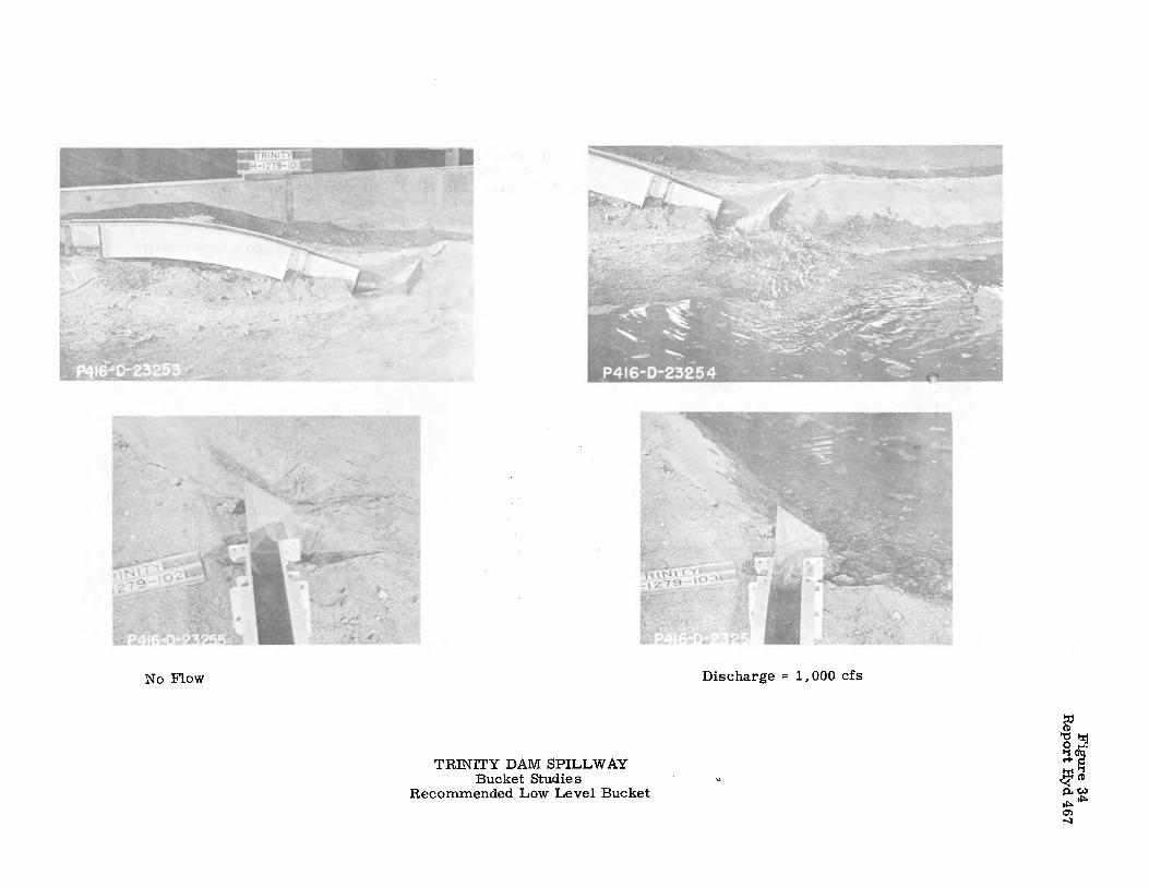
The recommended bucket, Figure 33, met the requirements that small flows· be introduced into the tail water without excessive vertical drop to prevent excessive erosion near the base of the structure. and that large flows be flipped downstream away from the structure with as much dispersion as possible. The recommended bucket was formed by three
Sam Peng
Sticky Note
None set by Sam Peng
Sam Peng
Sticky Note
MigrationNone set by Sam Peng
Sam Peng
Sticky Note
Unmarked set by Sam Peng
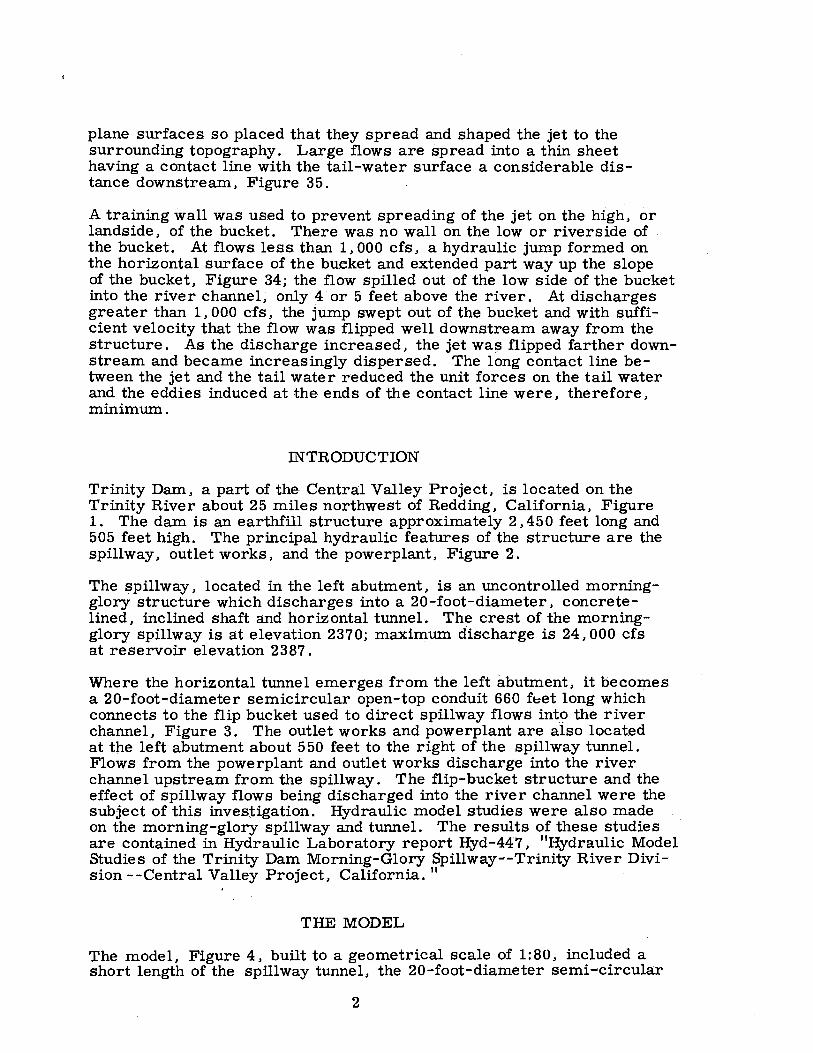
plane surfaces so placed that they spread and shaped the jet to the surrounding topography. Large flows are spread into a thin sheet having a contact line with the tail-water surface a considerable distance downstream, Figure 35.
A training wall was used to prevent spreading of the jet on the high, or landside, of the bucket. There was no wall on the low or riverside of the bucket. At flows less than 1,000 cfs, a hydraulic jump formed on the horizontal surface of the bucket and extended part way up the slope of the bucket, Figure 34; the flow spilled out of the low side of the bucket into the river channel; only 4 or 5 feet above the river. At discharges greater than 1, 000 cf s, the jump swept out of the bucket and with sufficient velocity that the flow was flipped well downstream away from the structure. As the discharge increased, the jet wa~ flipped farther downstream and became increasingly dispersed. The long contact line between the jet and the tail water reduced the unit forces on the tail water and the eddies induced at the ends of the contact line were, therefore, minimum.
INTRODUCTION
Trinity Dam, a part of the Central Valley Project, is located on the Trinity River about 25 miles northwest of Redding, California, Figure 1. The dam is an earthfill structure approximately 2,450 feet long and 505 feet high. The principal hydraulic features of the structure are the spillway, outlet works, and the powerplant, Figure 2.
The spillway, located in the left abutment, is an uncontrolled morningglory structure which discharges into a 20-foot-diameter, concretelined, inclined shaft and horizontal tunnel. The crest of the morningglory spillway is at elevation 2370; maximum discharge is 24, 000 cfs at reservoir elevation 2387.
Where the horizontal tunnel emerges from the left abutment, it becoI?J.eS a 20-foot-diameter semicircular open-top conduit 660 ft:et long which connects to the flip bucket used to direct spillway flows int9 the river channel, Figure 3. The outlet works and powerplant are also located at the left abutment about 550 feet to the right of the spillway tunnel. Flows from the powerplant and outlet works discharge into the river channel upstream from the spillway. The flip-bucket structure and the effect of spillway flows being discharged into the river channel were the subject of this investigation. Hydraulic model studies were also made on the morning-glory spillway and tunnel. The results of these studies are contained in Hydraulic Laboratory report Hyd-447, "Hydraulic Model Studies of the Trinity Dam Morning-Glory Spillway--Trinity River Division --Central Valley Project, California."
THE MODEL
The model, Figure 4, built to a geometrical scale of 1:80, included a short length of the spillway tunnel, the 20-foot-diameter semi-circular
2
Sam Peng
Sticky Note
None set by Sam Peng
Sam Peng
Sticky Note
MigrationNone set by Sam Peng
Sam Peng
Sticky Note
Unmarked set by Sam Peng
Sam Peng
Sticky Note
None set by Sam Peng
Sam Peng
Sticky Note
MigrationNone set by Sam Peng
Sam Peng
Sticky Note
Unmarked set by Sam Peng

open channel from the tunnel portal to the flip bucket, the flip bucket, the outlet works, the powerplant and about 1, 500 feet of the river channel downstream from the dam. The 20-foot-diameter concrete open channel, Section A-A in Figure 4, was represented in the model by a 3-inqh-diameter specially formed sheetmetal channel. The flip bucket was fabricated from sheetmetal and concrete. The outlet works and powerhouse structures were made of wood. The downstream ·channel was formed in concrete and river· sand.
The spillway tunnel was connected directly to the laboratory water-supply system. The depth of flow in the spillway conduit was controlled by a vertical slide gate at the upstream end of the open channel. Various combinations of flow depth and discharge quantity could, therefore, be tested by changing the discharge or slide-gate opening or both. Discharges were measured using a calibrated orifice Venturi meter lpcated upstream from the vertical slide gate. Tail-water elevations were 'controlled by an _adjustable tailgate at the downstream end of the model; elevation was measured by a point gage located in the channel near the tailgate.
The powerplant and outlet works were nonoperating models but were installed in the test box to determine whether spillway discharges would create any adverse flow, scour, or wave conditions in their vicinity.
THE INVESTIGATION
In order to properly evaluate flip-bucket performance, it is necessary that the model provide correct flow velocities at the upstream end of the flip bucket. For structural design purpos.es, the velocity at the flip bucket was computed to be 81. 5 feet per second if the Manning's roughness coefficient for the conduit was n = 0. 014 or 121. 6 feet per second if n = 0. 008. For the hydraulic model tests, a velocity of 121. 6 feet per second was used because the· higher velocity provided the most severe conditions and it was believed that a bucket which performed satisfactorily for high velocity would be satisfactory for lower velocities. In the model, the vertical slide gate at tne upstream end of the open-channel section was used to regulate the flow depth. For a given dis.charge, velocities were measured by a Pitot tube placed· at Station 36+60. In operating the model, the correct flow quantity was measured on the Venturi meter manometer and the flow depth was regulated by the gate; until the Pitot tube indicated the correct velocity. Gate openings to provide the desired velocity for discharges of 1,. 000 cfs_, 5, 000 cfs, 10, 000 cfs, 15, 000 cfs, 20. 000 cfs. and24, 000 cfs were thereby determined and were recorded for use in subsequent tests. In evaluating a flip bucket, a complete range of dis.charges was tested, but emphasis. was placed on the maximum discharge, 24,000 cfs. Tests were usually begun using the maximum flow and if the bucket showed promise of providing satisfactory operating characteristics, tests were also performed with smaller discharges.
The prototype channel downstream from the flip bucket has been subjected' over a period of many years to extensive hydraulic mining operations. As a result, most of the overburden, smaller than a nominal
3
Sam Peng
Sticky Note
None set by Sam Peng
Sam Peng
Sticky Note
MigrationNone set by Sam Peng
Sam Peng
Sticky Note
Unmarked set by Sam Peng
Sam Peng
Sticky Note
None set by Sam Peng
Sam Peng
Sticky Note
MigrationNone set by Sam Peng
Sam Peng
Sticky Note
Unmarked set by Sam Peng
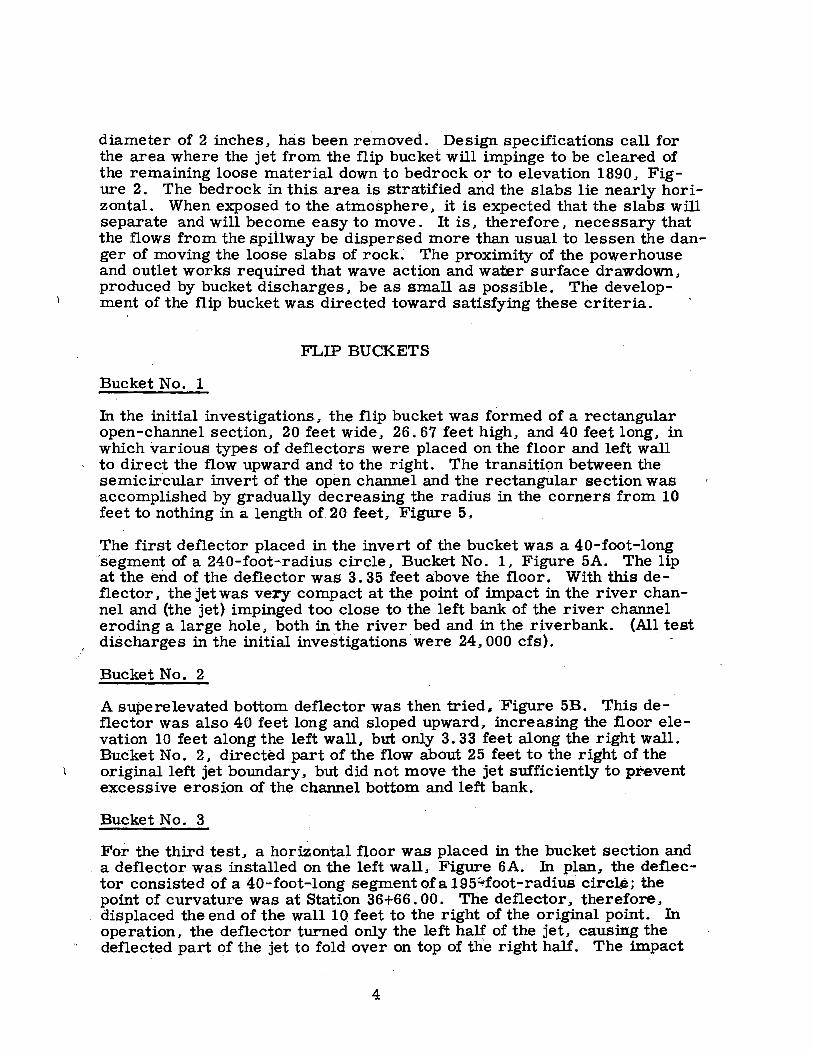
diameter of 2 inches, has been removed. Design specifications call for the area where the jet from the flip bucket will impinge to be cleared of the remaining loose material down to bedrock or to elevation 1890, Figure 2. The bedrock in this area is stratified and the slabs lie nearly horizontal. When exposed to the atmosphere, it is expected that the slabs will separate and will become easy to move. It is, therefore, necessary that the flows from the spiilway be dispersed more than usual to lessen the danger of moving the loose slabs of rock. The proximity of the powerhouse and outlet works required that wave action and water surface drawdown, produced by bucket discharges, be as small as possible. The development of the flip bucket was directed toward satisfying these criteria.
FLIP BUCKETS
Bucket No. 1
In the initial investigations, the flip bucket was formed of a rectangular open-channel section, 20 feet wide, 26. 67 feet high, and 40 feet long, in which various types of deflectors were placed on the floor and left wall to direct the flow upward and to the right. The transition between the semicircular invert of the open channel and the rectangular section was accomplished by gradually decreasing the radius in the corners from 10 feet to nothing in a length of 20 feet, Figure 5,
The first deflector placed in the invert of the bucket was a 40-foot-long -segment of a 240-foot-radius circle, Bucket No. 1, Figure 5A. The lip at the end of the deflector was 3. 35 feet above the floor. With this deflector, the jet was very compact at the point of impact in the river channel and (the jet) impinged too close to the left bank of the river channel eroding a large hole, both in the river bed and in the riverbank. (All test discharges in the initial investigations were 24,000 cfs).
Bucket No. 2 ·
A superelevated bottom deflector was then tried, Figure 5B. This deflector was also 40 feet long and sloped upward, increasing the floor elevation 10 feet along the left wall, but only 3. 33 feet along the right wall. Bucket No. 2, directed part of the flow about 25 feet to the right of the original left jet boundary, but did not move the jet sufficiently to prevent excessive erosion of the channel bottom and left bank.
Bucket No. 3
For the third test, a horizontal floor was placed in the bucket section and a deflector was installed on the left wall,. Figure 6A. In plan., the deflector consisted of a 40-foot-long segment ofa 195;,.foot-radius circle; the point of curvature was at Station 36+66. 00. The deflector,. therefore, displaced the end of the wall 10_ feet to the right of the original point. In operation, the deflector turned only the left half of the jet, causing the deflected part of the jet to fold over on top of the right half. The impact
4
Sam Peng
Sticky Note
None set by Sam Peng
Sam Peng
Sticky Note
MigrationNone set by Sam Peng
Sam Peng
Sticky Note
Unmarked set by Sam Peng
Sam Peng
Sticky Note
None set by Sam Peng
Sam Peng
Sticky Note
MigrationNone set by Sam Peng
Sam Peng
Sticky Note
Unmarked set by Sam Peng

point of the jet was about 25 feet to the right of its original line, but due to the fold over, the jet was more compact than ever, resulting in even greater scour.
Bucket No. 4
For the fourth test, two changes were made. The first change was in the channel alinement; at Station 35+81, the direction of the channel was turned 10 degrees to the right. The second change was to remove the right wall between Stations 36+66 and 37+06, Figure 6B. Jn operation, the impact point of the jet moved about 240 feet to the right, but the abrupt turn in the. channel prevented the jet from spreading and as. a result, the jet remained in a concentrated pattern with very little dispersion.
When the turn at Station 35+81 was reduced to 5 degrees, the impact point was about 160 feet to the right of the original point but the degree of dispersion was only slightly improved.
Bucket No. 5
For Bucket No. 5, the 5-degree turn in the channel alinement was maintained, the right wall was replaced, and a 40-foot-long curved deflector was placed in the floor of the bucket section, Figure 7 A. The deflector was a segment of a 123. 36-foot-radius circle with the point of curvature at Station 36+66. The lip at the end of the deflector was 6. 67 feet above the floor. At the point of impact, the jet covered an area of about 80 feet square. However, the vertical angle of the jet as it struck the tail-water surface was such that it caused a clockwise eddy to form in the deadwater area to the right of the bucket. The eddy moved material eroded by the jet into a sandbar in front of the powerplant and outlet-works stilling basin. It was apparent that this obstruction would interfere with the discharge from these structures.
Bucket No. 6
Jn order to obtain better dispersion of the jet and to move the point of impact farther downstream, the curved b.ottom deflector was changed to a segment of an 85-foot-radius circle with a total rise of 10 feet; other features of the Bucket No. 5 were retained, Figure 7B. The jet was thrown about 80 feet farther downstream and was considerably better
. dispersed, covering an area about 120 feet square. The magnitude of the eddy on the right was reduced, but the jet impinged in an area of the model molded in concrete to repres.ent an outcropping; instead of digging a hole, the flow raced downstream to the opposite riverbank, causing considerable bank damage. The high velocity downstream flow also . caused a noticeable water-surface drawdown at the powerplant afterbay.
Bucket No. 7 '
For Bucket No. 7, Figure 8, the turn in the open channel at Station 35+81 and the subsequent 125 feet of straight channel were replaced by a curved
5
Sam Peng
Sticky Note
None set by Sam Peng
Sam Peng
Sticky Note
MigrationNone set by Sam Peng
Sam Peng
Sticky Note
Unmarked set by Sam Peng
Sam Peng
Sticky Note
None set by Sam Peng
Sam Peng
Sticky Note
MigrationNone set by Sam Peng
Sam Peng
Sticky Note
Unmarked set by Sam Peng

channel. The curve was a segment of a 420-foot-radius circle with the point of curvature at Station 35+8 l. In the final 40 feet of the bucket, an · upward curved deflector was placed on the floor. This curve had a 123. 36-foot radius and provided a 6. 67-foot rise above the invert. The jet was not well dispersed with this arrangement, Figure 9A, and intersected the tail water about 120 feet clos.er to the bucket than with the previous arrangement. The flow raced downstream crossing over to the right bank where it tl,lrned back to the center of the channel. There was only slight scouring action along the right bank and minor action in the eddy on the right.
DISPERSION BUCKETS
The stratified bedrock in the prototype river channel was unprotected by overburden and it was apparent from the preceding tests that a compact jet striking the rock at a comparatively flat angle might cause slabs to peel off. A sufficient accumulation of eroded material could thereby produce adverse backwater conditions or flow conditions. To prevent this, the following flip-bucket investigations were directed toward developing a dispersion-type bucket that would spread the jet horizontally to provide a greater contact area.
Dispersion Bucket No. 1
For the Dispersion Bucket No. 1, an upward curved deflector was placed at the end of the semicircular open channel. The curve of the deflector was a segment of an 85-foot-radius circle with the point of curv.ature at Station 36+66, Figure 10. · On the left side of the channel, the length of the curved section was 40 feet with a total rise at the lip of 10 feet. On the right side of the channel, the curved floor was 20 feet long with a total rise of 2. 33 feet. The elevation of the lip sloped downward in a straight line from the left .side to the right side. With this arrangement slightly better jet dispersion was obtained. The pattern of the jet where it struck the river channel, Figure 9B, was similar to the numeral 7; the horizontal crossbar area was about 120 feet square and the vertical bar area about 40 feet wide by 200 feet long. The nearest point of impact was about 160 feet downstream from the end of the bucket. Performance was only slightly improved over that for the previous buckets. Consequently, tests were continued to develqp a bucket with even greater dis-persion characteristics. ·
Dispersion Bucket No. 2
Dispersion Bucket No .. 2 had its outer limits described by a quarter circle of 40-foot radius, Figure 11. The center qf the circle was on the left wall of the channel at Station 36+66. In cross section, the upward curve of the deflector was a quarter circle with a 10-foot radius. At Station 35+46, the alinement of the semicircular conduit was turned 5 degrees to the right, Figure 11. The deflector dispersed the jet very well both vertically and horizontally, and the turn in the channel directed
6
Sam Peng
Sticky Note
None set by Sam Peng
Sam Peng
Sticky Note
MigrationNone set by Sam Peng
Sam Peng
Sticky Note
Unmarked set by Sam Peng
Sam Peng
Sticky Note
None set by Sam Peng
Sam Peng
Sticky Note
MigrationNone set by Sam Peng
Sam Peng
Sticky Note
Unmarked set by Sam Peng

the flow toward the center of the river. However, there was some concentration of the flow near the right center of the jet caus.ed by the top layer of the flow not following the right wall downstream from the turn, and some water being forced from underneath to fill the void, Figure 12A. ~
Dispersion Bucket No. 3
Two changes were made to provide more even distribution and greater dispersion of the flow for Dispersion Bucket No. 3. The turn in the channel was modified by curving the alinement to the right in a 420-footradius arc with the po;i.nt of curvature at Station 35+46. The bucket was placed at the end of the curved channel and was des.cribed in plan by a 30-foot-radius quarter circle with its center on the left wall. In sectionthe deflector was formed by a 10-foot-high segment of a 15-foot-radius circle. Figure 13. The jet was very well dispersed and spread over a wide area. However, the jet was very ragged and there was some flow concentration along the left side. Figure 12B. When the curvature of thchannel was reduced by increasing the radius to 62·5 feet. there was somimprovement in the appearance and distribution of the flow.
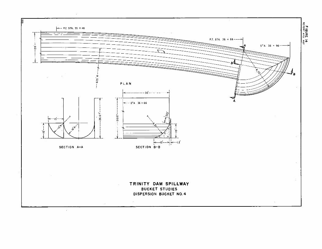
Dispersion Bucket No. 4
For Dispersion Bucket No. 4.,. the lip of the deflector was modified by increasing the height of the lip by adding an extension tangent to the end of the upward curve. The length of the tangent extension was 3. 33 feet on the left side. The lip sloped downward to the existing lip on the rightFigure 14. Operation showed more lift and greater dispersion to the jetand at the same time resulted in more equal flow distribution in the jet. Figure 15.
Since this type of bucket seemed to provide the neces.sary flow conditionfor satisfactory operation, a series of tests. was. performed to thoroughlinvestigate the effects in the river channel produced by the bucket. Theare discussed in the following paragraphs..
Water surface drawdown. At the time of the teats. the tail-water curvefor the river channel had not been finally determined. However. it was known that with the p-owerplant operating and the spillway discharging 24. 000 cfs. the tail-water elevation would be between elevations 1907 and 1922. To determine the difference between water-surface elevationat the powerplant and in the river channel about 1,600 feet downstream.an arbitrary tail-water elevation .was set at the downstream station withthe spillway discharging 24., 000 cfs; the tail-water elevation at the poweplant was then measured. Tests showed that when the downstream tail water was at elevation 1907. the powerplant tail water was about 1. 3 feet lower; for downstream tail-water elevation 1915, the powerplant tail water was 2. 0 feet lower; for downstream tail-water elevation 1922., the powerplant tail water was: about 1. 8 feet lower, Figure 16.
Wave heights. For the m~imum spillway discharge. 24. 000 cfs .• the average height of the waves at the powerpla:nt was about 1 foot, with a
7
Sam Peng
Sticky Note
None set by Sam Peng
Sam Peng
Sticky Note
MigrationNone set by Sam Peng
Sam Peng
Sticky Note
Unmarked set by Sam Peng
Sam Peng
Sticky Note
None set by Sam Peng
Sam Peng
Sticky Note
MigrationNone set by Sam Peng
Sam Peng
Sticky Note
Unmarked set by Sam Peng
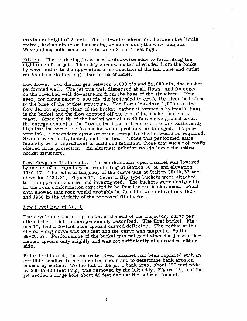
maximum height of 2 feet. The tail-water elevation, between the limits stated, had no effect on increasing or decreasing the wave heights. Waves along both banks were between 3 and 4 feet high.
Eddies. The impinging jet caused a clockwise eddy to form along the right side of the jet. The eddy carried material eroded from the banks by wave action to the approximate intersection of tb.e tail race and outlet works channels forming a bar in the channel.
Low flows. For discharges between 5, 000 cfs and 24, 000 cfs, the bucket performed well. The jet was well dispersed at all flows, and impinged on the riverbed well downstream from the base of the structure. However, for flows below 5, 000 cfs, the jet tended to erode the river bed close to the base of the bucket structure. For flows less than 1, 000 cfs, the flow did not spring clear of the bucket; rather it formed a hydraulic jump in the bucket and the flow dropped off the end of the bucket in a solid mass. Since the lip of the bucket was about 60 feet above ground level, the energy content in the flow at the base of the structure was sufficiently high that the structure foundation would probably be damaged. To prevent this, a secondary apron or other protective device would be required. Several were built, tested, and modified. Those that performed satisfactorily were impractical to build and maintain; those that were not costly offered little protection. An alternate solution was to lower the entire bucket structure.
Low elevation flip buckets. The semicircular open channel was lowered by means of a trajectory curve starting at Station 36+56 and elevation 1960.17. The point of tangency of the curve was at Station 38+10. 57 and elevation 1934. 21, Figure 17. Several flip-type buckets were attached to this approach channel and investigated. The buckets were designed to fit the rock conformation expected to be found in the bucket area. Field data showed that rock would probably be found between elevations 1925 and 1950 in the vicinity of the proposed flip bucket.
Low Level Bucket No. l
The development of a flip bucket at the end of the trajectory curve pa:ralleled the initial studies previously described. The first bucket, Figure 17, had a 20-foot wide upward curved deflector. The radius of the 40-foot-long curve was 240 feet and the curve was tangent at Station 38+20. 57. Performance of the bucket was not good since the jet was deflected upward only slightly and was not sufficiently dispersed to either side.
Prior to this test, the concrete river channel had been replaced with an erodible sandbed to measure. bed scour and to determine bank erosion caused by eddies. To the left of the jet a bank area, about 120 feet wide by 300 to 400 feet long, was removed by the left eddy, Figure 18, and the jet eroded a large hole about 4.0 feet deep at the point of impact.
8
Sam Peng
Sticky Note
None set by Sam Peng
Sam Peng
Sticky Note
MigrationNone set by Sam Peng
Sam Peng
Sticky Note
Unmarked set by Sam Peng
Sam Peng
Sticky Note
None set by Sam Peng
Sam Peng
Sticky Note
MigrationNone set by Sam Peng
Sam Peng
Sticky Note
Unmarked set by Sam Peng

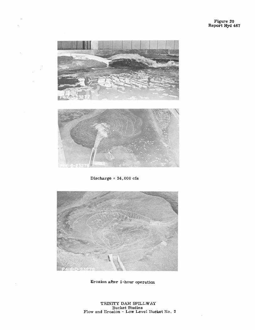
Low Level Bucket No. 2
For Low Level Bucket No. 2, Figure 19, the radius of curvature of the bottom deflector was reduced to 53. 33 feet, and a 40-foot-long deflector was placed on the left wall to turn the flow to the right.
The downstream end of the wall deflector was 5 feet thick. The downstream 40 feet of the right wall was turned to the right at the downstreaend. The divergence was 6. 67 feet.
In operation, the jet was turned to the right and the diverging right wallallowed the jet to spread more than had occurred with the previous bucThere also was more longitudinal dispersion in the jet, Figure 20. Thgreater dispersion reduced the·-depth of erosion from 40 feet to 20 feet; however, there was considerably more bank erosion. The bank on the left side was eroded back almost 300 feet from its original line. The material eroded from the left bank was moved to the right where it fora large bar near the center of the channel. However, a sufficient widthof channel remained between the sandbar and the right riverbank to ·pasnormal powerplant and outlet works discharges.
Low Level Bucket No. 2A
To provide greater turning and more dispersion of the jet, the convergence of the left wall and divergence of the right wall were both increasto 10 feet, Low Level Bucket No. 2A, Figure 19. The other features were the same as for the previous bucket. In operation, the jet was turned more _toward the center of the channel and was better dispersed. The depth of the channel-bed erosion was increased to 40 feet, but the left channel-bank erosion moved the bank line only about 100 feet. The eroded material moved farther toward the right than with the previous buckets and for med a bar which would probably interfere with the poweplant and outlet works discharges.
Using this bucket, two tests were made to. determine whether reducing the slope on the left channel bank or adding riprap protection to the banwould reduce the amount of bank erosion and bed scour. The tests shothat (1) a flatter bank slope reduced the depth of the bed scour to about ~0 feet but increased the extent of the bank erosion, and (2) that riprap on the banks reduced both the bed and bank erosion, but that individual stones 30 inches or greater in diameter would be required. Since. rip.rap of this size would be dffficult to acquire, no further investigations were made.
Low Level Bucket No. 3
For Low Level Bucket No. 3, Figure 21, the 10-foot convergence of the left wall was maintained but the divergence of the right wall was increased to 10 feet • The floor deflector was modified by adding a triangular fillet at the downstream end of the bucket. The fillet started along the left wall 20 feet upstream from the end of the bucket and
9
Sam Peng
Sticky Note
None set by Sam Peng
Sam Peng
Sticky Note
MigrationNone set by Sam Peng
Sam Peng
Sticky Note
Unmarked set by Sam Peng
Sam Peng
Sticky Note
None set by Sam Peng
Sam Peng
Sticky Note
MigrationNone set by Sam Peng
Sam Peng
Sticky Note
Unmarked set by Sam Peng

extended diagonally across to the end of the bucket on the right side. Along the left wall. the fillet sloped upward. increasing the elevation of the lip by 16. 67 feet; the elevation of the lip on the right side was not changed. Figure 21. For 24. 000 cfs. the added supereleva.tion turned the jet farther to the right and provided greater lift and dispersion, Figure 22. There was very little erosion of the left bank, and the channel bed ero-sion was about 30 feet deep. The sandbar. formed from the eroded material, extended across the channel downstream from the jet impact area. but an adequate channel remained for normal powerplant and outlet works flows.
L9w Level Bucket No. 4
For Low Level Bucket No. 4. the right wall of the bucket was shortened 30 feet and the leading edge of the tri~gular fillet was moved upstream about 5 feet. giving less superelevation in the bucket. Figure 23. Jet dispersion was increased by this bucket because the right side of the jet was deflected out of the open side of the bucket. However. water leaving the right side struck the river channel near the end of the bucket. This flow neutralized the damaging eddy previously in evidence· along the right side of the jet. The main portion of the flow from the spillway moved downstream in a direct line, Figure 24. The contact line of the jet with the tail water was continuous from a point to the right of the bucket to a point about 300 feet downstream. Bank erosion on the left side was negligible. Bed scour was about 20 feet deep but a small area was eroded an additional 10 feet deep. Figure 24.
Low Level Bucket No. 5
To provide even more turning and greater jet dispersion. the convergence of the left wall was increased to 18. 33 feet and the right wall diverged 40 feet to the right. Figure 25. The superelevation was increased so that the lip elevation on the left side was 23. 33 feet higher than on the right side. This alteration turned the jet farther to the right. but did not improve the jet dispersion, Figure 26. The rock jetty shown in Figure 26 was placed normal to the tunnel centerline about 300 feet downstream from the bucket. The purpose of the jetty was to intercept the reverse flow of the eddy and deflect it away from the river bank to reduce erosion. The river bed scour. shown in Figure 26, was about the same as with Low Level Bucket No. 4. The jetty reduced the extent of bank eros.ion. however. it would require such large-size rocks that it was not practical to construct. and no further tests using a jetty were made.
Low Level Bucket No. 6
A 10-foot-long extension was added to the sloped surface to increase the dispersion in the bucket. Figure 27. and thealinement of the river channel downstream from the bucket was also altered, Figure 27 A. Field investigations had shown that s·ome of the rock and gravel in the river channel was suitable for use in the earth dam. On the assumption that most of the rock and gravel above bedrock would be removed from the area shown in Figure -
10
Sam Peng
Sticky Note
None set by Sam Peng
Sam Peng
Sticky Note
MigrationNone set by Sam Peng
Sam Peng
Sticky Note
Unmarked set by Sam Peng
Sam Peng
Sticky Note
None set by Sam Peng
Sam Peng
Sticky Note
MigrationNone set by Sam Peng
Sam Peng
Sticky Note
Unmarked set by Sam Peng

28. the left riverbank was moved to the left almost 500 feet and the right was moved about 200 feet to the right. The modification to the bucket greatly improved the dispersion of the jet and practically eliminated the eddy action on both sides, Figure 29. Because of the increase in channel width, the eddy currents were reduced and bank erosion was negligible. Bottom scour was about 20 feet deep. The bed material removed by thejet formed a bar downstream, but it appeared that the bar would not interfere with normal flows from the powerplant.
Low Level Bucket No. 7
The flow pattern in the previous test had indicated that because of the wiriver channel it would not be necessary to turn the flow as far to the rigTherefore, the flip bucket was rebuilt without converging the left wall; iorder to simplify the design, the superelevation of the floor deflector waccomplished with two triangular-shaped plane surfaces. ·Figure 30. Theight of the bucket lip above the ground varied from 5 feet on the right side to 50 feet on the left side.
For flows of less than 1. 000 cfs, the jet did not spring clear of the buckbut dribbled over the bucket lip. On the right side where the drop from the lip to ground level was not great, the action was not harmful. However. since the lip was considerably more than 5 feet above the ground over most of the lip length, a drip apron was added to the bucket to catcthe flow and carry it to the lower elevation. This apron was placed abo5 feet below the lip and extended from the end of the right wall around thend of the bucket to the left wall; the drip apron sloped downward to the right away from the bucket.
Five--foot-high vertical sidewalls were placed on the drip apron to converge to a 20-foot width at the lower end, Figure 30. The drip apron wvery effective for low flows; all of the water that spilled over the lip edg
· was caught and carried to the· lower elevation where it entered the river channel very smoothly, Figure 31. When the jet s'prang clear of the bucthe water was thrown completely over and past the drip apron, Figure 3
For the larger discharges. the bucket was also very effective. The fiowwas equally distributed and well dispersed over a wide area, Figure 32. There was very little eddy action in the river channel on either side of the jet and practically no bank erosion. Because of the wide river channthe excellent dispersion of the jet and the relatively steep jet trajectory at the point of contact with the tail water. there was no measurable watesurface drawdown in the powerplant tailrace. The waves in the powerpla:rea were negligible. seldom attaining a height of more than 6 inches.
Although the drip apron was very effective, economic analysis indicated that it would be less costly to build the bucket at a lower elevation, even though extensive rock excavation would be necessary.
Recommended Bucket
In order to place the bucket on sounder rock the PVC of the trajectory curved channel, shown in Figure 17. was moved 75 feet upstream. On
11 .
Sam Peng
Sticky Note
None set by Sam Peng
Sam Peng
Sticky Note
MigrationNone set by Sam Peng
Sam Peng
Sticky Note
Unmarked set by Sam Peng
Sam Peng
Sticky Note
None set by Sam Peng
Sam Peng
Sticky Note
MigrationNone set by Sam Peng
Sam Peng
Sticky Note
Unmarked set by Sam Peng

the downstream end, the channel was extended on a 3:1 slope to elevation 1912. 0, 22. 21 feet lower than for the previous bucket. Low Level Flip Bucket No. 7 was placed at the end of the conduit, but the drip apron was eliminated. The rock on the right side of the bucket was removed to form an excavated channel leading down to river level. At the end of the bucket, the rock was removed to provide a smooth slope into the river channel. The recommended bucket and the surrounding topography are shown in Figure 33.
Operation with this bucket was as good, or better, in every respect than it had been with the bucket at the higher elevation, Figures 34 and 35. The long contact line of the jet impinging on the water surface practically eliminated the eddy currents. Wave heights were small. Downstream from the jet impact area the water surface was rough but near the left bank, the waves were about 12 to 18 inches high; near the right bank, they averaged about 12 inches· high; and in the vicinity of the powerhouse and outlet works, the waves averaged' about 6 inches in height.
The river bottom had been formed in nonerodible mortar so no scour tests were made. However, the channel banks were formed from erodible sand and tests performed at the maximum discharge did not cause extensive damage to the channe 1 banks.
At the maximum discharge the water-surface elevation in the powerplant afterbay was about 1. 5 feet lower than the downstream tailwater elevation.
This bucket wa~ recommended for prototype construction.
12
Sam Peng
Sticky Note
None set by Sam Peng
Sam Peng
Sticky Note
MigrationNone set by Sam Peng
Sam Peng
Sticky Note
Unmarked set by Sam Peng

FIGURE I REPORT HYO. 467
SCALE OF MILES'
UNITEO STATES DEPARTMENT OF THE INTERIOR
BUREAU OF RECLAMATION
12
CENTRAL VALLEY PROJECT - CALIFORNIA TRINITY RIVER DIVISION
TRINITY DAM LOCATION MAP
ORAWN _____ fi..t°,:.~..=. _______ SUBMITTEO _______ a ~- ____ _ _____ _ TRACED. __ .!:. I!·."!:. ______ Rl!COMMENOEo •• Z~~- __ _ CHECICEQ.,Ui,,.ft:,!_c;t:y4 •••• APPROVl!O. - .ii0.-ci°Hii IINt,-I cs,;·••••
Dl!NVl!R, CO&.ORAOO - F'lrS, 14, IIUJfl 416-D-10

I
E.1,788,000
<>" 'V ~
~
--------t,\---::i <. __ ___
'\ ,, L-, -
I -\ ,-v
--'+-··Limits of special I feundation treatment.-----··
g 0
! z
200
'
~-",.
:s-<., ~ ::,
~-------,:;,, r .._ l•L_., (:) ~1---- -
4:: / -:::,,;_/ £ "' '
·>: ~/ ...... ,/ --.~I'
r
?
PLAN
200 j
SCALE OF FEET
4?0
+
sgo
+ l C r>-D -Note, Slape all
berms to drain downstream
·- _;y~~ _,_-£12395 //// I",....._ •< / / l' "-.._)'.., ,,,- / ' '-(
,, ,.,....- / ' ......
21;·)_,, _,, / _.-t o.~;est of dam
,,,,,,--- " // f' ' £/. 2100·· __ ,,, \' 0 y ' .. "".
·--:,::.::.1:.-"'_, '>/ .-Limits (J{ spe ial '\:<, 4-:f_;)'...--- // / foundation t atment- ...• \y -
I -. '
/0'·~1~k-lY-<
FIGURE 2 REPORT HYO. 467
Excav. for dam t . . 1 Excav. l!·El.!250 embankment foundation··· - ·-·Ltmtls-·-·····>k-oreo1·
, -----!z; .. , Excav. area I ~! '"----..:{!!!!!P I
- I
--- -3·/··, ·/30'.-,,.i 100'
Original ground surface.·····,, -·Excavation /// , ',,, '-
-- J., , / ' ' ' C-~-----------~~-:-- ~------------r:-;...L.------r----i_-_=-------~---:i...-
:Original ground surface ....,_--r __ _ ,·El./934 I ~ I _,-Excav_g!jg'!_ _______ ~ . . <:> >. · }~
- ~----..... :.,._ --1- .- .
f Tai/race-·--·~--- r- \
PRT~~'~b1 d~ A-A
f Outlet works-''
t
I/ 17
,,,"- .... __ .,,- ......
<.:"".::: _____ .... ---1950-- - -- - ._
r·\ -','-----------
,__,---, ' ---- ------~~
,--"'
'' - ' \' ---------- - ---------------1 I I
f ,,,,---------' , , .... ___ /
\...__..1
_c.:
--/950 ·,~#~~
\
?72400 ··-Crest El. 2395 i /i;;j,j' f I / P'~ I I I
I . "~:::£12200-End downstream grout cap I r ~ It WO
~ ,,- -briginal ground surface J~
z ::--,j L-- ···Excavation
·"""' ·- ~ I I; .·. ' _. ~ ~"'¾.>< 2000;!
I ,th- 4 ... ~ -~~ ~
STATIONS 25 20 15 10 S !BOO
PROFILE ON CENTERLINE OF CREST OF DAM
_,..£ Spillway funnel
l
(Limits-excavation-areo 1
~> 1...-... N. 534,150
~ , ,_;__:._?~------- '\··-->-1 /Lim!!?..-!!C!J..vgf.!_o!!_-area 2-, - "-I t:=-- ....._ I
SECTION B·B
SECTION C-C
_ .... __ ',
i"-- - ' :j I _____ :::::__
''-'-':·-·-·---------~'il"?!';'tJ ,,:f ':--:Spillway Sia. 38~00- ->f--L1mif-excav.
area 3
«;_>---E·;Original ground surface
, ·•l':"~/2300 • LI!. __ ·,?I'-
REFERENCE DRAWINGS GENERAL PLAN AND SECTIONS.. •.••.•• 416-0-160
SPILLWAY-PLAN AND SECTIONS ....... 416-0·/62
OUTLET WORKS-PLAN, PROFILE
AND SECTIONS_ •. ---···--···· •• 416·0·164 OUTLET WORKS
DOWNSTREAM AREA ....• -··· ._416-0·168
AUXILIARY OUTLET WORKS -PLAN AND SECTIONS .. -- ••..•• _416·0-t 71
- ,,-.,; a;,"o--;- __ be,_,,-------- ' .
S(!i)5o'I, ------ ,-Ltm1t•excav. i!'~e/s. ', : area 2
,_ ,'11.2050 / .-1'/..( 'c.,/
·:;,, , ',>--~£1./977.5 ',
, '·-umit-excav. f Spi!/wa)'-. -· ·1 area I
SECTION D-D
UNITEO STATES
DEPARTMENT OF THE INTERIOR
BUREAU OF RECLAMATION
CENTRAL VALLEY PROJECT
TRINITY RIVER 0/V/S/ON-CALIFORNIA
TRINITY DAM EXCAVAT /ON-GENERAL PLAN AND SECTIONS
:::::: ;::~::~~~~~ ~::::::~::~~~'?~~·.· .. CHECl<EO....HW,&,.z'{;6', __ ___ APPROVEO-~c~i~li-
t>E:NVE:R,cocoRAt>o, oEc. 3,, .. e · I 416-0·161

t< ------ -- - -- ---- -------1s" o' -- - --- -- -- - ----------- ---+1 I I ----l
(Slide gate Ar>-r<-- -3'...o'---J.c---- -4'-o'-- -·>t<-· - - - -·- -i-e'- -
,-21'!..
I ' i Flange---- '
Transition e' t to 3' •----
~
.r N
1½' R N
SECTION A-A
Ur--t-1 --f ....
I
: __ t
SECTION B-B
I
Approach Pipe-3" t r-
·o -~
' ' '
Dam face ->-
1895------
., "' 0 ..,, +-C ·5
;.~ •t, I Q. l -b 0 N L... .. I- I .., I C I 0 I '(' I
' I --, / I
r-) : •.l,
t a~ -~
I -.:. -f : •' ,,
I
.t: . ' 0 +- I -./,. o, ..,, ' ' ' •o I
I I I- I
i-~! l V V V V V V V V V V V V V V Y:::::>, ). I I I I __ L:t I ' • ><----- --- --- ------- - - - - --- - - --- -- - - - - - - --- - - - --- - --- -37-0 i ------------~
,-3' LO. Pipe ,--Spillway channel P L A N • 4
.. t.. Elev. 1910-- 't--·Elev. 1970 Concrete Topography • : -] .., ,--.......;::...c....;_=--=~==--=:.::...:..:.:_:_ _____________________ :..:..:..:..:..::.:-.:.:.. ____________ ~ ,,,, -l'llt
';' ,--Floor ~ ~ J__________ ' ' __ :r
ELEVATION ALONG It. OF SPILLWAY
10
SCALE OF FEET
TRINITY DAM SPILLWAY BUCKET STUDIES
1:eo SCALE MODEL LAYOUT
"' "' .,, 0 -n "' -... Gl :,:C: -< ;;a .,,.. : .... ..

-x---I I I I I I I
-0
"' I I I I I I I _y__ __
-+ I I I I I I I I I -,__ ~ "' I I I I I I I I
_L_
r--STA. 36 + 46 r-- STA. 36 t 66
£-':\
PLAN
I I I
.lr I I
"' -o ... "' I
I I
A STA. 37 t 06----1 <,
~J A
~
l f I I I I I I I
-0
"' I I I
f I I
y
T--, I I I I I
,__ "' <D "' I
k-- P.V.C. STA. 36 t 66 \ I .. ,_ .. _~o;_::;.o.·_.-:o.·
. _.1-r .•. _f_
I I I I I I
_L_
-r-, I I I I
-' ,__ "! :ll
SECTION ALONG It.
---2d--+-------
.,..,o/' "' ... ,.;
_L_ I ',, ___ i __ ,/ I I ELEVATION A-A
A. BUCKET NO. I
TRINITY DAM SPILLWAY BUCKET STUDIES
FLIP BUCKETS I AND 2
A f<--STA. 36 + 46 ~--STA. 36 + 66 m. " • ,. _ _, 7 I~ I I I ct_---
'I.I
~ I I ~J PLAN A
k · ·------------ 40° --------------
-r--, I I I I I I I I I -... "!
"' "' -I "' I "! I "'
' . I I I I I I I
SECTION ALONG <t.
-,,·+----
_L~r, --- ~ _/ , _y__ ELEVATION A-A
B. BUCKET N0.2
--,.-1
_I !? I
__.t_
"' "' ....... o-"'G) .... C: :,: :u pl'l'I ,.c.n !!l

598
I
-~ I I I
_L
.--1 I I I I I -....
U>
'° "" I I I I I I I I I I
_L
i<, : '•-STA 36+46
r--··P.C. STA 36+66
PLAN
' ' ' ' ' ' ! /1951 R
--~ A STA 37+06----'• ~l--r
I _: :~
I
--<J A
I
r------------------ 40' -------------j
,-HORIZONTAL FLOOR···-•• ,
\
' ' I _, .... U>
'° "" ' I I I
f-c---101 -· ~-- 101
--~ I • I
I ,'
: / ' /
_j __ ----·'--___,;""""".......:;.---'
FIGURE 6 REPORT HYD 467
SECTION ALONG t ELEVATION A-A
-. : '·-STA 35+81 I
T -.... U> <D ""
I I I I I r-- 10 --T-~ ,o ---,
' j _},,- ,./'
j __ ~_..:::::.-.J........::'::.~_--_...J
ELEVATION A-A
A. BUCKET N0.3
,1-,: •• --P.c. STA 36 I +ss
' r<------ ----------- -401 ------- ----.,..,
,,·HOR I ZONTAL FLOOR·-, I ½ v I
B. BUCKET N0.4
TRINITY DAM SPILLWAY BUCKET STUDIES
FLIP BUCKETS 3 AND 4
I I I
SECTION B-B
i -T I I I
! ... <'! U>
"" I I I
' I : ' j_
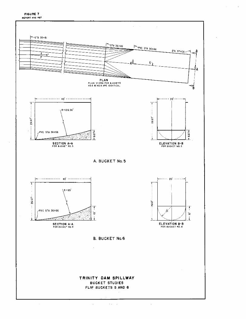
FIGURE 7 REPORT HYD 467
t-'··STA 35+81
1--srA 36+46
PLAN PLAN VIEWS FOR BUCKETS NO.5 11.N0.6 ARE IDENTICAL
r--------------- 401 ---------------,
r
' ' '
. L. /PVC·S-~~,,:.6.:.:,~,--~i-:i_:>_:':/){\/YNtfit:} J SECTION A-A FOR BUCKET NO. 5
A. BUCKET No. 5
r 40· --------------->1
r R' 85'
1 (PY C STA 36t66
j .L·"-=~~~~~~~~.:;.:,.;.i.::;J
SECTION A-A FOR BUCKET NO. 6
B. BUCKET No.6
TRINITY DAM SPILLWAY BUCKET STUDIES
FLIE' BUCKETS 5 AND 6
r''-pvc STA 36t66 STA 37+06-···1-<:; 8
l
T_r-------r-------~ '
.L.
f,-----1---1~' "-;! '....... ,,,' :g
--- _, _ _i_
ELEVATION B-B FOR BUCKET NO. 5
~-------- 201 -------~
' I 1-- - r-
1
' ' '
-T ,.,..~,, ,'
\,11' / < _,/ I
j _____ ~_-----~--+-=·------- _j_
ELEVATION B-B FOR BUCKET NO. 6
I
i J.A

-x--1 I I I I I I
-,.._ <D (I) N
I I I
~--·-P.C. STA. 35+81 < I I
-~ ..,. <),I I I I
I I ~------------- - 40 I
--------------~
' ~ '"1 ~ ;
I I
., I
i 1 .. /.¥.,c. STA 36•6~-l _1. IL.--=========----------.....1--Y.-
SECT ION A-A
PLAN
I I I I k-- -20 -- ---------...: I I
I Tl ,-, I
I -,.._ <D (I) N
I I I I I
J. I i IJ SECTION B-B
TRINITY DAM SPILLWAY BUCKET STUDIES
FLIP BUCKET NO. 7
:u "' "V"ll o-;uG) -IC: :c::O ~ITI
~CD ~

A. Flip Bucket No. 7
Discharge = 24,000 cfs
TRINITY DAM SPILLWAY Bucket Studies
B. Dispersion Bucket No. 1
Flow conditions for Flip Bucket No. 7 and Dispersion Bucket No. 1
~ (I)
'g ~ l~ Ill 'i '< (I)
P.CO
t -..1

555
A -cA-1:.
I I I I I I _,
0 N
PLAN
-~--' I i \85'R : I I I I A"° ~ _, ,._ ~ I \ ID I I
I STA. 37+06---.---i )..
.l~A
STA. 37+06-_,_,.
B -<7
I I
I
I -<J
B
~ PVC STA.36t6~ \
: I --T I I \ _A; I
_L : ·=·"~"J};i;:0rfi,Q1}j l SECTION A-A
I I t<- -- -- --20'- ------,:,,J I
1£
I
__j --r ~o~ , ,,,,, t:S:J 'I_I / 2
/ I -.,.- ' . / I
2.33~~ ~ <_.,, J__
ELEVATION B- B
STA. 37t 06--c~:
PVC STA.••••ti STA.36'867k 1 T I ! i-------=---;.;,;, . -~ I -I I
I I J - - - I I t _____ 2.33 __ L
ELEVATION C-C
TRINITY DAM SPILLWAY BUCKET STUDIES
DISPERSION BUCKET NO. I
~
~ 'Tl o;u G) -4 C ::J: ::u -< fTI 0 . -:o ...

',! r:---STA. 35 + 46
\I ..i-- ! -
PLAN
-x----------------- \ ... i ~ I I
' I
--10•-- k -1-- / -- / --1 /·
,/ 1 -~
,0~ , -q O. ,-!i:' ,t'
~ .. 0 ·. _y____ 0 -: •.• ,
SECTION A-A
A -<•
STA. 36 + 66---->-j
' ' ' i---', ---'-,~--
SECTION B-B
--r I I I I
... "! c.o ('J
I I I I I I I __ y_
TRINITY DAM SPILLWAY BUCKET STUDIES DISPERSION BUCKET NO- 2
~
A
' ' ' VO, -s>,
' ' ' '
"' '111 -v'! Oc., '"'c: -1:D
~"' p
'•= '11> , .. I

A. Dispersion Bucket No. 2
Discharge = 24. 000 cfs
TRINITY DAM SPILLWAY Bucket Studies
B. Dispersion Bucket No. 3
Flow Conditions - Dispersion Buckets 2 and 3
f 'g ~ '1 Cit! ... ~ Ill CD a .... ~~ Cl) -.:i

--,;--
' I I
-o C\J
I I
~_,.P.C. STA. 35+46
! 1 j· .L_ I ---~ I
+ I
I I
I ' ' IR= 420 AND 625 I
--r: I I I I I
: I O ft ":ii 1-c---10 --- / '° I , C\J
-x---· ~ : I : I I
-o l - I I I I I
I I _.:1 ___ 1.... __ ...;::w_ __ ::::::,_-1-...:::::::::...._.....J ___ .:J -- -
SECTION A-A
PLAN
:-«----------- 30° I
- -------- ~
-x---I I
, '
I I !
1 r··-I 'STA. 36+ 66 I I I
-,._ '° co C\J
I I I I I I I I I
_l__
*·, ' '
~.J ', ~
I 1
:..---101 --~
' I
SECTION e-e
TRINITY DAM SPILLWAY BUCKET STUDIES
DISPERSION BUCKET NO. 3
STA. 36+66--•.• _____ _
STA. 36+96-•• ___ _
::a ;"'II o::aG> .. c: :z:::U
?"' ~cii ....
.. .. .. r-- P.C. STA. 35 t 46
T ii-------~__ ~ I I I I I _L_
i I I
0::
"' C\J
"' I I
-ii I I I I I
I I + -,._ t<--10 -- .,/· :
-r--1 / N " ---- I I I I I
-o I I J
-L~-----=:::,,i __ ::::::,,._-i-..::::::::'.'.::_J__ : L
SECTION A-A
PLAN
I I f< --------- 30° --------->! I I
-A I
I I I I I I ,-.
: N
-- STA. 36 t 66
"£; +-, d"
I I I I I I I
''cl, -i._ " --it---------,\, \A~ -1 E \l 7 ·I- -
_y_ __
SECTION
-~ ·.1. I , .. :. ': :01. :i
I I 11-- - I
l<--10-->1 l<--1.2 I i 1 8-8
TRINITY DAM SPILLWAY BUCKET STUDIES
DISPERSION BUCKET NO. 4
P.T. STA. 36 t 66----
,4
., "' ... "" o_ "'CD .... C: :c :u ~ITI
:~ ...

Discharge = 5, 000 cfs
TRJNITY DAM SPILLWAY Bucket Studies
Discharge = 2, 000 cfs.
Fl.ow Conditions - Dispersion Bucket 4
l ij,. .... ~ q~ ~ .... ~en C)
-:i

z 0
~ LI.I .J LI.I
a:: w I-c(
~ <( I-
555
1923
1921
1919
1917
1915
1913
1911
1909
1907 1905
~ ~
~
V i
1907
.v .V.
V .V
.v lr'
• • Y. ·v'
1/.~ ,j • •
1909 1911 1913 1915 1917
WATER SURFACE ELEVATION AT POWERHOUSE
TRINITY DAM SPILLWAY BUCKET STUDIES
FIGURE 16 REPORT HYO. 467
I/ V
l/
1919 1921
WATER SURFACE DRAWDOWN FOR MAXIUM DISCHARGE DISPERSION BUCKET NO. 4

I'" "' '"
-x I I
_I 0 ,
_y_
r· ~
I
P.V.C. STA. 36 + 56 • A
~ l--,,. -
' ' '
A PLAN
El. 1960.17 ,, t:: ,z y=0.00256x· + 0.00l07X2
.l ~ . 0. o.·· 0 • .·.o._ .•. . ..
SECTION
I
P.T. STA. 38 + 10.57-t-10';:.f< 40°
- ~ ~
I I
~ \ I
P.C. STA. 38 + 20.57.h 1 El. 1930.88 -o \ . \ ..
~~',
19
i J
B
---r-1
-I ,._ U)
ui '-" I
1 _ __,:....,p,__,-_EI. 1934. 21
I
:,--r I 1 I I<-- 20'....>-1
J L--r ,~ -··.1 L
IOI
• I I
_1 ,._ U)
ui '-" I
. ·:zr- ,.__y_
SECTION A-A
I -1 ,._ -~ lli~ _y__ :
-r- .1__ I
ELEVATION B-B
TRINITY DAM SPILLWAY
BUCKET STUDIES LOW LEVEL BUCKET N~
:u "' "0"11 o:UG') -tc
21 :i:111 -c 0-.,. ... !.l

Discharge = 24,000 cfs
Erosion after 1-hour operation
TRINITY DAM SPILLWAY Bucket Studies
Flow and Erosion - Low Level Bucket No. 1
Figure 18 Report Hyd 467

P.C. STA. 38 +20.57--,-....i
Fl GURE 19 REPORT HYO. 467
STA. 38 t 60.57---, i --T-- ----------------------------------------1- 4-!- --
555
' I _, 0 T I I
P.T.
I I ~---- -20'-- -- --- ---->: I I
I ·it>~ I .r.-o __ J._-__ :J;_
+ I I
--+-----------It_-----------+ --+-' -I
-x--1 I I I I I
-tl U>
U> l\l
I I I I I I I I I I I I
I - I r-U>
l\l
+ ! ------ I -+ ~ : ~ ~ I
PLAN tO -~ I ___ Lt_L
,/
B --:::7
---------- I \R=53.33' 1
P.V.C. STA. 38 + 20.57
,---ELEV. 1930.88
I I I I I I I
~ I I I I I I I I I I
\
~-STA. 38 +60.57 /1 ELEV. 1934.63
SECTION ALONG Ct_ -<J
B
i
---06. 67-- - --+ ,-
,/ELEV. 1934.63
---,;-' I I I I I
,.!. U>
~ I I I I I I I
___ , ·------------- t_ .___.__ _____ -1,. _ _, ____ ~ _
SECTION A-A ELEVATION B-B
TRINITY DAM SPILLWAY BUCKET STUDIES
LOW LEVEL BUCKETS 2 AND 2A
Discharge = 24,000 cfs
Erosion after 1-hour operation
TRINITY DAM SPil.,LW AY Bucket Studies
Flow and Erosion - Low Level Bucket No. 2
Figure 20 Report Hyd 467

555
I P.C. STA 38+20.57----4
FIGURE 21 REPORT HYD 467
I
STA 38+60.57-----:
T -~====================::::::=::::::==--~~~~""-~----------------,- ----------------7 - - --f-_: ~----- 201 -- -- __ ,..: _:
0 I 0
I +-+------' I
·o I I I _y_!_ eL _______ _
I -I I I
ct_-. '
------------,-<i _,Y= 0.00256X +000I07X 2
I I I t-<----- 20 ---------->! I I I I --r
-
I I I I I
,._ co co (.\J
,,P.V.C. STA 38+20.57 f ELEV 1930.88
ELEVATION B-B
------ 20° --------
r
-T! I I I
-,._ co !!!
I I
)• STA 38+60.57 j_iELEV 1934.63
-<J C
-----r I I I --r
: I I I -,._
I I I -,._
co !e
~ (.\J
I I I I I I
I I
1934.63-,, : ---.1.-~ __________ 1_ ---------·~ __ i ___ j_
SECTION A-A ELEVATION C-C
TRINITY DAM SPILLWAY BUCKET STUDIES
LOW LEVEL BUCKET NO.3
Sam Peng
Sticky Note
None set by Sam Peng
Sam Peng
Sticky Note
MigrationNone set by Sam Peng
Sam Peng
Sticky Note
Unmarked set by Sam Peng

Discharge = 24,000 cfs
Erosion after 1-hour operation
TRINITY DAM SPILLWAY Bucket Studies
Flow and Erosion - Low Level Bucket No. 3
Figure 22 Report 11yd 467

--,--------
PLAN
I
FIGURE 23 REPORT HYO 467
STA. 38+60.57--------l I
1-c---------- 25' _______ J f I I I
!-.:-------------- 301
: ~ -~.
I I I I I I I
-----------~1
/ ,y=0.00256X + 0.00107x2
,-END OF ~ RIGHT WALL
I
--r, I I I
re------ 20· --------, : f : --r
I I I I I I
' .... U)
<O c,J
I I I I I I I
: I I I
,-P.V.C. STA. 38+20.57 ' ELEV.
ELEVATION B-B
} I I I I I
------20' -------
~ I I
I
_, .... U)
<O I
I I STA.38+60.57 JELEV.,934.63
C
-----1-
I I I I _,
.... U)
co
1 I I I I _,
.... U)
c,J
I I I I I I
I I ___ __,_ __ ~ ___________ j_ - -------~~--1 ____ {_ SECT ION A-A ELEVATION C-C
TRINITY DAM SPILLWAY BUCKET STUDIES
LOW LEVEL BUCKET NO. 4
Sam Peng
Sticky Note
None set by Sam Peng
Sam Peng
Sticky Note
MigrationNone set by Sam Peng
Sam Peng
Sticky Note
Unmarked set by Sam Peng

Discharge = 24,000 cfs
Erosion after 1-hour operation
TRINITY DAM SPILLWAY Bucket Studies
Flow and Erosion - Low Level Bucket No. 4
Figure 24 Report Hyd 467
Sam Peng
Sticky Note
None set by Sam Peng
Sam Peng
Sticky Note
MigrationNone set by Sam Peng
Sam Peng
Sticky Note
Unmarked set by Sam Peng

555
P.C.STA. 38 +20.57-,.. STA. 38 + 60.sr.J
FIGURE 25 REPORT HYO. 467
-T-- ------------------------------- ------~-- - , ·-' I ' _,
0 +-----------~ T ' ' I
' I -0 -----------
' I ' _j __ _
I I
!.v=o.002s6x +o.00102x2
~----- 2o' --------~ : I -r
I I I I I I
-,L
"' <O N I I I
' ' ' __ __._ __ ,,.. ___________ t_
\ '•-Fillet---,
/ +
SECTION A-A ELEVATION C-C
TRINITY DAM SPILLWAY BUCKET STUDIES
LOW LEVEL BUCKET NO. 5
I I
I ' I _I
I "' I .., I
_, ... "'
Sam Peng
Sticky Note
None set by Sam Peng
Sam Peng
Sticky Note
MigrationNone set by Sam Peng
Sam Peng
Sticky Note
Unmarked set by Sam Peng
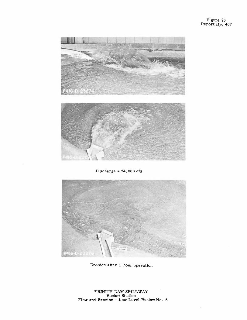
Discharge = 24, 000 cfs
Erosion after 1-hour operation
TRINITY DAM SPILLWAY Bucket Studies
Flow and Erosion - Low Level Bucket No. 5
Figure 26 Report Hyd 467

555
P.C. STA. 38+20.57-...j
-1--E~~~~~~~~~~~~~~~~~~~;:=====ei!!!l!l""-~---------------------------------1--* STA. 38 + 60.57~!-....i -il -~--+------------------,--'-------'""'-'--- ____ ...,.: __ .., .... ,· __ -: : 0 I I I I
FIGURE 27 REPORT HYO. 467
_j__ -<--,: 1--~!~3~;--~--
, __ Fillet·---, I
I I
t
a>-____ , ______ _
r:-----20- ------->-: I : I , 1 I
T ..... U)
<D "' I
PLAN
i R= 53.33' I I I I I I I
~ / I / I/
.,,,1"
I ·o '? I I I I I I I I I
P.V.C. STA. 38 +20.57 ,;-;:...:ELEV. 1930.88
,,.? : I
I
_.,._ __ .._..._ _ __. _j_
·:,;-' I I I I I I
j ---i....---- I ' I 1 , ~-----16----->, !-<----------- -- 31-- - -- - - -- -->j
' ' ELEVATION B-B
1----- ----- -- --·43.33'--------- ----....:r- ------1---- -r· : I I ' I I ' I I // --f :, i
_,,,. 1 I I .,,,,/,,,,, I I - I
,- I I It') ,,.,,,,,. I -0 N
/ _: 0 ~ ,,,,,,.,,, ~ rt) :
I ,_,,,. ~ : I / I I / I iT ,, I
: .: ,"'' .,ELEV.1931.00 : I I ~ / , I
___, _____________ _t __ yj_,,,, ____ ..._' __________ t __ t__J_
SECTION A-A ELEVATION 0-0
TRINITY DAM SPILLWAY BUCKET STUDIES
LOW LEVEL BUCKET NO. 6
_, "' ..,.
Sam Peng
Sticky Note
None set by Sam Peng
Sam Peng
Sticky Note
MigrationNone set by Sam Peng
Sam Peng
Sticky Note
Unmarked set by Sam Peng

555
Tunnel spillway----'·
100
SCALE OF FEET (PROTOTYPE)
200
,-Model outline I
I l
I I I I
--,:;--Excavate -to / ( ' , ,,
_-Toe of slope-modified /'., channel
I
rock or El. 1890 - - - - - - - -,.,__ , ... ',
~
" ' ' I
I I I I I
I I
I
, , -Toe of slope-preliminary channel-,. (
, --Toe of slope-modified channel /
I
TRINITY DAM SPILLWAY BUCKET STUDIES
RIVER CHANNEL MODIFICATION
:,J ~.,, o-,.,c, ... C: ::t: :u -<l'TI 0
"'1\:1 "'a, ...
Sam Peng
Sticky Note
None set by Sam Peng
Sam Peng
Sticky Note
MigrationNone set by Sam Peng
Sam Peng
Sticky Note
Unmarked set by Sam Peng

Discharge = 24,000 cfs
Erosion after 1-hour operation
TRINITY DAM SPILLWAY Bucket Studies
Flow and Erosion - Low Level Bucket No. 6
Figure 29 Report Hyd 467
Sam Peng
Sticky Note
None set by Sam Peng
Sam Peng
Sticky Note
MigrationNone set by Sam Peng
Sam Peng
Sticky Note
Unmarked set by Sam Peng

\~ i .,_ ~oO
:i;
z100 \ l ,Construction joint
Increase dimension to ~ ( ->< .,.4• ,- See profile frJr provide required space for ~~ location of tunnel concrete placement-___ ~?~ reinforcement
Face of / \_-f, 8" Wrought iron watertunnel -- , ' stop. Paint exposed half
with plastic compound.
: Top of concrete frJ frJl!ow rock , surface. fxtent frJ be de
El1970.0-,, °"' ! termined in field.
~-Assumed rock '"'T""~;:~ - . "° 24" 12"- .,,,
FIG.URE 3 REPORT HYD. 467
,Gravel or rock fragments grouted after : placing concrete tunnel lining \. ~ U 'A" Line
"\:~:b-12" · ·-·-5" Formed droin DETAIL W DETAIL X
' , '·-outline of dam-- - - - - >
·-r 28'-o" Dia. diversion and _ , outlet works tunnel -----Ii Auxiliary outlet \ .,,., t,oo,\
PLAN
,. S:. Ii Penstocks--_,,..,,\''\."-
Flip bucket--/
'-~ ~- .,_ Ii Diversion chute
. "'"· t__.:-r Outlet pipes
WROUGHT IRON WATERSTOP SECTION F-F ,-Spaces between continuous liner
: plates or lagging and the ex-, cavoted surfrJce shall be sohdly
packed wiffl clean rock fragments or grovel ond filled with mortar, or grout by_grouting methods / after placing concrete / ~," funnellining-------- Steelrib · ·'
1'\ff.~
~,1-r"' fl. DETAIL Y DETAIL Z
200 200 400
SCALE OF FEET
.1%~~ ~-
Provide offset along ,Toal 1ound or provide entire perimeter of FLOw : f chamfer contraction joint··:-~/,,
rj;f'.Ju r·< Sp,ltwoy /,a,>/
Ii j~
Max. RW.S. E/2387.0 Q=24,000c.fs.·.
'·Contraction joint
DETAIL U
/ f of crest of dam /. ~"1) /2,v~··.
#11 / -. - ' -Anchor bars tO' o" -. ·- . "' .·. "· . embed · · ·
5'.o" ment spc. @ /·-.
crs. e.w. __ ,,," -
,.--'Excavate as steeply as possib7e as directed -For dimensions of shaft above El2250.00,s~ Owg.4l6·0·163
SECTION A-A
P.C.Sta.t5+oooo: : y ... --El2260 -----------El225000 ;-+-,--- _:,L ___ K--fj = 40°00:
0 f . \ ', / R= 10000 fo f
ne rowo rem- , _,-,,,, r = 36 40' forcement e.f.---"\ · · _,,,_-,,, L = 69:8!'
P.T Sta. t5+23.40t,':.--{> \., ·---Diameter varies uniformly along r from 22. 7 2' El. 2185. 72 ! -~ 'o"" at El. 2250.00 ta 20.00' at El. 2185. 72
600
__,,...,,, -rf!.P'
,,- -Assumed original - __ / rack surface
-..J:'.,- --,-Slope ta drain
., ,·Assumed rock surface Spillway chute
I -:._ -#.11 Anchor bars L.,, ,~-
SECTION 8-8
'\ . • "t,L t'""-,1: 49°51'/2" ''<, -:,,'&- //: ;:ifi~· to f. ,-Intersection off auxiliary outlet works and r ,Origmal ground surface- __ .-Downstream limit /rJ be determined in the field
-- --
ti;
~~~ ~ ::.-., ~~~ -E?~~--'C
~-: 8.~ i~l t-i: '-' .., "ii:§.!!! :I:: -~· ., .,,.~-,, . -,,i;::; C: 'S #~'711'
&2-il;!"' ""·,, -~~ C ~~-i:: 50•00'-'··- ,':,,. / : - ·
52, : spillway,Sta. !9+84.62, see Owg.4t6·0·25t and 252 / _,,'.
', ~ ~,, 1 L=l30 1 f ----,, .... _J ----P.C.Sta.!6+55.25':•,f- ;,,@ : ,-·Stat8+00 f,A1rduct , , •,_,,.-, --., Af> . .. ---":. ----,:-Sto.36+00.00
~}~ ~~ :ii::
E/2028.58 ,· ,-- 2o, : ~------------------ ---------------Oramageholes 20:!:: deep@ 20:!:: crs------------------------------------------------>< , 'j>-·---"'"·----,---.-.---------Contract1on 101/fts@ 40·0 ________ .....,,.. •
One row of reinforcement e./ ___ ;;..__ "'crs ,fee '.Unsupported Sect1on;L --·,s1a7§+95·----~2clTt5.Tunner ··----------- - --- ---- -- ..... --- . - - . ----- ---- --- -- --_----- -----~~-~ I.,__ -r-,:<c.?t;!a:l':~ }!~~-- - - --.5;~0256 ,,-Assumed rock surface i ('./960}_~ ,_ ,El.1931.56
Cap--,
, ',, . - _ ',,_; El.1912.00·,
P.T f~;~;~J7>----~:---:.·: ,;,-,>¥'' : Sta. 25+00-----.----------">1 . 5=000256-' / , -------------~--------' ------- -- ,-------------------------------- - --..__ --J::_I ,/ . . ; -- ---- ---------- --------•,:-----<><;_- ---------------------.;;_;:_-,.; ;..;::UJJ.rew[qr<;1d-;;. ~: :-.::: ;;·.;.: :.-.-.-. :=.- - -- ---- --cSfrJ-2~~00---·r*"·Portal Sta 30+00 AL> ·Detail U ,_ #r//J;~~°/s ba~;.~~;:.;~~-Y{tJit---------~i':;..__ -
·One row of remforcement e.f pc Sta.37+-75.75 ---..i -----~=...i Vent holes at highest breaks in excavation- ..
Ori/I only these two grout -. holes between Sta. 20+90 ~ ~ and downstream portal-= ;:-"';~Wli.E.7!?.
UNSUPPORTED SECTION
~ 0 '00 200
• Pipe or drilled holes in tunnel SCALE OF FEET / archfrJrplacingmortarorgroutby
/ grouting method,Jocation as directed
~
, hales athighest breaks in excavation ~If Line
; Detail y. ---,
'.<;; /}--Foot beam optional
-...,_ ___ Base of steel rib ~~~ ~'Line (foot beam omitted}
,_-::~;.}(Line HALF SECTION -. HALF SECTION
LINER PLATES ONLY STRUCTURAL STEEL STRUCTURAL STEEL RIBS RIBS ONLY WITH METAL LAGGING
TYPICAL TUNNEL SECTIONS
STRUCTURAL STEEL RIBS WITH LINER PLATES
HALF SECTION ROOF SUPPORT BOLTS
6"-~ t-fS'~-2~!-~1~ ~611
-~~n'rn' I 1_ I I I
WNMM~-~--,-~-~-w-,-~--~--~,;_.
CONCRETE GUTTER
23861 I I I I I I I I I I -~/ l I
~ ~ 2ml I I I I I I LJ ~ I _b,. I I I ; I
~mel I I I I -r ~ ,,, I I I I I I I I
0: ~ 2 3741 I I<' I I I Lu , I I "' I I I I I I
2370 0 4- 8 12 16 20 24 DISCHARGE IN THOUSANDS OF C.F. S.
SPILLWAY DISCHARGE CURVE
"B"Line-. 'ir_,-Roof support
\_~----If:.. bolt
'A"L. /:, - - ; me __ _'[.ft
2" Mesh #9 gage / · cham-link fabric . / where directed -,/
DETAIL V
NOTES Design based on concre•e with minimum compressive strength
of 3000 pounds per square inch at 28 days. ¾" Chomfer on o/1 exposed formed corners and contraction
joint edges unless otherwise noted. All exposed.unformed corners.and joint edges to be tooled round. Slope tops ofa/1 walls {towards l. Excavation lines shown are minimum. i.f indicates inner frJce; e.f,each face; e.w.,each way. • Wrought iron waterstops to be placed in all transverse construdion
joints in tunnel lining upstream of Sta. 2 I+ 50. Spacing of transverse construction joints in tunnel
not frJ be greeter than 50'. CONCRETE FINISHES
Surfaces covered by fill, Fl; u/. Shaff and tunnel between El. 2330.00and Sta.15+43.40 and
between Sta. l9+80.00 and Sta. 20+!5.00; shaft and tunnel below spring line of the arch between Sta. 15 + 43.40 and Sta. 19+80.00 and between Sta. 20+ 1500 and downstream portal; and curved invert of chute, F4, U3, ·
Shaft and tunnel Sta 16+ 45.00 ta 11• BO. oo below springline of arch, F4 with special finish.
All other surfaces F2, u2
REFERENCE DRAWINGS AUXILIARY OUTLE:T WORKS-Pl.AN ANO SE"CTIONS. ... .416-0-17'1 SPILLWAY-CREST STRUCTURE" ....... •... _. _ .•••... 416·0·/63 SPILLWAY TUNNE"L·CONCRE"TE" ANO
R£/NFORC£M£NT OE"TAILS.. ••. _________ 416-0·251 ANO 252 10-1-58 I CHAHGEO LENGTH OF PAHELS AHO VEltT,CAL GVRVE FOR CHUTE
0 ccuv /-~ I :itfi~'k/Hg.1~ t~8.:~i. :gg:ff1NEi:L~f~i,t!A:-~s AHD
OOf#NSTREAM LIMITS OF METAL WATERSTOPS ANO ARCH GROUTING CHANGEO
REVISED TO PROV/OE METAL WATERSTOPS IN ALL TRANSVERSE CONSTRIJCTION JOINTS UPSTREAM OF STA. 25•00.
/- 17~~ I cz:~:;~ AC:oC:: ::::cTURE, AIR DUCT ANO REINFORCEMENT
UNITED STATES DEPARTMENT DF THE /NTERIOl'f
BUREAU OF RECLAMATION
CENTRAL VALLEY PROJECT TRINITY RIVER DIVISION-CALIFORNIA
TRINITY DAM SPILLWAY
PLAN AND SECTIONS
DRA'WN _____ K.:.!!:..7:_ _____ SUBMITTED __ t::Jf?..K:~ TRACED ____ l_;_f3.:..G_:. ____ RECOMMENDED ___ 9_~~-- ________ _ CHECKED-~.:..~·_!<_.Ff!r!tl_l.~I.PPRDVED ____ ?;~~,i" _____ _
DENVER, COLORADO, DEC. 3,r956 416-0-162
Sam Peng
Sticky Note
None set by Sam Peng
Sam Peng
Sticky Note
MigrationNone set by Sam Peng
Sam Peng
Sticky Note
Unmarked set by Sam Peng

No Flow
TRINITY DAM SPll.,LW AY Bucket Studies
Low Level Bucket No. 7
Discharge = 1, 000 cfs Jump in Bucket l;d
(I)
't:S l'tj 0 .....
!l.ij f: ~ .... a:, -.;J

Discharge = 1,000 cfs Jump swept out of bucket
TRINITY DAM SPILLWAY Bucket Studies
Flow Conditions - Low Level Bucket No. 7
Discharge = 24,000 cfs
~ 'C lzj 0 .....
:i~ ::r: 'i a.: ""'
1\:1
0)
-:i

.... .... ~ iii ci ti: ~
/~ /
,.,,o; ~
.f! ~:
AL·+-----·-------* '<' -( y I '\ - -~~ . I I \ r,.
/ ., .. ,.
/"L (_ r-Sto. 38+6!).II
,g10~
/'°''" /"~
FLIP BUCKET PLAN CONTOURS SHOW ROCK SURFACE
~-~~--~ I ~-~
1, : ~
/ ~
~ ~
.... a, ~ .... 0 .,;
'" .... 0 0 "' + + + CD CD CD
"' "' "' ci ci it.; tr: ~ I~
El. 1931.00·-,. •
El. 1915.00·:
~
~ -;t. +
., "' + ~
~ ci cZ1
El. 1948.67\ __ j -El. 1943.67 -- !_L
SECTION A-A
l_;en 1948.67
_[El. 1943.67
~ --t-----:.-~r-r (? I I ,,-El.1910.00
SECTION C-C
TRINITY DAM SPILLWAY BUCKET STUDIES
RECOMMENDED LOW LEVEL BUCKET
' ' ). ). / I :'I
;, 6 - .... uS ~
"' "' + + CD CD
"' "' c:i 0 +- +-CJ) CJ)
SECTION B-B
:a "' "'II .,,_ 0 G)
:!I~ ~l'TI Pc,i .o,c,i
"' ...
Sam Peng
Sticky Note
None set by Sam Peng
Sam Peng
Sticky Note
MigrationNone set by Sam Peng
Sam Peng
Sticky Note
Unmarked set by Sam Peng
No Fl.ow
TRJNITY DAM SPILLWAY Bucket Studies
Recommended Low Level Bucket
Discharge = 1, 000 cfs
..
f 'Cl l:rj 0 ...
l~ ~(1)
,:l.c.:1 ~~ 0, -.:i

.Q
'D 0
~ .. CD CD
Discharge = 2. 000 cfs
'•
TRINITY DAM SPILLWAY Bucket Studies
Discharge = 24·, 000 cfs
Flow Conditions - Recommended Low Level Bucket
f "C ':i:J ~Jci· ri- ij ~CD i::i..w ""'CJ1 0) ..;i

&"
Q,,__
ST
A.3
8+
82
.20
·--'
~S
TA
.38
+9
2.0
0
I I
1 ---k
_A l)
1il--~ S
TA
.38+ 10.57--------· I
, I
! :;i
I I
I'>
I I
I')
-!2 -~
+
,· I a
,
' I L ____ ::_
~
\ n
--
1 \
\~
\
--~
--/'--/
A·{._
__
__
,\\~
\--------FL
AT
--
-~\ \ \ '\-' ,. \ \ \\ \ ' ' ' ' ' ' \\\ \ .. a,~ \ \ ' ' \ ' ' ' \ \\ \\\
() ------_.,
\\ ,__, "' 0-0-;}, /,
.,,,
l I ,---SPIL
LW
AY
//
11 :
,!'. C
EN
TE
RL
INE
. -,,_,
... ~ :
__ j
' \ \
_;,.
-'!.<:,. I
, _,
-~-
_, II
_,J
A
--\ Q
--------------
\ \ _.,..
0
/?
/
//..,,,/ ///
ST
A.3
8t6
8.9
-El.1
97
0.8
8
-E!.1
96
5.8
8
-ST
A.3
8t8
3.2
-11 -·· •
•¥
.... -,.
<'-... _ _
/,,,, -E
f.19
32
.5
ST A. 3
8+
33
.93
··
.. _o_--. ·.·.
10 2
0
•o S
CA
LE
OF
FE
ET
SE
CT
ION
B
-B
TR
INIT
Y
DA
M
SP
ILL
WA
Y
BU
CK
ET
S
TU
DIE
S
LOW
L
EV
EL
B
UC
KE
T
NO
. 7
.0
,
SE
CT
ION
SE
CT
ION
-----r,
. . .::_,______,_
. ·o .
.o.,
A-A
.r,El.1949.21
,-El.1
94
9.2
1
,wm
,, ------1
_L .L
-1r--
·E1.1921.51 \1,
. . .. . . ·" · ..
,1 I
.IL
--:":'-.. ·,··~.· ..
-5~
I
c-c
SE
CT
ION
0
-0
FIG
UR
E
30
R
EP
OR
T
HY
O. 4
87
_,{~1~
1904.5
_t_~'.:.'._894 5
Sam Peng
Sticky Note
None set by Sam Peng
Sam Peng
Sticky Note
MigrationNone set by Sam Peng
Sam Peng
Sticky Note
Unmarked set by Sam Peng